Loading ...
Loading ...
Loading ...
Specications
2423
System Controls
Sound Pressure Level
• Sound pressure measurements were conducted in an anechoic chamber.
• The actual noise level depends on the distance from the unit and the acoustic environment.
MAJOR SYSTEM CONTROL
FOR P SERIES AND S SERIES INDOOR UNITS
2-remote Controller
Control
With two remote controllers, control
can be performed locally and remotely
from two locations.
Operation Control by
Level Signal
Air conditioner can be started/
stopped remotely. In addition,
On/O operation by local remote
controller can be prohibited/permitted.
Operation Control by
Pulse Signal
Remote Display of
Operating Status
Operating status can be
displayed at a remote location.
Allows On/O operation with
timer
*For control by an external timer,
refer to B Operation Control by
Level Signal.
Timer Operation
• Wired Remote Controller
PAR-31MAA
PAC-YT52CRA
(for PKA, PAC-SH29TC-E is required)
• Wireless Remote Controller
PAR-SL97A-E (for SEZ and PLA-RP)
• Wireless Remote Controller Kit for PCA
PAR-SL94B-E
• Adapter for remote On/O PAC-SE55RA-E
• Relay box (to be purchased locally)
• Remote control panel (to be purchased
locally)
Standard functions of PAR-31MAA
A
B
C
D
E
Details
Major Optional Parts Required
System Examples
Wired remote controller Wireless remote controller
• Up to two remote controllers can be
connected to one group.
• Both wired and wireless remote controllers can
be used in combination.
• Operation other than On/O (e.g., adjust-
ment of temperature, fan speed, and airow)
can
be performed even when remote controller
operation is prohibited.
• Timer control is possible with an external timer.
• Connector cable for remote display
PAC-SA88HA-E / PAC-725AD
(10 pcs. x PAC-SA88HA-E)
• Relay box (to be purchased locally)
• Remote control panel (to be purchased
locally)
• The pulse signal can be turned On/O.
• Operation/emergency signal can be received
at a remote location.
• Operation/emergency signal can be received
at a remote location (when channeled
through the PAC-SF40RM
no-voltage signal, when channeled through
the PAC-SA88HA-E DC 12V signal).
• Weekly Timer:
On/O and up to 8 pattern temperatures can be
set for each calendar day. (Initial setting)
• On/O Timer:
On/O can be set once each within 72hr. in
intervals of 5-minute units.
• Auto-o Timer:
Operation will be switched o after a certain time
elapse. Set time can be changed from
30 min. to 4 hr. at 10 min. intervals.
*Simple Timer and Auto-o Timer
cannot be used at the same time.
• Remote display panel (to be purchased
locally)
• Connector cable for remote display
PAC-SA88HA-E / PAC-725AD
(10 pcs. x PAC-SA88HA-E)
• Relay box (to be purchased locally)
• Remote operation adapter
PAC-SF40RM
*Unable to use with wireless remote controller
PAR-31MAA Control
PAC-YT52CRA Control
System Group Control
M-NET Connections
• PAR-31MAA (Wired remote controller)
• PAC-YT52CRA (Wired remote controller)
<
S Series Outdoor Unit
>
• MAC-397IF-E/MAC-333IF-E (Interface)
• PAR-31MAA (Wired remote controller)
• PAC-YT52CRA (Wired remote controller)
<
P Series Outdoor Unit
>
• PAR-31MAA (Wired remote controller)
A
B
C
Details
Major Optional Parts Required
System Examples
S Series & P Series Indoor Unit
PAR-31MAA
PAC-YT52CRA
PAR-31MAA
PAC-YT52CRA
(Example of 1 : 1 system)
(Example of 1 : 1 system)
Relay box (to be purchased) locally)
Relay box (to be purchased) locally)
Adapter for
remote
On/O
Adapter for
remote
On/O
PAR-SL97A-E
PAR-SL97A-E
(Example of 1 : 1 system)
PAR-31MAA
(Example of 1 : 1 system x 2)
Relay box (to be purchased locally)
(Example of 1 : 1 system x 2)
* Set "Main" and "Sub"
remote controllers.
* When using wired and wireless
remote controllers
PAR-SL97A-E
(Example of Simultaneous Twin)
(Example of Simultaneous Twin)
Remote
display
panel
Remote
display
panel
PAC -
YT52CRA
PAR-31MAA
Remote
control
panel
Remote
control
panelWired remote
controller
Connector
cable for
remote display
Connector
cable for
remote
display
PAR-SL97A-E
(Example of 1 : 1 system x 2)
Relay box (to be purchased locally)
(Example of 1 : 1 system x 2)
Remote
control
panel
Remote
control
panelWired remote
controller
Remote operation adapter/
Connector cable for remote display +
Relay box
Remote operation adapter/
Connector cable for remote display +
Relay box
P Series Indoor Unit
S Series Outdoor
Indoor Unit
Outdoor Unit
P Series Outdoor
Standard equipment (for indoor units
compatible with wired remote controllers)
• One remote controller can control plural air
conditioners with the same settings
simultaneously.
• One remote controller can control up to 16
refrigerant systems.
• Up to two remote controller can be connected.
<
S Series Outdoor Unit
>
• MAC-333IF-E
• MELANS System controller
<
P Series Outdoor Unit
>
• PAC-SF83MA-E (M-NET converter)
• MELANS System controller
• Group of air conditioners can be controlled by
MELANS system controller (M-NET).
PAR-31MAA
PAC-YT52CRA
MAC-397IF-E
MAC-333IF-E
PAR-31MAA
PAC-YT52CRA
Outdoor
unit
Indoor unit
MAC-333IF-E
MELANS
system controller
AE-200E
City Multi
indoor unit
Outdoor
unit
Indoor unit
PAR-31MAA
PAC-YT52CRA
M-NET adapter
PAC-SF81MA-E
MELANS
system controller
AE-200E
PAR-31MAA
PAC-YT52CRA
PAR-31MAA
PAC-YT52CRA
PAR-31MAA
PAC-YT52CRA
PAR-31MAA
PAC-YT52CRA
Indoor
unit
Indoor
unit
System Controls
(
SUZ and Mr. Slim Power Inverter only
)
Versatile system controls can be realised by using optional parts, relay circuits, control panels, etc.
*Above specications are for outdoor units only.
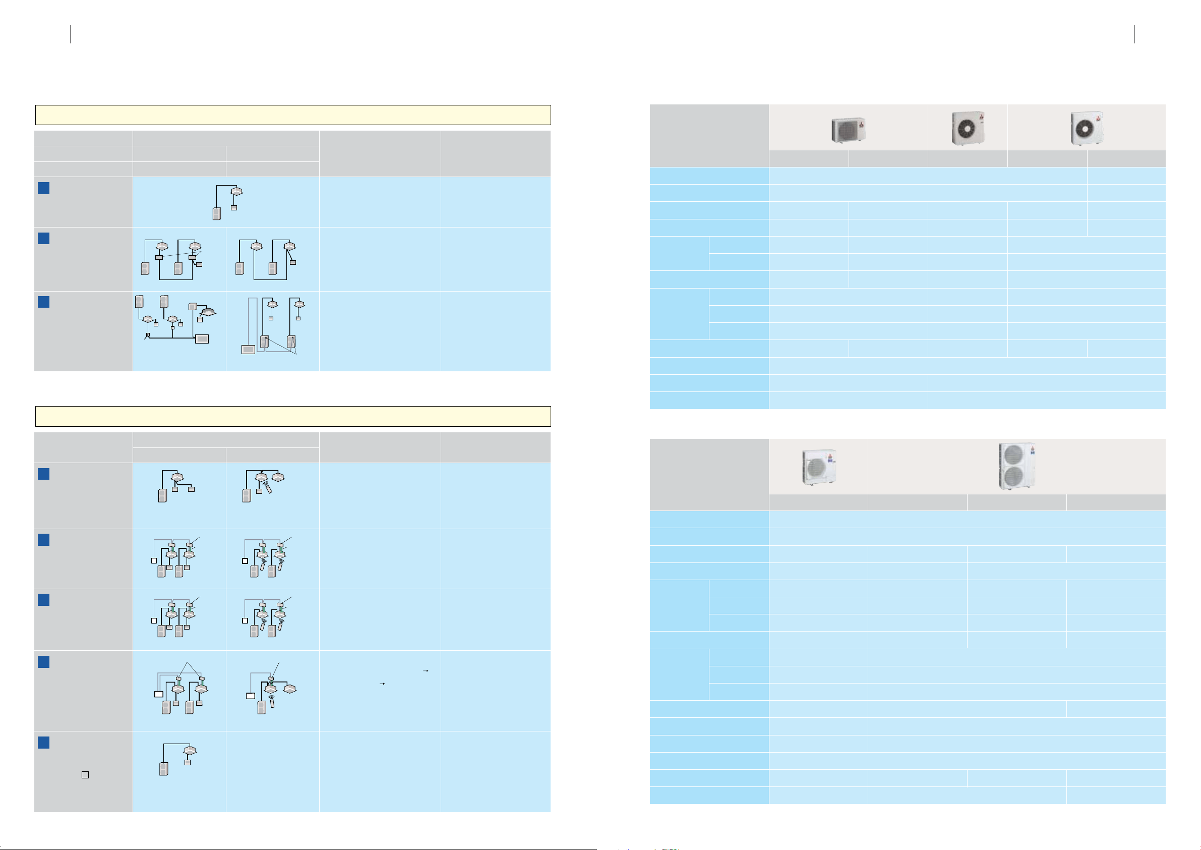
SUZ-KA25VAD SUZ-KA35VAD SUZ-KA50VAD SUZ-KA60VAD SUZ-KA71VAD
Specification: Outdoor Unit
Outdoor unit
Power supply
Compressor output
Airow (cooling/heating)
Cooling mode
Heating mode
Height
Width
Depth
Sound pressure
level
(
dB
)
Sound level
Dimensions
Weight
Chargeless piping length
Max. piping length
Breaker size
(mm)
(mm)
(mm)
(
kW
)
CMM
(
L /S
)
(
dB
)
(
kg
)
(m)
(m)
(
A
)
*Above specications are for outdoor units only.
PUHZ-RP71VHA5 PUHZ-RP100V/ YKA2 PUHZ-RP125V/YKA2 PUHZ-RP140V/YKA2
Munsell 3.0Y 7.8/1.1
V: Single-phase, 50Hz, 230V Y: Three-phase, 50Hz, 400V
1.6 1.9 2.4 2.9
60
(
1,000
)
110
(
1,830
)
49
120
(
2,000
)
47
46
50 50
44
51
47 47
48
69
52 52
7066 70
943 1,338
950
330
1,050
330
67 V: 118 Y: 119 V: 120 Y: 121
30 30
50 75
Discharge thermo, HP switch
9.05/9.64 V: 12.64/13.58 Y: 4.42/4.75 V: 16.36/16.90 Y: 5.73/5.91
V: 32 Y: 16
V: 17.17/19.23 Y: 6.01/6.73
25 V: 40 Y: 16
Outdoor unit
Power supply
Compressor output
Airow (cooling/heating)
Cooling mode
Heating mode
Height
Width
Depth
Sound pressure
level
(
dB
)
Sound level
Dimensions
Weight
Chargeless piping length
Max. piping length
Protection device
(mm)
(mm)
(mm)
(
kW
)
CMM
(
L /S
)
(
dB
)
(
kg
)
(m)
(m)
Silent mode
Rated running current
(cooling/heating)
(
A
)
Breaker size
(
A
)
External nish
External nish Munsell 3.0Y 7.8/1.1
Single-phase, 50Hz, 230V
0.55 0.65 0.9 1.2
34 (568)/32 (534) 33 (551) 49 (817) 57 (950)/48 (800)
46 47 53
46 48 55
59 61 68
550 850
800 840
285 330
30 33 53
0.9
58 (960)/49 (816)
55
55
69
880
840
330
50 53
7
20 30
10 20
Sound Pressure Level
• Sound pressure measurements were conducted in an anechoic chamber.
• The actual noise level depends on the distance from the unit and the acoustic environment.
Loading ...
Loading ...
Loading ...