© Panasonic Corporation 2015.
Order No: PAPAMY1501049CE
Indoor Unit Outdoor Unit
CS-E9RKUAW
CS-E12RKUAW
CS-E18RKUAW
CS-E24RKUAW
CU-E9RKUA
CU-E12RKUA
CU-E18RKUA
CU-E24RKUA
Destination
USA
Canada
Please file and use this manual together with the service manual for Model No. CU-2E18NBU and CU-5E36QBU, Order No.
PHAAM1111120A1 and PAPAMY1312037CE.
AUTO
COMFORT
MODE
POWERFUL /
QUIET
TEMP
OFF/ON
TIMER
SET
CANCEL
ON
OFF
123
AIR SWING
FANSPEED
SET CHECK CLOCK RESET
AC RC
ECONAVI
FAN
SPEED
AIR
SWING
AUTO
HEAT
COOL
DRY
FAN
/
TE
M P
O
FF/ON
TIMER
S
ET
CANCEL
ON
O
FF
1
2
3
C
HECK
AUTO
COMFORT
MODE
POWERFUL /
QUIET
TEMP
OFF/ON
TIMER
SET
CANCEL
ON
OFF
1
2
3
FANSPEED
SET CHECK CLOCK RESET
AC RC
ECONAVI
AUTO
HEAT
COOL
DRY
FAN
FAN
SPEED
AIR
SWING
AIR SWING
/
TE M P
O
FF/ON
T
I
M
E
R
S
ET
CANCEL
ON
O
FF
1
2
3
C
HE
C
K
WARNING
This service information is designed for experienced repair technicians only and is not designed for use by the general public.
It does not contain warnings or cautions to advise non-technical individuals of potential dangers in attempting to service a product.
Products powered by electricity should be serviced or repaired only by experienced professional technicians. Any attempt to
service or repair the products dealt with in this service information by anyone else could result in serious injury or death.
PRECAUTION OF LOW TEMPERATURE
In order to avoid frostbite, be assured of no refrigerant leakage during the installation or repairing of refrigerant circuit.

2
TABLE OF CONTENTS
1. Safety Precautions ............................................. 3
2. Specification ....................................................... 5
3. Features ............................................................. 11
4. Location of Controls and Components .......... 12
4.1 Indoor Unit .................................................. 12
4.2 Outdoor Unit ............................................... 12
4.3 Remote Control .......................................... 12
5. Dimensions ....................................................... 13
5.1 Indoor Unit .................................................. 13
5.2 Outdoor Unit ............................................... 15
6. Refrigeration Cycle Diagram ........................... 16
6.1 CU-E9RKUA CU-E12RKUA ...................... 16
6.2 CU-E18RKUA CU-E24RKUA .................... 17
7. Block Diagram .................................................. 18
7.1 CS-E9RKUAW CU-E9RKUA
CS-E12RKUAW CU-E12RKUA ................. 18
7.2 CS-E18RKUAW CU-E18RKUA
CS-E24RKUAW CU-E24RKUA ................. 19
8. Wiring Connection Diagram ............................ 20
8.1 Indoor Unit .................................................. 20
8.2 Outdoor Unit ............................................... 22
9. Electronic Circuit Diagram .............................. 24
9.1 Indoor Unit .................................................. 24
9.2 Outdoor Unit ............................................... 26
10. Printed Circuit Board ....................................... 28
10.1 Indoor Unit .................................................. 28
10.2 Outdoor Unit ............................................... 30
11. Installation Instruction (E9RK and E12RK) .... 33
11.1 Select the Best Location ............................. 33
11.2 Indoor Unit .................................................. 34
11.3 Outdoor Unit ............................................... 38
12. Installation Instruction
(E18RK and E24RK) ......................................... 41
12.1 Select the Best Location ............................. 41
12.2 Indoor Unit .................................................. 42
12.3 Outdoor Unit ............................................... 46
13. Operation Control ............................................. 49
13.1 Basic Function ............................................ 49
13.2 Indoor Fan Speed Control .......................... 50
13.3 Indoor Fan Motor Operation ....................... 51
13.4 Outdoor Fan Motor Operation .................... 51
13.5 Airflow Direction .......................................... 52
13.6 Quiet Operation (Cooling Mode/Cooling
Area of Dry Mode) ...................................... 53
13.7 Quiet Operation (Heating) .......................... 54
13.8 Powerful Mode Operation ........................... 54
13.9 Timer Control .............................................. 54
13.10 Auto Restart Control ................................... 55
13.11 Indication Panel .......................................... 55
13.12 ECONAVI and AUTO COMFORT
Operation ....................................................55
14. Operation Control
(For Multi Split Connection) ............................59
14.1 Cooling operation .......................................59
14.2 Soft Dry Operation ......................................59
14.3 Heating Operation ......................................59
14.4 Automatic Operation
(For Multi Split Connection Only) ...............60
14.5 Indoor Fan Motor Operation .......................60
14.6 Powerful Mode Operation ...........................60
14.7 Auto restart control .....................................60
14.8 Indication Panel ..........................................60
15. Protection Control (E9RK and E12RK) ...........61
15.1 Protection Control For All Operations .........61
15.2 Protection Control For Cooling & Soft Dry
Operation ....................................................63
16. Protection Control (E18RK and E24RK) .........66
16.1 Protection Control For All Operations .........66
16.2 Protection Control For Cooling & Soft Dry
Operation ....................................................67
17. Servicing Mode .................................................70
17.1 Auto Off/On Button .....................................70
17.2 Cooling Only Operation
(Single connection Only, Multi connection
please refer to Multi outdoor manual) .........71
17.3 Remote Control Button ...............................72
18. Troubleshooting Guide ....................................73
18.1 Refrigeration Cycle System ........................73
18.2 Breakdown Self Diagnosis Function ...........75
18.3 Error Code Table ........................................76
18.4 Self-diagnosis Method ................................78
19. Disassembly and Assembly Instructions ... 107
19.1 CS-E9RKUAW CS-E12RKUAW ............ 107
19.2 CS-E18RKUAW CS-E24RKUAW .......... 111
19.3 Outdoor Electronic Controller Removal
Procedure ................................................ 114
20. Technical Data ............................................... 116
20.1 Cool Mode Performance Data ................. 116
20.2 Heat Mode Performance Data ................. 120
21. Service Data ................................................... 122
21.1 Cool Mode Outdoor Air Temperature
Characteristic ........................................... 122
21.2 Heat Mode Outdoor Air Temperature
Characteristic ........................................... 126
21.3 Piping Length Correction Factor .............. 130
22. Exploded View and Replacement Parts
List .................................................................. 132
22.1 Indoor Unit ............................................... 132
22.2 Outdoor Unit ............................................ 138
3
CAUTION
WARNING
WARNING
1. Safety Precautions
Read the following “SAFETY PRECAUTIONS” carefully before perform any servicing.
Electrical work must be installed or serviced by a licensed electrician. Be sure to use the correct rating of the
power plug and main circuit for the model installed.
The caution items stated here must be followed because these important contents are related to safety. The
meaning of each indication used is as below. Incorrect installation or servicing due to ignoring of the instruction
will cause harm or damage, and the seriousness is classified by the following indications.
This indication shows the possibility of causing death or serious injury
This indication shows the possibility of causing injury or damage to properties.
The items to be followed are classified by the symbols:
Carry out test run to confirm that no abnormality occurs after the servicing. Then, explain to user the operation,
care and maintenance as stated in instructions. Please remind the customer to keep the operating instructions for
future reference.
1. Do not modify the machine, part, material during repairing service.
2. If wiring unit is supplied as repairing part, do not repair or connect the wire even only partial wire break. Exchange the whole wiring unit.
3. Do not wrench the fasten terminal. Pull it out or insert it straightly.
4. Engage authorized dealer or specialist for installation and servicing. If installation of servicing done by the user is defective, it will cause water
leakage, electrical shock or fire.
5. Install according to this installation instructions strictly. If installation is defective, it will cause water leakage, electric shock or fire.
6. Use the attached accessories parts and specified parts for installation and servicing. Otherwise, it will cause the set to fall, water leakage, fire
or electrical shock.
7. Install at a strong and firm location which is able to withstand the set’s weight. If the strength is not enough or installation is not properly done,
the set will drop and cause injury.
8. For electrical work, follow the local national wiring standard, regulation and the installation instruction. An independent circuit and single outlet
must be used. If electrical circuit capacity is not enough or defect found in electrical work, it will cause electrical shock or fire.
9. This equipment is strongly recommended to be installed with Earth Leakage Circuit Breaker (ELCB) or Residual Current Device (RCD).
Otherwise, it may cause electrical shock and fire in case equipment breakdown or insulation breakdown.
10. Do not use joint cable for indoor/outdoor connection cable. Use the specified indoor/outdoor connection cable, refer to installation instruction
CONNECT THE CABLE TO THE INDOOR UNIT and connect tightly for indoor/outdoor connection. Clamp the cable so that no external force
will be acted on the terminal. If connecting or fixing is not perfect, it will cause heat up or fire at the connection.
11. Wire routing must be properly arranged so that control board cover is fixed properly. If control board cover is not fixed perfectly, it will cause
heat-up or fire at the connection point of terminal, fire or electrical shock.
12. When install or relocate air conditioner, do not let any substance other than the specified refrigerant, eg. air etc. mix into refrigeration cycle
(piping). (Mixing of air etc. will cause abnormal high pressure in refrigeration cycle and result in explosion, injury etc.).
13. Do not install outdoor unit near handrail of veranda. When installing air-conditioner unit at veranda of high rise building, child may
climb up to outdoor unit and cross over the handrail and causing accident.
14. This equipment must be properly earthed. Earth line must not be connected to gas pipe, water pipe, earth of lightning rod and
telephone. Otherwise, it may cause electrical shock in case equipment breakdown or insulation breakdown.
15. Keep away from small children, the thin film may cling to nose and mouth and prevent breathing.
16. Do not use unspecified cord, modified cord, joint cord or extension cord for power supply cord. Do not share the single outlet with
other electrical appliances. Poor contact, poor insulation or over current will cause electrical shock or fire.
17. Tighten the flare nut with torque wrench according to specified method. If the flare nut is over-tightened, after a long period, the flare may
break and cause refrigerant gas leakage.
18. For R410A model, use piping, flare nut and tools which is specified for R410A refrigerant. Using of existing (R22) piping, flare nut
and tools may cause abnormally high pressure in the refrigerant cycle (piping), and possibly result in explosion and injury.
Thickness or copper pipes used with R410A must be more than 1/32" (0.8 mm). Never use copper pipes thinner than 1/32" (0.8 mm).
It is desirable that the amount of residual oil is less than 0.0008 oz/ft (40 mg/10 m).
This symbol denotes item that is PROHIBITED from doing.
4
CAUTION
WARNING
19. During installation, install the refrigerant piping properly before run the compressor. (Operation of compressor without fixing refrigeration piping
and valves at opened condition will cause suck-in of air, abnormal high pressure in refrigeration cycle and result in explosion, injury etc.).
20. During pump down operation, stop the compressor before remove the refrigeration piping. (Removal of refrigeration piping while compressor is
operating and valves are opened condition will cause suck-in of air, abnormal high pressure in refrigeration cycle and result in explosion, injury
etc.).
21. After completion of installation or service, confirm there is no leakage of refrigerant gas. It may generate toxic gas when the refrigerant
contacts with fire.
22. Ventilate if there is refrigerant gas leakage during operation. It may cause toxic gas when the refrigerant contacts with fire.
23. Do not insert your fingers or other objects into the unit, high speed rotating fan may cause injury.
24. Must not use other parts except original parts describe in catalog and manual.
25. Using of refrigerant other than the specified type may cause product damage, burst and injury etc.
1. Do not install the unit at place where leakage of flammable gas may occur. In case gas leaks and accumulates at surrounding of the
unit, it may cause fire.
2. Carry out drainage piping as mentioned in installation instructions. If drainage is not perfect, water may enter the room and damage
the furniture.
3. Tighten the flare nut with torque wrench according to specified method. If the flare nut is over-tightened, after a long period, the flare
may break and cause refrigerant gas leakage.
4. Do not touch outdoor unit air inlet and aluminium fin. It may cause injury.
5. Select an installation location which is easy for maintenance.
6. Pb free solder has a higher melting point than standard solder; typically the melting point is 50°F – 70°F (30°C – 40°C) higher. Please use
a high temperature solder iron. In case of the soldering iron with temperature control, please set it to 700 ± 20°F (370 ± 10°C).
Pb free solder will tend to splash when heated too high (about 1100°F / 600°C).
7. Power supply connection to the room air conditioner.
Power supply cord shall be UL listed or CSA approved 3 conductor with minimum AWG14 (For E9RK and E12RK) and AWG12
(For E18RK and E24RK) wires.
Power supply point should be in an easily accessible place for power disconnection in case of emergency.
In some countries, permanent connection of this air conditioner to the power supply is prohibited.
Fix power supply connection to a circuit breaker for permanent connection.
Use NRTL approved fuse or circuit breaker (rating refers to name plate) for permanent connection.
8. Do not release refrigerant during piping work for installation, servicing, reinstallation and during repairing a refrigerant parts. Take
care of the liquid refrigerant, it may cause frostbite.
9. Installation or servicing work: It may need two people to carry out the installation or servicing work.
10. Do not install this appliance in a laundry room or other location where water may drip from the ceiling, etc.
11. Do not sit or step on the unit, you may fall down accidentally.
12. Do not touch the sharp aluminium fins or edges of metal parts.
If you are required to handle sharp parts during installation or servicing, please wear hand glove.
Sharp parts may cause injury.
5
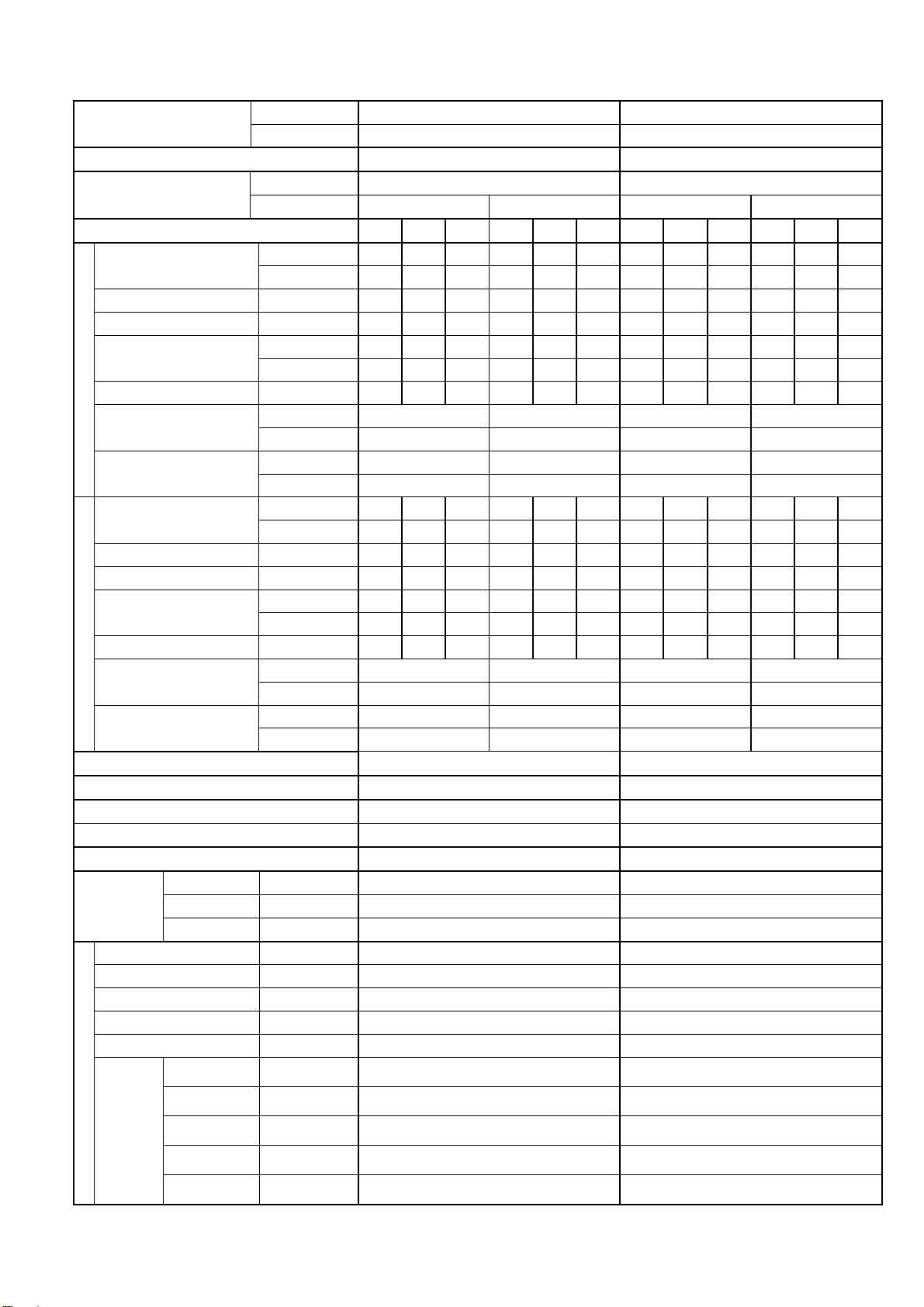
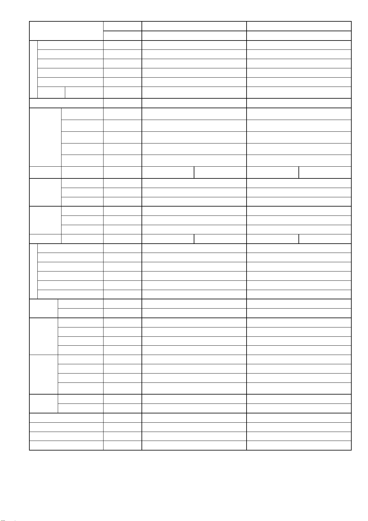
2. Specification
Model
Indoor CS-E9RKUAW CS-E12RKUAW
Outdoor CU-E9RKUA CU-E12RKUA
Performance Test Condition ARI ARI
Power Supply
Phase, Hz Single, 60 Single, 60
V 208 230 208 230
Min. Mid. Max. Min. Mid. Max. Min. Mid. Max. Min. Mid. Max.
Cooling
Capacity
kW 1.20 2.64 3.00 1.20 2.64 3.00 1.20 3.36 3.90 1.20 3.36 3.90
BTU/h 4100 9000 10200 4100 9000 10200 4100 11500 13300 4100 11500 13300
Running Current A - 3.6 - - 3.2 - - 4.7 - - 4.2 -
Input Power W 250 690 850 250 690 850 250 920 1.15k 250 920 1.15k
EER
W/W 4.80 3.83 3.53 4.80 3.83 3.53 4.80 3.65 3.39 4.80 3.65 3.39
Btu/hW 16.40 13.00 12.00 16.40 13.00 12.00 16.40 12.50 11.55 16.40 12.50 11.55
Power Factor % - 92 - - 94 - - 94 - - 95 -
Indoor Noise (H / L / QLo)
dB-A 40 / 25 / 20 40 / 25 / 20 43 / 28 / 20 43 / 28 / 20
Power Level dB 56 / - / - 56 / - / - 59 / - / - 59 / - / -
Outdoor Noise (H / L / QLo)
dB-A 47 / - / - 47 / - / - 48 / - / - 48 / - / -
Power Level dB 62 / - / - 62 / - / - 63 / - / - 63 / - / -
Heating
Capacity
kW 1.20 3.52 4.14 1.20 3.52 4.14 1.20 4.05 4.77 1.20 4.05 4.77
BTU/h 4100 12000 14100 4100 12000 14100 4100 13800 16300 4100 13800 16300
Running Current A - 5.7 - - 5.1 - - 6.3 - - 5.6 -
Input Power W 200 1.12k 1.50k 200 1.12k 1.50k 200 1.25k 1.71k 200 1.25k 1.71k
COP
W/W 6.00 3.14 2.76 6.00 3.14 2.76 6.00 3.24 2.79 6.00 3.24 2.79
Btu/hW 20.50 10.70 9.40 20.50 10.70 9.40 20.50 11.00 9.50 20.50 11.00 9.50
Power Factor % - 94 - - 95 - - 95 - - 97 -
Indoor Noise (H / L / QLo)
dB-A 42 / 29 / 26 42 / 29 / 26 44 / 35 / 32 44 / 35 / 32
Power Level dB 58 / - / - 58 / - / - 60 / - / - 60 / - / -
Outdoor Noise (H / L / QLo)
dB-A 48 / - / - 48 / - / - 49 / - / - 49 / - / -
Power Level dB 63 / - / - 63 / - / - 64 / - / - 64 / - / -
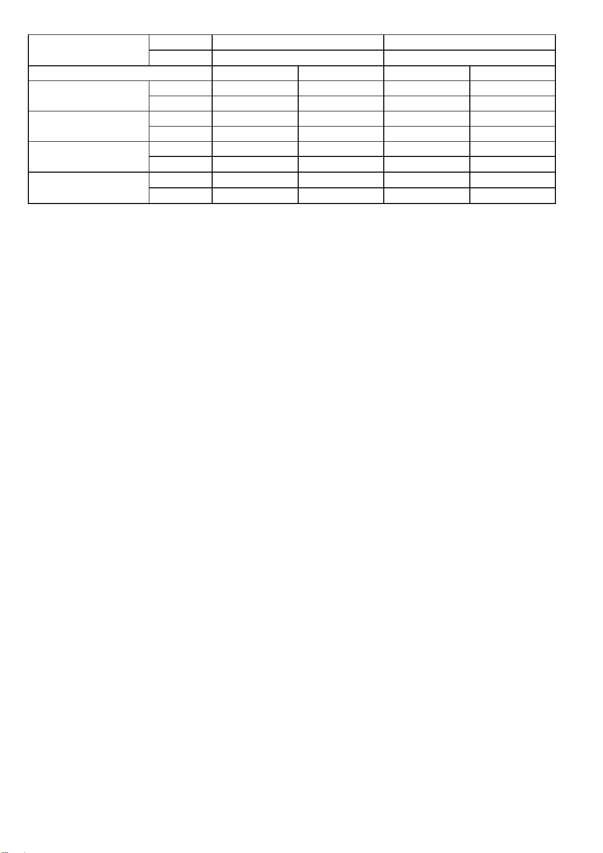
Max Current (A) / Max Input Power (W) 7.0 / 1.57k 7.8 / 1.71k
Starting Current (A) 5.7 6.3
Min Circuit Ampacity 15.0 15.0
Max. Current Protection 15.0 15.0
SEER / HSPF 23.00 / 11.00 22.50 / 11.00
Compressor
Type Hermetic Motor / Rotary Hermetic Motor / Rotary
Motor Type Brushless (4 poles) Brushless (4 poles)
Output Power W 700 700
Indoor Fan
Type Cross-flow fan Cross-flow fan
Material ASG20K1 ASG20K1
Motor Type DC (8 poles) DC (8 poles)
Input Power W 47.0 - 47.0 47.0 - 47.0
Output Power W 40 40
Speed
QLo rpm
Cooling : 610
Heating : 730
Cooling : 620
Heating : 940
Lo rpm
Cooling : 710
Heating : 830
Cooling : 780
Heating : 1040
Me rpm
Cooling : 910
Heating : 1040
Cooling : 1000
Heating : 1210
Hi rpm
Cooling : 1120
Heating : 1250
Cooling : 1230
Heating : 1380
SHi rpm
Cooling : 1210
Heating : 1340
Cooling : 1350
Heating : 1450
6
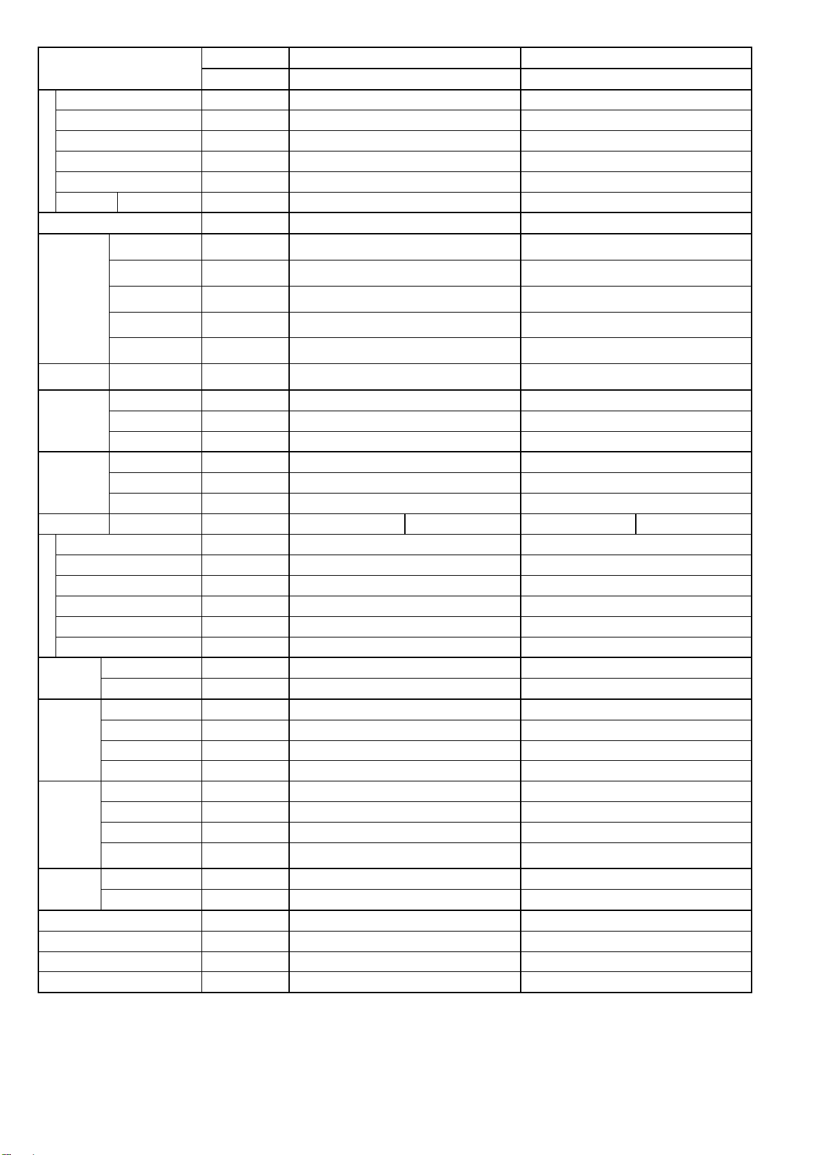
Model
Indoor CS-E9RKUAW CS-E12RKUAW
Outdoor CU-E9RKUA CU-E12RKUA
Outdoor Fan
Type Propeller Propeller
Material PP PP
Motor Type DC (8 poles) DC (8 poles)
Input Power W - -
Output Power W 40 40
Speed Hi rpm C: 830 H: 780 C: 830 H: 820
Moisture Removal L/h (Pt/h) 0.6 (1.3) 0.8 (1.7)
Indoor Airflow
QLo m
3
/min (ft
3
/min)
Cooling : 6.28 (222)
Heating : 7.08 (250)
Cooling : 5.97 (211)
Heating : 9.37 (331)
Lo m
3
/min (ft
3
/min)
Cooling : 7.40 (261)
Heating : 8.20 (290)
Cooling : 7.76 (274)
Heating : 10.49 (370)
Me m
3
/min (ft
3
/min)
Cooling : 9.64 (340)
Heating : 10.55 (373)
Cooling : 10.22 (361)
Heating : 12.40 (438)
Hi m
3
/min (ft
3
/min)
Cooling : 12.0 (425)
Heating : 12.9 (455)
Cooling : 12.8 (450)
Heating : 14.3 (505)
SHi m
3
/min (ft
3
/min)
Cooling : 13.00 (459)
Heating : 13.91 (491)
Cooling : 14.14 (499)
Heating : 15.08 (532)
Outdoor
Airflow
Hi m
3
/min (ft
3
/min)
Cooling : 31.0 (1095)
Heating : 31.0 (1095)
Cooling : 31.2 (1100)
Heating : 31.2 (1100)
Refrigeration
Cycle
Control Device Expansion Valve Expansion Valve
Refrigerant Oil cm
3
FV50S (320) FV50S (320)
Refrigerant Type g (oz) R410A, 980 (34.6) R410A, 1.08k (38.1)
Dimension
Height(I/D / O/D) mm (inch) 290 (11-7/16) / 540 (21-9/32) 290 (11-7/16) / 540 (21-9/32)
Width (I/D / O/D) mm (inch) 870 (34-9/32) / 780 (30-23/32) 870 (34-9/32) / 780 (30-23/32)
Depth (I/D / O/D) mm (inch) 214 (8-7/16) / 289 (11-13/32) 214 (8-7/16) / 289 (11-13/32)
Weight Net (I/D / O/D) kg (lb) 9 (20) 37 (82) 9 (20) 37 (82)
Piping
Pipe Diameter (Liquid / Gas) mm (inch) 6.35 (1/4) / 9.52 (3/8) 6.35 (1/4) / 12.70 (1/2)
Standard length m (ft) 7.5 (24.6) 7.5 (24.6)
Length range (min – max) m (ft) 3 (9.8) ~ 20 (65.6) 3 (9.8) ~ 20 (65.6)
I/D & O/D Height different m (ft) 15 (49.2) 15 (49.2)
Additional Gas Amount g/m (oz/ft) 20 (0.2) 20 (0.2)
Length for Additional Gas m (ft) 7.5 (24.6) 7.5 (24.6)
Drain Hose
Inner Diameter mm (inch) 16.7 (5/8) 16.7 (5/8)
Length mm (inch) 650 (25-5/8) 650 (25-5/8)
Indoor Heat
Exchanger
Fin Material Aluminium (Pre Coat) Aluminium (Pre Coat)
Fin Type Slit Fin Slit Fin
Row x Stage x FPI 2 x 15 x 21 2 x 15 x 21
Size (W x H x L) inch 1 x 12-13/32 x 24 1 x 12-13/32 x 24
Outdoor
Heat
Exchanger
Fin Material Aluminium (Blue coated) Aluminium (Blue coated)
Fin Type Corrugate Fin Corrugate Fin
Row x Stage x FPI 2 x 24 x 17 2 x 24 x 17
Size (W x H x L) inch
1-13/32 x 19-13/16 x 28-1/16
26-7/8
1-13/32 x 19-13/16 x 32-7/16
31-1/4
Air Filter
Material Polypropelene Polypropelene
Type One-touch One-touch
Power Supply Outdoor Outdoor
Power Supply Cord A - -
Thermostat - -
Protection Device - -
7
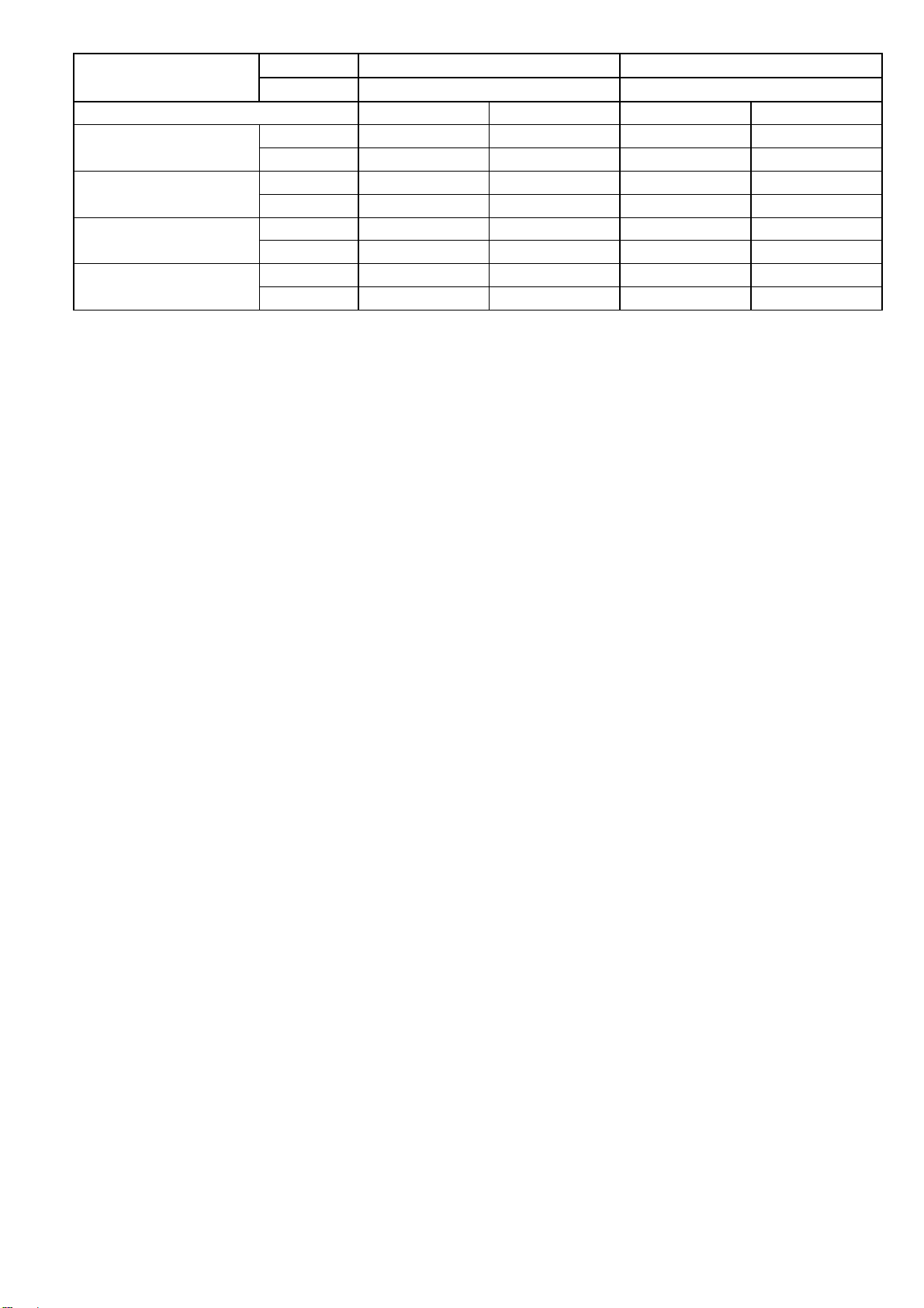
Model
Indoor CS-E9RKUAW CS-E12RKUAW
Outdoor CU-E9RKUA CU-E12RKUA
DRY BULB WET BULB DRY BULB WET BULB
Indoor Operation Range
(Cooling) (°F / °C)
Maximum 89.6 / 32 73.4 / 23 89.6 / 32 73.4 / 23
Minimum 60.8 / 16 51.8 / 11 60.8 / 16 51.8 / 11
Outdoor Operation Range
(Cooling) (°F / °C)
Maximum 114.8 / 46 78.8 / 26 114.8 / 46 78.8 / 26
Minimum 0 / -17.8 - / - 0 / -17.8 - / -
Indoor Operation Range
(Heating) (°F / °C)
Maximum 86.0 / 30 - / - 86.0 / 30 - / -
Minimum 60.8 / 16 - / - 60.8 / 16 - / -
Outdoor Operation Range
(Heating) (°F / °C)
Maximum 75.2 / 24 64.4 / 18 75.2 / 24 64.4 / 18
Minimum -4 / -20 -5.8 / -21 -4 / -20 -5.8 / -21
1. Cooling capacities are based on indoor temperature of 27°C DRY BULB (80.6°F DRY BULB), 19.0°C WET BULB (66°F WET BULB) and
outdoor air temperature of 35°C DRY BULB (95°F DRY BULB), 24°C WET BULB (75.2°F WET BULB)
2. Heating capacities are based on indoor temperature of 20°C Dry Bulb (68°F Dry Bulb) and outdoor air temperature of 7°C Dry Bulb (44.6°F
Dry Bulb), 6°C Wet Bulb (42.8°F Wet Bulb)
3. Specifications are subjected to change without prior notice for further improvement.
8
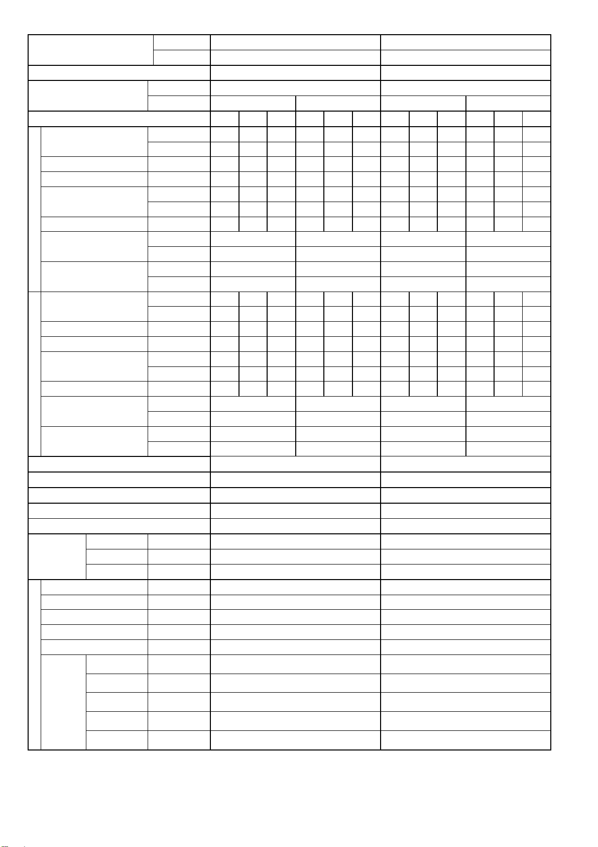
Model
Indoor CS-E18RKUAW CS-E24RKUAW
Outdoor CU-E18RKUA CU-E24RKUA
Performance Test Condition ARI ARI
Power Supply
Phase, Hz Single, 60 Single, 60
V 208 230 208 230
Min. Mid. Max. Min. Mid. Max. Min. Mid. Max. Min. Mid. Max.
Cooling
Capacity
kW 1.70 5.04 5.80 1.70 5.04 5.80 1.70 7.02 8.00 1.70 7.02 8.00
BTU/h 5800 17200 19800 5800 17200 19800 5800 24000 27200 5800 24000 27200
Running Current A - 7.00 - - 6.30 - - 11.90 - - 10.80 -
Input Power W 430 1.30k 1.60k 430 1.30k 1.60k 430 2.35k 2.72k 430 2.35k 2.72k
EER
W/W 3.95 3.88 3.63 3.95 3.88 3.63 3.95 2.99 2.94 3.95 2.99 2.94
Btu/hW 13.45 13.20 12.35 13.45 13.20 12.35 13.45 10.20 10.00 13.45 10.20 10.00
Power Factor % - 89 - - 90 - - 95 - - 95 -
Indoor Noise (H / L / QLo)
dB-A 47 / 39 / 36 47 / 39 / 36 48 / 40 / 37 48 / 40 / 37
Power Level dB 63 / - / - 63 / - / - 64 / - / - 64 / - / -
Outdoor Noise (H / L / QLo)
dB-A 49 / - / - 49 / - / - 51 / - / - 51 / - / -
Power Level dB 63 / - / - 63 / - / - 65 / - / - 65 / - / -
Heating
Capacity
kW 1.70 6.33 6.43 1.70 6.33 6.43 1.70 8.46 8.56 1.70 8.46 8.56
BTU/h 5800 21600 22000 5800 21600 22000 5800 28800 29200 5800 28800 29200
Running Current A - 9.30 - - 8.30 - - 12.60 - - 11.40 -
Input Power W 380 1.75k 1.80k 380 1.75k 1.80k 380 2.50k 2.66k 380 2.50k 2.66k
COP
W/W 4.47 3.62 3.57 4.47 3.62 3.57 4.47 3.38 3.22 4.47 3.38 3.22
Btu/hW 15.25 12.30 12.20 15.25 12.30 12.20 15.25 11.50 10.95 15.25 11.50 10.95
Power Factor % - 90 - - 92 - - 95 - - 95 -
Indoor Noise (H / L / QLo)
dB-A 46 / 39 / 36 46 / 39 / 36 48 / 40 / 37 48 / 40 / 37
Power Level dB 62 / - / - 62 / - / - 64 / - / - 64 / - / -
Outdoor Noise (H / L / QLo)
dB-A 51 / - / - 51 / - / - 53 / - / - 53 / - / -
Power Level dB 65 / - / - 65 / - / - 67 / - / - 67 / - / -
Max Current (A) / Max Input Power (W) 12.7 / 2.69k 13.7 / 3.06k
Starting Current (A) 9.3 12.6
Min Circuit Ampacity 15.0 20.0
Max. Overcurrent Protection 20.0 25.0
SEER / HSPF 19.50 / 10.00 19.00 / 10.00
Compressor
Type Hermetic Motor / Rotary Hermetic Motor / Rotary
Motor Type Brushless (4 poles) Brushless (4 poles)
Output Power W 1.7k 1.7k
Indoor Fan
Type Cross-flow fan Cross-flow fan
Material ASG30K1 ASG30K1
Motor Type DC (8 poles) DC (8 poles)
Input Power W 94.8 - 94.8 94.8 - 94.8
Output Power W 40 40
Speed
QLo rpm
Cooling : 970
Heating : 1030
Cooling : 1000
Heating : 1110
Lo rpm
Cooling : 1060
Heating : 1120
Cooling : 1090
Heating : 1220
Me rpm
Cooling : 1220
Heating : 1260
Cooling : 1240
Heating : 1360
Hi rpm
Cooling : 1380
Heating : 1410
Cooling : 1400
Heating : 1500
SHi rpm
Cooling : 1480
Heating : 1500
Cooling : 1500
Heating : 1600
9
Model
Indoor CS-E18RKUAW CS-E24RKUAW
Outdoor CU-E18RKUA CU-E24RKUA
Outdoor Fan
Type Propeller Propeller
Material PP PP
Motor Type DC Motor (8 poles) DC Motor (8 poles)
Input Power W - -
Output Power W 60 60
Speed Hi rpm
Cooling: 700
Heating: 700
Cooling: 730
Heating: 750
Moisture Removal L/h (Pt/h) 1.4 (3.0) 3.6 (7.6)
Indoor Airflow
QLo m
3
/min (ft
3
/min)
Cooling : 13.28 (469)
Heating : 14.40 (508)
Cooling : 13.42 (474)
Heating : 14.86 (525)
Lo m
3
/min (ft
3
/min)
Cooling : 14.53 (513)
Heating : 15.65 (553)
Cooling : 14.67 (518)
Heating : 16.39 (579)
Me m
3
/min (ft
3
/min)
Cooling : 16.77 (592)
Heating : 17.61 (622)
Cooling : 16.77 (592)
Heating : 18.35 (648)
Hi m
3
/min (ft
3
/min)
Cooling : 19.00 (670)
Heating : 19.70 (695)
Cooling : 19.00 (670)
Heating : 20.30 (715)
SHi m
3
/min (ft
3
/min)
Cooling : 20.40 (720)
Heating : 20.96 (740)
Cooling : 20.40 (720)
Heating : 21.70 (766)
Outdoor
Airflow
Hi m
3
/min (ft
3
/min)
Cooling : 54.5 (1925)
Heating : 54.5 (1925)
Cooling : 54.5 (1925)
Heating : 54.5 (1925)
Cooling : 54.9 (1940)
Heating : 56.5 (1995)
Cooling : 54.9 (1940)
Heating : 56.5 (1995)
Refrigeration
Cycle
Control Device Expansion Valve Expansion Valve
Refrigerant Oil cm
3
FV50S (800) FV50S (800)
Refrigerant Type g (oz) R410A, 1.60k (56.5) R410A, 1.85k (65.3)
Dimension
Height(I/D / O/D) mm (inch) 290 (11-7/16) / 795 (31-5/16) 290 (11-7/16) / 795 (31-5/16)
Width (I/D / O/D) mm (inch) 1070 (42-5/32) / 875 (34-15/32) 1070 (42-5/32) / 875 (34-15/32)
Depth (I/D / O/D) mm (inch) 240 (9-15/32) / 320 (12-5/8) 240 (9-15/32) / 320 (12-5/8)
Weight Net (I/D / O/D) kg (lb) 12 (26) 60 (132) 12 (26) 60 (132)
Piping
Pipe Diameter (Liquid / Gas) mm (inch) 6.35 (1/4) / 12.70 (1/2) 6.35 (1/4) / 15.88 (5/8)
Standard length m (ft) 7.5 (24.6) 7.5 (24.6)
Length range (min – max) m (ft) 3 (9.8) ~ 30.5 (100.0) 3 (9.8) ~ 30.5 (100.0)
I/D & O/D Height different m (ft) 15 (49.2) 15 (49.2)
Additional Gas Amount g/m (oz/ft) 25 (0.3) 25 (0.3)
Length for Additional Gas m (ft) 10 (32.8) 10 (32.8)
Drain Hose
Inner Diameter mm (inch) 16.7 (5/8) 16.7 (5/8)
Length mm (inch) 650 (25-5/8) 650 (25-5/8)
Indoor Heat
Exchanger
Fin Material Aluminium (Pre Coat) Aluminium (Pre Coat)
Fin Type Slit Fin Slit Fin
Row x Stage x FPI 2 x 15 x 21 2 x 15 x 21
Size (W x H x L) inch 1 x 12-13/32 x 31-7/8 1 x 12-13/32 x 31-7/8
Outdoor
Heat
Exchanger
Fin Material Aluminium (Blue coated) Aluminium (Blue coated)
Fin Type Corrugate Fin Corrugate Fin
Row x Stage x FPI 2 x 36 x 19 2 x 36 x 19
Size (W x H x L) inch
1-13/32 x 29-25/32 x 34-7/32
35-5/16
1-13/32 x 29-25/32 x 34-7/32
35-5/16
Air Filter
Material Polypropelene Polypropelene
Type One-touch One-touch
Power Supply Outdoor Outdoor
Power Supply Cord A - -
Thermostat - -
Protection Device - -
10
Model
Indoor CS-E18RKUAW CS-E24RKUAW
Outdoor CU-E18RKUA CU-E24RKUA
DRY BULB WET BULB DRY BULB WET BULB
Indoor Operation Range
(Cooling) (°F / °C)
Maximum 89.6 / 32 73.4 / 23 89.6 / 32 73.4 / 23
Minimum 60.8 / 16 51.8 / 11 60.8 / 16 51.8 / 11
Outdoor Operation Range
(Cooling) (°F / °C)
Maximum 114.8 / 46 78.8 / 26 114.8 / 46 78.8 / 26
Minimum 0 / -17.8 - / - 0 / -17.8 - / -
Indoor Operation Range
(Heating) (°F / °C)
Maximum 86.0 / 30 - / - 86.0 / 30 - / -
Minimum 60.8 / 16 - / - 60.8 / 16 - / -
Outdoor Operation Range
(Heating) (°F / °C)
Maximum 75.0 / 24 64.4 / 18 75.0 / 24 64.4 / 18
Minimum -4 / -20 -5.8 / -21 -4 / -20 -5.8 / -21
1. Cooling capacities are based on indoor temperature of 80°F DRY BULB, 67°F WET BULB and outdoor air temperature of 95°F DRY BULB,
75°F WET BULB.
2. Heating capacities are based on indoor temperature of 70°F DRY BULB, 60°F WET BULB and outdoor air temperature of 47°F DRY BULB,
43°F WET BULB.
3. Specifications are subjected to change without prior notice for further improvement.

11
3. Features
Inverter Technology
o Wider output power range
o Energy saving
o Quick Cooling
o More precise temperature control
Environment Protection
o Non-ozone depletion substances refrigerant (R410A)
Long Installation Piping
o CS/CU-E9/12RK, long piping up to 65 feet (20 meters)
o CS/CU-E18/24RK, long piping up to 100 feet (30 meters)
Easy to use remote control
Quality Improvement
o Random auto restart after power failure for safety restart operation
o Gas leakage protection
o Prevent compressor reverse cycle
o Inner protector to protect Compressor
o Noise prevention during soft dry operation
Operation Improvement
o Quiet mode to reduce the indoor unit operating sound
o Powerful mode to reach the desired room temperature quickly
Serviceability Improvement
o Breakdown Self Diagnosis function
12
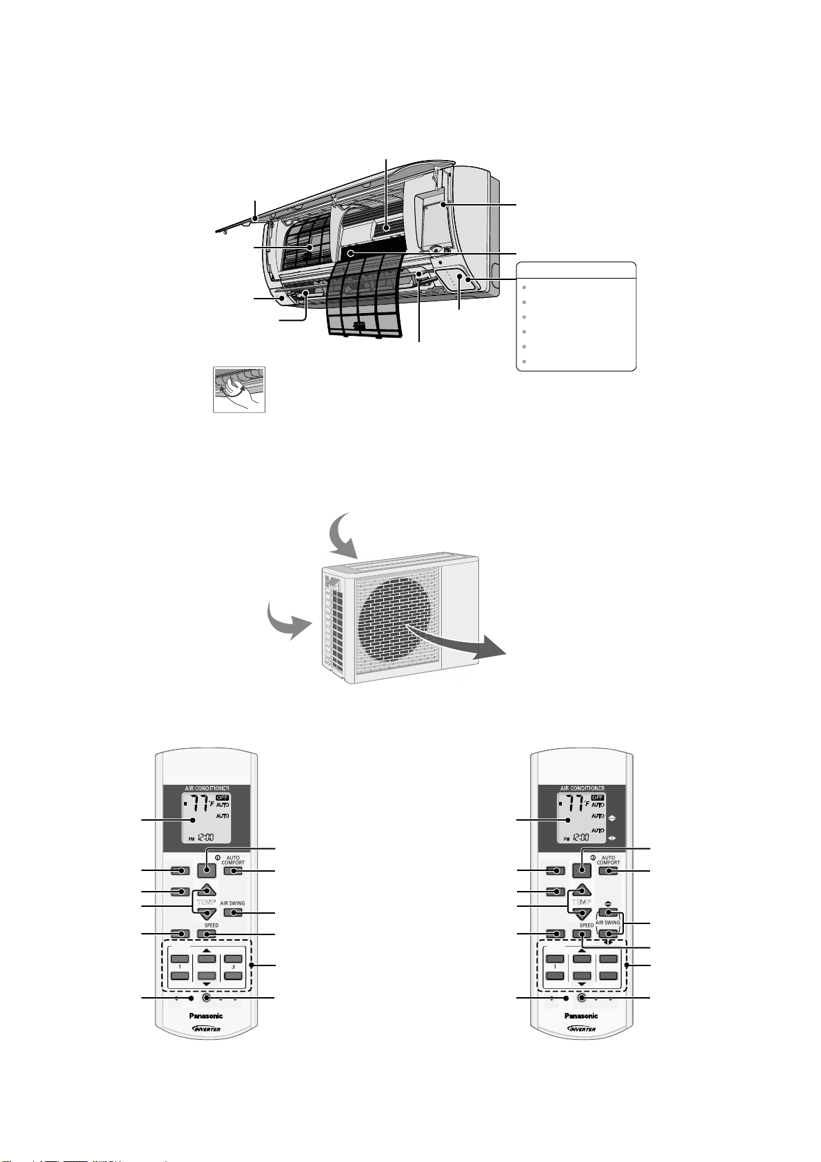
4. Location of Controls and Components
4.1 Indoor Unit
4.2 Outdoor Unit
4.3 Remote Control
P
O
W
E
R
T
I
M
E
R
E
C
O
N
A
V
I
A
U
T
O
C
O
M
F
O
R
T
P
O
W
E
R
F
U
L
Q
U
I
E
T
Horizontal Airflow
Direction Louver
• Manually adjustable
(E9RK and E12RK).
• Do not adjust by hand
(E18RK and E24RK).
A
l
u
m
i
n
i
u
m
Fi
n
Auto OFF/ON button
Air Purifying Filter
Human activity
sensor
Front Panel
Remote control
receiver and Indicator
INDICATOR
Vertical Airflow
Direction Louver
• Do not adjust by hand.
POWER
TIMER
ECONAVI
AUTO COMFORT
POWERFUL
QUIET
(Green)
(Orange)
(Green)
(Green)
(Orange)
(Orange)
Air Filters
Air inlet (rear)
A
ir inlet (side)
Air outlet
AUTO
COMFORT
MODE
POWERFUL/
QUIET
TEMP
OFF/ON
TIMER
SET
CANCEL
ON
OFF
1
2
3
AIR SWING
FAN SPEED
SET CHECK CLOCK RESET
AC
RC
ECONA VI
FAN
SPEED
AIR
SWING
AUTO
HEAT
COOL
DRY
FAN
/
TEMP
O
F
F
/
O
N
T
I
M
E
R
S
ET
C
AN
C
E
L
O
N
O
FF
1
2
3
C
HE
C
K
AUTO
COMFO RT
MODE
POWERFUL/
QUIET
TEMP
OFF/ON
TIMER
SET
CANCEL
ON
OFF
1
2
3
FAN SPEED
SET CHECK CLOCK RESET
AC
RC
ECONAV I
AUTO
HEAT
COOL
DRY
FAN
FAN
SPEED
AIR
SW ING
AIR SWING
/
TEMP
O
F
F
/
O
N
T
I
M
E
R
S
ET
C
AN
C
E
L
O
N
O
FF
1
2
3
C
HE
C
K
Timer setting
Clock setting
Fan speed selection
Vertical airflow
direction selection
Auto comfort operation
Remote control
display
OFF/ON
Operation mode
Temperature setting
Powerful/Sleep mode
operation
Check Check
Econavi operation
Timer setting
Clock setting
Fan speed selection
Airflow direction
selection
Auto comfort operation
Remote control
display
OFF/ON
Operation mode
Temperature setting
Powerful/Sleep mode
operation
E9RK E12RK E18RK E24RK
Econavi operation
13
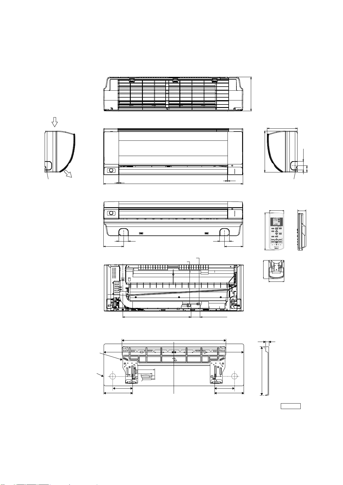
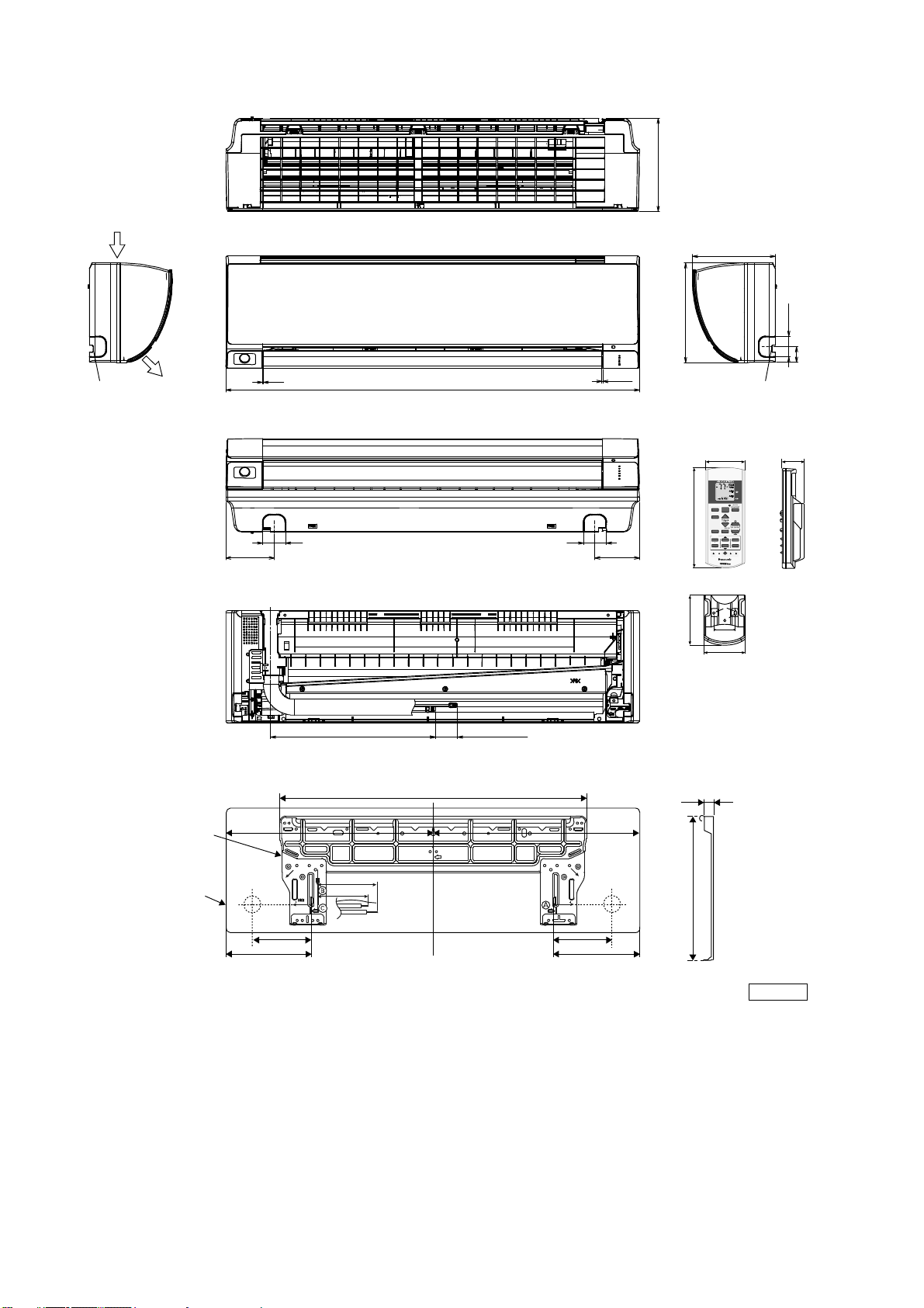
5. Dimensions
5.1 Indoor Unit
5.1.1 CS-E9RKUAW CS-E12RKUAW
7/8
1-7/8
5-1/4
Remote control
Remote control holder
2
2-3/8
AUTO
COMFORT
MODE
POWERFUL/
QUIET
TEMP
OFF/ON
TIMER
SET
CANCEL
ON
OFF
123
AIR SWIN G
FAN SPEED
SET CHECK CLOC K RESET
AC
RC
ECONAVI
FAN
SPEED
AIR
SWING
AUTO
HEAT
COOL
DRY
FAN
/
T
E
M
P
O
F
F
/
O
N
TIMER
S
ET
CANCEL
O
N
OFF
1
2
3
C
HE
C
K
5/8
10-3/8
Relative position between the indoor unit and the installation plate <Front View>
Unit: inch
29-29/64
5-1/16
3-3/4
1-11/16
9-17/32 9-17/32
5-1/16
Right
piping
hole
Left
piping
hole
Installation
plate
Indoor unit
external
dimensions
line
1717-9/32
(8-7/16)
11-7/ 16
2-13/32
1-49/64
8-7/16
1/32~1/16
1/32~1/16
34-9/32
4-17/32
(1-5/8~2-13/32)
16-1/8
Liquid side
Gas side
4-29/32
2-11/322-11/32
<Side View> <Side View>
<Top View>
<Front View>
<Bottom View>
<Rear View>
Air intake
direction
Air outlet
direction
Left piping
hole
Right piping
hole
14
5.1.2 CS-E18RKUAW CS-E24RKUAW
7/8
1-7/8
5-1/4
Remote control
Remote control holder
2
2-3/8
AUTO
COMFORT
MODE
POWERFUL/
QUIET
TEMP
OFF/ON
TIMER
SET
CANCEL
ON
OFF
123
FAN SPEED
SET CHECK CLOCK RESET
AC
RC
ECONA V I
AUTO
HEAT
COOL
DRY
FAN
FAN
SPEED
AIR
SWING
AIRSWING
/
T E M P
O
F
F
/
O
N
T
IMER
S
ET
CANCEL
ON
O
FF
1
2
3
C
HE
C
K
5/8
10-3/8
Relative position between the indoor unit and the installation plate <Front View>
Unit: inch
29-7/16
5-1/16
8-5/8
6-21/32
9-17/32 9-17/32
5-1/16
Right
piping
hole
Left
piping
hole
Installation
plate
Indoor unit
external
dimensions
line
20-15/1621-7/32
(9-15/32)
11-7/ 16
2-13/32
1-49/64
9-15/32
(1-39/64~2-13/32)
16-9/64
4-17/324-29/32
2-11/32
42-5/32
2-11/32
<Side View> <Side View>
<Top View>
<Front View>
<Bottom View>
<Rear View>
Air intake
direction
Air outlet
direction
Left piping
hole
Right piping
hole
1/32~1/16
1/32~1/16
15
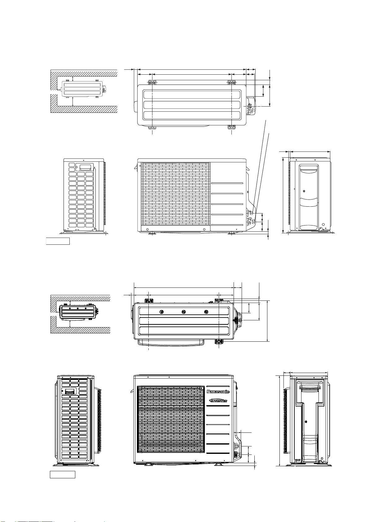
5.2 Outdoor Unit
5.2.1 CU-E9RKUA CU-E12RKUA
5.2.2 CU-E18RKUA CU-E24RKUA
<Side View>
<Side View> <Front View>
<Top View>
Unit : inch
30-23/321
2-5/8
1/2
21-9/32
(3/4)
(2-3/4) (2-3/8)
11-13/32
1-3/86-1/8
3-3/8
22-1/2
(4-1/8)
4-1/8 2-3/8
2-way valve at Liquid side
(High Pressure)
3-way valve at Gas side
(Low Pressure)
Space necessary for
installation
Anchor Bolt Pitch
12-5/8 x 22-1/2
39-3/8
3-7/8
3-7/8
Space necessary for
installation
Anchor Bolt Pitch
15-5/64 x 24-7/64
39-3/8
3-7/8
3-7/8
1-5/64
24-1/8 5-5/32
2-3/4
1-1/2
3-7/32
5-31/32
14-3/16
34-15/32
(5-5/32)
<Top View>
31-5/16
2-5/16
12-5/8
<Side View>
<Side View>
Unit: inch
<Front View>
2-61/64
2-17/32
(31/32)
2-3/4
16
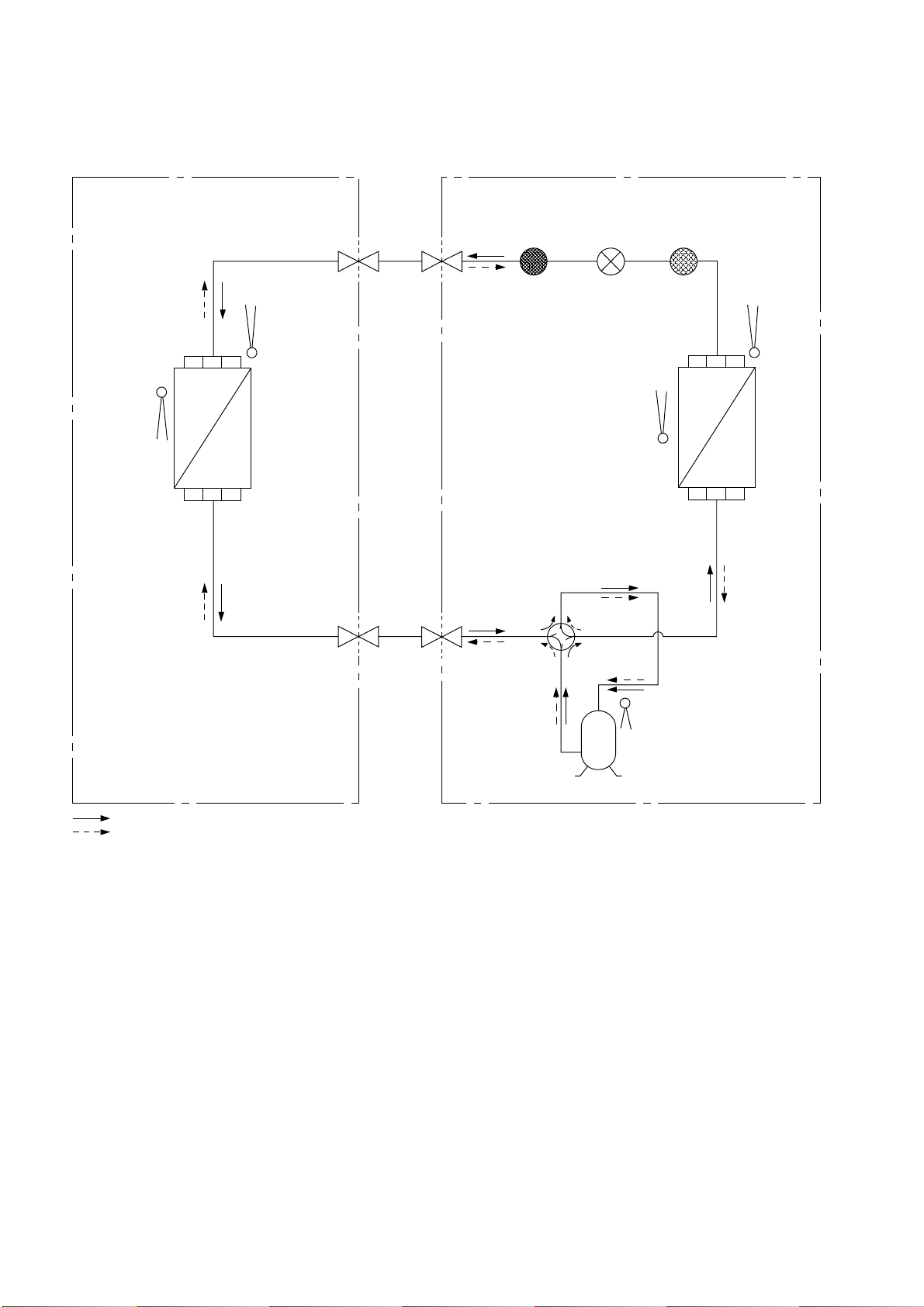
6. Refrigeration Cycle Diagram
6.1 CU-E9RKUA CU-E12RKUA
IN
D
O
O
R
O
U
T
D
O
O
R
INTAKE
TEMP.
SENSOR
PIPE
TEMP.
SENSOR
INTAKE
TEMP.
SENSOR
PIPE
TEMP.
SENSOR
LIQUID
SIDE
2-WAY
VALVE
3-WAY
VALVE
GAS
SIDE
COOLING
HEAT EXCHANGER
(EVAPORATOR)
HEAT EXCHANGER
(CONDENSER)
H
E
AT I N
G
COMPRESSOR
COMPRESSOR
TEMP. SENSOR
4-WAY VALVE
STRAINER
EXPANSION
VALVE
DISCHARGE
MUFFLER
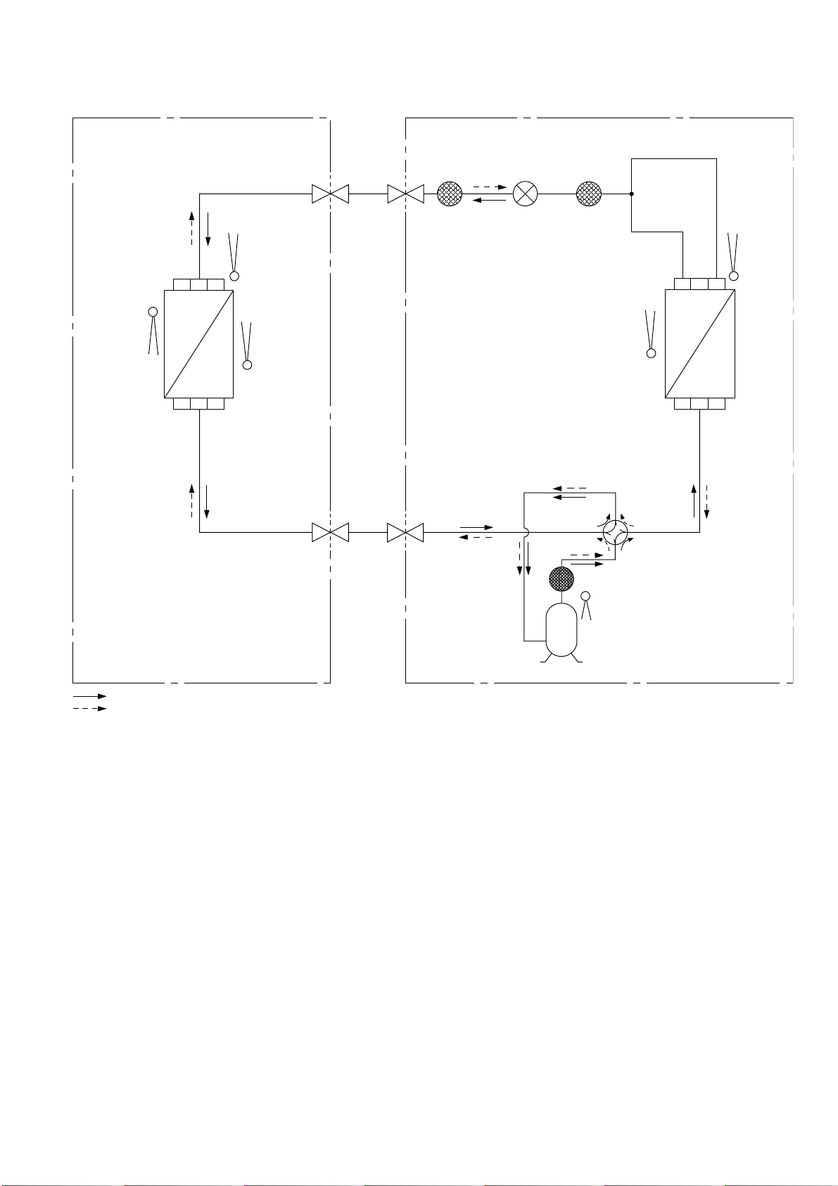
17
6.2 CU-E18RKUA CU-E24RKUA
I
N
DOOR O
U
T
DOOR
INTAKE
TEMP.
SENSOR
PIPE
TEMP.
SENSOR 1
PIPE
TEMP.
SENSOR 2
INTAKE
TEMP.
SENSOR
PIPE
TEMP.
SENSOR
LIQUID
SIDE
2-WAY
VALVE
3-WAY
VALVE
GAS
SIDE
COOLING
HEAT EXCHANGER
(EVAPORATOR)
HEAT EXCHANGER
(CONDENSER)
H
E
A
T
I
N
G
COMPRESSOR
COMPRESSOR
DISC. SENSOR
4-WAY VALVE
STRAINERRECEIVER
EXPANSION
VALVE
DISCHARGE MUFFLER
18
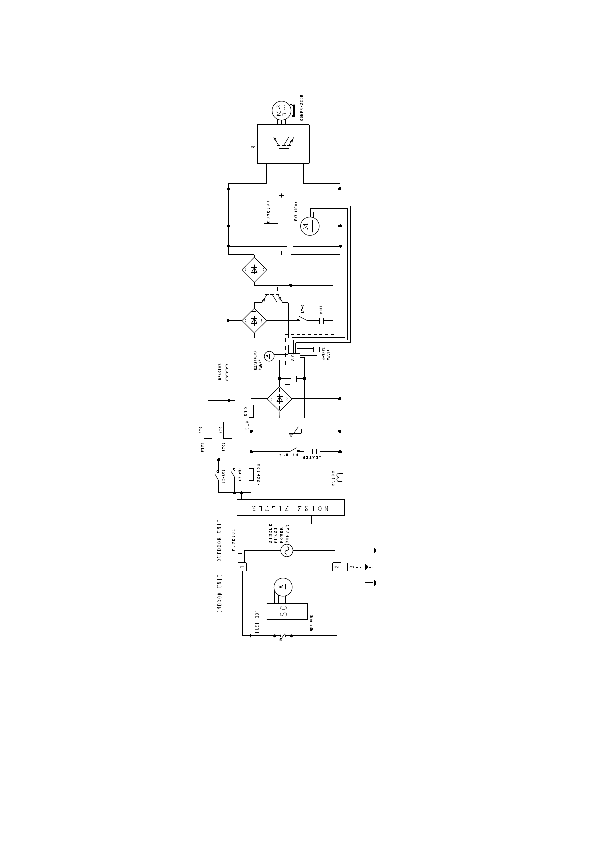
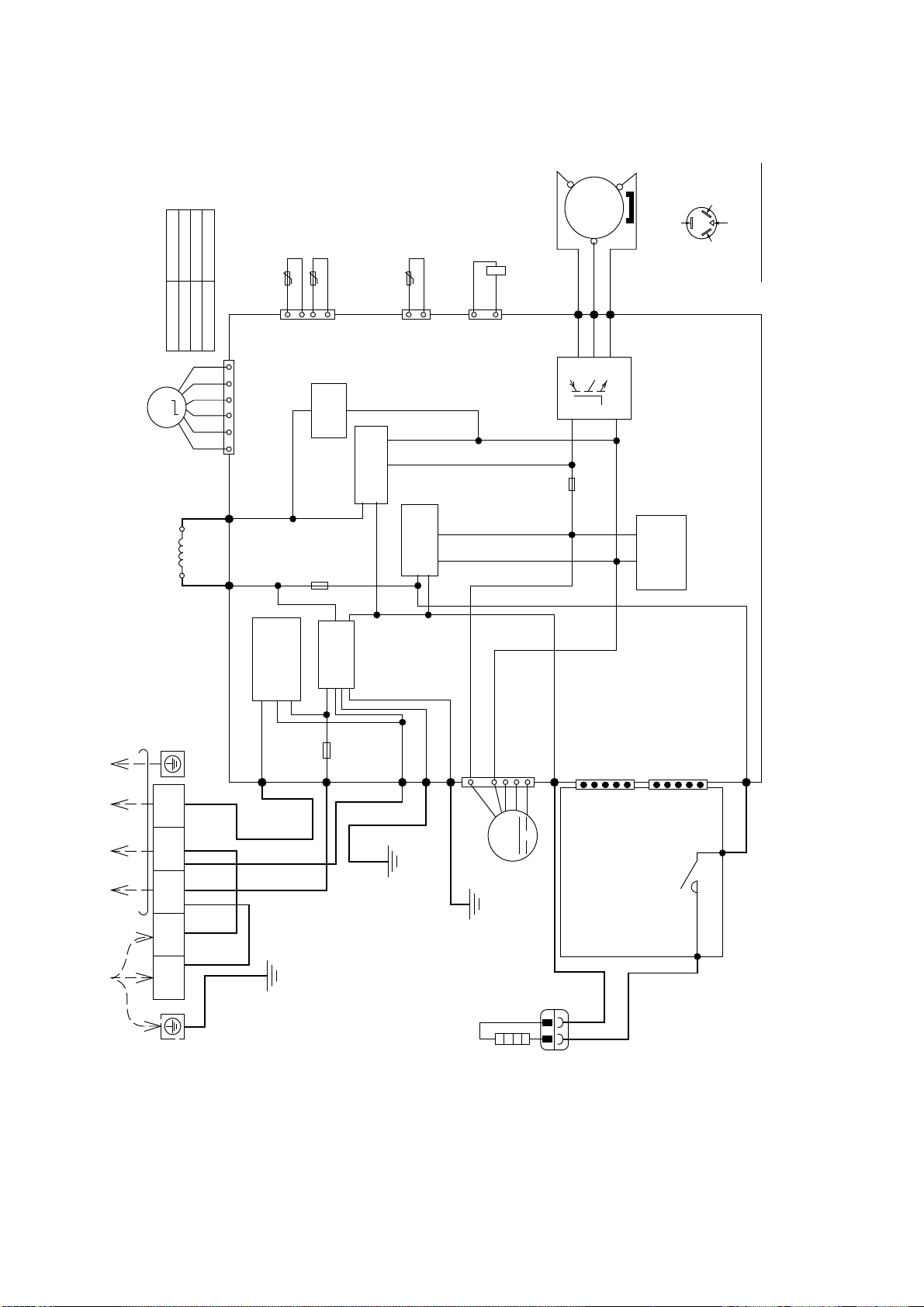
7. Block Diagram
7.1 CS-E9RKUAW CU-E9RKUA CS-E12RKUAW CU-E12RKUA
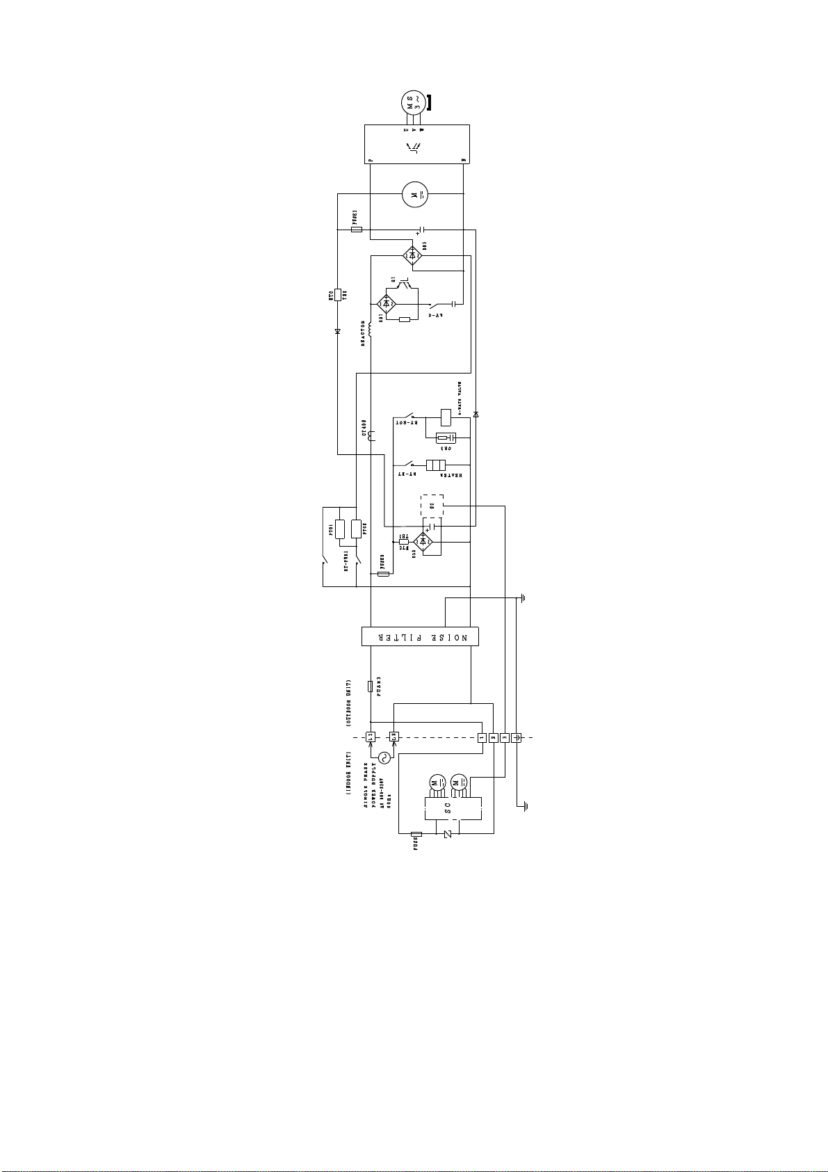
19
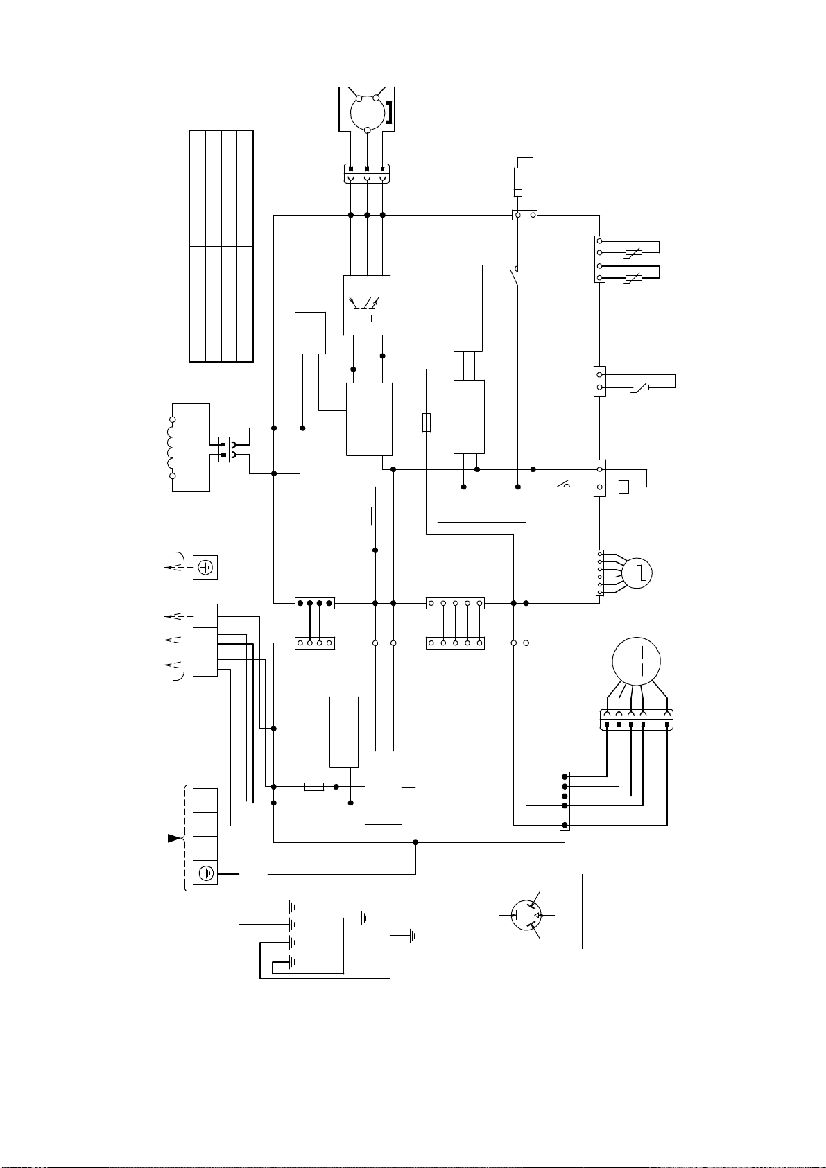
7.2 CS-E18RKUAW CU-E18RKUA CS-E24RKUAW CU-E24RKUA
20
8. Wiring Connection Diagram
8.1 Indoor Unit
8.1.1 CS-E9RKUAW CS-E12RKUAW
M
RECTIFICATION
CIRCUIT
COMMU NICATION
CIRCUIT
GROUNDING
TERMINA L
1
W
2
3
BL
EVAPORATOR
AC303 (WHT)
AC306 (BLK)
AC304 (RED)
G301 (GRN)
FUSE 301
T3.15A L250V
NOISE FILTER
CIRCUIT
TEMP.
FUSE
102°C
(3A)
TO
OUTDOOR
UNIT
TERM INAL
BOARD
R
Y/G
G
AUTO SW
(SW01)
ELECTRONIC
CONTROLLER
(MAIN )
CN–FM (WHT)
FAN MOTOR
5
6
7
1
4
BL
W
B
Y
R
REMOTE CONTROLLER
ELECTRONIC CONTROLLER
(DISPLAY & RECEIVER)
t
t
t
CN–STM1
(WH T )
CN–RMT
(WH T )
4
1
1
BR
R
O
Y
P
5
1
5
6
1
M
3
1
CN–MSENS
(W HT )
CN–TH
(RED )
PIPING TEMP. SENSOR 2
(THERMISTOR)
PIPING TEMP. SENSOR 1
(THERMISTOR)
SUCTION TEMP. SENSOR
(THERMISTOR)
UP DOWN
LOUVER MOTOR
ELECTRONIC
CONTROLLER
(EC O SENSO R)
ELECTRONIC CONTROLLER
(COMPARATOR)
1
8
1
3
1
3
CN
–
SENS1
(YLW )
CN–MSENS
(WH T )
CN–SENS1
(WH T )
W
W
W
W
W
W
REMARKS
B : BLUE P : PINK
BR : BROWN O : ORANGE
BL : BLACK Y : YELLOW
W : WHITE G : GREEN
R : RED
Y/G : YELLOW/GREEN
CN–DISP (WHT)
CN
–DIS P (Y LW)
1
11
1
12
WWW
W
WWWWW
21
8.1.2 CS-E18RKUAW CS-E24RKUAW
M
REC T IF ICA T IO N
CIRCUIT
COMM UNICATION
CIRCUIT
1
W
2
3
BL
AC303 (WH T)
AC306 (BLK)
AC304 (RED)
G301 (GRN)
FUSE301
T3.15A L250V
NOISE FILTER
CIRCUIT
TEMP.
FUSE
102°C
(3A )
TERM INAL
BOARD
R
AUTO SW
(SW 01)
ELECTRONIC
CONTROLLER
(MAIN)
CN–FM (WHT)
FAN MOTOR
5
6
7
1
4
BL
W
B
Y
R
REMOTE CONTROLLER
ELECTRONIC CONTROLLER
(DISPLAY & RECEIVER)
CN–STM 1
(WH T )
CN–STM2
(YLW )
CN–RMT
(WH T )
4
1
1
BR
R
O
Y
P
BR
R
O
Y
P
5
1
5
1
5
1
M
M
5
3
1
CN–MSENS
(WH T )
UP DOWN
LOUVER MOTOR
LEFT RIGHT
LOUVER M OTOR
ELECTRONIC
CONTROLLER
(ECO SENSOR)
ELECTRONIC CONTROLLER
(COMPARATOR)
1
8
1
3
1
3
CN–SENS1
(YLW )
CN–MSENS
(WH T )
CN-SEN S1
(WH T )
W
W
W
W
W
W
t
t
t
6
1
CN–TH
(RED )
PIPING TEMP. SENSOR 2
(THERMISTOR)
PIPING TEMP. SENSOR 1
(THERMISTOR)
SUCTION TEMP. SENSOR
(THERMISTOR)
CN–DISP (WHT)
CN–DISP (YLW)
1
11
1
12
WWW
W
WWWWW
GROUNDING
TERM INAL
EVAPOR ATOR
Y/G
G
T
O
O
UTDOOR
UNIT
REMARKS
B : BLUE P : PINK
BR : BROWN O : ORANGE
BL : BLACK Y : YELLOW
W : WHITE G : GREEN
R : RED
Y/G : YELLOW/GREEN
22
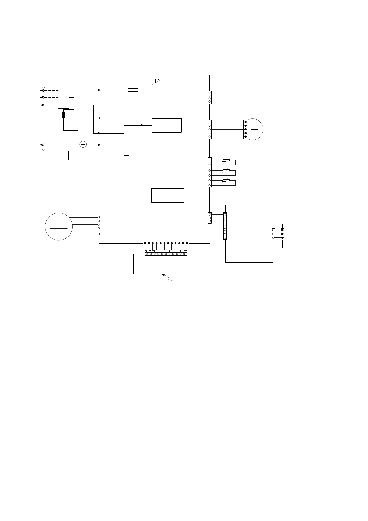
8.2 Outdoor Unit
8.2.1 CU-E9RKUA CU-E12RKUA
5RS102XHA21
1.741
1.765
1.711
CONNECTION
Resistance of Compressor Windings
U-V
U-W
V-W
L1 L2
1
(BLACK)
2
(BLACK)
3
(RED)
TERMINAL BOARD
GRN
GRN
GRN
BLK
BLK
WHT
WHT RED
T
OI
N
DOOR
U
N
I
T
POW
E
RS
U
PPL
Y
DATA (RED)
REMARKS;
BLACK; (BLK)
BLUE; (BLU)
WHITE; (WHT)
RED; (RED)
GRAY; (GRY)
GREEN; (GRN)
BROWN; (BRW)
ORANGE; (ORG)
YELLOW/GREEN; (YLW/GRN)
GRY GRY
REACTOR
RAT2
(GRY)
FUSE 102
T3.15A L250V
RAT1
(GRY)
16
ELECTRONIC-MAGNETIC
COIL (EXPANSION VALVE)
CN-STM
CN-TH
1
CN-TANK
CN-HOT
Q1
FUSE 103
T3.15A l250v
RED
BLU
YLW
COMPRESSOR
YELLOW (YLW)
RED (RED)
(TRADERMARK)
BLUE (BLU)
(RED)
(BLU)
(YLW)
P
U
V
W
N
1
1
3
3
AIR TEMP. SENSOR
(THERMISTOR)
PIPING TEMP. SENSOR
(THERMISTOR)
t°
t°
t°
COMPRESSOR TEMP. SENSOR
(THERMISTOR)
ELECTRONIC-MAGNETIC
COIL (4-WAY VALVE)
YLW
YLW
2
3
4
AC-BLK
(BLK)
FUSE 101
20A 250V
AC-WHT
(WHT)
FG1 (GRN)
LJP101 (GRN)
CN-DCFM
HT2 (ORG)
SWITCHING
POWER SUPPLY
CIRCUIT
RECTIFICATION
CIRCUIT
RECTIFICATION
CIRCUIT
PFC
CIRCUIT
COMMUNICATION
CIRCUIT
NOISE FILTER
CIRCUIT
1
5
CN4
(BLK)
CN5
(BLK)
RY-HT2
HT2 (ORG)
ORG
ORG
FAN
MOTOR
M
ELECTRONIC
CONTROLLER
ELECTRONIC CONTROLLER
HEATER
ACL (BRW)
ACL (BRW)BRW
5
1
1
4
5
6
7
M
MS
3~
COMPRESSOR TERMINAL
THE PARENTHESIZED LETTERS IS
INDICATED ON TERMINAL COVER.
23
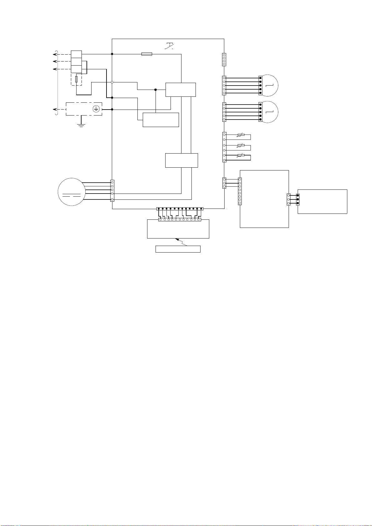
8.2.2 CU-E18RKUA CU-E24RKUA
NOIS E FILTER
CIRCUIT
COMMUNICATION
CIRCUIT
RECT IFIC ATION
CIRCUIT
REC TIFICATION
CIRCUIT
PFC
CIRCUIT
SWITCHING POWER
SUPPLY CIRCUIT
ELECTRONIC CONTROLLER
(NOISE FILTER )
PIPING TEMP.
SENSOR
(THERMISTOR)
DISCHARGE TEMP.
SENSOR (THERMISTOR)
ELECTRO-MAGNETIC
COIL (4-WAY VALVE)
ELECTRO-MAGNETIC
COIL
(EXPANSION VALVE)
FAN MOTOR
CN-DCFM
(WHITE )
CN-FM1
(WHITE )
CN-WHT
(WHITE)
AC-WHT
(WHITE )
AC-BLK
(BLACK)
CN-BLK
(BL ACK)
CN-COM
(YELLOW)
CN-COM
(YELLOW)
CN-FM1
(WHITE)
DC-FMG
(YELLOW)
DC-FMG
(YELLOW)
DC-FM1
(ORANGE)
DC-FM1
(ORANGE)
YLW
YELLOW (YLW)
BLUE
(BL U)
(TRADEMARK)
COMP. TERMINAL
THE PARENTHES IZED LETTER S IS
INDICATED ON TERMINAL COVER
RED
(RED)
FG1
(GREEN)
YLW/GRN
YLW/GRN
GRN
GRN WHT
WHT
RED
GRY
L2-1
(GRAY)
L2-0
(BL ACK)
ELECTRONIC CONTROLLER (MAIN)
GRY
REACT
O
R
BLK
BLK
L1
123
L2
ACN1
(WHITE )
ACL1
(BLACK)
COM3
(RE D)
BLK
BLK
FUSE3
(25A, 250V)
FUSE2
(T 3.15A L 250V)
FUSE1
(T 2.5A L 250V)
Q10
P
N
U
RED
HEATER
RY-HT
CN-HT
(BLACK)
COMPRESSOR
MS
3
BLU
YLW
RED
BLU
YLW
(RED) U
(BL UE) V
(YELLOW) W
V
W
POWER SUPPLY
TO INDO O R UN IT
TERMINAL
BOARD
TERMINAL
BOARD
YLW
ORG
RED
BLU
7
7
7
11
1
1
11
44
1
1
1
1
1
3
3
t°
t° t°
3
1
2
2
55
16
44
4
BLK
BLK
WHT
WHT
WHT
WHT
WHT
WHT
WHT
WHT
WHT
WHT
WHT
M
M
OUTDOOR AIR
TEMP. SENSOR
(THERMISTOR)
CN-TH1
(WHITE )
CN-DIS
(WHITE )
CN-EV
(WHITE )
4
11
2
CN-HOT
(BLUE)
RY-HOT
BLU
1
3
~
CONNECTION
Resistance of Compressor Windings
U-V
U-W
V-W
5KD240XAF21
0.720Ω
0.726Ω
0.708Ω
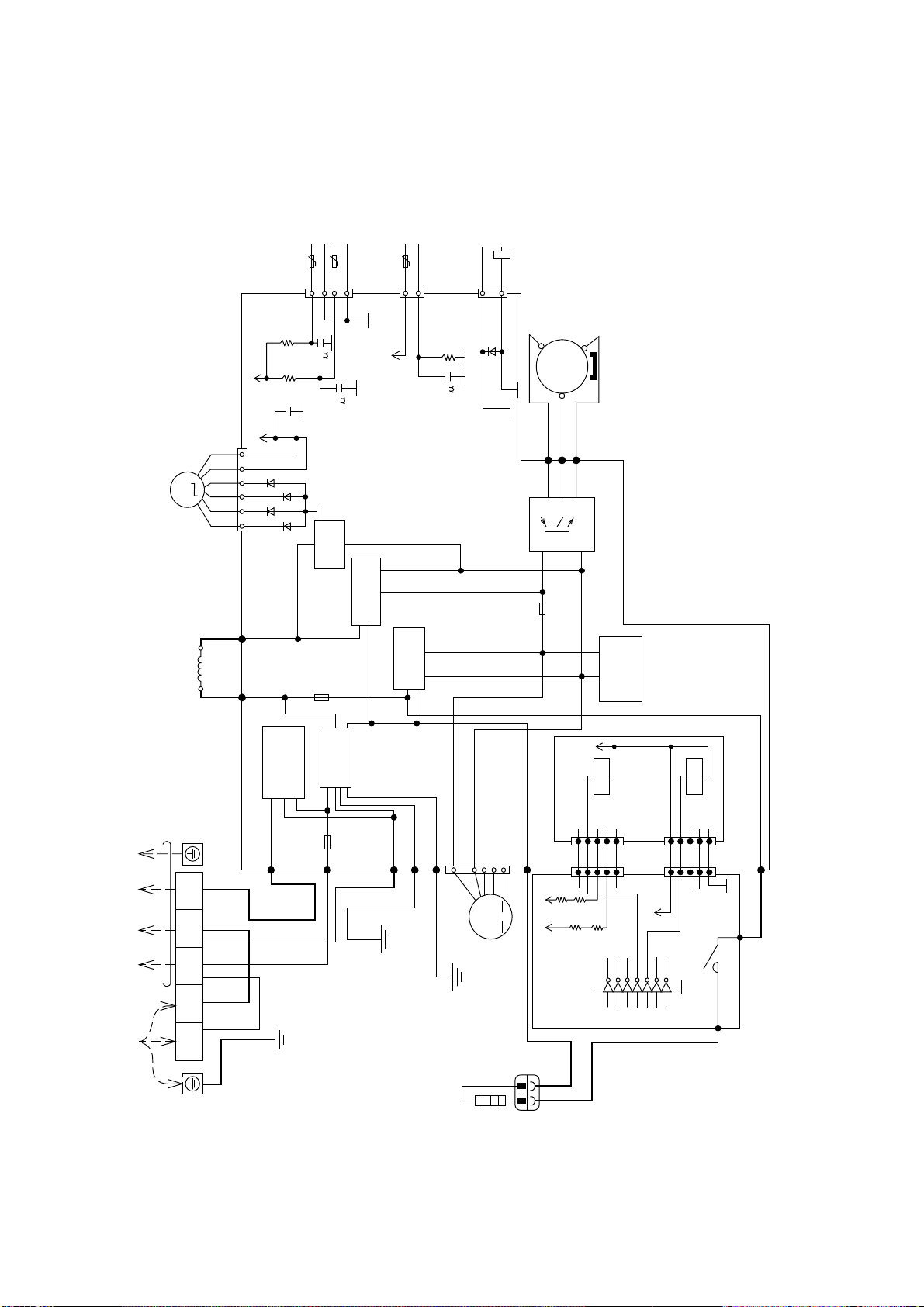
24
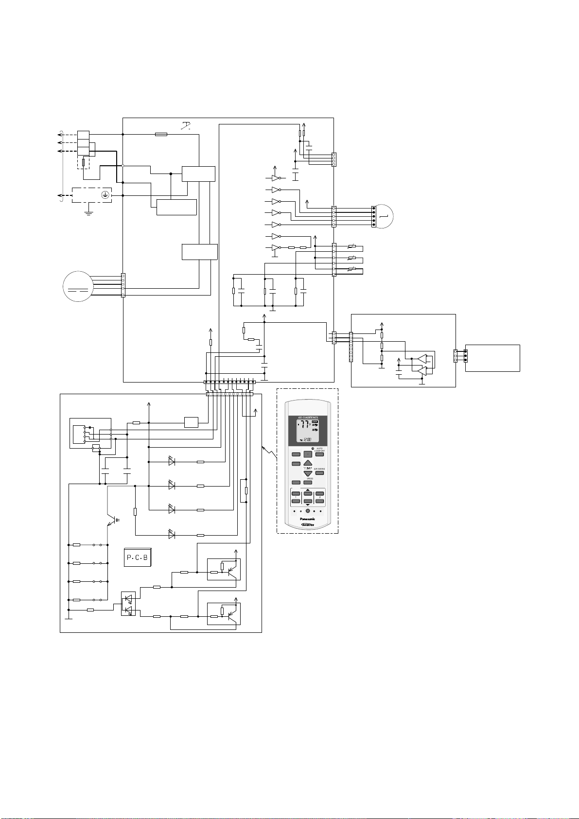
9. Electronic Circuit Diagram
9.1 Indoor Unit
9.1.1 CS-E9RKUAW CS-E12RKUAW
BZ201
BZ
5V_
R209
47
IC201
C202
0.01u
C201
47u
R218
0
c
e
JP201R210
JP200R211
JP203R212
JP204
POWERFUL/QUIET
(orange/green)
1
3
2
LED205
R207
620
SEN201
PCB3
R216
0
R206
2.7k
R217
0
b
c
e
Q202
Q201
4.7k
10k
R213
R208
GND-A
+
1
2
3
Vout
Vcc
GND
GNDGND
45
5V_
5V_
R215
0
R204
820
R203
27k
R202
2k
R201 470
LED204
(green)
NANOE G/AUTO COMF
LED203
(green)
ECO NAVI
LED202
(orange)
TIMER
LED201
(green)
POWER
b
c
e
4.7k
10k
12V
C27
1u
R61
20.0k
*R63
C25
1u
R62
15.0k
*C28
5V
12V
R46R47
VCC
9
8
16
15
14
13
12
11
10
1
2
3
4
5
6
7
GND
12V
IC03
IC03
IC03
IC03
IC03
IC03
IC03
5V
5V
*C49
NONE
*C45
0.1u
*R54
270
*R37
10k
M
RECTIFICATION
CIRCUIT
COMMUNICATION
CIRCUIT
GROUNDING
TERMINAL
1
W
2
3
BL
EVAPORATOR
AC303 (WHT)
AC306 (BLK)
AC304 (RED)
G301 (GRN)
FUSE301
T3.15A L250V
NOISE FILTER
CIRCUIT
TEMP.
FUSE
102°C
(3A)
TO
OUTDOOR
UNIT
TERMINAL
BOARD
R
Y/G
G
AUTO SW
(SW01)
ELECTRON IC
CONTROLLER
(MAIN)
CN–FM (WHT)
FAN MOTOR
5
6
7
1
4
BL
W
B
Y
R
ELECTRONIC CONTROLLER
(DISPLAY & RECEIVER)
t
t
t
CN–STM1
(WHT)
CN–RMT
(WHT)
4
1
1
BR
R
O
Y
P
5
1
5
6
1
M
3
1
CN–MSENS
(WHT)
CN–TH
(RED)
PIPING TEMP. SENSOR 2
(THERMISTOR)
PIPING TEMP. SENSOR 1
(THERMISTOR)
SUCTION TEM P. SENSOR
(THERMISTOR)
UP DOWN
LOUVER MOTOR
ELECTRONIC
CONTROLLER
(ECO SENSOR)
ELECTRONIC CONTROLLER
(COMPARATOR)
1
8
1
3
1
3
CN
–
SENS1
(YLW)
CN–MSENS
(WHT)
CN–SENS1
(WHT)
W
W
W
W
W
W
CN–DISP (WHT)
CN–DISP (YLW)
1
11
1
12
WWW
W
WWWWW
REMOTE CONTROLLER
AUTO
COM FORT
MODE
POWERFUL/
QUIET
TEMP
OFF/ON
TIMER
SET
CANCEL
ON
OFF
1
2
3
AIR SW ING
FAN SP EED
SET CHECK CLOCK RESET
AC
RC
ECONAVI
FAN
SPEED
AIR
SW ING
AUTO
HEAT
COOL
DRY
FAN
/
TE M P
O
F
F
/
O
N
T
I
M
E
R
S
ET
C
AN
C
E
L
O
N
O
FF
1
2
3
C
HECK
5V
5V
*R74
*R75
*C41
R89
C3
0.1u
5V_3
5V_3
6
5
2
3
4
1
7
8
R401
R402
R403
C403
IC401
IC401
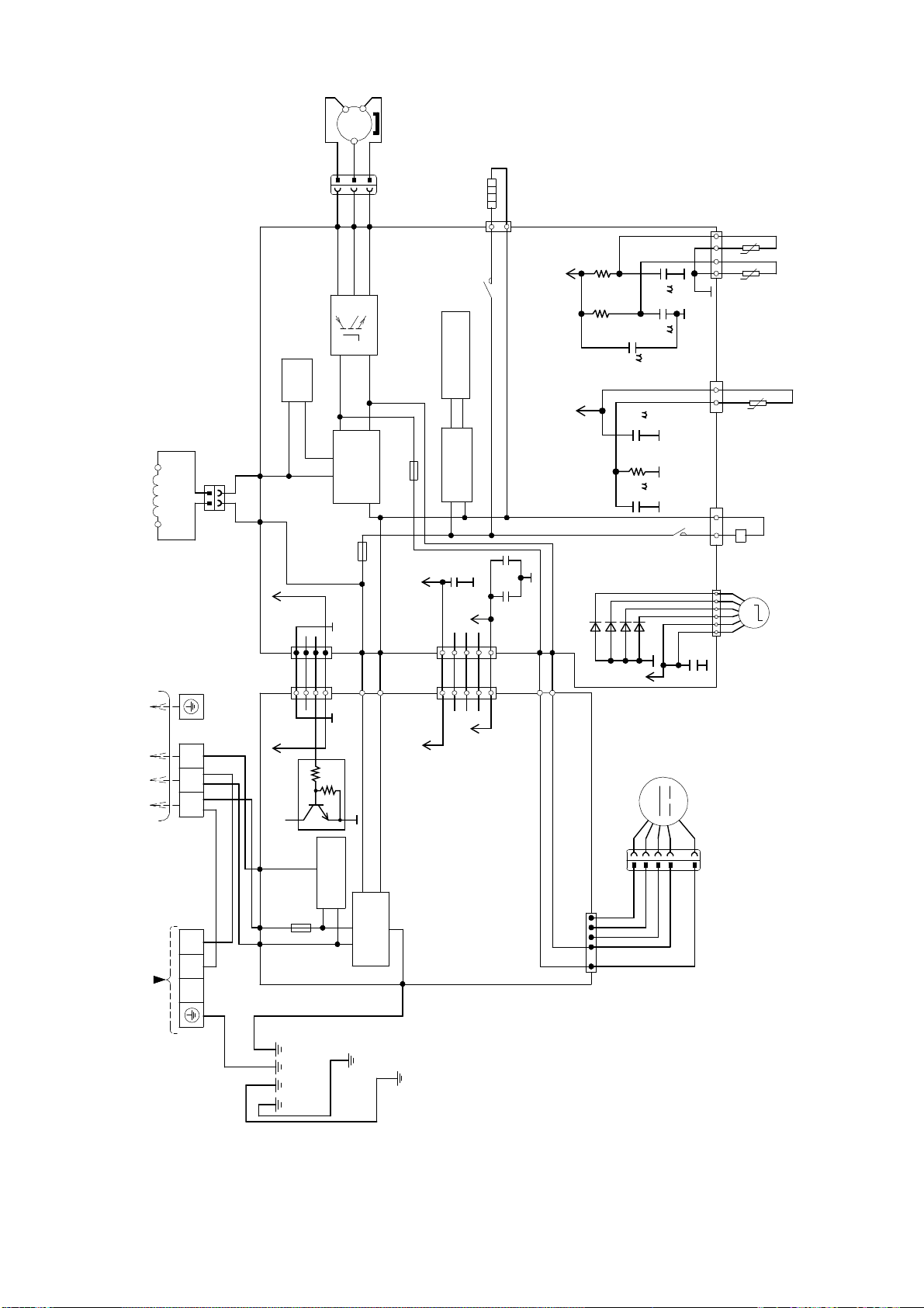
25
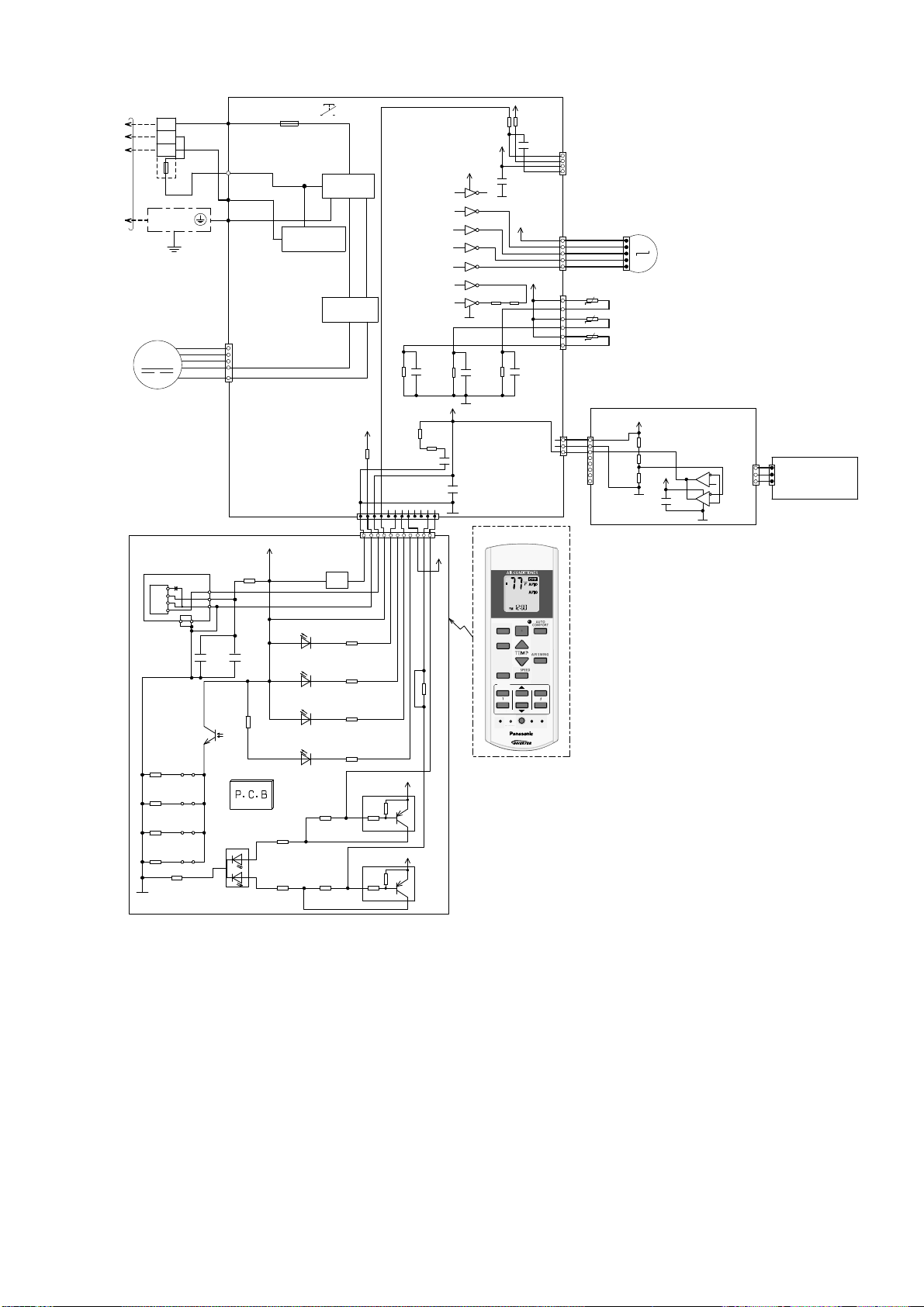
9.1.2 CS-E18RKUAW CS-E24RKUAW
BZ201
BZ
5V_
R209
47
IC201
C202
0.01u
C201
47u
R218
0
c
e
JP201R210
JP200R211
JP203R212
JP204
POWERFUL/QUIET
(oran g e /green)
1
3
2
LED205
R207
620
SEN201
PCB3
R216
0
R206
2.7k
R217
0
b
c
e
Q202
Q201
4.7k
10k
R213
R208
GND-A
+
1
2
3
Vout
Vcc
GND
GNDGND
45
5V_
5V_
R215
0
R204
820
R203
27k
R202
2k
R201 470
LED204
(gree n )
NANOE G/AUTO COMF
LED203
(gree n )
ECO NAVI
LED202
(oran g e )
TIMER
LED201
(green)
POW ER
b
c
e
4.7k
10k
12V
C27
1u
R61
20.0k
*R63
C25
1u
R62
15.0k
*C28
5V
12V
R46R47
VCC
9
8
16
15
14
13
12
11
10
1
2
3
4
5
6
7
GND
12V
IC03
IC03
IC03
IC03
IC03
IC03
IC03
5V
5V
*C49
NONE
*C45
0.1u
*R54
270
*R37
10k
M
RECTIFICATION
CIRCUIT
COMMUNICATION
CIRCUIT
GROUNDING
TERMINAL
1
W
2
3
BL
EVAPORA TOR
AC303 (WHT)
AC306 (BLK)
AC304 (RED)
G301 (GRN)
FUSE301
T3.15A L250V
NOISE FILTER
CIRCUIT
TEMP.
FUSE
102°C
(3A)
TO
OUTDOOR
UNIT
TERMINAL
BOARD
R
Y/G
G
AUTO SW
(SW01)
ELECTRONIC
CONTROLLER
(MAIN)
CN–FM (WHT)
FAN MOTOR
5
6
7
1
4
BL
W
B
Y
R
ELECTRONIC CONTROLLER
(DISPLAY & RECEIVER)
t
t
t
CN–STM1
(WHT)
CN–RMT
(WHT)
4
1
1
BR
R
O
Y
P
5
1
5
6
1
M
3
1
CN–MSENS
(WHT)
CN–TH
(RED)
PIPING TEMP. SENSOR 2
(THERMISTOR)
PIPING TEMP. SENSOR 1
(THERMISTOR)
SUCTION TEMP. SENSOR
(THERMISTOR)
UP DOWN
LOUVER M OTOR
ELECTRONIC
CONTROLLER
(ECO SENSOR)
ELECTRONIC CONTROLLER
(COMPARATOR)
1
8
1
3
1
3
CN
–
SENS1
(YLW)
CN–MSENS
(WHT)
CN–SENS1
(WHT)
W
W
W
W
W
W
CN–DISP (WHT)
CN–DISP (YLW)
1
11
1
12
WWW
W
WWWWW
REMOTE CONTROLLER
AUTO
COMFO RT
MODE
POW ERFU L/
QUIET
TEMP
OFF/ON
TIMER
SET
CANCEL
ON
OFF
1
2
3
AIR SW ING
FAN SPEED
SET CHECK CLOCK RESET
AC
RC
ECON AV I
FAN
SPEED
AIR
SW ING
AUTO
HEAT
COOL
DRY
FAN
/
TE M P
O
F
F
/
O
N
T
I
M
E
R
S
ET
C
AN
C
E
L
O
N
O
FF
1
2
3
C
HECK
5V
5V
*R74
*R75
*C41
R89
C3
0.1u
5V_3
5V_3
6
5
2
3
4
1
7
8
R401
R402
R403
C403
IC401
IC401
26
9.2 Outdoor Unit
9.2.1 CU-E9RKUA CU-E12RKUA
L1 L2
1
(BLACK)
2
(BLACK)
3
(RED)
TERMINAL BOARD
GRN
GRN
GRN
BLK
BLK
WHT
WHT RED
TO INDOOR UNITPOWER SUPPLY
DATA (RED)
GRY GRY
REACTOR
RAT2
(GRY)
FUSE 102
T3.15A L250V
RAT1
(GRY)
123456
ELECTRONIC-MAGNETIC
COIL (EXPANSION VALVE)
CN-STM
CN-TH
(WHT)
1
CN-TANK
(WHT)
CN-HOT
(WHT)
Q1
FUSE 103
T3.15A l250v
RED
BLU
YLW
COMPRESSOR
(RED)
(BLU)
(YLW)
P
U
V
W
N
1
1
3
3
AIR TEMP. SENSOR
(THERMISTOR)
PIPING TEMP. SENSOR
(THERMISTOR)
t°
t°
t°
COMPRESSOR TEMP. SENSOR
(THERMISTOR)
ELECTRONIC-MAGNETIC
COIL (4-WAY VALVE)
YLW
YLW
2
3
4
AC-BLK
(BLK)
FUSE 101
20A 250V
AC-WHT
(WHT)
FG1 (GRN)
LJP101 (GRN)
CN-DCFM
HT2 (ORG)
SWITCHING
POWER SUPPLY
CIRCUIT
RECTIFICATION
CIRCUIT
RECTIFICATION
CIRCUIT
PFC
CIRCUIT
COMMUNICATION
CIRCUIT
NOISE FILTER
CIRCUIT
RY -HT2
HT2 (ORG)
ORG
ORG
FAN
MOTOR
M
ELECTRONIC
CONTROLLER
ELECTRONIC CONTROLLER
HEATER
ACL (BRW)
ACL (BRW)BRW
1
4
5
6
7
M
MS
3~
13V
C80
D26
D27
D28
D29
D19
R12
15.0k
C7
1
R11
15.8k
5V
C6
1
C3
1
R1
4.99k
5V
CN5
(BLK)
1
CN-HT2
2
3
4
5
1
2
3
4
5
CN4
(BLK)
1
2
3
4
5
1
2
3
4
5
1
2
3
4
5
6
7
9
8
16
15
14
13
12
11
10
IC1 2
IC1 2
IC1 2
IC1 2
IC1 2
IC1 2
IC1 2
13_1V
R129
1k
R118
5V
R130
1k
R116
5V
13V
RY-HT2
RY-HT1
CN-HT1
27
9.2.2 CU-E18RKUA CU-E24RKUA
NO IS E FILTER
CIRCUIT
COMMUNICATION
CIRCUIT
RE C T IF IC ATION
CIRCUIT
RE C T IF IC ATION
CIRCUIT
PFC
CIRCUIT
SWITCHING POWER
SUPPLY CIRCUIT
ELECTRONIC CONTROLLER
(NO IS E FILTER)
PIPING TEMP.
SENSOR
(THERMISTOR)
DISCHARGE TEMP.
S
E
N
S
O
R
(
T
HE
R
M
I
S
T
O
R
)
ELECTRO-MAGNETIC
CO IL (4-WAY VALV E )
ELECTRO-MAG NETIC
COIL
(EXPANSION VALVE)
FAN MOTOR
CN-DCFM
(WHITE )
CN-FM1
(WHITE )
CN-WHT
(WHITE )
AC-WHT
(W H IT E )
AC-B L K
(BLAC K )
CN-BLK
(BLACK)
CN-COM
(YELLOW)
CN-COM
(YEL LOW )
CN-FM1
(WHITE )
DC-FMG
(YELLOW)
DC-FMG
(YELLOW)
DC-FM1
(ORANGE)
DC-FM1
(ORANGE)
YLW
FG1
(GREEN)
YLW/GRN
YLW/GRN
GRN
GRN WHT
WHT
RED
GRY
L2-1
(GR AY)
L2-0
(BLAC K )
ELECTRONIC CONTROLLER (MAIN)
GRY
R
E
A
C
T
O
R
BLK
BLK
L1
123
L2
ACN1
(WHITE )
ACL1
(BLAC K )
COM3
(RE D )
BLK
BLK
FUSE3
(25A, 250V)
FUSE2
(T 3.15A L 250V)
FUSE1
(T 2.5A L 250V)
Q10
P
N
U
RED
HEATER
RY-HT
CN-HT
(BLACK)
COMPRESSOR
MS
3
BLU
YLW
RED
BLU
YLW
(RE D ) U
(BLUE) V
(YELLOW) W
V
W
POWER SUPPLY
TO INDOOR UNIT
TERMINAL
BOARD
TERMINAL
BOARD
YLW
ORG
RED
BLU
7
7
7
11
1
1
2
3
4
1
2
3
4
1
2
3
4
1
1
1
1
3
3
t°
t° t°
3
1
2
2
5
1
2
3
4
5
123456
44
4
BLK
BLK
WHT
WHT
WHT
WHT
WHT
WHT
WHT
WHT
WHT
WHT
WHT
M
M
OUTDOOR AIR
TEMP. S ENSOR
(THERMISTOR)
CN-TH1
(WHITE )
CN-DIS
(WHITE )
CN-EV
(WHITE )
1234
1
2
CN-HOT
(BL U E )
RY-HOT
BLU
1
3
~
5V
15V_2
5V
C209
15V_2
C259
+
C260
5V5V
13V
*C8 4
*D3 6
*D3 5
*D3 4
*D3 3
5
V
C45
1
C46
1
C251
220
R100
15.0k
R101
15.8k
5V
C212
1
R102
4.99k
C47
1
Q25
4.7k
10k
c
b
e

28
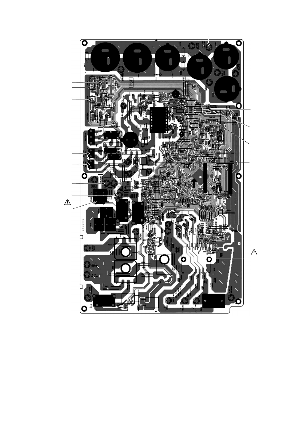
10. Printed Circuit Board
10.1 Indoor Unit
10.1.1 Main Printed Circuit Board
10.1.2 Indicator Printed Circuit Board
CN-RMT
CN-FM
CN-STM2
(E18/24RKUAW only)
CN-STM1
CN-MSENS
CN-TH
J
P
1
(
R
a
n
d
o
m
Auto
R
e
start
e
n
a
b
l
e
/
d
isa
b
l
e
)
CN-DISP
CN-DISP
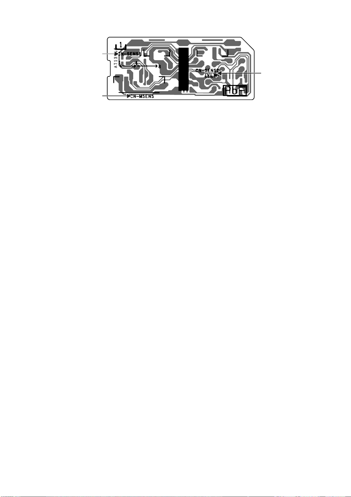
29
10.1.3 Comparator Printed Circuit Board
CN-SENS1
CN-SENS2
CN-MSENS
30
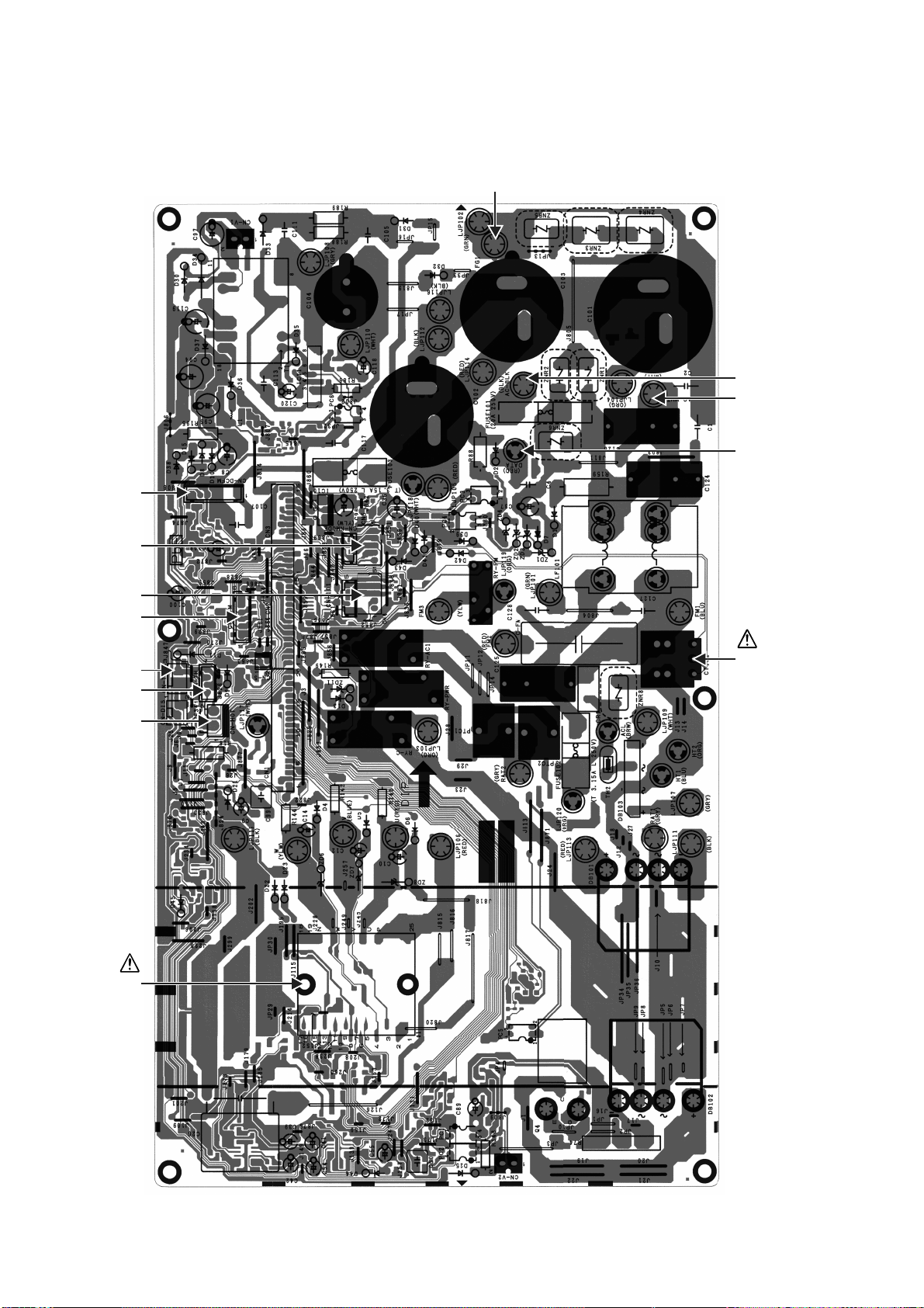
10.2 Outdoor Unit
10.2.1 Main Printed Circuit Board
10.2.1.1 CU-E9RKUA CU-E12RKUA
CN-DCFM
F
G
1
CN-STM
CN4
CN5
CN-TANK
CN-TH
CN-HOT
CURRENT
TRANSFORMER
(CT)
DA TA
AC-WHT
AC-BLK
POWER
TRANSISTOR
(IPM)
31
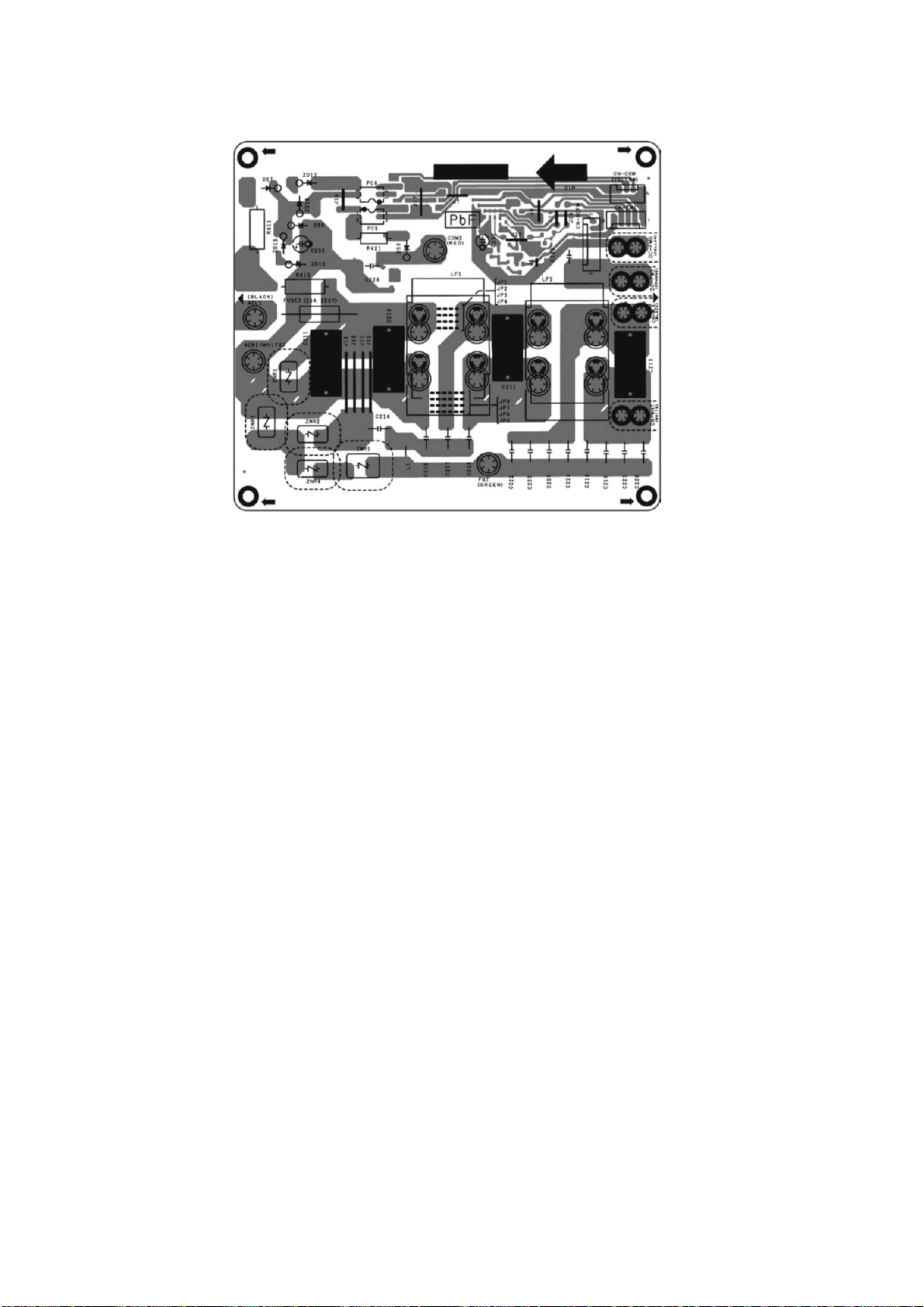
10.2.1.2 CU-E18RKUA CU-E24RKUA
CN-S
CN-COM
CN-TH1
CN-EV
CN-DIS
CN-HT
CN-HO T
AC-BLK
AC-WHT
POWER
TRANSISTOR
(IPM)
CURRENT
TRANSFORMER
(CT)
D
C
-F
M
G
DC-FM1
CN-FM1
32
10.2.2 Noise Filter Printed Circuit Board
10.2.2.1 CU-E18RKUA CU-E24RKUA
33
11. Installation Instruction (E9RK and E12RK)
11.1 Select the Best Location
11.1.1 Indoor Unit
Do not install the unit in excessive oil fume area
such as kitchen, workshop and etc.
There should not be any heat source or steam
near the unit.
There should not be any obstacles blocking the air
circulation.
A place where air circulation in the room is good.
A place where drainage can be easily done.
A place where noise prevention is taken into
consideration.
Do not install the unit near the door way.
Ensure the spaces indicated by arrows from the
wall, ceiling, fence or other obstacles.
Recommended installation height for indoor unit
shall be at least 8 ft (2.4 m).
11.1.2 Outdoor Unit
If an awning is built over the unit to prevent direct
sunlight or rain, be careful that heat radiation from
the condenser is not obstructed.
There should not be any animal or plant which
could be affected by hot air discharged.
Keep the spaces indicated by arrows from wall,
ceiling, fence or other obstacles.
Do not place any obstacles which may cause a
short circuit of the discharged air.
If piping length is over the [piping length for
additional gas], additional refrigerant should be
added as shown in the table.
Recommended installation height for outdoor unit
should be above the seasonal snow level.
Example: For E9RKUAW
If the unit is installed at 32.8 ft (10 m) distance, the
quantity of additional refrigerant should be 1.64 oz
(50 g) .... (32.8 - 24.6) ft x 0.2 oz/ft = 1.64 oz.
((10 -7.5) m x 20 g/m = 50 g).
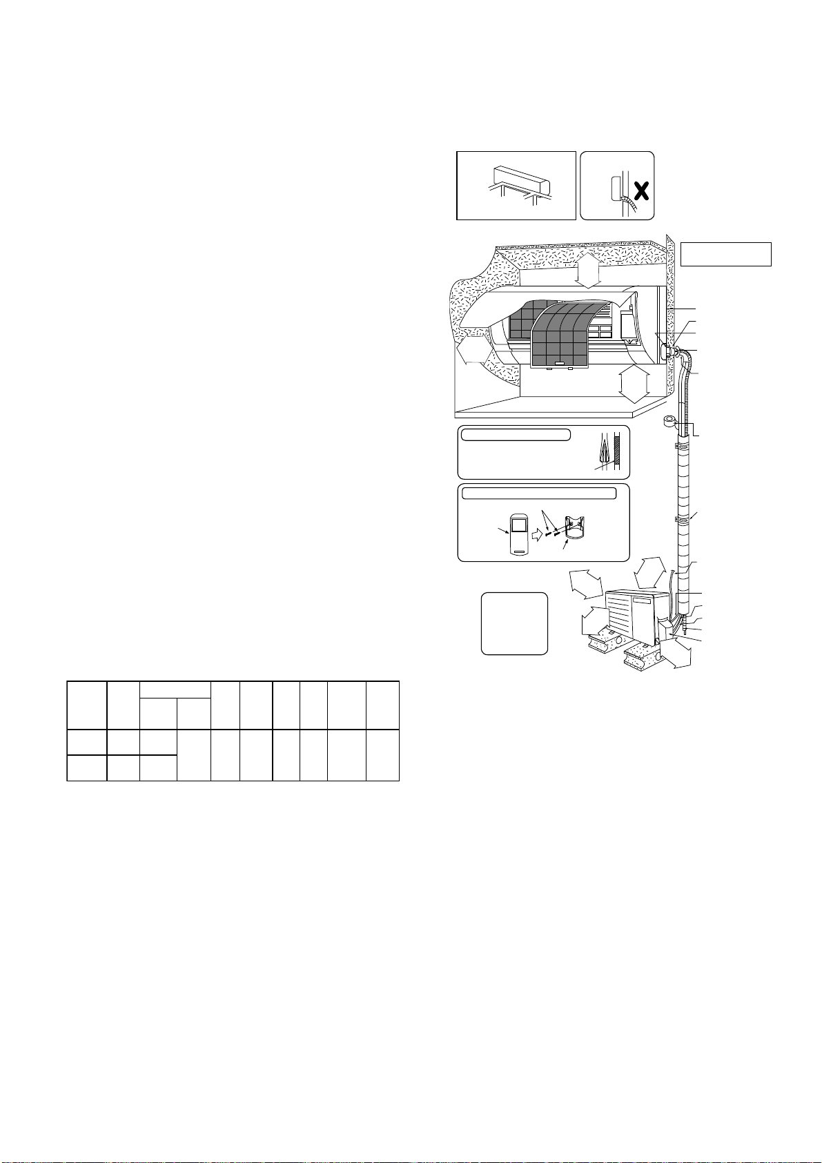
11.1.3 Indoor/Outdoor Unit Installation
Diagram
Model
Capacity
(Btu/h)
Piping size
Std.
Length
Max.
Elevation
Min.
Piping
Length
Max.
Piping
Length
Additional
Refrigerant
Piping
Length
fo r add.
gas
Gas
Liquid
E9RKUAW 9000
3/8"
(9.52 mm)
1/4"
(6.35 mm)
24.6 ft
(7.5 m)
49.2 ft
(15 m)
9.8 ft
(3 m)
65.6 ft
(20 m )
0.2 oz/ft
(20 g /m)
24.6 ft
(7.5 m)
E12RKUAW 11500
1/2"
(12.7 mm)
1
31
/
32
"
(50 mm)
or more
2
9
/
1
6
"
(
6
5
m
m
)
o
r
m
o
r
e
8
f
t
(
2
.
4
m
)
o
r
m
o
r
e
(Left and right are identical)
Floor / Grade level
Vinyl tape
•
This illustration is for
explanation purposes only.
The indoor unit will actually face
a different way.
3
1
5
/
1
6
"
(
1
0
0
m
m
)
o
r
m
o
r
e
3
9
3
/
8
"
(
1
0
0
0
m
m
)
o
r
m
o
r
e
3
1
5
/
1
6
"
(1
0
0
m
m
)
o
r
m
o
r
e
1
1
1
3
/
1
6
"
(
3
0
0
m
m
)
o
r
m
o
r
e
It is a dvisable to
avoid m ore than 2
blockage directions.
For better ventilation
& m ultiple-outdoor
installation, please
consult author ized
dealer/specialist.
Installation plate 1
Sleeve (
)
Bushing-Sleeve (
)
Bendthepipeas
closely on the wall as
possible, but be careful
that it doesn’t break.
Saddle (
)
Conduit
(Power supply cord (
))
Control Board cover
6
Remote
control
3
Additional drain hose (
)
Gas side piping (
)
Conduit
(Connection cable)
Putty (
)
(Gum Type Sealer)
Installation parts you
should purchase ()
Vinyl tape (wide) (
)
• Apply after carrying
out a drainage test.
• To carry out the
drainage test,
and pour water into
remove the air filters
the heat exchanger.
Liquidsidepiping(
)
Piping direction Do not bend up
drain hose
(Front side)
Right
Rear
Right
bottom
Left
Rear
Left bottom
Left
Insulation of piping connections
Attaching the remote control holder to the wall
• Carry out insulation after
checking for gas leaks and
secure with vinyl tape.
Remote control h older fixing screw s
Remote control holder
5
34
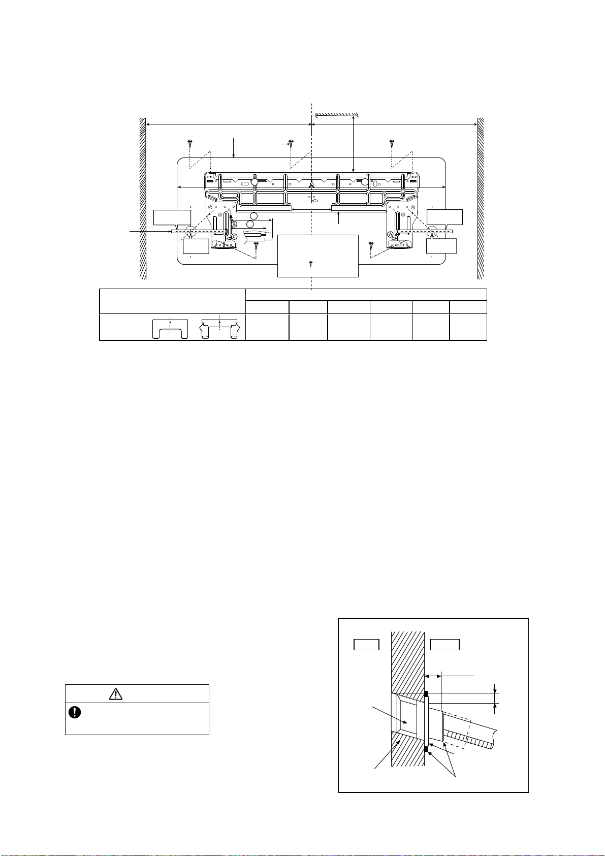
11.2 Indoor Unit
11.2.1 How to Fix Installation Plate
The mounting wall shall be strong and solid enough to prevent it from the vibration.
The center of installation plate should be at more than at right and left of the wall.
The distance from installation plate edge to ceiling should more than .
From installation plate left edge to unit’s left side is .
From installation plate right edge to unit’s right side is .
○
B : For left side piping, piping connection for liquid should be about from this line.
: For left side piping, piping connection for gas should be about from this line.
1 Mount the installation plate on the wall with 5 screws or more (at least 5 screws).
(If mounting the unit on the concrete wall, consider using anchor bolts.)
o Always mount the installation plate horizontally by aligning the marking-off line with the thread and using
a level gauge.
2 Drill the piping plate hole with ø2 3/4" (ø70 mm) hole-core drill.
o Line according to the left and right side of the installation plate. The meeting point of the extended line is
the center of the hole. Another method is by putting measuring tape at position as shown in the diagram
above. The hole center is obtained by measuring the distance namely 5 1/16" (128 mm) for left and right
hole respectively.
o Drill the piping hole at either the right or the left and the hole should be slightly slanting to the outdoor
side.
11.2.2 To Drill a Hole in the Wall and
Install a Sleeve of Piping
1 Insert the piping sleeve to the hole.
2 Fix the bushing to the sleeve.
3 Cut the sleeve until it extrudes about 19/32"
(15 mm) from the wall.
4 Finish by sealing the sleeve with putty or
caulking compound at the final stage.
3 4
5
6
Wall
Wall
Wall
Installation plate 1
2 screw
More than 1
More than 1
M
easuring
Ta p e
Indoor unit
9
17
/
32
"
(241.5 mm)
5
1
/
16
"
(128 m m)
5
1
/
16
" (128 mm)
5
1
/
16
"
(128 m m )
More than
2
Model
Dimension
123 456
E9RKUAW,
E12RKUAW
or
19
9
/
32
"
(490 mm)
3
7
/
32
"
(82 mm )
17
9
/
32
"
(439 mm)
17"
(432 mm )
1
11
/
16
"
(43 mm)
3
3
/
4
"
(95 mm )
9
17
/
32
"
(241.5 mm)
For best strength of
INDOOR unit installation,
it is highly recommended
to locate “
” at 5 position
as shown.
CAUTION
When the wall is hollow, please be sure
to use the sleeve for tube assembly to
prevent dangers caused by mice biting
the connection cable.
19
/32" (15 mm)
Putty or caulking compound
ø2
3
/4" (ø70 mm)
through hole
Indoor
Outdoor
Sleeve for
tube
assembly
Approx.
7
/32" -
9
/32"
(5-7 mm)
Bushing for tube
assembly
Wall
35
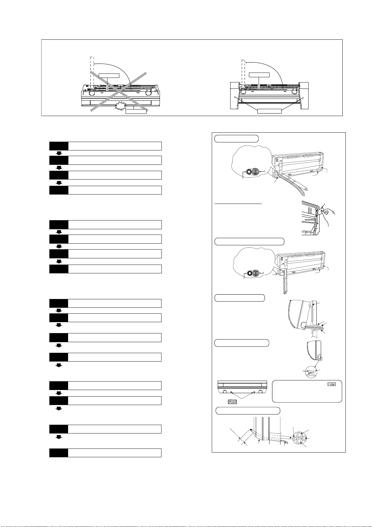
11.2.3 Indoor Unit Installation
11.2.3.1 For the right rear piping
11.2.3.2 For the right bottom piping
11.2.3.3 For the embedded piping
(This can be used for left rear piping and bottom
piping also.)
Do not turn over the unit without it’s shock absorber during pull out the piping.
It may cause intake grille damage.
Use shock absorber during pull out the piping to protect the intake grille from damage.
PUSH PUSH
Piping
Intake grille
p
u
l
l
o
u
t
t
h
e
p
i
p
i
n
g
PUSH PUSH
Piping
Shock absorber
p
u
l
l
o
u
t
t
h
e
p
i
p
i
n
g
Install the Indoor Unit
Pull out the Indoor piping
Step-2
Secure the Indoor Unit
Step-1
Step-3
Insert the connection cable
Step-4
Install the Indoor Unit
Pull out the Indoor piping
Step-2
Insert the connection cable
Step-1
Step-3
Secure the Indoor Unit
Step-4
Bend the embedded piping
• Use a spring bender or equivalent to bend the
piping so that the piping is not crushed.
• The inside and outside connection cable can be
connected without removing the front grille.
• Please refer to “Connecting the piping” column in
outdoor unit section. (Below steps are done after
connecting the outdoor piping and gas-leakage
confirmation.)
• Whe n determining the dimensions of the piping,
slide the unit all the way to the left on the installation
plate.
• Refer to the section “Cutting and flaring the piping”.
Replace the drain hose
Step-2
Pull the connection cable into Indoor Unit
Step-1
Step-3
Cut and flare the embedded piping
Step-4
Install the Indoor Unit
Step-5
Connect the piping
Step-6
• Please refer to “Insulation of piping connection”
column as m entioned in indoor/outdoor unit
installation.
Insulate and finish the piping
Step-7
Secure the Indoor Unit
Step-8
To take out the unit, push the
marking at the bottom unit, and pull it
slightly towards you to disengage the
hooks from the unit.
Right Rear piping
Insert the connection cable
Cover for the
botto m piping
Tape it with piping in a
position as mentioned
in Fig. below .
Cover for
the right
piping
Piping
Drain hose
Cover for
the left
piping
Cover for the
botto m piping
Cover for the
botto m piping
Tap e i t wi t h
piping in a position as
mentioned in
Fig. below.
Piping
Drain
hose
Cover
for the
left
piping
Right and Right Bottom piping
Secure the Indoor Unit
1. Press the lower left and right side
of the unit against the installation
plate until hooks engages with their
slot (sound click).
Cover for piping
In case of the cover is cut, keep the
cover at the rear of chassis as shown
in the illustration for future
reinstallation.
(Left and 2 bottom covers for piping.)
How to keep the cover
Install the indoor unit
Hook the indoor unit onto the upper
portion of installation plate. (Engage
the indoor unit with the upper edge
of the installation plate). Ensure the
hooks are properly seated on the
installation plate by moving it in left
and right.
Drain hose
Sleeve for
piping hole
Indoor unit
Hooks at
insta lla tion
plate
Piping
Installation
plate
Unit’s
hook
g
n
i
k
r
a
m
Guide
surface
Connection c able
A
b
o
u
t
2
3
/
4
"
-
3
5
/
3
2
"
(
7
0
-
8
0mm
)
Connection
cable
Gas side
piping
Liquid side
piping
Drain h ose
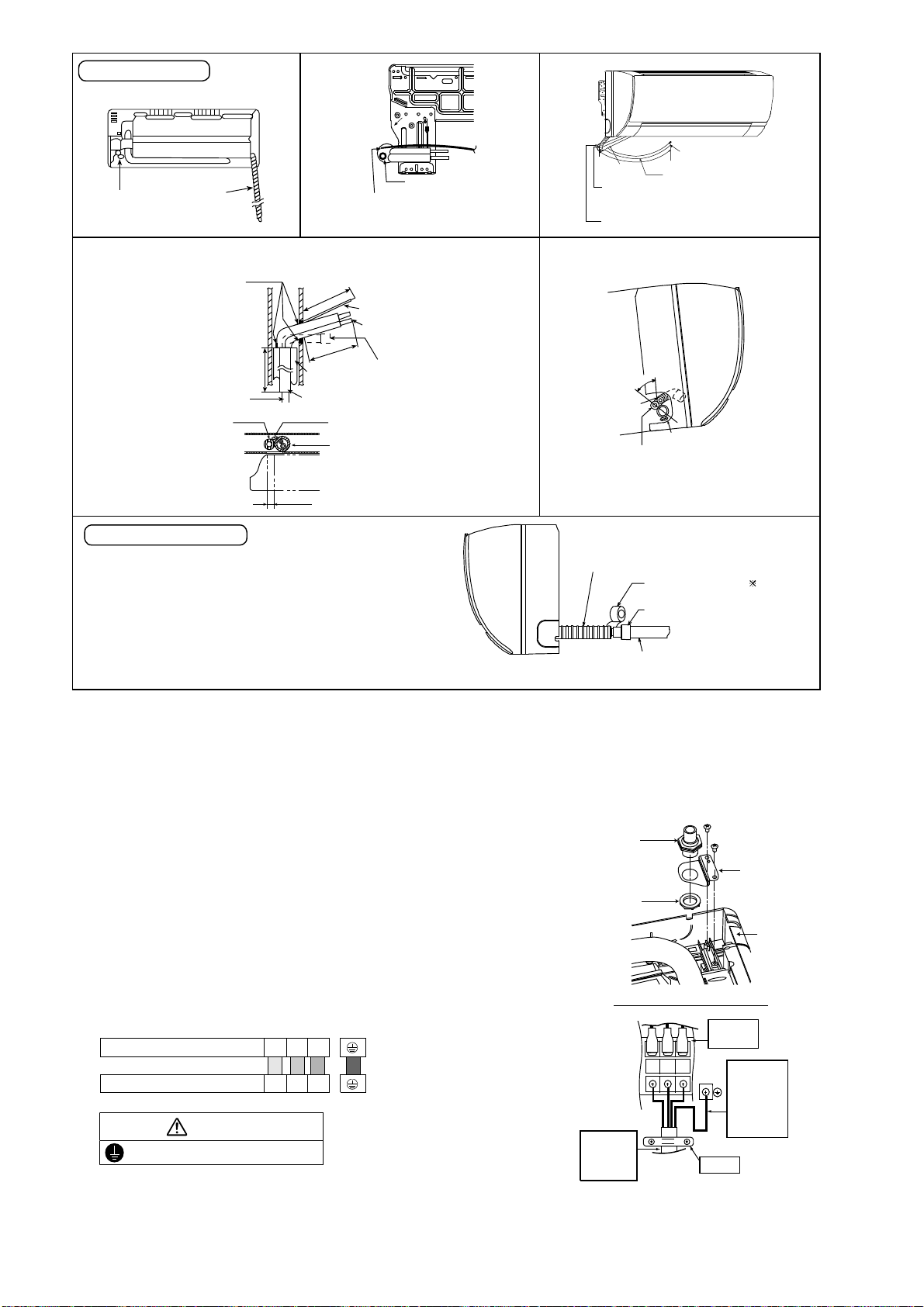
36
11.2.4 Connect the Cable to the Indoor Unit
1. The inside and outside connection cable can
be connected without removing the front grille.
2. Unscrew the conduit cover and fix the conduit
connector to conduit cover with lock nut, then
secure it against chassis.
3. Connection cable between indoor unit and
outdoor unit should be UL listed or CSA
approved 4 conductor wires minimum AWG16
in accordance with local electric codes.
4. Connection cable between indoor unit and
outdoor unit should be UL listed or CSA
approved 4 conductor wires minimum AWG16
in accordance with local electric codes.
o Ensure the colour of wires of outdoor unit
and terminal number are the same as the
indoor's repectively.
o Earth lead wire shall be Yellow/Green
(Y/G) in colour and shall be longer than
other lead wires as shown in the figure for
electrical safety in case of the slipping.
Rear view for left piping installation
Drain cap
Drain hose
Adjust the piping slightly downwards.
Drain hose
Connection
cable
•
How to p ull the piping and drain hose out, in case of embedded piping.
PVC tube
for drain
hose
Indoor unit
3
15
/
16
"(100mm)
Piping
Cable
Apply putty or
caulking material
to se al th e wall
opening.
Connection
cable
Piping
M
o
r
e
t
h
a
n
18
1
/
2
"
(
4
7
0
m
m
)
M
o
r
e
t
h
a
n
3
7
1
3
/
3
2
"
(
9
5
0
m
m
)
PVC tube (VP-65) for piping
and conne ction cable
PVC tube for drain hose (VP-30)
PVC tube for
drain hose (VP-20)
More than 27
9
/
16
"
(700 mm)
•
How to insert the connection cable and drain hose
inthecaseofleftpiping.
Cable
4
5
°
Drain
hose
Piping
Drain hose
from main unit
(For right piping, follow the same procedure)
Sleeve for p iping ho le
Drain hose
Piping
Connection
cable
More than 37
13
/
32
"
(950 mm)
Replace the drain hose
Indoor unit
drain hose
3/4" (2 0 mm) nominal PVC pipe
- Install incline downward more than 1 °
- Apply PV C glue at the join.
Drain hose adapter
9
Close join by V inyl Ta pe ( )
•
Join indoor drain hose to 3/4" (20 mm) nom ina l PVC pipe size
by using drain hose adapter
9
when necessary.
Drain hose adapter
9
usage
Remarks :
Make sure indoor un it drain hose & 3 /4" (20 mm ) nom inal PV C pipe
are fully inserted to drain hose adapter
9
.
Terminals on the indoor unit 1 2 3
Colour of wires (connection cable)
Terminals on the outdoor unit 1 2 3
WARNING
This equipment must be properly earthed.
123
Earth Wire
longer than
others AC
wires for
safety
reason
Term i nal
Board
Holder
Indoor and
outdoor
connection
cable
Chassis
Conduit
Connector
Conduit
Cover
Lock Nut
Rear Side of Indoor Unit
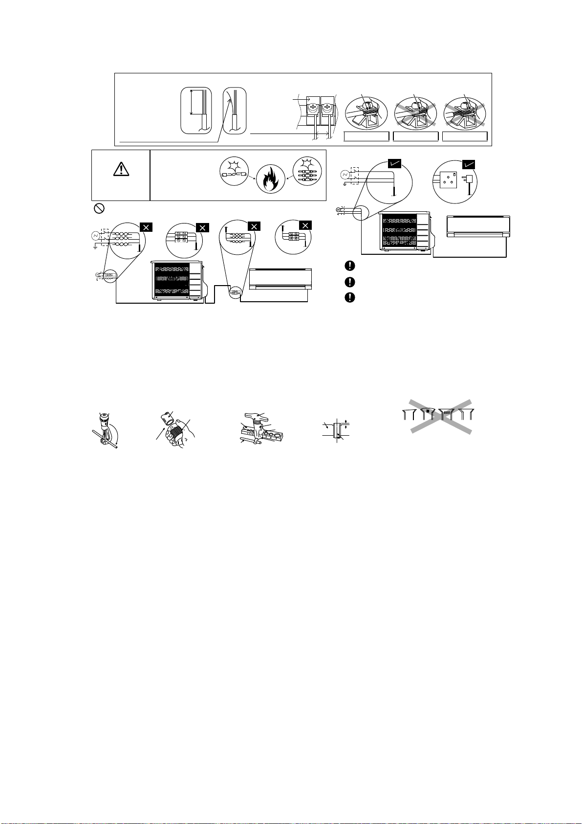
37
11.2.5 Wiring Stripping and connecting requirement
11.2.5.1 Cutting and flaring the piping
1 Please cut using pipe cutter and then remove the burrs.
2 Remove the burrs by using reamer. If burrs are not removed, gas leakage may be caused. Turn the piping
end down to avoid the metal powder entering the pipe.
3 Please make flare after inserting the flare nut onto the copper pipes.
WARNING
RISK OF FIRE
JOINING OF WIRES
MAY CAUSE
OVERHEATING
AND FIRE.
OR
OR
OR
Wire stripping
No loose strand
when inserted
Conductor
fully inserted
Conductor
over inserted
Conductor not
fully inserted
ACCEPT PROHIBITED PROHIBITED
Use complete wire without joining.
Use approved socket and plug w ith earth pin.
Wire connection in this area m ust follow to
national wiring rules.
Do not joint wires
13/32" ± 1 /16"
(10±1 mm)
Indoor/outdoor
connection
terminal board
7
/
32
"
(5 mm)
or more
(gap between wires)
1
.Tocut
3. To flare
Inclined Surface
damage d
Cr acked Uneven
thickness
Bar
Handle
Core
Yo k e
Clamp handle
Bar
0–
1
/
32
"
(0-0.5 mm)
When properly flared, the internal surface of the
flare will evenly shine and be of even thickness.
Since the flare part comes into contact with the
connections, carefully check the flare finish.
I
m
p
r
o
p
e
r
fl
a
r
i
n
g
Copper
pipe
Reamer
2. To remove burrs
Point down
Pipe
Red arrow mark
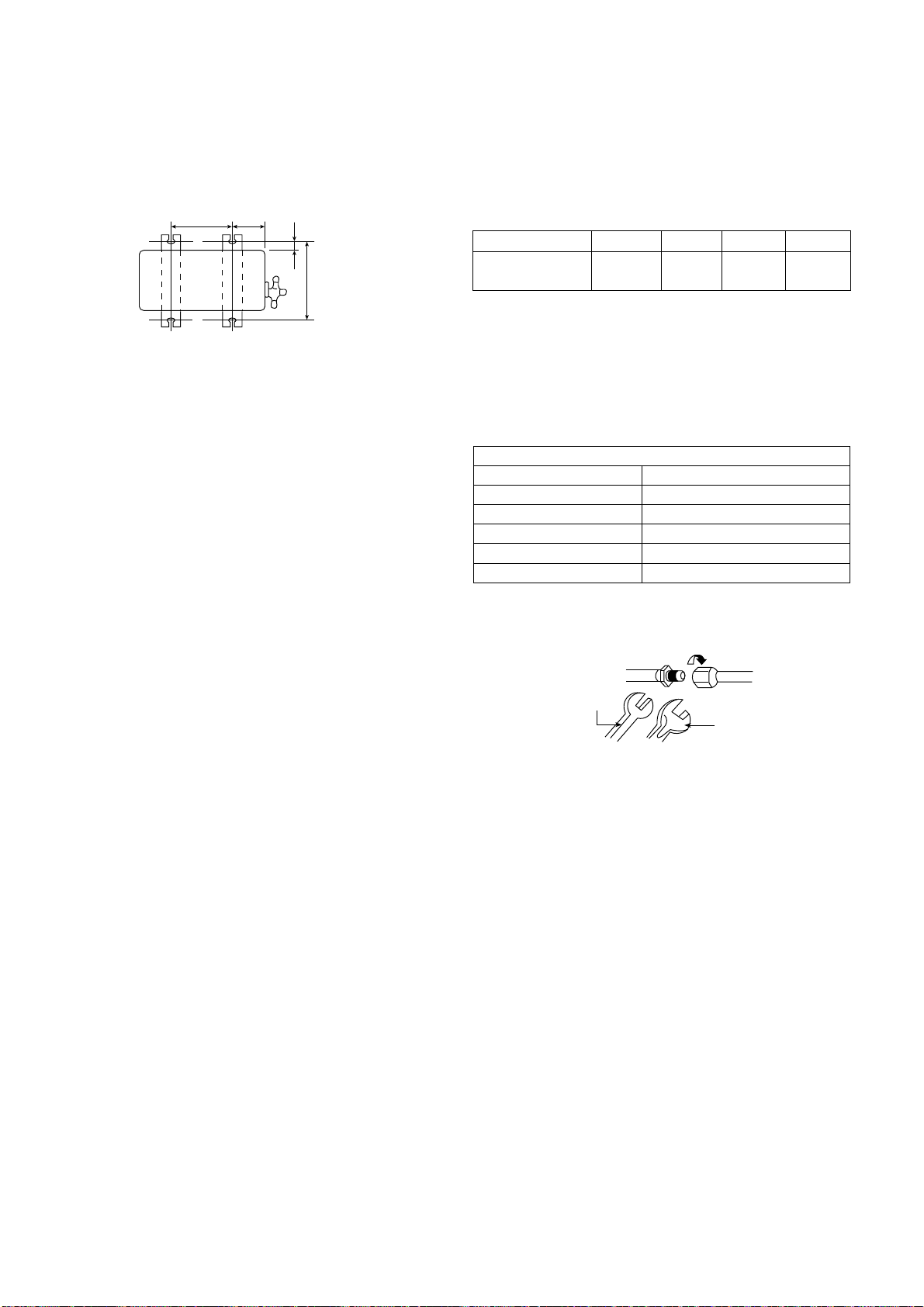
38
11.3 Outdoor Unit
11.3.1 Install the Outdoor Unit
After selecting the best location, start installation according to indoor/outdoor unit installation diagram.
1 Fix the unit on concrete or rigid frame firmly and horizontally by bolt nut (ø13/32" (ø10 mm)).
2 When installing at roof, please consider strong wind and earthquake.
Please fasten the installation stand firmly with bolt or nails.
Model A B C D
E9RKUA, E12RKUA
22-7/16"
(570 mm)
4-1/8"
(105 mm)
23/32"
(18.5 mm)
12-19/32"
(320 mm)
11.3.2 Connect the Piping
11.3.2.1 Connecting the piping to
indoor
Please make flare after inserting flare nut (locate at
joint portion, of tube assembly) onto the copper pipe.
(In case of using long piping)
Connect the piping
Align the center of piping and sufficiently tighten
the flare nut with fingers.
Further tighten the flare nut with torque wrench in
specified torque as stated in the table.
11.3.2.2 Connecting the piping to
outdoor
Decide piping length and then cut by using pipe cutter.
Remove burrs from cut edge.
Make flare after inserting the flare nut (locate at valve)
onto the copper pipe.
Align center of piping to valves and then tighten with
torque wrench to the specified torque as stated in the
table.
AB
C
D
Tor q u e
wrench
S
panner
or Wrench
Do not over tighten, over tightening may cause gas leakage.
Piping size Torque
1/4" (6.35 mm) 13.3 Ibf.ft [18 N•m (1.8 kgf•m)]
3/8” (9.52 mm) 31.0 Ibf.ft [42 N•m (4.3 kgf•m)]
1/2" (12.7 mm) 40.6 Ibf.ft [55 N•m (5.6 kgf•m)]
5/8” (15.88 mm) 47.9 Ibf.ft [65 N•m (6.6 kgf•m)]
3/4" (19.05 mm) 73.8 Ibf.ft [100 N•m (10.2 kgf•m)]
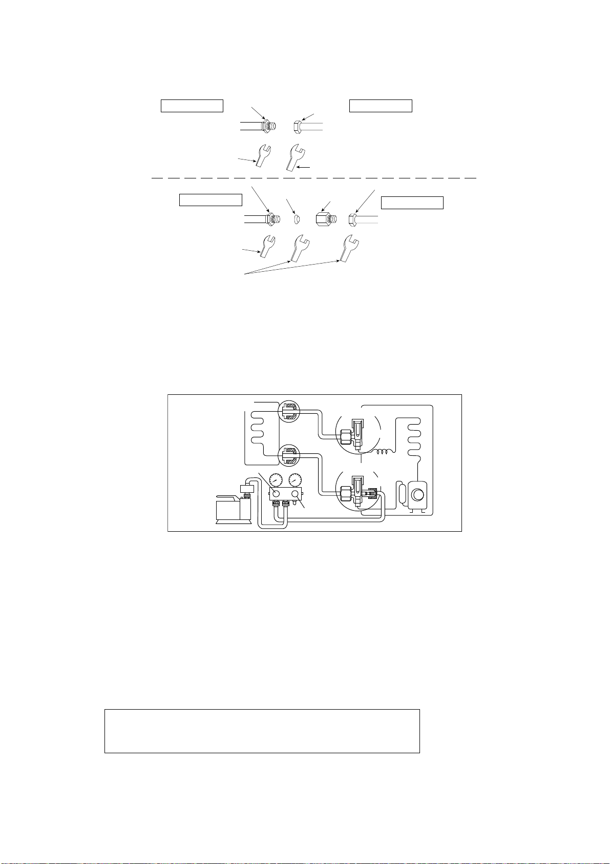
39
11.3.2.3 Connecting the piping to outdoor multi
Decide piping length and then cut by using pipe cutter. Remove burrs from cut edge.
Make flare after inserting the flare nut (locate at valve) onto the copper pipe.
Align center of piping to valve and then tighten with torque wrench to the specified torque as stated in the table.
11.3.2.4 Gas Leak Checking
Pressure test to system to 400 PSIG with dry nitrogen, in stages. Thoroughly leak check the system.
If the pressure holds, release the nitrogen and proceed to section 11.3.3.
11.3.3 Evacuation of the equipment
WHEN INSTALLING AN AIR CONDITIONER, BE SURE TO EVACUATE THE AIR INSIDE THE INDOOR UNIT AND
PIPES in the following procedures.
1. Connect a charging hose with a push pin to the Low side of a charging set and the service port of the 3-way
valve.
2. Connect the micron gauge between vacuum pump and service port of outdoor units.
3. Turn on the power switch of the vacuum pump and make sure that connect digital micron gauge and to pull
down to a value of 500 microns.
4. To make sure micron gauge a value 500 microns and close the low side valve of the charging set and turn off
the vacuum pump.
5. Disconnect the vacuum pump house from the service port of the 3-way valve.
6. Tighten the service port caps of the 3-way valve at a torque of 13.3 Ibf.ft (18 N•m) with a torque wrench.
7. Remove the valve caps of both of the 2-way valve and 3-way valve. Position both of the valves to “Open”
using a hexagonal wrench (5/32" (4 mm)).
8. Mount valve caps onto the 2-way valve and the 3-way valve.
o Be sure to check for gas leakage.
Hall Union
Flare Nut
(Auxiliary pipe)
(Connection pipe)
Applicable to
Liquid and Gas side of
CS-E9RKUAW
Liquid side of
CS-E12RKUAW
Torque Wrench for Flare Nut
Wrench
(Adjustable W rench)
Male side Female side
Hall Union
Flare Nut
Pipe Siz e
Reducer
Packing
Tor que Wrench for Flare
Nut and Pipe Size Reducer
Wrench
(Adjustable W rench)
Applicable to
Gas side of
CS-E12RKUAW
(Connection pipe)
(Auxiliary pipe)
Female side
Male side
Lo
Hi
OPEN
CLOSE
Gas side
Liquid side
Outdoor unit
Two-way valve
Three-way valve
Indoor unit
Vacuum
pump
Close
Close
•
If micron gauge value does not descend 500 microns, take the following measures:
- If the leak stops when the piping connections are tightened further, continue working from step
3
.
- If the leak does not stop when the connections are retightened, repair location of leak.
- Do not release refrigerant during piping work for installation and reinstallation.
- Be careful with the liquid refrigerant, it may cause frostbite.
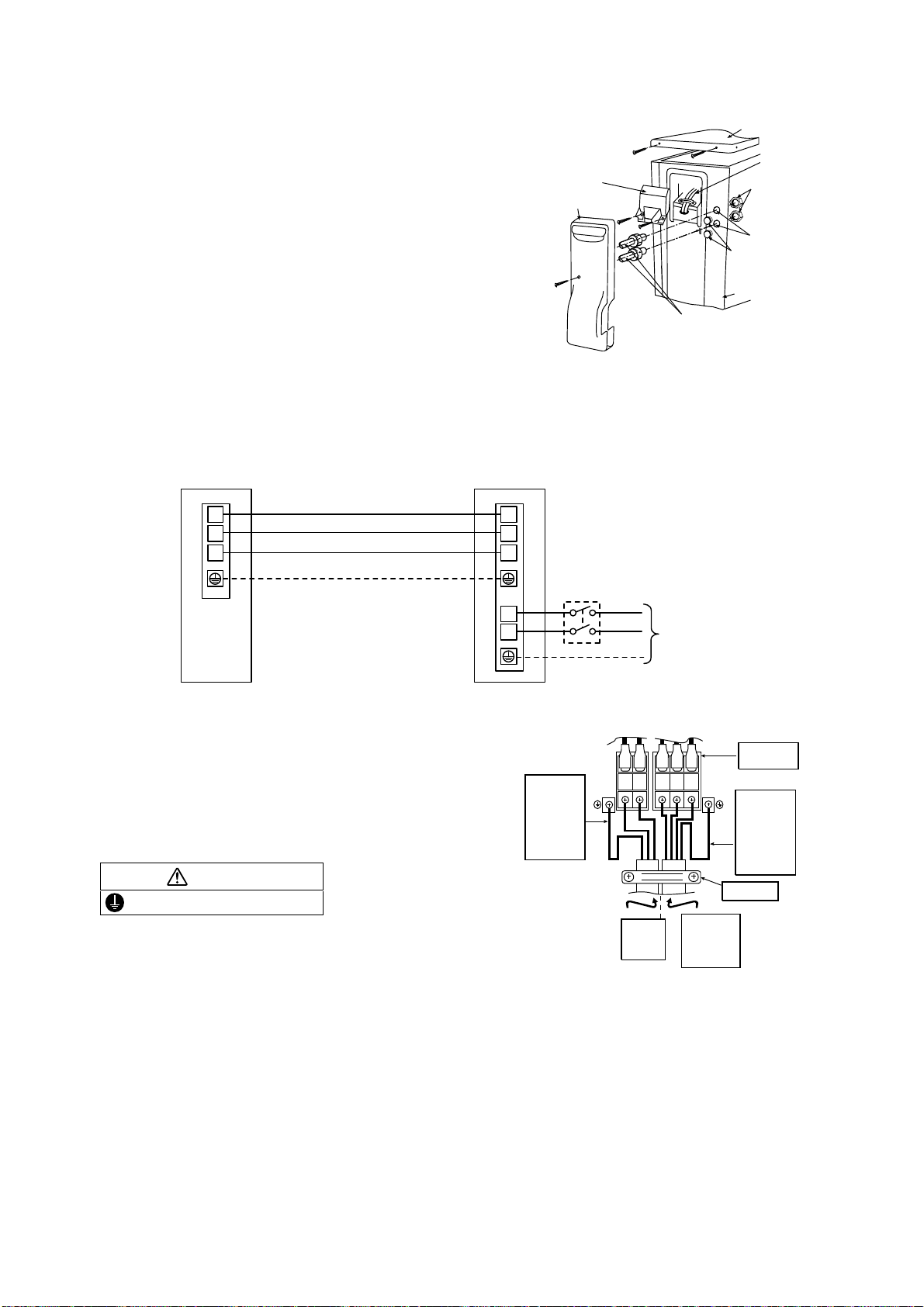
40
11.3.3.1 Connect the Cable to the Outdoor Unit
1. Remove Top panel.
2. Remove Control Board Cover (Resin and
Metal).
3. Remove Plugs.
4. Fix the conduit connectors to the knockout
holes with lock-nuts, then secure them against
the side panel.
5. All wires pass through conduits.
6. Connection cable between indoor unit and
outdoor unit should be UL listed or CSA
approved 4 conductor wires minimum AWG16
in accordance with local electric codes.
7. Wire connection to the power supply
(208/230V 60Hz) through circuit breaker.
o Connect the UL listed or CSA approved
wires minimum AWG14 to the terminal
board, and connect the other end of the
wires to ELCB / GFCI.
8. Connect the power supply cord and
connection cable between indoor unit and
outdoor unit according to the diagram below.
9. Secure the wire onto the control board with
the holder (clamper).
10. After completing wiring connections, reattach
the control board cover (Metal and Resin) and
the top panel to the original position with the
screws.
11. For wire stripping and connection requirement,
refer to instruction 11.2.5 of indoor unit.
Earth lead wire shall be Yellow/Green (Y/G) in
colour and shall be longer than other lead wires
as shown in the figure for electrical safety in case
of the slipping.
11.3.3.2 Piping Insulation
1. Please carry out insulation at pipe connection portion as mentioned in Indoor/Outdoor Unit Installation
Diagram. Please wrap the insulated piping end to prevent water from going inside the piping.
2. If drain hose or connecting piping is in the room (where dew may form), please increase the insulation by
using POLY-E FOAM with thickness 1/4" (6 mm) or above.
Control Board
Metal Cover
T
o
p
P
a
n
el
Power
Supply
Wires
Lock Nuts
Knockout
Holes
Plugs
Side Panel
Connectors
C
ontrol Board
C
over (Resin)
Outdoo
r
U
nit
1
2
3
1
2
L1
L2
3
lanimreTlanimreT
Indo o
r
U
nit
Disconnect
Switch
Field supply
Grounding wire
Grounding wire min AWG16
* Ensure all connecting wire
between indoor unit and
outdoor unit and power supply
cord are installed in individual
conduit.
Power Supply
Single Phase
208/230V 60Hz
min AWG14
208/230V min AWG16
208/230V min AWG16
208/230V min AWG16
WARNING
This equipment must be properly earthed.
Holder
L1 L2 1 2 3
Power
supply
cord
Indoor &
outdoor
connection
cable
Term i nal
Board
Earth wire
longer than
others AC
wires for
safety
reason
Earth wire
longer than
others AC
wires for
safety
reason
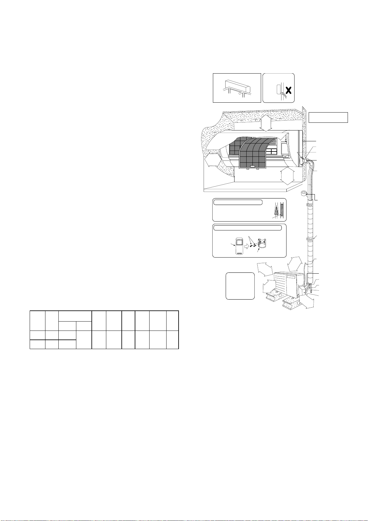
41
12. Installation Instruction (E18RK and E24RK)
12.1 Select the Best Location
12.1.1 Indoor Unit
Do not install the unit in excessive oil fume area
such as kitchen, workshop and etc.
There should not be any heat source or steam
near the unit.
There should not be any obstacles blocking the air
circulation.
A place where air circulation in the room is good.
A place where drainage can be easily done.
A place where noise prevention is taken into
consideration.
Do not install the unit near the door way.
Ensure the spaces indicated by arrows from the
wall, ceiling, fence or other obstacles.
Recommended installation height for indoor unit
shall be at least 8 ft (2.4 m).
12.1.2 Outdoor Unit
If an awning is built over the unit to prevent direct
sunlight or rain, be careful that heat radiation from
the condenser is not obstructed.
There should not be any animal or plant which
could be affected by hot air discharged.
Keep the spaces indicated by arrows from wall,
ceiling, fence or other obstacles.
Do not place any obstacles which may cause a
short circuit of the discharged air.
If piping length is over the [piping length for
additional gas], additional refrigerant should be
added as shown in the table.
Recommended installation height for outdoor unit
should be above the seasonal snow level.
Example: For E18RKUA
If the unit is installed at 41 ft (12.5 m) distance, the
quantity of additional refrigerant should be 2.46 oz
(62.5 g) .... (41 - 32.8) ft x 0.3 oz/ft = 2.46 oz.
((12.5 - 10) m x 25 g/m = 62.5 g).
12.1.3 Indoor/Outdoor Unit Installation
Diagram
Model
Capacity
(Btu/h)
Piping size
Std.
Length
Max.
Elevation
Min.
Piping
Length
Max.
Piping
Length
Additional
Refrigerant
Piping
Length
for add.
gas
Gas Liquid
E18RKUA
17200
1/2"
(
12.7 mm)
1/4"
(
6.35 mm)
24.6 ft
(
7.5 m)
49.2 ft
(
15 m)
9.8 ft
(
3m)
100.0 ft
(
30.5 m)
0.3 oz/ft
(
25 g/m)
32.8 ft
(
10 m)
E24RKUA
24000
5/8"
(
15.88 mm)
2
9
/
1
6
"
(
6
5
m
m
)
o
r
m
o
r
e
8
f
t
(
2
.
4
m
)
o
r
m
o
r
e
(Left and right are identical)
Floor / Grade lev el
• C arr y out insulation after
checking for gas leaks and
Remote control holder fixing screws
secure with vinyl tape.
Vinyl tape
• This illustration is for
explanation purposes only.
The indoor unit will actually face
adif
f
e
r
e
n
t
w
a
y
.
It is advisable to
avoid m ore than 2
blockage directions.
For better ventilation
& multiple-outdoor
installation, please
consult au tho rized
dealer/specialist.
Installation plate 1
Sleeve (
)
Bushing-Slee ve (
)
Bend the pipe as
closely on the wall as
possible, but be careful
that it doesn’t break.
Saddle (
)
Conduit
(Po wer supply cord (
))
Control Board cover
6
Remote control holder
5
Remote
control
3
Additional drain hose
Gas side piping (
)
Conduit
(Connection cable)
Putty (
)
(Gum Type Sealer)
Installation parts you
should purchase ()
Vinyl tape (wide) (
)
• Apply after carrying
out a drainage test.
• To carry out the
drainage test,
and pour water into
the heat exchanger.
remove the air filters
Liquid side piping (
)
Piping direction Attention not to bend
up drain hose(Front side)
Right
Rear
Right
bottom
Left
Rear
Left bottom
Left
Insulation of piping connections
Attaching the remote co n trol h o ld e r to the wall
1
31
/
32
"
(50 mm)
or more
3
1
5
/
1
6
"
(
1
0
0
m
m
)
o
r
m
o
r
e
3
1
5
/
1
6
"
(
1
0
0
m
m
)
o
r
m
o
r
e
3
9
3
/
8
"
(
1
0
0
0
m
m
)
o
r
m
o
r
e
1
1
1
3
/
1
6
"
(
3
0
0mm)
o
r
mo
r
e
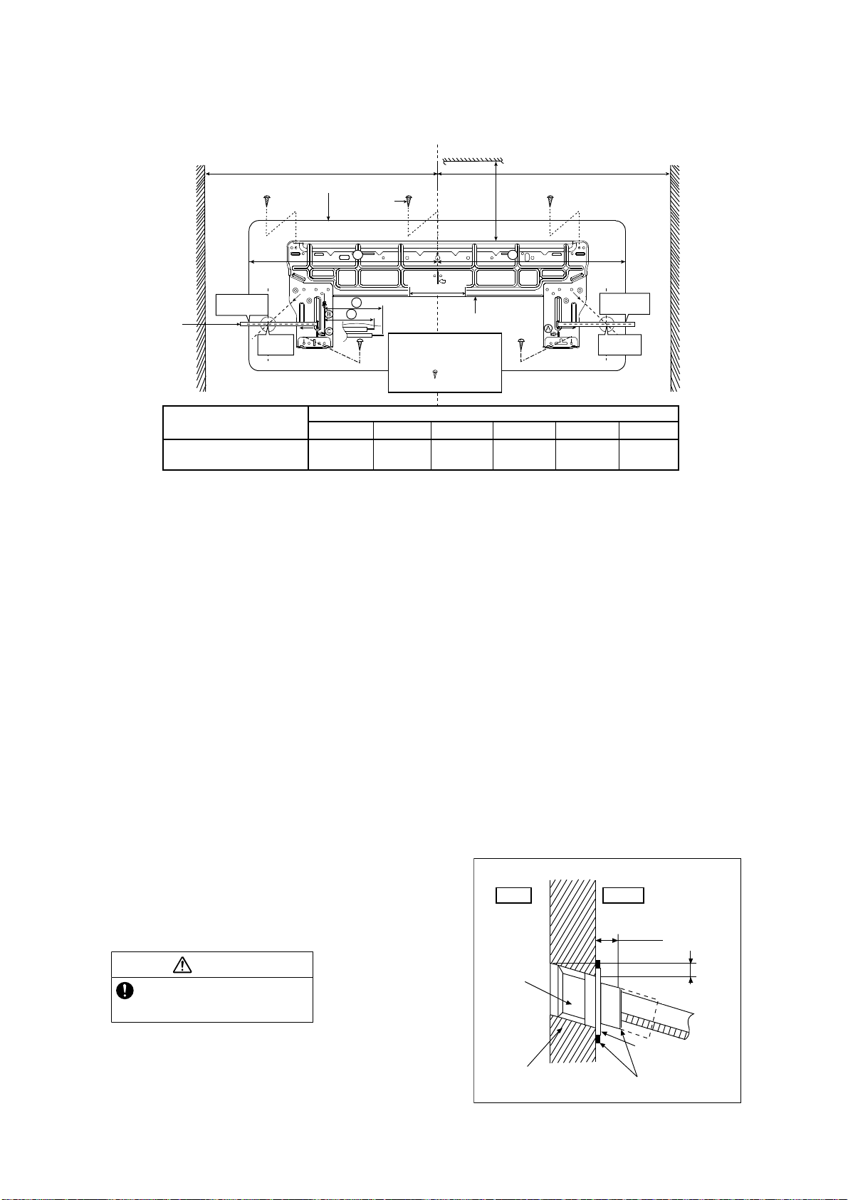
42
12.2 Indoor Unit
12.2.1 How to Fix Installation Plate
The mounting wall shall be strong and solid enough to prevent it from the vibration.
The center of installation plate should be at more than at right and left of the wall.
The distance from installation plate edge to ceiling should more than .
From installation plate left edge to unit’s left side is .
From installation plate right edge to unit’s right side is .
○
B : For left side piping, piping connection for liquid should be about from this line.
: For left side piping, piping connection for gas should be about from this line.
1 Mount the installation plate on the wall with 5 screws or more (at least 5 screws).
(If mounting the unit on the concrete wall, consider using anchor bolts.)
o Always mount the installation plate horizontally by aligning the marking-off line with the thread and using
a level gauge.
2 Drill the piping plate hole with ø2 3/4" (ø70 mm) hole-core drill.
o Line according to the left and right side of the installation plate. The meeting point of the extended line is
the center of the hole. Another method is by putting measuring tape at position as shown in the diagram
above. The hole center is obtained by measuring the distance namely 5 1/16" (128 mm) for left and right
hole respectively.
o Drill the piping hole at either the right or the left and the hole should be slightly slanting to the outdoor
side.
12.2.2 To Drill a Hole in the Wall and
Install a Sleeve of Piping
1 Insert the piping sleeve to the hole.
2 Fix the bushing to the sleeve.
3 Cut the sleeve until it extrudes about 19/32"
(15 mm) from the wall.
4 Finish by sealing the sleeve with putty or
caulking compound at the final stage.
3 4
5
6
Wall
Wall
Wall
Installation plate 1
2 screw
More than 1
More than 1
Measuring
Ta p e
Indoor unit
9
17
/
32
"
(241.5 mm)
More than
2
Model
Dimension
1234 56
E18RKUA, E24RKUA
23
7
/
32
"
(590 m m )
3
7
/
32
"
(82 mm)
21
7
/
32
"
(539 mm)
20
15
/
16
"
(532 mm)
6
21
/
32
"
(169 m m )
8
5
/
8
"
(219 mm)
5
1
/
16
"
(128 mm)
9
17
/
32
”
(241.5 mm)
5
1
/
16
"
(128 mm)
5
1
/
16
" (128 mm)
For best strength of
INDOOR unit installation,
it is highly recommended
to locate “
” at 5 position
as shown.
CAUTION
When the wall is hollow, please be sure
to use the sleeve for tube assembly to
prevent dangers caused by mice biting
the connection cable.
19
/
32
" (15 mm)
Putty or caulking compound
ø2
3
/
4
" (ø70 mm)
through hole
Indoor
Outdoor
Sleeve for
tube
assembly
Approx.
7
/
32
"-
9
/
32
"
(5 - 7 mm )
Bushing for tube
assembly
Wall
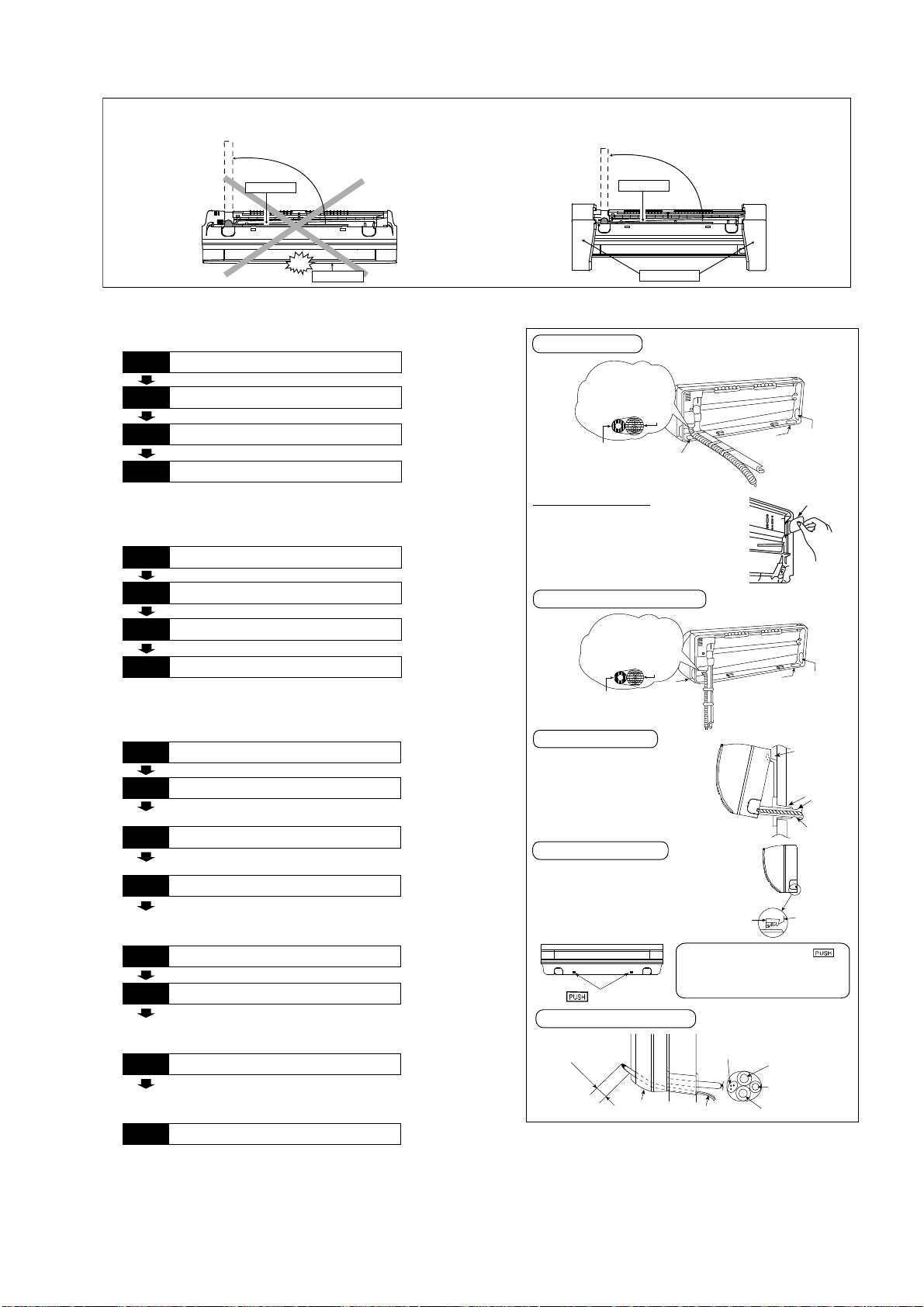
43
12.2.3 Indoor Unit Installation
12.2.3.1 For the right rear piping
12.2.3.2 For the right bottom piping
12.2.3.3 For the embedded piping
(This can be used for left rear piping and bottom
piping also.)
Do not turn ov er the unit without it’s shock absorber during pull out the piping.
It may cause intake grille damage.
Use shock absorber during pull out the piping to protect the intake grille from damage.
PUSH PUSH
Piping
Intake grille
p
u
l
l
o
u
t
t
h
e
p
i
p
i
n
g
PUSH PUSH
Piping
Shock absorber
p
u
l
l
o
u
t
t
h
e
p
i
p
i
n
g
Install the Indoor Unit
Pull out the Indoor piping
Step-2
Secure the Indoor Unit
Step-1
Step-3
Insert the connection cable
Step-4
Install the Indoor Unit
Pull out the Indoor piping
Step-2
Insert the connection cable
Step-1
Step-3
Secure the Indoor Unit
Step-4
Bend the embedded piping
• Use a spring bender or equivalent to bend the
piping so that the piping is not crushed.
• The inside and outside connection cable can be
connected without removing the front grille.
• Please refer to “Connecting the piping” column in
outdoor unit section. (Below steps are done after
connecting the outdoor piping and gas-leakage
confirmation.)
• Whe n determining the dimensions of the piping,
slide the unit all the way to the left on the installation
plate.
• Refer to the section “Cutting and flaring the piping”.
Replace the drain hose
Step-2
Pull the connection cable into Indoor Unit
Step-1
Step-3
Cut and flare the embedded piping
Step-4
Install the Indoor Unit
Step-5
Connect the piping
Step-6
• Please refer to “Piping and finishin g” column of
outdoor section and “Insulation of piping
connection” column as m entioned in indoor/outdoor
unit installation.
Insulate and finish the piping
Step-7
Secure the Indoor Unit
Step-8
To take out the unit, push the
marking at the bottom unit, and pull it
slightly towards you to disengage the
hooks from the unit.
Right Rear piping
Insert the connection cable
Cover for the
botto m piping
Tape it with piping in a
position as mentioned
in Fig. below .
Cover for
the right
piping
Piping
Drain hose
Cover for
the left
piping
Cover for the
botto m piping
Cover for the
botto m piping
Tap e i t w i t h
piping in a position as
mentioned in
Fig. below .
Piping
Drain
hose
Cover
for the
left
piping
Right and Right Bottom piping
Secure the Indoor Unit
1. Press the lower left and right side
of the unit against the installation
plate until hooks engages with their
slot (sound click).
Cover for piping
In case of the cover is cut, keep the
cover at the rear of chassis as shown
in the illustration for future
reinstallation.
(Left and 2 bottom covers for piping.)
How to keep the cover
Install the indoor unit
Hook the indoor unit onto the upper
portion of installation plate. (Engage
the indoor unit with the upper edge
of the installation plate). Ensure the
hooks are properly seated on the
installation plate by moving it in left
and right.
Drain hose
Sleeve for
piping hole
Indoor unit
Hooks at
insta llation
plate
Piping
Insta lla tion
plate
Unit’s
hook
g
n
i
k
r
a
m
Guide
surface
Connection c able
A
b
o
u
t
2
3
/
4
"
-
3
5
/
3
2
"
(
7
0
-
8
0mm)
Connection
cable
Gas side
piping
Liquid side
piping
Drain h ose
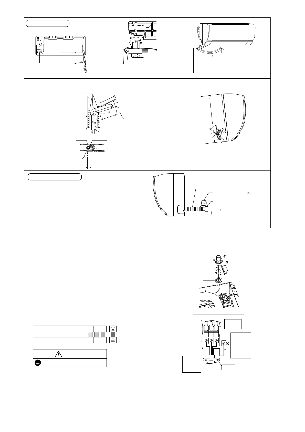
44
12.2.4 Connect the Cable to the Indoor Unit
1. The inside and outside connection cable can
be connected without removing the front grille.
2. Unscrew the conduit cover and fix the conduit
connector to conduit cover with lock nut, then
secure it against chassis.
3. Connecting wire between indoor unit and
outdoor unit should be UL listed or CSA
approved 4 conductor wires minimum AWG16
in accordance with local electric codes.
o Ensure the colour of wires of outdoor unit
and terminal number are the same as the
indoor's repectively.
o Earth lead wire shall be Yellow/Green
(Y/G) in colour and shall be longer than
other lead wires as shown in the figure for
electrical safety in case of the slipping.
Rear view for left piping installation
Drain cap
Drain hose
Adjust the piping slightly downwards.
Drain hose
Connection
cable
•
How to p ull the piping and drain hose out, in case of em bed ded piping.
•
How to insert the connection cable and drain hose
inthecaseofleftpiping.
Cable
4
5
°
Drain
hose
Piping
(For right piping, follow the same procedure)
Sleeve for piping hol e
Drain hose
Piping
Connection
cable
More than 45
9
/
32
"
(1150 mm)
Replace the drain hose
Indoor unit
drain hose
3/4" (20 m m) nominal PVC pipe
- Install incline downward more than 1°
- Apply PV C glue at the join.
Drain hose adapter
9
Close join by V inyl Tape ( )
•
Join indoor drain hose to 3/4" (20 mm) nom ina l PVC pipe size
by using drain hose adapter
9
when necessary.
Drain hose adapter
9
usage
Remarks :
Make sure indoo r unit drain hose & 3/4" (20 mm ) nominal PVC pipe
are fully inserted to drain hose adapter
9
.
2
27
/
32
" (72 mm)
M
o
r
e
t
h
a
n
1
8
1
/
2
"
(
4
7
0
m
m
)
M
o
r
e
t
h
a
n
4
5
9
/
3
2
"
(
1
1
5
0
m
m
)
More than 27
9
/
16
"
(700 mm)
PVC tube
for dra in
hose
Indoor unit
Piping
Cable
Apply putty or
caulking material
to seal the wall
opening.
Connection cable
Piping
PVC tube (VP-65) for piping
and conne ction cable
PVC tube for drain hose (VP-30)PVC tub e for drain
hose (VP-20)
Drain hose
from main unit
Terminals on the indoor unit 1 2 3
Colour of wires (Connecting wire)
Terminals on the outdoor unit 1 2 3
WARNING
This equipment must be properly earthed.
123
Earth Wire
longer than
others AC
wires for
safety
reason
Term i nal
Board
Holder
Indoor and
outdoor
connection
cable
Chassis
Conduit
Connector
Conduit
Cover
Lock Nut
Rear Side of Indoor Unit
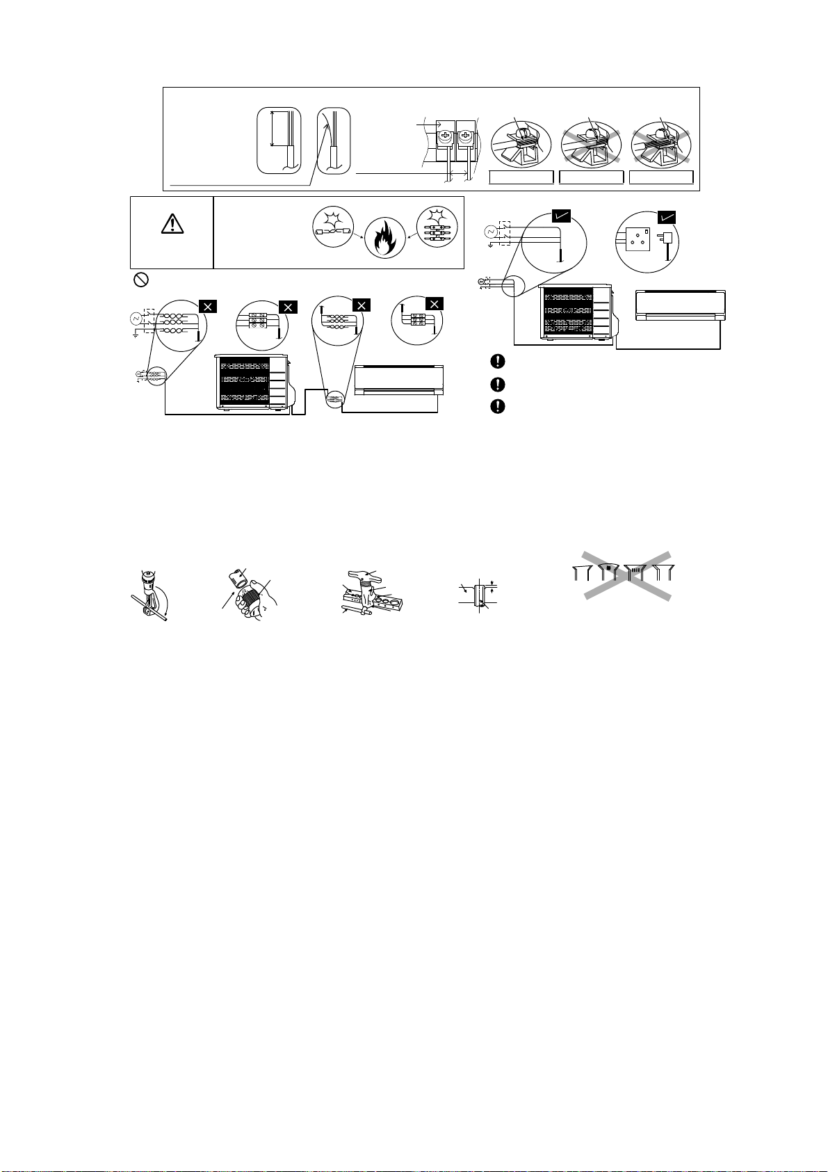
45
12.2.5 Wiring Stripping and connecting requirement
12.2.5.1 Cutting and flaring the piping
1 Please cut using pipe cutter and then remove the burrs.
2 Remove the burrs by using reamer. If burrs are not removed, gas leakage may be caused. Turn the piping
end down to avoid the metal powder entering the pipe.
3 Please make flare after inserting the flare nut onto the copper pipes.
WARNING
RISK OF FIRE
JOINING OF WIRES
MAY CAUSE
OVERHEATING
AND FIRE.
OR
OR
OR
Wire stripping
No loose strand
when inserted
Conductor
fully inserted
Conductor
over inserted
Conductor not
fully inserted
ACCEPT PROHIBITED PROHIBITED
Use complete wire without joining.
Use approved socket and plug w ith earth pin.
Wire connection in this area m ust follow to
national wiring rules.
Do not joint wires
13/32" ± 1/16"
(10±1 mm)
Indoor/outdoor
connection
terminal board
7
/
32
"
(5 mm)
or more
(gap between wires)
1
.Tocut
3. To flare
Inclined Surface
damage d
Cr acked Uneven
thickness
Bar
Handle
Core
Yo k e
Clamp handle
Bar
0–
1
/
32
"
(0-0.5 mm)
When properly flared, the internal surface of the
flare will evenly shine and be of even thickness.
Since the flare part comes into contact with the
connections, carefully check the flare finish.
I
m
p
r
o
p
e
r
fl
a
r
i
n
g
Copper
pipe
Reamer
2. To remove burrs
Point down
Pipe
Red arrow mark
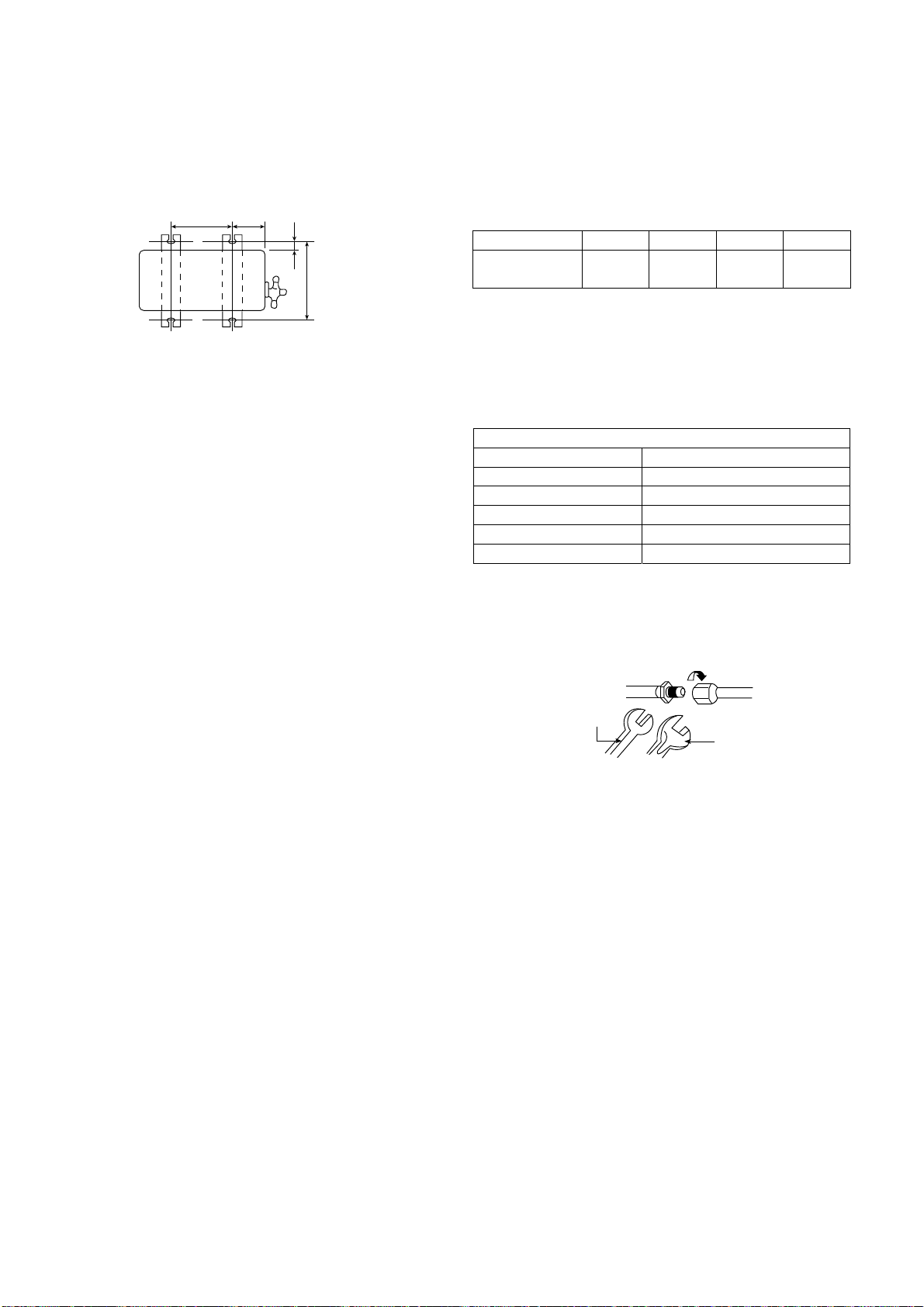
46
12.3 Outdoor Unit
12.3.1 Install the Outdoor Unit
After selecting the best location, start installation according to indoor/outdoor unit installation diagram.
1 Fix the unit on concrete or rigid frame firmly and horizontally by bolt nut ø13/32" (ø10 mm).
2 When installing at roof, please consider strong wind and earthquake.
Please fasten the installation stand firmly with bolt or nails.
Model A B C D
E18RKUA,
E24RKUA
24-1/8"
(613 mm)
5 5/32"
(131 mm)
5/8"
(16 mm)
14 3/16"
(360.5 mm)
12.3.2 Connect the Piping
12.3.2.1 Connecting the piping to
indoor
Please make flare after inserting flare nut (locate at
joint portion, of tube assembly) onto the copper pipe.
(In case of using long piping)
Connect the piping
Align the center of piping and sufficiently tighten
the flare nut with fingers.
Further tighten the flare nut with torque wrench in
specified torque as stated in the table.
12.3.2.2 Connecting the piping to
outdoor
Decide piping length and then cut by using pipe cutter.
Remove burrs from cut edge.
Make flare after inserting the flare nut (locate at valve)
onto the copper pipe.
Align center of piping to valves and then tighten with
torque wrench to the specified torque as stated in the
table.
AB
C
D
Tor q u e
wrench
S
panner
or Wrench
Do not over tighten, over tightening may cause gas leakage.
Piping size Torque
1/4" (6.35 mm) 13.3 Ibf.ft [18 N•m (1.8 kgf•m)]
3/8” (9.52 mm) 31.0 Ibf.ft [42 N•m (4.3 kgf•m)]
1/2" (12.7 mm) 40.6 Ibf.ft [55 N•m (5.6 kgf•m)]
5/8” (15.88 mm) 47.9 Ibf.ft [65 N•m (6.6 kgf•m)]
3/4" (19.05 mm) 73.8 Ibf.ft [100 N•m (10.2 kgf•m)]
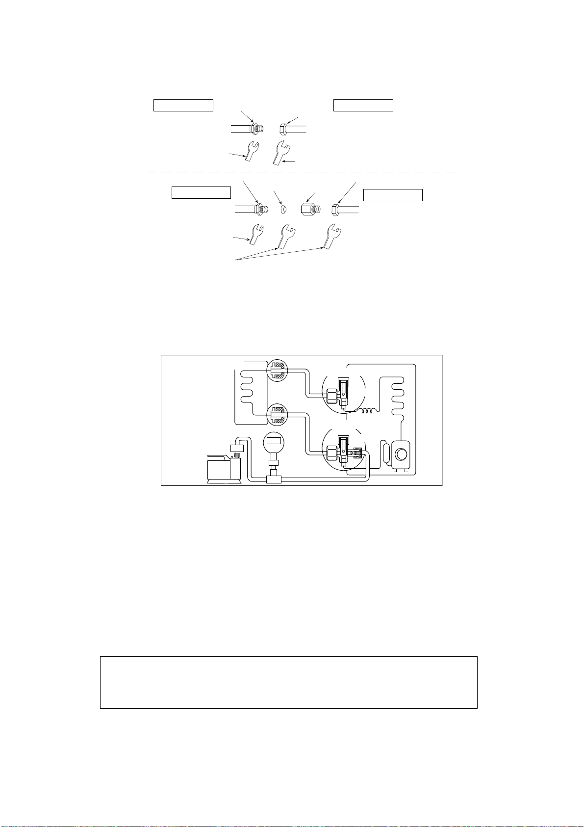
47
12.3.2.3 Connecting the piping to outdoor multi
Decide piping length and then cut by using pipe cutter. Remove burrs from cut edge.
Make flare after inserting the flare nut (locate at valve) onto the copper pipe.
Align center of piping to valve and then tighten with torque wrench to the specified torque as stated in the table.
12.3.2.4 Gas Leak Checking
Pressure test to system to 400 PSIG with dry nitrogen, in stages. Thoroughly leak check the system.
If the pressure holds, release the nitrogen and proceed to section 12.3.3.
12.3.3 Evacuation of the equipment
1. Connect a charging hose with a push pin to the Low side of a charging set and the service port of the 3-way
valve.
2. Connect the micron gauge between vacuum pump and service port of outdoor units.
3. Turn on the power switch of the vacuum pump and make sure that connect digital micron gauge and to pull
down to a value of 500 microns.
4. To make sure micron gauge a value 500 microns and close the low side valve of the charging set and turn off
the vacuum pump.
5. Disconnect the vacuum pump house from the service port of the 3-way valve.
6. Tighten the service port caps of the 3-way valve at a torque of 13.3 Ibf•ft (18 N•m) with a torque wrench.
7. Remove the valve caps of both of the 2-way valve and 3-way valve. Position both of the valves to “Open”
using a hexagonal wrench (5/32" (4 mm)).
8. Mount valve caps onto the 2-way valve and the 3-way valve.
o Be sure to check for gas leakage.
Hall Union
Flare Nut
Pipe Size
Reducer
Packing
Torque Wrench for Flare
Nut and Pipe Size Reducer
Wrench
(Adjustable Wrench)
Applicable to
Gas side of
CS-E18RKUA
CS-E24RKUA
(Connection pipe)
(Auxiliary pipe)
Female side
Male side
Hall Union
Flare Nut
(Auxiliary pipe)
(Connection pipe)
Applicable to
Liquid side of
CS-E18RKUA
CS-E24RKUA
Tor q u e W r e n c h
for Flare Nut
Wrench
(Adjustable Wrench)
Male side Female side
Gas side
Liquid side
Outdoor unit
Two-way valve
Three-way valve
Indoor unit
Vacuum
pump
Close
Close
•
If micron gauge value does not descend 500 microns, take the following measures:
- If the leak stops when the piping connections are tightened further, continue working from step
3
.
- If the leak does not stop when the connections are retightened, repair location of leak.
- Do not release refrigerant during piping work for installation and reinstallation.
- Be careful with the liquid refrigerant, it may cause frostbite.
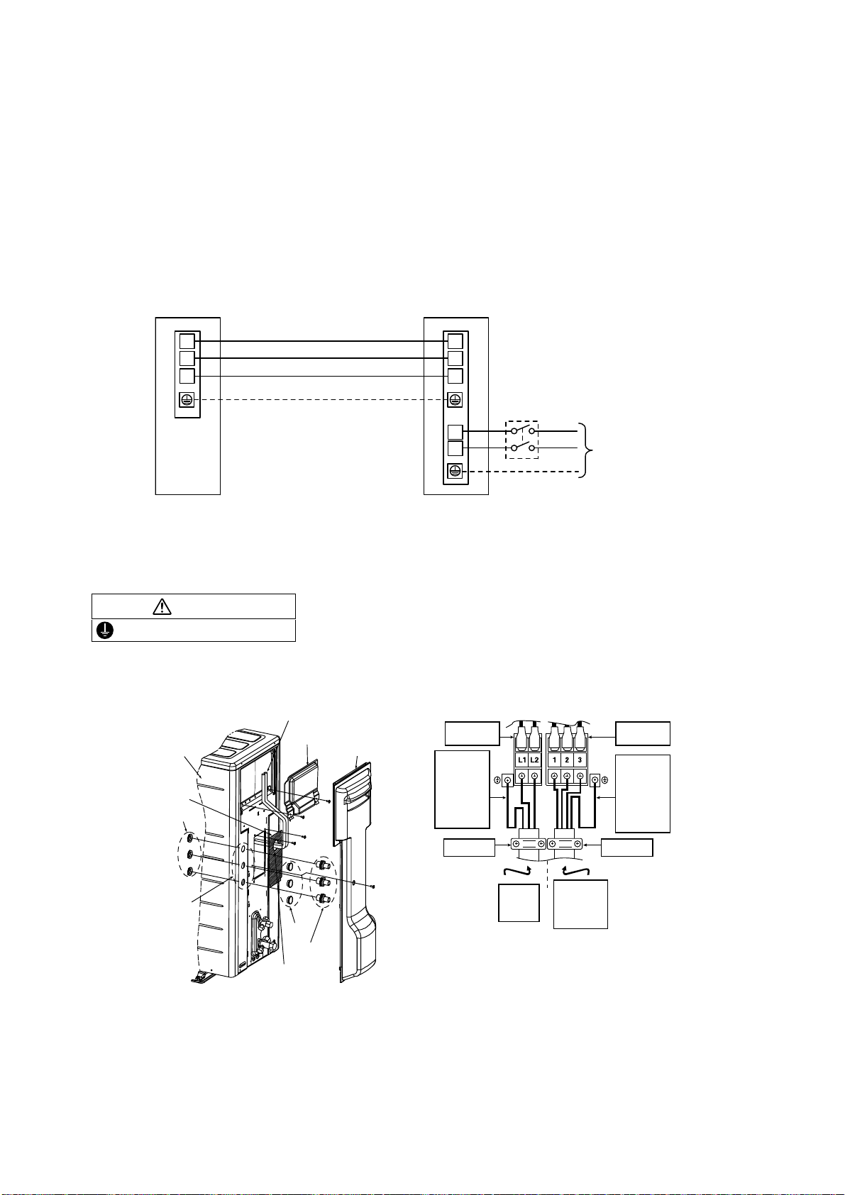
48
12.3.3.1 Connect the Cable to the Outdoor Unit
1. Remove control board cover (Resin and Metal).
2. Remove particular plate.
3. Remove plugs.
4. Fix the conduit connectors to the knockout holes with lock-nuts, then secure them against the side panel.
5. All wires pass through conduits & particular plate’s opening hole.
6. Connecting wire between indoor unit and outdoor unit should be UL listed or CSA approved 4 conductor
wires minimum AWG16 in accordance with local electric codes.
7. Wire connection to the power supply (208/230V 60Hz) through circuit breaker.
o Connect the UL listed or CSA approved wires minimum AWG12 to the terminal board, and connect the
other end of the wires to ELCB / GFCI.
8. Connect the power supply cord and connecting wire between indoor unit and outdoor unit according to the
diagram below.
9. Secure the wire onto the control board with the holder (clamper).
10. After completing wiring connections, reattach the control board cover (Metal and Resin) and the top panel to
the original position with the screws.
11. For wire stripping and connection requirement, refer to instruction 12.2.5 of indoor unit.
Earth lead wire shall be Yellow/Green (Y/G) in colour and longer than other lead wires for electrical safety in case
of the slipping.
12.3.3.2 Piping Insulation
1. Please carry out insulation at pipe connection portion as mentioned in Indoor/Outdoor Unit Installation
Diagram. Please wrap the insulated piping end to prevent water from going inside the piping.
2. If drain hose or connecting piping is in the room (where dew may form), please increase the insulation by
using POLY-E FOAM with thickness 1/4" (6 mm) or above.
Outdoo
r
U
nit
1
2
3
1
2
L1
L2
3
TerminalTerminal
Indoo
r
U
nit
Disconnect
Switch
Field supply
Grounding wire
Grounding wire min AWG16
Power Supply
Single Phase
208/230V 60Hz
min AWG12
208/230V min AWG16
208/230V min AWG16
208/230V min AWG16
* Ensure all connecting wire
between indoor unit and
outdoor unit and power supply
cord are installed in individual
conduit.
WARNING
This equipment must be properly earthed.
HolderHolder
Power
supply
cord
Indoor &
outdoor
connection
cable
Te r m i n a l
Board
Ter m i n a l
Board
Earth wire
longer than
others
AC wires
for safety
reason
Earth wire
longer than
others
AC wires
for safety
reason
Control Board
Cover (Metal)
Lock Nuts
Knockout
Holes
Plugs
Connectors
Control Board
Cover (Resin)
Front Panel
C
o
n
n
ecti
n
g
Wi
r
e
s
P articular Plate’s
opening holes
P articular
Plate
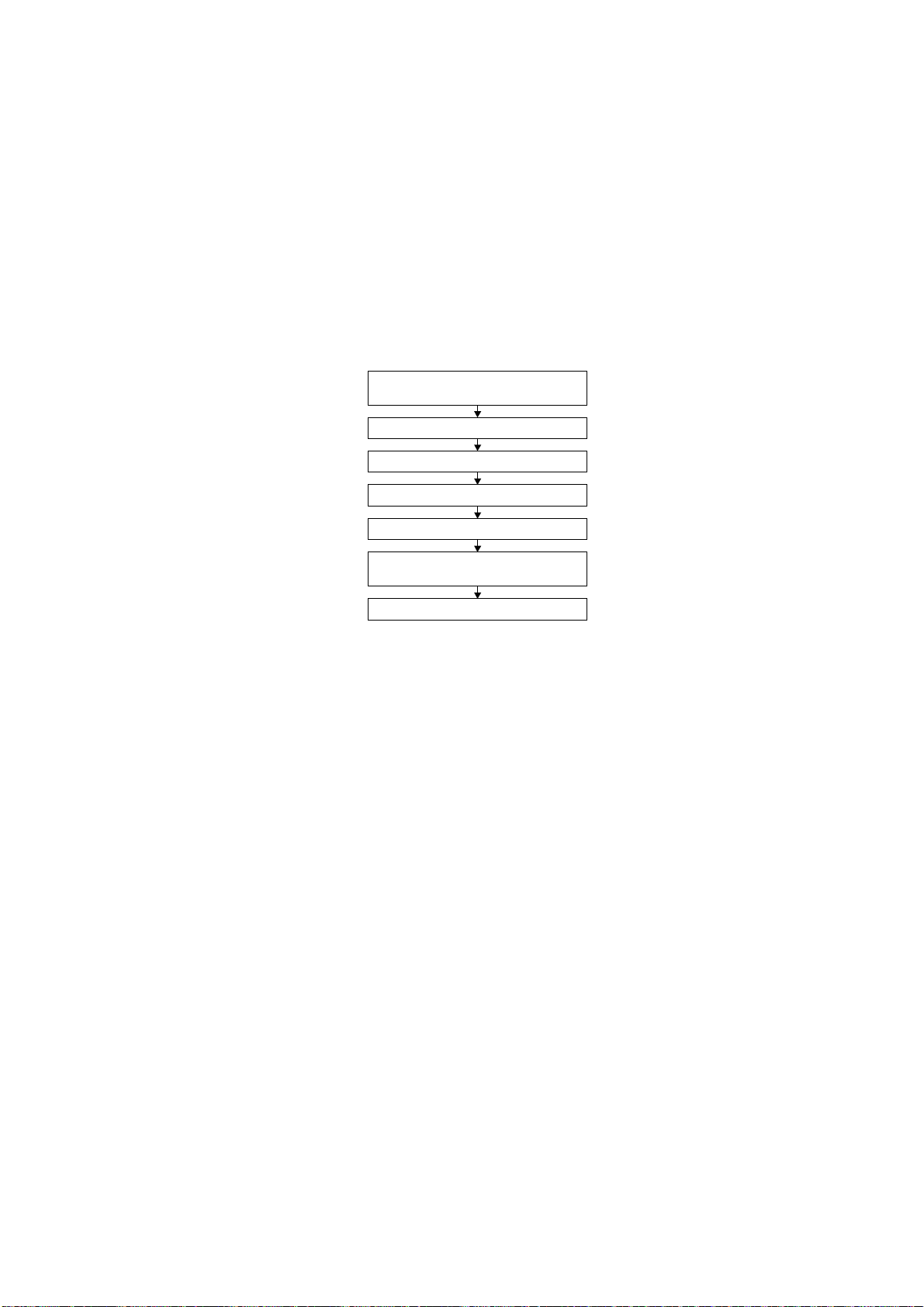
49
13. Operation Control
13.1 Basic Function
Inverter control, which equipped with a microcomputer in determining the most suitable operation mode as time
passes, automatically adjusts output power for maximum comfort always. In order to achieve the suitable operation
mode, the microcomputer maintains the set temperature by measuring the temperature of the environment and
performing temperature shifting. The compressor at outdoor unit is operating following the frequency instructed by
the microcomputer at indoor unit that judging the condition according to internal setting temperature and intake air
temperature.
13.1.1 Internal Setting Temperature
Once the operation starts, remote control setting temperature will be taken as base value for temperature shifting
processes. These shifting processes are depending on the air conditioner settings and the operation environment.
The final shifted value will be used as internal setting temperature and it is updated continuously whenever the
electrical power is supplied to the unit.
13.1.2 Cooling Operation
13.1.2.1 Thermostat control
Compressor is OFF when intake Air Temperature - Internal Setting Temperature < 2.7°F.
Compressor is ON after waiting for 3 minutes, if the Intake Temperature - Internal Setting Temperature >
Compressor OFF point.
13.1.3 Soft Dry Operation
13.1.3.1 Thermostat control
Compressor is OFF when Intake Temperature - Internal Setting Temperature < -3.6°F.
Compressor is ON after waiting for 3 minutes, if the Intake Air Temperature - Internal Setting Temperature >
Compressor OFF point.
13.1.4 Heating Operation
13.1.4.1 Thermostat control
Compressor is OFF when Intake Temperature - Internal Setting Temperature > 3.6°F.
Compressor is ON after waiting for 3 minutes, if the Intake Air Temperature - Internal Setting Temperature <
Compressor OFF point
Remote Control Setting Temperature
60.8°F - 86°F
Setting Temperature Limit Checking
(Min: 60.8°F; Max 91.4°F)
Auto Operation Mode Shifting
Indoor Air Temperature Shifting
Outdoor Air Temperature Shifting
Powerful Mode Shifting
Internal Setting Temperature
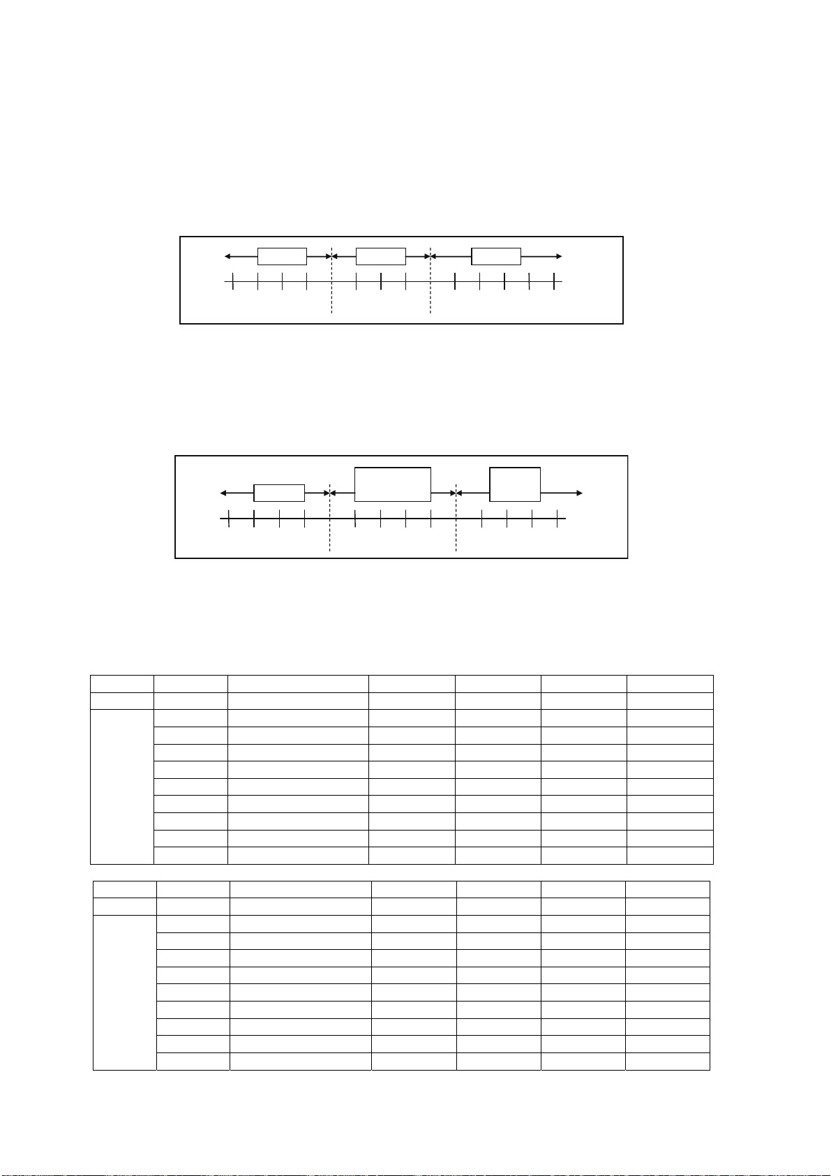
50
13.1.4.2 Automatic Operation (For Single Split Connection Only)
This mode can be set using remote control and the operation is decided by remote control setting temperature,
remote control operation mode and indoor intake air temperature.
During operation mode judgment, indoor fan motor (with speed of Lo-) is running for 30 seconds to detect the
indoor intake air temperature.
Every 10 minutes, the indoor temperature is judged.
For the 1st judgment
o If indoor intake temperature - remote control setting temperature 3.6°F, COOL mode is decided.
o If -3.6°F ≤ indoor intake temperature - remote control setting temperature < 3.6°F, DRY mode is decided.
o If indoor intake temperature - remote control setting temperature < -3.6°F , HEAT mode is decided.
For the 2nd judgment onwards
o If indoor intake temperature - remote control setting temperature 5.4°F, if previous operate in DRY mode,
then continue in DRY mode. otherwise COOL mode is decided.
o If -3.6°F ≤ indoor intake temperature - remote control setting temperature < 5.4°F, maintain with previous
mode.
o If indoor intake temperature - remote control setting temperature < -3.6°F, HEAT mode is decided.
13.2 Indoor Fan Speed Control
Indoor Fan Speed can be set using remote control.
13.2.1 Fan Speed Rotation Chart
E9RKUAW E12RKUAW E18RKUAW E24RKUAW
Mode Fan Tap Application rpm rpm rpm rpm
COOL
SHi Pwr Me+ 1210 1350 1480 1500
Hi Fc, RC 1120 1230 1380 1400
Me+ RC 1010 1110 1300 1320
Me RC 910 1000 1220 1240
Me- RC 810 890 1140 1160
Lo Fcmin, RC 710 780 1060 1090
Lo- QuietLo 610 620 970 1000
SLo Dry 550 560 690 690
SSLo Auto Cut 540 550 580 580
E9RKUAW E12RKUAW E18RKUAW E24RKUAW
Mode Fan Tap Application rpm rpm rpm rpm
HEAT
SSHi Pwr Me+ 1340 1450 1500 1600
SHi Fh, RC 1250 1380 1410 1500
Me+ RC 1140 1290 1330 1430
Me RC 1040 1210 1260 1360
Me- RC 930 1120 1190 1290
Lo Fhmin, RC 830 1040 1120 1220
Lo- QuietLo 730 940 1030 1110
SLo Thermo Off, Hot start 570 570 430 430
SSLo Thermo Off 560 560 330 330
-10.8 -9.0 -7.2 -5.4 -3.6 -1.8 1.8 3.6 5.4 7.2 9.0 10.80
Heat Dr
y
Cool
-10.8 -9.0 -7.2 -5.4 -3.6 -1.8 1.8 3.6 5.4 7.2 9.0 10.80
Heat
Maintain
current mode
Cool
/Dry
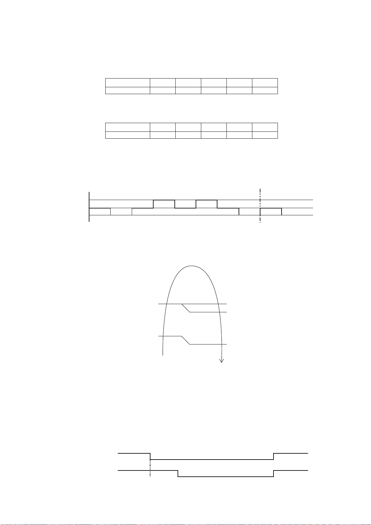
51
13.3 Indoor Fan Motor Operation
13.3.1 Basic Rotation Speed (rpm)
Manual Fan Speed
[Cooling, Dry]
o Fan motor’s number of rotation is determined according to remote control setting.
Remote control ○ ○ ○ ○ ○
Tab Hi Me+ Me Me- Lo
[Heating]
o Fan motor’s number of rotation is determined according to remote control setting.
Remote control ○ ○ ○ ○ ○
Tab Shi Me+ Me Me- Lo
Auto Fan Speed
[Cooling, Dry]
o According to room temperature and setting temperature, indoor fan speed is determined automatically.
o The indoor fan will operate according to pattern below.
o During operation, indoor fan motor may stop due to odor prevention.
[Heating]
o According to indoor pipe temperature, automatic heating fan speed is determined as follows.
Feedback control
o Immediately after the fan motor started, feedback control is performed once every second.
o During fan motor on, if fan motor feedback ≥ 2550 rpm or < 50 rpm continue for 10 seconds, then fan motor
error counter increase, fan motor is then stop and restart. If the fan motor counter becomes 7 times, then
H19 - fan motor error is detected. Operation stops and cannot on back.
13.4 Outdoor Fan Motor Operation
Outdoor fan motor is operated with fan speed number of rotation. It starts when compressor starts operation and it
stops 30 seconds after compressor stops operation.
ON ON
Compressor OFF
ON Fan Speed ON
Outdoor Fan 30 sec OFF
abc def gh
[1 pattern : 10 s]
ab
H
igher
F
an
S
peed
M
edium
Lower
RPM Increased
RPM Maintain
RPM Reduced
OFF
Indoor Pipe Temp.
95
o
C
102.2
o
F
60.8
o
F
66.2
o
F
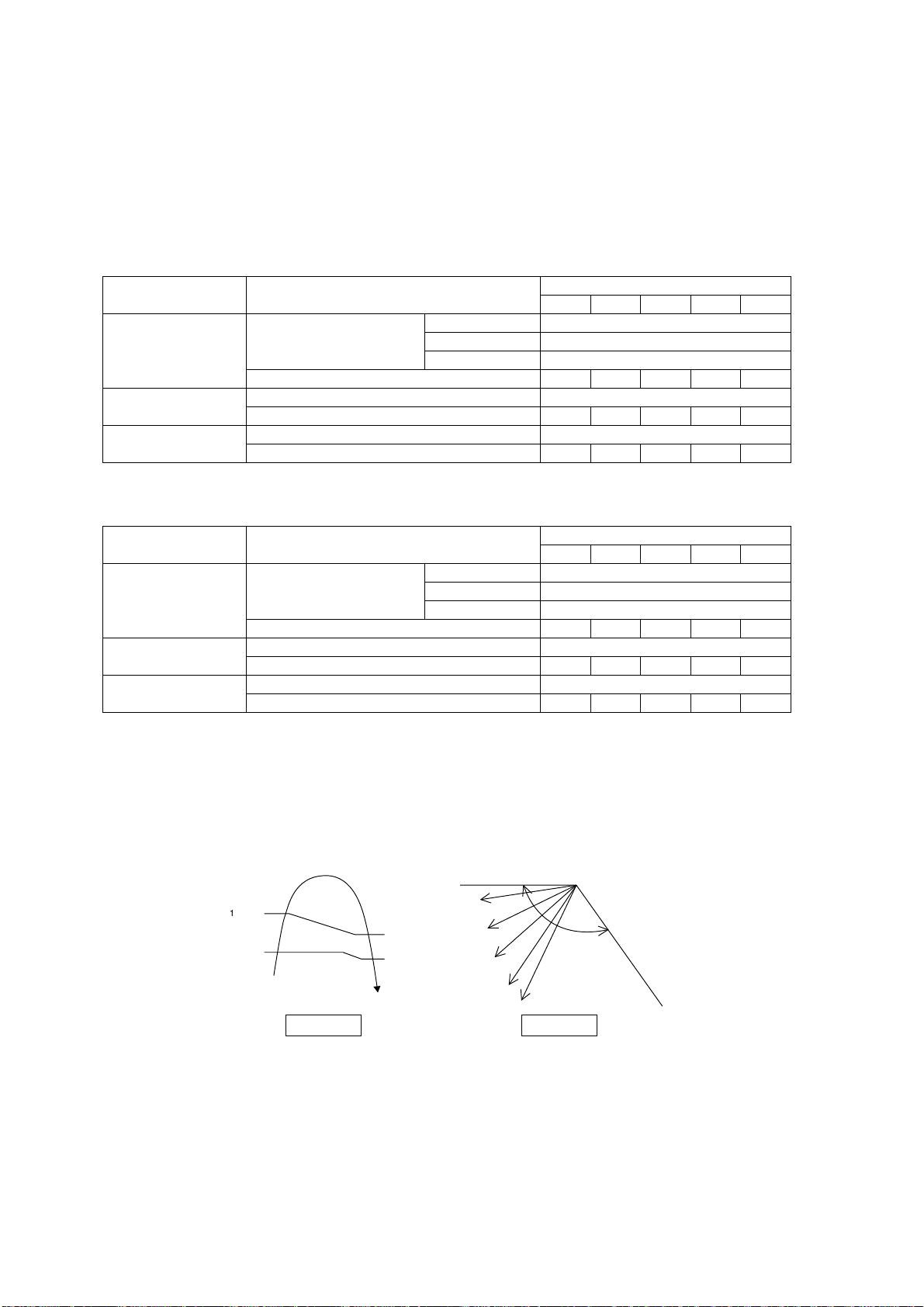
52
13.5 Airflow Direction
There are two types of airflow, vertical airflow (directed by horizontal vane) and horizontal airflow (directed by
vertical vanes).
Control of airflow direction can be automatic (angles of direction is determined by operation mode, heat
exchanger temperature and intake air temperature) and manual (angles of direction can be adjusted using
remote control).
13.5.1 Vertical Airflow
13.5.1.1 CU-E9RKUA CU-E12RKUA
Operation Mode Airflow Direction
Vane angle (°)
1 2 3 4 5
Heating
Auto with Heat Exchanger
Temperature
A 20
B 57
C 32
Manual 20 32 45 57 68
Cooling
Auto 20 ~ 45
Manual 20 26 32 37 45
Soft Dry
Auto 20 ~ 45
Manual 20 26 32 37 45
13.5.1.2 CU-E18RKUA CU-E24RKUA
Operation Mode Airflow Direction
Vane angle (°)
1 2 3 4 5
Heating
Auto with Heat Exchanger
Temperature
A 20
B 45
C 32
Manual 20 32 45 57 68
Cooling
Auto 20 ~ 45
Manual 20 26 32 37 45
Soft Dry
Auto (Anti-Dew Control) 20 ~ 45
Manual (Anti-Dew Control) 20 26 32 37 45
Automatic vertical airflow direction can be set using remote control; the vane swings up and down within the
angles as stated above. For heating mode operation, the angle of the vane depends on the indoor heat
exchanger temperature as Figure 1 below. When the air conditioner is stopped using remote control, the vane
will shift to close position.
Manual vertical airflow direction can be set using remote control; the angles of the vane are as stated above and
the positions of the vane are as Figure 2 below. When the air conditioner is stopped using remote control, the
vane will shift to close position.
13.5.2 Horizontal Airflow (CU-E9RKUA CU-E12RKUA)
The horizontal airflow direction louvers can be adjusted manually by hand.
140°
Close position
0
°
122°F
86°F
96.8°F
1
36.4°F
C
B
A
Indoor Heat Exchanger
Temperature
1
2
3
4
5
Side View
Figure 2Figure 1
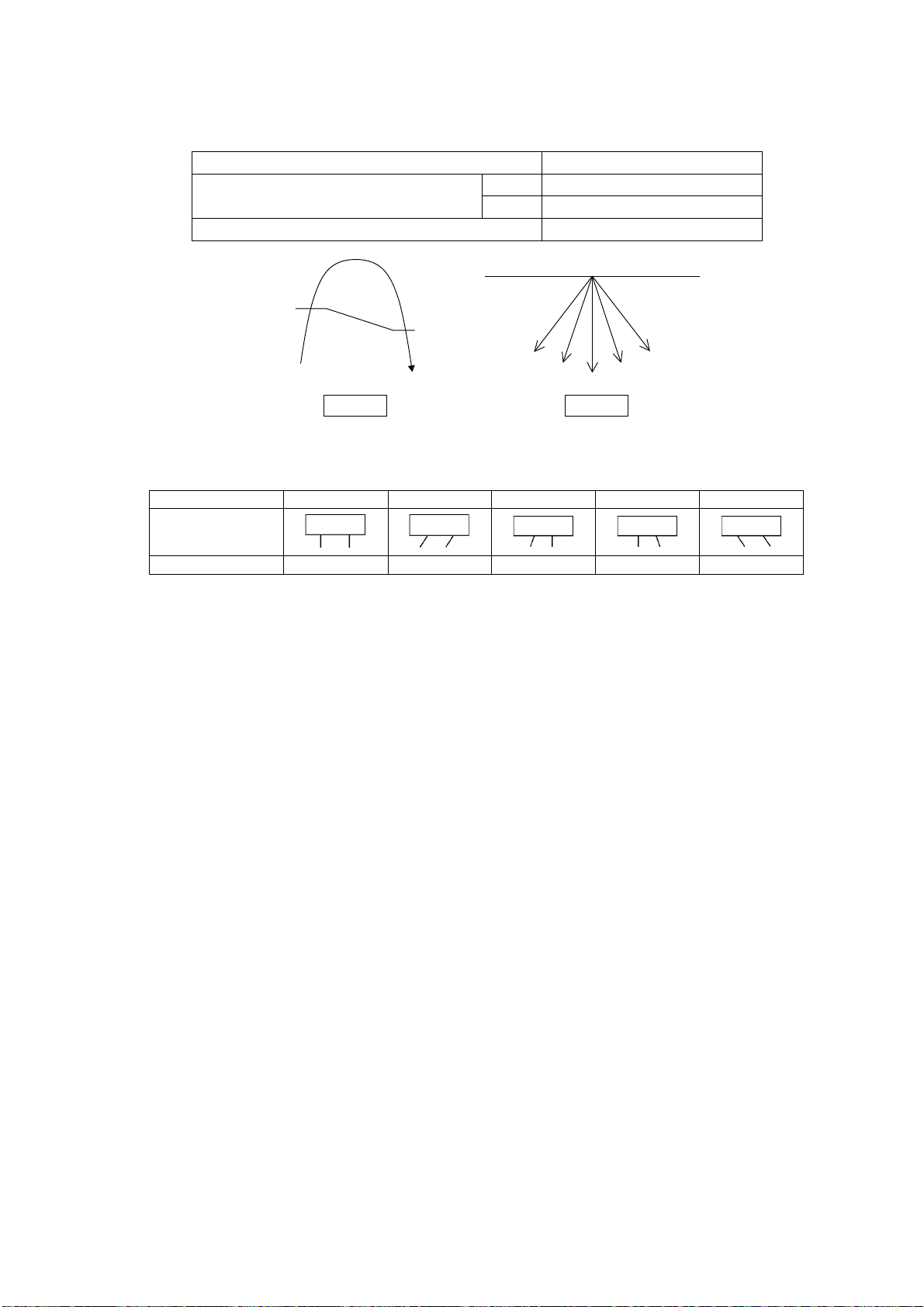
53
13.5.3 Horizontal Airflow (CU-E18RKUA CU-E24RKUA)
Automatic horizontal airflow direction can be set using remote control; the vane swings left and right within the
angles as stated below. For heating mode operation, the angle of the vane depends on the indoor heat
exchanger temperature as Figure 1 below.
Operation Mode Vane Angle (°)
Heating with heat exchanger temperature
A 68 ~ 112
B 90
Cooling and Soft Sry 68 ~ 112
Manual vertical airflow direction can be set using remote control; the angles of the vane are as stated below and
the positions of the vane are as figure below:
13.6 Quiet Operation (Cooling Mode/Cooling Area of Dry Mode)
Purpose
o To provide quiet cooling operation compare to normal operation.
Control condition
o Quiet operation start condition
When “Quiet” button at remote control is pressed.
Quiet LED illuminates.
o Quiet operation stop condition
When one of the following conditions is satisfied, quiet operation stops:
POWERFUL/QUIET button is pressed.
Stop by OFF/ON button.
OFF Timer activates.
POWERFUL/QUIET button is pressed again.
When quiet operation is stopped, operation is shifted to normal operation with previous setting.
When fan speed is changed, quiet operation is shifted to quiet operation of the new fan speed.
When operation mode is changed, quiet operation is shifted to quiet operation of the new mode.
During quiet operation, if ON timer activates, quiet operation maintains.
After off, when on back, quiet operation is not memorised.
Control contents
o Auto fan speed is change from normal setting to quiet setting of respective fan speed. This is to reduce
sound of Hi, Me, Lo for 3dB.
o Manual fan speed for quiet operation is -1 step from setting fan speed.
Indoor Heat Exchanger
Temperature
109.4°F
104.0°F
A: swing
B: fix front
0°
To p Vi e w
5
4
3
Figure 2
2
1
Figure 1
54321nrettaP
Airflow Direction
Patterns at Remote
Control
Vane Angle (° ) 90 68 78 102 112

54
13.7 Quiet Operation (Heating)
Purpose
o To provide quiet heating operation compare to normal operation.
Control condition
o Quiet operation start condition
When “POWERFUL/QUIET” button at remote control is pressed.
Quiet LED illuminates.
o Quiet operation stop condition
When one of the following conditions is satisfied, quiet operation stops:
Stop by OFF/ON button.
Timer “off” activates.
POWERFUL/QUIET button is pressed again.
When quiet operation is stopped, operation is shifted to normal operation with previous setting.
When fan speed is changed, quiet operation is shifted to quiet operation of the new fan speed.
When operation mode is changed, quiet operation is shifted to quiet operation of the new mode.
During quiet operation, if timer “on” activates, quiet operation maintains.
After off, when on back, quiet operation is not memorised.
Control contents
o Fan speed auto
Indoor FM RPM depends on pipe temperature sensor of indoor heat exchanger. Auto fan speed is
changed from normal setting to quiet setting of respective fan speed. This is to reduce sound of Hi, Me,
Lo for 3dB.
o Fan speed manual
Manual fan speed for quiet operation is -1 step from setting fan speed.
13.8 Powerful Mode Operation
When the powerful mode is selected, the internal setting temperature will shift lower up to 3.6°F (for Cooling/Soft
Dry) or higher up to 6.3°F (for Heating) than remote control setting temperature for 20 minutes to achieve the
setting temperature quickly.
13.9 Timer Control
13.9.1 ON Timer Control
ON Timer can be set using remote control, where the unit with timer set will start operation earlier than the setting
time. This is to provide a comfortable environment when reaching the set ON time.
60 minutes before the set ON time, indoor (at fan speed of Lo-) and outdoor fan motor start operation for 30
seconds to determine the indoor intake air temperature and outdoor air temperature in order to judge the
operation starting time.
From the above judgment, the decided operation will start operation earlier than the set time as shown below.
13.9.2 OFF Timer Control
OFF Timer can be set using remote control, the unit with timer set will stop at set time.
In
d
oo
r
int
a
k
e
a
i
r
temperature (
o
F)
Outdoor air
temperature (
o
F)
86
86 95
Cooling/Soft Dry
(
o
F)
10 min
15 min
5min
77
In
d
oo
r
int
a
k
e
a
i
r
temperature (
o
F)
Outdoor air
temperature (
o
F)
59
32 41
Heating
(
o
F)
30 min
25 min
35 min
41
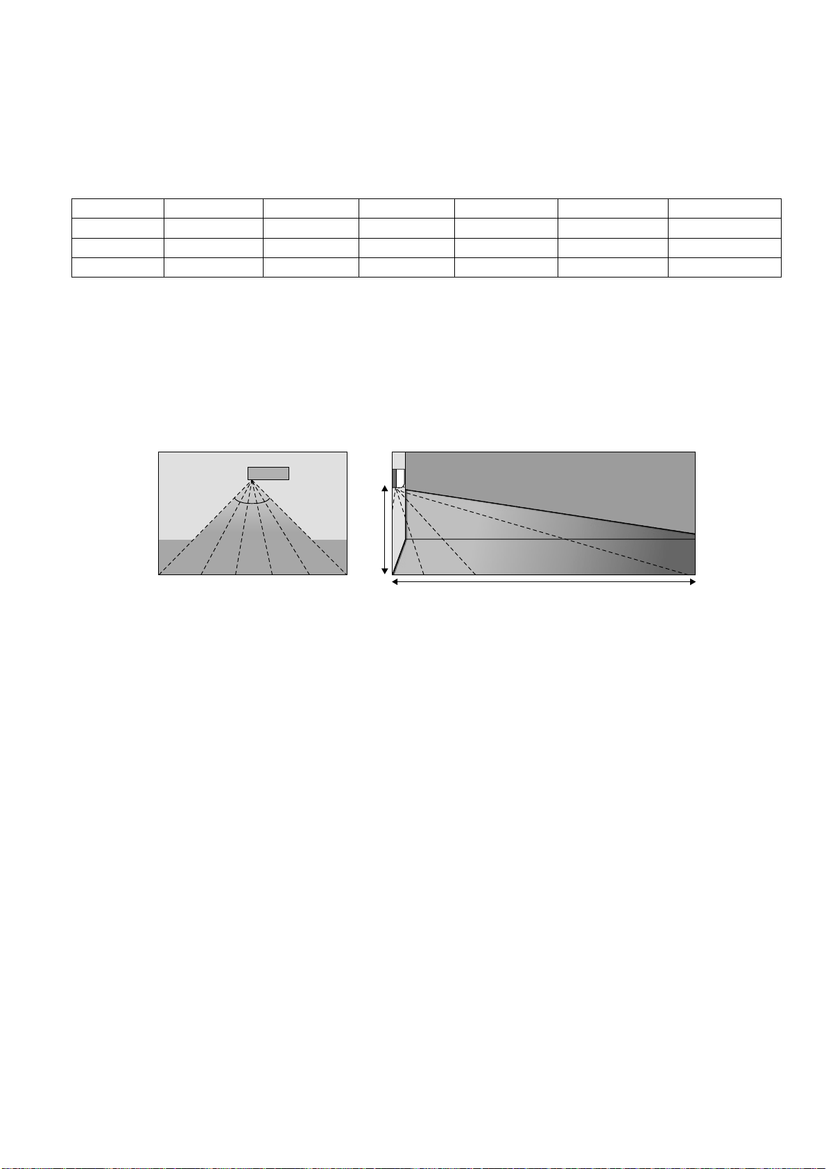
55
13.10 Auto Restart Control
When the power supply is cut off during the operation of air conditioner, the compressor will re-operate within
three to four minutes (there are 10 patterns between 2 minutes 58 seconds and 3 minutes 52 seconds to be
selected randomly) after power supply resumes.
This type of control is not applicable during ON/OFF Timer setting.
13.11 Indication Panel
LED POWER TIMER QUIET POWERFUL AUTO COMFORT ECONAVI
Color Green Orange Orange Orange Green Green
Light ON Operation ON Timer Setting ON Quiet Mode ON Powerful Mode ON Auto Comfort ON Econavi Mode ON
Light OFF Operation OFF Timer Setting OFF Quiet Mode OFF Powerful Mode OFF Auto Comfort OFF Econavi Mode OFF
Note:
If POWER LED is blinking, the possible operation of the unit are Hot Start, during Deice operation, operation
mode judgment, or ON timer sampling.
If Timer LED is blinking, there is an abnormality operation occurs.
13.12 ECONAVI and AUTO COMFORT Operation
A Pyoelectric infrared sensor is used to detect injection strength variation of infrared at setting area to determine
the presence or absence of human and its activity level. Human detection area is shown in figure below:
ECONAVI and AUTO COMFORT operation – Human presence/absence detection outlined flow
Process infrared sensor output signal
Human detection (movement) every 3 seconds.
▼
Human detection records
Records human detection (movement) result for 30 seconds and determine its activity level i.e. Hi/Lo.
▼
Presence / absence detection
Compares current and previous human detection result every 30 seconds to determine the presence
or absence of human.
▼
Presence / absence determination
Based on human presence / absence detection, if human presence detection showed within
30 minutes, it is recognised that human is present. If human absence detection showed continuously
for more than 30 minutes, it is recognised that no human is present.
ECONAVI and AUTO COMFORT Sensor abnormality detection
1. Connector pulled out (disconnected), Wire cut Abnormality (Fix Output at Hi)
a. Abnormal judgment start condition.
Start from ECONAVI and AUTO COMFORT Sensor power ON, and end after 30 seconds.
b. Control content.
Judge ECONAVI and AUTO COMFORT Sensor power level every 100ms.
c. Abnormal Judgment condition.
When ECONAVI and AUTO COMFORT Sensor has continues for 25 seconds Hi level.
Top Vi e w
90°
Angle of detection
Area of detection
7m
2m
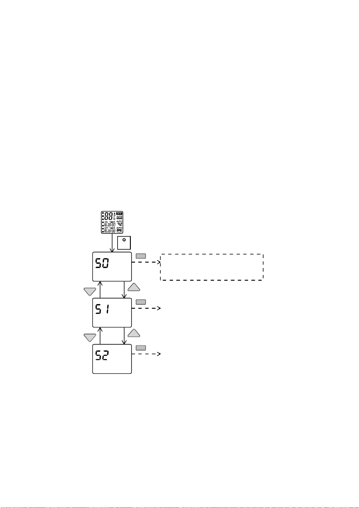
56
2. Circuit Abnormal (Fix Output Lo)
a. Abnormal judgment start condition.
After ECONAVI and AUTO COMFORT Sensor unit power ON, and after pressed 70 seconds.
b. Control content.
Judge ECONAVI and AUTO COMFORT Sensor power level every 100ms.
c. Abnormal Judgment condition.
When ECONAVI and AUTO COMFORT Sensor has continues at Lo level for 25 seconds.
3. Abnormal treatment
Any one of the above self-diagnosis result is abnormal
Abnormal counter +1 and ECONAVI and AUTO COMFORT Sensor power supply OFF.
After ECONAVI and AUTO COMFORT Sensor unit power is OFF for 5 seconds, Retry the ECONAVI and
AUTO COMFORT operation.
When Abnormal counter reach 4 counts, ECONAVI and AUTO COMFORT sensor abnormality is
confirmed.
(Abnormal counter is cleared when sensor power ON and maintain normal for 120 seconds and above or
Clear Abnormal counter by power reset)
Save ECONAVI and AUTO COMFORT Sensor Abnormality H59 (no Timer LED blinking).
ECONAVI & AUTO COMFORT Sensor operation OFF, but ECONAVI and AUTO COMFORT LED
maintain ON.
The unit still operate as normal.
Sensor error counter can be cleared only after power supply reset or AC Reset button on the remote
control is pressed.
ECONAVI and AUTO COMFORT Demo Mode
To enable ECO DEMO mode, during unit is OFF (power standby):
To disable ECO Demo MODE:
Transmit ECO Demo signal again.
Control details:
During ECONAVI and AUTO COMFORT Demo mode, operation LED ON and horizontal vane will set to Auto
Swing.
When Hi activity judge, Fan speed change to Hi Fan and ECONAVI and AUTO COMFORT LED ON.
When Lo activity judge, Fan speed change to Lo Fan and ECONAVI and AUTO COMFORT LED OFF.
No setting temperature adjustment.
During ECONAVI and AUTO COMFORT operation, the internal setting temperature and fan speed are adjusted
in order to provide comfort and energy saving.
SET
Press continously for 5s
Remote control normal mode
TEM P
TEMP
SET
TEM P
TEMP
SET
SET
Transmit ECO demo code
and after 30 seconds return to normal
mode.
Transmit sunlight sensor check code
and after 30 seconds return to normal
mode.
Transmit check code
and after 30 seconds return to normal
mode.
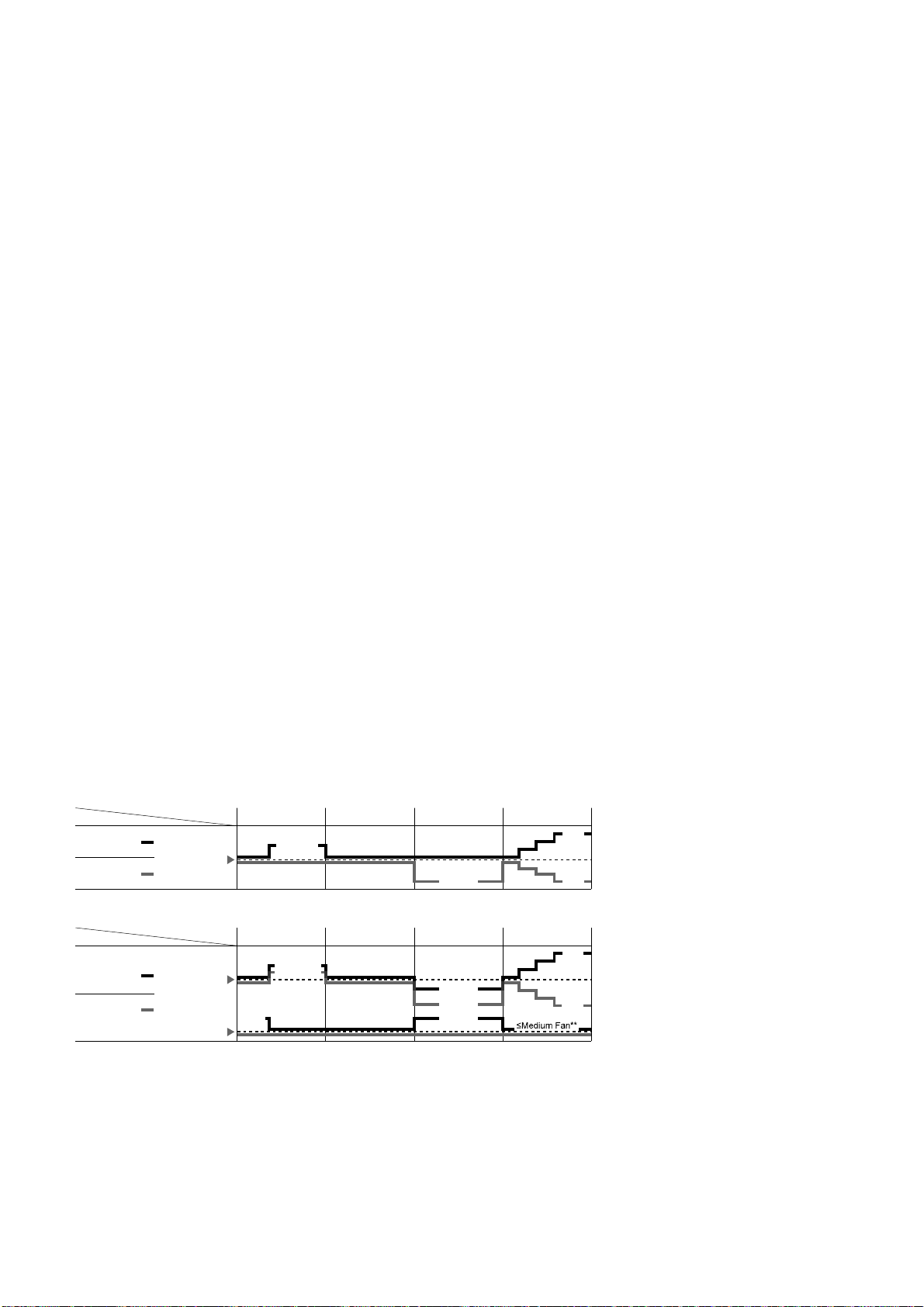
57
ECONAVI Start condition.
Press ECONAVI button.
ECONAVI Stop condition.
Press ECONAVI button again.
OFF Timer activates.
Press OFF/ON button to turn off the air conditioner.
Press AUTO OFF/ON button to turn off the air conditioner.
Press POWERFUL/QUIET button.
AUTO COMFORT Start condition.
Press AUTO COMFORT button.
AUTO COMFORT Stop condition.
Press AUTO COMFORT button again.
OFF Timer activates.
Press OFF/ON button to turn off the air conditioner.
Press AUTO OFF/ON button to turn off the air conditioner.
Press POWERFUL/QUIET button.
ECONAVI and AUTO COMFORT operation could ON when any of the following conditions is fulfilled:
During forced cooling or forced heating operation.
Power Failure
ECONAVI and AUTO COMFORT operation will be resuming after recovered from power failure.
Timer Operation
When unit is turn on by ON Timer and ECONAVI and AUTO COMFORT operation is ON during previous
operation before OFF, ECONAVI and AUTO COMFORT operation will not be ON automatically.
When unit is turn on by ON Timer and ECONAVI and AUTO COMFORT operation is OFF during
previous operation before OFF, ECONAVI and AUTO COMFORT operation will not be ON automatically.
Other Information
ECONAVI and AUTO COMFORT, Powerful, Quiet and Mild Dry Cooling cannot be operated at the same
time.
ECONAVI and AUTO COMFORT sensor initialized time is 70 seconds from power supplied to ECONAVI
and AUTO COMFORT sensor, or 70 seconds from the operation start.
Setting Temperature and Fan Speed Shift
Mono Sensor
Low activity Normal activity
Human
Mode
Set
temperature
High activity Absent
ECONA
V
I ; Detecting human presence and activity, the unit controls room temperature to save energy.
Low activity Normal activity
Human
Mode
Set
temperature
High activity Absent
Set
Fan Speed
AUTO COMFORT ; Detecting human presence and activity, the unit controls room temperature to keep human
comfortable consistently.
HEAT
COOL/DRY
HEAT
COOL/DRY
* During low activity, fan speed 1 tap up for first 15 minutes or until set temperature is reached.
** During human absence, maximum fan speed for COOL/DRY mode is medium fan.
+1 tap
+1 tap*
+2°F / +1°C
+2°F / +1°C
+0.5°F / +0.3°C
-2°F / -1°C
-4°F / -2°C
+4°F /
+2°C
-4°F /
-2°C
-4°F / -2°C
+4°F /
+2°C
-4°F /
-2°C
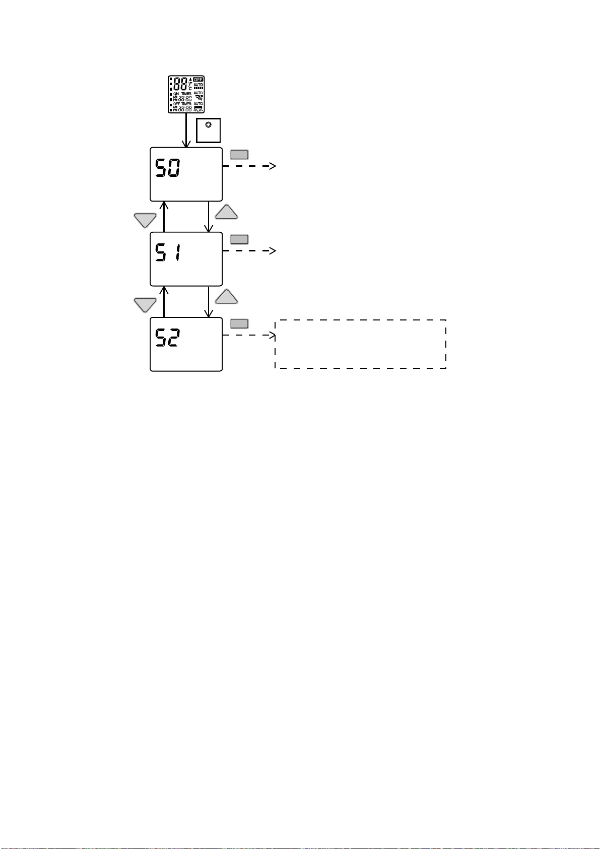
58
13.12.1 Human Activity Sensor Check Mode
To enable Human Activity sensor abnormality check mode, during ECONAVI operation ON:
During ECONAVI is ON, when CHECK signal received, if either sensors has abnormality, the 4 times abnormality
counter is ignored, ECONAVI Indicator will blink immediately and error code is memorized.
The unit could operate without ECONAVI or AUTO COMFORT.
The ECONAVI indicator blinking could be cancelled by pressing ECONAVI button again.
If the human activity sensor has no abnormality, the CHECK process will end and continue with normal operation.
SET
Press continously for 5s
Remote control normal mode
TEMP
TEMP
SET
TEMP
TEMP
SET
SET
Transmit ECO demo code
and after 30 seconds return to normal
mode.
Transmit sunlight sensor check code
and after 30 seconds return to normal
mode.
Transmit check code
and after 30 seconds return to normal
mode.

59
14. Operation Control (For Multi Split Connection)
During multi split connection, indoor unit’s operation controls are same with single split connection unless specified in
this chapter.
14.1 Cooling operation
14.1.1 Thermostat control
Capability supply to indoor unit is OFF (Expansion valve closed) when Intake Air Temperature — Internal setting
temperature < 28.4°F.
Capability resume supply to indoor unit after waiting for 3 minutes, if the Intake Air temperature — Internal setting
temperature > Capability supply OFF point.
14.2 Soft Dry Operation
14.2.1 Thermostat control
Capability supply to indoor unit is OFF (Expansion valve closed) when Intake Air Temperature — Internal setting
temperature < 26.6°F.
Capability resume to indoor unit after waiting for 3 minutes, if the Intake Air temperature — Internal setting
temperature > Capability supply OFF point.
14.3 Heating Operation
14.3.1 Thermostat control
Capability supply to indoor unit is OFF (Expansion valve closed) when Intake Air Temperature — Internal setting
temperature > 33.8°F.
During this condition, the indoor fan is stopped if compressor is ON.
Capability resume supply to indoor unit after waiting for 3 minutes, if the Intake Air Temperature — Internal
setting temperature < Capability supply OFF point.
14.3.2 Temperature Sampling Control
Temperature sampling is controlled by outdoor unit where room temperature for all power supply ON indoor unit
could be obtained.
When capability supply to the indoor unit is OFF and the compressor is ON during heating operation, the indoor
fan motor is stopped. During this condition, 15 seconds after sampling signal from outdoor unit is received, the
indoor fan start operation at low fan speed.
However, within first 4 minutes of capability stopped supply to the indoor unit, even sampling signal is received,
the sampling control is cancelled.
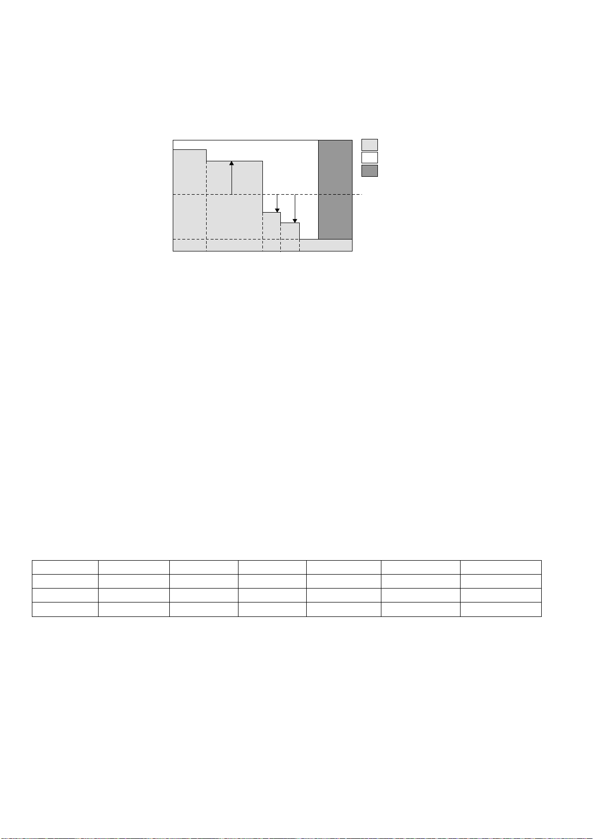
60
14.4 Automatic Operation (For Multi Split Connection Only)
This mode can be set using remote control and the operation is decided by remote control setting temperature,
remote control operation mode, indoor intake and outdoor air temperature.
During operation mode judgment, indoor fan motor (with speed of -Lo) and outdoor fan motor are running for
30 seconds to detect the indoor intake and outdoor air temperature. The operation mode is decided based on
below chart.
Every 180 minutes, the indoor and outdoor temperature is judge. Based on remote control setting temperature,
the value of T1 will increase up to 50°F, T2 will decrease by 37.4°F and T3 will decrease up to 46.4°F.
14.5 Indoor Fan Motor Operation
14.5.1 Residual Heat Removal Control
To prevent high pressure at indoor unit, when heating mode thermostat-off condition or power supply OFF,
indoor fan continue to operate at controlled fan speed for maximum 30 seconds then stop.
14.6 Powerful Mode Operation
When the power mode is selected, the internal setting temperature will shift lower up to 39.2F for Cooling/Soft
Dry or higher up to 42.8°F for heating than remote control setting temperature, the powerful operation continue
until user cancel the Powerful operation by pressing powerful button again.
14.7 Auto restart control
When the power supply is cut off during the operation of air conditioner, the compressor will re-operate between
three to four minutes (10 patterns to be selected randomly) after power resume.
During multi split connection, Indoor unit will resume previous mode, include unit standby mode.
14.8 Indication Panel
LED POWER TIMER QUIET POWERFUL AUTO COMFORT ECONAVI
Color Green Orange Orange Orange Green Green
Light ON Operation ON Timer Setting ON Quiet Mode ON Powerful Mode ON Auto Comfort ON Econavi Mode ON
Light OFF Operation OFF Timer Setting OFF Quiet Mode OFF Powerful Mode OFF Auto Comfort OFF Econavi Mode OFF
Note:
If POWER LED is blinking (0.5 second ON, 0.5 second OFF), the possible operation of the unit are during Indoor
Residual Heat Removal, Hot Start, during Deice operation, operation mode judgment, or ON timer sampling.
If POWER LED is blinking (2.5 seconds ON, 0.5 second OFF), the unit is in standby mode.
If TIMER LED is blinking, there is an abnormality operation occurs.
Indoor intake air
temperature (F)
Heating Mode
Soft Dry Mode
Cooling Mode
Remote Control
setting temperature
T1
T2
T3
96.8
60.8
66.255.4 69.8 73.4 77
Outdoor air
temperature (F)
61
15. Protection Control (E9RK and E12RK)
15.1 Protection Control For All Operations
15.1.1 Restart Control (Time Delay Safety Control)
The compressor will not turn on within 3 minutes from the moment operation stops, although the unit is turned on
again by pressing OFF/ON button at remote control within this period.
This control is not applicable if the power supply is cut off and on again.
This phenomenon is to balance the pressure inside the refrigerant cycle.
15.1.2 30 Seconds Forced Operation
Once the air conditioner is turned on, the compressor will not stop within 30 seconds in a normal operation
although the intake air temperature has reached the thermo-off temperature. However, force stop by pressing the
OFF/ON button at the remote control is permitted or the Auto OFF/ON button at indoor unit.
The reason for the compressor to force operation for minimum 30 seconds is to allow the refrigerant oil run in a
full cycle and return back to the outdoor unit.
15.1.3 Total Running Current Control
When the outdoor unit total running current (AC) exceeds X value, the frequency instructed for compressor
operation will be decreased.
If the running current does not exceed X value for 5 seconds, the frequency instructed will be increased.
However, if total outdoor unit running current exceeds Y value, compressor will be stopped immediately for
3 minutes.
Model E9RKUA E12RKUA
Cool (X)
A 3.89 A 6.55 A
B 3.28 A 6.10 A
C 3.28 A 6.10 A
Heat (X) 5.27 A 7.05 A
Y 15.01 A 15.01 A
1. The first 30 minutes of cooling operation, (A) will be applied.
15.1.4 IPM (Power Transistor) Prevention Control
Overheating Prevention Control
o When the IPM temperature rises to 212°F, compressor operation will stop immediately.
o Compressor operation restarts after 3 minutes the temperature decreases to 203°F.
o If this condition repeats continuously 4 times within 20 minutes, timer LED will be blinking (“F96” is indicated).
DC Peak Current Control
o When electric current to IPM exceeds set value of 18.5A, the compressor will stop operate. Then, operation
will restart after 3 minutes.
o If the set value exceeds again more than 30 seconds after the compressor starts, the operation will restart
after 2 minutes.
o If the set value exceeds again within 30 seconds after the compressor starts, the operation will restart after
1 minute. If this condition repeats continuously for 7 times, all indoor and outdoor relays will be cut off, timer
LED will be blinking (“F99” is indicated).
Outdoor Intake temperature
Outdoor Intake temperature
A
B
C
109.4°F
107.6°F
100.4°F
102.2°F
62
15.1.5 Compressor Overheating Prevention Control
Instructed frequency for compressor operation will be regulated by compressor discharge temperature. The
changes of frequency are as below.
If compressor discharge temperature exceeds 224.6°F, compressor will be stopped, occurs 4 times per
20 minutes, timer LED will be blinking. (“F97” is indicated.)
15.1.6 Low Pressure Prevention Control (Gas Leakage Detection)
Control start conditions
o For 5 minutes, the compressor continuously operates and outdoor total current is between 0.64A and 0.85A.
o During Cooling and Soft Dry operations:
Indoor suction temperature - indoor piping temperature is below 7.2.°F.
o During Heating operations:
Indoor piping temperature - indoor suction is under 9°F.
Control contents
o Compressor stops (and restart after 3 minutes).
o If the conditions above happen 2 times within 20 minutes, the unit will:
Stop operation
Timer LED blinks and “F91” indicated.
15.1.7 Low Frequency Protection Control 1
When the compressor operates at frequency lower than 24Hz continued for 240 minutes, the operation frequency
will be changed to 25Hz for 2 minutes.
15.1.8 Low Frequency Protection Control 2
When all below conditions comply, minimum limit of compressor will be set.
Temperature, T, for: Cooling / Soft Dry Heating
Indoor intake air (°F) T < 57.2 or T ≥ 86 -
Outdoor air (°F) T < 55.4 or T ≥ 100.4 T < 57.2 or T ≥ 82.4
Indoor heat exchanger (°F) T < 86 T ≥ 32
Compressor = OFF
Compressor Frequency
Reduce
Compressor Frequency
Maintain
Free
224.6
o
F
217.4
o
F
212
o
F
197.6
o
F
195.8
o
F
194
o
F
C
omp. Discharge temperature
63
15.2 Protection Control For Cooling & Soft Dry Operation
15.2.1 Outdoor Air Temperature Control
The maximum current value is regulated when the outdoor air temperature rise above 57.2°F in order to avoid
compressor overloading.
The compressor will be stopped at outdoor air temperature ≤ -4°F. The unit still operate within the temperature
range.
15.2.2 Cooling Overload Control
Pipe temperature limitation / restriction.
o Detects the outdoor pipe temperature and carry out restriction / limitation below (Limit the compressor
operation frequency)
o The compressor stops if outdoor pipe temperature exceeds 141.8°F.
o If the compressor stops 4 times in 20 minutes, Timer LED blinks (“F95” indicated: Outdoor high pressure rise
protection)
15.2.3 Freeze Prevention Control 1
When indoor heat exchanger temperature is lower than 32°F continuously for 6 minutes, compressor will stops
operation.
Compressor will resume its operation 3 minutes after the indoor heat exchanger is higher than 41°F.
At the same time, indoor fan speed will be higher than during its normal operation.
If the indoor heat exchanger temperature is higher than 55.4°F for 5 minutes, the fan speed will return to its
normal operation.
15.2.4 Freeze Prevention Control 2
Control start conditions
o During Cooling operation and soft dry operation
During thermo OFF condition, indoor intake temperature is less than 50°F or
Compressor stops for freeze prevention control
o Either one of the conditions above occurs 5 times in 60 minutes.
Control contents
o Operation stops
o Timer LED blinks and “H99” indicated
101.3°F
99.5°F
Compressor OFF
Compressor ON
Outdoor Air Temperature
-0.4°F
-4°F
Compressor OFF
Compressor ON
O
utdoor Air Temperature
64
15.2.5 Dew Prevention Control 1
To prevent dew formation at indoor unit discharge area.
This control will be activated if:
o Outdoor air temperature and Indoor pipe temperature judgment by microcontroller is fulfilled.
o When Cooling or Dry mode is operated more than 20 minutes or more.
This control stopped if:
o Compressor stopped.
o Remote control setting changed (fan speed / temperature).
o Outdoor air temperature and indoor intake temperature changed.
Fan speed, angle of louver (vertical airflow angle) will be adjusted accordingly in this control.
1. Fan speed will be increased slowly when control is activated until predetermine value.
Compressor frequency will be regulated accordingly.
15.2.6 Protection Control For Heating Operation
15.2.6.1 Intake Air Temperature Control
Compressor will operate at limited freq., if indoor intake air temperature is 86°F or above.
15.2.6.2 Outdoor Air Temperature Control
The maximum current value is regulated when the outdoor air temperature rise above 57.2°F in order to avoid
compressor overloading.
The compressor will be stopped at outdoor air temperature ≤ -4°F. The unit still operate within the temperature
range.
57.2°F
52.6°F
Free withing maximum limit
Current Regulated
O
utdoor Air Temperature
-0.4°F
-4°F
Compressor OFF
Compressor ON
O
utdoor Air Temperature
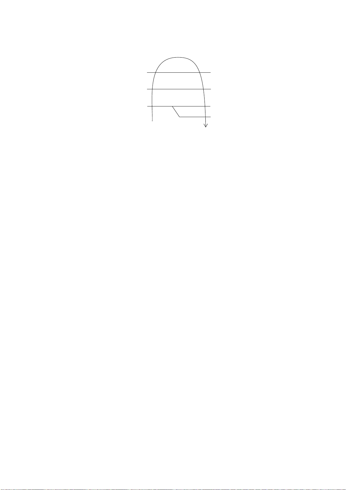
65
15.2.6.3 Overload Protection Control
The compressor operating frequency is regulated in accordance to indoor heat exchanger temperature as shown
below.
If the heat exchanger temperature exceeds 140.0°F, compressor will stop.
15.2.6.4 Low Temperature Compressor Oil Return Control
In heating operation, if the outdoor temperature falls below 14°F when compressor starts, the compressor
frequency will be regulated up to 600 seconds.
15.2.6.5 Cold Draught Prevention Control
When indoor pipe temperature is low, cold draught operation starts where indoor fan speed will be reduced or
stop.
Horizontal vane angle may be adjusted in Auto vane setting.
15.2.6.6 Deice Operation
When outdoor pipe temperature and outdoor air temperature is low, deice operation start where indoor fan motor
and outdoor fan motor stop and operation LED blinks. Horizontal vane is closed during auto vane setting.
OFF
Frequency Reduced
Frequency Limited
Frequency
Limited
Free
Indoor Heat
Exchanger Temp.
140°F
114.8°F
131°F
120.2°F
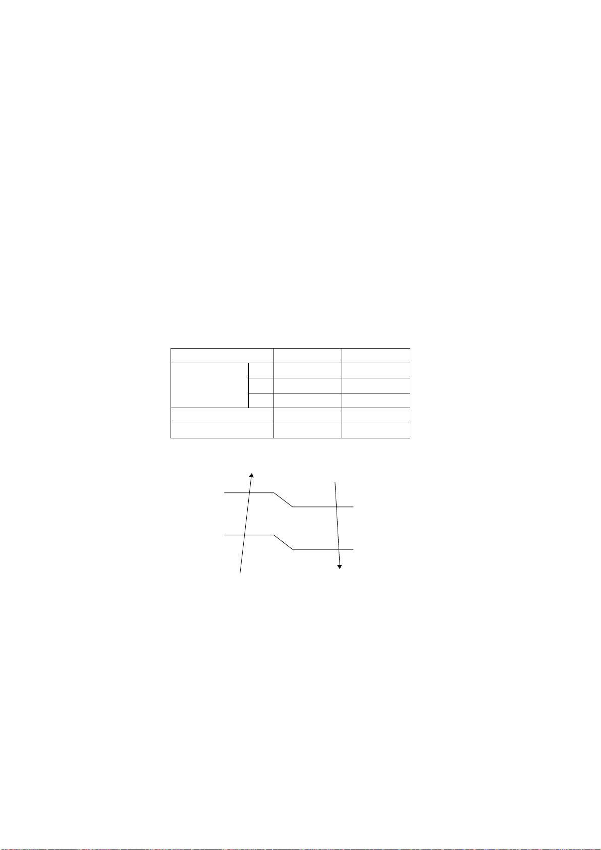
66
16. Protection Control (E18RK and E24RK)
16.1 Protection Control For All Operations
16.1.1 Restart Control (Time Delay Safety Control)
The compressor will not turn on within 3 minutes from the moment operation stops, although the unit is turned on
again by pressing OFF/ON button at remote control within this period.
This control is not applicable if the power supply is cut off and on again.
This phenomenon is to balance the pressure inside the refrigerant cycle.
16.1.2 30 Seconds Forced Operation
Once the air conditioner is turned on, the compressor will not stop within 30 seconds in a normal operation
although the intake air temperature has reached the thermo-off temperature. However, force stop by pressing the
OFF/ON button at the remote control is permitted or the Auto OFF/ON button at indoor unit.
The reason for the compressor to force operation for minimum 30 seconds is to allow the refrigerant oil run in a
full cycle and return back to the outdoor unit.
16.1.3 Total Running Current Control
When the outdoor unit total running current (AC) exceeds X value, the frequency instructed for compressor
operation will be decreased.
If the running current does not exceed X value for 5 seconds, the frequency instructed will be increased.
However, if total outdoor unit running current exceeds Y value, compressor will be stopped immediately for
3 minutes.
Model E18RKUA E24RKUA
Cool (X)
A 10.85 A 12.47 A
B 9.84 A 11.46 A
C 9.84 A 10.16 A
Heat (X) 11.29 A 13.80 A
Y 19.30 A 19.30 A
1. The first 30 minutes of cooling operation, (A) will be applied.
16.1.4 IPM (Power Transistor) Prevention Control
Overheating Prevention Control
o When the IPM temperature rises to 212°F, compressor operation will stop immediately.
o Compressor operation restarts after 3 minutes the temperature decreases to 203°F.
DC Peak Current Control
o When electric current to IPM exceeds set value of 29.9A, the compressor will stop operate. Then, operation
will restart after 3 minutes.
o If the set value is exceeded again more than 30 seconds after the compressor starts, the operation will
restart after 2 minute.
o If the set value is exceeded again within 30 seconds after the compressor starts, the operation will restart
after 1 minute. If this condition repeats continuously for 7 times, all indoor and outdoor relays will be cut off.
Timer LED will be blinking (F99 is indicated).
Outdoor Intake temperature
Outdoor Intake temperature
A
B
C
109.4°F
107.6°F
100.4°F
102.2°F

67
16.1.5 Compressor Overheating Prevention Control
Instructed frequency for compressor operation will be regulated by compressor discharge temperature. The
changes of frequency are as below.
If compressor discharge temperature exceeds 233.6°F, compressor will be stopped, occurs 4 times per
20 minutes, timer LED will be blinking. “F97” is indicated.
16.1.6 Low Pressure Protection Control (Gas Leakage Detection)
For 5 minutes, the compressor continuously operates and outdoor total current is between 0.78A and 1.16A.
During Cooling and Soft Dry operation:
Indoor suction temperature – indoor piping temperature is below 39.2°F.
During Heating operations :
Indoor piping temperature - indoor suction is under 41.0°F.
16.1.7 Low Frequency Protection Control 1
When the compressor operates at frequency lower than 25Hz continued for 240 minutes, the operation frequency
will be changed to 24Hz for 2 minutes.
16.1.8 Low Frequency Protection Control 2
When all below conditions comply, minimum limit of compressor will be set.
E18RKUA, E24RKUA
Temperature, T, for: Cooling / Soft Dry Heating
Indoor intake air (°F) T < 57.2 or T ≥ 86.0 T < 57.2 or T ≥ 82.4
Outdoor air (°F) T < 55.4 or T ≥ 100.4 T < 39.2 or T ≥ 75.2
Indoor heat exchanger (°F) T < 86.0 T ≥ 32.0
16.2 Protection Control For Cooling & Soft Dry Operation
16.2.1 Outdoor Air Temperature Control
The compressor operating frequency is regulated in accordance to the outdoor air temperature as shown in the
diagram below.
This control will begin 1 minute after the compressor starts.
Compressor frequency will adjust based on outdoor air temperature.
Compressor Frequency
Reduced
Compressor = OFF
233.6°F
206.6°F
204.8°F
194.0°F
230.0°F
212.0°F
Compressor Frequency
Maintain
Free
Comp Discharge temperature
77.0°F
71.6°F
Limited frequency
Free

68
The compressor will be stopped at outdoor air temperature ≤ -4°F. The unit still operate within the temperature
range.
16.2.2 Cooling Overload Control
Pipe temperature limitation / restriction.
o Detects the outdoor pipe temperature and carry out restriction / limitation below (Limit the compressor
operation frequency)
o The compressor stops if outdoor pipe temperature exceeds 145.4°F.
o If the compressor stops 4 times in 20 minutes, Timer LED blinks (“F95” indicated: Outdoor high pressure rise
protection)
16.2.3 Freeze Prevention Control 1
When indoor heat exchanger temperature is lower than 32°F continuously for 6 minutes, compressor will stops
operation.
Compressor will resume its operation 3 minutes after the indoor heat exchanger is higher than 41.0°F.
At the same time, indoor fan speed will be higher than during its normal operation.
If the indoor heat exchanger temperature is higher than 55.4°F for 5 minutes, the fan speed will return to its
normal operation.
16.2.4 Freeze Prevention Control 2
Control start conditions
o During Cooling operation and soft dry operation
During thermo OFF condition, indoor intake temperature is less than 50.0°F or
Compressor stops for freeze prevention control
o Either one of the conditions above occurs 5 times in 60 minutes.
Control contents
o Operation stops
o Timer LED blinks and “H99” indicated
16.2.5 Dew Prevention Control 1
To prevent dew formation at indoor unit discharge area.
This control will be activated if:
o Outdoor air temperature and Indoor pipe temperature judgment by microcontroller is fulfilled.
o When Cooling or Dry mode is operated more than 20 minutes or more.
This control stopped if:
o Compressor stopped.
o Remote control setting changed (fan speed / temperature).
o Outdoor air temperature and indoor intake temperature changed.
Fan speed, angle of louver (vertical airflow angle) will be adjusted accordingly in this control.
1. Fan speed will be increased slowly when control is activated until predetermine value.
Compressor frequency will be regulated accordingly.
16.2.6 Protection Control For Heating Operation
16.2.6.1 Intake Air Temperature Control
Compressor will operate at limited freq., if indoor intake air temperature is 86.0°F or above.
-0.4°F
-4°F
Compressor OFF
Compressor ON
O
utdoor Air Temperature
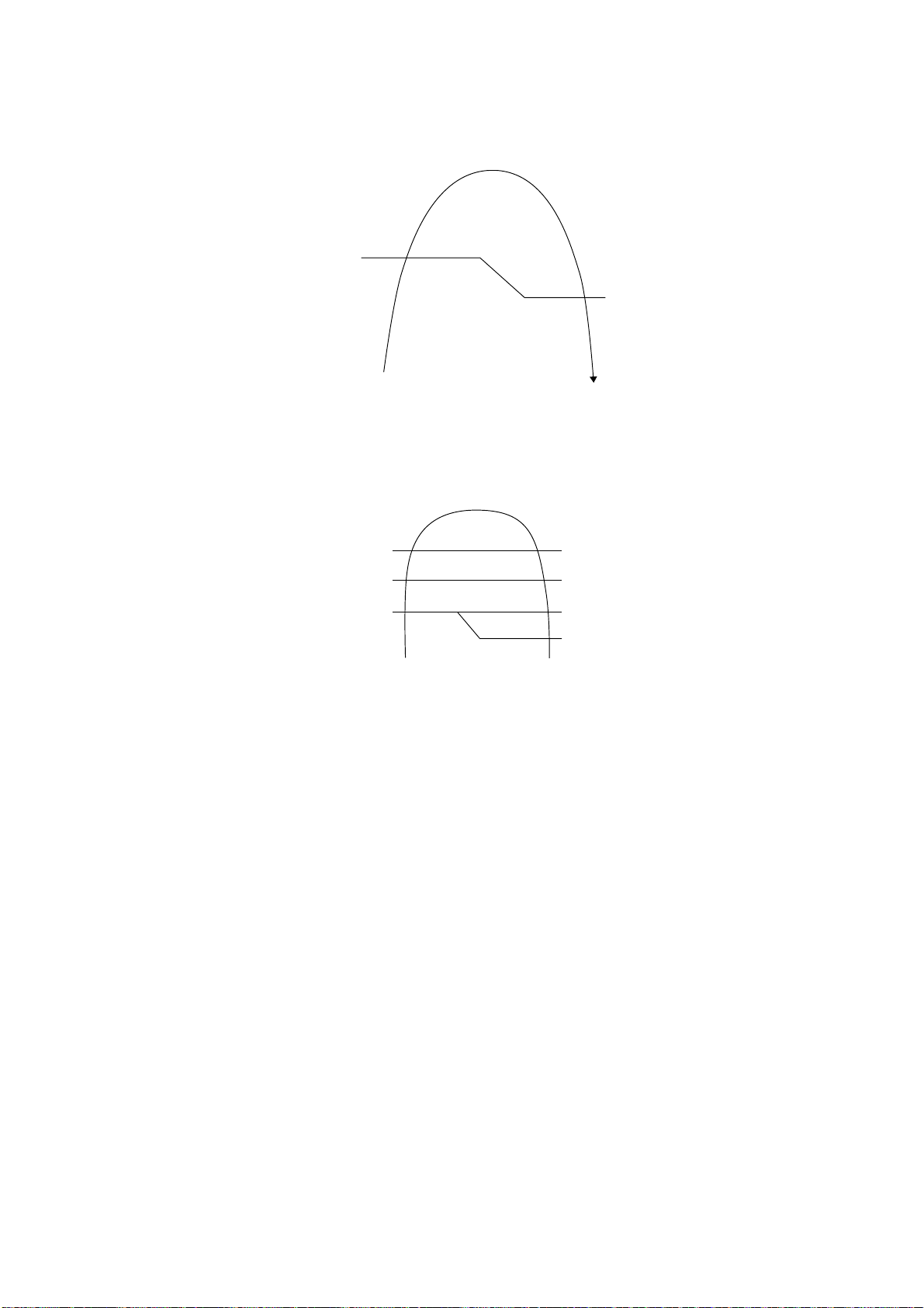
69
16.2.6.2 Outdoor Air Temperature Control
The Max current value is regulated when the outdoor air temperature rise above 57.2°F in order to avoid
compressor overloading.
The compressor will be stopped at outdoor air temperature ≤ -4°F. The unit still operate within the temperature
range.
16.2.6.3 Overload Protection Control
The compressor operating frequency is regulated in accordance to indoor heat exchanger temperature as shown
below.
If the heat exchanger temperature exceeds 140.0°F, compressor will stop.
16.2.6.4 Low Temperature Compressor Oil Return Control
In heating operation, if the indoor temperature falls below 17.6°F when compressor starts, the compressor
frequency will be regulated up to 600 seconds.
16.2.6.5 Cold Draught Prevention Control
When indoor pipe temperature is low, cold draught operation starts where indoor fan speed will be reduced or
stop.
Horizontal vane angle may be adjusted in Auto vane setting.
16.2.6.6 Deice Operation
When outdoor pipe temperature and outdoor air temperature is low, deice operation start where indoor fan motor and
outdoor fan motor stop and operation LED blinks. Horizontal vane is closed during auto vane setting.
-0.4°F
-4°F
Compressor OFF
Compressor ON
O
utdoor Air Temperature
OFF
Frequency Reduced
Frequency Limited
Free
140.0°F
114.8°F
125.6°F
120.2°F
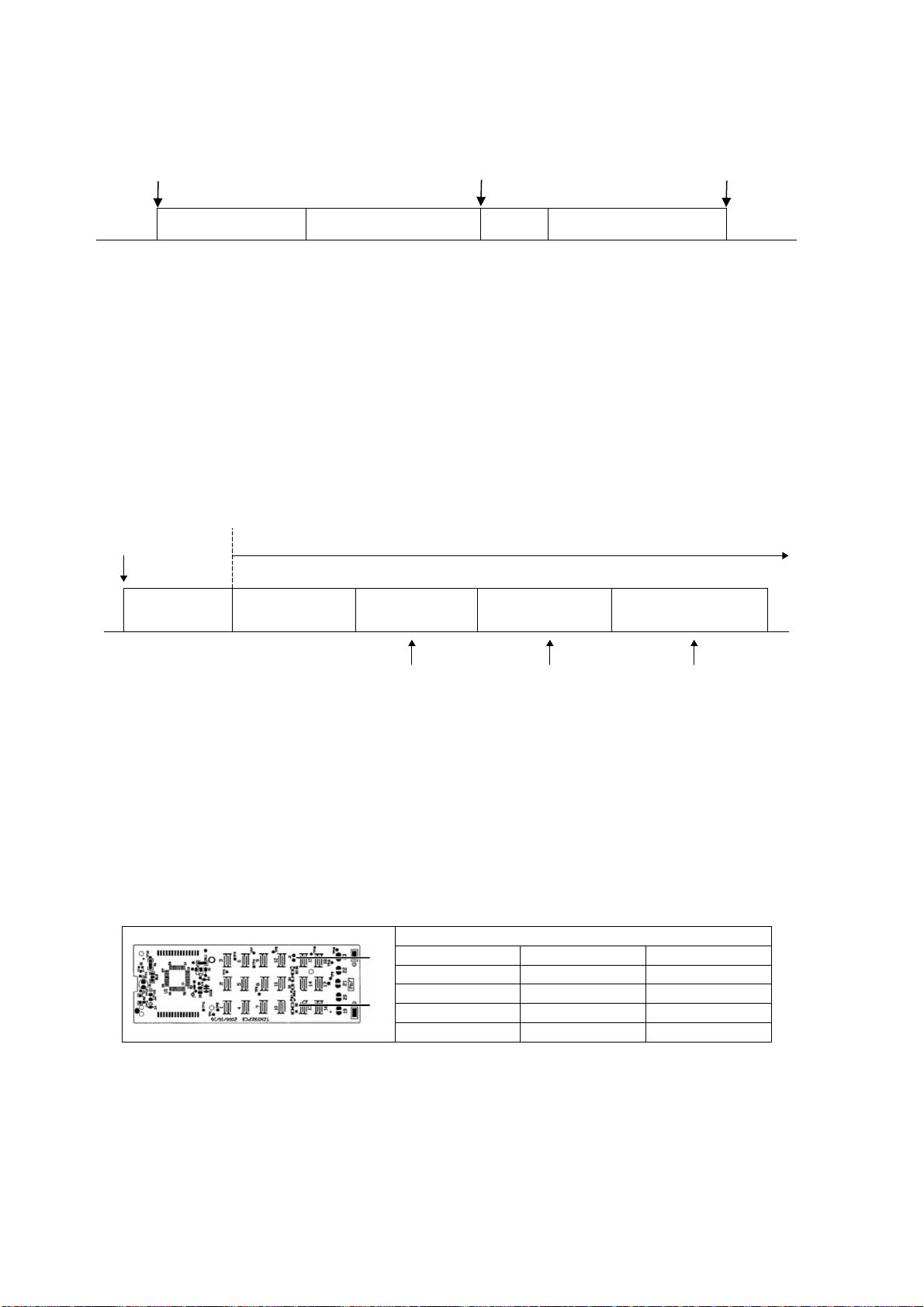
70
17. Servicing Mode
17.1 Auto Off/On Button
Auto OFF/ON
Button pressed
Auto OFF/ON
Button pressed
Auto OFF/ON
Button pressed
5 sec
5 sec
Auto Operation Test Run Operation
(Forced Cooling Operation)
Stop Test Run Operation
(Forced Cooling Operation)
Stop
Beep Beep x 2
1 AUTO OPERATION MODE
The Auto operation will be activated immediately once the Auto OFF/ON button is pressed. This operation
can be used to operate air conditioner with limited function if remote control is misplaced or malfunction.
2 TEST RUN OPERATION (FOR PUMP DOWN/SERVICING PURPOSE)
The Test Run operation will be activated if the Auto OFF/ON button is pressed continuously for more than
5 seconds. A “beep” sound will heard at the fifth seconds, in order to identify the starting of Test Run
operation (Forced cooling operation). Within 5 minutes after Forced cooling operation start, the Auto OFF/ON
button is pressed for more than 5 seconds. A 2 “beep” sounds will heard at the fifth seconds, in order to
identify the starting of Forced heating operation.
The Auto OFF/ON button may be used together with remote control to set / change the advance setting of air
conditioner operation.
3 REMOTE CONTROL NUMBER SWITCH MODE
The Remote Control Number Switch Mode will be activated if the Auto OFF/ON button is pressed
continuously for more than 11 seconds (3 “beep” sounds will occur at 11th seconds to identify the Remote
Control Number Switch Mode is in standby condition) and press “AC RESET” button and then press any
button at remote control to transmit and store the desired transmission code to the EEPROM.
There are 4 types of remote control transmission code could be selected and stored in EEPROM of indoor
unit. The indoor unit will only operate when received signal with same transmission code from remote control.
This could prevent signal interference when there are 2 or more indoor units installed nearby together.
To change remote control transmission code, short or open jumpers at the remote control printed circuit
board.
Remote Control Printed Circuit Board
Jumper A (J1) Jumper B (D2) Remote Control No.
Short Open A (Default)
Open Open B
Short Short C
Open Short D
During Remote Control Number Switch Mode, press any button at remote control to transmit and store
the transmission code to the EEPROM.
4 REMOTE CONTROL RECEIVING SOUND OFF/ON MODE
The Remote Control Receiving Sound OFF/ON Mode will be activated if the Auto OFF/ON button is pressed
continuously for more than 16 seconds (4 “beep” sounds will occur at 16
th
seconds to identify the Remote
Control Receiving Sound OFF/ON Mode is in standby condition) and press “AC Reset” button at remote
control.
Auto OFF/ON button
pressed
Auto Operation
5sec 8sec 11sec 16sec
Tes t R un O pe ra ti on
(Forced Cooling Operation)
Test Run Operation
(Forced Heating Operation)
Main unit always continue Test Run (forced cooling) operation
Beep Beep x 2
Press “AC RESET” Press “AC RESET”, then any
key at remote control
Press “AC RESET”
at remote control
Beep x 3 Beep x 4
Remote Control Number
Switch Mode
Remote Control Receiving
Sound OFF/ON
J1
D2
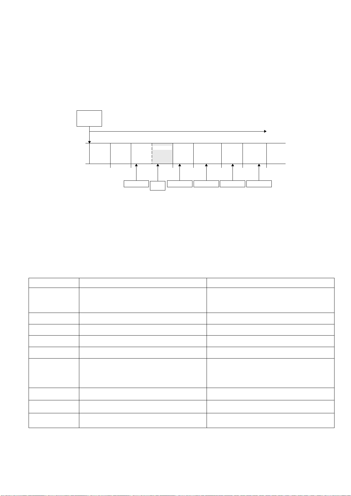
71
Press Auto OFF/ON button to toggle remote control receiving sound.
- Short “beep”: Turn OFF remote control receiving sound.
- Long “beep”: Turn ON remote control receiving sound.
After Auto OFF/ON button is pressed, the 20 seconds counter for Remote Control Receiving Sound OFF/ON
Mode is restarted.
17.2 Cooling Only Operation (Single connection Only, Multi connection
please refer to Multi outdoor manual)
17.2.1 How to activate and deactivate Cooling Only Operation
The default setting is "Cool Only" mode disable.
To enable the "Cool Only" mode, press the AUTO OFF/ON SW for more than 8s and less than 11s, “Pit Pit”
sound will be heard, then release the AUTO OFF/ON SW and press remote controller CHECK button. A short
“Pit” sound will be heard. “Cool Only” mode is now enable.
To disable the "Cool Only" mode, press the AUTO OFF/ON SW for more than 8s and less than 11s, “Pit Pit”
sound will be heard, then release the AUTO OFF/ON SW and press remote controller CHECK button. A long
"Pit" sound will be heard. “Cool Only” mode is now disable.
17.2.2 Operation mode during Cooling Only Operation
The table below shows the operation mode comparison when cooling only operation mode activated and deactivated.
Operation mode Cooling Only Operation Mode Activated Cooling Only Operation Mode Deactivated
AUTO
After 30s sampling, regardless of indoor intake or outdoor
intake temperature judgement, the unit will run Cooling or
DRY operation.
After 30s sampling, the unit will judge the operation mode
base on remote controller temperature setting and Indoor
Intake Sensor (New Auto Mode) or Outdoor Intake Sensor
(Old Auto Mode)
HEAT The unit will stop and Power LED blinking. The unit will run Heating operation.
COOL The unit will run Cooling operation. The unit will run Cooling operation.
DRY The unit will run DRY operation. The unit will run Dry operation.
Force Heating The unit will run Force Cooling operation. The unit will run Force Heating operation.
AUTO (with Timer)
The unit will turn ON by the timer and run Auto Operation.
After 30s sampling, regardless of indoor intake or outdoor
intake temperature judgement, the unit will run Cooling or
DRY operation.
The unit will turn ON by the timer and run Auto Operation.
After 30s sampling, the unit will judge the operation mode
base on remote controller temperature setting and Indoor
Intake Sensor (New Auto Mode) or Outdoor Intake Sensor
(Old Auto Mode)
HEAT (with Timer)
The unit will not turn ON by the Timer. Power LED
blinking.
The unit will turn ON by the timer and run Heating
Operation.
COOL (with Timer)
The unit will turn ON by the Timer and run Cooling
operation.
The unit will turn ON by the timer and run Cooling
Operation.
DRY (with Timer) The unit will turn ON by the Timer and run DRY operation.
The unit will turn ON by the timer and run Cooling Dry
Operation.
** Power LED blinking = 2.5s ON, 0.5s OFF
AUTO SW
is pressed
5s
Emergency
Operation
Forced
Cooling
Operation
Forced
Heating
Operation
8s 11s 16s 21s 26s 36s
Pit PitPit PitPitPit PitPitPitPit Peet No
Cool Only
Mode
Enable/
Disable
Remote
Control
Number
Switch
Mode
Remote
Control
Receiving
Sound
No
Setting
Mode
*Operation
Time Check
Mode
Forced
Cooling
Operation
AC reset code AC reset code AC reset code AC reset code AC reset code
CHECK
code

72
17.3 Remote Control Button
17.3.1 SET Button
To check remote control transmission code and store the transmission code to EEPROM
o Press “Set” button continuously for 10 seconds by using pointer
o Press “Timer Set” button unit a “beep” sound is heard as confirmation of transmission code change.
17.3.2 RESET (RC)
To clear and restore the remote control setting to factory default.
o Press once to clear the memory
17.3.3 RESET (AC)
To restore the unit’s setting to factory default.
o Press once to restore the unit’s setting
17.3.4 TIMER ▲
To change indoor unit indicator’s LED intensity:
o Press continuously for 5 seconds.
17.3.5 TIMER ▼
To change remote control display from Degree Celsius (°C) to Degree Fahrenheit (°F)
o Press continuously for 10 seconds.
17.3.6 CLOCK Button
To change the remote control time format:
o Press for more than 5 seconds
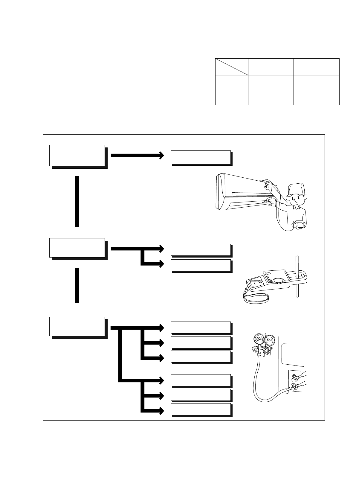
73
18. Troubleshooting Guide
18.1 Refrigeration Cycle System
In order to diagnose malfunctions, make sure that there are no
electrical problems before inspecting the refrigeration cycle.
Such problems include insufficient insulation, problem with the
power source, malfunction of a compressor and a fan.
The normal outlet air temperature and pressure of the
refrigeration cycle depends on various conditions, the standard
values for them are shown in the table on the right.
Value of electric
current during operation
Difference in the intake
and outlet
air temperatures
Lower than specified
Higher than specified
Cooling Mode
Heating Mode
High
Low
Low
Low
Low
Low
Gas side
pressure
Dusty condenser
preventing heat radiation
● Measuring electric current
during operation
● Measuring gas side pressure
Excessive amount
of refrigerant
Inefficient compressor
Insufficient refrigerant
Insufficient refrigerant
Inefficient compressor
Clogged strainer or
expansion valve
Clogged strainer or
capillary tube
Less than 14.4°F at the cooling mode.
Less than 25.2°F at the cooling mode.
More than 14.4°F
(15 minutes after an
operation is started.)
at cooling mode.
Above 25.2°F
(15 minutes after an
operation is started.)
at heating mode
Normal
● Measuring the air temperature
difference
Normal Pressure and Outlet Air Temperature (Standard)
Gas Pressure
PSI
(kg/cm
2
G)
Outlet air
Temperature
(°F)
Cooling Mode
130.53 ~ 174.04
(9 ~ 12)
53.6 ~ 60.8
Heating Mode
333.58 ~ 420.60
(23 ~ 29)
96.8 ~ 113
Condition: Indoor fan speed = High
Outdoor temperature 95°F at cooling mode
and 44.6°F at heating mode.
Compressor operate at rated frequency
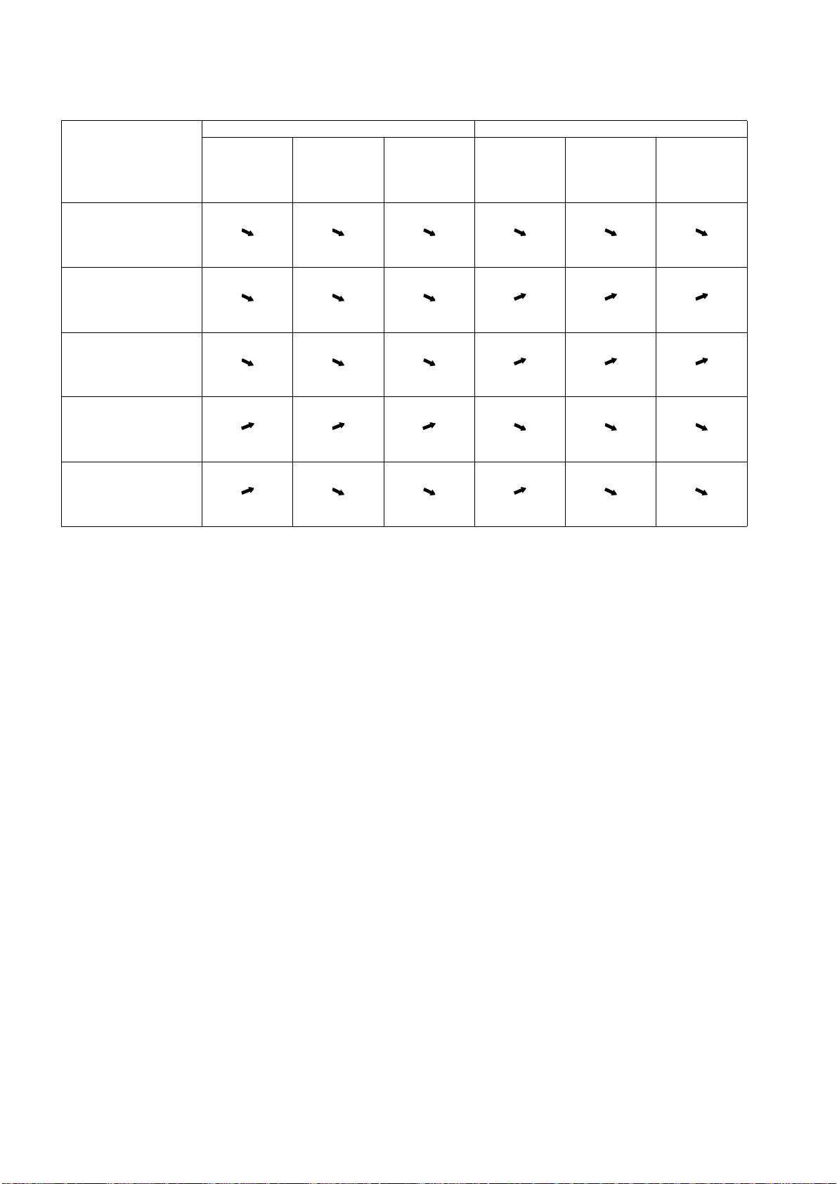
74
18.1.1 Relationship between the condition of the air conditioner and pressure and
electric current
Carry out the measurements of pressure, electric current, and temperature fifteen minutes after an operation is
started.
edoMgnitaeHedoMgnilooC
Low Pressure High Pressure
Electric current
during operating
Low Pressure High Pressure
Electric current
during operating
Condition of the air
conditioner
Insufficient refrigerant
(gas leakage)
Clogged capillary tube
or Strainer
Short circuit in the
indoor unit
Heat radiation deficiency
of the outdoor unit
Inefficient compression
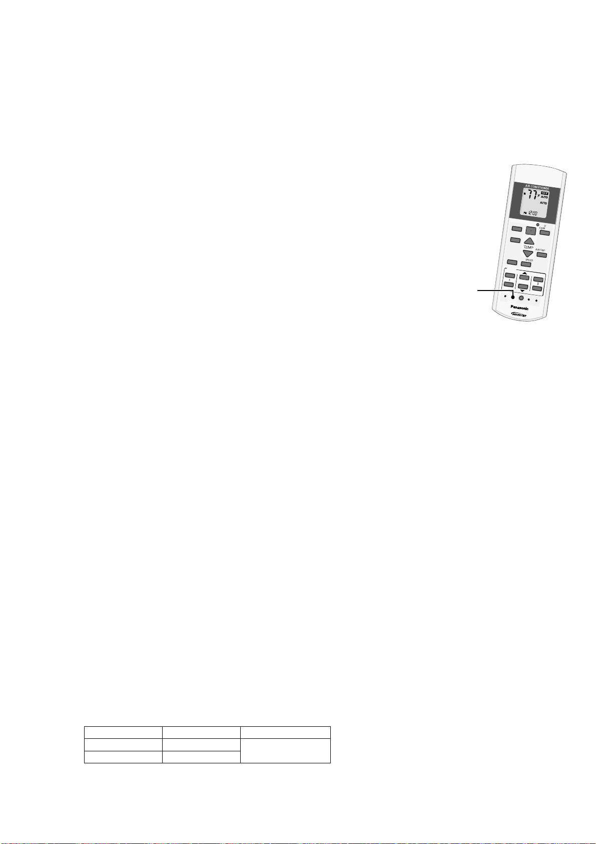
75
18.2 Breakdown Self Diagnosis Function
18.2.1 Self Diagnosis Function (Three Digits Alphanumeric Code)
Once error occurred during operation, the unit will stop its operation, and Timer LED blinks.
Although Timer LED goes off when power supply is turned off, if the unit is operated under a breakdown
condition, the LED will ON again.
In operation after breakdown repair, the Timer LED will not blink. The last error code (abnormality) will be stored
in IC memory.
18.2.2 To Make a Diagnosis
1 Timer LED starts to blink and the unit automatically stops the operation.
2 Press the CHECK button on the remote control continuously for
5 seconds.
3 “- -“ will be displayed on the remote control display.
Note: Display only for “- -“ (No signal transmission, no receiving sound
and no Power LED blinking)
4 Press the TIMER ▲ or ▼ button on the remote control. The code “H00”
(no abnormality) will be displayed and signal will be transmit to the main
unit.
5 Each press of the button (▲ or ▼) will increase error code number and
transmit error code signal to the main unit.
6 When the latest abnormality code on the main unit and code transmitted
from the remote control are matched, Power LED will light up for
30 seconds and a “beep” sound (continuously for 4 seconds) will be
heard. If no codes are matched, Power LED will light up for 0.5 seconds and no sound will be heard.
7 The breakdown diagnosis mode will be canceled unless pressing the CHECK button continuously for
5 seconds or operating the unit for 30 seconds.
8 The LED will be off if the unit is turned off or the RESET button on the main unit is pressed.
18.2.3 To Display Memorized Error Code (Protective Operation)
1 Turn power on.
2 Press the CHECK button on the remote control
3 “- -“ will be displayed on the remote control display.
Note: Display only for “- -“ (No signal transmission, no receiving sound and no Power LED blinking)
4 Press the TIMER ▲ or ▼ button on the remote control. The code “H00” (no abnormality) will be displayed
and signal will be transmit to the main unit.
5 Each press of the button (▲ or ▼) will increase error code number and transmit error code signal to the main
unit.
6 When the latest abnormality code on the main unit and code transmitted from the remote control are matched,
Power LED will light up for 30 seconds and a “beep” sound (continuously for 4 seconds) will be heard. If no
codes are matched, Power LED will light up for 0.5 seconds and no sound will be heard.
7 The breakdown diagnosis mode will be canceled unless pressing the CHECK button continuously for 5
seconds or operating the unit for 30 seconds.
8 The same diagnosis can be repeated by turning power on again.
18.2.4 To Clear Memorized Error Code after Repair (Protective Operation)
1 Turn power on (in standby condition).
2 Press the AUTO button for 5 seconds (a “beep” sound is heard) on the main unit to operate the unit at
Forced Cooling Operation Mode.
3 Press the CHECK button on the remote control for about 1 second with a pointed object to transmit signal to
main unit. A “beep” sound is heard, and the Error Code is cleared.
18.2.5 Temporary Operation (Depending On Breakdown Status)
1 Press the Auto OFF/ON button on the main unit (a “beep” sound is heard) to operate the unit. (Remote
control is enable again).
2 The unit can be temporarily be used until repaired.
Error Code Operation Temporary items
H23 Cooling
Emergency Operation
with limited power
H27, H28 Cooling, Heating
A
U
T
O
C
O
M
F
O
R
T
M
O
D
E
P
O
W
E
R
F
U
L
/
Q
U
I
E
T
T
E
M
P
O
F
F
/
O
N
T
I
M
E
R
S
E
T
C
A
N
C
E
L
O
N
O
F
F
1
2
3
A
I
R
S
W
I
N
G
F
A
N
S
P
E
E
D
S
E
T
C
H
E
C
K
C
L
O
C
K
R
E
S
E
T
A
C
R
C
E
C
O
N
A
V
I
F
A
N
S
P
E
E
D
A
I
R
S
W
I
N
G
A
U
T
O
H
E
A
T
C
O
O
L
D
R
Y
F
A
N
/
T
E
M
P
O
F
F
/
O
N
T
I
M
E
R
S
E
T
C
A
N
C
E
L
O
N
O
F
F
1
2
3
C
H
E
C
K
"Check" button
76
18.3 Error Code Table
Abnormality /
Protection control
Abnormality
Judgement
Protection
operation
Problem Check location
Diagnosis
display
——noitarepolamroN—eruliaffoyromemoN00H
H11 Indoor/outdoor
abnormal
communication
After operation for
1 minute
Indoor fan only
operation can
start by entering
into force cooling
operation
Indoor/outdoor
communication not establish
• Indoor/outdoor wire terminal
• Indoor/outdoor PCB
• Indoor/outdoor connection wire
H12 Indoor unit capacity
unmatched
90s after power
supply
— Total indoor capability more
than maximum limit or less
than minimum limit, or
number of indoor unit less
than two.
• Indoor/outdoor connection wire
• Indoor/outdoor PCB
• Specification and combination
table in catalogue
H14 Indoor intake air
temperature sensor
abnormality
Continuous for 5s — Indoor intake air temperature
sensor open or short circuit
• Indoor intake air temperature
sensor lead wire and connector
H15 Compressor
temperature sensor
abnormality
Continuous for 5s — Compressor temperature
sensor open or short circuit
• Compressor temperature sensor
lead wire and connector
H16 Outdoor current
transformer (CT)
abnormality
— — Current transformer faulty or
compressor faulty
• Outdoor PCB faulty or
compressor faulty
H19 Indoor fan motor
merchanism lock
Continuous
happen for 7 times
— Indoor fan motor lock or
feedback abnormal
• Fan motor lead wire and
connector
• Fan motor lock or block
H23 Indoor heat exchanger
temperature sensor
abnormality
Continuous for 5s — Indoor heat exchanger
temperature sensor open or
short circuit
• Indoor heat exchanger
temperature sensor lead wire and
connector
H24 Indoor heat exchanger
temperature sensor 2
abnormality
Continuous for 5s — Indoor heat exchanger
temperature sensor 2 open
or short circuit
• Indoor heat exchanger
temperature sensor 2 lead wire
and connector
H27 Outdoor air temperature
sensor abnormality
Continuous for 5s — Outdoor air temperature
sensor open or short circuit
• Outdoor air temperature sensor
lead wire and connector
H28 Outdoor heat exchanger
temperature sensor 1
abnormality
Continuous for 5s — Outdoor heat exchanger
temperature sensor 1 open
or short circuit
• Outdoor heat exchanger
temperature sensor 1 lead wire
and connector
H30 Outdoor discharge pipe
temperature sensor
abnormality
Continuous for 5s — Outdoor discharge pipe
temperature sensor open or
short circuit
• Outdoor discharge pipe
temperature sensor lead wire and
connector
H33 Indoor / outdoor
misconnection
abnormality
— — Indoor and outdoor rated
voltage different
• Indoor and outdoor units check
H38 Indoor/Outdoor
mismatch (brand code)
— — Brand code not match
• Check indoor unit and outdoor
unit.
H32 Outdoor heat exchanger
temperature sensor 2
abnormality
Continuous for 5s — Outdoor heat exchanger
temperature sensor 2 open
or short circuit
• Outdoor heat exchanger
temperature sensor 2 lead wire
and connector
H36 Outdoor gas pipe
temperature sensor
abnormality
Continuous for 5s Heating protection
operation only
Outdoor gas pipe
temperature sensor open or
short circuit
• Outdoor gas pipe temperature
sensor lead wire and connector
H37 Outdoor liquid pipe
temperature sensor
abnormality
Continuous for 5s Cooling protection
operation only
Outdoor liquid pipe
temperature sensor open or
short circuit
• Outdoor liquid pipe temperature
sensor lead wire and connector
H41 Abnormal wiring or
piping connection
— — Wrong wiring and
connecting pipe, expansion
valve abnormality
• Check indoor/outdoor
connection wire and connection
pipe
• Expansion valve and lead wire
and connector
H39 Abnormal indoor
operating unit or
standby units
3 times happen
within 40 minutes
— Wrong wiring and connecting
pipe, expansion valve
abnormality, indoor heat
exchanger sensor open
circuit
• Check the indoor/outdoor
connection wire and connection
pipe.
• Indoor heat exchanger sensor
lead wire and connector.
• Expansion valve and lead wire
and connector system.

77
Note:
“○” – Frequency measured and fan speed fixed
The memory data of error code is erased when the power supply is cut off, or press the Auto Switch until “beep”
sound heard following by pressing the CHECK button at remote control.
Although operation forced to stop when abnormality detected, emergency operation is possible for certain errors
(refer to Error Code Table) by using remote control or Auto OFF/ON button at indoor unit. However, the remote
control signal receiving sound is changed from one “beep” to four “beep” sounds.
F91 Refrigeration cycle
abnormality
2 times happen
within 20 minutes
— Refrigeration cycle abnormal • Insufficient refrigerant or valve
close
F93 Compressor abnormal
revolution
4 times happen
within 20 minutes
— Compressor abnormal
revolution
• Power transistor module faulty or
compressor lock
F95 Outdoor cooling high
pressure protection
4 times happen
within 20 minutes
— Cooling high pressure
protection
• Check refrigeration system
• Outdoor air circuit
F94 Compressor discharge
overshoot protection
4 times happen
within 30 minutes
— Compressor discharge
pressure overshoot
• Check refrigeration system
F96 Power transistor module
overheating protection
4 times happen
within 30 minutes
— Power transistor module
overheat
• PCB faulty
• Outdoor air circuit (fan motor)
F97 Compressor
overheating protection
3 times happen
within 30 minutes
— Compressor overheat • Insufficient refrigerant
F98 Total running current
protection
3 times happen
within 20 minutes
— Total current protection • Check refrigeration system
• Power source or compressor lock
F99 Outdoor direct current
(DC) peak detection
Continuous
happen for 7 times
— Power transistor module
current protection
• Power transistor module faulty or
compressor lock
Abnormality /
Protection control
Abnormality
Judgement
Protection
operation
Problem Check location
Diagnosis
display
F11 4-way valve switching
abnormality
4 times happen
within 30 minutes
— 4-way valve switching
abnormal
• 4-way valve
• Lead wire and connector.
F90 Power factor correction
(PFC) circuit protection
4 times happen
within 10 minutes
— Power factor correction
circuit abnormal
• Outdoor PCB faulty
H99 Indoor operating unit
freeze protection
— — Indoor freeze protection
(Cooling)
• Check indoor heat exchanger
• Air filter dirty
• Air circulation short circuit
F17 Indoor standby units
freezing abnormality
3 times happen
within 40 minutes
— Wrong wiring and connecting
pipe, expansion valve
leakage, indoor heat
exchanger sensor open
circuit
• Check indoor/outdoor connection
wire and pipe
• Indoor heat exchanger sensor
lead wire and connector
• Expansion valve lead wire and
connector.
H98 Indoor high pressure
protection
— — Indoor high pressure
protection (Heating)
• Check indoor heat exchanger
• Air filter dirty
• Air circulation short circuit
H97 Outdoor fan motor
mechanism lock
2 times happen
within 30 minutes
— Outdoor fan motor lock or
feedback abnormal
• Outdoor fan motor lead wire and
connector
• Fan motor lock or block
H64 Outdoor high pressure
sensor abnormality
Continuous for 1
minutes
— High pressure sensor open
circuit during compressor
• High pressure sensor
• Lead wire and connector
H59 ECONAVI sensor
abnormality
Continuous for
25s
— ECOANVI sensor open or
short circuit
• ECONAVI sensor (defective or
disconnected)
• ECONAVI PCB
78
18.4 Self-diagnosis Method
18.4.1 H11 (Indoor/Outdoor Abnormal Communication)
Malfunction Decision Conditions
During startup and operation of cooling and heating, the data received from outdoor unit in indoor unit signal
transmission is checked whether it is normal.
Malfunction Caused
Faulty indoor unit PCB.
Faulty outdoor unit PCB.
Indoor unit-outdoor unit signal transmission error due to wrong wiring.
Indoor unit-outdoor unit signal transmission error due to breaking of wire in the connection wires between the
indoor and outdoor units.
Indoor unit-outdoor unit signal transmission error due to disturbed power supply waveform.
Troubleshooting
Check the indoor-outdoor units’ connection wires.
Is there any wiring error?
Disconnect terminal 3 wire and measure Vdc between terminal
2 & 3 from the outdoor unit.
Reconnect terminal 3 wire and measure Vdc between terminal
2 & 3 from the outdoor unit.
Is the Vdc fluctuate between 10~70Vdc?
Is the Vdc fluctuate between 10~70 Vdc?
When abnormality indication starts again.
For safety reason and to prevent
component breakdown, always switch
off the power before remove and
connect the component.
Replace indoor unit PCB.
Replace outdoor PCB.
Correct the indoor-outdoor units
connection wires.
NO
NO
NO
YES
YES
79
18.4.2 H12 (Indoor/Outdoor Capacity Rank Mismatched)
Malfunction Decision Conditions
During startup, error code appears when different types of indoor and outdoor units are interconnected.
Malfunction Caused
Wrong models interconnected.
Wrong indoor unit or outdoor unit PCBs mounted.
Indoor unit or outdoor unit PCBs defective.
Indoor-outdoor unit signal transmission error due to wrong wiring.
Indoor-outdoor unit signal transmission error due to breaking of wire 3 in the connection wires between the indoor
and outdoor units.
Troubleshooting
Check the indoor and outdoor unit connection wires.
Check indoor and outdoor units model number.
Is indoor unit and outdoor unit model numbers matched?
Check the spare part numbers of the indoor and outdoor unit
PCBs and compare with their Part Lists.
Matched compatibility?
Is there any wiring error?
When abnormality indication starts again.
For safety reason and to prevent
component breakdown, always switch
off the power before remove and
connect the component.
Correct the indoor-outdoor unit’s connection wires.
Change for the specified indoor or outdoor unit
PCB.
Replace the indoor and outdoor unit PCBs.
Match the compatible model(s).
NO
NO
NO
YES
YES
YES
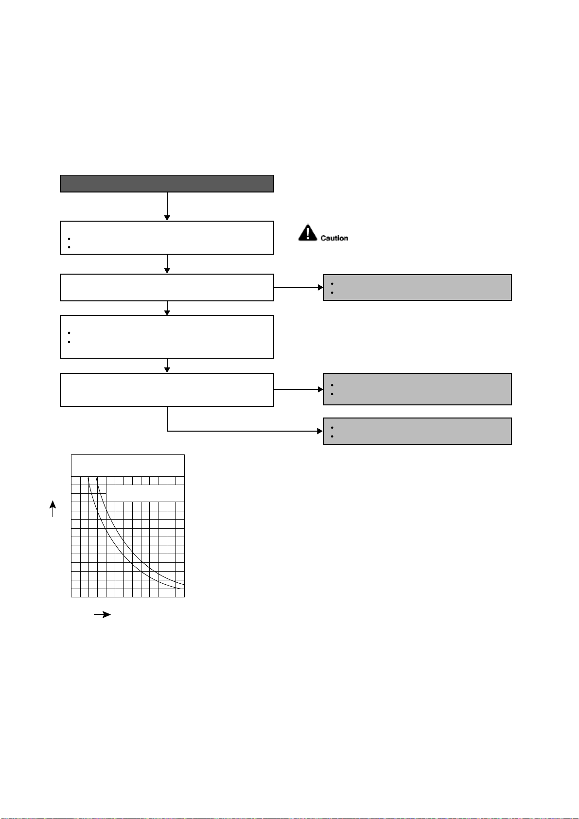
80
18.4.3 H14 (Indoor Intake Air Temperature Sensor Abnormality)
Malfunction Decision Conditions
During startup and operation of cooling and heating, the temperatures detected by the indoor intake air
temperature sensor are used to determine sensor errors.
Malfunction Caused
Faulty connector connection.
Faulty sensor.
Faulty PCB.
Troubleshooting
Check the connector connection:
Turn off the power.
Check the connector connection.
Is the connector connection normal?
When abnormality indication starts again.
For safety reason and to prevent component
breakdown, always switch off the power
before remove and connect the component.
Connector poor contact.
Correct the connection.
Defect in indoor unit PCB.
Replace the indoor unit PCB.
Defect in indoor intake air temperature sensor.
Replace the indoor intake air temperature sensor.
Check the indoor intake air temperature sensor:
Plug out connector from the indoor unit PCB.
Measure the resistance of the indoor intake air
temperature sensor.
Is the measured resistance of the indoor intake air
temperature sensor matches the value specified in its
characteristic chart?
NO
NO
YES
YES
0
10
14 50 68 86 104 12232
20
30
40
50
60
70
Temperature (°F)
Resistance (K
)
Sensor (Thermistor)
Characteristics
Pipe temp. Sensor
Intake Air Temp. Sensor
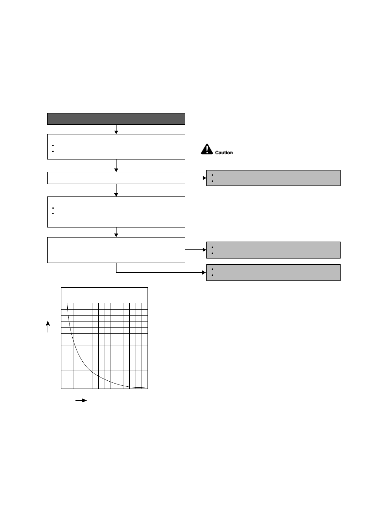
81
18.4.4 H15 (Compressor Temperature Sensor Abnormality)
Malfunction Decision Conditions
During startup and operation of cooling and heating, the temperatures detected by the outdoor compressor
temperature sensor are used to determine sensor errors.
Malfunction Caused
Faulty connector connection.
Faulty sensor.
Faulty PCB.
Troubleshooting
When abnormality indication starts again.
For safety reason and to prevent component
breakdown, always switch off the power
before remove and connect the component.
Connector poor contact.
Correct the connection.
Defect in outdoor compressor temperature sensor.
Replace the outdoor compressor temperature sensor.
Defect in outdoor unit PCB.
Replace the outdoor unit PCB.
Turn off the power.
Check the connector connection.
YES
YES
0
10
20
68 104 140 176 212 248 284
30
40
50
60
70
Temperature (°F)
Resistance (K
)
Compressor Temp. Sensor
(Thermistor) Charateristics
Check the connector connection:
Plug out connector from the outdoor unit PCB.
Measure the resistance of the outdoor compressor
temperature sensor.
Check the outdoor compressor temperature sensor:
Is the connector connection normal?
Is the measured resistance of the outdoor compressor
temperature sensor matches the value specified in its
characteristic chart?
NO
NO
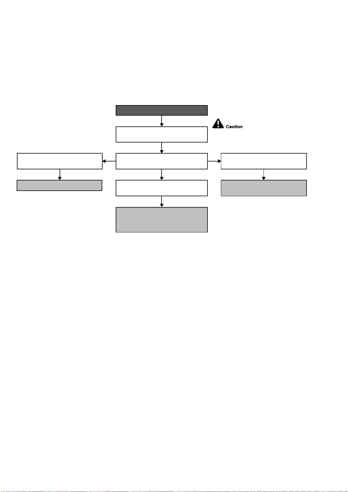
82
18.4.5 H16 (Outdoor Current Transformer)
Malfunction Decision Conditions
An input current, detected by Current Transformer CT, is below threshold value when the compressor is
operating at certain frequency value for 3 minutes.
Malfunction Caused
Lack of gas.
Broken CT (current transformer).
Broken Outdoor PCB.
Troubleshooting
For safety reason and to
prevent component breakdown,
always switch off the power before
remove and connect the component.
When abnormality indication starts again.
● Check for gas leaking source; Repair
or replace defected part(s).
● Capillary tube/expansion valve
blockage; Replace defected part(s).
● Compressor Lack Compression.
● Replace Compressor.
● Check & replace defected CT.
Refer to Service Manual Technical Graph
for Temp vs Current and Pressure.
In forced cooling, check suction pressure
versus running current.
Suction pressure and running current is
normal.
Running current is much too low and
suction pressure is much too high.
Running current and suction pressure is
very low.
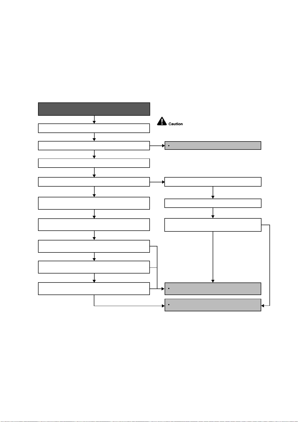
83
18.4.6 H19 (Indoor Fan Motor – DC Motor Mechanism Locked)
Malfunction Decision Conditions
The rotation speed detected by the Hall IC during fan motor operation is used to determine abnormal fan motor
(feedback of rotation > 2550rpm or < 50rpm)
Malfunction Caused
Operation stops due to short circuit inside the fan motor winding.
Operation stops due to breaking of wire inside the fan motor.
Operation stops due to breaking of fan motor lead wires.
Operation stops due to Hall IC malfunction.
Operation error due to faulty indoor unit PCB.
Troubleshooting
Turn off power supply and rotate fan by hand.
When abnormality indication starts again.
Replace fan motor.
Does fan rotate smoothly?
Turn power supply on and operate fan.
Does it rotate? Stop fan motor.
Check the rotation feedback output from fan motor.
Rotate the fan motor by hand, is the rotation
feedback voltage 15Vdc (pin 7 & 4) generated?
Turn off power supply and disconnect fan motor connector,
then turn power on.
Check the output of fan motor from indoor PCB.
Is the motor power supply voltage~325Vdc (pin 1 & 4)
generated?
Is the motor control voltage 15Vdc (pin 5 & 4) generated?
Operate the fan, is the rotation command voltage 1~5Vdc
(pin 6 & 4) generated?
NO
NO
NO
NO
NO
NO
YES
YES
YES
YES
For safety reason and to prevent
component breakdown, always switch
off the power before remove and
connect the component.
Replace indoor PCB.
Replace fan motor.
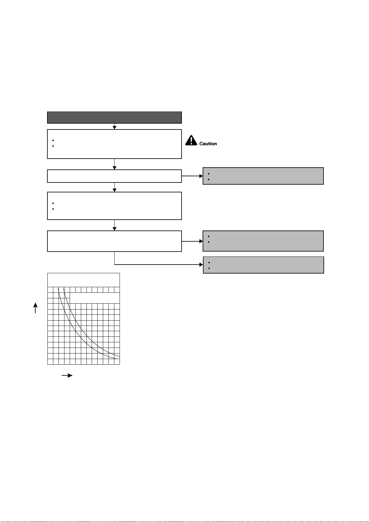
84
18.4.7 H23 (Indoor Pipe Temperature Sensor Abnormality)
Malfunction Decision Conditions
During startup and operation of cooling and heating, the temperatures detected by the indoor heat exchanger
temperature sensor are used to determine sensor errors.
Malfunction Caused
Faulty connector connection.
Faulty sensor.
Faulty PCB.
Troubleshooting
When abnormality indication starts again.
For safety reason and to prevent component
breakdown, always switch off the power
before remove and connect the component.
Connector poor contact.
Correct the connection.
Defect in outdoor unit PCB.
Replace the outdoor unit PCB.
Defect in outdoor intake air temperature sensor.
Replace the outdoor intake air temperature
sensor.
NO
NO
YES
YES
0
10
14 50 68 86 104 12232
20
30
40
50
60
70
Temperature (°F)
Resistance (K
)
Sensor (Thermistor)
Characteristics
Pipe temp. Sensor
Intake Air Temp. Sensor
Check the connector connection:
Plug out connector from the indoor unit PCB.
Is the connector connection normal?
Measure the resistance of the indoor pipe temperature
sensor.
Check the outdoor air temperature sensor:
Is the measured resistance of the outdoor intake air
temperature sensor matches the value specified in its
characteristic chart?
Plug out connector from the outdoor unit PCB.
Measure the resistance of the outdoor intake air
temperature sensor.
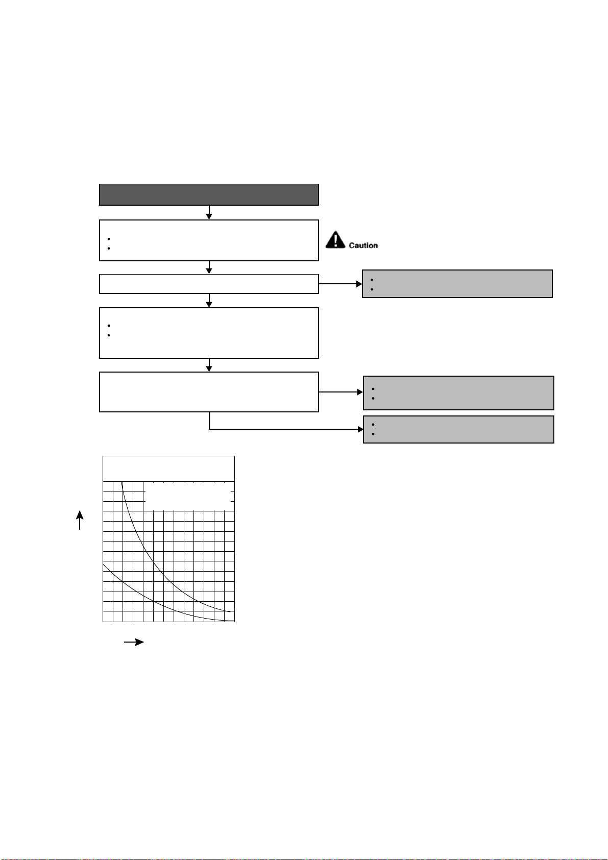
85
18.4.8 H27 (Outdoor Air Temperature Sensor Abnormality)
Malfunction Decision Conditions
During startup and operation of cooling and heating, the temperatures detected by the outdoor air temperature
sensor are used to determine sensor errors.
Malfunction Caused
Faulty connector connection.
Faulty sensor.
Faulty PCB.
Troubleshooting
Check the connector connection:
Is the measured resistance of the outdoor air temperature
sensor matches the value specified in its characteristic
chart?
Is the connector connection normal?
When abnormality indication starts again.
For safety reason and to prevent component
breakdown, always switch off the power
before remove and connect the component.
Turn off the power.
Check the connector connection.
Defect in outdoor air temperature sensor.
Replace the outdoor air temperature sensor.
Defect in outdoor unit PCB.
Replace the outdoor unit PCB.
NO
NO
YES
YES
Check the outdoor air temperature sensor:
Plug out connector from the outdoor unit PCB.
Measure the resistance of the outdoor air temperature
sensor.
Connector poor contact.
Correct the connection.
0
10
14 50 68 86 104 12232
20
30
40
50
60
70
Temperature (°F)
Resistance (K
)
Sensor (Thermistor)
Characteristics
Outdoor Air Sensor
Outdoor Heat Exchanger
Sensor

86
18.4.9 H28 (Outdoor Pipe Temperature Sensor Abnormality)
Malfunction Decision Conditions
During startup and operation of cooling and heating, the temperatures detected by the outdoor pipe temperature
sensor are used to determine sensor errors.
Malfunction Caused
Faulty connector connection.
Faulty sensor.
Faulty PCB.
Troubleshooting
Is the measured resistance of the outdoor heat exchanger
temperature sensor matches the value specified in its
characteristic chart?
Is the connector connection normal?
When abnormality indication starts again.
For safety reason and to prevent
component breakdown, always switch
off the power before remove and
connect the component.
No
No
YES
YES
Check the outdoor heat exchanger temperature sensor:
Plug out connector from the outdoor unit PCB.
Measure the resistance of the outdoor heat exchanger
temperature sensor.
0
10
14 50 68 86 104 12232
20
30
40
50
60
70
Temperature (°F)
Resistance (K
)
Sensor (Thermistor)
Characteristics
Outdoor Air Sensor
Outdoor Heat Exchanger
Sensor
Check the connector connection:
Turn off the power.
Check the connector connection.
Connector poor contact.
Correct the connection.
Defect in outdoor unit PCB.
Replace the outdoor unit PCB.
Defect in outdoor heat exchanger
temperature sensor.
Replace the outdoor heat exchanger
temperature sensor.
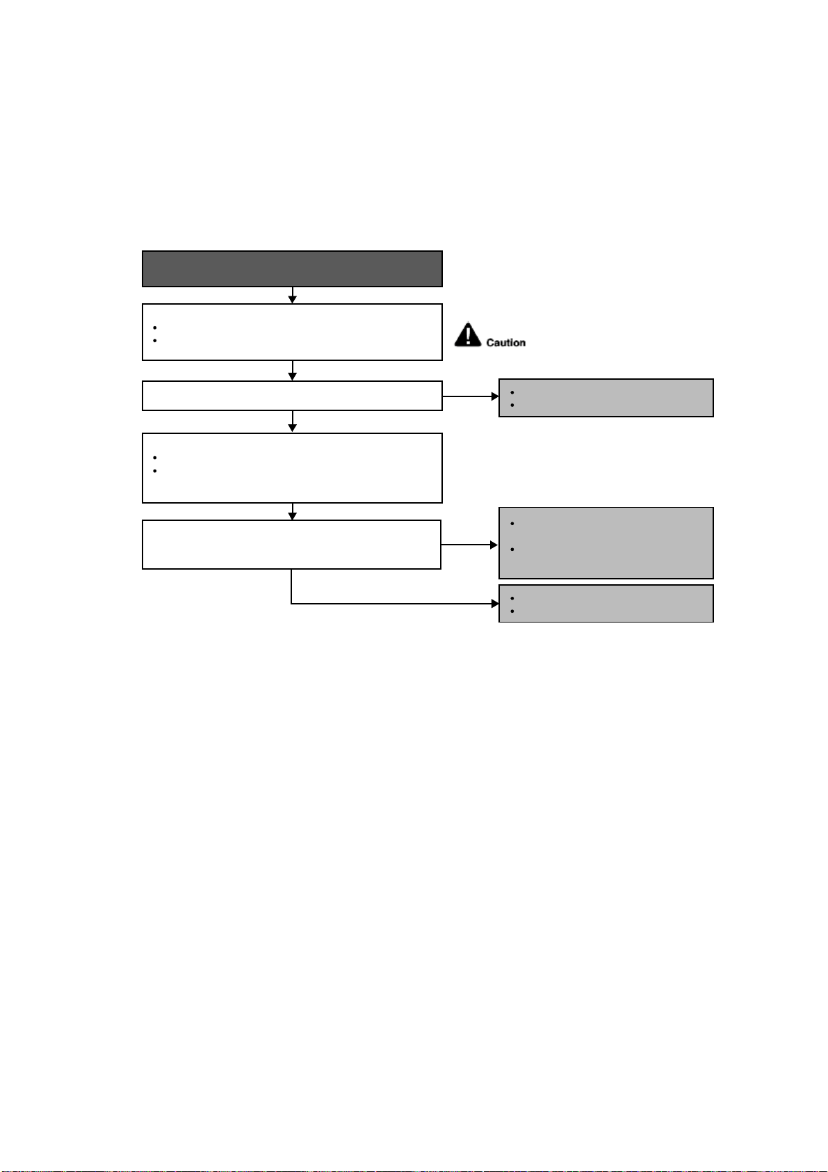
87
18.4.10 H30 (Compressor Discharge Temperature Sensor Abnormality)
Malfunction Decision Conditions
During startup and operation of cooling and heating, the temperatures detected by the outdoor discharge pipe
temperature sensor are used to determine sensor errors.
Malfunction Caused
Faulty connector connection.
Faulty sensor.
Faulty PCB.
Troubleshooting
When abnormality indication starts again.
For safety reason and to prevent
component breakdown, always switch
off the power before remove and
connect the component.
Is the measured resistance of the outdoor discharge pipe
temperature sensor matches the value specified in its
characteristic chart?
Is the connector connection normal?
YES
YES
Check the outdoor discharge pipe temperature sensor:
Plug out connector from the outdoor unit PCB.
Measure the resistance of the outdoor discharge pipe
temperature sensor.
Check the connector connection:
Turn off the power.
Check the connector connection.
Connector poor contact.
Correct the connection.
Defect in outdoor unit PCB.
Replace the outdoor unit PCB.
Defect in outdoor discharge pipe
temperature sensor.
Replace the outdoor discharge pipe
temperature sensor.
NO
NO
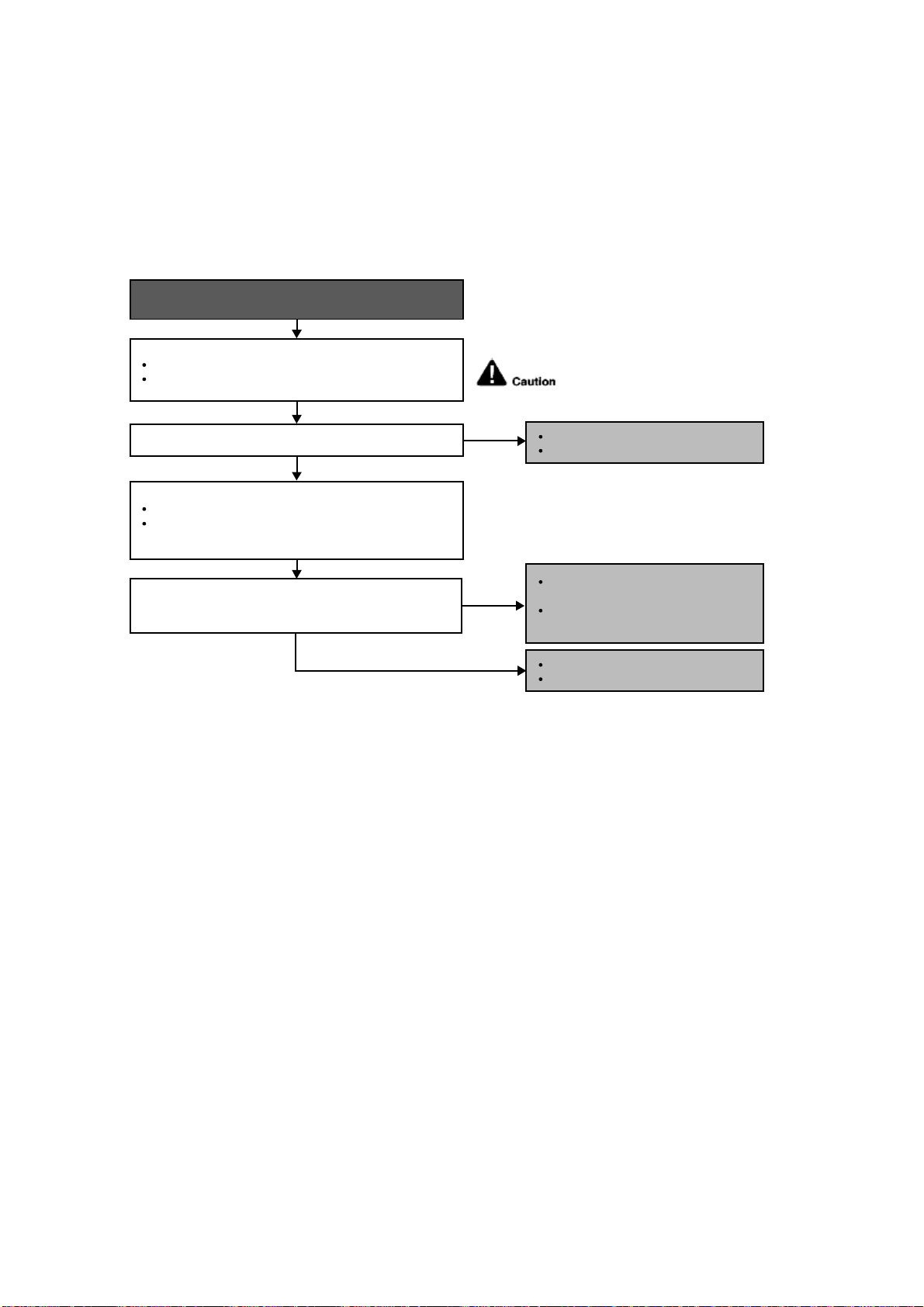
88
18.4.11 H32 (Outdoor Heat Exchanger Temperature Sensor 2 Abnormality)
Malfunction Decision Conditions
During startup and operation of cooling and heating, the temperatures detected by the outdoor heat exchanger
temperature sensor are used to determine sensor errors.
Malfunction Caused
Faulty connector connection.
Faulty sensor.
Faulty PCB.
Troubleshooting
When abnormality indication starts again.
For safety reason and to prevent
component breakdown, always switch
off the power before remove and
connect the component.
Is the measured resistance of the outdoor heat exchanger
temperature sensor matches the value specified in its
characteristic chart?
Is the connector connection normal?
YES
YES
Check the outdoor discharge pipe temperature sensor:
Plug out connector from the outdoor unit PCB.
Measure the resistance of the outdoor discharge pipe
temperature sensor.
Check the connector connection:
Turn off the power.
Check the connector connection.
Connector poor contact.
Correct the connection.
Defect in outdoor unit PCB.
Replace the outdoor unit PCB.
Defect in outdoor discharge pipe
temperature sensor.
Replace the outdoor discharge pipe
temperature sensor.
NO
NO
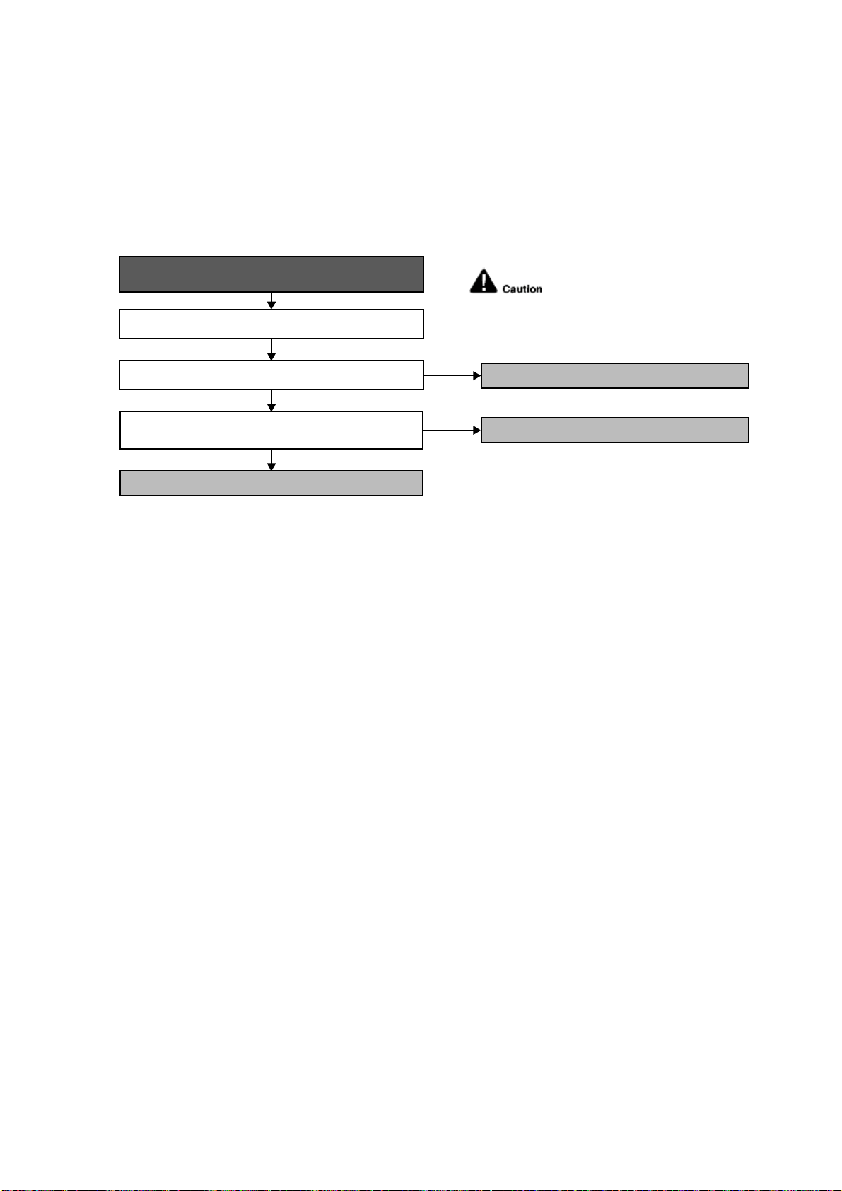
89
18.4.12 H33 (Unspecified Voltage between Indoor and Outdoor)
Malfunction Decision Conditions
The supply power is detected for its requirement by the indoor/outdoor transmission.
Malfunction Caused
Wrong models interconnected.
Wrong indoor unit and outdoor unit PCBs used.
Indoor unit or outdoor unit PCB defective.
Troubleshooting
When abnormality indication starts again.
For safety reason and to prevent
component breakdown, always switch
off the power before remove and
connect the component.
Check indoor and outdoor units model number.
Check indoor and outdoor PCB part number and compare if
they matched the part list.
NO
NO
Is the indoor and outdoor unit model number matched?
● Match the compatible model (follow specification).
YES
● Replace the indoor and outdoor unit PCB.
Change for the specified indoor or outdoor unit PCB.
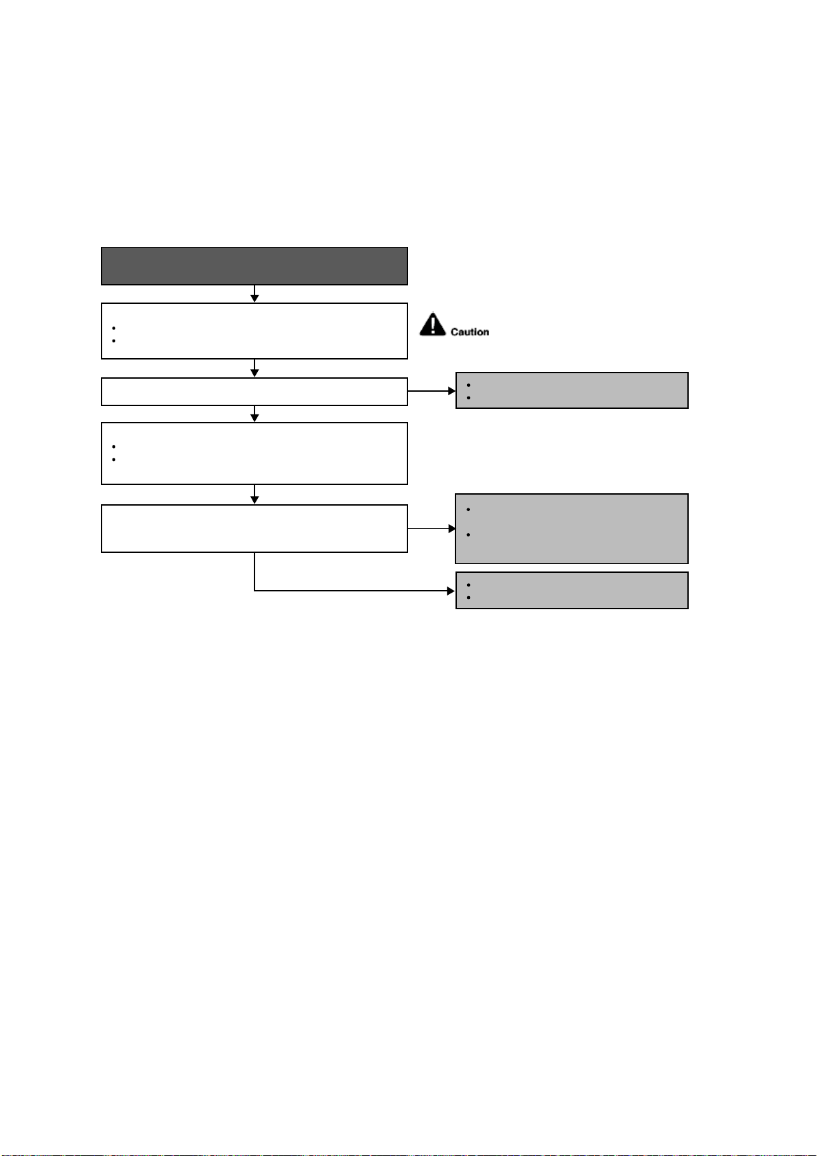
90
18.4.13 H36 (Outdoor Gas Pipe Sensor Abnormality)
Malfunction Decision Conditions
During startup and operation of cooling and heating, the temperatures detected by the outdoor gas pipe
temperature sensor are used to determine sensor errors.
Malfunction Caused
Faulty connector connection.
Faulty sensor.
Faulty PCB.
Troubleshooting
Is the measured resistance of the outdoor gas pipe
temperature sensor matches the value specified in its
characteristic chart?
Is the connector connection normal?
When abnormality indication starts again.
For safety reason and to prevent
component breakdown, always switch
off the power before remove and
connect the component.
NO
NO
YES
YES
Check the outdoor discharge pipe temperature sensor:
Plug out connector from the outdoor unit PCB.
Measure the resistance of the outdoor discharge pipe
temperature sensor.
Check the connector connection:
Turn off the power.
Check the connector connection.
Connector poor contact.
Correct the connection.
Defect in outdoor unit PCB.
Replace the outdoor unit PCB.
Defect in outdoor discharge pipe
temperature sensor.
Replace the outdoor discharge pipe
temperature sensor.
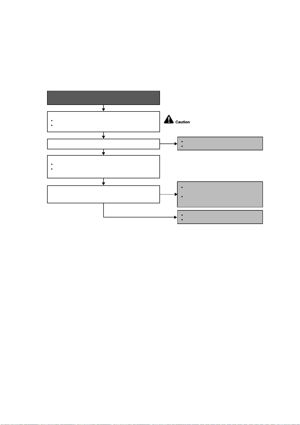
91
18.4.14 H37 (Outdoor Liquid Pipe Temperature Sensor Abnormality)
Malfunction Decision Conditions
During startup and operation of cooling and heating, the temperatures detected by the outdoor liquid pipe
temperature sensor are used to determine sensor errors.
Malfunction Caused
Faulty connector connection.
Faulty sensor.
Faulty PCB.
Troubleshooting
Is the measured resistance of the outdoor liquid pipe
temperature sensor matches the value specified in its
characteristic chart?
Is the connector connection normal?
When abnormality indication starts again.
For safety reason and to prevent
component breakdown, always switch
off the power before remove and
connect the component.
NO
NO
YES
YES
Check the outdoor discharge pipe temperature sensor:
Plug out connector from the outdoor unit PCB.
Measure the resistance of the outdoor discharge pipe
temperature sensor.
Check the connector connection:
Turn off the power.
Check the connector connection.
Connector poor contact.
Correct the connection.
Defect in outdoor unit PCB.
Replace the outdoor unit PCB.
Defect in outdoor discharge pipe
temperature sensor.
Replace the outdoor discharge pipe
temperature sensor.
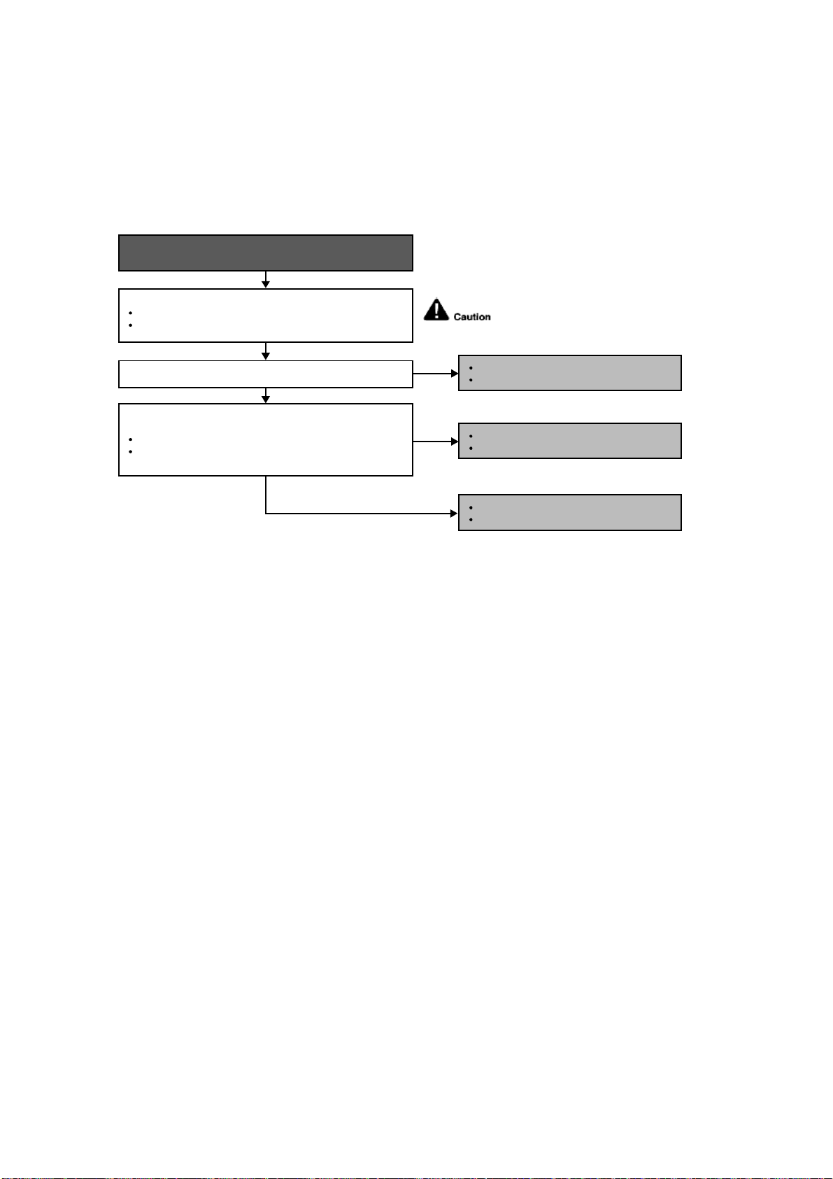
92
18.4.15 H59 (Human Activity Sensor Abnormality)
Malfunction Decision Conditions
Feedback signal of human activity sensor.
Malfunction Caused
Feedback signal is fixed at 0 VDC or 5 VDC continuously for 25 seconds during ECONAVI or AUTO COMFORT
operation.
Feedback signal is detected during ECONAVI or AUTO COMFORT off.
Troubleshooting
Is the connector connection normal?
When abnormality indication starts again.
For safety reason and to prevent
component breakdown, always switch
off the power before remove and
connect the component.
NO
YES
YES
Check if the feedback signal of human activity sensor
(pin 2 and 3) is normal.
When no motion, feedback is 0V.
When motion detected, feedback is between 1.5VDC
to 2.5VDC.
Check the connector connection:
Turn off the power.
Check the connector connection.
Connector poor contact.
Correct the connection.
Defect in outdoor unit PCB.
Replace the outdoor unit PCB.
NO
Defect in human activity sensor.
Replace the human activity sensor.
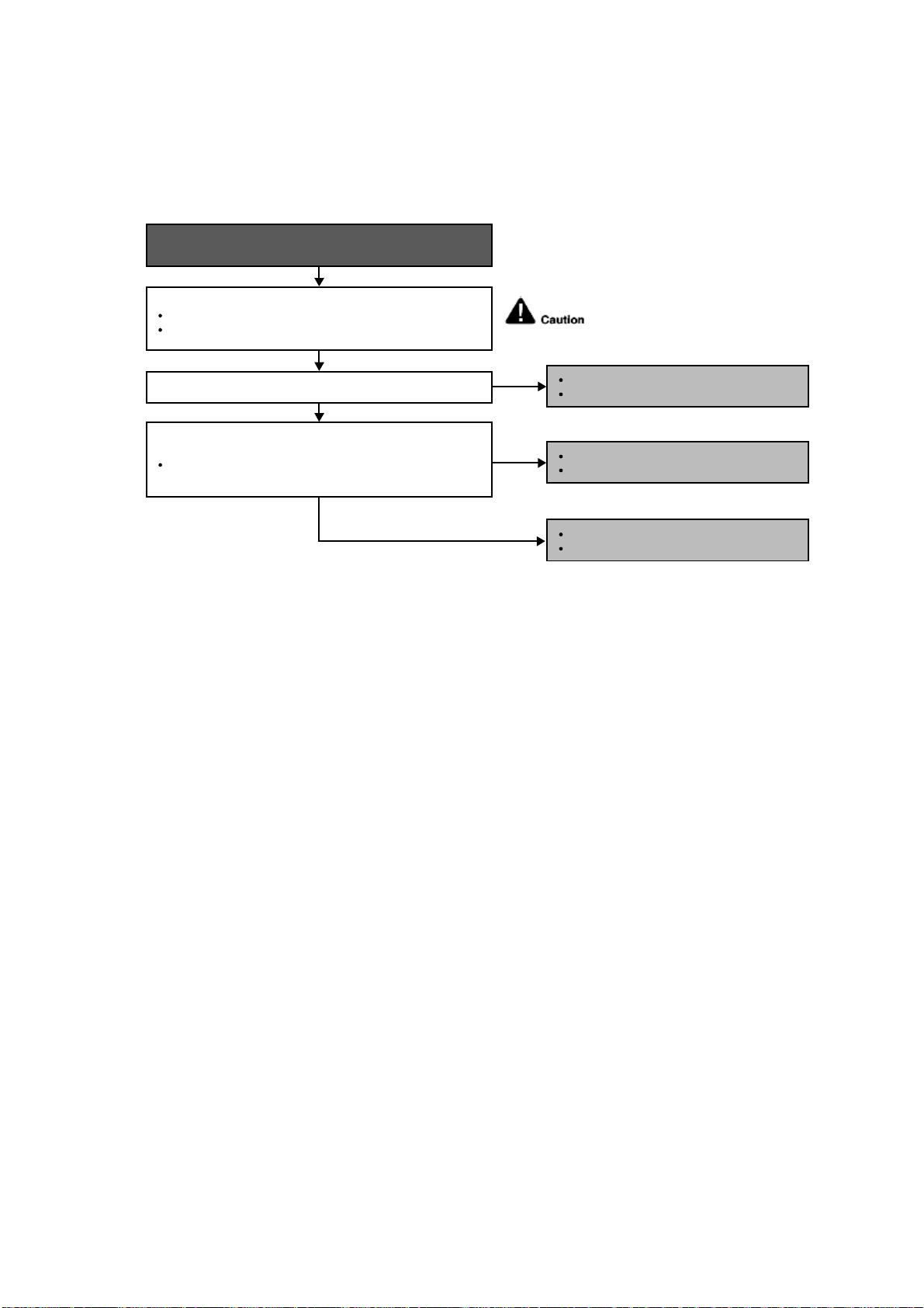
93
18.4.16 H70 (Light Sensor Abnormality)
Malfunction Decision Conditions
Feedback signal of light sensor.
Malfunction Caused
Feedback value is 0 VDC continuously.
Troubleshooting
Is the connector connection normal?
When abnormality indication starts again.
For safety reason and to prevent
component breakdown, always switch
off the power before remove and
connect the component.
NO
YES
YES
Check if the feedback signal of sunlight sensor (pin 11 and 13)
is normal.
Depends on indoor light intensity, feedback voltage
= 0.06 ~ 4.8 VDC (from dim to bright).
Check the connector connection:
Turn off the power.
Check the connector connection.
Connector poor contact.
Correct the connection.
Defect in indoor unit PCB.
Replace the indoor unit PCB.
NO
Defect in sunlight sensor.
Replace the sinlight sensor.
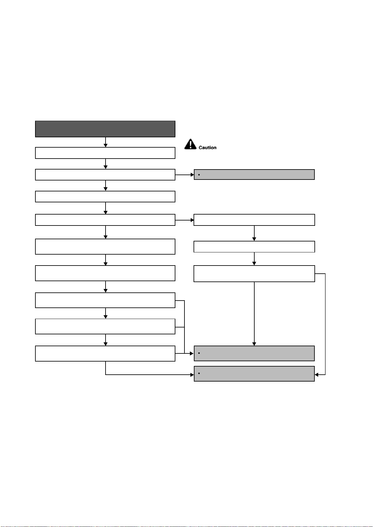
94
18.4.17 H97 (Outdoor Fan Motor – DC Motor Mechanism Locked)
Malfunction Decision Conditions
The rotation speed detected by the Hall IC during fan motor operation is used to determine abnormal fan motor.
Malfunction Caused
Operation stops due to short circuit inside the fan motor winding.
Operation stops due to breaking of wire inside the fan motor.
Operation stops due to breaking of fan motor lead wires.
Operation stops due to Hall IC malfunction.
Operation error due to faulty outdoor unit PCB.
Troubleshooting
Turn off power supply and rotate fan by hand.
When abnormality indication starts again.
Replace fan motor.
Does fan rotate smoothly?
Turn power supply on and operate fan.
Does it rotate? Stop fan motor.
Check the rotation feedback output from fan motor.
Rotate the fan motor by hand, is the rotation feedback
voltage 15 Vdc (pin 1 & 4) generated?
Turn off power supply and disconnect fan motor connector,
then turn power on.
Check the output of fan motor from outdoor PCB.
Is the motor power supply voltage ~325Vdc (pin 7 & 4)
generated?
Is the motor control voltage 15Vdc (pin 3 & 4) generated?
Operate the fan, is the rotation command voltage 1~5Vdc (pin 2
& 4) generated?
NO
NO
NO
NO
NO
NO
YES
YES
YES
YES
For safety reason and to prevent
component breakdown, always switch
off the power before remove and
connect the component.
Replace outdoor PCB.
Replace fan motor.
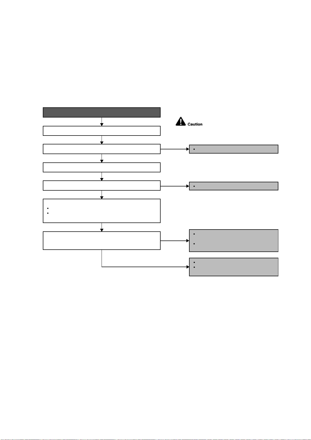
95
18.4.18 H98 (Error Code Stored in Memory and no alarm is triggered / no TIMER LED
flashing)
Malfunction Decision Conditions
Indoor high pressure is detected when indoor heat exchanger is detecting very high temperature when the unit is
operating in heating operation.
Phenomena: unit is stopping and re-starting very often in heating mode.
Malfunction Caused
Indoor heat exchanger thermistor.
Clogged air filter or heat exchanger.
Over-bent pipe (liquid side).
Troubleshooting
Is the measured resistance of the indoor pipe temperature
thermistor matches the value specified in its characteristic
chart?
Check the indoor unit intake air filter.
When abnormality indication starts again.
For safety reason and to prevent
component breakdown, always switch
off the power before remove and
connect the component.
YES
NO
NO
NO
YES
Check the indoor pipe temperature thermistor:
Plug out connector (CN-TH) from the indoor unit PCB.
Measure the resistance of the indoor heat exchanger
temperature thermistor.
Is the air filter dirty?
Check the dust accumulation on the indoor unit heat exchanger.
Is the indoor unit heat exchanger dirty?
Clean the air filter.
Check the piping & installation condition.
Replace piping / reinstall the unit if
necessary.
Defect in indoor pipe temperature
thermistor.
Replace the indoor pipe temperature
thermistor.
YES
Clean the indoor unit heat exchanger.
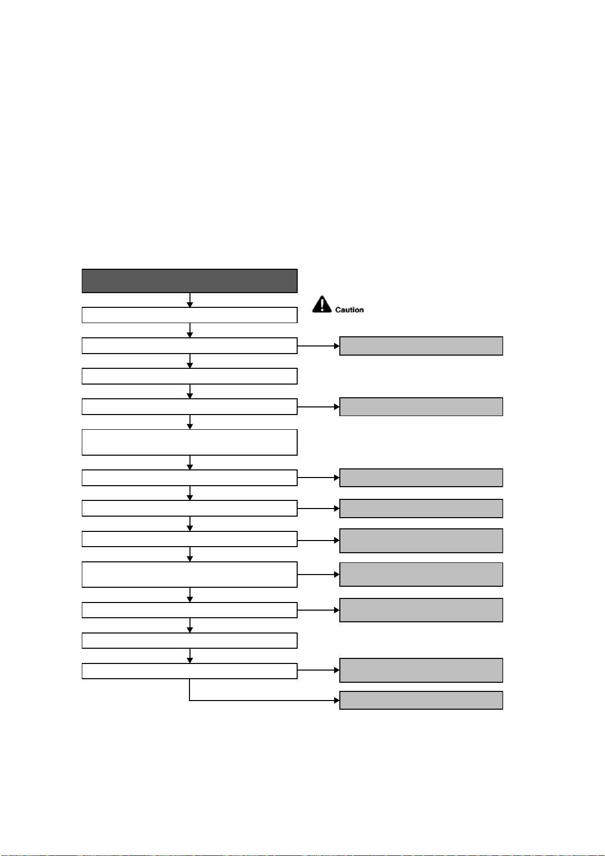
96
18.4.19 H99 (Indoor Freeze Prevention Protection: Cooling or Soft Dry)
Error Code will not display (no Timer LED blinking) but store in EEPROM
Malfunction Decision Conditions
Freeze prevention control takes place (when indoor pipe temperature is lower than 2°C).
Malfunction Caused
Air short circuit at indoor unit.
Clogged indoor unit air filter.
Dust accumulation on the indoor unit heat exchanger.
2/3 way valve closed.
Faulty indoor unit fan motor.
Refrigerant shortage (refrigerant leakage).
Clogged expansion valve or strainer.
Faulty indoor pipe temperature sensor.
Faulty indoor unit PCB.
Troubleshooting
Check the air passage.
When abnormality indication starts again.
For safety reason and to prevent
component breakdown, always switch
off the power before remove and
connect the component.
Is there any short circuit?
YES
YES
YES
YES
YES
YES
YES
NO
NO
Check the indoor unit air filter.
Is the air filter dirty?
Is the indoor unit heat exchanger dirty?
Check if 2/3 way valve is closed?
Check if indoor fan motor operates normally?
Check if expansion valve or strainer clogged (ice formed)?
Does it conform to the sensor characteristic chart?
Check the indoor pipe temperature sensor.
Check the dust accumulation on the indoor unit heat
exchanger.
Check for gas leakage, Is oil oozing out from the 2/3 way
valve?
● Provide sufficient air passage.
● Clean the air filter.
● Clean the indoor unit heat exchanger.
● Open the 2/3 way valve.
● Replace the indoor unit PCB.
● Replace the indoor pipe temperature
sensor.
● Reclaim and recharge with correct
amount of refrigerant.
● Replace the indoor unit fan motor and/or
indoor unit PCB.
● Repair the pipe flare or union nuts.
● Reclaim and recharge refrigerant.
NO
NO
NO
NO
YES
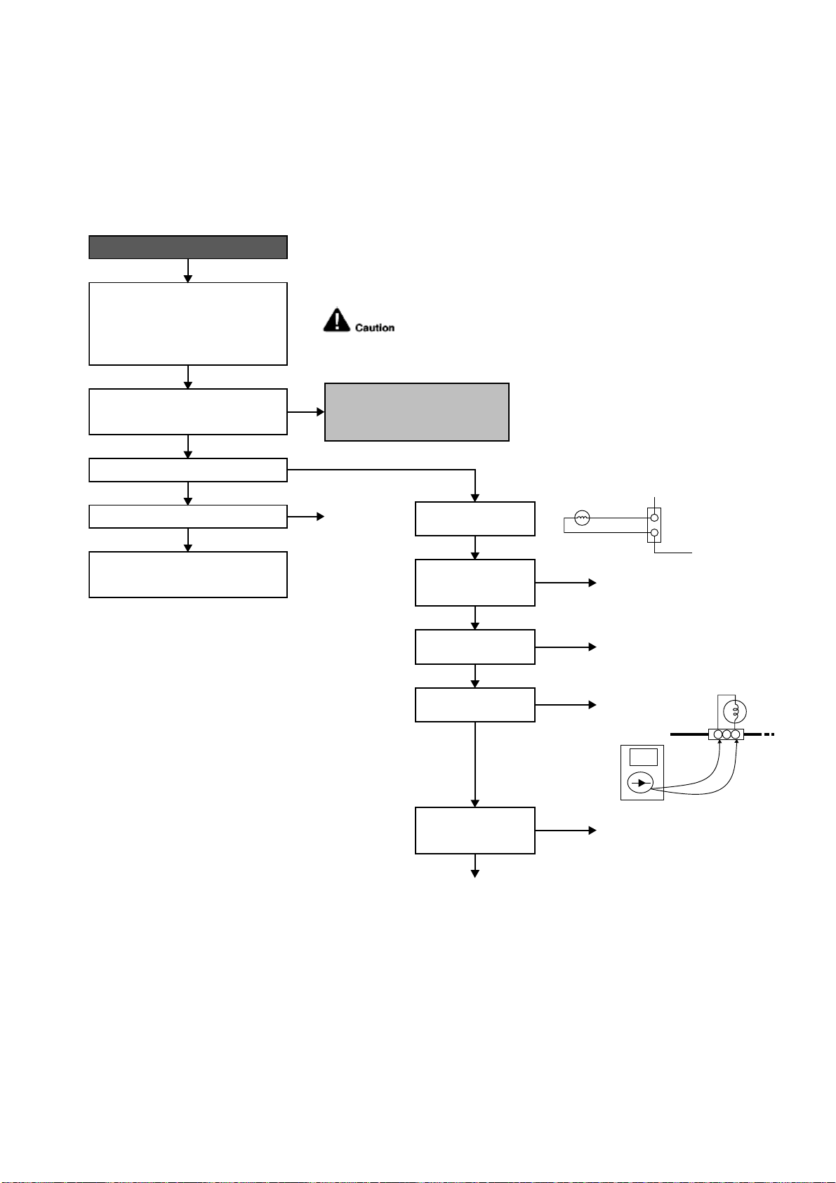
97
18.4.20 F11 (4-way Valve Switching Failure)
Malfunction Decision Conditions
When indoor heat exchanger is cold during heating (except deice) or when indoor heat exchanger is hot during
cooling and compressor operating, the 4-way valve is detected as malfunction.
Malfunction Caused
Indoor heat exchanger (pipe) thermistor
4-way valve malfunction
Troubleshooting
* Check gas side pipe – for hot gas flow in cooling mode
1 2 3
CN-HOT
(VH3-2)
4WAYS
VALVE
For safety reason and to prevent component
breakdown, always switch off the power before
remove and connect the component.
When abnormality starts again.
Problem occurs in heating mode only?
4-way valve not working
(not energize).
Check V-coil attach to
solenoid valve.
Check valve v-coil
continuity.
Check CN-HOT
connection
(4-way valve connector).
Measure voltage
supplied to CN-HOT at
the start of heating.
Check the indoor pipe temperature
thermistor:
● Plug out connector (CN-TH) from the
indoor unit PCB.
● Measure the resisitance of the indoor
heat exchanger temperature thermistor.
● Defect in indoor pipe temperature
thermistor.
● Replace the indoor pipe temperature
thermistor.
Outdoor PCB fault
● Replace Outdoor PCB.
Reverse solenoid value faulty
● Replace the 4-way valve.
● Reconnect CN-HOT
(4-way valve connector).
V-coil fault
● Replace
V-coil only.
● Attach and screw the V-coil
to solenoid valve.
Remove CN-HOT.
Measure continuity
of the coil.
Outdoor PCB fault
● Replace
Outdoor PCB.
No supply.
OK
OK (Depending on 4-way valve model).
OK
OK
YES
No
Good.
4 WAYS VALVE
COIL COMPLETE
YELLOW
YELLOW
CN-HOT
(WHT)
1
2
No
Good.
No
continuity
(open).
YES
YES
NO
NO
NO, it happen in cooling/dry as well.
● Check connecting tubes to 4-way valve.
Is the measured resistance of the indoor pipe
temperature thermistor matches the value
specified in its characteristic chart?
The 4-way valve may have been damaged or
wrongly connected between discharge and
suction tube.
Is 4-way solenoid valve being energised?
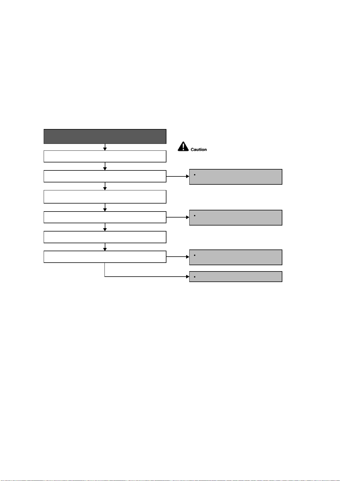
98
18.4.21 F17 (Indoor Standby Units Freezing Abnormality)
Malfunction Decision Conditions
When the different between indoor intake air temperature and indoor pipe temperature is above 50°F or indoor
pipe temperature is below 30.2°F
Remark:
When the indoor standby unit is freezing, the outdoor unit transfers F17 error code to the corresponding indoor
unit and H39 to other indoor unit(s).
Malfunction Caused
Wrong wiring connection
Faulty sensor
Faulty expansion valve
Troubleshooting
When F17 indication happens.
For safety reason and to prevent
component breakdown, always switch
off the power before remove and
connect the component.
Check the system wiring connection.
YES
YES
NO
Is the wiring connection ok?
Perform Auto Wiring to correct the wiring
connection.
NO
Replace the indoor intake air or indoor
pipe temperature sensor.
NO
Replace the solenoid coil or expansion
valve.
Replace outdoor unit PCB.
YES
Does it conform to the sensor characteristic chart?
Check the expansion valve.
Is the expansion valve ok?
Check the indoor intake air and indoor pipe temperature
sensors.
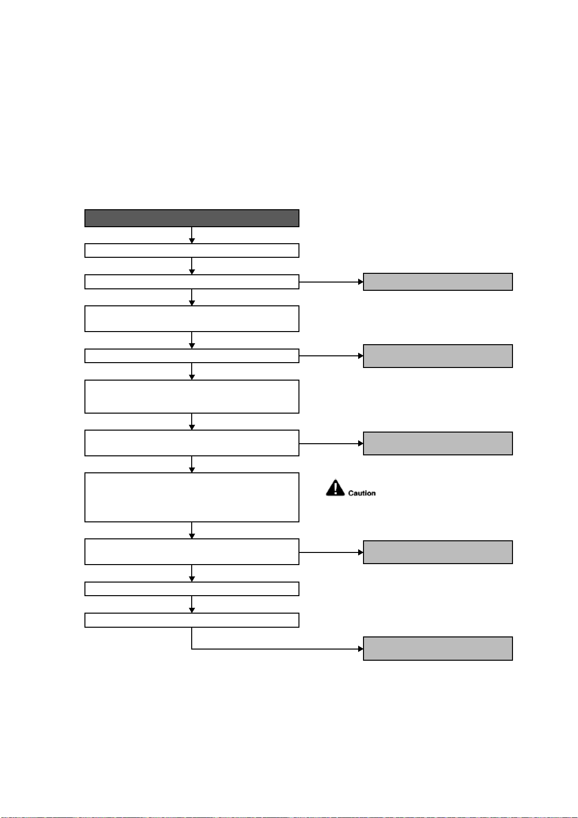
99
18.4.22 F90 (Power Factor Correction Protection)
Malfunction Decision Conditions
To maintain DC voltage level supply to power transistor.
To detect high DC voltage level after rectification.
Malfunction Caused
During startup and operation of cooling and heating, when Power Factor Correction (PFC) protection circuitry at
the outdoor unit main PCB senses abnormal DC voltage level for power transistors.
When DC voltage detected is LOW, transistor switching will turn ON by controller to push-up the DC level.
When DC voltage detected is HIGH (391Vdc – 425Vdc), active LOW signal will send by the controller to turn OFF
relay RY-C.
Troubleshooting
When abnormality indication starts again.
Reset the error code and turn on the unit again.
Is AC power supply normal fluctuation?
Verify PFC abnormality by measuring DC voltage between
DCP(+) and DCN(-) at the capacitor PCB.
Is the DC voltage between DCP(+) and DCN(-) normal?
Check the reactor impedance.
Is the impedence of the reactor low?
Is the DC voltage between CN-FM1 and 4 of the outdoor fan
motor normal?
Are the compressor’s winding resistance (U-V, V-W, U-W)
uniform?
Confirm the DC voltage between CN-FM 1 and 4 when
compressor is running. Normal voltage range should be
between 265-325Vdc.
NO
YES
YES
YES
NO (391.2Vdc ~ 425Vdc)
● AC power supply abnormal surge.
YES (~280Vdc)
● Defect in PFC circuitry.
● Replace the outdoor unit PCB.
NO
● Defect in outdoor fan motor.
● Replace outdoor fan motor.
NO
● Defect in compressor.
● Replace compressor.
● Defect in reactor.
● Replace reactor.
For safety reason and to prevent
component breakdown, always
switch off the power before remove
and connect the component.
Check the compressor winding resistance:
● Turn off the power and disconnect the harnesses U, V,
and W.
● Measure the winding resistance between U-V, V-W, and
W-U.
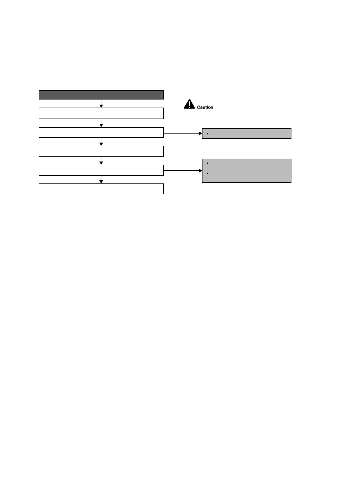
100
18.4.23 F91 (Refrigeration Cycle Abnormality)
Malfunction Decision Conditions
The input current is low while the compressor is running at higher than the setting frequency.
Malfunction Caused
Lack of gas.
3-way valve close.
Troubleshooting
When F91 indication happens.
For safety reason and to prevent
component breakdown, always switch
off the power before remove and
connect the component.
Open 3 way valve.
NO, closed.
NO, gas amount is OK.
Check 3 way valve.
3-way valve opened?
Check for gas leaking source (Refer H16).
Gas leaking?
Check other parts in refrigeration cycles.
Check for gas leaking source;
Repair or replace defected part(s).
Re-claim and then re-charge the
right amount.
YES
YES
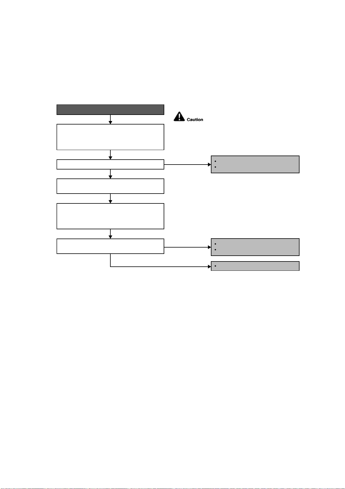
101
18.4.24 F93 (Compressor Rotation Failure)
Malfunction Decision Conditions
A compressor rotation failure is detected by checking the compressor running condition through the position
detection circuit.
Malfunction Caused
Compressor terminal disconnect.
Faulty Outdoor PCB.
Faulty compressor.
Troubleshooting
When F93 indication happens.
Check the U, V and W connector connection:
-TurnOFFthepower.
- Check the U, V and W connector connection at
outdoor PCB and compressor terminal.
NO
From the disconnected harnesses U, V and W,
correct them to the inverter checker. Turn ON the
power and operate the system. Check the inverter
checker 6 LEDs blinking condition.
Disconnect the harnesses U, V and W from the
compressor terminal.
Is the blinking of the 6 LEDs in same
sequence/condition.
Is the connector connection normal?
For safety reason and to prevent
component breakdown, always
switch off the power before remove
and connect the component.
Correct the connection.
Connector poor contact.
NO
YES
YES
Replace outdoor unit PCB.
IPM defective.
Replace compressor.

102
18.4.25 F95 (Outdoor High Pressure Protection: Cooling or Soft Dry)
Malfunction Decision Conditions
During operation of cooling or soft dry, when outdoor unit heat exchanger high temperature data is detected by
the outdoor unit heat exchanger thermistor.
Malfunction Caused
Outdoor heat exchanger temperature rise due to short-circuit of hot discharge air flow.
Outdoor heat exchanger temperature rise due to defective of outdoor fan motor.
Outdoor heat exchanger temperature rise due to defective outdoor heat exchanger thermistor.
Outdoor heat exchanger temperature rise due to defective of outdoor unit PCB.
Troubleshooting
For safety reason and to prevent component
breakdown, always switch off the power
before remove and connect the component.
When abnormality indication starts again.
Is there any improper heat radiation?
Is the outdoor fan motor operating?
Check the outdoor unit installation condition
(during cooling or soft dry operation).
Is the measured resistance of the outdoor
heat exchanger thermistor matches the
value specified in its characteristic chart?
Reset the error code and turn on the unit
again.
Check the outdoor heat exchanger
thermistor:
● Turn off the power and disconnect the
connector of outdoor heat exchanger
thermistor from the PCB.
● Measure the resistance of the outdoor
heat exchanger thermistor.
● Reinstall the outdoor unit.
● Remove the obstacle(s).
● Clean the outdoor heat exchanger.
Measure the AC/DC voltage between
pins of connector CN-FM outdoor unit
PCB.
Is the voltage supplied to the outdoor
fan motor normal?
● Defect in outdoor unit PCB.
● Replace the outdoor unit PCB.
● Defect in outdoor unit PCB.
● Replace the outdoor unit PCB.
● Defect in outdoor heat exchanger
thermistor.
● Replace the outdoor heat exchanger
thermistor.
● Defect in outdoor fan motor.
● Replace the outdoor fan motor.
NO
NO
NO
YES
NO (0V)
YES (240VAC / 265~326VDC)
YES
YES
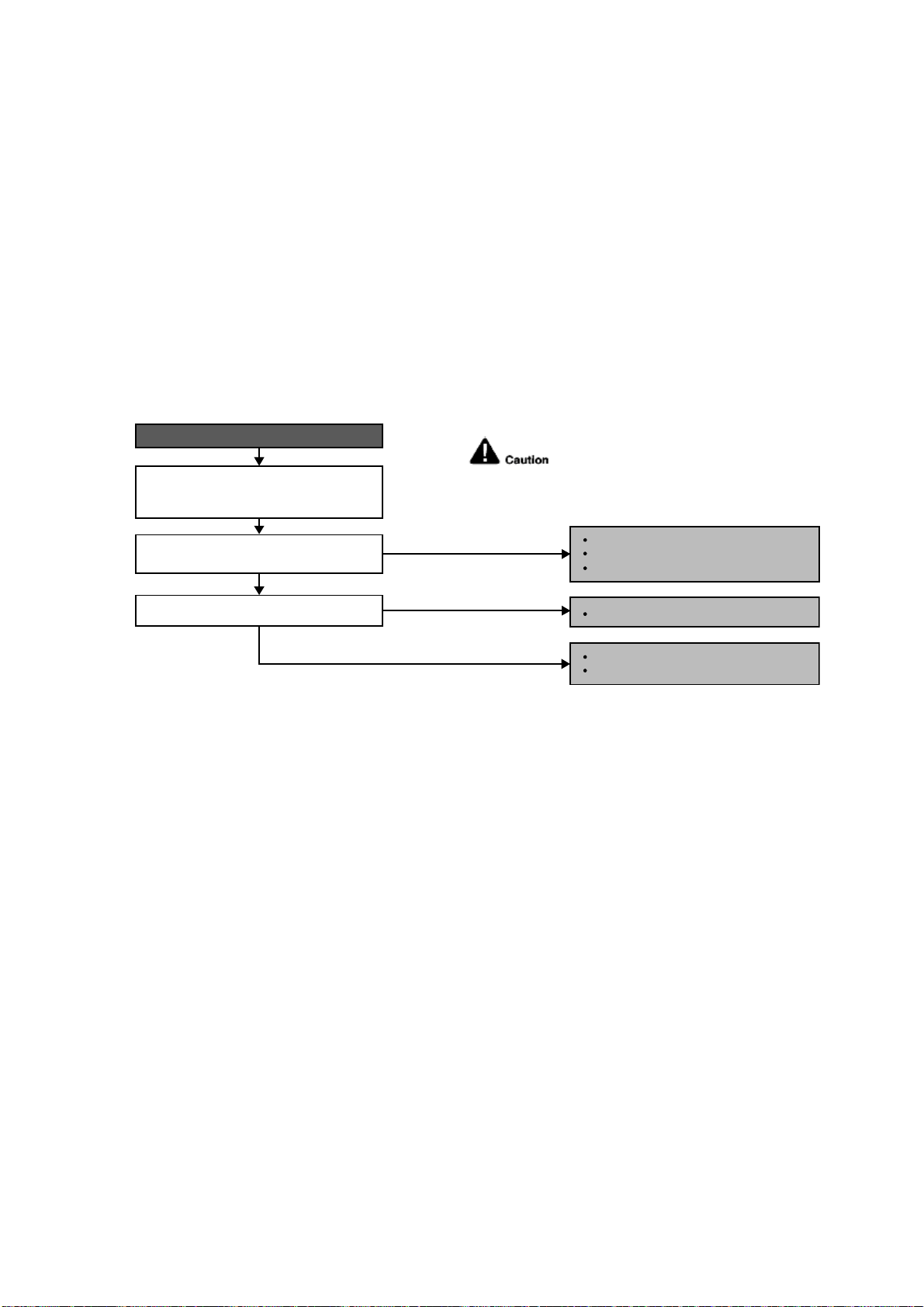
103
18.4.26 F96 (IPM Overheating)
Malfunction Decision Conditions
During operating of cooling and heating, when IPM temperature data (212°F) is detected by the IPM temperature
sensor.
Multi Models only
o Compressor Overheating: During operation of cooling and heating, when the compressor OL is activated.
o Heat Sink Overheating: During operation of cooling and heating, when heat sink temperature data (194°F) is
detected by the heat sink temperature sensor.
Malfunction Caused
IPM overheats due to short circuit of hot discharge air flow.
IPM overheats due to defective of outdoor fan motor.
IPM overheats due to defective of internal circuitry of IPM.
IPM overheats due to defective IPM temperature sensor.
Multi Models Only
o Compressor OL connector poor contact.
o Compressor OL faulty.
Troubleshooting
When F96 indication happens.
For safety reason and to prevent component
breakdown, always switch off the power
before remove and connect the component.
Check the outdoor unit installation
condition (during cooling or soft-dry
operation).
Is there any improper heat radiation?
YES
YES
NO
NO
Reinstall the outdoor unit.
Replace the outdoor fan motor.
Remove the obstacle(s).
Clean the outdoor heat exchanger.
Defect in IPM.
Replace the outdoor unit PCB.
Is outdoor fan motor operating?
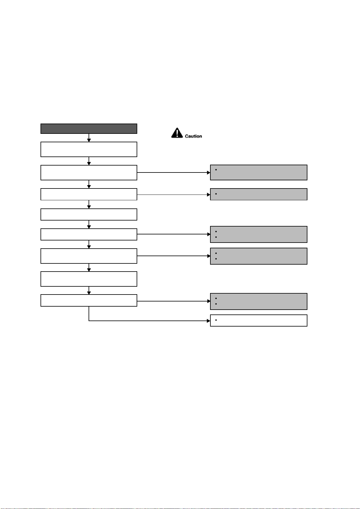
104
18.4.27 F97 (Compress or Overheating)
Malfunction Decision Conditions
During operation of cooling and heating, when compressor tank temperature data (233.6°F) is detected by the
compressor tank temperature sensor.
Malfunction Caused
Faulty compressor tank temperature sensor
2/3 way valve closed
Refrigerant shortage (refrigerant leakage)
Faulty outdoor unit PCB
Faulty compressor
Troubleshooting
When F97 indication happens.
For safety reason and to prevent component
breakdown, always switch off the power
before remove and connect the component.
Replace the compressor tank
temperature sensor.
Repair the pipe flare or union nuts.
Reclaim and recharge refrigerant.
Open the 2/3 way valve.
Procedure complete.
Check the compressor tank temperature
sensor.
Does it conform to the sensor
characteristic chart?
Check if expansion valve or strainer
clogged (ice formed).
Reclaim and recharge for a specified
amount of refrigerant.
2/3 way valve closed?
Check for gas leakage.
Oil oozing out from the 2/3 way valve?
Refrigerant cycle abnormality error again?
YES
YES
YES
NO
NO
NO
NO
NO
Replace expansion valve and/or strainer.
Reclaim and recharge refrigerant.
YES
Replace outdoor unit PCB.
Replace outdoor unit compressor.
YES
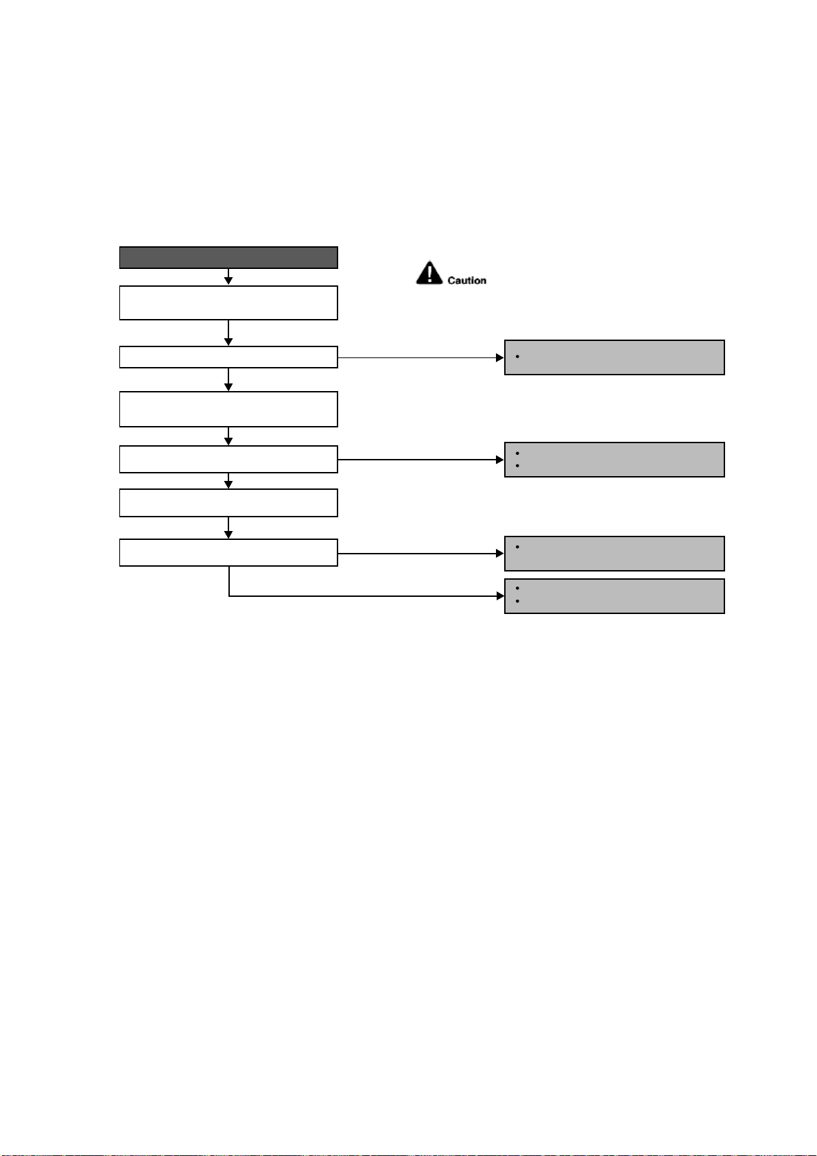
105
18.4.28 F98 (Input Over Current Detection)
Malfunction Decision Conditions
During operation of cooling and heating, when an input over-current (X value in Total Running Current Control) is
detected by checking the input current value being detected by current transformer (CT) with the compressor
running.
Malfunction Caused
Excessive refrigerant.
Faulty outdoor unit PCB.
Troubleshooting
For safety reason and to prevent component
breakdown, always switch off the power
before remove and connect the component.
Replace the outdoor unit PCB.
Repair the pipe flare or union nuts.
Reclaim and recharge refrigerant.
Reclaim and recharge with correct
amount of refrigerant.
Replace outdoor unit PCB.
Replace outdoor unit compressor.
When F98 indication happens.
Get restarted and measure the input
current.
Turn off power supply. Check the main
circuit electrolytic capacitor.
Input current > limit?
Normal?
Check refrigerant amount.
Excess refrigerant?
YES
YES
YES
NO
NO
NO
NO
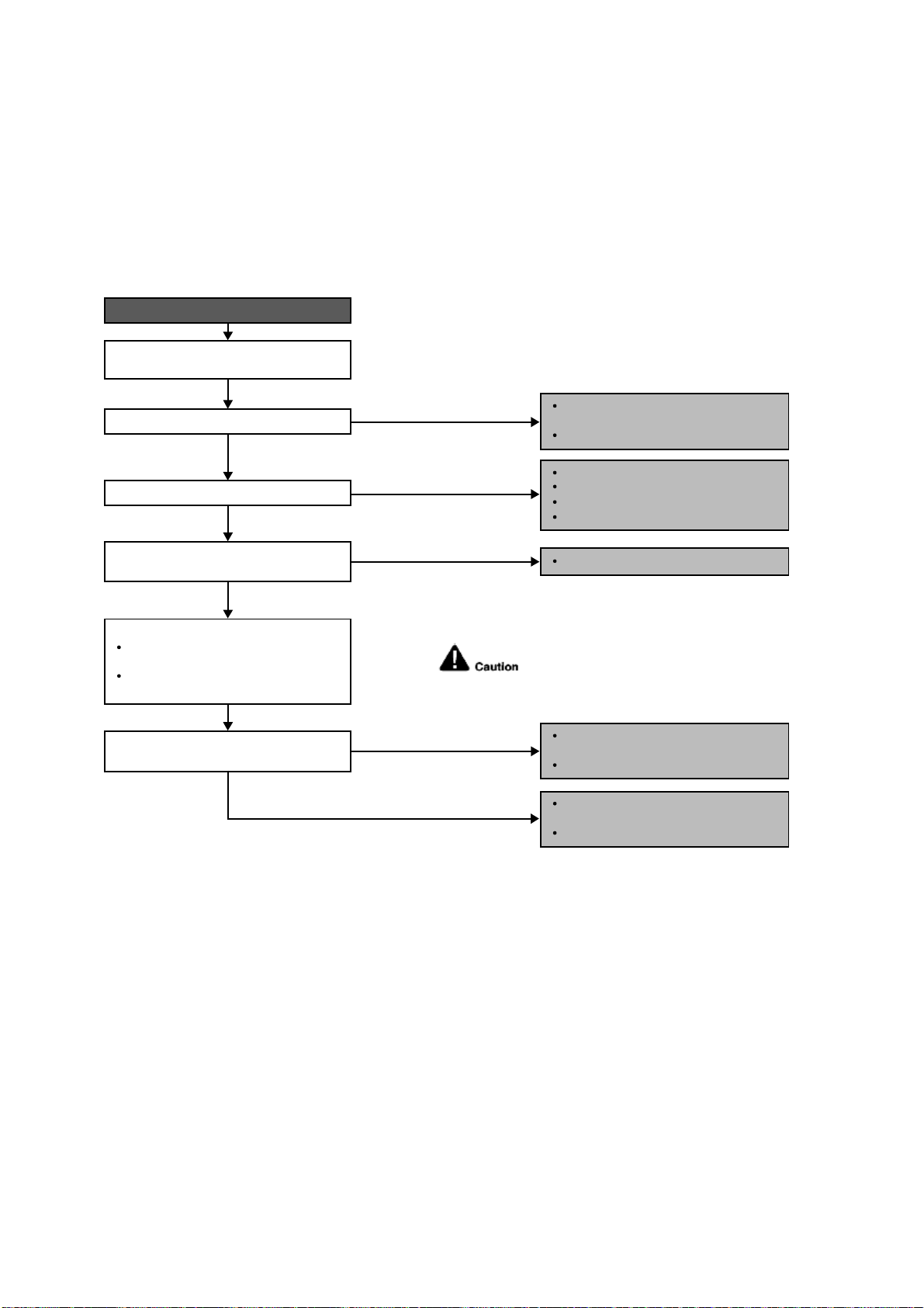
106
18.4.29 F99 (DC Peak Detection)
Malfunction Decision Conditions
During startup and operation of cooling and heating, when inverter DC peak data is received by the outdoor internal
DC Peak sensing circuitry.
Malfunction Caused
DC current peak due to compressor failure.
DC current peak due to defective power transistor(s).
DC current peak due to defective outdoor unit PCB.
DC current peak due to short circuit.
Troubleshooting
For safety reason and to prevent component
breakdown, always switch off the power
before remove and connect the component.
Outdoor electronic circuit defect due to
power transistor short.
Excessive amount of refrigerant.
Replace the outdoor unit PCB.
Compressor defective due to
mechanical locked.
Replace compressor.
Compressor defective due to winding
shorted.
Replace compressor.
Amplification IC defect.
Diode defect.
Defect in microcontroller.
Replace the outdoor unit PCB.
When abnormality indication starts again.
Reset the error code and turn on the unit
again.
Is there no change even if all refrigerant
is discharged?
Are the compressor’s winding resistance
(U-V, V-W or U-W) shorted?
Is there a sound when compressor starts?
Is compressor vibration even?
YES
YES
YES
Turn off the power and disconnect
the harnesses U, V and W.
Measure the winding resistance
between U-V, V-W and W-U.
Check the compressor winding resistance:
NO (Compressor stops)
NO (Normal)
NO (Normal)
NO (Quite a lot of vibration at
start operation)
YES (Stops after 2, 3 seconds
of noise during operation)
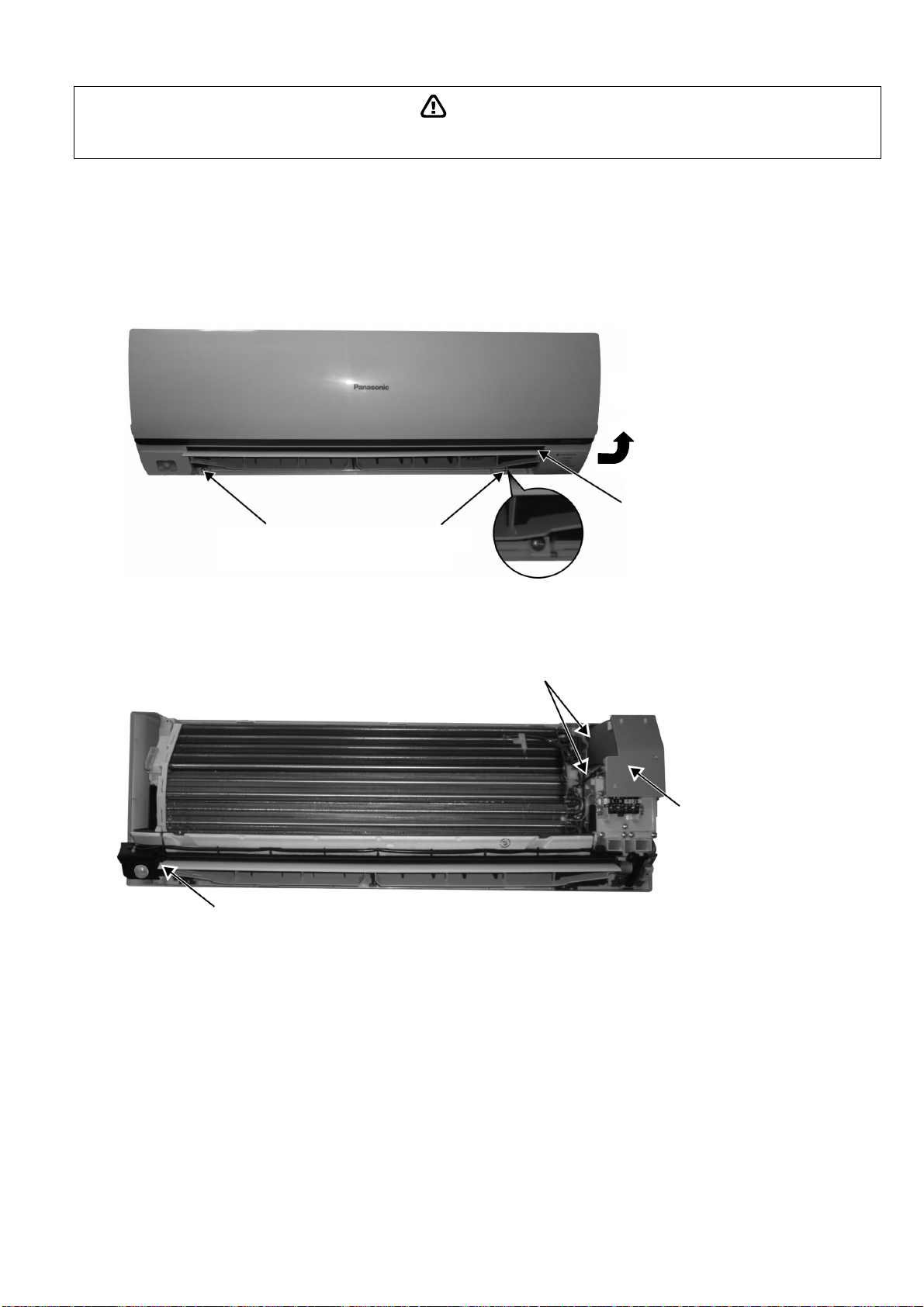
107
WARNING
19. Disassembly and Assembly Instructions
High Voltage is generated in the electrical parts area by the capacitor. Ensure that the capacitor has discharged sufficiently before proceeding with
repair work. Failure to heed this caution may result in electric shocks.
19.1 CS-E9RKUAW CS-E12RKUAW
19.1.1 Indoor Electronic Controllers, Cross Flow Fan and Indoor Fan Motor Removal
Procedures
19.1.1.1 To remove front grille
Figure 1
19.1.1.2 To remove power electronic controller
Figure 2
2. Remove 2 caps and 2 screws at the
bottom of discharge vane.
3. Hold both sides of the front grille and
remove it by pulling up and toward
yourself gently.
1. Lift to open the vertical vane
gently.
5. Remove the control
board cover by releasing
the 2 hooks.
4. Remove the eco sensor complete by screw.
2 Hooks (left hand side)
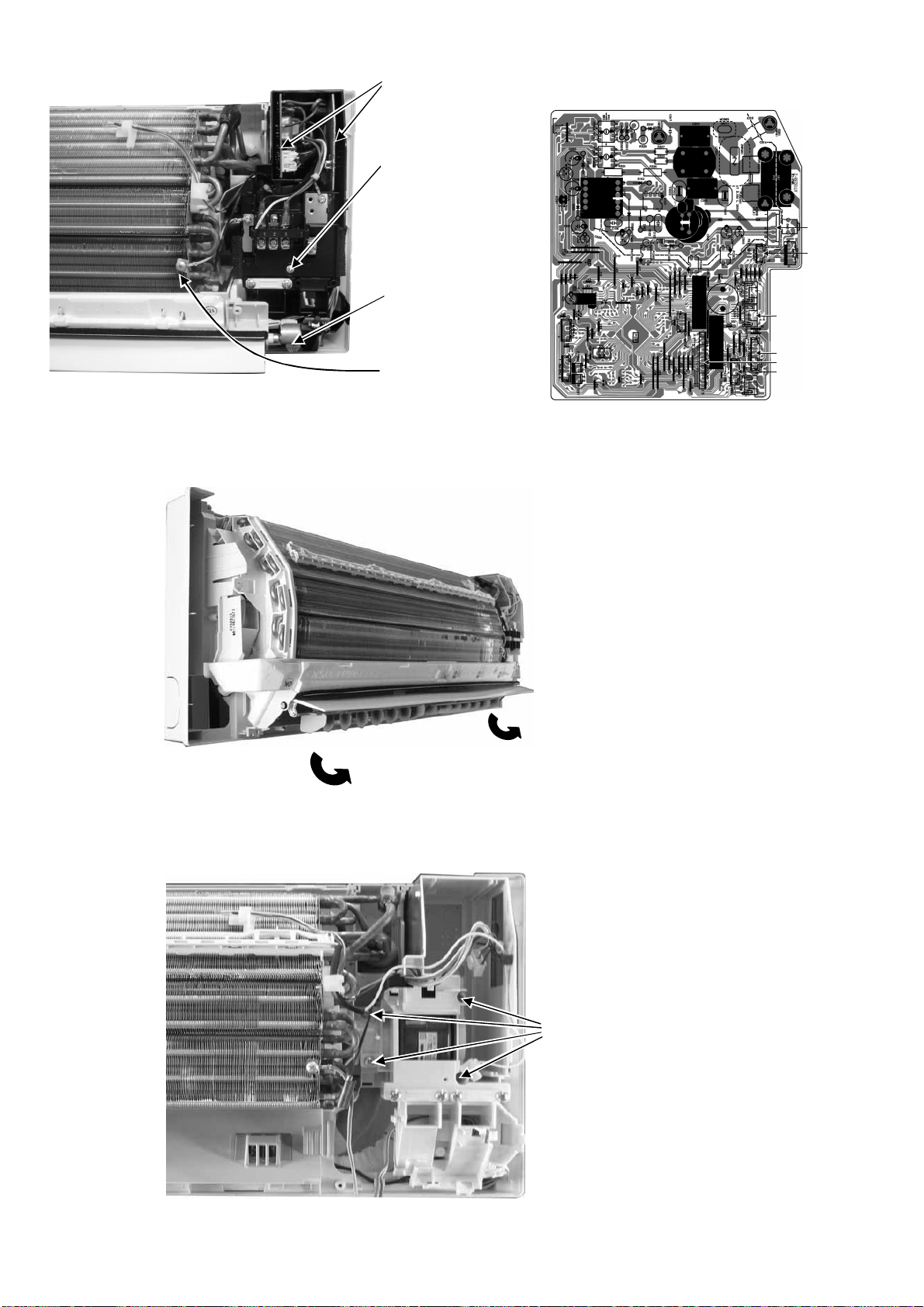
108
Figure 3 Figure 4
19.1.1.3 To remove discharge grille
Figure 5
19.1.1.4 To remove control board
Figure 6
CN-RMT
CN-FM
CN-STM1
CN-MSENS
CN-TH
CN-DISP
7. Detach the CN-DISP
connector then remove
the indicator complete.
10. Detach 3 or 4 connectors as labeled from
the electronic controller. Then pull out
main controller gently
9. Pull out the main
electronic controller and
power electronic
controller halfway.
8. Remove screw to
remove terminal board
complete.
6. Detach the Earth wire
11. Pull out to remove the drain hose
from the discharge grille
12. Then pull the discharge grille
downward gently to dismantle it
13. Remove 4 screws holding the
control board then pull out the
control board.
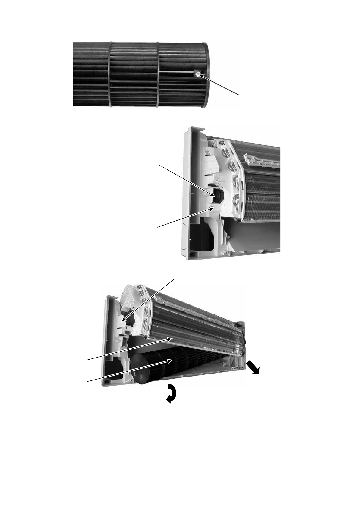
109
19.1.1.5 To remove cross flow fan and indoor fan motor
Figure 7
Figure 8
Figure 9
14. Remove the screw that holding
the cross flow fan and fan motor
axis.
16. Remove the bearing by pulling it
out gently
15. Remove the screw from the
evaporator.
17. Push the holdfast to the left and lift up the evaporator.
19. Fan motor can be removed after the
removal of cross flow fan.
Reminder: To reinstall the fan motor, adjust
the fan motor connector to 45° towards you
before fixing control board.
18. Remove the cross flow fan from the unit by
pulling it to the left and downward.
Evaporator
Cross flow f an
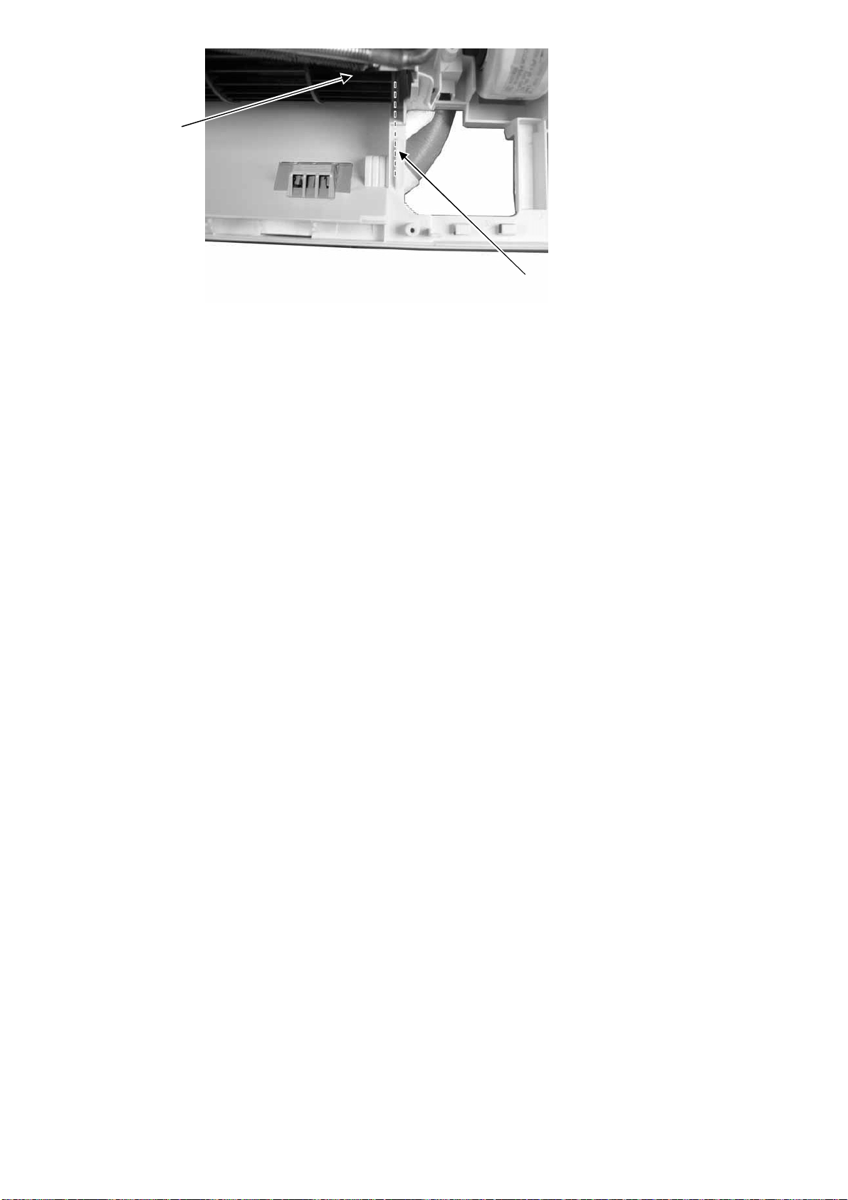
110
Figure 10
Reminder: To reinstall the cross flow
fan, ensure cross flow fan is in line as
shown in figure 10
Cross Flow Fan
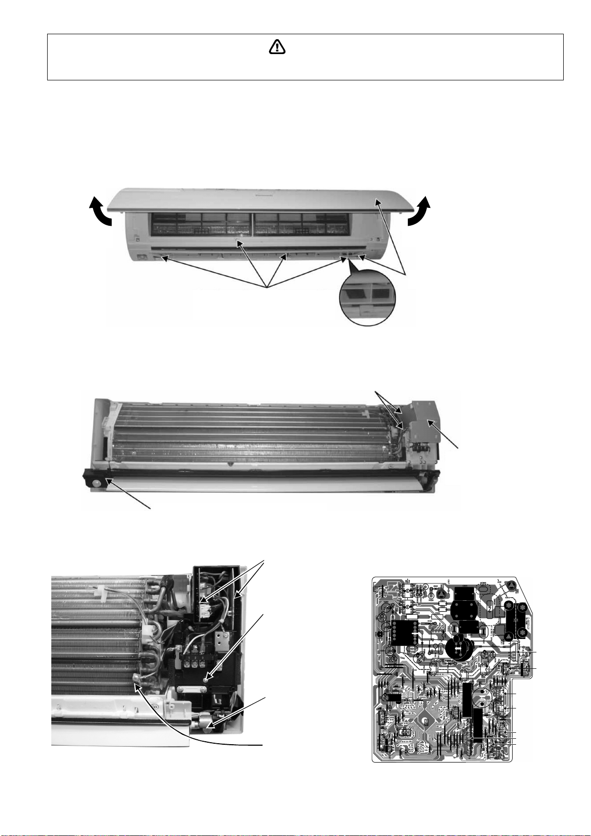
111
WARNING
High Voltage is generated in the electrical parts area by the capacitor. Ensure that the capacitor has discharged sufficiently before proceeding with
repair work. Failure to heed this caution may result in electric shocks.
19.2 CS-E18RKUAW CS-E24RKUAW
19.2.1 Indoor Electronic Controllers, Cross Flow Fan and Indoor Fan Motor Removal
Procedures
19.2.1.1 To remove front grille
Figure 1
19.2.1.2 To remove power electronic controller
Figure 2
Figure 3 Figure 4
1. Lift to open the horizontal vane
and intake grille gently.
2. Remove 3 caps and 4 screws at the
bottom of the discharge vane.
3. Hold both sides of the front
grille and remove it by pulling
up and toward you gently.
4. Remove the eco sensor complete by screw.
5. Remove the control
board cover by
releasing the 2 hooks.
2 Hooks (left hand side)
7. Detach the CN-DISP
connector then remove
the indicator complete.
10. Detach 3 or 4 connectors as labeled from
the electronic controller. Then pull out
main controller gently
9. Pull out the main
electronic controller and
power electronic
controller halfway.
8. Remove screw to
remove terminal board
complete.
6. Detach the Earth wire
CN-RMT
CN-FM
CN-STM1
CN-STM2
CN-MSENS
CN-TH
CN-DISP
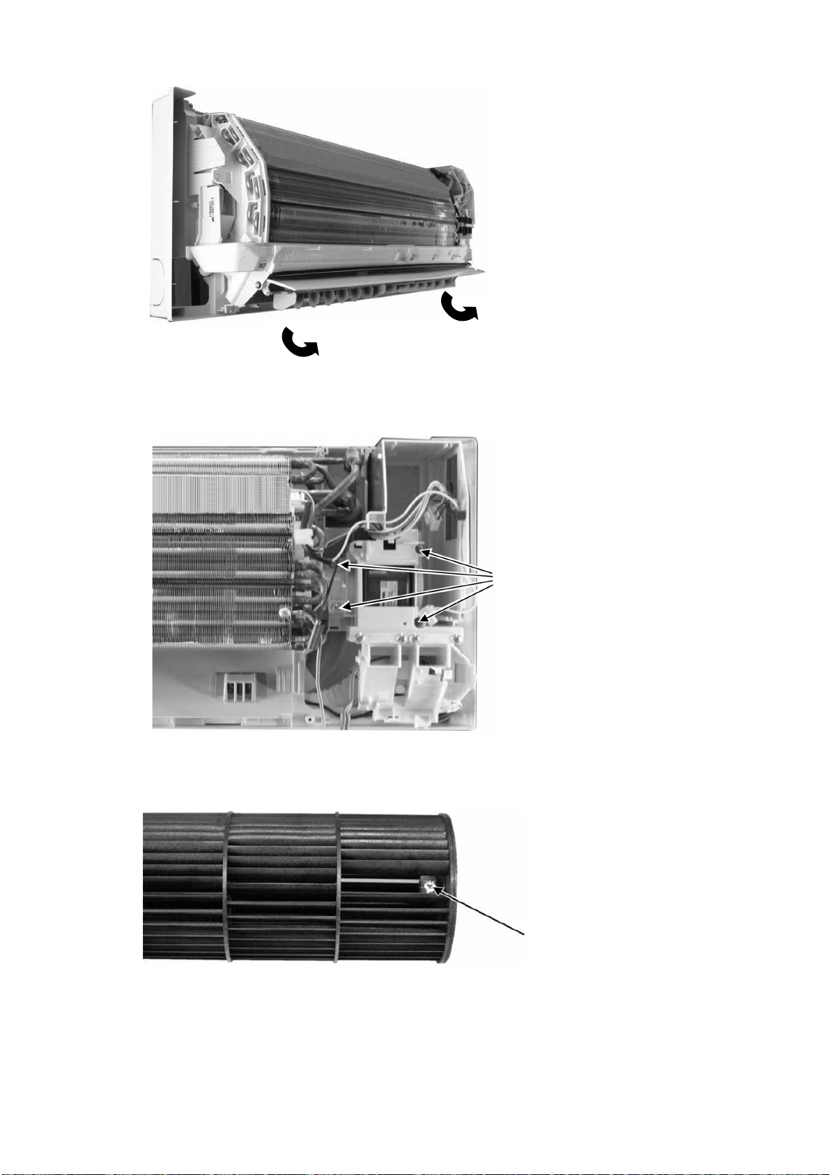
112
19.2.1.3 To remove discharge grille
Figure 5
19.2.1.4 To remove control board
Figure 6
19.2.1.5 To remove cross flow fan and indoor fan motor
Figure 7
11. Pull out to remove the drain hose
from the discharge grille.
12. Then pull the discharge grille
downward gently to dismantle it.
13. Remove 4 screws holding the
control board then pull out the
control board.
14. Remove the screw that holding
the cross flow fan and fan motor
axis.
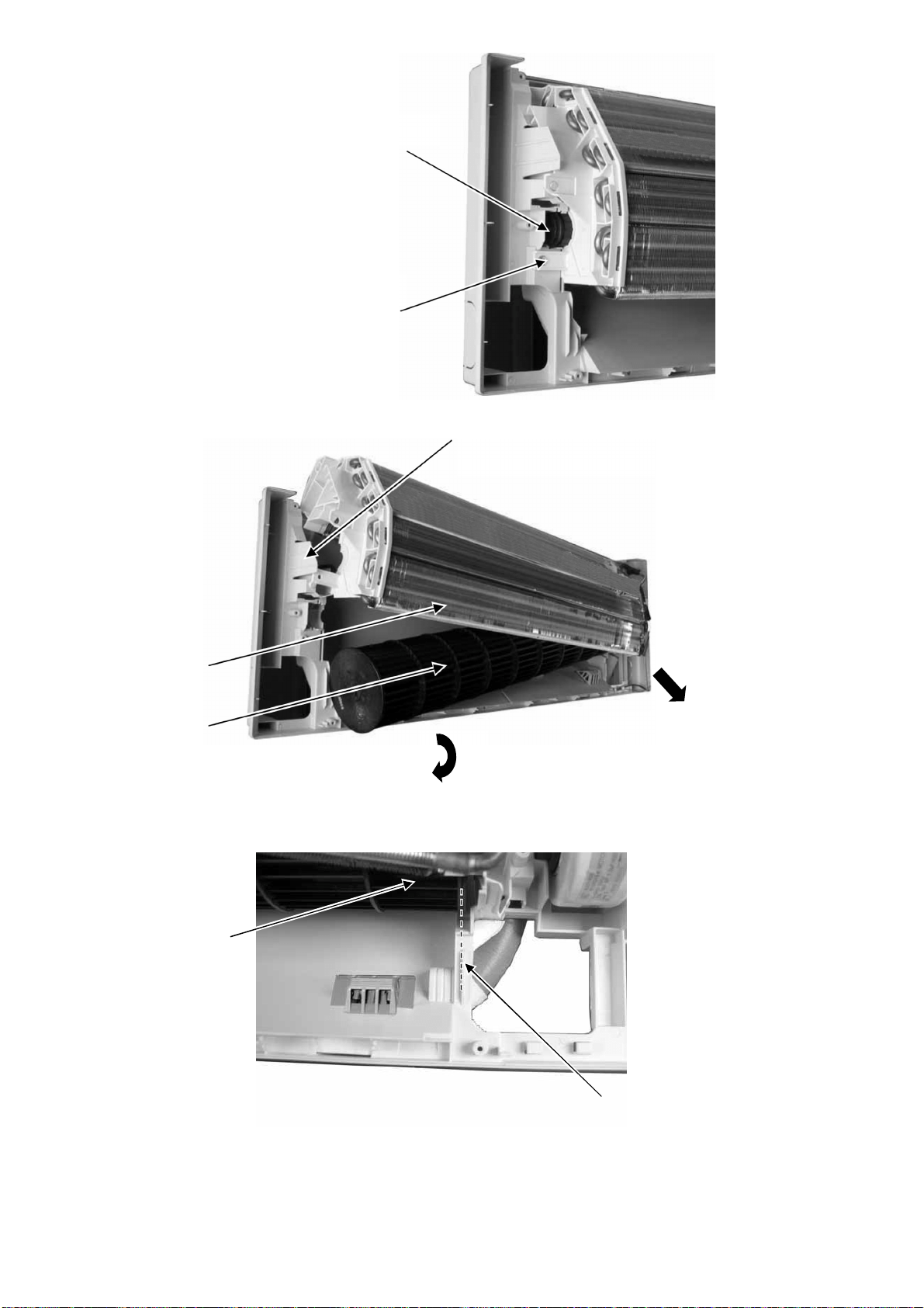
113
Figure 8
Figure 9
Figure 10
15. Remove the screw from the
evaporator.
16. Remove the bearing by pulling it
out gently.
19. Fan motor can be removed after the
removal of cross flow fan.
18. Remove the cross flow fan from the unit by
pulling it to the left and downward.
17. Push the holdfast to the left and lift up the evaporator.
Cross flow fan
Evaporator
Reminder: To reinstall the fan motor, adjus
t
the fan motor connector to 45° towards you
before fixing control board.
Reminder: To reinstall the cross flow
fan, ensure cross flow fan is in line as
showninfigure10
Cross Flow Fan
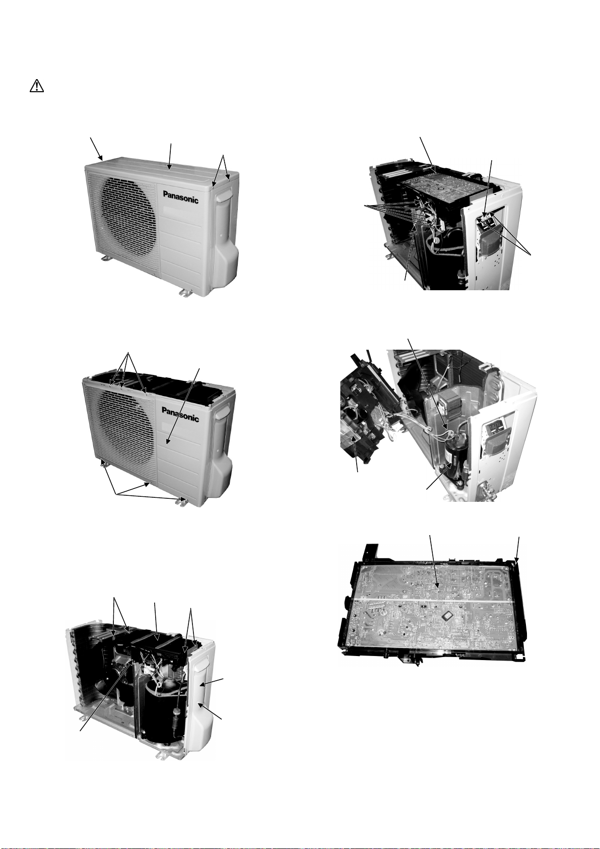
114
19.3 Outdoor Electronic Controller Removal Procedure
19.3.1 CU-E9RKUA CU-E12RKUA
Caution! When handling electronic controller, be careful of electrostatic discharge.
1 Remove the 3 screws of the Top Panel.
Fig. 1
2 Remove the 6 screws of the Front Panel.
Fig. 2
3 Remove the screw of the Terminal Board
Cover.
4 Remove the Top Cover of the Control Board
by 4 hooks.
Fig. 3
5 Remove the Control Board as follows:
Fig. 4
Fig. 5
Fig. 6
Sc
r
e
w
Top Panel
Screws
Sc
r
e
ws
Screws
Front Panel
Hoo
k
s
Top Cover
Hooks
Terminal
Board
Cover
Screw
Control Board
C
o
n
t
r
o
l
B
o
a
r
d
Release 5•
Connectors
Release 3
Terminal Connectors
and Earth Wire Screw
Remove
2Screws
Release Earth
W ire Screw
R
e
m
o
v
e
t
h
e
T
e
r
m
i
n
a
l
C
o
v
e
r
and 3 Terminal Compressor
Control Board
Compressor
E
le
c
tr
o
ni
c
C
o
ntr
o
ller
Con tro l Bo a rd
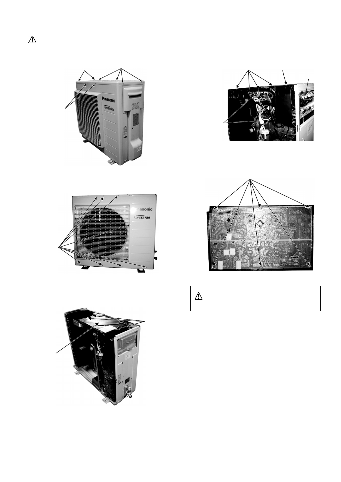
115
19.3.2 CU-E18RKUA CU-E24RKUA
Caution! When handling electronic controller, be careful of electrostatic discharge.
1 Remove the 8 screws of the Top Panel.
Fig. 1
2 Remove the 8 screws of the Front Panel.
Fig. 2
3 Remove the Top Cover of the Electronic
Controller.
Fig. 3
4 Remove the Control Board.
Fig. 4
5 Remove the 6 screws of the Electronic
Controller.
Fig. 5
Caution! When handling electronic controller, be careful
of electrostatic discharge.
Sc
r
e
w
s
Screws
Screws
Screws
Top Cover
Hooks
Release 8
connectors
R
e
l
e
a
s
e
7
terminal
connectors
Control boardRelease the hooks
Sc
r
e
ws
116
20. Technical Data
Technical data provided are based on the air conditioner running under free frequency.
20.1 Cool Mode Performance Data
Unit setting: Standard piping length, Hi Fan, Cool mode at 60.8°F
Voltage: 230V
20.1.1 CS-E9RKUAW CU-E9RKUA
Rated frequency (compressor speed is fixed during forced heating or cooling for capacity measurement and
diagnosis purpose)
Indoor (°C / °F) Outdoor (°C / °F)
DB WB -20 (-4) -10 (14) 0 (32) 5 (41)
TC SHC IP TC SHC IP TC SHC IP TC SHC IP
27
(80.6)
19 (66.2) 10120 9156 508 10120 9156 516 10071 9237 504 10280 9429 476
22 (71.6) 10694 6508 540 10694 6508 549 10760 6603 517 11617 7015 386
23
(73.4)
16 (60.8) 9471 9376 485 9471 9376 493 9153 9062 527 10369 10265 424
18 (64.4) 9962 6484 498 9962 6484 506 9648 6373 530 10193 6706 447
20
(68)
13 (55.4) 8999 8909 525 8999 8909 534 8679 8592 547 7954 7874 375
16 (60.8) 9274 6447 535 9274 6447 544 9299 6400 525 8372 6037 355
Indoor (°C / °F) Outdoor (°C / °F)
DB WB 16 (60.8) 25 (77) 35 (95) 46 (114.8)
TC SHC IP TC SHC IP TC SHC IP TC SHC IP
27
(80.6)
19 (66.2) 10698 9191 422 9450 8466 617 9008 8558 690 7391 6622 829
22 (71.6) 11048 6569 420 10314 5946 590 9591 5942 678 8067 4650 792
23
(73.4)
16 (60.8) 9488 9393 473 8560 8474 633 8301 8218 699 6695 6628 850
18 (64.4) 10035 6503 456 9406 5994 616 8515 6133 690 7357 4689 827
20
(68)
13 (55.4) 7031 6961 209 6969 6899 478 7628 7552 702 5174 5122 642
16 (60.8) 8062 5730 402 8377 5865 630 7752 5886 695 6552 4588 847
20.1.2 CS-E12RKUAW CU-E12RKUA
Rated frequency (compressor speed is fixed during forced heating or cooling for capacity measurement and
diagnosis purpose)
Indoor (°C / °F) Outdoor (°C / °F)
DB WB -20 (-4) -10 (14) 0 (32) 5 (41)
TC SHC IP TC SHC IP TC SHC IP TC SHC IP
27
(80.6)
19 (66.2) 12880 11530 678 12880 11530 689 12818 11632 671 13084 11874 635
22 (71.6) 13610 8196 720 13610 8196 732 13694 8315 689 14785 8834 515
23
(73.4)
16 (60.8) 12053 11933 647 12053 11933 657 11649 11533 703 13196 13064 565
18 (64.4) 12679 8165 664 12679 8165 674 12279 8026 706 12972 8445 596
20
(68)
13 (55.4) 11453 11339 700 11453 11339 712 11046 10935 729 10123 10022 500
16 (60.8) 11803 8119 714 11803 8119 725 11834 8060 700 10655 7603 474
Indoor (°C / °F) Outdoor (°C / °F)
DB WB 16 (60.8) 25 (77) 35 (95) 46 (114.8)
TC SHC IP TC SHC IP TC SHC IP TC SHC IP
27
(80.6)
19 (66.2) 13616 11574 563 12028 10662 823 11465 10777 920 9407 8843 1105
22 (71.6) 14061 8272 560 13126 7487 786 12206 7483 904 10016 6140 1086
23
(73.4)
16 (60.8) 12075 11954 631 10894 10785 844 10565 10459 932 8669 8582 1120
18 (64.4) 12772 8190 608 11971 7549 821 10837 7723 919 8892 6337 1104
20
(68)
13 (55.4) 8948 8859 279 8870 8781 638 9708 9611 935 7966 7886 1123
16 (60.8) 10260 7216 536 10662 7386 841 9867 7413 926 8096 6082 1113
117
20.1.3 CS-E18RKUAW CU-E18RKUA
Rated frequency (compressor speed is fixed during forced heating or cooling for capacity measurement and
diagnosis purpose)
Indoor (°C / °F) Outdoor (°C / °F)
DB WB -20 (-4) -10 (14) 0 (32) 5 (41)
TC SHC IP TC SHC IP TC SHC IP TC SHC IP
27
(80.6)
19 (66.2) 21188 17930 935 21167 17913 924 21141 18234 896 21082 17831 888
22 (71.6) 24306 14656 817 24282 14641 807 23146 14323 936 21589 13429 934
23
(73.4)
16 (60.8) 18646 18460 1032 18628 18442 1019 19803 19605 849 18879 18690 941
18 (64.4) 20846 13794 945 20825 13780 933 23204 14860 739 21619 13003 982
20
(68)
13 (55.4) 16414 16250 1024 16398 16234 1011 16292 16129 672 15704 15547 803
16 (60.8) 16372 12160 1182 16356 12148 1168 17139 12557 699 18527 13408 689
Indoor (°C / °F) Outdoor (°C / °F)
DB WB 16 (60.8) 25 (77) 35 (95) 46 (114.8)
TC SHC IP TC SHC IP TC SHC IP TC SHC IP
27
(80.6)
19 (66.2) 21000 18063 876 18377 16061 1195 17197 15993 1300 11804 10978 1169
22 (71.6) 21726 14368 879 19983 12710 1208 18977 9991 1317 13026 6858 1184
23
(73.4)
16 (60.8) 19472 19278 876 17002 16832 1172 15737 15580 1373 10802 10694 1234
18 (64.4) 21253 13726 878 18690 12233 1185 17325 11865 1398 11892 8144 1257
20
(68)
13 (55.4) 17023 16853 734 15925 15765 1171 14512 14366 1349 9961 9861 1212
16 (60.8) 19378 15270 1189 19083 13310 1503 16210 6590 1469 11126 4523 1321
20.1.4 CS-E24RKUAW CU-E24RKUA
Rated frequency (compressor speed is fixed during forced heating or cooling for capacity measurement and
diagnosis purpose)
Indoor (°C / °F) Outdoor (°C / °F)
DB WB -20 (-4) -10 (14) 0 (32) 5 (41)
TC SHC IP TC SHC IP TC SHC IP TC SHC IP
27
(80.6)
19 (66.2) 29512 24706 1691 29483 24681 1670 29446 25124 1621 29365 24568 1606
22 (71.6) 33855 20194 1477 33821 20174 1459 32240 19735 1692 30071 18504 1688
23
(73.4)
16 (60.8) 25972 25712 1866 25946 25686 1843 27583 27307 1534 26296 26033 1701
18 (64.4) 29036 19007 1708 29006 18988 1687 31474 20475 1335 30112 17917 1775
20
(68)
13 (55.4) 22863 22634 1851 22840 22612 1828 22693 22466 1214 21873 21654 1451
16 (60.8) 22804 16755 2137 22781 16738 2111 23873 17302 1263 25806 18475 1246
Indoor (°C / °F) Outdoor (°C / °F)
DB WB 16 (60.8) 25 (77) 35 (95) 46 (114.8)
TC SHC IP TC SHC IP TC SHC IP TC SHC IP
27
(80.6)
19 (66.2) 29250 24889 1584 25596 22130 2159 23953 22037 2350 16441 15126 2113
22 (71.6) 30261 19797 1589 27833 17513 2183 26432 13767 2381 18143 9449 2140
23
(73.4)
16 (60.8) 27122 26851 1584 23682 23445 2119 21920 21700 2481 15046 14895 2231
18 (64.4) 29602 18912 1588 26032 16855 2141 24131 16348 2527 16563 11221 2272
20
(68)
13 (55.4) 23711 23474 1326 22181 21959 2117 20212 20010 2438 13874 13735 2192
16 (60.8) 26991 21041 2149 26580 18340 2717 22578 9080 2655 15497 6233 2387
TC : Total capacity (BTU)
SHC: Sensible Heat Capacity (BTU)
IP: Input Power (Watt)
118
20.1.5 CS-E9RKUAW CU-E9RKUA
Maximum Capacity
Indoor (°C / °F) Outdoor (°C / °F)
DB WB -20 (-4) -10 (14) 0 (32) 5 (41)
TC SHC IP TC SHC IP TC SHC IP TC SHC IP
27
(80.6)
19 (66.2) 10120 8963 508 10120 8963 516 10073 9043 504 10281 9231 476
22 (71.6) 10694 6372 540 10694 6372 549 10758 6463 517 11615 6866 386
23
(73.4)
16 (60.8) 9472 9377 485 9472 9377 493 9155 9063 527 10369 10266 424
18 (64.4) 9963 6348 498 9963 6348 506 9646 6238 530 10192 6565 447
20
(68)
13 (55.4) 8998 8908 525 8998 8908 534 8677 8590 547 8268 8185 412
16 (60.8) 9274 6312 535 9274 6312 544 9298 6265 525 9046 6386 430
Indoor (°C / °F) Outdoor (°C / °F)
DB WB 16 (60.8) 25 (77) 35 (95) 46 (114.8)
TC SHC IP TC SHC IP TC SHC IP TC SHC IP
27
(80.6)
19 (66.2) 10748 9039 432 10739 9418 730 10236 9520 850 7391 6873 829
22 (71.6) 11601 6753 500 11301 6378 670 10898 6610 835 8066 4892 792
23
(73.4)
16 (60.8) 10305 10202 530 9830 9732 751 9433 9339 861 6695 6628 850
18 (64.4) 10271 6516 481 9963 6216 671 9676 6822 850 7609 5365 842
20
(68)
13 (55.4) 7725 7648 274 7766 7688 564 8668 8582 864 6057 5996 768
16 (60.8) 8766 6099 482 8906 6104 691 8809 6548 856 6773 5034 864
20.1.6 CS-E12RKUAW CU-E12RKUA
Maximum Capacity
Indoor (°C / °F) Outdoor (°C / °F)
DB WB -20 (-4) -10 (14) 0 (32) 5 (41)
TC SHC IP TC SHC IP TC SHC IP TC SHC IP
27
(80.6)
19 (66.2) 12898 11300 688 12929 11327 701 12884 11443 682 13157 11686 645
22 (71.6) 13642 8041 734 13662 8053 746 13744 8168 699 14846 8682 520
23
(73.4)
16 (60.8) 12127 12005 659 12127 12005 669 11687 11570 721 13236 13103 575
18 (64.4) 12720 8018 676 12720 8018 684 12318 8677 718 13017 8294 609
20
(68)
13 (55.4) 11506 11391 721 11506 11391 723 11103 10992 738 10492 10387 534
16 (60.8) 11871 7992 722 11871 7992 735 11898 7931 719 10697 7470 480
Indoor (°C / °F) Outdoor (°C / °F)
DB WB 16 (60.8) 25 (77) 35 (95) 46 (114.8)
TC SHC IP TC SHC IP TC SHC IP TC SHC IP
27
(80.6)
19 (66.2) 13666 11369 573 13140 11400 945 13307 12243 1150 10079 9273 1234
22 (71.6) 14263 8212 574 14635 8170 921 14168 8500 1130 10219 6131 1165
23
(73.4)
16 (60.8) 12250 12127 651 11721 11603 960 12263 12140 1165 8721 8634 1198
18 (64.4) 13004 8161 628 12802 7901 921 12579 8774 1149 9233 6440 1198
20
(68)
13 (55.4) 9499 9404 305 9998 9898 756 11269 11156 1169 8175 8094 1254
16 (60.8) 10721 7380 570 11038 7484 919 11452 8421 1158 8384 6165 1196
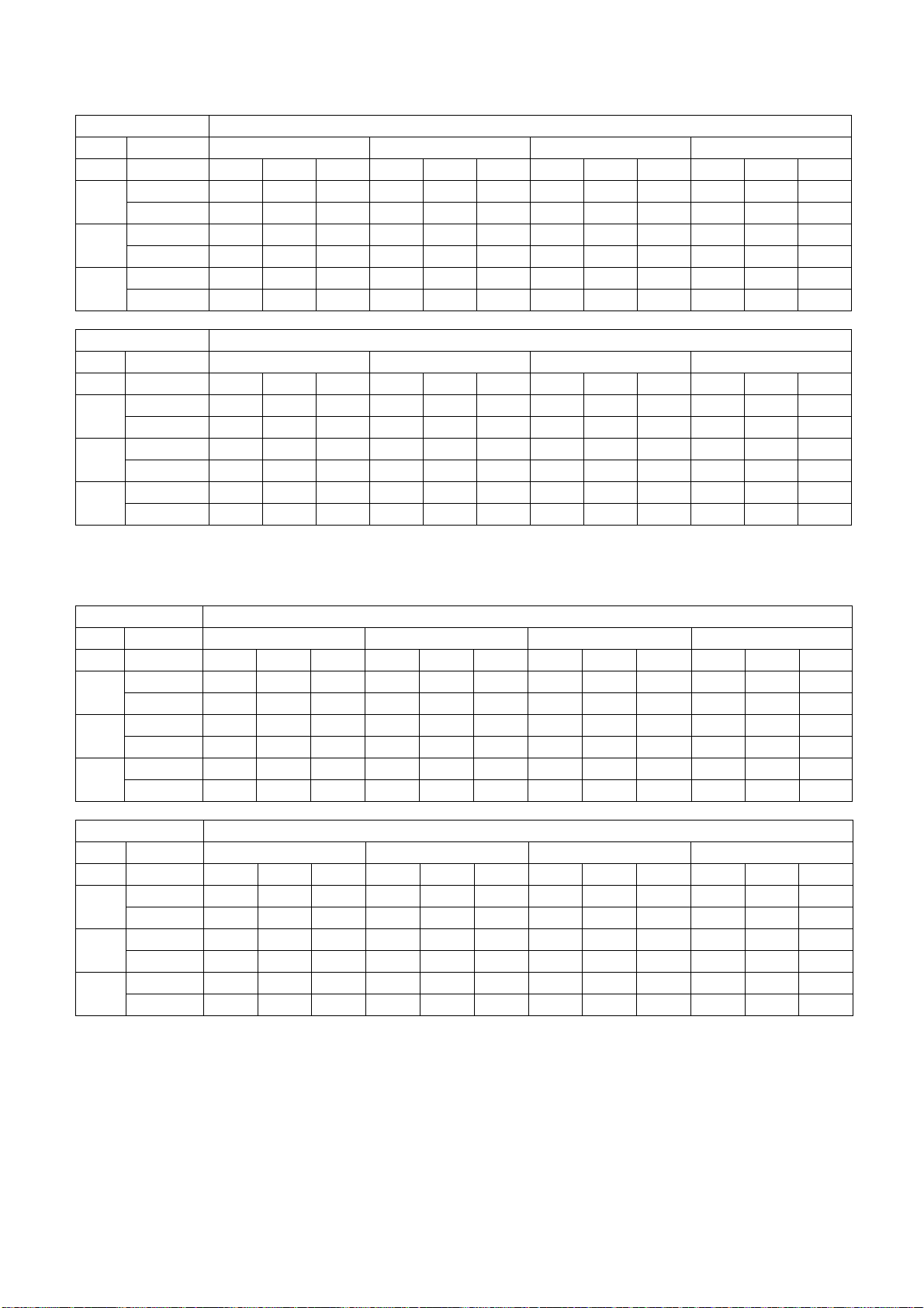
119
20.1.7 CS-E18RKUAW CU-E18RKUA
Maximum Capacity
Indoor (°C / °F) Outdoor (°C / °F)
DB WB -20 (-4) -10 (14) 0 (32) 5 (41)
TC SHC IP TC SHC IP TC SHC IP TC SHC IP
27
(80.6)
19 (66.2) 21189 17546 935 21166 17526 924 21142 17843 896 21084 17448 888
22 (71.6) 24305 14340 817 24281 14326 807 23148 14016 936 21930 13348 956
23
(73.4)
15.7 (60.26) 18647 18461 1059 18627 18441 1046 19804 19606 871 19869 19670 1020
18.4 (65.12) 20845 13497 969 20824 13483 958 23203 14540 758 22131 13801 1005
20
(68)
13.3 (55.94) 16429 16265 1051 16467 16302 1038 16344 16181 689 15969 15809 855
15.8 (60.44) 16395 11915 1213 16354 11885 1198 17238 12358 717 18699 13241 735
Indoor (°C / °F) Outdoor (°C / °F)
DB WB 16 (60.8) 25 (77) 35 (95) 46 (114.8)
TC SHC IP TC SHC IP TC SHC IP TC SHC IP
27
(80.6)
19 (66.2) 21002 17676 896 20650 17660 1395 19790 18009 1600 11803 10740 1169
22 (71.6) 22971 14257 972 22493 13999 1415 21839 11251 1621 13024 6710 1184
23
(73.4)
15.7 (60.26) 20101 19900 945 18876 18687 1358 18110 17929 1689 10803 10695 1234
18.4 (65.12) 21595 13647 921 20343 13029 1341 19937 13360 1720 12014 8051 1290
20
(68)
13.3 (55.94) 17252 17079 785 17043 16872 1301 16700 16533 1660 10107 10006 1268
15.8 (60.44) 21220 13940 1340 20423 13938 1682 18654 7421 1808 11332 4508 1387
20.1.8 CS-E24RKUAW CU-E24RKUA
Maximum Capacity
Indoor (°C / °F) Outdoor (°C / °F)
DB WB -20 (-4) -10 (14) 0 (32) 5 (41)
TC SHC IP TC SHC IP TC SHC IP TC SHC IP
27
(80.6)
19 (66.2) 29529 24182 1698 29508 24166 1681 29484 24610 1631 29396 24059 1621
22 (71.6) 33889 19776 1510 33886 19774 1511 32286 19334 1699 30549 18389 1756
23
(73.4)
15.7 (60.26) 26041 25781 1886 26014 25754 1858 27645 27369 1559 26693 26426 1721
18.4 (65.12) 29126 18651 1721 29109 18640 1721 31678 19633 1374 30211 18633 1801
20
(68)
13.3 (55.94) 22981 22751 1883 22967 22737 1856 22865 22636 1264 22118 21896 1498
15.8 (60.44) 22865 16434 2158 22899 16459 2164 24103 17090 1301 25973 18190 1358
Indoor (°C / °F) Outdoor (°C / °F)
DB WB 16 (60.8) 25 (77) 35 (95) 46 (114.8)
TC SHC IP TC SHC IP TC SHC IP TC SHC IP
27
(80.6)
19 (66.2) 29283 24375 1591 28181 23835 2541 27297 24567 2720 16457 14811 2126
22 (71.6) 30371 18644 1618 30348 18680 2481 30122 15347 2756 18200 9273 2180
23
(73.4)
15.7 (60.26) 27338 27065 1654 26106 25845 2431 24980 24730 2872 15205 15052 2275
18.4 (65.12) 29757 18598 1611 27928 17690 2464 27499 18225 2924 16904 11203 2321
20
(68)
13.3 (55.94) 23957 23717 1336 23626 23389 2400 23034 22804 2822 14061 13921 2212
15.8 (60.44) 29269 19017 2451 28170 19014 3000 25730 10123 3074 15553 6119 2421
TC : Total capacity (BTU)
SHC: Sensible Heat Capacity (BTU)
IP: Input Power (Watt)
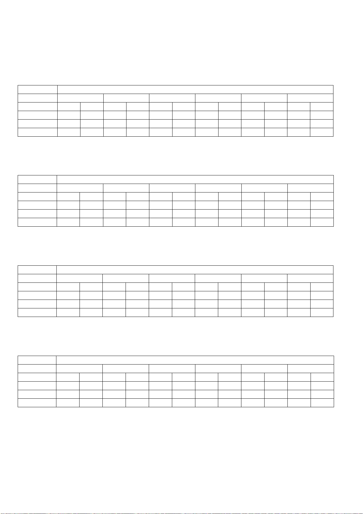
120
20.2 Heat Mode Performance Data
Unit setting: Standard piping length, Hi Fan, Heat mode at 86°F
Voltage: 230V
20.2.1 CS-E9RKUAW CU-E9RKUA
Rated frequency (compressor speed is fixed during forced heating or cooling for capacity measurement and
diagnosis purpose)
Indoor (°C / °F) Outdoor (°C / °F)
DB -20 (-4) -8.3 (17.06) 1.7 (35.06) 8.3 (46.94) 12 (53.6) 23.9 (75.02)
TC IP TC IP TC IP TC IP TC IP TC IP
24 (75.2) 4364 747 8712 1039 11021 1128 12059 1129 12375 1149 13471 1114
20 (68) 4598 736 9315 1035 11336 1106 12011 1120 12253 1124 14239 1089
16 (60.8) 3711 718 9571 1024 12262 1116 12890 1149 12988 1104 13891 1071
20.2.2 CS-E12RKUAW CU-E12RKUA
Rated frequency (compressor speed is fixed during forced heating or cooling for capacity measurement and
diagnosis purpose)
Indoor (°C / °F) Outdoor (°C / °F)
DB -20 (-4) -8.3 (17.06) 1.7 (35.06) 8.3 (46.94) 12 (53.6) 23.9 (75.02)
TC IP TC IP TC IP TC IP TC IP TC IP
24 (75.2) 5021 833 10024 1159 12681 1259 13875 1260 13337 1282 15499 1243
20 (68) 5290 822 10717 1155 13043 1235 13819 1250 14098 1254 16383 1216
16 (60.8) 4270 802 11012 1143 14108 1245 14831 1283 13753 1233 15983 1195
20.2.3 CS-E18RKUAW CU-E18RKUA
Rated frequency (compressor speed is fixed during forced heating or cooling for capacity measurement and
diagnosis purpose)
Indoor (°C / °F) Outdoor (°C / °F)
DB -20 (-4) -8.3 (17.06) 1.7 (35.06) 8.3 (46.94) 12 (53.6) 23.9 (75.02)
TC IP TC IP TC IP TC IP TC IP TC IP
24 (75.2) 6715 1213 12572 1615 16051 1628 21041 1850 21969 1839 23675 1767
20 (68) 6913 1169 12610 1554 16284 1561 21599 1750 22844 1765 24618 1695
16 (60.8) 6455 1117 12720 1485 16459 1495 22135 1654 23456 1671 25278 1605
20.2.4 CS-E24RKUAW CU-E24RKUA
Rated frequency (compressor speed is fixed during forced heating or cooling for capacity measurement and
diagnosis purpose)
Indoor (°C / °F) Outdoor (°C / °F)
DB -20 (-4) -8.3 (17.06) 1.7 (35.06) 8.3 (46.94) 12 (53.6) 23.9 (75.02)
TC IP TC IP TC IP TC IP TC IP TC IP
24 (75.2) 8975 1733 16802 2307 21452 2326 28122 2643 29361 2628 31641 2524
20 (68) 9239 1670 16854 2220 21764 2230 28867 2500 30530 2522 32901 2422
16 (60.8) 8627 1596 17000 2122 21997 2136 29584 2363 31349 2388 33784 2293
TC : Total capacity (BTU)
IP: Input Power (Watt)
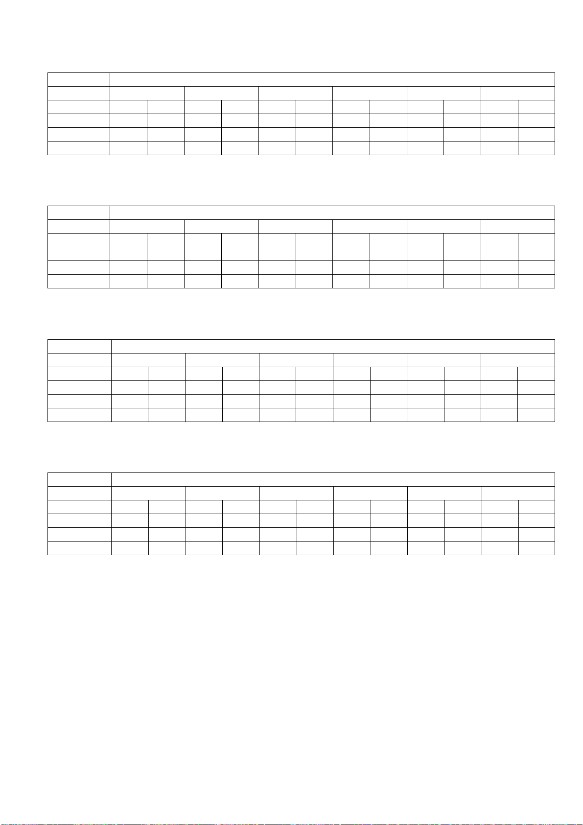
121
20.2.5 CS-E9RKUAW CU-E9RKUA
Maximum Capacity
Indoor (°C / °F) Outdoor (°C / °F)
DB -20 (-4) -8.3 (17.06) 1.7 (35.06) 8.3 (46.94) 12 (53.6) 23.9 (75.02)
TC IP TC IP TC IP TC IP TC IP TC IP
24 (75.2) 7056 1301 9370 1320 12234 1459 14183 1512 14534 1525 15225 1424
20 (68) 7433 1295 10019 1315 12583 1431 14126 1500 14390 1491 16093 1393
16 (60.8) 6000 1261 10294 1301 13611 1443 15160 1539 15253 1466 15700 1369
20.2.6 CS-E12RKUAW CU-E12RKUA
Maximum Capacity
Indoor (°C / °F) Outdoor (°C / °F)
DB -20 (-4) -8.3 (17.06) 1.7 (35.06) 8.3 (46.94) 12 (53.6) 23.9 (75.02)
TC IP TC IP TC IP TC IP TC IP TC IP
24 (75.2) 8129 1625 10796 1505 14095 1663 16342 1724 15685 1738 17541 1623
20 (68) 8564 1664 11543 1499 14498 1631 16276 1710 16580 1700 18542 1588
16 (60.8) 6914 1654 11861 1484 15682 1645 17468 1755 16175 1671 18089 1561
20.2.7 CS-E18RKUAW CU-E18RKUA
Maximum Capacity
Indoor (°C / °F) Outdoor (°C / °F)
DB -20 (-4) -8.3 (17.06) 1.7 (35.06) 8.3 (46.94) 12 (53.6) 23.9 (75.02)
TC IP TC IP TC IP TC IP TC IP TC IP
24 (75.2) 9834 1881 14795 1984 18316 1952 21374 1903 22308 1892 24058 1783
20 (68) 10124 1825 14840 1910 18582 1843 21940 1800 23196 1816 25016 1711
16 (60.8) 9454 1750 14969 1829 18782 1781 22485 1702 23818 1719 25687 1620
20.2.8 CS-E24RKUAW CU-E24RKUA
Maximum Capacity
Indoor (°C / °F) Outdoor (°C / °F)
DB -20 (-4) -8.3 (17.06) 1.7 (35.06) 8.3 (46.94) 12 (53.6) 23.9 (75.02)
TC IP TC IP TC IP TC IP TC IP TC IP
24 (75.2) 13092 2741 19696 2832 24383 2755 28454 2812 29697 2796 32027 2525
20 (68) 13478 2641 19756 2761 24738 2650 29208 2660 30880 2683 33303 2423
16 (60.8) 12585 2500 19928 2684 25003 2521 29933 2515 31708 2541 34196 2295
TC : Total capacity (BTU)
IP: Input Power (Watt)

122
21. Service Data
Service data provided are based on the air conditioner running under rated frequency during forced cooling / forced
heating mode.
21.1 Cool Mode Outdoor Air Temperature Characteristic
Condition
- Indoor room temperature: 80°F Dry Bulb/67°F Wet Bulb
- Unit setting: Standard piping length, forced cooling at 60.8°F, Hi fan
- Compressor frequency: Rated for cooling operation
- Piping length: 24.6ft
- Voltage: 230V
21.1.1 CS-E9RKUAW CU-E9RKUA
59.0
59.5
60.0
60.5
61.0
61.5
62.0
62.5
63.0
63.5
64.0
64.5
-4 6 162636465666768696106116
Outlet Air
(°F)
Outdoor Air Temperature (°F)
230
1.5
2.0
2.5
3.0
3.5
4.0
-4 6 162636465666768696106116
Current
(A)
Outdoor Air Temperature (°F)
134.0
136.0
138.0
140.0
142.0
144.0
146.0
148.0
150.0
152.0
-4 6 162636465666768696106116
Gas Side Piping
Pressure (PSI)
Outdoor Air Temperature (°F)

123
21.1.2 CS-E12RKUAW CU-E12RKUA
57.0
57.5
58.0
58.5
59.0
59.5
60.0
60.5
61.0
61.5
62.0
-4 6 162636465666768696106116
Outlet Air
(°F)
Outdoor Air Temperature (°F)
230
2.5
3.0
3.5
4.0
4.5
5.0
5.5
-4 6 162636465666768696106116
Current
(A)
Outdoor Air Temperature (°F)
132.0
134.0
136.0
138.0
140.0
142.0
144.0
146.0
148.0
150.0
-4 6 162636465666768696106116
Gas Side Piping
Pressure (PSI)
Outdoor Air Temperature (°F)
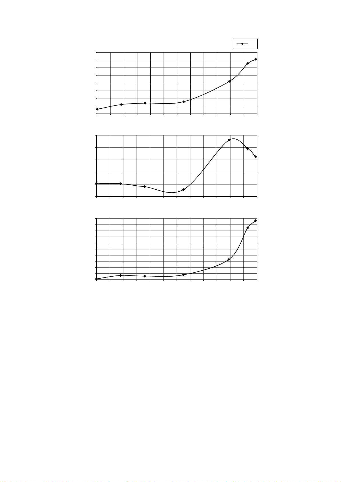
124
21.1.3 CS-E18RKUAW CU-E18RKUA
52.0
54.0
56.0
58.0
60.0
62.0
64.0
66.0
68.0
-4 6 162636465666768696106116
Outlet Air
(°F)
Outdoor Air Temperature (°F)
230
4.0
4.5
5.0
5.5
6.0
6.5
-4 6 162636465666768696106116
Current
(A)
Outdoor Air Temperature (°F)
125.0
130.0
135.0
140.0
145.0
150.0
155.0
160.0
165.0
170.0
175.0
-4 6 162636465666768696106116
Gas Side Piping
Pressure (PSI)
Outdoor Air Temperature (°F)
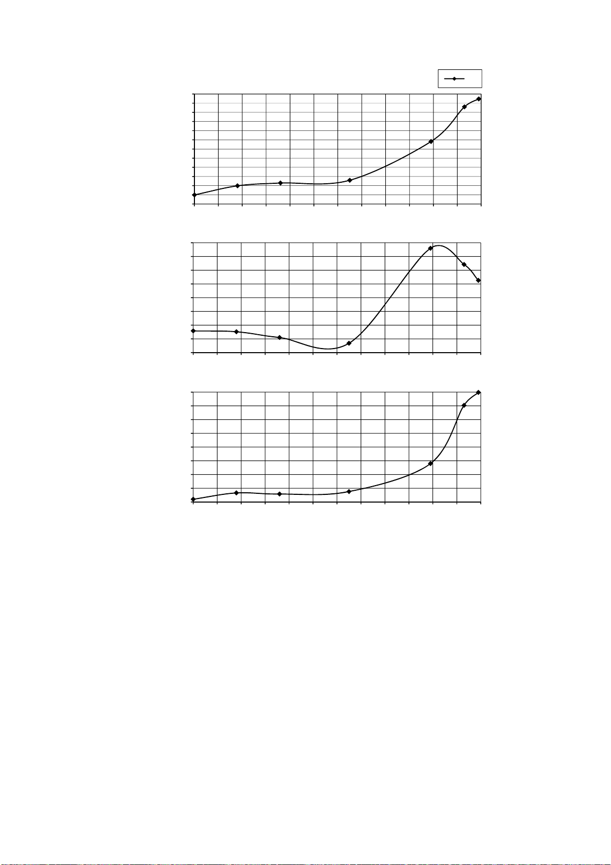
125
21.1.4 CS-E24RKUAW CU-E24RKUA
48.0
49.0
50.0
51.0
52.0
53.0
54.0
55.0
56.0
57.0
58.0
59.0
60.0
-4 6 162636465666768696106116
Outlet Air
(°F)
Outdoor Air Temperature (°F)
230
7.0
7.5
8.0
8.5
9.0
9.5
10.0
10.5
11.0
-4 6 162636465666768696106116
Current
(A)
Outdoor Air Temperature (°F)
102.0
107.0
112.0
117.0
122.0
127.0
132.0
137.0
142.0
-4 6 162636465666768696106116
Gas Side Piping
Pressure (PSI)
Outdoor Air Temperature (°F)
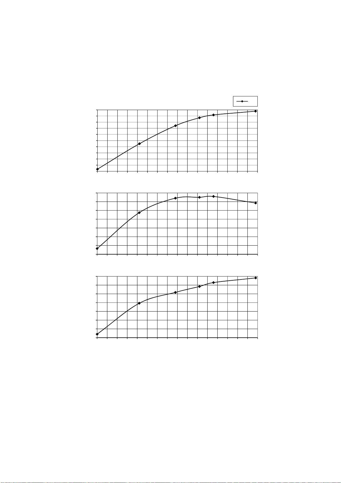
126
21.2 Heat Mode Outdoor Air Temperature Characteristic
Condition
- Indoor room temperature: 68°F Dry Bulb/-°F Wet Bulb
- Unit setting: Standard piping length, forced heating at 86°F, Hi fan
- Compressor frequency: Rated for Heating operation
- Piping length: 24.6ft
- Voltage: 230V
21.2.1 CS-E9RKUAW CU-E9RKUA
82.0
84.0
86.0
88.0
90.0
92.0
94.0
96.0
98.0
100.0
102.0
-4 1 6 11 16 21 26 31 36 41 46 51 56 61 66 71 76
Outlet Air
(°F)
Outdoor Air Temperature (°F)
230
3.8
4.0
4.2
4.4
4.6
4.8
5.0
5.2
-4 1 6 11 16 21 26 31 36 41 46 51 56 61 66 71 76
Current
(A)
Outdoor Air Temperature (°F)
240.0
260.0
280.0
300.0
320.0
340.0
360.0
380.0
-4 1 6 11 16 21 26 31 36 41 46 51 56 61 66 71 76
Gas Side Piping
Pressure (PSI)
Outdoor Air Temperature (°F)
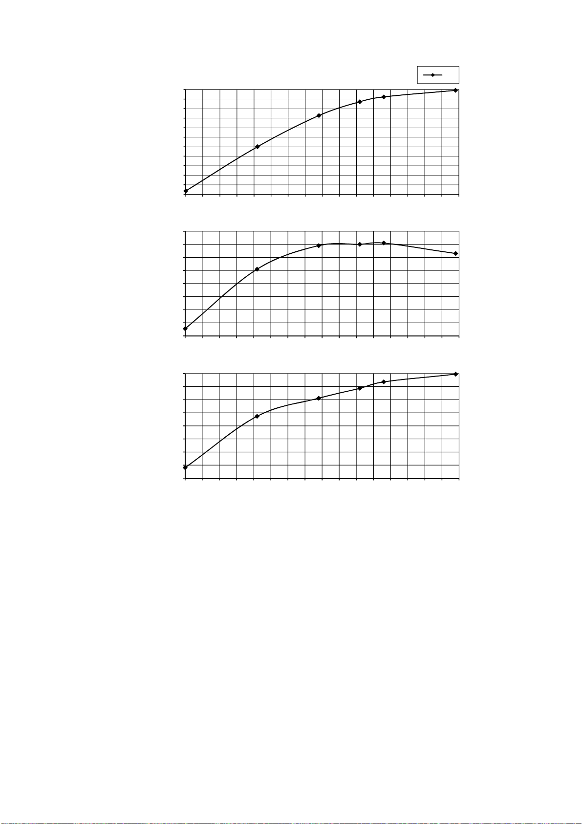
127
21.2.2 CS-E12RKUAW CU-E12RKUA
88.0
90.0
92.0
94.0
96.0
98.0
100.0
102.0
104.0
106.0
108.0
110.0
-4 1 6 11 16 21 26 31 36 41 46 51 56 61 66 71 76
Outlet Air
(°F)
Outdoor Air Temperature (°F)
230
4.2
4.4
4.6
4.8
5.0
5.2
5.4
5.6
5.8
-4 1 6 11 16 21 26 31 36 41 46 51 56 61 66 71 76
Current
(A)
Outdoor Air Temperature (°F)
260.0
280.0
300.0
320.0
340.0
360.0
380.0
400.0
420.0
-4 1 6 11 16 21 26 31 36 41 46 51 56 61 66 71 76
Gas Side Piping
Pressure (PSI)
Outdoor Air Temperature (°F)
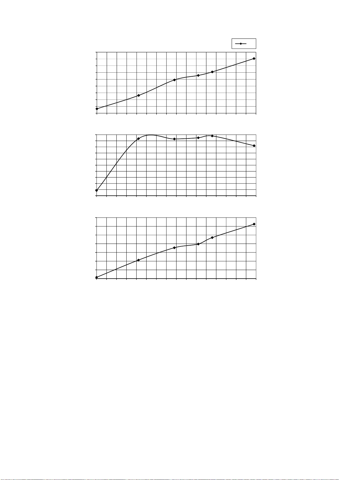
128
21.2.3 CS-E18RKUAW CU-E18RKUA
88.0
90.0
92.0
94.0
96.0
98.0
100.0
102.0
104.0
106.0
-4 1 6 11 16 21 26 31 36 41 46 51 56 61 66 71 76
Outlet Air
(°F)
Outdoor Air Temperature (°F)
230
6.4
6.6
6.8
7.0
7.2
7.4
7.6
7.8
8.0
8.2
8.4
-4 1 6 11 16 21 26 31 36 41 46 51 56 61 66 71 76
Current
(A)
Outdoor Air Temperature (°F)
280.0
300.0
320.0
340.0
360.0
380.0
400.0
420.0
-4 1 6 11 16 21 26 31 36 41 46 51 56 61 66 71 76
Gas Side Piping
Pressure (PSI)
Outdoor Air Temperature (°F)
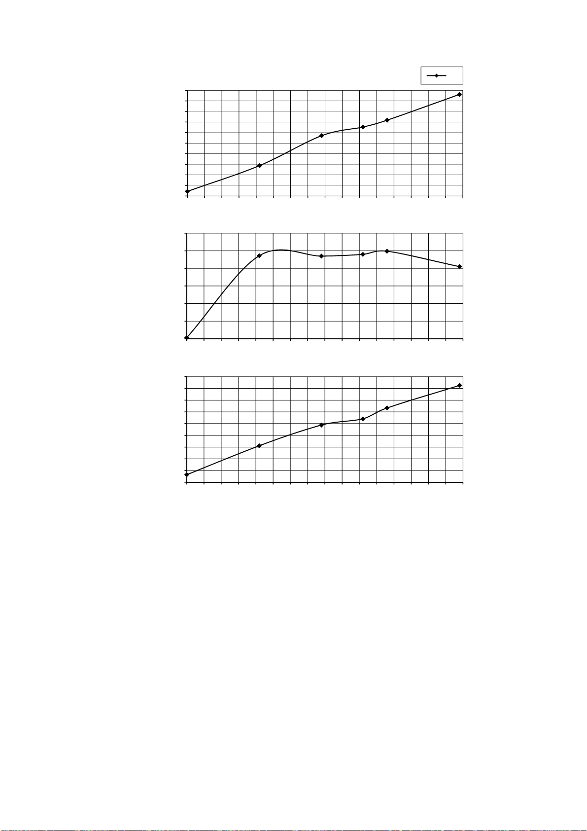
129
21.2.4 CS-E24RKUAW CU-E24RKUA
102.0
104.0
106.0
108.0
110.0
112.0
114.0
116.0
118.0
120.0
122.0
-4 1 6 11 16 21 26 31 36 41 46 51 56 61 66 71 76
Outlet Air
(°F)
Outdoor Air Temperature (°F)
230
9.0
9.5
10.0
10.5
11.0
11.5
12.0
-4 1 6 11 16 21 26 31 36 41 46 51 56 61 66 71 76
Current
(A)
Outdoor Air Temperature (°F)
340.0
360.0
380.0
400.0
420.0
440.0
460.0
480.0
500.0
520.0
-4 1 6 11 16 21 26 31 36 41 46 51 56 61 66 71 76
Gas Side Piping
Pressure (PSI)
Outdoor Air Temperature (°F)
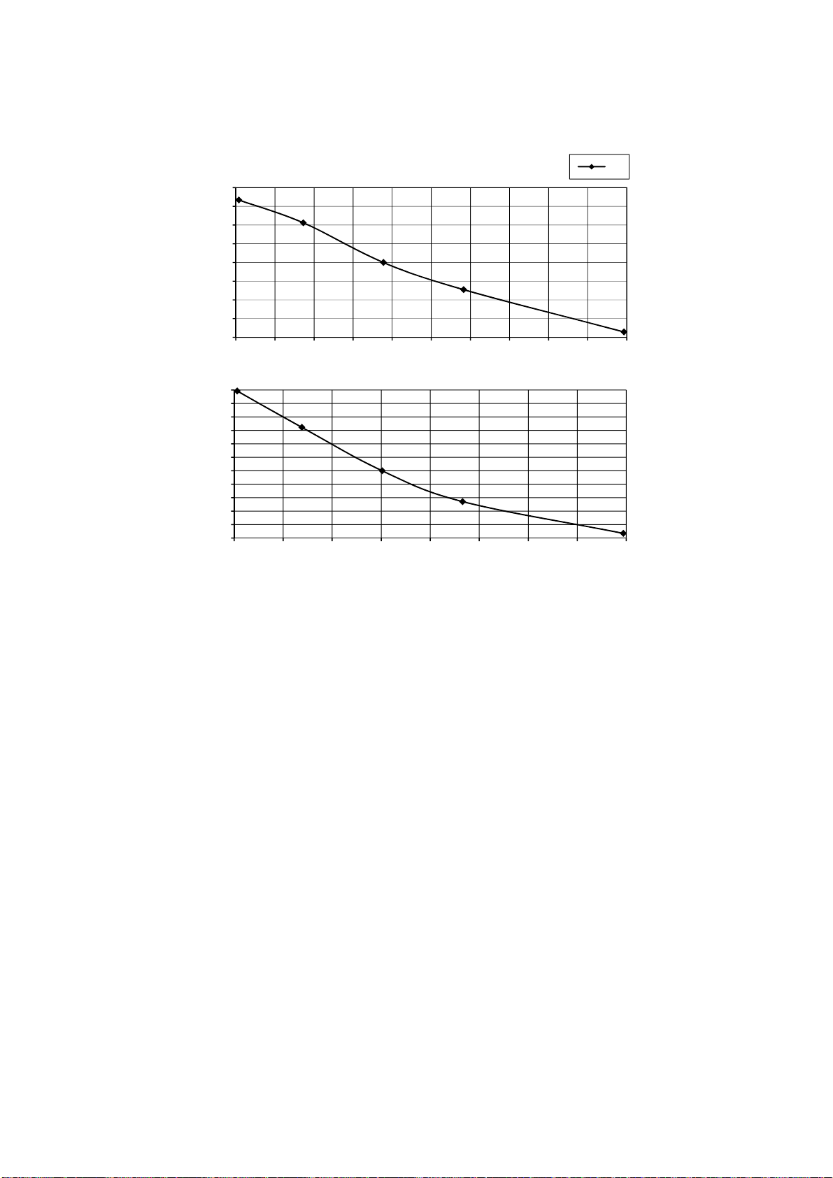
130
21.3 Piping Length Correction Factor
The characteristic of the unit has to be corrected in accordance with the piping length.
21.3.1 CS-E9RKUAW CU-E9RKUA CS-E12RKUAW CU-E12RKUA
Note: The graphs show the factor after added right amount of additional refrigerant.
0.960
0.970
0.980
0.990
1.000
1.010
1.020
1.030
1.040
9.5 13.5 17.5 21.5 25.5 29.5 33.5 37.5 41.5 45.5 49.5
Cooling Capacity
Correction Factor
Piping Length (ft)
230
0.950
0.960
0.970
0.980
0.990
1.000
1.010
1.020
1.030
1.040
1.050
1.060
9.5 14.5 19.5 24.5 29.5 34.5 39.5 44.5 49.5
Heating Capacity
Correction Factor
Piping Length (ft)
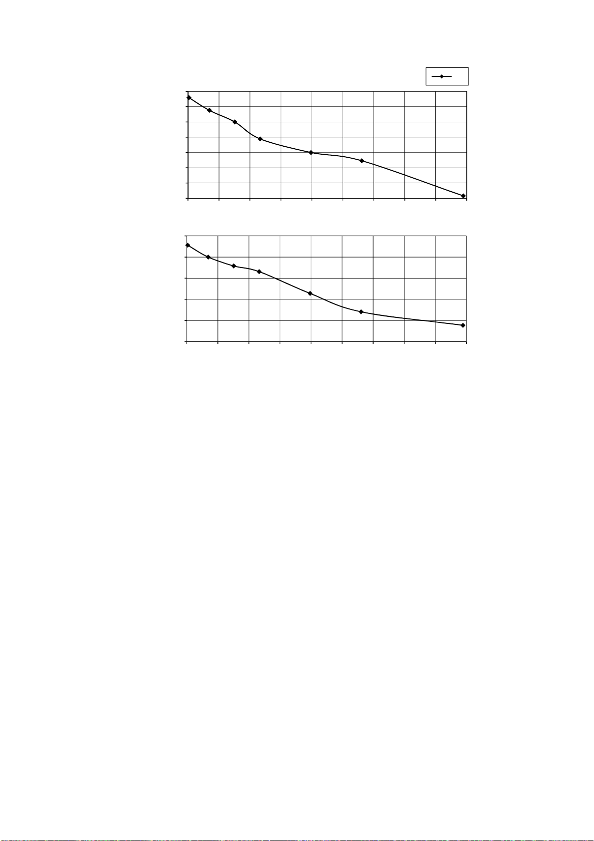
131
21.3.2 CS-E18RKUAW CU-E18RKUA CS-E24RKUAW CU-E24RKUA
Note: The graphs show the factor after added right amount of additional refrigerant.
0.950
0.960
0.970
0.980
0.990
1.000
1.010
1.020
9.5 19.5 29.5 39.5 49.5 59.5 69.5 79.5 89.5 99.5
Cooling Capacity
Correction Factor
Piping Length (ft)
230
0.960
0.970
0.980
0.990
1.000
1.010
9.5 19.5 29.5 39.5 49.5 59.5 69.5 79.5 89.5 99.5
Heating Capacity
Correction Factor
Piping Length (ft)
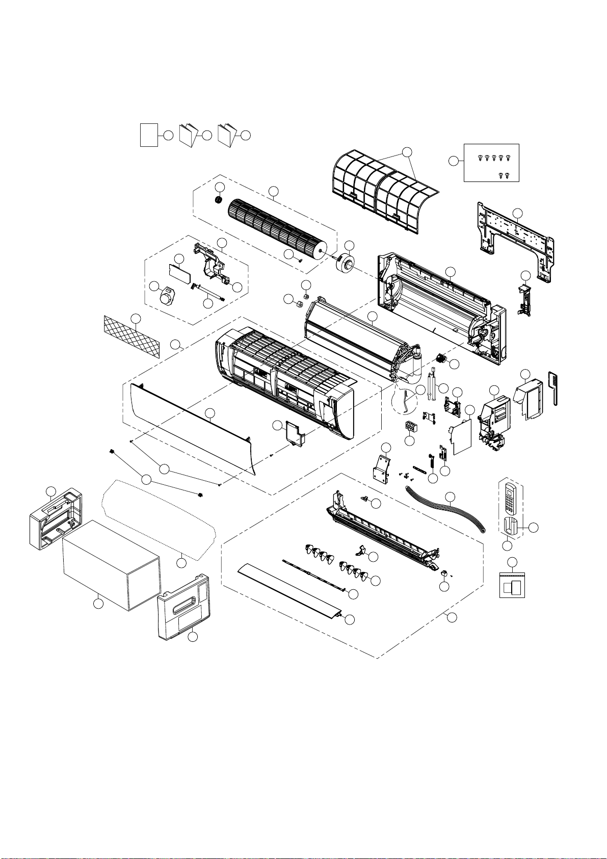
132
22. Exploded View and Replacement Parts List
22.1 Indoor Unit
22.1.1 CS-E9RKUAW CS-E12RKUAW
Note
The above exploded view is for the purpose of parts disassembly and replacement.
The non-numbered parts are not kept as standard service parts.
I/I I/I
O/I
CWH55025J
CWH55051J
12
24
15
36
55
33
50
45
46 47 48
40
44
3
4
2
5
1
27
23
11
16
26
34
28
29
30
39
9
37
35
10
7
38
8
41
42
43
13
14
6
25
53
52
51
21
54
22
18
17
20
49
133
SAFETY REF. NO. PART NAME & DESCRIPTION QTY. CS-E9RKUAW CS-E12RKUAW REMARK
1 CHASSIS COMPLETE 1 CWD50C1633 ←
2 FAN MOTOR 1 L6CBYYYL0055 ← O
3 CROSS-FLOW FAN COMPLETE 1 CWH02C1076 ←
4 BEARING ASSY 1 CWH64K007 ← O
5 SCREW - CROSS-FLOW FAN 1 CWH551146 ←
6 PARTICULAR PIECE 1 CWD933067 ←
7 EVAPORATOR 1 CWB30C5033 CWB30C5026
8 FLARE NUT (LIQUID) 1 CWT251030 ←
9 FLARE NUT (GAS) 1 CWT251031 CWT251032
10 CLIP FOR SENSOR 1 CWH321085 ←
11 CONTROL BOARD CASING 1 CWH102605A ←
12 TERMINAL BOARD COMPLETE 1 CWA28C2357 ← O
13 ELECTRONIC CONTROLLER - MAIN 1 CWA73C9156 CWA73C9157 O
14 PARTICULAR PIECE - TERMINAL 1 CWD933137A ←
15 ELECTRONIC CONTROLLER-INDICATOR 1 CWA748158 ← O
16 SENSOR COMPLETE 1 CWA50C3228 ← O
17 SENSOR COMPLETE (ECO) 1 CWA50C2820 ← O
18 ELECTRONIC CONTROLLER (ECO SENSOR) 1 CWA745791 ← O
20 ELECTRONIC CONTROLLER (COMPARATOR) 1 CWA746769 ← O
21 LEAD WIRE - PCB ECO 1 CWA67C9786 ← O
22 CONTROL BOARD CASING FOR PCB ECO 1 CWD933427 ←
23 CONTROL BOARD TOP COVER 1 CWH131467 ←
24 INDICATOR HOLDER 1 CWD933406 ←
25 CONTROL BOARD FRONT COVER CO. 1 CWH13C1333 ←
26 DISCHARGE GRILLE COMPLETE 1 CWE20C3495 ←
27 BACK COVER CHASSIS 1 CWD933233B ←
28 FULCRUM 1 CWH621131 ←
29 VERTICAL VANE 8 CWE241374 ←
30 CONNECTING BAR 2 CWE261251 ←
33 AIR SWING MOTOR 1 CWA981264 ← O
34 CAP - DRAIN TRAY 1 CWH521259 ←
35 HORIZONTAL VANE COMPLETE 1 CWE24C1385 ←
36 REMOTE CONTROL COMPLETE 1 CWA75C4567 ← O
37 FRONT GRILLE COMPLETE 1 CWE11C5960 ← O
38 INTAKE GRILLE COMPLETE 1 CWE22C1946 ←
39 GRILLE DOOR COMPLETE 1 CWE14C1131 ←
40 AIR FILTER 2 CWD001279 ← O
41 SCREW - FRONT GRILLE 2 XTT4+16CFJ ←
42 CAP - FRONT GRILLE 2 CWH521227 ←
43 DRAIN HOSE 1 CWH851173 ←
44 INSTALLATION PLATE 1 CWH361134 ←
45 BAG COMPLETE - INSTALLATION SCREW 1 CWH82C1705 ←
46 OPERATING INSTRUCTION 1 CWF569755 ←
47 INSTALLATION INSTRUCTION 1 CWF616529 ←
48 INSTALLATION INSTRUCTION 1 CWF616530 ←
49 REMOTE CONTROL HOLDER 1 CWH361078 ←
50 BAG 1 CWG861497 ←

134
SAFETY REF. NO. PART NAME & DESCRIPTION QTY. CS-E9RKUAW CS-E12RKUAW REMARK
51 SHOCK ABSORBER ( L ) 1 CWG713386 ←
52 SHOCK ABSORBER ( R ) 1 CWG713387 ←
53 C.C.CASE 1 CWG567355 ←
54 AIR PURIFYING FILTER 1 CWD00C1141 ← O
55 BAG COMPLETE (TUBE CONNECTOR) 1 CWH82C2030 ←
(Note)
All parts are supplied from PHAAM, Malaysia (Vendor Code: 00029488).
“O” marked parts are recommended to be kept in stock.
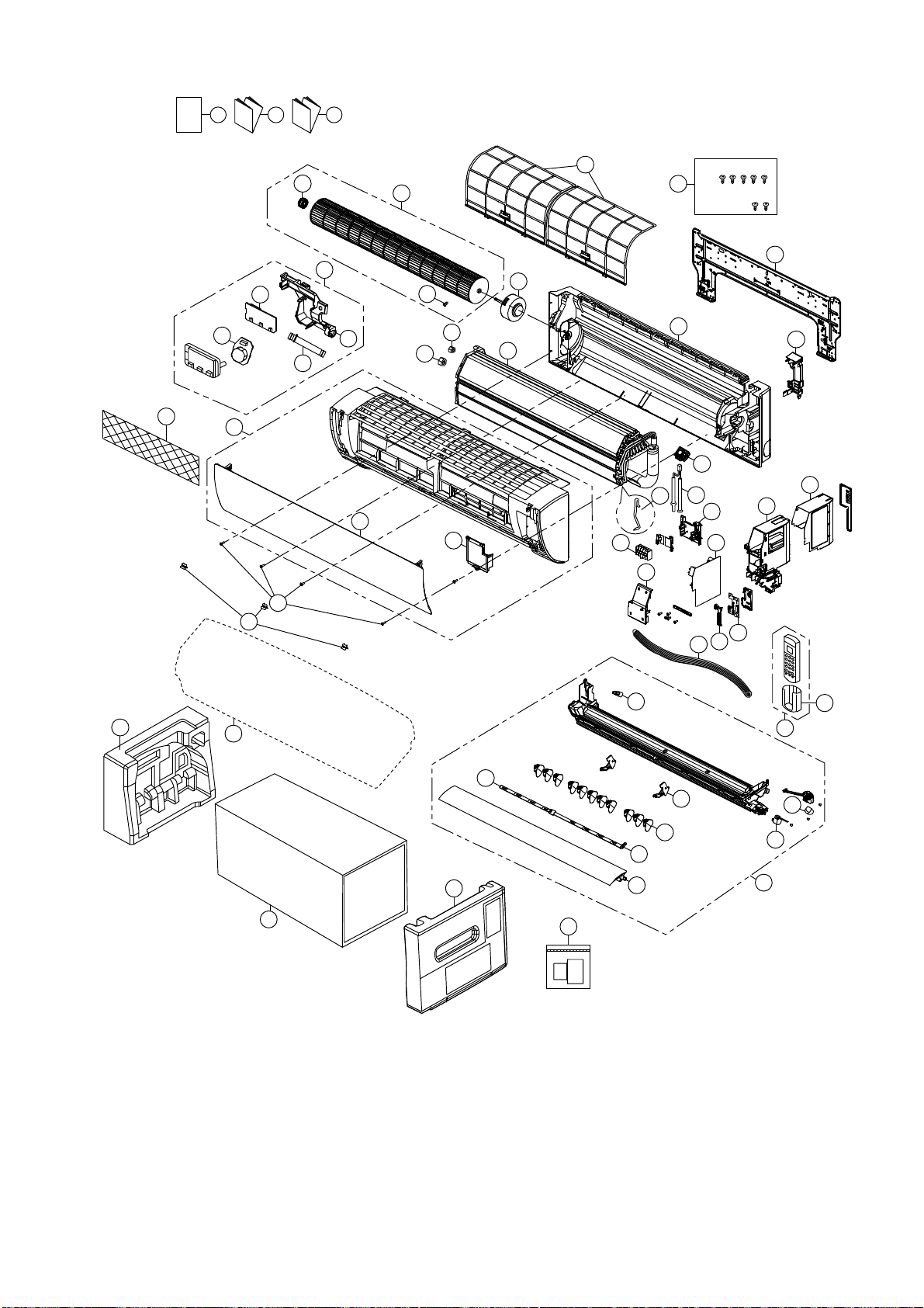
135
22.1.2 CS-E18RKUAW CS-E24RKUAW
Note
The above exploded view is for the purpose of parts disassembly and replacement.
The non-numbered parts are not kept as standard service parts.
CWH55025J
CWH55051J
28
I/I I/I
O/I
35
30
31
29
34
25
13
16
6
1
40
3
4
17
5
22
8
21
37
38
39
50
53
27
44
10
23
11
12
24
43
15
18
20
46 47 48
32
36
26
33
41
42
45
9
7
2
51
54
14
49
55
52
136
SAFETY REF. NO. PART NAME & DESCRIPTION QTY. CS-E18RKUAW CS-E24RKUAW REMARK
1 CHASSIS COMPLETE 1 CWD50C1637 ←
2 FAN MOTOR 1 L6CBYYYL0056 ← O
3 CROSS-FLOW FAN COMPLETE 1 CWH02C1077 ←
4 BEARING ASSY 1 CWH64K007 ← O
5 SCREW - CROSS-FLOW FAN 1 CWH551146 ←
6 PARTICULAR PIECE 1 CWD933067 ←
7 EVAPORATOR 1 CWB30C3963 CWB30C3967
8 FLARE NUT (LIQUID) 1 CWT251030 ←
9 FLARE NUT (GAS) 1 CWT251032 CWT251033
10 CLIP FOR SENSOR 1 CWH32142 ←
11 CONTROL BOARD CASING 1 CWH102605A ←
12 TERMINAL BOARD COMPLETE 1 CWA28C2357 ← O
13 ELECTRONIC CONTROLLER - MAIN 1 CWA73C9158 CWA73C9159 O
14 PARTICULAR PIECE - TERMINAL 1 CWD933137A ←
15 ELECTRONIC CONTROLLER-INDICATOR 1 CWA748158 ← O
16 SENSOR COMPLETE 1 CWA50C3228 ← O
17 SENSOR COMPLETE (ECO) 1 CWA50C2827 ← O
18 ELECTRONIC CONTROLLER (ECO SENSOR) 1 CWA745791 ← O
20 ELECTRONIC CONTROLLER (COMPARATOR) 1 CWA746769 ← O
21 LEAD WIRE - PCB ECO 1 CWA67C9935 ← O
22 CONTROL BOARD CASING FOR PCB ECO 1 CWD933455 ←
23 CONTROL BOARD TOP COVER 1 CWH131467 ←
24 INDICATOR HOLDER 1 CWD933406 ←
25 CONTROL BOARD FRONT COVER CO. 1 CWH13C1333 ←
26 DISCHARGE GRILLE COMPLETE 1 CWE20C3496 ←
27 BACK COVER CHASSIS 1 CWD933031B ←
28 FULCRUM 1 CWH621138 ←
29 VERTICAL VANE 11 CWE241374 ←
30 CONNECTING BAR 1 CWE261257 ←
31 CONNECTING BAR 1 CWE261258 ←
32 AIR SWING MOTOR ASS'Y. 1 CWA98K1024 ←
33 AIR SWING MOTOR 1 CWA981241 ← O
34 CAP - DRAIN TRAY 1 CWH521259 ←
35 HORIZONTAL VANE COMPLETE 1 CWE24C1392 ←
36 REMOTE CONTROL COMPLETE 1 CWA75C4569 ← O
37 FRONT GRILLE COMPLETE 1 CWE11C5961 ← O
38 INTAKE GRILLE COMPLETE 1 CWE22C1945 ←
39 GRILLE DOOR COMPLETE 1 CWE14C1131 ←
40 AIR FILTER 2 CWD001283 ← O
41 SCREW - FRONT GRILLE 3 XTT4+16CFJ ←
42 CAP - FRONT GRILLE 3 CWH521227 ←
43 DRAIN HOSE 1 CWH851173 ←
44 INSTALLATION PLATE 1 CWH361098 ←
45 BAG COMPLETE - INSTALLATION SCREW 1 CWH82C1705 ←
46 OPERATING INSTRUCTION 1 CWF569756 ←
47 INSTALLATION INSTRUCTION 1 CWF616730 ←
48 INSTALLATION INSTRUCTION 1 CWF616731 ←

137
SAFETY REF. NO. PART NAME & DESCRIPTION QTY. CS-E18RKUAW CS-E24RKUAW REMARK
49 REMOTE CONTROL HOLDER 1 CWH361078 ←
50 BAG 1 CWG861498 ←
51 SHOCK ABSORBER ( L ) 1 CWG713402 ←
52 SHOCK ABSORBER ( R ) 1 CWG713403 ←
53 C.C. CASE 1 CWG567455 ←
54 AIR PURIFYING FILTER 1 CWD00C1141 ← O
55 BAG COMPLETE (TUBE CONNECTOR) 1 CWH82C2030 ←
(Note)
All parts are supplied from PAPAMY, Malaysia (Vendor Code: 00029488).
“O” marked parts are recommended to be kept in stock.
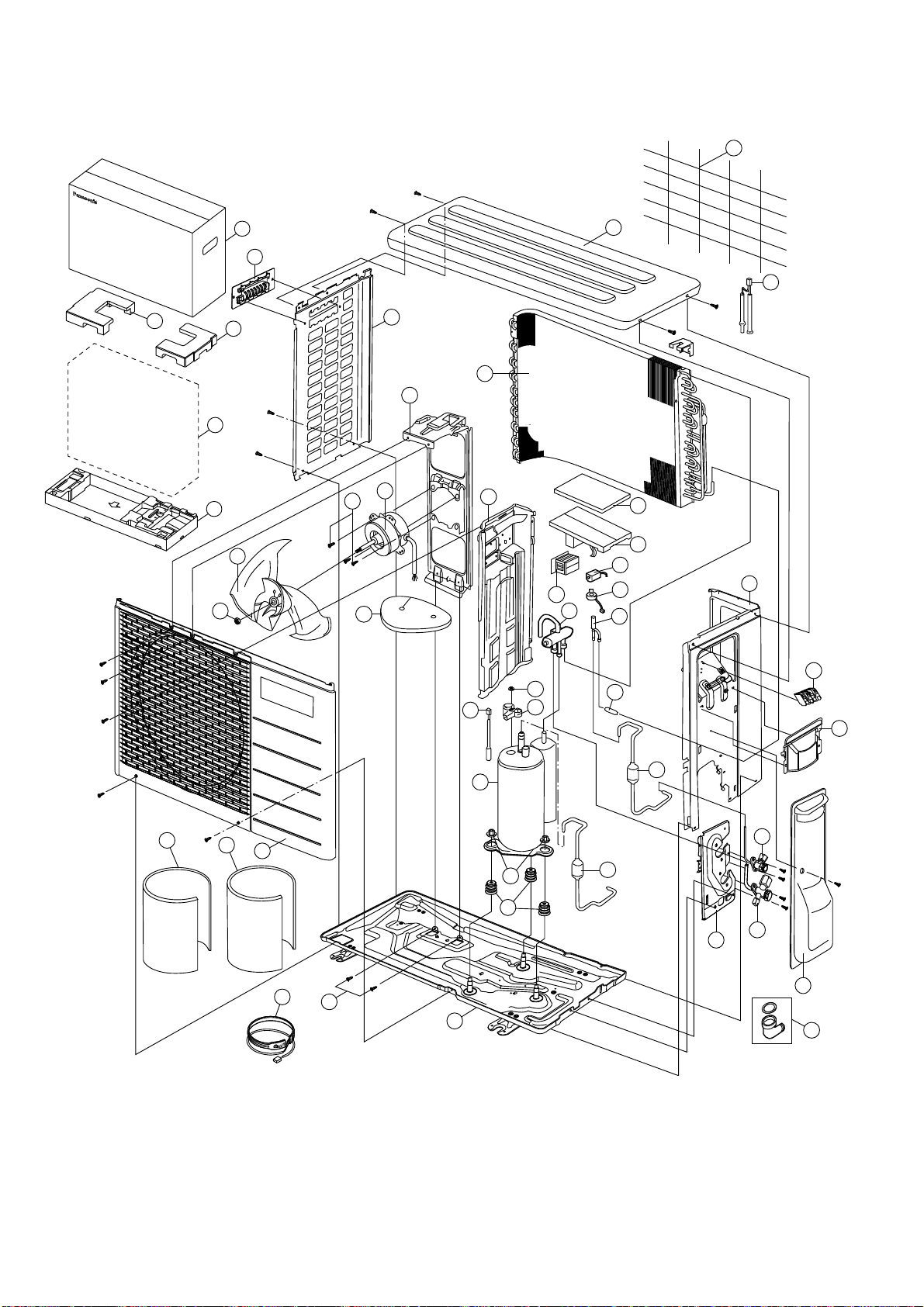
138
22.2 Outdoor Unit
22.2.1 CU-E9RKUA CU-E12RKUA
Note
The above exploded view is for the purpose of parts disassembly and replacement.
The non-numbered parts are not kept as standard service parts.
24
27
23
19
4
20
5
26
15
18
8
9
10
1
36
17
22
16
32
33
14
2
11
29
6
7
30
3
31
28
37
39
43
12
34
47
49
48
45
42
44
13
41
38
40
50
51
46
139
SAFETY REF. NO. PART NAME & DESCRIPTION QTY. CU-E9RKUA CU-E12RKUA REMARK
1 CHASSIS COMPLETE 1 CWD50K2081A ←
2 FAN MOTOR BRACKET 1 CWD541089 ←
3 SCREW - FAN MOTOR BRACKET 2 CWH551217 ←
4 FAN MOTOR 1 ARW6404AC ← O
5 SCREW - FAN MOTOR MOUNT 4 CWH55252J ←
6 PROPELLER FAN ASSY 1 CWH03K1014 ←
7 NUT - PROPELLER FAN 1 CWH56053J ←
8 COMPRESSOR 1 5RS102XHA21 ← O
9 ANTI - VIBRATION BUSHING 3 CWH50077 ←
10 NUT - COMPRESSOR MOUNT 3 CWH561096 ←
11 CONDENSER 1 CWB32C3394 CWB32C4129
12 EXPANSION VALVE 1 CWB051016J ← O
13 DISCHARGE MUFFLER (EXPANSION VALVE) 1 CWB121021 ←
14 HOLDER COUPLING 1 CWH351231A ←
15 2-WAYS VALVE (LIQUID) 1 CWB021180J CWB021654 O
16 3-WAY VALVE (GAS) 1 CWB011374 CWB011367 O
17 TERMINAL COVER 1 CWH171039A ←
18 NUT - TERMINAL COVER 1 CWH7080300J ←
19 SOUND PROOF BOARD 1 CWH151172A ←
20 SOUND PROOF MATERIAL 1 CWG302570 ←
22 SENSOR CO-COMP TEMP 1 CWA50C2340 ← O
23 CONTROL BOARD COVER - TOP 1 CWH131264 ←
24 ELECTRONIC CONTROLLER - MAIN 1 CWA73C9160R CWA73C9161R O
26 TERMINAL BOARD ASSY 1 CWA28K1154 ← o
27 CABINET SIDE PLATE CO. 1 CWE04C1226 CWE04C1558
28 SENSOR CO-AIR TEMP AND PIPE TEMP 1 CWA50C2793 CWA50C3315 O
29 CABINET SIDE PLATE 1 CWE041492A ←
30 CABINET FRONT PLATE CO. 1 CWE06C1142 ←
31 CABINET TOP PLATE 1 CWE031018A ←
32 PLATE - C. B. COVER TERMINAL 1 CWH131301 ←
33 CONTROL BOARD COVER CO. 1 CWH13C1345 ←
34 HANDLE 1 CWE161010 ←
36 REACTOR 1 G0C193J00002 G0C193J00004 O
37 4-WAYS VALVE 1 CWB001058 ← O
38 WIRE NET 1 CWD041161A ←
39 V-COIL COMPLETE (4 W. VALVE) 1 CWA43C2432 ← O
40 HEATER 1 CWA341065 ←
41 BAG-COMPLETE 1 CWG87C900 ←
42 STRAINER 1 CWB111061 ←
43 V-COIL COMPLETE (EXPANSION VALVE) 1 CWA43C2393 ← O
44 DISCHARGE MUFFLER (4 W. VALVE) 1 CWB121047 ←
45 BAG 1 CWG861078 ←
46 BASE BOARD-COMPLETE 1 CWG50C2388 ←
47 SHOCK ABSORBER ( R ) 1 CWG712210 ←
48 SHOCK ABSORBER ( L ) 1 CWG712209 ←
49 C.C.CASE 1 CWG565107 ←

140
SAFETY REF. NO. PART NAME & DESCRIPTION QTY. CU-E9RKUA CU-E12RKUA REMARK
50 SOUND PROOF MATERIAL 1 CWG302292 ←
51 SOUND PROOF MATERIAL 1 CWG302569 ←
(Note)
All parts are supplied from PHAAM, Malaysia (Vendor Code: 00029488).
“O” marked parts are recommended to be kept in stock.
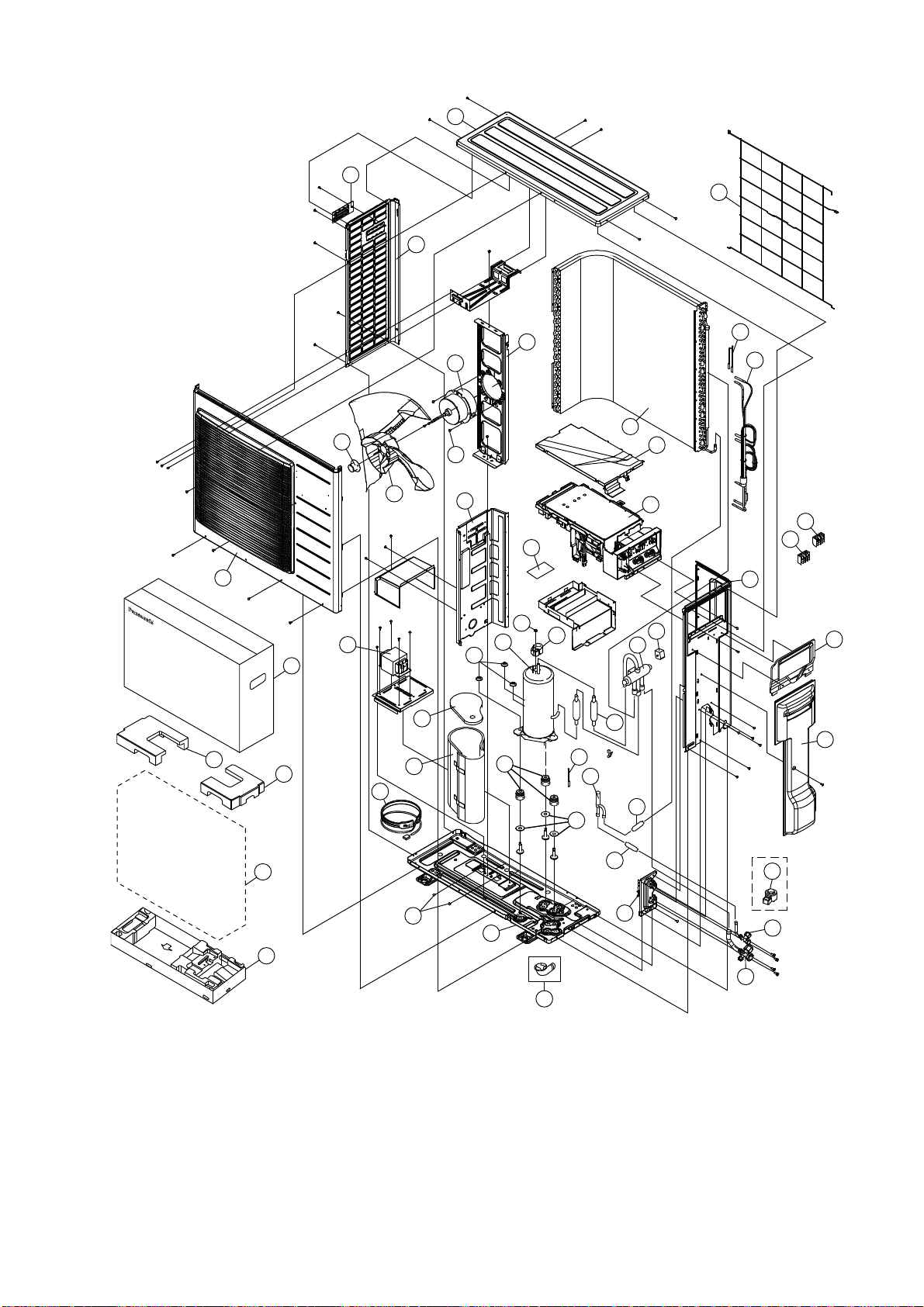
141
22.2.2 CU-E18RKUA CU-E24RKUA
Note
The above exploded view is for the purpose of parts disassembly and replacement.
The non-numbered parts are not kept as standard service parts.
46
29
32
26
27
28
11
45
24
44
34
35
30
31
5
6
8
9
19
52
10
33
51
25
50
49
47
48
7
1
43
40
39
42
2
23
12
37
16
18
17
22
14
41
3
20
21
4
15
36
13
142
SAFETY REF. NO. PART NAME & DESCRIPTION QTY. CU-E18RKUA CU-E24RKUA REMARK
1 CHASSIS COMPLETE 1 CWD52K1228A ←
2 ANTI - VIBRATION BUSHING 3 CWH50055 ←
3 COMPRESSOR 1 5KD240XAF21 ← O
4 NUT - COMPRESSOR MOUNT 3 CWH561049 ←
5 FAN MOTOR BRACKET 1 CWD541127 ←
6 FAN MOTOR 1 EHDS80CAC ← O
7 SCREW - FAN MOTOR BRACKET 3 CWH551217 ←
8 SCREW - FAN MOTOR MOUNT 4 CWH551323 ←
9 PROPELLER FAN ASSY 1 CWH00K1006 ←
10 NUT - PROPELLER FAN 1 CWH561092 ←
11 CONDENSER 1 CWB32C3516 ←
12 EXPANSION VALVE 1 CWB051018J ← O
13 STRAINER 1 CWB111076 ←
14 4-WAYS VALVE 1 CWB001057 ← O
15 DISCHARGE MUFFLER (4 W. VALVE) 1 CWB121055 ←
16 HOLDER COUPLING 1 CWH351228A ←
17 3-WAY VALVE (GAS) 1 CWB011672 CWB011363 O
18 2-WAYS VALVE (LIQUID) 1 CWB021464 ← O
19 SOUND PROOF BOARD 1 CWH151197 ←
20 TERMINAL COVER 1 CWH171039A ←
21 NUT - TERMINAL COVER 1 CWH7080300J ←
22 V-COIL COMPLETE (EXPANSION VALVE) 1 CWA43C2393 ← O
23 SENSOR CO-COMP TEMP 1 CWA50C2689 ← O
24 SENSOR CO-AIR TEMP AND PIPE TEMP 1 CWA50C2710 ← O
25 REACTOR 1 G0C452J00002 ← O
26 TERMINAL BOARD ASSY 1 CWA28K1277 ← O
27 TERMINAL BOARD ASSY 1 CWA28K1076J ← O
28 ELECTRONIC CONTROLLER - MAIN 1 CWA73C9162R CWA73C9163R O
29 CONTROL BOARD COVER - COMPLETE 1 CWH13C1210 ←
30 CABINET SIDE PLATE 1 CWE041490A ←
31 HANDLE 1 CWE161010 ←
32 CABINET SIDE PLATE 1 CWE041488A ←
33 CABINET FRONT PLATE CO. 1 CWE06K1070 ←
34 WIRE NET 1 CWD041128A ←
35 CABINET TOP PLATE 1 CWE031131A ←
36 RECEIVER 1 CWB14030 ←
37 PACKING 3 CWB81043 ←
39 SOUND PROOF MATERIAL 1 CWG302245 ←
40 SOUND PROOF MATERIAL 1 CWG302246 ←
41 V-COIL COMPLETE (4 W. VALVE) 1 CWA43C2392 ← O
42 HEATER 1 CWA341067 ←
43 BAG-COMPLETE 1 CWG87C900 ←
44 TUBE ASSY CO. (CAP. TUBE) 1 CWT01C6093 ←
45 CONTROL BOARD COVER - TOP 1 CWH131333 ←
46 CONTROL BOARD COVER 1 CWH131332 ←
47 BAG 1 CWG861154 ←
48 BASE BOARD-COMPLETE 1 CWG62C1082 ←
143
SAFETY REF. NO. PART NAME & DESCRIPTION QTY. CU-E18RKUA CU-E24RKUA REMARK
49 SHOCK ABSORBER ( R ) 1 CWG712880 ←
50 SHOCK ABSORBER ( L ) 1 CWG712879 ←
51 C.C. CASE 1 CWG565614 ←
52 ELECTRONIC CONTROLLER - NF 1 CWA747077 ←
(Note)
All parts are supplied from PAPAMY, Malaysia (Vendor Code: 00029488).
“O” marked parts are recommended to be kept in stock.
Printed in Malaysia
FB0115-0