© Panasonic Corporation 2016.
Order No: PAPAMY1601004CE
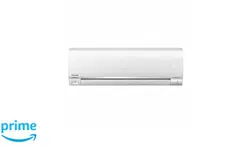
Air Conditioner
Indoor Unit Outdoor Unit
CS-XE9SKUA
CS-XE12SKUA
CU-XE9SKUA
CU-XE12SKUA
Destination
U.S.A.
Canada
CLOCK
AIRCO NDITIONER
OFF/ON
SET CHECK RESET
AC
RC
ON
OFF
SET
123
TIMER
AUTO
COMFORT
POWERFUL /
QUIET
MODE
TEMP
FAN SPEED
AIR SWING
ECONAV I
RFP
MODE
O
FF/
O
N
C
HE
C
K
O
N
O
FF
S
ET
1
2
3
T
I
M
E
R
T
E
M
P
CANCEL
IMPORTANT SAFETY NOTICE
There are special components used in this equipment which are important for safety. These parts are marked by in the Schematic
Diagrams, Circuit Board Diagrams, Exploded Views and Replacement Parts List. It is essential that these critical parts should be replaced
with manufacturer’s specified parts to prevent shock, fire or other hazards. Do not modify the original design without permission of
manufacturer.
!
This service information is designed for experienced repair technicians only and is not designed for use by the general public.
It does not contain warnings or cautions to advise non-technical individuals of potential dangers in attempting to service a product.
Products powered by electricity should be serviced or repaired only by experienced professional technicians. Any attempt to service
or repair the products dealt with in this service information by anyone else could result in serious injury or death.
WARNING
PRECAUTION OF LOW TEMPERATURE
In order to avoid frostbite, be assured of no refrigerant leakage during the installation or repairing of refrigerant circuit.
Installation Manual
24
11. Installation Instruction
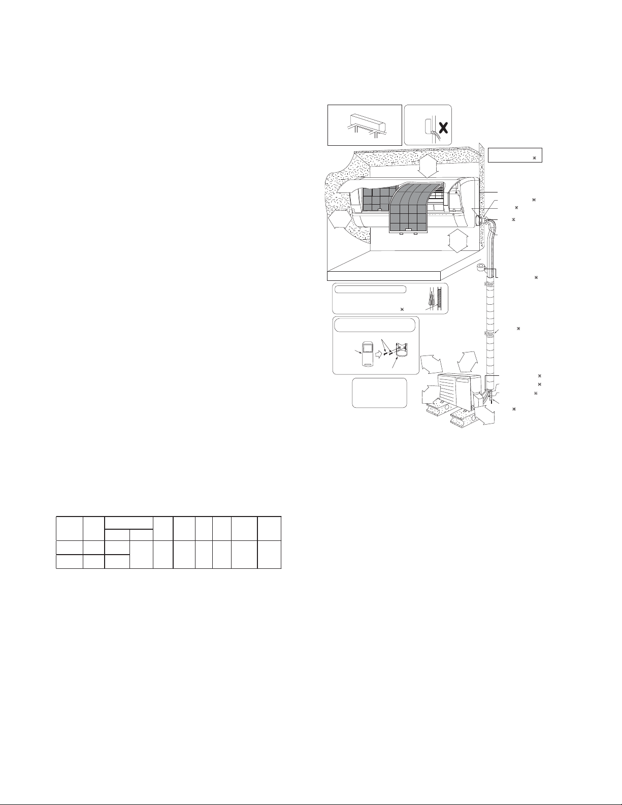
11.1 Select the Best Location
11.1.1 Indoor Unit
Do not install the unit in excessive oil fume area
such as kitchen, workshop and etc.
There should not be any heat source or steam
near the unit.
There should not be any obstacles blocking the air
circulation.
A place where air circulation in the room is good.
A place where drainage can be easily done.
A place where noise prevention is taken into
consideration.
Do not install the unit near the door way.
Ensure the spaces indicated by arrows from the
wall, ceiling, fence or other obstacles.
Mount with the lowest moving parts at least 8ft
(2.4 m) above floor or grade level.
11.1.2 Outdoor Unit
If an awning is built over the unit to prevent direct
sunlight or rain, be careful that heat radiation from
the condenser is not obstructed.
There should not be any animal or plant which
could be affected by hot air discharged.
Keep the spaces indicated by arrows from wall,
ceiling, fence or other obstacles.
Do not place any obstacles which may cause a
short circuit of the discharged air.
If piping length is over the [piping length for
additional gas], additional refrigerant should be
added as shown in the table.
Recommended installation height for outdoor unit
should be above the seasonal snow level.
Be careful not to locate outdoor unit directly under
a roof line where falling snow or ice can cause
damage or dripping water can increase ice
accumulation and defrost cycles.
Example: For XE9SKUA
If the unit is installed at 32.8 ft (10 m) distance, the
quantity of additional refrigerant should be 1.64 oz
(50 g) .... (32.8 - 24.6) ft x 0.2 oz/ft = 1.64 oz.
((10-7.5) m x 20 g/m = 50 g)
11.1.3 Indoor/Outdoor Unit Installation
Diagram
Model
Capacity
(Btu/h)
Piping size
Std.
Length
Max.
Elevation
Min.
Piping
Length
Max.
Piping
Length
Additional
Refrigerant
Piping
Length for
add. gas
Gas Liquid
XE9SKUA
8700
3/8"
(9.52 mm)
1/4"
(6.35 mm)
24.6 ft
(7.5 m)
49.2 ft
(15 m)
9.8 ft
(3 m)
65.6 ft
(20 m)
0.2 oz/ft
(20 g/m)
24.6 ft
(7.5 m)
XE12SKUA
11500
1/2"
(12.7 mm)
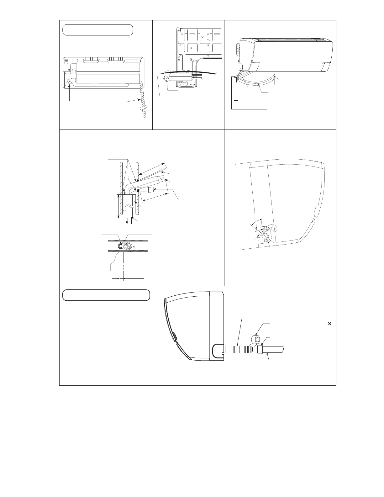
Piping direction Do not bend up
drain hose
(Front side)
Right
Rear
Right
bottom
Left
Rear
Left bottom
Left
(Left and right are identical)
Vinyl tape
6
Remote control holder
5
Remote
control
3
• This illustration is for
explanation purposes only.
The indoor unit will actually face
a different wa y.
It is advisable to avoid m ore
than 2 blockage directions.
For better ventilation &
multiple-outdoor installation,
please consult authorized
dealer/specialist.
Installation plate 1
Sleeve (
)
Bushing-Sleeve (
)
Bend the pipe as
closely on the wall
as possible, but be
careful that it doesn’t
break.
Saddle (
)
Additional drain
hose (
)
Gas side piping (
)
Connection cable (
)
Putty (
)
(Gum Type Sealer)
Installation parts you
should purchase (
)
Vinyl tape (wide) ( )
• Apply after carrying
out a drainage test.
• To carry out the
drainage test,
and pour water into
remove the air filter
s
the heat exchanger.
Liquid side piping (
)
• Carry out insulation after
checking for gas leaks and
secure with vinyl tape.
Remote control holder fixing screws
Attaching the remote control holder
to the wall
Insulation of piping connections
Floor / Grade level
2
9
/
1
6
"
(
6
5
mm
)
o
r
m
or
e
1
31
/
32
"
(50 mm)
or more
3
1
5
/
1
6
"
(
1
0
0
m
m
)
o
r
m
o
r
e
3
9
3
/
8
"
(
1
0
0
0
m
m
)
o
r
m
o
r
e
3
1
5
/
1
6
"
(
1
0
0
m
m
)
o
r
m
o
r
e
1
1
1
3
/
1
6
"
(
3
0
0
m
m
)
o
r
m
o
r
e
8ft(2.4m)
or more
25
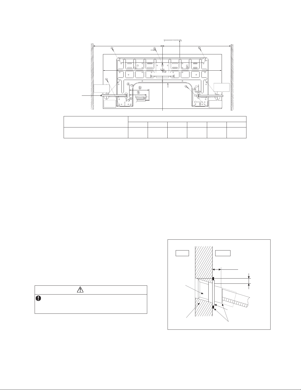
11.2 Indoor Unit
The mounting wall shall be strong and solid enough to prevent it from vibration.
Model
Dimension
1 2 3 4 5 6
XE9SKUA, XE12SKUA
19-9/32"
(490 mm)
3-7/32"
(82 mm)
17-9/32"
(439 mm)
17"
(432 mm)
1-11/16"
(43 mm)
3-3/4"
(95 mm)
The center of installation plate should be at more than 1 at right and left of the wall.
The distance from installation plate edge to ceiling should more than 2.
From installation plate left edge to unit’s left side is 3.
From installation plate right edge to unit’s right is 4.
ƻ
B : For left side piping, piping connection for liquid should be about 5 from this line.
: For left side piping, piping connection for gas should be about 6 from this line.
1 Mount the installation plate on the wall with 5 screws or more (at least 5 screws).
(If mounting the unit on the concrete wall, consider using anchor bolts.)
o Always mount the installation plate horizontally by aligning the marking-off line with the thread and using
a level gauge.
2 Drill the piping plate hole with ø2-3/4" (ø70 mm) hole-core drill.
o Line according to the left and right side of the installation plate. The meeting point of the extended line is
the center of the hole. Another method is by putting measuring tape at position as shown in the diagram
above. The hole center is obtained by measuring the distance namely 5-1/16" (128 mm) for left and right
hole respectively.
o Drill the piping hole at either the right or the left and the hole should be slightly slanting to the outdoor
side.
11.2.1 To Drill a Hole in the Wall and
Install a Sleeve of Piping
1 Insert the piping sleeve to the hole.
2 Fix the bushing to the sleeve.
3 Cut the sleeve until it extrudes about 19/32"
(15 mm) from the wall.
CAUTION
When the wall is hollow, please be sure to use the
sleeve for tube assembly to prevent dangers
caused by mice biting the connection cable.
4 Finish by sealing the sleeve with putty or
caulking compound at the final stage.
DISTANCE
TO PIPE
HOLE
CENTER
128 mm
DISTANCE TO
PIPE HOLE
CENTER 128 mm
PIPE HOLE CENTER
PIPE HOLE
CENTER
Wall
Wall
Wall
Insta llatio n
plate 1
2 screw
More than 1
More than 1
Measuring
Tape
9
17
/
32
"
(241.5 mm)
9
17
/
32
"
(241.5 mm)
5
1
/
16
"
(128 mm)
More
than 2
5
1
/
16
" (128 mm)
5
1
/
16
"
(128 mm)
Putty or caulking compound
Indoor
Outdoor
Sleeve
for tube
assembly
Bushing for tube
assembly
Wall
19
/
32
"(15mm)
ø2
3
/4" (ø70 mm)
through hole
Approx.
7
/32"-
9
/32"
(5-7 mm)
26
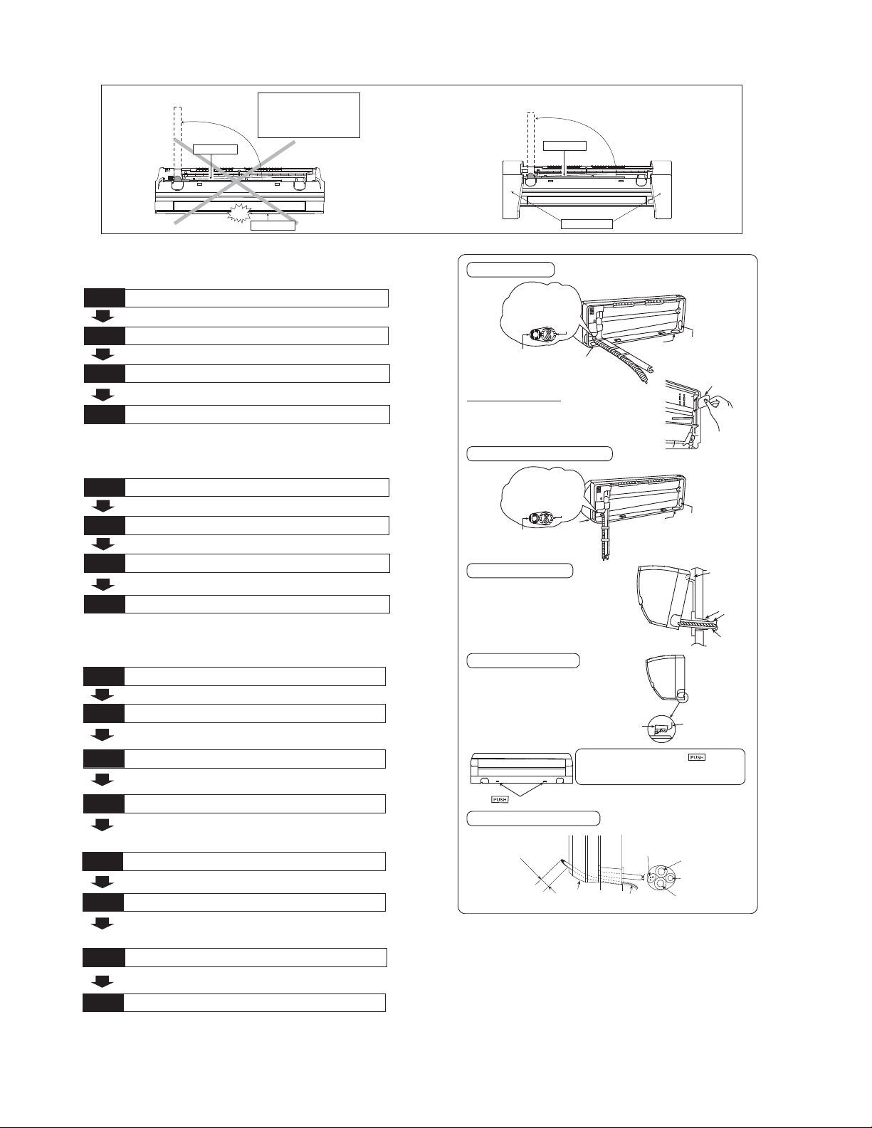
11.2.2 Indoor Unit Installation
11.2.2.1 For the right rear piping
11.2.2.2 For the right bottom piping
11.2.2.3 For the embedded piping
(This can be used for left rear piping and bottom
piping also.)
PUSH PUSH
PUSH PUSH
Piping
Piping
Shock absorber
Intake grille
p
u
l
l
o
u
t
t
h
e
p
i
p
i
n
g
p
u
l
l
o
u
t
t
h
e
p
i
p
i
n
g
Do not turn over the unit
without it’s shock absorber
during pulling out the piping.
It may cause intake grille
damage.
Use shock absorber
during pulling out
the piping to protect
the intake grille from
damage.
Install the Indoor Unit
Pull out the Indoor piping
Step-2
Step-1
Secure the Indoor Unit
Insert the connection cable
Step-3
Step-4
Install the Indoor Unit
Pull out the Indoor piping
Step-2
Step-1
Insert the connection cable
Secure the Indoor Unit
Step-3
Step-4
• Use a spring bender or equivalent to bend the piping so that the
piping is not crushed.
• When determining the dimensions of the piping, slide the unit all the
•
way to the left on the installation plate.
• Refer to the section “Cutting and flaring the piping”.
Bend the embedded piping
Replace the drain hose
• The inside and outside connection cable can be connected without
remo vin g the front grille.
• Please refer to “Connecting the piping” column in outdoor unit
section. (Below steps are done after connecting the outdoor piping
and gas-leakage confirmation.)
Connect the piping
• Please ref er to “Insulation of piping conn ection” column as
mentioned in indoor/outdoor unit installation.
Install the Indoor Unit
Secure the Indoor Unit
Insulate and finish the piping
Step-1
Pull the connection cable into Indoor Unit
Step-3
Cut and flare the embedded piping
Step-4
Step-2
Step-5
Step-6
Step-7
Step-8
Install the indoor unit
Right Rear piping
Hook the indoor unit onto the upper portion
of installation plate. (Engage the indoor unit
with the up per ed ge of the installation plate).
Ensure the hooks are properly seated on
the installation plate by moving it in left and
right.
Cover for the
bottom piping
Cover for the
botto m p ip in g
Tape it with
piping in a position as
mentioned in
Fig. below.
Piping
Drain
hose
Cover
for the
left
piping
1. Press the lower left and right side of the
unit against the installation plate until hooks
engages w ith their slot (sound click).
Cover for piping
In case the cover is cut, keep the cover at the rear
of chassis as shown in the illustration for future
reinstallation.
(Left and 2 bottom covers for p iping.)
How to keep the cover
Right and R ight Bottom piping
Insert the connection cable
Secure the Indoor Unit
To take out the unit, push the marking
at the bottom unit, and pull it slightly towards
you to disengage the hooks from the u nit.
g
n
i
k
r
a
m
Drain hose
Sleeve for
piping hole
Indoor unit
Hooks at
installa tio n
plate
Piping
Installa tio n
plate
Unit’s
hook
Cover for the
bottom p iping
Tape it with piping in a
position as m entioned in
Fig. below.
Cover for
the r ight
piping
Piping
Drain hose
Cover for
the le ft
piping
Guide
surface
Connection cable
Connection
cable
Gas side
piping
Liquid side
piping
Drain hose
A
b
o
u
t
2
3
/
4
"
-
3
5
/
3
2
"
(
7
0
-
8
0
m
m
)
27
Rear view for left piping installation
Drain cap
Drain hose
Adjust the piping
slightly downwards.
•
How to insert the connection cable
and drain hose in the case of left
piping.
(F or right piping, follow the same
procedure)
Replace the drain hose
Drain hose
Connection cable
Sleeve for piping hole
Drain hose
Piping
Connection cable
Cable
4
5
°
Drain
hose
Piping
More than 45
9
/
32
"
(1150 mm)
•
How to pull the piping and drain hose out, in case
of embedded piping
.
PVC tube
for drain
hose
Indoor unit
Piping
Cable
Apply putty or
caulking material
to seal the wall
opening.
Connection
cable
Piping
PVC tube (VP-65) for piping
and connection cable
PVC tube for drain hose (VP-30)
PVC tube for drain
hose (VP-20)
Drain hose
from main unit
2
27
/
32
"(72mm)
M
o
r
e
t
h
a
n
1
8
1
/
2
"
(
4
7
0
m
m
)
M
o
re
t
ha
n
4
5
9
/
3
2
"
(1
15
0
m
m
)
More than
27
9
/
16
"
(700 mm)
Indoor unit
drain hose
3/4" (20 mm) nominal PVC pipe
- Install incline downward more than 1°
- Apply PVC glue at the join.
Drain hose adapter
7
Close join by Vinyl Tape ( )
•
Join indoor drain hose to 3/4"
(20 mm) nominal PVC pipe size
by using drain hose adapter
7
when necessary.
Drain hose adapter
7
usage
Remarks :
Make sure indoor unit drain hose
& 3/4" (20 mm) nominal PVC pipe
are fully inserted to drain hose
adapter
7
.
28
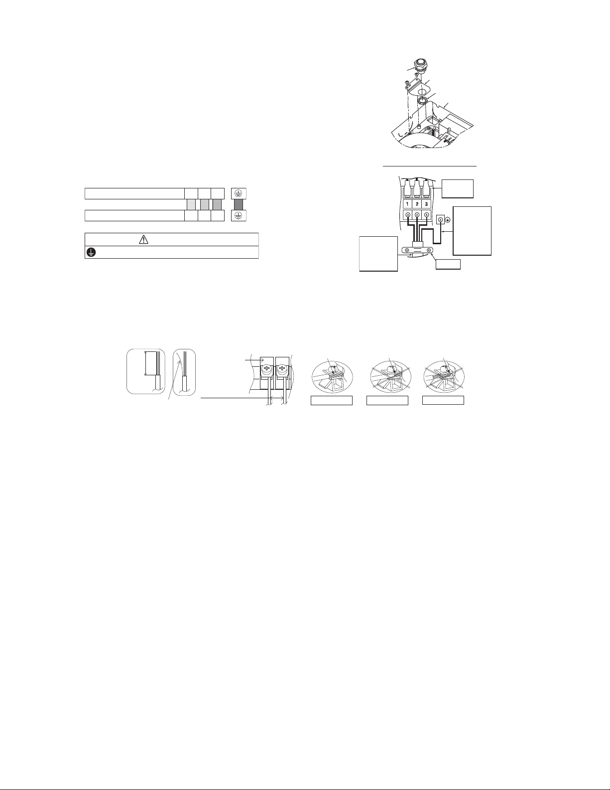
11.2.3 Connect the Cable to the Indoor Unit
1 The inside and outside connection cable can
be connected without removing the front grille.
2 Unscrew the conduit cover and fix the conduit
connector to conduit cover with lock nut, then
secure it against chassis.
3 Connection cable between indoor unit and
outdoor unit should be UL listed or CSA
approved 4 conductor wires minimum AWG16
in accordance with local electric codes.
o Ensure the colour of wires of outdoor unit
and terminal number are the same as the
indoor's respectively.
o Earth lead wire shall be Yellow/Green
(Y/G) in colour and shall be longer than
other lead wires as shown in the figure
for electrical safety in case of slipping.
11.2.3.1 Wire Stripping and Connecting Requirement
Terminals on the indoor unit 1 2 3
Colour of wires (connection cable)
Terminals on the outdoor unit 1 2 3
WARNING
This equipment must be properly earthed.
Holder
Chassis
Conduit
Connector
Conduit Cover
Lock Nut
Rear Side of Indoor Unit
Indoor and
outdoor
connection
cable
Terminal
Board
Earth wire
longer than
others
AC wires
for safety
reason
Wi
r
e
s
t
r
i
p
p
i
n
g
7
/
32
" (5 mm)
or more
(gap between wires)
ACCEPT
PROHIBITED
Conductor
over inserted
No loose strand
when inserted
Indoor/outdoor
connecting
terminal board
Conductor
fully inserted
PROHIBITED
Conductor not
fully inserted
13/32" ± 1/16"
(10 ± 1 mm)
29
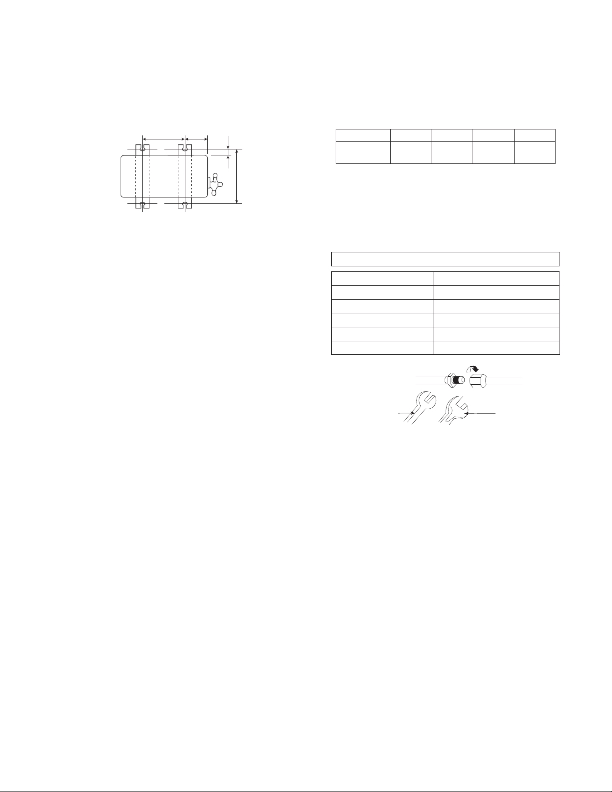
11.3 Outdoor Unit
11.3.1 Install the Outdoor Unit
After selecting the best location, start installation according to Indoor/Outdoor Unit Installation Diagram.
1 Fix the unit on concrete or rigid frame firmly and horizontally with a bolt nut ø13/32" (ø10 mm).
2 When installing at roof, please consider strong wind and earthquake.
Please fasten the installation stand firmly with bolt or nails.
Model A B C D
XE9SKUA,
XE12SKUA
24-1/8"
(613 mm)
5-5/32"
(131 mm)
5/8"
(16 mm)
14-3/16"
(360.5 mm)
11.3.2 Connect the Piping
11.3.2.1 Connecting the Piping to
Indoor
Please make flare after inserting flare nut (locate at
joint portion, of tube assembly) onto the copper pipe.
(In case of using long piping)
Connect the piping
Align the center of piping and sufficiently tighten
the flare nut with fingers.
Further tighten the flare nut with torque wrench in
specified torque as stated in the table.
11.3.2.2 Connecting the Piping to
Outdoor
Decide piping length and then cut by using pipe cutter.
Remove burrs from cut edge.
Make flare after inserting the flare nut (located at valve)
onto the copper pipe.
Align center of piping to valve and then tighten with
torque wrench to the specified torque as stated in the
table.
11.3.2.3 Gas leak checking
Pressure test to system to 400 PSIG with dry nitrogen, in stages. Thoroughly leak check the system.
If the pressure holds, release the nitrogen and proceed to section 11.3.3.
A
B
C
D
Torque
wrench
S
panner
or Wrench
Do not over tighten, over tightening may cause gas leakage
Piping size Torque
1/4" (6.35 mm) 13.3 Ibf.ft [18N•m (1.8 kgf.m)]
3/8" (9.52 mm) 31.0 Ibf.ft [42 N•m (4.3 kgf.m)]
1/2" (12.7 mm) 40.6 Ibf.ft [55 N•m (5.6 kgf.m)]
5/8" (15.88 mm) 47.9 Ibf.ft [65 N•m (6.6 kgf.m)]
3/4" (19.05 mm) 73.8 Ibf.ft [100 N•m (10.2 kgf.m)]
30
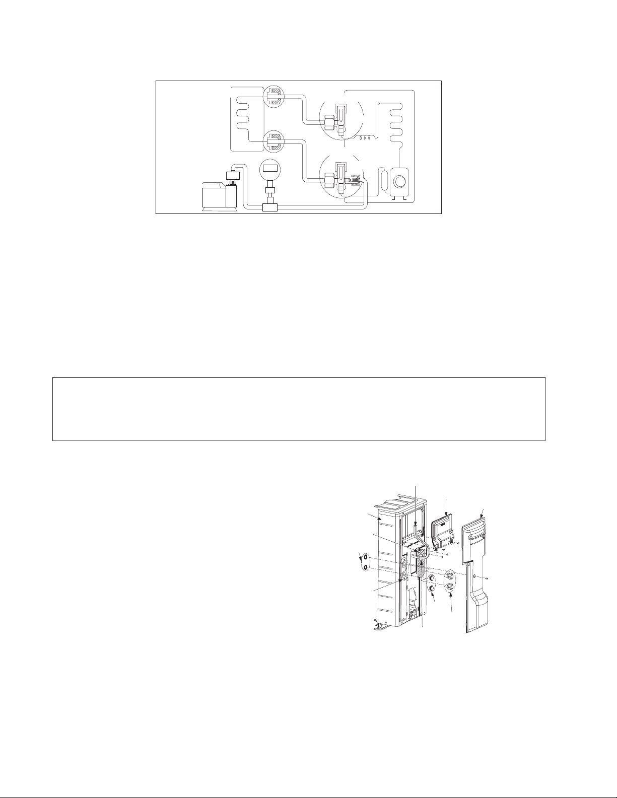
11.3.3 Evacuation of the Equipment
WHEN INSTALLING AN AIR CONDITIONER, BE SURE TO EVACUATE THE AIR INSIDE THE INDOOR UNIT AND
PIPES in the following procedure.
1 Connect a charging hose with a push pin to the Low side of a charging set and the service port of the 3-way
valve.
2 Connect the micron gauge between vacuum pump and service port of outdoor units.
3 Turn on the power switch of the vacuum pump and make sure that connect digital micron gauge and to pull
down to a value of 500 microns.
4 To make sure micron gauge a value 500 microns and close the low side valve of the charging set and turn off
the vacuum pump.
5 Disconnect the vacuum pump house from the service port of the 3-way valve.
6 Tighten the service port caps of the 3-way valve at a torque of 13.3 Ibf.ft (18 N•m) with a torque wrench.
7 Remove the valve caps of both of the 2-way valve and 3-way valve. Position both of the valves to “Open”
using a hexagonal wrench (5/32" (4 mm)).
8 Mount valve caps onto the 2-way valve and the 3-way valve.
o Be sure to check for gas leakage.
If micron gauge value does not descend 500 microns, take the following measures:
- If the leak stops when the piping connections are tightened further, continue working from step e.
- If the leak does not stop when the connections are retightened, repair location of leak.
- Do not release refrigerant during piping work for installation and reinstallation.
- Be careful with the liquid refrigerant, it may cause frostbite.
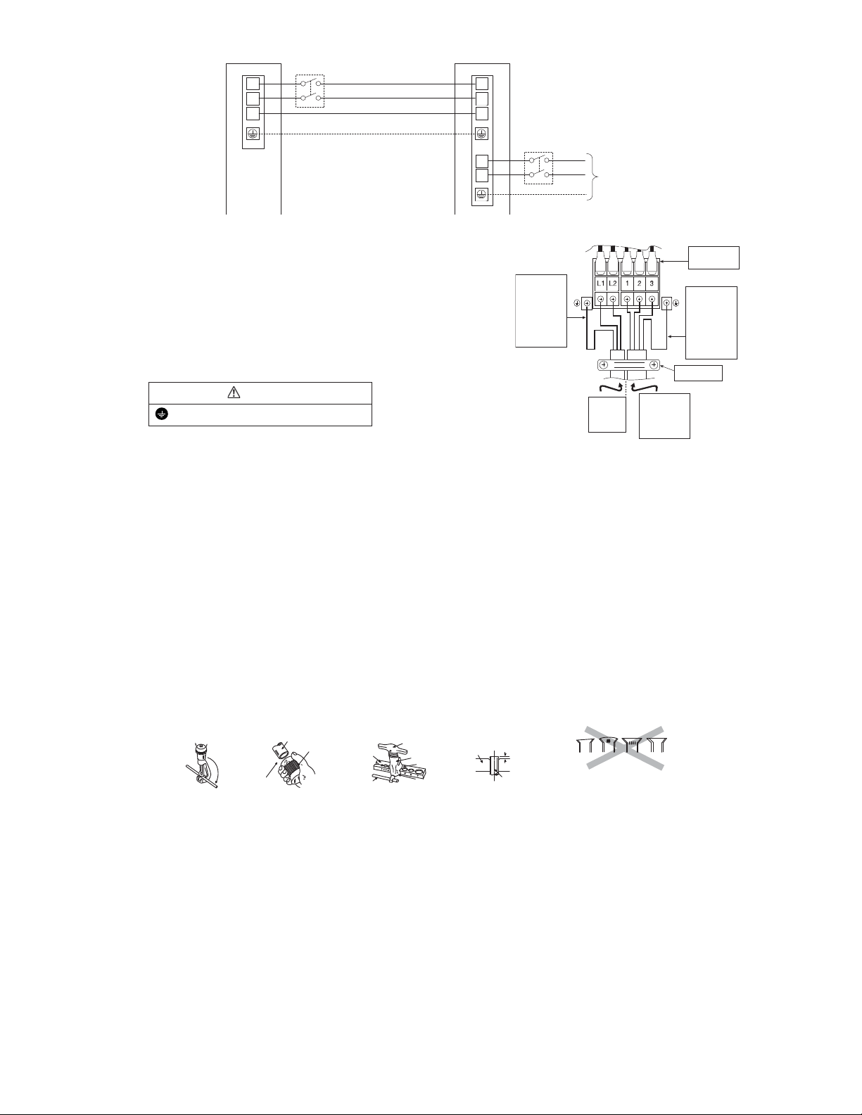
11.3.4 Connect the Cable to the Outdoor Unit
1 Remove control board cover (Resin and
Metal).
2 Remove particular plate.
3 Remove plugs.
4 Fix the conduit connectors to the knockout
holes with lock-nuts, then secure them against
the side panel.
5 All wires pass through conduits & particular
plate’s opening hole.
6 Connecting wire between indoor unit and
outdoor unit should be UL listed or CSA
approved 4 conductor wires minimum AWG16
in accordance with local electric codes.
7 Wire connection to the power supply
(208/230V 60Hz) through circuit breaker.
o Connect the UL listed or CSA approved
wires minimum AWG14 to the terminal
board, and connect the other end of the
wires to ELCB/ GFCI.
8 Connect the power supply cord and
connecting wire between indoor unit and
outdoor unit according to the diagram below.
Gas side
Liquid side
Outdoor unit
Tw o - w ay v a l ve
Three-way valve
Indoor unit
Vacuum
pump
Close
Close
Control Board
Cover (Metal)
L
ock Nuts
Knockout
Holes
Front
Panel
Conn
e
c
ting wi
r
e
s
Control Board
Cover (Resin)
Connectors
Particular
Plate
Particular Plate
O
p
e
nin
g
hol
e
Plugs
31
9 Secure the wire onto the control board with
the holder (clamper).
10 After completing wiring connections, reattach
the particular plate and control board cover
(metal and resin) to the original position with
the screws.
11 For wire stripping and connection
requirement, refer to instruction 11.2.3.1 of
indoor unit.
WARNING
This equipment must be properly earthed.
Earth lead wire shall be Yellow/Green (Y/G) in
colour and should be longer than other lead wires
as shown in the figure for electrical safety in case
of slipping.
11.3.5 Piping Insulation
1 Please carry out insulation at pipe connection portion as mentioned in Indoor/Outdoor Unit Installation
Diagram. Please wrap the insulated piping end to prevent water from going inside the piping.
2 If drain hose or connecting piping is in the room (where dew may form), please increase the insulation by
using POLY-E FOAM with thickness 1/4" (6 mm) or above.
11.3.5.1 Cutting and flaring the piping
1 Please cut using pipe cutter and then remove the burrs.
2 Remove the burrs by using reamer. If burrs are not removed, gas leakage may be caused. Turn the piping
end down to avoid the metal powder entering the pipe.
3 Please make flare after inserting the flare nut onto the copper pipes.
Outdoor Unit
1
2
3
1
2
L1
L2
3
lanimreTlanimreT
Indoor Unit
D
i
s
c
o
nn
e
c
t
Switch
Field supply
Disconnect
Switch
Field supply
Grounding wire
Grounding wire m in AWG16
Power Supply
Single Phase
208/230V 60H z
min AWG14
208/230V m in AWG16
208/230V m in AWG16
208/230V m in AWG16
Holder
Power
supply
cord
Indoor &
outdoor
connection
cable
Terminal
Board
Earth wire
longer
than other
AC wires
for safety
reasons
Earth wire
longer
than other
AC wires
for safety
reasons
1. To cut
When properly flared, the internal surface of the
flare will evenly shine and be of even thickness.
Since the flare part comes into contact w ith the
connec tion s, carefully check the flare fin is h.
Inclined Surface
damaged
Cracked Uneven
thickness
Bar
Handle
Core
Yo k e
Clamp handle
Bar
I
m
p
r
o
p
e
r
fl
a
i
r
i
n
g
0–
1
/
32
" (0-0.5 mm)
Copper
pipe
Reamer
2. To remove burrs
3. To flare
Point down
Pipe
Red arrow mark
32
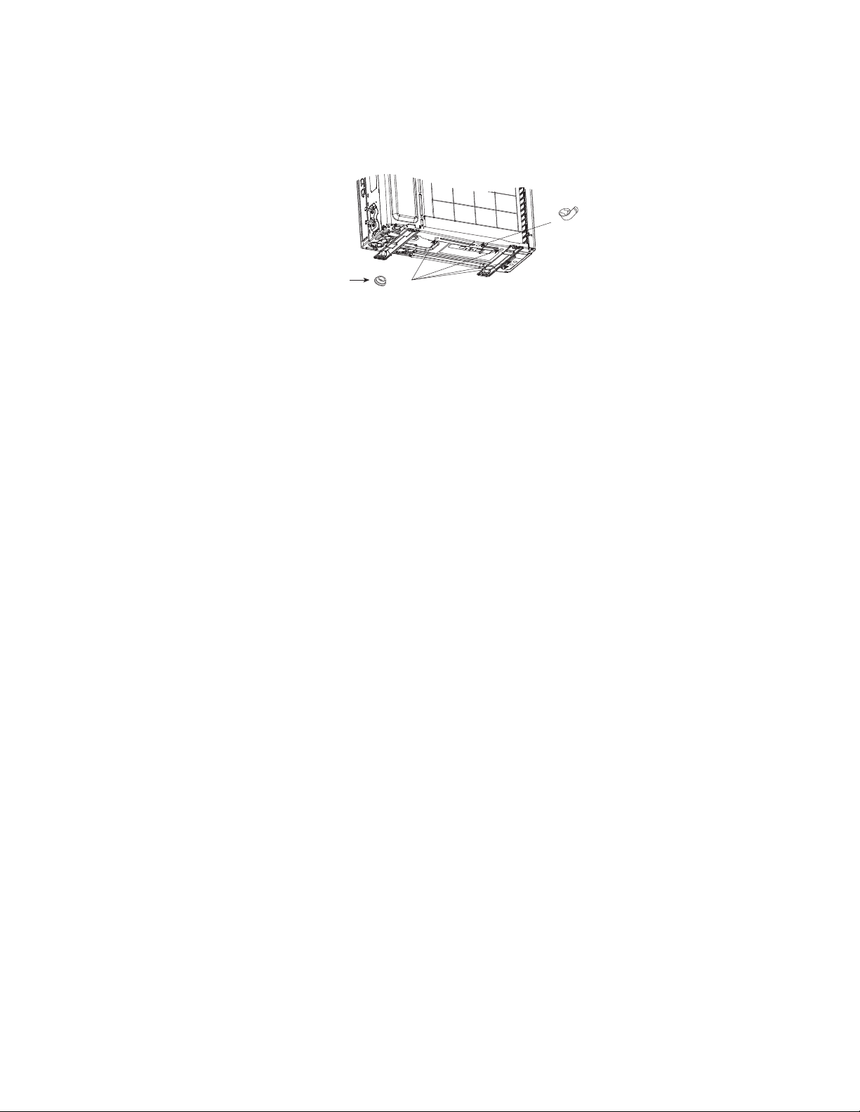
11.3.6 Disposal of Outdoor Unit Drain Water
The unit should be mounted on a stand that suits to a local environmental requirement.
When the Drain elbow being used, please ensure to:-
o Provide a minimum clearance of 2" (50mm) to access the bottom of base pan.
o Seal the four 25/32" (20mm) diameter holes with Rubber caps (refer to illustration below).
o Use a rigid or flexible PVC pipe (local supply) to dispose drained water from the elbow or use a stainless
steel tray (local supplied) to collect and dispose water.
If the unit is used in an area where temperature falls below 32°F (0°C) for 2 or 3 consecutive days, it is
recommended not to use the Drain elbow and Rubber caps, water from defrost process will trap, freeze up and
obstruct fan rotation. Water may drip from the basepan hole area during defrost function, do not stand or place
objects underneath.
Drain
elbow
R
ubber cap
x4