PRINTED IN MALAYSIA
F616529
ENGLISH
CHECK ITEMS
Is there any gas leakage at flare nut
connections?
Has the heat insulation been carried out at flare
nut connection?
Is the connection cable being fixed to terminal
board firmly?
Is the connection cable being clamped firmly?
Is the drainage ok?
(Refer to “Check the drainage” section)
Is the earth wire connection properly done?
Is the indoor unit properly hooked to the
installation plate?
Is the power supply voltage complied with rated
value?
Is there any abnormal sound?
Is the cooling/heating operation normal?
Is the thermostat operation normal?
Is the remote control’s LCD operation normal?
Is the Air purifying filter installed?
PUSH PUSH
PUSH PUSH
Piping
Piping
Shock absorber
Intake grille
Do not turn over the unit without it’s shock absorber during pull out the piping.
It may cause intake grille damage.
Use shock absorber during pull out the piping to protect the intake grille from damage.
p
u
l
l
o
u
t
t
h
e
p
i
p
i
n
g
p
u
l
l
o
u
t
t
h
e
p
i
p
i
n
g
3 4
5
6
1. Insert the piping sleeve to the hole.
2. Fix the bushing to the sleeve.
3. Cut the sleeve until it extrudes about
19
/32" (15 mm) from the wall.
4. Finish by sealing the sleeve with putty
or caulking compound at the fi nal stage.
No. Accessories part Qty.
1
Installation plate
1
2
Installation plate fixing
screw
5
3
Remote
Control
1
4
Battery
2
5
Remote control
holder
1
No. Accessories part Qty.
6
Remote control holder
fixing screw
2
7
Drain elbow
1
8
Air purifying filter
1
9
Drain hose adapter
1
F616529
Required tools for Installation Works
INDOOR UNIT
1
2
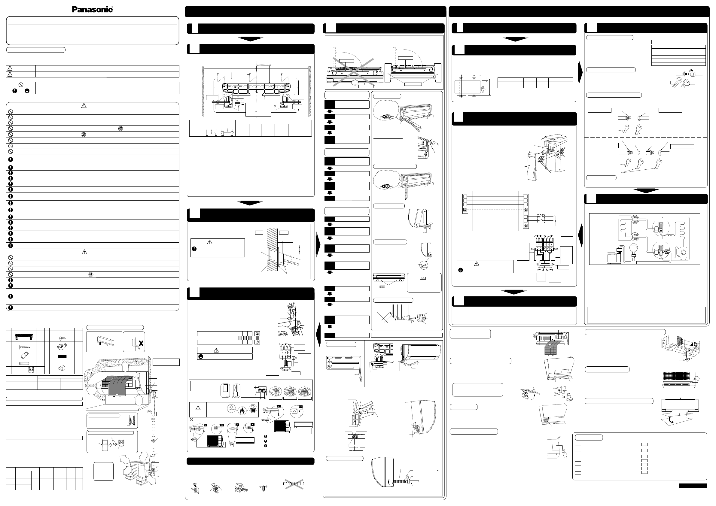
HOW TO FIX INSTALLATION PLATE
The mounting wall shall be strong and solid enough to prevent it from the vibration.
SELECT THE BEST LOCATION
(Refer to “Select the best location” section)
The center of installation plate should be at more than 1 at right and left of the wall.
The distance from installation plate edge to ceiling should more than 2.
From installation plate left edge to unit’s left side is 3.
From installation plate right edge to unit’s right is 4.
b : For left side piping, piping connection for liquid should be about 5 from this line.
: For left side piping, piping connection for gas should be about 6 from this line.
1. Mount the installation plate on the wall with 5 screws or more (at least 5 screws).
(If mounting the unit on the concrete wall, consider using anchor bolts.)
•
Always mount the installation plate horizontally by aligning the marking-off line with the thread and using
a level gauge.
2. Drill the piping plate hole with ø2
3
/4" (ø70 mm) hole-core drill.
•
Line according to the left and right side of the installation plate. The meeting point of the extended line is
the center of the hole. Another method is by putting measuring tape at position as shown in the diagram
above. The hole center is obtained by measuring the distance namely 5
1
/16" (128 mm) for left and right
hole respectively.
•
Drill the piping hole at either the right or the left and the hole should be slightly slanting to the outdoor side.
INDOOR UNIT INSTALLATION
4
OUTDOOR UNIT
1
SELECT THE BEST LOCATION
(Refer to “Select the best location” section)
•
After selecting the best location, start installation to Indoor/Outdoor Unit Installation Diagram.
1. Fix the unit on concrete or rigid frame fi rmly and horizontally with a bolt nut (ø
13
/32" (ø10 mm)).
2. When installing at roof, please consider strong wind and earthquake.
Please fasten the installation stand fi rmly with bolt or nails.
2
INSTALL THE OUTDOOR UNIT
AB
C
D
Rear view for left piping installation
Drain cap
Drain hose
Adjust the piping
slightly downwards.
Drain hose
Connection
cable
•
How to pull the piping and drain hose out, in case
of embedded piping
.
PVC tube
for drain
hose
Indoor unit
3
15
/16" (100 mm)
Piping
Cable
Apply putty or
caulking material
to seal the wall
opening.
Connection
cable
Piping
More than
18
1
/
2
" (470 mm)
More than
37
13
/
32
" (950 mm)
PVC tube (VP-65) for piping
and connection cable
PVC tube for drain hose (VP-30)
PVC tube for
drain hose (VP-20)
More than 27
9
/16"
(700 mm)
•
How to insert the connection cable
and drain hose in the case of left
piping.
Cable
45°
Drain
hose
Piping
Drain hose
from main unit
(For right piping, follow the same
procedure)
Sleeve for piping hole
Drain hose
Piping
Connection
cable
More than 37
13
/32"
(950 mm)
CUTTING AND FLARING THE PIPING
1. Please cut using pipe cutter and then remove the burrs.
2. Remove the burrs by using reamer. If burrs are not removed, gas leakage may be
caused. Turn the piping end down to avoid the metal powder entering the pipe.
3. Please make fl are after inserting the fl are nut onto the copper pipes.
TO DRILL A HOLE IN THE WALL AND
INSTALL A SLEEVE OF PIPING
19
/32" (15 mm)
Putty or caulking compound
ø2
3
/4" (ø70 mm)
through hole
Indoor
Outdoor
Sleeve for
tube
assembly
Approx.
7
/32" -
9
/32"
(5-7 mm)
Bushing for tube
assembly
Wall
CONNECT THE CABLE TO THE INDOOR
UNIT
5
1. The inside and outside connection cable can be connected
without removing the front grille.
2. Unscrew the conduit cover and fi x the conduit connector to
conduit cover with lock nut, then secure it against chassis.
3. Connection cable between indoor unit and outdoor unit should
be UL listed or CSA approved 4 conductor wires minimum
AWG16 in accordance with local electric codes.
•
Ensure the colour of wires of outdoor unit and terminal number
are the same as the indoor's repectively.
•
Earth lead wire shall be Yellow/Green (Y/G) in colour and
shall be longer than other lead wires as shown in the fi gure
for electrical safety in case of slipping.
Holder
3
Please follow the steps below to take out front grille if necessary such as when servicing.
1. Set the vertical airfl ow direction louvers to the horizontal position.
2. Slide down the 2 caps on the front grille as shown in the illustration at right, and
then remove the 2 mounting screws.
3. Pull the lower section of the front grille towards you to remove the front grille.
The below operations will be performed by pressing the “AUTO” switch.
1. AUTO OPERATION MODE
The Auto operation will be activated immediately once the Auto Switch is pressed
and released before 5 sec..
2. TEST RUN OPERATION (FOR PUMP DOWN/SERVICING PURPOSE)
The Test Run operation will be activated if the Auto Switch is pressed continuously
for more than 5 sec. to below 8 sec..
A “pep” sound will occur at the fi fth sec., in order to identify the starting of Test Run
operation.
3. HEATING TRIAL OPERATION
Press the “AUTO” switch continuously for more than 8 sec. to below 11 sec. and release when a “pep
pep” sound is occured at eight sec. (However, a “pep” sound is heard at fi fth sec..) then press Remote
controller “A/C Reset” button once. Remote controller signal will activate operation force heating mode.
4. REMOTE CONTROLLER RECEIVING SOUND ON/OFF
The ON/OFF of Remote controller receiving sound can be changed by the following steps:
a) Press “AUTO” switch continuously for more than 16 sec. to below 21 sec..
A “pep”, “pep”, “pep”, “pep” sound will occur at the sixteenth sec..
b) Press the “A/C Reset” button once. Remote controller signal will activate the Remote controller
sound setting mode.
c) Press the “AUTO” switch once to select Remote controller receiving sound ON/OFF. A “pep” sound
indicates receiving sound ON, and a “pep” sound indicates receiving sound OFF.
DISPOSAL OF OUTDOOR UNIT DRAIN WATER
•
If a drain elbow is used, the unit should be placed on a
stand which is taller than 1
3
/16" (30 mm).
•
If the unit is used in an area where temperature falls
below 32°F (0°C) for 2 or 3 days in succession, it is
recommended not to use a drain elbow, for the drain
water freezes and the fan will not rotate.
CHECK THE DRAINAGE
•
Open front panel and remove air fi lters.
(Drainage checking can be carried out without removing the
front grille.)
•
Pour a glass of water into the drain tray-styrofoam.
•
Ensure that water fl ows out from drain hose of the indoor unit.
Hose
Install the hose at an angle so that the water smoothly fl ows out.
Drain elbow
7
EVALUATION OF THE PERFORMANCE
•
Operate the unit at cooling/heating operation mode for
fi fteen minutes or more.
•
Measure the temperature of the intake and discharge air.
•
Ensure the difference between the intake temperature
and the discharge is more than 46.4°F (8°C) during
Cooling operation or more than 57.2°F (14°C) during
Heating operation.
Discharge air
1 Philips screw driver
2 Level gauge
3 Electric drill, hole core drill (ø2
3
/4" (ø70 mm))
4 Hexagonal wrench (
5
/32" (ø4 mm))
5 Spanner
6 Pipe cutter
7 Reamer
8 Knife
9 Gas leak detector
10 Measuring tape
11 Thermometer
12 Megameter
13 Multimeter
14 Torque wrench
13.3 Ibf.ft (18 N•m (1.8 kgf•m))
31.0 Ibf.ft (42 N•m (4.3 kgf•m))
40.6 Ibf.ft (55 N•m (5.6 kgf•m))
47.9 Ibf.ft (65 N•m (6.6 kgf•m))
73.8 Ibf.ft (100 N•m (10.2 kgf•m))
15 Vacuum pump
16 Digital Micron Gauge
Wall
Wall
Wall
Installation plate 1
2 screw
More than 1
More than 1
Measuring
Tape
Indoor unit
9
17
/
32
"
(241.5 mm)
5
1
/
16
"
(128 mm)
5
1
/
16
" (128 mm)
5
1
/
16
"
(128 mm)
marking
Guide
surface
Connection cable
About
2
3
/
4
" - 3
5
/
32
"
(70-80 mm)
Connection
cable
Gas side
piping
Liquid side
piping
Drain hose
Drain
tray-
styrofoam
Cover for the
bottom piping
Tape it with piping in a
position as mentioned in
Fig. below.
Cover for
the right
piping
Piping
Drain hose
Cover for
the left
piping
Cover for the
bottom piping
Cover for the
bottom piping
Tape it with
piping in a position as
mentioned in
Fig. below.
Piping
Drain
hose
Cover
for the
left
piping
1. Press the lower left and right side
of the unit against the installation
plate until hooks engage with their
slot (sound click).
Installation
plate
Unit’s
hook
Cover for piping
In case the cover is cut, keep the
cover at the rear of chassis as
shown in the illustration for future
reinstallation.
(Left and 2 bottom covers for piping.)
How to keep the cover
6
1. Please carry out insulation at pipe connection portion as mentioned in Indoor/Outdoor Unit Installation
Diagram. Please wrap the insulated piping end to prevent water from going inside the piping.
2. If drain hose or connecting piping is in the room (where dew may form), please increase the insulation by
using POLY-E FOAM with thickness 1/4" (6 mm) or above.
PIPING INSULATION
Hook the indoor unit onto the
upper portion of installation
plate. (Engage the indoor unit
with the upper edge of the
installation plate). Ensure the
hooks are properly seated
on the installation plate by
moving it in left and right.
Drain hose
Sleeve for
piping hole
Indoor unit
Hooks at
installation
plate
Piping
1. Open the front panel.
2. Remove the air fi lters.
3. Put the Air purifying fi lter into place as shown in illustration at right.
3
CONNECT THE PIPING
Please make fl are after inserting fl are nut (locate at joint
portion of tube assembly) onto the copper pipe. (In case
of using long piping)
Connect the piping
Align the center of piping and suffi ciently tighten the
fl are nut with fi ngers.
Further tighten the fl are nut with torque wrench in
specifi ed torque as stated in the table.
Decide piping length and then cut by using pipe cutter.
Remove burrs from cut edge.
Make fl are after inserting the fl are nut (locate at valve) onto
the copper pipe.
Align center of piping to valve and then tighten with torque
wrench to the specifi ed torque as stated in the table.
CONNECT THE CABLE TO THE OUTDOOR
UNIT
5
1. Remove Top panel.
2. Remove Control Board Cover (Resin and Metal).
3. Remove Plugs.
4. Fix the conduit connectors to the knockout holes
with lock-nuts, then secure them against the side
panel.
5. All wires pass through conduits.
6. Connection cable between indoor lunit and outdoor
unit should be UL listed or CSA approved 4
conductor wires minimum AWG16 in accordance
with local electric codes.
7. Wire connection to the power supply (208/230V
60Hz) through circuit breaker.
•
Connect the UL listed or CSA approved wires
minimum AWG14 to the terminal board, and
connect the other end of the wires to ELCB / GFCI.
8. Connect the power supply cord and connection
cable between indoor unit and outdoor unit
according to the diagram below.
9. Secure the wire onto the control board with the
holder (clamper).
10. After completing wiring connections, reattach the
control board cover (Metal and Resin) and the top
panel to the original position with the
screws.
11. For wire stripping and connection requirement, refer
to instruction 5 of indoor unit.
•
Earth lead wire shall be Yellow/Green (Y/G) in colour and
should be longer than other lead wires as shown in the
fi gure for electrical safety in case of slipping.
More than
2
Air purifying fi lter 8
Air fi lter
1
31
/32"
(50 mm)
or more
2
9
/
16
"
(65 mm)
or more
8 ft (2.4 m)
or more
(Left and right are identical)
Floor / Grade level
Vinyl tape
• This illustration is for
explanation purposes only.
The indoor unit will actually face
a different way.
3
15
/
16
"
(100 mm)
or more
39
3
/
8
"
(1000 mm)
or more
3
15
/
16
"
(100 mm)
or more
11
13
/
16
"
(300 mm)
or more
It is advisable to
avoid more than 2
blockage directions.
For better ventilation
& multiple-outdoor
installation, please
consult authorized
dealer/specialist.
Installation plate 1
Sleeve (
)
Bushing-Sleeve (
)
Bend the pipe as
closely on the wall as
possible, but be careful
that it doesn’t break.
Saddle (
)
Conduit
(Power supply cord (
))
Control Board cover
Remote control holder fi xing screws
6
Remote
control
3
Additional drain hose (
)
Gas side piping (
)
Conduit
(Connection cable)
Putty (
)
(Gum Type Sealer)
Installation parts you
should purchase ()
Vinyl tape (wide) ()
• Apply after carrying
out a drainage test.
• To carry out the
drainage test,
remove the air fi lters
and pour water into
the heat exchanger.
Liquid side piping (
)
Piping direction Do not bend up
drain hose
(Front side)
Right
Rear
Right
bottom
Left
Rear
Left bottom
Left
Chassis
Conduit
Connector
Conduit
Cover
Lock Nut
Rear Side of Indoor Unit
Holder
Power
supply
cord
Indoor &
outdoor
connection
cable
Terminal
Board
Earth wire
longer
than other
AC wires
for safety
reasons
Earth wire
longer
than other
AC wires
for safety
reasons
Control Board
Metal Cover
Top Panel
Power
Supply
Wires
Lock Nuts
Knockout
Holes
Plugs
Side Panel
Connectors
Control Board
Cover (Resin)
1. To cut
When properly fl ared, the internal surface of the
fl are will evenly shine and be of even thickness.
Since the fl are part comes into contact with the
connections, carefully check the fl are fi nish.
Improper fl aring
Inclined Surface
damaged
Cracked Uneven
thickness
3. To fl are
Bar
Handle
Core
Yo k e
Clamp handle
Bar
0 –
1
/32"
(0-0.5 mm)
Copper
pipe
Reamer
2. To remove burrs
Point down
Pipe
Red arrow mark
Torque
wrench
Spanner
or Wrench
Pressure test to system to 400 PSIG with dry nitrogen, in stages. Thoroughly leak check the system.
If the pressure holds, release the nitrogen and proceed to section 4.
WHEN INSTALLING AN AIR CONDITIONER, BE SURE TO EVACUATE THE AIR INSIDE THE INDOOR
UNIT AND PIPES in the following procedure.
1. Connect a charging hose with a push pin to the Low side of a charging set and the service port of the
3-way valve.
2. Connect the micron gauge between vacuum pump and service port of outdoor units.
3. Turn on the power switch of the vacuum pump and make sure that connect digital micron gauge and
to pull down to a value of 500 microns.
4. To make sure micron gauge a value 500 microns and close the low side valve of the charging set and
turn off the vacuum pump.
5. Disconnect the vacuum pump house from the service port of the 3-way valve.
6. Tighten the service port caps of the 3-way valve at a torque of 13.3 Ibf.ft (18 N•m) with a torque
wrench.
7. Remove the valve caps of both of the 2-way valve and 3-way valve. Position both of the valves to
“Open” using a hexagonal wrench (5/32" (4 mm)).
8. Mount valve caps onto the 2-way valve and the 3-way valve.
•
Be sure to check for gas leakage.
4
•
If micron gauge value does not descend 500 microns, take the following measures:
- If the leak stops when the piping connections are tightened further, continue working from step
3
.
- If the leak does not stop when the connections are retightened, repair location of leak.
- Do not release refrigerant during piping work for installation and reinstallation.
- Be careful with the liquid refrigerant, it may cause frostbite.
Gas side
Liquid side
Outdoor unit
Two-way valve
Three-way valve
Indoor unit
Vacuum
pump
Close
Close
Hall Union
Flare Nut
(Auxiliary pipe)
(Connection pipe)
Applicable to
Liquid and Gas side of
CS-E9RKUAW
Liquid side of
CS-E12RKUAW
Torque Wrench for Flare Nut
Wrench
(Adjustable Wrench)
Male side Female side
Hall Union
Flare Nut
Pipe Size
Reducer
Packing
Torque Wrench for Flare
Nut and Pipe Size Reducer
Wrench
(Adjustable Wrench)
Applicable to
Gas side of
CS-E12RKUAW
(Connection pipe)
(Auxiliary pipe)
Female side
Male side
Decide piping length and then cut by using pipe cutter. Remove burrs from cut edge.
Make fl are after inserting the fl are nut (locate at valve) onto the copper pipe.
Align center of piping to valve and then tighten with torque wrench to the specifi ed torque as stated in the table.
•
Pipe size reducer (CZ-MA1P) for outdoor Multi connection
CS-E12RKUAW
•
Read the following “SAFETY PRECAUTIONS” carefully before installation.
•
Electrical work must be installed by a licensed electrician. Be sure to use the correct rating of the power plug and main circuit for the model to be installed.
•
The caution items stated here must be followed because these important contents are related to safety. The meaning of each indication used is as below.
Incorrect installation due to ignoring of the instruction will cause harm or damage, and the seriousness is classifi ed by the following indications.
The items to be followed are classifi ed by the symbols:
•
Carry out test running to confi rm that no abnormality occurs after the installation. Then, explain to user the operation, care and maintenance as stated in
instructions. Please remind the customer to keep the operating instructions for future reference.
SAFETY PRECAUTIONS
WARNING
This indication shows the possibility of causing death or serious injury.
CAUTION
This indication shows the possibility of causing injury or damage to properties only.
Symbol with white background denotes item that is PROHIBITED.
Symbol with dark background denotes item that must be carried out.
WARNING
Do not install outdoor unit near handrail of veranda. When installing air-conditioner unit on veranda of a high rise building, child may climb up to outdoor unit
and cross over the handrail causing an accident.
Do not use unspecifi ed cord, modifi ed cord, joint cord or extension cord for power supply cord. Do not share the single outlet with other electrical appliances.
Poor contact, poor insulation or over current will cause electrical shock or fi re.
Do not tie up the power supply cord into a bundle by band. Abnormal temperature rise on power supply cord may happen.
Do not insert your fi ngers or other objects into the unit, high speed rotating fan may cause injury.
Do not sit or step on the unit, you may fall down accidentally.
Keep plastic bag (packaging material) away from small children, it may cling to nose and mouth and prevent breathing.
When installing or relocating air conditioner, do not let any substance other than the specifi ed refrigerant, eg. air etc mix into refrigeration cycle (piping). Mixing
of air etc will cause abnormal high pressure in refrigeration cycle and result in explosion, injury etc.
Do not add or replace refrigerant other than specifi ed type. It may cause product damage, burst and injury etc.
•
For R410A model, use piping, fl are nut and tools which is specifi ed for R410A refrigerant. Using of existing (R22) piping, fl are nut and tools may cause
abnormally high pressure in the refrigerant cycle (piping), and possibly result in explosion and injury.
•
Thickness or copper pipes used with R410A must be more than
1
/32" (0.8 mm). Never use copper pipes thinner than
1
/32" (0.8 mm).
•
It is desirable that the amount of residual oil is less than 0.0008 oz/ft (40 mg/10 m).
Engage authorized dealer or specialist for installation. If installation done by the user is incorrect, it will cause water leakage, electrical shock or fi re.
Install according to this installation instructions strictly. If installation is defective, it will cause water leakage, electrical shock or fi re.
Use the attached accessories parts and specifi ed parts for installation. Otherwise, it will cause the set to fall, water leakage, fi re or electrical shock.
Install at a strong and fi rm location which is able to withstand the set’s weight. If the strength is not enough or installation is not properly done, the set will
drop and cause injury.
For installation work, follow all electrical, building, plumbing, local codes, regulations and these installation instructions. If electrical circuit capacity is not
enough or a defect is found in electrical work, it will cause electrical shock or fi re.
Do not use spliced wires for indoor / outdoor connection cable. Use the specifi ed indoor / outdoor connection cable, refer to instruction 5 INDOOR/OUTDOOR
UNIT ELECTRICAL WIRING and connect tightly for indoor/outdoor connection. Clamp the cable so that no external force will have impact on the terminal. If
connection or fi xing is not perfect, it will cause heat-up or fi re at the connection.
Wire routing must be properly arranged so that control board cover is fi xed properly. If control board cover is not fi xed perfectly, it will cause fi re or electrical
shock.
This equipment must installed with an Earth Leakage Circuit Breaker (ELCB) or Ground Fault Current Interrupter (GFCI) or Appliance Leakage Current
Interrupter (ALCI) that has been certifi ed by an NRTL Certifi ed Testing Agency and that is suitable for the voltages and amperages involved. Otherwise, if may
cause electrical shock and fi re in case of equipment breakdown.
During installation, install the refrigerant piping properly before running the compressor. Operation of compressor without fi xing refrigeration piping and valves
at opened condition will cause suck-in of air, abnormal high pressure in refrigeration cycle and result in explosion, injury etc.
During pump down operation, stop the compressor before removing the refrigeration piping. Removal of refrigeration piping while compressor is operating and
valves are opened will cause suck-in of air, abnormal high pressure in refrigeration cycle and result in explosion, injury etc.
Tighten the fl are nut with torque wrench according to specifi ed method. If the fl are nut is over-tightened, after a long period, the fl are may break and cause
refrigerant gas leakage.
After completion of installation, confi rm there is no leakage of refrigerant gas. It may generate toxic gas when the refrigerant comes into contact with fi re.
Ventilate if there is refrigerant gas leakage during operation. It may cause toxic gas when the refrigerant comes into contact with fi re.
This equipment must be properly earthed. Earth line must not be connected to gas pipe, water pipe, earth of lightning rod and telephone. Otherwise, it may
cause electrical shock in case of equipment breakdown or insulation breakdown.
CAUTION
Do not install the unit at place where leakage of fl ammable gas may occur. In case gas leaks and accumulates at surrounding of the unit, it may cause fi re.
Do not release refrigerant during piping work for installation, re-installation and during repairing a refrigeration parts. Take care of the liquid refrigerant, it may
cause frostbite.
Do not install this appliance in a laundry room or other location where water may drip from the ceiling, etc.
Do not touch the sharp aluminium fi n, sharp parts may cause injury.
Carry out drainage piping as mentioned in installation instructions. If drainage is not perfect, water may enter the room and damage the furniture.
Select an installation location which is easy for maintenance.
Power supply connection to the room air conditioner.
Power supply cord shall be UL listed or CSA approved 3 conductor with minimum AWG14 wires.
Power supply point should be in an easily accessible place for power disconnection in case of emergency.
In some countries, permanent connection of this air conditioner to the power supply is prohibited.
Fix power supply connection to a circuit breaker for permanent connection.
Use NRTL approved fuse or circuit breaker (rating refers to name plate) for permanent connection.
Installation work.
It may take two people to carry out the installation work.
Example: For E9RKUAW
If the unit is installed at 32.8 ft (10 m) distance, the quantity of additional refrigerant
should be 1.64 oz (50 g) .... (32.8 - 24.6) ft x 0.2 oz/ft = 1.64 oz. ((10 - 7.5) m x
20 g/m = 50 g).
INDOOR UNIT
OUTDOOR UNIT
Do not install the unit in excessive oil fume area such as kitchen, workshop
and etc.
There should not be any heat source or steam near the unit.
There should not be any obstacles blocking the air circulation.
A place where air circulation in the room is good.
A place where drainage can be easily done.
A place where noise prevention is taken into consideration.
Do not install the unit near the door way.
Ensure the spaces indicated by arrows from the wall, ceiling, fence or other
obstacles.
Recommended installation height for indoor unit shall be at least 8 ft (2.4 m).
If an awning is built over the unit to prevent direct sunlight or rain, be careful that
heat radiation from the condenser is not obstructed.
There should not be any animal or plant which could be affected by hot air
discharged.
Keep the spaces indicated by arrows from wall, ceiling, fence or other obstacles.
Do not place any obstacles which may cause a short circuit of the discharged air.
If piping length is over the [piping length for additional gas], additional refrigerant
should be added as shown in the table.
Recommended installation height for outdoor unit should be above the seasonal
snow level.
Attached accessories
Applicable piping kit
Piping size
Gas Liquid
CZ-3F5, 7BP 3/8" (9.52 mm) 1/4" (6.35 mm)
CZ-4F5, 7, 10BP 1/2" (12.7 mm) 1/4" (6.35 mm)
CZ-52F5, 7, 10BP 5/8" (15.88 mm) 1/4" (6.35 mm)
SELECT THE BEST LOCATION
Model
Capacity
(Btu/h)
Piping size
Std.
Length
Max.
Elevation
Min.
Piping
Length
Max.
Piping
Length
Additional
Refrigerant
Piping
Length
for add.
gas
Gas
Liquid
E9RKUAW 9000
3/8"
(9.52 mm)
1/4"
(6.35 mm)
24.6 ft
(7.5 m)
49.2 ft
(15 m)
9.8 ft
(3 m)
65.6 ft
(20 m)
0.2 oz/ft
(20 g/m)
24.6 ft
(7.5 m)
E12RKUAW 11500
1/2"
(12.7 mm)
Indoor/Outdoor Unit Installation Diagram
Insulation of piping connections
Attaching the remote control holder to the wall
• Carry out insulation after
checking for gas leaks and
secure with vinyl tape.
Remote control holder
5
WARNING
This equipment must be properly earthed.
Model
Dimension
123 456
E9RKUAW,
E12RKUAW
or
19
9
/32"
(490 mm)
3
7
/32"
(82 mm)
17
9
/32"
(439 mm)
17"
(432 mm)
1
11
/16"
(43 mm)
3
3
/4"
(95 mm)
CAUTION
When the wall is hollow, please be sure
to use the sleeve for tube assembly to
prevent dangers caused by mice biting
the connection cable.
Replace the drain hose
Indoor and
outdoor
connection
cable
Terminal
Board
Earth wire
longer than
others
AC wires
for safety
reason
1. FOR THE RIGHT REAR
PIPING
Step-1
Pull out the Indoor
piping
Step-2 Install the Indoor Unit
Step-3 Secure the Indoor Unit
Step-4
Insert the connection
cable
2. FOR THE RIGHT BOTTOM
PIPING
Step-1
Pull out the Indoor
piping
Step-2 Install the Indoor Unit
Step-3
Insert the connection
cable
Step-4 Secure the Indoor Unit
3. FOR THE EMBEDDED
PIPING
Step-1 Replace the drain hose
Step-2
Bend the embedded
piping
• Use a spring bender or equivalent
to bend the piping so that the
piping is not crushed.
Step-3
Pull the connection
cable into Indoor Unit
• The inside and outside connection
cable can be connected without
removing the front grille.
Step-4
Cut and fl are the
embedded piping
• When determining the dimensions
of the piping, slide the unit all the
way to the left on the installation
plate.
• Refer to the section “Cutting and
fl aring the piping”.
Step-5 Install the Indoor Unit
Step-6 Connect the piping
• Please refer to “Connecting the
piping” column in outdoor unit
section. (Below steps are done
after connecting the outdoor piping
and gas-leakage confi rmation.)
Step-7
Insulate and fi nish the
piping
• Please refer to “Insulation of piping
connection” column as mentioned
in indoor/outdoor unit installation.
Step-8 Secure the Indoor Unit
Right Rear piping
Right and Right Bottom piping
Install the indoor unit
Secure the Indoor Unit
To take out the unit,
push the
marking at
the bottom unit, and pull
it slightly towards you to
disengage the hooks from
the unit.
Insert the connection cable
(This can be used for left rear piping and bottom piping also.)
Model A B C D
E9RKUA, E12RKUA
22
7
/16"
(570 mm)
4
1
/8"
(105 mm)
23
/32"
(18.5 mm)
12
19
/32"
(320 mm)
WARNING
This equipment must be properly earthed.
Connecting The Piping to Indoor
Connecting The Piping to Outdoor
Connecting The Piping to Outdoor Multi
Gas Leak Checking
Do not over tighten, overtightening may cause gas leakage.
Piping size Torque
1/4" (6.35 mm) 13.3 Ibf.ft [18 N•m (1.8 kgf•m)]
3/8" (9.52 mm) 31.0 Ibf.ft [42 N•m (4.3 kgf•m)]
1/2" (12.7 mm) 40.6 Ibf.ft [55 N•m (5.6 kgf•m)]
5/8" (15.88 mm) 47.9 Ibf.ft [65 N•m (6.6 kgf•m)]
3/4" (19.05 mm) 73.8 Ibf.ft [100 N•m (10.2 kgf•m)]
EVACUATION OF THE EQUIPMENT
HOW TO TAKE OUT FRONT GRILLE
INSTALLATION OF AIR
PURIFYING FILTER
AUTO SWITCH OPERATION
When reinstalling the front grille, fi rst set
the vertical airfl ow direction louver to the
horizontal position and then carry out
above steps 2 - 3 in the reverse order.
•
IMPORTANT
This product has been designed and manufactured to meet ENERGY STAR
®
criteria for energy efficiency when matched with appropriate coil components. However,
proper refrigerant charge and proper air flow are critical to achive rated capacity and efficiency. Installation of this product should follow the manufacturer’s
refrigerant charging and air flow instructions. Failure to confirm proper charge and airflow may reduce energy efficiency and shorten equipment life.
9
17
/
32
"
(241.5 mm)
Indoor unit
drain hose
3/4" (20 mm) nominal PVC pipe
- Install incline downward more than 1°
- Apply PVC glue at the join.
Drain hose adapter
9
Close join by Vinyl Tape ( )
•
Join indoor drain hose to 3/4"
(20 mm) nominal PVC pipe size
by using drain hose adapter
9
when necessary.
Drain hose adapter
9 usage
Remarks :
Make sure indoor unit drain hose
& 3/4" (20 mm) nominal PVC pipe
are fully inserted to drain hose
adapter
9.
Outdoor Unit
1
2
3
1
2
L1
L2
3
Terminal Terminal
Indoor Unit
Disconnect
Switch
Field supply
Grounding wire
Grounding wire min AWG16
* Ensure all connecting wire
between indoor unit and
outdoor unit and power supply
cord are installed in individual
conduit.
Power Supply
Single Phase
208/230V 60Hz
min AWG14
208/230V min AWG16
208/230V min AWG16
208/230V min AWG16
Terminals on the indoor unit 1 2 3
Colour of wires (connection cable)
Terminals on the outdoor unit 1 2 3
For best strength of
INDOOR unit installation,
it is highly recommended
to locate “
” at 5 position
as shown.
WARNING
RISK OF FIRE
JOINING OF WIRES
MAY CAUSE
OVERHEATING
AND FIRE.
OR
OR
OR
Wire stripping
No loose strand
when inserted
WIRE STRIPPING,
CONNECTING
REQUIREMENT
Conductor
fully inserted
Conductor
over inserted
Conductor not
fully inserted
ACCEPT PROHIBITED PROHIBITED
Use complete wire without joining.
Use approved socket and plug with earth pin.
Wire connection in this area must follow to
national wiring rules.
Do not joint wires
13/32" ± 1/16"
(10±1 mm)
Indoor/outdoor
connection
terminal board
7
/32" (5 mm)
or more
(gap between wires)
Cap
Screw
(Move the vane
to upward)
Vane
Cap
Vane
Front grille
ECO SENSOR
•
Do not hit or violently press the sensor.
This can lead to damage and malfunction.
•
Do not place large objects near the sensor and keep heating units
or humidifi ers of the sensor’s detection area.
This may lead to sensor malfunction.
ECO SENSOR

IMPRIMÉ EN MALAISIE
F616530
FRANÇAIS
ÉLÉMENTS À VÉRIFIER
Y a-t-il une fuite de gaz aux connexions d’écrous
évasés?
Est-ce que l’isolation thermique a été effectuée à la
connexion de l’écrou évasé?
Le câble de connexion est-il bien fixé au bornier?
Le câble de connexion est-il fermement fixé?
L’évacuation est-elle suffisante?
(Consulter la section « Vérification de l’évacuation »)
La connexion de mise à la terre est-elle bien faite?
L’unité intérieure est-elle bien accrochée à la plaque
d’installation?
La tension d’alimentation se conforme-t-elle à la
tension nominale?
Existe-t-il un son anormal?
Le refroidissement/chauffage est-il normal?
Est-ce que le thermostat fonctionne normalement?
Est-ce que le fonctionnement de l’affichage à
cristaux liquides de la télécommande est normal?
Le filtre de purification d’air est-il installé?
PUSH PUSH
PUSH PUSH
Canalisation
Canalisation
Amortisseur
Grille de l’entrée d’air
•
Ne pas renverser l’unité sans son amortisseur lorsqu’il est retiré du conduit.
Cela pourrait endommager la grille de l’entrée d’air.
•
Utiliser l’amortisseur lors du retrait du conduit afi n de protéger la grille de l’entrée d’air.
T
i
r
e
r
l
e
t
u
y
a
u
T
i
r
e
r
l
e
t
u
y
a
u
3 4
5
6
1. Insérer le manchon de canalisation dans le trou.
2. Fixer la bague au manchon.
3. Couper le manchon pour qu’il sorte d’environ
15 mm (
19
/
32
po) du mur.
F616530
Outils nécessaires à l’installation
UNITÉ INTÉRIEURE
1
2
FIXATION DE LA PLAQUE D’INSTALLATION
Le mur d’installation devrait être assez solide pour absorber les vibrations.
CHOIX DU MEILLEUR EMPLACEMENT
(Cf. chapitre « Choix du meilleur emplacement »)
Le centre de la plaque d’installation doit être à plus de
1
à droite ou à gauche du mur.
La distance du rebord de la plaque d’installation au plafond doit être de plus de
2
.
La distance du rebord gauche de la plaque d’installation au côté gauche de l’unité est de
3
.
La distance du rebord droit de la plaque d’installation au côté droit de l’unité est de
4
.
b
: Dans le cas de la canalisation à gauche, la connexion de la canalisation de liquide doit se situer à environ
5
de
cette dernière.
: Dans le cas de la canalisation à gauche, la connexion de la canalisation de gaz doit se situer à environ
6
de
cette dernière.
1. Poser la plaque d’installation au mur à l’aide de 5 vis ou plus (au moins 5 vis).
(Si l’appareil est monté sur un mur de béton, utiliser des boulons d’ancrage)
•
Toujours poser la plaque d’installation à l’horizontale en alignant la ligne de marquage avec le fi letage et en utilisant
un indicateur de niveau.
2. Percer le trou de la canalisation de la plaque à l’aide d’un foret-aléseur de ø70 mm (2
3
/
4
po).
•
Aligner selon les côtés inférieurs gauche et droit de la plaque d’installation. L’intersection avec la ligne prolongée est le
centre du trou. Une autre méthode consiste à placer le ruban à mesurer à la position illustrée sur le schéma ci-dessus.
Le centre du trou est obtenu en mesurant la distance, 128 mm (5
1
/
16
po) tant pour le trou droit que pour le trou gauche.
•
Percer le trou de la canalisation du côté droit ou gauche et ce trou doit être légèrement incliné vers l’extérieur.
INSTALLATION DE L’UNITÉ INTÉRIEURE
4
UNITÉ EXTÉRIEURE
1
CHOIX DU MEILLEUR EMPLACEMENT
(Cf. chapitre « Choix du meilleur emplacement »)
•
Après avoir choisi le meilleur emplacement, commencer l’installation selon le diagramme d’installation d’une
unité intérieure/extérieure.
1. Fixer fermement à l’horizontale l’appareil au béton ou à un cadre rigide à l’aide d’un boulon et écrou (ø10 mm
(ø13/32 po)).
2. Lors de l’installation sur un toit, prendre en considération les vents forts et les tremblements de terre.
Fixer fermement le support d’installation à l’aide de boulons ou de clous.
2
INSTALLATION DE L’UNITÉ EXTÉRIEURE
AB
C
D
Vue arrière de l’installation de la
canalisation de gauche
Bouchon
d’évacuation
Tuyau
d’évacuation
Ajuster la canalisation
légèrement vers le bas.
Tuyau d’évacuation
Câble de
connexion
•
Retrait de la canalisation et du tuyau d’évacuation, dans
le cas d’une canalisation intégrée.
Tube de PVC pour le
tuyau d’évacuation
Unité intérieure
100 mm (3
15
/
16
po)
Canalisation
Câble
Appliquer du mastic
ou du matériel de
calfeutrage pour sceller
l’ouverture du mur.
Câble de connexion
Canalisation
Plus de 470 mm
( 18
1
/
2
po)
Plus de 950 mm (37
13
/
32
po)
Tube de PVC (VP-65) pour
canalisation et câble de connexion
Tube de PVC pour le tuyau
d’évacuation (VP-30)
Tube de PVC pour le tuyau
d’évacuation (VP-20)
Plus de 700 mm (27
9
/
16
po)
•
Mise en place du câble de connexion et
du tuyau d’évacuation pour la canalisation
de gauche.
Câble
45°
Tuyau d’évacuation
Canalisation
Tuyau
d’évacuation de
l’unité principale
(Pour la canalisation de droite, faire
de même.)
Manchon pour le trou de canalisation
Tuyau d’évacuation
Canalisation
Câble de
connexion
Plus de 950 mm (37
13
/
32
po)
COUPE ET ÉVASEMENT DU TUYAU
1. Couper à l’aide du coupe-tuyau et ébarber.
2. Ébarber à l’aide d’un alésoir. Si les bavures ne sont pas enlevées, il peut y avoir fuite de gaz. Tourner le tuyau vers le bas
pour éviter que la poudre métallique n’entre dans le tuyau.
3. Évaser après avoir inséré l’écrou évasé sur les tuyaux de cuivre.
PERÇAGE D’UN TROU DANS LE MUR ET
INSTALLATION D’UN MANCHON DE CANALISATION
15 mm (
19
/
32
po)
Mastic ou composé de calfeutrage
Trou de passage
ø70 mm (ø2
3
/
4
po)
Manchon
d’assemblage
de tube
Environ 5-7 mm
(
7
/32 po -
9
/32 po)
Bague d’assemblage
de tube
Mur
CONNEXION ÉLECTRIQUE DE L’UNITÉ
INTÉRIEURE
5
1. Le câble de connexion intérieur et extérieur peut être branché sans
enlever la grille avant.
2. Retirer le couvercle du conduit en desserrant les vis et fi xer les
connecteurs au conduit avec des écrous de blocage, puis bien les
assujettir.
3. Le câble de connexion entre l’unité intérieure et l’unité extérieure doit
être un câble à 4 fi ls conducteurs de calibre AWG16 ou plus homologué
UL ou CSA et conforme aux codes d’électricité locaux.
•
Assurez-vous de connecter les fi ls de même couleur et ayant les
mêmes numéros de prise lors du raccordement entre l’unité intérieure
et l’unité extérieure.
•
Pour des raisons de sécurité, le fi l de mise à la terre
sera jaune/vert et plus long que les autres fi ls c.a., tel
qu’indiqué dans l’illustration.
Supports
3
Suivre les étapes ci-dessous pour enlever au besoin la grille avant lors de l’entretien.
1. Placer les évents verticaux directionnels d’écoulement d’air en position horizontale.
2. Faire glisser les 2 chapeaux de la grille avant de la façon illustrée à droite et puis
enlever les 2 vis de fi xation.
3. Tirer vers soi sur la section inférieure de la grille avant pour enlever cette dernière.
Les opérations ci-dessous sont effectuées en appuyant sur le commutateur « AUTO ».
1. MODE DE FONCTIONNEMENT AUTOMATIQUE
Le fonctionnement automatique est immédiatement activé lorsqu’on appuie sur le
commutateur et le relâche en moins de 5 s.
2. ESSAI DE FONCTIONNEMENT (POUR POMPE HORS SERVICE/ENTRETIEN)
L’essai de fonctionnement est activé si on appuie sur le commutateur automatique (AUTO)
de façon continue pendant plus de 5 s, mais moins de 8 s.
Un « bip » se produit après la cinquième seconde pour identifi er le démarrage de l’essai de fonctionnement.
3. ESSAI DE FONCTIONNEMENT DU CHAUFFAGE
Maintenir le commutateur « AUTO » enfoncé pendant 8 à 11 secondes, et le relâcher lorsque 2 courts « bip » sont
émis à la huitième seconde. (Par contre, un « bip » se produit à la cinquième seconde.). Puis, appuyer une fois
sur la touche « A/C Reset ». Le signal de la télécommande activera l’opération pour démarrer le mode chauffage.
4. ACTIVATION/DÉSACTIVATION DU SON DE RÉCEPTION DE LA TÉLÉCOMMANDE
On peut activer ou désactiver la tonalité de réception de la télécommande par la démarche suivante :
a) Appuyer sur le commutateur automatique (AUTO) de façon continue pendant plus de 16 s, mais moins de 21 s.
Un « bip », « bip », « bip », « bip » se produit à la seizième seconde.
b) Appuyer ensuite une fois sur la touche de réinitialisation (A/C Reset). Le signal de la télécommande activera
le mode de réglage du son de la télécommande.
c) Appuyer une fois sur le commutateur automatique (AUTO) pour sélectionner la tonalité de réception de la
télécommande entre la mise en marche et l’arrêt. Un « bip » long indique que la tonalité de réception est
activée et un « bip » court indique que la tonalité de réception est désactivée.
ÉVACUATION DE L’EAU DE DRAINAGE DE L’UNITÉ EXTÉRIEURE
•
Si un coude de renvoi est utilisé, l’unité doit être placée sur
un support mesurant au moins 30 mm (1
3
/
16
po) de haut.
•
Si l’appareil est utilisé dans un endroit où la température peut
être inférieure à 0 °C (32 °F) pendant 2 ou 3 jours consécutifs,
il est recommandé de ne pas recourir à un coude de renvoi car
l’eau de drainage pourrait geler et le ventilateur ne pas tourner.
VÉRIFICATION DE L’ÉVACUATION
•
Ouvrir le panneau avant et enlever les fi ltres à air.
(La vérifi cation de l’évacuation peut être effectuée sans enlever la
grille avant.)
•
Verser un verre d’eau dans le plateau d’évacuation en polystyrène.
•
S’assurer que l’eau s’écoule du tuyau d’évacuation de l’unité intérieure.
Tu ya u
Installer le tuyau à l’angle de manière à favoriser l’écoulement en douceur de l’eau.
Coude de renvoi
7
ÉVALUATION DE LA PERFORMANCE
•
Faire fonctionner l’unité en mode de refroidissement/ de
chauffage pendant quinze minutes ou plus.
•
Mesurer la température de l’air d’entrée et de sortie.
•
S’assurer que la différence de température entre l’entrée et la
sortie d’air dépasse 8 °C (46,4 °F) lors du refroidissement, et
14 °C (57,2 °F) lors de l’opération de chauffage.
Air de sortie
1 Tournevis Phillips
2 Indicateur de niveau
3 Perceuse électrique, foret-aléseur (ø70 mm (ø2
3
/4
po))
4 Clé hexagonale (ø4 mm (
5
/
32
po))
5 Clé à écrous
6 Coupe-tuyau
7 Alésoir
8 Couteau
9 Détecteur de fuite de gaz
10 Ruban à mesurer
11 Thermomètre
12 Mégamètre
13 Multimètre
14 Clé dynamométrique
13,3 Ibf.pi (18 N•m (1,8 kgf•m))
31,0 Ibf.pi (42 N•m (4,3 kgf•m))
40,6 Ibf.pi (55 N•m (5,6 kgf•m))
47,9 Ibf.pi (65 N•m (6,6 kgf•m))
73,8 Ibf.pi (100 N•m (10,2 kgf•m))
15 Pompe à vide
16 Jauge micrométrique numérique
Mur
Mur
Mur
Plaque d’installation
1
2
Vis
Plus de
1
Plus de
1
Ruban à
mesurer
Unité intérieure
241,5 mm
(9
17
/
32
po)
128 mm
(5
1
/
16
po)
128mm (5
1
/
16
po)
128 mm
(5
1
/
16
po)
Indications
Surface de
guidage
Câble de connexion
Environ 70-80 mm
(2
3
/
4
po - 3
5
/
32
po)
Câble de
connexion
Tuyau côté gaz
Tuyau côté
liquide
Tuyau
d’évacuation
Plateau
d’évacuation
- polystyrène
Couvercle pour
la canalisation
du bas
Utiliser du ruban adhésif
pour le fi xer tel qu’illustré à
la fi gure ci-dessous.
Couvercle
pour la
canalisation
de droite
Canalisation
Tuyau
d’évacuation
Couvercle
pour la
canalisation
de gauche
Couvercle pour
la canalisation
du bas
Couvercle pour
la canalisation
du bas
Utiliser du ruban adhésif
pour le fi xer tel qu’illustré
à la fi gure ci-dessous.
Canalisation
Tuyau d’évacuation
Couvercle
pour la
canalisation
de gauche
1. Insérer les côtés inférieurs gauche
et droit de l’appareil dans la plaque
d’installation jusqu’à ce que les
crochets se fi xent dans leur fente
(déclic).
Plaque
d’installation
Crochet de l’unité
Couvercle de la
canalisation
Dans le cas où le couvercle serait coupé,
garder le couvercle sur l’arrière du châssis
tel qu’illustré pour usage ultérieur.
(Couvercles des conduits de gauche et
du bas 2.)
Conservation du couvercle
6
1. Isoler la partie de la connexion du tuyau conformément à ce qui est mentionné sur le diagramme d’installation d’une
unité intérieure/extérieure. Entourer l’extrémité isolée de la canalisation pour que l’eau ne s’y infi ltre pas.
2. Si le tuyau d’évacuation ou la tuyauterie de connexion se trouve dans la pièce (où il peut se former de la
condensation), augmenter l’isolation en utilisant du POLY-E FOAM d’une épaisseur de 6 mm (1/4 po) ou plus.
ISOLANT DE TUYAU
Accrocher l’unité intérieure à la
partie supérieure de la plaque
d’installation. (Enclencher l’unité
intérieure au rebord supérieur
de la plaque d’installation).
S’assurer que les crochets
sont bien placés sur la plaque
d’installation en déplaçant l’unité
intérieure vers la gauche et
la droite.
Tuyau
d’évacuation
Manchon pour
le trou de
canalisation
Unité intérieure
Accrocher
à la plaque
d’installation
Canalisation
1. Ouvrir le couvercle avant.
2. Retirer les fi ltres à air.
3. Mettre en place le fi ltre de purifi cation d’air comme indiqué sur l’illustration
ci-contre.
3
CONNEXION DE LA CANALISATION
Évaser le tuyau après l’insertion d’un écrou évasé (situé au
joint du tube) sur le tuyau de cuivre. (En cas d’utilisation d’un
tuyau long)
Connecter le tuyau
•
Aligner le centre du tuyau et serrer suffi samment l’écrou
évasé avec les doigts.
•
Serrer complètement l’écrou évasé à l’aide d’une clé
dynamométrique, conformément à ce qui est mentionné
au tableau.
Décider de la longueur de tuyau et le couper à l’aide du coupe-
tuyau. Ébarber l’extrémité coupée.
Évaser le tuyau après avoir inséré l’écrou évasé (du côté de la
soupape) sur le tuyau de cuivre.
Aligner le centre du tuyau aux clapets et le serrer à l’aide d’une clé
dynamométrique, conformément à ce qui est mentionné au tableau.
CONNEXION ÉLECTRIQUE À L’UNITÉ
EXTÉRIEURE
5
1. Enlever le panneau supérieur.
2. Retirer le couvercle du panneau de commande (métal
et résine).
3. Enlever les bouchons.
4. Fixer les connecteurs du conduit aux trous à défoncer
à l’aide des écrous de blocage, puis les fi xer contre le
panneau latéral.
5. Tous les fi ls passent par des conduits.
6. Le câble de connexion entre l’unité intérieure et l’unité
extérieure doit être un câble à 4 fi ls conducteurs de
calibre AWG16 ou plus homologué UL ou CSA et
conforme aux codes d’électricité locaux.
7. Faire la connexion à la source d’alimentation
(208/230 V 60 Hz) par un disjoncteur.
•
Brancher le cordon des fi ls d’alimentation AWG14
(ou plus gros) homologués UL ou CSA au bornier
et brancher l’autre extrémité des fi ls au disjoncteur.
8. Brancher le cordon d’alimentation et le câble
raccordant les unités intérieure et extérieure selon le
diagramme ci-dessous.
9. Fixer le fi l sur le boîtier de commande à l’aide de la pince
(caleur).
10. Après avoir terminé la connexion des fi ls, poser le
couvercle du boîtier de commande (métal et résine)
et le panneau supérieur dans leur position d’origine à
l’aide de vis.
11. Pour les spécifi cations relatives au dénudage et à
la connexion des fi ls, se reporter à l’étape 5 des
instructions de l’unité intérieure.
•
Pour des raisons de sécurité, le fi l de mise à la terre sera
jaune/vert et plus long que les autres fi ls c.a., tel qu’indiqué
dans l’illustration.
Plus de
2
Filtre de purifi cation d’air
8
Filtre à air
50 mm
(1
31
/
32
po
)
ou plus
65 mm
(2
9
/
16
po)
ou plus
2,4 m
(8 pi)
ou plus
(Gauche et droit sont identiques)
Plancher / Niveau du sol
Ruban vinyle
•
Cette illustration ne sert que d’explication.
L’unité intérieure fait actuellement face de manière
différente.
100 mm
(3
15
/
16
po
)
ou plus
1000 mm
(39
3
/
8
po
)
ou plus
100 mm
(3
15
/
16
po
)
ou plus
300 mm
( 11
13
/
16
po
)
ou plus
Il est recommandé d’éviter
d’avoir plus de 2 directions de
blocage. Pour une ventilation
optimale et une installation de
plusieurs unités extérieures,
consultez un revendeur
autorisé ou un technicien
spécialisé.
Plaque d’installation
1
Manchon (
)
Bague (
)
Plier le tuyau aussi près
du mur que possible,
mais s’assurer de ne pas
le briser.
Sellette (
)
Conduit (Cordon
d’alimentation (
))
Couvercle du panneau
de commande
Vis de fi xation de support de télécommande
6
Télécommande
3
Tuyau d’évacuation
supplémentaire (
)
Tuyau côté gaz (
)
Conduit (Câble de
connexion)
Mastic (
)
(scellant gomme)
Pièces d’installation à
acheter (
)
Ruban vinyle (large) (
)
• Poser après avoir effectué
le test d’évacuation.
• Pour effectuer le test
d’évacuation, enlever les
fi ltres à air et verser de
l’eau dans l’échangeur de
chaleur.
Tuyau côté liquide (
)
Direction du tuyau
Prenez garde à ne pas plier
le tuyau d’évacuation
(Avant)
Arrière
droit
Fond
droit
Arrière
gauche
Fond gauche
Gauche
Châssis
Connecteur
du conduit
Couvercle
du conduit
Contre-écrou
Côté arrière de l’unité intérieure
Couvercle
métallique
du boîtier de
commande
Panneau supérieur
Cordons
d’alimentation
Contre-écrous
Trous à
défoncer
Bouchons
Panneau latéral
Connecteurs
Couvercle du panneau
de commande (résine)
1. Couper
Lorsque l’évasement est bien fait, la surface interne de
l’évasement brille uniformément et l’épaisseur est régulière.
Vérifi er le fi ni de l’évasement étant donné que la partie évasée
vient en contact avec les connexions.
Évasement imparfait
Incliné
Dommage à
la surface
Fissuré Épaisseur
irrégulière
3. Évaser
Barre
Poignée
Noyau
Mandrin
Poignée-pince
Barre
0-0,5 mm
(0 –
1
/
32
po)
Tuyau de
cuivre
Alésoir
2. Ébarber
Pointer vers
le bas
Tu ya u
Marque d’une fl èche
rouge
Clé dynamométrique
Clé à écrous
ou clé
Effectuer sur le système un test de pression à l’azote à 400 psi, par étapes. Vérifi er soigneusement qu’il n’y a pas
fuite dans le système.
Si la pression se maintient, cesser de pomper l’azote et passer à la section 4.
LORS DE L’INSTALLATION DU CLIMATISEUR, S’ASSURER D’ÉVACUER L’AIR À L’INTÉRIEUR DE L’UNITÉ
INTÉRIEURE ET DES TUYAUX en suivant la procédure suivante.
1. Connecter une tubulure de charge avec une goupille-poussoir du côté « LOW » (bas) d’un groupe de charge et
au port de service de la soupape à 3 voies du côté gaz.
2. Connecter la jauge micrométrique entre la pompe à vide au port de service des unités extérieures.
3. Enclencher l’interrupteur d’alimentation de la pompe à vide, s’assurer que la jauge micrométrique numérique est
bien connectée et qu’elle descend jusqu’à une valeur de 500 µm.
4. S’assurer que la jauge indique une valeur de 500 µm, fermer la soupape du côté bas du groupe de charge et
mettre la pompe à vide hors marche.
5. Déconnecter la pompe à vide du port de service de la soupape à 3 voies.
6. Avec une clé dynamométrique, serrer les capuchons de la soupape à 3 voies du côté gaz à un couple de
18 N•m (13,3 Ibf.pi).
7. Retirer les capuchons des soupapes à deux et à trois voies. Mettre les deux soupapes en position « OPEN »
(ouvert) à l’aide d’une clé de serrage hexagonale 4 mm (5/32 po).
8. Placer les capuchons sur les soupapes à deux et à trois voies.
•
S’assurer de vérifi er qu’il n’y a pas de fuite de gaz.
4
•
Si la jauge micrométrique ne descend pas à 500 µm, prendre les mesures suivantes :
- Si la fuite cesse après un serrage plus poussé des connexions de canalisation, continuer le travail à partir de
l’étape
3
.
- Si la fuite ne cesse pas après un serrage plus poussé des connexions, réparer l’emplacement de la fuite.
- Ne pas libérer de frigorigène au cours de l’installation et de la réinstallation de la canalisation.
- Attention au frigorigène, il peut provoquer des gelures.
Côté gaz
Côté liquide
Unité extérieure
Pompe à
vide
Raccord d’entrée
Écrou évasé
(Tuyau auxiliaire)
(Tuyau de raccordement)
Applicable aux côtés liquide et
gaz de CS-E9RKUAW
Côté liquide du
CS-E12RKUAW
Clé dynamométrique pour écrou évasé
Clé (ajustable)
Raccord d’entrée
Écrou évasé
Adaptateur
réducteur de
tuyau
Garniture
Clé dynamométrique pour écrou évasé et
adaptateur réducteur pour tuyau
Clé (ajustable)
Applicable au côté gaz du
CS-E12RKUAW
(Tuyau de raccordement)
(Tuyau auxiliaire)
Décider de la longueur de tuyau et le couper à l’aide du coupe-tuyau. Ébarber l’extrémité coupée.
Évaser le tuyau après avoir inséré l’écrou évasé (du côté de la soupape) sur le tuyau de cuivre.
Aligner le centre du tuyau aux clapets et le serrer à l’aide d’une clé dynamométrique, conformément à ce qui est
mentionné au tableau.
•
Adaptateur réducteur de tuyau (CZ-MA1P) pour multi connecteur extérieur
CS-E12RKUAW
•
Lire attentivement les « CONSIGNES DE SÉCURITÉ » suivantes avant l’installation.
•
L’installation électrique doit être effectuée par un électricien agréé. S’assurer que le régime nominal de la prise secteur et du circuit principal convient au modèle utilisé.
•
Les avertissements donnés ici doivent être suivis car ils sont importants pour la sécurité. La signifi cation de chaque indication suit. Une installation inadéquate attribuable
à l’inobservation des instructions entraînera des dommages dont la gravité est indiquée par les symboles suivants.
Les éléments à suivre sont classés selon les symboles suivants :
•
Effectuer des tests pour confi rmer le bon fonctionnement de l’installation. Expliquer ensuite à l’utilisateur le fonctionnement et l’entretien de l’appareil. Rappeler au client
de conserver les instructions de fonctionnement pour référence.
CONSIGNES DE SÉCURITÉ
AVERTISSEMENT
Cette indication démontre la possibilité de décès ou de blessure grave.
ATTENTION
Ce symbole indique un risque de blessures ou de dommages matériels.
Un symbole avec arrière-plan blanc indique une action INTERDITE.
Un symbole avec arrière-plan noir indique une action requise.
AVERTISSEMENT
Ne pas installer l’appareil près de la balustrade d’un balcon. Si le climatiseur devait être installé sur le balcon d’un immeuble à étages, un enfant pourrait y grimper, passer
au-dessus de la balustrade et tomber.
Ne pas utiliser de cordon, de cordon modifi é, de cordon joint ou de cordon prolongateur non spécifi é. Ne pas partager la prise unique avec d’autres appareils électriques. Un
mauvais contact, une mauvaise isolation ou un courant excessif provoquera un choc électrique ou un incendie.
Ne pas attacher la longueur non utilisée du cordon avec un élastique. Une élévation anormale de la température du cordon d’alimentation pourrait survenir.
Ne pas introduire un doigt ou un objet dans l’appareil; le ventilateur à rotation rapide peut causer des blessures.
Pour prévenir les risques de chute, ne pas s’asseoir ou poser le pied sur l’appareil.
Tenir le sac de plastique (matériel d’emballage) hors de la portée des jeunes enfants; il pourrait adhérer à la bouche et au nez et provoquer la suffocation.
Lors de l’installation ou d’un changement de l’emplacement du climatiseur, s’assurer de ne pas faire pénétrer autre chose que le frigorigène dans le cycle frigorifi que (tuyauterie).
Cela pourrait provoquer une pression élevée anormale dans le cycle frigorifi que, une explosion, des blessures, etc.
Ne pas ajouter ou remplacer de frigorigène autre que celui spécifi é. Autrement, cela pourrait causer des dommages à l’appareil, un éclatement, des blessures, etc.
•
Pour le modèle R410A, utiliser la tuyauterie, l’écrou évasé et les outils qui sont spécifi és pour le frigorigène R410A. L’utilisation de la tuyauterie, de l’écrou évasé et des
outils existants (R22) pourrait provoquer une pression anormalement élevée dans le cycle frigorifi que (tuyauterie), et possiblement, causer une explosion et des blessures.
•
Ne jamais utiliser de tuyaux en cuivre plus minces que 0,8 mm (
1
/
32
po). Ne jamais utiliser de tuyaux en cuivre plus minces que 0,8 mm (
1
/
32
po).
•
Il est recommandé que l’huile résiduelle mesure moins que 40 mg/10 m (0,0008 oz/pi).
Retenir les services d’un détaillant ou d’un installateur agréé pour faire l’installation de l’appareil. Si l’installation effectuée par l’utilisateur est défectueuse, cela peut provoquer
des fuites d’eau, un choc électrique ou un incendie.
Installer en suivant ces instructions seulement. Si l’installation est défectueuse, elle peut provoquer des fuites d’eau, un choc électrique ou un incendie.
Utiliser les accessoires et les pièces spécifi ées pour l’installation. Autrement, l’appareil peut tomber, subir une fuite d’eau et provoquer un incendie ou un choc électrique.
Poser dans un endroit stable qui peut supporter le poids de l’appareil. Si l’emplacement n’est pas assez solide ou que l’installation est mal effectuée, l’appareil peut tomber et
provoquer des blessures.
Lors de l’installation, se conformer à tous les codes et règlements locaux sur l’électricité, la construction, la plomberie ainsi qu’à ces instructions d’installation. Si la capacité du
circuit électrique est insuffi sante ou que le circuit électrique est défectueux, il y a possibilité de choc électrique ou d’incendie.
Ne pas utiliser de fi ls épissés pour la connexion intérieure/extérieure. Utiliser le câble de connexion intérieure/extérieure recommandé; se reporter à l’instruction
5
CÂBLAGE
ÉLECTRIQUE DE L’UNITÉ INTÉRIEURE/EXTÉRIEURE et assurer une connexion ferme. Fixer le câble au moyen d’une bride de serrage de manière qu’aucune force externe
ne puisse s’exercer sur la fi che. Si la connexion ou la fi xation n’est pas appropriée, cela entraînera un risque de surchauffe à la connexion ou d’incendie.
Le cheminement du câble doit être adéquat de manière que le couvercle du boîtier de commande soit bien fi xé. Pour prévenir tout risque de choc électrique ou d’incendie,
s’assurer que le couvercle du panneau de commande est bien installé.
Cet équipement doit être installé sur un circuit comportant un disjoncteur de courant de fuite à la terre (ELCB), un disjoncteur différentiel de fuite à la terre (GFCI) ou un
coupe-circuit de courant de fuite d’appareil (ALCI) homologué CSA-NRTL et qui est compatible avec la tension et l’ampérage utilisés. Autrement, en cas de défectuosité ou de
dommage à l’isolation électrique, il pourrait y avoir des risques de choc électrique ou d’incendie.
Au moment de l’installation, vérifi er que la canalisation du circuit de réfrigération est en place avant de mettre le compresseur en marche. Autrement, la mise en marche du
compresseur sans ouvrir la tuyauterie du frigorigène et les clapets entraînera une entrée d’air, une pression anormalement élevée dans le cycle frigorifi que et pourrait provoquer
une explosion, causer des blessures, etc.
Lors de l’évacuation du frigorigène, arrêter le compresseur avant de retirer la canalisation du circuit de refroidissement. Si la canalisation est retirée alors que le compresseur fonctionne
et que les clapets sont ouverts, il y aura une entrée d’air, une pression anormalement élevée dans le cycle frigorifi que, ce qui provoquera une explosion et des blessures, etc.
Serrer l’écrou évasé avec une clé dynamométrique au couple de serrage indiqué. Un écrou évasé trop serré peut, après un certain temps, se rompre et entraîner une fuite du
gaz réfrigérant.
Une fois l’installation terminée, s’assurer qu’il n’y a aucune fuite du gaz réfrigérant. Le contact de ce gaz avec une fl amme ouverte produit un gaz toxique.
En cas de fuite de gaz réfrigérant, bien aérer la pièce. Le contact de ce gaz avec une fl amme ouverte produit un gaz toxique.
Cet équipement doit être mis à la terre. Le conducteur de mise à la terre ne doit pas être connecté à un conduit de gaz, à un conduit d’eau, à la mise à la terre d’un paratonnerre
ou d’une ligne téléphonique. Autrement, en cas de défectuosité ou de dommage à l’isolation électrique, il pourrait y avoir des risques de choc électrique.
ATTENTION
Ne pas installer l’appareil dans un endroit où il peut y avoir une fuite de gaz infl ammable. La fuite et l’accumulation de gaz autour de l’appareil peuvent présenter un risque
d’incendie.
Ne pas libérer de frigorigène au cours de la canalisation, de la réinstallation et de la réparation des pièces de réfrigération. Attention au frigorigène, il peut provoquer des gelures.
Ne pas installer cet appareil dans une pièce de lavage ou dans un autre endroit où l’eau peut s’égoutter du plafond, etc.
Ne pas toucher les ailettes tranchantes en aluminium; cela peut entraîner des blessures.
Poser le tuyau d’évacuation d’eau selon les instructions d’installation. Si l’évacuation est insuffi sante, l’eau peut s’écouler dans la pièce et endommager l’ameublement.
Choisir un emplacement qui facilite l’entretien de l’appareil.
Connexion de la source d’alimentation au climatiseur de la pièce.
Utiliser un câble à 3 x AWG14 (ou un câble plus gros) homologué UL ou CSA.
Le point d’alimentation doit être facilement accessible afi n de pouvoir le débrancher en cas d’urgence.
Dans certains pays, la connexion permanente de ce climatiseur à une source d’alimentation est interdite.
Dans le cas d’une connexion permanente, brancher l’alimentation à un disjoncteur.
Pour la connexion permanente, utiliser un fusible ou un disjoncteur homologué CSA-NRTL (se reporter à la plaque signalétique pour la puissance nominale).
Installation.
Deux personnes pourraient être nécessaires pour effectuer l’installation.
Exemple : Pour le E9RKUAW
Si l’unité est installée à une distance de 10 m (32,8 pi), la quantité additionnelle de frigorigène
devrait être de 50 g (1,64 oz).... (10 - 7,5) m x 20 g/m = 50 g. ((32,8 - 24,6) pi x 0,2 oz/pi = 1,64 oz).
UNITÉ INTÉRIEURE
UNITÉ EXTÉRIEURE
Ne pas installer l’appareil dans un milieu où pourraient se trouver des
émanations huileuses, comme dans une cuisine, un atelier, etc.
Il ne devrait pas y avoir d’unité de chauffage ou de vapeur près de l’appareil.
Il ne devrait pas y avoir d’obstructions qui bloquent la circulation d’air.
Choisir un endroit de la pièce où la circulation d’air est bonne.
Choisir un emplacement où l’évacuation puisse se faire facilement.
Choisir un emplacement où l’appareil ne risque pas de déranger lorsqu’il est
mis en marche.
Ne pas installer l’appareil près d’une porte.
Allouer les jeux libres indiqués par les fl èches entre l’appareil et tout mur,
plafond, cloison et autres obstacles.
La hauteur recommandée d’installation pour une unité intérieure est d’au moins
2,4 m (8 pi).
Si un vélum est construit au-dessus de l’appareil pour empêcher les rayons directs du
soleil ou la pluie, s’assurer de ne pas obstruer le dégagement de chaleur du condenseur.
S’assurer qu’aucun animal ni aucune plante ne puisse souffrir de l’air chaud dégagé.
S’assurer de respecter les espaces indiqués par les fl èches à laisser entre l’appareil
et le mur, le plafond, la clôture ou d’autres obstacles.
Ne pas placer près d’obstacles qui pourraient provoquer un court-circuit de l’air évacué.
Si la longueur de la tuyauterie excède la longueur du tuyau pour gaz
supplémentaire, il est recommandé d’ajouter une quantité supplémentaire de
frigorigène conformément aux indications du tableau.
Il est recommandé d’installer l’unité extérieure au-dessus du niveau des chutes de
neige saisonnière.
Accessoires fi xes
Nécessaire de canalisation
Dimension du tuyau
Gaz Liquide
CZ-3F5, 7BP 9,52 mm (3/8 po) 6,35 mm (1/4 po)
CZ-4F5, 7, 10BP 12,7 mm (1/2 po) 6,35 mm (1/4 po)
CZ-52F5, 7, 10BP 15,88 mm (5/8 po) 6,35 mm (1/4 po)
CHOIX DU MEILLEUR EMPLACEMENT
Modèle
Capacité
(Btu/h)
Dimension du tuyau
Longueur
Élévation
maximale
Longueur
minimale
du tuyau
Longueur
maximale
du tuyau
Frigorigène
supplémentaire
Longueur
max. du tuyau
pour gaz
supplémentaire
Gaz Liquide
E9RKUAW 9000
9,52 mm
(3/8 po)
6,35 mm
(1/4 po)
7,5 m
(24,6 pi)
15 m
(49,2 pi)
3 m
(9,8 pi)
20 m
(65,6 pi)
20 g/m
(0,2 oz/pi)
7,5 m
(24,6 pi)
E12RKUAW 11500
12,7 mm
(1/2 po)
Diagramme d’installation d’une unité intérieure/extérieure
Isolation des connexions de canalisation
Fixation du support de télécommande au mur
•
Poser l’isolant après vérifi cation
des fuites de gaz et fi xer à l’aide du
ruban vinyle.
Support de télécommande
5
AVERTISSEMENT
Cet équipement doit être mis à la terre.
Modèle
Dimensions
123 4 56
E9RKUAW,
E12RKUAW
ou
490 mm
(19
9
/32 po)
82 mm
(3
7
/32 po)
439 mm
(17
9
/32 po)
432 mm
(17 po)
43 mm
(1
11
/16 po)
95 mm
(3
3
/4 po)
ATTENTION
Dans le cas d’un mur creux, s’assurer
d’utiliser un manchon d’assemblage de
tube pour éviter que les souris ne mordent
le câble de connexion.
Remplacer le tuyau de drainage
Câble de
connexion
entre les unités
intérieure et
extérieure
Bornier
Le fi l de mise
à la terre est
plus long pour
des raisons de
sécurité
1. POUR LA CANALISATION
ARRIÈRE DROITE
Étape-1 Tirer le tuyau intérieur
Étape-2 Installer l’unité intérieure
Étape-3 Fixer l’unité intérieure
Étape-4
Insérer le câble de
connexion
2. TUYAUTERIE SUR LE CÔTÉ
INFÉRIEUR DROIT
Étape-1 Tirer le tuyau intérieur
Étape-2 Installer l’unité intérieure
Étape-3
Insérer le câble de
connexion
Étape-4 Fixer l’unité intérieure
3. POUR LA CANALISATION
INTÉGRÉE
Étape-1
Remplacer le tuyau de
drainage
Étape-2 Plier le tuyau intégré
•
Utiliser un ressort à cintrer ou
l’équivalent pour plier le tuyau de
manière à ne pas l’écraser.
Étape-3
Faire passer le câble de
connexion dans l’unité
intérieure
•
Le câble de connexion intérieur et
extérieur peut être branché sans
enlever la grille avant.
Étape-4
Couper et évaser le tuyau
intégré
•
Lors de la détermination des
dimensions du tuyau, glisser
complètement l’unité vers la gauche
de la plaque d’installation.
•
Consulter la section « Coupe et
évasement du tuyau ».
Étape-5 Installer l’unité intérieure
Étape-6
Connecter le tuyau
•
Consulter la colonne « Connexion
de la canalisation » à la section
concernant l’unité extérieure. (Les
étapes ci-dessous sont exécutées
après la connexion de la canalisation
extérieure et la confi rmation du test de
fuite de gaz.)
Étape-7
Isoler et terminer la
canalisation
•
Se reporter à la colonne « Isolation
des connexions de canalisation » tel
qu’indiqué pour l’installation de l’unité
à l’intérieur/extérieur.
Étape-8 Fixer l’unité intérieure
Conduit arrière droit
Tuyauterie sur le côté droit et inférieur droit
Installer l’unité intérieure
Fixer l’unité intérieure
Pour retirer l’unité, appuyer
sur les parties marquées
sur le fond de l’unité et
tirer légèrement vers soi pour
dégager les crochets de l’unité.
Insérer le câble de connexion
(Ceci peut aussi être utilisé pour la canalisation arrière gauche
et celle du bas.)
Modèle A B C D
E9RKUA, E12RKUA
570 mm
(22
7
/16 po)
105 mm
(4
1
/8 po)
18,5 mm
(
23
/32 po)
320 mm
(12
19
/32 po)
AVERTISSEMENT
Cet équipement doit être mis à la terre.
Connexion de la canalisation à l’unité intérieure
Connexion de la canalisation à l’unité extérieure
Raccordement de la tuyauterie au multi connecteur extérieur
Vérifi cation des fuites de gaz
Ne pas trop serrer; cela pourrait provoquer une fuite de
frigorigène.
Dimension du tuyau Couple
6,35 mm (1/4 po) (13,3 Ibf.pi) [18 N•m (1,8 kgf•m)]
9,52 mm (3/8 po) (31,0 Ibf.pi) [42 N•m (4,3 kgf•m)]
12,7 mm (1/2 po) (40,6 Ibf.pi) [55 N•m (5,6 kgf•m)]
15,88 mm (5/8 po) (47,9 Ibf.pi) [65 N•m (6,6 kgf•m)]
19,05 mm (3/4 po) (73,8 Ibf.pi) [100 N•m (10,2 kgf•m)]
ÉVACUATION DE L’ÉQUIPEMENT
RETRAIT DE LA GRILLE AVANT
INSTALLATION DU FILTRE DE
PURIFICATION D’AIR
FONCTIONNEMENT EN MODE AUTOMATIQUE
Lors de la réinstallation de la grille avant,
mettre d’abord les évents verticaux
directionnels d’écoulement d’air en position
horizontale, puis exécuter les étapes 2 et 3
ci-dessus en ordre inverse.
•
IMPORTANT
Ce produit a été conçu et fabriqué pour répondre aux exigences ENERGY STAR
®
en matière d’efficacité énergétique lorsque les composants à bobine appropriés sont utilisés.
Toutefois, une charge de frigorigène et un flux d’air adéquats sont essentiels pour atteindre la capacité et l’efficacité nominales. L’installation de ce produit doit être conforme aux
instructions du fabricant relatives à la charge de frigorigène et le flux d’air.
Le non-respect de la charge de frigorigène et du flux d’air recommandés peut réduire
l’efficacité énergétique et la durée de vie de cet appareil.
241,5 mm
(9
17
/
32
po)
No Pièces accessoires Qté
1
Plaque d’installation
1
2
Vis de fixation de plaque
d’installation
5
3
Télécommande
1
4
Piles
2
5
Support de la
télécommande
1
No Pièces accessoires Qté
6
Vis de fixation de support
de télécommande
2
7
Coude de renvoi
1
8
Filtre de purification d’air
1
9
Raccord
1
Tuyau d’évacuation
de l’unité intérieure
Tuyau en PVC d’un diamètre nominal de 20 mm (3/4 po)
- Installer avec une inclinaison vers le bas à un angle
de plus de 1°.
- Appliquer la colle à PVC sur le joint.
Raccord
9
Sceller le joint au moyen de
ruban en vinyle (
)
•
Raccorder le tuyau d’évacuation de
l’unité intérieure à un tuyau en PVC
d’un diamètre nominal de 20 mm
(3/4 po) au moyen d’un raccord
9
,
au besoin.
Utilisation d’un raccord
9
Nota :
S’assurer que le tuyau d’évacuation de
l’unité intérieure et le tuyau en PVC d’un
diamètre nominal de 20 mm (3/4 po)
sont insérés à fond dans le raccord
9
.
Unité extérieure
1
2
3
1
2
L1
L2
3
Borne
Borne
Unité intérieure
Sectionneur
(pour l’alimentation du champ)
Fil de mise à la terre
Fil de mise à la terre, min. AWG16
* S'assurer que tous les fi ls de
raccordement entre l'unité
intérieure et l'unité extérieure et le
cordon d'alimentation sont installés
dans un conduit individuel.
Alimentation
monophasée
208/230 V 60 Hz,
min. AWG14
208/230 V, min. AWG16
208/230 V, min. AWG16
208/230 V, min. AWG16
Bornes de l’unité intérieure 1 2 3
Couleur des fi ls (câble de connexion)
Bornes de l’unité extérieure 1 2 3
Pour une meilleure résistance
de l'installation de l'unité
INTÉRTIEURE, il est fortement
conseillé de placer «
» en
position 5, comme illustré.
AVERTISSEMENT
RISQUE D’INCENDIE
LA JOINTURE DES FILS
PEUT PROVOQUER UNE
SURCHAUFFE ET UN
INCENDIE.
OU
OU
OU
Dénudage des fi ls
Aucun brin ne doit
être à nu
DÉNUDAGE
DES FILS,
CONNEXION
Conducteur
complètement
inséré
Conducteur
inséré trop loin
Conducteur
insuffisamment
inséré
CORRECT INCORRECT INCORRECT
Cordon sans prolongation.
Utiliser une prise et une fi che approuvées avec une
broche de mise à la terre
La connexion dans cette zone doit respecter les
règles de câblage nationales.
Ne pas joindre les fi ls
(13/32 po ± 1/16 po)
Bornier de
connexion des
unités intérieure/
extérieure
5 mm (
7
/
32
po
)
ou plus
(jeu entre les fi ls)
Chapeau
Vis
(Orienter le
diffuseur vers
le haut)
Diffuseur
Chapeau
Diffuseur
Grille avant
CAPTEUR ÉCO
•
Ne pas frapper ou appuyer avec force sur le capteur.
Ceci pourrait mener à une dysfonction.
•
Ne pas placer des objets de grande taille près du détecteur et éloigner
tout appareil de chauffage ou humidifi cateur de la zone de détection du
détecteur.
Ceci pourrait mener à une dysfonction du capteur.
CAPTEUR ÉCO
4. Terminer en scellant le manchon avec du mastic ou
un composé de calfeutrage.
Intérieur Extérieur
10±1 mm
Supports
Cordon
d’alimentation
Câble de connexion entre
les unités intérieure et
extérieure
Bornier
Le fi l de mise
à la terre est
plus long pour
des raisons de
sécurité
Le fi l de
mise à la
terre est plus
long pour
des raisons
de sécurité
Côté mâle Côté femelle
Côté femelle
Côté mâle
Fermer
Fermer
Soupape à 2 voies
Soupape à 3 voies
Unité intérieure