Loading ...
Loading ...
Loading ...
4
INSTALLATION
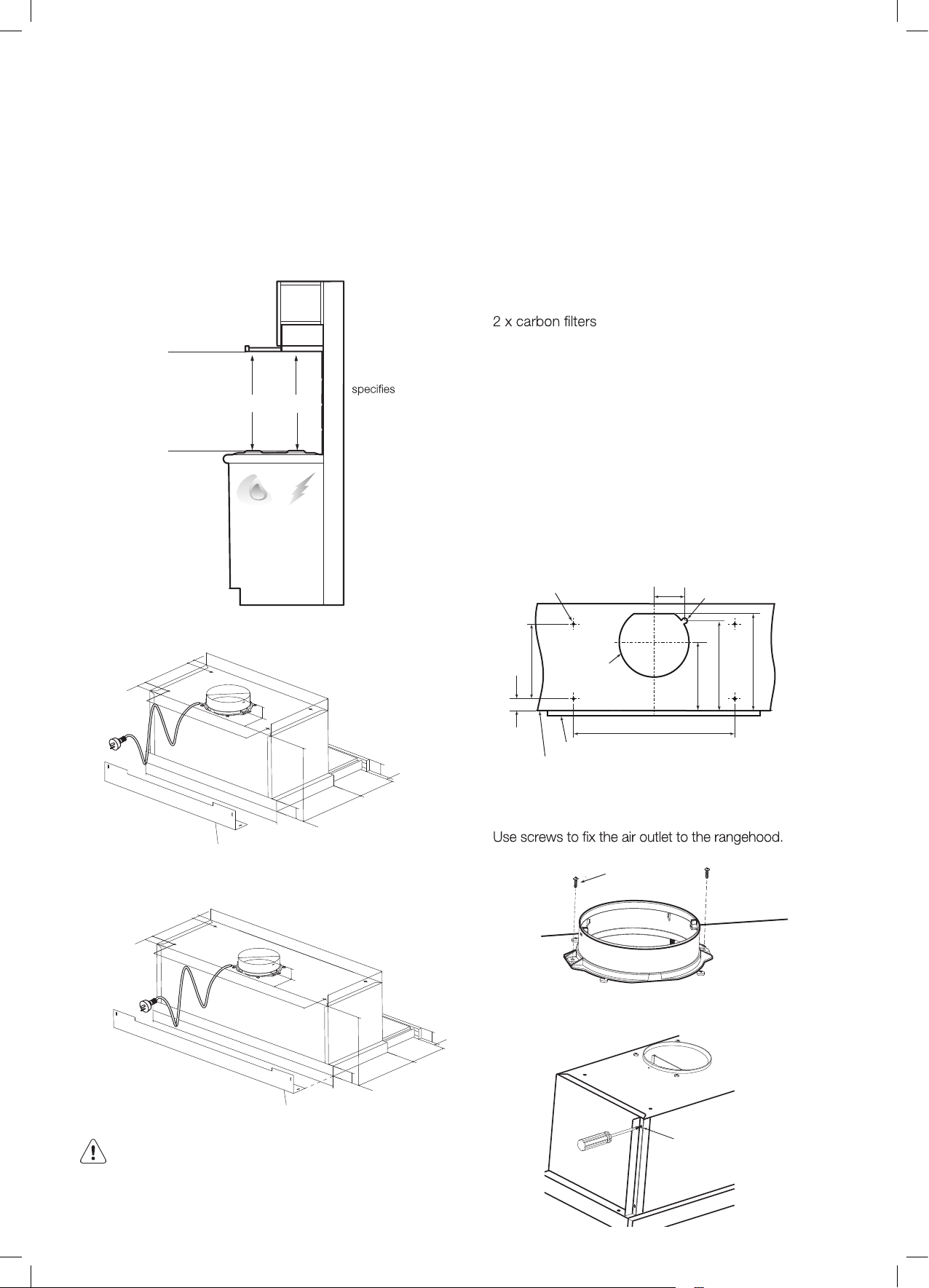
Standard ducting installation
It is recommended that the unit be positioned at a
minimum of 600mm for an electric cooktop and 650mm
for a gas cooktop, and no further from the cooktop than
800mm. Then unit becomes less effective as the distance
from the cooking surface to the rangehood increase.
650
GAS
ELECTRIC
600
Fixing point dimensions – WRR626SB
rear cover can be reversed
to suit gap at rear
Fixing point dimensions – WRR926SBW
rear cover can be reversed
to suit gap at rear
WARNING!
accordance with these instructions may result in
electrical hazards.
Parts supplied with hood
1 x Ø 150mm air outlet
1 x Ø 150mm to Ø 120mm converter
2 x rear covers
2 x lateral covers
6 x self tapping screws 3 x 12mm
2 x self tapping screws 3.5 x 10mm
4 x Ø 6 washers
4 x M6 x 40 screws
2 x air intake grilles
Parts to be purchased
•
• Ducting accessories
Drilling holes
Drill the holes on top wooden support
• drill Ø 7mm hole
• drill Ø 16mm hole
• cut Ø 196mm hole
Ø 7 for hood
fastening screws
86
Ø 16 for cable
clearance
Ø
clearance
453/753
door/hood fascia
front of
cabinet
33
210
272
252
192
Fixing the air outlet
ST 3.5 x 10
Fixing the lateral cover
Use screws to fix the lateral cover to the rangehood.
ST 3 x 12
underside of
rangehood
top of cooking
surface
if the cooktop
manufacturer
a greater
clearance
then that
must be used
196 for flue
Aluminium tape or cable ties to secure flue pipe
Failure to install the screws or fixing device in
37
210
453
600
555
280
160
42
40
272
280
20
88
45
150
33
40
37
210
753
900
855
280
160
42
272
280
20
88
45
150
33
Ø
Ø
Loading ...
Loading ...
Loading ...