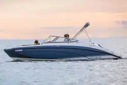

2020 Yamaha Boat
AR210 / SX210
212X / 212S / 212
OWNER’S/OPERATOR’S MANUAL
F3R-F8199-13
LIT-18626-12-67
Read this manual carefully
before operating this boat.
U.S.A. Edition
WARNING:
Operating, servicing
and maintaining a recreational marine
vessel can expose you to chemicals
including engine exhaust, carbon monoxide,
phthalates, and lead, which are known to
the State of California to cause cancer and
birth defects or other reproductive harm. To
minimize exposure, avoid breathing exhaust,
service your vessel in a well-ventilated area
and wear gloves or wash your hands
frequently when servicing this vessel.
For more information go to
www.P65warnings.ca.gov/marine
Read this manual carefully before operating this boat. This manual should stay
with the boat if it is sold.
SportsBoat_F3R13.book Page 1 Friday, May 31, 2019 9:42 AM
Important manual information
To the owner
Thank you for choosing a Yamaha boat. This
owner’s/operator’s manual contains informa-
tion you will need for proper operation, main-
tenance, and care. A thorough understanding
of these simple instructions will help you to
obtain maximum enjoyment from your new
Yamaha. If you have any questions about the
operation or maintenance of your boat,
please consult a Yamaha Boat Dealer.
In this manual, information of particular im-
portance is distinguished in the following
ways:
This is the safety alert symbol. It is used
to alert you to potential personal injury haz-
ards. Obey all safety messages that follow
this symbol to avoid possible injury or death.
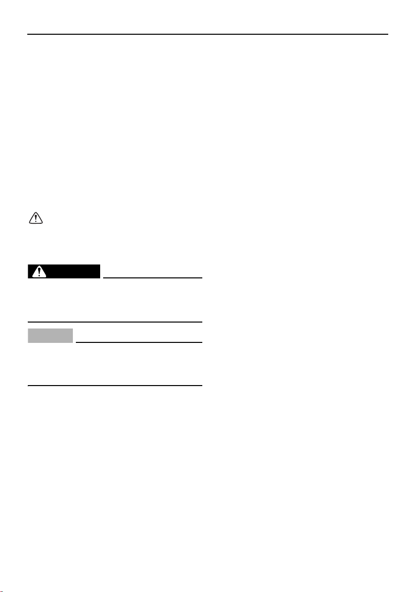
WARNING
A WARNING indicates a hazardous situa-
tion which, if not avoided, could result in
death or serious injury.
NOTICE
A NOTICE indicates special precautions
that must be taken to avoid damage to the
boat or other property.
TIP:
A TIP provides key information to make pro-
cedures easier or clearer.
Engine data recording
This model’s ECM stores certain engine data
to assist in the diagnosis of malfunctions and
for research, statistical analysis and develop-
ment purposes.
Although the sensors and recorded data will
vary by model, the main data points are:
● Engine status and engine performance
data
This data will be uploaded only when a spe-
cial Yamaha diagnostic tool is attached to the
engine, such as when maintenance checks or
service procedures are performed.
Yamaha will not disclose this data to a third
party except in the following cases. In addi-
tion, Yamaha may provide engine data to a
contractor in order to outsource services re-
lated to the handling of the engine data. Even
in this case, Yamaha will require the contrac-
tor to properly handle the engine data we
provided and Yamaha will appropriately
manage the data.
● With the consent of the boat owner
● Where obligated by law
● For use by Yamaha in litigation
● For general Yamaha-conducted research
purposes when the data is not related to an
individual engine or owner
SportsBoat_F3R13.book Page 1 Friday, May 31, 2019 9:42 AM

Important manual information
Because Yamaha has a policy of continuing
product improvement, this product may not
be exactly as described in this owner’s/oper-
ator’s manual. Specifications are subject to
change without notice.
This manual should be considered a perma-
nent part of this boat and should remain with
it even if the boat is subsequently sold.
AR210 / SX210 / 212X / 212S / 212
OWNER’S/OPERATOR’S MANUAL
©2020 by Yamaha Motor Corporation,
U.S.A.
1st Edition, March 2019
All rights reserved.
Any reprinting or unauthorized use
without the written permission of
Yamaha Motor Corporation, U.S.A.
is expressly prohibited.
Printed in U.S.A.
P/N LIT-18626-12-67
SportsBoat_F3R13.book Page 2 Friday, May 31, 2019 9:42 AM

Table of contents
General and important labels........... 1
Identification number records .......... 1
Primary Identification (PRI-ID)
number....................................... 1
Hull Identification Number (HIN) ...1
Engine serial numbers................... 1
Emission control information ........... 3
Approval labels of emission
control certificate ....................... 3
Manufactured date labels
(AR210 / SX210)......................... 4
Manufactured date labels
(212X / 212S / 212) .................... 4
Star labels (4-star models) ............ 5
Important labels ............................... 7
Warning labels ............................ 10
Other labels................................. 14
Safety information........................... 15
Limitations on who may operate
the boat ....................................... 15
Cruising limitations......................... 16
Operational requirements .............. 17
Required equipment....................... 18
Additional equipment
recommendations ....................... 18
Hazard information......................... 19
Boat characteristics ....................... 19
Night operation .............................. 20
Wakeboarding and water-skiing .... 21
Rules of the road............................ 22
To get more boating safety
information .................................. 26
Enjoy your boat responsibly........... 26
Description....................................... 27
Boat glossary ................................. 27
Location of main components ....... 28
Exterior components................... 28
Seats ........................................... 31
Stern components ...................... 32
Helm components....................... 33
Engine components .................... 35
Control function operation .............. 38
Boat control functions ................... 38
Engine shut-off switch ................ 38
Battery switch
(AR210 / SX210) ...................... 38
Battery switches
(212X / 212S / 212) .................. 39
Main switches............................. 40
Remote control levers................. 40
Steering ...................................... 42
Tilt lever ...................................... 43
Instrument operation ....................... 44
Helm controls (AR210 / SX210) ..... 44
Tachometers............................... 45
Multi-function display unit
operation.................................. 45
Multi-function display elements..... 46
Screen tab bar ............................ 47
Center display............................. 47
Warning bar ................................ 48
Home screen ................................. 49
Trip screen ..................................... 49
Setting screen................................ 50
Time setting screen .................... 50
Brightness setting screen ........... 51
Unit setting screen...................... 51
Depth alarm setting screen......... 52
Maintenance setting screen ....... 52
Language setting screen ............ 53
Factory reset screen ................... 53
Warnings........................................ 54
Check engine warning ................ 55
Low oil pressure warning............ 55
Over temperature warning.......... 55
Communication error warning .... 56
No-wake mode/cruise assist
switch ...................................... 57
Operating the boat with a
minimal wake
(no-wake mode)....................... 57
Operating the boat at a steady
speed (cruise assist) ................ 57
Operating the boat in reverse
with more thrust
(reverse RPM control) .............. 58
Light operation............................ 58
SportsBoat_F3R13.book Page 1 Friday, May 31, 2019 9:42 AM

Table of contents
Turning the courtesy light on or
off ............................................. 59
Turning the anchor light and
bow light on or off.................... 59
Horn switch ................................. 60
Ventilating the engine
compartment............................ 60
Draining the bilge water .............. 60
Switch circuit breakers ............... 61
Accessory outlet ............................ 61
Audio control keypad ..................... 62
Helm controls
(212X / 212S / 212) ..................... 63
Accessory outlet ............................ 64
Horn switch .................................... 64
Remote control keypad.................. 65
Bilge pump indicator light .............. 65
USB charger................................... 66
Multi-function display unit
operation ..................................... 66
Touching the multi-function
display...................................... 66
Using the joystick........................ 66
Operation buttons .......................... 68
Controller .................................... 68
Operating the boat at a steady
speed (cruise assist) ................ 68
Operating the boat with a
minimal wake
(no-wake mode) ....................... 69
Operating the boat in reverse
with more thrust
(reverse RPM control) .............. 69
Multi-function display elements ..... 70
Static bar..................................... 71
Center display ............................. 72
Screen tab bar ............................ 72
Status indicator bar..................... 73
Home screen.................................. 74
Map screen .................................... 74
Trip screen ..................................... 75
Media screen.................................. 76
Radio screen (AM/FM) ................ 77
Bluetooth screen......................... 77
Auxiliary screen........................... 79
USB screen ................................. 79
Main audio setting screen .......... 80
System control screen ................... 82
Ballast setting screen (212X) ...... 82
Shutting off water intake............. 83
Setting screen................................ 84
Time setting screen .................... 84
Brightness setting screen ........... 85
Language setting screen ............ 85
Unit setting screen...................... 86
Depth alarm setting screen......... 86
Maintenance setting screen ....... 86
Factory reset screen ................... 87
Warnings........................................ 88
Check engine warning ................ 90
Low oil pressure warning............ 90
Over temperature warning.......... 90
House/Start Battery voltage
warning .................................... 91
Communication error warning .... 91
Low fuel level warning ................ 91
Depth warning ............................ 91
Equipment operation ...................... 92
Seats.............................................. 92
Driver’s seat (AR210 / SX210) .... 93
Driver’s seat
(212X / 212S / 212) .................. 94
Passenger’s seat
(212X / 212S / 212) .................. 96
Engine hood................................... 97
Storage compartments.................. 97
Anchor storage compartment..... 97
Front underseat storage
compartments ......................... 98
Ski locker .................................... 98
Rear underseat storage
compartment (starboard)......... 99
Rear underseat storage
compartment (port)................ 100
Enclosed storage
compartment ......................... 100
Driver’s side console
compartment ......................... 101
Stowable table
(212X / 212S / 212) ................ 102
Glove compartment
(AR210 / SX210) .................... 102
SportsBoat_F3R13.book Page 2 Friday, May 31, 2019 9:42 AM

Table of contents
Glove compartment
(212X / 212S / 212) ................ 102
Wet storage compartment ........ 103
Walk-through ............................... 104
Front walk-through.................... 104
Rear walk-through .................... 104
Windshield.................................... 104
Folding mirror (212X).................105
Anchor light
(AR210 / 212X / 212S)............... 106
Anchor light (SX210 / 212) ........... 106
Bow ladder................................... 107
Swim platform .............................. 108
Stern ladder .............................. 108
Side table .................................. 109
Wakeboard tower
(AR210 / 212X / 212S)............... 110
Collapsing and setting up the
wakeboard tower (AR210) ..... 111
Collapsing and setting up the
wakeboard tower
(212X / 212S).......................... 112
Bimini top
(AR210 / 212X / 212S)............... 113
Setting up the bimini top........... 113
Storing the bimini top................ 115
Trailering with the bimini top..... 116
Removing the bimini top ........... 116
Installing the bimini top ............. 116
Bimini top (SX210 / 212) .............. 117
Setting up the bimini top........... 117
Storing the bimini top in the
upright position ...................... 118
Storing the bimini top in the
fully collapsed position .......... 119
Trailering with the bimini top..... 119
Removing the bimini top ........... 119
Installing the bimini top ............. 119
Operation and handling
requirements ................................. 120
Fuel requirement .......................... 120
Fuel ........................................... 120
Engine oil requirement ................. 121
Engine oil................................... 121
Draining the bilge water ............... 125
Draining the bilge water on
land ........................................ 125
Draining the bilge water on
water...................................... 126
First-time operation ....................... 129
Engine break-in
(AR210 / SX210) ....................... 129
Engine break-in
(212X / 212S / 212) ................... 129
Pre-operation checks ................... 130
Pre-operation checklist............. 130
Pre-operation check points ......... 132
Pre-launch checks .................... 132
Steering system checks ........... 132
Remote control lever checks .... 132
Fire extinguisher check............. 133
Access port cap check ............. 134
Jet intake checks...................... 135
Fuel system checks .................. 135
Engine oil level check ............... 135
Battery check............................ 137
Bilge water check ..................... 137
Drain plug check....................... 137
Blower switch check
(AR210 / SX210) .................... 138
Blower checks
(212X / 212S / 212) ................ 139
Navigation and anchor lights
switch check
(AR210 / SX210) .................... 139
Navigation and anchor lights
checks (212X / 212S / 212).... 140
Horn check ............................... 141
Engine shut-off cord (lanyard)
check ..................................... 141
Post-launch checks .................. 141
Engine shut-off switch check ... 141
Cooling water pilot outlet
check ..................................... 142
Fuel level check ........................ 142
Operation ....................................... 144
Driving your boat ......................... 144
Getting to know your boat........ 144
Learning to operate your boat .. 144
SportsBoat_F3R13.book Page 3 Friday, May 31, 2019 9:42 AM

Table of contents
Starting the engines .................. 144
Stopping the engines ................ 147
Leaving a dock.......................... 147
Turning the boat........................ 148
Boating with passengers .......... 149
Stopping the boat ..................... 150
Boarding from the water ........... 151
Boarding from the bow ............. 151
Boarding from a dock or
landing jetty............................ 151
Docking ..................................... 151
Beaching ................................... 152
Anchoring.................................. 153
Crossing wakes and swells....... 153
Post-operation checks................. 154
Trailering ........................................ 156
Trailering the boat ........................ 156
Hitch.......................................... 156
Trailering checklist .................... 156
Backing your trailer ................... 157
Launching ................................. 158
Loading ..................................... 158
Lifting ........................................ 159
Care and storage........................... 160
Post-operation care ..................... 160
Flushing the cooling system .....160
Cleaning the boat...................... 161
Basic stain guide....................... 164
Battery care (AR210 / SX210) ...165
Battery care
(212X / 212S / 212) ................ 166
Long-term storage ....................... 168
Fuel system ............................... 168
Lubrication ................................ 168
Grease points............................ 168
Maintenance .................................. 170
Maintenance................................. 170
Owner’s/operator’s manual ...... 170
Removing and installing the
engine covers
(212X / 212S / 212) ................ 170
Periodic maintenance chart ...... 172
Specifications ..................................175
Specifications (AR210 / SX210)... 175
Specifications
(212X / 212S / 212) ................... 177
Trouble recovery ........................... 180
Troubleshooting........................... 180
Troubleshooting chart............... 180
Emergency procedures ............... 182
Jet pump clean-out
procedure .............................. 182
Jump-starting ........................... 184
Fuse replacement
(AR210 / SX210) .................... 185
Fuse replacement
(212X / 212S / 212) ................ 186
Running on one engine............. 188
Towing the boat........................ 188
Consumer information ................... 189
Limited warranty .......................... 189
YAMAHA EXTENDED SERVICE
(Y.E.S.) ...................................... 191
Sample float plan......................... 192
Index............................................... 193
SportsBoat_F3R13.book Page 4 Friday, May 31, 2019 9:42 AM
1
General and important labels
Identification number records
Record your Primary Identification (PRI-ID)
number, Hull Identification Number (HIN), and
engine serial numbers in the spaces provided
to assist you in ordering spare parts from
your Yamaha Boat Dealer. Also, record and
keep these ID numbers in a separate place in
case your boat is stolen.
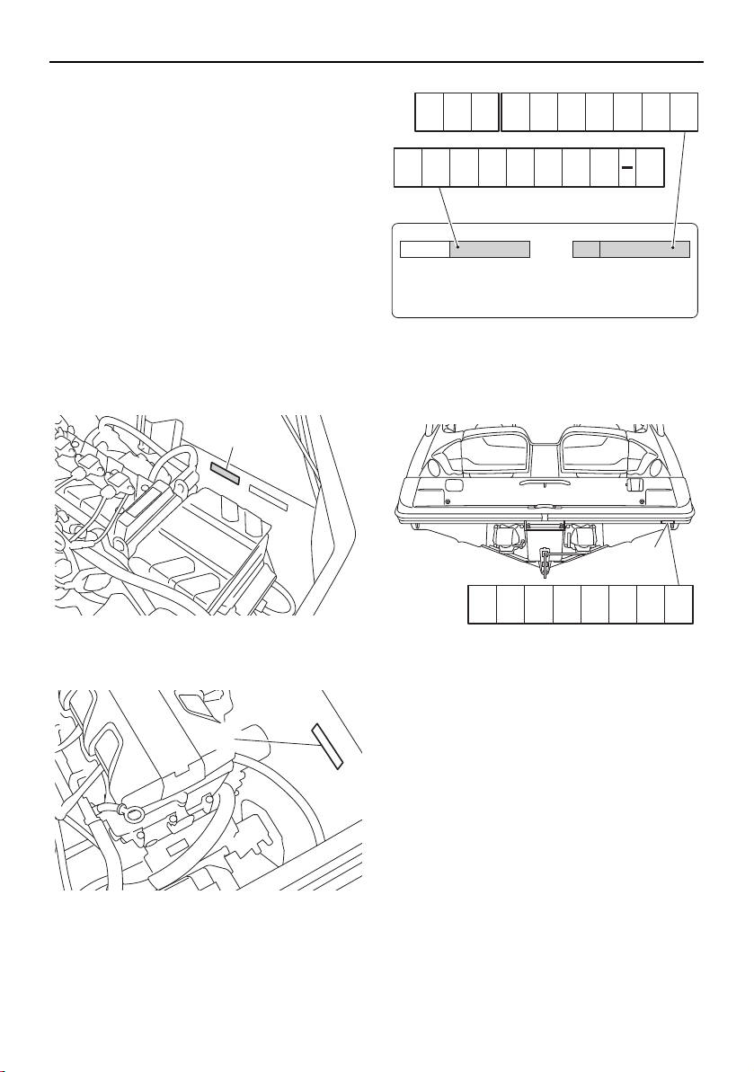
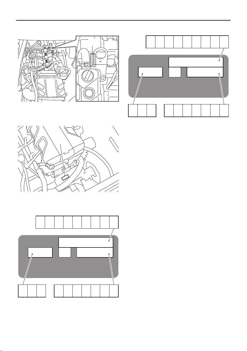
Primary Identification (PRI-ID) number
The PRI-ID number is stamped on a label at-
tached inside the engine compartment. (See
page 97 for engine hood opening and closing
procedures.)
AR210 / SX210
1 Primary Identification (PRI-ID) number
212X / 212S / 212
1 Primary Identification (PRI-ID) number
Hull Identification Number (HIN)
The HIN is stamped into the right rear corner
of the hull.
1 Hull Identification Number (HIN)
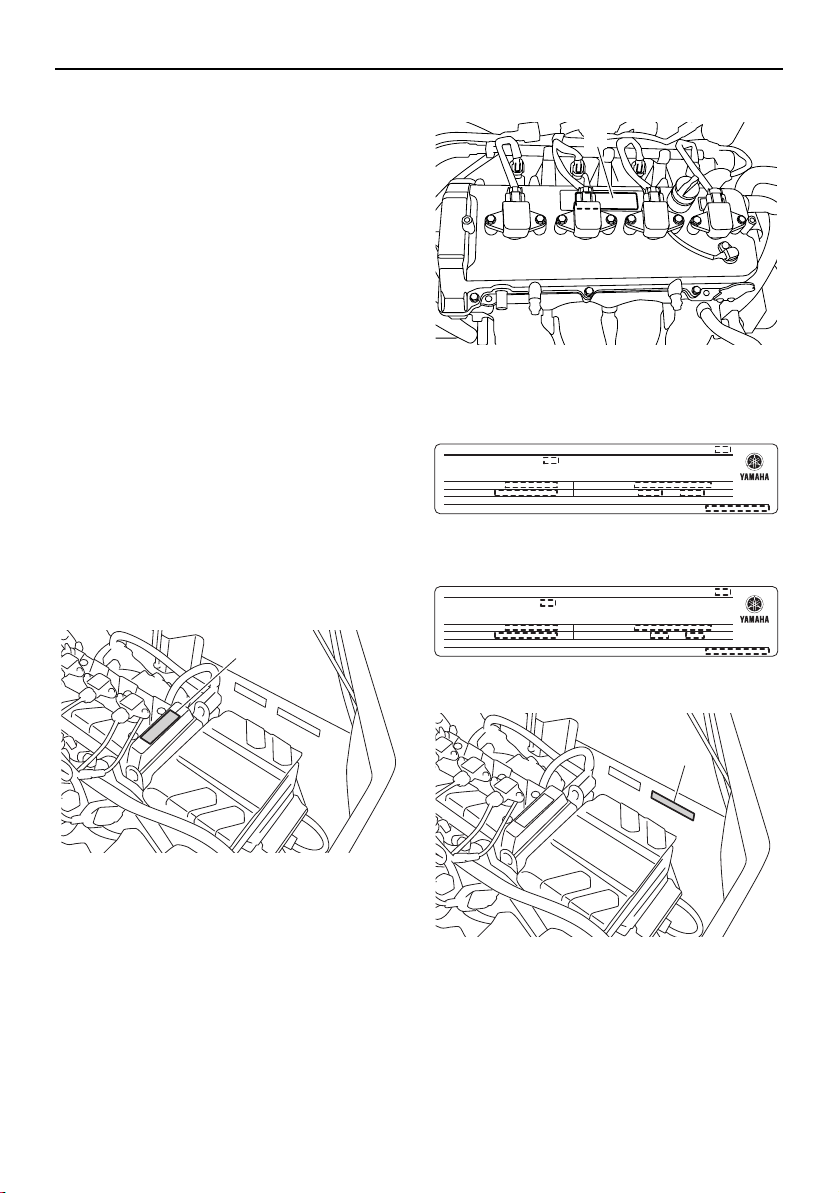
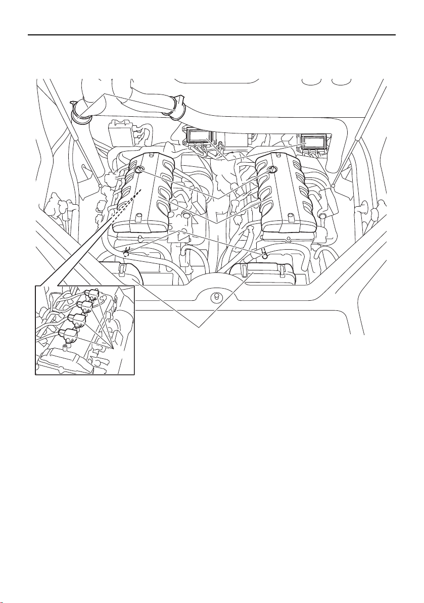
Engine serial numbers
The engine serial numbers are stamped on a
label attached to each engine unit. (See page
97 for engine hood opening and closing pro-
cedures.)
1
1
MODEL
YAMAHA MOTOR CO.,LTD.
ASSEMBLED IN U.S.A. WITH FOREIGN & DOMESTIC
COMPONENTS.
ASSEMBLÉ EN U.S. AVEC DES COMPOSANTS ÉTRANGERS ET
DOMESTIQUES.
PRI-I.D.
1
YAMC
SportsBoat_F3R13.book Page 1 Friday, May 31, 2019 9:42 AM
General and important labels
2
AR210 / SX210
1 Engine serial number
212X / 212S / 212
1 Engine serial number
Port side
Starboard side
1
1
YAMAHA
YAMAHA MOTOR CO., LTD.
MADE IN JAPAN
PAYS D’ORIGINE JAPON
YAMAHA
YAMAHA MOTOR CO., LTD.
MADE IN JAPAN
PAYS D’ORIGINE JAPON
SportsBoat_F3R13.book Page 2 Friday, May 31, 2019 9:42 AM
General and important labels
3
Emission control information
These engines conform to U.S. Environmen-
tal Protection Agency (EPA) and/or California
Air Resources Board (CARB) regulations for
marine SI engines applicable at the time of
manufacture.
The 4-star labels are affixed to models that
meet the Air Resources Board’s emission
standards for 4-star models. (See page 5 for
information on the star labels.)
Star labels are not affixed to 3-star models.
These engines are certified to operate on reg-
ular unleaded gasoline.
Approval labels of emission control
certificate
These labels are attached to each engine unit
and to the inside of the engine compartment.
(See page 97 for engine hood opening and
closing procedures and page 170 for engine
cover removal and installation procedures.)
AR210 / SX210
1 Emission control information label
212X / 212S / 212
1 Emission control information label
3-star models
4-star models
AR210 / SX210
1 Emission control information label
1
1
EMISSION CONTROL INFORMATION
ENGINE FAMILY :
MAX POWER : kW
DISPLACEMENT : liters
EPA FEL : HC+NOx , CO g/kW-h
THIS ENGINE CONFORMS TO U.S. EPA EXHAUST REGULATIONS FOR SI MARINE
ENGINES. REFER TO OWNER’S MANUAL FOR MAINTENANCE SPECIFICATIONS AND
ADJUSTMENTS.
YAMAHA MOTOR CO.,LTD.
EMISSION CONTROL INFORMATION
ENGINE FAMILY :
MAX POWER : kW
DISPLACEMENT : liters
EPA/CA FEL : HC+NOx , CO g/kW-h
THIS ENGINE CONFORMS TO CALIFORNIA AND U.S. EPA EXHAUST REGULATIONS
FOR SI MARINE ENGINES. REFER TO OWNER’S MANUAL FOR MAINTENANCE
SPECIFICATIONS AND ADJUSTMENTS.
YAMAHA MOTOR CO.,LTD.
1
SportsBoat_F3R13.book Page 3 Friday, May 31, 2019 9:42 AM

General and important labels
4
212X / 212S / 212
1 Emission control information label
3-star models
4-star models
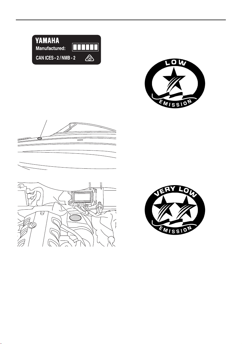
Manufactured date labels
(AR210 / SX210)
These labels are attached to each port sides
of the air filter case. (See page 97 for engine
hood opening and closing procedures.)
1 Manufactured date label
Manufactured date labels
(212X / 212S / 212)
These labels are attached to each engine
unit. (See page 97 for engine hood opening
and closing procedures and page 170 for en-
gine cover removal and installation proce-
dures.)
1 Manufactured date label
1
YAMAHA MOTOR CO., LTD.
EPA CERTIFIED EVAP COMPONENTS:
MAX POWER: kW
ENGINE FAMILY:
EMISSIONS CONTROL SYSTEM INFORMATION
EPA FEL: HC+NOx ,CO g/kW-h
DISPLACEMENT: liters
THIS ENGINE CONFORMS TO U.S. EPA EXHAUST REGULATIONS FOR SI MARINE
ENGINES. REFER TO OWNER’S MANUAL FOR MAINTENANCE SPECIFICATIONS AND
ADJUSTMENTS. MEETS U.S. EPA EVAP STANDARDS USING CERTIFIED COMPONENTS.
YAMAHA MOTOR CO., LTD.
ARB EVAP FAMILY:
EPA CERTIFIED EVAP COMPONENTS:
MAX POWER: kW
ENGINE FAMILY:
EMISSIONS CONTROL SYSTEM INFORMATION
TWC/HO25/MFI/OBD/EECS
ARB EVAP EMISSION CONTROL SYSTEM: CP
EPA/CA FEL: HC+NOx ,CO g/kW-h
DISPLACEMENT: liters
THIS ENGINE CONFORMS TO CALIFORNIA AND U.S. EPA EXHAUST REGULATIONS
FOR SI MARINE ENGINES. REFER TO OWNER’S MANUAL FOR MAINTENANCE
SPECIFICATIONS AND ADJUSTMENTS. MEETS U.S. EPA EVAP STANDARDS USING
CERTIFIED COMPONENTS. MEETS MY CALIFORNIA EVAP EMISSIONS.
REGULATIONS FOR SPARK-IGNITION MARINE WATERCRAFT.
1
1
SportsBoat_F3R13.book Page 4 Friday, May 31, 2019 9:42 AM
General and important labels
5
Star labels (4-star models)
This boat is labeled with a California Air Re-
sources Board (CARB) star label. See below
for a description of your particular label.
1 Star label location
1 Star label location
One Star - Low Emission
The one-star label identifies engines that
meet the Air Resources Board’s Personal
Watercraft and Outboard marine engine 2001
exhaust emission standards. Engines meet-
ing these standards have 75% lower emis-
sions than conventional carbureted two-
stroke engines. These engines are equivalent
to the U.S. EPA’s 2006 standards for marine
engines.
Two Stars - Very Low Emission
The two-star label identifies engines that
meet the Air Resources Board’s Personal
Watercraft and Outboard marine engine 2004
exhaust emission standards. Engines meet-
ing these standards have 20% lower emis-
sions than One Star-Low Emission engines.
Three Stars - Ultra Low Emission
The three-star label identifies engines that
meet the Air Resources Board’s Personal
Watercraft and Outboard marine engine 2008
exhaust emission standards or the Sterndrive
and Inboard marine engine 2003-2008 ex-
haust emission standards. Engines meeting
these standards have 65% lower emissions
than One Star-Low Emission engines.
1
1
SportsBoat_F3R13.book Page 5 Friday, May 31, 2019 9:42 AM
General and important labels
6
Four Stars - Super Ultra Low Emission
The four-star label identifies engines that
meet the Air Resources Board’s Sterndrive
and Inboard marine engine 2009 exhaust
emission standards. Personal Watercraft and
Outboard marine engines may also comply
with these standards. Engines meeting these
standards have 90% lower emissions than
One Star-Low Emission engines.
SportsBoat_F3R13.book Page 6 Friday, May 31, 2019 9:42 AM
General and important labels
7
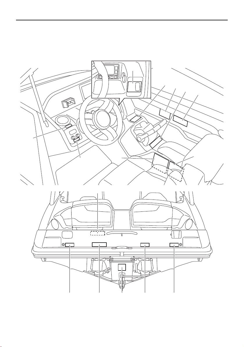
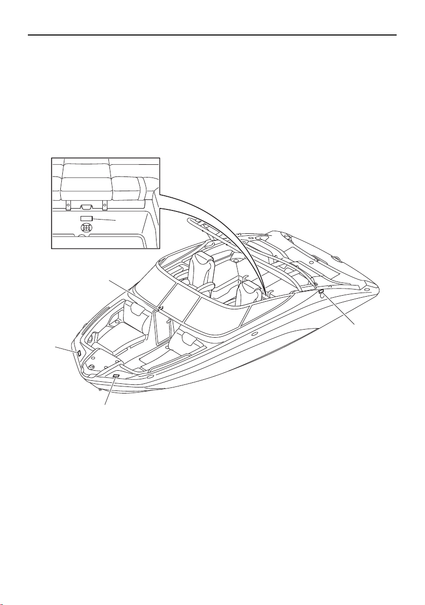
Important labels
Read the following labels before operating this boat. If you need any additional information,
contact a Yamaha Boat Dealer.
1
6
7
9101711
8
9
5
4
2
3
16
20
AR210/SX210
SportsBoat_F3R13.book Page 7 Friday, May 31, 2019 9:42 AM
General and important labels
8
18
13
14
14
12
SportsBoat_F3R13.book Page 8 Friday, May 31, 2019 9:42 AM
General and important labels
9
19
14
15
15
18
14
212X/212S/212
AR210/SX210
AR210 212X/212S
19
19
4-star models
3-star models
3-star models
SportsBoat_F3R13.book Page 9 Friday, May 31, 2019 9:42 AM
General and important labels
10
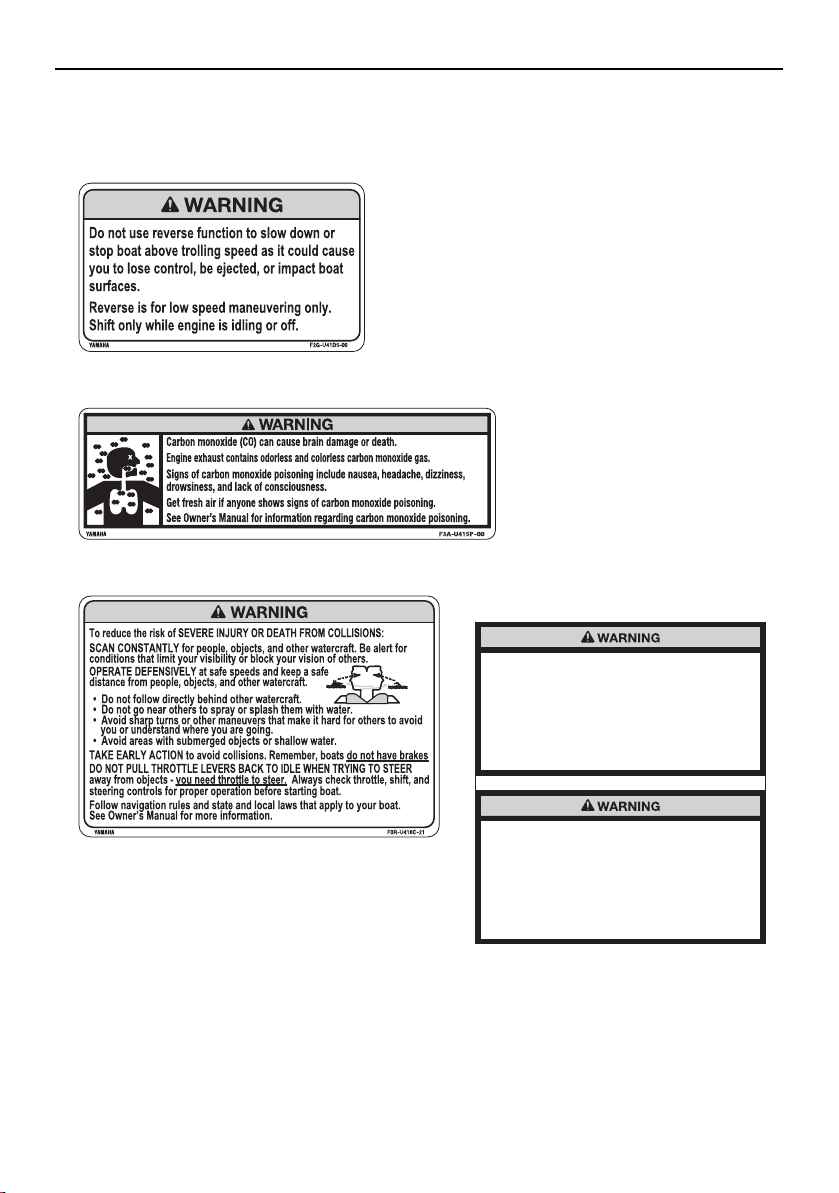
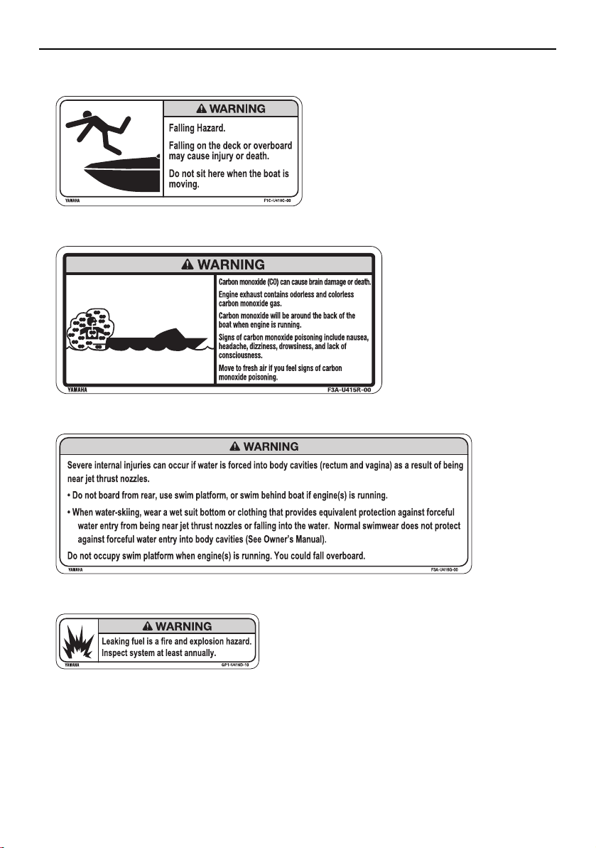
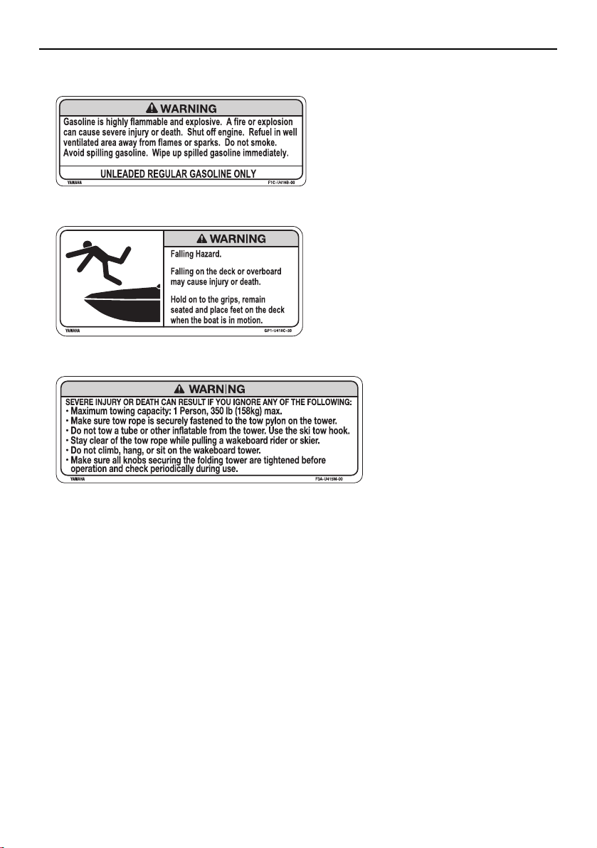
Warning labels
If any of these labels is damaged or missing, contact a Yamaha Boat Dealer for a replacement.
Improper use of the ballast system can
overload the boat, causing poor handling and
increased risk of swamping.
Ballast system adds 1303 lb (591 kg) when full.
Include this weight when making sure your
load does not exceed the weight shown on
the Maximum Capacities Label.
Drain ballast completely before trailering the
boat to reduce the risk of a towing accident.
The Increased weight of ballast can cause
unsafe towing conditions due to negative
tongue weight, including decreased tow
vehicle stability and greater chance of a
runaway trailer that has come off the hitch.
3
2
1
4
212X
SportsBoat_F3R13.book Page 10 Friday, May 31, 2019 9:42 AM

General and important labels
11
8
5
6 AR210/SX210
7 212X/212S/212
SportsBoat_F3R13.book Page 11 Friday, May 31, 2019 9:42 AM
General and important labels
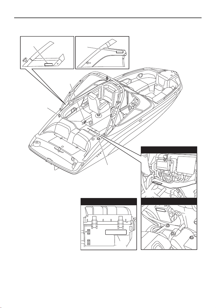
12
9
10
11
12
SportsBoat_F3R13.book Page 12 Friday, May 31, 2019 9:42 AM
General and important labels
13
14
13
15
SportsBoat_F3R13.book Page 13 Friday, May 31, 2019 9:42 AM
General and important labels
14
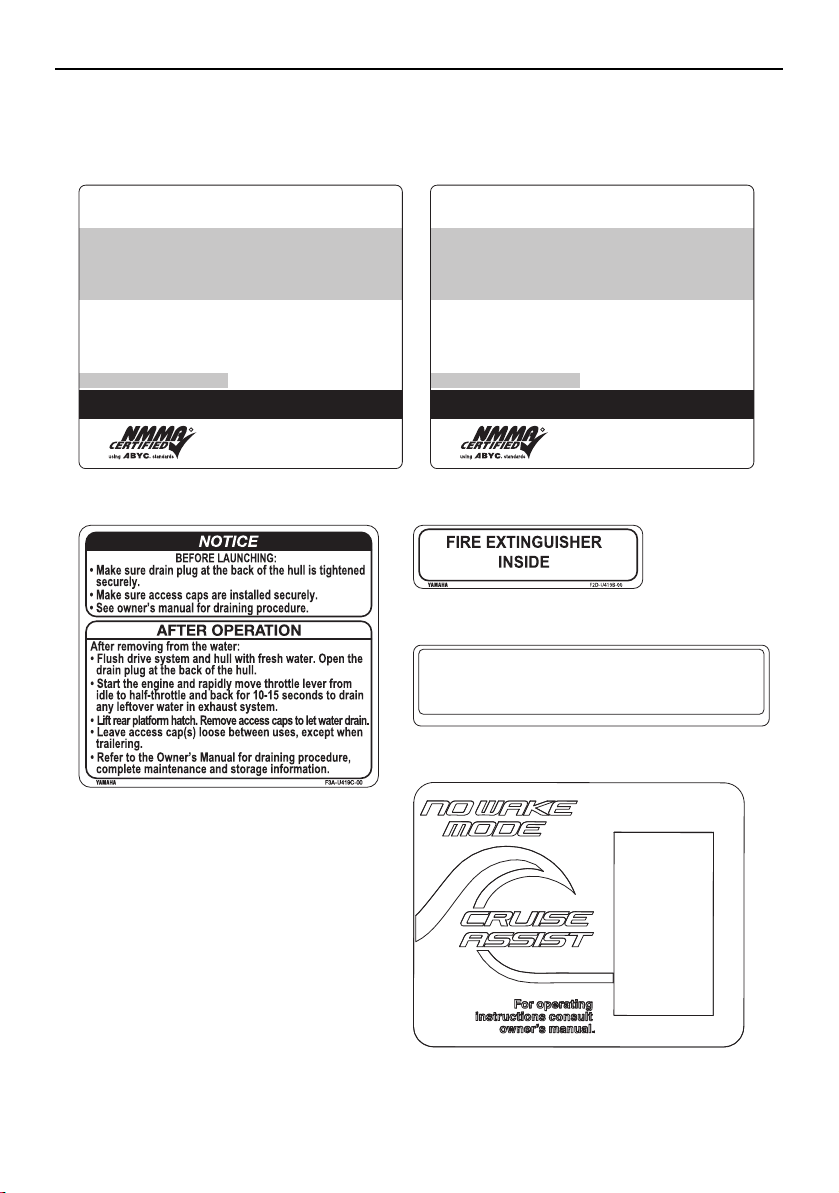
Other labels
THIS BOAT COMPLIES WITH U.S. COAST GUARD SAFETY
STANDARDS IN EFFECT ON THE DATE OF CERTIFICATION
MAXIMUM CAPACITIES
2200 POUNDS, PERSONS, GEAR
MEETS U.S. EPA EVAP STANDARDS USING CERTIFIED COMPONENTS
DESIGN COMPLIANCE WITH NMMA REQUIREMENTS IS VERIFIED.
MANUFACTURER RESPONSIBLE FOR PRODUCTION CONTROL.
NATIONAL MARINE
MANUFACTURERS ASSOCIATION
MANUFACTURER: YAMAHA JET BOAT MANUFACTURING U.S.A., INC.
MODEL: VONORE, TN
PERSONS OR
LBS.
10
1860
R
THIS BOAT COMPLIES WITH U.S. COAST GUARD SAFETY
STANDARDS IN EFFECT ON THE DATE OF CERTIFICATION
MAXIMUM CAPACITIES
2100 POUNDS, PERSONS, GEAR
MEETS U.S. EPA EVAP STANDARDS USING CERTIFIED COMPONENTS
DESIGN COMPLIANCE WITH NMMA REQUIREMENTS IS VERIFIED.
MANUFACTURER RESPONSIBLE FOR PRODUCTION CONTROL.
NATIONAL MARINE
MANUFACTURERS ASSOCIATION
MANUFACTURER: YAMAHA JET BOAT MANUFACTURING U.S.A., INC.
MODEL: VONORE, TN
PERSONS OR
LBS.
10
1860
R
YAMAHA 60E-83627-00
All applicable electrical system components installed as
original equipment meet appropriate U.S.C.G. requirements
for ignition protection. (Ref. 33 CFR 183.410 and 183.440)
16
except for 212X 212X
17 18
20
19
SportsBoat_F3R13.book Page 14 Friday, May 31, 2019 9:42 AM

15
Safety information
The safe use and operation of this boat is
dependent upon the use of proper operat-
ing techniques, as well as upon the com-
mon sense, good judgment, and expertise
of the operator. Every operator should
know the following requirements before
operating the boat.
Before operating the boat, read the own-
er’s/operator’s manual, the Operation In-
struction card, and all labels on the boat.
These materials should give you an under-
standing of the boat and its operation.
Never allow anyone to operate this boat
until they too have read this owner’s/oper-
ator’s manual, the Operation Instruction
card, and all labels.
Limitations on who may
operate the boat
Yamaha recommends a minimum operator
age of 16 years old.
Adults must supervise use by minors.
Know the operator age and training re-
quirements for your state. A boating safety
course is recommended and may be re-
quired in your state. You can find local rules
by contacting the United States Coast
Guard (USCG), the National Association of
State Boating Law Administrators, or your
local Power Squadron.
This boat is designed to carry the operator,
up to 9 passengers, and cargo. Never ex-
ceed the maximum load limit or allow more
than 10 persons (or 9 persons if the wake-
boarder or water-skier is being pulled) to
ride in the boat at any time. Weight distri-
bution affects performance. Keep weight in
the boat low and evenly distributed from
side-to-side and bow-to-stern. Remove
any unnecessary cargo and store it on
shore.
Maximum load (212X):
Total weight of cargo, operator, and
passengers:
952 kg (2100 lb): ballast is empty
495 kg (1092 lb): ballast is full
Total weight of operator and passen-
gers:
843 kg (1860 lb): ballast is empty
386 kg (852 lb): ballast is full
Maximum load (except for 212X):
Total weight of cargo, operator, and
passengers:
997 kg (2200 lb)
Total weight of operator and passen-
gers:
843 kg (1860 lb)
SportsBoat_F3R13.book Page 15 Friday, May 31, 2019 9:42 AM
Safety information
16
Cruising limitations
Scan constantly for people, objects, and
other watercraft. Be alert for conditions
that limit your visibility or block your vision
of others.
Operate defensively at safe speeds and
keep a safe distance from people, objects,
and other watercraft.
Do not follow directly behind other water-
craft.
Do not go near others to spray or splash
them with water.
Avoid sharp turns or other maneuvers that
make it hard for others to avoid you or un-
derstand where you are going.
Avoid areas with submerged objects or
shallow water.
Take early action to avoid collisions. Re-
member, boats do not have brakes.
Do not pull the remote control levers back
to idle when trying to steer away from ob-
jects—you need throttle to steer. Always
check throttle, shift, and steering controls
for proper operation before starting boat.
Operate within your limits and avoid ag-
gressive maneuvers to reduce the risk of
loss of control, ejection, and collision.
This is a high-performance boat—not a toy.
Sharp turns or jumping wakes or waves
can increase the risk of back/spinal injury
(paralysis), facial injuries, and broken legs,
ankles, and other bones. Do not jump
wakes or waves.
Do not operate the boat in rough water,
bad weather, or when visibility is poor; this
may lead to an accident causing injury or
death. Be alert to the possibility of adverse
weather. Take note of weather forecasts
and the prevailing weather conditions be-
fore setting out in your boat.
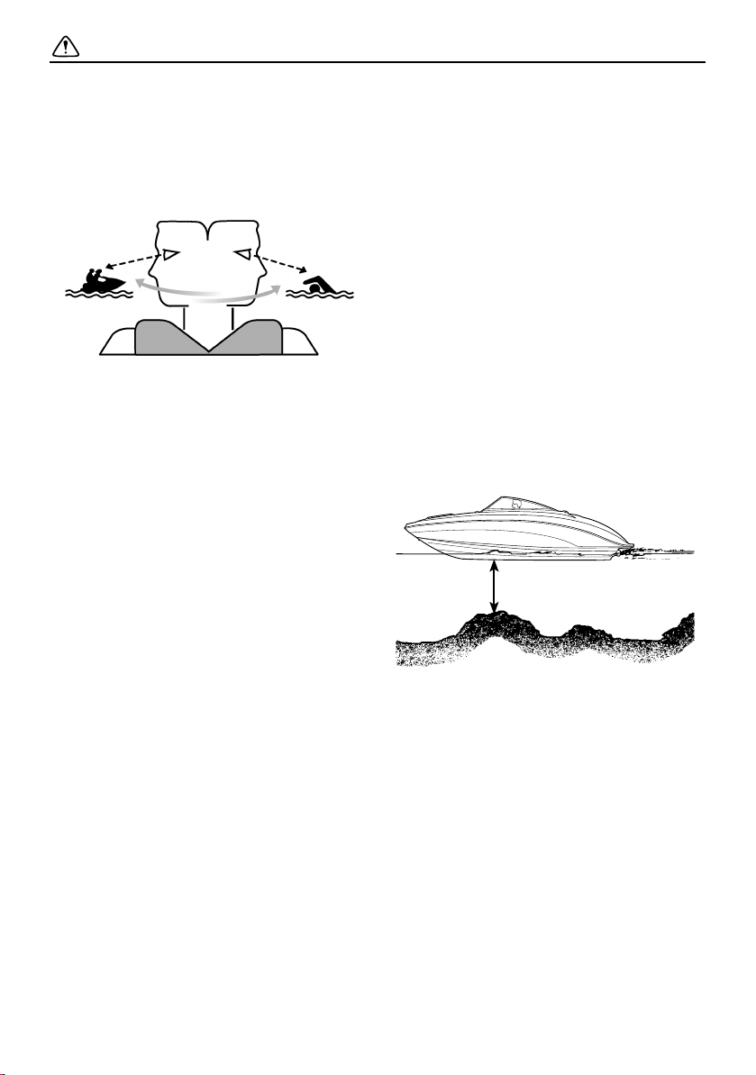
Never operate in water that is less than
90 cm (3 ft) deep from the bottom of the
boat, otherwise you increase your chance
of hitting a submerged object, which could
result in injury.
Leave a “float plan” with a responsible per-
son on shore. Tell where you plan to go and
when you plan to arrive, and provide a de-
scription of your boat. Advise this person if
your plans change and also when you ar-
rive to prevent false alarms. A sample float
plan is included on page 192.
Follow navigation rules and state and local
laws that apply to your boat.
90 cm (3 ft)
SportsBoat_F3R13.book Page 16 Friday, May 31, 2019 9:42 AM
Safety information
17
Operational requirements
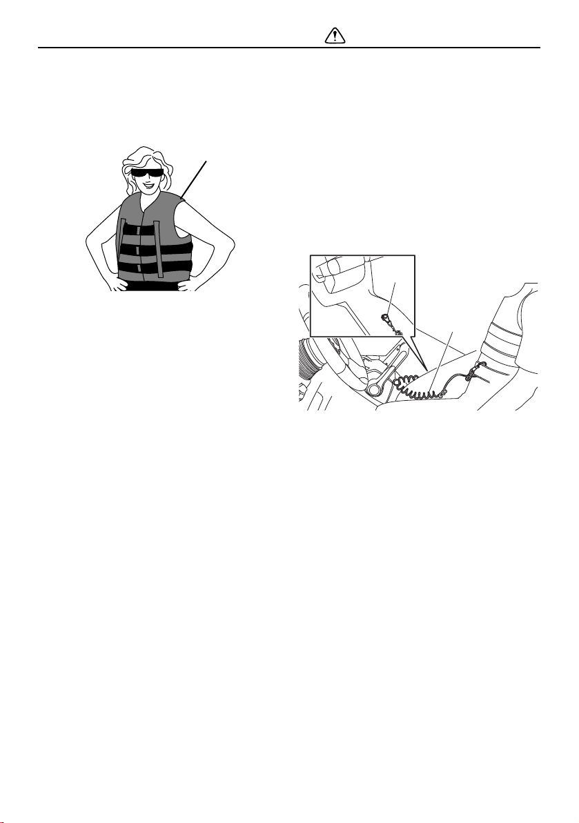
The operator and all passengers must wear
a U.S. Coast Guard (USCG) approved per-
sonal flotation device (PFD).
1 PFD
Eye protection is recommended to keep
wind, water, and glare from the sun out of
your eyes while you operate your boat. Re-
straining straps for eyewear are made
which are designed to float should your
eyewear fall in the water.
Footwear is recommended.
Never operate the boat after consuming al-
cohol or taking drugs.
For reasons of safety and proper care of
the boat, always perform the pre-operation
checks listed on page 130 before operating
the boat.
Passengers must always sit in a designat-
ed seating area, place feet on the deck,
and hold on to the handgrips, handrails, or
straps when the boat is in motion.
Always consult your doctor on whether it is
safe for you to ride in this boat if you are
pregnant or in poor health.
Do not attempt to modify this boat.
Modifications to your boat may reduce
safety and reliability, and render the boat
unsafe or illegal to use.
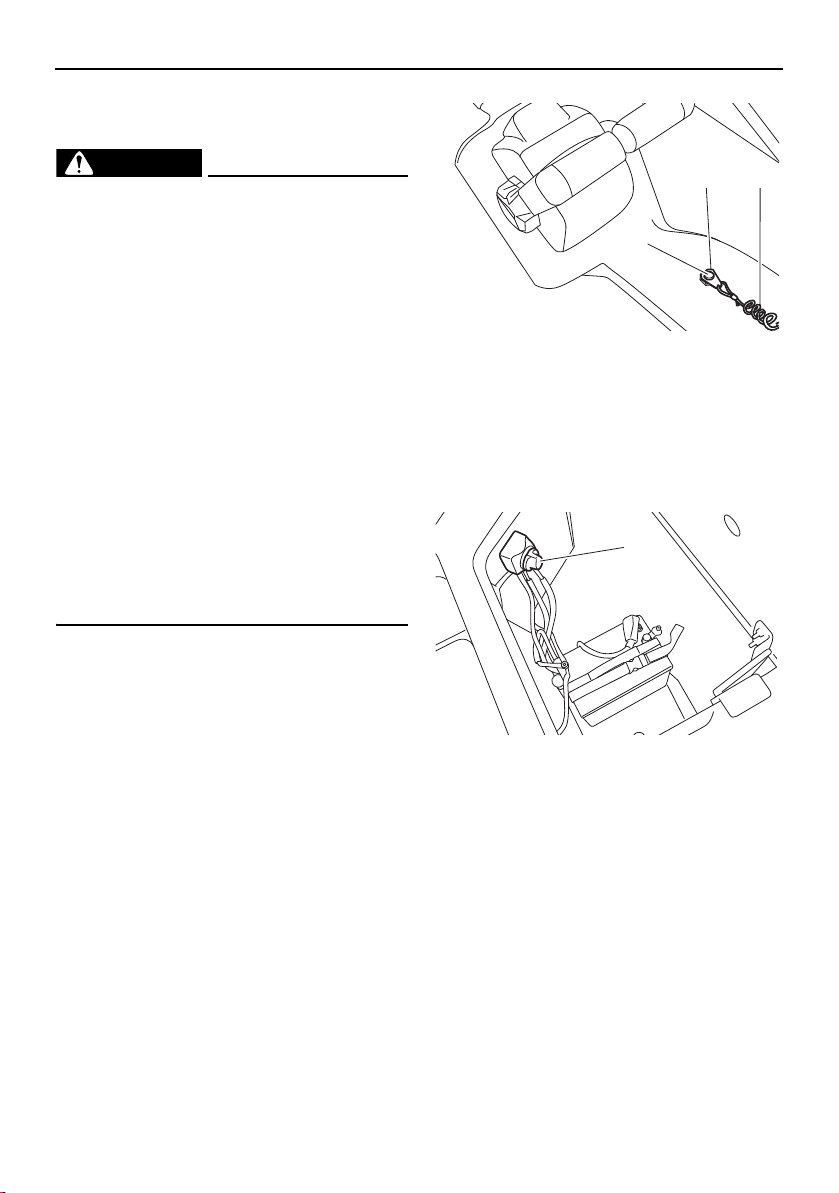
Attach the engine shut-off cord (lanyard) to
the PFD and keep it free from the steering
wheel or other controls so that the engines
stop if the operator accidentally leaves the
helm. Failure to attach the engine shut-off
cord (lanyard) could result in a runaway
boat if the operator is ejected.
After operation, remove the engine shut-off
cord (lanyard) and the main switch keys to
avoid accidental starting or unauthorized
use by children or others.
1 Engine shut-off switch
2 Engine shut-off cord (lanyard)
Scan constantly for swimmers and stay
away from swimming areas. Swimmers are
hard to see and you could accidentally hit
someone in the water.
Avoid being hit by another boat. You
should always take responsibility to watch
for traffic; other boaters may not be watch-
ing for you. If they do not see you, or you
maneuver more quickly than other boaters
expect, you risk a collision.
Maintain a safe distance from other boats
and watercraft, and also watch for ski
ropes or fishing lines. Obey the “Rules of
the road”, and be sure to check behind you
before making a turn. (See “Rules of the
road” on page 22.)
1
1
2
SportsBoat_F3R13.book Page 17 Friday, May 31, 2019 9:42 AM

Safety information
18
Required equipment
The U.S. Coast Guard (USCG) has regula-
tions which describe minimum standards of
safety. You must comply with these regula-
tions, which apply to boats like your boat
which are less than 26 feet long.
Personal flotation devices (PFD):
Type I, II, or III as required for all people on
board (see “Operational requirements” for
more information), plus at least one Type IV
(throwable type).
Fire extinguisher:
At least one B-1 type hand-held portable
fire extinguisher.
Visual distress signals:
It is recommended that a USCG-approved
day/night pyrotechnic device be stored on
your boat. A mirror can also be used as an
emergency signal. Contact your Yamaha
Boat Dealer or the Coast Guard for more
information.
Sound signalling device:
Your boat is equipped with a horn that can
be used to signal other boats. See “Rules
of the road” for more information.
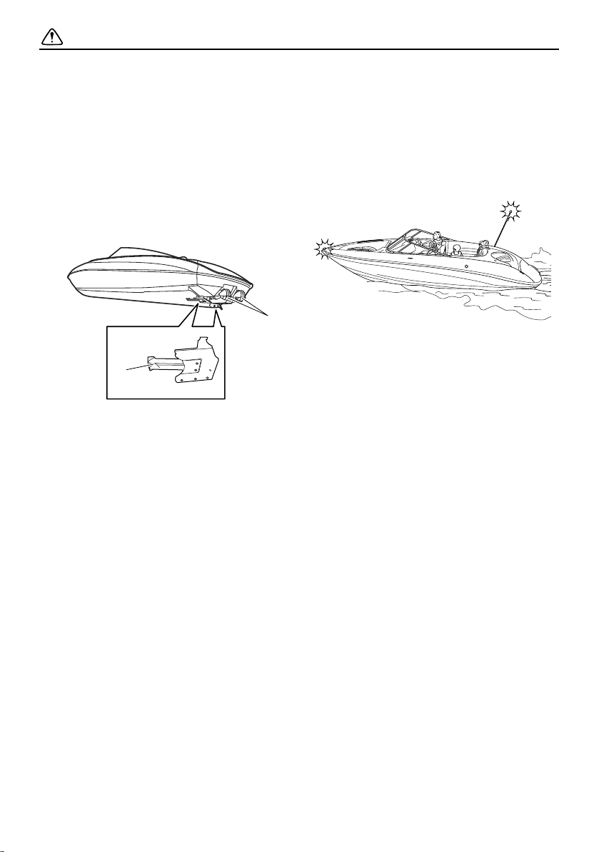
Navigation lights:
Your boat is equipped with navigation
lights for use between sunset and sunrise,
and during periods of reduced visibility,
such as fog. Be sure these lights are work-
ing and are turned on when necessary.
(See pages 59, 82, and 106 for more infor-
mation.)
Additional equipment
recommendations
The following equipment can help make your
boating experience safer and more enjoy-
able:
Mooring fenders and lines.
Anchor with suitable line (a “Danforth” type
anchor and line that is at least 6 times the
depth of the water where you will drop an-
chor are recommended).
Manual-type bilge pump.
First-aid kit.
Waterproof flashlight with extra batteries.
Tool kit with assorted screwdrivers, pliers,
wrenches (including metric sizes), and
electrical tape.
Oar or paddle (look for one with a boat
hook on the other end).
Spare parts, such as fuses.
Navigation charts for the waters where you
will be boating.
Tow-rope.
SportsBoat_F3R13.book Page 18 Friday, May 31, 2019 9:42 AM

Safety information
19
Hazard information
Never start the engines or let them run for any
length of time in an enclosed area. Exhaust
fumes contain carbon monoxide, a colorless,
odorless gas that may cause loss of con-
sciousness and death within a short time. Al-
ways operate the boat in an open area.
It is also important to have the engines off
when anyone is using the ladder on models
equipped with one because of the carbon
monoxide in the exhaust gases coming from
underneath the step.
Boat characteristics
Jet thrust turns the boat. Moving the re-
mote control levers completely back to idle
or the neutral position produces only mini-
mum thrust. If you are traveling at speeds
above trolling, you will have rapidly de-
creasing ability to steer without throttle.
You may still have some turning ability im-
mediately after moving the remote control
levers back to idle, but once the engines
slow down, the boat will no longer respond
to steering wheel input until you apply
throttle again or you reach a trolling speed.
Practice turning in an open area without
obstructions until you have a good feel for
the maneuver.
This Yamaha boat is water-jet propelled.
The pumps are directly connected to the
engines. This means that the jet thrust will
produce some movement whenever the
engines are running. The boat has a “neu-
tral” position, but since the boat is always
producing thrust while the engines are run-
ning, some forward or reverse movement
may occur.
Do not use the reverse function to slow
down or stop the boat above trolling speed
as it could cause you to lose control, be
ejected, or impact the steering wheel or
other parts of the boat. This could increase
the risk of serious injury. It could also dam-
age the shift mechanisms.
Reverse can be used to slow down or stop
during slow-speed maneuvering, such as
when docking. Once the engines are idling,
shift to reverse and gradually increase en-
gine speed. Make sure that there are no
obstacles or people behind you before
shifting into reverse.
SportsBoat_F3R13.book Page 19 Friday, May 31, 2019 9:42 AM
Safety information
20
Keep away from the intake grates while the
engines are on. Items such as long hair,
loose clothing, or PFD straps can become
entangled in moving parts, resulting in se-
vere injury or drowning.
Never insert any object into the jet thrust
nozzles while the engines are running. Se-
vere injury or death could result from com-
ing in contact with the rotating parts of the
jet pumps.
1 Intake grate
2 Jet thrust nozzle
Stop the engines and remove the clip from
the engine shut-off switch before removing
any debris or weeds, which may have col-
lected around the jet intakes. (See page
182 for more information.)
Night operation
When using your boat before dawn or after
dusk, you must have both bow and anchor
lights operating. When at anchor in the dark,
the anchor light must be lit. (See pages 59,
82, and 106 for instructions.)
2
1
SportsBoat_F3R13.book Page 20 Friday, May 31, 2019 9:42 AM

Safety information
21
Wakeboarding and water-
skiing
You can use the boat to tow a wakeboarder
or water-skier, using the tow pylon or the ski
tow hook provided.
It is the boat operator’s responsibility to be
alert to the safety of the wakeboarder or wa-
ter-skier and others. Know and follow all state
and local regulations in effect for the waters
in which you will be operating.
The following are some important consider-
ations for minimizing risks while pulling a
wakeboarder or water-skier.
The wakeboarder or water-skier should
wear an approved PFD, preferably a bright-
ly colored one so boat operators can see
the person being pulled.
The wakeboarder or water-skier should
wear protective clothing. Severe internal in-
juries can occur if water is forced into body
cavities as a result of falling into the water
or while reboarding. Normal swimwear
does not adequately protect against force-
ful water entry into the rectum or vagina.
The person being pulled should wear a
wetsuit bottom or clothing that provides
equivalent protection. Such clothing in-
cludes thick, tightly woven, sturdy, and
snug-fitting apparel such as denim, but
does not include spandex or similar fab-
rics, like those used in bicycle shorts.
A second person should be on board as a
spotter to watch the wakeboarder or wa-
ter-skier; in most states, it is required by
law. Let the person being pulled direct the
operator’s control of speed and direction
with hand signals. Be sure the seat is
locked in place (see page 92) before get-
ting underway.
When preparing to pull the wakeboarder or
water-skier, operate the boat at the slowest
possible speed until the boat is well away
from the person being pulled and slack in
the tow-rope is taken up. Make sure that
the rope is not looped around anything.
After checking that the wakeboarder or wa-
ter-skier is ready and that there is no traffic
or other obstacles, apply enough throttle to
raise the person.
Make smooth, wide turns. The boat is ca-
pable of very sharp turns, which could ex-
ceed the abilities of the wakeboarder or
water-skier. Keep the person being pulled
at least 50 m (164 ft), about twice the dis-
tance of a standard tow-rope, away from
any potential hazard.
The operators of boats and other water-
craft may not be aware that you are pulling
a wakeboarder or water-skier. Together
with the spotter, pay attention to others
around you and cruise at safe speeds.
Be alert to the hazard of the tow-rope han-
dle snapping back at the boat when the
wakeboarder or water-skier falls or is un-
able to get up.
See pages 10 and 110 for wakeboard tower
use.
SportsBoat_F3R13.book Page 21 Friday, May 31, 2019 9:42 AM

Safety information
22
Rules of the road
Your Yamaha boat is legally considered a
powerboat. Operation of the boat must be
in accordance with the rules and regula-
tions governing the waterway on which it
is used.
Just as there are rules that apply when you
are driving on streets and highways, there are
waterway rules that apply when you are oper-
ating your boat. These rules are used interna-
tionally, and are also enforced by the United
States Coast Guard and local agencies. You
should be aware of these rules, and follow
them whenever you encounter another vessel
on the water.
Several sets of rules prevail according to
geographic location, but are all basically the
same as the International Rules of the Road.
The rules presented here in this owner’s/op-
erator’s manual are condensed, and have
been provided for your convenience only.
Consult your local U.S. Coast Guard Auxiliary
or Department of Motor Vehicles for a com-
plete set of rules governing the waters in
which you will be operating your boat.
Steering and sailing rules
Whenever two vessels on the water meet one
another, one vessel has the right-of-way; it is
called the “stand-on” vessel. The vessel that
does not have the right-of-way is called the
“give-way” or “burdened” vessel. These rules
determine which vessel has the right-of-way,
and what each vessel should do.
Stand-on vessel
The vessel with the right-of-way has the duty
to continue its course and speed, except to
avoid an immediate collision. When you
maintain your direction and speed, the other
vessel will be able to determine how best to
avoid you.
Give-way vessel
The vessel which does not have the right-of-
way has the duty to take positive and timely
action to stay out of the way of the stand-on
vessel. Normally, you should not cross in
front of the vessel with the right-of-way. You
should slow down or change directions brief-
ly and pass behind the other vessel. You
should always move in such a way that the
operator of the other vessel can see what you
are doing.
The General Prudential Rule regarding the
right-of-way is that if a collision appears un-
avoidable, neither boat has the right-of-way.
Both boats must avoid the collision.
In other words, follow the standard rules ex-
cept when a collision will occur unless both
vessels try to avoid each other. If that is the
case, both vessels become give-way ves-
sels.
Rules when encountering vessels
There are three main situations that you may
encounter with other vessels which could
lead to a collision unless the Steering Rules
are followed:
Meeting: you are approaching another vessel
head-on.
Crossing: you are traveling across another
vessel’s path.
Overtaking: you are passing or being passed
by another vessel.
SportsBoat_F3R13.book Page 22 Friday, May 31, 2019 9:42 AM
Safety information
23
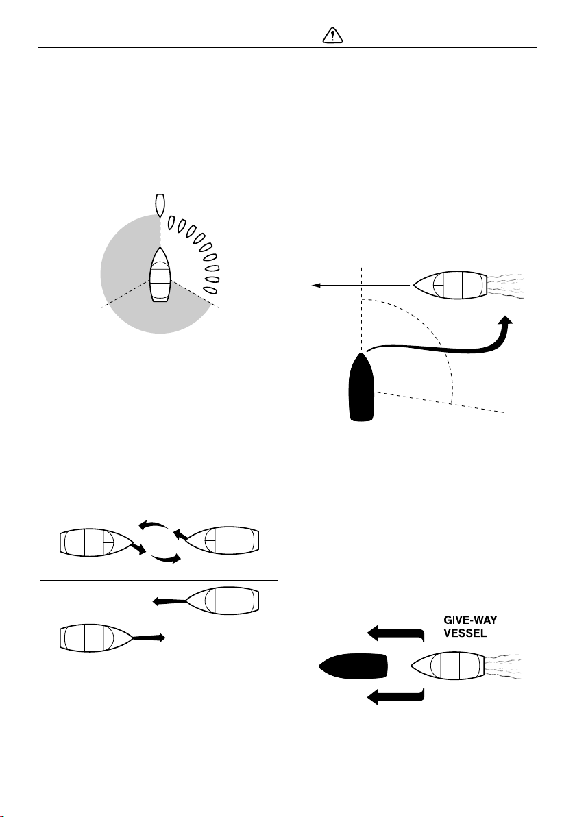
In the following illustration, your boat is in the
center. You should give the right-of-way to
any vessels shown in the white area (you are
the give-way vessel). Any vessels in the shad-
ed area must yield to you (they are the give-
way vessels). Both you and the meeting ves-
sel must alter course to avoid each other.
Meeting
If you are meeting another power-driven ves-
sel head-on, and are close enough to run the
risk of collision, neither of you has the right-
of-way. Both of you should alter course to
avoid an accident. You should keep the other
vessel on your port (left) side. This rule does
not apply if both of you will clear one another
if you continue on your set course and speed.
Crossing
When two power-driven vessels are crossing
each other’s path close enough to run the risk
of collision, the vessel which has the other on
the starboard (right) side must keep out of the
way of the other. If the other vessel is on your
starboard (right) side, you must keep out of
its way; you are the give-way vessel. If the
other vessel is on your port (left) side, remem-
ber that you should maintain course and di-
rection, provided the other vessel gives you
the right-of-way, as it should.
Overtaking
If you are passing another vessel, you are the
give-way vessel. This means that the other
vessel is expected to maintain its course and
speed. You must stay out of its way until you
are clear of it. Likewise, if another vessel is
passing you, you should maintain your speed
and direction so that the other vessel can
steer itself around you.
SportsBoat_F3R13.book Page 23 Friday, May 31, 2019 9:42 AM

Safety information
24
Other special situations
There are three other rules you should be
aware of when operating your boat around
other vessels.
Narrow channels and bends
When navigating in narrow channels, you
should keep to the right when it is safe and
practical to do so. If the operator of a power-
driven vessel is preparing to go around a
bend that may obstruct the view of other wa-
ter vessels, the operator should sound a pro-
longed blast of four to six seconds on the
horn. If another vessel is around the bend, it
too should sound the horn. Even if no reply is
heard, however, the vessel should still pro-
ceed around the bend with caution.
Fishing vessel right-of-way
All vessels fishing with nets, lines, or trawls
are considered to be “fishing vessels” under
the International Rules. Vessels with trolling
lines are not considered fishing vessels. Fish-
ing vessels have the right-of-way regardless
of position. Fishing vessels cannot, however,
impede the passage of other vessels in nar-
row channels.
Sailing vessel right-of-way
Sailing vessels should normally be given the
right-of-way. The exceptions to this are:
(1) When the sailing vessel is overtaking the
power-driven vessel, the power-driven
vessel has the right-of-way.
(2) Sailing vessels should keep clear of any
fishing vessel.
(3) In a narrow channel, a sailing vessel
should not hamper the safe passage of a
power-driven vessel that can navigate
only in such a channel.
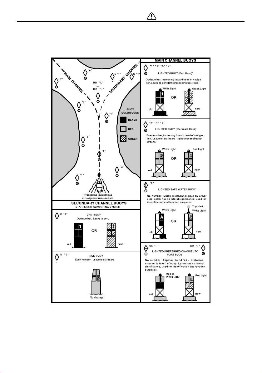
Reading buoys and other markers
The waters of the United States are marked
for safe navigation by the lateral system of
buoyage. Simply put, buoys and markers
have an arrangement of shapes, colors, num-
bers, and lights to show which side of the
buoy a boater should pass on when navigat-
ing in a particular direction. The markings on
these buoys are oriented from the perspec-
tive of being entered from seaward (the boat-
er is going towards the harbor). Red buoys
are passed on your starboard (right) side
when proceeding from open water into port,
and black buoys are to your port (left) side. An
easy way to remember the meaning of the
colors is the phrase “red right returning.”
When navigating out of the harbor, your posi-
tion with respect to the buoys should be re-
versed; red buoys should be to port and
black buoys to starboard.
Many bodies of water used by boaters are
entirely within the boundaries of a particular
state. The Uniform State Waterway Marking
System has been devised for these waters.
SportsBoat_F3R13.book Page 24 Friday, May 31, 2019 9:42 AM
Safety information
25
This system uses buoys and signs with distinctive shapes and colors to show regulatory or
advisory information. These markers are white with black letters and orange borders. They
signify speed zones, restricted areas, danger areas, and general information.
Remember, markings may vary by geographic location. Always consult local boating author-
ities before riding your boat in unfamiliar waters.
SportsBoat_F3R13.book Page 25 Friday, May 31, 2019 9:42 AM

Safety information
26
To get more boating safety
information
Be informed about boating safety. Additional
publications and information can be obtained
from many organizations, including the fol-
lowing.
United States Coast Guard
Consumer Affairs Staff (G-BC)
Office of Boating, Public, and Consumer Af-
fairs
US Coast Guard Headquarters
Washington, D.C. 20593-0001
http://www.uscgboating.org
Other sources
You can find local rules by contacting the Na-
tional Association of State Boating Law Ad-
ministrators, or your local Power Squadron.
Boat Education and Training
The Online Boating Safety Course, available
through the watercraft section of the
yamaha-motor.com website, is a free, 50-
question learning course available to the
public. Upon successful completion of 80
percent or better, the user can request a cer-
tificate of completion by mail or can down-
load one immediately. The Online Boating
Safety Course, provided by the Boat/US
Foundation, is approved by the National As-
sociation of State Boating Law Administra-
tors (NASBLA) and recognized by the United
States Coast Guard. This course meets the
education requirement for those states that
recognize non-proctored, NASBLA-ap-
proved courses.
Enjoy your boat responsibly
You share the areas you enjoy when operat-
ing your boat with others and with nature. So
your enjoyment includes a responsibility to
treat these other people, and the lands, wa-
ters, and wildlife with respect and courtesy.
Whenever and wherever you are boating,
think of yourself as the guest of those around
you. Remember, for example, that the sound
of your boat may be music to you, but it could
be just noise to others. And the exciting
splash of your wake can make waves others
won’t enjoy. Avoid riding close to shoreline
homes and waterfowl nesting areas or other
wildlife areas, and keep a respectful distance
from fishermen, other boats, swimmers, and
populated beaches. When travel in areas like
these is unavoidable, operate slowly and
obey all laws.
Remember that pollution can be harmful to
the environment. Do not refuel or add oil
where a spill could cause damage to nature.
Keep your surroundings pleasant for the peo-
ple and wildlife that share the waterways:
don’t litter!
When you go boating responsibly, with re-
spect and courtesy for others, you help en-
sure that our waterways stay open for the
enjoyment of a variety of recreational oppor-
tunities.
The Online Boating Safety Course:
http://www.boatus.org/
SportsBoat_F3R13.book Page 26 Friday, May 31, 2019 9:42 AM

27
Description
Boat glossary
TERM DEFINITION
Bow The front part of the boat.
Deck The “floor” or upper structure which covers the hull.
Give-way The vessel that must yield the right-of-way when two boats meet.
Gunwale The meeting junction of the deck and hull; the upper edge around the
boat. Pronounced “gunnel.”
Hatch An opening in the deck that provides access below.
Helm The steering console.
Hull The basic part of the boat; the underside.
Lanyard The cord or tether that connects the operator to the engine shut-off
switch so the engines will stop if the operator accidentally leaves the
helm.
PFD A personal flotation device, also known as “life jacket.”
Planing Traveling at a speed fast enough so the boat has leveled out and is
skimming on top of the water. There is a wake.
Port The left side of the boat.
Stand-on The vessel with the right-of-way when two boats meet.
Starboard The right side of the boat.
Stern The back part of the boat.
Sub-planing Traveling at a medium speed. The bow of the boat is out of the water,
but you are still traveling through the water. There is a wake.
Transom The vertical part of the stern.
Trolling Traveling at idle speed, using little or no throttle. The boat is down in the
water and it is not leaving a wake.
Wake The visible track of disturbed water that the boat leaves behind as it
moves in the water.
SportsBoat_F3R13.book Page 27 Friday, May 31, 2019 9:42 AM
Description
28
Location of main components
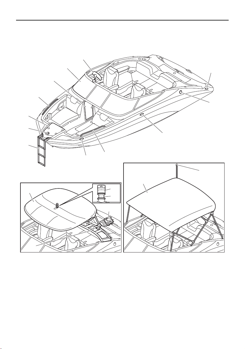
Exterior components
1 Bow ladder (page 107)
2 Bow light (page 59, 82)
3 Anchor storage compartment (page 97)
4 Handrail
5 Driver’s side console compartment (page 101)
6 Windshield (page 104)
7 Folding mirror (212X) (page 105)
8 Cleat
9 Fuel tank filler cap (page 120)
10 Bimini top (page 113)
11 Anchor light (page 82, 106)
12 To w pyl o n
13 Wakeboard tower (page 110)
14 Wakeboard tower rack (212X)
15 Bimini top (page 117)
16 Anchor light (page 59, 106)
AR210/212X/212S
SX210/212
1
8
14
10
13
16
15
9
8
4
8
3
4
5
6
7
2
11
12
SportsBoat_F3R13.book Page 28 Friday, May 31, 2019 9:42 AM
Description
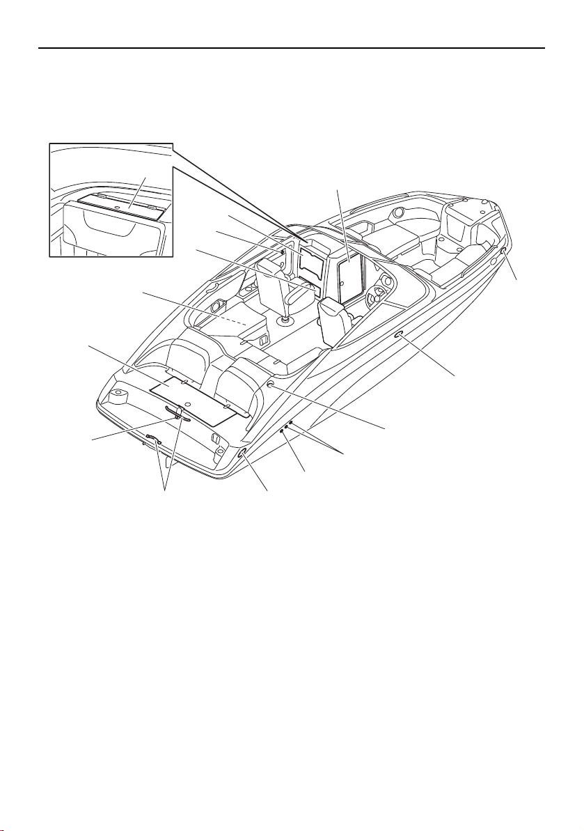
29
1 Rear platform hatch (page 103)
2 Battery (page 137, 165, 166)
3 Glove compartment (page 102)
4 Stowable table (page 102)
5 Glove compartment (page 102)
6 Enclosed storage compartment (page 100)
7 Cleat
8 Anchor light socket (SX210/212) (page 106)
9 Cooling water pilot outlet (page 142)
10 Bilge pump outlet (page 126)
11 Reboarding grip
12 Ski tow hook
13 USB charger
11
12
1
2
4
6
7
7
8
7
10
9
3
13
5
AR210/SX210
SportsBoat_F3R13.book Page 29 Friday, May 31, 2019 9:42 AM
Description
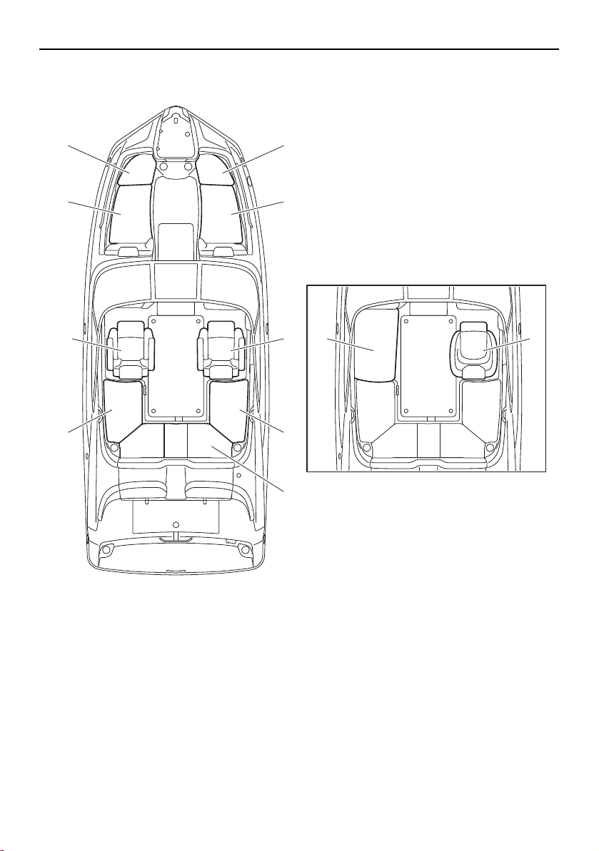
31
Seats
1 Front port seat (rear) (page 92)
2 Front port seat (front) (page 92)
3 Front starboard seat (front) (page 92)
4 Front starboard seat (rear) (page 92)
5 Driver’s seat (212X/212S/212) (page 94)
6 Driver’s seat (AR210/SX210) (page 93)
7 Rear starboard seat (page 93)
8 Rear center seat (page 93)
9 Rear port seat (page 93)
10 Passenger’s seat (212X/212S/212) (page 96)
11 Passenger’s seat (AR210/SX210) (page 93)
2
1
10
9
3
4
5 11 6
7
8
AR210/SX210
SportsBoat_F3R13.book Page 31 Friday, May 31, 2019 9:42 AM

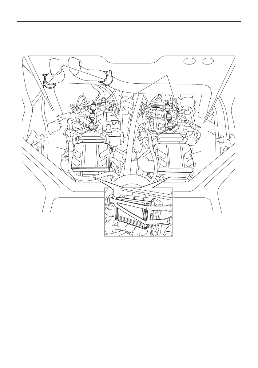
Description
32
Stern components
1 Stern ladder (page 108)
2 Stern eye
3 Shift gate (page 41)
4 Jet thrust nozzle
5 Articulating keel (page 42)
6 Intake grate
7 Hull drain plug (page 126)
8 Water temperature/water depth sensor
9 Flush hose connector (page 160)
2
1
5
3
2
4
3
4
7
6
9 9
6
8
SportsBoat_F3R13.book Page 32 Friday, May 31, 2019 9:42 AM
Description
33
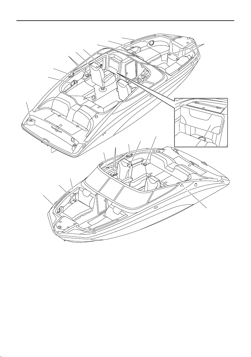
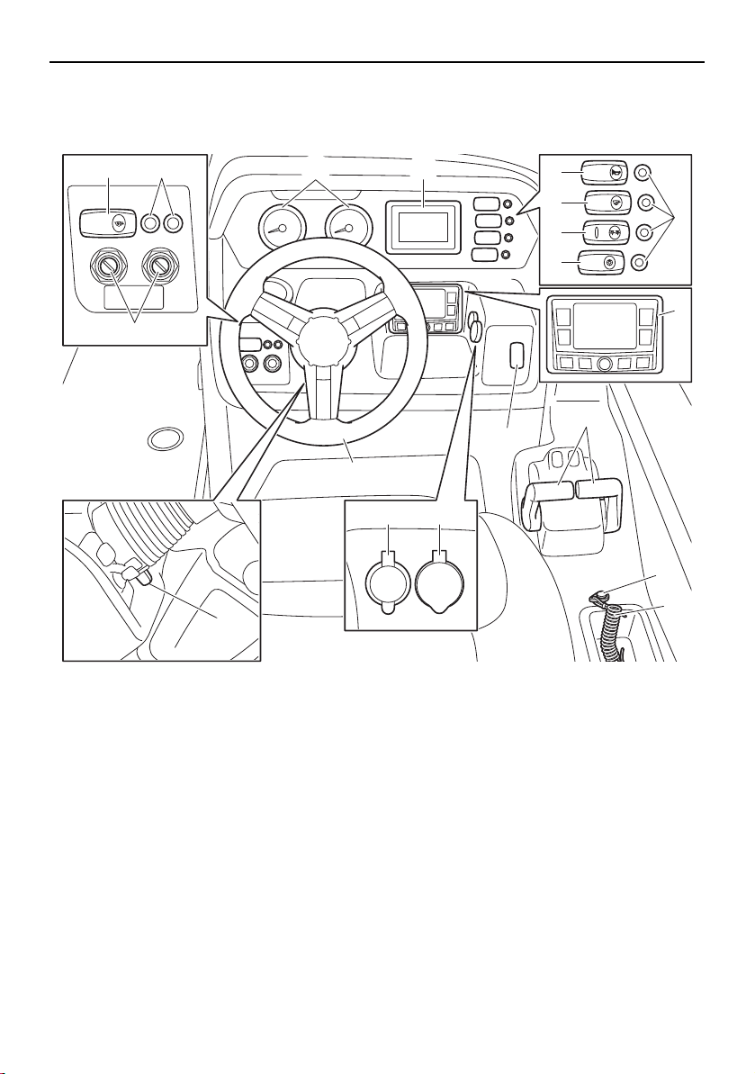
Helm components
AR210/SX210
1 Tachometer (page 45)
2 Multi-function display unit (page 45)
3 Horn switch (page 60)
4 Bilge pump switch (page 60)
5 Navigation and anchor lights switch (page 59)
6 Courtesy light switch (page 59)
7 Switch circuit breaker (page 61)
8 Audio control keypad (page 62)
9 No-wake mode/cruise assist switch (page 57)
10 Remote control lever (page 40)
11 Engine shut-off switch (page 38)
12 Engine shut-off cord (lanyard) (page 38)
13 Aux input (page 61)
14 12 V DC outlet (page 61)
15 Steering wheel (page 42)
16 Tilt lever (page 43)
17 Main switch (page 40)
18 Blower switch (page 60)
12V
AUDIO
AUX-USB
BLOWER
BILGE
NAVI
ANC
HORN
CTSY
LIGHTS
15
1 2
9
7
3
4
5
6
11
12
10
17
18 7
16
1314
8
SportsBoat_F3R13.book Page 33 Friday, May 31, 2019 9:42 AM
Description
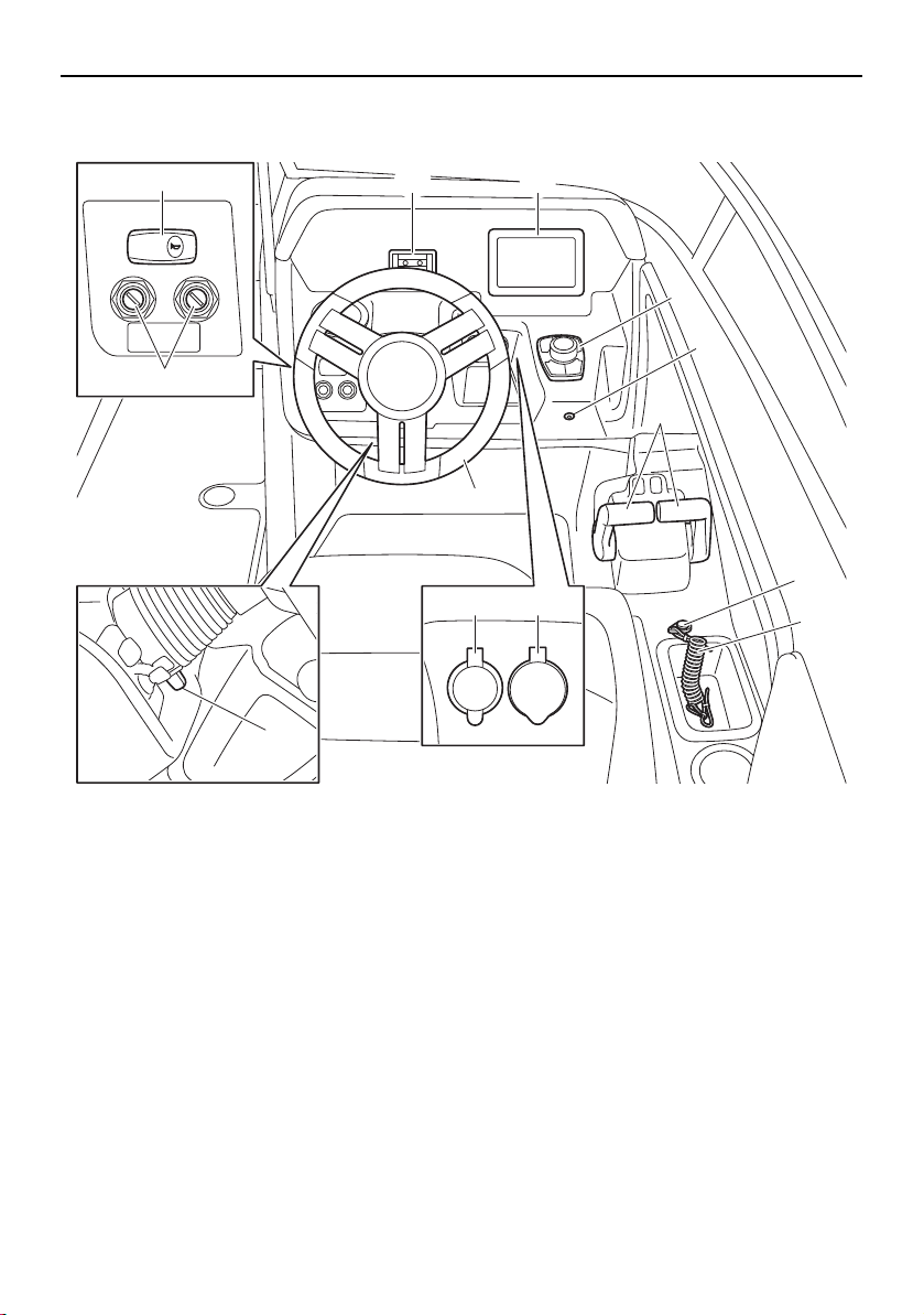
34
212X/212S/212
1 Phone holder
2 Multi-function display unit (page 66)
3 Controller (page 66)
4 Bilge pump indicator light (page 65)
5 Remote control lever (page 40)
6 Engine shut-off switch (page 38)
7 Engine shut-off cord (lanyard) (page 38)
8 Aux input (page 79)
9 12 V DC outlet (page 79)
10 Steering wheel (page 42)
11 Tilt lever (page 43)
12 Main switch (page 40)
13 Horn switch (page 64)
HORN
12V
AUDIO
AUX-USB
10
21
3
4
6
7
5
12
13
11
89
SportsBoat_F3R13.book Page 34 Friday, May 31, 2019 9:42 AM
38
Control function operation
Boat control functions
Engine shut-off switch
WARNING
Always attach the engine shut-off cord
(lanyard) to your PFD before starting the
engines. Failure to attach the cord could
result in a runaway boat if the operator is
ejected.
Do not attach the cord to clothing that
could tear loose. Do not route the cord
in such a way that it could become en-
tangled, preventing it from functioning.
Avoid accidentally pulling the cord dur-
ing normal operation. Once the engines
have stopped, you have no steering con-
trol of the boat which could result in an
accident. Also, without engine power,
the boat could slow rapidly from planing
speed. This could cause people and ob-
jects in the boat to be thrown forward,
which could cause injury.
The clip on the end of the engine shut-off
cord (lanyard) must be attached to the engine
shut-off switch for the engines to run. The
cord must be attached to a secure place on
the operator’s PFD. Should the operator fall
overboard or leave the helm, the cord will pull
out the clip, stopping the ignition to the both
engines. This will prevent the boat from run-
ning away under power.
1 Engine shut-off switch
2 Clip
3 Engine shut-off cord (lanyard)
Battery switch (AR210 / SX210)
The battery switch is located in the rear un-
derseat storage compartment (port).
1 Battery switch
Turn the battery switch to the OFF position
when the boat will not be used again right
away. Turning the switch to the OFF position
will prevent the battery from being drained if
another electrical switch is accidentally left in
the on position. NOTICE : Do not turn the
battery switch to the OFF position if the
boat is moored in the water as it will pre-
vent the anchor light from functioning.
1
2 3
1
SportsBoat_F3R13.book Page 38 Friday, May 31, 2019 9:42 AM

Control function operation
39
1 ON position (green)
2 OFF position (red)
Battery switches (212X / 212S / 212)
The batteries and switch assembly are locat-
ed in the rear underseat storage compart-
ment (port).
This boat uses two marine batteries. One bat-
tery is designated as the start battery. The
start battery is connected to the starter cir-
cuits on both engines to provide current for
the starter motors.
The other battery is designated as the house
battery. The house battery provides power
for the various accessory circuits on the boat,
such as the circuits for lighting, bilge pump,
blowers and audio system.
1 Battery switch assembly
2 Start battery
3 House battery
There are three switches on the battery
switch assembly: the “START” switch,
“HOUSE” switch, and “EMERG PARALLEL”
switch.
1 “HOUSE” switch (red)
2 “EMERG PARALLEL” switch (yellow)
3 “START” switch (red)
1 ON position (green)
2 OFF position (red)
In normal operation, keep the “START” and
“HOUSE” switches in the ON position. Keep
the “EMERG PARALLEL” switch in the OFF
position. This setting allows both batteries to
be charged automatically while the engines
are running. NOTICE: Do not turn the
“HOUSE” switch to the OFF position if the
boat is moored in the water as it will pre-
vent the anchor light from functioning.
1 2
1
2 3
21
3
1 2
SportsBoat_F3R13.book Page 39 Friday, May 31, 2019 9:42 AM
Control function operation
40
If the start battery is discharged, turn the
“EMERG PARALLEL” switch to the ON posi-
tion to start the engines. Once the engines
are started or the start battery is charged,
turn the “EMERG PARALLEL” switch to the
OFF position.
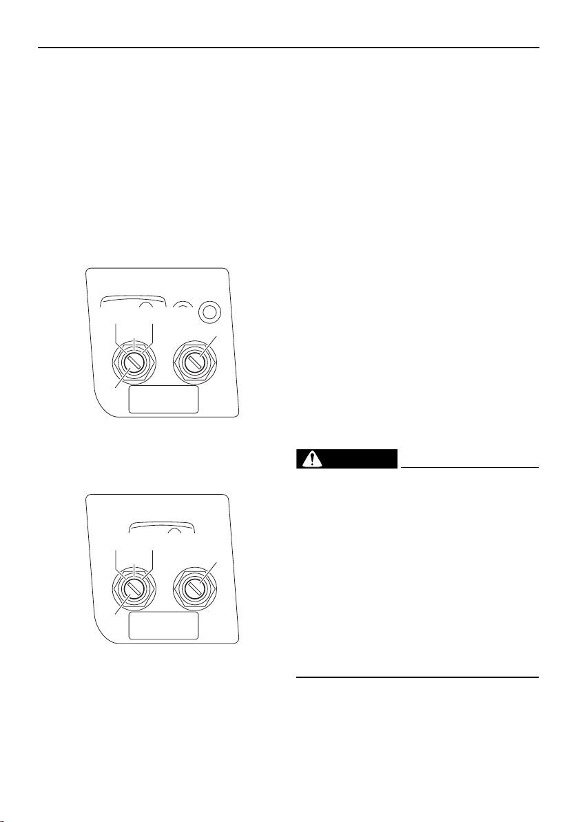
Main switches
There is a main switch for each engine.
The main switch controls the ignition and
electrical circuits as follows:
AR210 / SX210
1 Main switch (port engine)
2 Main switch (starboard engine)
212X / 212S / 212
1 Main switch (port engine)
2 Main switch (starboard engine)
OFF:
Ignition circuit is switched off. The engine
cannot be started, but other switches will op-
erate. (The main switch key can be removed.)
ON:
Ignition circuit is switched on. (The main
switch key cannot be removed.)
START:
The starter motor will turn to start the engine.
(When the main switch key is released, it re-
turns automatically to “ON”.)
TIP:
The engine will not start when the clip is re-
moved from the engine shut-off switch.
The starter motor will turn over without the
cord attached.
The main switch will not operate (the starter
motor will not turn over) if the battery
switch in the rear underseat storage com-
partment (port) is turned to the OFF posi-
tion. (See page 38 for more information.)
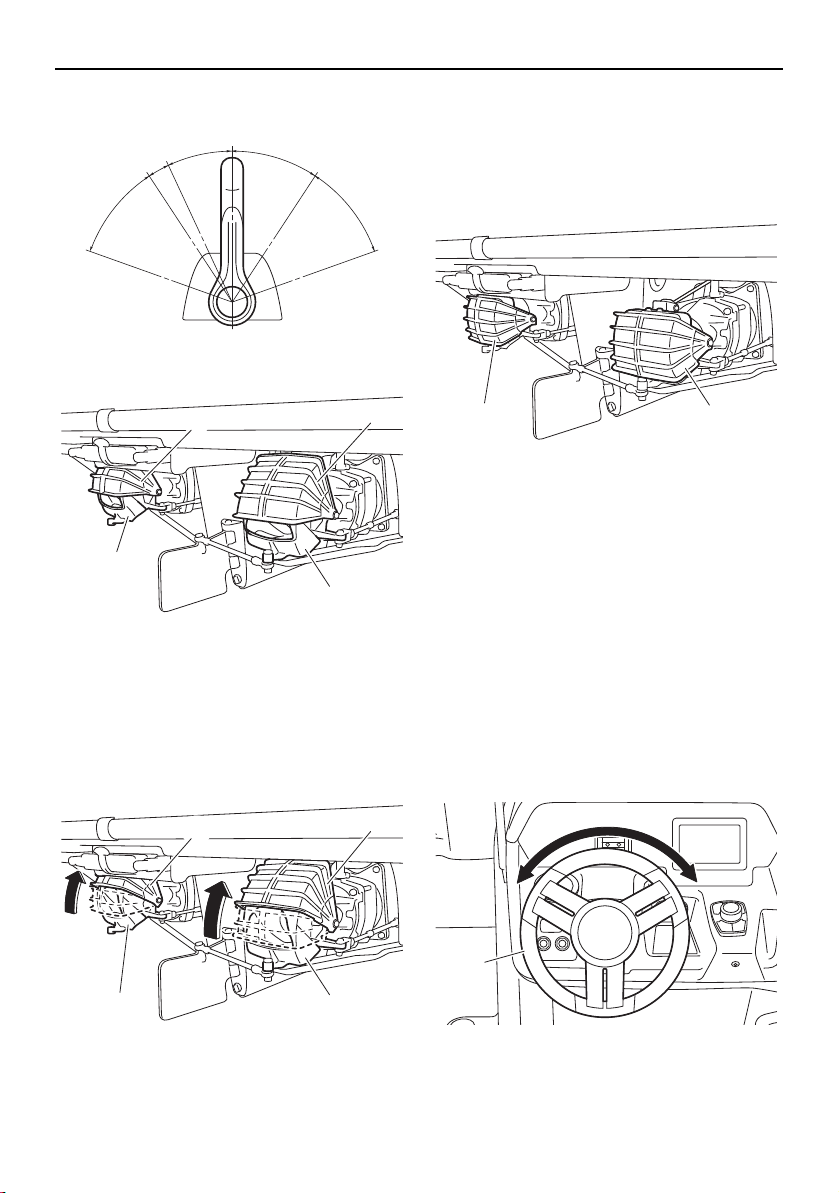
Remote control levers
WARNING
Before shifting, make sure there are no
swimmers or obstacles in the water
near you.
When operating in reverse, go slowly.
Do not open the throttle more than half.
Otherwise, the boat may become unsta-
ble, which could result in loss of control
and an accident.
Do not shift into reverse while traveling
at planing speeds. Loss of control, boat
swamping, or damage to the boat could
occur.
The remote control lever for each engine con-
trols both throttle and shifting. In normal op-
eration, the levers are moved together.
BLOWER
ON
OFF START
1
2
BLOWER
ON
OFF START
1
2
SportsBoat_F3R13.book Page 40 Friday, May 31, 2019 9:42 AM
Control function operation
41
Moving the remote control levers forward
from the neutral position shifts into the for-
ward position, and then as the levers are
moved farther, accelerates the engines for
more thrust. Moving the levers back from the
neutral position shifts into the reverse posi-
tion, and then as the levers are moved farther,
accelerates the engines for more thrust.
For cruising, adjust the remote control levers
so both engines are running at the same en-
gine speed.
TIP:
Because of the mechanical throttle linkage,
the remote control levers may not be exactly
even with one another when the engines are
running at the same engine speed.
1 Neutral position
2 TDE position
3 Forward position
4 Reverse position
5 Shift
6 Fully closed
7 Throttle
8 Fully open
TIP:
This boat is equipped with a “start-in-gear”
protection. The engines will not start unless
the levers are in the neutral position.
This boat uses a direct-drive propulsion sys-
tem. Therefore, jet thrust is always being pro-
duced while the engines are running. The
direction of the boat is controlled by the shift
gates, which direct the flow of the jet thrust as
follows:
Neutral
The shift gates are dropped down part way
over the jet thrust nozzles. The neutral posi-
tion balances forward and reverse thrust to
help keep the boat from moving, although
some movement may occur.
1 Shift gate
2 Jet thrust nozzle
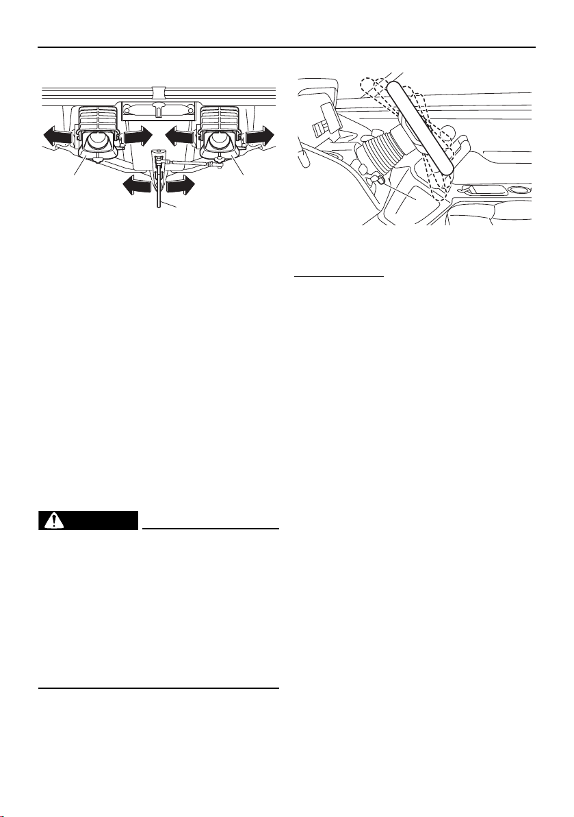
Forward
When the remote control levers are initially
moved to the forward position and the boat is
operating at a slow speed, the shift gates are
lifted up slightly from the neutral position and
jet thrust is directed downward at an angle.
This function, which is called the thrust direc-
tional enhancer (TDE), helps to provide good
handling response when the steering wheel is
turned, even though there is less thrust avail-
able at low engine speeds.
N
1
F
8
7
3
R
4
2
55
7
6
8
6
1
1
2 2
SportsBoat_F3R13.book Page 41 Friday, May 31, 2019 9:42 AM
Control function operation
42
1 TDE position
1 Shift gate
2 Jet thrust nozzle
When the remote control levers are moved
farther forward, the shift gates are lifted all the
way up. All jet thrust is to the rear, which
moves the boat forward.
1 Shift gate
2 Jet thrust nozzle
Reverse
The shift gates are dropped all the way down
over the jet thrust nozzles. Jet thrust is redi-
rected toward the bow of the boat, which
moves the boat backward.
1 Shift gate
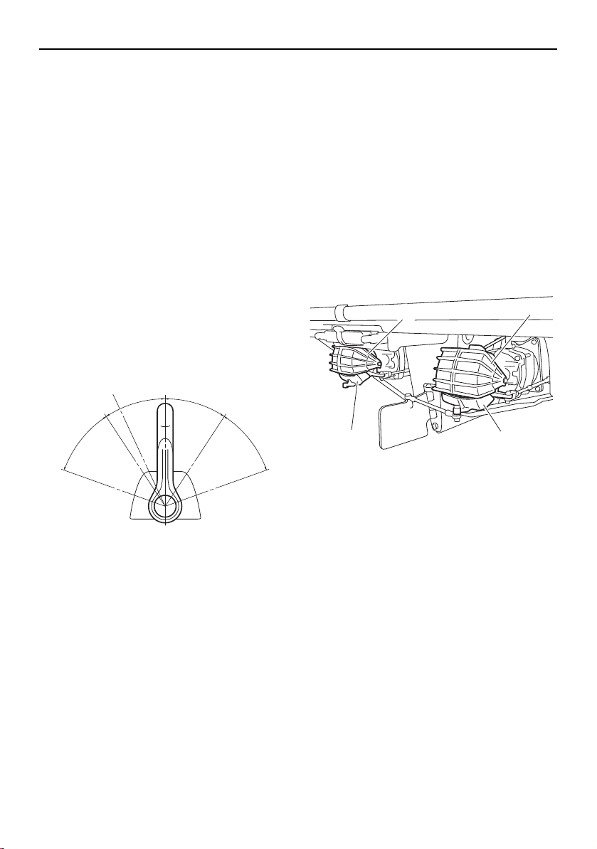
Steering
Your boat can be steered by turning the
steering wheel the same direction you wish to
travel, to the right or left. When the steering
wheel is turned, the angle of the jet thrust
nozzles at the rear of the craft is changed,
and the change in direction of the jet thrust
nozzles changes the direction of the boat ac-
cordingly.
In addition, the direction of the articulating
keel changes according to the movement of
the jet thrust nozzles.
1 Steering wheel
N
F
1
R
1
1
2
2
1
1
2 2
1 1
1
SportsBoat_F3R13.book Page 42 Friday, May 31, 2019 9:42 AM
Control function operation
43
1 Jet thrust nozzle
2 Articulating keel
Since the strength of the jet thrust determines
the speed and direction of a turn, the throttle
must always be opened above idle when at-
tempting a turn, except at trolling speed.
Because boats steer from the stern, the stern
of the boat swings out in the opposite direc-
tion of your turn. If you turn to starboard, for
example, the stern of the boat will swing to
the left. Keep this in mind when navigating
near a person in the water, such as a down
wakeboarder or water-skier, or an obstacle,
such as a dock.
Tilt lever
WARNING
Never touch the tilt lever during opera-
tion, otherwise the steering wheel could
suddenly change position, which may
lead to an accident.
Be sure the steering wheel is locked in
position after adjustment. If the steering
wheel is not locked in position, it may
suddenly change position during opera-
tion, which may lead to an accident.
The tilt lever is located under the steering
wheel and is used to adjust the tilt of the
steering wheel. There are 5 positions.
1 Tilt lever
To adjust the tilt:
(1) Push the lever down, and then move the
steering wheel up or down to the desired
position.
(2) The lever will lock into place when the
steering wheel is moved into one of the 5
available positions.
(3) Make sure that the tilt lever returns to its
original position and that the steering
wheel is securely locked in place.
1 1
2
1
SportsBoat_F3R13.book Page 43 Friday, May 31, 2019 9:42 AM
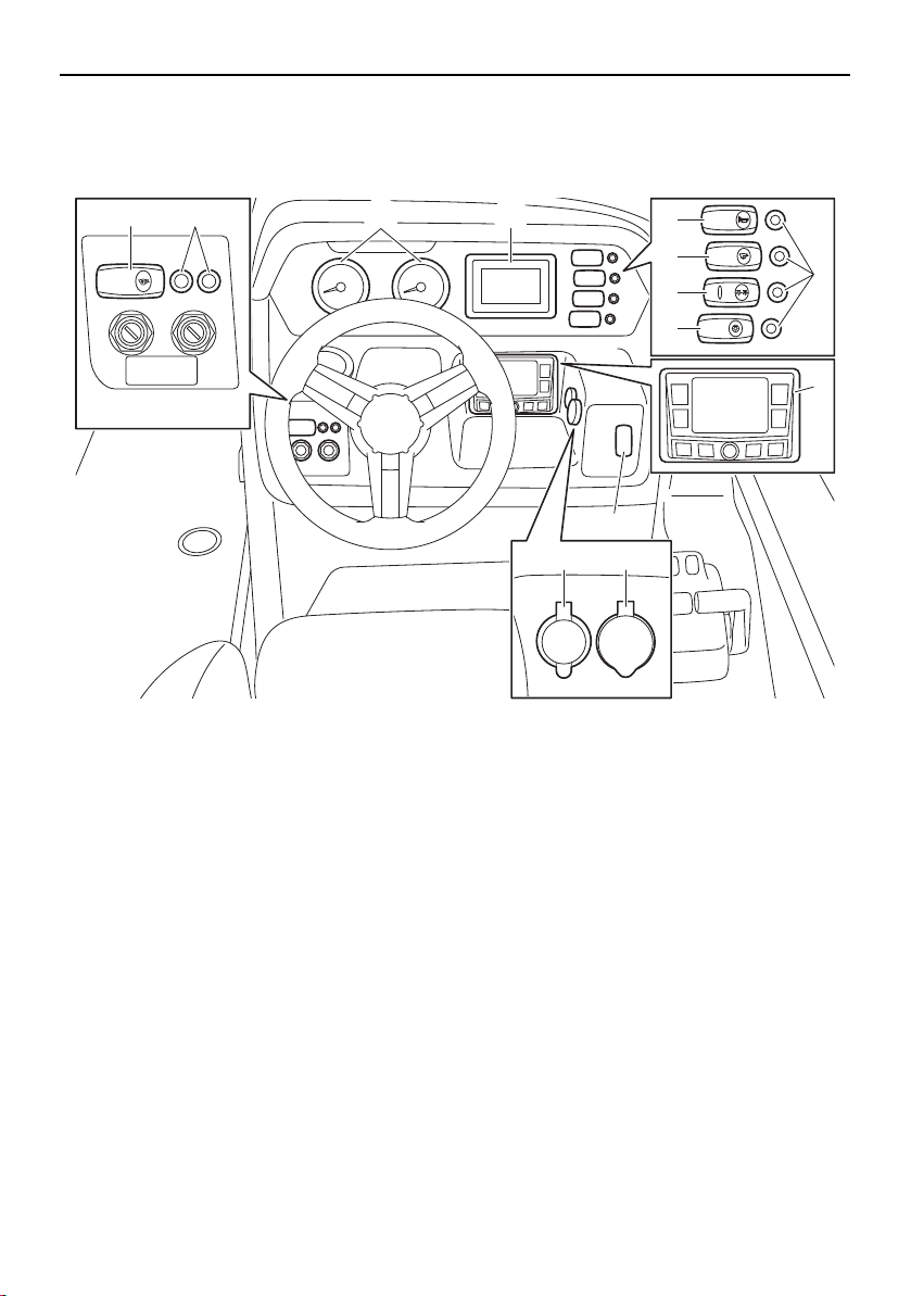
44
Instrument operation
Helm controls (AR210 / SX210)
1 Tachometer
2 Multi-function display unit
3 Horn switch
4 Bilge pump switch
5 Navigation and anchor lights switch
6 Courtesy light switch
7 Switch circuit breaker
8 Audio control keypad
9 No-wake mode/cruise assist switch
10 Aux input
11 12 V DC outlet
12 Blower switch
12V
AUDIO
AUX-USB
BLOWER
BILGE
NAVI
ANC
HORN
CTSY
LIGHTS
1 2
9
7
3
4
5
6
12 7
1011
8
SportsBoat_F3R13.book Page 44 Friday, May 31, 2019 9:42 AM
Instrument operation
45
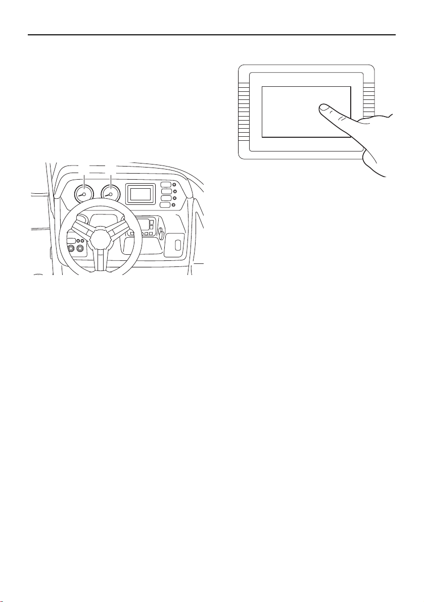
Tachometers
The boat is equipped with two tachometers.
The tachometer on the left is for the port en-
gine. The one on the right is for the starboard
engine.
The analog tachometers show the engine
speed. The numbers on the meters show the
engine speed × 1000 rpm (r/min).
1 Port tachometer
2 Starboard tachometer
TIP:
The tachometer starts operating when the
engine is started. At the same time, the buzz-
er will sound.
Multi-function display unit operation
Because the multi-function display unit is
equipped with a touch screen, you can touch
the display directly to operate the display
functions.
Touching the multi-function display
1 2
SportsBoat_F3R13.book Page 45 Friday, May 31, 2019 9:42 AM
Instrument operation
46
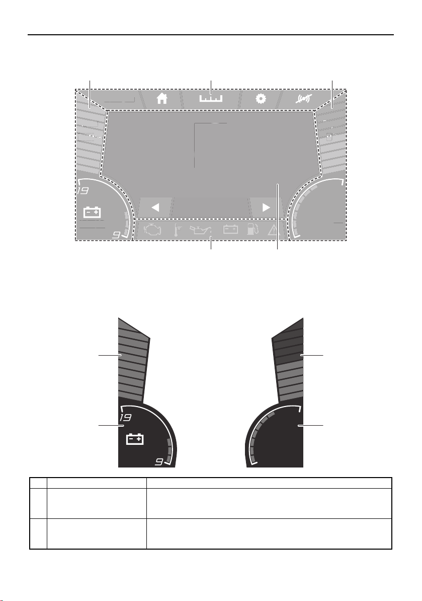
Multi-function display elements
1 Static bar
2 Screen tab bar
3 Center display
4 Warning bar
Static bar
am10:27
FUEL
100
%
Depth
9
ft
12.3V
79.3
Water Temp
°F
MPH
0
0.3 Avg MPG
am
1
0
:2
7
FUEL
L
FUEL
100
100
00
%
%
%
Depth
D
Depth
pth
9
9
9
ft
ft
ft
12.3
V
7
9
.
3
Water Tem
p
°F
MP
H
0
0
.3 Avg MP
G
1 1
4 3
2
Name Function
1 Fuel level bar graph Displays the amount of fuel remaining in the fuel tank. Depending
on the amount of remaining fuel, the bar graph is displayed in 3
colors: blue, yellow, and red.
2 Depth level Shows the water depth in feet or meters. Depending on the water
depth, the bar graph is displayed in 3 colors: blue, orange, and
red.
am10:27
FUEL
100
%
12.3V
Depth
9
ft
79.3
Water Temp
°F
1
4
2
3
SportsBoat_F3R13.book Page 46 Friday, May 31, 2019 9:42 AM
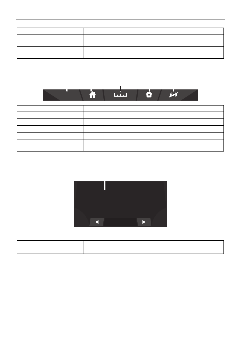
Instrument operation
47
Screen tab bar
Center display
3 Water temperature Displays the ambient water temperature in degrees Fahrenheit or
degrees Celsius.
4 Battery voltage bar graph Shows the battery voltage in a bar graph format and numerical for-
mat.
Name Function
1 Clock Displays the time. Tap the clock to set the time. (See page 50.)
2 Home screen tab Displays the home screen. (See page 49.)
3 Trip screen tab Displays the trip screen. (See page 49.)
4 Setting screen tab Displays the setting screen. (See page 50.)
5 Mute Mutes the sound of the buzzer for a specific time depending on
the warnings present.
Name Function
1 Center display Displays various information for each screen.
Name Function
am10:27
321 54
MPH
0
0.3 Avg MPG
1
SportsBoat_F3R13.book Page 47 Friday, May 31, 2019 9:42 AM

Instrument operation
48
Warning bar
Name Function
1 Warning bar Displays the warning icons.
When a warning icon is displayed, tap the icon to display the
warning message for that icon.
1
SportsBoat_F3R13.book Page 48 Friday, May 31, 2019 9:42 AM
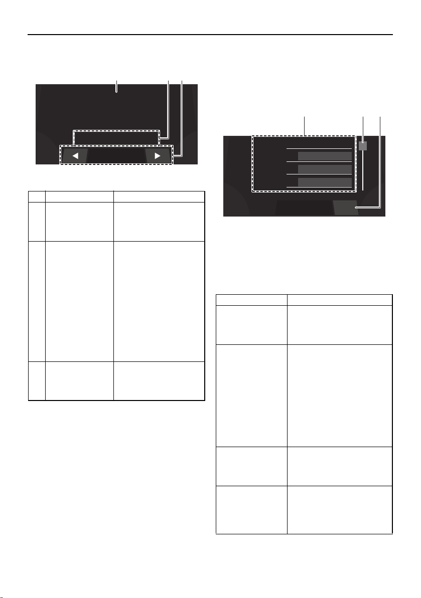
Instrument operation
49
Home screen Trip screen
This screen displays the hours of engine op-
eration, fuel consumption, and other informa-
tion.
1 Menu
2 Scrollbar
3 “Reset” button
The menu displays 4 items at one time. Scroll
through the menu items using the scrollbar.
Name Function
1 Boat speed Displays the boat
speed in miles per
hour or kilometers per
hour.
2 Cruise assist/
no-wake mode
status indicator
Displays whether the
cruise assist or no-
wake mode is activat-
ed.
When the cruise assist
is activated, “Cruise”
and the cruise assist
setting level will be dis-
played.
When the no-wake
mode is activated, “No
Wake Mode” will be
displayed.
3 Data bar Displays trip screen in-
formation. See “Trip
screen” for more infor-
mation.
MPH
0
No Wake Mode
0.3 Avg MPG
1 2 3
Name Function
Water tempera-
ture*
Displays the ambient water
temperature in degrees
Fahrenheit or degrees Cel-
sius.
Average fuel con-
sumption
Displays the average dis-
tance that was traveled on
1.0 gallon or 1.0 liter of fuel
since the item was last re-
set. When gallons are se-
lected for the display units,
the value is displayed in
miles and when liters are
selected for the display
units, the value is dis-
played in kilometers.
Trip distance Displays the distance trav-
eled by the boat in miles or
kilometers since the item
was last reset.
Fuel used Displays the total fuel that
has been consumed by the
port and starboard engines
in gallons or liters since the
item was last reset.
Water :
79.3
°F
Economy :
23.0
Avg MPG
Trip :
262.8
Miles
Used :
89.9
Gal
Reset
1 2 3
SportsBoat_F3R13.book Page 49 Friday, May 31, 2019 9:42 AM
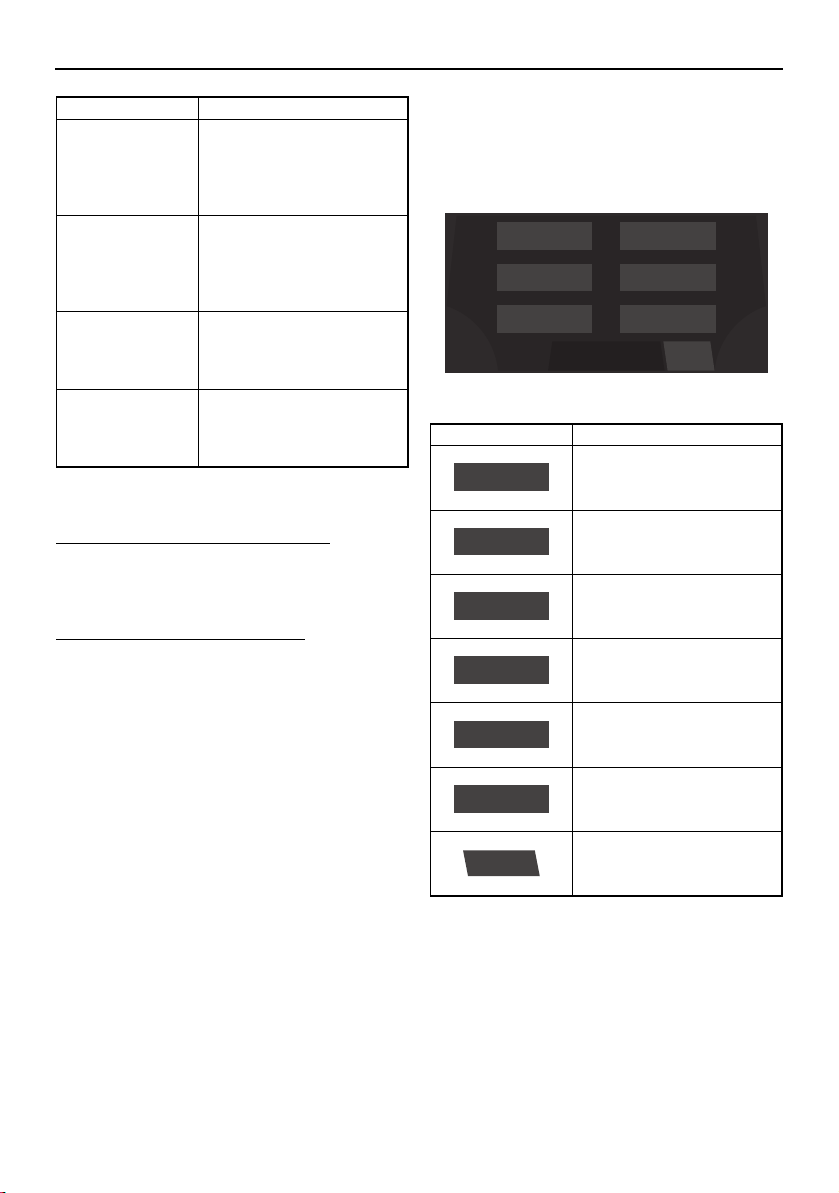
Instrument operation
50
* This item cannot be reset.
To reset an item on the trip screen:
Touch and hold the item that you want to re-
set for several seconds.
To reset all of the display items:
Touch the “Reset” button to reset all of the
items.
Setting screen
The setting screen can be used to change the
settings of the multi-function display unit.
Time setting screen
Tap the time unit that you want to set and
scroll up or down.
Fuel flow* Displays the total fuel con-
sumption of the port and
starboard engines in gal-
lons per hour or liters per
hour.
Highest speed Displays the highest speed
of the boat in miles per
hour or kilometers per hour
since the item was last re-
set.
Average speed Displays the average boat
speed in miles per hour or
kilometers per hour since
the item was last reset.
Engine hours* Displays the total number
of hours that the engines
have been running since
the boat was new.
Name Function
Item Function
Displays the time setting
screen.
Displays the depth alarm
setting screen.
Displays the unit setting
screen.
Displays the brightness
setting screen.
Displays the maintenance
setting screen.
Displays the language set-
ting screen.
Displays the factory reset
screen.
Language
Brightness
Depth
Wellness
Unit
Time
Menu
Reset
Time
Depth
Unit
Brightness
Wellness
Language
Reset
SportsBoat_F3R13.book Page 50 Friday, May 31, 2019 9:42 AM
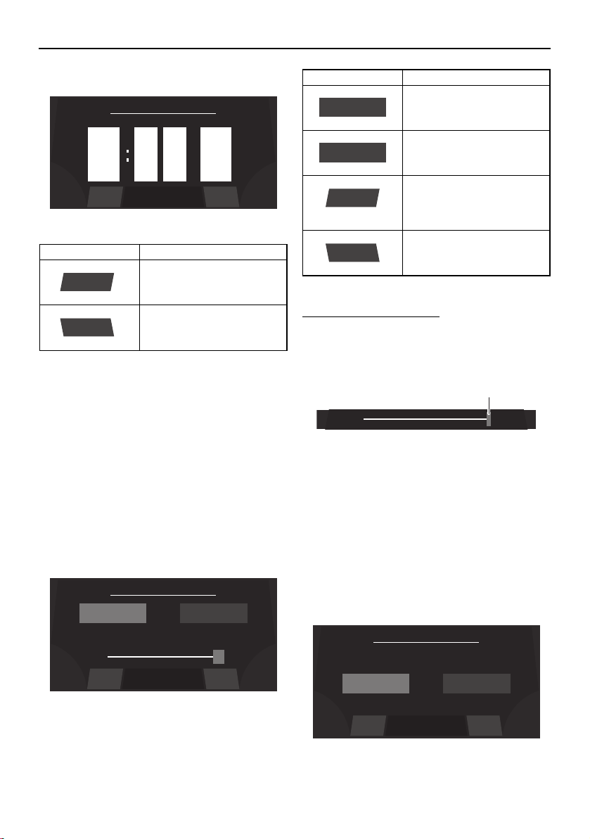
Instrument operation
51
TIP:
When “US Unit” is selected, the time is dis-
played in the 12-hour format. When “Metric
Unit” is selected, the time is displayed in the
24-hour format.
Brightness setting screen
The multi-function display has a day mode
and a night mode.
The brightness can be set separately for the
day mode and for the night mode.
To adjust the brightness:
To make the display darker, drag the slider to
the left. To make the display brighter, drag
the slider to the right.
1 Slider control
TIP:
The slider limits depend on the selected light
mode.
Unit setting screen
The display units for the multi-function dis-
play unit can be changed.
Item Function
Saves the set time as the
current time and displays
the setting screen.
Displays the setting screen
without saving the set
time.
9
10
8
pm
am
am
0
1
9
0
1
9
Set Time
BackSave
Save
Back
50%
Set Brightness
BackSave
NIGHT
100%
DAY
Item Function
Displays the current night
mode setting.
Displays the current day
mode setting.
Saves the set brightness
as the brightness level set-
ting and displays the set-
ting screen.
Displays the setting screen
without saving the set
brightness level.
NIGHT
DAY
Save
Back
1
Set Unit
BackSave
Metric UnitUS Unit
SportsBoat_F3R13.book Page 51 Friday, May 31, 2019 9:42 AM
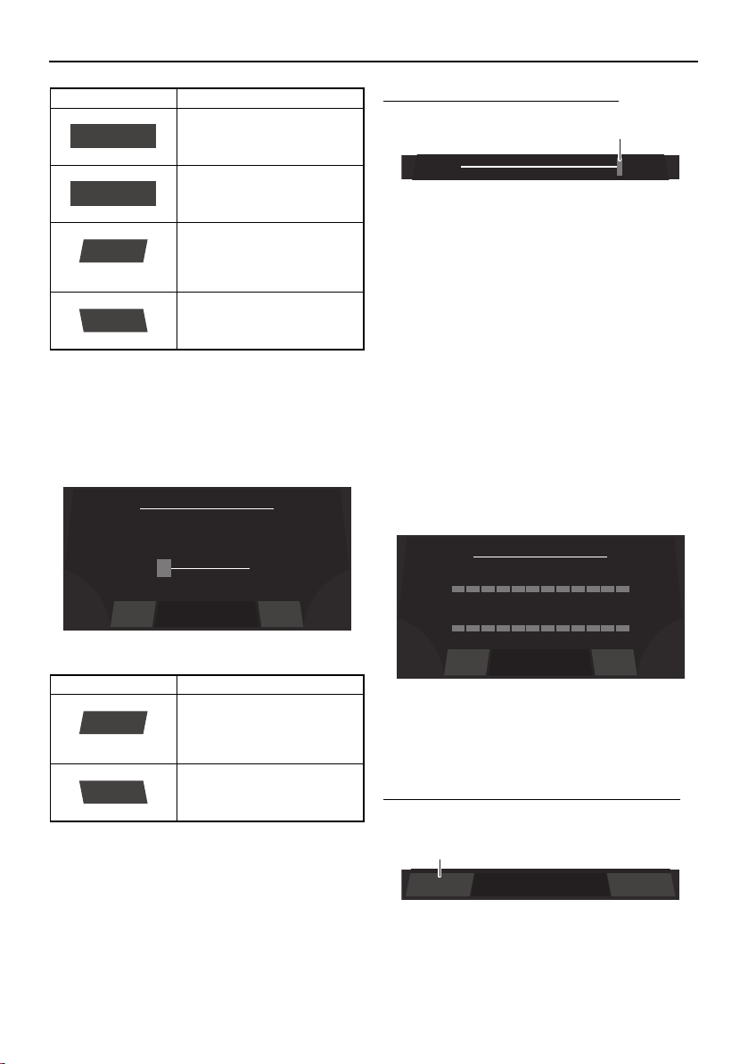
Instrument operation
52
Depth alarm setting screen
The water depth for the depth alarm can be
set.
To adjust the water depth setting:
1 Slider control
To reduce the water depth setting, drag the
slider to the left.
To increase the water depth setting, drag the
slider to the right.
TIP:
If the water depth is set to 0.0 m (0.0 ft), the
depth alarm will not operate.
Maintenance setting screen
This screen displays the number of hours that
the engines have been running since the last
maintenance.
After maintenance is performed, reset the
number of hours of operation as follows.
To reset the number of hours of operation:
(1) Tap the “Reset” button.
1 “Reset” button
Item Function
Sets the display units to
US units.
Sets the display units to
metric units.
Saves the selected unit
setting as the current units
and displays the setting
screen.
Displays the setting screen
without saving the select-
ed unit setting.
Item Function
Saves the set water depth
as the current depth alarm
setting and displays the
setting screen.
Displays the setting screen
without saving the set wa-
ter depth.
US Unit
Metric Unit
Save
Back
4.0
ft
Depth Alarm
BackSave
Save
Back
1
Time Since Last Maintenance
BackReset
0.0 HrsPort:
0.0 HrsStbd:
BackReset
1
SportsBoat_F3R13.book Page 52 Friday, May 31, 2019 9:42 AM

Instrument operation
53
(2) When the confirmation message ap-
pears, tap the “YES” button to reset the
number of hours of operation.
TIP:
To return to the maintenance setting screen
without resetting the number of hours, tap
the “NO” button.
1 “YES” button
Language setting screen
The language for the multi-function display
unit can be changed.
Tap the desired language, and then tap the
“Save” button to save the setting.
To display the setting screen without saving
the language setting, tap the “Back” button.
Factory reset screen
This screen can be used to reset the settings
to their factory default settings.
To reset the settings:
(1) Tap the “Reset” button.
1 “Reset” button
(2) When the confirmation message ap-
pears, tap the “YES” button to reset the
settings.
TIP:
To return to the factory reset screen without
resetting the settings, tap the “NO” button.
1 “YES” button
YES NOAre you sure ?
1
Set Language
BackSave
Francais
Espanol
English
Reset all parameters to factory setting?
Factory Reset
BackReset
BackReset
1
YES NOAre you sure ?
1
SportsBoat_F3R13.book Page 53 Friday, May 31, 2019 9:42 AM
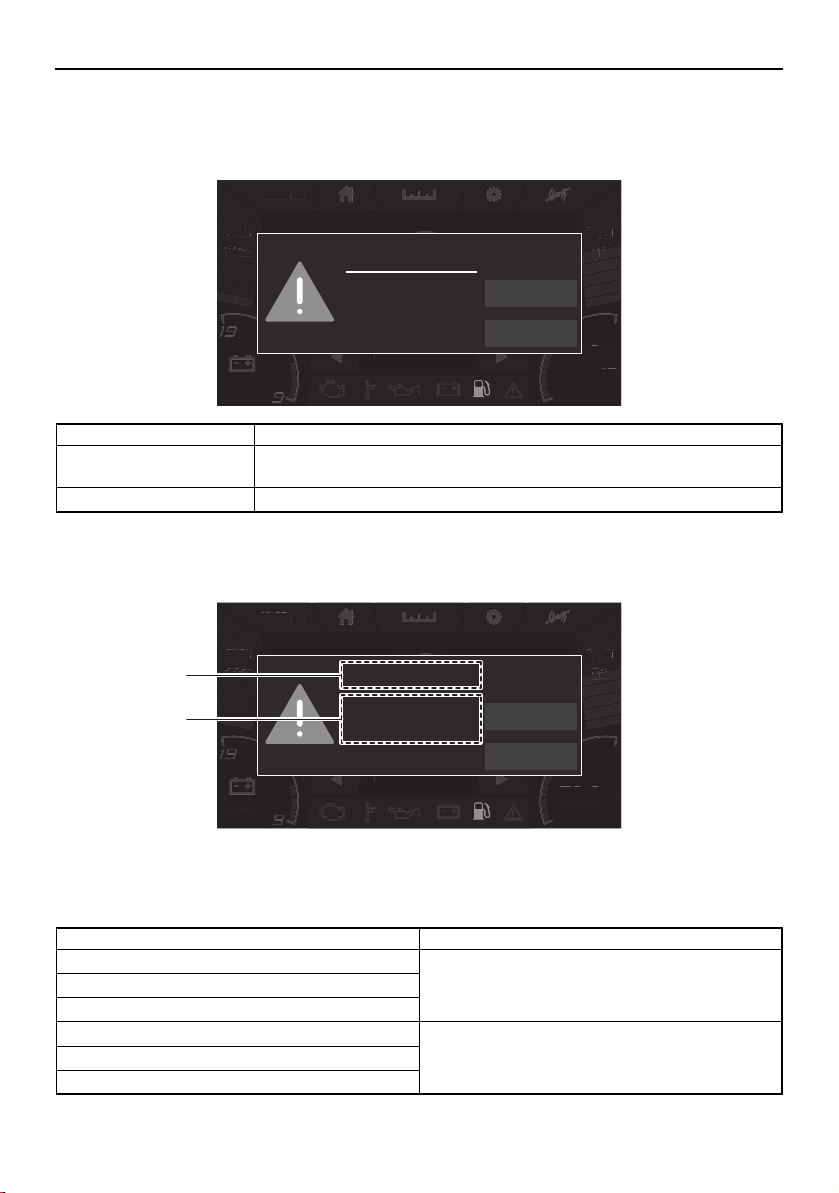
Instrument operation
54
Warnings
If a malfunction or fault occurs, a warning buzzer will sound and a warning icon and warning
message will be displayed on the center display.
If the displayed warning message includes instructions, follow those instructions. If you have
any questions, consult a Yamaha Boat Dealer.
1 Warning title
2 Message
Warning example
Name Function
NEXT Displays the next active warning. When there is only 1 warning, the dis-
played warning will not change.
QUIT Closes the displayed warning.
am10:27
FUEL
100
%
Depth
9
ft
12.3V
79.3
Water Temp
°F
MPH
0
0.3 Avg MPG
FUEL
10
%
a
m
10
:
2
7
Depth
D
Depth
pth
9
9
9
ft
ft
ft
12.3
V
79
.
3
W
ater
T
em
p
°
F
MPH
0
0
.3 Av
g
MP
G
FUEL
L
FUEL
10
10
10
%
%
%
Fuel
NEXT
QUIT
Low Fuel Level
am10:27
FUEL
100
%
Depth
9
ft
12.3V
79.3
Water Temp
°F
MPH
0
0.3 Avg MPG
FUEL
10
%
a
m
10
:
2
7
Depth
D
Depth
pth
9
9
9
ft
ft
ft
12.3
V
79
.
3
W
ater
T
em
p
°
F
MPH
0
0
.3 Av
g
MP
G
FUEL
L
FUEL
10
10
10
%
%
%
Fuel
NEXT
QUIT
Low Fuel Level
1
2
Warning title Message
Check Engine Stop Port Engine.
Consult YAMAHA dealer.
Low Oil Pressure
Over Temperature
Check Engine Stop Starboard Engine.
Consult YAMAHA dealer.
Low Oil Pressure
Over Temperature
SportsBoat_F3R13.book Page 54 Friday, May 31, 2019 9:42 AM
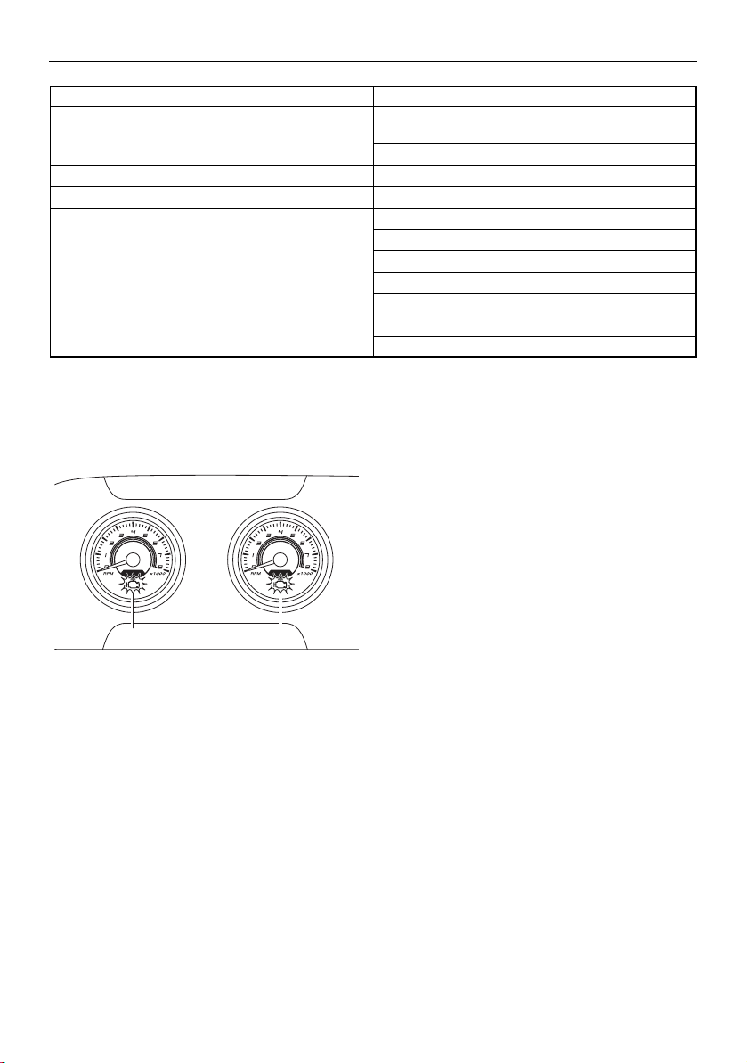
Instrument operation
55
The check engine warning indicator is also
displayed on the tachometer for the engine
with the warning.
1 Check engine warning indicator
Check engine warning
If an engine sensor malfunction or a short cir-
cuit is detected, a warning will appear on the
multi-function display and the buzzer will
sound. If a fault is detected for an engine,
“Check Engine” will be displayed. If this oc-
curs, reduce the engine speed, return to
shore, and have a Yamaha Boat Dealer check
the engine.
Low oil pressure warning
If the oil pressure does not rise to specifica-
tion, a warning will appear on the multi-func-
tion display and the buzzer will sound. If a
fault is detected for an engine, “Low Oil Pres-
sure” will be displayed. At the same time, the
engine speed is automatically limited to help
prevent damage. If this occurs, reduce the
engine speed, return to shore or maneuver to
a safe location, and check the engine oil level.
(See page 122 for engine oil level checking
procedures.)
If the oil level is low, add enough engine oil to
raise it to the proper level. If the oil level is suf-
ficient, have a Yamaha Boat Dealer check the
engine.
Over temperature warning
This model is equipped with an over temper-
ature warning system. If the engines start to
overheat, a warning will appear on the multi-
function display and the buzzer will sound. If
an engine is overheating, “Over Tempera-
ture” will be displayed. At the same time, the
engine speed is automatically limited to help
prevent damage. If this occurs, immediately
reduce the engine speed, return to shore or
Battery Low Voltage.
Start engine to recharge the battery.
High Voltage.
Fuel Low Fuel Level
Depth Low Depth Level
Communication Error Port Engine
Starboard Engine
Engine CAN
No transducer found
No LIN Communications
Port Gauge
Starboard Gauge
Warning title Message
11
SportsBoat_F3R13.book Page 55 Friday, May 31, 2019 9:42 AM
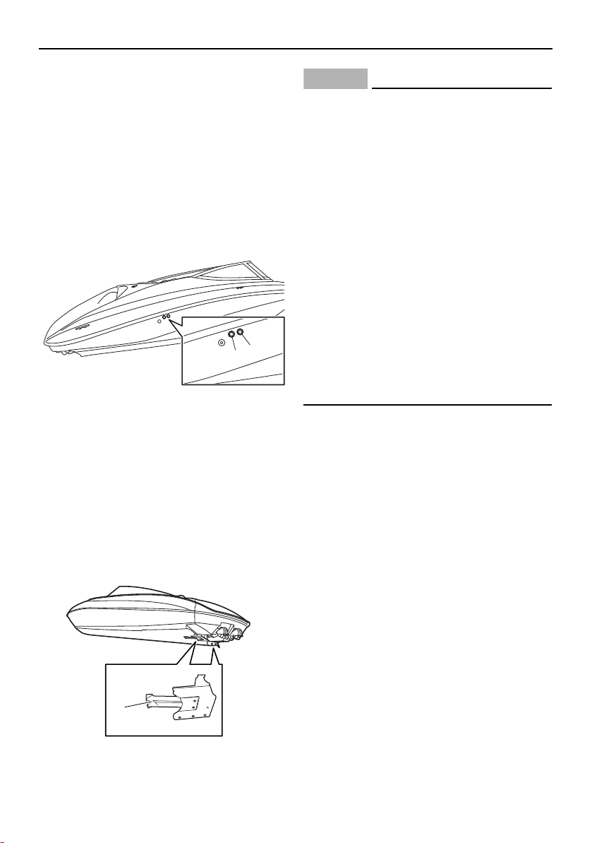
Instrument operation
56
maneuver to a safe location, and check for
water discharge at the cooling water pilot
outlets. There are cooling water pilot outlets
on the starboard side of the hull. Check that
water comes out of the outlets while the en-
gines are running, particularly while applying
throttle. If you do not see any water at the
outlets, cooling water may not be circulating
in the engines.
1 Cooling water pilot outlet (starboard engine)
2 Cooling water pilot outlet (port engine)
TIP:
If the cooling water passages in the engines
are dry, it will take about 20 seconds for wa-
ter to reach the pilot outlets after starting.
If water is not circulating, something may be
clogging the intake grates. Refer to “Jet
pump clean-out procedure” on page 182.
1 Intake grate
NOTICE
If the cause of overheating cannot be
found and corrected, take special precau-
tions to avoid major engine damage while
you return to shore.
Single engine overheating — Shut off the
overheating engine and use the properly
running engine to return to shore. Operate
at no-wake speed (8 km/h, 5 mph) to pre-
vent water from flooding the non-operat-
ing engine through the water intake. See
page 57 for information on the no-wake
mode.
Both engines overheating — If getting a
tow from another vessel is not possible,
operate both engines just slightly above
idle while you return to shore. If you can be
towed, refer to “Towing the boat” on page
188.
Communication error warning
If a generic error is detected, a warning will
appear on the multi-function display and the
buzzer will sound. If this occurs, reduce the
engine speed, return to shore, and have a
Yamaha Boat Dealer check the boat.
1
2
1
SportsBoat_F3R13.book Page 56 Friday, May 31, 2019 9:42 AM

Instrument operation
57
No-wake mode/cruise assist switch
This switch activates and sets the no-wake
mode, cruise assist, and reverse RPM con-
trol.
1 No-wake mode/cruise assist switch
To operate the no-wake mode and cruise as-
sist, see the following sections. To activate
the reverse RPM control, see “Reverse RPM
control” on page 58.
Operating the boat with a minimal
wake (no-wake mode)
The no-wake mode is useful for operating the
boat at a steady speed with a minimal wake.
This is especially convenient when traveling
in harbors, channels, or other areas posted
with low speed limits as “no wake zones”.
The no-wake mode can be activated only
when the engines are operating at idle speed.
To activate the no-wake mode:
(1) Put the remote control levers in the TDE
position or forward position so that both
engines are operating at idle speed.
(2) Push the plus side of the no-wake
mode/cruise assist switch. Once “No
Wake Mode” is displayed in the multi-
function display, the no-wake mode is
activated.
TIP:
The no-wake mode can be set to 3 engine
speeds. To adjust the engine speed while the
no-wake mode is activated, push the plus
side or minus side of the no-wake
mode/cruise assist switch.
To deactivate the no-wake mode:
Perform one of the following operations.
Push the minus side of the no-wake
mode/cruise assist switch until “No Wake
Mode” disappears.
Push the remote control levers forward to
open the throttle.
Operating the boat at a steady speed
(cruise assist)
The cruise assist feature is for steady engine
speed operation when the boat is traveling
above no-wake speeds. The cruise assist is
available for use whenever the engines are
running above 4000 rpm and below 7000
rpm.
To activate the cruise assist:
(1) Push the remote control levers forward
to open the throttle until the desired en-
gine speed is reached and both engines
are operating at the same engine speed.
(2) Push the plus side or minus side of the
no-wake mode/cruise assist switch.
Once “Cruise” is displayed in the multi-
1
am10:27
FUEL
100
%
Depth
9
ft
12.3V
79.3
Water Temp
°F
MPH
0
No Wake Mode
0.3 Avg MPG
SportsBoat_F3R13.book Page 57 Friday, May 31, 2019 9:42 AM
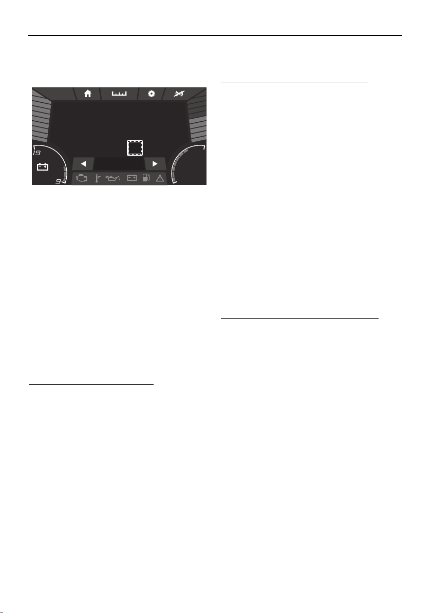
Instrument operation
58
function display, the cruise assist is acti-
vated.
TIP:
Once the cruise assist is activated, the set
engine speed can be increased by pushing
the plus side of the switch or decreased by
pushing the minus side. However, the ad-
justment is limited to a maximum of 8 incre-
ments above or below the initial cruise
assist setting. Each time the switch is
pushed, the engine speed will increase or
decrease approximately 100–200 rpm.
While the cruise assist is activated, the en-
gine speed can also be adjusted by operat-
ing the remote control levers.
To deactivate the cruise assist:
Operate the remote control levers to de-
crease the engine speed to 3000 rpm or less.
Once “Cruise” disappears, the cruise assist is
deactivated.
Operating the boat in reverse with
more thrust (reverse RPM control)
Engine speed in reverse is limited to approx-
imately 4500 rpm. If more thrust is required
when the boat is traveling in reverse, use the
reverse RPM control. WARNING! Be pre-
pared to reduce throttle as soon as the
boat moves as desired. Otherwise, the
boat may become unstable, which could
result in loss of control and an accident.
To activate the reverse RPM control:
(1) Move the remote control levers back-
ward so that the throttle is opened in re-
verse and both engines are operating at
the same engine speed.
(2) Increase the engine speed to 4500 rpm,
and then push the plus side of the no-
wake mode/cruise assist switch.
TIP:
Once the reverse RPM control is activated,
pushing the plus side of the no-wake
mode/cruise assist switch will increase the
available engine speed by approximately 500
rpm in 3 stages up to a maximum of 6000
rpm, and pushing the minus side will de-
crease the available engine speed. However,
the adjustment is limited to these 3 incre-
ments.
To deactivate the reverse RPM control:
Operate the remote control levers to de-
crease the engine speed to less than 4500
rpm.
Light operation
The light switches can be used to turn the
boat lights on or off.
am10:27
FUEL
100
%
Depth
9
ft
12.3V
79.3
Water Temp
°F
MPH
0
Cruise +4
0.3 Avg MPG
SportsBoat_F3R13.book Page 58 Friday, May 31, 2019 9:42 AM
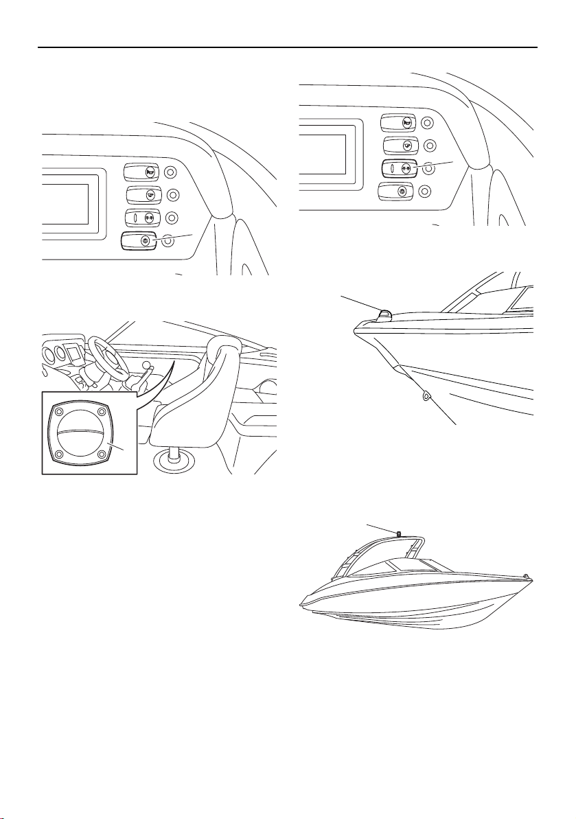
Instrument operation
59
Turning the courtesy light on or off
Push the courtesy light switch to turn on the
courtesy light inside the boat.
1 Courtesy light switch
1 Courtesy light
Turning the anchor light and bow light
on or off
The navigation and anchor lights switch is a
toggle switch that controls the bow light and
anchor light. Push the right side of the switch
to turn on both the bow light and anchor light
for night running (“NAVI”). Push the left side
of the switch to operate the anchor light alone
when anchored at night (“ANC”). Put the
switch in the middle position to turn off all
lights.
1 Navigation and anchor lights switch
1 Bow light
AR210
1 Anchor light
BILGE
NAVI
ANC
HORN
CTSY
LIGHTS
1
1
BILGE
NAVI
ANC
HORN
CTSY
LIGHTS
1
1
1
SportsBoat_F3R13.book Page 59 Friday, May 31, 2019 9:42 AM
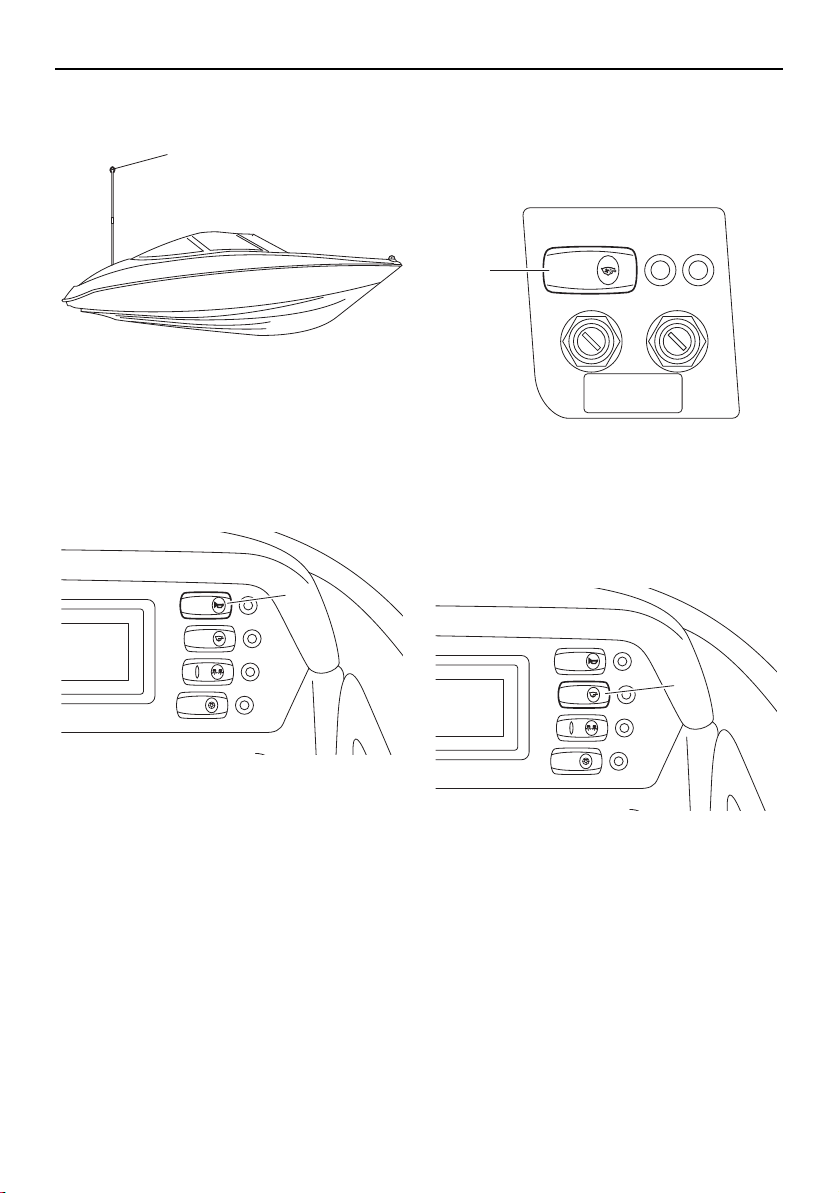
Instrument operation
60
SX210
1 Anchor light
Horn switch
Push this switch to activate the horn. The
horn can be used to signal other boats as re-
quired by the “Rules of the road”. (See page
22 for more information.)
1 Horn switch
Ventilating the engine compartment
Push the blower switch to turn on the blowers
to ventilate the engine compartment. (See
page 138 for more information.)
1 Blower switch
Draining the bilge water
Push the bilge pump switch to activate the
bilge pump. (See page 126 for more informa-
tion.)
1 Bilge pump switch
1
BILGE
NAVI
ANC
HORN
CTSY
LIGHTS
1
BLOWER
1
BILGE
NAVI
ANC
HORN
CTSY
LIGHTS
1
SportsBoat_F3R13.book Page 60 Friday, May 31, 2019 9:42 AM
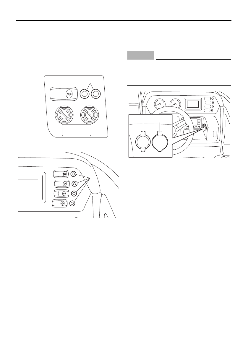
Instrument operation
61
Switch circuit breakers
The electrical circuit for each switch is pro-
tected by a circuit breaker. If the button pops
out, push it back in with your finger. If it pops
out again, ask a Yamaha Boat Dealer to in-
spect the electrical system.
1 Switch circuit breaker
1 Switch circuit breaker
Accessory outlet
There is a 12V DC outlet located on the star-
board side of the steering wheel.
NOTICE
Do not use an automotive cigarette lighter
or other accessories that get hot because
the outlet can be damaged.
1 12V DC outlet
2 Aux input
BLOWER
1
BILGE
NAVI
ANC
HORN
CTSY
LIGHTS
1
12V
AUDIO
AUX-USB
1 2
SportsBoat_F3R13.book Page 61 Friday, May 31, 2019 9:42 AM
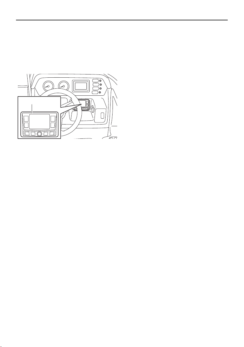
Instrument operation
62
Audio control keypad
The audio control keypad is located under
the multi-function meter.
For operating instructions, refer to the stereo
system owner’s manual included with your
boat.
1 Audio control keypad
TIP:
The audio control keypad does not turn off
even if you turn the main switch keys to the
off position. To turn off the audio control key-
pad, push the power button on the keypad.
1
SportsBoat_F3R13.book Page 62 Friday, May 31, 2019 9:42 AM
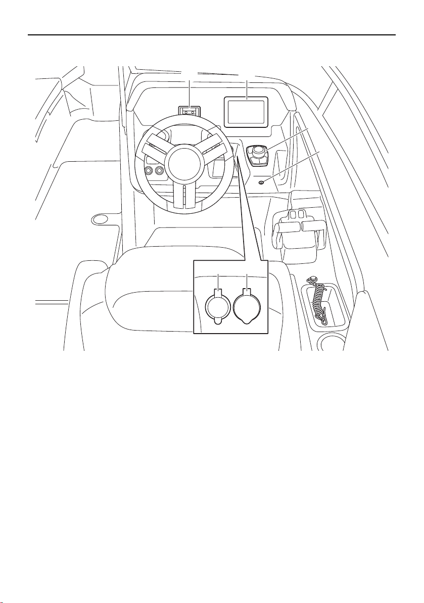
Instrument operation
63
Helm controls (212X / 212S / 212)
1 Phone holder
2 Multi-function display unit
3 Controller
4 Bilge pump indicator light
5 Aux input
6 12 V DC outlet
12V
AUDIO
AUX-USB
21
3
4
56
SportsBoat_F3R13.book Page 63 Friday, May 31, 2019 9:42 AM
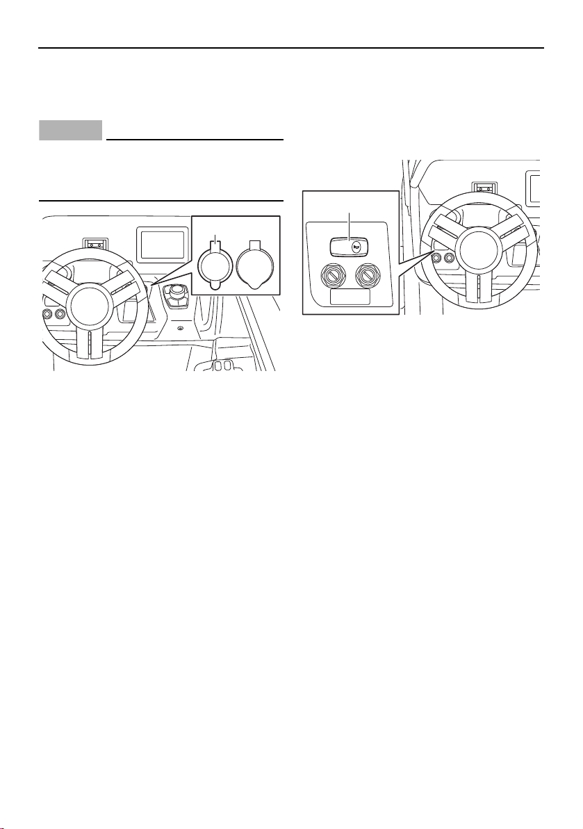
Instrument operation
64
Accessory outlet
There is a 12 V DC outlet located on the star-
board side of the steering wheel.
NOTICE
Do not use an automotive cigarette lighter
or other accessories that get hot because
the outlet can be damaged.
1 12 V DC outlet
Horn switch
Push this switch to activate the horn. The
horn can be used to signal other boats as re-
quired by the “Rules of the road”. (See page
22 for more information.)
1 Horn switch
12V
AUDIO
AUX-USB
1
HORN
1
SportsBoat_F3R13.book Page 64 Friday, May 31, 2019 9:42 AM

Instrument operation
65
Remote control keypad
The remote control keypad is located on the
port side of the swim platform.
For operating instructions, refer to the stereo
system owner’s manual included with your
boat.
1 Remote control keypad
Bilge pump indicator light
This indicator light comes on while the bilge
pump is operating.
1 Bilge pump indicator light
TIP:
Even if the bilge pump is turned off, the pump
will operate every 2 minutes when the battery
switch is in the on position.
1
1
SportsBoat_F3R13.book Page 65 Friday, May 31, 2019 9:42 AM
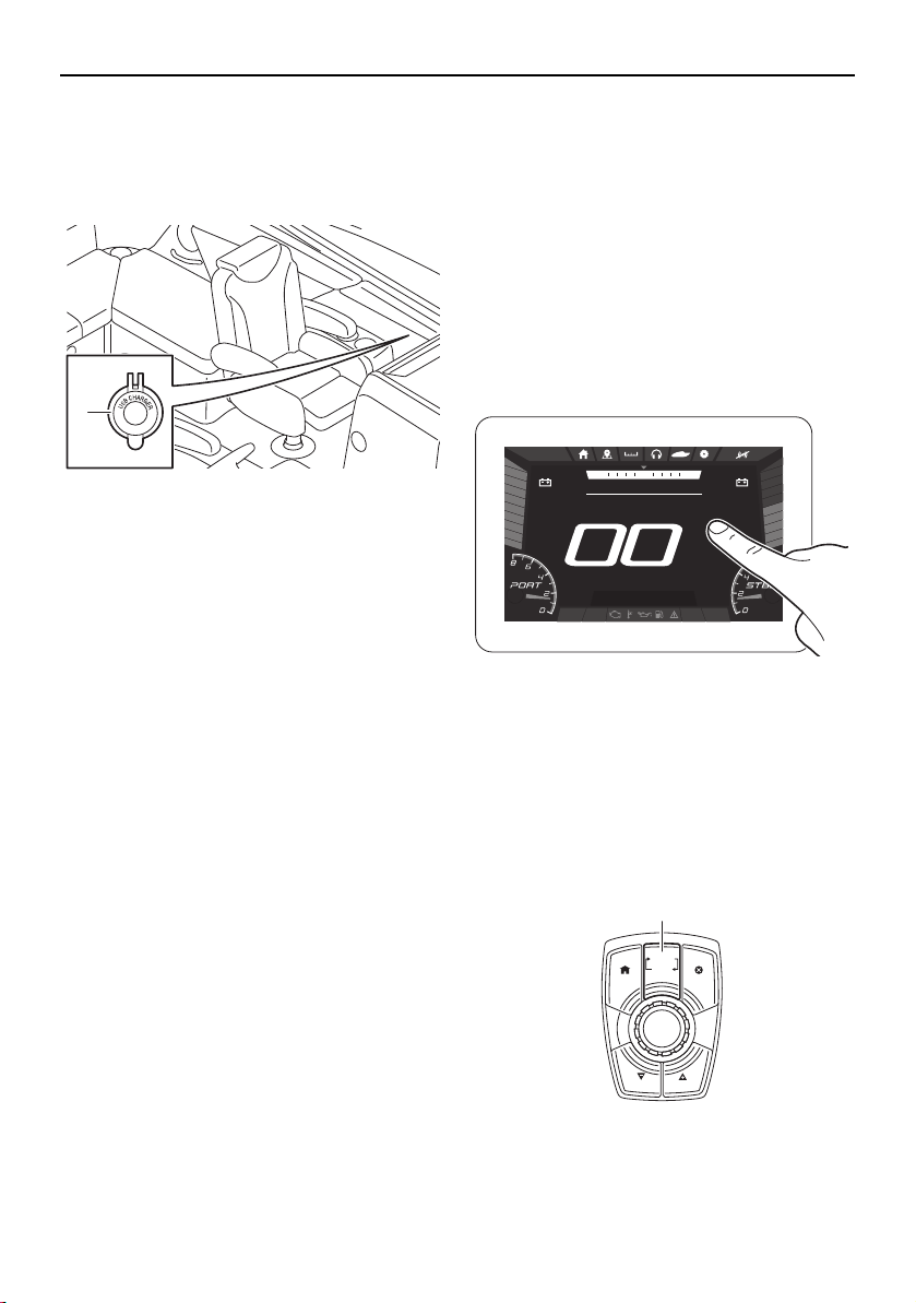
Instrument operation
66
USB charger
There is a USB charger on the deck. The USB
charger can be used to charge external de-
vices.
1 USB charger cap
Multi-function display unit
operation
Because the multi-function display unit is
equipped with a touch screen, you can touch
the display directly to operate the display
functions.
In addition to touching the display, you can
use the joystick to operate the display func-
tions.
Touching the multi-function display
Using the joystick
This joystick has the following two operation
modes.
Volume control mode
Navigation control mode
Push the “VOLUME–(SCROLL)” button to
switch the operation mode.
1 “VOLUME–(SCROLL)” button
5V
2A
1
Bilge
Blower Anchor
Nav
DEPTH
ft
.89
FUEL
%
100
am10:27
1350
RPM
1350
RPM
NNW NE
SPEED
HOUSE
V
13.0
START
V
13.0
MPH
CRUISE
CANCELHOME
NO WAKE
CRUISE
NO WAKE
VOLUME
(SCROLL)
1
SportsBoat_F3R13.book Page 66 Friday, May 31, 2019 9:42 AM
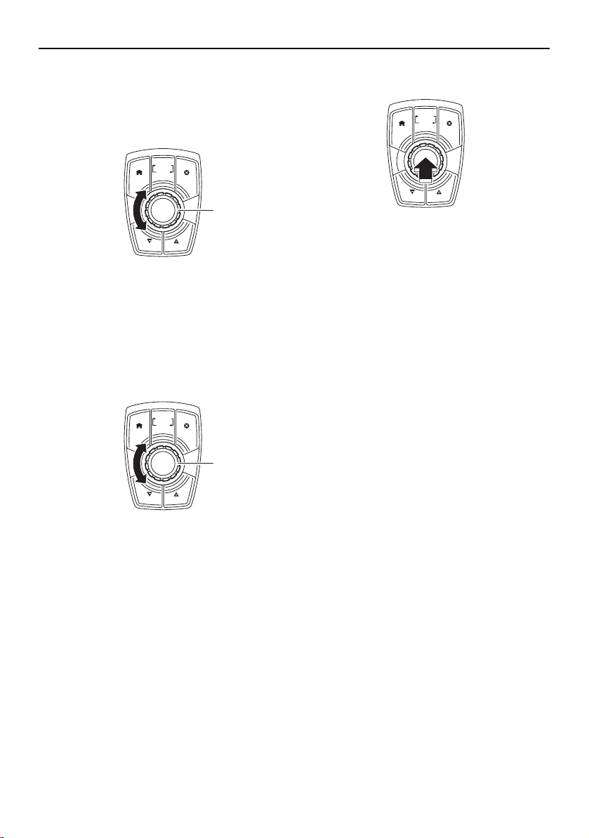
Instrument operation
67
Volume control mode
Turn the joystick knob to change the audio
volume.
1 Joystick knob
Navigation control mode
(1) Turn the joystick knob to change the se-
lected setting or item.
1 Joystick knob
(2) Push the joystick knob to select an item
or confirm a setting.
TIP:
Although the procedures in this manual ex-
plain how to make selections by touching the
display, you can also make selections using
the joystick knob.
CRUISE
CANCELHOME
NO WAKE
CRUISE
NO WAKE
VOLUME
(SCROLL)
1
CRUISE
CANCELHOME
NO WAKE
CRUISE
NO WAKE
VOLUME
(SCROLL)
1
CRUISE
CANCELHOME
NO WAKE
CRUISE
NO WAKE
VOLUME
(SCROLL)
SportsBoat_F3R13.book Page 67 Friday, May 31, 2019 9:42 AM
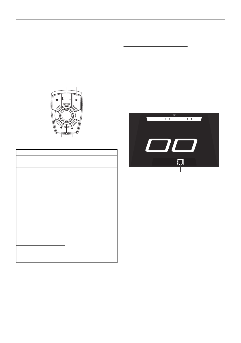
Instrument operation
68
Operation buttons
In addition to touching the multi-function dis-
play directly, you can use the operation but-
tons and the controller to operate various
functions.
Controller
Operating the boat at a steady speed
(cruise assist)
The cruise assist feature is for steady engine
speed operation when the boat is traveling
above no-wake speeds. The cruise assist is
available for use whenever the engines are
running above 3000 rpm and below 7000
rpm.
To activate the cruise assist:
(1) Push the remote control levers forward
to open the throttle until the desired en-
gine speed is reached and both engines
are operating at the same engine speed.
(2) Push the “CRUISE/NO WAKE” (+) button
or “CRUISE/NO WAKE” (–) button. When
the cruise assist is activated, “Cruise”
and the cruise assist setting level will be
displayed under the boat speed.
1 Cruise assist setting level
Once the cruise assist is activated, the set
engine speed can be increased by pushing
the “CRUISE/NO WAKE” (+) button or de-
creased by pushing the “CRUISE/NO
WAKE” (–) button. However, the adjust-
ment is limited to a maximum of 8 incre-
ments above or below the initial cruise
assist setting. Each time a button is
pushed, the engine speed will increase or
decrease approximately 100–200 rpm.
While the cruise assist is activated, the en-
gine speed can also be adjusted by operat-
ing the remote control levers.
To deactivate the cruise assist:
Operate the remote control levers to de-
crease the engine speed to 3000 rpm or less.
Name Function
1 “HOME” button Displays the home
screen. (See page 74.)
2“VOLUME –
(SCROLL)” but-
ton
Switches the joystick
between the volume
control mode and the
navigation control
mode. When the main
switches are turned to
the on position, the
volume control mode
is selected by default.
3 “CANCEL” but-
ton
Deselects the current-
ly selected item.
4“CRUISE/NO
WAKE” (–) but-
ton
Activate and set the
cruise assist, no-wake
mode, and reverse
RPM control. (See the
following sections.)
5“CRUISE/NO
WAKE” (+) but-
ton
CRUISE
CANCELHOME
NO WAKE
CRUISE
NO WAKE
VOLUME
(SCROLL)
21 3
54
NNW NE
SPEED
MPH
Cruise +4
1
SportsBoat_F3R13.book Page 68 Friday, May 31, 2019 9:42 AM
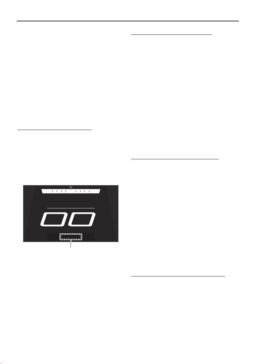
Instrument operation
69
When “Cruise” and the cruise assist setting
level disappear, the cruise assist is deactivat-
ed.
Operating the boat with a minimal
wake (no-wake mode)
The no-wake mode is useful for operating the
boat at a steady speed with a minimal wake.
This is especially convenient when traveling
in harbors, channels, or other areas posted
with low speed limits as “no wake zones”.
The no-wake mode can be used only when
the engines are operating at idle speed.
To activate the no-wake mode:
(1) Put the remote control levers in the TDE
position or forward position so that both
engines are operating at idle speed.
(2) Push the “CRUISE/NO WAKE” (+) but-
ton. When the no-wake mode is activat-
ed, “No Wake” will be displayed under
the boat speed.
1 “No Wake”
The no-wake mode can be set to 3 engine
speeds. To adjust the engine speed while the
no-wake mode is activated, push the
“CRUISE/NO WAKE” (+) button or
“CRUISE/NO WAKE” (–) button.
To deactivate the no-wake mode:
Perform one of the following operations.
Push the “CRUISE/NO WAKE” (–) button
repeatedly until “No Wake” disappears.
Push the remote control levers forward to
open the throttle.
Operating the boat in reverse with
more thrust (reverse RPM control)
Engine speed in reverse is limited to approx-
imately 4500 rpm. If more thrust is required
when the boat is traveling in reverse, use the
reverse RPM control. WARNING! Be pre-
pared to reduce throttle as soon as the
boat moves as desired. Otherwise, the
boat may become unstable, which could
result in loss of control and an accident.
To activate the reverse RPM control:
(1) Move the remote control levers back-
ward so that the throttle is opened in re-
verse and both engines are operating at
the same engine speed.
(2) Increase the engine speed to 4500 rpm,
and then push the “CRUISE/NO WAKE”
(+) button.
Once the reverse RPM control is activated,
pushing the “CRUISE/NO WAKE” (+) button
will increase the available engine speed by
approximately 500 rpm in 3 stages up to a
maximum of 6000 rpm, and pushing the
“CRUISE/NO WAKE” (–) button will decrease
the available engine speed. However, the ad-
justment is limited to these 3 increments.
To deactivate the reverse RPM control:
Operate the remote control levers to de-
crease the engine speed to less than 4500
rpm.
NNW NE
SPEED
MPH
No Wake
1
SportsBoat_F3R13.book Page 69 Friday, May 31, 2019 9:42 AM
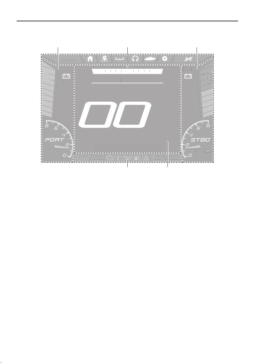
Instrument operation
70
Multi-function display elements
1 Static bar
2 Screen tab bar
3 Center display
4 Status indicator bar
Bilge
Blower Anchor
Nav
DEPTH
ft
.8
9
FUEL
%
100
am10:27
1350
RPM
1350
RPM
NNW NE
SPEED
HOUSE
V
13.0
START
V
13.0
MPH
Bil
g
e
B
l
o
w
e
r An
c
h
or
N
a
v
EPTH
DEPTH
EPTH
ft
f
ft
8
8
.8
9
9
9
FUEL
FUEL
FUE
%
%
%
100
100
100
a
m
10:2
7
1350
0
RPM
RPM
1350
13
RPM
N
NW
NE
S
PEE
D
H
OUSE
V
13
.
0
S
TAR
T
V
13
.
0
MP
H
4 3
21 1
SportsBoat_F3R13.book Page 70 Friday, May 31, 2019 9:42 AM
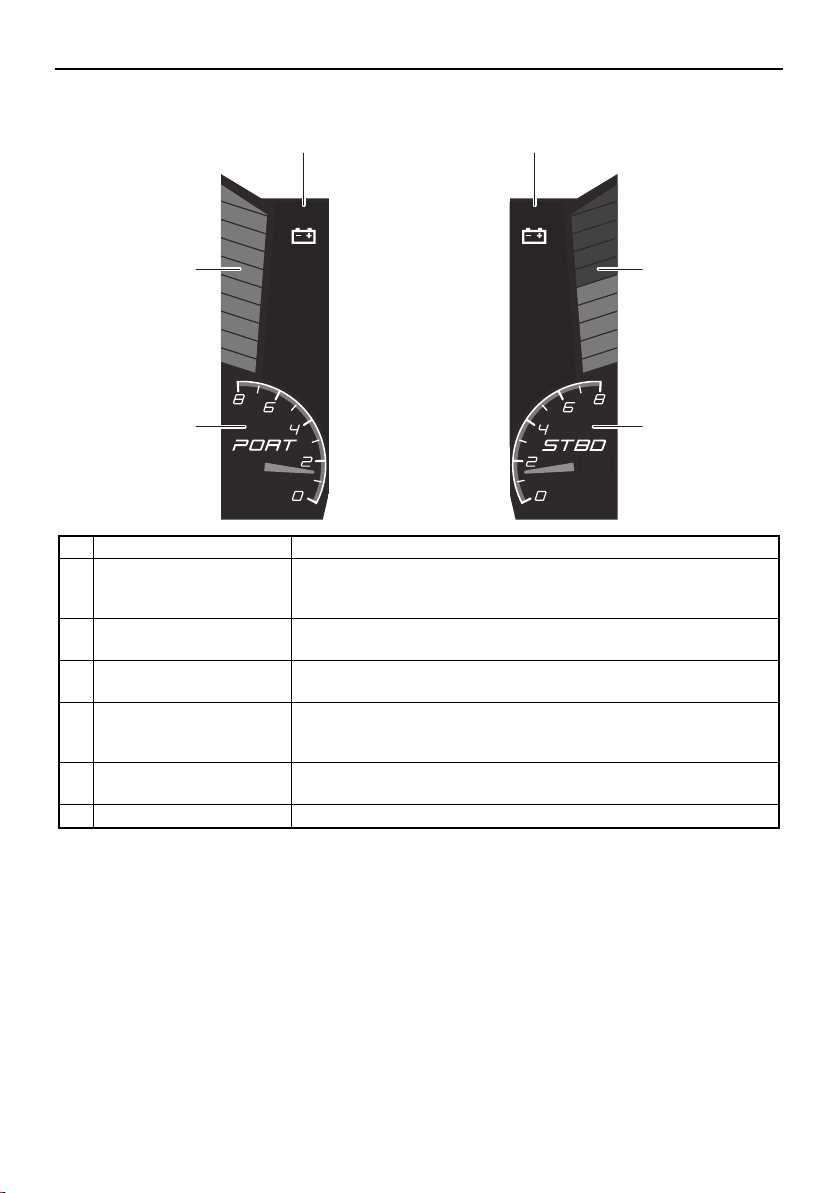
Instrument operation
71
Static bar
Name Function
1 Fuel level bar graph Displays the amount of fuel remaining in the fuel tank. Depending
on the amount of remaining fuel, the bar graph is displayed in 3
colors: blue, orange, and red.
2 Start battery voltage val-
ue
Displays the start battery voltage in a numerical format.
3 House battery voltage
value
Displays the house battery voltage in a numerical format.
4 Depth level Displays the water depth in feet or meters. Depending on the wa-
ter depth, the bar graph is displayed in 3 colors: blue, orange, and
red.
5 Starboard engine ta-
chometer
Displays the engine speed.
6 Port engine tachometer Displays the engine speed.
DEPTH
ft
.89
1350
RPM
HOUSE
V
13.0
FUEL
%
100
am10:27
1350
RPM
START
V
13.0
2 3
1
6
4
5
SportsBoat_F3R13.book Page 71 Friday, May 31, 2019 9:42 AM
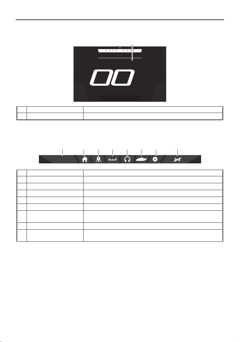
Instrument operation
72
Center display
Screen tab bar
Name Function
1 Center display Displays various information for each screen tab.
Name Function
1 Clock Displays the time. Tap the clock to set the time. (See page 84.)
2 Home screen tab Displays the home screen. (See page 74.)
3 Map screen tab Displays the map screen. (See page 74.)
4 Trip screen tab Displays the trip screen. (See page 75.)
5 Media screen tab Displays the media screen. (See page 76.)
6 System control screen
tab
Displays the system control screen. (See page 82.)
7 Setting screen tab Displays the setting screen. (See page 84.)
8 Warning mute button Mutes the sound of the buzzer for a specific time depending on
the warnings present.
NNW NE
SPEED
MPH
1
am10:27
2 3 4 5 6 7 81
SportsBoat_F3R13.book Page 72 Friday, May 31, 2019 9:42 AM

Instrument operation
73
Status indicator bar
Name Function
1 Bilge pump indicator Indicates the operation setting of the bilge pump. When the bilge
pump is turned off, the indicator will be gray, and when the bilge
pump is turned on, the indicator will be blue.
You can also tap this indicator to change the bilge pump setting.
2 Blower indicator Displays the operating status of the blowers. When the main
switches are turned to the on position, a 5-minute timer will be
displayed in this indicator while the blowers operate automatically.
You can also tap this indicator to turn the blowers on or off.
3 Warning icon bar Displays the warning icons.
When a warning icon is displayed, tap the icon to display the
warning message for that icon.
4 Navigation light indicator Displays the operating status of the navigation light mode. (When
the navigation light mode is activated, the bow light and anchor
light are turned on.)
You can also tap this indicator to turn the navigation light mode on
or off.
5 Anchor light indicator Displays the operating status of the anchor light mode. (When the
anchor light mode is activated, only the anchor light is turned on.)
You can also tap this indicator to turn the anchor light mode on or
off.
Bilge
Blower Anchor
Nav
1 2 4 53
SportsBoat_F3R13.book Page 73 Friday, May 31, 2019 9:42 AM
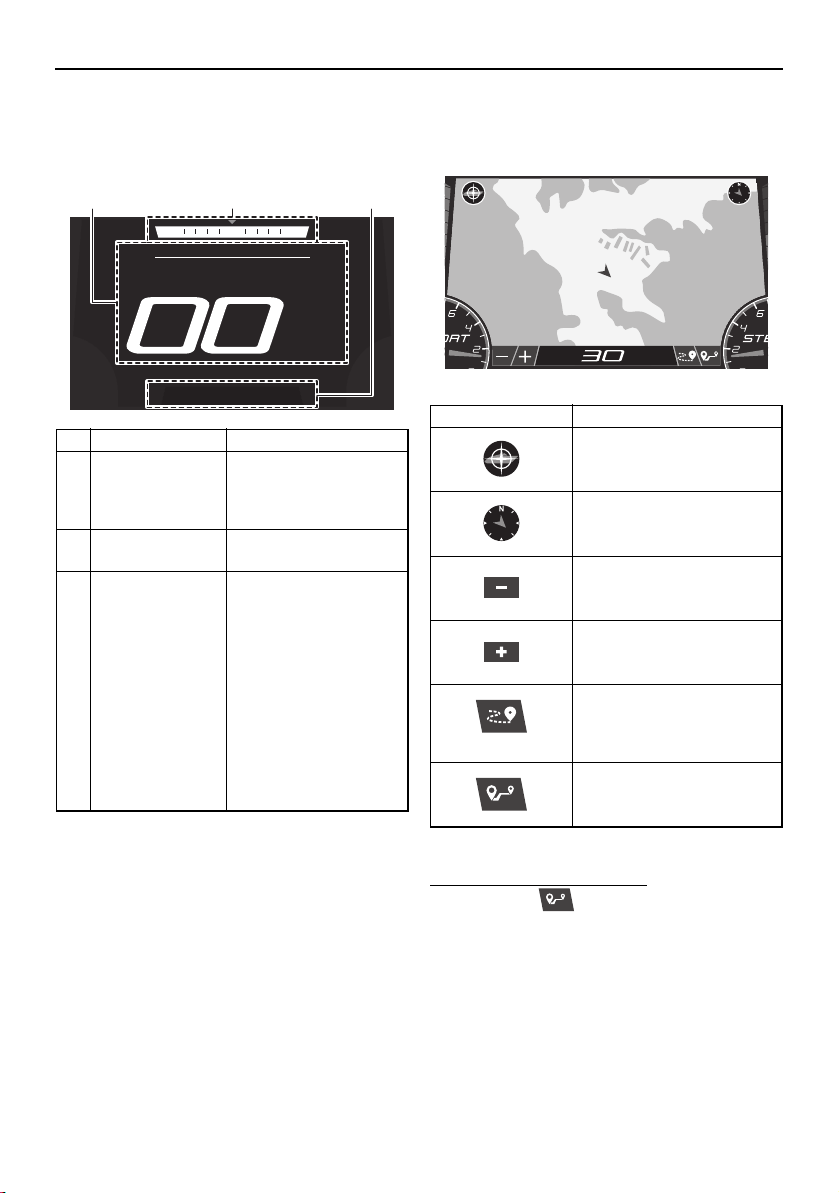
Instrument operation
74
Home screen
This screen displays the boat speed, current
heading of the boat, and other information.
* When both engines are not running, the wa-
ter temperature will be displayed.
Map screen
This screen displays a map.
To use the waypoint marks:
(1) Tap the “ ” button.
(2) Tap the location of the desired waypoint
mark on the map.
Name Function
1 Boat speed* Displays the boat
speed in miles per
hour or kilometers per
hour.
2 Heading Displays the heading
of the boat.
3 Cruise assist/
no-wake mode
status indicator
Displays the operating
status of the cruise as-
sist and no-wake
mode.
When the cruise assist
is activated, “Cruise”
and the cruise assist
setting level will be dis-
played.
When the no-wake
mode is activated, “No
Wake” will be dis-
played.
NNW NE
SPEED
MPH
2 31
Item Function
Re-centers the map on
your current location.
Displays the heading of the
boat.
Zooms out to display a
more distant view of the
map.
Zooms in to display a clos-
er view of the map.
Activates and deactivates
the tracking function that
displays the route your
boat has traveled.
Sets a waypoint mark.
DL
%
135
5
0
RPM
MPH
SportsBoat_F3R13.book Page 74 Friday, May 31, 2019 9:42 AM
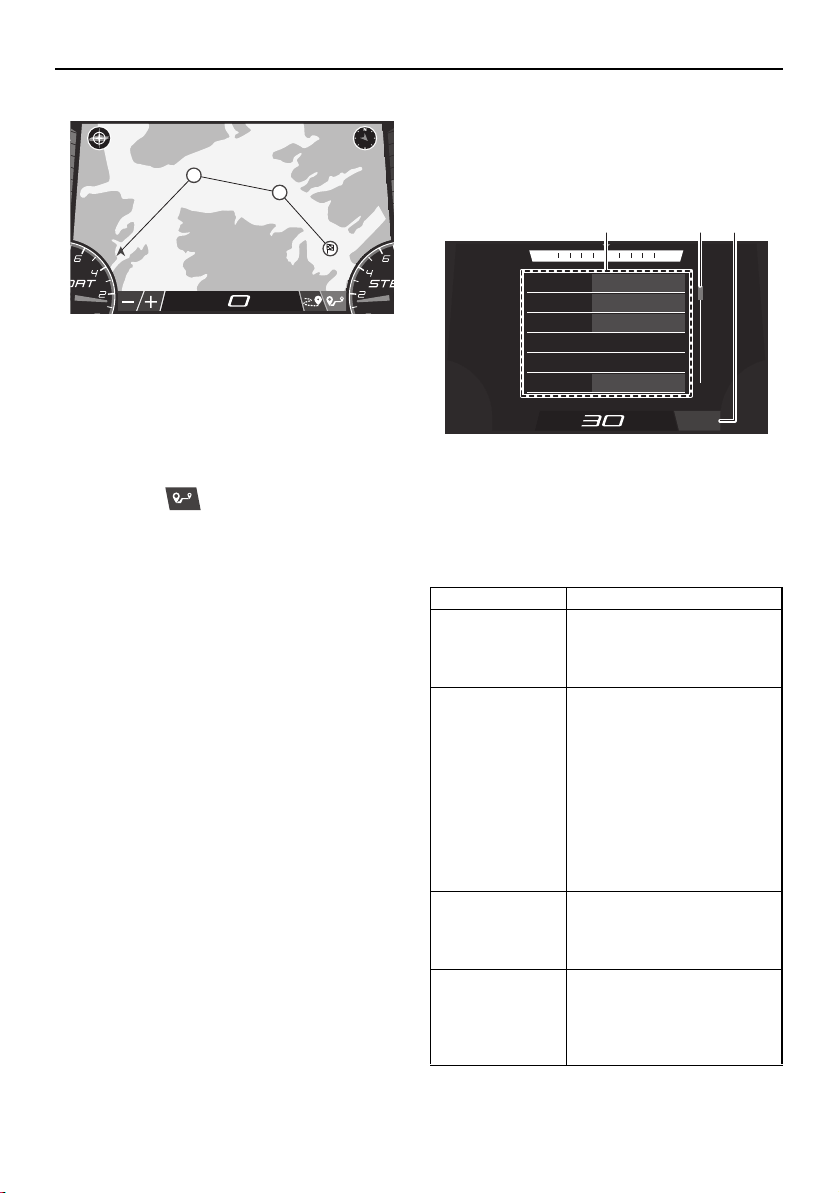
Instrument operation
75
TIP:
You can tap multiple locations.
Once you tap a location, a line will be
drawn from your current location to where
you tapped.
(3) Tap the “ ” button again to return to
the normal map display.
Trip screen
This screen displays the hours of engine op-
eration, fuel consumption, and other informa-
tion.
1 Menu
2 Scrollbar
3 “Reset All” button
The menu displays 6 items at one time. Scroll
through the menu items using the scrollbar.
DL
%
135
5
0
RPM
1
2
MPH
Name Function
Water tempera-
ture*
(Water Temp)
Displays the ambient water
temperature in degrees
Fahrenheit or degrees Cel-
sius.
Average fuel
consumption
(Fuel Economy)
Displays the average dis-
tance that was traveled on
1.0 gallon or 1.0 liter of fuel
since the item was last re-
set. When gallons are se-
lected for the display units,
the value is displayed in
miles and when liters are
selected for the display
units, the value is displayed
in kilometers.
Trip distance
(Trip)
Displays the distance trav-
eled by the boat in miles or
kilometers since the item
was last reset.
Fuel used
(Fuel Used)
Displays the total fuel that
has been consumed by the
port and starboard engines
in gallons or liters since the
item was last reset.
Fuel Economy:
23.0 MPG
Trip:
262.8 Miles
Fuel Used:
89.9 Gallons
Fuel Flow:
5.0 GPH
Water Temp:
81 MPG
Highest Speed:
0.2 MPH
NNW NE
MPH
Reset All
1 2 3
SportsBoat_F3R13.book Page 75 Friday, May 31, 2019 9:42 AM
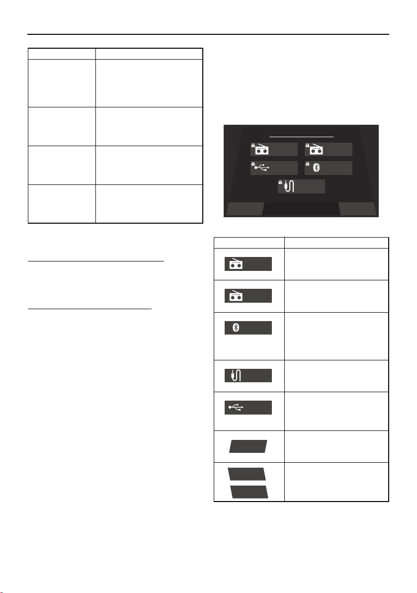
Instrument operation
76
* This item cannot be reset.
To reset an item on the trip screen:
Touch and hold the item that you want to re-
set for several seconds.
To reset all of the display items:
Tap the “Reset All” button to reset all of the
items.
Media screen
This screen can be used to receive a radio
broadcast, connect to an external device us-
ing Bluetooth wireless technology, and per-
form other functions.
Fuel flow*
(Fuel Flow)
Displays the total fuel con-
sumption of the port and
starboard engines in gal-
lons per hour or liters per
hour.
Highest speed
(Highest Speed)
Displays the highest speed
of the boat in miles per hour
or kilometers per hour since
the item was last reset.
Average speed
(Average Speed)
Displays the average boat
speed in miles per hour or
kilometers per hour since
the item was last reset.
Engine hours*
(Engine Hours)
Displays the total number of
hours that the engines have
been running since the boat
was new.
Name Function
Item Function
Switches the source to the
AM radio tuner and dis-
plays the AM radio screen.
Switches the source to the
FM radio tuner and dis-
plays the FM radio screen.
Switches the source to an
external device connected
using Bluetooth wireless
technology, and displays
the Bluetooth screen.
Switches the source to the
auxiliary device and dis-
plays the auxiliary screen.
Switches the source to the
device connected to the
USB terminal and displays
the USB screen.
Displays the main audio
setting screen.
/
Turns the audio system on
or off.
Settings Turn ONSelect a Source
Source
AM Radio FM Radio
USB Bluetooth
Auxiliary
AM Radio
FM Radio
Bluetooth
Auxiliary
USB
Settings
Turn ON
Turn OFF
SportsBoat_F3R13.book Page 76 Friday, May 31, 2019 9:42 AM
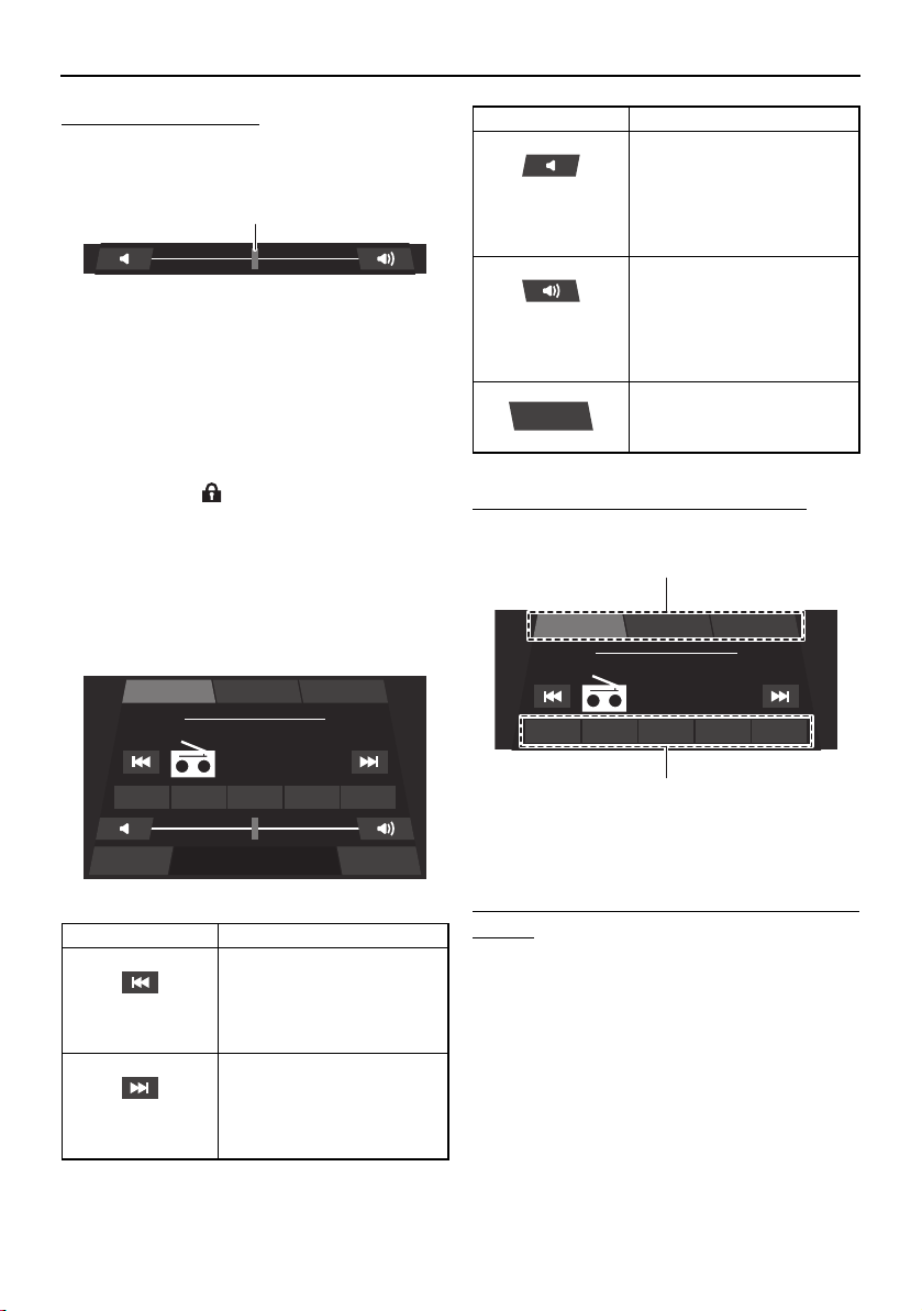
Instrument operation
77
To change the volume:
The following slider is displayed in each
screen.
1 Slider control
To decrease the volume level, drag the slider
to the left. To increase the volume level, drag
the slider to the right.
TIP:
The lock mark “ ” appears when the entire
audio system is turned off or an external de-
vice is not connected.
Radio screen (AM/FM)
You can receive a radio broadcast.
To change the radio station frequency:
Tap a preset list button or preset button.
1 Preset list button
2 Preset button
To save a radio station frequency to a preset
button:
Tune the radio to the desired radio station,
and then touch and hold the desired preset
button for 3 seconds.
Bluetooth screen
Smartphones and other external devices that
are compatible with Bluetooth can be con-
nected wirelessly to the audio system to lis-
Item Function
Decreases the radio sta-
tion frequency. Touch and
hold this button to auto-
matically seek the next
available radio station.
Increases the radio station
frequency. Touch and hold
this button to automatically
seek the next available ra-
dio station.
1
Settings Source
FM Radio
Playing
107.7
MHz
P1 107.7 P2 103.5 P3 103.1 P4 102.7 P5 107.7
FM-3FM-2FM-1
Decreases the volume lev-
el. Tap this button to de-
crease the volume by 1
level, and touch and hold
the button to decrease the
volume level continuously.
Increases the volume level.
Tap this button to increase
the volume by 1 level, and
touch and hold the button
to increase the volume lev-
el continuously.
Displays the media screen.
Item Function
Source
FM Radio
Playing
107.7
MHz
P1 107.7 P2 103.5 P3 103.1 P4 102.7 P5 107.7
FM-3FM-2FM-1
1
2
SportsBoat_F3R13.book Page 77 Friday, May 31, 2019 9:42 AM
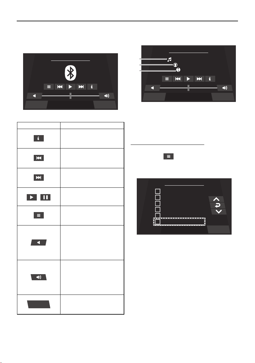
Instrument operation
78
ten to the audio tracks stored on the devices
through the audio system’s speakers.
Audio track information
1 Song title
2 Artist name
3 Album title
To connect an external device:
Multi-function display:
(1) Tap the “ ” button.
(2) Tap the “Discoverable” checkbox.
External device:
(1) Turn on the Bluetooth function of the ex-
ternal device, and then search for the
multi-function display unit (MS-RA70) of
the boat.
TIP:
The displayed name of the multi-function
display unit varies according to the external
device.
Make sure that other external devices have
their Bluetooth function disabled before
Item Function
Displays information about
the current audio track.
Selects the previous audio
track.
Selects the next audio
track.
/
Pauses or resumes the
playback of the audio
track.
Pairs an external device
that is compatible with
Bluetooth.
Decreases the volume lev-
el. Tap this button to de-
crease the volume by 1
level, and touch and hold
the button to decrease the
volume level continuously.
Increases the volume level.
Tap this button to increase
the volume by 1 level, and
touch and hold the button
to increase the volume lev-
el continuously.
Displays the media screen.
Settings Source
Bluetooth - Connect Device ...
Source
Settings Source
Bluetooth - Connect Device ...
Paradise Circus
Massive Attack
Heligoland
1
2
3
Menu
chris.s iPhone
iPhone (2)
Thomas’ iPhone
Samsung Galaxy S
SAMSUNG-SM-G870A
Discoverable
Back
SportsBoat_F3R13.book Page 78 Friday, May 31, 2019 9:42 AM
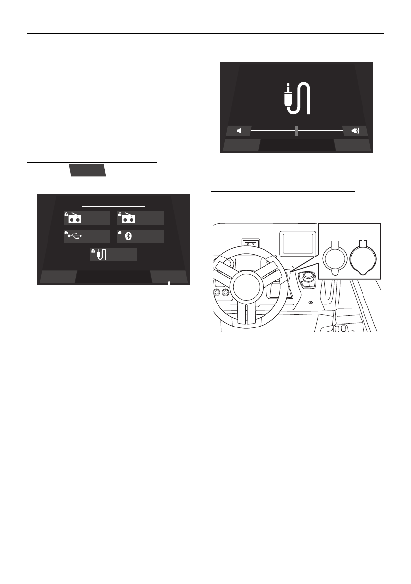
Instrument operation
79
beginning the pairing process to reduce
connection issues.
(2) Select the multi-function display unit of
the boat to connect to it.
TIP:
When an external device is connected using
Bluetooth wireless technology, the audio
tracks will automatically start playing.
To disconnect an external device:
Tap the “ ” button to disconnect
the connected device.
1 “Turn OFF” button
TIP:
You can also disconnect an external device
by turning it off.
If you connect another device, the currently
connected device will be disconnected.
Auxiliary screen
Portable media players and other external
devices can be connected to the audio sys-
tem to listen to the audio tracks stored on the
devices through the audio system’s speak-
ers.
To connect to the auxiliary input jack:
Open the “AUDIO AUX-USB” cap and con-
nect the device to the auxiliary input jack.
1 “AUDIO AUX-USB” cap
TIP:
You can adjust the volume level of the
speakers using the multi-function display
unit or the volume control of the external
device.
To select the audio tracks, use the external
device.
USB screen
USB flash drives and other external devices
can be connected to the USB terminal to lis-
ten to the audio tracks stored on the devices
through the audio system’s speakers.
Turn OFF
Settings Turn OFFSelect a Source
Source
AM Radio FM Radio
USB Bluetooth
Auxiliary
1
SourceSettings
Auxiliary
12V
AUDIO
AUX-USB
1
SportsBoat_F3R13.book Page 79 Friday, May 31, 2019 9:42 AM
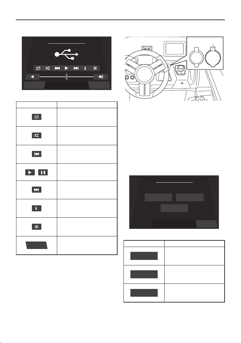
Instrument operation
80
Location of the USB terminal
1 “AUDIO AUX-USB” cap
TIP:
Open the “AUDIO AUX-USB” cap and con-
nect to the USB terminal.
Main audio setting screen
The settings of the audio system can be
changed.
Item Function
Repeats the playback of
the audio track.
Shuffles the order in which
the audio tracks are played
back.
Selects the previous audio
track.
/
Pauses or resumes the
playback of the audio
track.
Selects the next audio
track.
Displays information about
the current audio track.
Displays the list of audio
tracks.
Displays the media screen.
Settings Source
USB
Source
Item Function
Displays the balance/fader
setting screen.
Displays the bass/mid/tre-
ble setting screen.
Displays the equalizer set-
ting screen.
12V
AUDIO
AUX-USB
1
BackSelect a Setting
Media Setting
Balance/Fader Bass/Mid/Treble
Equalizer
Balance/Fader
Bass/Mid/Treble
Equalizer
SportsBoat_F3R13.book Page 80 Friday, May 31, 2019 9:42 AM
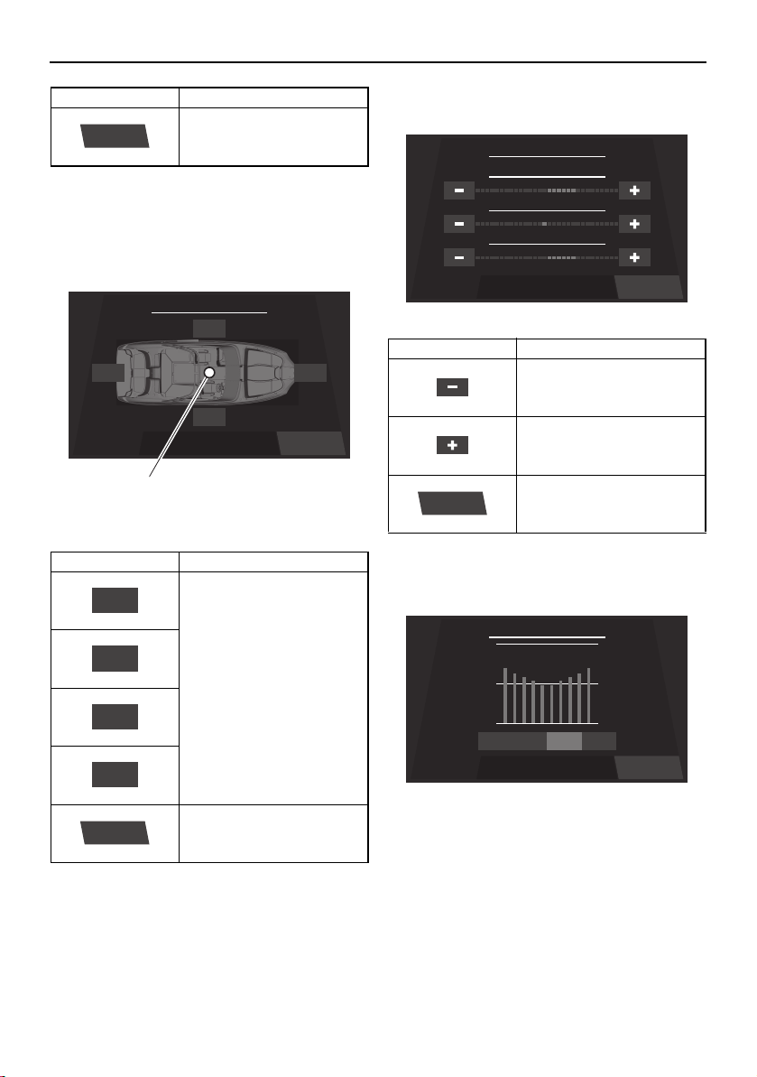
Instrument operation
81
Balance/fader setting screen
The currently selected levels for the balance
and fader are indicated by a blue dot on the
illustration of the boat.
1 Blue dot
TIP:
The settings can also be adjusted by drag-
ging the blue dot.
Bass/mid/treble setting screen
Equalizer setting screen
TIP:
The 4 available modes are “Flat”, “Pop”,
“Rock”, and “Classic”.
Displays the media screen.
Item Function
Increase the balance and
fader levels. Tap a button
to adjust the setting by 1
level, and touch and hold
the button to adjust the
setting continuously.
Displays the main audio
setting screen.
Item Function
Back
Balance / Fader
Left
Right
Rear Front
Back
1
Rear
Left
Front
Right
Back
Item Function
Decreases the setting lev-
el.
Increases the setting level.
Displays the main audio
setting screen.
Back
Bass / Mid / Treble
+6
TREBLE
-1
MIDDLE
+6
BASS
Back
Back
Equalizer
PopFlat ClassicRock
SportsBoat_F3R13.book Page 81 Friday, May 31, 2019 9:42 AM
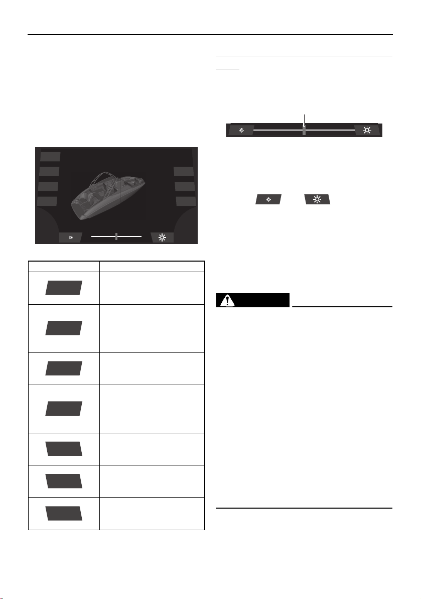
Instrument operation
82
System control screen
The system control screen can be used to
turn the boat lights, blowers, and bilge pump
on and off.
When a light is turned on, it will be indicated
on the illustration of the boat displayed on the
screen.
To adjust the brightness of the courtesy
lights:
Use the slider control to adjust the brightness
of the courtesy lights.
1 Slider control
TIP:
The brightness can also be adjusted by tap-
ping the “ ” or “ ” button.
Ballast setting screen (212X)
This boat is equipped with an adjustable bal-
last system to increase the amount of wake
the boat leaves behind it. The more water that
is pumped into the ballast bag and ballast
tanks, the bigger the boat’s wake.
WARNING
Improper use of the ballast system can
overload the boat, causing poor han-
dling and increased risk of swamping.
The ballast system adds 591 kg (1303 lb)
when full. Include this weight when
making sure your load does not exceed
the weight shown on the maximum ca-
pacities label.
Drain the ballast completely before
trailering the boat to reduce the risk of a
towing accident. The increased weight
of ballast can cause unsafe towing con-
ditions due to negative tongue weight,
including decreased tow vehicle stabili-
ty and greater chance of a runaway trail-
er that has come off the hitch.
Item Function
Turns the docking lights on
or off.
Turns the courtesy lights
on or off. The slider indi-
cates the brightness of the
lights while they are turned
on.
Turns the anchor light and
bow light on or off.
Turns the anchor light on
or off. If this button is
tapped while the naviga-
tion lights are turned on,
the bow light will turn off.
Turns the blowers on or off.
(See page 139.)
Displays the ballast set-
ting screen.
Turns the bilge pump on or
off. (See page 127.)
Dock
Interior
Navigation
Anchor
Ballast
Blower
Bilge
Dock
Interior
Navigation
Anchor
Blower
Ballast
Bilge
1
SportsBoat_F3R13.book Page 82 Friday, May 31, 2019 9:42 AM
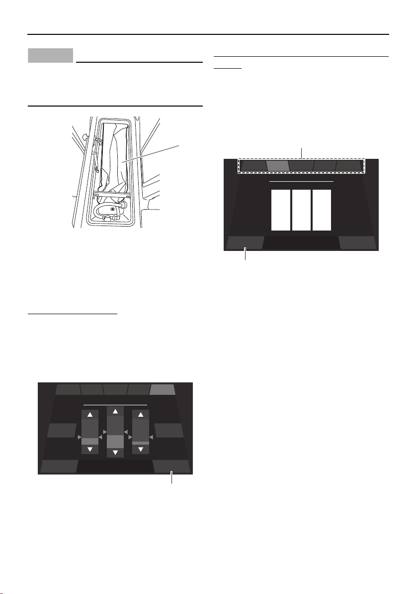
Instrument operation
83
NOTICE
Be sure there is no cargo in the ski locker
that can be damaged by the ballast bag as
it is filled.
1 Ballast bag
TIP:
This boat has a ballast bag and two ballast
tanks. The ballast tanks are not visible.
To set the ballast level:
(1) Tap the up or down button to set the
amount of water for each bag.
(2) Wait a few minutes until the ballast level
reaches the desired level.
(3) Tap the “Back” button.
1 “Back” button
To save the current ballast level to a favorite
button:
(1) Touch and hold a favorite button for 3
seconds.
(2) To set a 3-letter profile name for the fa-
vorite button, tap each letter and scroll
up or down.
1 Favorite button
2 “Save” button
(3) Tap the “Save” button.
TIP:
There are 5 favorite buttons for saving differ-
ent ballast level settings.
Shutting off water intake
The ballast system has seacock valves. One
seacock valve is located in the ski locker and
the other is located to the side of the star-
board engine.
If you believe there is a failure in the hoses
that is causing the boat to take on water and
possibly sink, turn the seacock valves as fol-
lows to shut off water intake.
Ski locker:
Turn the seacock valve 90° clockwise.
1
Stop Back
Press Stop to stop the
ballast
Ballast
Fill All Drain All
50
%
EXP EVYINT LIGBEG
1
Save BackPress save to store preset
Preset Name
N
O
M
I
J
H
T
U
S
EXP EVYINT LIGBEG
2
1
SportsBoat_F3R13.book Page 83 Friday, May 31, 2019 9:42 AM
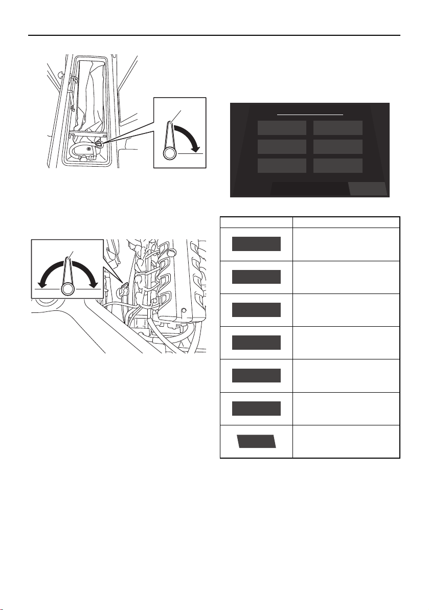
Instrument operation
84
1 Seacock valve
Engine compartment:
Turn the seacock valve 90° clockwise or
counterclockwise.
1 Seacock valve
Ask your Yamaha Boat Dealer to inspect the
boat before continuing to use it. It is recom-
mended that you also shut off the seacock
valves whenever the boat will be left in the
water for a long time.
Setting screen
The setting screen can be used to change the
settings of the multi-function display unit.
Time setting screen
Tap the time unit that you want to set and
scroll up or down.
1
1
Item Function
Displays the time setting
screen.
Displays the depth alarm
setting screen.
Displays the unit setting
screen.
Displays the brightness
setting screen.
Displays the maintenance
setting screen.
Displays the language set-
ting screen.
Displays the factory reset
screen.
ResetSelect a Menu
Menu
Language
Brightness
Depth
Wellness
Unit
Time
Time
Depth
Unit
Brightness
Wellness
Language
Reset
SportsBoat_F3R13.book Page 84 Friday, May 31, 2019 9:42 AM
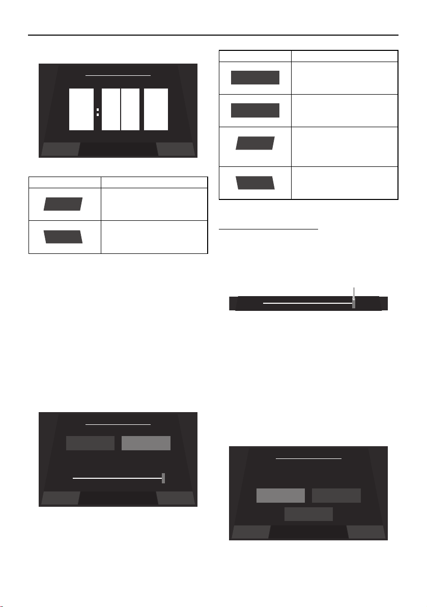
Instrument operation
85
TIP:
When “US Unit” is selected, the time is dis-
played in the 12-hour format. When “Metric
Unit” is selected, the time is displayed in the
24-hour format.
Brightness setting screen
The multi-function display has a day mode
and a night mode.
The brightness can be set separately for the
day mode and for the night mode.
To adjust the brightness:
To make the display darker, drag the slider to
the left. To make the display brighter, drag
the slider to the right.
1 Slider control
TIP:
The default settings are 75% for the day
mode and 50% for the night mode.
Language setting screen
The language for the multi-function display
unit can be changed.
Item Function
Saves the set time as the
current time and displays
the setting screen.
Displays the setting screen
without saving the set
time.
9
10
8
pm
am
am
0
1
9
0
1
9
Save Back
Set Time
Save
Back
Save Back
Set Brightness
Night Brightness Day Brightness
50% 100%
Item Function
Displays the current night
mode setting.
Displays the current day
mode setting.
Saves the set brightness
as the brightness level set-
ting and displays the set-
ting screen.
Displays the setting screen
without saving the set
brightness level.
Night Brightness
Day Brightness
Save
Back
1
Save Back
Set Language
English
English Español
Français
SportsBoat_F3R13.book Page 85 Friday, May 31, 2019 9:42 AM
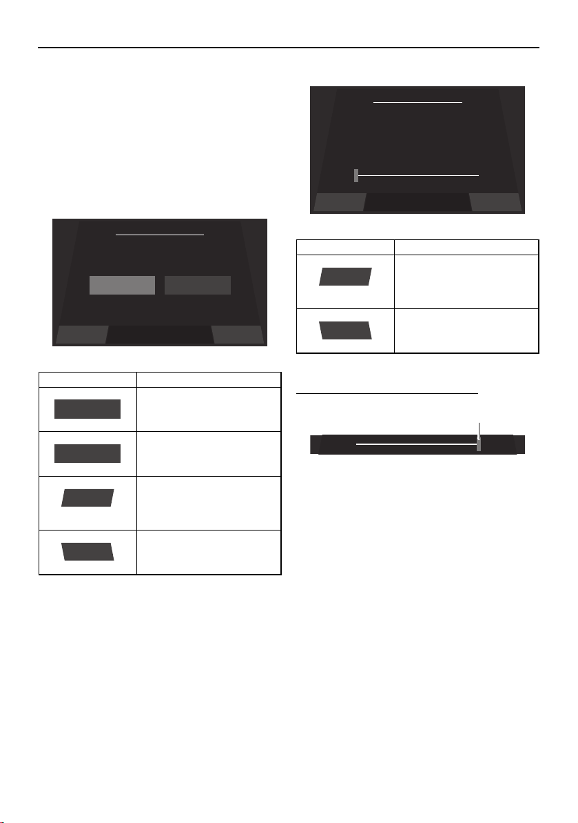
Instrument operation
86
Tap the desired language, and then tap the
“Save” button to save the setting.
To display the setting screen without saving
the language setting, tap the “Back” button.
Unit setting screen
The display units for the multi-function dis-
play unit can be changed.
Depth alarm setting screen
The water depth for the depth alarm can be
set.
To adjust the water depth setting:
1 Slider control
To reduce the water depth setting, drag the
slider to the left.
To increase the water depth setting, drag the
slider to the right.
TIP:
If the water depth is set to 0.0 m (0.0 ft), the
depth alarm will not operate.
Maintenance setting screen
This screen displays the number of hours that
the engines have been running since the last
maintenance.
Item Function
Sets the display units to
US units.
Sets the display units to
metric units.
Saves the selected unit
setting as the current units
and displays the setting
screen.
Displays the setting screen
without saving the select-
ed unit setting.
Save Back
Set Unit
US Unit
US Unit Metric Unit
US Unit
Metric Unit
Save
Back
Item Function
Saves the set water depth
as the current depth alarm
setting and displays the
setting screen.
Displays the setting screen
without saving the set wa-
ter depth.
Save Back
Depth Alarm
0.0
ft
Save
Back
1
SportsBoat_F3R13.book Page 86 Friday, May 31, 2019 9:42 AM

Instrument operation
87
After maintenance is performed, reset the
number of hours of operation as follows.
To reset the number of hours of operation:
(1) Tap the “Reset” button.
1 “Reset” button
(2) When the confirmation message ap-
pears, tap the “YES” button to reset the
number of hours of operation.
TIP:
To return to the maintenance setting screen
without resetting the number of hours, tap
the “NO” button.
1 “YES” button
Factory reset screen
This screen can be used to reset the settings
to their factory default settings.
To reset the settings:
(1) Tap the “Reset” button.
1 “Reset” button
(2) When the confirmation message ap-
pears, tap the “YES” button to reset the
settings.
TIP:
To return to the factory reset screen without
resetting the settings, tap the “NO” button.
1 “YES” button
BackReset
Time Since Last Maintenance
0
Hrs
Port Engine
0
Hrs
Starboard Engine
BackReset
1
YES NOAre you sure ?
1
Factory Reset
Reset all parameters to
factory settings?
BackReset
BackReset
1
YES NOAre you sure ?
1
SportsBoat_F3R13.book Page 87 Friday, May 31, 2019 9:42 AM
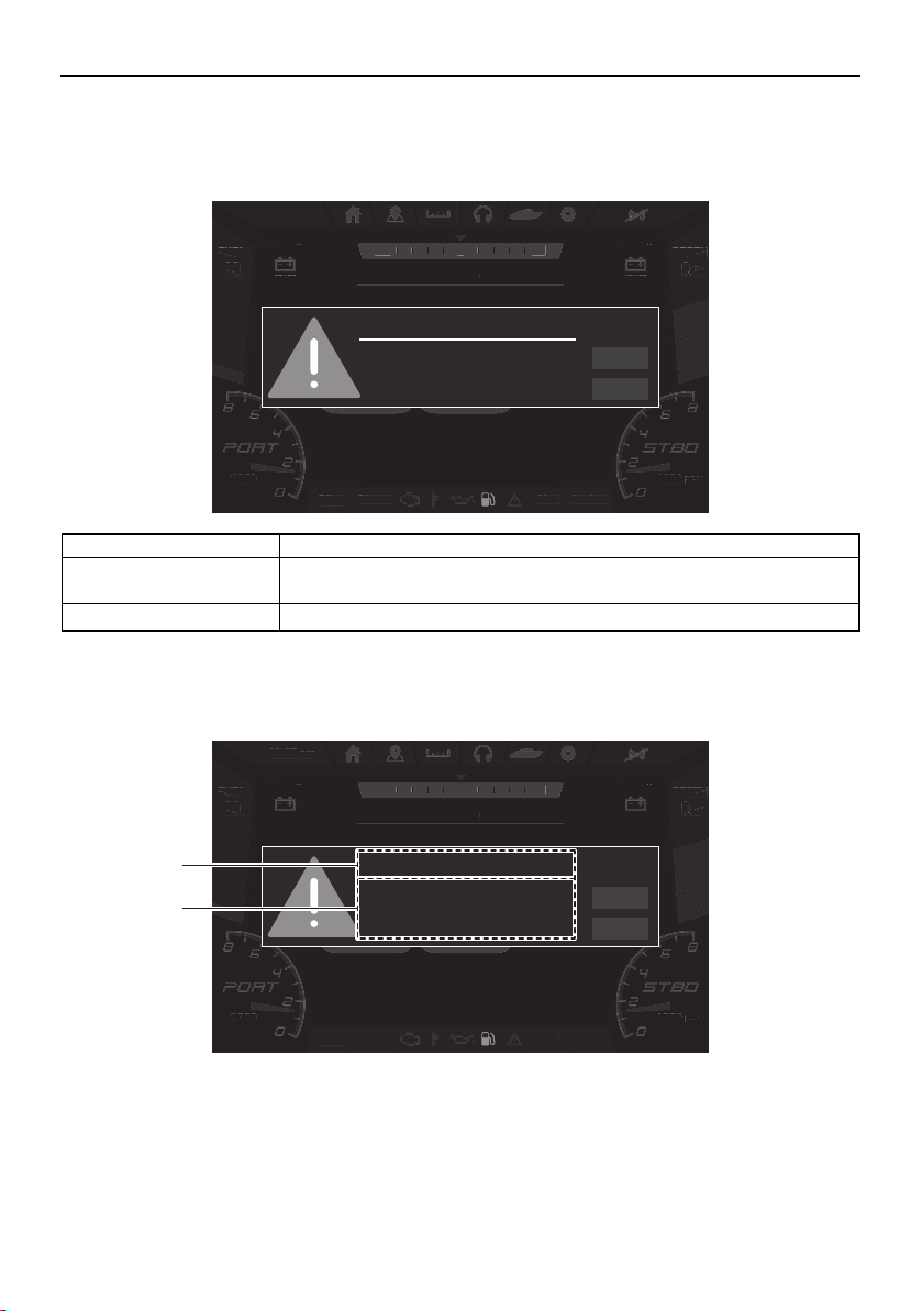
Instrument operation
88
Warnings
If a malfunction or fault occurs, a warning buzzer will sound and a warning icon and warning
message will be displayed on the center display.
If the displayed warning message includes instructions, follow those instructions. If you have
any questions, consult a Yamaha Boat Dealer.
1 Warning title
2 Message
Name Function
NEXT Displays the next active warning. When there is only 1 warning, the dis-
played warning will not change.
QUIT Closes the displayed warning.
Bilge
Blower Anchor
Nav
DEPTH
ft
.8
9
FUEL
%
100
am10:27
1350
RPM
1350
RPM
NNW NE
SPEED
HOUSE
V
13.0
START
V
13.0
MPH
FUEL
%
10
Bilg
e
Bl
o
w
e
r An
c
h
or
N
a
v
EPTH
DEPTH
EPTH
ft
f
ft
8
8
.8
9
9
9
am
10
:
27
1350
0
RPM
RPM
1350
13
RPM
N
NW
NE
S
PEED
HO
U
S
E
V
13
.
0
S
TAR
T
V
13
.
0
MPH
FUEL
FUEL
FUE
%
%
%
10
10
10
Fuel Level
NEXT
QUIT
Low Fuel Level
1
2
SportsBoat_F3R13.book Page 88 Friday, May 31, 2019 9:42 AM

Instrument operation
89
Warning example
Warning title Message
Check Engine Stop Port Engine.
Consult YAMAHA dealer.
Low Oil Pressure
Over Temperature
Check Engine Stop Starboard Engine.
Consult YAMAHA dealer.
Low Oil Pressure
Over Temperature
House Battery Low Voltage.
Start engine to recharge the battery.
High Voltage.
Start Battery Low Voltage.
Start engine to recharge the battery.
High Voltage.
Fuel Level Low Fuel Level
Depth Low Depth Level
Port Engine Maintenance Due
Starboard Engine Maintenance Due
Ballast System Check the seacock valve.
Verify it is open and remove obstruction.
Communication Error Port Engine.
Starboard Engine.
SPU25-15.
Depth transducer.
Joystick.
Pump controller.
212X:
SPU25-15, joystick, Depth transducer and the
pump controller
Except 212X:
SPU25-15, joystick and Depth transducer
Engine CAN.
Stereo.
GPS.
SportsBoat_F3R13.book Page 89 Friday, May 31, 2019 9:42 AM
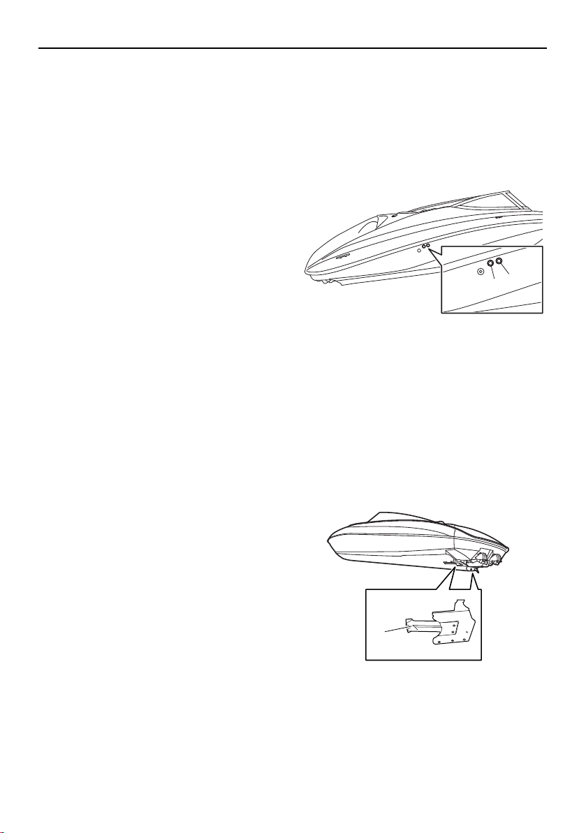
Instrument operation
90
Check engine warning
If an engine sensor malfunction or a short cir-
cuit is detected, a warning will appear on the
multi-function display and the buzzer will
sound. If a fault is detected for the engines,
“Check Engine” will be displayed. If this oc-
curs, reduce the engine speed, return to
shore, and have a Yamaha Boat Dealer check
the engine.
Low oil pressure warning
If the oil pressure does not rise to specifica-
tion, a warning will appear on the multi-func-
tion display and the buzzer will sound. If a
fault is detected for the engines, “Low Oil
Pressure” will be displayed. At the same time,
the engine speed is automatically limited to
help prevent damage. If this occurs, reduce
the engine speed, return to shore or maneu-
ver to a safe location, and check the engine
oil level. (See page 135 for engine oil level
checking procedures.)
If the oil level is low, add enough engine oil to
raise it to the proper level. If the oil level is suf-
ficient, have a Yamaha Boat Dealer check the
engine.
Over temperature warning
This model is equipped with an over temper-
ature warning system. If the engines start to
overheat, a warning will appear on the multi-
function display and the buzzer will sound. If
the engine is over heating, “Over Tempera-
ture” will be displayed. At the same time, the
engine speed is automatically limited to help
prevent damage. If this occurs, immediately
reduce the engine speed, return to shore or
maneuver to a safe location, and check for
water discharge at the cooling water pilot
outlets. There are cooling water pilot outlets
on the starboard side of the hull. Check that
water comes out of the outlets while the en-
gines are running, particularly while applying
throttle. If you do not see any water at the
outlets, cooling water may not be circulating
in the engines.
1 Cooling water pilot outlet (starboard engine)
2 Cooling water pilot outlet (port engine)
TIP:
If the cooling water passages in the engines
are dry, it will take about 20 seconds for wa-
ter to reach the pilot outlets after starting.
If water is not circulating, something may be
clogging the intake grates. Refer to “Jet
pump clean-out procedure” on page 182.
1 Intake grate
1
2
1
SportsBoat_F3R13.book Page 90 Friday, May 31, 2019 9:42 AM

Instrument operation
91
NOTICE
If the cause of overheating cannot be
found and corrected, take special precau-
tions to avoid major engine damage while
you return to shore.
Single engine overheating — Shut off the
overheating engine and use the properly
running engine to return to shore. Operate
at no-wake speed (8 km/h, 5 mph) to pre-
vent water from flooding the non-operat-
ing engine through the water intake. See
page 69 for information on the no-wake
mode.
Both engines overheating — If getting a
tow from another vessel is not possible,
operate both engines just slightly above
idle while you return to shore. If you can be
towed, refer to “Towing the boat” on page
188.
House/Start Battery voltage warning
If “House Battery” “Start Battery” appears on
the multi-function display and the buzzer will
sound, check the battery connections. If the
battery connections are clean and tight and
the warning indication continues, have a
Yamaha Boat Dealer check the charging sys-
tem.
Communication error warning
If a communication error is detected for the
GPS function, a sensor, or other device, a
warning will appear on the multi-function dis-
play and the buzzer will sound. If this occurs,
reduce the engine speed, return to shore, and
have a Yamaha Boat Dealer check the boat.
Low fuel level warning
If “Fuel Level” appears on the multi-function
display and the buzzer will sound, refill the
fuel tank as soon as possible. (See page 120
for information on filling the fuel tank.)
Depth warning
If the boat enters an area that is shallower
than the water depth set for the depth alarm,
the depth warning will be activated and the
buzzer will sound.
If the warning is activated, move the boat to
an area that is deeper than the water depth
set for the depth alarm. (See page 86 for in-
formation on setting the depth alarm.)
SportsBoat_F3R13.book Page 91 Friday, May 31, 2019 9:42 AM
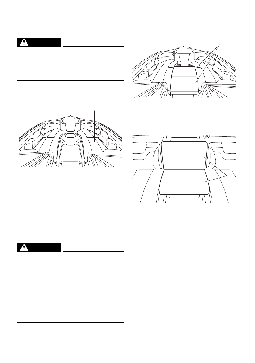
92
Equipment operation
Seats
WARNING
Passengers must always sit in a designat-
ed seating area, place feet on the deck,
and hold on to the handgrips, handrails, or
straps when the boat is in motion.
This boat is equipped with the following
seats.
1 Handrail
2 Front port seat (rear)
3 Front port seat (front)
4 Front starboard seat (front)
5 Front starboard seat (rear)
Two bow filler cushions are provided for use
while the boat is not being operated.
These cushions can be used to make a large
flat area in the bow for use as a sundeck.
WARNING
Do not use the bow filler cushions while
the boat is underway. A passenger
could lose balance and fall on the deck
or overboard, causing injury or death.
Stow the cushions securely before oper-
ating the boat. A loose cushion could be
blown by the wind, distracting the oper-
ator or striking a passenger, which
could result in an accident.
1 Bow filler cushion
These cushions can also be used to create a
temporary center seat.
1 Bow filler cushion
1 2 3 154
1
1
SportsBoat_F3R13.book Page 92 Friday, May 31, 2019 9:42 AM
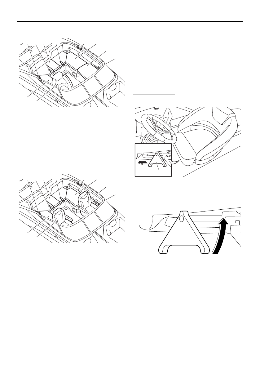
Equipment operation
93
AR210 / SX210
1 Driver’s seat
2 Rear starboard seat
3 Handgrip
4 Rear center seat
5 Rear port seat
6 Passenger’s seat
7 Strap
212X / 212S / 212
1 Driver’s seat
2 Passenger’s seat
3 Handgrip
4 Rear starboard seat
5 Strap
6 Rear center seat
7 Rear port seat
Driver’s seat (AR210 / SX210)
The driver’s seat can slide forward and rear-
ward, and the seat can swivel. In addition, the
seat bolster at the front of the seat can be
flipped up to change the seat style for a
raised seating position.
Make sure that the seat is securely locked in
place before getting underway.
To slide the seat:
(1) Extend the slide/swivel lock lever.
1 Slide/swivel lock lever
(2) Rotate the lever to port (left).
(3) Move the seat to the desired position,
and then release the lever.
(4) Push the lever to its original position.
1
3
3
3 7 4 7
6
5
2
1
3
3
3 5 6 5
2
7
4
1
SportsBoat_F3R13.book Page 93 Friday, May 31, 2019 9:42 AM
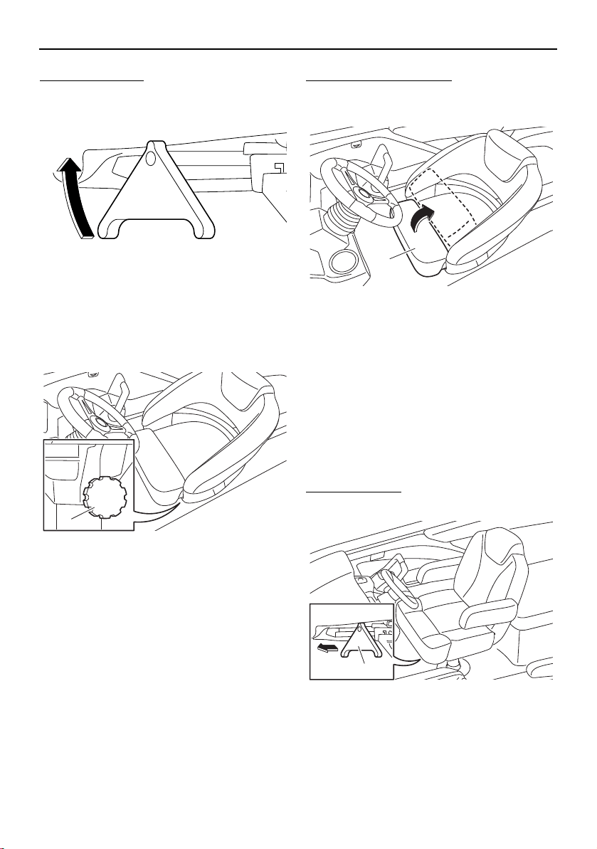
Equipment operation
94
To swivel the seat:
(1) Extend the slide/swivel lock lever.
(2) Rotate the lever to starboard (right).
(3) Swivel the seat to the desired position. If
it is too easy or too difficult to rotate the
seat, adjust the swivel friction by turning
the swivel friction knob in or out.
1 Swivel friction knob
(4) Push the lever to its original position.
To flip up the seat bolster:
Lift up the seat bolster at the front of the seat
so that it is resting against the backrest.
1 Seat bolster
Driver’s seat (212X / 212S / 212)
The driver’s seat can slide forward and rear-
ward, and the seat can swivel, and the back-
rest angle can be adjusted. In addition, the
seat bolster at the front of the seat can be
flipped up to change the seat style for a
raised seating position.
Make sure that the seat is securely locked in
place before getting underway.
To slide the seat:
(1) Extend the slide/swivel lock lever.
1 Slide/swivel lock lever
1
1
1
SportsBoat_F3R13.book Page 94 Friday, May 31, 2019 9:42 AM
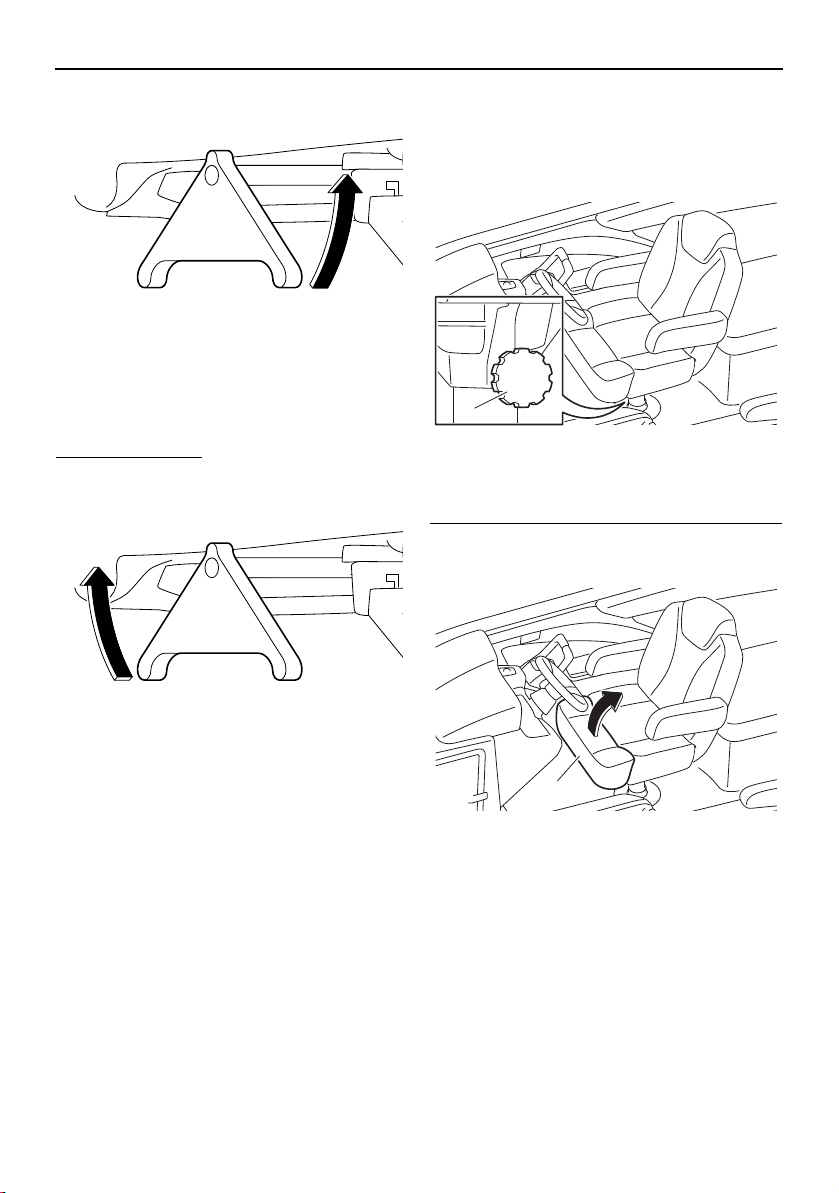
Equipment operation
95
(2) Rotate the lever to port (left).
(3) Move the seat to the desired position,
and then release the lever.
(4) Push the lever to its original position.
To swivel the seat:
(1) Extend the slide/swivel lock lever.
(2) Rotate the lever to starboard (right).
(3) Swivel the seat to the desired position. If
it is too easy or too difficult to rotate the
seat, adjust the swivel friction by turning
the swivel friction knob in or out.
1 Swivel friction knob
(4) Push the lever to its original position.
To flip up the seat bolster (driver’s seat only):
Lift up the seat bolster at the front of the seat
so that it is resting against the backrest.
1 Seat bolster
1
1
SportsBoat_F3R13.book Page 95 Friday, May 31, 2019 9:42 AM
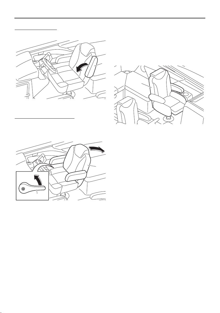
Equipment operation
96
To use the armrests:
Lower the armrests until they stop.
1 Armrest
To adjust the backrest angle:
While lifting the adjusting lever on the star-
board side of the seat, move the backrest to
the desired position.
1 Backrest
2 Adjusting lever
Passenger’s seat (212X / 212S / 212)
The passenger’s seat can be adjusted in the
same ways as the driver’s seat.
See “Driver’s seat” for instructions on adjust-
ing the seat. However, the seat bolster of the
passenger’s seat cannot be adjusted.
1 Passenger’s seat
1
1
2
1
SportsBoat_F3R13.book Page 96 Friday, May 31, 2019 9:42 AM
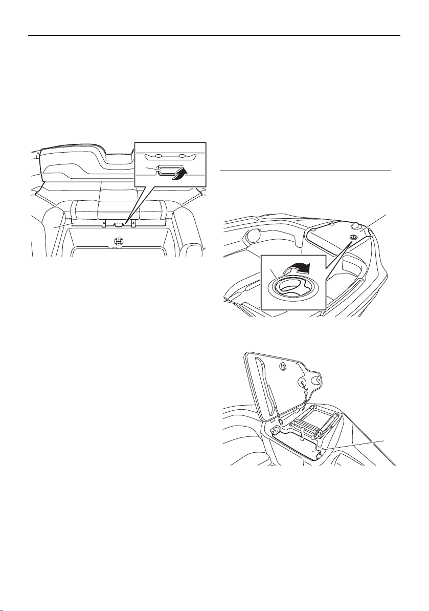
Equipment operation
97
Engine hood
The engine hood can be opened to access
the engines.
The engine hood latch is located under the
front of the rear center seat.
To open the engine hood, pull the engine
hood latch up and lift the engine hood.
1 Engine hood
2 Engine hood latch
To prevent excess water from spilling onto
the engines after a rainfall or washing down
the boat, wipe off the seat cushions before
opening the engine hood.
To close the engine hood, push the front of
the rear center seat to securely lock it in
place.
Storage compartments
This boat is equipped with the following con-
venient on-board storage compartments.
Make sure that the storage compartments
are securely closed before getting underway.
Anchor storage compartment
The anchor storage compartment is located
at the bow.
To open the anchor storage compartment:
Pull the anchor storage compartment lid latch
to open the lid.
1 Anchor storage compartment lid
2 Anchor storage compartment lid latch
1 Anchor storage compartment
When storing the anchor, place some cush-
ioning material or the anchor line under the
anchor.
1
2
1
2
1
SportsBoat_F3R13.book Page 97 Friday, May 31, 2019 9:42 AM
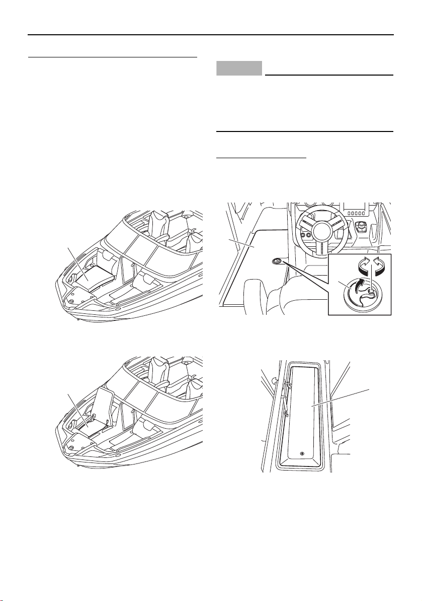
Equipment operation
98
To close the anchor storage compartment:
Close the anchor storage compartment lid,
and then push it to securely lock it in place.
Front underseat storage
compartments
The front underseat storage compartment
(starboard) and front underseat storage com-
partment (port) are located under the front
starboard seat and front port seat respective-
ly.
To open a front underseat storage compart-
ment, lift the front seat (rear) up.
1 Front starboard seat (rear)
1 Front under storage compartment
To close a front underseat storage compart-
ment, lower the front seat (rear).
Ski locker
NOTICE
212X: This storage compartment contains
a ballast bag. Be careful not to store items
in this area that could be crushed or dam-
aged by the ballast bag as it fills.
The ski locker is located under the floor.
To open the ski locker:
(1) Pull the lock handle up.
(2) Turn the lock handle, and then open the
ski locker lid.
1 Lock handle
2 Ski locker lid
1 Ski locker
1
1
2
1
1
SportsBoat_F3R13.book Page 98 Friday, May 31, 2019 9:42 AM

Equipment operation
99
To close the ski locker:
(1) Close the ski locker lid.
(2) Turn the lock handle and make sure that
the lid is securely closed.
(3) Push the lock handle down.
To drain water from the ski locker:
(1) Remove the drain plug on the bottom of
the ski locker to drain the water.
1 Drain plug
(2) Securely install the drain plug in its origi-
nal position.
Rear underseat storage compartment
(starboard)
The rear underseat storage compartment
(starboard) is located under the rear star-
board seat.
To open the rear underseat storage compart-
ment (starboard), unsnap the retaining strap,
and then lift the rear starboard seat up.
1 Rear starboard seat
2 Retaining strap
1 Rear underseat storage compartment (star-
board)
To close the rear underseat storage compart-
ment (starboard), lower the rear starboard
seat, and then snap the retaining strap.
1
1
2
1
SportsBoat_F3R13.book Page 99 Friday, May 31, 2019 9:42 AM
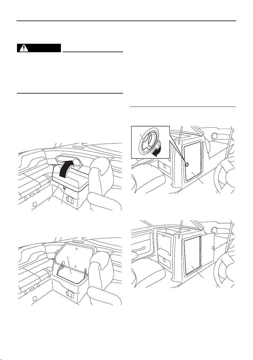
Equipment operation
100
Rear underseat storage compartment
(port)
WARNING
Do not carry any flammable substances in
the storage compartment or any heavy or
metal items that can damage the battery
or cause a short circuit. Sparks or fire
could result.
The rear underseat storage compartment
(port) is located under the rear port seat.
To open the rear underseat storage compart-
ment (port), unsnap the retaining strap, and
then lift the rear port seat up.
1 Rear port seat
2 Retaining strap
1 Rear underseat storage compartment (port)
To close the rear underseat storage compart-
ment (port), lower the rear port seat, and then
snap the retaining strap.
Enclosed storage compartment
The enclosed storage compartment is a large
storage compartment that is located on the
port side.
There is a cooler box in the enclosed storage
compartment.
To open the enclosed storage compartment:
Pull the enclosed storage compartment door
latch to open the door.
1 Enclosed storage compartment door latch
2 Enclosed storage compartment door
1 Enclosed storage compartment
1
2
1
1
2
1
SportsBoat_F3R13.book Page 100 Friday, May 31, 2019 9:42 AM

Equipment operation
101
To close the enclosed storage compartment:
Close the enclosed storage compartment
door, and then push it to securely lock it in
place.
Driver’s side console compartment
The driver’s side console compartment is lo-
cated in front of the helm.
The driver’s side console compartment door
can be used as a partition in the front walk-
through.
To open the driver’s side console compart-
ment, unhook the driver’s side console com-
partment door latch.
1 Driver’s side console compartment door
2 Driver’s side console compartment door latch
1 Driver’s side console compartment
To close the driver’s side console compart-
ment, close the driver’s side console com-
partment door, and then hook the latch to
securely lock it in place.
To use the driver’s side console compart-
ment door as the partition:
(1) Unfold the door and guide the edge of it
into the channel on the enclosed storage
compartment.
1 Edge
2 Channel
(2) To hold the door in place, hook the driv-
er’s side console compartment door
latch to the metal tab on the front side of
the door.
1 Driver’s side console compartment door latch
2 Metal tab
1
2
1
1
2
1
2
SportsBoat_F3R13.book Page 101 Friday, May 31, 2019 9:42 AM
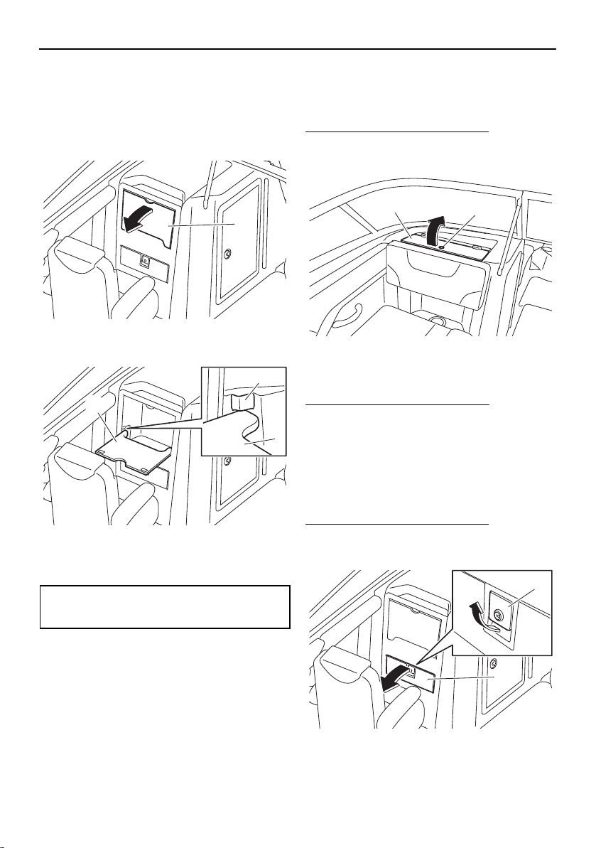
Equipment operation
102
Stowable table (212X / 212S / 212)
The stowable table is located in front of the
passenger’s seat.
To use the stowable table, pull the table and
lower it until it contacts the stoppers.
1 Stowable table
1 Stowable table
2 Stopper
To stow the stowable table, lift the table and
place it in its original position.
Glove compartment (AR210 / SX210)
The glove compartment is located in the port
console.
To open the glove compartment:
Insert your finger into the glove compartment
lid hole and open the glove compartment lid.
1 Glove compartment lid hole
2 Glove compartment lid
To close the glove compartment:
Close the glove compartment lid.
Glove compartment
(212X / 212S / 212)
The glove compartment is located in front of
the passenger’s seat.
To open the glove compartment:
While pulling the glove compartment latch,
pull the glove compartment lid to open it.
1 Glove compartment latch
2 Glove compartment lid
Maximum weight limit:
9 kg (20 lb)
1
1
1
2
2
1
2
1
SportsBoat_F3R13.book Page 102 Friday, May 31, 2019 9:42 AM
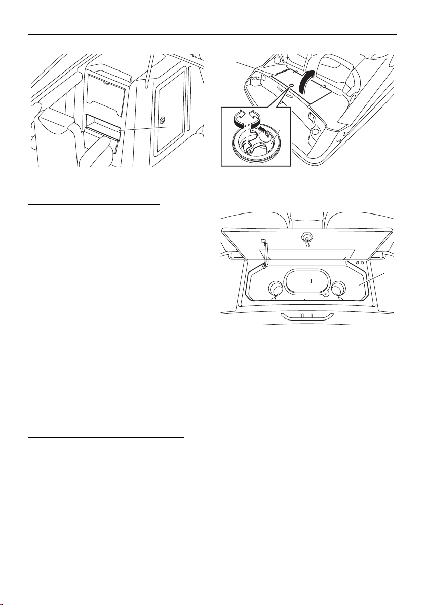
Equipment operation
103
1 Glove compartment
To close the glove compartment:
Close the glove compartment lid, and then
push it to securely lock it in place.
To lock the glove compartment:
(1) Close the glove compartment.
(2) Insert the glove compartment key into
the glove compartment latch, and then
turn the key counterclockwise.
TIP:
Store the glove compartment key so that it is
not lost.
To unlock the glove compartment:
Insert the glove compartment key into the
glove compartment latch, and then turn the
key clockwise.
Wet storage compartment
The wet storage compartment is located un-
der the swim platform.
To open the wet storage compartment:
(1) Pull the lock handle up.
(2) Turn the lock handle, and then open the
rear platform hatch.
1 Rear platform hatch
2 Lock handle
1 Wet storage compartment
To close the wet storage compartment:
(1) Close the rear platform hatch.
(2) Turn the lock handle and make sure that
the hatch is securely closed.
(3) Push the lock handles down.
TIP:
The engines will not start if the rear platform
hatch is not securely closed.
1
1
2
1
SportsBoat_F3R13.book Page 103 Friday, May 31, 2019 9:42 AM
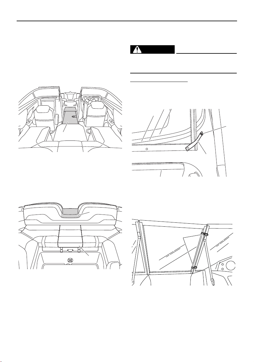
Equipment operation
104
Walk-through
Front walk-through
This boat has a large bow area where two
adults can sit comfortably with their legs out-
stretched. The front walk-through provides
easy access to the bow area from the cabin
area.
1 Front walk-through
Rear walk-through
The backrest of the rear center seat is low in
order to make boarding the boat from the
rear easier.
1 Rear walk-through
2 Center seat cushion
TIP:
In order to board or disembark from the boat,
the center seat cushion can be removed.
Windshield
The windshield can be opened and closed.
WARNING
To avoid injury, the windshield must be se-
cured when the boat is in motion.
To close the windshield:
(1) Unsnap the retaining strap from the
windshield, and then snap it onto the
strap base.
1 Retaining strap
2 Strap base
(2) Close the windshield, and then turn the
windshield latches to the lock position.
1 Windshield latch
1
2
1
1
2
1
SportsBoat_F3R13.book Page 104 Friday, May 31, 2019 9:42 AM
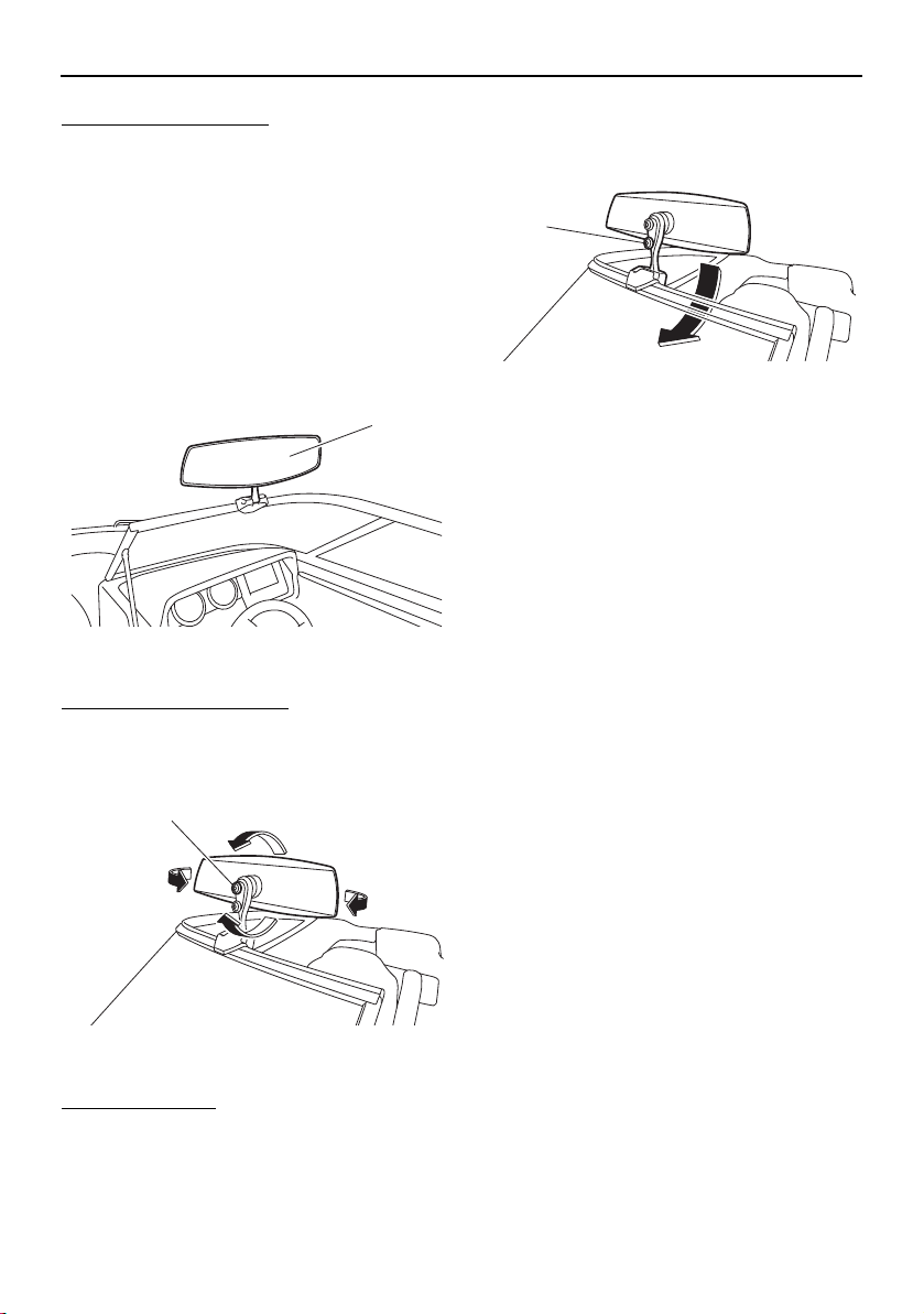
Equipment operation
105
To open the windshield:
(1) Turn the windshield latches to the unlock
position, and then open the windshield.
(2) Unsnap the retaining strap from the strap
base, and then snap it onto the wind-
shield.
Folding mirror (212X)
The mirror is installed on the driver’s side of
the windshield.
1 Folding mirror
To adjust the mirror angle:
Loosen the upper lock knob, adjust the angle
of the mirror, and then tighten the knob.
1 Upper lock knob
To fold the mirror:
Loosen the lower lock knob, fold the mirror,
and then tighten the knob.
1 Lower lock knob
1
1
1
SportsBoat_F3R13.book Page 105 Friday, May 31, 2019 9:42 AM
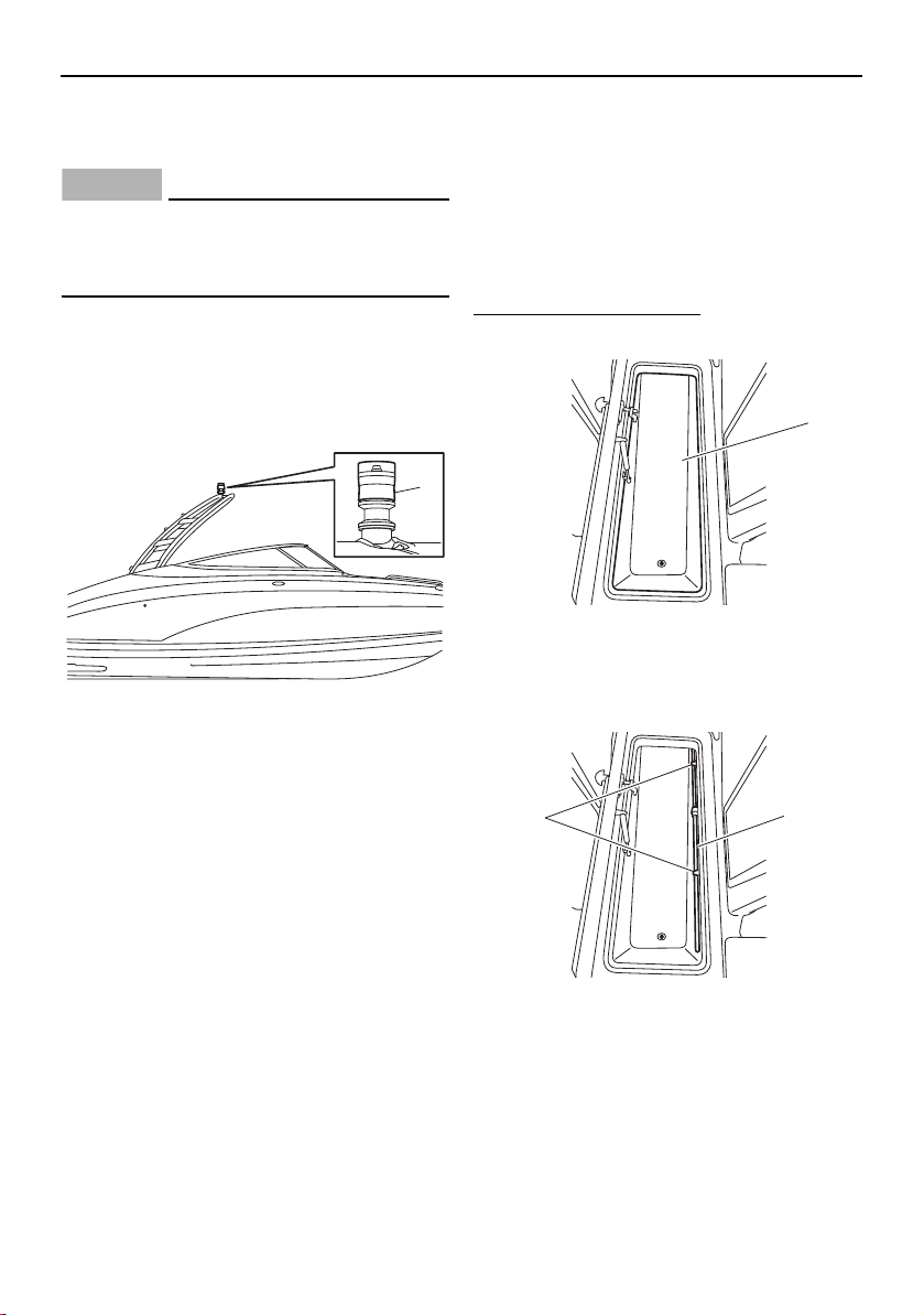
Equipment operation
106
Anchor light
(AR210 / 212X / 212S)
NOTICE
Do not attach a ski rope or other tow-rope
to the anchor light. Otherwise, the anchor
light could be damaged.
The anchor light is located at the top center of
the wakeboard tower. It is also the “all-
around” light for navigation at night or in low-
visibility conditions. (See page 59, 82 for in-
formation on the anchor light on.)
1 Anchor light
Anchor light (SX210 / 212)
The boat is equipped with a removable an-
chor light.
The anchor light is stored in the ski locker. It
is also the “all-around” light for navigation at
night or in low-visibility conditions. (See page
59, 82 for information on the anchor light on.)
To set up the anchor light:
(1) Open the ski locker. (See page 98.)
1 Ski locker
(2) Remove the anchor light from the anchor
light holder.
1 Anchor light holder
2 Anchor light
1
1
2
1
SportsBoat_F3R13.book Page 106 Friday, May 31, 2019 9:42 AM
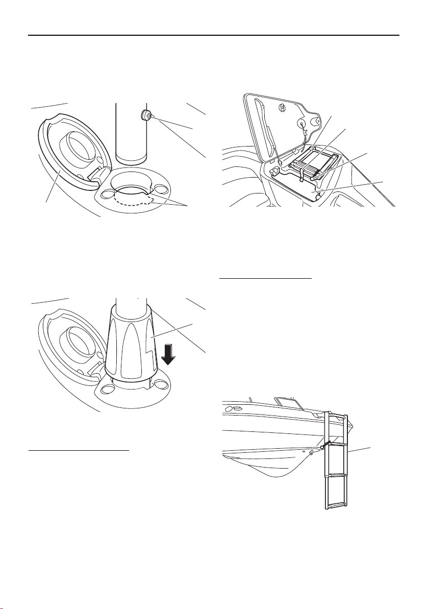
Equipment operation
107
(3) Open the cap of the anchor light socket,
fit the protrusion on the anchor light into
the slot in the socket, and then install the
light into the socket.
1 Cap
2 Slot
3 Protrusion
(4) Fit the anchor light stopper into the an-
chor light socket.
1 Anchor light stopper
To store the anchor light:
(1) Pull the anchor light stopper upward, re-
move the anchor light, and then close the
cap of the anchor light socket.
(2) Install the anchor light into the anchor
light holder, and then close the ski lock-
er.
Bow ladder
The bow ladder is located in the anchor stor-
age compartment.
1 Bow ladder
2 Retaining strap
3 Bow ladder strap
4 Anchor storage compartment
To use the bow ladder:
(1) Open the anchor storage compartment
lid. (See page 97.)
(2) Unsnap the retaining strap from the an-
chor storage compartment.
(3) Unhook the bow ladder strap.
(4) Extend the bow ladder out completely,
and then lower it.
(5) Close the anchor storage compartment
lid to use it as a step.
1 Bow ladder
2
3
1
1
1
2
3
4
1
SportsBoat_F3R13.book Page 107 Friday, May 31, 2019 9:42 AM
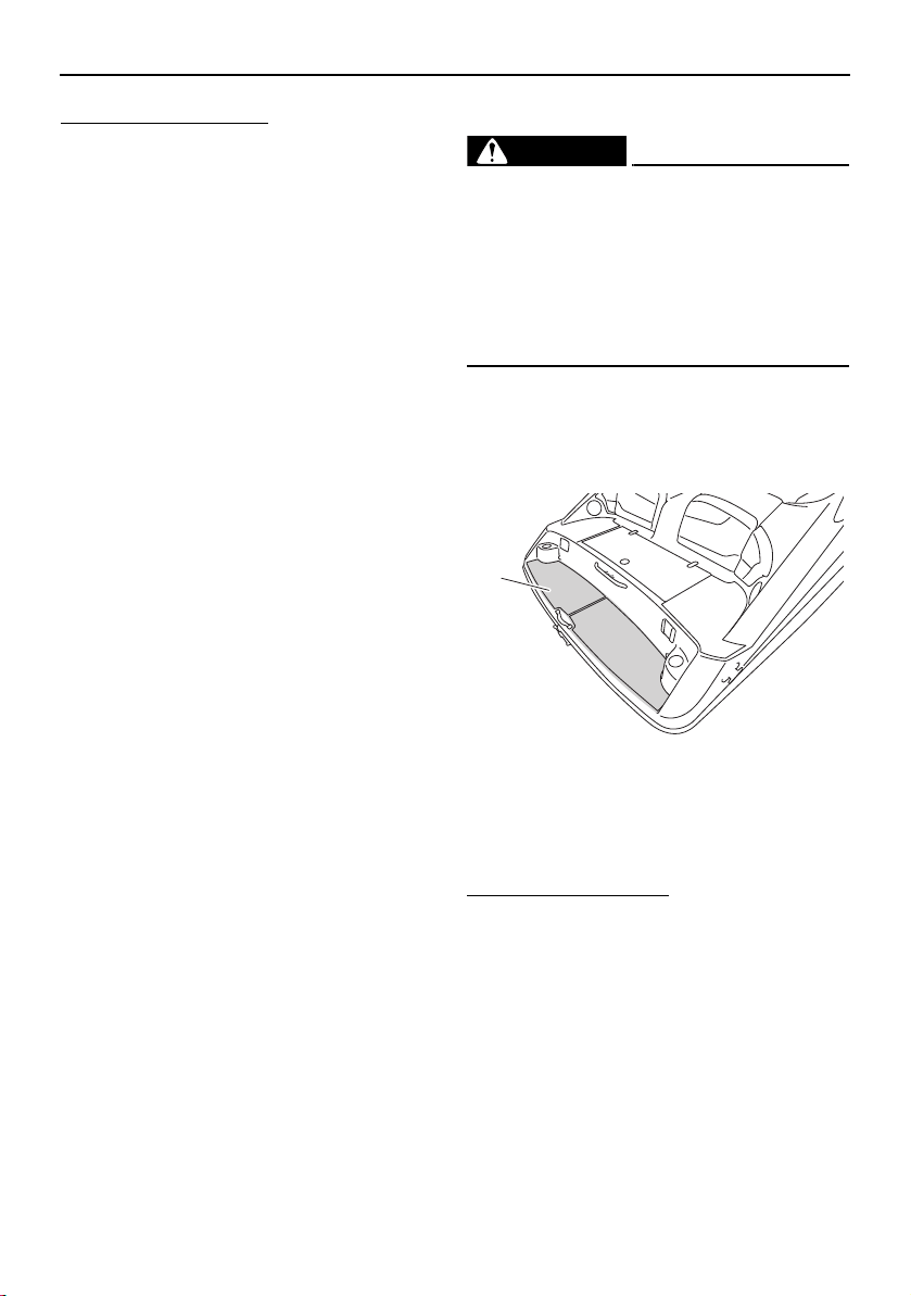
Equipment operation
108
To stow the bow ladder:
(1) Open the anchor storage compartment
lid.
(2) Raise the bow ladder, and then pull it
rearward completely.
(3) Hook the bow ladder strap onto the bow
ladder.
(4) Fold the bow ladder, and then store it in
the anchor storage compartment.
(5) Snap the retaining strap onto the strap
base to secure the bow ladder.
(6) Close the anchor storage compartment
lid.
Swim platform
WARNING
Stay away from the swim platform area
while the engines are running. Exhaust
gases coming from underneath it contain
carbon monoxide, a colorless, odorless
gas which may cause brain damage or
death when inhaled. Symptoms include
nausea, dizziness, and drowsiness.
The swim platform area provides a place to
stand or sit while putting on skis or a wake-
board, and includes a stern ladder to make
boarding from the water easier.
1 Swim platform
Stern ladder
The stern ladder is stored under the swim
platform.
To use the stern ladder:
(1) Lift the end of the stern ladder to release
it from the hooks on the boat.
1
SportsBoat_F3R13.book Page 108 Friday, May 31, 2019 9:42 AM
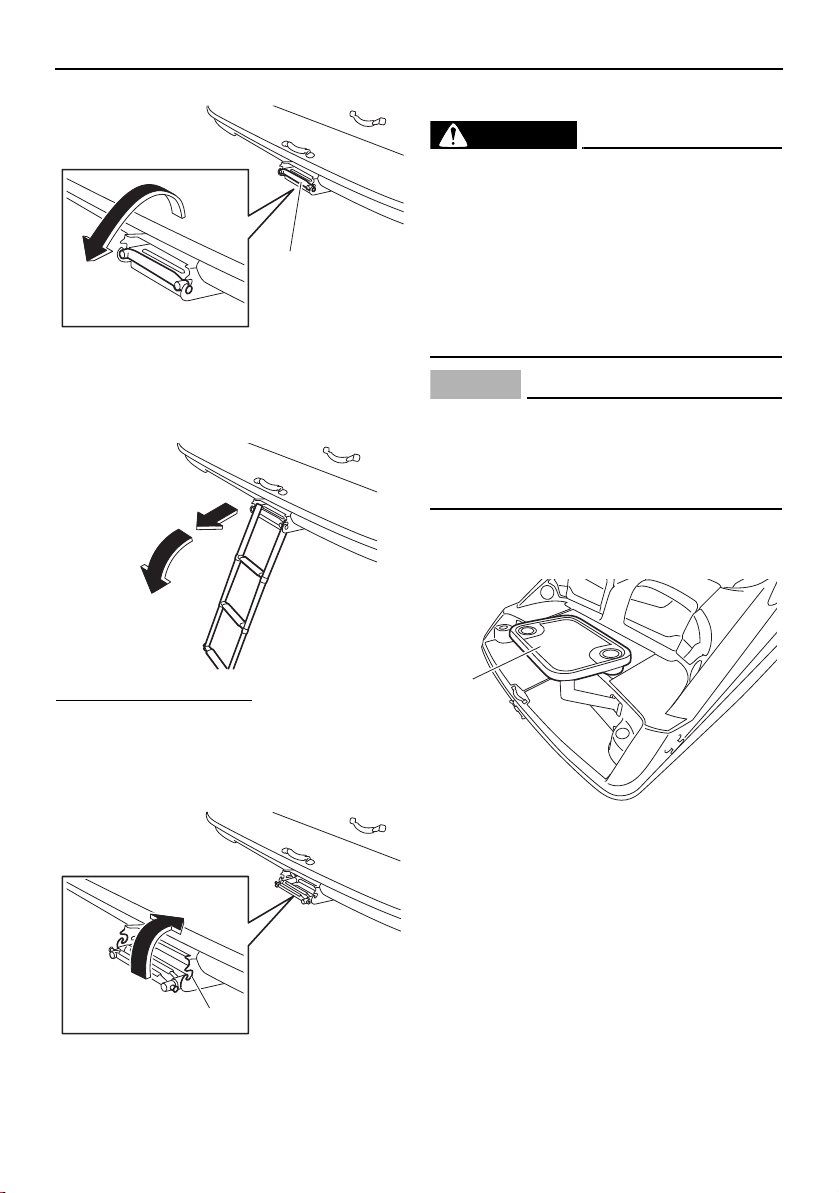
Equipment operation
109
1 Stern ladder
(2) Pull the stern ladder out completely, and
then lower it.
To stow the stern ladder:
(1) Raise the stern ladder until it is horizon-
tal, and then push it forward completely.
(2) Push the end of the stern ladder to fit it
onto the hooks on the boat.
1 Hook
Side table
WARNING
If the side table is installed at the swim
platform, do not use the table while the en-
gines are running. Exhaust gases coming
from underneath the swim platform con-
tain carbon monoxide, a colorless, odor-
less gas which may cause brain damage
or death when inhaled. Symptoms include
nausea, dizziness, and drowsiness.
NOTICE
If the side table is installed at the swim
platform, remove the side table before op-
erating the boat. Otherwise, the side table
may fall into the water.
The side table can be installed at the swim
platform or in front of the rear port seat.
1 Side table
1
1
1
SportsBoat_F3R13.book Page 109 Friday, May 31, 2019 9:42 AM

Equipment operation
110
1 Side table
To install the side table, slide the end of the
table pole into the table bracket until it is
locked in place.
1 Table bracket
2 Table pole
3 Table bracket knob
To remove the side table, pull the table brack-
et knob, and then pull the table pole upward.
Wakeboard tower
(AR210 / 212X / 212S)
The wakeboard tower is provided as an ele-
vated tow point suitable for wakeboards and
similar towable recreational equipment. The
tow pylon can be used to attach a standard
ski rope or other tow-rope.
WARNING
Severe injury or death can result if you ig-
nore any of the following:
Maximum towing capacity:
1 Person, 158 kg (350 lb) max.
Make sure the tow-rope is securely fas-
tened to the tow pylon on the wake-
board tower.
Do not tow a tube or other inflatable
from the wakeboard tower. Use the ski
tow hook on the transom.
Stay clear of the tow-rope while pulling
a wakeboard rider or skier.
Do not climb, hang, or sit on the wake-
board tower.
Make sure all knobs securing the wake-
board tower are tightened before opera-
tion and check periodically during use.
1
1
3
2
SportsBoat_F3R13.book Page 110 Friday, May 31, 2019 9:42 AM
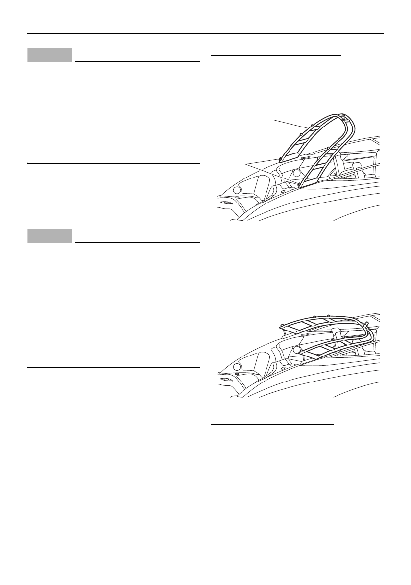
Equipment operation
111
NOTICE
Do not modify the wakeboard tower to tow
from it or to carry accessories not de-
signed for it. The wakeboard tower could
be damaged. Also, the wakeboard tower
collapsing feature is intended for storage
only. The boat should not be transported
or operated with the tower in the col-
lapsed position.
Collapsing and setting up the
wakeboard tower (AR210)
When storing the boat, collapse the wake-
board tower.
NOTICE
Accidentally dropping the wakeboard
tower while collapsing or raising it can
damage the tower, the boat, or both. An
assistant needs to help hold the wake-
board tower in place during the proce-
dure.
Do not operate the boat or transport it
on the trailer with the tower in the col-
lapsed position to avoid possible dam-
age.
To collapse the wakeboard tower:
(1) While an assistant supports the wake-
board tower, completely loosen the lock
knobs on both sides of the wakeboard
tower.
1 Wakeboard tower
2 Lock knob
(2) Lower the wakeboard tower until it
stops.
To set up the wakeboard tower:
(1) Lift the wakeboard tower.
(2) While an assistant supports the wake-
board tower, tighten the lock knobs on
both sides of the wakeboard tower until
they stop.
2
1
SportsBoat_F3R13.book Page 111 Friday, May 31, 2019 9:42 AM
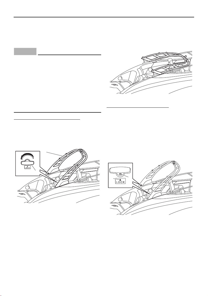
Equipment operation
112
Collapsing and setting up the
wakeboard tower (212X / 212S)
When storing the boat, collapse the wake-
board tower.
NOTICE
Accidentally dropping the upper tower
section while collapsing or raising it can
damage the tower, the boat, or both. An
assistant needs to support the upper
tower section during the procedure.
Do not operate the boat or transport it
on the trailer with the tower in the col-
lapsed position to avoid possible dam-
age.
To collapse the wakeboard tower:
(1) While an assistant supports the wake-
board tower, remove the T-handle lock
pin on both sides of the wakeboard tow-
er by turning it 180° and pulling it out.
1 Wakeboard tower
2 T-handle lock pin
(2) Lower the wakeboard tower until it
stops.
To set up the wakeboard tower:
(1) Lift the wakeboard tower.
(2) While an assistant supports the wake-
board tower, insert the T-handle lock
pins into the tower with the white mark
on each pin facing up.
(3) Turn each T-handle lock pin 180° so that
the white mark on the pin is aligned with
the “LOCK” arrow mark.
1 White mark
2 Arrow mark
2
1
2
1
SportsBoat_F3R13.book Page 112 Friday, May 31, 2019 9:42 AM
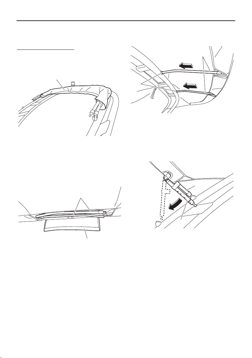
Equipment operation
113
Bimini top (AR210 / 212X / 212S)
Setting up the bimini top
To set up the bimini top:
(1) Remove the storage cover, and then un-
wrap the bimini top.
1 Storage cover
(2) Pull the front of the bimini top toward the
bow, and then open the flap and pull out
the front support poles from the bimini
top.
1 Front support pole
2 Flap
(3) Insert the front support poles into the
mounting holes in the wakeboard tower.
1 Mounting hole
2 Front support pole
(4) Pull the rear of the bimini top toward the
stern, and then unhook the rear support
poles from the main pole.
1 Rear support pole
2 Main pole
1
1
2
2
1
1
2
SportsBoat_F3R13.book Page 113 Friday, May 31, 2019 9:42 AM
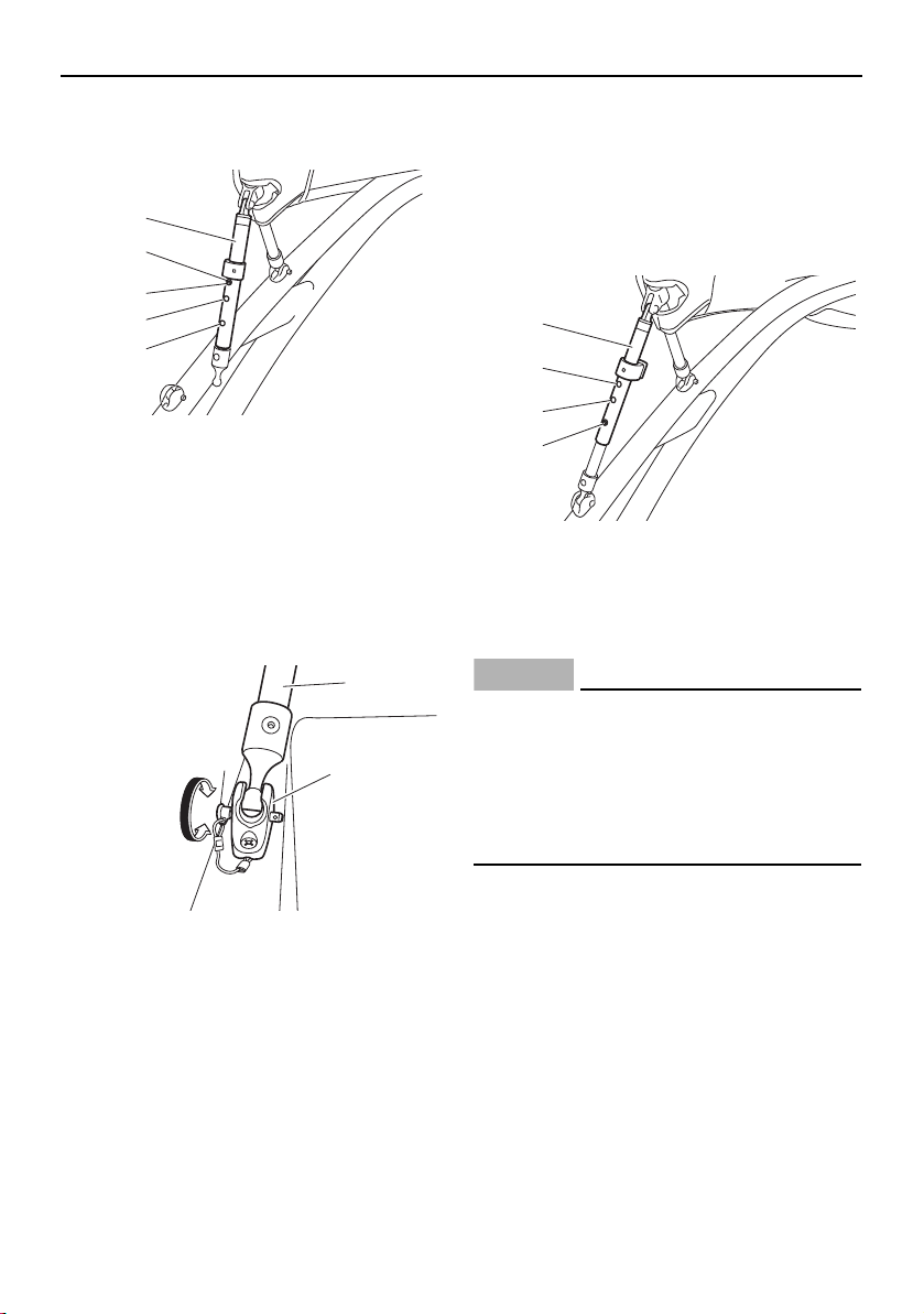
Equipment operation
114
(5) Push the snap button and extend each
rear support pole to the long position.
1 Rear support pole
2 Snap button
3 Short position
4 Middle position
5 Long position
(6) Secure each rear support pole to the rear
support pole mounting bracket using the
lock pin.
1 Rear support pole
2 Lock pin
3 Rear support pole mounting bracket
(7) While pulling the main pole down, push
the snap button and shorten each rear
support pole to either the middle position
for cruising or to the short position if you
are using the wakeboard tower. Be sure
the snap buttons click into place.
1 Rear support pole
2 Short position
3 Middle position
4 Snap button
NOTICE
Do not exceed 72 km/h (45 mph) with the
bimini top in the up position.
Be careful not to push the snap button
and extend the pole too far. Otherwise,
the lower section of the pole could fall
into the water.
1
2
3
4
5
2
3
1
1
2
3
4
SportsBoat_F3R13.book Page 114 Friday, May 31, 2019 9:42 AM
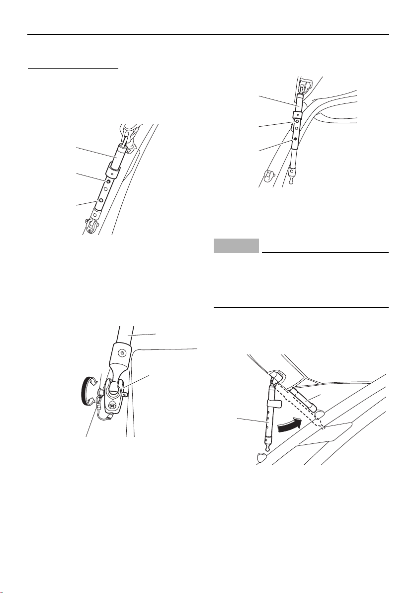
Equipment operation
115
Storing the bimini top
To store the bimini top:
(1) While pulling the main pole down slightly,
push the snap button, and then extend
each rear support pole to the long posi-
tion to loosen the bimini top.
1 Rear support pole
2 Snap button
3 Long position
(2) Remove each rear support pole from the
rear support pole mounting bracket by
rotating the lock pin.
1 Rear support pole
2 Lock pin
3 Rear support pole mounting bracket
(3) Push the snap button and shorten each
rear support pole to the short position.
1 Rear support pole
2 Short position
3 Snap button
NOTICE
Be careful not to push the snap button and
extend the pole too far. Otherwise, the
lower section of the pole could fall into the
water.
(4) Hook the rear support poles onto the
main pole, and then pull the rear of the
bimini top toward the bow.
1 Rear support pole
2 Main pole
1
2
3
2
3
1
1
2
3
2
1
SportsBoat_F3R13.book Page 115 Friday, May 31, 2019 9:42 AM
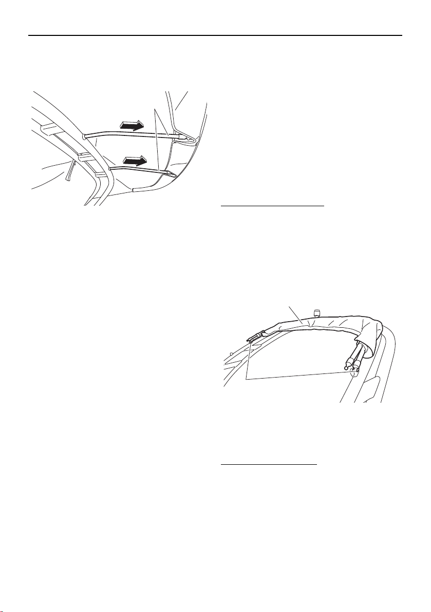
Equipment operation
116
(5) Remove the front support poles from the
wakeboard tower, and then place the
poles in the flap of the bimini top.
1 Front support pole
(6) Pull the front of the bimini top toward the
stern, wrap the bimini top around the
main pole, and then install the storage
cover.
Trailering with the bimini top
The bimini top must be secured to the boat
when it is being trailered. When the boat is
trailered with a genuine Yamaha boat cover,
simply store the bimini top in the fully col-
lapsed position and install the storage cover.
If a boat cover is not used, wrap an elastic
cord around the top and secure the ends to
the tow pylon on the wakeboard tower to re-
strict movement.
Removing the bimini top
To remove the bimini top:
(1) Store the bimini top. See “Storing the bi-
mini top”.
(2) While supporting the bimini top, remove
the lock pins securing the main pole to
the wakeboard tower, and then remove
the top.
1 Bimini top
2 Lock pin
Installing the bimini top
To install the bimini top:
When installing the bimini top, simply reverse
the removal steps, and then make sure that
the lock pins are securely installed.
1
1
2
SportsBoat_F3R13.book Page 116 Friday, May 31, 2019 9:42 AM
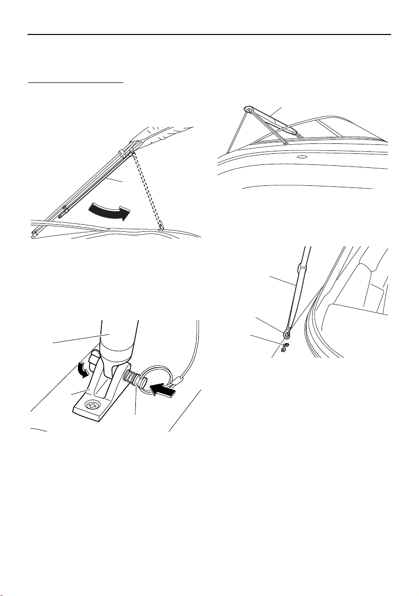
Equipment operation
117
Bimini top (SX210 / 212)
Setting up the bimini top
To set up the bimini top:
(1) Raise the bimini top, and then unhook
the rear support poles from the main
pole.
1 Rear support pole
(2) Secure each rear support pole to the rear
support pole mounting bracket using the
lock pin. Make sure that the tab on the
end of the lock pin is pointing downward.
1 Rear support pole
2 Rear support pole mounting bracket
3 Lock pin
(3) Remove the storage cover, unfold the bi-
mini top, and pull it toward the bow.
1 Storage cover
(4) Hook the latch on each front strap onto
the strap eye.
1 Front strap
2 Latch
3 Strap eye
1
3
2
1
1
3
1
2
SportsBoat_F3R13.book Page 117 Friday, May 31, 2019 9:42 AM
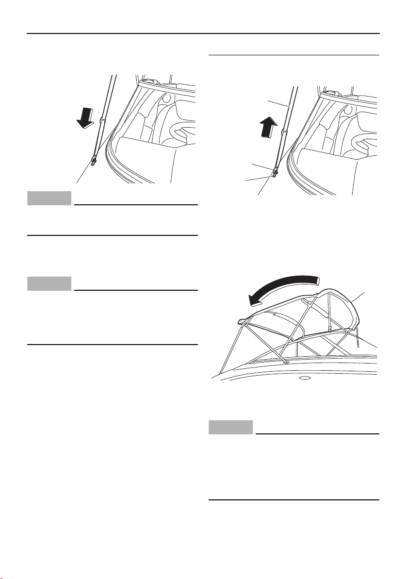
Equipment operation
118
(5) Tighten the front straps so that the top is
snug and wrinkle free.
NOTICE
Do not exceed 72 km/h (45 mph) with the
bimini top in the up position.
Storing the bimini top in the upright
position
NOTICE
Do not trailer the boat with the bimini top
in the fully extended or upright storage po-
sition. Put the bimini top in the fully col-
lapsed position to avoid damage.
To store the bimini top in the upright position:
(1) Loosen each front strap, and then un-
hook the latch from the strap eye.
1 Front strap
2 Latch
3 Strap eye
(2) Pull the bimini top toward the stern, and
then fold it.
1 Bimini top
(3) Install the storage cover.
NOTICE
Do not trailer the boat with the bimini top
in the fully extended or upright position.
When transporting the boat, put the bimini
top in the fully collapsed position to avoid
damage.
1
2
3
1
SportsBoat_F3R13.book Page 118 Friday, May 31, 2019 9:42 AM
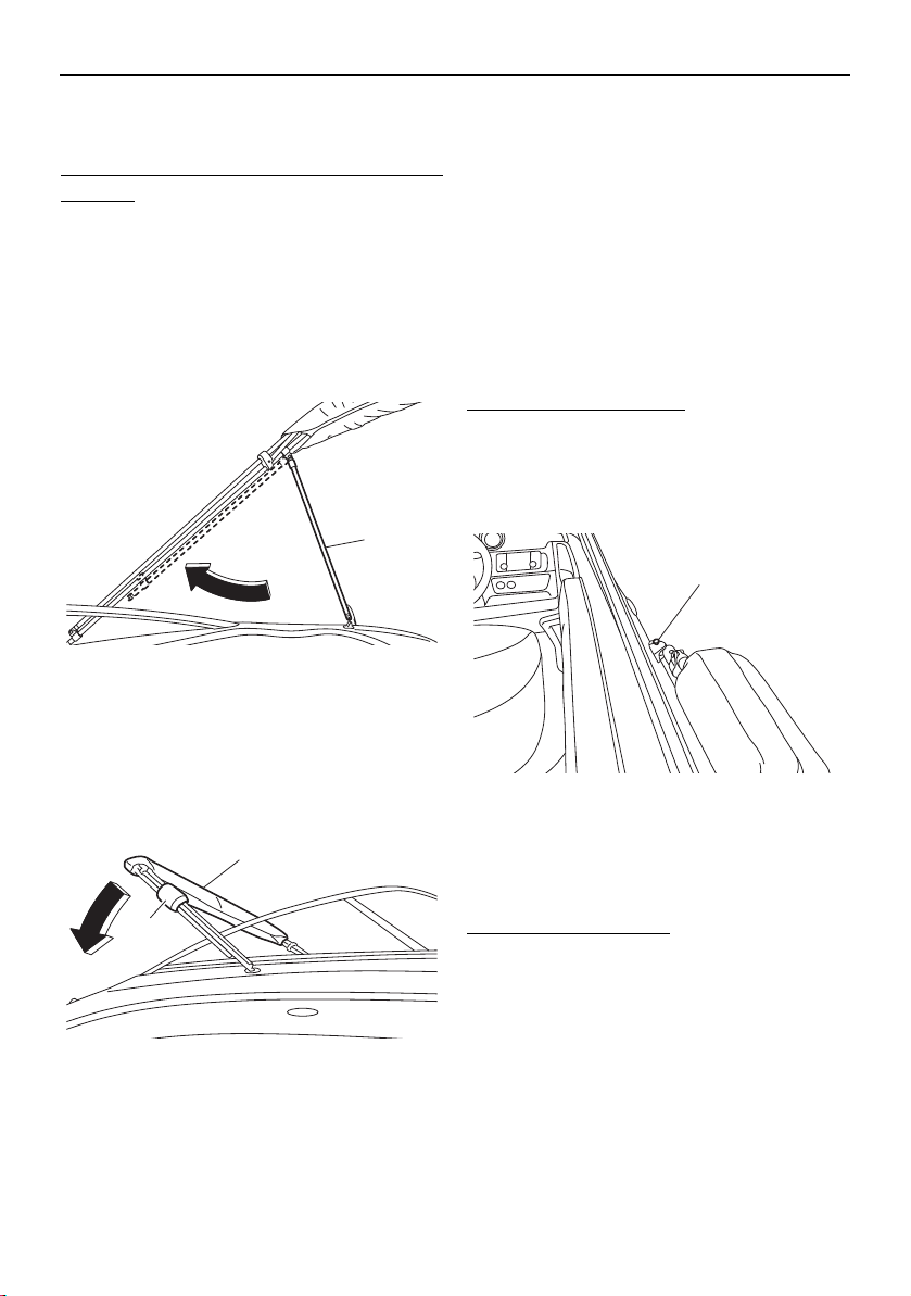
Equipment operation
119
Storing the bimini top in the fully
collapsed position
To store the bimini top in the fully collapsed
position:
(1) Follow the above steps for “Storing the
bimini top in the upright position”.
(2) While supporting the bimini top, remove
the lock pins securing the rear support
poles to the rear support pole mounting
brackets, and then hook each rear sup-
port pole onto the main pole.
1 Rear support pole
(3) Install the protective cushions around
the poles, and then lower the bimini top
onto the rear deck.
1 Protective cushion
2 Bimini top
Trailering with the bimini top
The bimini top must be secured to the boat
when it is being trailered. When the boat is
trailered with a genuine Yamaha boat cover,
simply store the bimini top in the fully col-
lapsed position and install the storage cover.
If a boat cover is not used, wrap an elastic
cord around the top and secure the ends to
the ski tow hook to restrict movement.
Removing the bimini top
To remove the bimini top:
(1) Store the bimini top. See “Storing the bi-
mini top in the fully collapsed position”.
(2) Remove the lock pins securing the bimini
top to the main pole mounting brackets.
1 Lock pin
(3) Remove the bimini top from the boat.
Installing the bimini top
To install the bimini top:
When installing the bimini top, simply reverse
the removal steps, and then make sure that
the lock pins are securely installed.
1
2
1
1
SportsBoat_F3R13.book Page 119 Friday, May 31, 2019 9:42 AM
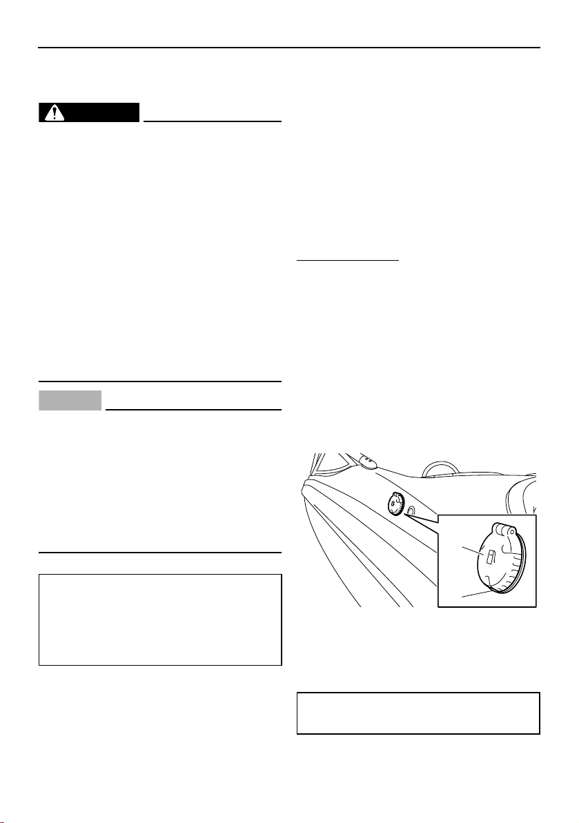
120
Operation and handling requirements
Fuel requirement
Fuel
WARNING
Gasoline and gasoline vapors are ex-
tremely flammable. To avoid fires and
explosions and to reduce the risk of in-
jury when refueling, follow these in-
structions.
Gasoline is poisonous and can cause in-
jury or death. Handle gasoline with care.
Never siphon gasoline by mouth. If you
should swallow some gasoline, inhale a
lot of gasoline vapor, or get some gaso-
line in your eyes, see your doctor imme-
diately. If gasoline spills on your skin,
wash with soap and water. If gasoline
spills on your clothing, change your
clothes.
NOTICE
Do not use leaded gasoline. Leaded
gasoline can seriously damage the en-
gines.
Avoid getting water and contaminants in
the fuel tank. Contaminated fuel can
cause poor performance and engine
damage. Use only fresh gasoline that
has been stored in clean containers.
Gasohol
There are two types of gasohol: gasohol con-
taining ethanol and that containing methanol.
Gasohol containing ethanol can be used if
ethanol content does not exceed 10% and
the fuel meets minimum octane ratings. E-85
is a fuel blend containing 85% ethanol and
therefore must not be used in this boat. All
ethanol blends containing more than 10%
ethanol can cause fuel system damage or en-
gine performance problems.
Yamaha does not recommend gasohol con-
taining methanol because it can cause fuel
system damage and engine performance
problems.
To fill the fuel tank:
(1) Before refueling, turn off the engines.
Never refuel while smoking, or while in
the vicinity of sparks, open flames, or
other sources of ignition.
(2) Refuel the boat in a well-ventilated area.
If the boat is in the water, be sure it is se-
curely moored to the fueling dock. All
passengers must be out of the boat dur-
ing refueling.
(3) Press the fuel tank filler cap button, and
then open the fuel tank filler cap.
1 Fuel tank filler cap
2 Fuel tank filler cap button
(4) Slowly add fuel to the fuel tank.
Recommended fuel:
Regular unleaded gasoline with a
minimum octane rating of 86
(Pump octane number) = (R + M)/2
90 (Research octane number)
Fuel tank capacity:
189 L (50.0 US gal, 41.6 Imp.gal)
1
2
SportsBoat_F3R13.book Page 120 Friday, May 31, 2019 9:42 AM
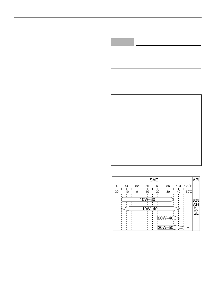
Operation and handling requirements
121
(5) Stop filling when the fuel just becomes
visible in the bottom of the filler tube. Do
not “top off” the tank, because gasoline
could spill out.
(6) Wipe up any spilled fuel immediately.
(7) Close the fuel tank filler cap by pushing it
until it locks in place. Make sure that the
fuel tank filler cap is securely closed.
Engine Med RX Fuel Additive
As the fuel mixture burns in your engine’s
combustion chambers, carbon deposits are
left behind. Over time, these deposits can re-
duce performance and even cause engine
damage. Marine engines tend to run at lower
operating temperatures than other engines,
making them more likely to accumulate these
harmful deposits. Engine Med RX, available
from your Yamaha Boat Dealer, is formulated
to remove existing deposits and, when used
continuously, prevent new ones from form-
ing, while also helping to keep fuel injectors
and other fuel system components clean for
proper performance and longer engine life.
Engine oil requirement
Engine oil
NOTICE
Use only 4-stroke engine oil. Usage of 2-
stroke engine oil could result in severe en-
gine damage.
Select an oil grade according to the average
temperatures in the area where the boat will
be used.
3-star models
Recommended engine oil:
YAMALUBE 4W
Recommended engine oil type:
SAE 10W-30, 10W-40, 20W-40, 20W-
50
Recommended engine oil grade
(3-star models):
API SG, SH, SJ, SL
Recommended engine oil grade
(4-star models):
API SJ, SL
SportsBoat_F3R13.book Page 121 Friday, May 31, 2019 9:42 AM
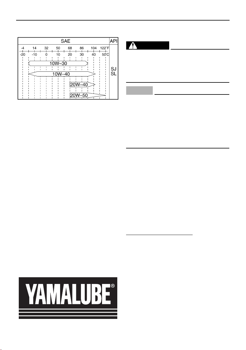
Operation and handling requirements
122
4-star models
TIP:
When the engine is operated at high speeds,
some engine oil may be consumed. Be sure
to check the engine oil level.
Why Yamalube
YAMALUBE oil is a Genuine YAMAHA Part
born of the engineers’ passion and belief that
engine oil is an important liquid engine com-
ponent. We form teams of specialists in the
fields of mechanical engineering, chemistry,
electronics and track testing, and have them
develop the engine together with the oil it will
use. Yamalube oils take full advantage of the
base oil’s qualities and blend in the ideal bal-
ance of additives to make sure the final oil
clears our performance standards. Thus,
Yamalube mineral, semisynthetic and syn-
thetic oils have their own distinct characters
and value. Yamaha’s experience gained over
many years of research and development
into oil since the 1960’s helps make
Yamalube the best choice for your Yamaha
engine.
Checking the engine oil level
(AR210 / SX210)
WARNING
Engine oil is extremely hot immediately af-
ter the engines are turned off. Coming in
contact with or getting any engine oil on
your clothes could result in burns.
NOTICE
Do not run the engine with too much or
not enough oil in the oil tank, otherwise
the engine could be damaged.
Make sure that debris and water do not
enter the oil tank filler hole. Debris and
water in the engine oil can cause serious
engine damage.
TIP:
When checking the engine oil level on land,
the engine must be running while water is
being supplied to the cooling water pas-
sages. (See “Flushing the cooling system”
on page 160 for information on supplying
water.)
When checking the engine oil level on wa-
ter, moor the boat so that it will not drift
away.
To check the engine oil level:
(1) With the engine stopped, place the boat
in a precisely level position on land or
launch the boat.
(2) Look in all directions, and then start the
engine. (See page 144 for information on
starting the engine.)
(3) Run the engine at idling speed for 6 min-
utes or more. Run the engine an addi-
tional 5 minutes if the ambient
temperature is 20 °C (68 °F) or less.
(4) Stop the engine.
(5) Open the engine hood. (See page 97.)
SportsBoat_F3R13.book Page 122 Friday, May 31, 2019 9:42 AM
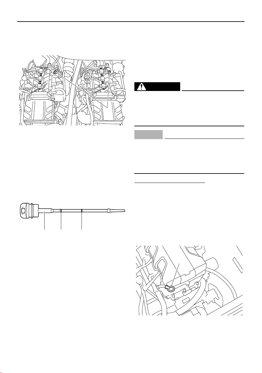
Operation and handling requirements
123
(6) Loosen the oil tank filler cap and remove
it, and then wipe the attached dipstick
clean.
1 Oil tank filler cap/Dipstick
(7) Screw the oil tank filler cap into the filler
hole until it stops. Remove the oil tank
filler cap again and make sure that the
engine oil level is between the minimum
and maximum level marks.
1 Dipstick
2 Maximum level mark
3 Minimum level mark
(8) If the engine oil level is significantly
above the maximum level mark, consult
a Yamaha Boat dealer. If the engine oil
level is below the minimum level mark,
slowly add engine oil.
(9) Repeat steps (6)–(8) until the engine oil is
at the proper level.
(10) Securely install the oil tank filler cap and
turn it until it stops.
(11) Repeat the checking oil level procedure
for the other engine.
(12) Close the engine hood.
Checking the engine oil (212X / 212S / 212)
WARNING
Engine oil is extremely hot immediately af-
ter the engines are turned off. Coming in
contact with or getting any engine oil on
your clothes could result in burns.
NOTICE
Make sure debris and water do not enter
the oil filler hole. Debris and water in the
engine oil can cause serious engine dam-
age.
To check the engine oil level:
(1) Place the boat in a precisely level posi-
tion on land with the engine stopped. If
the engine was running, allow the engine
oil to settle by waiting 5 minutes or more
before checking the oil level.
(2) Open the engine hood. (See page 97.)
(3) Remove the dipstick and wipe it clean.
3-star models
1 Dipstick
1
21 3
1
SportsBoat_F3R13.book Page 123 Friday, May 31, 2019 9:42 AM
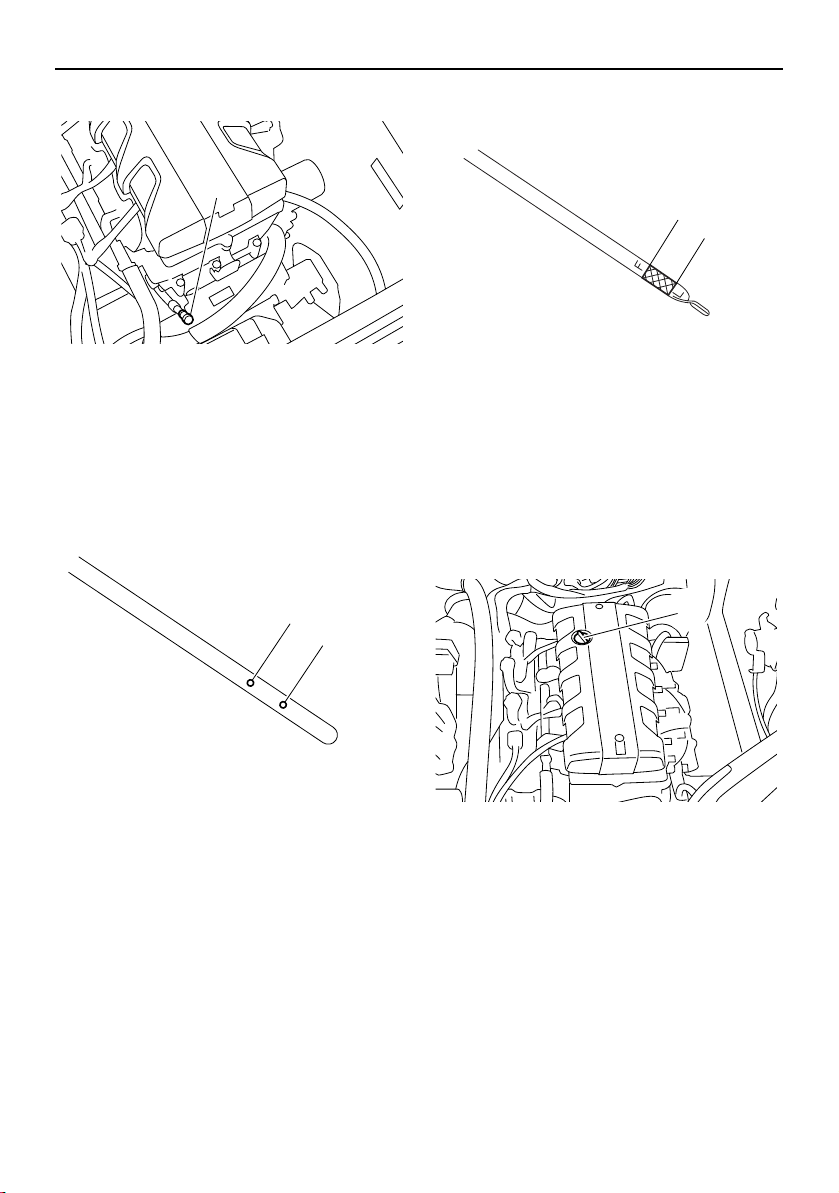
Operation and handling requirements
124
4-star models
1 Dipstick
(4) Insert the dipstick back into the dipstick
tube completely. Remove the dipstick
again and check that the engine oil level
is between the minimum level mark and
maximum level mark.
3-star models
1 Maximum level mark
2 Minimum level mark
4-star models
1 Maximum level mark
2 Minimum level mark
(5) If the engine oil level is significantly
above the maximum level mark, consult
a Yamaha Boat Dealer. If the engine oil
level is below the minimum level mark,
add engine oil.
(6) Remove the engine oil filler cap.
1 Engine oil filler cap
(7) Slowly add engine oil.
(8) Wait approximately 5 minutes to allow
the engine oil to settle, and then check
the engine oil level again.
(9) Repeat steps 3–8 until the engine oil is at
the proper level.
(10) Install the engine oil filler cap.
(11) Repeat the checking oil level procedure
for the other engine.
(12) Close the engine hood.
1
2
1
2
1
1
SportsBoat_F3R13.book Page 124 Friday, May 31, 2019 9:42 AM
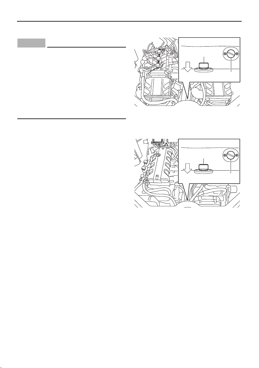
Operation and handling requirements
125
Draining the bilge water
NOTICE
Do not run the engines at full throttle
when bilge water remains in the engine
compartment. The bilge water can
splash into the engines, which can result
in severe damage.
Be sure all drain plugs are tightened be-
fore operating your boat. Otherwise,
water may flood the boat and cause it to
submerge.
Draining the bilge water on land
This model is equipped with a fuel tank com-
partment drain plug, engine compartment
drain plug, and hull drain plug.
To drain the bilge water from the various
compartments, see the following sections.
Draining the bilge water from the fuel tank
compartment and engine compartment
If there is fuel or a fuel/water mixture in the
engine compartment, wipe it up immediately
with dry rags. WARNING! This indicates a
fuel leak. Do not operate the boat until the
source of the fuel leak is found and cor-
rected. Gasoline and its vapors are highly
flammable and explosive.
(1) Open the engine hood.
(2) Remove the fuel tank compartment drain
plug to drain the water.
(3) Remove the engine compartment drain
plug to drain the water.
AR210 / SX210
1 Fuel tank compartment drain plug
2 Engine compartment drain plug
212X / 212S / 212
1 Fuel tank compartment drain plug
2 Engine compartment drain plug
(4) If the boat was operated in salt water,
wash down the compartment with fresh
water.
(5) Securely install the drain plugs in their
original positions.
(6) Close the engine hood.
1
2
BOW
1
2
BOW
SportsBoat_F3R13.book Page 125 Friday, May 31, 2019 9:42 AM
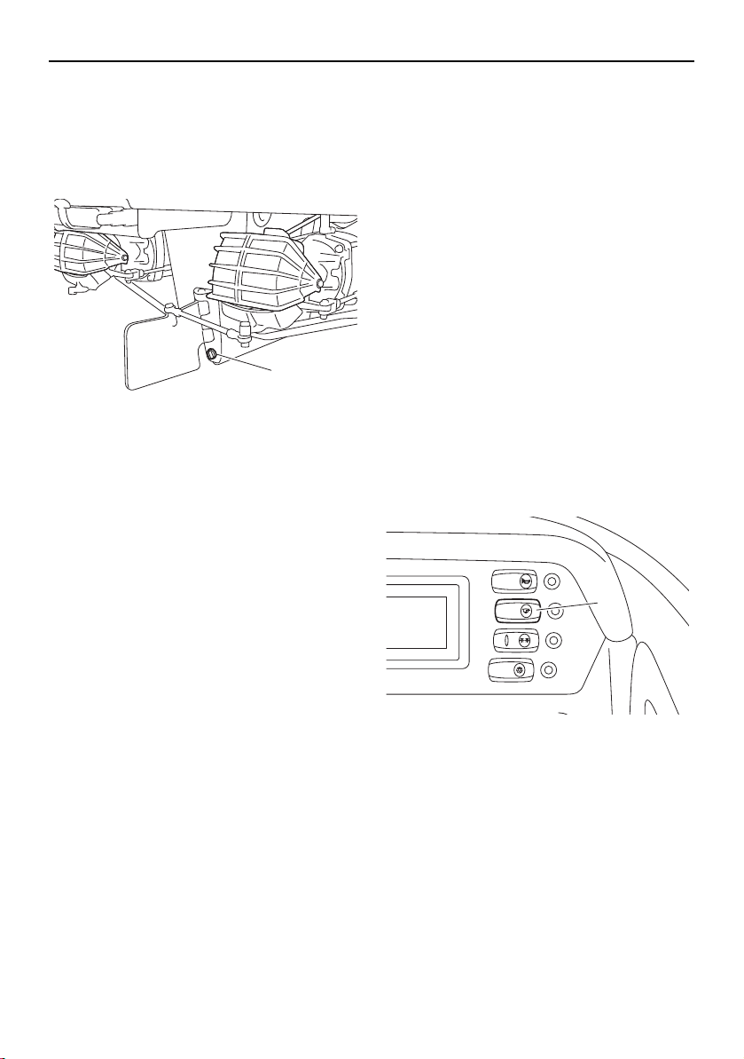
Operation and handling requirements
126
Draining the bilge water from the hull
Remove the hull drain plug at the stern to
drain the water. Check the condition of the
O-ring on the hull drain plug, and then se-
curely install the drain plug.
1 Hull drain plug
Draining the bilge water on water
This model is equipped with a self-draining
deck and bilge pump to drain the bilge water
on water.
Self-draining deck
Most water that enters the deck area drains
automatically out the stern through the large
drain hole in the deck.
A one-way check valve in the drain prevents
water from traveling back to the deck while
the boat is moored or moving in reverse.
Bilge pump (AR210 / SX210)
Your boat is equipped with a drainage sys-
tem that channels water that enters the boat
from the storage compartments to the bilge
under the engine compartment.
When the bilge pump switch is turned on, the
bilge pump will operate.
1 Bilge pump switch
1
BILGE
NAVI
ANC
HORN
CTSY
LIGHTS
1
SportsBoat_F3R13.book Page 126 Friday, May 31, 2019 9:42 AM
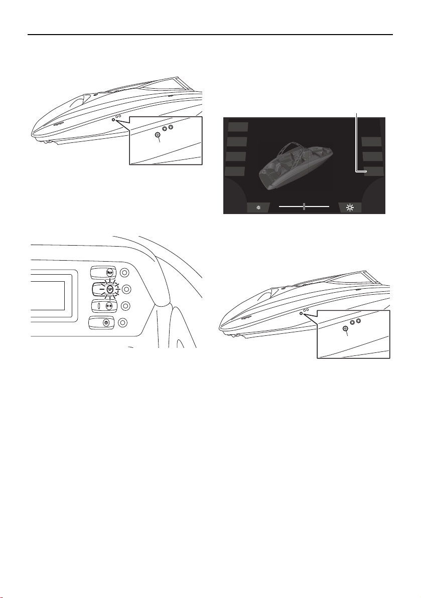
Operation and handling requirements
127
1 Bilge pump outlet
TIP:
The bilge pump indicator light comes on
while the bilge pump is operating.
Even if the bilge pump switch is not turned
on, the bilge pump will detect when there is
excessive water in the bilge and will automat-
ically drain most of it through the bilge pump
outlet. This function works automatically,
even if the battery switches are turned to the
off position.
TIP:
When the bilge pump operates automatically,
the bilge pump will not stop until most of the
bilge water is drained.
Bilge pump (212X / 212S / 212)
Your boat is equipped with a drainage sys-
tem that channels water that enters the boat
from the storage compartments to the bilge
under the engine compartment.
When the “Bilge” button is tapped, the bilge
pump will operate.
1 “Bilge” button
1 Bilge pump outlet
1
BILGE
NAVI
ANC
HORN
CTSY
LIGHTS
Dock
Interior
Navigation
Anchor
Ballast
Blower
Bilge
1
1
SportsBoat_F3R13.book Page 127 Friday, May 31, 2019 9:42 AM
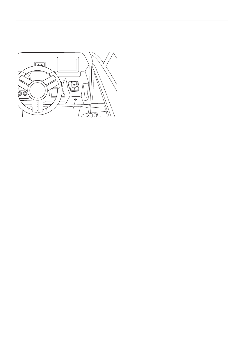
Operation and handling requirements
128
TIP:
The bilge pump indicator light comes on
while the bilge pump is operating.
1 Bilge pump indicator light
The bilge pump will operate every 2 min-
utes automatically, even if the “Bilge” but-
ton is not tapped.
Even if the “Bilge” button is not tapped to op-
erate the bilge pump, the bilge pump will de-
tect when there is excessive water in the bilge
and will automatically drain most of it through
the bilge pump outlet. This function works
automatically, even if the battery switches are
turned to the off position.
TIP:
When the bilge pump operates automatically,
the bilge pump will not stop until most of the
bilge water is drained.
1
SportsBoat_F3R13.book Page 128 Friday, May 31, 2019 9:42 AM

129
First-time operation
Engine break-in
(AR210 / SX210)
NOTICE
Failure to perform the engine break-in
could result in reduced engine life or even
severe engine damage.
The engine break-in period is essential to al-
low the various components of the engines to
wear and polish themselves to the correct
operating clearances. This ensures proper
performance and promotes longer compo-
nent life.
(1) Check the engine oil level. (See page 122
for information on checking the engine
oil level.)
(2) Launch the boat and start the engines.
(See page 144 for information on starting
the engines.)
(3) For the first 5 minutes, operate with the
engines at idling speed.
(4) For the next 30 minutes, operate with the
engines speed below 5000 r/min.
(5) For the next 1 hour, operate with the en-
gines speed below 6500 r/min.
After the engine break-in is complete, the
boat can be operated normally.
Engine break-in
(212X / 212S / 212)
NOTICE
Failure to perform the engine break-in
could result in reduced engine life or even
severe engine damage.
The engine break-in period is essential to al-
low the various components of the engines to
wear and polish themselves to the correct
operating clearances. This ensures proper
performance and promotes longer compo-
nent life.
(1) Check the engine oil level. (See page 123
for information on checking the engine
oil level.)
(2) Launch the boat and start the engines.
(See page 144 for information on starting
the engines.)
(3) For the first 5 minutes, operate with the
engines at trolling speed.
(4) For the next 30 minutes, operate with the
engines speed below 5000 r/min.
(5) For the next 1 hour, operate with the en-
gines speed below 6000 r/min.
After the engine break-in is complete, the
boat can be operated normally.
SportsBoat_F3R13.book Page 129 Friday, May 31, 2019 9:42 AM
130
Pre-operation checks
WARNING
Failure to inspect or maintain the boat properly increases the possibility of an accident
or damage to the boat. Do not operate the boat if you find any problem.
If a problem cannot be corrected by the procedures provided in this manual, have the
boat inspected by a Yamaha Boat Dealer.
Pre-operation checklist
Before operating this boat, perform the checks in the following checklist. Always follow the in-
spection and maintenance procedures and schedules described in this owner’s/operator’s man-
ual.
Pre-operation checks should be made each time the boat is used. These checks can be com-
pleted in a short time. It is worth the time spent to ensure safety and reliability.
ITEM CHECK PAGE
PRE-LAUNCH CHECKS
Steering system Check for proper steering operation. 132
Remote control levers Check for proper throttle operation.
Check for proper shift operation.
132
Fire extinguisher Check readiness of the extinguisher. 133
Hull Check hull for damage and cracks before launching. —
Access port caps Check for proper installation. 134
Jet intakes Check that no debris is in the intakes before launching. 135
Fuel system Check fuel system for leaks. 135
Engine oil level Check engine oil level; add as necessary. 122, 123
Battery Check battery condition, mounting, and connection. 137
Bilge water Check the engine compartment and fuel tank compart-
ment for bilge water.
137
Drain plugs Check the drain plugs for damage and foreign material
and check that they are securely installed.
137
Engine compartment and
blowers
Open the engine hood and check to be sure no gasoline,
gasoline vapors, or loose electrical connections are
present. Operate the blowers for at least 4 minutes.
138, 139
Engine hood Check that the hood latch is secure. 97
Lights and horn Check lights to be sure they operate. Push the horn
switch/button to be sure it operates.
139, 141
Bimini top Check that the top is secure. 113, 117
Engine shut-off cord (lan-
yard)
Check the engine shut-off cord (lanyard) for damage. 141
Collapsible tower fasteners
(AR210 / 212X / 212S)
Check that the tower fasteners are secured. 110
SportsBoat_F3R13.book Page 130 Friday, May 31, 2019 9:42 AM

Pre-operation checks
131
The steering and shifting pre-operation checks will require two persons: one person to oper-
ate the controls and one person to observe the proper operation at the stern.
POST-LAUNCH CHECKS
Switches Check operation of the main switches and engine shut-
off switch.
141
Cooling water pilot outlets Check that water comes out while the engines are run-
ning.
142
Fuel level Check fuel level; add as necessary. 142
ITEM CHECK PAGE
SportsBoat_F3R13.book Page 131 Friday, May 31, 2019 9:42 AM
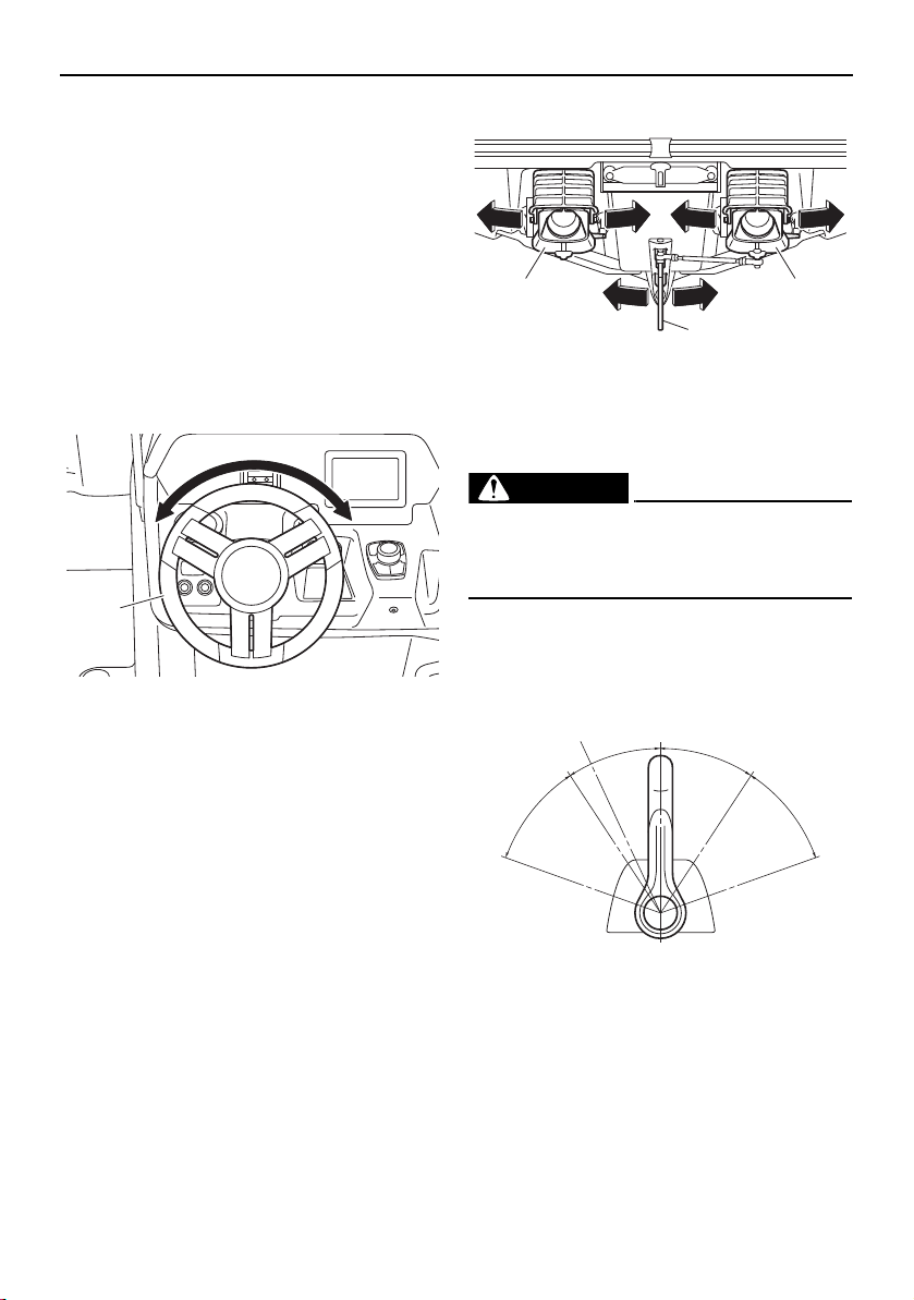
Pre-operation checks
132
Pre-operation check points
Pre-launch checks
Perform the pre-launch checks in the pre-op-
eration checklist while the boat is on land.
Steering system checks
Make sure the steering wheel is not loose.
There should not be any free play, either in-
and-out or in rotation. Turn the steering wheel
fully to the right and left to make sure opera-
tion is smooth and unrestricted throughout
the whole range.
1 Steering wheel
Make sure both jet thrust nozzles change di-
rections as the steering wheel is turned. The
jet thrust nozzles should point to starboard
(right) when the wheel is turned to the right.
The jet thrust nozzles should point to port
(left) when the wheel is turned to the left.
There should not be free play between the
steering wheel and the jet thrust nozzles. In
addition, check that the direction of the artic-
ulating keel changes according to the move-
ment of the jet thrust nozzles.
1 Jet thrust nozzle
2 Articulating keel
Remote control lever checks
WARNING
Do not touch the shift gates while the re-
mote control levers are being operated,
otherwise, you could be pinched.
Operate the remote control levers several
times to make sure that operation is smooth
throughout the whole range.
1 Neutral position
2 TDE position
3 Forward position
4 Reverse position
5 Shift
6 Fully closed
7 Throttle
8 Fully open
1
1 1
2
N
1
F
8
7
3
R
4
2
55
7
6
8
6
SportsBoat_F3R13.book Page 132 Friday, May 31, 2019 9:42 AM
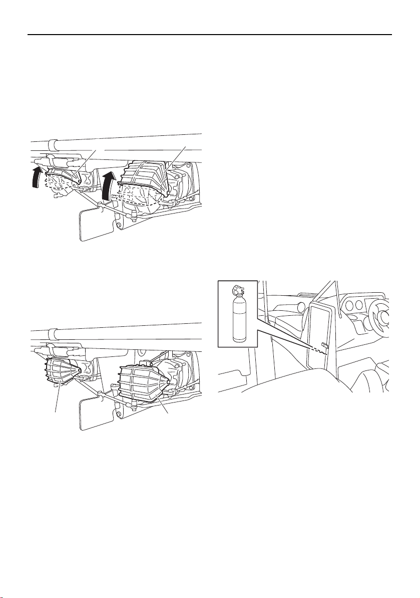
Pre-operation checks
133
Check that the shift gates are slightly above
the shift gate neutral position when the re-
mote control levers are in the forward posi-
tion, and that the shift gates are in the fully
open position when the remote control levers
are moved farther forward.
Fully open position
1 Shift gate
Check that the shift gates are in the fully
closed position when the remote control le-
vers are in the reverse position.
Fully closed position
1 Shift gate
Fire extinguisher check
As an inboard boat less than 26 feet in length,
your boat must be fitted with one B-1 type fire
extinguisher when navigating waters con-
trolled by the U.S. Coast Guard. In addition,
most state and local boating laws require that
the craft carry a USCG-approved fire extin-
guisher whenever the boat is operated.
Make sure at least one fire extinguisher is
aboard and full; two fire extinguishers are
recommended. See the instructions supplied
by the extinguisher manufacturer to deter-
mine the indication of the condition.
A fire extinguisher is not standard equipment
with this boat. If you do not have a fire extin-
guisher, contact your local Yamaha Boat
Dealer or fire extinguisher dealer for one
meeting the proper specifications.
Storing the fire extinguisher
One fire extinguisher is to be mounted in the
driver’s side console storage compartment.
The fire extinguisher recommended for this
location is a chemical-type extinguisher with
a capacity of two pounds or more.
If you choose to have two fire extinguishers,
the other fire extinguisher is to be mounted in
the rear underseat storage compartment
(port). There is a location label outside the
compartment. This fire extinguisher located
near the engine compartment should be a
“clean agent” type designed to displace oxy-
gen, with an inert gas, such as CO
2
, or FE-
36™, and have a capacity of five pounds or
more.
1
1
1 1
SportsBoat_F3R13.book Page 133 Friday, May 31, 2019 9:42 AM
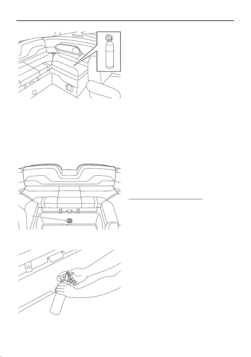
Pre-operation checks
134
Operating the fire extinguisher
A chemical-type fire extinguisher may not
help when sprayed into the engine compart-
ment through the FIRE-PORT™ because that
type needs to be aimed directly at the base of
the flames to be effective. See below for
FIRE-PORT™ information.
1 FIRE-PORT™
A FIRE-PORT™ is mounted below the rear
center seat. Use this port to spray the con-
tents of a fire extinguisher into the engine
compartment if a fire breaks out in the engine
area. WARNING! If there is a fire in the en-
gine compartment, opening the hatch will
add more oxygen to the fire, increasing
the risk of a larger fire or an explosion.
If you see smoke or otherwise suspect a fire,
you can look through the transparent flaps of
the FIRE-PORT™ to look for signs of flames.
If there is a fire, push the nozzle of the fire ex-
tinguisher through the FIRE-PORT™ and fol-
low the manufacturer’s instructions to empty
the contents of the fire extinguisher into the
engine compartment.
A “clean agent” type fire extinguisher is rec-
ommended; a chemical-type fire extinguisher
may not be adequate in this application.
Access port cap check
Make sure that the access port caps are se-
curely installed.
To check the access port caps:
(1) Open the rear platform hatch. (See page
103 for information on the rear platform
hatch.)
(2) Make sure that the access port caps are
securely installed. If they are removed or
are not locked, securely install them.
(See page 182 for information on the ac-
cess port caps.)
1
SportsBoat_F3R13.book Page 134 Friday, May 31, 2019 9:42 AM
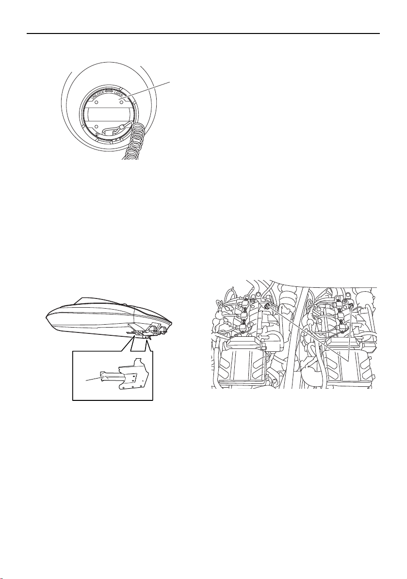
Pre-operation checks
135
1 Access port cap
(3) Close the rear platform hatch.
Jet intake checks
Carefully check the jet intakes under the boat
for weeds, debris, or anything else that might
restrict the intake of water. If the intakes are
clogged, cavitation could occur, reducing jet
thrust, and possibly damaging jet pump
parts.
1 Jet intake
In some cases, the engines may overheat be-
cause of a lack of cooling water, and damage
could result. If the jet intakes are clogged,
clean them. (See page 182 for information on
the jet intakes.) WARNING! Rotating parts
could cause severe injury or death. Before
attempting to remove weeds or debris
from the jet intakes or impeller areas; shut
off the engines, remove the main switch
keys, and then remove the engine shut-off
cord (lanyard) from the engine shut-off
switch.
Fuel system checks
Check the fuel filler hoses and joints in the en-
gine compartment for damage, looseness,
and signs of leaking. At least annually, or if a
problem is suspected, check the fuel tank
and fuel filler hoses and clamps. Have a
Yamaha Boat Dealer check the fuel tank and
fuel filler hoses and clamps.
Engine oil level check
Make sure that the engine oil level is between
the minimum level mark and maximum level
mark on the dipstick. (See page 122, 123 for
information on checking the engine oil level.)
3-star models (AR210 / SX210)
1 Oil tank filler cap/Dipstick
1
1
1
SportsBoat_F3R13.book Page 135 Friday, May 31, 2019 9:42 AM
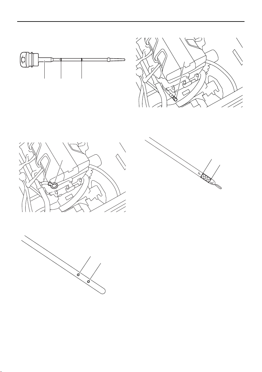
Pre-operation checks
136
1 Dipstick
2 Maximum level mark
3 Minimum level mark
3-star models (212X / 212S / 212)
1 Dipstick
1 Maximum level mark
2 Minimum level mark
4-star models (212X / 212S)
1 Dipstick
1 Maximum level mark
2 Minimum level mark
21 3
1
2
1
1
2
1
SportsBoat_F3R13.book Page 136 Friday, May 31, 2019 9:42 AM
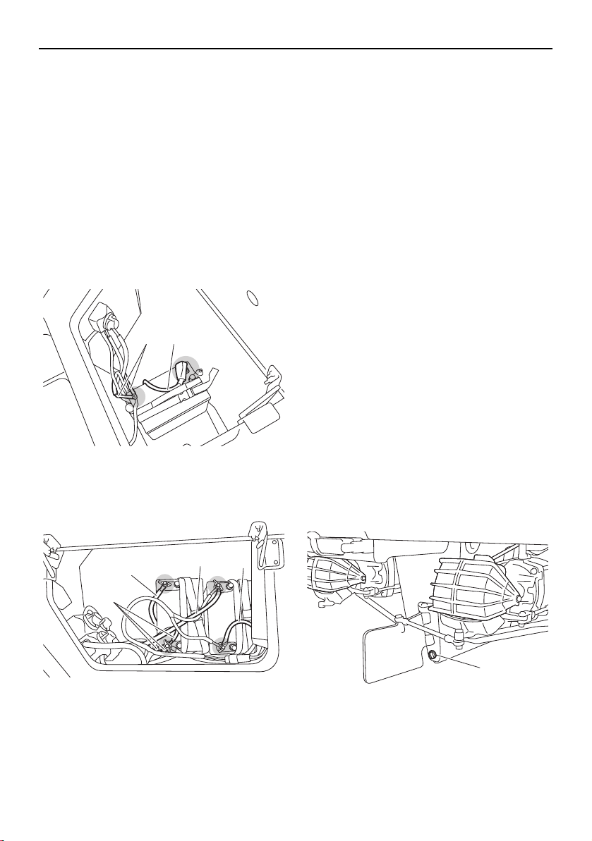
Pre-operation checks
137
Battery check
Make sure that the battery terminals are not
damaged and that the battery leads are con-
nected properly. (See pages 165 and 166 for
battery cover removal and installation proce-
dures.) WARNING! The battery must al-
ways be fully charged and in good
condition. Loss of battery power may
leave you stranded. Never operate the
boat if the battery does not have sufficient
power to start the engines or if it shows
any other signs of decreased power.
AR210 / SX210
1 Positive (+) battery terminal: Red lead
2 Negative (–) battery terminal: Black lead
212X / 212S / 212
1 Positive (+) battery terminal: Red lead
2 Negative (–) battery terminal: Black lead
Bilge water check
Make sure that no bilge water has collected in
the engine compartment and the fuel tank
compartment. If bilge water has collected in
the engine compartment and the fuel tank
compartment, drain it. (See page 125 for in-
formation on draining the bilge water.)
Drain plug check
Loosen the drain plugs and remove them,
and then make sure that the plugs and the
O-ring on the hull drain plug are not damaged
and that there is no foreign material on the
threads or the O-ring on the hull drain plug.
NOTICE: Before installing the drain plugs,
clean the drain plug threads and the O-
ring on the hull drain plug to remove any
foreign materials, such as dirt or sand.
Otherwise, the drain plugs could be dam-
aged, allowing water to enter the engine
compartment or the fuel tank compart-
ment. Make sure that the drain plugs are
tightened securely before launching the
boat. Otherwise, water may flood the boat
and cause it to submerge.
Securely install the drain plugs by tightening
them until they stop.
1 Hull drain plug
12
2
1
1
2
1
SportsBoat_F3R13.book Page 137 Friday, May 31, 2019 9:42 AM
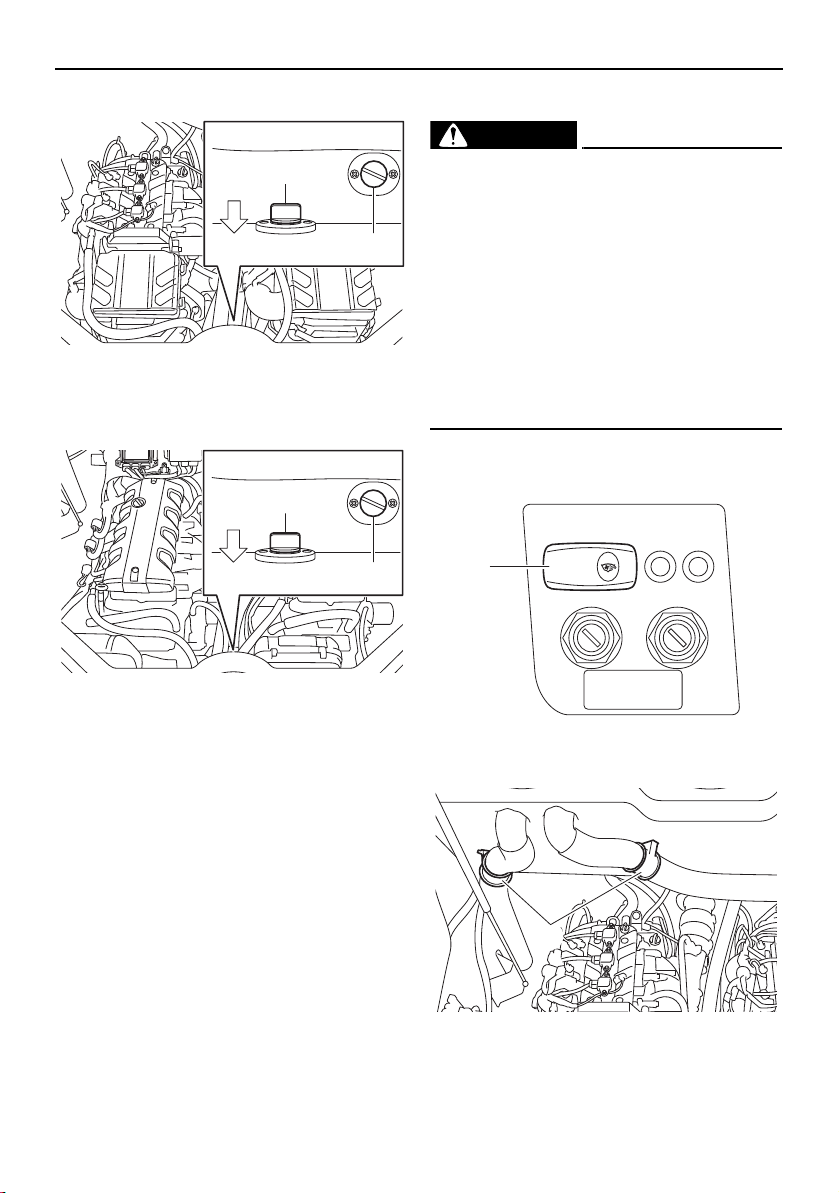
Pre-operation checks
138
AR210 / SX210
1 Fuel tank compartment drain plug
2 Engine compartment drain plug
212X / 212S / 212
1 Fuel tank compartment drain plug
2 Engine compartment drain plug
Blower switch check (AR210 / SX210)
WARNING
Gasoline vapors can explode. Before
starting the engines, check the engine
compartment for gasoline, gasoline va-
pors, and loose electrical connections,
and then operate the blowers for at least 4
minutes. Do not start the engines or oper-
ate the blowers if you can smell gasoline
vapors in the engine compartment or if
there are any loose electrical connections.
Contact a Yamaha Boat Dealer if there is a
problem you cannot locate or correct.
Make sure that the blowers operate properly
when the blower switch is pushed.
1 Blower switch
1 Blower
1
2
BOW
1
2
BOW
BLOWER
1
1
SportsBoat_F3R13.book Page 138 Friday, May 31, 2019 9:42 AM
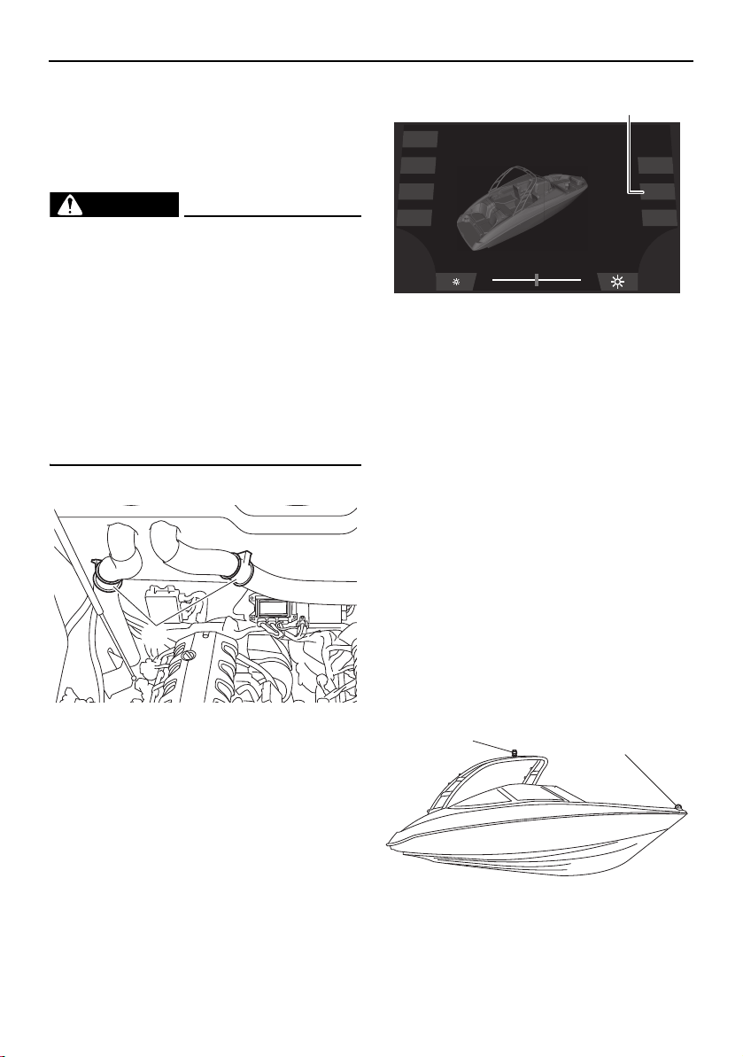
Pre-operation checks
139
Push the blower switch to operate the blow-
ers and ventilate the engine compartment for
at least 4 minutes.
Blower checks (212X / 212S / 212)
WARNING
Gasoline vapors can explode. Before
starting the engines, check the engine
compartment for gasoline, gasoline va-
pors, and loose electrical connections,
and then operate the blowers for at least 4
minutes. Do not start the engines or oper-
ate the blowers if you can smell gasoline
vapors in the engine compartment or if
there are any loose electrical connections.
Contact a Yamaha Boat Dealer if there is a
problem you cannot locate or correct.
Make sure that the blowers operate properly.
1 Blower
(1) Tap the “Blower” button and check that
the blowers operate.
1 “Blower” button
(2) Tap the “Blower” button to turn off the
blowers.
Navigation and anchor lights switch
check (AR210 / SX210)
Make sure that the bow light and anchor light
operate properly.
The procedure for setting up the anchor light
varies according to the model. See the page
indicated below for your boat.
SX210: See page 106.
TIP:
SX210: Before operating the boat in daylight
hours after checking the navigation and an-
chor lights, store the anchor light.
AR210
1 Bow light
2 Anchor light
1
Dock
Interior
Navigation
Anchor
Ballast
Blower
Bilge
1
1
2
SportsBoat_F3R13.book Page 139 Friday, May 31, 2019 9:42 AM
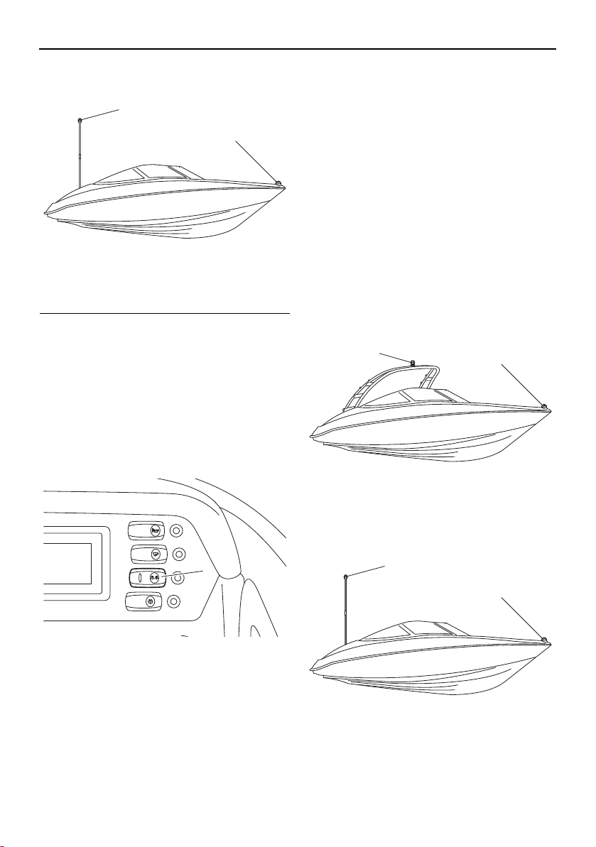
Pre-operation checks
140
SX210
1 Bow light
2 Anchor light
To check the operation using the switch panel:
Push the right side of the navigation and an-
chor lights switch and check that the bow
light and anchor light come on.
Push the left side of the navigation and an-
chor lights switch and check that only the an-
chor light comes on.
Put the navigation and anchor lights switch in
the middle position and check that the bow
light and anchor light are off.
1 Navigation and anchor lights switch
Navigation and anchor lights checks
(212X / 212S / 212)
Make sure that the bow light and anchor light
operate properly.
The procedure for setting up the anchor light
varies according to the model. See the page
indicated below for your boat.
212: See page 106.
TIP:
212: Before operating the boat in daylight
hours after checking the navigation and an-
chor lights, store the anchor light.
212X / 212S
1 Bow light
2 Anchor light
212
1 Bow light
2 Anchor light
1
2
BILGE
NAVI
ANC
HORN
CTSY
LIGHTS
1
1
2
1
2
SportsBoat_F3R13.book Page 140 Friday, May 31, 2019 9:42 AM
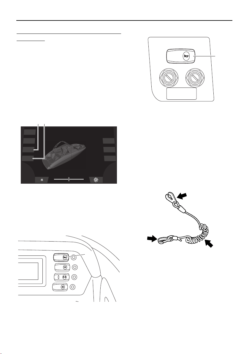
Pre-operation checks
141
To check the operation using the multi-func-
tion display:
(1) Tap the “Navigation” light button on the
system control screen. Check that the
bow light and anchor light come on when
the button is blue and that both lights go
off when the button is gray.
(2) Tap the “Anchor” light button on the sys-
tem control screen. Check that only the
anchor light comes on when the button is
blue and that the anchor light goes off
when the button is gray.
1 “Navigation” light button
2 “Anchor” light button
Horn check
Push the horn switch/button and check that
the horn sounds.
AR210 / SX210
1 Horn switch
212X / 212S / 212
1 Horn button
Engine shut-off cord (lanyard) check
Make sure that the engine shut-off cord (lan-
yard) is not damaged. If the cord is damaged,
replace it. WARNING! Never try to repair
the engine shut-off cord (lanyard) or tie it
together. The engine shut-off cord (lan-
yard) may not pull free when the operator
falls off, allowing the boat to continue to
run and cause an accident.
Post-launch checks
Perform the post-launch checks in the pre-
operation checklist while the boat is in the
water and the engines are running.
Engine shut-off switch check
Check the engine shut-off switch for proper
operation.
Dock
Interior
Navigation
Anchor
Ballast
Blower
Bilge
21
BILGE
NAVI
ANC
HORN
CTSY
LIGHTS
1
HORN
1
SportsBoat_F3R13.book Page 141 Friday, May 31, 2019 9:42 AM
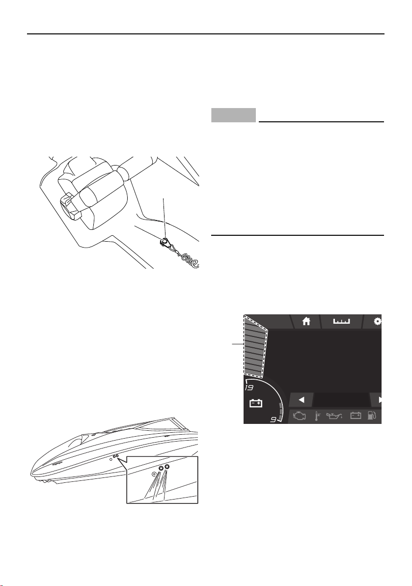
Pre-operation checks
142
(1) Start the engines. (See page 144 for in-
formation on starting the engines.)
(2) Pull the engine shut-off cord (lanyard) to
remove the clip from the engine shut-off
switch to make sure that the engines
stop immediately.
(3) Make sure that the engines cannot be
started with the clip removed from the
engine shut-off switch.
1 Engine shut-off switch
2 Clip
Cooling water pilot outlet check
Check that water comes out from the pilot
outlets while the engines are running in the
water. If water is not circulating, something
may be clogging the intake grates. Refer to
“Jet pump clean-out procedure” on page
182.
TIP:
It may take up to 20 seconds for water to
reach the pilot outlets when first launching
the boat. The amount and force of the exiting
water will vary with engine speed.
NOTICE
A continuous flow of water from the pilot
outlets shows that water is flowing
through the engine cooling water passag-
es. If water is not flowing out of the pilot
outlets during operation, do not continue
to run the engines. Overheating and seri-
ous damage could occur. (See “Over tem-
perature warning” on page 55, 90 for more
information.)
Fuel level check
Check the amount of fuel remaining in the
fuel tank using the fuel level bar graph on the
multi-function display.
AR210 / SX210
1 Fuel level bar graph
1
2
am10:27
FUEL
100
%
12.3V
MP
H
0
0.3 Avg MPG
1
SportsBoat_F3R13.book Page 142 Friday, May 31, 2019 9:42 AM


144
Operation
Driving your boat
Getting to know your boat
Operating your boat requires skills acquired
through practice over a period of time. Take
the time to learn the basic techniques well
before attempting more difficult maneuvers.
Boating with your new boat can be a very en-
joyable activity, providing you with hours of
pleasure. But it is essential to familiarize your-
self with the operation of the boat to achieve
the skill necessary to enjoy boating safely.
Before operating this boat, read this own-
er’s/operator’s manual, the Operation In-
struction card, and all labels on the boat. Pay
particular attention to the safety information
beginning on page 15. These materials
should give you an understanding of the boat
and its operation. This boat is designed to
carry one operator and up to 9 passengers.
Learning to operate your boat
Before boating, always perform the pre-oper-
ation checks listed on page 130. The short
time spent checking the boat will reward you
with added safety and reliability.
Know and follow U.S. Coast Guard, state,
and local laws when operating your boat.
Select a wide area to learn in, where visibility
is good and other boat traffic is light. Keep
the proper distance from other boats and ve-
hicles. Do not operate where people are
swimming.
Always attach the engine shut-off cord (lan-
yard) to your PFD before operating.
You and all other passengers must always
wear a USCG-approved PFD when riding in
the boat. You should consider wearing water
shoes, eye protection, and other protective
apparel. Water sports increase your risk of in-
jury from contact with your boat, other ves-
sels, docks, rocks, or coral.
Grip the steering wheel firmly and keep both
feet on the deck when driving the boat.
Starting the engines
WARNING
Severe injury or death may result if you ig-
nore any of the following:
Before operating your boat, become fa-
miliar with all controls. Consult a
Yamaha Boat Dealer about any control
or function you do not fully understand.
Failure to understand how the controls
work could cause an accident or pre-
vent you from avoiding an accident.
Maximum load (212X):
Total weight of cargo, operator, and
passengers:
952 kg (2100 lb): ballast is empty
495 kg (1092 lb): ballast is full
Total weight of operator and passen-
gers:
843 kg (1860 lb): ballast is empty
386 kg (852 lb): ballast is full
Maximum load (except for 212X):
Total weight of cargo, operator, and
passengers:
997 kg (2200 lb)
Total weight of operator and passen-
gers:
843 kg (1860 lb)
SportsBoat_F3R13.book Page 144 Friday, May 31, 2019 9:42 AM
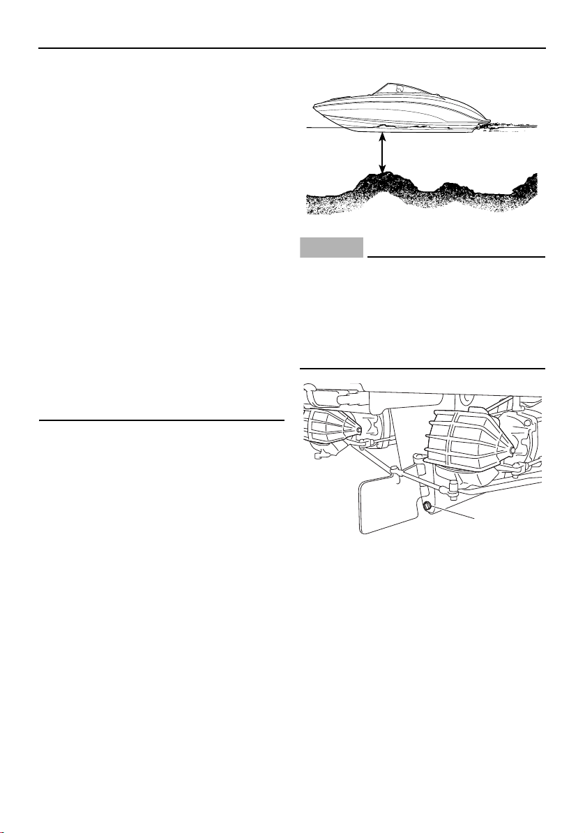
Operation
145
Gasoline vapors can explode. Before
starting the engines, check the engine
compartment for gasoline, gasoline va-
pors, and loose electrical connections,
and then operate the blowers for at least
4 minutes. Do not start the engines or
operate the blowers if you can smell
gasoline vapors in the engine compart-
ment or if there are any loose electrical
connections. Contact a Yamaha Boat
Dealer if there is a problem you cannot
locate or correct.
Attach the engine shut-off cord (lanyard)
to your PFD before operating. Failure to
attach the cord could result in a run-
away boat if the operator is ejected.
Do not apply throttle when anyone is at
the rear of the boat. Turn the engines off
or keep them at idle. Water and debris
exiting the jet thrust nozzles can cause
severe injury.
(1) Always make sure the boat is launched
and used in waters that are free from
weeds and debris, and at least 90 cm
(3 ft) deep from the bottom of the boat.
WARNING! Never operate in water
that is less than 90 cm (3 ft) deep from
the bottom of the boat. You increase
your chance of hitting an underwater
obstacle. You could be injured. Peb-
bles or sand can also be sucked into
the jet intakes, damaging the impel-
lers.
NOTICE
There is a hull drain plug at the bottom of
the stern. Check the O-ring on the hull
drain plug and make sure that the plug is
tightened securely before launching the
boat. Otherwise, water may flood the boat
and cause it to submerge.
1 Hull drain plug
(2) Turn the battery switch to the ON (green)
position.
(3) AR210 / SX210: Push the blower switch
to operate the blowers and ventilate the
engine compartment for at least 4 min-
utes.
90 cm (3 ft)
1
SportsBoat_F3R13.book Page 145 Friday, May 31, 2019 9:42 AM
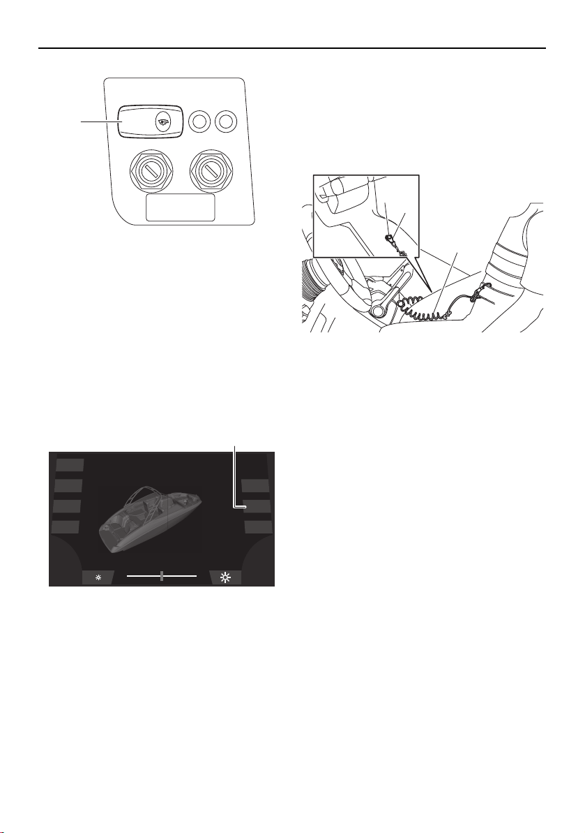
Operation
146
1 Blower switch
(4) 212X / 212S / 212: Turn the main switch
keys to the on position to operate the
blowers automatically for 5 minutes.
TIP:
To operate the blowers manually, tap the
“Blower” button. Ventilate the engine com-
partment for at least 4 minutes, and then tap
the “Blower” button again to turn off the
blowers.
1 “Blower” button
(5) Attach the engine shut-off cord (lanyard)
to your PFD. Install the clip onto the en-
gine shut-off switch by pushing the clip
groove over the nut beneath the knob.
Be sure the cord is not wrapped around
the steering wheel or tangled in the con-
trols. WARNING! Check that the en-
gine shut-off cord (lanyard) is
attached correctly. If the engine shut-
off cord (lanyard) is not attached cor-
rectly, it may not pull free when the
operator falls off, allowing the boat to
continue to run and cause an acci-
dent.
1 Engine shut-off switch
2 Clip
3 Engine shut-off cord (lanyard)
TIP:
The engines will not start when the clip is re-
moved from the engine shut-off switch. The
starter motors will turn over without the cord
attached.
(6) Put the remote control levers in the neu-
tral position. The starter motors will not
operate unless the remote control levers
are in neutral.
(7) Turn the main switch keys to the start po-
sition and release them when the en-
gines start. If the engines do not start
after 5 seconds of cranking, release the
keys. Wait at least 15 seconds before
trying to start the engines again.
BLOWER
1
Dock
Interior
Navigation
Anchor
Ballast
Blower
Bilge
1
2
1
3
SportsBoat_F3R13.book Page 146 Friday, May 31, 2019 9:42 AM
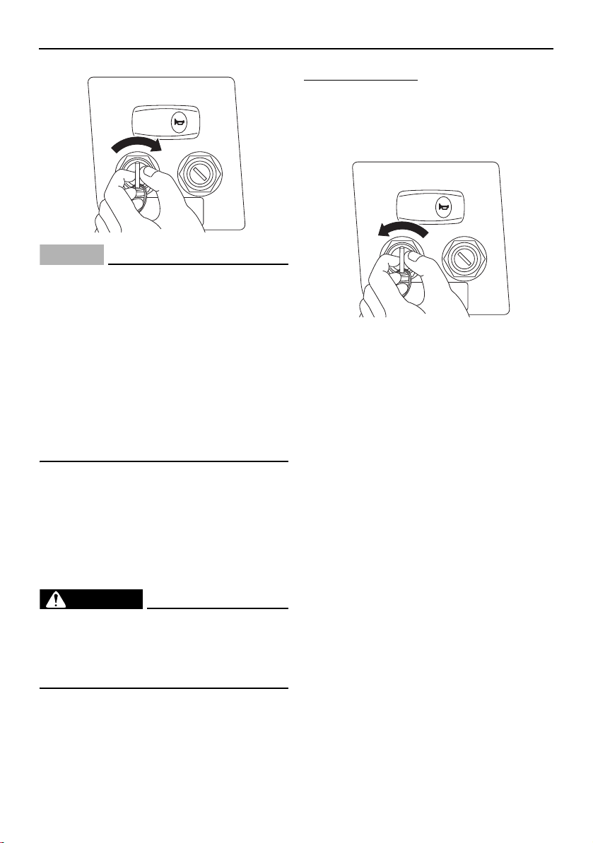
Operation
147
NOTICE
Never turn the main switch keys to the
start position while the engines are run-
ning. The starter mechanisms could be
damaged.
If the starter motors are engaged con-
tinuously for more than 5 seconds, the
battery will become quickly discharged
and it will be impossible to start the en-
gines. The starter motors may also be
damaged if they are engaged continu-
ously for more than 5 seconds.
On this boat, the engines are connected di-
rectly to the drive units. Starting either engine
generates some thrust immediately. Only
enough throttle should be applied to keep the
engine at a fast enough idle to stay running.
Stopping the engines
WARNING
Once the engines have stopped, you have
NO STEERING CONTROL over the boat.
You could collide with another boat, a
dock, or other obstacle.
Stopping the engines immediately after oper-
ating at high engine speeds is not recom-
mended. Let the engines cool off at idle or
low speed for a few minutes first.
To stop the engines:
(1) Return the remote control levers to the
neutral position.
(2) Turn the main switch keys to the off po-
sition.
TIP:
The engines can also be stopped by pulling
the engine shut-off cord (lanyard).
(3) Remove the main switch keys and the
engine shut-off cord (lanyard) if the boat
will be left unattended.
Leaving a dock
Because boats steer from the stern, the stern
first moves in the direction opposite your de-
sired turn. It is especially important to under-
stand this characteristic when leaving a dock.
If you move the remote control levers to the
forward position and simply turn the steering
wheel to steer the bow away from the dock,
as you would when driving a car out of a
parking space, you will drive the stern of the
boat into the dock.
The following steps are basic maneuvering
techniques which can be used in most cir-
cumstances:
(1) With the engines idling and the bow still
moored to the dock, turn the steering
wheel toward the dock. Moving the re-
mote control levers into the TDE position
HORN
HORN
SportsBoat_F3R13.book Page 147 Friday, May 31, 2019 9:42 AM
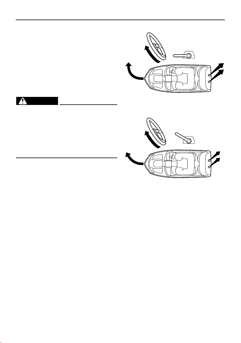
Operation
148
or forward position will start to move the
stern of the boat away from the dock.
(2) When the stern is out a few feet, release
the bow mooring, and then turn the
steering wheel to the center position or
away from the dock. Move the remote
control levers into the reverse position
and move away from the dock.
Turning the boat
WARNING
Do not pull the remote control levers
back to idle when trying to steer away
from objects — you need throttle to
steer.
Be sure passengers are holding on be-
fore making turns. An unprepared pas-
senger could lose balance and fall.
Steering control depends on the combination
of steering wheel position and the amount of
throttle.
Water sucked in through the intake grates is
pressurized by the impellers in the jet pumps.
As the pressurized water is expelled from the
pumps through the jet thrust nozzles, it cre-
ates thrust to move and steer the boat. The
higher the engine speed, the more thrust is
produced.
The amount of jet thrust, in addition to the po-
sition of the steering wheel, determines how
sharply you turn.
A. More throttle produces high thrust, so
the boat will turn more sharply.
B. Less throttle produces low thrust, so the
boat will turn more gradually.
C. Pulling the remote control levers back to
idle or the neutral position produces only
minimum thrust. If you are traveling at
speeds above trolling, you will have rap-
idly decreasing ability to steer without
throttle. You may still have some turning
ability immediately after pulling the re-
mote control levers back to idle, but
when the engines slow down, the boat
will no longer respond to steering wheel
input until you apply throttle again or you
reach a trolling speed.
At trolling speed, the boat can be turned
gradually by steering wheel position
alone using just the amount of thrust
available at engine idle.
A
B
SportsBoat_F3R13.book Page 148 Friday, May 31, 2019 9:42 AM
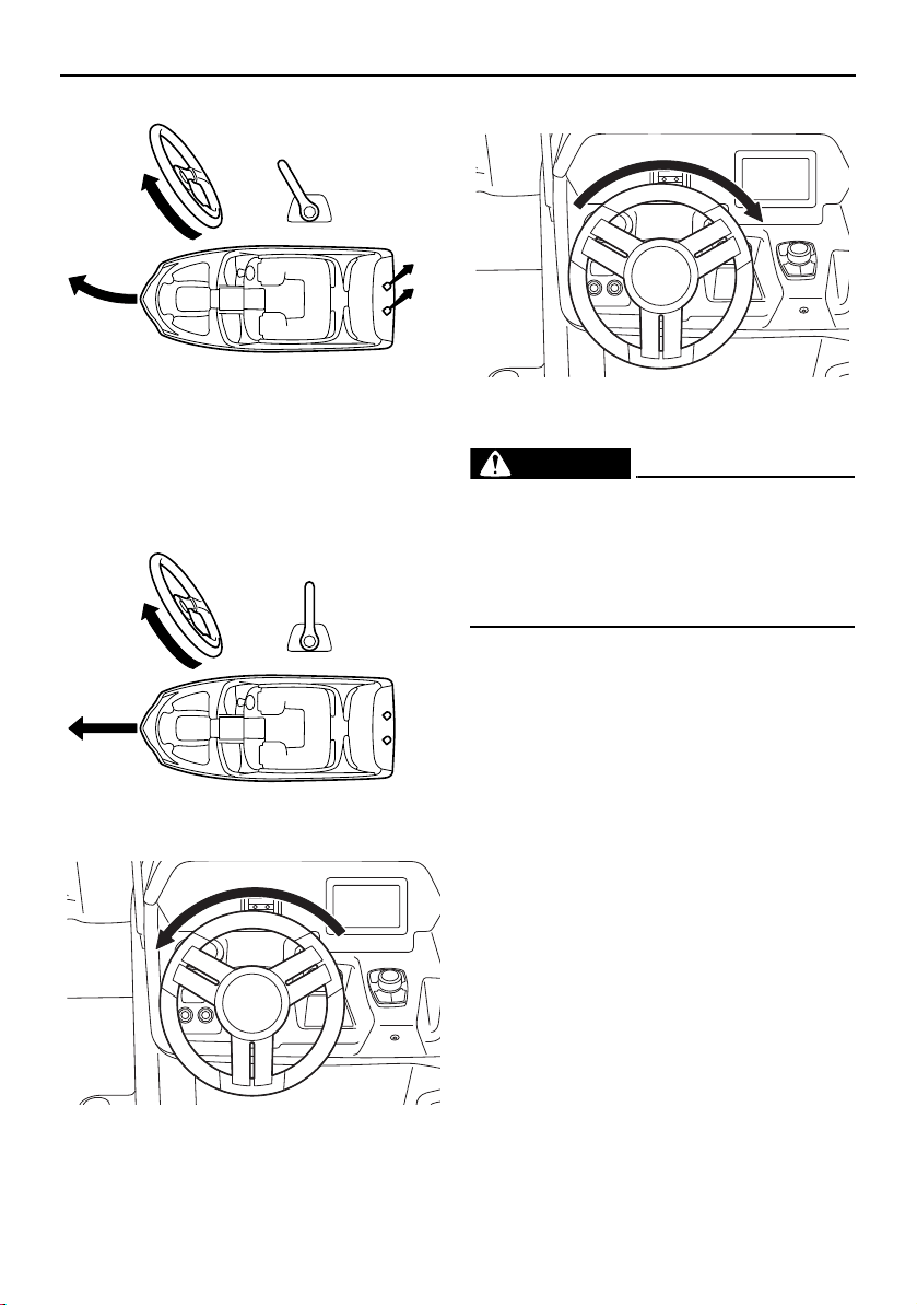
Operation
149
D. If the boat is moving and the remote con-
trol levers are in the neutral position, or if
there is no thrust because the engines
are stopped, the boat will go straight
even though the steering wheel is turned.
You need throttle to steer.
Turning left
Turning right
Boating with passengers
WARNING
When passengers are on board, make
sure they are seated and holding onto the
handgrips, handrails, or straps before you
start to accelerate. An unprepared pas-
senger could lose balance and fall.
Your boat is designed for one operator and
up to 9 passengers only. Never have more
than 10 people in the boat. Passengers must
sit in one of the seats and hold onto the hand-
grips. Passengers should sit so the weight in
the boat is balanced from side-to-side and
bow-to-stern as much as possible. If the pas-
senger seat in front of the helm is used, be
sure the operator’s view ahead is not ob-
structed.
C
D
SportsBoat_F3R13.book Page 149 Friday, May 31, 2019 9:42 AM
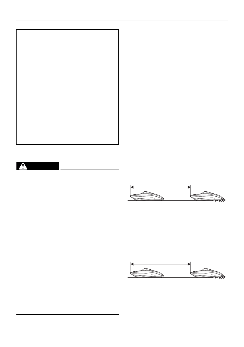
Operation
150
Stopping the boat
WARNING
Allow adequate stopping distance.
Take early action to avoid collisions. Re-
member, boats do not have brakes.
Operate defensively at safe speeds and
keep a safe distance away from people,
objects, and other boats to give you time
to stop.
Do not shut the engines off when slow-
ing down in case you need engine power
to steer away from a boat or other ob-
stacle that comes into your path.
You will lose steering control if you com-
pletely pull the remote control levers
back to idle. You need throttle to steer.
Do not use the reverse function to slow
down or stop the boat from planing
speed as it could cause you to lose con-
trol, be ejected, or impact the steering
wheel or other parts of the boat. This
could increase the risk of serious injury.
The boat is not equipped with a separate
braking system. It is stopped by water resis-
tance after the remote control levers are
moved back to idle. From full speed, the boat
stops in approximately 105 m (344 ft) for the
AR210 / SX210 or 140 m (459 ft) for the
212X / 212S / 212 after the remote control le-
vers are moved back to idle. The stopping
distance varies depending on gross weight,
water surface conditions, and wind direction.
The stated straight-line stopping distance
should be used for a reference. The boat
slows down as soon as the remote control le-
vers are returned to idle but will coast for a
distance before fully stopping. If you are not
sure you can stop in time before hitting an
obstacle, apply throttle and turn in another di-
rection.
AR210 / SX210
212X / 212S / 212
Maximum load (212X):
Total weight of cargo, operator, and
passengers:
952 kg (2100 lb): ballast is empty
495 kg (1092 lb): ballast is full
Total weight of operator and passen-
gers:
843 kg (1860 lb): ballast is empty
386 kg (852 lb): ballast is full
Maximum load (except for 212X):
Total weight of cargo, operator, and
passengers:
997 kg (2200 lb)
Total weight of operator and passen-
gers:
843 kg (1860 lb)
105 m (344 ft)
140 m (459 ft)
SportsBoat_F3R13.book Page 150 Friday, May 31, 2019 9:42 AM
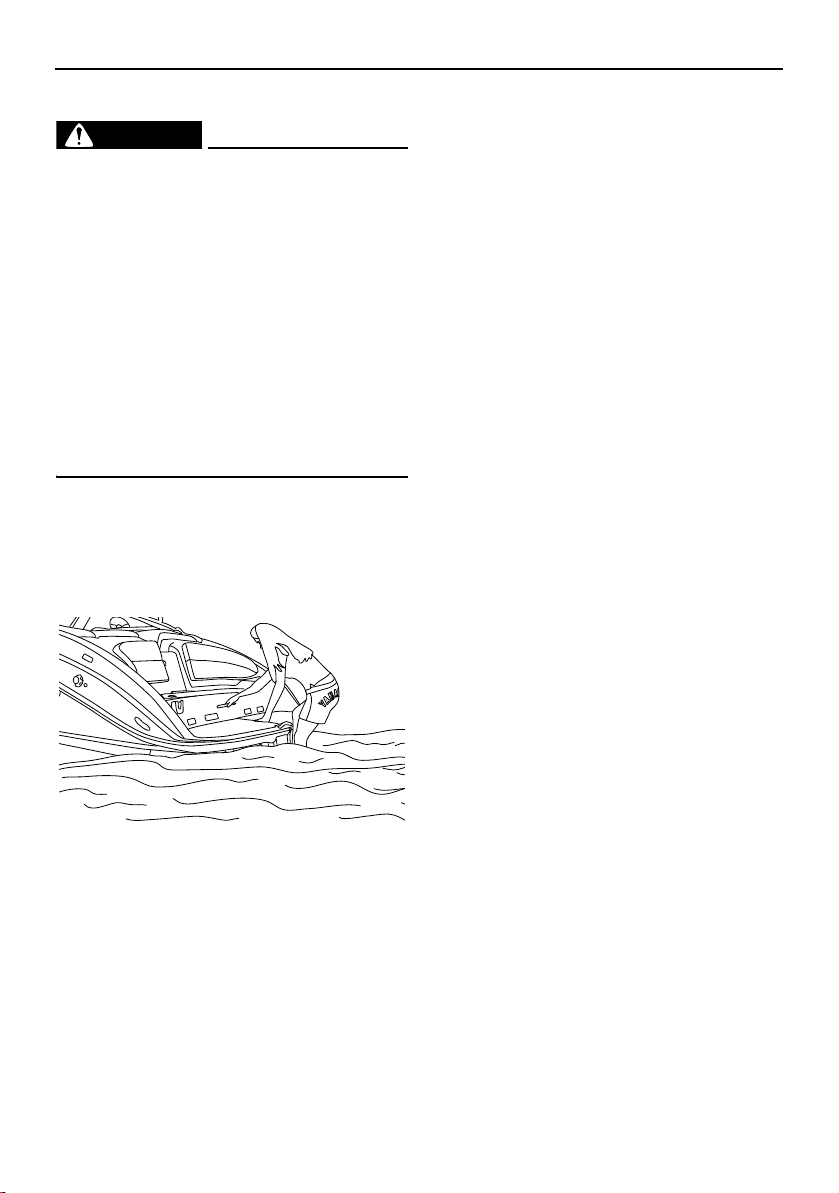
Operation
151
Boarding from the water
WARNING
To avoid severe injury or death, do not
board from the rear, use swim platform, or
swim behind boat if the engines are run-
ning.
Severe internal injuries can occur if wa-
ter is forced into body cavities as a re-
sult of being near the jet thrust nozzles.
Exhaust gases coming from underneath
the swim platform contain carbon mon-
oxide, a colorless, odorless gas which
may cause brain damage or death when
inhaled. Symptoms include nausea, diz-
ziness, and drowsiness.
(1) Be sure the engines are off, and then
move to the stern of the boat.
(2) Pull out the stern ladder and climb up
onto the swim platform. (See page 108
for information on the stern ladder.)
(3) Return the stern ladder to the stowed po-
sition, and then sit in one of the seats
provided.
Boarding from the bow
A bow ladder is available when boarding from
the bow of the boat is desired, when the boat
is beached. (See page 107 for bow ladder us-
ing procedures.)
Boarding from a dock or landing jetty
(1) Board the boat from the side. One per-
son should board at a time by stepping
into the boat. Never jump in. Avoid step-
ping on slick gelcoat surfaces on the
boat’s gunwales, especially if wet.
(2) Sit in one of the seats provided and put
both feet on the deck.
Docking
(1) Make sure no obstructions, boats, or
swimmers are close to the boat. Come to
a stop before you reach the dock.
(2) Notice how wind and water currents are
affecting boat movement as you attach
your mooring lines and fenders.
(3) Approach the dock at idle speed. Use re-
verse as necessary during slow-speed
maneuvering to help control speed and
direction. Position the boat according to
wind and water conditions. WARNING!
Do not use your hand, arm, or other
parts of your body to try to keep the
boat from hitting the dock. You could
be injured if the boat pushes against
the dock.
SportsBoat_F3R13.book Page 151 Friday, May 31, 2019 9:42 AM
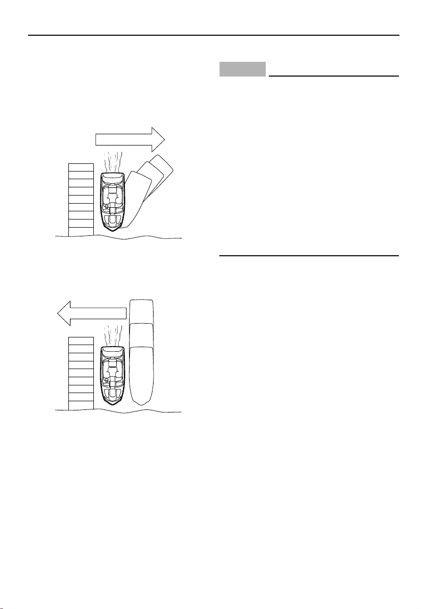
Operation
152
Wind or current pushing boat away from
dock:
Slowly approach the dock at about a 45° an-
gle. Secure the bow to the dock, and then
use engine thrust or a boat hook to gently
move the stern to the dock.
Wind or current pushing boat toward
dock:
Slowly maneuver to a shallow angle and al-
low the boat to move toward the dock.
No wind or current:
Approach the dock at a shallow angle. Se-
cure the bow to the dock, and then use en-
gine thrust or a boat hook to gently move the
stern to the dock.
Beaching
NOTICE
Small pebbles, sand, seaweed, and oth-
er debris can be sucked into the jet in-
takes and impair or damage the
impellers. Always stop the engines be-
fore beaching the boat. Be sure the boat
is in water 90cm (3 ft) deep from the
bottom of the boat before starting the
engines again.
Do not beach the boat on rocky beach-
es. The hull gelcoat and exposed pump
housings can be damaged.
Pay attention to shifts in tides. Beaching
at high tide may make it impossible to
re-launch the boat if the tide recedes.
(1) Make sure no obstructions, boats, or
swimmers are near the beach.
(2) Approach the beach slowly and stop the
engines when the water is about 90 cm
(3 ft) deep from the bottom of the boat.
Remember: turning is impossible with
the engines stopped.
(3) Get out of the boat and pull the bow up
on the beach.
(4) When leaving the beach, push the boat
out into water that is at least 90 cm (3 ft)
deep from the bottom of the boat before
starting the engines.
Wind or current
Wind or current
SportsBoat_F3R13.book Page 152 Friday, May 31, 2019 9:42 AM
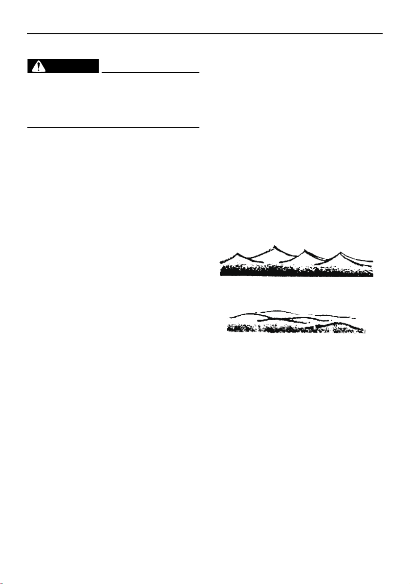
Operation
153
Anchoring
WARNING
Always anchor from the bow. Anchoring
from the stern will make the boat un-
steady. A strong current can pull a stern-
anchored boat underwater.
Select an anchor appropriate for your boat
and water conditions. A “Danforth” (or fluke)
type anchor is suitable for most applications;
your Yamaha Boat Dealer can help you
choose an anchor.
(1) Make sure the anchor line is securely tied
to the anchor and to the bow eye or a
bow cleat.
(2) Move the boat to the spot where you
want to lower the anchor, heading the
boat into the wind or current. Stop the
boat, and then lower the anchor until it
hits bottom.
(3) While keeping tension on the line, slowly
back up the boat until you have let out
line that is 4–6 times the depth of the wa-
ter. For example, if you are anchoring in
10 feet of water, let out 40–60 feet of line.
Secure the line.
(4) Pull on the line to be sure the anchor is
holding. Also, periodically check your
boat’s position against the shoreline to
make sure it is not drifting and dragging
the anchor. Reset if necessary.
(5) To pull in (“weigh”) the anchor, start the
engines and move forward, keeping ten-
sion on the line as you pull it in. When the
anchor line is straight up and down, pull
hard to lift the anchor from the bottom
material.
(6) If the anchor is stuck on the bottom, try
this: Let out a few feet of anchor line and
secure the line to the boat, again. Slowly
maneuver the boat around the anchor
until the anchor pulls loose. Keep the line
taut during this procedure.
Crossing wakes and swells
You will not always have flat, smooth water.
There will be swells and wakes from other
boats, etc.
The best way to cross wakes and swells is
with the least jolt to you and the boat. Small
swells are not as difficult to cross as larger
swells or wakes. Crossing a sharp wake gives
more of a jolt than a broad swell.
Sharp wakes
Broad swell
SportsBoat_F3R13.book Page 153 Friday, May 31, 2019 9:42 AM
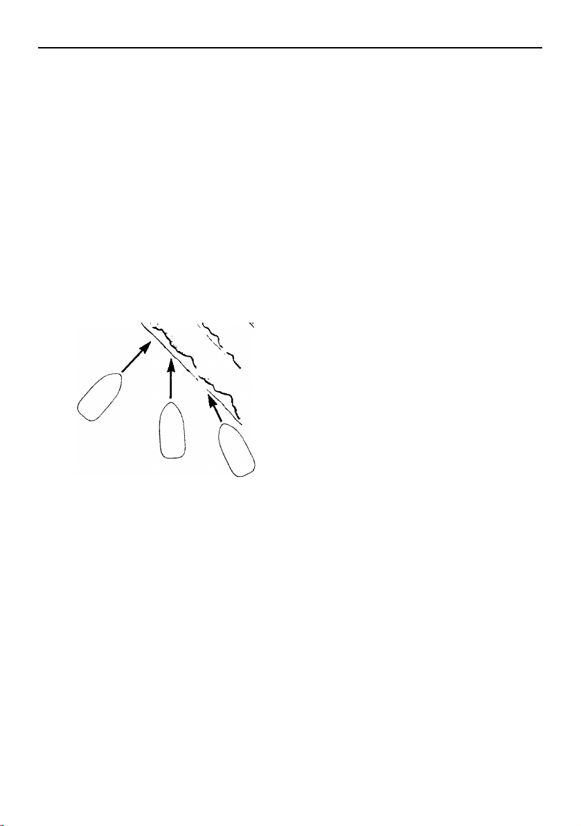
Operation
154
To cross a wake or swell, change your speed
and choose the angle at which you cross the
wake or swell. Usually, a slower speed and
“quartering” the wake (crossing at an angle)
will reduce the jolt.
Two other things you may notice. The first is
that crossing a group of wakes or swells is
not as easy or smooth as crossing just one
wake. The second is that when you quarter
the wake or swell, the boat will try to steer
away from the wake or swell. When crossing
at a 45° angle, you may not notice this, but at
a smaller angle, say 10°, it can be very strong.
Be prepared to steer and balance as neces-
sary.
Post-operation checks
These post-operation procedures are devel-
oped to help preserve the long-term appear-
ance and reliability of your boat. Perform
these procedures as soon as possible after
the boat is loaded back on the trailer after the
day’s use.
Some owners prefer to moor their boat sea-
sonally, rather than keeping it on the trailer
between uses. Extended mooring is not
recommended. Proper flushing of the cool-
ing system on each engine is not possible
with the boat in the water. In addition, condi-
tions such as stray electrical voltage in the
water, marine organisms, and saltwater cor-
rosion can adversely affect the life of many
boat components. NOTICE: Leaving the
boat in the water for extended periods will
accelerate the rate of normal deterioration
of the jet pump components, sacrificial
anodes, hull finish and other components.
If you do decide to moor your boat, be sure to
remove it from the water periodically to clean
the hull and jet pump areas. The frequency of
maintenance required will depend upon
whether the water is salt water or fresh water
and other local water conditions.
(1) After putting the boat on the trailer, flush
the cooling system on each engine to
prevent the cooling system from clog-
ging up with salt, sand, or dirt. Refer to
page 160 for the cooling system flushing
procedure.
(2) Drain residual water from the exhaust
system by starting the engine, and then
alternately pushing the remote control le-
ver up to half throttle and back to idle for
10 to 15 seconds. NOTI CE : Do not run
the engine over 4000 r/min on land. Al-
so, do not run the engine for more
than 15 seconds without supplying
Wake
90˚
45˚
10˚
SportsBoat_F3R13.book Page 154 Friday, May 31, 2019 9:42 AM

Operation
155
water, otherwise, the engine could
overheat and/or seize.
(3) Stop the engine.
(4) Wash down the hull, helm, and both jet
drive units with fresh water.
(5) Open the rear platform hatch. (See page
103 for rear platform hatch opening and
closing procedures.)
(6) Remove the access port caps to let any
water drain that has pooled on them.
(See page 182 for access port cap re-
moval and installation procedures.) If the
boat will be stored on the trailer nearby,
leave the caps out until you prepare to
launch the boat again. If the boat will be
transported on the trailer any distance,
temporarily reinstall the caps and close
the hatch until you get home. Open the
hatch again when you arrive and remove
the caps as before. Leave the caps loose
until you plan to transport the boat on the
trailer again. NOTICE: Leaving the ac-
cess port caps out when you are not
using or transporting the boat helps
keep them from becoming stuck in the
access ports.
(7) Remove the hull drain plug, the engine
compartment drain plug, and the fuel
tank compartment drain plug. (See page
125.)
(8) Rinse the engine compartment with a
small amount of fresh water. Be careful
not to get water on the air filter area or
electrical components. Allow any water
in the bilge to drain out. After the water
has drained, wipe the engine compart-
ment and bilge with dry rags.
(9) Reinstall all drain plugs. NOTICE: Tight-
en the hull drain plug securely before
launching the boat. Otherwise, water
may flood the boat and cause it to
submerge. Clean any foreign material,
such as dirt or sand, from the threads
and the O-ring on the hull drain plug
before installing the drain plug.
(10) Spray a rust inhibitor, such as Yamaha
Silicone Protectant and Lubricant, on
metallic parts to minimize corrosion.
(11) Use a boat cover designed for your boat,
or store the boat in a building or under a
canopy or carport in order to prevent rain
from falling onto the boat. Because all of
the water will not be drained from the
deck automatically, take sufficient mea-
sures to prevent rainwater from entering
the boat. NOTICE: Make sure that the
turnbuckles on the boat cover do not
contact the boat directly when using
the cover. Otherwise, the boat could
be damaged.
(12) Turn the battery switch in the rear under-
seat storage compartment (port) to the
OFF (red) position. (See page 38 and 39
for more information.)
SportsBoat_F3R13.book Page 155 Friday, May 31, 2019 9:42 AM

156
Trailering
Trailering the boat
WARNING
Avoid accident and injury from improper
trailering:
The trailer must be matched for the
boat’s weight and hull.
The towing vehicle must have the ca-
pacity of pulling the load. Pulling a load
that exceeds the towing capacity may
cause loss of control.
Be sure the boat is secured to the trailer
and the trailer is properly hitched to the
towing vehicle before towing.
Read the manuals supplied with the
trailer by the manufacturer.
A trailer is provided as standard equipment
with your boat. If you need to obtain another
trailer, choose one that is manufactured to
carry a boat of the size and weight of your
boat. Check the certification label on the left
forward side of the trailer. This label is re-
quired to show the Gross Vehicle Weight Rat-
ing (GVWR), which is the load carrying
capacity of the trailer plus the trailer’s weight.
Be sure that the total weight of your boat, any
cargo, and the trailer weight itself does not
exceed the GVWR.
Hitch
The trailer hitch ball must match the size of
the socket on the trailer hitch coupler. Hitch-
es are divided into classes that specify the
Gross Trailer Weight (GTW) and the maxi-
mum tongue weight. Always use a hitch rated
for the same or higher class. Use a bolted-on
or welded-on hitch; clamp-on bumper hitch-
es are not recommended. Be sure the trailer
hitch’s release handle is latched with the lock
pin installed before towing.
Use safety chains between the towing vehicle
and the trailer so the trailer will not detach
completely from the towing vehicle if it acci-
dentally comes loose from the hitch ball.
Crisscross the chains under the trailer tongue
so the tongue will not hit the road surface if it
falls loose. Rig the chains as tightly as possi-
ble while allowing just enough slack to permit
tight turns.
Be sure the tongue weight (vertical weight on
the hitch point) is correct. Generally, 5% to
10% of the combined weight of the boat and
trailer should be on the tongue. Too much or
too little weight can cause difficult steering or
trailer swaying.
Trailering checklist
Check your state laws to be sure your trail-
er meets all regulations, such as proper li-
censing, brake, axle load, and safety chain
requirements.
Check the trailer for any loose fasteners or
damaged parts.
Check the tires for proper inflation.
Check the wheel bearings and wheel lug
nuts before each trip.
Check the tail, brake, and turn signal lights
for proper operation.
SportsBoat_F3R13.book Page 156 Friday, May 31, 2019 9:42 AM
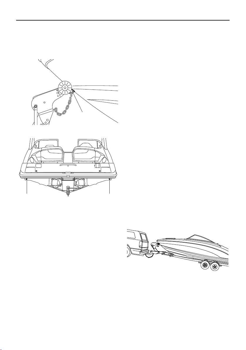
Trailering
157
Secure the bow of the boat to the trailer
with the winch line and also with the chain.
Secure the stern eyes to the trailer with tie-
downs.
1 Bow eye
1 Stern eye
Take down and store the bimini top, if
used. The bimini top is not designed to stay
unsecured on the boat at highway speeds.
(See page 115 or 119.)
TIP:
During transport, use a boat cover to prevent
any items from blowing out of the boat, or
make sure to store any items inside the stor-
age compartments and securely close the
compartments.
Be sure the access port caps are properly
installed (see page 182 for more informa-
tion) and the rear platform hatch is closed
securely.
Be sure any cargo that must be carried in
the boat as well as the folding windshield
and all hatches are secured. A durable,
properly fitting cover, such as the genuine
Yamaha cover available from your Yamaha
Boat Dealer designed specifically for your
boat, is highly recommended to help pro-
tect your boat during transport and stor-
age.
Carry a spare tire for the trailer, along with
sufficient tools to change the tire.
While traveling, check the wheel hubs on
the trailer whenever you park. If a hub feels
abnormally hot, have the bearing inspected
before continuing your trip. On longer trips,
it is a good idea to carry a set of spare
wheel bearings, seals, and races.
When making a turn, do not cut corners.
The trailer has a smaller turning circle, so it
turns more sharply around the corner than
the towing vehicle.
Backing your trailer
It takes practice to back a trailer successfully.
If you are not familiar backing up with a trailer,
practice first in an open area away from ob-
stacles.
1
11
SportsBoat_F3R13.book Page 157 Friday, May 31, 2019 9:42 AM
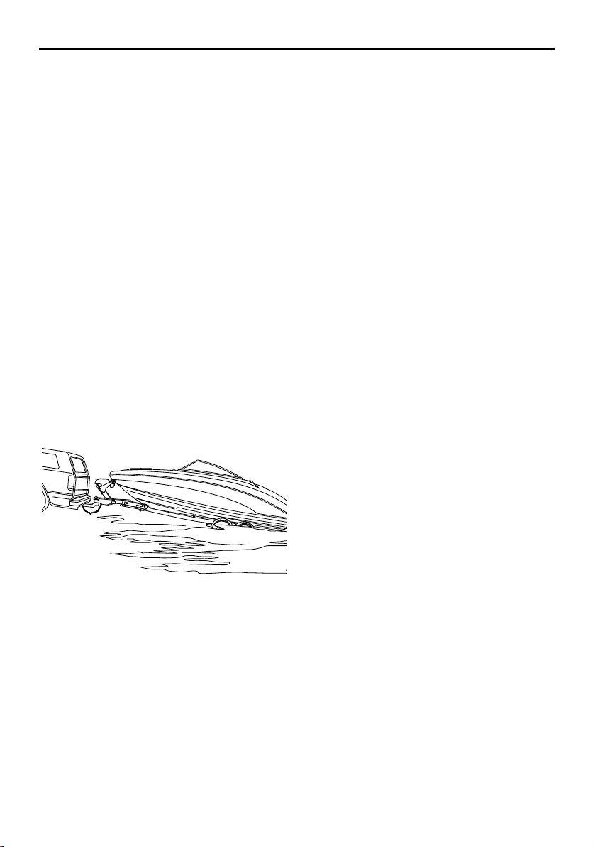
Trailering
158
Keep the following points in mind when
backing up
Back slowly. Make steering adjustments in
small steps.
Turn the towing vehicle’s wheels opposite
the direction you want the trailer to go.
After the trailer begins moving, turn the
towing vehicle to follow it.
Have a second person stand by to help di-
rect you with hand signals.
Launching
As a courtesy to other boaters, prepare your
boat for launching before using the ramp.
Each launch may have particular differences,
such as ramp angle, prevailing wind, waves,
and water currents. If possible, watch a cou-
ple of boaters launch their boats first to notice
any problems. While every boater develops a
preferred launch procedure, here is a recom-
mended general procedure:
(1) Perform the pre-operation checks
shown on page 130 that can be per-
formed on land.
(2) Remove all trailering tie-down lines from
the boat and attach your docking lines
and fenders, if used.
(3) Disconnect the trailer lights from the
towing vehicle.
(4) Back the trailer down the ramp as close
to 90° to the shoreline as you can. If pos-
sible, have a second person stand aside
as an observer. Stop when the wheels
are at least halfway submerged. Set the
parking brake.
(5) Remove the bow line from the bow eye.
(6) Back the trailer farther into the water until
just the tops of the fenders show, and
then reset the parking brake. Board the
boat and start it. If possible, remain on
the trailer until the engines are warm and
are responding to throttle.
(7) Back the boat out into the water, watch-
ing carefully for people, other boats, or
obstacles.
Loading
(1) Disconnect the trailer lights from the
towing vehicle.
(2) Back the trailer down the ramp as close
to 90° to the shoreline as you can. If pos-
sible, have a second person act as an
observer while standing to the side of the
trailer. Stop when the tops of the trailer’s
fenders are about 3 inches above the
waterline.
(3) With the boat moving at the slowest idle
speed, guide the boat onto the support
rails. Use throttle only if necessary for
steering ability. WARNING! Using too
much throttle can cause the boat to
jump over the front of the trailer,
which can result in injury to the boat
operator and bystanders.
(4) Make sure the boat is centered on the
support rails and is headed straight for
the bow stop (bumper board). Ease the
boat forward until the bow rests against
the bow stop. NOTICE: The winch line
is not designed to pull the boat onto
the trailer.
SportsBoat_F3R13.book Page 158 Friday, May 31, 2019 9:42 AM
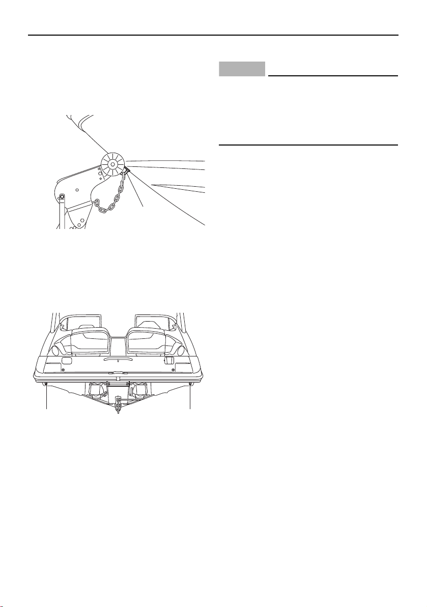
Trailering
159
(5) Attach and tighten the winch line.
NOTICE: The winch line should not be
the only line securing the bow during
trailering. Use the chain along with the
winch to secure the boat to the trailer.
1 Bow eye
(6) Pull the trailer up the ramp out of the way
of other boaters. Attach the bow and
stern tie-downs. Reconnect the trailer
lights.
1 Stern eye
(7) Perform the post-operation checks on
page 154.
Lifting
NOTICE
Do not attach lifting cables to the bow eye,
cleats, stern eyes, ski tow hook, or hand-
grips. Serious damage to the boat can oc-
cur. Use only a sling designed specifically
for lifting boats.
If you need to remove the boat from the water
without a trailer, use these guidelines:
Use a sling-type lifting mechanism de-
signed for lifting boats. The sling should be
covered with a protective material to pre-
vent damage to the hull gelcoat.
Use spreader bars to avoid side stress to
the hull that may cause cracks in the gel-
coat and fiberglass.
Attach guidelines to the bow eye and stern
eyes to control movement of the boat dur-
ing lifting.
Remove all people and all cargo from the
boat. Drain any excess water from the bilge
using the bilge pump.
Be sure all people are standing clear, and
then lift the boat slowly and just far enough
to verify that the boat is securely held and
properly balanced. If necessary, lower the
boat again and adjust the slings.
When ready, lift the boat slowly and care-
fully.
1
11
SportsBoat_F3R13.book Page 159 Friday, May 31, 2019 9:42 AM
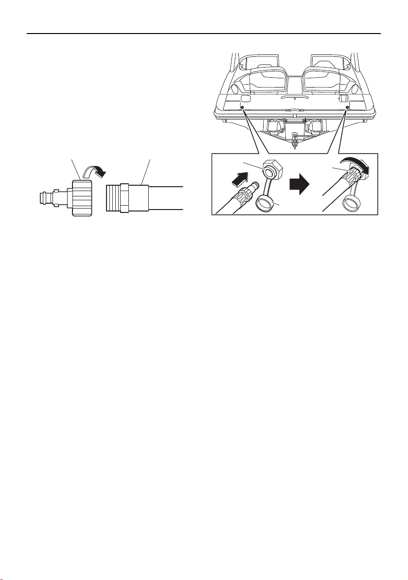
160
Care and storage
Post-operation care
Flushing the cooling system
Cooling system flushing is essential to pre-
vent the cooling system from clogging up
with salt, sand, or dirt.
(1) Connect the garden hose adapter to a
garden hose.
1 Garden hose adapter
2 Garden hose
(2) Loosen the flush hose connector cap for
the engine you are going to flush and re-
move it. Insert the garden hose adapter
into the flush hose connector by pushing
and twisting it until it is securely connect-
ed.
1 Flush hose connector
2 Flush hose connector cap
3 Garden hose adapter
(3) Connect the garden hose to a water tap.
(4) Make sure that the area around the boat
is clear, and then start the engine. Imme-
diately after the engine starts, fully turn
the water supply on so that water flows
out continually from the jet thrust nozzle
and cooling water pilot outlet. NOTICE:
Never turn on the water before start-
ing the engine. The water could flow
back through the muffler into the
crankcase causing severe engine
damage. Be sure to turn on the water
immediately after starting the engine
to prevent engine overheating.
(5) Run the engine at a fast idle for 3 to 5
minutes. If the engine stops while flush-
ing, turn the water supply off immediately
and perform the procedure again from
step 4.
(6) Turn off the water supply, and then drain
residual water from the exhaust system
by alternately pushing the remote control
12
1
3
2
SportsBoat_F3R13.book Page 160 Friday, May 31, 2019 9:42 AM
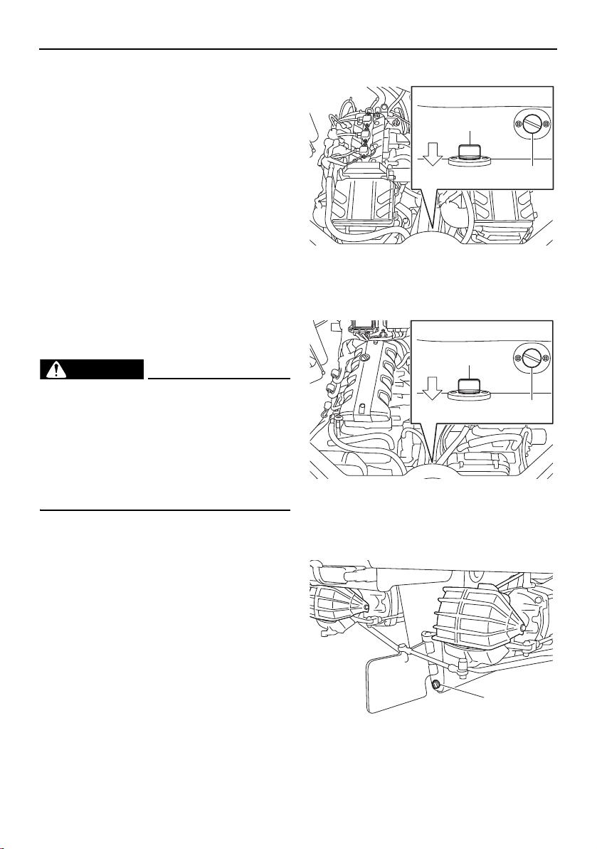
Care and storage
161
lever up to half throttle and back to idle
for 10 to 15 seconds.
(7) Stop the engine. NOTICE: Never have
the water on when the engine is not
running. The water could flow back
through the muffler into the crankcase
causing severe engine damage. Do
not run the engine for more than 15
seconds after the water supply has
been turned off to avoid engine over-
heating.
(8) Remove the garden hose adapter.
(9) Install and tighten the cap securely.
(10) Repeat the flushing procedure for the
other engine.
Cleaning the boat
WARNING
Gasoline and its vapors are highly flamma-
ble and explosive. If there is fuel or a fu-
el/water mixture in the engine
compartment or the fuel tank compart-
ment, wipe it up immediately with dry rags.
Do not operate the boat until the source of
the fuel leak is found and corrected.
TIP:
Quality Yamaclean
®
, Yamashield™, and oth-
er Yamalube care products are available from
your Yamaha Boat Dealer.
(1) Remove the engine compartment drain
plug and the fuel tank compartment
drain plug to drain the water. (See page
125 for engine compartment drain plug
and fuel tank compartment drain plug re-
moval and installation procedures.) Rein-
stall the fuel tank compartment drain
plug.
AR210 / SX210
1 Fuel tank compartment drain plug
2 Engine compartment drain plug
212X / 212S / 212
1 Fuel tank compartment drain plug
2 Engine compartment drain plug
(2) Remove the hull drain plug.
1 Hull drain plug
1
2
BOW
1
2
BOW
1
SportsBoat_F3R13.book Page 161 Friday, May 31, 2019 9:42 AM

Care and storage
162
(3) Clean the hull, boat interior, and drive
units with Yamaclean Wash & Wax Con-
centrate, or a mild natural soap, and wa-
ter. Rinse with fresh water. Scum on the
hull can be removed with Yamaclean Hull
Cleaner™. NOTICE: Incorrect cleaning
can damage vinyl. See “Basic stain
guide” on page 164.
(4) Clean the engine and bilge areas with
Yamaclean Bilge Cleaner™ or an equiv-
alent and rinse with fresh water. Drain all
water and wipe up any remaining mois-
ture with clean, dry rags. Reinstall the en-
gine compartment drain plug. NOTICE:
Be careful not to get water on the air
filter area or electrical components.
Do not use high-pressure water when
rinsing the engine or engine compart-
ment as severe engine damage could
result.
(5) Open the rear platform hatch. (See page
103 for rear platform hatch opening and
closing procedures.)
(6) Remove the access port caps to let any
water drain that has pooled on them.
(See page 182 for access port cap re-
moval and installation procedures.) If the
boat will be stored on the trailer nearby,
leave the caps out until you prepare to
launch the boat again. If the boat will be
transported on the trailer any distance,
temporarily reinstall the caps and close
the hatch until you get home. Open the
hatch again when you arrive and remove
the caps as before. Leave the caps loose
until you plan to transport the boat on the
trailer again. NOTICE: Leaving the ac-
cess port caps out when you are not
using or transporting the boat helps
keep them from becoming stuck in the
access ports. (See page 182 for more
information.)
(7) Securely install the hull drain plug by
tightening it until it stops. NOTICE: Be-
fore installing the hull drain plug, clean
the drain plug threads and O-ring to
remove any foreign materials, such as
dirt or sand. Otherwise, the hull drain
plug could be damaged, allowing wa-
ter to enter the hull. Check the O-ring
on the hull drain plug and make sure
that the hull drain plug is tightened se-
curely before launching the boat. Oth-
erwise, water may flood the boat and
cause it to submerge.
(8) Spray the exterior of the engines with
Yamalube Silicone Protectant & Lubri-
cant, or an equivalent. For areas requir-
ing heavy protection, use Yamashield™.
(9) Wax the hull with Yamaclean Spray
Wax
®
or other non-abrasive wax de-
signed for marine gelcoat. WARNING!
Slippery surfaces can cause falls and
injury. Be careful not to apply too
much wax on deck and gunwale step-
ping surfaces. This will make them
slippery.
(10) Wipe all vinyl and rubber components,
such as the seats and engine compart-
ment seals, with Yamaclean Vinyl Dress-
ing™ or other quality vinyl protectant.
NOTICE: Some well-known “protec-
tant” products on the market can ac-
tually damage vinyl over time. Consult
a Yamaha Boat Dealer if you want to
use a product other than Yamaclean
Vinyl Protectant.
(11) Vacuum and hose-off the carpeting as
necessary. If needed, use Yamaclean
Carpet Cleaner
®
or other quality brand-
name carpet cleaner product to clean
SportsBoat_F3R13.book Page 162 Friday, May 31, 2019 9:42 AM

Care and storage
163
soiled areas. Roll up the carpet face out
for storage. NOTICE: Always dry the
carpet face up. Never roll up the car-
pet while wet. Never fold the carpet.
(12) Wash the fabric of the bimini top with a
mild natural soap in lukewarm water,
then rinse. Do not use detergents. Allow
to air dry thoroughly before storage.
SportsBoat_F3R13.book Page 163 Friday, May 31, 2019 9:42 AM

Care and storage
164
Basic stain guide
Here are basic steps to remove common stains from boat upholstery. Consult a Yamaha Boat
Dealer or upholstery-cleaning professional for difficult stains.
* May cause permanent staining.
TYPE OF STAIN STEPS
(rinse with clean, warm water and then dry after application)
123
General care/Dirt A B —
Chewing gum E A —
Coffee/Tea/Chocolate B — —
Grease E B —
Ink* C F D
Ketchup A B —
Lipstick C B A
Mustard A B C
Mildew/Wet leaves* C B A
Motor oil B — —
Permanent marker* C F D
Suntan lotion* A B —
Tar/Asphalt E B —
A Medium-soft brush with warm, soapy water
B Yamaclean All Purpose Cleaner or equivalent
C Isopropyl alcohol (91% is best)
D
Mixture of 1 tablespoon (15 ml) ammonia, 1/4 cup (60 ml) hydrogen peroxide, and
3/4 cup (177 ml) water
E Wipe or scrape off excess (chill gum with ice first)
F Name brand ink remover
SportsBoat_F3R13.book Page 164 Friday, May 31, 2019 9:42 AM

Care and storage
165
Battery care (AR210 / SX210)
If the boat will not be used for more than a
month, remove the battery and store it in a
cool, dark place.
The battery is located in the rear underseat
storage compartment (port).
To remove the battery:
(1) Turn the battery switch to the OFF (red)
position. (See page 38.)
(2) Remove the battery cover by removing
the nuts.
1 Nut
2 Battery cover
(3) Disconnect the ground lead (black), the
negative (–) battery leads (black).
(4) Disconnect the positive (+) battery lead
(red).
(5) Unfasten the battery strap, and then re-
move the battery from the boat.
1 Negative (–) battery lead (black)
2 Positive (+) battery lead (red)
3 Battery strap
4 Ground lead (black)
To store the battery:
(1) Clean the battery casing and terminals
using a mixture of baking soda and water
(one tablespoon of baking soda to one
cup of water).
(2) Apply dielectric grease or petroleum jelly
to the battery terminals and to all ex-
posed connectors.
(3) If the battery will be stored for a longer
period, check its state of charge (use a
hydrometer or a voltmeter and load tes-
ter) at least once a month and recharge
the battery if it gets too low.
To charge the battery:
(1) Remove the caps from the cells. Add dis-
tilled water if necessary to top up the
electrolyte to the proper level.
(2) Follow the battery manufacturer’s in-
structions for charging. WARNING!
When charging a battery, keep it well
away from sparks and open flames, as
it gives off explosive gases. When us-
ing a battery charger, connect the bat-
tery to the charger before you turn on
the charger. This will prevent sparking
1
2
2 3
4
1
SportsBoat_F3R13.book Page 165 Friday, May 31, 2019 9:42 AM
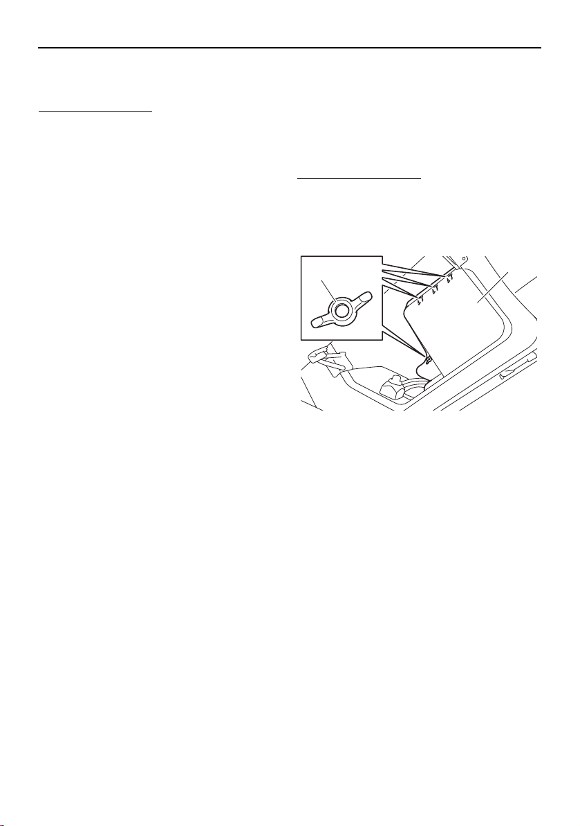
Care and storage
166
at the terminals that could ignite bat-
tery gases.
To install the battery:
(1) Place the battery in the battery holder,
and then fasten the battery using the bat-
tery strap.
(2) Connect the positive (+) battery lead (red)
to the positive (+) battery terminal.
NOTICE: Reversal of the battery leads
will damage the electrical parts.
(3) Connect the negative (–) battery lead
(black) and the ground lead (black) to the
negative (–) battery terminal.
(4) Make sure that the battery is securely
held in place.
(5) Install the battery cover by installing the
nuts.
Battery care (212X / 212S / 212)
If the boat will not be used for more than a
month, remove the battery and store it in a
cool, dark place.
The battery is located in the rear underseat
storage compartment (port).
To remove the battery:
(1) Turn the battery switch to the OFF (red)
position. (See page 39.)
(2) Remove the battery cove by removing
the nuts.
1 Nut
2 Battery cover
(3) Disconnect the ground lead (black), the
negative (–) battery lead (black), and the
negative (–) amplifier lead (black) (212X).
(4) Disconnect the positive (+) battery lead
(red) and the positive (+) amplifier lead
(red) (212X).
(5) Unfasten the battery strap, and then re-
move the battery from the boat.
1
2
SportsBoat_F3R13.book Page 166 Friday, May 31, 2019 9:42 AM

Care and storage
167
1 Positive (+) battery lead (red)
2 Negative (–) battery lead (black)
3 Battery strap
4 Ground lead (black)
5 Positive (+) amplifier lead (red) (212X)
6 Negative (–) amplifier lead (black) (212X)
To store the battery:
(1) Clean the battery casing and terminals
using a mixture of baking soda and water
(one tablespoon of baking soda to one
cup of water).
(2) Apply dielectric grease or petroleum jelly
to the battery terminals and to all ex-
posed connectors.
(3) If the battery will be stored for a longer
period, check its state of charge (use a
hydrometer or a voltmeter and load tes-
ter) at least once a month and recharge
the battery if it gets too low.
To charge the battery:
(1) Remove the caps from the cells. Add dis-
tilled water if necessary to top up the
electrolyte to the proper level.
(2) Follow the battery manufacturer’s in-
structions for charging. WARNING!
When charging a battery, keep it well
away from sparks and open flames, as
it gives off explosive gases. When us-
ing a battery charger, connect the bat-
tery to the charger before you turn on
the charger. This will prevent sparking
at the terminals that could ignite bat-
tery gases.
To install the battery:
(1) Place the battery in the battery holder,
and then fasten the battery using the bat-
tery strap.
(2) Connect the positive (+) amplifier lead
(red) (212X) and the positive (+) battery
lead (red) to the positive (+) battery termi-
nal. NOTICE: Reversal of the battery
leads will damage the electrical parts.
(3) Connect the negative (–) amplifier lead
(black) (212X) and the negative (–) battery
lead (black), and the ground lead (black)
to the negative (–) battery terminal.
(4) Make sure that the battery is securely
held in place.
(5) Install the battery cover by installing the
nuts.
6
5
4
3 3
2
1
SportsBoat_F3R13.book Page 167 Friday, May 31, 2019 9:42 AM
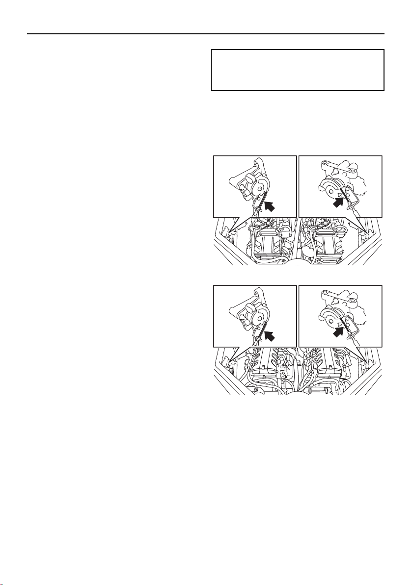
Care and storage
168
Long-term storage
Storing your boat for prolonged periods of
time, such as winter storage, requires pre-
ventative maintenance to ensure against de-
terioration. It is advisable to have the boat
serviced by an authorized Yamaha Boat
Dealer before storage. However, the follow-
ing procedures can be performed by the
owner with a minimum of tools.
Fuel system
Fill the fuel tank with fresh fuel, adding one
ounce of Fuel Med RX, available from your
Yamaha Boat Dealer, to each gallon of fuel or
use an equivalent according to the manufac-
ture’s instructions. (See page 120 for infor-
mation on filling the fuel tank.) Do not “top
off” the tank, because fuel could spill. A full
fuel tank is less likely to allow condensation
to collect in the tank, reducing the chance of
contaminated fuel. Running the engines with
treated fuel during cooling system flushing
will also help protect the fuel system.
TIP:
Use of Fuel Med RX eliminates the need to
drain the fuel system. Consult a Yamaha Boat
Dealer or other qualified mechanic if the fuel
system is to be drained instead.
Lubrication
It is advisable to take the boat to a Yamaha
Boat Dealer to have the engines fogged for
long-term storage.
Grease points
To keep moving parts sliding or rotating
smoothly, coat them with water-resistant
grease.
Throttle cables
Grease the throttle-cable inner wires at the
pulley wheel of each APS.
AR210 / SX210
212X / 212S / 212
Steering cable ball joints and inner wires
Grease the steering cable and shift cable ball
joints at the jet thrust nozzles. Extend the
steering cable and shift cable inner wires and
apply a thin coat of grease to them.
Recommended water-resistant grease:
YAMALUBE MARINE GREASE or
Yamaha Grease A
SportsBoat_F3R13.book Page 168 Friday, May 31, 2019 9:42 AM
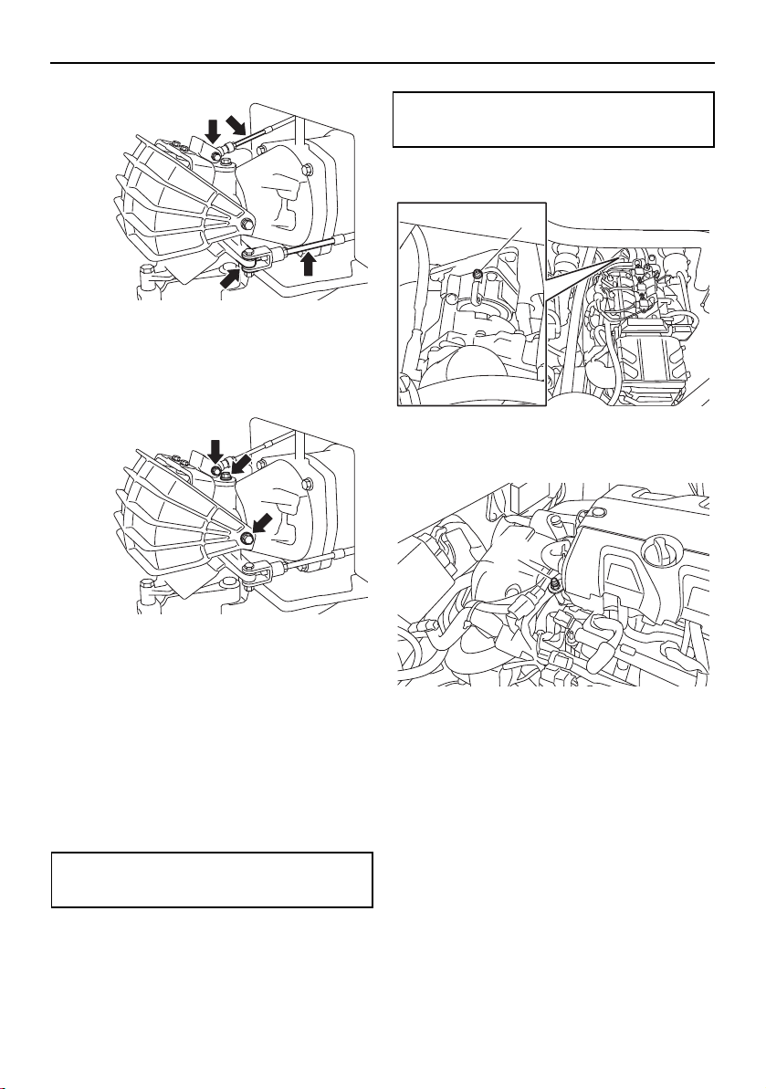
Care and storage
169
Pivot points
Grease all pivot points of the steering and
shift mechanisms at the pump ends.
Bearing housings
Grease the bearing housings through the
grease nipples. NOTICE: Fill the grease
slowly and carefully, because it can dam-
age the hoses and the joints.
The first service should be done after 10
hours or 1 month by a Yamaha Boat Dealer.
Fill the bearing housings with water-resistant
grease through the grease nipples.
After first service: Every 100 hours or 6
months (you may do this yourself).
AR210 / SX210
1 Bearing housing grease nipple
212X / 212S / 212
1 Bearing housing grease nipple
Grease capacity:
33.0–35.0 cc (1.11–1.18 oz)
Grease capacity:
6.0–8.0 cc (0.20–0.27 oz)
1
1
SportsBoat_F3R13.book Page 169 Friday, May 31, 2019 9:42 AM

170
Maintenance
Maintenance
WARNING
Be sure to turn off the engines when you
perform maintenance unless otherwise
specified. If you are not familiar with ma-
chine servicing, this work should be done
by a Yamaha Boat Dealer or other quali-
fied mechanic.
Maintenance, replacement, or repair of the
emission control devices and system may be
performed by any marine SI engine repair es-
tablishment or individual. Warranty repair,
however, must be performed at an autho-
rized Yamaha Boat Dealer. A service manual
is available for purchase through a Yamaha
Boat Dealer for owners who have the me-
chanical skills, tools, and other equipment
necessary to perform maintenance not cov-
ered by this owner’s/operator’s manual.
Owner’s/operator’s manual
It is advisable to always carry the own-
er’s/operator’s manual with you whenever
you use the boat.
To protect these materials from water dam-
age, it would be a good idea to put them in a
waterproof bag. If your owner’s/operator’s
manual is damaged, order a replacement
from a Yamaha Boat Dealer.
The service information included in this man-
ual is intended to provide you, the owner,
with the necessary information for complet-
ing your own preventive maintenance and
minor repairs.
Removing and installing the engine
covers (212X / 212S / 212)
The engine cover of each engine is remov-
able.
To remove the engine cover:
(1) Open the engine hood. (See page 97.)
(2) Remove the engine cover screws.
1 Engine cover screw
(3) Lift up the engine cover and remove it.
1 Engine cover
1
1
SportsBoat_F3R13.book Page 170 Friday, May 31, 2019 9:42 AM

Maintenance
171
To install the engine cover:
(1) Place the engine cover in its original po-
sition, and then push it down.
(2) Install the engine cover screws.
(3) Close the engine hood.
SportsBoat_F3R13.book Page 171 Friday, May 31, 2019 9:42 AM

Maintenance
172
Periodic maintenance chart
The periodic maintenance chart gives general guidelines for periodic maintenance. Have a
Yamaha dealer perform the checks in the following chart. However, maintenance may need
to be performed more frequently depending on your operating conditions. If you have any
questions, consult a Yamaha dealer.
This “√” mark indicates items to be checked and serviced by a Yamaha dealer.
Item Operation
Initial Thereafter every
10
hours
50
hours
or 12
months
*1
100
hours
or 12
months
*1
200
hours
or 24
months
*1
Fuel hoses, clamps,
canister, and check
valve
Check for damage, and check con-
nections and tightening of clamps
√
Fuel filler cap
Check cap for damage, and check
seal for cracks and deformation
√
Fuel tank Check installation √√
Main switches and
engine shut-off
switch
Check operation √√
Battery
(AR210 / SX210)
Batteries
(212X / 212S / 212)
Check state of charge and termi-
nals, and check for broken battery
straps
√
Battery leads Check terminals √
Battery switch
(AR210 / SX210)
Battery switches
(212X / 212S / 212)
Check operation √√
Meters (after com-
pleting the pre-oper-
ation checks)
Check lighting √√
Neutral switches Check operation √√
Hatch interlock
switches (wet stor-
age compartment)
Check operation √√
Blowers Check operation √√
Horn Check operation √√
Navigation lights Check lighting √√
Electric bilge pump
Check for water discharge by auto-
matic operation, clean filter, check
hoses for damage, and check tight-
ening of clamps
√
Other electrical com-
ponents
Check operation of stereo, and oth-
er components
√√
SportsBoat_F3R13.book Page 172 Friday, May 31, 2019 9:42 AM

Maintenance
173
Steering master
ASSY
Check operation and tilting mecha-
nism, and check for looseness
√√
Steering cables
Check connections and exterior,
and lubricate
√
Articulating keel
Check operation, and check link rod
for bends and damage
√
Remote control le-
vers
Check exterior and operation,
check shift operation, and check for
looseness
√√
Throttle cables
Check connections and exterior,
and lubricate
√
Shift cables
Check connections and exterior,
and lubricate (shift gate end)
√
Exhaust hoses, wa-
ter locks, and resona-
tors
Check for exhaust leakage, and
check clamps at connections
√
Drain passages Remove clogs √
Drain plugs Check O-rings √√
Hull and deck Check for damage √√
Windshield and seats
Check installation and operation,
and check for damage
√√
Wakeboard tower
(AR210 / 212X / 212S)
and bimini top
Check installation, and check for
damage
√√
Hatches, hinges, and
packing seals
Check installation √√
Ladders (bow and
stern)
Check installation √√
Access port caps Check exterior and installation √
Spark plugs Check √√
High-pressure fuel
hoses
Check connections and exterior,
and check for leakage
√
Engine oil
(AR210 / SX210)
Replace √√
Engine oil
(212X / 212S / 212)
Replace √√√
Engine oil filters Replace √
Air filter elements Check for damage and dirt √
Intake hoses and
breather hoses
Check for damage, and check con-
nections
√
Item Operation
Initial Thereafter every
10
hours
50
hours
or 12
months
*1
100
hours
or 12
months
*1
200
hours
or 24
months
*1
SportsBoat_F3R13.book Page 173 Friday, May 31, 2019 9:42 AM

Maintenance
174
*1: Whichever comes first.
*2: Check every 200 hours.
Perform the pre-operation checks and post-operation checks before performing periodic
maintenance.
Throttle bodies Lubricate throttle valves √
Anodes (engines) Check for corrosion √ *2
Valve clearance Check and adjust √ *2
Rubber couplings Check for looseness and noise √
Engine mounts Check for damage and peeling √
Cooling water hoses
and cooling water pi-
lot outlet hoses
Check for damage, and check con-
nections
√
Water inlet strainers Check for damage √√
Intake grates Check for damage √√
Impellers
Check for bends, damage, and for-
eign material
√√
Impeller ducts Check and lubricate √
Jet thrust nozzles Check movement, and lubricate √
Intermediate hous-
ings
Lubricate √
Anodes (jet pump
units)
Check for corrosion √
Item Operation
Initial Thereafter every
10
hours
50
hours
or 12
months
*1
100
hours
or 12
months
*1
200
hours
or 24
months
*1
SportsBoat_F3R13.book Page 174 Friday, May 31, 2019 9:42 AM

175
Specifications
Specifications (AR210 / SX210)
ITEM Specification
Boat capacity
Maximum people on board: 10
Maximum load capacity: 998 kg (2200 lb)
Dimensions and weight
Length: 6460 mm (254.3 in)
Beam: 2580 mm (101.6 in)
Height: 2780 mm (109.5 in) (AR210)
1780 mm (70.1 in) (SX210)
Draft: 430 mm (16.9 in)
Dry weight: 1464 kg (3228 lb) (AR210)
1439 kg (3172 lb) (SX210)
Performance
Maximum fuel consumption (for each engine): 67.0 L/h (17.7 US gal/h, 14.7 Imp.gal/h)
Cruising range at full throttle: 2.83 hour
Trolling speed: 1500 ±100 r/min
Engine
Number of engines: 2
Engine type: Liquid cooled 4-stroke, DOHC
Number of cylinders: 3
Engine displacement: 1049 cm³
Bore × stroke: 82.0 × 66.2 mm (3.23 × 2.61 in)
Compression ratio: 11.0 : 1
Valve clearance-intake (cold): 0.15–0.22 mm (0.0059–0.0087 in)
Valve clearance-exhaust (cold): 0.26–0.32 mm (0.0102–0.0126 in)
Lubrication system: Dry sump
Cooling system: Water
Starting system: Electric
Ignition system: T.C.I.
Spark plug (NGK): CR9EB
Spark plug gap: 0.7–0.8 mm (0.028–0.031 in)
Battery capacity: 12 V, 85 Ah
Charging system: Flywheel magneto
SportsBoat_F3R13.book Page 175 Friday, May 31, 2019 9:42 AM
Specifications
176
Drive unit
Propulsion system: Jet pump
Jet pump type: Axial flow, single stage
Impeller rotation: Counterclockwise
Pitch angle: 11.2°
Transmission: Direct drive from engine
Jet thrust nozzle angle: 23+23°
Jet thrust nozzle trim angle 3°
Fuel and oil
Recommended fuel: Regular unleaded gasoline
Minimum octane rating (PON): 86
Minimum octane rating (RON): 90
Fuel tank total capacity: 189 L (50.0 US gal, 41.6 Imp.gal)
Recommended engine oil:
YAMALUBE 4W or 4-stroke motor oil
Recommended engine oil type SAE: SAE 10W-30, 10W-40, 20W-40, 20W-50
Recommended engine oil grade API: API SG, SH, SJ, SL
Engine oil total quantity: 3.7 L (3.91 US qt, 3.26 Imp.qt)
Engine oil quantity with oil filter replacement: 3.4 L (3.59 US qt, 2.99 Imp.qt)
Engine oil quantity without oil filter replacement: 3.2 L (3.38 US qt, 2.82 Imp.qt)
Fuse amperage
Battery fuse: 30 A
Main fuse: 20 A
Main relay drive fuse: 10 A
Electronic throttle valve fuse: 10 A
Accessory fuse: 20 A
Fuel pump fuse: 10 A
ITEM Specification
SportsBoat_F3R13.book Page 176 Friday, May 31, 2019 9:42 AM

Specifications
177
Specifications (212X / 212S / 212)
ITEM Specification
Boat capacity
Maximum people on board: 10
Maximum load capacity: 953 kg (2100 lb) (212X)
998 kg (2200 lb) (212S, 212)
Dimensions and weight
Length: 6460 mm (254.3 in)
Beam: 2580 mm (101.6 in)
Height: 2730 mm (107.5 in) (212X, 212S)
1780 mm (70.1 in) (212)
Draft: 520 mm (20.5 in)
Dry weight: 1640 kg (3616 lb) (3-star models [212X])
1650 kg (3638 lb) (4-star models [212X])
1632 kg (3598 lb) (3-star models [212S])
1642 kg (3620 lb) (4-star models [212S])
1581 kg (3486 lb) (3-star models [212])
Performance
Maximum fuel consumption (for each engine):
97.0 L/h (25.6 US gal/h, 21.3 Imp.gal/h) (3-star
models)
88.8 L/h (23.4 US gal/h, 19.5 Imp.gal/h) (4-star
models)
Cruising range at full throttle: 1.95 hour (3-star models)
2.13 hour (4-star models)
Trolling speed: 1300 ± 100 r/min
SportsBoat_F3R13.book Page 177 Friday, May 31, 2019 9:42 AM

Specifications
178
Engine
Number of engines: 2
Engine type: Liquid cooled 4-stroke, DOHC
Number of cylinders: 4
Engine displacement: 1812 cm³
Bore × stroke: 86.0 × 78.0 mm (3.39 × 3.07 in)
Compression ratio: 11.0 : 1
Valve clearance-intake (cold): 0.14–0.23 mm (0.0055–0.0091 in)
Valve clearance-exhaust (cold): 0.28–0.37 mm (0.0110–0.0146 in)
Lubrication system: Wet sump
Cooling system: Water
Starting system: Electric
Ignition system: T.C.I.
Spark plug (NGK): LFR6A
Spark plug gap: 0.8–0.9 mm (0.031–0.035 in)
Battery capacity: 12 V, 85 Ah
Charging system: Flywheel magneto
Drive unit
Propulsion system: Jet pump
Jet pump type: Axial flow, single stage
Impeller rotation: Counterclockwise
Pitch angle: 14.7°
Transmission: Direct drive from engine
Jet thrust nozzle angle: 23+23°
Jet thrust nozzle trim angle 3°
ITEM Specification
SportsBoat_F3R13.book Page 178 Friday, May 31, 2019 9:42 AM

Specifications
179
Fuel and oil
Recommended fuel: Regular unleaded gasoline
Minimum octane rating (PON): 86
Minimum octane rating (RON): 90
Fuel tank total capacity: 189 L (50.0 US gal, 41.6 Imp.gal)
Recommended engine oil:
YAMALUBE 4W or 4-stroke motor oil
Recommended engine oil type SAE: SAE 10W-30, 10W-40, 20W-40, 20W-50
Recommended engine oil grade API:
3-star models
API SG, SH, SJ, SL
4-star models
API SJ, SL
Engine oil total quantity: 5.3 L (5.60 US qt, 4.66 Imp.qt)
Engine oil quantity with oil filter replacement: 3.7 L (3.91 US qt, 3.26 Imp.qt)
Engine oil quantity without oil filter replacement: 3.5 L (3.70 US qt, 3.08 Imp.qt)
Fuse amperage
Battery fuse: 30 A
Main fuse: 20 A
Main relay drive fuse: 10 A
Electronic throttle valve fuse: 10 A
Accessory fuse: 20 A, 30 A, 40 A (212X)
20 A (212S, 212)
Fuel pump fuse: 10 A
ITEM Specification
SportsBoat_F3R13.book Page 179 Friday, May 31, 2019 9:42 AM

180
Trouble recovery
Troubleshooting
If you have any trouble with your boat, use this section to check for the possible cause. If you
cannot find the cause or if the procedure for replacement or repair is not described in this own-
er’s/operator’s manual, ask your Yamaha Boat Dealer or a qualified mechanic for the proper
service.
Troubleshooting chart
The Troubleshooting chart contains: “TROUBLE,” “POSSIBLE CAUSE,” “REMEDY,” and
“PAGE.”
Check the possible cause and remedy, and also the referred page for the maintenance steps
to solve the trouble.
TROUBLE POSSIBLE CAUSE REMEDY PA GE
Starter mo-
tor does not
turn over
Fuse Burned out Replace fuse and check wiring 185,
186
Battery Run down Recharge 165,
166
Poor terminal con-
nections
Tighten as required 165,
166
Battery switch off Turn on switch 38, 39
Rear platform
hatch
Not latched Latch securely
103
Starter compo-
nent
Faulty Have serviced by Yamaha
Boat Dealer
—
Remote control
lever
Not in neutral posi-
tion
Move remote control lever to
neutral position
40
Starter mo-
tor turns
over/engine
does not
start
Engine shut-off
switch
Clip on cord is not in
place
Install clip in engine shut-off
switch
38
Fuel Empty Refill as soon as possible 120
Stale or contaminat-
ed
Have serviced by Yamaha
Boat Dealer
—
Fuel tank Water or dust col-
lected
Have serviced by Yamaha
Boat Dealer
—
Spark plug Fouled or defective Have serviced by Yamaha
Boat Dealer
—
Crankcase Filled with fuel Have serviced by Yamaha
Boat Dealer
—
Filled with water Have serviced by Yamaha
Boat Dealer
—
Fuel filter Clogged or water
collected
Have serviced by Yamaha
Boat Dealer
—
SportsBoat_F3R13.book Page 180 Friday, May 31, 2019 9:42 AM

Trouble recovery
181
TROUBLE POSSIBLE CAUSE REMEDY PA GE
Warning is
displayed
Over temperature
warning*
Jet intake clogged Clean 182
Cooling system
clogged
Clean
142
Low oil pressure
warning*
Oil pressure dropped Have serviced by Yamaha
Boat Dealer
—
Fuel Empty Refill as soon as possible 120
Check engine
warning
Faulty sensors Have serviced by Yamaha
Boat Dealer
—
Engine runs
irregularly or
stalls
Fuel Empty Refill as soon as possible 120
Stale or contaminat-
ed
Have serviced by Yamaha
Boat Dealer
—
Fuel filter Water or dust col-
lected
Have serviced by Yamaha
Boat Dealer
—
Fuel tank Water or dirt present Have serviced by Yamaha
Boat Dealer
—
Spark plug Fouled or defective Have serviced by Yamaha
Boat Dealer
—
Incorrect heat range Have serviced by Yamaha
Boat Dealer
—
Gap incorrect Have serviced by Yamaha
Boat Dealer
—
Boat speed
too slow or
loses power
Cavitation Jet intake clogged Clean 182
Engine overheat* Jet intake clogged Clean 182
Cooling system
clogged
Clean
142
Fuel filter Clogged Have serviced by Yamaha
Boat Dealer
—
Spark plug Fouled or defective Have serviced by Yamaha
Boat Dealer
—
Incorrect heat range Have serviced by Yamaha
Boat Dealer
—
Gap incorrect Have serviced by Yamaha
Boat Dealer
—
Fuel Stale or contaminat-
ed
Have serviced by Yamaha
Boat Dealer
—
*Engine speed will be limited to 3500 rpm.
SportsBoat_F3R13.book Page 181 Friday, May 31, 2019 9:42 AM
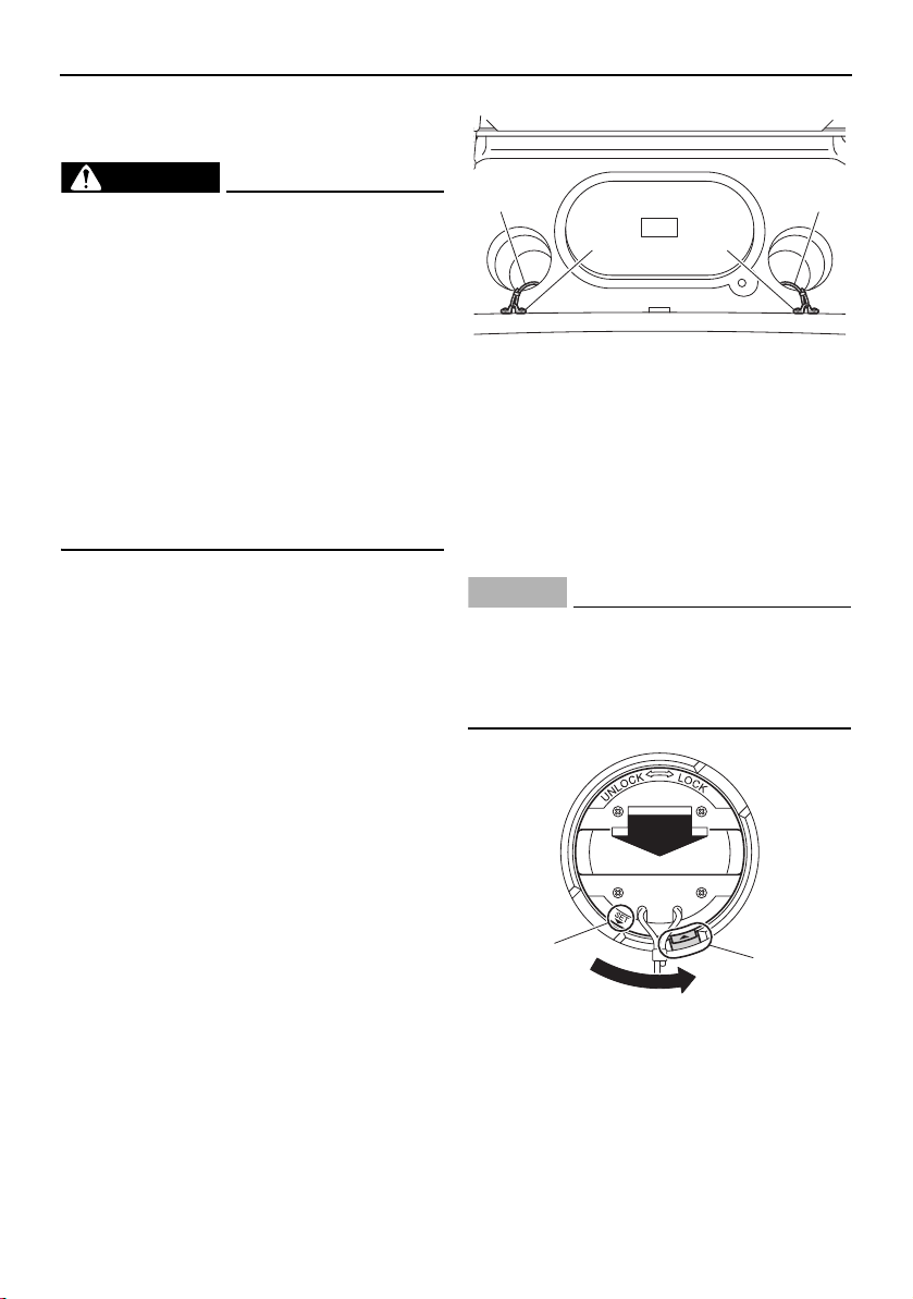
Trouble recovery
182
Emergency procedures
Jet pump clean-out procedure
WARNING
Severe injury or death may result if you ig-
nore any of the following:
Turn off and remove both main switch
keys, remove the clip from the engine
shut-off switch, and wait for all move-
ment to stop before removing the ac-
cess port caps.
Never override the interlocks to run the
engines with the rear platform hatch
open.
The impellers have sharp edges. Be
careful when reaching into jet pump ar-
eas.
If weeds or debris get caught in the intakes or
impellers, cavitation can occur, and though
the engine speed rises, forward thrust will de-
crease. If this condition is allowed to contin-
ue, jet pump damage can occur and the
engines may overheat and seize. If there is
any sign that a jet intake or impeller is
clogged with weeds or debris, follow this
clean-out procedure.
(1) Turn off and remove the main switch key,
remove the clip from the engine shut-off
switch, and wait for all movement to
stop.
(2) Open the rear platform hatch. (See page
103.)
(3) Check that the retaining cord is securely
attached to the access port cap and
strap eye.
1 Retaining cord
2 Strap eye
(4) While holding the handle and pushing
down, turn the access port cap counter-
clockwise until the “SET” mark is aligned
with the slot, and then lift the cap by the
handle.
NOTICE
Do not lift or pull the cap with the retain-
ing cord.
Set the cap where it cannot be acciden-
tally knocked overboard.
1 “SET” mark
2 Slot
1
2
1
2
2
1
SportsBoat_F3R13.book Page 182 Friday, May 31, 2019 9:42 AM
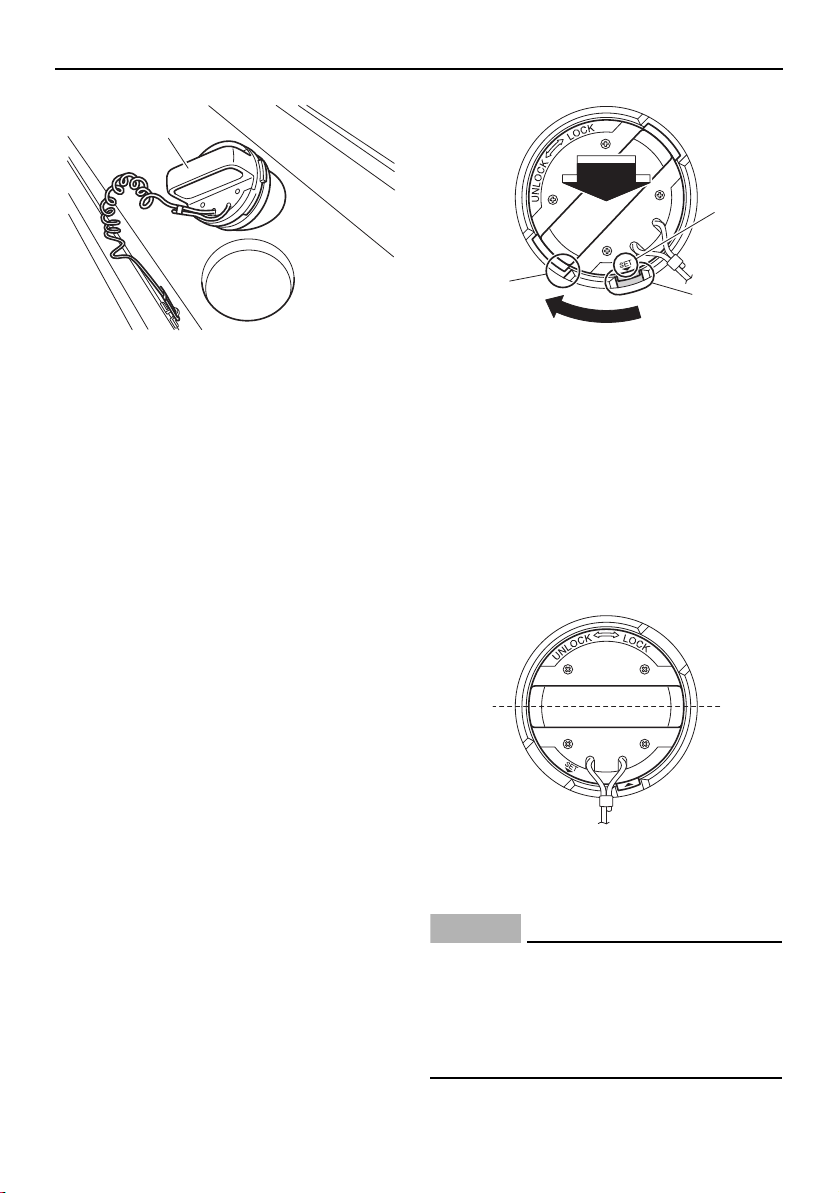
Trouble recovery
183
1 Access port cap
(5) Remove any weeds or debris from the
drive shaft, impeller, pump housing, and
jet thrust nozzle. If you cannot remove
the debris, consult a Yamaha Boat Deal-
er.
(6) To reinstall the access port cap, first
clean off any sand or other foreign matter
from the cap or port surfaces. Apply a
light coat of Yamalube Waterproof Ma-
rine Grease (P/N: ACC-GREAS-10-CT), if
available, to the seal of the access port
cap. If grease is not available, apply the
grease during the post-operation
checks.
(7) Insert the cap so that the “SET” mark is
aligned with the slot, and then while
pushing the handle turn the cap clock-
wise until the “SET” mark is aligned with
the edge of the access port.
1 “SET” mark
2 Slot
3 Edge of the access port
(8) Check that the cap is perpendicular to
the centerline of the boat. Pull the handle
forcefully to make sure that the cap is
locked securely. If a strong pull will move
the access port cap, it is not locked se-
curely—the cap could be forced out by
water pressure during operation.
1 Perpendicular to the centerline of the boat
(9) Close the rear platform hatch.
NOTICE
Be sure the access port caps are locked
securely in place. Otherwise, the caps
could be forced out of the access ports by
water pressure, causing loss of perfor-
mance and possible damage.
1
2
3
1
1
SportsBoat_F3R13.book Page 183 Friday, May 31, 2019 9:42 AM
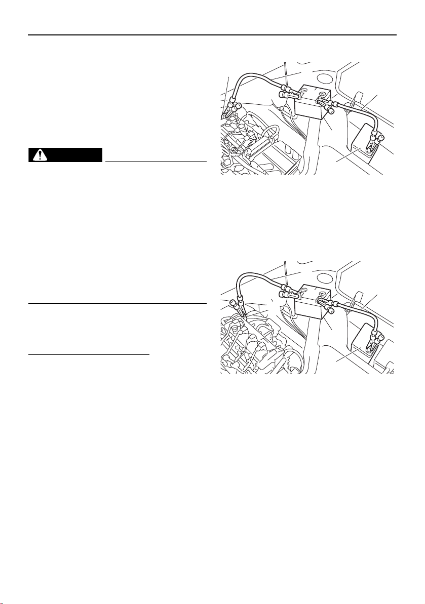
Trouble recovery
184
TIP:
The rear platform hatch has interlocks to shut
off the engines should the hatch be acciden-
tally opened during operation. The engines
will not restart unless the hatch is closed and
latched.
Jump-starting
WARNING
Severe injury or death may result if you ig-
nore any of the following:
If the blowers will not operate, ventilate
the engine compartment by opening the
engine hood for several minutes before
attempting a jump-start.
Do not connect the negative (–) jumper
cable to the negative (–) terminal of the
dead battery. Sparks could ignite bat-
tery or fuel vapors, which could cause
an explosion.
If the boat battery runs down, the engines
can be started in an emergency using a 12-
volt booster battery and jumper cables.
To connect the jumper cables:
(1) Connect the positive (+) terminal of the
dead battery to the positive (+) terminal
of the booster battery with the positive
(+) jumper cable.
(2) Connect one end of the negative (–)
jumper cable to the negative (–) terminal
of the booster battery.
(3) Connect the other end of the negative (–)
jumper cable to an engine hanger.
NOTICE: Be sure all connections are
secure and correct before attempting
to start the engine. Any wrong con-
nection may damage the electrical
system.
AR210 / SX210
1 Negative (–) jumper cable
2 Positive (+) jumper cable
3 Engine hanger
4 Booster battery
5 Starter battery
212X / 212S / 212
1 Negative (–) jumper cable
2 Positive (+) jumper cable
3 Engine hanger
4 Booster battery
5 Starter battery
(4) Start the engine, and then disconnect the
jumper cables by reversing the above
steps. NOTICE: Do not turn the main
switch key for more than 5 seconds. If
the engine does not start in 5 seconds,
release the main switch key and try
again after 15 seconds. Continuous
cranking for more than 5 seconds will
2
4
1
5
3
2
4
1
5
3
SportsBoat_F3R13.book Page 184 Friday, May 31, 2019 9:42 AM

Trouble recovery
185
discharge the battery and the engine
will not start. The starter motor may
also be damaged if they are engaged
continuously for more than 5 seconds.
Fuse replacement (AR210 / SX210)
WARNING
Do not use fuses of a higher amperage
than recommended. Substitution with a
fuse that has an improper rating can cause
extensive electrical system damage and
possible fire.
If a fuse is blown, replace it with the proper
fuse.
To replace a fuse:
(1) Open the engine hood. (See page 97.)
(2) Unfasten the band.
1 Band
(3) Remove the fuse box from the air filter
case by pulling the fuse box toward the
bow.
(4) While pushing both sides of the fuse box
cover inward, pull the cover toward the
bow and remove it.
1 Fuse box cover
1 Electronic throttle valve fuse
2 Fuel pump fuse
3 Main relay drive fuse
4 Main fuse
5 Fuse puller
6 Battery fuse
7 Spare fuse
8 Unused fuse
(5) When replacing the accessory fuse, re-
move the accessory fuse holder. (Open
the rear underseat storage compartment
[port] to access the accessory fuse. [See
page 100.])
1
1
123 4 5 6
78
SportsBoat_F3R13.book Page 185 Friday, May 31, 2019 9:42 AM
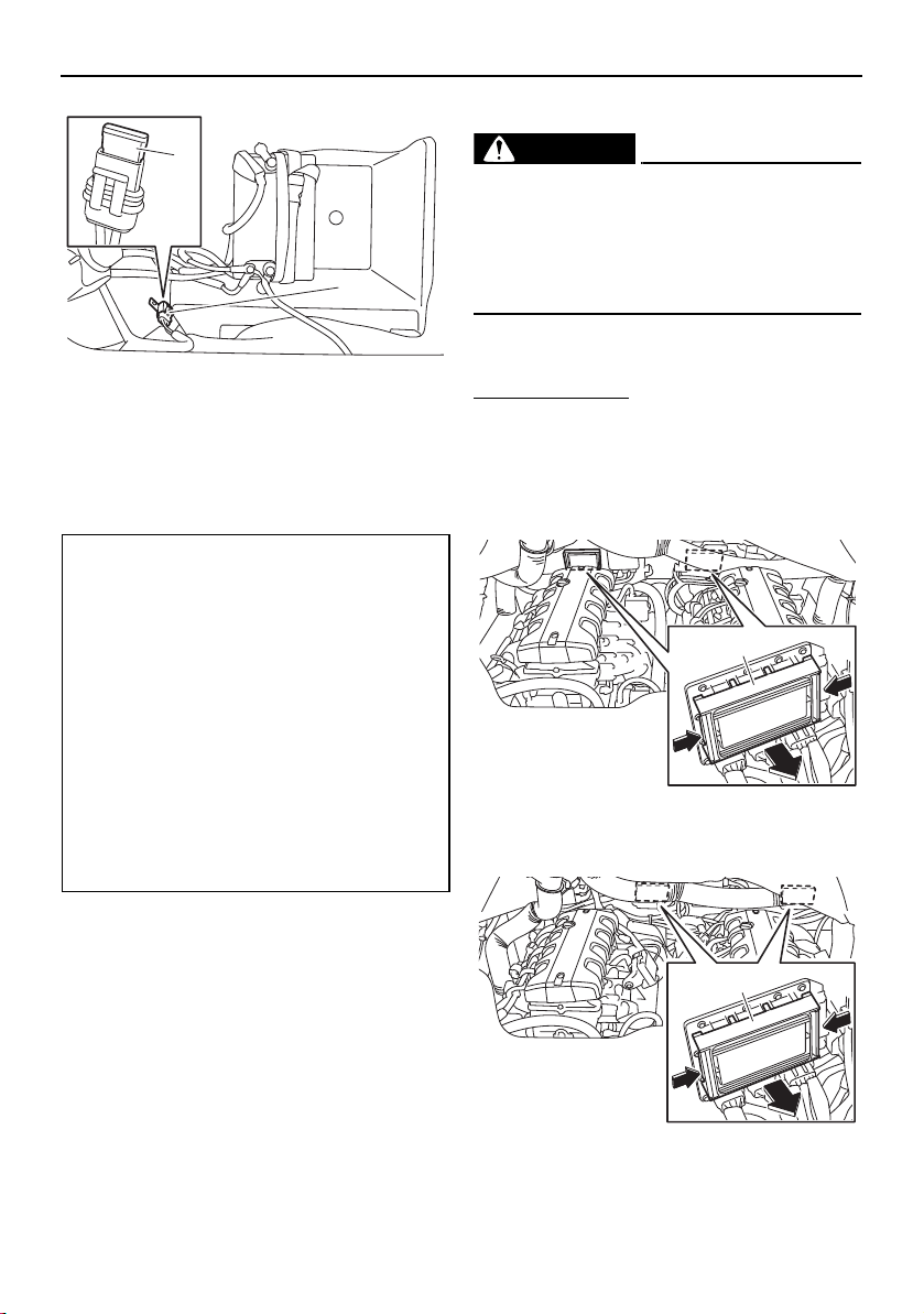
Trouble recovery
186
1 Accessory fuse holder
2 Accessary fuse
(6) Replace the blown fuse with the spare
fuse of the correct amperage by using
the fuse puller.
(7) Install the fuse box cover.
(8) If the accessory fuse was replaced, in-
stall the accessory fuse holder.
(9) Install the fuse box to the air filter case.
(10) Fasten the band.
(11) Close the engine hood.
Fuse replacement (212X / 212S / 212)
WARNING
Do not use fuses of a higher amperage
than recommended. Substitution with a
fuse that has an improper rating can cause
extensive electrical system damage and
possible fire.
If a fuse is blown, replace it with the proper
fuse.
To replace a fuse:
(1) Open the engine hood. (See page 97.)
(2) While pushing both sides of the fuse box
cover inward, pull the cover toward the
bow and remove it.
3-star models
1 Fuse box cover
4-star models
1 Fuse box cover
Fuse amperage:
Electronic throttle valve fuse:
10 A
Fuel pump fuse:
10 A
Main relay drive fuse:
10 A
Main fuse:
20 A
Battery fuse:
30 A
Accessory fuse:
20 A
2
1
1
1
SportsBoat_F3R13.book Page 186 Friday, May 31, 2019 9:42 AM
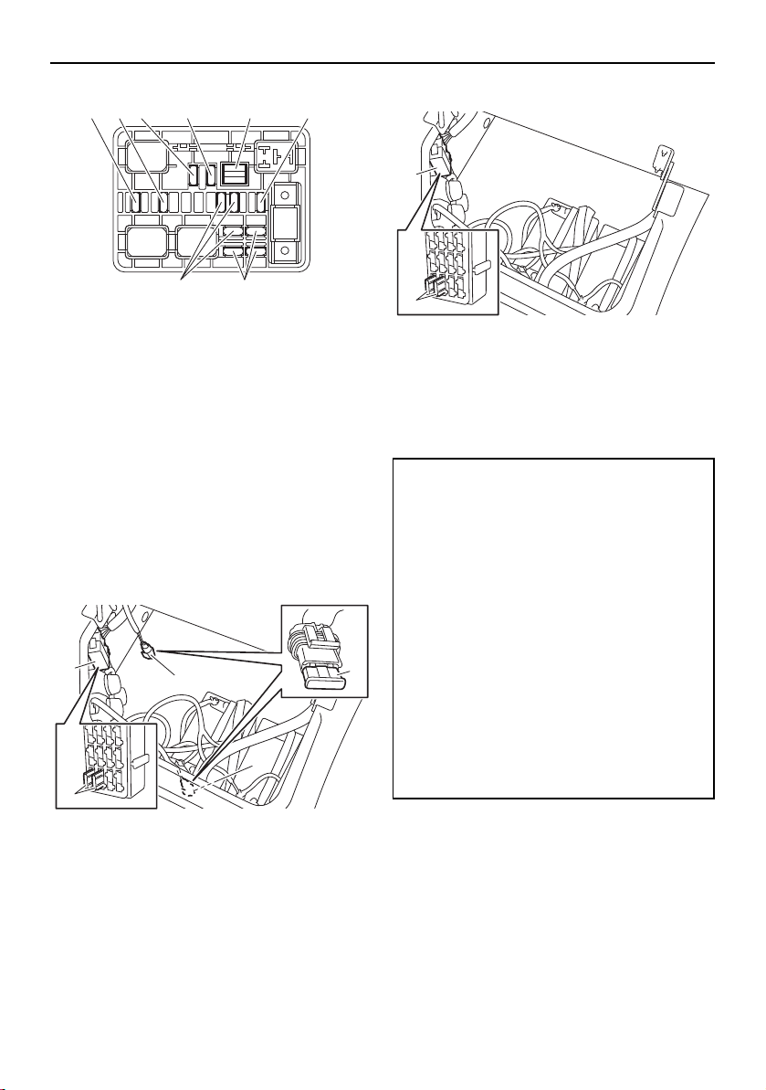
Trouble recovery
187
1 Electronic throttle valve fuse
2 Fuel pump fuse
3 Main relay drive fuse
4 Main fuse
5 Fuse puller
6 Battery fuse
7 Spare fuse
8 Unused fuse
(3) When replacing an accessory fuse, re-
move the accessory fuse holder or cov-
er. (Lift up the rear port seat to access
the accessory fuse. [See page 100])
212X
1 Accessory fuse holder
2 Accessory fuse cover
3 Accessory fuse
212S / 212
1 Accessory fuse cover
2 Accessory fuse
(4) Replace the blown fuse with the spare
fuse of the correct amperage by using
the fuse puller.
(5) Install the fuse box cover.
(6) If an accessory fuse was replaced, install
the accessory fuse holder or cover.
(7) Close the engine hood.
123 4 5 6
78
3
3
2
1
1
Fuse amperage:
Electronic throttle valve fuse:
10 A
Fuel pump fuse:
10 A
Main relay drive fuse:
10 A
Main fuse:
20 A
Battery fuse:
30 A
Accessory fuse:
40 A
30 A
20 A
2
1
SportsBoat_F3R13.book Page 187 Friday, May 31, 2019 9:42 AM
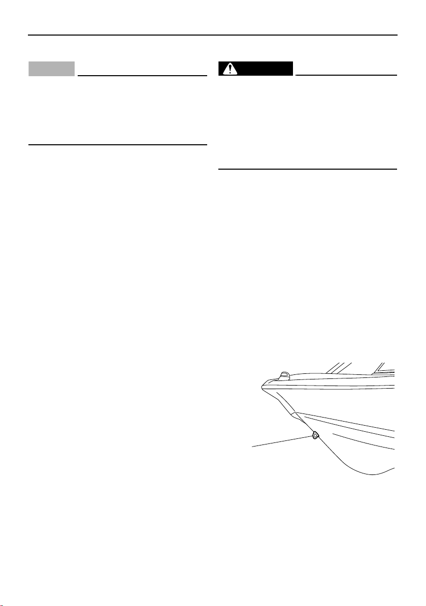
Trouble recovery
188
Running on one engine
NOTICE
Do not operate the boat above a no-wake
speed with just one engine.
Severe engine damage could result be-
cause water can flood the non-operating
engine through the water intake.
If one engine becomes inoperative, the prop-
erly running engine can be used to return to
shore. Operate at a no-wake speed to pre-
vent water from flooding the non-operating
engine through the water intake. The no-
wake mode can be used for this purpose.
(See page 57, 69.)
Towing the boat
WARNING
The operator of the towing boat must
keep speed to a minimum and avoid
traffic or obstacles which could be a
hazard to either boat.
The towing line should be long enough
so the towed boat will not collide with
the towing boat when slowing down.
The boat should be towed only if it becomes
inoperative.
The towing rope should be long enough so
that the boat will not collide with the towing
boat when slowing down. A good rule of
thumb is a tow rope which is three times the
combined length of the towing boat and the
boat.
Tow the boat using the bow eye only. Tow the
boat at a no-wake speed. NOTICE: Do not
tow the boat at speed fast enough to leave
a wake (8 km/h, 5 mph). Severe engine
damage could result because water can
flood the non-operating engines through
the water intakes.
1 Bow eye
1
SportsBoat_F3R13.book Page 188 Friday, May 31, 2019 9:42 AM
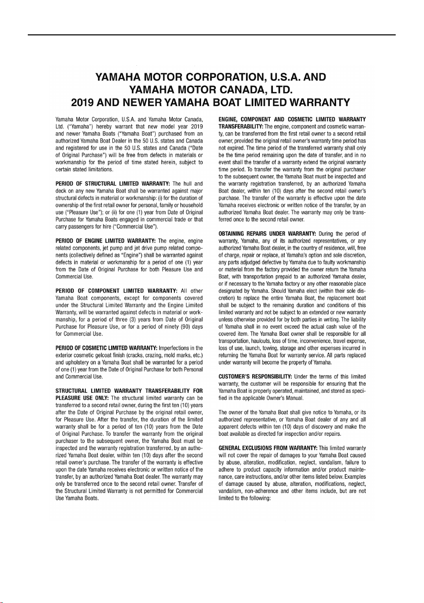
189
Consumer information
Limited warranty
SportsBoat_F3R13.book Page 189 Friday, May 31, 2019 9:42 AM
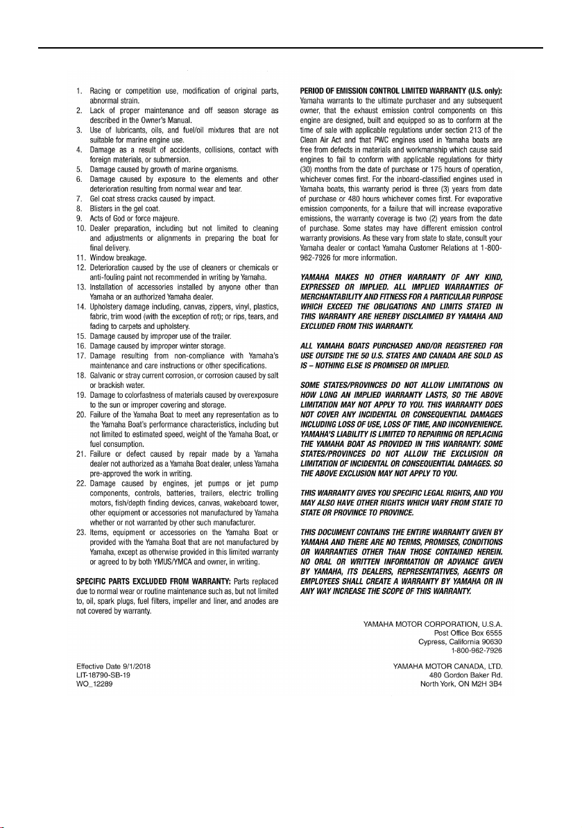
Consumer information
190
SportsBoat_F3R13.book Page 190 Friday, May 31, 2019 9:42 AM

Consumer information
191
YAMAHA EXTENDED SERVICE (Y.E.S.)
Keep your Yamaha Boat protected even after
the 1-year warranty coverage provisions
expire with genuine Yamaha Extended Service
(Y.E.S.).
Y.E.S. is designed and administered by
Yamaha Motor Corporation to provide maxi-
mum owner satisfaction. You get uninterrupted
factory-backed coverage for extra peace of
mind.
This excellent Y.E.S. plan coverage is only
available to Yamaha owners like you, and only
while your Yamaha is still within the first year
of the Yamaha Limited Warranty period. So
visit your authorized Yamaha dealer to get all
the facts. He can show you how easy it is to
protect your investment with Yamaha Extended
Service. We urge you to act now. You’ll get
the excellent benefits of TRIP coverage right
away, and you’ll rest easy knowing you’ll have
strong factory-backed protection even after
your Yamaha Limited Warranty expires. See
your dealer today!
A special note:
If visiting your dealer isn’t convenient, contact
Yamaha with your Primary ID number or Hull
Identification Number. We’ll be happy to help
you get the Y.E.S. coverage you need.
Yamaha Service Marketing
P.O. Box 6555
Cypress, CA 90630
1-(866)-YES-EXTD
(1-866-937-3983)
•
Y.E.S. is flexible. You choose the plan that’s
right for you: 12 months, 24 months, 36
months, or up to 48 months on certain mod-
els beyond the 1-year warranty coverage pe-
riod. That means you can get up to 5 years
of coverage on the power train, controls, and
other components to match the comforting
5-year standard protection on the hull.
•
Y.E.S. is designed and administered by the
same Yamaha people who handle your war-
ranty–and it shows in the comprehensive
coverage benefits. There are no limitations
on hours of use. Coverage isn’t limited to
“moving parts” or the “drive train” like many
other plans. And Y.E.S. covers manufactur-
ing defects just like the warranty. See the
sample contract at your Yamaha dealer to
see how comforting uninterrupted factory-
backed protection can be.
•
You don’t have to pay anything for cov-
ered repairs. There’s no deductible to pay,
and repairs aren’t “prorated.” You don’t have
any “out-of-pocket” expenses for covered
repairs.
•
In addition, Travel and Recreation
Interruption Protection (TRIP) is included
at no extra cost. TRIP gives you up to $250
reimbursement per occurrence for any rea-
sonable expenses you incur because your
Yamaha needs covered service: replace-
ment vehicle rental, emergency towing,
phone calls, even food and lodging when
you are away from home. This superb cov-
erage goes into effect when you purchase
Y.E.S., so it applies to any warranty repairs
as well as covered repairs during your entire
Y.E.S. plan period.
•
Y.E.S. coverage is honored at any autho-
rized Yamaha dealer nationwide.
•
Y.E.S. coverage is transferable to a new
owner if you sell or trade-in. That can make
your Yamaha Boat much more valuable!
SportsBoat_F3R13.book Page 191 Friday, May 31, 2019 9:42 AM
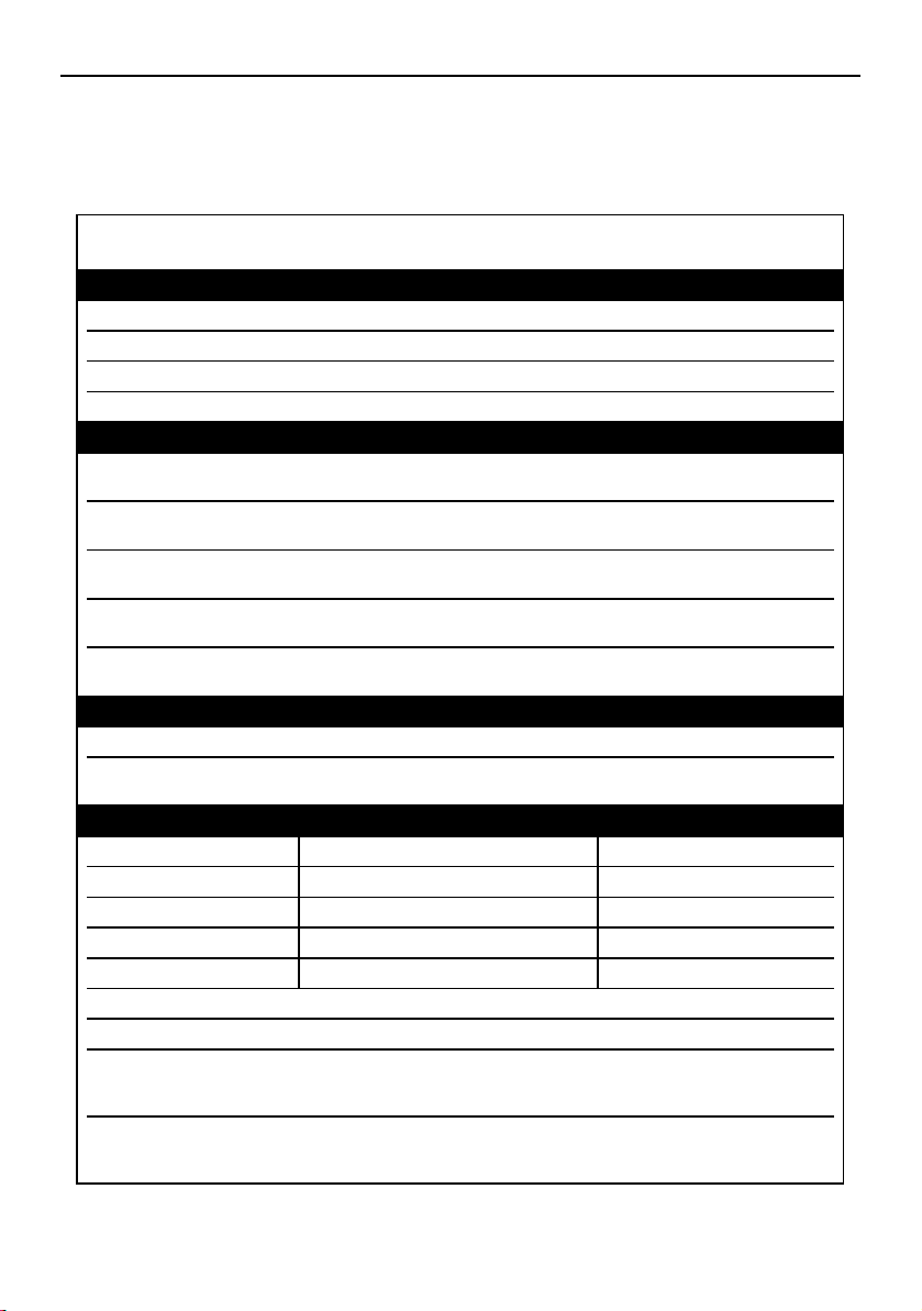
Consumer information
192
Sample float plan
Leave a float plan with a responsible person on shore before boating. The example below can
be copied and used.
FLOAT PLAN
VESSEL INFORMATION
BOAT MAKE:
Yamaha
MOTOR TYPE:
Jet
MODEL:
LENGTH: REGISTRATION NO:
DECK COLOR: HULL COLOR:
PASSENGER
OPERATOR
ADDRESS:
EMERGENCY PHONE:
PASSENGER #1:
ADDRESS:
EMERGENCY PHONE:
PASSENGER #2:
ADDRESS:
EMERGENCY PHONE:
PASSENGER #3:
ADDRESS:
EMERGENCY PHONE:
PASSENGER #4:
ADDRESS:
EMERGENCY PHONE:
DEPARTURE INFORMATION
POINT OF DEPARTURE: DATE/TIME:
TOW VEHICLE
MAKE / MODEL
LICENSE: TRAILER LICENSE:
DESTINATION INFORMATION
DESTINATION: LORAN OR GPS COORDINATES: INTENDED ACTIVITY:
EXPECTED RETURN DATE: TIME:
LOCAL U.S. COAST GUARD PHONE #:
NOTES: HULL COLOR:
OPERATOR
ADDRESS:
EMERGENCY PHONE:
PASSENGER #1:
ADDRESS:
EMERGENCY PHONE:
SportsBoat_F3R13.book Page 192 Friday, May 31, 2019 9:42 AM

193
Index
A
Access port cap check .......................... 134
Accessory outlet ................................ 61, 64
Additional equipment
recommendations................................. 18
Anchor light (AR210 / 212X / 212S) ....... 106
Anchor light (SX210 / 212) ..................... 106
Anchor storage compartment.................. 97
Anchoring............................................... 153
Approval labels of emission control
certificate ................................................ 3
Audio control keypad............................... 62
B
Backing your trailer ................................ 157
Basic stain guide.................................... 164
Battery care (212X / 212S / 212)............ 166
Battery care (AR210 / SX210) ................ 165
Battery check......................................... 137
Battery switch (AR210 / SX210)............... 38
Battery switches (212X / 212S / 212)....... 39
Beaching ................................................ 152
Bilge pump indicator light ........................ 65
Bilge water check................................... 137
Bilge water, draining .............................. 125
Bilge water, draining on land ................. 125
Bilge water, draining on water ............... 126
Bimini top (AR210 / 212X / 212S) .......... 113
Bimini top, installing
(AR210 / 212X / 212S) ........................ 116
Bimini top, installing (SX210 / 212) ........ 119
Bimini top, removing
(AR210 / 212X / 212S) ........................ 116
Bimini top, removing (SX210 / 212) ....... 119
Bimini top, setting up
(AR210 / 212X / 212S) ........................ 113
Bimini top, setting up (SX210 / 212) ...... 117
Bimini top, storing
(AR210 / 212X / 212S) ........................ 115
Bimini top, storing in the fully
collapsed position (SX210 / 212)........ 119
Bimini top, storing in the upright
position (SX210 / 212) ........................ 118
Bimini top (SX210 / 212) ........................ 117
Bimini top, trailering
(AR210 / 212X / 212S) ........................ 116
Bimini top, trailering (SX210 / 212)......... 119
Blower checks (212X / 212S / 212)........ 139
Blower switch check (AR210 / SX210)... 138
Boarding from a dock or landing jetty.... 151
Boarding from the bow .......................... 151
Boarding from the water ........................ 151
Boat characteristics ................................. 19
Boat control functions.............................. 38
Boating with passengers........................ 149
Bow ladder............................................. 107
C
Check engine warning........................ 55, 90
Cleaning the boat................................... 161
Communication error warning.................. 91
Cooling water pilot outlet check ............ 142
Crossing wakes and swells.................... 153
Cruise assist....................................... 57, 68
Cruising limitations................................... 16
D
Depth warning.......................................... 91
Docking .................................................. 151
Drain plug check .................................... 137
Draining the bilge water ........................... 60
Driver’s seat (212X / 212S / 212) ............. 94
Driver’s seat (AR210 / SX210).................. 93
Driver’s side console compartment ....... 101
Driving your boat.................................... 144
E
Emergency procedures.......................... 182
Emission control information ..................... 3
Enclosed head compartment................. 100
Engine break-in (212X / 212S / 212) ...... 129
Engine break-in (AR210 / SX210)........... 129
Engine covers, removing and installing
(212X / 212S / 212) ............................. 170
Engine hood ............................................. 97
Engine oil................................................ 121
Engine oil level check............................. 135
Engine oil requirement ........................... 121
Engine serial numbers................................ 1
Engine shut-off cord (lanyard) check ..... 141
SportsBoat_F3R13.book Page 193 Friday, May 31, 2019 9:42 AM

Index
194
Engine shut-off switch ............................. 38
Engine shut-off switch check................. 141
Enjoy your boat responsibly..................... 26
F
Fire extinguisher check .......................... 133
Flushing the cooling system .................. 160
Front underseat storage compartments .. 98
Front walk-through................................. 104
Fuel ........................................................ 120
Fuel level check ..................................... 142
Fuel requirement .................................... 120
Fuel system............................................ 168
Fuel system checks ............................... 135
Fuse replacement (212X / 212S / 212)... 186
G
Generic warning....................................... 56
Getting to know your boat ..................... 144
Glossary, boat.......................................... 27
Glove compartment
(212X / 212S / 212)............................. 102
Glove compartment (AR210 / SX210).... 102
Grease points......................................... 168
H
Hazard information................................... 19
Helm controls (212X / 212S / 212)........... 63
Helm controls (AR210 / SX210) ............... 44
Hitch....................................................... 156
Home screen............................................ 74
Horn check............................................. 141
Horn switch.............................................. 60
Hull Identification Number (HIN) ................ 1
I
Identification number records.................... 1
J
Jet intake checks ................................... 135
Jet pump clean-out procedure .............. 182
Jump-starting......................................... 184
L
Labels, important ....................................... 7
Labels, other ............................................ 14
Labels, warning........................................ 10
Launching............................................... 158
Learning to operate your boat................ 144
Leaving a dock....................................... 147
Lifting ..................................................... 159
Light operation ......................................... 58
Limitations on who may operate the
boat....................................................... 15
Limited warranty .................................... 189
Loading .................................................. 158
Long-term storage ................................. 168
Low fuel level warning.............................. 91
Low oil pressure warning ................... 55, 90
Lubrication ............................................. 168
M
Main components, location...................... 28
Main switches .......................................... 40
Maintenance........................................... 170
Manufactured date label
(212X / 212S / 212) ................................. 4
Manufactured date label
(AR210 / SX210) ..................................... 4
Map screen .............................................. 74
Media screen............................................ 76
Multi-function display elements ............... 70
Multi-function display unit
operation......................................... 45, 66
N
Navigation and anchor lights checks
(212X / 212S / 212) ............................. 140
Navigation and anchor lights switch
check (AR210 / SX210)....................... 139
Night operation ........................................ 20
No-wake mode................................... 57, 69
No-wake mode/cruise assist switch ........ 57
O
Operational requirements ........................ 17
Over temperature warning ................. 55, 90
Owner’s/operator’s manual.................... 170
P
Passenger’s seat (212X / 212S / 212)...... 96
Periodic maintenance chart ................... 172
Post-launch checks ............................... 141
SportsBoat_F3R13.book Page 194 Friday, May 31, 2019 9:42 AM

Index
195
Post-operation care ............................... 160
Post-operation checks........................... 154
Pre-launch checks ................................. 132
Pre-operation check points ................... 132
Pre-operation checklist.......................... 130
Primary Identification (PRI-ID) number ...... 1
R
Rear underseat storage compartment
(port) ................................................... 100
Rear underseat storage compartment
(starboard) ............................................ 99
Rear walk-through ................................. 104
Remote control keypad............................ 65
Remote control lever checks ................. 132
Remote control levers .............................. 40
Required equipment ................................ 18
Reverse RPM control ......................... 58, 69
Rules of the road...................................... 22
Running on one engine .......................... 188
S
Sample float plan ................................... 192
Seats ........................................................ 92
Setting screen .......................................... 84
Side table ............................................... 109
Ski locker ................................................. 98
Specifications (212X / 212S / 212)......... 177
Specifications (AR210 / SX210) ............. 175
Star labels (4-star models) ......................... 5
Starting the engines ............................... 144
Steering.................................................... 42
Steering system checks......................... 132
Stern ladder ........................................... 108
Stopping the boat .................................. 150
Stopping the engines ............................. 147
Storage compartments ............................ 97
Stowable table (212X / 212S / 212) ....... 102
Swim platform........................................ 108
Switch circuit breakers ............................ 61
System control screen ............................. 82
T
Tachometers ............................................ 45
Tilt lever.................................................... 43
To get more boating safety information... 26
Towing the boat ..................................... 188
Trailering checklist ................................. 156
Trailering the boat .................................. 156
Trip screen ......................................... 49, 75
Troubleshooting ..................................... 180
Troubleshooting chart ............................ 180
Turning the anchor light and bow light
on or off ................................................ 59
Turning the boat..................................... 148
Turning the courtesy light on or off.......... 59
V
Ventilating the engine compartment ........ 60
W
Wakeboard tower
(AR210 / 212X / 212S) ........................ 110
Wakeboard tower, collapsing and
setting up............................................ 111
Wakeboard tower, collapsing and
setting up (212X / 212S) ..................... 112
Wakeboarding and water-skiing .............. 21
Walk-through ......................................... 104
Water intake, shutting off ......................... 83
Wet storage compartment ..................... 103
Windshield.............................................. 104
Y
YAMAHA EXTENDED SERVICE
(Y.E.S.) ................................................ 191
SportsBoat_F3R13.book Page 195 Friday, May 31, 2019 9:42 AM

SportsBoat_F3R13.book Page 196 Friday, May 31, 2019 9:42 AM

For your best ownership experience, think Genuine Yamaha!
Genuine Yamaha Parts – Genuine Yamaha replacement parts are the exact same
parts as the ones originally equipped on your vehicle, providing you with the
performance and durability you have come to expect. Why settle for aftermarket parts
that may not provide full confidence and satisfaction?
Genuine Yamaha Accessories – Yamaha only offers accessories that meet our
high standards for quality and performance. Buy with confidence, knowing your
Genuine Yamaha Accessories will fit right and perform right – right out of the box.
Yamalube – Take care of your Yamaha with legendary Yamalube oils, lubricants,
and care products. They’re formulated and approved by the toughest judges we
know: the Yamaha engineering teams that know your Yamaha from the inside out.
Genuine Yamaha Service Manuals – Get the same factory man
ual for your vehicle
that the technicians at your authorized Yamaha dealer use. Service manuals are
available through your Yamaha dealer or you can order them directly through
yamahapubs.com.
Genuine Yamaha products are available only from your Yamaha dealer.
Find out more at yamaha-motor.com
SportsBoat_F3R13.book Page 1 Friday, May 31, 2019 9:42 AM

DIC183
Printed in USA
June 2019–0.1 × 1 CR