
2015 WaveRunner
VXS
VXR
OWNER’S/OPERATOR’S MANUAL
F2W-F8199-10
LIT-18626-10-55
U.S.A. Edition
Read this manual carefully
before operating this watercraft.
DIC183
Read this manual carefully before operating this watercraft. This manual
should stay with the WaveRunner if it is sold.
UF2W10E0.book Page 1 Tuesday, December 1, 2015 3:25 PM
Important manual information
EJU30183
To the owner/operator
Thank you for choosing a Yamaha watercraft.
This owner’s/operator’s manual contains in-
formation you will need for proper operation,
maintenance, and care. A thorough under-
standing of these simple instructions will help
you to obtain maximum enjoyment from your
new Yamaha. If you have any questions
about the operation or maintenance of your
watercraft, please consult a Yamaha dealer.
In this manual, information of particular im-
portance is distinguished in the following
ways:
This is the safety alert symbol. It is used
to alert you to potential personal injury haz-
ards. Obey all safety messages that follow
this symbol to avoid possible injury or death.
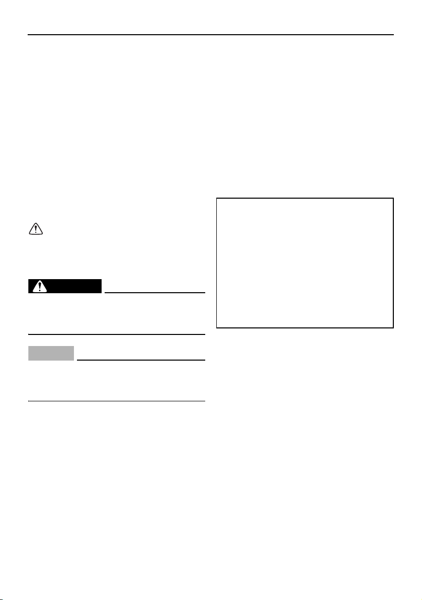
WARNING
EWJ00072
A WARNING indicates a hazardous situa-
tion which, if not avoided, could result in
death or serious injury.
NOTICE
ECJ00092
A NOTICE indicates special precautions
that must be taken to avoid damage to the
watercraft or other property.
TIP:
A TIP provides key information to make pro-
cedures easier or clearer.
EJU40401
Because Yamaha has a policy of continuing
product improvement, this product may not
be exactly as described in this owner’s/oper-
ator’s manual. Specifications are subject to
change without notice.
This manual should be considered a perma-
nent part of this watercraft and should remain
with it even if the watercraft is subsequently
sold.
EJU30223
WaveRunner VXS / VXR
OWNER’S/OPERATOR’S MANUAL
©2015 by Yamaha Motor Corporation,
U.S.A.
2nd Edition, November 2015
All rights reserved.
Any reprinting or unauthorized use
without the written permission of
Yam ah a Mo to r C or poration, U.S.A.
is expressly prohibited.
Printed in U.S.A.
P/N LIT-18626-10-55
UF2W10E0.book Page 1 Tuesday, December 1, 2015 3:25 PM

Table of contents
General and important labels........... 1
Identification numbers .................... 1
Primary Identification (PRI-ID)
number............................................ 1
Hull Identification Number (HIN)......... 1
Engine serial number.......................... 1
Emission control information .......... 2
Approval label of emission control
certificate ........................................ 2
Manufactured date label .................... 2
Star labels .......................................... 3
Important labels .............................. 5
Warning labels.................................... 6
Other labels ........................................ 8
Safety information........................... 10
Limitations on who may operate
the watercraft ............................. 10
Cruising limitations........................ 11
Operation requirements ................ 13
Recommended equipment ........... 15
Hazard information........................ 16
Watercraft characteristics ............. 16
Wakeboarding and water-skiing ... 18
Rules of the Road ......................... 19
To get more boating safety
information ................................. 23
Enjoy your watercraft
responsibly................................. 24
Description....................................... 26
Watercraft glossary ....................... 26
Location of main components ...... 27
Control function operation ............. 31
Watercraft control functions ......... 31
Remote control transmitter .............. 31
Yamaha Security System................. 32
Engine stop switch .......................... 33
Engine shut-off switch .................... 33
Start switch ..................................... 33
Throttle lever .................................... 34
RiDE lever......................................... 34
Steering system................................ 35
Cooling water pilot outlet ................. 35
Water separator................................ 35
Watercraft operation ...................... 37
Watercraft operation functions ..... 37
Shift system...................................... 37
Electric trim system.......................... 39
Watercraft operation modes......... 41
Low RPM Mode ............................... 41
Instrument operation ...................... 43
Multifunction information center... 43
Information display........................... 43
Hour meter ....................................... 47
Voltmeter.......................................... 48
Equipment operation ...................... 49
Equipment..................................... 49
Seats ................................................ 49
Handgrip........................................... 50
Reboarding step (VXR) ..................... 50
Bow eye............................................ 51
Stern eyes ........................................ 51
Cleat ................................................. 51
Storage compartments .................... 52
Fire extinguisher holder and cover... 54
Operation and handling
requirements ................................... 56
Fuel requirements ......................... 56
Fuel................................................... 56
Engine oil requirements ................ 58
Engine oil.......................................... 58
Draining the bilge water ................ 60
Draining the bilge water on land....... 60
Draining the bilge water on water .... 60
UF2W10E0.book Page 1 Tuesday, December 1, 2015 3:25 PM

Table of contents
Transporting on a trailer................ 61
First-time operation ........................ 62
Engine break-in ............................. 62
Pre-operation checks ..................... 63
Pre-operation checklist .................... 63
Pre-operation check points........... 65
Pre-launch checks ........................... 65
Post-launch checks ......................... 71
Operation ......................................... 74
Operating your watercraft ............. 74
Getting to know your watercraft ...... 74
Learning to operate your
watercraft...................................... 74
Riding position ................................. 75
Launching the watercraft ................. 75
Starting the engine on water............ 75
Stopping the engine......................... 76
Leaving the watercraft...................... 76
Operating the watercraft .................. 76
Turning the watercraft ...................... 77
Stopping the watercraft ................... 78
Operating the watercraft in reverse
or neutral....................................... 79
Boarding the watercraft ................... 80
Starting off........................................ 82
Capsized watercraft ......................... 83
Beaching and docking the
watercraft...................................... 84
Operating in weeded areas .............. 84
After removing the watercraft from
the water ....................................... 84
Care and storage............................. 86
Post-operation care ...................... 86
Flushing the cooling water
passages....................................... 86
Cleaning the watercraft .................... 87
Battery care...................................... 87
Long-term storage ........................ 90
Cleaning ........................................... 90
Lubrication ....................................... 90
Rustproofing..................................... 90
Maintenance.................................... 91
Maintenance ................................. 91
Tool kit.............................................. 91
Removing and installing the engine
cover ............................................. 91
Periodic maintenance chart ............. 93
Engine oil and oil filter ...................... 94
Specifications.................................. 95
Specifications ............................... 95
Trouble recovery ............................. 96
Troubleshooting............................ 96
Troubleshooting chart ...................... 96
Emergency procedures ................ 99
Cleaning the jet intake and
impeller ......................................... 99
Raising the reverse gate................. 100
Jumping the battery ....................... 100
Replacing the fuses........................ 101
Towing the watercraft..................... 103
Submerged watercraft ................... 103
Consumer information ................. 105
Limited warranty ......................... 105
YAMAHA EXTENDED SERVICE
(Y.E.S.) ..................................... 107
Index............................................... 108
UF2W10E0.book Page 2 Tuesday, December 1, 2015 3:25 PM
General and important labels
1
EJU30263
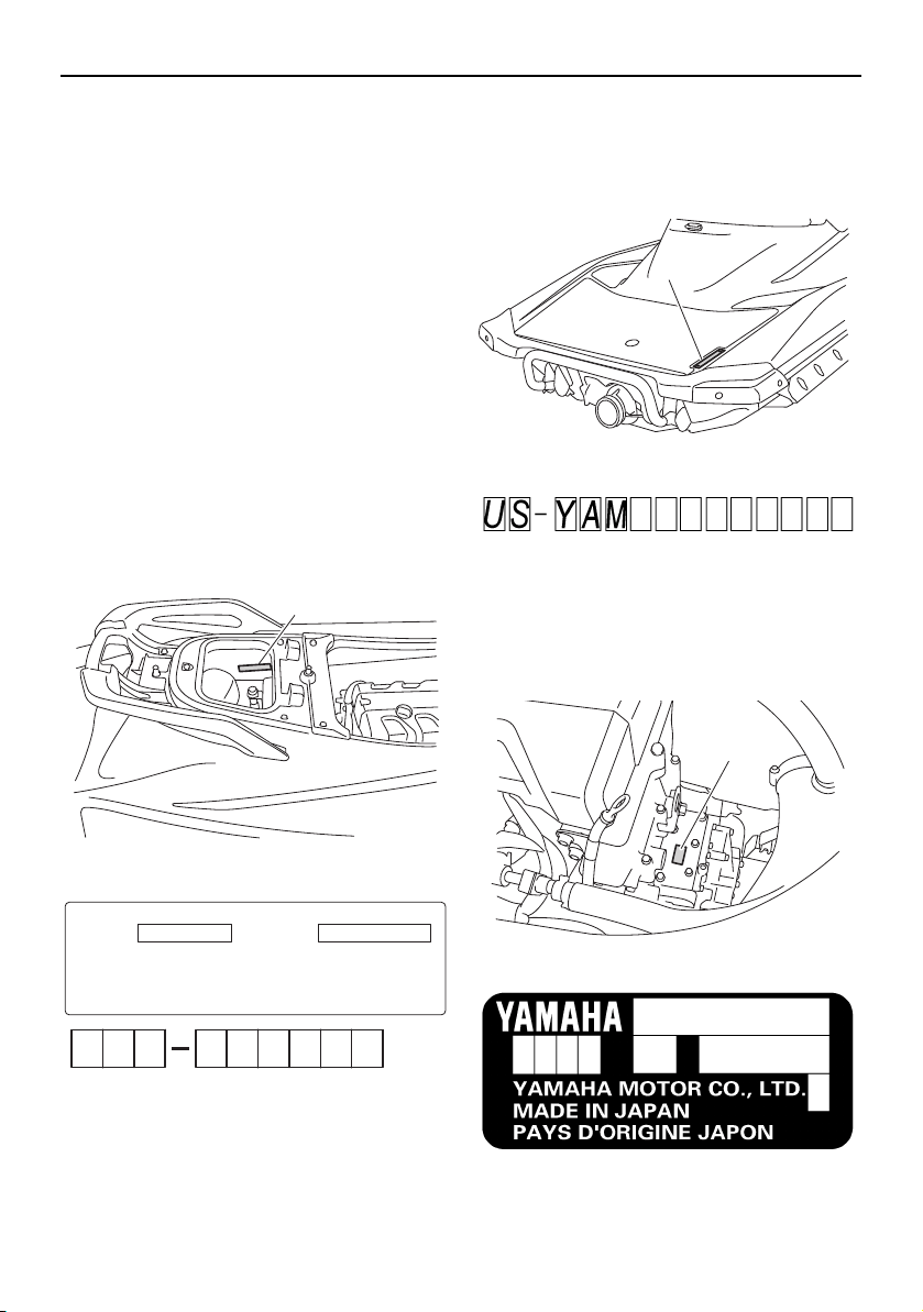
Identification numbers
Record the Primary Identification (PRI-ID)
number, Hull Identification Number (HIN), and
engine serial number in the spaces provided
for assistance when ordering genuine parts
from a Yamaha dealer. Also record and keep
these ID numbers in a separate place in case
your watercraft is stolen.
EJU42521
Primary Identification (PRI-ID) number
The PRI-ID number is stamped on a plate at-
tached inside the engine compartment. (See
page 49 for seat removal and installation pro-
cedures and page 54 for information on the
removable watertight storage compartment.)
MODEL:
VX1800-P (VXS)
VX1800A-P (VXR)
EJU30301
Hull Identification Number (HIN)
The HIN is stamped on a plate attached to
the aft deck.
EJU30312
Engine serial number
The engine serial number is stamped on a
plate attached to the engine unit. (See page
49 for seat removal and installation proce-
dures.)
1 Primary Identification (PRI-ID) number loca-
tion
1
MODEL
F2W
F
PRI-I.D.
YAMAHA MOTOR CO., LTD.
ASSEMBLED IN U.S.A. FROM AMERICAN AND JAPANESE
COMPONENTS.
ASSEMBLÉ AUX ÉTATS-UNIS DE PIÈCES AMÉRICAINES ET
JAPONAISES.
2
W
1 Hull Identification Number (HIN) location
1 Engine serial number location
1
1
UF2W10E0.book Page 1 Tuesday, December 1, 2015 3:25 PM
General and important labels
2
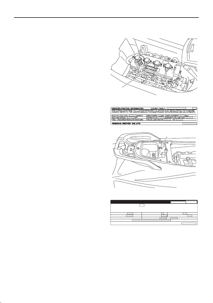
EJU30353
Emission control information
This engine conforms to U.S. Environmental
Protection Agency (EPA) and/or California Air
Resources Board (CARB) regulations for ma-
rine SI engines applicable at the time of man-
ufacture.
This engine is certified to operate on regular
unleaded gasoline.
EJU42511
Approval label of emission control
certificate
This label is attached to the top of the cylin-
der head and to the inside of the engine com-
partment. (See page 49 for seat removal and
installation procedures, page 91 for engine
cover removal and installation procedures,
and page 54 for information on the removable
watertight storage compartment.)
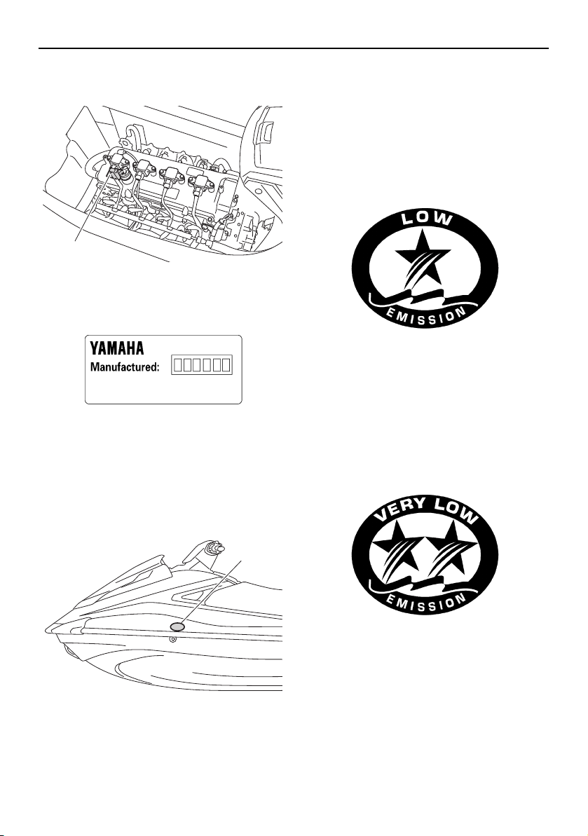
EJU40491
Manufactured date label
This label is attached to the top of the cylin-
der head. (See page 49 for seat removal and
installation procedures and page 91 for en-
1 Emission control information label location
1 Emission control information label location
1
1
EMISSION CONTROL INFORMATION
ENGINE FAMILY:
THIS ENGINE CONFORMS TO CALIFORNIA AND U.S. EPA EXHAUST REGULATIONS
FOR SI MARINE ENGINES. REFER TO THE OWNER’S MANUAL FOR MAINTENANCE
SPECIFICATIONS AND ADJUSTMENTS. THIS VESSEL MEETS U.S. EPA EVAP STANDARDS.
FELS (HC+NOx/CO) : g/kW-hr
TROLLING SPEED : rpm
FUEL : UNLEADED REGULAR GASOLINE
CERTIFIED COMPONENTS :
YAMAHA MOTOR CO., LTD.
MAX POWER : kW
SPARK PLUG :
VALVE LASH (mm) IN : EX :
DISPLACEMENT : liters
SPARK PLUG GAP (mm) :
UF2W10E0.book Page 2 Tuesday, December 1, 2015 3:25 PM
General and important labels
3
gine cover removal and installation proce-
dures.)
EJU30441
Star labels
This watercraft is labeled with a California Air
Resources Board (CARB) star label. See be-
low for a description of your particular label.
One Star - Low Emission
The one-star label identifies engines that
meet the Air Resources Board’s Personal
Watercraft and Outboard marine engine 2001
exhaust emission standards. Engines meet-
ing these standards have 75% lower emis-
sions than conventional carbureted two-
stroke engines. These engines are equivalent
to the U.S. EPA’s 2006 standards for marine
engines.
Two Stars - Very Low Emission
The two-star label identifies engines that
meet the Air Resources Board’s Personal
Watercraft and Outboard marine engine 2004
exhaust emission standards. Engines meet-
ing these standards have 20% lower emis-
sions than One Star-Low Emission engines.
Three Stars - Ultra Low Emission
The three-star label identifies engines that
meet the Air Resources Board’s Personal
Watercraft and Outboard marine engine 2008
exhaust emission standards or the Sterndrive
and Inboard marine engine 2003-2008 ex-
haust emission standards. Engines meeting
1 Manufactured date label location
1 Star label location
1
1
UF2W10E0.book Page 3 Tuesday, December 1, 2015 3:25 PM
General and important labels
4
these standards have 65% lower emissions
than One Star-Low Emission engines.
Four Stars - Super Ultra Low Emission
The four-star label identifies engines that
meet the Air Resources Board’s Sterndrive
and Inboard marine engine 2009 exhaust
emission standards. Personal Watercraft and
Outboard marine engines may also comply
with these standards. Engines meeting these
standards have 90% lower emissions than
One Star-Low Emission engines.
UF2W10E0.book Page 4 Tuesday, December 1, 2015 3:25 PM

General and important labels
5
EJU30453
Important labels
Read the following labels before using this watercraft. If have any questions, consult a
Yamaha dealer.
1
510
7
4
3
9
11
2
6
8
UF2W10E0.book Page 5 Tuesday, December 1, 2015 3:25 PM

General and important labels
6
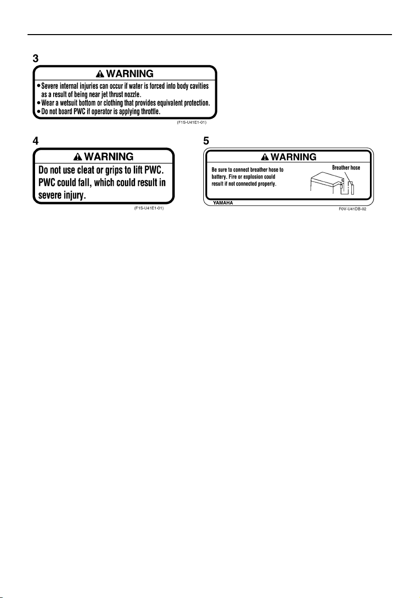
EJU35914
Warning labels
If any of these labels are damaged or missing, contact a Yamaha dealer for replacements.
F1S-U415B-01
1
2
UF2W10E0.book Page 6 Tuesday, December 1, 2015 3:25 PM
General and important labels
7
UF2W10E0.book Page 7 Tuesday, December 1, 2015 3:25 PM
General and important labels
8
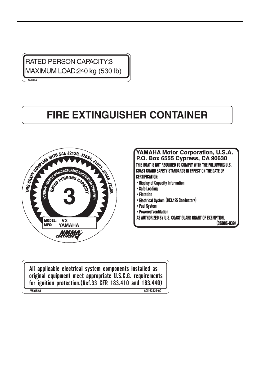
EJU35926
Other labels
F1S-U41G1-01
F0V-U41F5-01
(F1S-U41E1-01)
6
7
8
10
9
UF2W10E0.book Page 8 Tuesday, December 1, 2015 3:25 PM
General and important labels
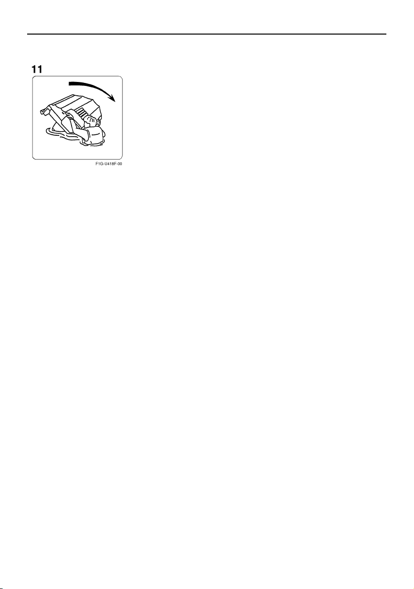
9
The following label indicates the correct direction to upright a capsized watercraft.
UF2W10E0.book Page 9 Tuesday, December 1, 2015 3:25 PM
Safety information
10
EJU30672
The safe use and operation of this water-
craft is dependent upon the use of proper
riding techniques, as well as upon the
common sense, good judgment, and ex-
pertise of the operator. Every operator
should know the following requirements
before riding the watercraft.
Before operating the watercraft, read this
owner’s/operator’s manual, the Riding
Practice Guide, the Riding Instruction card,
and all labels on the watercraft. Also, watch
the Basic Orientation Video provided with
your watercraft. These materials should
give you an understanding of the watercraft
and its operation.
Never allow anyone to operate this water-
craft until they too have read this own-
er’s/operator’s manual, the Riding Practice
Guide, the Riding Instruction card, and all
labels, and, if possible, watched the Basic
Orientation Video.
Showing them the video may help reinforce
the information contained in these materi-
als.
EJU30732
Limitations on who may
operate the watercraft
Yamaha recommends a minimum operator
age of 16 years old.
Adults must supervise use by minors.
Know the operator age and training re-
quirements for your state. A boating safety
course is recommended and may be re-
quired in your state. You can find local rules
by contacting the United States Coast
Guard (USCG), the National Association of
State Boating Law Administrators, or your
local Power Squadron.
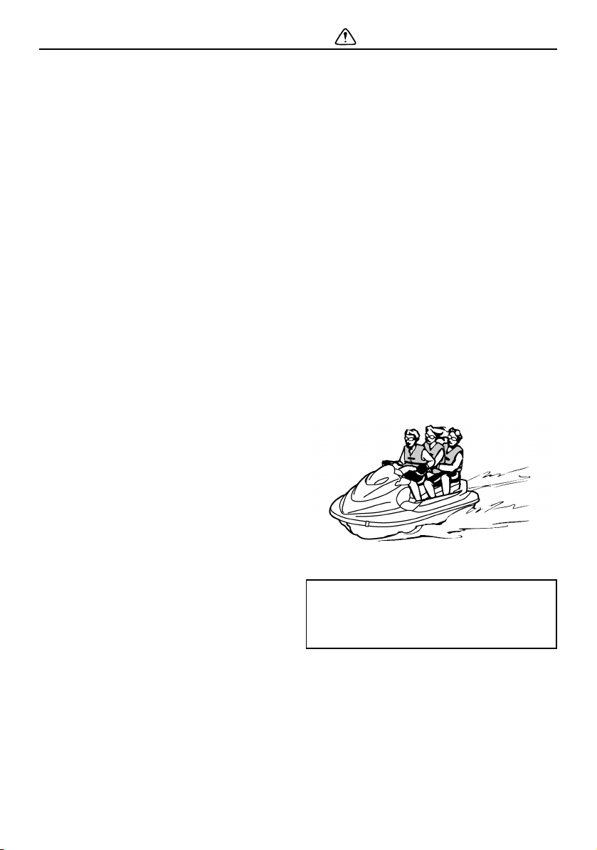
This watercraft is designed to carry the op-
erator and up to 2 passengers. Never ex-
ceed the maximum load limit or allow more
than 3 persons (or 2 persons if a wake-
boarder or water-skier is being pulled) to
ride the watercraft at any time.
Do not operate the watercraft with any pas-
sengers on board until you have consider-
able practice and experience riding alone.
Operating the watercraft with passengers
requires more skill. Take the time to be-
come accustomed to the handling charac-
Maximum load:
240 kg (530 lb)
Load is the total weight of cargo, op-
erator, and passengers.
UF2W10E0.book Page 10 Tuesday, December 1, 2015 3:25 PM
Safety information
11
teristics of the watercraft before trying any
difficult maneuvers.
EJU43321
Cruising limitations
Scan constantly for people, objects, and
other watercraft. Be alert for conditions
that limit your visibility or block your vision
of others.
Operate defensively at safe speeds and
keep a safe distance away from people,
objects, and other watercraft.
Do not follow directly behind watercraft or
other boats.
Do not go near others to spray or splash
them with water.
Take early action to avoid collisions. Re-
member, watercraft and other boats do not
have brakes. In addition, the Reverse with
Intuitive Deceleration Electronics (RiDE)
system is not a braking device for avoiding
dangerous situations. The RiDE system is
an electronic system for controlling the en-
gine speed and reverse gate, which is lo-
cated near the jet thrust nozzle. The RiDE
lever located at the left handlebar grip can
be used to change the direction of the jet
thrust so that the watercraft moves in re-
verse or is in neutral. The RiDE system as-
sists the operator when slowing down and
during slow-speed maneuvering, such as
launching, beaching, and docking.
Avoid sharp turns, slowing down rapidly by
squeezing the RiDE lever forcefully, and
other maneuvers that make it hard for oth-
UF2W10E0.book Page 11 Tuesday, December 1, 2015 3:25 PM
Safety information
12
ers to avoid you or understand where you
are going.
Avoid areas with submerged objects or
shallow water.
Do not release the throttle lever when trying
to steer away from objects—you need
throttle to steer. Always check throttle and
steering controls before starting the water-
craft.
Ride within your limits and avoid aggres-
sive maneuvers to reduce the risk of loss of
control, ejection, and collision.
This is a high performance boat—not a toy.
Sharp turns or jumping wakes or waves
can increase the risk of back/spinal injury
(paralysis), facial injuries, and broken legs,
ankles, and other bones. Do not jump
wakes or waves.
Do not operate the watercraft in rough wa-
ter, bad weather, or when visibility is poor;
this may lead to an accident causing injury
or death. Be alert to the possibility of ad-
verse weather. Take note of weather fore-
casts and the prevailing weather
conditions before setting out on your wa-
tercraft.
As with any water sport, you should not op-
erate your watercraft without someone else
nearby. If you operate further than swim-
ming distance from shore, you should be
accompanied by another boat or water-
craft, but make sure you stay a safe dis-
tance away. It’s good, common sense.
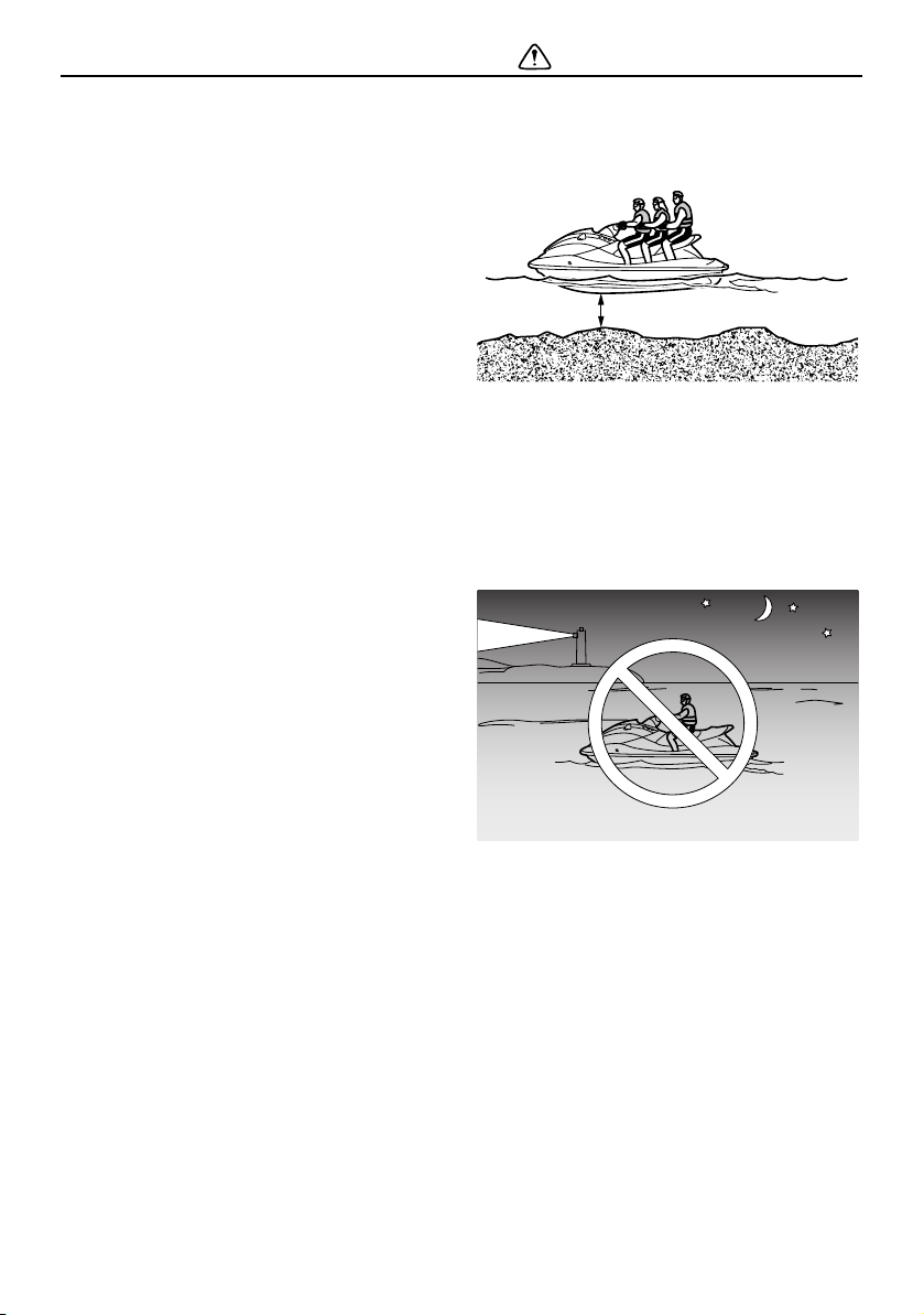
Never operate in water that is less than 60
cm (2 ft) deep from the bottom of the wa-
tercraft, otherwise you increase your
chance of hitting a submerged object,
which could result in injury.
This watercraft is not equipped with light-
ing required for night operation. Do not op-
erate the watercraft after sunset or before
dawn, otherwise you increase the risk of
colliding with another boat, which could re-
sult in severe injury or death.
Follow navigation rules, and state/provin-
cial and local laws that apply to watercraft.
60 cm (2 ft)
UF2W10E0.book Page 12 Tuesday, December 1, 2015 3:25 PM
Safety information
13
EJU43120
Operation requirements
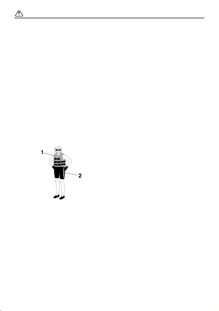
All riders must wear a U.S. Coast Guard
(USCG) approved personal flotation device
(PFD) that is suitable for personal water-
craft use.
Wear protective clothing. Severe internal
injuries can occur if water is forced into
body cavities as a result of falling into the
water or being near the jet thrust nozzle.
Normal swimwear does not adequately
protect against forceful water entry into the
rectum or vagina. All riders must wear a
wetsuit bottom or clothing that provides
equivalent protection. Such clothing in-
cludes thick, tightly woven, sturdy and
snug-fitting apparel such as denim, but
does not include spandex or similar fab-
rics, like those used in bicycle shorts.
Eye protection is recommended to keep
wind, water, and glare from the sun out of
your eyes while you operate your water-
craft. Restraining straps for eyewear are
made which are designed to float should
your eyewear fall in the water.
Footwear and gloves are recommended.
Helmets meeting Snell or DOT standards
are required for IJSBA-sanctioned races.
You must decide whether to wear a helmet
while you ride for recreation. You should
know that a helmet could help protect you
in certain kinds of accidents and that it
could injure you in others.
A helmet is designed to provide some head
protection. Although helmets cannot pro-
tect against all foreseeable impacts, a hel-
met might reduce your injuries in a collision
with a boat or other obstacle.
A helmet may have potential safety haz-
ards, as well. Falling into the water could
risk the chance of the helmet catching wa-
ter, commonly known as “bucketing”, and
the resulting strain on your neck could
cause choking, severe and permanent
neck injuries, or death. A helmet could also
increase the risk of an accident if it reduces
your vision or hearing, or if it distracts you
or increases your fatigue.
How should you decide if a helmet’s poten-
tial safety benefits outweigh its potential
risks for you? Consider your particular rid-
ing conditions. Consider factors such as
your riding environment and your riding
style and ability. Also consider the likeli-
hood of traffic congestion, and the water
surface conditions.
If you decide to wear a helmet based upon
your riding circumstances, choose one
carefully. Look for a helmet designed for
personal watercraft use, if possible. Con-
sider a helmet meeting Snell or DOT stan-
dards. If you will be engaging in closed-
course competition, follow the helmet re-
quirements of the sanctioning organization.
Never operate the watercraft after consum-
ing alcohol or taking other drugs.
For reasons of safety and proper care of
the watercraft, always perform the pre-op-
eration checks listed on page 63 before op-
erating the watercraft.
1 USCG approved PFD
2 Wetsuit bottom
UF2W10E0.book Page 13 Tuesday, December 1, 2015 3:25 PM
Safety information
14
The operator should grip the handlebars
firmly with both hands and the passengers
should hold on firmly, either to the person
in front of them or to the handgrip provid-
ed.
The operator and passengers should al-
ways keep their feet on the floor of the foot-
well when the watercraft is in motion.
Lifting your feet increases the chances of
losing your balance, or hitting objects out-
side the watercraft with your feet. Do not
give a ride to children if their feet cannot
reach the floor of the footwell.
Never allow a passenger to ride in front of
the operator.
Always consult your doctor on whether it is
safe for you to ride this watercraft if you are
pregnant or in poor health.
Do not attempt to modify this watercraft.
Modifications to your watercraft may re-
duce safety and reliability, and render the
watercraft unsafe or illegal for use.
Attach the engine shut-off cord (lanyard) to
your left wrist and keep it free from the han-
dlebars so that the engine stops if you, the
operator, fall off. After riding, remove the
engine shut-off cord (lanyard) from the wa-
tercraft to avoid accidental starting or un-
authorized use by children or others.
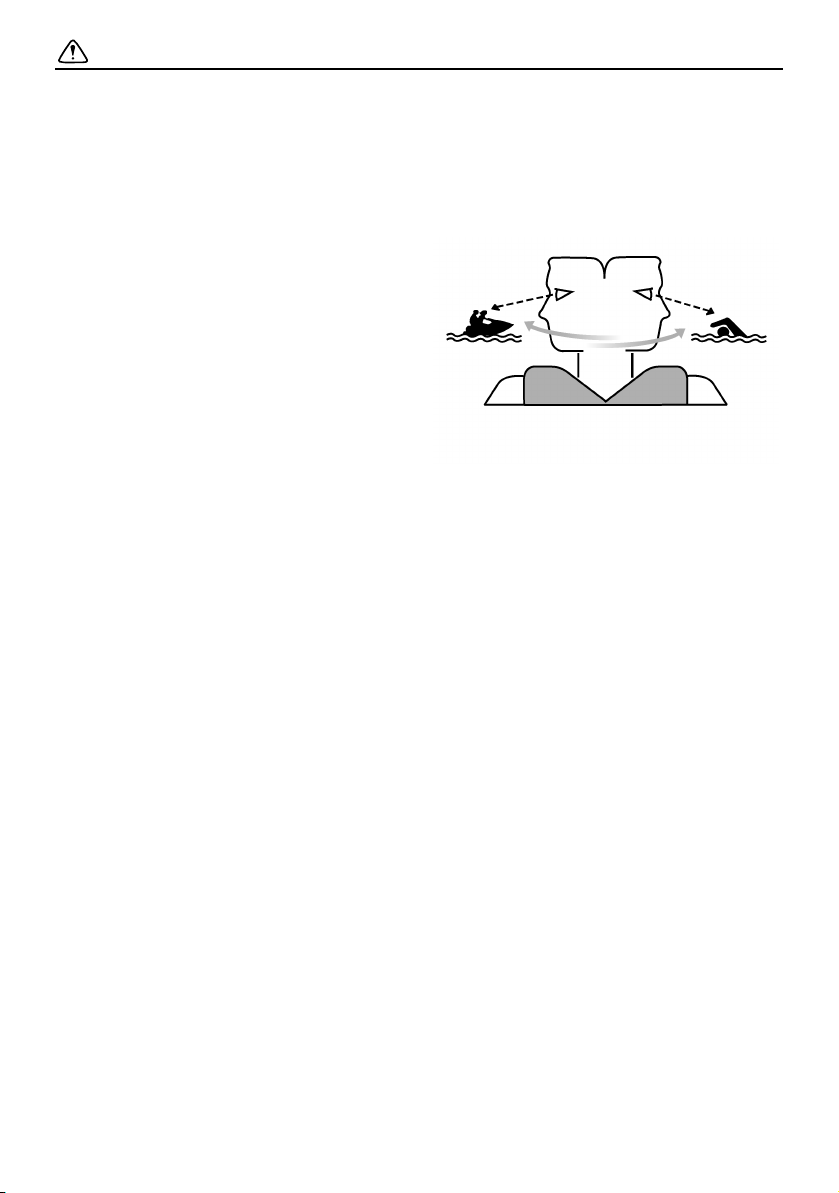
Scan carefully for swimmers and stay away
from swimming areas. Swimmers are hard
to see and you could accidentally hit some-
one in the water.
Avoid being hit by another boat. You
should always take the responsibility to
watch for traffic; other boaters may not be
watching for you. If they do not see you, or
if you maneuver more quickly than other
boaters expect, you risk a collision.
Maintain a safe distance from other boats
and watercraft, and also watch for ski
ropes or fishing lines. Obey the “Rules of
the Road” and be sure to check behind you
before making a turn or slowing down. (See
“Rules of the Road” on page 19.)
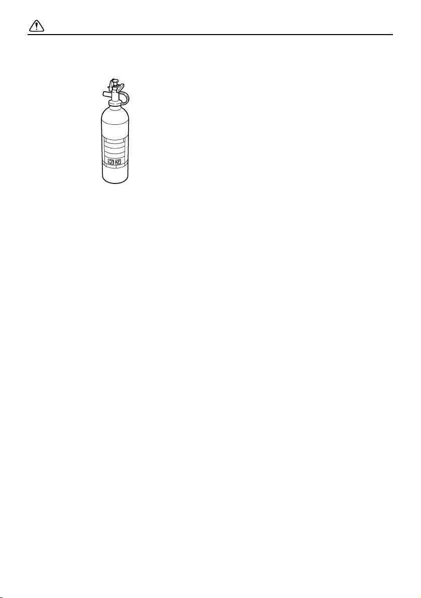
According to the USCG, boats under 6.1 m
(20 ft) in length like your watercraft must
carry a fire extinguisher of a B-1 classifica-
tion, with a capacity of two pounds or more
when navigating in waters under USCG ju-
risdiction. In addition, most state and local
UF2W10E0.book Page 14 Tuesday, December 1, 2015 3:25 PM
Safety information
15
boating laws also require that the fire extin-
guisher be approved by the USCG.
EJU30831
Recommended equipment
The following items should be carried on
board your watercraft:
Sound-signaling device
You should carry a whistle or other sound-
signaling device that can be used to signal
other boats. See “Rules of the Road” for
more information.
Visual distress signals
It is recommended that a U.S. Coast Guard
approved pyrotechnic device be stored in a
waterproof container on your watercraft. A
mirror can also be used as an emergency
signal. Contact a Yamaha dealer or the
U.S. Coast Guard for more information.
Watch
A watch is helpful so you will know how
long you have been operating the water-
craft.
Towline
A towline can be used to tow a disabled
watercraft in an emergency.
UF2W10E0.book Page 15 Tuesday, December 1, 2015 3:25 PM

Safety information
16
EJU42474
Hazard information
Never start the engine or let it run for any
length of time in an enclosed area. Exhaust
fumes contain carbon monoxide, a color-
less, odorless gas that may cause loss of
consciousness and death within a short
time. Always operate the watercraft in an
open area.
Do not touch the hot muffler or engine dur-
ing or immediately after engine operation;
they can cause serious burns.
Do not place magnets or objects with a
strong magnetic force near the throttle le-
ver or RiDE lever. The electronic throttle
mechanism of the levers can be adversely
affected, which could cause loss of control.
In addition, do not place objects suscepti-
ble to magnetic forces (i.e., credit cards,
watches, etc.) close to the throttle lever or
RiDE lever.
EJU42414
Watercraft characteristics
Jet thrust turns the watercraft. Releasing
the throttle lever completely produces only
minimum thrust. If you are traveling at
speeds above trolling, you will have rapidly
decreasing ability to steer without throttle.
This model is equipped with the Yamaha
Engine Management System (YEMS) that
includes an off-throttle steering (OTS) sys-
tem. It will activate at planing speeds
should you attempt to steer the watercraft
after releasing the throttle lever. The OTS
system assists in turning by continuing to
supply some thrust while the watercraft is
decelerating, but you can turn more sharp-
ly if you apply throttle while turning the han-
dlebars.
The OTS system does not function below
planing speeds or when the engine is off.
Once the engine slows down, the water-
craft will no longer turn in response to han-
dlebar input until you apply throttle again or
you reach trolling speed.
Practice turning in an open area without
obstacles until you have a good feel for this
maneuver.
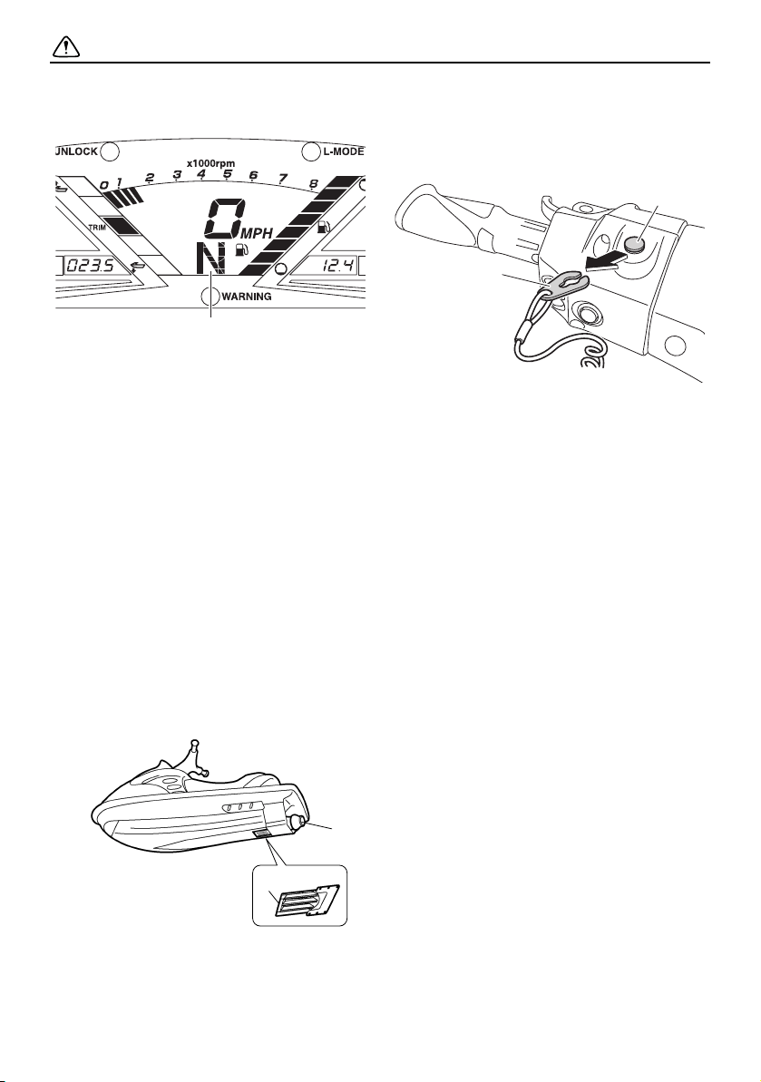
This watercraft is water-jet propelled. The
jet pump is directly connected to the en-
gine. This means that jet thrust will produce
some movement whenever the engine is
running and the “F” (forward) or “R” (re-
verse) shift indicator is displayed in the
multifunction display. When the “N” (neu-
tral) shift indicator is displayed, the forward
and reverse thrust are balanced to help
keep the watercraft from moving in either
UF2W10E0.book Page 16 Tuesday, December 1, 2015 3:25 PM
Safety information
17
direction, although some movement may
occur.
To avoid rear-end collisions while operat-
ing the watercraft, check behind you be-
fore using the RiDE lever to slow down or
stop the watercraft. Make sure that there
are no obstacles or people behind you be-
fore shifting into reverse.
Keep away from the intake grate while the
engine is on. Items such as long hair, loose
clothing, or PFD straps can become entan-
gled in moving parts, resulting in severe in-
jury or drowning.
Never insert any object into the jet thrust
nozzle while the engine is running. Severe
injury or death could result from coming in
contact with the rotating parts of the jet
pump.
Stop the engine and remove the clip from
the engine shut-off switch before removing
any debris or weeds, which may have col-
lected around the jet intake.
1 “N” (Neutral position)
1 Intake grate
2 Jet thrust nozzle
1
1
2
1 Clip
2 Engine shut-off switch
2
1
UF2W10E0.book Page 17 Tuesday, December 1, 2015 3:25 PM
Safety information
18
EJU30946
Wakeboarding and water-
skiing
You can use the watercraft for wakeboarding
or water-skiing if it has the seating capacity to
carry the operator, a rearward-facing spotter,
and the wakeboarder or water-skier when he
or she is not being pulled.
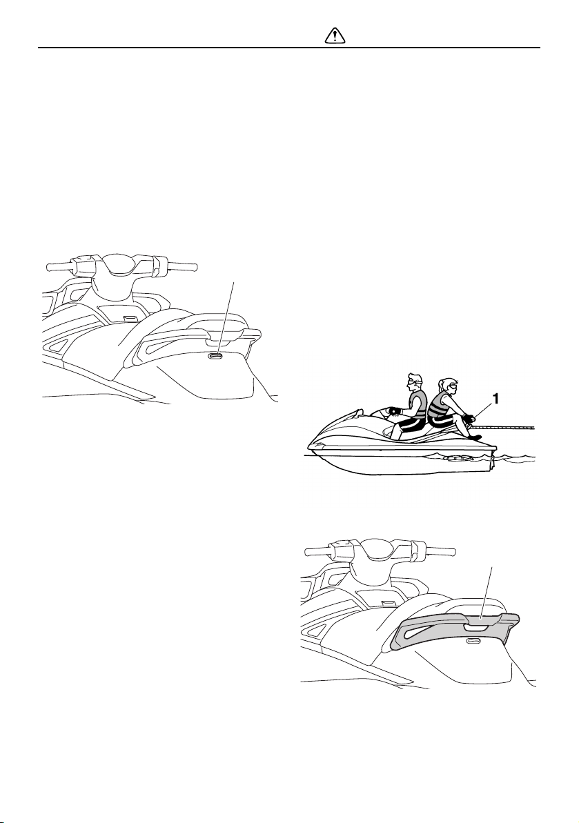
The watercraft must also have a cleat de-
signed to pull a ski rope; do not attach the
rope to any other location.
It is the watercraft operator’s responsibility to
be alert to the safety of the wakeboarder or
water-skier and others. Know and follow all
state and local regulations in effect for the
waters in which you will be operating.
The operator should be comfortable carrying
passengers before attempting to pull a wake-
boarder or water-skier.
The following are some important consider-
ations for minimizing risks while pulling a
wakeboarder or water-skier.
The wakeboarder or water-skier should
wear an approved PFD, preferably a bright-
ly colored one so boat operators can see
the person being pulled.
The wakeboarder or water-skier should
wear protective clothing. Severe internal in-
juries can occur if water is forced into body
cavities as a result of falling into the water.
Normal swimwear does not adequately
protect against forceful water entry into the
rectum or vagina. The person being pulled
should wear a wetsuit bottom or clothing
that provides equivalent protection.
A second person should be on board as a
spotter to watch the wakeboarder or wa-
ter-skier; in most states it is required by
law. Let the person being pulled direct the
operator’s control of speed and direction
with hand signals.
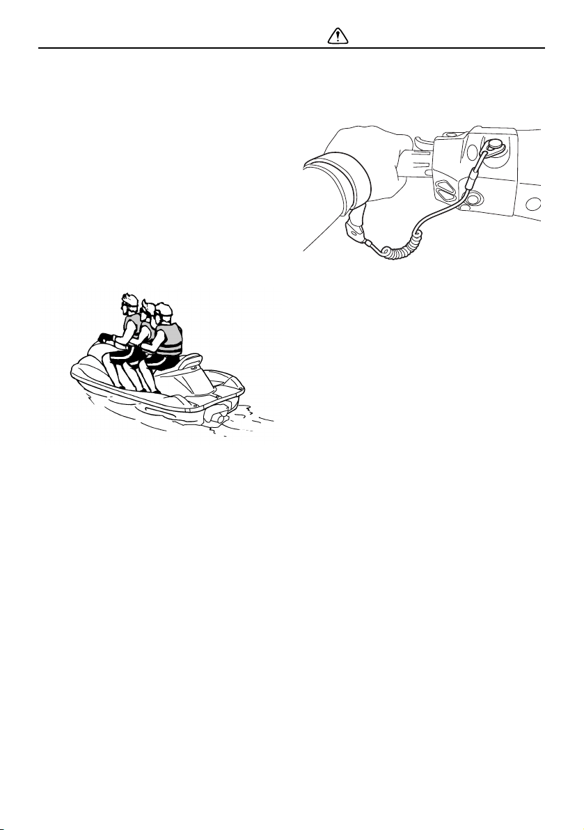
The spotter should sit astride the rear of the
seat and hold onto the handgrip with both
feet firmly on the floor of the footwell for
proper balance while facing to the rear to
watch the wakeboarder’s or water-skier’s
hand signals and condition.
Your control while pulling a wakeboarder or
water-skier is affected by the wakeboard-
1 Cleat
1
1 Handgrip
1 Handgrip
1
UF2W10E0.book Page 18 Tuesday, December 1, 2015 3:25 PM

Safety information
19
er’s or water-skier’s ability, as well as water
and weather conditions.
When preparing to pull a wakeboarder or
water-skier, operate the watercraft at the
slowest possible speed until the watercraft
is well away from the person being pulled
and slack in the ski rope is taken up. Make
sure that the rope is not looped around
anything.
After checking that the wakeboarder or wa-
ter-skier is ready and that there is no traffic
or other obstacles, apply enough throttle to
raise the person.
Make smooth, wide turns. The watercraft is
capable of very sharp turns, which could
exceed the abilities of the wakeboarder or
water-skier. Keep the person being towed
at least 50 m (164 ft), about twice the dis-
tance of a standard ski rope, away from
any potential hazard.
The operators of boats and other water-
craft may not be aware that you are pulling
a wakeboarder or water-skier. Together
with the spotter, pay attention to others
around you and cruise at safe speeds.
Be alert to the hazard of the ski rope handle
snapping back at the watercraft when the
wakeboarder or water-skier falls or is un-
able to get up.
Towing heavy or bulky objects other than
wakeboarders or water-skiers, such as an-
other boat or watercraft, can cause loss of
steering control and create a hazardous
condition. If you must tow another boat in
an emergency situation, operate slowly
and cautiously.
EJU30962
Rules of the Road
Your Yamaha watercraft is legally consid-
ered a powerboat. Operation of the water-
craft must be in accordance with the rules
and regulations governing the waterway
on which it is used.
Just as there are rules that apply when you
are driving on streets and highways, there are
waterway rules that apply when you are oper-
ating your watercraft. These rules are used
internationally, and are also enforced by the
United States Coast Guard and local agen-
cies. You should be aware of these rules, and
follow them whenever you encounter another
vessel on the water.
Several sets of rules prevail according to
geographic location, but are all basically the
same as the International Rules of the Road.
The rules presented here in this owner’s/op-
erator’s manual are condensed, and have
been provided for your convenience only.
Consult your local U.S. Coast Guard Auxiliary
or Department of Motor Vehicles for a com-
plete set of rules governing the waters in
which you will be operating your watercraft.
Steering and sailing rules
Whenever two vessels on the water meet one
another, one vessel has the right-of-way; it is
called the “stand-on” vessel. The vessel that
does not have the right-of-way is called the
“give-way” or “burdened” vessel. These rules
determine which vessel has the right-of-way,
and what each vessel should do.
Stand-on vessel
The vessel with the right-of-way has the duty
to continue its course and speed, except to
avoid an immediate collision. When you
maintain your direction and speed, the other
vessel will be able to determine how best to
avoid you.
UF2W10E0.book Page 19 Tuesday, December 1, 2015 3:25 PM
Safety information
20
Give-way vessel
The vessel which does not have the right-of-
way has the duty to take positive and timely
action to stay out of the way of the stand-on
vessel. Normally, you should not cross in
front of the vessel with the right-of-way. You
should slow down or change directions brief-
ly and pass behind the other vessel. You
should always move in such a way that the
operator of the other vessel can see what you
are doing.
The General Prudential Rule regarding the
right-of-way is that if a collision appears un-
avoidable, neither boat has the right-of-way.
Both boats must avoid the collision.
In other words, follow the standard rules ex-
cept when a collision will occur unless both
vessels try to avoid each other. If that is the
case, both vessels become give-way ves-
sels.
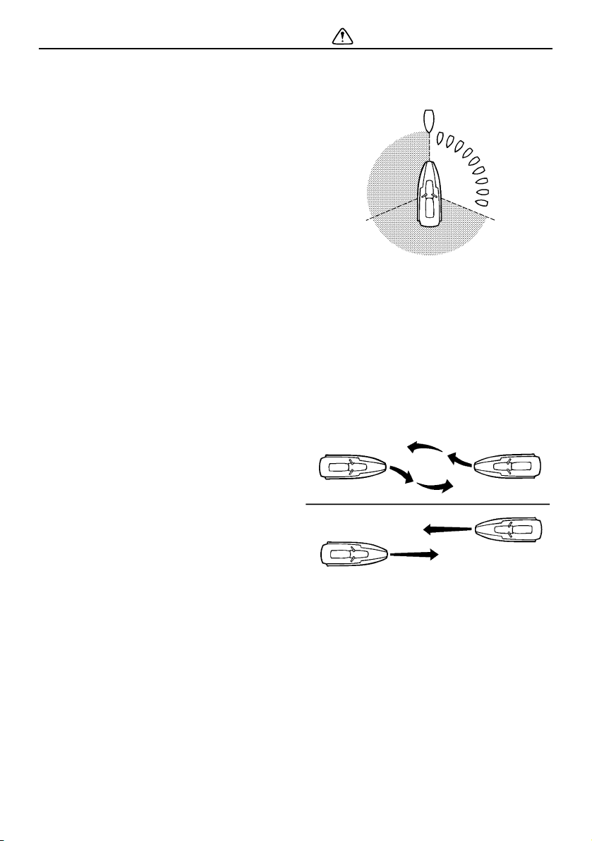
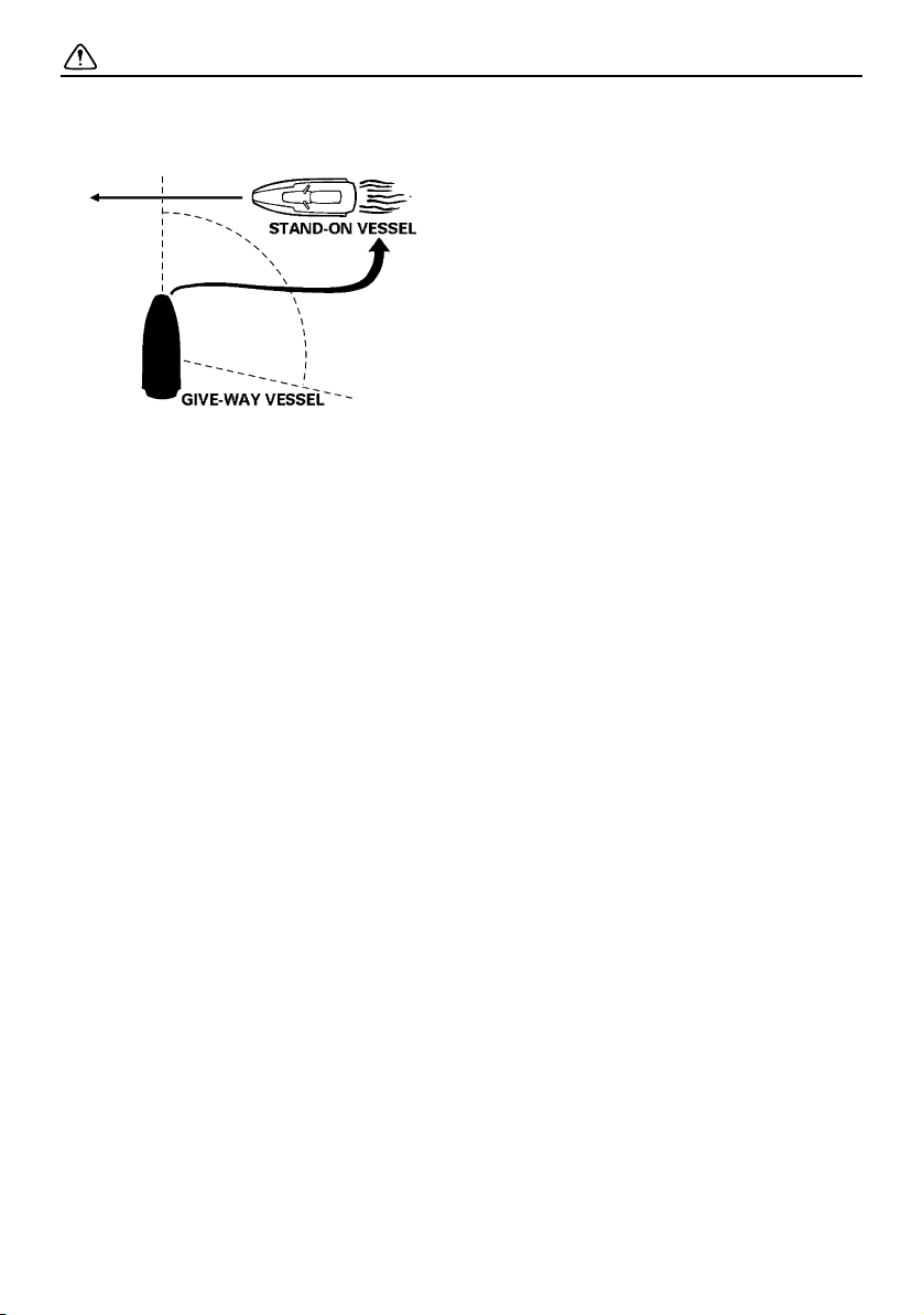
Rules when encountering vessels
There are three main situations that you may
encounter with other vessels which could
lead to a collision unless the Steering Rules
are followed:
Meeting: you are approaching another vessel
head-on
Crossing: you are traveling across another
vessel’s path
Overtaking: you are passing or being passed
by another vessel
In the following illustration, your watercraft is
in the center. You should give the right-of-
way to any vessels shown in the white area
(you are the give-way vessel). Any vessels in
the shaded area must yield to you (they are
the give-way vessels). Both you and the
meeting vessel must alter course to avoid
each other.
Meeting
If you are meeting another power-driven ves-
sel head on, and are close enough to run the
risk of collision, neither of you has the right-
of-way. Both of you should alter course to
avoid an accident. You should keep the other
vessel on your port (left) side. This rule does
not apply if both of you will clear one another
if you continue on your set course and speed.
Crossing
When two power-driven vessels are crossing
each other’s path close enough to run the risk
of collision, the vessel which has the other on
the starboard (right) side must keep out of the
way of the other. If the other vessel is on your
starboard (right) side, you must keep out of
its way; you are the give-way vessel. If the
other vessel is on your port (left) side, remem-
ber that you should maintain course and di-
UF2W10E0.book Page 20 Tuesday, December 1, 2015 3:25 PM
Safety information
21
rection, provided the other vessel gives you
the right-of-way as it should.
Overtaking
If you are passing another vessel, you are the
give-way vessel. This means that the other
vessel is expected to maintain its course and
speed. You must stay out of its way until you
are clear of it. Likewise, if another vessel is
passing you, you should maintain your speed
and direction so that the other vessel can
steer itself around you.
Other special situations
There are three other rules you should be
aware of when riding your watercraft around
other vessels.
Narrow channels and bends
When navigating in narrow channels, you
should keep to the right when it is safe and
practical to do so. If the operator of a power-
driven vessel is preparing to go around a
bend that may obstruct the view of other wa-
ter vessels, the operator should sound a pro-
longed blast of four to six seconds on the
whistle. If another vessel is around the bend,
it too should sound the whistle. Even if no re-
ply is heard, however, the vessel should still
proceed around the bend with caution. If you
navigate such waters with your watercraft,
you will need to carry a portable air horn,
available from local marine supply stores.
Fishing vessel right-of-way
All vessels fishing with nets, lines, or trawls
are considered to be “fishing vessels” under
the International Rules. Vessels with trolling
lines are not considered fishing vessels. Fish-
ing vessels have the right-of-way regardless
of position. Fishing vessels cannot, however,
impede the passage of other vessels in nar-
row channels.
Sailing vessel right-of-way
Sailing vessels should normally be given the
right-of-way. The exceptions to this are:
(1) When the sailing vessel is overtaking the
power-driven vessel, the power-driven
vessel has the right-of-way.
(2) Sailing vessels should keep clear of any
fishing vessel.
(3) In a narrow channel, a sailing vessel
should not hamper the safe passage of a
power-driven vessel that can navigate
only in such a channel.
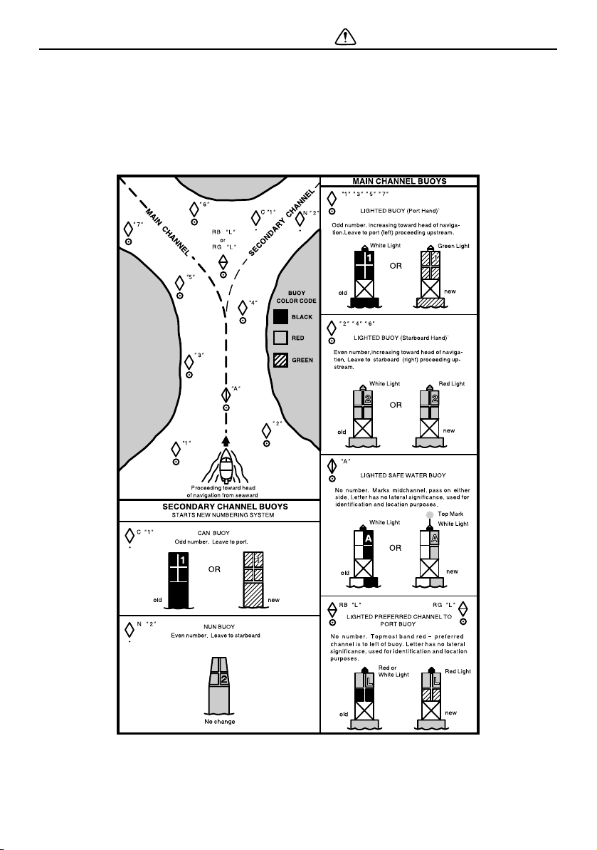
Reading buoys and other markers
The waters of the United States are marked
for safe navigation by the lateral system of
buoyage. Simply put, buoys and markers
have an arrangement of shapes, colors, num-
bers, and lights to show which side of the
buoy a boater should pass on when navigat-
ing in a particular direction. The markings on
these buoys are oriented from the perspec-
tive of being entered from seaward (the boat-
er is going towards the harbor). Red buoys
are passed on your starboard (right) side
when proceeding from open water into the
harbor, and black buoys are to your port (left)
side. An easy way to remember the meaning
of the colors is the phrase “red right return-
ing”. When navigating out of the harbor, your
position with respect to the buoys should be
reversed; red buoys should be to port and
black buoys to starboard.
UF2W10E0.book Page 21 Tuesday, December 1, 2015 3:25 PM
Safety information
22
Many bodies of water used by boaters are
entirely within the boundaries of a particular
state. The Uniform State Waterway Marking
System has been devised for these waters.
This system uses buoys and signs with dis-
tinctive shapes and colors to show regulatory
or advisory information. These markers are
white with black letters and orange borders.
They signify speed zones, restricted areas,
danger areas, and general information.
UF2W10E0.book Page 22 Tuesday, December 1, 2015 3:25 PM

Safety information
23
Remember, markings may vary by geograph-
ic location. Always consult local boating au-
thorities before riding your watercraft in
unfamiliar waters.
EJU30983
To get more boating safety
information
Be informed about boating safety. Additional
publications and information can be obtained
from many organizations, including the fol-
lowing.
United States Coast Guard
Consumer Affairs Staff (G-BC)
Office of Boating, Public, and Consumer Af-
fairs
U.S. Coast Guard Headquarters
Washington, D.C. 20593-0001
http://www.uscgboating.org/
Other sources
You can find local rules by contacting the Na-
tional Association of State Boating Law Ad-
ministrators, or your local Power Squadron.
Watercraft Education and Training
The Online Boating Safety Course, available
through the watercraft section of the yama-
ha-motor.com website, is a free, 50 question
learning course available to the public. Upon
successful completion of 80 percent or bet-
ter, the user can request a certificate of com-
pletion by mail or can download one
immediately. The Online Boating Safety
Course, provided by the Boat/US Founda-
tion, is approved by the National Association
of State Boating Law Administrators (NASB-
LA) and recognized by the United States
Coast Guard. This course meets the educa-
tion requirement for those states that recog-
nize non-proctored, NASBLA-approved
courses.
Yamaha is the watercraft industry’s leading
manufacturer to build awareness and sup-
port for boating education. In 1997, Yamaha
launched its GET W.E.T. (Watercraft Educa-
tion and Training) initiative and has since
reached out to over one million Americans
promoting the benefits of boating education.
UF2W10E0.book Page 23 Tuesday, December 1, 2015 3:25 PM

Safety information
24
EJU30992
Enjoy your watercraft
responsibly
You share the areas you enjoy when riding
your watercraft with others and with nature.
So your enjoyment includes a responsibility
to treat these other people, and the lands,
waters, and wildlife with respect and courte-
sy.
Whenever and wherever you ride, think of
yourself as the guest of those around you.
Remember, for example, that the sound of
your watercraft may be music to you, but it
could be just noise to others. And the exciting
splash of your wake can make waves others
won’t enjoy.
Avoid riding close to shoreline homes and
waterfowl nesting areas or other wildlife ar-
eas, and keep a respectful distance from fish-
ermen, other boats, swimmers, and
populated beaches. When travel in areas like
these is unavoidable, ride slowly and obey all
laws.
Proper maintenance is necessary to ensure
that the exhaust emission and sound levels of
your watercraft will continue to be within reg-
ulated limits. You have the responsibility to
make sure that the recommended mainte-
nance in this owner’s/operator’s manual is
carried out.
Remember, pollution can be harmful to the
environment. Do not refuel or add oil where a
spill could cause damage to nature. Remove
your watercraft from the water and move it
away from the shoreline before refueling. Dis-
pose of water and any fuel and oil residue in
the engine compartment according to local
regulations. And keep your surroundings
pleasant for the people and wildlife that share
the waterways: don’t litter.
The Online Boating Safety Course:
http://www.boatus.org/
UF2W10E0.book Page 24 Tuesday, December 1, 2015 3:25 PM

Safety information
25
When you ride responsibly, with respect and
courtesy for others, you help ensure that our
waterways stay open for the enjoyment of a
variety of recreational opportunities.
UF2W10E0.book Page 25 Tuesday, December 1, 2015 3:25 PM

Description
26
EJU43331
Watercraft glossary
Trolling speed
“Trolling” is the lowest maneuvering speed. You are applying little or no throttle. The water-
craft is down in the water, and there is no wake.
Sub-planing speed
“Sub-planing” is a medium speed. The bow of the watercraft is slightly up from the water sur-
face, but you are still traveling through the water. There is a wake.
Planing speed
“Planing” is a faster speed. The watercraft is more level and is skimming on top of the water.
There is a wake.
Bow
The front end of the watercraft.
Stern
The rear end of the watercraft.
Starboard
The right side of the watercraft when facing forward.
Port
The left side of the watercraft when facing forward.
Bilge water
Water that has collected in the engine compartment.
Yamaha Engine Management System (YEMS)
YEMS is an integrated, computerized management system that controls and adjusts ignition
timing, fuel injection, engine diagnostics, and the off-throttle steering (OTS) system.
Reverse with Intuitive Deceleration Electronics (RiDE)
RiDE is an electronic system that controls the reverse, neutral, and deceleration operations of
the watercraft.
UF2W10E0.book Page 26 Tuesday, December 1, 2015 3:25 PM
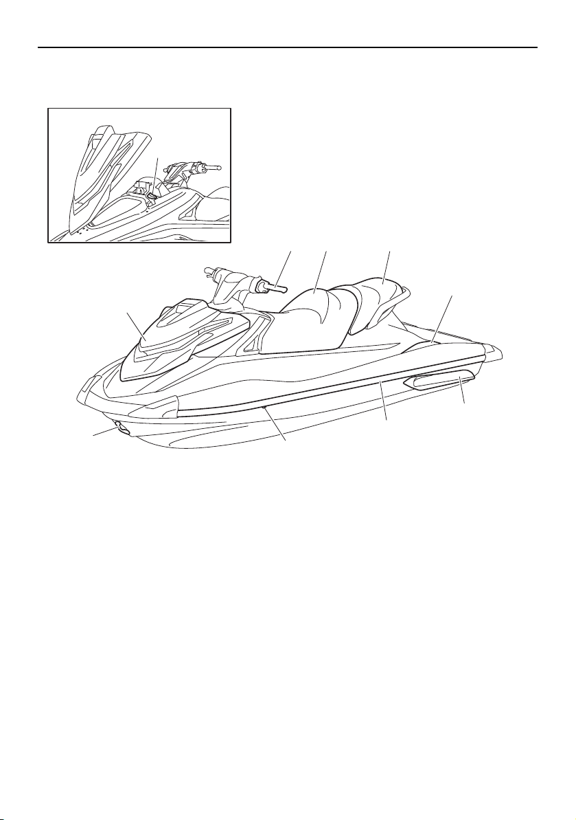
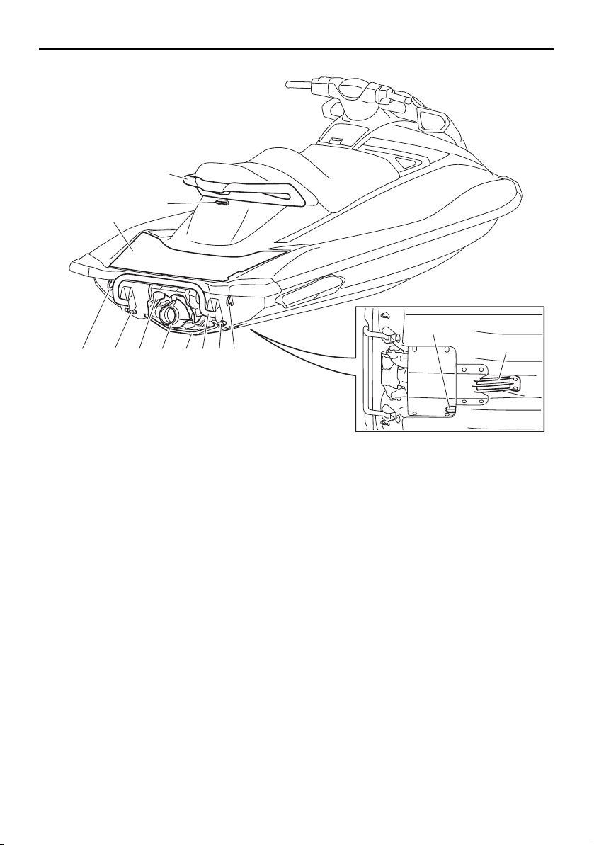
Description
28
1
10
11
4 5 6 7 8 9 5 4
2
3
1 Boarding platform
2 Cleat (page 51)
3 Handgrip (page 50)
4 Stern eye (page 51)
5 Stern drain plug (page 60)
6 Reverse gate (page 37)
7 Jet thrust nozzle
8 Ride plate
9 Reboarding step (VXR) (page 50)
10 Speed sensor
11 Intake grate
UF2W10E0.book Page 28 Tuesday, December 1, 2015 3:25 PM
Description
29
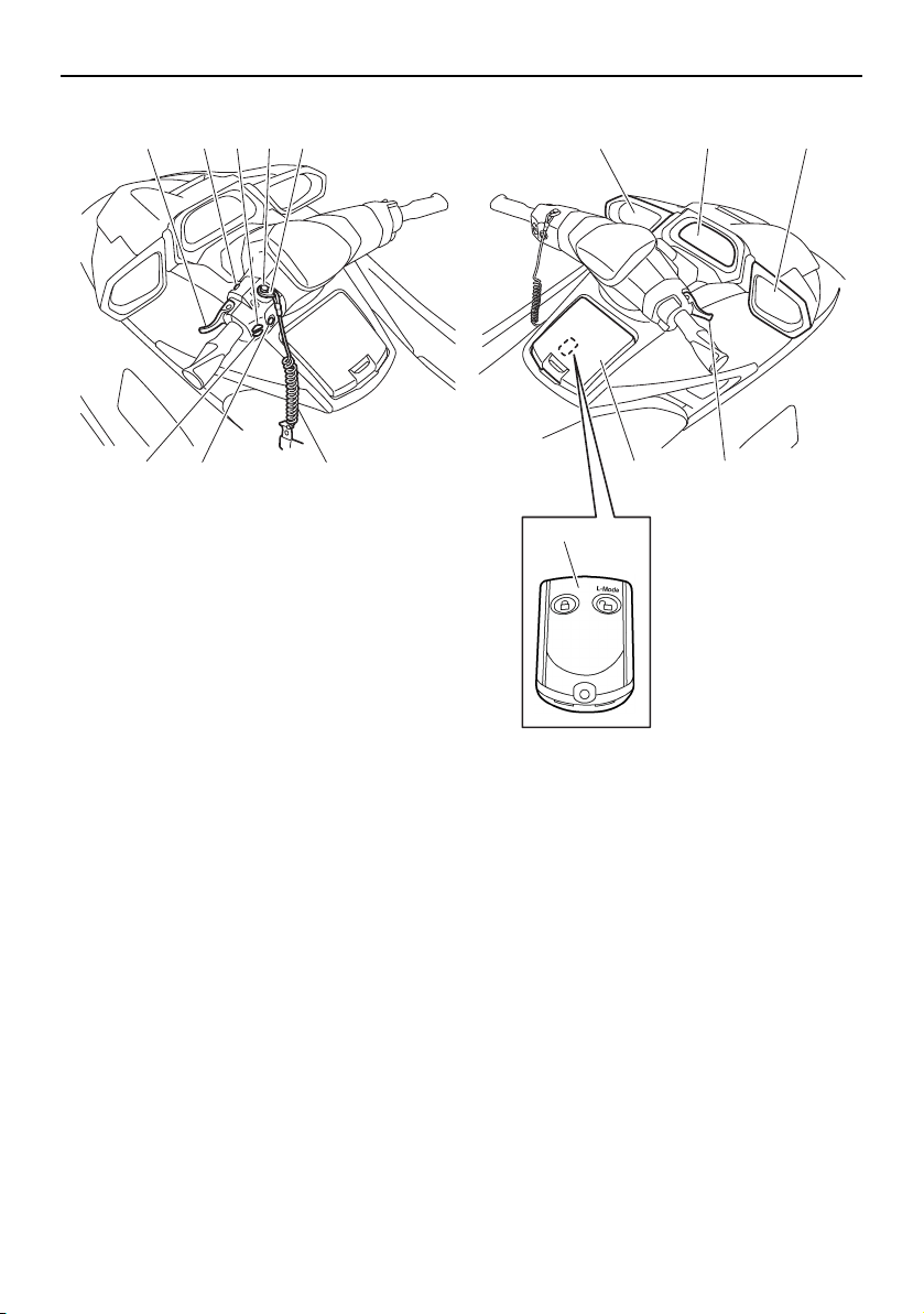
13
12 4
35 9 10 9
7
68
11
12
1 RiDE lever (page 37)
2 Start switch (page 33)
3 Electric trim up switch (page 39)
4 Engine shut-off switch (page 33)
5 Clip (page 33)
6 Engine shut-off cord (lanyard) (page 33)
7 Engine stop switch (page 33)
8 Electric trim down switch (page 39)
9 Rearview mirror
10 Multifunction information center (page 43)
11 Throttle lever (page 34)
12 Glove compartment (page 53)
13 Remote control transmitter (page 31)
UF2W10E0.book Page 29 Tuesday, December 1, 2015 3:25 PM
Description
30
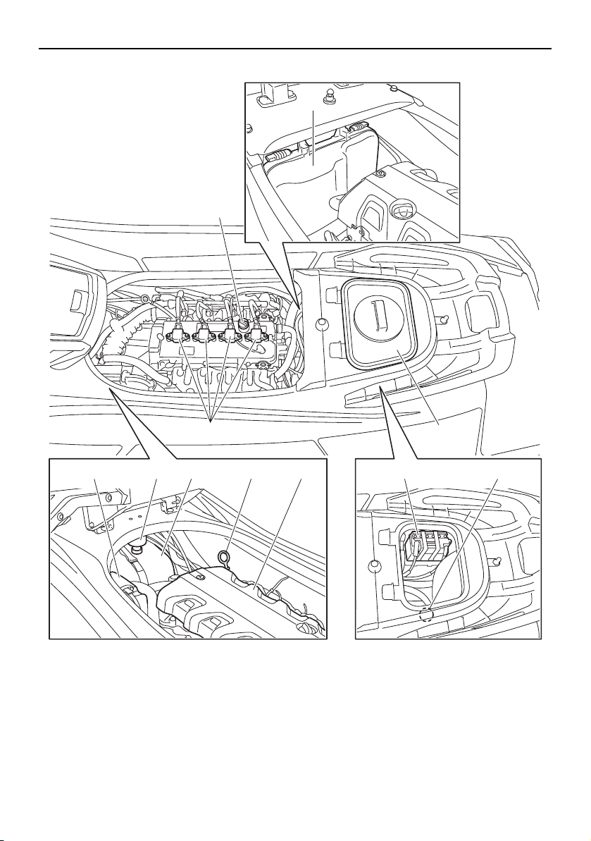
Engine compartment
1
3
5 6 10 117 8 9
2 4
1 Electrical box
2 Spark plug/Spark plug cap/Ignition coil
3 Engine oil filler cap (page 58)
4 Removable watertight storage compart-
ment (page 54)
5 Air filter case
6 Water separator (page 35)
7 Fuel tank
8 Dipstick
9 Engine cover
10 Battery (page 66)
11 Flushing hose connector
UF2W10E0.book Page 30 Tuesday, December 1, 2015 3:25 PM
Control function operation
31
EJU31026
Watercraft control functions
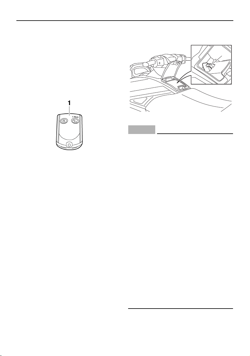
EJU43910
Remote control transmitter
The Yamaha Security System and Low RPM
Mode settings can be selected by operating
the remote control transmitter. (See page 32
for Yamaha Security System setting proce-
dures and page 41 for Low RPM Mode acti-
vation procedures.)
Since the watercraft is programmed to rec-
ognize the internal code from this transmitter
only, the settings can only be selected with
this transmitter.
If you accidentally lose your remote control
transmitter or if it is not operating properly,
contact a Yamaha dealer.
When operating the watercraft, always keep
the transmitter with you, such as by storing it
in the transmitter holder in the glove compart-
ment, so that it is not lost.
NOTICE
ECJ00753
The remote control transmitter is not
completely waterproof. Do not sub-
merge the transmitter or operate it un-
derwater. If the transmitter is
submerged, dry it with a soft, dry cloth,
and then check that it is operating prop-
erly. If the transmitter is not operating
properly, contact a Yamaha dealer.
Keep the remote control transmitter
away from high temperatures and do
not place it in direct sunlight.
Do not drop the remote control trans-
mitter, subject it to strong shocks, or
place any heavy items on it.
Use a soft, dry cloth to clean the remote
control transmitter. Do not use deter-
gent, alcohol, or other chemicals.
Do not attempt to disassemble the re-
mote control transmitter yourself. Oth-
erwise, the transmitter may not operate
properly. If the transmitter needs a new
battery, contact a Yamaha dealer. Refer
to local hazardous waste regulations
when disposing of transmitter batteries.
This device complies with Part 15 of the FCC
Rules. Operation is subject to the following
1 Remote control transmitter
1 Transmitter holder
1
UF2W10E0.book Page 31 Tuesday, December 1, 2015 3:25 PM

Control function operation
32
two conditions: (1) this device may not cause
harmful interference, and (2) this device must
accept any interference received, including
interference that may cause undesired oper-
ation.
NOTICE
ECJ00031
Changes or modifications not expressly
approved by the party responsible for
compliance could void the user’s authority
to operate the remote control transmitter.
EJU31385
Yamaha Security System
The Yamaha Security System functions to
help prevent unauthorized use or theft of the
watercraft. The lock and unlock modes of the
security system can be selected by operating
the remote control transmitter that is included
with this watercraft. The engine cannot be
started if the lock mode of the security sys-
tem is selected. The engine can only be start-
ed if the unlock mode is selected. (See page
31 for information on the remote control
transmitter.)
TIP:
The Yamaha Security System settings can
only be selected while the engine is stopped.
EJU36776
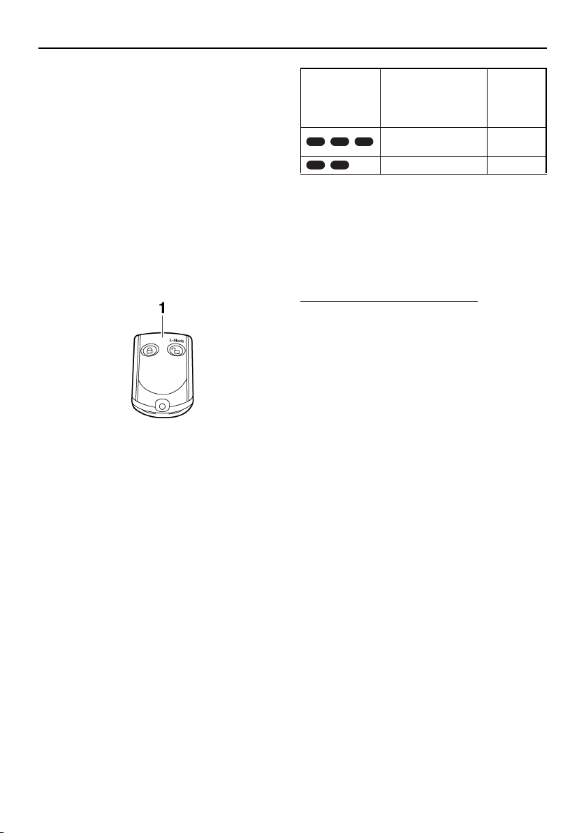
Yamaha Security System settings
The Yamaha Security System settings will be
confirmed by the number of beeps when the
remote control transmitter is operated, and
by the “UNLOCK” indicator light of the multi-
function information center. (See page 43 for
information on the multifunction information
center.)
TIP:
The beeper sounds two times for the nor-
mal operation mode or three times for the
Low RPM Mode. (See page 41 for Low
RPM Mode activation procedures.)
If the remote control transmitter is operated
while the multifunction information center
is in the standby state, the center will per-
form the initial operation, and then the set-
ting is selected.
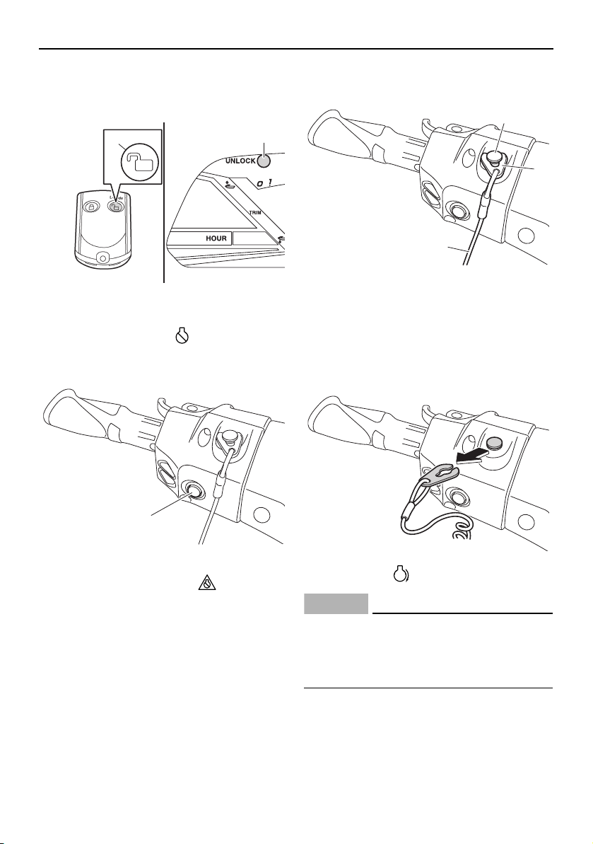
To select the lock mode:
Push the lock button on the remote control
transmitter briefly. The beeper sounds once
and the “UNLOCK” indicator light blinks
once, then goes off. This indicates the lock
mode is selected.
To select the unlock mode:
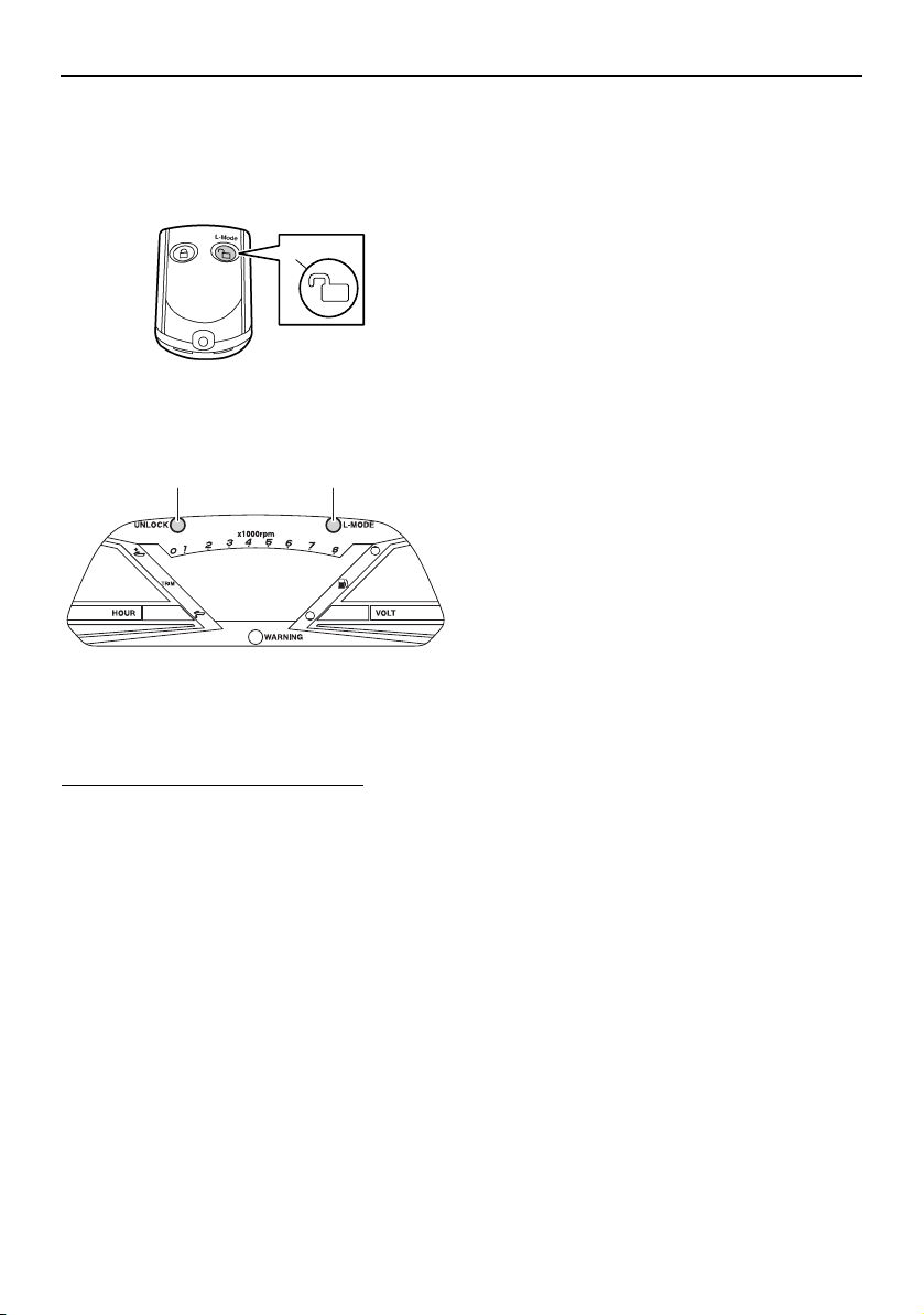
Push the “L-Mode” (unlock) button on the re-
mote control transmitter briefly. The beeper
sounds two or three times and the “UN-
Number of
beeps
Yamaha Security
System mode
“UN-
LOCK” in-
dicator
light
Lock Goes off
Unlock
(normal operation
mode)
Comes
on
Unlock
(Low RPM Mode)
Comes
on
1 Lock button
2 “UNLOCK” indicator light
2
1
UF2W10E0.book Page 32 Tuesday, December 1, 2015 3:25 PM
Control function operation
33
LOCK” indicator light blinks two or three
times, then comes on. This indicates the un-
lock mode is selected.
EJU31153
Engine stop switch “ ”
The engine stop switch (red button) stops the
engine when the switch is pushed.
EJU31164
Engine shut-off switch “ ”
The engine shut-off switch automatically
stops the engine when the clip, on the end of
the engine shut-off cord (lanyard), is removed
from the switch, such as if the operator falls
off the watercraft.
Insert the clip under the engine shut-off
switch before starting the engine.
When the engine is not running, remove the
clip from the engine shut-off switch to pre-
vent accidental starting or unauthorized op-
eration by children or others.
EJU42323
Start switch “ ”
NOTICE
ECJ01311
Do not run the engine over 4000 r/min on
land. Also, do not run the engine for more
than 15 seconds without supplying water,
otherwise the engine could overheat.
The start switch (green button) starts the en-
gine when the switch is pushed.
Release the start switch as soon as the en-
gine starts to run. If the engine does not start
1 “L-Mode” (unlock) button
2 “UNLOCK” indicator light
1 Engine stop switch
2
L-Mode
1
1
1 Engine shut-off switch
2 Clip
3 Engine shut-off cord (lanyard)
1
2
3
UF2W10E0.book Page 33 Tuesday, December 1, 2015 3:25 PM
Control function operation
34
in 5 seconds, release the start switch, wait 15
seconds, and then try again. NO TICE : Never
push the start switch while the engine is
running. Do not operate the start switch
for more than 5 seconds, otherwise the
battery will be discharged and the engine
will not start. Also, the starter motor could
be damaged.
[ECJ01041]
The engine will not start under any of the fol-
lowing conditions:
Lock mode of the Yamaha Security System
has been selected. (See page 32 for
Yamaha Security System setting proce-
dures.)
Clip is removed from the engine shut-off
switch.
Throttle lever is squeezed.
Throttle lever is malfunctioning.
RiDE lever is squeezed.
RiDE lever is malfunctioning.
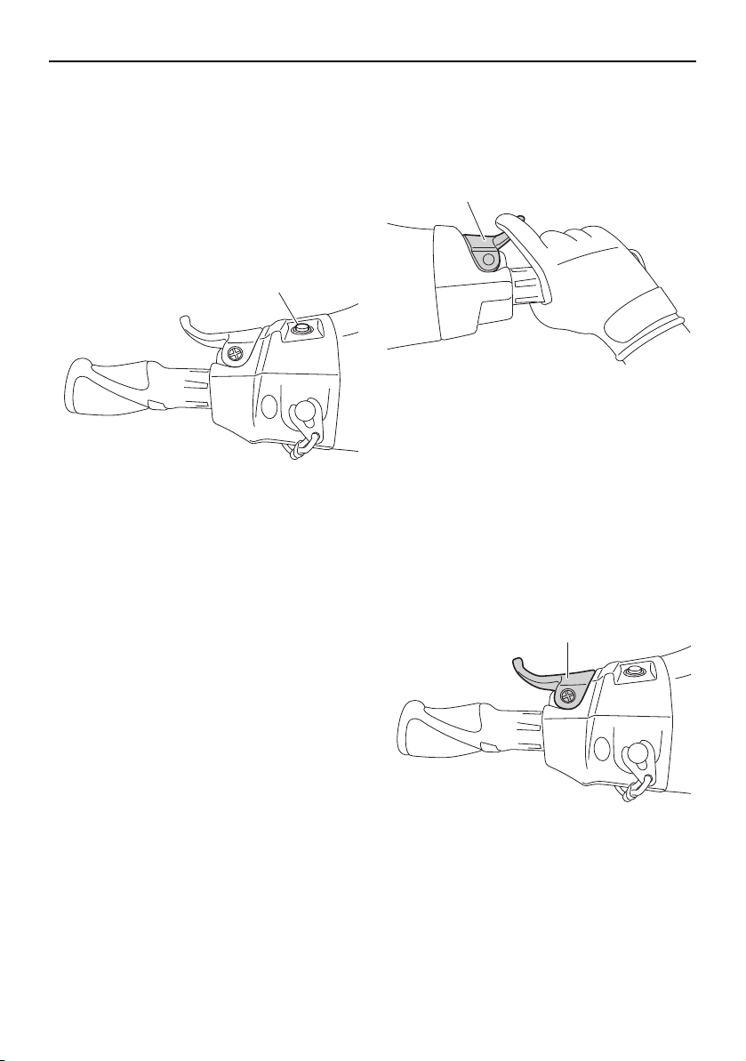
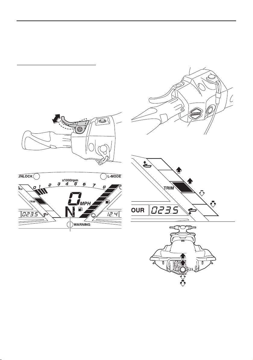
EJU31212
Throttle lever
The throttle lever increases the engine speed
when the lever is squeezed.
The throttle lever returns automatically to its
fully closed (idle) position when released.
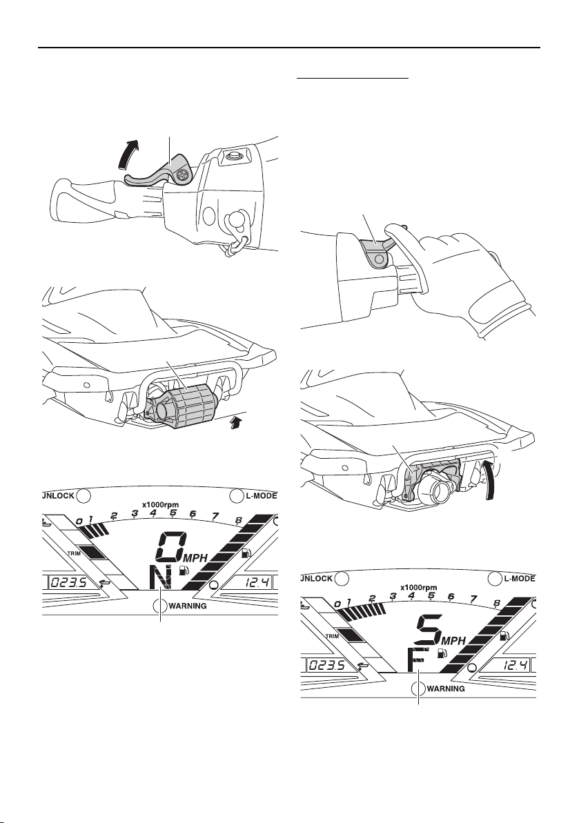
EJU43341
RiDE lever
When the RiDE lever is squeezed, the reverse
gate lowers and the watercraft starts moving
in reverse. If the watercraft is moving forward,
the watercraft gradually slows down until it
stops, and then the watercraft starts moving
in reverse.
When the RiDE lever is released, it automati-
cally returns to its fully closed (idle) position
and the reverse gate moves to the neutral po-
sition.
1 Start switch
1
1 Throttle lever
1 RiDE lever
1
1
UF2W10E0.book Page 34 Tuesday, December 1, 2015 3:25 PM
Control function operation
35
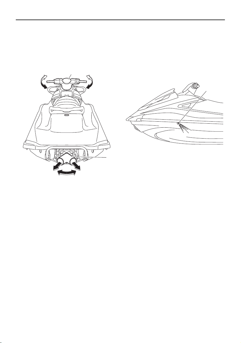
EJU31262
Steering system
By turning the handlebars in the direction you
wish to travel, the angle of the jet thrust noz-
zle is changed, and the direction of the water-
craft is changed accordingly.
Since the strength of the jet thrust determines
the speed and degree of a turn, throttle must
always be applied when attempting a turn,
except at trolling speed.
This model is equipped with the Yamaha En-
gine Management System (YEMS) that in-
cludes an off-throttle steering (OTS) system.
It will activate at planing speeds should you
attempt to steer the watercraft after releasing
the throttle lever. The OTS system assists in
turning by continuing to supply some thrust
while the watercraft is decelerating, but you
can turn more sharply if you apply throttle
while turning the handlebars. The OTS sys-
tem does not function below planing speeds
or when the engine is off. Once the engine
slows down, the watercraft will no longer turn
in response to handlebar input until you apply
throttle again or you reach trolling speed.
EJU35975
Cooling water pilot outlet
When the engine is running, some of the
cooling water that is circulated in the engine
is discharged from the cooling water pilot
outlet.
There is a cooling water pilot outlet on the
port (left) side of the watercraft. To check for
proper operation of the cooling system, make
sure that water is being discharged from the
cooling water pilot outlet. If water is not being
discharged from the outlet, stop the engine
and check the jet intake for clogging. (See
page 99 for information on the jet intake.)
TIP:
It will take about 60 seconds for the water
to reach the outlet after the engine is start-
ed.
Water discharge may not be constant
when the engine is running at idling speed.
If this occurs, apply a little throttle to make
sure that water discharges properly.
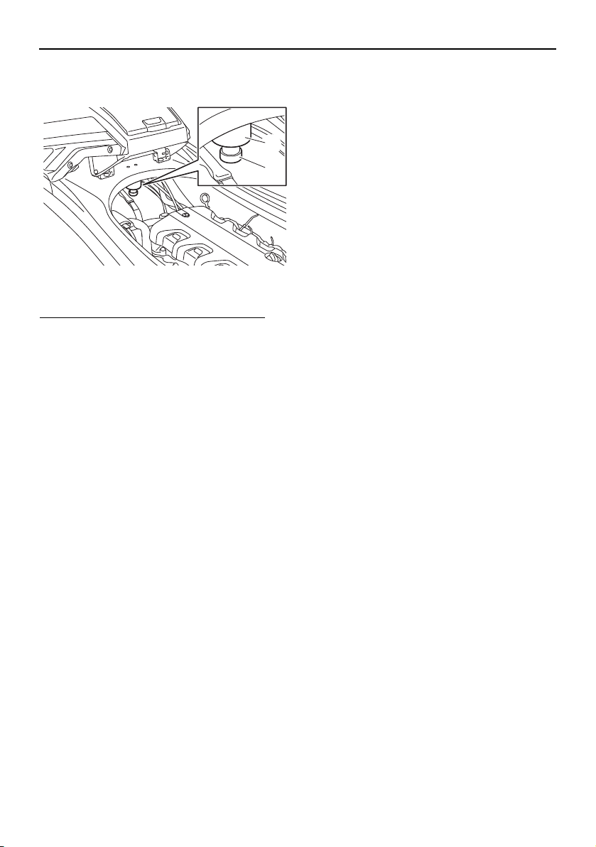
EJU40323
Water separator
The water separator prevents water from en-
tering the fuel tank by collecting any water
that has entered the fuel tank breather hose if
the watercraft was capsized.
1 Handlebar
2 Jet thrust nozzle
1
2
1 Cooling water pilot outlet
1
UF2W10E0.book Page 35 Tuesday, December 1, 2015 3:25 PM
Control function operation
36
If water has collected in the water separator,
drain it by loosening the drain screw.
To drain water from the water separator:
(1) Place a drain pan or dry cloth under the
water separator.
(2) Gradually loosen the drain screw to drain
the water. Catch the draining water in the
drain pan or soak it up with the dry cloth
so that it does not spill into the engine
compartment. If any water spills into the
watercraft, be sure to wipe it up with a
dry cloth.
(3) Securely tighten the drain screw until it
stops.
1 Water separator
2 Drain screw
1
2
UF2W10E0.book Page 36 Tuesday, December 1, 2015 3:25 PM
Watercraft operation
37
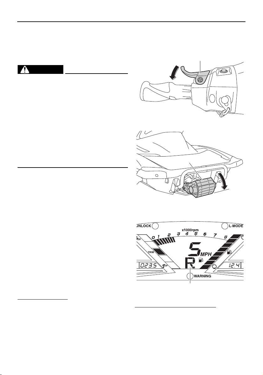
EJU40013
Watercraft operation functions
EJU43153
Shift system
WARNING
EWJ01773
Make sure that there are no obstacles or
people behind you before shifting into
reverse.
Do not touch the reverse gate while the
RiDE lever is being operated, otherwise
you could be pinched.
If the RiDE lever and throttle lever are
being operated at the same time, do not
release only the RiDE lever. Otherwise,
the watercraft could accelerate more
quickly than expected, which may lead
to an accident.
The RiDE lever and throttle lever can be oper-
ated to change the forward or rearward
movement of the watercraft only when the
engine is running. When the RiDE lever is
squeezed, the reverse gate lowers and de-
flects the water jet being discharged from the
jet thrust nozzle so that the watercraft moves
in reverse or is in neutral. When the throttle le-
ver is squeezed, the reverse gate rises and
the watercraft moves forward.
TIP:
This model is equipped with a function
which limits the engine speed in reverse.
When the engine is started, the reverse
gate automatically moves to the neutral po-
sition.
To shift into reverse:
(1) Release the throttle lever.
(2) Squeeze the RiDE lever. The reverse
gate will lower, the engine speed will in-
crease, the watercraft will start moving in
reverse, and the “R” (reverse) shift indi-
cator will be displayed.
To shift into neutral from reverse:
Release the RiDE lever. The reverse gate will
automatically return to the neutral position
1 RiDE lever
1 Reverse gate
2 Reverse position
1 “R” (Reverse position)
1
1
2
1
UF2W10E0.book Page 37 Tuesday, December 1, 2015 3:25 PM
Watercraft operation
38
and the “N” (neutral) shift indicator will be dis-
played.
TIP:
Although the neutral position helps keep the
watercraft from moving even when the en-
gine is running, some movement may occur.
To shift into forward:
(1) Release the RiDE lever.
(2) Squeeze the throttle lever. The reverse
gate will rise completely, the engine
speed will increase, the watercraft will
start moving forward, and the “F” (for-
ward) shift indicator will be displayed.
1 RiDE lever
1 Reverse gate
2 Neutral position
1 “N” (Neutral position)
1
1
2
1
1 Throttle lever
1 Reverse gate
2 Forward position
1 “F” (Forward position)
1
1
2
1
UF2W10E0.book Page 38 Tuesday, December 1, 2015 3:25 PM
Watercraft operation
39
TIP:
If the RiDE lever is squeezed while the throttle
lever is squeezed, the watercraft will slow
down, and once stopped, move in reverse.
To shift into neutral from forward:
(1) Release the throttle lever.
(2) Lightly squeeze and release the RiDE le-
ver. The “N” (neutral) shift indicator will
be displayed.
TIP:
If the RiDE lever is squeezed continuously,
the reverse gate will move to the reverse po-
sition.
EJU43161
Electric trim system
The electric trim up switch and electric trim
down switch are located at the left handlebar
grip and are operated to change the vertical
angle of the jet thrust nozzle, which adjusts
the trim angle of the watercraft. The switches
can be operated only when the engine is run-
ning.
There are 5 positions: neutral, 2 bow-down
positions (a) and (b), and 2 bow-up positions
(c) and (d).
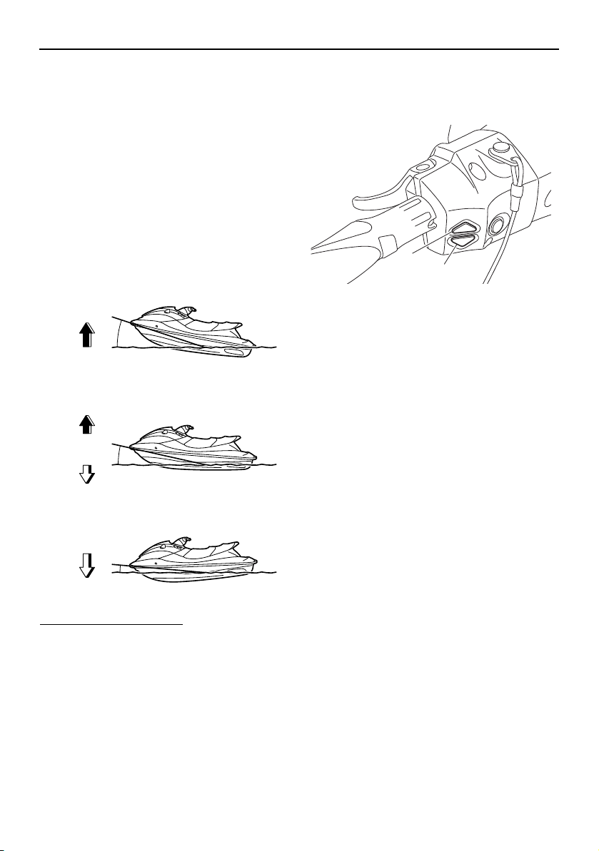
Bow-down positions (a) and (b)
The bow will go down, causing the trim angle
to decrease.
1 “N” (Neutral position)
1
1 Electric trim up switch
2 Electric trim down switch
1
2
(d)
(c)
(b)
(a)
(d)
(c)
(b)
(a)
UF2W10E0.book Page 39 Tuesday, December 1, 2015 3:25 PM
Watercraft operation
40
Vertical movement of the bow will be reduced
and the watercraft will get up on plane more
quickly when accelerating.
Bow-up positions (c) and (d)
The bow will go up, causing the trim angle to
increase.
There is less water resistance, therefore,
straight-ahead acceleration is enhanced.
TIP:
The watercraft performance characteristics
according to the trim angle change depend-
ing on the operating conditions.
To change the trim angle:
(1) If the reverse gate is in the neutral posi-
tion, lightly squeeze the throttle lever so
that the watercraft moves forward.
(2) Push the electric trim up switch or elec-
tric trim down switch to select the de-
sired trim angle.
TIP:
When the reverse gate moves to the neutral
or reverse position, the jet thrust nozzle will
automatically return to the neutral position.
When the reverse gate moves to the for-
ward position, the jet thrust nozzle will au-
tomatically change to the set trim angle.
When the engine stops, the jet thrust noz-
zle returns to the neutral position.
(d)
(c)
(b)
N
(a)
1 Electric trim up switch
2 Electric trim down switch
1
2
UF2W10E0.book Page 40 Tuesday, December 1, 2015 3:25 PM
Watercraft operation
41
EJU40001
Watercraft operation modes
EJU36787
Low RPM Mode
The Low RPM Mode is a function that limits
the maximum engine speed to approximately
70% of the maximum engine speed in the
normal mode.
The Low RPM Mode can only be activated
and deactivated by operating the remote
control transmitter that is included with this
watercraft. (See page 31 for information on
the remote control transmitter.)
TIP:
The Low RPM Mode can only be activated
when the engine is stopped in the unlock
mode of the Yamaha Security System.
Activating and deactivating the Low RPM
Mode
Activation of the Low RPM Mode will be con-
firmed by the number of beeps when the re-
mote control transmitter is operated, and by
the “L-MODE” indicator light of the multifunc-
tion information center. (See page 43 for in-
formation on the multifunction information
center.)
TIP:
If the remote control transmitter is operated
while the multifunction information center is
in the standby state, the center performs the
initial operation, and then the setting is se-
lected.
To activate the Low RPM Mode:
Push the “L-Mode” (unlock) button on the re-
mote control transmitter for more than 4 sec-
onds. Once the beeper sounds three times
and the “UNLOCK” indicator light blinks
three times, then comes on, the “L-MODE”
indicator light comes on and the Low RPM
Mode is activated.
TIP:
If the Low RPM Mode is activated immediate-
ly after the information display turns off, the
“L-MODE” indicator light will not come on.
1 Remote control transmitter
Number of
beeps
Low RPM Mode
operation
“L-
MODE”
indicator
light
Activated
Comes
on
Deactivated Goes off
UF2W10E0.book Page 41 Tuesday, December 1, 2015 3:25 PM
Watercraft operation
42
The “L-MODE” indicator light will come on
when the engine is started.
To deactivate the Low RPM Mode:
Push the “L-Mode” (unlock) button on the re-
mote control transmitter for more than 4 sec-
onds. Once the beeper sounds two times and
the “UNLOCK” indicator light blinks two
times, then comes on, the “L-MODE” indica-
tor light goes off and the Low RPM Mode is
deactivated. When the Low RPM Mode is de-
activated, the watercraft returns to the nor-
mal operation mode.
1 “L-Mode” (unlock) button
1 “UNLOCK” indicator light
2 “L-MODE” indicator light
L-Mode
1
1 2
UF2W10E0.book Page 42 Tuesday, December 1, 2015 3:25 PM
Instrument operation
43
EJU43760
Multifunction information
center
The multifunction information center displays
various watercraft information.
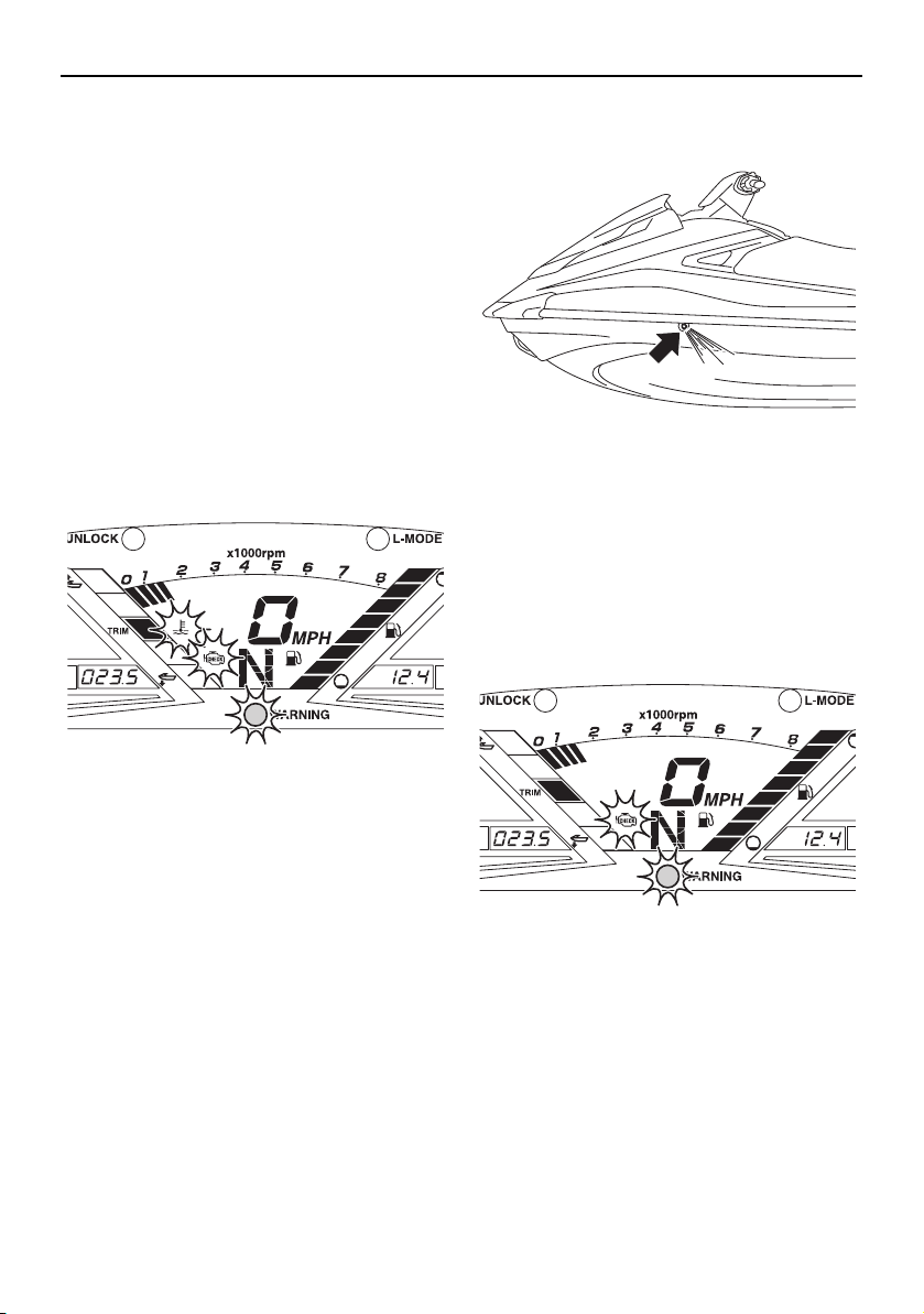
Multifunction information center initial op-
eration
When the multifunction information center is
activated, all of the display segments come
on. After 2 seconds, the warning indicators in
the information display go off, and then the
center starts to operate normally.
If only the multifunction information center is
activated, the “WARNING” indicator light
blinks once.
TIP:
The “UNLOCK” indicator light also comes on
as part of the initial operation.
The “UNLOCK” indicator light will go off
when the engine is started.
Multifunction information center standby
state
If the multifunction information center does
not receive any operation input within 25 sec-
onds after the engine stops, the center will
turn off and enter a standby state. When the
engine is started again, the displays return to
their state before the center turned off, and
then the center starts to operate normally.
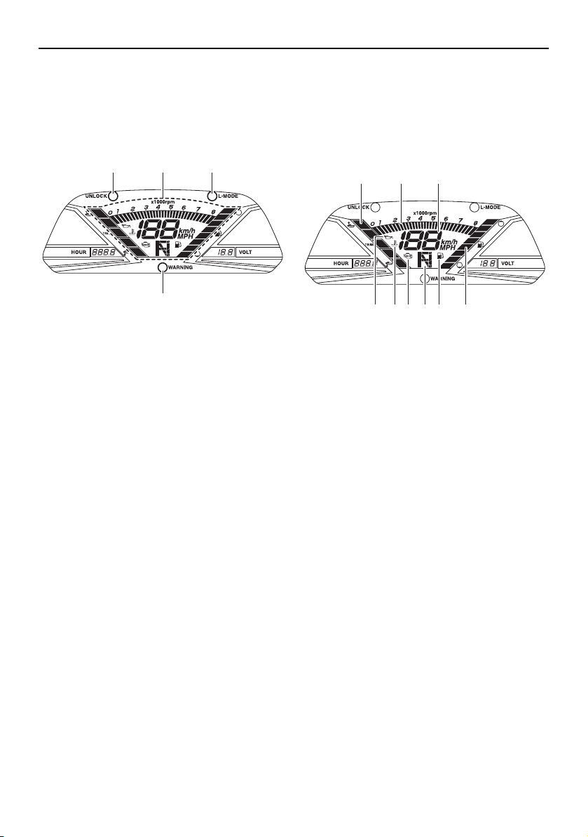
EJU35027
Information display
The information display shows watercraft op-
erating conditions.
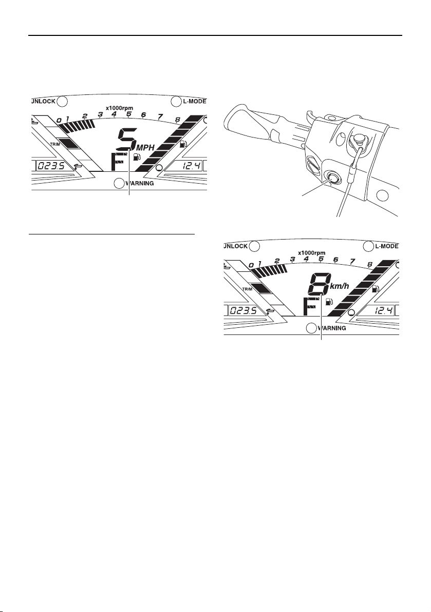
EJU43830
Speedometer
The speedometer shows the watercraft
speed against water.
By switching the display units, the speed can
be shown in kilometers per hour “km/h” or
miles per hour “MPH”.
1 “UNLOCK” indicator light
2 Information display
3 “L-MODE” indicator light
4 “WARNING” indicator light
1 2 3
4
1 Trim indicator
2 Tachometer
3 Speedometer
4 Oil pressure warning indicator
5 Engine overheat warning indicator
6 Check engine warning indicator
7 Shift indicator
8 Fuel indicator
9 Fuel level meter
21 3
4 5 6 87 9
UF2W10E0.book Page 43 Tuesday, December 1, 2015 3:25 PM
Instrument operation
44
TIP:
“MPH” is selected as the display unit at the
Yamaha factory.
To switch the speedometer display units:
Start the engine, stop the engine, and then
push the engine stop switch for at least 4
seconds before the multifunction information
center turns off. The speedometer display
units change.
To switch the speedometer display units
again, repeat this procedure.
EJU31464
Tachometer
The tachometer shows the engine speed.
1 Speedometer
1
1 Engine stop switch
1 Speedometer
1
1
UF2W10E0.book Page 44 Tuesday, December 1, 2015 3:25 PM

Instrument operation
45
The outer numbers × 1000 r/min and display
segments on the meter show the engine
speed.
EJU43890
Shift indicator
This indicator shows the reverse gate shift
positions: “F” (forward), “N” (neutral), and “R”
(reverse). (See page 37 for shifting proce-
dures.)
EJU44010
Trim indicator
This indicator shows the trim angle of the jet
thrust nozzle. One of the two upper display
segments will be shown when the trim angle
is increased, and one of the two lower display
segments will be shown when the trim angle
1 Tachometer
1
1 “F” (Forward position)
1 “N” (Neutral position)
1 “R” (Reverse position)
1
1
1
UF2W10E0.book Page 45 Tuesday, December 1, 2015 3:25 PM
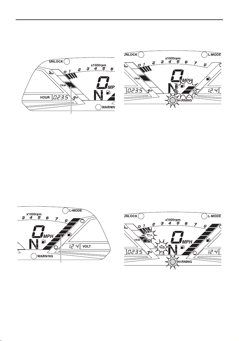
Instrument operation
46
is decreased. When the neutral position of
the jet thrust nozzle is selected, the middle
display segment will be shown. (See page 39
for trim angle selection procedures.)
EJU31515
Fuel level meter
The fuel level meter shows the amount of fuel
remaining in the fuel tank. The amount of re-
maining fuel is shown using eight display
segments, which disappear two at a time as
the fuel level decreases.
TIP:
The accuracy of the fuel level meter varies
depending on the operating conditions. Use
this function as a reference only.
EJU44080
Fuel level warning
If the fuel remaining in the fuel tank drops to
about 18 L (4.8 US gal, 4.0 Imp.gal), the low-
est two fuel level segments, the fuel indicator,
and the “WARNING” indicator light blink, and
the buzzer sounds intermittently for 30 sec-
onds.
If the fuel level warning is activated, refill the
fuel tank as soon as possible. (See page 56
for information on filling the fuel tank.)
After the fuel tank is refilled, the warning sig-
nals will be cleared when the engine is re-
started.
EJU43720
Oil pressure warning
If the oil pressure drops significantly, the oil
pressure warning indicator, the check engine
warning indicator, and the “WARNING” indi-
cator light blink, and the buzzer sounds inter-
mittently for 30 seconds. At the same time,
the maximum engine speed is limited.
If the oil pressure warning is activated, imme-
diately reduce the engine speed, return to
shore, and then check the engine oil level.
(See page 58 for information on checking the
1 Trim indicator
1 Fuel level meter
1
1
UF2W10E0.book Page 46 Tuesday, December 1, 2015 3:25 PM
Instrument operation
47
engine oil level.) If the oil level is sufficient,
have a Yamaha dealer check the watercraft.
EJU43901
Engine overheat warning
If the engine temperature rises significantly,
the engine overheat warning indicator, the
check engine warning indicator, and the
“WARNING” indicator light blink, and the
buzzer sounds intermittently. After 5 sec-
onds, the engine overheat warning indicator
and the “WARNING” indicator light stop
blinking and remain on, and the buzzer
sounds continuously. After 30 seconds, the
buzzer stops. While the engine overheat
warning is activated, the maximum engine
speed is limited.
If the engine overheat warning is activated,
immediately reduce the engine speed, return
to shore, and then make sure that water is
being discharged from the cooling water pilot
outlet while the engine is running. If there is
no discharge of water, stop the engine, and
then check the jet intake for clogging. (See
page 99 for information on the jet intake.)
NOTICE: If you cannot locate and correct
the cause of the overheating, consult a
Yamaha dealer. Continuing to operate at
higher speeds could result in severe en-
gine damage.
[ECJ00042]
EJU43731
Check engine warning
If a sensor malfunction or a short circuit is de-
tected, the check engine warning indicator
and the “WARNING” indicator light blink, and
the buzzer sounds intermittently for 30 sec-
onds.
If the engine is stopped after the check en-
gine warning is activated, the information dis-
play will indicate an error code.
If the check engine warning is activated, im-
mediately reduce the engine speed, return to
shore, and have a Yamaha dealer check the
engine.
EJU43740
Hour meter
The hour meter shows the total number of
hours that the engine has been running since
the watercraft was new.
UF2W10E0.book Page 47 Tuesday, December 1, 2015 3:25 PM
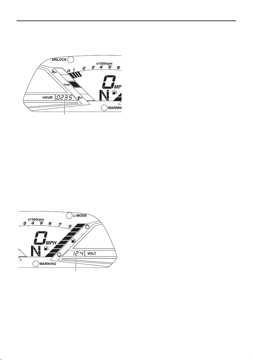
Instrument operation
48
TIP:
The elapsed time will be kept even if the bat-
tery terminals have been disconnected.
EJU43750
Voltmeter
The voltmeter shows the battery voltage.
When the battery voltage is normal, the volt-
meter displays approximately 12 volts.
If the battery voltage has dropped significant-
ly, “LO” is displayed on the voltmeter. If the
battery voltage has risen significantly, “HI” is
displayed. If “LO” or “HI” is displayed, imme-
diately return to shore and have a Yamaha
dealer service the watercraft.
1 Hour meter
1 Voltmeter
1
1
UF2W10E0.book Page 48 Tuesday, December 1, 2015 3:25 PM
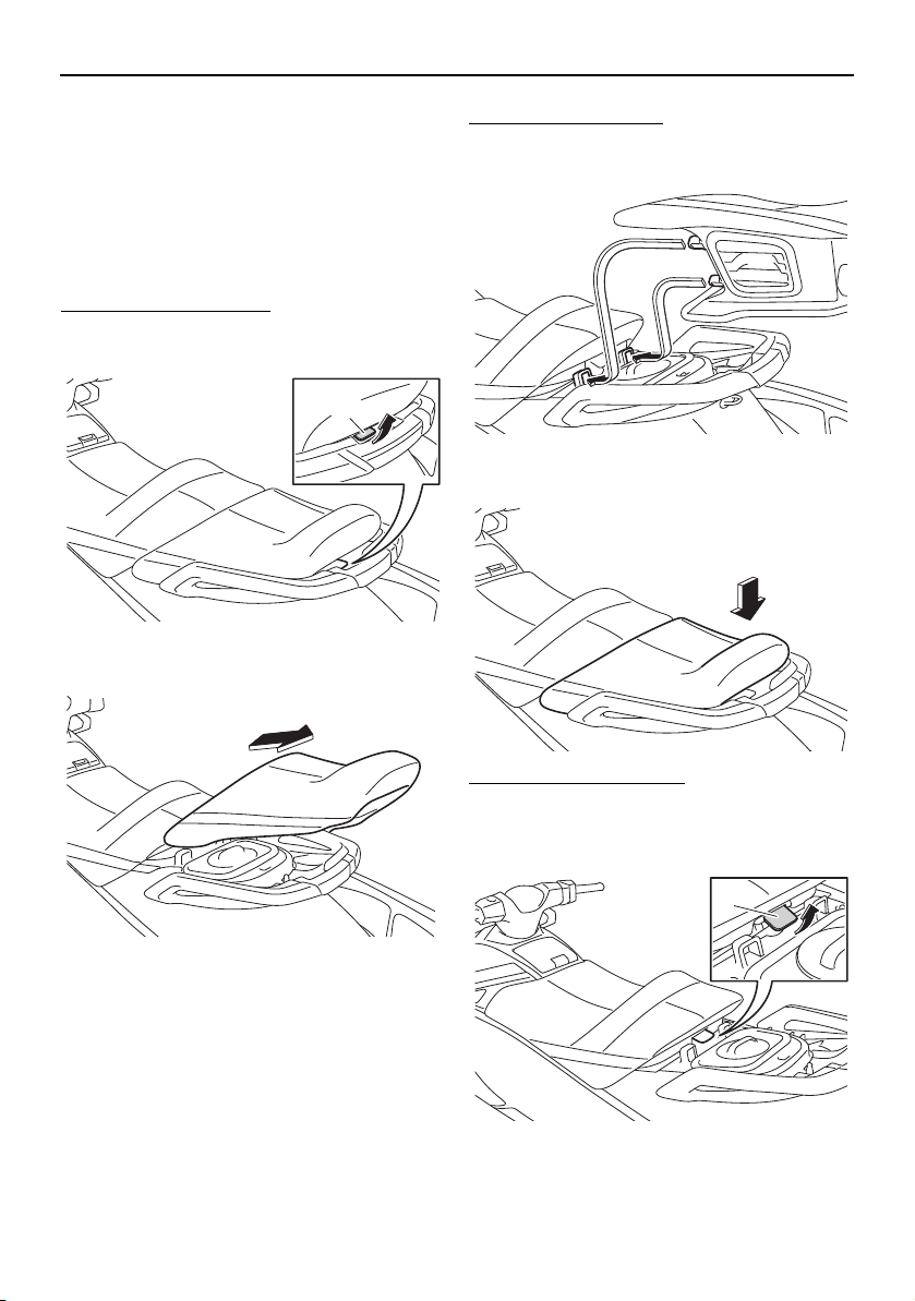
Equipment operation
49
EJU40334
Equipment
EJU42203
Seats
The front and rear seats are removable.
Remove the seats to access the engine com-
partment and removable watertight storage
compartment.
To remove the rear seat:
(1) Pull the rear seat latch up, and then lift up
the rear of the seat.
(2) Pull the seat rearward and remove it.
To install the rear seat:
(1) Insert the projections on the front of the
seat into the stays on the deck.
(2) Push the rear of the seat down to secure-
ly lock it in place.
To remove the front seat:
(1) Remove the rear seat.
(2) Pull the front seat latch up, and then lift
up the rear of the seat.
1 Seat latch
1
1 Seat latch
1
UF2W10E0.book Page 49 Tuesday, December 1, 2015 3:25 PM

Equipment operation
50
(3) Pull the seat rearward and remove it.
To install the front seat:
(1) Insert the projection on the front of the
seat into the stay on the deck.
(2) Push the rear of the seat down to secure-
ly lock it in place.
(3) Securely install the rear seat in its original
position.
EJU31364
Handgrip
The handgrip is used when boarding the wa-
tercraft from the water and when the spotter
is facing rearward. WARNING! Do not use
the handgrip to lift the watercraft. The
handgrip is not designed to support the
watercraft’s weight. If the handgrip
breaks, the watercraft could fall, which
could result in severe injury.
[EWJ00022]
EJU34865
Reboarding step (VXR)
The reboarding step is used to assist in re-
boarding the watercraft from the water.
When boarding the watercraft, push the re-
boarding step down until it stops. The step
returns automatically to its original position
when released. WARNING! Do not use the
reboarding step to lift the watercraft. The
reboarding step is not designed to support
the watercraft’s weight. If the reboarding
1 Handgrip
1
UF2W10E0.book Page 50 Tuesday, December 1, 2015 3:25 PM
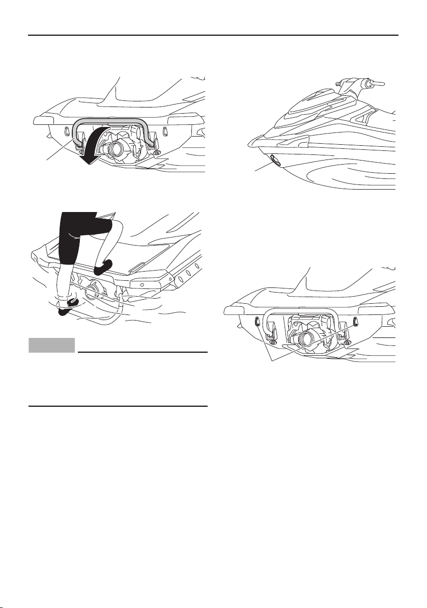
Equipment operation
51
step breaks, the watercraft could fall,
which could result in severe injury.
[EWJ01212]
NOTICE
ECJ00743
Use the reboarding step only to board the
watercraft in the water. Do not use the re-
boarding step for any other purpose. The
watercraft can be damaged.
EJU34873
Bow eye
The bow eye is used to attach a rope to the
watercraft when transporting, mooring, or
towing it in an emergency. (See page 103 for
information on towing the watercraft.)
EJU34882
Stern eyes
The stern eyes are used to attach a rope to
the watercraft when transporting or mooring
it.
EJU40422
Cleat
The cleat is used to attach a ski rope to the
watercraft when pulling a wakeboarder or
water-skier. WARNING! Do not use the
cleat to lift the watercraft. The cleat is not
designed to support the watercraft’s
weight. If the cleat breaks, the watercraft
1 Reboarding step
1
1 Bow eye
1 Stern eye
1
1
UF2W10E0.book Page 51 Tuesday, December 1, 2015 3:25 PM

Equipment operation
52
could fall, which could result in severe in-
jury.
[EWJ01511]
EJU35147
Storage compartments
This watercraft is equipped with the following
storage compartments.
Only the securely closed watertight storage
compartment is waterproof. If you carry ob-
jects that must be kept dry, put them in a wa-
terproof bag.
Make sure that the storage compartments
are closed securely before operating the wa-
tercraft.
EJU43770
Bow storage compartment
The bow storage compartment is located un-
der the hood.
To open the bow storage compartment:
Pull the hood latch up, and then lift up the
rear of the hood.
1 Cleat
1
1 Hood latch
1 Bow storage compartment
Bow storage compartment:
Capacity:
72.0 L (19.0 US gal, 15.8 Imp.gal)
Load limit:
5.0 kg (11 lb)
1
1
1
UF2W10E0.book Page 52 Tuesday, December 1, 2015 3:25 PM
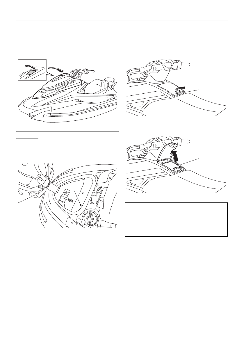
Equipment operation
53
To close the bow storage compartment:
Return the hood to its original position, and
then push the hood latch down to securely
lock it in place.
To drain water from the bow storage com-
partment:
(1) Remove the drain plug on the bottom of
the storage compartment to drain the
water into the engine compartment.
(2) Securely install the drain plug in its origi-
nal position.
EJU43781
Glove compartment
The glove compartment is located in front of
the seat.
To open the glove compartment:
Pull the glove compartment latch up, and
then lift up the lid.
1 Drain plug
1
1 Glove compartment latch
1 Glove compartment
Glove compartment:
Capacity:
3.4 L (0.9 US gal, 0.7 Imp.gal)
Load limit:
1.5 kg (3 lb)
1
1
UF2W10E0.book Page 53 Tuesday, December 1, 2015 3:25 PM
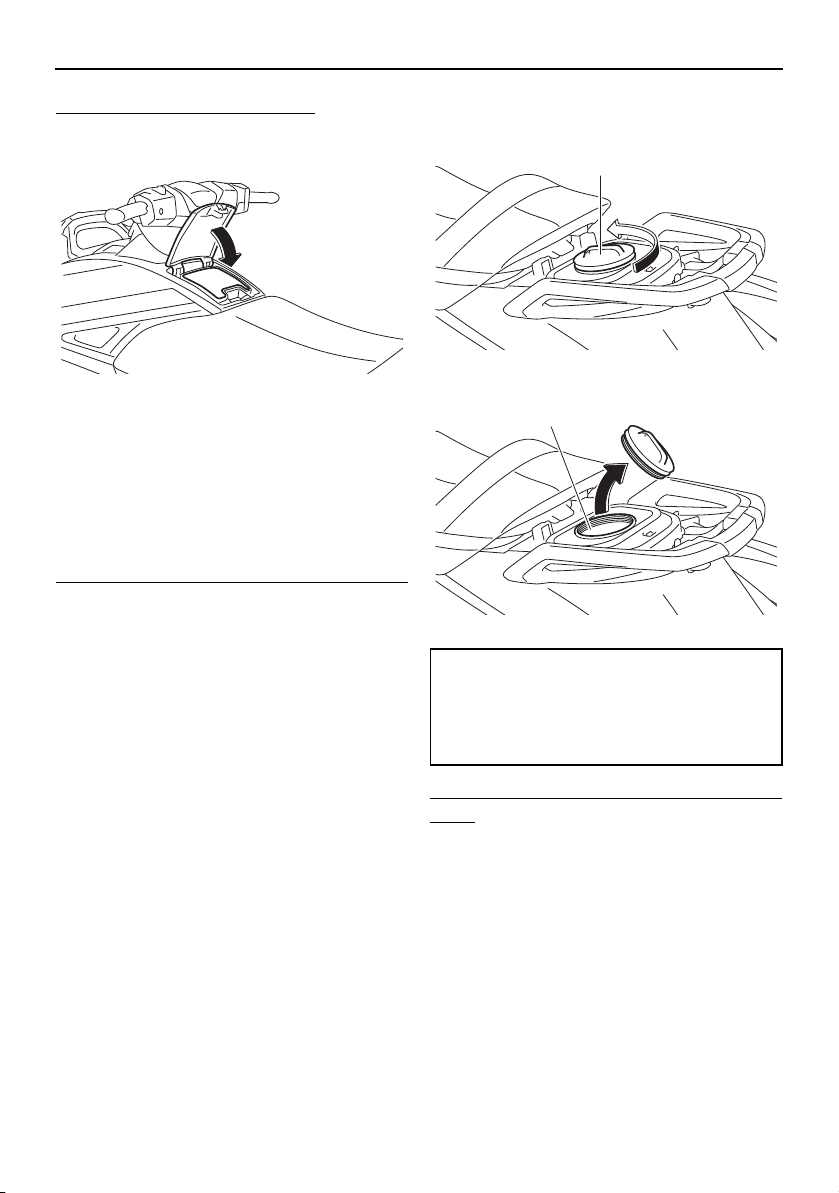
Equipment operation
54
To close the glove compartment:
Push the lid down to securely lock it in place.
EJU37234
Watertight storage compartment
The watertight storage compartment is locat-
ed under the rear seat.
The compartment is watertight when the cap
is closed securely.
The watertight storage compartment is re-
movable.
To open the watertight storage compartment:
(1) Remove the rear seat. (See page 49 for
seat removal and installation proce-
dures.)
(2) Loosen the cap and remove it.
To close the watertight storage compart-
ment:
(1) Securely install the cap by tightening it
until it stops.
(2) Securely install the rear seat in its original
position.
EJU43790
Fire extinguisher holder and cover
The fire extinguisher holder and cover are lo-
cated in the bow storage compartment.
1 Watertight storage compartment cap
1 Watertight storage compartment
Watertight storage compartment:
Capacity:
5.8 L (1.5 US gal, 1.3 Imp.gal)
Load limit:
3.0 kg (7 lb)
1
1
UF2W10E0.book Page 54 Tuesday, December 1, 2015 3:25 PM
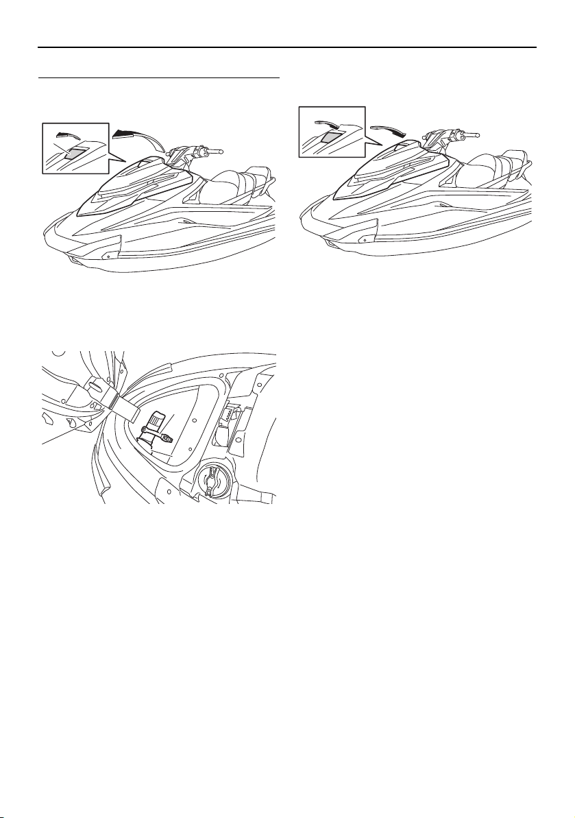
Equipment operation
55
To use the fire extinguisher holder and cover:
(1) Pull the hood latch up, and then lift up
the rear of the hood.
(2) Unhook the band and remove the fire ex-
tinguisher from the fire extinguisher cov-
er.
(3) Place the fire extinguisher in the fire ex-
tinguisher cover, and then securely fas-
ten the fire extinguisher with the band.
(4) Return the hood to its original position,
and then push the hood latch down to
securely lock it in place. Make sure that
the hood is securely closed before using
the watercraft.
1 Hood latch
1 Band
2 Fire extinguisher holder and cover
1
1
2
UF2W10E0.book Page 55 Tuesday, December 1, 2015 3:25 PM
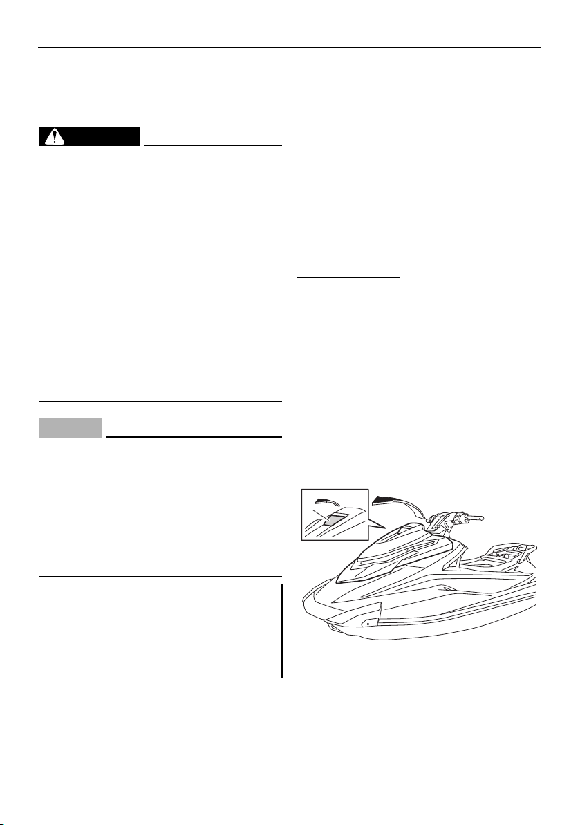
Operation and handling requirements
56
EJU31823
Fuel requirements
EJU43641
Fuel
WARNING
EWJ00283
Gasoline and gasoline vapors are ex-
tremely flammable. To avoid fires and
explosions and to reduce the risk of in-
jury when refueling, follow these in-
structions.
Gasoline is poisonous and can cause in-
jury or death. Handle gasoline with care.
Never siphon gasoline by mouth. If you
should swallow some gasoline, inhale a
lot of gasoline vapor, or get some gaso-
line in your eyes, see your doctor imme-
diately. If gasoline spills on your skin,
wash with soap and water. If gasoline
spills on your clothing, change your
clothes.
NOTICE
ECJ00322
Do not use leaded gasoline. Leaded
gasoline can seriously damage the en-
gine.
Avoid getting water and contaminants in
the fuel tank. Contaminated fuel can
cause poor performance and engine
damage. Use only fresh gasoline that
has been stored in clean containers.
Gasohol
There are two types of gasohol: gasohol con-
taining ethanol and that containing methanol.
Gasohol containing ethanol can be used if
ethanol content does not exceed 10% and
the fuel meets the minimum octane ratings.
E-85 is a fuel blend containing 85% ethanol
and therefore must not be used in this water-
craft. All ethanol blends containing more than
10% ethanol can cause fuel system damage
or engine performance problems.
Yamaha does not recommend gasohol con-
taining methanol because it can cause fuel
system damage and engine performance
problems.
To fill the fuel tank:
(1) Before refueling, stop the engine. Do not
stand or sit on the watercraft. Never refu-
el while smoking, or while in the vicinity
of sparks, open flames, or other sources
of ignition.
(2) Place the watercraft in a well-ventilated
area and in a horizontal position.
(3) Remove the seats, and then check the
fuel level. (See page 49 for seat removal
and installation procedures.)
(4) Pull the hood latch up, and then lift up
the rear of the hood.
Recommended fuel:
Regular unleaded gasoline with a
minimum octane rating of
86
(Pump octane number) = (R + M)/2
90 (Research octane number)
1 Hood latch
1
UF2W10E0.book Page 56 Tuesday, December 1, 2015 3:25 PM

Operation and handling requirements
57
(5) Loosen the fuel filler cap and remove it.
(6) Slowly add fuel to the fuel tank.
(7) Stop filling when the fuel level reaches
approximately 50 mm (2 in) from the top
of the fuel tank. Do not overfill the fuel
tank. Because fuel expands when it
heats up, heat from the engine or the sun
can cause fuel to spill out of the fuel tank.
Do not leave the watercraft with a full
tank in direct sunlight.
(8) Wipe up any spilled fuel immediately with
a dry cloth.
(9) Securely install the fuel filler cap by tight-
ening it until it clicks.
(10) Return the hood to its original position,
and then push the hood latch down to
securely lock it in place. Make sure that
the fuel filler cap and the hood are se-
1 Fuel filler cap
Fuel tank capacity:
70 L (18.5 US gal, 15.4 Imp.gal)
1
1 Top of the fuel tank
2 Approximately 50 mm (2 in) from top of the
fuel tank
1 Top of the fuel tank
2 Approximately 50 mm (2 in) from top of the
fuel tank
1
2
2
1
UF2W10E0.book Page 57 Tuesday, December 1, 2015 3:25 PM

Operation and handling requirements
58
curely closed before using the water-
craft.
(11) Securely install the seats in their original
positions.
EJU40291
Engine oil requirements
EJU31897
Engine oil
NOTICE
ECJ00282
Use only 4-stroke engine oil. Usage of 2-
stroke engine oil could result in severe en-
gine damage.
TIP:
When the engine is operated at high speeds,
some engine oil may be consumed. Be sure
to check the engine oil level.
Checking the engine oil level
WARNING
EWJ00341
Engine oil is extremely hot immediately af-
ter the engine is turned off. Coming in con-
tact with or getting any engine oil on your
clothes could result in burns.
NOTICE
ECJ01002
Make sure that debris and water do not
enter the oil filler hole. Debris and water in
the engine oil can cause serious engine
damage.
To check the engine oil level:
(1) Place the watercraft in a precisely level
position on land with the engine
stopped. If the engine was running, allow
the engine oil to settle by waiting 5 min-
utes or more before checking the oil lev-
el.
Recommended engine oil:
YAMALUBE 4W
Recommended engine oil type:
SAE 10W-30, 10W-40, 20W-40,
20W-50
Recommended engine oil grade:
API SE,SF,SG,SH,SJ,SL
UF2W10E0.book Page 58 Tuesday, December 1, 2015 3:25 PM
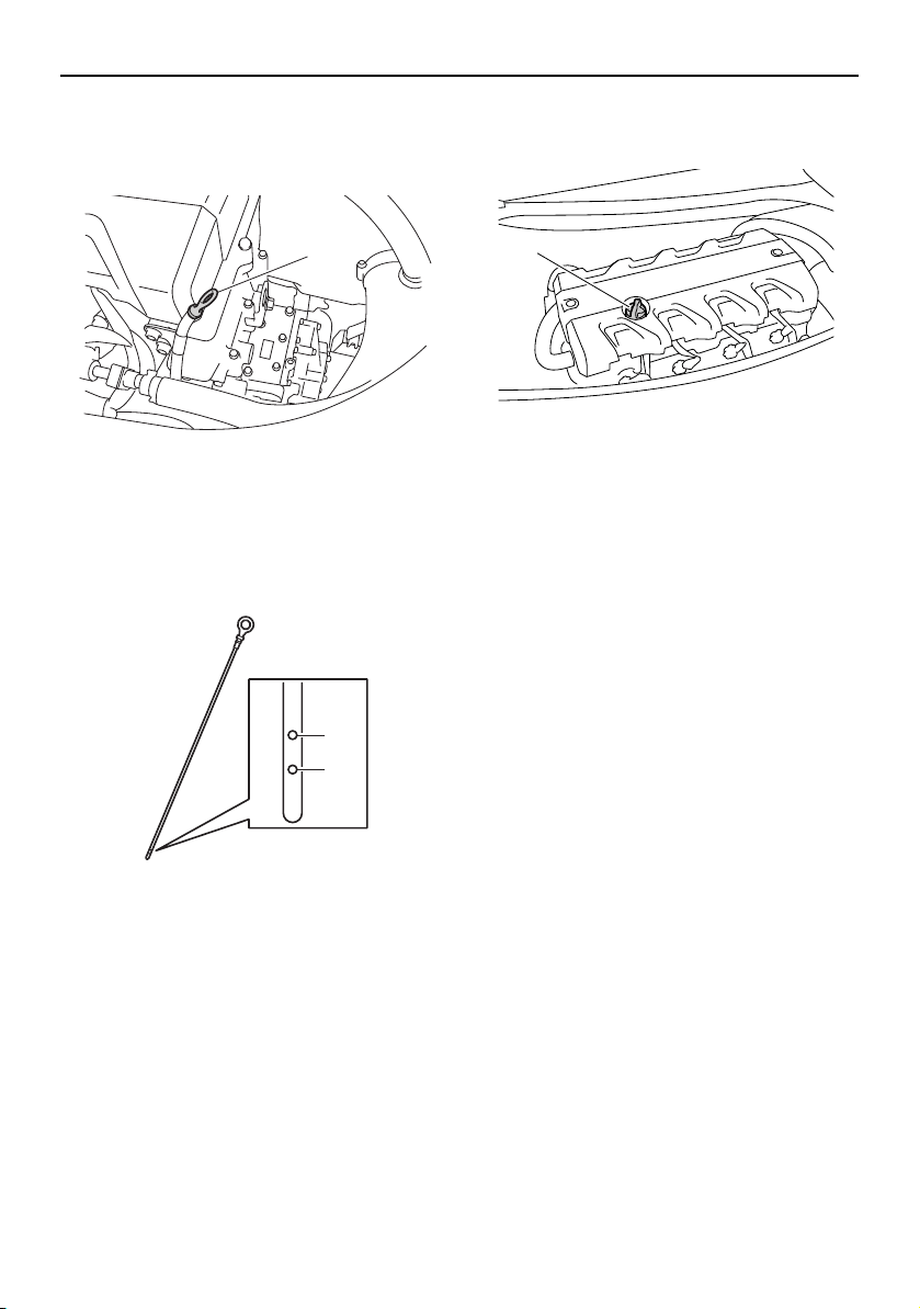
Operation and handling requirements
59
(2) Remove the seats. (See page 49 for seat
removal and installation procedures.)
(3) Remove the dipstick and wipe it clean.
(4) Insert the dipstick back into the dipstick
tube completely. Remove the dipstick
again and make sure that the engine oil
level is between the minimum and maxi-
mum level marks.
(5) If the engine oil level is significantly
above the maximum level mark, consult
a Yamaha dealer. If the engine oil level is
below the minimum level mark, add en-
gine oil.
(6) Loosen the engine oil filler cap and re-
move it.
(7) Slowly add engine oil.
TIP:
The difference between the minimum and
maximum level marks on the dipstick is equal
to approximately 1 L (1.06 US qt, 0.88 Imp.qt)
of engine oil.
(8) Wait approximately 5 minutes to allow
the engine oil to settle, and then check
the engine oil level again.
(9) Repeat steps 3–8 until the engine oil is at
the proper level.
(10) Securely install the engine oil filler cap by
tightening it until it stops.
(11) Securely install the seats in their original
positions.
1 Dipstick
1 Maximum level mark
2 Minimum level mark
1
1
2
1 Engine oil filler cap
1
UF2W10E0.book Page 59 Tuesday, December 1, 2015 3:25 PM
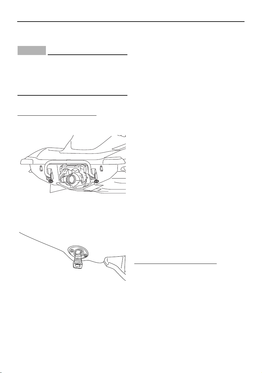
Operation and handling requirements
60
EJU40022
Draining the bilge water
NOTICE
ECJ01302
Do not run the engine at full throttle when
bilge water remains in the engine com-
partment. The bilge water can splash into
the engine, which can result in severe
damage.
EJU40035
Draining the bilge water on land
To drain the bilge water on land:
(1) Loosen the stern drain plugs and remove
them.
(2) Raise the bow of the watercraft, such as
by placing the watercraft on a slope, to
drain the bilge water from the engine
compartment.
(3) After the bilge water has drained from the
stern drain plug holes, wipe up any re-
maining moisture in the engine compart-
ment with a dry cloth.
(4) Securely install the stern drain plugs by
tightening them until they stop. NOTICE:
Before installing the stern drain plugs,
clean the drain plug threads and the
O-rings on the plugs to remove any
foreign materials, such as dirt or sand.
Otherwise, the stern drain plugs could
be damaged, allowing water to enter
the engine compartment. Check the
O-rings on the stern drain plugs and
make sure that the plugs are tightened
securely before launching the water-
craft. Otherwise, water may flood the
engine compartment and cause the
watercraft to submerge.
[ECJ00363]
EJU40535
Draining the bilge water on water
A small quantity of bilge water will remain in
the engine compartment even after the bilge
water is drained on water. To completely
drain the bilge water, remove the watercraft
from the water and drain the bilge water on
land.
Jet vacuum bilge draining system
While the watercraft is operating, bilge water
in the engine compartment is drawn in by the
vacuum that is generated in the jet pump and
discharged from the watercraft through the
jet thrust nozzle.
To drain the bilge water on water:
Operate the watercraft as straight as possible
and above planing speed for at least 2 min-
utes. NOTICE : Do not run the engine at full
throttle for at least 1 minute after the en-
gine has been restarted. Bilge water in the
engine compartment can splash into the
1 Stern drain plug
1
UF2W10E0.book Page 60 Tuesday, December 1, 2015 3:25 PM
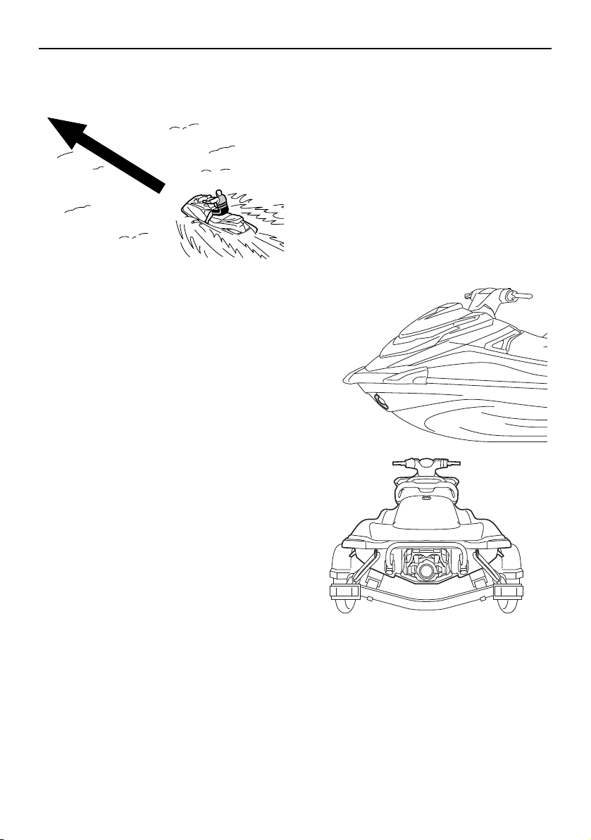
Operation and handling requirements
61
engine, which can result in severe dam-
age.
[ECJ00554]
EJU42432
Transporting on a trailer
When transporting the watercraft on a trailer,
secure the tie downs to the trailer through the
bow eye and stern eyes. NOTICE: Do not at-
tach ropes or tie downs to any part of the
watercraft other than the bow eye and
stern eyes to secure the watercraft to the
trailer. Otherwise, the watercraft may be
damaged. Wrap the ropes or tie downs
with towels or rags where they touch the
body of the watercraft to avoid scratches
or damage.
[ECJ02150]
UF2W10E0.book Page 61 Tuesday, December 1, 2015 3:25 PM

First-time operation
62
EJU36666
Engine break-in
NOTICE
ECJ00432
Failure to perform the engine break-in
could result in reduced engine life or even
severe engine damage.
The engine break-in is essential to allow the
various components of the engine to wear
and polish themselves to the correct operat-
ing clearances. This ensures proper perfor-
mance and promotes longer component life.
To perform the engine break-in:
(1) Check the engine oil level. (See page 58
for information on checking the engine
oil level.)
(2) Launch the watercraft and start the en-
gine. (See page 75 for information on
starting the engine.)
(3) For the first 5 minutes, operate with the
engine speed at 2000 r/min.
(4) For the next 30 minutes, operate with the
engine speed below 5000 r/min.
(5) For the next 1 hour, operate with the en-
gine speed below 6000 r/min.
After the engine break-in is complete, the wa-
tercraft can be operated normally.
UF2W10E0.book Page 62 Tuesday, December 1, 2015 3:25 PM

Pre-operation checks
63
EJU31982
WARNING
EWJ00412
Failure to inspect or maintain the watercraft properly increases the possibility of an ac-
cident or damage to the watercraft. Do not operate the watercraft if you find any prob-
lem. If a problem cannot be corrected by the procedures provided in this manual, have
the watercraft inspected by a Yamaha dealer.
EJU41234
Pre-operation checklist
Before using this watercraft, be sure to perform the checks in the following checklist.
ITEM ROUTINE PAGE
PRE-LAUNCH CHECKS
Engine compartment
Ventilate the engine compartment.
Check inside the engine compartment for damage.
65
Fuel system
Check the fuel system for leakage.
Check the fuel level in the fuel tank.
65
Water separator Check the water separator for water. 65
Engine unit Check the exterior of the engine unit for damage. 66
Engine oil level Check the engine oil level. 66
Bilge water Check the engine compartment for bilge water. 66
Battery Check the battery connections and electrolyte level. 66
Steering system Check the steering system for proper operation. 67
RiDE lever Check the RiDE lever for proper operation. 68
Throttle lever Check the throttle lever for proper operation. 68
Remote control transmitter
Check the remote control transmitter for proper op-
eration.
68
Engine shut-off cord (lan-
yard)
Check the engine shut-off cord (lanyard) for dam-
age.
68
Switches
Check the start switch, engine stop switch, and en-
gine shut-off switch for proper operation.
69
Storage compartments
Check the storage compartments for damage and
water.
69
Fire extinguisher holder,
cover, and band
Check the fire extinguisher holder, cover, and band
for damage.
69
Fire extinguisher Check the condition of the fire extinguisher. 70
Safety equipment
Check that safety equipment meeting the applica-
ble regulations is on board.
70
Hull and deck Check the hull and deck for damage. 70
Jet intake Check the jet intake for damage and clogging. 70
Jet thrust nozzle and re-
verse gate
Check the jet thrust nozzle and reverse gate for
damage.
70
Stern drain plugs
Check the stern drain plugs for damage and foreign
material and check that they are securely installed.
70
UF2W10E0.book Page 63 Tuesday, December 1, 2015 3:25 PM

Pre-operation checks
64
TIP:
To ensure safety and reliability, pre-operation checks should be made each time the water-
craft is used.
Hood Check that the hood is securely closed. 71
Front and rear seats Check that the seats are securely installed. 49
POST-LAUNCH CHECKS
Cooling water pilot outlet
Check that water is discharged from the cooling
water pilot outlet while the engine is running.
71
Multifunction information
center
Check the multifunction information center for prop-
er operation.
71
Shift system Check the shift system for proper operation. 72
Trim indicator Check the trim indicator for proper operation. 72
Engine idling speed Check the engine idling speed. 73
ITEM ROUTINE PAGE
UF2W10E0.book Page 64 Tuesday, December 1, 2015 3:25 PM

Pre-operation checks
65
EJU32282
Pre-operation check points
EJU42382
Pre-launch checks
Perform the pre-launch checks in the pre-op-
eration checklist while the watercraft is on
land.
To perform the pre-launch checks:
(1) Remove the seats and removable water-
tight storage compartment. (See page 49
for seat removal and installation proce-
dures and page 54 for information on the
removable watertight storage compart-
ment.)
(2) Perform the checks and make sure that
there are no malfunctioning items or oth-
er problems.
(3) After completing these checks, securely
install the removable watertight storage
compartment and seats in their original
positions.
EJU32334
Engine compartment check
WARNING
EWJ00462
Failure to ventilate the engine compart-
ment could result in a fire or explosion. Do
not start the engine if there is a fuel leak.
Ventilate the engine compartment. Leave the
engine compartment open for a few minutes
to allow any fuel vapors to escape.
Make sure that there is no damage inside the
engine compartment.
EJU34215
Fuel system checks
WARNING
EWJ00382
Leaking fuel can result in fire or explosion.
Check for fuel leakage regularly.
If any fuel leakage is found, the fuel sys-
tem must be repaired by a qualified me-
chanic. Improper repairs can make the
watercraft unsafe to operate.
Make sure that there is no damage, leakage,
or other problem in the fuel system.
Check:
Fuel filler cap and seal for damage
Fuel tank for damage and leakage
Fuel hoses and joints for damage and leak-
age
Fuel tank breather hose for damage and
leakage
EJU36875
Fuel level check
Check the fuel level in the fuel tank.
Add fuel if necessary. (See page 56 for infor-
mation on filling the fuel tank.)
EJU32424
Water separator check
Make sure that no water has collected in the
water separator. If water has collected in the
UF2W10E0.book Page 65 Tuesday, December 1, 2015 3:25 PM
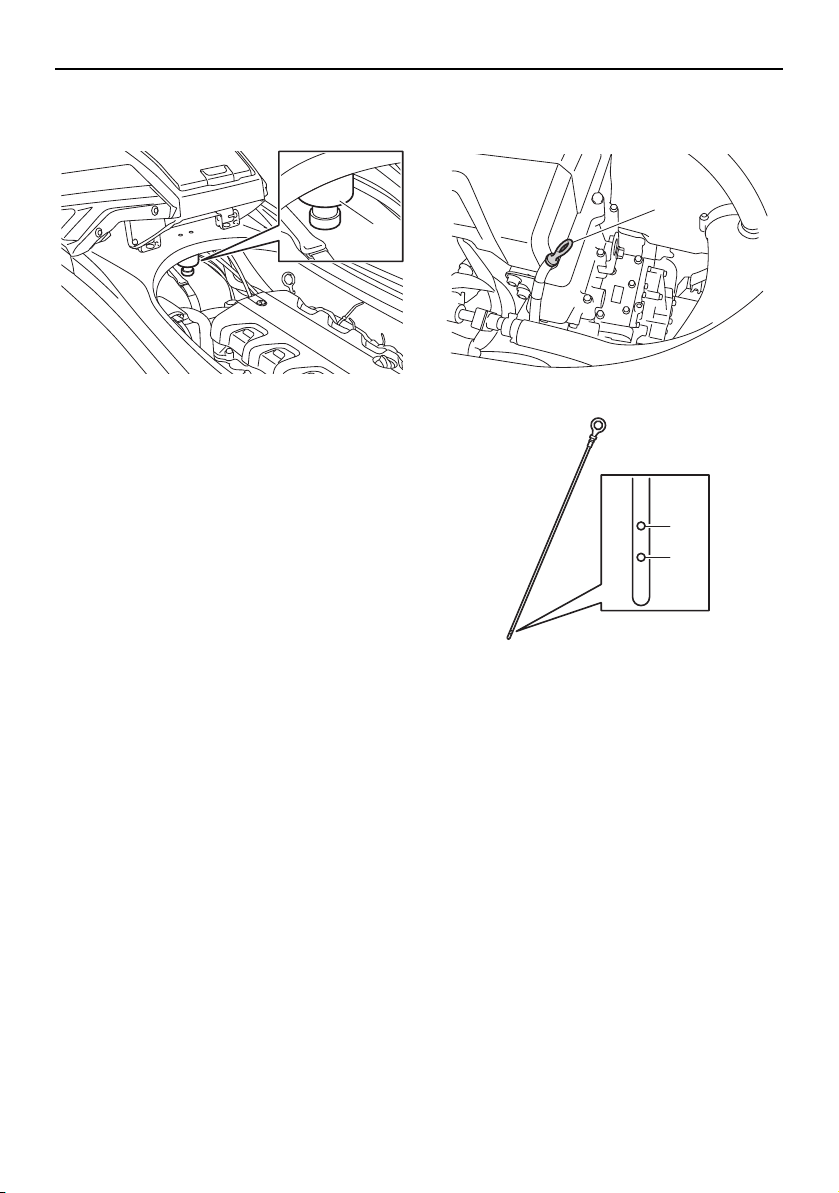
Pre-operation checks
66
water separator, drain it. (See page 35 for in-
formation on draining the water separator.)
EJU40182
Engine unit check
Check the exterior of the engine unit for dam-
age or other problem.
EJU36886
Engine oil level check
Make sure that the engine oil level is between
the minimum and maximum level marks on
the dipstick. (See page 58 for information on
checking the engine oil level.)
EJU32456
Bilge water check
Make sure that no bilge water has collected in
the engine compartment. If bilge water has
collected in the engine compartment, drain it.
(See page 60 for information on draining the
bilge water.)
EJU32485
Battery checks
Make sure that the battery terminals and
breather hose are not damaged and that the
battery leads and breather hose are connect-
ed properly. WARNING! Fire or explosion
could result if the breather hose is dam-
1 Water separator
1
1 Dipstick
1 Maximum level mark
2 Minimum level mark
1
1
2
UF2W10E0.book Page 66 Tuesday, December 1, 2015 3:25 PM
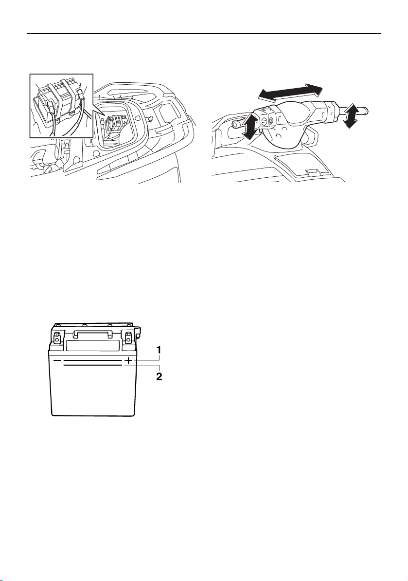
Pre-operation checks
67
aged, obstructed, or not connected prop-
erly.
[EWJ00452]
Make sure that the electrolyte level is be-
tween the minimum and maximum level
marks. WARNING! Never operate the wa-
tercraft if the battery does not have suffi-
cient power to start the engine or if it
shows any other signs of decreased pow-
er. Loss of battery power may leave you
stranded.
[EWJ01241]
Make sure that the battery is securely held in
place.
EJU32614
Steering system checks
Turn the handlebars to the right and left sev-
eral times to make sure that operation is
smooth and unrestricted throughout the
whole range, and that the free play is not ex-
cessive.
Turn the handlebars as far as possible to the
right and left to make sure that the jet thrust
nozzle moves as the handlebars are turned,
and that there is no difference between the
1 Negative (–) battery terminal: Black lead
2 Positive (+) battery terminal: Red lead
3 Breather hose
1 Maximum level mark
2 Minimum level mark
1
3
2
UF2W10E0.book Page 67 Tuesday, December 1, 2015 3:25 PM
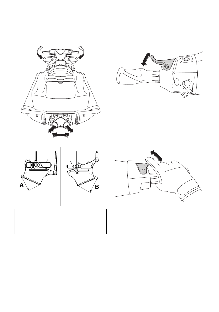
Pre-operation checks
68
right and left fully turned positions of the jet
thrust nozzle.
EJU43212
RiDE lever checks
Operate the RiDE lever several times to make
sure that operation is smooth throughout the
whole range. Also, make sure that the RiDE
lever returns automatically to its fully closed
position when released.
EJU42181
Throttle lever checks
Operate the throttle lever several times to
make sure that operation is smooth through-
out the whole range. Also, make sure that the
throttle lever returns automatically to its fully
closed (idle) position when released.
EJU40113
Remote control transmitter check
Make sure that the remote control transmitter
operates properly. (See page 32 for Yamaha
Security System setting procedures and
page 41 for Low RPM Mode activation pro-
cedures.)
EJU32664
Engine shut-off cord (lanyard) check
Make sure that the engine shut-off cord (lan-
yard) is not damaged. If the cord is damaged,
replace it. WARNING! Never try to repair
the engine shut-off cord (lanyard) or tie it
together. The engine shut-off cord (lan-
Difference between fully turned posi-
tions of jet thrust nozzle (distances A
and B):
Maximum 5 mm (0.20 in)
UF2W10E0.book Page 68 Tuesday, December 1, 2015 3:25 PM
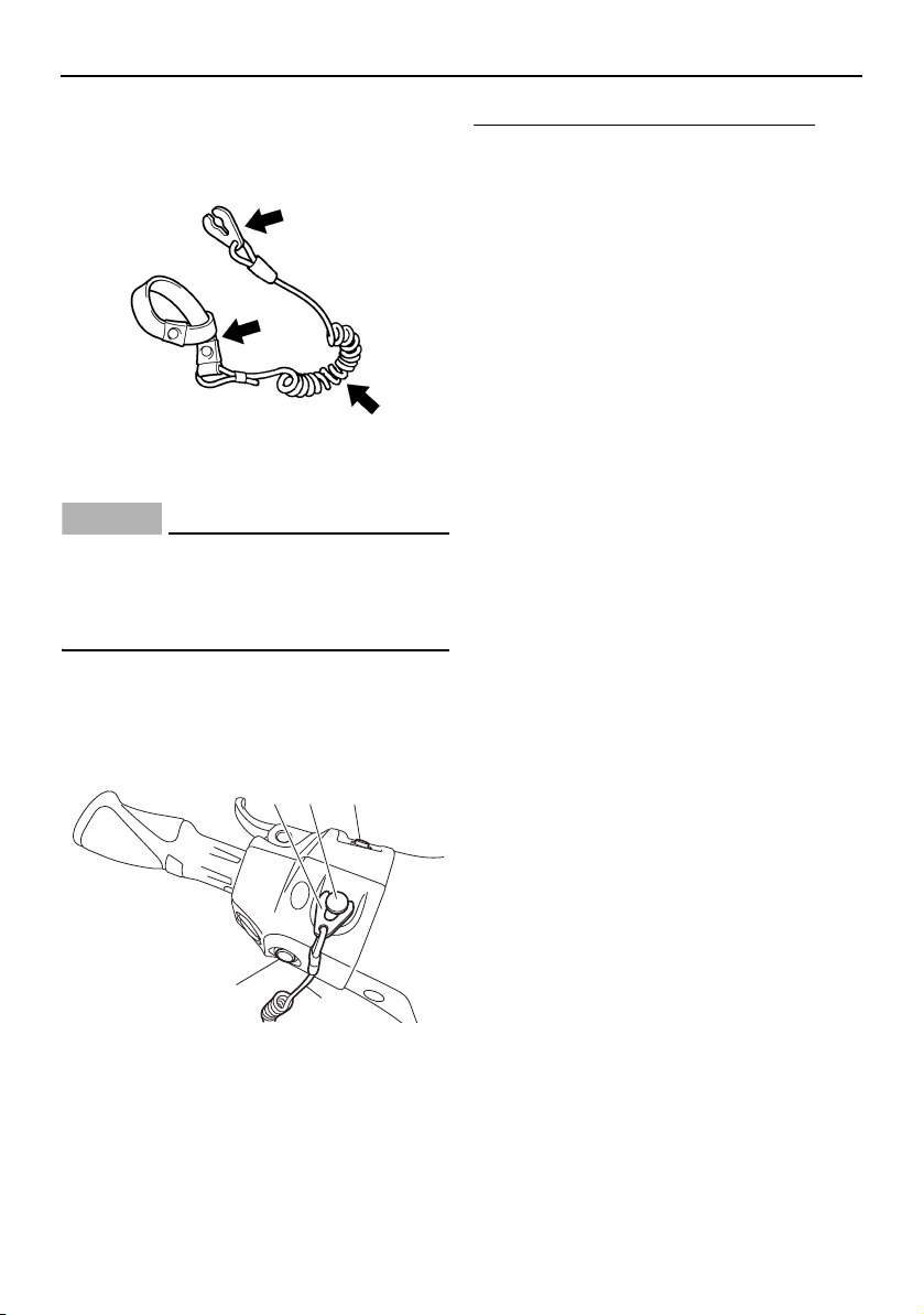
Pre-operation checks
69
yard) may not pull free when the operator
falls off, allowing the watercraft to contin-
ue to run and cause an accident.
[EWJ01221]
EJU32676
Switch checks
NOTICE
ECJ01311
Do not run the engine over 4000 r/min on
land. Also, do not run the engine for more
than 15 seconds without supplying water,
otherwise the engine could overheat.
Check the start switch, the engine stop
switch, and the engine shut-off switch for
proper operation. (See pages 33 to 33 for in-
formation on operating each switch.)
To check the operation of the switches:
(1) If the lock mode is selected for the
Yamaha Security System setting, select
the unlock mode. (See page 32 for
Yamaha Security System setting proce-
dures.)
(2) Push the start switch to make sure that
the engine starts.
(3) As soon as the engine starts running,
push the engine stop switch to make
sure that the engine stops immediately.
(4) Restart the engine, and then pull the en-
gine shut-off cord (lanyard) to remove
the clip from the engine shut-off switch
to make sure that the engine stops im-
mediately.
EJU40102
Storage compartment checks
Make sure that the storage compartments
are not damaged and that water has not col-
lected in the compartments. (See page 52 for
information on the storage compartments.)
EJU43800
Fire extinguisher holder, cover, and band
checks
Make sure that the fire extinguisher holder,
cover, and band are not damaged and that
the fire extinguisher is securely held in place
using the band. (See page 54 for information
on the fire extinguisher holder, cover, and
band.)
1 Clip
2 Engine shut-off switch
3 Start switch
4 Engine stop switch
5 Engine shut-off cord (lanyard)
12 3
5
4
UF2W10E0.book Page 69 Tuesday, December 1, 2015 3:25 PM
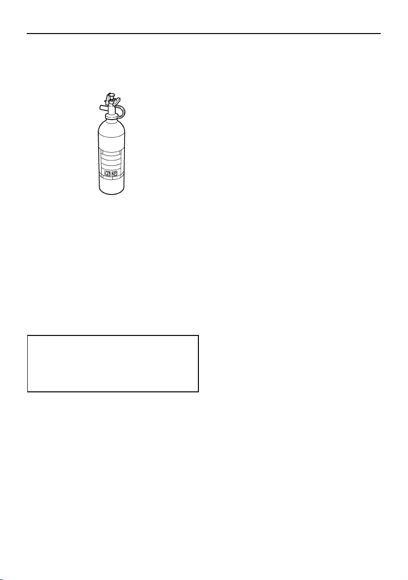
Pre-operation checks
70
EJU32534
Fire extinguisher check
Check that there is a full fire extinguisher on
board.
To check the fire extinguisher, see the in-
structions supplied by the fire extinguisher
manufacturer. Always keep the fire extin-
guisher secured in the holder with its cover in
place.
Always carry a fire extinguisher on board. A
fire extinguisher is not standard equipment
with this watercraft. If you do not have one,
contact a Yamaha dealer or a fire extinguish-
er dealer to obtain one meeting the proper
specifications.
EJU40122
Safety equipment check
Check that safety equipment meeting the ap-
plicable regulations is on board.
EJU32353
Hull and deck check
Check the hull and deck for damage or other
problem.
EJU32657
Jet intake checks
Make sure that the jet intake is not damaged
or clogged with weeds or debris. If the jet in-
take is clogged, clean it. (See page 99 for in-
formation on the jet intake.)
EJU43220
Jet thrust nozzle and reverse gate check
Check the jet thrust nozzle and reverse gate
for damage or other problem.
EJU32477
Stern drain plug checks
Loosen the stern drain plugs and remove
them, and then make sure that the plugs and
O-rings on the plugs are not damaged and
that there is no foreign material on the
threads or O-rings on the plugs. NOTICE:
Before installing the stern drain plugs,
clean the drain plug threads and the O-
rings on the plugs to remove any foreign
materials, such as dirt or sand. Otherwise,
the stern drain plugs could be damaged,
allowing water to enter the engine com-
partment. Check the O-rings on the stern
drain plugs and make sure that the plugs
are tightened securely before launching
the watercraft. Otherwise, water may
flood the engine compartment and cause
the watercraft to submerge.
[ECJ00363]
Fire extinguisher:
Classification:
B-1
Capacity:
2 lb or more
UF2W10E0.book Page 70 Tuesday, December 1, 2015 3:25 PM
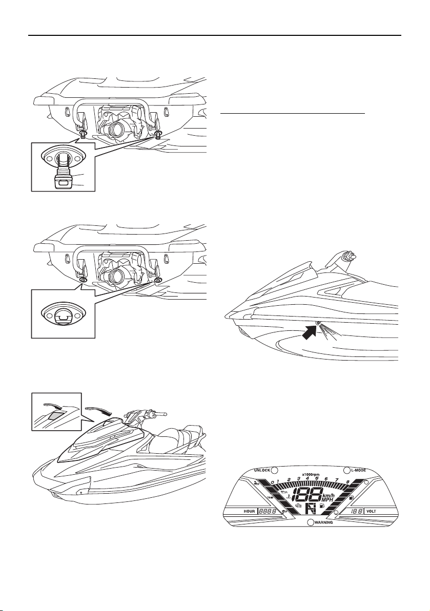
Pre-operation checks
71
Securely install the stern drain plugs by tight-
ening them until they stop.
EJU43810
Hood check
Push down the hood latch and make sure
that it is securely closed.
EJU40146
Post-launch checks
Perform the post-launch checks in the pre-
operation checklist while the watercraft is in
the water and the engine is running.
To perform the post-launch checks:
(1) Launch the watercraft. (See page 75 for
information on launching the watercraft.)
(2) Perform the checks and make sure that
there are no malfunctioning items or oth-
er problems.
EJU40553
Cooling water pilot outlet check
Make sure that water is discharged from the
cooling water pilot outlet while the engine is
running. (See page 35 for information on the
cooling water pilot outlet.)
EJU32715
Multifunction information center check
Make sure that the multifunction information
center operates properly. (See page 43 for in-
formation on proper operation of the multi-
function information center.)
1 Stern drain plug
2 O-ring
2
1
UF2W10E0.book Page 71 Tuesday, December 1, 2015 3:25 PM
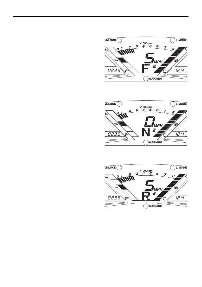
Pre-operation checks
72
EJU43391
Shift system check
Operate the throttle lever and RiDE lever, and
check that the watercraft moves or does not
move according to the displayed shift indica-
tor. (See page 37 for shift system operation
procedures.) WARNING! To avoid colli-
sions, operate at safe speeds and keep a
safe distance away from people, objects,
and other watercraft.
[EWJ01860]
EJU43400
Trim indicator check
Operate the electric trim switches and check
that the trim indicator shows the correct trim
1 “F” (Forward position)
1 “N” (Neutral position)
1 “R” (Reverse position)
1
1
1
UF2W10E0.book Page 72 Tuesday, December 1, 2015 3:25 PM
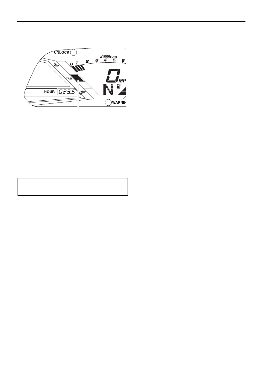
Pre-operation checks
73
angle of the jet thrust nozzle. (See page 39 for
electric trim system operation procedures.)
EJU40172
Engine idling speed check
Start the engine and warm it up. Use the ta-
chometer in the multifunction information
center to make sure that the engine idling
speed is not significantly above or below the
specified range.
1 Trim indicator
Engine idling speed:
1300 ±100 r/min
1
UF2W10E0.book Page 73 Tuesday, December 1, 2015 3:25 PM
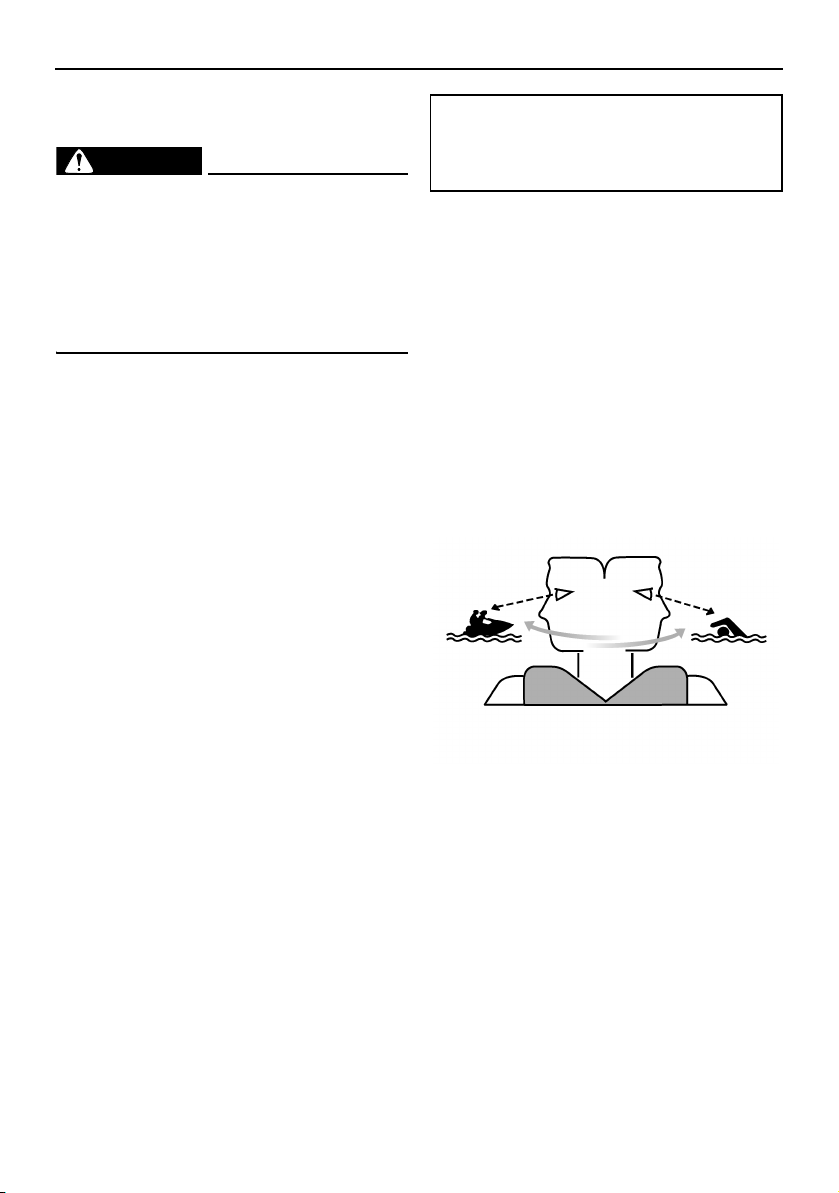
Operation
74
EJU32903
Operating your watercraft
WARNING
EWJ00511
Before operating your watercraft, become
familiar with all of the controls. Consult a
Yamaha dealer about any control or func-
tion that you do not fully understand. Fail-
ure to understand how the controls work
could cause an accident or prevent you
from avoiding an accident.
EJU32956
Getting to know your watercraft
Operating your watercraft requires skills ac-
quired through practice over a period of time.
Take the time to learn the basic techniques
well before attempting more difficult maneu-
vers.
Operating your new watercraft can be a very
enjoyable activity, providing you with hours of
pleasure. However, it is essential to familiar-
ize yourself with the operation of the water-
craft to achieve the skill level necessary to
enjoy riding safely.
Before operating this watercraft, read this
owner’s/operator’s manual, the Riding Prac-
tice Guide, the Riding Instruction card, and all
labels on the watercraft. Pay particular atten-
tion to the safety information beginning on
page 10. Also, watch the Basic Orientation
Video provided with your watercraft. These
materials should give you an understanding
of the watercraft and its operation.
Remember: This watercraft is designed to
carry the operator and up to 2 passengers.
Never exceed the maximum load limit or al-
low more than 3 persons (or 2 persons if a
wakeboarder or water-skier is being pulled)
to ride the watercraft at any time.
EJU32996
Learning to operate your watercraft
Before operating the watercraft, always per-
form the pre-operation checks listed on page
63. The short time spent checking the water-
craft will reward you with added safety and
reliability.
Check state and local laws before operating
your watercraft.
Operate defensively at safe speeds and keep
a safe distance away from people, objects,
and other watercraft. Select a wide area to
learn in, where there is good visibility and
light boat traffic.
Use the buddy system—operate with some-
one nearby. Scan constantly for people, ob-
jects, and other watercraft. Be alert for
conditions that limit your visibility or block
your vision of others.
You should grip the handlebars firmly and
keep both feet on the floor of the footwell. Do
not attempt to ride with passengers until your
operating skills are fully developed.
Maximum load:
240 kg (530 lb)
Load is the total weight of cargo, op-
erator, and passengers.
UF2W10E0.book Page 74 Tuesday, December 1, 2015 3:25 PM
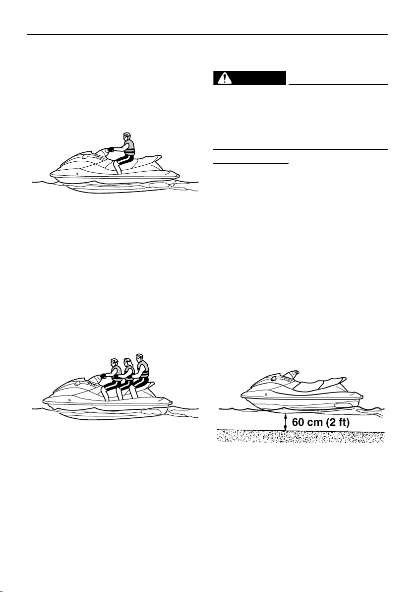
Operation
75
EJU40212
Riding position
Operator riding position
The operator should grip the handlebars firm-
ly with both hands and sit astride the seat
with both feet on the floor of the footwell.
Passenger riding position
The passenger(s) should hold on firmly, either
to the person in front of them or to the hand-
grip provided, and sit astride the seat with
their feet on the floor of the footwell. Never al-
low a passenger to ride in front of the opera-
tor. (See page 18 for information on the riding
position when pulling a wakeboarder or wa-
ter-skier.)
EJU32803
Launching the watercraft
When launching the watercraft, make sure
that there are no obstacles around you.
If the watercraft is launched from a trailer,
someone should make sure that waves do
not push the watercraft into the trailer.
EJU36346
Starting the engine on water
WARNING
EWJ01531
Do not apply throttle when anyone is at the
rear of the watercraft. Turn the engine off
or keep it at idle. Water and debris exiting
the jet thrust nozzle can cause severe in-
jury.
To start the engine:
(1) If the lock mode is selected for the
Yamaha Security System setting, select
the unlock mode. (See page 32 for
Yamaha Security System setting proce-
dures.)
(2) Move the watercraft to an area that is
free from weeds and debris, and has a
water depth of at least 60 cm (2 ft) from
the bottom of the watercraft. NOTIC E:
Never run the engine in water that is
less than 60 cm (2 ft) deep from the
bottom of the watercraft, otherwise
pebbles or sand could be sucked into
the jet intake, causing impeller dam-
age and engine overheating.
[ECJ00473]
(3) Attach the engine shut-off cord (lanyard)
to your left wrist, and then attach the clip
to the engine shut-off switch. (See page
33 for information on operating the en-
gine shut-off switch.) WARNING! Check
that the engine shut-off cord (lanyard)
UF2W10E0.book Page 75 Tuesday, December 1, 2015 3:25 PM
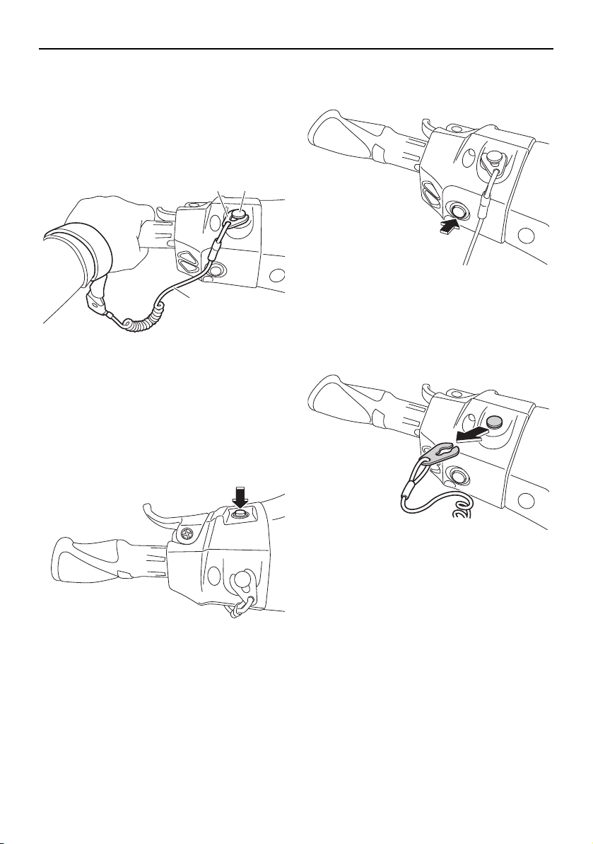
Operation
76
is attached correctly. If the engine
shut-off cord (lanyard) is not attached
correctly, it may not pull free when the
operator falls off, allowing the water-
craft to continue to run and cause an
accident.
[EWJ00582]
(4) With the throttle lever released, push the
start switch (green button) to start the
engine. (See page 33 for information on
operating the start switch.)
EJU32863
Stopping the engine
Release the throttle lever, and then push the
engine stop switch (red button) to stop the
engine. WARNING! You need throttle to
steer. Shutting the engine off can cause
you to hit an obstacle you are attempting
to avoid. A collision could result in severe
injury or death.
[EWJ00602]
EJU32873
Leaving the watercraft
If leaving the watercraft, remove the clip from
the engine shut-off switch to prevent acci-
dental starting or unauthorized operation by
children or others.
EJU43410
Operating the watercraft
When the throttle lever is squeezed, the “F”
(forward) shift indicator will be displayed in
the multifunction display and the watercraft
will move forward. While the “F” (forward)
shift indicator is displayed, the watercraft will
move forward at trolling speed even if the
throttle lever is in the fully closed (idle) posi-
1 Clip
2 Engine shut-off switch
3 Engine shut-off cord (lanyard)
2
3
1
UF2W10E0.book Page 76 Tuesday, December 1, 2015 3:25 PM
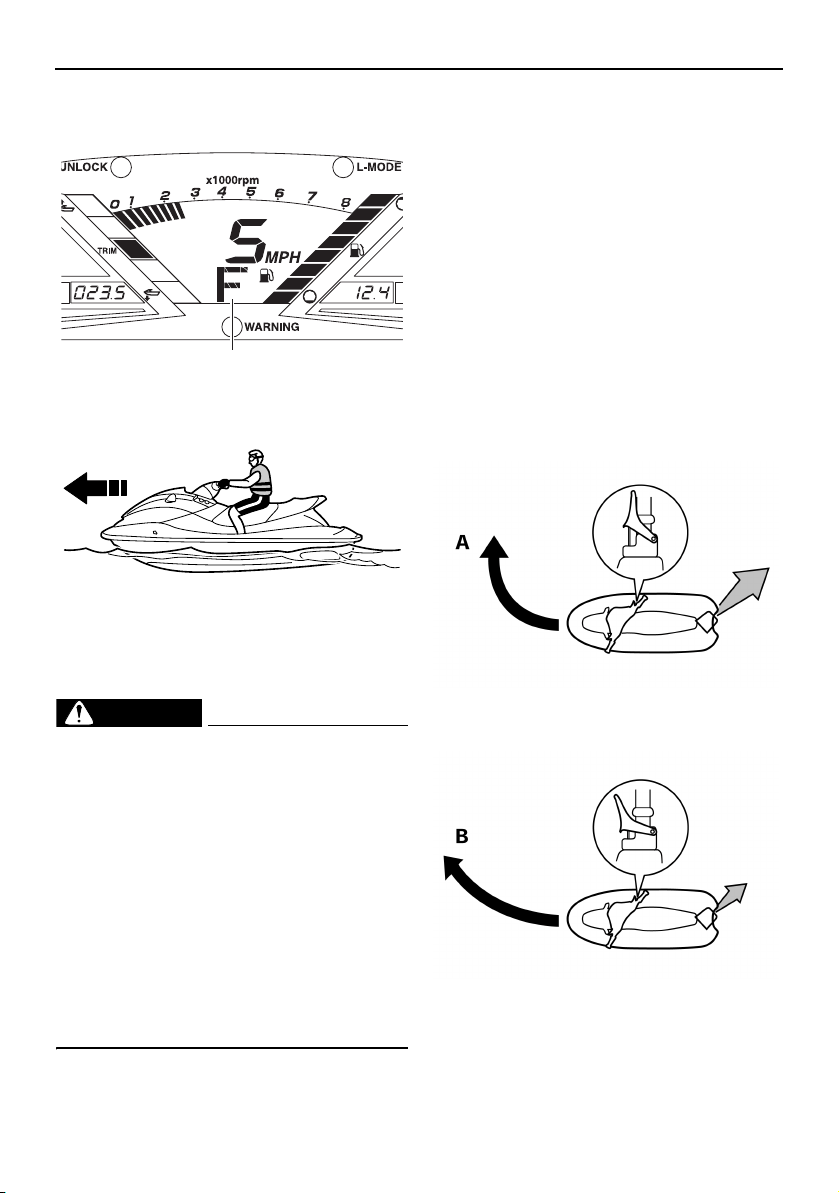
Operation
77
tion. (See page 37 for shift system operation
procedures.)
EJU43421
Turning the watercraft
WARNING
EWJ01781
Do not release the throttle lever when
trying to steer away from objects—you
need throttle to steer. A collision could
result in severe injury or death.
When operating at higher speeds, make
gradual turns or slow down before turn-
ing. Sharp high-speed turns may cause
the watercraft to slide sideways or spin,
throwing the operator and passenger(s)
overboard, which could cause an injury.
Take early action to avoid collisions. The
RiDE system is not a braking device for
avoiding dangerous situations.
Steering control depends on the combination
of handlebar position and the amount of
throttle.
Water sucked in through the intake grate is
pressurized by the impeller in the jet pump.
As the pressurized water is expelled from the
pump through the jet thrust nozzle, it creates
thrust to move and steer the watercraft. The
higher the engine speed, the more thrust pro-
duced.
The amount of jet thrust, in addition to the po-
sition of the handlebars, determines how
sharply you turn.
A. More throttle produces higher thrust, so
the watercraft will turn more sharply.
B. Less throttle produces lower thrust, so
the watercraft will turn more gradually.
C. Releasing the throttle lever completely
produces only minimum thrust. If you are
traveling at speeds above trolling, you
will have rapidly decreasing ability to
1 “F” (Forward position)
1
UF2W10E0.book Page 77 Tuesday, December 1, 2015 3:25 PM
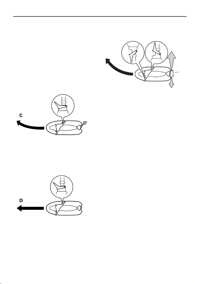
Operation
78
steer without throttle. You may still have
some turning ability immediately after re-
leasing the throttle lever, but once the
engine slows down, the watercraft will no
longer respond to handlebar input until
you apply throttle again or you reach
trolling speed.
At trolling speed, the watercraft can be
turned gradually by handlebar position
alone using just the amount of thrust
available at idle.
D. If the engine is stopped while riding,
there is no thrust. The watercraft will go
straight even though the handlebars are
turned.
You need throttle to steer.
E. If the RiDE lever is squeezed and the
handlebars are turned when the water-
craft is cruising at planing speed, the wa-
tercraft will turn gradually while slowing
down.
This model is equipped with the Yamaha En-
gine Management System (YEMS) that in-
cludes an off-throttle steering (OTS) system.
It will activate at planing speeds should you
attempt to steer the watercraft after releasing
the throttle lever (see condition C above).
The OTS system assists in turning by con-
tinuing to supply some thrust while the water-
craft is decelerating, but you can turn more
sharply if you apply throttle while turning the
handlebars. The OTS system does not func-
tion below planing speeds or when the en-
gine is off. Once the engine slows down, the
watercraft will no longer turn in response to
handlebar input until you apply throttle again
or you reach trolling speed.
EJU43251
Stopping the watercraft
The watercraft is not equipped with a sepa-
rate braking system. The watercraft slows
down by water resistance or, when operating
in reverse, by the water jet. The watercraft
slows down as soon as the throttle lever is re-
leased, but will coast for a distance before
fully stopping. If you are not sure you can
stop in time before hitting an obstacle, apply
throttle and turn in another direction.
From full speed, the watercraft comes to a
complete stop due to water resistance in ap-
1 Reverse gate
E
1
UF2W10E0.book Page 78 Tuesday, December 1, 2015 3:25 PM
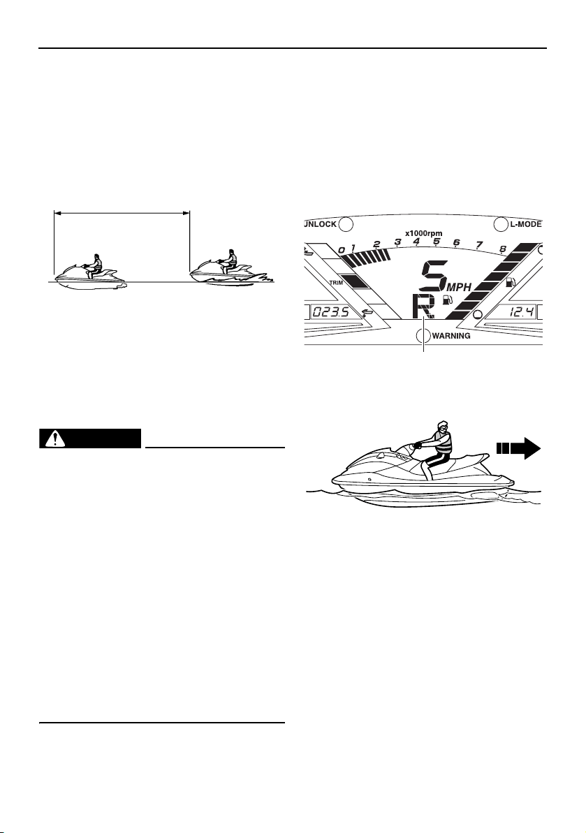
Operation
79
proximately 110 m (360 ft) after the throttle le-
ver is released or the engine is stopped,
although this distance will vary depending on
many factors, including gross weight, water
surface conditions, and wind direction.
If the RiDE lever is squeezed to slow down,
the stopping distance is approximately 30%
shorter than when the RiDE lever is not used.
However, this distance will vary depending
on many factors, including gross weight, wa-
ter surface conditions, and wind direction.
WARNING
EWJ01791
Allow adequate stopping distance.
Take early action to avoid collisions. Re-
member, watercraft and other boats do
not have brakes.
Operate defensively at safe speeds and
keep a safe distance away from people,
objects, and other watercraft to give you
time to stop.
Do not shut the engine off when slowing
down in case you need engine power to
steer away from a boat or other obstacle
that comes into your path.
To avoid rear-end collisions while oper-
ating the watercraft, check behind you
before using the RiDE lever to slow
down or stop the watercraft.
EJU43441
Operating the watercraft in reverse or
neutral
Operating in reverse
When the RiDE lever is squeezed, the “R” (re-
verse) shift indicator will be displayed in the
multifunction display and the watercraft will
move in reverse. (See page 37 for shift sys-
tem operation procedures.)
Make sure that there are no obstacles or peo-
ple behind you before shifting into reverse.
TIP:
This model is equipped with a function which
limits the engine speed in reverse.
Operating in neutral
When the RiDE lever is squeezed lightly and
released, the “N” (neutral) shift indicator will
be displayed in the multifunction display and
the watercraft will stop in its current location.
110 m (360 ft)
1 “R” (Reverse position)
1
UF2W10E0.book Page 79 Tuesday, December 1, 2015 3:25 PM
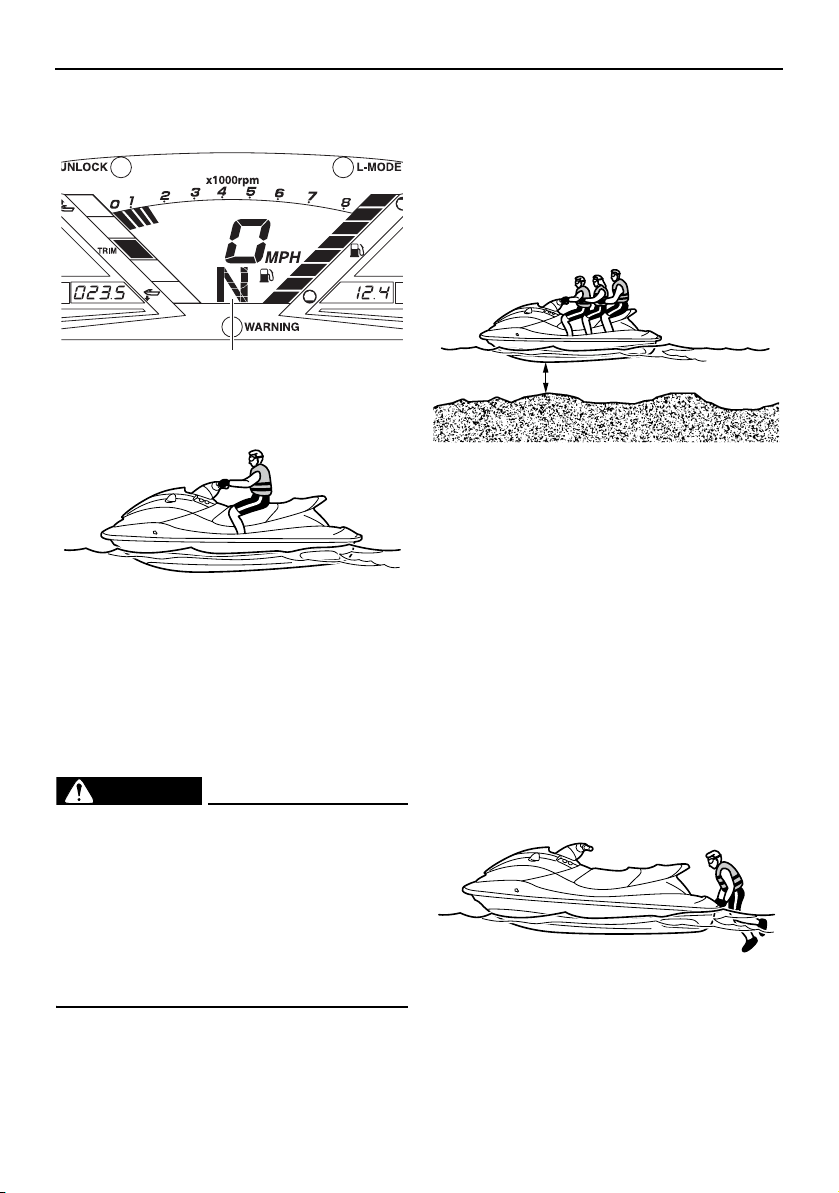
Operation
80
(See page 37 for shift system operation pro-
cedures.)
TIP:
This model is equipped with a function which
limits the engine speed in neutral.
EJU36087
Boarding the watercraft
WARNING
EWJ01112
Be sure the operator and any passengers
have practiced boarding from the water
while still close to shore before riding. A
person who has made many unsuccessful
attempts to get back on the watercraft
may become fatigued and suffer from ex-
posure, increasing the risk of injury and
drowning.
Board the watercraft in water free from
weeds and debris and at least 60 cm (2 ft)
deep from the bottom of the watercraft.
NOTICE: Never run the engine in water
that is less than 60 cm (2 ft) deep from the
bottom of the watercraft, otherwise peb-
bles or sand could be sucked into the jet
intake, causing impeller damage and en-
gine overheating.
[ECJ00473]
TIP:
VXR: This watercraft is equipped with a re-
boarding step, which can be lowered and
used to assist in reboarding. (See page 50 for
information on operating the reboarding
step.)
EJU36354
Boarding alone
(1) From the rear of the watercraft, place
both hands on the boarding platform,
pull yourself up, and then grasp the
handgrip with one hand.
1 “N” (Neutral position)
1
60 cm (2 ft)
UF2W10E0.book Page 80 Tuesday, December 1, 2015 3:25 PM
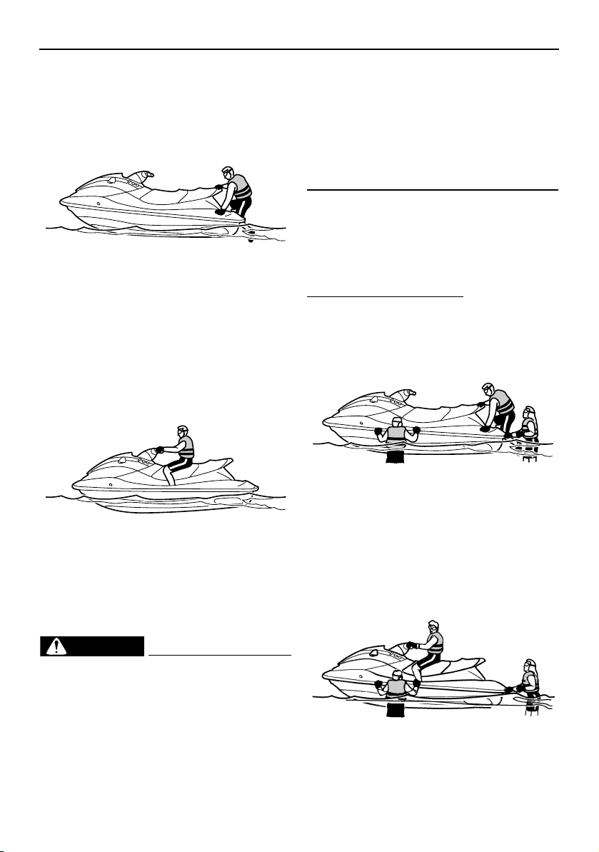
Operation
81
(2) Pull yourself up to a kneeling position on
the boarding platform, and then move to
the seat and sit astride.
(3) Attach the engine shut-off cord (lanyard)
to your left wrist, and then attach the clip
to the engine shut-off switch.
(4) Grip the handlebars with both hands and
place both feet on the floor of the foot-
well.
(5) Look in all directions, start the engine,
and then start off slowly.
EJU43260
Boarding with passenger(s)
WARNING
EWJ01800
Severe internal injuries can occur if wa-
ter is forced into body cavities as a re-
sult of being near the jet thrust nozzle.
Do not start the engine until the passen-
gers are seated with their feet on the
floor of the footwell and are securely
holding on to the person in front of them
or to the handgrip provided.
Before boarding the watercraft, make
sure that the engine is stopped. If the
engine is running, the reverse gate may
move down and a person boarding
could be pinched.
The heavier the total weight of the operator
and passenger(s), the more difficult it will be
to balance the watercraft. Do not operate the
watercraft when the total weight exceeds 240
kg (530 lb) including any cargo.
To board with passenger(s):
(1) Board as noted in the previous section
“Boarding alone”.
(2) Grip the handlebars with both hands and
place both feet on the floor of the foot-
well.
(3) Have the first passenger move to the rear
of the watercraft.
UF2W10E0.book Page 81 Tuesday, December 1, 2015 3:25 PM
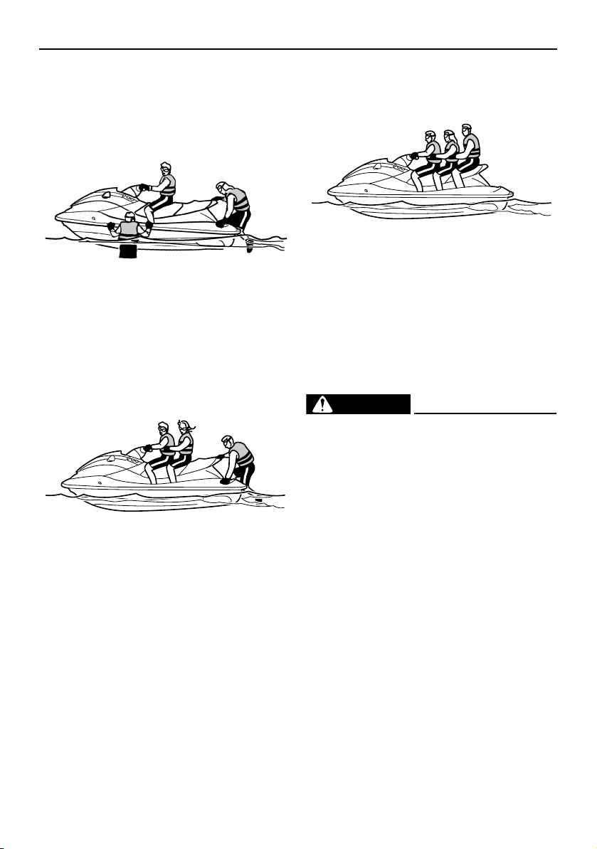
Operation
82
(4) Have the first passenger board using the
same procedure as the operator, place
their feet on the floor of the footwell, and
securely hold on to the operator.
(5) Have the second passenger follow the
same procedure. When the second pas-
senger is boarding, try to balance the
watercraft together with the first passen-
ger.
(6) Make sure that the passenger(s) have
their feet on the floor of the footwell and
are securely holding on to the person in
front of them or to the handgrip provided.
(7) Attach the engine shut-off cord (lanyard)
to your left wrist, and then attach the clip
to the engine shut-off switch.
(8) Look in all directions, start the engine,
and then start off slowly.
EJU33083
Starting off
WARNING
EWJ00712
To avoid collisions:
Scan constantly for people, objects, and
other watercraft. Be alert for conditions
that limit your visibility or block your vi-
sion of others.
Operate defensively at safe speeds and
keep a safe distance away from people,
objects, and other watercraft.
Do not follow directly behind watercraft
or other boats. Do not go near others to
spray or splash them with water. Avoid
sharp turns or other maneuvers that
make it hard for others to avoid you or
understand where you are going. Avoid
areas with submerged objects or shal-
low water.
Take early action to avoid collisions. Re-
member, watercraft and other boats do
not have brakes. Do not release the
throttle lever when trying to steer away
UF2W10E0.book Page 82 Tuesday, December 1, 2015 3:25 PM

Operation
83
from objects—you need throttle to
steer.
NOTICE
ECJ01341
Never run the engine in water that is less
than 60 cm (2 ft) deep from the bottom of
the watercraft, otherwise pebbles or sand
could be sucked into the jet intake, caus-
ing impeller damage and engine overheat-
ing.
EJU43271
Starting off from a trailer
(1) Launch the watercraft.
(2) Attach the engine shut-off cord (lanyard)
to your left wrist, and then attach the clip
to the engine shut-off switch.
(3) Look in all directions, and then start the
engine.
(4) Squeeze the RiDE lever and move the
watercraft back slowly. (See page 37 for
RiDE lever operation procedures.)
EJU33114
Boarding and starting off from a dock
(1) Board the watercraft from the side.
(2) Attach the engine shut-off cord (lanyard)
to your left wrist, and then attach the clip
to the engine shut-off switch.
(3) Push the watercraft away from the dock,
grip the handlebars with both hands, and
place both feet on the floor of the foot-
well.
(4) Look in all directions, start the engine,
and then start off slowly.
EJU33236
Capsized watercraft
WARNING
EWJ00672
Improper uprighting can cause injury.
Be sure to shut the engine off by pulling
on the engine shut-off cord (lanyard) to
remove the clip from the engine shut-off
switch.
Do not put your hands in the intake
grate.
If the watercraft capsizes, turn it over imme-
diately.
To upright the watercraft:
(1) Remove the clip from the engine shut-off
switch.
(2) Swim to the rear of the watercraft. Turn
the watercraft over clockwise by pulling
on the ride plate with your left hand while
pushing down on the gunwale with your
right hand or foot.
If the port (left) side of the capsized wa-
tercraft is tilting up, push down on the
gunwale so that the port (left) side is
down before turning the watercraft
clockwise. NOTICE: Do not turn the
watercraft over counterclockwise,
UF2W10E0.book Page 83 Tuesday, December 1, 2015 3:25 PM
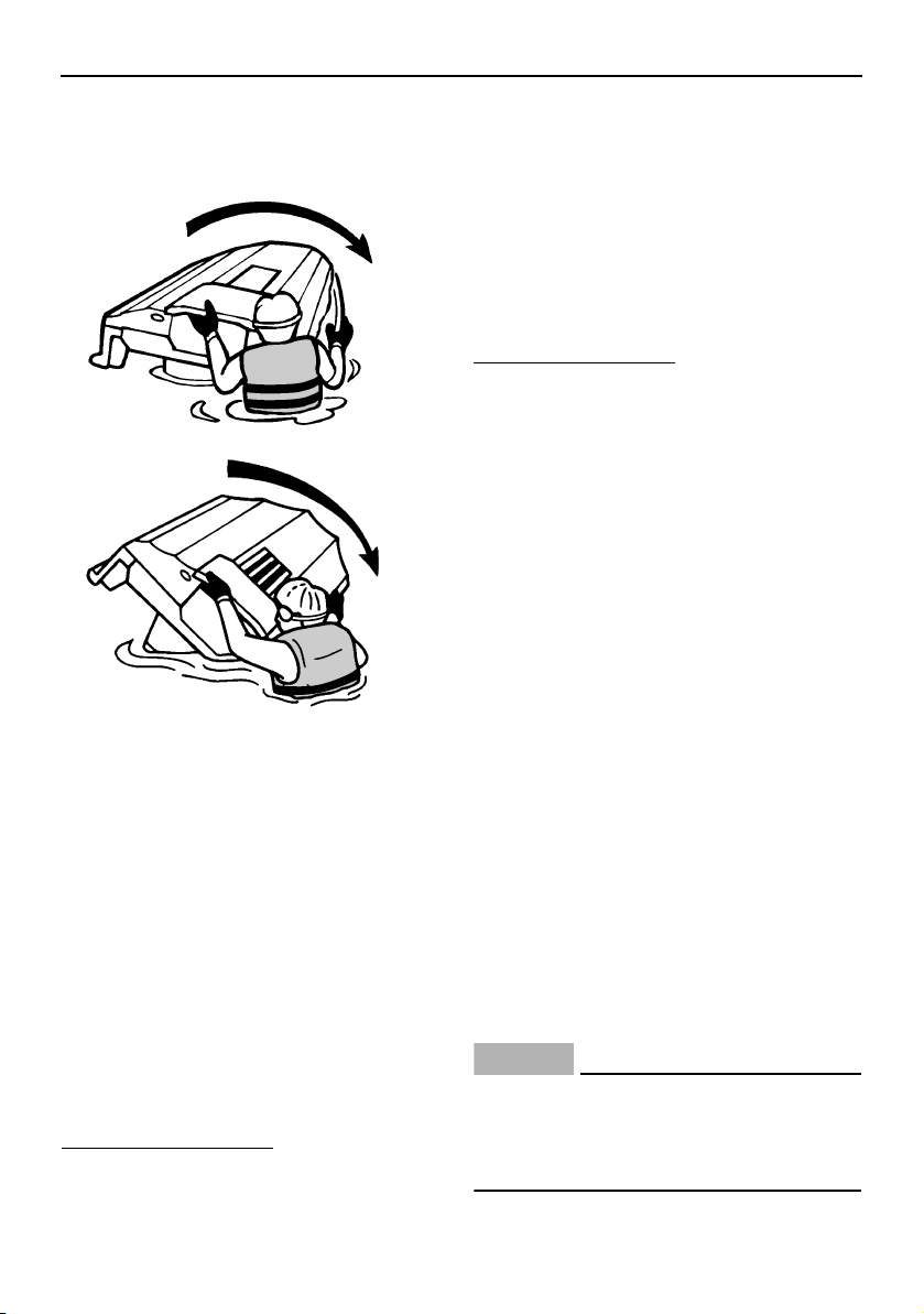
Operation
84
otherwise water can enter the engine,
which can result in severe damage.
[ECJ00542]
(3) Start the engine and operate the water-
craft at planing speed to drain the bilge
water from the engine compartment.
(See page 60 for information on draining
the bilge water. If the engine does not
start, see “Towing the watercraft” on
page 103 or “Submerged watercraft” on
page 103.) NOTICE: Do not run the en-
gine at full throttle for at least 1 minute
after the engine has been restarted.
Bilge water in the engine compart-
ment can splash into the engine,
which can result in severe damage.
[ECJ00554]
EJU43281
Beaching and docking the watercraft
To beach the watercraft:
(1) Make sure that there are no boats, swim-
mers, or obstacles near the beach.
(2) Release the throttle lever to reduce
speed about 110 m (360 ft) before you
reach the intended beaching area.
(3) Slowly approach the beach using the
throttle lever and RiDE lever to control
the watercraft speed.
(4) After reaching land, stop the engine, and
then get off the watercraft and pull it up
on the beach.
To dock the watercraft:
(1) Make sure that there are no boats, swim-
mers, or obstacles near the dock.
(2) Release the throttle lever to reduce
speed about 110 m (360 ft) away from
the dock.
(3) Slowly approach the dock using the
throttle lever and RiDE lever to control
the watercraft speed.
(4) After coming alongside the dock, stop
the engine, and then get off the water-
craft.
EJU37194
Operating in weeded areas
Always avoid using your watercraft in areas
where weed growth is thick. If operating in
weeded areas is unavoidable, alternately
squeeze the throttle lever and relax your grip
on the throttle lever to vary the engine speed.
Weeds tend to become clogged more when
operating at a steady speed and at trolling
speed. If weeds may have clogged the intake
area, clean the jet intake. (See page 99 for in-
formation on the jet intake.)
EJU40242
After removing the watercraft from
the water
NOTICE
ECJ01311
Do not run the engine over 4000 r/min on
land. Also, do not run the engine for more
than 15 seconds without supplying water,
otherwise the engine could overheat.
UF2W10E0.book Page 84 Tuesday, December 1, 2015 3:25 PM

Operation
85
After operating and removing the watercraft
from the water, promptly discharge the re-
maining water from the cooling water pas-
sages.
To discharge water from the cooling water
passages:
(1) Make sure that the area around the wa-
tercraft is clear, and then start the en-
gine.
(2) Discharge the remaining water out of the
cooling water passages by alternately
squeezing and releasing the throttle lever
quickly for 10 to 15 seconds.
(3) Stop the engine.
UF2W10E0.book Page 85 Tuesday, December 1, 2015 3:25 PM
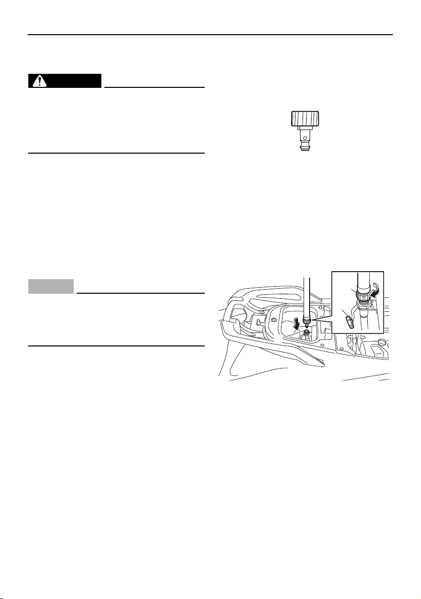
Care and storage
86
EJU37146
Post-operation care
WARNING
EWJ00331
Always place the watercraft upright in a
horizontal position when storing it, other-
wise fuel could leak out into the engine or
engine compartment, which could create
a fire hazard.
After using the watercraft, always take it out
of the water, clean it, and store it. Leaving the
watercraft in the water for extended periods
will accelerate the rate of normal deteriora-
tion of the jet pump and hull. Marine organ-
isms and corrosion are some of the
conditions that can shorten the life of many
watercraft components.
EJU43651
Flushing the cooling water passages
NOTICE
ECJ01311
Do not run the engine over 4000 r/min on
land. Also, do not run the engine for more
than 15 seconds without supplying water,
otherwise the engine could overheat.
Flush the cooling water passages to prevent
them from clogging with salt, sand, or dirt.
(1) Place the watercraft in a horizontal posi-
tion.
(2) Remove the seats and watertight stor-
age compartment. (See page 49 for seat
removal and installation procedures and
page 54 for information on the watertight
storage compartment.)
(3) Connect the garden hose adapter to a
garden hose.
(4) Loosen the flushing hose connector cap
and remove it. Insert the garden hose
adapter into the flushing hose connector
by pushing and twisting it until it is se-
curely connected.
(5) Connect the garden hose to a water tap.
(6) Make sure that the area around the wa-
tercraft is clear, and then start the en-
gine. Immediately after the engine starts,
fully turn the water supply on so that wa-
1 Garden hose adapter
1 Garden hose adapter
2 Flushing hose connector
3 Flushing hose connector cap
1
3
2
1
UF2W10E0.book Page 86 Tuesday, December 1, 2015 3:25 PM
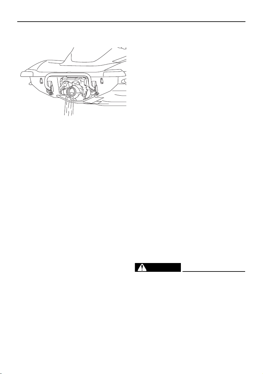
Care and storage
87
ter flows out continually from the jet
thrust nozzle.
(7) Run the engine at idling speed for about
3 minutes watching the engine condition.
If the engine stops while flushing, turn
the water supply off immediately and
perform the procedure again from step 6.
NOTICE: Do not supply water to the
cooling water passages when the en-
gine is not running. The water could
flow back through the muffler into the
engine, causing severe engine dam-
age.
[ECJ00123]
(8) Turn the water supply off.
(9) Discharge the remaining water out of the
cooling water passages by alternately
squeezing and releasing the throttle lever
quickly for 10 to 15 seconds.
(10) Stop the engine.
(11) Remove the garden hose adapter, and
then securely install the flushing hose
connector cap by tightening it until it
stops.
(12) Securely install the watertight storage
compartment and seats in their original
positions.
EJU33746
Cleaning the watercraft
(1) Remove the seats. (See page 49 for seat
removal and installation procedures.)
(2) Rinse the engine and engine compart-
ment with a small amount of water.
NOTICE: Do not use high-pressure
water when rinsing the engine or en-
gine compartment as severe engine
damage could result.
[ECJ00572]
(3) Drain the water from the engine com-
partment. (See page 60 for information
on draining the bilge water.)
(4) Wipe the engine and engine compart-
ment with a dry cloth.
(5) Wash down the hull, deck, and jet pump
with fresh water.
(6) Wipe the hull, deck, and jet pump with a
dry cloth.
(7) Wipe all vinyl and rubber components,
such as the seats and engine compart-
ment seals, with a vinyl protectant such
as Yamaha Protectant.
(8) To minimize corrosion, spray metallic
parts of the hull, deck, and engine with a
rust inhibitor such as Yamaha Silicone
Protectant and Lubricant.
(9) Allow the engine compartment to air dry
completely before installing the seats.
(10) Securely install the seats in their original
positions.
EJU41631
Battery care
If the watercraft will not be used for more than
a month, remove the battery from the water-
craft, check it, and then store it in a cool, dry
place.
WARNING
EWJ00792
Battery electrolyte is poisonous and dan-
gerous, causing severe burns, etc. Elec-
trolyte contains sulfuric acid. Avoid
contact with skin, eyes, or clothing.
Antidotes
External: Flush with water.
Internal: Drink large quantities of water or
milk. Follow with milk of magnesia, beaten
UF2W10E0.book Page 87 Tuesday, December 1, 2015 3:25 PM
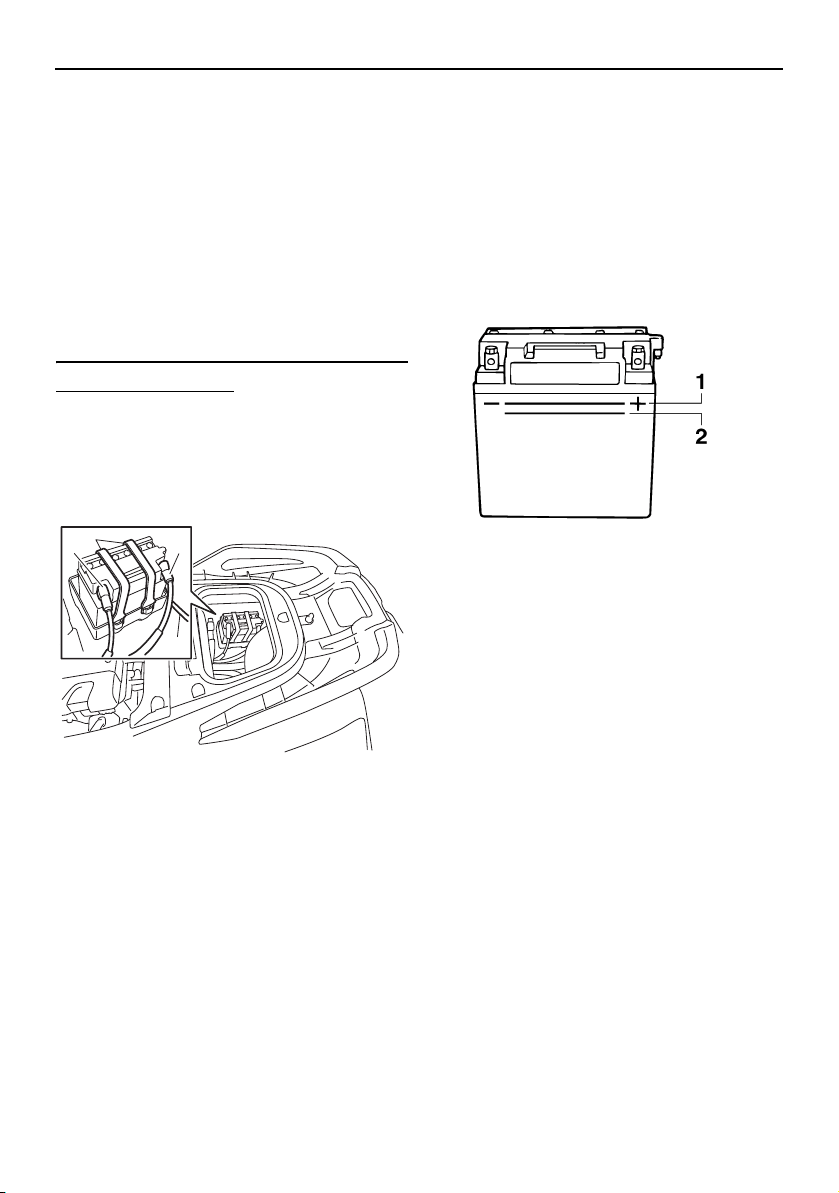
Care and storage
88
egg, or vegetable oil. Call a physician im-
mediately.
Eyes: Flush with water for 15 minutes and
get prompt medical attention.
Batteries produce explosive gases. Keep
sparks, flames, cigarettes, etc., well away.
If using or charging the battery in an en-
closed space, make sure that it is well
ventilated. Always shield your eyes when
working near batteries.
Keep out of the reach of children.
To remove the battery:
(1) Disconnect the negative (–) battery lead.
(2) Disconnect the positive (+) battery lead.
(3) Disconnect the breather hose.
(4) Unhook the battery bands, and then re-
move the battery from the watercraft.
Checking the battery
Make sure that the battery case is not dam-
aged.
Make sure that the battery terminals are
not corroded or damaged.
Make sure that the breather hose is not
clogged or damaged.
Checking the electrolyte level
Make sure that the electrolyte level is be-
tween the maximum and minimum level
marks.
If the electrolyte level is low, add distilled wa-
ter to raise it to the specified level. NOTICE:
Use only distilled water for replenishing
the battery, otherwise battery life could be
shortened.
[ECJ00242]
If distilled water was added, check the bat-
tery voltage.
It is recommended to have a Yamaha dealer
check the battery voltage and charge the bat-
tery. If you charge the battery yourself, be
sure to read and follow the instructions pro-
vided with the battery tester and charger you
use. NOTICE: Do not attempt to charge a
battery hastily. Battery life could be short-
ened.
[ECJ00252]
1 Negative (–) battery terminal: Black lead
2 Battery band
3 Positive (+) battery terminal: Red lead
4 Breather hose
1
2
3
4
1 Maximum level mark
2 Minimum level mark
UF2W10E0.book Page 88 Tuesday, December 1, 2015 3:25 PM
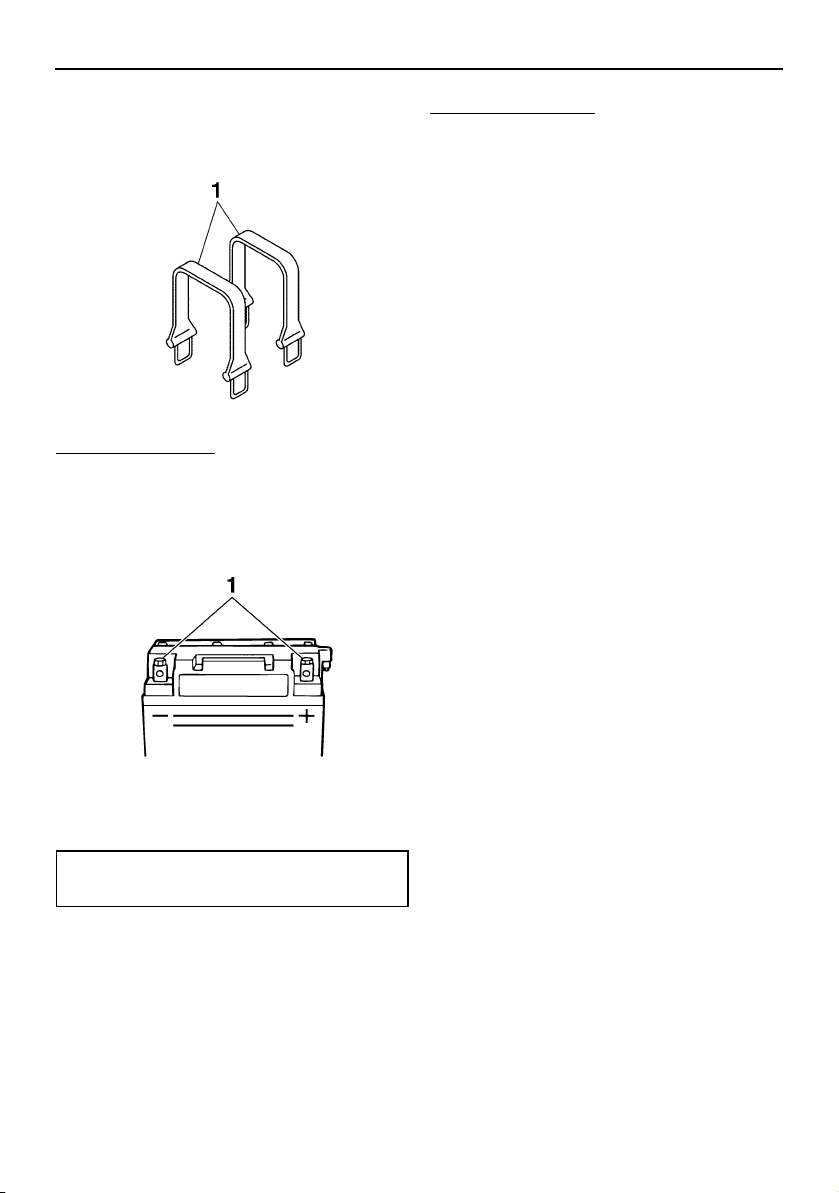
Care and storage
89
Checking the battery bands
Make sure that the battery bands are not
damaged.
To store the battery:
(1) Clean the battery case using fresh water.
(2) If the battery terminals are dirty or cor-
roded, clean them using a wire brush.
(3) Apply YAMALUBE MARINE GREASE to
the battery terminals.
(4) Store the battery in a cool, dry place.
NOTICE: Storing the battery in an un-
charged condition can cause perma-
nent battery damage. Check the
battery periodically.
[ECJ00103]
To install the battery:
(1) Place the battery in the battery compart-
ment and hook the battery bands onto
the holders.
(2) Connect the positive (+) battery lead (red)
to the positive (+) battery terminal.
NOTICE: Reversal of the battery leads
will damage the electrical parts.
[ECJ00262]
(3) Connect the negative (–) battery lead
(black) to the negative (–) battery termi-
nal.
(4) Connect the breather hose to the bat-
tery. WARNING! Fire or explosion
could result if the breather hose is
damaged, obstructed, or not connect-
ed properly.
[EWJ00452]
(5) Make sure that the battery is securely
held in place.
1 Battery band
1 Battery terminal
Recommended water-resistant grease:
YAMALUBE MARINE GREASE
UF2W10E0.book Page 89 Tuesday, December 1, 2015 3:25 PM
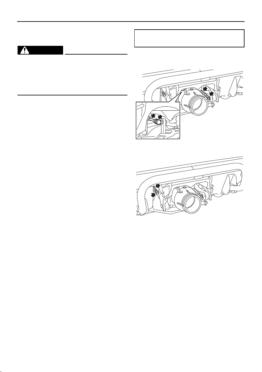
Care and storage
90
EJU33493
Long-term storage
WARNING
EWJ00331
Always place the watercraft upright in a
horizontal position when storing it, other-
wise fuel could leak out into the engine or
engine compartment, which could create
a fire hazard.
Storage for long periods of time, such as win-
ter storage, requires preventive maintenance
to ensure against deterioration. It is advisable
to have the watercraft serviced by a Yamaha
dealer prior to storage.
However, the following procedures can be
performed easily by the owner.
EJU40253
Cleaning
(1) Flush the cooling water passages. (See
page 86 for information on flushing the
cooling water passages.)
TIP:
If you will be storing the watercraft for a pro-
longed period, such as winter storage, top off
the fuel tank with fresh gasoline and add one
ounce of Yamaha Fuel Stabilizer and Condi-
tioner to each gallon of fuel in the fuel tank
before starting the engine.
(2) Clean the watercraft. (See page 87 for in-
formation on cleaning the watercraft.)
Wax the hull with a non-abrasive wax
such as Yamaha Silicone Wax.
EJU43291
Lubrication
Use a Yamaha Power Cable Luber and spray
Yamaha Lube-Zall between the inner and
outer cables to lubricate the cables and
purge out any dirt and moisture.
To keep moving parts sliding or rotating
smoothly, lubricate them with water-resistant
grease.
Steering cable (jet thrust nozzle end) and
electric trim rod (jet thrust nozzle end)
Shift rod (reverse gate end)
EJU40262
Rustproofing
Spray metallic parts of the hull, deck, and en-
gine with a rust inhibitor such as Yamaha Sil-
icone Protectant and Lubricant.
Have a Yamaha dealer rustproof the internal
engine components.
Recommended water-resistant grease:
YAMALUBE MARINE GREASE
UF2W10E0.book Page 90 Tuesday, December 1, 2015 3:25 PM
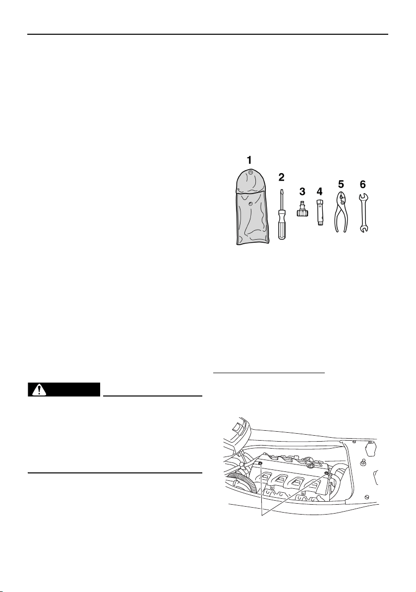
Maintenance
91
EJU33758
Maintenance
Periodic checks and lubrication will keep
your watercraft in the safest and most effi-
cient condition possible. Therefore, make
sure to carry out the periodic maintenance.
Safety is an obligation of the watercraft own-
er. Proper maintenance must be carried out
to keep the exhaust emission and sound lev-
els within the regulated limits. The most im-
portant points of watercraft inspection and
lubrication are explained on the following
pages.
See a Yamaha dealer for genuine Yamaha re-
placement parts and optional accessories
designed for your watercraft.
Remember, failures that are the result of the
installation of parts or accessories which are
not qualitatively equivalent to genuine
Yamaha parts are not covered by the limited
warranty.
Maintenance, replacement, or repair of
the emission control devices and system
may be performed by any marine SI engine
repair establishment or individual. War-
ranty repair, however, must be performed
at an authorized Yamaha marine dealer-
ship.
WARNING
EWJ00312
Be sure to turn off the engine when you
perform maintenance unless otherwise
specified. If you are not familiar with ma-
chine servicing, this work should be done
by a Yamaha dealer or other qualified me-
chanic.
A service manual is available for purchase
through a Yamaha dealer for owners who
have the mechanical skills, tools, and other
equipment necessary to perform mainte-
nance not covered by this owner’s/operator’s
manual.
EJU33803
Tool kit
A tool kit is included with this watercraft.
Place the tool kit in a waterproof bag and al-
ways carry it with you whenever you use the
watercraft.
EJU42021
Removing and installing the engine
cover
The engine cover is removable.
To remove the engine cover:
(1) Remove the seats. (See page 49 for seat
removal and installation procedures.)
(2) Remove the engine cover screws.
1 Tool bag
2 Screwdriver
3 Garden hose adapter
4 10/12 mm box wrench
5 Pliers
6 10/12 mm open-end wrench
1 Engine cover screw
1
UF2W10E0.book Page 91 Tuesday, December 1, 2015 3:25 PM
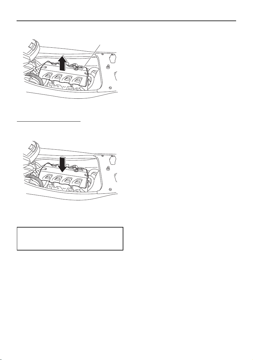
Maintenance
92
(3) Lift up the engine cover to remove it.
To install the engine cover:
(1) Place the engine cover in its original po-
sition, and then push it down.
(2) Install the engine cover screws, and then
tighten them to the specified torque.
(3) Securely install the seats in their original
positions.
1 Engine cover
Tightening torque:
Engine cover screw:
4.5 Nm (0.46 kgf-m, 3.3 ft-lb)
1
UF2W10E0.book Page 92 Tuesday, December 1, 2015 3:25 PM

Maintenance
93
EJU43101
Periodic maintenance chart
The periodic maintenance chart gives general guidelines for periodic maintenance. Have a
Yamaha dealer perform the checks in the following chart. However, maintenance may need
to be performed more frequently depending on your operating conditions. If you have any
questions, consult a Yamaha dealer.
This “√” mark indicates items to be checked and serviced by a Yamaha dealer.
Item Operation
Initial Thereafter every
Page
10 hours
50 hours
or 12
months
*1
100
hours or
12
months
*1
200
hours or
24
months
*1
Fuel line
Check fuel hoses and
clamps
√ —
Fuel filler cap/Wa-
ter separator
Check O-rings for cracks
and deformation
√ —
Fuel tank
Check installation and
straps
√ —
Water inlet strainer
Check for clogs and dam-
age
√ —
Cooling water hos-
es
Check for damage and
leakage, and check
clamps
√ —
Engine oil Replace √√ 94
Oil filter Replace √ 94
Intermediate hous-
ing
Lubricate √ —
Spark plugs Check √√—
Battery
Check specific gravity of
electrolyte, terminals,
bands, and breather hose
√ —
Battery leads Check terminals √ —
Steering master
Check operation and for
looseness
√√—
Steering cable
Check exterior and con-
nections, and lubricate
√ —
Electric trim rod
Check exterior and con-
nections, and lubricate
√ —
Shift rod and re-
verse gate
Check exterior and con-
nections, and lubricate
√ —
Air filter element
Check for damage and
dirt
√ —
Air intake hoses
Check for damage, and
check clamps
√
—
Throttle body Lubricate throttle valves √ —
UF2W10E0.book Page 93 Tuesday, December 1, 2015 3:25 PM
Maintenance
94
*1: Whichever comes first.
*2: Check every 200 hours.
Perform the pre-operation checks and post-operation checks before performing periodic
maintenance.
EJU36943
Engine oil and oil filter
WARNING
EWJ00341
Engine oil is extremely hot immediately af-
ter the engine is turned off. Coming in con-
tact with or getting any engine oil on your
clothes could result in burns.
NOTICE
ECJ00992
Do not run the engine with too much or not
enough oil in the engine, otherwise the en-
gine could be damaged.
It is recommended to have a Yamaha dealer
change the engine oil and the engine oil filter.
However, if you choose to change the oil and
filter on your own, consult a Yamaha dealer.
Exhaust system
Check for exhaust leak-
age, and check hoses and
clamps
√ —
Breather hose
Check breather hose and
clamps
√ —
Impeller
Check for bends, dam-
age, and foreign material
√ —
Jet thrust nozzle
Check movement, and lu-
bricate
√ —
Jet vacuum bilge
Check hoses for clogs
and damage, check
clamps, and clean bilge
strainer
√ —
Stern drain plugs Check O-rings √ —
Anode
Check for corrosion, and
clean
√ *2 —
Valve clearance Check and adjust √ *2 —
Rubber coupling
Check for cracks, inden-
tations, looseness, and
noise
√ —
Engine mount
Check for damage and
peeling
√ —
Item Operation
Initial Thereafter every
Page
10 hours
50 hours
or 12
months
*1
100
hours or
12
months
*1
200
hours or
24
months
*1
UF2W10E0.book Page 94 Tuesday, December 1, 2015 3:25 PM

Specifications
95
EJU34543
Specifications
Watercraft capacity:
Maximum people on board:
3 person
Maximum load capacity:
240 kg (530 lb)
Dimensions:
Length:
VXS 3340 mm (131.5 in)
VXR 3350 mm (131.9 in)
Width:
1220 mm (48.0 in)
Height:
1190 mm (46.9 in)
Dry weight:
VXS 347 kg (765 lb)
VXR 348 kg (767 lb)
Performance:
Maximum fuel consumption:
48.7 L/h (12.9 US gal/h, 10.7 Imp.gal/h)
Cruising range at full throttle:
1.44 hour
Trolling speed:
1300 ±100 r/min
Engine:
Engine type:
Liquid cooled 4-stroke, DOHC
Number of cylinders:
4
Engine displacement:
1812 cm³
Bore × stroke:
86.0 × 78.0 mm (3.39 × 3.07 in)
Compression ratio:
11.0 : 1
Valve clearance-intake (cold):
0.14–0.23 mm (0.0055–0.0091 in)
Valve clearance-exhaust (cold):
0.28–0.37 mm (0.0110–0.0146 in)
Lubrication system:
Wet sump
Cooling system:
Water
Starting system:
Electric
Ignition system:
T.C.I.
Spark plug:
LFR6A
Spark plug gap:
0.8–0.9 mm (0.031–0.035 in)
Battery capacity:
12 V, 19 Ah
Charging system:
Flywheel magneto
Drive unit:
Propulsion system:
Jet pump
Jet pump type:
Axial flow, single stage
Impeller rotation:
Counterclockwise
Jet thrust nozzle angle:
24.0+24.0 °
Jet thrust nozzle trim angle:
-6, -3, 0, 3, 6 °
Fuel and oil:
Recommended fuel:
Regular unleaded gasoline
Minimum octane rating (PON):
86
Minimum octane rating (RON):
90
Recommended engine oil type SAE:
SAE 10W-30, 10W-40, 20W-40, 20W-50
Recommended engine oil grade API:
API SE,SF,SG,SH,SJ,SL
Fuel tank total capacity:
70 L (18.5 US gal, 15.4 Imp.gal)
Engine oil quantity with oil filter replacement:
3.6 L (3.81 US qt, 3.17 Imp.qt)
Engine oil quantity without oil filter replacement:
3.5 L (3.70 US qt, 3.08 Imp.qt)
Engine oil total quantity:
5.3 L (5.60 US qt, 4.66 Imp.qt)
UF2W10E0.book Page 95 Tuesday, December 1, 2015 3:25 PM

Trouble recovery
96
EJU34562
Troubleshooting
If you have any trouble with your watercraft, use the troubleshooting chart to check for the
possible cause.
If you cannot find the cause, consult a Yamaha dealer.
EJU43512
Troubleshooting chart
Confirm the possible cause and remedy, and then refer to the applicable page.
TROUBLE POSSIBLE CAUSE REMEDY PAGE
Engine does not
start (Starter motor
does not turn over)
Yam ah a Se-
curity System
Lock mode selected Select unlock mode
32
Engine shut-
off switch
Clip not in place Install clip
33
Fuse Burned out Replace fuse and
check wiring
101
Battery Run down Recharge 87
Poor terminal con-
nections
Tighten as required
87
Terminal corroded Clean or replace 87
Starter motor Faulty Have serviced by
Yamaha dealer
—
Engine does not
start (Starter motor
turns over)
Throttle lever Squeezed Release 33
Faulty Have serviced by
Yamaha dealer
—
RiDE lever Squeezed Release 33
Faulty Have serviced by
Yamaha dealer
—
Fuel Fuel tank empty Refill as soon as pos-
sible
56
Stale or contaminat-
ed
Have serviced by
Yamaha dealer
—
Fuel tank Water or dirt present Have serviced by
Yamaha dealer
—
Spark plug Fouled or defective Have serviced by
Yamaha dealer
—
Spark plug
cap
Not connected or
loose
Have serviced by
Yamaha dealer
—
Connected to wrong
cylinder
Have serviced by
Yamaha dealer
—
Fuel injec-
tion system
Fuel pump faulty Have serviced by
Yamaha dealer
—
UF2W10E0.book Page 96 Tuesday, December 1, 2015 3:25 PM

Trouble recovery
97
Engine runs irregu-
larly or stalls
Fuel Fuel tank empty Refill as soon as pos-
sible
56
Stale or contaminat-
ed
Have serviced by
Yamaha dealer
—
Fuel tank Water or dirt present Have serviced by
Yamaha dealer
—
Spark plug Fouled or defective Have serviced by
Yamaha dealer
—
Incorrect heat range Have serviced by
Yamaha dealer
—
Gap incorrect Have serviced by
Yamaha dealer
—
Spark plug
cap
Not connected or
loose
Have serviced by
Yamaha dealer
—
Cracked, torn, or
damaged
Have serviced by
Yamaha dealer
—
Electrical wir-
ing
Loose connection Have serviced by
Yamaha dealer
—
Fuel injec-
tion system
Faulty or clogged in-
jectors
Have serviced by
Yamaha dealer
—
Warning light or in-
dicator blinks or
comes on
Fuel level
warning
Fuel tank empty Refill as soon as pos-
sible
56
Oil pressure
warning
Oil pressure dropped Have serviced by
Yamaha dealer
46
Engine over-
heat warning
Jet intake clogged Clean
99
Check en-
gine warning
Faulty sensors Have serviced by
Yamaha dealer
47
TROUBLE POSSIBLE CAUSE REMEDY PAGE
UF2W10E0.book Page 97 Tuesday, December 1, 2015 3:25 PM

Trouble recovery
98
Watercraft slow or
loses power
Watercraft
operation
mode
Low RPM Mode acti-
vated
Deactivate Low RPM
Mode 41
Cavitation Jet intake clogged Clean 99
Impeller damaged or
worn
Have serviced by
Yamaha dealer
99
Engine over-
heat warning
Engine speed reduc-
tion control activated
Clean jet intake and
cool engine
47
Oil pressure
warning
Engine speed reduc-
tion control activated
Add oil
46
Spark plug Fouled or defective Have serviced by
Yamaha dealer
—
Incorrect heat range Have serviced by
Yamaha dealer
—
Gap incorrect Have serviced by
Yamaha dealer
—
Spark plug
cap
Not connected or
loose
Have serviced by
Yamaha dealer
—
Electrical wir-
ing
Loose connection Have serviced by
Yamaha dealer
—
Fuel Stale or contaminat-
ed
Have serviced by
Yamaha dealer
—
Air filter Clogged Have serviced by
Yamaha dealer
—
Oil buildup Have serviced by
Yamaha dealer
—
Throttle lever Faulty Have serviced by
Yamaha dealer
—
TROUBLE POSSIBLE CAUSE REMEDY PAGE
UF2W10E0.book Page 98 Tuesday, December 1, 2015 3:25 PM
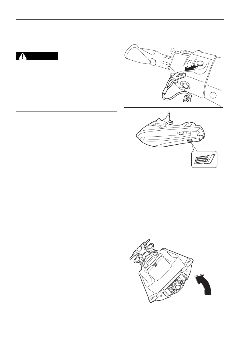
Trouble recovery
99
EJU34625
Emergency procedures
EJU34635
Cleaning the jet intake and impeller
WARNING
EWJ00783
Before attempting to remove weeds or de-
bris from the jet intake or impeller area,
shut the engine off and remove the clip
from the engine shut-off switch. Severe in-
jury or death could result from coming in
contact with the rotating parts of the jet
pump.
If weeds or debris gets caught in the jet intake
or impeller, cavitation can occur, causing jet
thrust to decrease even though engine speed
rises. If this condition is allowed to continue,
the engine will overheat and may seize.
NOTICE: If weeds or debris gets caught in
the jet intake, do not operate the water-
craft above trolling speed until they have
been removed.
[ECJ00654]
If there is any sign that the jet intake or impel-
ler is clogged with weeds or debris, return to
shore and check the intake and impeller. Al-
ways stop the engine before beaching the
watercraft.
(1) Place a suitable clean cloth or carpeting
underneath the watercraft to protect it
from abrasions and scratches. Turn the
watercraft on its side as shown.
NOTICE: Always turn the watercraft
over onto its port (left) side. When
turning the watercraft on its side, sup-
port the bow so that the handlebars
are not bent or damaged.
[ECJ00662]
UF2W10E0.book Page 99 Tuesday, December 1, 2015 3:25 PM
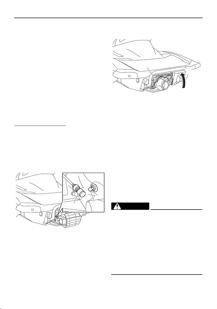
Trouble recovery
100
(2) Remove any weeds or debris from
around the jet intake, drive shaft, impel-
ler, jet pump housing, and jet thrust noz-
zle.
If debris is difficult to remove, consult a
Yamaha dealer.
EJU43471
Raising the reverse gate
If the RiDE system malfunctions and the re-
verse gate remains in the lowered position,
the watercraft will not be able to move for-
ward.
After raising the reverse gate so that the wa-
tercraft can move forward, immediately re-
turn to shore and have a Yamaha dealer
service the watercraft.
To raise the reverse gate:
(1) Stop the engine and remove the clip from
the engine shut-off switch.
(2) Enter the water and move to the rear of
the watercraft.
(3) Slide the shift rod joint toward the bow,
and then disconnect the shift rod joint
from the ball joint.
(4) Raise the reverse gate to the forward po-
sition.
TIP:
While the shift rod is disconnected, the re-
verse gate will not move to the neutral po-
sition or reverse position even if the RiDE
lever is squeezed.
If the RiDE lever is squeezed while the shift
rod is disconnected, the watercraft will
move forward.
EJU34642
Jumping the battery
If the watercraft battery has run down, the en-
gine can be started using a 12-volt booster
battery and jumper cables.
EJU34664
Connecting the jumper cables
WARNING
EWJ01251
To avoid battery explosion and serious
damage to the electrical system:
Do not reverse the polarity of the jumper
cables when connecting to the batter-
ies.
Do not connect the negative (–) jumper
cable to the negative (–) terminal of the
watercraft battery.
Do not touch the positive (+) jumper ca-
ble to the negative (–) jumper cable.
1 Shift rod joint
2 Ball joint
1
2
1 Reverse gate
2 Forward position
1
2
UF2W10E0.book Page 100 Tuesday, December 1, 2015 3:25 PM
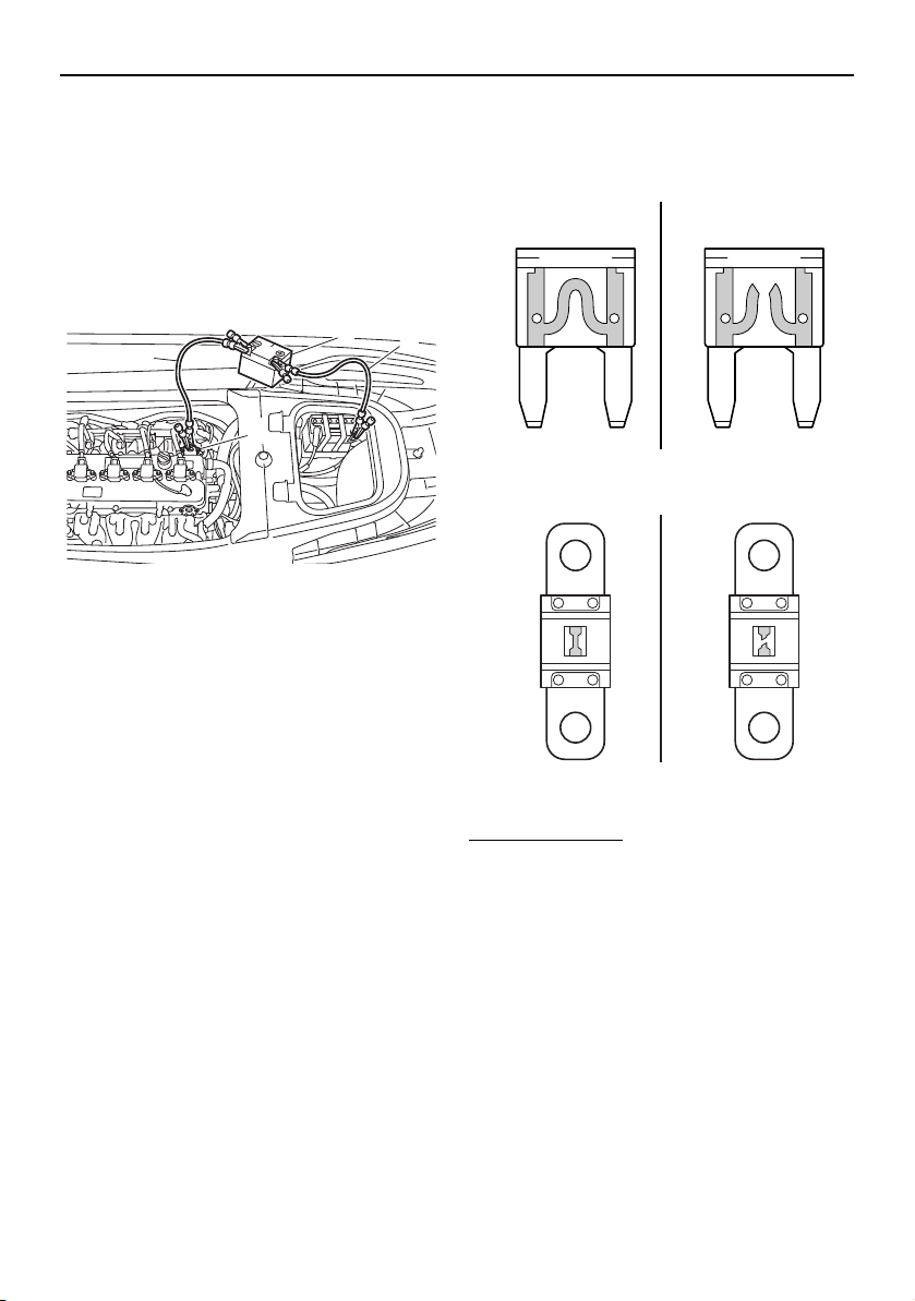
Trouble recovery
101
(1) Connect the positive (+) jumper cable to
the positive (+) battery terminals of both
batteries.
(2) Connect one end of the negative (–)
jumper cable to the negative (–) battery
terminal of the booster battery.
(3) Connect the other end of the negative (–)
jumper cable to an engine hanger.
(4) Start the engine, and then disconnect the
jumper cables by reversing the steps
above. (See page 33 for information on
starting the engine.)
EJU44050
Replacing the fuses
If a fuse is blown, replace it with the proper
fuse.
To replace a fuse:
(1) Remove the seats and removable water-
tight storage compartment. (See page 49
for seat removal and installation proce-
dures and page 54 for information on the
removable watertight storage compart-
ment.)
1 Positive (+) jumper cable
2 Booster battery
3 Negative (–) jumper cable
4 Engine hanger
3
4
2
1
1 Good fuse
2 Blown fuse
1 Good fuse
2 Blown fuse
21
21
UF2W10E0.book Page 101 Tuesday, December 1, 2015 3:25 PM
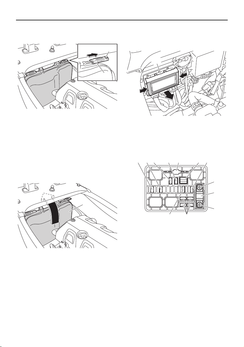
Trouble recovery
102
(2) While pushing the projection on each
lock, slide the locks outward.
(3) Remove the electrical box cover from the
electrical box and move it under the deck
beam toward the stern. NOTICE: Do not
attempt to forcefully remove the elec-
trical box cover from the watercraft.
Otherwise, the electrical box cover,
electrical system, and engine could be
damaged.
[ECJ02610]
(4) While pushing both sides of the fuse box
cover inward, pull the cover toward the
bow and remove it.
(5) When replacing the SCU fuse, remove
the screws, and then remove the fuse.
Install the spare fuse, and then tighten
the screws.
(6) When replacing a fuse other than the
SCU fuse, remove the fuse using the
fuse puller. Install a spare fuse of the
proper amperage. WARNING! Do not
1 Lock
2 Projection
1 Electrical box cover
1
2
1
1 Fuse box cover
1 Electronic throttle valve fuse
2 Fuel pump fuse
3 Main relay drive fuse
4 Main fuse
5 Spare fuse
6 Fuse puller
7 Battery fuse
8 Screw
9 SCU fuse (BCU fuse)
10 Security system fuse
1
1
5
23 4 5 6 7
8
9
8
10
UF2W10E0.book Page 102 Tuesday, December 1, 2015 3:25 PM
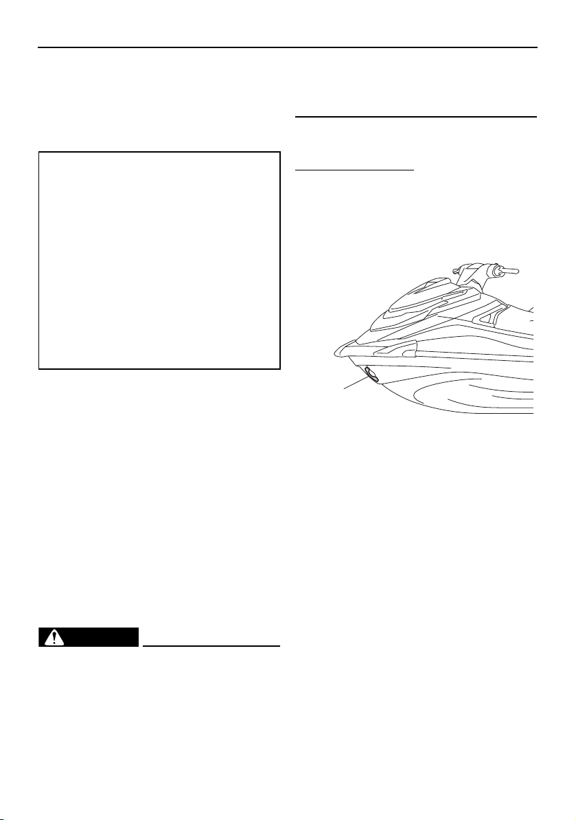
Trouble recovery
103
use fuses of a different amperage than
recommended. Substitution with a
fuse that has an improper rating can
cause extensive electrical system
damage and possible fire.
[EWJ00803]
(7) Securely install the fuse box cover in its
original position.
(8) Securely install the electrical box cover in
its original position.
(9) Slide the locks to their original positions
to securely lock the electrical box cover
in place.
(10) Securely install the removable watertight
storage compartment and seats in their
original positions.
If the fuse immediately blows again, the elec-
trical system may be defective. If this occurs,
have a Yamaha dealer service the watercraft.
EJU34716
Towing the watercraft
WARNING
EWJ00812
The operator of the towing boat must
keep speed to a minimum and avoid
traffic or obstacles which could be a
hazard to the operator on the water-
craft.
The towline should be long enough so
that the watercraft will not collide with
the towing boat when slowing down.
If the watercraft becomes inoperative in the
water, it can be towed to shore.
To tow the watercraft:
Use a towline that is three times the com-
bined length of the towing boat and the wa-
tercraft.
(1) Securely attach the towline to the bow
eye of the watercraft being towed.
(2) Sit astride the seat and hold on to the
handlebars in order to balance the water-
craft. NOTICE: The bow must be kept
up out of the water during towing, oth-
erwise water could flood the engine
compartment or water could flow
back into the engine, causing severe
engine damage.
[ECJ01331]
Tow the watercraft at 8 km/h (5 mph) or less.
NOTICE: Tow the watercraft at 8 km/h (5
mph) or less, otherwise water could flood
the engine compartment or water could
flow back into the engine, causing severe
engine damage.
[ECJ01322]
EJU36156
Submerged watercraft
If the watercraft is submerged or flooded with
water, drain the bilge water from the engine
Fuse amperage:
Electronic throttle valve fuse:
10 A
Fuel pump fuse:
10 A
Main relay drive fuse:
10 A
Main fuse:
20 A
Battery fuse:
30 A
SCU fuse:
50 A
Security system fuse:
3 A
1 Bow eye
1
UF2W10E0.book Page 103 Tuesday, December 1, 2015 3:25 PM

Trouble recovery
104
compartment. Then, have a Yamaha dealer
service the watercraft as soon as possible.
If the watercraft was submerged:
(1) Remove the watercraft from the water
and drain the water from the storage
compartments. (See page 52 for infor-
mation on draining the storage compart-
ments.)
(2) Drain the bilge water from the engine
compartment. (See page 60 for informa-
tion on draining the bilge water.)
(3) Have the watercraft serviced by a
Yamaha dealer as soon as possible.
NOTICE: Be sure to have a Yamaha
dealer inspect the watercraft. Other-
wise, serious engine damage could
result.
[ECJ00792]
UF2W10E0.book Page 104 Tuesday, December 1, 2015 3:25 PM

Consumer information
105
EJU34784
Limited warranty
YAMAHA MOTOR CORPORATION, U.S.A.
WAVERUNNER
®
WATERCRAFT LIMITED WARRANTY
Yamaha Motor Corporation, U.S.A. hereby warrants that new Yamaha WaveRunner watercraft purchased from an authorized Yamaha
WaveRunner Watercraft Dealer in the United States (excluding its territories) will be free from defects in material and workmanship for
the period of time stated herein, subject to certain stated limitations.
PERIOD OF WARRANTY. Any new Yamaha WaveRunner watercraft purchased for pleasure use will be warranted for a period of one
(1) year from the date of purchase, subject to exclusions noted herein. Any Yamaha WaveRunner watercraft purchased and utilized for
commercial applications will be warranted for a period of ninety (90) days from the date of purchase, subject to exclusions noted herein.
The battery will be warranted against defects in material or workmanship for thirty (30) days from the date of vehicle purchase for either
pleasure or commercial use. Replacement parts used in warranty repairs will be warranted for the balance of the applicable warranty
period.
OBTAINING REPAIRS UNDER WARRANTY. During the period of warranty, any authorized Yamaha WaveRunner Watercraft Dealer
will, free of charge, repair or replace, at Yamaha’s option, any part adjudged defective by Yamaha due to faulty workmanship or material
from the factory. All parts replaced under warranty will become the property of Yamaha Motor Corporation, U.S.A.
THE CUSTOMER’S RESPONSIBILITY under this warranty shall be to:
1. Operate, maintain, and store the WaveRunner watercraft as specified in the appropriate Owner’s/Operator’s Manual, and
2. Give notice to an authorized Yamaha WaveRunner watercraft dealer of any and all apparent defects within ten (10) days after
discovery, and make the machine available at that time for inspection and repairs at such dealer’s place of business.
GENERAL EXCLUSIONS from this warranty shall include any failures caused by:
a. Racing or competition use, modification of original parts, abnormal strain.
b. Lack of proper maintenance and off-season storage as described in the Owner’s/Operator’s Manual.
c. Installation of parts or accessories that are not equivalent in design and quality to genuine Yamaha parts.
d. Use of lubricants, oils, and fuels that are not suitable for WaveRunner watercraft use.
e. Damage as a result of accidents, collisions, contact with foreign materials, or submersion.
f. Growth of marine organism on motor or hull surfaces.
g. Normal deterioration.
h. Gel coat stress cracks
i. Damage due to improper transportation.
SPECIFIC PARTS EXCLUDED FROM WARRANTY. Parts replaced due to normal wear or routine maintenance such as oil, spark
plugs, fuel filters, impeller and liner, and anodes are not covered by warranty. Charges for transporting the WaveRunner watercraft to
and from an authorized Yamaha WaveRunner Watercraft Dealer are excluded from warranty coverage.
EMISSION CONTROL WARRANTY.
Yamaha warrants to the ultimate purchaser and any subsequent owner, that the exhaust emission control components on this engine
are designed, built and equipped so as to conform at the time of sale with applicable regulations under section 213 of the Clean Air Act
and that this engine is free from defects in materials and workmanship which cause said engine to fail to conform with applicable
regulations for 30 months from the date of purchase or 175 hours of operation, whichever comes first. For evaporative emission
components, for a failure that will increase evaporative emissions, the warranty coverage is 2 years from the date of purchase. Some
states may have different emission control warranty provisions. As these vary from state to state, consult your Yamaha dealer or contact
Yamaha Customer Relations at 1-800-962-7926 for more information.
WARRANTY TRANSFER: To transfer the warranty from the original purchaser to any subsequent purchaser(s), it is imperative that the
WaveRunner watercraft be inspected and registered for warranty by an authorized Yamaha WaveRunner watercraft dealer. In order for
this warranty to remain in effect, this inspection and registration must take place within ten (10) days after transfer of ownership to the
subsequent purchaser. A reasonable dealer-imposed fee may be charged for this inspection.
YAMAHA MOTOR CORPORATION, U.S.A. MAKES NO OTHER WARRANTY OF ANY KIND, EXPRESSED OR IMPLIED. ALL
IMPLIED WARRANTIES OF MERCHANTABILITY AND FITNESS FOR A PARTICULAR PURPOSE WHICH EXCEED THE
OBLIGATIONS AND TIME LIMITS STATED IN THIS WARRANTY ARE HEREBY DISCLAIMED BY YAMAHA MOTOR
CORPORATION, U.S.A. AND EXCLUDED FROM THIS WARRANTY.
SOME STATES DO NOT ALLOW LIMITATIONS ON HOW LONG AN IMPLIED WARRANTY LASTS, SO THE ABOVE LIMITATIONS
MAY NOT APPLY TO YOU. ALSO EXCLUDED FROM THIS WARRANTY ARE ANY INCIDENTAL OR CONSEQUENTIAL DAMAGES
INCLUDING LOSS OF USE. SOME STATES DO NOT ALLOW THE EXCLUSION OR LIMITATION OF INCIDENTAL OR
CONSEQUENTIAL DAMAGES, SO THE ABOVE EXCLUSION MAY NOT APPLY TO YOU.
UF2W10E0.book Page 105 Tuesday, December 1, 2015 3:25 PM

Consumer information
106
THIS WARRANTY GIVES YOU SPECIFIC LEGAL RIGHTS, AND YOU MAY ALSO HAVE OTHER RIGHTS WHICH VARY FROM STATE TO
STATE.
YAMAHA MOTOR CORPORATION, U.S.A.
Post Office Box 6555
Cypress, California 90630
WARRANTY QUESTIONS AND ANSWERS
Q. What costs are my responsibility during the warranty period?
A. The customer’s responsibility includes all costs of normal maintenance services, non-warranty repairs, accident and collision dam-
ages.
Q. What are some examples of “abnormal” strain, neglect, or abuse?
A. These terms are general and overlap each other in areas. Specific examples include:
Running the watercraft out of oil, operating the machine with a broken or damaged part which causes another part to fail, and so
on. If you have any specific questions on operation or maintenance, please contact your Yamaha dealer for advice.
Q. Does the warranty cover incidental costs such as transportation due to a failure?
A. No. The warranty is limited to repair of the watercraft itself.
Q. May I perform any or all of the recommended maintenance shown in the Owner’s/Operator’s Manual instead of having the dealer do
them?
A. Yes, if you are a qualified mechanic and follow the procedures specified in the Owner’s/Operator’s and Service Manual. We do rec-
ommend, however, that items requiring special or equipment be done by a Yamaha dealer.
Q. Will the warranty be void or cancelled if I do not operate or maintain my new watercraft exactly as specified in the Owner’s/Opera-
tor’s Manual?
A. No. The warranty on a new watercraft cannot be “voided” or “cancelled”.
However, if a particular failure is caused by operation
or maintenance other than as shown in the Owner’s/Operator’s
Manual, that failure may not be covered under warranty.
Q. What responsibility does my dealer have under this warranty?
A. Each Yamaha dealer is expected to:
1. Completely set up each new watercraft before sale.
2. Explain the operation, maintenance, and warranty requirements to your satisfaction at the time of sale, and upon your request at
any later date. In addition, each Yamaha dealer is held responsible for his setup, service and warranty repair work.
Q. Is the warranty transferable to second owners?
A. Yes. The remainder of the existing warranty can be transferred upon request. The unit has to be inspected and re-registered by an
authorized Yamaha dealer for the policy to remain effective.
CUSTOMER SERVICE
If your watercraft requires warranty service, you must take it to any authorized Yamaha dealer within the continental United States. Be
sure to bring your warranty registration card or other valid proof of the original date of purchase. If a question or problem arises regard-
ing warranty, first contact the owner of the dealership. Since all warranty matters are handled at the dealer level, this person is in the
best position to help you. If you are still not satisfied and require additional assistance, please write:
YAMAHA MOTOR CORPORATION U.S.A.
CUSTOMER RELATIONS DEPARTMENT
P.O. Box 6555
Cypress, California 90630
CHANGE OF ADDRESS
The federal government requires each manufacturer to maintain a complete, up-to-date list of all first purchasers against the possibility
of a safety-related defect and recall. This list is complied from the purchase registrations sent to Yamaha Motor Corporation, U.S.A. by
the selling dealer at the time of your purchase.
If you should move after you have purchased your new watercraft, please advise us of your new address by sending a postcard listing
your Yamaha model name, engine number, dealer number [or dealer’s name] as it is shown on your warranty card, your name and new
mailing address.
Mail to:
YAMAHA MOTOR CORPORATION, U.S.A.
P.O. Box 6555
Cypress, California 90630
Attention: Warranty Department
This will ensure that Yamaha Motor Corporation, U.S.A. has an up-to-date registration record in accordance with federal law.
UF2W10E0.book Page 106 Tuesday, December 1, 2015 3:25 PM

Consumer information
107
EJU34802
YAMAHA EXTENDED SERVICE (Y.E.S.)
Keep your Yamaha protected even after your warranty expires with genuine Yamaha Extended
Service (Y.E.S.).
•
Y.E.S. is designed and administered by Yamaha Motor Corporation to provide maximum owner
satisfaction. You get uninterrupted factory-backed coverage for extra peace of mind.
•
Y.E.S. is flexible. You choose the plan that is right for you: 12 months, 24 months, 36 months, or
(on four-stroke models) 48 months beyond your warranty period.
•
Y.E.S. is designed and administered by the same Yamaha people who handle your warranty—
and it shows in the comprehensive coverage benefits. There are no mileage limitations. Cover-
age is not limited to “moving parts” or the “drive train” like many other plans. And Y.E.S. covers
manufacturing defects just like the warranty. See the sample contract at your Yamaha dealer to
see how comforting uninterrupted factory-backed protection can be.
•
You do not have to pay anything for covered repairs. There is no deductible to pay, and repairs
are not “pro-rated.” You do not have any “out-of-pocket” expenses for covered repairs.
•
In addition, Travel and Recreation Interruption Protection (TRIP) is included at no extra cost.
TRIP gives you up to $250 reimbursement per occurrence for any reasonable expenses you
incur because your Yamaha needs covered service: replacement vehicle rental, emergency
towing, phone calls, even food and lodging when you are away from home. This superb cover-
age goes into effect when you purchase Y.E.S., so it applies to any warranty repairs as well as
covered repairs during your entire Y.E.S. plan period.
•
Y.E.S. coverage is honored at any authorized Yamaha dealer nationwide.
•
Y.E.S. coverage is transferable to a new owner if you sell or trade-in. That can make your
Yamaha much more valuable!
This excellent Y.E.S. plan coverage is only available to Yamaha owners like you, and only while
your Yamaha is still within the Yamaha Limited Warranty period. So visit your authorized Yamaha
dealer to get all the facts. He can show you how easy it is to protect your investment with Yamaha
Extended Service.
We urge you to act now. You will get the excellent benefits of TRIP coverage right away, and you
will rest easy knowing you will have strong factory-backed protection even after your Yamaha
Limited Warranty expires.
A special note:
If visiting your dealer is not convenient, contact Yamaha with your Primary ID number (your Owner’s
Manual shows you where to find this number). We will be happy to help you get the Y.E.S. coverage
you need.
Yamaha Service Marketing
P.O. Box 6555
Cypress, CA 90630
1-(866)-YES-EXTD
(1-866-937-3983)
UF2W10E0.book Page 107 Tuesday, December 1, 2015 3:25 PM

108
Index
A
After removing the watercraft from the
water..................................................... 84
Approval label of emission control
certificate ................................................ 2
B
Battery care.............................................. 87
Battery checks ......................................... 66
Battery, jumping..................................... 100
Beaching and docking the watercraft...... 84
Bilge water check..................................... 66
Bilge water, draining ................................ 60
Bilge water, draining on land ................... 60
Bilge water, draining on water ................. 60
Boarding alone......................................... 80
Boarding and starting off from a dock..... 83
Boarding the watercraft ........................... 80
Boarding with passenger(s) ..................... 81
Bow eye ................................................... 51
Bow storage compartment ...................... 52
C
Capsized watercraft................................. 83
Check engine warning ............................. 47
Cleaning ................................................... 90
Cleaning the watercraft............................ 87
Cleat......................................................... 51
Cooling water pilot outlet......................... 35
Cooling water pilot outlet check .............. 71
Cruising limitations................................... 11
E
Electric trim system.................................. 39
Emergency procedures............................ 99
Emission control information ..................... 2
Engine break-in........................................ 62
Engine compartment check..................... 65
Engine cover, removing and installing ..... 91
Engine idling speed check ....................... 73
Engine oil ................................................. 58
Engine oil and oil filter.............................. 94
Engine oil level check............................... 66
Engine oil requirements ........................... 58
Engine overheat warning ......................... 47
Engine serial number ................................. 1
Engine shut-off cord (lanyard) check ....... 68
Engine shut-off switch ............................. 33
Engine stop switch................................... 33
Engine unit check..................................... 66
Enjoy your watercraft responsibly............ 24
Equipment................................................ 49
F
Fire extinguisher check ............................ 70
Fire extinguisher holder and cover........... 54
Fire extinguisher holder, cover, and
band checks ......................................... 69
Flushing the cooling water passages....... 86
Fuel .......................................................... 56
Fuel level check........................................ 65
Fuel level meter ........................................ 46
Fuel level warning..................................... 46
Fuel requirements .................................... 56
Fuel system checks ................................. 65
Fuses, replacing ..................................... 101
G
Getting to know your watercraft .............. 74
Glossary, watercraft ................................. 26
Glove compartment ................................. 53
H
Handgrip .................................................. 50
Hazard information................................... 16
Hood check.............................................. 71
Hour meter ............................................... 47
Hull and deck check ................................ 70
Hull Identification Number (HIN)................. 1
I
Identification numbers ............................... 1
Information display................................... 43
J
Jet intake and impeller, cleaning.............. 99
Jet intake checks ..................................... 70
Jet thrust nozzle and reverse gate
check .................................................... 70
Jumper cables, connecting.................... 100
L
Labels, important ....................................... 5
Labels, other .............................................. 8
Labels, warning .......................................... 6
Launching the watercraft ......................... 75
Learning to operate your watercraft......... 74
Leaving the watercraft.............................. 76
UF2W10E0.book Page 108 Tuesday, December 1, 2015 3:25 PM

Index
109
Limitations on who may operate the
watercraft.............................................. 10
Limited warranty .................................... 105
Long-term storage ................................... 90
Low RPM Mode ....................................... 41
Lubrication ............................................... 90
M
Main components, location of ................. 27
Maintenance ............................................ 91
Manufactured date label ............................ 2
Multifunction information center .............. 43
Multifunction information center check ... 71
O
Oil pressure warning ................................ 46
Operating in weeded areas...................... 84
Operating the watercraft .......................... 76
Operating the watercraft in reverse or
neutral................................................... 79
Operating your watercraft ........................ 74
Operation requirements ........................... 13
P
Periodic maintenance chart ..................... 93
Post-launch checks ................................. 71
Post-operation care ................................. 86
Pre-launch checks ................................... 65
Pre-operation check points ..................... 65
Pre-operation checklist............................ 63
Primary Identification (PRI-ID) number ...... 1
R
Raising the reverse gate ........................ 100
Reboarding step (VXR)............................. 50
Recommended equipment ...................... 15
Remote control transmitter ...................... 31
Remote control transmitter check ........... 68
RiDE lever................................................. 34
RiDE lever checks .................................... 68
Riding position ......................................... 75
Rules of the Road .................................... 19
Rustproofing ............................................ 90
S
Safety equipment check .......................... 70
Seats ........................................................ 49
Shift indicator........................................... 45
Shift system ............................................. 37
Shift system check................................... 72
Speedometer ........................................... 43
Star labels .................................................. 3
Start switch .............................................. 33
Starting off ............................................... 82
Starting off from a trailer .......................... 83
Starting the engine on water.................... 75
Steering system ....................................... 35
Steering system checks........................... 67
Stern drain plug checks ........................... 70
Stern eyes ................................................ 51
Stopping the engine................................. 76
Stopping the watercraft ........................... 78
Storage compartment checks.................. 69
Storage compartments ............................ 52
Submerged watercraft ........................... 103
Switch checks.......................................... 69
T
Tachometer .............................................. 44
Throttle lever ............................................ 34
Throttle lever checks................................ 68
To get more boating safety information... 23
Tool kit ..................................................... 91
Towing the watercraft ............................ 103
Transporting on a trailer........................... 61
Trim indicator ........................................... 45
Trim indicator check ................................ 72
Troubleshooting ....................................... 96
Troubleshooting chart .............................. 96
Turning the watercraft.............................. 77
V
Voltmeter.................................................. 48
W
Wakeboarding and water-skiing .............. 18
Water separator ....................................... 35
Water separator check............................. 65
Watercraft characteristics ........................ 16
Watercraft control functions..................... 31
Watercraft operation functions ................ 37
Watercraft operation modes .................... 41
Watertight storage compartment............. 54
Y
YAMAHA EXTENDED SERVICE
(Y.E.S.) ................................................ 107
Yamaha Security System......................... 32
Yamaha Security System settings ........... 32
UF2W10E0.book Page 109 Tuesday, December 1, 2015 3:25 PM

EJU42011
For your best ownership experience, think Genuine Yamaha!
Genuine Yamaha Parts – Genuine Yamaha replacement parts are the exact same
parts as the ones originally equipped on your vehicle, providing you with the
performance and durability you have come to expect. Why settle for aftermarket parts
that may not provide full confidence and satisfaction?
Genuine Yamaha Accessories – Yamaha only offers accessories that meet our
high standards for quality and performance. Buy with confidence, knowing your
Genuine Yamaha Accessories will fit right and perform right – right out of the box.
Yamalube – Take care of your Yamaha with legendary Yamalube oils, lubricants,
and care products. They’re formulated and approved by the toughest judges we
know: the Yamaha engineering teams that know your Yamaha from the inside out.
Genuine Yamaha Service Manuals – Get the same factory manual for your vehicle
that the technicians at your authorized Yamaha dealer use. Service manuals are
available through your Yamaha dealer or you can order them directly through
yamahapubs.com.
Genuine Yamaha products are available only from your Yamaha dealer.
Find out more at yamaha-motor.com
UF2W10E0.book Page 1 Tuesday, December 1, 2015 3:25 PM

DIC183
Printed in U.S.A.
December 2014–1.1 × 2 CR