
16VM-926-AA
.
RAM ProMaster city
.
Third Edition REV 2
.
User Guide
DOWNLOAD A FR ELECTRONIC COPY
OF THE OWNER’S MANUAL AND WARRANTY BOOKLET BY VISITING:
WWW.RAMTRUCKS.COM/EN/OWNERS/MANUALS/ OR WWW.RAMTRUCKS.COM/EN/WARRANTY/ (U.S.);
WWW.OWNERS.MOPAR.CA/EN (CANADA).
©
2016 FCA US LLC. ALL RIGHTS RESERVED. RAM IS A REGISTERED TRADEMARK OF FCA US LLC.

The driver’s primary responsibility is the safe operation of the vehicle. Driving
while distracted can result in loss of vehicle control, resulting in a collision and
personal injury. FCA US LLC strongly recommends that the driver use extreme
caution when using any device or feature that may take their attention off the
road. Use of any electrical devices, such as cellular telephones, computers,
portable radios, vehicle navigation or other devices, by the driver while the
vehicle is moving is dangerous and could lead to a serious collision. Texting
while driving is also dangerous and should never be done while the vehicle is
moving. If you nd yourself unable to devote your full attention to vehicle
operation, pull off the road to a safe location and stop your vehicle. Some
states or provinces prohibit the use of cellular telephones or texting while
driving. It is always the driver’s responsibility to comply with all local laws.
If you are the rst registered retail owner of your vehicle, you may obtain a
complimentary printed copy of the Owner’s Manual, Navigation/Uconnect
Manuals or Warranty Booklet by calling 1-866-726-4636 (U.S.) or
1-800-387-1143 (Canada) or by contacting your dealer.
This guide has been prepared to help you get quickly acquainted with your new
Ram vehicle and to provide a convenient reference source for common questions.
However
, it is not a substitute for your Owner’s Manual.
For complete operational instructions, maintenance procedures and important
safety messages, please consult your Owner’s Manual, Navigation/Uconnect
Manuals and other Warning Labels in your vehicle.
Not all features shown in this guide may apply to your vehicle. For additional
information on accessories to help personalize your vehicle, visit
www.mopar.com (U.S.), www.mopar.ca (Canada) or your local Ram brand dealer.
DRIVING AND ALCOHOL
Drunken driving is one of the most frequent causes of collisions. Your
driving ability can be seriously impaired with blood alcohol levels far below
the legal minimum. If you are drinking, don’t drive. Ride with a designated
non-drinking driver, call a cab, a friend, or use public transportation.
WARNING
Driving after drinking can lead to a collision. Your perceptions are less
sharp, your reexes are slower, and your judgment is impaired when you
have been drinking. Never drink and then drive.
RAM
2016 User Guide
RAM
2016 User Guide
IMPORTANT
This User Guide is intended to familiarize you with the important features of your
vehicle. The DVD enclosed contains your Owner’s Manual, Navigation/Uconnect
Manuals, Warranty Booklets, Tire Warranty and Roadside Assistance (new vehicles
purchased in the U.S.) or Roadside Assistance (new vehicles purchased in Canada)
in electronic format. We hope you nd it useful. U.S. residents can purchase
replacement DVD kits by visiting www.techauthority.com and Canadian residents
can purchase replacement DVD kits by calling 1-800-387-1143.

INTRODUCTION/WELCOME
WELCOME FROM FCA US LLC .......2
CONTROLS AT A GLANCE
DRIVER COCKPIT ..............4
INSTRUMENT CLUSTER ..........6
GETTING STARTED
KEYFOB ....................8
OCCUPANT RESTRAINT SYSTEMS ....9
HEAD RESTRAINTS .............20
FRONT SEATS ................22
60/40 SPLIT SECOND-ROW PASSENGER
SEATS .....................24
HEATEDSEATS ...............26
TILT/TELESCOPING STEERING
COLUMN ...................27
OPERATING YOUR VEHICLE
ENGINE BREAK-IN
RECOMMENDATIONS ............28
MANUAL CLIMATE CONTROLS ......29
MULTIFUNCTION LEVER .........30
WINDSHIELD WIPERS AND
WASHERS .................. 32
INTERIOR LIGHTS .............34
ELECTRONIC SPEED CONTROL .....35
PARKSENSE REAR PARK ASSIST ....38
PARKVIEW REAR BACK-UP CAMERA . . 39
ELECTRONICS
YOUR VEHICLE'S SOUND SYSTEM . . . 40
CYBERSECURITY ..............42
IDENTIFYING YOUR RADIO ........43
UCONNECT 3.0 ...............44
UCONNECT 5.0/5.0N ............46
UCONNECT PHONE ............58
STEERING WHEEL AUDIO CONTROLS . 67
ELECTRONIC VEHICLE INFORMATION
CENTER (EVIC) ...............68
PROGRAMMABLE FEATURES .......68
POWER OUTLETS ..............69
UTILITY
REAR CARGO TIE-DOWNS .........72
TRAILER TOWING WEIGHTS (MAXIMUM
TRAILER WEIGHT RATINGS) .......73
RECREATIONAL TOWING (BEHIND
MOTORHOME, ETC.) ............73
WHAT TO DO IN EMERGENCIES
ROADSIDE ASSISTANCE ..........74
WARNING AND INDICATOR LIGHTS . . . 74
IF YOUR ENGINE OVERHEATS ......81
JACKING AND TIRE CHANGING .....82
TIRESERVICEKIT .............92
JUMP-STARTING PROCEDURES .....95
TOWING A DISABLED VEHICLE .....97
FREEING A STUCK VEHICLE ....... 98
GEAR SELECTOR OVERRIDE .......99
IGNITION KEY REMOVAL OVERRIDE . 100
ENHANCED ACCIDENT RESPONSE SYSTEM
(EARS) ....................100
EVENT DATA RECORDER (EDR) ....100
MAINTAINING YOUR VEHICLE
OPENING THE HOOD ..........101
ENGINE COMPARTMENT — 2.4L . . . 102
FLUID CAPACITIES ............104
FLUIDS, LUBRICANTS, AND GENUINE
PARTS .................... 104
MAINTENANCE PROCEDURES .....106
MAINTENANCE SCHEDULE .......106
FUSES ...................111
TIRES — GENERAL INFORMATION . . 113
REPLACEMENT BULBS .........117
CUSTOMER ASSISTANCE
FCA US LLC CUSTOMER CENTER . . . 118
FCA CANADA INC. CUSTOMER
CENTER ..................118
ASSISTANCE FOR THE HEARING
IMPAIRED .................118
PUBLICATIONS ORDERING .......119
REPORTING SAFETY DEFECTS IN THE
UNITEDSTATES ..............120
MOPAR® ACCESSORIES
AUTHENTIC ACCESSORIES BY
MOPAR ...................121
FREQUENTLY ASKED QUESTIONS
FREQUENTLY ASKED QUESTIONS . . . 122
INDEX
...................123
TABLE OF CONTENTS

WELCOME FROM FCA US LLC
Congratulations on selecting your new FCA US LLC (“FCA US”) vehicle. Be assured
that it represents precision workmanship, distinctive styling, and high quality - all
essentials that are traditional to our vehicles.
Your new FCA US vehicle has characteristics to enhance the driver's control under
some driving conditions. These are to assist the driver and are never a substitute for
attentive driving. They can never take the driver's place. Always drive carefully.
Your new vehicle has many features for the comfort and convenience of you and your
passengers. Some of these should not be used when driving because they take your
eyes from the road or your attention from driving. Never text while driving or take your
eyes more than momentarily off the road.
This guide illustrates and describes the operation of features and equipment that are
either standard or optional on this vehicle. This guide may also include a description
of features and equipment that are no longer available or were not ordered on this
vehicle. Please disregard any features and equipment described in this guide that are
not available on this vehicle. FCA US reserves the right to make changes in design
and specifications and/or make additions to or improvements to its products without
imposing any obligation upon itself to install them on products previously manufac-
tured.
This User Guide has been prepared to help you quickly become acquainted with the
important features of your vehicle. It contains most things you will need to operate
and maintain the vehicle, including emergency information.
The DVD includes a computer application containing detailed owner's information
which can be viewed on a personal computer or MAC computer. The multimedia DVD
also includes videos which can be played on any standard DVD player (including the
Uconnect Touchscreen Radios if equipped with DVD player capabilities). Additional
DVD operational information is located on the back of the DVD sleeve.
For complete owner information, refer to your Owner's Manual on the DVD in the owner’s
kit provided at the time of new vehicle purchase. For your convenience, the information
contained on the DVD may also be printed and saved for future reference.
FCA US is committed to protecting our environment and natural resources. By
converting from paper to electronic delivery for the majority of the user information
for your vehicle, together we greatly reduce the demand for tree-based products and
lessen the stress on our environment.
INTRODUCTION/WELCOME
2

VEHICLES SOLD IN CANADA
With respect to any vehicles sold in Canada, the name FCA US LLC shall be deemed
to be deleted and the name FCA Canada Inc. used in substitution (excluding legal
lines).
WARNING!
• Pedals that cannot move freely can cause loss of vehicle control and increase
the risk of serious personal injury.
• Always make sure that objects cannot fall into the driver foot well while the
vehicle is moving. Objects can become trapped under the brake pedal and
accelerator pedal causing a loss of vehicle control.
• Failure to properly follow floor mat installation or mounting can cause interfer-
ence with the brake pedal and accelerator pedal operation causing loss of
control of the vehicle.
• Never leave children alone in a vehicle, or with access to an unlocked vehicle.
Allowing children to be in a vehicle unattended is dangerous for a number of
reasons. A child or others could be seriously or fatally injured. Children should
be warned not to touch the parking brake, brake pedal or the transmission gear
selector.
• Do not leave the key fob in or near the vehicle, or in a location accessible to
children. A child could operate power windows, other controls, or move the
vehicle.
• Never use the ‘PARK’ position as a substitute for the parking brake. Always
apply the parking brake fully when parked to guard against vehicle movement
and possible injury or damage.
• Refer to your Owner's Manual on the DVD for further details.
USE OF AFTERMARKET PRODUCTS (ELECTRONICS)
The use of aftermarket devices including cell phones, MP3 players, GPS systems, or
chargers may affect the performance of on-board wireless features. If you are
experiencing difficulties with any of your wireless features, try disconnecting your
aftermarket devices to see if the situation improves. If your symptoms persist, please
see an authorized dealer.
When it comes to service, remember that your authorized dealer knows your vehicle
best, has factory-trained technicians and genuine MOPAR
®
parts, and cares about
your satisfaction.
INTRODUCTION/WELCOME
3

DRIVER COCKPIT
1. Manual Mirrors
2. Uconnect Phone Controls
3. Headlight Switch pg. 30
4. Instrument Cluster/Electronic Vehicle Information Center (EVIC) Display pg. 68
5. Speed Control pg. 35
6. Wiper/Washer pg. 32
7. Ignition Switch
8. EVIC Controls
9. Audio System (Touchscreen Radio Shown) pg. 40
CONTROLS AT A GLANCE
4

10. Switch Panel
• Front Fog Lights
• Electronic Stability Control (ESC) OFF pg. 80
• Hazard Warning Switch
• Defroster
11. Storage
12. Glove Compartment
13. Climate Controls pg. 29
14. Gear Selector
15. Gear Selections
16. USB Port (Charging Only) /AUX
17. Hood Release pg. 101
18. Power Window Switch
CONTROLS AT A GLANCE
5


KEY FOB
Locking And Unlocking The
Doors
CARGO Vehicle (Canada)
Push and release the LOCK button once
to lock all the doors.
Push and release the UNLOCK button
once to unlock all doors or only the two
front doors depending on vehicle.
Push and release the CARGO UNLOCK
button once to unlock the cargo area
(side lateral sliding doors and rear doors).
Cargo Vehicle (US) – Passenger Vehicle
(All)
Push and release the LOCK button once
to lock all the doors.
Push and release the UNLOCK button
once to unlock all doors.
Push and release the CARGO UNLOCK button once to unlock the trunk area.
Refer to “A Word About Your Keys” in “Things To Know Before Starting” in your
Owner’s Manual on the DVD for further information.
Key Fob
1 — Unlock
2 — Lock
3 — Cargo Unlock
GETTING STARTED
8

OCCUPANT RESTRAINT SYSTEMS
Some of the most important safety features in your vehicle are the restraint systems:
• Seat Belt Systems
• Supplemental Restraint Systems (SRS) Air Bags
• Child Restraints
SEAT BELT
Lap/Shoulder Belts
All seating positions in your vehicle are equipped with lap/shoulder belts.
Be sure everyone in your vehicle is in a seat and using a seat belt properly.
Position the lap belt so that it is snug and lies low across your hips, below your
abdomen. To remove slack in the lap belt portion, pull up on the shoulder belt. To
loosen the lap belt if it is too tight, tilt the latch plate and pull on the lap belt. A snug
seat belt reduces the risk of sliding under the seat belt in a collision.
Position the shoulder belt across the shoulder and chest with minimal, if any slack so
that it is comfortable and not resting on your neck. The retractor will withdraw any
slack in the shoulder belt.
Seat Belt Pretensioner
The front seat belt system is equipped with pretensioning devices that are designed
to remove slack from the seat belt in the event of a collision.
A deployed pretensioner or a deployed air bag must be replaced immediately.
WARNING!
• In a collision, you and your passengers can suffer much greater injuries if you are
not properly buckled up. You can strike the interior of your vehicle or other
passengers, or you can be thrown out of the vehicle. Always be sure you and
others in your vehicle are buckled up properly.
• A shoulder belt placed behind you will not protect you from injury during a
collision. You are more likely to hit your head in a collision if you do not wear your
shoulder belt. The lap and shoulder belt are meant to be used together.
• A seat belt that is too loose will not protect you properly. In a sudden stop, you
could move too far forward, increasing the possibility of injury. Wear your seat
belt snugly.
• A frayed or torn seat belt could rip apart in a collision and leave you with no
protection. Inspect the seat belt system periodically, checking for cuts, frays, or
loose parts. Damaged parts must be replaced immediately. Do not disassemble
or modify the system. Seat belt assemblies must be replaced after a collision.
GETTING STARTED
9

SUPPLEMENTAL RESTRAINT SYSTEM (SRS) — AIR BAGS
Air Bag System Components
Your vehicle may be equipped with the following air bag system components:
• Occupant Restraint Controller (ORC)
• Air Bag Warning Light
• Steering Wheel and Column
• Instrument Panel
• Knee Impact Bolsters
• Advanced Front Air Bags
• Supplemental Knee Air Bags
• Supplemental Side Air Bags
• Front and Side Impact Sensors
• Seat Belt Pretensioners
• Seat Belt Buckle Switch
Advanced Front Air Bags
This vehicle has Advanced Front Air Bags for both the driver and front passenger as
a supplement to the seat belt restraint systems. The Advanced Front Air Bags will not
deploy in every type of collision.
Advanced Front Air Bags are designed to provide additional protection by supple-
menting the seat belts. Advanced Front Air Bags are not expected to reduce the risk
of injury in rear, side, or rollover collisions.
The Advanced Front Air Bags will not deploy in all frontal collisions, including some
that may produce substantial vehicle damage — for example, some pole collisions,
truck underrides, and angle offset collisions.
On the other hand, depending on the type and location of impact, Advanced Front Air
Bags may deploy in crashes with little vehicle front-end damage but that produce a
severe initial deceleration.
Because air bag sensors measure vehicle deceleration over time, vehicle speed and
damage by themselves are not good indicators of whether or not an air bag should
have deployed.
Seat belts are necessary for your protection in all collisions, and also are needed to
help keep you in position, away from an inflating air bag.
After any collision, the vehicle should be taken to an authorized dealer immediately.
Do not drive your vehicle after the air bags have deployed. If you are involved in
another collision, the air bags will not be in place to protect you.
If it is necessary to modify the air bag system for persons with disabilities, contact
your authorized dealer.
GETTING STARTED
10

Refer to the Owner's Manual on the DVD for further details regarding the Supple-
mental Restraint System (SRS).
Supplemental Knee Air Bags
This vehicle is equipped with a Supplemental Driver Knee Air Bag mounted in the
instrument panel below the steering column. The Supplemental Driver Knee Air Bag
provides enhanced protection during a frontal impact by working together with the
seat belts, pretensioners, and Advanced Front Air Bags.
WARNING!
• Relying on the air bags alone could lead to more severe injuries in a collision.
The air bags work with your seat belt to restrain you properly. In some collisions,
the air bags won't deploy at all. Always wear your seat belts even though you have
air bags.
• Being too close to the steering wheel or instrument panel during Advanced Front
Air Bag deployment could cause serious injury, including death. Air bags need
room to inflate. Sit back, comfortably extending your arms to reach the steering
wheel or instrument panel.
• No objects should be placed over or near the air bag on the instrument panel or
steering wheel because any such objects could cause harm if the vehicle is in a
collision severe enough to cause the air bag to inflate.
Supplemental Side Air Bags
This vehicle is equipped with Supplemental Seat-Mounted Side Air Bags (SABs)
located in the outboard side of the front seats. The SABs are marked with a SRS
AIRBAG or AIRBAG label sewn into the outboard side of the seats.
This vehicle is equipped with Supplemental Side Air Bag Inflatable Curtains
(SABICs) located above the side windows. The trim covering the SABICs is labeled
SRS AIRBAG or AIRBAG. The SABICs may help reduce the risk of partial or complete
ejection of vehicle occupants through side windows in certain side impact events.
GETTING STARTED
11

The SABICs and SABs (“Side Air Bags”) are designed to activate in certain side
impacts. The Occupant Restraint Controller (“ORC”) determines whether the deploy-
ment of the Side Air Bags in a particular impact event is appropriate, based on the
severity and type of collision. Vehicle damage by itself is not a good indicator of
whether or not Side Air Bags should have deployed.
WARNING!
• Side Air Bags need room to inflate. Do not lean against the door or window. Sit
upright in the center of the seat.
• Being too close to the Side Air Bags during deployment could cause you to be
severely injured or killed.
• Relying on the Side Air Bags alone could lead to more severe injuries in a
collision. The Side Air Bags work with your seat belt to restrain you properly. In
some collisions, Side Air Bags won’t deploy at all. Always wear your seat belt
even though you have Side Air Bags.
• This vehicle is equipped with left and right Supplemental Side Air Bag Inflatable
Curtains (SABICs). Do not stack luggage or other cargo up high enough to block
the deployment of the SABICs. The trim covering above the side windows where
the SABIC and its deployment path are located should remain free from any
obstructions.
• This vehicle is equipped with SABICs. In order for the SABICs to work as
intended, do not install any accessory items in your vehicle which could alter the
roof. Do not add an aftermarket sunroof to your vehicle. Do not add roof racks
that require permanent attachments (bolts or screws) for installation on the
vehicle roof. Do not drill into the roof of the vehicle for any reason.
• Do not use accessory seat covers or place objects between you and the Side Air
Bags; the performance could be adversely affected and/or objects could be
pushed into you, causing serious injury.
Enhanced Accident Response System
In the event of an impact, if the communication network remains intact, and the
power remains intact, depending on the nature of the event, the ORC will determine
whether to have the Enhanced Accident Response System perform the following
functions:
• Cut off fuel to the engine.
• Flash hazard lights as long as the battery has power or until the hazard light button
is pushed. The hazard lights can be deactivated by pushing the hazard light
button.
• Turn on the interior lights, which remain on as long as the battery has power or for
15 minutes from the intervention of the Enhanced Accident Response System.
• Unlock the power door locks.
GETTING STARTED
12

Enhanced Accident Response System Reset Procedure
In order to reset the Enhanced Accident Response System functions after an event,
the ignition switch must be changed from ignition AVV or MAR to ignition STOP.
Carefully check the vehicle for fuel leaks in the engine compartment and on the
ground near the engine compartment and fuel tank before resetting the system and
starting the engine.
Air Bag Warning Light
The air bags must be ready to inflate for your protection in a collision. The Occupant
Restraint Controller (ORC) monitors the internal circuits and interconnecting wiring
associated with air bag system electrical components.
The ORC monitors the readiness of the electronic parts of the air bag system
whenever the ignition switch is in the AVV or MAR position. If the ignition switch is
in the STOP position the air bag system is not on and the air bags will not inflate.
The ORC turns on the Air Bag Warning Light in the instrument panel for approxi-
mately four to eight seconds for a self-check when the ignition switch is first turned
to the MAR position. After the self-check, the Air Bag Warning Light will turn off. If
the ORC detects a malfunction in any part of the system, it turns on the Air Bag
Warning Light, either momentarily or continuously. A single chime will sound to alert
you if the light comes on again after initial startup.
If the Air Bag Warning Light in the instrument panel is not on during the four to eight
seconds when the ignition switch is first turned to the MAR position, stays on, or
turns on while driving, have the vehicle serviced by an authorized service center
immediately.
NOTE:
If the speedometer, tachometer (if equipped), or any engine related gauges are not
working, the Occupant Restraint Controller (ORC) may also be disabled. In this
condition the air bags may not be ready to inflate for your protection. Have an
authorized dealer service the air bag system immediately.
Event Data Recorder (EDR)
This vehicle is equipped with an event data recorder (EDR). The main purpose of an
EDR is to record, in certain crash or near crash-like situations, such as an air bag
deployment or hitting a road obstacle, data that will assist in understanding how a
vehicle’s systems performed. The EDR is designed to record data related to vehicle
dynamics and safety systems for a short period of time, typically 30 seconds or less.
The EDR in this vehicle is designed to record such data as:
• How various systems in your vehicle were operating;
• Whether or not the driver and passenger safety belts were buckled/fastened;
• How far (if at all) the driver was depressing the accelerator and/or brake pedal;
and,
• How fast the vehicle was traveling.
GETTING STARTED
13

These data can help provide a better understanding of the circumstances in which
crashes and injuries occur.
NOTE:
EDR data are recorded by your vehicle only if a non-trivial crash situation occurs; no
data are recorded by the EDR under normal driving conditions and no personal data
(e.g., name, gender, age, and crash location) are recorded. However, other parties,
such as law enforcement, could combine the EDR data with the type of personally
identifying data routinely acquired during a crash investigation.
To read data recorded by an EDR, special equipment is required, and access to the
vehicle or the EDR is needed. In addition to the vehicle manufacturer, other parties,
such as law enforcement, that have the special equipment, can read the information
if they have access to the vehicle or the EDR.
CHILD RESTRAINTS
Installing Child Restraints In Passenger Wagons
Children 12 years or younger should ride properly buckled up in a rear seat, if
available. According to crash statistics, children are safer when properly restrained in
the rear seats rather than in the front.
Every state in the United States and all Canadian provinces require that small
children ride in proper restraint systems. This is the law, and you can be prosecuted
for ignoring it.
NOTE:
• For additional information, refer to www.Seatcheck.org or call 1-866-
SEATCHECK.
• Canadian residents should refer to Transport Canada’s website for additional
information:
http://www.tc.gc.ca/eng/motorvehiclesafety/safedrivers-childsafety-index-53.htm
LATCH – Lower Anchors And Tethers For CHildren
Your vehicle is equipped with the child restraint anchorage system called LATCH,
which stands for Lower Anchors and Tethers for CHildren.
The rear outboard seating positions have lower anchors and top tether anchors. The
rear center seating position has a top tether anchor only.
LATCH System Weight Limit
You may use the LATCH anchorage system until the combined weight of the child and
the child restraint is 65 lbs (29.5 kg). Use the seat belt and tether anchor instead of
the LATCH system once the combined weight is more than 65 lbs (29.5 kg).
GETTING STARTED
14

Locating LATCH Anchorages
The lower anchorages are round bars that
are found at the rear of the seat cushion
where it meets the seatback, below the
anchorage symbols
on the seatback.
They are just visible when you lean into
the rear seat to install the child restraint.
You will easily feel them if you run your
finger along the gap between the seat-
back and seat cushion.
Locating Tether Anchorages
In addition, there are tether strap anchor-
ages
behind each rear seating posi-
tion located on the back of the seat.
Center Seat LATCH
Do not install a child restraint in the
center position using the LATCH system.
Use the seat belt and tether anchor to
install a child seat in the center seating
position.
Installing The Child Restraint Using The
LATCH Lower Anchors
NOTE:
Never “share” a LATCH anchorage with
two or more child restraints.
1. Loosen the adjusters on the lower
straps and on the tether strap of the
child seat so that you can more easily
attach the hooks or connectors to the
vehicle anchorages.
2. Attach the lower hooks or connectors of the child restraint to the lower anchorages
in the selected seating position.
3. If the child restraint has a tether strap, connect it to the top tether anchorage. See
below for directions to attach a tether anchor.
4. Tighten all of the straps as you push the child restraint rearward and downward
into the seat. Remove slack in the straps according to the child restraint
manufacturer’s instructions.
Lower Anchors
Tether Anchors
GETTING STARTED
15

5. Test that the child restraint is installed tightly by pulling back and forth on the
child seat at the belt path. It should not move more than 1 inch (25.4 mm) in any
direction.
Installing The Child Restraint Using The Vehicle Seat Belts
The seat belts in the passenger seating positions are equipped with a Switchable
Automatic Locking Retractor (ALR) that is designed to keep the lap portion of the
seat belt tight around the child restraint. Any seat belt system will loosen with time,
so check the belt occasionally, and pull it tight if necessary.
Tether Anchorage Weight Limit
Always use the tether anchor when using the seat belt to install a forward facing child
restraint, up to the recommended weight limit of the child restraint.
To Install A Child Seat Using An ALR
1. Pull enough of the seat belt webbing from the retractor to pass it through the belt
path of the child restraint. Do not twist the belt webbing in the belt path.
2. Slide the latch plate into the buckle until you hear a “click.”
3. Pull on the webbing to make the lap portion tight against the child seat.
4. To lock the seat belt, pull down on the shoulder part of the belt until you have
pulled all the seat belt webbing out of the retractor. Then, allow the webbing to
retract back into the retractor. As the webbing retracts, you will hear a clicking
sound. This means the seat belt is now in the Automatic Locking mode.
5. Try to pull the webbing out of the retractor. If it is locked, you should not be able
to pull out any webbing. If the retractor is not locked, repeat the last step.
6. Finally, pull up on any extra webbing to tighten the lap portion around the child
restraint while you push the child restraint rearward and downward into the
vehicle seat.
7. If the child restraint has a top tether strap and the seating position has a top tether
anchorage, connect the tether strap to the anchorage and tighten the tether strap.
See below for directions to attach a tether anchor.
8. Test that the child restraint is installed tightly by pulling back and forth on the
child seat at the belt path. It should not move more than 1 inch (25.4 mm) in any
direction.
GETTING STARTED
16

Installing The Top Tether Strap (With Either Lower Anchors Or Vehicle Seat Belt)
When installing a forward-facing child restraint, always secure the top tether strap,
up to the tether anchor weight limit, whether the child restraint is installed with the
lower anchors or the vehicle seat belt.
Tether Strap Installation
1. Route the tether strap to provide the
most direct path for the strap between
the anchor and the child seat.
2. If your vehicle is equipped with ad-
justable rear head restraints, raise the
head restraint, and where possible,
route the tether strap under the head
restraint and between the two posts. If
not possible, lower the head restraint
and pass the tether strap around the
outboard side of the head restraint.
3. Attach the tether strap hook of the
child restraint to the top tether an-
chorage and remove slack in the
tether strap according to the child
restraint manufacturer’s instructions.
Installing Child Restraints In Commercial Vehicles
This commercial vehicle is not designed for use as a family vehicle and is not
intended for carrying children in the front passenger seat(s). Never install rear-facing
child restraints in this vehicle. If you must carry a child in a forward-facing child
restraint, the passenger seat should be moved to the full rearward position and the
child must be in a proper restraint system based on its age, size and weight. Follow
the instructions below to secure the child restraint using the seat belt.
WARNING!
Rear-facing infant restraints must never be secured in the passenger seat of a
vehicle with a passenger Air Bag. In a collision, a passenger Air Bag may deploy
causing severe injury or death to infants riding in rear-facing infant restraints.
Tether Strap Attachment
GETTING STARTED
17

Installing The Child Restraint Using The Vehicle Seat Belts (Commercial Vehicle)
The front passenger seating position is equipped with a Switchable Automatic
Locking Retractor (ALR) that is designed to keep the lap portion of the seat belt tight
around the child restraint. Any seat belt system will loosen with time, so check the
belt occasionally, and pull it tight if necessary.
There is a tether strap anchor located behind the front passenger seat, on the
seatback near the floor.
Tether Weight Limit
The Tether Anchor can be used with the seat belt until the combined weight of the
child and the child restraint is 65 lbs (29.5 kg). Use the seat belt without the Tether
Anchor once the combined weight is more than 65 lbs (29.5 kg).
To Install A Child Seat Using An ALR — In Commercial Vehicles:
1. Pull enough of the seat belt webbing from the retractor to pass it through the belt
path of the child restraint. Do not twist the belt webbing in the belt path.
2. Slide the latch plate into the buckle until you hear a “click.”
3. Pull on the webbing to make the lap portion tight against the child seat.
4. To lock the seat belt, pull down on the shoulder part of the belt until you have
pulled all the seat belt webbing out of the retractor. Then, allow the webbing to
retract back into the retractor. As the webbing retracts, you will hear a clicking
sound. This means the seat belt is now in the Automatic Locking mode.
5. Try to pull the webbing out of the retractor. If it is locked, you should not be able
to pull out any webbing. If the retractor is not locked, repeat the last step.
6. Finally, pull up on any extra webbing to tighten the lap portion around the child
restraint while you push the child restraint rearward and downward into the
vehicle seat.
7. If the child restraint has a top tether strap and the seating position has a top tether
anchorage, connect the tether strap to the anchorage and tighten the tether strap.
See below for directions to attach a tether anchor.
8. Test that the child restraint is installed tightly by pulling back and forth on the
child seat at the belt path. It should not move more than 1 inch (25.4 mm) in any
direction.
Installing the Top Tether Strap with the Vehicle Seat Belt:
When installing a forward-facing child restraint, always secure the top tether strap,
up to the tether anchor weight limit, when the child restraint is installed with the
vehicle seat belt.
GETTING STARTED
18

Tether Strap Installation (Commercial Vehicle)
1. Route the tether strap to provide the
most direct path for the strap between
the anchor and the child seat.
2. If your vehicle is equipped with ad-
justable rear head restraints, raise the
head restraint, and where possible,
route the tether strap under the head
restraint and between the two posts. If
not possible, lower the head restraint
and pass the tether strap around the
outboard side of the head restraint.
3. Attach the tether strap hook of the
child restraint to the top tether an-
chorage and remove slack in the
tether strap according to the child
restraint manufacturer’s instructions.
Tether Strap Attachment
GETTING STARTED
19

WARNING!
• In a collision, an unrestrained child, even a tiny baby, can become a projectile
inside the vehicle. The force required to hold even an infant on your lap could
become so great that you could not hold the child, no matter how strong you are.
The child and others could be severely injured or killed. Any child riding in your
vehicle should be in a proper restraint for the child's size.
• Never place a rear-facing child restraint in front of an air bag. A deploying
Passenger Advanced Front Air Bag can cause death or serious injury to a child
12 years or younger, including a child in a rear-facing child restraint.
• Only use a rear-facing child restraint in a vehicle with a rear seat.
• Improper installation of a child restraint to the LATCH anchorages can lead to
failure of an infant or child restraint. The child could be severely injured or
killed. Follow the manufacturer’s directions exactly when installing an infant or
child restraint.
• An incorrectly anchored tether strap could lead to increased head motion and
possible injury to the child. Use only the anchor positions directly behind the
child seat to secure a child restraint top tether strap.
• If your vehicle is equipped with a split rear seat, make sure the tether strap does
not slip into the opening between the seatbacks as you remove slack in the strap.
HEAD RESTRAINTS
Head restraints are designed to reduce the risk of injury by restricting head
movement in the event of a rear impact. Head restraints should be adjusted so that
the top of the head restraint is located above the top of your ear.
WARNING!
The head restraints for all occupants must be properly installed and adjusted prior
to operating the vehicle or occupying a seat. Head restraints should never be
adjusted while the vehicle is in motion. Driving a vehicle with the head restraints
improperly adjusted or removed could cause serious injury or death in the event of
a collision.
Front Head Restraints
To raise the head restraint, push the adjustment button, located on the base of the
head restraint, pull upward on the head restraint. To lower the head restraint, push
the adjustment button, located on the base of the head restraint, and push downward
on the head restraint.
To remove the head restraint, raise it as far as it can go then push the release button
and the adjustment button at the base of each post while pulling the head restraint
up. To reinstall the head restraint, put the head restraint posts into the holes and
push downward. Then adjust the head restraint to the appropriate height.
GETTING STARTED
20

WARNING!
• A loose head restraint thrown forward in a collision or hard stop could cause
serious injury or death to occupants of the vehicle. Always securely stow
removed head restraints in a location outside the occupant compartment.
• ALL the head restraints MUST be reinstalled in the vehicle to properly protect
the occupants. Follow the re-installation instructions above prior to operating
the vehicle or occupying a seat.
Rear Head Restraints
The outboard head restraints can be removed by pushing the release buttons, located
at the base of the head restraint and pull upward on the whole assembly.
To reinstall the head restraint, put the head restraint posts into the holes and push
downward. Then adjust it to the appropriate height.
WARNING!
A loose head restraint thrown forward in a collision or hard stop could cause
serious injury or death to occupants of the vehicle. Always securely stow removed
head restraints in a location outside the occupant compartment.
The center head restraint is adjustable and removable. To raise the head restraint,
push and hold the adjustment button, located on the base of the head restraint and
pull upward on the head restraint. To lower the head restraint, push and hold the
adjustment button, and push downward on the head restraint till the desired height
is reached.
To remove the head restraint, push the release button and adjustment button while
pulling upward on the whole assembly and raise it as far as it can go. To reinstall the
headrest, put the headrest posts into the holes while pushing the release button and
adjustment button. Then adjust it to the appropriate height.
WARNING!
ALL the head restraints MUST be reinstalled in the vehicle to properly protect the
occupants. Follow the re-installation instructions above prior to operating the
vehicle or occupying a seat.
GETTING STARTED
21

FRONT SEATS
Manual Seat Adjustments
The front driver and passenger seats can be adjusted forward and rearward and if
equipped may be reclined and the height and lumbar can be adjusted.
WARNING!
• Adjusting a seat while driving may be dangerous. Moving a seat while driving
could result in loss of control which could cause a collision and serious injury or
death.
• Seats should be adjusted before fastening the seat belts and while the vehicle
is parked. Serious injury or death could result from a poorly adjusted seat belt.
Manual Seat Levers
1 — Adjusting Bar
2 — Height Adjustment
3 — Recliner Knob
4 — Lumbar Control Knob
GETTING STARTED
22

Forward And Rearward Adjustment
The adjusting bar is at the front of the seat, near the floor. Pull the bar upward to
move the seat forward or rearward. Release the bar once the seat is in the desired
position. Then, using body pressure, move forward and rearward on the seat to be
sure that the seat adjusters have latched.
Height Adjustment — If Equipped
The height adjusting lever is located on the center outboard side of the seat. Lift up
or push down on the front lever to adjust the front of the seat up or down.
Recliner Adjustment — If Equipped
The recliner knob is on the rear outboard side of the seat. To recline the seatback,
rotate the knob rearward without leaning back. To return the seatback to its normal
upright position, lean forward, rotate the knob forward until the seatback is in the
upright position.
Lumbar Support — If Equipped
This feature allows you to increase or decrease the amount of lumbar support. The
lumbar control knob is located on the rear upper outboard side of the seatback.
Rotate the control forward to increase and rearward to decrease the desired amount
of lumbar support.
WARNING!
• Adjusting a seat while the vehicle is moving is dangerous. The sudden move-
ment of the seat could cause you to lose control. The seat belt might not be
adjusted properly and you could be injured. Adjust the seat only while the
vehicle is parked.
• Do not ride with the seatback reclined so that the shoulder belt is no longer
resting against your chest. In a collision you could slide under the seat belt and
be seriously or even fatally injured. Use the recliner only when the vehicle is
parked.
GETTING STARTED
23

60/40 SPLIT SECOND-ROW PASSENGER SEATS
Folding Rear Seat — If Equipped
To provide additional storage area, each rear seat can be folded flat to allow for
extended cargo space.
1. Locate the release lever (upper outboard side of seat), and lift it upward until the
seatback releases.
2. Slowly fold down the seatback.
Seatback Release Lever
Seatback Latch Indicator Unlocked Position
GETTING STARTED
24

3. Pull forward on the lower release lever located on the lower outboard side of seat
and lift the seat for extended cargo space.
4. Reverse order for original setting.
Lower Release Lever
GETTING STARTED
25

HEATED SEATS
Heated Seats — If Equipped
On some models, the front driver and passenger seats may be equipped with heaters
in both the seat cushions and seatbacks. The controls for the front heated seats are
located on the lower outboard side of the seat.
Push the button once to turn on the
heated seats. The LED on the button
turns on when the heated seat is on. Push
the button a second time to shut the
heating elements off.
NOTE:
• This features is allowed only with igni-
tion key at MAR (ACC/ON/RUN) posi-
tion.
• Once a heat setting is selected, heat
will be felt within two to five minutes.
WARNING!
• Persons who are unable to feel pain to the skin because of advanced age,
chronic illness, diabetes, spinal cord injury, medication, alcohol use, exhaustion
or other physical condition must exercise care when using the seat heater. It may
cause burns even at low temperatures, especially if used for long periods of
time.
• Do not place anything on the seat or seatback that insulates against heat, such
as a blanket or cushion. This may cause the seat heater to overheat. Sitting in a
seat that has been overheated could cause serious burns due to the increased
surface temperature of the seat.
Heated Seat Switch
GETTING STARTED
26

TILT/TELESCOPING STEERING COLUMN
This feature allows you to tilt the steering column upward or downward. It also allows
you to lengthen or shorten the steering column. The tilt/telescoping control handle is
located on the steering column, below the turn signal lever.
To unlock the steering column, pull the
control handle down. To tilt the steering
column, move the steering wheel upward
or downward as desired. To lengthen or
shorten the steering column, pull the
steering wheel outward or push it inward
as desired. To lock the steering column in
position, pull the control handle up until
fully engaged.
WARNING!
Do not adjust the steering column while driving. Adjusting the steering column
while driving or driving with the steering column unlocked, could cause the driver
to lose control of the vehicle. Failure to follow this warning may result in serious
injury or death.
Tilt/Telescoping Lever
GETTING STARTED
27

ENGINE BREAK-IN RECOMMENDATIONS
A long break-in period is not required for the engine and drivetrain (transmission and
axle) in your vehicle.
Drive moderately during the first 300 miles (500 km). After the initial 60 miles
(100 km), speeds up to 50 or 55 mph (80 or 90 km/h) are desirable.
While cruising, brief full-throttle acceleration within the limits of local traffic laws
contributes to a good break-in. Wide-open throttle acceleration in low gear can be
detrimental and should be avoided.
The engine oil installed in the engine at the factory is a high-quality energy
conserving type lubricant. Oil changes should be consistent with anticipated climate
conditions under which vehicle operations will occur. Refer to “Maintenance Proce-
dures” in “Maintaining Your Vehicle” in your Owner’s Manual on the DVD for further
details.
NOTE:
A new engine may consume some oil during its first few thousand miles (kilometers)
of operation. This should be considered a normal part of the break-in and not
interpreted as an indication of an engine problem or malfunction.
CAUTION!
Never use Non-Detergent Oil or Straight Mineral Oil in the engine or damage may
result.
OPERATING YOUR VEHICLE
28

MANUAL CLIMATE CONTROLS
Manual Climate Controls
1 — A/C Button
2 — Air Recirculation Button
3 — Rear Window Defroster/Heated
Mirrors Button
4 — Rotate Mode Control
5 — Rotate Blower Control
6 — Rotate Temperature Control
Air Recirculation
• Use Recirculation for maximum A/C operation.
• For window defogging, turn the Recirculation button off.
• Recirculation is not allowed in defrost.
• Recirculation is allowed in floor mode and defrost/floor (mix modes) for approxi-
mately five minutes.
Heated Mirrors — If Equipped
The mirrors are heated to melt frost or ice. This feature is activated whenever you turn
on the rear window defroster.
OPERATING YOUR VEHICLE
29

MULTIFUNCTION LEVER
The multifunction lever, located on the left side of the steering wheel, controls the
operation of the headlights, high beams, parking lights, passing light and turn
signals.
NOTE:
The external lights can only be turned on with the ignition in the ON/RUN position.
Turn Signal Headlight Lever
1 — Headlights
2 — Turn Signals
3 — High Beams
OPERATING YOUR VEHICLE
30

Turn Signals
Move the multifunction lever up or down and the arrows on each side of the
instrument cluster flash to show proper operation of the front and rear turn signal
lights.
NOTE:
If either light remains on and does not flash, or there is a very fast flash rate, check
for a defective outside light bulb. If an indicator fails to light when the lever is moved,
it would suggest that the indicator bulb is defective.
Headlights
Rotate the end of the multifunction lever upward to the first detent for headlight
operation.
NOTE:
When the headlights are turned on, the Daytime Running Lights will be deactivated.
Lane Change Assist
Tap the lever up or down once, without moving beyond the detent, and the turn signal
(right or left) will flash five times then automatically turn off.
Parking Lights
To turn on the parking lights, remove the key or turn the ignition to OFF/LOCK
position and turn on the headlights.
High Beams
With the low beams activated, pull the multifunction lever towards the steering wheel
to turn on the high beams. A high beam symbol will illuminate in the cluster to
indicate the high beams are on. Pull the multifunction lever a second time to switch
the headlights back to low beam.
Front Fog Lights — If Equipped
The fog light switch is located on the center stack of the instrument panel, just below
the radio. Push the switch once to turn the front fog lights on. Push the switch a
second time to turn the front fog lights off.
OPERATING YOUR VEHICLE
31

WINDSHIELD WIPERS AND WASHERS
The windshield wiper/washer lever is located on the right side of the steering column.
NOTE:
The windshield wipers/washers will only operate with the ignition in the ON/RUN
position.
Front Windshield Wiper Operation
There are five different modes of operation for the front windshield wipers. The
windshield wiper lever can be moved in several positions to access these modes.
Wiper Washer Lever
1 — Front Wiper/Washer
2 — Rear Wiper/Washer
3 — Intermittent, Low And High Speed
4 — Mist
OPERATING YOUR VEHICLE
32

Windshield Wiper Off
This is the normal position of the wiper lever: O.
Intermittent Speed
Rotate the end of the lever upward to the first detent. The wipers will operate at
intermittent speed. When the vehicle's speed increases, the time between the wipes
will decrease.
Low Speed
Rotate the end of the lever upward to the second detent. The wipers will operate at
low speed.
High Speed
Rotate the end of the lever upward to the third detent. The wipers will operate at high
speed.
Manual High Speed/Mist
Push the lever upward from the off position. The wipers will operate at high speed to
clear off road mist or spray from a passing vehicle. This operation will continue until
the lever is released. When the lever is released, the wipers will return to the off
position and automatically shut off.
Front Windshield Washer Operation
Pull the windshield wiper/washer lever toward the steering wheel to activate the
washers. The wipers will activate automatically for three cycles after the lever is
released.
CAUTION!
• Turn the windshield wipers off when driving through an automatic car wash.
Damage to the windshield wipers may result if the wiper control is left in any
position other than off.
• In cold weather, always turn off the wiper switch and allow the wipers to return
to the “Park” position before turning off the engine. If the wiper switch is left on
and the wipers freeze to the windshield, damage to the wiper motor may occur
when the vehicle is restarted.
•
Always remove any buildup of snow that prevents the windshield wiper blades from
returning to the off position. If the windshield wiper control is turned off and the
blades cannot return to the off position, damage to the wiper motor may occur.
NOTE:
For Service Position of the windshield wipers, refer to “Maintenance Procedures” in
the “Maintaining Your Vehicle” section in your Owner’s Manual on the DVD for more
information.
OPERATING YOUR VEHICLE
33

Rear Window Wiper/Washer
Rear Windshield Wiper Operation
Rotate the windshield wiper lever center ring upwards to operate the rear window
wiper as follows:
• In intermittent mode when the front window wiper is not operating.
• In synchronous mode (at half the speed of the front window wiper) when the front
window wiper is operating.
• In continuous mode with reverse engaged.
With the windshield wipers on and reverse gear engaged, rear window wiping will be
continuous in the same way.
Rear Windshield Washer Operation
Pushing the windshield wiper lever forward activates the rear window washer. Keep
the windshield wiper lever pushed for more than quarter a second to activate the rear
window wiper as well. Releasing the windshield wiper lever will activate the smart
washing function, as described for the windshield wipers.
The function stops when the windshield wiper lever is released.
INTERIOR LIGHTS
Map/Dome/Lights
These lights are mounted between the sun visors on the overhead console. Each light
is turned on by pushing the corresponding switch.
Left Switch
• Push the left switch to the left to turn
OFF the auto dome lights. The dome
lights will not automatically turn on
when a door is opened.
• Push the left switch to the right to turn
ON the dome lights.
Right Switch
• Push the right switch to the left to turn
ON the left map light.
• Push the right switch to the right to
turn ON the right map light.
Map/Dome Lights
1 — Auto/Off 3 — Left Map
2 — Dome 4 — Right Map
OPERATING YOUR VEHICLE
34

Rear Cargo Lights
Your vehicle may be equipped with a rear cargo light that can be set to three different
positions (On/Left Position, Auto/Center Position, On/Right Position). Using the
interior light lens, push the lens to the right or left from its center position and the
light is turned on. Leave the lens in the center position, and the light is turned on and
off when the doors are opened or closed.
The light above the sliding door or above the second row seats depending on model
can be set to three different positions (Off/Left Position, Auto/Center Position,
On/Right Position). Using the interior light lens, push the lens to the right from its
center position and the light is turned on. Push the lens to the left and the light is
turned off. Leave the lens in the center position, and the light is turned on and off
when the doors are opened or closed.
NOTE:
The light will turn off automatically after 15 minutes.
ELECTRONIC SPEED CONTROL
When engaged, the Electronic Speed Control takes over accelerator operations at
speeds greater than 25 mph (40 km/h).
The Electronic Speed Control buttons is located on the right side of the steering
wheel.
NOTE:
In order to ensure proper operation, the
Electronic Speed Control System has
been designed to shut down if multiple
Speed Control functions are operated at
the same time. If this occurs, the Elec-
tronic Speed Control System can be re-
activated by pushing the ON/OFF button
and resetting the desired vehicle set
speed.
To Activate
Push the ON/OFF button. The Cruise In-
dicator Light in the instrument cluster
will illuminate. To turn the system off,
push the ON/OFF button a second time.
The Cruise Indicator Light will turn off.
The system should be turned off when
not in use.
Electronic Speed Control Switches
1 — ON/OFF
2 — Resume +/Accel
3 — Set –/Decel
4 — Cancel
OPERATING YOUR VEHICLE
35

WARNING!
Leaving the Electronic Speed Control system on when not in use is dangerous. You
could accidentally set the system or cause it to go faster than you want. You could
lose control and have an accident. Always leave the system OFF when you are not
using it.
To Set A Desired Speed
Turn the Electronic Speed Control ON. When the vehicle has reached the desired
speed greater than 25 mph, push the SET (-) button and release. Release the
accelerator and the vehicle will operate at the selected speed.
NOTE:
The vehicle should be traveling at a steady speed and on level ground before pushing
the SET (-) button.
To Deactivate
A soft tap on the brake pedal, pushing the CAN button, or normal brake pressure
while slowing the vehicle will deactivate Electronic Speed Control without erasing the
set speed memory. Pushing the ON/OFF button or turning the ignition switch OFF
erases the set speed memory.
To Resume Speed
To resume a previously set speed, push the RES button and release. Resume can be
used at any speed above 20 mph (32 km/h) up to the maximum speed of 100 mph
(160 km/h).
To Vary The Speed Setting
To Increase Speed
When the Electronic Speed Control is set, you can increase speed by pushing the
RES (+) button.
The speed increment is dependant on the chosen speed unit of U.S. (mph) or Metric
(km/h):
U.S. Speed (mph)
• Pushing the RES (+) button once will result in a 1 mph increase in set speed. Each
subsequent tap of the button results in an increase of 1 mph.
• If the button is continually pushed, the set speed will continue to increase until
the button is released, then the new set speed will be established.
OPERATING YOUR VEHICLE
36

Metric Speed (km/h)
• Pushing the RES (+) button once will result in a 1 km/h increase in set speed.
Each subsequent tap of the button results in an increase of 1 km/h.
• If the button is continually pushed, the set speed will continue to increase until
the button is released, then the new set speed will be established.
To Decrease Speed
When the Electronic Speed Control is set, you can decrease speed by pushing the
SET (-) button.
The speed decrement is dependant on the chosen speed unit of U.S. (mph) or Metric
(km/h):
U.S. Speed (mph)
• Pushing the SET (-) button once will result in a 1 mph decrease in set speed. Each
subsequent tap of the button results in a decrease of 1 mph.
• If the button is continually pushed, the set speed will continue to decrease until
the button is released, then the new set speed will be established.
Metric Speed (km/h)
• Pushing the SET (-) button once will result in a 1 km/h decrease in set speed. Each
subsequent tap of the button results in a decrease of 1 km/h.
• If the button is continually pushed, the set speed will continue to decrease until
the button is released, then the new set speed will be established.
To Accelerate For Passing
Press the accelerator as you would normally. When the pedal is released, the vehicle
will return to the set speed.
Using Electronic Speed Control On Hills
The transmission may downshift on hills to maintain the vehicle set speed.
NOTE:
The Electronic Speed Control system maintains speed up and down hills. A slight
speed change on moderate hills is normal.
On steep hills, a greater speed loss or gain may occur so it may be preferable to drive
without Electronic Speed Control.
WARNING!
Electronic Speed Control can be dangerous where the system cannot maintain a
constant speed. Your vehicle could go too fast for the conditions, and you could
lose control and have an accident. Do not use Electronic Speed Control in heavy
traffic or on roads that are winding, icy, snow-covered or slippery.
OPERATING YOUR VEHICLE
37

PARKSENSE REAR PARK ASSIST
If an object is detected behind the rear bumper while the vehicle is in REVERSE, a
chime sounds. The chime rate changes depending on the distance of the object,
getting faster as the object gets closer to the bumper. The chime sounds off
continuously when the distance between the vehicle and the obstacle is less than
12 inches (30 cm).
OPERATING YOUR VEHICLE
38

PARKVIEW REAR BACK-UP CAMERA
You can see an on-screen image of the rear of your vehicle whenever the transmission
is shifted into REVERSE. The ParkView Rear Back-Up Camera image will be
displayed on the radio display screen, located on the center stack of the instrument
panel.
If the radio display screen appears foggy, clean the camera lens located on the rear
of the vehicle above the rear license plate.
Refer to “ParkView Rear Back-Up Camera — If Equipped” in “Understanding The
Features Of Your Vehicle” in your Owner's Manual on the DVD for further details.
WARNING!
Drivers must be careful when backing up; even when using the ParkView Rear
Back-Up Camera. Always check carefully behind your vehicle, and be sure to
check for pedestrians, animals, other vehicles, obstructions, or blind spots before
backing up. You must continue to pay attention while backing up. Failure to do so
can result in serious injury or death.
OPERATING YOUR VEHICLE
39


CYBERSECURITY
Your vehicle may be a connected vehicle and may be equipped with both wired and
wireless networks. These networks allow your vehicle to send and receive informa-
tion. This information allows systems and features in your vehicle to function
properly.
Your vehicle may be equipped with certain security features to reduce the risk of
unauthorized and unlawful access to vehicle systems and wireless communications.
Vehicle software technology continues to evolve over time and FCA US LLC, working
with its suppliers, evaluates and takes appropriate steps as needed. Similar to a
computer or other devices, your vehicle may require software updates to improve the
usability and performance of your systems or to reduce the potential risk of
unauthorized and unlawful access to your vehicle systems.
The risk of unauthorized and unlawful access to your vehicle systems may still exist,
even if the most recent version of vehicle software (such as Uconnect software) is
installed.
WARNING!
• It is not possible to know or to predict all of the possible outcomes if your
vehicle’s systems are breached. It may be possible that vehicle systems,
including safety related systems, could be impaired or a loss of vehicle control
could occur that may result in an accident involving serious injury or death.
• ONLY insert media (e.g., USB, SD card, or CD) into your vehicle if it came from
a trusted source. Media of unknown origin could possibly contain malicious
software, and if installed in your vehicle, it may increase the possibility for
vehicle systems to be breached.
• As always, if you experience unusual vehicle behavior, take your vehicle to your
nearest authorized dealer immediately.
NOTE:
• FCA or your dealer may contact you directly regarding software updates.
• To help further improve vehicle security and minimize the potential risk of a
security breach, vehicle owners should:
• Routinely check www.driveuconnect.com/software-update to learn about avail-
able Uconnect software updates.
• Only connect and use trusted media devices (e.g. personal mobile phones,
USBs, CDs).
Privacy of any wireless and wired communications cannot be assured. Third parties
may unlawfully intercept information and private communications without your
consent. For further information, refer to “Onboard Diagnostic System (OBD II)
Cybersecurity” in your Owner’s Manual.
ELECTRONICS
42

IDENTIFYING YOUR RADIO
Uconnect 3.0
• 3.0” Black And White Display
Uconnect 5.0
• 5.0” Full Color Touchscreen Display
• Bluetooth Connectivity/Streaming
Audio
Uconnect 5.0N
• 5.0” Full Color Touchscreen Display
• Bluetooth Connectivity/Streaming Au-
dio
• Navigation Capability
Uconnect 3.0
Uconnect 5.0
Uconnect 5.0N
ELECTRONICS
43

UCONNECT 3.0
Audio Setting
• Push the MENU button on the radio faceplate.
• The Audio Menu shows the following options for you to customize your audio
settings.
Treble, Mid, Bass, Fade, Balance, Speed Adjusted Volume, Loudness and AUX Offset
• Select the desired setting to adjust, then push the ENTER/BROWSE button. Turn
the TUNE/SCROLL knob to adjust the setting + or - . Push the “Back” button when
done.
Uconnect 3.0 Radio
1 — RADIO Button
2 — INFO Button
3 — MEDIA Button
4 — AUDIO Button
5 — A-B-C Button
6 — Preset Buttons
7 — MENU Button
8 — BROWSE/ENTER Button/TUNE/
SCROLL Knob
9 — BACK Button
10 — SEEK Up Button
11 — SEEK Down Button
12 — Play/Pause — Mute Button
13 — ON/OFF Button/Volume Knob
ELECTRONICS
44

Radio Operation
Seek Up/Down Buttons
• Push the up or down button to seek through radio stations in AM, FM or SXM
bands.
• Hold either button to bypass stations without stopping.
Store Radio Presets Manually
The Presets are available for all Radio Modes, and are activated by pushing any of the
six Preset buttons. The Radio stores up to 18 presets in each of the Radio modes.
Push the A-B-C button on the faceplate to select the A, B or C preset list.
To store a radio preset manually, follow the steps below:
1. Tune to the desired station.
2. Push and hold the desired numbered button for more than two seconds, or until
you hear a confirmation beep.
USB/Audio Jack (AUX) Operation
USB/iPod
• USB/iPod Mode is entered by either inserting a USB Jump Drive or iPod cable into
the USB port or by pushing the MEDIA button located left of the display. Once in
Media Mode, select “USB/iPod” for the source.
• Push the MEDIA button, then select “USB/iPod” to change the mode to the USB
device if the device is connected, allowing the music from your portable device to
play through the vehicle's speakers.
Audio Jack (AUX)
The AUX allows a portable device such as an MP3 player or an iPod to be plugged into
the radio and utilize the vehicle’s audio system, using a 3.5 mm audio cable, to
amplify the source and play through the vehicle’s speakers.
• If the audio cable is connected to the AUX jack and portable device, push the
MEDIA button, then press the “Source” button on the touchscreen and select
“AUX” to change the mode to auxiliary device. This allows the music from your
portable device to play through the vehicle's speakers.
The functions of the portable device are controlled using the device buttons, not the
buttons on the radio. The volume may be controlled using the radio or portable
device.
Uconnect 3.0 Available Media Hubs
Uconnect 3.0
Media Hub (USB, AUX Ports)
S
S = Standard Equipment
ELECTRONICS
45

UCONNECT 5.0/5.0N
Clock Setting
1. To start the clock setting procedure, push the SETTINGS button on the right
side of the display, then “Clock & Date” button on the touchscreen, and then “Set
Time & Format” button on the touchscreen. Select the up or down arrows as
appropriate.
2. Press the “Up or Down arrows” to adjust the hours or minutes, next select the AM
or PM button on the touchscreen. You can also select 12hr or 24hr format by
pressing the desired button on the touchscreen.
Uconnect 5.0/5.0N
1 — Screen On/Off Button
2 — Settings Button
3 — Back Button
4 — Browse/Enter — Tune/Scroll
5 — More Button
6 — Uconnect Phone
7 — Compass/NAV — If Equipped
8 — Media Button
9 — Radio Button
10 — On/Off — Volume Knob
11 — Mute Button
ELECTRONICS
46

3. Once the time is set press the “Done” or “back arrow” button on the touchscreen
to exit the time screen.
NOTE:
Once the time has been set on the radio, the time will also appear in the Electronic
Vehicle Information Center (EVIC).
Equalizer, Balance And Fade
1. Push the SETTINGS button on the right side of the display.
2. Scroll down and press the “Audio” button on the touchscreen to open the Audio
menu.
3. The Audio Menu shows the following options for you to customize your audio
settings.
Equalizer
• Press the “Equalizer” button on the touchscreen to adjust the Bass, Mid and
Treble. Use the “+” or “-” buttons on the touchscreen to adjust the equalizer to
your desired settings.
Balance/Fade
• Press the “Balance/Fade” button on the touchscreen to adjust the sound from the
speakers. Use the “arrow” buttons on the touchscreen to adjust the sound level
from the front and rear or right and left side speakers. Press the Center “C” button
on the touchscreen to reset the balance and fade to the factory setting.
Speed Adjusted Volume
• Press the “Speed Adjusted Volume” button on the touchscreen to select between
OFF, 1, 2 or 3. This decreases the radio volume relative to a decrease in vehicle
speed.
Loudness
• Press the “Loudness” button on the touchscreen to select the Loudness feature.
When this feature is activated it improves sound quality at lower volumes.
Auto-On Radio
• Press the “Auto-On Radio” button on the touchscreen, select On, Off, or Recall
Last followed by pressing “Done” or the “back arrow” button on the touchscreen.
When this feature is activated, the radio automatically turns on when the vehicle
is in run or recalls whether it was on or off at last ignition off.
ELECTRONICS
47

Radio Operation
Seek Up/Down Buttons
• Push the up or down button to seek through radio stations in AM, FM or SXM
bands.
• Hold either button to bypass stations without stopping.
Store Radio Presets Manually
The Radio stores up to 12 presets in each of the Radio modes. There are four visible
presets at the top of the radio screen. Pressing the “All” button on the touchscreen
will display all of the preset stations for that mode.
To store a radio preset manually, follow the steps below:
1. Tune to the desired station.
2. Press and hold the desired numbered button on the touchscreen for more than
two seconds, or until you hear a confirmation beep.
Uconnect 5.0/5.0N Radio
1 — Radio Station Presets
2 — Show All Presets
3 — Seek Up
4 — Audio Settings
5 — Station Info
6 — Direct Tune
7 — Radio Band
8 — Seek Down
ELECTRONICS
48

SiriusXM Premier Over 160 Channels
Get every channel available on your satellite radio, and enjoy all you want, all in one
place. Hear commercial-free music plus sports, news, talk and entertainment. Get all
the premium programming, including Howard Stern, every NFL game, Oprah Radio,
every MLB and NHL game, every NASCAR race and more. And get 20+ Xtra
channels, including SiriusXM Latino, a selection of channels dedicated to Spanish
language programming.
• To access SiriusXM Satellite Radio, push the RADIO button on the faceplate and
then the “SXM” button on the touchscreen.
SiriusXM services require subscriptions, sold separately after the 12-month trial
included with the new vehicle purchase. If you decide to continue your service at the
end of your trial subscription, the plan you choose will automatically renew and bill at
then-current rates until you call SiriusXM at 1-866-635-2349 for U.S. residents and
1-888-539-7474 for Canadian residents to cancel. U.S. residents see SiriusXM Customer
Agreement for complete terms at www.siriusxm.com. Canadian residents should visit
www.siriusxm.ca for complete terms. All fees and programming subject to change. Our
satellite service is available only to those at least 18 and older in the 48 contiguous
USA and D.C. Our Sirius satellite service is also available in PR (with coverage
limitations). Our Internet radio service is available throughout our satellite service
area and in AK. © 2016 Sirius XM Radio Inc. Sirius, XM and all related marks and
logos are trademarks of Sirius XM Radio Inc.
USB/AUX Jack/Bluetooth Operation
USB/iPod
The USB Input and Auxiliary Jack is lo-
cated on the instrument panel left of the
radio (driver’s lower right).
• USB/iPod Mode is entered by either
inserting a USB Jump Drive or an iPod
cable into the USB port or by pushing
the MEDIA button on the faceplate
located below the display. Once in
Media Mode, press the “Source” but-
ton on the touchscreen and select
USB/iPod
• Push the MEDIA button on the face-
plate, press the “Source” button on
the touchscreen then select USB/iPod
to change the mode to the USB de-
vice. If the device is connected, music
from your portable device plays through the vehicle's speakers.
USB Port And AUX Jack
1 — USB Port
2 — AUX Jack
ELECTRONICS
49

Audio Jack (AUX)
The AUX jack allows a portable device, such as an MP3 player or an iPod, to be
plugged into the radio and utilize the vehicle’s audio system. Using a 3.5 mm audio
jack plugged into the AUX jack will amplify the source and play the music through the
vehicle speakers.
• Push the MEDIA button on the faceplate, press the “Source” button on the
touchscreen then select AUX to change the mode to the AUX device. If the device
is connected in play mode, music from your portable device will play through the
vehicle's speakers.
• The functions of the portable device are controlled using the device. However, the
volume may be controlled using the radio or portable device.
Bluetooth
If using a Bluetooth - equipped device, you may also be able to stream music through
your vehicle's sound system.
• Push the MEDIA button on the faceplate, press the “Source” button on the
touchscreen then select Bluetooth to change the mode to Bluetooth. If the device
is paired, music from your portable device plays through the vehicle's speakers.
Uconnect 5.0/5.0N Available Media Hub
Uconnect 5.0/5.0N
Media Hub (USB Port, AUX Jack)
S
S = Standard Equipment
Navigation
If your vehicle is equipped with Navigation, there will be a NAV button on the
faceplate in place of the COMPASS button on the faceplate.
Map Updates
The Navigation maps can be updated using a USB device to download the most
recent maps. To prepare a USB device to update a map follow the steps below:
1. Ensure that the map you are updating is active in the Navigation system.
2. Select Navigation Updates in the Settings menu.
3. Select “Yes” when asked to prepare a USB device for downloading updates.
4. Insert a USB device (meeting the requirements shown in the note below).
NOTE:
When the USB device is ready a message will be displayed that it is safe to remove
the USB device.
5. Remove the USB device and connect it to a computer.
ELECTRONICS
50

An updated map can now be downloaded to the USB device using the TomToM HOME
application on the computer. Refer to www.tomtom.com/getstarted to download the
TomTom HOME application.
NOTE:
To update the map, a USB device that meets the following requirements must be
used:
• 8 GB of free memory
• Use a FAT-32 file system
• The USB device must not be blocked and allow files to be saved
Refer to your Uconnect Supplement manual or www.ramtrucks.com/promaster_city
for additional information.
Uconnect 5.0/5.0N VOICE RECOGNITION QUICK TIPS
Introducing Uconnect
Start using Uconnect Voice Recognition with these helpful quick tips. It provides the
key Voice Commands and tips you need to know to control your Uconnect 5.0/5.0N
system.
Key Features:
• Five-inch Color Touchscreen Display with AM/FM/USB/Bluetooth
• Bluetooth with integrated voice control
• GPS navigation (if equipped)
Uconnect 5.0/5.0N
ELECTRONICS
51

Get Started
1. Visit UconnectPhone.com to check mobile device and feature compatibility and to
find phone pairing instructions.
2. Reduce background noise. Wind and passenger conversations are examples of
noise that may impact recognition.
3. Speak clearly at a normal pace and volume while facing straight ahead. The
microphone is positioned on the rearview mirror and aimed at the driver.
4. Each time you give a Voice Command, you must first push either the VR or Phone
button, wait until after the beep, then say your Voice Command.
5. You can interrupt the help message or system prompts by pushing the VR or
Phone button and saying a Voice Command from current category.
All you need to control your Uconnect system with your voice are the buttons on your
steering wheel.
Uconnect VR/Phone Buttons
1 — Push To Mute
2 — Push To Initiate Or To Answer A Phone Call, Send Or Receive A Text
3 — Push To End Call
4 — Push To Begin Radio Or Media Functions
ELECTRONICS
52

Basic Voice Commands
The basic Voice Commands below can be given at any point while using your
Uconnect system.
Push the VR button
. After the beep, say:
• Cancel to stop a current voice session
• Help to hear a list of suggested Voice Commands
• Repeat to listen to the system prompts again
Notice the visual cues that inform you of your voice recognition system’s status. Cues
appear on the touchscreen.
Uconnect 5.0/5.0N Visual Cues
ELECTRONICS
53

Radio
Use your voice to quickly get to the AM, FM or SiriusXM Satellite Radio stations you
would like to hear. (Subscription or included SiriusXM Satellite Radio trial required.)
Push the VR button
. After the beep, say:
• Tune to ninety-five-point-five FM
• Tune to Satellite Channel Hits 1
TIP: At any time, if you are not sure of what to say or want to learn a Voice Command,
push the VR button
and say “Help.” The system will provide you with a list of
commands.
Uconnect 5.0/5.0N Radio
ELECTRONICS
54

Media
Uconnect offers connections via USB, Bluetooth and auxiliary ports. Voice operation
is only available for connected USB and iPod devices.
Push the VR button
. After the beep, say one of the following commands and
follow the prompts to switch your media source or choose an artist.
• Change source to Bluetooth
• Change source to iPod
• Change source to USB
• Play artist Beethoven; Play album Greatest Hits; Play song Moonlight Sonata; Play
genre Classical
TIP: Press the Browse button on the touchscreen to see all of the music on your iPod
or USB device. Your Voice Command must match exactly how the artist, album, song
and genre information is displayed.
Uconnect 5.0/5.0N Media
ELECTRONICS
55

Phone
Making and answering hands-free phone calls is easy with Uconnect. When the
Phonebook button is illuminated on your touchscreen, your system is ready.
U.S. residents can visit UconnectPhone.com to check mobile device and feature
compatibility and to find phone pairing instructions.
Push the Phone button
. After the beep, say one of the following commands…
• Call John Smith
• Dial 123-456-7890 and follow the system prompts
• Redial (call previous outgoing phone number)
• Call back (call previous incoming phone number)
TIP: When providing a Voice Command, push the Phone button
and say “Call,”
then pronounce the name exactly as it appears in your phone book. When a contact
has multiple phone numbers, you can say “Call John Smith work.”
Uconnect 5.0/5.0N Phone
ELECTRONICS
56

Voice Text Reply
Uconnect will announce incoming text messages. Push the Phone button and
say Listen. (Must have compatible mobile phone paired to Uconnect system.)
1. Once an incoming text message is read to you, push the Phone button
. After
the beep, say: Reply
2. Listen to the Uconnect prompts. After the beep, repeat one of the pre-defined
messages and follow the system prompts.
TIP: Your mobile phone must have the full implementation of the Message Access
Profile (MAP) to take advantage of this feature. For details about MAP, visit
UconnectPhone.com for U.S. residents. Apple iPhone iOS6 or later supports reading
incoming text messages only.
PRE-DEFINED VOICE TEXT REPLY RESPONSES
Yes. Stuck in Traffic. See you later.
No. Start without me. I’ll be Late.
Okay. Where are you?
I will be <number> min-
utes late.
Call me. Are you there yet?
I’ll call you later. I need directions.
See you in <number> of
minutes.
I’m on my way.
Can’t talk right now.
I’m lost. Thanks.
Additional Information
© 2016 FCA US LLC. All rights reserved. Mopar, Mopar Owner Connect and
Uconnect are registered trademarks of FCA US LLC. Android is a trademark of Google
Inc. SiriusXM and all related marks and logos are trademarks of SiriusXM Radio Inc.
Yelp, Yelp logo, Yelp burst and related marks are registered trademarks of Yelp.
Uconnect System Support:
• U.S. residents visit DriveUconnect.com or call: 1-877-855-8400 (24 hours a day
7 days a week)
• Canadian residents visit DriveUconnect.ca or call: 1-800-465-2001 (English) or
1-800-387-9983 (French)
Mon. – Fri., 8:00 am – 8:00 pm, ET
Sat., 9:00 am – 5:00 pm, ET
Sun., Closed
Uconnect Access Services Support 1-855-792-4241. Please have your Uconnect
Security PIN ready when you call.
ELECTRONICS
57

UCONNECT PHONE
Uconnect Phone (Bluetooth Hands Free Calling)
The Uconnect Phone feature enables you to place and receive hands-free mobile
phone calls. Drivers can also place mobile phone calls using their voice or by using
the buttons on the touchscreen (see Voice Command section).
The hands-free calling feature is made possible through Bluetooth technology — the
global standard that enables different electronic devices to connect to each other
wirelessly.
If the Uconnect Phone Button
exists on your steering wheel, you then have the
Uconnect Phone features.
Uconnect 5.0/5.0N Phone Menu
1 — Call/Redial/Hold
2 — Mobile Phone Signal Strength
3 — Currently Paired Mobile Phone
4 — Mobile Phone Battery Life
5 — Mute Microphone
6 — Transfer To/From Uconnect Sys-
tem
7 — Uconnect Phone Settings Menu
8 — Text Messaging
9 — Direct Dial Pad
10 — Recent Call Log
11 — Browse Phone Book (Contains
911)
12 — End Call
ELECTRONICS
58

Refer to the “Uconnect 5.0 Voice Recognition Quick Tips” in “Understanding Your
Instrument Panel” in the Owner's Manual on the DVD for further details.
NOTE:
• The Uconnect Phone requires a mobile phone equipped with the Bluetooth
Hands-Free Profile, Version 1.0 or higher.
• Most mobile phones/devices are compatible with the Uconnect system, however
some mobile phones/devices may not be equipped with all of the required features
to utilize all of the Uconnect system features.
• For Uconnect Customer Care:
• U.S. residents visit UconnectPhone.com or call 1-877-855-8400.
• Canadian Residents visit UconnectPhone.com or call, 1-800-465-2001 (Eng-
lish) or 1-800-387-9983 (French).
Pairing (Wirelessly Connecting) Your Mobile Phone To The
Uconnect System
Mobile phone pairing is the process of establishing a wireless connection between a
cellular phone and the Uconnect system.
NOTE:
• To use the Uconnect Phone feature, you first must determine if your mobile phone
and software are compatible with the Uconnect system. Please visit
UconnectPhone.com for complete mobile phone compatibility information.
• Mobile phone pairing is not available while the vehicle is in motion.
• A maximum of 10 mobile phones can be paired to the Uconnect system.
Start Pairing Procedure On The Radio
Uconnect 5.0/5.0N:
1. Place the ignition in the ACC or ON
position.
2. Press the “Phone” button.
3. Select “Settings.”
4. Select “Paired Phones.”
5. Select “Add device.”
NOTE:
Uconnect Phone will display an “In prog-
ress” screen while the system is connect-
ing.
Uconnect 5.0/5.0N
ELECTRONICS
59

Pair Your iPhone:
To search for available devices on your
Bluetooth enabled iPhone:
1. Press the Settings button.
2. Select Bluetooth.
• Ensure the Bluetooth feature is en-
abled. Once enabled, the mobile
phone will begin to search for
Bluetooth connections.
3. When your mobile phone finds the
Uconnect system, select “Uconnect.”
Complete The iPhone Pairing Procedure:
When prompted on the mobile phone,
accept the connection request from
Uconnect Phone.
NOTE:
Some mobile phones will require you to
enter the PIN number.
Select The iPhone's Priority Level
When the pairing process has success-
fully completed, the system will prompt
you to choose whether or not this is your
favorite mobile phone. Selecting “Yes”
will make this mobile phone the highest priority. This mobile phone will take
precedence over other paired mobile phones within range and will connect to the
Uconnect system automatically when entering the vehicle. Only one mobile phone
and/or one Bluetooth audio device can be connected to the Uconnect system at a
time. If “No” is selected, simply select “Uconnect” from the mobile phone/audio
device Bluetooth screen, and the Uconnect system will reconnect to the Bluetooth
device.
Bluetooth On/Uconnect Device
Pairing Request
ELECTRONICS
60

Pair Your Android Device:
To search for available devices on your
Bluetooth enabled Android Device:
1. Push the Menu button.
2. Select Settings.
3. Select Connections.
4. Turn Bluetooth setting to “On.”
• Ensure the Bluetooth feature is en-
abled. Once enabled, the mobile
phone will begin to search for
Bluetooth connections.
5. Once your mobile phone finds the Uconnect system, select “Uconnect.”
• You may be prompted by your mobile phone to download the phonebook, check
“Do Not Ask Again” to automatically download the phonebook. This is so you
can make calls by saying the name of your contact.
Complete The Android Pairing Procedure:
Confirm the passkey shown on the mobile
phone matches the passkey shown on the
Uconnect system then accept the
Bluetooth pairing request.
NOTE:
Some mobile phones require the PIN to
be entered manually, enter the PIN num-
ber shown on the Uconnect screen.
Select The Android Mobile Phone's Priority
Level
When the pairing process has success-
fully completed, the system will prompt
you to choose whether or not this is your
favorite mobile phone. Selecting “Yes”
will make this mobile phone the highest priority. This mobile phone will take
precedence over other paired mobile phones within range and will connect to the
Uconnect system automatically when entering the vehicle. Only one mobile phone
and/or one Bluetooth audio device can be connected to the Uconnect system at a
time. If “No” is selected, simply select “Uconnect” from the mobile phone/audio
device Bluetooth screen, and the Uconnect system will reconnect to the Bluetooth
device.
Bluetooth On/Uconnect Device
Pairing Request
ELECTRONICS
61

You are now ready to make hands-free calls. Press the Uconnect “Phone” button
on your steering wheel to begin.
NOTE:
Refer to UconnectPhone.com website for additional information on mobile phone
pairing and for a list of compatible phones.
Common Phone Commands (Examples)
• “Call John Smith”
• “Call John Smith mobile”
• “Dial 1 248 555 1212”
• “Redial”
Mute (Or Unmute) Microphone During Call
During a call, press the “Mute” button on the Phone main screen to mute and
unmute the call.
Transfer Ongoing Call Between Handset And Vehicle
During an on-going call, press the “Transfer” button on the Phone main screen to
transfer an on-going call between handset and vehicle.
Phonebook
The Uconnect system will automatically sync your phonebook from your paired
phone, if this feature is supported by your phone. Phonebook contacts are updated
each time that the phone is connected. If your phone book entries do not appear,
check the settings on your phone. Some phones require you to enable this feature
manually.
• Your phonebook can be browsed on the Uconnect system touchscreen, but editing
can only be done on your phone. To browse, press the “Phone” button on the
touchscreen, then the “Phonebook” button on the touchscreen.
Favorite phonebook entries can be saved as Favorites for quicker access. Favorites
are shown at the top of the main phone screen.
Voice Command Tips
• Speaking complete names (i.e. Call John Doe vs. Call John) will result in greater
system accuracy.
• You can “link” commands together for faster results. Say “Call John Doe, mobile,”
for example.
• If you are listening to available voice command options, you do not have to listen
to the entire list. When you hear the command that you need, push the
button on the steering wheel, wait for the beep and say your command.
ELECTRONICS
62

Changing The Volume
• Start a dialogue by pushing the Phone button , then say a command for
example - "Help".
• Use the radio VOLUME/MUTE rotary knob to adjust the volume to a comfortable
level while the Uconnect system is speaking.
NOTE:
The volume setting for Uconnect is different than the audio system.
NOTE:
To access help, push the Uconnect Phone button
on the steering wheel and say
"help." Push the Uconnect Phone Pickup button
or the VR button and say
"cancel" to cancel the help session.
Incoming Text Messages
After pairing your Uconnect system with a Bluetooth enabled mobile device with the
Message Access Profile (MAP), the Uconnect system can announce a new incoming
text message and read it to you over the vehicle’s audio system.
NOTE:
Only incoming text messages received during the current ignition cycle can be
viewed/read.
ELECTRONICS
63

To enable incoming text messaging:
iPhone
1. Press the settings button on the mobile phone.
2. Select Bluetooth.
• Ensure Bluetooth is enabled, and the mobile phone is paired to the Uconnect
system.
3. Select
located under DEVICES next to Uconnect.
4. Turn “Show Notifications” to On.
Enable iPhone Incoming Text Messages
ELECTRONICS
64

Android Devices
1. Push the Menu button on the mobile phone.
2. Select Settings.
3. Select Connections.
4. Turn “Show Notifications” to On.
• A pop up will appear asking you to
accept a request for permission to
connect to your messages. Select
“Don’t ask again” and press OK.
NOTE:
All incoming text messages received dur-
ing the current ignition cycle will be de-
leted from the Uconnect system when the
ignition is turned to the Off position.
Voice Text Reply (Not
Compatible With iPhone)
NOTE:
Voice texting reply and voice texting fea-
tures require a compatible mobile device
enabled with Bluetooth Message Access
Profile (MAP). iPhone, and some other smartphones, may not entirely support
Bluetooth MAP. Visit UconnectPhone.com for the latest system and device compat-
ibility.
• Due to the extremely large number of mobile phone manufacturers, your mobile
device may not be listed. For further assistance, contact Uconnect Customer Care
@ 1-877-855-8400 for U.S. residents or, 1-800-465-2001 (English) /
1-800-387-9983 (French) for Canadian residents.
Once your Uconnect system is paired with a compatible mobile device, the system
can announce a new incoming text message, and read it to your over the vehicle audio
system. You can reply to the message using Voice Recognition by selecting, or saying,
one of the 18 pre-defined messages.
Here’s How:
1. Push the Uconnect Phone button
and wait for the beep, then say “reply.”
Uconnect will give the following prompt: “Please say the message you would like
to send.”
2. Wait for the beep and say one of the pre-defined messages. (If you are not sure,
you can say “help”). Uconnect will then read the pre-defined messages allowed.
Enable Android Device Incoming Text Mes-
sages
ELECTRONICS
65

3. As soon as you hear the message you would like to send, you can interrupt the list
of prompts by pushing the Uconnect phone button and saying the phrase.
Uconnect will confirm the message by reading it back to you.
4. Push the Phone button and say “Send.”
PRE-DEFINED VOICE TEXT REPLY RESPONSES
Yes. Stuck in Traffic. See you later.
No. Start without me. I’ll be Late.
Okay. Where are you?
I will be <5, 10,
15,...etc.> minutes late.
Call me. Are you there yet?
I’ll call you later. I need directions.
See you in <5, 10,
15,...etc.> of minutes.
I’m on my way.
Can’t talk right now.
I’m lost. Thanks.
NOTE:
To make the SMS voice reading function available, the SMS notification option on
phone must be enabled; this option is usually available on the phone, in the
Bluetooth connections menu for a device registered as Uconnect. After enabling this
function on the mobile phone, it must be disconnected and reconnected with the
Uconnect system in order to make it effective.
Helpful Tips And Common Questions To Improve Bluetooth
Performance With Your Uconnect System
Mobile Phone won’t reconnect to system after pairing:
• Set mobile phone to auto-connect or trusted device in mobile phone Bluetooth
settings (Blackberry devices).
• Perform a factory reset on your mobile phone. Refer to your mobile phone
manufacturer or cellular provider for instructions.
• Many mobile phones do not automatically reconnect after being restarted (hard
reboot). Your mobile phone can still be connected manually. Close all applications
that may be operating (refer to mobile phone manufacturer’s instructions), and
follow “Pairing (Wirelessly Connecting) Your Mobile Phone To The Uconnect
System”.
Mobile Phone won’t pair to system:
• Perform a hard reset in the mobile phone by removing the battery (if removable —
see your mobile phone’s owner manual).
• Delete pairing history in mobile phone and Uconnect system; usually found in
phone’s Bluetooth connection settings.
• Verify you are selecting “Uconnect” in the discovered Bluetooth devices on your
mobile phone.
• If your vehicle system generates a pin code the default is 0000.
ELECTRONICS
66

Mobile Phonebook didn’t download:
• Check “Do not ask again,” then accept the “phonebook download” request on
your mobile phone.
• Up to 2,000 contact names with six numbers per contact will transfer to the
Uconnect 5.0/5.0N system phonebook.
Text messaging won’t work:
• Check “Do not ask again,” then accept the “connect to your messages” request on
your mobile phone.
• Verify that your mobile phone has the Bluetooth feature (Message Access Profile).
Can’t make a conference call:
• CDMA (Code-Division Multiple Access) carriers do not support conference calling.
Refer to your mobile phone user’s manual for further information.
Making calls while connected to AUX:
• Plugging in your mobile phone to AUX while connected to Bluetooth will disable
Hands-Free Calling. Do not make calls while your mobile phone is plugged into the
AUX jack.
STEERING WHEEL AUDIO CONTROLS
The steering wheel audio controls are located on the rear surface of the steering
wheel.
Right Switch
• Push the switch up or down to in-
crease or decrease the volume.
• Push the button in the center to
change modes AM/FM/SXM/AUX or
USB port.
Left Switch
• Push the switch up or down to search
for the next listenable station.
• Push the button in the center to select
the next preset station (radio).
Steering Wheel Audio Controls
ELECTRONICS
67

ELECTRONIC VEHICLE INFORMATION CENTER (EVIC)
The EVIC features a driver interactive display that is located in the instrument
cluster. Pushing the controls on the left side of the steering column allows the driver
to select vehicle information and Personal Settings. For additional information, refer
to “Programmable Features” in this guide.
• Push the UP
arrow button to scroll
upward through the main menus
(Speed Beep, Trip B Data, Set Time,
Set Date, Autoclose, Units, Language,
Buzzer Volume, Seat Belt Buzzer, Ser-
vice, Daylights, Exit Menu) and sub
menus.
• Push the DOWN
arrow button to
scroll downward through the main
menus and sub menus.
• Push the MENU button for access to
main menus, sub menus or to select a
personal setting in the setup menu.
Push and hold the MENU button for
two seconds to reset features.
• Push and hold the MENU button for two seconds to reset displayed/selected
features that can be reset.
PROGRAMMABLE FEATURES
Uconnect Customer Programmable Features
The Uconnect system allows you to access Customer Programmable feature settings
such as Display, Clock & Date, Safety/Assistance, Lights, Doors & Locks, Audio,
Phone/Bluetooth, SiriusXM Setup, Restore Default Settings and Clear Personal Data
through buttons on the touchscreen.
To change a setting:
1. Push the SETTINGS
button located on the right side of the display.
2. Select a programmable feature you would like to adjust.
3. Make your selection highlighting the button.
EVIC Controls
ELECTRONICS
68

Depending on the vehicles options, the following feature settings are available:
• Display • Audio
• Clock & Date • Phone/Bluetooth
• Safety/Assistance • SiriusXM Setup
• Lights • Restore Settings
• Doors & Locks • Clear Personal Data
• Brakes
POWER OUTLETS
There are three possible 12 Volt Power Outlets in this vehicle.
Passenger Compartment Power Outlets
The passenger compartment power outlets are located in the center console, and
both operate with the ignition key in the MAR (ACC/ON/RUN) position. The outlets
can operate a conventional cigar lighter unit or power accessories designed for use
with a standard power outlet adapter.
Passenger Compartment Power Outlets
ELECTRONICS
69

Load Compartment Power Outlet
The Load Compartment Power Outlet is located on the left side of the rear cargo
compartment. It operates with the ignition key in the MAR (ACC/ON/RUN) position.
The outlet can be is used for powering 12 Volt adaptive accessories and recharging
communications devices.
NOTE:
• Do not exceed the maximum power of
180 Watts (13 Amps) at 12 Volts. If
the 180 Watt (13 Amp) power rating is
exceeded the fuse protecting the sys-
tem will need to be replaced.
Power Outlet — Rear Cargo Compartment
ELECTRONICS
70

• Power outlets are designed for accessory plugs only. Do not insert any other object
in the power outlet as this will damage the outlet and blow the fuse. Improper use
of the power outlet can cause damage not covered by your New Vehicle Limited
Warranty.
Interior Fuse Panel Power Outlet Fuse
1 — #05 Fuse 15A Blue Second IP
Power Outlet 12V
Underhood Power Outlet Fuses
1 — #85 Fuse 20A Yellow Rear Power
Outlet 12V
2 — #86 Fuse 30A Green IP Power
Outlet 12V
ELECTRONICS
71

REAR CARGO TIE-DOWNS
To make it easier to secure your load, there are hooks (if equipped) fixed to the floor.
WARNING!
• To help protect against personal injury, passengers should not be seated in the
rear cargo area. The rear cargo space is intended for load carrying purposes only,
not for passengers, who should sit in seats and use seat belts.
• Cargo tie-down hooks are not safe anchors for a child seat tether strap. In a
sudden stop or accident, a hook could pull loose and allow the child seat to
come loose. A child could be badly injured. Use only the anchors provided for
child seat tethers.
The weight and position of cargo and passengers can change the vehicle center of
gravity and vehicle handling. To avoid loss of control resulting in personal injury,
follow these guidelines for loading your vehicle:
• Do not carry loads which exceed the load limits described on the label attached
to the left door or left door center pillar.
• Always place cargo evenly on the cargo floor. Put heavier objects as low and as
far forward as possible.
• Place as much cargo as possible in front of the rear axle. Too much weight or
improperly placed weight over or behind the rear axle can cause the rear of the
vehicle to sway.
• Do not pile luggage or cargo higher than the top of the seatback. This could
impair visibility or become a dangerous projectile in a sudden stop or accident.
Rear Cargo Tie-Down
UTILITY
72

TRAILER TOWING WEIGHTS (MAXIMUM TRAILER WEIGHT RATINGS)
NOTE:
For additional trailer towing information (maximum trailer weight ratings) refer to the
following website addresses:
• ramtrucks.com/en/towing_guide/
• ramtruck.ca (Canada)
• rambodybuilder.com
RECREATIONAL TOWING (BEHIND MOTOR HOME, ETC.)
Towing This Vehicle Behind Another Vehicle
Towing Condition Wheels OFF the Ground Automatic Transmission
Flat Tow NONE
NOT ALLOWED
Dolly Tow
Front OK
Rear
NOT ALLOWED
On Trailer ALL OK
NOTE:
When recreationally towing your vehicle, always follow applicable state and provin-
cial laws. Contact state and provincial Highway Safety offices for additional details.
Recreational Towing — Automatic Transmission
Recreational towing is allowed ONLY if the front wheels are OFF the ground. This may
be accomplished using a tow dolly or vehicle trailer. If using a tow dolly, follow this
procedure:
1. Properly secure the dolly to the tow vehicle, following the dolly manufacturer's
instructions.
2. Drive the front wheels onto the tow dolly.
3. Firmly apply the parking brake. Place the transmission in PARK.
4. Properly secure the front wheels to the dolly, following the dolly manufacturer's
instructions.
5. Release the parking brake.
CAUTION!
• DO NOT flat tow this vehicle. Damage to the drivetrain will result. If this vehicle
requires towing, make sure the drive wheels are OFF the ground.
• Towing this vehicle in violation of the above requirements can cause severe
transmission damage. Damage from improper towing is not covered under the
New Vehicle Limited Warranty.
UTILITY
73

ROADSIDE ASSISTANCE
Dial toll-free 1-800-521-2779 for U.S. Residents or 1-800-363-4869 for Canadian
Residents.
• Provide your name, vehicle identification number, license plate number, and your
location, including the telephone number from which you are calling.
• Briefly describe the nature of the problem and answer a few simple questions.
• You will be given the name of the service provider and an estimated time of arrival.
If you feel you are in an “unsafe situation”, please let us know. With your consent,
we will contact local police or safety authorities.
WARNING AND INDICATOR LIGHTS
IMPORTANT: The warning/indicator lights switch on in the instrument panel together
with a dedicated message and/or acoustic signal when applicable. These indications
are indicative and precautionary and as such must not be considered as exhaustive
and/or alternative to the information contained in the Owner’s Manual, which you are
advised to read carefully in all cases. Always refer to the information in this chapter
in the event of a failure indication.
All active telltales will display first, if applicable. The system check menu may
appear different based upon equipment options and current vehicle status.
This guide illustrates and describes the operation of warning and indicator telltales
that are either standard or optional based on the vehicle build. FCA reserves the right
to make changes in design and specifications and/or make additions to or improve-
ments to its products without imposing any obligation upon itself to install them on
products previously manufactured.
Instrument Cluster Warning Lights
– Low Fuel Warning Light
If the Low Fuel Warning Light comes on the fuel level is approximately 2.8 gal
(10.6 L), this light will turn on and a single chime will sound until fuel is added.
– Battery Charge Warning Light
This light illuminates when the battery is not charging properly. If the battery charge
warning light remains on, it means that the vehicle is experiencing a problem with the
charging system.
We recommend you do not continue driving if the battery charge warning light is on.
Have the vehicle serviced immediately.
– Oil Pressure Warning Light
This light indicates low engine oil pressure. If the light turns on while driving, stop
the vehicle and shut off the engine as soon as possible. A chime will sound when this
light turns on.
WHAT TO DO IN EMERGENCIES
74
We recommend you do not operate the vehicle or engine damage will occur. Have the
vehicle serviced immediately.
– Engine Temperature Warning Light
This light warns of an overheated engine condition and is located next to the “H” hot
indicator portion of the temperature gauge.
This light warns of an overheated engine condition. As engine coolant temperatures
rise and the gauge approaches H, this indicator will illuminate and a single chime will
sound after reaching a set threshold. Further overheating will cause the temperature
gauge to pass H. A continuous chime will occur until the engine is allowed to cool or
the four minutes duration is expired, whichever comes first.
We recommend that you do not operate the vehicle or engine damage will occur. Have
the vehicle serviced immediately.
WARNING!
A hot engine cooling system is dangerous. You or others could be badly burned by
steam or boiling coolant.
– Transmission Temperature Warning Light
This light indicates that there is excessive transmission fluid temperature that might
occur with severe usage such as trailer towing. If this light turns on, you will
experience reduced vehicle performance until the automatic transmission cools
down. If the overheating continues, stop the vehicle and run the engine at idle, with
the transmission in NEUTRAL, until the light turns off. Once the light turns off, you
may continue to drive normally.
CAUTION!
Continuous driving with the Transmission Temperature Warning Light illuminated
will eventually cause severe transmission damage or transmission failure.
WARNING!
If you continue operating the vehicle when the Transmission Temperature Warning
Light is illuminated you could cause the fluid to boil over, come in contact with hot
engine or exhaust components and cause a fire.
– Anti-Lock Brake (ABS) Light
This light monitors the Anti-Lock Brake System (ABS).
If the light is not on during startup, stays on, or turns on while driving we recommend
you contact the nearest authorized dealer and have the vehicle serviced immediately.
WHAT TO DO IN EMERGENCIES
75

– Air Bag Warning Light
If the light is not on during startup, stays on, or turns on while driving have the vehicle
serviced by an authorized dealer immediately.
– Electronic Throttle Control (ETC) Indicator Light
This light informs you of a problem with the system.
If a problem is detected, the light will come on while the engine is running. Cycle the
ignition when the vehicle has completely stopped and the gear selector is placed in
the PARK position; the light should turn off.
If the light remains lit with the engine running, your vehicle will usually be drivable.
However, see an authorized dealer immediately. If the light is flashing when the
engine is running, immediate service is required, and you may experience reduced
performance, an elevated/rough idle or engine stall, and your vehicle may require
towing.
– Tire Pressure Monitoring System (TPMS) Light
Each tire, including the spare (if provided), should be checked monthly when cold
and inflated to the inflation pressure recommended by the vehicle manufacturer on
the vehicle placard or tire inflation pressure label. (If your vehicle has tires of a
different size than the size indicated on the vehicle placard or tire inflation pressure
label, you should determine the proper tire inflation pressure for those tires).
As an added safety feature, your vehicle has been equipped with a tire pressure
monitoring system (TPMS) that illuminates a low tire pressure telltale when one or
more of your tires is significantly under-inflated. Accordingly, when the low tire
pressure telltale illuminates, you should stop and check your tires as soon as possible
and inflate them to the proper pressure. Driving on a significantly under-inflated tire
causes the tire to overheat and can lead to tire failure. Under-inflation also reduces
fuel efficiency and tire tread life and may affect the vehicle’s handling and stopping
ability.
IF THE LIGHT STARTS FLASHING INDICATING A LOW TIRE PRESSURE, ADJUST
THE AIR PRESSURE IN THE LOW TIRE TO THE AIR PRESSURE SHOWN ON THE
VEHICLE PLACARD OR TIRE INFLATION PRESSURE LABEL LOCATED ON THE
DRIVER'S DOOR.
WHAT TO DO IN EMERGENCIES
76

NOTE:
AFTER INFLATION, THE VEHICLE MAY NEED TO BE DRIVEN FOR 20 MINUTES
BEFORE THE FLASHING LIGHT WILL TURN OFF.
Please note that the TPMS is not a substitute for proper tire maintenance, and it is
the driver’s responsibility to maintain correct tire pressure, even if under-inflation
has not reached the level to trigger illumination of the TPMS low tire pressure telltale.
Your vehicle has also been equipped with a TPMS malfunction indicator to indicate
when the system is not operating properly. The TPMS malfunction indicator is
combined with the low tire pressure telltale.
When the system detects a malfunction, the telltale will flash for approximately one
minute and then remain continuously illuminated. This sequence will continue upon
subsequent vehicle start-ups as long as the malfunction exists. When the malfunc-
tion indicator is illuminated, the system may not be able to detect or signal low tire
pressure as intended. TPMS malfunctions may occur for a variety of reasons,
including the installation of replacement or alternate tires or wheels on the vehicle
that prevent the TPMS from functioning properly. Always check the TPMS malfunc-
tion telltale after replacing one or more tires or wheels on your vehicle to ensure that
the replacement or alternate tires and wheels allow the TPMS to continue to function
properly.
NOTE:
Tire pressures change by approximately 1 psi (7 kPa) per 12° F (7° C) of air
temperature change. Keep this in mind when checking tire pressure inside a garage,
especially in the Winter. Example: If garage temperature is 68°F (20°C), and the
outside temperature is 32°F (0°C), then the cold tire inflation pressure should be
increased by 3 psi (21 kPa), which equals 1 psi (7 kPa) for every 12°F (7°C) for this
outside temperature condition.
CAUTION!
The TPMS has been optimized for the original equipment tires and wheels. TPMS
pressures and warning have been established for the tire size equipped on your
vehicle. Undesirable system operation or sensor damage may result when using
replacement equipment that is not of the same size, type, and/or style. Aftermar-
ket wheels can cause sensor damage. Do not use tire sealant from a can, or
balance beads if your vehicle is equipped with a TPMS, as damage to the sensors
may result.
– Seat Belt Reminder Light
When the ignition switch is first turned to the ON/RUN position, if the driver's seat
belt is unbuckled, a chime will sound and this light will turn on. When driving, if the
driver or front passenger seat belt remains unbuckled, the Seat Belt Indicator Light
will flash or remain on continuously. Refer to “Seat Belt Systems” in “Things To
Know Before Starting” in the Owner’s Manual on your DVD for further information.
WHAT TO DO IN EMERGENCIES
77

– Brake Warning Light
This light monitors various brake functions, including brake fluid level and parking
brake application. If the brake light turns on, it may indicate that the parking brake
is applied, that the brake fluid level is low, or that there is a problem with the brake
system master cylinder reservoir.
If the light remains on when the parking brake has been disengaged, and the fluid
level is at the full mark on the master cylinder reservoir, it indicates a possible brake
hydraulic system malfunction or that a problem with the Brake Booster has been
detected by the Anti-Lock Brake System (ABS)/Electronic Stability Control (ESC)
system. In this case, the light will remain on until the condition has been corrected.
If the problem is related to the brake booster, the ABS pump will run when applying
the brake, and a brake pedal pulsation may be felt during each stop.
The dual brake system provides a reserve braking capacity in the event of a failure to
a portion of the hydraulic system. A leak in either half of the dual brake system is
indicated by the Brake Warning Light, which will turn on when the brake fluid level
in the master cylinder has dropped below a specified level. The light will remain on
until the cause is corrected.
Vehicles equipped with the Anti-Lock Brake System (ABS) are also equipped with
Electronic Brake Force Distribution (EBD). In the event of an EBD failure, the Brake
Warning Light will turn on along with the ABS Light. Immediate repair to the ABS
system is required.
Operation of the Brake Warning Light can be checked by turning the ignition switch
from the OFF position to the ON/RUN position. The light should illuminate for
approximately two seconds. The light should then turn off unless the parking brake
is applied or a brake fault is detected. If the light does not illuminate, have the light
inspected by an authorized dealer.
The light also will turn on when the parking brake is applied with the ignition switch
in the ON/RUN position.
NOTE:
This light shows only that the parking brake is applied. It does not show the degree
of brake application.
WARNING!
Driving a vehicle with the red brake light on is dangerous. Part of the brake system
may have failed. It will take longer to stop the vehicle. You could have a collision.
Have the vehicle checked immediately.
WHAT TO DO IN EMERGENCIES
78

– Malfunction Indicator Light (MIL)
Certain conditions, such as a loose or missing gas cap, poor fuel quality, etc., may
illuminate the MIL after engine start. The vehicle should be serviced if the light stays
on through several typical driving cycles. In most situations, the vehicle will drive
normally and not require towing.
If the MIL flashes when the engine is running, serious conditions may exist that could
lead to immediate loss of power or severe catalytic converter damage. We recommend
you do not operate the vehicle. Have the vehicle serviced immediately.
– Generic Warning Light
The Generic Warning Light will illuminate if any of the following conditions occur:
Engine Oil Pressure Sensor Failure, External Light Failure, Parking Sensor Failure,
DST System Failure, Airbag Warning Light Failure, Fuel Cut Off Fail or Intervention.
(In this case, the Generic Warning Light will flash. If it happens, have an authorized
dealer service the vehicle immediately).
Instrument Cluster Indicator Lights
– Turn Signal Indicator
The arrows will flash with the exterior turn signals when the turn signal lever is
operated. A tone will chime, and a EVIC message will appear if either turn signal is
left on for more than 1 mile (1.6 km).
NOTE:
If either indicator flashes at a rapid rate, check for a defective outside light bulb.
– High Beam Indicator
Indicates that headlights are on high beam.
– Front Fog Light Indicator
This indicator will illuminate when the front fog lights are on.
– Glow Plug Light — If Equipped
To prevent possible engine damage while starting at low temperatures, this vehicle
will inhibit engine cranking and this icon will blink when the ambient temperature is
less than –35° C and the oil temperature sensor reading indicates an engine block
heater has not been used.
The message “plug in engine heater” will be displayed in the instrument cluster
when the ambient temperature is below -32° C at the time the engine is shut off as
a reminder.
WHAT TO DO IN EMERGENCIES
79

– Park/Headlight ON Indicator
This indicator will illuminate when the park lights or headlights are turned on.
– Electronic Speed Control SET Indicator
This indicator will illuminate when the cruising speed has been set.
– Door Open Indicator
This indicator will illuminate when a door(s) is left open and not fully closed.
– Electronic Stability Control OFF
This light indicates the ESC system has been turned off by the driver.
– Electronic Stability Control (ESC) Activation/Malfunction Indicator Light
The “ESC Activation/Malfunction Indicator Light” in the instrument cluster will
come on for four seconds when the ignition switch is turned to the ON/RUN position.
If the “ESC Activation/Malfunction Indicator Light” comes on continuously with the
engine running, a malfunction has been detected in the ESC system. If this light
remains on, see your authorized dealer as soon as possible to have the problem
diagnosed and corrected.
NOTE:
• The “ESC Off Indicator Light” and the “ESC Activation/Malfunction Indicator
Light” come on momentarily each time the ignition switch is turned to ON/RUN.
• Each time the ignition is turned to ON/RUN, the ESC system will be ON even if it
was turned off previously.
• ESC Activation/Malfunction Light can blink during a ESC or TC intervention.
Oil Life Reset
Your vehicle is equipped with an engine oil change indicator system. The “Oil Change
Due” message will flash in the EVIC display for approximately 10 seconds after a
single chime has sounded to indicate the next scheduled oil change interval. The
engine oil change indicator system is duty cycle based, which means the engine oil
change interval may fluctuate, dependent upon your personal driving style.
Unless reset, this message will continue to display each time you turn the ignition
switch to the ON/RUN position. To turn off the message temporarily, push and release
the MENU button. To reset the oil change indicator system (after performing the
scheduled maintenance), refer to the following procedure:
1. Cycle the ignition key to the ON/RUN position (Do not start the engine)
2. Fully depress the accelerator pedal, slowly, three times within 10 seconds.
3. Turn the ignition switch to the STOP/OFF position.
WHAT TO DO IN EMERGENCIES
80

IF YOUR ENGINE OVERHEATS
In any of the following situations, you can reduce the potential for overheating by
taking the appropriate action:
• On the highways — slow down.
• In city traffic — while stopped, shift the transmission to NEUTRAL, but do not
increase engine idle speed.
NOTE:
There are steps that you can take to slow down an impending overheat condition:
• If your air conditioner (A/C) is on, turn it off. The A/C system adds heat to the
engine cooling system and turning the A/C off can help remove this heat.
• You can also turn the temperature control to maximum heat, the mode control to
floor and the blower control to high. This allows the heater core to act as a
supplement to the radiator and aids in removing heat from the engine cooling
system.
WARNING!
You or others can be badly burned by hot engine coolant (antifreeze) or steam from
your radiator. If you see or hear steam coming from under the hood, do not open
the hood until the radiator has had time to cool. Never try to open a cooling system
pressure cap when the radiator or coolant bottle is hot.
CAUTION!
Driving with a hot cooling system could damage your vehicle. If the temperature
gauge reads HOT (H), pull over and stop the vehicle. Idle the vehicle with the air
conditioner turned off until the pointer drops back into the normal range. If the
pointer remains on HOT (H), and you hear continuous chimes, turn the engine off
immediately, and call for service.
WHAT TO DO IN EMERGENCIES
81

JACKING AND TIRE CHANGING
WARNING!
• Do not attempt to change a tire on the side of the vehicle close to moving traffic.
Pull far enough off the road to avoid the danger of being hit when operating the
jack or changing the wheel.
• Being under a jacked-up vehicle is dangerous. The vehicle could slip off the jack
and fall on you. You could be crushed. Never put any part of your body under a
vehicle that is on a jack. If you need to get under a raised vehicle, take it to a
service center where it can be raised on a lift.
• Never start or run the engine while the vehicle is on a jack.
• The jack is designed to be used as a tool for changing tires only. The jack should
not be used to lift the vehicle for service purposes. The vehicle should be jacked
on a firm level surface only. Avoid ice or slippery areas.
Jack Location
The jack and tools are stowed under the drivers front seat or in the storage
compartment (if equipped).
Jack/Tools Location
WHAT TO DO IN EMERGENCIES
82

Removing The Spare Tire
1. Remove the spare tire before attempting to jack up the vehicle. Attach the wrench
handle to the winch extension.
Jack Tools
1 — Wrench Handle
2 — Winch Extension
3 — Emergency Screwdriver
4 — Bolt Install Wrench
5 — Wheel Chock
6 — Jack
WHAT TO DO IN EMERGENCIES
83

2. To access the winch mechanism open the rear doors of the vehicle to expose the
winch mechanism access cover. Remove the access cover and install the winch
extension into the winch mechanism.
3. Rotate the wheel wrench handle
counterclockwise until the spare tire
is on the ground with enough cable
slack to allow you to pull it out from
under the vehicle.
NOTE:
The winch mechanism is designed for
use with the winch extension only. Use of
an air wrench or other power tools is not
recommended and can damage the
winch.
Jack Tools
1 — Wrench Handle
2 — Winch Extension
Winch Location
WHAT TO DO IN EMERGENCIES
84

4. Pull the spare tire out from under the vehicle to gain access to the spare tire
retainer.
5. Remove the retainer nut prior to re-
moving the retainer from the wheel.
6. Lift the spare tire with one hand to
give clearance to tilt the retainer at
the end of the cable.
7. Pull the retainer through the center of
the wheel.
NOTE:
• To properly stow the spare tire follow
the procedure above in the reverse
order.
• When winching the tire back into
place, the winch will make three au-
dible noises once secure. Reach un-
derneath and shake tire by hand to
confirm that it is secure. The tire
should not move. If tire is still loose
and/or three audible noises are not
heard, place and secure damaged
wheel into the vehicle and seek dealer
assistance for the winch mechanism.
Spare Tire
Retainer Nut
WHAT TO DO IN EMERGENCIES
85

Preparations For Jacking
1. Park the vehicle on a firm level surface as far from the edge of the roadway as
possible. Avoid icy or slippery areas.
WARNING!
Do not attempt to change a tire on the side of the vehicle close to moving traffic,
pull far enough off the road to avoid being hit when operating the jack or changing
the wheel.
2. Turn on the Hazard Warning flasher.
3. Set the parking brake.
4. Place the gear selector into PARK.
5. Turn the ignition off to the LOCK position.
6. Chock both the front and rear of the wheel diagonally opposite of the jacking
position. For example, if changing the right front tire, chock the left rear wheel.
NOTE:
Passengers should not remain in the ve-
hicle when the vehicle is being jacked.
Wheel Chocks
WHAT TO DO IN EMERGENCIES
86
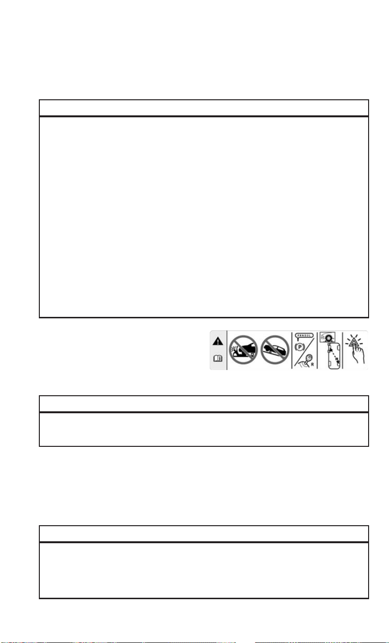
Jacking Instructions
WARNING!
Carefully follow these tire changing warnings to help prevent personal injury or
damage to your vehicle:
• Always park on a firm, level surface as far from the edge of the roadway as
possible before raising the vehicle.
• Turn on the Hazard Warning flasher.
• Block the wheel diagonally opposite the wheel to be raised.
• Set the parking brake firmly and set an automatic transmission in PARK; a
manual transmission in REVERSE.
• Never start or run the engine with the vehicle on a jack.
• Do not let anyone sit in the vehicle when it is on a jack.
• Do not get under the vehicle when it is on a jack. If you need to get under a raised
vehicle, take it to a service center where it can be raised on a lift.
• Only use the jack in the positions indicated and for lifting this vehicle during a
tire change.
• If working on or near a roadway, be extremely careful of motor traffic.
• To assure that spare tires, flat or inflated, are securely stowed, spares must be
stowed with the valve stem facing the ground.
CAUTION!
Do not attempt to raise the vehicle by jacking on locations other than those
indicated in the Jacking Instructions for this vehicle.
1. Loosen (but do not remove) the wheel lug bolts with the wrench handle by turning
them to the left one turn while the wheel is still on the ground.
2. There are two jack engagement locations on each side of the vehicle body.
NOTE:
Place the jack underneath the jack engagement location that is closest to the flat tire.
WARNING!
Being under a jacked-up vehicle is dangerous. The vehicle could slip off the jack
and fall on you. You could be crushed. Never get any part of your body under a
vehicle that is on a jack. If you need to get under a raised vehicle, take it to a
service center where it can be raised on a lift.
Jack Warning Label
WHAT TO DO IN EMERGENCIES
87

CAUTION!
Do not attempt to raise the vehicle by jacking on locations other than those
indicated.
3. Turn the handle on the jack screw to the right until the jack head is properly
engaged in the described location. Do not raise the vehicle until you are sure the
jack is securely engaged.
4. Raise the vehicle by turning the jack
screw to the right until the tire just
clears the surface and enough clear-
ance is obtained to install the spare
tire. Minimum tire lift provides maxi-
mum stability.
WARNING!
Raising the vehicle higher than necessary can make the vehicle less stable. It
could slip off the jack and hurt someone near it. Raise the vehicle only enough to
remove the tire.
Front Jacking Location Engaged
Rear Jacking Location Engaged
WHAT TO DO IN EMERGENCIES
88

5. Remove the wheel lug bolts. For vehicles with wheel covers, remove the cover
from the wheel by hand. Do not pry the wheel cover off. Then pull the wheel off the
hub.
6. Install the spare tire. Lightly tighten the wheel lug bolts using the bolt install
wrench.
CAUTION!
Be sure to mount the spare tire with the valve stem facing outward. The vehicle
could be damaged if the spare tire is mounted incorrectly.
WARNING!
To avoid the risk of forcing the vehicle off the jack, do not tighten the wheel nuts
fully until the vehicle has been lowered. Failure to follow this warning may result
in serious injury.
7. Lower the vehicle by turning the jack screw to the left.
8. The correct wheel bolt torque is 63 ft lbs (86 N·m) for steel wheels and 89 ft lbs
(120 N·m) for aluminum wheels. If you doubt that you have tightened the bolts
correctly, have them checked with a torque wrench by your authorized dealer or
service station.
9. Lower the jack to its fully-closed position.
Mounting Spare Tire
WHAT TO DO IN EMERGENCIES
89

WARNING!
A loose tire or jack thrown forward in a collision or hard stop could endanger the
occupants of the vehicle. Always stow the jack parts and the spare tire in the
places provided. Have the deflated (flat) tire repaired or replaced immediately.
10. Stow the cable and wheel spacer before driving the vehicle.
NOTE:
For vehicles with alloy wheels remove the adapter bracket and bolts from the storage
bag in the glove compartment. Take the adapter and fit the plastic spacer between
the spring and the flange of the bracket (The adapter bracket is sold separately
through the dealer). The plastic fin must be directed downwards and perfectly
coincide with the flange cut part; fit the bracket in the adapter, fold the bracket up
and secure it to the adapter with the fastening knob. Position the tire vertically and
lay the mounted adapter on the inner part of the rim, using the supplied bolts fasten
the wheel to the adapter using the bolt install wrench. Tighten the bolts with the
wrench handle. Rotate the winch mechanism clockwise until the wheel is properly
stowed under the vehicle and until the wench makes three audible noises. Reach
underneath and shake tire by hand to confirm that it is secure. The tire should not
move. If tire is still loose and/or three audible noises are not heard, place and secure
damaged wheel into the vehicle and seek dealer assistance for the wench mecha-
nism. This is for temporary use only.
11. Stow the jack and tools under the drivers seat.
12. Check the spare tire pressure as soon as possible. Correct the tire pressure, as
required.
WHAT TO DO IN EMERGENCIES
90
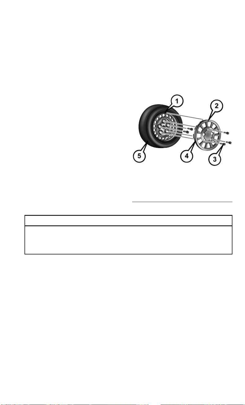
Vehicles Equipped With Wheel Covers
1. Mount the road tire on the axle.
2. To ease the installation process for steel wheels with wheel covers, install two
wheel bolts on the wheel. Install the wheel bolts with the threaded end of the bolt
toward the wheel. Lightly tighten the wheel bolts.
3. Align the valve notch in the wheel
cover with the valve stem on the
wheel. Install the cover by hand,
snapping the cover over the two wheel
bolts. Do not use a hammer or exces-
sive force to install the cover.
4. Install the remaining wheel bolts with
the threaded end of the wheel bolt
toward the wheel. Lightly tighten the
wheel bolts.
WARNING!
To avoid the risk of forcing the vehicle off the jack, do not tighten the wheel bolts
fully until the vehicle has been lowered. Failure to follow this warning may result
in personal injury.
5. Lower the vehicle to the ground by turning the jack handle counterclockwise.
6. Finish tightening the wheel bolts. Push down on the wrench while at the end of
the handle for increased leverage. Tighten the wheel bolts in a star pattern until
each wheel bolt has been tightened twice. The correct wheel bolt torque is
63 ft lbs (86 N·m) for steel wheels and 89 ft lbs (120 N·m) for aluminum wheels.
If you doubt that you have tightened the bolts correctly, have them checked with
a torque wrench by your authorized dealer or service station.
7. After 25 miles (40 km) check the wheel bolt torque with a torque wrench to
ensure that all wheel bolts are properly seated against the wheel.
Tire And Wheel Cover Or Center Cap
1 — Valve Stem 4 — Wheel Cover
2 — Valve Notch 5 — Road Wheel
3 — Wheel Bolt
WHAT TO DO IN EMERGENCIES
91

TIRE SERVICE KIT
If a tire is punctured, you can make a first emergency repair using the Tire Service Kit
located under the passenger seat.
Tire punctures of up to 1/4” (6 mm) can be repaired; the kit can be used in all
weather conditions. Do not remove the foreign object from the punctured tire, i.e.,
screw or nail.
Remove the Tire Service Kit from the vehicle, take it out from the bag and place it
near the punctured tire. Screw the clear flexible filling tube to the tire valve.
Tire Service Kit Components
1 — Sealant Bottle
2 — Pressure Gauge
3 — Power Plug (located behind stor-
age door)
4 — Power Button
5 — Sealant Hose (Clear)
WHAT TO DO IN EMERGENCIES
92

WARNING!
• Do not attempt to seal a tire on the side of the vehicle closest to traffic. Pull far
enough off the road to avoid the danger of being hit when using the Tire Service
Kit.
• Do not use Tire Service Kit or drive the vehicle under the following circum-
stances:
• If the puncture in the tire tread is approximately 1/4 inch (6 mm) or larger.
• If the tire has any sidewall damage.
• If the tire has any damage from driving with extremely low tire pressure.
• If the tire has any damage from driving on a flat tire.
• If the wheel has any damage.
• If you are unsure of the condition of the tire or the wheel.
• Keep Tire Service Kit away from open flames or heat source.
• A loose Tire Service Kit thrown forward in a collision or hard stop could endanger
the occupants of the vehicle. Always stow the Tire Service Kit in the place
provided. Failure to follow these warnings can result in injuries that are serious
or fatal to you, your passengers, and others around you.
• Take care not to allow the contents of Tire Service Kit to come in contact with
hair, eyes, or clothing. Tire Service Kit sealant is harmful if inhaled, swallowed,
or absorbed through the skin. It causes skin, eye, and respiratory irritation. Flush
immediately with plenty of water if there is any contact with eyes or skin. Change
clothing as soon as possible, if there is any contact with clothing.
• Tire Service Kit Sealant solution contains latex. In case of an allergic reaction or
rash, consult a physician immediately. Keep Tire Service Kit out of reach of
children. If swallowed, rinse mouth immediately with plenty of water and drink
plenty of water. Do not induce vomiting! Consult a physician immediately.
Insert the power plug into the vehicle power outlet socket. Start the vehicle engine.
Push the Tire Service Kit power button to the “I” position. The electric compressor
will be turned on, sealant and air will inflate the tire.
Minimum 26 psi (1.8 bar) of pressure should be reached within 20 minutes. If the
pressure has not been reached turn off and remove the Tire Service Kit, drive the
vehicle 30 feet (10 meters) back and forth, to better distribute the sealant inside the
tire.
Attach the clear flexible filling tube of the compressor directly to the tire valve and
repeat the inflation process.
When the correct pressure has been reached, start driving the vehicle to uniformly
distribute the sealant inside the tire. After 10 minutes, stop and check the tire
pressure. If the pressure is below 19 psi (1.3 bar), do not drive the vehicle, as the tire
is too damaged, contact the nearest Authorized Dealer.
WHAT TO DO IN EMERGENCIES
93

WARNING!
Tire Service Kit is not a permanent flat tire repair. Have the tire inspected and
repaired or replaced after using Tire Service Kit. Do not exceed 65 mph
(110 km/h) until the tire is repaired or replaced. Failure to follow this warning can
result in injuries that are serious or fatal to you, your passengers, and others
around you. Have the tire checked as soon as possible at an Authorized Dealer.
If the pressure is at 19 psi (1.3 bar) or above repeat the inflation process to reach the
correct tire pressure and continue driving.
Peel off the warning label from the bottle and place it on the dashboard as a reminder
to the driver that a tire has been treated with Tire Service Kit.
WARNING!
The metal end fitting from Power Plug may get hot after use, so it should be
handled carefully.
NOTE:
Replace the sealant canister prior to the expiration date at your Authorized Dealer.
WARNING!
Store the sealant canister in its special compartment, away from sources of heat.
Failure to follow this WARNING may result in sealant canister rupture and serious
injury or death.
Tire Service Kit Expiration Date Location
WHAT TO DO IN EMERGENCIES
94

JUMP-STARTING PROCEDURES
If your vehicle has a discharged battery it can be jump-started using a set of jumper
cables and a battery in another vehicle or by using a portable battery booster pack.
Jump-starting can be dangerous if done improperly so please follow the procedures
in this section carefully.
NOTE:
When using a portable battery booster pack follow the manufacturer’s operating
instructions and precautions.
WARNING!
Do not attempt jump-starting if the battery is frozen. It could rupture or explode
and cause personal injury.
CAUTION!
Do not use a portable battery booster pack or any other booster source with a
system voltage greater than 12 Volts or damage to the battery, starter motor,
alternator or electrical system may occur.
Preparations For Jump-Start
The battery in your vehicle is located in the front of the engine compartment, behind
the left headlight assembly.
NOTE:
The positive battery post is covered with a
protective cap. Lift up on the cap to gain
access to the positive battery post.
Battery Posts
1 — Positive Battery Post
2 — Negative Battery Post
WHAT TO DO IN EMERGENCIES
95

WARNING!
• Take care to avoid the radiator cooling fan whenever the hood is raised. It can
start anytime the ignition switch is ON. You can be injured by moving fan blades.
• Remove any metal jewelry such as rings, watch bands and bracelets that could
make an inadvertent electrical contact. You could be seriously injured.
• Batteries contain sulfuric acid that can burn your skin or eyes and generate
hydrogen gas which is flammable and explosive. Keep open flames or sparks
away from the battery.
1. Set the parking brake, shift the automatic transmission into PARK and turn the
ignition to LOCK.
2. Turn off the heater, radio, and all unnecessary electrical accessories.
3. If using another vehicle to jump-start the battery, park the vehicle within the
jumper cables reach, set the parking brake and make sure the ignition is OFF.
WARNING!
Do not allow vehicles to touch each other as this could establish a ground
connection and personal injury could result.
Jump-Starting Procedure
WARNING!
Failure to follow this jump-starting procedure could result in personal injury or
property damage due to battery explosion.
CAUTION!
Failure to follow these procedures could result in damage to the charging system
of the booster vehicle or the discharged vehicle.
Connecting The Jumper Cables
1. Connect the positive (+) end of the jumper cable to the positive (+) post of the
discharged vehicle.
2. Connect the opposite end of the positive (+) jumper cable to the positive (+) post
of the booster battery.
3. Connect the negative (-) end of the jumper cable to the negative (-) post of the
booster battery.
4. Connect the opposite end of the negative (-) jumper cable to a good engine ground
(exposed metal part of the discharged vehicle’s engine) away from the battery and
the fuel injection system.
WHAT TO DO IN EMERGENCIES
96

WARNING!
Do not connect the jumper cable to the negative (-) post of the discharged battery.
The resulting electrical spark could cause the battery to explode and could result
in personal injury. Only use the specific ground point, do not use any other exposed
metal parts.
5. Start the engine in the vehicle that has the booster battery, let the engine idle a
few minutes, and then start the engine in the vehicle with the discharged battery.
6. Once the engine is started, remove the jumper cables in the reverse sequence:
Disconnecting The Jumper Cables
1. Disconnect the negative (-) end of the jumper cable from the engine ground of the
vehicle with the discharged battery.
2. Disconnect the opposite end of the negative (-) jumper cable from the negative (-)
post of the booster battery.
3. Disconnect the positive (+) end of the jumper cable from the positive (+) post of
the booster battery.
4. Disconnect the opposite end of the positive (+) jumper cable from the positive (+)
post of the vehicle with the discharged battery.
If frequent jump-starting is required to start your vehicle you should have the battery
and charging system inspected at your authorized dealer.
TOWING A DISABLED VEHICLE
This section describes procedures for towing a disabled vehicle using a commercial
towing service.
Towing Condition Wheel OFF the Ground ALL MODELS
Flat Tow NONE
NOT ALLOWED
Wheel Lift Or Dolly Tow
Rear
NOT ALLOWED
Front OK
Flatbed
ALL BEST METHOD
Refer to your Owner’s Manual on the DVD for further information.
CAUTION!
Towing this vehicle in violation of the above requirements can cause severe
transmission damage. Damage from improper towing is not covered under the New
Vehicle Limited Warranty.
WHAT TO DO IN EMERGENCIES
97

FREEING A STUCK VEHICLE
If your vehicle becomes stuck in mud, sand, or snow, it can often be moved using a
rocking motion. Turn the steering wheel right and left to clear the area around the
front wheels. Push and hold the lock button on the gear selector. Then shift back and
forth between DRIVE and REVERSE , while gently pressing the accelerator. Use the
least amount of accelerator pedal pressure that will maintain the rocking motion,
without spinning the wheels or racing the engine.
NOTE:
Shifts between DRIVE and REVERSE can only be achieved at wheel speeds of 5 mph
(8 km/h) or less. Whenever the transmission remains in NEUTRAL for more than 2
seconds, you must push the brake pedal to engage DRIVE or REVERSE.
CAUTION!
Racing the engine or spinning the wheels may lead to transmission overheating
and failure. Allow the engine to idle with the transmission in NEUTRAL for at least
one minute after every five rocking-motion cycles. This will minimize overheating
and reduce the risk of transmission failure during prolonged efforts to free a stuck
vehicle.
NOTE:
Push the "ESC Off" switch, to place the Electronic Stability Control (ESC) system in
"Partial Off" mode, before rocking the vehicle. Refer to “Electronic Brake Control
System” in “Starting And Operating” in the Owner’s Manual on DVD for further
information. Once the vehicle has been freed, push the "ESC Off" switch again to
restore "ESC On" mode.
WARNING!
Fast spinning tires can be dangerous. Forces generated by excessive wheel speeds
may cause damage, or even failure, of the axle and tires. A tire could explode and
injure someone. Do not spin your vehicle's wheels faster than 30 mph (48 km/h)
or for longer than 30 seconds continuously without stopping when you are stuck.
And do not let anyone near a spinning wheel, no matter what the speed.
CAUTION!
• When “rocking” a stuck vehicle by shifting between DRIVE and REVERSE, do
not spin the wheels faster than 15 mph (24 km/h), or drivetrain damage may
result.
• Revving the engine or spinning the wheels too fast may lead to transmission
overheating and failure. It can also damage the tires. Do not spin the wheels
above 30 mph (48 km/h) while in gear (no transmission shifting occurring).
WHAT TO DO IN EMERGENCIES
98

GEAR SELECTOR OVERRIDE
If a malfunction occurs and the gear selector cannot be moved out of the PARK
position, you can use the following procedure to temporarily move the gear selector:
1. Turn the engine OFF.
2. Firmly apply the parking brake.
3. Using a screwdriver or similar tool, carefully separate the gear selector boot from
the center console.
4. Push and maintain firm pressure on
the brake pedal.
5. Insert a small screwdriver or a similar
tool into the gear selector override access hole (at the right front corner of the gear
selector assembly) then push and hold the override release lever down. While still
holding down the override release lever, move the gear selector to the NEUTRAL
position (the shift knob button must be pushed normally to move the lever).
6. The vehicle may then be started in
NEUTRAL.
7. Reinstall the gear selector boot.
Gear selector Boot Location
Gear Selector Override Access Hole
WHAT TO DO IN EMERGENCIES
99

IGNITION KEY REMOVAL OVERRIDE
This vehicle is equipped with a Key Ignition Park Interlock which requires the
transmission to be in PARK before the ignition switch can be turned to the LOCK/OFF
(key removal) position. To remove the key manually, proceed as follows:
1. Firmly apply the parking brake
2. Remove the Allen Key located in the rear cargo area, in the tool bag (if equipped)
or on the left side in the cargo box.
3. Unlock the steering column, pull the tilt/telescoping control handle down.
4. Pull the steering wheel outward until it is in the end of the travel position, then
lock the steering column in position, push the control handle up until fully
engaged.
5. Using the Allen key, undo the lower steering column cover screws, and remove the
lower cover.
6. Pull the release tab downwards using one hand and with the other one remove the
key, sliding it outwards.
7. Once the key is removed, reinstall the steering column cover.
CAUTION!
It is advisable to contact your Authorized Dealer to have the reinstall procedure
carried out. If you would like to proceed in performing the reinstall procedure
special attention must be paid to the correct coupling of the clips. Otherwise
damage to the cover or noise might be heard due to incorrect fastening of the lower
cover.
ENHANCED ACCIDENT RESPONSE SYSTEM (EARS)
This vehicle is equipped with an Enhanced Accident Response System.
Please refer to “Supplemental Restraint System (SRS) — Air Bags” for further
information on the Enhanced Accident Response System (EARS) function.
EVENT DATA RECORDER (ED R)
This vehicle is equipped with an Event Data Recorder (EDR). The main purpose of an
EDR is to record, in certain crash or near crash-like situations, such as an air bag
deployment or hitting a road obstacle, data that will assist in understanding how a
vehicle’s systems performed.
Please refer to “Supplemental Restraint System (SRS) — Air Bags” for further
information on the Event Data Recorder (EDR).
WHAT TO DO IN EMERGENCIES
100

OPENING THE HOOD
To open the hood, two levers must be released:
1. Pull the hood release lever located under the driver side of the instrument panel.
2. Move to the front of the vehicle.
3. Reach under the center front edge of
the hood and push up and hold the
safety latch lever.
4. Lift the hood upward to the open po-
sition and place the prop rod in the
receptacle location on the underbody
of the hood.
NOTE:
Properly place the hood prop rod in the
retaining clip when closing the hood or
damage to the vehicle may occur.
WARNING!
Be sure the hood is fully latched before driving your vehicle. If the hood is not fully
latched, it could open when the vehicle is in motion and block your vision. Failure
to follow this warning could result in serious injury or death.
Release Lever
Safety Latch Lever Location
MAINTAINING YOUR VEHICLE
101

ENGINE COMPARTMENT — 2.4L
1. Air Cleaner Filter
2. Power Steering Fluid Reservoir
3. Oil Fill Cap
4. Engine Oil Dipstick
MAINTAINING YOUR VEHICLE
102

5. Brake Fluid Reservoir
6. Power Distribution Center (Fuses)
7. Washer Fluid Reservoir
8. Engine Coolant Pressure Cap
MAINTAINING YOUR VEHICLE
103

FLUID CAPACITIES
U.S. Metric
Fuel (Approximate)
2.4L Engine 16 Gallons 60.5 Liters
Engine Oil With Filter
2.4 Liter Engine (SAE 0W-
20, API Certified)
5.5 Quarts 5.2 Liters
Cooling System*
2.4 Liter Engine (MOPAR
Antifreeze/Engine Coolant
10 Year/150,000 Mile For-
mula)
7.2 Quarts 6.8 Liters
* Includes heater and coolant reservoir filled to MAX level.
FLUIDS, LUBRICANTS, AND GENUINE PARTS
Engine
Component Fluid, Lubricant, or Genuine Part
Engine Coolant We recommend you use MOPAR
Antifreeze/Coolant 10 Year/150,000 Mile
Formula OAT (Organic Additive Technol-
ogy) or equivalent meeting the require-
ments of FCA Material Standard
MS.90032.
Engine Oil – 2.4L Engine We recommend you use SAE 0W-20 API
Certified Engine Oil, meeting the require-
ments of FCA Material Standard MS-
6395 such as MOPAR, Pennzoil, and Shell
Helix. Refer to your engine oil filler cap for
correct SAE grade.
Engine Oil Filter We recommend you use a MOPAR Engine
Oil Filter.
Spark Plugs – 2.4L Engine We recommend you use MOPAR Spark
Plugs.
Fuel Selection – 2.4L Engine 87 Octane, 0-15% Ethanol.
MAINTAINING YOUR VEHICLE
104

CAUTION!
• Mixing of engine coolant (antifreeze) other than specified Organic Additive
Technology (OAT) engine coolant (antifreeze), may result in engine damage and
may decrease corrosion protection. Organic Additive Technology (OAT) engine
coolant is different and should not be mixed with Hybrid Organic Additive
Technology (HOAT) engine coolant (antifreeze) or any “globally compatible”
coolant (antifreeze). If a non-OAT engine coolant (antifreeze) is introduced into
the cooling system in an emergency, the cooling system will need to be drained,
flushed, and refilled with fresh OAT coolant (conforming to MS.90032), by an
authorized dealer as soon as possible.
• Do not use water alone or alcohol-based engine coolant (antifreeze) products. Do
not use additional rust inhibitors or antirust products, as they may not be
compatible with the radiator engine coolant and may plug the radiator.
• This vehicle has not been designed for use with propylene glycol-based engine
coolant (antifreeze). Use of propylene glycol-based engine coolant (antifreeze)
is not recommended.
Chassis
Component Fluid, Lubricant, or Genuine Part
Automatic Transmission
Use only MOPAR ZF 8&9 Speed ATF Automatic Transmission
Fluid, or equivalent.
Failure to use the correct fluid may affect the function or
performance of your transmission.
Brake Master Cylinder
We recommend you use MOPAR DOT 4.
The fluid must be changed every 24 months. This interval is
time based only, mileage intervals do not apply.
Power Steering Reservoir
Use Pentosin CHF 11S power steering fluid meeting FCA
Material Standard MS-11655.
MAINTAINING YOUR VEHICLE
105

MAINTENANCE PROCEDURES
For information on the maintenance procedures for your vehicle, please refer to
“Maintenance Procedures” in “Maintaining Your Vehicle” in your Owner’s Manual or
applicable supplement on the DVD for further details.
MAINTENANCE SCHEDULE
Your vehicle is equipped with an automatic oil change indicator system. The oil
change indicator system will remind you that it is time to take your vehicle in for
scheduled maintenance.
Based on engine operation conditions, the oil change indicator message will
illuminate. This means that service is required for your vehicle. Operating conditions
such as frequent short-trips, trailer tow, extended engine idle time, extremely hot or
cold ambient temperatures will influence when the “Oil Change Required” message
is displayed. Severe Operating Conditions can cause the change oil message to
illuminate as early as 3,500 miles (5,600 km) since last reset. Have your vehicle
serviced as soon as possible, within the next 500 miles (805 km).
Your authorized dealer will reset the oil change indicator message after completing
the scheduled oil change. If a scheduled oil change is performed by someone other
than your authorized dealer, the message can be reset by referring to the steps
described under “Oil Change Reset” in “Electronic Vehicle Information Center
(EVIC)” in “Understanding Your Instrument Panel” in your Owners Manual on the
DVD for further information.
NOTE:
Under no circumstances should oil change intervals exceed 10,000 miles
(16,000 km), 350 hours of engine run time or twelve months, whichever comes first.
The 350 hours of engine run or idle time is generally only a concern for fleet
customers.
MAINTAINING YOUR VEHICLE
106

Severe Duty All Models
Change Engine Oil at 4,000 miles (6,500 km) if the vehicle is operated in a dusty
and off road environment or is operated predominantly at idle or only very low engine
RPM’s. This type of vehicle use is considered Severe Duty.
Once A Month Or Before A Long Trip:
• Check engine oil level.
• Check windshield washer fluid level.
• Check tire pressure and look for unusual wear or damage. Rotate tires at the first
sign of irregular wear, even if it occurs before the oil indicator system turns on.
• Check the fluid levels of the coolant reservoir and brake master cylinder, fill as
needed.
• Check function of all interior and exterior lights.
Maintenance Chart
Required Maintenance Intervals
Refer to the maintenance schedules on the following page for the required mainte-
nance intervals.
At Every Oil Change Interval As Indicated By Oil Change Indicator System:
•
Change oil and filter
• Rotate the tires; Rotate at the first sign of irregular wear, even if it occurs before the oil
indicator system turns on
•
Inspect battery and clean and tighten terminals as required
•
Inspect brake pads, shoes, rotors, drums, hoses, lines and park brake
•
Inspect engine cooling system protection and hoses
•
Inspect exhaust system
•
Inspect engine air cleaner if using in dusty or off-road conditions
MAINTAINING YOUR VEHICLE
107

Mileage:
20,000
30,000
40,000
50,000
60,000
70,000
80,000
90,000
100,000
110,000
120,000
130,000
140,000
150,000
Or Years: 2 3 4 5 6 7 8 9 10 11 12 13 14 15
Or Kilometers:
32,000
48,000
64,000
80,000
96,000
112,000
128,000
144,000
160,000
176,000
192,000
208,000
224,000
240,000
Additional Inspections
Inspect the CV joints. X X X X X X X
Inspect front suspension, boot seals, tie rod ends, and replace
if necessary.
XXX X X X X
Inspect the brake linings, parking brake function. X X X X X X X
Inspect front accessory drive belt, tensioner, idler pulley, and
replace if necessary.
X
Additional Maintenance
Replace engine air cleaner filter. * X X X X X
Replace air conditioning/cabin air filter. X X X X X X X
Change brake fluid every two years.** X X X X X X X
Replace spark plugs.*** X
MAINTAINING YOUR VEHICLE
108

Mileage:
20,000
30,000
40,000
50,000
60,000
70,000
80,000
90,000
100,000
110,000
120,000
130,000
140,000
150,000
Or Years: 2 3 4 5 6 7 8 9 10 11 12 13 14 15
Or Kilometers:
32,000
48,000
64,000
80,000
96,000
112,000
128,000
144,000
160,000
176,000
192,000
208,000
224,000
240,000
Flush and replace the engine coolant at 10 years or
150,000 miles (240,000 km) whichever comes first.
XX
Inspect and replace PCV valve if necessary. X
* Change engine air filter every 10,000 miles (16,000 km) if operated in dusty and off road environment.
** The brake fluid must be changed every 24 months. This interval is time based only, mileage intervals do not apply.
*** The spark plug change interval is mileage based only, yearly intervals do not apply.
NOTE:
Routine transmission fluid and filter changes are not required. Under normal operating conditions, the fluid installed at the factory
will provide satisfactory lubrication for the life of the vehicle.
WARNING!
• You can be badly injured working on or around a motor vehicle. Do only service work for which you have the knowledge and the
right equipment. If you have any doubt about your ability to perform a service job, take your vehicle to a competent mechanic.
• Failure to properly inspect and maintain your vehicle could result in a component malfunction and effect vehicle handling and
performance. This could cause an accident.
MAINTAINING YOUR VEHICLE
109

MAINTENANCE RECORD
Odometer Date Signature, Autho-
rized Service Center
20,000 Miles
(32,000 km) or
2 Years
30,000 Miles
(48,000 km) or
3 Years
40,000 Miles
(64,000 km) or
4 Years
50,000 Miles
(80,000 km) or
5 Years
60,000 Miles
(96,000 km) or
6 Years
70,000 Miles
(112,000 km) or
7 Years
80,000 Miles
(128,000 km) or
8 Years
Odometer Date Signature, Autho-
rized Service Center
90,000 Miles
(144,000 km) or
9 Years
100,000 Miles
(160,000 km) or
10 Years
110,000 Miles
(176,000 km) or
11 Years
120,000 Miles
(192,000 km) or
12 Years
130,000 Miles
(208,000 km) or
13 Years
140,000 Miles
(224,000 km) or
14 Years
150,000 Miles
(240,000 km) or
15 Years
MAINTAINING YOUR VEHICLE
110

FUSES
WARNING!
• When replacing a blown fuse, always use an appropriate replacement fuse with
the same amp rating as the original fuse. Never replace a fuse with another fuse
of higher amp rating. Never replace a blown fuse with metal wires or any other
material. Failure to use proper fuses may result in serious personal injury, fire
and/or property damage.
• Before replacing a fuse, make sure that the ignition is off and that all the other
services are switched off and/or disengaged.
• If the replaced fuse blows again, contact an authorized dealer.
• If a general protection fuse for safety systems (air bag system, braking system),
power unit systems (engine system, gearbox system) or steering system blows,
contact an authorized dealer.
Underhood Fuses
The Front Distribution Unit is located on the right side of the engine compartment,
next to the battery. To access the fuses, remove fasteners and remove the cover.
The ID number of the electrical component corresponding to each fuse can be found
on the back of the cover.
Cavity Maxi Fuse Mini Fuse Description
F01 60 Amp Blue – Body Controller
F02 40 Amp Orange –
Front Heated Seats, Second
12 Volt IP Outlet
F02 60 Amp Blue –
Rear Power Window Including
Front Heated Seats, Second
12 Volt IP Outlet
F03 20 Amp Yellow – Ignition Switch
F04 40 Amp Orange – BSM System Module
F06 30 Amp Green – Radiator Fan - Low Speed
F07 40 Amp Orange – Radiator Fan - High Speed
F08 40 Amp Orange – Blower Motor
F10 – 10 Amp Red Horn
F11 – 10 Amp Red Secondary Loads ECM
F14 – 15 Amp Blue High Beam
F16 – 5 Amp Tan ECM and Transmission Shifter
F17 – 25 Amp Clear ECM Power Loads
F18 – 5 Amp Tan ECM Load, Main Relay
F19 – 7.5 Amp Brown Air Conditioning
F20 – 30 Amp Green Rear Defroster
F21 – 5 Amp Tan Key Unlock
MAINTAINING YOUR VEHICLE
111

Cavity Maxi Fuse Mini Fuse Description
F22 – 10 Amp Red Primary ECM Loads
F23 – 20 Amp Yellow BSM System
F24 – 5 Amp Tan
BSM System, Positive Key and
Steering Angle Sensor
F30 – 15 Amp Blue Fog Lamp
F83 20 Amp Yellow – Fuel Pump
F84 – 15 Amp Blue AT Module
F85 – 20 Amp Yellow Rear Power Outlet 12V
F86 – 30 Amp Green IP Power Outlet 12V
F87 – 5 Amp Tan IBS
F88 – 7.5 Amp Brown External Mirror Defrost
Interior Fuses
The interior fuse panel is part of the Body Control Module (BCM) and is located on the
driver's side under the instrument panel.
Cavity Mini Fuse Description
F53 5 Amp Beige KL 30 (+30) - IPC
F38 20 Amp Yellow Central Doors Locking
F36 10 Amp Red
KL 30 (+30) - TPMS,
EOBD, HVAC, Radio
F43 15 Amp Blue
Bi-Directional Washer
Pump
F48 20 Amp Yellow Passenger Power Windows
F50 7.5 Amp Brown KL 15 (+15) - Air-Bag
F51 7.5 Amp Brown
KL 15 (+15) - External
Mirror Adjustment Com-
mand, HVAC, RVC, HWB
Coils
F37 5 Amp Beige
KL 15 (+15) - Brake Pedal
Switch (N.O.), IPC, Brake
Pedal Switch (N.C.)
F49 5 Amp Beige
KL 15 (+15) - PAM, CSS
Lighting, ECM Backlight-
ing, TTM
F31 5 Amp Beige
KL 15a (INT A) - HWB,
MCO
F47 20 Amp Yellow Driver Power Windows
MAINTAINING YOUR VEHICLE
112

Central Unit Fuse Panel
The central power fuse panel is located on the driver’s side under the instrument
panel.
Cavity Mini Fuse Description
F1 10 Amp Red Front Heated Seat Driver
F2 10 Amp Red Front Heated Seat Passenger
F3 20 Amp Yellow Rear Power Window Driver side
F4 20 Amp Yellow Rear Power Window Passenger side
F5 15 Amp Blue 2nd Instrument Panel Power Outlet 12V
TIRES — GENERAL INFORMATION
Tire Pressures
Check the inflation pressure of each tire, including the spare tire (if equipped), at
least monthly and inflate to the recommended pressure for your vehicle.
The tire pressures recommended for your vehicle are found on the “Tire and Loading
Information” label located on the driver’s side door opening or B-Pillar.
NOTE:
Refer to the Owner's Manual on the DVD
or the Tire Information Supplement lo-
cated in your Owner’s Information kit for
more information regarding tire warnings
and instructions.
Tire And Loading Information Location (Ex-
ample)
MAINTAINING YOUR VEHICLE
113

WARNING!
• Overloading of your tires is dangerous. Overloading can cause tire failure, affect
vehicle handling, and increase your stopping distance. Use tires of the recom-
mended load capacity for your vehicle. Never overload them.
• Improperly inflated tires are dangerous and can cause collisions. Under-
inflation increases tire flexing and can result in over-heating and tire failure.
Over-inflation reduces a tire’s ability to cushion shock. Objects on the road and
chuck holes can cause damage that results in tire failure. Unequal tire pressures
can cause steering problems. You could lose control of your vehicle. Over-
inflated or under-inflated tires can affect vehicle handling and can fail suddenly,
resulting in loss of vehicle control. Always drive with each tire inflated to the
recommended cold tire inflation pressure.
Spare Tires — If Equipped
NOTE:
For vehicles equipped with Tire Service Kit instead of a spare tire, please refer to the
“Tire Service Kit” section located in your Owner’s Information kit for further
information.
CAUTION!
Because of the reduced ground clearance, do not take your vehicle through an
automatic car wash with a compact or limited-use temporary spare installed.
Damage to the vehicle may result.
Spare Tire Matching Original Equipped Tire And Wheel — If Equipped
Your vehicle may be equipped with a spare tire and wheel equivalent in look and
function to the original equipment tire and wheel found on the front or rear axle of
your vehicle. This spare tire may be used in the tire rotation for your vehicle. If your
vehicle has this option, refer to an authorized tire dealer for the recommended tire
rotation pattern.
Compact Spare Tire — If Equipped
The compact spare is for temporary emergency use only. You can identify if your
vehicle is equipped with a compact spare by looking at the spare tire description on
the Tire and Loading Information Placard located on the driver’s side door opening or
on the sidewall of the tire. Compact spare tire descriptions begin with the letter “T”
or “S” preceding the size designation. Example: T145/80D18 103M.
T,S=Temporary Spare Tire
Since this tire has limited tread life, the original equipment tire should be repaired
(or replaced) and reinstalled on your vehicle at the first opportunity.
MAINTAINING YOUR VEHICLE
114

Do not install a wheel cover or attempt to mount a conventional tire on the compact
spare wheel, since the wheel is designed specifically for the compact spare tire. Do
not install more than one compact spare tire and wheel on the vehicle at any given
time.
WARNING!
Compact and Collapsible spares are for temporary emergency use only. With these
spares, do not drive more than 50 mph (80 km/h). Temporary use spares have
limited tread life. When the tread is worn to the tread wear indicators, the
temporary use spare tire needs to be replaced. Be sure to follow the warnings,
which apply to your spare. Failure to do so could result in spare tire failure and loss
of vehicle control.
Full Size Spare — If Equipped
The full size spare is for temporary emergency use only. This tire may look like the
originally equipped tire on the front or rear axle of your vehicle, but it is not. This
spare tire may have limited tread life. When the tread is worn to the tread wear
indicators, the temporary use full size spare tire needs to be replaced. Since it is not
the same as your original equipment tire, replace (or repair) the original equipment
tire and reinstall on the vehicle at the first opportunity.
Limited Use Spare — If Equipped
The limited use spare tire is for temporary emergency use only. This tire is identified
by a label located on the limited use spare wheel. This label contains the driving
limitations for this spare. This tire may look like the original equipped tire on the front
or rear axle of your vehicle, but it is not. Installation of this limited use spare tire
affects vehicle handling. Since it is not the same as your original equipment tire,
replace (or repair) the original equipment tire and reinstall on the vehicle at the first
opportunity.
WARNING!
Limited use spares are for emergency use only. Installation of this limited use
spare tire affects vehicle handling. With this tire, do not drive more than the speed
listed on the limit use spare wheel. Keep inflated to the cold tire inflation
pressures listed on your Tire and Loading Information Placard located on the
driver’s side B-Pillar or the rear edge of the driver’s side door. Replace (or repair)
the original equipment tire at the first opportunity and reinstall it on your vehicle.
Failure to do so could result in loss of vehicle control.
MAINTAINING YOUR VEHICLE
115

Wheel And Wheel Trim Care
All wheels and wheel trim, especially aluminum and chrome plated wheels, should
be cleaned regularly using mild (neutral Ph) soap and water to maintain their luster
and to prevent corrosion. Wash wheels with the same soap solution recommended for
the body of the vehicle.
Your wheels are susceptible to deterioration caused by salt, sodium chloride,
magnesium chloride, calcium chloride, etc., and other road chemicals used to melt
ice or control dust on dirt roads. Use a soft cloth or sponge and mild soap to wipe
away promptly. Do not use harsh chemicals or a stiff brush. They can damage the
wheel’s protective coating that helps keep them from corroding and tarnishing.
NOTE:
Many aftermarket wheel cleaners contain strong acids or strong alkaline additives
that can harm the wheel surface.
CAUTION!
Avoid products or automatic car washes that use acidic solutions or strong alkaline
additives or harsh brushes. These products and automatic car washes may damage
the wheel's protective finish. Such damage is not covered by the New Vehicle
Limited Warranty. Only car wash soap, MOPAR Wheel Cleaner or equivalent is
recommended.
When cleaning extremely dirty wheels including excessive brake dust, care must be
taken in the selection of tire and wheel cleaning chemicals and equipment to prevent
damage to the wheels. Mopar Wheel Treatment or Mopar Chrome Cleaner or their
equivalent is recommended or select a non-abrasive, non-acidic cleaner for alumi-
num or chrome wheels. Do not use any products on Dark Vapor or Black Satin Chrome
Wheels. They will permanently damage this finish and such damage is not covered by
the New Vehicle Limited Warranty.
CAUTION!
Do not use scouring pads, steel wool, a bristle brush, metal polishes or oven
cleaner. These products may damage the wheel's protective finish. Such damage
is not covered by the New Vehicle Limited Warranty. Only car wash soap, MOPAR
Wheel Cleaner or equivalent is recommended.
NOTE:
If you intend parking or storing your vehicle for an extended period after cleaning the
wheels with wheel cleaner, drive your vehicle for a few minutes before doing so.
Driving the vehicle and applying the brakes when stopping will reduce the risk of
brake rotor corrosion.
MAINTAINING YOUR VEHICLE
116

Dark Vapor Or Black Satin Chrome Wheels
CAUTION!
If your vehicle is equipped with Dark Vapor or Black Satin Chrome wheels DO NOT
USE wheel cleaners, abrasives or polishing compounds. They will permanently
damage this finish and such damage is not covered by the New Vehicle Limited
Warranty. USE ONLY MILD SOAP AND WATER WITH A SOFT CLOTH. Used on a
regular basis this is all that is required to maintain this finish.
REPLACEMENT BULBS
Interior Bulbs
Lamps Bulb Number
Front Courtesy Lamps C10W
Rear Courtesy Lamps C10W
Luggage Lamp C5W
Exterior Bulbs
Lamps Bulb Number
Front Low Beam Headlamp H11
Front High Beam Headlamps HB3
Front Side Marker Lamps LED (See your authorized dealer)
Front Parking/Daytime Running Lamps W21W
Front Turn Signal Lamps WY21W
Rear Stop Lamp P21W
Rear Turn Signal Lamps PY21W
Rear Tail Lamps P21/5W
Rear Side Marker Lamps LED (See your authorized dealer)
Center Mount Brake Lamp W5W
Reverse Light W16W
Front Fog Lamps H11
NOTE:
Numbers refer to commercial bulb types that can be purchased from your authorized
dealer.
If a bulb needs to be replaced, visit your authorized dealer or refer to the applicable
Service Manual.
MAINTAINING YOUR VEHICLE
117

FCA US LLC CUSTOMER CENTER
P.O. Box 21–8004 Auburn Hills, MI 48321–8004 Phone: 1-866-726-4636
FCA CANADA INC. CUSTOMER CENTER
P.O. Box 1621 Windsor, Ontario N9A 4H6 Phone: 1-800-465-2001 (English)
Phone: 1-800-387-9983 (French)
ASSISTANCE FOR THE HEARING IMPAIRED
To assist customers who have hearing difficulties, the manufacturer has installed
special TDD (Telecommunication Devices for the Deaf) equipment at its customer
center. Any hearing or speech impaired customer, who has access to a TDD or a
conventional teletypewriter (TTY) in the United States, can communicate with the
manufacturer by dialing 1-800-380-CHRY. Canadian residents with hearing difficul-
ties that require assistance can use the special needs relay service offered by Bell
Canada. For TTY teletypewriter users, dial 711 and for Voice callers, dial
1-800-855-0511 to connect with a Bell Relay Service operator.
WARNING!
Engine exhaust, some of its constituents, and certain vehicle components con-
tain, or emit, chemicals known to the State of California to cause cancer and birth
defects, or other reproductive harm. In addition, certain fluids contained in
vehicles and certain products of component wear contain, or emit, chemicals
known to the State of California to cause cancer and birth defects, or other
reproductive harm.
CUSTOMER ASSISTANCE
118

PUBLICATIONS ORDERING
• If you are the first registered retail owner of your vehicle, you may obtain a
complimentary printed copy of the Owner's Manual, Navigation/Uconnect Manu-
als or Warranty Booklet. United States customers may visit the Ram Truck Contact
Us page at www.ramtrucks.com scroll to the bottom of the page and select the
“Contact Us” link, then select the “Owner’s Manual and Glove Compartment
Material” from the left menu. You may also obtain a complimentary copy by
calling 1-866-726-4636 (U.S.) or 1-800-387-1143 (Canada).
• Replacement User Guide kits or DVDs or, if you prefer, additional printed copies
of the Owner's Manual, Warranty Booklet or Radio Manuals may be purchased by
visiting www.techauthority.com or by calling 1-800-890-4038 (U.S.) or
1-800-387-1143 (Canada). Visa, Master Card, American Express and Discover
orders are accepted. If you prefer mailing your order, please call the above
numbers for an order form.
NOTE:
• A street address is required when ordering manuals (no P.O. Boxes).
• The Owner's Manual and User Guide electronic files are also available on the
Chrysler, Jeep
®
, Ram Truck, Dodge and SRT websites.
• Click on the “Owners” tab, select “Owner And Service Manuals”, then select your
desired model year and vehicle from the drop down lists.
CUSTOMER ASSISTANCE
119

REPORTING SAFETY DEFECTS IN THE UNITED STATES
If you believe that your vehicle has a defect that could cause a collision or cause
injury or death, you should immediately inform the National Highway Traffic Safety
Administration (NHTSA) in addition to notifying the manufacturer.
If NHTSA receives similar complaints, it may open an investigation, and if it finds
that a safety defect exists in a group of vehicles, it may order a recall and remedy
campaign. However, NHTSA cannot become involved in individual problems between
you, your authorized dealer and the manufacturer.
To contact NHTSA, you may either call the Auto Safety Hotline toll free at
1-888-327-4236 (TTY: 1-800-424-9153), or go to http://www.safercar.gov; or write
to: Administrator, NHTSA, 1200 New Jersey Avenue, SE., West Building,
Washington, D.C. 20590. You can also obtain other information about motor vehicle
safety from http://www.safercar.gov.
In Canada
If you believe that your vehicle has a safety defect, you should contact the Customer
Service Department immediately. Canadian customers who wish to report a safety
defect to the Canadian government should contact Transport Canada, Motor Vehicle
Defect Investigations and Recalls at 1-800-333-0510 or go to http://www.tc.gc.ca/
roadsafety/.
French Canadian customers who wish to report a safety defect to the Canadian
government should contact Transport Canada, Motor Vehicle Defect Investigations
and Recalls at 1-800-333-0510 or go to http://www.tc.gc.ca/securiteroutiere/.
CUSTOMER ASSISTANCE
120

AUTHENTIC ACCESSORIES BY MOPAR
• In choosing Authentic Accessories you gain far more than expressive style,
premium protection, or extreme entertainment, you also benefit from enhancing
your vehicle with accessories that have been thoroughly tested and factory-
approved.
• The following highlights just some of the many Authentic Ram Accessories by
Mopar featuring a fit, finish, and functionality specifically for your Ram.
• For the full line of Authentic Ram Accessories by Mopar, visit your local dealership
or online at mopar.com for U.S. residents and mopar.ca for Canadian residents.
NOTE:
All parts are subject to availability.
EXTERIOR:
• Utility Roof Rack • Side Window Deflector • Hitch Receiver
• Molded Splash Guards • Full Size Spare Tire • Bike Carriers
• Ski Carriers • Water Sports Carriers • Wheel Locks
INTERIOR:
• Premium Carpet Mats • Roadside Safety Kit • Slush Mats
• Floor Liner
ELECTRONICS:
• Rear Backup Camera • Hands Free Phone • Mopar Connect
• Electronic Vehicle Track-
ing
• Cargo Lighting
MOPAR® ACCESSORIES
121

FREQUENTLY ASKED QUESTIONS
GETTING STARTED
Where are the controls for the Front Heated Seats? pg. 26
How to adjust your seat? pg. 22
ELECTRONICS
Which radio is in my vehicle? pg. 43
How do I activate the Audio Jack? pg. 49
How do I set the clock on my radio? pg. 46
How do I pair my cell phone via Bluetooth with the Uconnect Hands-Free Voice
Activation System? pg. 59
How to use the power outlet? pg. 69
UTILITY
How do I know how much I can tow with my Ram ProMaster? pg. 73
WHAT TO DO IN EMERGENCIES
What do I do if my TPMS warning light is blinking? pg. 76
How do I change a flat tire? pg. 82
How do I Jump-Start my vehicle? pg. 95
MAINTAINING YOUR VEHICLE
Where is my Fuse Block located? pg. 111
What type of oil do I use? pg. 104
How often should I change my engine’s oil? pg. 106
What should my tire pressure be set at? pg. 113
FREQUENTLY ASKED QUESTIONS
122

Accessories..............121
Mopar ...............121
Adding Engine Coolant (Antifreeze).106
Adding Washer Fluid .........106
Air Bag
AdvancedFrontAirBag ......10
AdvanceFrontAirBag ......10
AirBags ...............10
AirBagWarningLight.....10,13
Driver Knee Air Bag ........11
Enhanced Accident
Response ........12,13,100
Event Data Recorder (EDR) .13, 100
FrontAirBag ............10
PassengerKneeAirBag......11
Rollover ...............10
SideImpacts ............10
AirBagLight............13,76
Air Cleaner, Engine (Engine Air Cleaner
Filter) ................106
Air Conditioner Maintenance ....106
Air Conditioning ............29
Air Conditioning Refrigerant .....106
Air Conditioning System .......106
Antifreeze (Engine Coolant) . .104, 106
Disposal ..............106
Anti-Lock Warning Light ........75
Appearance Care ...........106
Assistance Towing ...........74
Automatic Transmission
Adding Fluid ...........105
FluidType ............105
Axle Lubrication............105
Back-Up Camera ............39
Battery .................106
Body Mechanism Lubrication ....106
Brake Fluid ..............105
Brakes .................106
Brake System .............106
Fluid Check ............105
Master Cylinder .........106
WarningLight ...........78
Break-In Recommendations, New
Vehicle ................28
BulbReplacement..........117
Bulbs,Light..............117
Canada.................120
Capacities, Fluid ...........104
Caps, Filler
Oil(Engine) ............106
Cargo Tie-Downs ............72
CarWashes ..............106
Charging System Light.........74
Child Restraint .............14
Child Restraints
Lower Anchors And Tethers For Chil-
dren .................14
Cleaning
Wheels ...........106, 116
Windshield Wiper Blades ....106
Clock Setting ..............46
Cluster Warning/Indicator Lights
Anti-Lock Brake (ABS) Light . . .75
Brake Warning Light ........78
Charging System Light ......74
Electronic Speed Control SET Indi-
cator ................80
Electronic Throttle Control (ETC)
Indicator Light ...........76
Engine Temperature Warning
Light ................75
Front Fog Light Indicator .....79
High Beam Indicator .......79
Malfunction Indicator Light (MIL) .79
Oil Pressure Warning Light ....74
Park/Headlight ON Indicator . . .80
Tire Pressure Monitoring System
(TPMS) Light ............76
Turn Signal Indicator .......79
Clutch.................106
ClutchFluid..............106
CompactSpareTire..........114
Cooling System ............106
Adding Coolant (Antifreeze) . .106
Coolant Capacity .........
104
Coolant Level ...........106
Disposal Of Used Coolant ....106
Drain, Flush, And Refill .....106
Inspection ............106
PointsToRemember ......106
Pressure Cap ...........106
Selection Of Coolant
(Antifreeze) ........104, 106
INDEX
123

Corrosion Protection .........106
Customer Assistance . .118, 119, 120
Customer Programmable Features . .68
Defects, Reporting ..........120
Defroster, Rear Window ........29
Disabled Vehicle Towing .....74,97
Disposal
Antifreeze (Engine Coolant) . . .106
Electronic Speed Control (Cruise
Control)................35
Electronic Stability Control (ESC) . .80
Electronic Throttle Control Warning
Light.................76
Electronic Vehicle Information Center
(EVIC) ................68
Emergencies, What To Do In .....74
Emergency ...............74
Emergency, In Case Of
Freeing Vehicle When Stuck . . .98
Jump Starting ...........95
Overheating ............81
Towing .............74,97
Engine
AirCleaner ............106
Break-In Recommendations . . .28
Checking Oil Level ........106
Coolant (Antifreeze) .......104
Cooling ...............106
Jump Starting ...........95
Oil ..............104, 106
Oil Filler Cap ...........106
OilSelection ........104, 106
Overheating ............81
Temperature Warning Light ....75
Enhanced Accident Response
Feature ............12,100
Exhaust System ............106
Filters
AirCleaner ............106
EngineOil .........104, 106
Engine Oil Disposal .......106
Flashers
TurnSignal .............79
Fluid,Brake..............105
Fluid Capacities............104
Fluids, Lubricants And Genuine
Parts ................104
FogLights .............31,79
Freeing A Stuck Vehicle ........98
Fuel
Octane Rating ..........104
Specifications ..........104
Tank Capacity ..........104
Fuses..................111
Gear Select Lever Override ......99
General Maintenance.........106
Glass Cleaning ............106
Hands-Free Phone (Uconnect) ....58
Headlights................31
Cleaning .............106
Head Restraints ............20
Heated Mirrors .............29
Heated Seats ..............26
High Beam Indicator ..........79
Hood Release .............101
Installing A Child Restraint
WithALR............16,18
Installing Child Restraints Using The
LATCH Lower Anchorages .....15
Instrument Cluster Indicator Lights .79
Instrument Cluster Warning Lights . .74
Instrument Panel Cover .......106
Instrument Panel Lens Cleaning . .106
Interior
And Instrument Lights . .5, 34
Interior Appearance Care.......106
Interior Lighting ............34
Introduction ...............2
iPod/USB/MP3 Control
Bluetooth Streaming Audio ....58
Jump Starting..............95
KeyFob..................8
Lane Change Assist ..........31
Lap/Shoulder Belts............9
LATCH (Lower Anchors And Tether For
CHildren)............14,15
LightBulbs ..............117
Lights..................31
INDEX
124

AirBag ...............13
Fog .................79
HighBeamIndicator .......79
Park .................31
SeatBeltReminder ........77
Tire Pressure Monitoring (TPMS) .76
Transmission Warning .......75
Wait To Start ............79
Lubrication, Body ...........106
Maintaining Your Vehicle.......101
Maintenance .............101
Maintenance Free Battery ......106
Maintenance,General.....101, 106
MaintenanceProcedures.......106
Maintenance Record .........110
MaintenanceSchedule........106
Malfunction Indicator Light (Check
Engine)................79
Master Cylinder (Brakes).......106
MediaCenterRadio ..........55
Mopar .................121
MOPAR Accessories .........121
Multi-Function Control Lever .....31
Navigation................50
New Vehicle Break-In Period .....28
Octane Rating, Gasoline (Fuel) . . .104
Oil,Engine ...........104, 106
Capacity ..............104
Change Interval .........106
Checking .............106
Disposal ..............106
Filter ............104, 106
Filter Disposal ..........106
Materials Added To .......106
Recommendation .....104, 106
Viscosity ..........104, 106
Oil Filter, Selection ..........106
Oil Pressure Light ...........74
Outlet
Power ................69
Overheating, Engine ..........81
PaintCare...............106
ParkSense System, Rear........38
Phone, Hands-Free (Uconnect) ....58
Phone (Pairing) .............59
Phone (Uconnect) ...........58
Placard, Tire And Loading
Information.............113
Power
Outlet (Auxiliary Electrical
Outlet) ...............69
Preparation For Jacking ........86
Programmable Electronic Features . .68
Radio................46,54
Presets .............45,48
RadioOperation ............48
Radio(SoundSystems)........54
RearCamera ..............39
Rear ParkSense System......38,39
Recreational Towing ..........73
Refrigerant...............106
Replacement Bulbs..........117
Reporting Safety Defects.......120
Restraint, Head .............20
Schedule,Maintenance .......106
Seat Belt
Seat Belt Pretensioner .......9
SeatBeltMaintenance........106
Seat Belts.................9
Adjustable Shoulder Belt ......9
Pretensioners ............
9
Reminder ..............77
Seats...................22
Heated ...............26
Selection Of Coolant (Antifreeze) . .104
Shift Lever Override ..........99
Signals, Turn ..............79
Sirius Satellite Radio .........49
SpareTire............114, 115
SparkPlugs..............104
Specifications
Fuel (Gasoline) ..........104
Oil .................104
Speed Control
Accel/Decel ............37
Speed Control (Cruise Control) ....35
Steering
TiltColumn .............27
Wheel, Tilt .............27
Steering Wheel Audio Controls ....67
INDEX
125

Supplemental Restraint System - Air
Bag..................10
Telescoping Steering Column .....27
Tether Anchor, Child
Restraint ..........16,17,19
Text Messaging...........63,65
Tie Down Hooks, Cargo ........72
Tilt Steering Column ..........27
Tires ...............113, 114
Air Pressure ...........113
CompactSpare ..........114
General Information ....113, 114
SpareTire .........114, 115
Towing..................73
Disabled Vehicle ..........97
Recreational ............73
Towing Vehicle Behind A Motorhome
.73
Trailer Towing
Trailer And Tongue Weight ....73
Trailer Weight ..............73
Transmission
Fluid ................106
Maintenance ...........106
TurnSignals...............79
Uconnect3.0..............44
Uconnect (Hands-Free Phone)
Making A Phone Call .......58
Receiving A Call ..........58
UconnectPhone .......58,62,63
Uconnect Voice
Command.......51,54,55,62
Using The Top Tether Anchorage . . .17
Voice Command .....51,54,55,62
Voice Recognition System
(VR) ..........51,54,55,62
WaitToStartLight...........79
Washer
AddingFluid ...........106
Washers, Windshield ..........32
Washing Vehicle............106
WheelAndWheelTrim.....106, 116
Wheel And Wheel Trim Care. .106, 116
WindshieldWashers..........32
WindshieldWiperBlades ......106
WindshieldWipers...........32
Wiper Blade Replacement ......106
Wrecker Towing .............97
INDEX
126

NOTES
127

NOTES
128

The driver’s primary responsibility is the safe operation of the vehicle. Driving
while distracted can result in loss of vehicle control, resulting in a collision and
personal injury. FCA US LLC strongly recommends that the driver use extreme
caution when using any device or feature that may take their attention off the
road. Use of any electrical devices, such as cellular telephones, computers,
portable radios, vehicle navigation or other devices, by the driver while the
vehicle is moving is dangerous and could lead to a serious collision. Texting
while driving is also dangerous and should never be done while the vehicle is
moving. If you nd yourself unable to devote your full attention to vehicle
operation, pull off the road to a safe location and stop your vehicle. Some
states or provinces prohibit the use of cellular telephones or texting while
driving. It is always the driver’s responsibility to comply with all local laws.
If you are the rst registered retail owner of your vehicle, you may obtain a
complimentary printed copy of the Owner’s Manual, Navigation/Uconnect
Manuals or Warranty Booklet by calling 1-866-726-4636 (U.S.) or
1-800-387-1143 (Canada) or by contacting your dealer.
This guide has been prepared to help you get quickly acquainted with your new
Ram vehicle and to provide a convenient reference source for common questions.
However
, it is not a substitute for your Owner’s Manual.
For complete operational instructions, maintenance procedures and important
safety messages, please consult your Owner’s Manual, Navigation/Uconnect
Manuals and other Warning Labels in your vehicle.
Not all features shown in this guide may apply to your vehicle. For additional
information on accessories to help personalize your vehicle, visit
www.mopar.com (U.S.), www.mopar.ca (Canada) or your local Ram brand dealer.
DRIVING AND ALCOHOL
Drunken driving is one of the most frequent causes of collisions. Your
driving ability can be seriously impaired with blood alcohol levels far below
the legal minimum. If you are drinking, don’t drive. Ride with a designated
non-drinking driver, call a cab, a friend, or use public transportation.
WARNING
Driving after drinking can lead to a collision. Your perceptions are less
sharp, your reexes are slower, and your judgment is impaired when you
have been drinking. Never drink and then drive.
RAM
2016 User Guide
RAM
2016 User Guide
IMPORTANT
This User Guide is intended to familiarize you with the important features of your
vehicle. The DVD enclosed contains your Owner’s Manual, Navigation/Uconnect
Manuals, Warranty Booklets, Tire Warranty and Roadside Assistance (new vehicles
purchased in the U.S.) or Roadside Assistance (new vehicles purchased in Canada)
in electronic format. We hope you nd it useful. U.S. residents can purchase
replacement DVD kits by visiting www.techauthority.com and Canadian residents
can purchase replacement DVD kits by calling 1-800-387-1143.

16VM-926-AA
.
RAM ProMaster city
.
Third Edition REV 2
.
User Guide
DOWNLOAD A FR ELECTRONIC COPY
OF THE OWNER’S MANUAL AND WARRANTY BOOKLET BY VISITING:
WWW.RAMTRUCKS.COM/EN/OWNERS/MANUALS/ OR WWW.RAMTRUCKS.COM/EN/WARRANTY/ (U.S.);
WWW.OWNERS.MOPAR.CA/EN (CANADA).
©
2016 FCA US LLC. ALL RIGHTS RESERVED. RAM IS A REGISTERED TRADEMARK OF FCA US LLC.