Loading ...
Loading ...
Loading ...
30
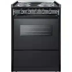
THREE-WIRE CONDUIT CONNECTION
1. Remove the access plate to gain access
to the electrical junction box.
2. Install the three-wire range conduit and
an appropriate strain relief clamp
through the hole in the junction box.
3. Use an appropriate insulated wire
connector to connect the red and black
wires from the range conduit to the
corresponding red and black leads from
the branch circuit.
4. Connect the green (ground) wire from
the range conduit to the white (neutral)
lead from the branch circuit in like
manner.
5. Secure the strain relief clamp around the
conduit and tighten the nut against the
wall of the junction box.
6. Tuck all wire leads into the junction box
and replace the access plate removed
earlier in step 1.
If local codes do not allow grounding
through the neutral, refer to the
illustration below of FOUR-WIRE
CONDUIT CONNECTION.
NOTE: A 4-conductor connection is to be
used when the appliance is installed in a
mobile home or when local codes do not
permit grounding through the neutral.
240 VAC
240 VAC
Effective January 1, 1996 the National Electrical
Code requires that new construction (not
existing) utilize a 4-conductor connection to an
electric range.
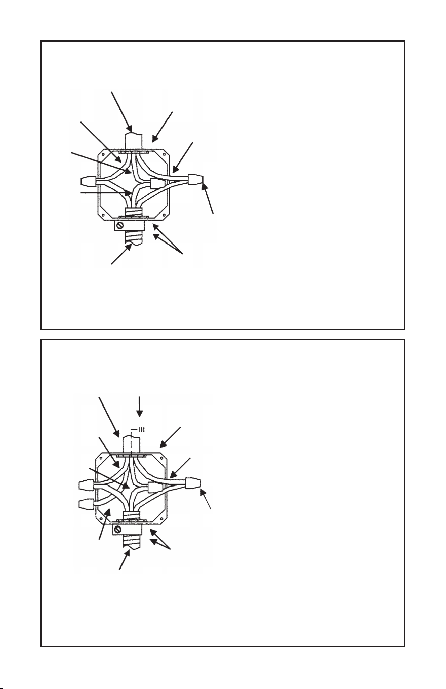
FOUR-WIRE CONDUIT CONNECTION
1. Remove the access plate to gain access
to the electrical junction box.
2. Install the four-wire range conduit and
an appropriate strain relief clamp through
the hole in the junction box.
3. Use an appropriate insulated wire
connector to connect the red and black
wires from the range conduit to the
corresponding red and black leads from
the branch circuit.
4. Connect the green (ground) wire from
the range conduit to the grounding lead
from the branch circuit in like manner.
5. The white (neutral) lead from the branch
circuit must be properly insulated away
from all other leads.
6. Secure the strain relief clamp around the
conduit and tighten the nut against the
wall of the junction box.
7. Tuck all wire leads into the junction
box and replace the access plate removed
earlier in step 1.
BRANCH
CIRCUIT
BLACK
LEAD
WHITE
LEAD
RED
LEAD
JUNCTION BOX
(ACCESS PLATE
REMOVED)
GREEN
(GROUND
TO UNIT)
RANGE
CONDUIT
STRAIN
RELIEF
CLAMP
& NUT
INSULATED WIRE
CONNECTORS
BRANCH
CIRCUIT
BLACK
LEAD
INSULATED
WHITE LEAD
JUNCTION BOX
(ACCESS PLATE
REMOVED)
GREEN
(GROUND
TO UNIT)
RANGE
CONDUIT
STRAIN
RELIEF
CLAMP
& NUT
INSULATED WIRE
CONNECTORS
BRANCH
GROUND
LEAD
RED
LEAD
Loading ...
Loading ...