Loading ...
Loading ...
Loading ...
12
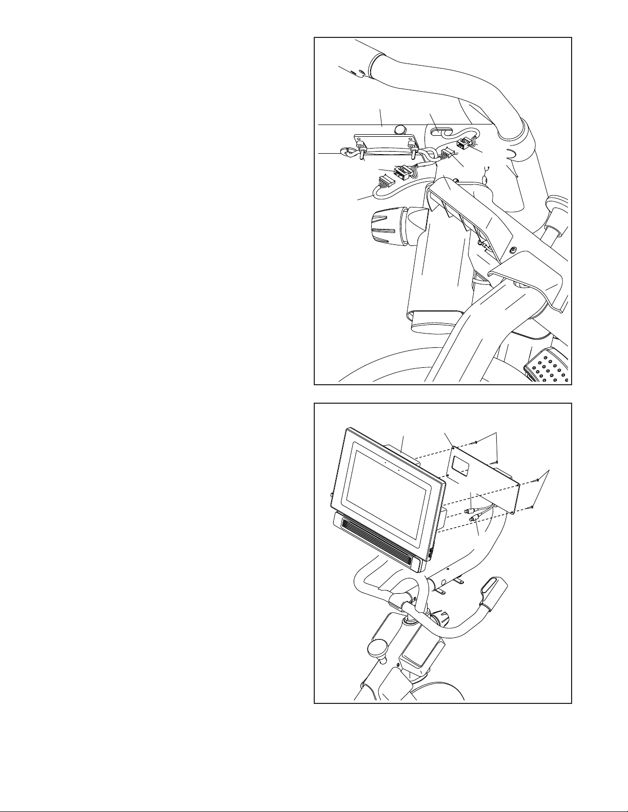
7. Look under the Console Support (8) and iden-
tify the Upper Wire (123), which has a larger
connector than the Extension Wire (124).
Connect the Upper Wire (123) to the Lower Wire
(122) extending from the Handlebar Post (7).
Then, insert the connectors on both Wires into
the Handlebar Post.
Next, connect the Extension Wire (124) to
the Control Wire (125) extending from the
Handlebar (97). Then, insert the connectors on
both Wires into the Handlebar.
8
7
97
122
125
124
7
123
Note: This drawing is scaled to 94% compared to the
other assembly drawings and to the exploded drawing.
8. Have a second person hold the Console (10)
near the Console Bracket (11).
Plug the Upper/Yellow Wire (123) and the
Extension/Red Wire (124) into the receptacles
on the back of the Console (10); make sure
to plug the Wire marked with red into the
receptacle marked with red, and plug the
Wire marked with yellow into the receptacle
marked with yellow.
Tip: Avoid pinching the wires. If neces-
sary, tilt the Console Bracket (11) upward
to make this step easier. Attach the Console
(10) to the Console Bracket with four #8 x 5/8"
Screws (17); start all the Screws, and then
tighten them.
Avoid pinching
the wires
8
17
11
10
17
123
124
Loading ...
Loading ...
Loading ...