1
0301710m 05/2023
Wi
re
le
s
s
by Lutron
Advanced Installation GuideAdvanced Installation Guide
Dimmer &
PRO dimmer
PD-6WCL/PD-10NXD
Plug-in
lamp dimmer
PD-3PCL
ELV+ Dimmer
PD-5NE
Thank you for purchasing Caséta Wireless from Lutron. This document will guide you through several additional
installation topics beyond those covered in the quick-start guide included with your product.
Table of Contents
Switch
PD-5WS-DV /
PD-5ANS / PD-6ANS
3-Way Installation -
If you have two switches controlling your lights, follow this procedure to install your dimmer or switch
With a Pico Remote Control
Dimmer with Pico Remote Control (PD-6WCL): ............................................................................................................ Page 3 - 6
Switch with Pico Remote Control (PD-5WS-DV): .......................................................................................................... Page 7 - 10
PRO Dimmer with Pico Remote Control (PD-10NXD): ................................................................................................. Page 11 - 14
Neutral Switch with Pico Remote Control (PD-5ANS / PD-6ANS): .............................................................................. Page 15 - 18
ELV+ Dimmer with Pico Remote Control (PD-5NE): ..................................................................................................... Page 19 - 22
Fan Control with Pico Remote Control (PD-FSQN): ..................................................................................................... Page 23 - 26
Diva Smart Dimmer with Pico Remote Control (DVRF-6L): ......................................................................................... Page 27 - 30
Claro Smart Switch with Pico Remote Control (DVRF-5NS): ...................................................................................... Page 31 - 34
With a Mechanical Toggle Switch
Switch with Mechanical Toggle Switch (PD-5WS-DV): ................................................................................................ Page 35 - 37
PRO Dimmer with Mechanical Toggle Switch (PD-10NXD): ........................................................................................ Page 38 - 40
Neutral Switch with Mechanical Toggle Switch (PD-5ANS / PD-6ANS): ..................................................................... Page 41 - 43
Diva Smart Dimmer with Mechanical Toggle Switch (DVRF-6L): ................................................................................ Page 44 - 46
Claro Smart Switch with Mechanical Toggle Switch (DVRF-5NS): ............................................................................. Page 47 - 49
With a Wired Accessory
Diva Smart Dimmer with a Claro Smart Accessory Switch (DVRF-6L/DVRF-AS): .................................................... Page 50 - 53
Claro Smart Switch with a Claro Smart Accessory Switch (DVRF-5NS/DVRF-AS): ................................................. Page 54 - 57
Multi-Location Installation
- If you have three or more switches controlling your lights, follow this procedure to
install your dimmer or switch
With a Pico Remote Control
Dimmer with Pico Remote Controls (PD-6WCL): .......................................................................................................... Page 58 - 62
PRO Dimmer with Pico Remote Controls (PD-10NXD): ............................................................................................... Page 63 - 67
Switch with Pico Remote Controls (PD-5WS-DV): ........................................................................................................ Page 68 - 72
Neutral Switch with Pico Remote Controls (PD-5ANS / PD-6ANS): ............................................................................ Page 73 - 77
ELV+ Dimmer with Pico Remote Controls (PD-5NE): ................................................................................................... Page 78 - 82
Fan Control with Pico Remote Controls (PD-FSQN): ................................................................................................... Page 83 - 87
Diva Smart Dimmer with Pico Remote Controls (DVRF-6L) ......................................................................................... Page 88 - 92
Claro Smart Switch with Pico Remote Controls (DVRF-5NS) ...................................................................................... Page 93 - 97
With a Wired Accessory
Diva Smart Dimmer with Claro Smart Accessory Switch (DVRF-6L / DVRF-AS): ....................................................... Page 98 - 102
Claro Smart Switch with with Claro Smart Accessory Switch (DVRF-5NS / DVRF-AS): ............................................ Page 103 - 107
(continued on next page)
Fan Control
PD-FSQN
Motion Sensor
PD-OSENS /
PD-VSENS
Caséta Diva
Smart Dimmer
DVRF-6L
Caséta Claro
Smart Switch
DVRF-5NS
Caséta Claro Smart
Accessory Switch
DVRF-AS
2
by Lutron
Table of Contents
(continued)
Adjusting the Low-End Trim
- Follow this procedure if you experience performance issues such as flickering,
flashing or other abnormal light behavior when your dimmer is at a low light level
On a Dimmer (PD-6WCL): ......................................................................................................................................................Page 108
On a PRO Dimmer (PD-10NXD): ............................................................................................................................................Page 110
On an ELV+ Dimmer (PD-5NE): .............................................................................................................................................Page 112
On a Plug-In Lamp Dimmer (PD-3PCL): ......................................................................................................................... Page 114
On a Diva Smart Dimmer (DVRF-6L): ............................................................................................................................. Page 116
Adjusting the High-End Trim -
Follow this procedure to adjust the maximum light output allowed by your
dimmer
On a Dimmer (PD-6WCL): ................................................................................................................................................ Page 109
On a PRO Dimmer (PD-10NXD): ..................................................................................................................................... Page 111
On an ELV+ Dimmer (PD-5NE): ....................................................................................................................................... Page 113
On a Plug-In Lamp Dimmer (PD-3PCL): ......................................................................................................................... Page 115
Converting a Plug-In Lamp Dimmer to a Switch to Control Non-Dim Loads (Lights Only) (PD-3PCL)
Follow this procedure if you would like your plug-in lamp dimmer to act as a switch for non-dimmable lighting loads ...... Page 117
Setting Dimmer Phase on a Caséta Wireless ELV+ Dimmer (PD-5NE)
....................................................... Page 118
Removing Paired Pico Remote Controls -
Follow this procedure if you need to remove paired Pico remote
controls or reset your dimmer or switch to its factory default settings
From a Dimmer (PD-6WCL/PD-10NXD/PD-5NE/PD-3PCL): ........................................................................................ Page 119
From a Switch (PD-5WS-DV/PD-5ANS/PD-6ANS): ....................................................................................................... Page 120
From a Fan Control (PD-FSQN): ..................................................................................................................................... Page 121
From a Lutron Shade: ...................................................................................................................................................... Page 122
From a Diva Smart Dimmer (DVRF-6L): ......................................................................................................................... Page 124
From a Claro Smart Switch (DVRF-5NS): ........................................................................................................................ Page 125
Changing the Favorite Light Level on a Pico Remote Control -
Follow this procedure to change the
light level your dimmer recalls when you press the "Favorite" button on your Pico remote control ....................................... Page 126
Changing the Favorite Light Level on an ELV+ Dimmer (PD-5NE) -
Follow this procedure to change the
light level your dimmer recalls when you press the "Favorite" button on your Phase Selectable Dimmer ............................. Page 127
Changing the Favorite Fan Speed Setting on a Fan Control (PD-FSQN) -
Follow this procedure to
change the fan speed your control recalls when you press the "Favorite" button on your Fan Control ................................. Page 128
Installing a LUT-MLC Load Adapter with an Switch (PD-5WS-DV) -
The LUT-MLC is provided
to help ensure proper operation of the Caséta Wireless switch with LED, fluorescent, and ELV lighting loads..................... Page 129
Motion Sensor Placement and Coverage (PD-OSENS / PD-VSENS) - .................................................
Page 130
Motion Sensor Advanced Features (PD-OSENS / PD-VSENS) - ...........................................................
Page 136
Troubleshooting -
............................................................................................................................................................ Page 137

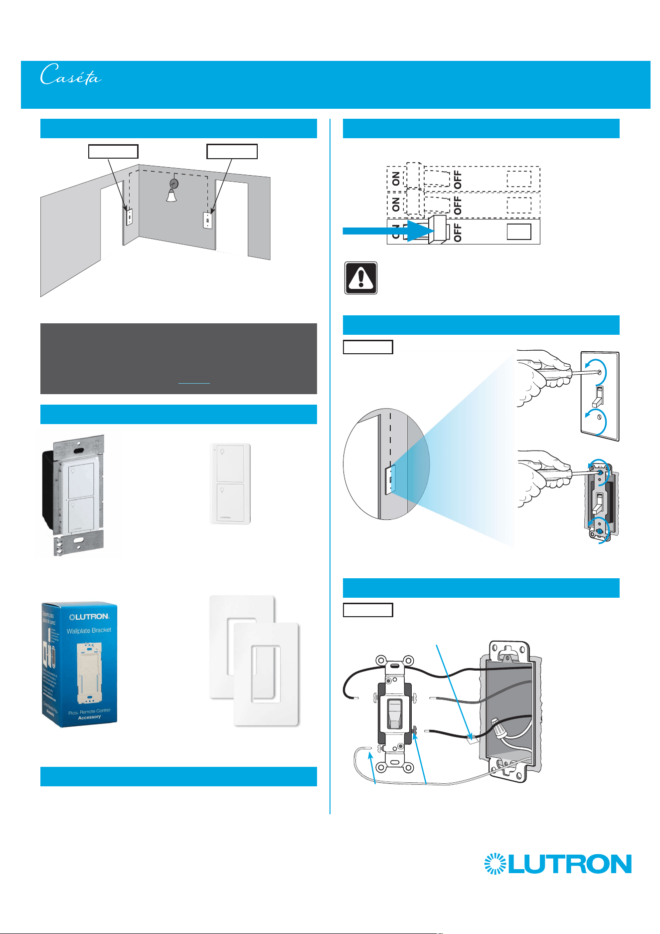
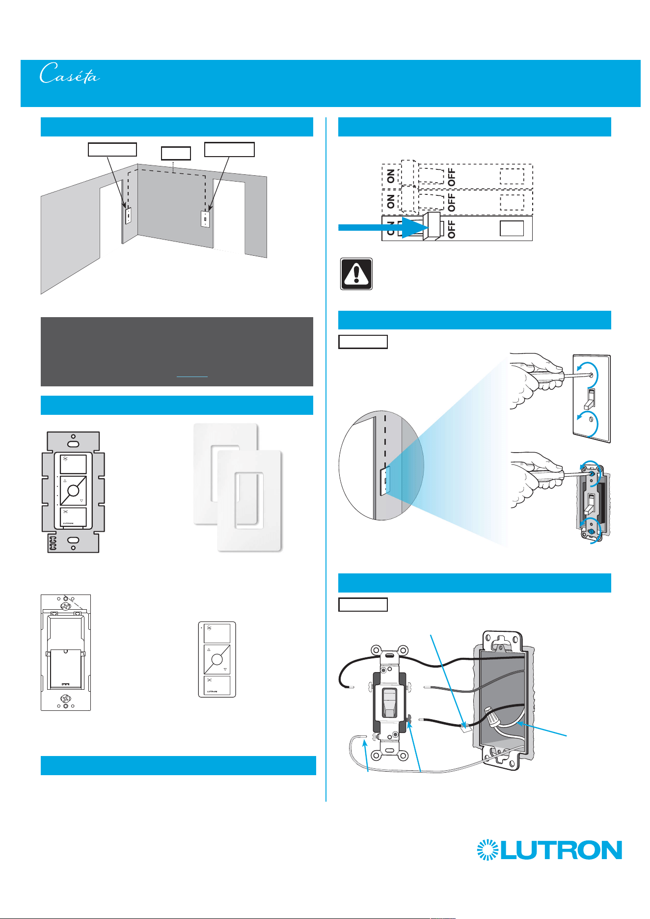
3
by Lutron
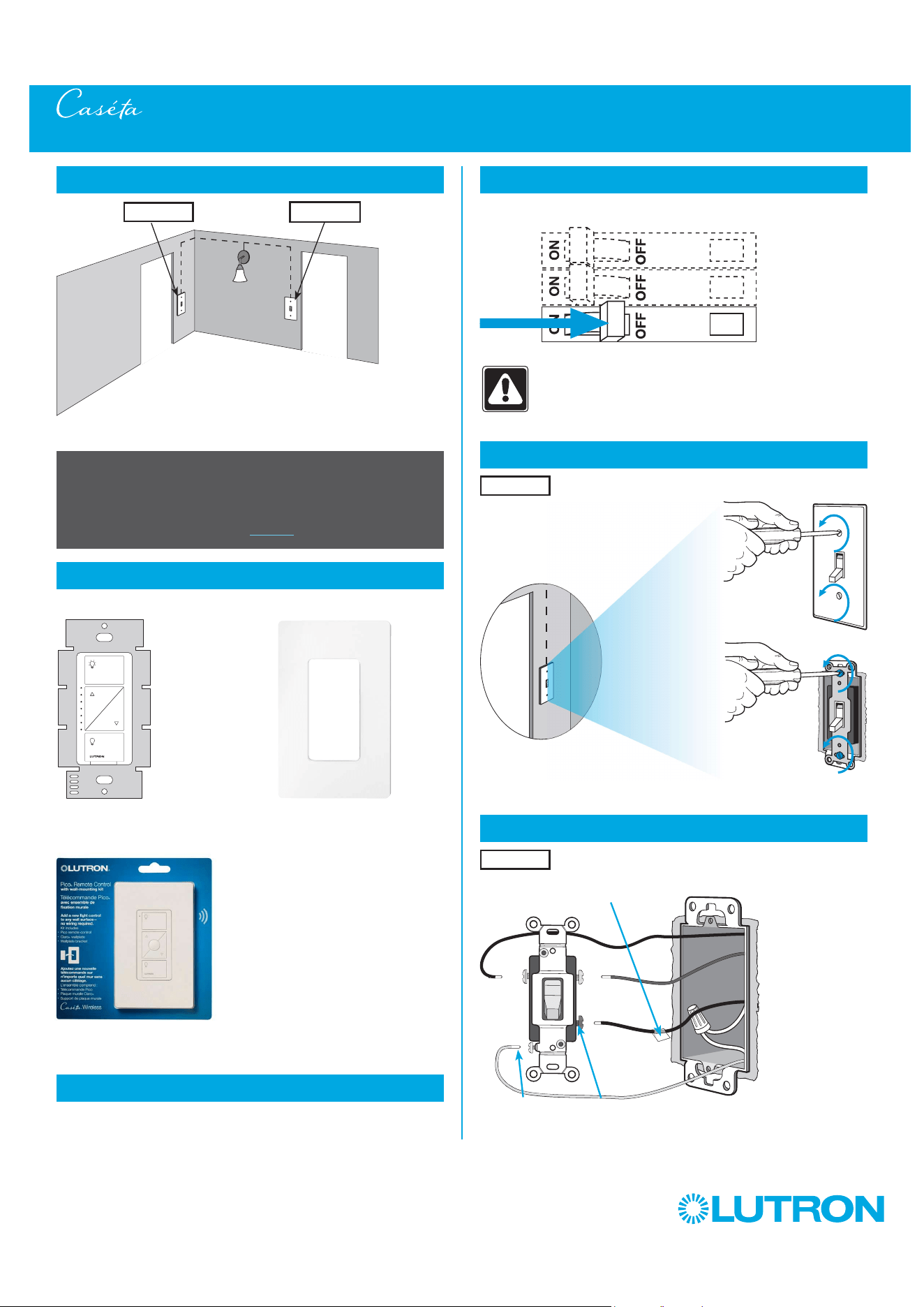
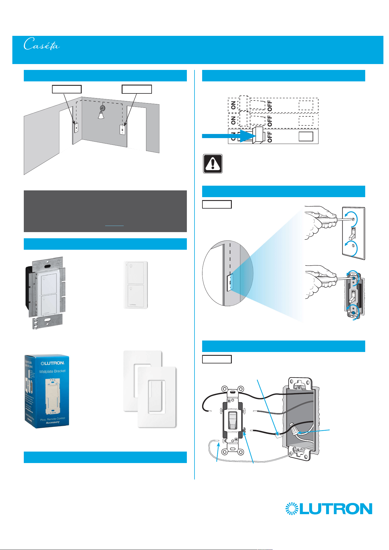
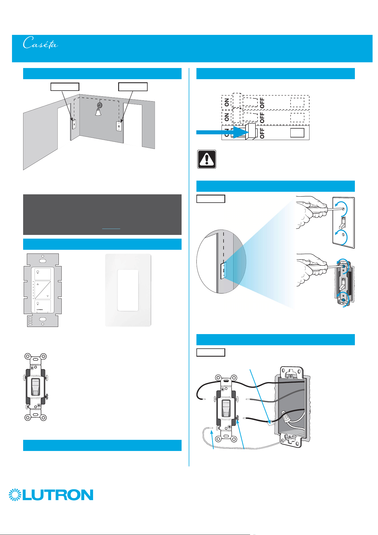
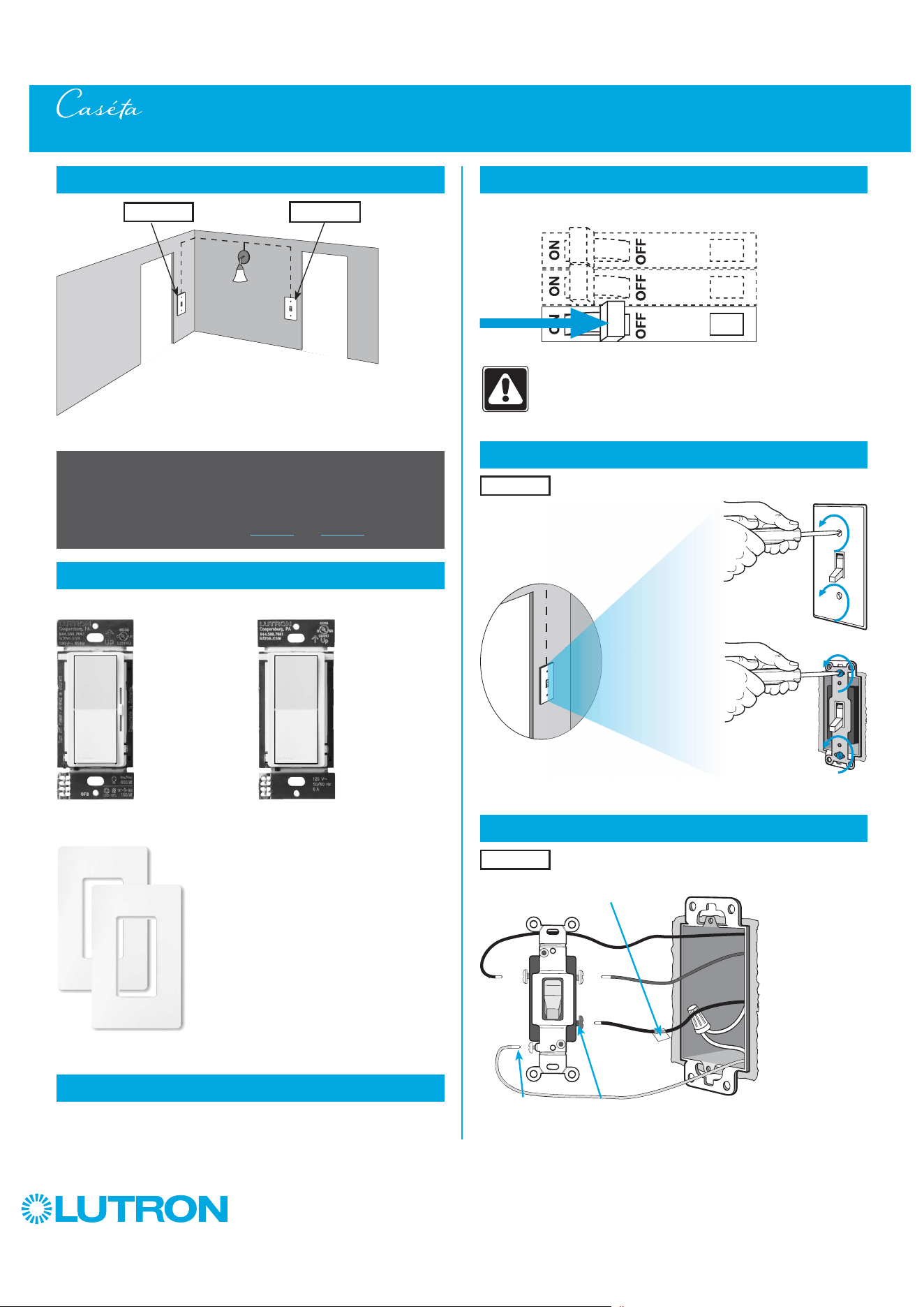
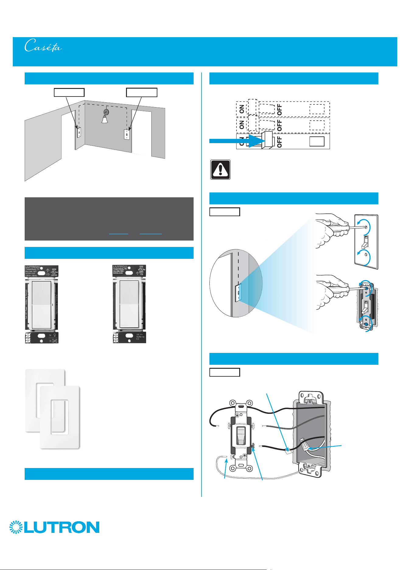
1
Identify existing wiring
Two switches control the lights (3-way installation)
2
What you need for a 3-way installation
+
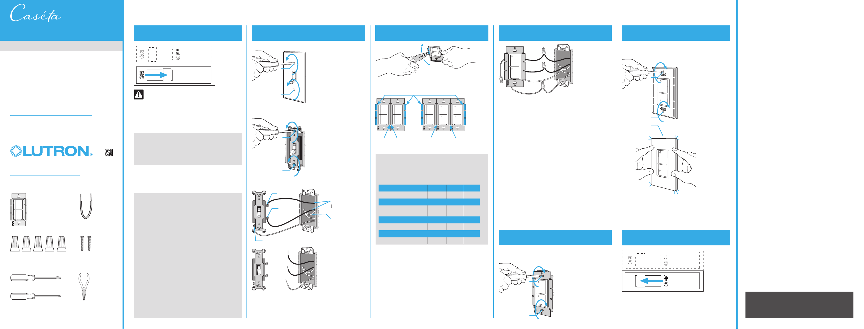
WARNING! Shock Hazard. May result in Serious
Injury or Death. Turn off power at circuit breaker
before installing the unit.
4
Turn power off at circuit breaker
5
Remove existing switch from wall
6
Tag and disconnect wires from the existing switch
Place tag - to identify wire on
different color screw
Different
Color
Screw
Ground
(Green /
Bare Copper)
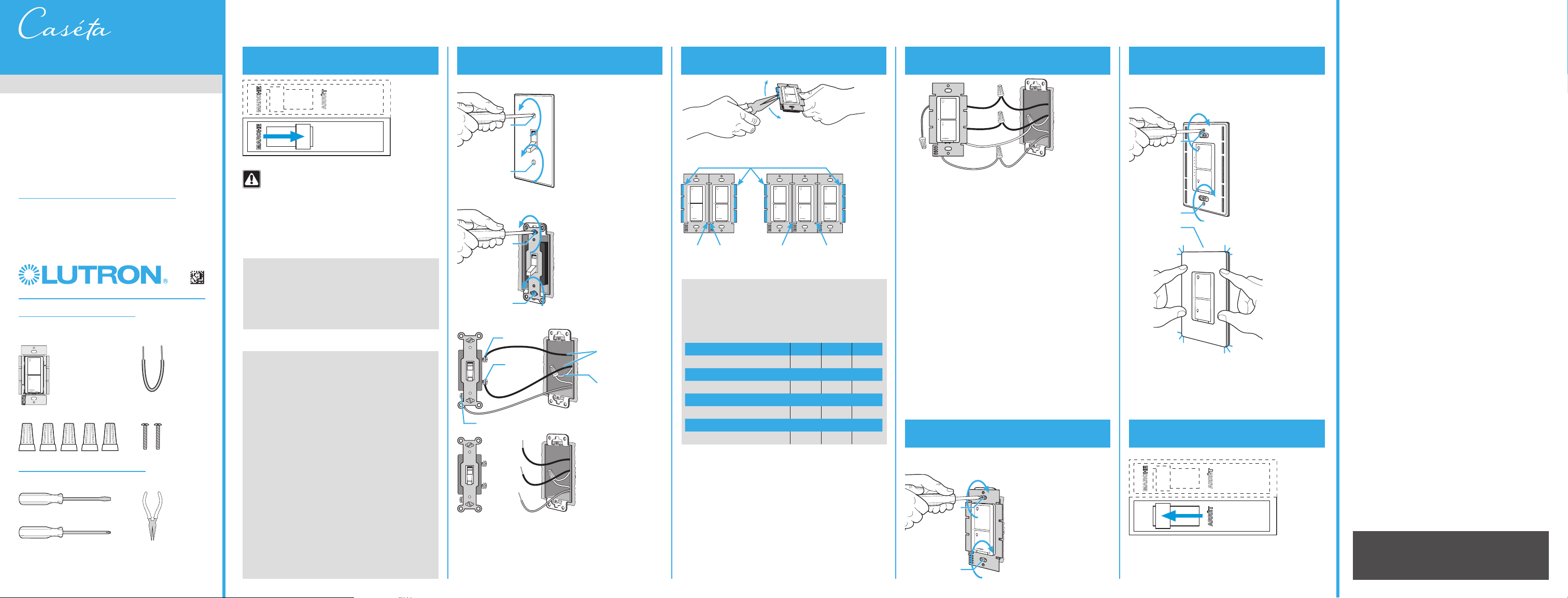
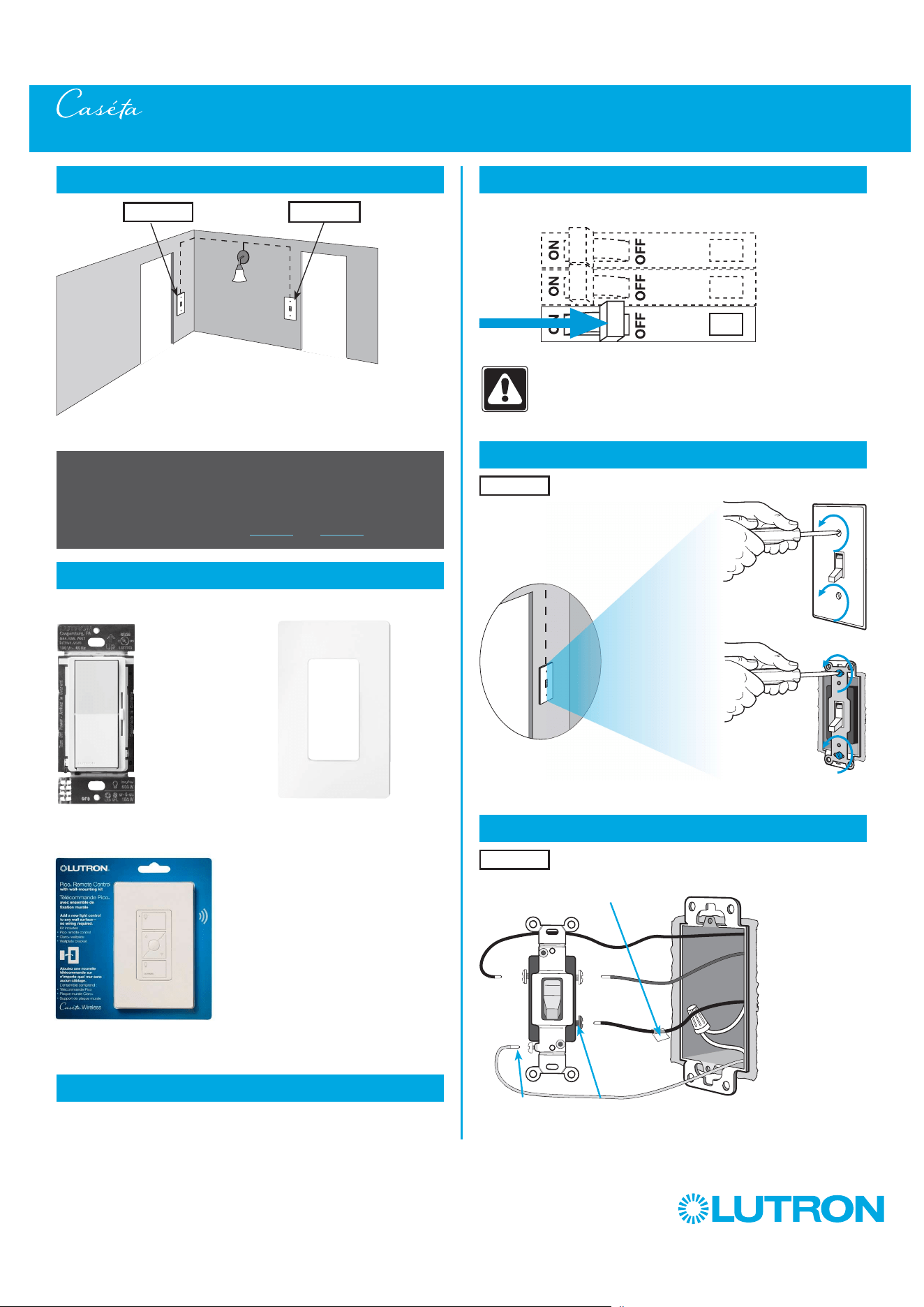
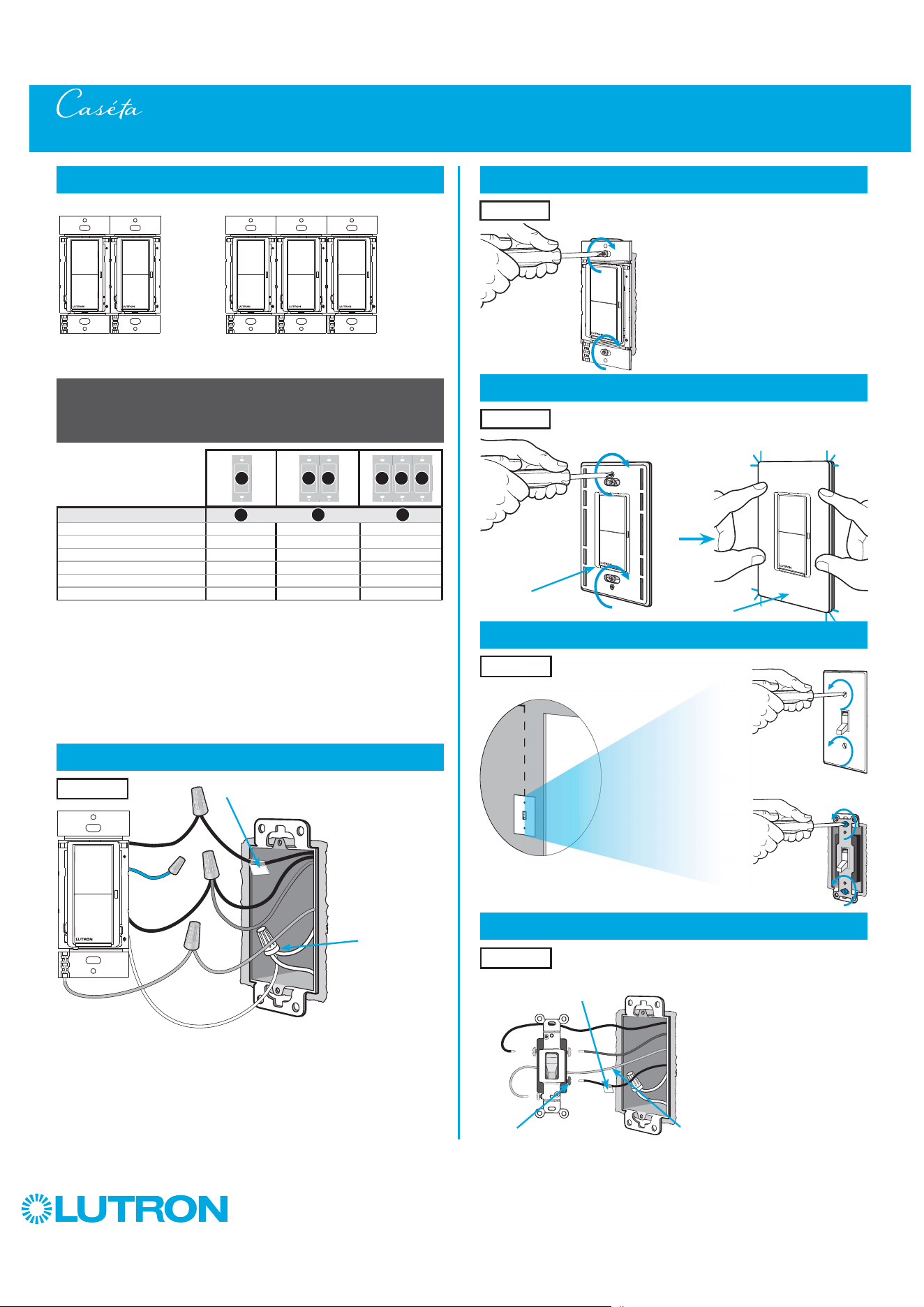
3-Way Installation - Caséta Wireless Dimmer with Pico Remote Control (PD-6WCL)
Location 1 Location 2
Dimmer
PD-6WCL
Pico remote control
with wall-mounting kit
PJ2-WALL
- If one switch controls the lights (single-pole installation)
See quick-start guide that came with your dimmer
- If three or more switches control the lights
(multi-location installation) See page 58 for details
Important note:
3
Choose a location for your Caséta Wireless dimmer
Choose which location you want the Caséta Wireless dimmer installed in.
This will be Location 1.
Location 1
Location 1
Claro wallplate
CW-1
+
4
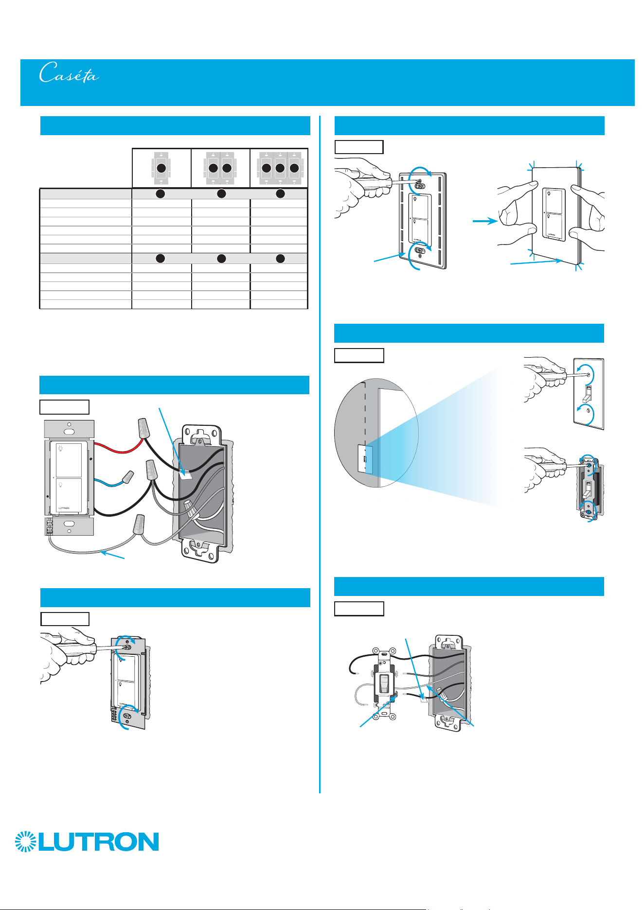
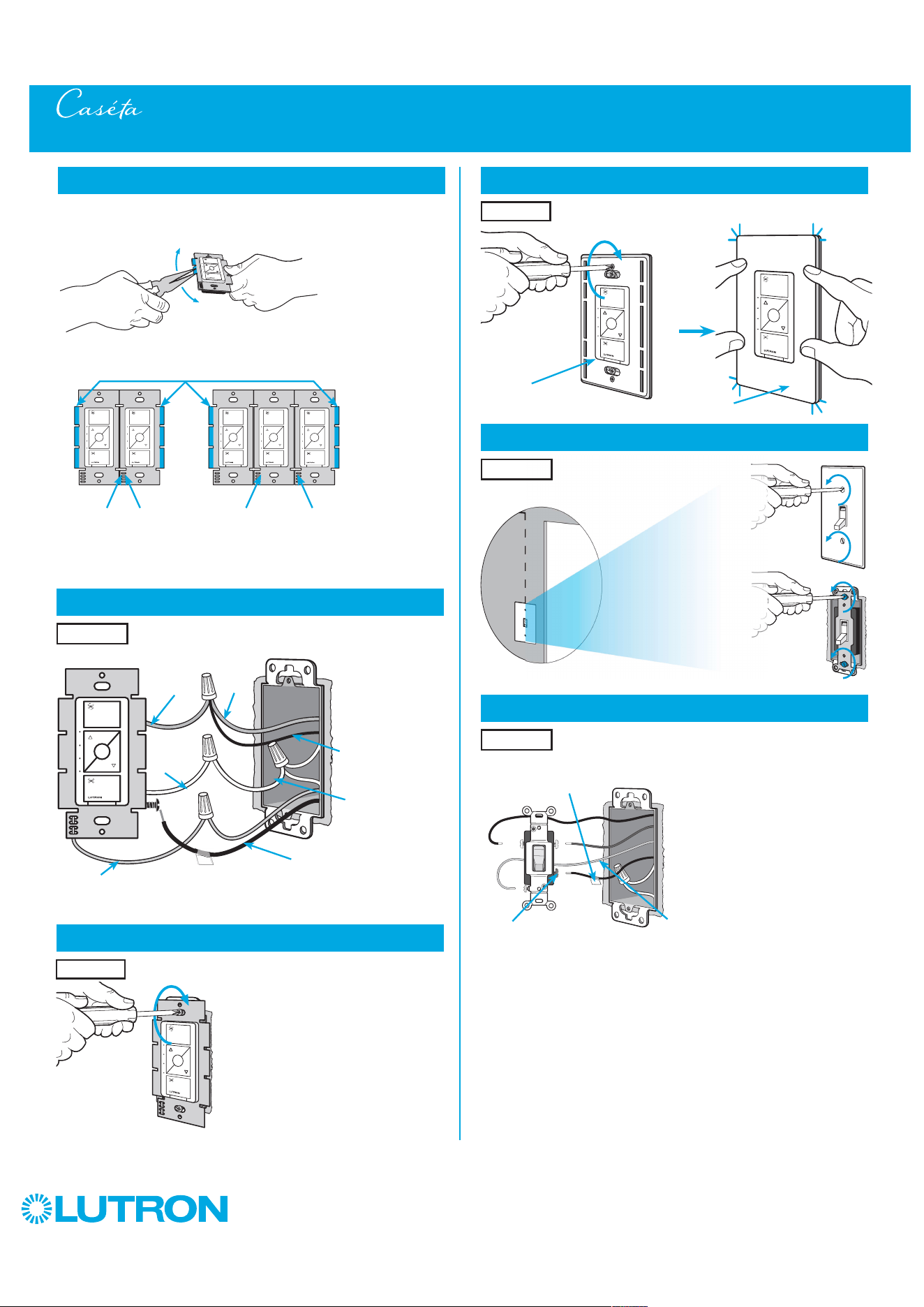
by Lutron
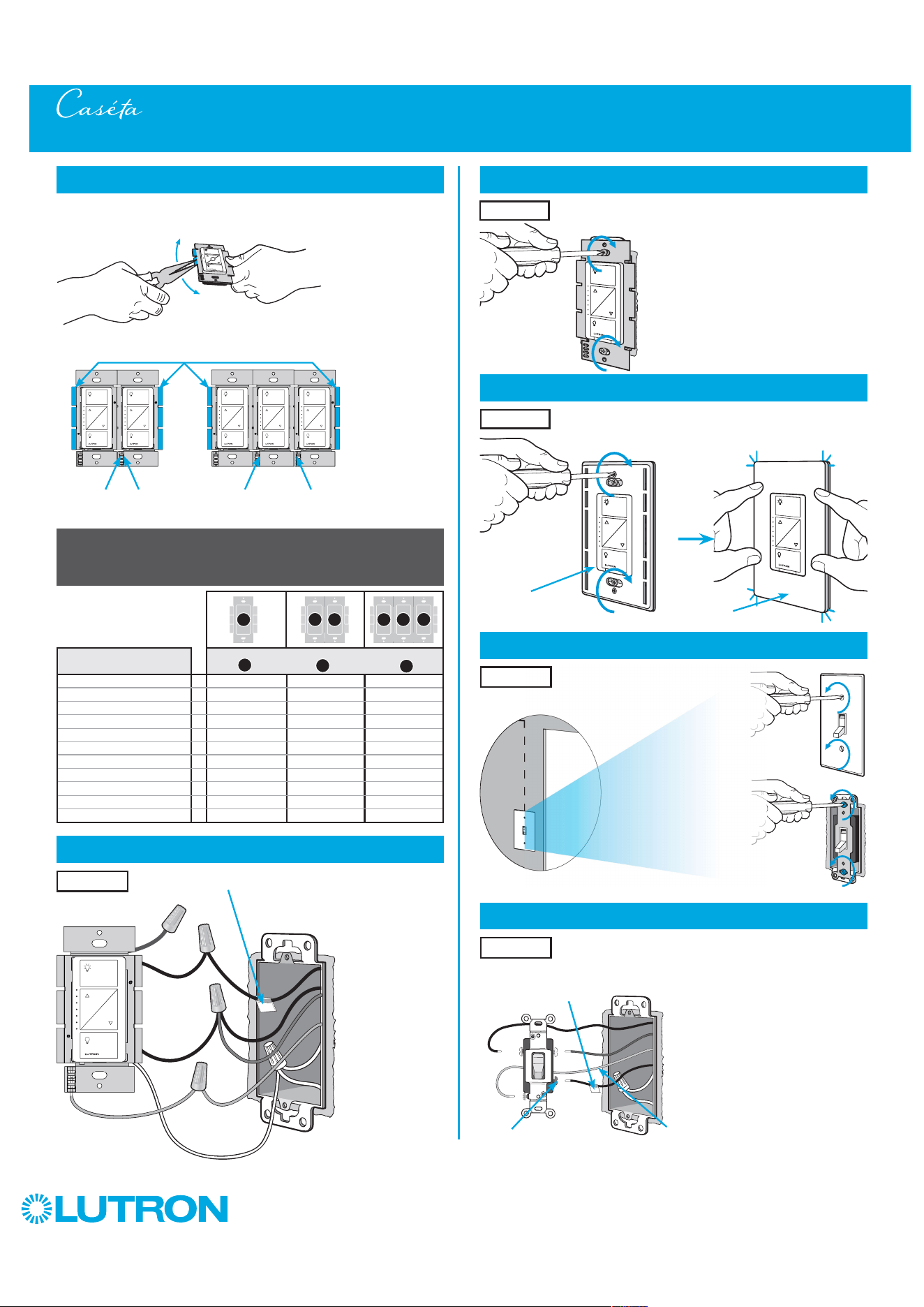
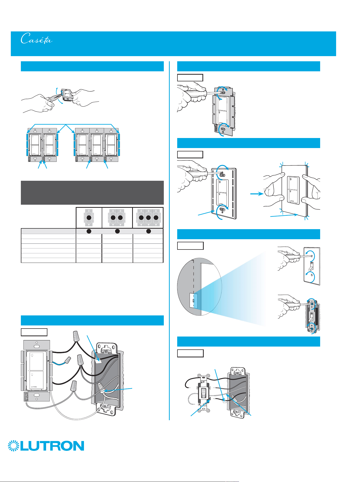
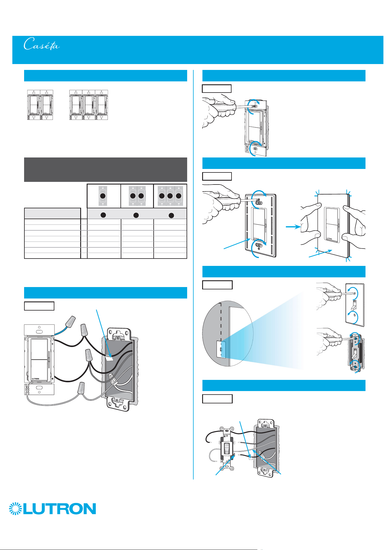
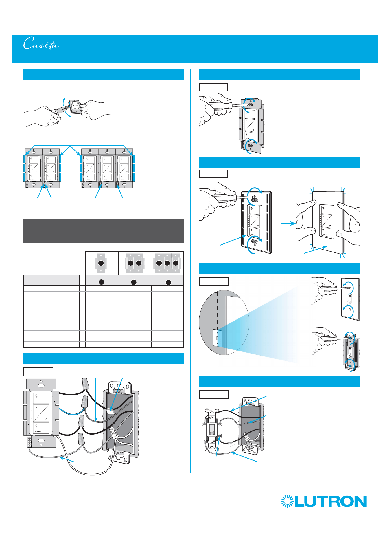
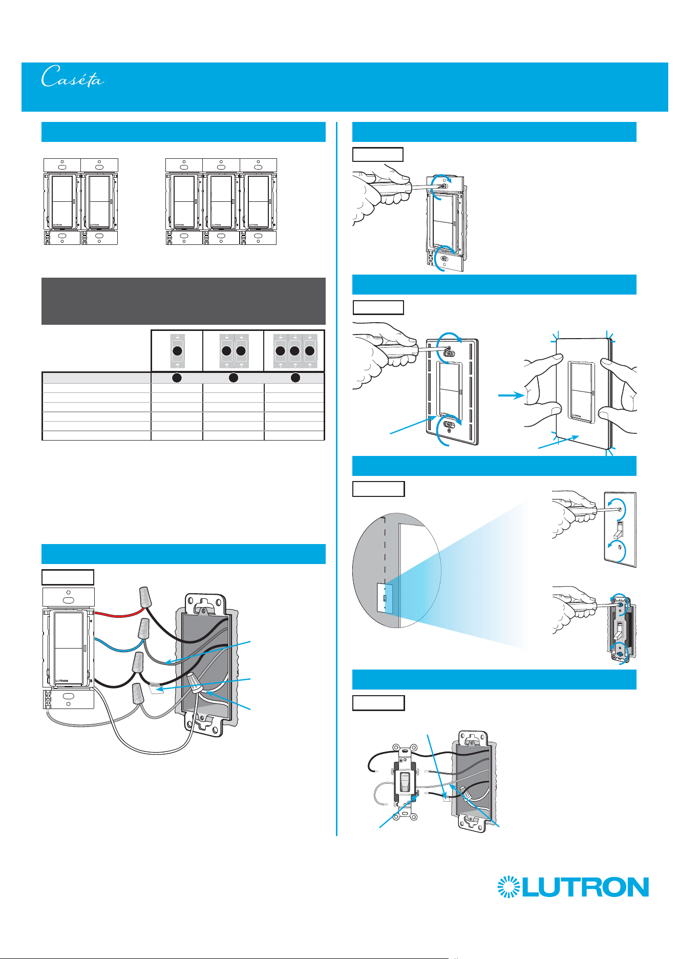
7
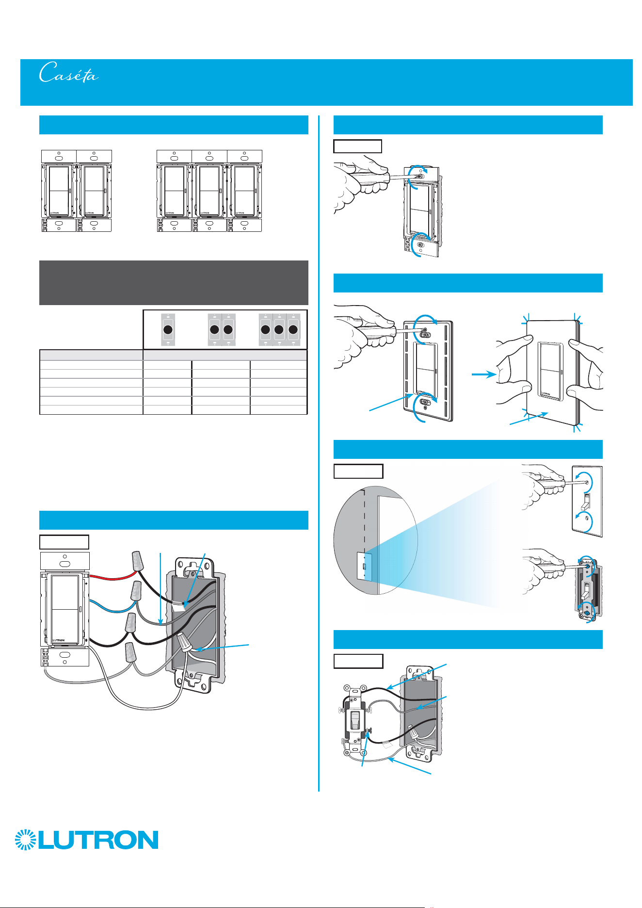
Remove side sections (if necessary)
Do not remove outside side sections
on dimmers at the end of gang.
Each dimmer has inside
side sections removed.
Dimmer in the middle
has all side sections
removed.
Total Dimmable LED Wattage
Incandescent/Halogen Total Wattage
0 W + 600 W 500 W 400 W
1 W – 25 W + 500 W 400 W 300 W
26 W – 50 W + 400 W 300 W 200 W
51 W – 75 W + 300 W 200 W 100 W
76 W – 100 W + 200 W 100 W 50 W
101 W – 125 W + 100 W 50 W 0 W
126 W – 150 W + 0 W 0 W 0 W
A
B
C
B B B C B
A
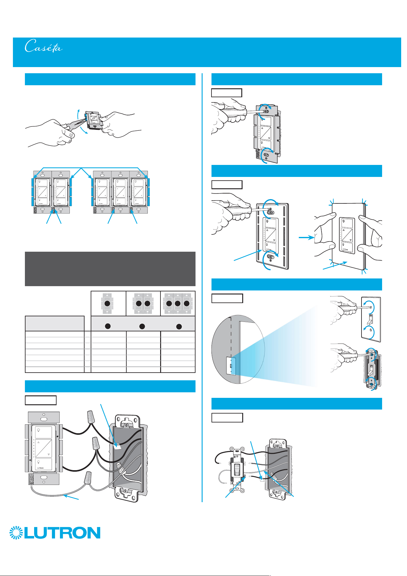
8
Connect the Caséta Wireless dimmer
Tagged Wire
Ground
(Green Wire)
9
Mount the Caséta Wireless dimmer
10
Attach the wallplate
‘snap’
11
Remove existing switch from wall at Location 2
3-Way Installation - Caséta Wireless Dimmer with Pico Remote Control (PD-6WCL)
12
Tag and disconnect wires from the switch
Ground (Green / Bare Copper)
Different
Color
Screw
Important note:
Removing side sections reduces the dimmer’s maximum wattage
rating. See the chart below for maximum wattage information.
When installing more than one Caséta Wireless dimmer in the same
wallbox, it is necessary to remove inner side sections prior to wiring. See
image and chart below for more information.
Wallplate
Adapter
Wallplate
Location 1
Location 1
Location 2
Place tag - to identify wire on
different color screw
Location 2
Location 1
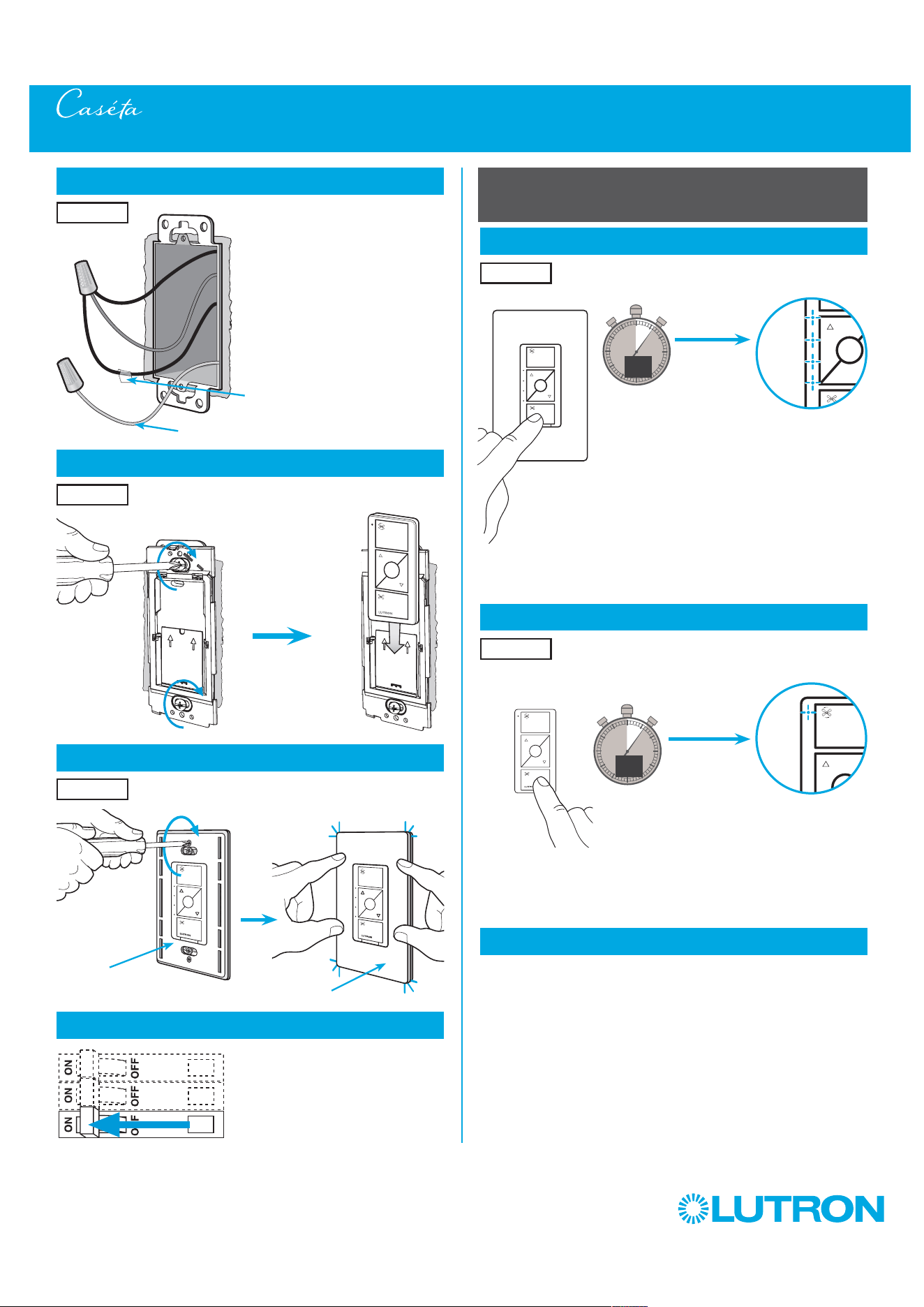
5
by Lutron
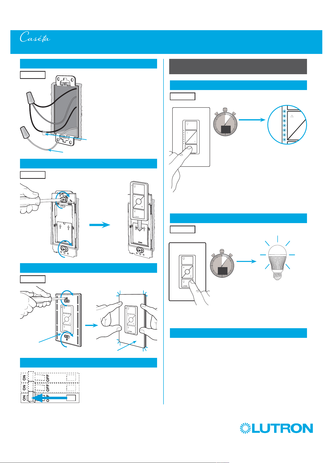
0
5
10
15
13
Connect the wires
Ground
14
Attach the wallplate bracket and Pico remote control
15
Attach the wallplate
‘snap’
16
Turn power on at circuit breaker
3-Way Installation - Caséta Wireless Dimmer with Pico Remote Control (PD-6WCL)
Pairing the dimmer and Pico remote control
17
Press and hold "Off" button on dimmer
6
sec.
UNTIL
HOLD
Status LEDs flash
18
Press and hold "Off" button on remote control
Lights flash
three times
0
5
10
15
6
sec.
UNTIL
Wallplate
Adapter
Wallplate
Location 2
Tagged Wire
Location 2
Location 2
Location 2
Location 1
Repeat steps 17 and 18 to pair additional
remote controls.
19
Pair additional remote controls
HOLD
3x

6
by Lutron
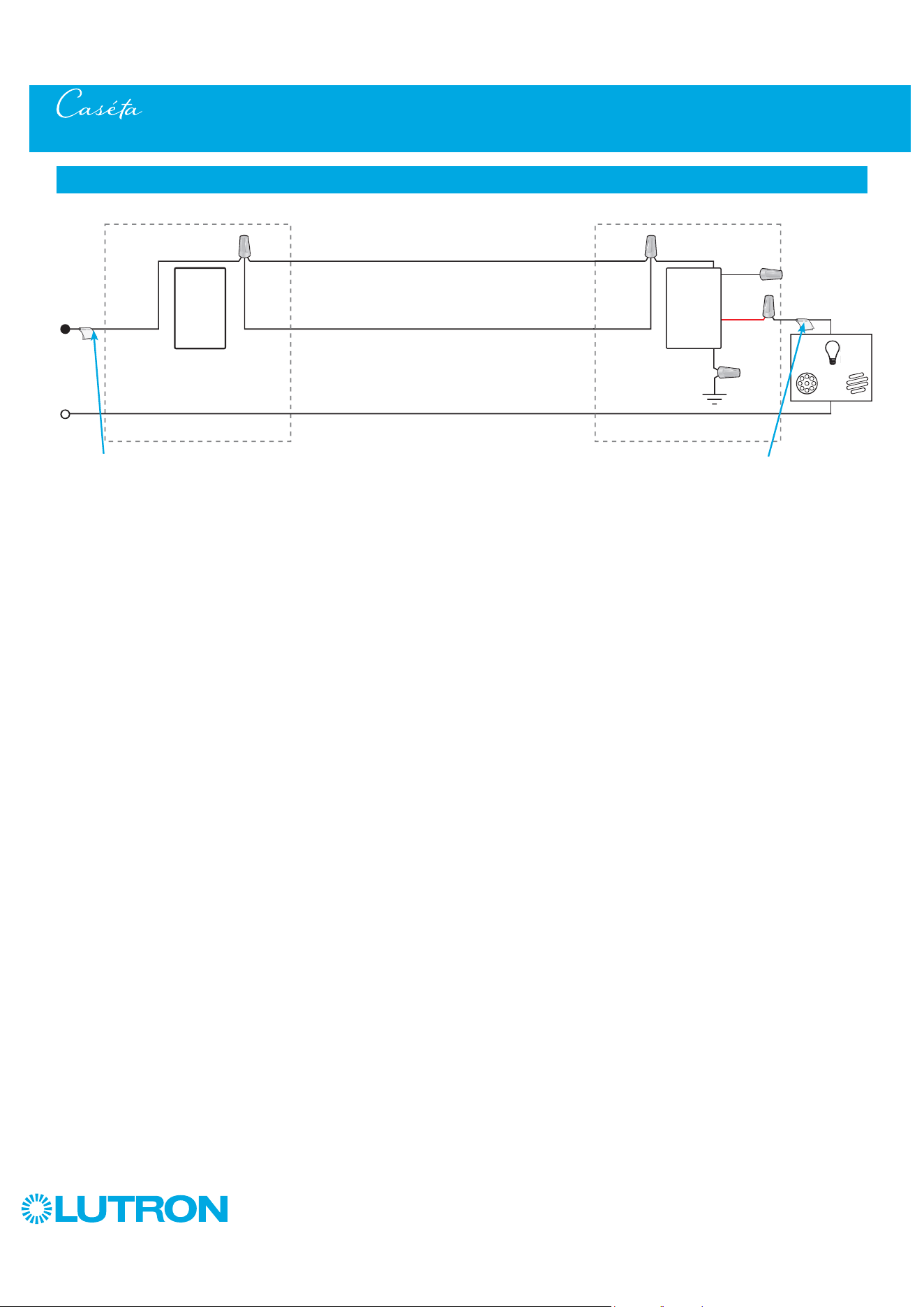
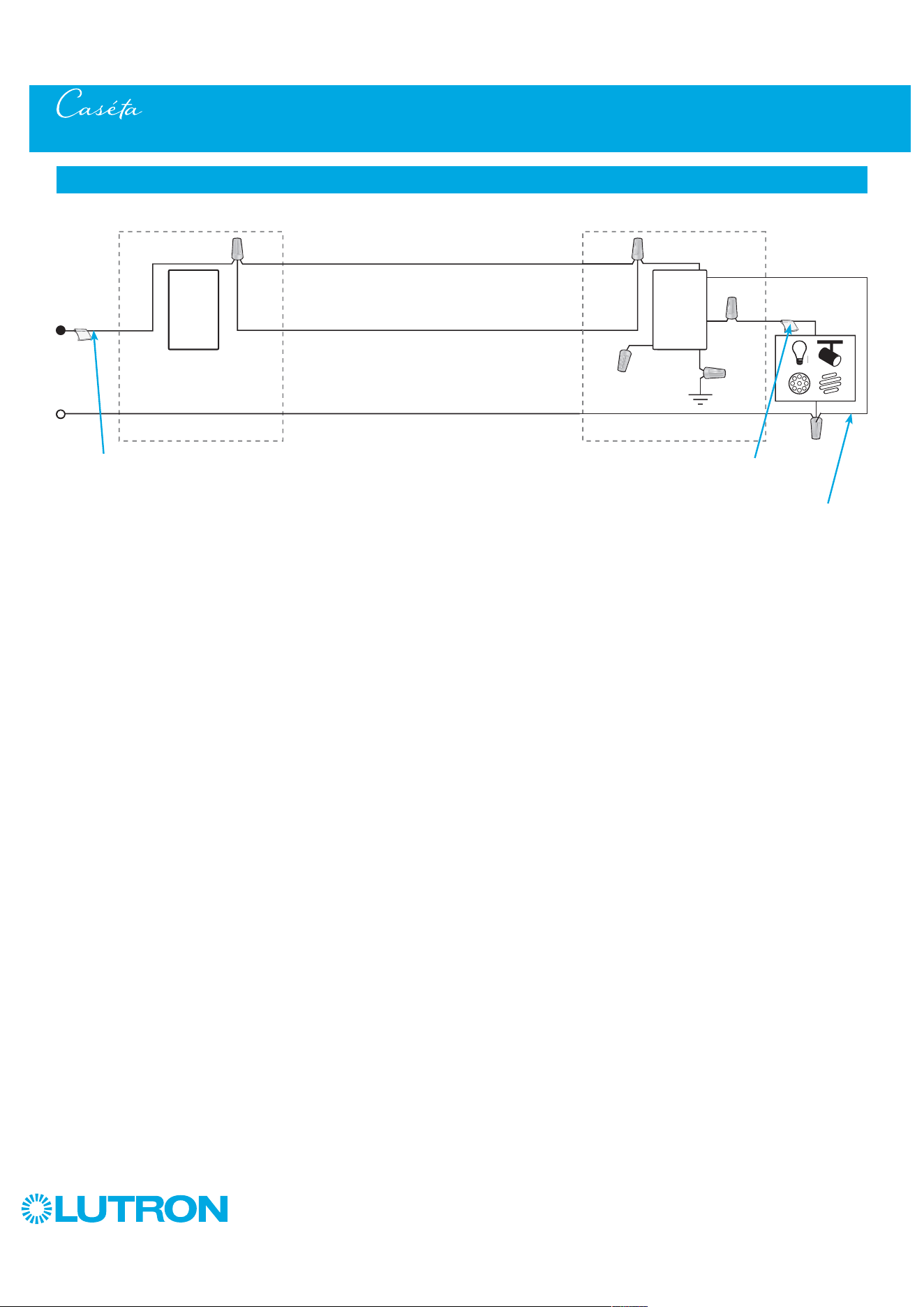
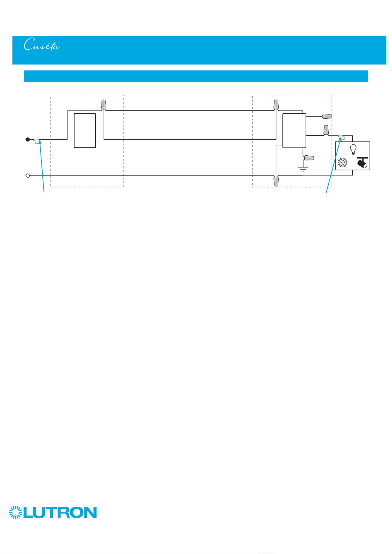
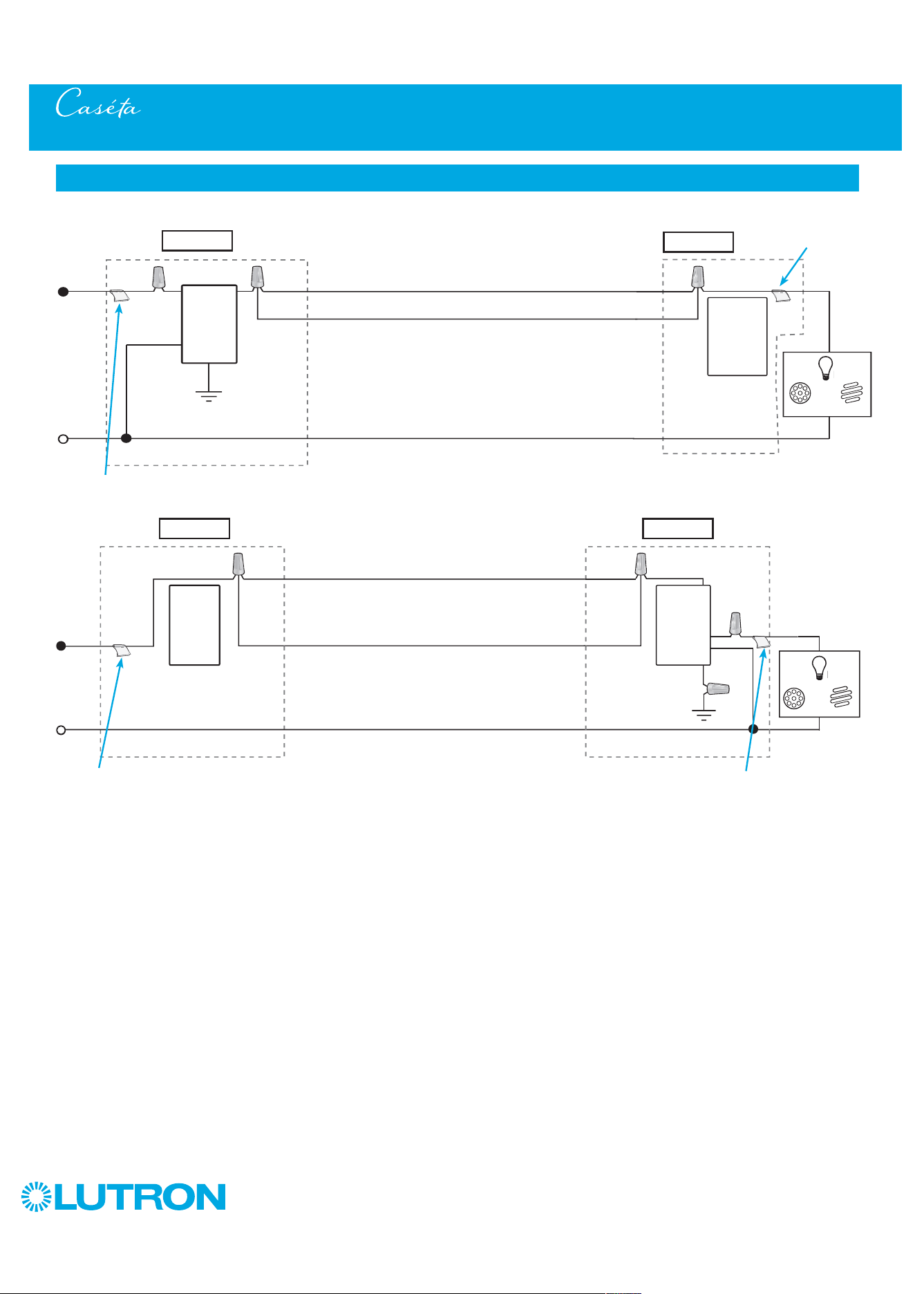
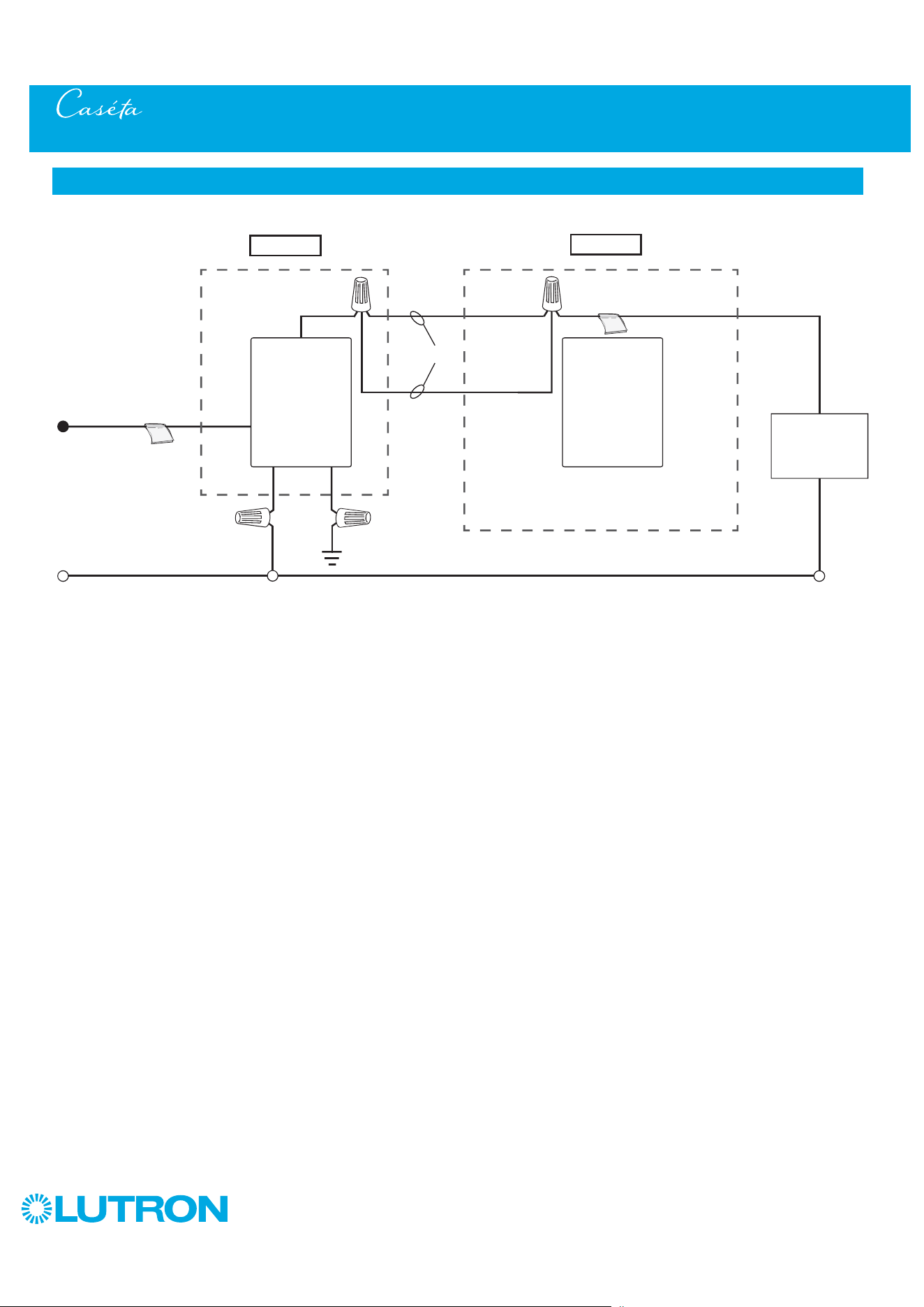
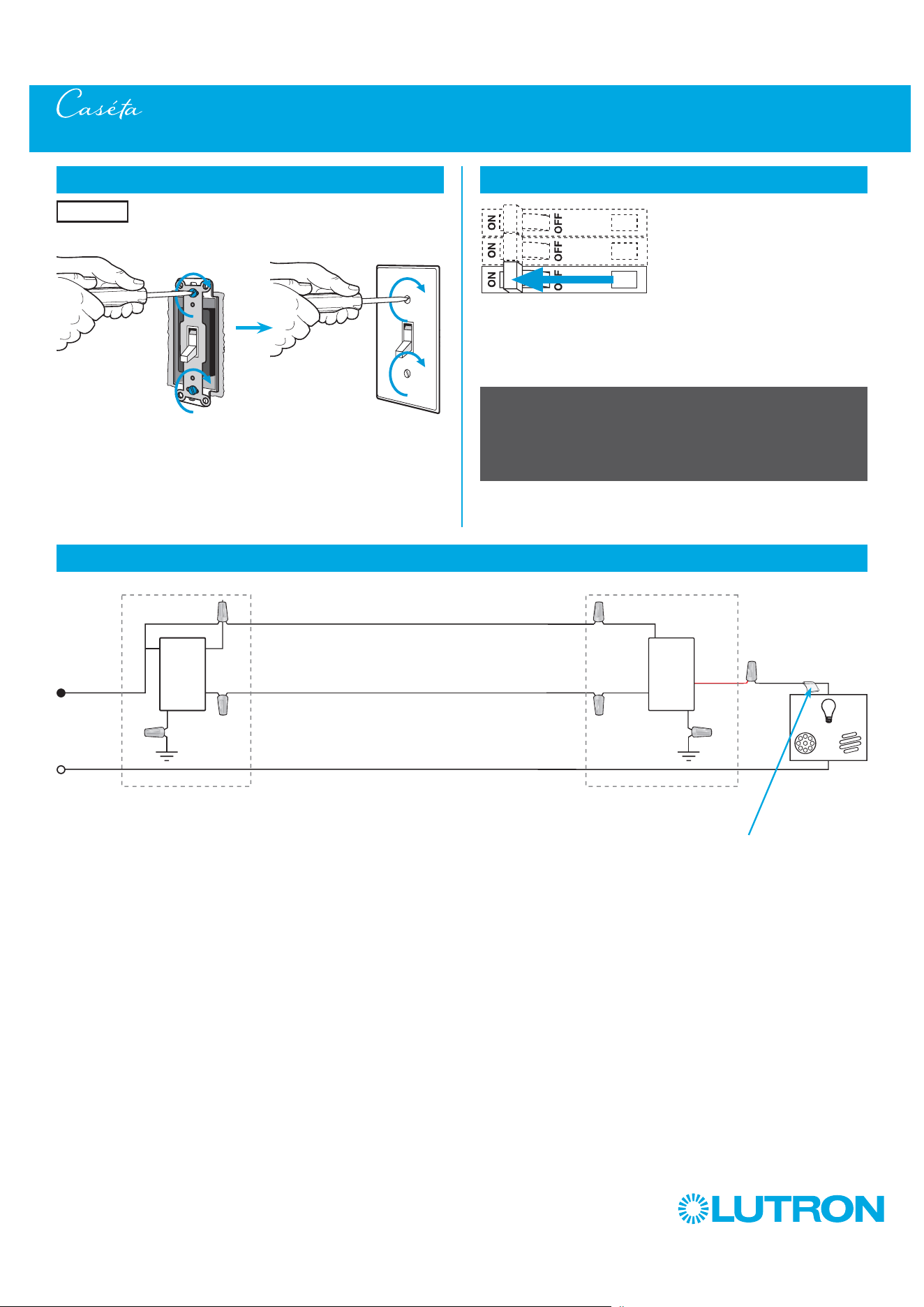
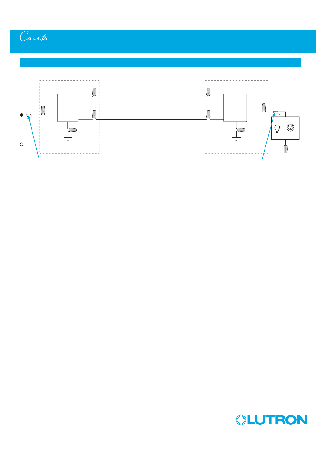
3-Way Installation - Caséta Wireless Dimmer with Pico Remote Control (PD-6WCL)
Neutral
Pico
Remote
Control
Line / Hot
Traveler
Caséta
Wireless
Dimmer *
Ground
Load
INC
HAL
Schematic Diagram
Traveler
* Dimmer may be installed in either location.
Tagged Wire
Tagged Wire
7
by Lutron
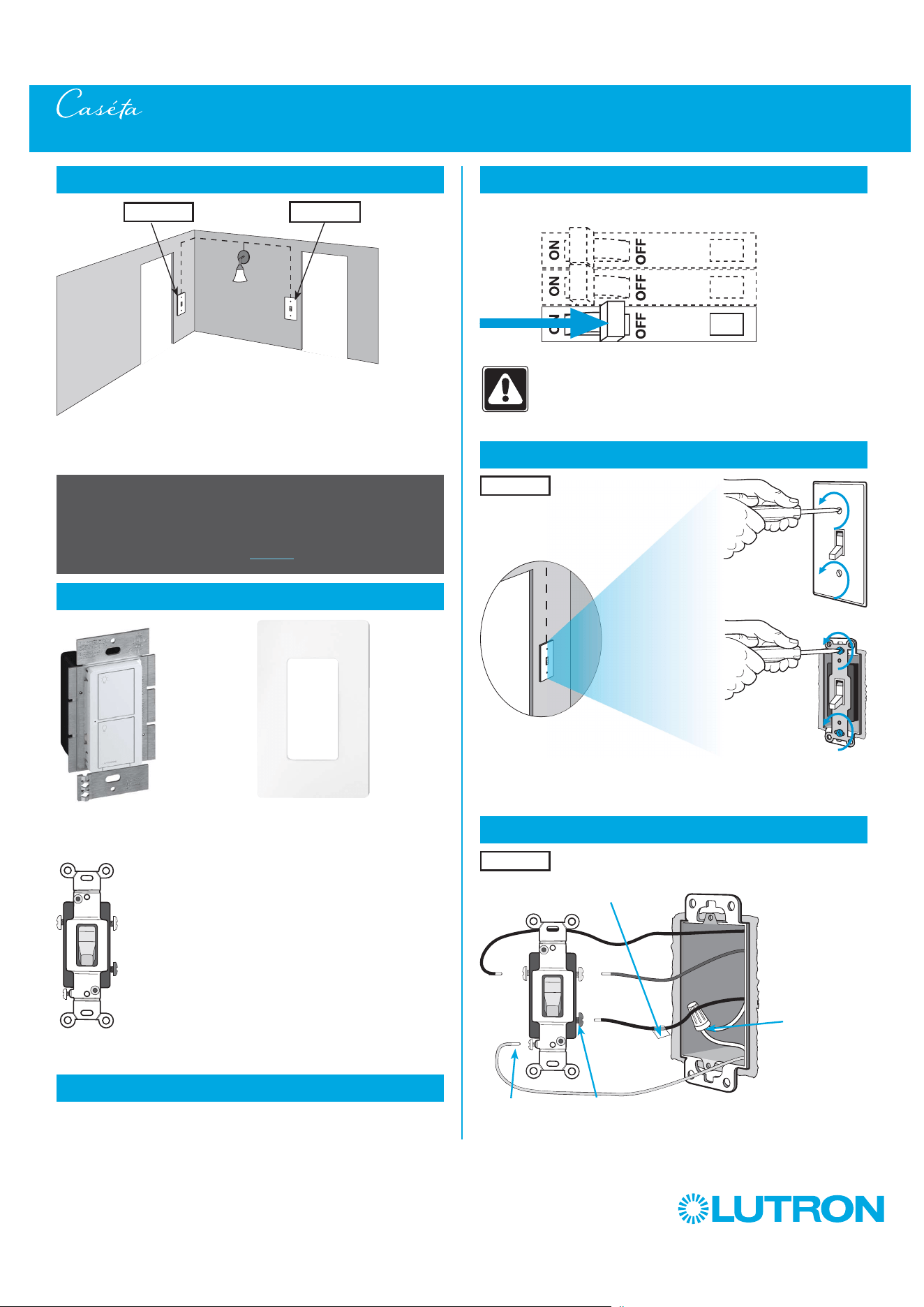
1
Identify existing wiring
Two switches control the lights (3-way installation)
2
What you need for a 3-way installation
WARNING! Shock Hazard. May result in Serious
Injury or Death. Turn off power at circuit breaker
before installing the unit.
4
Turn power off at circuit breaker
5
Remove existing switch from wall
6
Tag and disconnect wires from the existing switch
Place tag - to identify wire on
different color screw
Different
Color
Screw
Ground
(Green /
Bare Copper)
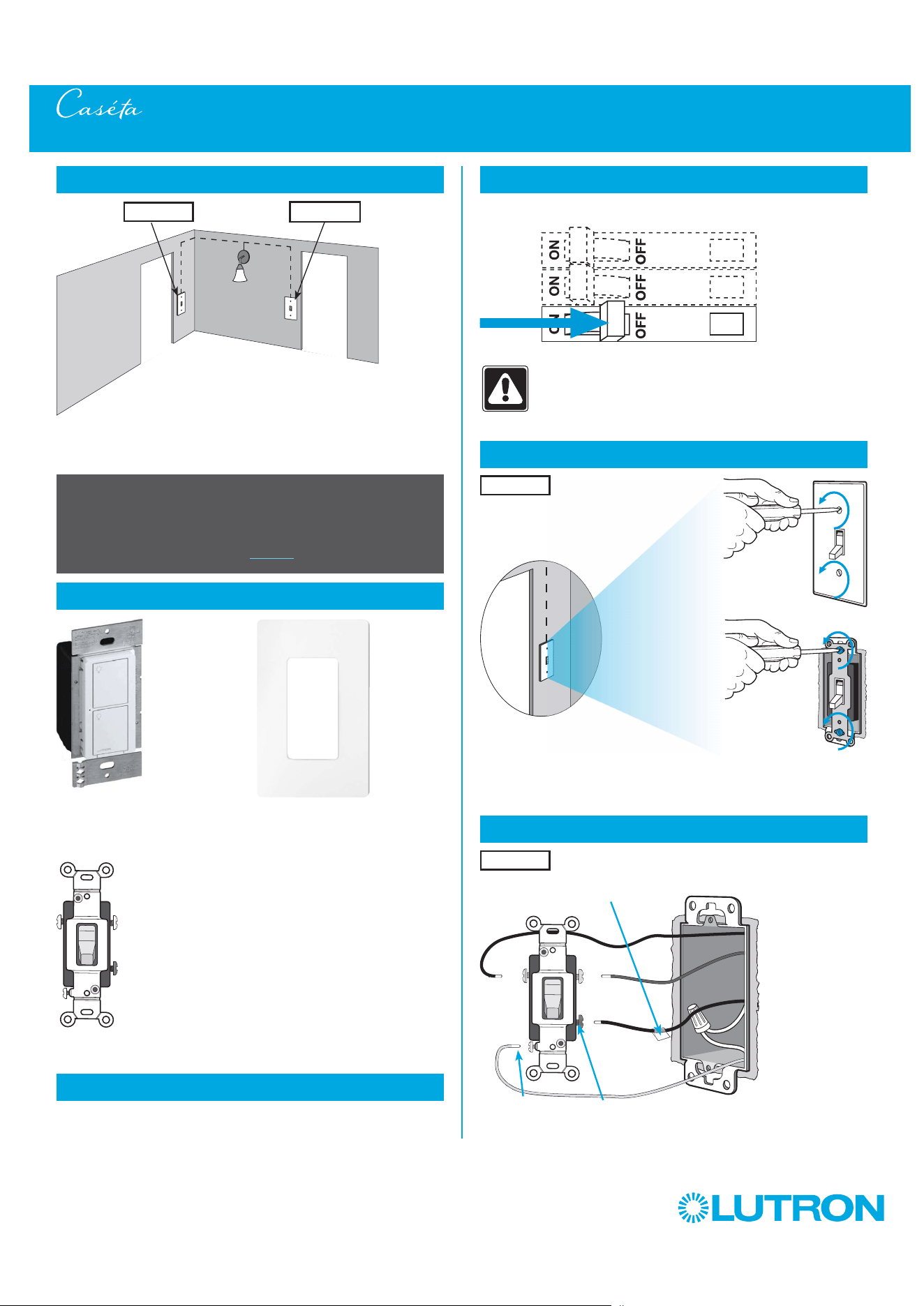
3-Way Installation - Caséta Wireless Switch with Pico Remote Control (PD-5WS-DV)
Location 1 Location 2
- If one switch controls the lights (single-pole installation)
See quick-start guide that came with your switch
- If three or more switches control the lights
(multi-location installation) See page 68 for details
Important note:
3
Choose a location for your Caséta Wireless switch
Choose which location you want the Caséta Wireless switch installed in.
This will be Location 1.
Location 1
Location 1
+
Switch
PD-5WS-DV
Pico remote control
PJ2-2B
+
Wallplate bracket
PICO-WBX-ADAPT
+
Two Claro wallplates
CW-1
8
by Lutron
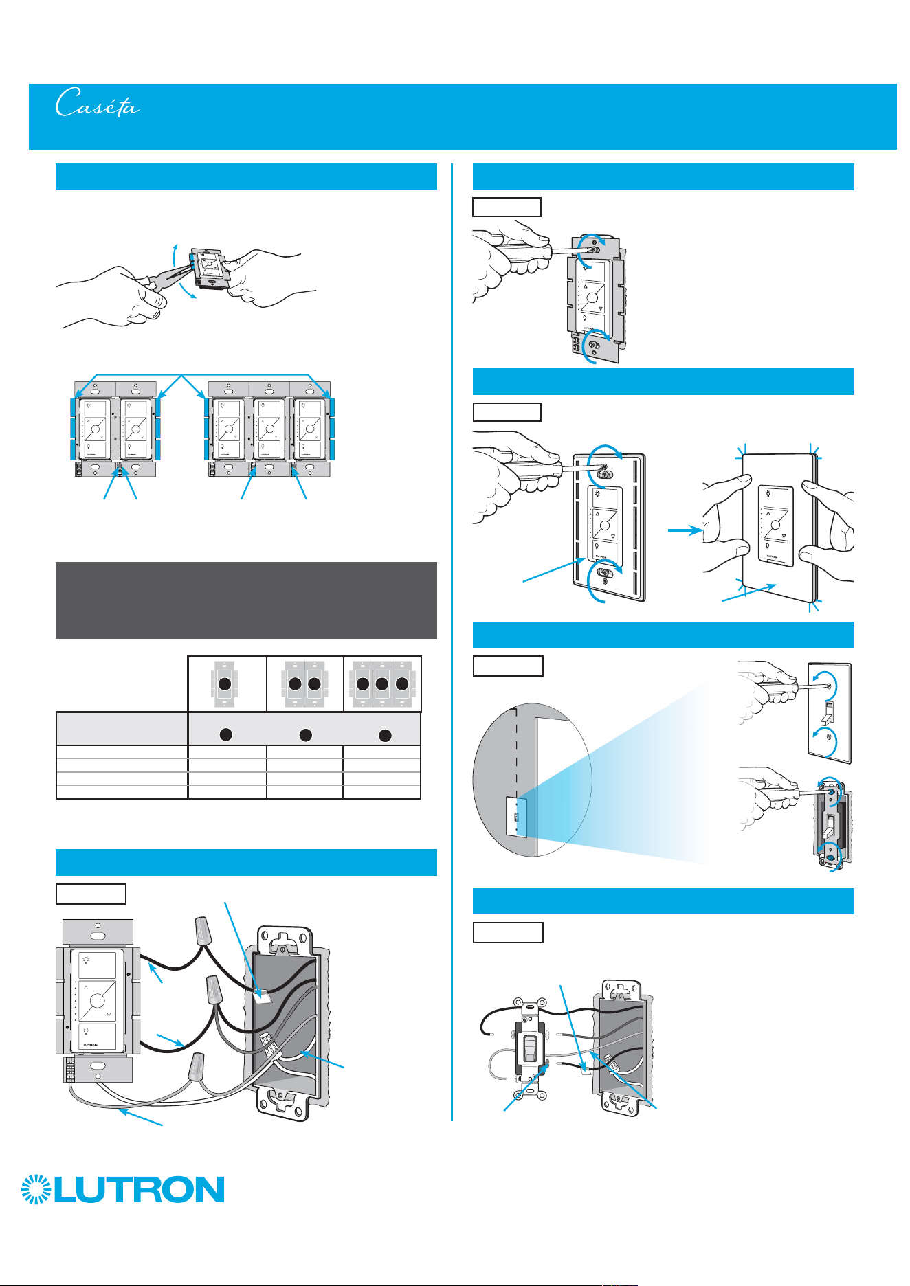
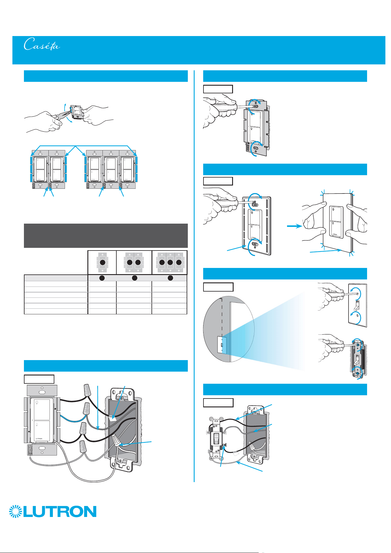
7
Ganging and derating
8
Connect the new Caséta Wireless switch
Tagged Wire
Ground
(Green Wire)
9
Mount the Caséta Wireless switch
10
Attach the wallplate
‘snap’
11
Remove existing switch from wall at Location 2
3-Way Installation - Caséta Wireless Switch with Pico Remote Control (PD-5WS-DV)
12
Tag and disconnect wires from the existing switch
Ground (Green / Bare Copper)
Different
Color
Screw
Wallplate
Adapter
Wallplate
Location 1
Location 1
Location 2
Place tag - to identify wire on
different color screw
Location 2
Location 1
B
B B C
B
A
PD-5WS-DV (120 V
~
)
LED 5 A 4 A 3 A
Halogen / incandescent 600 W 450 W 350 W
Electronic Low-Voltage 600 W 450 W 350 W
Magnetic Low-Voltage
1
600 VA / 475 W 450 VA / 350 W 350 VA / 275 W
Fluorescent
2
5 A 4 A 3 A
General Purpose Fan 3 A 3 A 3 A
PD-5WS-DV ( 277 V
~
)
LED 5 A 4 A 3 A
Halogen / incandescent 1350 W 1100 W 800 W
Electronic Low-Voltage 1350 W 1100 W 800 W
Magnetic Low-Voltage
1
1350 VA / 1075 W 1100 VA / 875 W 800 VA / 625 W
Fluorescent
2
5 A 4 A 3 A
A
B C
A
B C
1
The maximum lamp wattage is determined by the efficiency of the transformer, with
70% – 85% as typical. For actual transformer efficiency, contact either the fixture or
transformer manufacturer. The total VA rating of the transformer(s) shall not exceed the VA
rating of the switch.
2
The switch is UL
R
Listed for use with all magnetic and electronic fluorescent ballasts.
Red
Blue
Black

9
by Lutron
13
Connect the wires
Ground
14
Attach the wallplate bracket and Pico remote control
15
Attach the wallplate
‘snap’
16
Turn power on at circuit breaker
3-Way Installation - Caséta Wireless Switch with Pico Remote Control (PD-5WS-DV)
Pairing the switch and Pico remote control
17
Press and hold "Off" button on switch
0
5
10
15
6
sec.
UNTIL
HOLD
Status LED flashes
18
Press and hold "Off" button on remote control
Lights flash
three times
0
5
10
15
6
sec.
UNTIL
Wallplate
Adapter
Wallplate
Location 2
Tagged Wire
Location 2
Location 2
Location 2
Location 1
Repeat steps 17 and 18 to pair additional
remote controls.
19
Pair additional remote controls
HOLD
3x
10
by Lutron
3-Way Installation - Caséta Wireless Switch with Pico Remote Control (PD-5WS-DV)
Neutral
Pico
Remote
Control
Line / Hot
Traveler
Caséta
Wireless
Switch *
Ground
(Green)
Load
INC
HAL
Schematic Diagram
Traveler
* Switch may be installed in either location.
Tagged Wire
Tagged Wire
Red
Blue
Black
11
by Lutron
1
Identify existing wiring
Two switches control the lights (3-way installation)
2
What you need for a 3-way installation
+
WARNING! Shock Hazard. May result in Serious
Injury or Death. Turn off power at circuit breaker
before installing the unit.
4
Turn power off at circuit breaker
5
Remove existing switch from wall
6
Tag and disconnect wires from the existing switch
Place tag - to identify wire on
different color screw
Different
Color
Screw
Ground
(Green /
Bare Copper)
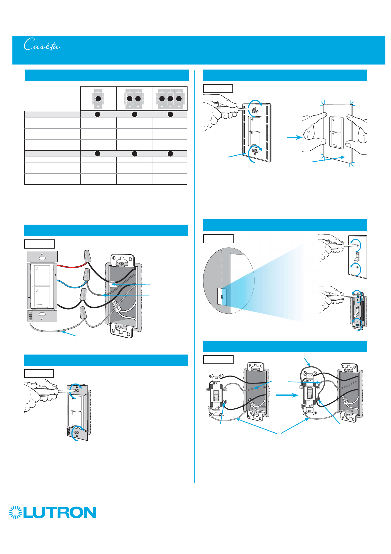
3-Way Installation - Caséta Wireless PRO Dimmer with Pico Remote Control (PD-10NXD)
Location 1 Location 2
PRO dimmer
PD-10NXD
Pico remote control
with wall-mounting kit
PJ2-WALL
- If one switch controls the lights (single-pole installation)
See quick-start guide that came with your dimmer
- If three or more switches control the lights
(multi-location installation) See page 63 for details
Important note:
3
Choose a location for your Caséta Wireless dimmer
Choose which location you want the Caséta Wireless dimmer installed in.
This will be Location 1.
Location 1
Location 1
Claro wallplate
CW-1
+
12
by Lutron
7
Remove side sections (if necessary)
Do not remove outside side sections
on dimmers at the end of gang.
Each dimmer has inside
side sections removed.
Dimmer in the middle has all
side sections removed.
Total Dimmable LED Wattage Incandescent/Halogen Total Wattage
0 W + 1000 W 800 W 600 W
1 W – 25 W + 900 W 750 W 550 W
26 W – 50 W + 800 W 700 W 500 W
51 W – 75 W + 700 W 600 W 450 W
76 W – 100 W + 600 W 500 W 400 W
101 W – 125 W + 500 W 400 W 300 W
126 W – 150 W + 400 W 300 W 200 W
151 W – 175 W + 300 W 200 W 100 W
176 W – 200 W + 200 W 100 W 50 W
201 W – 225 W + 100 W 50 W 0 W
226 W – 250 W + 0 W 0 W 0 W
A
B
C
B B B C B
A
8
Connect the Caséta Wireless dimmer
Tagged Wire
Ground
(Green Wire)
Red
White *
*
If available,
connect the
neutral wire from
the wallbox to the
white wire on the
dimmer. If neutral
is not available,
cap the white
wire with a wire
connector.
Neutral required
for: MLV loads,
LED drivers,
PHPM-PA,
PHPM-3F,
GRX-TVI.
Black
Blue
9
Mount the Caséta Wireless dimmer
10
Attach the wallplate
‘snap’
11
Remove existing switch from wall at Location 2
3-Way Installation - Caséta Wireless PRO Dimmer with Pico Remote Control (PD-10NXD)
12
Tag and disconnect wires from the switch
Ground (Green / Bare Copper)
Different
Color
Screw
Important note:
Removing side sections reduces the dimmer’s maximum wattage
rating. See the chart below for maximum wattage information.
When installing more than one Caséta Wireless dimmer in the same
wallbox, it is necessary to remove inner side sections prior to wiring. See
image and chart below for more information.
Wallplate
Adapter
Wallplate
Location 1
Location 1
Location 2
Place tag - to identify wire on
different color screw
Location 2
Location 1
13
by Lutron
13
Connect the wires
Ground
14
Attach the wallplate bracket and Pico remote control
15
Attach the wallplate
‘snap’
16
Turn power on at circuit breaker
3-Way Installation - Caséta Wireless PRO Dimmer with Pico Remote Control (PD-10NXD)
Pairing the dimmer and Pico remote control
17
Press and hold "Off" button on dimmer
0
5
10
15
6
sec.
UNTIL
HOLD
Status LEDs flash
18
Press and hold "Off" button on remote control
Lights flash
three times
0
5
10
15
6
sec.
UNTIL
Wallplate
Adapter
Wallplate
Location 2
Tagged Wire
Location 2
Location 2
Location 2
Location 1
Repeat steps 17 and 18 to pair additional
remote controls.
19
Pair additional remote controls
HOLD
3x
14
by Lutron
3-Way Installation - Caséta Wireless PRO Dimmer with Pico Remote Control (PD-10NXD)
Neutral
Pico
Remote
Control
Line / Hot
Traveler
Caséta
Wireless
Dimmer *
Ground
Load
INC
HAL
Schematic Diagram
Traveler
* Dimmer may be installed in either location.
Tagged Wire
Tagged Wire
Black White
(optional)
Red
Blue
If available, connect the neutral wire
from the wallbox to the white wire on the
dimmer. If neutral is not available, cap the
white wire with a wire connector.
Neutral required for: MLV loads, LED
drivers, PHPM-PA, PHPM-3F, GRX-TVI.
15
by Lutron
1
Identify existing wiring
Two switches control the lights (3-way installation)
2
What you need for a 3-way installation
WARNING! Shock Hazard. May result in Serious
Injury or Death. Turn off power at circuit breaker
before installing the unit.
4
Turn power off at circuit breaker
5
Remove existing switch from wall
6
Tag and disconnect wires from the existing switch
Place tag - to identify wire on
different color screw
Different
Color
Screw
Ground
(Green /
Bare Copper)
3-Way Installation - Caséta Wireless Neutral Switch with Pico Remote Control (PD-5ANS/PD-6ANS)
Location 1 Location 2
- If one switch controls the lights (single-pole installation)
See quick-start guide that came with your switch
- If three or more switches control the lights
(multi-location installation) See page 73 for details
Important note:
3
Choose a location for your Caséta Wireless switch
Choose which location you want the Caséta Wireless switch installed in.
This will be Location 1.
Location 1
Location 1
+
Switch
PD-5ANS/PD-6ANS
Pico remote control
PJ2-2B
+
Wallplate bracket
PICO-WBX-ADAPT
+
Two Claro wallplates
CW-1
Neutral
connection
required
16
by Lutron
7
Remove side sections (if necessary)
Do not remove outside side sections
on switches at the end of gang.
Each switch has inside side
sections removed.
Switch in the middle has
all side sections removed.
8
Connect the new Caséta Wireless neutral switch
Tagged Wire
Ground
(Green Wire)
9
Mount the Caséta Wireless neutral switch
10
Attach the wallplate
‘snap’
11
Remove existing switch from wall at Location 2
3-Way Installation - Caséta Wireless Neutral Switch with Pico Remote Control (PD-5ANS/PD-6ANS)
12
Tag and disconnect wires from the existing switch
Ground (Green / Bare Copper)
Different
Color
Screw
When installing more than one Caséta Wireless switch in the same wallbox,
it is necessary to remove inner side sections prior to wiring. See image and
chart below for more information.
Wallplate
Adapter
Wallplate
Location 1
Location 1
Location 2
Place tag - to identify wire on
different color screw
Location 2
Location 1
Important note:
Removing side sections reduces the switch’s maximum wattage rating.
See the chart below for maximum wattage information.
1
Neutral required.
2
The maximum lamp wattage is determined by the efficiency of the transformer, with
70% – 85% as typical. For actual transformer efficiency, contact either the fixture or
transformer manufacturer. The total VA rating of the transformer(s) shall not exceed the VA
rating of the switch.
3
The switch is UL
R
Listed for use with all magnetic and electronic fluorescent ballasts.
Red
Blue
Black
B B B C BA
PD-5ANS/PD-6ANS (120 V
~
)
1
LED 6 A 6 A 5 A
Halogen / incandescent 720 W 720 W 600 W
Electronic Low-Voltage 720 VA 720 VA 600 VA
Magnetic Low-Voltage
2
720 VA 720 VA 600 VA
Fluorescent
3
6 A 6 A 5 A
General Purpose Fan 3.6 A 3.6 A 3.6 A
A
B C
White
Neutral
connection
required

17
by Lutron
13
Connect the wires
Ground
14
Attach the wallplate bracket and Pico remote control
15
Attach the wallplate
‘snap’
16
Turn power on at circuit breaker
3-Way Installation - Caséta Wireless Neutral Switch with Pico Remote Control (PD-5ANS/PD-6ANS)
Pairing the switch and Pico remote control
17
Press and hold "Off" button on switch
0
5
10
15
6
sec.
UNTIL
HOLD
Status LED flashes
18
Press and hold "Off" button on remote control
Lights flash
three times
0
5
10
15
6
sec.
UNTIL
Wallplate
Adapter
Wallplate
Location 2
Tagged Wire
Location 2
Location 2
Location 2
Location 1
Repeat steps 17 and 18 to pair additional
remote controls.
19
Pair additional remote controls
HOLD
3x
18
by Lutron
3-Way Installation - Caséta Wireless Neutral Switch with Pico Remote Control (PD-5ANS/PD-6ANS)
Neutral
Pico
Remote
Control
Line / Hot
Traveler
Caséta
Wireless
Switch *
Ground
(Green)
Load
INC
HAL
Schematic Diagram
Traveler
* Switch may be installed in either location.
Note: The red wire must be connected to the load and the black wire must be connected to Line/Hot. The product will not work if the wires
are reversed.
Tagged Wire
Tagged Wire
Red
Blue
Black
White

19
by Lutron
1
Identify existing wiring
Two switches control the lights (3-way installation)
2
What you need for a 3-way installation
+
WARNING! Shock Hazard. May result in Serious
Injury or Death. Turn off power at circuit breaker
before installing the unit.
4
Turn power off at circuit breaker
5
Remove existing switch from wall
6
Tag and disconnect wires from the existing switch
Place tag - to identify wire on
different color screw
Different
Color
Screw
Access to
Neutral is
required
Ground
(Green /
Bare Copper)
3-Way Installation - Caséta Wireless ELV+ Dimmer with Pico Remote Control (PD-5NE)
Location 1 Location 2
ELV+ dimmer
PD-5NE
Pico remote control
with wall-mounting kit
PJ2-WALL
- If one switch controls the lights (single-pole installation)
See quick-start guide that came with your dimmer
- If three or more switches control the lights
(multi-location installation) See page 78 for details
Important note:
3
Choose a location for your Caséta Wireless dimmer
Choose which location you want the Caséta Wireless dimmer installed in.
This will be Location 1.
Location 1
Location 1
Claro wallplate
CW-1
+
20
by Lutron
7
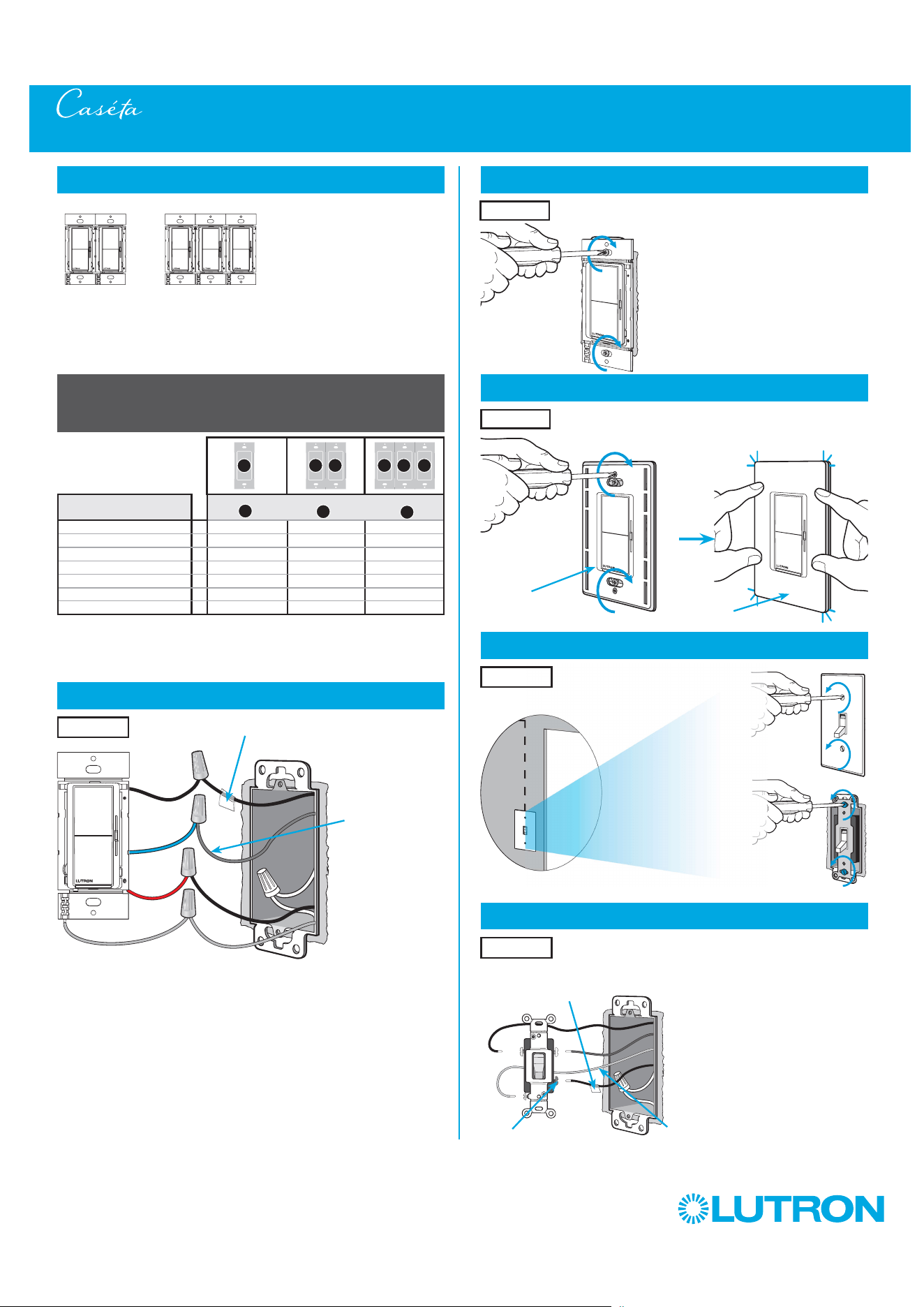
Remove side sections (if necessary)
Do not remove outside side sections
on dimmers at the end of gang.
Each dimmer has inside
side sections removed.
Dimmer in the middle
has all side sections
removed.
PD-5NE (120 V
~
)
1
Incandescent/Halogen Total Wattage
LED 250 W 250 W 250 W
Halogen / Incandescent 500 W 400 W 300 W
Electronics Low-Voltage 500 W 400 W 300 W
Magnetic Low Voltage 400 VA 400 VA 400 VA
A
B
C
B B B C B
A
8
Connect the Caséta Wireless dimmer
Tagged Wire
Black Wire
Red Wire
White Wire
(Neutral Required)
Ground
(Green Wire)
9
Mount the Caséta Wireless dimmer
10
Attach the wallplate
‘snap’
11
Remove existing switch from wall at Location 2
3-Way Installation - Caséta Wireless ELV+ Dimmer with Pico Remote Control (PD-5NE)
12
Tag and disconnect wires from the switch
Ground (Green / Bare Copper)
Different
Color
Screw
Important note:
Removing side sections reduces the dimmer’s maximum wattage
rating. See the chart below for maximum wattage information.
When installing more than one Caséta Wireless dimmer in the same
wallbox, it is necessary to remove inner side sections prior to wiring. See
image and chart below for more information.
Wallplate
Adapter
Wallplate
Location 1
Location 1
Location 2
Place tag - to identify wire on
different color screw
Location 2
Location 1

21
by Lutron
13
Connect the wires
Ground
14
Attach the wallplate bracket and Pico remote control
15
Attach the wallplate
‘snap’
16
Turn power on at circuit breaker
3-Way Installation - Caséta Wireless ELV+ Dimmer with Pico Remote Control (PD-5NE)
Pairing the dimmer and Pico remote control
17
Press and hold "Off" button on dimmer
0
5
10
15
6
sec.
UNTIL
HOLD
Status LEDs flash
18
Press and hold "Off" button on remote control
Lights flash
three times
0
5
10
15
6
sec.
UNTIL
Wallplate
Adapter
Wallplate
Location 2
Tagged Wire
Location 2
Location 2
Location 2
Location 1
Repeat steps 17 and 18 to pair additional
remote controls.
19
Pair additional remote controls
HOLD
3x
22
by Lutron
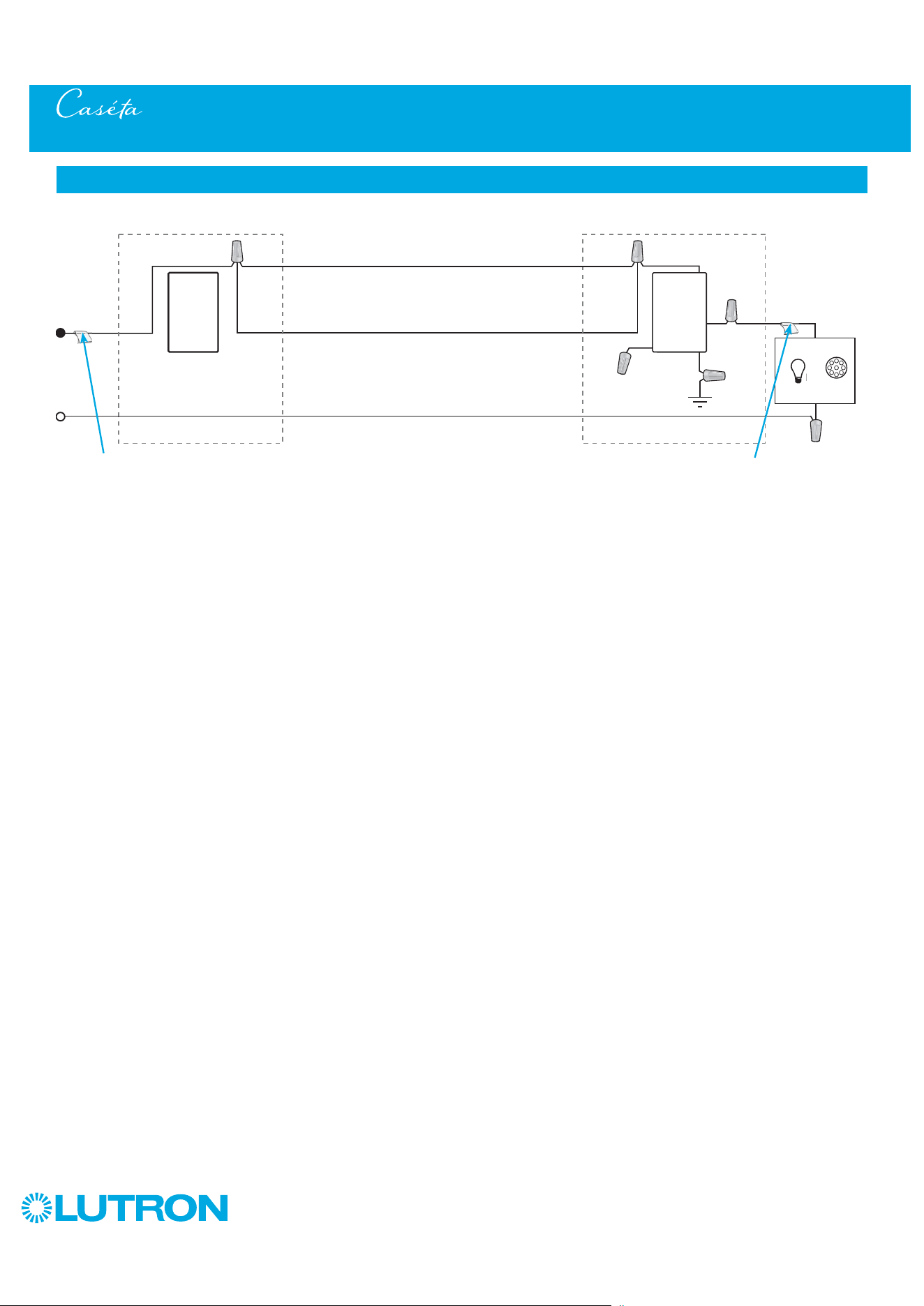
3-Way Installation - Caséta Wireless ELV+ Dimmer with Pico Remote Control (PD-5NE)
Schematic Diagram
Black
Pico
Remote
Control
Dimmer
INC
HAL
Line / Hot
Neutral
Traveler
Traveler
Ground
Tagged Wire
Tagged Wire
Location 1
Location 2
Neutral
Pico
Remote
Control
Line / Hot
Traveler
Caséta
Wireless
Dimmer
Ground
Load
INC
HAL
Traveler
Tagged Wire
Tagged Wire
Black
Red
White
Location 1 Location 2
23
by Lutron
1
Identify existing wiring
Two switches control the fan (3-way installation)
2
What you need for a 3-way installation
+
+
WARNING! Shock Hazard. May result in Serious
Injury or Death. Turn off power at circuit breaker
before installing the unit.
4
Turn power off at circuit breaker
5
Remove existing switch from wall
6
Tag and disconnect wires from the existing switch
Place tag - to identify wire on
different color screw
Different
Color
Screw
Access to
Neutral is
required
Ground
(Green /
Bare Copper)
3-Way Installation - Caséta Wireless Fan Control with Pico Remote Control (PD-FSQN)
Location 1 Location 2
Fan control
PD-FSQN
Pico wallbox adapter
PICO-WBX-ADAPT
- If one switch controls the fan (single-pole installation)
See quick-start guide that came with your control
- If three or more switches control the fan
(multi-location installation) See page 83 for details
Important note:
3
Choose a location for your Caséta Wireless fan control
Choose which location you want the Caséta Wireless fan control installed in.
This will be Location 1.
Location 1
Location 1
+
To Fan
Two Claro wallplates
CW-1
Pico remote control
for fans
PJ2-3BRL-XXX-F01
24
by Lutron
7
Remove side sections (if necessary)
Do not remove outside side sections
on fan controls at the end of gang.
Each fan control has
inside side sections
removed.
Fan control in the middle
has all side sections
removed.
8
Connect the Caséta Wireless fan control
Yellow
Wire
Red
Wire
Black Wire
Black Wire
Tag
White
Wire
White Wire
(Neutral Required)
Ground
(Green Wire)
9
Mount the Caséta Wireless fan control
10
Attach the wallplate
‘snap’
11
Remove existing switch from wall at Location 2
3-Way Installation - Caséta Wireless Fan Control with Pico Remote Control (PD-FSQN)
12
Tag and disconnect wires from the switch
Ground (Green / Bare Copper)
Different
Color
Screw
When installing more than one Caséta Wireless fan control in the same
wallbox, it is necessary to remove inner side sections prior to wiring. See
image and chart below for more information.
Wallplate
Adapter
Wallplate
Location 1
Location 1
Location 2
Place tag - to identify wire on
different color screw
Location 2
Location 1
25
by Lutron
13
Connect the wires
Ground
14
Attach the wallplate bracket and Pico remote control
15
Attach the wallplate
‘snap’
16
Turn power on at circuit breaker
3-Way Installation - Caséta Wireless Fan Control with Pico Remote Control (PD-FSQN)
Pairing the fan control and Pico remote
control
17
Press and hold "Off" button on fan control
0
5
10
15
6
sec.
UNTIL
HOLD
Status LEDs flash
18
Press and hold "Off" button on remote control
0
5
10
15
6
sec.
UNTIL
Wallplate
Adapter
Wallplate
Location 2
Tagged Wire
Location 2
Location 2
Location 2
Location 1
Repeat steps 17 and 18 to pair additional
remote controls.
19
Pair additional remote controls
HOLD
Status LEDs flash
26
by Lutron
3-Way Installation - Caséta Wireless Fan Control with Pico Remote Control (PD-FSQN)
Schematic Diagram
Location 1
Location 2
Black
Yellow
Black
PD-FSQN*
Pico Remote
Control and
Wallbox Mounting
Adapter
&
Fan
Line/Hot
Tag
Tag
Neutral
GreenWhite
Ground
120 V
~
50/60 Hz
Travelers
* Control can be installed in either location.
NOTE: The yellow wire must be connected to the load and the black wire must be connected to line/hot. The product will not work if the
wires are reversed.
27
by Lutron
1
Identify existing wiring
Two switches control the lights (3-way installation)
2
What you need for a 3-way installation
+
WARNING! Shock Hazard. May result in Serious
Injury or Death. Turn off power at circuit breaker
before installing the unit.
4
Turn power off at circuit breaker
5
Remove existing switch from wall
6
Tag and disconnect wires from the existing switch
Place tag - to identify wire on
different color screw
Different
Color
Screw
Ground
(Green /
Bare Copper)
3-Way Installation - Caséta Diva Smart Dimmer with Pico Remote Control (DVRF-6L)
Location 1 Location 2
Diva Smart dimmer
DVRF-6L
Pico remote control
with wall-mounting kit
PJ2-WALL
- If one switch controls the lights (single-pole installation)
See quick-start guide that came with your dimmer
- If three or more switches control the lights
(multi-location installation) See page 88 and page 98 for details
Important note:
3
Choose a location for your Caséta Diva Smart dimmer
Choose which location you want the Caséta Diva Smart dimmer installed in.
This will be Location 1.
Location 1
Location 1
Claro wallplate
CW-1
+
28
by Lutron
7
Ganging and derating
Total Dimmable LED Wattage Incandescent/Halogen Total Wattage
0 W + 600 W 500 W 400 W
1 W – 25 W + 500 W 400 W 300 W
26 W – 50 W + 400 W 300 W 200 W
51 W – 75 W + 300 W 200 W 100 W
76 W – 100 W + 200 W 100 W 50 W
101 W – 125 W + 100 W 50 W 0 W
126 W – 150 W + 0 W 0 W 0 W
A
B
C
B B B C B
A
8
Connect the Caséta Diva Smart dimmer
Tagged Wire
Ground
(Green Wire)
Red
Black
Blue
9
Mount the Caséta Diva Smart dimmer
10
Attach the wallplate
‘snap’
11
Remove existing switch from wall at Location 2
3-Way Installation - Caséta Diva Smart Dimmer with Pico Remote Control (DVRF-6L)
12
Tag and disconnect wires from the switch
Ground (Green / Bare Copper)
Different
Color
Screw
Important note:
Ganging units together may reduce the dimmer’s maximum wattage
rating. See the chart below for maximum wattage information.
Wallplate
Adapter
Wallplate
Location 1
Location 1
Location 2
Place tag - to identify wire on
different color screw
Location 2
Location 1
Note: Diva Smart controls don’t have fins but derating is
still required. See the chart below.

29
by Lutron
13
Connect the wires
Ground
14
Attach the wallplate bracket and Pico remote control
15
Attach the wallplate
‘snap’
16
Turn power on at circuit breaker
3-Way Installation - Caséta Diva Smart Dimmer with Pico Remote Control (DVRF-6L)
Pairing the dimmer and Pico remote control
17
Press and hold "Off" button on dimmer
0
5
10
15
6
sec.
UNTIL
HOLD
Status bar flashes
18
Press and hold "Off" button on remote control
Lights flash
three times
0
5
10
15
6
sec.
UNTIL
Wallplate
Adapter
Wallplate
Location 2
Tagged Wire
Location 2
Location 2
Location 2
Location 1
Repeat steps 17 and 18 to pair additional
remote controls.
19
Pair additional remote controls
HOLD
3x
30
by Lutron
3-Way Installation - Diva Smart Dimmer with Pico Remote Control (DVRF-6L)
Neutral
Pico
Remote
Control
Line / Hot
Traveler
Caséta
Diva
Smart
Dimmer *
Ground
Load
INC
HAL
Schematic Diagram
Traveler
* Dimmer may be installed in either location.
Tagged Wire
Tagged Wire
Black
Red
Blue
NOTE: When using Picos in a multilocation installation with a Diva Smart dimmer the Black and Red wires are reversible.

31
by Lutron
1
Identify existing wiring
Two switches control the lights (3-way installation)
2
What you need for a 3-way installation
WARNING! Shock Hazard. May result in Serious
Injury or Death. Turn off power at circuit breaker
before installing the unit.
4
Turn power off at circuit breaker
5
Remove existing switch from wall
6
Tag and disconnect wires from the existing switch
Place tag - to identify wire on
different color screw
Different
Color
Screw
Ground
(Green /
Bare Copper)
3-Way Installation - Caséta Claro Smart Switch with Pico Remote Control (DVRF-5NS)
Location 1 Location 2
- If one switch controls the lights (single-pole installation)
See quick-start guide that came with your switch
- If three or more switches control the lights
(multi-location installation) See page 93 and page 103 for details
Important note:
3
Choose a location for your Caséta Claro Smart switch
Choose which location you want the Caséta Claro Smart switch installed in.
This will be Location 1.
Location 1
Location 1
+
Pico remote control
PJ2-2B
+
Wallplate bracket
PICO-WBX-ADAPT
+
Two Claro wallplates
CW-1
Neutral
connection
required
Claro Smart switch
DVRF-5NS
32
by Lutron
7
Ganging and derating
8
Connect the new Caséta Claro Smart switch
Tagged Wire
Ground
(Green Wire)
9
Mount the Caséta Claro Smart switch
10
Attach the wallplate
11
Remove existing switch from wall at Location 2
3-Way Installation - Caséta Claro Smart Switch with Pico Remote Control (DVRF-5NS)
12
Tag and disconnect wires from the existing switch
Ground (Green / Bare Copper)
Different
Color
Screw
Location 2
Place tag - to identify wire on
different color screw
Location 2
Location 1
Important note:
Ganging units together may reduce the switch’s maximum wattage
rating. See the chart below for maximum wattage information.
1
Neutral required.
2
The maximum lamp wattage is determined by the efficiency of the transformer, with
70% – 85% as typical. For actual transformer efficiency, contact either the fixture or
transformer manufacturer. The total VA rating of the transformer(s) shall not exceed the VA
rating of the switch.
3
The switch is UL
R
Listed for use with all magnetic and electronic fluorescent ballasts.
Red
Blue
Black
DVRF-5NS (120 V
~
)
1
LED 5 A 5 A 5 A
Halogen / incandescent 600 W 600 W 600 W
Electronic Low-Voltage 600 VA 600 VA 600 VA
Magnetic Low-Voltage
2
600 VA 600 VA 600 VA
Fluorescent
3
5 A 5 A 5 A
General Purpose Fan 3 A 3 A 3 A
A
B C
White
Neutral
connection
required
Note: Claro Smart controls don’t have fins but derating is
still required. See the chart below.
‘snap’
Wallplate
Adapter
Wallplate
Location 1
Location 1
B B B C B
A

33
by Lutron
13
Connect the wires
Ground
14
Attach the wallplate bracket and Pico remote control
15
Attach the wallplate
‘snap’
16
Turn power on at circuit breaker
3-Way Installation - Caséta Claro Smart Switch with Pico Remote Control (DVRF-5NS)
Pairing the switch and Pico remote control
17
Press and hold "Off" button on switch
0
5
10
15
6
sec.
UNTIL
HOLD
Status LED flashes
18
Press and hold "Off" button on remote control
Lights flash
three times
0
5
10
15
6
sec.
UNTIL
Wallplate
Adapter
Wallplate
Location 2
Tagged Wire
Location 2
Location 2
Location 2
Location 1
Repeat steps 17 and 18 to pair additional
remote controls.
19
Pair additional remote controls
HOLD
3x

34
by Lutron
3-Way Installation - Caséta Claro Smart Switch with Pico Remote Control (DVRF-5NS)
Neutral
Pico
Remote
Control
Line / Hot
Traveler
Caséta
Claro
Smart
Switch *
Ground
(Green)
Load
INC
HAL
Schematic Diagram
Traveler
* Switch may be installed in either location.
Note: The red wire must be connected to the load and the black wire must be connected to Line/Hot. The product will not work if the wires
are reversed.
Tagged Wire
Tagged Wire
Red
Blue
Black
White
35
by Lutron
1
Identify existing wiring
Two switches control the lights (3-way installation)
2
What you need for a 3-way installation
WARNING! Shock Hazard. May result in Serious
Injury or Death. Turn off power at circuit breaker
before installing the unit.
4
Turn power off at circuit breaker
5
Remove existing switch from wall
6
Tag and disconnect wires from the existing switch
Place tag - to identify wire on
different color screw
Different
Color
Screw
Ground
(Green /
Bare Copper)
3-Way Installation - Caséta Wireless Switch with Mechanical Toggle Switch (PD-5WS-DV)
Location 1 Location 2
- If one switch controls the lights (single-pole installation)
See quick-start guide that came with your switch
- If three or more switches control the lights
(multi-location installation) See page 68 for details
Important note:
3
Choose a location for your Caséta Wireless switch
Choose which location you want the Caséta Wireless switch installed in.
This will be Location 1.
Location 1
Location 1
+
Switch
PD-5WS-DV
Existing mechanical
toggle switch
+
Claro wallplate
CW-1
36
by Lutron
7
Ganging and derating
8
Connect the new Caséta Wireless switch
Tagged Wire
Non-Black
Wire
Ground
(Green Wire)
9
Mount the Caséta Wireless switch
10
Attach the wallplate
‘snap’
11
Remove existing toggle switch from wall at Location 2
3-Way Installation - Caséta Wireless Switch with Mechanical Toggle Switch (PD-5WS-DV)
12
Modify wiring for existing toggle switch
Ground (Green / Bare Copper)
Different
Color
Screw
Wallplate
Adapter
Wallplate
Location 1
Location 1
Location 2
Add jumper wire as shown
Location 2
Location 1
B B B C B
A
PD-5WS-DV (120 V
~
)
LED 5 A 4 A 3 A
Halogen/incandescent 600 W 450 W 350 W
Electronic Low-Voltage 600 W 450 W 350 W
Magnetic Low-Voltage
1
600 VA / 475 W 450 VA / 350 W 350 VA / 275 W
Fluorescent
2
5 A 4 A 3 A
General Purpose Fan 3 A 3 A 3 A
PD-5WS-DV (277 V
~
)
LED 5 A 4 A 3 A
Halogen/incandescent 1350 W 1100 W 800 W
Electronic Low-Voltage 1350 W 1100 W 800 W
Magnetic Low-Voltage
1
1350 VA / 1075 W 1100 VA / 875 W 800 VA / 625 W
Fluorescent
2
5 A 4 A 3 A
A
B C
A
B C
1
The maximum lamp wattage is determined by the efficiency of the transformer, with
70% – 85% as typical. For actual transformer efficiency, contact either the fixture or
transformer manufacturer. The total VA rating of the transformer(s) shall not exceed the VA
rating of the switch.
2
The switch is UL
R
Listed for use with all magnetic and electronic fluorescent ballasts.
Red
Blue
Black
Different
Color
Screw
Non-Black
Wire
37
by Lutron
13
Remount existing switch
14
Turn power on at circuit breaker
3-Way Installation - Caséta Wireless Switch with Mechanical Toggle Switch (PD-5WS-DV)
Location 2
Neutral
Toggle
Switch
Line / Hot
Traveler
Caséta
Wireless
Switch*
Load
INC
HAL
Schematic Diagram
Traveler
* Switch may be installed in either location.
Tagged Wire
Ground
(Green)
Red
Blue
Black
Important note: Pico remote control
(optional)
If you would like to pair a Pico remote control to the Caséta Wireless
switch, please follow the procedure described in the quick-start guide
that came with your switch.
38
by Lutron
1
Identify existing wiring
Two switches control the lights (3-way installation)
2
What you need for a 3-way installation
WARNING! Shock Hazard. May result in Serious
Injury or Death. Turn off power at circuit breaker
before installing the unit.
4
Turn power off at circuit breaker
5
Remove existing switch from wall
6
Tag and disconnect wires from the existing switch
Place tag - to identify wire on
different color screw
Different
Color
Screw
Ground
(Green /
Bare Copper)
3-Way Installation - Caséta Wireless PRO Dimmer with Mechanical Toggle Switch (PD-10NXD)
Location 1 Location 2
- If one switch controls the lights (single-pole installation)
See quick-start guide that came with your switch
- If three or more switches control the lights
(multi-location installation) See page 63 for details
Important note:
3
Choose a location for your Caséta Wireless dimmer
Choose which location you want the Caséta Wireless dimmer installed in.
This will be Location 1.
Location 1
Location 1
+
PRO dimmer
PD-10NXD
Existing mechanical
toggle switch
+
Claro wallplate
CW-1
39
by Lutron
7
Remove side sections (if necessary)
Do not remove outside side sections
on switches at the end of gang.
Each dimmer has inside
side sections removed.
Dimmer in the middle has
all side sections removed.
8
Connect the new Caséta Wireless dimmer
Tagged Wire
Note wire color
tied to blue wire
Ground
(Green Wire)
White *
9
Mount the Caséta Wireless dimmer
10
Attach the wallplate
11
Remove existing toggle switch from wall at Location 2
3-Way Installation - Caséta Wireless PRO Dimmer with Mechanical Toggle Switch (PD-10NXD)
12a
Modify wiring for existing toggle switch
When installing more than one Caséta Wireless dimmer in the same
wallbox, it is necessary to remove inner side sections prior to wiring. See
image and chart below for more information.
Location 1
Location 2
Location 1
Red
Blue
Black
‘snap’
Wallplate
Adapter
Wallplate
Location 1
*
If available,
connect the
neutral wire from
the wallbox to the
white wire on the
dimmer. If neutral
is not available,
cap the white
wire with a wire
connector.
Neutral required
for: MLV loads,
LED drivers,
PHPM-PA,
PHPM-3F,
GRX-TVI.
Total Dimmable LED Wattage Incandescent/Halogen Total Wattage
0 W + 1000 W 800 W 600 W
1 W – 25 W + 900 W 750 W 550 W
26 W – 50 W + 800 W 700 W 500 W
51 W – 75 W + 700 W 600 W 450 W
76 W – 100 W + 600 W 500 W 400 W
101 W – 125 W + 500 W 400 W 300 W
126 W – 150 W + 400 W 300 W 200 W
151 W – 175 W + 300 W 200 W 100 W
176 W – 200 W + 200 W 100 W 50 W
201 W – 225 W + 100 W 50 W 0 W
226 W – 250 W + 0 W 0 W 0 W
A
B
C
B B B C B
A
Important note:
Removing side sections reduces the dimmer’s maximum wattage
rating. See the chart below for maximum wattage information.
Ground - Green / Bare Copper
(keep connected to switch)
Different Color
Screw / Tagged Wire
(disconnect from switch)
Noted wire color
from Step 8
(keep connected to switch)
Location 2
Remaining Wire
(disconnect from switch)

40
by Lutron
13
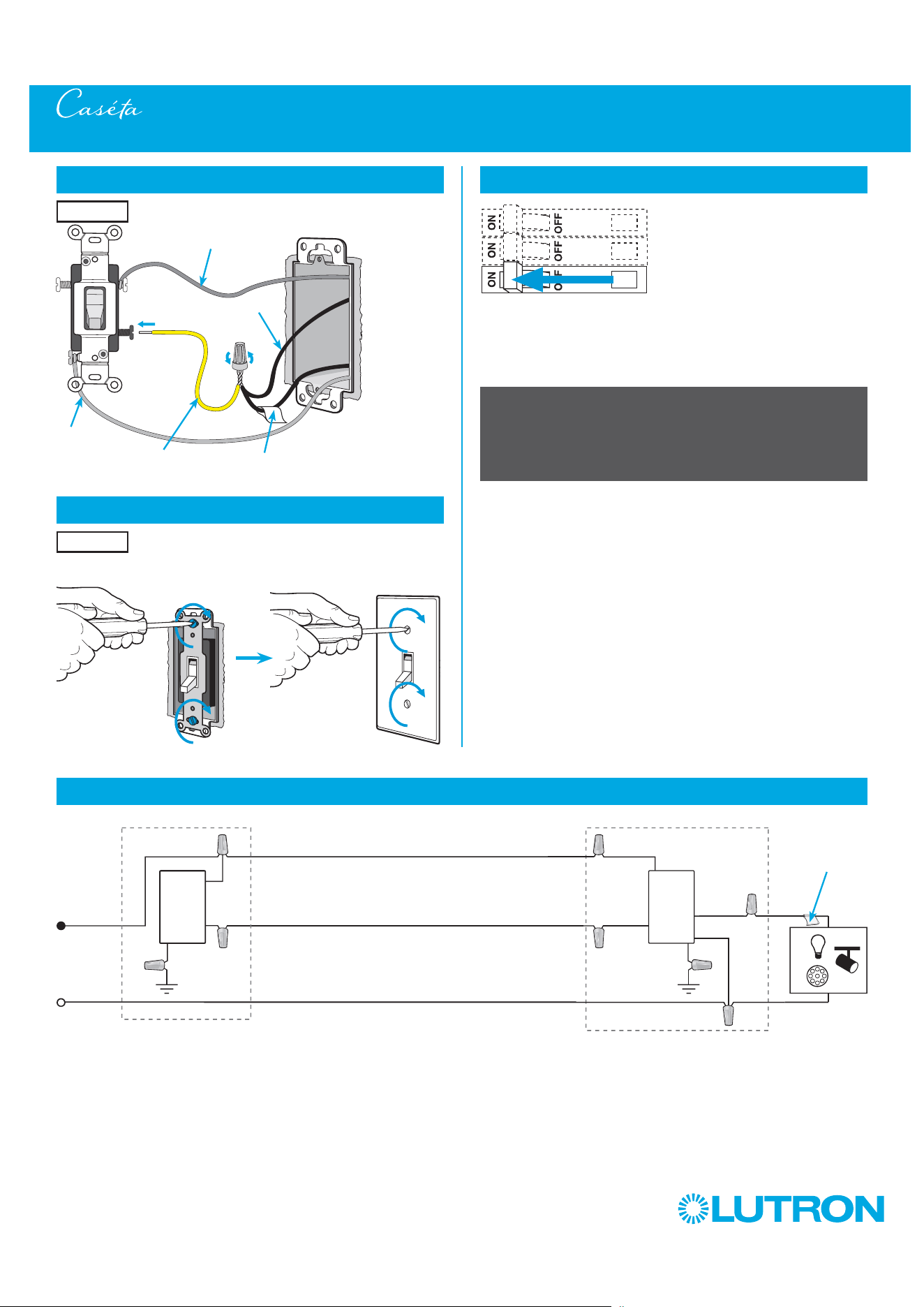
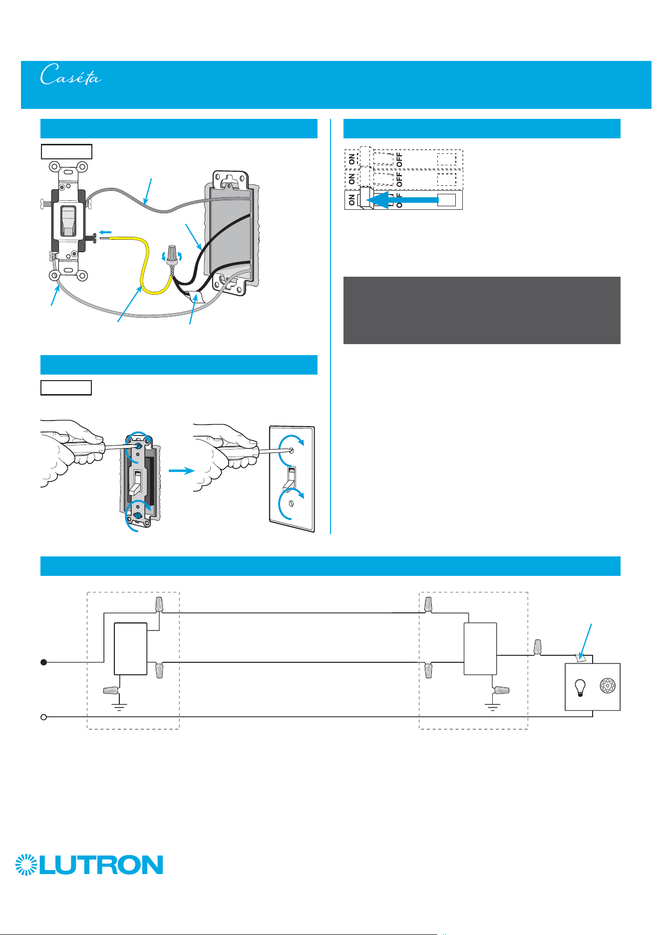
Remount existing switch
14
Turn power on at circuit breaker
3-Way Installation - Caséta Wireless PRO Dimmer with Mechanical Toggle Switch (PD-10NXD)
Location 2
Neutral
Toggle
Switch
Line / Hot
Traveler
Caséta
Wireless
Dimmer*
Load
INC
HAL
Schematic Diagram
Traveler
* Dimmer may be installed in either location.
Tagged Wire
Ground
(Green)
Red
White
Blue
Black
Important note: Pico remote control
(optional)
If you would like to pair a Pico remote control to the Caséta Wireless
dimmer, please follow the procedure described in the quick-start guide
that came with your dimmer.
If available, connect the neutral wire
from the wallbox to the white wire on the
dimmer. If neutral is not available, cap the
white wire with a wire connector.
Neutral required for: MLV loads, LED
drivers, PHPM-PA, PHPM-3F, GRX-TVI.
12b
Modify wiring for existing toggle switch
Location 2
Different Color Screw /
Tagged Wire
Jumper wire
(included in box)
Noted wire color
from Step 8
Remaining wire
Ground
(Green / Bare
Copper)
41
by Lutron
1
Identify existing wiring
Two switches control the lights (3-way installation)
2
What you need for a 3-way installation
WARNING! Shock Hazard. May result in Serious
Injury or Death. Turn off power at circuit breaker
before installing the unit.
4
Turn power off at circuit breaker
5
Remove existing switch from wall
6
Tag and disconnect wires from the existing switch
Place tag - to identify wire on
different color screw
Different
Color
Screw
Ground
(Green /
Bare Copper)
3-Way Installation - Caséta Wireless Neutral Switch with Mechanical Toggle Switch (PD-5ANS/PD-6ANS)
Location 1 Location 2
- If one switch controls the lights (single-pole installation)
See quick-start guide that came with your switch
- If three or more switches control the lights
(multi-location installation) See page 73 for details
Important note:
3
Choose a location for your Caséta Wireless switch
Choose which location you want the Caséta Wireless switch installed in.
This will be Location 1.
Location 1
Location 1
+
Existing mechanical
toggle switch
+
Claro wallplate
CW-1
Switch
PD-5ANS/PD-6ANS
Neutral
connection
required
42
by Lutron
7
Remove side sections (if necessary)
8
Connect the new Caséta Wireless neutral switch
Tagged Wire
Note wire color
tied to blue wire
Ground
(Green Wire)
White
9
Mount the Caséta Wireless switch
10
Attach the wallplate
11
Remove existing toggle switch from wall at Location 2
3-Way Installation - Caséta Wireless Neutral Switch with Mechanical Toggle Switch (PD-5ANS/PD-6ANS)
12a
Modify wiring for existing toggle switch
Ground - Green / Bare Copper
(keep connected to switch)
Different Color
Screw / Tagged Wire
(disconnect from switch)
Noted wire color
from Step 8
(keep connected to switch)
When installing more than one Caséta Wireless switch in the same wallbox,
it is necessary to remove inner side sections prior to wiring. See image and
chart below for more information.
Location 2
Location 2
Location 1
Red
Blue
Black
Important note:
Removing side sections reduces the switch’s maximum wattage rating.
See the chart below for maximum wattage information.
Neutral
connection
required
1
Neutral required.
2
The maximum lamp wattage is determined by the efficiency of the transformer, with
70% – 85% as typical. For actual transformer efficiency, contact either the fixture or
transformer manufacturer. The total VA rating of the transformer(s) shall not exceed the VA
rating of the switch.
3
The switch is UL
R
Listed for use with all magnetic and electronic fluorescent ballasts.
B B B C B
A
PD-5ANS/PD-6ANS (120 V
~
)
1
LED 6 A 6 A 5 A
Halogen / incandescent 720 W 720 W 600 W
Electronic Low-Voltage 720 VA 720 VA 600 VA
Magnetic Low-Voltage
2
720 VA 720 VA 600 VA
Fluorescent
3
6 A 6 A 5 A
General Purpose Fan 3.6 A 3.6 A 3.6 A
A
B C
Do not remove outside side sections
on switches at the end of gang.
Each switch has inside
side sections removed.
Switch in the middle has
all side sections removed.
‘snap’
Wallplate
Adapter
Wallplate
Location 1
Location 1
Remaining Wire
(disconnect from switch)
43
by Lutron
13
Remount existing switch
14
Turn power on at circuit breaker
3-Way Installation - Caséta Wireless Neutral Switch with Mechanical Toggle Switch (PD-5ANS/PD-6ANS)
Location 2
Location 2
Neutral
Toggle
Switch
Line / Hot
Traveler
Caséta
Wireless
Switch*
Load
INC
HAL
Schematic Diagram
Traveler
Tagged Wire
Ground
(Green)
Red
White
Blue
Black
Important note: Pico remote control
(optional)
If you would like to pair a Pico remote control to the Caséta Wireless
switch, please follow the procedure described in the quick-start guide
that came with your switch.
12b
Modify wiring for existing toggle switch
Different Color Screw /
Tagged Wire
Jumper wire
(included in box)
Noted wire color
from Step 8
Remaining wire
Ground
(Green / Bare
Copper)
* Switch may be installed in either location.
Note: The red wire must be connected to the load and the black wire must be connected to Line/Hot. The product will not work if the wires
are reversed.

44
by Lutron
1
Identify existing wiring
Two switches control the lights (3-way installation)
2
What you need for a 3-way installation
WARNING! Shock Hazard. May result in Serious
Injury or Death. Turn off power at circuit breaker
before installing the unit.
4
Turn power off at circuit breaker
5
Remove existing switch from wall
6
Tag and disconnect wires from the existing switch
Place tag - to identify wire on
different color screw
Different
Color
Screw
Ground
(Green /
Bare Copper)
3-Way Installation - Caséta Diva Smart Dimmer with Mechanical Toggle Switch (DVRF-6L)
Location 1 Location 2
- If one switch controls the lights (single-pole installation)
See quick-start guide that came with your switch
- If three or more switches control the lights
(multi-location installation) See page 88 and page 98 for details
Important note:
3
Choose a location for your Caséta Diva Smart dimmer
Choose which location you want the Caséta Diva Smart dimmer installed in.
This will be Location 1.
Location 1
Location 1
+
Existing mechanical
toggle switch
+
Claro wallplate
CW-1
Diva Smart dimmer
DVRF-6L
45
by Lutron
Total Dimmable LED Wattage Incandescent/Halogen Total Wattage
0 W + 600 W 500 W 400 W
1 W – 25 W + 500 W 400 W 300 W
26 W – 50 W + 400 W 300 W 200 W
51 W – 75 W + 300 W 200 W 100 W
76 W – 100 W + 200 W 100 W 50 W
101 W – 125 W + 100 W 50 W 0 W
126 W – 150 W + 0 W 0 W 0 W
B B B C B
A
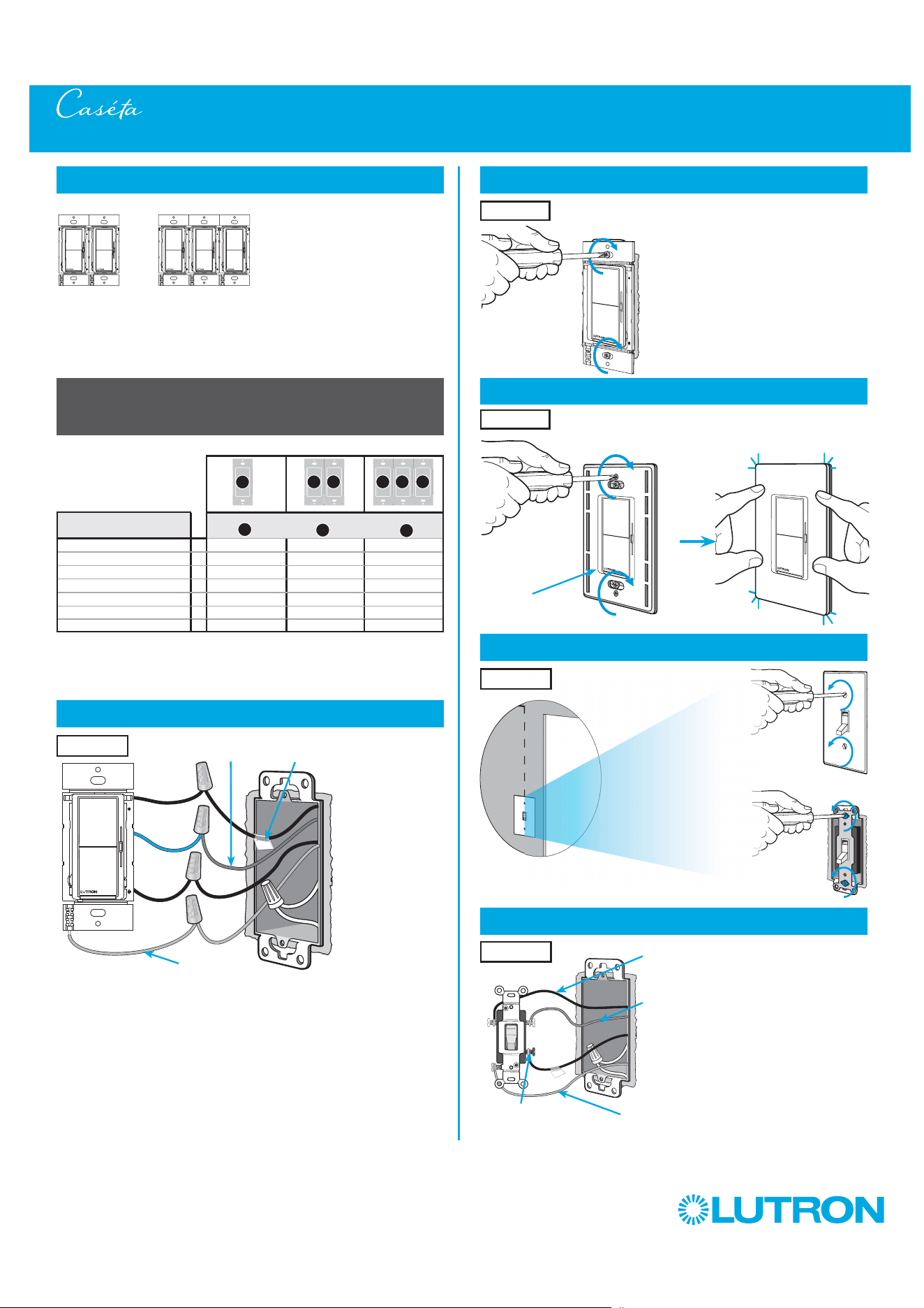
8
Connect the new Caséta Diva Smart dimmer
Tagged Wire
Note wire color
tied to blue wire
Ground
(Green Wire)
9
Mount the Caséta Diva Smart dimmer
10
Attach the wallplate
11
Remove existing toggle switch from wall at Location 2
3-Way Installation - Caséta Diva Smart Dimmer with Mechanical Toggle Switch (DVRF-6L)
12a
Modify wiring for existing toggle switch
Location 1
Location 2
Location 1
Red
Blue
Black
Location 1
A
B
C
Important note:
Ganging units together may reduce the dimmer’s maximum wattage
rating. See the chart below for maximum wattage information.
Ground - Green / Bare Copper
(keep connected to switch)
Different Color
Screw / Tagged Wire
(disconnect from switch)
Noted wire color
from Step 8
(keep connected to switch)
Location 2
Remaining Wire
(disconnect from switch)
7
Ganging and derating
Note: Diva Smart controls don’t have fins but derating is
still required. See the chart below.
‘snap’
Wallplate
Adapter
Wallplate
46
by Lutron
13
Remount existing switch
14
Turn power on at circuit breaker
3-Way Installation - Caséta Diva Smart Dimmer with Mechanical Toggle Switch (DVRF-6L)
Location 2
Neutral
Toggle
Switch
Line / Hot
Traveler
Caséta
Diva
Smart
Dimmer*
Load
INC
HAL
Schematic Diagram
Traveler
* Dimmer may be installed in either location.
Tagged Wire
Ground
(Green)
Red
Blue
Black
Important note: Pico remote control
(optional)
If you would like to pair a Pico remote control to the Caséta Diva Smart
dimmer, please follow the procedure described in the quick-start guide
that came with your dimmer.
12b
Modify wiring for existing toggle switch
Location 2
Different Color Screw /
Tagged Wire
Jumper wire
(included in box)
Noted wire color
from Step 8
Remaining wire
Ground
(Green / Bare
Copper)
47
by Lutron
1
Identify existing wiring
Two switches control the lights (3-way installation)
2
What you need for a 3-way installation
WARNING! Shock Hazard. May result in Serious
Injury or Death. Turn off power at circuit breaker
before installing the unit.
4
Turn power off at circuit breaker
5
Remove existing switch from wall
6
Tag and disconnect wires from the existing switch
Place tag - to identify wire on
different color screw
Different
Color
Screw
Ground
(Green /
Bare Copper)
3-Way Installation - Caséta Claro Smart Switch with Mechanical Toggle Switch (DVRF-5NS)
Location 1 Location 2
- If one switch controls the lights (single-pole installation)
See quick-start guide that came with your switch
- If three or more switches control the lights
(multi-location installation) See page 93 and page 103 for details
Important note:
3
Choose a location for your Caséta Claro Smart switch
Choose which location you want the Caséta Claro Smart switch installed in.
This will be Location 1.
Location 1
Location 1
+
Existing mechanical
toggle switch
+
Claro wallplate
CW-1
Neutral
connection
required
Claro Smart switch
DVRF-5NS
48
by Lutron
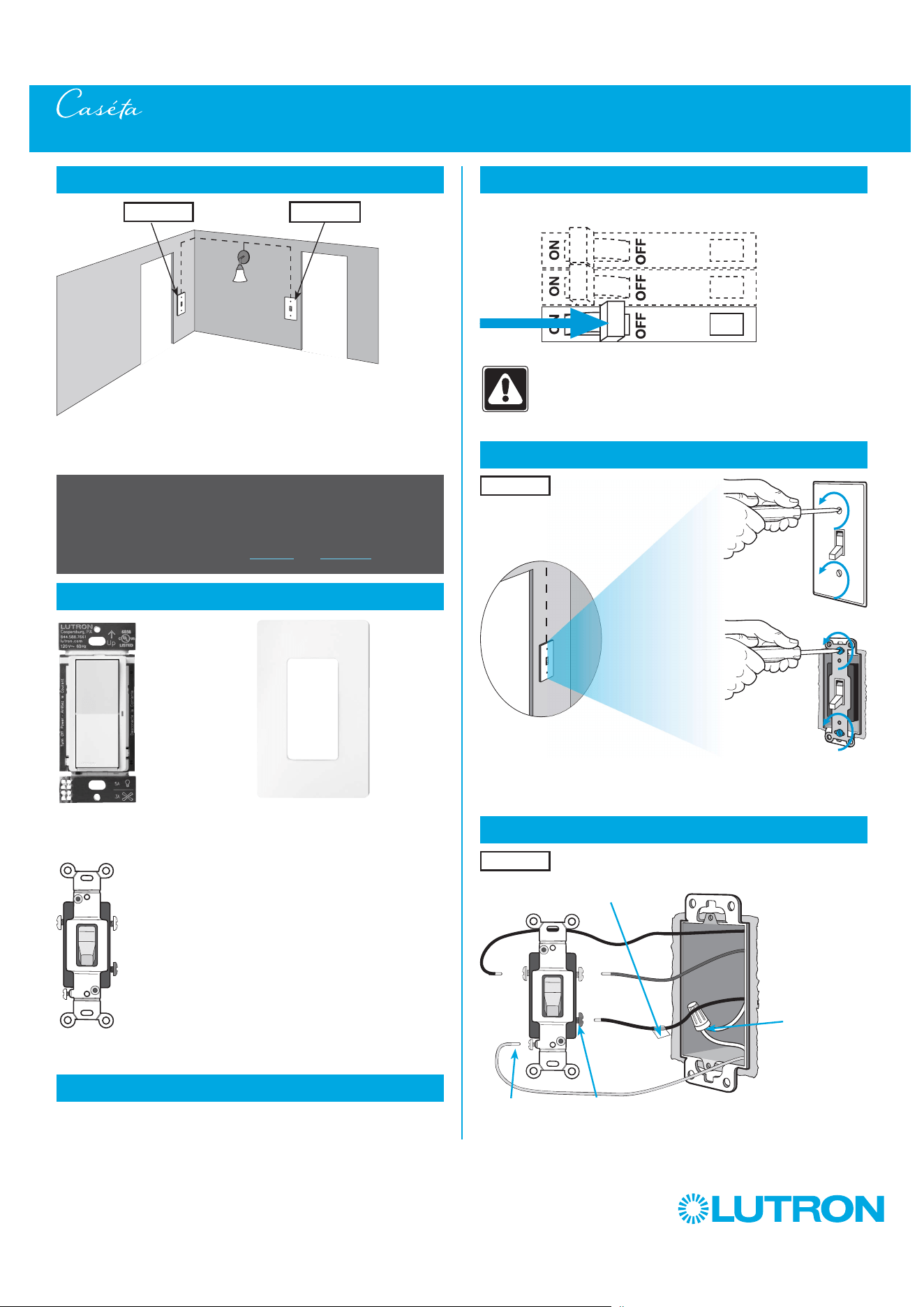
8
Connect the new Caséta Claro Smart switch
Tagged Wire
Note wire color
tied to blue wire
Ground
(Green Wire)
White
11
Remove existing toggle switch from wall at Location 2
3-Way Installation - Caséta Claro Smart Switch with Mechanical Toggle Switch (DVRF-5NS)
12a
Modify wiring for existing toggle switch
Ground - Green / Bare Copper
(keep connected to switch)
Different Color
Screw / Tagged Wire
(disconnect from switch)
Noted wire color
from Step 8
(keep connected to switch)
Location 2
Location 2
Location 1
Red
Blue
Black
Neutral
connection
required
1
Neutral required.
2
The maximum lamp wattage is determined by the efficiency of the transformer, with
70% – 85% as typical. For actual transformer efficiency, contact either the fixture or
transformer manufacturer. The total VA rating of the transformer(s) shall not exceed the VA
rating of the switch.
3
The switch is UL
R
Listed for use with all magnetic and electronic fluorescent ballasts.
Remaining Wire
(disconnect from switch)
7
Ganging and derating
9
Mount the Caséta Claro Smart switch
10
Attach the wallplate
Important note:
Ganging units together may reduce the switch’s maximum wattage
rating. See the chart below for maximum wattage information.
DVRF-5NS (120 V
~
)
1
LED 5 A 5 A 5 A
Halogen / incandescent 600 W 600 W 600 W
Electronic Low-Voltage 600 VA 600 VA 600 VA
Magnetic Low-Voltage
2
600 VA 600 VA 600 VA
Fluorescent
3
5 A 5 A 5 A
General Purpose Fan 3 A 3 A 3 A
Note: Claro Smart controls don’t have fins but derating is
still required. See the chart below.
‘snap’
Wallplate
Adapter
Wallplate
Location 1
B B B C B
A

49
by Lutron
13
Remount existing switch
14
Turn power on at circuit breaker
3-Way Installation - Caséta Claro Smart Switch with Mechanical Toggle Switch (DVRF-5NS)
Location 2
Location 2
Neutral
Toggle
Switch
Line / Hot
Traveler
Caséta
Claro
Smart
Switch*
Load
INC
HAL
Schematic Diagram
Traveler
Tagged Wire
Ground
(Green)
Red
White
Blue
Black
Important note: Pico remote control
(optional)
If you would like to pair a Pico remote control to the Caséta Claro Smart
switch, please follow the procedure described in the quick-start guide
that came with your switch.
12b
Modify wiring for existing toggle switch
Different Color Screw /
Tagged Wire
Jumper wire
(included in box)
Noted wire color
from Step 8
Remaining wire
Ground
(Green / Bare
Copper)
* Switch may be installed in either location.
Note: The red wire must be connected to the load and the black wire must be connected to Line/Hot. The product will not work if the wires
are reversed.
50
by Lutron
1
Identify existing wiring
Two switches control the lights (3-way installation)
2
What you need for a 3-way installation
+
WARNING! Shock Hazard. May result in Serious
Injury or Death. Turn off power at circuit breaker
before installing the unit.
4
Turn power off at circuit breaker
5
Remove existing switch from wall
6
Tag and disconnect wires from the existing switch
Place tag - to identify wire on
different color screw
Different
Color
Screw
Ground
(Green /
Bare Copper)
3-Way Installation - Caséta Diva Smart Dimmer with Claro Smart Accessory Switch (DVRF-6L / DVRF-AS)
Location 1 Location 2
Diva Smart dimmer
DVRF-6L
- If one switch controls the lights (single-pole installation)
See quick-start guide that came with your dimmer
- If three or more switches control the lights
(multi-location installation) See page 88 and page 98 for details
Important note:
3
Choose a location for your Caséta Diva Smart dimmer
Choose which location you want the Caséta Diva Smart dimmer installed in.
This will be Location 1.
Location 1
Location 1
Two Claro wallplates
CW-1
+
Claro Smart accessory switch
DVRF-AS
51
by Lutron
7
Ganging and derating
Total Dimmable LED Wattage Incandescent/Halogen Total Wattage
0 W + 600 W 500 W 400 W
1 W – 25 W + 500 W 400 W 300 W
26 W – 50 W + 400 W 300 W 200 W
51 W – 75 W + 300 W 200 W 100 W
76 W – 100 W + 200 W 100 W 50 W
101 W – 125 W + 100 W 50 W 0 W
126 W – 150 W + 0 W 0 W 0 W
A
B
C
B B B C B
A
8
Connect the Caséta Diva Smart dimmer
Tagged Wire
Ground
(Green Wire)
Red
Black
Blue
9
Mount the Caséta Diva Smart dimmer
10
Attach the wallplate
‘snap’
11
Remove existing switch from wall at Location 2
3-Way Installation - Caséta Diva Smart Dimmer with Claro Smart Accessory Switch (DVRF-6L / DVRF-AS)
12
Tag and disconnect wires from the switch
Ground (Green / Bare Copper)
Different
Color
Screw
Important note:
Ganging units together may reduce the dimmer’s maximum wattage
rating. See the chart below for maximum wattage information.
Wallplate
Adapter
Wallplate
Location 1
Location 1
Location 2
Place tag - to identify wire on
different color screw
Location 2
Location 1
Note: Diva Smart models don’t have fins but derating is
still required. See the chart below.
Note wire color
tied to blue wire

52
by Lutron
13
Connect the Claro Smart accessory switch
14
Mount the Claro Smart accessory switch
15
Attach the wallplate
‘snap’
16
Turn power on at circuit breaker
3-Way Installation - Caséta Diva Smart Dimmer with Claro Smart Accessory Switch (DVRF-6L / DVRF-AS)
Wallplate
Adapter
Wallplate
Location 2
Location 2
Tagged Wire
Ground
(Green Wire)
Red
Black
Blue
Location 2
Match noted wire
color from Step 8
tied to blue wire.
53
by Lutron
3-Way Installation - Caséta Diva Smart Dimmer with Claro Smart Accessory Switch (DVRF-6L / DVRF-AS)
Neutral
Diva
Smart
Dimmer
Line / Hot
Traveler
Claro
Smart
Accessory
Switch
Ground
Load
INC
HAL
Schematic Diagram
Traveler
Tagged Wire
Tagged Wire
Red
BlueBlue
BlackRed
Black
Ground
Note: When using Claro Smart Accessory Switches in a 3-way installation with a Diva Smart dimmer, the Black and Red wires are reversible.
54
by Lutron
1
Identify existing wiring
Two switches control the lights (3-way installation)
2
What you need for a 3-way installation
WARNING! Shock Hazard. May result in Serious
Injury or Death. Turn off power at circuit breaker
before installing the unit.
4
Turn power off at circuit breaker
5
Remove existing switch from wall
6
Tag and disconnect wires from the existing switch
Place tag - to identify wire on
different color screw
Different
Color
Screw
Ground
(Green /
Bare Copper)
3-Way Installation - Caséta Claro Smart Switch with a Claro Smart Accessory Switch (DVRF-5NS / DVRF-AS)
Location 1 Location 2
- If one switch controls the lights (single-pole installation)
See quick-start guide that came with your switch
- If three or more switches control the lights
(multi-location installation) See page 93 and page 103 for details
Important note:
3
Choose a location for your Caséta Claro Smart switch
Choose which location you want the Caséta Claro Smart switch installed in.
This will be Location 1.
Location 1
Location 1
Neutral
connection
required
Claro Smart switch
DVRF-5NS
+
Two Claro wallplates
CW-1
+
Claro Smart accessory switch
DVRF-AS
55
by Lutron
7
Ganging and derating
9
Mount the Caséta Claro Smart switch
10
Attach the wallplate
11
Remove existing switch from wall at Location 2
3-Way Installation - Caséta Claro Smart Switch with a Claro Smart Accessory Switch (DVRF-5NS / DVRF-AS)
12
Tag and disconnect wires from the existing switch
Ground (Green / Bare Copper)
Different
Color
Screw
Location 2
Place tag - to identify wire on
different color screw
Location 2
Important note:
Ganging units together may reduce the switch’s maximum wattage
rating. See the chart below for maximum wattage information.
1
Neutral required.
2
The maximum lamp wattage is determined by the efficiency of the transformer, with
70% – 85% as typical. For actual transformer efficiency, contact either the fixture or
transformer manufacturer. The total VA rating of the transformer(s) shall not exceed the VA
rating of the switch.
3
The switch is UL
R
Listed for use with all magnetic and electronic fluorescent ballasts.
DVRF-5NS (120 V
~
)
1
LED 5 A 5 A 5 A
Halogen / incandescent 600 W 600 W 600 W
Electronic Low-Voltage 600 VA 600 VA 600 VA
Magnetic Low-Voltage
2
600 VA 600 VA 600 VA
Fluorescent
3
5 A 5 A 5 A
General Purpose Fan 3 A 3 A 3 A
A
B C
Note: Claro Smart models don’t have fins but derating is
still required. See the chart below.
‘snap’
Wallplate
Adapter
Wallplate
Location 1
Location 1
B B B C B
A
8
Connect the new Caséta Claro Smart switch
Tagged Wire
Note wire color
tied to blue wire
Ground
(Green Wire)
White
Location 1
Red
Blue
Black
Neutral
connection
required
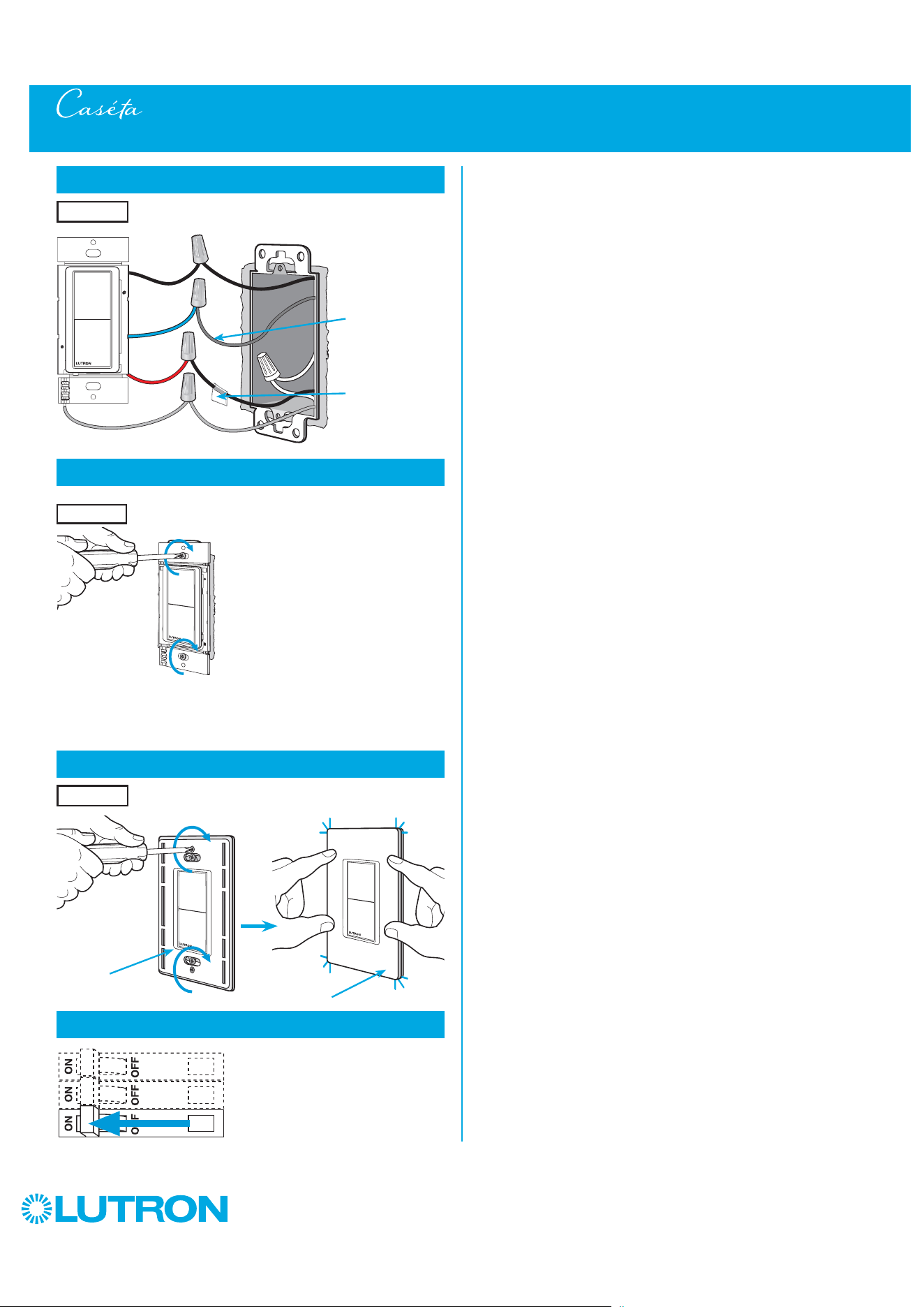
56
by Lutron
13
Connect the Claro Smart accessory switch
14
Mount the Claro Smart accessory switch
15
Attach the wallplate
‘snap’
16
Turn power on at circuit breaker
3-Way Installation - Caséta Claro Smart Switch with a Claro Smart Accessory Switch (DVRF-5NS / DVRF-AS)
Wallplate
Adapter
Wallplate
Location 2
Location 2
Tagged Wire
Ground
(Green Wire)
Red
Black
Blue
Location 2
Match noted wire
color from Step 8
tied to blue wire.
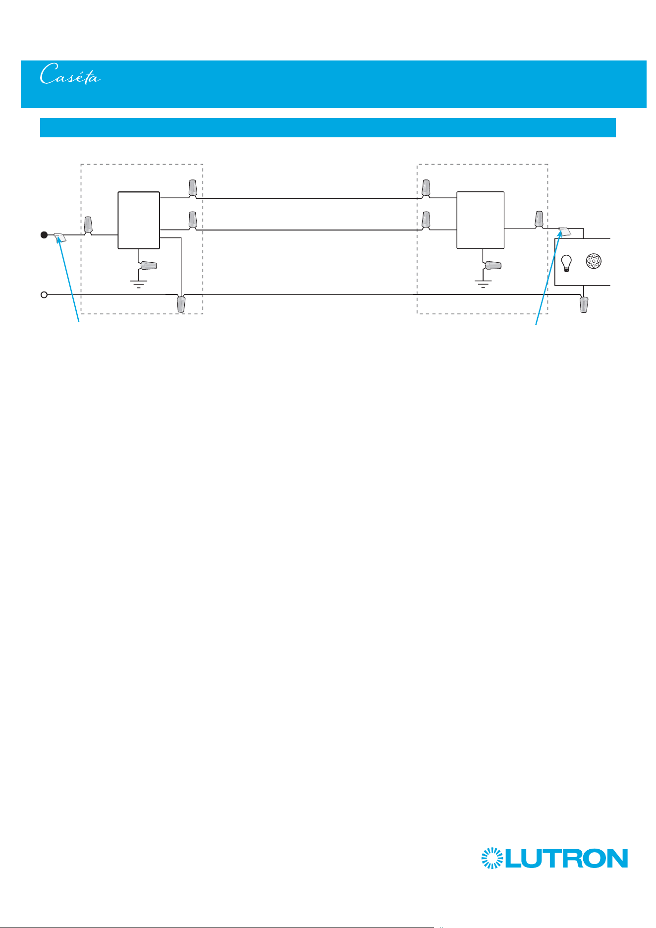
57
by Lutron
3-Way Installation - Caséta Diva Smart Dimmer with Claro Smart Accessory Switch (DVRF-6L / DVRF-AS)
Neutral
Claro
Smart
Switch
Line / Hot
Traveler
Claro
Smart
Accessory
Switch
Ground
Load
INC
HAL
Schematic Diagram
Traveler
Tagged Wire
Tagged Wire
Red
BlueBlue
BlackRed
Black
Ground
* Switch may be installed in either location.
Note: The red wire must be connected to the load and the black wire must be connected to Line/Hot. The product will not work if the wires
are reversed.
White
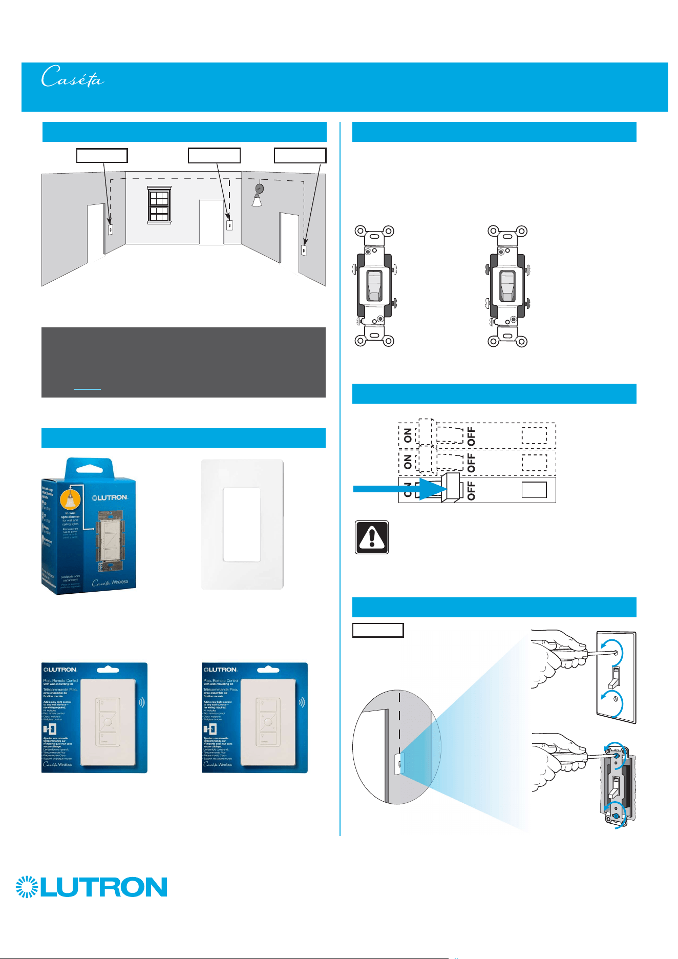
58
by Lutron
Multi-Location Installation - Caséta Wireless Dimmer with Pico Remote Controls (PD-6WCL)
1
Identify existing wiring
2
What you need for a multi-location installation
WARNING! Shock Hazard. May result in Serious
Injury or Death. Turn off power at circuit breaker
before installing the unit.
4
Turn power off at circuit breaker
5
Remove existing switch from wall at Location 1
+
- If one switch controls the lights (single-pole installation)
See quick-start guide that came with your dimmer
- If two switches control the lights (3-way installation)
See page 3 for details
Important note:
Dimmer
PD-6WCL or P-PKG1W
Two Pico remote controls with wall-mounting kits
PJ2-WALL
3
Choose a location for your Caséta Wireless dimmer
NOTE: There will be two different types of existing switches in this
application. Locations 1 and 3 will use 3-way switches (three screws
which control the lights, plus one ground screw) and Location 2 will use
a 4-way switch (four screws which control the lights, plus one ground
screw). For easiest installation, we recommend replacing one of the 3-way
switches with your dimmer (Locations 1 or 3). In this example, we will use
Location 1.
Location 1
3-Way Switch
(Locations 1 and 3)
4-Way Switch
(Location 2)
+
Claro wallplate
CW-1
Three or more switches control the lights
(multi-location installation)
Location 1 Location 2 Location 3
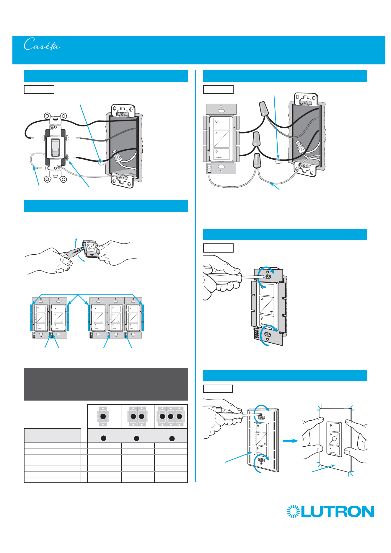
59
by Lutron
Multi-Location Installation - Caséta Wireless Dimmer with Pico Remote Controls (PD-6WCL)
8
Connect the new Caséta Wireless dimmer
9
Mount the Caséta Wireless dimmer
10
Attach the wallplate
‘snap’
Ground
(Green / Bare Copper)
Wallplate
Adapter
Wallplate
Tagged wire
Location 1
Location 1
Location 1
6
Tag and disconnect wires from the existing switch
7
Remove side sections (if necessary)
Do not remove outside side sections
on dimmers at the end of gang.
Each dimmer has inside
side sections removed.
Dimmer in the middle has
all side sections removed.
Total Dimmable LED Wattage
Incandescent/Halogen Total Wattage
0 W + 600 W 500 W 400 W
1 W – 25 W + 500 W 400 W 300 W
26 W – 50 W + 400 W 300 W 200 W
51 W – 75 W + 300 W 200 W 100 W
76 W – 100 W + 200 W 100 W 50 W
101 W – 125 W + 100 W 50 W 0 W
126 W – 150 W + 0 W 0 W 0 W
A
B
C
B B B C BA
When installing more than one Caséta Wireless dimmer in the same wallbox,
it is necessary to remove inner side sections prior to wiring. See image and
chart below for more information.
Important note:
Removing side sections reduces the dimmer’s maximum wattage
rating. See the chart below for maximum wattage information.
Different
Color Screw
Ground
(Green / Bare Copper)
Place tag - to identify wire on
different color screw
Location 1
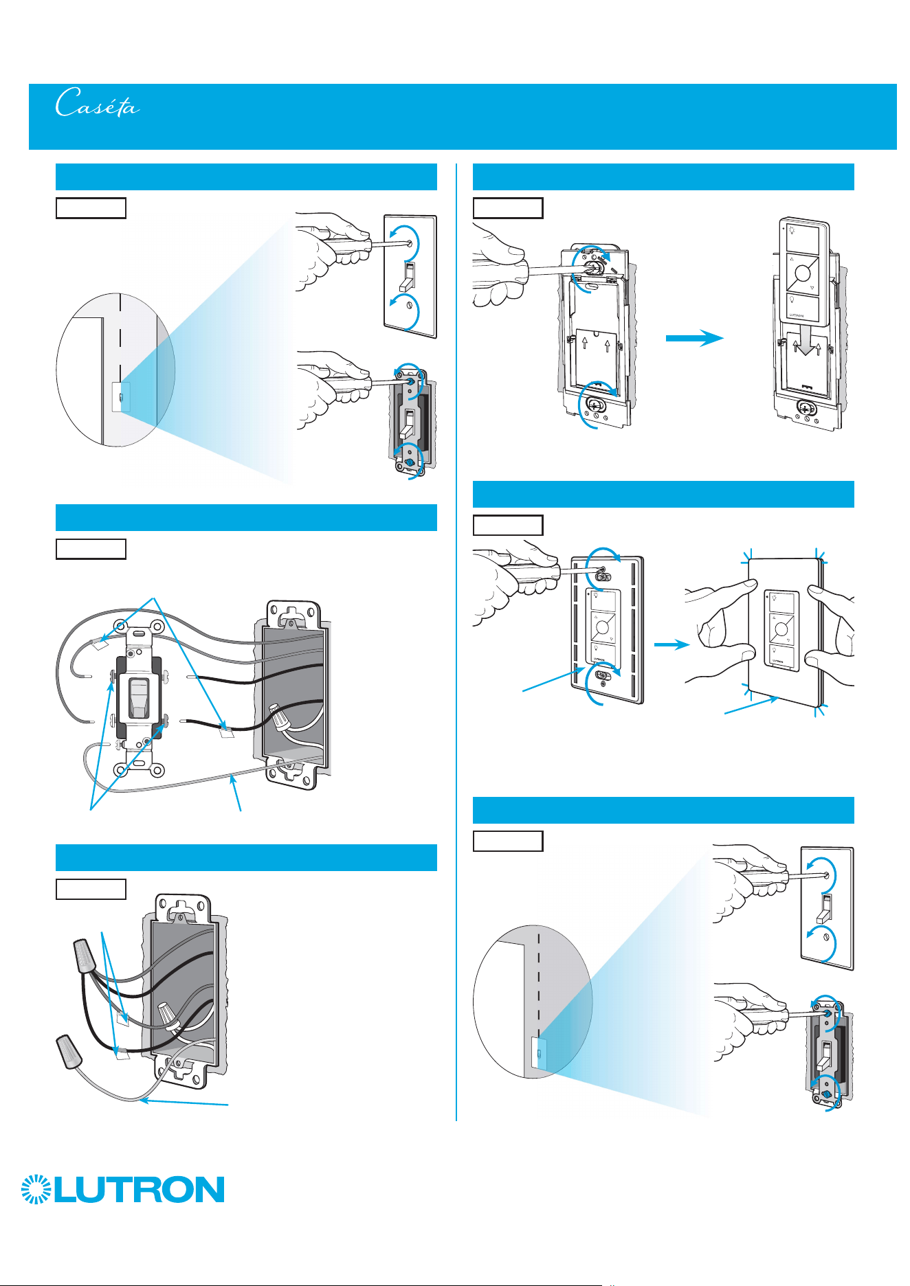
60
by Lutron
14
Attach the wallplate bracket and Pico remote control
15
Attach the wallplate
‘snap’
Multi-Location Installation - Caséta Wireless Dimmer with Pico Remote Controls (PD-6WCL)
16
Remove existing switch from wall at Location 3
Wallplate
Adapter
Wallplate
Location 2
Location 2
13
Connect the wires
Ground
(Green / Bare Copper)
Tagged Wires
Location 2
11
Remove existing switch from wall at Location 2
12
Tag and disconnect wires from the existing switch
Ground (Green / Bare Copper)
Location 2
Location 2
Place tags - to identify wires
on different color screws
Different Color Screws
Location 3

61
by Lutron
Multi-Location Installation - Caséta Wireless Dimmer with Pico Remote Controls (PD-6WCL)
21
Turn power on at circuit breaker
Pairing the dimmer and Pico remote controls
22
Press and hold "Off" button on dimmer
0
5
10
15
6
sec.
UNTIL
HOLD
Status LEDs flash
23
Press and hold "Off" button on remote control
0
5
10
15
6
sec.
UNTIL
Location 2
Location 1
Repeat steps 22 and 23 to pair remote control
at Location 3.
24
Repeat for remote control at Location 3
17
Tag and disconnect wires from the existing switch
Different Color ScrewGround (Green / Bare Copper)
18
Connect the wires
19
Attach the wallplate bracket and Pico remote control
Ground (Green / Bare Copper)
Place tag - to
identify wire on
different color screw
Location 3
Tagged Wire
Location 3
Location 3
20
Attach the wallplate
‘snap’
Wallplate
Adapter
Wallplate
Location 3
HOLD
Lights flash
three times
3x
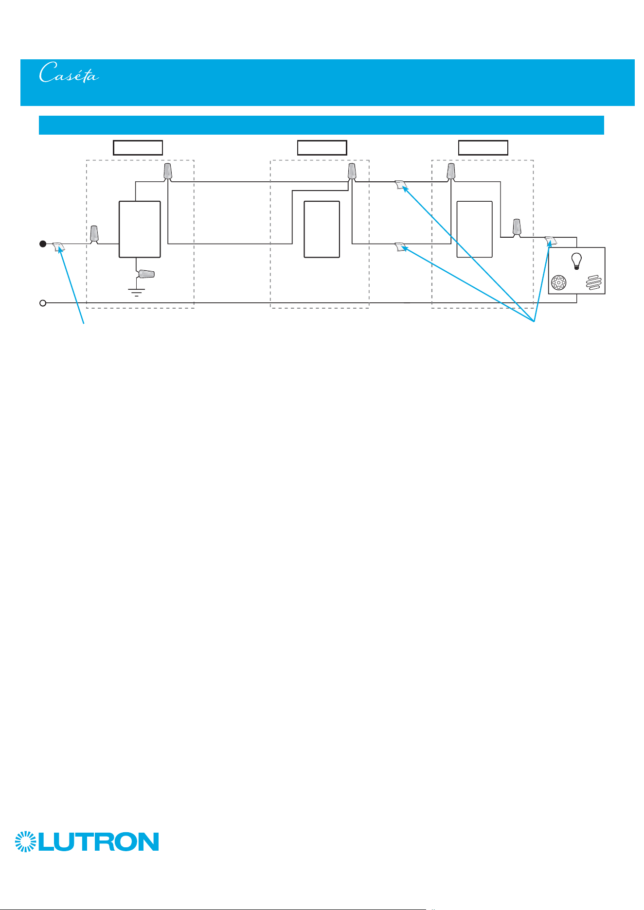
62
by Lutron
Multi-Location Installation - Caséta Wireless Dimmer with Pico Remote Controls (PD-6WCL)
Neutral
Pico
Remote
Control
Line / Hot
Traveler Traveler
Traveler
Traveler
Caséta
Wireless
Dimmer *
Ground
Load
INC
HAL
Schematic Diagram
Pico
Remote
Control
* It is recommended to install dimmer in either Location 1 or 3.
Location 1 Location 2 Location 3
Tagged Wire Tagged Wires
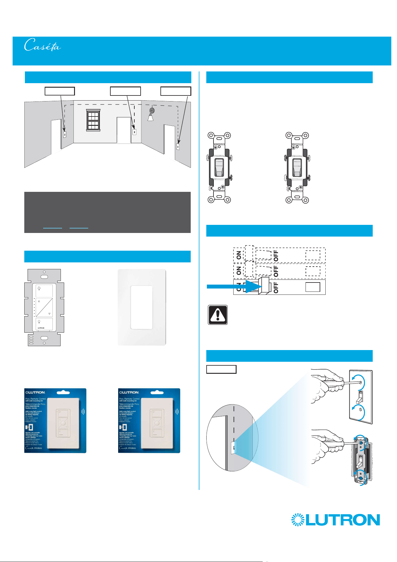
63
by Lutron
Multi-Location Installation - Caséta Wireless PRO Dimmer with Pico Remote Controls (PD-10NXD)
1
Identify existing wiring
2
What you need for a multi-location installation
WARNING! Shock Hazard. May result in Serious
Injury or Death. Turn off power at circuit breaker
before installing the unit.
4
Turn power off at circuit breaker
5
Remove existing switch from wall at Location 1
+
- If one switch controls the lights (single-pole installation)
See quick-start guide that came with your dimmer
- If two switches control the lights (3-way installation)
See page 11 or page 38 for details
Important note:
PRO dimmer
PD-10NXD
Two Pico remote controls with wall-mounting kits
PJ2-WALL
3
Choose a location for your Caséta Wireless dimmer
NOTE: There will be two different types of existing switches in this
application. Locations 1 and 3 will use 3-way switches (three screws
which control the lights, plus one ground screw) and Location 2 will use
a 4-way switch (four screws which control the lights, plus one ground
screw). For easiest installation, we recommend replacing one of the 3-way
switches with your dimmer (Locations 1 or 3). In this example, we will use
Location 1.
Location 1
3-Way Switch
(Locations 1 and 3)
4-Way Switch
(Location 2)
+
Claro wallplate
CW-1
Three or more switches control the lights
(multi-location installation)
Location 1 Location 2 Location 3
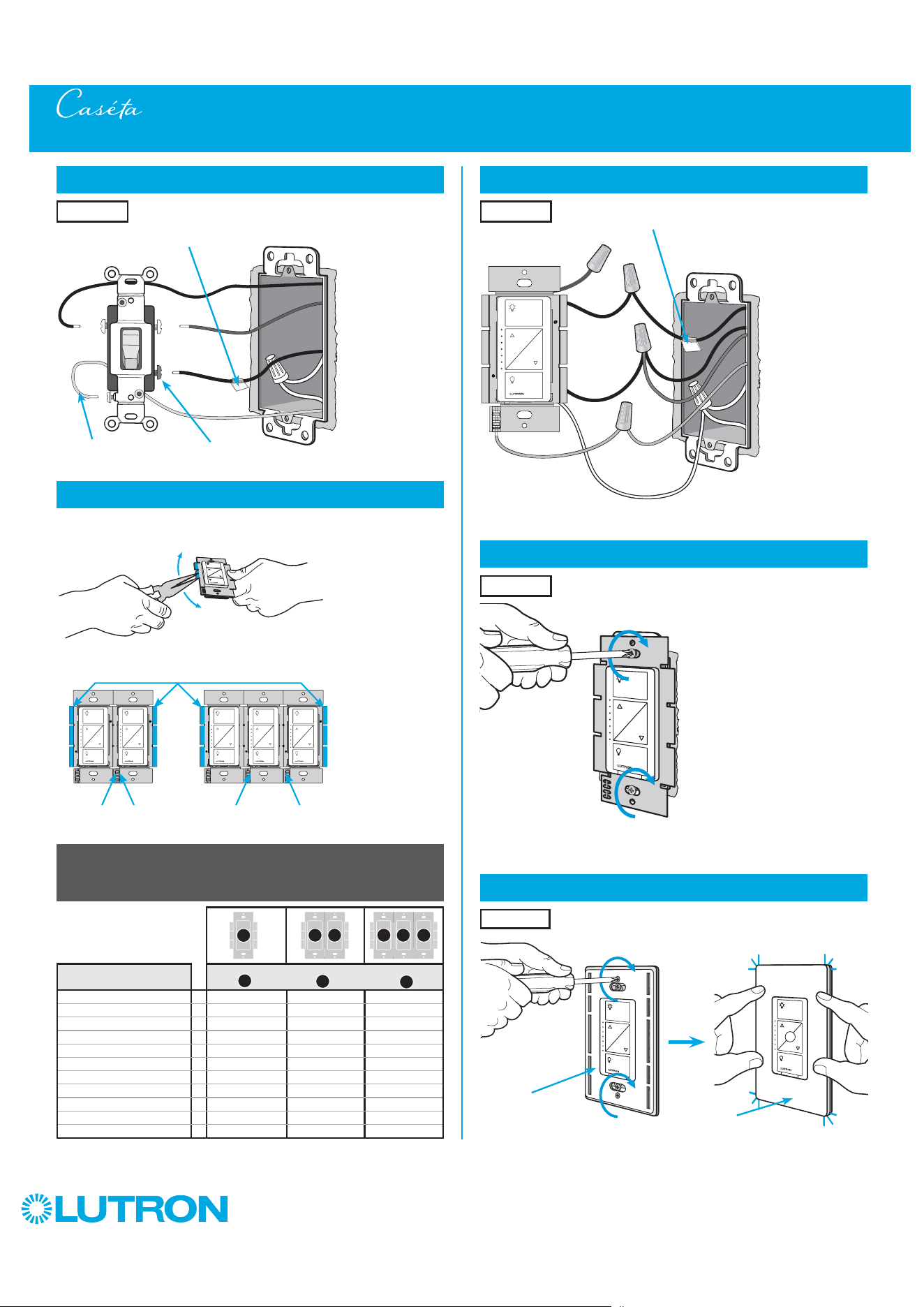
64
by Lutron
Multi-Location Installation - Caséta Wireless PRO Dimmer with Pico Remote Controls (PD-10NXD)
8
Connect the new Caséta Wireless dimmer
9
Mount the Caséta Wireless dimmer
10
Attach the wallplate
‘snap’
Wallplate
Adapter
Wallplate
Location 1
Location 1
Location 1
6
Tag and disconnect wires from the existing switch
7
Remove side sections (if necessary)
Do not remove outside side sections
on dimmers at the end of gang.
Each dimmer has inside
side sections removed.
Dimmer in the middle has
all side sections removed.
When installing more than one Caséta Wireless dimmer in the same wallbox,
it is necessary to remove inner side sections prior to wiring. See image and
chart below for more information.
Different
Color Screw
Ground
(Green / Bare Copper)
Place tag - to identify wire on
different color screw
Location 1
Tagged Wire
Ground
(Green Wire)
Red
White *
*
If available,
connect the
neutral wire from
the wallbox to the
white wire on the
dimmer. If neutral
is not available,
cap the white
wire with a wire
connector.
Neutral required
for: MLV loads,
LED drivers,
PHPM-PA,
PHPM-3F,
GRX-TVI.
Black
Blue
Total Dimmable LED Wattage Incandescent/Halogen Total Wattage
0 W + 1000 W 800 W 600 W
1 W – 25 W + 900 W 750 W 550 W
26 W – 50 W + 800 W 700 W 500 W
51 W – 75 W + 700 W 600 W 450 W
76 W – 100 W + 600 W 500 W 400 W
101 W – 125 W + 500 W 400 W 300 W
126 W – 150 W + 400 W 300 W 200 W
151 W – 175 W + 300 W 200 W 100 W
176 W – 200 W + 200 W 100 W 50 W
201 W – 225 W + 100 W 50 W 0 W
226 W – 250 W + 0 W 0 W 0 W
A
B
C
B B B C B
A
Important note:
Removing side sections reduces the dimmer’s maximum wattage
rating. See the chart below for maximum wattage information.

65
by Lutron
14
Attach the wallplate bracket and Pico remote control
15
Attach the wallplate
‘snap’
Multi-Location Installation - Caséta Wireless PRO Dimmer with Pico Remote Controls (PD-10NXD)
16
Remove existing switch from wall at Location 3
Wallplate
Adapter
Wallplate
Location 2
Location 2
13
Connect the wires
Ground
(Green / Bare Copper)
Tagged Wires
Location 2
11
Remove existing switch from wall at Location 2
12
Tag and disconnect wires from the existing switch
Ground (Green / Bare Copper)
Location 2
Location 2
Place tags - to identify wires
on different color screws
Different Color Screws
Location 3
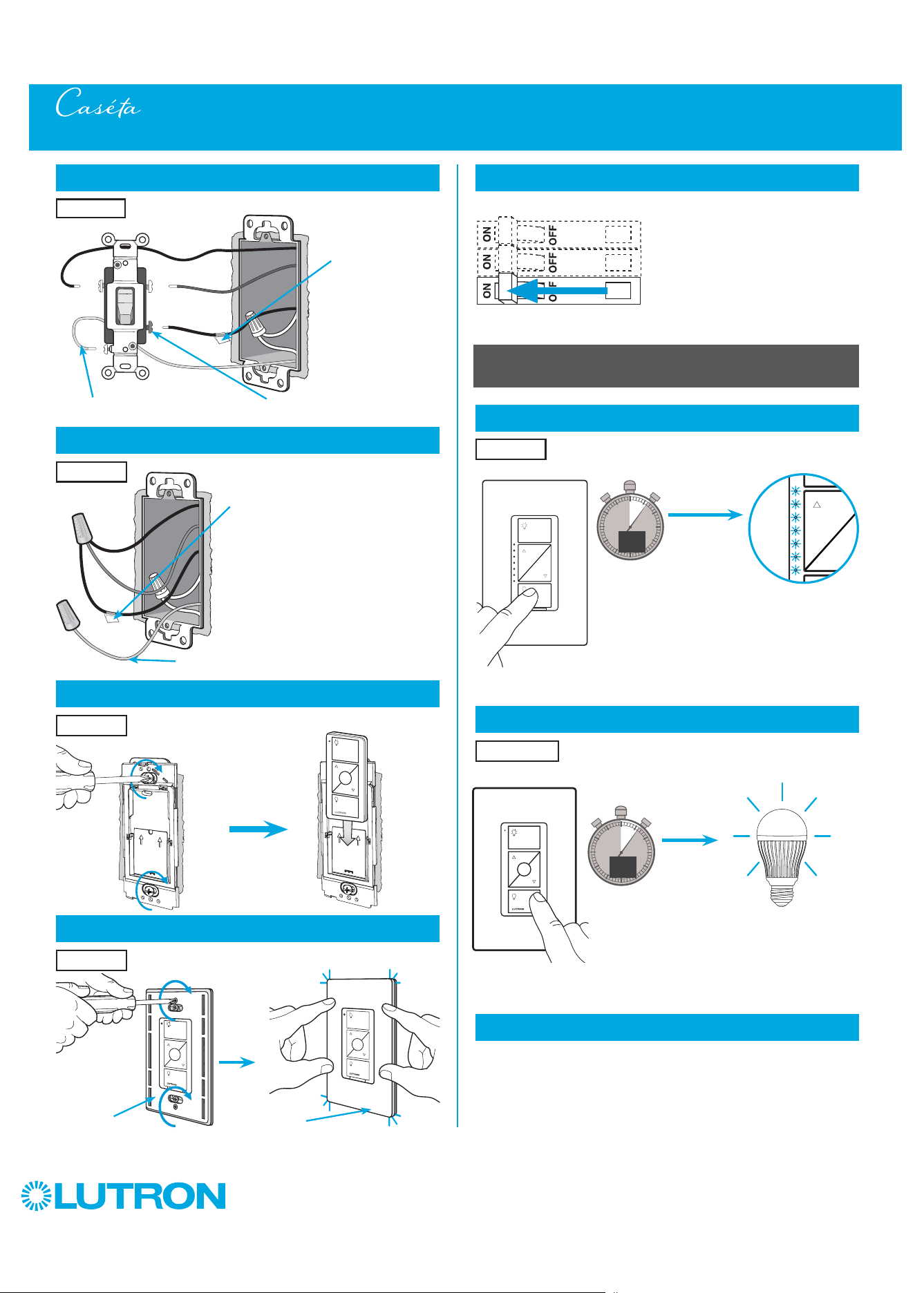
66
by Lutron
Multi-Location Installation - Caséta Wireless PRO Dimmer with Pico Remote Controls (PD-10NXD)
21
Turn power on at circuit breaker
Pairing the dimmer and Pico remote controls
22
Press and hold "Off" button on dimmer
0
5
10
15
6
sec.
UNTIL
HOLD
Status LEDs flash
23
Press and hold "Off" button on remote control
0
5
10
15
6
sec.
UNTIL
Location 2
Location 1
Repeat steps 22 and 23 to pair remote control
at Location 3.
24
Repeat for remote control at Location 3
17
Tag and disconnect wires from the existing switch
Different Color ScrewGround (Green / Bare Copper)
18
Connect the wires
19
Attach the wallplate bracket and Pico remote control
Ground (Green / Bare Copper)
Place tag - to
identify wire on
different color screw
Location 3
Tagged Wire
Location 3
Location 3
20
Attach the wallplate
‘snap’
Wallplate
Adapter
Wallplate
Location 3
HOLD
Lights flash
three times
3x
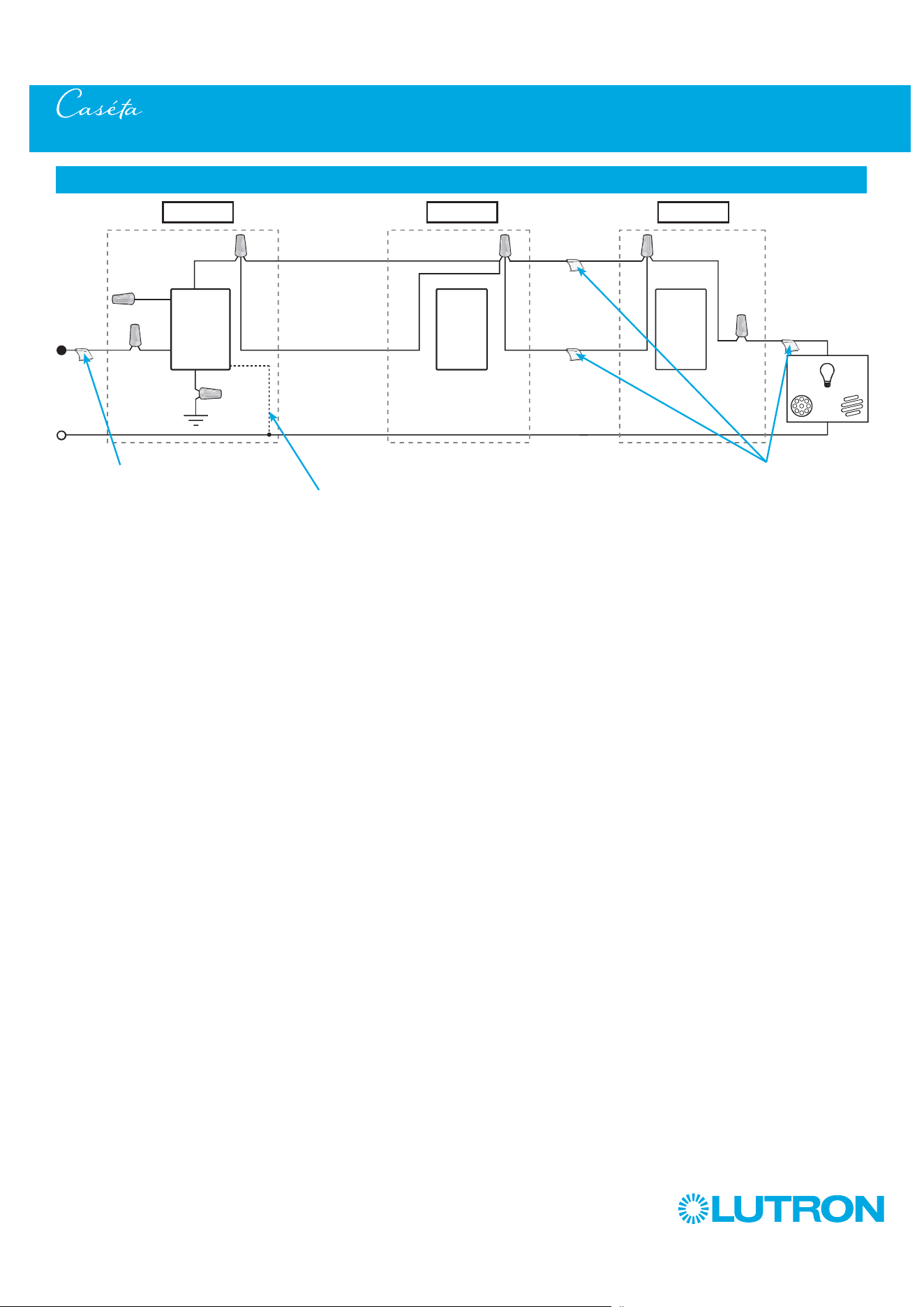
67
by Lutron
Multi-Location Installation - Caséta Wireless PRO Dimmer with Pico Remote Controls (PD-10NXD)
Neutral
Pico
Remote
Control
Line / Hot
Traveler Traveler
Traveler
Traveler
Caséta
Wireless
Dimmer *
Ground
White
Blue
Load
INC
HAL
Schematic Diagram
Pico
Remote
Control
* It is recommended to install
dimmer in either Location 1 or 3.
Location 1 Location 2 Location 3
Tagged Wire Tagged Wires
If available, connect the neutral wire from the
wallbox to the white wire on the dimmer. If neutral
is not available, cap the white wire with a wire
connector.
Neutral required for: MLV loads, LED drivers,
PHPM-PA, PHPM-3F, GRX-TVI.
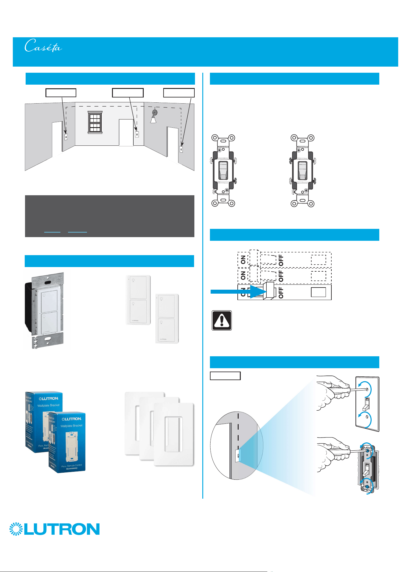
68
by Lutron
Multi-Location Installation - Caséta Wireless Switch with Pico Remote Controls (PD-5WS-DV)
1
Identify existing wiring
2
What you need for a multi-location installation
WARNING! Shock Hazard. May result in Serious
Injury or Death. Turn off power at circuit breaker
before installing the unit.
4
Turn power off at circuit breaker
5
Remove existing switch from wall at Location 1
- If one switch controls the lights (single-pole installation)
See quick-start guide that came with your switch
- If two switches control the lights (3-way installation)
See page 7 or page 35 for details
Important note:
3
Choose a location for your Caséta Wireless switch
NOTE: There will be two different types of existing switches in this
application. Locations 1 and 3 will use 3-way switches (three screws
which control the lights, plus one ground screw) and Location 2 will use
a 4-way switch (four screws which control the lights, plus one ground
screw). For easiest installation, we recommend replacing one of the 3-way
switches with your Caséta Wireless switch (Locations 1 or 3). In this
example, we will use Location 1.
Location 1
3-Way Switch
(Locations 1 and 3)
4-Way Switch
(Location 2)
Three or more switches control the lights
(multi-location installation)
Location 1 Location 2 Location 3
+
Switch
PD-5WS-DV
Two Pico
remote controls
PJ2-2B
Two wallplate brackets
PICO-WBX-ADAPT
+
Three Claro wallplates
CW-1
+
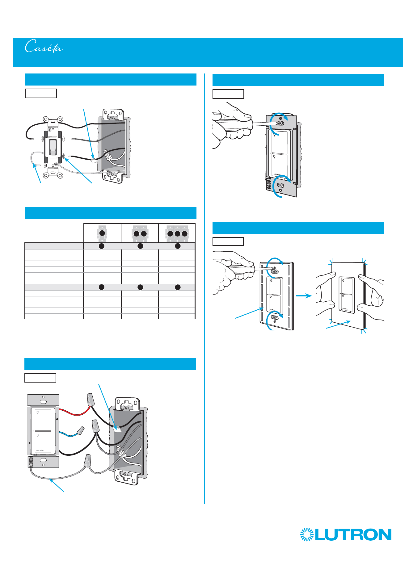
69
by Lutron
8
Connect the new Caséta Wireless switch
9
Mount the Caséta Wireless switch
10
Attach the wallplate
‘snap’
Wallplate
Adapter
Wallplate
Tagged wire
Location 1
Location 1
Location 1
6
Tag and disconnect wires from the existing switch
7
Ganging and derating
Different
Color Screw
Ground
(Green / Bare Copper)
Place tag - to identify wire on
different color screw
Location 1
Multi-Location Installation - Caséta Wireless Switch with Pico Remote Controls (PD-5WS-DV)
B B B C B
A
PD-5WS-DV (120 V
~
)
LED 5 A 4 A 3 A
Halogen/incandescent 600 W 450 W 350 W
Electronic Low-Voltage 600 W 450 W 350 W
Magnetic Low-Voltage
1
600 VA / 475 W 450 VA / 350 W 350 VA / 275 W
Fluorescent
2
5 A 4 A 3 A
General Purpose Fan 3 A 3 A 3 A
PD-5WS-DV (277 V
~
)
LED 5 A 4 A 3 A
Halogen/incandescent 1350 W 1100 W 800 W
Electronic Low-Voltage 1350 W 1100 W 800 W
Magnetic Low-Voltage
1
1350 VA / 1075 W 1100 VA / 875 W 800 VA / 625 W
Fluorescent
2
5 A 4 A 3 A
A
B C
A
B C
1
The maximum lamp wattage is determined by the efficiency of the transformer, with
70% – 85% as typical. For actual transformer efficiency, contact either the fixture or
transformer manufacturer. The total VA rating of the transformer(s) shall not exceed the VA
rating of the switch.
2
The switch is UL
R
Listed for use with all magnetic and electronic fluorescent ballasts.
Red
Blue
Black
Ground
(Green Wire)
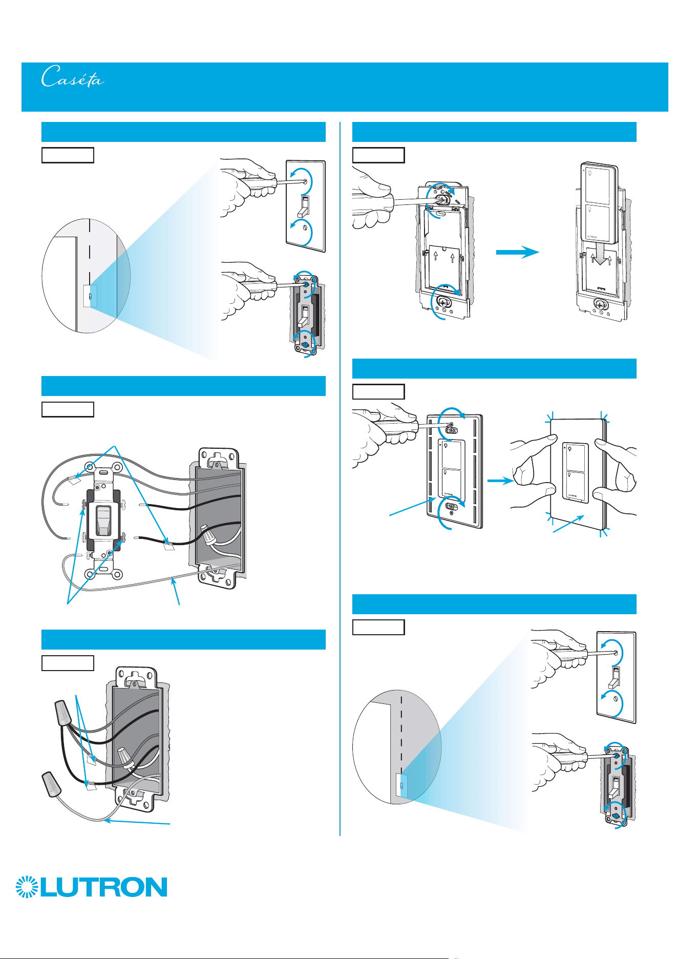
70
by Lutron
14
Attach the wallplate bracket and Pico remote control
15
Attach the wallplate
‘snap’
Multi-Location Installation - Caséta Wireless Switch with Pico Remote Controls (PD-5WS-DV)
16
Remove existing switch from wall at Location 3
Wallplate
Adapter
Wallplate
Location 2
Location 2
13
Connect the wires
Ground
(Green / Bare Copper)
Tagged Wires
Location 2
11
Remove existing switch from wall at Location 2
12
Tag and disconnect wires from the existing switch
Ground (Green / Bare Copper)
Location 2
Location 2
Place tags - to identify wires
on different color screws
Different Color Screws
Location 3
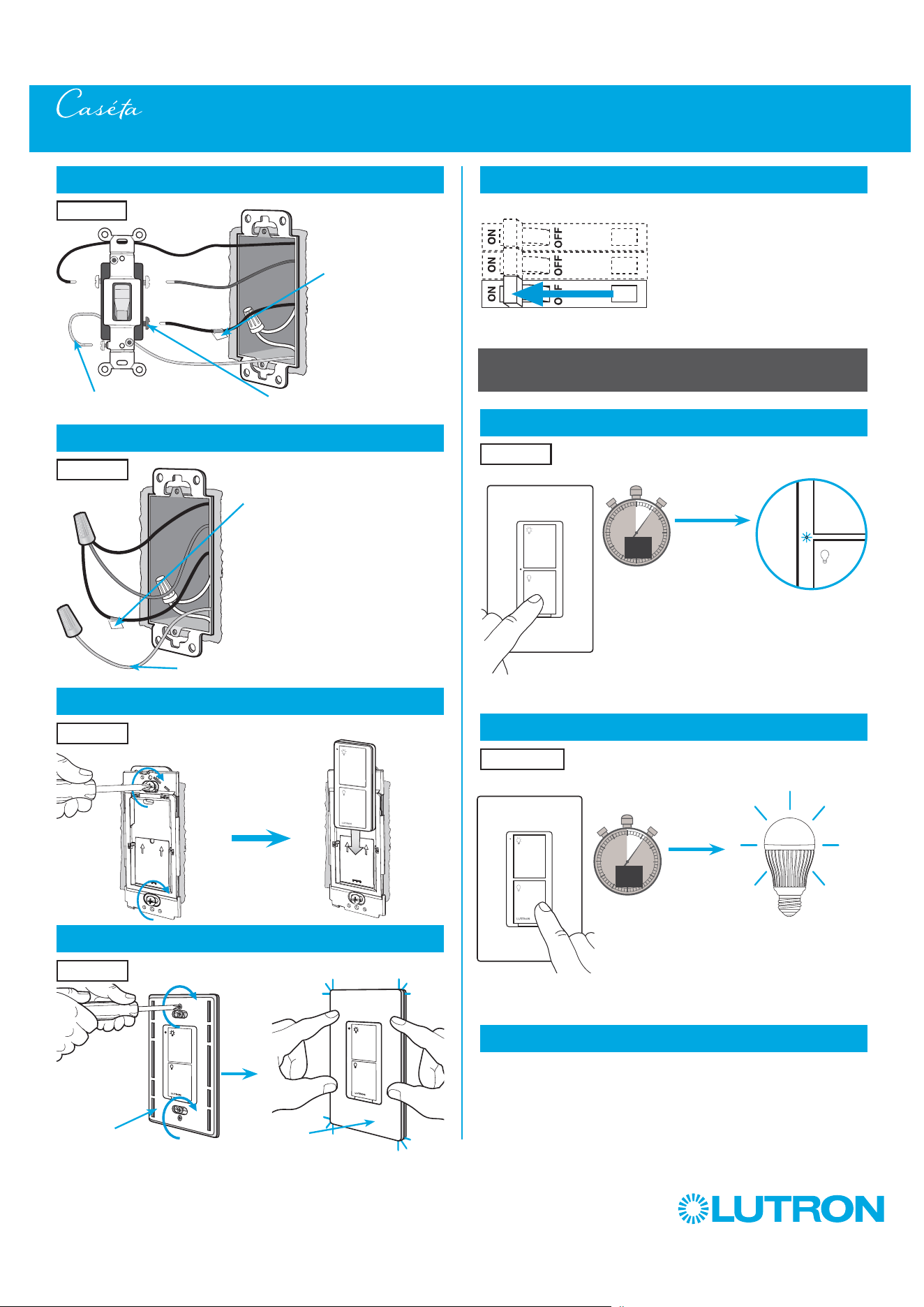
71
by Lutron
Multi-Location Installation - Caséta Wireless Switch with Pico Remote Controls (PD-5WS-DV)
21
Turn power on at circuit breaker
Pairing the switch and Pico remote controls
22
Press and hold "Off" button on switch
0
5
10
15
6
sec.
UNTIL
HOLD
Status LED flashes
23
Press and hold "Off" button on remote control
0
5
10
15
6
sec.
UNTIL
Location 2
Location 1
Repeat steps 22 and 23 to pair remote control
at Location 3.
24
Repeat for remote control at Location 3
17
Tag and disconnect wires from the existing switch
Different Color ScrewGround (Green / Bare Copper)
18
Connect the wires
19
Attach the wallplate bracket and Pico remote control
Ground (Green / Bare Copper)
Place tag - to
identify wire on
different color screw
Location 3
Tagged Wire
Location 3
Location 3
20
Attach the wallplate
‘snap’
Wallplate
Adapter
Wallplate
Location 3
HOLD
Lights flash
three times
3x
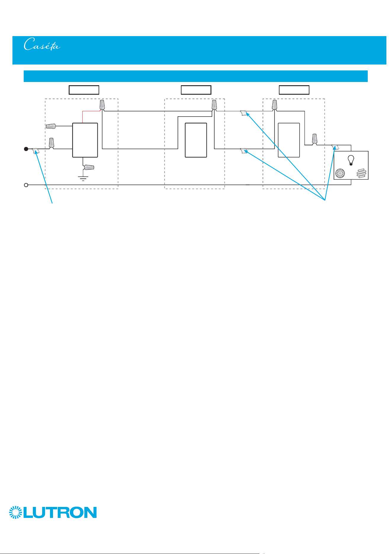
72
by Lutron
Multi-Location Installation - Caséta Wireless Switch with Pico Remote Controls (PD-5WS-DV)
Neutral
Pico
Remote
Control
Line / Hot
Traveler Traveler
Traveler
Traveler
Caséta
Wireless
Switch *
Ground
(Green)
Load
INC
HAL
Schematic Diagram
Pico
Remote
Control
* It is recommended to install switch in either Location 1 or 3.
Location 1 Location 2 Location 3
Tagged Wire Tagged Wires
Blue
Black
Red

73
by Lutron
Multi-Location Installation - Caséta Wireless Neutral Switch with Pico Remote Controls (PD-5ANS/PD-6ANS)
1
Identify existing wiring
2
What you need for a multi-location installation
WARNING! Shock Hazard. May result in Serious
Injury or Death. Turn off power at circuit breaker
before installing the unit.
4
Turn power off at circuit breaker
5
Remove existing switch from wall at Location 1
- If one switch controls the lights (single-pole installation)
See quick-start guide that came with your switch
- If two switches control the lights (3-way installation)
See page 15 or page 41 for details
Important note:
3
Choose a location for your Caséta Wireless switch
NOTE: There will be two different types of existing switches in this
application. Locations 1 and 3 will use 3-way switches (three screws
which control the lights, plus one ground screw) and Location 2 will use
a 4-way switch (four screws which control the lights, plus one ground
screw). For easiest installation, we recommend replacing one of the 3-way
switches with your Caséta Wireless switch (Locations 1 or 3). In this
example, we will use Location 1.
Location 1
3-Way Switch
(Locations 1 and 3)
4-Way Switch
(Location 2)
Three or more switches control the lights
(multi-location installation)
Location 1 Location 2 Location 3
+
Switch
PD-5ANS/PD-6ANS
Two Pico
remote controls
PJ2-2B
Two wallplate brackets
PICO-WBX-ADAPT
+
Three Claro wallplates
CW-1
+
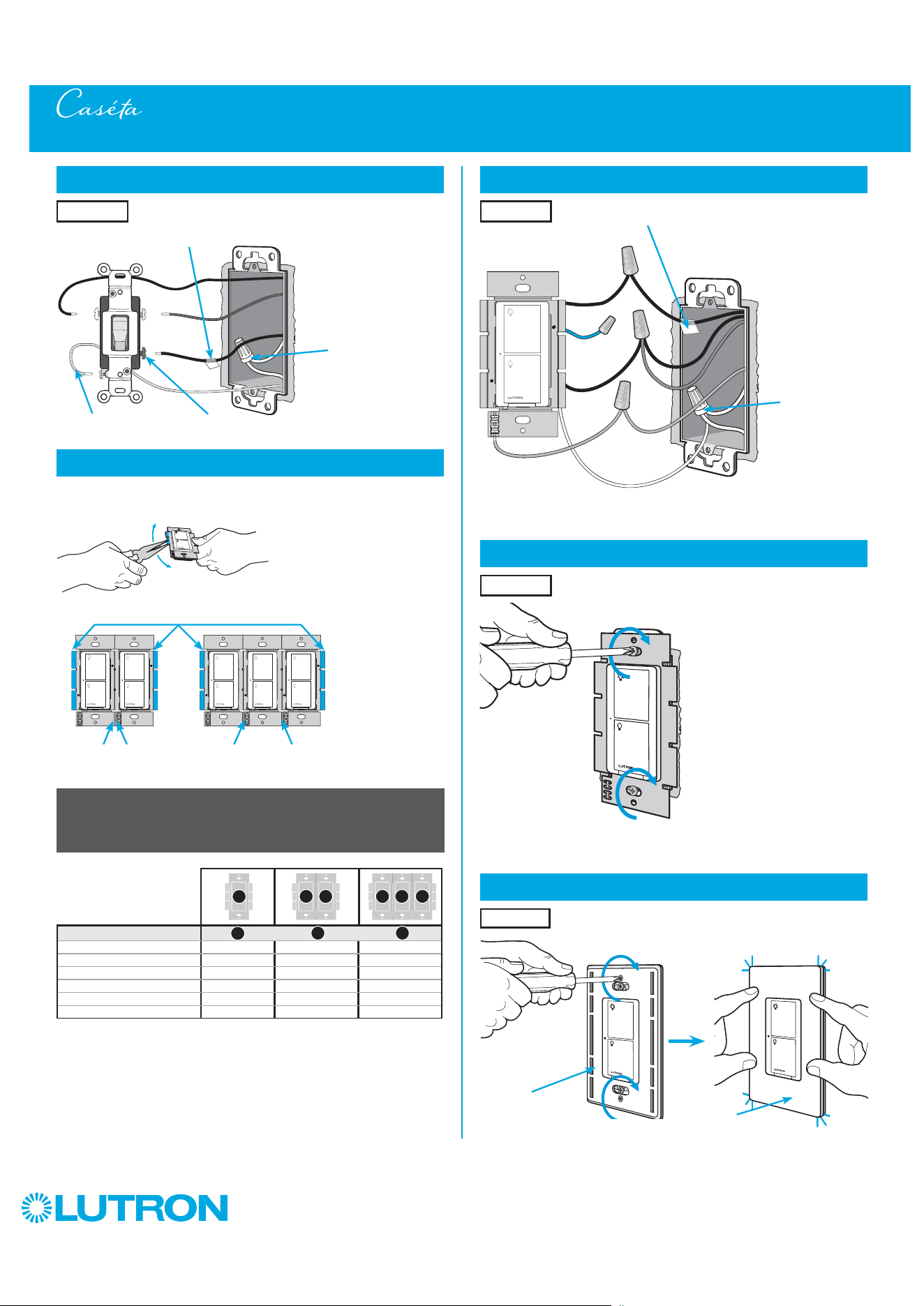
74
by Lutron
8
Connect the new Caséta Wireless neutral switch
9
Mount the Caséta Wireless neutral switch
10
Attach the wallplate
‘snap’
Wallplate
Adapter
Wallplate
Tagged wire
Location 1
Location 1
Location 1
6
Tag and disconnect wires from the existing switch
7
Remove side sections (if necessary)
Different
Color Screw
Ground
(Green / Bare Copper)
Place tag - to identify wire on
different color screw
Location 1
Multi-Location Installation - Caséta Wireless Neutral Switch with Pico Remote Controls (PD-5ANS/PD-6ANS)
Do not remove outside side sections
on switches at the end of gang.
Each switch has inside
side sections removed.
Switch in the middle has
all side sections removed.
When installing more than one Caséta Wireless switch in the same wallbox,
it is necessary to remove inner side sections prior to wiring. See image and
chart below for more information.
Important note:
Removing side sections reduces the switch’s maximum wattage rating.
See the chart below for maximum wattage information.
Black
Blue
Red
Ground
(Green Wire)
Neutral
connection
required
1
Neutral required.
2
The maximum lamp wattage is determined by the efficiency of the transformer, with
70% – 85% as typical. For actual transformer efficiency, contact either the fixture or
transformer manufacturer. The total VA rating of the transformer(s) shall not exceed the VA
rating of the switch.
3
The switch is UL
R
Listed for use with all magnetic and electronic fluorescent ballasts.
B B B C B
A
PD-5ANS/PD-6ANS (120 V
~
)
1
LED 6 A 6 A 5 A
Halogen / incandescent 720 W 720 W 600 W
Electronic Low-Voltage 720 VA 720 VA 600 VA
Magnetic Low-Voltage
2
720 VA 720 VA 600 VA
Fluorescent
3
6 A 6 A 5 A
General Purpose Fan 3.6 A 3.6 A 3.6 A
A
B C
White
Neutral
connection
required
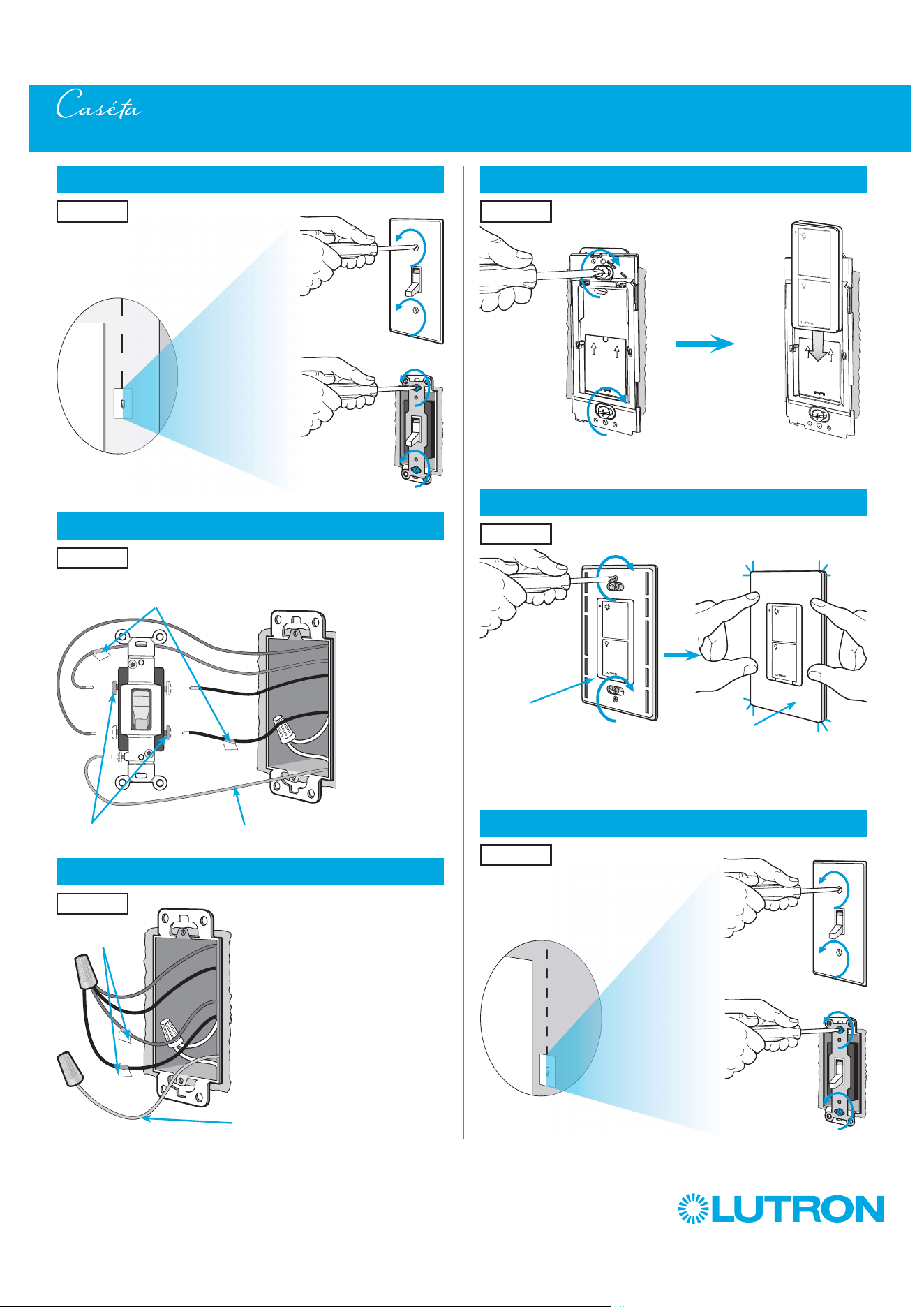
75
by Lutron
14
Attach the wallplate bracket and Pico remote control
15
Attach the wallplate
‘snap’
Multi-Location Installation - Caséta Wireless Neutral Switch with Pico Remote Controls (PD-5ANS/PD-6ANS)
16
Remove existing switch from wall at Location 3
Wallplate
Adapter
Wallplate
Location 2
Location 2
13
Connect the wires
Ground
(Green / Bare Copper)
Tagged Wires
Location 2
11
Remove existing switch from wall at Location 2
12
Tag and disconnect wires from the existing switch
Ground (Green / Bare Copper)
Location 2
Location 2
Place tags - to identify wires
on different color screws
Different Color Screws
Location 3

76
by Lutron
Multi-Location Installation - Caséta Wireless Neutral Switch with Pico Remote Controls (PD-5ANS/PD-6ANS)
21
Turn power on at circuit breaker
Pairing the switch and Pico remote controls
22
Press and hold "Off" button on switch
0
5
10
15
6
sec.
UNTIL
HOLD
Status LED flashes
23
Press and hold "Off" button on remote control
0
5
10
15
6
sec.
UNTIL
Location 2
Location 1
Repeat steps 22 and 23 to pair remote control
at Location 3.
24
Repeat for remote control at Location 3
17
Tag and disconnect wires from the existing switch
Different Color ScrewGround (Green / Bare Copper)
18
Connect the wires
19
Attach the wallplate bracket and Pico remote control
Ground (Green / Bare Copper)
Place tag - to
identify wire on
different color screw
Location 3
Tagged Wire
Location 3
Location 3
20
Attach the wallplate
‘snap’
Wallplate
Adapter
Wallplate
Location 3
HOLD
Lights flash
three times
3x

77
by Lutron
Multi-Location Installation - Caséta Wireless Neutral Switch with Pico Remote Controls (PD-5ANS/PD-6ANS)
Neutral
Pico
Remote
Control
Line / Hot
Traveler Traveler
Traveler
Traveler
Caséta
Wireless
Switch *
Ground
(Green)
Load
INC
HAL
Schematic Diagram
Pico
Remote
Control
Location 1 Location 2 Location 3
Tagged Wire Tagged Wires
Blue
Black
Red
White
* It is recommended to install switch in either Location 1 or 3.
Note: The red wire must be connected to the load and the black wire must be connected to Line/Hot. The product will not work if the wires
are reversed.
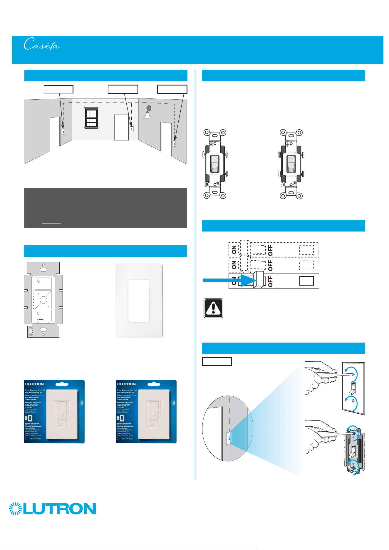
78
by Lutron
Multi-Location Installation - Caséta Wireless ELV+ Dimmer with Pico Remote Controls (PD-5NE)
1
Identify existing wiring
2
What you need for a multi-location installation
WARNING! Shock Hazard. May result in Serious
Injury or Death. Turn off power at circuit breaker
before installing the unit.
4
Turn power off at circuit breaker
5
Remove existing switch from wall at Location 1
+
- If one switch controls the lights (single-pole installation)
See quick-start guide that came with your dimmer
- If two switches control the lights (3-way installation)
See page 19 for details
Important note:
ELV+ dimmer
PD-5NE
Two Pico remote controls with wall-mounting kits
PJ2-WALL
3
Choose a location for your Caséta Wireless dimmer
NOTE: There will be two different types of existing switches in this
application. Locations 1 and 3 will use 3-way switches (three screws
which control the lights, plus one ground screw) and Location 2 will use
a 4-way switch (four screws which control the lights, plus one ground
screw). For easiest installation, we recommend replacing one of the 3-way
switches with your dimmer (Locations 1 or 3). In this example, we will use
Location 1.
Location 1
3-Way Switch
(Locations 1 and 3)
4-Way Switch
(Location 2)
+
Claro wallplate
CW-1
Three or more switches control the lights
(multi-location installation)
Location 1 Location 2 Location 3
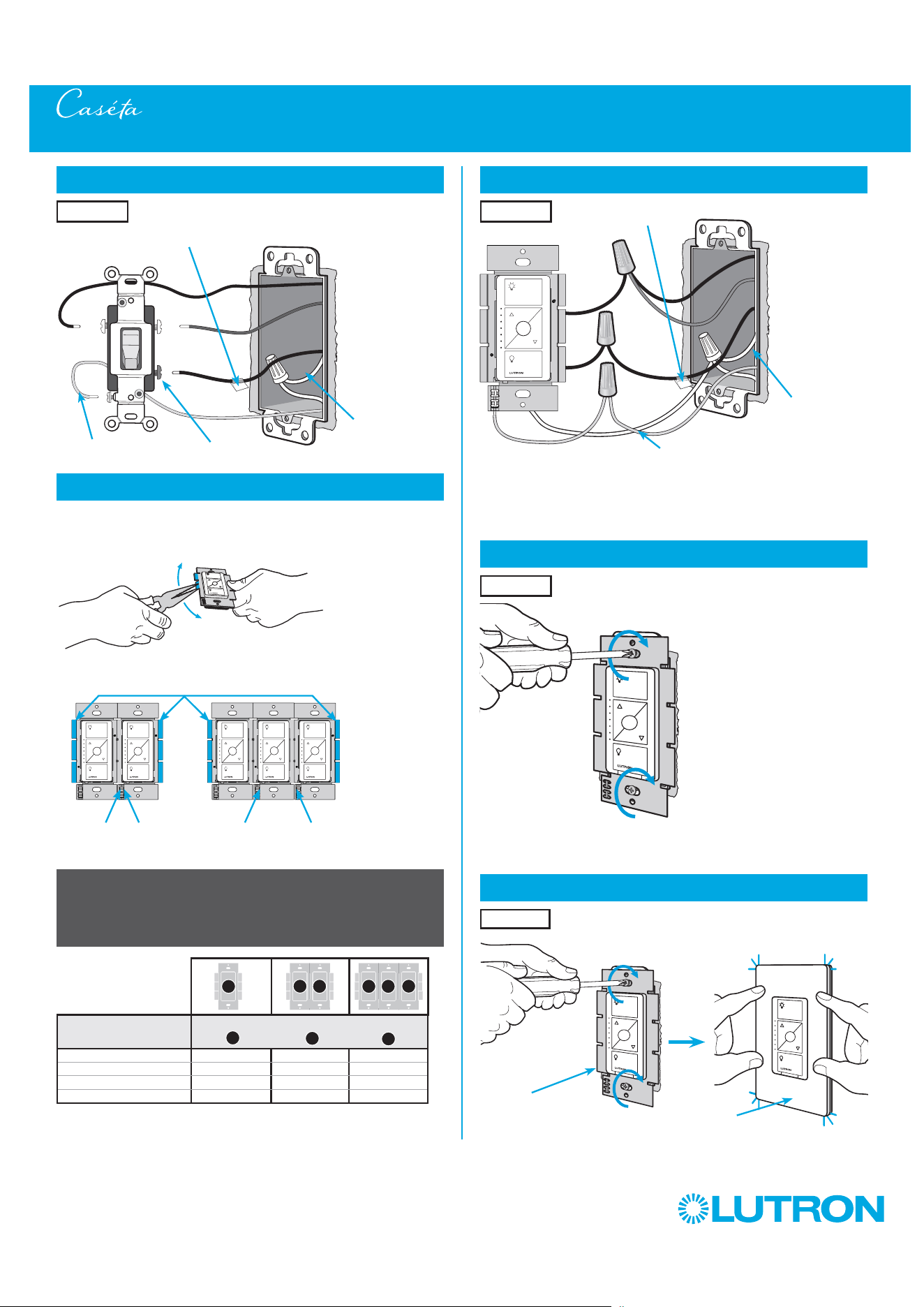
79
by Lutron
Multi-Location Installation - Caséta Wireless ELV+ Dimmer with Pico Remote Controls (PD-5NE)
8
Connect the new Caséta Wireless dimmer
9
Mount the Caséta Wireless dimmer
10
Attach the wallplate
‘snap’
Ground
(Green / Bare Copper)
Wallplate
Adapter
Wallplate
Tagged wire
Red
Black
White
Neutral Required
Location 1
Location 1
Location 1
6
Tag and disconnect wires from the existing switch
7
Remove side sections (if necessary)
Do not remove outside side sections
on dimmers at the end of gang.
Each dimmer has inside
side sections removed.
Dimmer in the middle has
all side sections removed.
When installing more than one Caséta Wireless dimmer in the same wallbox,
it is necessary to remove inner side sections prior to wiring. See image and
chart below for more information.
Important note:
Removing side sections reduces the dimmer’s maximum wattage
rating. See the chart below for maximum wattage information.
Different
Color Screw
Neutral
Required
Ground
(Green / Bare Copper)
Place tag - to identify wire on
different color screw
Location 1
PD-5NE (120 V
~
)
1
Incandescent/Halogen Total Wattage
LED 250 W 250 W 250 W
Halogen / Incandescent 500 W 400 W 300 W
Electronics Low-Voltage 500 W 400 W 300 W
Magnetic Low Voltage 400 VA 400 VA 400 VA
A
B
C
B B B C B
A

80
by Lutron
14
Attach the wallplate bracket and Pico remote control
15
Attach the wallplate
‘snap’
Multi-Location Installation - Caséta Wireless ELV+ Dimmer with Pico Remote Controls (PD-5NE)
16
Remove existing switch from wall at Location 3
Wallplate
Adapter
Wallplate
Location 2
Location 2
13
Connect the wires
Ground
(Green / Bare Copper)
Tagged Wires
Location 2
11
Remove existing switch from wall at Location 2
12
Tag and disconnect wires from the existing switch
Ground (Green / Bare Copper)
Location 2
Location 2
Place tags - to identify wires
on different color screws
Different Color Screws
Location 3
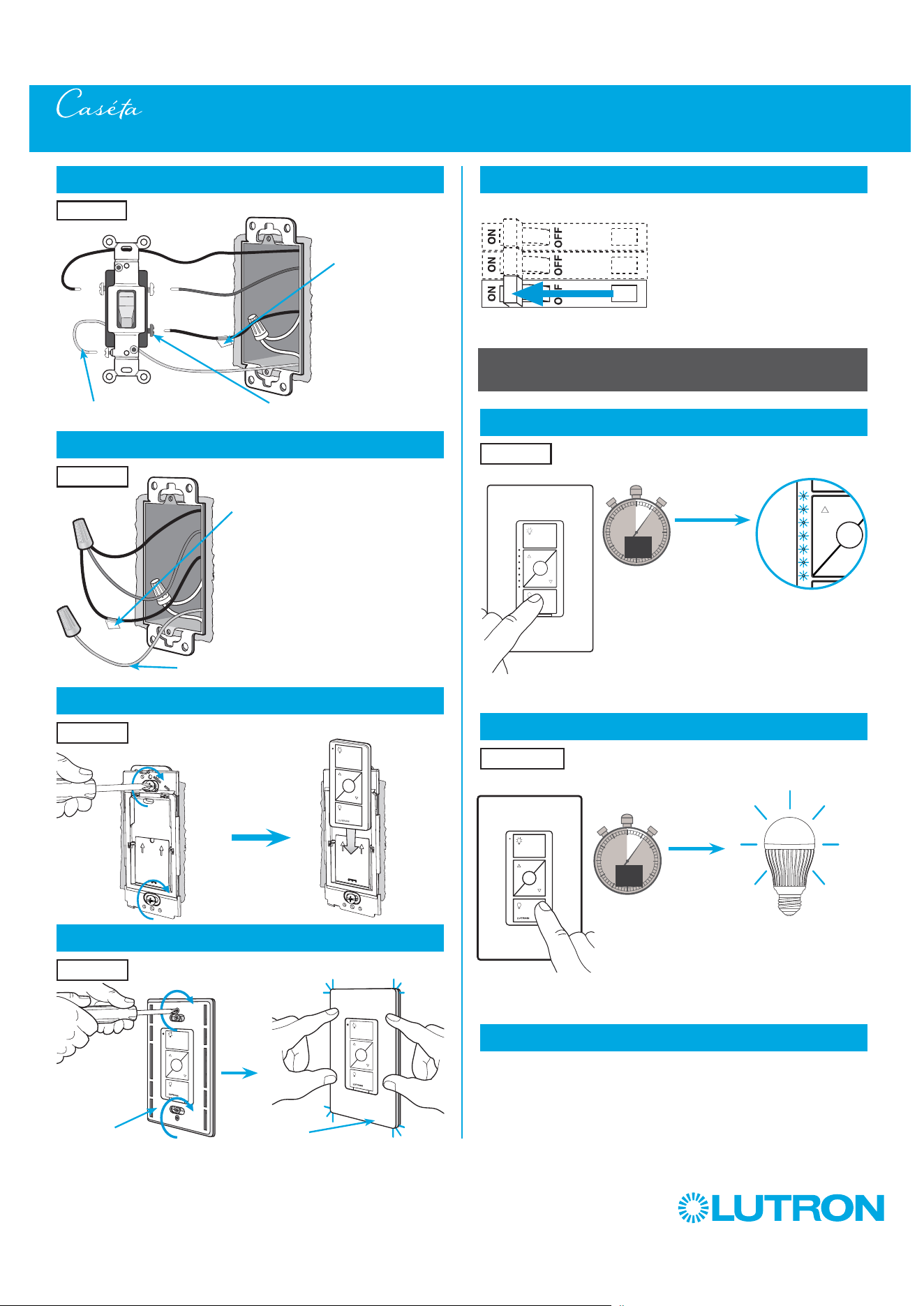
81
by Lutron
Multi-Location Installation - Caséta Wireless ELV+ Dimmer with Pico Remote Controls (PD-5NE)
21
Turn power on at circuit breaker
Pairing the dimmer and Pico remote controls
22
Press and hold "Off" button on dimmer
0
5
10
15
6
sec.
UNTIL
HOLD
Status LEDs flash
23
Press and hold "Off" button on remote control
0
5
10
15
6
sec.
UNTIL
Location 2
Location 1
Repeat steps 22 and 23 to pair remote control
at Location 3.
24
Repeat for remote control at Location 3
17
Tag and disconnect wires from the existing switch
Different Color ScrewGround (Green / Bare Copper)
18
Connect the wires
19
Attach the wallplate bracket and Pico remote control
Ground (Green / Bare Copper)
Place tag - to
identify wire on
different color screw
Location 3
Tagged Wire
Location 3
Location 3
20
Attach the wallplate
‘snap’
Wallplate
Adapter
Wallplate
Location 3
HOLD
Lights flash
three times
3x
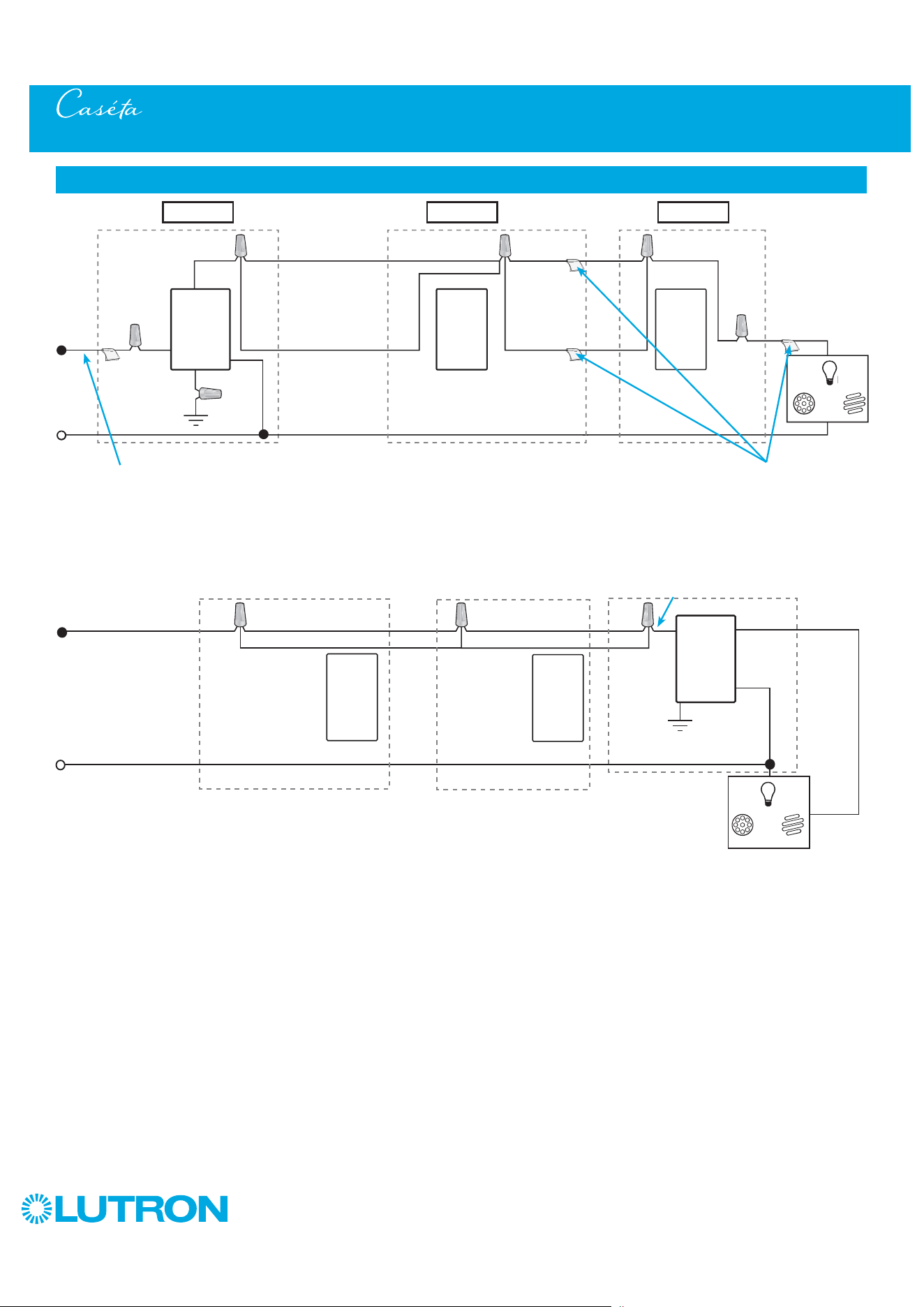
82
by Lutron
Multi-Location Installation - Caséta Wireless ELV+ Dimmer with Pico Remote Controls (PD-5NE)
Neutral
Pico
Remote
Control
Line / Hot
Traveler Traveler
Traveler
Traveler
Caséta
Wireless
Dimmer
Ground
Load
INC
HAL
INC
HAL
Schematic Diagram
Pico
Remote
Control
* Neutral Required
Location 1 Location 2 Location 3
Tagged Wire Tagged Wires
Red
Red
Black
Black
Caséta
Wireless
Dimmer
Traveler Traveler
TravelerTraveler
Line / Hot
Neutral
Ground
White
White
Load
Pico
Remote
Control
Pico
Remote
Control
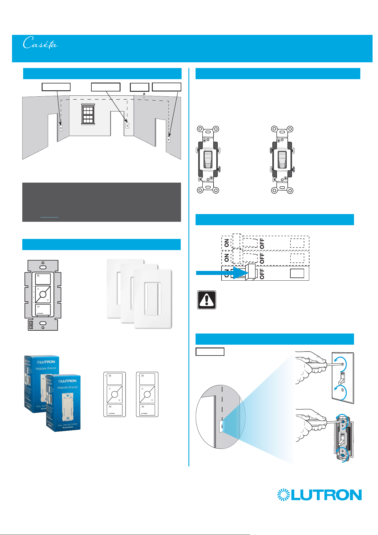
83
by Lutron
Multi-Location Installation - Caséta Wireless Fan Control with Pico Remote Controls (PD-FSQN)
1
Identify existing wiring
2
What you need for a multi-location installation
WARNING! Shock Hazard. May result in Serious
Injury or Death. Turn off power at circuit breaker
before installing the unit.
4
Turn power off at circuit breaker
5
Remove existing switch from wall at Location 1
- If one switch controls the fan (single-pole installation)
See quick-start guide that came with your fan control
- If two switches control the fan (3-way installation)
See page 23 for details
Important note:
3
Choose a location for your Caséta Wireless fan control
NOTE: There will be two different types of existing switches in this
application. Locations 1 and 3 will use 3-way switches (three screws
which control the fan, plus one ground screw) and Location 2 will use a
4-way switch (four screws which control the fan, plus one ground screw).
For easiest installation, we recommend replacing one of the 3-way
switches with your fan control (Locations 1 or 3). In this example, we will
use Location 1.
Location 1
3-Way Switch
(Locations 1 and 3)
4-Way Switch
(Location 2)
Three or more switches control the fan
(multi-location installation)
Location 1
Location 2
To Fan
Location 3
+
+
Fan control
PD-FSQN
Two Pico wallbox
adapters
PICO-WBX-ADAPT
+
Three Claro wallplates
CW-1
Two Pico remote controls
for fans
PJ2-3BRL-XXX-F01
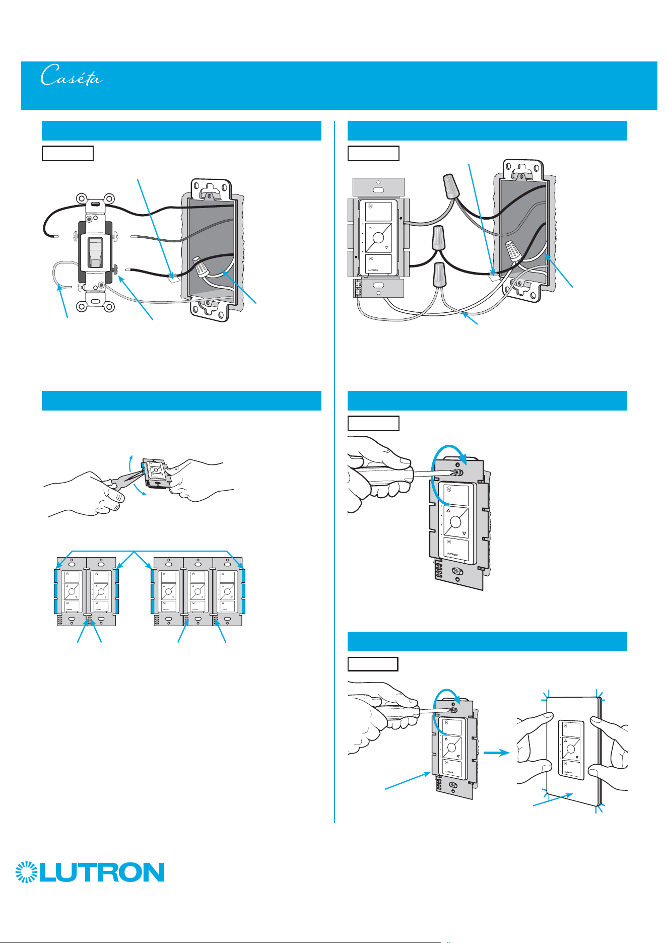
84
by Lutron
Multi-Location Installation - Caséta Wireless Fan Control with Pico Remote Controls (PD-FSQN)
8
Connect the new Caséta Wireless fan control
9
Mount the Caséta Wireless fan control
10
Attach the wallplate
‘snap’
Ground
(Green / Bare Copper)
Wallplate
Adapter
Wallplate
Tagged wire
Red
Yellow
Black
White
(Neutral Required)
Location 1
Location 1
Location 1
6
Tag and disconnect wires from the existing switch
7
Remove side sections (if necessary)
Do not remove outside side sections
on the controls at the end of gang.
Each control has inside
side sections removed.
The control in the middle
has all side sections
removed.
When installing more than one Caséta Wireless control in the same wallbox,
it is necessary to remove inner side sections prior to wiring. See image below
for more information.
Different
Color Screw
Neutral
Required
Ground
(Green / Bare Copper)
Place tag - to identify wire on
different color screw
Location 1
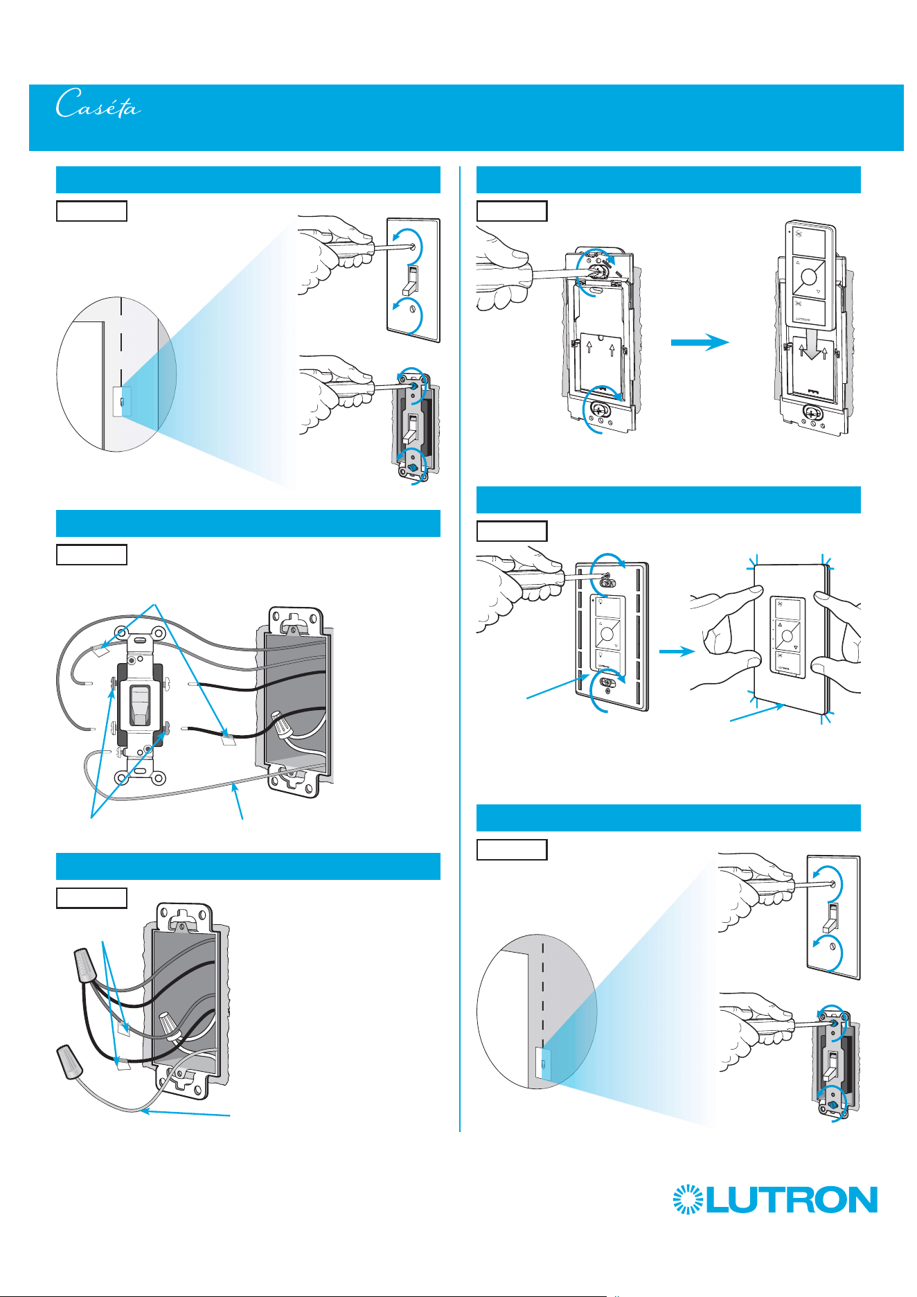
85
by Lutron
14
Attach the wallplate bracket and Pico remote control
15
Attach the wallplate
‘snap’
Multi-Location Installation - Caséta Wireless Fan Control with Pico Remote Controls (PD-FSQN)
16
Remove existing switch from wall at Location 3
Wallplate
Adapter
Wallplate
Location 2
Location 2
13
Connect the wires
Ground
(Green / Bare Copper)
Tagged Wires
Location 2
11
Remove existing switch from wall at Location 2
12
Tag and disconnect wires from the existing switch
Ground (Green / Bare Copper)
Location 2
Location 2
Place tags - to identify wires
on different color screws
Different Color Screws
Location 3

86
by Lutron
Multi-Location Installation - Caséta Wireless Fan Control with Pico Remote Controls (PD-FSQN)
21
Turn power on at circuit breaker
Pairing the fan control and Pico remote
controls
22
Press and hold "Off" button on the fan control
0
5
10
15
6
sec.
UNTIL
HOLD
Status LEDs flash
23
Press and hold "Off" button on remote control
0
5
10
15
6
sec.
UNTIL
Location 2
Location 1
Repeat steps 22 and 23 to pair remote control
at Location 3.
24
Repeat for remote control at Location 3
17
Tag and disconnect wires from the existing switch
Different Color ScrewGround (Green / Bare Copper)
18
Connect the wires
19
Attach the wallplate bracket and Pico remote control
Ground (Green / Bare Copper)
Place tag - to
identify wire on
different color screw
Location 3
Tagged Wire
Location 3
Location 3
20
Attach the wallplate
‘snap’
Wallplate
Adapter
Wallplate
Location 3
HOLD
Status LEDs flash
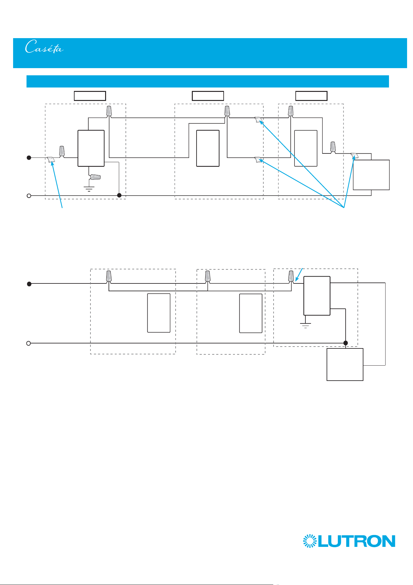
87
by Lutron
Multi-Location Installation - Caséta Wireless Fan Control with Pico Remote Controls (PD-FSQN)
Neutral
Pico
Remote
Control
Line / Hot
Traveler Traveler
Traveler
Traveler
PD-FSQN
Ground
Load
Schematic Diagram
Pico
Remote
Control
* Neutral Required
Location 1 Location 2 Location 3
Tagged Wire
Tagged Wires
Yellow
Yellow
Black
Black
PD-FSQN
Traveler Traveler
TravelerTraveler
Line / Hot
Neutral
Ground
White
White
Load
Fan
Pico
Remote
Control
Pico
Remote
Control
&
&
Fan
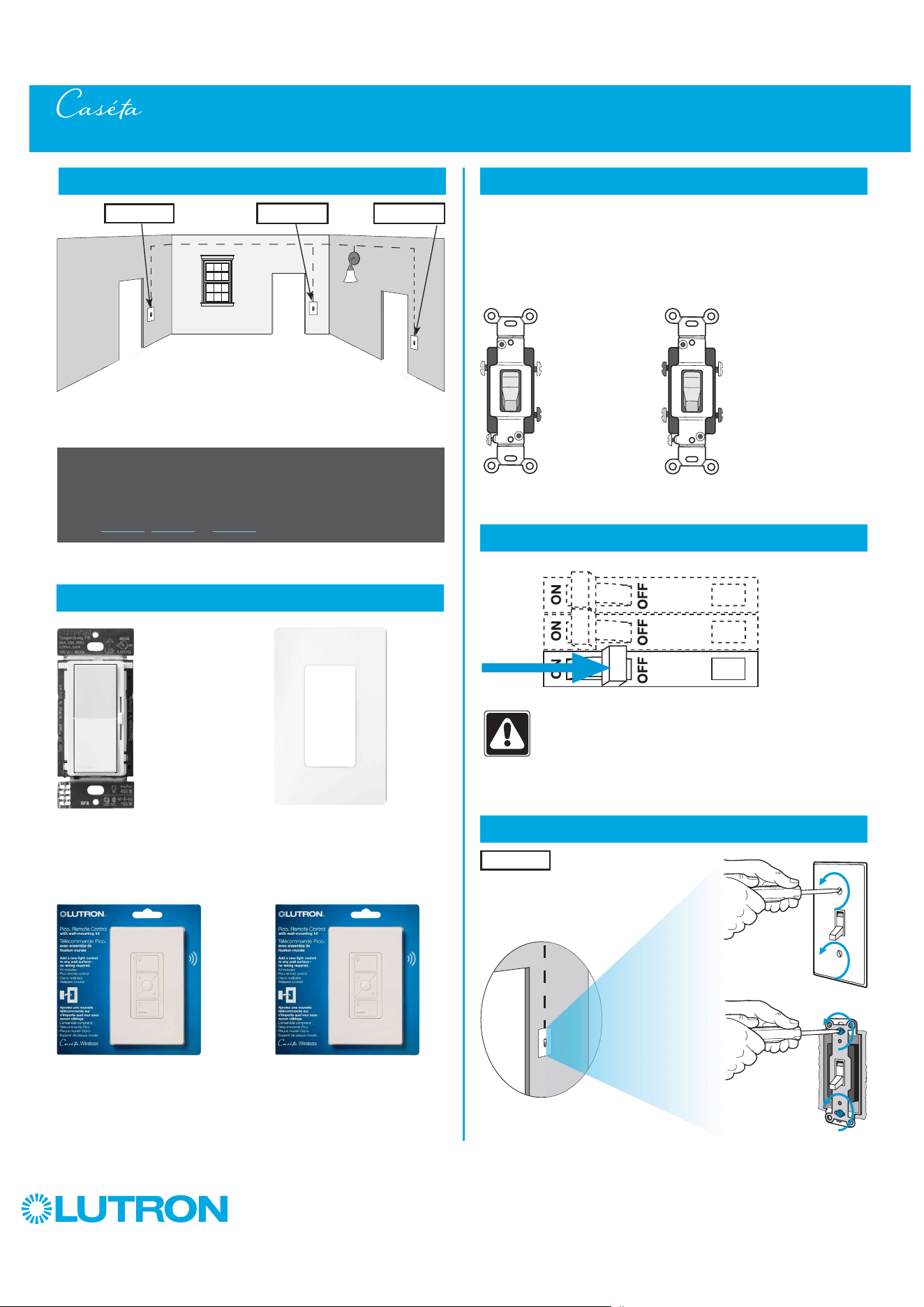
88
by Lutron
Multi-Location Installation - Caséta Diva Smart Dimmer with Pico Remote Controls (DVRF-6L)
1
Identify existing wiring
2
What you need for a multi-location installation
WARNING! Shock Hazard. May result in Serious
Injury or Death. Turn off power at circuit breaker
before installing the unit.
4
Turn power off at circuit breaker
5
Remove existing switch from wall at Location 1
+
- If one switch controls the lights (single-pole installation)
See quick-start guide that came with your dimmer
- If two switches control the lights (3-way installation)
See page 27, page 44 or page 50 for details
Important note:
Diva Smart dimmer
DVRF-6L
Two Pico remote controls with wall-mounting kits
PJ2-WALL
3
Choose a location for your Caséta Diva Smart dimmer
NOTE: There will be two different types of existing switches in this
application. Locations 1 and 3 will use 3-way switches (three screws
which control the lights, plus one ground screw) and Location 2 will use
a 4-way switch (four screws which control the lights, plus one ground
screw). For easiest installation, we recommend replacing one of the 3-way
switches with your dimmer (Locations 1 or 3). In this example, we will use
Location 1.
Location 1
3-Way Switch
(Locations 1 and 3)
4-Way Switch
(Location 2)
+
Claro wallplate
CW-1
Three or more switches control the lights
(multi-location installation)
Location 1 Location 2 Location 3
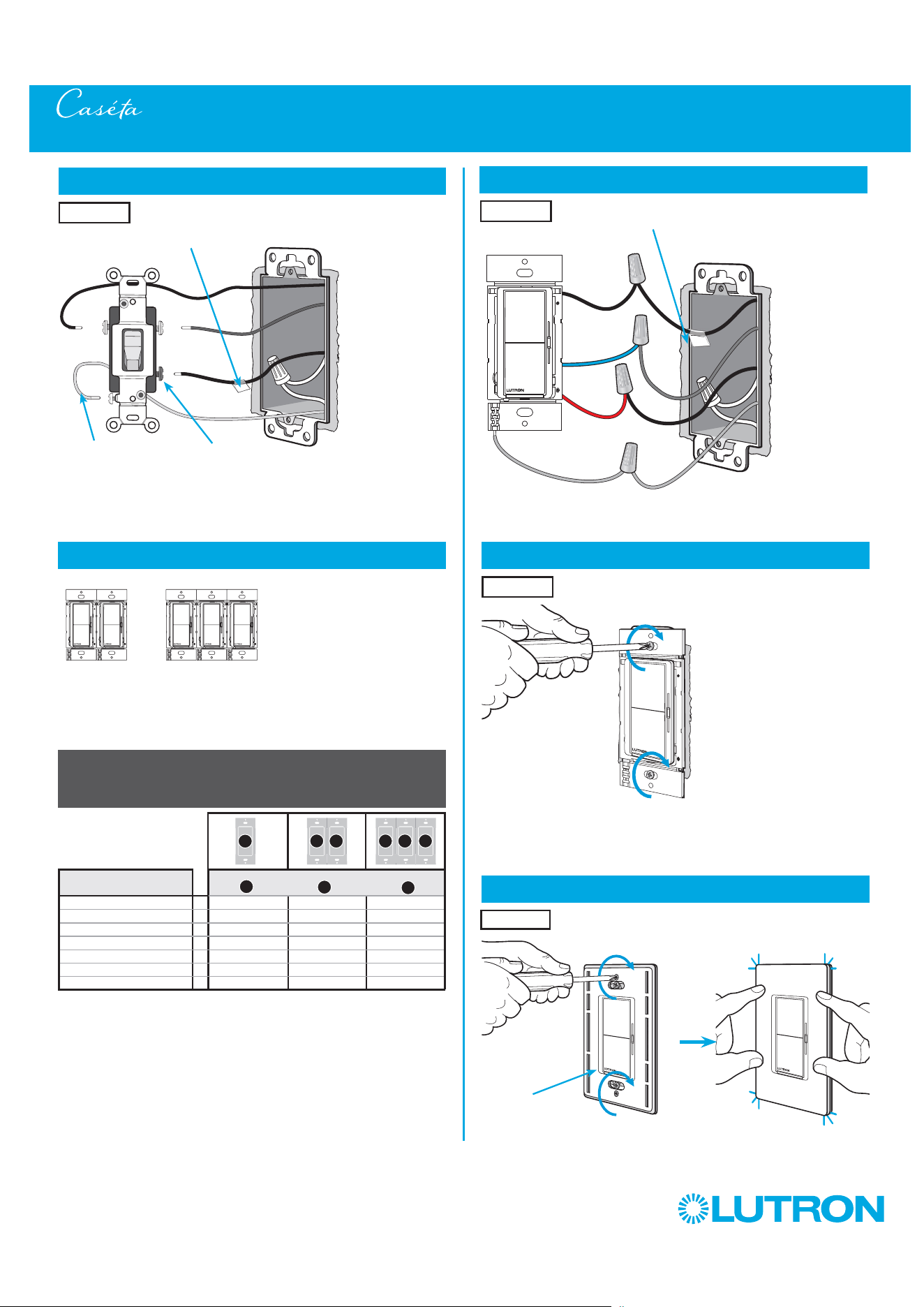
89
by Lutron
Multi-Location Installation - Caséta Diva Smart Dimmer with Pico Remote Controls (DVRF-6L)
9
Mount the Caséta Diva Smart dimmer
10
Attach the wallplate
Location 1
6
Tag and disconnect wires from the existing switch
Different
Color Screw
Ground
(Green / Bare Copper)
Place tag - to identify wire on
different color screw
Location 1
8
Connect the new Caséta Diva Smart dimmer
Location 1
Tagged Wire
Ground
(Green Wire)
Red
Black
Blue
Location 1
‘snap’
Wallplate
Adapter
Wallplate
7
Ganging and derating
Total Dimmable LED Wattage Incandescent/Halogen Total Wattage
0 W + 600 W 500 W 400 W
1 W – 25 W + 500 W 400 W 300 W
26 W – 50 W + 400 W 300 W 200 W
51 W – 75 W + 300 W 200 W 100 W
76 W – 100 W + 200 W 100 W 50 W
101 W – 125 W + 100 W 50 W 0 W
126 W – 150 W + 0 W 0 W 0 W
A
B
C
B B B C B
A
Important note:
Ganging units together may reduce the dimmer’s maximum wattage
rating. See the chart below for maximum wattage information.
Note: Diva Smart controls don’t have fins but derating is
still required. See the chart below.
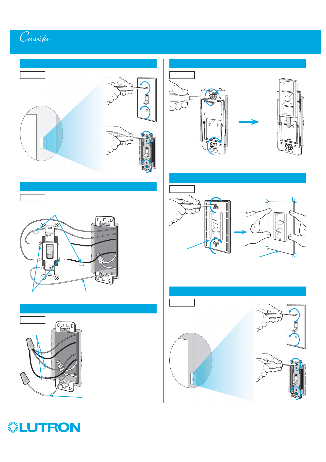
90
by Lutron
14
Attach the wallplate bracket and Pico remote control
15
Attach the wallplate
‘snap’
Multi-Location Installation - Caséta Diva Smart Dimmer with Pico Remote Controls (DVRF-6L)
16
Remove existing switch from wall at Location 3
Wallplate
Adapter
Wallplate
Location 2
Location 2
13
Connect the wires
Ground
(Green / Bare Copper)
Tagged Wires
Location 2
11
Remove existing switch from wall at Location 2
12
Tag and disconnect wires from the existing switch
Ground (Green / Bare Copper)
Location 2
Location 2
Place tags - to identify wires
on different color screws
Different Color Screws
Location 3

91
by Lutron
Multi-Location Installation - Caséta Diva Smart Dimmer with Pico Remote Controls (DVRF-6L)
21
Turn power on at circuit breaker
Pairing the dimmer and Pico remote controls
22
Press and hold "Off" button on dimmer
0
5
10
15
6
sec.
UNTIL
HOLD
The light bar
starts flashing
23
Press and hold "Off" button on remote control
0
5
10
15
6
sec.
UNTIL
Location 2
Location 1
Repeat steps 22 and 23 to pair remote control
at Location 3.
24
Repeat for remote control at Location 3
17
Tag and disconnect wires from the existing switch
Different Color ScrewGround (Green / Bare Copper)
18
Connect the wires
19
Attach the wallplate bracket and Pico remote control
Ground (Green / Bare Copper)
Place tag - to
identify wire on
different color screw
Location 3
Tagged Wire
Location 3
Location 3
20
Attach the wallplate
‘snap’
Wallplate
Adapter
Wallplate
Location 3
HOLD
Lights flash
three times
3x
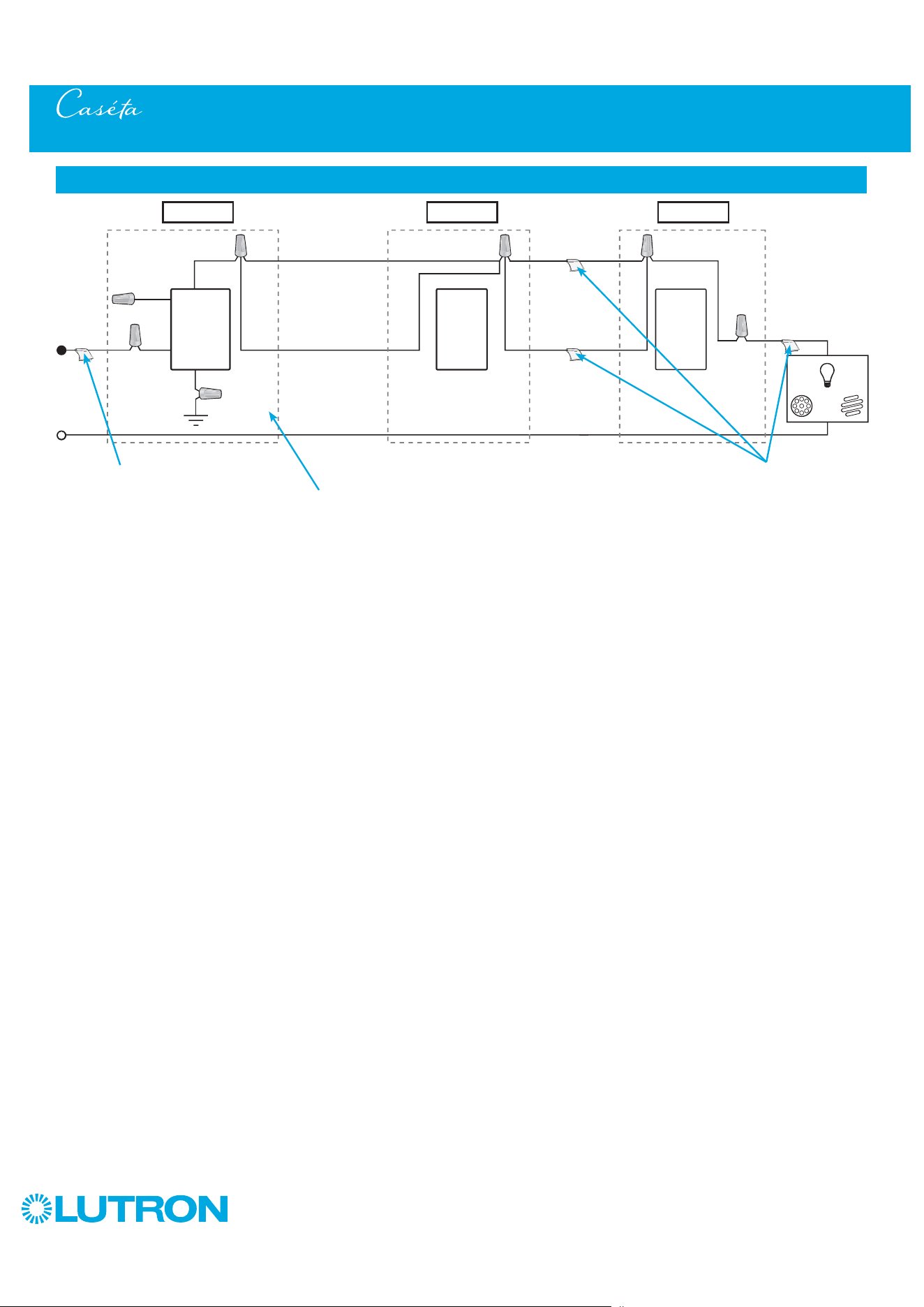
92
by Lutron
Multi-Location Installation - Caséta Diva Smart Dimmer with Pico Remote Controls (DVRF-6L)
Neutral
Pico
Remote
Control
Line / Hot
Traveler Traveler
Traveler
Traveler
Caséta
Diva
Smart
Dimmer *
Ground
Blue
Load
INC
HAL
Schematic Diagram
Pico
Remote
Control
* It is recommended to install
dimmer in either Location 1 or 3.
Location 1 Location 2 Location 3
Tagged Wire Tagged Wires
NOTE: When using Picos in a multilocation installation with a Diva Smart dimmer the Black and Red wires are reversible.
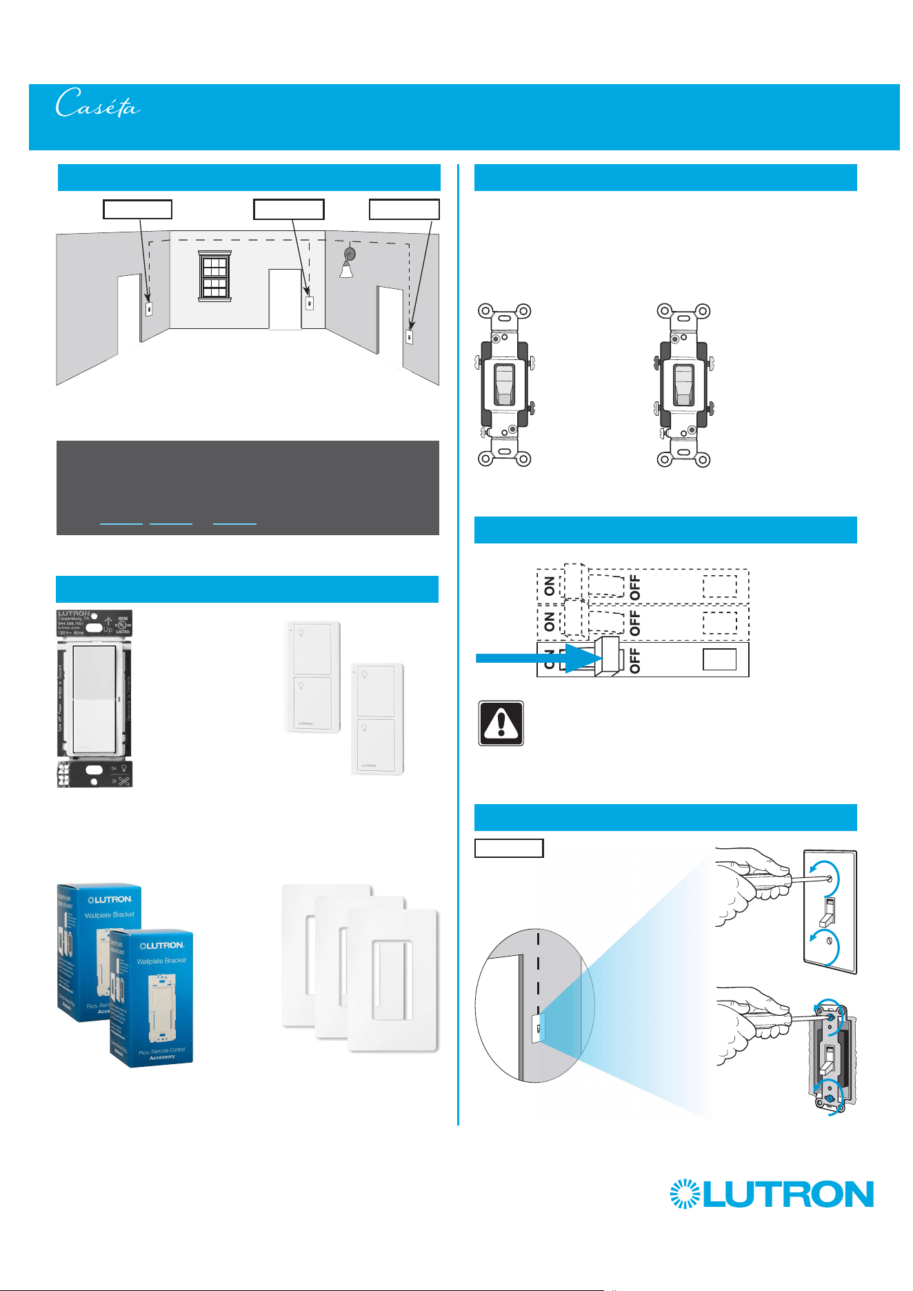
93
by Lutron
Multi-Location Installation - Caséta Claro Smart Switch with Pico Remote Controls (DVRF-5NS)
1
Identify existing wiring
2
What you need for a multi-location installation
WARNING! Shock Hazard. May result in Serious
Injury or Death. Turn off power at circuit breaker
before installing the unit.
4
Turn power off at circuit breaker
5
Remove existing switch from wall at Location 1
- If one switch controls the lights (single-pole installation)
See quick-start guide that came with your switch
- If two switches control the lights (3-way installation)
See page 31, page 47, or page 54 for details
Important note:
3
Choose a location for your Caséta Claro Smart switch
NOTE: There will be two different types of existing switches in this
application. Locations 1 and 3 will use 3-way switches (three screws
which control the lights, plus one ground screw) and Location 2 will use
a 4-way switch (four screws which control the lights, plus one ground
screw). For easiest installation, we recommend replacing one of the 3-way
switches with your Caséta Wireless switch (Locations 1 or 3). In this
example, we will use Location 1.
Location 1
3-Way Switch
(Locations 1 and 3)
4-Way Switch
(Location 2)
Three or more switches control the lights
(multi-location installation)
Location 1 Location 2 Location 3
+
Switch
DVRF-5NS
Two Pico
remote controls
PJ2-2B
Two wallplate brackets
PICO-WBX-ADAPT
+
Three Claro wallplates
CW-1
+
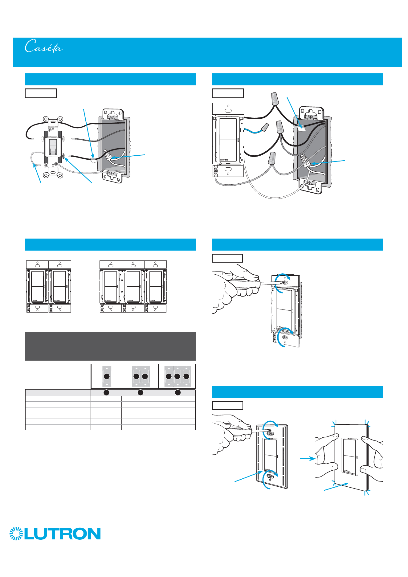
94
by Lutron
6
Tag and disconnect wires from the existing switch
Different
Color Screw
Ground
(Green / Bare Copper)
Place tag - to identify wire on
different color screw
Location 1
Multi-Location Installation - Caséta Claro Smart Switch with Pico Remote Controls (DVRF-5NS)
Neutral
connection
required
8
Connect the new Caséta Claro Smart switch
Tagged Wire
Ground
(Green Wire)
Location 1
Red
Blue
Black
White
Neutral
connection
required
7
Ganging and derating
Important note:
Ganging units together may reduce the switch’s maximum wattage
rating. See the chart below for maximum wattage information.
1
Neutral required.
2
The maximum lamp wattage is determined by the efficiency of the transformer, with
70% – 85% as typical. For actual transformer efficiency, contact either the fixture or
transformer manufacturer. The total VA rating of the transformer(s) shall not exceed the VA
rating of the switch.
3
The switch is UL
R
Listed for use with all magnetic and electronic fluorescent ballasts.
DVRF-5NS (120 V
~
)
1
LED 5 A 5 A 5 A
Halogen / incandescent 600 W 600 W 600 W
Electronic Low-Voltage 600 VA 600 VA 600 VA
Magnetic Low-Voltage
2
600 VA 600 VA 600 VA
Fluorescent
3
5 A 5 A 5 A
General Purpose Fan 3 A 3 A 3 A
A
B C
Note: Claro Smart controls don’t have fins but derating is
still required. See the chart below.
B B B C BA
9
Mount the Caséta Claro Smart switch
Location 1
10
Attach the wallplate
‘snap’
Wallplate
Adapter
Wallplate
Location 1

95
by Lutron
14
Attach the wallplate bracket and Pico remote control
15
Attach the wallplate
‘snap’
Multi-Location Installation - Caséta Claro Smart Switch with Pico Remote Controls (DVRF-5NS)
16
Remove existing switch from wall at Location 3
Wallplate
Adapter
Wallplate
Location 2
Location 2
13
Connect the wires
Ground
(Green / Bare Copper)
Tagged Wires
Location 2
11
Remove existing switch from wall at Location 2
12
Tag and disconnect wires from the existing switch
Ground (Green / Bare Copper)
Location 2
Location 2
Place tags - to identify wires
on different color screws
Different Color Screws
Location 3
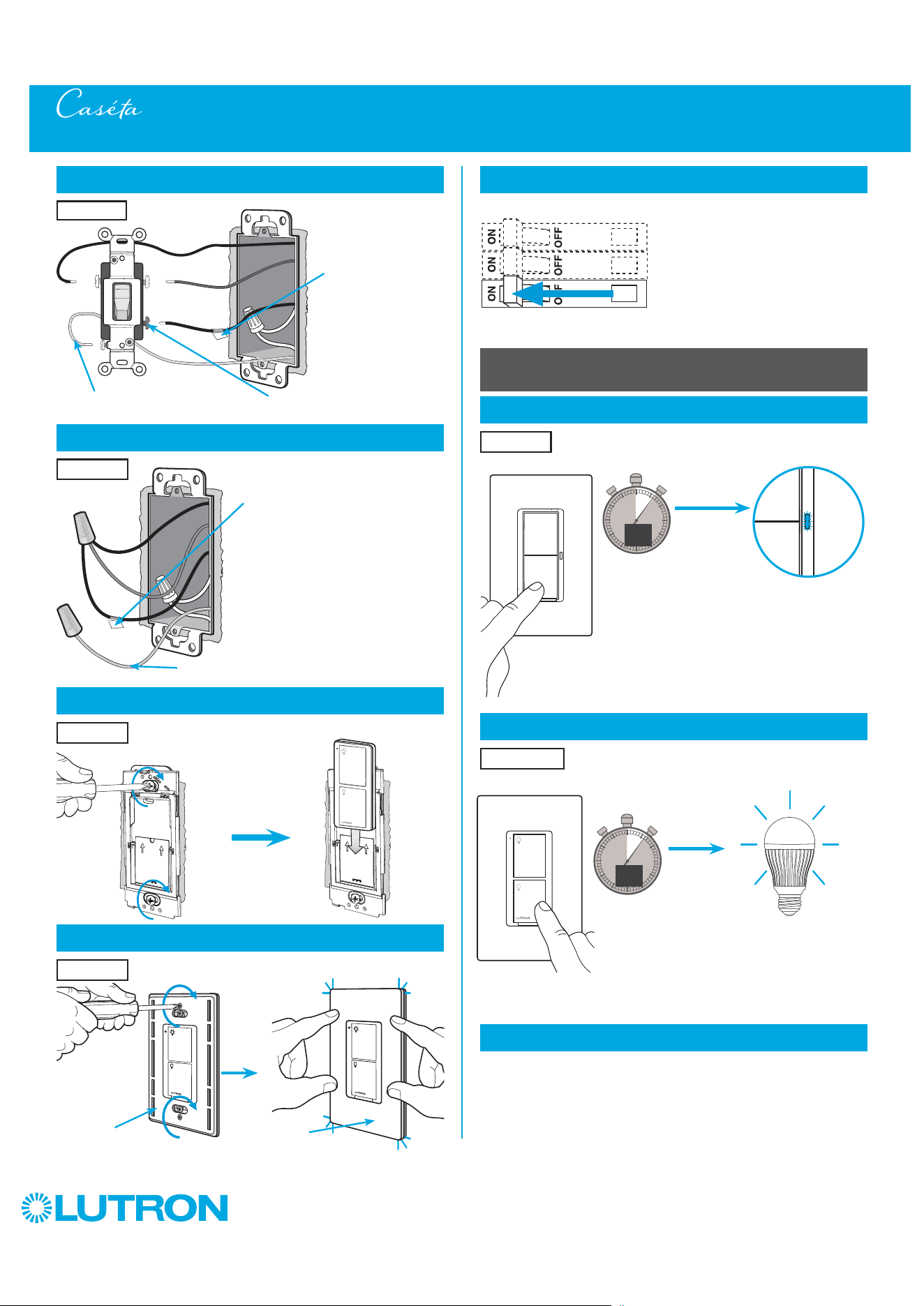
96
by Lutron
Multi-Location Installation - Caséta Claro Smart Switch with Pico Remote Controls (DVRF-5NS)
21
Turn power on at circuit breaker
Pairing the switch and Pico remote controls
23
Press and hold "Off" button on remote control
0
5
10
15
6
sec.
UNTIL
Location 2
Repeat steps 22 and 23 to pair remote control
at Location 3.
24
Repeat for remote control at Location 3
17
Tag and disconnect wires from the existing switch
Different Color ScrewGround (Green / Bare Copper)
18
Connect the wires
19
Attach the wallplate bracket and Pico remote control
Ground (Green / Bare Copper)
Place tag - to
identify wire on
different color screw
Location 3
Tagged Wire
Location 3
Location 3
20
Attach the wallplate
‘snap’
Wallplate
Adapter
Wallplate
Location 3
HOLD
Lights flash
three times
3x
22
Press and hold "Off" button on switch
0
5
10
15
6
sec.
UNTIL
HOLD
Status LED flashes
Location 1
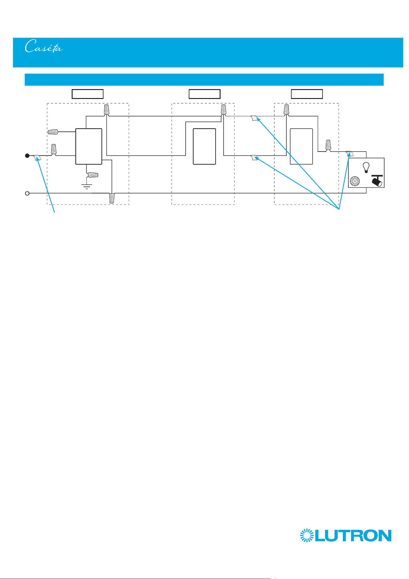
97
by Lutron
Multi-Location Installation - Caséta Claro Smart Switch with Pico Remote Controls (DVRF-5NS)
Neutral
Pico
Remote
Control
Line / Hot
Traveler Traveler
Traveler
Traveler
Caséta
Claro
Smart
Switch *
Ground
(Green)
Load
INC
HAL
Schematic Diagram
Pico
Remote
Control
Location 1 Location 2 Location 3
Tagged Wire Tagged Wires
Blue
Black
Red
White
* It is recommended to install switch in either Location 1 or 3.
Note: The red wire must be connected to the load and the black wire must be connected to Line/Hot. The product will not work if the wires
are reversed.
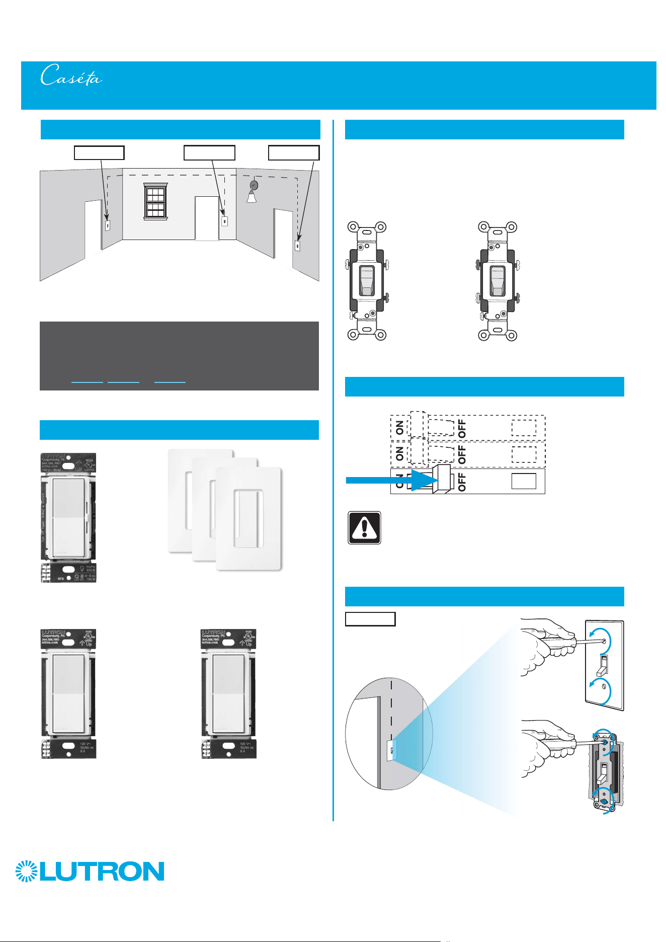
98
by Lutron
Multi-Location Installation - Caséta Diva Smart Dimmer with Claro Smart Accessory Switch (DVRF-6L / DVRF-AS)
1
Identify existing wiring
2
What you need for a multi-location installation
WARNING! Shock Hazard. May result in Serious
Injury or Death. Turn off power at circuit breaker
before installing the unit.
4
Turn power off at circuit breaker
5
Remove existing switch from wall at Location 1
- If one switch controls the lights (single-pole installation)
See quick-start guide that came with your dimmer
- If two switches control the lights (3-way installation)
See page 27, page 44, or page 50 for details
Important note:
Two Claro Smart accessory switches
DVRF-AS
3
Choose a location for your Caséta Diva Smart dimmer
NOTE: There will be two different types of existing switches in this
application. Locations 1 and 3 will use 3-way switches (three screws
which control the lights, plus one ground screw) and Location 2 will use
a 4-way switch (four screws which control the lights, plus one ground
screw). For easiest installation, we recommend replacing one of the 3-way
switches with your dimmer (Locations 1 or 3). In this example, we will use
Location 1.
Location 1
3-Way Switch
(Locations 1 and 3)
4-Way Switch
(Location 2)
+
Three or more switches control the lights
(multi-location installation)
Location 1 Location 2 Location 3
Diva Smart dimmer
DVRF-6L
+
Three Claro wallplates
CW-1
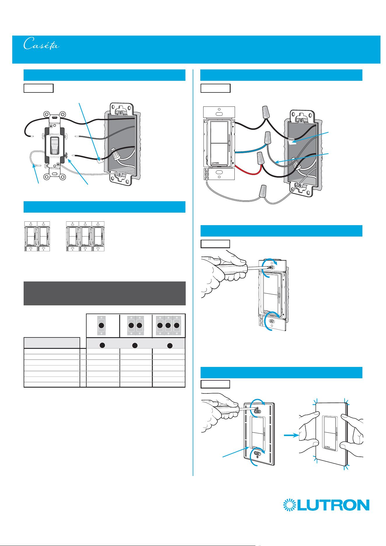
99
by Lutron
Multi-Location Installation - Caséta Diva Smart Dimmer with Claro Smart Accessory Switch (DVRF-6L / DVRF-AS)
8
Connect the new Caséta Diva Smart dimmer
Location 1
6
Tag and disconnect wires from the existing switch
Different
Color Screw
Ground
(Green / Bare Copper)
Place tag - to identify wire on
different color screw
Location 1
Tagged Wire
Ground
(Green Wire)
Red
Black
Blue
7
Ganging and derating
Note: Diva Smart models don’t have fins but derating is
still required. See the chart below.
9
Mount the Caséta Diva Smart dimmer
10
Attach the wallplate
Location 1
Location 1
‘snap’
Wallplate
Adapter
Wallplate
Total Dimmable LED Wattage Incandescent/Halogen Total Wattage
0 W + 600 W 500 W 400 W
1 W – 25 W + 500 W 400 W 300 W
26 W – 50 W + 400 W 300 W 200 W
51 W – 75 W + 300 W 200 W 100 W
76 W – 100 W + 200 W 100 W 50 W
101 W – 125 W + 100 W 50 W 0 W
126 W – 150 W + 0 W 0 W 0 W
Important note:
Ganging units together may reduce the dimmer’s maximum wattage
rating. See the chart below for maximum wattage information.
B B B C BA
A
B
C
Note wire
color tied to
blue wire
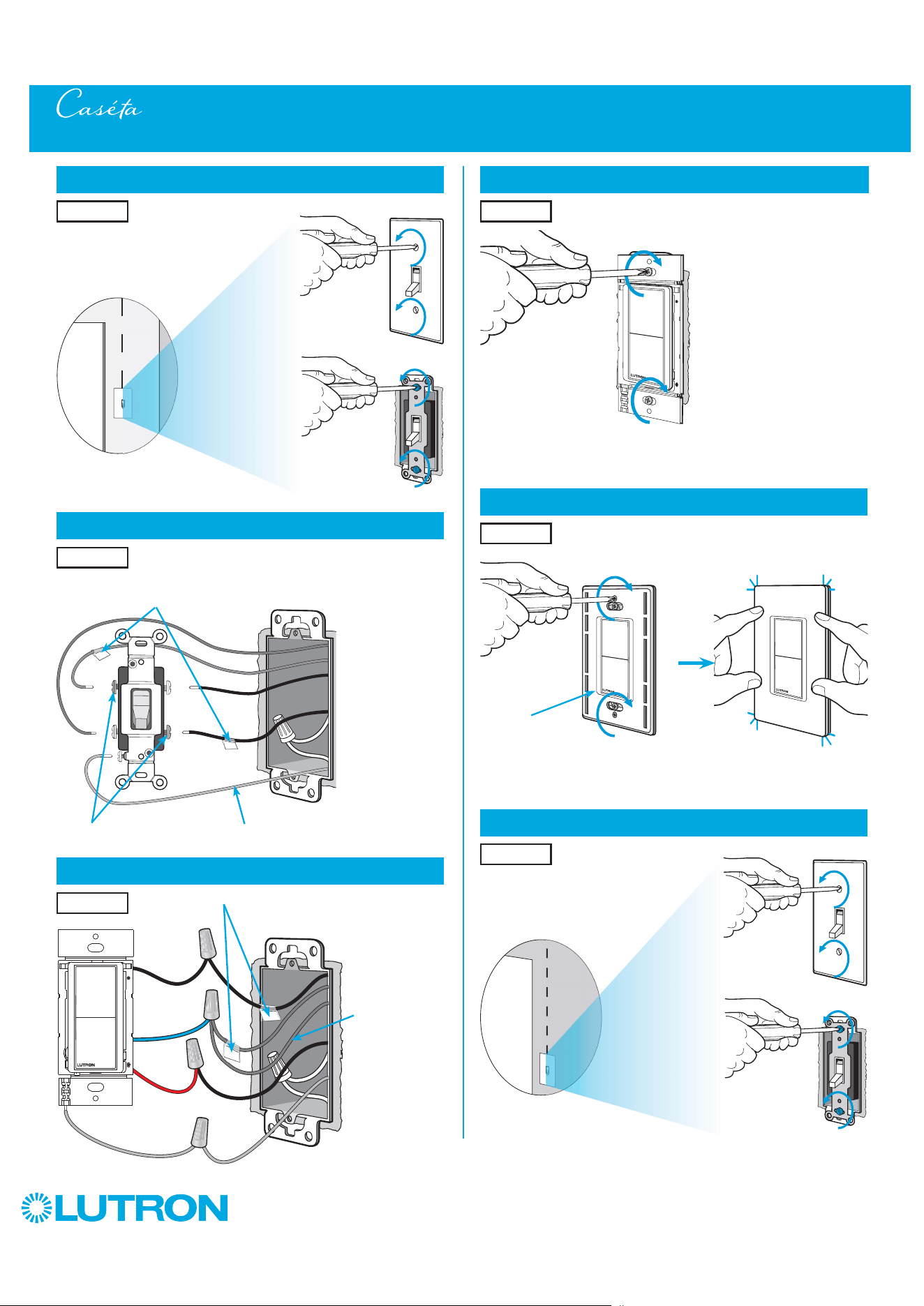
100
by Lutron
14
Mount the Claro Smart accessory switch
15
Attach the wallplate
Multi-Location Installation - Caséta Diva Smart Dimmer with Claro Smart Accessory Switch (DVRF-6L / DVRF-AS)
16
Remove existing switch from wall at Location 3
Location 2
Location 2
13
Connect the Claro Smart accessory switch for Location 2
Location 2
11
Remove existing switch from wall at Location 2
12
Tag and disconnect wires from the existing switch
Ground (Green / Bare Copper)
Location 2
Location 2
Place tags - to identify wires
on different color screws
Different Color Screws
Location 3
‘snap’
Wallplate
Adapter
Wallplate
Tagged Wire
Ground
(Green Wire)
Red
Black
Blue
Match noted wire
color from Step 8
tied to blue wire.
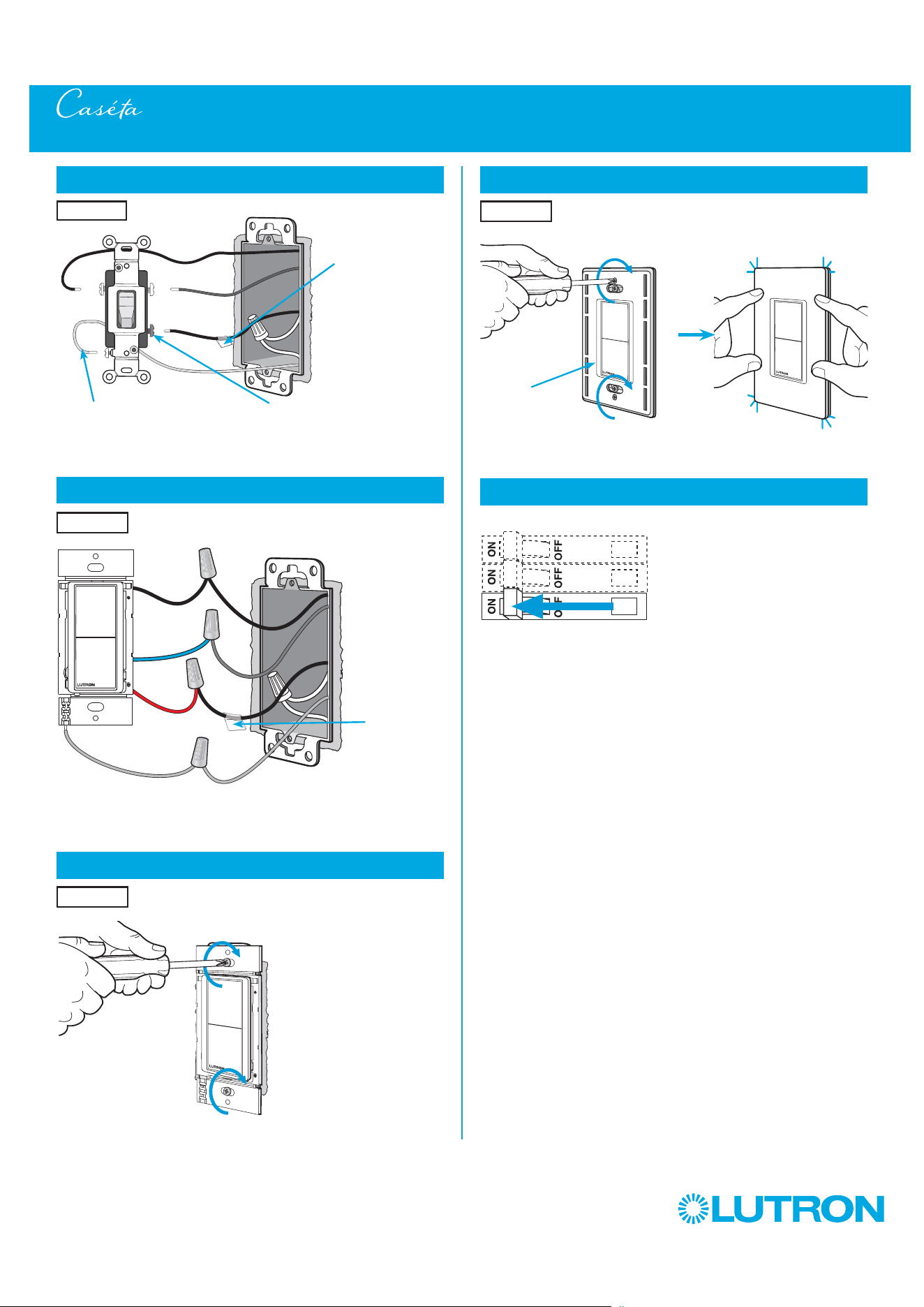
101
by Lutron
Multi-Location Installation - Caséta Diva Smart Dimmer with Claro Smart Accessory Switch (DVRF-6L /DVRF-AS)
21
Turn power on at circuit breaker
17
Tag and disconnect wires from the existing switch
Different Color ScrewGround (Green / Bare Copper)
18
Connect the Claro Smart accessory switch for Location 3
19
Mount the Claro Smart accessory awitch
Place tag - to
identify wire on
different color screw
Location 3
Location 3
20
Attach the wallplate
Location 3
Location 3
Tagged Wire
Ground
(Green Wire)
Red
Black
Blue
‘snap’
Wallplate
Adapter
Wallplate
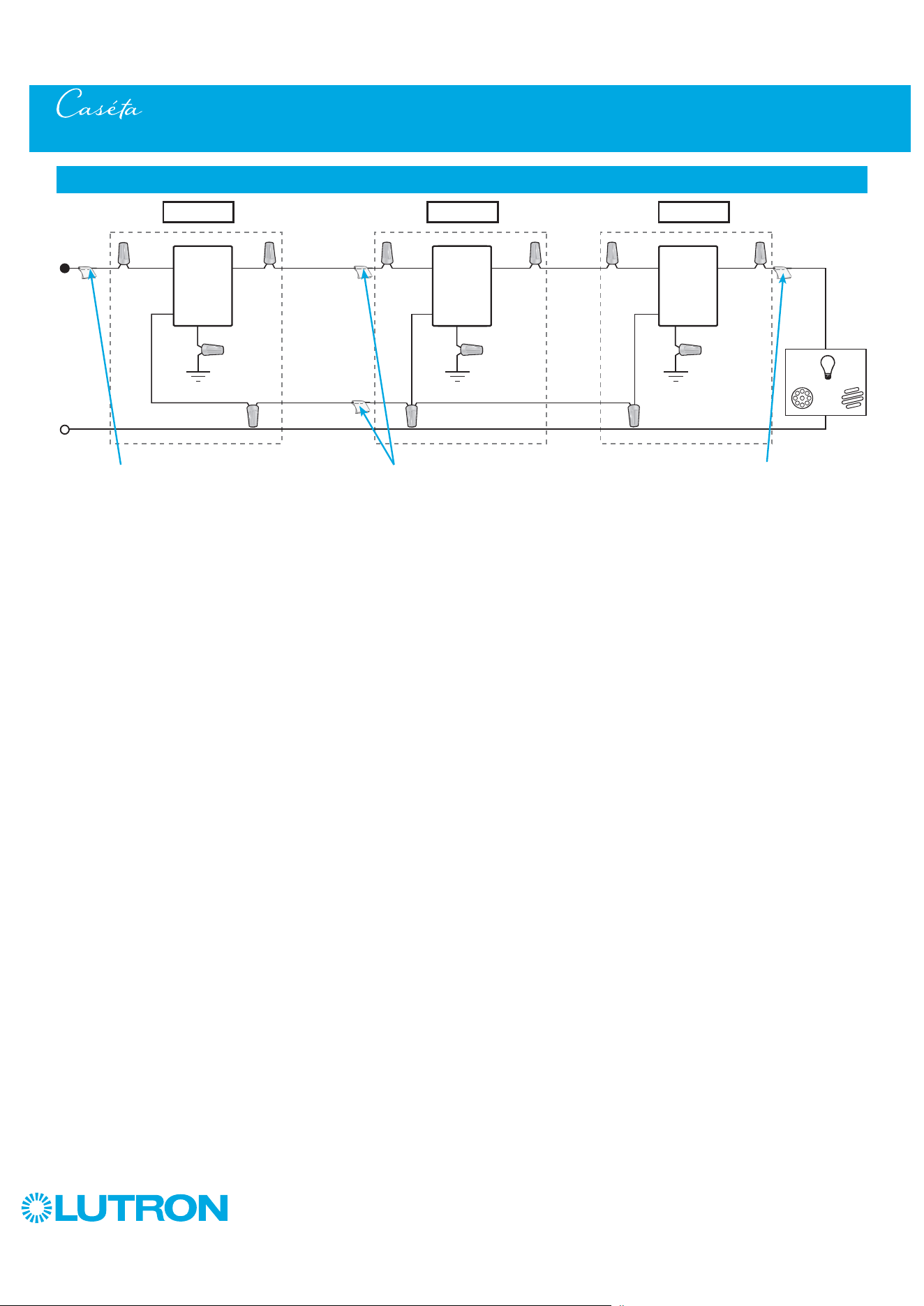
102
by Lutron
Multi-Location Installation - Caséta Diva Smart Dimmer with Claro Smart Accessory Switch (DVRF-6L / DVRF-AS)
Neutral
Claro
Smart
Accessory
Switch
Line / Hot
Traveler
Traveler
Traveler
Traveler
Caséta
Diva
Smart
Dimmer *
Ground
Blue
Load
INC
HAL
Schematic Diagram
Claro
Smart
Accessory
Switch
* It is recommended to install
dimmer in either Location 1 or 3.
Location 1 Location 2 Location 3
Tagged Wire Tagged Wire
Blue
Blue
Ground Ground
Black
Black
Red
Red
Red
Black
Note: When using Claro Smart Accessory Switches in a multilocation installation with a Diva Smart dimmer, the Black and Red wires are reversible.
Tagged Wire

103
by Lutron
Multi-Location Installation - Caséta Claro Smart Switch with Claro Smart Accessory Switches (DVRF-5NS/DVRF-AS)
1
Identify existing wiring
2
What you need for a multi-location installation
WARNING! Shock Hazard. May result in Serious
Injury or Death. Turn off power at circuit breaker
before installing the unit.
4
Turn power off at circuit breaker
5
Remove existing switch from wall at Location 1
- If one switch controls the lights (single-pole installation)
See quick-start guide that came with your switch
- If two switches control the lights (3-way installation)
See page 31, page 47, or page 54 for details
Important note:
3
Choose a location for your Caséta Claro Smart switch
NOTE: There will be two different types of existing switches in this
application. Locations 1 and 3 will use 3-way switches (three screws
which control the lights, plus one ground screw) and Location 2 will use
a 4-way switch (four screws which control the lights, plus one ground
screw). For easiest installation, we recommend replacing one of the 3-way
switches with your Caséta Wireless switch (Locations 1 or 3). In this
example, we will use Location 1.
Location 1
3-Way Switch
(Locations 1 and 3)
4-Way Switch
(Location 2)
Three or more switches control the lights
(multi-location installation)
Location 1 Location 2 Location 3
Claro Smart switch
DVRF-5NS
Two Claro Smart accessory switches
DVRF-AS
+
+
Three Claro wallplates
CW-1
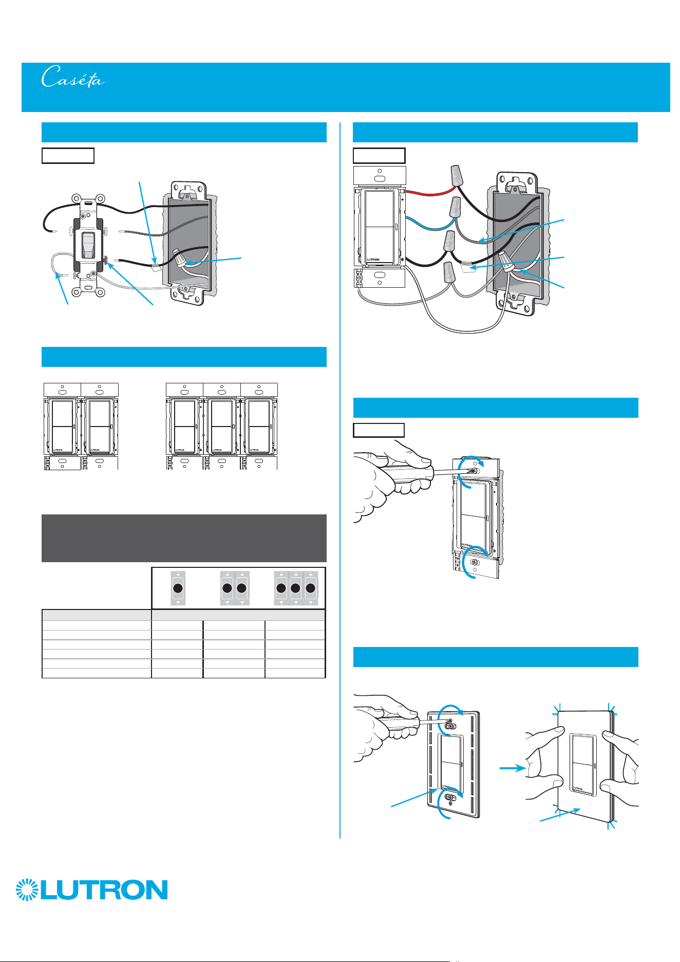
104
by Lutron
6
Tag and disconnect wires from the existing switch
Different
Color Screw
Ground
(Green / Bare Copper)
Place tag - to identify wire on
different color screw
Location 1
Multi-Location Installation - Caséta Claro Smart Switch with Claro Smart Accessory Switches (DVRF-5NS/DVRF-AS)
Neutral
connection
required
1
Neutral required.
2
The maximum lamp wattage is determined by the efficiency of the transformer, with
70% – 85% as typical. For actual transformer efficiency, contact either the fixture or
transformer manufacturer. The total VA rating of the transformer(s) shall not exceed the VA
rating of the switch.
3
The switch is UL
R
Listed for use with all magnetic and electronic fluorescent ballasts.
7
Ganging and derating
Important note:
Ganging units together may reduce the switch’s maximum wattage
rating. See the chart below for maximum wattage information.
DVRF-5NS (120 V
~
)
1
LED 5 A 5 A 5 A
Halogen / incandescent 600 W 600 W 600 W
Electronic Low-Voltage 600 VA 600 VA 600 VA
Magnetic Low-Voltage
2
600 VA 600 VA 600 VA
Fluorescent
3
5 A 5 A 5 A
General Purpose Fan 3 A 3 A 3 A
Note: Claro Smart models don’t have fins but derating is
still required. See the chart below.
B B B C BA
9
Mount the Caséta Claro Smart switch
10
Attach the wallplate
‘snap’
Wallplate
Adapter
Wallplate
Location 1
8
Connect the new Caséta Claro Smart switch
Ground
(Green Wire)
White
Location 1
Red
Blue
Black
Tagged Wire
Note wire color
tied to blue wire
Neutral
connection
required

105
by Lutron
Multi-Location Installation - Caséta Claro Smart Switch with Claro Smart Accessory Switches (DVRF-5NS/DVRF-AS)
16
Remove existing switch from wall at Location 3
11
Remove existing switch from wall at Location 2
12
Tag and disconnect wires from the existing switch
Ground (Green / Bare Copper)
Location 2
Location 2
Place tags - to identify wires
on different color screws
Different Color Screws
Location 3
14
Mount the Claro Smart accessory awitch
Location 2
15
Attach the wallplate
Location 2
‘snap’
Wallplate
Adapter
Wallplate
13
Connect the Claro Smart accessory switch for Location 2
Location 2
Tagged Wire
Ground
(Green Wire)
Red
Black
Blue
Match noted wire
color from Step 8
tied to blue wire.
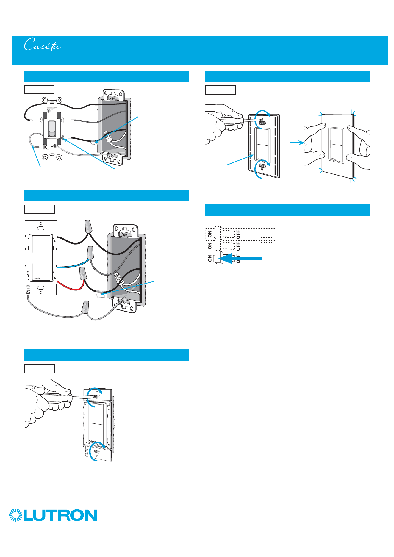
106
by Lutron
Multi-Location Installation - Caséta Claro Smart Switch with Claro Smart Accessory Switches (DVRF-5NS/DVRF-AS)
17
Tag and disconnect wires from the existing switch
Different Color ScrewGround (Green / Bare Copper)
Place tag - to
identify wire on
different color screw
Location 3
18
Connect the Claro Smart accessory switch for Location 3
19
Mount the Claro Smart accessory awitch
Location 3
Location 3
Tagged Wire
Ground
(Green Wire)
Red
Black
Blue
21
Turn power on at circuit breaker
20
Attach the wallplate
Location 3
‘snap’
Wallplate
Adapter
Wallplate
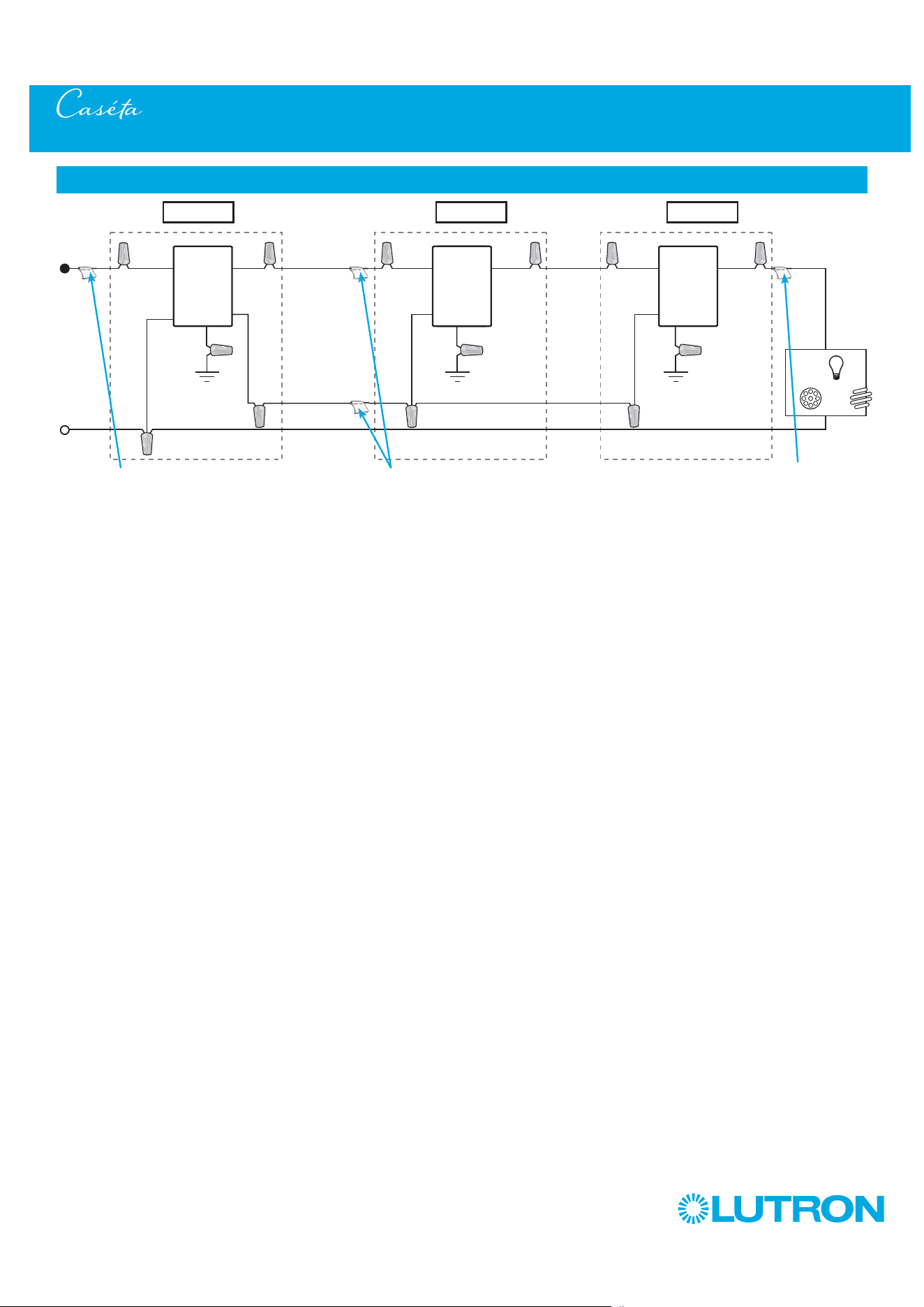
107
by Lutron
Multi-Location Installation - Caséta Claro Smart Switch with Claro Smart Accessory Switches (DVRF-5NS/DVRF-AS)
Neutral
Caséta
Claro
Smart
Accessory
Switch
Line / Hot
Traveler
Traveler
Traveler
Traveler
Caséta
Claro
Smart
Switch *
Ground
Blue
Load
INC
HAL
Schematic Diagram
Caséta
Claro
Smart
Accessory
Switch
* It is recommended to install
switch in either Location 1 or 3.
Location 1 Location 2 Location 3
Tagged Wire
Tagged Wire
Blue
Blue
Ground Ground
Black
Black
Red
Red
Red
Black
Note: The red wire must be connected to the load and the black wire must be connected to Line/Hot. The product will not work if the wires
are reversed.
White
Tagged Wire
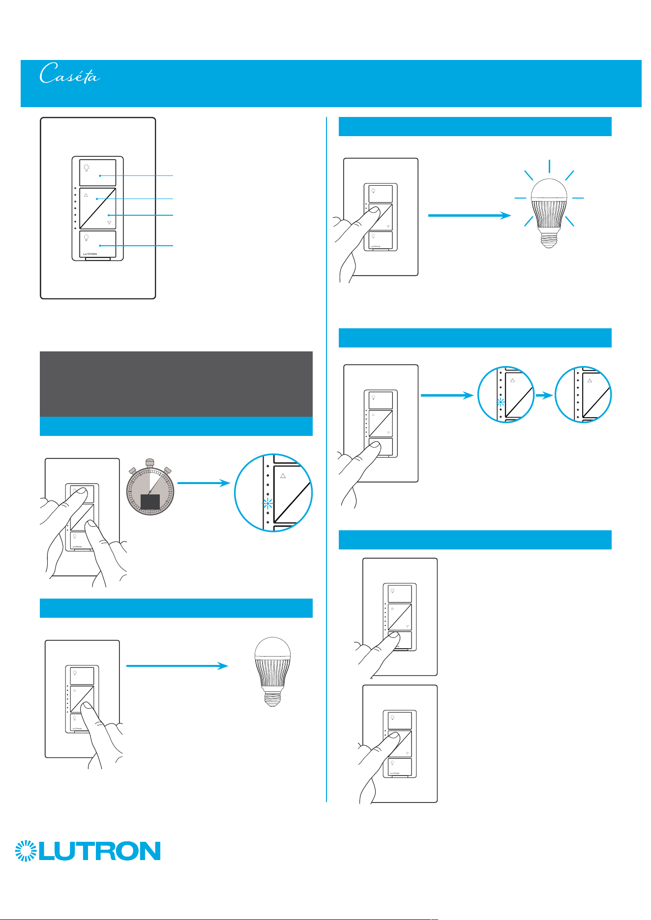
108
by Lutron
Adjusting Low-End Trim on a Caséta Wireless Dimmer (PD-6WCL)
On
Off
Darker
Brighter
Dimmer
Adjusting Low-End Trim -
To optimize performance of dimmable LED lamps
1
Enter
0
5
10
15
6
sec.
UNTIL
2
Adjust
HOLD
Hold
a.
2
Adjust (continued)
Light stops flickering
and is stable
b.
A status LED starts
flashing
Light stops dimming
or turns off
Status LED stops flashing
4
Verify
a. Tap "Off" one time. Light will
turn off.
b. Tap "Brighter"
one time. Light
will turn on.
c. If light is still off or is flickering,
repeat steps 1-4.
a
.
b.
b
.
3
Save
UNTIL
HOLD
UNTIL
TAP
UNTIL
HOLD
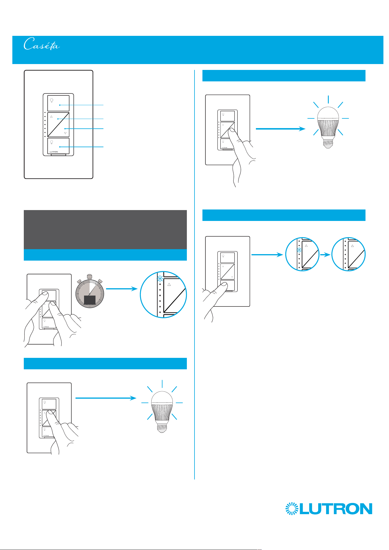
109
by Lutron
Adjusting High-End Trim on a Caséta Wireless Dimmer (PD-6WCL)
Adjusting High-End Trim -
To optimize performance of dimmable LED lamps
1
Enter
0
5
10
15
6
sec.
2
Adjust
Hold
a.
2
Adjust (continued)
Desired light
level is achieved
b.
A status LED starts
flashing
Status LED stops flashing
3
Save
Light is at full
brightness
On
Off
Darker
Brighter
Dimmer
UNTIL
HOLD
UNTIL
HOLD
UNTIL
HOLD
UNTIL
TAP

110
by Lutron
Adjusting Low-End Trim on a Caséta Wireless PRO Dimmer (PD-10NXD)
On
Off
Darker
Brighter
PRO dimmer
Adjusting Low-End Trim -
To optimize performance of dimmable LED lamps
1
Enter
0
5
10
15
6
sec.
UNTIL
2
Adjust
HOLD
Hold
a.
2
Adjust (continued)
Light stops flickering
and is stable
b.
A status LED starts
flashing
Light stops dimming
or turns off
Status LED stops flashing
4
Verify
a. Tap "Off" one time. Light will
turn off.
b. Tap "Brighter"
one time. Light
will turn on.
c. If light is still off or is flickering,
repeat steps 1-4.
a
.
b.
b
.
3
Save
UNTIL
HOLD
UNTIL
TAP
UNTIL
HOLD

111
by Lutron
Adjusting High-End Trim on a Caséta Wireless PRO Dimmer (PD-10NXD)
Adjusting High-End Trim -
To optimize performance of dimmable LED lamps
1
Enter
0
5
10
15
6
sec.
2
Adjust
Hold
a.
2
Adjust (continued)
Desired light
level is achieved
b.
A status LED starts
flashing
Status LED stops flashing
3
Save
Light is at full
brightness
On
Off
Darker
Brighter
PRO dimmer
UNTIL
HOLD
UNTIL
HOLD
UNTIL
HOLD
UNTIL
TAP
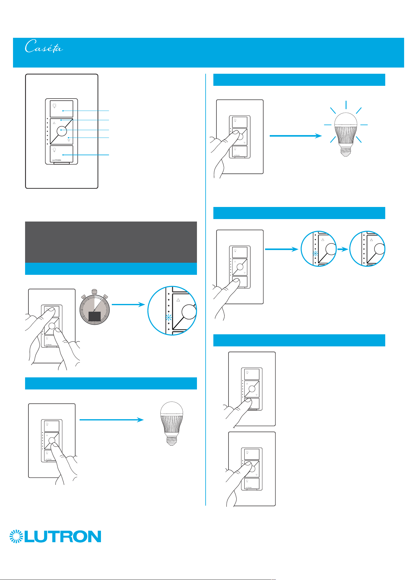
112
by Lutron
Adjusting Low-End Trim on a Caséta Wireless ELV+ Dimmer (PD-5NE)
On
Off
Darker
Brighter
Dimmer
Adjusting Low-End Trim -
To optimize performance of dimmable LED lamps
1
Enter
0
5
10
15
6
sec.
UNTIL
2
Adjust
HOLD
(ON AND DARKER)
Hold
a.
2
Adjust (continued)
Light stops flickering
and is stable
b.
A status LED starts
flashing
Light stops dimming
or turns off
Status LED stops flashing
4
Verify
a. Tap "Off" one time. Light will
turn off.
b. Tap "Brighter"
one time. Light
will turn on.
c. If light is still off or is flickering,
repeat steps 1-4.
a
.
b.
b
.
3
Save
UNTIL
HOLD
UNTIL
TAP
UNTIL
HOLD
Favorite

113
by Lutron
Adjusting High-End Trim on a Caséta Wireless ELV+ Dimmer (PD-5NE)
Adjusting High-End Trim -
To optimize performance of dimmable LED lamps
1
Enter
0
5
10
15
6
sec.
2
Adjust
Hold
a.
2
Adjust (continued)
Desired light
level is achieved
b.
A status LED starts
flashing
Status LED stops flashing
3
Save
Light is at
desired high-end
On
Off
Darker
Brighter
Dimmer
UNTIL
HOLD (ON AND
BRIGHTER)
UNTIL
HOLD
UNTIL
HOLD
UNTIL
TAP
Favorite
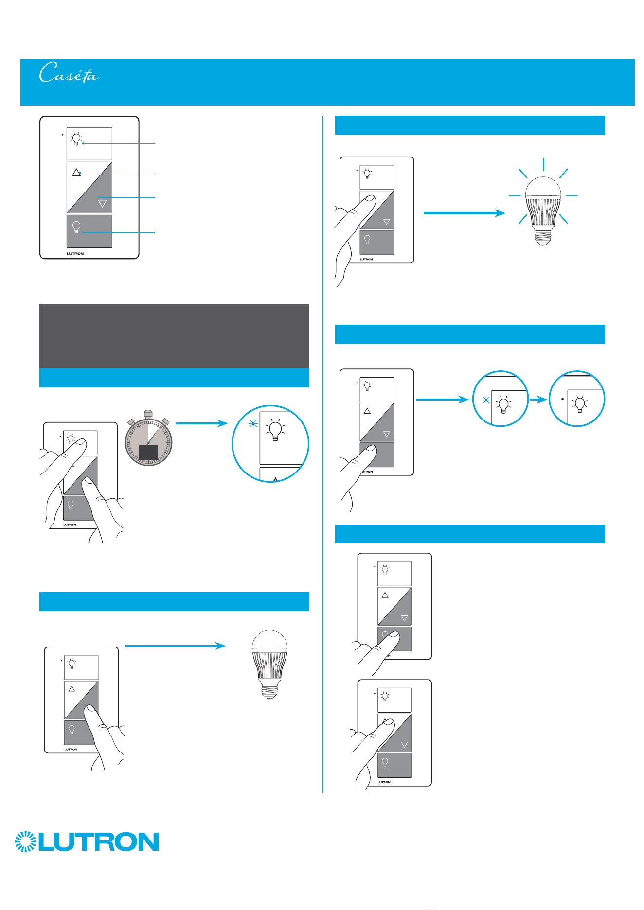
114
by Lutron
Plug-in lamp dimmer
Adjusting Low-End Trim on a Caséta Wireless Plug-In Lamp Dimmer (PD-3PCL)
On
Off
Darker
Brighter
Adjusting Low-End Trim -
To optimize performance of dimmable LED lamps
1
Enter
0
5
10
15
6
sec.
2
Adjust
Hold
a.
2
Adjust (continued)
b.
The Status LED
starts flashing
The status LED stops flashing
4
Verify
a
.
b.
Light stops dimming
or turns off
Light stops flickering
and is stable
a. Tap "Off" one time. Light will
turn off.
b. Tap "Brighter"
one time. Light
will turn on.
c. If light is still off or is flickering,
repeat steps 1-4.
3
Save
UNTIL
HOLD
UNTIL
HOLD
UNTIL
TAP
UNTIL
HOLD
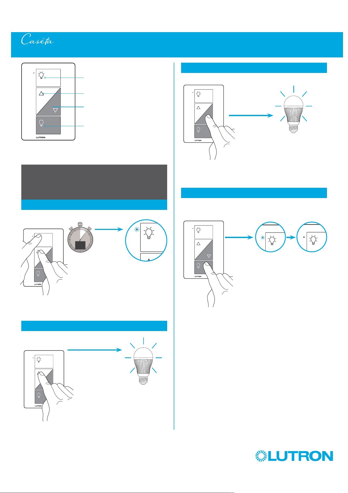
115
by Lutron
Plug-in lamp dimmer
On
Off
Darker
Brighter
Adjusting High-End Trim -
To optimize performance of dimmable LED lamps
1
Enter
0
5
10
15
6
sec.
2
Adjust
Hold
a.
2
Adjust (continued)
b.
The status LED
starts flashing
Light is at full
brightness
The status LED stops flashing
Desired light
level is achieved
3
Save
Adjusting High-End Trim on a Caséta Wireless Plug-In Lamp Dimmer (PD-3PCL)
UNTIL
HOLD
UNTIL
HOLD
UNTIL
TAP
UNTIL
HOLD
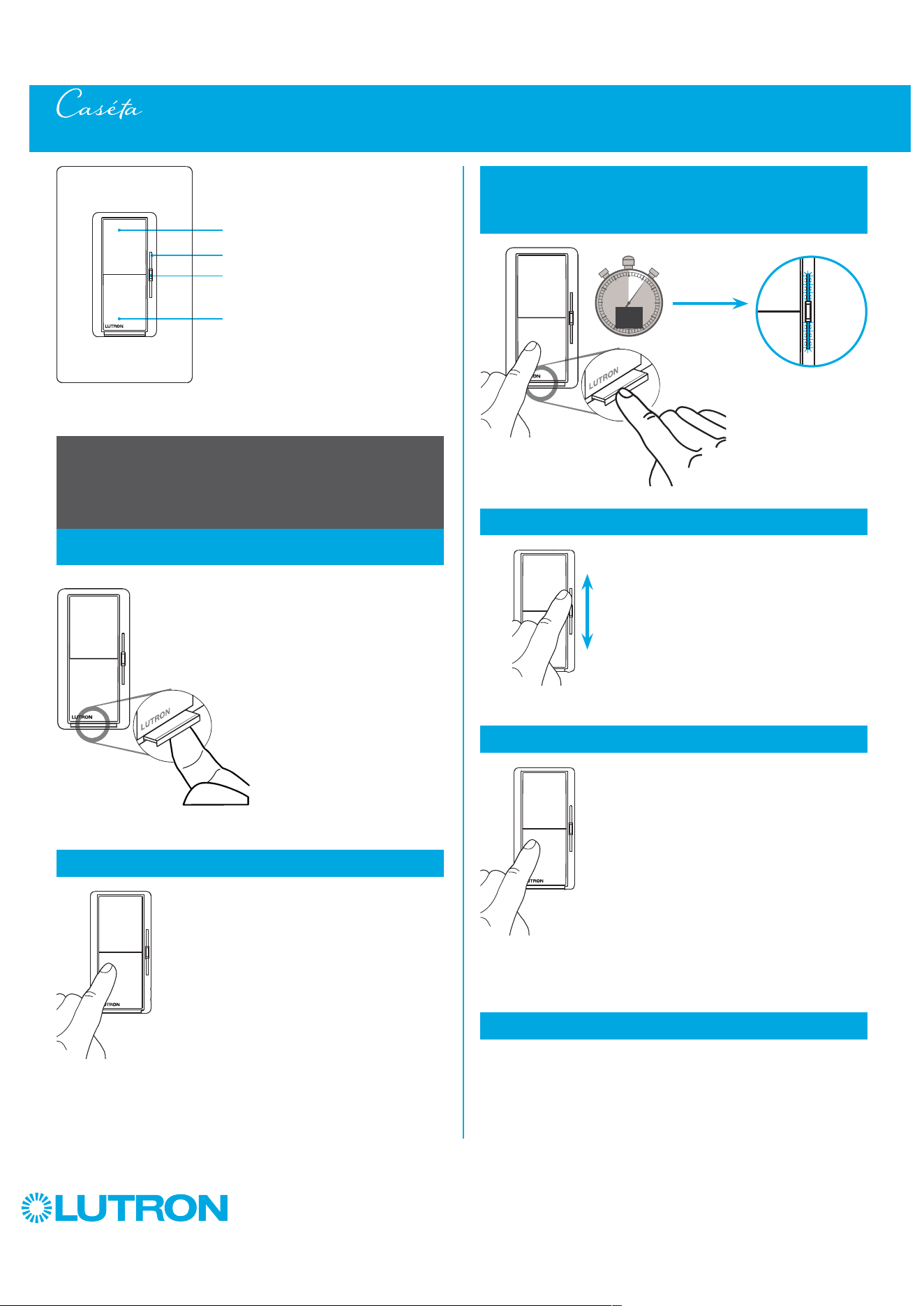
116
by Lutron
Adjusting Low-End Trim on a Caséta Diva Smart Dimmer (DVRF-6L)
Diva Smart dimmer
On
Off
Adjust
• Slide to adjust light level
• Will not turn lights Off
Soft-glow light bar
Adjusting Low-End Trim -
To optimize performance of dimmable LED lamps
1
Pull the Front Accessible Service Switch (FASS) out
to the open position
2
Press and hold the OFF button
3
Continue to hold the OFF button and push the FASS
in to the closed position. Continue to hold the OFF
button for approximately 6 seconds until the light bar
starts flashing.
6
Verify
Test low-end setting and repeat steps 1-4 as needed to set the
desired level.
5
Save
UNTIL
HOLD
0
5
10
15
6
sec.
The light bar
starts flashing
Note: Low-end trim will also be available in the app
Tap the OFF button to save
the setting
4
Adjust the low-end level
Release the OFF button
and use the slider to adjust
the low-end level.
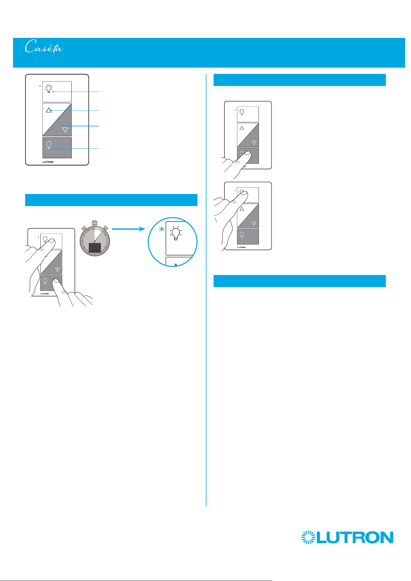
117
by Lutron
Converting a Caséta Wireless Plug-In Lamp Dimmer to a Switch to Control Non-Dim Loads (PD-3PCL)
1
Press and Hold "On" and "Off" buttons
0
5
10
15
6
sec.
The indicator light
flashes
2
Verify
a. Tap "Off" one time. Light will
turn off.
b. Tap "On" one time. Light will
turn on.
– The "Brighter" and
"Darker" buttons will be
disabled and do nothing.
NOTE: Only use lighting loads
on your plug-in lamp
dimmer, even when
operating in switch mode.
a.
b.
3
To change back to dimmer mode repeat step 1
Plug-in lamp dimmer
On
Off
Darker
Brighter
UNTIL
HOLD
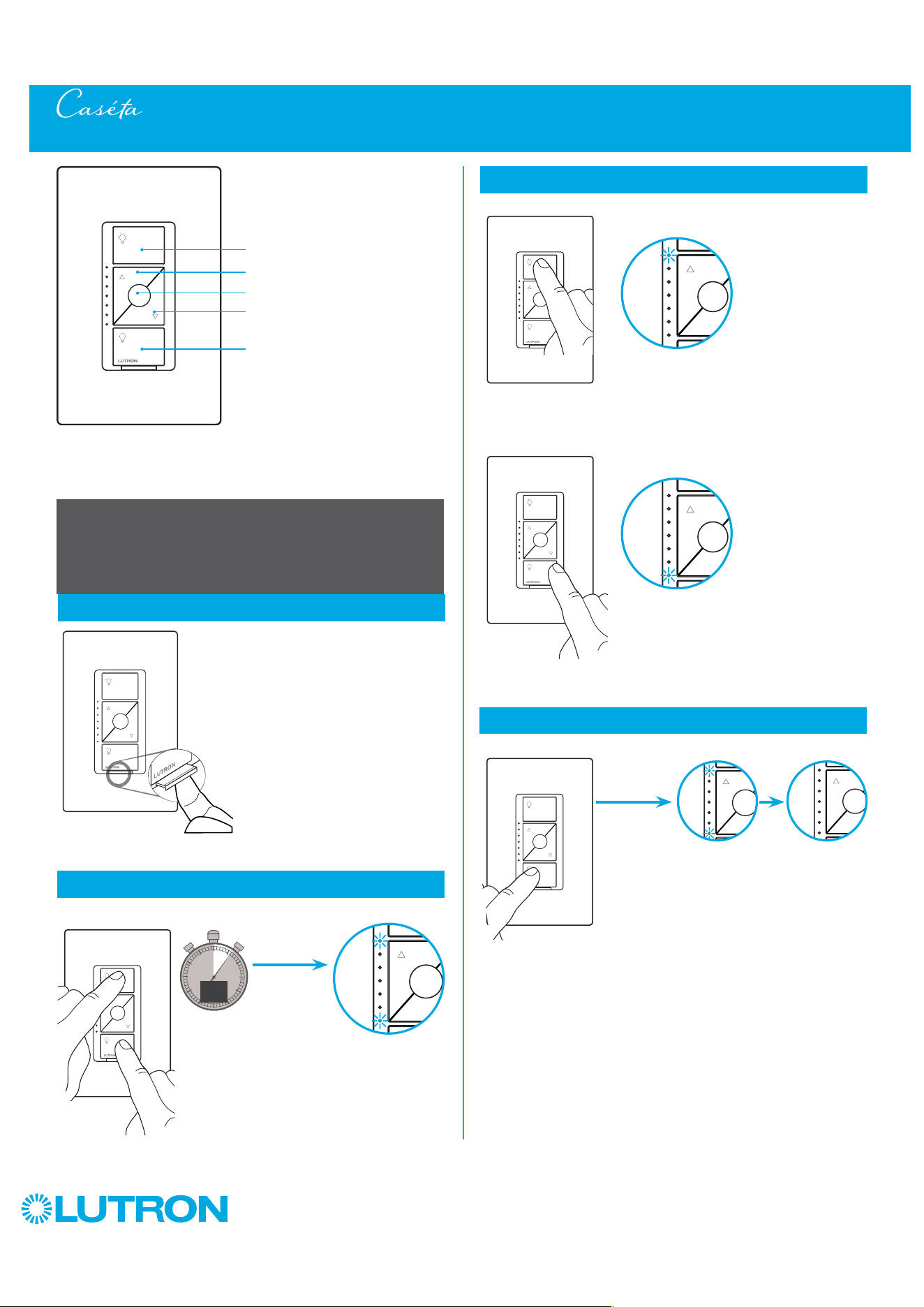
118
by Lutron
Setting Dimmer Phase on a Caséta Wireless ELV+ Dimmer (PD-5NE)
On
Off
Darker
Brighter
ELV+ dimmer
Adjusting for Load Types -
Configurable between ELV and MLV load types
1
Pull out the FASS and then push back in
2
Enter
0
5
10
15
6
sec.
UNTIL
3
Select
HOLD
Hold
a.
A status LED starts
flashing
Status LED stops flashing
4
Save
TAP
UNTIL
HOLD
Favorite
NOTE: Changes will not be saved if dimmer
times out (no button press for
1 minute) or if power is turned off.
+
TOP status LED
starts flashing
=
Forward-Phase
(MLV) selected
Hold
b.
TAP
+
BOTTOM status
LED starts flashing
=
Reverse-Phase
(ELV) selected
OR
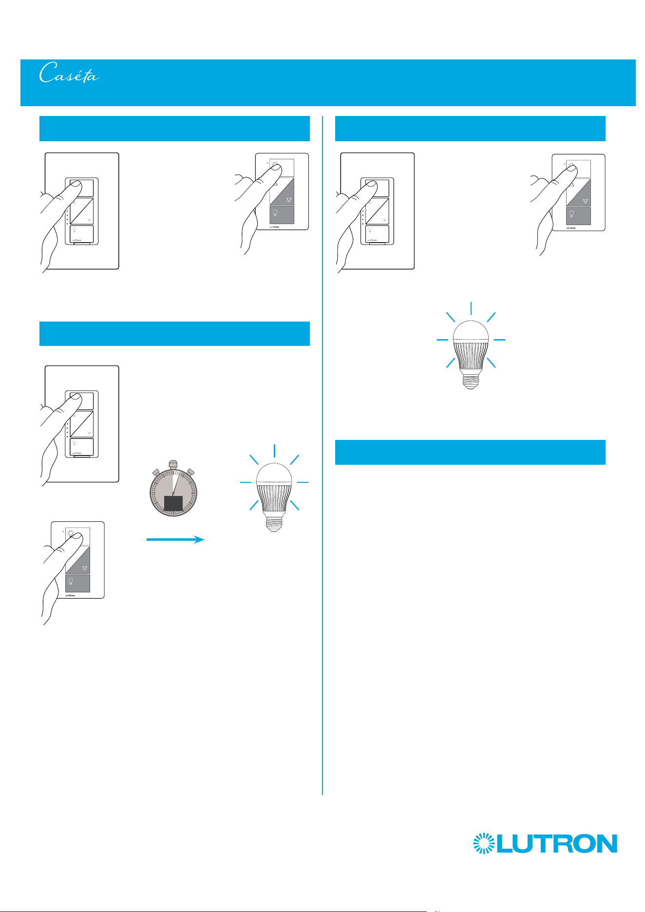
119
by Lutron
Removing Paired Pico Remote Controls from a Caséta Wireless Dimmer (PD-6WCL / PD-10NXD / PD-5NE/PD-3PCL)
1
Tap the "On" button quickly at least three times,
holding on the last press
0
5
10
15
3
sec.
2
Continue to hold the "On" button until the light
begins to flash quickly
UNTIL
3
Release the button, then immediately tap the button
at least three more times and release
Light will flash slowly
three times, then turn off
4
All paired Pico remote controls are removed and all
settings are returned to factory default
– After the dimmer resets, the light will turn on to the full on state.
NOTE: This procedure also resets the high-end and low-end trim
settings.
HOLD
HOLD
Light starts
flashing quickly
3x
TAP 3x and HOLD
TAP 3x
TAP 3x
TAP 3x
OR
OROR
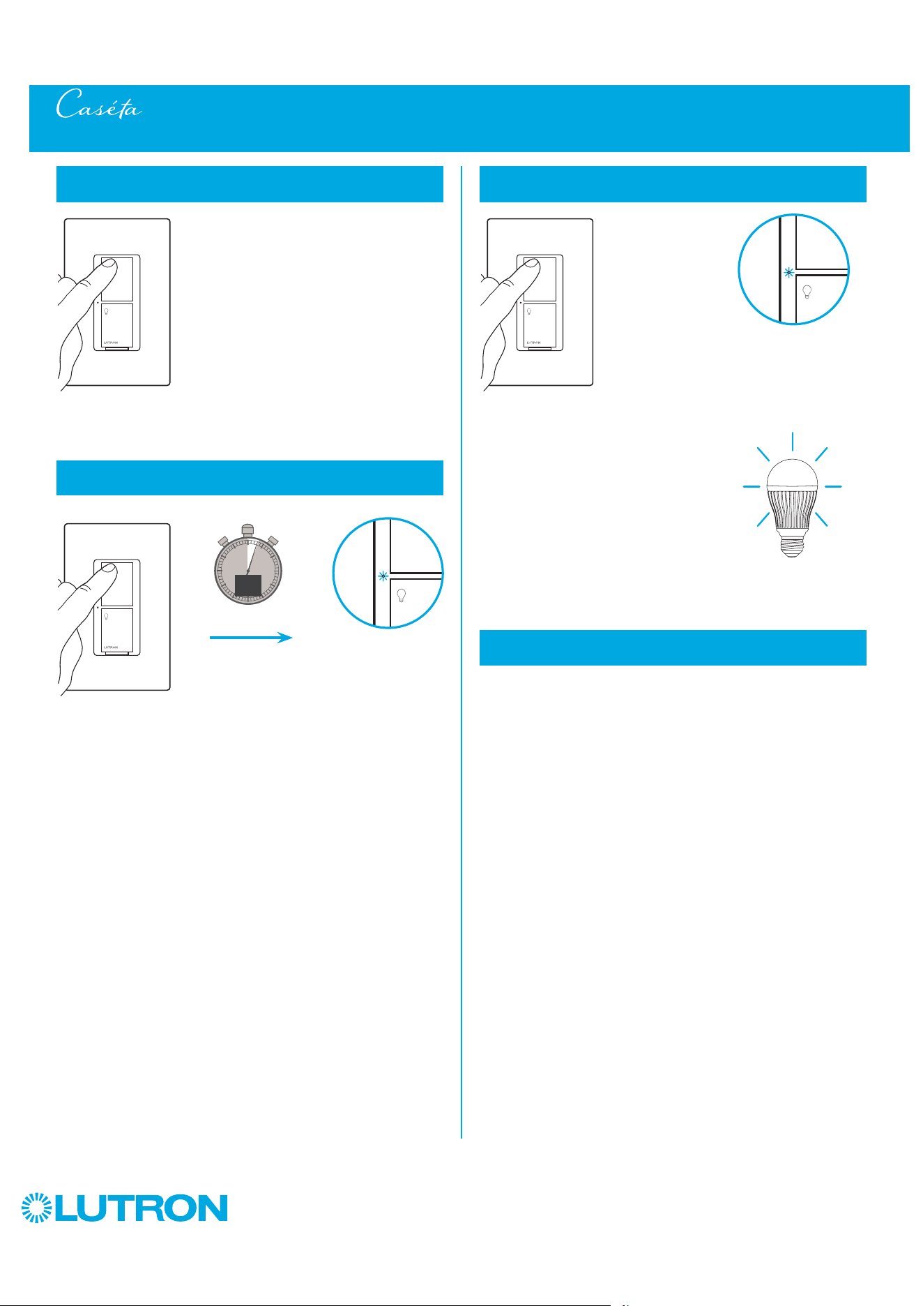
120
by Lutron
Removing Paired Pico Remote Controls from a Caséta Wireless Switch (PD-5WS-DV/PD-6ANS/PD-5ANS)
1
Tap the "On" button quickly at least three times,
holding on the last press
0
5
10
15
3
sec.
2
Continue to hold the "On" button until the Status LED
begins to flash slowly
UNTIL
3
Release the button, then immediately tap the button
at least three more times and release
Light will flash slowly
two times
4
All paired Pico remote controls are removed and all
settings are returned to factory default
– After the switch resets, the light will turn on to the full
on state.
2x
Status LED flashes
slowly
HOLD
Status LED flashes
quickly
AND
TAP 3x TAP 3x
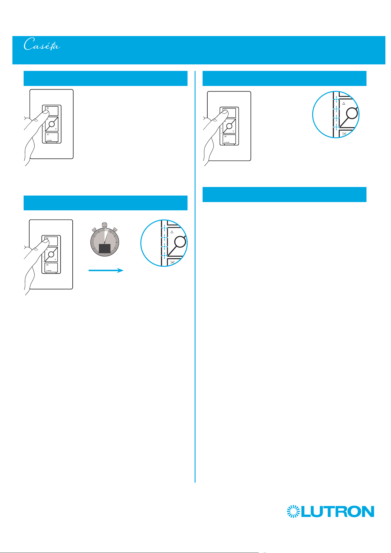
121
by Lutron
Removing Paired Pico Remote Controls from a Caséta Wireless Fan Control (PD-FSQN)
1
Tap the "On" button quickly at least three times,
holding on the last press
0
5
10
15
3
sec.
2
Continue to hold the "On" button until the Status LED
begins to flash slowly
UNTIL
3
Release the button, then immediately tap the button
at least three more times and release
4
All paired Pico remote controls are removed and all
settings are returned to factory defaults
– After the switch resets, the fan will turn on to high.
Status LED flashes
slowly
Status LED flashes
quickly
TAP 3x TAP 3x
HOLD
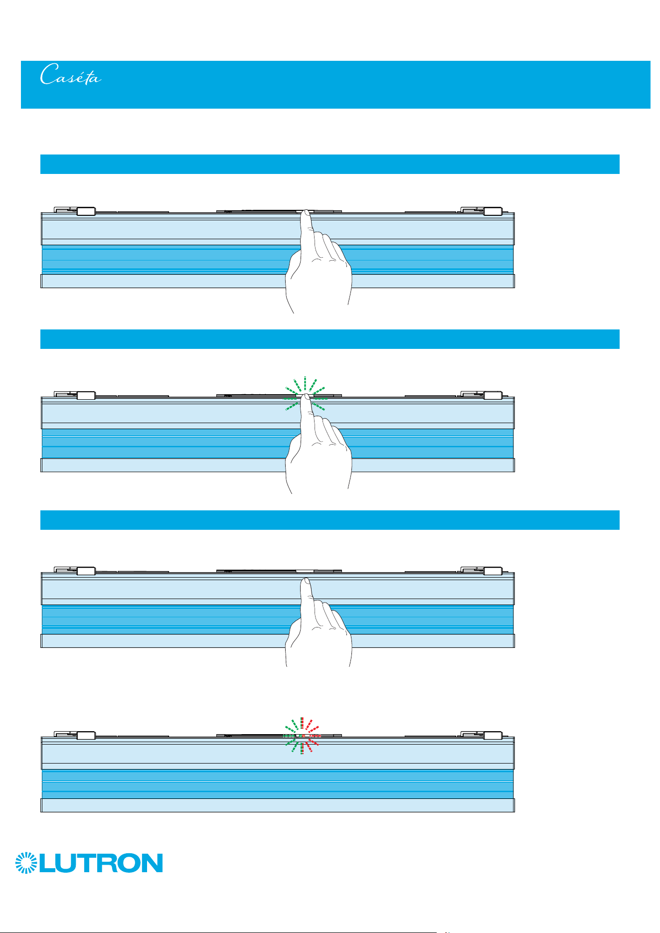
122
by Lutron
1
Tap the "Shade" button quickly at least three times, holding on the last press.
3
Release the "Shade" button, then immediately tap the button at least three more times and release.
2
Continue to hold the "Shade" button until the button LED flashes green.
HOLD
NOTE: This procedure will remove all paired Pico remote controls and favorite button programming. Upper and lower limits are retained.
NOTE: The "Shade" button LED will flash GREEN-then-RED three times, signaling the successful completion of the procedure.
3x
Removing Paired Pico Remote Controls from a Lutron Honeycomb Shade
TAP 3x
TAP 3x
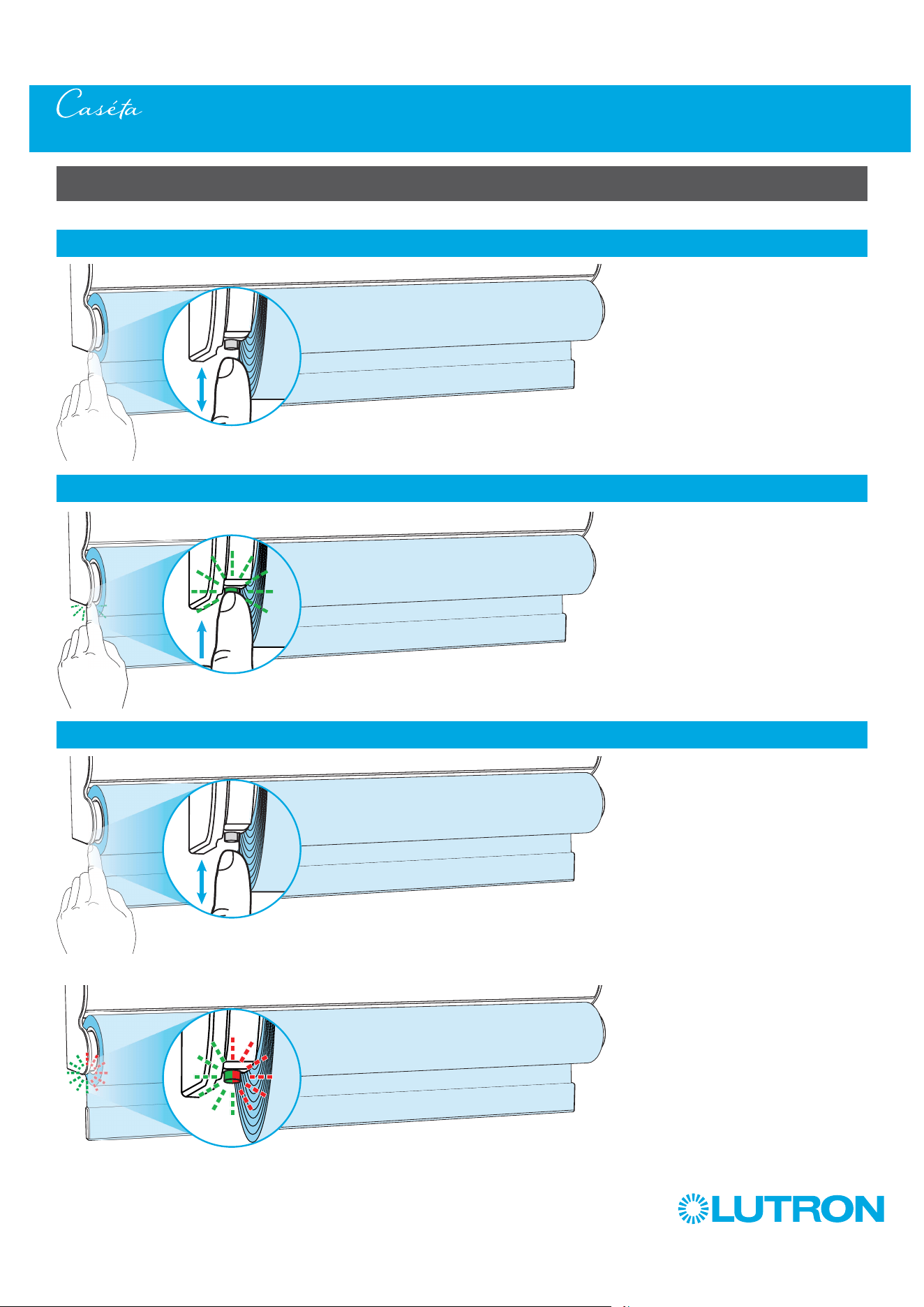
123
by Lutron
Roller Shades with a Single-Button (Battery-Powered and Plug-In)
Removing Paired Pico Remote Controls from a Lutron Roller Shade
1
Tap the "Shade" button quickly at least three times, holding on the last press.
3
Release the "Shade" button, then immediately tap the button at least three more times and release.
2
Continue to hold the "Shade" button until the button LED flashes green.
NOTE: The "Shade" button LED will flash GREEN-then-RED three times, signaling the successful completion of the procedure.
NOTE: This procedure will remove all paired Pico remote controls and favorite button programming. Upper and lower limits are retained.
TAP
3x
HOLD
TAP
3x
3x
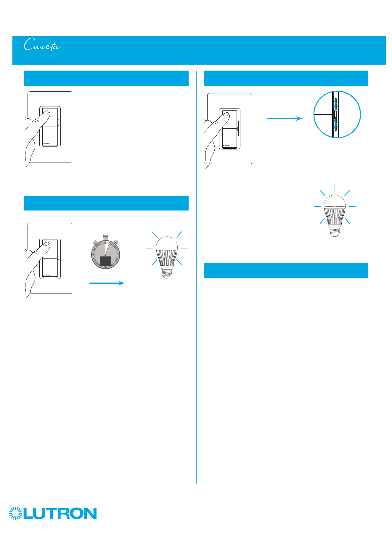
124
by Lutron
AND
Removing Paired Pico Remote Controls from a Caséta Diva Smart Dimmer (DVRF-6L)
1
Tap the "On" button quickly at least three times,
holding on the last press
0
5
10
15
3
sec.
2
Continue to hold the "On" button until the light
begins to flash quickly
UNTIL
3
Release the button, then immediately tap the button
at least three more times and release
4
All paired Pico remote controls are removed and all
settings are returned to factory default
After the dimmer resets, the light will turn on to the full on state.
NOTE: This procedure also resets the high-end and low-end trim
settings.
HOLD
Light starts
flashing quickly
TAP 3x and HOLD
TAP 3x
Light will flash slowly
three times, then turn off
3x
The light bar
starts flashing
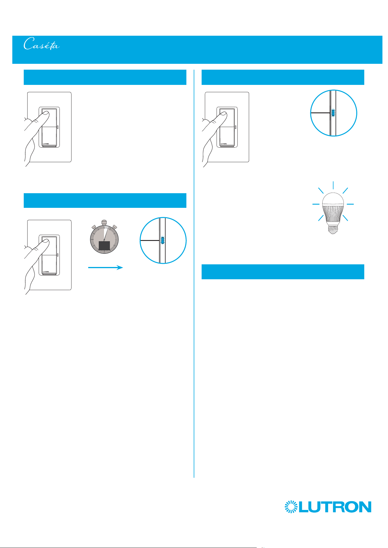
125
by Lutron
Removing Paired Pico Remote Controls from a Caséta Claro Smart Switch (DVRF-5NS)
1
Tap the "On" button quickly at least three times,
holding on the last press
0
5
10
15
3
sec.
2
Continue to hold the "On" button until the Status
LED begins to flash slowly
UNTIL
3
Release the button, then immediately tap the button
at least three more times and release
Light will flash slowly
two times
4
All paired Pico remote controls are removed and all
settings are returned to factory default
After the switch resets, the light will turn on to the full
on state.
2x
Status LED flashes
slowly
HOLD
Status LED flashes
quickly
AND
TAP 3x TAP 3x
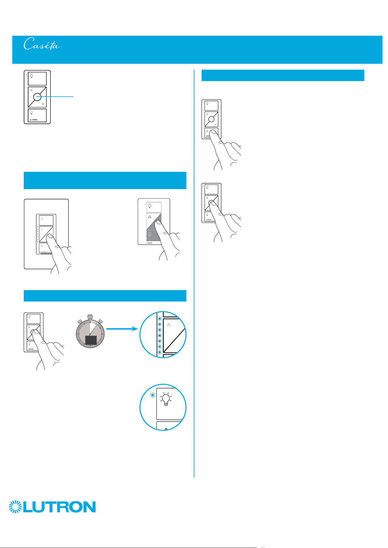
126
by Lutron
You can use the round “Favorite” button
on a Pico remote control to recall a favorite
light level. We’ve set it to 50%, but you can
change it to any level you like.
Favorite
1
Set desired light level on a dimmer that has already
been paired with a remote control
2
Save favorite light level
0
5
10
15
6
sec.
UNTIL
Dimmer LED(s)
flash(es) two times
3
Verify
Changing the Favorite Light Level on a Pico Remote Control
or
2x
2x
or
a. Tap "Off" button one time
on remote control. Light will
turn off.
b. Tap "Favorite" button one
time on remote control.
Light will turn on to the
newly saved level.
a.
b.
HOLD
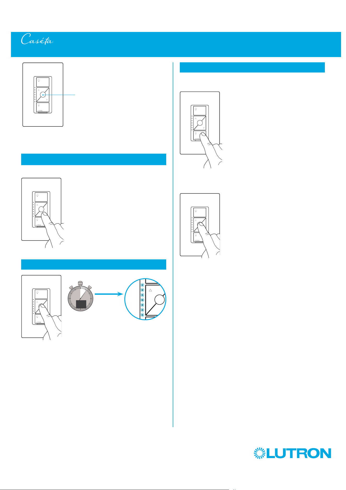
127
by Lutron
You can use the round “Favorite” button on
the dimmer to recall a favorite light level.
We’ve set it to 50%, but you can change it to
any level you like.
Use the "Brighter" or "Darker" buttons to
adjust lights to your favorite level.
Hold the round "Favorite" button.
1
Set the desired light level on the dimmer
2
Save favorite light level
0
5
10
15
6
sec.
UNTIL
3
Verify
Changing the Favorite Light Level on a Caséta Wireless ELV+ Dimmer (PD-5NE)
2x
a. Tap "Off" button one time
on dimmer control. Light will
turn off.
b. Tap "Favorite" button one
time on dimmer control.
Light will turn on to the
newly saved level.
a.
b.
Favorite
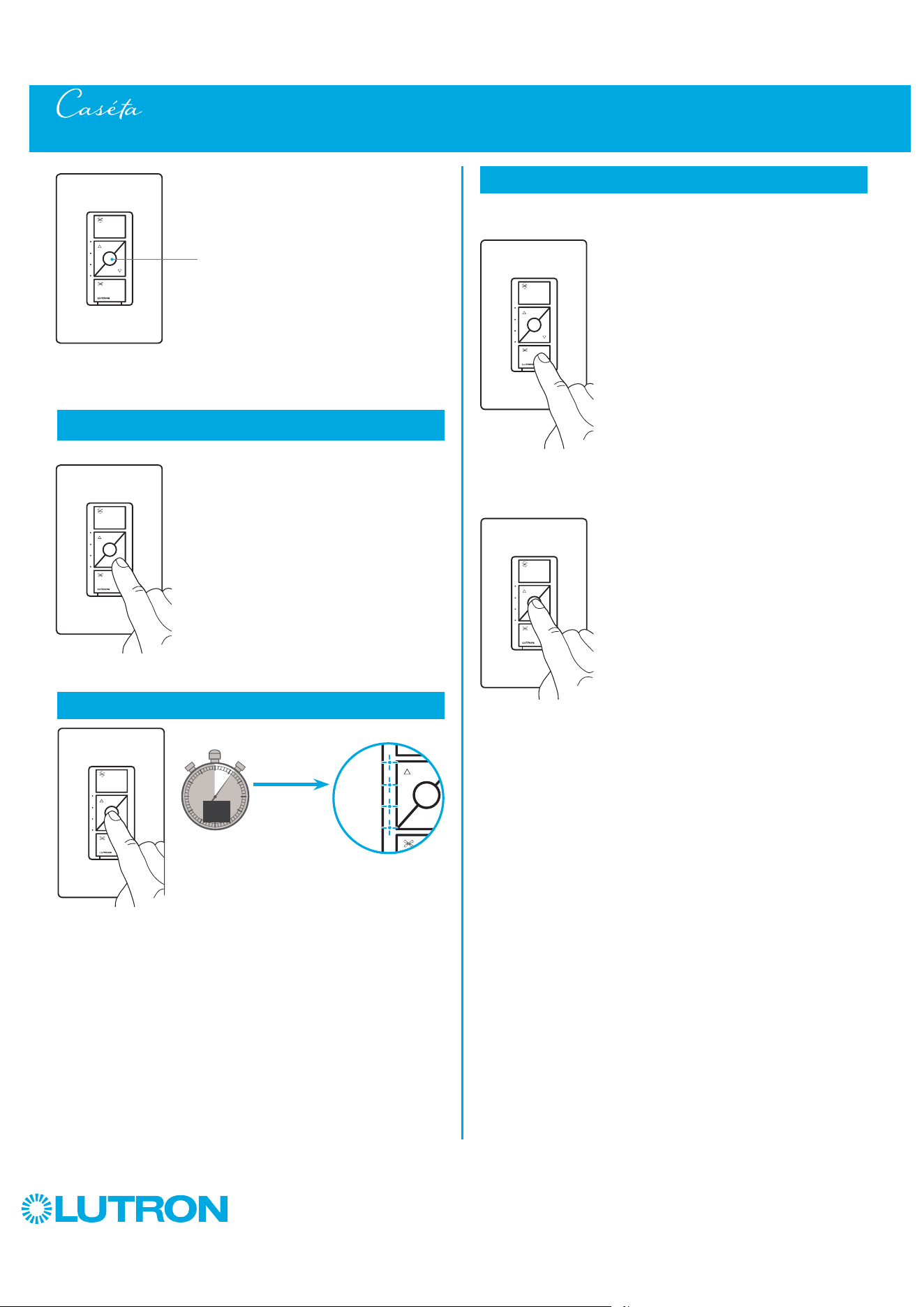
128
by Lutron
You can use the round “Favorite” button on the
fan control to recall a favorite fan speed setting.
We’ve set it to the medium fan speed, but you
can change it to any level you like.
Use the "Faster" or "Slower" buttons to
adjust lights to your favorite level.
Hold the round "Favorite" button.
1
Set the desired fan speed on the fan control
2
Save favorite fan speed
0
5
10
15
6
sec.
UNTIL
3
Verify
Changing the Favorite Fan Speed on a Caséta Wireless Fan Control (PD-FSQN)
2x
a. Tap "Off" button one time on
fan control. Fan will turn off.
b. Tap "Favorite" button one
time on fan control.
Fan will turn on to the newly
saved setting.
a.
b.
Favorite
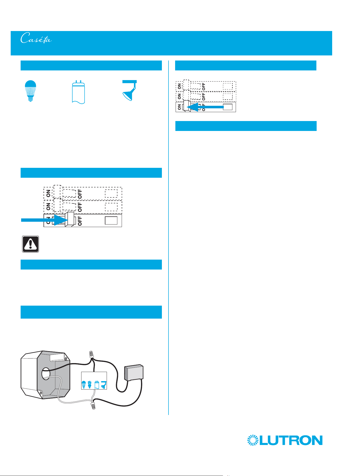
129
by Lutron
Installing a LUT-MLC Load Adapter with a Caséta Wireless Switch (PD-5WS-DV)
1
Identify load type
The LUT-MLC load adapter is provided to help ensure proper
operation of the switch with LED, fluorescent, and ELV lighting
loads. When controlling one of these load types, a LUT-MLC
may be required, especially at lower wattages. If the status LED
on the switch is flashing or a solid red color, a LUT-MLC must be
installed. It is recommended to install a LUT-MLC with these load
types regardless of wattage to guarantee best performance.
LED ELVFluorescent
WARNING! Shock Hazard. May result in Serious
Injury or Death. Turn off power at circuit breaker
before installing the unit.
2
Turn power off at circuit breaker
3
Choose installation location
The LUT-MLC must be connected to the neutral and switched hot
feed to the load. Install the LUT-MLC inside a load fixture or in a
separate junction box within the circuit.
4
Installing the LUT-MLC in a load fixture
or junction box
1. Connect one lead of the LUT-MLC to the neutral (white) wire.
2. Connect the other lead of the LUT-MLC to the switched hot
(black) wire.
1
2
LUT-MLC
Junction Box
Load
5
Turn power on at circuit breaker
6
Verify performance
Verify that the LED on the switch is not flashing or solid red color
and that the load stays off when the switch is turned off. In rare
instances, some loads may still flicker or glow in the off state
with the LUT-MLC installed. If this occurs, a different load may
be required or additional LUT-MLC load adapters may need to
installed.
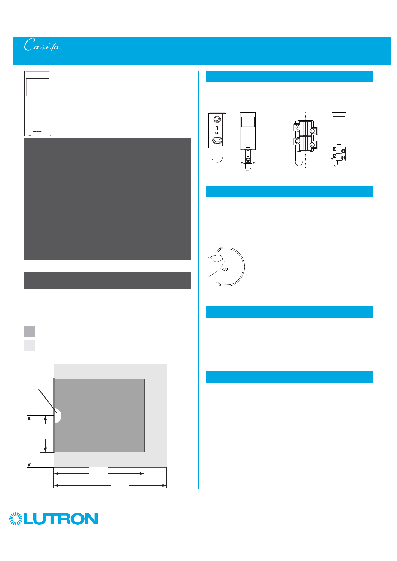
130
by Lutron
Motion Sensor Placement and Coverage (PD-OSENS / PD-VSENS)
2
Enter test mode
– If you cannot see the sensor, it cannot see you.
– The sensor should be mounted at eye level. Recommended
placement height 6 ft to 8 ft (1.8 m to 2.4 m).
– DO NOT place the sensor within 4 ft (1.2 m) of moving air
currents (e.g., HVAC vents), heat sources (e.g., light bulbs, or
microwave / standard ovens), or within 6 in (15 cm) of other
RF devices.
– The sensor must have an unobstructed view of the room.
DO NOT place behind or near tall cabinets, shelves, hanging
fixtures, or anything that may obstruct sensor’s view. The
sensor cannot detect occupants through glass objects such as
patio or shower doors.
– If there is line of sight from the sensor to the associated devices
(no obstructions), sensor can be located within 60 ft (18.3 m)
otherwise sensor must be within 30 ft (9.1 m).
– Whenever possible, avoid placing the sensor in a location
where it has a broad view outside the intended space.
Before mounting the sensor, please note the following:
Sensor Coverage
Minor Motion Coverage-
(small movement, i.e., turning a page
)
15
X
2
X
35= 1050 ft
2
(97.5 m
2
)
Major Motion Coverage-
(large movement, i.e., walking
)
20
X
2
X
45= 1800 ft
2
(167.2 m
2
)
Testing Sensor Coverage
Test the sensor coverage using the temporary mounting 3M
TM
Command
TM
adhesive strip and test procedure below to ensure the
sensor will perform as desired prior to permanent mounting.
Test
Press and release the "Test" button on the top of the sensor. The
lens will glow briefly, indicating the test mode has been entered.
There is a 90 second warm-up period after the battery is installed
before test mode can activated. If the "Test" button is pressed
within 90 seconds of installing the battery the lens will flash
rapidly until the warm-up is complete.
3
Walk around the space
Walk around the space while observing the lens. If the lens glows,
motion is detected. If you are not satisfied with the sensor's
performance, relocate the sensor and repeat the test.
4
Exit test mode
Press and release the "Test" button again to exit test mode. The
sensor will automatically exit test mode after 15 minutes, or after
5 minutes if no motion is detected.
1
Temporary Mounting
To test sensor coverage, a 3M
T
Command
T
adhesive strip is
provided for temporarily mounting the sensor. The strip is not
reusable and should not be used for permanently mounting the
sensor.
Flat Wall-Mount
Corner-Mount
20 ft
(6.1 m)
15 ft
(4.6 m)
35 ft
(10.7 m)
45 ft
(15.2 m)
Sensor
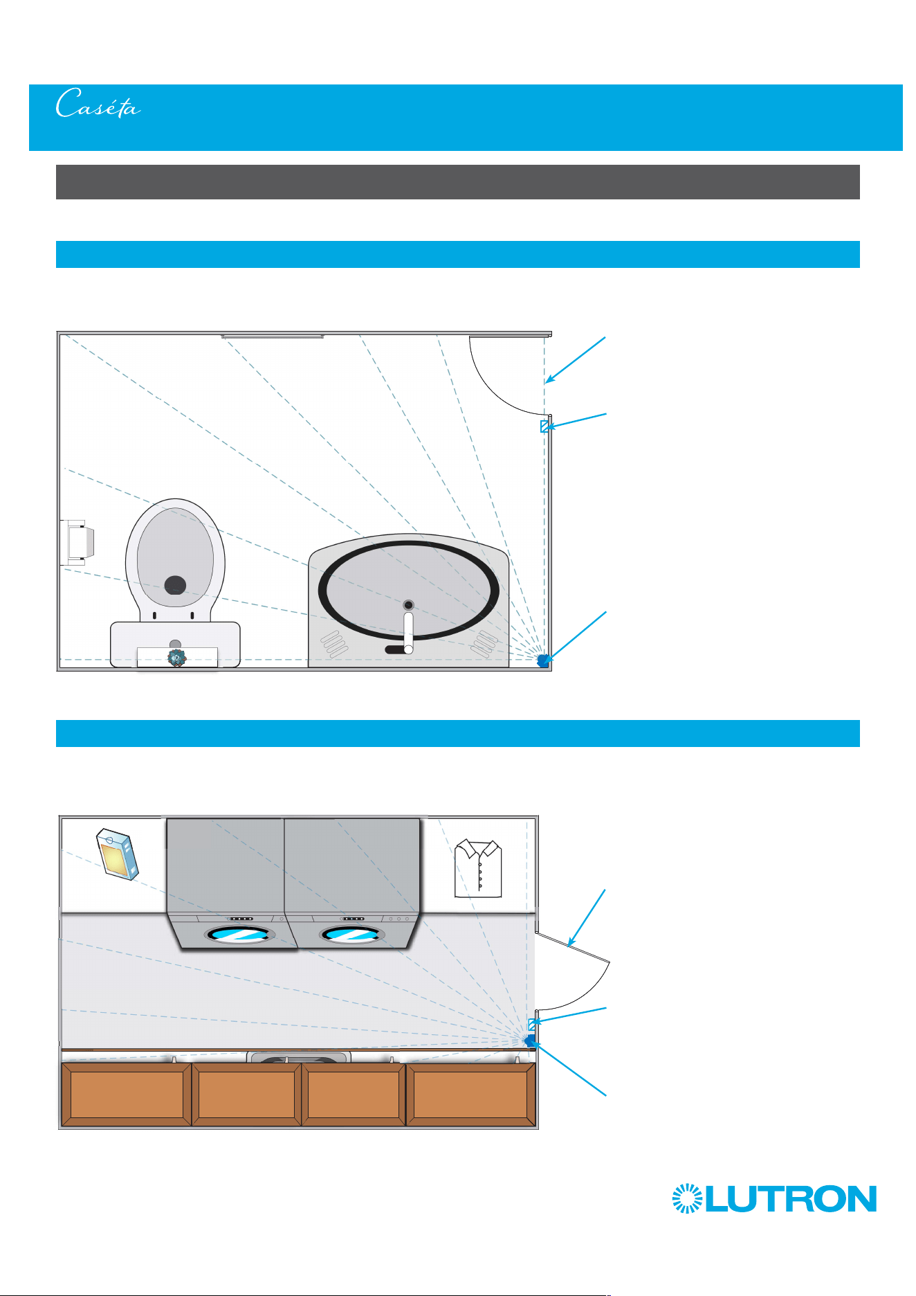
131
by Lutron
Motion Sensor Placement and Coverage (PD-OSENS / PD-VSENS)
Motion Sensor Placement Examples
Below and on the next few pages are examples of different spaces to place your motion sensor. Every home layout is different and these
examples should only be used as a guideline.
1
Powder Room
A Caséta Wireless motion sensor is mounted in the corner at the height of 6 ft (1.8 m) where it can "see" the whole room. The placement
of the sensor ensures that it won’t see any movement outside of the powder room. The sensor is paired to a Caséta Wireless switch. The
Auto-On setting is set to "Enabled", allowing for the sensor to automatically turn the light On / Off when a person enters / exits the powder
room.
Entry
Caséta Wireless
Switch
Corner-Mount
Caséta Wireless
Motion Sensor
2
Laundry Room
A Caséta Wireless motion sensor is mounted flat on the wall at the height of 6 ft (1.8 m) where it can "see" the whole room. The placement
of the sensor ensures that it won’t see any movement outside of the laundry room. The sensor is paired to a Caséta Wireless switch. The
Auto-On setting is set to "Enabled", allowing for the sensor to automatically turn the light On / Off when a person enters / exits the laundry
room.
Entry
Caséta Wireless
Switch
Flat Wall-Mount
Caséta Wireless
Motion Sensor
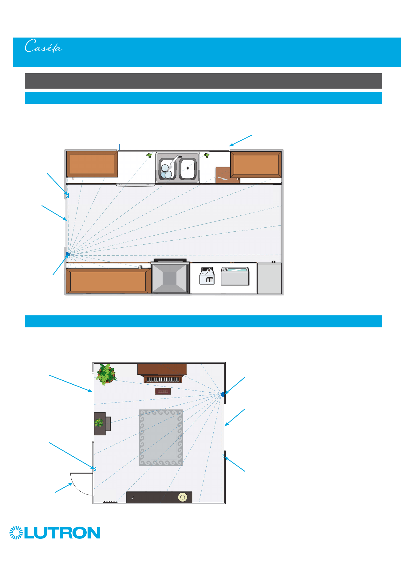
132
by Lutron
Motion Sensor Placement and Coverage (PD-OSENS / PD-VSENS)
Motion Sensor Placement Examples
(continued)
4
Foyer
A Caséta Wireless motion sensor is mounted flat on the wall at the height of 6 ft (1.8 m) where it can "see" the whole room. The placement
of the sensor ensures that it won’t see any movement outside of the room, nor can the sensor see movement through the glass window.
The sensor and Pico remote control are paired to a Caséta Wireless dimmer allowing the user to adjust the brightness of the light in the
foyer. The Auto-On setting is set to "Enabled", allowing for the sensor to automatically turn the light On / Off when a person enters / exits the
foyer.
Pico Remote
Control
Flat Wall-Mount
Caséta Wireless
Motion Sensor
Caséta Wireless
Dimmer
Front Door
Entry
Window
Adjacent
Room Entry
3
Kitchen
A Caséta Wireless motion sensor is mounted flat on the wall at the height of 6 ft (1.8 m) where it can "see" the whole room *. The placement
of the sensor ensures that it won’t see any movement outside of the kitchen, nor can the sensor see movement through the glass window.
The sensor is paired to a Caséta Wireless dimmer allowing the user to adjust the brightness of the light. The Auto-On setting is set to
"Enabled", allowing for the sensor to automatically turn the light On / Off when a person enters / exits the kitchen.
Entry
Flat Wall-
Mount Caséta
Wireless
Motion Sensor
Window
Caséta
Wireless
Dimmer
* DO NOT place sensor within 4 ft (1.2
m) of moving air currents (e.g., HVAC
vents), heat source (e.g., light bulbs
or microwave / standard ovens). Heat
from an oven may cause sensor to
see movement. Changing the activity
setting to medium- or high-activity may
be necessary. Refer to the back of the
sensor or visit:
www.casetawireless.com/sensorfeatures
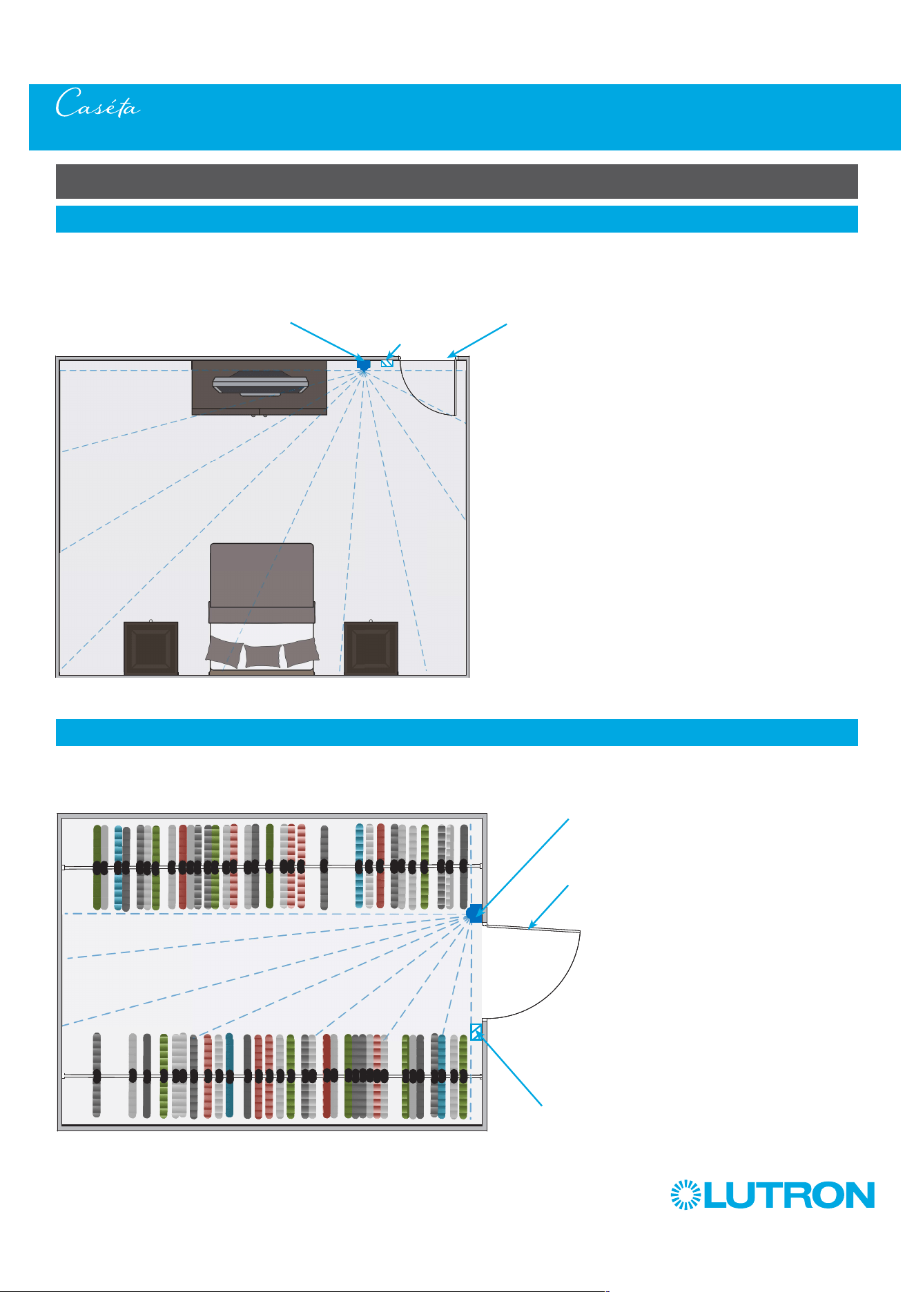
133
by Lutron
Motion Sensor Placement and Coverage (PD-OSENS / PD-VSENS)
Motion Sensor Placement Examples
(continued)
6
Closet
A Caséta Wireless motion sensor is mounted flat on the wall at the height of 6 ft (1.8 m) where it can "see" the walking path of the closet. * The
placement of the sensor ensures that it won’t see any movement outside of the closet. The sensor is paired to a Caséta Wireless switch. The
Auto-On setting is set to "Enabled", allowing for the sensor to automatically turn the light On / Off when a person enters / exits the closet.
Entry
Caséta Wireless
Switch
Flat Wall-Mount
Caséta Wireless
Motion Sensor
* DO NOT place sensor within 4 ft (1.2 m)
of moving air currents (ie: HVAC vents),
heat source (ie: light bulbs). Changing the
activity setting to medium or high activity
may be necessary. Refer to the back of
the sensor or visit:
www.casetawireless.com/sensorfeatures
5
Bedroom
A Caséta Wireless motion sensor is mounted flat on the wall near the Caséta Wireless dimmer at the height of 6 ft (1.8 m) where it can "see"
the whole room. The placement of the sensor ensures that it won’t see any movement outside of the bedroom. The sensor is paired to a
Caséta Wireless dimmer allowing the user to adjust the brightness of the bedroom light. The Auto-On setting is set to "Disabled", requiring
the light to be turned on manually, but allowing for the sensor to automatically turn the light Off. This setting is recommended for bedrooms
so the sensor won’t turn on the lights when it sees movement while a person is sleeping.
EntryCaséta Wireless
Switch
Flat Wall-Mount Caséta
Wireless Motion Sensor
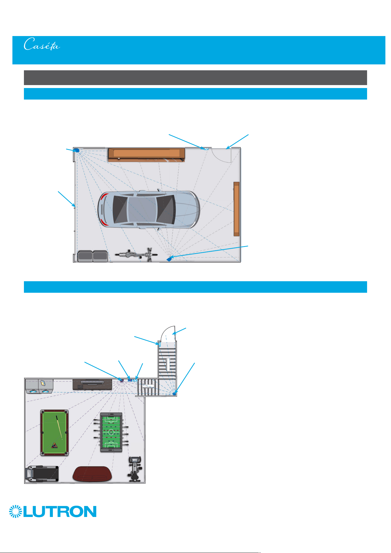
134
by Lutron
Motion Sensor Placement Examples
(continued)
8
Basement / Stairway
A Caséta Wireless motion sensor is mounted in the corner of the stairs ensuring it will see movement at the top of the stairs as well as at
the bottom. The sensor and a Pico remote control are paired to a Caséta Wireless switch that controls the light in the stairwell. The second
motion sensor is placed to ensure coverage of the whole basement. The second sensor is paired to a Caséta Wireless dimmer allowing you
to adjust the brightness of the basement light. The Auto-On setting is set to "Enabled", allowing for the sensor to automatically turn the light
On / Off when a person enters / exits the basement.
Pico
Remote
Control
Corner-Mount Caséta Wireless
Motion Sensor paired to the
Switch on the Stairs
Caséta Wireless
Switch for Stairs
Entry
Caséta Wireless
Dimmer for
Room
Flat Wall-Mount Caséta
Wireless Motion Sensor
paired to the Dimmer in
the Room
Motion Sensor Placement and Coverage (PD-OSENS / PD-VSENS)
7
Garage
A Caséta Wireless motion sensor is mounted in the corner at the height of 6 ft (1.8 m) and a second Caséta Wireless motion sensor is
mounted offset to the wall. This allows for full coverage of the garage. While the corner sensor may be enough to cover the whole garage,
if there are objects on the wall blocking the line of sight of the sensor, the placement of the second sensor will ensure full coverage. Both
sensors are paired to one Caséta Wireless switch. The Auto-On setting is set to "Enabled", allowing for the sensor to automatically turn the
light On / Off when a person enters / exits the garage.
Corner-Mount
Caséta Wireless
Motion Sensor
Entry
Garage Door
Caséta Wireless
Dimmer
Corner-Mount Caséta
Wireless Motion Sensor,
offset on the wall
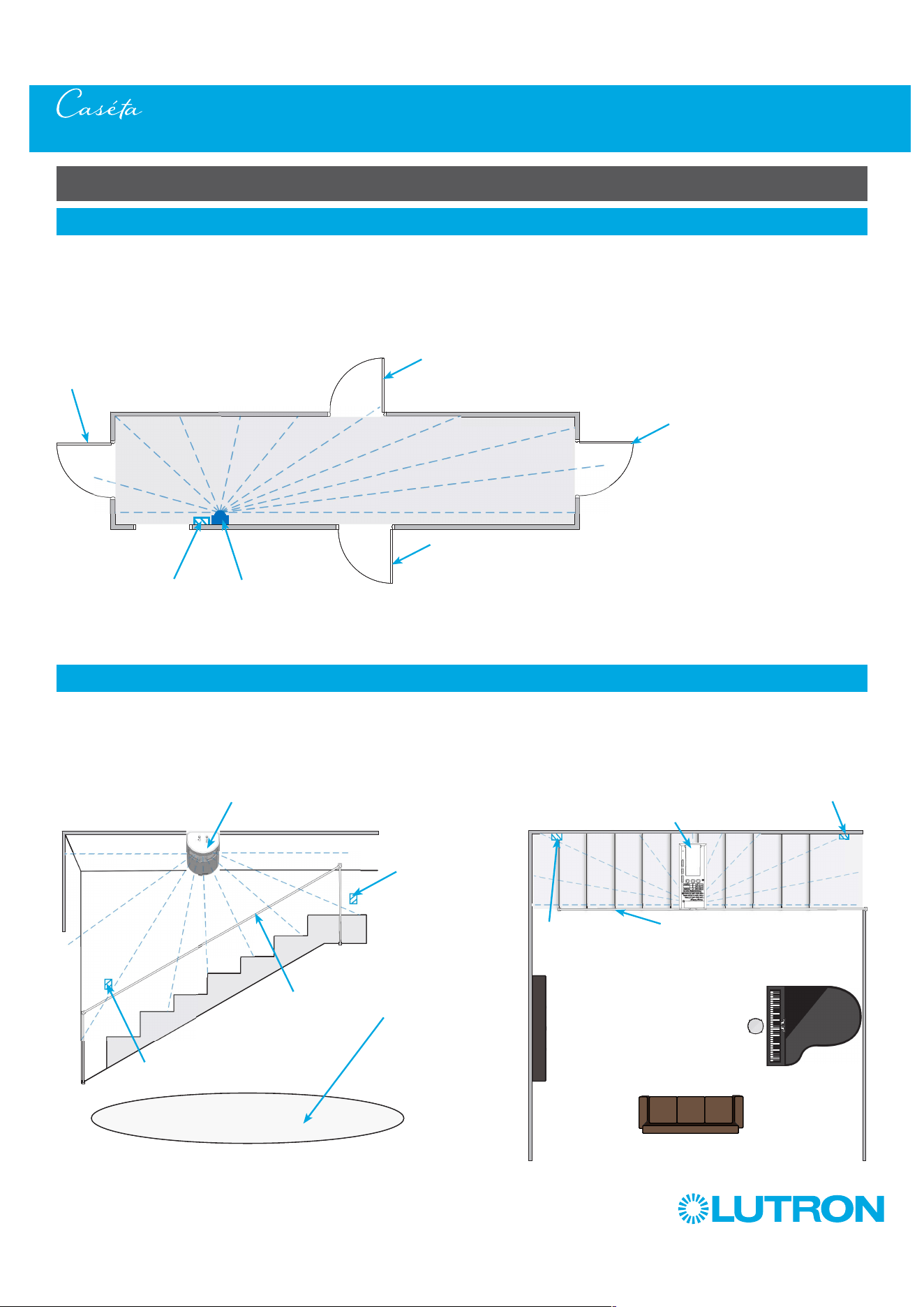
135
by Lutron
Motion Sensor Placement Examples
(continued)
10
Staircase
A Caséta Wireless motion sensor is mounted flat on the ceiling, perpendicular to the staircase. If there is a railing present (or one side of
staircase is open to an adjacent area as shown below), align the top of the sensor with the railing (or edge of adjacent area), and the bottom
of the sensor facing the wall, so the sensor only "sees" the staircase and not the adjacent area. The sensor and Pico remote control with
wallplate are paired to a Caséta Wireless switch that controls the light in the staircase. The Auto-On setting is set to "Enabled", allowing for
the sensor to automatically turn the light On / Off when a person enters / exits the staircase.
Adjacent
Room
Caséta Wireless
Switch
Top of Flat Wall-Mount
Caséta Wireless Motion
Sensor
Pico
Remote
Control
Hand Rail
Pico Remote
Control
Back of Flat Wall-Mount
Caséta Wireless Motion
Sensor
Caséta Wireless
Switch
Hand Rail
Adjacent
Room
Side View Top View
Motion Sensor Placement and Coverage (PD-OSENS / PD-VSENS)
9
Hallway
A Caséta Wireless motion sensor is mounted flat on the wall near the Caséta Wireless switch at the height of 6 ft (1.8 m) where it can "see"
the whole hallway. The sensor may see movement in the rooms if the doors are open. Adjusting sensor location may be necessary based
on layout. The sensor is paired to Caséta Wireless switch. The Auto-On setting is set to "Enabled", allowing for the sensor to automatically
turn the light On / Off when a person enters / exits the hallway.
Room
Entry
Caséta Wireless
Switch
Flat Wall-Mount Caséta
Wireless Motion Sensor
Room
Entry
Room
Entry
Room
Entry
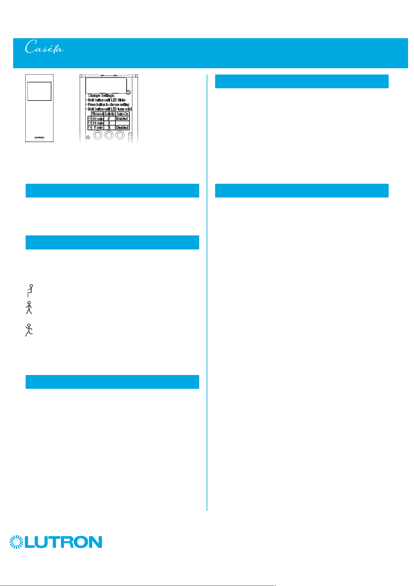
136
by Lutron
Motion Sensor Advanced Features (PD-OSENS / PD-VSENS)
The motion sensor has several advanced set-up features. For the
majority of installations, the default settings will provide the best
performance and you will not need to utilize the advanced set-up.
The motion sensor has three adjustable advanced set-up modes:
Timeout, Activity, and Auto-On.
The sensor will turn the lights off if no motion occurs for the duration of
the timeout period. The available timeout settings are: 1, 5, 15, and
30 minutes. (Default: 15 minutes)
The sensitivity of the sensor can be adjusted based on the expected
level of activity within the room. There are three available activity
settings: Low Activity, Medium Activity, and High Activity.
(Default: Low Activity)
Low Activity: This is the most sensitive setting and is
recommended for most applications.
Medium Activity *: This setting is slightly less sensitive than
the Low Activity setting and can be used for spaces that
experience normal activity.
High Activity *: This is the least sensitive setting and can
be used for spaces that will generally only experience large
motions, such as foot traffic.
* If the sensor is placed near external noise sources such as HVAC vents, it
might turn the lights on without occupancy or keep lights on too long after
vacancy. If this occurs, change the sensitivity to Medium or High Activity.
The automatic-on functionality of the sensor can be adjusted to
control how the lights respond upon initial occupancy. There are two
available settings: Enabled and Disabled. (Default: Enabled)
Enabled: The lights will always turn on automatically on
occupancy and automatically turn off after vacancy.
Also known as occupancy mode.
Disabled: The lights will not turn on automatically on
occupancy, but will still turn off automatically after
vacancy. After the lights turn off, a 15 second grace
period allows for lights to turn back on if motion is
detected. This is also known as vacancy mode.
Recommendations: For applications in bedrooms or when pets
are in the space, it’s suggested to change Auto-on setting to
Disabled.
1
Timeout
2
Activity
3
Auto-On (PD-OSENS model only)
When the load control is manually turned OFF, the sensor will not
turn the lights back ON automatically while the room is occupied.
Once the room is vacated, the Auto-On feature returns to normal
operation after the timeout period has expired. (Feature only
available when Auto-On is enabled).
The Advanced Feature set-up is accessed by using the buttons
on the back of the sensor. The procedure for selecting a 1-minute
timeout is different and described below.
Check Setting: Press and release the button beneath the
desired mode. An LED will illuminate briefly to indicate the
current setting.
Change Setting: The setting for Timeout, Activity, and
Auto-On can be changed using the standard procedure below.
Standard Mode
1. Press and hold the desired button until the LED corresponding
to the current setting begins flashing rapidly.
2. Press and release the button to increment the mode to the next
available setting.
3. To save the selected setting, press and hold the button until the
LED turns on solid.
1-Minute Timeout (For use in areas that experience brief activity;
hallways, laundry rooms, etc.)
1. Press and hold the timeout button for 10 seconds until all
3 LEDs begin flashing rapidly.
2. Press and hold the timeout button until all 3 LEDs turn on solid,
indicating the 1-minute timeout has been saved.
4
Off While Occupied
5
Advanced Feature Set-Up (optional)
137
by Lutron
Dimmer and Switch Troubleshooting
Symptoms Probable cause and action
Light does not turn on or LEDs on the devices do not
illuminate.
• Light bulb(s) burned out.
• Breaker is OFF or tripped.
• Light not properly installed.
• Wiring error.
Dimmer or switch:
• FASS on the dimmer or switch
is in the off position.
Plug-in lamp dimmer:
• Outlet is switched off.
• Lamp is turned off.
• Lamp is not plugged in.
Light does not respond to Pico remote control. • The dimmer or switch failed to pair with Pico remote control.
• The dimmer or switch is already at the light level the Pico remote
control is sending.
• The Pico remote control is outside the 30 ft (9 m)
operating range.
• The Pico remote control battery is low.
• The Pico remote control battery is installed incorrectly.
• Bulbs turn off while being dimmed.
• Bulbs turn on at high light level but do not turn on at a low
light level.
• Bulbs flicker or flash when dimmed to a low light level.
Dimmer or plug-in lamp dimmer only:
Verify bulbs are marked dimmable and visit
www.casetawireless.com/lowend for information on adjusting
the dimmer for best bulb performance.
• LED on switch is flashing or solid red color.
• Light stays on when the switch is turned off.
Switch only:
Proper bulb operation requires LUT-MLC installation. See Page 59.
Top and middle LEDs are blinking rapidly. Product detected an MLV fault (PRO Dimmer only)
• Connect Neutral to the dimmer (required for MLV load)
Top and second from bottom LEDs are blinking rapidly. No Load (PRO Dimmer only)
• Apply or replace the load
Top three LEDs flashing Over voltage detected, verify unit does not have MLV load and is in
reverse phase
Middle three LEDs flashing Over temperature event, verify unit is not overloaded
Bottom three LEDs flashing Over current detected, verify unit does not have ELV load while in
forward phase
Go to www.casetawireless.com/support for additional troubleshooting suggestions.
138
by Lutron
Lutron Contact Numbers
)
Lutron, Lutron, Caséta, Claro, Diva, Pico, and FASS are trademarks or registered trademarks of Lutron Electronics Co., Inc. in the US
and/or other countries.
All product names, logos, and brands are property of their respective owners.
© 2014 – 2022 Lutron Electronics Co., Inc.
WORLD HEADQUARTERS
USA
Lutron Electronics Co., Inc.
7200 Suter Road
Coopersburg, PA 18036-1299
TEL: +1.610.282.3800
FAX: +1.610.282.1243
Customer Assistance: 1.844.LUTRON1
Mexico:
+1.888.235.2910
Central/South America:
+1.610.282.6701
www.lutron.com/support
Fan Troubleshooting
Symptoms Probable cause and action
Fan does not turn ON and no indicator lights turn ON. • Front Accessible Service Switch (FASS) is pulled out to the OFF
position. Push FASS in fully to the ON position.
• Fan pull chain is in the OFF position. Set pull chain speed to high.
• Neutral wire is not connected. Check wiring.
• Breaker is OFF or tripped (or fuse blown). Reset breaker or replace
fuse. If condition persists, contact Lutron Customer Assistance or
a licensed electrician.
• Load and Line wires may be reversed. Check wiring.
Fan does not turn ON and indicator lights are ON. Fan direction switch is between forward and reverse. Set switch to
desired position.
Fan vibrates or wobbles. • Fan direction switch is between forward and reverse. Set switch to
desired position.
• Fan blades must be balanced. See fan manufacturers installation
guide to balance fan.
Fan speed is too slow. Set fan pull chain speed to high.
Fan does not respond to Pico remote control. • The fan control failed to pair with Pico remote control.
• The fan control is already at the fan speed level that the Pico
remote control is sending.
• The Pico remote control is outside the 30 ft (9 m)
operating range.
• The Pico remote control battery is low.
• The Pico remote control battery is installed incorrectly.
Go to www.casetawireless.com/support for additional troubleshooting suggestions.
Lutron Electronics Co., Inc.
7200 Suter Road
Coopersburg, PA 18036-1299 U.S.A.
P/N 0301710 Rev. L 05/2023