Loading ...
Loading ...
Loading ...
En-3
1-6. DRAIN PIPING FOR OUTDOOR UNIT
Please perform the drain piping work only when draining from one place.
1) Provide drain piping before indoor and outdoor piping connection.
2) Connect the soft PVC hose (L) I.D.15 mm as shown in the illustration.
3)Makesuretoprovidedrainpipingwithadownhillgradeforeasydrainow.
Note:
Install
the unit horizontally.
Do not use the drain socket (1) in the cold regions. Drain may freeze and it makes
the fan stop.
The outdoor unit produces condensate during the heating operation. Select the in
-
s
tallation place to ensure to prevent the outdoor unit and/or the grounds from being
wet by drain water or damaged by frozen drain water.
(1) Drain socket
(L) Soft PVC hose
2. OUTDOOR UNIT INSTALLATION
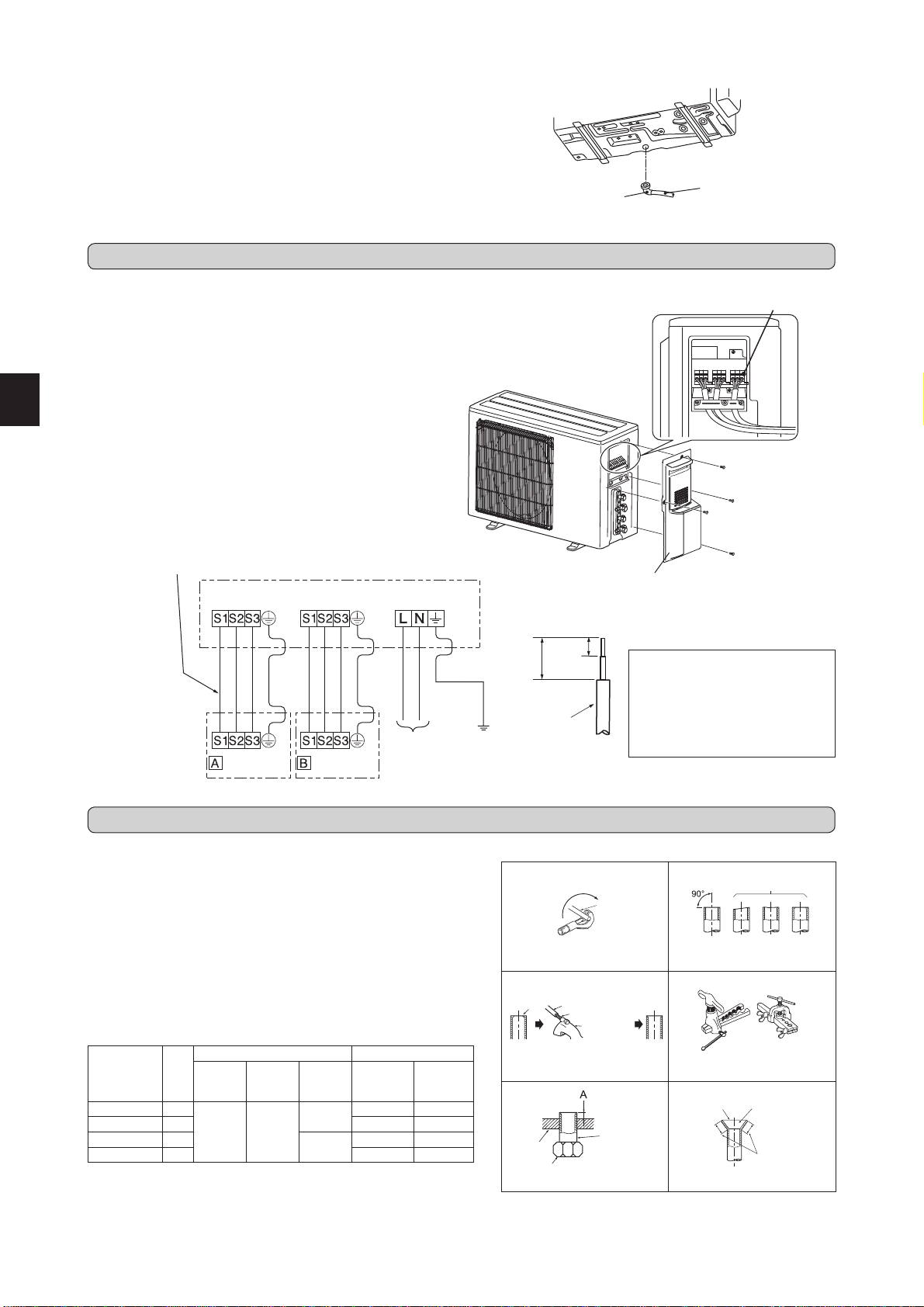
2-1. CONNECTING WIRES FOR OUTDOOR UNIT
• Be sure to attach each screw to its
correspondent terminal when secur-
i
ng the cord and/or the wire to the
terminal block.
• Make earth wire a little longer than
others. (More than 35 mm)
• For future servicing, give extra length
to the connecting wires.
Terminal block for power supply
1) Remove the service panel.
2) Loosen terminal screw, and connect indoor/outdoor unit connecting
wire (B) from the indoor unit correctly on the terminal block. Be careful
not to make mis-wiring. Fix the wire to the terminal block securely so
that no part of its core is appeared, and no external force is conveyed
to the connecting section of the terminal block.
3) Firmly tighten the terminal screws to prevent them from loosening. Af
-
ter
tightening,pullthewireslightlytoconrmthattheydonotmove.
4) Perform 2) and 3) for each indoor unit.
5) Connect power supply cord (A).
6) Fix indoor/outdoor unit connecting wire (B) and power supply cord (A)
with the cable clamps.
7) Close the service panel securely. Make sure that 3-2. PIPE CONNEC
-
TION
is completed.
• After making connections between both power supply cord (A) and
indoor/outdoorunitconnectingwire(B),besuretoxbothcableand
wire with cable clamps.
Indoor/outdoor unit connecting wire
<OUTDOOR UNIT>
35 mm
15 mm
Lead wire
Terminal block
UNIT
UNIT
Terminal
block for
power supply
<INDOOR UNIT>
POWER SUPPLY
~/N 230 V 50 Hz
Service panel
Fig. 1 Fig. 2
Fig. 3 Fig. 4
Fig. 5 Fig. 6
3. FLARING WORK AND PIPE CONNECTION
3-1. FLARING WORK
Pipe diameter
(mm)
Nut
(mm)
A (mm) Tightening torque
Clutch
type tool
for
R410A
Clutch
type tool
for R22
Wing nut
type tool
for R22
N•m kgf•cm
ø6.35 (1/4”) 17
0 to 0.5 1.0 to 1.5
1.5 to 2.0
13.7 to 17.7 140 to 180
ø9.52 (3/8”) 22 34.3
to 41.2 350 to 420
ø12.7 (1/2”) 26
2.0
to 2.5
49.0 to 56.4 500 to 575
ø15.88 (5/8”) 29 73.5
to 78.4 750 to 800
Tilted Uneven Burred
Good
No good
Burr
Copper pipe
Spare reamer
Pipe cutter
Smooth all
around
Even
length
all around
Inside is shin-
ing
without any
scratches.
Flare nut
Die
Copper
pipe
Clutch type
Flaring tool
Wing nut type
Copper
pipe
1) Cut the copper pipe correctly with pipe cutter. (Fig. 1, 2)
2) Completely remove all burrs from the cut cross section of pipe. (Fig. 3)
• Aim the copper pipe downward while removing burrs to prevent
burrs from dropping in the pipe.
3)Removearenutsattachedtoindoorandoutdoorunits,thenputthem
on pipe having completed burr removal. (Not possible to put them on
afteraringwork.)
4) Flaring work (Fig. 4, 5). Firmly hold copper pipe in the dimension
shown in the table. Select A mm from the table according to the tool
selected.
5)
Check
• ComparethearedworkwithFig.6.
• Ifareisnotedtobedefective,cutoffthearedsectionanddoar
-
ing
work again.
JG79A641H01_en.indd 3 2013/09/06 15:47:06
Loading ...
Loading ...
Loading ...