1
Español p. 18
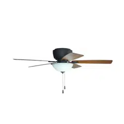
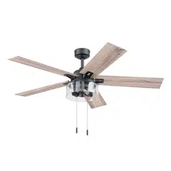
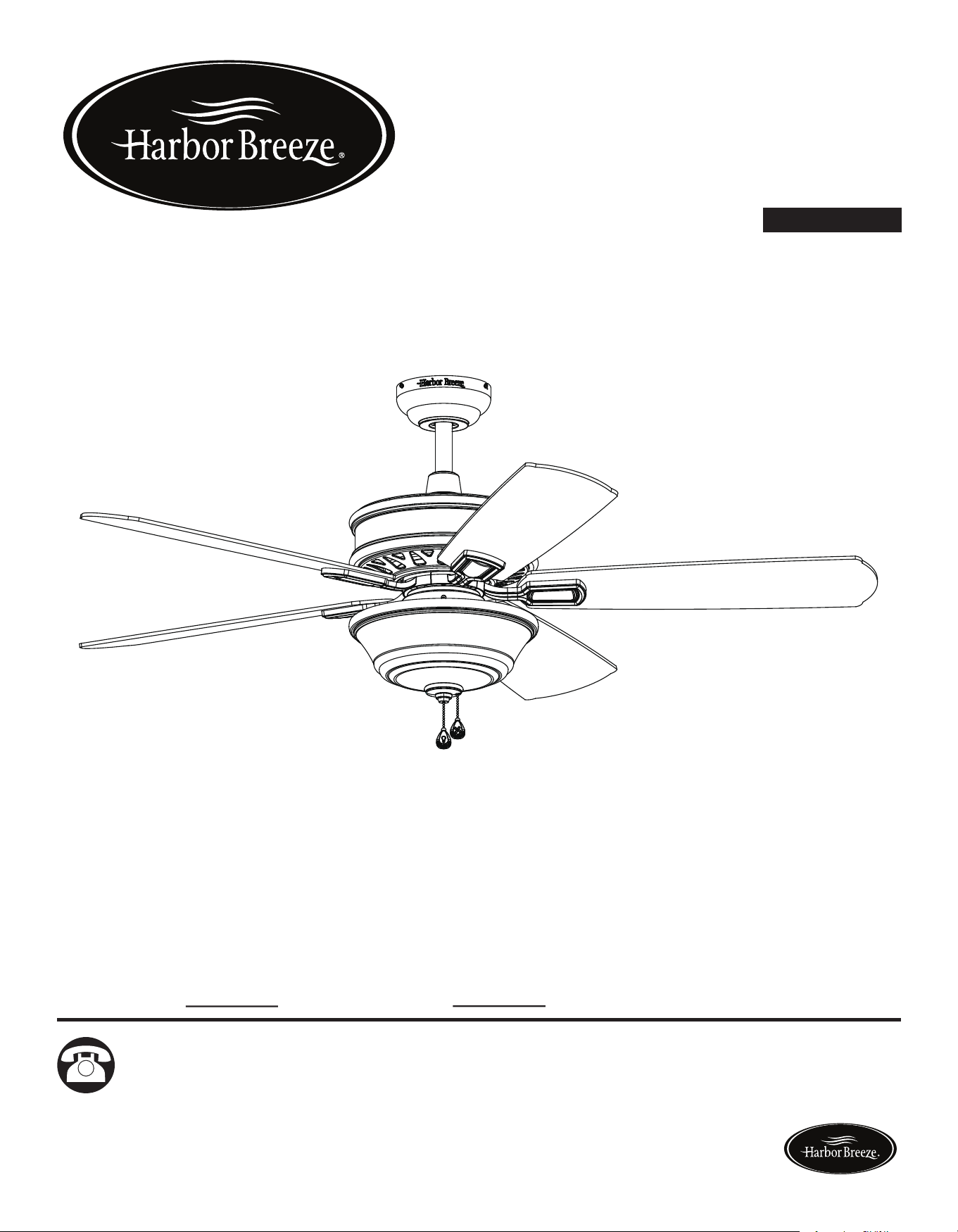
EASY BREEZE CEILING FAN
ITEM #0698390, 0698391
MODEL #00887, 00888
Serial Number
Purchase Date
Harbor Breeze ® is a registered trademark of LF,
LLC. All Rights Reserved.
Questions, problems, missing parts? Before returning to your retailer, call our customer
service department at 1-866-473-4537, 8 a.m. - 7 p.m., EST, Monday - Friday,
9 a.m. - 6 p.m., EST, Saturday.
EB165
ATTACH YOUR RECEIPT HERE
UL MODEL #EBZ54
Lowes.com/harborbreeze Lowes.com/harborbreeze
3
2
TABLE OF CONTENTS
Safety Information............................................................................................................... 2
Package Contents............................................................................................................... 4
Hardware Contents...............................................................................................................5
Preparation ......................................................................................................................... 5
Assembly or Installation Instructions .................................................................................. 6
Operating Instructions ........................................................................................................ 15
Care and Maintenance ....................................................................................................... 16
Troubleshooting................................................................................................................... 16
Warranty.............................................................................................................................. 17
Replacement Parts List ...................................................................................................... 17
SAFETY INFORMATION
WARNING
CAUTION
READ AND SAVE THESE INSTRUCTIONS
Please read and understand this entire manual before attempting to assemble, operate or
install the product.
• When using an existing outlet box, be sure the box is securely attached to the building structure
and can support the full weight of the fan, so to avoid potential serious injury or death.
• All wiring must be in accordance with the National Electrical Code “ANSI/NFPA 70” and local
electricalcodes.Electricalinstallationshouldbeperformedbyaqualiedlicensedelectrician.
• DONOTusebulbswithwattagegreaterthanthemaximumvaluestatedonthextureandin
thismanual.Usingahigherwattagebulbthanspeciedwillincreasexturetemperatureand
causeriskofre.
• Disconnect the electrical supply circuit to the fan before installing kit.
• Electrical diagrams are for reference only.
• The net weight of this fan including the light kit is: 22 lbs.
• ELECTRIC SHOCK HAZARD - To reduce the risk of electric shock, do not use this fan with any
solid-state speed control device.
• ELECTRIC SHOCK HAZARD - To reduce the risk of electric shock, make sure the electricity
has been turned off at the circuit breaker or fuse box before beginning installation.
• PERSONAL INJURY HAZARD - To reduce the risk of injury to persons, install fan so that the
bladesare7ft.abovetheoor.
• ELECTRIC SHOCK HAZARD - Do not install this fan with variable speed wall control or wall-
mounted dimmer switch. It will permanently damage the fan’s remote control receiver and cause
the fan’s functions to fail.
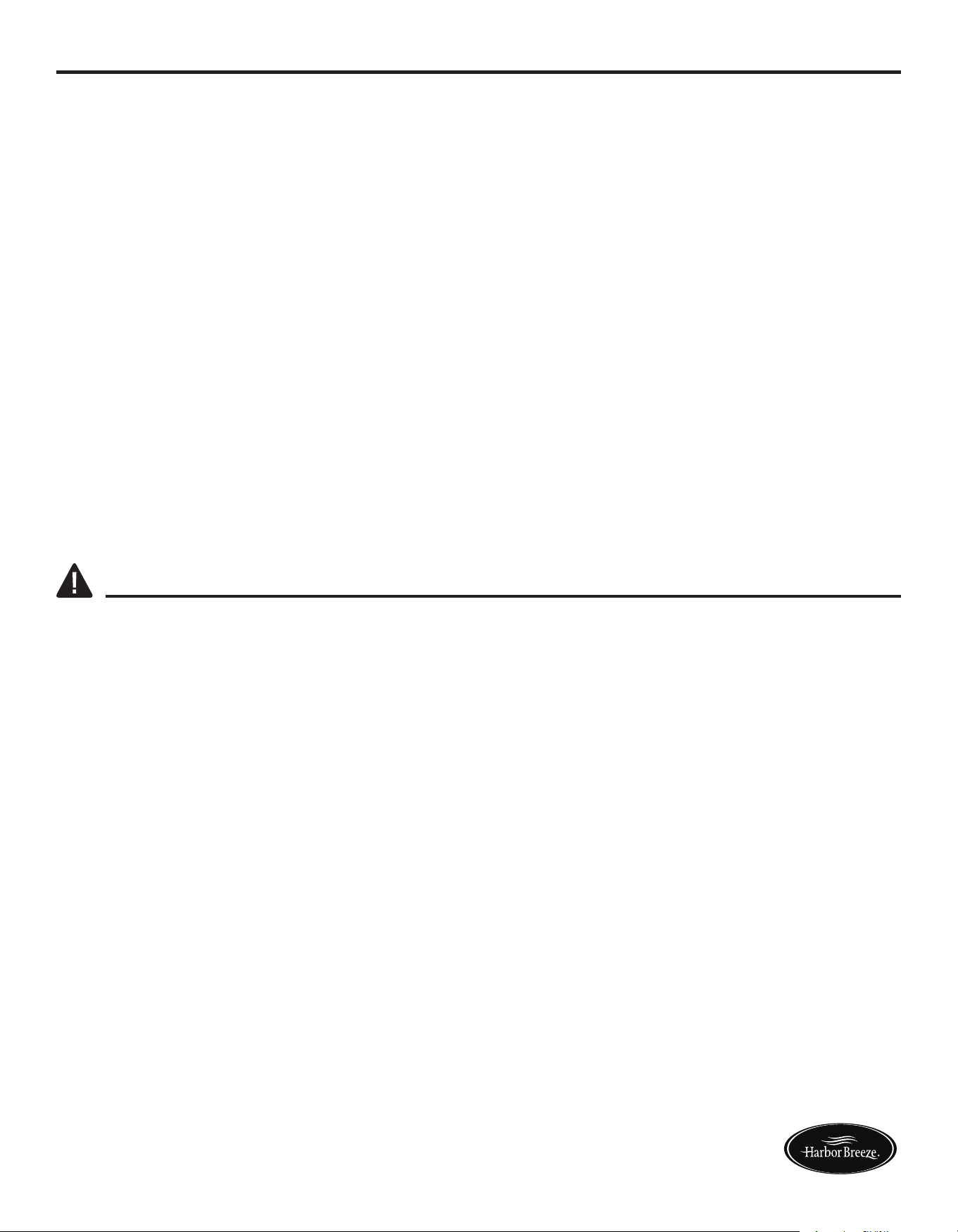
ON
ON / OFF switch NO Variable speed wall control NO Dimmer switch
• FIRE,ELECTRICSHOCKORPERSONALINJURYHAZARD-Toreducetheriskofre,
electric shock, or personal injury, mount to an outlet box marked “ACCEPTABLE FOR FAN
SUPPORT OF 35.1 lbs OR LESS” and use the mounting screws provided with the outlet box.
Mostoutletboxescommonlyusedforthesupportoflightingxturesarenotacceptableforfan
supportandmayneedtobereplaced.Consultaqualiedlicensedelectricianifindoubt.
• PERSONAL INJURY HAZARD - To reduce the risk of personal injury, do not bend the blade
brackets when installing the brackets, balancing the blades, or cleaning the fan. DO NOT insert
foreign objects in between the rotating fan blades.
Lowes.com/harborbreeze Lowes.com/harborbreeze
3
2
TABLE OF CONTENTS
Safety Information............................................................................................................... 2
Package Contents............................................................................................................... 4
Hardware Contents...............................................................................................................5
Preparation ......................................................................................................................... 5
Assembly or Installation Instructions .................................................................................. 6
Operating Instructions ........................................................................................................ 15
Care and Maintenance ....................................................................................................... 16
Troubleshooting................................................................................................................... 16
Warranty.............................................................................................................................. 17
Replacement Parts List ...................................................................................................... 17
SAFETY INFORMATION
WARNING
CAUTION
READ AND SAVE THESE INSTRUCTIONS
Please read and understand this entire manual before attempting to assemble, operate or
install the product.
• When using an existing outlet box, be sure the box is securely attached to the building structure
and can support the full weight of the fan, so to avoid potential serious injury or death.
• All wiring must be in accordance with the National Electrical Code “ANSI/NFPA 70” and local
electricalcodes.Electricalinstallationshouldbeperformedbyaqualiedlicensedelectrician.
• DONOTusebulbswithwattagegreaterthanthemaximumvaluestatedonthextureandin
thismanual.Usingahigherwattagebulbthanspeciedwillincreasexturetemperatureand
causeriskofre.
• Disconnect the electrical supply circuit to the fan before installing kit.
• Electrical diagrams are for reference only.
• The net weight of this fan including the light kit is: 22 lbs.
• ELECTRIC SHOCK HAZARD - To reduce the risk of electric shock, do not use this fan with any
solid-state speed control device.
• ELECTRIC SHOCK HAZARD - To reduce the risk of electric shock, make sure the electricity
has been turned off at the circuit breaker or fuse box before beginning installation.
• PERSONAL INJURY HAZARD - To reduce the risk of injury to persons, install fan so that the
bladesare7ft.abovetheoor.
• ELECTRIC SHOCK HAZARD - Do not install this fan with variable speed wall control or wall-
mounted dimmer switch. It will permanently damage the fan’s remote control receiver and cause
the fan’s functions to fail.
ON
ON / OFF switch NO Variable speed wall control NO Dimmer switch
• FIRE,ELECTRICSHOCKORPERSONALINJURYHAZARD-Toreducetheriskofre,
electric shock, or personal injury, mount to an outlet box marked “ACCEPTABLE FOR FAN
SUPPORT OF 35.1 lbs OR LESS” and use the mounting screws provided with the outlet box.
Mostoutletboxescommonlyusedforthesupportoflightingxturesarenotacceptableforfan
supportandmayneedtobereplaced.Consultaqualiedlicensedelectricianifindoubt.
• PERSONAL INJURY HAZARD - To reduce the risk of personal injury, do not bend the blade
brackets when installing the brackets, balancing the blades, or cleaning the fan. DO NOT insert
foreign objects in between the rotating fan blades.
Lowes.com/harborbreeze Lowes.com/harborbreeze
A 1
B 1
C 1
D 1
E 1
F 1
G 5
H 5
I 1
J 1
K 1
L 1
M 1
54
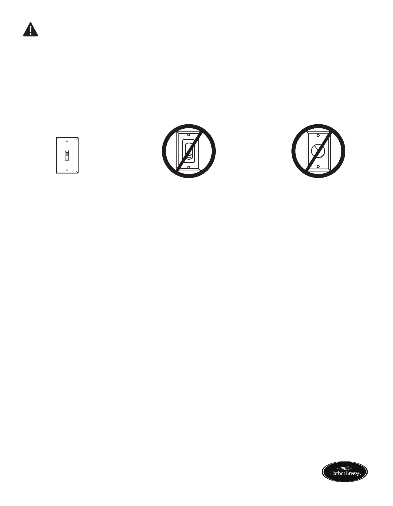
HARDWARE CONTENTS (shown actual size)
PREPARATION
Before beginning assembly of product, make sure all parts are present. Compare parts with package
contents list and hardware contents list. If any part is missing or damaged, do not attempt to
assemble the product.
Estimated Assembly Time: 45 minutes.
Tools Required for Assembly (not included): Phillips screwdriver, step ladder, electrical tape, pliers,
wire cutters, wire strippers.
Helpful Tools (not included): Electrical circuit tester.
PACKAGE CONTENTS
A
Mounting Bracket (preassembled to canopy (B))
Canopy
Canopy Cover (preassembled to canopy (B))
Yoke Cover
Downrod Assembly
Motor Assembly
Blade Bracket
Blade
Switch Box
Light Kit
Glass
Glass Cap (preassembled to light kit (J))
Finial (preassembled to light kit (J))
PART
DESCRIPTION
QUANTITY
A
B
C
D
E
F
G
K
L
M
J
H
I
Blade Bracket
Screw
Qty. 10 + 1 extra
Wire
Connector
Qty. 3 + 1 extra
AA
BB
EE
FF
Blade Screw
Qty. 15 + 1 extra
Rubber Gasket
Qty. 1
(NOT TO SCALE)
(NOT TO SCALE) (NOT TO SCALE)
CC
DD
Fan Pull Chain
Extension
Qty. 1
Light Pull Chain
Extension
Qty. 1
Lowes.com/harborbreeze Lowes.com/harborbreeze
A 1
B 1
C 1
D 1
E 1
F 1
G 5
H 5
I 1
J 1
K 1
L 1
M 1
54
HARDWARE CONTENTS (shown actual size)
PREPARATION
Before beginning assembly of product, make sure all parts are present. Compare parts with package
contents list and hardware contents list. If any part is missing or damaged, do not attempt to
assemble the product.
Estimated Assembly Time: 45 minutes.
Tools Required for Assembly (not included): Phillips screwdriver, step ladder, electrical tape, pliers,
wire cutters, wire strippers.
Helpful Tools (not included): Electrical circuit tester.
PACKAGE CONTENTS
A
Mounting Bracket (preassembled to canopy (B))
Canopy
Canopy Cover (preassembled to canopy (B))
Yoke Cover
Downrod Assembly
Motor Assembly
Blade Bracket
Blade
Switch Box
Light Kit
Glass
Glass Cap (preassembled to light kit (J))
Finial (preassembled to light kit (J))
PART
DESCRIPTION
QUANTITY
A
B
C
D
E
F
G
K
L
M
J
H
I
Blade Bracket
Screw
Qty. 10 + 1 extra
Wire
Connector
Qty. 3 + 1 extra
AA
BB
EE
FF
Blade Screw
Qty. 15 + 1 extra
Rubber Gasket
Qty. 1
(NOT TO SCALE)
(NOT TO SCALE) (NOT TO SCALE)
CC
DD
Fan Pull Chain
Extension
Qty. 1
Light Pull Chain
Extension
Qty. 1
Lowes.com/harborbreeze Lowes.com/harborbreeze

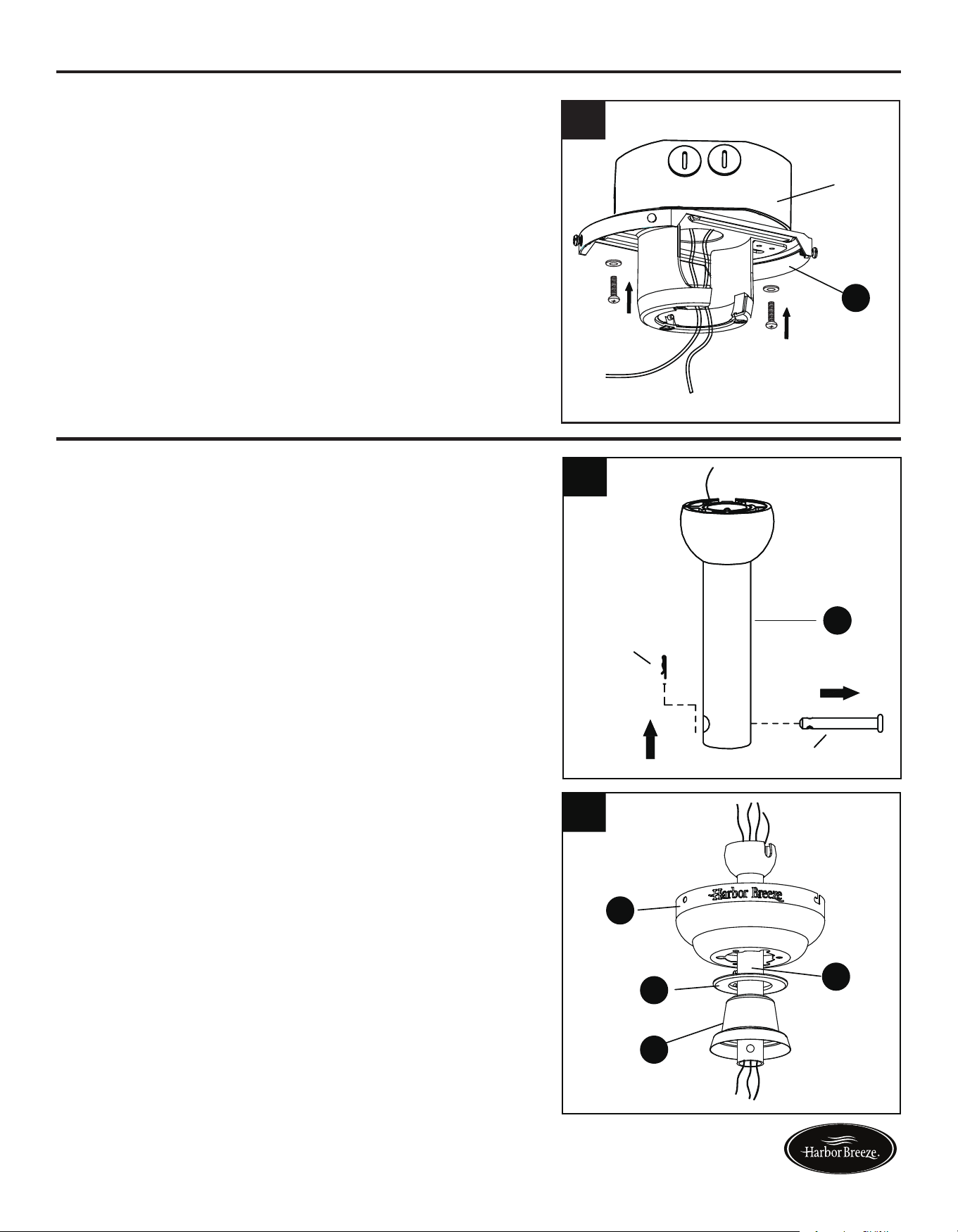
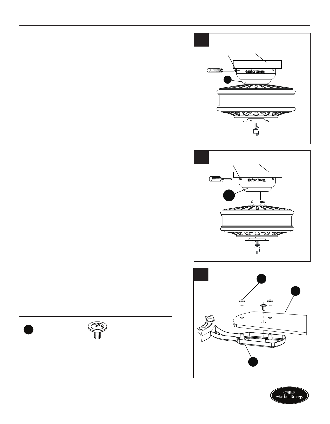
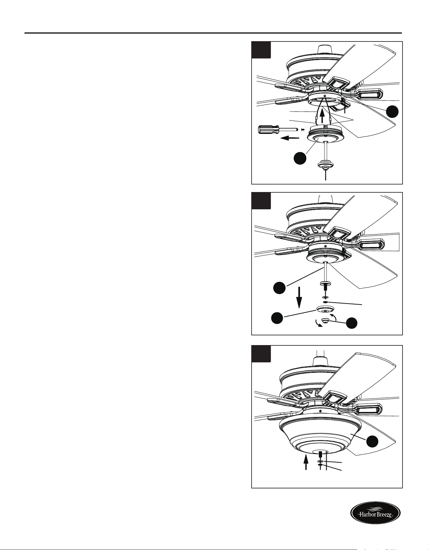
6 7
ASSEMBLY INSTRUCTIONS ASSEMBLY INSTRUCTIONS
1. Determine mounting method to use.
A - Downrod Mount (normal or angled ceiling)
B - Closemount (normal ceiling only)
Important: lf using the angle mount, check to
make sure the ceiling angle is not steeper than 20°.
4. Install the mounting bracket (A) to the outlet box
(not included) using the two screws provided
with the outlet box. Securely tighten the two
screws.
2.Removeanddiscardtheverubberinsertsand
vemountingscrewsfromtheundersideof
the motor assembly (F).
2. Insert downrod assembly (E) through canopy
(B), canopy cover (C) and yoke cover (D).
Thread wires from the motor assembly (F) up
through downrod assembly (E).
Outlet box
A
4
3. Remove the mounting bracket (A) from the canopy
(B) by loosening the four preassembled screws on
the top of the canopy (B). Remove the two non-
slotted screws and save.
1
A
B
Loosen but
do not remove
A
Remove
and save
A
B
3
If using the angle mount, make sure open end of
mounting bracket (A) is installed facing the ceiling.
Follow mounting instructions for Downrod Style
Fan Mounting on page 7 or Closemount Style
Fan Mounting on page 8, depending on mounting
method (A or B) chosen in step 1 on page 6.
DOWNROD STYLE FAN MOUNTING
1. Remove pin and clip from downrod assembly
(E) and save.
Rubber insert
and screw
F
2
E
B
C
D
E
Clip
Pin
E
1
2
Lowes.com/harborbreeze Lowes.com/harborbreeze
8 9
DOWNROD STYLE FAN MOUNTING CLOSEMOUNT STYLE FAN MOUNTING
3. Loosen the two set screws from the yoke. Slip
downrod assembly (E) into yoke, aligning holes
in downrod assembly (E) and yoke. Insert the
pin through yoke and downrod assembly (E),
then insert clip into pin until it snaps into place.
Tighten set screws. Slide the yoke cover (D)
down over the motor assembly (F).
2. Remove every other screw from the top of the
motor assembly (E) -- for a total of 3 screws --
and save.
4. Install hanger ball on the top of downrod assembly
(E) into mounting bracket (A) opening. Rotate fan
until slot on hanger ball engages the tab on the
mounting bracket (A).
3. Place the rubber gasket (FF) over the remaining
screws on motor assembly (F). Pull wires from
motor assembly (F) through hole in canopy
(B), and attach canopy (B) using the three
screws previously removed. Tighten the screws
securely.
1. Remove the canopy cover (C) from the bottom
of the canopy (B).
4. Temporarily hang the canopy (B) onto the hook
on the mounting bracket (A) using one of the
non-slotted holes in the canopy (B). This will
allow for hands-free wiring.
H
F
2
1
DANGER: Be careful when aligning the tab
to the slot! If not fully engaged, there is a
possibility of fan falling, which may result in
serious injury or death.
Proceed to WIRING on page 10.
CLOSEMOUNT STYLE FAN MOUNTING
H
Hardware Used
FF Rubber Gasket
x 1
H
B
FF
4
Tab
Slot
A
E
3
H
B
FF
3
4
Clip
Pin
Set screw
E
D
F
Yoke
C
B
B
F
FF
A
B
Hook
Lowes.com/harborbreeze Lowes.com/harborbreeze
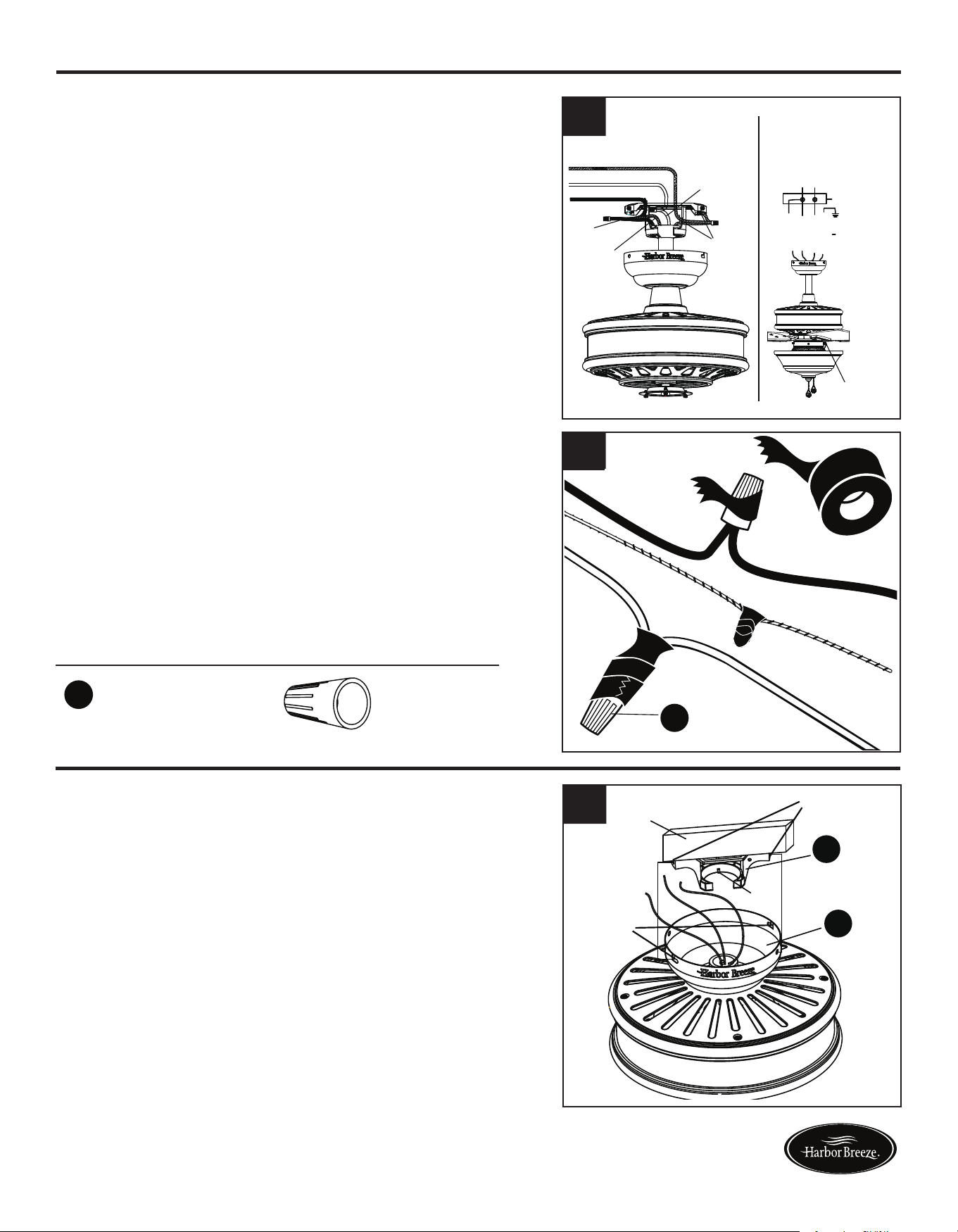
10
WIRING
Hardware Used
1. Connect the GREEN/GROUND wire from fan
to the BARE/GREEN supply wire. Connect the
BLACK/BLUE wire from the fan to the supply
BLACK wire. Connect the WHITE wire from fan to
the supply WHITE wire.
2. To connect wires, twist wire ends together and
screw wire with wire connectors (AA) in a clockwise
direction. Tape the wire connectors (AA) and wires
together with electrical tape (not included). Be sure
no bare wire or wire strands are visible after making
connection.
Place GREEN and WHITE connections on opposite
side of box from the BLACK and BLUE connections.
The splices should be turned upward and pushed
carefully up into the outlet box.
1
2
x 3
Wire Connector
AA
FINAL INSTALLATION
You may now proceed to Step 4.
3. Directly align the locking slots of the canopy (B) with
the two screws previously loosened (step 3, page 6)
in the mounting bracket (A). Push up to engage the
slots and turn clockwise to lock in place. Immediately
tightenthetwoscrewsrmly,thenre-installthetwo
screws that were previously removed (step 3, page 6)
to fully secure the canopy (B) to the mounting bracket
(A).
4. Attach blade (H) to a blade bracket (G) using three
blade screws (BB).
Repeat for remaining blade assemblies.
11
2. Re-install the two screws that were previously removed
(step 3, page 6) to fully secure the canopy (B) to the
mounting bracket (A).
AA
FINAL INSTALLATION
If you installed the fan with “Closemount Style Fan
Mounting”, continue to Steps 1 and 2. If you installed
the fan with “Downrod Style Fan Mounting”, skip to
Step 3.
1. Remove the fan from the hook on the mounting
bracket (A). Align the locking slots of the canopy
(B) with the two screws previously loosened (step
3, page 6) in the mounting bracket (A). Push up to
engage the slots and turn clockwise to lock in place.
Immediatelytightenthetwoscrewsrmly.
BB
Blade Screw x 15
Hardware Used
H
G
BB
4
1
2
3
Grounded/Green
Black
White
Grounded/
Green
Black
Blue
White
Supply circuit
Speed switch
Outlet box
Blue
Black
White
Green
White
GREEN/
GROUNDED
Black
Locking
slots
Outlet
box
Screws
Hook
B
A
Outlet box
Screw
B
Outlet box
Screw
B
NOTE: BLACK wire is hot power for fan. BLUE wire
is hot power for light kit. WHITE wire is common for
fan and light kit. GREEN wire is ground wire.
WARNING: If house wires are different colors than
referred to above, stop immediately. Consult a
licensed electrician to determine proper wiring.
Lowes.com/harborbreeze Lowes.com/harborbreeze
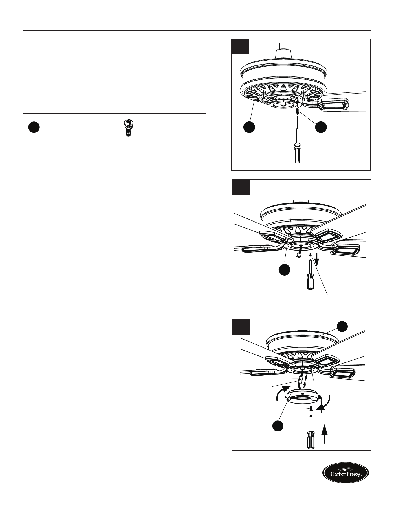
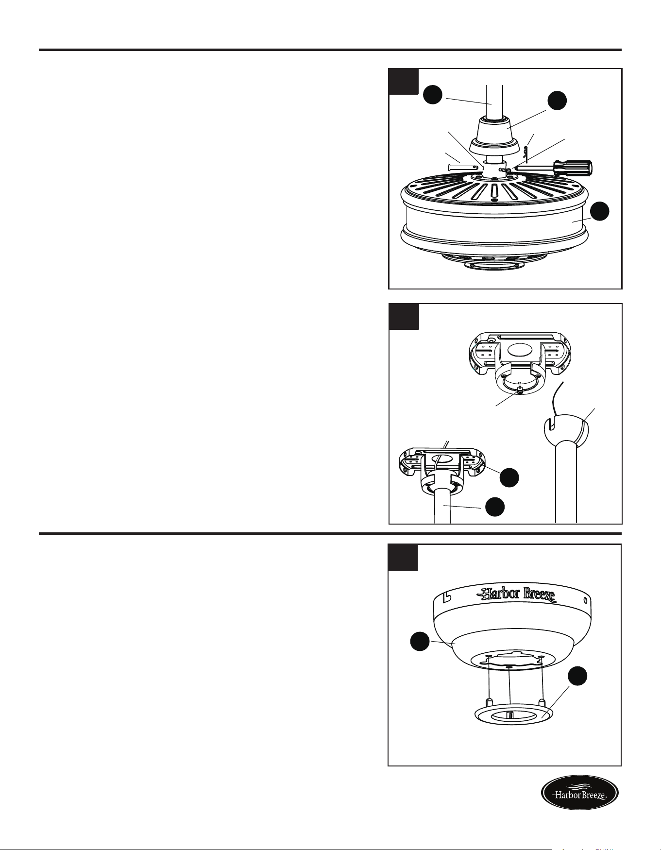
12 13
FINAL INSTALLATION
5. Align the post of blade bracket (G) to the slot on the
bottom of the motor housing assembly (F). Secure each
blade bracket (G) using 2 blade bracket screws (EE).
Repeat this step for the remaining blade assemblies.
8. Remove and save three preassembled screws from
light kit (J). Connect the BLUE wire from motor
assembly (F) to BLACK wire from light kit (J).
Connect WHITE wire from motor assembly (F) to
WHITE wire from light kit (J).
Attach the light kit (J) to the switch box (I) on bottom
of motor assembly (F). Replace the previously
removed screws and securely tighten all screws.
9. Removethepreassemblednial(M),glasscap(L),
rubber washer and hex nut from light kit (J).
10. Place glass (K) on the preassembled pipe on the
lightkit(J)untilitisushwiththepreassembled
metal disk. Thread fan pull chain through side
hole on glass (K). Make sure pull chain hangs
clear and is not tangled in light kit (J). Thread light
kit pull chain through center hole on glass (K).
Place previously removed rubber washer and hex
nut onto the pipe and securely tighten.
FINAL INSTALLATION
7. Connect the MALE plug from motor assembly (F)
to the FEMALE plug from switch box (I). Attach the
switch box (I) to the bottom of the motor assembly
(F) by aligning the keyholes on the switch box (I) with
the loosened screws on the support plate of motor
assembly (F). Twist switch box (I) until the loosened
screws engage the narrow end of the keyholes, then
replace previously removed screw and securely
tighten all screws.
6. Loosen two of the three preassembled screws from
the support plate of motor assembly (F). Remove
and save remaining preassembled screw.
EE
Blade Bracket Screw
x 10
Hardware Used
H
B
FF
5
H
B
FF
6
7
8
9
10
EE F
Screw
F
Black
Blue
White
J
I
Rubber washer
Hex nut
M
L
J
Rubber washer
Hex nut
K
Keyhole
Male plug
Female plug
Screw
I
F
Lowes.com/harborbreeze Lowes.com/harborbreeze
14
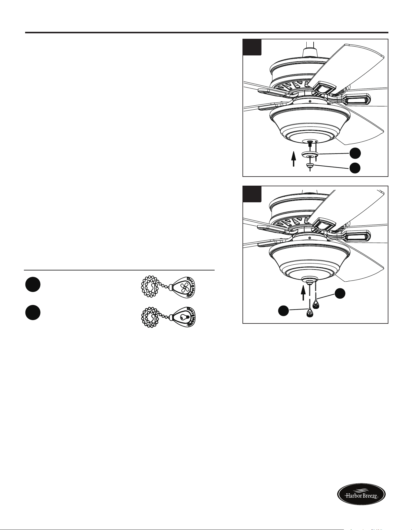
15
Hardware Used
11. Pass fan pull chain through side hole on glass cap (L),
thenplaceglasscap(L)andnial(M)overpipeand
securely tighten.
12. Attach fan pull chain extension (CC) and light kit pull
chain extension (DD) to corresponding chains.
Assembly is now complete.
FINAL INSTALLATION
Light pull chain extensions
x
CC
DD
1
x
1
Fan pull chain extensions
H
B
FF
11
H
B
FF
12
L
M
CC
DD
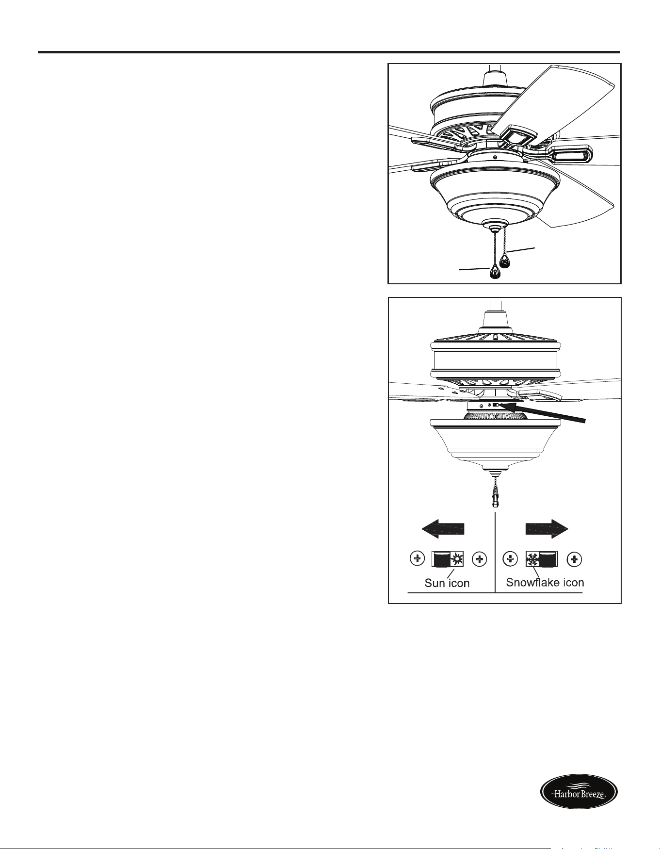
1. PULL CHAIN:
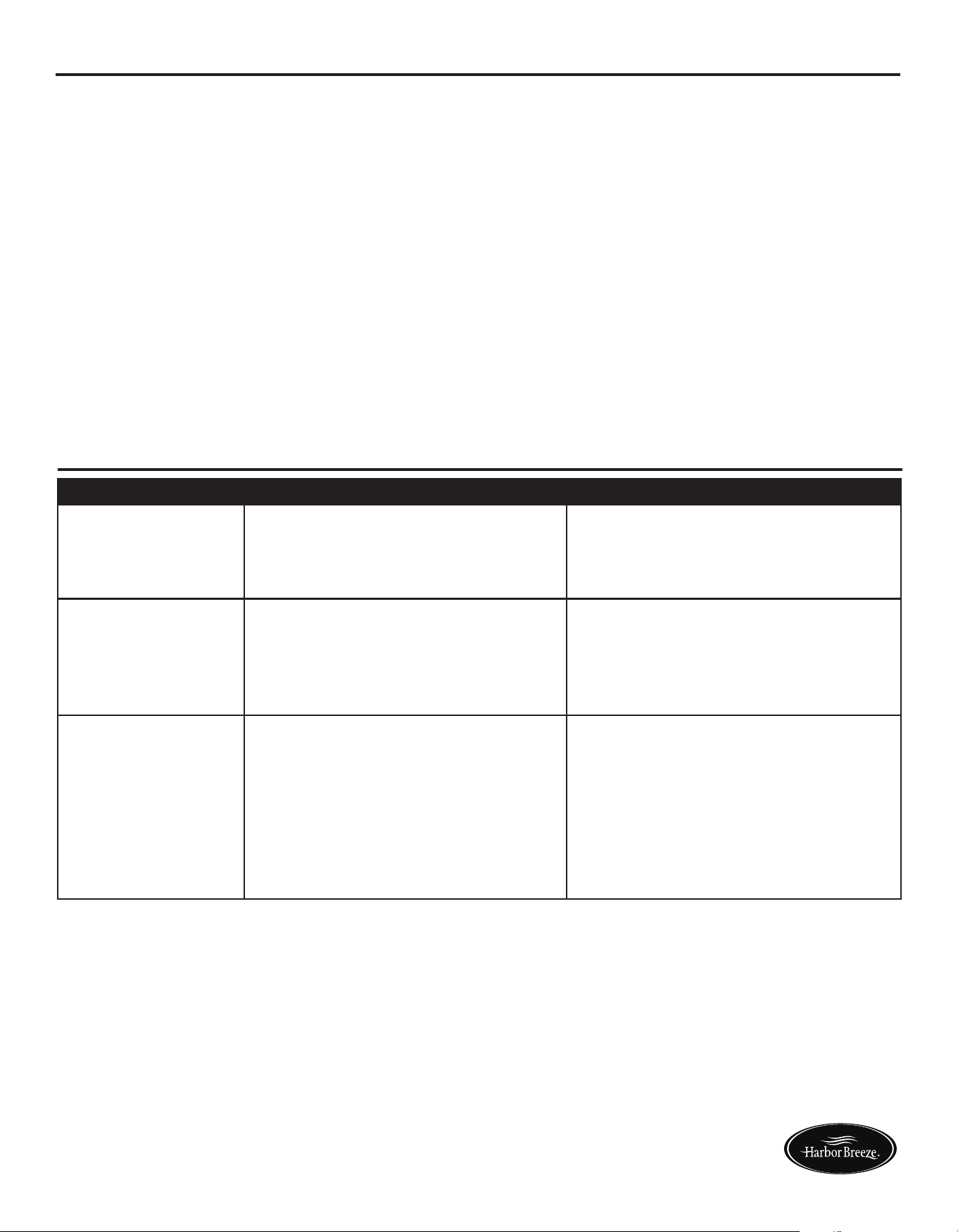
2. REVERSE SWITCH:
When the season changes, you may want to change
the direction your fan spins. To switch between
clockwiseandcounterclockwiserotations,ipthefan
reversal switch.
WARNING: Wait for fan to stop before reversing the
switch.
A. In cooler weather, clockwise rotation creates an
upwardairow,whichmoveshotairfromthe
ceiling into the room. Push the switch RIGHT.
B. In warmer weather, counterclockwise rotation
createsadownwardairow,whichcoolstheair.
Push the switch LEFT.
• The fan pull chain is for motor speed control:
High, Medium, Low and Off. Pull chain once for
each position.
• Thelightpullchaincontrolsthelightxtureeither
ON or OFF with each pull of the chain.
OPERATING INSTRUCTIONS
Fan pull chain
Light pull
chain
Lowes.com/harborbreeze Lowes.com/harborbreeze
14
15
Hardware Used
11. Pass fan pull chain through side hole on glass cap (L),
thenplaceglasscap(L)andnial(M)overpipeand
securely tighten.
12. Attach fan pull chain extension (CC) and light kit pull
chain extension (DD) to corresponding chains.
Assembly is now complete.
FINAL INSTALLATION
Light pull chain extensions
x
CC
DD
1
x
1
Fan pull chain extensions
H
B
FF
11
H
B
FF
12
L
M
CC
DD
1. PULL CHAIN:
2. REVERSE SWITCH:
When the season changes, you may want to change
the direction your fan spins. To switch between
clockwiseandcounterclockwiserotations,ipthefan
reversal switch.
WARNING: Wait for fan to stop before reversing the
switch.
A. In cooler weather, clockwise rotation creates an
upwardairow,whichmoveshotairfromthe
ceiling into the room. Push the switch RIGHT.
B. In warmer weather, counterclockwise rotation
createsadownwardairow,whichcoolstheair.
Push the switch LEFT.
• The fan pull chain is for motor speed control:
High, Medium, Low and Off. Pull chain once for
each position.
• Thelightpullchaincontrolsthelightxtureeither
ON or OFF with each pull of the chain.
OPERATING INSTRUCTIONS
Fan pull chain
Light pull
chain
Lowes.com/harborbreeze Lowes.com/harborbreeze
PROBLEM POSSIBLE CAUSE CORRECTIVE ACTION
Fan does not move. 1. Chain switch is “off”.
2. Faulty wire connection.
3. Reverse switch not engaged.
1. Pull chain switch.
2. Turn power off. Loosen canopy,
check all connections.
3. Pushswitchrmlyeitherway.
Noisy operation. 1. Blades are loose.
2. Cracked blade.
3. Unapproved speed control.
1. Tighten all blade screws.
2. Replace blades (call customer
service).
3. Replace with an approved speed
control device.
Excessive wobbling. 1. The blades are loose.
2. Blade brackets incorrectly
attached.
3. Unbalanced blades.
4. The fan is not securely mounted.
5. Fan too close to vaulted ceiling.
1. Tighten all blade screws.
2. Reinstall blade brackets.
3. Switch with blade from the
opposite side.
4. Turn power off. Carefully loosen
the canopy and remount securely.
5. Lower fan or move it to another
location.
TROUBLESHOOTING
CARE AND MAINTENANCE
IMPORTANT: Shut off main power supply before beginning any maintenance.
• Do not use water or detergents when cleaning the fan or fan blades. A dry dust cloth or lightly
dampened cloth will be suitable for most cleaning.
• Cleanfanhousingwithonlyasoftbrushorlint-freeclothtoavoidscratchingthenish.Clean
blades with a lint-free cloth. You may occasionally apply a light coat of furniture polish to blades
for added protection.
• At least twice a year, tighten all screws and lower canopy to check mounting bracket screws and
downrod assembly.
• Totalxturewattage:17watts;donotattempttoreplaceLEDs.
17
16
Lowes.com/harborbreeze Lowes.com/harborbreeze
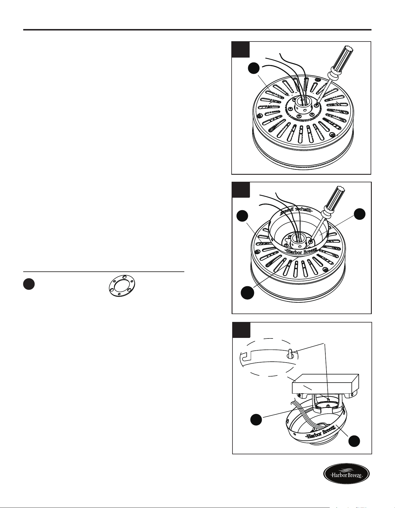
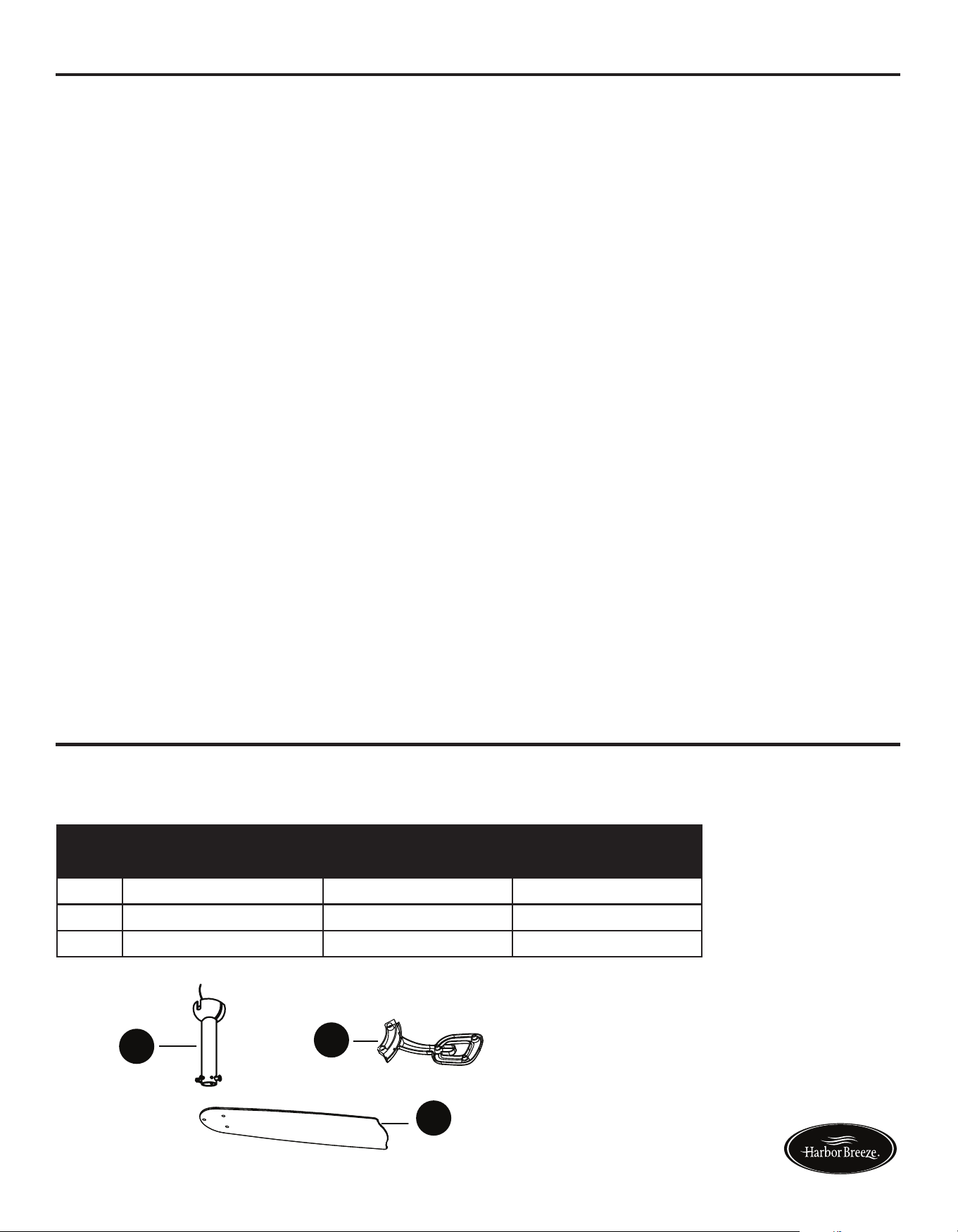
PART DESCRIPTION PART #
Item# 0698390 Item# 0698391
E Downrod Assembly 102200-0150RW 102200-0150BN
G Blade Bracket 104000-0356RW 104000-0356BN
H Blade 108002-507059 108002-5070S6
WARRANTY
REPLACEMENT PARTS LIST
The manufacturer warrants this fan to be free from defects in workmanship and material present at
time of shipment from the factory for lifetime limited from the date of purchase. This warranty applies
only to the original purchaser. The manufacturer agrees to correct such defect at no charge or at our
option replace the ceiling fan with a comparable or superior model.
To obtain warranty service, present a copy of your sales receipt as proof of purchase. All cost of
removal and reinstallation are the expressed responsibility of the purchaser. Any damage to the
ceilingfanbyaccident,misuse,orimproperinstallation,orbyafxingaccessoriesnotproducedby
the manufacturer of the fan, are at the purchaser’s own responsibility. The manufacturer assumes
no responsibility whatsoever for fan installation during the lifetime limited warranty. Any service
performed by an unauthorized person will render the warranty invalid.
Duetovaryingclimaticconditions,thiswarrantydoesnotcoverchangesinbrassnish,rusting,
pitting,tarnishing,corroding,orpeeling.Brassnishfansmaintaintheirbeautywhenprotectedfrom
varying weather conditions. Any glass provided with this fan is not covered by this warranty. Any
replacementofdefectivepartsfortheceilingfanmustbereportedwithintherstyearfromthedate
of purchase. For the balance of the warranty, call our customer service department at 1-866-473-4537
for return authorization and shipping instructions so that we may repair or replace the ceiling fan.
Any fan or parts returned improperly packaged is the sole responsibility of the purchaser. There is no
further expressed warranty. The manufacturer disclaims any and all implied warranties.
The duration of any implied warranty which can not be disclaimed is limited to the lifetime limited
periodasspeciedinourwarranty.Themanufacturershallnotbeliableforincidental,consequential
or special damages arising at or in connection with product use or performance except as may
otherwisebeaccordedbylaw.Thiswarrantygivesyouspeciclegalrightsanyoualsohaveother
rights which may vary from state to state. This warranty supersedes all prior warranties.
Note: A small amount of “wobble” is normal and should not be considered a defect.
Printed in China
For replacement parts, call our customer service department at 1-866-473-4537,
8 a.m. - 7 p.m., EST, Monday - Friday, 9 a.m. - 6 p.m., EST, Saturday.
G
A
H
E
Harbor Breeze ® is a registered
trademark of LF, LLC. All Rights
Reserved.
PROBLEM POSSIBLE CAUSE CORRECTIVE ACTION
Fan does not move. 1. Chain switch is “off”.
2. Faulty wire connection.
3. Reverse switch not engaged.
1. Pull chain switch.
2. Turn power off. Loosen canopy,
check all connections.
3. Pushswitchrmlyeitherway.
Noisy operation. 1. Blades are loose.
2. Cracked blade.
3. Unapproved speed control.
1. Tighten all blade screws.
2. Replace blades (call customer
service).
3. Replace with an approved speed
control device.
Excessive wobbling. 1. The blades are loose.
2. Blade brackets incorrectly
attached.
3. Unbalanced blades.
4. The fan is not securely mounted.
5. Fan too close to vaulted ceiling.
1. Tighten all blade screws.
2. Reinstall blade brackets.
3. Switch with blade from the
opposite side.
4. Turn power off. Carefully loosen
the canopy and remount securely.
5. Lower fan or move it to another
location.
TROUBLESHOOTING
CARE AND MAINTENANCE
IMPORTANT: Shut off main power supply before beginning any maintenance.
• Do not use water or detergents when cleaning the fan or fan blades. A dry dust cloth or lightly
dampened cloth will be suitable for most cleaning.
• Cleanfanhousingwithonlyasoftbrushorlint-freeclothtoavoidscratchingthenish.Clean
blades with a lint-free cloth. You may occasionally apply a light coat of furniture polish to blades
for added protection.
• At least twice a year, tighten all screws and lower canopy to check mounting bracket screws and
downrod assembly.
• Totalxturewattage:17watts;donotattempttoreplaceLEDs.
17
16
Lowes.com/harborbreeze Lowes.com/harborbreeze
PART DESCRIPTION PART #
Item# 0698390 Item# 0698391
E Downrod Assembly 102200-0150RW 102200-0150BN
G Blade Bracket 104000-0356RW 104000-0356BN
H Blade 108002-507059 108002-5070S6
WARRANTY
REPLACEMENT PARTS LIST
The manufacturer warrants this fan to be free from defects in workmanship and material present at
time of shipment from the factory for lifetime limited from the date of purchase. This warranty applies
only to the original purchaser. The manufacturer agrees to correct such defect at no charge or at our
option replace the ceiling fan with a comparable or superior model.
To obtain warranty service, present a copy of your sales receipt as proof of purchase. All cost of
removal and reinstallation are the expressed responsibility of the purchaser. Any damage to the
ceilingfanbyaccident,misuse,orimproperinstallation,orbyafxingaccessoriesnotproducedby
the manufacturer of the fan, are at the purchaser’s own responsibility. The manufacturer assumes
no responsibility whatsoever for fan installation during the lifetime limited warranty. Any service
performed by an unauthorized person will render the warranty invalid.
Duetovaryingclimaticconditions,thiswarrantydoesnotcoverchangesinbrassnish,rusting,
pitting,tarnishing,corroding,orpeeling.Brassnishfansmaintaintheirbeautywhenprotectedfrom
varying weather conditions. Any glass provided with this fan is not covered by this warranty. Any
replacementofdefectivepartsfortheceilingfanmustbereportedwithintherstyearfromthedate
of purchase. For the balance of the warranty, call our customer service department at 1-866-473-4537
for return authorization and shipping instructions so that we may repair or replace the ceiling fan.
Any fan or parts returned improperly packaged is the sole responsibility of the purchaser. There is no
further expressed warranty. The manufacturer disclaims any and all implied warranties.
The duration of any implied warranty which can not be disclaimed is limited to the lifetime limited
periodasspeciedinourwarranty.Themanufacturershallnotbeliableforincidental,consequential
or special damages arising at or in connection with product use or performance except as may
otherwisebeaccordedbylaw.Thiswarrantygivesyouspeciclegalrightsanyoualsohaveother
rights which may vary from state to state. This warranty supersedes all prior warranties.
Note: A small amount of “wobble” is normal and should not be considered a defect.
Printed in China
For replacement parts, call our customer service department at 1-866-473-4537,
8 a.m. - 7 p.m., EST, Monday - Friday, 9 a.m. - 6 p.m., EST, Saturday.
G
A
H
E
Harbor Breeze ® is a registered
trademark of LF, LLC. All Rights
Reserved.

1
Español p. 18
EASY BREEZE CEILING FAN
ITEM #0698390, 0698391
MODEL #00887, 00888
Serial Number
Purchase Date
Harbor Breeze ® is a registered trademark of LF,
LLC. All Rights Reserved.
Questions, problems, missing parts? Before returning to your retailer, call our customer
service department at 1-866-473-4537, 8 a.m. - 7 p.m., EST, Monday - Friday,
9 a.m. - 6 p.m., EST, Saturday.
EB165
ATTACH YOUR RECEIPT HERE
UL MODEL #EBZ54
Lowes.com/harborbreeze Lowes.com/harborbreeze