
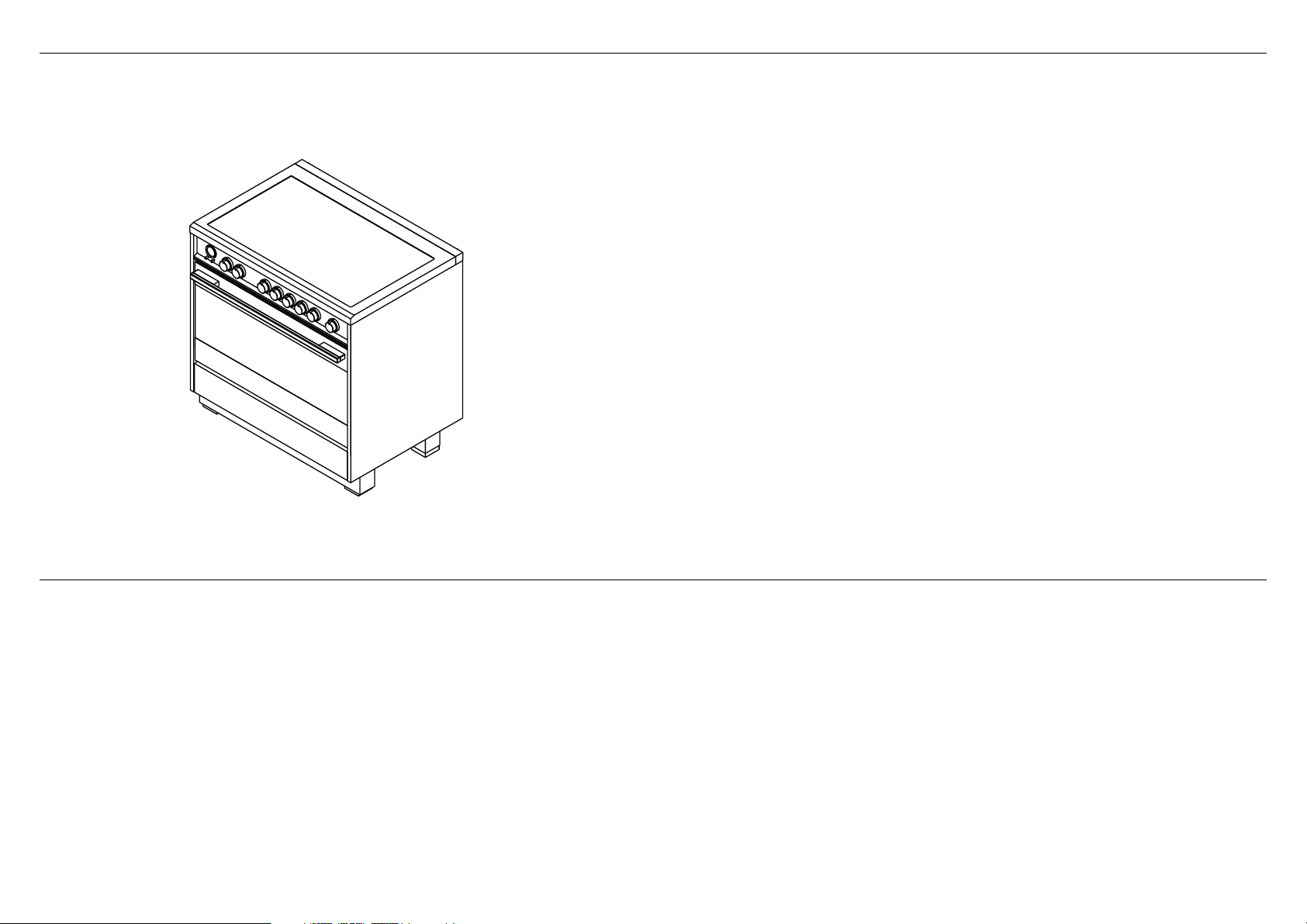
OR90 Induction models
FREESTANDING COOKER
INSTALLATION GUIDE
NZ AU

3
1SAFETY AND WARNINGS
IMPORTANT!
SAVE THESE INSTRUCTIONS
The models shown in this installation guide may not be available in all markets and are subject to change at any time. For current details about model and specification availability in your country,
please go to our website fisherpaykel.com or contact your local Fisher & Paykel dealer.
IMPORTANT SAFETY INSTRUCTIONS!
●
To avoid hazard, follow these instructions carefully before installing or using this
appliance.
●
Please make this information available to the person installing the appliance - doing so
could reduce your installation costs.
●
This appliance must be installed and connected to the mains power supply only by a
suitably qualified person according to these installation instructions and in compliance
with any applicable local building and electricity regulations. Failure to install the
appliance correctly could invalidate any warranty or liability claims.
●
If the power supply cable is damaged, it must be replaced by the manufacturer, its
service agent or similarly qualified person in order to avoid a hazard.
●
Isolating switch: make sure this cooker is connected to a circuit which incorporates an
isolating switch providing full disconnection from the power supply in accordance with
the wiring rules.
●
The cooker must be earthed.
●
Do not use adaptors, reducers or branching devices to connect the cooker to the mains
electricity supply, as they can cause overheating and burning.
●
Check for damaged after unpacking and that the cooker door closes correctly.
●
Some appliances are supplied with a protective film on steel and aluminium parts. This
film must be removed before using the appliance.
●
Packing elements (i.e. plastic bags, polystyrene foam, nails, packing straps, etc.) should
not be left around within easy reach of children, as these may cause serious injuries.
●
Make sure you recycle the packaging material where possible.
●
The manufacturer accepts no responsibility for the incorrect installation of appliances.
Incorrect installation may result in personal injury, damage to property and may
invalidate any warranty or liability claims.
●
Do not modify this appliance.
●
Before disposing of any appliance, make sure that it can no longer be used and that all
hazardous parts are removed or made harmless, so that children playing with the old
appliance cannot harm themselves.
●
The various components of the appliance are recyclable. Dispose of them in accordance
with the regulations in force in your country. If the appliance is to be scrapped, remove
the power cord.
WARNING!
Cut Hazard
Take care – some edges are sharp.
Failure to use caution could result in injury or cuts.
WARNING!
Electrical shock hazard
Before carrying out any work on the electrical section of the appliance, it
must be disconnected from the mains electricity supply.
Connection to a good ground wiring system is absolutely essential
and mandatory.
Alterations to the domestic wiring system must only be made by a qualified
electrician
Failure to follow this advice may result in electrical shock or death.
WARNING!
To reduce the risk of tipping the appliance, the appliance must
be secured by properly installed anti-tip device packed with
the appliance.
●
A child or adult can tip the cooker and be killed.
●
Install the anti-tip device to the structure by fastening the
supplied bracket to the floor and wall following the instructions
for installing the anti-tip device.
●
Engage the anti-tip device.
●
Re-engage the anti-tip device if the cooker is moved.
Failure to do so can result in death or serious burns to children
or adults.
GENERAL INSTALLATION INFORMATION
Cleaning and servicing
●
Service should only be performed by an authorised technician.
●
Always disconnect the appliance from mains power supply before carrying out any
maintenance operations or repairs.
●
When removing appliance for cleaning and/or service:
●
Disconnect power supply.
●
Carefully remove the cooker by pulling outward.
●
The misuse of oven door (eg stepping, sitting, or leaning on them) can result in potential
hazards and/or injuries.
●
When installing or removing the cooker for service, a rolling lift jack should be used.
Do not push against any of the edges of the cooker in an attempt to slide it into or out
of the installation. Pushing or pulling a cooker (rather than using a lift jack) also increases
the possibility of bending the leg spindles or the internal coupling connectors.
IMPORTANT!
●
Cooker is heavy; use care in handling.
●
Do not lift the cooker by the oven door handle or hob rail, or by lifting the cooktop trim
as this may damage the appliance.
Replacement parts
Only authorised replacement parts may be used in performing service on the cooker.
Replacement parts are available from factory authorised parts distributors.
Contact the nearest parts distributor in your area.
4
IMPORTANT!
THIS APPLIANCE MUST BE INSTALLED BY A QUALIFIED INSTALLER.
●
Improper installation, adjustment, alteration, services, or maintenance can cause injury or property damage.
Consult a qualified installer or the service agent.
●
The use of suitable protective clothing/gloves is recommended when handling or installing this appliance.
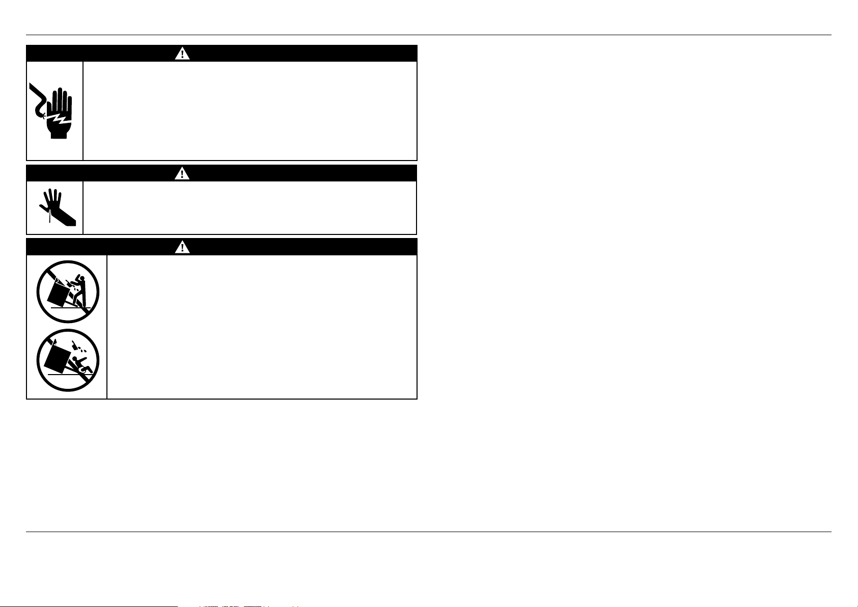
2PARTS SUPPLIED FOR INSTALLATION
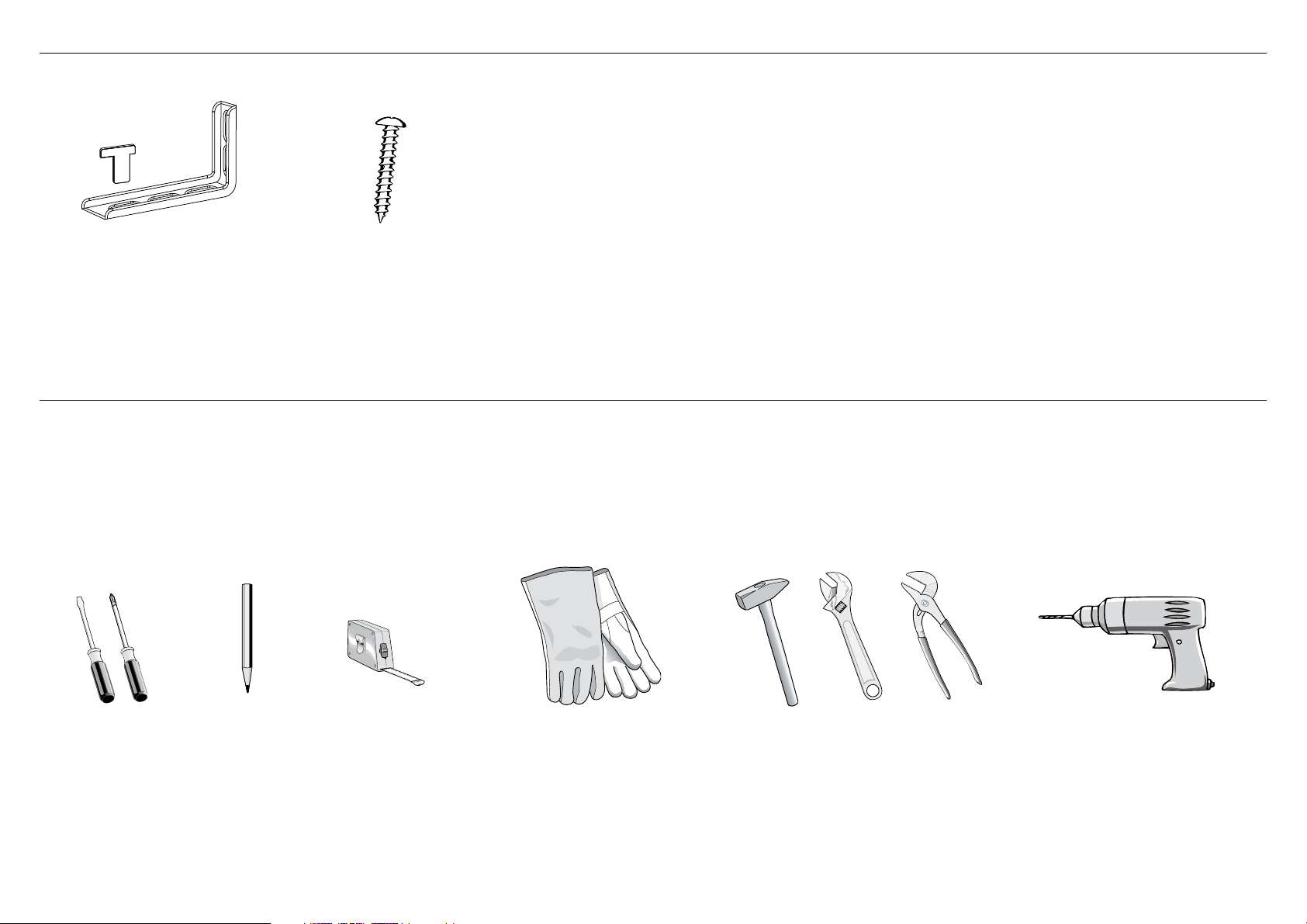
3TOOLS NEEDED FOR INSTALLATION (NOT SUPPLIED WITH THE APPLIANCE)
Screwdriver Pencil Tape measure Suitable
protective gloves
Hammer Adjustable
wrench
Adjustable
pliers
Drill
Screws and plastic
sleeve anchors (2)
Anti-tip bracket
and lock pin (1)
5
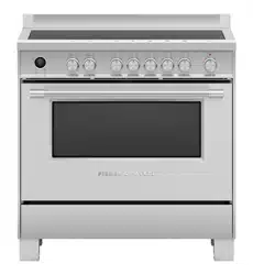
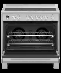
4MODEL IDENTIFICATION
OR90SCI1
OR90SCI4
OR90SCI6
OR90SDI6
NOTE: Model features may vary
OR90 INDUCTION MODELS
5PRIOR TO INSTALLATION
Unpacking and handling
●
Inspect the cooker to verify that there is no shipping damage. If any damage is detected, call the shipper and initiate a damage claim. Fisher & Paykel is not responsible for shipping damage.
●
DO NOT discard any packing material until the cooker has been inspected.
●
Remove the outer carton and any packing material from cooker. Some models are supplied with a protective film on steel and aluminum parts.
This film must be removed before installing or using the appliance.
6
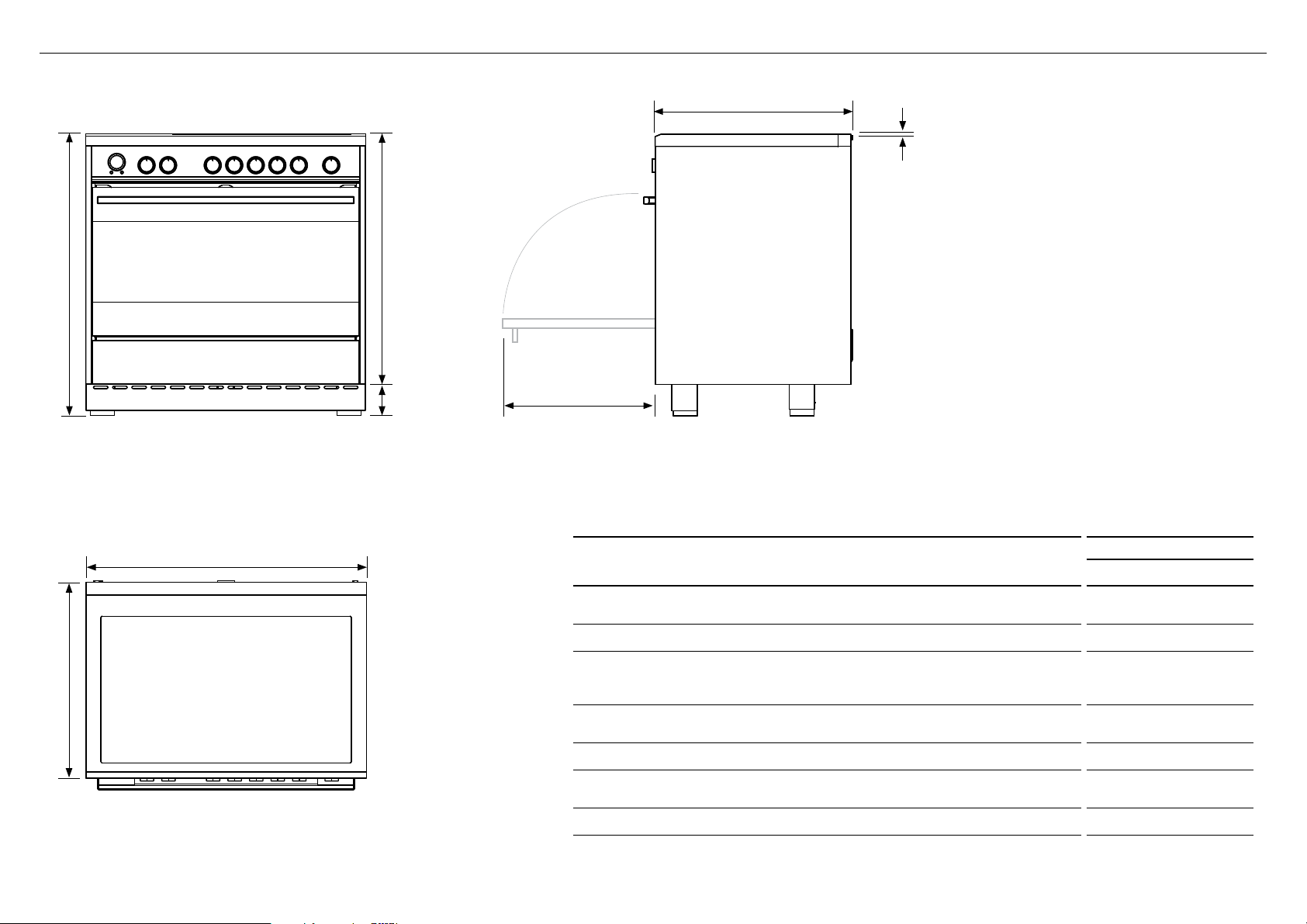
6PRODUCT DIMENSIONS
FRONT
TOP
SIDE
E
B
C
C
A
D
F
G
PRODUCT DIMENSIONS
OR90SCI MODELS
mm
A
Overall height of cooker
(from floor to top of cooktop, excluding optional backguard)
min 898
max 946
B
Overall width of cooker
897
C
Overall depth of cooker
(from front of cooker to rear of island trim/backguard,
excluding handles and dials)
600
D
Height of optional backguard from top of cooktop
(supplied with some models only)
60
E
Height of chassis (excluding adjustable feet)
813
F
Adjustable feet height
min 85
max 133
G
Depth of open door to front of cooker
451
NOTE: Model features may vary
Optional kickstrip available (purchased separately)
7
F
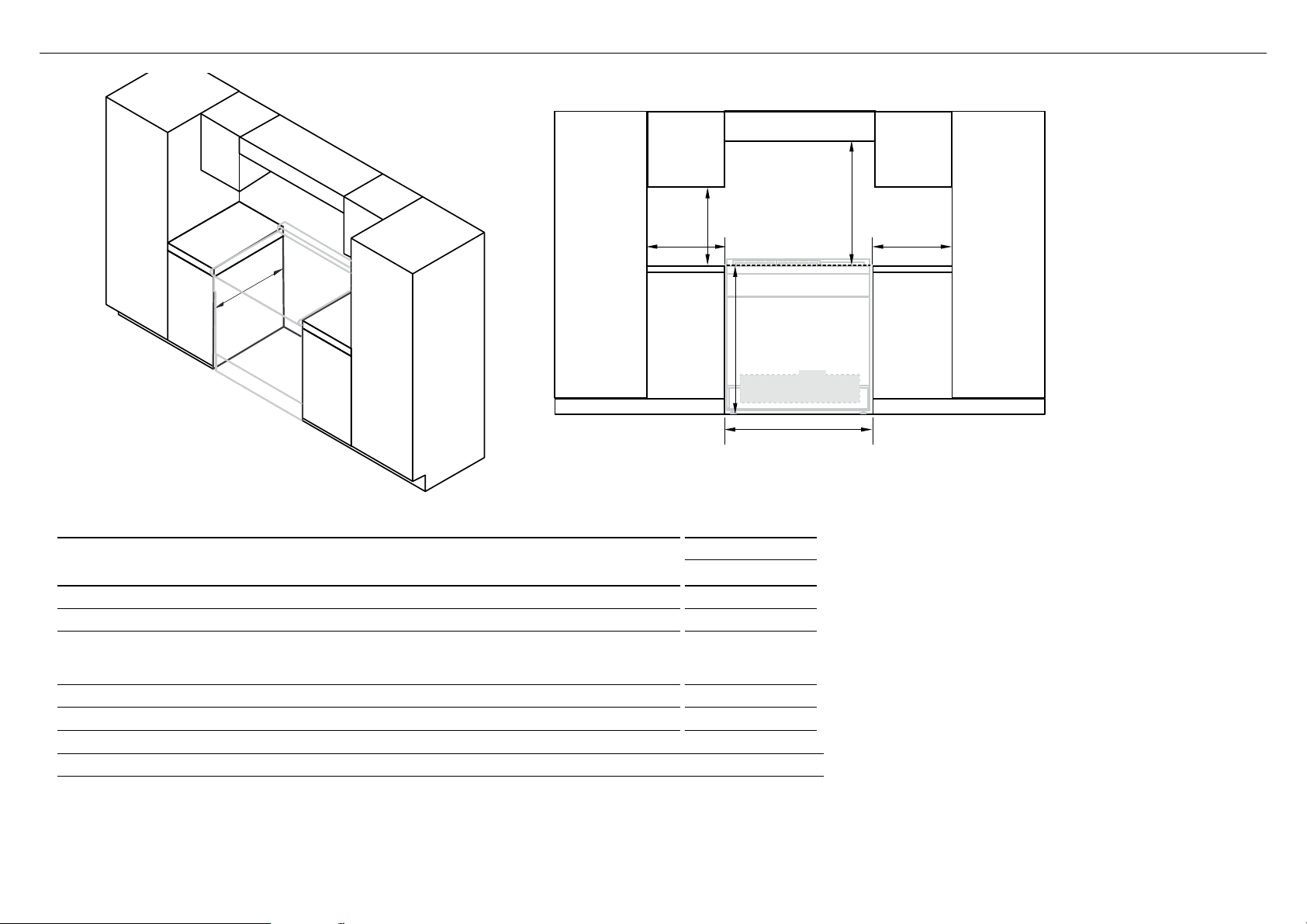
7CLEARANCE DIMENSIONS
D
C
A
BB
E
Electrical
(see diagrams following)
COOKING SURFACE
Note
●
The cabinetry surrounding the cooker
must be heat resistant and capable
of withstanding temperatures of 75°C
above room temperature.
●
Do not install the cooker near flammable
materials such as curtains.
●
Installing the cooker on a plinth: the
cooker can be installed on a plinth
without the adjustable feet fitted.
●
Ensure the cooker is secure and provide
safety measures to keep it in place.
●
Cabinetry dimensions can be adjusted
to suit the plinth height, see product
dimensions for chassis height.
●
The cooker must sit flush or above
benchtop level.
ISO
FRONT
CLEARANCE DIMENSIONS
OR90SCI MODELS
mm
A
Minimum vertical distance between benchtop and cabinet extending above counter 450
B
Minimum clearance from left and right edge of cooker to nearest vertical combustible surface
50
C
Minimum clearance from cooking surface to:
– Overhead cabinet centered above the cooktop
– Ventilation hood centered above the cooktop
650
650
D
Width of cabinetry opening 900
E
Maximum height of cabinetry immediately adjacent to the cooker (from floor to countertop)*
946
F
Maximum depth from wall to cabinetry face
600
* Depending on the height of the feet adjustment. The cooking surface must sit flush or above benchtop level.
8
8FITTING THE OPTIONAL BACKGUARD
Backguard (supplied with some models only)
●
Remove the screws and spacers on the rear of the cooktop.
●
Assemble the backguard as shown and fix onto the back of the cooker using the
same screws and spacers.
●
Fix the backguard onto the cooker using the screws provided.
C
B
A
9LOCATION OF ELECTRICAL SUPPLY
Final position of cooker against wall
Left side
of cavity
Floor
Electricity
B
AAC
D
SUPPLY AREA DIMENSIONS mm
A
Distance from either edge of
Cooker to supply area
19
B
Height of electrical supply area
(from floor)*
210 - 260
C
Width of electrical supply areas 859
D
Depth of supply area (ie
maximum protrusion of electrical
connection from wall)
74
* Depending on adjustment of feet
9
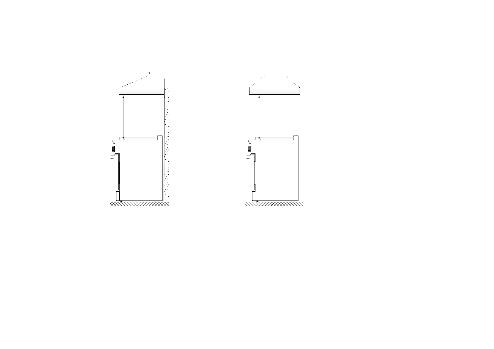
!0VENTILATION REQUIREMENTS
A suitable ventilation hood may be installed above the cooker.
Fisher & Paykel has a choice of ventilation hoods designed to match the rest of our kitchen appliance family. See fisherpaykel.com or your local dealer for more details.
IMPORTANT
●
Consult local building codes and/or local agencies, before starting, to ensure that hood and duct installation will meet local requirements.
●
Hood blower speeds should be variable to reduce noise and loss of heated or air conditioned household air when maximum ventilation is not required.
Normally, the maximum blower speed is only required when using the grill or the self-cleaning cycle.
Wall Installation
Island Installation
650mm 650mm
Hood (inc. combustible) Hood (inc. combustible)
10
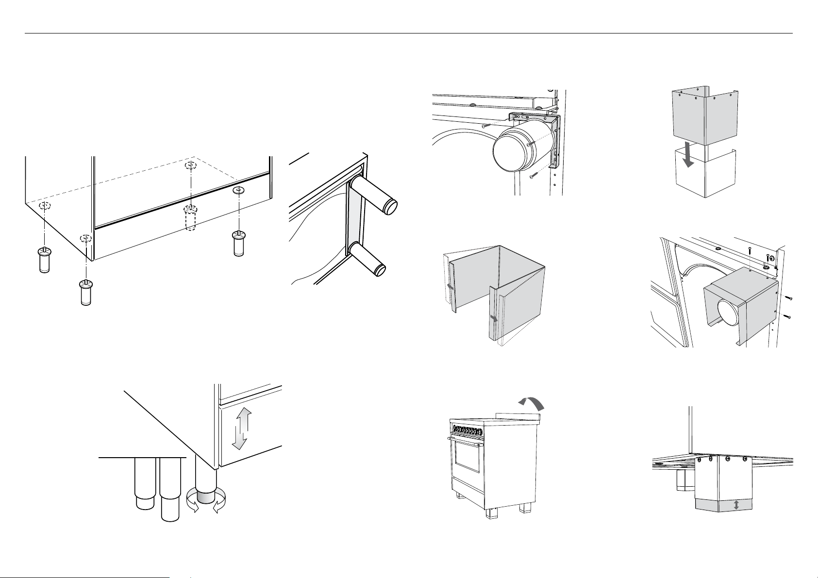
Fitting the adjustable feet
The adjustable feet must be fitted to the base of the cooker before use.
Rest the rear of the cooker on a piece of the polystyrene packaging exposing
the base for the fitting of the feet.
IMPORTANT
Take care not to damage the cooker during this operation.
Fit the four legs by screwing them tight into the support base as shown.
Levelling the cooker
●
The cooker may be levelled by screwing the lower ends of the feet IN or OUT.
●
Small adjustments may be made to the cooker in the upright position, however it
may be necessary to tip the cooker again to make larger adjustments.
Fitting the adjustable feet covers (optional)
If using the adjustable feet covers fit these while the cooker is tipped over.
!1FITTING THE ADJUSTABLE FEET
3 Note: gently bend the edges of the
inner cover to adjust the tension
between the two parts if needed.
5 Stand cooker back upright. 6 Adjust the inner panels of the foot
covers to suit height of cooker
feet.
4 Secure covers to brackets using
the provided screws
2 Assemble the feet covers by slotting
the inner cover inside the outer cover.
1 Tip cooker onto its back and fix
brackets to mounting holes.
11
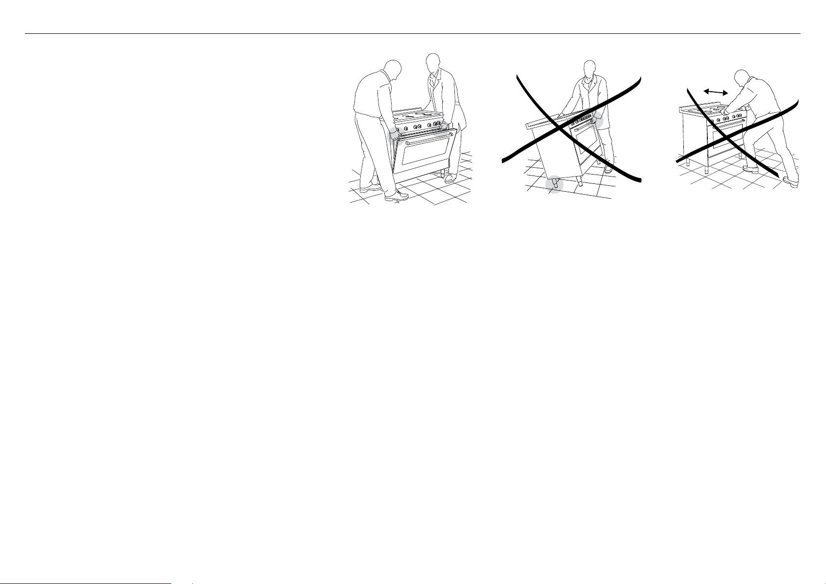
IMPORTANT!
●
When raising cooker to upright position always ensure two
people carry out this manoeuvre to prevent damage to the
adjustable feet.
●
Be careful: do not lift the cooker by the oven door handle, the
hob rail or by lifting the cooktop trim as this may damage the
appliance.
●
When moving cooker to its final position DO NOT DRAG.
Lift feet clear of floor.
!2MOVING THE COOKER
12
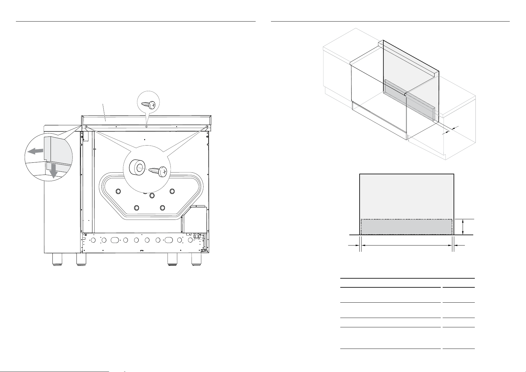
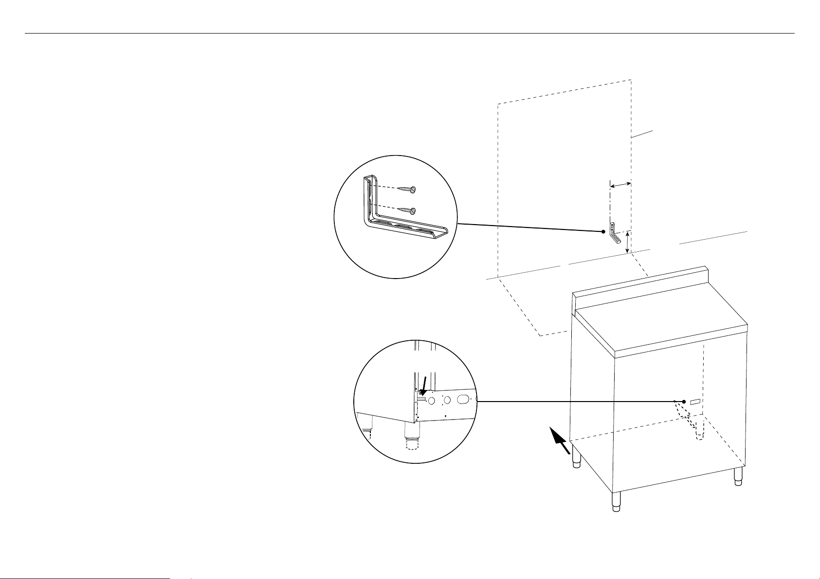
!3INSTALLING THE ANTI-TIP BRACKET
To fit the anti-tip bracket
1 Loosely fix the anti-tip bracket to the wall using the supplied screws.
●
Drill two 8mm diameter holes in the wall and insert the supplied
plastic sleeve anchors before inserting the screws.
2 Slide the cooker into place and adjust the height of the bracket so
that it will align with the slot on the back of the cooker.
3 Tighten the screws to fix the anti-tilt bracket in place.
4 Push the cooker back into place so that the bracket is fully inserted
into the slot on the back of the cooker.
Dotted line showing the position
of the cooker when installed
40mm
min. 167mm
max. 217mm
bracket slot at back
of the cooker
anti-tip bracket
IMPORTANT!
●
To restrain the cooker and prevent it tipping accidentally secure
the cooker to the wall using the supplied anti-tip bracket. Make
sure you also fit the supplied lock pin to the anti-tip bracket.
●
If installing the cooker above a plinth (without fitting the
adjustable feet) revise the installation dimensions for the anti-tip
bracket accordingly, considering that the feet have the following
measurements: min 85mm - max 133mm.
●
Before drilling and holes or inserting any screws into the floor or
wall check that you will not damage any wiring or pipes.
13
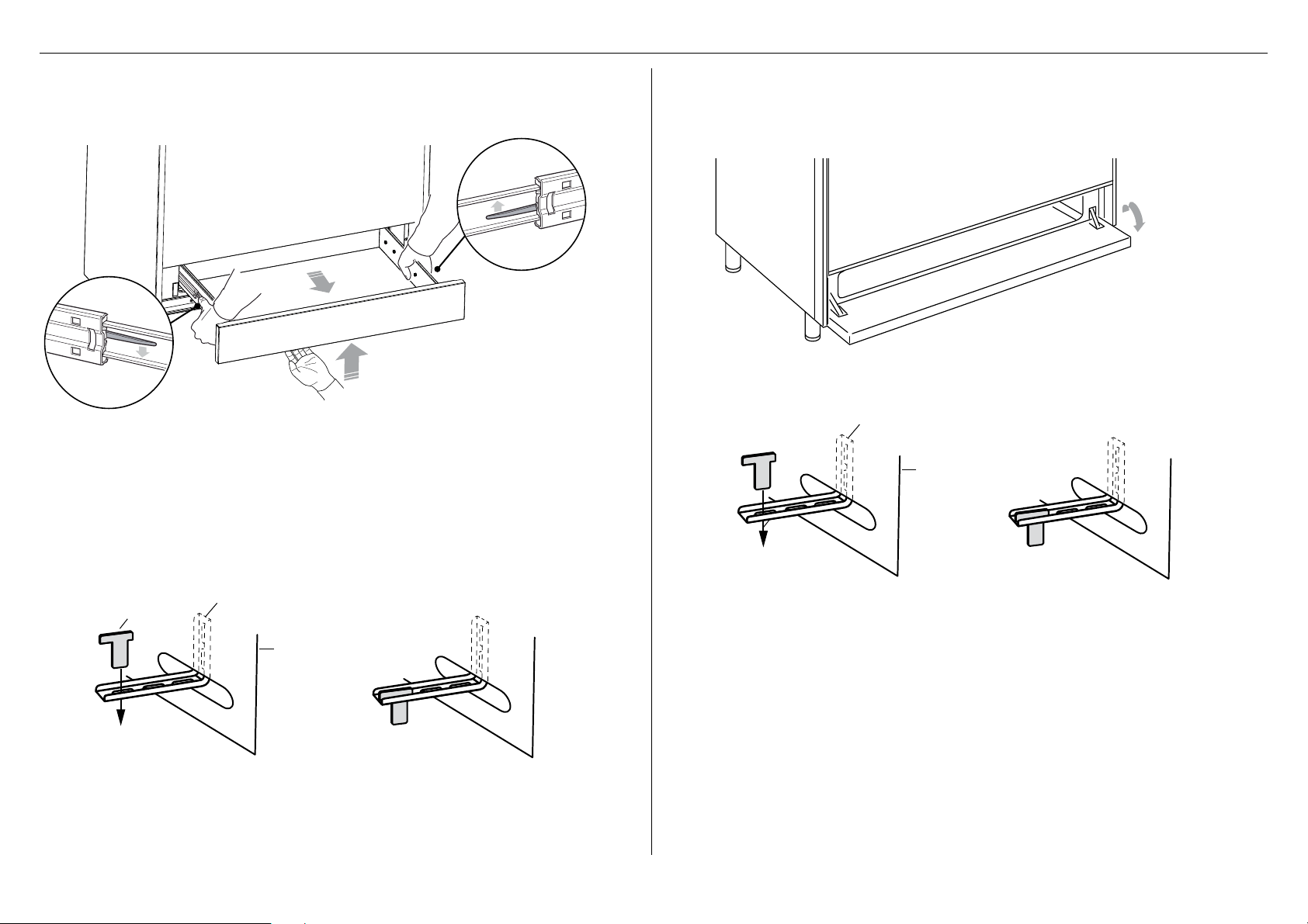
6 Fit the lock pin through the bracket as shown
7 Insert the drawer guides onto the sliding runners on either side of the cooker interior.
●
Make sure they are correctly lined up on both sides of the drawer.
8 Gently close the drawer completely. The safety catches will automatically lock into place.
2 Fit the lock pin through the bracket as shown.
3 Close the storage compartment door.
!3INSTALLING THE ANTI-TIP BRACKET
1 Open the storage compartment door.
bracket mounted
to rear wall
bracket mounted
to rear wall
lock pin
lock pin
To remove the storage/warming drawer
1 Open the storage/warming drawer completely.
2 Move down the lever of left guide A and up the lever of right guide B.
3 Remove the drawer holding the levers in the same position.
IMPORTANT
●
Do not remove storage/warming drawer while hot or during operation.
●
Be sure storage/warming drawer is empty before removing.
●
Always position your hand below the front panel to open/close the drawer.
A
B
Fitting the lock pin (models with a storage/warming drawer)
The anti-tip bracket is accessible by removing the storage/warmer drawer, and is
positioned on the rear right side of the cooker.
Fitting the lock pin (models with a storage compartment)
The anti-tip bracket is accessible by opening the storage compartment door., and is
positioned on the rear right side of the cooker.
14
!4ELECTRICAL CONNECTION
●
If the installation requires alterations to the domestic electrical system, call a qualified electrician. The electrician should also check that the
electrical system is suitable for the electricity drawn by the cooker.
●
The appliance must be connected to the mains electricity supply, checking that the voltage corresponds to the value given in the rating plate and
that the electrical cable sections can withstand the load specified on the plate.
●
A suitable disconnection switch must be incorporated in the permanent wiring, mounted and positioned to comply with the local wiring rules and
regulations. The switch must be of an approved type installed in the fixed wiring and provide a 3 mm air gap contact separation in all poles in
accordance with the local wiring rules.
●
A switch of the approved type with a 3 mm air gap must be installed in the active (phase) conductor of the fixed wiring.
●
The switch must always be accessible.
●
The power supply cable must not touch any hot parts and must be positioned so that it does not exceed 75 C at any point.
●
This cooker must be connected to a suitable double pole control unit adjacent to the cooker. No diversity can be applied to this control unit.
●
This appliance must be connected to the electrical supply using a cable fitted with an appropriately rated plug. The plug must be compatible with
the socket-outlet fitted to the final subcircuit in the fixed wiring that is intended to supply the appliance.
Replacing the power cord
●
Replacements should only be made by a qualified electrician.
●
Use a cable according to the applicable local regulations.
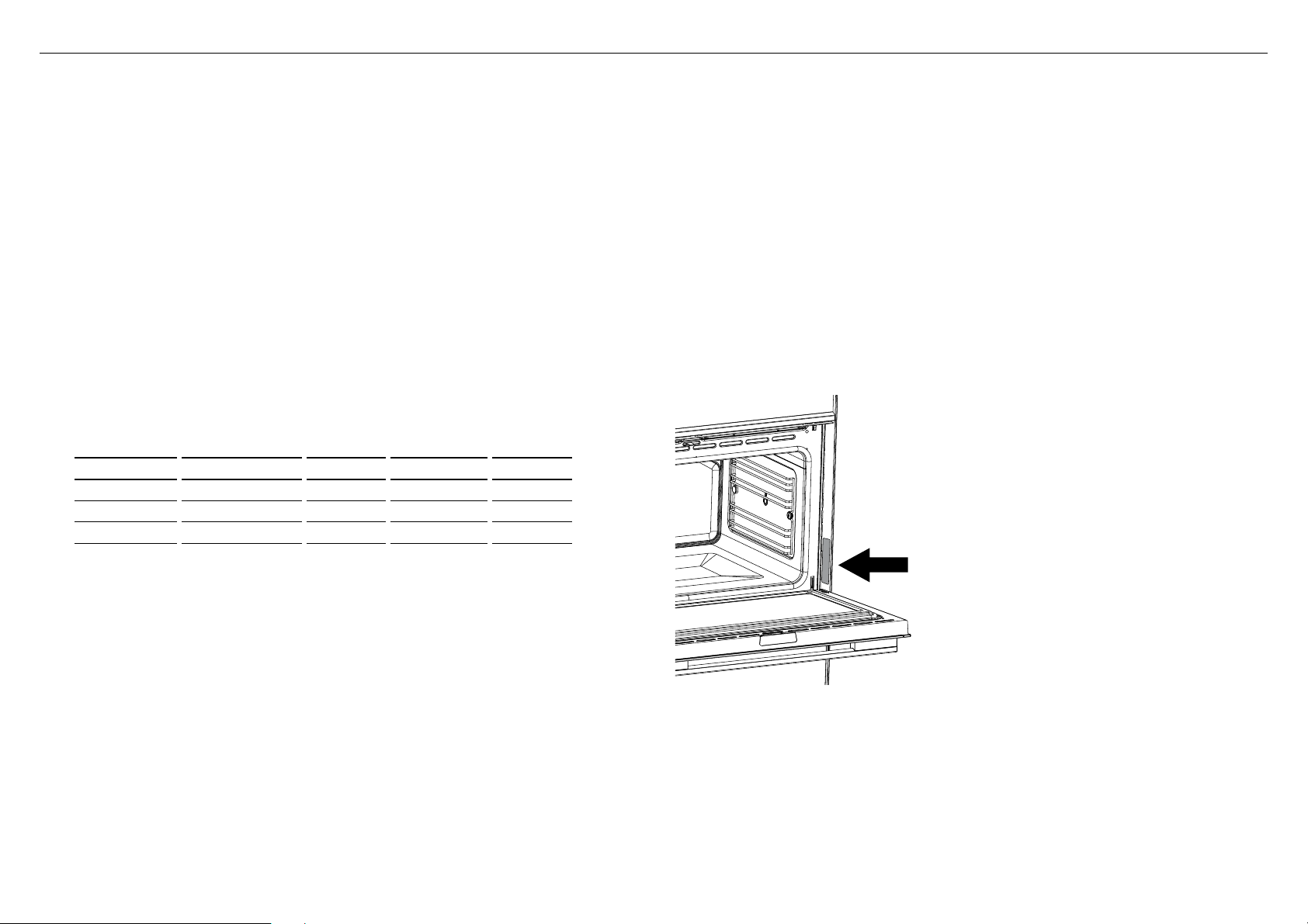
Location of
nameplate
MODEL CODE MAX POWER (W) HZ VOLTAGE (V) AMPS (A)
OR90S*1 10610 50 Hz 220 - 240 V~ 46.13
OR90S*4 15300 50 Hz 220 - 240 V~ 66.54
OR90S*6 15550 50 Hz 220 - 240 V~ 67.6
IMPORTANT!
●
This cooker must be connected to the mains power supply only by a suitably qualified person.
●
This cooker must be earthed.
15
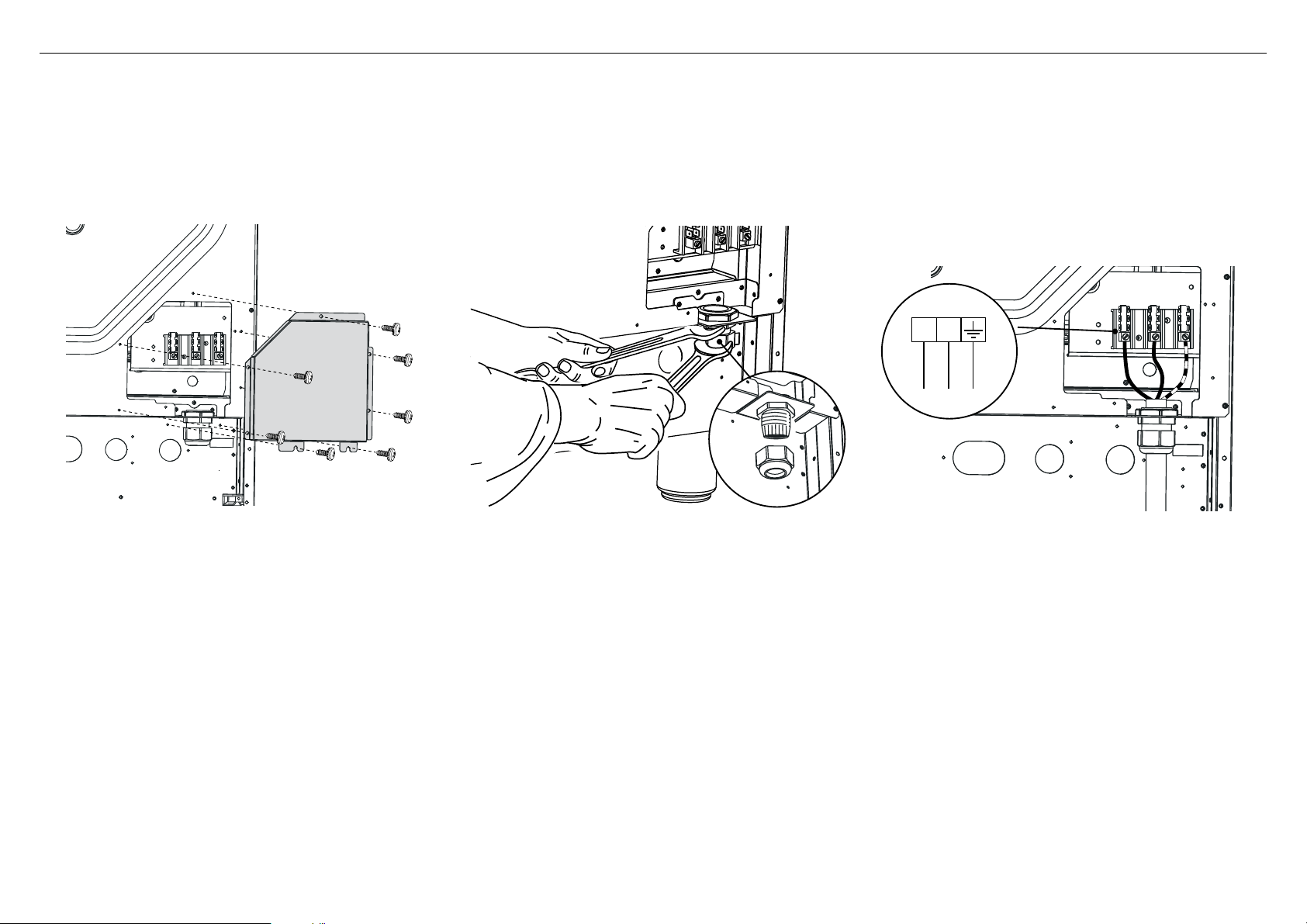
!5ELECTRICAL FEEDER CABLE CONNECTION
IMPORTANT!
The power supply cable must be connected by an authorised service person
PENL
220-240 V AC
IMPORTANT!
Do not to unscrew the
strain relief from the
cooker
Feeder cable section
Use a type of cable according to the applicable local regulations.
220-240 Vac 3 x 10 mm2*
*Connection with wall box connection.
IMPORTANT!
The earth conductor should remain around 30mm
longer than the others
1 Remove the screws that hold the cover in place at the
back of the cooker
2 Unscrew the bottom terminal end of the strain relief
by using two spanners. Insert terminal into the power
suply cable, then insert the feeder cable into the strain
relief (ensure sealing ring stays secured inside the
strain relief).
3 Connect the live, neutral and earth cables to the
terminal as shown above. Lock the power supply cable
in place by screwing the terminal end back to the
strain relief. Re-mount the screw cover back onto to
the cooker.

16
TO BE COMPLETED BY THE INSTALLER
GENERAL
F Placement of unit.
F Specified clearance maintained to cabinet surfaces.
F Unit Level – front to back, side to side.
F All packaging material and tie straps removed.
F Island trim or optional backguard correctly attached.
F The anti-tip bracket is correctly installed.
ELECTRICAL
F Adequate ground connection.
!6FINAL CHECKLIST
Complete and keep for safe reference:
Model
Serial No.
Purchase Date
Purchaser
Dealer Address
Installer’s Name
Installer’s Signature
Installation Company
Installation Date
OPERATION
F All internal packing materials removed. Check inside the oven.
F Dials turn correctly and freely.
F Oven and cooktop displays are functioning correctly and oven and cooking zones can
be turned on.
F Oven door hinges seated and door opens and closes properly.

17


FISHERPAYKEL.COM
NZ AU
591517A / 1105510-ß0 12.17
© Fisher & Paykel Appliances 2017. All rights reserved.
The product specifications in this booklet apply to the specific products
and models described at the date of issue. Under our policy of continuous
product improvement, these specifications may change at any time. You
should therefore check with your Dealer to ensure this booklet correctly
describes the product currently available.