■ Lay out the vent duct system before installing the range hood to determine the best routing for the vent duct.
■ It is recommended that the vent system be installed before the range hood is installed.
■ Before making cutouts, make sure there is proper clearance within the ceiling for the exhaust vent.
■ Range hood is to be installed 24" (61 cm) min. for electric cooking surfaces, 27" (68.6 cm) min. for gas cooking surfaces, to a suggested maximum of 36" (91.4 cm) above the cooking surface.
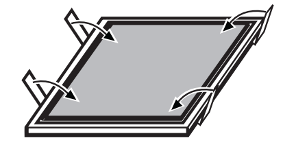
■ Remove film from metal surfaces as needed prior to assembly.
■ Check your ceiling height and the range hood height maximum before you install your hood.
1. Disconnect power.
2. Determine which venting method to use: roof, wall or non-vented.
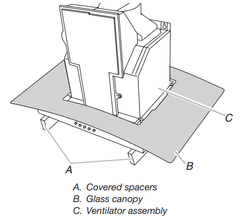
3. Select a flat surface for assembling the range hood. Place covering over that surface. Place two 3" (7.6 cm) high spacers (not included) onto the covered surface.
4. Using 2 or more people, lift range hood onto covered spacers.
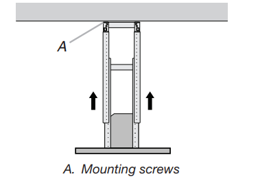
Range Hood Mounting Screws Installation
1. Determine and mark the centerline on the ceiling where the range hood will be installed, considering the requirements for ceiling support structures. See the “Location Requirements” section. Make sure the range hood is centered over the cooking surface.
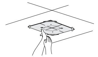
2. Tape the template in place on the ceiling at the marked centerline. The line for the front of the range hood should be parallel to the front of the cooktop.
3. Use a pencil to mark the mounting screws, wire access, and duct hole locations on the ceiling. NOTE: Mounting hole locations should be into a ceiling support structure capable of holding 80 lbs (36.6 kg). Remove the template.
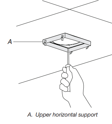
4. Drill 4 - 3 /16" (4.8 mm) pilot holes for mounting the upper horizontal support.
Complete Preparation
1. Determine the required location for the home power supply cable and drill a 1 /2" (1.3 cm) diameter hole for wire access.
2. Run 1 /2" (1.3 cm) conduit and wires or home power supply cable according to the National Electrical Code or CSA Standards and local codes and ordinances. There must be enough 1 /2" conduit and wires or home power supply cable from the fused disconnect (or circuit breaker) box to make the connection in the hood’s electrical terminal box. NOTE: Do not reconnect power until installation is complete.
3. For vented installations only: Using a jigsaw or keyhole saw, cut a 61 /2" (16.5 cm) diameter hole for the vent duct.
4. Attach the upper horizontal support bracket with 4 - 5 x 45 mm wood screws. NOTE: Upper horizontal support screws must be into a ceiling support structure capable of holding 80 lbs (36.6 kg).
Install In-Line Smart Kit - Optional
NOTE: Your range hood can work with either an internal or an inline (external) blower motor system. An optional In-Line Smart Kit (purchased separately) allows the blower motor that comes with this range hood to be installed in a location other than inside the range hood cavity.
CAUTION: To reduce the risk of fire and electric shock, install this range hood only with the In-Line Smart Kit manufactured by Whirlpool, Part Number W10692945. For installation see the In-Line Smart Kit installation instructions. See the “Assistance or Service” section to order.
Assemble Range Hood.
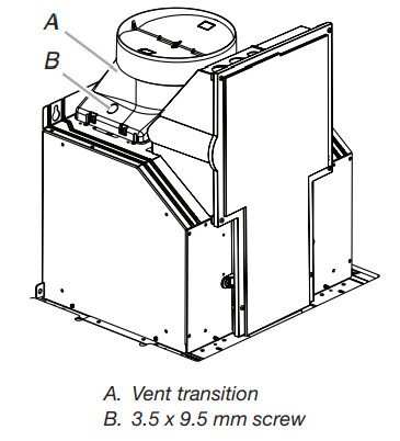
1. Install transition on top of hood (if removed for shipping) with 2 - 3.5 x 9.5 mm sheet metal screws.
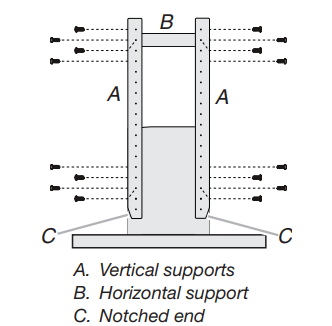
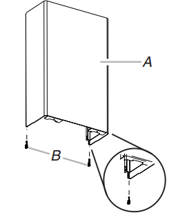
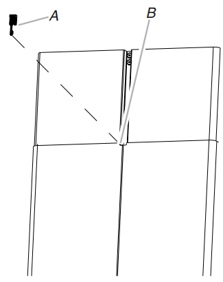
2. Position the 4 vertical supports (A) with the notches at the bottom and attach to the range hood using 16 - 4.2 x 8 mm screws.
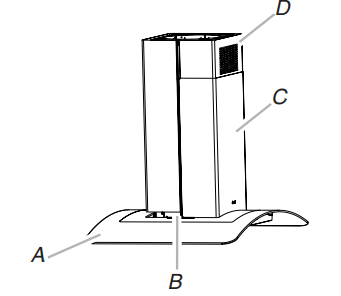
3. Attach the horizontal support (B) using 8 - 4.2 x 8 mm screws.
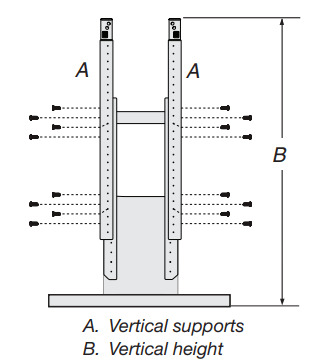
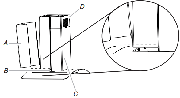
4. Attach a second set of vertical supports (A) and set the vertical height (B). See “Installation Dimensions” in the “Location Requirements” section to help determine the desired dimension for vertical height “B.” Secure with 16 - 4.2 x 8 mm T20® screws.
Install Range Hood
Non-Vented (recirculating) Installation
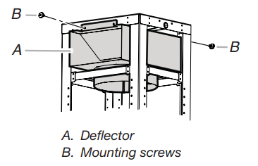
1. Attach the air deflector to the upper horizontal support using 4 mounting screws.
2. Measure the length of 6" (15.2 cm) duct needed to connect the transition to the deflector. NOTE: Vent should fit up inside the deflector 1" (2.5 cm) minimum.
3. Install vent between the transition and the deflector. NOTE: To make vent installation easier, temporarily remove the deflector from the chimney support bracket and replace after vent section is in place.
4. Seal all connections with vent clamps. Continue with “Range Hood Installation” in this section.
Range Hood Installation
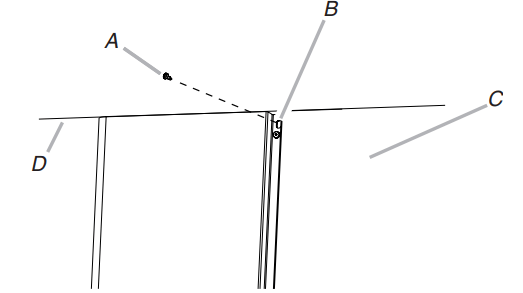
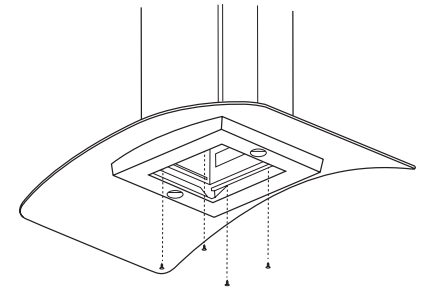
1. Using 2 or more people, lift the range hood assembly and attach it by snapping the vertical supports to the spring clips in the upper horizontal support bracket that is mounted to the ceiling. NOTE: The range hood assembly must be held in place while you are installing the screws in the next step.
2. Install 16 - 4.2 x 8 mm screws and tighten to secure.
Connect Vent System
1. Install vent system.
2. Push the duct over the exhaust outlet. Seal all connections with vent clamps.
3. Use caulk to seal all openings.
Make Electrical Connection
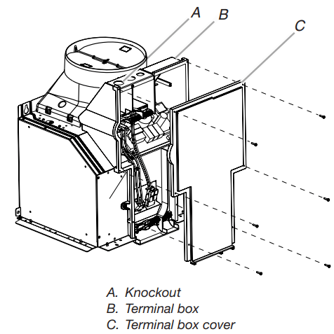
1. Disconnect power.
2. Remove the terminal box cover.
3. Remove the knockout in the terminal box and install a UL-listed or CSA approved 1 /2" strain relief
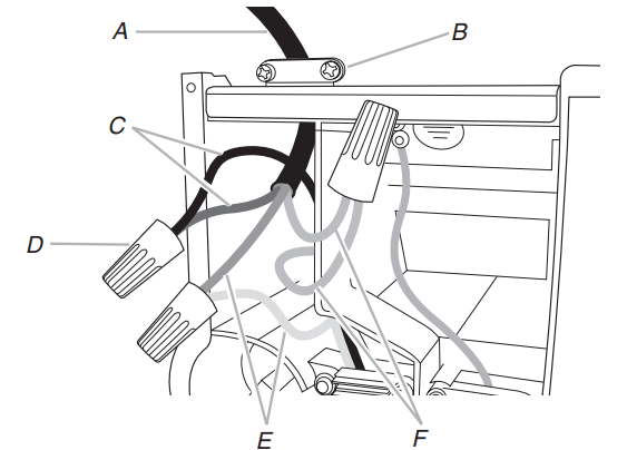
4. Run the home power supply cable through strain relief into the terminal box.
A. Home power supply cable
B. UL-listed or CSA-approved strain relief
C. Black wires
D. UL listed wire connectors
E. White wires
F. Green (or bare) and yellow-green ground wires
5. Use UL-listed wire connectors and connect black wires (C) together.
6. Use UL-listed wire connectors and connect white wires (E) together.
7. Connect green (or bare) ground wire from home power supply to yellow-green ground wire (F) in terminal box using UL listed wire connectors.
8. Tighten strain relief screw.
9. Install terminal box cover.
10. Check that all light bulbs are secure in their sockets.
11. Reconnect power.
Optional Power Cord Kit Installations
For optional power cord kit installations, follow the instructions supplied with the power cord kit. See the “Assistance or Service” section for information on ordering.
Install Duct Covers
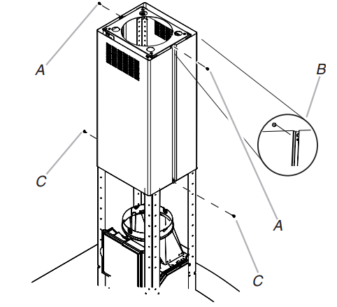
1. Assemble the upper duct covers together and install the duct covers around the support frame. The larger hole in the flanges of the upper duct cover must be outside the smaller hole in the mating flange of the other upper duct cover.
2. Secure the upper duct covers together with two 3.5 x 6.5 mm screws at the top and two 2.9 x 3 mm screws at the bottom. Install 1 screw on each side at the top and bottom of the assembled duct covers.
A. 3.5 x 6.5 mm screws (2)
B. Assembly holes (larger hole outside of smaller hole on both sides)
C. 2.9 x 3 mm screws (2)
3. Slide the upper duct covers up the frame to the ceiling and secure to the upper horizontal support with 2 - 3.5 x 6.5 mm screws.
A. 3.5 x 6.5 mm screw
B. Slotted holes (2)
C. Upper duct covers
D. Ceiling
4. Place the long end of the plastic clips (2) into the bottom of the front lower duct cover.
A. Lower duct cover - (front)
B. Plastic clips (2) (long end for front placement)
5. Install the lower duct cover (front) to the range hood canopy. Spread the lower duct cover opening slightly and position it over the upper duct cover. Set the lower duct cover in place. Position so the flanges of the lower duct cover set into the flanges of the upper duct covers.
A. Range hood canopy
B. Plastic clips
C. Lower duct covers
D. Upper duct covers
6. Install the lower duct cover (rear) to the range hood canopy. Spread the lower duct cover opening slightly and position it over the upper duct cover. Set the lower duct cover in place. Position so the flanges of the lower duct cover set into the flanges of the upper duct cover. Make sure the front and rear lower duct covers mate properly
A. Lower duct cover (rear)
B. Plastic clips
C. Lower duct covers
D. Upper duct covers
7. Secure the lower duct covers together at the top using 2 plastic clips. Use one plastic clip on each side.
A. Plastic clips (2)
B. Lower duct covers top clip area
8. Secure the lower duct cover to the range hood canopy using 4 - 4.2 x 8 mm screws.
Complete Installation
1. For non-vented (recirculating) installations only, install charcoal filters over metal grease filter. See the “Range Hood Care” section.
2. Install metal filters. See the “Range Hood Care” section.
3. Check the operation of the range hood blower and light. See the “Range Hood Use” section. If range hood does not operate, check to see whether a circuit breaker has tripped or a household fuse has blown.
RANGE HOOD USE
The range hood is designed to remove smoke, cooking vapors and odors from the cooktop area. For best results, start the hood before cooking and allow it to operate several minutes after the cooking is complete to clear all smoke and odors from the kitchen.
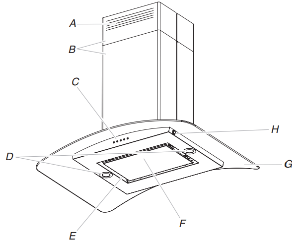
The hood controls are located on the front side of the canopy
A. Louver holes (non-vented [recirculating] installations only)
B. Duct covers
C. Control panel
D. LED lights
E. Metal grease filters (located behind the perimetric cover)
F. Perimetric cover
G. Glass canopy
H. Light switch (ambient lighting
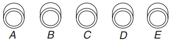
Range Hood Controls
A. Blower speed maximum button
B. Blower speed medium button
C. Blower speed minimum button
D. Blower off button
E. On/Off LED task light button
Operating the LED task light
The On/Off light button controls both lights. Press once for On and again for Off.
Operating the blower
The Blower Speed buttons turn the blower On and control the blower speed and sound level for quiet operation. The speed can be changed anytime during fan operation by pressing the desired Blower Speed button.
The Blower Off button turns the blower Off.
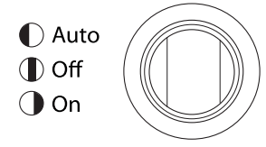
Operating the Ambient Lighting
The switch controls the ambient lighting.
1. Press to the left to turn Auto On.
2. Press to the right to turn Ambient Lighting On.
3. Press to the center to turn Ambient Lighting or Auto Off.
RANGE HOOD CARE
Cleaning
Exterior Surfaces
To avoid damage to the exterior surface, do not use steel wool or soap-filled scouring pads. Always wipe dry to avoid water marks.
Cleaning Method:
■ Liquid detergent soap and water, or all-purpose cleanser.
■ Wipe with a damp soft cloth or nonabrasive sponge, and then rinse with clean water and wipe dry.
Metal Grease Filter
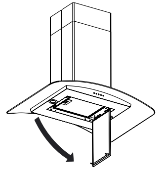
1. Open the stainless steel panel. Grasp the panel at the left corners and pull down to disengage the 2 catch pins from the spring catches. The panel is attached at the right and will rotate down.
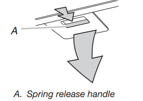
2. Remove the filter by pulling the spring release handle and then pulling down the filter
3. Wash the metal filter as needed in the dishwasher or hot detergent solution.
4. Reinstall the filter by making sure the spring release handles are toward the front. Insert the aluminum filter into the upper track.
5. Push in the spring release handle.
6. Push up on the metal filter and release the handle to latch into place.
Non-Vented (recirculating) Installation Filters
The charcoal filter is not washable. It should last up to 6 months with normal use. Replace with Charcoal Filter Kit Number W10412939.
To replace the charcoal filter:
1. Remove the metal grease filter from the range hood. See “Metal Grease Filter” in this section.
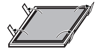
2. Bend spring clips away from the metal grease filter.
3. Place the charcoal filter into top side of the metal filter.
4. Bend spring clips back into place to secure the charcoal filter to the metal filter.
5. Replace metal grease filter. See “Metal Grease Filter” in this section.
Replacing an LED Lamp
The LED lights are replaceable by a service technician only. See the “Assistance and Service” section for service contact information.