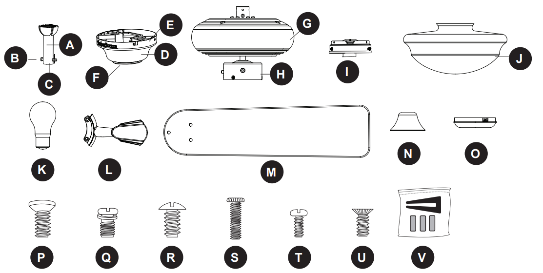
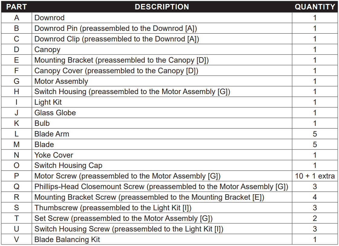
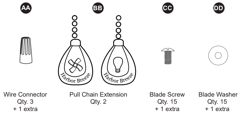
Before beginning the assembly of this product, ensure that all parts are present. Compare all parts with the package contents list and hardware contents list. If any part is missing or damaged, do not attempt to assemble the product.
After opening the top of the carton, remove the mounting hardware package from the foam inserts, then remove the motor from the packaging and place it on a soft surface, such as a carpet, to avoid damage to the finish.
Estimated Assembly Time: 120 minutes
Tools Required for Assembly (not included): Electrical Tape, Phillips Screwdriver, Pliers, Safety Glasses, Step Ladder, and Wire Strippers
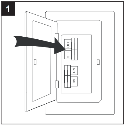
1. Turn off the circuit breakers and the wall switch to the fan supply line leads.
DANGER: Failure to disconnect the power supply prior to installation may result in serious injury or death.
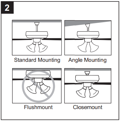
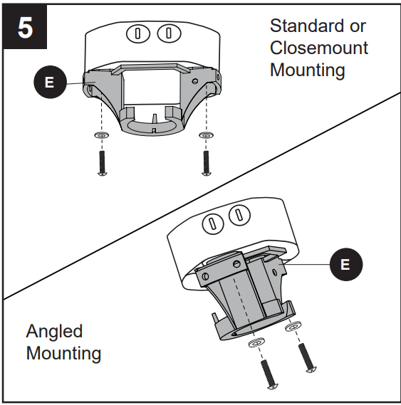
2. Determine the mounting method to use.
Standard mounting is best suited for ceilings 8 ft. or higher. For taller ceilings you may want to use a longer downrod (not included).
Angle mounting is best suited for angled or vaulted ceilings. A longer downrod is sometimes necessary to ensure proper blade clearance. If using the angle mount, check to ensure the ceiling angle is not steeper than 16°.
Closemount installation is more suitable for ceilings lower than 8 ft. high.
Flushmount installation is not available for this item.
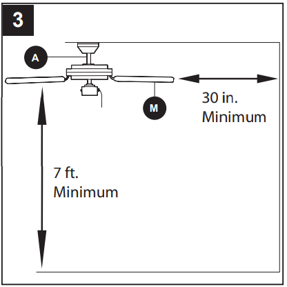
3. Ensure the blades (M) will be at least 30 in. from any obstructions. Also check the downrod (A) length to ensure the blades (M) will be at least 7 ft. above the floor.
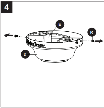
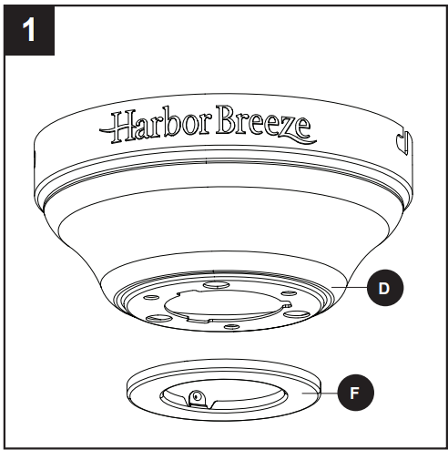
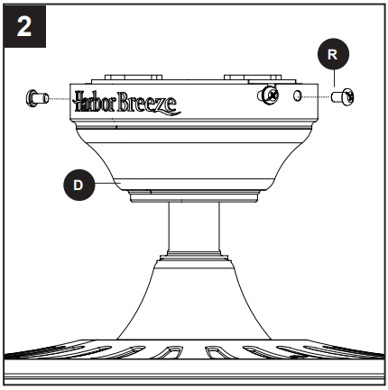
4. Loosen all four preassembled mounting bracket screws (R), then completely remove the two mounting bracket screws (R) from the round holes of canopy (D). Set aside for later use. Detach mounting bracket (E) from canopy (D).
Hardware Used
5. Attach mounting bracket (E) to outlet box (not included) using screws and washers provided with the outlet box.
CAUTION: It is very important you use the proper hardware when installing the mounting bracket (E) as this will support the fan.
Important
If using the angle mount, ensure that the open end of the mounting bracket (E) is installed facing the ceiling.
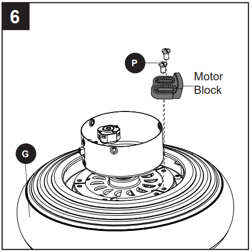
6. Remove all ten preassembled motor screws (P) and five preassembled plastic motor blocks from the underside of the motor assembly (G). Discard the motor blocks, but keep the motor screws (P) for later.
For Standard or Angle Mounting Instructions, continue to page 9. For Closemount Instructions
STANDARD OR ANGLE MOUNTING INSTRUCTIONS
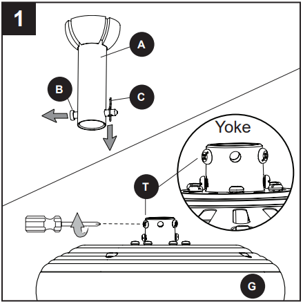
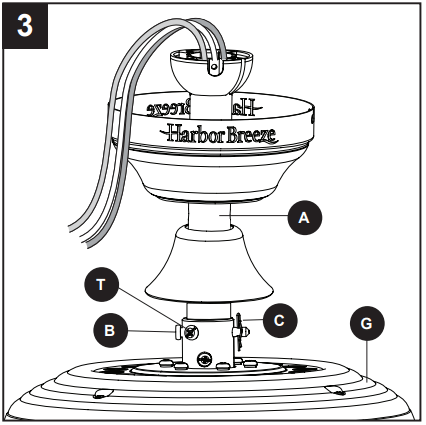
1. Remove the downrod pin (B) and downrod clip (C) from the downrod (A). Then partially loosen the motor housing set screws (T) in the yoke at the top of the motor assembly (G).
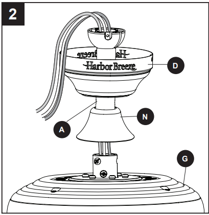
2. Insert the downrod (A) through the canopy (D) and yoke cover (N). Feed the wires from the motor assembly (G) through the downrod (A).
3. Slide the downrod (A) into the yoke of the motor assembly (G), align the holes, then re-install the downrod clip (C) and downrod pin (B). Secure with set screws (T).
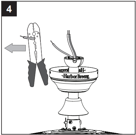
4. Depending on the length of downrod you use, you may need to cut the lead wires back to simplify the wiring. If you decide to cut back the lead wires, it is suggested you do so in the following manner: Take the lead wires and make sure you have pulled them all the way through the top of the downrod. Measure 8 inches of lead wire, then cut the excess wire off with wire cutters (not included).
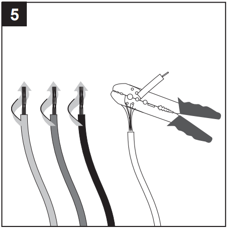
5. If you decided to cut back the lead wire in Step 4, strip 1/2 in. of insulation from the end of the white wire. Twist the stripped ends of each strand of wire within the insulation with pliers (not included). Repeat this step for black, blue and green wires.
Important: If you did not cut back the lead wires in Step 4, Step 5 is not necessary and you may proceed to Step 6.
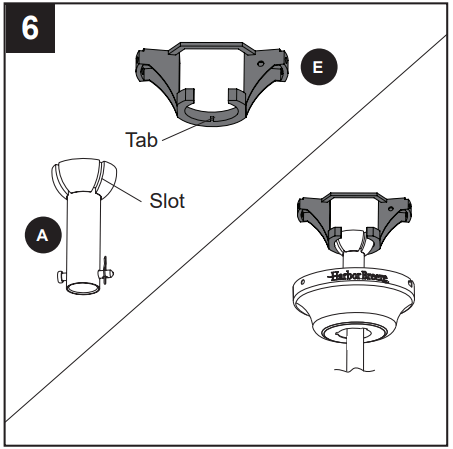
6. Install the ball end of the downrod (A) into the opening of mounting bracket (E). Align one of the four slots in the ball with the tab in the mounting bracket (E).
Note: The downrod should not rotate if installed correctly.
DANGER: Failure to align the slot in the downrod (A) with the tab of the mounting bracket (E) could cause the fan to fall, resulting in serious injury or death.
Proceed to the Wiring
CLOSEMOUNT INSTRUCTIONS
Helpful Hint: The downrod (A), canopy cover (F) and yoke cover (N) are not used in this type of installation.
1. Remove the canopy cover (F) from the bottom of the canopy (D).
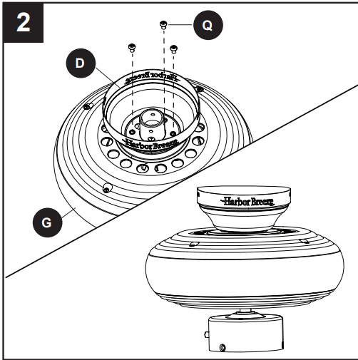
2. Remove three Phillips-head closemount screws (Q) from the top of the motor assembly (G). Align the canopy (D) with the holes in the top of the motor assembly (G), then re-install the Phillips-head closemount screws (Q) to secure the canopy (D) to the top of the motor assembly (G).
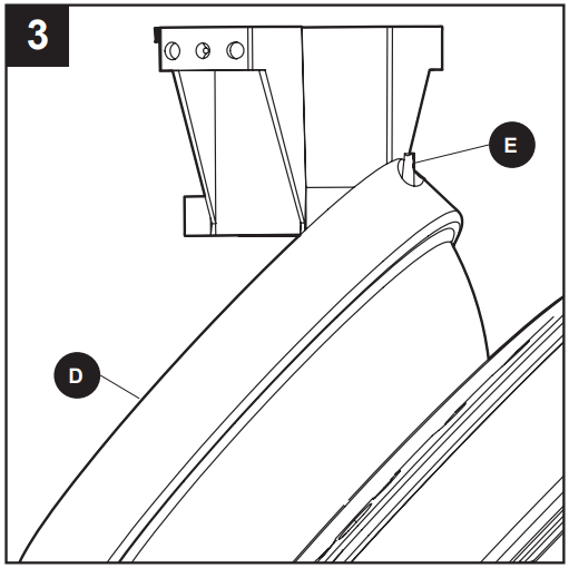
3. Raise the fan and place the canopy (D) on the hook on the mounting bracket (E), temporarily leaving hands free for the wiring process.
WARNING: To reduce the risk of fire, electrical shock or personal injury, wire connectors provided with this fan are designed to accept only one 12-gauge house wire and two lead wires from the fan. If your house wire is larger than 12-gauge and/or there is more than one house wire to connect to the two fan lead wires, consult an electrician for the proper size wire connectors to use.
CAUTION: Be sure the outlet box is properly grounded or that a Ground (Green or Bare) wire is present.
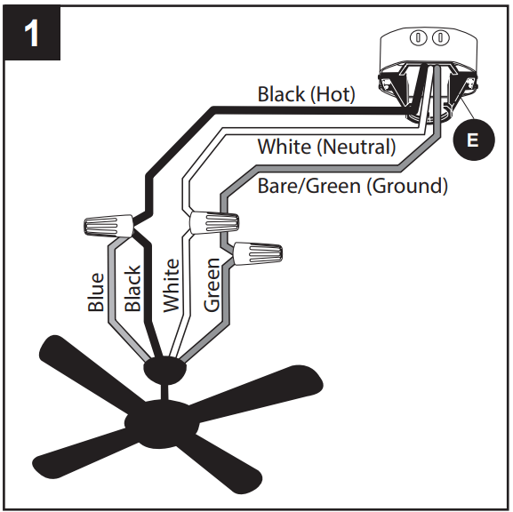
1. Connect household supply and fan wires according to the diagram and these steps:
• Connect the Green wire from the downrod (A) and mounting bracket (E) to the Bare/Green supply wire.
Note: Closemount installation does not use downrod (A), so there will only be two Green wires to connect.
• Connect the White wire from the fan to the White supply wire.
• Connect the Black and Blue wires from the fan to the Black supply wire.
• Secure all wiring connections together with wire connectors (AA).
Note: The Black wire is hot power for the fan. The White wire is common for the fan and light kit. The Blue wire is hot power for light. The Green wire is the ground wire. If household supply wires are different colors than referred to above, it is recommended a professional electrician determines the proper wiring.
Hardware Used
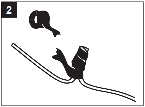
2. Wrap electrical tape (not included) around each individual wire connector down to the wire.
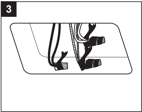
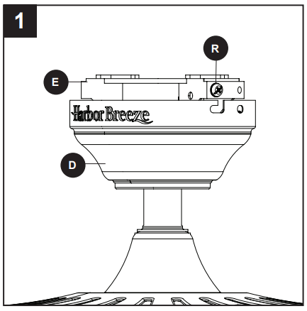
3. Turn the spliced/taped wires upward and gently push the wires and wire connectors into the outlet box. WARNING: Ensure no bare wire or wire strands are visible after making connections. Place the Green and White wire connections on the opposite side of the outlet box from the Black and Blue wire connections
FINAL INSTALLATION
Note: Closemount installation will not have the downrod (A), yoke cover (N) or canopy cover (F).
1. Align the canopy (D) over the loose mounting bracket screws (R) preassembled on mounting bracket (E). Place the keyholes of the canopy (D) onto the mounting bracket screws (R) and rotate the canopy (D) clockwise.
2. Secure the canopy (D) with the mounting bracket screws (R) previously removed (Step 4, page 8). Tighten all mounting bracket screws (R) securely.
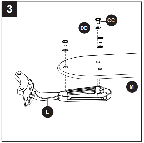
3. Partially insert the blade screws (CC) along with the blade washers (DD) through the blade (M) and into the blade arm (L). Tighten each blade screw (CC) with a Phillips screwdriver (not included), starting with the one in the middle.
Repeat this step for the remaining blades (M) and blade arms (L).
Hardware Used
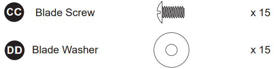
4. Install the blade arm (L) to the underside of the motor assembly (G) with motor screws (P) previously removed (Step 6, page 8). Tighten with Phillips screwdriver. Repeat for each blade arm (L).
Note: If you wish to install the fan without the light kit, proceed to Step 7.
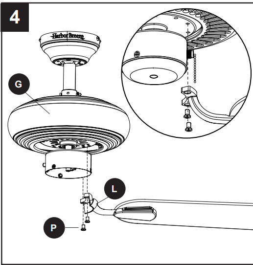
5. To install the light kit (I), first remove the three switch housing screws (U) from the light kit (I). Then connect the single-pin connectors from the switch housing (H) to the single-pin connectors from the light kit (I) -- black to black and white to white. Secure the light kit (I) to the switch housing (H) using the three switch housing screws (U). Note: Align the notch in the light kit (I) with the reverse switch on the switch housing (H).
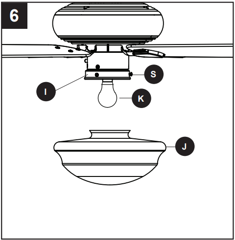
6. Install the bulb (K) into the socket of the light kit (I). Then loosen the three thumbscrews (S) on the lower edge of the light kit (I). Lift glass globe (J) to light kit (I), securing by tightening the loosened thumbscrews (S). Proceed to Step 8.
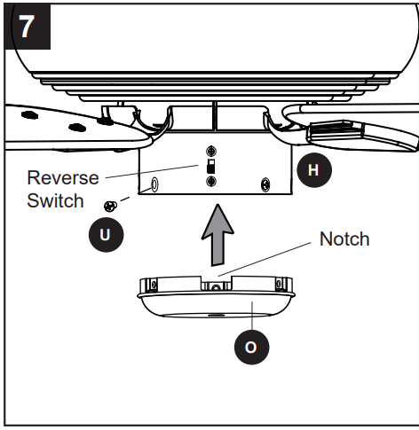
7. To install the fan without the light kit (I), remove all three switch housing screws (U) from the light kit (I). Then install the switch housing cap onto the switch housing (H) using the switch housing screws (U).
Note: Align the notch in the switch housing cap (O) with the reverse switch on the switch housing (H).
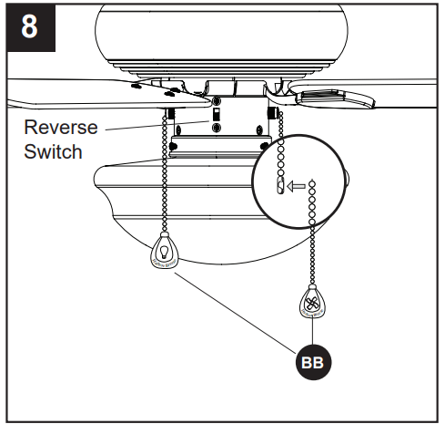
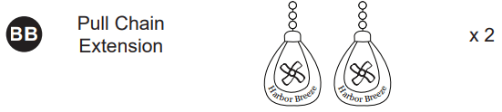
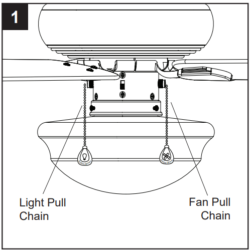
8. Attach the pull chain extensions (BB) or custom pull chain extensions (not included) to the fan and light pull chains (if applicable).
Note: When facing the reverse switch, the pull chain for the fan is on the right and the pull chain for the light is on the left. If installing without the light kit, the pull chain extension for the light pull chain will not be used.
Hardware Used
OPERATING INSTRUCTIONS
1. The fan pull chain has four positions to control fan speed. One pull is HIGH, two is MEDIUM, three is LOW and four turns the fan OFF.
The light pull chain has two positions to control the light, ON and OFF.
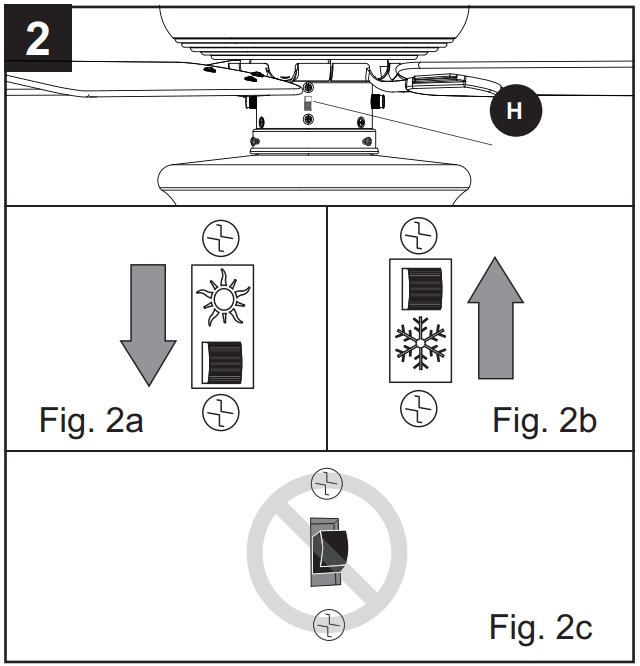
2. Use the fan reverse switch, located on the switch housing (H), to optimize your fan for seasonal performance.
A ceiling fan will allow you to raise your thermostat setting in summer and lower your thermostat setting in winter without feeling a difference in your comfort.
Note: Wait for the fan to stop before moving the reverse switch.
2a. In warmer weather, push the reverse switch down to display a sun icon, which will result in downward airflow creating a wind chill effect.
2b. In cooler weather, push the reverse switch up to display a snowflake icon, which will result in upward airflow that can help move stagnant, hot air off the ceiling area.
Important: The reverse switch must be set either completely up or down in order for the fan to function correctly. If the reverse switch is set in the middle position, the fan will not operate (Fig. 2c).
CARE AND MAINTENANCE
At least twice each year, lower the canopy to check the downrod assembly, and then tighten all screws on the fan. Clean the motor housing with only a soft brush or lint-free cloth to avoid scratching the finish. Clean the blades with a lint-free cloth. You may occasionally apply a light coat of furniture polish to wood blades for added protection.
Bulb Replacement: Use 60-watt max. E26-base LED, CFL or incandescent bulbs. Halogen bulbs are not recommended for this item.
Important Shut off the main power supply before you begin any maintenance task. Do not use water or a damp cloth to clean the fan.
TROUBLESHOOTING
The fan does not move.
The reverse switch is not engaged.
Firmly push the reverse switch to either the left or right.
The wall switch is turned off.
Make sure the wall switch is turned on.
The power is off or the fuse (breaker) is blown.
Turn the power on or check the fuse (breaker).
There is a faulty wire connection.
Turn the power off and check all connections at the ceiling outlet box.
The fan is noisy.
The blades are loose.
Check and tighten all screws that hold the fan blades to the blade arms and the motor.
There is a cracked blade.
Replace the cracked blade.
The wall control is not compatible with the fan.
Do not use a full range dimmer switch to control the fan speed.
The outlet box is not secure.
Ensure the outlet box is secured to the building structure.
The mounting bracket is not secure.
Ensure the mounting bracket is secured to the outlet box and that the screws are tight.
There is excessive wobbling.
The blades and/or blade are loose.
Check and tighten all screws that hold the fan blades to the blade arms and the blade arms to the motor.
The blades are unbalanced.
Switch one blade with a blade from the opposite side. Or balance the fan using a balancing kit (not supplied).
The fan mounting is not secure.
Turn off the power. Loosen the canopy and verify that the mounting bracket is secure to the electrical outlet box. The bracket must be flush without movement against the outlet box
The fan is too close to the vaulted ceiling.
Use a longer downrod or move the fan to another location.
The set screw on the motor housing yoke is loose.
Lift up the yoke cover and tighten the set screw to the yoke until secure.
The fan operates correctly, but the lights are not working (if applicable).
The bulb(s) are not installed correctly.
Re-install the bulb(s).
The light kit wire plugs are not connected properly.
Ensure that the male and female plugs in the light kit fitter are connected properly.
There is a faulty wire connection.
Turn the power off and check all connections at the ceiling outlet box.
-109929.png) DANGER: Failure to disconnect the power supply prior to installation may result in serious injury or death.
DANGER: Failure to disconnect the power supply prior to installation may result in serious injury or death.