

Kia, THE COMPANY
Thank you for becoming the owner of a new Kia vehicle.
As a global car manufacturer focused on building high-quality, value
for money prices, Kia Motors is dedicated to providing you with a
customer service experience that exceeds your expectations.
At all of our Kia dealerships you will be treated with warmth, hospi‐
tality and professionalism by people who care based on our
Family-
like Care promise.
All information contained in this Owner’s Manual was accurate at the
time of publication. However, Kia reserves the right to make changes
at any time so that our policy of continual product improvement can
be carried out.
This manual applies to all models of this vehicle and includes descrip‐
tions and explanations of optional as well as standard equipment. As
a result, you may encounter material in this manual that is not appli‐
cable to your specific Kia vehicle.
Enjoy your vehicle and Kia’s Family-like Care experience!

Thank you for choosing a Kia vehicle.
This manual will familiarize you with operational, maintenance and safety information about your new vehicle. It
is supplemented by a Warranty and Maintenance book that provides important information on all warranties re‐
garding your vehicle. Kia urges you to read these publications carefully and follow the recommendations to help
assure an enjoyable and safe operation of your new vehicle.
Kia offers a great variety of options, components and features for its various models. Therefore, some of the
equipment described in this manual, along with the various illustrations, may not be applicable to your particular
vehicle.
The information and specifications provided in this manual were accurate at the time of printing. Kia reserves the
right to discontinue or change specifications or design at any time without notice and without incurring any obli‐
gation. If you have questions, Kia recommends to check with an authorized Kia dealer/service partner.
Kia assures you of our continuing interest in your motoring pleasure and satisfaction in your Kia vehicle.
© 2017 Kia MOTORS Corp.
All
rights reserved. Reproduction by any means, elec‐
tronic or mechanical, including photocopying, record‐
ing, or by any information storage and retrieval sys‐
tem or translation in whole or part is not permitted
without written authorization from Kia MOTORS Cor‐
poration.
Printed in Korea
Foreword
ii

iv

How to use this manual........................................................... 1-02
Fuel requirements.....................................................................1-03
Gasoline engine..................................................................... 1-03
Vehicle break-in process..........................................................1-06
Introduction
1
HOW TO USE THIS MANUAL
We want to help you get the greatest
possible driving pleasure from your ve‐
hicle. Your Owner’s Manual can assist
you in many ways. We strongly recom‐
mend that you read the entire manual.
In order to minimize the chance of
death or injury, you must read the
WARNING and CAUTION sections in the
manual.
Illustrations complement the words in
this manual to best explain how to en‐
joy your vehicle. By reading your man‐
ual, you will learn about features, im‐
portant safety information, and driving
tips under various road conditions.
The general layout of the manual is
provided in the Table of Contents. Use
the index when looking for a specific
area or subject; it has an alphabetical
listing of all information in your manual.
Chapters: This manual has eight chap‐
ters plus an index. Each chapter begins
with a brief list of contents so you can
tell at a glance if that chapter has the
information you want.
You will find various WARNINGS, CAU‐
TIONS, and NOTICES in this manual.
These were prepared to enhance your
personal safety. You should carefully
read and follow ALL procedures and
recommendations provided in these
WARNINGS, CAUTIONS and NOTICES.
WARNING
A WARNING indicates a situation in
which harm, serious bodily injury or
death could result if the warning is
ignored.
CAUTION
A CAUTION indicates a situation in
which damage to your vehicle could
result if the caution is ignored.
NOTICE
A NOTICE indicates interesting or
helpful information is being provi‐
ded.
Introduction
1-02
FUEL REQUIREMENTS
Gasoline engine
Unleaded
For Europe
For the optimal vehicle performance,
we recommend you use unleaded gaso‐
line of an octane rating of RON (Re‐
search Octane Number) 95 / AKI (Anti
Knock Index) 91 or higher. (Do not use
methanol blended fuels.)
You may use unleaded gasoline with an
octane rating of RON 91~94 / AKI 87~90
but it may result in slight performance
reduction of the vehicle.
Except Europe
Your new Kia vehicle is designed to use
only unleaded fuel having an Octane
Rating of RON (Research Octane Num‐
ber) 91 / AKI (Anti-Knock Index) 87 or
higher. (Do not use methanol blended
fuels.)
Your new vehicle is designed to obtain
maximum performance with UNLEA‐
DED FUEL, as well as minimize exhaust
emissions and spark plug fouling.
CAUTION
NEVER USE LEADED FUEL. The use
of leaded fuel is detrimental to the
catalytic converter and will damage
the engine control system’s oxygen
sensor and affect emission control.
Never add any fuel system cleaning
agents to the fuel tank other than
what has been specified. (Kia recom‐
mends to consult an authorized Kia
dealer/service partner for details.)
WARNING
• Do not "top off" after the nozzle
automatically shuts off when re‐
fueling.
• Always check that the fuel cap is
installed securely to prevent fuel
spillage in the event of an acci‐
dent.
Gasoline containing alcohol and
methanol
Gasohol, a mixture of gasoline and
ethanol (also known as grain alcohol),
and gasoline or gasohol containing
methanol (also known as wood alcohol)
are being marketed along with or in‐
stead of leaded gasoline.
Do not use gasohol containing more
than 10% ethanol, and do not use gas‐
oline or gasohol containing any metha‐
nol. Either of these fuels may cause
drivability problems and damage to the
fuel system, engine control system and
emission control system.
Discontinue using gasohol of any kind if
drivability problems occur.
Vehicle damage or drivability problems
may not be covered by the manufac‐
turer’s warranty if they result from the
use of:
1. Gasohol containing more than 10%
ethanol.
2. Gasoline or gasohol containing
methanol.
3. Leaded fuel or leaded gasohol.
1-03
1
Introduction

CAUTION
Never use gasohol which contains
methanol. Discontinue use of any
gasohol product which impairs driva‐
bility.
Other fuels
Using fuels such as;
- Silicone (Si) contained fuel,
- MMT (Manganese, Mn) contained
fuel,
- Ferrocene (Fe) contained fuel, and
- Other metallic additives contained
fuels,
may cause vehicle and engine damage
or cause plugging, misfiring, poor accel‐
eration, engine stalling, catalyst melt‐
ing, abnormal corrosion, life cycle re‐
duction, etc.
Also, the Malfunction Indicator Lamp
(MIL) may illuminate.
NOTICE
Damage to the fuel system or per‐
formance problem caused by the
use of these fuels may not be cov‐
ered by your New Vehicle Limited
Warranty.
Use of MTBE
Kia recommends avoiding fuels contain‐
ing MTBE (Methyl Tertiary Butyl Ether)
over 15.0% vol. (Oxygen Content 2.7%
weight) in your vehicle.
Fuel containing MTBE over 15.0% vol.
(Oxygen Content 2.7% weight) may re‐
duce vehicle performance and produce
vapor lock or hard starting.
CAUTION
Your New Vehicle Limited Warranty
may not cover damage to the fuel
system and any performance prob‐
lems that are caused by the use of
fuels containing methanol or fuels
containing MTBE (Methyl Tertiary
Butyl Ether) over 15.0% vol. (Oxygen
Content 2.7% weight.)
Do not use methanol
Fuels containing methanol (wood alco‐
hol) should not be used in your vehicle.
This type of fuel can reduce vehicle
performance and damage components
of the fuel system, engine control sys‐
tem and emission control system.
Fuel additives
Kia recommends that you use unleaded
gasoline which has an octane rating of
RON (Research Octane Number) 95 /
AKI (Anti Knock Index) 91 or higher (for
Europe) or Octane Rating of RON (Re‐
search Octane Number) 91 / AKI (Anti-
Knock Index) 87 or higher (except Eu‐
rope).
For customers who do not use good
quality gasolines including fuel additives
regularly, and have problems starting
or the engine does not run smoothly,
one bottle of additives added to the
fuel tank at every 15,000km (for Eu‐
rope) / 5,000km (except Europe) or ev‐
ery engine oil change is recommended.
Additives are available from a profes‐
sional workshop along with information
on how to use them. Kia recommends
to visit an authorized Kia dealer/service
partner.
Introduction
1-04

Operation in foreign countries
If you are going to drive your vehicle in
another country, be sure to:
• Observe all regulations regarding reg‐
istration and insurance.
• Determine that acceptable fuel is
available.
1-05
1
Introduction

VEHICLE BREAK-IN PROCESS
No special break-in period is needed. By
following a few simple precautions for
the first 1,000 km (600 miles) you may
add to the performance, economy and
life of your vehicle.
• Do not race the engine.
• While driving, keep your engine speed
(rpm, or revolutions per minute) be‐
tween 2,000 rpm and 4,000 rpm.
• Do not maintain a single speed for
long periods of time, either fast or
slow. Varying engine speed is needed
to properly break-in the engine.
• Avoid hard stops, except in emergen‐
cies, to allow the brakes to seat
properly.
Introduction
1-06

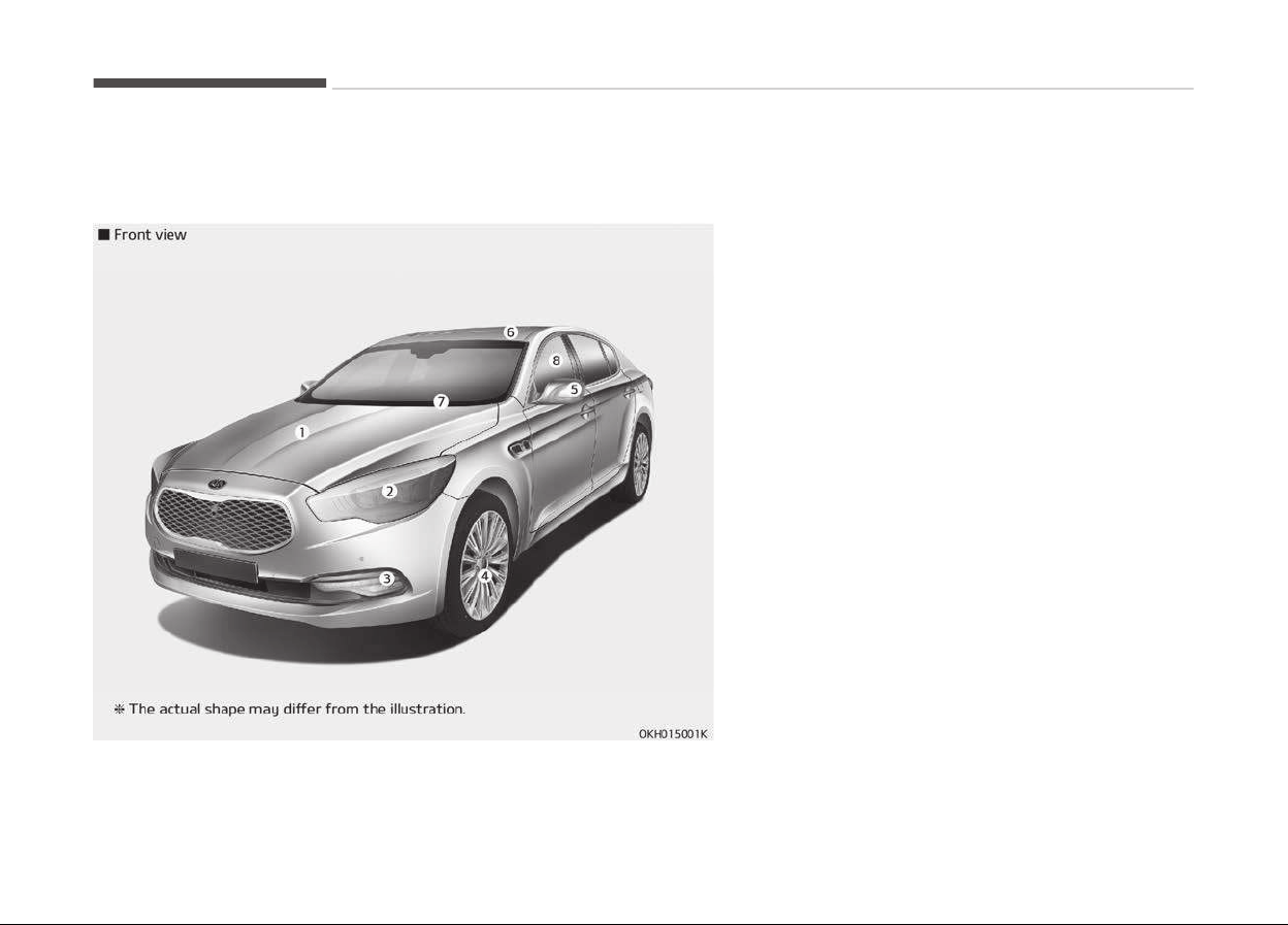
EXTERIOR OVERVIEW
1. Hood...................................... ...................................... p. 4-33
2. Head lamp (Features of your vehicle).................. p. 4-108
Head lamp (Maintenance)........................................ p. 7-78
3. Fog lamp (Features of your vehicle).......... .......... p. 4-109
Fog lamp (Maintenance)..................... ..................... p. 7-79
4. Tire and wheel (Maintenance)................ ................ p. 7-49
Tire and wheel (Specification)................ ................ p. 8-07
5. Outside rearview mirror..................... ..................... p. 4-45
6. Sunroof........................................................................ p. 4-38
7. Front windshield wiper blades (Features of your ve‐
hicle).......................................................................... p. 4-111
Front windshield wiper blades (Maintenance)...... p. 7-42
8. Windows...................................................................... p. 4-29
Your vehicle at a glance
2-02
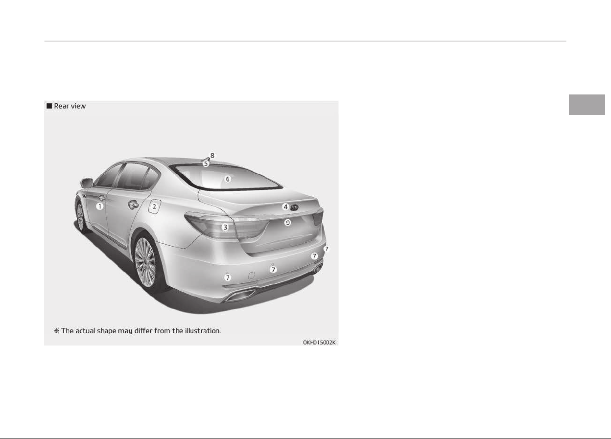
1. Door...................................... ...................................... p. 4-13
2. Fuel filler lid................................................................ p. 4-35
3. Rear combination lamp...................... ...................... p. 7-80
4. Trunk lid................................... ................................... p. 4-18
5. High mounted stop lamp.......................................... p. 7-81
6. Rear window defroster.......................................... p. 4-118
7. Rear parking assist system.................. .................. p. 4-94
8. Antenna.................................. .................................. p. 4-154
9. Rearview camera........................... ........................... p. 4-99
2-03
2
Your vehicle at a glance
INTERIOR OVERVIEW
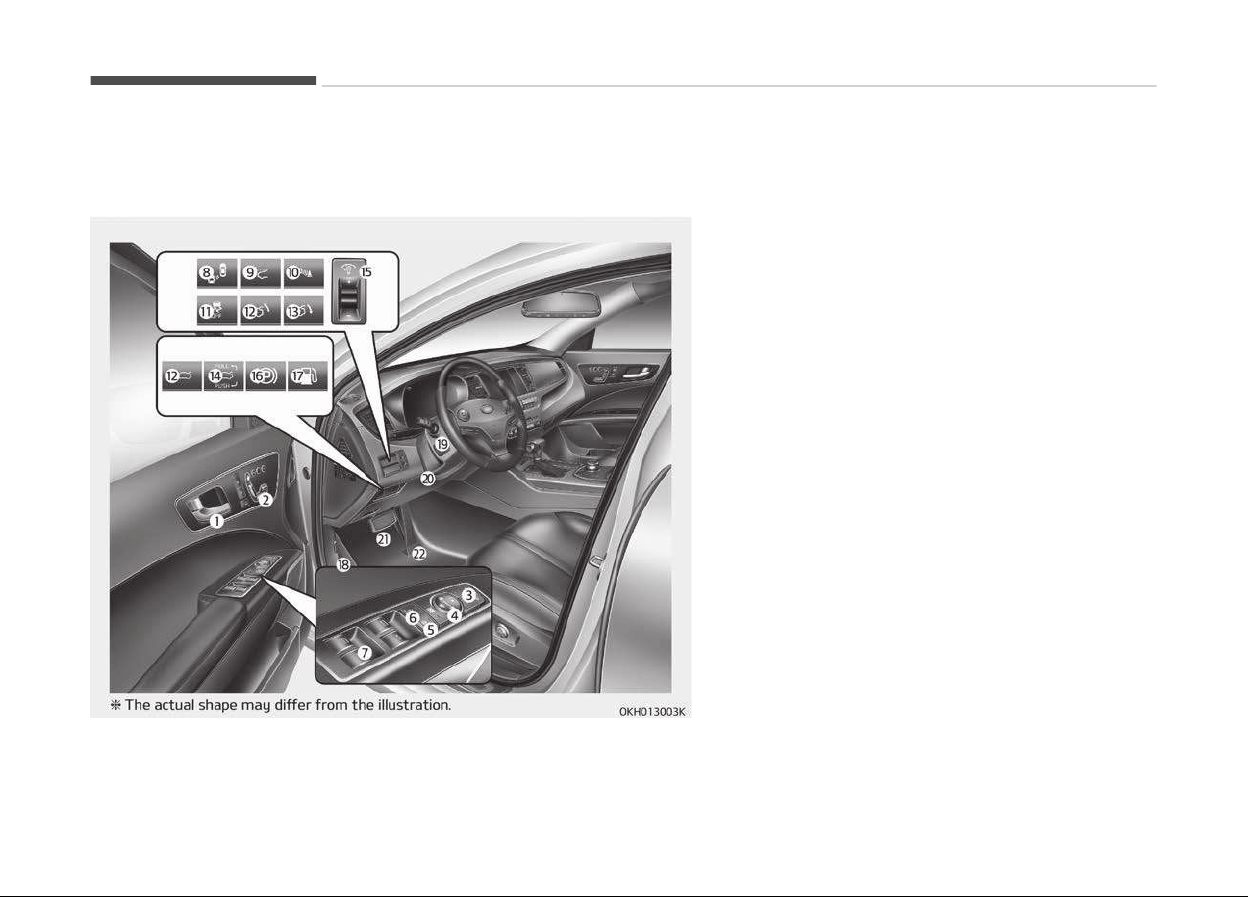
1. Inside door handle.......................... .......................... p. 4-14
2. Front power seat adjust switch.............................. p. 3-05
3. Outside rearview mirror folding.............................. p. 4-48
4. Outside rearview mirror control.............. .............. p. 4-45
5. Power window lock switch................... ................... p. 4-31
6. Central door lock switch..................... ..................... p. 4-15
7. Power window switches..................... ..................... p. 4-29
8. BSD On/Off button.................................................... p. 5-81
9. HUD On/OFF button.................................................. p. 4-93
10. Parking assist system On/Off button.................... p. 4-94
11. ESC Off button............................. ............................. p. 5-37
12. Trunk lid open button....................... ....................... p. 4-18
13. Trunk lid close button....................... ....................... p. 4-19
14. Trunk lid open / close button................. ................. p. 4-19
15. Instrument panel illumination control lever.......... p. 4-49
16. Electric parking brake switch.................................. p. 5-27
17. Fuel filler lid open switch.......................................... p. 4-35
18. Hood release lever.......................... .......................... p. 4-33
19. Steering wheel............................. ............................. p. 4-42
20. Tilt and telescopic steering control lever.............. p. 4-42
21. Brake pedal................................ ................................ p. 5-25
22. Accelerator pedal........................... ........................... p. 5-08
Your vehicle at a glance
2-04
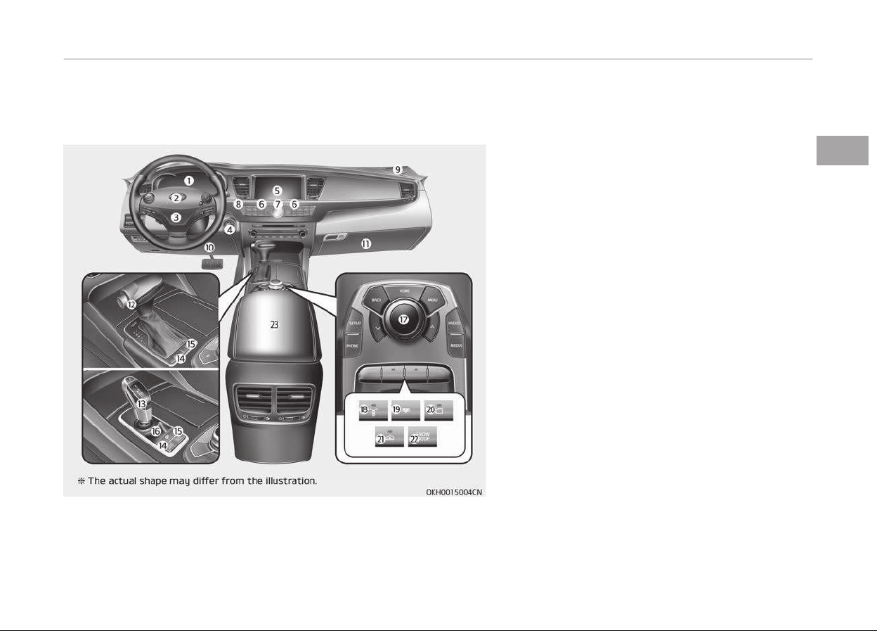
1. Instrument cluster.................................................... p. 4-49
2. Horn...................................... ...................................... p. 4-44
3. Driver’s front air bag........................ ........................ p. 3-51
4. Engine start/stop button.................... .................... p. 5-06
5. Audio / Video / Navigation.................. .................. p. 4-152
6. climate control system.......................................... p. 4-119
7. Clock..................................... ..................................... p. 4-147
8. Hazard warning flasher............................................ p. 6-02
9. Passenger’s front air bag ........................................ p. 3-51
10. Knee air bag................................................................ p. 3-51
11. Glove box.................................................................. p. 4-138
12. SBC(Shift by cable) control lever.............. .............. p. 5-10
13. SBW(Shift by wire) control lever.............. .............. p. 5-16
14. Drive mode button.................................................... p. 5-50
15. AUTO HOLD button.................................................... p. 5-32
16. Electric parking brake switch.................................. p. 5-27
17. DIS central key............................ ............................ p. 4-153
18. Front blind spot monitoring system On/Off button
.................................................................................... p. 4-103
19. Rear curtain folding button................. ................. p. 4-150
20. Surround view monitoring system On/Off button......
.................................................................................... p. 4-104
21. Vehicle height control button.................................. p. 5-58
22. Snow mode button.................................................... p. 5-50
23. Center console storage box................. ................. p. 4-137
2-05
2
Your vehicle at a glance
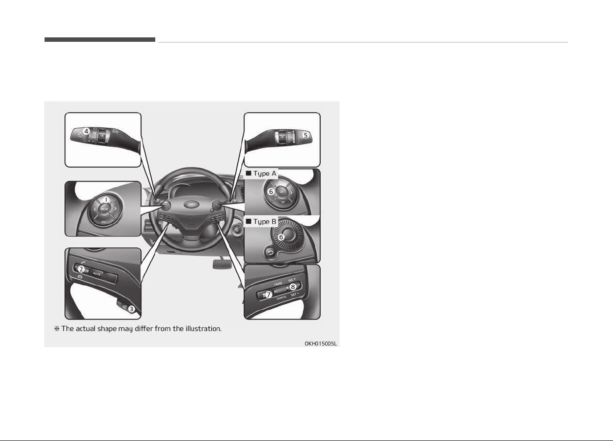
1. Audio remote control buttons.............................. p. 4-155
2. Bluetooth hands free buttons.............................. p. 4-153
3. Steering wheel warmer On/Off Button........ ........ p. 4-43
4. Light control / Turn signals lever.......................... p. 4-106
5. Wiper and washer control lever............................ p. 4-112
6. LCD display control.................................................... p. 4-50
7. Advanced smart cruise control switch (vehicle to ve‐
hicle distance setting)....................... ....................... p. 5-70
8. Cruise control switch........................ ........................ p. 5-62
Advanced smart cruise control switch......... ......... p. 5-66
Your vehicle at a glance
2-06
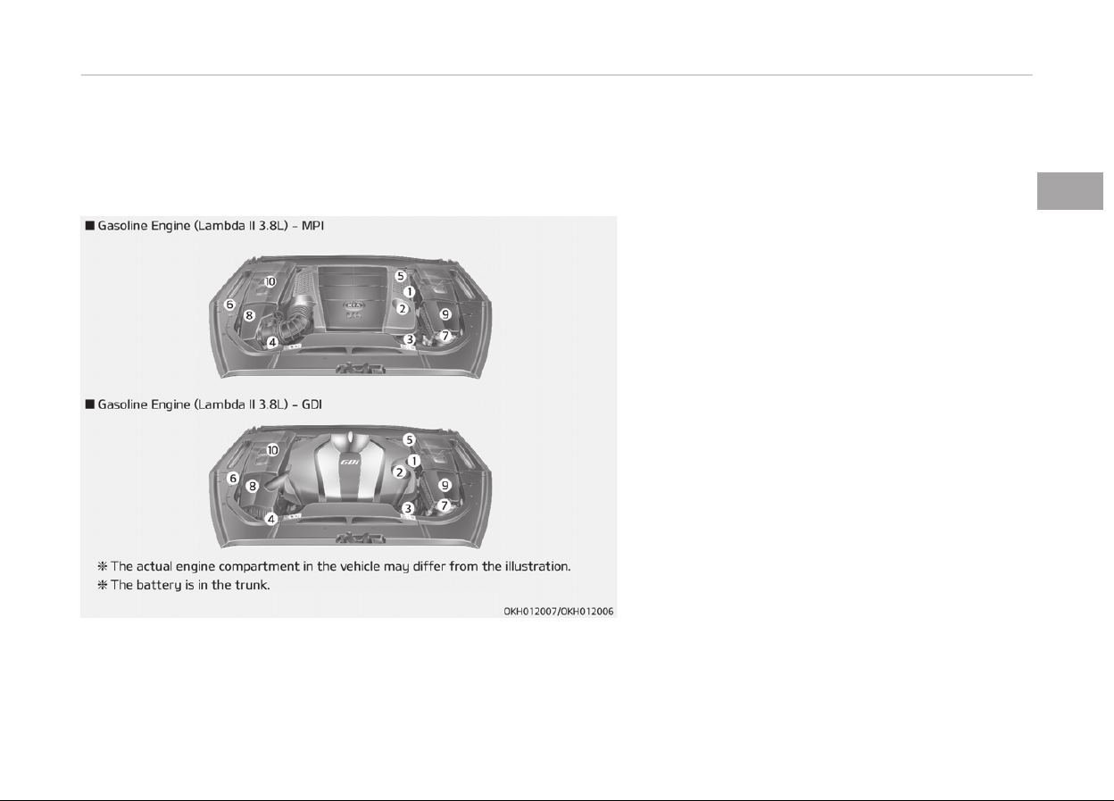
ENGINE COMPARTMENT
1. Engine oil dipstick...................................................... p. 7-30
2. Engine oil filler cap.......................... .......................... p. 7-30
3. Engine coolant reservoir.......................................... p. 7-32
4. Radiator cap............................... ............................... p. 7-33
5. Brake fluid reservoir.................................................. p. 7-35
6. Power steering fluid reservoir................................ p. 7-36
7. Windshield washer fluid reservoir.......................... p. 7-37
8. Air cleaner................................. ................................. p. 7-38
9. Fuse box...................................................................... p. 7-58
10. Jumper terminal............................ ............................ p. 6-05
2-07
2
Your vehicle at a glance
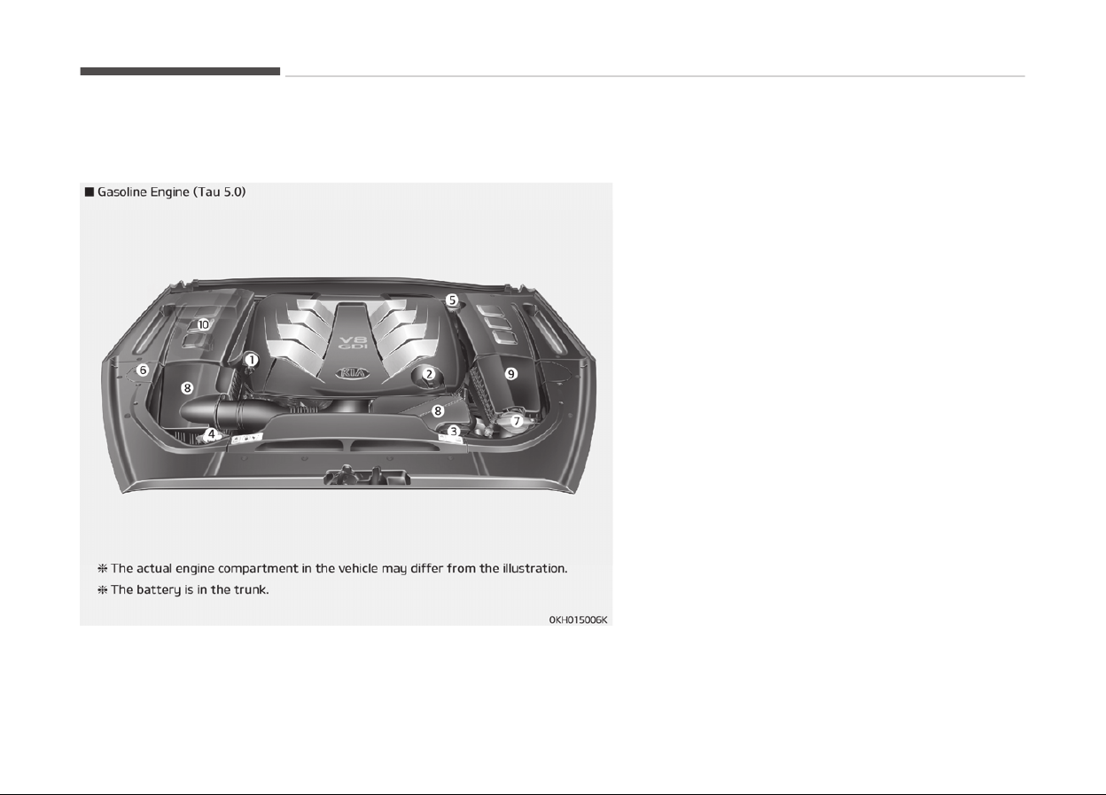
1. Engine oil dipstick...................................................... p. 7-30
2. Engine oil filler cap.......................... .......................... p. 7-30
3. Engine coolant reservoir.......................................... p. 7-32
4. Radiator cap............................... ............................... p. 7-33
5. Brake fluid reservoir.................................................. p. 7-35
6. Power steering fluid reservoir................................ p. 7-36
7. Windshield washer fluid reservoir.......................... p. 7-37
8. Air cleaner................................. ................................. p. 7-38
9. Fuse box...................................................................... p. 7-58
10. Jumper terminal............................ ............................ p. 6-05
Your vehicle at a glance
2-08

Seats............................................................................................3-02
Front seat adjustment.........................................................3-05
Driver position memory system ....................................... 3-07
Headrest (for front seat).....................................................3-09
Rear seat adjustment.......................................................... 3-13
Headrest (for rear seat)...................................................... 3-18
Seat belts....................................................................................3-21
Seat belt restraint system..................................................3-21
Pre-tensioner seat belt....................................................... 3-26
Pre-active seat belt (PSB) ..................................................3-28
Seat belt precautions........................................................... 3-29
Care of seat belts..................................................................3-31
Child restraint system..............................................................3-33
Using a child restraint system............................................3-35
Air bag - Supplemental restraint system.............................3-44
How does the air bag system operate..............................3-45
Air bag warning light............................................................ 3-48
SRS components and functions..........................................3-48
Driver's and passenger's front air bag.............................. 3-51
Side air bag.............................................................................3-54
Curtain air bag....................................................................... 3-56
SRS care..................................................................................3-62
Additional safety precautions.............................................3-63
Adding equipment to or modifying your air bag-
equipped vehicle.................................................................... 3-64
Air bag warning label............................................................3-64
Safety features of your vehicle
3
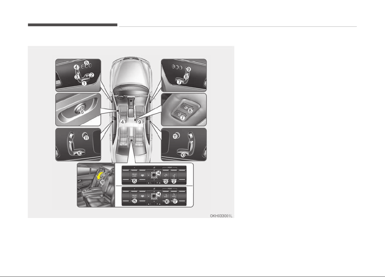
SEATS
Driver`s seat
1. Forward and rearward
2. Seat cushion length
3. Seatback angle
4. Headrest height
5.
Driver position memory system
*1
6. Lumbar support
Front Passenger`s seat
7. Forward and rearward
8. Seatback angle
9. Headrest height
Rear seat
10. Forward and rearward
11.
Easy access button
*1
12. Front passenger’s seat forward and
rearward
*1
13.
Front passenger’s seat back angle
*1
14. Lumbar support
15. Rear control lock button
16. Front passenger’s seat walk in but‐
ton
*1
if equipped
Safety features of your vehicle
3-02
17.
Relaxation mode button
*1
(Front passenger's seat and rear
seat are operated simultaneously)
18. Armrest
WARNING
n
Loose objects
Loose objects in the driver’s foot
area could interfere with the opera‐
tion of the foot pedals, possibly
causing an accident. Do not place
anything under the front seats.
WARNING
n
Driver responsibility for pas‐
sengers
(Continued)
*1
if equipped
(Continued)
Riding in a vehicle with the seatback
reclined could lead to serious or fatal
injury in an accident. If a seat is re‐
clined during an accident, the occu‐
pant’s hips may slide under the lap
portion of the seat belt applying
great force to the unprotected abdo‐
men. Serious or fatal internal injuries
could result. The driver must advise
the passenger to keep the seatback
in an upright position whenever the
vehicle is in motion.
WARNING
Do not use an aftermarket sitting
cushion that reduces friction be‐
tween the seat and passenger. The
passenger's hips may slide under the
lap portion of the seat belt during an
accident or a sudden stop. Serious or
fatal internal injuries could result be‐
cause the seat belt can't operate
normally.
WARNING
n
Driver’s seat
• Never attempt to adjust the seat
while
the vehicle is moving. This
could result in loss of control, and
an accident causing death, serious
injury, or property damage.
(Continued)
3-03
3
Safety features of your vehicle
(Continued)
• Do not allow anything to interfere
with
the normal position of the
seatback. Storing items against a
seatback or in any other way in‐
terfering with proper locking of a
seatback could result in serious or
fatal injury in a sudden stop or col‐
lision.
• Always drive and ride with your
seatback
upright and the lap por‐
tion of the seat belt snug and low
across the hips. This is the best
position to protect you in case of
an accident.
• In order to avoid unnecessary and
perhaps severe air bag injuries, al‐
ways sit as far back as possible
from the steering wheel while
maintaining comfortable control of
the vehicle. We recommend that
your chest be at least 250 mm
(10 inches) away from the steer‐
ing wheel.
WARNING
• Do not adjust the seat while wear‐
ing seat belts. Moving the seat
cushion forward may cause strong
pressure on the abdomen.
• Use extreme caution so that hands
or other objects are not caught in
the seat mechanisms while the
seat is moving.
• Use extreme caution when picking
small objects trapped under the
seats or between the seat and the
center console. Your hands might
be cut or injured by the sharp
edges of the seats mechanism.
• Do not put a cigarette lighter on
the floor or seat. When you oper‐
ate the seat, gas may gush out of
the lighter and cause fire.
• If there are occupants in the rear
seats, be careful while adjusting
the front seat position.
Feature of Seat Leather
• Leather is made from the outer skin
of an animal, which goes through a
special process to be available for
use. Since it is a natural substance,
each part differs in thickness or den‐
sity. Wrinkles may appear as a natu‐
ral result of stretching and shrinking
depending on the temperature and
humidity.
• The seat is made of stretchable fab‐
ric to improve comfort.
• The parts contacting the body are
curved and the side supporting area
is high which provides driving comfort
and stability.
• Wrinkles may appear naturally from
usage. It is not a fault of the product.
CAUTION
• Wrinkles or abrasions which ap‐
pear naturally from usage are not
covered by warranty.
• Belts with metallic accessories,
zippers or keys inside the back
pocket may damage the seat fab‐
ric.
(Continued)
Safety features of your vehicle
3-04
(Continued)
• Make sure not to wet the seat. It
may
change the nature of natural
leather.
• Jeans or clothes which could
bleach
may contaminate the sur‐
face of the seat covering fabric.
Front seat adjustment
The front seat can be adjusted by using
the control switch located on the doors.
Before driving, adjust the seat to the
proper position so as to easily control
the steering wheel, pedals and switches
on the instrument panel.
WARNING
The power seat is operable with the
engine start/stop button in OFF.
Therefore, children should never be
left unattended in the vehicle.
CAUTION
• The power seat is driven by an
electric motor. Stop operating once
the adjustment is completed. Ex‐
cessive operation may damage the
electrical equipment.
• When in operation, the power seat
consumes a large amount of elec‐
trical power. To prevent unneces‐
sary charging system drain, don’t
adjust the power seat longer than
necessary while the engine is not
running.
• Do not operate two or more power
seat control knobs at the same
time. Doing so may result in power
seat motor or electrical compo‐
nent malfunction.
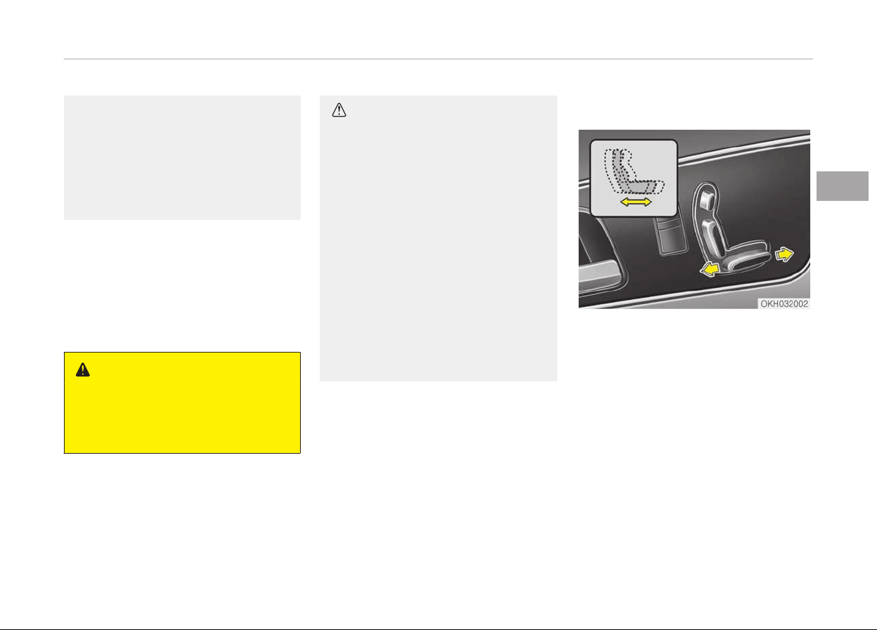
Forward and backward
Push the control switch forward or
rearward to move the seat to the de‐
sired position. Release the switch once
the seat reaches the desired position.
When adjusting the seat position, the
headrest will be adjusted simultaneous‐
ly to the proper position. (if equipped)
3-05
3
Safety features of your vehicle
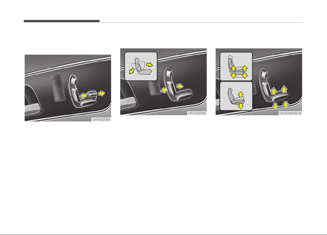
Cushion length adjustment (for
driver’s seat)
Push the control switch forward or
backward to move the seat cushion to
the desired length. Release the switch
once the seat cushion reaches the de‐
sired length.
Seatback angle
Push the upper part of the control
switch forward or backward to move
the seatback to the desired angle. Re‐
lease the switch once the seat reaches
the desired position.
Seat cushion height (if equipped)
Push the front portion of the control
switch up to raise or down to lower the
front part of the seat cushion. Push the
rear portion of the control switch up to
raise or down to lower the height of
the seat cushion. Release the switch
once the seat reaches the desired posi‐
tion.
Safety features of your vehicle
3-06
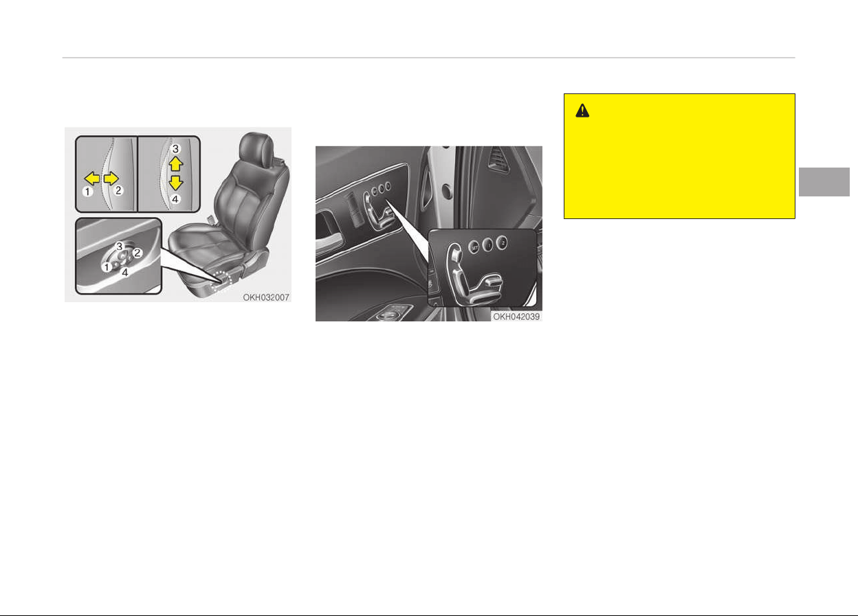
Lumbar support (for driver’s seat)
The lumbar support can be adjusted by
pressing the lumbar support switch.
Press the front portion of the switch
(1) to increase support or the rear por‐
tion of the switch (2) to decrease sup‐
port.
To move the support position up or
down, press the switch (3) or (4).
Release the switch once the seat rea‐
ches the desired position.
Driver position memory system
(if equipped)
A driver position memory system is
provided to store and recall the driver
seat, outside rearview mirror, HUD
*
(Head-Up Display), brightness of the in‐
strument cluster illumination and
steering wheel positions with a simple
button operation. By saving the desired
positions into the system memory, dif‐
ferent drivers can reposition the driver
seat, outside rearview mirror and
steering wheel based upon their driving
preference.
*
if equipped
WARNING
Never attempt to operate the driver
position memory system while the
vehicle is moving.
This could result in loss of control,
and an accident causing death, seri‐
ous injury, or property damage.
Storing positions into memory
using the buttons on the door
Storing driver’s seat positions
1. Shift the shift lever into P while the
engine start/stop button is ON.
2. Adjust the driver seat, outside rear‐
view mirror, HUD
*
(Head-up Dis‐
play), brightness of the instrument
cluster illumination and steering
wheel to positions comfortable for
the driver.
3. Press SET button on the control
panel. The system will beep once.
4. Press one of the memory buttons
(1 or 2) within 5 seconds after
pressing the SET button. The sys‐
tem will beep twice when the
memory has been successfully
stored.
*
if equipped
3-07
3
Safety features of your vehicle
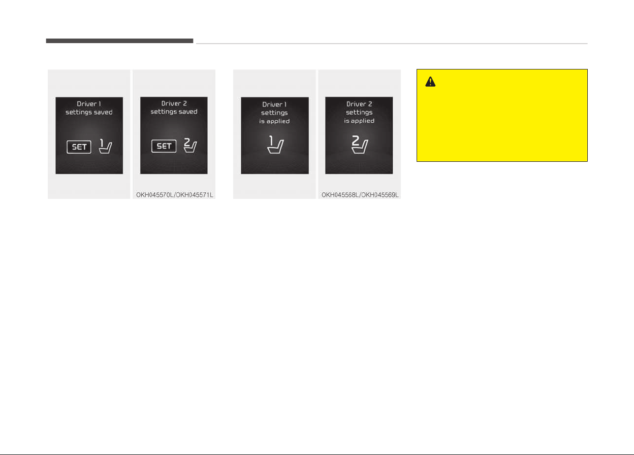
5. "Driver 1 (or 2) settings saved" will
appear on the LCD display.
Recalling positions from memory
1. Shift the shift lever into P while the
engine start/stop button is ON.
2. To recall the position in memory,
press the desired memory button
(1 or 2). The system will beep once,
then the driver seat, outside rear‐
view mirror and steering wheel will
automatically adjust to the stored
positions.
3. "Driver 1 (or 2) settings is applied"
will appear on the LCD display.
Adjusting one of the control knobs
for the driver seat, outside rear‐
view mirror and steering wheel
while the system is recalling the
stored positions will cause the
movement for that component to
stop and move in the direction that
the control knob is moved. Other
components will continue to the re‐
called position.
WARNING
Use caution when recalling adjust‐
ment memory while sitting in the
vehicle. Push the seat position con‐
trol knob to the desired position im‐
mediately if the seat moves too far
in any direction.
Easy access function
The steering wheel will move away
from the driver and the seat will move
rearward, when the engine start/stop
button is turned to the OFF position
and front driver’s door is opened.
The steering wheel will move toward
the driver and the seat will move for‐
ward, when the engine start/stop but‐
ton is turned to the ACC position or
when you insert the smart key into the
smart key holder with the shift lever in
the P position.
Safety features of your vehicle
3-08
NOTICE
You can activate or deactivate the
easy access function in the instru‐
ment cluster.
If you want detailed informations,
refer to the Seat/Steering on page
4-66.
Headrest (for front seat)
The driver's and front passenger's
seats are equipped with a headrest for
the occupant's safety and comfort.
The headrest not only provides comfort
for the driver and front passenger, but
also helps to protect the head and neck
in the event of a collision.
WARNING
• For maximum effectiveness in
case of an accident, the headrest
should be adjusted so the middle
of the headrest is at the same
height as the center of gravity of
an occupant's head. Generally, the
center of gravity of most people's
head is similar with the height of
the top of their eyes. Also, adjust
the headrest as close to your head
as possible. For this reason, the
use of a cushion that holds the
body away from the seatback is
not recommended.
• Do not operate the vehicle with
the headrests removed as severe
injury to the occupants may occur
in the event of an accident. Headr‐
ests may provide protection
against neck injuries when proper‐
ly adjusted.
(Continued)
(Continued)
• Do not adjust the headrest posi‐
tion
of the driver's seat while the
vehicle is in motion.
WARNING
Do not place or attach the accesso‐
ries or other things near the head‐
rest. When the vehicle stops sudden‐
ly or in certain collisions, they could
come loose and injure vehicle occu‐
pants.
3-09
3
Safety features of your vehicle
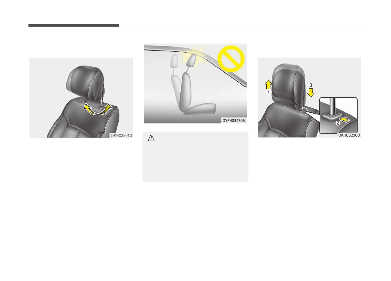
Forward and backward adjustment
The headrest may be adjusted forward
or backward by pulling the lower part
of the headrest forward or backward to
the desired detent in the direction of
the arrow. Adjust the headrest so that
it properly supports the head and neck.
CAUTION
If you recline the seatback towards
the front with the headrest and seat
cushion raised, the headrest may
come in contact with the sunvisor or
other parts of the vehicle.
Adjusting the height up and down
For manual type
To raise the headrest, pull it up to the
desired position (1). To lower the head‐
rest, push and hold the release button
(2) on the headrest support and lower
the headrest to the desired position (3).
Safety features of your vehicle
3-10
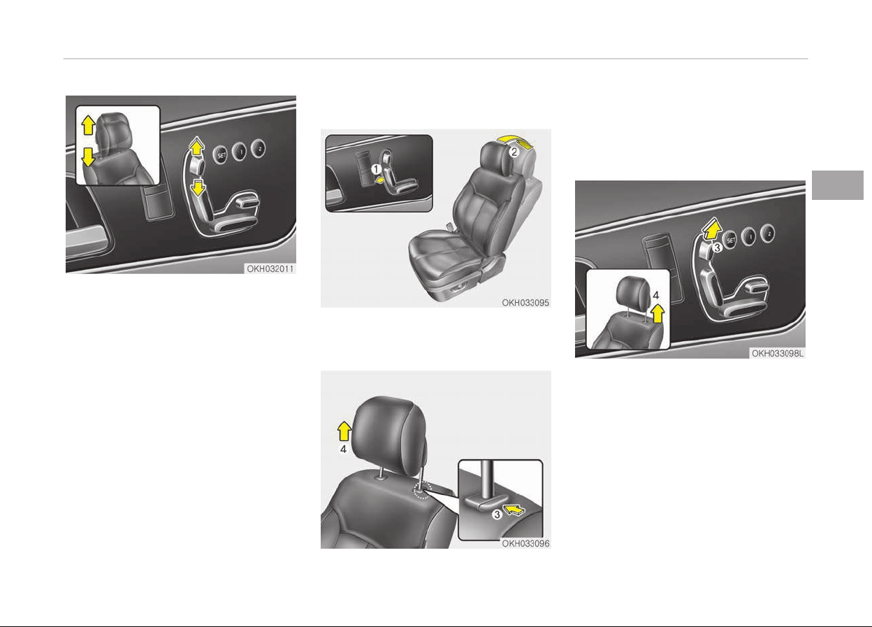
For power type
Push the control switch up to raise or
down to lower the headrest. Release
the switch once the headrest reaches
the desired position.
Removal
1. Recline the seatback (2) with the
recliner control switch (1).
For manual type
2. Raise it as far as it can go.
3. Press the release button (3) while
pulling upward (4).
For power type
2. Raise it as far as it can go by pulling
the switch up (3).
3. Pull the headrest up (4).
3-11
3
Safety features of your vehicle
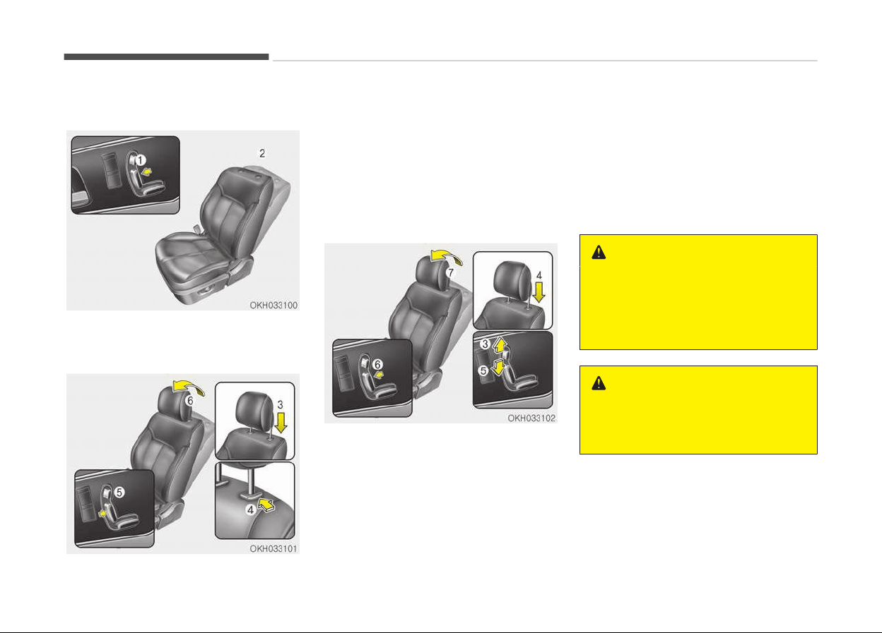
Installation
1. Recline the seatback (2) with the
recliner control switch (1).
For manual type
2. Put the headrest poles (3) into the
holes while pressing the release
button (4).
3. Recline the seatback (6) with the
recliner control switch (5).
4. Adjust the headrest to the appro‐
priate height.
For power type
2. Raise it as far as it can go by pulling
the switch up (3).
3. Put the headrest poles (4) into the
holes and then pull the switch down
(5) until the headrest moves to the
lowest position.
4. T
o install the headrest securely,
move the headrest up and down 2
or 3 times by pulling the switch up
and down.
5. Recline the seatback (7) with the
recliner control switch (6).
6. Adjust the headrest to the appro‐
priate height.
WARNING
If you don't install the headrest se‐
curely, the active headrest may not
operate normally. When reinstalling
the headrest, install it securely as
procedures.
WARNING
Make sure the headrest locks in po‐
sition after adjusting it to properly
protect the occupants.
Safety features of your vehicle
3-12
WARNING
Do not operate the vehicle with the
headrests removed as severe injury
to the occupants may occur in the
event of an accident. Headrests may
provide protection against neck inju‐
ries when properly adjusted.
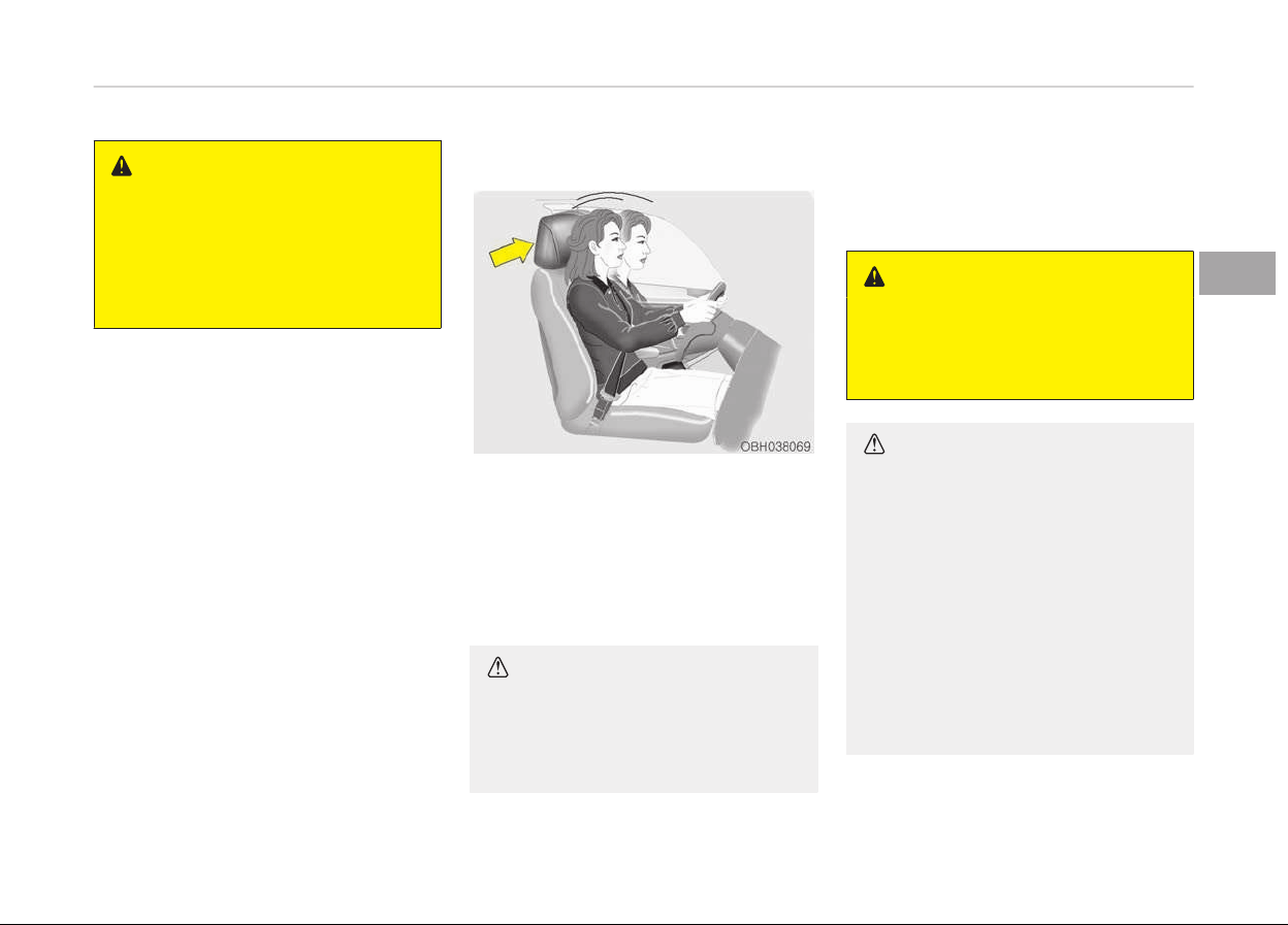
Electronic active headrest
The electronic active headrest is de‐
signed to trigger the headrest forward
and upward when impact sensor de‐
tects a rear impact. This helps to pre‐
vent the driver's and front passenger’s
heads from moving backward and thus
helps minimize neck injuries.
CAUTION
The active headrest is a safety de‐
vice
to reduce injuries from a rear
impact. Do not hit or pull the head‐
rest intentionally.
Rear seat adjustment
The rear seat can be adjusted by using
the control switches located on the
door.
WARNING
The power seat is operable with the
engine start/stop button in OFF.
Therefore, children should never be
left unattended in the vehicle.
CAUTION
• The power seat is driven by an
electric motor. Stop operating once
the adjustment is completed. Ex‐
cessive operation may damage the
electrical equipment.
• When in operation, the power seat
consumes a large amount of elec‐
trical power. To prevent unneces‐
sary charging system drain, don’t
adjust the power seat longer than
necessary while the engine is not
running.
(Continued)
3-13
3
Safety features of your vehicle
(Continued)
• Do not operate two or more power
seat
control switches at the same
time. Doing so may result in power
seat motor or electrical compo‐
nent malfunction.
WARNING
Use extreme caution so that hands
or
other objects are not caught in
the seat mechanisms while the seat
is moving.
Do not adjust the seat while wearing
seat belts. Moving the seat cushion
forward may cause strong pressure
on the abdomen.
WARNING
Do not operate the rear power seat
while the child seat is installed.
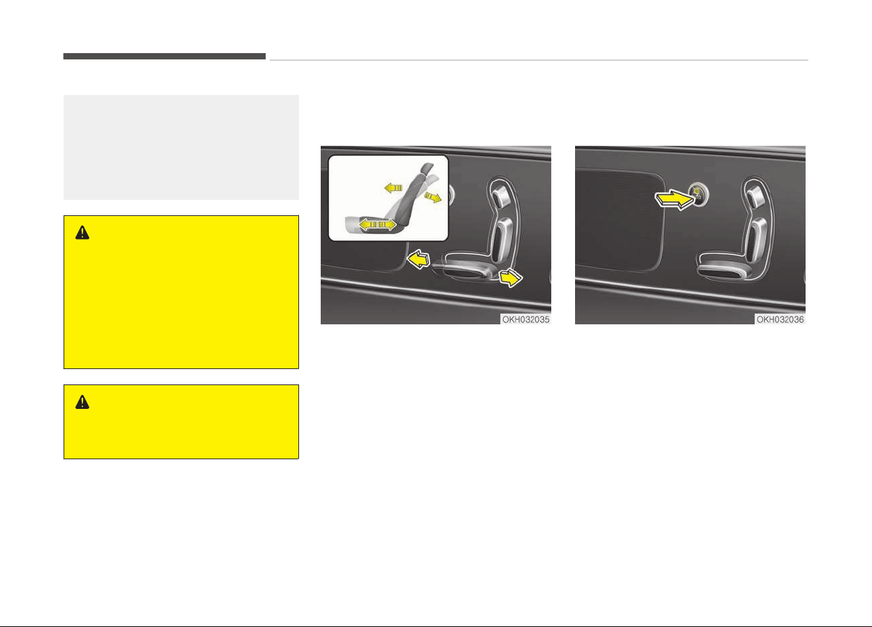
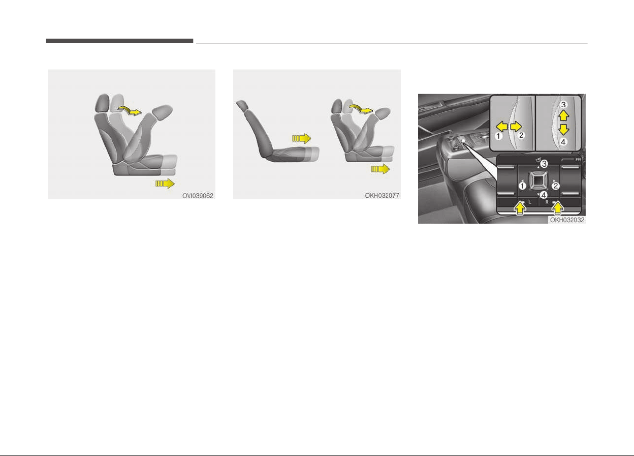
Forward, backward and seatback
angle (for power seat)
Push the control switch forward or
backward to move the seat to the de‐
sired position. Release the switch once
the seat reaches the desired position.
Easy access switch (for power
seat)
Your vehicle features easy access sys‐
tem to provide convenient access for
rear passengers. When opening the
rear door, the rear seats will move
rearward automatically to make pas‐
senger get off easily. This easy access
system will operate only when the con‐
trol switch is in "ON" position.
Safety features of your vehicle
3-14
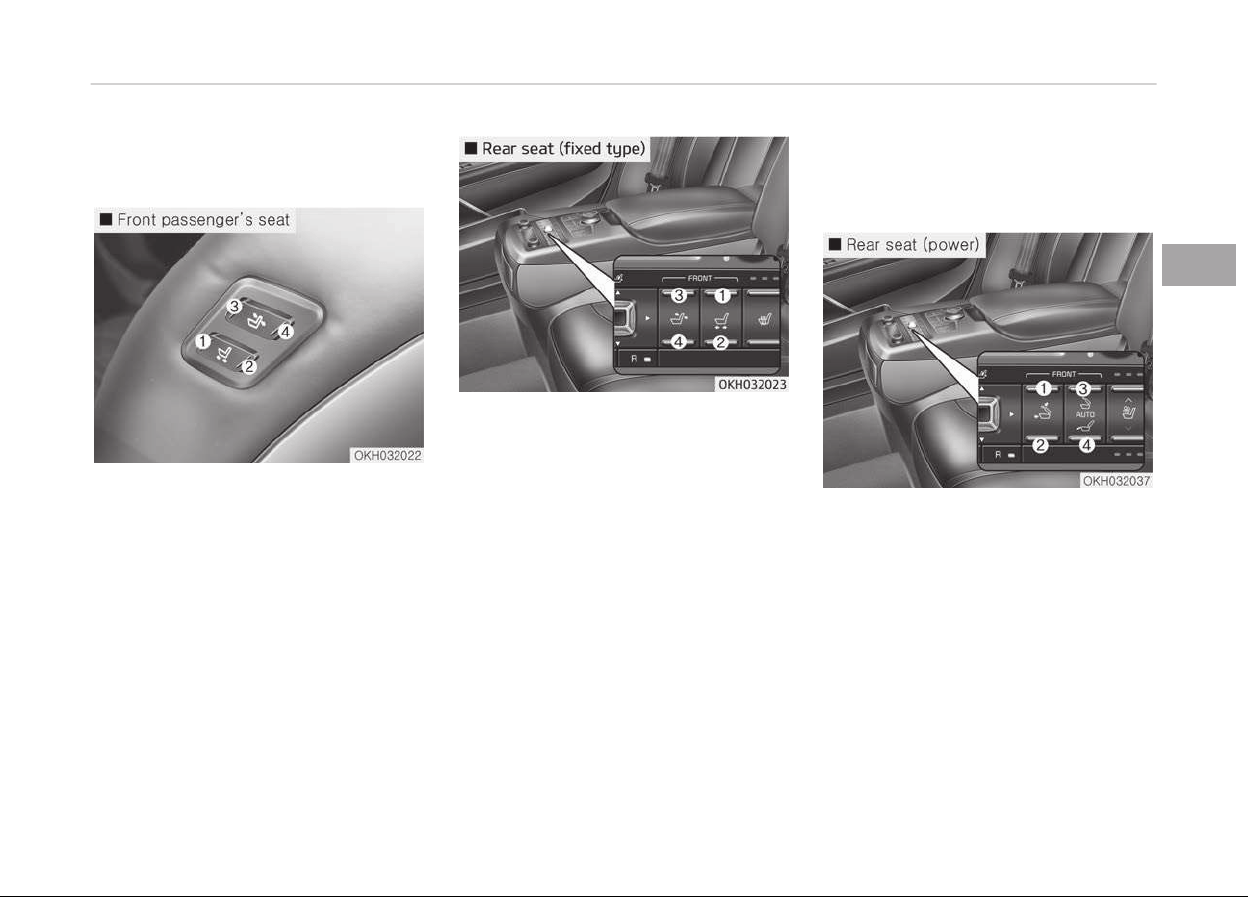
Additional switches for adjusting
the front passenger seat
• Front passenger’s seat
The switch is located on the left side of
the front passenger’s seatback.
To adjust the position of front passeng‐
er’s seat;
Press the control switch forward (1) or
rearward (2) to move the seat to the
desired position.
Press the control switch forward (3) or
rearward (4) to move the seatback to
the desired angle.
Do not use these switches while the
front passenger seat is occupied.
• Rear seat - for fixed type
The switch is located in the armrest of
the rear seat.
To adjust the position of front passeng‐
er’s seat;
Press the control switch forward (1) or
rearward (2) to move the seat to the
desired position.
Press the control switch forward (3) or
rearward (4) to move the seatback to
the desired angle.
Do not use these switches while the
front passenger seat is occupied.
Rear relaxation seat system (for
rear right passenger’s seat) (for
power type)
The rear relaxation seat system pro‐
vides the passenger’s comfort.
The front passenger seat will move for‐
ward and the seatback will fold forward
to provide space. The rear right side
passenger seat seatback will lean to‐
wards the back of the vehicle.
But if the front passenger’s side door is
opened, the rear relaxation seat sys‐
tem will not operate.
3-15
3
Safety features of your vehicle
Front passenger side walk-in seat
Press and hold the switch (1).
The seat will move forward and the
seatback will fold automatically. After
the operation is completed, a beep will
sound once.
Press and hold the switch (2).
The seat and seatback will move to its
standard position. After the operation
is completed, a beep will sound once.
If the seat reaches the desired position,
release the switch.
Rear relaxation seat system
Press and hold the switch (3).
The front passenger seat will move for‐
ward and the seatback will fold auto‐
matically. Then the rear right side pas‐
senger seat seatback will lean towards
the back of the vehicle.
After the operation is completed, a
beep will sound once.
Press and hold the switch (4).
The front passenger seat and the rear
right side passenger seat will move to
its standard position. After the opera‐
tion is completed, a beep will sound.
If the seat reaches the desired position,
release the switch.
Lumbar support
The lumbar support can be adjusted by
pushing the lumbar support switch.
Push the lever to left side(1) increase
support or push the lever to the right
side (2) to decrease support.
To move the support position up or
down, push the lever upside (3) or down
side (4).
Safety features of your vehicle
3-16
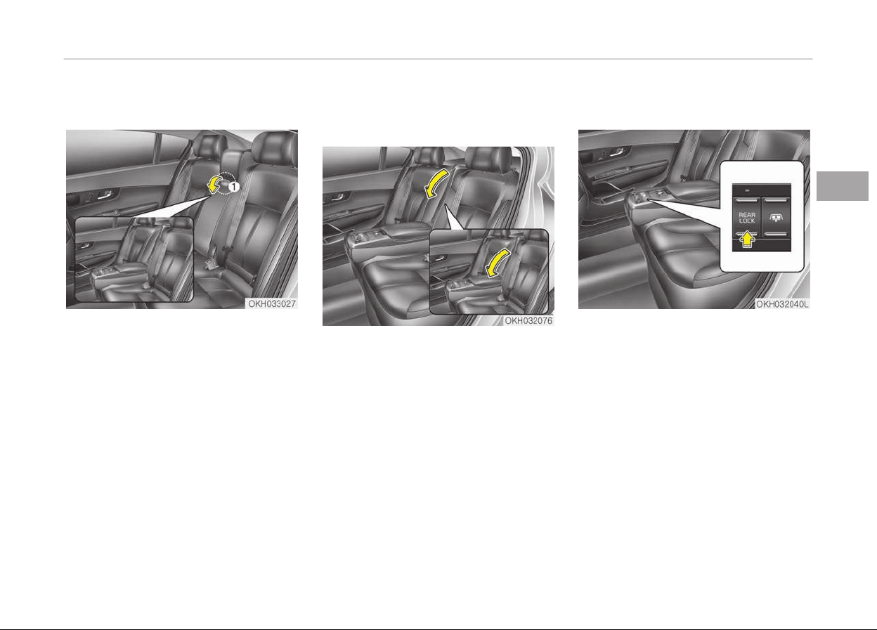
Armrest
To use the armrest, pull it forward
from the seatback.
Carrying long / narrow cargo (for
fixed seat, if equipped)
Additional cargo space is provided to
accommodate long/narrow cargo (skis,
poles, etc.) not able to fit properly in
the trunk when closed.
1. Pull the armrest down.
2. Pull the cover down while pushing
the release lever down.
Rear control lock
You can activate or deactivate the rear
seat control, rear audio control and cli‐
mate control by using the REAR LOCK
button on the rear armrest or System
Settings in the AVN (Audio, Video, and
Navigation
*
).
*
if equipped
3-17
3
Safety features of your vehicle
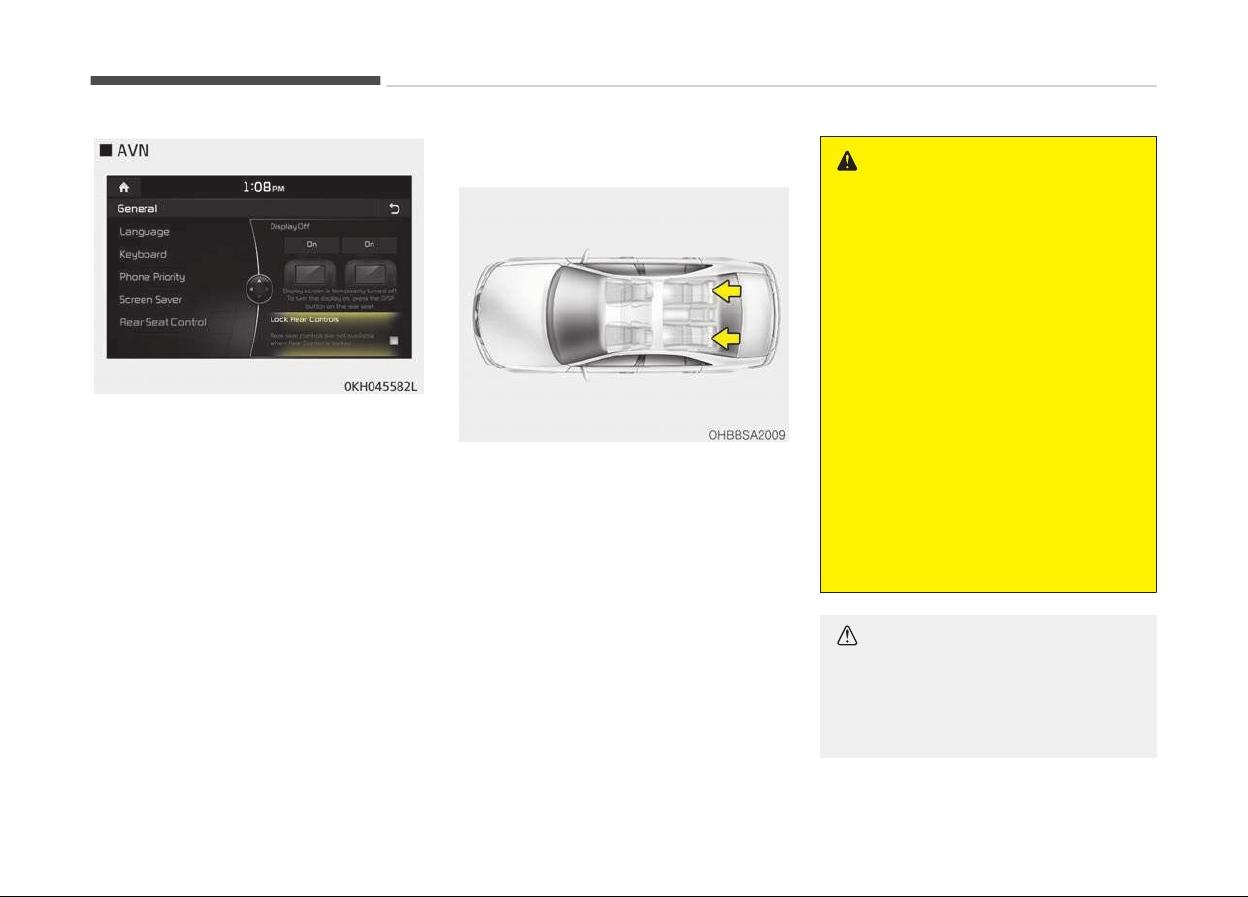
Detailed information for the "System
Settings" is described in a separately
supplied manual.
If the rear control button has deactiva‐
ted through AVN, you can reactivate
the rear control button only through
AVN.
Headrest (for rear seat)
The rear seat(s) is equipped with
headrests in all the seating positions
for the occupant's safety and comfort.
The headrest not only provides comfort
for passengers, but also helps protect
the head and neck in the event of a col‐
lision.
WARNING
• For maximum effectiveness in
case of an accident, the headrest
should be adjusted so the middle
of the headrest is at the same
height of the center of gravity of
an occupant's head. Generally, the
center of gravity of most people's
head is similar with the height of
the top of their eyes. Also adjust
the headrest as close to your head
as possible. The use of a cushion
that holds the body away from the
seatback is not recommended.
• Do not operate the vehicle with
the headrests removed as severe
injury to an occupant may occur in
the event of an accident. Headr‐
ests may provide protection
against severe neck injuries when
properly adjusted.
CAUTION
When there is no occupant in the
r
ear seats, adjust the height of the
headrest to the lowest position. The
(Continued)
Safety features of your vehicle
3-18

(Continued)
rear seat headrest can reduce the
visibility of the r
ear area.
WARNING
Do not place or attach the accesso‐
ries or other things near the head‐
rest. When the vehicle stops sudden‐
ly or in certain collisions, they could
come loose and injure vehicle occu‐
pants.
Adjusting the height up and down
To raise the headrest, pull it up to the
desired position (1). To lower the head‐
rest, push and hold the release button
(2) on the headrest support and lower
the headrest to the desired position (3).
Removal (for power type)
To remove the headrest move the seat
forward as much as possible. Raise it as
far as it can go then press the release
button (1) while pulling the headrest up
(2).
WARNING
Do not operate the vehicle with the
headrests removed as severe injury
to the occupants may occur in the
event of an accident. Headrests may
provide protection against neck inju‐
ries when properly adjusted.
3-19
3
Safety features of your vehicle
Reinstall (for power type)
To reinstall the headrest move the seat
forward as much as possible. Put the
headrest poles (3) into the holes while
pressing the release button (1). Then
adjust it to the appropriate height (2).
WARNING
Make sure the headrest locks in po‐
sition after adjusting it to properly
protects the occupants.
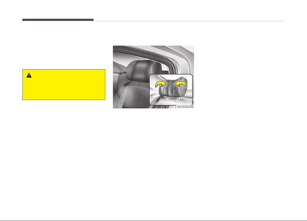
Wing-out (if equipped)
For rear passenger's convenience, the
ends of the headrest can be bent in‐
ward.
Safety features of your vehicle
3-20

SEAT BELTS
Seat belt restraint system
WARNING
• For maximum restraint system
protection, the seat belts must al‐
ways be used whenever the car is
moving.
• Seat belts are most effective when
seatbacks
are in the upright posi‐
tion.
• Children age 12 and younger must
always
be properly restrained in
the rear seat. Never allow children
to ride in the front passenger seat.
If a child over 12 must be seated in
the front seat, he/she must be
properly belted and the seat
should be moved as far back as
possible.
• Never wear the shoulder belt un‐
der
your arm or behind your back.
An improperly positioned shoulder
belt can cause serious injuries in a
crash. The shoulder belt should be
positioned midway over your
shoulder across your collarbone.
(Continued)
(Continued)
• Never wear a seat belt over fragile
objects. If there is a sudden stop
or impact, the seat belt can dam‐
age it.
• Avoid wearing twisted seat belts.
A twisted belt can't do its job as
well. In a collision, it could even cut
into you. Be sure the belt webbing
is straight and not twisted.
• Be careful not to damage the belt
webbing or hardware. If the belt
webbing or hardware is damaged,
replace it.
WARNING
Seat belts are designed to bear upon
the bony structure of the body, and
should be worn low across the front
of the pelvis or the pelvis, chest and
shoulders, as applicable; wearing the
lap section of the belt across the ab‐
dominal area must be avoided.
Seat belts should be adjusted as
firmly as possible, consistent with
comfort, to provide the protection
for which they have been designed.
(Continued)
(Continued)
A slack belt will greatly reduce the
protection afforded to the wearer.
Care should be taken to avoid con‐
tamination of the webbing with pol‐
ishes, oils and chemicals, and partic‐
ularly battery acid.
Cleaning may safely be carried out
using mild soap and water. The belt
should be replaced if webbing be‐
comes frayed, contaminated or
damaged. It is essential to replace
the entire assembly after it has
been worn in a severe impact even if
damage to the assembly is not obvi‐
ous. Belts should not be worn with
straps twisted. Each belt assembly
must only be used by one occupant;
it is dangerous to put a belt around a
child being carried on the occupant's
lap.
3-21
3
Safety features of your vehicle
WARNING
• No modifications or additions
should be made by the user which
will either prevent the seat belt
adjusting devices from operating
to remove slack, or prevent the
seat belt assembly from being ad‐
justed to remove slack.
• When you fasten the seat belt, be
careful not to latch the seat belt in
buckles of other seat. It's very
dangerous and you may not be
protected by the seat belt proper‐
ly.
• Do not unfasten the seat belt and
do not fasten and unfasten the
seat belt repeatedly while driving.
This could result in loss of control,
and an accident causing death, se‐
rious injury, or property damage.
• When fastening the seat belt,
make sure that the seat belt does
not pass over objects that are hard
or can break easily.
• Make sure there is nothing in the
buckle.
The seat belt may not be
fastened securely.
Seat belt warning
■ Type A
As a reminder to the driver, the seat
belt warning light will blink for approxi‐
mately 6 seconds each time you turn
the Engine Start/Stop button ON re‐
gardless of belt fastening.
If the driver’s seat belt is unfastened
after the Engine Start/Stop button is
ON, the seat belt warning light blinks
again for approximately 6 seconds.
If the driver's seat belt is not fastened
when the Engine Start/Stop button is
turned ON or if it is unfastened after
the Engine Start/Stop button is ON, the
seat belt warning chime will sound for
approximately 6 seconds.
At this time, if the seat belt is fas‐
tened, the chime will stop at once. (if
equipped)
■ Type B
As a reminder to the driver, the driver’s
seat belt warning lights will illuminate
for approximately 6 seconds each time
you turn the Engine Start/Stop button
ON regardless of belt fastening.
If the driver’s seat belt is not fastened
when the Engine Start/Stop button is
turned ON or if it is disconnected after
the Engine Start/Stop button is turned
ON, the seat belt warning light will illu‐
minate until the belt is fastened.
If you continue not to fasten the seat
belt and you drive over 9 km/h, the illu‐
minated warning light will start to blink
until you drive under 6 km/h.
If you continue not to fasten the seat
belt and you drive over 20 km/h the
seat belt warning chime will sound for
approximately 100 seconds and the
corresponding warning light will blink.
Safety features of your vehicle
3-22
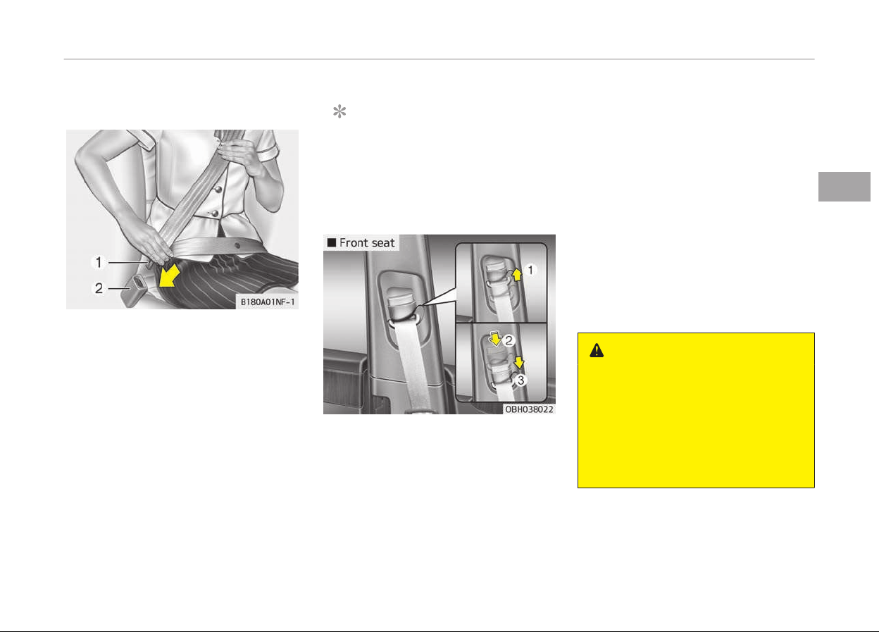
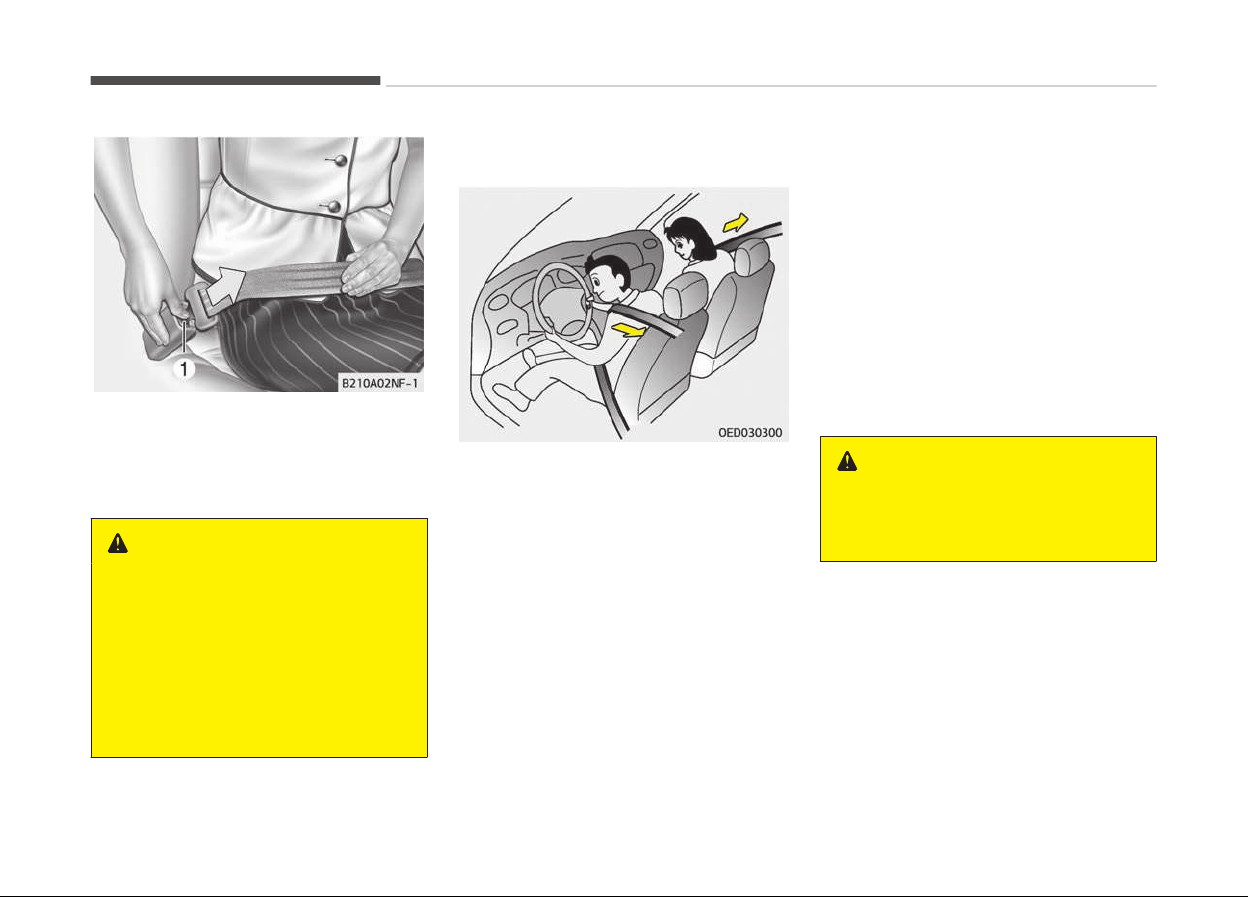
Lap/shoulder belt
To fasten your seat belt:
To fasten your seat belt, pull it out of
the retractor and insert the metal tab
(1) into the buckle (2). There will be an
audible "click" when the tab locks into
the buckle.
The seat belt automatically adjusts to
the proper length only after the lap
belt portion is adjusted manually so
that it fits snugly around your hips. If
you lean forward in a slow, easy mo‐
tion, the belt will extend and let you
move around. If there is a sudden stop
or impact, however, the belt will lock in‐
to position. It will also lock if you try to
lean forward too quickly.
NOTICE
If you are not able to pull out the
seat belt from the retractor, firmly
pull the belt out and release it. Then
you will be able to pull the belt out
smoothly.
Height adjustment (front seat)
You can adjust the height of the shoul‐
der belt anchor to one of 4 positions for
maximum comfort and safety.
The height of the adjusting seat belt
should
not be too near your neck. The
shoulder portion should be adjusted so
that it lies across your chest and mid‐
way over your shoulder nearest the
door and not your neck.
To adjust the height of the seat belt
anchor, lower or raise the height ad‐
juster into an appropriate position.
To raise the height adjuster, pull it up
(1). To lower it, push it down (3) while
pressing the height adjuster button (2).
Release the button to lock the anchor
into position. Try sliding the height ad‐
juster to make sure that it has locked
into position.
WARNING
• Verify the shoulder belt anchor is
locked into position at the appro‐
priate height. Never position the
shoulder belt across your neck or
face. Improperly positioned seat
belts can cause serious injuries in
an accident.
(Continued)
3-23
3
Safety features of your vehicle
(Continued)
• Failure to replace seat belts after
an
accident could leave you with
damaged seat belts that will not
provide protection in the event of
another collision leading to person‐
al injury or death. Replace your
seat belts after being in an acci‐
dent as soon as possible.
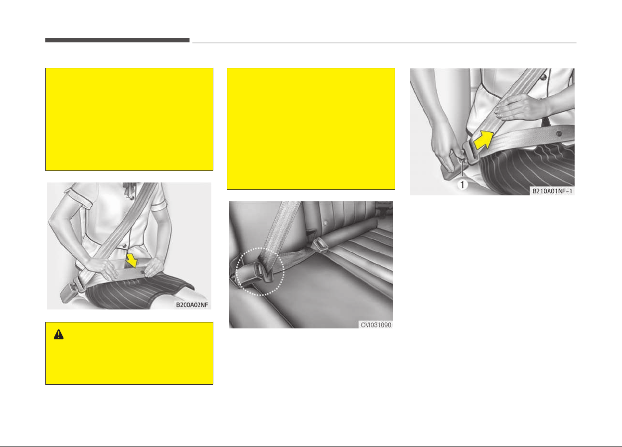
WARNING
You should place the lap belt portion
as
low as possible and snugly across
(Continued)
(Continued)
your hips, not on your waist. If the
lap
belt is located too high on your
waist, it may increase the chance of
injury in the event of a collision. Both
arms should not be under or over
the belt. Rather, one should be over
and the other under, as shown in the
illustration.
Never wear the seat belt under the
arm nearest the door.
When using the rear center seat belt,
the buckle with the CENTER mark
must be used. (if equipped)
To release the seat belt:
The seat belt is released by pressing
the release button (1) in the locking
buckle. When it is released, the belt
should automatically draw back into
the retractor.
If this does not happen, check the belt
to be sure it is not twisted, then try
again.
Safety features of your vehicle
3-24
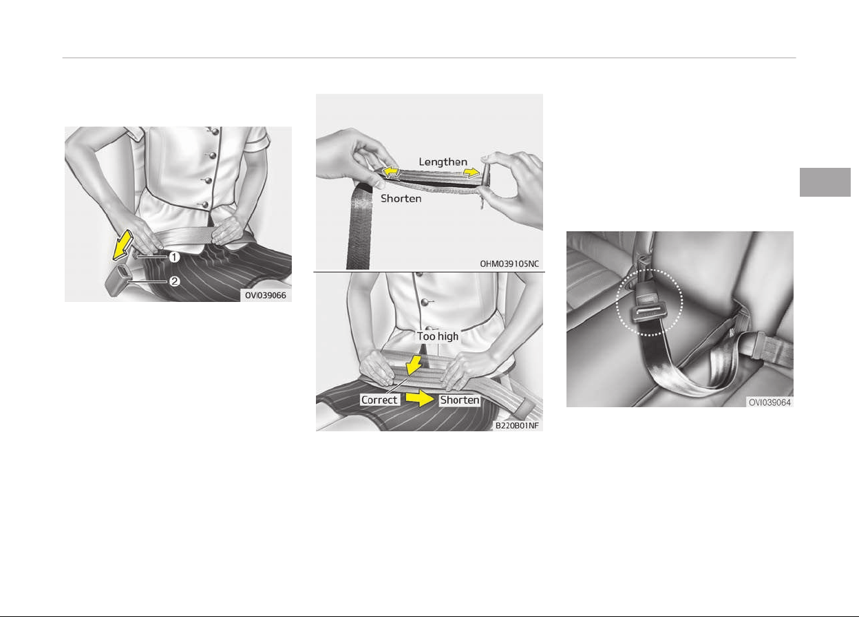
Lap belt (if equipped)
To fasten your seat belt:
To fasten a 2-point static type belt, in‐
sert the metal tab (1) into the locking
buckle (2). There will be an audible
"click" when the tab locks into the buck‐
le. Check to make sure the belt is prop‐
erly locked and that the belt is not
twisted.
With a 2-point static type seat belt, the
length must be adjusted manually so it
fits snugly around your body. Fasten
the belt and pull on the loose end to
tighten. The belt should be placed as
low as possible on your hips, not on
your waist. If the belt is too high, it
could increase the possibility of your
being injured in an accident.
When using the rear center seat belt,
the buckle with the CENTER mark
must be used.
3-25
3
Safety features of your vehicle
To release the seat belt:
When you want to release the seat
belt, press the button (1) in the locking
buckle.
WARNING
The center lap belt latching mecha‐
nism is different from those for the
rear seat shoulder belts. When fas‐
tening the rear seat shoulder belts
or the center lap belt, make sure
they are inserted into the correct
buckles to obtain maximum protec‐
tion from the seat belt system and
assure proper operation.
Pre-tensioner seat belt
Your vehicle is equipped with driver's
and front passenger's pre-tensioner
seat belts. The pre-tensioner seat belts
can be activated, where the frontal col‐
lision is severe enough, together with
the air bags.
When the vehicle stops suddenly, or if
the occupant tries to lean forward too
quickly, the seat belt retractor will lock
into position. In certain frontal colli‐
sions, the pre-tensioner will activate
and pull the seat belt into tighter con‐
tact against the occupant's body.
• Retractor Pretensioner
The purpose of the retractor preten‐
sioner is to make sure that the shoul‐
der belts fit in tightly against the oc‐
cupant's upper body in certain frontal
collisions.
If the system senses excessive tension
on the driver or passenger's seat belt
when the pre-tensioner system acti‐
vates, the load limiter inside the retrac‐
tor pre-tensioner will release some of
the pressure on the affected seat belt.
WARNING
For your safety, be sure that the
belt webbing is not loose or twisted
and always sit properly on your seat.
Safety features of your vehicle
3-26
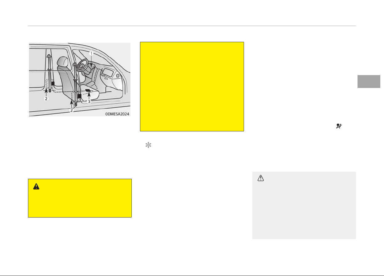
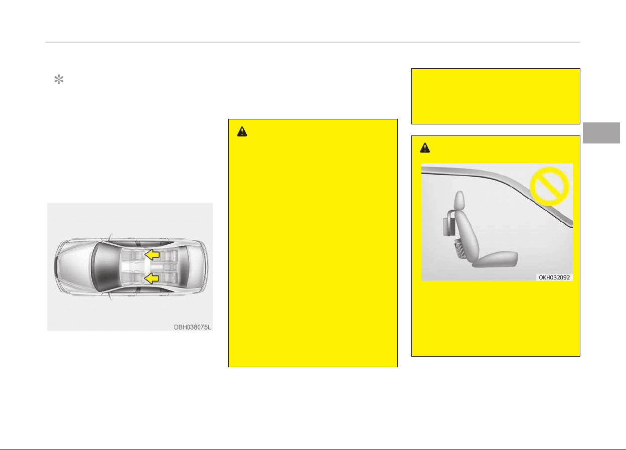
The seat belt pre-tensioner system
consists mainly of the following compo‐
nents. Their locations are shown in the
illustration:
1. SRS air bag warning light
2. Retractor pre-tensioner assembly
3. SRS control module
WARNING
To obtain maximum benefit from a
pre-tensioner seat belt:
(Continued)
(Continued)
1. The seat belt must be worn cor‐
r
ectly and adjusted to the proper
position. Please read and follow
all of the important information
and precautions about your vehi‐
cle’s occupant safety features –
including seat belts and air bags
– that are provided in this man‐
ual.
2. Be sure you and your passen‐
gers
always wear seat belts
properly.
NOTICE
• Both the driver's and front pas‐
senger's pre-tensioner seat belts
may be activated in certain frontal
collisions.
• When the pre-tensioner seat belts
are activated, a loud noise may be
heard and fine dust, which may
appear to be smoke, may be visi‐
ble in the passenger compart‐
ment. These are normal operating
conditions and are not hazardous.
(Continued)
(Continued)
• Although
it is harmless, the fine
dust may cause skin irritation and
should not be breathed for pro‐
longed periods. Wash all exposed
skin areas thoroughly after an ac‐
cident in which the pre-tensioner
seat belts were activated.
• Because the sensor that activates
the SRS air bag is connected with
the pre-tensioner seat belt, the
SRS air bag warning light on
the
instrument panel will illumi‐
nate for approximately 6 seconds
after the Engine Start/Stop button
has been turned to the ON posi‐
tion, and then it should turn off.
CAUTION
If the SRS air bag warning light does
not
illuminate when the ignition key
is turned to ON, or if it remains illu‐
minated after illuminating for ap‐
proximately 6 seconds, or if it illumi‐
nates while the vehicle is being driv‐
en, have the system inspected by a
(Continued)
3-27
3
Safety features of your vehicle
(Continued)
professional workshop. Kia recom‐
mends
to visit an authorized Kia
dealer/service partner.
WARNING
• Pre-tensioners seat belt system
ar
e designed to operate only one
time. After activation, pre-ten‐
sioner seat belts must be replaced.
All seat belts, of any type, should
always be replaced after they
have been worn during a collision.
• The pre-tensioner seat belt as‐
sembly
mechanisms become hot
during activation. Do not touch the
pre-tensioner seat belt assemblies
for several minutes after they
have been activated.
• Do not attempt to inspect or re‐
place
the pre-tensioner seat belts
yourself. In this case, have the
system inspected by a professio‐
nal workshop. Kia recommends to
visit an authorized Kia dealer/serv‐
ice partner.
(Continued)
(Continued)
• Do not strike the pre-tensioner
seat belt assemblies.
• Do not attempt to service or repair
the
pre-tensioner seat belt sys‐
tem in any manner.
• Improper handling of the preten‐
sioner
seat belt assemblies, and
failure to heed the warnings not to
strike, modify, inspect, replace,
service or repair the pre-tensioner
seat belt assemblies may lead to
improper operation or inadvertent
activation and serious injury.
• Always wear the seat belts when
driving or riding in a motor vehicle.
• If the vehicle or pre-tensioner seat
belt must be discarded, contact a
professional workshop. Kia recom‐
mends to visit an authorized Kia
dealer/service partner.
CAUTION
Body work on the front area of the
v
ehicle may damage the pretension‐
(Continued)
(Continued)
er seat belt system. Therefore, have
the
system serviced by a professio‐
nal workshop. Kia recommends to
visit an authorized Kia dealer/service
partner.
Pre-active seat belt (PSB) (if
equipped)
The purpose of the pre-active seat belt
is to prevent passengers from getting
hurt by tightening the seat belt right
before a collision or dangerous maneu‐
ver.
Safety features of your vehicle
3-28
CAUTION
The pre-active seat belt activates
only when the passenger is wearing
his/her seat belt.
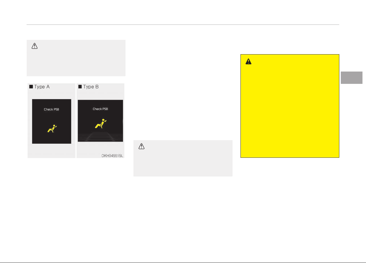
The pre-active seat belt warning will
turn on if there is a problem with your
pre-active seat belt.
Have the system checked by a profes‐
sional workshop. Kia recommends to
visit an authorized Kia dealer/service
partner.
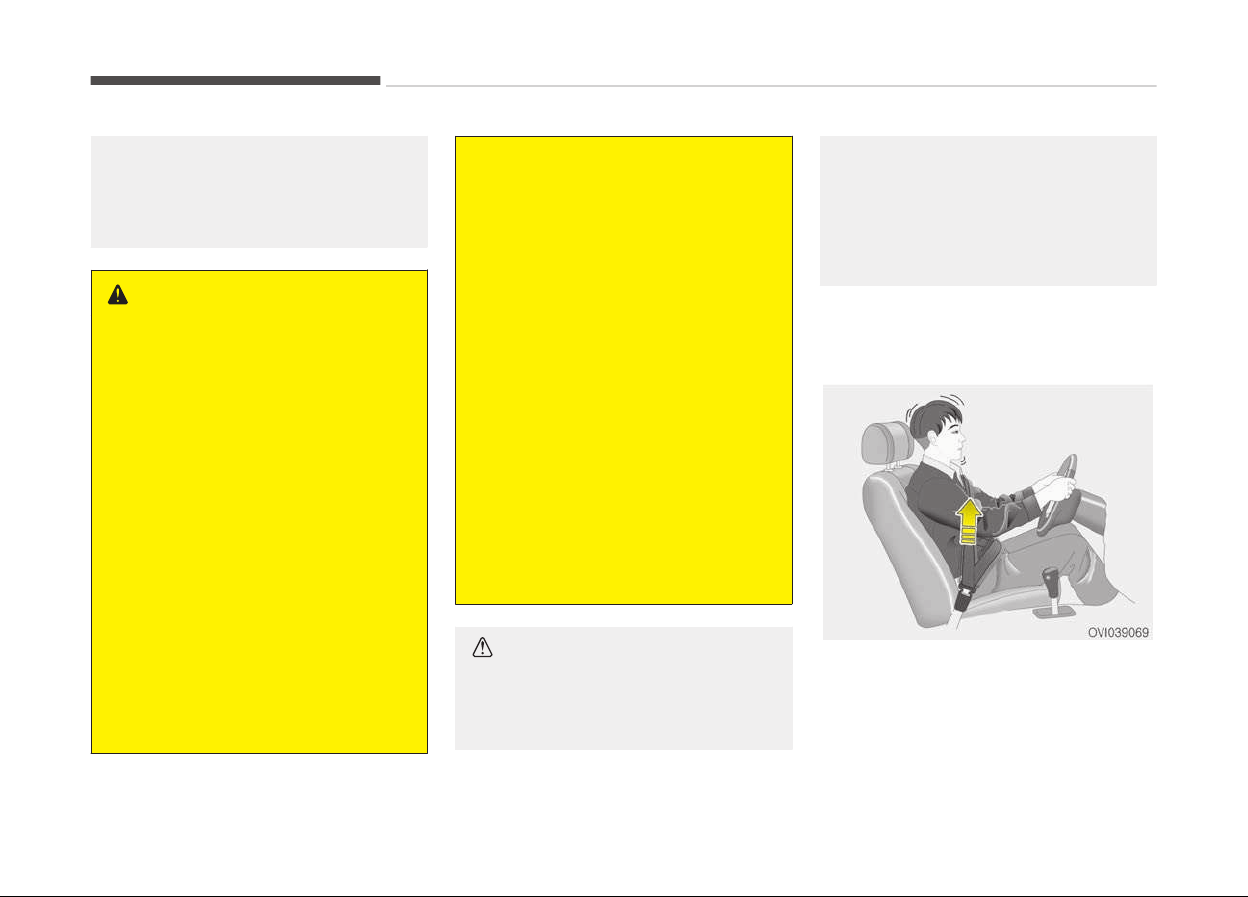
The warning message comes on while
the
vehicle is in motion. If the PSB
warning message disappeared, the
warning indicator (master symbol)
turns on.
In order to maximize the safety of the
passenger, the pre-active seat belt
system operates as below
• The seat belt is tightened when:
- The vehicle senses a collision
- Emergency braking situation occurs
- Losing control of the vehicle
• The seat belt vibrates when:
- The vehicle senses a object too
near the vehicle
CAUTION
Do not be surprised when the seat
belt vibrates. It's not a malfunction
but a warning for your safety.
Other functions is winding a loose seat
belt after unfastening the seat belt.
Seat belt precautions
WARNING
All occupants of the vehicle must
wear their seat belts at all times.
Seat belts and child restraints re‐
duce the risk of serious or fatal inju‐
ries for all occupants in the event of
a collision or sudden stop. Without a
seat belt, occupants could be shifted
too close to a deploying air bag,
strike the interior structure or be
thrown from the vehicle. Properly
worn seat belts greatly reduce these
hazards.
Always follow the precautions about
seat belts, air bags and occupant
seating contained in this manual.
Infant or small child
You should be aware of the specific re‐
quirements in your country. Child
and/or infant seats must be properly
placed and installed in the rear seat.
For more information about the use of
these restraints, refer to Child re‐
straint system on page 3-33.
3-29
3
Safety features of your vehicle
WARNING
Every person in your vehicle needs
to be properly restrained at all
times, including infants and children.
Never hold a child in your arms or lap
when riding in a vehicle. The violent
forces created during a crash will
tear the child from your arms and
throw the child against the interior.
Always use a child restraint appro‐
priate for your child's height and
weight.
NOTICE
Small children are best protected
from
injury in an accident when
properly restrained in the rear seat
by a child restraint system that
meets the requirements of the
Safety Standards of your country.
Before buying any child restraint
system, make sure that it has a la‐
bel certifying that it meets Safety
Standards of your country. The re‐
straint must be appropriate for your
child's height and weight. Check the
(Continued)
(Continued)
label on the child restraint for this
information. Refer to 3-33.
Larger children
Children who are too large for child re‐
straint systems should always occupy
the rear seat and use the available lap/
shoulder belts. The lap portion should
be fastened and snugged on the hips
and as low as possible. Check periodi‐
cally if the belt fits. A child's squirming
could put the belt out of position. Chil‐
dren are given the most safety in the
event of an accident when they are re‐
strained by a proper restraint system
in the rear seat. If a larger child (over
age 12) must be seated in the front
seat, the child should be securely re‐
strained by the available lap/shoulder
belt and the seat should be placed in
the rearmost position. Children age 12
and under should be restrained secure‐
ly in the rear seat. NEVER place a child
age 12 and under in the front seat.
NEVER place a rear facing child seat in
the front seat of a vehicle.
If the shoulder belt portion slightly
touches the child’s neck or face, try
placing the child closer to the center of
the vehicle. If the shoulder belt still
touches their face or neck they need to
be returned to a child restraint system.
WARNING
n
Shoulder belts on small chil‐
dren
• Never allow a shoulder belt to be in
contact with a child’s neck or face
while the vehicle is in motion.
• If seat belts are not properly worn
and adjusted on children, there is a
risk of death or serious injury.
Restraint of pregnant women
Pregnant women should wear lap/
shoulder belt assemblies whenever
possible according to specific recom‐
mendations by their doctors. The lap
portion of the belt should be worn AS
SNUGLY AND LOW AS POSSIBLE on the
hips, not across the abdomen.
Safety features of your vehicle
3-30

WARNING
n
Pregnant women
Pregnant women must never place
the lap portion of the safety belt
over the area of the abdomen where
the fetus is located or above the ab‐
domen where the belt could crush
the fetus during an impact.
Injured person
A seat belt should be used when an in‐
jured person is being transported.
When this is necessary, you should con‐
sult a physician for recommendations.
One person per belt
Two people (including children) should
never attempt to use a single seat belt.
This could increase the severity of inju‐
ries in case of an accident.
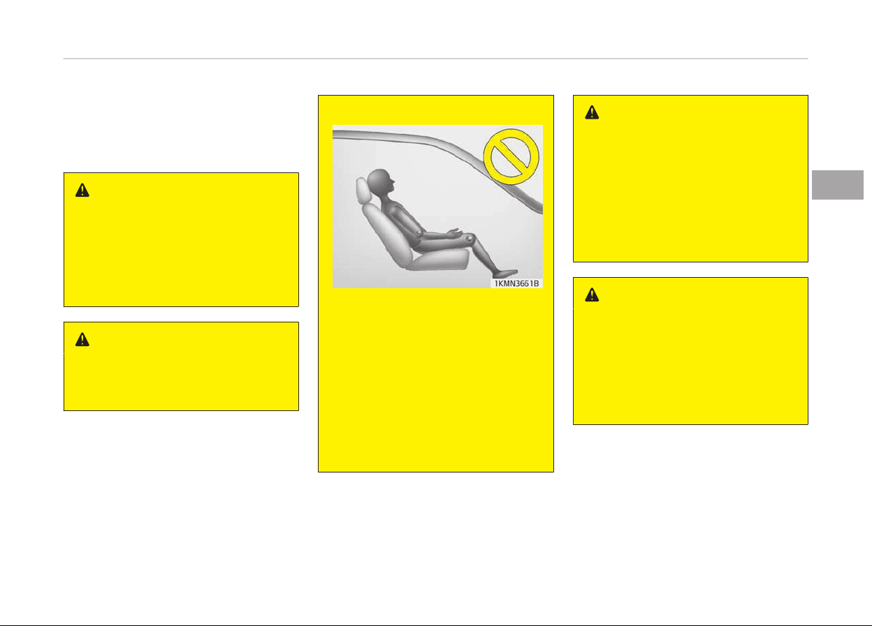
Do not lie down
To reduce the chance of injuries in the
event of an accident and to achieve
maximum effectiveness of the re‐
straint system, all passengers should
be sitting up and the front and rear
seats should be in an upright position
when the car is moving. A seat belt
cannot provide proper protection if the
person is lying down in the rear seat or
if the front and rear seats are in a re‐
clined position.
WARNING
Riding with a reclined seatback in‐
creases your chance of serious or fa‐
tal injuries in the event of a collision
or sudden stop. The protection of
your restraint system (seat belts
and air bags) is greatly reduced by
reclining your seat. Seat belts must
be snug against your hips and chest
to work properly. The more the
seatback is reclined, the greater the
chance that an occupant's hips will
slide under the lap belt causing seri‐
ous internal injuries or the occu‐
pant's neck could strike the shoulder
(Continued)
(Continued)
belt. Drivers and passengers should
always
sit well back in their seats,
properly belted, and with the seat‐
backs upright.
Care of seat belts
Seat belt systems should never be dis‐
assembled or modified. In addition, care
should be taken to assure that seat
belts and belt hardware are not dam‐
aged by seat hinges, doors or other
abuse.
Periodic inspection
All seat belts should be inspected peri‐
odically for wear or damage of any
kind. Any damaged parts should be re‐
placed as soon as possible.
Keep belts clean and dry
Seat belts should be kept clean and dry.
If belts become dirty, they can be
cleaned by using a mild soap solution
and warm water. Bleach, dye, strong
detergents or abrasives should not be
used because they may damage and
weaken the fabric.
3-31
3
Safety features of your vehicle

When to replace seat belts
Entire in-use seat belt assembly or as‐
semblies should be replaced if the vehi‐
cle has been involved in an accident.
This should be done even if no damage
is visible. In this case, have the system
replaced by a professional workshop.
Kia recommends to consult an author‐
ized Kia dealer/service partner.
Safety features of your vehicle
3-32

CHILD RESTRAINT SYSTEM
Children riding in the car should sit in
the rear seat and must always be prop‐
erly restrained to minimize the risk of
injury in an accident, sudden stop or
sudden maneuver. According to acci‐
dent statistics, children are safer when
properly restrained in the rear seats
than in the front seat. Larger children
not in a child restraint should use one
of the seat belts provided.
You should be aware of the specific re‐
quirements in your country. Child
and/or infant safety seats must be
properly placed and installed in the rear
seat. You must use a commercially
available child restraint system that
meets the requirements of the Safety
Standards of your country.
Child restraint systems are designed to
be secured in vehicle seats by lap belts
or the lap belt portion of a lap/shoulder
belt, or by a tether anchor and/or ISO‐
FIX anchors.
Children could be injured or killed in a
crash if their restraints are not proper‐
ly secured. For small children and ba‐
bies, a child seat or infant seat must be
used. Before buying a particular child
restraint system, make sure it fits your
car seat and seat belts, and fits your
child. Follow all the instructions provi‐
ded by the manufacturer when instal‐
ling the child restraint system.
WARNING
• A child restraint system must be
placed in the rear seat. Never in‐
stall a child or infant seat on the
front passenger's seat. Should an
accident occur and cause the pas‐
senger-side air bag to deploy, it
could severely injure or kill an in‐
fant or child seated in an infant or
child seat. Thus only use a child re‐
straint in the rear seat of your ve‐
hicle.
(Continued)
(Continued)
• A seat belt or child restraint sys‐
tem can become very hot if it is
left in a closed vehicle on a sunny
day, even if the outside tempera‐
ture does not feel hot. Be sure to
check the seat cover and buckles
before placing a child there.
• When the child restraint system is
not in use, store it in the luggage
area or fasten it with a seat belt
so that it will not be thrown for‐
ward in the case of a sudden stop
or an accident.
• Children may be seriously injured
or killed by an inflating air bag. All
children, even those too large for
child restraints, must ride in the
rear seat.
WARNING
To reduce the chance of serious or
fatal injuries:
(Continued)
3-33
3
Safety features of your vehicle

(Continued)
• Children of all ages are safer when
r
estrained in the rear seat. A child
riding in the front passenger seat
can be forcefully struck by an in‐
flating air bag resulting in serious
or fatal injuries.
• Always follow the child restraint
system
manufacturer’s instruc‐
tions for installation and use of
the child restraint.
• Always make sure the child seat is
secured properly in the vehicle and
your child is securely restrained in
the child seat.
• Never hold a child in your arms or
lap when riding in a vehicle. The vi‐
olent forces created during a crash
will tear the child from your arms
and throw the child against the ve‐
hicle’s interior.
• Never put a seat belt over yourself
and a child. During a crash, the belt
could press deep into the child
causing serious internal injuries.
(Continued)
(Continued)
• Never leave children unattended in
a
vehicle – not even for a short
time. The car can heat up very
quickly, resulting in serious injuries
to children inside. Even very young
children may inadvertently cause
the vehicle to move, entangle
themselves in the windows, or lock
themselves or others inside the
vehicle.
• Never allow two children, or any
two
persons, to use the same seat
belt.
• Children often squirm and reposi‐
tion themselves improperly. Never
let a child ride with the shoulder
belt under their arm or behind
their back. Always properly posi‐
tion and secure children in the rear
seat.
• Never allow a child to standup or
kneel on the seat or floor of a
moving vehicle. During a collision
or sudden stop, the child can be vi‐
olently thrown against the vehi‐
cle’s interior, resulting in serious
injury.
(Continued)
(Continued)
• Never use an infant carrier or a
child
safety seat that "hooks" over
a seatback, it may not provide ad‐
equate security in an accident.
• Seat belts can become very hot,
especially
when the vehicle is
parked in direct sunlight. Always
check seat belt buckles before fas‐
tening them over a child.
• After an accident, have the sys‐
tem checked by a professional
workshop. Kia recommends to visit
an authorized Kia dealer/service
partner.
• If there is not enough space to
place the child restraint system
because of the driver's seat, install
the child restraint system in the
rear right seat.
WARNING
Do not operate the rear power seat
(if equipped) while the child seat is
installed.
Safety features of your vehicle
3-34
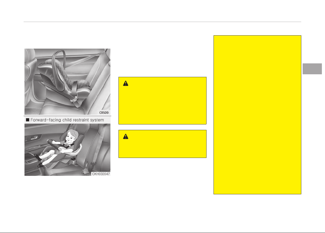
Using a child restraint system
For small children and babies, the use
of a child seat or infant seat is r
equired.
This child seat or infant seat should be
of appropriate size for the child and
should be installed in accordance with
the manufacturer's instructions.
For safety reasons, we recommend
that the child restraint system be used
in the rear seats.
WARNING
Never place a rear-facing child re‐
straint in the front passenger seat,
because of the danger that an inflat‐
ing passenger-side air bag could im‐
pact the rear-facing child restraint
and kill the child.
WARNING
n
Child seat installation
(Continued)
(Continued)
• A child can be seriously injured or
killed
in a collision if the child re‐
straint is not properly anchored to
the vehicle and the child is not
properly restrained in the child re‐
straint. Before installing the child
restraint system, read the instruc‐
tions supplied by the child re‐
straint system manufacturer.
• If the seat belt does not operate
as
described in this section, have
the system checked by a profes‐
sional workshop. Kia recommends
to visit an authorized Kia dealer/
service partner.
• Failure to observe this manual's in‐
structions regarding child restraint
systems and the instructions pro‐
vided with the child restraint sys‐
tem could increase the chance
and/or severity of injury in an acci‐
dent.
• If the vehicle headrest prevents
proper installation of a child seat
(as described in the child seat sys‐
tem manual), the headrest of the
respective seating position shall be
readjusted or entirely removed.
3-35
3
Safety features of your vehicle
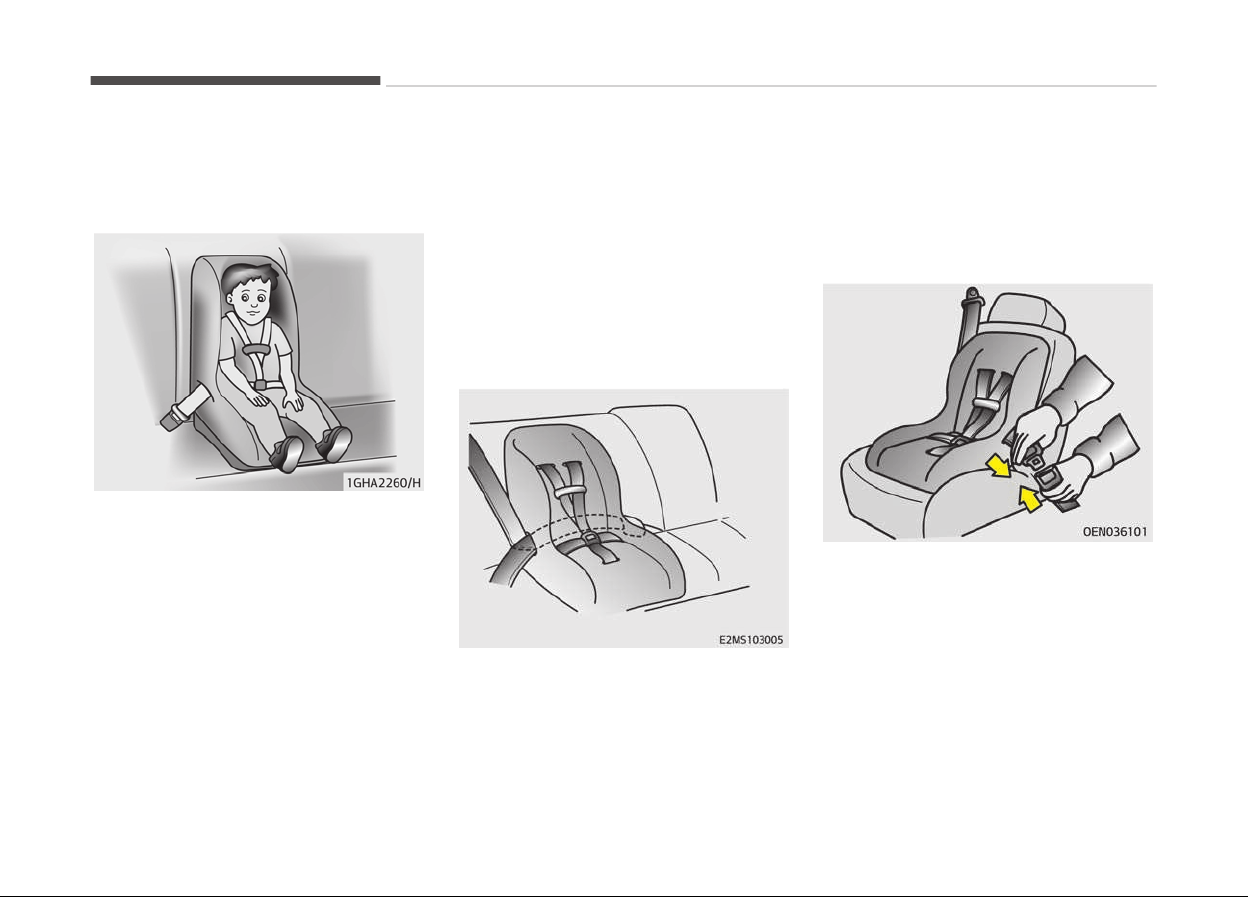
Installing a child restraint system
by lap belt (on the center rear seat)
(if equipped)
To install a child restraint system on
the center rear seats, do the following:
1. Place the child restraint system on
the center rear seat.
2. Extend the latch plate tongue of
the lap belt.
3. Route the lap belt through the re‐
straint according to the seat manu‐
facturer’s instructions.
4. Buckle the seat belt and adjust the
lap belt for a snug hold on the child
restraint by pulling on the loose
end of the belt. After installation of
the child restraint system, try to
move it in all directions to be sure
the child restraint system is se‐
curely installed.
Installing a child restraint system
by lap/shoulder belt
To install a child restraint system on
the outboard or center rear seats, do
the following:
1. Place the child restraint system in
the seat and route the lap/shoulder
belt around or through the re‐
straint, following the restraint
manufacturer’s instructions. Be
sure the seat belt webbing is not
twisted.
2. Fasten the lap/shoulder belt latch
into the buckle. Listen for the dis‐
tinct click sound.
Position the release button so that it is
easy to access in case of an emergen‐
cy.
Safety features of your vehicle
3-36
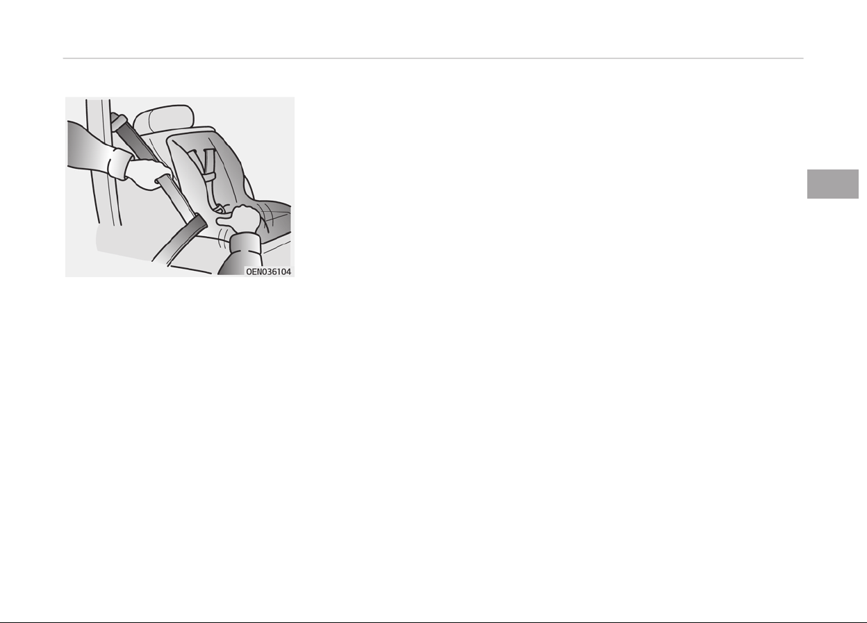
3. Buckle the seat belt and allow the
seat belt to take up any slack. After
installation of the child restraint
system, try to move it in all direc‐
tions to be sure the child restraint
system is securely installed.
If you need to tighten the belt, pull
more webbing toward the retractor.
When you unbuckle the seat belt and
allow it to retract, the retractor will au‐
tomatically revert back to its normal
seated passenger emergency locking
usage condition.
3-37
3
Safety features of your vehicle

Child seat restraint suitability for seat position using the seat belt - For Europe
Use child safety seats that have been officially approved and are appropriate for your children. When using the child safety
seats, refer to the following table.
Mass Group
Seating Position
Front passenger Rear outboard Rear centre
0: Up to 10 kg
U* U X
(0 - 9 months)
0+: Up to 13 kg
U* U X
(0 - 2 years)
I: 9 to 18 kg
U* U X
(9 months - 4 years)
II & III: 15 to 36 kg
U* U X
(4 - 12 years)
U* = Suitable for "universal" category restraints approved for use in this mass group only for height adjustable seat
and when seat position is rearmost highest.
U = Suitable for "universal" category restraints approved for use in this mass group.
UF = Suitable for forward-facing "universal" category restraints approved for use in this mass group
X = Seat position not suitable for children in this mass group.
Safety features of your vehicle
3-38
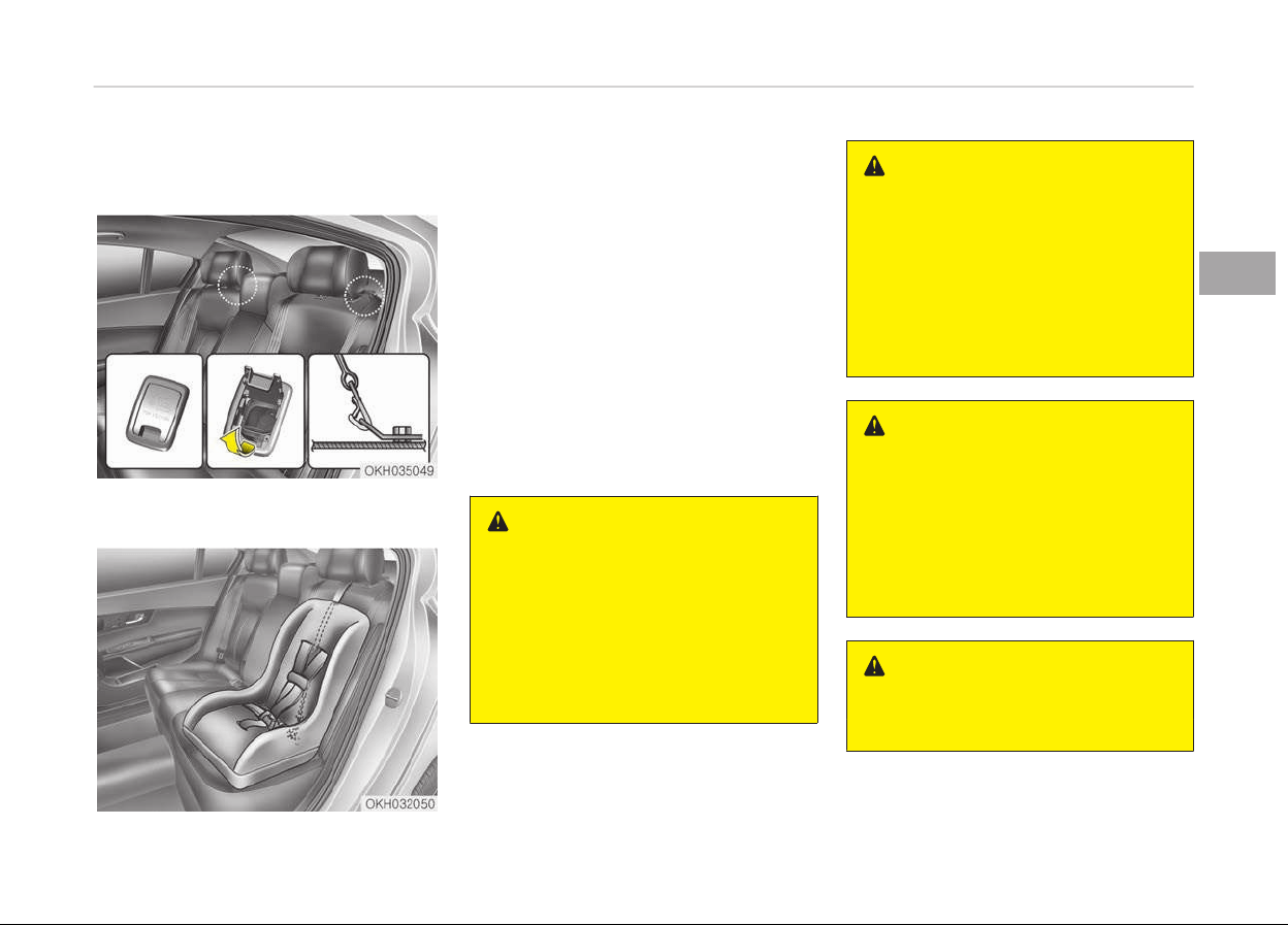
Securing a child restraint seat with
Tether Anchor system
Child restraint hook holders are located
on the package tray.
1. Route the child restraint seat strap
over the seatback.
For vehicles with adjustable head‐
rest, route the tether strap under
the headrest and between the
headrest posts, otherwise route
the tether strap over the top of the
seatback. In case of interference
between the child restraint seat
and the headrest remove the par‐
ticular head restraint for better fit‐
ment of the child restraint seat.
2. Connect the tether strap hook to
the appropriate child restraint hook
holder and tighten to secure the
child restraint seat.
WARNING
A child can be seriously injured or kil‐
led in a collision if the child restraint
is not properly anchored to the car
and the child is not properly re‐
strained in the child restraint. Al‐
ways follow the child seat manufac‐
turer’s instructions for installation
and use.
WARNING
n
Tether strap
Never mount more than one child re‐
straint to a single tether or to a sin‐
gle lower anchorage point. The in‐
creased load caused by multiple
seats may cause the tethers or an‐
chorage points to break, causing se‐
rious injury or death.
WARNING
n
Child restraint check
Check that the child restraint sys‐
tem is secure by pushing and pulling
it in different directions. Incorrectly
fitted child restraints may swing,
twist, tip or separate causing death
or serious injury.
WARNING
n
Child restraint anchorage
(Continued)
3-39
3
Safety features of your vehicle
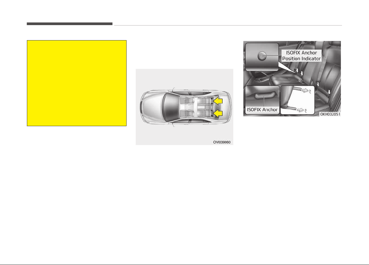
(Continued)
• Child restraint anchorages are de‐
signed
to withstand only those
loads imposed by correctly fitted
child restraints. Under no circum‐
stances are they to be used for
adult seat belts or harnesses or
for attaching other items or equip‐
ment to the vehicle.
• The tether strap may not work
properly
if attached somewhere
other than the correct tether an‐
chor.
Securing a child restraint system
with ISOFIX system and Tether
Anchorage system
ISOFIX is a standardised method of fit‐
ting child seats that eliminates the
need to use the standard adult seat
belt to secure the seat in the vehicle.
This enables a much more secure and
positive location with the added benefit
of easier and quicker installation.
An ISOFIX-seat can only be installed if it
has vehicle-specific approval in accord‐
ance with the requirements of ECE-
R44.
There is a child restraint symbol loca‐
ted on the lower portion of each side of
the rear seatbacks. These symbols indi‐
cate the position of the lower anchors
for child restraints so equipped.
On each side of the rear seat, between
the cushion and backrest, are located a
pair of ISOFIX anchorage points togeth‐
er with a top tether mounting on the
shelf behind the rear seats.
During the installation, the seat has to
be engaged at the anchorage-points in
a way you can hear it clicking (check by
pulling!) and has to be fixed with the
Top Tether-anchor on the belonging
point on the shelf behind rear seats.
Safety features of your vehicle
3-40
The installing and the use of a child-
seat has to be done according to the in‐
stalling-manual, which is added to the
ISOFIX-seat.
WARNING
Install the child restraint seat fully
rearward against the seatback with
the seatback in a vertical position,
not reclined.
WARNING
• When using the vehicle's "ISOFIX"
system to install a child restraint
system in the rear seat, all unused
vehicle rear seat belt metal latch
plates or tabs must be latched se‐
curely in their seat belt buckles
and the seat belt webbing must be
retracted behind the child restraint
to prevent the child from reaching
and taking hold of unretracted
seat belts. Unlatched metal latch
plates or tabs may allow the child
to reach the unretracted seat
belts which may result in strangu‐
lation and a serious injury or death
to the child in the child restraint.
• Do not place anything around the
lower anchors. Also make sure
that the seat belt is not caught in
the lower anchors.
To secure the child restraint seat
1. To engage the child restraint seat
to the ISOFIX anchor, insert the
child restraint seat latch into the
ISOFIX anchor. Listen for the audi‐
ble click sound.
CAUTION
Do not allow the rear seat belt web‐
bing to get scratched or pinched by
the ISOFIX-seat latch and ISOFIX an‐
chor during the installation.
2. Connect the tether strap hook to
the child restraint hook holder and
tighten to secure the seat. (Refer
to the previous page.)
3-41
3
Safety features of your vehicle

WARNING
• Do not install a child restraint seat
at the center of the rear seat us‐
ing the vehicle's ISOFIX anchors.
The ISOFIX anchors are only provi‐
ded for the left and right outboard
rear seating positions. Do not mis‐
use the ISOFIX anchors by at‐
tempting to attach a child re‐
straint seat in the middle of the
rear seat to the ISOFIX anchors. In
a crash, the child restraint seat
ISOFIX attachments may not be
strong enough to secure the child
restraint seat properly in the cen‐
ter of the rear seat and may
break, causing serious injury or
death.
• Do not mount more than one child
restraint to a child restraint lower
anchorage point. The improper in‐
creased load may cause the an‐
chorage points or tether anchor to
break, causing serious injury or
death.
(Continued)
(Continued)
• Attach the ISOFIX or ISOFIX-com‐
patible
child restraint seat only to
the appropriate locations shown in
the illustration.
• Always follow the installation and
use
instructions provided by the
manufacturer of the child re‐
straint.
Safety features of your vehicle
3-42

Child seat restraint suitability for vehicle ISOFIX positions - For Europe
Mass Group Size Class Fixture
Vehicle ISOFIX Position
Front Passenger
Rear Outboard
(Driver Side)
Rear Outboard
(Passenger Side)
Rear Center
Carrycot
F ISO/L1 × × × ×
G ISO/L2 × × × ×
0: Up to 10 kg E ISO/R1 × IL IL ×
0: Up to 13 kg
E ISO/R1 × IL IL ×
D ISO/R2 × IL IL ×
C ISO/R3 × IL IL ×
I: 9 to 18 kg
D ISO/R2 × IL IL ×
C ISO/R3 × IL IL ×
B ISO/F2 × IUF IUF ×
B1 ISO/F2X × IUF IUF ×
A ISO/F3 × IUF IUF ×
X = Seat position not suitable for children in this mass group
IUF = Suitable for ISOFIX forward child restraints systems of universal category approved for use in the mass group.
IL = Suitable for particular ISOFIX child restraints systems (CRS) given in the attached list. These ISOFIX CRS are those
of the "specific vehicle", "restricted" or "semi-universal" categories.
3-43
3
Safety features of your vehicle
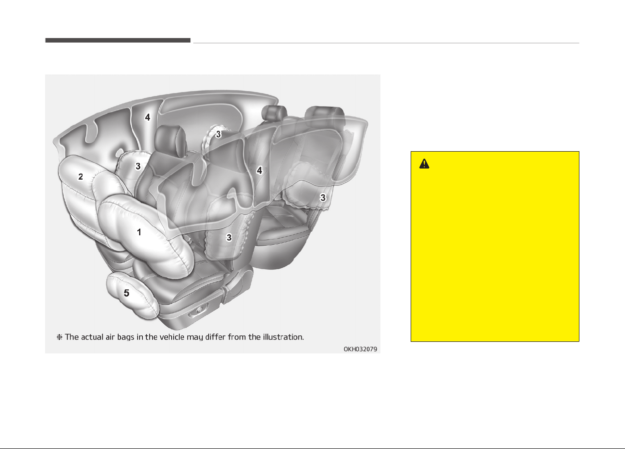
AIR BAG - SUPPLEMENTAL RESTRAINT SYSTEM
1. Driver’s front air bag
2. Passenger’s front air bag
3. Side air bag
4. Curtain air bag
5. Driver’s knee air bag
WARNING
• Even in vehicles with air bags, you
and
your passengers must always
wear the safety belts provided in
order to minimize the risk and se‐
verity of injury in the event of a
collision or rollover.
• SRS and pretensioners contain ex‐
plosiv
e chemicals.
If scraping a vehicle without re‐
moving SRS and pretensioners
from a vehicle, it may cause fire.
Before scraping a vehicle, contact
a professional workshop. Kia rec‐
ommends to visit an authorized
Kia dealer/service partner.
(Continued)
Safety features of your vehicle
3-44

(Continued)
• Keep the SRS parts and wirings
away
from water or any liquid. If
the SRS components are inopera‐
tive due to exposure to water or
liquids, it may cause fire or severe
injury.
How does the air bag system
operate
• Air bags are activated (able to inflate
if necessary) only when the engine
start/stop button is turned to the ON
or START position.
• Air bags inflate instantly in the event
of a serious frontal collision or side
collision in order to help protect the
occupants from serious physical in‐
jury.
• There is no single speed at which the
air bags will inflate.
Generally, air bags are designed to in‐
flate based upon the severity of a
collision and its direction. These two
factors determine whether the sen‐
sors produce an electronic deploy‐
ment/ inflation signal.
• Air bag deployment depends on a
number of factors including vehicle
speed, angles of impact and the den‐
sity and stiffness of the vehicles or
objects which your vehicle hits in the
collision. The determining factors are
not limited to those mentioned
above.
• The front air bags will completely in‐
flate and deflate in an instant.
It is virtually impossible for you to
see the air bags inflate during an ac‐
cident.
It is much more likely that you will
simply see the deflated air bags
hanging out of their storage com‐
partments after the collision.
• In order to help provide protection in
a severe collision, the air bags must
inflate rapidly. The speed of air bag
inflation is a consequence of the ex‐
tremely short time in which a collision
occurs and the need to inflate the air
bag between the occupant and the
vehicle structures before the occu‐
pant impacts those structures. This
speed of inflation reduces the risk of
serious or life-threatening injuries in
a severe collision and is thus a neces‐
sary part of air bag design.
However, air bag inflation can also
cause injuries which can include facial
abrasions, bruises and broken bones
because the inflation speed also cau‐
ses the air bags to expand with a
great deal of force.
•
There are even circumstances under
which contact with the steering
wheel air bag can cause fatal injuries,
especially if the occupant is posi‐
tioned excessively close to the steer‐
ing wheel.
3-45
3
Safety features of your vehicle

WARNING
• To avoid severe personal injury or
death caused by deploying air bags
in a collision, the driver should sit
as far back from the steering
wheel air bag as possible (at least
250 mm away). The front passen‐
gers should always move their
seats as far back as possible and
sit back in their seat.
• Air bags inflate instantly in the
event of collision, and passengers
may be injured by the air bag ex‐
pansion force if they are not in a
proper position.
• Air bag inflation may cause injuries
including facial or bodily abrasions,
injuries from broken glasses or
burns.
Noise and smoke
When the air bags inflate, they make a
loud noise and they leave smoke and
powder in the air inside of the vehicle.
This is normal and is a result of the ig‐
nition of the air bag inflator. After the
air bag inflates, you may feel substan‐
tial discomfort in breathing due to the
contact of your chest with both the
seat belt and the air bag, as well as
from breathing the smoke and powder.
Open your doors and/or windows as
soon as possible after impact in order
to reduce discomfort and prevent pro‐
longed exposure to the smoke and
powder.
Though the smoke and powder are
non-toxic, they may cause irritation to
the skin (eyes, nose and throat, etc). If
this is the case, wash and rinse with
cold water immediately and consult a
doctor if the symptom persists.
WARNING
When the air bags deploy, the air
bag related parts in the steering
wheel and/or instrument panel
and/or in both sides of the roof rails
(Continued)
(Continued)
above the front and rear doors are
v
ery hot. To prevent injury, do not
touch the air bag storage area’s in‐
ternal components immediately af‐
ter an air bag has inflated.
Safety features of your vehicle
3-46
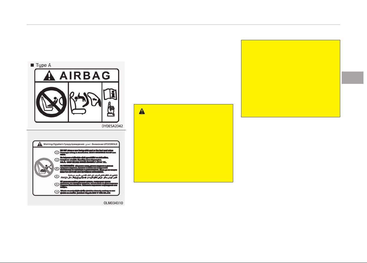
Do not install a child restraint on
the front passenger’s seat
Never place a rear-facing child restraint
in the front passenger’s seat. If the air
bag deploys, it would impact the rear-
facing child restraint, causing serious or
fatal injury.
In addition, do not place front-facing
child restraints in the front passenger’s
seat either. If the front passenger air
bag inflates, it could cause serious or
fatal injuries to the child.
WARNING
• NEVER use a rearward facing child
restraint on a seat protected by an
ACTIVE AIR BAG in front of it,
DEATH or SERIOUS INJURY to the
CHILD can occur.
• Never put a child restraint in the
front passenger’s seat. If the front
passenger air bag inflates, it can
cause serious or fatal injuries.
(Continued)
(Continued)
• When children are seated in the
r
ear outboard seats of a vehicle
equipped with side and/or curtain
air bags, be sure to install the child
restraint system as far away from
the door side as possible, and se‐
curely lock the child restraint sys‐
tem in position. Inflation of side
and/or curtain air bags could cause
serious injury or death to an infant
or child.
3-47
3
Safety features of your vehicle
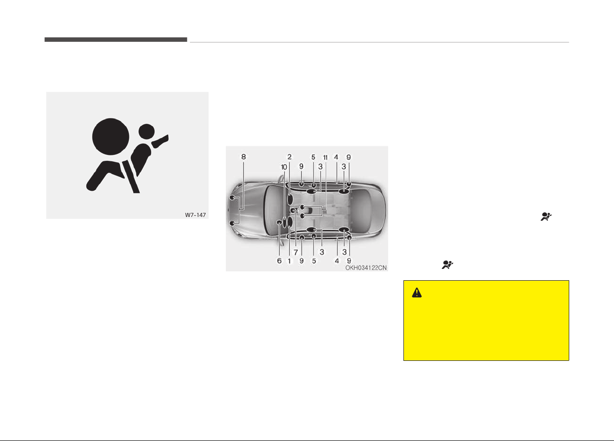
Air bag warning light
The purpose of the air bag warning
light in your instrument panel is to alert
you of a potential problem with your
air bag - Supplemental Restraint Sys‐
tem (SRS).
When the Engine Start/Stop button is
turned ON, the warning light should illu‐
minate for approximately 6 seconds,
then go off.
Have the system checked if:
• The light does not turn on briefly
when you turn the engine start/stop
button to the ON position.
• The light stays on after illuminating
for approximately 6 seconds.
• The light comes on while the vehicle
is in motion.
• The light blinks when the engine
start/stop button is in ON position.
SRS components and functions
The SRS consists of the following com‐
ponents:
1. Driver's front air bag module
2. Passenger's front air bag module
3. Side air bag modules
4. Curtain air bag modules
5. Retractor pre-tensioner assemblies
6. Air bag warning light
7. SRS control module (SRSCM)
8.
Front impact sensors
9. Side impact sensors
10. Driver’s knee air bag module
11. Driver’s and front passenger’s seat
belt buckle sensors.
*1
The SRSCM continually monitors all SRS
components while the engine start/
stop button is ON to determine if a
crash impact is severe enough to re‐
quire air bag deployment or pre-ten‐
sioner seat belt deployment.
The SRS air bag warning light "
" on
the instrument panel will illuminate for
about 6 seconds after the engine start/
stop button is turned to the ON posi‐
tion, after which the SRS air bag warn‐
ing light " " should go out.
WARNING
If any of the following conditions oc‐
curs,
this indicates a malfunction of
the SRS. In this case, have the sys‐
tem inspected by a professional
(Continued)
*1
if equipped
Safety features of your vehicle
3-48
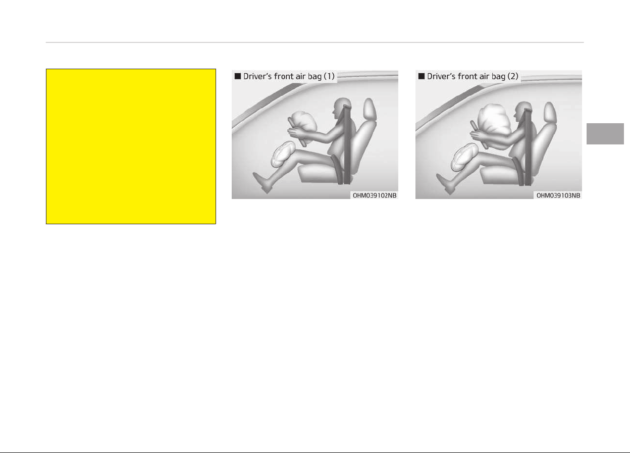
(Continued)
workshop. Kia recommends to visit
an
authorized Kia dealer/service
partner.
• The light does not turn on briefly
when
you turn the Engine Start/
Stop button to the ON position.
• The light stays on after illuminat‐
ing for approximately 6 sec
onds.
• The light comes on while the vehi‐
cle is in motion.
• The light blinks when the Engine
Start/Stop button is in ON position.
The front air bag modules are located
in the center of the steering wheel, in
the front passenger's panel above the
glove box and/or in the driver’s side
knee bolster. When the SRSCM detects
a sufficiently severe impact to the
front of the vehicle, it will automatically
deploy the front air bags.
Upon deployment, tear seams molded
directly into the pad covers will sepa‐
rate under pressure from the expan‐
sion of the air bags. Further opening of
the covers then allows full inflation of
the air bags.
3-49
3
Safety features of your vehicle
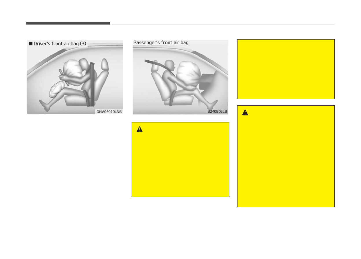
A fully inflated air bag, in combination
with a properly worn seat belt, slows
the driver's or the passenger's forward
motion, reducing the risk of head and
chest injury.
After complete inflation, the air bag im‐
mediately starts deflating, enabling the
driver to maintain forward visibility and
the ability to steer or operate other
controls.
WARNING
• Do not install or place any acces‐
sories (drink holder, cassette hold‐
er, sticker, etc.) on the front pas‐
senger's panel above the glove box
in a vehicle with a passenger's air
bag. Such objects may become
dangerous projectiles and cause
injury if the passenger's air bag in‐
flates.
(Continued)
(Continued)
• When installing a container of liq‐
uid
air freshener inside the vehicle,
do not place it near the instrument
cluster nor on the instrument pan‐
el surface.
It may become a dangerous pro‐
jectile and cause injury if the pas‐
senger's air bag inflates.
WARNING
• If an air bag deploys, there may be
a
loud noise followed by a fine
dust released in the vehicle. These
conditions are normal and are not
hazardous - the air bags are
packed in this fine powder. The
dust generated during air bag de‐
ployment may cause skin or eye
irritation as well as aggravate
asthma for some persons. Always
wash all exposed skin areas thor‐
oughly with cold water and a mild
soap after an accident in which the
air bags were deployed.
(Continued)
Safety features of your vehicle
3-50
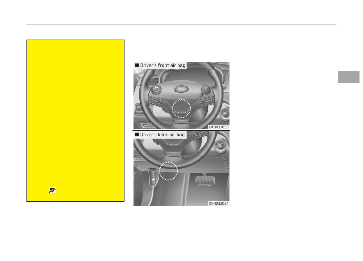
(Continued)
• The SRS can function only when
the
Engine Start/Stop button is in
the ON position. If the SRS air bag
warning light does not illuminate,
or continuously remains on after
illuminating for about 6 seconds
when the Engine Start/Stop but‐
ton is turned to the ON position, or
after the engine is started, comes
on while driving, the SRS is not
working properly.
In this case, have the system in‐
spected by a professional work‐
shop. Kia recommends to visit an
authorized Kia dealer/service part‐
ner.
• Before you replace a fuse or dis‐
c
onnect a battery terminal, turn
the engine start/stop button to
the OFF position. Never remove or
replace the air bag related fuse(s)
when the engine start/stop button
is in the ON position. Failure to
heed this warning will cause the
SRS
warning light to illumi‐
nate.
Driver's and passenger's front
air bag
Your vehicle is equipped with a Supple‐
mental Restraint (Air Bag) System and
the lap/shoulder belts at both the driv‐
er and passenger seating positions.
The indications of the system's pres‐
ence are the letters "SRS AIR BAG" em‐
bossed on the air bag pad cover in the
steering wheel and/or on the cover of
the driver's side knee bolster located
below the steering wheel and the pas‐
senger's side front panel pad above the
glove box.
3-51
3
Safety features of your vehicle
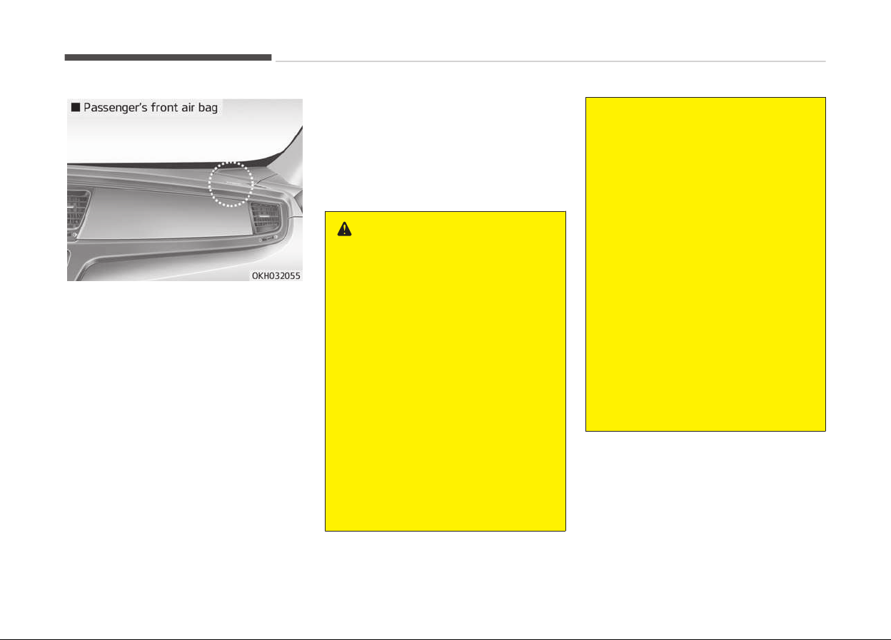
The SRS consists of air bags installed
under the pad covers in the center of
the steering wheel, in the knee bolster
below the steering wheel column and
the passenger's side front panel above
the glove box.
The purpose of the SRS is to provide
the vehicle's driver and/or the front
passenger with additional protection
than that offered by the seat belt sys‐
tem alone in case of a frontal impact of
sufficient severity. The SRS uses sen‐
sors to gather information about the
driver's seat position, the driver's and
front passenger's seat belt usage and
impact severity.
The seat belt buckle sensors (if equip‐
ped) determine if the driver and front
passenger's seat belts are fastened.
These sensors provide the ability to
control the SRS deployment based on
whether or not the seat belts are fas‐
tened, and how severe the impact is.
WARNING
Always use seat belts and child re‐
straints – every trip, every time, ev‐
eryone! Air bags inflate with consid‐
erable force and in the blink of an
eye. Seat belts help keep occupants
in proper position to obtain maxi‐
mum benefit from the air bag. Even
with air bags, improperly and unbel‐
ted occupants can be severely in‐
jured when the air bag inflates. Al‐
ways follow the precautions about
seat belts, air bags and occupant
safety contained in this manual.
To reduce the chance of serious or
fatal injuries and receive the maxi‐
mum safety benefit from your re‐
straint system:
• Never place a child in any child or
booster seat in the front seat.
(Continued)
(Continued)
• ABC – Always Buckle Children in
the
back seat. It is the safest place
for children of any age to ride.
• Front and side air bags can injure
occupants
improperly positioned in
the front seats.
• Move your seat as far back as
practical
from the front air bags,
while still maintaining control of
the vehicle.
• You and your passengers should
never sit or lean unnecessarily
close to the air bags. Improperly
positioned drivers and passengers
can be severely injured by inflating
air bags.
• Never lean against the door or
center console – always sit in an
upright position.
(Continued)
Safety features of your vehicle
3-52

(Continued)
• No objects should be placed over
or
near the air bag modules on the
steering wheel, instrument panel
or the front passenger's panel
above the glove box, because any
such object could cause harm if
the vehicle is in a crash severe
enough to cause the air bags to
deploy.
• Do not tamper with or disconnect
SRS
wiring or other components of
the SRS system. Doing so could re‐
sult in injury, due to accidental de‐
ployment of the air bags or by
rendering the SRS inoperative.
• If the SRS air bag warning light re‐
mains illuminated while the vehicle
is being driven. In this case, have
the system inspected by a profes‐
sional workshop. Kia recommends
to visit an authorized Kia dealer/
service partner
• Air bags can only be used once –
have the system replaced by a
professional workshop.
Kia recommends to visit an au‐
thorized Kia dealer/service part‐
ner.
(Continued)
(Continued)
• The SRS is designed to deploy the
front
air bags only when an impact
is sufficiently severe. Additionally,
the air bags will only deploy once.
Seat belts must be worn at all
times.
• Front air bags are not intended to
deploy
in side-impact, rear-impact
or rollover crashes. In addition,
front air bags will not deploy in
frontal crashes below the deploy‐
ment threshold.
• A child restraint system must nev‐
er be placed in the front seat. The
infant or child could be severely in‐
jured or killed by an air bag deploy‐
ment in case of an accident.
• Children age 12 and under must al‐
ways be properly restrained in the
rear seat. Never allow children to
ride in the front passenger seat. If
a child over 12 must be seated in
the front seat, he or she must be
properly belted and the seat
should be moved as far back as
possible.
(Continued)
(Continued)
• For maximum safety protection in
all
types of crashes, all occupants
including the driver should always
wear their seat belts whether or
not an air bag is also provided at
their seating position to minimize
the risk of severe injury or death in
the event of a crash.
Do not sit or lean unnecessarily
close to the air bag while the vehi‐
cle is in motion.
• Sitting improperly or out of posi‐
tion
can result in serious or fatal
injury in a crash. All occupants
should sit upright with the seat
back in an upright position, cen‐
tered on the seat cushion with
their seat belt on, legs comforta‐
bly extended and their feet on the
floor until the vehicle is parked and
the Engine Start/Stop button is in
the OFF position.
(Continued)
3-53
3
Safety features of your vehicle
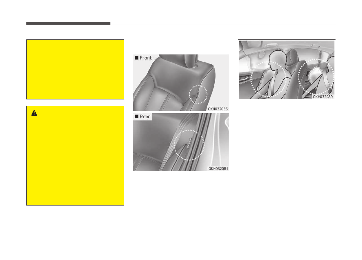
(Continued)
• The SRS air bag system must de‐
ploy
very rapidly to provide pro‐
tection in a crash. If an occupant is
out of position because of not
wearing a seat belt, the air bag
may forcefully contact the occu‐
pant causing serious or fatal inju‐
ries.
WARNING
n
No attaching objects
No objects (such as crash pad cover,
cellular phone holder, cup holder,
perfume or stickers) should be
placed over or near the air bag mod‐
ules on the steering wheel, instru‐
ment panel, windshield glass, and
the front passenger's panel above
the glove box. Such objects could
cause harm if the vehicle is in a
crash severe enough to cause the air
bags to deploy. Do not place any ob‐
jects over the air bag or between the
air bag and yourself.
Side air bag
❈ The actual air bags in the vehicle
may differ from the illustration.
Your vehicle is equipped with a side air
bag in each front and outboard rear
seat. The purpose of the air bag is to
provide the vehicle's driver and/or the
front and outboard rear passengers
with additional protection than that of‐
fered by the seat belt alone.
• The side air bags are designed to de‐
ploy during certain side-impact colli‐
sions, depending on the crash severi‐
ty, angle, speed and point of impact.
• The side air bags are not designed to
deploy in all side impact.
Safety features of your vehicle
3-54

WARNING
Do not allow the passengers to lean
their heads or bodies onto doors, put
their arms on the doors, stretch
their arms out of the window, or
place objects between the doors and
passengers when they are seated on
seats equipped with side and/or cur‐
tain air bags.
WARNING
• The side air bag is supplemental to
the driver’s and the passengers
seat belt systems and is not a
substitute for them. Therefore
your seat belts must be worn at all
times while the vehicle is in mo‐
tion. The air bags deploy only in
certain side impact conditions se‐
vere enough to cause significant
injury to the vehicle occupants.
(Continued)
(Continued)
• For best protection from the side
air
bag system and to avoid being
injured by the deploying side air
bag, both front and all rear (if
equipped) seat occupants should
sit in an upright position with the
seat belt properly fastened. The
driver's hands should be placed on
the steering wheel at the 9:00 and
3:00 positions. The passenger’
arms and hands should be placed
on their laps.
• Do not use any accessory seat
c
overs.
• Use of seat covers could reduce or
prevent the effectiveness of the
system.
• To prevent unexpected deploy‐
ment of the side air bag that may
result in personal injury, avoid im‐
pact to the side impact sensor
when the Engine Start/Stop but‐
ton is on.
• If the seat or seat cover is dam‐
aged, have the system serviced by
a professional workshop. Kia rec‐
ommends to visit an authorized
Kia dealer/service partner.
WARNING
n
No attaching objects
• Do not place any objects over the
air bag or between the air bag and
yourself. Also, do not attach any
objects around the area the air bag
inflates such as the door, side door
glass, front and rear pillar.
• Do not place any objects between
the door and the seat. They may
become dangerous projectiles if
the side air bag inflates.
• Do not install any accessories on
the side or near the side air bags.
3-55
3
Safety features of your vehicle
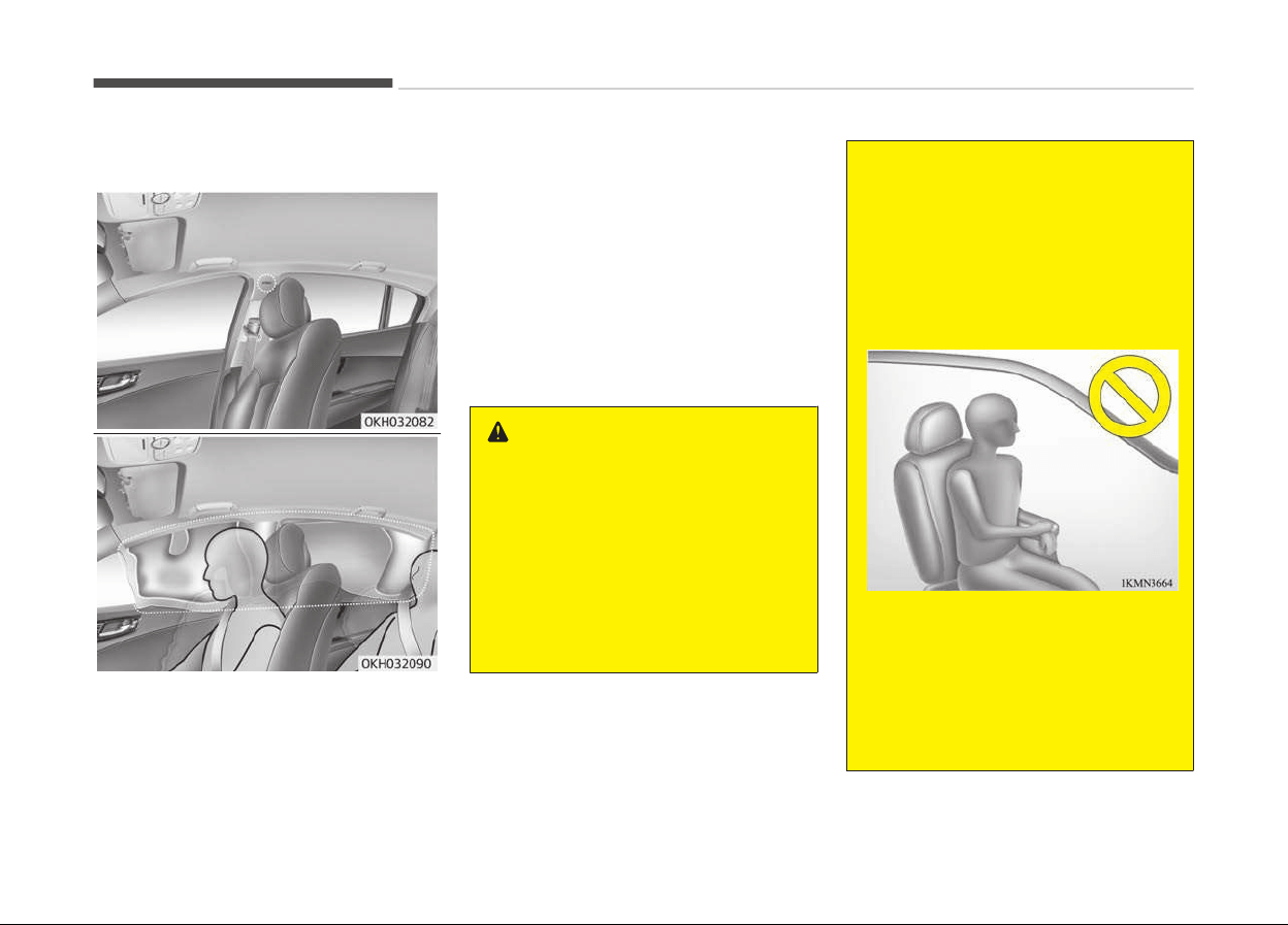
Curtain air bag
❈ The
actual air bags in the vehicle
may differ from the illustration.
Curtain air bags are located along both
sides of the roof rails above the front
and rear doors.
They are designed to help protect the
heads of the front seat occupants and
the rear outboard seat occupants in
certain side impact collisions.
The curtain air bags are designed to
deploy only during certain side impact
collisions, depending on the crash se‐
verity, angle, speed and impact. The
curtain air bags are not designed to de‐
ploy in all side impact situations, colli‐
sions from the front or rear of the ve‐
hicle or in most rollover situations.
WARNING
• In order for side and curtain air
bags to provide the best protec‐
tion, front seat occupants and
outboard rear occupants should sit
in an upright position with the seat
belts properly fastened. Impor‐
tantly, children should sit in a
proper child restraint system in
the rear seat.
(Continued)
(Continued)
• When children are seated in the
r
ear outboard seats, they must be
seated in the proper child restraint
system. Make sure to position the
child restraint system as far away
from the door side as possible, and
secure the child restraint system
in a locked position.
• Do not allow the passengers to
lean their heads or bodies onto
doors, put their arms on the
doors, stretch their arms out of
the window, or place objects be‐
tween the doors and passengers
when they are seated on seats
(Continued)
Safety features of your vehicle
3-56

(Continued)
equipped with side and/or curtain
air bags.
• Never try to open or repair any
components of the side curtain air
bag system. If necessary, have the
system serviced by a professional
workshop. Kia recommends to visit
an authorized Kia dealer/service
partner.
Failure to follow the above men‐
tioned instructions can result in in‐
jury or death to the vehicle occu‐
pants in an accident.
WARNING
n
No attaching objects
• Do not place any objects over the
air bag. Also, do not attach any
objects around the area the air bag
inflates such as the door, side door
glass, front and rear pillar, roof
side rail.
• Do not hang hard or breakable ob‐
jects on the clothes hanger.
Why didn’t my air bag go off in a colli‐
sion?
(Inflation and non-inflation condi‐
tions of the air bag)
There are many types of accidents in
which the air bag would not be expec‐
ted to provide additional protection.
These include rear impacts, second or
third collisions in multiple impact acci‐
dents, as well as low speed impacts.
3-57
3
Safety features of your vehicle
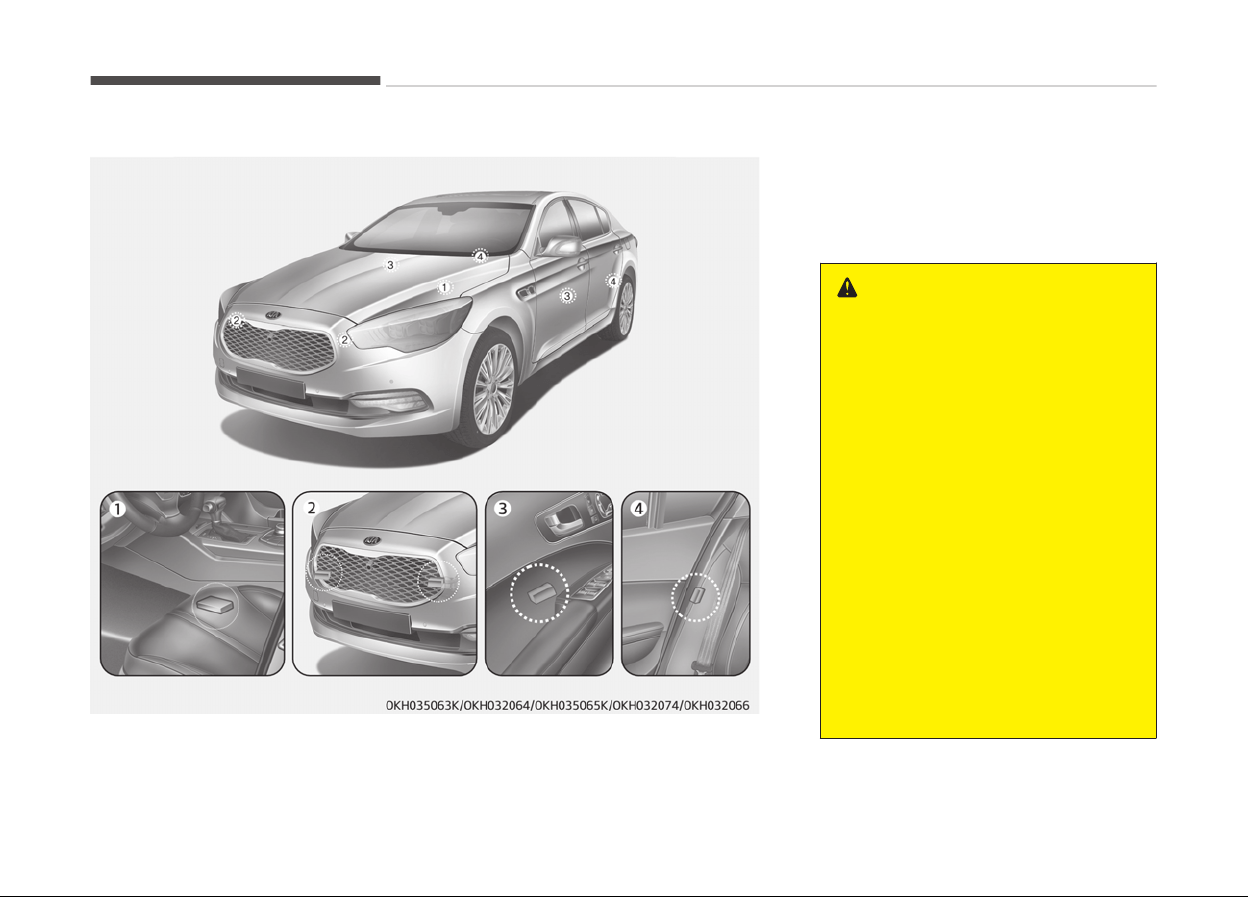
Air bag collision sensors
1. SRS control module
2. Front impact sensor
3. Side impact sensor (front)
4. Side impact sensor (rear)
WARNING
• Do not hit or allow any objects to
impact the locations where air
bags or sensors are installed.
This may cause unexpected air
bag deployment, which could re‐
sult in serious personal injury or
death.
• If the installation location or angle
of the sensors is altered in any
way, the air bags may deploy
when they should not or they may
not deploy when they should,
causing severe injury or death.
Therefore, do not try to perform
maintenance on or around the air
bag sensors. Have the system
serviced by a professional work‐
shop. Kia recommends to visit an
authorized Kia dealer/service part‐
ner.
(Continued)
Safety features of your vehicle
3-58
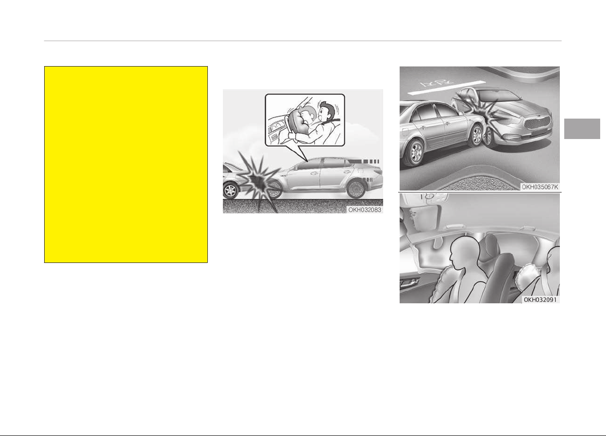
(Continued)
• Problems may arise if the sensor
installation angles ar
e changed due
to the deformation of the front
bumper, body, front door or C pil‐
lar where the collision sensors are
installed. Have the system serv‐
iced by a professional workshop.
Kia recommends to visit an au‐
thorized Kia dealer/service part‐
ner.
• Your vehicle has been designed to
absorb
impact and deploy the air
bag(s) in certain collisions. Instal‐
ling aftermarket bumper guards or
replacing a bumper with non-gen‐
uine parts may adversely affect
your vehicles collision and air bag
deployment performance.
Air bag inflation conditions
Front air bags
Front air bags are designed to inflate in
a frontal collision depending on the in‐
tensity, speed or angles of impact of
the front collision.
❈ The actual air bags in the vehicle
may differ from the illustration.
3-59
3
Safety features of your vehicle
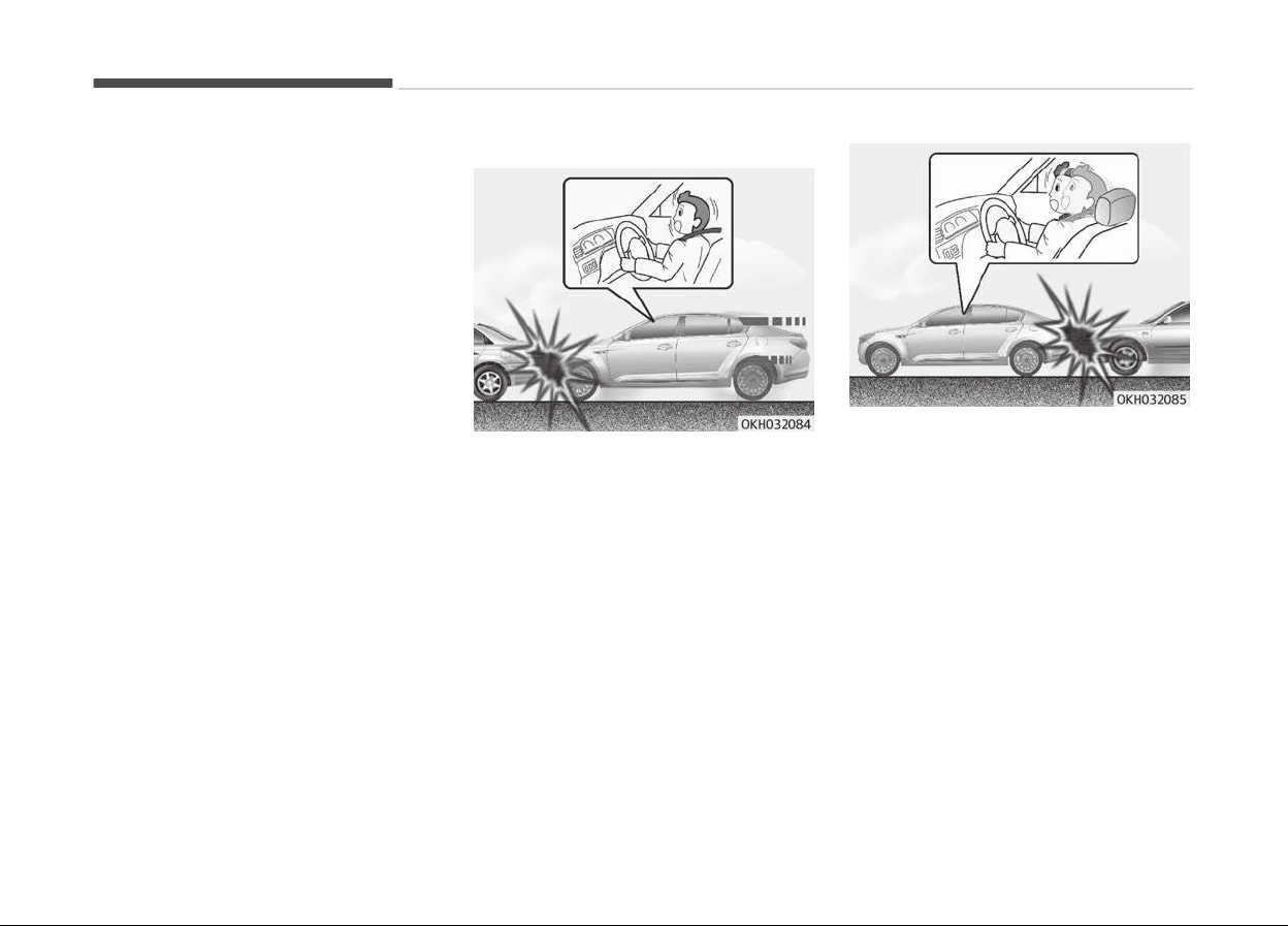
Side and curtain air bags
Side and curtain air bags are designed
to inflate when an impact is detected
by side collision sensors depending on
the strength, speed or angles of impact
resulting from a side impact collision.
Although the front air bags (driver’s
and front passenger’s air bags) are de‐
signed to inflate only in frontal colli‐
sions, they also may inflate in other
types of collisions if the front impact
sensors detect a sufficient impact. Side
and curtain air bags are designed to in‐
flate only in side impact collisions, but
they may inflate in other collisions if
the side impact sensors detect a suffi‐
cient impact.
If the vehicle chassis is impacted by
bumps or objects on unimproved roads,
the air bags may deploy. Drive carefully
on unimproved roads or on surfaces
not designed for vehicle traffic to pre‐
vent unintended air bag deployment.
Air bag non-inflation conditions
• In certain low-speed collisions the air
bags may not deploy. The air bags
are designed not to deploy in such
cases because they may not provide
benefits beyond the protection of the
seat belts in such collisions.
• Frontal air bags are not designed to
inflate in rear collisions, because oc‐
cupants are moved backward by the
force of the impact. In this case, in‐
flated air bags would not be able to
provide any additional benefit.
Safety features of your vehicle
3-60
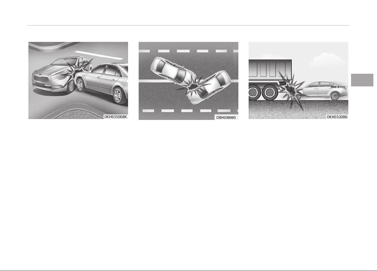
• Front air bags may not inflate in side
impact collisions, because occupants
move to the direction of the collision,
and thus in side impacts, frontal air
bag deployment would not provide
additional occupant protection.
However, side impact and curtain air
bags may inflate depending on the
intensity, vehicle speed and angles of
impact.
• In an angled collision, the force of im‐
pact may direct the occupants in a di‐
rection where the air bags would not
be able to provide any additional ben‐
efit, and thus the sensors may not
deploy any air bags.
• Just before impact, drivers often
brake heavily. Such heavy braking
lowers the front portion of the vehi‐
cle causing it to ride under a vehicle
with a higher ground clearance. Air
bags may not inflate in this "under-
ride" situation because deceleration
forces that are detected by sensors
may be significantly reduced by such
under-ride collisions.
3-61
3
Safety features of your vehicle
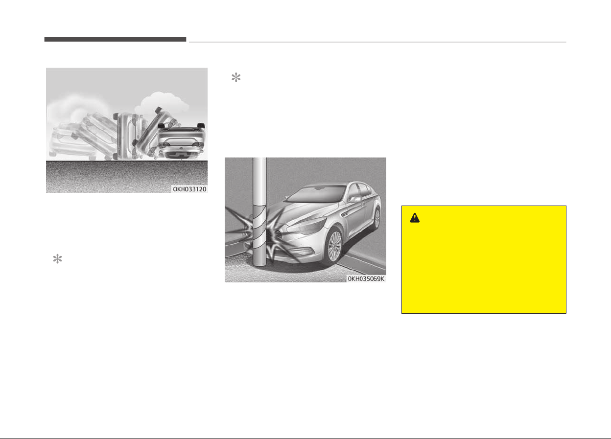
• Front air bags may not inflate in roll‐
over accidents because front air bag
deployment would not provide addi‐
tional occupant protection.
NOTICE
n
with rollover sensor
However, the side and curtain air
bags may inflate in a rollover, when
it is detected by ACU (Airbag Control
Unit).
NOTICE
n
without rollov
er sensor
However, side and curtain air bags
may inflate when the vehicle is rol‐
led over by a side impact collision.
• Air bags may not inflate if the vehicle
collides with objects such as utility
poles or trees, where the point of im‐
pact is concentrated to one area and
the full force of the impact is not de‐
livered to the sensors.
SRS care
The SRS is virtually maintenance-free
and so there are no parts you can safe‐
ly service by yourself. If the SRS air bag
warning light does not illuminate, or
continuously remains on, we recom‐
mend that the system be inspected by
an authorized Kia dealer. If the SRS air
bag warning light does not illuminate,
or continuously remains on, have the
system inspected by a professional
workshop. Kia recommends to visit an
authorized Kia dealer/service partner.
WARNING
• Modification to SRS components or
wiring, including the addition of
any kind of badges to the pad cov‐
ers or modifications to the body
structure, can adversely affect
SRS performance and lead to pos‐
sible injury.
(Continued)
Safety features of your vehicle
3-62

(Continued)
• For cleaning the air bag pad cov‐
ers,
use only a soft, dry cloth or
one which has been moistened
with plain water. Solvents or clean‐
ers could adversely affect the air
bag covers and proper deployment
of the system.
• No objects should be placed over
or
near the air bag modules on the
steering wheel, instrument panel,
and the front passenger's panel
above the glove box, because any
such object could cause harm if
the vehicle is in a crash severe
enough to cause the air bags to in‐
flate.
• If the air bags inflate, have the
system replaced by a professional
workshop. Kia recommends to visit
an authorized Kia dealer/service
partner.
• Do not tamper with or disconnect
SRS wiring, or other components
of the SRS system. Doing so could
result in injury, due to accidental
inflation of the air bags or by ren‐
dering the SRS inoperative.
(Continued)
(Continued)
• If components of the air bag sys‐
tem
must be discarded, or if the
vehicle must be scrapped, certain
safety precautions must be ob‐
served. An authorized Kia dealer
knows these precautions and can
give you the necessary informa‐
tion. Failure to follow these pre‐
cautions and procedures could in‐
crease the risk of personal injury.
• If your car was flooded and has
soaked
carpeting or water on
flooring, you shouldn't try to start
the engine; in this case, have your
vehicle inspected by a professional
workshop. Kia recommends to
contact an authorized Kia dealer/
service partner.
Additional safety precautions
• All occupants should sit upright, fully
back in their seats with their seat
belts on and their feet on the floor.
•
Passengers should not move out of
or change seats while the vehicle is
moving. A passenger who is not
wearing a seat belt during a crash or
emergency stop can be thrown
against the inside of the vehicle,
against other occupants, or out of
the vehicle.
• Each seat belt is designed to restrain
one occupant. If more than one per‐
son uses the same seat belt, they
could be seriously injured or killed in a
collision.
• Do not use any accessories on seat
belts. Devices claiming to improve oc‐
cupant comfort or reposition the seat
belt can reduce the protection provi‐
ded by the seat belt and increase the
chance of serious injury in a crash.
• Passengers should not place hard or
sharp objects between themselves
and the air bags. Carrying hard or
sharp objects on your lap or in your
mouth can result in injuries if an air
bag inflates.
3-63
3
Safety features of your vehicle
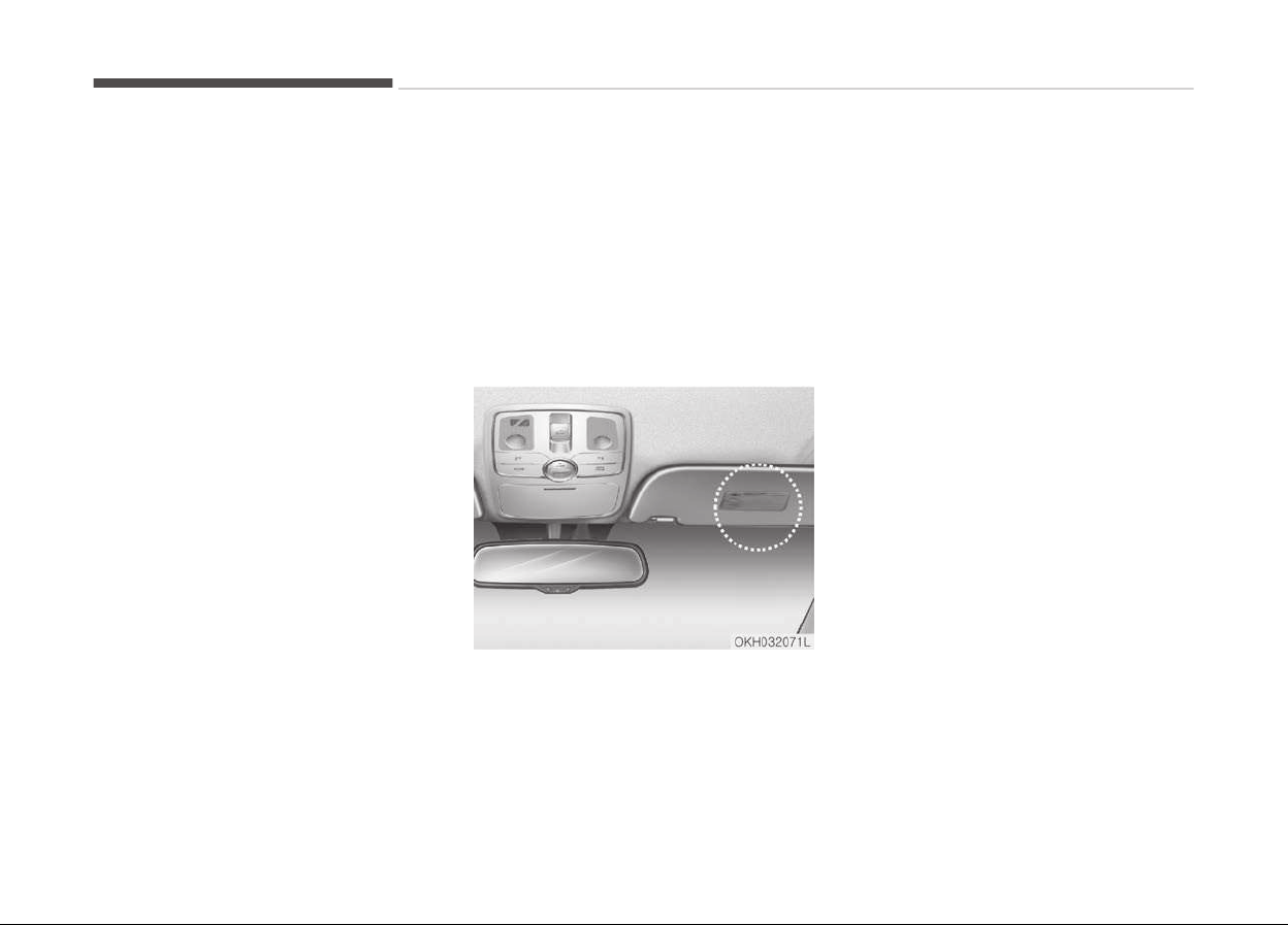
• Keep
occupants away from the air
bag covers. All occupants should sit
upright, fully back in their seats with
their seat belts on and their feet on
the floor. If occupants are too close
to the air bag covers, they could be
injured if the air bags inflate.
• Do not attach or place objects on or
near the air bag covers. Any object
attached to or placed on the front or
side air bag covers could interfere
with the proper operation of the air
bags.
• Do not modify the front seats. Modi‐
fication of the front seats could in‐
terfere with the operation of the
supplemental restraint system sens‐
ing components or side air bags.
• Do not place items under the front
seats. Placing items under the front
seats could interfere with the opera‐
tion of the supplemental restraint
system sensing components and wir‐
ing harnesses.
• Never hold an infant or child on your
lap. The infant or child could be seri‐
ously injured or killed in the event of
a crash. All infants and children
should be properly restrained in ap‐
propriate child safety seats or seat
belts in the rear seat.
Adding equipment to or
modifying your air bag-
equipped vehicle
If you modify your vehicle by changing
your vehicle's frame, bumper system,
front end or side sheet metal or ride
height, this may affect the operation of
your vehicle's air bag system.
Air bag warning label
Air bag warning labels are attached to
alert the driver and passengers of po‐
tential risk of air bag system.
Note that these government warnings
focus on the risk to children, we also
want you to be aware of the risks
which adults are exposed to. Those
have been described in previous pages.
Safety features of your vehicle
3-64

Smart key...................................................................................4-04
Record your key number..................................................... 4-04
Smart key function...............................................................4-04
Buttons on the smart key................................................... 4-06
Restrictions in handling keys.............................................. 4-07
Smart key precautions.........................................................4-07
Immobilizer system.............................................................. 4-08
Battery replacement............................................................4-09
Theft-alarm system ............................................................... 4-11
Armed stage.......................................................................... 4-11
Theft-alarm stage................................................................4-11
Opening the trunk with the alarm armed ....................... 4-12
Disarmed stage..................................................................... 4-12
Door locks................................................................................... 4-13
Operating door locks from outside the vehicle................4-13
Power door latch ..................................................................4-14
Operating door locks from inside the vehicle...................4-14
Door lock/unlock features................................................... 4-16
Child-protector rear door lock............................................ 4-17
Trunk........................................................................................... 4-18
Non-powered trunk..............................................................4-18
Power trunk .......................................................................... 4-19
Emergency trunk safety release........................................4-23
Smart trunk .............................................................................. 4-25
How to use the smart trunk............................................... 4-25
How to deactivate the smart trunk function us‐
ing the smart key..................................................................4-27
Detecting area....................................................................... 4-27
Windows..................................................................................... 4-29
Power windows..................................................................... 4-29
Hood............................................................................................ 4-33
Opening the hood..................................................................4-33
Closing the hood....................................................................4-33
Fuel filler lid................................................................................4-35
Opening the fuel filler lid......................................................4-35
Closing the fuel filler lid........................................................4-35
Emergency fuel filler lid release......................................... 4-37
Panorama sunroof ................................................................... 4-38
Sunroof open warning .........................................................4-38
Sliding the sunroof................................................................4-39
Closing the sunroof...............................................................4-39
Tilting the sunroof................................................................ 4-40
Sunshade................................................................................ 4-41
Resetting the sunroof..........................................................4-41
Steering wheel...........................................................................4-42
Electronic Hydraulic Power Steering (EHPS)....................4-42
Tilt steering............................................................................4-42
Heated steering wheel ........................................................4-43
Horn.........................................................................................4-44
Mirrors........................................................................................ 4-45
Inside rearview mirror..........................................................4-45
Outside rearview mirror.......................................................4-45
Instrument cluster....................................................................4-49
Instrument cluster control.................................................. 4-49
LCD display control............................................................... 4-50
Gauges.................................................................................... 4-51
LCD display................................................................................. 4-56
LCD modes..............................................................................4-56
Trip computer mode............................................................. 4-57
Turn by turn (TBT) mode ................................................... 4-58
Features of your vehicle
4

ASCC mode ............................................................................ 4-58
A/V mode................................................................................4-58
Information mode................................................................. 4-58
User settings mode.............................................................. 4-60
Warning messages ...............................................................4-68
Trip computer............................................................................ 4-79
Overview.................................................................................4-79
Fuel economy.........................................................................4-79
Trip A/B................................................................................... 4-80
Drive mode............................................................................. 4-81
Warning and indicator lights................................................... 4-82
Warning lights........................................................................4-82
Indicator lights.......................................................................4-88
Head up display (HUD) .............................................................4-92
Description............................................................................. 4-92
Head up display ON/OFF...................................................... 4-93
Head up display information...............................................4-93
Head up display setting....................................................... 4-93
Parking assist system.............................................................. 4-94
Operation of the parking assist system........................... 4-94
Non-operational conditions of parking assist system.... 4-97
Self-diagnosis........................................................................ 4-98
Rearview camera ..................................................................... 4-99
Parking guide system ........................................................... 4-100
Reverse parking (Back-in parking)...................................4-100
Parallel parking....................................................................4-101
Front blind spot monitoring system .................................. 4-103
Surround view monitoring system (SVM) ......................... 4-104
Lighting.....................................................................................4-105
Battery saver function...................................................... 4-105
Headlight escort function..................................................4-105
Daytime running light........................................................ 4-105
Traffic change (for Europe).............................................. 4-105
Lighting control................................................................... 4-106
High beam operation..........................................................4-108
Turn signals and lane change signals.............................. 4-109
Front fog light..................................................................... 4-109
Rear fog light ......................................................................4-110
Headlight leveling device .................................................. 4-110
Headlight washer ...............................................................4-110
Wipers and washers............................................................... 4-111
Windshield wipers...............................................................4-111
Windshield washers............................................................4-112
Interior light............................................................................. 4-114
Automatic turn off function ............................................ 4-114
Front lamp switch...............................................................4-114
Rear lamp switch................................................................ 4-115
Trunk room lamp................................................................ 4-115
Door courtesy lamp............................................................4-116
Glove box lamp....................................................................4-116
Vanity mirror lamp............................................................. 4-116
Welcome system.................................................................... 4-117
Puddle lamp and door handle lamp................................. 4-117
Headlight.............................................................................. 4-117
Interior light.........................................................................4-117
Defroster..................................................................................4-118
Rear window defroster......................................................4-118
Wiper deicer ........................................................................4-118
Automatic climate control system...................................... 4-119
Automatic heating and air conditioning..........................4-120
4

Manual heating and air conditioning............................... 4-121
System operation............................................................... 4-129
Climate control air filter.................................................... 4-130
Checking the amount of air conditioner refriger‐
ant and compressor lubricant...........................................4-131
Windshield defrosting and defogging..................................4-132
To defog inside windshield................................................ 4-132
To defrost outside windshield.......................................... 4-132
Defogging logic....................................................................4-133
Climate control additional features .................................... 4-136
Cluster ionizer..................................................................... 4-136
Smart ventilation................................................................ 4-136
Storage compartment........................................................... 4-137
Center console storage......................................................4-137
Rear seat storage...............................................................4-137
Glove box..............................................................................4-138
Sunglass holder................................................................... 4-138
Seatback pocket..................................................................4-139
Map pocket.......................................................................... 4-139
Interior features......................................................................4-140
Cigarette lighter .................................................................4-140
Ashtray.................................................................................4-140
Cup holder............................................................................ 4-141
Sunvisor................................................................................4-142
Power outlet........................................................................4-142
Seat warmer .......................................................................4-143
Air ventilation seat ............................................................ 4-145
Clock...................................................................................... 4-147
Clothes hanger ................................................................... 4-147
Floor mat anchor(s) ...........................................................4-148
Rear mirror ......................................................................... 4-148
Bag hanger ..........................................................................4-149
Luggage net (holder) .........................................................4-149
Rear curtain ........................................................................ 4-150
Side curtain .........................................................................4-151
Multimedia system.................................................................4-152
AUX and USB port...............................................................4-152
Audio / Video / Navigation system (AVN)....................... 4-152
Driver information system (DIS)...................................... 4-153
Bluetooth
®
wireless technology hands-free................. 4-153
Antenna................................................................................ 4-154
Steering wheel audio control............................................4-155
4
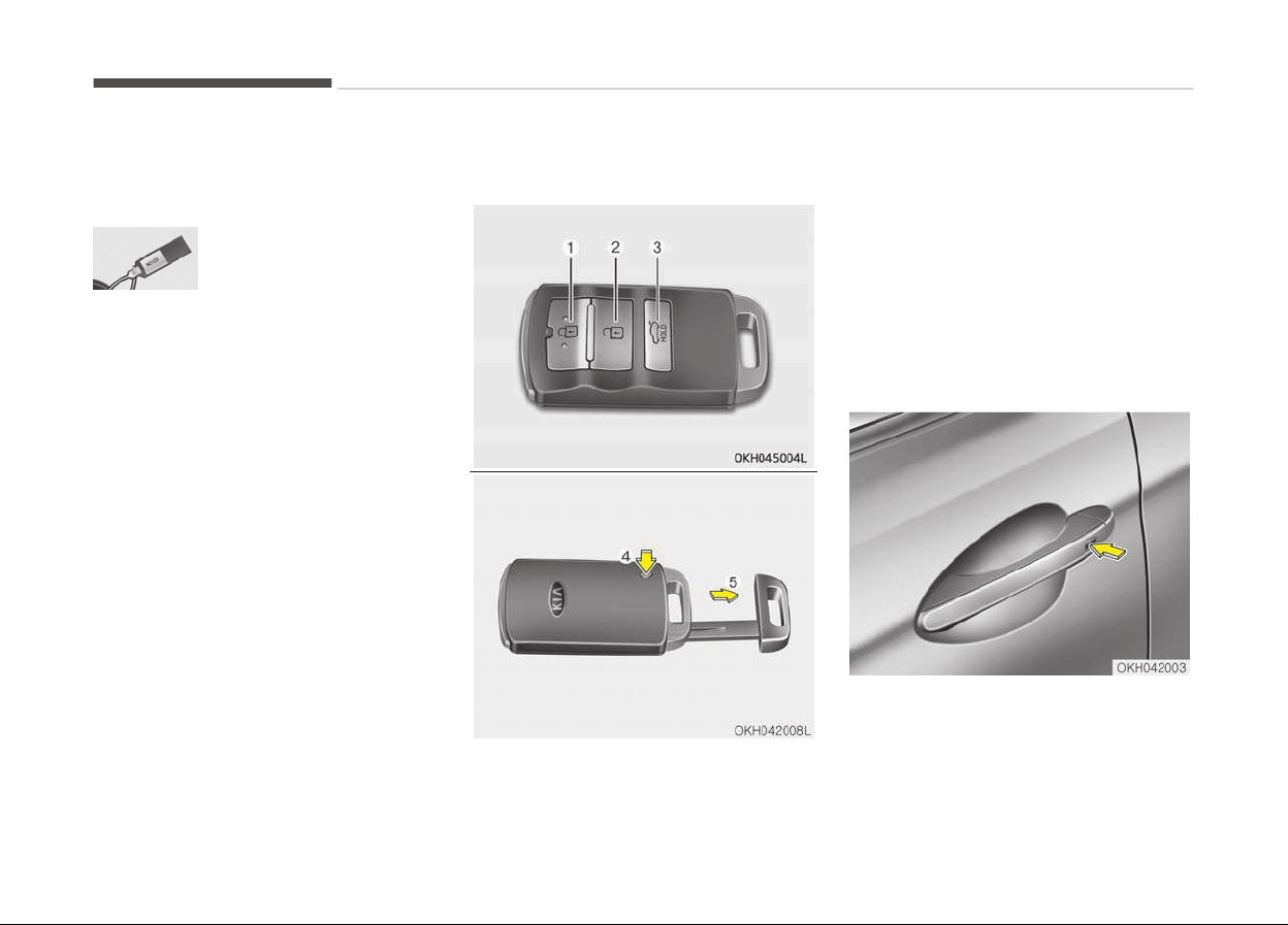
SMART KEY
Record your key number
The key code number is
stamped on the key code
tag attached to the key
set.
Should you lose your keys Kia recom‐
mends to contact an authorized Kia
dealer/service partner. Remove the key
code tag and store it in a safe place. Al‐
so, record the key code number and
keep it in a safe place (not in the vehi‐
cle).
Smart key function
1. Door lock
2. Door unlock
3. Trunk unlock and/or open
With the smart key, you can lock or un‐
lock a door and trunk and even start
the engine.
• To remove the mechanical key, press
and hold the release button (4) and
remove the mechanical key (5).
• To reinstall the mechanical key, put
the key into the hole and push it until
a click sound is heard.
Carrying the smart key, you may lock
and unlock the vehicle doors and trunk.
Locking
1. Carry the smart key.
Features of your vehicle
4-04

2. Close all doors.
3. Press the button of the outside
door handle.
4. The hazard warning lights will blink
once (the engine hood and trunk
must be closed).
Also, the outside rearview mirror
will automatically fold when the
outside rearview mirror folding
switch is in the AUTO position (if
equipped).
5. Make sure that doors are locked by
pulling the outside door handle.
NOTICE
• The button will only operate when
the smart key is within 0.7 m from
the outside door handle.
• Even though you press the outside
door handle button, the doors will
not lock and the chime will sound
for 3 seconds if any of following
occur:
- The smart key is in the vehicle.
- The engine start/stop button is
in ACC or ON position.
(Continued)
(Continued)
- Any
door except the trunk is
opened.
Unlocking
1. Carry the smart key.
2. Press the button of the front out‐
side door handle.
3. All doors will unlock and the hazard
warning lights will blink twice.
Also, the outside rearview mirror
will automatically unfold when the
outside rearview mirror folding
switch is in the AUTO position (if
equipped).
NOTICE
• The button will only operate when
the smart key is within 0.7 m from
the outside door handle.
• When the smart key is recognized
in the area of 0.7 m from the
front outside door handle, other
people can also open the doors.
(Continued)
(Continued)
• After unlocking all doors, the doors
will
lock automatically unless a
door is opened within 30 seconds.
Trunk unlocking
Power trunk
1. Carry the smart key.
2. Press the trunk handle switch.
3. The trunk will unlock and open.
Non-powered trunk
1. Carry the smart key.
2. Press the trunk handle switch.
3. The trunk will unlock.
NOTICE
• Once the trunk is opened and then
closed, the trunk will lock auto‐
matically.
• The button will only operate when
the smart key is within 0.7 m from
the trunk handle.
4-05
4
Features of your vehicle
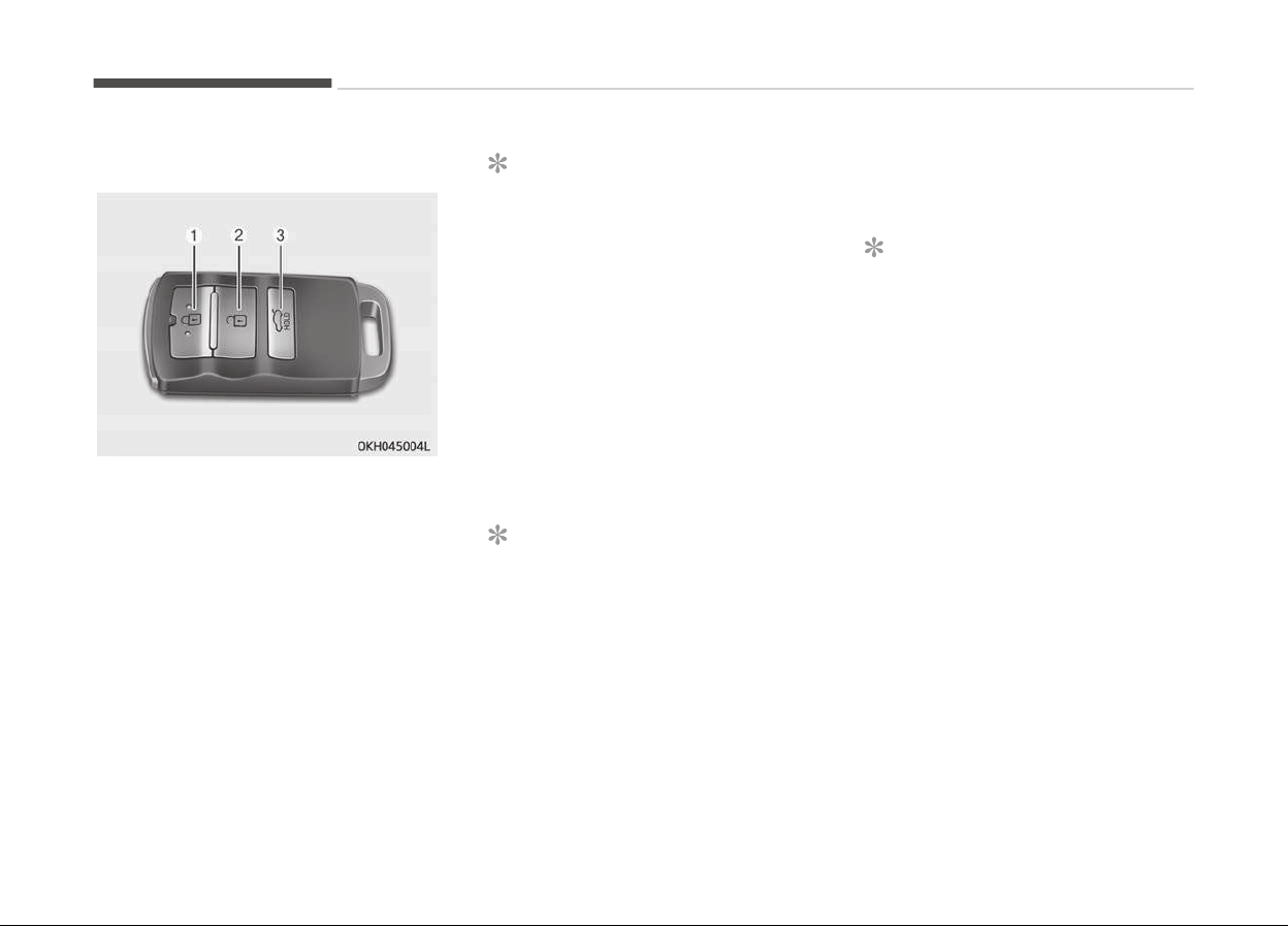
Buttons on the smart key
Lock (1)
1. Close all doors.
2. Press the lock button.
3. The hazard warning light will blink
once to indicate that all doors are
locked (the engine hood and trunk
must be closed).
Also, the outside rearview mirror
will automatically fold when the
outside rearview mirror folding
switch is in the AUTO position (if
equipped).
NOTICE
The doors will not lock if any door is
opened.
Unlock (2)
1. Press the unlock button.
2. The hazard warning lights will blink
twice to indicate that all doors are
unlocked.
Also, the outside rearview mirror
will automatically unfold when the
outside rearview mirror folding
switch is in the AUTO position (if
equipped).
NOTICE
After unlocking all doors, the doors
will lock automatically unless a door
is opened within 30 seconds.
Trunk unlock (3)
Non-powered trunk.
1. Press the trunk unlock button for
more than 1 second.
2. The hazard warning light will blink
twice to indicate that the trunk is
unlocked.
NOTICE
• After unlocking the trunk, the
trunk will lock automatically unless
it is opened within 30 seconds.
• Once the trunk is opened and then
closed, the trunk will lock auto‐
matically.
• The word "HOLD" is written on the
button to inform you that you
must press and hold the button.
Power trunk
1. Press the trunk unlock button for
more than 1 second.
2. The hazard warning light will blink
and chime will sound twice to indi‐
cate the trunk is unlocked and
opened.
Features of your vehicle
4-06
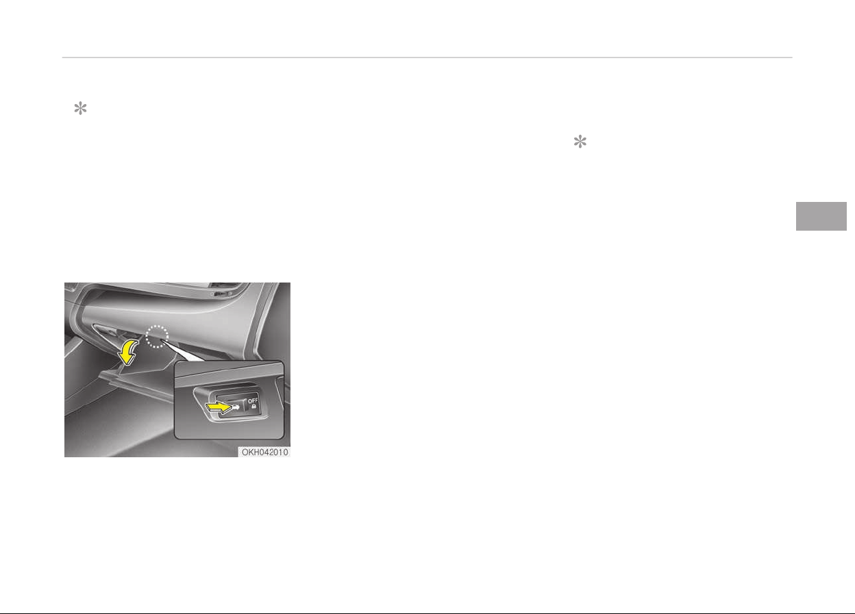
NOTICE
• Once the trunk is opened and then
closed, the trunk will lock auto‐
matically.
• The word "HOLD" is written on the
button to inform you that you
must press and hold the button.
Restrictions in handling keys
When leaving keys with parking lot and
valet attendants, the following proce‐
dures will ensure that your vehicle’s
trunk and glove box compartment can
not be opened in your absence.
To activate the trunk lock system so
that the trunk can only be opened with
the mechanical key, perform the fol‐
lowing:
1. Press and hold the release button
and remove the mechanical key
from the smart key.
2. Unlock the glove box by using the
mechanical key then open it.
3. Set the trunk lid control button to
OFF position (unpressed).
4. Close and lock the glove box using
the mechanical key.
When leaving your keys with a parking
lot attendant or valet, perform steps 1
to 4 above, remove the mechanical key
from the smart key and leave the
smart key with the attendant. In this
manner the smart key can only be used
to start the engine and operate door
locks.
Lock release
To release the trunk lock feature, open
the glove box with the mechanical key
and set the trunk lid control button to
ON position (pressed). In this position
the trunk will open with the trunk lid
button or smart key.
Smart key precautions
NOTICE
• If, for some reason, you happen to
lose your smart key, you will not
be able to start the engine. Tow
the vehicle, if necessary, Kia rec‐
ommends to contact an author‐
ized Kia dealer/service partner.
• A maximum of 2 smart keys can
be registered to a single vehicle. If
you lose a smart key, Kia recom‐
mends to contact an authorized
Kia dealer/service partner.
• The smart key will not work if any
of the following occurs:
- The smart key is close to a ra‐
dio transmitter such as a radio
station or an airport which can
interfere with normal operation
of the smart key.
- The smart key is near a mobile
two-way radio system or a cel‐
lular phone.
(Continued)
4-07
4
Features of your vehicle
(Continued)
- Another
vehicle’s smart key is
being operated close to your
vehicle.
When the smart key does not
work properly, open and close the
door with the mechanical key. If
you have a problem with the
transmitter, Kia recommends to
contact an authorized Kia dealer/
service partner.
• If the smart key is in close proxim‐
ity to your cell phone or smart
phone, the signal from the smart
key could be blocked by normal
operation of your cell phone or
smart phone. This is especially im‐
portant when the phone is active
such as making call, receiving calls,
text messaging, and/or sending/
receiving emails. Avoid placing the
smart key and your cell phone or
smart phone in the same pants or
jacket pocket and maintain ade‐
quate distance between the two
devices.
CAUTION
• Keep the smart key away from
water or any liquid. If the keyless
entry system is inoperative due to
exposure to water or liquids, it will
not be covered by your manufac‐
turer’s vehicle warranty.
• Keep the smart key away from
electromagnetic materials that
blocks electromagnetic waves to
the key surface.
Immobilizer system
Your vehicle may be equipped with an
electronic engine immobilizer system to
reduce the risk of unauthorized vehicle
use.
Your immobilizer system is comprised
of a small transponder in the key and
electronic devices inside the vehicle.
Whenever the engine start/stop button
is changed to the ON position, the im‐
mobilizer system checks and verifies if
the key is valid or not.
If the key is valid, the engine will start.
If the key is invalid, the engine will not
start.
To deactivate the immobilizer
system
Change the engine start/stop button to
the ON position.
To activate the immobilizer system
Change the engine start/stop button to
the OFF position. The immobilizer sys‐
tem activates automatically. Without a
valid smart key for your vehicle, the
engine will not start.
WARNING
In order to prevent theft of your ve‐
hicle,
do not leave spare keys any‐
where in your vehicle. Your immobil‐
izer password is a customer unique
password and should be kept confi‐
dential. Do not leave this number
anywhere in your vehicle.
NOTICE
When starting the engine, do not
use
the key with other immobilizer
keys around. Otherwise the engine
(Continued)
Features of your vehicle
4-08
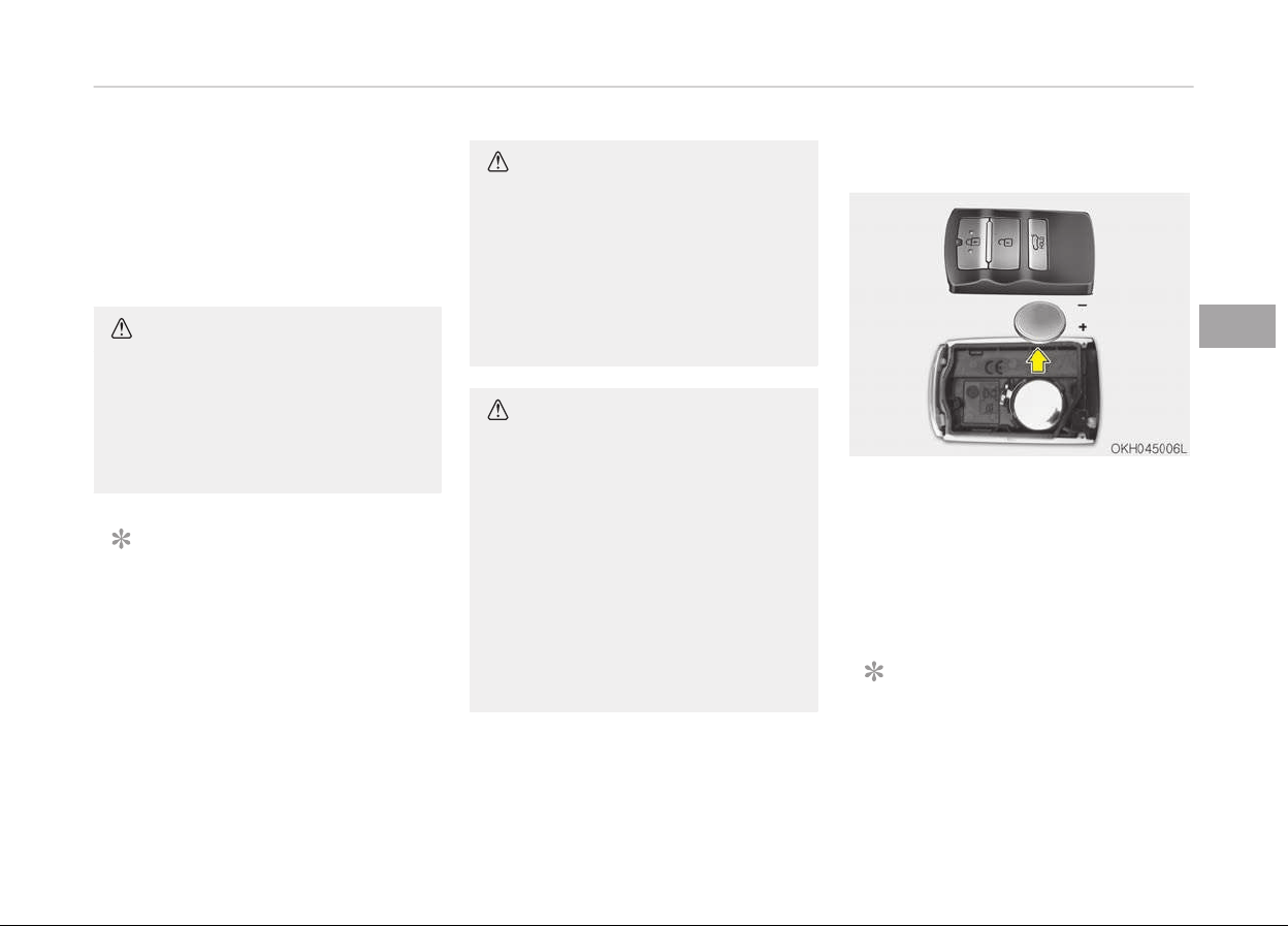
(Continued)
may not start or may stop soon af‐
ter
it starts. Keep each key separate
in order to avoid a starting malfunc‐
tion.
CAUTION
Do not put metal accessories near
the smart key.
The
engine may not start for the
metal accessories may interrupt the
transponder signal from normally
transmitting.
NOTICE
If you need additional keys or lose
your keys, Kia recommends to visit
an authorized Kia dealer/service
partner.
CAUTION
The transponder in your smart key
is an important part of the immobil‐
izer system. It is designed to give
years of trouble-free service, how‐
ever you should avoid exposure to
moisture, static electricity and rough
handling. Immobilizer system mal‐
function could occur.
CAUTION
Do not change, alter or adjust the
immobilizer system because it could
cause the immobilizer system to
malfunction. In this case, have the
system serviced by a professional
workshop. Kia recommends to visit
an authorized Kia dealer/service
partner.
Malfunctions caused by improper al‐
terations, adjustments or modifica‐
tions to the immobilizer system are
not covered by your vehicle manu‐
facturer warranty.
Battery replacement
A smart key battery should last for
several years, but if the smart key is
not working properly, try replacing the
battery with a new one. If you are un‐
sure how to use or replace the battery,
Kia recommends to contact an author‐
ized Kia dealer/service partner.
NOTICE
The circuit inside the smart key can
hav
e a problem if exposed to mois‐
ture or static electricity.
4-09
4
Features of your vehicle

1. Pry open the rear cover of the
smart key.
2. Replace the battery with a new
battery (CR2032). When replacing
the battery, make sure the battery
position.
3. Install the battery in the reverse
order of removal.
NOTICE
• Using the wrong battery can cause
the smart key to malfunction. Be
sure to use the correct battery.
• Circuits inside the smart key may
develop problems when dropped,
exposed to moisture or static elec‐
tricity.
• If you suspect that your smart key
might have sustained some dam‐
age, or you feel your smart key is
not working correctly, Kia recom‐
mends to contact an authorized
Kia dealer/service partner.
CAUTION
An inappropriately disposed battery
can be harmful to the environment
and human health.
Dispose the battery according to
your local law(s) or regulation.
Features of your vehicle
4-10
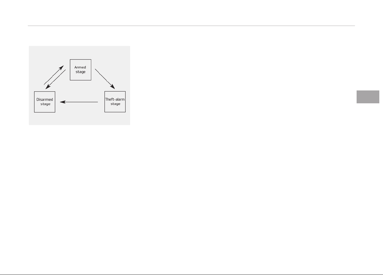
THEFT-ALARM SYSTEM (IF EQUIPPED)
This system is designed to provide pro‐
tection from unauthorized entry into
the car. This system is operated in
three stages: the first is the "Armed"
stage, the second is the "Theft-alarm"
stage, and the third is the "Disarmed"
stage. If triggered, the system provides
an audible alarm with blinking of the
hazard warning lights.
Armed stage
Park the vehicle and stop the engine.
Arm the system as described below.
1. Turn off the engine.
2. Make sure that all doors, the en‐
gine hood and trunk lid are closed
and latched.
3. • Lock the doors by pressing the
button of the outside door handle
with the smart key in your pos‐
session.
After completion of the steps
above, the hazard warning lights
operate once to indicate that the
system is armed.
If any door remains open, the
doors won't lock and the chime
will sound for 3 seconds. Close
the door and try again to lock the
doors.
If trunk lid or engine hood re‐
mains open, the hazard warning
lights won't operate and theft-
alarm will not arm. After this, if
the trunk lid and engine hood are
closed, the hazard warning lights
will blink once.
• Lock the doors by pressing the
lock button on the smart key.
After completion of the steps
above, the hazard warning lights
will operate once to indicate that
the system is armed.
If any door, trunk lid or engine
hood remains open, the hazard
warning lights won't operate and
theft-alarm will not arm. After
this, if all doors, trunk lid and en‐
gine hood are closed, the hazard
warning lights will blink once.
•
Do not arm the system until all pas‐
sengers have left the vehicle. If the
system is armed while a passenger(s)
remains in the vehicle, the alarm may
be activated when the remaining pas‐
senger(s) leave the vehicle. If any
door, trunk lid or engine hood is
opened within 30 seconds after en‐
tering the armed stage, the system
is disarmed to prevent unnecessary
alarm.
Theft-alarm stage
The alarm will be activated if any of the
following
occurs while the system is
armed.
• A door is opened without using the
smart key.
4-11
4
Features of your vehicle

• The trunk is opened without using
the smart key.
• The engine hood is opened.
The horn will sound and the hazard
warning lights will blink continuously
for approximately 27 seconds. To turn
off the system, unlock the doors with
the smart key.
Opening the trunk with the
alarm armed (if equipped)
When the alarm is armed, the alarm
will not sound if the trunk lid is opened
with the smart key.
Once the trunk is opened and then
closed, the trunk will lock automatically
and the system will be armed again.
Also, if any of the doors or hood is
opened while the trunk lid is opened
and the alarm armed, the alarm will
sound.
Disarmed stage
The system will be disarmed when the
doors are unlocked with the smart key.
After depressing the unlock button, the
hazard warning lights will blink twice to
indicate that the system is disarmed.
After depressing the unlock button, if
any door (or trunk) is not opened within
30 seconds, the system will be re‐
armed.
NOTICE
• Avoid trying to start the engine
while the alarm is activated. The
vehicle starter motor is disabled
during the theft-alarm stage.
If the system is not disarmed with
the smart key, open the doors by
using the mechanical key and start
the engine by directly pressing the
engine Start/Stop button with the
smart key.
• If you lose your keys, Kia recom‐
mends to contact an authorized
Kia dealer/service partner.
CAUTION
Do not change, alter or adjust the
theft-alarm
system because it could
cause the theft-alarm system to
(Continued)
(Continued)
malfunction. In this case, have the
system
serviced by a professional
workshop. Kia recommends to visit
an authorized Kia dealer/service
partner.
Malfunctions caused by improper al‐
terations, adjustments or modifica‐
tions to the theft-alarm system are
not covered by your vehicle manu‐
facturer warranty.
Features of your vehicle
4-12
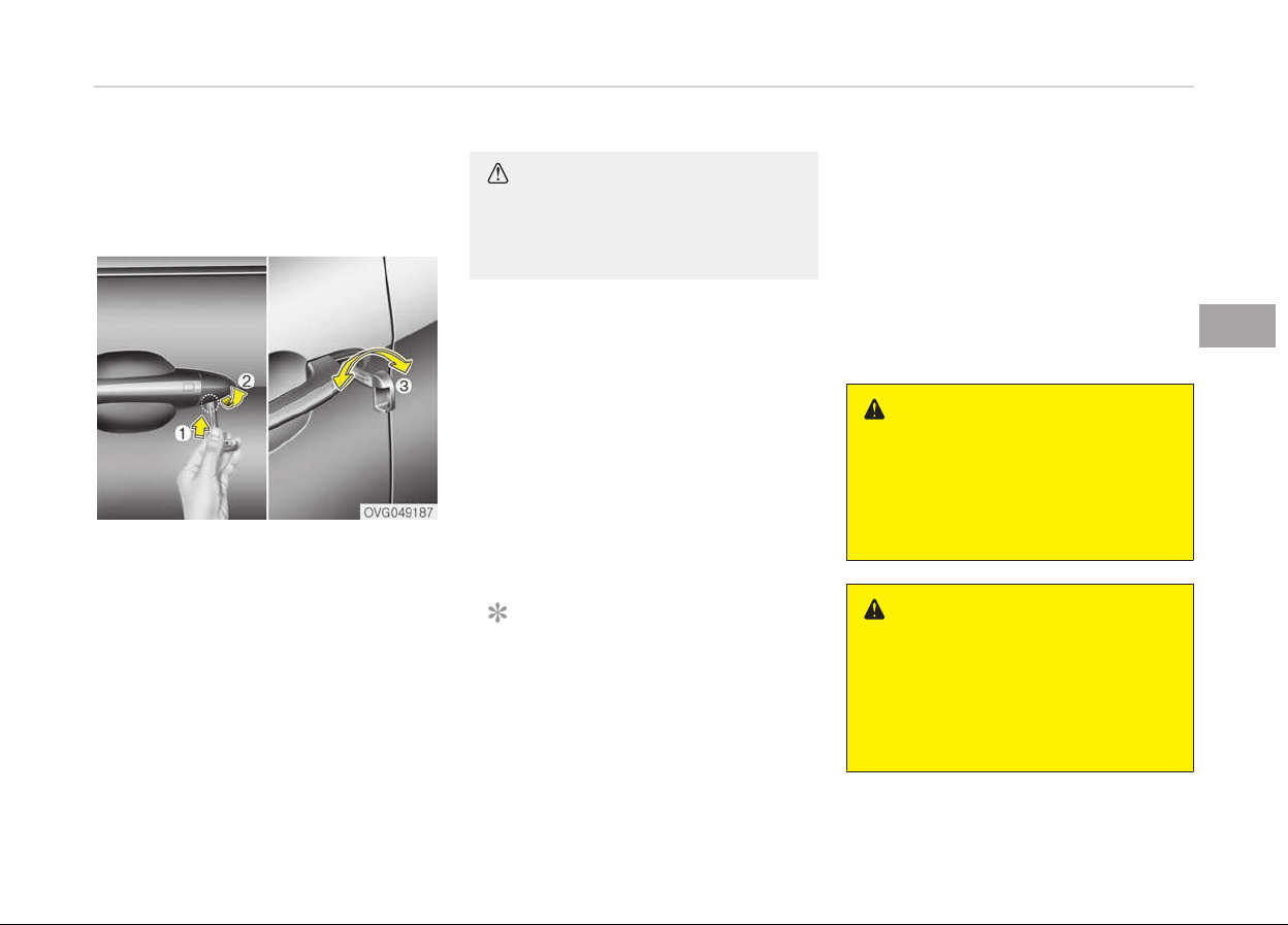
DOOR LOCKS
Operating door locks from
outside the vehicle
Mechanical key
• After removing the cover (1~2), turn
the key clockwise or counterclock‐
wise to unlock or lock the doors (3).
• Once the doors are unlocked, they
may be opened by pulling the door
handle.
• When closing the door, push the door
by hand. Make sure that doors are
closed securely.
CAUTION
When removing the door handle cov‐
er, be careful not to scratch the ve‐
hicle and not to lose the cover.
Smart key
• Doors can be locked and unlocked
pressing the buttons on the smart
key or pressing the button of the
outside door handle with the smart
key in your possession.
• Once the doors are unlocked, they
may be opened by pulling the door
handle.
• When closing the door, push the door
by hand. Make sure that doors are
closed securely.
NOTICE
• In
cold and wet climates, door
locks and door mechanisms may
not work properly due to freezing
conditions.
(Continued)
(Continued)
• If the door is locked/unlocked mul‐
tiple times in rapid succession with
either the vehicle key or door lock
switch, the system may stop op‐
erating temporarily in order to
protect the circuit and prevent
damage to system components.
WARNING
• If you don’t close the door secure‐
ly, the door may open again.
• Be careful that someone’s body
and
hands are not trapped when
closing the door.
WARNING
If people must spend a longer time in
the
vehicle while it is very hot or cold
outside, there is rick of injuries or
danger to life. Do not lock the vehicle
from the outside when there are
people in it.
4-13
4
Features of your vehicle
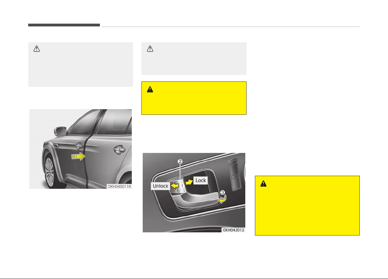
CAUTION
Do not frequently repeat opening
and closing of doors, or apply exces‐
sive force to a door while the door
closer is operating.
Power door latch (if equipped)
If a door isn’t closed completely but is
closed to the first detent position, the
door will close automatically.
CAUTION
Before closing the door, ensure that
all obstructions are removed.
WARNING
If the door is open slightly, be care‐
ful not to nip fingers in the door.
Operating door locks from inside
the vehicle
With the door lock button
• To unlock a door, push the door lock
button (1) to the Unlock position.
The red mark (2) on the door lock
button will be visible.
• To lock a door, push the door lock
button (1) to the Lock position. If
the door is locked properly, the red
mark (2) on the door lock button will
not be visible.
• To open a door, pull the door handle
(3) outward.
• If the inner door handle of the driv‐
er’s (or front passenger’s) door is
pulled when the door lock button is in
lock position, the button is unlocked
and door opens.
• Doors cannot be locked if the smart
key is in the vehicle and any door is
opened.
WARNING
n
Door lock malfunction
If a power door lock ever fails to
function while you are in the vehicle,
try one or more of the following
techniques to exit:
(Continued)
Features of your vehicle
4-14

(Continued)
• Operate the door unlock feature
r
epeatedly (both electronic and
manual) while simultaneously pull‐
ing on the door handle.
• Operate the other door locks and
handles, front and r
ear.
• Lower a front window and use the
key
to unlock the door from out‐
side.
WARNING
Do not pull the inner door handle of
driv
er's (or passenger's) door while
the vehicle is moving.
Rear door lock button
• To lock a rear door, press the door
lock button (1). The indicator on the
button will illuminate.
• To unlock a rear door, press the door
unlock button (2). The indicator on
the button will illuminate.
With central door lock/unlock
button switch
Locking
4-15
4
Features of your vehicle

• When pressing the door lock button
(1), all vehicle doors will lock and the
indicator on the button will illuminate.
If any door is unlocked, the indicator
will turn off.
• If the smart key is in the vehicle and
any door is opened, doors will not
lock.
Unlocking
When pressing the door unlock button
(2), all vehicle doors will unlock and the
indicator on the button will illuminate.
If any door is locked, the indicator will
turn off.
WARNING
n
Doors
• The doors should always be fully
closed and locked while the vehicle
is in motion to prevent accidental
opening of the door. Locked doors
will also discourage potential in‐
truders when the vehicle stops or
slows.
(Continued)
(Continued)
• Be careful when opening doors and
watch
for vehicles, motorcycles,
bicycles or pedestrians approach‐
ing the vehicle in the path of the
door. Opening a door when some‐
thing is approaching can cause
damage or injury.
WARNING
n
Unlocked vehicles
Leaving your vehicle unlocked can in‐
vite theft or possible harm to you or
others from someone hiding in your
vehicle while you are gone. Always
press the engine start/stop button
to the OFF position, engage the
parking brake, close all windows and
lock all doors when leaving your ve‐
hicle unattended.
WARNING
n
Unattended children
(Continued)
(Continued)
An enclosed vehicle can become ex‐
tr
emely hot, causing death or severe
injury to unattended children or ani‐
mals who cannot escape the vehicle.
Furthermore, children might operate
features of the vehicle that could in‐
jure them, or they could encounter
other harm, possibly from someone
gaining entry to the vehicle. Never
leave children or animals unattended
in your vehicle.
Door lock/unlock features
Impact sensing door unlock system
All doors will automatically unlock when
an impact causes the air bags to de‐
ploy.
Speed sensing door lock system
All doors will automatically lock after
the vehicle speed exceeds 15 km/h.
Engine off door unlock system
All doors will automatically unlock when
the engine start/stop button is turned
to the ACC or OFF position.
Features of your vehicle
4-16
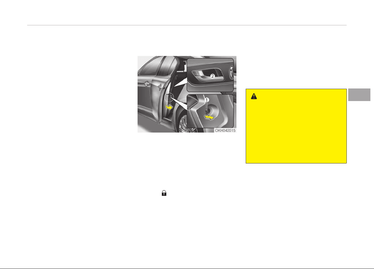
Shift lever door lock/unlock system
• All doors will automatically lock when
the shift lever is moved out of P
(Park).
• All doors will automatically unlock
when the shift lever is moved into P
(Park).
You can activate or deactivate the auto
door lock/unlock features in the vehicle.
Refer to LCD display on page 4-56.
Child-protector rear door lock
The child safety lock is provided to help
prevent children from accidentally
opening the rear doors from inside the
vehicle. The rear door safety locks
should be used whenever children are in
the vehicle.
1. Open the rear door.
2. Push the child safety lock (1) to the
lock (
) position. When the child
safety lock is in the lock position,
the rear door will not open even
though the inner door handle is
pulled.
3. Close the rear door.
To open the rear door, pull the outside
door handle.
Even though the doors may be un‐
locked, the rear door will not open by
pulling the inner door handle (2) until
the rear door child safety lock is un‐
locked.
WARNING
n
Rear door locks
If children accidentally open the rear
doors while the vehicle is in motion,
they could fall out and be severely
injured or killed. To prevent children
from opening the rear doors from
the inside, the rear door safety locks
should be used whenever children
are in the vehicle.
4-17
4
Features of your vehicle
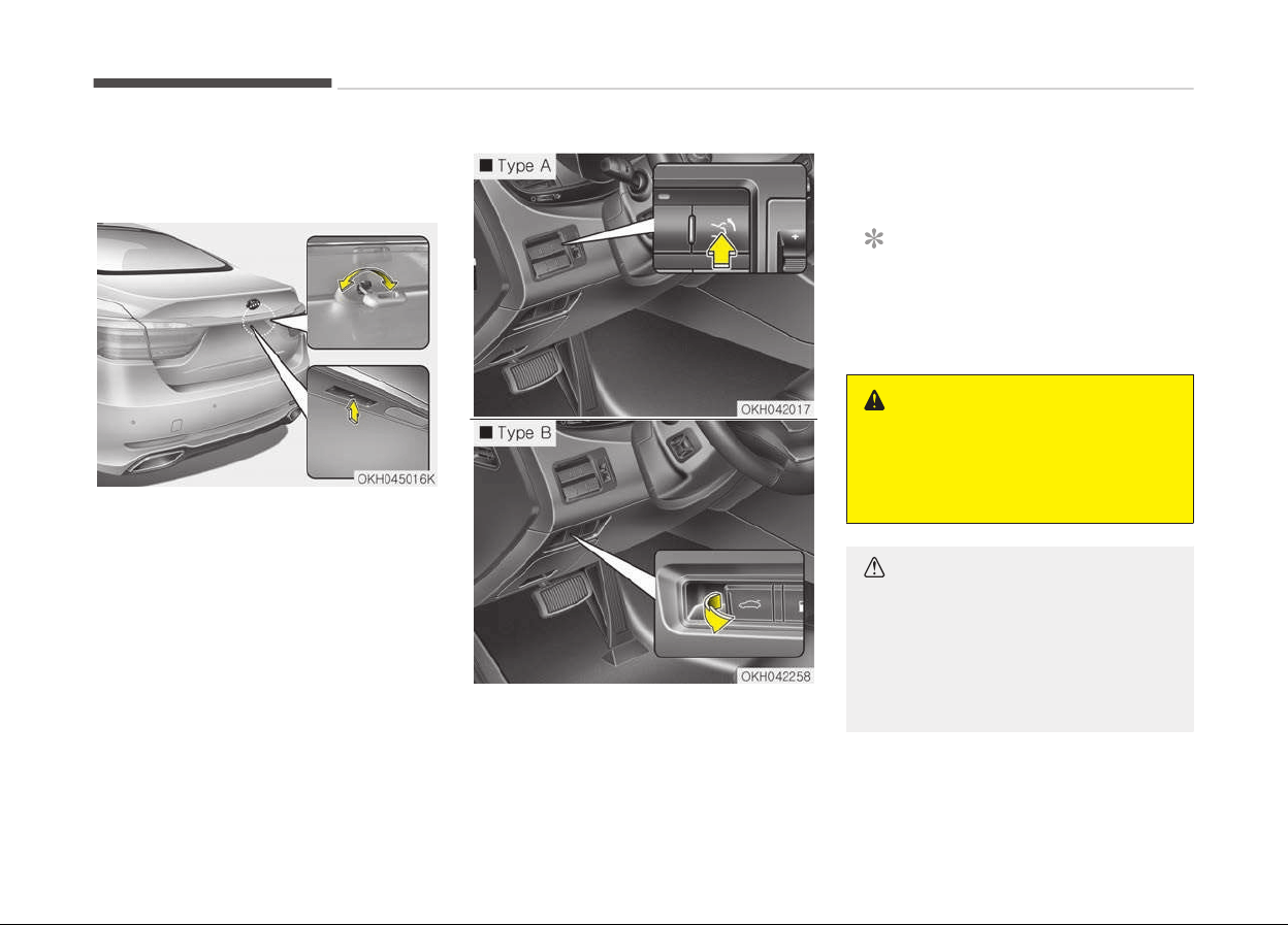
TRUNK
Non-powered trunk
Opening the trunk
• Press the trunk unlock button for
more than 1 second on the smart
key.
• Press the button on the trunk handle
with the smart key in your posses‐
sion.
• Insert the mechanical key into the
lock and turn it clockwise.
Once the trunk is opened and then
closed, the trunk locks automatically.
Type A
T
o open the trunk from inside the vehi‐
cle, press the trunk lid release switch.
Type B
To open the trunk from inside the vehi‐
cle, pull the trunk lid r
elease switch.
NOTICE
In cold and wet climates, door lock
and door mechanisms may not work
properly due to freezing conditions.
WARNING
The trunk swings upward. Make sure
no objects or people are near the
rear of the vehicle when opening the
trunk.
CAUTION
Make certain that you close the
trunk
before driving your vehicle.
Possible damage may occur to the
trunk lift cylinders and attached
hardware if the trunk is not closed
prior to driving.
Features of your vehicle
4-18
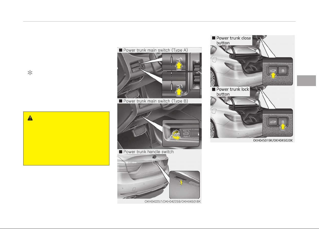
Closing the trunk
To close, lower the trunk lid, then press
down on it until it locks. To be sure the
trunk lid is securely fastened, always
check by trying to pull it up again.
NOTICE
If the trunk is closed with the smart
key in it, the chime will sound for ap‐
proximately 3 seconds and the trunk
can be opened.
WARNING
n
Exhaust fumes
The
trunk lid should be always kept
completely closed while the vehicle is
in motion. If it is left open or ajar,
poisonous exhaust gases may enter
the car and serious illness or death
may result.
Power trunk (if equipped)
The power trunk can be opened and
closed automatically with the smart
key, the power trunk main switch, the
trunk handle switch, or the close but‐
ton on the trunk lid.
If you depress the power trunk main
switch, trunk handle switch, or close
button while operating the power
trunk, you could stop operating the
power trunk.
4-19
4
Features of your vehicle

If that happens, to operate the power
trunk again, push any button or switch.
CAUTION
For your safety, do not leave the
power trunk open for a long time, it
could also to prevent unnecessary
charging system drain.
WARNING
Never leave children or animals unat‐
tended in your vehicle. Children or
animals might operate the power
trunk that could result in injury to
themselves or others, or damage to
the vehicle.
NOTICE
In cold and wet climates, the power
trunk may not work properly due to
freezing conditions.
WARNING
Make sure there are no people or ob‐
jects around the trunk before oper‐
ating the power trunk. Wait until the
trunk is open fully and stopped be‐
fore loading or unloading cargo or
passengers from the vehicle.
WARNING
Make sure the trunk is closed firmly
before driving. If the trunk is open,
you will draw dangerous exhaust
fumes into your vehicle which can
cause serious injury or death to vehi‐
cle occupants.
CAUTION
Do not close or open the power
trunk manually. This may cause
damage to the power trunk. If it is
necessary to close or open the pow‐
er trunk manually when the battery
is discharged or disconnected, do not
apply excessive force.
Opening the trunk
The power trunk will open automatical‐
ly by doing one of the following:
• Press the trunk open button on the
smart key more than 1 second. The
chime will sound twice.
• Press the open button of the power
trunk main switch (Type A). The
chime will sound twice.
• Pull the power trunk main switch
(Type B).The chime will sound twice.
• Press the trunk handle switch carry‐
ing the smart key with you. If all
doors have unlocked, you can open
the trunk by pressing the trunk han‐
dle switch without the smart key.
Closing the trunk
To close the power trunk, do one of the
following:
• Push the close button of the power
trunk main switch until the power
trunk is closed securely (Type A). The
chime will sound twice.
• Push the power trunk main switch
until the power trunk is closed se‐
curely (Type B). The chime will sound
twice.
• Push the power trunk close button.
Features of your vehicle
4-20

• Push the power trunk lock button
when all doors and engine hood are
closed with the smart key in your
possession. After closing, all doors
and trunk lock automatically.
NOTICE
The chime sound will operate if you
push the power trunk lock button
when:
- Any door is open.
- The engine start/stop button is
not in the OFF position.
- The smart key is in the vehicle.
Power trunk non-opening
conditions
The power trunk will not open or close
automatically, when the vehicle is mov‐
ing more than 3 km/h (2 mph).
NOTICE
If there are obstacles such as snow
on the power trunk, it may not open
(Continued)
(Continued)
automatically. After remove the ob‐
stacle, try to open it again
.
CAUTION
The chime will sound 10 times if you
driv
e over 3km/h
n
(2mph)
with the trunk opened. Stop your ve‐
hicle immediately at a safe place and
check if your trunk is opened.
NOTICE
• The power trunk can be operated
when the engine is not running.
However the power trunk opera‐
tion consumes large amounts of
vehicle electric power. To prevent
the battery from being dis‐
charged, do not operate it exces‐
sively e.g.: more than approxi‐
mately 10 times repeatedly.
(Continued)
(Continued)
• T
o prevent the battery from being
discharged, do not leave the power
trunk in the open position for a
long lime.
• Do not apply excessive force while
operating the power trunk. This
could cause damage to the power
trunk.
• Do not modify or repair any part
of the power trunk by yourself. In
this case, have the system serv‐
iced by a professional workshop.
Kia recommends to visit an au‐
thorized Kia dealer/service part‐
ner.
• When jacking up the vehicle to
change a tire or repair the vehicle,
do not operate the power trunk.
This could cause the power trunk
to operate improperly.
4-21
4
Features of your vehicle
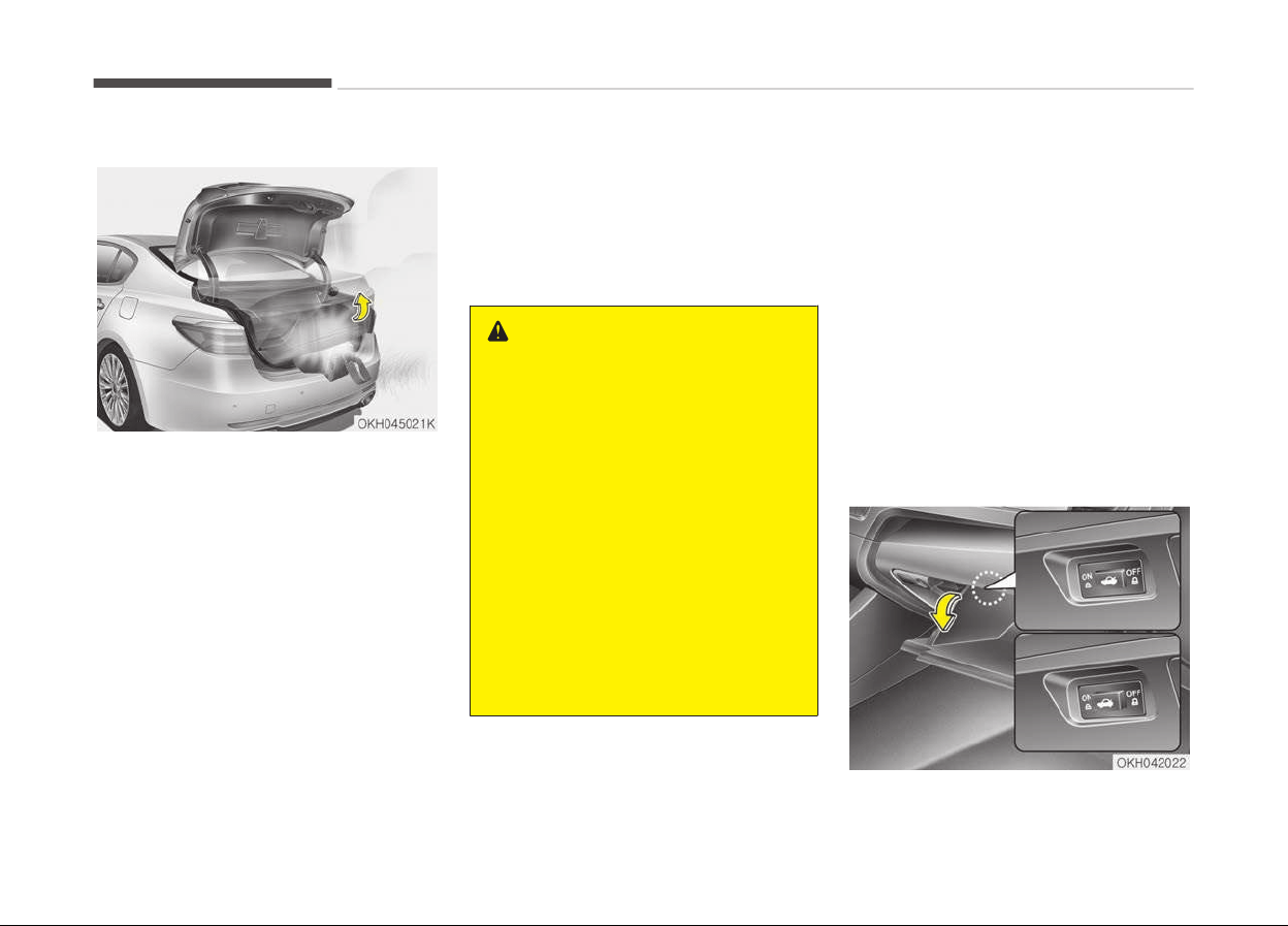
Automatic reversal
If, during power opening or closing, the
trunk is blocked by an object or part of
the body, the power trunk will detect
the resistance, and it will stop move‐
ment or move to the full open position
to allow the object to be cleared.
However, if the resistance is weak such
as from an object that is thin or soft, or
the trunk is near the latched position,
the automatic stop and reversal may
not detect the resistance and the clos‐
ing operation will continue. Also, if the
power trunk is forced by a strong im‐
pact, the automatic stop and reversal
may operate.
If the automatic stop and reversal fea‐
ture operates continuously more than
twice during opening or closing opera‐
tion, the power trunk may stop at that
position. At this time, close the trunk
manually and operate the trunk auto‐
matically again.
WARNING
• Never intentionally place any ob‐
ject or part of your body in the
path of the power trunk to make
sure the automatic stop operates.
• Make sure all faces, arms, hands,
body parts and any other obstruc‐
tions are safely out of the way be‐
fore operating the power trunk.
• Never place any object or part of
your body in the path of the pow‐
er trunk. This could result in seri‐
ous injury or cause damage to the
vehicle.
• Make sure there are no people or
objects around the trunk before
operating the power trunk.
How to reset the power trunk
If the battery has been discharged or
disconnected, or if the related fuse has
been replaced or disconnected, for the
power trunk to operate normally, reset
the power trunk as follow:
1. Put the shift lever in P (Park).
2. Close the trunk manually.
If the power trunk does not work prop‐
erly after the above procedure, have
the system checked by a professional
workshop. Kia recommends to visit an
authorized Kia dealer/service partner.
Trunk lid control button
Features of your vehicle
4-22
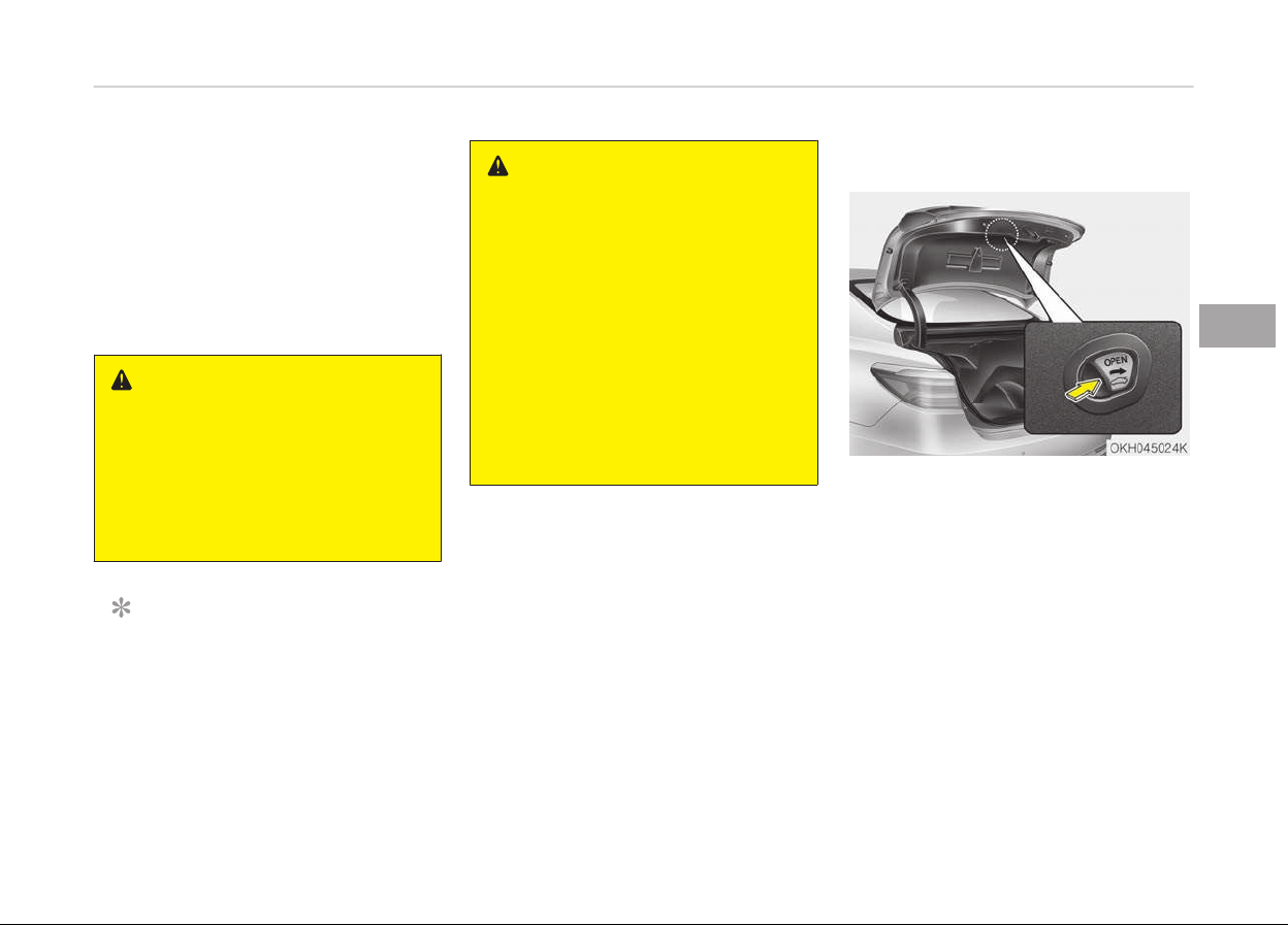
• When the trunk lid control button is
ON (depressed), the power trunk can
be controlled with the power trunk
main switch, power trunk open, close
button, and the smart key.
• When the trunk lid control button is
OFF (not depressed), the power trunk
can controlled with the mechanical
key of the smart key only.
WARNING
Do not allow children to play with
the power trunk. Keep the trunk lid
control button in the OFF (not de‐
pressed) position when not in use.
Serious injury or death can result
from unintentional power operation
by a child.
NOTICE
Close the trunk, and keep the trunk
lid control button in the OFF (not de‐
pressed) position before washing
the vehicle in an automatic car wash.
WARNING
Even though the trunk lid control
button is in the OFF (not depressed)
position, the trunk will still be pro‐
pelled upward by mechanical force if
the trunk is manually opened more
than 10 degrees beyond the fully
closed position. In addition, if the
trunk is manually closed to the sec‐
ondary latch position, the trunk will
be electrically moved to the fully
latched position. Make sure that
face, arms, hands, and other ob‐
structions are safely out of the way
before operating the trunk.
Emergency trunk safety release
Your vehicle is equipped with an emer‐
gency trunk safety release lever loca‐
ted inside the trunk. When someone is
inadvertently locked in the trunk, the
trunk can be opened by moving the lev‐
er in the direction of the arrow and
pushing open the trunk.
4-23
4
Features of your vehicle

WARNING
• For emergencies, be fully aware of
the location of the emergency
trunk safety release lever in this
vehicle and how to open the trunk
if you are accidentally locked in the
trunk.
• No one should be allowed to occu‐
py the trunk at any time. The
trunk is a very dangerous location
in the event of a crash.
• Use the release lever for emergen‐
cies only. Use with extreme cau‐
tion, especially while the vehicle is
in motion.
WARNING
Make sure that there are no people
or objects in the path of the trunk
prior to use. Serious injury, damage
to the vehicle or damage to sur‐
rounding objects may result if con‐
tact with the trunk occurs.
Features of your vehicle
4-24
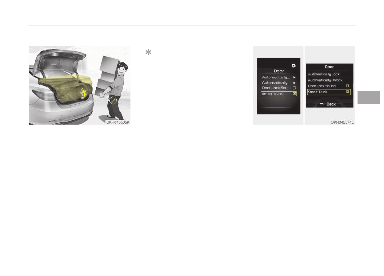
SMART TRUNK (IF EQUIPPED)
On a vehicle equipped with a smart key,
the trunk can be opened with no-touch
activation using the Smart Trunk sys‐
tem.
How to use the smart trunk
The trunk can be opened with no-touch
activation satisfying all the conditions
below.
• After 15 seconds when all doors are
closed and locked
• Positioned in the detecting area for
more than 3 seconds.
NOTICE
• The Smart Trunk does not operate
when:
- The smart key is detected with‐
in 15 seconds after the doors
are closed and locked, and is
continuously detected.
- The smart key is detected with‐
in 15 seconds after the doors
are closed and locked, and
1.5 m from the front door han‐
dles. (for vehicles equipped with
Welcome Light)
- A door is not locked or closed.
- The smart key is in the vehicle.
1. Setting
To activate the Smart Trunk, go to
User Settings Mode and select
Smart Trunk on the LCD display.
For more details, refer to LCD dis‐
play on page 4-56.
4-25
4
Features of your vehicle
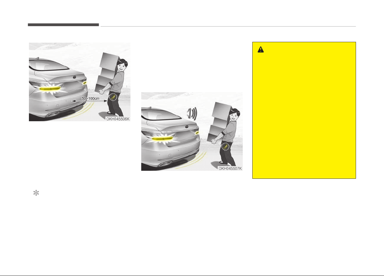
2. Detect and Alert
If you are positioned in the detect‐
ing area (50 ~100 cm behind the
vehicle) carrying a smart key, the
hazard warning lights will blink and
chime will sound for about
3 seconds to alert you the smart
key has been detected and the
trunk will open.
NOTICE
Do not approach the detecting area
if
you do not want the trunk to
open. If you have unintentionally en‐
tered the detecting area and the
(Continued)
(Continued)
hazard warning lights and chime
starts
to operate, leave the detect‐
ing area with the smart key. The
trunk will stay closed.
3. Automatic opening
The hazard warning lights will blink
and chime will sound 2 times and
then the trunk will slowly open.
WARNING
• Make sure you close the trunk be‐
fore driving your vehicle.
• Make sure there are no people or
objects around the trunk before
opening or closing the trunk.
• Make sure objects in the trunk do
not come out when opening the
trunk on a slope. It may cause se‐
rious injury.
• Make sure to deactivate the Smart
Trunk when washing your vehicle.
Otherwise, the trunk may open in‐
advertently.
• The key should be kept out of
reach of children. Children may in‐
advertently open the Smart Trunk
while playing around the rear area
of the vehicle.
Features of your vehicle
4-26
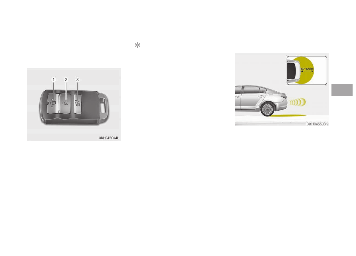
How to deactivate the smart
trunk function using the smart
key
1. Door lock
2. Door unlock
3. Trunk open
If you press any button of the smart
key during the Detect and Alert stage,
the Smart Trunk function will be deacti‐
vated.
Make sure to be aware of how to deac‐
tivate the Smart Trunk function for
emergency situations.
NOTICE
• If you press the door unlock but‐
ton (2), the Smart Trunk function
will be deactivated temporarily.
But, if you do not open any door
for 30 seconds, the smart trunk
function will be activated again.
• If you press the trunk open button
(3) for more than 1 second, the
trunk opens.
• If you press the door lock button
(1) or trunk open button (3) when
the Smart Trunk function is not in
the Detect and Alert stage, the
smart trunk function will not be
deactivated.
• In case you have deactivated the
Smart Trunk function by pressing
the smart key button and opened
a door, the smart trunk function
can be activated again by closing
and locking all doors.
Detecting area
• The Smart Trunk operates with a
welcome alert if the smart key is de‐
tected within 50~100 cm from the
trunk.
• The alert stops at once if the smart
key is positioned outside the detect‐
ing area during the Detect and Alert
stage.
4-27
4
Features of your vehicle

NOTICE
• The Smart Trunk function will not
work if any of the following oc‐
curs:
- The smart key is close to a ra‐
dio transmitter such as a radio
station or an airport which can
interfere with normal operation
of the transmitter.
- The smart key is near a mobile
two way radio system or a cel‐
lular phone.
- Another vehicle's smart key is
being operated close to your
vehicle.
• The detecting range may decrease
or increase when :
- One side of the tire is raised to
replace a tire or to inspect the
vehicle.
- The vehicle is slantingly parked
on a slope or unpaved road, etc.
Features of your vehicle
4-28
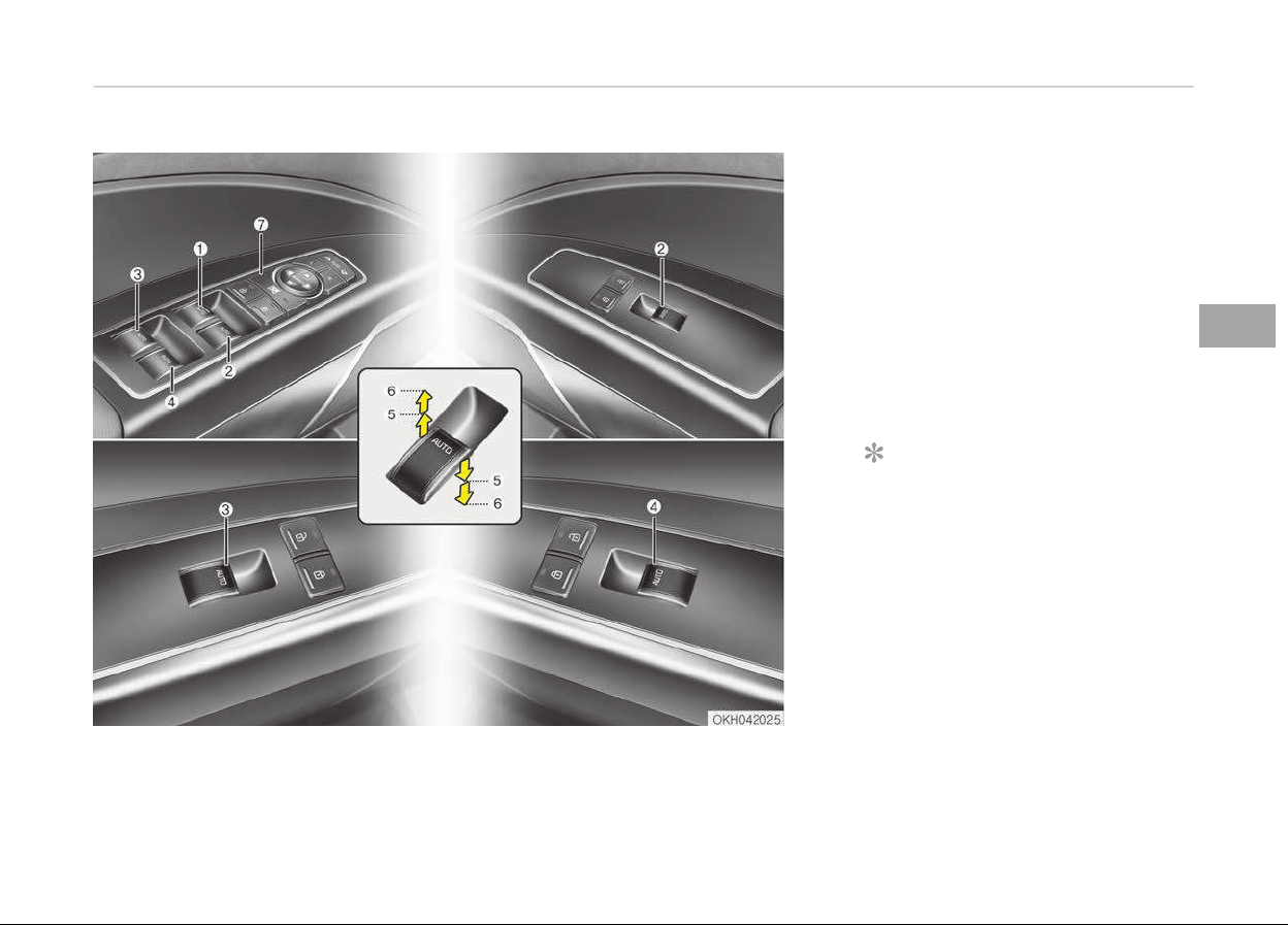
WINDOWS
1. Driver’s door power window switch
2. Front passenger’s door power win‐
dow switch
3. Rear door (left) power window
switch
4. Rear door (right) power window
switch
5. Window opening and closing
6. Automatic power window up/down
7. Power window lock switch
NOTICE
In cold and wet climates, power win‐
dows may not work properly due to
freezing conditions.
Power windows
The engine start/stop button must be
in the ON position for power windows
to operate.
4-29
4
Features of your vehicle
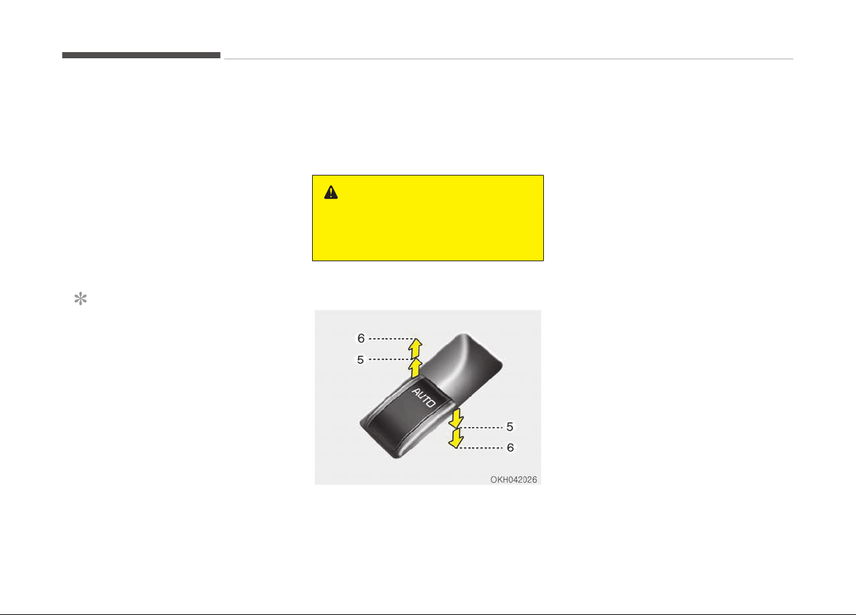
Each door has a power window switch
that controls the door's window. The
driver has a power window lock switch
which can block the operation of rear
passenger windows. The power win‐
dows can be operated for approximate‐
ly 30 seconds after engine is turned
off. However, if the front doors open,
the power windows cannot be operated
within the 30 second period.
If the window cannot be closed because
it is blocked by objects, remove the ob‐
jects and close the window.
NOTICE
While driving with the rear windows
down or with the sunroof (if equip‐
ped) in an open (or partially open po‐
sition), your vehicle may demon‐
strate a wind buffeting or pulsation
noise. This noise is a normal occur‐
rence and can be reduced or elimina‐
ted by taking the following actions.
If the noise occurs with one or both
of the rear windows down, partially
lower both front windows approxi‐
mately one inch. If you experience
the noise with the sunroof open,
(Continued)
(Continued)
slightly reduce the size of the sun‐
roof opening.
WARNING
Do not install any accessories in the
ar
ea of windows. It may impact jam
protection.
Window opening and closing
The driver’s door has a master power
window
switch that controls all the
windows in the vehicle.
To open or close a window, press down
or pull up the front portion of the cor‐
responding switch to the first detent
position (5).
Pressing or pulling up the power win‐
dow switch momentarily to the second
detent position (6) completely lowers
or lifts the window even when the
switch is released. To stop the window
at the desired position while the win‐
dow is in operation, pull up or press and
release the switch to the opposite di‐
rection of the movement.
If the power window is not operated
correctly, the automatic power window
system must be reset as follows:
1. Place the Engine Start/Stop button
to the ON position.
2. Close the window and continue
pulling up on the driver’s power
window switch for at least
1 second after the window is com‐
pletely closed.
Features of your vehicle
4-30
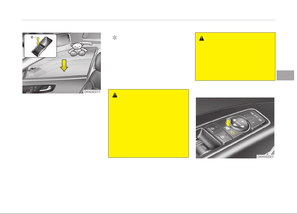
Automatic reversal
If the upward movement of the window
is blocked by an object or part of the
body, the window will detect the resist‐
ance and will stop upward movement.
The window will then lower approxi‐
mately 30 cm (11.8 in.) to allow the ob‐
ject to be cleared.
If the window detects the resistance
while the power window switch is
pulled up continuously, the window will
stop upward movement then lower ap‐
proximately 2.5 cm (1 in.).
And if the power window switch is
pulled up continuously again within
5 seconds after the window is lowered
by the automatic window reversal fea‐
ture, the automatic window reversal
will not operate.
NOTICE
The automatic reverse feature is on‐
ly active when the auto up feature
is used by fully pulling up the switch.
The automatic reverse feature will
not operate if the window is raised
using the halfway position on the
power window switch.
WARNING
Always check for obstructions be‐
fore raising any window to avoid in‐
juries or vehicle damage. If an object
less than 4 mm
n
(0.16 in.)
in diameter is caught between the
window glass and the upper window
channel, the automatic reverse win‐
dow may not detect the resistance
and will not stop and reverse direc‐
tion.
WARNING
The automatic reverse feature
doesn’t active while resetting power
window system. Make sure body
parts or other objects are safely out
of the way before closing the win‐
dows to avoid injuries or vehicle
damage.
Power window lock button
The driver can disable the power win‐
dow switches on the rear passengers’
doors by pressing the power window
lock switch. The indicator will be illumi‐
nated.
4-31
4
Features of your vehicle

When the power window lock switch in‐
dicator is illuminated :
• The driver’s master control can oper‐
ate all the power windows.
• The front passenger’s control can op‐
erate the front passenger’s power
window.
• The rear passenger’s control cannot
operate the rear passenger’s power
window.
CAUTION
• To prevent possible damage to the
power window system, do not
open or close two windows or
more at the same time. This will
also ensure the longevity of the
fuse.
• Never try to operate the main
switch on the driver's door and the
individual door window switch in
opposite directions at the same
time. If this is done, the window
will stop and cannot be opened or
closed.
WARNING
n
Windows
• NEVER leave the keys in your vehi‐
cle with unsupervised children,
when the engine is running.
• NEVER leave any child unattended
in the vehicle. Even very young
children may inadvertently cause
the vehicle to move, entangle
themselves in the windows, or
otherwise injure themselves or
others.
• Always double check to make sure
all arms, hands, head and other
obstructions are safely out of the
way before closing a window.
• Do not allow children to play with
the power windows. Keep the driv‐
er’s door power window lock but‐
ton in the LOCK position (The indi‐
cator on the button illuminates).
Serious injury can result from un‐
intentional window operation by
the child.
• Do not extend a face or arms out‐
side
through the window opening
while driving.
Features of your vehicle
4-32
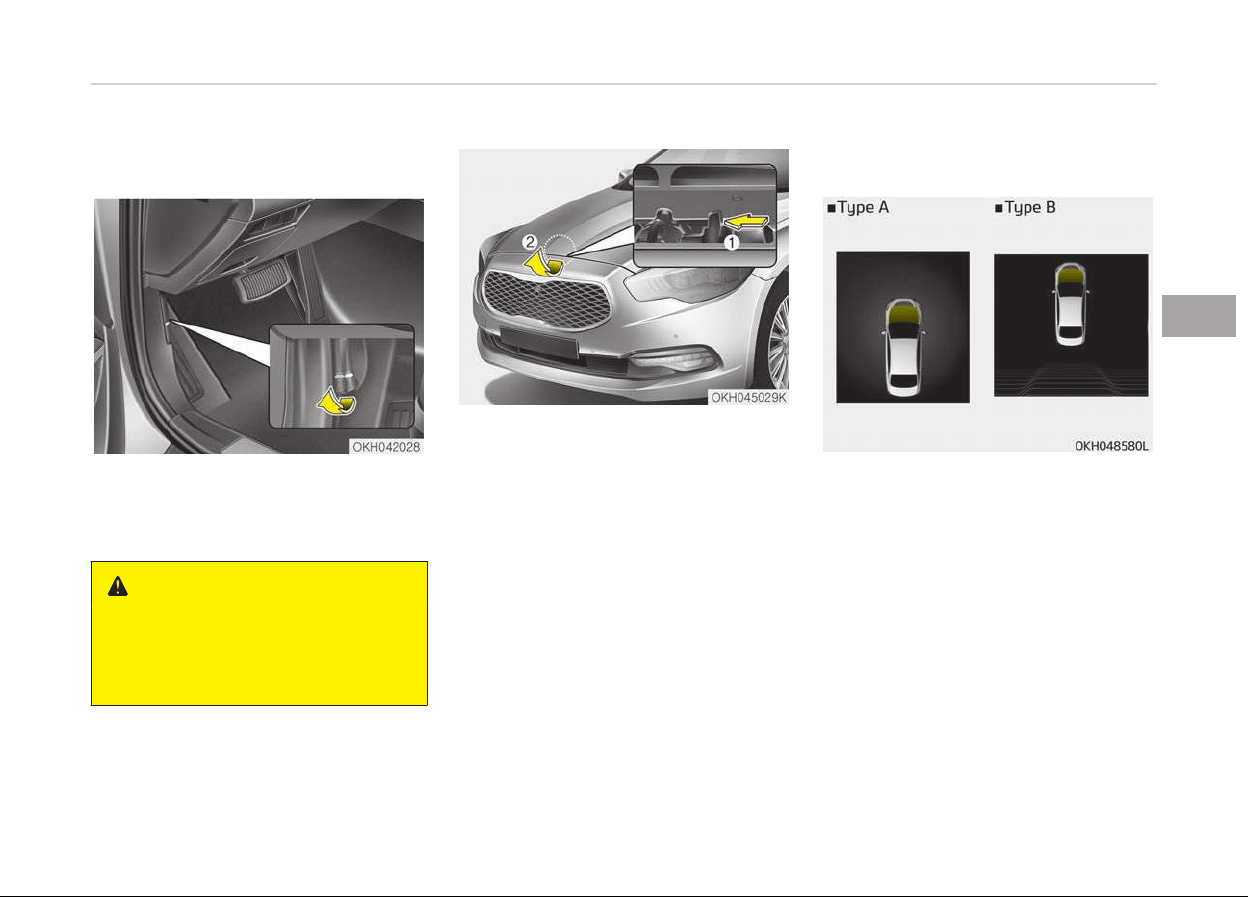
HOOD
Opening the hood
1. Pull the release lever to unlatch the
hood. The hood should pop open
slightly.
WARNING
Open the hood after turning off the
engine on a flat surface, shifting the
shift lever to the P(Park) position
and setting the parking brake.
2. Go to the front of the vehicle, raise
the hood slightly, push the secon‐
dary latch (1) inside of the hood
center and lift the hood (2).
3. Raise the hood. It will raise com‐
pletely by itself after it has been
raised about halfway.
Hood open warning (if equipped)
The warning message will appear on
the LCD display when hood is open.
The warning chime will operate when
the vehicle is being driven above 3 km/h
(2 mph) with the hood open.
Closing the hood
1. Before closing the hood, check the
following:
• All filler caps in engine compart‐
ment must be correctly installed.
• Gloves, rags or any other com‐
bustible material must be re‐
moved from the engine compart‐
ment.
4-33
4
Features of your vehicle

2. Return the support rod to its clip to
prevent it from rattling.
3. Lower the hood until it is about
30cm above the closed position and
let it drop. Make sure that it locks
into place.
4. Check that the hood has engaged
properly. If the hood can be raised
slightly, it is not properly engaged.
Open it again and close it with a lit‐
tle more force
WARNING
• Before closing the hood, ensure
that all obstructions are removed
from the hood opening. Closing the
hood with an obstruction present
in the hood opening may result in
property damage or severe per‐
sonal injury.
• Do not leave gloves, rags or any
other combustible material in the
engine compartment. Doing so
may cause a heat-induced fire.
WARNING
• Always double check to be sure
that the hood is firmly latched be‐
fore driving away. If it is not latch‐
ed, the hood could fly open while
the vehicle is being driven, causing
a total loss of visibility, which
might result in an accident.
• Do not move the vehicle with the
hood raised. The view will be
blocked and the hood could fall or
be damaged.
Features of your vehicle
4-34
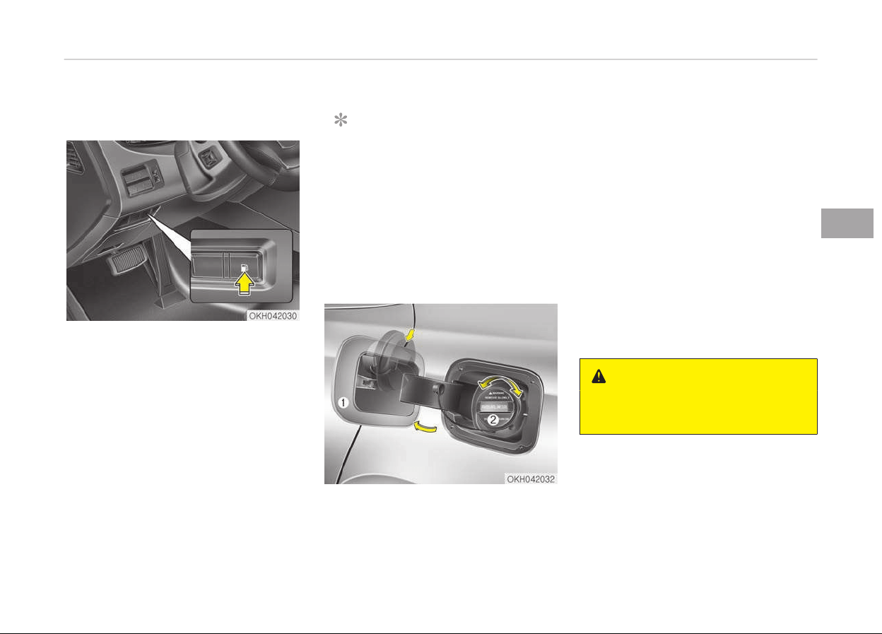
FUEL FILLER LID
Opening the fuel filler lid
The fuel filler lid must be opened from
inside the vehicle by pushing the fuel
filler lid opener button.
NOTICE
If the fuel filler lid will not open be‐
cause ice has formed around it, tap
lightly or push on the lid to break the
ice and release the lid. Do not pry on
the lid. If necessary, spray around
the lid with an approved de-icer fluid
(do not use radiator anti-freeze) or
move the vehicle to a warm place
and allow the ice to melt.
1. Stop the engine.
2. Push the fuel filler lid opener but‐
ton, then the fuel filler lid slowly
open (1).
3. To remove the cap, turn the fuel
tank cap (2) counterclockwise.
4. Refuel as needed.
Closing the fuel filler lid
1. T
o install the cap, turn it clockwise
until it clicks. This indicates that
the cap is securely tightened.
2. Close the fuel filler lid and push it
lightly and make sure that it is se‐
curely closed.
WARNING
n
Refueling
(Continued)
4-35
4
Features of your vehicle

(Continued)
• If pressurized fuel sprays out, it
can
cover your clothes or skin and
thus subject you to the risk of fire
and burns. Always remove the fuel
cap carefully and slowly. If the cap
is venting fuel or if you hear a
hissing sound, wait until the condi‐
tion stops before completely re‐
moving the cap.
• Do not "top off" after the nozzle
automatically
shuts off when re‐
fueling.
• Always check that the fuel cap is
installed securely to prevent fuel
spillage in the event of an acci‐
dent.
WARNING
n
Refueling dangers
Automotive fuels are flammable ma‐
terials. When refueling, please note
the following guidelines carefully.
Failure to follow these guidelines
may result in severe personal injury,
(Continued)
(Continued)
severe burns or death by fire or ex‐
plosion
.
• Read and follow all warnings at
the gas station facility.
• Before refueling note the location
of
the Emergency Gasoline Shut-
Off, if available, at the gas station
facility.
• Before touching the fuel nozzle,
you should eliminate potentially
dangerous static electricity dis‐
charge by touching another metal
part of the vehicle, a safe distance
away from the fuel filler neck,
nozzle, or other gas source.
(Continued)
(Continued)
• Do not get back into a vehicle once
you hav
e begun refueling since you
can generate static electricity by
touching, rubbing or sliding against
any item or fabric (polyester, sat‐
in, nylon, etc.) capable of produc‐
ing static electricity. Static elec‐
tricity discharge can ignite fuel va‐
pors resulting in rapid burning. If
you must reenter the vehicle, you
should once again eliminate poten‐
tially dangerous static electricity
discharge by touching a metal part
of the vehicle, away from the fuel
filler neck, nozzle or other gasoline
source.
• When using an approved portable
fuel
container, be sure to place the
container on the ground prior to
refueling. Static electricity dis‐
charge from the container can ig‐
nite fuel vapors causing a fire.
Once refueling has begun, contact
with the vehicle should be main‐
tained until the filling is complete.
Use only approved portable plastic
fuel containers designed to carry
and store gasoline.
(Continued)
Features of your vehicle
4-36
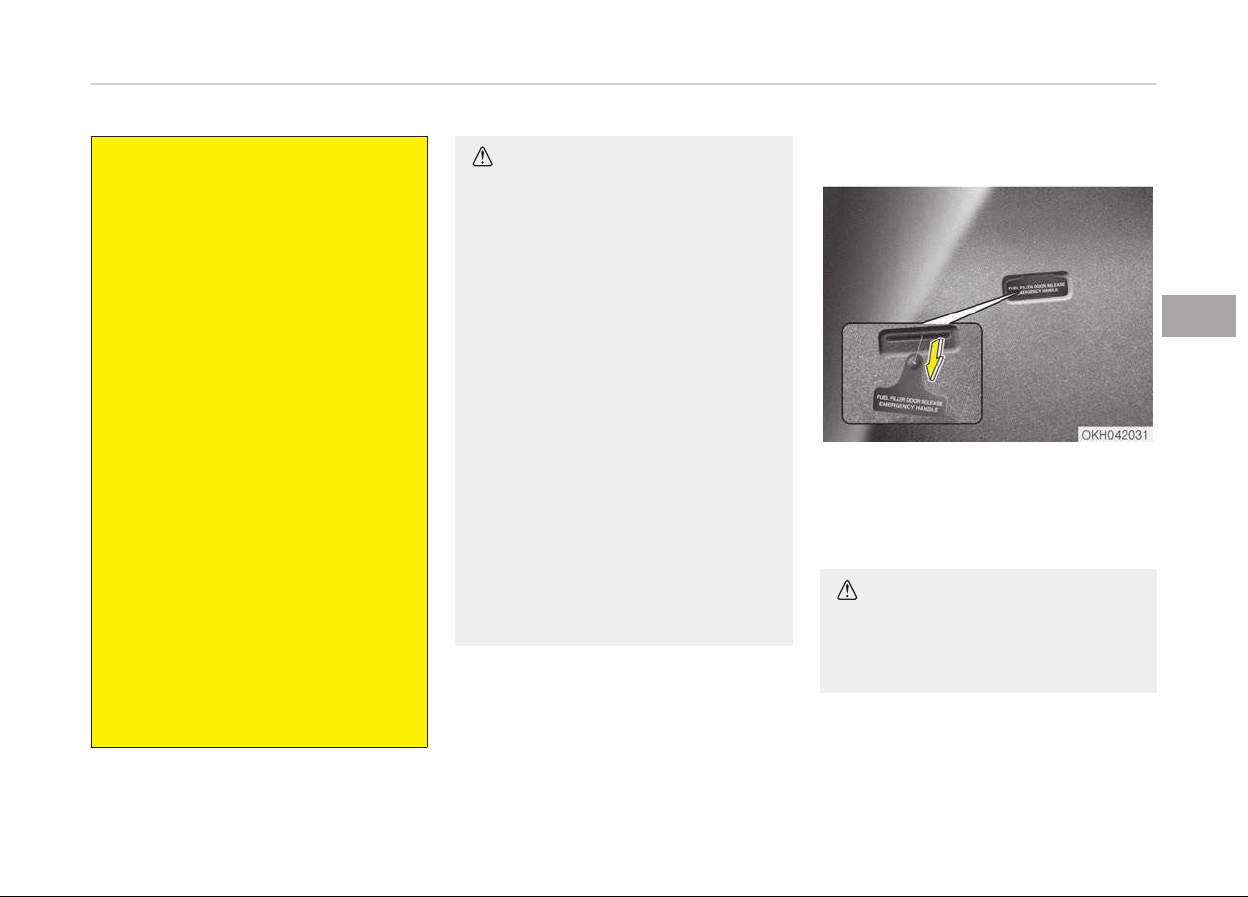
(Continued)
• Do not use cellular phones while
r
efueling. Electric current and/or
electronic interference from cellu‐
lar phones can potentially ignite
fuel vapors causing a fire.
• When refueling, always shut the
engine
off. Sparks produced by
electrical components related to
the engine can ignite fuel vapors
causing a fire. Once refueling is
complete, check to make sure the
filler cap and filler door are secure‐
ly closed, before starting the en‐
gine.
• DO NOT use matches or a lighter
and DO NOT SMOKE or leave a lit
cigarette in your vehicle while at a
gas station especially during refu‐
eling. Automotive fuel is highly
flammable and can, when ignited,
result in fire.
• If a fire breaks out during refuel‐
ing, leave the vicinity of the vehi‐
cle, and immediately contact the
manager of the gas station and
then contact the local fire depart‐
ment. Follow any safety instruc‐
tions they provide.
CAUTION
• Make sure to refuel your vehicle
according to the Fuel require‐
ments on page 1-03.
• If the fuel filler cap requires re‐
placement, please make sure that
you use parts designed for re‐
placement in your vehicle. An in‐
correct fuel filler cap can result in
a serious malfunction of the fuel
system or emission control sys‐
tem. For more detailed informa‐
tion, Kia recommends to visit an
authorized Kia dealer/service part‐
ner.
• Do not spill fuel on the exterior
surfaces of the vehicle. Any type
of fuel spilled on painted surfaces
may damage the paint.
• After refueling, make sure the fuel
cap is installed securely to prevent
fuel spillage in the event of an ac‐
cident.
Emergency fuel filler lid release
If the fuel filler lid does not open using
the remote fuel filler lid release, you
can open it manually by pulling the
handle outward slightly.
CAUTION
Do not pull the handle excessively,
otherwise the luggage area trim or
release handle may be damaged.
4-37
4
Features of your vehicle
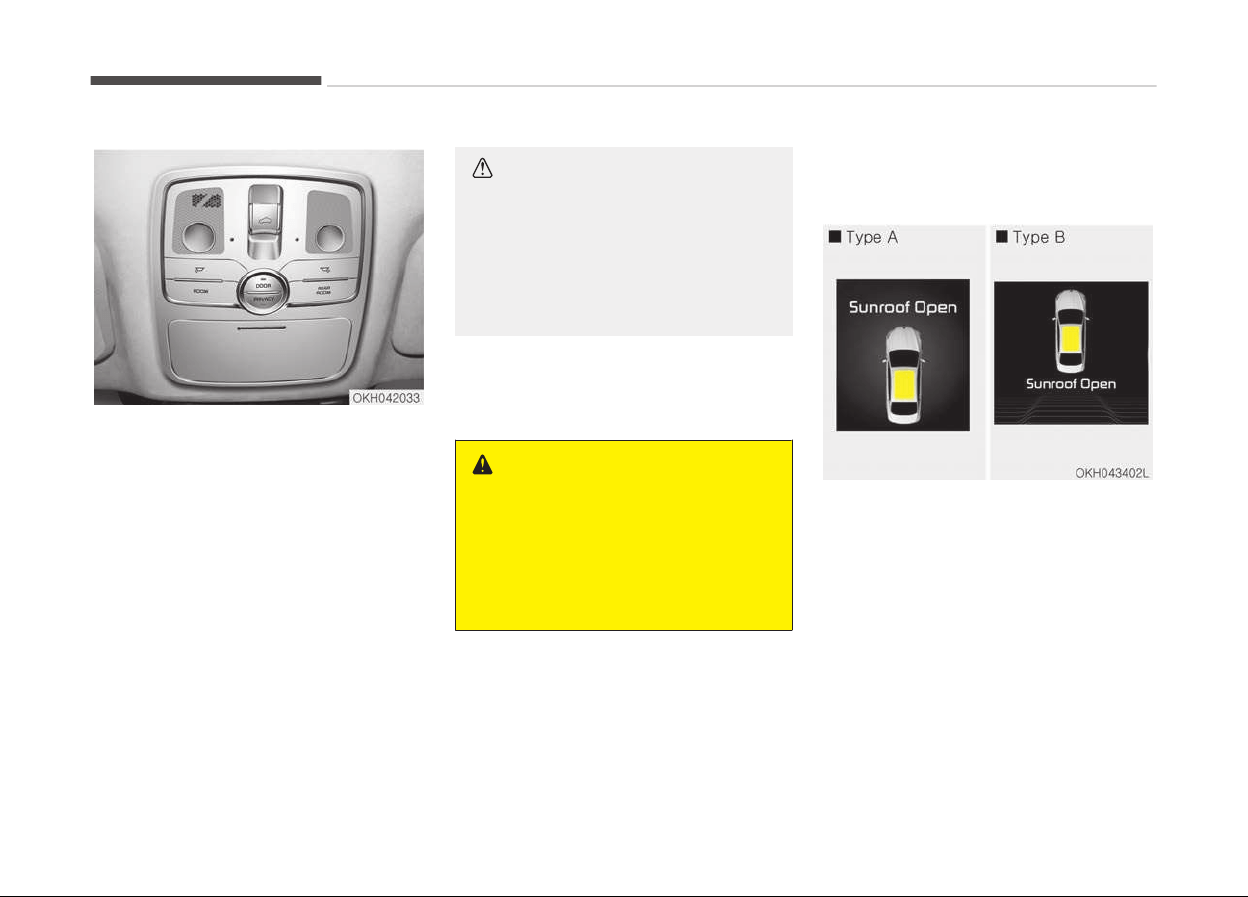
PANORAMA SUNROOF (IF EQUIPPED)
If your vehicle is equipped with a sun‐
roof, you can slide or tilt your sunroof
with the sunroof control lever located
on the overhead console.
The sunroof can only be opened,
closed, or tilted when the Engine Start/
Stop button is in the ON position.
In cold and wet climates, the sunroof
may not work properly due to freezing
conditions.
After the vehicle is washed or in a rain‐
storm, be sure to wipe off any water
that is on the sunroof before operating
it.
CAUTION
n
Sunroof c
ontrol lever
Do not continue to press the sunroof
control lever after the sunroof is
fully opened, closed, or tilted. Dam‐
age to the motor or system compo‐
nents could occur.
The sunroof cannot slide when it is in
the tilt position nor can it be tilted
while in an open or slide position.
WARNING
• In order to prevent accidental op‐
eration of the sunroof, especially
by a child, do not let a child oper‐
ate the sunroof.
• Do not sit on the top of the vehi‐
cle. It may cause vehicle damage.
Sunroof open warning (if
equipped)
If the driver turns off the engine when
the sunroof is not fully closed, the
warning chime will sound for a few sec‐
onds and a warning message will ap‐
pear on the LCD display.
Close the sunroof securely when leav‐
ing your vehicle.
Features of your vehicle
4-38
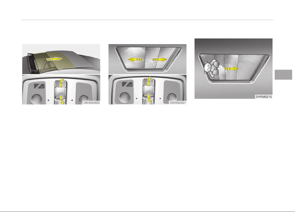
Sliding the sunroof
When the sunshade is closed
If you pull the sunroof control lever
backward to the second detent posi‐
tion, the sunshade will slide all the way
open then the sunroof glass will slide all
the way open. To stop the sunroof
movement at any point, pull or push
the sunroof control lever momentarily.
When the sunshade is opened
If you pull the sunroof control lever
backward, the sunroof glass will slide all
the way open. To stop the sunroof
movement at any point, pull or push
the sunroof control lever momentarily.
Closing the sunroof
To close the sunroof glass only
Push the sunroof control lever forward
to the first detent position or pull the
lever downward.
To close the sunroof glass with the
sunshade
Push the sunroof control lever forward
to the second detent position. The sun‐
roof glass will close then the sunshade
close automatically.
To stop the sunroof movement at any
point, pull or push the sunroof control
lever momentarily.
Automatic reversal
If an object or part of the body is de‐
tected while the sunroof glass or sun‐
shade is closing automatically, it will re‐
verse the direction, and then stop.
The auto reverse function does not
work if a tiny obstacle is between the
sliding glass or sunshade and the sun‐
roof sash. You should always check
that all passengers and objects are
away from the sunroof before closing
it.
Objects less than 0.16 inch (4 mm) in
diameter caught between the sunroof
glass and the front glass channel may
not be detected by the automatic re‐
verse glass and the glass will not stop
and reverse direction.
4-39
4
Features of your vehicle
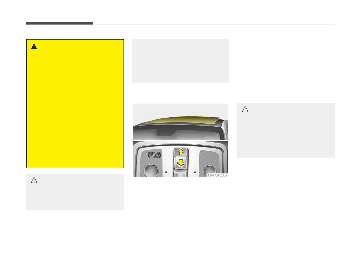
WARNING
n
Sunroof
• Be careful that someone’s head,
hands and body are not trapped by
a closing sunroof.
• Do not extend the face, neck,
arms or body outside through the
sunroof opening while driving.
• Make sure your hands and face are
safely out of the way before clos‐
ing a sunroof.
• A panorama sunroof is made of
glass, therefore it may break in an
accident. If you do not have your
seat belt on, you may stick out of
the bro-ken glass and get injured
or killed. For all passengers safety,
have an appropriate protection on
(ex. seat belt, CRS, etc.).
CAUTION
• Periodically remove any dirt that
may accumulate on the guide rail.
(Continued)
(Continued)
• If you try to open the sunroof
when
the temperature is below
freezing or when the sunroof is
covered with snow or ice, the glass
or the motor could be damaged.
Tilting the sunroof
When the sunshade is closed
If you push the sunroof control lever
upward, the sunshade will slide all the
way open then the sunroof glass will
tilt.
To stop the sunroof movement at any
point, pull or push the sunroof control
lever momentarily.
When the sunshade is opened
If you push the sunroof control lever
upward, the sunroof glass will tilt.
To stop the sunroof movement at any
point, pull or push the sunroof control
lever momentarily.
CAUTION
n
Sunroof motor damage
If you try to open the sunroof when
the temperature is below freezing or
when the sunroof is covered with
snow or ice, the glass or the motor
could be damaged.
Features of your vehicle
4-40
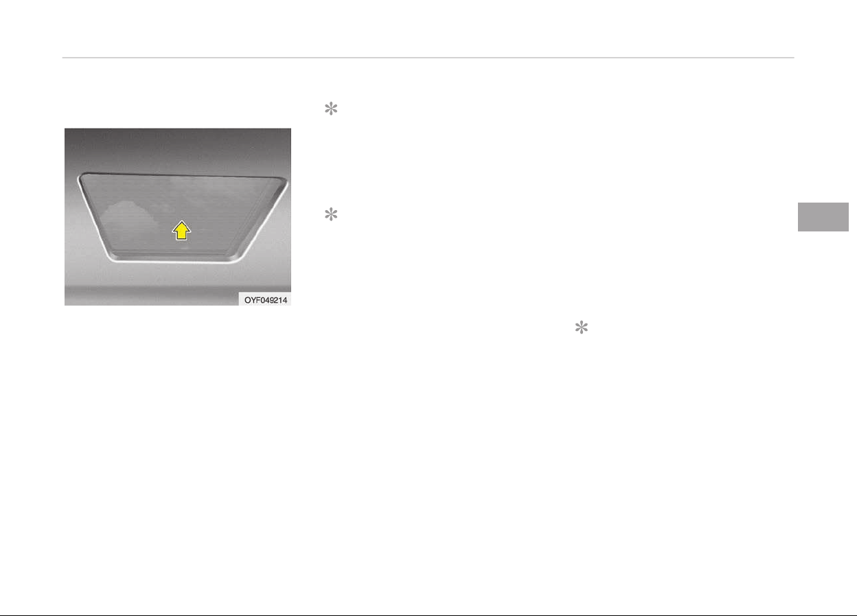
Sunshade
• To open the sunshade, pull the sun‐
roof control lever backward to the
first detent position.
• To close the sunshade when the sun‐
roof glass is closed, push the sunroof
control lever forward.
To stop the sliding at any point, pull or
push the sunroof control lever momen‐
tarily.
NOTICE
It is normal for wrinkles to form on
the blind because of its material
characteristic.
NOTICE
Only the front glass of the panora‐
ma sunroof opens and closes.
Resetting the sunroof
Whenever the vehicle battery is discon‐
nected or discharged, or related fuse is
blown, you must reset your sunroof
system as follows:
1. The Engine Start/Stop Button must
be in the ON position.
2. Release the control lever.
3. Push and hold the control lever for‐
ward (for more than 10 seconds)
until the sunroof tilts and slightly
moves. Then, release the lever.
4. Push the sunroof control lever for‐
ward in the direction of close until
the sunroof operates as follows:
Sunroof glass and sunshade open
→
Sunroof glass and sunshade close
Then, release the control lever.
When this is complete, the sunroof
system is reset.
❈ For more detailed information, con‐
tact an authorized Kia dealer.
NOTICE
If the sunroof is not reset when the
vehicle battery is disconnected or
discharged, or related fuse is blown,
the sunroof may operate improper‐
ly.
4-41
4
Features of your vehicle
STEERING WHEEL
Electronic Hydraulic Power
Steering (EHPS)
EHPS uses an electromotor to assist
you in steering the vehicle. It senses
the vehicle speed and road condition.
If the engine is off or if the power
steering system becomes inoperative,
the vehicle may still be steered, but it
will require increased steering effort.
Should you notice any change in the ef‐
fort required to steer during normal ve‐
hicle operation, have the system
checked by a professional workshop.
Kia recommends to visit an authorized
Kia dealer/service partner.
CAUTION
Never hold the steering wheel
against a stop (extreme right or left
turn) for more than 5 seconds with
the engine running. Holding the
steering wheel for more than
5 seconds in either position may
cause damage to the power steering
pump.
NOTICE
If the power steering drive belt
breaks or if the power steering
pump malfunctions, the steering ef‐
fort will greatly increase.
NOTICE
If the vehicle is parked for extended
periods outside in cold weather (be‐
low -10C/14F), the power steering
may require increased effort when
the engine is first started. This is
caused by increased fluid viscosity
due to the cold weather and does
not indicate a malfunction.
When this happens, increase the en‐
gine RPM by depressing accelerator
until the RPM reaches 1,500 rpm
then release or let the engine idle
for two or three minutes to warm
up the fluid.
Tilt steering
Tilt steering allows you to adjust the
steering wheel before you drive. You
can also raise it to give your legs more
room when you exit and enter the vehi‐
cle.
The steering wheel should be posi‐
tioned so that it is comfortable for you
to drive, while permitting you to see
the instrument panel warning lights
and gauges.
WARNING
• Never adjust the angle of the
steering wheel while driving. You
may lose steering control and
cause severe personal injury,
death or accidents.
• After adjusting, push the steering
wheel
both up and down to be cer‐
tain it is locked in position.
Features of your vehicle
4-42
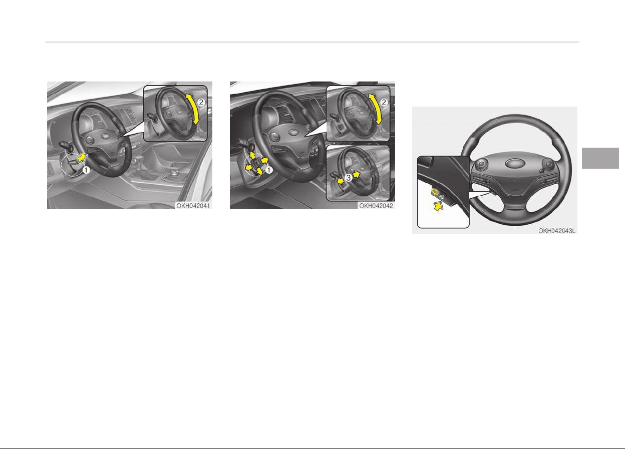
Manual type
To change the steering wheel angle,
pull down the lock release lever (1) and
adjust the steering wheel to the de‐
sired angle (2), then pull up the lock-re‐
lease lever to lock the steering wheel in
place. Be sure to adjust the steering
wheel to the desired position before
driving.
Electric type
Adjust the steering wheel angle (2) and
position (3) with the switch (1). Never
adjust the position of the steering
wheel while driving.
Heated steering wheel (if
equipped)
With the engine start/stop button in
the ON position, pressing the heated
steering wheel button warms the
steering wheel. The indicator on the
button will illuminate.
To turn the heated steering wheel off,
press the button once again. The indi‐
cator on the button will turn off.
It will turn off automatically approxi‐
mately 30 minutes after the heated
steering wheel is turned on.
4-43
4
Features of your vehicle
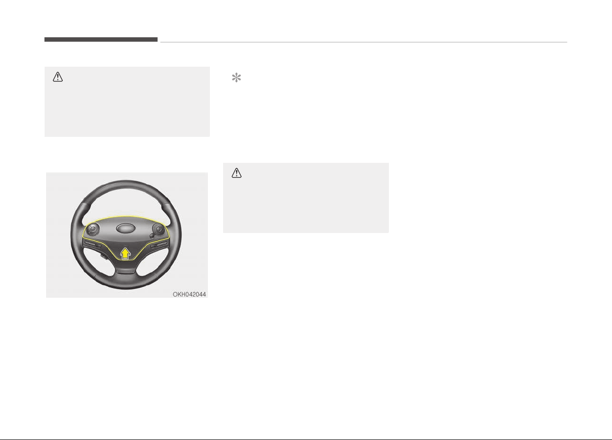
CAUTION
Do not install any grip to operate the
steering wheel. This causes damage
to the heated steering wheel sys‐
tem.
Horn
To sound the horn, press the horn sym‐
bols on your steering wheel. Check the
horn regularly to be sure it operates
properly.
NOTICE
To sound the horn, press the area in‐
dicated by the horn symbol on your
steering wheel (see illustration). The
horn will operate only when this
area is pressed.
CAUTION
Do not strike the horn severely to
operate it, or hit it with your fist. Do
not press on the horn with a sharp-
pointed object.
Features of your vehicle
4-44
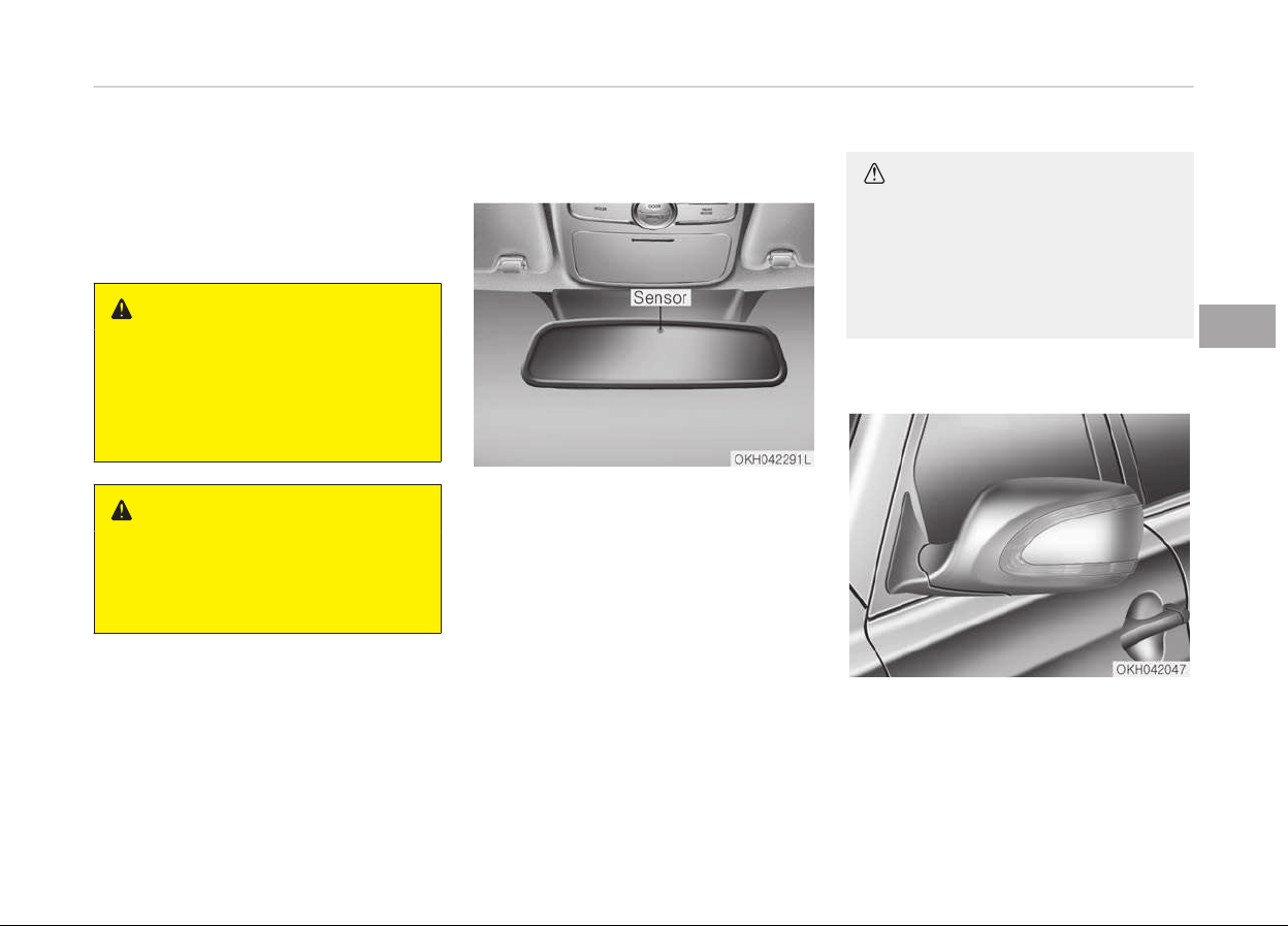
MIRRORS
Inside rearview mirror
Adjust the rearview mirror to center on
the view through the rear window.
Make this adjustment before you start
driving.
WARNING
n
Rear visibility
Do not place objects in the rear seat
or cargo area which would interfere
with your vision through the rear
window.
WARNING
Do not modify the inside mirror and
don’t install a wide mirror. It could
result in injury, during an accident or
deployment of the air bag.
Electric chromic mirror (ECM)
The electric chromic mirror automati‐
cally controls the glare from the head‐
lights of the car behind you in night‐
time or low light driving conditions. The
sensor mounted in the mirror senses
the light level around the vehicle, and
automatically controls the headlight
glare from vehicles behind you.
When the engine is running, the glare is
automatically controlled by the sensor
mounted in the rearview mirror.
Whenever the shift lever is shifted into
R (Reverse), the mirror will automati‐
cally go to the brightest setting in or‐
der to improve the drivers view behind
the vehicle.
CAUTION
When cleaning the mirror, use a pa‐
per towel or similar material damp‐
ened with glass cleaner. Do not
spray glass cleaner directly on the
mirror as that may cause the liquid
cleaner to enter the mirror housing.
Outside rearview mirror
Be sure to adjust mirror angles before
driving.
4-45
4
Features of your vehicle

Your vehicle is equipped with both left-
hand and right-hand outside rearview
mirrors. The mirrors can be adjusted
remotely with the remote switch. The
mirror heads can be folded back to pre‐
vent damage during an automatic car
wash or when passing in a narrow
street.
WARNING
n
Rearview mirrors
• The outside rearview mirror is
convex. In some countries, the left
outside rearview mirror is also
convex. Objects seen in the mirror
are closer than they appear.
• Use your interior rearview mirror
or direct observation to determine
the actual distance of following
vehicles when changing lanes.
CAUTION
Do not scrape ice off the mirror face;
this
may damage the surface of the
glass. If ice should restrict move‐
ment of the mirror, do not force the
(Continued)
(Continued)
mirror for adjustment. To remove
ice,
use a deicer spray, or a sponge
or soft cloth with very warm water.
CAUTION
If the mirror is jammed with ice, do
not
adjust the mirror by force. Use
an approved spray de-icer (not radi‐
ator antifreeze) to release the fro‐
zen mechanism or move the vehicle
to a warm place and allow the ice to
melt.
WARNING
Do not adjust or fold the outside
r
earview mirrors while the vehicle is
moving. This could result in loss of
control, and an accident which could
cause death, serious injury or prop‐
erty damage.
Remote control
The electric remote control mirror
switch allows you to adjust the position
of the left and right outside rearview
mirrors. To adjust the position of either
mirror, press the R or L button (1) to
select the right side mirror or the left
side mirror, then press a corresponding
point (
) on the mirror adjustment
control to position the selected mirror
up, down, left or right.
After adjustment, press the R or L but‐
ton again to prevent the inadvertent
adjustment.
Features of your vehicle
4-46
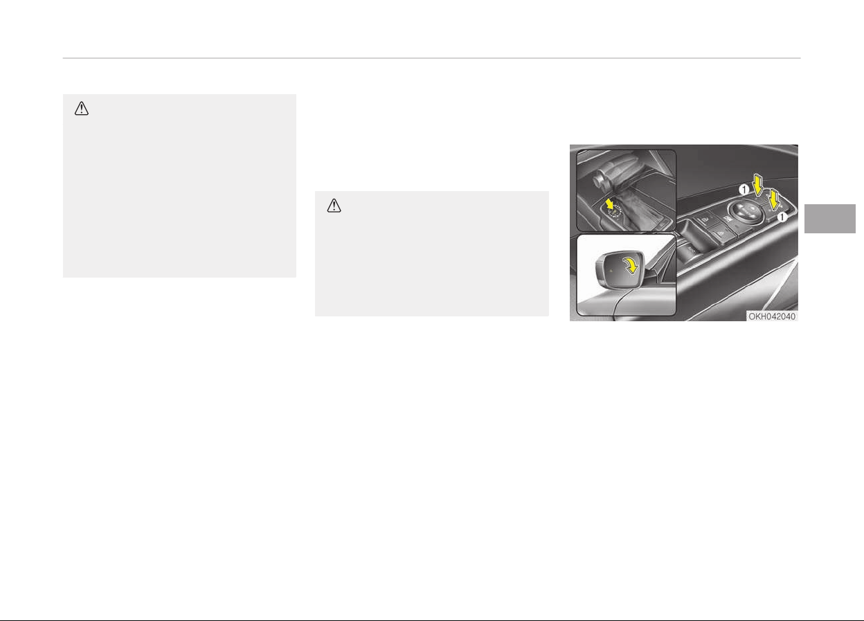
CAUTION
• The mirrors stop moving when
they reach the maximum adjusting
angles, but the motor continues to
operate while the switch is press‐
ed. Do not press the switch longer
than necessary, the motor may be
damaged.
• Do not attempt to adjust the out‐
side rearview mirror by hand. Do‐
ing so may damage the parts.
Electric chromic mirror (ECM) (if
equipped)
The electric chromic mirror automati‐
cally controls the glare from the head‐
lights of the car behind you in night‐
time or low light driving conditions. The
sensor mounted in the mirror senses
the light level around the vehicle, and
automatically controls the headlight
glare from vehicles behind you.
When the engine is running, the glare is
automatically controlled by the sensor
mounted in the rearview mirror.
Whenever the shift lever is shifted into
R (Reverse), the mirror will automati‐
cally go to the brightest setting in or‐
der to improve the drivers view behind
the vehicle. If the ECM of inside rear
view mirror operates, it will be working
CAUTION
When cleaning the mirror, use a pa‐
per towel or similar material damp‐
ened with glass cleaner. Do not
spray glass cleaner directly on the
mirror as that may cause the liquid
cleaner to enter the mirror housing.
Reverse parking aid function (if
equipped)
When you shift the shift lever to the R
(Reverse) position, the outside rearview
mirror(s) will move downward to aid re‐
verse parking. According to the position
of the outside rearview mirror switch
(1), the outside rearview mirror(s) will
operate as follows:
Left or Right : When the L or R switch is
selected, both outside rearview mirrors
will move downward.
Neutral : When neither switch is selec‐
ted, the outside rearview mirrors will
not operate.
4-47
4
Features of your vehicle
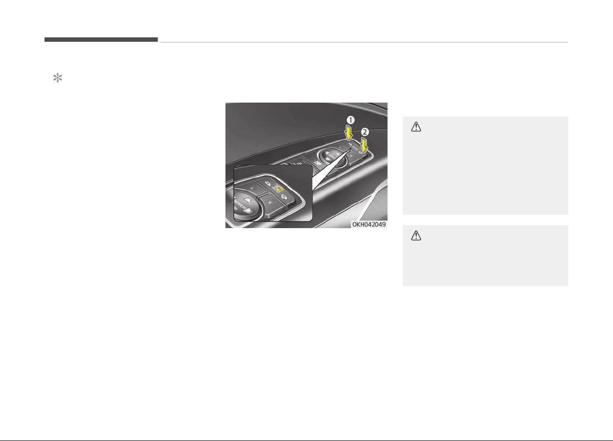
NOTICE
The outside rearview mirrors will au‐
tomatically revert to their original
positions under the following condi‐
tions:
1. Engine start/stop button is
turned to the ACC or OFF posi‐
tion.
2. Shift lever is moved to any posi‐
tion except R.
3. Remote control outside rearview
mirror switch is not selected.
Folding/Unfolding the outside
rearview mirror
The outside rearview mirror can be fol‐
ded or unfolded by pressing the switch
as below.
Left (1) : The mirror will unfold.
Right (2) : The mirror will fold.
Center (AUTO) :
The mirror will fold or unfold automati‐
cally as follows:
-
The mirror will fold or unfold when
the door is locked or unlocked by the
smart key.
-
The mirror will fold or unfold when
the door is locked or unlocked by the
button on the outside door handle.
-
The mirror will unfold when you ap‐
proach the vehicle (all doors closed
and locked) with a smart key in pos‐
session.
CAUTION
The electric type outside rearview
mirror operates even though the En‐
gine Start/Stop button is in the OFF
position. However, to prevent unnec‐
essary battery discharge, do not ad‐
just the mirrors longer than neces‐
sary while the engine is not running.
CAUTION
In case it is an electric type outside
rearview mirror, don’t fold it by
hand. It could cause motor failure.
Features of your vehicle
4-48
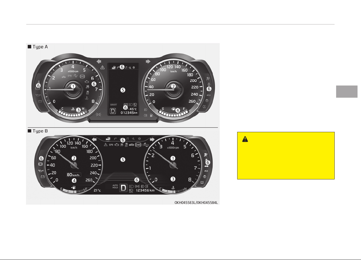
INSTRUMENT CLUSTER
1. Tachometer
2. Speedometer
3. Engine coolant temperature gauge
4. Fuel gauge
5. LCD display
6. Warning and indicator lights
❈ The actual cluster in the vehicle
may differ from the illustration.
For more details, refer to the
Gauges on page 4-51.
Instrument cluster control
WARNING
Never adjust the instrument cluster
while driving. This could result in loss
of control and lead to an accident
that may cause death, serious in‐
jury, or property damage.
4-49
4
Features of your vehicle
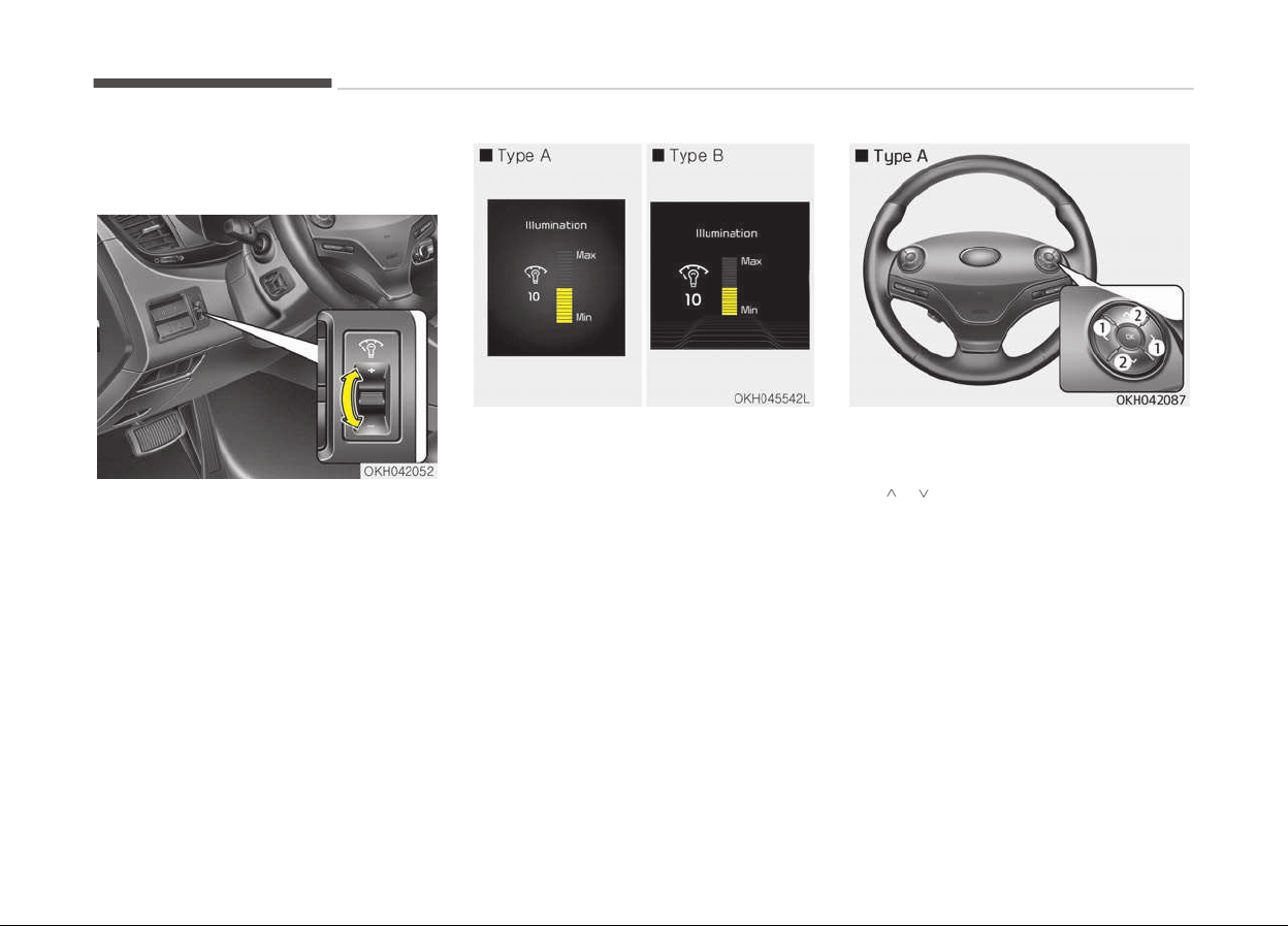
Adjusting instrument cluster
illumination
The brightness of the instrument panel
illumination can be adjusted by pressing
the illumination control buttons (+ or
-) when the Engine Start/Stop Button
is ON or the tale lights are turned on.
• If you hold the illumination control
button ("+" or "-"), the brightness will
be changed continuously.
• If the brightness reaches to the max‐
imum or minimum level, an alarm will
sound.
LCD display control
The LCD display modes can be changed
by using the control buttons on the
steering wheel.
1. < , > : MODE button for changing
modes.
2.
, : MOVE button for changing
items
3. OK : SELECT/RESET button for set‐
ting or resetting the selected item
Features of your vehicle
4-50
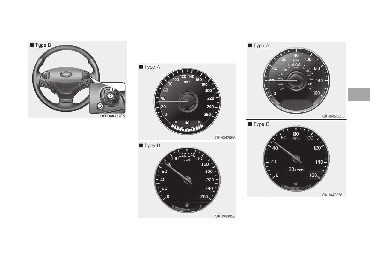
1. Haptic switch : changing LCD modes
or items
2. OK button : selecting or resetting
3. RETURN button : returning to pre‐
vious position
You can adjust the rotating effort of
the haptic switch on the "user settings
mode" of the LCD Display
❈ For more details, refer to LCD Dis‐
play on page 4-56.
Gauges
Speedometer
The speedometer indicates the speed
of the vehicle and is calibrated in miles
per hour (mph) and/or kilometers per
hour (km/h).
4-51
4
Features of your vehicle
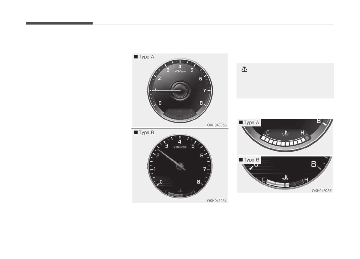
The unit of the speedometer (Type B)
can be changed from km/h to MPH or
from MPH to km/h on the LCD display.
❈ From more details, refer to LCD
Display (Type B) on page 4-56.
Tachometer
The tachometer indicates the approxi‐
mate number of engine revolutions per
minute (rpm).
Use the tachometer to select the cor‐
rect shift points and to prevent lugging
and/or over-revving the engine.
CAUTION
Do not operate the engine within the
tachometer's RED ZONE. This may
cause severe engine damage.
Engine coolant temperature gauge
This gauge indicates the temperature
of the engine coolant when the Engine
Start/Stop button is ON.
Features of your vehicle
4-52
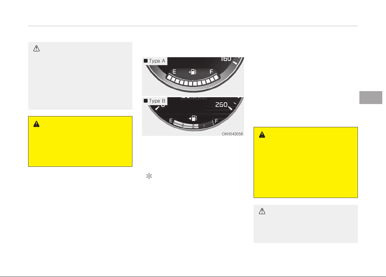
CAUTION
If the gauge pointer moves beyond
the normal range area toward the
H position, it indicates overheating
that may damage the engine.
Do not continue driving with an over‐
heated engine. If your vehicle over‐
heats, refer to If the Engine Over‐
heats on page 6-08.
WARNING
Never remove the radiator cap when
the engine is hot. The engine coolant
is under pressure and could severely
burn. Wait until the engine is cool be‐
fore adding coolant to the reservoir.
Fuel gauge
This gauge indicates the approximate
amount of fuel remaining in the fuel
tank.
NOTICE
• The fuel tank capacity is given in
Recommended lubricants and ca‐
pacities on page 8-10.
(Continued)
(Continued)
• The fuel gauge is supplemented by
a low fuel warning light, which will
illuminate when the fuel tank is
nearly empty.
• On inclines or curves, the fuel
gauge pointer may fluctuate or
the low fuel warning light may
come on earlier than usual due to
the movement of fuel in the tank.
WARNING
n
Fuel gauge
Running out of fuel can expose vehi‐
cle occupants to danger.
You must stop and obtain additional
fuel as soon as possible after the
warning light comes on or when the
gauge indicator comes close to the
E (Empty) level.
CAUTION
Avoid driving with an extremely low
fuel
level. Running out of fuel could
(Continued)
4-53
4
Features of your vehicle
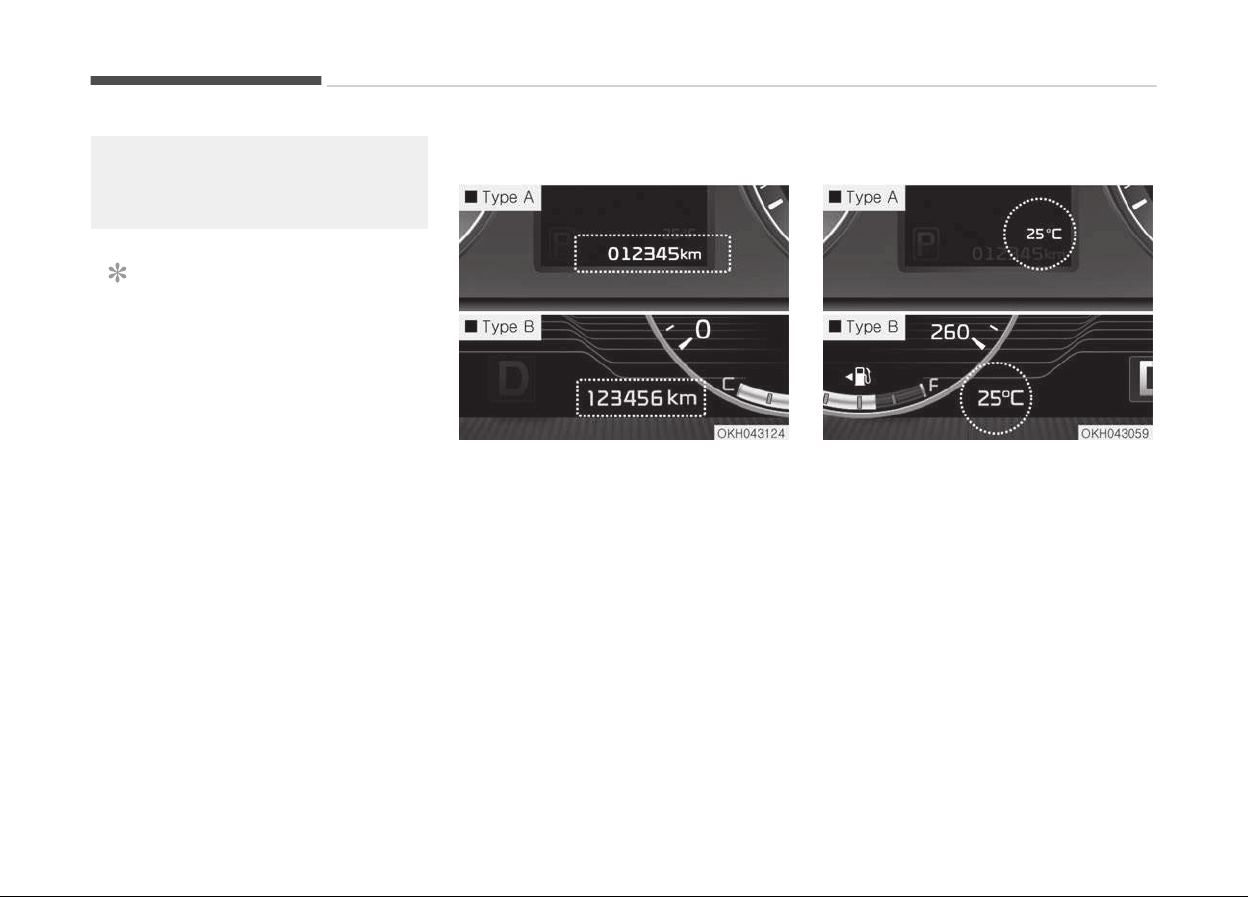
(Continued)
cause the engine to misfire damag‐
ing the catalytic c
onverter.
NOTICE
Fuel display may not be accurate if
you are filling in sloping places.
Odometer
The odometer Indicates the total dis‐
tance that the vehicle has been driven
and should be used to determine when
periodic maintenance should be per‐
formed.
-
Odometer range: 0 ~ 999999 kilome‐
ters or 0~999999 miles.
Outside temperature gauge
This gauge indicates the current out‐
side air temperatures by 1C (1F).
-
Temperature range : -40C ~ 60C
The outside temperature on the display
may not change immediately like a
general thermometer to prevent the
driver from being inattentive.
The temperature unit (from C to F or
from F to C) can be changed by
pressing the OFF button and AUTO but‐
ton on the front climate control panel
for 3 seconds simultaneously.
Features of your vehicle
4-54
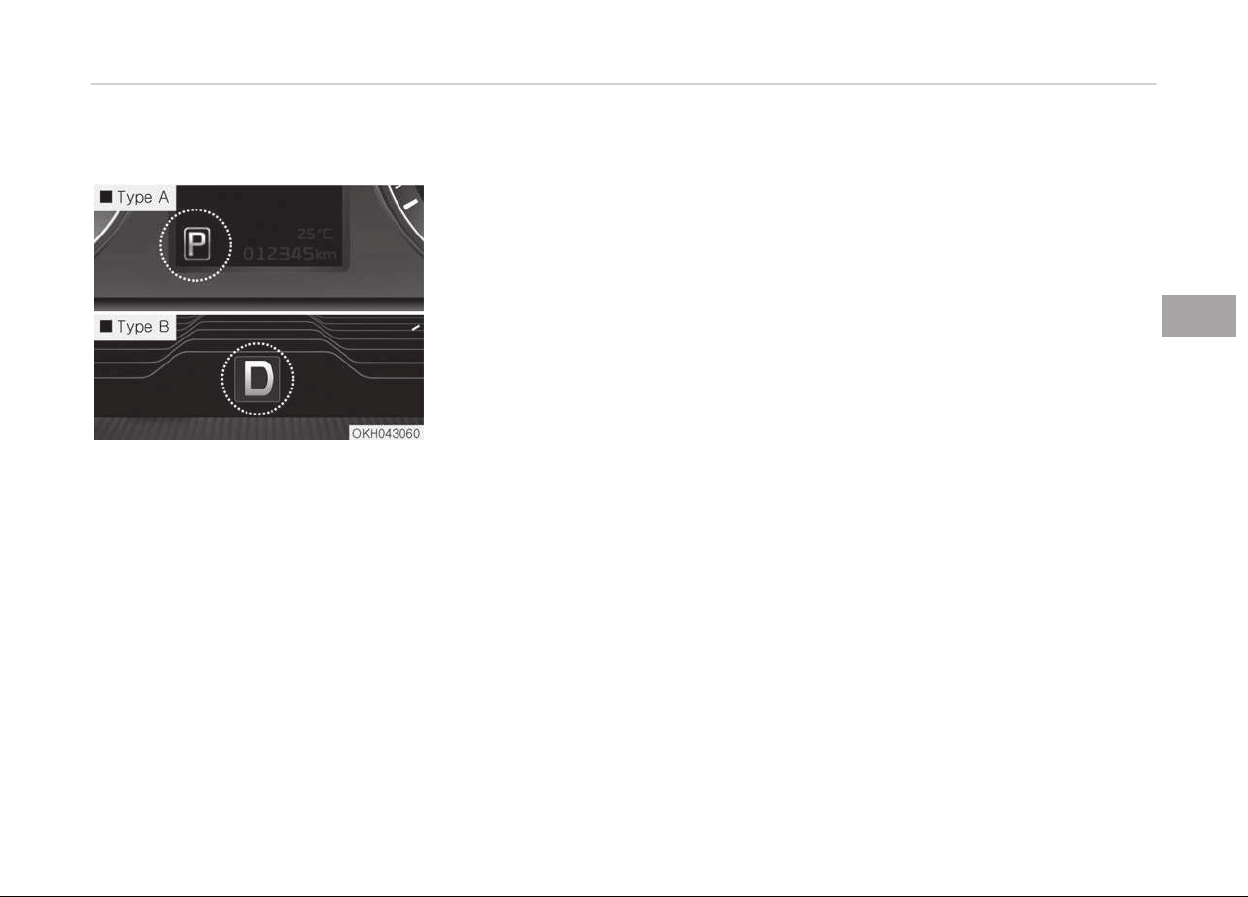
Automatic transaxle shift indicator
This indicator displays which automatic
transaxle shift lever is selected.
• Park: P
• Reverse: R
• Neutral: N
• Drive: D
• Sports Mode: 1, 2, 3, 4, 5, 6, 7, 8
4-55
4
Features of your vehicle

LCD DISPLAY
LCD modes
Modes Symbol Explanation
Trip Computer
This mode displays driving information like the tripmeter, fuel economy, and so on.
For more details, refer to Trip computer on page 4-79.
Turn By Turn
(if equipped)
This mode displays the state of the navigation.
ASCC
(if equipped)
This mode displays the state of the Advanced Smart Cruise Control system (ASCC).
For more details, refer to Advanced Smart Cruise Control system (ASCC) on page
5-66.
A/V This mode displays the state of the A/V system.
Information
or
This mode informs of the tire pressure information, service interval (mileage or
days) and warning messages related to the advanced smart cruise control system,
pre-active seat belt, and so on.
User Settings On this mode, you can change settings of the doors, lamps and so on.
❈ For controlling the LCD modes, refer to LCD display control on page 4-50.
Features of your vehicle
4-56
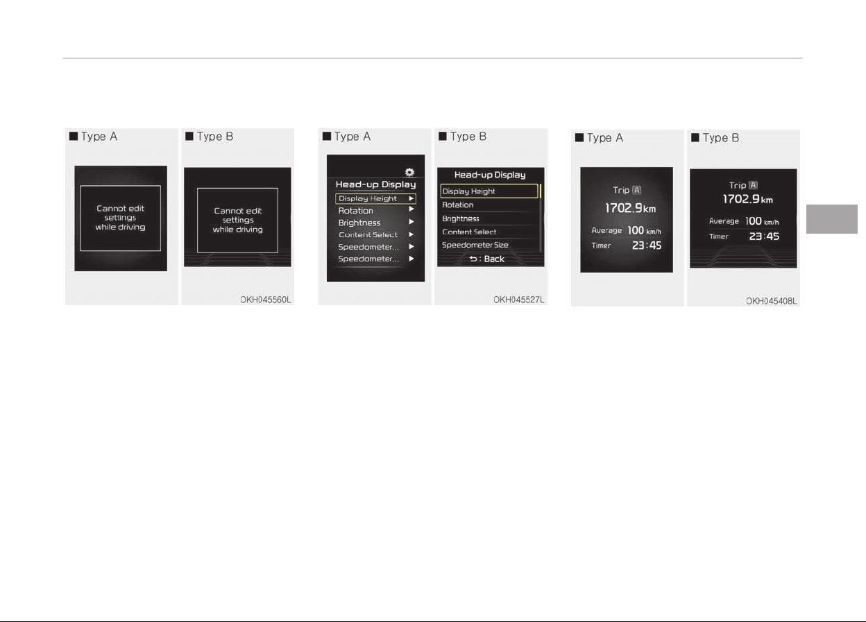
Cannot edit settings while driving
This warning message illuminates if
you try to select the other User Set‐
tings item except Head-up display item
when driving.
For safety, change the User Settings
after parking the vehicle and moving
the shift lever to P (Park) position.
Quick guide (Help)
If you press and hold the OK button in
the User Settings Mode, explanation
about the selected item is displayed in
the cluster.
Trip computer mode
This mode displays driving information
like the tripmeter, fuel economy, and so
on.
❈ For more details, refer to Trip
computer on page 4-79.
4-57
4
Features of your vehicle
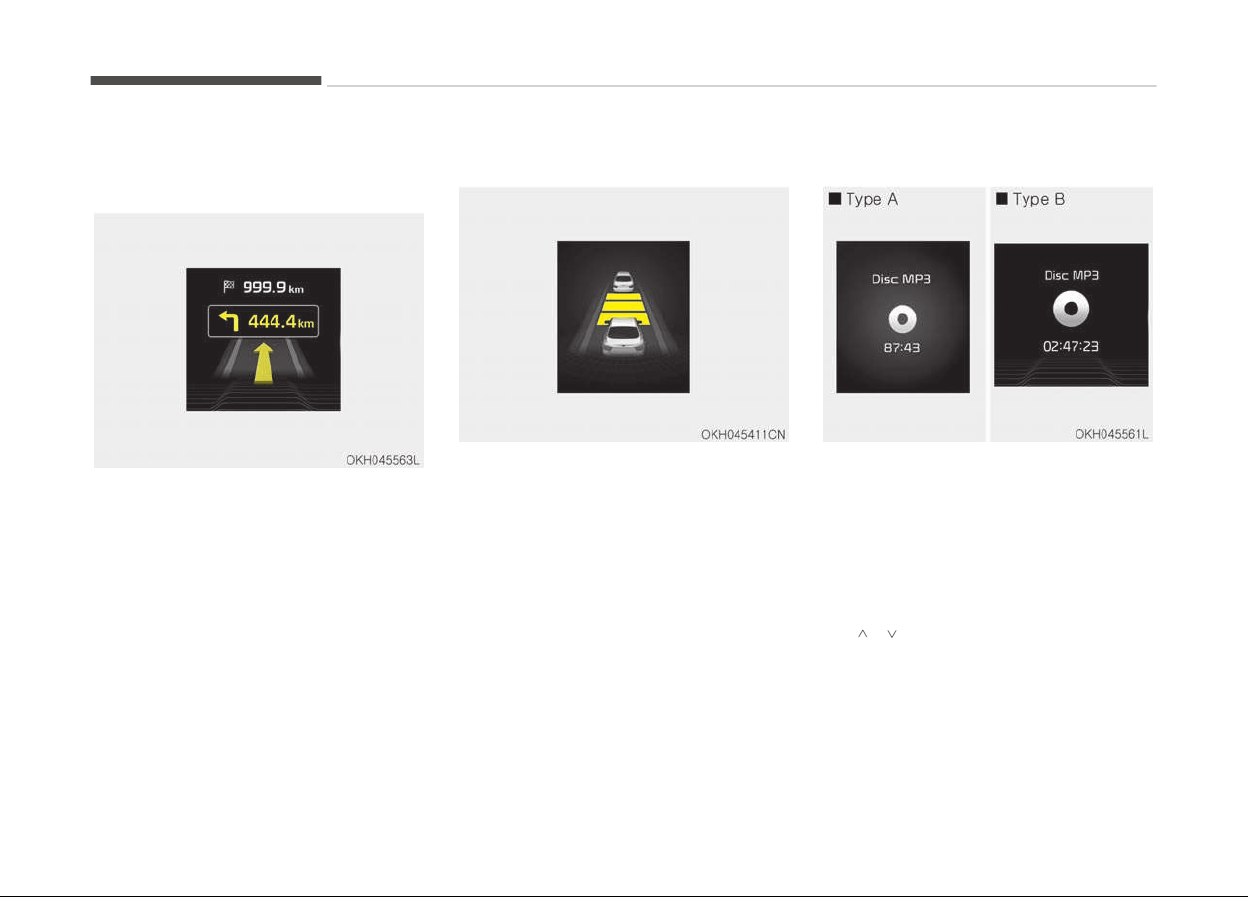
Turn by turn (TBT) mode (if
equipped)
This mode displays the state of the
navigation.
ASCC mode (if equipped)
This mode displays the state of the Ad‐
vanced Smart Cruise Control (ASCC).
❈ For more details, refer to Ad‐
vanced Smart Cruise Control
(ASCC) on page 5-66.
A/V mode
This mode displays the state of the A/V
system.
Information mode
This mode shows the service interval
(mileage and days) and pressure of
each tire.
To change the information mode, press
the
. (MOVE) button.
❈ For the setting of the service inter‐
val, refer to User settings mode
on page 4-60.
Features of your vehicle
4-58
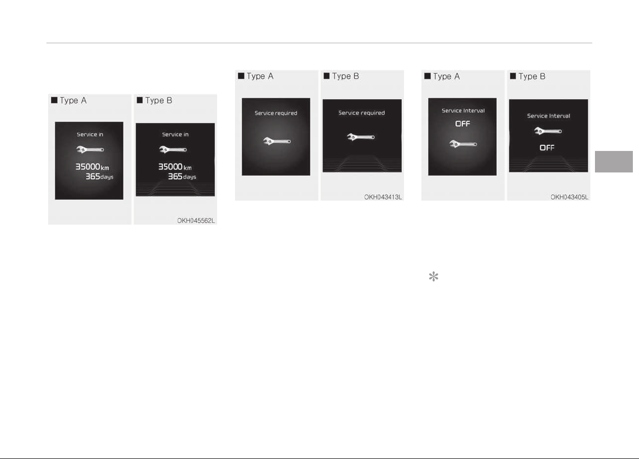
Service interval
Service in
It calculates and displays when you
need a scheduled maintenance service
(mileage or days).
If the remaining mileage or time rea‐
ches 1,500 km or 30 days, "Service in"
message is displayed for several sec‐
onds each time you set the Engine
Start/Stop Button to the ON position.
For the setting of the service interval,
refer to User settings mode on page
4-60.
Service required
If you do not have your vehicle serviced
according to the already inputted serv‐
ice interval, "Service required" message
is displayed for several seconds each
time you set the Engine Start/Stop
Button to the ON position.
To reset the service interval to the
mileage and days you inputted before:
- Press the OK button for more than
1 second.
Service interval OFF
If the service interval is not set, "Serv‐
ice interval OFF" message is displayed
on the LCD display.
NOTICE
If any of the following conditions oc‐
curs, the mileage and days may be
incorrect.
- The battery cable is disconnected.
- The fuse switch is turned off.
- The battery is discharged.
4-59
4
Features of your vehicle
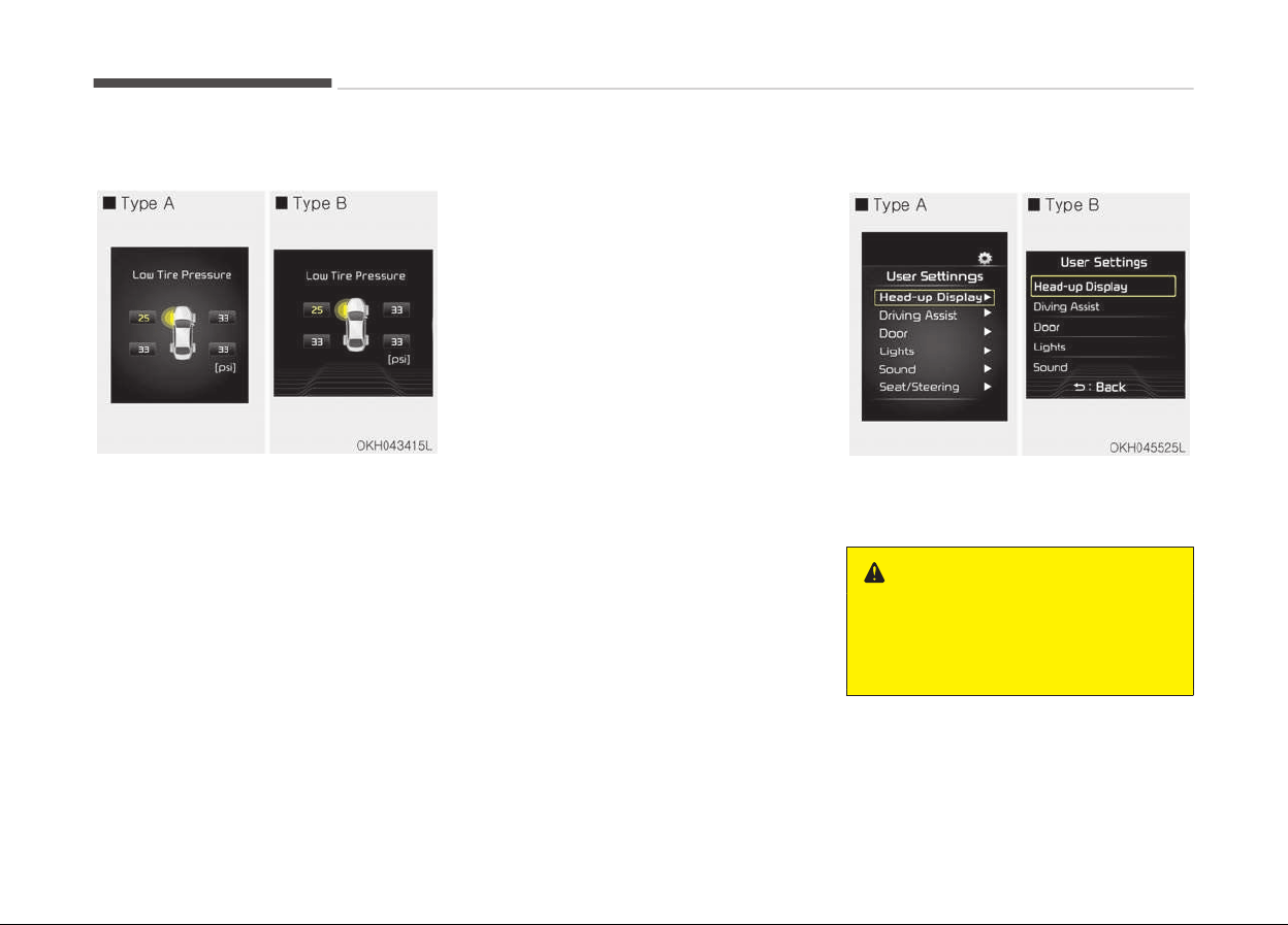
Tire pressure information
This mode displays the pressure status
of each tire.
You can change the tire pressure unit in
"User settings" mode.
❈ For more details, refer to User
settings mode on page 4-60.
Warning message
If one of followings occurs, warning
messages will be displayed on the in‐
formation mode for several seconds.
-
Malfunction of below systems
• Blind Spot Detection (BSD)
• Preactive Seat Belt (PSB)
• Electronic Control Suspension (ECS)
• Tire Pressure Monitoring System
• Advanced Smart Cruise Control
• Low washer fluid
• LED Headlamp (LED)
User settings mode
On this mode, you can change setting
of the doors, lights, and so on.
WARNING
Do not adjust the User Setting while
driving. You may lose your steering
control and cause severe personal
injury or accidents.
Features of your vehicle
4-60

Head-up display (HUD) (if equipped)
Items Explanation
Display Height Adjust the height of the HUD image on the windshield glass.
Rotation Adjust the degree of the HUD rotation.
Brightness Adjust the intensity of the HUD brightness
Contents Select
Activate or deactivate each contents of the HUD.
•
Turn by Turn
*
•
Traffic Information
*
•
(Advanced) Smart Cruise control
*
•
Cruise control
*
•
Blind Spot Detection
*
Speedometer Size • Choose the size of the HUD speedometer (Small, Medium, Large).
Speedometer Color • Choose the color of the HUD speedometer (White, Orange, Green).
*
if equipped
NOTICE
If you select the Turn By Turn (TBT) navigation information as HUD contents, the Turn By Turn (TBT) navigation informa‐
tion will not be displayed on the LCD.
4-61
4
Features of your vehicle

Driving assist
Items Explanation
AEB (Autonomous
Emergency Braking) (if equipped)
To activate or deactivate the AEB system.
For more details, refer to Autonomous Emergency Braking (AEB) on page 5-46.
RCTA
(Rear Cross Traffic Alert) (if equipped)
To activate or deactivate the RCTA system.
For more details, refer to Rear Cross Traffic Alert (RCTA) on page 5-83.
Features of your vehicle
4-62

Door
Items Explanation
Automatically Lock
• Disable : The auto door lock operation will be deactivated.
• Enable on Speed : All doors will be automatically locked when the vehicle speed ex‐
ceeds 15km/h
• Enable on Shift : All doors will be automatically locked if the automatic transmis‐
sion shift lever is shifted from the P (Park) position to the R (Reverse), N (Neutral),
or D (Drive) position.
Automatically Unlock
• Disable : The auto door unlock operation will be canceled.
• Vehicle Off : All doors will be automatically unlocked when the Engine Star/Stop
Button is set to the OFF position.
• Driver Door Unlock : All doors will be automatically unlocked if the driver's door is
unlocked
• On Shift to P : All doors will be automatically unlocked if the automatic transmis‐
sion shift lever is shifted to the P (Park) position.
Door lock Sound Activate or deactivate door lock confirm sound.
Smart Trunk (if equipped)
To activate or deactivate the Smart Trunk system.
For more details, refer to Smart Trunk on page 4-25.
4-63
4
Features of your vehicle

Lights
Items Explanation
One Touch Turn Signal
• Off: The one touch turn lamp function will be deactivated.
• 3, 5, 7 Flashing : The lane change signals will blink 3, 5, or 7 times when the turn
signal lever is moved slightly.
❈ For more details, refer to Lighting on page 4-105.
Head Lamp Delay
Activate or deactivate the head lamp delay function.
❈ For more details, refer to Lighting on page 4-105.
Welcome Light
Activate or deactivate the welcome light function.
❈ For more details, refer to Welcome system on page 4-117.
Travel mode
To use when entering countries with different road systems.
This label is displayed when the ignition is turned on with the headlamp traffic
change function in on state. (For Europe)
Sound
Items Explanation
BSD (Blind Spot Detection) Sound
• Off : The BSD sound function will be deactivated.
• On : The BSD sound function will be activated.
Welcome Sound
• Off : The welcome sound function will be deactivated.
• On : The welcome sound function will be activated.
Features of your vehicle
4-64

Display (for type display B cluster)
Items Explanation
Theme Choose the instrument cluster theme. (Default or Retro)
Auto Theme change
• On (checked) : The instrument cluster theme is automatically changed.
• Off : The automatic change function of the instrument cluster theme will be deac‐
tivated
Traffic Alerts (if equipped)
• On(checked) : The LCD display will show traffic information.
• Off(unchecked) : The LCD display will not show traffic information.
Speedometer Size Choose the size of the number in the speedometer (Small, Medium, Large).
Speedometer unit Choose the main unit of the speedometer (km/h or MPH).
Fuel Economy Unit Choose the main unit of the Fuel economy (km/h or L/100).
4-65
4
Features of your vehicle

Seat/Steering
Items Explanation
Seat Easy Access
• None : The seat easy access function will be deactivated.
• Normal/Enhanced:
- When you turn off the engine, the driver’s seat will automatically move rearward
by 5 cm (Normal) or 7.6 cm (Enhanced) for you to enter or exit the vehicle more
comfortably.
- If you change the Engine Start/Stop Button from OFF position to the ACC, ON, or
START position, the driver’s seat will return to the original position.
❈ For more details, refer to Driver position memory system (if equipped) on page
3-07.
Steering Easy Access
• On (checked) : The steering wheel will automatically move forward or rearward for
the driver to enter or exit the vehicle comfortably.
• Off (unchecked) : The steering easy access function will be deactivated.
❈ For more details, refer to Driver position memory system (if equipped) on page
3-07.
Features of your vehicle
4-66

Other features
Items Explanation
Fuel Economy Auto Reset
• Off : The average fuel economy will not reset automatically whenever refueling.
• On (Auto Reset) : The average fuel economy will reset automatically when refuel‐
ing.
For more details, refer to Trip computer on page 4-79.
Wiper/Light Display Choose the Wiper or Light Display.
Tire Pressure Unit Choose the tire pressure unit. (psi, kPa, Bar)
Haptic Steering System Switch (if
equipped)
Adjust the rotating effort of the haptic switch on the steering wheel for LCD display
control (Strong, Normal, Soft).
For the haptic switch, refer to LCD display control on page 4-50.
Service interval
Items Explanation
Service Interval (Except Europe)
On this mode, you can activate the service interval function with mileage (km or mi.)
and period (months).
• Off : The service interval function will be deactivated.
• On :You can set the service interval (mileage and months).
4-67
4
Features of your vehicle
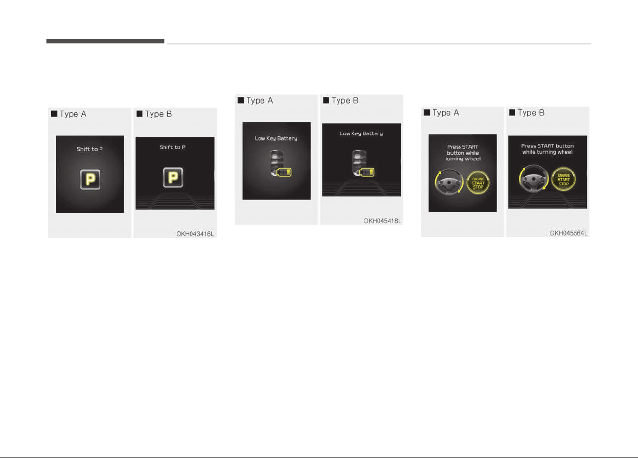
Warning messages (if equipped)
Shift to P
• This warning message illuminates if
you try to turn off the engine with‐
out the shift lever in P (Park) position.
• At this time, the Engine Start/Stop
Button turns to the ACC position (If
you press the Engine Start/Stop But‐
ton once more, it will turn to the ON
position).
Low key battery
• This warning message illuminates if
the battery of the smart key is dis‐
charged when the Engine Start/Stop
Button changes to the OFF position.
Press START button while turn
steering
• This warning message illuminates if
the steering wheel does not unlock
normally when the Engine Start/Stop
button is pressed.
• It means that you should press the
Engine Start/Stop button while turn‐
ing the steering wheel right and left.
Features of your vehicle
4-68
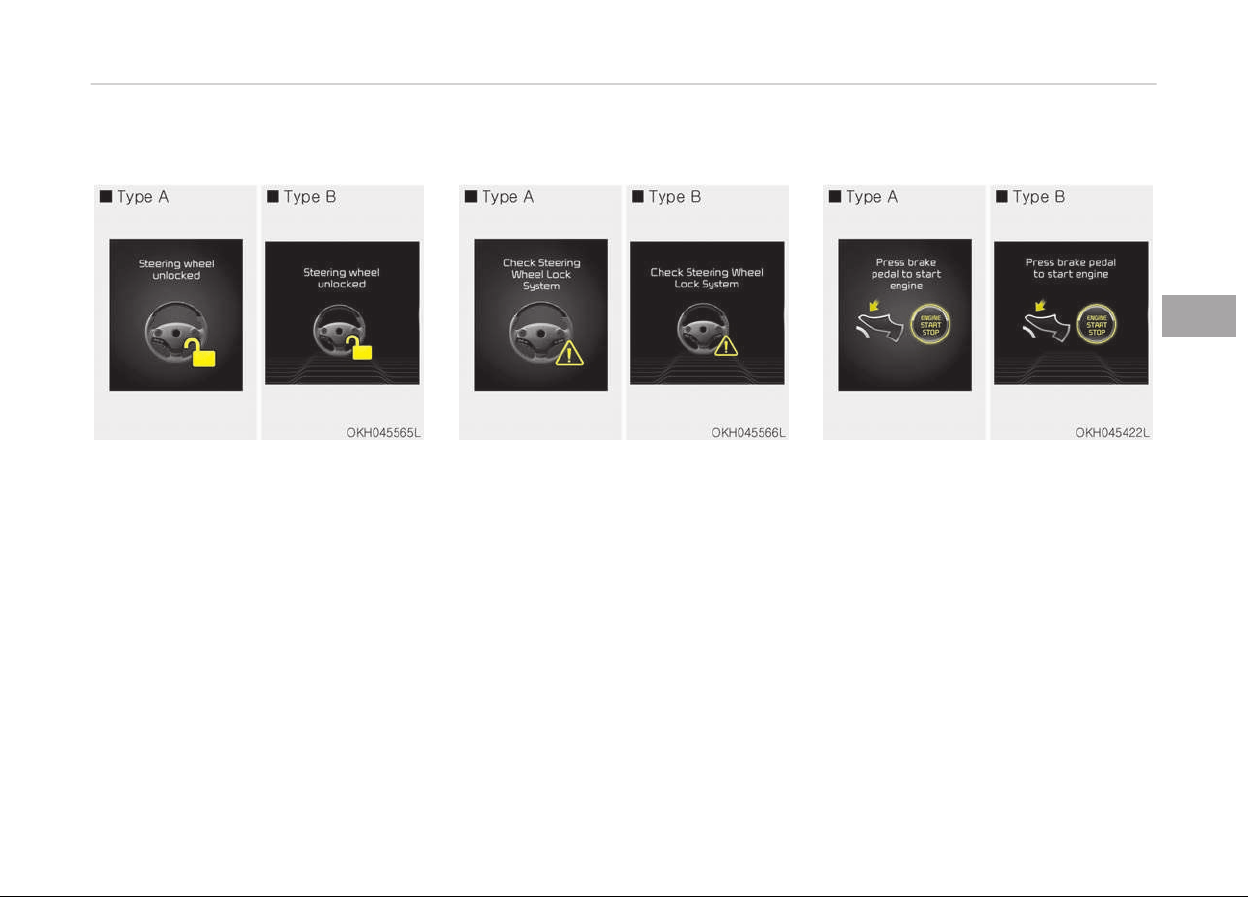
Steering wheel unlocked
• This warning message illuminates if
the steering wheel does not lock
when the Engine Start/Stop button
changes to the OFF position.
Check steering wheel lock system
• This warning message illuminates if
the steering wheel does not lock nor‐
mally when the Engine Start/Stop
button changes to the OFF position.
Press brake pedal to start engine
• This warning message illuminates if
the Engine Start/Stop button
changes to the ACC position twice by
pressing the button repeatedly with‐
out depressing the brake pedal.
• It means that you should depress the
brake pedal to start the engine.
4-69
4
Features of your vehicle
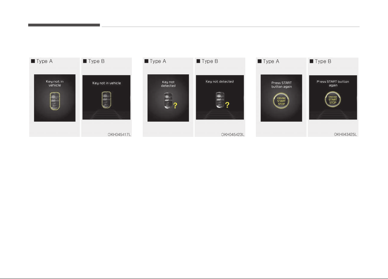
Key not in vehicle
• This warning message illuminates if
the smart key is not in the vehicle
when you press the Engine Start/
Stop button.
• It means that you should always have
the smart key with you.
Key not detected
• This warning message illuminates if
the smart key is not detected when
you press the Engine Start/Stop But‐
ton.
Press START button again
• This warning message illuminates if
you can not operate the Engine
Start/Stop Button when there is a
problem with the Engine Start/Stop
Button system.
• It means that you could start the en‐
gine by pressing the Engine Start/
Stop Button once more.
• If the warning illuminates each time
you press the Engine Start/Stop But‐
ton, have the vehicle inspected by a
professional workshop. Kia recom‐
mends to visit an authorized Kia deal‐
er/service partner.
Features of your vehicle
4-70
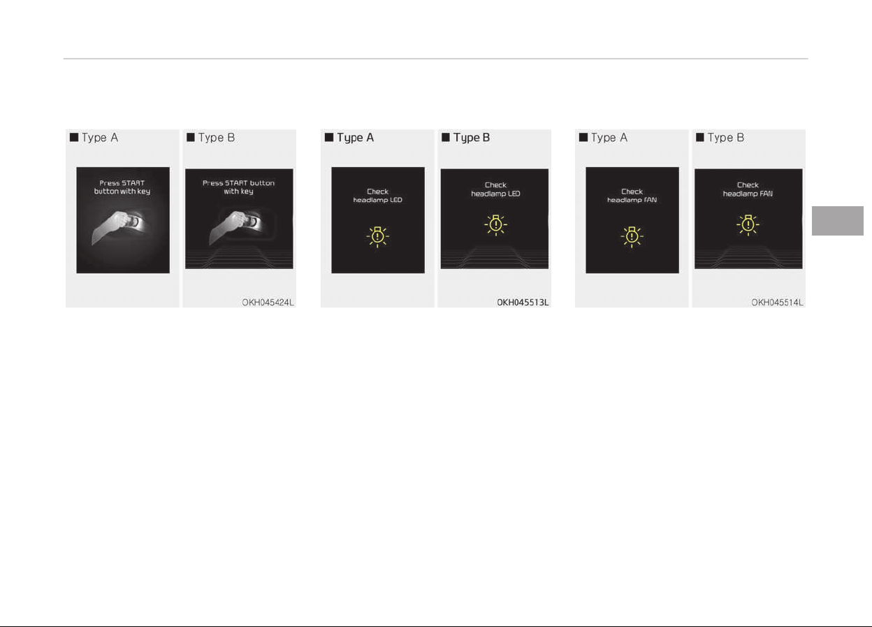
Press START button with key
• This warning message illuminates if
you press the Engine Start/Stop But‐
ton while the warning message Key
not detected is illuminating.
• At this time, the immobilizer indicator
light blinks.
Check headlamp LED (if equipped)
• This warning message illuminates if
the headlamp does not turned on
normally when you turn the head
lamp on. In this case, have your vehi‐
cle inspected by an authorized Kia
dealer.
Check headlamp FAN (if equipped)
• This warning message illuminates if
the headlamp is overheated. It
means, the headlamp fan does not
work normally. In this case, have your
vehicle inspected by an authorized
Kia dealer as soon as possible.
4-71
4
Features of your vehicle
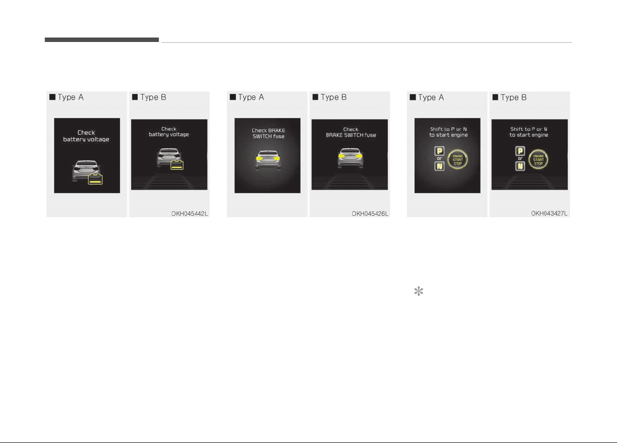
Check battery voltage
• This warning message illuminates if
the battery voltage is abnormally
low, or the battery has poor per‐
formance. In the case, have your ve‐
hicle inspected by an authorized Kia
dealer.
Check BRAKE SWITCH fuse
• This warning message illuminates if
the brake switch fuse is disconnec‐
ted.
• It means that you should replace the
fuse with a new one. If that is not
possible, you can start the engine by
pressing the Engine Start/Stop But‐
ton for 10 seconds in the ACC posi‐
tion.
Shift to P or N to start engine
• This warning message illuminates if
you try to start the engine with the
shift lever not in the P (Park) or N
(Neutral) position.
NOTICE
You can start the engine with the
shift lever in the N (Neutral) position.
But, for your safety, we recommend
that you start the engine with the
shift lever in the P (Park) position.
Features of your vehicle
4-72
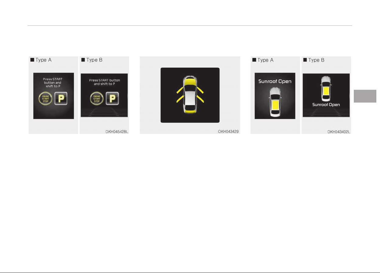
Press START button and shift to P
• This warning message illuminates if
you try to turn off the engine with‐
out the shift lever in P (Park) position.
• At this time, the Engine Start/Stop
Button turns to the ACC position (If
you press the Engine Start/Stop But‐
ton once more, it will turn to the ON
position).
• Set the Engine Start/Stop Button to
the ON position, then shift to P (Park)
by pressing the P button on the top
of the shift lever.
Door / Hood / Trunk open
• It means that any door, hood, or
trunk is open.
Sunroof Open (if equipped)
• The warning message illuminates if
you turn off the engine when the
sunroof is open.
4-73
4
Features of your vehicle
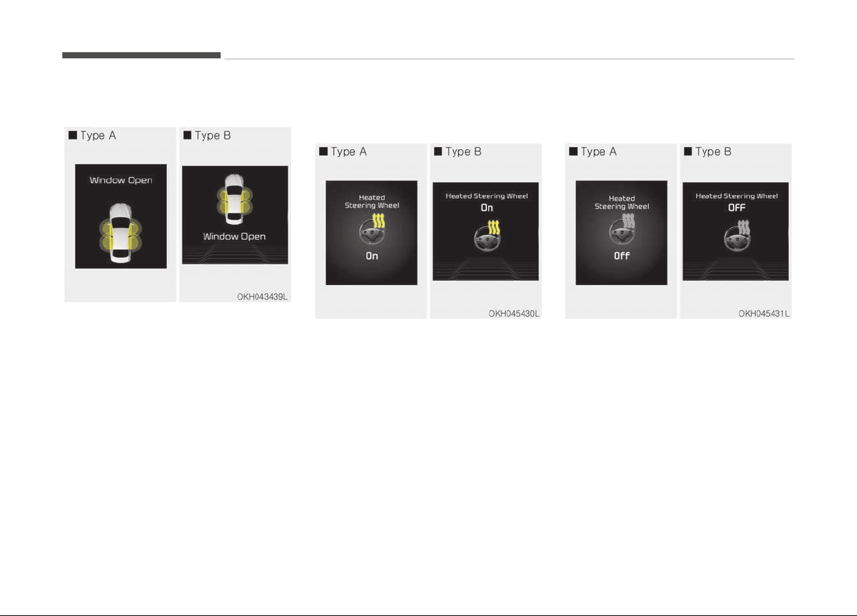
Window open
This warning message illuminates if
you turn off the engine when any win‐
dow is open.
Heated steering wheel on (if
equipped)
• This warning message illuminates if
you turn on the heated steering
wheel.
For more details, refer to Heated
steering wheel (if equipped) on page
4-43.
Heated steering wheel off (if
equipped)
• This warning message illuminates if
you turn off the heated steering
wheel.
For more details, refer to Heated
steering wheel (if equipped) on page
4-43.
Features of your vehicle
4-74
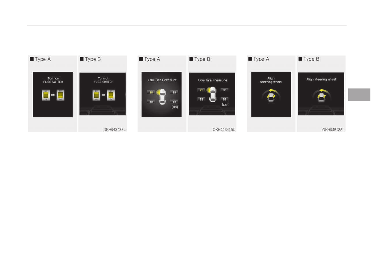
Turn on FUSE SWITCH
• This warning message illuminates if
the fuse switch on the fuse box is
OFF.
• It means that you should turn the
fuse switch on.
For more details, refer to Fuses on
page 7-58.
Low tire pressure (if equipped)
• This warning message illuminates if
the tire pressure is low with the En‐
gine Start/Stop button in ON position.
For more details, refer to Tire pressure
monitoring system (TPMS) (if equip‐
ped) on page 6-09.
Align steering wheel
• This warning message illuminates if
you start the engine when the steer‐
ing wheel is turned to more than 90
degrees to the left or right.
• It means that you should turn the
steering wheel and make the angle of
the steering wheel be less than 30
degrees.
4-75
4
Features of your vehicle
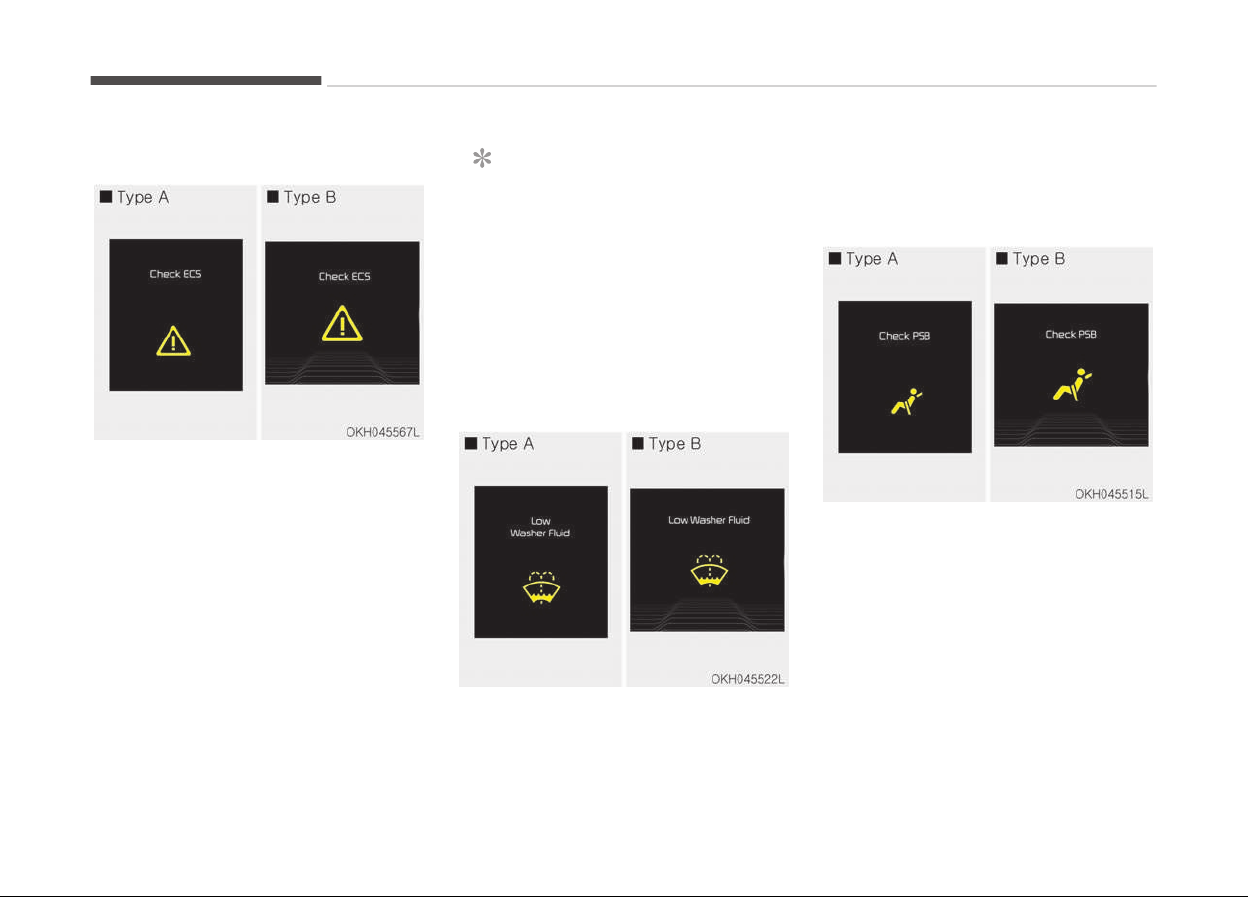
Check ECS (if equipped)
• This warning message illuminates if
there is a malfunction with the Elec‐
tronic Control Suspension (ECS) sys‐
tem. In this case, have the vehicle in‐
spected by a professional workshop.
Kia recommends to visit an author‐
ized Kia dealer/service partner
For more details, refer to Electronic
Control Suspension (ECS) on page
5-58.
NOTICE
n
ECS W
arning Message
When there is a malfunction with
the Electronic Stability Control (ESC),
the Electronic Control Suspension
(ECS) warning message may illumi‐
nate as well as the Electronic Stabili‐
ty Control (ESC) Indicator Light.
Low washer fluid
• This warning message illuminates on
the service reminder mode if the
washer fluid level in the reservoir is
nearly empty.
• It means that you should refill the
washer fluid.
Check PSB (if equipped)
• This warning message illuminates if
there is a malfunction with the Pre-
active Seat Belt (PSB) system. In this
case, have the vehicle inspected by a
professional workshop. Kia recom‐
mends to visit an authorized Kia deal‐
er/service partner.
For more details, refer to Seat belts
on page 3-21.
Features of your vehicle
4-76
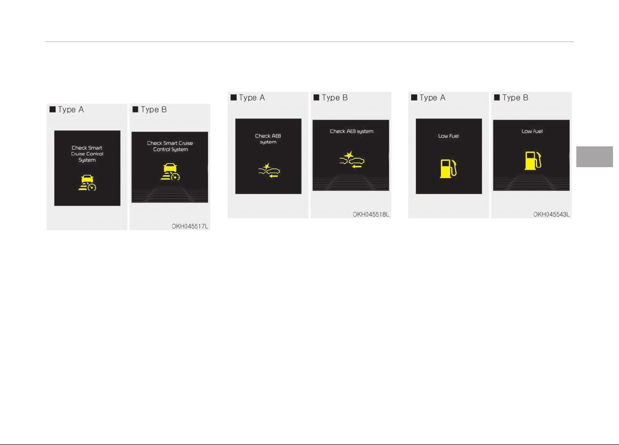
Check smart cruise control system
(if equipped)
• This warning message illuminates if
there is a malfunction with the ad‐
vanced smart cruise control system.
In this case, have the vehicle inspec‐
ted by a professional workshop. Kia
recommends to visit an authorized
Kia dealer/service partner.
For more details, refer to Advanced
Smart Cruise Control System on page
5-66.
Check AEB system (if equipped)
• This warning message illuminates if
there is a malfunction with the Au‐
tonomous Emergency Braking (AEB)
system. In this case, have the vehicle
inspected by a professional work‐
shop. Kia recommends to visit an au‐
thorized Kia dealer/service partner.
For more details, refer to Autonomous
Emergency Braking (AEB) system on
page 5-46.
Low fuel
• This warning message illuminates if
the fuel tank is nearly empty.
- When the low fuel level warning
light is illuminates.
- When the trip computer displays
--- km(or mile) as distance to
empty.
Add fuel as soon as possible.
4-77
4
Features of your vehicle
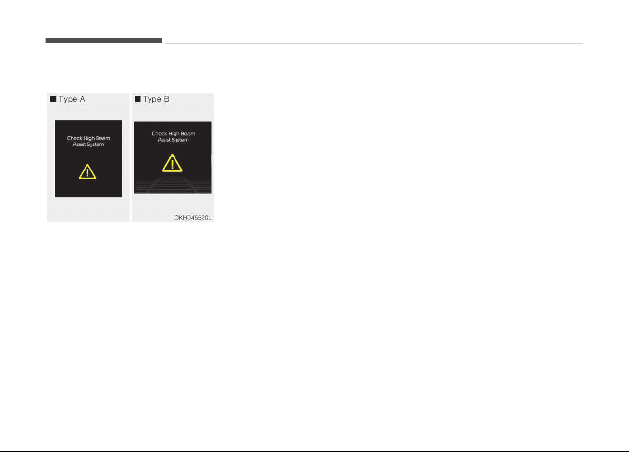
Check high beam assist system
• This warning message illuminates if
there is a malfunction with the High
Beam Assist System. In this case,
have the vehicle inspected by a pro‐
fessional workshop. Kia recommends
to visit an authorized Kia dealer/serv‐
ice partner.
For more details, refer to High Beam
Assist System on page 4-108.
Features of your vehicle
4-78
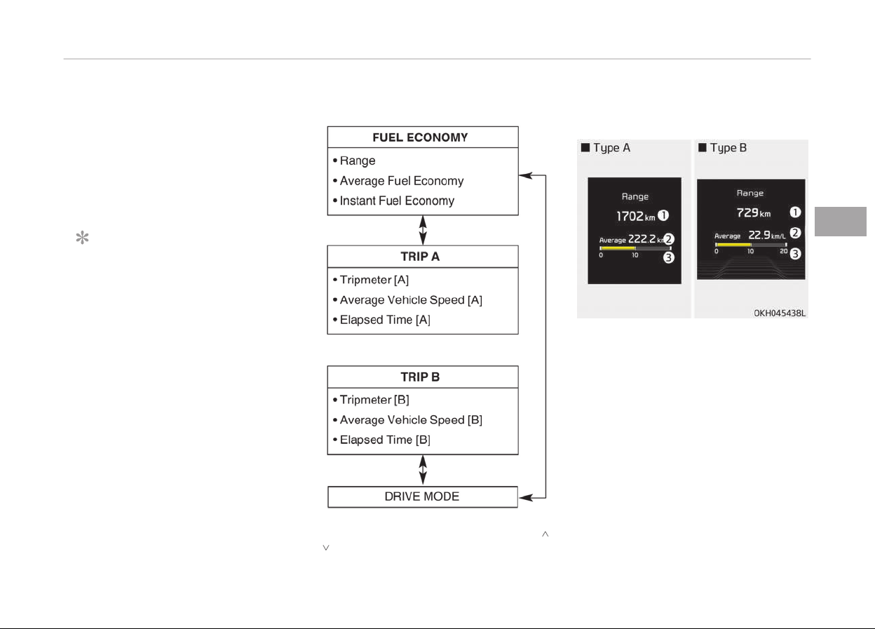
TRIP COMPUTER
Overview
Description
The trip computer is a microcomputer-
controlled driver information system
that displays information related to
driving.
NOTICE
Some driving information stored in
the trip computer (for example
Average Vehicle Speed) resets if the
battery is disconnected.
Trip Modes
To change the trip mode, press the ,
(MOVE) button.
Fuel economy
Range (1)
• The range is the estimated distance
the vehicle can be driven with the re‐
maining fuel.
- Distance range : 1 ~ 9999 km or
1 ~ 9999 mi.
• If the estimated distance is below
1 km (1 mi.), the trip computer will
display --- as range.
4-79
4
Features of your vehicle
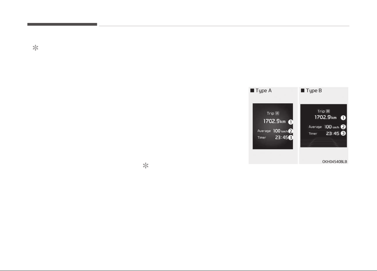
NOTICE
• If the vehicle is not on level ground
or the battery power has been in‐
terrupted, the range function may
not operate correctly.
• The range may differ from the ac‐
tual driving distance as it is an es‐
timate of the available driving dis‐
tance.
• The trip computer may not regis‐
ter additional fuel if less than
6 liters (1.6 gallons) of fuel are
added to the vehicle.
• The fuel economy and range may
vary significantly based on driving
conditions, driving habits, and con‐
dition of the vehicle.
Average fuel economy (2)
• The average fuel economy is calcula‐
ted by the total driving distance and
fuel consumption since the last aver‐
age fuel economy reset.
- Fuel economy range: 0.0 ~ 99.9
L/100 km or MPG
• The average fuel economy can be re‐
set both manually and automatically.
Manual reset
To clear the average fuel economy
manually, press the OK (RESET) button
on the steering wheel for more than
1 second when the average fuel econo‐
my is displayed.
Automatic reset
To make the average fuel economy be
reset automatically whenever refueling,
select the Auto Reset mode in User
Setting menu of the LCD display (Refer
to LCD display on page 4-56).
Under Auto Reset mode, the average
fuel economy will be cleared to zero
(---) when the vehicle speed exceeds
1 km/h after refueling more than
6 liters .
NOTICE
The average fuel economy is not dis‐
played for more accurate calculation
if the vehicle does not drive more
than 300 meters since the Engine
Start/Stop button is turned to ON.
Instant fuel economy (3)
• This mode displays the instant fuel
economy during the last few seconds
when the vehicle speed is more than
10 km/h .
- Fuel economy range:
0 ~ 30 L/100km or 0 ~ 50 MPG
Trip A/B
Tripmeter (1)
• The tripmeter is the total driving dis‐
tance since the last tripmeter reset.
- Distance range: 0.0 ~ 9999.9 km or
mi.
• To reset the tripmeter, press the OK
(RESET) button on the steering wheel
for more than 1 second when the
tripmeter is displayed.
Features of your vehicle
4-80
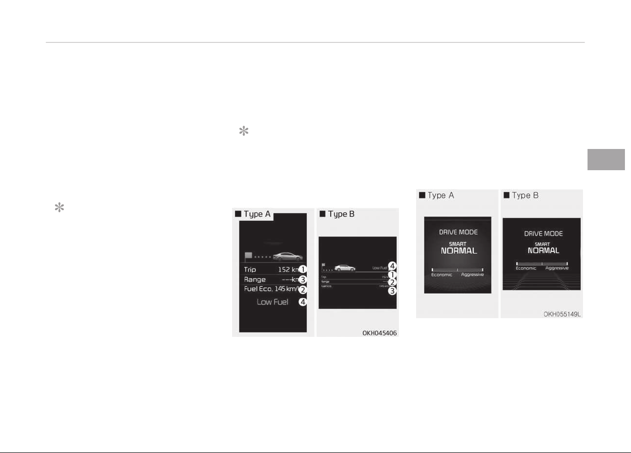
Average Vehicle Speed (2)
• The average vehicle speed is calcula‐
ted by the total driving distance and
driving time since the last average
vehicle speed reset.
- Speed range: 0 ~ 999 km/h or MPH
• To reset the average vehicle speed,
press the OK (RESET) button on the
steering wheel for more than
1 second when the average vehicle
speed is displayed.
NOTICE
• The average vehicle speed is not
displayed if the driving distance is
less than 300 meters since the
Engine Start/Stop button is turned
to ON.
• Even if the vehicle is not in motion,
the average vehicle speed keeps
going while the engine is running.
Elapsed Time (3)
• The elapsed time is the total driving
time since the last elapsed time re‐
set.
- Time range (hh:mm): 00:00 ~
99:59
• To reset the elapsed time, press the
OK (RESET) button on the steering
wheel for more than 1 second when
the elapsed time is displayed.
NOTICE
Even if the vehicle is not in motion,
the elapsed time keeps going while
the engine is running.
One time driving information mode
This display shows trip distance (1),
average fuel economy (2) and the vehi‐
cle can be driven with the remaining
fuel (3).
This information is displayed for a few
seconds when you turn off the engine
and then goes off automatically. The
information provided is calculated ac‐
cording to each trip.
If the estimated distance is below 1km ,
the distance to empty (3) will display as
"---" and a refuel message will appear
(4).
Drive mode
By selecting the drive mode screen, the
driver can personalize the drive mode
based on vehicle control preference and
driving style.
For more details, refer to Drive mode /
Snow mode on page 5-50.
4-81
4
Features of your vehicle
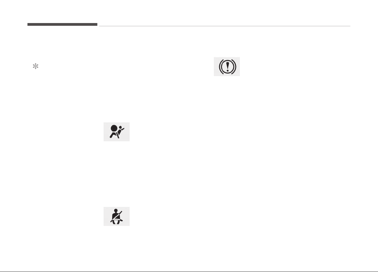
WARNING AND INDICATOR LIGHTS
Warning lights
NOTICE
n
W
arning lights
Make sure that all warning lights are
OFF after starting the engine. If any
light is still ON, this indicates a situa‐
tion that needs attention.
Air bag warning light
This warning light illumi‐
nates:
• Once you set the Engine
Start/Stop Button to the ON position.
- It illuminates for approximately
6 seconds and then goes off.
• When there is a malfunction with the
SRS.
In this case, have the vehicle inspec‐
ted by a professional workshop. Kia
recommends to visit an authorized
Kia dealer/service partner.
Seat belt warning light
This warning light informs
the driver that the seat belt
is not fastened.
❈ For more details, refer to Seat
belts on page 3-21.
Parking brake & brake
fluid warning light
This warning light illumi‐
nates:
• Once you set the Engine Start/Stop
Button to the ON position.
- It illuminates for approximately
3 seconds
- It remains on if the parking brake
is applied.
• When the parking brake is applied.
• When the brake fluid level in the res‐
ervoir is low.
- If the warning light illuminates
with the parking brake released, it
indicates the brake fluid level in
reservoir is low.
If the brake fluid level in the reservoir is
low:
1. Drive carefully to the nearest safe
location and stop your vehicle.
2. With the engine stopped, check the
brake fluid level immediately and
add fluid as required (For more de‐
tails, refer to Brake fluid on page
7-29). Then check all brake com‐
ponents for fluid leaks. If any leak
on the brake system is still found,
the warning light remains on, or the
brakes do not operate properly, do
not drive the vehicle.
In this case, have the vehicle towed
to a professional workshop and in‐
spected. Kia recommends to visit
an authorized Kia dealer/service
partner.
Dual-diagonal braking system
Your vehicle is equipped with dual-diag‐
onal braking systems. This means you
still have braking on two wheels even if
one of the dual systems should fail.
With only one of the dual systems
working, more than normal pedal travel
and greater pedal pressure are required
to stop the vehicle.
Also, the vehicle will not stop in as
short a distance with only a portion of
the brake system working.
If the brakes fail while you are driving,
shift to a lower gear for additional en‐
gine braking and stop the vehicle as
soon as it is safe to do so.
Features of your vehicle
4-82
WARNING
n
Parking Brake & Brake Fluid
Warning Light
Driving the vehicle with a warning
light ON is dangerous. If the Parking
Brake & Brake Fluid Warning Light il‐
luminates with the parking brake re‐
leased, it indicates that the brake
fluid level is low.
In this case, have the DPF system
checked by a professional workshop.
Kia recommends to visit an author‐
ized Kia dealer/service partner.
Anti-lock brake system
(ABS) warning light
This warning light illumi‐
nates:
• Once you set the Engine Start/Stop
Button to the ON position.
- It illuminates for approximately
3 seconds and then goes off.
• When there is a malfunction with the
ABS (The normal braking system will
still be operational without the assis‐
tance of the anti-lock brake system).
In this case, have the DPF system
checked by a professional workshop.
Kia recommends to visit an author‐
ized Kia dealer/service partner.
Electronic Brake force
Distribution (EBD)
system warning light
These two warning lights il‐
luminate at the same time
while driving:
• When the ABS and regular
brake system may not
work normally.
In this case, have the DPF system
checked by a professional workshop.
Kia recommends to visit an author‐
ized Kia dealer/service partner.
WARNING
n
Electronic Brake force Distri‐
bution (EBD) system warning
light
(Continued)
(Continued)
When both ABS and Parking Brake &
Brake
Fluid Warning Lights are on,
the brake system will not work nor‐
mally and you may experience an
unexpected and dangerous situation
during sudden braking.
In this case, avoid high speed driving
and abrupt braking.
Have the vehicle inspected by a pro‐
fessional workshop as soon as possi‐
ble. Kia recommends to visit an au‐
thorized Kia dealer/service partner
NOTICE
n
Electronic Brake force Distri‐
bution (EBD) system warning
light
When the ABS Warning Light is on or
both ABS and Parking Brake & Brake
Fluid Warning Lights are on, the
speedometer, odometer, or tripme‐
ter may not work. Also, the EPS
Warning Light may illuminate and
(Continued)
4-83
4
Features of your vehicle
(Continued)
the steering effort may increase or
decr
ease.
In this case have the vehicle inspec‐
ted by a professional workshop as
soon as possible. Kia recommends to
visit an authorized Kia dealer/service
partner
Malfunction Indicator
Lamp (MIL)
This warning light illumi‐
nates:
• Once you set the Engine Start/Stop
Button to the ON position.
- It remains on until the engine is
started.
• When there is a malfunction with the
emission control system.
In this case, have the vehicle inspec‐
ted by a professional workshop. Kia
recommends to visit an authorized
Kia dealer/service partner.
CAUTION
n
Malfunction Indicator Lamp
(MIL)
Driving with the Malfunction Indica‐
tor Lamp (MIL) on may cause dam‐
age to the emission control systems
which could effect drivability and/or
fuel economy.
CAUTION
n
Gasoline Engine
If the Malfunction Indicator Lamp
(MIL) illuminates, potential catalytic
converter damage is possible which
could result in loss of engine power.
In this case, we recommend that you
have the vehicle inspected by an au‐
thorized Kia dealer as soon as possi‐
ble.
In this case, have the vehicle inspec‐
ted by a professional workshop as
soon as possible. Kia recommends to
visit an authorized Kia dealer/service
partner.
Charging system warning
light
This warning light illumi‐
nates:
• Once you set the Engine Start/Stop
Button to the ON position.
- It remains on until the engine is
started.
• When there is a malfunction with ei‐
ther the alternator or electrical
charging system.
If there is a malfunction with either the
alternator or electrical charging sys‐
tem:
1. Drive carefully to the nearest safe
location and stop your vehicle.
2. Turn the engine off and check the
alternator drive belt for looseness
or breakage.
If the belt is adjusted properly,
there may be a problem in the elec‐
trical charging system.
In this case, have the vehicle in‐
spected by a professional workshop
as soon as possible. Kia recom‐
mends to visit an authorized Kia
dealer/service partner.
Features of your vehicle
4-84
Engine coolant
temperature warning
light
This warning light illumi‐
nates:
• When the engine coolant tempera‐
ture is above 120C (248F). This
means that the engine is overheated
and may be damaged.
If your vehicle is overheated, refer to
Overheating on page 6-08.
• When your vehicle is overheated, the
color of the engine coolant tempera‐
ture symbol will change (white →
red). (for type B cluster)
CAUTION
n
Engine Overheating
Do not continue driving with the en‐
gine overheated. Otherwise engine
may be damaged.
Engine oil pressure
warning light
This warning light illumi‐
nates:
• Once you set the Engine Start/Stop
Button to the ON position.
- It remains on until the engine is
started.
• When the engine oil pressure is low.
If the engine oil pressure is low:
1. Drive carefully to the nearest safe
location and stop your vehicle.
2. Turn the engine off and check the
engine oil level (For more details,
refer to Engine oil on page
7-30). If the level is low, add oil as
required. If the warning light re‐
mains on after adding oil or if oil is
not available, have the vehicle in‐
spected by a professional workshop
as soon as possible. Kia recom‐
mends to visit an authorized Kia
dealer/service partner.
CAUTION
n
Engine Oil Pressure Warning
Light
• If the engine does not stop imme‐
diately after the Engine Oil Pres‐
sure Warning Light is illuminated,
severe damage could result.
• If the warning light stays on while
the engine is running, it indicates
that there may be serious engine
damage or malfunction. In this
case,
1. Stop the vehicle as soon as it is
safe to do so.
2. Turn off the engine and check
the oil level. If the oil level is
low, fill the engine oil to the
proper level.
3. Start the engine again. If the
warning light stays on after the
engine is started, turn the en‐
gine off immediately. In this
case, have the vehicle inspected
by a professional workshop. Kia
recommends to visit an author‐
ized Kia dealer/service partner.
4-85
4
Features of your vehicle
Low fuel level warning
light
This warning light illumi‐
nates:
• When the fuel tank is nearly empty.
• When the fuel tank is nearly empty,
the color of the fuel level symbol will
change (white → orange). (for type B
cluster)
If the fuel tank is nearly empty:
Add fuel as soon as possible.
CAUTION
n
Low Fuel Level
Driving with the Low Fuel Level
warning light on or with the fuel lev‐
el below E can cause the engine to
misfire and damage the catalytic
converter (if equipped).
Low tire pressure
warning light (if
equipped)
This warning light illumi‐
nates:
• Once you set the Engine Start/Stop
Button to the ON position.
- It illuminates for approximately
3 seconds and then goes off.
• When one or more of your tires are
significantly underinflated (The loca‐
tion of the underinflated tires are
displayed on the LCD display).
For more details, refer to Tire Pres‐
sure Monitoring System (TPMS) on
page 6-09.
This warning light remains on after
blinking for approximately 60 seconds
or repeats blinking and off at the inter‐
vals of approximately 3 seconds:
• When there is a malfunction with the
TPMS.
Have the vehicle inspected by a pro‐
fessional workshop as soon as possi‐
ble. Kia recommends to visit an au‐
thorized Kia dealer/service partner.
For more details, refer to Tire Pres‐
sure Monitoring System (TPMS) on
page 6-09.
WARNING
n
Safe Stopping
• The TPMS cannot alert you to se‐
vere and sudden tire damage
caused by external factors.
• If you notice any vehicle instability,
immediately take your foot off the
accelerator pedal, apply the brakes
gradually with light force, and
slowly move to a safe position off
the road.
Autonomous emergency
braking (AEB) warning
light (if equipped)
This indicator light illumi‐
nates:
• When there is a malfunction with the
AEB.
In this case, have the vehicle inspected
by a professional workshop as soon as
possible. Kia recommends to visit an
authorized Kia dealer/service partner.
Features of your vehicle
4-86
Master warning light
This indicator light illumi‐
nates:
• When there is a malfunc‐
tion on the pre-active seat belt, elec‐
tronic control suspension, or ad‐
vanced smart cruise control or other
systems etc. To identify the details
of the warning, look at the LCD dis‐
play.
Door open warning light
This warning light illumi‐
nates:
When a door is not closed
securely.
Trunk open warning light
This warning light illumi‐
nates:
When the trunk is not
closed securely.
Overspeed warning light
(if equipped)
This warning light blinks:
• When you drive the vehi‐
cle more than 120 km/h.
- This is to prevent you from driving
your vehicle with overspeed.
- The overspeed warning chime also
sound for approximately 5 sec‐
onds.
Adaptive front lighting
system (AFLS) warning
light
This warning light blinks:
• Once you set the Engine Start/Stop
Button to the ON position.
- It illuminates for approximately
3 seconds and then goes off.
• When there is a malfunction with the
AFLS.
If there is a malfunction with the AFLS:
1. Drive carefully to the nearest safe
location and stop your vehicle.
2. Turn the engine off and restart the
engine. If the warning light remains
on, have the vehicle inspected by a
professional workshop. Kia recom‐
mends to visit an authorized Kia
dealer/service partner.
LED headlamp warning
light (if equipped)
This warning light illumi‐
nates:
• Once you set the Engine Start/Stop
Button to the ON position.
- It illuminates for approximately
3 seconds and then goes off.
• When there is a malfunction with the
LED headlamp.
In this case, have the vehicle inspected
by a professional workshop as soon as
possible. Kia recommends to visit an
authorized Kia dealer/service partner.
This warning light blinks:
• When
there is a malfunction with a
LED headlamp related part.
In this case, have the vehicle inspected
by a professional workshop as soon as
possible. Kia recommends to visit an
authorized Kia dealer/service partner.
CAUTION
n
LED Headlamp Warning Light
Continuous driving with the LED
Headlamp Warning Light on or blink‐
ing can reduce LED headlamp (low
beam) life.
4-87
4
Features of your vehicle
Electric parking brake
(EPB) warning light
This warning light illumi‐
nates:
• Once you set the Engine Start/Stop
Button to the ON position.
- It illuminates for approximately
3 seconds and then goes off.
• When there is a malfunction with the
EPB.
In this case, have the vehicle inspected
by a professional workshop as soon as
possible. Kia recommends to visit an
authorized Kia dealer/service partner.
NOTICE
n
Electric Parking Brake (EPB)
Warning Light
The Electric Parking Brake (EPB)
Warning Light may illuminates when
the Electronic Stability control (ESC)
Indicator Light comes on to indicates
that the ESC is not working properly
(This does not indicate malfunction
of the EPB).
Indicator lights
Electronic stability
control (ESC) indicator
light
This indicator light illumi‐
nates:
• Once you set the Engine Start/Stop
Button to the ON position.
- It illuminates for approximately
3 seconds and then goes off.
• When there is a malfunction with the
ESC system.
In this case, have the vehicle inspec‐
ted by a professional workshop as
soon as possible. Kia recommends to
visit an authorized Kia dealer/service
partner.
This indicator light blinks:
While the ESC is operating.
For more details, refer to Electronic
Stability Control (ESC) on page 5-37.
Electronic stability
control (ESC) OFF
indicator light
This indicator light illumi‐
nates:
• Once you set the Engine Start/Stop
Button to the ON position.
- It illuminates for approximately
3 seconds and then goes off.
• When you deactivate the ESC system
by pressing the ESC OFF button.
For more details, refer to Electronic
Stability Control (ESC) on page 5-37.
AUTO HOLD indicator
light (if equipped)
This indicator light illumi‐
nates:
• [White] When you activate the auto
hold system by pressing the AUTO
HOLD button.
• [Green] When you stop the vehicle
completely by depressing the brake
pedal with the auto hold system acti‐
vated.
• [Yellow] When there is a malfunction
with the auto hold system.
Features of your vehicle
4-88
In this case, have the vehicle inspected
by a professional workshop as soon as
possible. Kia recommends to visit an
authorized Kia dealer/service partner.
For more details, refer to Auto Hold
on page 5-32.
Advanced vehicle safety
management (AVSM) OFF
indicator light (if
equipped)
This indicator light illuminates:
• Once
you set the Engine Start/Stop
Button to the ON position.
- It illuminates for approximately
3 seconds and then goes off.
• When you deactivate the AVSM sys‐
tem by setting on the LCD display.
For more details, refer to LCD display
on page 4-56.
If this indicator stays on when AVSM
OFF is not selected, the AVSM may
have malfunctioned.
In this case, have the vehicle inspected
by a professional workshop as soon as
possible. Kia recommends to visit an
authorized Kia dealer/service partner.
For more details, refer to Advanced
Vehicle Safety Management (AVSM)
System on page 5-43.
SPORT mode indicator
light
This indicator light illumi‐
nates:
• When you select SPORT mode as
drive mode.
For more details, refer to Drive Mode
on page 5-50.
SNOW mode indicator
light
This indicator light illumi‐
nates:
• When you select SNOW mode as
drive mode.
For more details, refer to Drive mode /
Snow mode on page 5-50.
Smart mode indicator
light
This indicator light illumi‐
nates:
• When you select SMART mode as
drive mode.
The Smart Mode indicator will illumi‐
nate in three different colors- Green
(SMART ECO MODE), White (SMART
NORMAL MODE), Yellow (SMART SPORT
MODE), depending on real time driving
mode.
For more details, refer to Drive mode /
Snow mode on page 5-50.
WARNING
Giving too much attention to the in‐
dicator light may lead to distracted
driving. Always keep focused on the
road.
ECO indicator light (if
equipped)
This indicator light illumi‐
nates :
• When the Active ECO system is acti‐
vated by pressing the DRIVE mode
button.
• The ECO indicator (green) will illumi‐
nate to show that the Active ECO is
operating.
4-89
4
Features of your vehicle
For more details, refer to Drive mode /
Snow mode on page 5-50.
Immobilizer indicator
light
This indicator light illumi‐
nates for up to 30 seconds:
• When the vehicle detects the smart
key in the vehicle properly while the
Engine Start/Stop Button is ACC or
ON.
- At this time, you can start the en‐
gine.
- The indicator light goes off after
starting the engine.
This indicator light blinks for a few sec‐
onds:
• When the smart key is not in the ve‐
hicle.
- At this time, you can not start the
engine.
This indicator light illuminates for
2 seconds and goes off:
• When the vehicle can not detect the
smart key which is in the vehicle
while the Engine Start/Stop Button is
ON.
In this case, have the vehicle inspec‐
ted by a professional workshop as
soon as possible. Kia recommends to
visit an authorized Kia dealer/service
partner.
This indicator light blinks:
• When the battery of the smart key is
weak.
- At this time, you can not start the
engine. However, you can start the
engine if you press the Engine
Start/Stop Button with the smart
key. (For more details, refer to
Starting the engine on page
5-08.
• When there is a malfunction with the
immobilizer system.
In this case, have the vehicle inspected
by a professional workshop as soon as
possible. Kia recommends to visit an
authorized Kia dealer/service partner.
Turn signal indicator light
This indicator light blinks:
• When
you turn the turn
signal light on.
If any of the following occurs, there
may a malfunction with the turn signal
system. In this case, have the vehicle
inspected by a professional workshop
as soon as possible. Kia recommends to
visit an authorized Kia dealer/service
partner.
- The indicator light does not blink but
illuminates.
- The indicator light blinks more rapid‐
ly.
- The indicator light does not illuminate
at all.
Low beam indicator light
(if equipped)
This indicator light illumi‐
nates:
• When the headlights are on.
High beam indicator light
This indicator light illumi‐
nates:
• When the headlights are
on and in the high beam position
Features of your vehicle
4-90
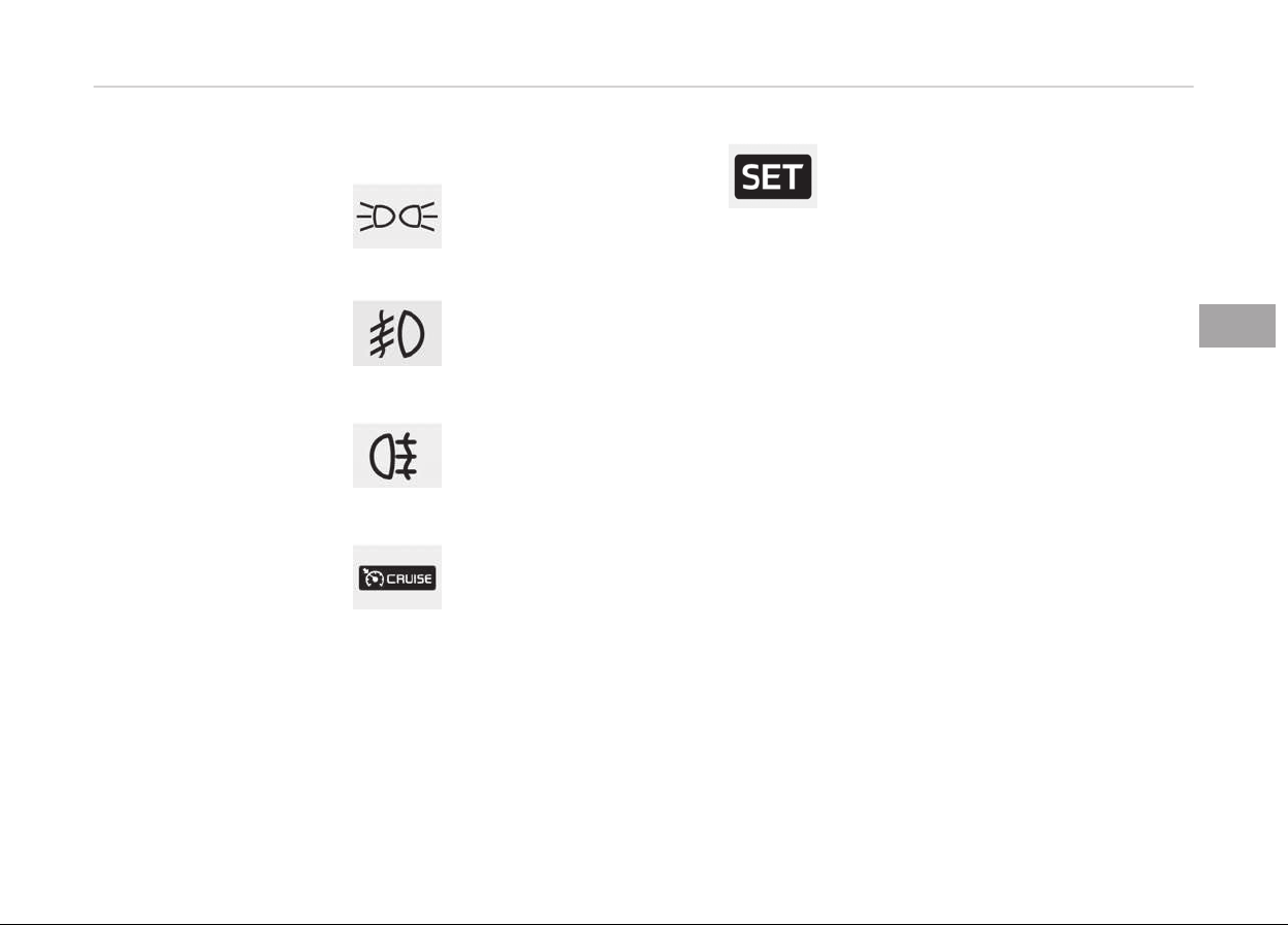
• When the turn signal lever is pulled
into the Flash-to-Pass position.
Light ON indicator light
This indicator light illumi‐
nates:
• When the tail lights or
headlights are on.
Front fog indicator light
(if equipped)
This indicator light illumi‐
nates:
• When the front fog lights are on.
Rear fog indicator light
(if equipped)
This indicator light illumi‐
nates:
• When the rear fog lights are on.
Cruise indicator light
This indicator light illumi‐
nates:
• When the cruise control
system is enabled.
For more details, refer to Cruise Con‐
trol System on page 5-61.
Cruise SET indicator light
This indicator light illumi‐
nates:
• When the cruise control
speed is set.
For more details, refer to Cruise Con‐
trol System on page 5-61.
4-91
4
Features of your vehicle
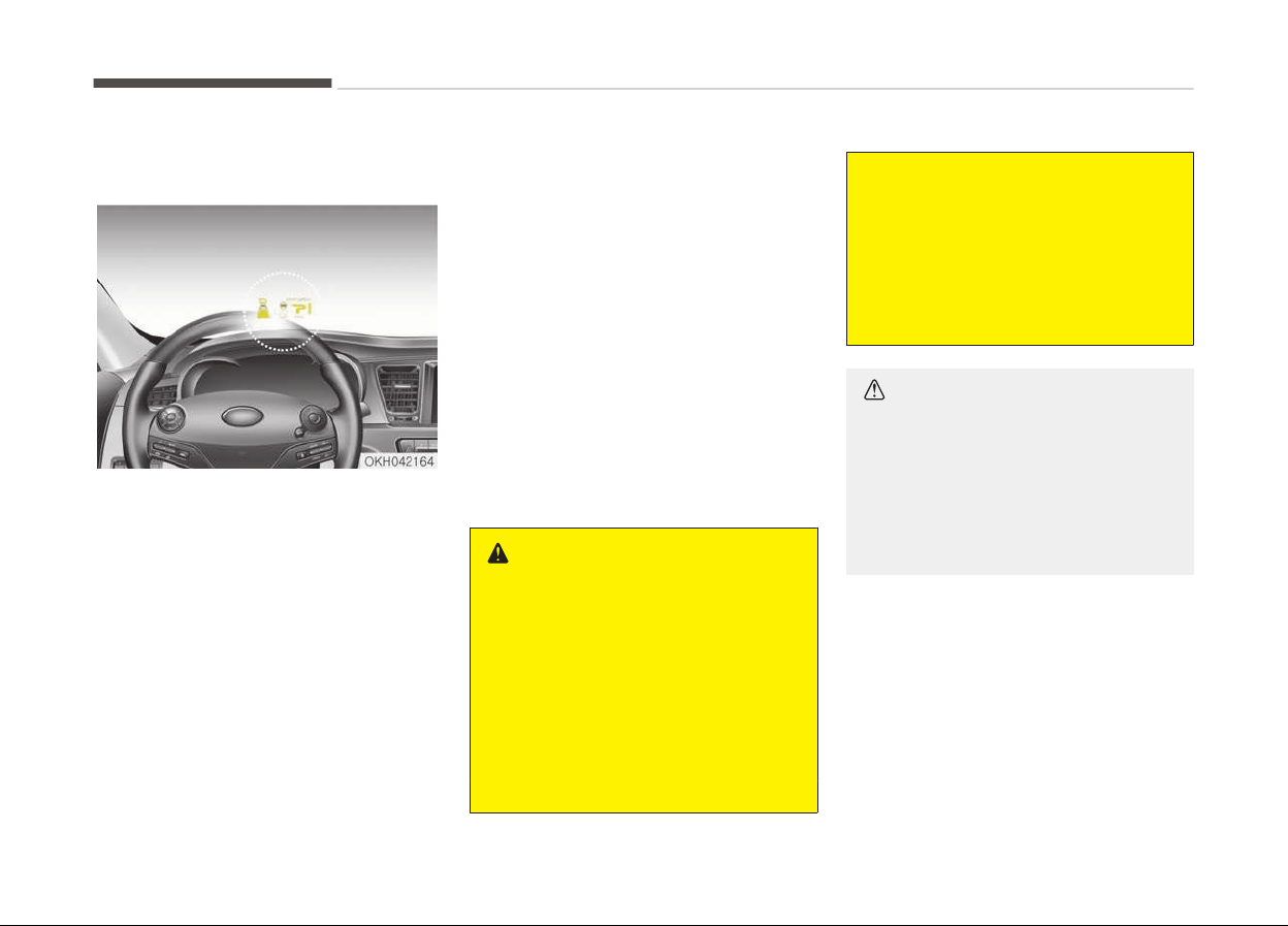
HEAD UP DISPLAY (HUD) (IF EQUIPPED)
Description
The head up display is a transparent
display which projects a shadow of
some information of the instrument
cluster and navigation on the wind‐
shield glass.
• The head up display image on the
windshield glass may be invisible
when:
- Sitting posture is bad.
- Wearing a polarized sunglasses.
- There is an object on the cover of
the head up display.
- Driving on a wet road.
- An inadequate lighting is turned on
inside the vehicle.
- Any light comes from the outside.
- Wearing an inadequate glasses to
your eyesight.
• If the head up display image is not
shown well, adjust the height, rota‐
tion or illumination of the head up
display in the LCD display.
❈ For more details, refer to LCD dis‐
play on page 4-56.
• When the head up display needs in‐
spection or repair, Kia recommends to
visit an authorized Kia dealer/service
partner
WARNING
n
Head Up Display
• Do not make the front windshield
glass have window tint or other
types of metallic coating. Other‐
wise, the head up display image
may be invisible.
• Do not place any accessories on
the
clash pad or attach any objects
on the windshield glass.
(Continued)
(Continued)
• As the Blind Spot Detection (BSD)
system is a supplemental device
for your safe driving, it may be
dangerous to rely on only the BSD
information of the head up display
image when changing the lane. Al‐
ways pay attention to drive safely.
CAUTION
When replacing the front windshield
glass of the vehicles equipped with
the head up display, replace it with a
windshield glass designed for the
head up display operation. Other‐
wise, duplicated images may be dis‐
played on the windshield glass.
Features of your vehicle
4-92
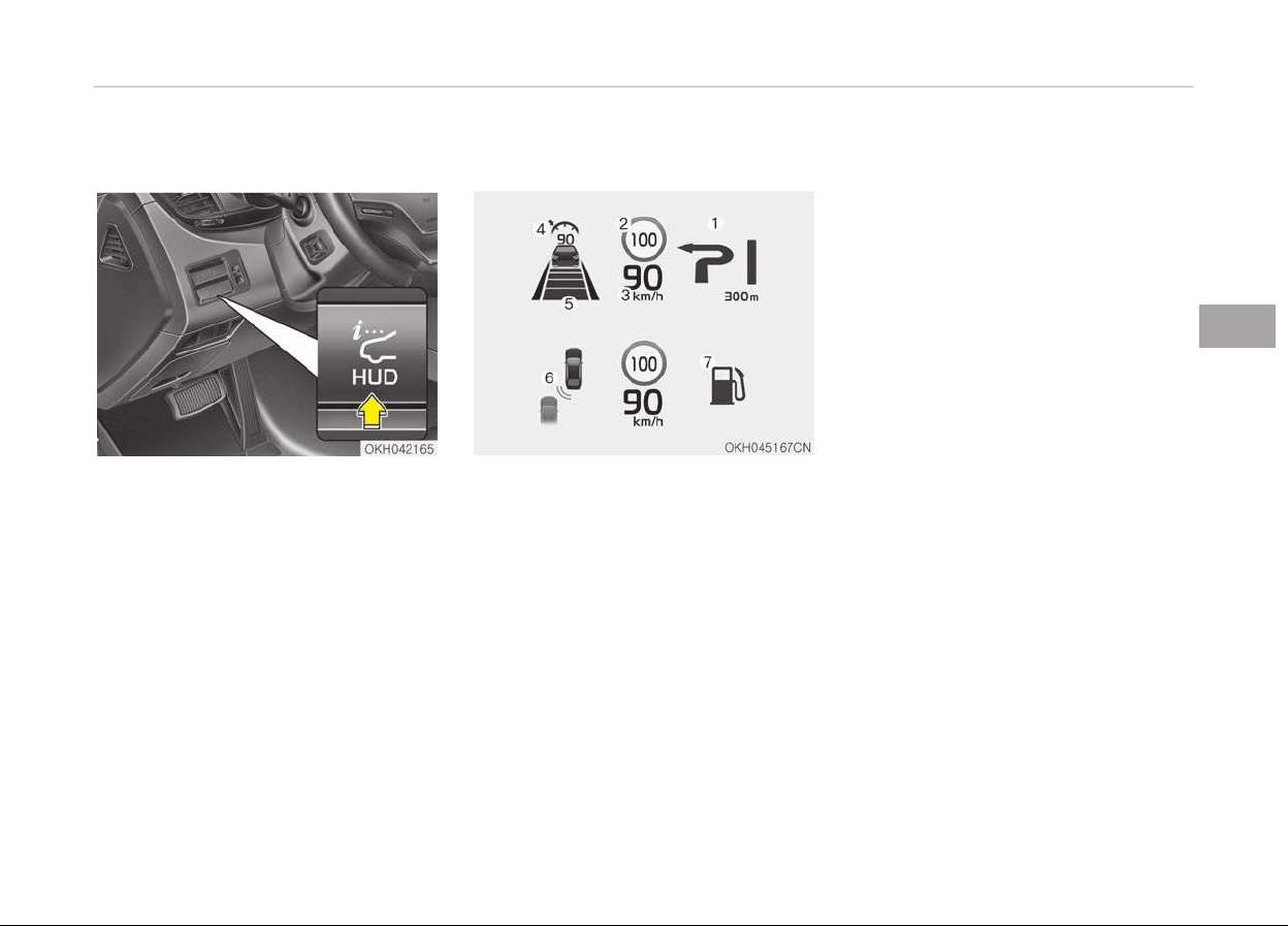
Head up display ON/OFF
• The head up display is always activa‐
ted whenever you set the Engine
Start/Stop Button to the ON position.
• To deactivate the head up display,
press the HUD button. If you press
the HUD button again, the head up
display will be activated.
Head up display information
1. Turn By Turn navigation informa‐
tion
2. Road signs
3. Speedometer
4. Cruise setting speed
5. Smart Cruise Control (SCC) infor‐
mation
6. Blind Spot Detection (BSD) system
information
7. Warning lights (Low fuel, BSD)
Head up display setting
On the LCD display, you can change the
head up display settings as follows.
1. Display height
2. Rotation
3. Brightness
4. Content select
5. Speedometer size
6. Speedometer color
❈ For more details, refer to LCD dis‐
play on page 4-56.
4-93
4
Features of your vehicle
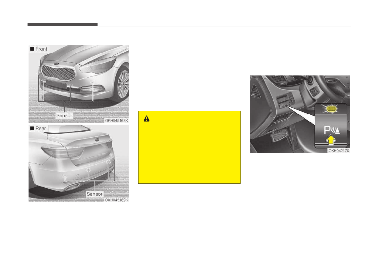
PARKING ASSIST SYSTEM
The parking assist system assists the
driv
er during movement of the vehicle
by chiming if any object is sensed with‐
in the distance of 60 cm in front and
100 cm behind the vehicle.
This system is a supplemental system
and
it is not intended to nor does it re‐
place the need for extreme care and
attention of the driver.
The sensing range and objects detecta‐
ble by the sensors are limited. Whenev‐
er moving pay as much attention to
what is in front and behind of you as
you would in a vehicle without a parking
assist system.
WARNING
The parking assist system should
only be considered as a supplemen‐
tary function. The driver must check
the front and rear view. The opera‐
tional function of the parking assist
system can be affected by many
factors and conditions of the sur‐
roundings, so the responsibility rests
always with the driver.
Operation of the parking assist
system
Operating condition
• This system activates when the
parking assist button is pressed with
the Engine Start/Stop button ON.
• The parking assist button turns on
automatically and activates the park‐
ing assist system when you shift the
gear to the R (Reverse) position. It
will turn off automatically when you
shift out of R (Reverse) and drive
above 20 km/h.
Features of your vehicle
4-94

• The sensing distance while backing
up is approximately 100 cm when
you are driving less than 10 km/h.
• The sensing distance while moving
forward is approximately 60 cm
when you are driving less than
10 km/h.
• When more than two objects are
sensed at the same time, the closest
one will be recognized first.
NOTICE
It may not operate if it’s distance
from the object is already less than
approximately 25 cm when the sys‐
tem is ON.
4-95
4
Features of your vehicle
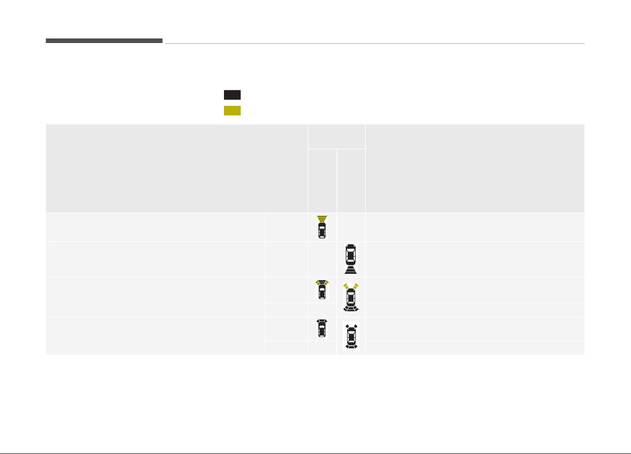
Types of warning sound and indicator
:
with Warning sound
:
without Warning sound
Distance from object
Warning in‐
dicator
Warning sound
Whe
n
driv‐
ing
for‐
ward
Whe
n
driv‐
ing
rear‐
ward
100 cm~61 cm Front
- -
120 cm~61 cm Rear -
Buzzer beeps intermittently
60 cm~31 cm
Front Buzzer beeps frequently
Rear - Buzzer beeps frequently
30 cm
Front Buzzer sounds continuously
Rear - Buzzer sounds continuously
Features of your vehicle
4-96

NOTICE
The indicator may differ from the illustration as objects or sensors status.
If the indicator blinks, have the system checked by a professional workshop. Kia recommends to visit an authorized Kia
dealer/service partner.
Non-operational conditions of
parking assist system
Parking assist system may not
operate normally when:
1. Moisture is frozen to the sensor (It
will operate normally when mois‐
ture melts).
2. Sensor is covered with foreign mat‐
ter, such as snow or water, or the
sensor cover is blocked. (It will op‐
erate normally when the material
is removed or the sensor is no lon‐
ger blocked).
3. Sensor is stained with foreign mat‐
ter such as snow or water. (Sensing
range will return to normal when
removed.)
4. The parking assist button is off.
There is a possibility of parking
assist system malfunction when:
1. Driving on uneven road surfaces
such as unpaved roads, gravel,
bumps, or gradient.
2. Objects generating excessive noise
such as vehicle horns, loud motor‐
cycle engines, or truck air brakes
can interfere with the sensor.
3. Heavy rain or water spray.
4. Wireless transmitters or mobile
phones present near the sensor.
5. Sensor is covered with snow.
Detecting range may decrease
when:
1. Outside air temperature is ex‐
tremely hot or cold.
2. Undetectable objects smaller than
1 m and narrower than 14 cm in di‐
ameter.
The following objects may not be
recognized by the sensor:
1. Sharp or slim objects such as ropes,
chains or small poles.
2. Objects, which tend to absorb sen‐
sor frequency such as clothes,
spongy material or snow.
NOTICE
1. The warning may not sound se‐
quentially depending on the
speed and shapes of the objects
detected.
(Continued)
4-97
4
Features of your vehicle
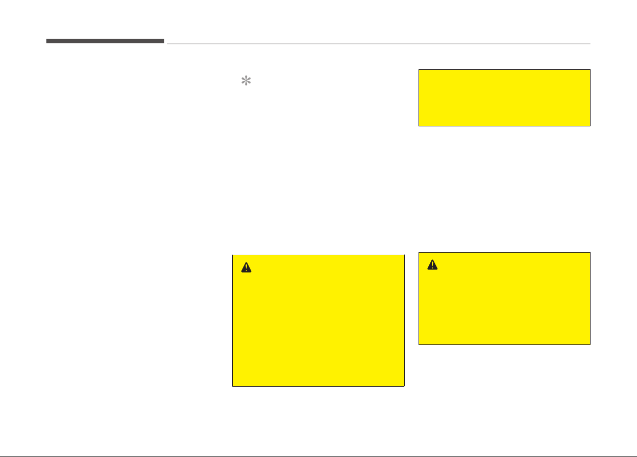
(Continued)
2. The
parking assist system may
malfunction if the vehicle bump‐
er height or sensor installation
has been modified. Any non-fac‐
tory installed equipment or ac‐
cessories may also interfere
with the sensor performance.
3. Sensor may not recognize ob‐
jects less than 30 cm from the
sensor, or it may sense an incor‐
rect distance. Use with caution.
4. When the sensor is frozen or
stained with snow or water, the
sensor may be inoperative until
the stains are removed using a
soft cloth.
5. Do not push, scratch or strike
the sensor with any hard objects
that could damage the surface
of the sensor. Sensor damage
could occur.
NOTICE
This system can only sense objects
within the range and location of the
sensors, it can not detect objects in
other areas where sensors are not
installed. Also, small or slim objects,
or objects located between sensors
may not be detected.
Always visually check in front and
behind the vehicle when driving.
Be sure to inform any drivers in the
vehicle that may be unfamiliar with
the system regarding the systems
capabilities and limitations.
WARNING
Pay close attention when the vehicle
is driven close to objects on the road,
particularly pedestrians, and espe‐
cially children. Be aware that some
objects may not be detected by the
sensors, due to the objects distance,
size or material, all of which can lim‐
it the effectiveness of the sensor.
Always perform a visual inspection
(Continued)
(Continued)
to make sure the vehicle is clear of
all
obstructions before moving the
vehicle in any direction.
Self-diagnosis
If you don’t hear an audible warning
sound or if the buzzer sounds intermit‐
tently when shifting the shift lever into
the R (Reverse) position, this may indi‐
cate a malfunction in the parking assist
system. If this occurs, have the system
checked by a professional workshop.
Kia recommends to visit an authorized
Kia dealer/service partner.
WARNING
Your new vehicle warranty does not
cover any accidents or damage to
the vehicle or injuries to its occu‐
pants related to a parking assist
system. Always drive safely and
cautiously.
Features of your vehicle
4-98
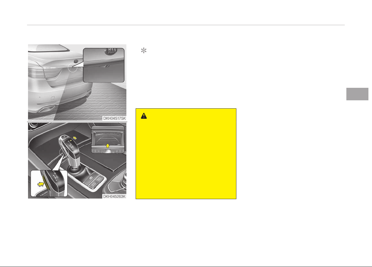
REARVIEW CAMERA (IF EQUIPPED)
The rearview camera will activate when
the
back-up light is ON with the Engine
Start/Stop button ON and the shift lev‐
er in the R (Reverse) position.
NOTICE
The rearview camera may not oper‐
ate normally, when you drive in ex‐
tremely high or low temperature
area.
(operating temperature:
-20C ~ 65C (-13F ~ 149F))
WARNING
• This system is a supplementary
function only. It is the responsibili‐
ty of the driver to always check
the inside/outside rearview mirror
and the area behind the vehicle
before and while backing up be‐
cause there is a dead zone that
can't be seen through the camera.
• Always keep the camera lens
clean. If the lens is covered with
foreign matter, the camera may
not operate normally.
4-99
4
Features of your vehicle
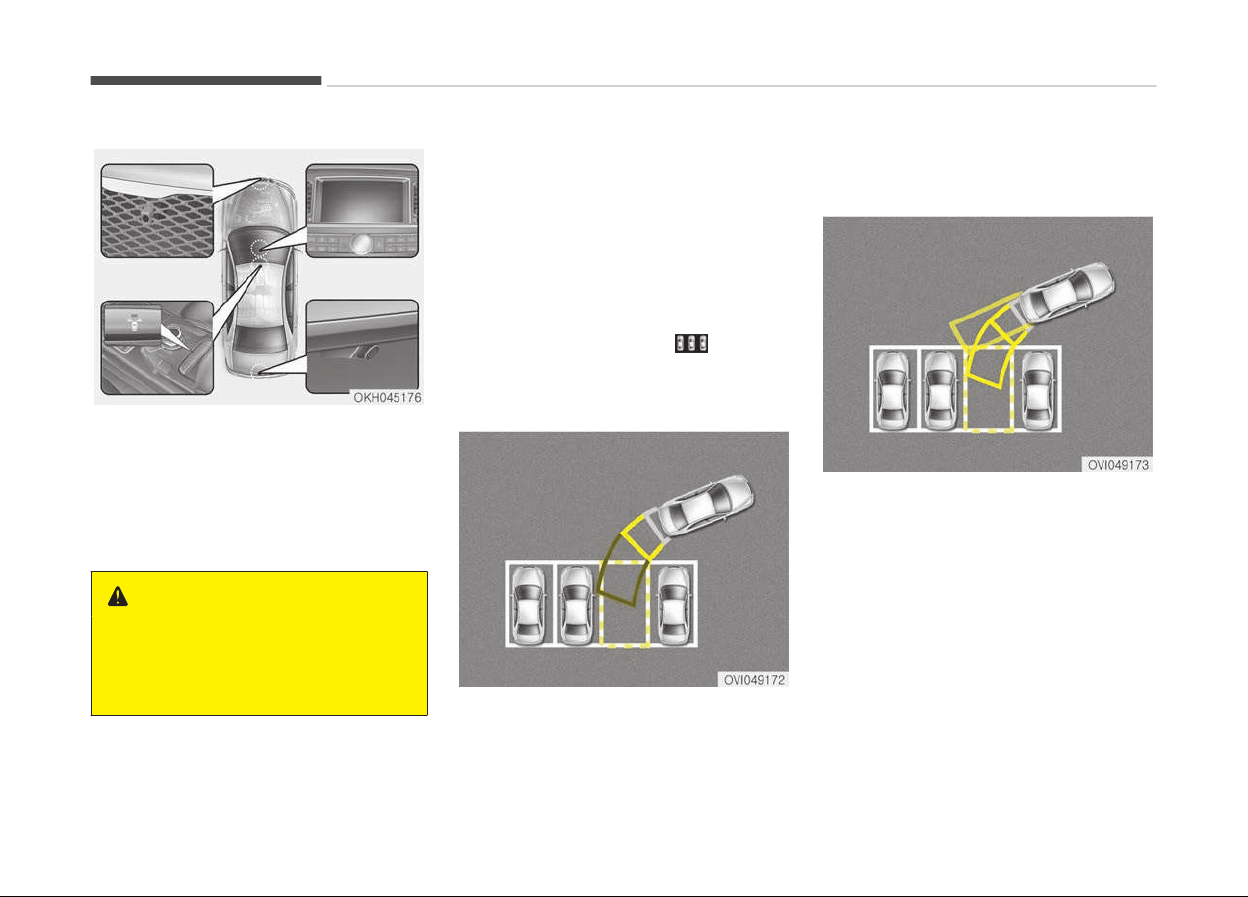
PARKING GUIDE SYSTEM (IF EQUIPPED)
This function assists you when reverse
parking (back-in parking) or parallel
parking.
The parking guide system is only avail‐
able when the vehicle speed is less than
10km/h.
WARNING
This is a supplementary system. It is
the responsibility of the driver to al‐
ways check the area around the ve‐
hicle when parking the vehicle.
Reverse parking (Back-in
parking)
1. Drive the vehicle to a proper place
to park.
2. Stop the vehicle and shift the
transmission lever to the R posi‐
tion.
3. Select the reverse parking mode by
touching the icon
on the
screen.
4. The parking guide line show on the
screen.
5. Turn the steering wheel so that the
parking guide line is aligned with
the parking area.
6. Hold the steering wheel and care‐
fully back up the vehicle until the
screen changes.
7. Carefully back up the vehicle while
fitting the steering wheel guide line
to the parking area by turning the
steering wheel.
8. After parking, you can check the
bottom of the rear bumper by se‐
lecting the icon "Top View" on the
screen.
Features of your vehicle
4-100
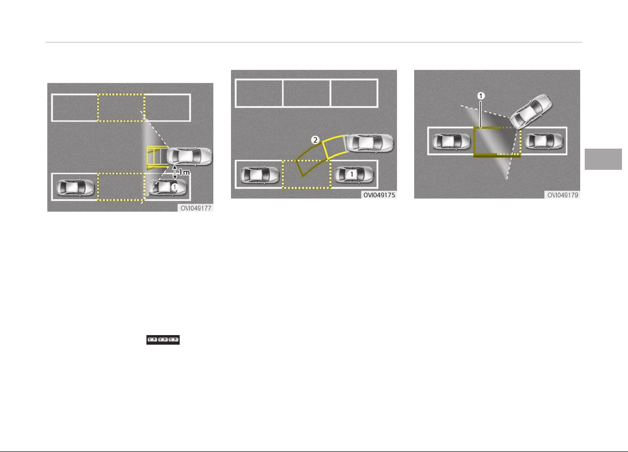
Parallel parking
1. Stop the vehicle at a distance of
approximately 1 meter parallel to
the parked vehicle (1) that is in
front of the desired parking space.
Make sure that the front of the
parked vehicle (1) is parallel to your
rear wheel.
2. Stop the vehicle and shift the
transmission lever to the R posi‐
tion.
3. Select the parallel parking mode by
touching the icon
on the
screen.
4. Back up carefully parallel to the
parked vehicle (1) until the vertical
red guide line (2) is at the end of
the parked vehicle (1).
5. Stop the vehicle.
6. With the vehicle at standstill, turn
the steering wheel to the direction
of the parking space. The guide
lines will blink.
7. Continue turning the steering
wheel until the guide lines stop
blinking.
8. Hold the steering wheel and care‐
fully back up the vehicle until the
green guide line (1) is aligned with
the target parking line.
9. Stop the vehicle
10. With the vehicle at standstill, turn
the steering wheel to the opposite
direction until the screen changes.
4-101
4
Features of your vehicle
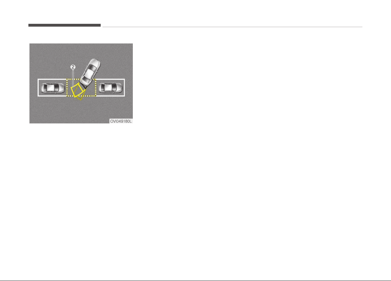
11. Carefully back up the vehicle by re‐
ferring to the steering wheel guide
line (2).
12. After parking, you can check the
bottom of the rear bumper by se‐
lecting the icon "Top View" on the
screen.
Features of your vehicle
4-102
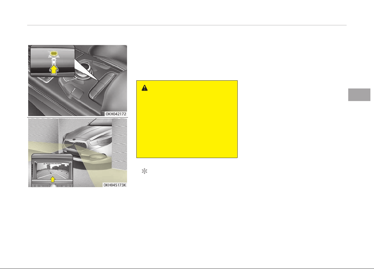
FRONT BLIND SPOT MONITORING SYSTEM (IF EQUIPPED)
Front blind spot monitoring system is a
supplemental system that shows blind
spot in front of the vehicle through the
AV monitor.
The front blind spot monitoring system
will operate when you press the button
and shift the shift lever into N(Neutral)
or D(Drive) while driving less than
10km/h.
WARNING
This is a supplementary system. It is
the responsibility of the driver to al‐
ways check the area around the ve‐
hicle before driving because there is
a dead zone that can't be seen
through the camera.
Always keep the camera lens clean.
If the lens is covered with foreign
matter, the camera may not operate
normally.
NOTICE
The front blind spot monitoring sys‐
tem may not operate normally,
when you drive in the extremely
high or low temperature area. (oper‐
ating temperature: -20C~65C
(-4F ~ 149F))
4-103
4
Features of your vehicle
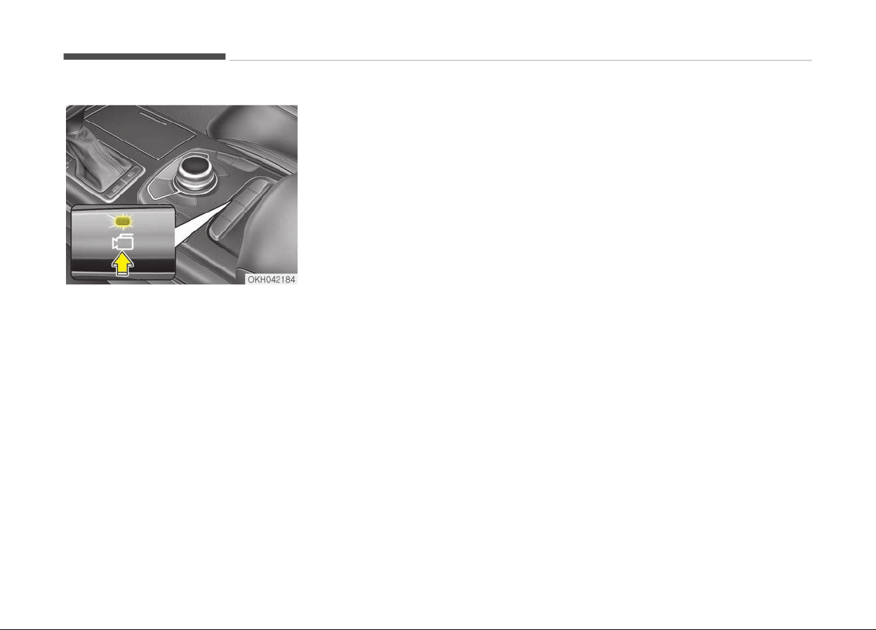
SURROUND VIEW MONITORING SYSTEM (SVM) (IF EQUIPPED)
This is the parking support system to
show around circumstance when you
park the vehicle in monitor. When you
push the button in [ON] position, it is
operated. To cancel the system, push
again.
Operating conditions
-
When Engine Start/Stop button is ON
-
When the transaxle is on D, N or R
-
When the vehicle speed is not over
20km/h
• When the vehicle speed is over
20km/h, the SVM system is turned
off. If the vehicle speed is not over
20km/h after turning off the SVM by
over speed, the SVM is not turned on.
To operate again, push the button.
• When the vehicle moves backwards,
regardless of On/Off of button and
vehicle speed, the SVM is operated.
• When the trunk and driver/passenger
door are opened and the outside mir‐
ror is folded, the warning is illumina‐
ted in SVM system.
• If the SVM system does not operate
normally, contact a professional
workshop. Kia recommends to visit
an authorized Kia dealer/service part‐
ner.
* SVM : Surround View Monitoring
Features of your vehicle
4-104

LIGHTING
Battery saver function
• The purpose of this feature is to pre‐
vent the battery from being dis‐
charged. The system automatically
turns off the parking lights when the
driver turns off the engine and opens
the driver-side door.
• With this feature, the parking lights
will be turned off automatically if the
driver parks on the side of road at
night.
If necessary, to keep the lights on
when the engine is turned off per‐
form the following:
1. Open the driver-side door.
2. Turn the parking lights OFF and ON
again.
Headlight escort function
The headlights (and/or parking lights)
will
remain on for approximately
5 minutes after the engine start/stop
button is turned to the ACC or OFF po‐
sition. However, if the driver’s door is
opened and closed, the headlights are
turned off after 15 seconds.
The headlights can be turned off by
pressing the lock button on the smart
key twice or turning off the light switch
from the headlight or Auto light posi‐
tion.
CAUTION
If the driver gets out of the vehicle
through other doors (except driver's
door), the battery saver function
does not operate and the headlight
escort function does not turn off au‐
tomatically. Therefore, It causes the
battery to be discharged. In this
case, make sure to turn off the lamp
before getting out of the vehicle.
Daytime running light
The Daytime Running Lights (DRL) can
make it easier for others to see the
front of your vehicle during the day.
DRL can be helpful in many different
driving conditions, and it is especially
helpful after dawn and before sunset.
The DRL system will turn the dedicated
lamp OFF when:
1. The headlight or fog lamp switch is
ON.
2. The engine is OFF.
3. The front fog light is ON.
4. Engaging the parking brake.
Traffic change (for Europe)
Use this function when you visit a
country with opposite traffic direction.
If the traffic change is activated when
you visit a country with opposite traffic
direction, it will decrease the dazzle on
oncoming vehicle drivers.
Follow the below procedure.
1. Select User Settings by pressing
the mode button (
) on the steer‐
ing wheel.
2. Select Light by pressing the move
button (
) and select button ( )
on the steering wheel.
3. Select Travel Mode by pressing
the move button ( ) and select
button ( ) on the steering wheel.
4. • Select "On" to activate the traffic
change function.
• Select "Off" to deactivate the
traffic change function.
NOTICE
If the engine is turned off with the
traffic
change function activated,
(Continued)
4-105
4
Features of your vehicle
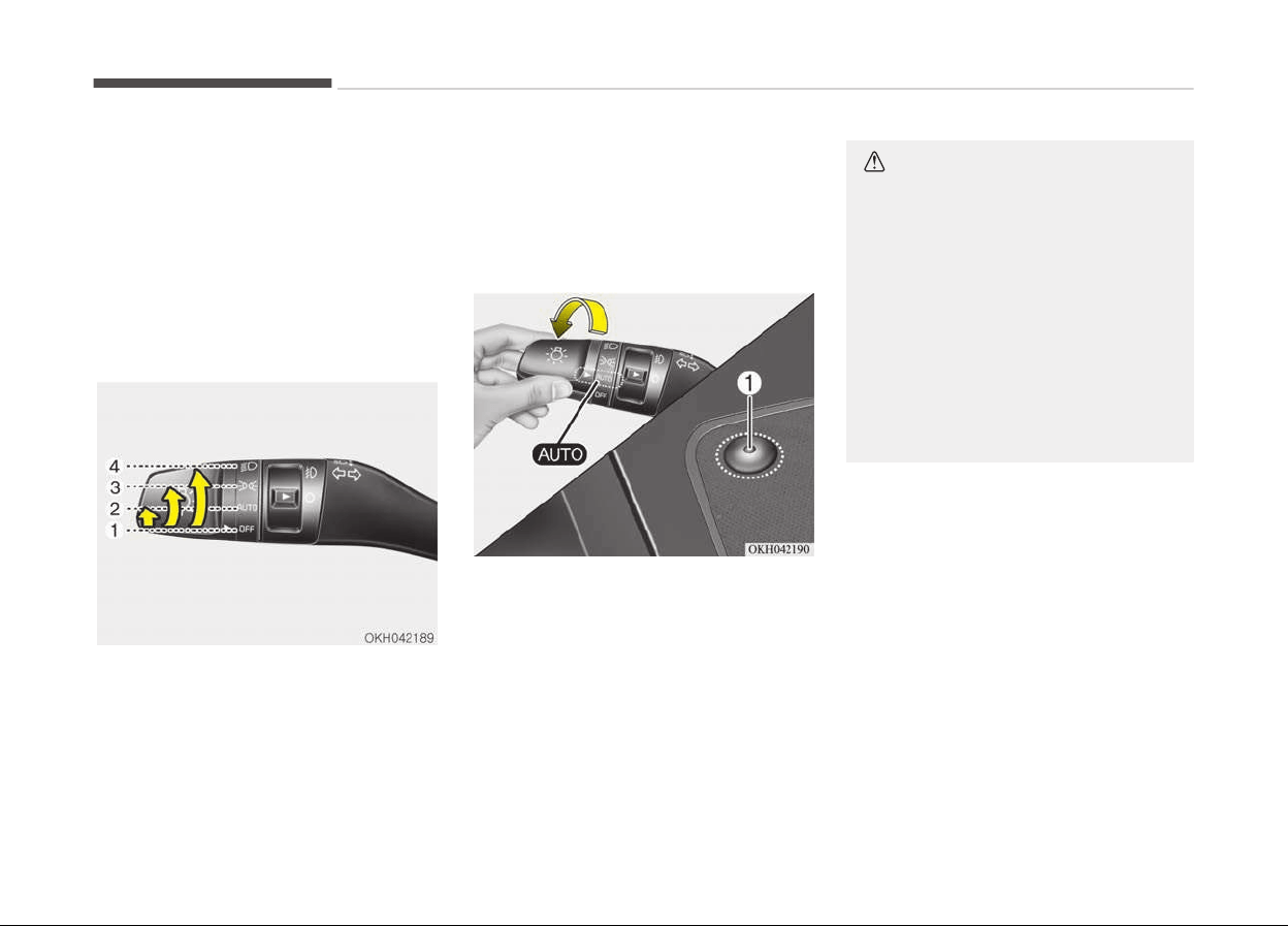
(Continued)
and the engine turned on again, a
message
"Headlamp beam pattern
set to opposite side range has been
reduced" will appear. It is to notify
the driver the function is activated.
Lighting control
The light switch has a Headlight and a
Parking light position.
To operate the lights, turn the knob at
the end of the control lever to one of
the following positions:
1. OFF position
2. Auto light / AFLS position
3. Parking light position
4. Headlight position
Auto light/AFLS position
When the light switch is in the AUTO
light position, the taillights and head‐
lights will be turned ON or OFF auto‐
matically depending on the amount of
light outside the vehicle.
If your vehicle is equipped with the
adaptive front lighting system (AFLS),
it will also operate when the headlamp
is ON.
CAUTION
• Never place anything over the sen‐
sor (1) located on the instrument
panel, this will ensure better auto-
light system control.
• Don’t clean the sensor using a win‐
dow cleaner, the cleaner may leave
a light film which could interfere
with sensor operation.
• If your vehicle has window tint or
other types of coating on the front
windshield, the Auto light system
may not work properly.
Features of your vehicle
4-106
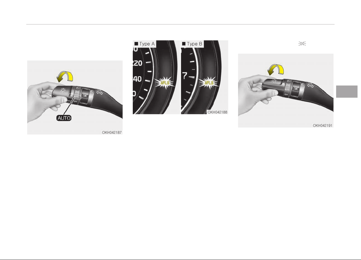
AFLS (Adaptive front lighting
system) (if equipped)
Adaptive front lighting system uses the
steering angle and vehicle speed, to
keep your field of vision wide by swivel‐
ing and leveling the headlamp.
Change the switch to the AUTO position
when the engine is running. The adap‐
tive front lighting system will operate
when the headlamp is ON. To turn off
the AFLS, change the switch to other
positions. After turning the AFLS off,
headlamp swiveling no longer occurs,
but leveling operates continuously.
If the AFLS malfunction indicator comes
on, the AFLS is not working properly.
Drive to the nearest safe location and
restart the engine. If the indicator con‐
tinuously remains on, have the system
checked by a professional workshop.
Kia recommends to visit an authorized
Kia dealer/service partner.
Parking light position ( )
When the light switch is in the parking
light position, the tail and license will
turn ON.
4-107
4
Features of your vehicle
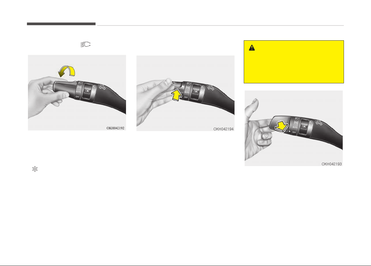
Headlight position ( )
When the light switch is in the head‐
light position, the head, tail, license and
instrument panel lights will turn ON.
NOTICE
The Engine Start/Stop button must
be in the ON position to turn on the
headlights.
High beam operation
To turn on the high beam headlights,
push the lever away from you. Pull it
back for low beams.
The high beam indicator will light when
the headlight high beams are switched
on.
To prevent the battery from being dis‐
charged, do not leave the lights on for a
prolonged time while the engine is not
running.
WARNING
Do not use high beam when there
are other vehicles. Using high beam
could obstruct the other driver’s vi‐
sion.
To flash the headlights, pull the lever
towards you. It will return to the nor‐
mal (low beam) position when released.
The headlight switch does not need to
be on to use this flashing feature.
Features of your vehicle
4-108
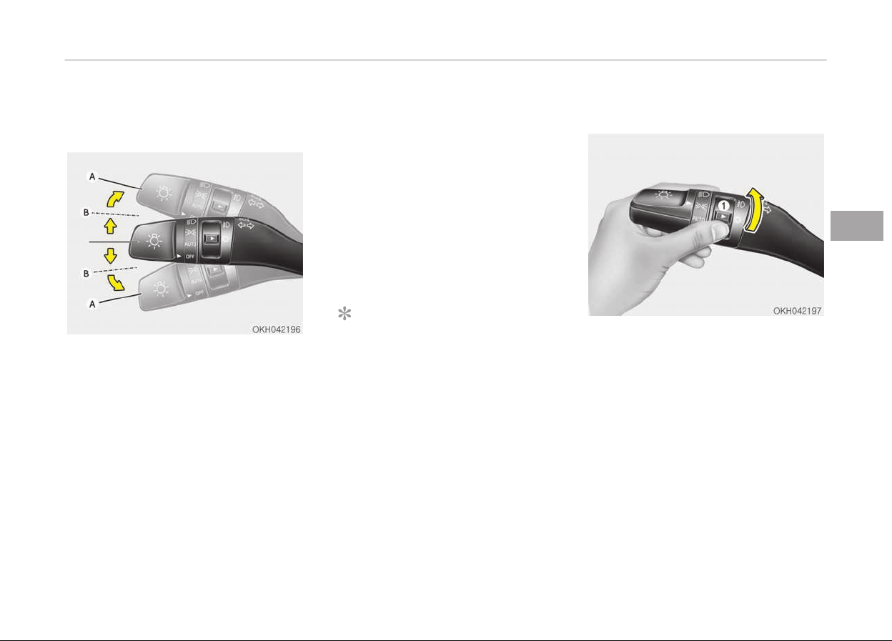
Turn signals and lane change
signals
The Engine Start/Stop button must be
on for the turn signals to function. To
turn on the turn signals, move the lever
up or down (A). The green arrow indica‐
tors on the instrument panel indicate
which turn signal is operating.
They will self-cancel after a turn is
completed. If the indicator continues to
flash after a turn, manually return the
lever to the OFF position.
To signal a lane change, move the turn
signal lever slightly and hold it in posi‐
tion (B). The lever will return to the OFF
position when released.
If an indicator stays on and does not
flash or if it flashes abnormally, one of
the turn signal bulbs may be burned
out and will require replacement.
One-touch turn signal
To activate an one-touch turn signal
move the turn signal lever slightly and
then release it. The lane change signals
will blink 3, 5 or 7 times.
You can set the number of operating
times. Refer to LCD display on page
4-56.
NOTICE
If an indicator flash is abnormally
quick or slow, a bulb may be burned
out or have a poor electrical connec‐
tion in the circuit.
Front fog light
Fog lights are used to provide improved
visibility when visibility is poor due to
fog, rain or snow, etc.
1. Turn on the park light.
2. Turn the light switch (1) to the
front fog light position.
3. To turn off the front fog light, turn
the light switch to the front fog
light position again or turn off the
park light.
4-109
4
Features of your vehicle
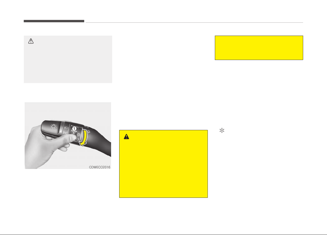
CAUTION
When in operation, the fog lights
consume large amounts of vehicle
electrical power. Only use the fog
lights when visibility is poor or un‐
necessary battery and generator
drain could occur.
Rear fog light (if equipped)
To turn the rear fog lights on, turn the
rear fog light switch (1) to the on posi‐
tion when the headlight is turned on.
Also, the rear fog lights turn on when
the rear fog light switch is turned on
after the front fog light switch (if
equipped) is turned on and the head‐
light switch is in the parklight position.
To turn the rear fog lights off, turn the
rear fog light switch to the on position
again.
Headlight leveling device (if
equipped)
It is automatically adjusted the head‐
light beam level according to the num‐
ber of the passengers and the loading
weight in the luggage area.
And it offers the proper headlight beam
under the various conditions.
WARNING
If it does not work properly even
though your car is inclined backward
according to passenger's posture, or
the headlight beam is irradiated to
the high or low position, have the
system inspected by a professional
workshop. Kia recommends to visit
an authorized Kia dealer/service
partner.
(Continued)
(Continued)
Do not attempt to inspect or replace
the wiring yourself.
Headlight washer (if equipped)
If your vehicle is equipped with the
headlight washer it will be operating at
the same time when you operate the
windshield washer. It will operate when
the headlight switch is in the first or
second position and the engine start/
stop button is in the ON position.
The washer fluid will be sprayed on to
the headlights.
NOTICE
• Check the headlight washers peri‐
odically to confirm that the wash‐
er fluid is being sprayed properly
onto the headlight lenses.
• The headlight washer can be oper‐
ated 15 minutes after being oper‐
ated last time.
Features of your vehicle
4-110
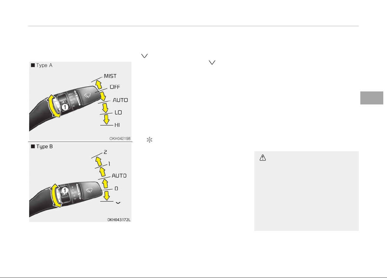
WIPERS AND WASHERS
Windshield wipers
Operates as follows when the Engine
Start/Stop button is turned ON.
• MIST /
:
For a single wiping cycle,
move the lever to this po‐
sition (MIST/
) and re‐
lease it with the lever in
the OFF position. The wip‐
ers will operate continu‐
ously if the lever is held in
this position.
• OFF / O: Wiper is not in operation
• AUTO: Auto control wipe
• LO (1): Normal wiper speed
• HI (2): Fast wiper speed
NOTICE
If there is heavy accumulation of
snow or ice on the windshield, de‐
frost the windshield for about
10 minutes, or until the snow and/or
ice is removed before using the
windshield wipers to ensure proper
operation. If you do not remove the
snow and/or ice before using the
wiper and wash-er, it may damage
the Wiper and washer system.
Auto control (if equipped)
The rain sensor located on the upper
end of the windshield glass senses the
amount of rainfall and controls the
wiping cycle for the proper interval.
The more it rains, the faster the wiper
operates. When the rain stops, the wip‐
er stops.
To vary the speed setting, turn the
speed control knob (1).
If the wiper switch is set in AUTO mode
when the Engine Start/Stop button is
ON, the wiper will operate once to per‐
form a self-check of the system. Set
the wiper to OFF / O position when the
wiper is not in use.
CAUTION
When the Engine Start/Stop button
is ON and the windshield wiper
switch is placed in the AUTO mode,
use caution in the following situa‐
tions to avoid any injury to the
hands or other parts of the body:
• Do not touch the upper end of the
windshield glass facing the rain
sensor.
(Continued)
4-111
4
Features of your vehicle
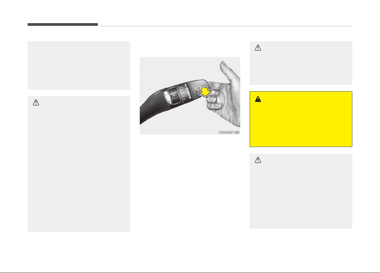
(Continued)
• Do not wipe the upper end of the
windshield
glass with a damp or
wet cloth.
• Do not put pressure on the wind‐
shield glass.
CAUTION
When washing the vehicle, set the
wiper
switch in the OFF / O position
to stop the auto wiper operation.
The wiper may operate and be dam‐
aged if the switch is set in the AUTO
mode while washing the vehicle.
Do not remove the sensor cover lo‐
cated on the upper end of the pas‐
senger side windshield glass. Dam‐
age to system parts could occur and
may not be covered by your vehicle
warranty.
When starting the vehicle in winter,
set the wiper switch in the OFF / O
position. Otherwise, wipers may op‐
erate and ice may damage the wind‐
shield wiper blades. Always remove
all snow and ice and defrost the
windshield properly prior to operat‐
ing the windshield wipers.
Windshield washers
In the OFF / O position, pull the lever
gently toward you to spray washer flu‐
id on the windshield and to run the wip‐
ers 1-3 cycles.
Use this function when the windshield
is dirty.
The spray and wiper operation will con‐
tinue until you release the lever.
If the washer does not work, check the
washer fluid level. If the fluid level is
not sufficient, you will need to add ap‐
propriate non-abrasive windshield
washer fluid to the washer reservoir.
The reservoir filler neck is located in
the front of the engine compartment
on the passenger side.
CAUTION
To prevent possible damage to the
washer pump, do not operate the
washer when the fluid reservoir is
empty.
WARNING
Do not use the washer in freezing
temperatures without first warming
the windshield with the defrosters;
the washer solution could freeze on
contact with the windshield and ob‐
scure your vision.
CAUTION
• To prevent possible damage to the
wipers or windshield, do not oper‐
ate the wipers when the wind‐
shield is dry.
• To prevent damage to the wiper
blades,
do not use gasoline, kero‐
sene, paint thinner, or other sol‐
vents on or near them.
(Continued)
Features of your vehicle
4-112

(Continued)
• To prevent damage to the wiper
arms
and other components, do
not attempt to move the wipers
manually.
• To prevent possible damage to the
wipers
and washer system, use
anti-freezing washer fluids in the
winter season or cold weather.
4-113
4
Features of your vehicle
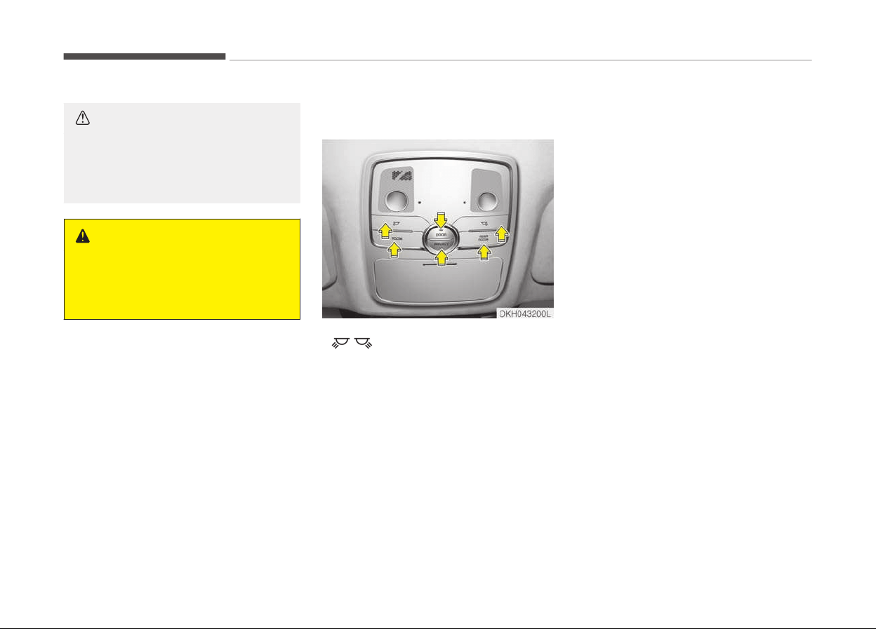
INTERIOR LIGHT
CAUTION
Do not use the interior lights for ex‐
tended periods when the engine is
not running.
It may cause battery discharge.
WARNING
Do not use the interior lights when
driving in the dark. Accidents could
happen because the view may be
obscured by interior lights.
Automatic turn off function (if
equipped)
The interior lights automatically turn
off approximately 20 minutes after the
engine is turned off.
If your vehicle is equipped with the
theft alarm system, the interior lights
automatically turns off several seconds
after the system is armed stage.
Front lamp switch
• : Press the button to turn the
lamp on. This light produces a spot
beam for convenient use as a map
lamp at night or as a personal lamp
for the driver and the front passen‐
ger. To turn the lamp off, press the
button again.
• ROOM : Press the button to turn the
front and rear lamp on. To turn the
lamp off, press the button again.
• REAR ROOM : Press the button to
turn the rear lamp on. To turn the
lamp off, press the button again.
• DOOR :
Press the button to operate the door
mode. The indicator on the button will
illuminate and lamps will turn on or off
as follows:
-
The front and rear lamp comes on
when a door is opened. The lamps go
out after approximately 30 seconds.
-
The front and rear lamp comes on for
approximately 30 seconds when
doors are unlocked with the smart
key as long as the doors are not
opened.
-
The front and rear lamp will stay on
for approximately 20 minutes if a
door is opened with the engine start/
stop button in the ACC or OFF posi‐
tion.
-
The front and rear lamp will stay on
continuously if the door is opened
with the engine start/stop button in
the ON position.
-
The front and rear lamp will go out
immediately if the engine start/stop
button is changed to the ON position
or all doors are locked.
To turn off the door mode, press the
button again. The indicator on the but‐
ton will turn off.
• PRIVACY :
Features of your vehicle
4-114
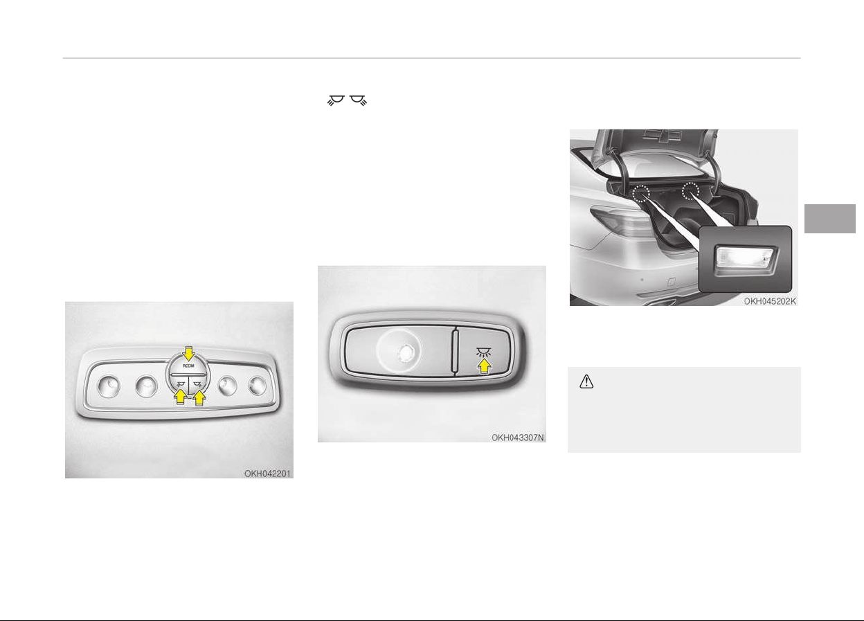
Press the button to operate the privacy
mode. The indicator on the button will
illuminate and lamps will turn on or off
as follows:
-
If you open any door, the lamp for
the open door will illuminate.
To turn off the privacy mode, press the
button again. The indicator on the but‐
ton will turn off.
Rear lamp switch
Type A
• : Press the button to turn the
lamp on. This light produces a spot
beam for convenient use as a map
lamp at night or as a personal lamp
for the driver and the front passen‐
ger. To turn the lamp off, press the
button again.
• ROOM : Press the button to turn the
rear lamp on. To turn the lamp off,
press the button again.
Type B
Press the button to turn the rear lamp
on. To turn the lamp off, press the but‐
ton again.
Trunk room lamp
The trunk room lamp comes on when
the trunk is opened.
CAUTION
To prevent unnecessary charging
system drain, close the trunk lid se‐
curely after using the trunk room.
4-115
4
Features of your vehicle
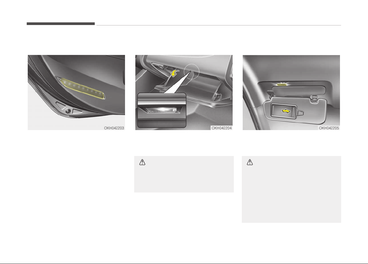
Door courtesy lamp
The door courtesy lamp comes ON
when the door is opened to assist en‐
tering or exiting the vehicle. It also
serves as a warning to passing vehicles
that the vehicle door is open.
Glove box lamp
The glove box lamp comes on when the
glove box is opened.
CAUTION
To prevent unnecessary charging
system drain, close the glove box se‐
curely after using the glove box.
Vanity mirror lamp
Opening the lid of the vanity mirror will
automatically turn on the mirror light.
CAUTION
n
Vanity mirror lamp (if equip‐
ped)
Always have the switch in the off
position when the vanity mirror
lamp is not in use. If the sunvisor is
closed without the lamp off, it may
discharge the battery or damage the
sunvisor.
Features of your vehicle
4-116
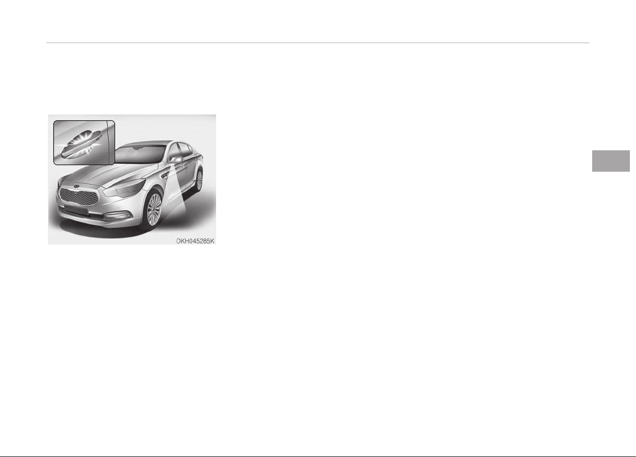
WELCOME SYSTEM
Puddle lamp and door handle
lamp
When all the doors (and trunk) are
locked and closed, the puddle lamp and
door handle lamp will come on for
about 15 seconds if any of the below is
performed.
-
When the door unlock button is
pressed on the smart key.
-
When the button of the outside door
handle is pressed.
-
When the vehicle is approached with
the smart key in possession.
Also, if the outside rearview mirror
folding switch is in the AUTO position,
the outside rearview mirror will unfold
automatically.
Headlight
When the headlight(light switch in the
headlight or AUTO position) is on and all
doors (and trunk) are locked and closed,
the position light and headlight will
come on for 15 seconds if any of the
below is performed.
-
When the door unlock button is
pressed on the smart key.
At this time, if you press the door lock
or unlock button, the position light and
headlight will turn off immediately.
Interior light
When the interior light switch is in the
DOOR position and all doors (and trunk)
are locked and closed, the room lamp
will come on for 30 seconds if any of
the below is performed.
-
When the door unlock button is
pressed on the smart key.
-
When the button of the outside door
handle is pressed.
At this time, if you press the door lock
or unlock button, the room lamp will
turn off immediately.
4-117
4
Features of your vehicle
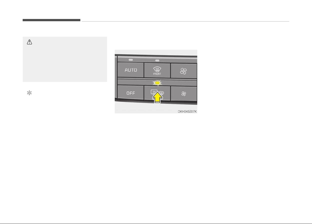
DEFROSTER
CAUTION
To prevent damage to the conduc‐
tors bonded to the inside surface of
the rear window, never use sharp in‐
struments or window cleaners con‐
taining abrasives to clean the win‐
dow.
NOTICE
If you want to defrost and defog the
front windshield, refer to Wind‐
shield defrosting and defogging on
page 4-132.
Rear window defroster
The defroster heats the window to re‐
move frost, fog and thin ice from the
rear window, while the engine is run‐
ning.
To activate the rear window defroster,
press the rear window defroster button
located in the center facia switch panel.
The indicator on the rear window de‐
froster button illuminates when the de‐
froster is ON.
To turn off the defroster, press the
rear window defroster button again.
If there is heavy accumulation of snow
on the rear window, brush it off before
operating the rear defroster.
The rear window defroster automati‐
cally turns off after approximately
20 minutes or when the Engine Start/
Stop button is turned off. To turn off
the defroster, press the rear window
defroster button again.
Outside rearview mirror defroster
If your vehicle is equipped with the out‐
side rearview mirror defrosters, they
will operate at the same time you turn
on the rear window defroster.
Wiper deicer (if equipped)
If your vehicle is equipped with the wip‐
er deicer, it will be operating at the
same time you turn on the rear window
defroster.
Features of your vehicle
4-118
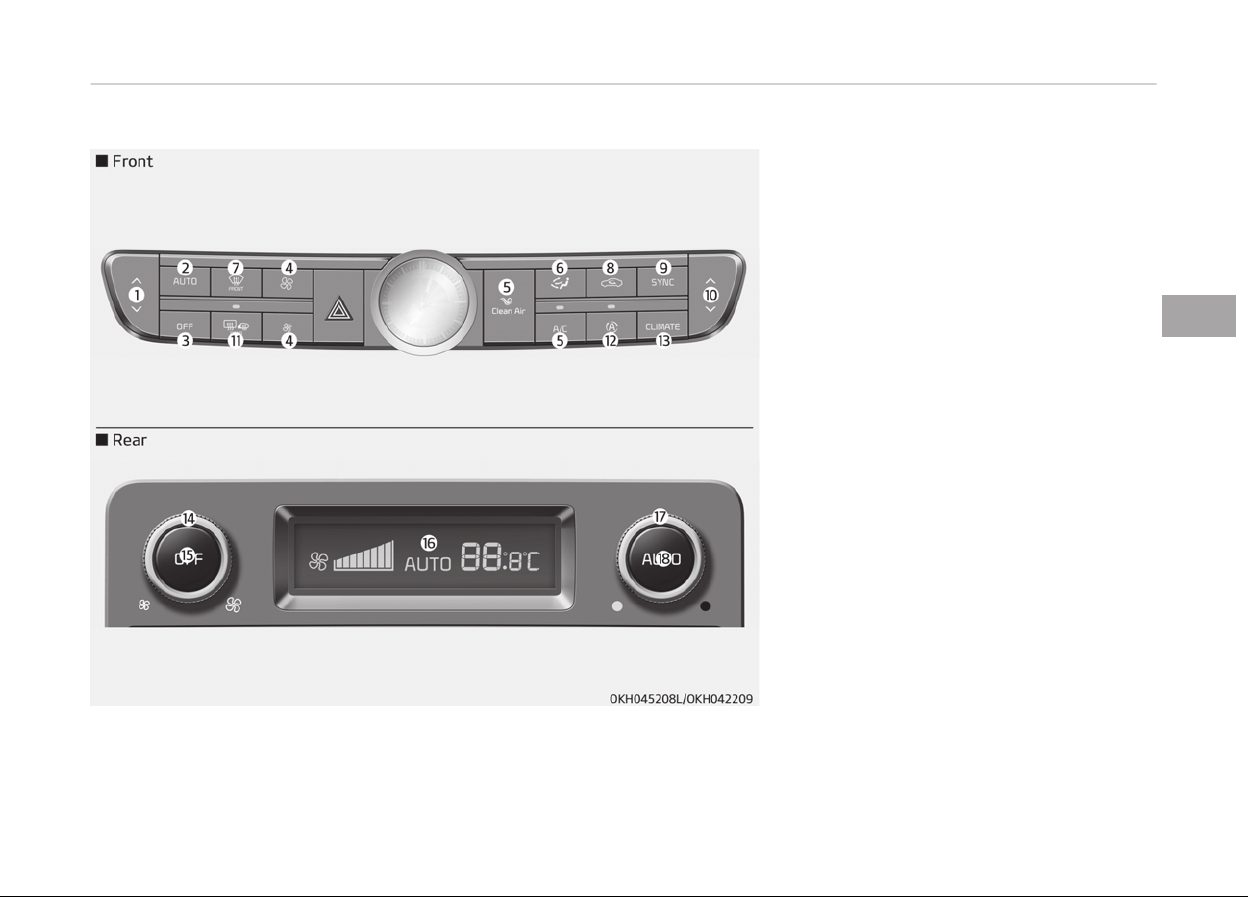
AUTOMATIC CLIMATE CONTROL SYSTEM
1. Driver’s temperature control but‐
ton
2. AUTO (automatic control) button
3. OFF button
4. Fan speed control button
5. Air conditioning button
6. Mode selection button
7. Front windshield defrost button
8. Air intake control button
9. SYNC button
10. Passenger’s temperature control
button
11. Rear window defrost button
12. AQS (Air quality system) button
13. Climate information screen selec‐
tion button
14. Fan speed control button (Rear)
15. OFF button (Rear)
16. LCD display
17. Rear side temperature control knob
18. AUTO (automatic control) button
4-119
4
Features of your vehicle
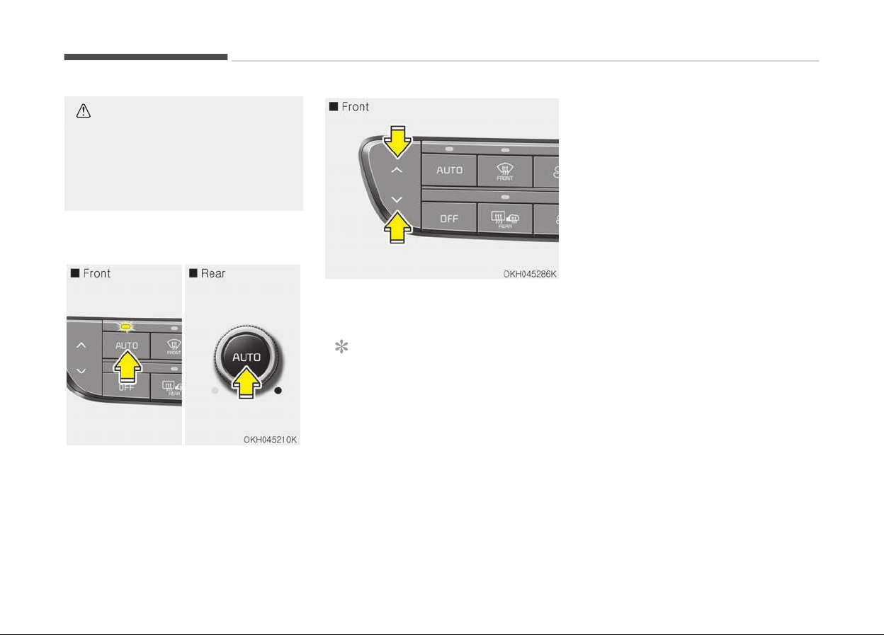
CAUTION
Operating the blower when the En‐
gine Start/Stop button is in the ON
position could cause the battery to
discharge. Operate the blower when
the engine is running.
Automatic heating and air
conditioning
1. Press the AUTO button.
The modes, fan speeds, air intake
and air-conditioning will be control‐
led automatically according to the
temperature setting.
2. Press the temperature control but‐
ton to set the desired temperature.
NOTICE
• To turn the automatic operation
off, select any button of the fol‐
lowing:
- Mode selection button
(Continued)
(Continued)
- Front windshield defrost button
(Press the button one more
time to deselect the front wind‐
shield defroster function. The
'AUTO' sign will illuminate on
the information display once
again.)
- Fan speed control button
The selected function will be con‐
trolled manually while other func‐
tions operate automatically.
• For your convenience and to im‐
prove the effectiveness of the cli‐
mate control, use the AUTO but‐
ton and set the temperature to
23C (73F).
Features of your vehicle
4-120
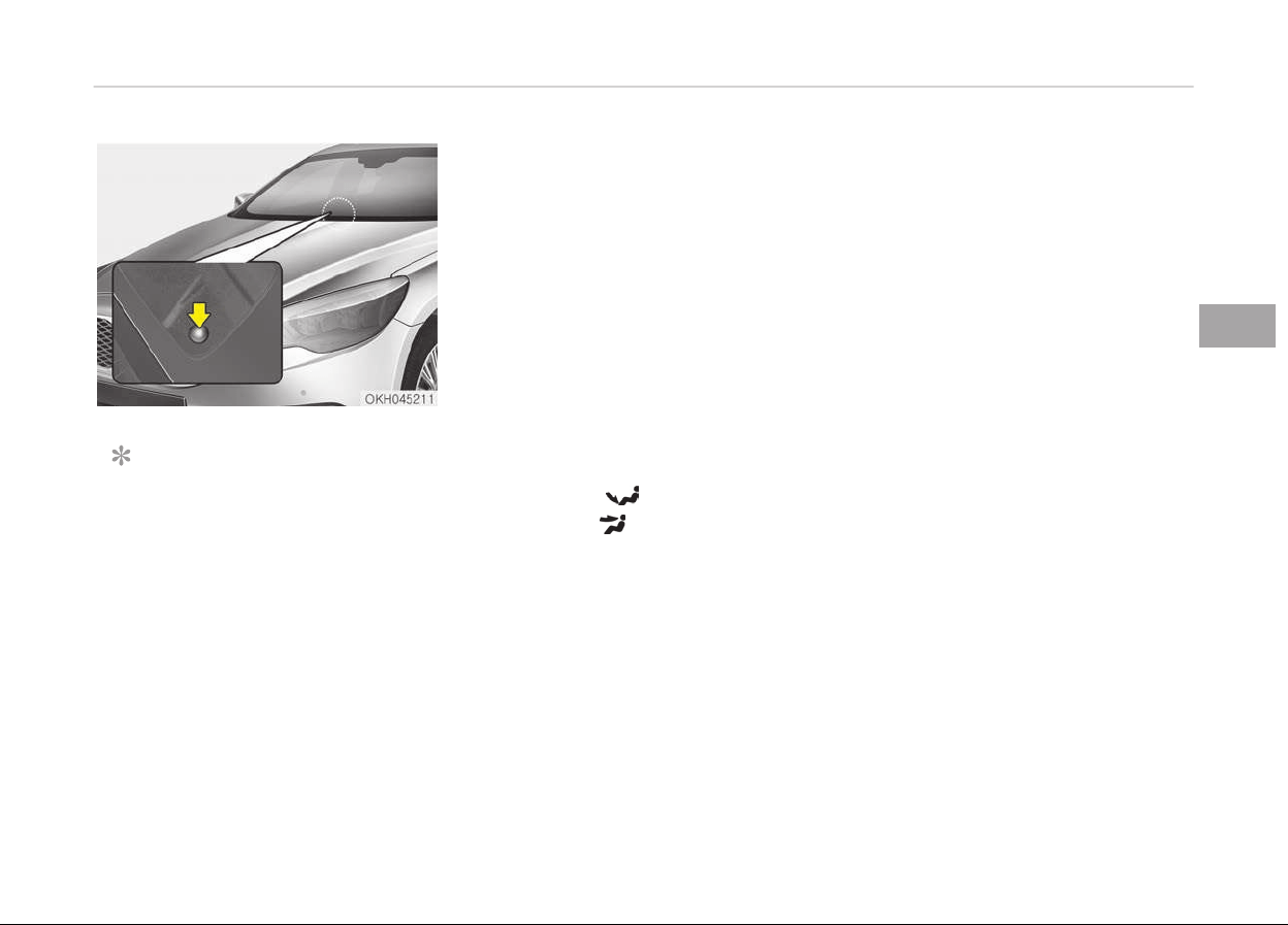
NOTICE
Never place anything over the sen‐
sor located on the instrument panel
to ensure better control of the heat‐
ing and cooling system.
Manual heating and air
c
onditioning
The heating and cooling system can be
controlled manually by pushing buttons
other than the AUTO button. In this
case, the system works sequentially
according to the order of buttons selec‐
ted. When pressing any button except
the AUTO button while using automatic
operation, the functions not selected
will be controlled automatically.
1. Start the engine.
2. Set the mode to the desired posi‐
tion.
For improving the effectiveness of
heating and cooling;
- Heating:
- Cooling:
3. Set the temperature control to the
desired position.
4. Set the air intake control to the
outside (fresh) air position.
5. Set the fan speed control to the
desired speed.
6. If air conditioning is desired, turn
the air conditioning system on.
Press the AUTO button in order to con‐
vert to full automatic control of the
system.
4-121
4
Features of your vehicle
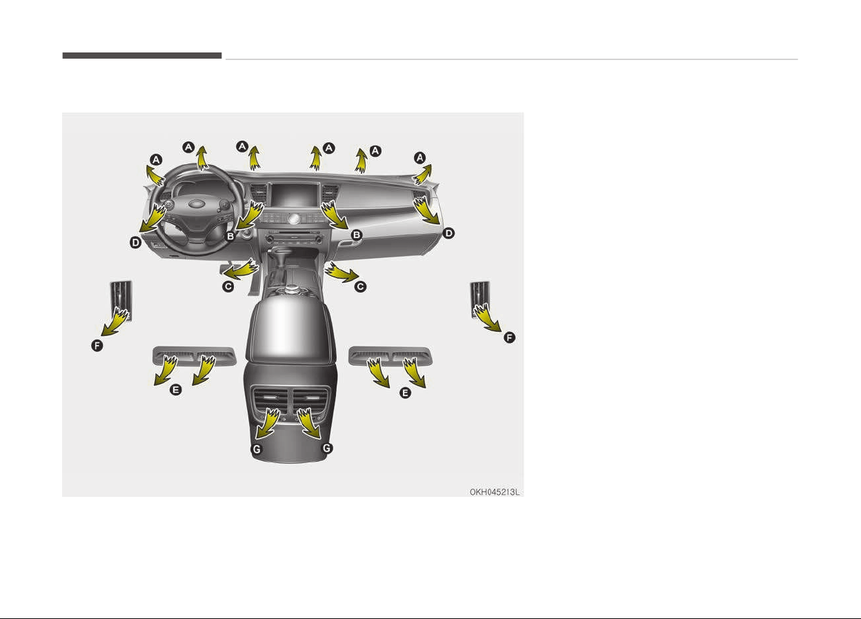
Manual heating and air conditioning
❈ Rear outlet v
ents (F)
• The air flow of the Rear outlet vents
is controlled by the front climate con‐
trol system and delivered through
the inside air duct of the front doors.
If the door is open or not closed com‐
pletely, the air flow of the Rear out‐
let vent is not delivered properly.
Make sure the front doors are closed
completely.
• The air flow of the Rear outlet vents
may be weaker than the instrument
panel vents for the long air duct in
the front doors.
Features of your vehicle
4-122
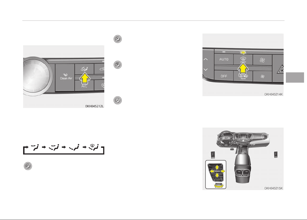
Mode selection
The mode selection button controls the
direction of the air flow through the
ventilation system.
The air flow outlet port is converted as
follows:
Face-Level (B, D, F, G)
Air flow is directed toward the upper
body and face. Additionally, each out‐
let can be controlled to direct the air
discharged from the outlet.
Bi-Level (B, C, D, E, F, G)
Air flow is directed towards the face
and the floor.
Floor & Defrost (A, C, E, G)
Most of the air flow is directed to the
floor and the windshield with a small
amount directed to the side window
defrosters.
Floor-Level (A, C, E, G)
Most of the air flow is directed to the
floor, with a small amount of the air
being directed to the windshield and
side window defrosters.
Defrost-Level (A)
Most of the air flow is directed to the
windshield with a small amount of air
directed to the side window defrosters.
4-123
4
Features of your vehicle
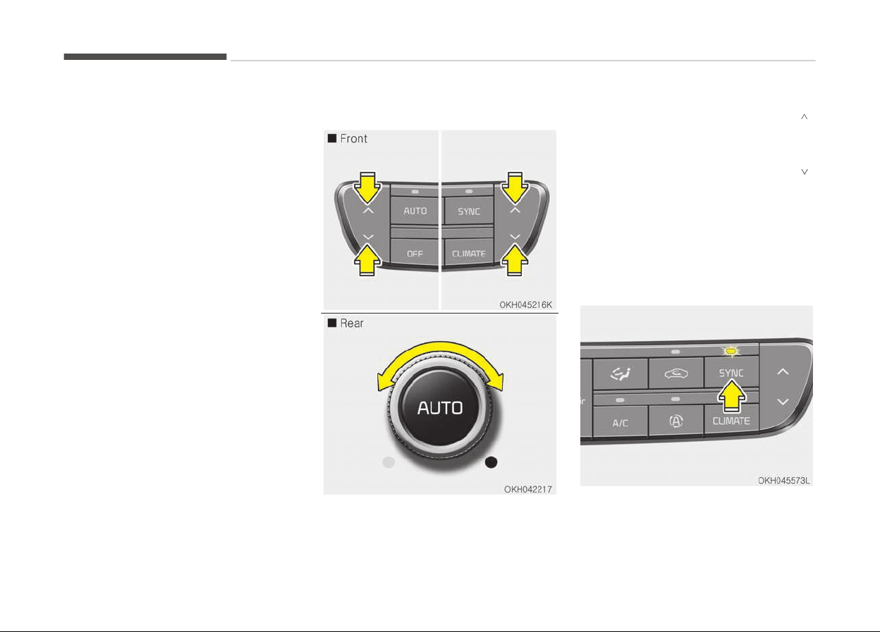
Instrument panel vents
The outlet vents can be opened or
closed separately using the horizontal
thumbwheel. To close the vent, rotate
it left to the maximum position. To
open the vent, rotate it right to the de‐
sired position.
Also, you can adjust the direction of air
delivery from these vents using the
vent control lever as shown.
Temperature control
The temperature will increase to the
maximum (HI) by pushing the up ( )
button (for front) or turn the knob to
the right (for rear).
The temperature will decrease to the
minimum (Lo) by pushing the down (
)
button (for front) or turn the knob to
the left (for rear).
When pushing the button (for front) or
turning the knob (for rear), the tem‐
perature will increase or decrease by
0.5C/1F. When set to the lowest tem‐
perature setting, the air conditioning
will operate continuously.
Features of your vehicle
4-124
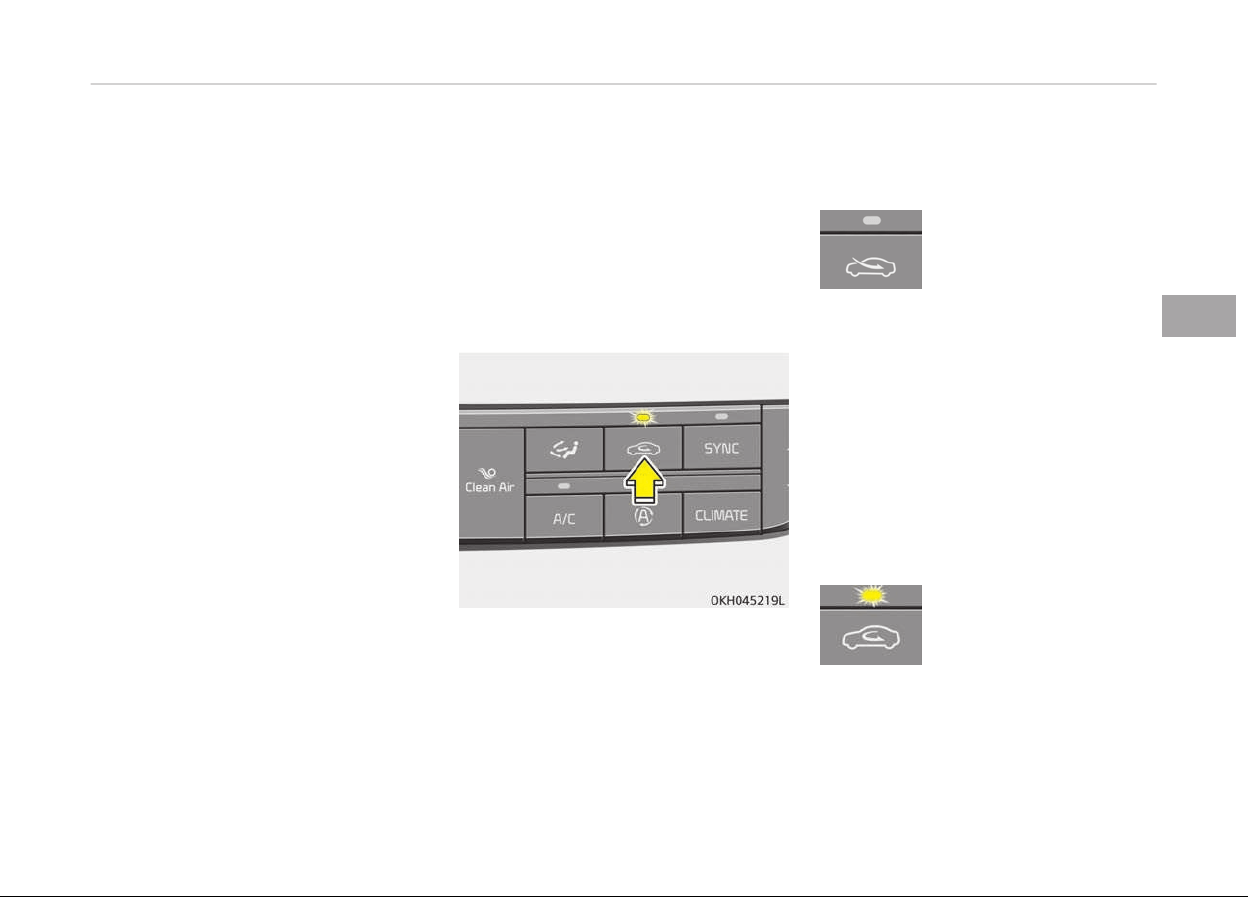
Adjusting the driver and passenger side
temperature equally
• Press the SYNC button to adjust the
driver and passenger side tempera‐
ture equally.
The passenger side temperature will
be set to the same temperature as
the driver side temperature.
• Press the driver side temperature
control button. The driver and pas‐
senger side temperature will be ad‐
justed equally.
Adjusting the driver and passenger side
temperature individually
• Press the SYNC button again to ad‐
just the driver and passenger side
temperature individually. The illumi‐
nation of button turns off.
• Operate the driver side temperature
control button to adjust the driver
side temperature.
• Operate the passenger side tempera‐
ture control button to adjust the pas‐
senger side temperature.
Temperature conversion
If the battery has been discharged or
disconnected, the temperature mode
display will reset to Centigrade.
This is a normal condition. You can
switch
the temperature mode between
Centigrade to Fahrenheit as follows;
While pressing the OFF button, depress
the AUTO button for 3 seconds or
more. The display will change from
Centigrade to Fahrenheit, or from Fah‐
renheit to Centigrade.
Air intake control
This is used to select the outside
(fresh) air position or recirculated air
position.
To change the air intake control posi‐
tion, push the control button.
Recirculated air position
With the recirculated air
position selected, air from
the passenger compart‐
ment will be drawn
through the heating sys‐
tem and heated or cooled
according to the function
selected. When driving at
high speed, the outside air
may come in to circulate
the air inside the vehicle.
To block the air from en‐
tering, press the air intake
control button for about
2 seconds. The outside air
will be blocked from com‐
ing in for 3 minutes.
Outside (fresh) air position
With the outside (fresh)
air position selected, air
enters the vehicle from
outside and is heated or
cooled according to the
function selected.
4-125
4
Features of your vehicle
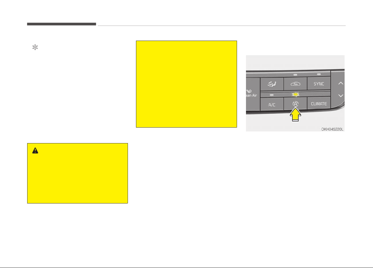
NOTICE
Prolonged operation of the heater in
the recirculated air position (without
air conditioning selected) may cause
fogging of the windshield and side
windows and the air within the pas‐
senger compartment may become
stale.
In addition, prolonged use of the air
conditioning with the recirculated air
position selected will result in exces‐
sively dry air in the passenger com‐
partment.
WARNING
• Continued climate control system
operation in the recirculated air
position may allow humidity to in‐
crease inside the vehicle which
may fog the glass and obscure vis‐
ibility.
(Continued)
(Continued)
• Do not sleep in a vehicle with the
air
conditioning or heating system
on. It may cause serious harm or
death due to a drop in the oxygen
level and/or body temperature.
• Continued climate control system
operation
in the recirculated air
position can cause drowsiness or
sleepiness, and loss of vehicle con‐
trol. Set the air intake control to
the outside (fresh) air position as
much as possible while driving.
Air quality system
The air inflow from outside the vehicle
can be automatically controlled. Press
the button to activate the air quality
control system.
When using AQS mode, AQS(Air Quality
System) automatically senses outdoor
air pollutants and minimizes them from
entering the vehicle, however, unpleas‐
ant or foul odors that might be present
may still be noticeable within the vehi‐
cle.
Exhaust gas cutoff mode :
Air enters the vehicle from the outside.
Features of your vehicle
4-126
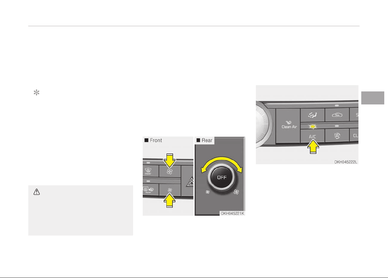
If exhaust gas enters the vehicle from
the outside, the exhaust gas cutoff
mode is automatically converted from
the outside air position to the recircula‐
ted air position to prevent exhaust gas
from entering the vehicle.
NOTICE
It should be noted that prolonged
operation of the heating system in
recirculation mode will give rise to
misting of the windshield and side
windows and the air within the pas‐
senger compartment will become
stale. In addition, prolonged use of
the air conditioning with the recircu‐
lation mode selected may result in
the air within the passenger com‐
partment becoming excessively dry.
CAUTION
If the windows fog up with the Re‐
circulation or A.Q.S mode selected,
set the air intake control to the
fresh air position or A.Q.S control to
OFF.
Sunroof inside air recirculation (if
equipped)
If the sunroof opens while the heater
or Air Conditioning system operates,
the outside (fresh) air will be selected
automatically for ventilating the car.
Then, if you select the recirculated air
position, the outside (fresh) air will be
selected automatically after 3 minutes.
If you close the sunroof, the intake
mode will be changed to the previous
selected mode.
Fan speed control
The fan speed can be set to the desired
speed by pushing the fan speed control
button.
The higher the fan speed is, the more
air is delivered.
Pressing the OFF button turns off the
fan.
Air conditioning
Push the A/C button to turn the air
conditioning system on (indicator light
will illuminate).
Push the button again to turn the air
conditioning system off.
4-127
4
Features of your vehicle
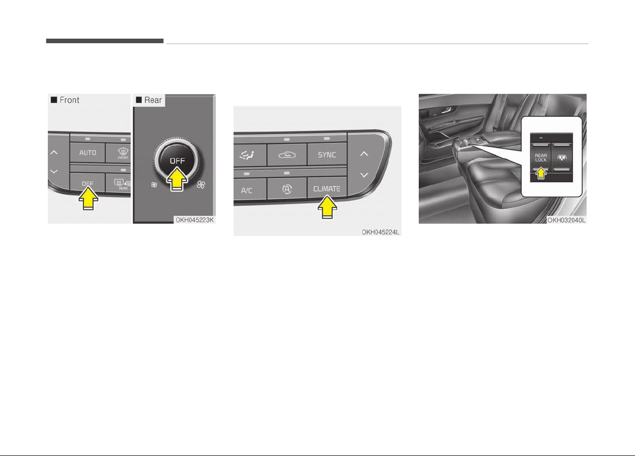
OFF mode
• Press the front OFF button to turn
off the air climate control system.
However, you can still operate the
mode and air intake buttons as long
as the Engine Start/Stop Button is in
the ON position.
• Press the rear OFF button to turn off
the air coming out of the rear console
vent.
Climate information screen
selection button
To change the screen into the climate
information screen, push the button.
Rear control lock
You can activate or deactivate the rear
seat control, rear audio control and cli‐
mate control by using the REAR LOCK
button on the rear armrest or System
Settings in the AVN (Audio, Video, and
Navigation).
Detailed information for the System
Settings is described in a separately
supplied manual.
If the rear control button has deactiva‐
ted through AVN, you can reactivate
the rear control button only through
AVN.
Features of your vehicle
4-128

System operation
Ventilation
1. Set the mode to the position.
2. Set the air intake control to the
outside (fresh) air position.
3. Set the temperature control to the
desired position.
4. Set the fan speed control to the
desired speed.
Heating
1. Set the mode to the position.
2. Set the air intake control to the
outside (fresh) air position.
3. Set the temperature control to the
desired position.
4. Set the fan speed control to the
desired speed.
5. If dehumidified heating is desired,
turn the air conditioning system (if
equipped) on.
• If the windshield fogs up, set the
mode to the
or press the front
defrost button ( ).
Operation tips
• To keep dust or unpleasant fumes
from entering the car through the
ventilation system, temporarily set
the air intake control to the recircula‐
ted air position. Be sure to return the
control to the fresh air position when
the irritation has passed to keep
fresh air in the vehicle. This will help
keep the driver alert and comforta‐
ble.
• Air for the heating/cooling system is
drawn in through the grilles just
ahead of the windshield. Care should
be taken that these are not blocked
by leaves, snow, ice or other obstruc‐
tions.
• To prevent interior fog on the wind‐
shield, set the air intake control to
the fresh air position and fan speed
to the desired position, turn on the
air conditioning system, and adjust
the temperature control to desired
temperature.
Air conditioning
Kia Air Conditioning Systems are filled
with environmentally friendly refriger‐
ant.
1. Start the engine. Press the air con‐
ditioning button.
2. Set the mode to the
position.
3. Set the air intake control to the
outside air or recirculated air posi‐
tion.
4. Adjust the fan speed control and
temperature control to maintain
maximum comfort.
NOTICE
• When using the air conditioning
system, monitor the temperature
gauge closely while driving up hills
or in heavy traffic when outside
temperatures are high. Air condi‐
tioning system operation may
cause engine overheating. Contin‐
ue to use the blower fan but turn
the air conditioning system off if
the temperature gauge indicates
engine overheating.
(Continued)
4-129
4
Features of your vehicle
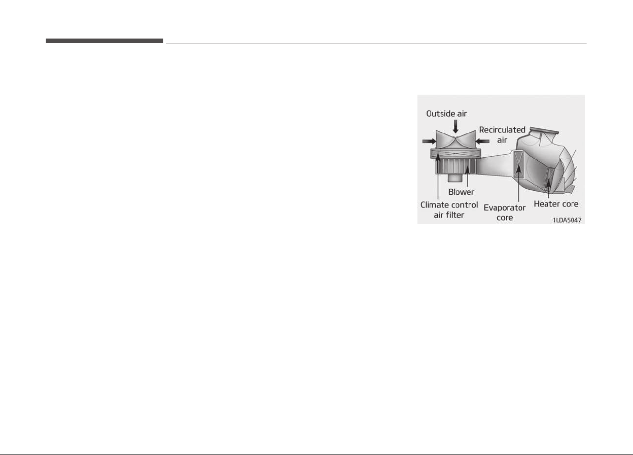
(Continued)
• When
opening the windows in hu‐
mid weather air conditioning may
create water droplets inside the
vehicle. Since excessive water
droplets may cause damage to
electrical equipment, air condition‐
ing should only be run with the
windows closed.
Air conditioning system operation tips
• If the vehicle has been parked in di‐
rect sunlight during hot weather,
open the windows for a short time to
let the hot air inside the vehicle es‐
cape.
• To help reduce moisture inside of the
windows on rainy or humid days, de‐
crease the humidity inside the vehicle
by operating the air conditioning sys‐
tem.
• During air conditioning system opera‐
tion, you may occasionally notice a
slight change in engine speed as the
air conditioning compressor cycles.
This is a normal system operation
characteristic.
• Use
the air conditioning system every
month only for a few minutes to en‐
sure maximum system performance.
• When using the air conditioning sys‐
tem, you may notice clear water
dripping (or even puddling) on the
ground under the passenger side of
the vehicle. This is a normal system
operation characteristic.
• Operating the air conditioning system
in the recirculated air position pro‐
vides maximum cooling, however,
continual operation in this mode may
cause the air inside the vehicle to be‐
come stale.
• During cooling operation, you may oc‐
casionally notice a misty air flow be‐
cause of rapid cooling and humid air
intake. This is a normal system oper‐
ation characteristics.
Climate control air filter
The climate control air filter installed
behind the glove box filters the dust or
other pollutants that come into the ve‐
hicle from the outside through the
heating and air conditioning system. If
dust or other pollutants accumulate in
the filter over a period of time, the air
flow from the air vents may decrease,
resulting in moisture accumulation on
the inside of the windshield even when
the outside (fresh) air position is selec‐
ted.
If this happens, have the climate con‐
trol air filter replaced by a professional
workshop. Kia recommends to visit an
authorized Kia dealer/service partner.
Features of your vehicle
4-130
NOTICE
• Replace the filter according to the
Maintenance Schedule.
If the car is being driven in severe
conditions such as dusty, rough
roads, more frequent climate con‐
trol air filter inspections and
changes are required.
• When the air flow rate suddenly
decreases, have the system
checked by a professional work‐
shop. Kia recommends to visit an
authorized Kia dealer/service part‐
ner.
Checking the amount of air
c
onditioner refrigerant and
compressor lubricant
When the amount of refrigerant is low,
the performance of the air conditioning
is reduced. Overfilling also has a bad in‐
fluence on the air conditioning system.
Therefore, if abnormal operation is
found, have the system inspected by a
professional workshop.
Kia recommends to visit an authorized
Kia dealer/service partner.
WARNING
n
Vehicles equipped with R-134a
Because the refrigerant is
at very high pressure, the
air conditioning system
should only be serviced
by trained and certified
technicians.
It is important that the correct type
and amount of oil and refrigerant is
used.
Otherwise, it may cause damage to
the vehicle and personal injury.
4-131
4
Features of your vehicle
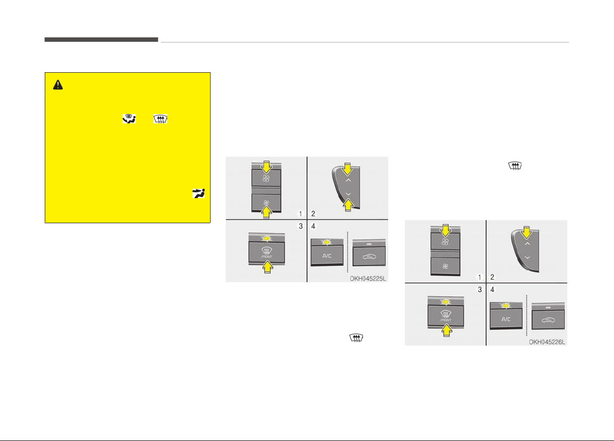
WINDSHIELD DEFROSTING AND DEFOGGING
WARNING
n
Windshield heating
Do
not use the
or position
during cooling operation in extreme‐
ly humid weather. The difference be‐
tween the temperature of the out‐
side air and that of the windshield
could cause the outer surface of the
windshield to fog up, causing loss of
visibility. In this case, set the mode
selection knob or button to the
position and fan speed control knob
or button to the lower speed.
• For maximum defrosting, set the
temperature control to the extreme
right/hot position and the fan speed
control to the highest speed.
• If warm air to the floor is desired
while defrosting or defogging, set the
mode to the floor-defrost position.
• Before driving, clear all snow and ice
from the windshield, rear window,
outside rear view mirrors, and all side
windows.
• Clear all snow and ice from the hood
and air inlet in the cowl grille to im‐
prove heater and defroster efficiency
and to reduce the probability of fog‐
ging up inside of the windshield.
To defog inside windshield
1. Set the fan speed to the desired
position.
2. Select desired temperature.
3. Press the defrost button ( ).
4. The air conditioning will be turned
on according to the detected ambi‐
ent temperature and outside
(fresh) air position will be selected
automatically.
If the air conditioning and outside
(fresh) air position are not selected au‐
tomatically, adjust the corresponding
button manually. If the
position is
selected, lower fan speed is adjusted to
a higher fan speed.
To defrost outside windshield
1. Set the fan speed to the highest
position.
Features of your vehicle
4-132
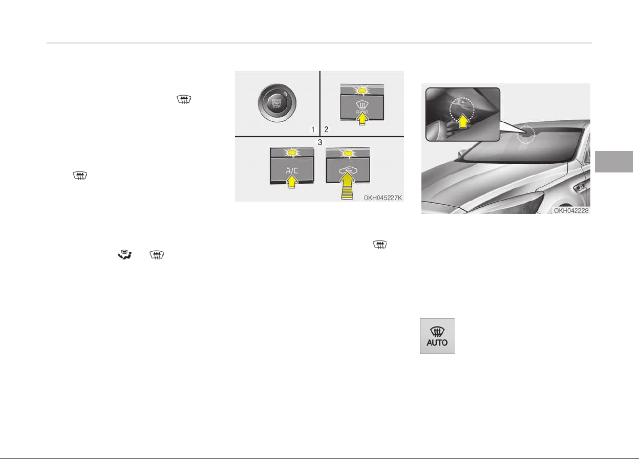
2. Set the temperature to the ex‐
treme hot (HI) position.
3. Press the defrost button (
).
4. The air conditioning will be turned
on according to the detected ambi‐
ent temperature and outside
(fresh) air position will be selected
automatically.
If the
position is selected, lower fan
speed is adjusted to a higher fan speed.
Defogging logic
To reduce the probability of fogging up
the
inside of the windshield, the air in‐
take or air conditioning are controlled
automatically according to certain con‐
ditions such as
or position. To
cancel
or return the defogging logic, do
the following.
1. Turn the Engine Start/Stop button
to the ON position.
2. Press the defroster button (
).
3. While pressing the air conditioning
button (A/C), press the air intake
control button at least 5 times
within 3 seconds.
The indicator on the air intake button
blinks 3 times with 0.5 seconds of in‐
terval. It indicates that the defogging
logic is canceled or returned to the pro‐
grammed status.
If the battery has been discharged or
disconnected, it resets to the defog
logic status.
Auto defogging system
Auto defogging reduces the probability
of fogging up the inside of the wind‐
shield by automatically sensing the
moisture of inside the windshield.
The auto defogging system operates
when the heater or air conditioning is
on.
This indicator illuminates
when the auto defogging sys‐
tem senses the moisture of
inside the windshield and op‐
erates.
4-133
4
Features of your vehicle
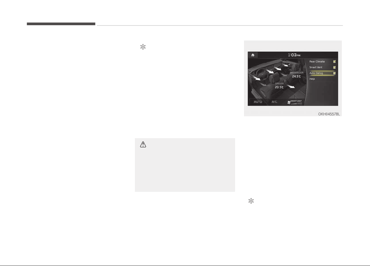
If more moisture is in the vehicle, the
higher steps operate as follow. For ex‐
ample if auto defogging does not defog
inside the windshield at step 2 Outside
air position, it tries to defog again at
step 1 Blowing air toward the wind‐
shield.
Step 1: Operating the air conditioning
Step 2: Outside air position
Step 3: Blowing air toward the wind‐
shield
Step 4: Increasing air flow toward the
windshield
To cancel or reset the Auto Defogging
System
Press the front windshield defroster
button for 3 seconds when the Engine
Start/Stop button is in the ON position.
When the Auto Defogging System is
canceled, Front defroster button will
blink 6 times.
When the Auto Defogging System is re‐
set, Front defroster button will blink 3
times without a signal.
NOTICE
• If the A/C off is manually selected
while the auto defogging system
is on, the auto defogging indicator
will blink 3 times to give notice
that manual operation is canceled.
• If the air quality system (AQS) is
selected while the auto defogging
system is operating at the step 1
outside air position, the recircula‐
ted air position may operate when
the outside air is polluted.
CAUTION
Do not remove the sensor cover lo‐
cated
on the upper end of the pas‐
senger side windshield glass. Dam‐
age to system parts could occur and
may not be covered by your vehicle
warranty.
Auto defogging system ON/OFF
If your vehicle is equipped with the auto
defogging system, it is automatically
activated when the conditions are met.
However, if you would like to cancel the
auto defogging system, turn off the
Auto defogging function in the AVN cli‐
mate monitor.
If the battery has been disconnected or
discharged, it resets to the auto defog‐
ging status.
NOTICE
If the A/C off is manually selected
while the auto defogging system is
(Continued)
Features of your vehicle
4-134

(Continued)
on, the auto defogging indicator will
blink
3 times to give notice that the
A/C off can not be selected.
CAUTION
Do not remove the sensor cover lo‐
cated
on the upper end of the driver
side windshield glass. Damage to the
system parts could occur and may
not be covered by your vehicle war‐
ranty.
4-135
4
Features of your vehicle
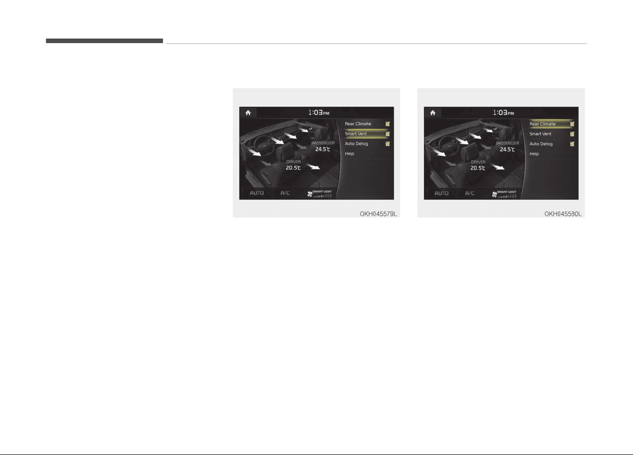
CLIMATE CONTROL ADDITIONAL FEATURES (IF EQUIPPED)
Cluster ionizer
When the Engine Start/Stop button is
in the ON position, the clean air func‐
tion turns on automatically.
Also, the clean air function turns off
automatically, when the Engine Start/
Stop button is in the OFF position.
Smart ventilation
When driving and the heater and air
conditioning system is off, the smart
ventilation system maintains pleasant
indoor aerial environment by controlling
the temperature, humidity and CO2 of
interior.
SMART VENTILATION ON message is
displayed on the AVN climate monitor
for 5 seconds when the smart ventila‐
tion system operates.
Smart ventilation system ON/OFF
If you would like to cancel the smart
ventilation system, turn off the Smart
ventilation in the AVN climate monitor.
Rear climate system ON/OFF
If you would like to cancel the rear cli‐
mate system, turn off the rear climate
in the AVN climate monitor.
Features of your vehicle
4-136
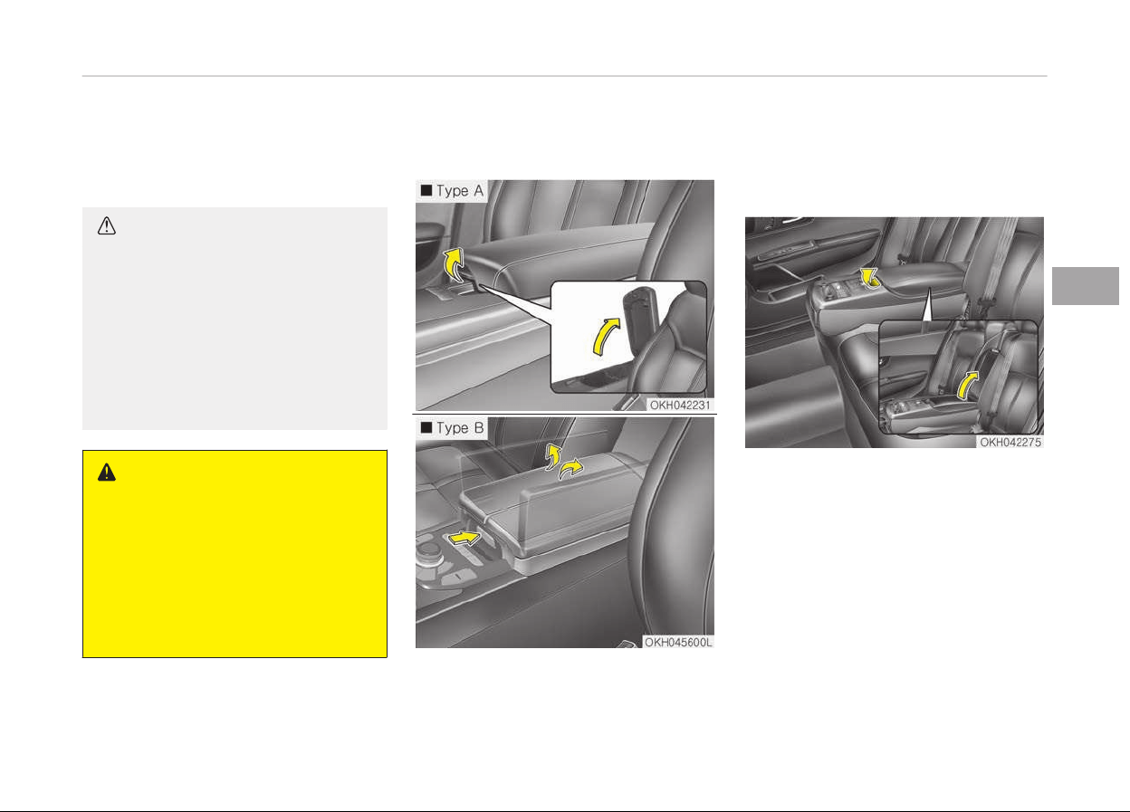
STORAGE COMPARTMENT
These compartments can be used to
store small items required by the driver
or passengers.
CAUTION
• To avoid possible theft, do not
leave valuables in the storage
compartments.
• Always keep the storage compart‐
ment
covers closed while driving.
Do not attempt to place so many
items in the storage compartment
that the storage compartment
cover cannot close securely.
WARNING
n
Flammable materials
Do not store cigarette lighters, pro‐
pane cylinders, or other flammable/
explosive materials in the vehicle.
These items may catch fire and/or
explode if the vehicle is exposed to
hot temperatures for extended peri‐
ods.
Center console storage
• Type A
To open: Pull up the lever.
• Type B
To open: Press the button.
Rear seat storage
To open the rear seat storage, pull up
the lever.
4-137
4
Features of your vehicle
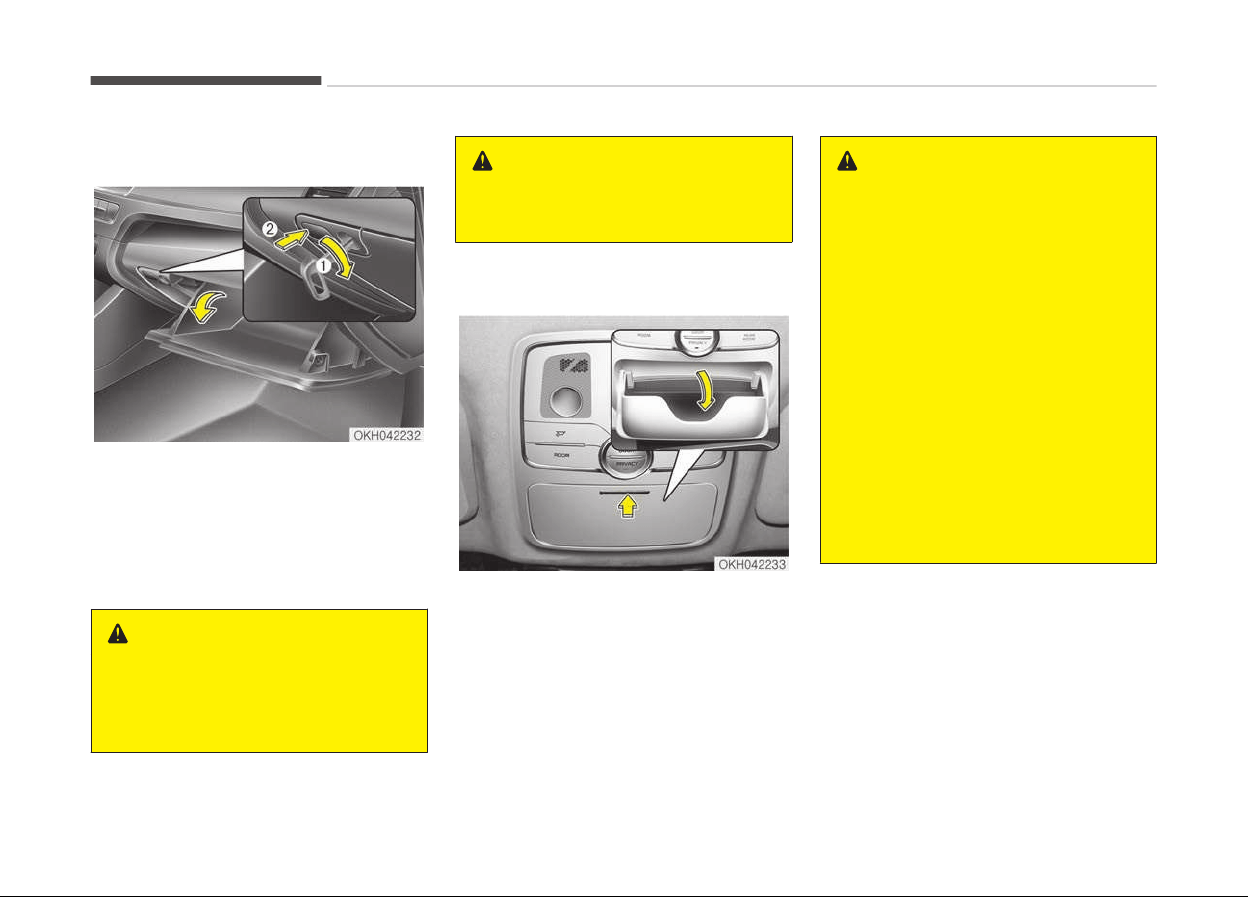
Glove box
The glove box can be locked and un‐
locked with a mechanical key of smart
key.
To open the glove box, press the button
and the glove box will automatically
open. Close the glove box after use.
WARNING
To reduce the risk of injury in an ac‐
cident
or sudden stop, always keep
the glove box door closed while driv‐
ing.
WARNING
Do not keep food in the glove box for
a long time.
Sunglass holder
To open the sunglass holder, press the
cover and the holder will slowly open.
Place your sunglasses with the lenses
facing out.
To close the sunglass holder push it up.
WARNING
• Do not keep objects except sun‐
glasses inside the sunglass holder.
Such objects can be thrown from
the holder in the event of a sudden
stop or an accident, possibly injur‐
ing the passengers in the vehicle.
• Do not open the sunglass holder
while the vehicle is moving. The
rear view mirror of the vehicle can
be blocked by an open sunglass
holder.
• Do not put the glasses forcibly into
a sunglass holder to prevent
breakage or deformation of
glasses. It may cause personal in‐
jury if you try to open it forcibly
when the glasses are jammed in
holder.
Features of your vehicle
4-138
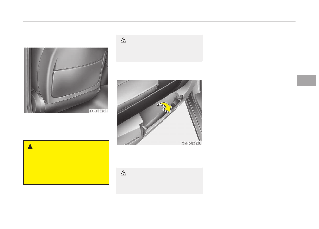
Seatback pocket
The seatback pocket is provided on the
back of the front passenger’s and driv‐
er’s seatbacks.
WARNING
n
Seatback pockets
Do not put heavy or sharp objects in
the seatback pockets. In an accident
they could come loose from the
pocket and injure vehicle occupants.
CAUTION
Be careful not to nip fingers when
using the pocket.
Map pocket
The map pocket is provided on the
doors.
CAUTION
Be careful not to nip fingers when
using the pocket.
4-139
4
Features of your vehicle
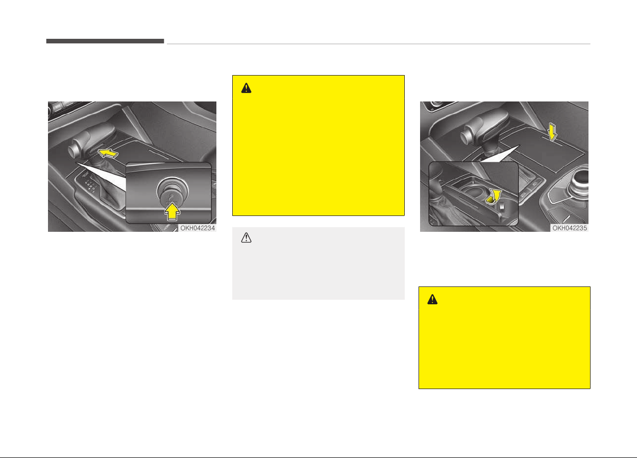
INTERIOR FEATURES
Cigarette lighter (if equipped)
For the cigarette lighter to work, the
Engine Start/Stop button must be in
the ACC position or the ON position.
To open the cover, push the cover for‐
ward. To close the cover, push the cover
forward again.
To use the cigarette lighter, push it all
the way into its socket. When the ele‐
ment has heated, the lighter will pop
out to the ready position.
Kia recommends to use parts for re‐
placement from an authorized Kia deal‐
er/service partner.
WARNING
• Do not hold the lighter in after it is
already heated because it will
overheat.
• If the lighter does not pop out
within 30 seconds, remove it to
prevent overheating.
• Do not insert foreign objects into
the socket of the cigarette lighter.
It may damage the cigarette light‐
er.
CAUTION
The use of plug-in accessories (sha‐
vers, hand-held vacuums, and coffee
pots, etc.) may damage the socket
or cause electrical failure.
Ashtray
To use the ashtray, open the cover.
To clean or empty the ashtray, pull it
out.
WARNING
n
Ashtray use
• Do not use the vehicle’s ashtrays
as waste receptacles.
• Putting lit cigarettes or matches in
an
ashtray with other combustible
materials may cause a fire.
Features of your vehicle
4-140
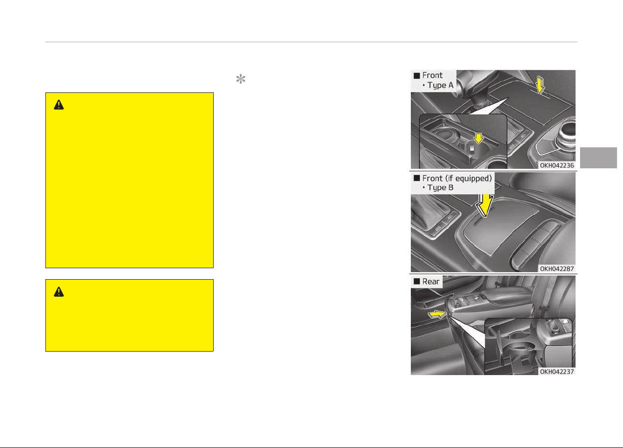
Cup holder
WARNING
n
Hot liquids
• Do not place uncovered cups of hot
liquid in the cup holder while the
vehicle is in motion. If the hot liq‐
uid spills, you could be burned.
Such a burn to the driver could
lead to loss of control of the vehi‐
cle.
• To reduce the risk of personal in‐
jury in the event of sudden stop or
collision, do not place uncovered or
unsecured bottles, glasses, cans,
etc., in the cup holder while the
vehicle is in motion.
WARNING
Keep cans or bottles out of direct
sun light and do not put them in a
vehicle that is heated up. It may ex‐
plode.
NOTICE
• Keep your drinks sealed while driv‐
ing to prevent spilling your drink. If
liquid spills, it may get into the ve‐
hicle's electrical/electronic system
and damage electrical/electronic
parts.
• When cleaning spilled liquids, do
not dry the cup holder at high
temperature. This may damage
the cup holder.
4-141
4
Features of your vehicle
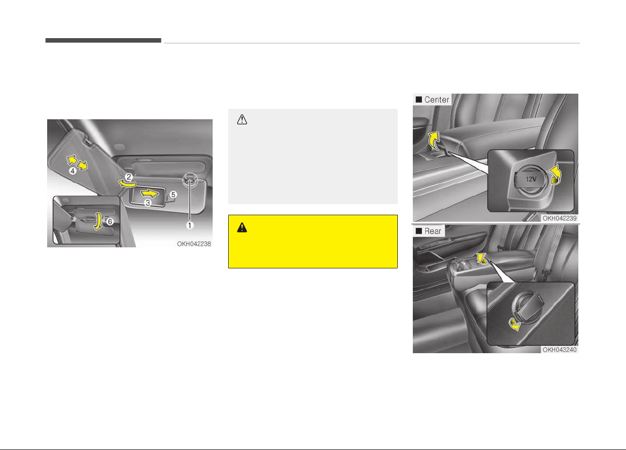
Cups or small beverage cans may be
placed in the cup holders.
Sunvisor
Use the sunvisor to shield direct light
through the front or side windows.
To use the sunvisor, pull it downward.
To use the sunvisor for the side win‐
dow, pull it downward, unsnap it from
the bracket (1) and swing it to the side
(2).
To use the vanity mirror, pull down the
visor and slide the mirror cover (3).
Adjust the sunvisor extension forward
or backward (4).
The ticket holder (5) is provided for
holding a tollgate ticket.
When using the sunvisor for the side
window, you can use the secondary
sunvisor (6) for the front window.
CAUTION
n
Vanity mirror lamp
If you use the vanity mirror lamp,
turn off the lamp before returning
the sunvisor to its original position. It
could result in battery discharge and
possible sunvisor damage.
WARNING
For your safety, do not obstruct
your vision when using the sunvisor.
Power outlet
Features of your vehicle
4-142
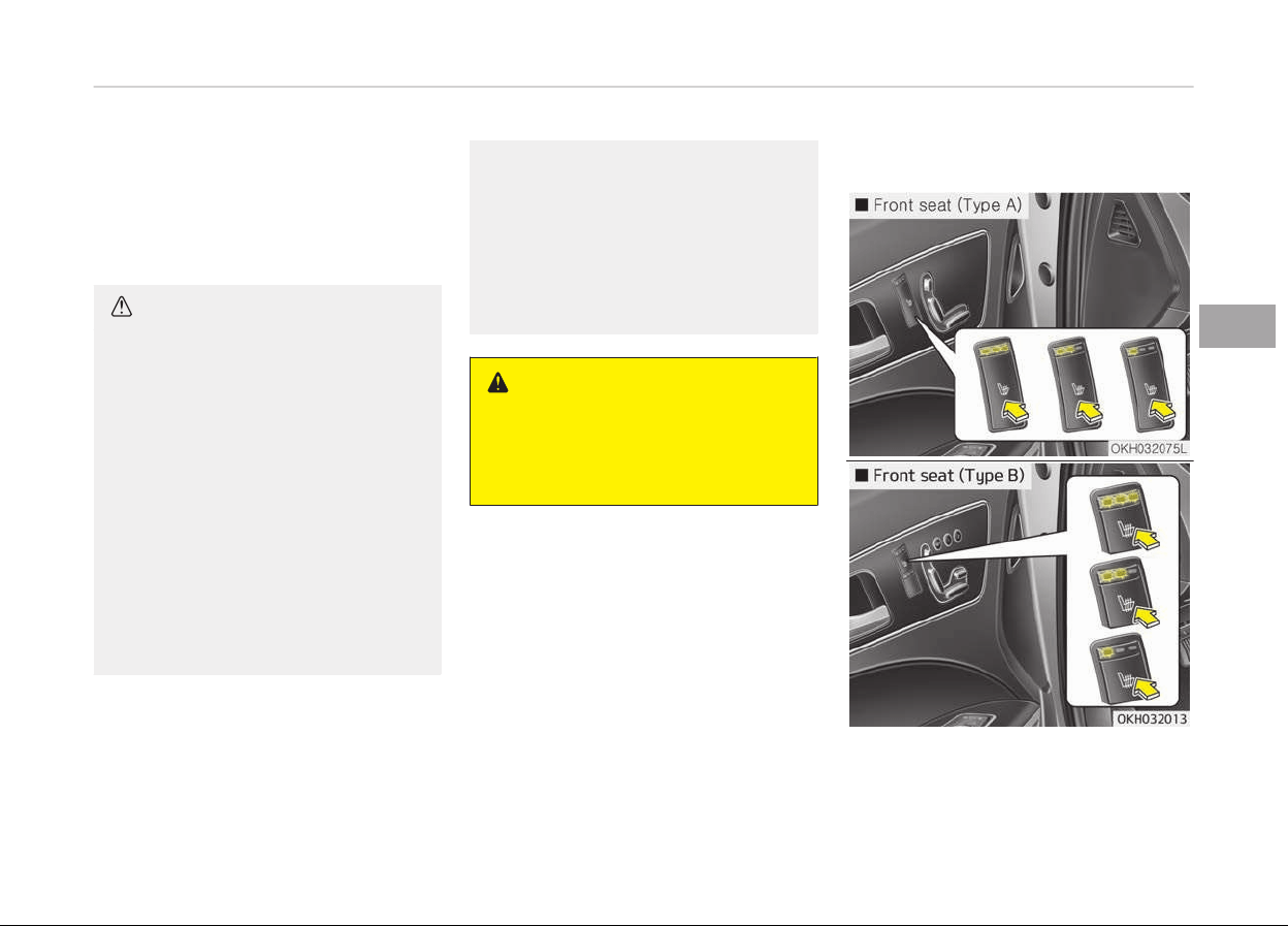
The power outlet is designed to provide
power for mobile telephones or other
devices designed to operate with vehi‐
cle electrical systems. The devices
should draw less than 10 amps with
the engine running.
CAUTION
• Use the power outlet only when
the engine is running and remove
the accessory plug after use. Using
the accessory plug for prolonged
periods of time with the engine off
could cause the battery to dis‐
charge.
• Only use 12V electric accessories
which are less than 10A in electric
capacity.
• Adjust the air-conditioner or heat‐
er to the lowest operating level
when using the power outlet.
• Close the cover when not in use.
(Continued)
(Continued)
• Some electronic devices can cause
electronic
interference when plug‐
ged into a vehicle’s power outlet.
These devices may cause exces‐
sive audio static and malfunctions
in other electronic systems or de‐
vices used in your vehicle.
WARNING
Do not put a finger or a foreign ele‐
ment
(pin, etc.) into a power outlet
and do not touch with a wet hand.
You may get an electric shock.
Seat warmer (if equipped)
4-143
4
Features of your vehicle
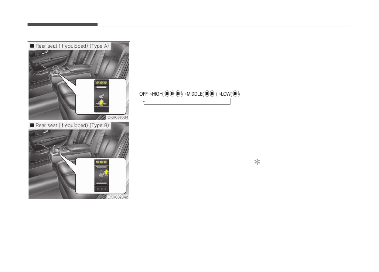
The seat warmer is provided to warm
the seats during cold weather. With the
engine start/stop button in the ON po‐
sition, push the switch to warm the
seat.
During mild weather or under condi‐
tions where the operation of the seat
warmer is not needed, keep the
switches in the "OFF" position.
• Each time you press the switch, the
temperature setting of the seat will
change as follows :
• When pressing the switch for more
than 1.5 seconds with the seat
warmer operating, the seat warmer
will turn OFF.
• The seat warmer defaults to the OFF
position whenever the engine start/
stop button is turned on.
• You can activate or deactivate the
rear seat warmer button by using
the REAR LOCK button on the rear
armrest or System Settings in
AVN(Audio, Video, and Navigation).
Detailed information for System
Settings is described in a separately
supplied manual. If the REAR LOCK
button activated (LED ON), you can
not activate the rear seat warmer
button.
After deactivating (LED OFF) the
REAR LOCK button, you can activate
the rear seat warmer button.
If the REAR LOCK button has activa‐
ted through AVN, you can deactivate
the REAR LOCK button only Through
AVN.
NOTICE
With the seat warmer switch in ON
position, the heating system in the
seat turns off or on automatically
depending on the seat temperature.
Features of your vehicle
4-144
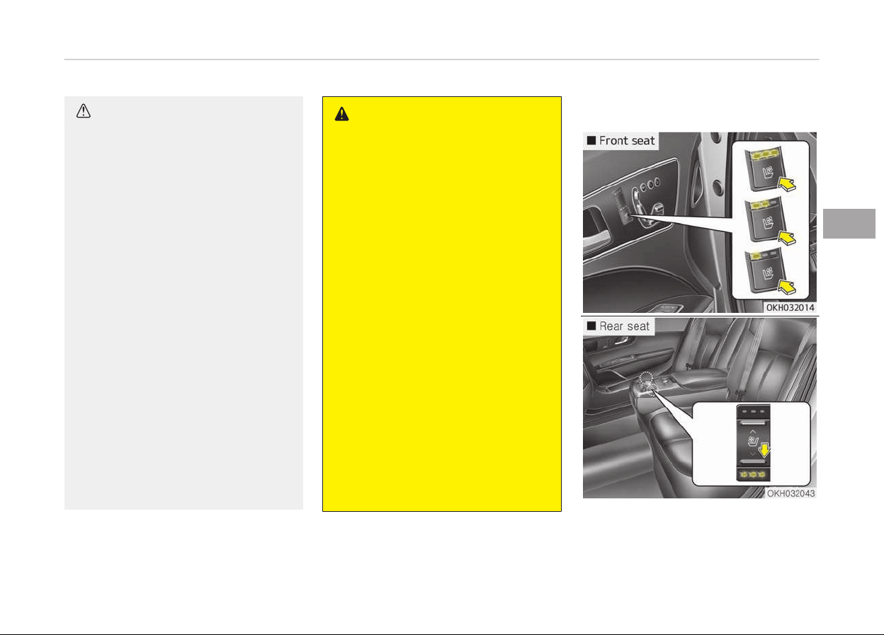
CAUTION
n
Seat damage
• When cleaning the seats, do not
use an organic solvent such as
paint thinner, benzene, alcohol and
gasoline. Doing so may damage
the surface of the heater or seats.
• To prevent overheating the seat
warmer, do not place anything on
the seats that insulates against
heat, such as blankets, cushions or
seat covers on the seats while the
seat warmer is in operation.
• Do not place heavy or sharp ob‐
jects on the seat. Those things
may damage the seat warmer
system.
• Be careful not to spill liquid such as
water or beverages on the seat. If
you spill some liquid, wipe the seat
with a dry towel. Before using the
seat warmer, dry the seat com‐
pletely.
• Do not change the seat cover. It
may
damage the seat warmer or
airventilation system.
WARNING
n
Seat warmer burns
Passengers should use extreme cau‐
tion when using seat warmers due
to the possibility of excess heating
or burns. The occupants must be
able to feel if the seat is becoming
too warm and to turn the seat
warmer off. The seat warmer may
cause burns even at low tempera‐
tures, especially if used for long pe‐
riods of time.
In particular, the driver must exer‐
cise extreme care for the following
types of passengers:
1. Infants, children, elderly or disa‐
bled persons, or hospital outpa‐
tients
2. Persons with sensitive skin or
those that burn easily
3. Fatigued individuals
4. Intoxicated individuals
5. Individuals taking medication
that
can cause drowsiness or
sleepiness (sleeping pills, cold
tablets, etc.)
Air ventilation seat (if equipped)
4-145
4
Features of your vehicle
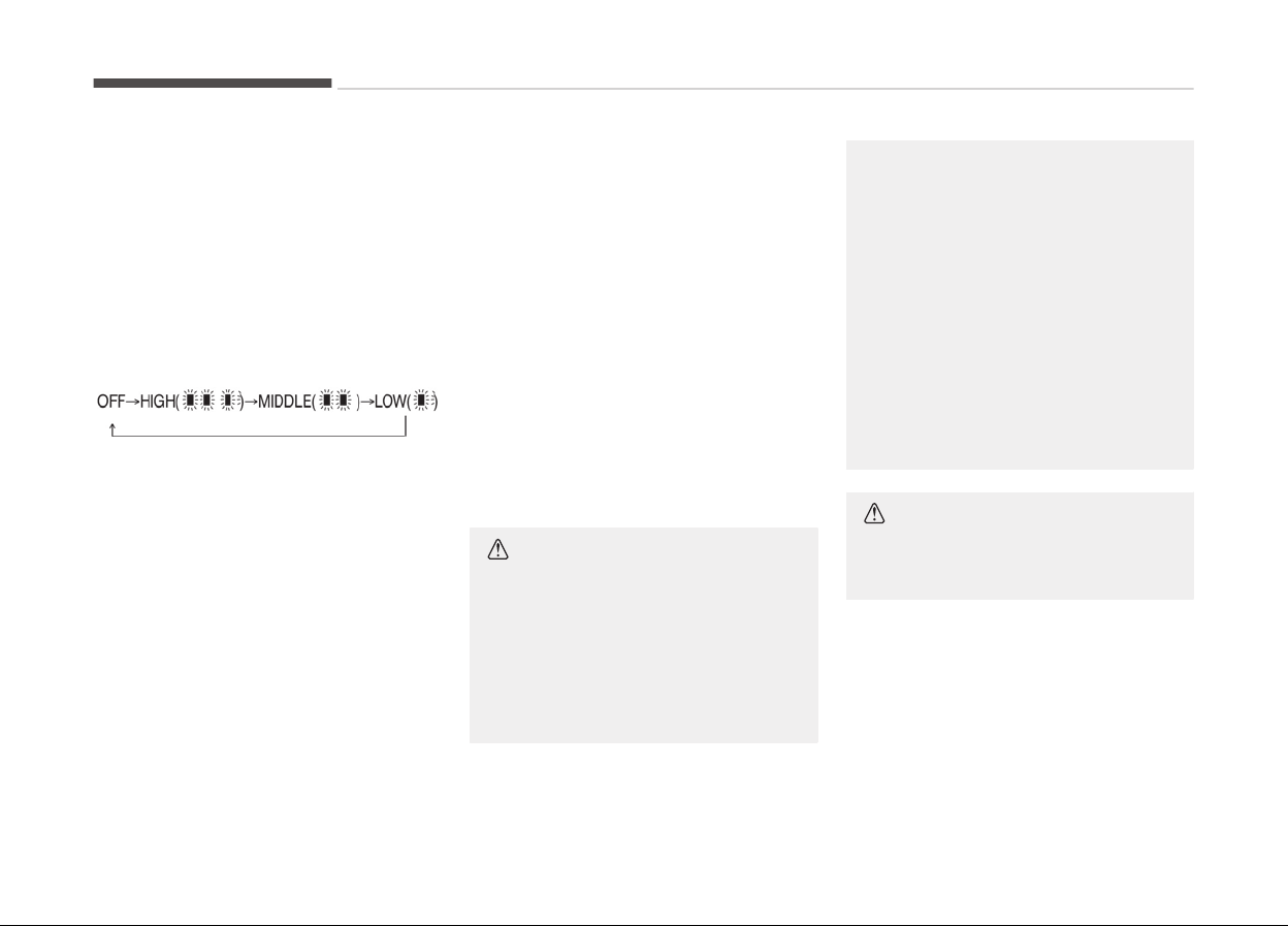
The air ventilation is provided to cool
the seats during hot weather by blow‐
ing air through small vent holes on the
surface of the seats and seatbacks.
While the engine is running, press the
switch to cool the seat.
When the operation of the air ventila‐
tion is not needed, keep the switches in
the OFF position.
• Each time you press the switch, the
airflow will change as follows:
• When pressing the switch for more
than 1.5 seconds with the seat cooler
operating, the seat cooler will turn
OFF.
• When the air ventilation seat is
turned on, the seat may get cooler
after about 5 minutes.
• Because the air ventilation uses the
air in the vehicle, cooling efficiency
depends on the temperature of the
air. In order to improve cooling effi‐
ciency, use the air conditioning sys‐
tem together.
• The air ventilation seat defaults to
the OFF position whenever the En‐
gine Start/Stop button is turned to
the ON position.
• Y
ou can activate or deactivate the
rear air ventilation button by using
the REAR LOCK button on the rear
armrest or System Settings in
AVN(Audio, Video, and Navigation).
Detailed information for System
Settings is described in a separately
supplied manual. If the REAR LOCK
button activated (LED ON), you can
not activate the rear air ventilation
button.
After deactivating (LED OFF) the
REAR LOCK button, you can activate
the rear air ventilation button.
If the REAR LOCK button has activa‐
ted through AVN, you can deactivate
the REAR LOCK button only Through
AVN.
CAUTION
n
Seat damage
• When cleaning the seats, do not
use an organic solvent such as
paint thinner, benzene, alcohol and
gasoline. Doing so may damage
the air ventilation seat.
(Continued)
(Continued)
• Do not place heavy or sharp ob‐
jects
on the seat. Those things
may damage the air ventilation
seat.
• Be careful not to spill liquid such as
water
or beverages on the seat. If
you spill some liquid, wipe the seat
with a dry towel. Before using the
air ventilation seat, dry the seat
completely.
• Do not change the seat cover. It
may damage the seat warmer or
airventilation system.
CAUTION
n
Air intake
(Continued)
Features of your vehicle
4-146
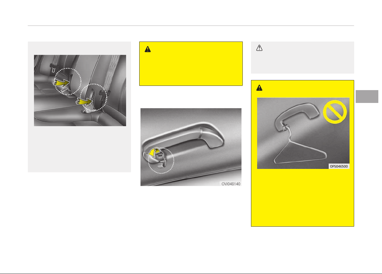
(Continued)
There is an air intake for the rear air
ventilation at the lower part of the
rear center seatback. If the air in‐
take is blocked, efficiency of the rear
air ventilation will be lower. Be care‐
ful not to block the air intake.
Clock
You can set the clock by using the AVN
(Audio or Navigation)
For the details, refer to the AVN man‐
ual.
WARNING
Do not adjust the clock while driving.
You may lose your steering control
and cause an accident that results in
severe personal injury or death.
Clothes hanger (if equipped)
To use the hanger, pull down the upper
portion of hanger.
CAUTION
Do not hang heavy clothes, since
those may damage the hook.
WARNING
Do not hang other objects such as
hangers or hard objects except
clothes. Also, do not put heavy,
sharp or breakable objects in the
clothe pockets. In an accident or
when the curtain air bag is inflated,
it may cause vehicle damage or per‐
sonal injury.
4-147
4
Features of your vehicle
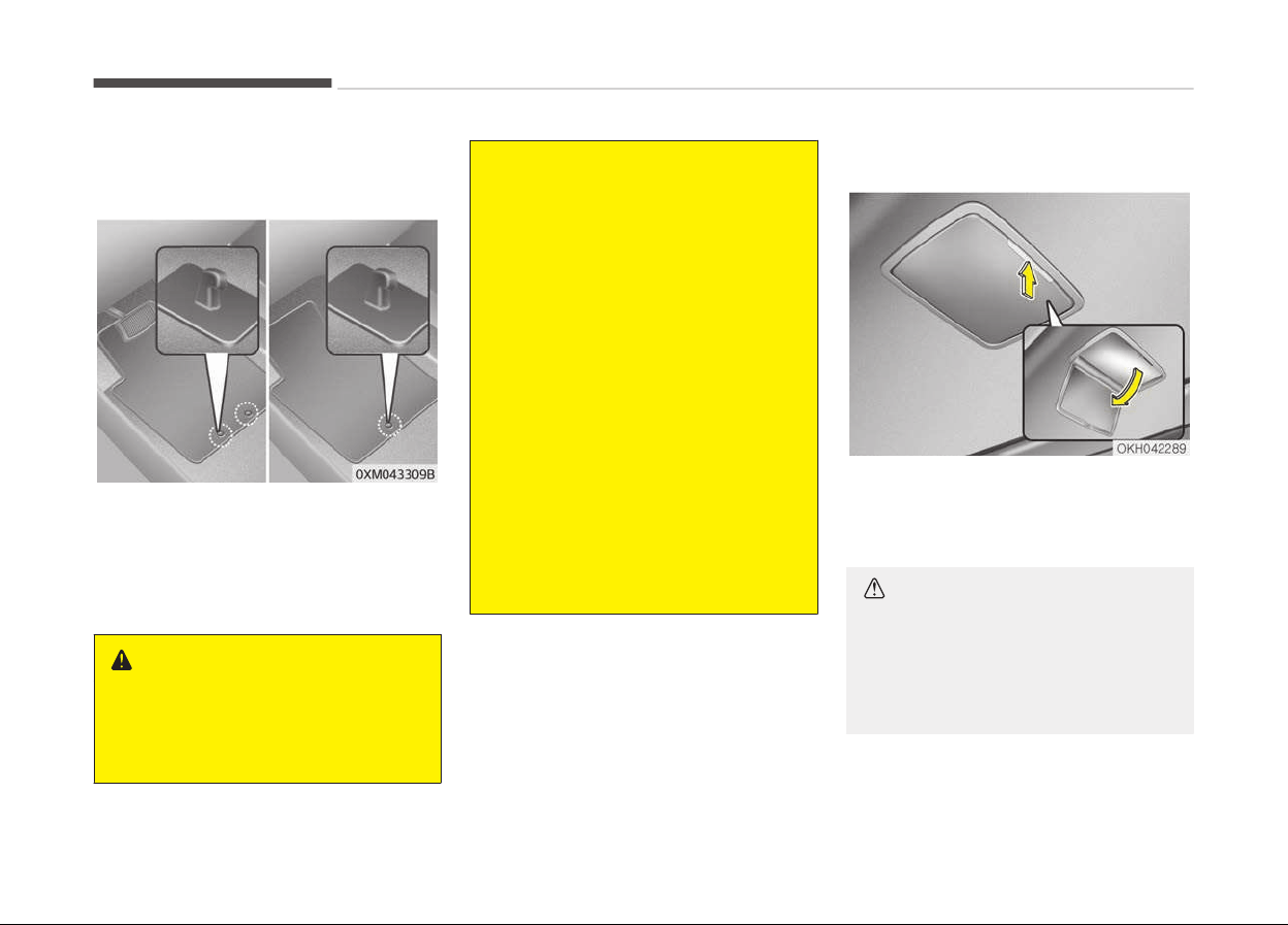
Floor mat anchor(s) (if
equipped)
When using a floor mat on the front
floor carpet, make sure it attaches to
the floor mat anchor(s) in your vehicle.
This keeps the floor mat from sliding
forward.
WARNING
The following must be observed
when
installing ANY floor mat to the
vehicle.
(Continued)
(Continued)
• Ensure that the floor mats are se‐
cur
ely attached to the vehicle's
floor mat anchor(s) before driving
the vehicle.
• Do not use ANY floor mat that
cannot
be firmly attached to the
vehicle's floor mat anchors.
• Do not stack floor mats on top of
one
another (e.g. all-weather rub‐
ber mat on top of a carpeted floor
mat). Only a single floor mat
should be installed in each position.
IMPORTANT - Your vehicle was man‐
ufactured with driver's side floor
mat anchors that are designed to
securely hold the floor mat in place.
To avoid any interference with pedal
operation, we recommend that the
Kia floor mat designed for use in
your vehicle be installed.
Rear mirror (if equipped)
To use the rear mirror, press the cover
and it will slowly open and the mirror
lamp will turn on.
CAUTION
Close the mirror cover securely. If
the mirror cover is not closed, the
lamp will stay on and could result in
battery discharge and possible mir‐
ror damage.
Features of your vehicle
4-148
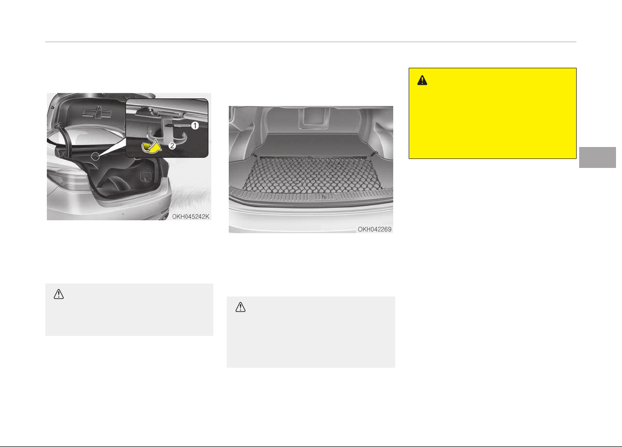
Bag hanger (if equipped)
Pull the strap (1) to hang a bag on the
hook (2).
When you are not use the hook, fold
the hook.
CAUTION
Do not hang heavy things, since
those may damage the hook.
Luggage net (holder) (if
equipped)
To keep items from shifting in the car‐
go area, you can use the holders loca‐
ted in the cargo area to attach the lug‐
gage net.
CAUTION
To prevent damage to the goods or
the vehicle, care should be taken
when carrying fragile or bulky ob‐
jects in the luggage compartment.
WARNING
To avoid eye injury, DO NOT over‐
stretch the luggage net. ALWAYS
keep your face and body out of the
luggage net’s recoil path. DO NOT
use the luggage net when the strap
has visible signs of wear or damage.
4-149
4
Features of your vehicle
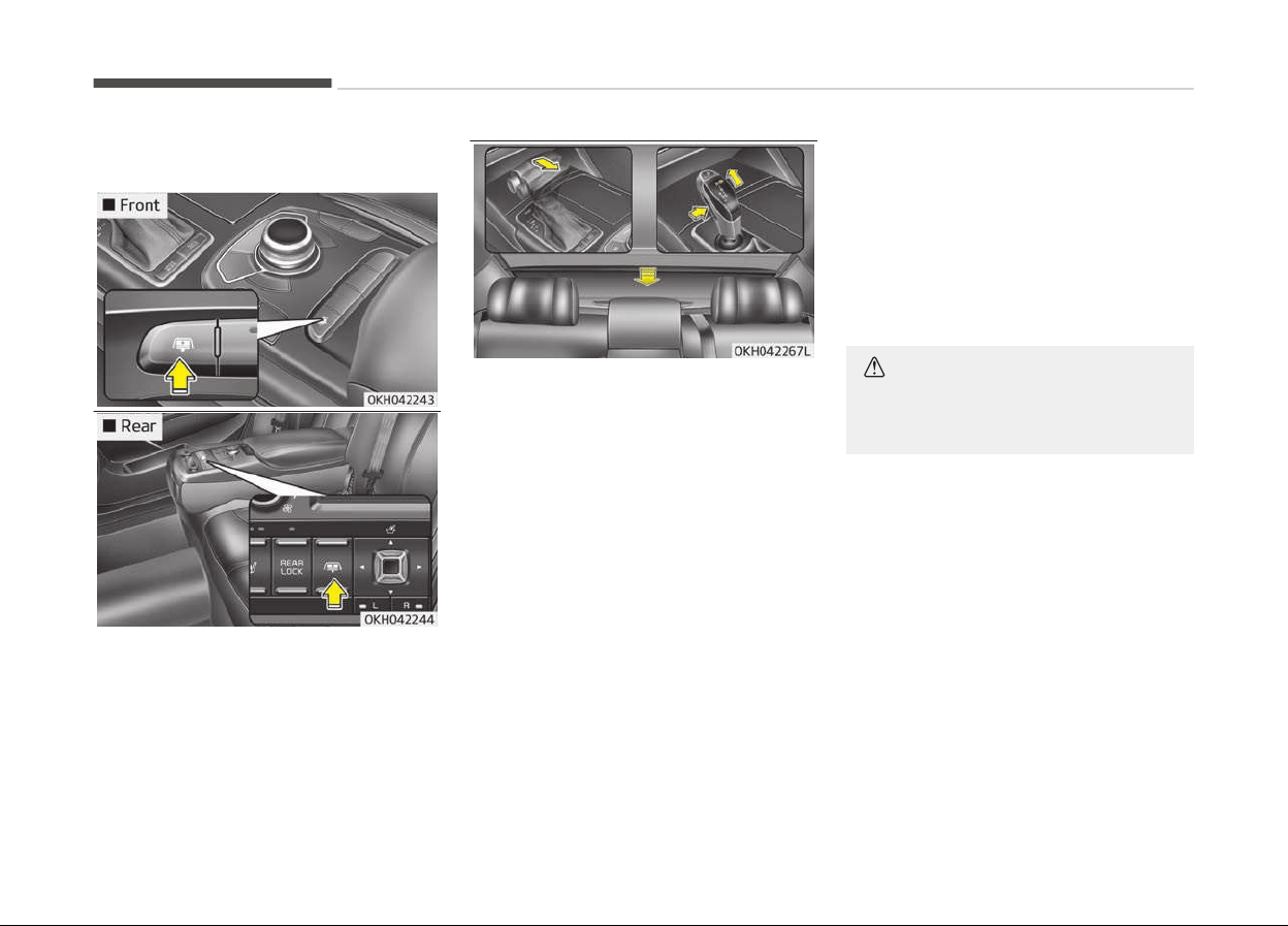
Rear curtain (if equipped)
To fold the rear curtain, press the but‐
ton. To unfold the rear curtain, press
the button again.
The rear curtain will fold automatically
when you shift the shift lever into R
(Reverse) and unfold automatically
when you shift the shift lever from R
(Reverse) into P (Park).
After the rear curtain is folded by shift‐
ing the shift lever into R (Reverse) and
drive more than 20 km/h with the shift
lever in D (Drive), the rear curtain will
unfold automatically.
You can activate or deactivate the rear
curtain button on the rear armrest by
using the REAR LOCK button on the
rear armrest or System Settings in
AVN(Audio, Video, and Navigation).
Detailed information for System Set‐
tings is described in a separately sup‐
plied manual.
If the REAR LOCK button activated (LED
ON), you can not activate the rear
curtain button.
After deactivating (LED OFF) the
REAR LOCK button, you can activate
the rear curtain button.
If the REAR LOCK button has activated
through AVN, you can deactivate the
REAR LOCK button only Through AVN.
CAUTION
Do not pull or fold the rear curtain
by hand. It could cause motor failure.
Features of your vehicle
4-150
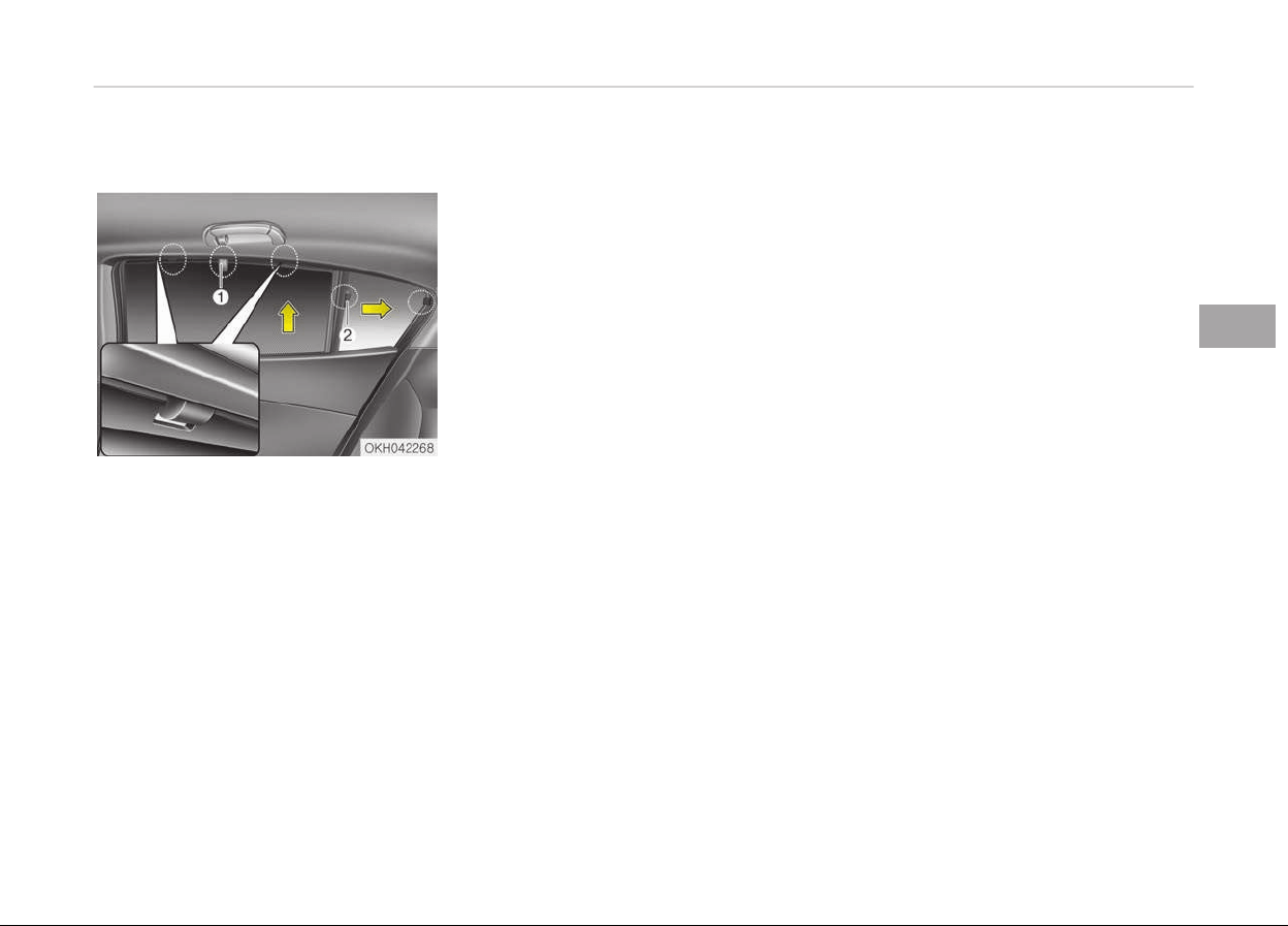
Side curtain (if equipped)
To use the side curtain:
1. Lift the curtain by the hook (1).
2. Hang the curtain on both sides of
the hook.
3. Pull the curtain backward by the
hook (2).
4. Hang the curtain on the hook.
4-151
4
Features of your vehicle
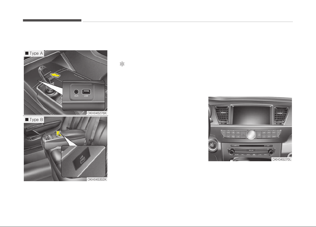
MULTIMEDIA SYSTEM
AUX and USB port
You can use an AUX port to connect au‐
dio devices and an USB port to plug in
an USB and in an iPod
®
.
NOTICE
When using a portable audio device
connected to the power outlet, noise
may occur during playback. If this
happens, use the power source of
the portable audio device.
❈
iPod
®
is a trademark of Apple Inc.
USB charger
The USB charger is designed to re‐
charge batteries of small size electrical
devices using a USB cable. The electrical
devices can be recharged when the en‐
gine start/stop button is in acc/on/start
position.
The battery charging state may be
monitored on the electrical device.
Disconnect the USB cable from the USB
port after use.
• Some devices are not supported for
fast charging but will be charged with
normal speed.
• Use the USB charger when the engine
is running to prevent battery dis‐
charge.
• Only devices that fits the USB port
can be used.
• Battery chargers cannot be charged.
Audio / Video / Navigation
system (A
VN)
Detailed information for the AVN sys‐
tem is described in a separately sup‐
plied manual.
Features of your vehicle
4-152
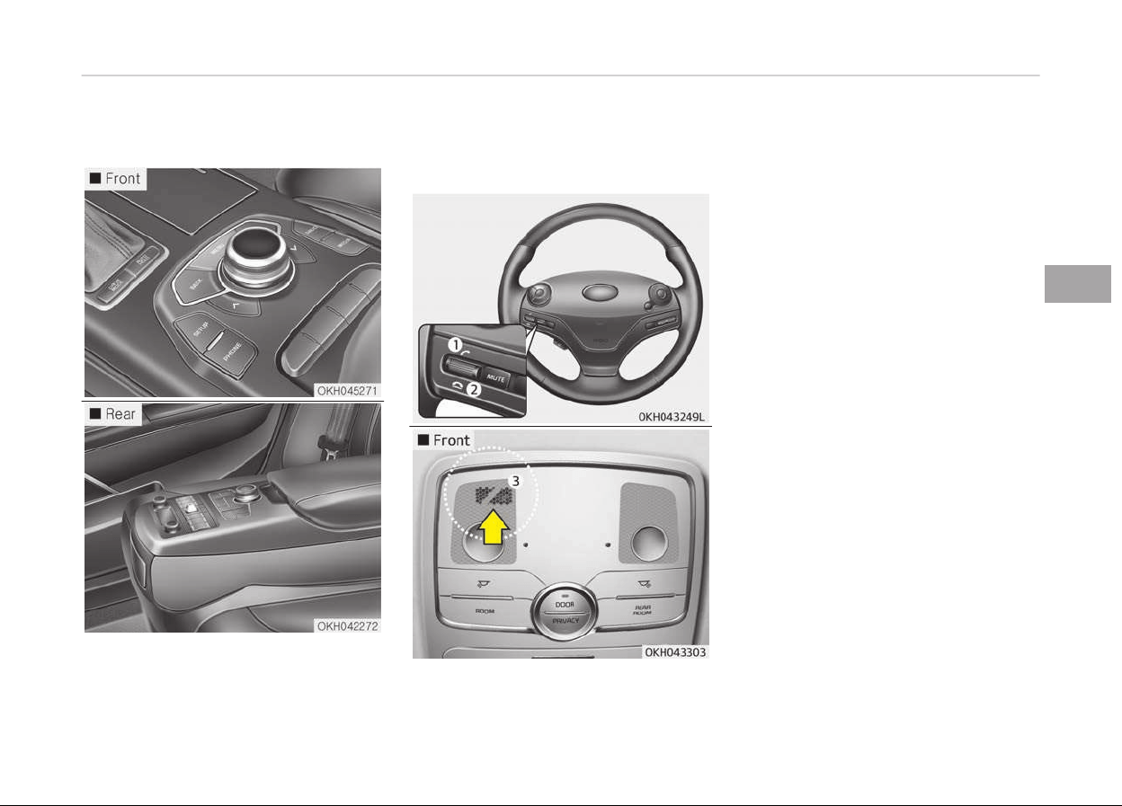
Driver information system (DIS)
Detailed information for the DIS sys‐
tem is described in a separately sup‐
plied manual.
Bluetooth
®
wireless technology
hands-free
You can use the phone wirelessly by
using the
Bluetooth
®
Wireless Technol‐
ogy.
1. Call / Answer lever
2. Call end lever
3. Microphone
Detailed information for the
Bluetooth
®
Wireless Technology hands-free is de‐
scribed in the manual supplied sepa‐
rately.
4-153
4
Features of your vehicle
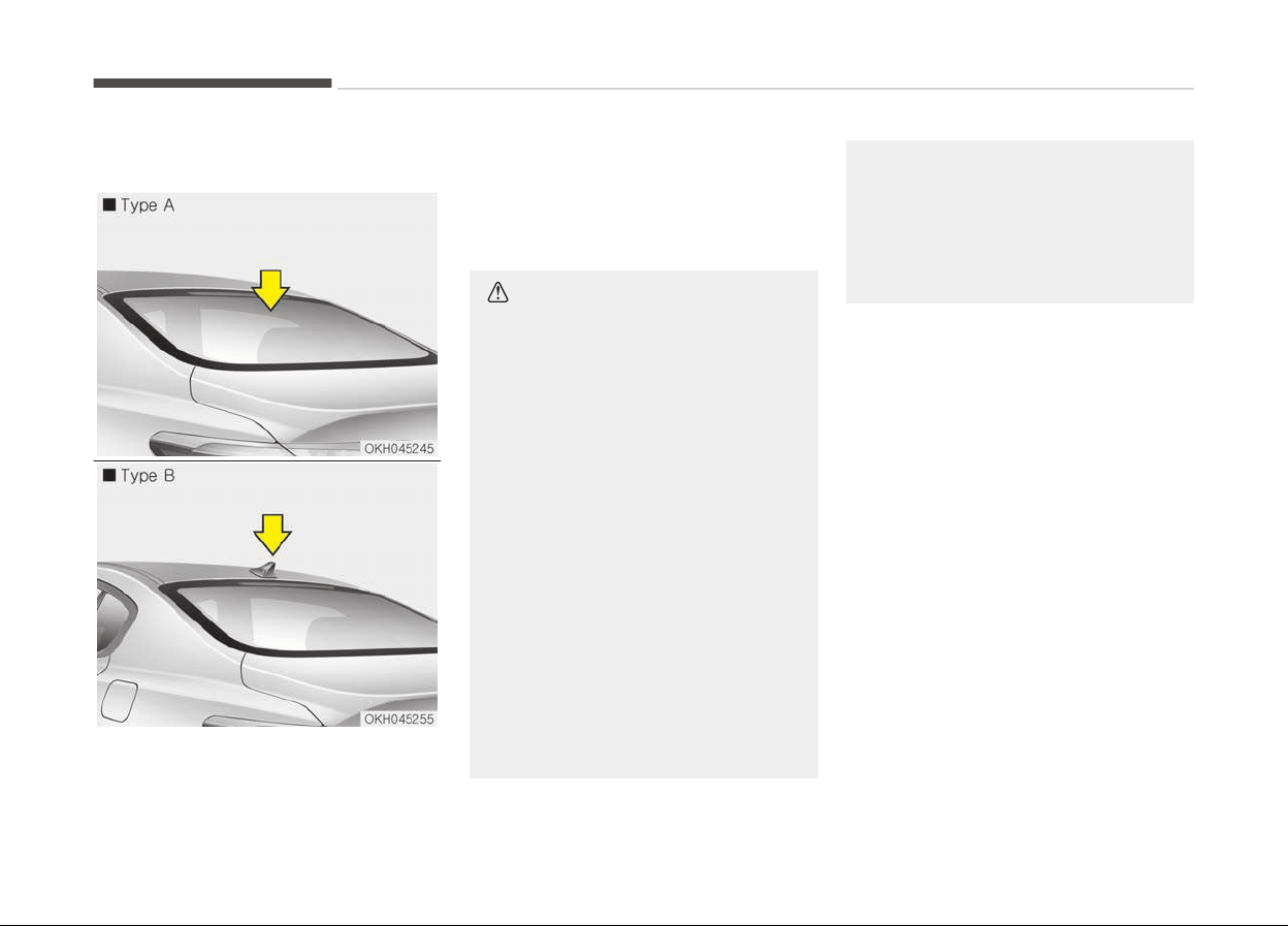
Antenna
Glass antenna (Type A)
Your vehicle uses a glass antenna to re‐
ceive both AM and FM signals.
Shark fin antenna (Type B) (if
equipped)
The shark fin antenna will receive the
transmit data. (for example : GPS and
DAB signal)
CAUTION
• Do not clean the inside of the rear
window glass with a cleaner or use
a scraper to remove foreign de‐
posits as this may cause damage
to the antenna elements.
• Avoid adding metallic coatings such
as Ni, Cd, and so on. These can dis‐
turb receiving AM and FM broad‐
cast signals.
• To prevent damage to the rear
glass antenna, never use sharp in‐
struments or window cleaner con‐
taining abrasives to clean the win‐
dow. Clean the inside surface of
the rear glass window with a piece
of soft cloth.
• When putting a sticker on the in‐
side surface of the rear window,
be careful not to damage to the
rear glass antenna.
(Continued)
(Continued)
• Do not put sharp instruments
nearby the r
ear glass antenna.
• Tinted rear window may affect
the
proper functioning of the an‐
tenna.
Features of your vehicle
4-154
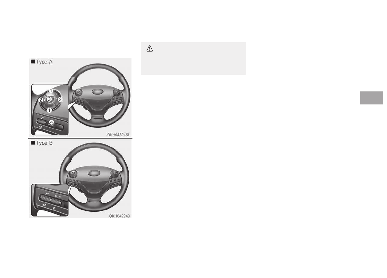
Steering wheel audio control
The steering wheel audio control but‐
ton is installed to promote safe driving.
CAUTION
Do not operate audio remote control
buttons simultaneously.
VOLUME (VOL + / VOL -) (1)
• Press the up button (VOL+) to in‐
crease volume.
• Press the down button (VOL-) to de‐
crease volume.
SEEK/PRESET ( < / > ) (2)
If the SEEK/PRESET button is pressed
for 0.8 second or more, it will work as
follows in each mode.
RADIO mode
It will function as the AUTO SEEK select
button. It will SEEK until you release the
button.
DISC mode
It will function as the FF/ REW button.
If the SEEK/PRESET button is pressed
for less than 0.8 second, it will work as
follows in each mode.
RADIO mode
It will function as the PRESET STATION
select buttons.
DISC mode
It will function as the TRACK UP/DOWN
button.
MODE (3)
Press the MODE button to select Radio,
DISC, USB or AUX.
When the AV is ON and the MODE but‐
ton is press for more than 0.8 second,
the AV will turn off.
MUTE (4)
Type A
• Press the MUTE button cancel the
sound.
• Press the MUTE button again to acti‐
vate the sound.
Type B
• Move the MUTE lever up to cancel the
sound.
• Move the MUTE lever up again to ac‐
tivate the sound.
Detailed information is described in a
separately supplied manual.
4-155
4
Features of your vehicle


Engine exhaust can be dangerous!........................................ 5-03
Before driving............................................................................ 5-04
Before entering vehicle........................................................ 5-04
Necessary inspections..........................................................5-04
Before starting......................................................................5-04
Engine start/stop button.........................................................5-06
Illuminated engine start/stop button................................5-06
Engine start/stop button position..................................... 5-06
Starting the engine...............................................................5-08
Automatic transmission (shift by cable)...............................5-10
Automatic transmission operation.................................... 5-10
Good driving practices..........................................................5-14
Automatic transmission (shift by wire)................................ 5-16
Automatic transmission operation.................................... 5-16
Good driving practices..........................................................5-23
Brake system.............................................................................5-25
Power brakes.........................................................................5-25
Electric parking brake (EPB)................................................5-27
Emergency braking...............................................................5-31
AUTO HOLD ........................................................................... 5-32
Anti-lock brake system (ABS).............................................5-35
Electronic stability control (ESC) ....................................... 5-37
Hill-start assist control (HAC).............................................5-41
Good braking practices.........................................................5-41
Advanced vehicle safety management (AVSM) .................. 5-43
Brake operating.....................................................................5-43
Seat belt operating ..............................................................5-43
User setting mode................................................................ 5-44
Malfunction indicator............................................................5-44
Autonomous emergency braking (AEB) ...............................5-46
AEB Operation....................................................................... 5-46
Brake operation.....................................................................5-47
To cancel the AEB................................................................. 5-47
Malfunction indicator............................................................5-48
Drive mode integrated control system................................. 5-50
Drive mode / Snow mode.....................................................5-50
ECO mode driving.................................................................. 5-51
Conditions that limit active ECO mode.............................. 5-51
DRIVE MODE Indicator Screen.............................................5-55
Electronic controlled suspension (ECS) ................................ 5-58
To control the vehicle height...............................................5-58
ECS (Electronic Controlled Suspension) malfunc‐
tion warning message..........................................................5-59
Towing your vehicle.............................................................. 5-60
Cruise control system ............................................................. 5-61
Cruise control switch............................................................5-62
To set cruise control speed................................................. 5-62
To increase cruise control set speed................................. 5-63
To decrease the cruising speed.......................................... 5-63
To temporarily accelerate with the cruise control on.... 5-63
To cancel cruise control........................................................5-63
To resume cruising speed at more than approxi‐
mately ()................................................................................. 5-64
To turn cruise control off.................................................... 5-64
Advanced smart cruise control system ............................... 5-66
Speed setting.........................................................................5-67
Vehicle to vehicle distance setting..................................... 5-70
To convert to cruise control mode..................................... 5-75
Limitations of the system...................................................5-76
Blind Spot Detection System (BSD)....................................... 5-80
Driving your vehicle
5

BSD (Blind Spot Detection) / LCA (Lane Change
Assist)..................................................................................... 5-81
RCTA (Rear cross traffic alert)........................................... 5-83
Non-operating condition......................................................5-85
Economical operation............................................................... 5-87
Special driving conditions.........................................................5-89
Hazardous driving conditions..............................................5-89
Rocking the vehicle............................................................... 5-89
Smooth cornering................................................................. 5-90
Driving at night......................................................................5-90
Driving in the rain..................................................................5-91
Driving in flooded areas....................................................... 5-91
Driving off-road.................................................................... 5-92
Highway driving.....................................................................5-92
Winter driving............................................................................ 5-93
Snowy or icy conditions....................................................... 5-93
Use high quality ethylene glycol coolant...........................5-95
Check battery and cables.................................................... 5-95
Change to "winter weight" oil if necessary...................... 5-95
Check spark plugs and ignition system.............................5-95
To keep locks from freezing................................................5-96
Use approved window washer anti-freeze in system.... 5-96
Don't let your parking brake freeze...................................5-96
Don't let ice and snow accumulate underneath.............. 5-96
Carry emergency equipment.............................................. 5-96
Vehicle weight............................................................................5-97
Base curb weight.................................................................. 5-97
Vehicle curb weight...............................................................5-97
Cargo weight..........................................................................5-97
GAW (Gross axle weight)..................................................... 5-97
GAWR (Gross axle weight rating).......................................5-97
GVW (Gross vehicle weight)................................................ 5-97
GVWR (Gross vehicle weight rating)..................................5-97
Overloading............................................................................ 5-97
5

ENGINE EXHAUST CAN BE DANGEROUS!
WARNING
n
ENGINE EXHAUST CAN BE D
ANGEROUS!
Engine exhaust fumes can be extremely dangerous. If, at any time, you smell exhaust fumes inside the vehicle, open the
windows immediately.
• Do not inhale exhaust fumes.
Exhaust fumes contain carbon monoxide, a colorless, odorless gas that can cause unconsciousness and death by asphyx‐
iation.
• Be sure the exhaust system does not leak.
The exhaust system should be checked whenever the vehicle is raised to change the oil or for any other purpose. If you
hear a change in the sound of the exhaust or if you drive over something that strikes the underneath side of the vehicle,
have the system checked by a professional workshop. Kia recommends to visit an authorized Kia dealer/service partner.
• Do not run the engine in an enclosed area.
Letting the engine idle in your garage, even with the garage door open, is a hazardous practice. Never run the engine in
your garage any longer than it takes to start the engine and back the vehicle out.
• Avoid idling the engine for prolonged periods with people inside the vehicle.
If it is necessary to idle the engine for a prolonged period with people inside the vehicle, be sure to do so only in an open
area with the air intake set at "Fresh" and fan operating at one of the higher speeds so fresh air is drawn into the interi‐
or.
If you must drive with the trunk lid open because you are carrying objects that make this necessary:
1. Close all windows.
2. Open side vents.
3. Set the air intake control at "Fresh", the air flow control at "Floor" or "Face" and the fan at one of the higher speeds.
To assure proper operation of the ventilation system, be sure the ventilation air intakes located just in front of the wind‐
shield are kept clear of snow, ice, leaves or other obstructions.
5-03
5
Driving your vehicle

BEFORE DRIVING
Before entering vehicle
• Be sure that all windows, outside
mirror(s), and outside lights are clean.
• Check the condition of the tires.
• Check under the vehicle for any sign
of leaks.
• Be sure there are no obstacles behind
you if you intend to back up.
Necessary inspections
Fluid levels, such as engine oil, engine
c
oolant, brake fluid, and washer fluid
should be checked on a regular basis,
with the exact interval depending on
the fluid. Further details are provided in
Chapter 8, Maintenance.
WARNING
Driving while distracted can result in
a loss of vehicle control, that may
lead to an accident, severe personal
injury, and death. The driver’s pri‐
mary responsibility is in the safe and
legal operation of a vehicle, and use
of any handheld devices, other
equipment, or vehicle systems which
(Continued)
(Continued)
take the driver’s eyes, attention and
focus away from the safe operation
of a vehicle or which are not permis‐
sible by law should never be used
during operation of the vehicle.
Before starting
• Close and lock all doors.
• Position the seat so that all controls
are easily reached.
• Adjust the inside and outside rear‐
view mirrors.
• Be sure that all lights work.
• Check all gauges.
• Check the operation of warning lights
when the Engine Start/Stop button is
in the ON position.
• Release the parking brake and make
sure the brake warning light goes
out.
For safe operation, be sure you are fa‐
miliar with your vehicle and its equip‐
ment.
WARNING
All passengers must be properly bel‐
ted whenever the vehicle is moving.
Refer to Seat belts on page 3-21
for more information on their proper
use.
WARNING
Always check the surrounding areas
near your vehicle for people, espe‐
cially children, before putting a vehi‐
cle into D (Drive) or R (Reverse).
WARNING
n
Driving under the influence of
alcohol or drugs
Drinking and driving is dangerous.
Drunk driving is the number one con‐
tributor to the highway death toll
each year. Even a small amount of
alcohol will affect your reflexes, per‐
ceptions and judgement.
(Continued)
Driving your vehicle
5-04

(Continued)
Driving while under the influence of
drugs
is as dangerous or more dan‐
gerous than driving drunk.
You are much more likely to have a
serious accident if you drink or take
drugs and drive.
If you are drinking or taking drugs,
don’t drive. Do not ride with a driver
who has been drinking or taking
drugs. Choose a designated driver or
call a cab.
WARNING
• When you intend to park or stop
the
vehicle with the engine on, be
careful not to depress the acceler‐
ator pedal for a long period of
time. It may overheat the engine
or exhaust system and cause fire.
(Continued)
(Continued)
• When you make a sudden stop or
turn
the steering wheel rapidly,
loose objects may drop on the
floor and it could interfere with
the operation of the foot pedals,
possibly causing an accident. Keep
all things in the vehicle safely stor‐
ed.
• If you do not focus on driving, it
may
cause an accident. Be careful
when operating what may disturb
driving such as audio or heater. It
is the responsibility of the driver
to always drive safely.
5-05
5
Driving your vehicle
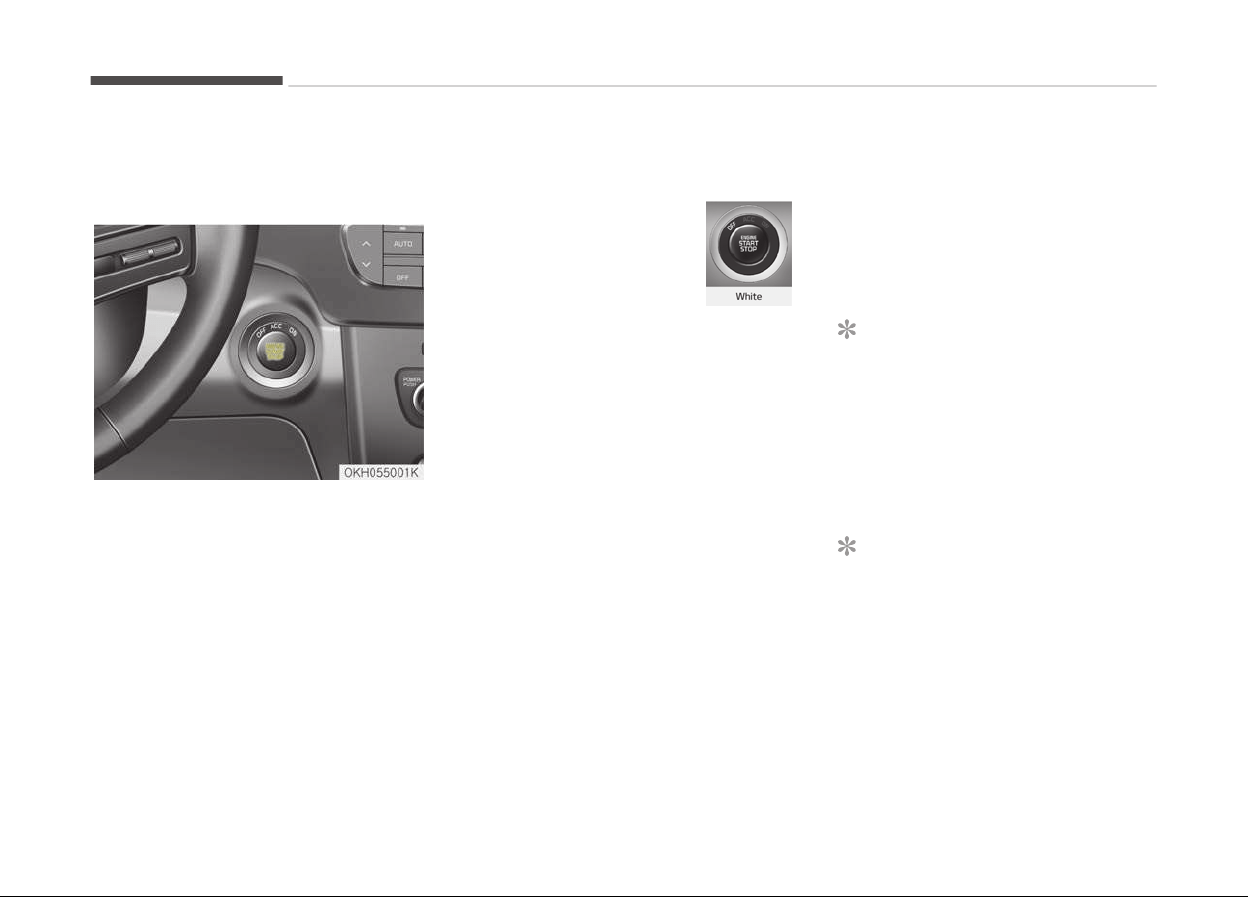
ENGINE START/STOP BUTTON
Illuminated engine start/stop
button
Whenever the front door is opened, the
engine start/stop button will illuminate
for your convenience. The light will go
off after about 30 seconds when the
door is closed. It will also go off imme‐
diately when the theft-alarm system is
armed.
Engine start/stop button
position
OFF
To turn off the engine
(START/RUN position) or ve‐
hicle power (ON position),
press the Engine Start/Stop
button with the shift lever
in the P (Park) position. When you press
the engine start/stop button without
the shift lever in the P (Park) position,
the engine start/stop button will not
change to the OFF position but to the
ACC position.
Vehicles equipped with anti-theft
steering c
olumn lock
The steering wheel locks when the En‐
gine Start/Stop button is in the OFF po‐
sition to protect you against theft.
It locks when the door is opened.
If the steering wheel is not locked prop‐
erly when you open the driver's door,
the warning chime will sound. Try lock‐
ing the steering wheel again. If the
problem is not solved, have the system
checked by a professional workshop.
Kia recommends to visit an authorized
Kia dealer/service partner.
In addition, if the engine start/stop but‐
ton is in the OFF position after the driv‐
er's door is opened, the steering wheel
will not lock and the warning chime will
sound. In such a situation, close the
door. Then the steering wheel will lock
and the warning chime will stop.
NOTICE
If the steering wheel doesn't unlock
properly, the engine start/stop but‐
ton will not work. Press the engine
start/stop button while turning the
steering wheel right and left to re‐
lease the tension.
NOTICE
You are able to turn off the engine
(START/RUN) or vehicle power (ON),
only when the vehicle is not in mo‐
tion.
Driving your vehicle
5-06
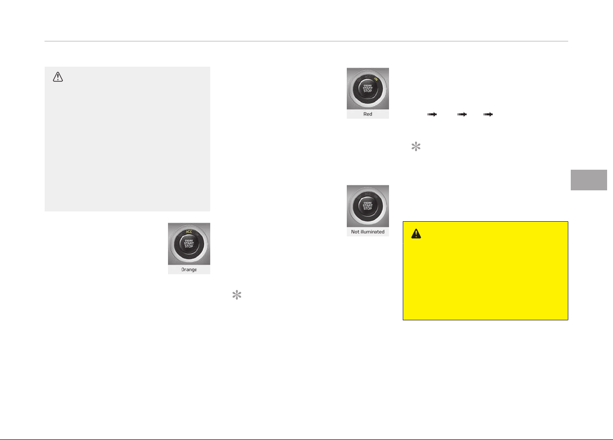
CAUTION
In an emergency situation while the
vehicle is in motion, you are able to
turn the engine off and to the ACC
position by pressing the engine
start/stop button for more than
2 seconds or 3 times successively
within 3 seconds. If the vehicle is still
moving, you can restart the engine
without depressing the brake pedal
by pressing the Engine Start/Stop
button with the shift lever in the N
(Neutral) position.
ACC (accessory)
Press the Engine Start/Stop
button while it is in the OFF
position without depressing
the brake pedal.
The steering wheel unlocks and electri‐
cal accessories are operational.
If the Engine Start/Stop button is in the
ACC position for more than 1 hour, the
button is turned off automatically to
prevent battery discharge.
ON
Press the Engine Start/Stop
button while it is in the ACC
position without depressing
the brake pedal.
The warning lights can be checked be‐
fore the engine is started. Do not leave
the Engine Start/Stop button in the ON
position for a long time. The battery
may discharge, because the engine is
not running.
START/RUN
To start the engine, depress
the brake pedal and press
the Engine Start/Stop but‐
ton with the shift lever in
the P (Park) or the N (Neu‐
tral) position. For your safety, start the
engine with the shift lever in the P
(Park) position.
NOTICE
If you press the engine start/stop
button without depressing the brake
pedal for automatic transaxle vehi‐
cles, the engine will not start and
(Continued)
(Continued)
the Engine Start/Stop button
changes as follow:
OFF ACC ON OFF or ACC
NOTICE
If you leave the Engine Start/Stop
button in the ACC or ON position for
a long time, the battery will dis‐
charge.
WARNING
• Never press the engine start/stop
button
while the vehicle is in mo‐
tion. This would result in loss of di‐
rectional control and braking func‐
tion, which could cause an acci‐
dent.
(Continued)
5-07
5
Driving your vehicle

(Continued)
• The anti-theft steering column
lock
is not a substitute for the
parking brake. Before leaving the
driver's seat, always make sure
the shift lever is engaged in P
(Park), set the parking brake fully
and shut the engine off. Unexpec‐
ted and sudden vehicle movement
may occur if these precautions are
not taken.
• Never reach for the engine start/
stop
button or any other controls
through the steering wheel while
the vehicle is in motion. The pres‐
ence of your hand or arm in the
area could cause loss of vehicle
control, an accident and serious
bodily injury or death.
• Do not place any movable objects
around the driver's seat as they
may move while driving, interfere
with the driver and lead to an acci‐
dent.
Starting the engine
WARNING
• Always wear appropriate shoes
when operating your vehicle. Un‐
suitable shoes (high heels, ski
boots,etc.) may interfere with
your ability to use the brake, ac‐
celerator pedal.
• Do not start the vehicle with the
accelerator pedal depressed. The
vehicle can move and lead to an
accident.
• Wait until the engine rpm is nor‐
mal. The vehicle may suddenly
move if the brake pedal is released
when the rpm is high.
1. Carry the smart key or leave it in‐
side the vehicle.
2. Make sure the parking brake is
firmly applied.
3. Place the transaxle shift lever in P
(Park). Depress the brake pedal
fully.
You can also start the engine when
the shift lever is in the N (Neutral)
position.
4. Press the engine start/stop button.
It should be started without de‐
pressing the accelerator.
5. Do not wait for the engine to warm
up whilst the vehicle remains sta‐
tionary.
Start driving at moderate engine
speeds. (Steep accelerating and de‐
celerating should be avoided.)
• Even if the smart key is in the vehicle,
if it is far away from you, the engine
may not start.
• When the engine start/stop button is
in the ACC position or above, if any
door is opened, the system checks
for the smart key. If the smart key is
not in the vehicle, the
indica‐
tor and a message Key not in the
vehicle will appear on the instrument
cluster and LCD display. And if all
doors are closed, the chime will sound
for 5 seconds. The indicator or warn‐
ing will turn off while the vehicle is
moving. Always have the smart key
with you.
Driving your vehicle
5-08
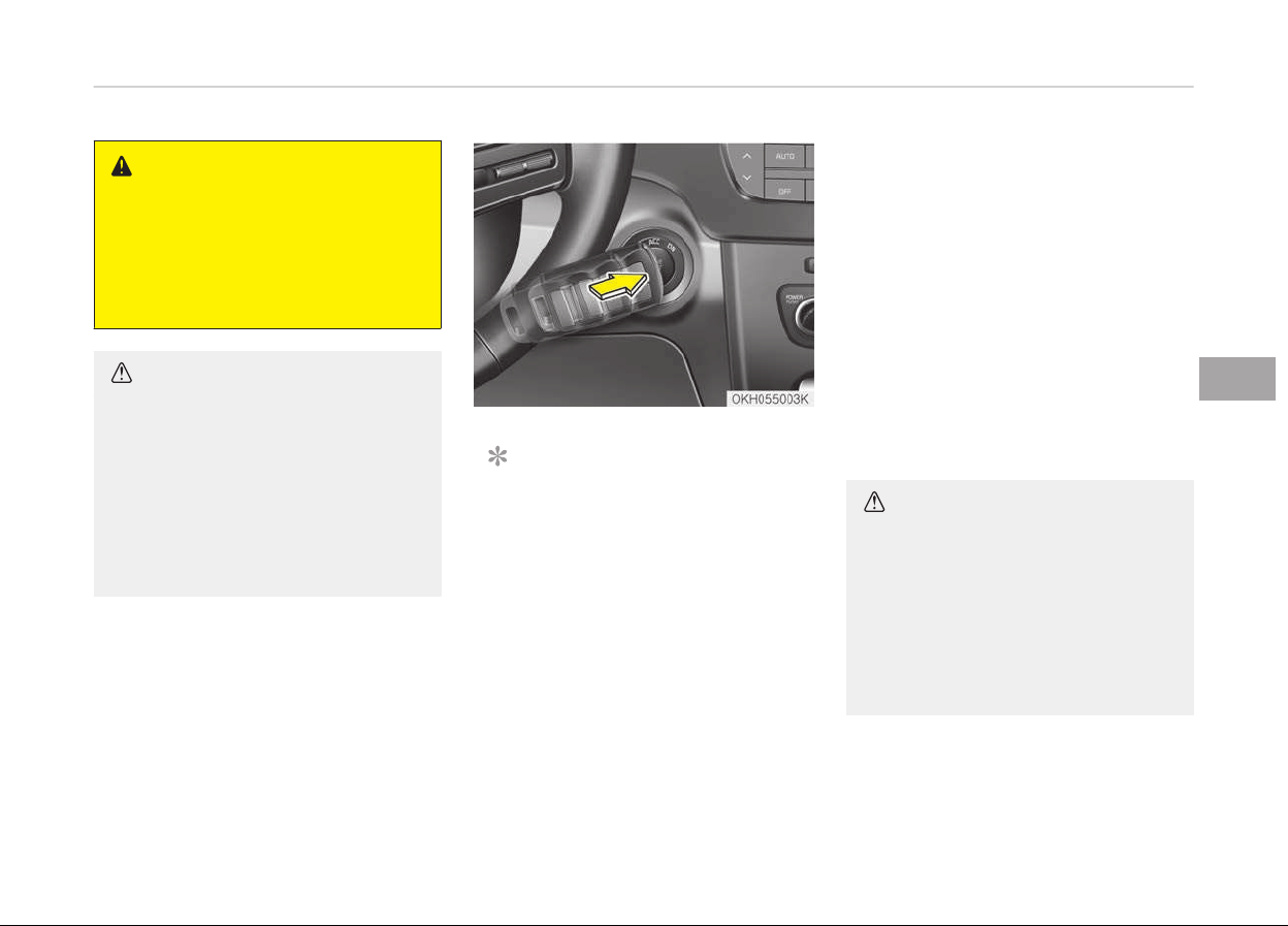
WARNING
The engine will start, only when the
smart key is in the vehicle.
Never allow children or any person
who is unfamiliar with the vehicle
touch the engine start/stop button
or related parts.
CAUTION
If the engine stalls while the vehicle
is in motion, do not attempt to move
the shift lever to the P (Park) posi‐
tion. If the traffic and road condi‐
tions permit, you may put the shift
lever in the N (Neutral) position while
the vehicle is still moving and press
the engine start/stop button in an
attempt to restart the engine.
NOTICE
• If the battery is weak or the smart
key does not work correctly, you
can start the engine by pressing
the engine start/stop button with
the smart key.
The side with the lock button
should contact the engine start/
stop button directly. When you
press the engine start/stop button
directly with the smart key, the
smart key should contact the but‐
ton at a right angle.
(Continued)
(Continued)
• When the stop lamp fuse is blown,
you cannot start the engine nor‐
mally.
Replace the fuse with a new one.
If it is not possible, you can start
the engine by pressing the engine
start/ stop button for 10 seconds
while it is in the ACC position. The
engine can start without depress‐
ing the brake pedal. But for your
safety always depress the brake
pedal before starting the engine.
CAUTION
• Do not press the Engine Start/Stop
button
for more than 10 seconds
except when the stop lamp fuse is
blown.
• Do not turn the Engine Start/Stop
button
to the START position with
the engine running. It may damage
the starter.
5-09
5
Driving your vehicle
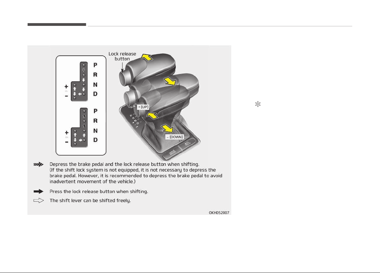
AUTOMATIC TRANSMISSION (SHIFT BY CABLE)
Automatic transmission
operation
The automatic transmission has 8 for‐
ward speeds and one reverse speed.
The individual speeds are selected au‐
tomatically, depending on the position
of the shift lever.
NOTICE
The first few shifts on a new vehicle,
if the battery has been disconnec‐
ted, may be somewhat abrupt. This
is a normal condition, and the shift‐
ing sequence will adjust after shifts
are cycled a few times by the TCM
(Transmission Control Module) or
PCM (Powertrain Control Module).
For smooth operation, depress the
brake pedal when shifting from N (Neu‐
tral) to a forward or reverse gear.
Driving your vehicle
5-10

WARNING
n
Automatic transmission
• Always check the surrounding
areas near your vehicle for people,
especially children, before shifting
a car into D (Drive) or R (Reverse).
• Before leaving the driver’s seat, al‐
ways make sure the shift lever is
in the P (Park) position; then set
the parking brake fully and shut
the engine off. Unexpected and
sudden vehicle movement can oc‐
cur if these precautions are not
followed in the order identified.
• Do not use the engine brake (shift‐
ing from a high gear to lower gear)
rapidly on slippery roads.
The vehicle may slip causing an ac‐
cident.
CAUTION
• To avoid damage to your trans‐
mission
, do not accelerate the en‐
gine in R (Reverse) or any forward
gear position with the brakes on.
(Continued)
(Continued)
• When stopped on an incline, do not
hold
the vehicle stationary with
engine power. Use the service
brake or the parking brake.
• Do not shift from N (Neutral) or P
(P
ark) into D (Drive), or R (Reverse)
when the engine is above idle
speed.
Transmission ranges
The indicator in the instrument cluster
displays the shift lever position when
the Engine Start/Stop button is in the
ON position.
P (Park)
Always come to a complete stop before
shifting into P (Park). This position
locks the transmission and prevents
the drive wheels from rotating.
WARNING
• Shifting into P (Park) while the ve‐
hicle is in motion will cause the
drive wheels to lock which will
cause you to lose control of the
vehicle.
• Do not use the P (Park) position in
place of the parking brake. Always
make sure the shift lever is latch‐
ed in the P (Park) position and set
the parking brake fully.
• Never leave a child unattended in a
vehicle.
CAUTION
The transmission may be damaged
if you shift into P (Park) while the
vehicle is in motion.
R (Reverse)
Use this position to drive the vehicle
backward.
5-11
5
Driving your vehicle
CAUTION
Always come to a complete stop be‐
fore shifting into or out of R (Re‐
verse); you may damage the trans‐
mission if you shift into R (Reverse)
while the vehicle is in motion, except
as explained in Rocking the vehicle
on page 5-89.
N (Neutral)
The wheels and transmission are not
engaged. The vehicle will roll freely
even on the slightest incline unless the
parking brake or service brakes are ap‐
plied.
WARNING
Do not drive with the shift lever in N
(Neutral).
The engine brake will not work and
lead to an accident.
- Parking in N (Neutral) gear
Follow below steps when parking and
you want the vehicle to move when
pushed.
1. After parking your vehicle, depress
the brake pedal and move the shift
lever to [P] with the ignition button
in [ON] or while the engine is run‐
ning.
2. If the parking brake is applied un‐
lock the parking brake.
- For EPB (Electronic Parking
Brake) equipped vehicles, push
the brake pedal with the ignition
button in [ON] or while the en‐
gine is running to disengage the
parking brake. If [AUTO HOLD]
function is used while driving (If
[AUTO HOLD] indicator is on in
the cluster), press [AUTO HOLD]
switch and [AUTO HOLD] func‐
tion should be turn off.
3. While pressing the brake pedal,
turn the ignition button [OFF].
- For smart key equipped vehicles,
the ignition switch can be moved
to [OFF] only when the shift lev‐
er is in [P].
4. Change the gear shift lever to [N]
(Neutral) while pressing the brake
pedal and pushing [SHIFT LOCK RE‐
LEASE] button or inserting, press‐
ing down a tool (e.g. flathead
screw-driver) into the [SHIFT LOCK
RELEASE] access hole at the same
time. Then, the vehicle will move
when external force is applied.
CAUTION
• With the exception of parking in
neutral gear, always park the vehi‐
cle in [P] (Park) for safety and en‐
gage the parking brake.
• Before parking in [N] (Neutral)
gear, first make sure the parking
ground is level and flat. Do not
park in [N] gear on any slopes or
gradients.
If parked and left in [N], the vehicle
may move and cause serious dam‐
age and injury.
• After the ignition switch has been
turned off, the electronic parking
brake cannot be disengaged.
(Continued)
Driving your vehicle
5-12
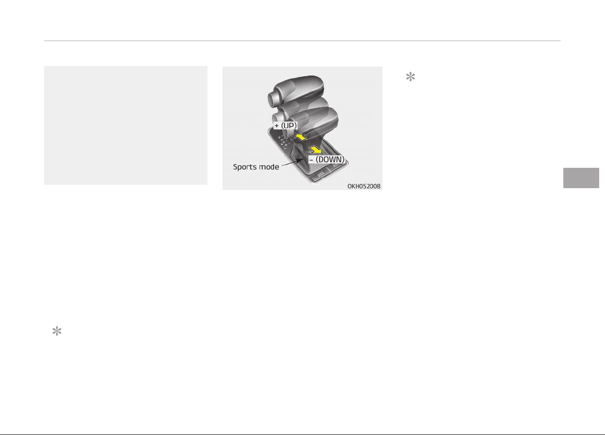
(Continued)
• For EPB (Electronic Parking Brake)
equipped
vehicles with [AUTO
HOLD] function used while driving,
if the ignition button has been
turned [OFF], the electronic park‐
ing brake will be engaged auto‐
matically. Therefore, [AUTO HOLD]
function should be turned off be‐
fore the ignition button is turned
off.
D (Drive)
This is the normal forward driving posi‐
tion. The transmission will automatical‐
ly shift through a 8-gear sequence,
providing the best fuel economy and
power.
For extra power when passing another
vehicle or climbing grades, depress the
accelerator fully, at which time the
transmission will automatically down‐
shift to the lower gear.
NOTICE
Always come to a complete stop be‐
fore shifting into D (Drive).
Manual mode
Whether the vehicle is stationary or in
motion, sports mode is selected by
pushing the shift lever from the D
(Drive) position into the manual gate.
To return to D (Drive) range operation,
push the shift lever back into the main
gate.
In manual mode, moving the shift lever
backwards and forwards will allow you
to make gearshifts rapidly.
Up (+): Push the lever forward
once to shift up one gear
.
Down (-): Pull the lever backwards
once to shift down one
gear.
NOTICE
• In manual mode, the driver must
execute upshifts in accordance
with road conditions, taking care
to keep the engine speed below
the red zone.
• In manual mode, only the 8 for‐
ward gears can be selected. To re‐
verse or park the vehicle, move
the shift lever to the R (Reverse)
or P (Park) position as required.
• In manual mode, downshifts are
made automatically when the ve‐
hicle slows down. When the vehicle
stops, 1st gear is automatically
selected.
• In manual mode, when the engine
rpm approaches the red zone shift
points are varied to upshift auto‐
matically.
• To maintain the required levels of
vehicle performance and safety,
the system may not execute cer‐
tain gearshifts when the shift lev‐
er is operated.
(Continued)
5-13
5
Driving your vehicle
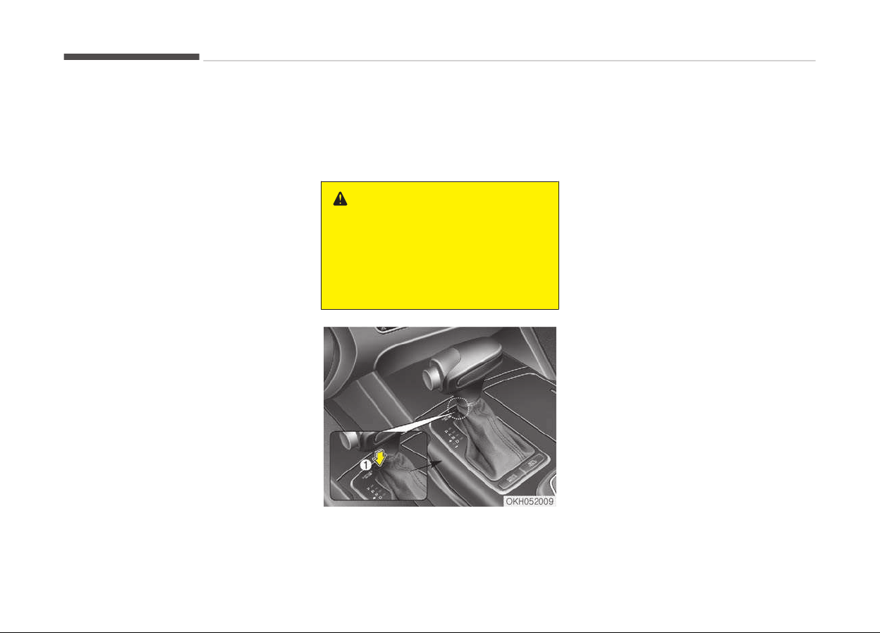
(Continued)
• When
driving on a slippery road,
push the shift lever forward into
the +(up) position. This causes the
transmission to shift into the 2nd
gear which is better for smooth
driving on a slippery road. Push
the shift lever to the -(down) side
to shift back to the 1st gear.
Shift lock system (if equipped)
For your safety, the automatic trans‐
mission has a shift lock system which
prevents shifting the transmission
from P (Park) into R (Reverse) unless
the brake pedal is depressed.
To shift the transmission from P (Park)
into R (Reverse):
1. Depress and hold the brake pedal.
2. Start the engine or press the En‐
gine Start/Stop button in the ON
position.
3. Move the shift lever with pressing
lock release button.
If the brake pedal is repeatedly de‐
pressed and released with the shift lev‐
er in the P (Park) position, a chattering
noise near the shift lever may be heard.
This is a normal condition.
WARNING
Always fully depress the brake pedal
before and while shifting out of the
P (Park) position into another posi‐
tion to avoid inadvertent motion of
the vehicle which could injure per‐
sons in or around the car.
Shift-lock override
If the shift lever cannot be moved from
the P (Park) position into R (Reverse)
position with the brake pedal de‐
pressed, continue depressing the brake,
then do the following:
1. Press the shift-lock release button.
(If the cover is equipped with your
vehicle, remove the cap covering
the shift-lock access hole. And in‐
sert a key into the access hole and
press down on the key.)
2. Move the shift lever.
3. Have the system inspected by a
professional workshop. Kia recom‐
mends to visit an authorized Kia
dealer/service partner.
Good driving practices
• Ne
ver move the shift lever from P
(Park) or N (Neutral) to any other po‐
sition with the accelerator pedal de‐
pressed.
• Never move the shift lever into P
(Park) when the vehicle is in motion.
• Be sure the car is completely stopped
before you attempt to shift into R
(Reverse) or D (Drive).
Driving your vehicle
5-14

• Never take the car out of gear and
coast down a hill. This may be ex‐
tremely hazardous. Always leave the
car in gear when moving.
• Do not "ride" the brakes. This can
cause them to overheat and malfunc‐
tion. Instead, when you are driving
down a long hill, slow down and shift
to a lower gear. When you do this,
engine braking will help slow the car.
• Slow down before shifting to a lower
gear. Otherwise, the lower gear may
not be engaged.
• Always use the parking brake. Do not
depend on placing the transmission in
P (Park) to keep the car from moving.
• Exercise extreme caution when driv‐
ing on a slippery surface. Be especial‐
ly careful when braking, accelerating
or shifting gears. On a slippery sur‐
face, an abrupt change in vehicle
speed can cause the drive wheels to
lose traction and the vehicle to go out
of control.
• Optimum vehicle performance and
economy is obtained by smoothly de‐
pressing and releasing the accelera‐
tor pedal.
WARNING
• Always buckle-up! In a collision, an
unbelted occupant is significantly
more likely to be seriously injured
or killed than a properly belted oc‐
cupant.
• Avoid high speeds when cornering
or turning.
• Do not make quick steering wheel
movements, such as sharp lane
changes or fast, sharp turns.
• The risk of rollover is greatly in‐
creased if you lose control of your
vehicle at highway speeds.
• Loss of control often occurs if two
or more wheels drop off the road‐
way and the driver over-steers to
reenter the roadway.
• In the event your vehicle leaves
the
roadway, do not steer sharply.
Instead, slow down before pulling
back into the travel lanes.
• Never exceed posted speed limits.
WARNING
If your vehicle becomes stuck in
snow, mud, sand, etc., then you may
attempt to rock the vehicle free by
moving it forward and backward. Do
not attempt this procedure if people
or objects are anywhere near the ve‐
hicle. During the rocking operation
the vehicle may suddenly move for‐
ward or backward as it becomes un‐
stuck, causing injury or damage to
nearby people or objects.
Moving up a steep grade from a
standing start
To move up a steep grade from a
standing start, depress the brake pedal,
shift the shift lever to D (Drive). Select
the appropriate gear depending on load
weight and steepness of the grade, and
release the parking brake. Depress the
accelerator gradually while releasing
the service brakes.
5-15
5
Driving your vehicle
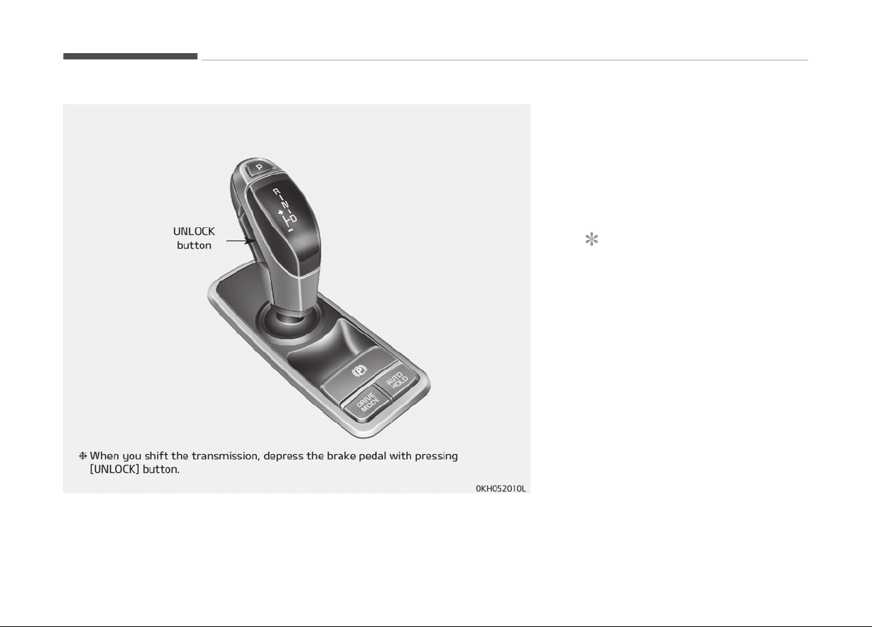
AUTOMATIC TRANSMISSION (SHIFT BY WIRE)
Automatic transmission
operation
The automatic transmission has 8 for‐
ward speeds and one reverse speed.
The individual speeds are selected au‐
tomatically, depending on the position
of the shift lever.
NOTICE
The first few shifts on a new vehicle,
if the battery has been disconnec‐
ted, may be somewhat abrupt. This
is a normal condition, and the shift‐
ing sequence will adjust after shifts
are cycled a few times by the TCM
(Transmission Control Module) or
PCM (Powertrain Control Module).
For smooth operation, depress the
brake pedal when shifting from N (Neu‐
tral) to a forward or reverse gear.
Driving your vehicle
5-16
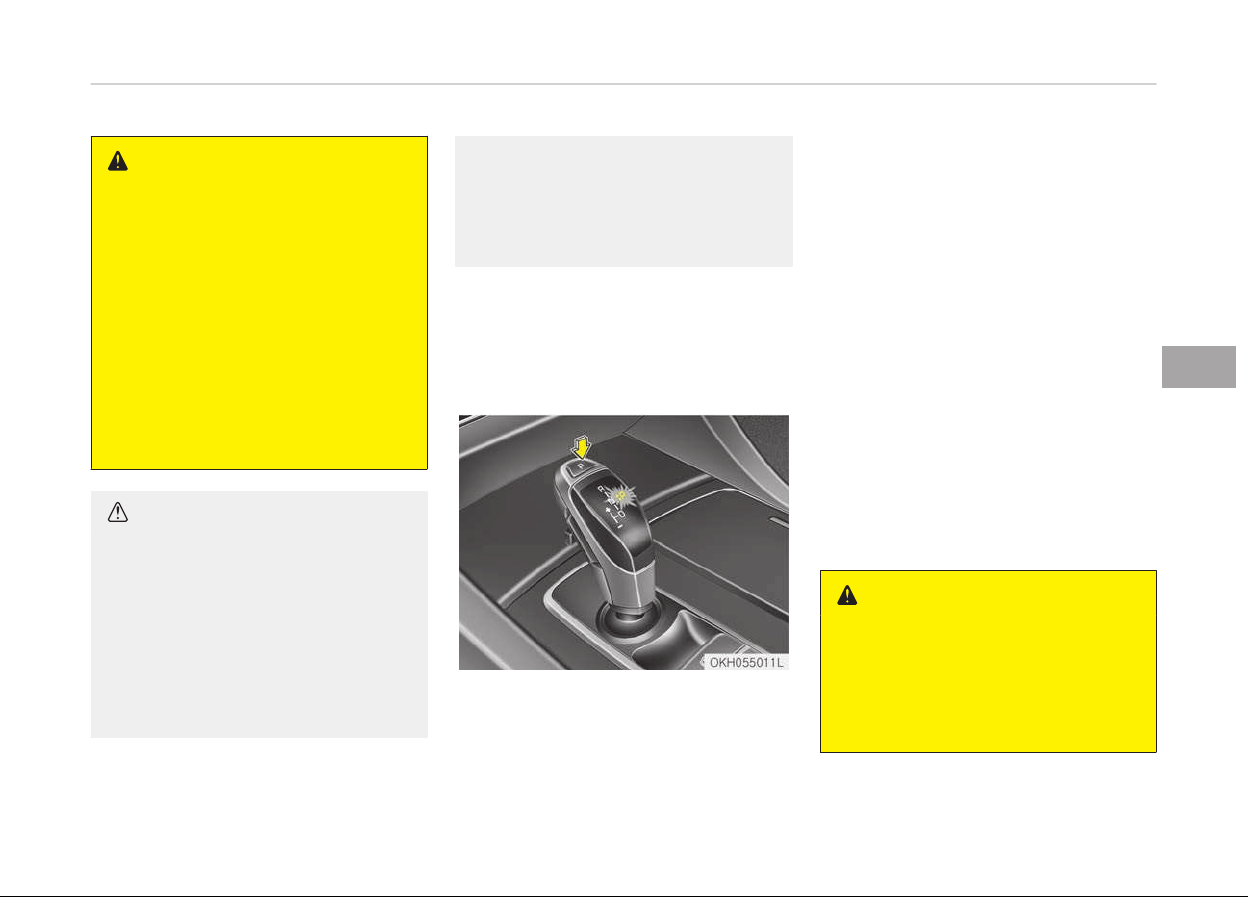
WARNING
n
Automatic transmission
• Always check the surrounding
areas near your vehicle for people,
especially children, before shifting
a car into D (Drive) or R (Reverse).
• Before leaving the driver’s seat, al‐
ways make sure the shift lever is
in the P (Park) position; then set
the parking brake fully and shut
the engine off. Unexpected and
sudden vehicle movement can oc‐
cur if these precautions are not
followed in the order identified.
CAUTION
• To avoid damage to your trans‐
mission, do not accelerate the en‐
gine in R (Reverse) or any forward
gear position with the brakes on.
• When stopped on an incline, do not
hold the vehicle stationary with
engine power. Use the service
brake or the parking brake.
(Continued)
(Continued)
• Do not shift from N (Neutral) or P
(P
ark) into D (Drive), or R (Reverse)
when the engine is above idle
speed.
Transmission ranges
The indicator in the instrument cluster
and shift lever displays the shift lever
position when the Engine Start/Stop
button is in the OFF/ACC/ON position.
P (Park)
Always come to a complete stop before
shifting into P (Park). This position
locks the transmission and prevents
the drive wheels from rotating.
To shift the gear from [R], [N], [D] or
[M] to [P], press the [P] button on the
shift lever.
If you turn off the engine in [D], [R] or
[M], the shifting automatically changes
to [P].
If you press the [P] button when the
shifting is on [M] or if you turn the en‐
gine off when the shifting is on [M], the
shift lever is automatically moved to
right side and the shifting is changed to
[P].
When the shift lever is automatically
moved to right side, if you hold the
shift lever by force, the warning mes‐
sage will be illuminated in cluster. Move
the shift lever to right side manually.
When you park the vehicle, press the
[P] button of shift lever with applying
brake pedal and apply the parking
brake.
WARNING
• Shifting into P (Park) while the ve‐
hicle is in motion will cause the
drive wheels to lock which will
cause you to lose control of the
vehicle.
(Continued)
5-17
5
Driving your vehicle
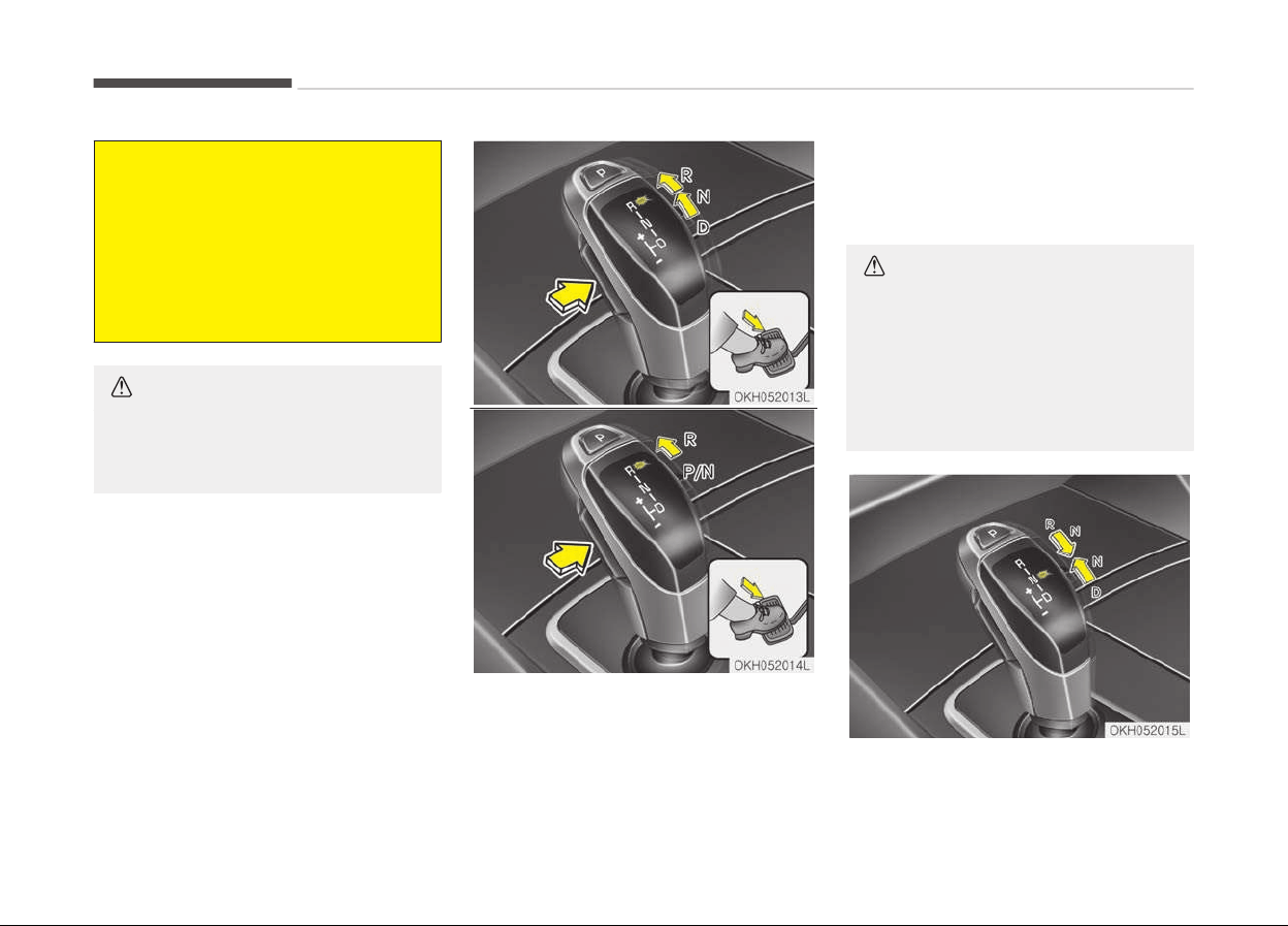
(Continued)
• Do not use the P (Park) position in
place
of the parking brake. Always
make sure the shift lever is latch‐
ed in the P (Park) position and set
the parking brake fully.
• Never leave a child unattended in a
v
ehicle.
CAUTION
The transmission may be damaged
if
you shift into P (Park) while the
vehicle is in motion.
R (Reverse)
Use this position to drive the vehicle
backward.
To shift the gear to [R] press the [UN‐
LOCK]
button of shift lever with de‐
pressing brake pedal and move the
shift lever forward.
CAUTION
Always come to a complete stop be‐
fore shifting into or out of R (Re‐
verse); you may damage the trans‐
mission if you shift into R (Reverse)
while the vehicle is in motion, except
as explained in Rocking the vehicle
on page 5-89.
Driving your vehicle
5-18
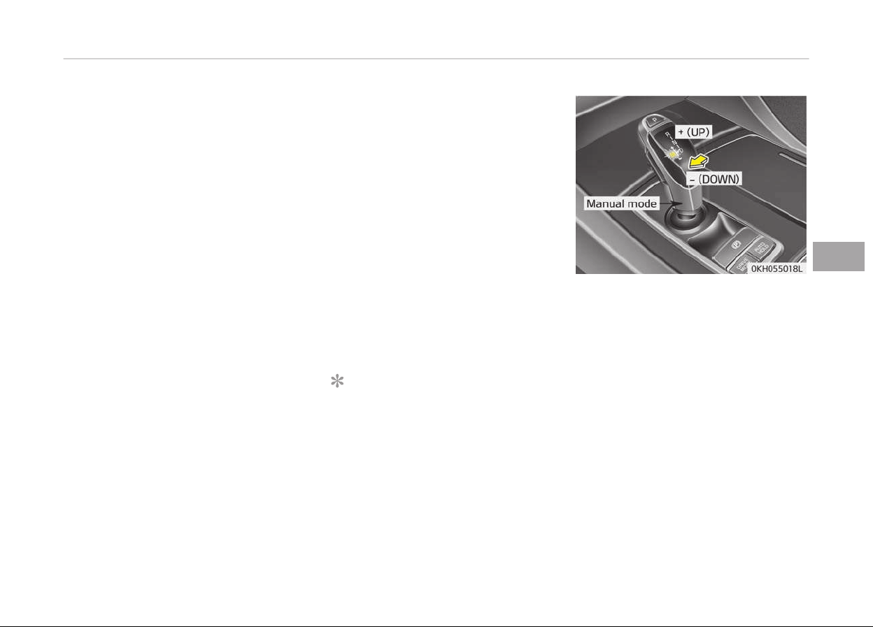
N (Neutral)
The wheels and transmission are not
engaged. The vehicle will roll freely
even on the slightest incline unless the
parking brake or service brakes are ap‐
plied.
In neutral range if you turn off the en‐
gine, the range will be on [N] and the
Engine Start/Stop button position will
be on ACC.
To turn off engine :
1. Press the engine start/stop button
again to the ON position.
2. Press the [P] button on the shift
lever.
3. Press the engine start/stop button
again, the engine start/stop button
will change to the OFF position.
However, when you open the door with
the shift lever in N (Neutral) and the
engine start/stop button in the ACC po‐
sition, the shift lever will automatically
move to P (Park) and the engine start/
stop button will change to the OFF po‐
sition.
D (Drive)
This
is the normal forward driving posi‐
tion. The shift lever will automatically
shift through a 8-gear sequence, pro‐
viding the best fuel economy and pow‐
er.
For extra power when passing another
vehicle or climbing grades, depress the
accelerator fully, at which time the
shift lever will automatically downshift
to the lower gear.
To shift into [D], depress the brake
pedal and press the [UNLOCK] button of
shift lever. And then move the shift lev‐
er to backward.
To shift into [D], from [N] you must de‐
press the brake pedal.
NOTICE
Always come to a complete stop be‐
for
e shifting into D (Drive).
Manual mode
Whether the vehicle is stationary or in
motion, sports mode is selected by
pushing the shift lever from the D
(Drive) position into the manual gate.
To return to D (Drive) range operation,
push the shift lever back into the main
gate.
In manual mode, moving the shift lever
backwards and forwards will allow you
to make gearshifts rapidly.
Up (+): Push the lever forward
once to shift up one gear
.
Down (-): Pull the lever backwards
once to shift down one
gear.
5-19
5
Driving your vehicle

NOTICE
• In manual mode, the driver must
execute upshifts in accordance
with road conditions, taking care
to keep the engine speed below
the red zone.
• In manual mode, only the 8 for‐
ward gears can be selected. To re‐
verse or park the vehicle, move
the shift lever to the R (Reverse)
or P (Park) position as required.
• In manual mode, downshifts are
made automatically when the ve‐
hicle slows down. When the vehicle
stops, 1
st
gear is automatically se‐
lected.
• In manual mode, when the engine
rpm approaches the red zone shift
points are varied to upshift auto‐
matically.
(Continued)
(Continued)
• T
o maintain the required levels of
vehicle performance and safety,
the system may not execute cer‐
tain gearshifts when the shift lev‐
er is operated.
• When driving on a slippery road,
push the shift lever forward into
the +(up) position. This causes the
transmission to shift into the 2
nd
gear which is better for smooth
driving on a slippery road. Push
the shift lever to the -(down) side
to shift back to the 1
st
gear.
Shift lock system (if equipped)
For your safety, the automatic trans‐
mission has a shift lock system which
prevents shifting the transmission
from P (Park) into R (Reverse) unless
the brake pedal is depressed.
To shift the transmission from P (Park)
into R (Reverse) or D (Drive) :
1. Depress and hold the brake pedal.
2. Start the engine or press the En‐
gine Start/Stop button in the ON
position.
3. Have the system inspected by a
professional workshop. Kia recom‐
mends to visit an authorized Kia
dealer/service partner.
If the brake pedal is repeatedly de‐
pressed and released with the shift lev‐
er in the P (Park) position, a chattering
noise near the shift lever may be heard.
This is a normal condition.
WARNING
Always fully depress the brake pedal
before and while shifting out of the
P (Park) position into another posi‐
tion to avoid inadvertent motion of
the vehicle which could injure per‐
sons in or around the car.
■ When the battery is discharged:
When the battery is discharged, the au‐
tomatic transmission (shift by wire) is
not shifted.
In emergency, if you want to shift into
[N], follow actions
Driving your vehicle
5-20
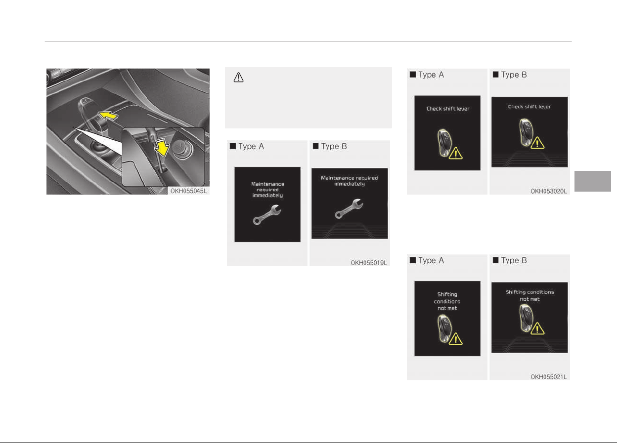
You can shift into [N] by using the driv‐
er if the jump starting is impossible to
do.
1. Open the storage cover.
2. Remove the rubber on bottom of
storage box.
3. Insert the driver (-) to service hole
as direction of clockwise 10 times.
The shifting is changed to [N] from
[P] position. If you want to shift to
[P] position, turn the driver coun‐
ter-clockwise.
CAUTION
If the electric parking brake is not
released, we recommend that the
vehicle is towed as flatbed towing.
1. If the shift lever is not operated as
normal, the warning will be illumi‐
nated. Kia recommends to contact
an authorized Kia dealer/service
partner
2. If the transmission has some prob‐
lem with the main system, the
warning will be illuminated. Kia rec‐
ommends to contact an authorized
Kia dealer/service partner
5-21
5
Driving your vehicle
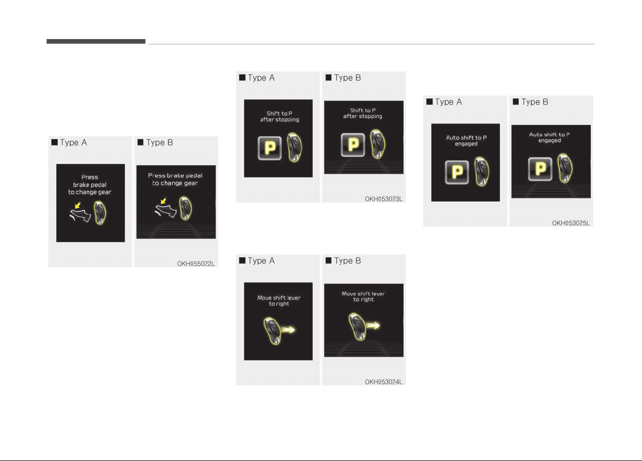
3. If the shifting condition is not
matched by high engine RPM or
high vehicle speed, the warning will
be illuminated. When you reduce
the engine RPM or vehicle speed,
the shifting will be operated.
4. When you shift the transmission, if
you do not depress the brake pedal,
the warning will be illuminated.
5. When you shift into [P], if the vehi‐
cle speed is high, warning will be il‐
luminated. Stop the vehicle at safe
area and shift into [P].
6. When the transmission is fixed on
[M], the warning will be illuminated.
7. While stopping in [D], [R] and [M],
when you get off the vehicle, the
warning will be illuminated for your
safety and the shifting is automati‐
cally changed to [P].
Driving your vehicle
5-22
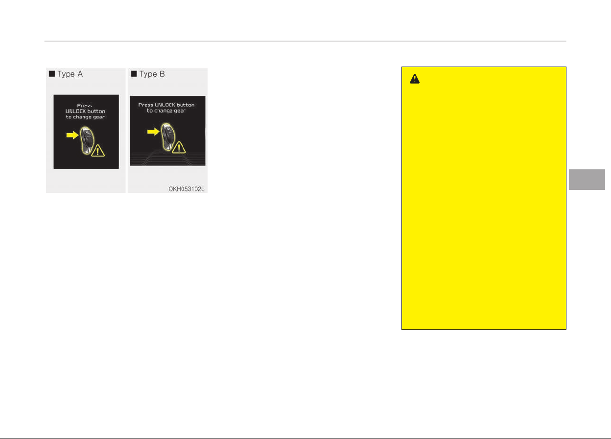
If you do not press [UNLOCK] button,
the warning will be illuminated.
Good driving practices
• Never move the shift lever from P
(Park) or N (Neutral) to any other po‐
sition with the accelerator pedal de‐
pressed.
• Never move the shift lever into P
(Park) when the vehicle is in motion.
• Be sure the car is completely stopped
before you attempt to shift into R
(Reverse) or D (Drive).
• Never take the car out of gear and
coast down a hill. This may be ex‐
tremely hazardous. Always leave the
car in gear when moving.
• Do not "ride" the brakes. This can
cause them to overheat and malfunc‐
tion. Instead, when you are driving
down a long hill, slow down and shift
to a lower gear. When you do this,
engine braking will help slow the car.
• Slow down before shifting to a lower
gear. Otherwise, the lower gear may
not be engaged.
• Always use the parking brake. Do not
depend on placing the transmission in
P (Park) to keep the car from moving.
• Exercise extreme caution when driv‐
ing on a slippery surface. Be especial‐
ly careful when braking, accelerating
or shifting gears. On a slippery sur‐
face, an abrupt change in vehicle
speed can cause the drive wheels to
lose traction and the vehicle to go out
of control.
• Optimum vehicle performance and
economy is obtained by smoothly de‐
pressing and releasing the accelera‐
tor pedal.
WARNING
• Always buckle-up! In a collision, an
unbelted occupant is significantly
more likely to be seriously injured
or killed than a properly belted oc‐
cupant.
• Avoid high speeds when cornering
or turning.
• Do not make quick steering wheel
movements, such as sharp lane
changes or fast, sharp turns.
• The risk of rollover is greatly in‐
creased if you lose control of your
vehicle at highway speeds.
• Loss of control often occurs if two
or more wheels drop off the road‐
way and the driver over-steers to
reenter the roadway.
• In the event your vehicle leaves
the
roadway, do not steer sharply.
Instead, slow down before pulling
back into the travel lanes.
• Never exceed posted speed limits.
5-23
5
Driving your vehicle

WARNING
If your vehicle becomes stuck in
snow, mud, sand, etc., then you may
attempt to rock the vehicle free by
moving it forward and backward. Do
not attempt this procedure if people
or objects are anywhere near the ve‐
hicle. During the rocking operation
the vehicle may suddenly move for‐
ward or backward as it becomes un‐
stuck, causing injury or damage to
nearby people or objects.
Moving up a steep grade from a
standing start
To move up a steep grade from a
standing start, depress the brake pedal,
shift the shift lever to D (Drive) or [1
st
]
gear of [M] mode. Select the appropri‐
ate gear depending on load weight and
steepness of the grade, and release the
parking brake. Depress the accelerator
gradually while releasing the service
brakes.
Driving your vehicle
5-24
BRAKE SYSTEM
Power brakes
Your vehicle has power-assisted brakes
that adjust automatically through nor‐
mal usage.
In the event that the power-assisted
brakes lose power because of a stalled
engine or some other reason, you can
still stop your vehicle by applying
greater force to the brake pedal than
you normally would. The stopping dis‐
tance, however, will be longer.
When the engine is not running, the re‐
serve brake power is partially depleted
each time the brake pedal is applied. Do
not pump the brake pedal when the
power assist has been interrupted.
Pump the brake pedal only when nec‐
essary to maintain steering control on
slippery surfaces.
WARNING
n
Brakes
(Continued)
(Continued)
• Do not drive with your foot resting
on the brake pedal. This will create
abnormal high brake tempera‐
tures, excessive brake lining and
pad wear, and increased stopping
distances.
• When descending a long or steep
hill, shift to a lower gear and avoid
continuous application of the
brakes. Continuous brake applica‐
tion will cause the brakes to over‐
heat and could result in a tempo‐
rary loss of braking performance.
• Wet brakes may impair the vehi‐
cle’s ability to safely slow down;
the vehicle may also pull to one
side when the brakes are applied.
Applying the brakes lightly will in‐
dicate whether they have been af‐
fected in this way. Always test
your brakes in this fashion after
driving through deep water.
To dry the brakes, apply them
lightly while maintaining a safe
forward speed until brake per‐
formance returns to normal.
(Continued)
(Continued)
• Always, confirm the position of
the brake and accelerator pedal
before driving. If you don't check
the position of the accelerator and
brake pedal before driving, you
may depress the accelerator in‐
stead of the brake pedal. It may
cause a serious accident.
In the event of brake failure
If service brakes fail to operate while
the vehicle is in motion, you can make
an emergency stop with the parking
brake. The stopping distance, however,
will be much greater than normal.
WARNING
n
Parking brake
Applying the parking brake while the
vehicle is moving at normal speeds
can cause a sudden loss of control of
the vehicle. If you must use the
parking brake to stop the vehicle,
use great caution in applying the
brake.
5-25
5
Driving your vehicle

CAUTION
Do not operate the parking brake
while the vehicle is moving except in
an emergency situation. It could
damage the vehicle system and
make endanger driving safety.
Disc brakes wear indicator
Your vehicle has disc brakes.
When your brake pads are worn and
new pads are required, you will hear a
high-pitched warning sound from your
front brakes or rear brakes. You may
hear this sound come and go or it may
occur whenever you depress the brake
pedal.
Please remember that some driving
conditions or climates may cause a
brake squeal when you first apply (or
lightly apply) the brakes. This is normal
and does not indicate a problem with
your brakes.
CAUTION
• To avoid costly brake repairs, do
not
continue to drive with worn
brake pads.
(Continued)
(Continued)
• Always replace the front or rear
brake pads as pairs.
WARNING
n
Brake wear
This brake wear warning sound
means your vehicle needs service. If
you ignore this audible warning, you
will eventually lose braking perform‐
ance, which could lead to a serious
accident.
WARNING
• To prevent unintentional move‐
ment
when stopped and leaving
the vehicle, do not use the gear‐
shift lever in place of the parking
brake. Set the parking brake AND
make sure the gearshift lever is
securely positioned in P (Park) for
automatic transmission equipped
vehicles.
(Continued)
(Continued)
• Never allow anyone who is unfa‐
miliar
with the vehicle to touch the
parking brake. If the parking brake
is released unintentionally, serious
injury may occur.
• All vehicles should always have the
parking
brake fully engaged when
parking to avoid inadvertent
movement of the vehicle which
can injure occupants or pedes‐
trians.
Driving your vehicle
5-26
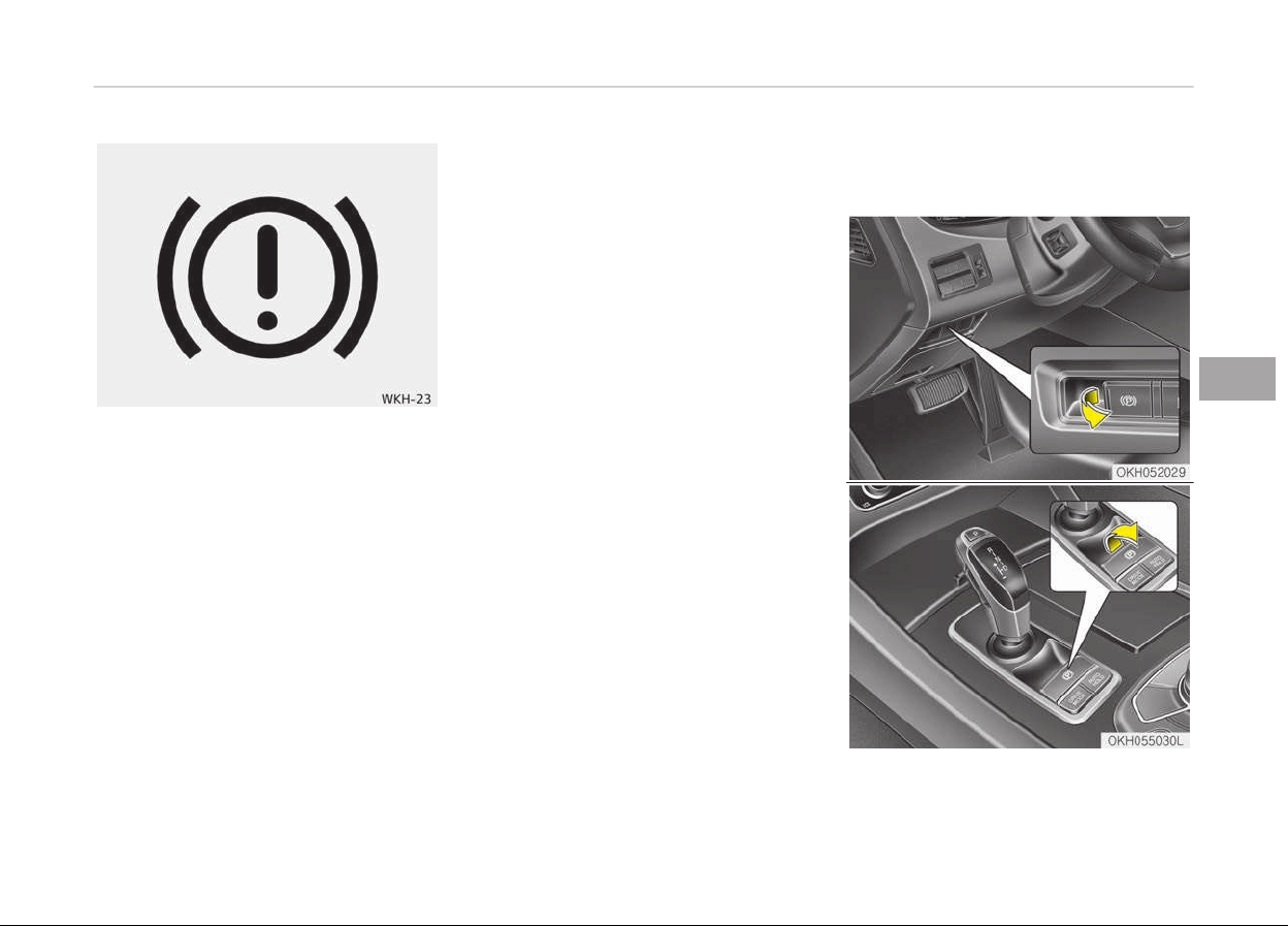
Check the brake warning light by press
the Engine Start/Stop button to the ON
position (do not start the engine). This
light will be illuminated when the park‐
ing brake is applied with the Engine
Start/Stop button in the START or ON
position.
Before driving, be sure the parking
brake is fully released and the brake
warning light is off.
If the brake warning light remains on
after the parking brake is released
while engine is running, there may be a
malfunction in the brake system. Im‐
mediate attention is necessary.
If at all possible, cease driving the vehi‐
cle immediately. If that is not possible,
use extreme caution while operating
the vehicle and only continue to drive
the vehicle until you can reach a safe
location or repair shop.
Electric parking brake (EPB)
Applying the parking brake
5-27
5
Driving your vehicle
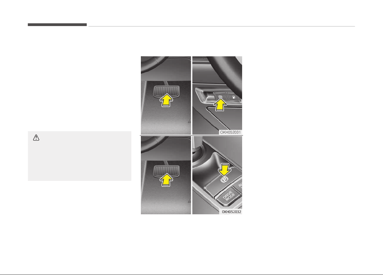
To apply the EPB (electric parking
brake):
1. Depress the brake pedal.
2. Pull up the EPB switch.
Make sure the warning light comes on.
Also, the EPB is applied automatically if
the Auto Hold button is on when the
engine is turned off.
However, if you press the EPB switch
within one second after the engine is
turned off, the EPB will not be applied.
CAUTION
Do not operate the parking brake
while
the vehicle is moving except in
an emergency situation. It could
damage the vehicle system and en‐
danger driving safety.
Releasing the parking brake
To release the EPB (electric parking
brake), press the EPB switch in the fol‐
lowing condition:
• Have the Engine Start/Stop button in
the ON position.
• Depress the brake pedal
Make sure the brake warning light goes
off.
To release EPB (electric parking brake)
automatically:
• Shift lever in P (Park)
With the engine running depress the
brake pedal and shift out of P (Park)
to R (Rear), N (Neutral) or D (Drive).
• Shift lever in N (Neutral)
With the engine running depress the
brake pedal and shift out of N (Neu‐
tral) to R (Rear) or D (Drive).
• Depress the accelerator pedal satis‐
fying the following conditions.
1. Engine running
2. Driver's seat belt fastened
3. Driver's door, engine hood and
trunk closed
4. Shift lever in R (Rear), D (Drive) or
M (Mode)
Driving your vehicle
5-28
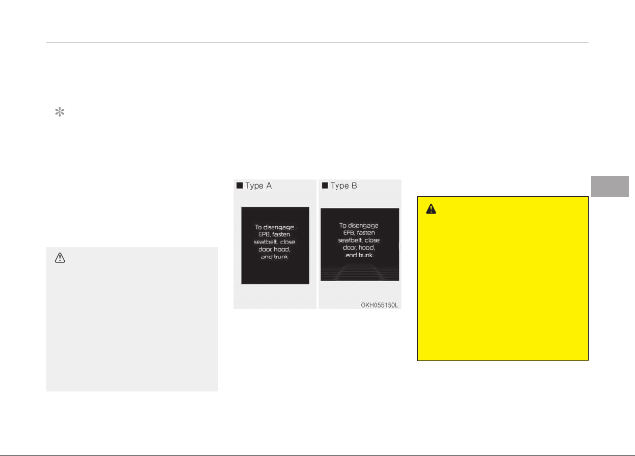
Make sure the brake warning light goes
off.
NOTICE
• For your safety, you can engage
the EPB even though the Engine
Start/Stop button is in the OFF po‐
sition, but you cannot release it.
• For your safety, depress the brake
pedal and release the parking
brake manually with the EPB
switch when you drive downhill or
when backing up the vehicle.
CAUTION
• If the parking brake warning light
is still on even though the EPB has
been released, have the system
checked by a professional work‐
shop. Kia recommends to visit an
authorized Kia dealer/ service
partner.
• Do not drive your vehicle with the
EPB
applied. It may cause exces‐
sive brake pad and brake rotor
wear.
EPB (electric parking brake) may be au‐
tomatically applied when:
• The EPB is overheated
• Reguested by other systems
• The engine is turned off with the EPB
applied
Warning message
To disengage EPB, fasten seatbelt,
close door, hood, and trunk
• If you try to drive off depressing the
accelerator pedal with the EPB ap‐
plied, but doesn't release automati‐
cally, a warning will sound and a mes‐
sage will appear.
• If the driver's seat belt is not fas‐
tened and the engine hood or trunk is
opened, a warning will sound and a
message will appear.
• If there is a problem with the vehicle,
a warning may sound and a message
may appear.
If the above situation occurs, depress
the brake pedal and release EPB by
pressing the EPB switch.
WARNING
• To prevent unintentional move‐
ment when stopped and leaving
the vehicle, do not use the shift
lever in place of the parking brake.
Set the parking brake and make
sure the shift lever is securely
positioned in P (Park).
• Never allow anyone who is unfa‐
miliar with the vehicle to touch the
parking brake. If the parking brake
is released unintentionally, serious
injury may occur.
(Continued)
5-29
5
Driving your vehicle
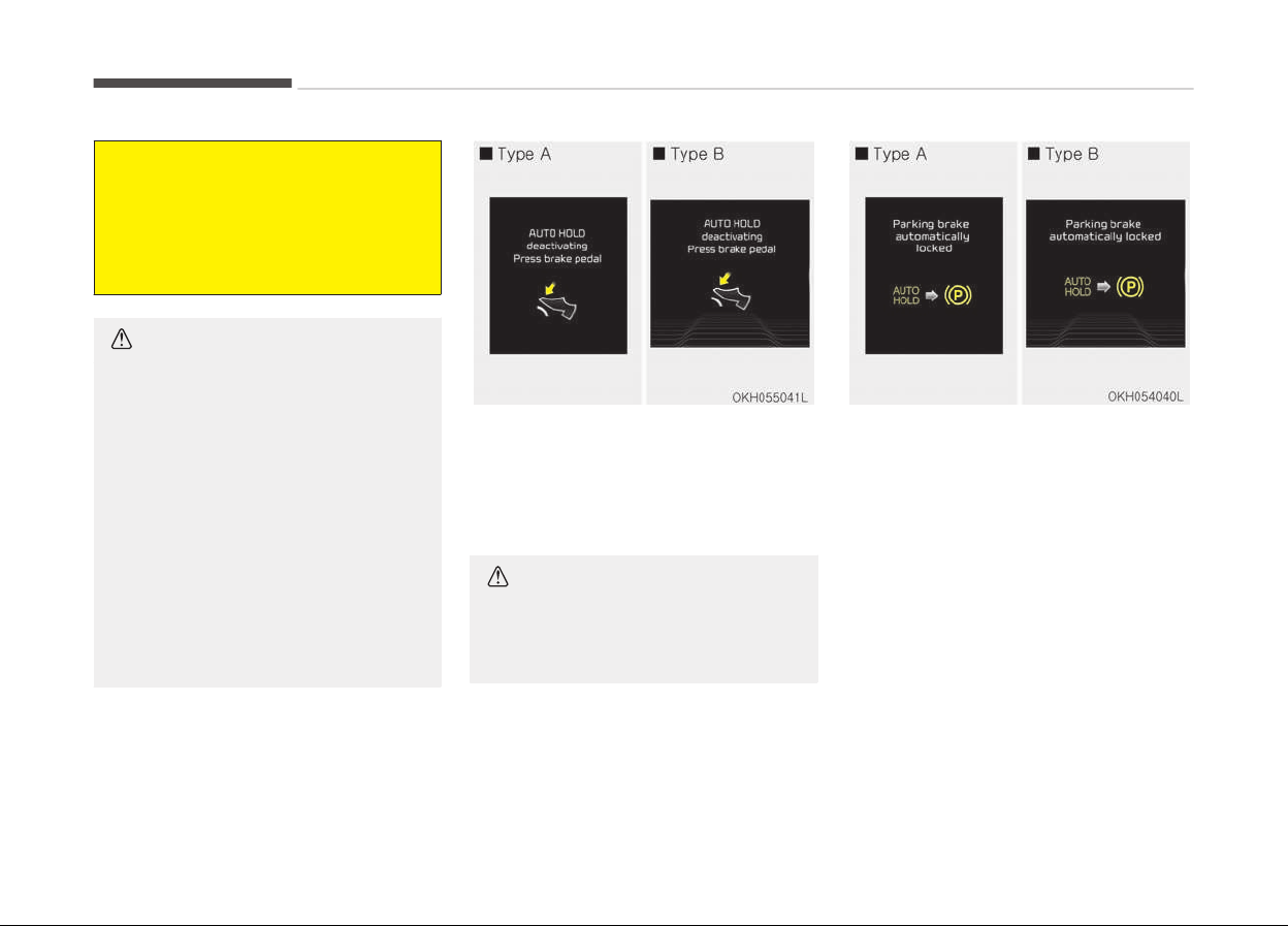
(Continued)
• All vehicles should always have the
parking
brake fully engaged when
parking to avoid inadvertent
movement of the car which can in‐
jure occupants or pedestrians.
CAUTION
• A click sound may be heard while
operating or r
eleasing the EPB, but
these conditions are normal and
indicate that the EPB is function‐
ing properly.
• When leaving your keys with a
parking
lot attendant or valet,
make sure to inform him/her how
to operate the EPB.
• The EPB may malfunction if you
driv
e with the EPB applied.
• When you automatically release
EPB by depressing the accelerator
pedal, depress it slowly.
AUTO HOLD deactivating press brake
pedal
When the conversion from Auto Hold to
EPB is not working properly a warning
will sound and a message will appear.
CAUTION
Depress the brake pedal when the
above message appears for the Auto
Hold and EPB may not activate.
Parking brake automatically locked
If the EPB is applied while Auto Hold is
activated because of ESC(electronic
stability control) signal, a warning will
sound and a message will appear.
Driving your vehicle
5-30
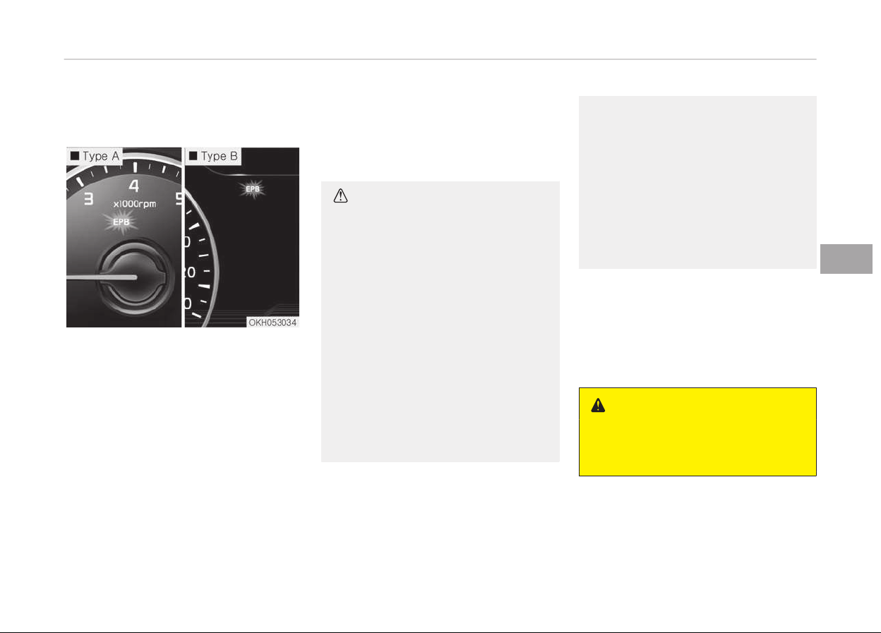
EPB malfunction indicator (if
equipped)
This warning light illuminates if the en‐
gine start/stop button is turned to the
ON position and goes off in approxi‐
mately 3 seconds if the system is oper‐
ation normally.
If the EPB malfunction indicator re‐
mains on, comes on while driving, or
does not come on when the Engine
Start/Stop button is turned to the ON
position, this indicates that the EPB
may have malfunctioned.
If this occurs, have the system checked
by a professional workshop. Kia recom‐
mends to visit an authorized Kia dealer/
service partner.
The EPB malfunction indicator may illu‐
minate when the ESC indicator comes
on to indicate that the ESP is not work‐
ing properly, but it does not indicate a
malfunction of the EPB.
CAUTION
• The EPB warning light may illumi‐
nate if the EPB switch operates
abnormally. Shut the engine off
and turn it on again after a few
minutes. The warning light will go
off and the EPB switch will oper‐
ate normally. However, if the EPB
warning light is still on, have the
system checked by a professional
workshop. Kia recommends to visit
an authorized Kia dealer/service
partner.
• If the parking brake warning light
does not illuminate or blinks even
though the EPB switch was pulled
up, the EPB is not applied.
(Continued)
(Continued)
• If the parking brake warning light
blinks
when the EPB warning light
is on, press the switch, then pull it
up. Once more press it back to its
original position and pull it back up.
If the EPB warning does not go
off, have the system checked by a
professional workshop. Kia recom‐
mends to visit an authorized Kia
dealer/service partner.
Emergency braking
If there is a problem with the brake
pedal while driving, emergency braking
is possible by pulling up and holding the
EPB switch. Braking is possible only
while you are holding the EPB switch.
WARNING
Do not operate the parking brake
while the vehicle is moving except in
an emergency situation.
5-31
5
Driving your vehicle
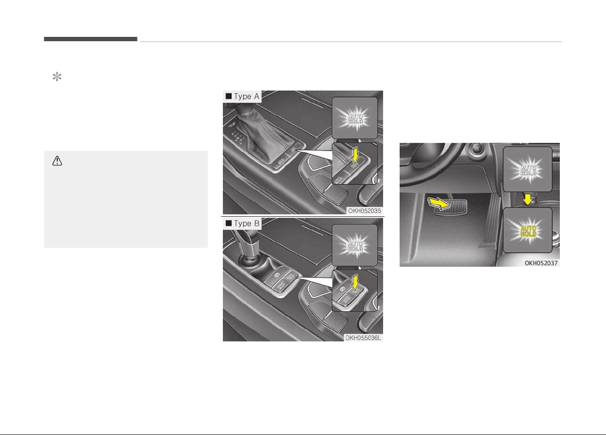
NOTICE
During emergency braking by the
EPB, the parking brake warning light
will illuminate to indicate that the
system is operating.
CAUTION
If you continuously notice a noise or
burning smell when the EPB is used
for emergency braking, have the
system checked by a professional
workshop.
Kia recommends to visit an author‐
ized Kia dealer/service partner.
When the EPB (electric parking
brake) is not released
If the EPB does not release normally,
load the vehicle on a flatbed tow truck
and have the system checked by a pro‐
fessional workshop. Kia recommends to
visit an authorized Kia dealer/service
partner.
AUTO HOLD (if equipped)
The Auto Hold maintains the vehicle in
a standstill even though the brake ped‐
al is not depressed after the driver
brings the vehicle to a complete stop by
depressing the brake pedal.
Set up
1. With the driver's door, engine hood
and trunk closed, fasten the driv‐
er's seat belt or depress the brake
pedal and then press the Auto Hold
button. The white AUTO HOLD indi‐
cator will come on and the system
will be in the standby position.
Driving your vehicle
5-32

2. When you stop the vehicle com‐
pletely by depressing the brake
pedal, the AUTO HOLD indicator
changes from white to green.
3. The vehicle will remain stationary
even if you release the brake pedal.
4. If EPB is applied, Auto Hold will be
released.
Leaving
If you press the accelerator pedal with
the shift lever in R (Reverse), D (Drive)
or manual mode, the Auto Hold will be
released automatically and the vehicle
will start to move. The indicator
changes from green to white.
WARNING
When driving off from Auto Hold by
depressing the accelerator pedal, al‐
ways check the surrounding area
near your vehicle.
Slowly depress the accelerator pedal
for a smooth launch.
Cancel
1. To cancel the Auto Hold operation,
press the Auto Hold switch while
depressing the brake pedal. The
AUTO HOLD indicator will go out.
2. If you want to release it manually,
pull the EPB switch while depress‐
ing the brake pedal. The AUTO
HOLD indicator changes from green
to white and the system changes
to the standby position.
For your safety, release the AUTO
HOLD operation manually if the ve‐
hicle ahead is too close or during
downhill driving.
NOTICE
• The Auto Hold does not operate
when:
- The driver's seat belt is unfas‐
tened and driver's door is
opened
- The engine hood is opened
- The trunk is opened
- The shift lever is in P (Park)
(Continued)
(Continued)
- The EPB is applied
• For your safety, the Auto Hold au‐
tomatically switches to EPB in
such cases:
- The driver's seat belt is unfas‐
tened and driver's door is
opened
- The engine hood is opened
- The trunk is opened
- The vehicle is in a standstill for
more than 10 minutes
- The vehicle is standing on a
steep slope for a long period of
time
- The vehicle moved several
times
In these cases, the brake warning
light comes on, the AUTO HOLD in‐
dicator changes from green to
white, and a warning sounds and a
message will appear to inform you
that EPB has been automatically
engaged.
(Continued)
5-33
5
Driving your vehicle
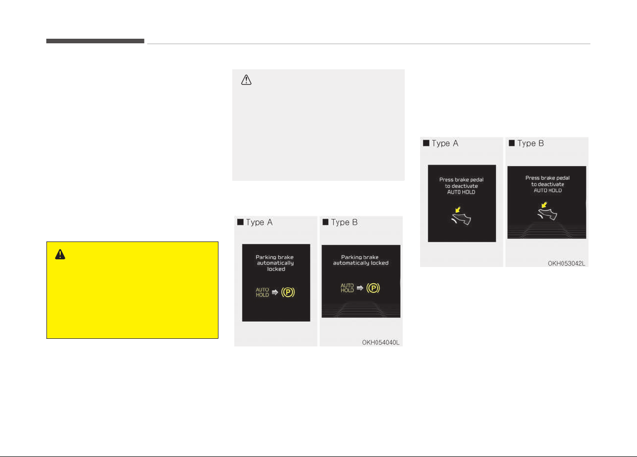
(Continued)
Before driving off again, press foot
brake pedal, check the surrounding
ar
ea near your vehicle and release
parking brake manually with the
EPB switch.
• If the AUTO HOLD indicator lights
up yellow, the Auto Hold is not
working properly. Take your vehi‐
cle to a professional workshop and
have the system checked. Kia rec‐
ommends to visit an authorized
Kia dealer/service partner.
WARNING
• Press the accelerator pedal slowly
when you start the v
ehicle.
• For your safety, cancel the Auto
Hold when you drive downhill or
back up the vehicle or park the ve‐
hicle.
CAUTION
If there is a malfunction with the
driver’s door, hood or trunk open de‐
tection system, the Auto Hold may
not work properly.
In this case, have your vehicle in‐
spected by a professional workshop.
Kia recommends to contact an au‐
thorized Kia dealer/service partner.
Warning message
Parking brake automatically locked
When the EPB is applied from Auto
Hold, the notice will illuminate on the
LCD display. Also warning chime sounds
once.
Press brake pedal to deactivate AUTO
HOLD
If
it is impossible to apply EPB from Au‐
to Hold, the notice will illuminate on the
LCD display. Also warning chime sounds
once. In that time, apply the brake ped‐
al.
Driving your vehicle
5-34
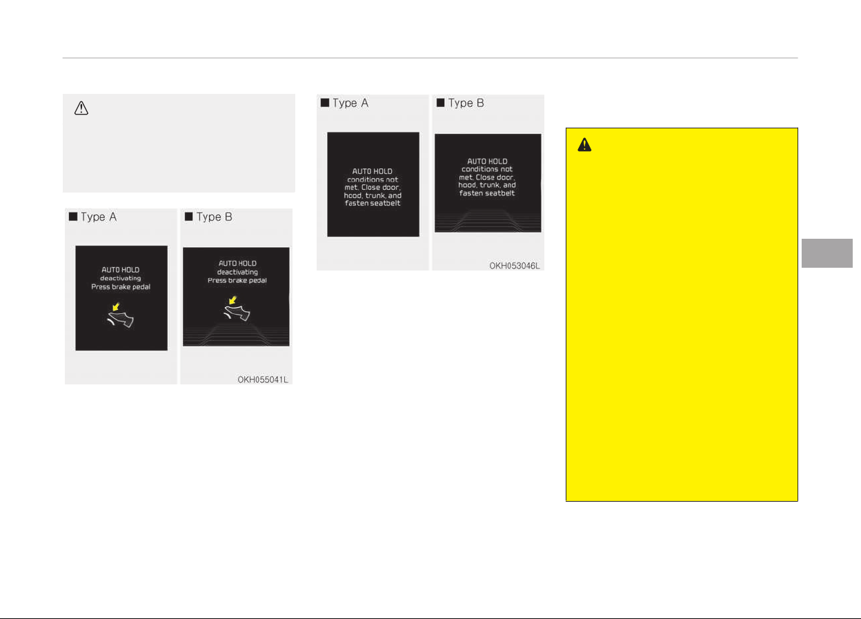
CAUTION
If this notice illuminates, the Auto
Hold and EPB may not be operated.
For your safety, apply the brake
pedal.
AUTO HOLD deactivating press brake
pedal
If you did not apply the brake pedal
when you release the Auto Hold by
pressing the [AUTO HOLD] switch, the
notice will illuminate on the LCD display.
Also warning chime sounds once.
AUTO HOLD conditions not met. Close
door
. hood. trunk. and fasten seatbelt
When you press the [AUTO HOLD]
switch, if the driver door, engine hood
and trunk are not closed or the driver
seat belt is not fastened, the notice will
illuminate on the LCD display. Also
warning chime sounds once. In that
time, press the [AUTO HOLD] button af‐
ter closing the driver door, engine hood
and trunk and fastening the seat belt.
Anti-lock brake system (ABS)
WARNING
ABS (or ESC) will not prevent acci‐
dents due to improper or dangerous
driving maneuvers. Even though ve‐
hicle control is improved during
emergency braking, always maintain
a safe distance between you and ob‐
jects ahead. Vehicle speeds should
always be reduced during extreme
road conditions.
The braking distance for cars equip‐
ped with an anti-lock braking sys‐
tem (or Electronic Stability Control
system) may be longer than for
those without it in the following
road conditions.
During these conditions the vehicle
should be driven at reduced speeds:
• Rough, gravel or snow-covered
roads.
• With tire chains installed.
• On roads where the road surface is
pitted or has different surface
height.
(Continued)
5-35
5
Driving your vehicle
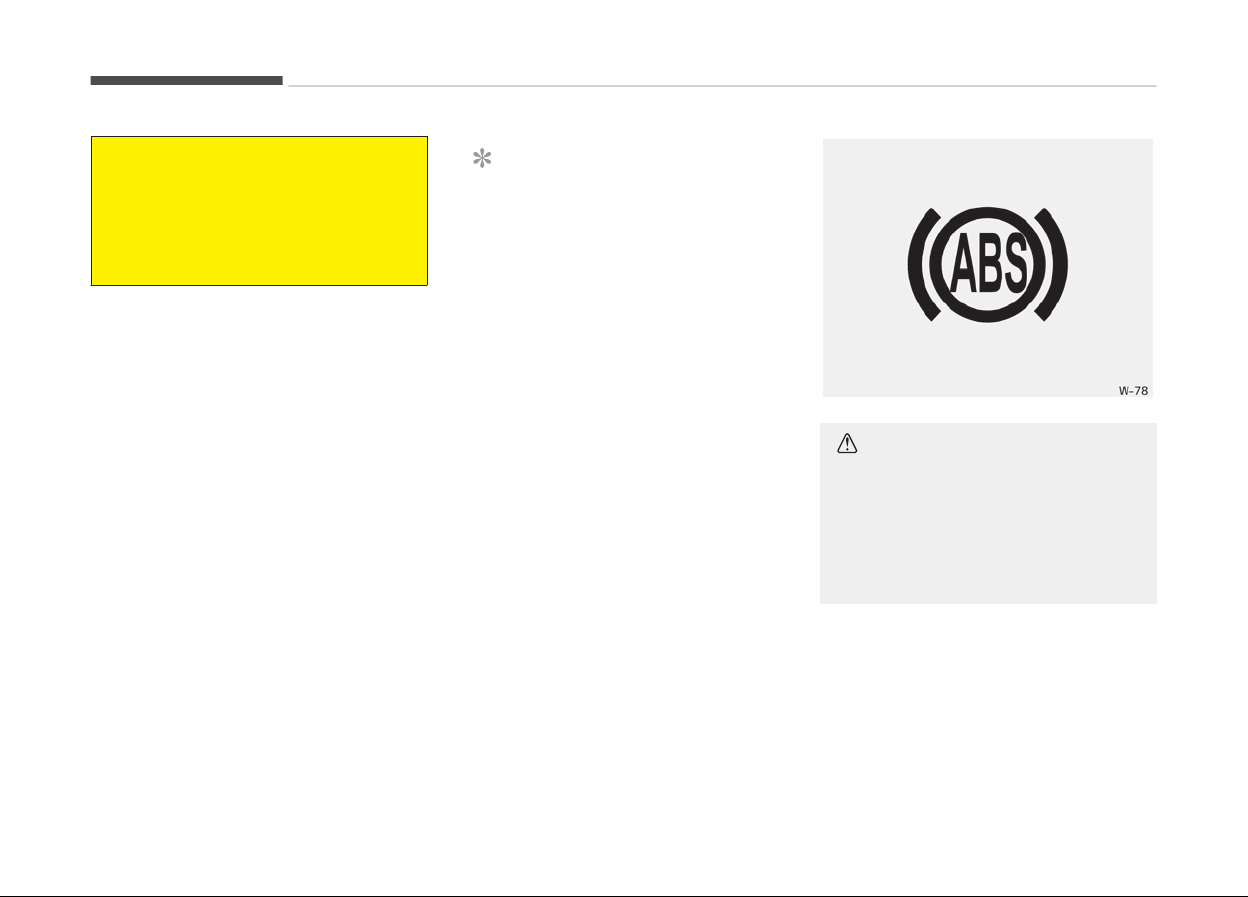
(Continued)
The safety features of an ABS (or
ESC)
equipped vehicle should not be
tested by high speed driving or cor‐
nering. This could endanger the
safety of yourself or others.
The ABS continuously senses the speed
of the wheels. If the wheels are going
to lock, the ABS system repeatedly
modulates the hydraulic brake pressure
to the wheels.
When you apply your brakes under
conditions which may lock the wheels,
you may hear a tik-tik’’ sound from
the brakes, or feel a corresponding sen‐
sation in the brake pedal. This is normal
and it means your ABS is active.
In order to obtain the maximum benefit
from your ABS in an emergency situa‐
tion, do not attempt to modulate your
brake pressure and do not try to pump
your brakes.
Press your brake pedal as hard as pos‐
sible or as hard as the situation war‐
rants and allow the ABS to control the
force being delivered to the brakes.
NOTICE
A click sound may be heard in the
engine compartment when the vehi‐
cle begins to move after the engine
is started. These conditions are nor‐
mal and indicate that the anti-lock
brake system is functioning proper‐
ly.
• Even with the anti-lock brake sys‐
tem, your vehicle still requires suffi‐
cient stopping distance. Always main‐
tain a safe distance from the vehicle
in front of you.
• Always slow down when cornering.
The anti-lock brake system cannot
prevent accidents resulting from ex‐
cessive speeds.
• On loose or uneven road surfaces, op‐
eration of the anti-lock brake system
may result in a longer stopping dis‐
tance than for vehicles equipped with
a conventional brake system.
CAUTION
• If the ABS warning light is on and
stays on, you may have a problem
with the ABS. In this case, howev‐
er, your regular brakes will work
normally.
(Continued)
Driving your vehicle
5-36
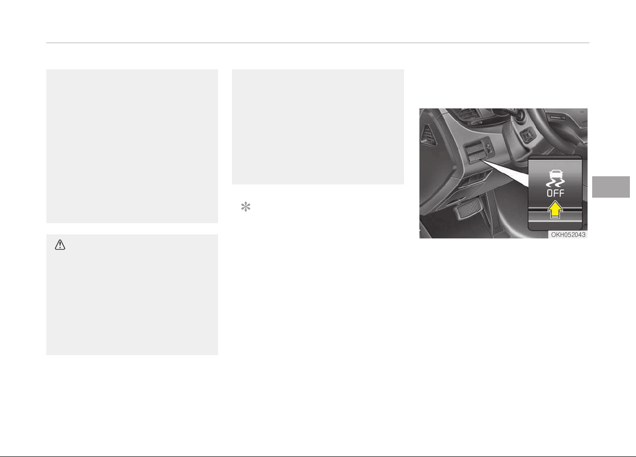
(Continued)
• The ABS warning light will stay on
for
approximately 3 seconds after
the Engine Start/Stop button is
ON. During that time, the ABS will
go through self-diagnosis and the
light will go off if everything is
normal. If the light stays on, you
may have a problem with your
ABS. In this case, have your vehicle
inspected by a professional work‐
shop. Kia recommends to contact
an authorized Kia dealer/service
partner.
CAUTION
• When you drive on a road having
poor
traction, such as an icy road,
and operate your brakes continu‐
ously, the ABS will be active con‐
tinuously and the ABS warning
light may illuminate. Pull your car
over to a safe place and stop the
engine.
(Continued)
(Continued)
• Restart the engine. If the ABS
warning
light is off, then your ABS
system is normal. Otherwise, you
may have a problem with the ABS.
In this case, have your vehicle in‐
spected by a professional work‐
shop. Kia recommends to contact
an authorized Kia dealer/service
partner.
NOTICE
When you jump start your vehicle
because of a drained battery, the
engine may not run as smoothly and
the ABS warning light may turn on
at the same time. This happens be‐
cause of the low battery voltage. It
does not mean your ABS is malfunc‐
tioning.
• Do not pump your brakes!
• Have the battery recharged before
driving the vehicle.
Electronic stability control (ESC)
(if equipped)
The Electronic Stability Control (ESC)
system is designed to stabilize the ve‐
hicle during cornering maneuvers. ESC
checks where you are steering and
where the vehicle is actually going. ESC
applies the brakes on individual wheels
and intervenes with the engine man‐
agement system to stabilize the vehi‐
cle.
5-37
5
Driving your vehicle

WARNING
Never drive too fast according to the
road conditions or too quickly when
cornering. Electronic Stability Control
(ESC) will not prevent accidents. Ex‐
cessive speed in turns, abrupt ma‐
neuvers and hydroplaning on wet
surfaces can still result in serious ac‐
cidents. Only a safe and attentive
driver can prevent accidents by
avoiding maneuvers that cause the
vehicle to lose traction. Even with
ESC installed, always follow all the
normal precautions for driving - in‐
cluding driving at safe speeds for the
conditions.
The Electronic Stability Control (ESC)
system is an electronic system de‐
signed to help the driver maintain vehi‐
cle control under adverse conditions. It
is not a substitute for safe driving
practices. Factors including speed, road
conditions and driver steering input can
all affect whether ESC will be effective
in preventing a loss of control. It is still
your responsibility to drive and corner
at reasonable speeds and to leave a
sufficient margin of safety.
When you apply your brakes under
conditions which may lock the wheels,
you may hear a tik-tik’’ sound from
the brakes, or feel a corresponding sen‐
sation in the brake pedal. This is normal
and it means your ESC is active.
NOTICE
A click sound may be heard in the
engine compartment when the vehi‐
cle begins to move after the engine
is started. These conditions are nor‐
mal and indicate that the Electronic
Stability Control System is function‐
ing properly.
ESC operation
ESC ON condition
• When the Engine Start/Stop
button is in the ON position,
ESC and ESC OFF indicator
lights illuminate for approx‐
imately 3 seconds, then ESC
is turned on.
• Press the ESC OFF button
for at least half a second
after placing the Engine
Start/Stop button to the
ON position to turn ESC off.
(ESC OFF indicator will illu‐
minate). To turn the ESC on,
press the ESC OFF button
(ESC OFF indicator light will
go off).
• When starting the engine,
you may hear a slight tick‐
ing sound. This is the ESC
performing an automatic
system self-check and does
not indicate a problem.
Driving your vehicle
5-38
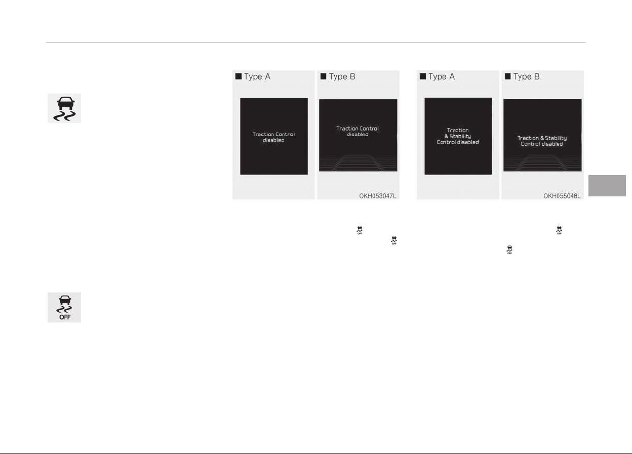
When operating
When the ESC is in operation,
the ESC indicator light blinks.
• When the Electronic Stabili‐
ty Control is operating
properly, you can feel a
slight pulsation in the vehi‐
cle. This is only the effect
of brake control and indi‐
cates nothing unusual.
• When moving out of the
mud or slippery road,
pressing the accelerator
pedal may not cause the
engine rpm (revolutions per
minute) to increase.
ESC operation off
ESC OFF state
This car has 2 kinds of ESC
off states.
If the engine stops when ESC
is off, ESC remains off. Upon
restarting the engine, the ESC
will automatically turn on
again.
• ESC off state 1
To cancel ESC operation, press the
ESC OFF button (ESC OFF
) shortly
(ESC OFF indicator light (ESC OFF )
illuminates). At this state, the engine
control function does not operate. It
means the traction control function
does not operate. Brake control func‐
tion only operates.
• ESC off state 2
To cancel ESC operation, press the
ESC OFF button (ESC OFF
) for
more than 3 seconds. ESC OFF indica‐
tor light (ESC OFF
) illuminates and
ESC OFF warning chime will sound. At
this state, the engine control function
and brake control function do not op‐
erate. It means the car stability con‐
trol function does not operate any
more.
5-39
5
Driving your vehicle
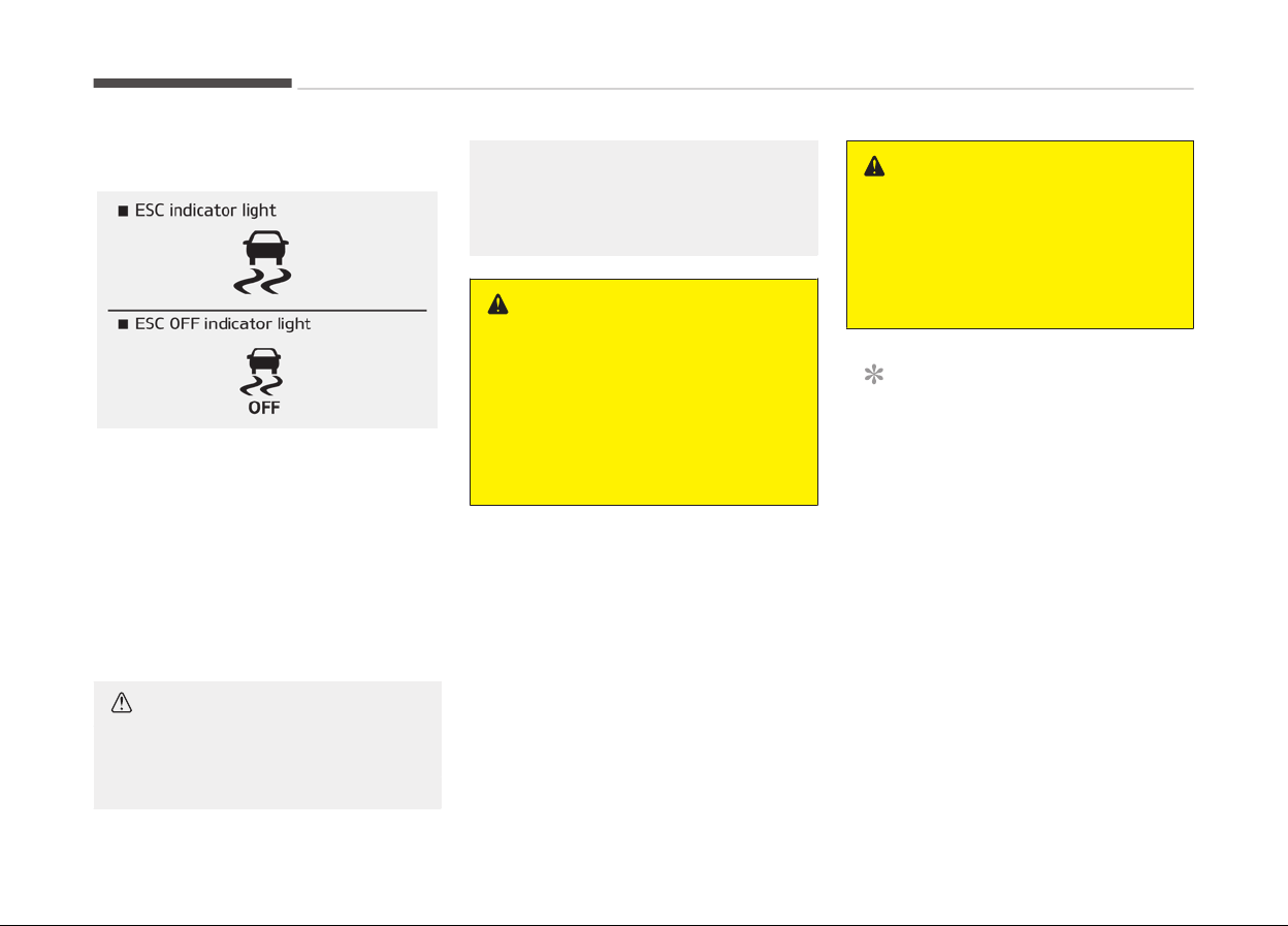
Indicator light
When Engine Start/Stop button is
pressed is turned to the ON position,
the indicator light illuminates, then
goes off if the ESC system is operating
normally.
The ESC indicator light blinks whenever
ESC is operating or illuminates when
ESC fails to operate.
ESC OFF indicator light comes on when
the ESC is turned off with the button.
CAUTION
Driving with varying tire or wheel
sizes
may cause the ESC system to
(Continued)
(Continued)
malfunction. When replacing tires,
make
sure they are the same size as
your original tires.
WARNING
The Electronic Stability Control is on‐
ly
a driving aid; use precautions for
safe driving by slowing down on
curved, snowy, or icy roads. Drive
slowly and don’t attempt to acceler‐
ate whenever the ESC indicator light
is blinking, or when the road surface
is slippery.
ESC OFF usage
When driving
• ESC should be turned on for daily
driving whenever possible.
• To turn ESC off while driving, press
the ESC OFF button while driving on a
flat road surface.
WARNING
Never press the ESC OFF button
while ESC is operating (ESC indicator
light blinks).
If ESC is turned off while ESC is op‐
erating, the vehicle may slip out of
control.
NOTICE
• When operating the vehicle on a
dynamometer, ensure that the
ESC is turned off (ESC OFF light il‐
luminated). If the ESC is left on, it
may prevent the vehicle speed
from increasing, and result in false
diagnosis.
• Turning the ESC off does not af‐
fect ABS or brake system opera‐
tion.
Driving your vehicle
5-40

Hill-start assist control (HAC)
A vehicle has the tendency to slip back
on a steep hill when it starts to go af‐
ter stopping. The Hill-start Assist Con‐
trol (HAC) prevents the vehicle from
slipping back by operating the brakes
automatically for about 2 seconds. The
brakes are released when the accelera‐
tor pedal is depressed or after about
2 seconds.
WARNING
The HAC is activated only for about
2 seconds, so when the vehicle is
starting off always depress the ac‐
celerator pedal.
NOTICE
• The HAC does not operate when
the transaxle shift lever is in the P
(Park) or N (Neutral) position.
• The HAC activates even though
the ESC is off but it does not acti‐
vate when the ESC has malfunc‐
tioned.
Good braking practices
WARNING
• Whenever leaving vehicle or park‐
ing, always set the parking brake
as far as possible and fully engage
the vehicle's transmission into the
park position. Vehicles not fully en‐
gaged in park with the parking
brake set are at risk for moving in‐
advertently and injuring yourself
or others.
• All vehicles should always have the
parking brake fully engaged when
parking to avoid inadvertent
movement of the car which can in‐
jure occupants or pedestrians.
• After parking the vehicle, check to be
sure the parking brake is not engaged
and that the parking brake indicator
light is out before driving away.
• Driving through water may get the
brakes wet. They can also get wet
when the car is washed. Wet brakes
can be dangerous! Your car will not
stop as quickly if the brakes are wet.
Wet brakes may cause the car to pull
to one side.
To dry the brakes, apply the brakes
lightly until the braking action returns
to normal, taking care to keep the car
under control at all times. If the brak‐
ing action does not return to normal,
stop as soon as it is safe to do so and
have your vehicle inspected by a pro‐
fessional workshop. Kia recommends
to call an authorized Kia dealer/serv‐
ice partner.
• Do not coast down hills with the car
out of gear. This is extremely hazard‐
ous. Keep the car in gear at all times,
use the brakes to slow down, then
shift to a lower gear so that engine
braking will help you maintain a safe
speed.
• Do not "ride" the brake pedal. Resting
your foot on the brake pedal while
driving can be dangerous because it
can result in the brakes overheating
and losing their effectiveness. It also
increases the wear of the brake com‐
ponents.
5-41
5
Driving your vehicle

• If a tire goes flat while you are driv‐
ing, apply the brakes gently and keep
the car pointed straight ahead while
you slow down. When you are moving
slowly enough for it to be safe to do
so, pull off the road and stop in a
safe place.
• If your car is equipped with an auto‐
matic transmission, don't let your car
creep forward. To avoid creeping for‐
ward, keep your foot firmly on the
brake pedal when the car is stopped.
• Be cautious when parking on a hill.
Firmly engage the parking brake and
place the shift lever in P (Park). If
your car is facing downhill, turn the
front wheels into the curb to help
keep the car from rolling. If your car
is facing uphill, turn the front wheels
away from the curb to help keep the
car from rolling. If there is no curb or
if it is required by other conditions to
keep the car from rolling, block the
wheels.
• Under some conditions your parking
brake can freeze in the engaged posi‐
tion. This is most likely to happen
when there is an accumulation of
snow or ice around or near the rear
brakes or if the brakes are wet. If
there is a risk that the parking brake
may freeze, apply it only temporarily
while you put the shift lever in P
(Park) and block the rear wheels so
the car cannot roll. Then release the
parking brake.
• Do not hold the vehicle on the up‐
grade with the accelerator pedal. This
can cause the transmission to over‐
heat. Always use the brake pedal or
parking brake.
Driving your vehicle
5-42
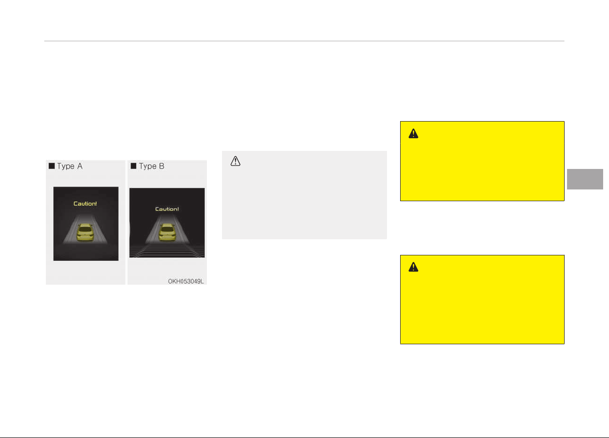
ADVANCED VEHICLE SAFETY MANAGEMENT (AVSM) (IF EQUIPPED)
AVSM detects the distance from the
vehicle ahead with the sensor, to warn
you before collision and protect you in
certain hazardous situations by using
warning message, warning sound and
seat belt vibration.
❈ The seat belt vibration is a optional
function.
• If the AVSM senses the object ahead
too near the vehicle and if driver's op‐
erating of the brake pedal or the
steering wheel should be needed, the
warning light illuminates.
Immediately reduce your speed.
• If the AVSM senses more dangerous,
the warning sound also operates and
the seat belt vibrates. Immediately
reduce your speed.
❈ The seat belt vibration is a optional
function.
CAUTION
Always check the road conditions to
prevent danger even if the warning
light does not illuminate, the warn‐
ing sound does not operate or the
accelerator pedal/seat belt does not
vibrate.
Brake operating
• If the AVSM senses the collision, the
brake system comes to standard
mode to react promptly when the
driver operates the brake pedal.
• If the driver releases the accelerator
after warning in hazardous situa‐
tions, the AVSM automatically brakes
the vehicle gently.
• If the driver hits the brake to reduce
vehicle speed, the brake assistant
system operates to raise efficiency
of braking.
• If danger disappears, if the driver de‐
presses the accelerator or if the driv‐
er releases the brake pedal, the brake
operating stop.
WARNING
The AVSM does not stop the vehicle
completely and does not avoid colli‐
sion. Always look ahead cautiously to
prevent unexpected and sudden sit‐
uations from occurring.
Seat belt operating (if equipped)
The seat belt tightens when the vehicle
senses a collision.
WARNING
The AVSM operates according to the
distance from the vehicle ahead, rel‐
ative velocity and driver's operation
of the brake or accelerator pedal. Do
not drive dangerously to operate the
AVSM.
5-43
5
Driving your vehicle
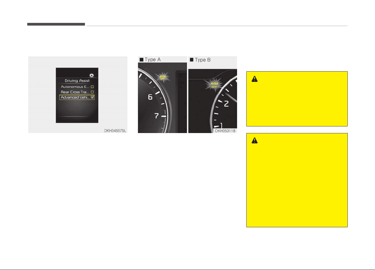
User setting mode
1. In user setting mode, select the
AVSM.
2. If you select [OFF], the warning for
collision or brake control is cancel‐
led and [AVSM OFF] indicator will
turn on. If you select [ON], the
warning for collision or brake con‐
trol is operated and [AVSM OFF] in‐
dicator will turn off.
Malfunction indicator
• The AVSM OFF indicator will illumi‐
nate when the engine start/stop but‐
ton is turned ON, but should go off
after approximately 3 seconds. If the
indicator does not come on, or con‐
tinuously remains on after coming on
for about 3 seconds when you turn
the engine start/stop button to the
ON position, or if the indicator comes
on while driving, the AVSM is not
working properly. In this case, have
the system checked by a professional
workshop. Kia recommends to visit
an authorized Kia dealer/ service
partner.
• The AVSM OFF indicator may illumi‐
nate when the ESC indicator or SCC
indicator comes on, but it does not in‐
dicate malfunction of the AVSM.
WARNING
The AVSM is not a substitute for
safe driving practices but a supple‐
mentary function only. It is the re‐
sponsibility of the driver to always
check the speed and the distance to
the vehicle ahead.
WARNING
• Even if there is a malfunction to
the brake operating of the AVSM,
when you depress the brake pedal,
the brake is operating normally.
But, the AVSM brake operating
does not operate even in certain
hazardous situations.
• The AVSM is designed to function
above approximately 15 km/h and
below approximately 180 km/h .
• The AVSM does not react to
(Continued)
Driving your vehicle
5-44

(Continued)
- Persons or animals.
- Oncoming vehicles in the oppo‐
site
lane or the vehicle in the in‐
tersection.
-
Stopped objects.
• The AVSM can not detect the ob‐
jects certainly, when:
- The sensors are stained with
dirt or covered.
- There is heavy rain or heavy
snow.
- There is interference by elec‐
tromagnetic waves.
- There are strong radar reflec‐
tions.
- Driving in curve.
- Driving uphill or downhill.
- Driving in areas under construc‐
tion.
- The object ahead is very narrow
such as motorcycles or bicycles.
- The vehicle cuts in suddenly.
(Continued)
(Continued)
• The AVSM brake operating does
not
operate, if the driver does not
release the accelerator pedal or
does not operate the brake pedal.
5-45
5
Driving your vehicle
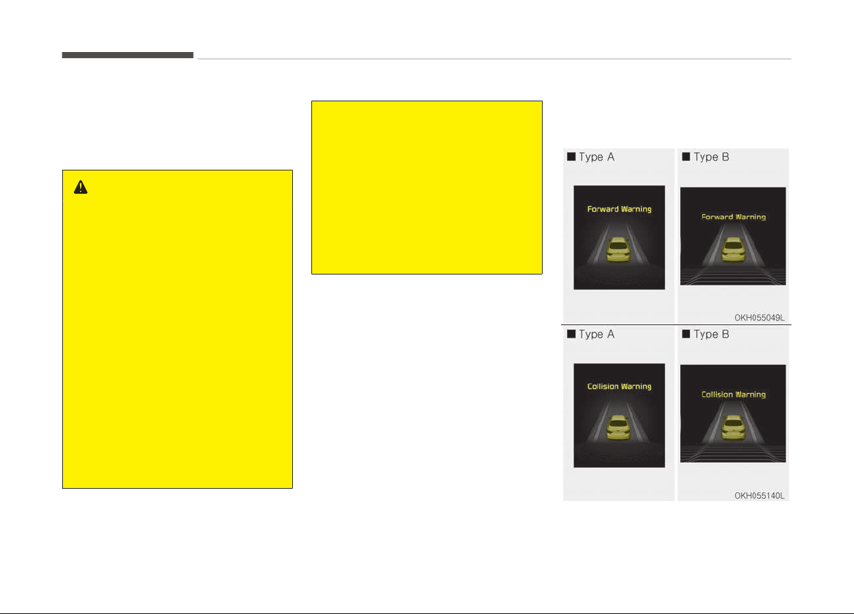
AUTONOMOUS EMERGENCY BRAKING (AEB) (IF EQUIPPED)
The Autonomous Emergency Braking
(AEB) helps avoid accidents by identify‐
ing critical situations early and warning
the driver.
WARNING
Take the following precautions when
using the Autonomous Emergency
Braking (AEB):
• This system is only a supplemen‐
tal system and it is not intended
to, nor does it replace the need for
extreme care and attention of the
driver. The sensing range and ob‐
jects detectable by the sensors are
limited. Pay attention to the road
conditions at all times.
• NEVER drive too fast for the road
c
onditions or too quickly when cor‐
nering.
• Always drive cautiously to prevent
unexpected
and sudden situations
from occurring. AEB does not stop
the vehicle completely and does
not avoid collisions.
(Continued)
(Continued)
• AEB operates according to the dis‐
tance from the vehicle ahead, rela‐
tive velocity, and driver's operation
of the brake or accelerator pedal.
Do not drive dangerously to inten‐
tionally operate the AEB.
• ALWAYS check the speed and the
distance to the vehicle ahead. The
AEB is not a substitute for safe
driving practices.
AEB Operation
Warning message
Driving your vehicle
5-46
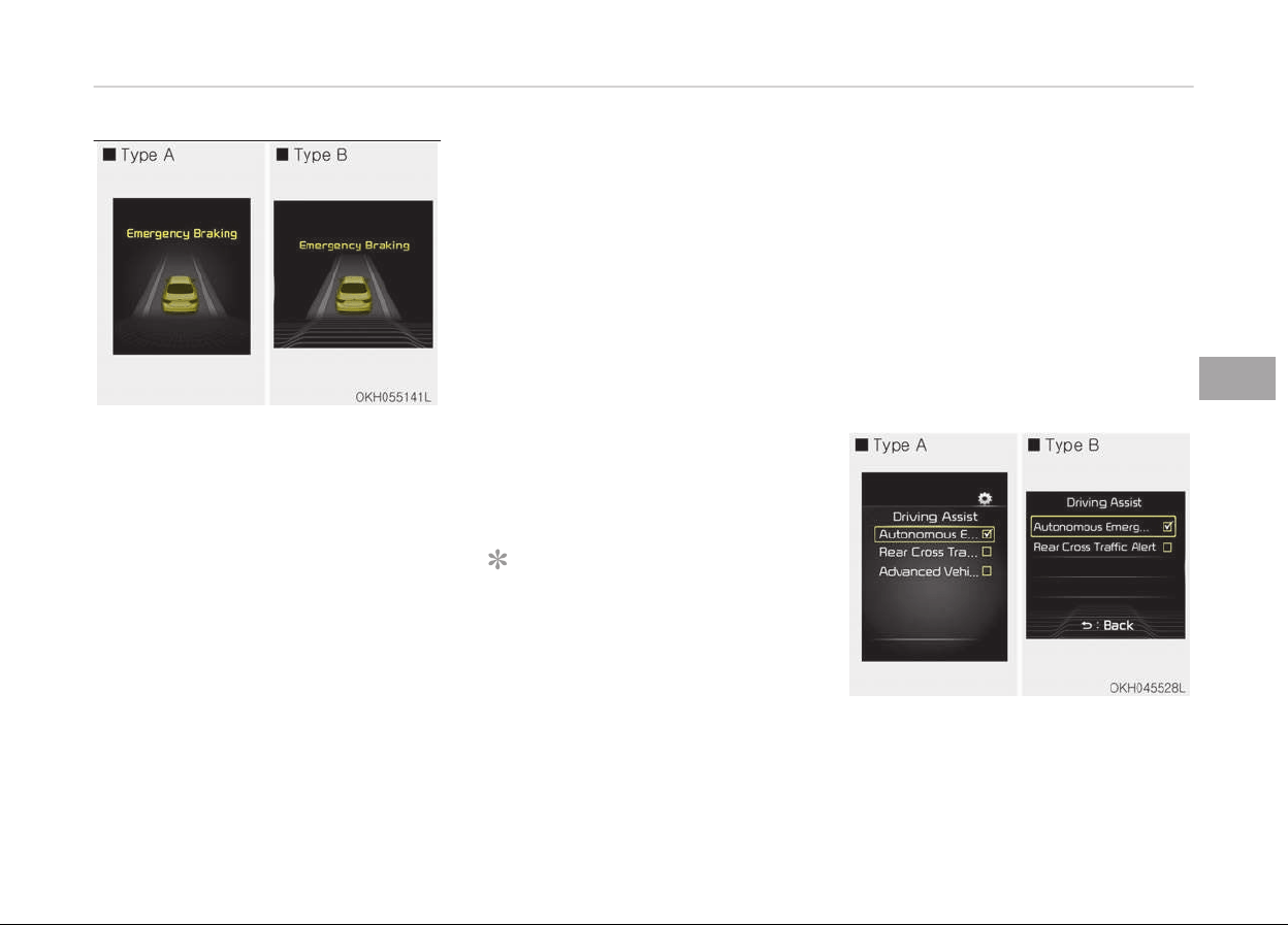
A warning message and chime will
sound when you need to use the brake
pedal or steering wheel due to a sud‐
den stop or lack of distance with the
vehicle ahead. The warning messages
will vary according to the severity of
the situation. Immediately reduce your
speed to prevent a collision.
Brake operation
In a critical situation:
• The brake assist system enters
standby mode to react promptly
when the driver operates the brake
pedal.
• The vehicle automatically reduces
speed according to the severity of
the situation.
- Rapidly reduces speed when vehi‐
cle speed is under 80 km/h
- Slowly reduces speed when vehicle
speed is over 80 km/h
• If the driver uses the brake pedal to
reduce vehicle speed, the brake assist
system operates to increase braking
efficiency.
• If the driver presses down hard on
the accelerator pedal or sharply turns
the steering wheel, the brake assist
system is canceled.
Seat belt operation
The driver's and passenger's seat belt
may tighten if the system detects that
a vehicle or object is close.
NOTICE
• If the AEB is canceled from the
User Settings Mode or there is a
problem with the AEB system, the
Automatic Emergency Mode will
not work.
(Continued)
(Continued)
• If
the ESC is off or there is a prob‐
lem with the ESC system, the Au‐
tomatic Emergency Mode will not
work.
• The ESC must be on for the Auto‐
matic Emergency Mode to control
ESC in collision situations.
To cancel the AEB
5-47
5
Driving your vehicle
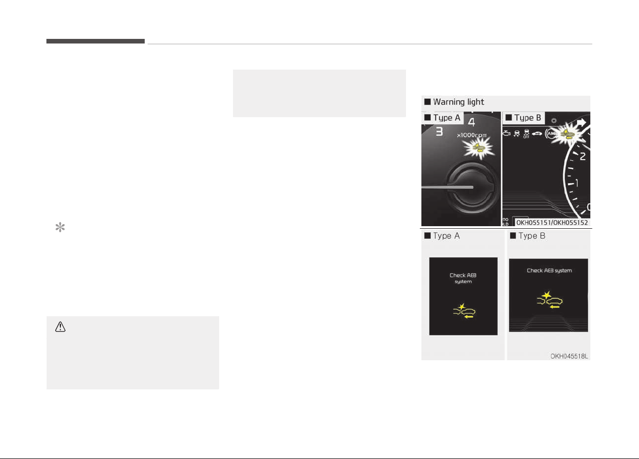
• Go to the User Settings Mode (Driving
Assist) and undo the check for AEB
(Autonomous Emergency Braking) on
the LCD display (For more details, re‐
fer to LCD display on page 4-56.).
The warning operation and automatic
braking operation will not function.
• To turn on the AEB, select AEB (Au‐
tonomous Emergency Braking) from
the User Settings Mode (Driving As‐
sist) on the LCD display. The warning
operation and automatic braking op‐
eration will function.
NOTICE
When the engine is started, AEB is
automatically turned on. If the sys‐
tem is not needed, turn the AEB
system off from the User Settings
Mode on the LCD display.
CAUTION
If the AEB is selected and the ESC
(Electronic
Stability Control) is
turned off from the User Settings
(Continued)
(Continued)
Mode, the AEB system is automati‐
cally canceled.
Malfunction indicator
Driving your vehicle
5-48

• When the AEB system is turned off,
the AEB warning light turns on.
(Warning message does not come
on.)
• If the sensor or cover is dirty or ob‐
scured with foreign matter such as
snow, the AEB warning light and
message comes on. In this case, the
AEB system may not function tem‐
porarily, but it does not indicate a
malfunction of the AEB system. Clean
the sensor or cover by using a soft
cloth.
• If there is a malfunction with the AEB
system, the AEB warning light and
message will come on. We recom‐
mend that the vehicle be checked by
an authorized Kia dealer.
• When the ESC (Electronic Stability
Control) or SCC (Smart Cruise Control)
message comes on, the AEB warning
message may come on but it does
not indicate a malfunction of the AEB
system.
WARNING
• Even if there is a malfunction to
the brake operation of the AEB,
when you depress the brake pedal,
the brake operates normally. AEB
brake operation does not operate
in certain hazardous situations.
• The AEB is designed to function
above approximately 8 km/h and
below approximately 180 km/h.
• The AEB does not detect:
- Persons or animals.
- Oncoming vehicles in the oppo‐
site lane or a vehicle in an inter‐
section.
- Stopped objects.
• The AEB cannot detect objects,
when:
- The sensors are covered with
dirt.
- There is heavy rain or heavy
snow.
- There is interference by elec‐
tromagnetic wav
es.
(Continued)
(Continued)
- There are strong radar reflec‐
tions.
- Driving in a curve.
- Driving uphill or downhill.
-
Driving in areas under construc‐
tion.
- An object ahead is very narrow
such as motorcycles or bicycles.
- A vehicle suddenly enters your
lane.
- The camera cannot secure a
clear view.
- The camera cannot catch the
whole vehicle.
- An unusual shape vehicle is
ahead such as a trailer, special
access vehicle or a truck with
unique shaped cargo.
- Driving at night, the tail lamp of
the vehicle ahead is missing, in‐
stalled on an unusual place or
installed unevenly.
-
Coming in or out of a tunnel,
wher
e the illumination intensity
is high.
5-49
5
Driving your vehicle
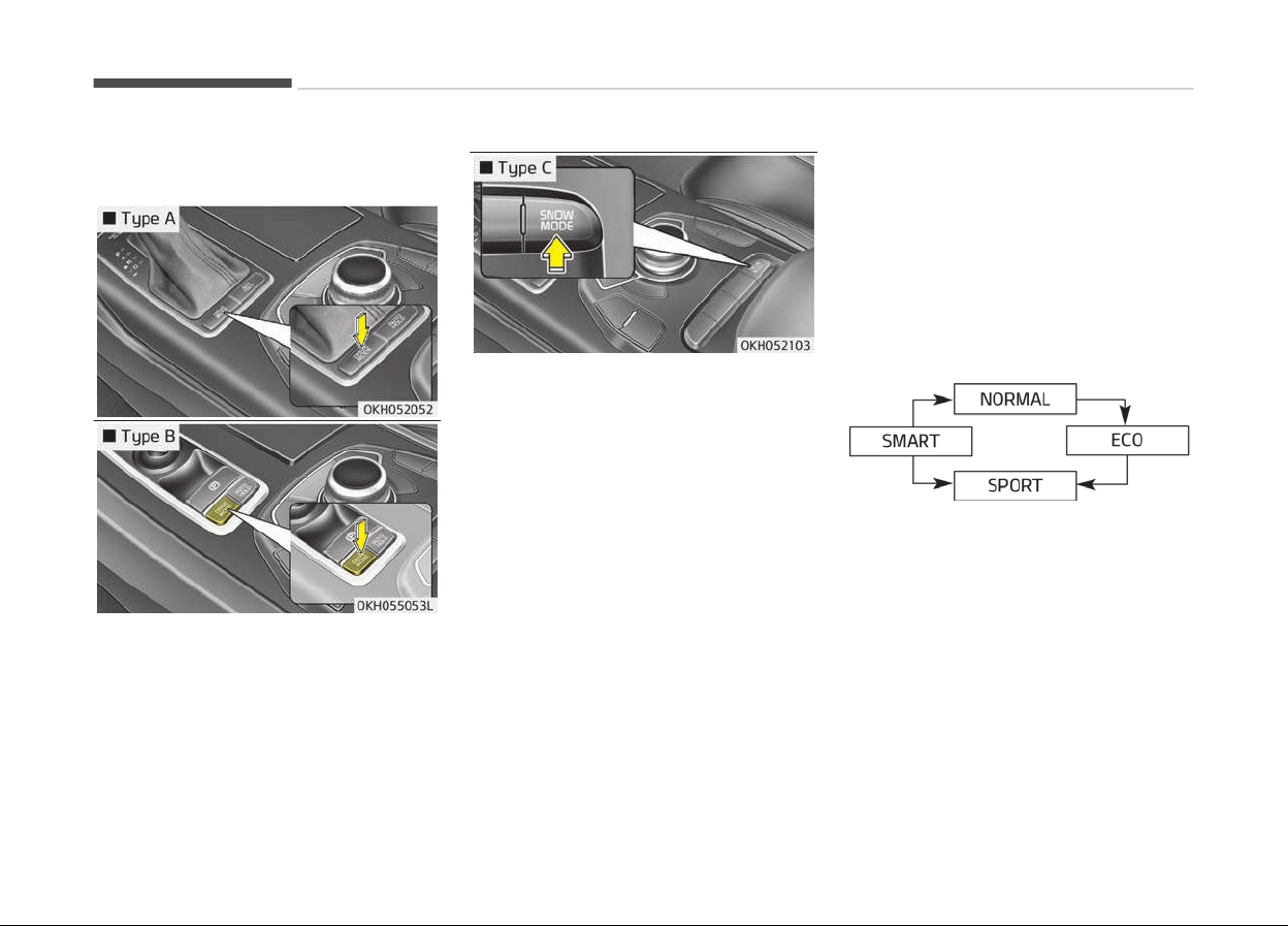
DRIVE MODE INTEGRATED CONTROL SYSTEM
Drive mode / Snow mode
The driver can personalize the DRIVE
MODE based on vehicle control prefer‐
ence and driving style.
Below is a list of the message which
will appear on the upper AVN screen.
• NORMAL MODE:
Drive mode for smooth and high ride
quality.
• ECO (ACTIVE ECO) MODE:
Drive mode optimized for economic
driving.
• SPORT MODE:
Drive mode for aggressive driving and
solid ride quality.
• SMART MODE:
Depending on the driver's driving style
(Ec
onomic ↔ Aggressive), drive mode
will automatically change among ECO ↔
NORMAL ↔ SPORT.
• SNOW MODE
DRIVE MODE optimized for slippery
road surfaces.
Below is a diagram of mode changes
when pressing the DRIVE MODE button.
❈ When selecting the NORMAL
MODE , nothing will show up on the
dashboard
• If you select the SNOW MODE, the
SNOW MODE will operate regardless
of previously selected mode (NOR‐
MAL / ECO / SPORT / SMART).
Press the SNOW MODE button one
more time to return back to the pre‐
viously selected DRIVE MODE (NOR‐
MAL / ECO / SPORT / SMART).
Driving your vehicle
5-50

• If you turn off the engine of the vehi‐
cle in any of the NORMAL / ECO /
SMART MODE, and restart the en‐
gine, DRIVE MODE will memorize and
return to the previous drive mode
setting. (With exception of SPORT
MODE. If the engine is turned off in
SPORT MODE, DRIVE MODE will be re‐
set to NORMAL MODE).
ECO (Active ECO) mode
• ACTIVE ECO system enhan‐
ces fuel efficiency through
eco control of the engine
and transmission. The ac‐
tual fuel efficiency will de‐
pend on personal driving
style and habits.
• By pressing the DRIVE
MODE button and selecting
ECO MODE, green ECO indi‐
cator light will illuminate.
ECO mode driving
The vehicle engine and transmission will
operate in fuel economy oriented
mode.
ACTIVE ECO MODE system will restrain
fuel economy worsening driving habits,
such as suddenly starts and accelera‐
tions, compare to the NORMAL MODE.
Conditions that limit active ECO
mode
Below are a list of conditions in which
when in ACTIVE ECO MODE, the indica‐
tor light will not change, but the inter‐
nal system may operate differently.
• When engine coolant temperature is
low:
When temperature of the transaxle
oil is below the normal range, the AC‐
TIVE ECO MODE may become tempo‐
rarily unavailable until the transaxle
oil heats up after vehicle ignition.
• When in an uphill gradient:
Since the ACTIVE ECO MODE partially
limits the engine torque, ACTIVE ECO
MODE may become temporarily un‐
available when more torque is essen‐
tial for going uphill.
• When using the manual transmission
operation mode:
If transmission operation is changed
from automatic to manual, vehicle
will reflect it and automatically stop
the ACTIVE ECO MODE.
5-51
5
Driving your vehicle

Sport mode
• When the DRIVE MODE button is pressed and the SPORT MODE is selected, the SPORT indicator (red) will illumi‐
nate on the dashboard.
• When the SPORT MODE is activated, and the Engine Start/Stop button is turned off and on again, drive mode
will reset to NORMAL MODE.
To turn on SPORT MODE, press DRIVE MODE button again.
• If the system is activated:
- After increasing speed and turning your foot off the accelerator pedal, it maintains the current gear and RPM
for some time even though the accelerator pedal is not depressed.
- Up-shift during acceleration is delayed.
NOTICE
In SPORT DRIVE MODE, the fuel efficiency may decrease.
Driving your vehicle
5-52

Snow mode (if equipped)
• SNOW MODE helps the driver drive more effectively on slippery road surfaces in snowy or muddy conditions.
• If the SNOW MODE button is pressed, the SNOW MODE will operate regardless of whichever drive mode (NOR‐
MAL/ ECO / SPORT / SMART) the vehicle is in.
If the SNOW MODE button is pressed once more, the DRIVE MODE (NORMAL / ECO / SPORT / SMART) will return
to the previously selected mode.
5-53
5
Driving your vehicle

Smart mode
• SMART MODE is an intelligent driving mode which automatically selects the most appropriate drive mode (Eco‐
nomic ↔ Aggressive) by measuring usage of steering wheel, and accelerator pedal.
• When DRIVE MODE button is pressed and the SMART MODE is selected, SMART indicator will illuminate on the
dashboard.
• The color of the SMART MODE indicator light will depend on the driving style. If the driving style is economic,
average, and speedy, the indicator light will be green, white, and red in respective order.
• When the SMART MODE is activated, and the Engine Start/Stop button is turned off and on again, your car will
still maintain the SMART MODE.
• Below is a summary of the automatic drive mode control depending on the usage of the steering wheel, engine and trans‐
axle system.
Driving style SMART DRIVE MODE
Gear Shift Pat‐
tern
Engine Torque Ride Quality
Economic
SMART
ECO
Fuel Efficient Fuel Efficient
Smooth
Average
SMART
NORMAL
Average Average
Aggressive
SMART
SPORT
Acceleration Highly Responsive Hard
Driving your vehicle
5-54

CAUTION
• SMART MODE an intelligent driving mode and when the driving style is economic and fuel efficient, the SMART ECO MODE
will be automatically selected. The engine and transaxle system will become more fuel efficient, but the actual fuel econ‐
omy will depend on various driving factors (on uphill/ downhill, heavy revving or braking).
• If you make sudden accelerations or turns in SMART MODE, the intelligent mode will select SMART SPORT MODE. This
may decrease fuel efficiency.
DRIVE MODE Indicator Screen
The DRIVE MODE indicator screen can
be displayed by using the trip computer
button on the steering wheel.
DRIVE MODE indicator screen displays
status of current drive mode.
• DRIVE MODE button is located on the
lower part of the transmission lever
for selecting drive mode.
If drive mode is selected manually by
the user, the drive mode indicator
screen will show user-selected drive
mode. (NORMAL, ECO, or SPORT)
If SMART MODE is selected by DRIVE
MODE button, the drive mode indica‐
tor screen will show current drive
mode automatically selected by
SMART MODE system. (SMART NOR‐
MAL, SMART ECO, or SMART SPORT)
• When the trip computer mode is se‐
lected to show DRIVE MODE and the
SMART MODE is in operation, an au‐
tomatically selected driving mode
SMART ECO, SMART NORMAL, or
SMART SPORT, will be selected on the
cluster's center.
And right below is the horizontal driv‐
ing style gauge which reflects the
driving style in real time.
• If you drive carefully and slowly in
SMART MODE, the left side of the
driving style gauge will illuminate,
and be automatically shifted to the
SMART ECO MODE.
When the driver accelerates more
frequently, the right side of the driv‐
ing style gauge will fill up, and shift to
SMART NORMAL MODE.
In addition, if the rate of acceleration
and speed is high, drive mode will
change to SMART SPORT MODE.
• If the auto cruise control function is
operated or the transmission is shif‐
ted to manual mode while SMART
MODE is on, the SMART MODE will
stop temporarily, and the DRIVE
MODE will be displayed as OFF. The
driving style gauge light will be
turned off accordingly.
5-55
5
Driving your vehicle
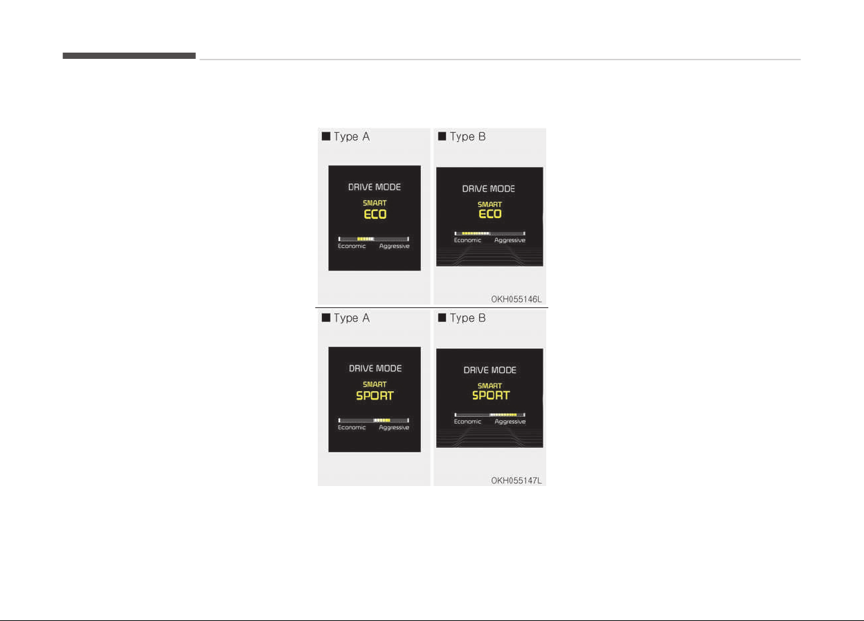
• If the trip computer is not set to
show DRIVE MODE indicator screen,
and you want to know the on/off
status of the SMART MODE, simply
check whether the letters 'SMART' is
lighten up on the screen or not (green
- ECO MODE, white - NORMAL MODE,
red - SPORT MODE).
Driving Style Gauge
Once the SMART MODE is selected by
pressing the DRIVE MODE button, and
the DRIVE MODE indicator screen is se‐
lected by pressing the trip computer
button on the steering wheel, the driv‐
ing style gauge bar will show up at the
bottom of screen and visualize current
style of driving.
• Left poles of the driving style gauge
indicates degree of economic and
gentle driving in green color. The
more economic and gentle you drive,
the more left poles will light up in
green.
Likewise, the right pole of the driving
style gauge indicates degree of ag‐
gressive and sporty driving in red col‐
or. The faster and more aggressive
you drive, the more far right poles
will light up in red.
• When driving style gauge fills up to‐
ward left side (or Economic side) and
kept for certain time, then your vehi‐
cle will be automatically switch to
SMART ECO MODE.
Likewise, when driving style gauge
fills up toward right side (or Aggres‐
sive side) and kept for certain time,
then your vehicle will be automatical‐
ly the switch to SMART SPORT MODE.
• If you wish to maintain the SMART
ECO MODE for better fuel economy,
try to maintain an economic driving
style and keep the driving style
gauge green.
Driving your vehicle
5-56

Attributes of SMART MODE.
• If the accelerator pedal is pressed
gently, your vehicle will recognize it
as an economic driving style. After
some time, the system will automati‐
cally shift to SMART ECO MODE.
• If you press the accelerator pedal
frequently and heavily in SMART ECO
MODE, the system will automatically
shift to SMART NORMAL MODE.
• Even when driving style has not
changed from SMART ECO MODE, if
your vehicle is driven uphill considera‐
bly, the system will detect the gradi‐
ent. Then, the SMART system will au‐
tomatically change the setting to the
SMART NORMAL MODE temporarily.
Once your vehicle is out of the hilly
ground, your vehicle will automatical‐
ly return to the SMART ECO MODE.
• The SMART system will recognize
sudden and repetitive acceleration or
steering as aggressive driving and au‐
tomatically turn to the SMART SPORT
MODE. Your vehicle will run at a lower
gear in SMART SPORT MODE com‐
pared to those in SMART NORMAL
MODE.
The vehicle's start and stop response
rate will become faster.
• When the SMART SPORT MODE is ac‐
tivated, and you take your feet off
the accelerator pedal, the vehicle will
remain in low gear and you may
sense engine brake. This is due to
necessary preparatory time for the
next acceleration and is only normal.
• The SMART SPORT MODE is activated
only when very aggressive and high
speed is detected. Therefore, in aver‐
age driving styles, the SMART system
will select either SMART ECO or
SMART NORMAL MODE.
• The artificial intelligence algorithm
will instantly calculate each driver's
style of driving. So if the driver is
changed to a different person, the al‐
gorithm will measure accordingly.
Conditions which Limit SMART
MODE
In following conditions your vehicle will
temporarily stop the SMART Mode and
the indicator light will turn off.
• When using the manual transmission
operation mode: If the transaxle sys‐
tem is changed from automatic to
manual, your vehicle will automatical‐
ly stop the SMART MODE.
If transmission operation is changed
from automatic to manual, the vehi‐
cle will reflect it and automatically
stop the SMART MODE.
• When the Cruise Control system is
turned on:
When the driver sets a target cruise
control speed, your vehicle will auto‐
matically stop the SMART MODE.
(The SMART MODE will not stop im‐
mediately after you press the cruise
control button, but when the cruise
control system takes control of the
vehicle speed.)
• If the temperature of the transaxle
oil is very high or low:
The SMART MODE control system will
operate in nearly all driving condi‐
tions. But when the temperature of
the transaxle oil is out of the normal
range, the SMART MODE system may
become temporarily unavailable.
5-57
5
Driving your vehicle
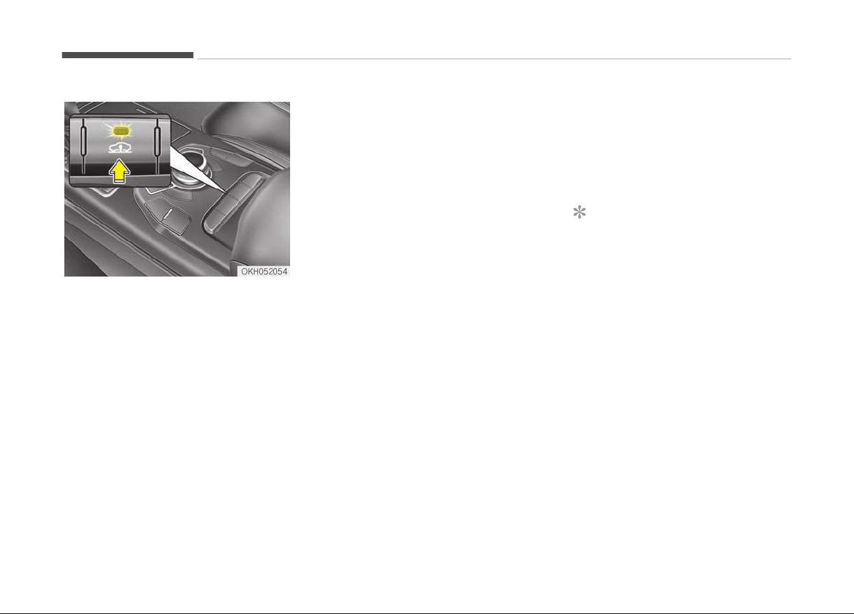
ELECTRONIC CONTROLLED SUSPENSION (ECS) (IF EQUIPPED)
ECS controls the vehicle suspension au‐
tomatically to maximise passenger
comfort by using the air spring in the
suspension.
You can also control the vehicle suspen‐
sion manually in NORMAL mode or HIGH
mode.
To control the vehicle height
• Push the vehicle height control but‐
ton to select the HIGH mode that
makes the vehicle height be higher
than the NORMAL mode and the indi‐
cator light on the vehicle height con‐
trol button will illuminate. It is useful
on rough roads.
• Push the vehicle height control but‐
ton again to select the NORMAL
mode that makes the vehicle height
lower than the HIGH mode. The indi‐
cator light in the vehicle height con‐
trol button will go off.
• When the vehicle stops with the shift
lever in P(Park) or N(Neutral), you
may change the vehicle height.
• When you drive under 70 km/h, you
may select the HIGH mode.
• If the vehicle speed exceeds 70 km/h
while driving in the HIGH mode, the
NORMAL mode will be selected auto‐
matically.
• If the vehicle speed exceeds
120 km/h while driving in NORMAL
mode, the LOW mode that is lower
than NORMAL mode will be selected
automatically. LOW mode can not be
selected manually.
• When you drive under 80 km/h in the
LOW mode, the NORMAL mode will be
selected automatically.
• When the engine start/stop button is
turned off with the HIGH mode selec‐
ted, the HIGH mode will be main‐
tained.
It is to prevent damage under the ve‐
hicle when parked in rough roads.
• The height of the vehicle may be ad‐
justed after the engine start/stop
button is turned off for
2 hours/5 hours/10 hours.
It is to compensate vehicle height af‐
fected by outside temperature.
NOTICE
• When you drive over 70 km/h, you
may not select the HIGH mode.
• Do not operate ECS when the air
filter of the compressor in the
lower part of the vehicle sinks un‐
der water.
Indraft of water into the compres‐
sor may happen, and ECS may not
operate normally.
Driving your vehicle
5-58
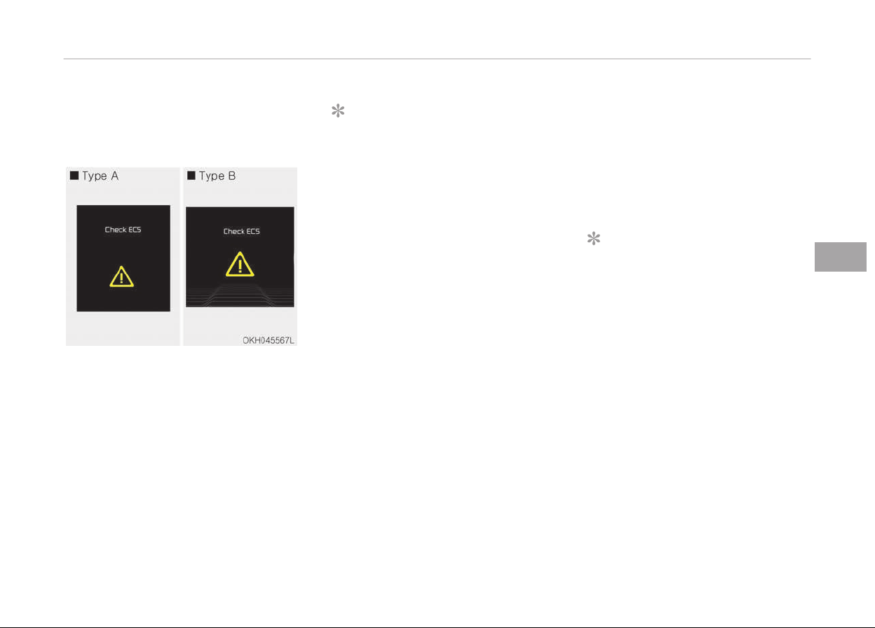
ECS (Electronic Controlled
Suspension) malfunction
warning message
If the ECS warning message may come
on, you may have a problem with the
ECS system. Kia recommends to visit
an authorized Kia dealer/service part‐
ner.
NOTICE
• Make sure there are no objects
under the vehicle before changing
the vehicle height.
• A click sound may be heard while
operating ECS, but these condi‐
tions are normal and indicate that
ECS is functioning properly.
• Depending on the outside temper‐
ature the vehicle height may be
different.
• When the vehicle is parked with
one side of the vehicle lifted or ve‐
hicle speed is suddenly acceler‐
ated/decelerated or the steering
wheel is suddenly turned, the
height may not temporarily be ad‐
justed. This is to protect the sys‐
tem.
• When one side of the vehicle was
lifted with a jack, the height may
not temporarily be adjusted. The
ECS will operate normally when
the engine is turned on again or
when the vehicle is accelerated.
(Continued)
(Continued)
• When
the vehicle is not driven for
a long period of time, vehicle
height may get low. The ECS will
operate normally when the engine
is turned on.
NOTICE
• If the battery is discharged, the
ECS warning message may comes
on to protect the system.
• When the height is adjusted re‐
peatedly, the height may not tem‐
porarily be adjusted for the com‐
pressor overheats. This is to pre‐
vent damage to related parts.
5-59
5
Driving your vehicle
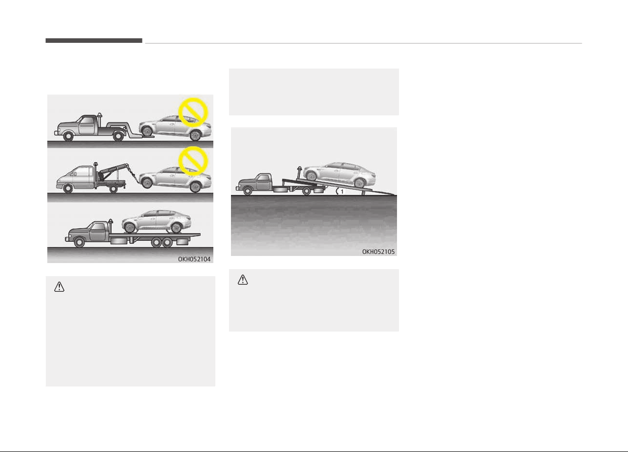
Towing your vehicle
CAUTION
If the ECS warning message comes
on
when there is no air in the sus‐
pension, the vehicle height will be
very low, so do not drive to protect
the vehicle from the projections on
the surface of the ground. Kia rec‐
ommends to visit an authorized Kia
(Continued)
(Continued)
dealer/service partner. You should
tow the v
ehicle as the picture.
CAUTION
When you load the vehicle onto the
tow truck, the loading angle (1)
should be smaller than 5°.
Driving your vehicle
5-60
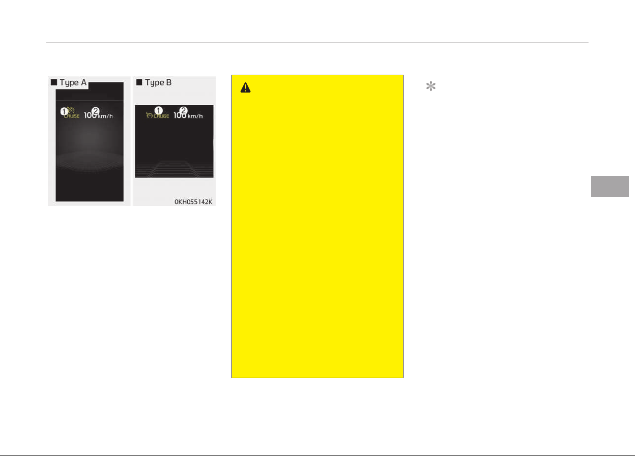
CRUISE CONTROL SYSTEM (IF EQUIPPED)
1. Cruise indicator
2. Set speed
The cruise control system allows you to
program the vehicle to maintain a con‐
stant speed without depressing the ac‐
celerator pedal.
This system is designed to function
above approximately 30 km/h.
WARNING
• If the cruise control is left on,
(CRUISE indicator light in the in‐
strument cluster is illuminated),
the cruise control can be switched
on accidentally. Keep the cruise
control system off (CRUISE indica‐
tor light OFF) when the cruise con‐
trol is not in use, to avoid inadver‐
tently setting a speed.
• Use the cruise control system only
when driving on open highways in
good weather.
• Do not use the cruise control when
it may not be safe to keep the ve‐
hicle at a constant speed, for in‐
stance, driving in heavy or varying
traffic, or on slippery (rainy, icy or
snow-covered) or winding roads or
over 6% uphill or down-hill roads.
• Pay particular attention to the
driving conditions whenever using
the cruise control system.
• Be careful when driving downhill
using the cruise control system,
which may increase the vehicle
speed.
NOTICE
• During normal cruise control oper‐
ation, when the SET switch is acti‐
vated or reactivated after applying
the brakes, the cruise control will
energize after approximately
3 seconds. This delay is normal.
• To activate cruise control, depress
the brake pedal at least once after
pressing the Engine Start/Stop
button to the ON position or start‐
ing the engine. This is to check if
the brake switch, which is an im‐
portant part, to cancel cruise con‐
trol, is in normal condition.
5-61
5
Driving your vehicle
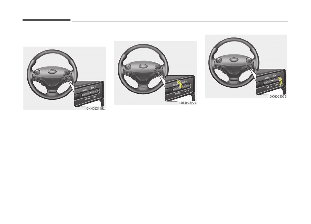
Cruise control switch
CRUISE : Turns cruise control system on
or off.
CANCEL: Cancels cruise control opera‐
tion.
RES+: Resumes or increases cruise con‐
trol speed.
SET-: Sets or decreases cruise control
speed.
To set cruise control speed:
1. Move the lever up (to CRUISE), to
turn the system on. The CRUISE in‐
dicator light will illuminate.
2. Accelerate to the desired speed,
which must be more than 30 km/h .
3. Move the lever down (to SET-), and
release it at the desired speed. The
set speed will illuminate. Release
the accelerator pedal at the same
time. The desired speed will auto‐
matically be maintained.
On a steep grade, the vehicle may slow
down or speed up slightly while going
uphill or downhill.
Driving your vehicle
5-62
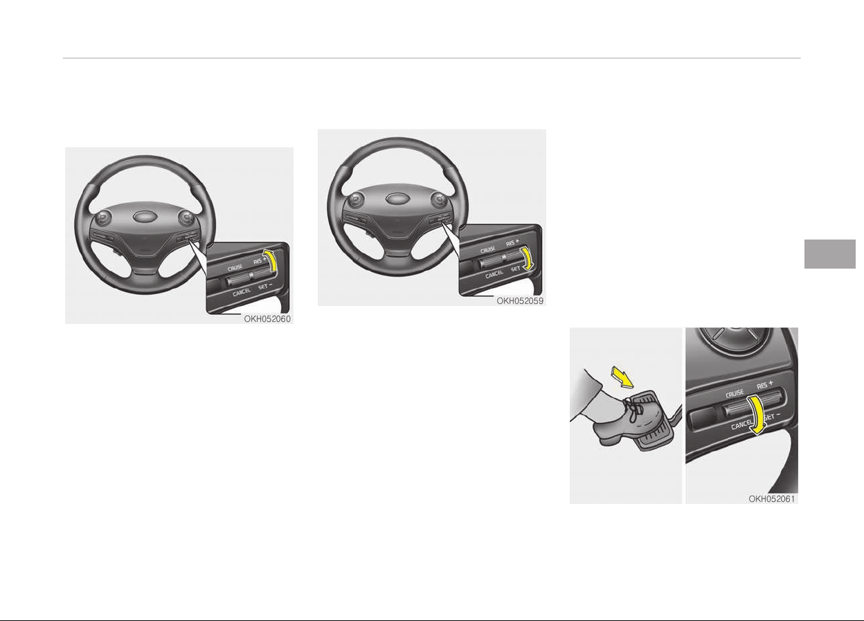
To increase cruise control set
speed:
Follow either of these procedures:
• Move the lever up (to RES+) and hold
it. Your vehicle will accelerate. Re‐
lease the lever at the speed you
want.
• Move the lever up (to RES+) and re‐
lease it immediately. The cruising
speed will increase by 2.0 km/h or
1 mph each time you move the lever
up (to RES+) in this manner.
To decrease the cruising speed:
Follow either of these procedures:
• Move the lever down (to SET-) and
hold it. Your vehicle will gradually
slow down. Release the lever at the
speed you want to maintain.
• Move the lever down (to SET-) and
release it immediately. The cruising
speed will decrease by 2.0 km/h or
1 mph each time you move the lever
down (to SET-) in this manner.
To temporarily accelerate with
the cruise control on:
If you want to speed up temporarily
when the cruise control is on, depress
the accelerator pedal. Increased speed
will not interfere with cruise control op‐
eration or change the set speed.
To return to the set speed, take your
foot off the accelerator pedal.
If you move the lever down (to SET-) at
the increased speed, the cruising speed
will be set again.
To cancel cruise control, do one
of the following:
• Depress the brake pedal.
5-63
5
Driving your vehicle
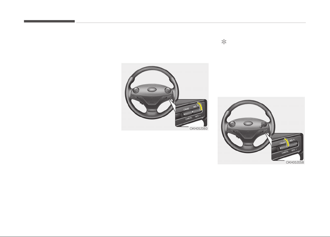
• Shift into N (Neutral) with an auto‐
matic transaxle.
• Move up the lever (to CANCEL) loca‐
ted on the steering wheel.
• Decrease the vehicle speed lower
than the memory speed by 20 km/h .
• Decrease the vehicle speed to less
than approximately 30 km/h .
• Increasing the vehicle speed to more
than approximately 200 km/h .
• The ESC is operating.
•
Downshifting to the 2
nd
gear in man‐
ual mode.
• Operating the EPB switch. Do not op‐
erate the parking brake while driving
except in an emergency situation.
Each of these actions will cancel cruise
control operation (the set speed in the
instrument cluster will go off), but it
will not turn the system off. If you wish
to resume cruise control operation,
move up the lever (to RES+) located on
your steering wheel. You will return to
your previously preset speed.
To resume cruising speed at
more than approximately
30 km/h(20 mph):
If any method other than the CRUISE
lever was used to cancel cruising speed
and the system is still activated, the
most recent set speed will automatical‐
ly resume when you move the lever up
(to RES+).
It will not resume, however, if the vehi‐
cle speed has dropped below approxi‐
mately 30 km/h (20 mph).
NOTICE
Always check the road conditions
when you move the lever up (to RES
+) to resume the speed.
To turn cruise control off, do
one of the following:
• Move the lever up (to CRUISE). (the
CRUISE indicator light in the instru‐
ment cluster will go off)
• Turn the engine off.
Driving your vehicle
5-64

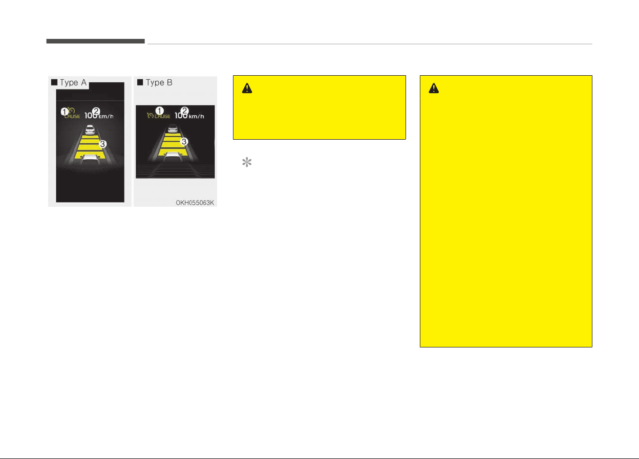
ADVANCED SMART CRUISE CONTROL SYSTEM (IF EQUIPPED)
1. Cruise indicator
2. Set speed
3. Vehicle-to-vehicle distance
The smart cruise control system allows
you to program the vehicle to maintain
constant speed and distance detecting
the vehicle ahead without depressing
the accelerator pedal.
WARNING
For your safety, please read the
owner's manual before using the
smart cruise control system.
NOTICE
To activate smart cruise control, de‐
press the brake pedal at least once
after pressing the Engine Start/Stop
button to the ON position or starting
the engine. This is to check if the
brake switch, which is an important
part to cancel smart cruise control,
is in normal condition.
WARNING
• If the smart cruise control is left
on, (cruise indicator light in the in‐
strument cluster illuminated) the
smart cruise control can be activa‐
ted unintentionally. Keep the
smart cruise control system off
(cruise indicator light off) when
the smart cruise control is not
used.
• Use the smart cruise control sys‐
tem only when traveling on open
highways in good weather.
• Do not use the smart cruise con‐
trol when it may not be safe to
keep the car at a constant speed.
For instance, driving in heavy or
varying traffic, or on slippery
(rainy, icy or snow-covered) or
winding roads or steep hills.
• Pay particular attention to the
driving conditions whenever using
the smart cruise control system.
(Continued)
Driving your vehicle
5-66
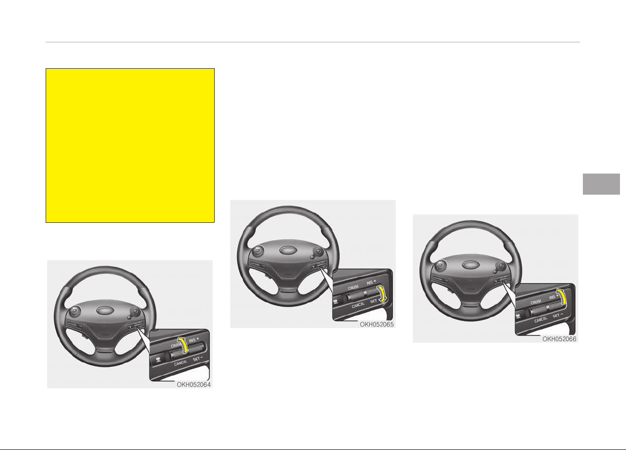
(Continued)
• The smart cruise control system is
not
a substitute for safe driving. It
is the responsibility of the driver
to always check the speed and dis‐
tance of the vehicle ahead.
• Be careful when driving downhill
using the ASCC.
• Limited visibility (rain, snow,
smog, etc)
• Cruise function should not be used
when the vehicle is being towed to
prevent any damage.
Speed setting
To set cruise control speed:
1. Move the lever up (to CRUISE), to
turn the system on. The CRUISE in‐
dicator light in the instrument clus‐
ter will illuminate.
2. Accelerate to the desired speed.
The smart cruise control speed can
be set as follows:
• 30 km/h (20mph) ~180 km/h
(110mph): when there is no vehi‐
cle in front
• 0 km/h~180 km/h (110mph):
when there is a vehicle in front
3. Move the lever down (to SET-), and
release it at the desired speed. The
set speed and vehicle to vehicle dis‐
tance on the LCD screen will illumi‐
nate.
4. Release the accelerator pedal. The
desired speed will automatically be
maintained.
If there is a vehicle in front of you, the
speed may decrease to maintain the
distance to the vehicle ahead.
On a steep grade, the vehicle may slow
down or speed up slightly while going
uphill or downhill.
To increase cruise control set
speed:
Follow either of these procedures:
5-67
5
Driving your vehicle
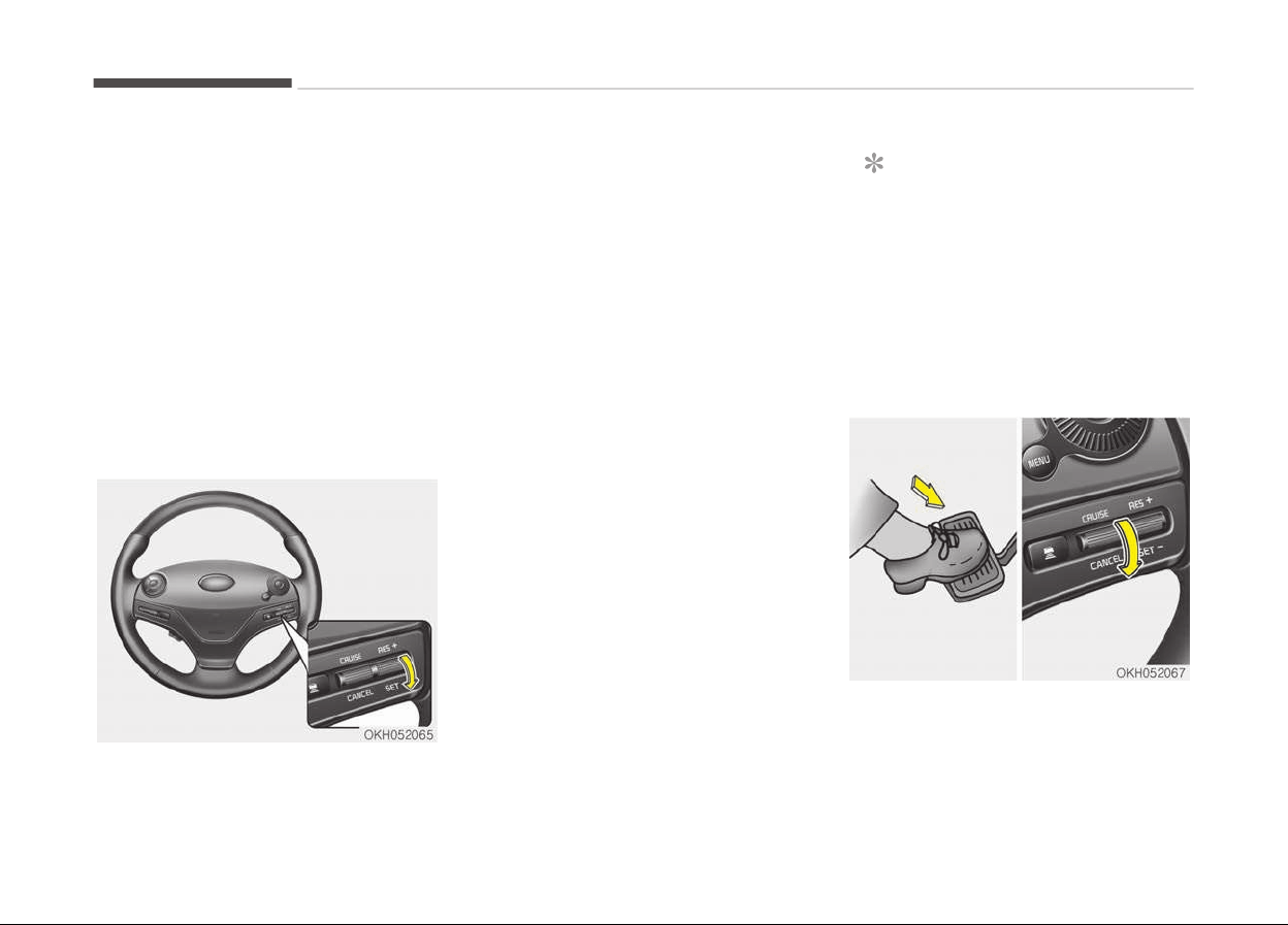
• Move the lever up (to RES+), and hold
it. Your vehicle set speed will increase
by 10 km/h (5 mph). Release the lev‐
er at the speed you want.
• Move the lever up (to RES+), and re‐
lease it immediately. The cruising
speed will increase by 1 km/h (1 mph)
each time you move the lever up (to
RES+) in this manner.
• You can set the speed to 180 km/h
(110 mph).
To decrease the cruise control set
speed:
Follow either of these procedures:
• Mov
e the lever down (to SET-), and
hold it. Your vehicle set speed will de‐
crease by 10 km/h (5 mph). Release
the lever at the speed you want.
• Move the lever down (to SET-), and
release it immediately. The cruising
speed will decrease by 1 km/h
(1 mph) each time you move the lev‐
er down (to SET-) in this manner.
• You can set the speed to 30 km/h
(20 mph).
To temporarily accelerate with the
cruise control on:
If you want to speed up temporarily
when the cruise control is on, depress
the accelerator pedal. Increased speed
will not interfere with cruise control op‐
eration or change the set speed.
To return to the set speed, take your
foot off the accelerator.
If you move the lever down (to SET-) at
increased speed, the cruising speed will
be set again.
NOTICE
Be careful when accelerating tempo‐
rarily, because the speed is not con‐
trolled automatically at this time
even if there is a vehicle in front of
you.
Smart cruise control will be
temporarily canceled when:
Canceled manually
• The brake pedal is depressed.
• Move down the lever (to CANCEL) lo‐
cated on the steering wheel.
Driving your vehicle
5-68
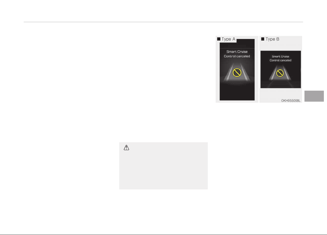
The advanced smart cruise control
turns off temporarily when the indica‐
tor on the LCD display turns off.
The CRUISE indicator is illuminated con‐
tinuously.
Canceled automatically
• The driver's door is opened.
• The shift lever is shifted to N (Neu‐
tral), R (Reverse) or D (Drive).
• The EPB (electronic parking brake) is
applied.
• The vehicle speed is over 190 km/h
• The vehicle stops on a steep incline.
• The ESC, TCS or ABS is operating.
• The ESC is turned off.
• The sensor or the cover is dirty or
blocked with foreign matter.
• When the vehicle is stopped for over
5 minutes.
• The vehicle stops and goes repeated‐
ly for a long period of time.
• The driver starts driving by pushing
the lever up (RES +) or down (SET -),
approximately 3 seconds after the
vehicle is stopped by the Smart
Cruise Control System with no other
vehicle ahead.
• The
driver starts driving by depress‐
ing the accelerator pedal, move up
the lever (to RES+) or down (to SET-),
if a vehicle stops far away ahead of
your vehicle.
• The accelerator pedal is continuously
depressed for more than 1 minute.
Each of these actions will cancel the
smart cruise control operation. (the set
speed and vehicle to vehicle distance on
the LCD display will go off.)
In a condition the smart cruise control
is canceled automatically, the smart
cruise control will not resume even
though the RES+ or SET-lever is moved.
Also, the EPB (electronic parking brake)
will be applied when the vehicle is stop‐
ped.
CAUTION
If the smart cruise control is cancel‐
led by other than the reasons men‐
tioned, have the system checked by
a professional workshop. Kia recom‐
mends to visit an authorized Kia
dealer/service partner.
If the system is cancelled, the warning
chime will sound and a message will ap‐
pear for a few seconds.
You must adjust the vehicle speed by
depressing the accelerator or brake
pedal according to the road condition
ahead and driving condition.
Always check the road conditions. Do
not rely on the warning chime.
5-69
5
Driving your vehicle
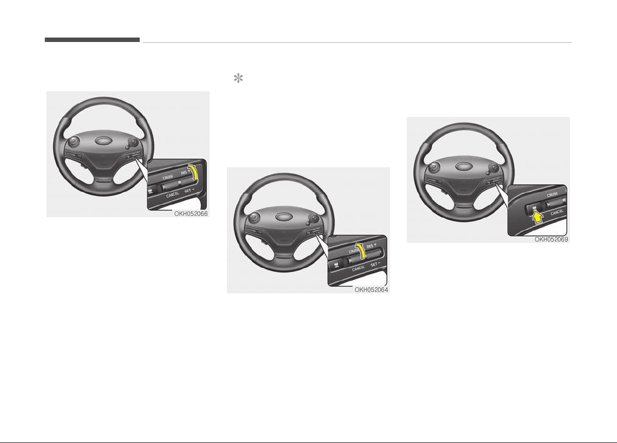
To resume cruise control set speed:
If any method other than the CRUISE
lever was used to cancel cruising speed
and the system is still activated, the
cruising speed will automatically re‐
sume when you move the lever up/
down (to RES+ or SET-).
If you move the lever up (to RES+), the
speed will resume to the recently set
speed. It will not resume if the vehicle
speed has dropped below approximate‐
ly 30 km/h (20 mph) .
NOTICE
Always check the road conditions
when you move the lever up (to RES
+) to resume speed.
To turn cruise control off:
Move the lever up (to CRUISE). (the
CRUISE indicator light in the instrument
cluster will go off).
Vehicle to vehicle distance
setting
To set vehicle to vehicle distance:
This function allows you to program
the vehicle to maintain relative distance
to the vehicle ahead without depressing
the accelerator pedal or brake pedal.
The vehicle to vehicle distance will au‐
tomatically activate when the smart
cruise control system is on.
Select the appropriate distance accord‐
ing to the road conditions and vehicle
speed.
Each time the button is pressed, the
vehicle to vehicle distance changes as
follows:
Driving your vehicle
5-70
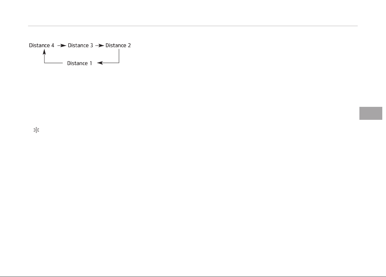
For example, if you drive at 90 km/h ,
the distance maintain as follows;
Distance 4 - approximately 52.5 m
Distance 3 - approximately 40 m
Distance 2 - approximately 32.5 m
Distance 1 - approximately 25 m
NOTICE
The 'Distance 4' is always set when
the system is used for the first time
after starting the engine.
5-71
5
Driving your vehicle
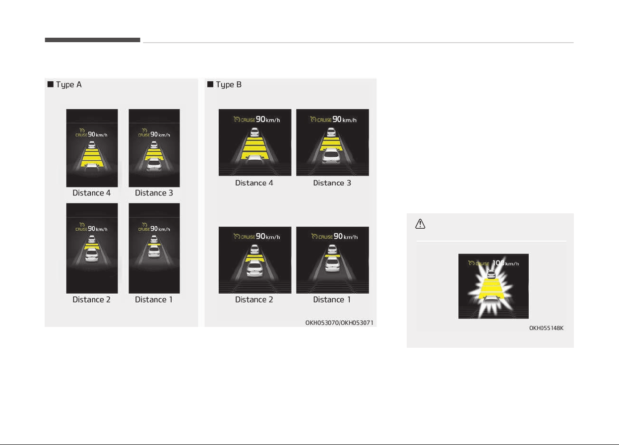
To set vehicle to vehicle distance:
• The vehicle will maintain the set
speed, when the lane ahead is clear.
• The vehicle will slow down or speed
up to maintain the selected distance,
when there is a vehicle ahead of you
in the lane. (A vehicle will appear in
front of your vehicle in the LCD dis‐
play only when there is an actual ve‐
hicle in front of you)
• If the vehicle ahead speeds up, your
vehicle will travel at a steady cruising
speed after accelerating to the selec‐
ted speed.
CAUTION
(Continued)
Driving your vehicle
5-72
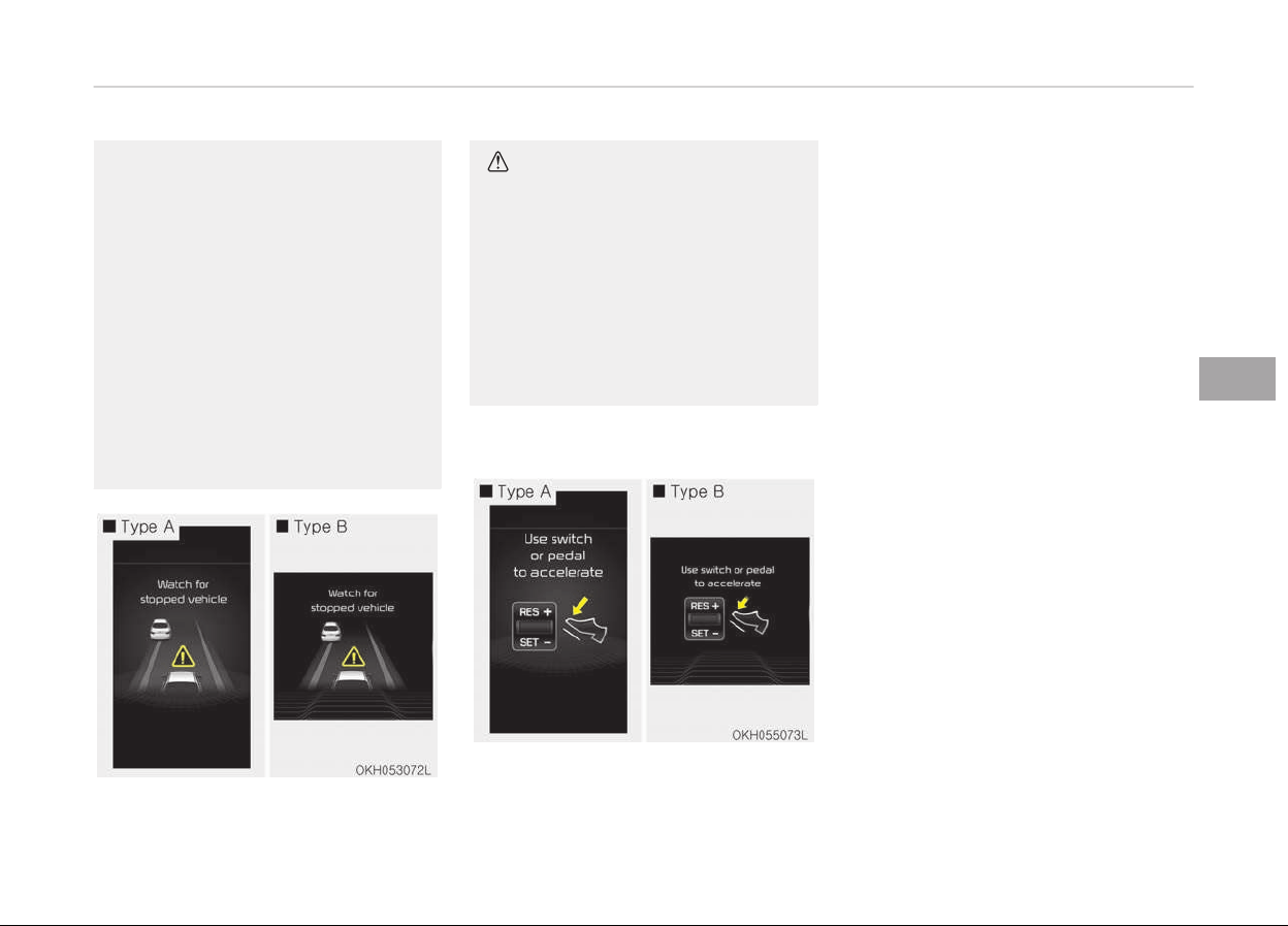
(Continued)
• The warning chime sounds and
malfunction
indicator blinks if it is
hard to maintain the selected dis‐
tance to the vehicle ahead.
• If the warning chime sounds, ac‐
tiv
ely adjust the vehicle speed by
depressing the brake pedal accord‐
ing to the road condition ahead
and driving condition.
• Even if the warning chime is not
activated, always pay attention to
the driving conditions to prevent
dangerous situations from occur‐
ring.
CAUTION
If the vehicle ahead (vehicle speed:
less than 30 km/h) disappears to the
next lane, the warning chime will
sound and a message will appear.
Adjust your vehicle speed for vehi‐
cles or objects that can suddenly ap‐
pear in front of you by depressing
the brake pedal according to the
road condition ahead and driving
condition.
In traffic situation
• In traffic, your vehicle will stop if the
vehicle ahead of you stops. Also, if
the vehicle ahead of you starts mov‐
ing, your vehicle will start as well.
However, if the vehicle stops for
more than 3 seconds, you must de‐
press the accelerator pedal, move up
the lever (to RES+) or down (to SET-)
to start driving.
• If you push the advanced smart
cruise control lever (RES+ or SET-)
while Auto Hold and advanced smart
cruise control is operating (The green
AUTO HOLD indicator), Auto Hold will
be released regardless of accelerator
pedal operation and the vehicle will
start to move.
5-73
5
Driving your vehicle
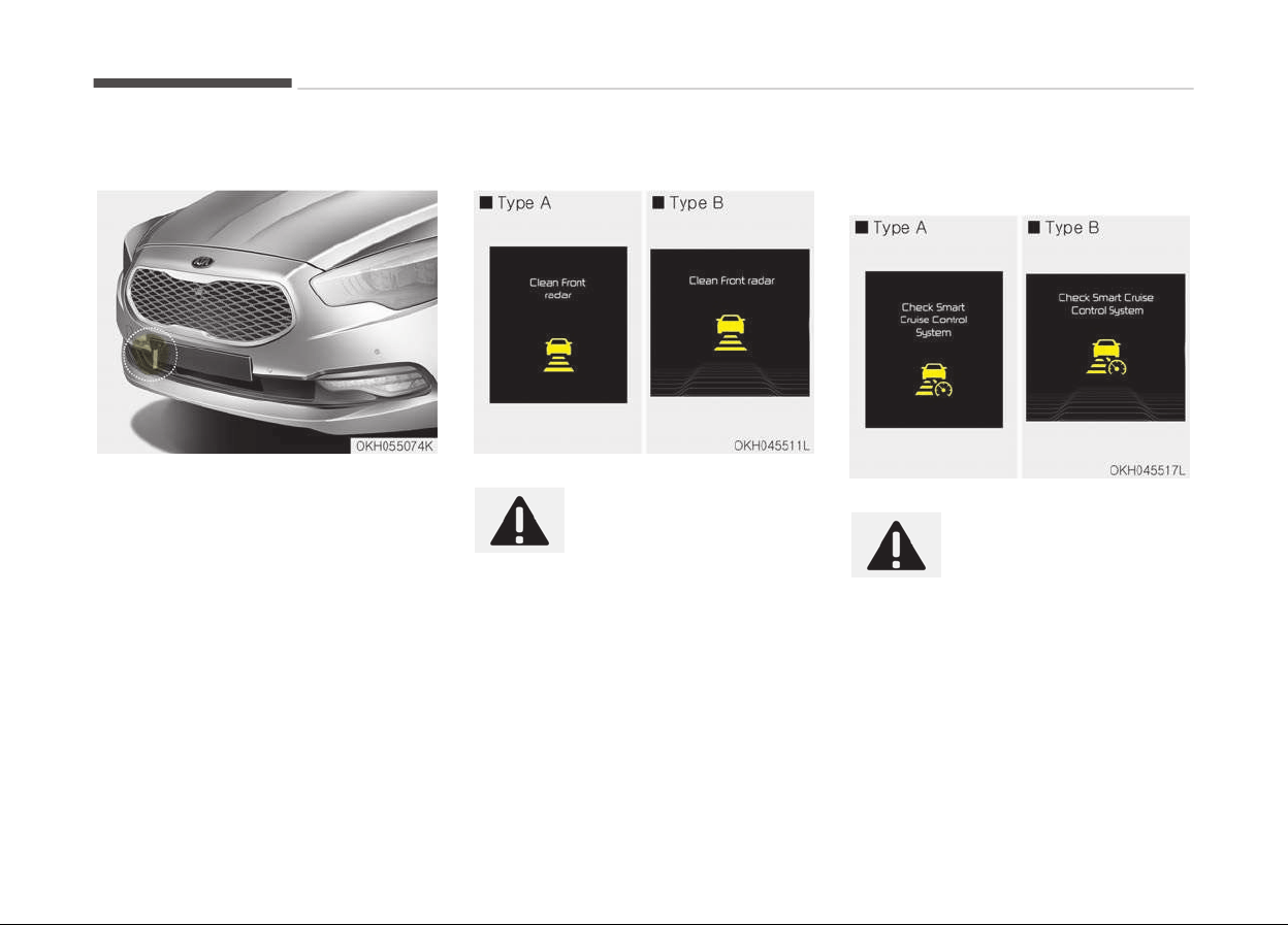
Distance to distance vehicle sensor
The sensor detects the distance to the
vehicle ahead.
If the sensor is covered with dirt or
other foreign matter, the vehicle to ve‐
hicle distance control may not operate
correctly.
Always keep the area in front of the
sensor clean.
Sensor warning message
If the sensor or cover is
dirty or obscured with for‐
eign matter such as snow,
this message will appear
and indicator light illumi‐
nates. In this case, the sys‐
tem may not function
temporarily, but it does
not indicate a malfunction
of the Smart Cruise Control
System.
Clean the sensor or cover
by using a soft cloth.
SCC (Smart Cruise Control)
malfunction message
The message will appear
and indicator light illumi‐
nates, when the vehicle to
vehicle distance control
system is not functioning
normally.
Kia recommends take your
vehicle to a professional
workshop and have the
system checked. Kia rec‐
ommends to visit an au‐
thorized Kia dealer/service
partner.
Driving your vehicle
5-74
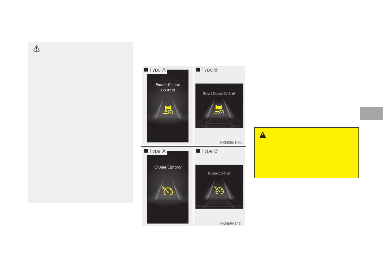
CAUTION
• Do not install accessories around
the sensor and do not replace the
bumper by yourself. It may inter‐
fere with the sensor performance.
• Always keep the sensor and
bumper clean.
• To prevent sensor cover damage
from occurring, wash the car with
a soft cloth.
• Do not damage the sensor or sen‐
sor area by a strong impact. If the
sensor moves slightly off position,
the smart cruise control system
will not operate correctly.
If this occurs, have the system
checked by a professional work‐
shop. Kia recommends to visit an
authorized Kia dealer/service part‐
ner.
• Use only a genuine Kia sensor cov‐
er for your vehicle. Do not paint
anything on the sensor cover.
To convert to cruise control
mode:
The driver may choose to only use the
cruise control mode (speed control
function) by doing as follows:
1. Turn the smart cruise control sys‐
tem on (the cruise indicator light
will be on but the system will not
be activated).
2. Push the distance to distance
switch for more than 2 seconds.
3. Choose between "Smart cruise con‐
trol(SCC) mode" and "Cruise con‐
trol(CC) mode".
WARNING
When using the cruise control mode,
you must manually assess the dis‐
tance to other vehicles as the sys‐
tem will not automatically brake to
slow down for other vehicles.
5-75
5
Driving your vehicle
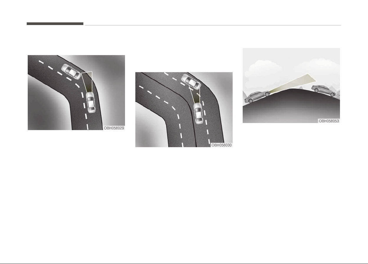
Limitations of the system
The smart cruise control system may
have limits to its ability to detect dis‐
tance to the vehicle ahead due to road
and traffic conditions.
On curves
• On curves, the smart cruise control
system may not detect a moving ve‐
hicle in your lane, and then your vehi‐
cle could accelerate to the set speed.
Also, the vehicle speed will rapidly go
down when the vehicle ahead is rec‐
ognized suddenly.
• Select the appropriate set speed on
curves and adjust your vehicle speed
by depressing the accelerator or
brake pedal according to the road
condition ahead and driving condition.
• Your vehicle speed can be reduced
due to a vehicle in the adjacent lane.
Adjust your vehicle speed by depress‐
ing the brake pedal according to the
road condition ahead and driving con‐
dition. Apply the accelerator pedal
and select the appropriate set speed.
Check to be sure that the road condi‐
tions permit safe operation of the
smart cruise control.
On inclines
• During uphill or downhill driving, the
smart cruise control system may not
detect a moving vehicle in your lane,
and cause your vehicle to accelerate
to the set speed. Also, the vehicle
speed will rapidly down when the ve‐
hicle ahead is recognized suddenly.
• Select the appropriate set speed on
inclines and adjust your vehicle speed
by depressing the accelerator or
brake pedal according to the road
condition ahead and driving condition.
Driving your vehicle
5-76
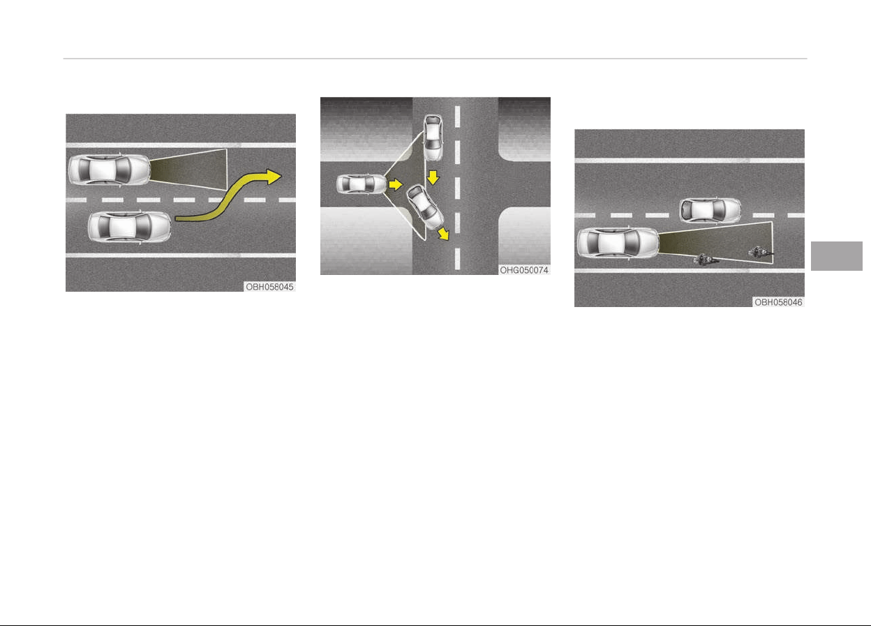
Lane changing
• A vehicle which moves into your lane
from an adjacent lane cannot be rec‐
ognized by the sensor until it is in the
sensor's detection range.
• The sensor may not detect immedi‐
ately when a vehicle cuts in suddenly.
Always pay attention to the traffic,
road and driving conditions.
• If a vehicle which moves into your
lane is slower than your vehicle, your
speed may decrease to maintain the
distance to the vehicle ahead.
• If a vehicle which moves into your
lane is faster than your vehicle, your
vehicle will accelerate to the selected
speed.
• Your vehicle may accelerate when a
vehicle ahead of you disappears.
• When you are warned that the vehi‐
cle ahead of you is not detected,
drive with caution.
Vehicle recognition
Some vehicles ahead in your lane can‐
not be recognized by the sensor as fol‐
lows:
-
Narrow vehicles such as motorcycles
or bicycles
-
Vehicles offset to one side
-
Slow-moving vehicles or sudden-de‐
celerating vehicles
-
Stopped vehicles
-
Vehicles with small rear profile such
as trailers with no loads
5-77
5
Driving your vehicle
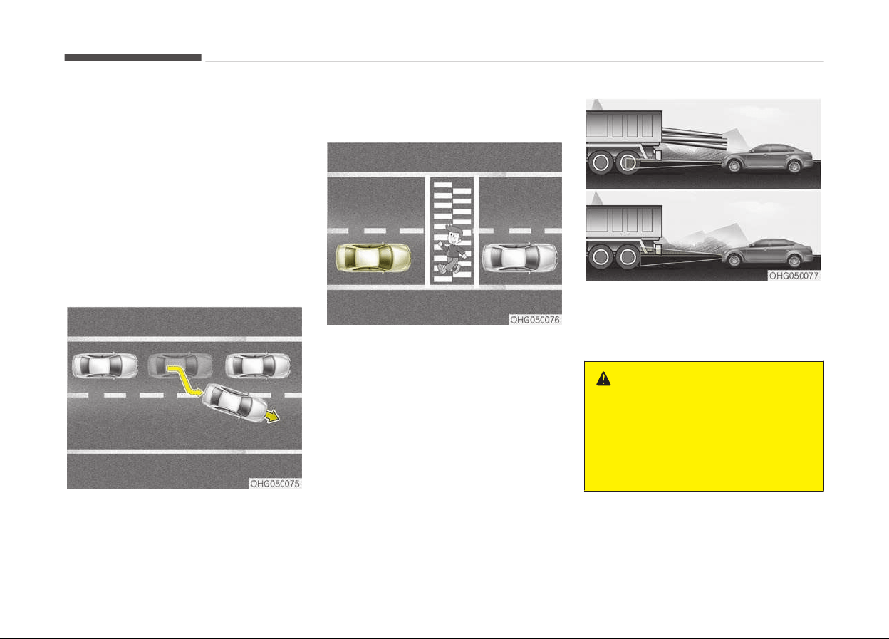
A vehicle ahead cannot be recognized
correctly by the sensor if any of follow‐
ing occurs:
-
When the vehicle is pointing upwards
due to overloading in the trunk
-
While making turns by steering
-
When driving to one side of the lane
-
When driving on narrow lanes or on
curves
Adjust your vehicle speed by depressing
the brake pedal according to the road
condition ahead and driving condition.
• When vehicles are at a standstill and
the vehicle in front of you changes to
the next lane, be careful when your
vehicle starts to move because it
may not recognize the stopped vehi‐
cle in front of you.
• Always look out for pedestrians when
your vehicle is maintaining a distance
with the vehicle ahead.
• Always be cautious for vehicles with
higher height or vehicles carrying
loads that sticks out to the back of
the vehicle.
WARNING
• The smart cruise control system
cannot guarantee the stop for ev‐
ery emergency situation.
If an emergency stop is necessary,
you must apply the brakes.
(Continued)
Driving your vehicle
5-78

(Continued)
• Keep a safe distance according to
road
conditions and vehicle speed.
If the vehicle to vehicle distance is
too close during a high-speed driv‐
ing, a serious collision may result.
• The smart cruise control system
cannot
recognize a stopped vehi‐
cle, pedestrians or an oncoming
vehicle. Always look ahead cau‐
tiously to prevent unexpected and
sudden situations from occurring.
• When other vehicles are changing
lanes in front of you frequently,
the smart cruise control system
may not operate appropriately. Al‐
ways look ahead cautiously to pre‐
vent unexpected and sudden sit‐
uations from occurring.
• The smart cruise control system is
not a substitute for safe driving
practices but a convenience func‐
tion only. It is the responsibility of
the driver to always check the
speed and the distance to the ve‐
hicle ahead.
• Always be aware of the selected
speed
and vehicle to vehicle dis‐
tance.
(Continued)
(Continued)
• Always maintain sufficient braking
distance
and decelerate your vehi‐
cle by applying the brakes if nec‐
essary.
• As the smart cruise control sys‐
tem
may not recognize complex
driving situations, always pay at‐
tention to driving conditions and
control your vehicle speed.
• For safe operation, carefully read
and follow the instructions in this
manual before use.
CAUTION
The smart cruise control system
may not operate temporarily due to
electrical interference.
5-79
5
Driving your vehicle
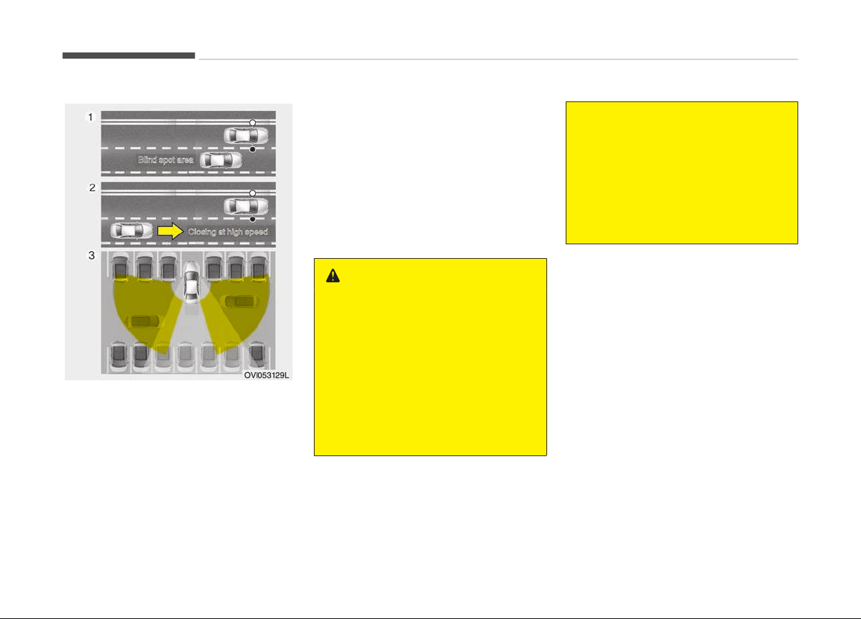
BLIND SPOT DETECTION SYSTEM (BSD) (IF EQUIPPED)
The Blind Spot Detection System (BSD)
uses a radar sensor to alert the driver.
It senses the rear side territory of the
vehicle and provides and indication to
the driver.
1. BSD (Blind spot detection)
Warning range is dependent on
your vehicle speed. However, if
your vehicle speed is speedy about
10 km/h than other vehicle, the
warning is not operated.
2. LCA (Lane change assist)
When the vehicle is approaching to
your vehicle at high speed, the
warning is operated.
3. RCTA (Rear cross traffic alert)
When your vehicle moves back‐
ward, the sensor detects the ap‐
proaching vehicles to the left or
right side direction and warning is
operated.
WARNING
• Always check the road condition
while
driving for unexpected situa‐
tions even though the Blind Spot
Detection System (BSD) is operat‐
ing.
• The Blind Spot Detection System
(BSD)
is a system made for con‐
venience. Do not solely rely on the
system but always pay attention
to drive safely.
(Continued)
(Continued)
• The Blind Spot Detection System
(BSD) is not a substitute for prop‐
er and safe lane changing proce‐
dures. Always drive safely and use
caution when changing lanes. The
Blind Spot Detection System may
not detect every object alongside
the vehicle.
Driving your vehicle
5-80
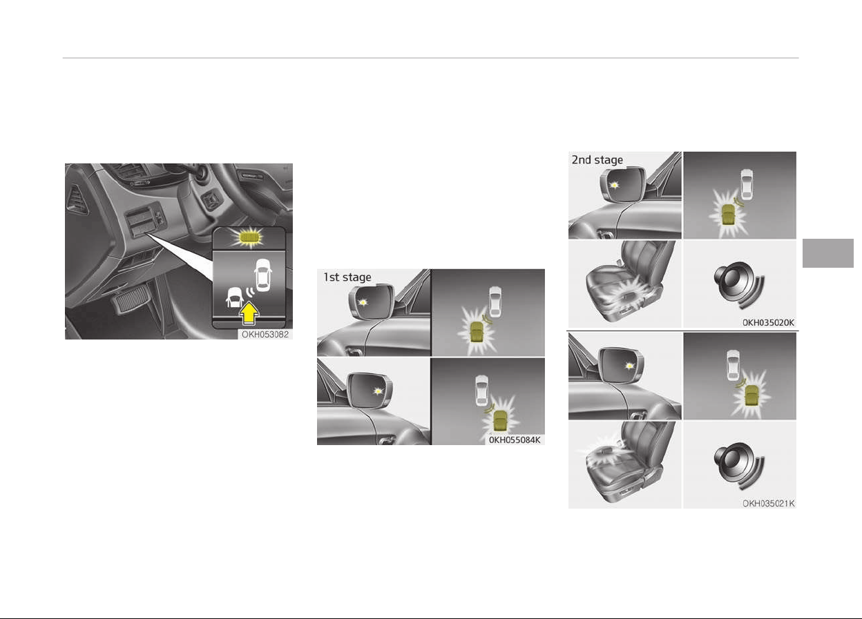
BSD (Blind Spot Detection) / LCA
(Lane Change Assist)
Operating conditions
The indicator on the switch will illumi‐
nate when the Blind Spot Detection
System (BSD) switch is pressed with
the Engine Start/Stop Button ON.
If vehicle speed exceeds about
30 km/h , the system will activate.
If you press the switch again, the
switch indicator and system will be
turned off.
If the Engine Start/Stop button is
turned OFF and ON the system returns
to the previous state.
When the system is not used turn the
system off by turning off the switch.
When the system is turned on the
warning light will illuminate for
3 seconds on the outside rearview mir‐
ror.
Warning type
The system will activate when:
1. The system is on
2. Vehicle speed is about 30 km/h
3. Other vehicles are detected in the
rear side
If a vehicle is detected within the boun‐
dary of the system, a warning light will
illuminate on the outside rearview mir‐
ror and the head up display.
If the detected vehicle is not in warning
range, the warning will turn off accord‐
ing to driving conditions.
5-81
5
Driving your vehicle
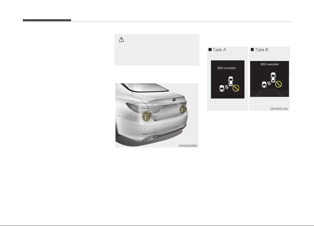
The second stage alarm will activate
when:
1. The first stage alert is on
2. The turn signal is on to change a
lane
When the second stage alert is activa‐
ted, a warning light will blink on the
outside rearview mirror, the head up
display and an alarm will sound.
If you move the turn signal switch to
the original position, the second stage
alert will be deactivated.
-
The second stage alarm may be de‐
activated.
• To activate the alarm:
Go to the User Settings Mode →
Sound and select "BSD" on the LCD
display.
• To deactivate the alarm:
Go to the User Settings Mode →
Sound and deselect "BSD" on the LCD
display.
CAUTION
The alarm function helps alert the
driver. Deactivate this function only
when it is necessary
Detecting sensor
The sensors are located inside of the
rear bumper.
Always keep the rear bumper clean for
the system to work properly.
Warning message
The message will appear to notify the
driver if there are foreign substances
on the rear bumper or it is hot near the
rear bumper. The light on the switch
and the system will turn off automati‐
cally.
Remove the foreign matter on the rear
bumper.
After the foreign substance is removed,
if you drive for approximately
10 minutes, the system will work nor‐
mally.
Driving your vehicle
5-82
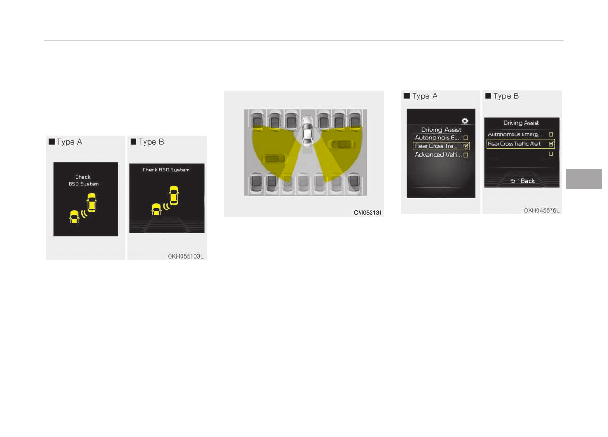
If the system does not work normally
even though camera’s field of view is
cleared, have the system checked by a
professional workshop. Kia recom‐
mends to visit an authorized Kia dealer/
service partner.
If the system does not work properly, a
warning message will appear and the
light on the switch will turn off. The
system will turn off automatically.
In this case, have the system checked
by a professional workshop. Kia recom‐
mends to visit an authorized Kia dealer/
service partner.
RCTA (Rear cross traffic alert)
When your vehicle moves backwards
from a parking position, the sensor de‐
tects approaching vehicles to the left or
right side direction and gives informa‐
tion to the driver.
Operating conditions
• Select RCTA (Rear Cross Traffic Alert)
in "User Settings" under "Driving As‐
sist" on the instrument cluster. The
system will turn on and stand by to
activate.
• Select RCTA again, to turn the sys‐
tem off.
• If the vehicle is turned off and on
again, the RCTA system will return to
the state right before the vehicle was
turned off. Always turn the RCTA
system off when not in use.
• The system is operated when the ve‐
hicle speed is below 10 km/h with the
shift lever in R (Reverse).
5-83
5
Driving your vehicle
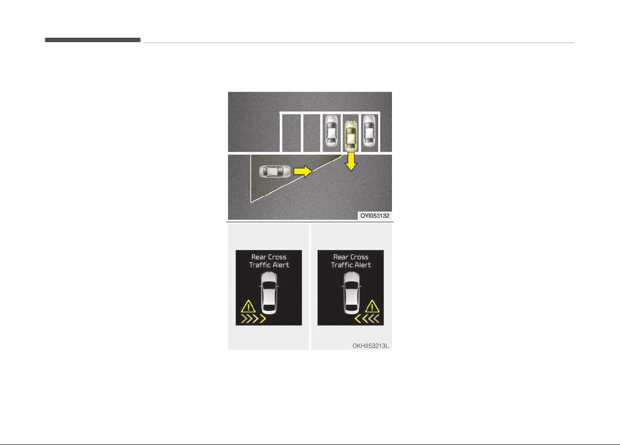
• The RCTA (Rear Cross Traffic Alert)
detecting range is 0.5 m~20 m based
on side direction. If the approaching
vehicle speed is 4 km/h~36 km/h in
sensing range, it is detected. Howev‐
er, the system sensing range is dif‐
ferent base on conditions. Always
pay attention to your surroundings.
Warning type
• If the vehicle detected by the sensors
approaches your vehicle, the warning
chime will sound, the warning light on
the outside rearview mirror will blink
and a message will appear on the LCD
display.
• If the detected vehicle is out of the
sensing range of your vehicle, move
the vehicle away from the detected
object slowly; the warning will be
canceled.
• The system may not operate proper‐
ly due to other factors or circum‐
stances. Always pay attention to
your surroundings.
❈ If your vehicle's left or right side
bumper is blinded by barriers or ve‐
hicles, the system sensing ability
may be reduced.
Driving your vehicle
5-84

WARNING
• The warning light on the outside
rearview mirror will illuminate
whenever a vehicle is detected at
the rear side by the system.
To avoid accidents, do not focus
only on the warning light and ne‐
glect to see the surrounding of the
vehicle.
• Drive safely even though the vehi‐
cle is equipped with a Blind Spot
Detection System (BSD) and Rear
Cross Traffic Alert (RCTA). Do not
solely rely on the system but
check for yourself before changing
lanes or backing the vehicle up.
The system may not alert the
driver in some conditions so al‐
ways check the surroundings while
driving.
• The Blind Spot Detection System
(BSD) and Rear Cross Traffic Alert
(RCTA) are not a substitute for
proper and safe driving. Always
drive safely and use caution when
changing lanes or backing the vehi‐
cles up. The Blind Spot Detection
System (BSD) may not detect ev‐
ery object alongside the vehicle.
CAUTION
• The system may not work proper‐
ly if the bumper has been replaced
or if repair work has been done
near the sensor.
• The detection area differs accord‐
ing to the roads width. If the road
is narrow the system may detect
other vehicles in the next lane.
• In addition, if the road is very wide
the system may not detect other
vehicles.
• The system may turn off due to
strong electromagnetic waves.
Non-operating condition
Driver's attention
The driver must be cautious in the be‐
low situations for the system may not
assist the driver and may not work
properly.
-
Curved roads, tollgates, etc.
-
The surrounding of the sensor is pol‐
luted with rain, snow, mud, etc.
-
The rear bumper near the sensor is
covered or hidden with a foreign mat‐
ter such as a sticker, bumper guard,
bicycle stand etc.
-
The rear bumper is damaged or the
sensor is out of place.
-
The height of the vehicle is altered
such as when the trunk is loaded with
heavy objects, or there is low tire
pressure etc.
-
Bad weather such as heavy rain or
snow.
-
A fixed object is near such as a
guardrail, tunnel, human and animal
etc.
-
Metal substances are near the vehi‐
cles such as in a construction area.
-
A big vehicle is near such as a bus or
truck.
-
A motorcycle or bicycle is near.
-
A flat trailer like vehicle is near.
-
If the vehicle has started at the same
time as the vehicle next to it and has
accelerated.
-
When the other vehicle passes by
very fast.
-
When changing lanes.
-
When going down or up a steep, un‐
even road.
-
When the other vehicle drives at the
rear very nearby or drives very close.
5-85
5
Driving your vehicle

-
When a trailer or carrier is installed.
-
When the temperature of the rear
bumper is very high or low.
-
When the sensors are covered by the
vehicle, wall or a pillar of parking lot.
-
When your vehicle is backing up, if
the detected vehicle approaches your
vehicle or also backs up.
-
Small objects like shopping carts and
baby carriages.
-
If there is a vehicle with decreased
ride height (lowered).
-
When the vehicle is close to another
vehicle.
-
When the vehicle in the next lane
moves two lanes away from my vehi‐
cle OR when the vehicle two lanes
away moves to the next lane from
my vehicle.
-
When exiting rearward from a park‐
ing space with pillars or metal struc‐
tures.
-
When driving through a narrow road
with many plants.
-
When driving on wet surface.
Outside rearview mirror may not
alert the driver when:
-
The outside rearview mirror housing
is damaged or covered with debris.
-
The window is covered with debris.
-
The windows are severely tinted.
Driving your vehicle
5-86

ECONOMICAL OPERATION
Your vehicle's fuel economy depends
mainly on your style of driving, where
you drive and when you drive.
Each of these factors affects how
many kilometers you can get from a li‐
ter of fuel. To operate your vehicle as
economically as possible, use the fol‐
lowing driving suggestions to help save
money in both fuel and repairs:
• Drive smoothly. Accelerate at a mod‐
erate rate. Do not make "jack-rabbit"
starts or full-throttle shifts and
maintain a steady cruising speed. Do
not race between stoplights. Try to
adjust your speed to the traffic so
you do not have to change speeds
unnecessarily. Avoid heavy traffic
whenever possible. Always maintain a
safe distance from other vehicles so
you can avoid unnecessary braking.
This also reduces brake wear.
• Drive at a moderate speed. The fast‐
er you drive, the more fuel your vehi‐
cle uses. Driving at a moderate
speed, especially on the highway, is
one of the most effective ways to re‐
duce fuel consumption.
• Do not "ride" the brake pedal. This
can increase fuel consumption and al‐
so increase wear on these compo‐
nents. In addition, driving with your
foot resting on the brake pedal may
cause the brakes to overheat, which
reduces their effectiveness and may
lead to more serious consequences.
• Take care of your tires. Keep them
inflated to the recommended pres‐
sure. Incorrect inflation, either too
much or too little, results in unneces‐
sary tire wear. Check the tire pres‐
sures at least once a month.
• Be sure that the wheels are aligned
correctly. Improper alignment can re‐
sult from hitting curbs or driving too
fast over irregular surfaces. Poor
alignment causes faster tire wear
and may also result in other prob‐
lems as well as greater fuel con‐
sumption.
• Keep your vehicle in good condition.
For better fuel economy and reduced
maintenance costs, maintain your ve‐
hicle in accordance with Chapter 8,
Maintenance. If you drive your vehicle
in severe conditions, more frequent
maintenance is required (Chapter 8,
Maintenance for details).
• Keep your vehicle clean. For maxi‐
mum service, your vehicle should be
kept clean and free of corrosive ma‐
terials. It is especially important that
mud, dirt, ice, etc. not be allowed to
accumulate on the underside of the
vehicle. This extra weight can result
in increased fuel consumption and al‐
so contribute to corrosion.
• Travel lightly. Do not carry unneces‐
sary weight in your vehicle. Weight
reduces fuel economy.
• Do not let the engine idle longer than
necessary. If you are waiting (and not
in traffic), turn off your engine and
restart only when you're ready to go.
• Remember, your vehicle does not re‐
quire extended warm-up. After the
engine has started, allow the engine
to run for 10 to 20 seconds prior to
placing the vehicle in gear. In very cold
weather, however, give your engine a
slightly longer warmup period.
• Do not "lug" or "over-rev" the engine.
Lugging is driving too slowly in too
high a gear resulting engine bucking.
If this happens, shift to a lower gear.
Over-revving is racing the engine be‐
yond its safe limit. This can be avoi‐
ded by shifting at the recommended
speeds.
5-87
5
Driving your vehicle

• Use your air conditioning sparingly.
The air conditioning system is oper‐
ated by engine power so your fuel
economy is reduced when you use it.
• Open windows at high speeds can re‐
duce fuel economy.
• Fuel economy is less in crosswinds
and headwinds. To help offset some
of this loss, slow down when driving
in these conditions.
Keeping a vehicle in good operating
condition is important both for econo‐
my and safety. Therefore, have the
system serviced by a professional
workshop. Kia recommends to visit an
authorized Kia dealer/service partner.
WARNING
n
Engine off during motion
Never turn the engine off to coast
down hills or anytime the vehicle is
in motion. The power steering and
power brakes will not function prop‐
erly without the engine running. In‐
stead, keep the engine on and down‐
shift to an appropriate gear for en‐
(Continued)
(Continued)
gine braking effect. In addition, turn‐
ing
off the engine while driving could
engage the steering wheel lock (if
equipped) resulting in loss of vehicle
steering which could cause serious
injury or death.
Driving your vehicle
5-88
SPECIAL DRIVING CONDITIONS
Hazardous driving conditions
When hazardous driving conditions are
encountered such as water, snow, ice,
mud, sand, or similar hazards, follow
these suggestions:
• Drive cautiously and allow extra dis‐
tance for braking.
• Avoid sudden braking or steering.
WARNING
n
ABS
Do not pump the brake pedal on a
vehicle equipped with ABS.
• If stalled in snow, mud, or sand, use
second gear. Accelerate slowly to
avoid spinning the drive wheels.
• Use sand, rock salt, tire chains, or
other non-slip material under the
drive wheels to provide traction when
stalled in ice, snow, or mud.
WARNING
n
Downshifting
Downshifting
with an automatic
transaxle, while driving on slippery
surfaces can cause an accident. The
sudden change in tire speed could
cause the tires to skid. Be careful
when downshifting on slippery sur‐
faces.
Rocking the vehicle
If it is necessary to rock the vehicle to
free it from snow, sand, or mud, first
turn the steering wheel right and left
to clear the area around your front
wheels. Then, shift back and forth be‐
tween R (Reverse) and any forward
gear in vehicles equipped with an auto‐
matic transaxle. Do not race the en‐
gine, and spin the wheels as little as
possible. If you are still stuck after a
few tries, have the vehicle pulled out by
a tow vehicle to avoid engine overheat‐
ing and possible damage to the trans‐
axle.
CAUTION
Prolonged rocking may cause engine
over-heating, transaxle damage or
failure, and tire damage.
WARNING
n
Spinning tires
Do not spin the wheels, especially at
speeds more than 56 km/h . Spinning
the wheels at high speeds when the
vehicle is stationary could cause a
tire to overheat which could result in
tire damage that may injure by‐
standers.
NOTICE
The ESC system should be turned
OFF prior to rocking the vehicle.
5-89
5
Driving your vehicle
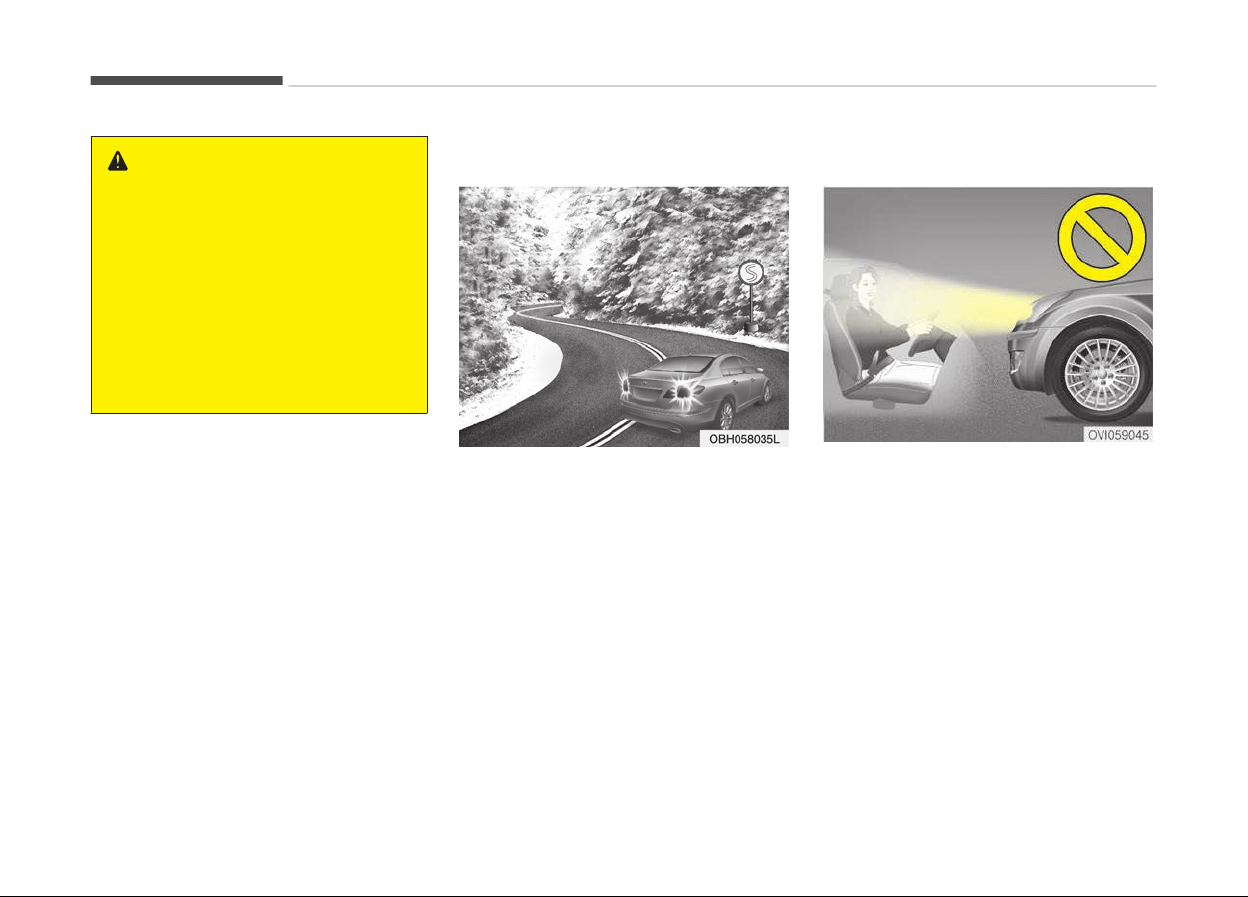
WARNING
If your vehicle becomes stuck in
snow, mud, sand, etc., then you may
attempt to rock the vehicle free by
moving it forward and backward. Do
not attempt this procedure if people
or objects are anywhere near the ve‐
hicle. During the rocking operation
the vehicle may suddenly move for‐
ward or backward as it becomes un‐
stuck, causing injury or damage to
nearby people or objects.
Smooth cornering
Avoid braking or gear changing in cor‐
ners, especially when roads are wet.
Ideally, corners should always be taken
under gentle acceleration. If you follow
these suggestions, tire wear will be
held to a minimum.
Driving at night
Because night driving presents more
hazards than driving in the daylight,
here are some important tips to re‐
member:
• Slow down and keep more distance
between you and other vehicles, as it
may be more difficult to see at night,
especially in areas where there may
not be any street lights.
• Adjust your mirrors to reduce the
glare from other driver's headlights.
Driving your vehicle
5-90
• Keep your headlights clean and prop‐
erly aimed on vehicles not equipped
with the automatic headlight aiming
feature. Dirty or improperly aimed
headlights will make it much more
difficult to see at night.
• Avoid staring directly at the head‐
lights of oncoming vehicles. You could
be temporarily blinded, and it will
take several seconds for your eyes to
readjust to the darkness.
Driving in the rain
Rain and wet roads can make driving
dangerous, especially if you’re not pre‐
pared for the slick pavement. Here are
a few things to consider when driving in
the rain:
• A heavy rainfall will make it harder to
see and will increase the distance
needed to stop your vehicle, so slow
down.
• Keep your windshield wiping equip‐
ment in good shape. Replace your
windshield wiper blades when they
show signs of streaking or missing
areas on the windshield.
• If your tires are not in good condition,
making a quick stop on wet pave‐
ment can cause a skid and possibly
lead to an accident. Be sure your tires
are in good shape.
• Turn on your headlights to make it
easier for others to see you.
• Driving too fast through large pud‐
dles can affect your brakes. If you
must go through puddles, try to drive
through them slowly.
• If you believe you may have gotten
your brakes wet, apply them lightly
while driving until normal braking op‐
eration returns.
Driving in flooded areas
Avoid driving through flooded areas un‐
less you are sure the water is no higher
than the bottom of the wheel hub.
Drive through any water slowly. Allow
adequate stopping distance because
brake performance may be affected.
After driving through water, dry the
brakes by gently applying them several
times while the vehicle is moving slow‐
ly.
5-91
5
Driving your vehicle
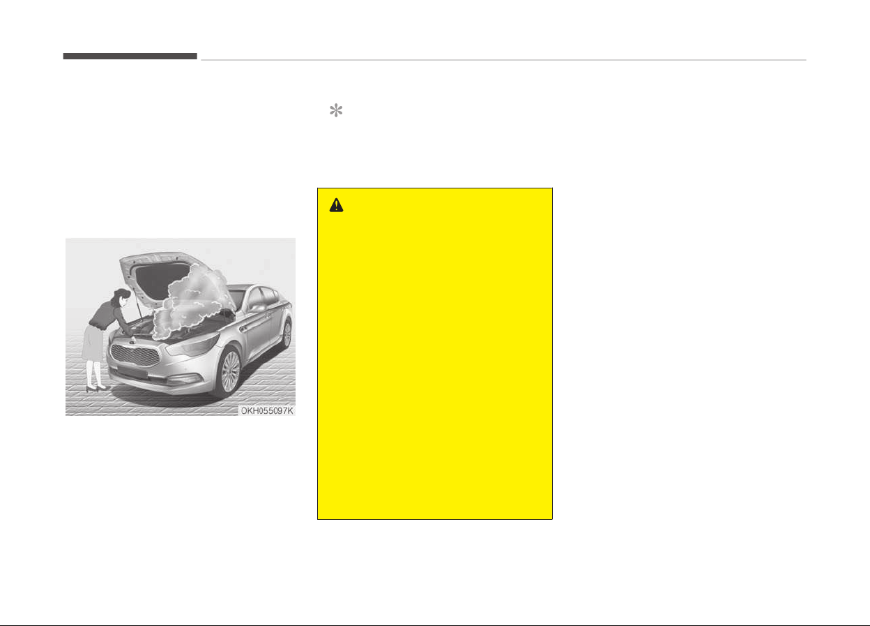
Driving off-road
Drive carefully off-road because your
vehicle may be damaged by rocks or
roots of trees. Become familiar with
the off-road conditions where you are
going to drive before you begin driving.
Highway driving
Tires
Adjust the tire inflation pressures to
specification. Low tire inflation pres‐
sures will result in overheating and pos‐
sible failure of the tires.
Avoid using worn or damaged tires
which may result in reduced traction or
tire failure.
NOTICE
Never exceed the maximum tire in‐
flation pressure shown on the tires.
WARNING
• Underinflated or overinflated tires
can cause poor handling, loss of
vehicle control, and sudden tire
failure leading to accidents, inju‐
ries, and even death. Always check
the tires for proper inflation be‐
fore driving. For proper tire pres‐
sures, refer to Tires and wheels
on page 7-49.
• Driving on tires with no or insuffi‐
cient tr
ead is dangerous. Worn-out
tires can result in loss of vehicle
control, collisions, injury, and even
death. Worn-out tires should be
replaced as soon as possible and
should never be used for driving.
Always check the tire tread before
driving your vehicle. For further in‐
formation and tread limits, refer
to Tires and wheels on page
7-49.
Fuel, engine coolant and engine oil
High speed travel consumes more fuel
than urban motoring. Do not forget to
check both engine coolant and engine
oil.
Drive belt
A loose or damaged drive belt may re‐
sult in overheating of the engine.
Driving your vehicle
5-92
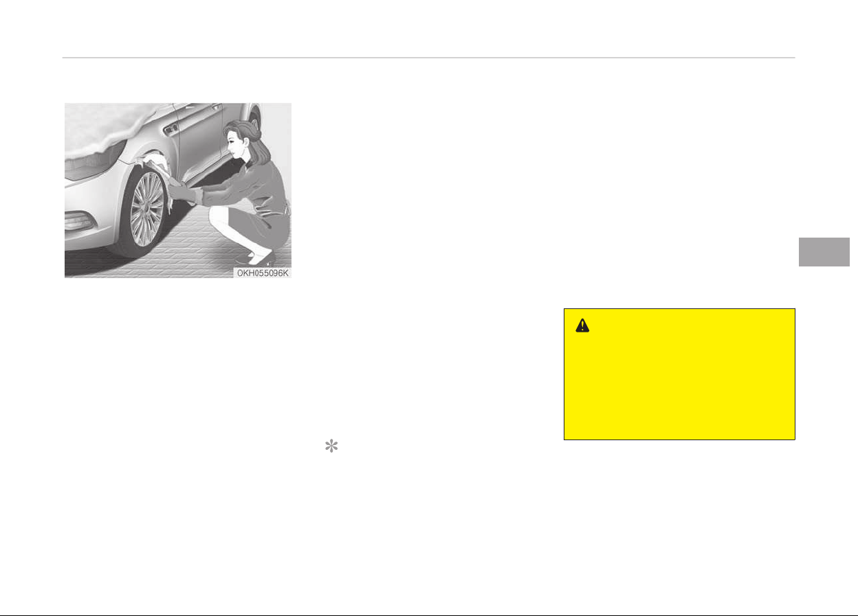
WINTER DRIVING
Severe weather conditions in the winter
result in greater wear and other prob‐
lems. To minimize the problems of win‐
ter driving, you should follow these
suggestions:
Snowy or icy conditions
To drive your vehicle in deep snow, it
may be necessary to use snow tires or
to install tire chains on your tires. If
snow tires are needed, it is necessary
to select tires equivalent in size and
type of the original equipment tires.
Failure to do so may adversely affect
the safety and handling of your vehicle.
Furthermore, speeding, rapid accelera‐
tion, sudden brake applications, and
sharp turns are potentially very haz‐
ardous practices.
During deceleration, use engine braking
to the fullest extent. Sudden brake ap‐
plications on snowy or icy roads may
cause skids to occur. You need to keep
sufficient distance between the vehicle
in operation in front and your vehicle.
Also, apply the brake gently. It should
be noted that installing tire chains on
the tire will provide a greater driving
force, but will not prevent side skids.
NOTICE
Tire chains are not legal in all coun‐
tries.
Check the country laws before
fitting tire chains.
Snow tires
If you mount snow tires on your vehi‐
cle, make sure they are radial tires of
the same size and load range as the
original tires. Mount snow tires on all
four wheels to balance your vehicle’s
handling in all weather conditions. Keep
in mind that the traction provided by
snow tires on dry roads may not be as
high as your vehicle's original equip‐
ment tires. You should drive cautiously
even when the roads are clear. Check
with the tire dealer for maximum
speed recommendations.
WARNING
n
Snow tire size
Snow tires should be equivalent in
size and type to the vehicle's stand‐
ard tires. Otherwise, the safety and
handling of your vehicle may be ad‐
versely affected.
Do not install studded tires without
first checking local, state and municipal
regulations for possible restrictions
against their use.
5-93
5
Driving your vehicle
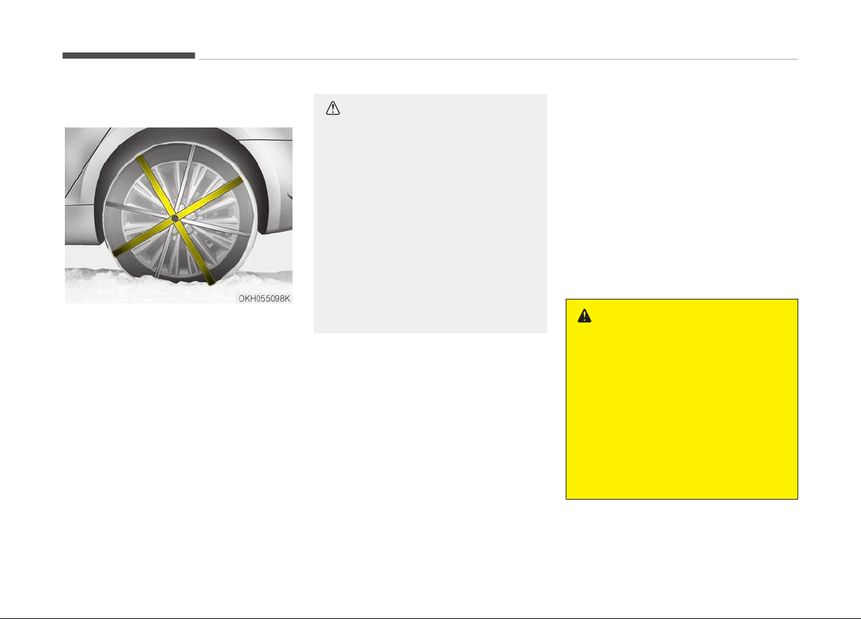
Tire chains
Since the sidewalls of radial tires are
thinner, they can be damaged by
mounting some types of snow chains
on them. Therefore, the use of snow
tires is recommended instead of snow
chains. Do not mount tire chains on ve‐
hicles equipped with aluminum wheels;
snow chains may cause damage to the
wheels. If snow chains must be used,
use the AutoSock
®
(fabric snow chain).
Damage to your vehicle caused by im‐
proper snow chain use is not covered
by your vehicle manufacturers warran‐
ty.
Install the AutoSock
®
(fabric snow
chain) only on the rear tires.
CAUTION
•
Make sure the AutoSock
®
(fabric
snow chain) are the correct size
and type for your tires. Incorrect
snow chains can cause damage to
the vehicle body and suspension
and may not be covered by your
vehicle manufacturer warranty.
•
Always check the AutoSock
®
(fab‐
ric snow chain) installation for
proper mounting after driving ap‐
proximately 0.5 to 1 km to ensure
safe mounting. Retighten or re‐
mount the AutoSock
®
(fabric snow
chain) if they are loose.
❈
AutoSock
®
is a Registered trade‐
mark of AutoSock
®
.
Chain installation
When installing the AutoSock
®
(fabric
snow chain), follow the manufacturer's
instructions and mount them as tightly
as you can. Drive slowly with the Auto‐
Sock
®
(fabric snow chain) installed. If
you hear the AutoSock
®
(fabric snow
chain) contacting the body or chassis,
stop and tighten them. If they still
make contact, slow down until it stops.
Remove the AutoSock
®
(fabric snow
chain) as soon as you begin driving on
cleared roads.
WARNING
n
Mounting chains
When mounting the AutoSock
®
(fab‐
ric snow chain), park the vehicle on
level ground away from traffic. Turn
on the vehicle Hazard Warning flash‐
ers and place a triangular emergency
warning device behind the vehicle if
available. Always place the vehicle in
P (Park), apply the parking brake and
turn off the engine before installing
the AutoSock
®
(fabric snow chain).
Driving your vehicle
5-94

WARNING
n
Tire chains
•
The use of the AutoSock
®
(fabric
snow chain) may adversely affect
vehicle handling.
• Do not exceed 30 km/h or the Au‐
toSock
®
(fabric snow chain) manu‐
facturer’s recommended speed
limit, whichever is lower.
• Drive carefully and avoid bumps,
holes, sharp turns, and other road
hazards, which may cause the ve‐
hicle to bounce.
• Avoid sharp turns or locked-wheel
braking.
CAUTION
•
The AutoSock
®
(fabric snow chain)
that are the wrong size or improp‐
erly installed can damage your ve‐
hicle's brake lines, suspension,
body and wheels.
(Continued)
(Continued)
• Stop driving and retighten the Au‐
toSock
®
(fabric snow chain) any
time you hear them hitting the ve‐
hicle.
❈
AutoSock
®
is a Registered trade‐
mark of AutoSock
®
.
Use high quality ethylene glycol
coolant
Your vehicle is delivered with high quali‐
ty ethylene glycol coolant in the cooling
system. It is the only type of coolant
that should be used because it helps
prevent corrosion in the cooling sys‐
tem, lubricates the water pump and
prevents freezing. Be sure to replace or
replenish your coolant in accordance
with the maintenance schedule on
page 7-28. Before winter, have your
coolant tested to assure that its freez‐
ing point is sufficient for the tempera‐
tures anticipated during the winter.
Check battery and cables
Winter puts additional burdens on the
battery system. Visually inspect the
battery and cables as described on
page 7-45. Have the level of charge in
your battery checked by a professional
workshop. Kia recommends to visit an
authorized Kia dealer/service partner.
Change to "winter weight" oil if
necessary
In some climates it is recommended
that a lower viscosity "winter weight"
oil be used during cold weather. See
Recommendations on page 8-10. If
you aren't sure what weight oil you
should use, Kia recommends to consult
an authorized Kia dealer/service part‐
ner.
Check spark plugs and ignition
system
Inspect your spark plugs as described
on page 7-28 and replace them if nec‐
essary. Also check all ignition wiring and
components to be sure they are not
cracked, worn or damaged in any way.
5-95
5
Driving your vehicle

To keep locks from freezing
To keep the locks from freezing, squirt
an approved de-icer fluid or glycerine
into the key opening. If a lock is covered
with ice, squirt it with an approved de-
icing fluid to remove the ice. If the lock
is frozen internally, you may be able to
thaw it out by using a heated key. Han‐
dle the heated key with care to avoid
injury.
Use approved window washer
anti-freeze in system
To keep the water in the window wash‐
er system from freezing, add an ap‐
proved window washer anti-freeze sol‐
ution in accordance with instructions on
the container. Window washer anti-
freeze is available from an authorized
Kia dealer/service partner and most au‐
to parts outlets. Do not use engine
coolant or other types of anti-freeze as
these may damage the paint finish.
Don't let your parking brake
fr
eeze
Under some conditions your parking
brake can freeze in the engaged posi‐
tion. This is most likely to happen when
there is an accumulation of snow or ice
around or near the rear brakes or if the
brakes are wet. If there is a risk the
parking brake may freeze, apply it only
temporarily while you put the shift lev‐
er in P and block the rear wheels so the
vehicle cannot roll. Then release the
parking brake.
Don't let ice and snow
accumulate underneath
Under some conditions, snow and ice
can build up under the fenders and in‐
terfere with the steering. When driving
in severe winter conditions where this
may happen, you should periodically
check underneath the vehicle to be sure
the movement of the front wheels and
the steering components is not ob‐
structed.
Carry emergency equipment
Depending on the severity of the
weather, you should carry appropriate
emergency equipment. Some of the
items you may want to carry include
tire chains, tow straps or chains, flash‐
light, emergency flares, sand, shovel,
jumper cables, window scraper, gloves,
ground cloth, coveralls, blanket, etc.
Driving your vehicle
5-96

VEHICLE WEIGHT
This section will guide you in the proper
loading of your vehicle and/or trailer, to
keep your loaded vehicle weight within
its design rating capability, with or
without a trailer. Properly loading your
vehicle will provide maximum return of
the vehicle design performance. Before
loading your vehicle, familiarize your‐
self with the following terms for deter‐
mining your vehicle's weight ratings,
with or without a trailer, from the vehi‐
cle's specifications and the certification
label:
Base curb weight
This is the weight of the vehicle includ‐
ing a full tank of fuel and all standard
equipment. It does not include passen‐
gers, cargo, or optional equipment.
Vehicle curb weight
This is the weight of your new vehicle
when you picked it up from your dealer
plus any aftermarket equipment.
Cargo weight
This figure includes all weight added to
the Base Curb Weight, including cargo
and optional equipment.
GAW (Gross axle weight)
This is the total weight placed on each
axle (front and rear) - including vehicle
curb weight and all payload.
GAWR (Gross axle weight rating)
This is the maximum allowable weight
that can be carried by a single axle
(front or rear). These numbers are
shown on the certification label.
The total load on each axle must never
exceed its GAWR.
GVW (Gross vehicle weight)
This is the Base Curb Weight plus actual
Cargo Weight plus passengers.
GVWR (Gross vehicle weight
rating)
This is the maximum allowable weight
of the fully loaded vehicle (including all
options, equipment, passengers and
cargo). The GVWR is shown on the cer‐
tification label.
Overloading
WARNING
n
Vehicle weight
The gross axle weight rating (GAWR)
and the gross vehicle weight rating
(GVWR) for your vehicle are on the
certification label attached to the
driver's (or front passenger’s) door.
Exceeding these ratings can cause
an accident or vehicle damage. You
can calculate the weight of your load
by weighing the items (and people)
before putting them in the vehicle.
Be careful not to overload your vehi‐
cle.
5-97
5
Driving your vehicle


Road warning.............................................................................6-02
Hazard warning flasher........................................................6-02
In case of an emergency while driving.................................. 6-03
If the engine stalls at a crossroad or crossing.................6-03
If you have a flat tire while driving.................................... 6-03
If the engine stalls while driving.........................................6-03
If the engine does not start.................................................... 6-04
If the engine doesn't turn over or turns over slowly......6-04
If engine turns over normally but does not start........... 6-04
Emergency starting..................................................................6-05
Jump starting.........................................................................6-05
Push-starting........................................................................ 6-07
If the engine overheats............................................................ 6-08
Tire pressure monitoring system (TPMS) ........................... 6-09
Low tire pressure telltale.....................................................6-10
TPMS (Tire pressure monitoring system) mal‐
function indicator..................................................................6-12
Changing a tire with TPMS..................................................6-12
If you have a flat tire................................................................6-14
Jack and tools........................................................................ 6-14
Removing and storing the spare tire.................................6-15
Changing tires........................................................................6-15
Jack label.................................................................................6-20
EC Declaration of Conformity for jack...............................6-21
Towing.........................................................................................6-22
Towing service....................................................................... 6-22
Removable towing hook.......................................................6-24
Emergency towing................................................................6-24
Emergency commodity ........................................................... 6-27
Fire extinguisher................................................................... 6-27
First aid kit............................................................................. 6-27
Triangle reflector.................................................................. 6-27
Tire pressure gauge .............................................................6-27
What to do in an emergency
6
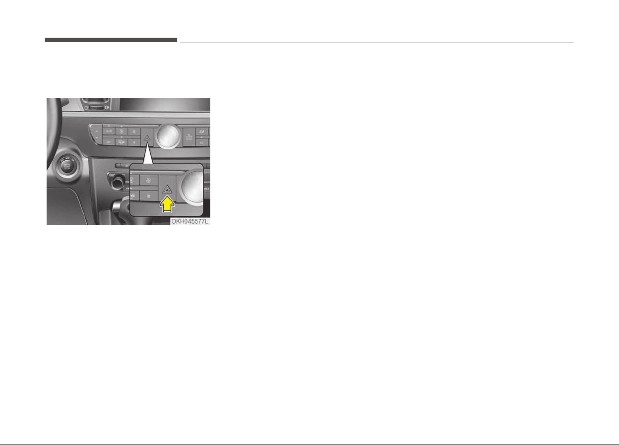
ROAD WARNING
Hazard warning flasher
The hazard warning flasher serves as a
warning to other drivers to exercise ex‐
treme caution when approaching, over‐
taking, or passing your vehicle.
It should be used whenever emergency
repairs are being made or when the ve‐
hicle is stopped near the edge of a
roadway.
Press the flasher switch with the En‐
gine Start/Stop button in any position.
The flasher switch is located in the cen‐
ter console switch panel. All turn signal
lights will flash simultaneously.
• The hazard warning flasher operates
whether your vehicle is running or
not.
• The turn signals do not work when
the hazard flasher is on.
• Care must be taken when using the
hazard warning flasher while the ve‐
hicle is being towed.
What to do in an emergency
6-02

IN CASE OF AN EMERGENCY WHILE DRIVING
If the engine stalls at a
crossroad or crossing
If the engine stalls at a crossroad or
crossing, set the shift lever in the N
(Neutral) position and then push the
vehicle to a safe place.
If you have a flat tire while
driving
If a tire goes flat while you are driving:
1. Take your foot off the accelerator
pedal and let the car slow down
while driving straight ahead. Do not
apply the brakes immediately or
attempt to pull off the road as this
may cause a loss of control. When
the car has slowed to such a speed
that it is safe to do so, brake care‐
fully and pull off the road. Drive off
the road as far as possible and park
on firm, level ground. If you are on
a divided highway, do not park in
the median area between the two
traffic lanes.
2. When the vehicle is stopped, turn
on your emergency hazard flash‐
ers, set the parking brake and put
the shift lever in P (Park).
3. Have all passengers get out of the
car. Be sure they all get out on the
side of the car that is away from
traffic.
4. When changing a flat tire, follow
the instruction provided later in If
you have a flat tire on page 6-14.
If the engine stalls while driving
1. Reduce your speed gradually, keep‐
ing a straight line. Move cautiously
off the road to a safe place.
2. Turn on your emergency flashers.
3. Try to start the engine again. If
your vehicle does not start, consult
a professional workshop. Kia rec‐
ommends to consult an authorized
Kia dealer/service partner.
6-03
6
What to do in an emergency

IF THE ENGINE DOES NOT START
If the engine doesn't turn over
or turns over slowly
1. If your vehicle has an automatic
transaxle, be sure the shift lever is
in N (Neutral) or P (Park) and the
emergency brake is set.
2. Check the battery connections to
be sure they are clean and tight.
3. Turn on the interior light. If the
light dims or goes out when you
operate the starter, the battery is
discharged.
4. Check the starter connections to be
sure they are securely tightened.
5. Do not push or pull the vehicle to
start it. See instructions for Jump
starting on page 6-05.
WARNING
If the engine will not start, do not
push
or pull the car to start it. This
could result in a collision or cause
other damage.
If engine turns over normally
but does not start
1. Check the fuel level.
2. With the ignition switch in the LOCK
position, check all connectors at the
ignition coils and spark plugs. Re‐
connect any that may be discon‐
nected or loose.
3. If the engine still does not start, call
a professional workshop. Kia rec‐
ommends to call an authorized Kia
dealer/service partner.
What to do in an emergency
6-04
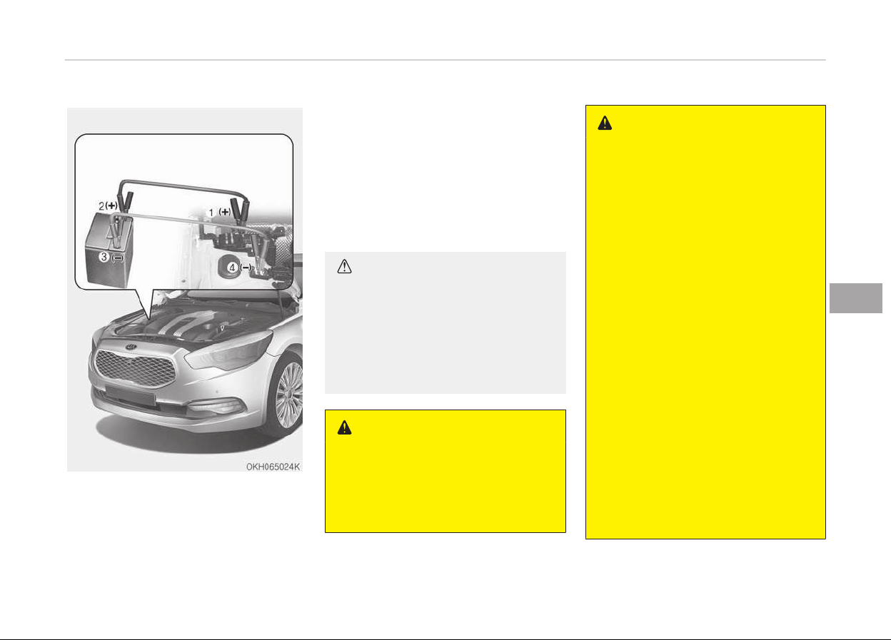
EMERGENCY STARTING
Connect cables in numerical order and
disconnect in reverse order.
Jump starting
Jump starting can be dangerous if done
incorrectly. Therefore, to avoid harm to
yourself or damage to your vehicle or
battery, follow the jump starting pro‐
cedures. If in doubt, we strongly rec‐
ommend that you have a competent
technician or towing service jump start
your vehicle.
CAUTION
Use only a 12-volt jumper system.
You can damage a 12-volt starting
motor, ignition system, and other
electrical parts beyond repair by use
of a 24-volt power supply (either
two 12-volt batteries in series or a
24-volt motor generator set).
WARNING
n
Battery
Never attempt to check the electro‐
lyte level of the battery as this may
cause the battery to rupture or ex‐
plode causing serious injury.
WARNING
n
Battery
• Keep all flames or sparks away
from the battery. The battery
produces hydrogen gas which may
explode if exposed to flame or
sparks.
If these instructions are not fol‐
lowed exactly, serious personal in‐
jury and damage to the vehicle
may occur! If you are not sure how
to follow this procedure, seek
qualified assistance. Automobile
batteries contain sulfuric acid. This
is poisonous and highly corrosive.
When jump starting, wear protec‐
tive glasses and be careful not to
get acid on yourself, your clothing
or on the car.
• Do not attempt to jump start the
vehicle if the discharged battery is
frozen or if the electrolyte level is
low; the battery may rupture or
explode.
• Do not allow the (+) and (-) jumper
cables to touch. It may cause
sparks.
(Continued)
6-05
6
What to do in an emergency
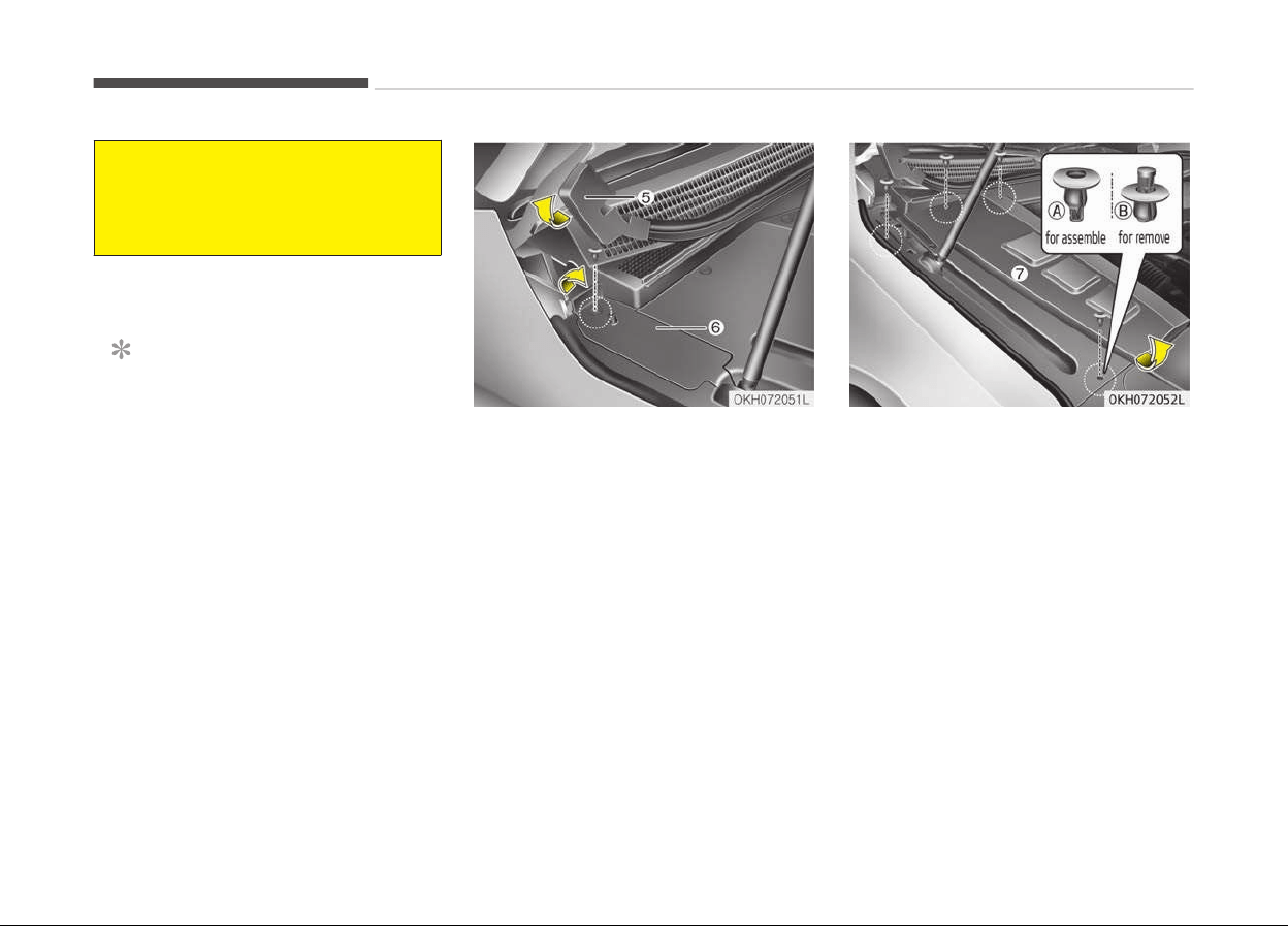
(Continued)
• The battery may rupture or ex‐
plode
when you jump start with a
low or frozen battery.
Jump starting procedure
NOTICE
Your vehicle has a battery in the
trunk room, but when you jump
start your vehicle, use the jumper
terminal in the engine room.
1. Make sure the booster battery is
12-volt and that its negative termi‐
nal is grounded.
2. If the booster battery is in another
vehicle, do not allow the vehicles to
touch.
3. Turn off all unnecessary electrical
loads.
4. Open the engine hood.
5. Lift the end of strip (5) up.
6. Press the fastener head with screw
driver and then pull the fastener
out.
7. Lift the rear portion of small serv‐
ice cover (6) up and then remove
the service cover.
(A) : for assemble, (B) : for remove
8. Press the fastener head with screw
driver and then pull the fastener
out from main service cover (7).
9. Pull the main service cover over
7 mm to toward the front of the
vehicle.
10. Lift the main service cover up and
then remove the main service cov‐
er. Be careful not to damage the
holder under the main service cov‐
er.
11. Connect the jumper cables in the
exact sequence shown in the illus‐
tration. First connect one end of a
jumper cable to the positive termi‐
nal of the jump start connector (1),
What to do in an emergency
6-06
then connect the other end to the
positive terminal on the booster
battery (2).
Proceed to connect one end of the
other jumper cable to the negative
terminal of the booster battery (3),
then the other end to the negative
terminal of the jump start connec‐
tor (4). Do not connect it to or near
any part that moves when the en‐
gine is cranked.
Do not allow the jumper cables to
contact anything except the correct
battery terminals or the correct
ground. Do not lean over the bat‐
tery when making connections.
CAUTION
n
Battery cables
Do not connect the jumper cable
from the negative terminal of the
booster battery to the negative ter‐
minal of the discharged battery. This
can cause the discharged battery to
overheat and crack, releasing bat‐
tery acid.
Make sure to connect one end of the
jumper cable to the negative termi‐
nal of the booster battery, and the
(Continued)
(Continued)
other end to a metallic point, far
away from the battery.
12. Start the engine of the vehicle with
the booster battery and let it run
at 2,000 rpm, then start the engine
of the vehicle with the discharged
battery.
If the cause of your battery discharging
is not apparent, have the system
checked by a professional workshop.
Kia recommends to visit an authorized
Kia dealer/service partner
Push-starting
Vehicles equipped with automatic
transaxle cannot be push-started.
Follow the directions in this section for
Jump starting on page 6-05.
WARNING
Never tow a vehicle to start it be‐
cause the sudden surge forward
when the engine starts could cause
a collision with the tow vehicle.
6-07
6
What to do in an emergency
IF THE ENGINE OVERHEATS
If your temperature gauge indicates
overheating, you will experience a loss
of power, or hear loud pinging or knock‐
ing, the engine is probably too hot. If
this happens, you should:
1. Pull off the road and stop as soon
as it is safe to do so.
2. Place the shift lever in P (Park) and
set the parking brake. If the air
conditioning is on, turn it off.
3. If engine coolant is running out un‐
der the car or steam is coming out
from the hood, stop the engine. Do
not open the hood until the coolant
has stopped running or the steam‐
ing has stopped. If there is no visi‐
ble loss of engine coolant and no
steam, leave the engine running
and check to be sure the engine
cooling fan is operating. If the fan is
not running, turn the engine off.
4. Check to see if the water pump
drive belt is missing. If it is not
missing, check to see that it is
tight. If the drive belt seems to be
satisfactory, check for coolant
leaking from the radiator, hoses or
under the car. (If the air condition‐
ing had been in use, it is normal for
cold water to be draining from it
when you stop).
WARNING
While the engine is running, keep
hair, hands and clothing away from
moving parts such as the fan and
drive belts to prevent injury.
5. If the water pump drive belt is bro‐
ken or engine coolant is leaking out,
stop the engine immediately and
call a professional workshop. Kia
recommends to call an authorized
Kia dealer/service partner.
WARNING
Do not remove the radiator cap
when the engine is hot. This can al‐
low coolant to blow out of the open‐
ing and cause serious burns.
6. If you cannot find the cause of the
overheating, wait until the engine
temperature has returned to nor‐
mal. Then, if coolant has been lost,
carefully add coolant to the reser‐
voir to bring the fluid level in the
reservoir up to the halfway mark.
7. Proceed with caution, keeping alert
for further signs of overheating. If
overheating happens again, call a
professional workshop. Kia recom‐
mends to call an authorized Kia
dealer/service partner.
CAUTION
• Serious loss of coolant indicates
there is a leak in the cooling sys‐
tem. In this case, have the sys‐
tem checked by a professional
workshop. Kia recommends to
visit an authorized Kia dealer/
service partner.
• When the engine overheats from
low
engine coolant, suddenly
adding engine coolant may cause
cracks in the engine. To prevent
damage, add engine coolant
slowly in small quantities.
What to do in an emergency
6-08
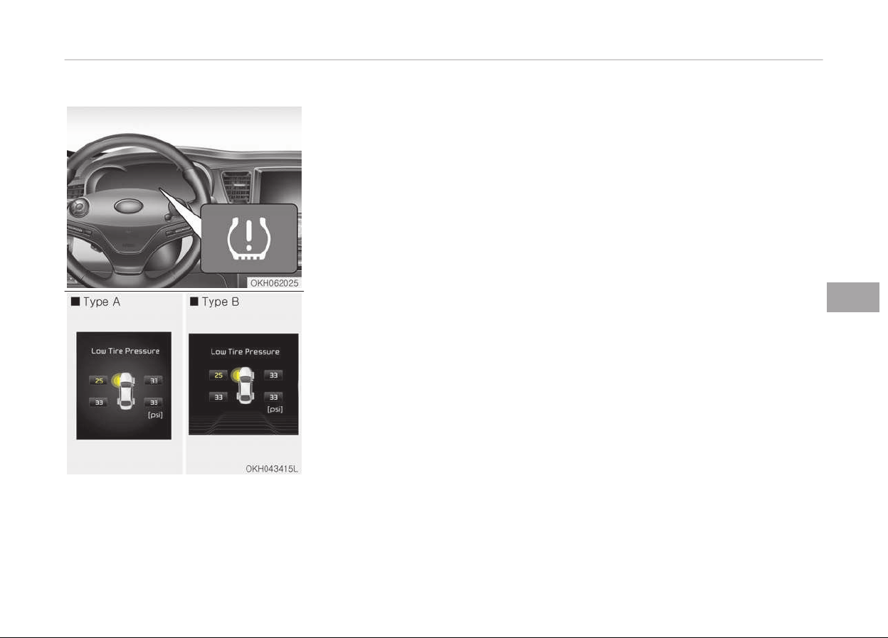
TIRE PRESSURE MONITORING SYSTEM (TPMS) (IF EQUIPPED)
1. Low
tire pressure telltale / TPMS
malfunction indicator
2. Low tire pressure position telltale
and tire pressure telltale (Shown on
the LCD display)
• You can check the tire pressure in the
information mode on the cluster.
- Refer to User settings mode on
page 4-60.
• Tire pressure is displayed
1~2 minutes later after driving.
• If tire pressure is not displayed when
the vehicle is stopped, "Drive to dis‐
play" message displays. After driving,
check the tire pressure.
• You can change the tire pressure unit
in the user settings mode on the
cluster.
- psi, kpa, bar (Refer to User set‐
tings mode on page 4-60).
Each tire, including the spare (if provi‐
ded), should be checked monthly when
cold and inflated to the inflation pres‐
sure recommended by the vehicle man‐
ufacturer on the vehicle placard or tire
inflation pressure label.
(If your vehicle has tires of a different
size than the size indicated on the vehi‐
cle placard or tire inflation pressure la‐
bel, you should determine the proper
tire inflation pressure for those tires.)
As an added safety feature, your vehi‐
cle
has been equipped with a tire pres‐
sure monitoring system (TPMS) that il‐
luminates a low tire pressure telltale
when one or more of your tires is sig‐
nificantly under-inflated. Accordingly,
when the low tire pressure telltale illu‐
minates, you should stop and check
your tires as soon as possible, and in‐
flate them to the proper pressure.
Driving on a significantly under-inflated
tire causes the tire to overheat and can
lead to tire failure. Under-inflation also
reduces fuel efficiency and tire tread
life, and may affect the vehicle’s han‐
dling and stopping ability.
Please note that the TPMS is not a
substitute for proper tire maintenance,
and it is the driver’s responsibility to
maintain correct tire pressure, even if
under-inflation has not reached the
level to trigger illumination of the TPMS
low tire pressure telltale.
6-09
6
What to do in an emergency
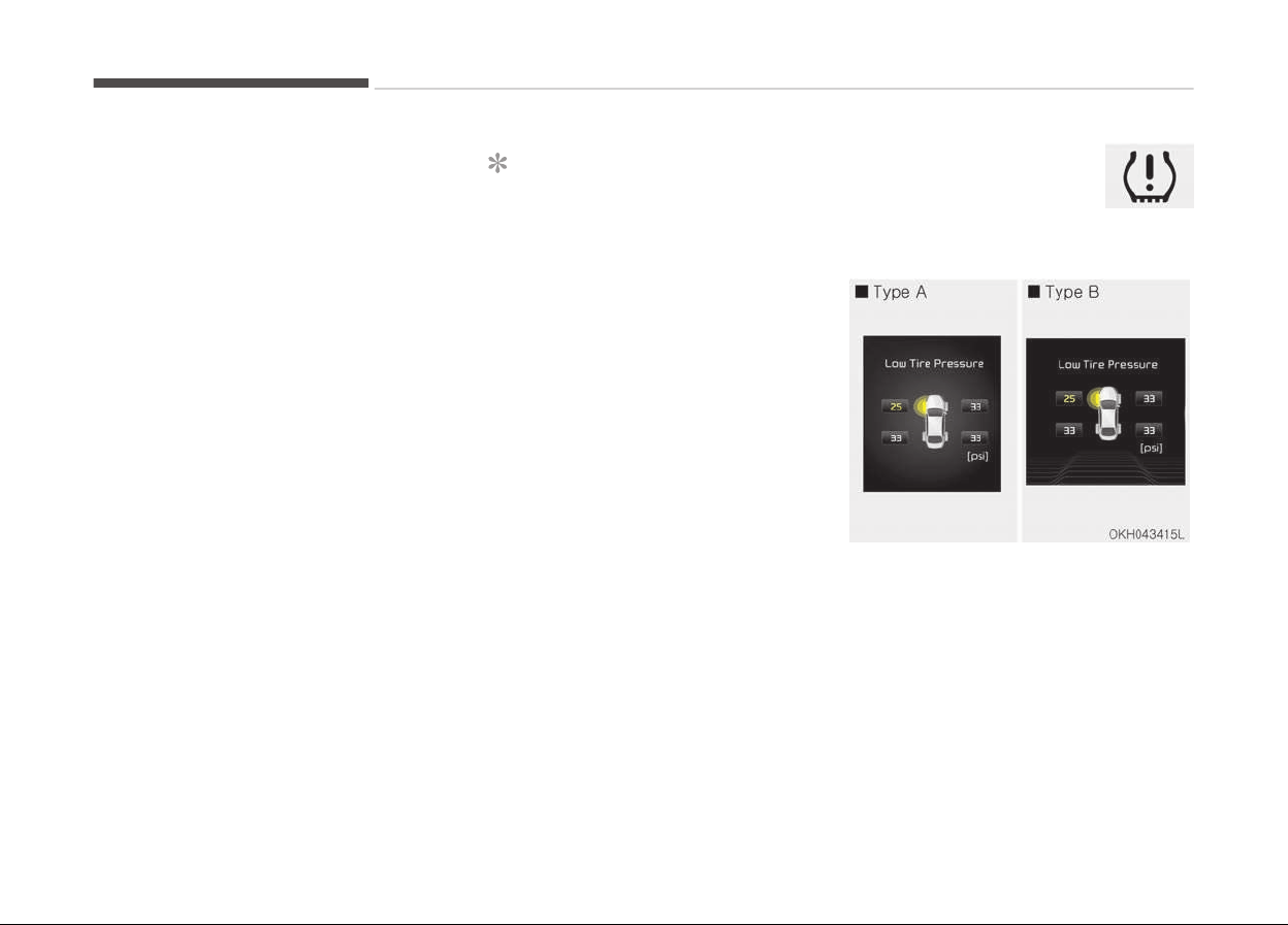
Your vehicle has also been equipped
with a TPMS malfunction indicator to
indicate when the system is not oper‐
ating properly. The TPMS malfunction
indicator is combined with the low tire
pressure telltale. When the system de‐
tects a malfunction, the telltale will
flash for approximately 1 minute and
then remain continuously illuminated.
This sequence will continue upon sub‐
sequent vehicle start-ups as long as
the malfunction exists. When the TPMS
malfunction indicator remains illumina‐
ted after blinking for approximately
1 minute, the system may not be able
to detect or signal low tire pressure as
intended.
TPMS malfunctions may occur for a va‐
riety of reasons, including the installa‐
tion of replacement or alternate tires
or wheels on the vehicle that prevent
the TPMS from functioning properly.
Always check the TPMS malfunction
telltale after replacing one or more
tires or wheels on your vehicle to en‐
sure that the replacement or alternate
tires and wheels allow the TPMS to
continue to function properly.
NOTICE
If any of the below happens, have
the system checked by a professio‐
nal workshop. Kia recommends to
visit an authorized Kia dealer/service
partner.
1. The low tire pressure telltale/
TPMS malfunction indicator does
not illuminate for 3 seconds
when the Engine Start/Stop but‐
ton is turned to the ON or en‐
gine is running.
2. The TPMS malfunction indicator
remains illuminated after blink‐
ing for approximately 1 minute.
3. The Low tire pressure position
telltale remains illuminated.
Low tire pressure
telltale
Low tire pressure
position telltale and tire
pressure telltale
When the tire pressure monitoring sys‐
tem warning indicators are illuminated
and warning message displayed on the
cluster LCD display, one or more of
your tires is significantly under-infla‐
ted. The low tire pressure position tell‐
tale light will indicate which tire is sig‐
nificantly under-inflated by illuminating
the corresponding position light.
What to do in an emergency
6-10
If either telltale illuminates, immediate‐
ly reduce your speed, avoid hard cor‐
nering and anticipate increased stop‐
ping distances. You should stop and
check your tires as soon as possible. In‐
flate the tires to the proper pressure as
indicated on the vehicle’s placard or tire
inflation pressure label located on the
driver’s side center pillar outer panel. If
you cannot reach a service station or if
the tire cannot hold the newly added
air, replace the low pressure tire with a
spare tire.
If you drive the vehicle for about
10 minutes at speeds above 25 km/h
after replacing the low pressure tire
with the spare tire, the below will hap‐
pen:
• The TPMS malfunction indicator may
blink for approximately 1 minute and
then remain continuously illuminated
because the TPMS sensor is not
mounted on the spare wheel.
NOTICE
The spare tire is not equipped with a
tir
e pressure sensor.
CAUTION
• In winter or cold weather, the low
tire pressure telltale may illumi‐
nate if the tire pressure was ad‐
justed to the recommended tire in‐
flation pressure in warm weather.
It does not mean your TPMS is
malfunctioning because the de‐
creased temperature leads to a
lowering of tire pressure.
• When you drive your vehicle from
a warm area to a cold area or from
a cold area to a warm area, or the
outside temperature is higher or
lower, you should check the tire in‐
flation pressure and adjust the
tires to the recommended tire in‐
flation pressure.
• When filling tires with more air,
conditions to turn off the low tire
pressure telltale may not be met.
This is because a tire inflator has a
margin of error in performance.
The low tire pressure telltale will
be turned off if the tire pressure is
above the recommended tire infla‐
tion pressure.
(Continued)
(Continued)
• The tire pressure may vary de‐
pending
on various factors includ‐
ing the temperature conditions of
parking area, driving conditions
and ambient temperature, altitude
above sea level.
• The low tire pressure position tell‐
tale
warning may illuminate when
the tire pressure is same or higher
than nearby tires. This is normal
since the tire pressure changes
along with the Internal tempera‐
ture of each tire.
• The tire pressure displayed on the
instrument panel may be different
from the tire pressure measured
by a tire pressure gauge.
WARNING
n
Low pressure damage
Significantly low tire pressure makes
the vehicle unstable and can contrib‐
ute to loss of vehicle control and in‐
creased braking distances.
(Continued)
6-11
6
What to do in an emergency
(Continued)
Continued driving on low pressure
tir
es can cause the tires to overheat
and fail.
TPMS (Tire pressure
monitoring system)
malfunction indicator
The TPMS malfunction indi‐
cator will illuminate after it blinks for
approximately one minute when there
is a problem with the Tire Pressure
Monitoring System.
In this case, have the system checked
by a professional workshop to deter‐
mine the cause of the problem. Kia rec‐
ommends to visit an authorized Kia
dealer/service partner.
NOTICE
If there is a malfunction with the
TPMS, the low tire pressure position
telltale will not be displayed even
though the vehicle has an under-in‐
flated tire.
CAUTION
• The TPMS malfunction indicator
may blink for approximately
1 minute and then remain continu‐
ously illuminated if the vehicle is
moving around electric power sup‐
ply cables or radios transmitter
such as at police stations, govern‐
ment and public offices, broad‐
casting stations, military installa‐
tions, airports, or transmitting
towers, etc. This can interfere
with normal operation of the Tire
Pressure Monitoring System
(TPMS).
• The TPMS malfunction indicator
may blink for approximately
1 minute and then remain continu‐
ously illuminated if snow chains
are used or some separate elec‐
tronic devices such as notebook
computer, mobile charger, remote
starter or navigation etc., are used
in the vehicle.
This can interfere with normal op‐
eration of the Tire Pressure Moni‐
toring System (TPMS).
Changing a tire with TPMS
If you have a flat tire, the low Tire
Pressure and Position telltales will
come on. Kia recommends to visit an
authorized Kia dealer/service partner.
CAUTION
If you use a puncture-repairing
agent to repair and/or inflate a low
pressure tire. The tire sealant may
damage the tire pressure sensor. We
recommend that you use the sealant
approved by Kia. If used, we recom‐
mend that the TPMS be checked by
an authorized Kia dealer.
Each wheel is equipped with a tire pres‐
sure sensor mounted inside the tire be‐
hind the valve stem. You must use
TPMS specific wheels. Have your tires
serviced by a professional workshop.
Kia recommends to visit an authorized
Kia dealer/service partner.
If you drive the vehicle for about
10 minutes at speeds above 25 km/h
after replacing the low pressure tire
with the spare tire, the below will hap‐
pen:
What to do in an emergency
6-12

• The TPMS malfunction indicator may
blink for approximately 1 minute and
then remain continuously illuminated
because the TPMS sensor is not
mounted on the spare wheel.
You may not be able identify a low tire
by simply looking at it. Always use a
good quality tire pressure gauge to
measure the tire's inflation pressure.
Please note that a tire that is hot (from
being driven) will have a higher pres‐
sure measurement than a tire that is
cold (from sitting stationary for at
least 3 hours and driven less than
1 mile during that 3 hour period).
Allow the tire to cool before measuring
the inflation pressure. Always be sure
the tire is cold before inflating to the
recommended pressure.
A cold tire means the vehicle has been
sitting for 3 hours and driven for less
than 1 mile in that 3 hour period.
WARNING
n
TPMS
(Continued)
(Continued)
• The TPMS cannot alert you to se‐
v
ere and sudden tire damage
caused by external factors such as
nails or road debris.
• If you feel any vehicle instability,
immediately take your foot off the
accelerator
, apply the brakes grad‐
ually and with light force, and
slowly move to a safe position off
the road.
WARNING
n
Protecting TPMS
Tampering with, modifying, or disa‐
bling the Tire Pressure Monitoring
System (TPMS) components may in‐
terfere with the system's ability to
warn the driver of low tire pressure
conditions and/or TPMS malfunc‐
tions. Tampering with, modifying, or
disabling the Tire Pressure Monitor‐
ing System (TPMS) components may
void the warranty for that portion of
the vehicle.
WARNING
n
For EUROPE
• Do not modify the vehicle, it may
interfere with the TPMS function.
• The wheels on the market do not
have a TPMS sensor.
For your safety, use parts for re‐
placement from a professional
workshop. Kia recommends to visit
an authorized Kia dealer/service
partner
• If you use the wheels on the mar‐
ket, use a TPMS sensor approved
by an authorized Kia dealer.
If your vehicle is not equipped with
a TPMS sensor or TPMS does not
work properly, you may fail the
periodic vehicle inspection conduc‐
ted in your country.
❈ All vehicles sold in the EUROPE
market during below period
must be equipped with TPMS.
- New model vehicle :
Nov. 1, 2012 ~
- Current model vehicle :
Nov.
1, 2014~ (Based on vehi‐
cle registrations)
6-13
6
What to do in an emergency
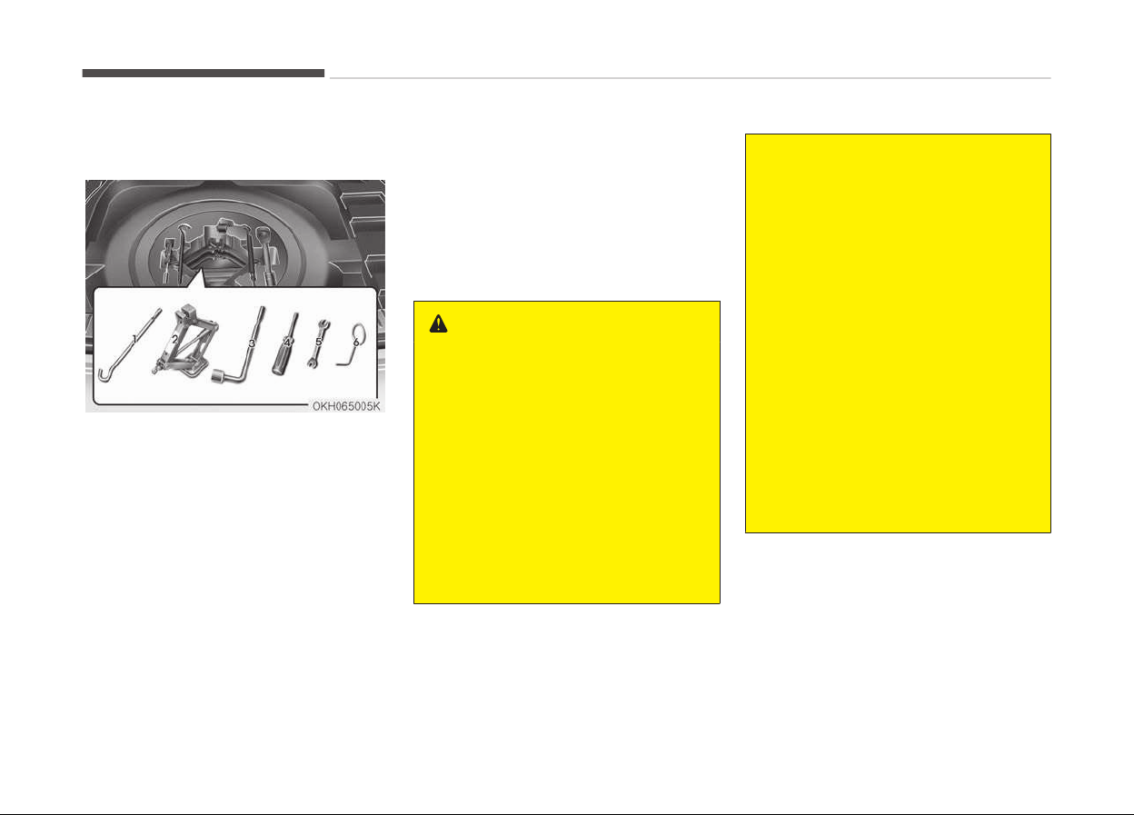
IF YOU HAVE A FLAT TIRE
Jack and tools
The jack, jack handle, and wheel lug nut
wrench are stored in the luggage com‐
partment. Pull up the luggage box cover
to reach this equipment.
1. Jack handle
2. Jack
3. Wheel lug nut wrench
4. Screw driver
(phillips and flat-head)
5. Spanner
6. Tool for removing wheel cover
Jacking instructions
The jack is provided for emergency tire
changing only.
To prevent the jack from rattling
while the vehicle is in motion, store it
properly.
Follow jacking instructions to reduce
the possibility of personal injury.
WARNING
n
Changing tires
• Never attempt vehicle repairs in
the
traffic lanes of a public road or
highway.
• Always move the vehicle com‐
pletely
off the road and onto the
shoulder before trying to change a
tire. The jack should be used on
level firm ground. If you cannot
find a firm, level place off the
road, call a towing service compa‐
ny for assistance.
(Continued)
(Continued)
• Be sure to use the correct front
and rear jacking positions on the
vehicle; never use the bumpers or
any other part of the vehicle for
jacking support.
• The vehicle can easily roll off the
jack causing serious injury or
death.
• Do not get under a vehicle that is
supported by a jack.
• Do not start or run the engine
while the vehicle is on the jack.
• Do not allow anyone to remain in
the vehicle while it is on the jack.
• Make sure any children present are
in
a secure place away from the
road and from the vehicle to be
raised with the jack.
What to do in an emergency
6-14
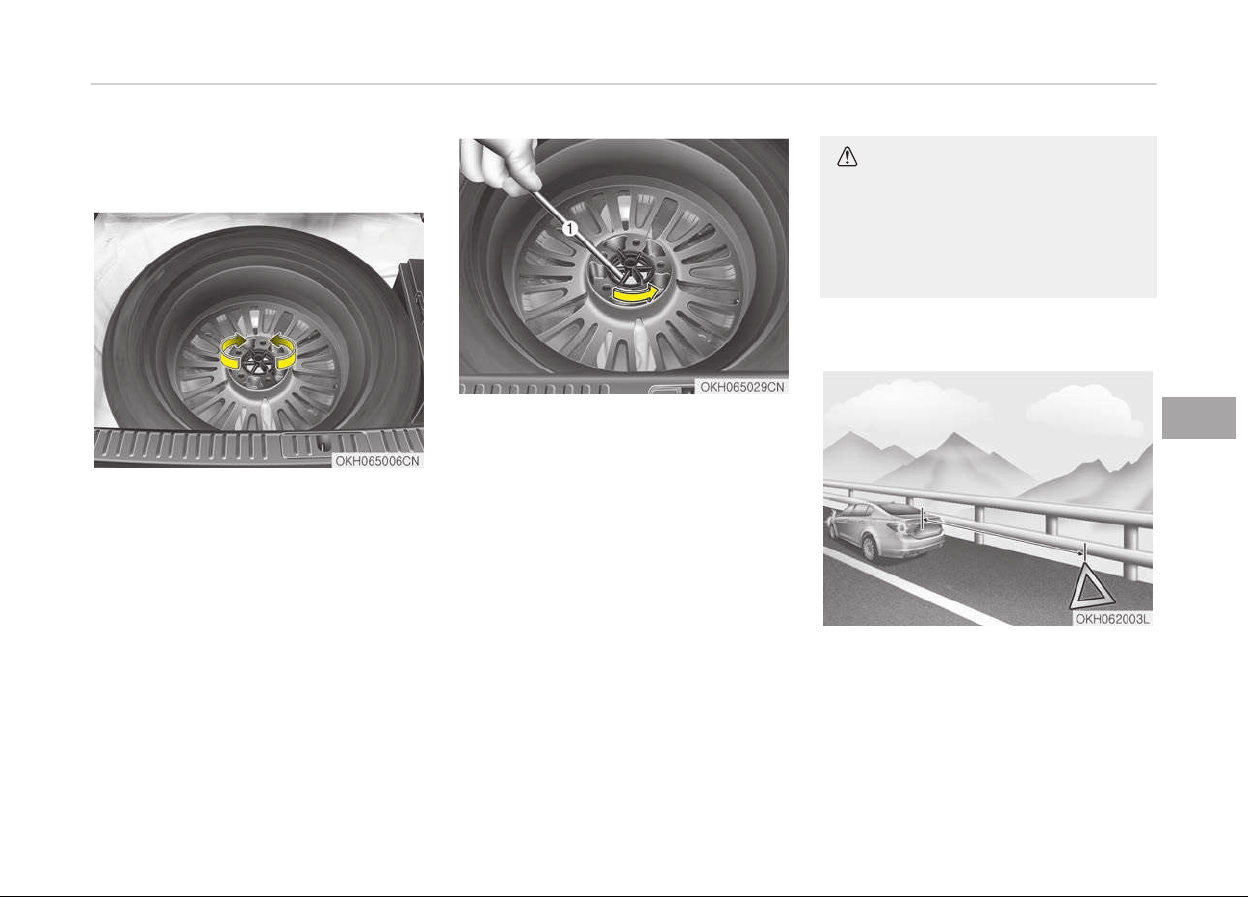
Removing and storing the spare
tir
e
Turn the tire hold-down wing bolt
counterclockwise.
Store the tire in the reverse order of
removal.
To prevent the spare tire and tools
from rattling while the vehicle is in
motion, store them properly.
If it is hard to loosen the tire hold-down
wing bolt by a hand, you can loosen it
easily using the Jack handle.
1. Put the Jack handle (1) into the in‐
side of tire hold-down wing bolt.
2. Turn the tire hold-down wing bolt
counterclockwise by the Jack han‐
dle to utilize the principles of the
lever and fulcrum.
CAUTION
When you remove or store the spare
tire, don't give a shock to the bat‐
tery.
Shock to the battery may cause fail‐
ure of electrical circuits.
Changing tires
1. Park on a level surface and apply
the parking brake firmly.
2. Place the shift lever into P (Park).
3. Activate the hazard warning flash‐
er.
6-15
6
What to do in an emergency
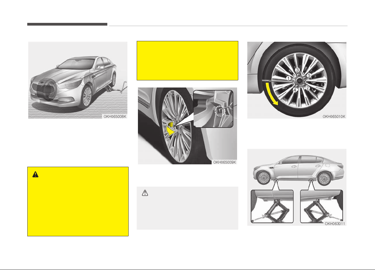
4. Remove the wheel lug nut wrench,
jack, jack handle, and spare tire
from the vehicle.
5. Block both the front and rear of the
wheel that is diagonally opposite
the jack position.
WARNING
n
Changing a tire
• To prevent vehicle movement
while changing a tire, always set
the parking brake fully, and al‐
ways block the wheel diagonally
opposite the wheel being
changed.
(Continued)
(Continued)
• We recommend that the wheels
of
the vehicle be blocked, and
that no person remain in the ve‐
hicle that is being jacked.
6. Insert the tool (1) into the hole and
pull out the wheel cover.
CAUTION
When removing the wheel cover, if
you use any other tool except the
tool (1), the wheel cover may be
damaged.
7. Loosen the wheel lug nuts counter‐
clockwise one turn each, but do not
remove any nut until the tire has
been raised off the ground.
What to do in an emergency
6-16
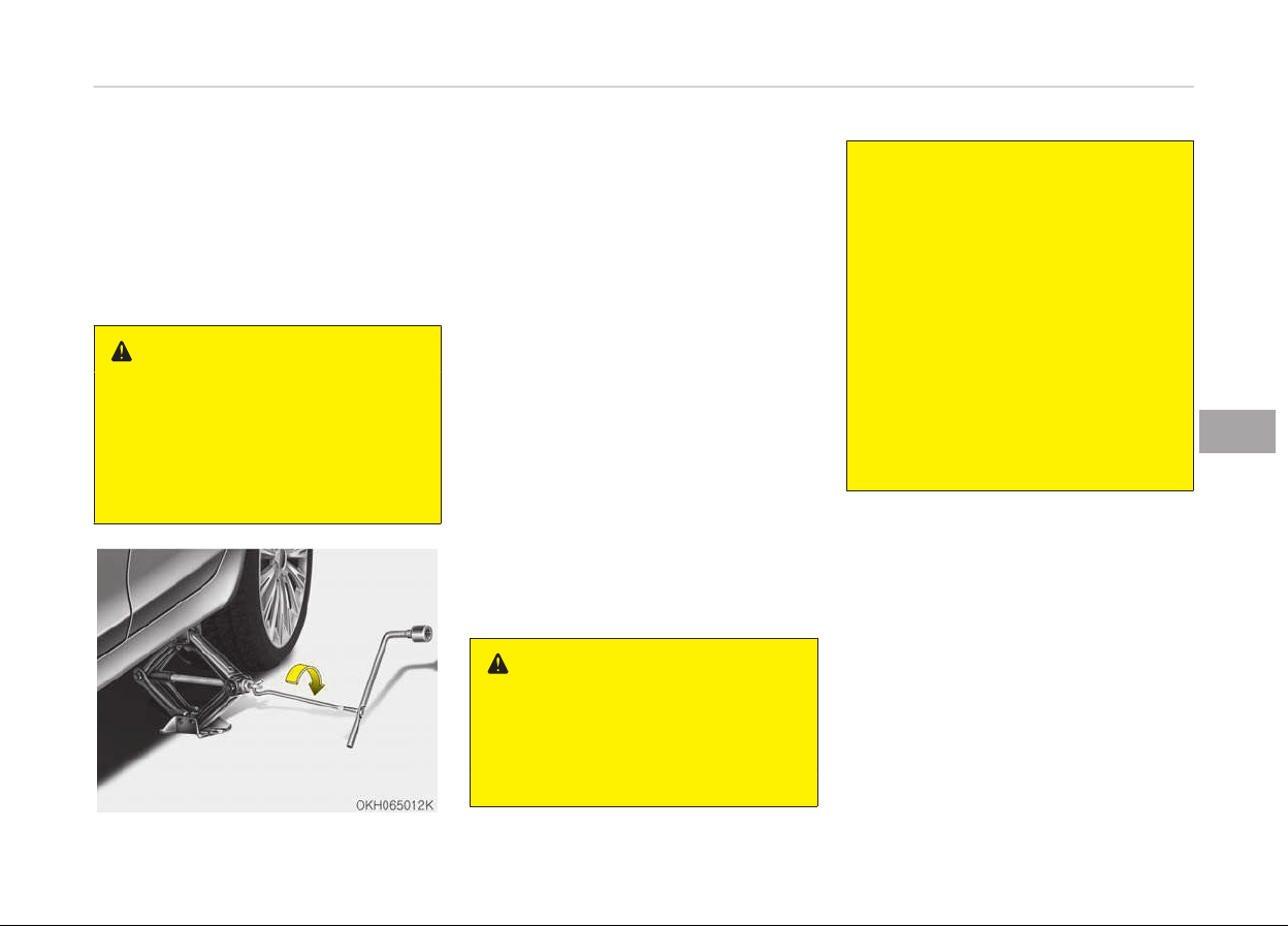
8. Place the jack at the front or rear
jacking position closest to the tire
you are changing. Place the jack at
the designated locations under the
frame. The jacking positions are
plates welded to the frame with
two tabs and a raised dot to index
with the jack.
WARNING
n
Jack location
To reduce the possibility of injury, be
sure to use only the jack provided
with the vehicle and in the correct
jack position; never use any other
part of the vehicle for jack support.
9. Insert the jack handle into the jack
and turn it clockwise, raising the
vehicle until the tire just clears the
ground. This measurement is ap‐
proximately 30 mm(1.2 in) . Before
removing the wheel lug nuts, make
sure the vehicle is stable and that
there is no chance for movement or
slippage.
10. Loosen the wheel nuts and remove
them with your fingers. Slide the
wheel off the studs and lay it flat
so it cannot roll away. To put the
wheel on the hub, pick up the spare
tire, line up the holes with the
studs and slide the wheel onto
them.
If this is difficult, tip the wheel
slightly and get the top hole in the
wheel lined up with the top stud.
Then jiggle the wheel back and
forth until the wheel can be slid
over the other studs.
WARNING
• Wheels and wheel caps may
have sharp edges. Handle them
carefully to avoid possible severe
injury.
(Continued)
(Continued)
• Before putting the wheel into
place,
be sure that there is noth‐
ing on the hub or wheel (such as
mud, tar, gravel, etc.) that inter‐
feres with the wheel from fitting
solidly against the hub. If there
is, remove it. If the contact of
the mounting surface between
the wheel and hub is not good,
the wheel nuts could come loose
and cause the loss of a wheel.
Loss of a wheel may result in
loss of control of the vehicle.
This may cause serious injury or
death.
11. To reinstall the wheel, hold it on the
studs, put the wheel nuts on the
studs and tighten them finger
tight. The nuts should be installed
with their tapered small diameter
ends directed inward. Jiggle the tire
to be sure it is completely seated,
then tighten the nuts as much as
possible with your fingers again.
12. Lower the car to the ground by
turning the wheel nut wrench
counterclockwise.
6-17
6
What to do in an emergency
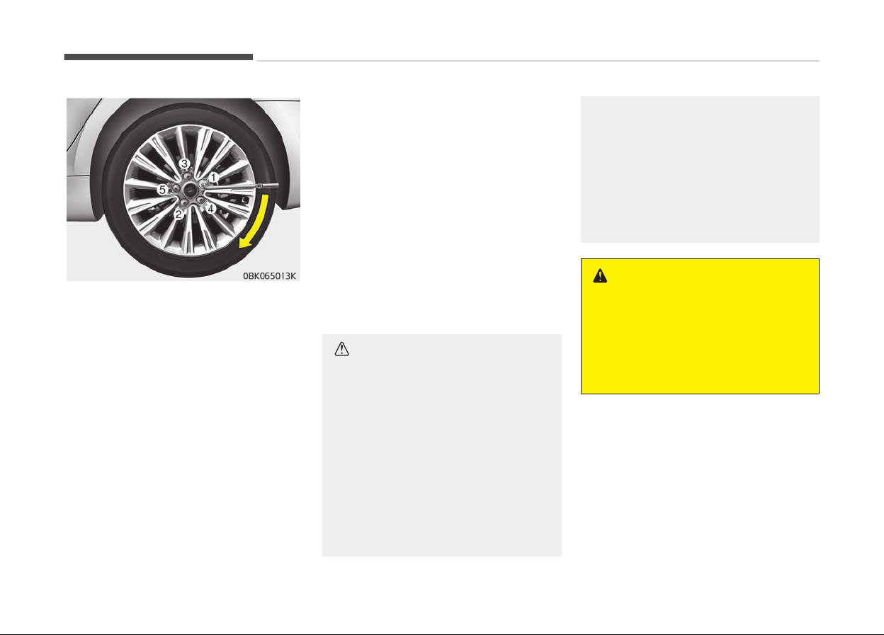
Then position the wrench as shown in
the drawing and tighten the wheel
nuts. Be sure the socket is seated com‐
pletely over the nut. Do not stand on
the wrench handle or use an extension
pipe over the wrench handle. Go around
the wheel tightening every nut follow‐
ing the numerical sequence shown in
the image until they are all tight. Then
double-check each nut for tightness.
After changing wheels, have the sys‐
tem checked by a professional work‐
shop. Kia recommends to visit an au‐
thorized Kia dealer/service partner.
Wheel nut tightening torque:
Steel wheel & aluminum alloy wheel:
9~11 kg·m (65~79 lb·ft)
If you have a tire gauge, remove the
valve cap and check the air pressure. If
the pressure is lower than recommen‐
ded, drive slowly to the nearest service
station and inflate to the correct pres‐
sure. If it is too high, adjust it until it is
correct. Always reinstall the valve cap
after checking or adjusting tire pres‐
sure. If the cap is not replaced, air may
leak from the tire. If you lose a valve
cap, buy another and install it as soon
as possible.
After you have changed wheels, always
secure the flat tire in its place and re‐
turn the jack and tools to their proper
storage locations.
CAUTION
Your vehicle has metric threads on
the wheel studs and nuts. Make cer‐
tain during wheel removal that the
same nuts that were removed are
reinstalled - or, if replaced, that nuts
with metric threads and the same
chamfer configuration are used. In‐
stallation of a non-metric thread nut
on a metric stud or vice-versa will
not secure the wheel to the hub
properly and will damage the stud so
that it must be replaced.
(Continued)
(Continued)
Note that most lug nuts do not have
metric
threads. Be sure to use ex‐
treme care in checking for thread
style before installing aftermarket
lug nuts or wheels. If in doubt, con‐
sult a professional workshop. Kia
recommends to consult an author‐
ized Kia dealer/service partner.
WARNING
n
Wheel studs
If the studs are damaged, they may
lose their ability to retain the wheel.
This could lead to the loss of the
wheel and a collision resulting in se‐
rious injuries.
To prevent the jack, jack handle, wheel
lug nut wrench and spare tire from rat‐
tling while the vehicle is in motion,
store them properly.
What to do in an emergency
6-18

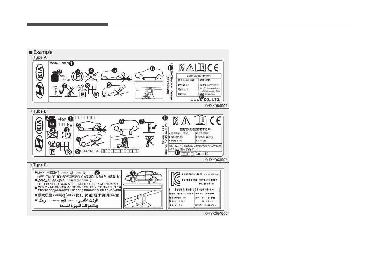
Jack label
❈ The actual Jack label in the vehicle
may differ from the illustration. For
more detailed specifications, refer
to the label attached to the jack.
1. Model Name
2. Maximum allowable load
3. When using the jack, set your park‐
ing brake.
4. When using the jack, stop the en‐
gine.
5. Do not get under a vehicle that is
supported by a jack.
6. The designated locations under the
frame
7. When supporting the vehicle, the
base plate of jack must be vertical
under the lifting point.
8. Shift into Reverse gear on vehicles
with manual transmission or move
the shift lever to the P position on
vehicles with automatic transmis‐
sion.
9. The jack should be used on firm
level ground.
10. Jack manufacturer
11. Production date
12. Representative company and ad‐
dress
What to do in an emergency
6-20
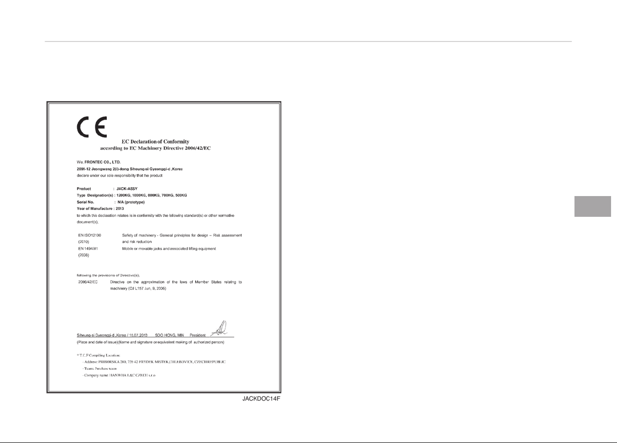
EC Declaration of Conformity
for jack
6-21
6
What to do in an emergency
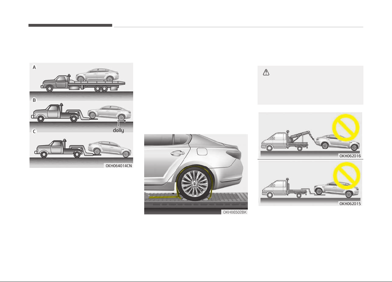
TOWING
Towing service
If emergency towing is necessary, we
recommend having it done by an au‐
thorized Kia dealer or a commercial
tow-truck service. Proper lifting and
towing procedures are necessary to
prevent damage to the vehicle. The use
of wheel dollies or flatbed is recom‐
mended.
It is acceptable to tow the vehicle with
the front wheels on the ground (with‐
out dollies) and the rear wheels off the
ground.
If any of the loaded wheels or suspen‐
sion components are damaged or the
vehicle is being towed with the rear
wheels on the ground, use a towing
dolly under the rear wheels.
When being towed by a commercial
tow truck and wheel dollies are not
used, the rear of the vehicle should al‐
ways be lifted, not the front.
• Ensure any metal parts on the tie‐
down straps do not contact painted
surfaces or the face of the wheels.
• Do not place straps over the body
panels or through the wheels.
CAUTION
Attaching straps to the chasis, sus‐
pension or other parts of the body
can cause damage.
What to do in an emergency
6-22
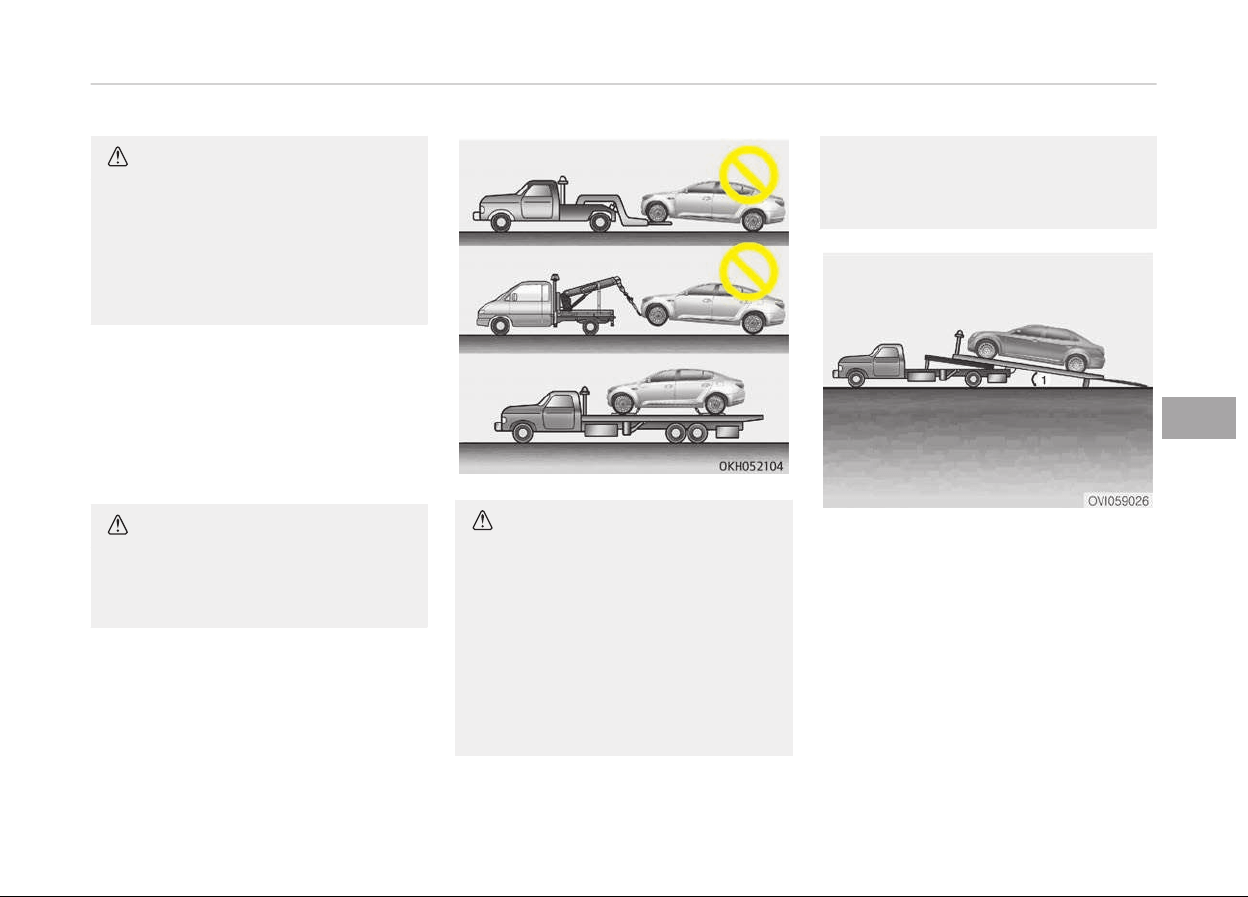
CAUTION
• Do not tow the vehicle with the
rear wheels on the ground as this
may cause damage to the vehicle.
• Do not tow with sling-type equip‐
ment. Use wheel lift or flatbed
equipment.
When towing your vehicle in an emer‐
gency without wheel dollies :
1. Set the Engine Start/Stop button in
the ACC position.
2. Place the shift lever in N (Neutral).
3. Release the parking brake.
CAUTION
Failure to place the shift lever in N
(Neutral) may cause internal dam‐
age to the transaxle.
CAUTION
If the ECS malfunction indicator illu‐
minates when there is no air in the
suspension, the vehicle height will be
very lower, so do not drive to pro‐
tect the vehicle from the projections
on the surface of the ground.
We recommend that you take your
vehicle to an authorized Kia dealer
by towing the vehicle and have the
(Continued)
(Continued)
system checked. You should tow the
v
ehicle as the picture.
When you load the vehicle onto the tow
truck, the loading angle(1) should be
smaller than 5.
6-23
6
What to do in an emergency
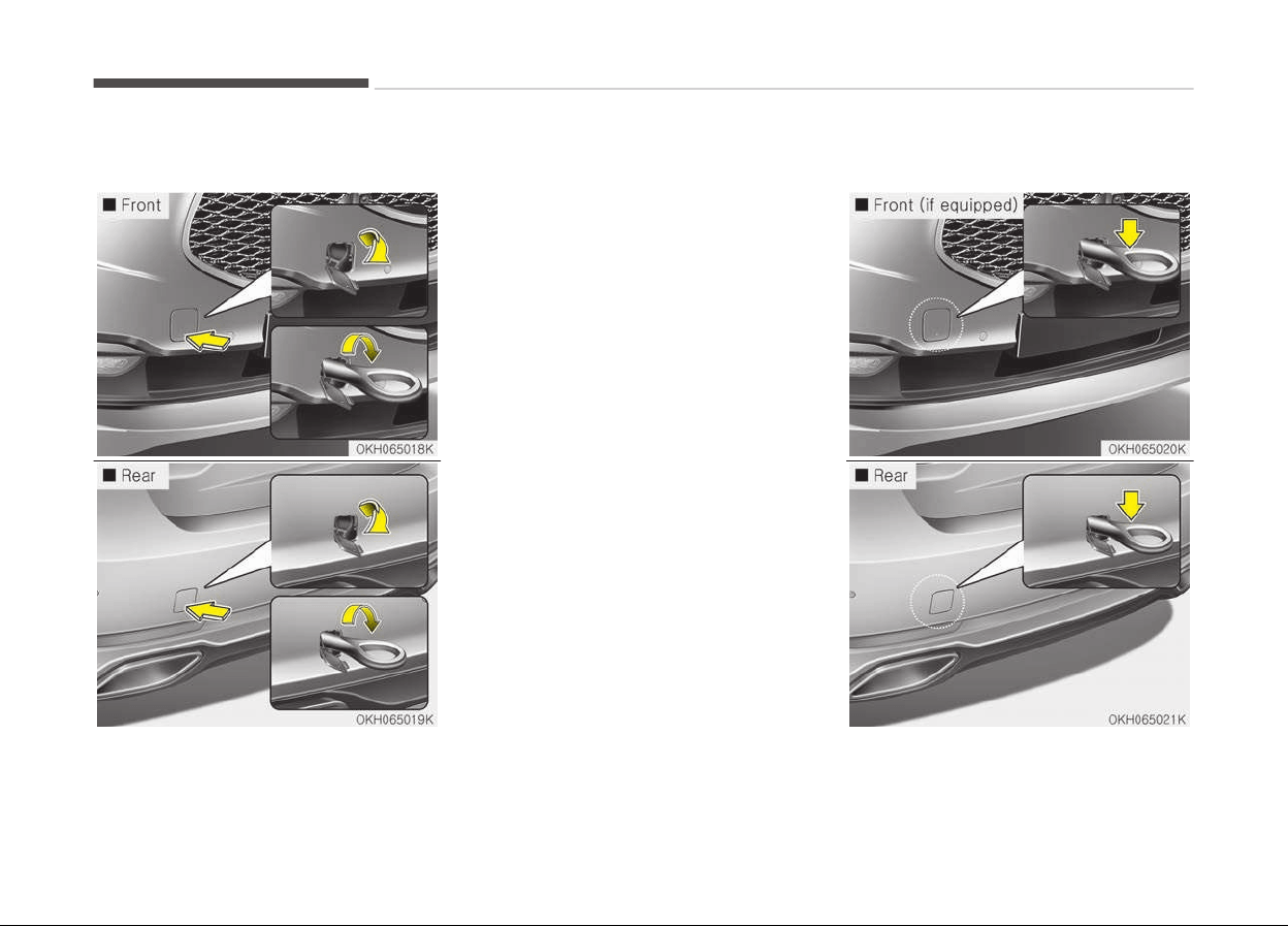
Removable towing hook
1. Open the trunk, and remove the
towing hook from the tool case.
2. Remove the hole cover pressing the
lower part of the cover on the
bumper.
3. Install the towing hook by turning it
clockwise into the hole until it is
fully secured.
4. Remove the towing hook and install
the cover after use.
Emergency towing
What to do in an emergency
6-24
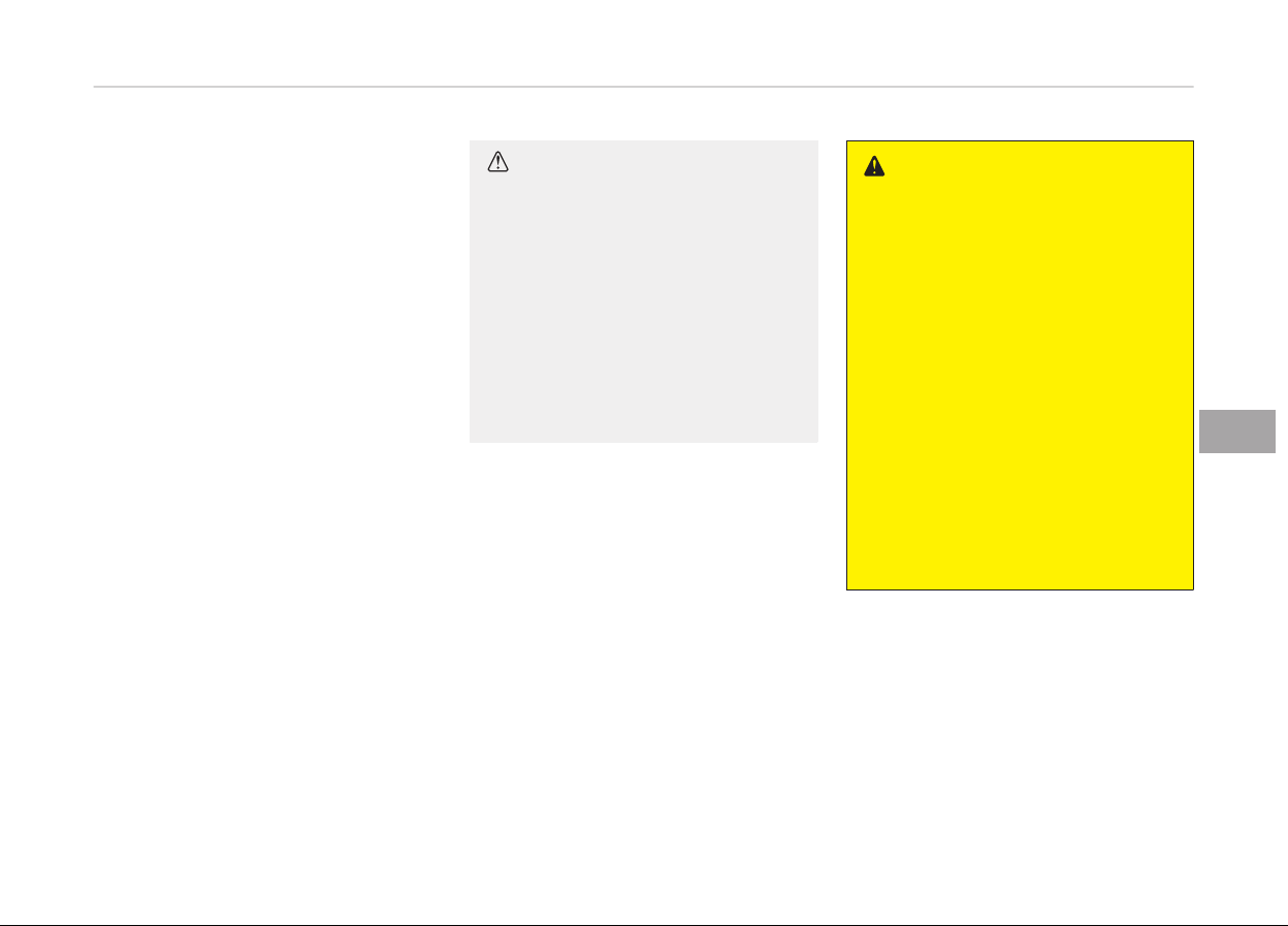
If towing is necessary, we recommend
you
to have it done by an authorized
Kia dealer or a commercial tow truck
service.
If towing service is not available in an
emergency, your vehicle may be tem‐
porarily towed using a cable or chain
secured to the emergency towing hook
under the rear of the vehicle. Use ex‐
treme caution when towing the vehicle.
A driver must be in the vehicle to steer
it and operate the brakes.
Towing in this manner may be done on‐
ly on hard-surfaced roads for a short
distance and at low speeds. Also, the
wheels, axles, power train, steering and
brakes must all be in good condition.
• Do not use the tow hooks to pull a
vehicle out of mud, sand or other
conditions from which the vehicle
cannot be driven out under its own
power.
• Avoid towing a vehicle heavier than
the vehicle doing the towing.
• The drivers of both vehicles should
communicate with each other fre‐
quently.
CAUTION
• Attach a towing strap to the tow
hook.
• Using a portion of the vehicle oth‐
er than the tow hooks for towing
may damage the body of your ve‐
hicle.
• Use only a cable or chain specifi‐
cally intended for use in towing
vehicles. Securely fasten the cable
or chain to the towing hook provi‐
ded.
• Before emergency towing, check that
the hook is not broken or damaged.
• Fasten the towing cable or chain se‐
curely to the hook.
• Do not jerk the hook. Apply steady
and even force.
• To avoid damaging the hook, do not
pull from the side or at a vertical an‐
gle. Always pull straight ahead.
WARNING
Use extreme caution when towing
the vehicle.
• Avoid sudden starts or erratic driv‐
ing maneuvers which would place
excessive stress on the emergency
towing hook and towing cable or
chain. The hook and towing cable
or chain may break and cause seri‐
ous injury or damage.
• If the disabled vehicle is unable to
be moved, do not forcibly continue
the towing. Contact an authorized
Kia dealer or a commercial tow
truck service for assistance.
• Tow the vehicle as straight ahead
as possible.
• Keep away from the vehicle during
towing.
6-25
6
What to do in an emergency
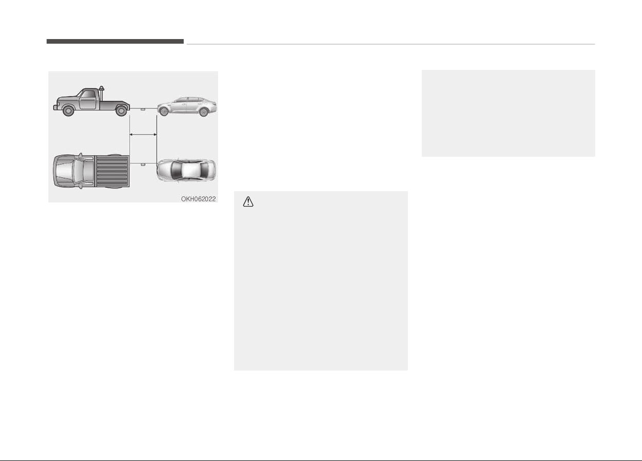
• Use a towing strap less than 5 m
long. Attach a white or red cloth
(about 30 cm wide) in the middle of
the strap for easy visibility.
• Drive carefully so that the towing
strap is not loosened during towing.
Emergency towing precautions
• Place the Engine Start/Stop button in
ACC so the steering wheel isn’t
locked.
• Place the transaxle shift lever in N
(Neutral).
• Release the parking bake.
• Press the brake pedal with more
force than normal since you will have
reduced brake performance.
• More steering effort will be required
because the power steering system
will be disabled.
• If you are driving down a long hill, the
brakes may overheat and brake per‐
formance will be reduced. Stop often
and let the brakes cool off.
CAUTION
n
Automatic transaxle
• If the car is being towed with all
four wheels on the ground, it can
be towed only from the front. Be
sure that the transaxle is in neu‐
tral. Engine Start/Stop button a
driver must be in the towed vehicle
to operate the steering and
brakes.
• To avoid serious damage to the
automatic transaxle, limit the ve‐
hicle speed to 15 km/h and drive
less than 1.5 km when towing.
(Continued)
(Continued)
• Before towing, check the auto‐
matic
transaxle for fluid leaks un‐
der your vehicle. If the automatic
transaxle fluid is leaking, a flatbed
equipment or towing dolly must be
used.
What to do in an emergency
6-26

EMERGENCY COMMODITY (IF EQUIPPED)
There are some emergency commodi‐
ties in the vehicle to help you respond
to the emergency situation.
Fire extinguisher
If there is small fire and you know how
to use the fire extinguisher, take the
following steps carefully.
1. Pull the pin at the top of the extin‐
guisher that keeps the handle from
being accidentally pressed.
2. Aim the nozzle toward the base of
the fire.
3. Stand approximately 2.5 m (8 ft)
away from the fire and squeeze
the handle to discharge the extin‐
guisher. If you release the handle,
the discharge will stop.
4. Sweep the nozzle back and forth at
the base of the fire. After the fire
appears to be out, watch it careful‐
ly since it may re-ignite.
First aid kit
There are some items such as scissors,
bandage and adhesive tape and etc. in
the kit to give first aid to an injured
person.
Triangle reflector
Place the triangle reflector on the road
to warn oncoming vehicles during
emergencies, such as when the vehicle
is parked by the roadside due to any
problems.
Tire pressure gauge (If
equipped)
Tires normally lose some air in day-to-
day use, and you may have to add a
few pounds of air periodically and it is
not usually a sign of a leaking tire, but
of normal wear. Always check tire pres‐
sure when the tires are cold because
tire pressure increases with tempera‐
ture.
To check the tire pressure, take the fol‐
lowing steps;
1. Unscrew the inflation valve cap
that is located on the rim of the
tire.
2. Press and hold the gauge against
the tire valve. Some air will escape
as you begin and more will escape
if you don't press the gauge in
firmly.
3. A firm non-leaking push will acti‐
vate the gauge.
4. Read the tire pressure on the
gauge to know whether the tire
pressure is low or high.
5. Adjust the tire pressures to the
specified pressure. Refer to Tires
and wheels on page 8-07.
6. Reinstall the inflation valve cap.
6-27
6
What to do in an emergency


Engine compartment................................................................7-03
Maintenance services............................................................... 7-05
Owner's responsibility.......................................................... 7-05
Owner maintenance precautions....................................... 7-05
Owner maintenance................................................................. 7-07
Owner maintenance schedule.............................................7-07
Scheduled maintenance service............................................. 7-09
Normal maintenance schedule - except Europe,
for Russia............................................................................... 7-10
Normal maintenance schedule - except Europe,
for Russia (continued)..........................................................7-12
Maintenance under severe usage conditions - ex‐
cept Europe, for Russia........................................................7-25
Explanation of scheduled maintenance items..................... 7-27
Engine oil and filter...............................................................7-27
Drive belts.............................................................................. 7-27
Fuel filter (for diesel)............................................................7-27
Fuel filter (for gasoline)....................................................... 7-27
Fuel lines, fuel hoses and connections.............................. 7-27
Vapor hose and fuel filler cap............................................. 7-27
Vacuum crankcase ventilation hoses ................................7-27
Air cleaner filter.....................................................................7-28
Spark plugs.............................................................................7-28
Valve clearance (3.8 L)......................................................... 7-28
Cooling system...................................................................... 7-28
Coolant....................................................................................7-28
Automatic transaxle fluid.................................................... 7-28
Brake hoses and lines...........................................................7-28
Brake fluid.............................................................................. 7-29
Parking brake.........................................................................7-29
Brake discs, pads, calipers and rotors............................... 7-29
Suspension mounting bolts................................................. 7-29
Steering gear box, linkage & boots/lower arm
ball joint.................................................................................. 7-29
Drive shafts and boots.........................................................7-29
Air conditioning refrigerant ................................................7-29
Engine oil.....................................................................................7-30
Checking the engine oil level .............................................. 7-30
Changing the engine oil and filter...................................... 7-31
Engine coolant........................................................................... 7-32
Checking the coolant level................................................... 7-32
Changing the coolant............................................................7-34
Brake fluid.................................................................................. 7-35
Checking the brake fluid level............................................. 7-35
Power steering fluid................................................................. 7-36
Checking the power steering fluid level............................ 7-36
Checking the power steering hose.....................................7-36
Washer fluid............................................................................... 7-37
Checking the washer fluid level.......................................... 7-37
Air cleaner.................................................................................. 7-38
Filter replacement.................................................................7-38
Climate control air filter...........................................................7-41
Filter inspection.....................................................................7-41
Filter replacement.................................................................7-41
Wiper blades...............................................................................7-42
Blade inspection.................................................................... 7-42
Blade replacement................................................................7-42
Battery........................................................................................7-45
For best battery service...................................................... 7-45
Battery capacity label ......................................................... 7-47
Maintenance
7

Battery recharging................................................................7-47
Reset items............................................................................7-48
Tires and wheels....................................................................... 7-49
Tire care..................................................................................7-49
Recommended cold tire inflation pressures.....................7-49
Checking tire inflation pressure..........................................7-50
Tire rotation...........................................................................7-51
Wheel alignment and tire balance......................................7-52
Tire replacement...................................................................7-52
Wheel replacement...............................................................7-53
Tire traction........................................................................... 7-54
Tire maintenance.................................................................. 7-54
Tire sidewall labeling............................................................ 7-54
Low aspect ratio tire ........................................................... 7-57
Fuses........................................................................................... 7-58
Instrument panel fuse replacement..................................7-59
Engine compartment fuse replacement........................... 7-61
Fuse/relay panel description...............................................7-62
Light bulbs.................................................................................. 7-78
Headlight, front position light, front turn signal
light, front fog light bulb replacement..............................7-79
Side repeater light bulb replacement................................ 7-80
Rear combination light bulb replacement.........................7-80
High mounted stop light replacement...............................7-81
License plate light bulb replacement.................................7-81
Interior light bulb replacement...........................................7-82
Appearance care........................................................................7-83
Exterior care.......................................................................... 7-83
Interior care........................................................................... 7-87
Emission control system ........................................................ 7-89
Crankcase emission control system.................................. 7-89
Evaporative emission control system............................... 7-89
Exhaust emission control system......................................7-89
7
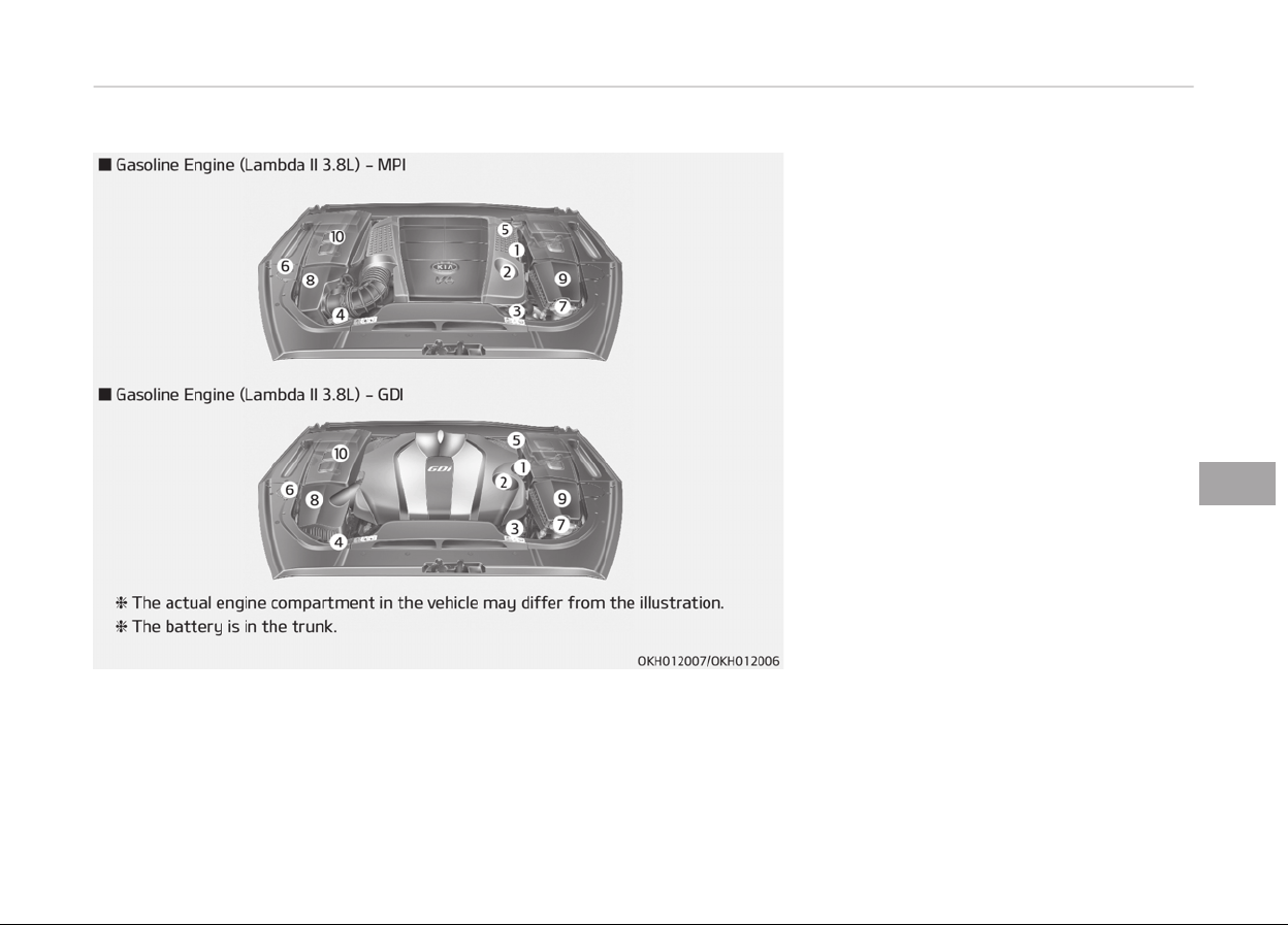
ENGINE COMPARTMENT
1. Engine oil dipstick
2. Engine oil filler cap
3. Engine coolant reservoir
4. Radiator cap
5. Brake fluid reservoir
6. Power steering fluid reservoir
7. Windshield washer fluid reservoir
8. Air cleaner
9. Fuse box
10. Jumper terminal
7-03
7
Maintenance
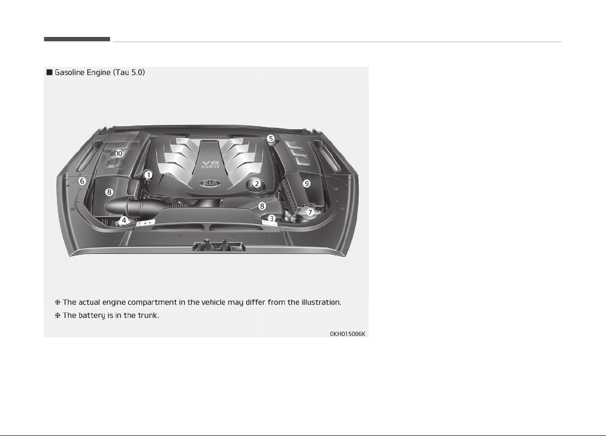
1. Engine oil dipstick
2. Engine oil filler cap
3. Engine coolant reservoir
4. Radiator cap
5. Brake fluid reservoir
6. Power steering fluid reservoir
7. Windshield washer fluid reservoir
8. Air cleaner
9. Fuse box
10. Jumper terminal
Maintenance
7-04

MAINTENANCE SERVICES
You should exercise the utmost care to
prevent damage to your vehicle and in‐
jury to yourself whenever performing
any maintenance or inspection proce‐
dures.
Inadequate, incomplete or insufficient
servicing may result in operational
problems with your vehicle that could
lead to vehicle damage, an accident, or
personal injury.
Owner's responsibility
NOTICE
Maintenance Service and Record Re‐
tention are the owner's responsibili‐
ty.
Have your vehicle serviced by a profes‐
sional workshop. Kia recommends to
visit an authorized Kia dealer/service
partner.
You should retain documents that show
proper maintenance has been per‐
formed on your vehicle in accordance
with the scheduled maintenance serv‐
ice charts shown on the following pa‐
ges. You need this information to es‐
tablish your compliance with the servic‐
ing and maintenance requirements of
your vehicle warranties.
Detailed warranty information is provi‐
ded in your Service Passport.
Repairs and adjustments required as a
result of improper maintenance or a
lack of required maintenance are not
covered when your vehicle is covered by
warranty.
Owner maintenance precautions
Improper or incomplete service may re‐
sult in problems. This section gives in‐
structions only for the maintenance
items that are easy to perform.
NOTICE
Improper owner maintenance during
the warranty period may affect
warranty coverage. For details, read
the separate Warranty & Mainte‐
(Continued)
(Continued)
nance book provided with the vehi‐
cle. If you're unsure about any serv‐
icing or maintenance procedure,
have the system serviced by a pro‐
fessional workshop. Kia recommends
to visit an authorized Kia dealer/
service partner.
WARNING
n
Maintenance work
• Performing maintenance work on
a
vehicle can be dangerous. You
can be seriously injured while per‐
forming some maintenance proce‐
dures. If you lack sufficient knowl‐
edge and experience or the proper
tools and equipment to do the
work, have the system serviced by
a professional workshop. Kia rec‐
ommends to visit an authorized
Kia dealer/service partner.
(Continued)
7-05
7
Maintenance

(Continued)
• Working under the hood with the
engine
running is dangerous. It be‐
comes even more dangerous when
you wear jewelry or loose clothing.
These can become entangled in
moving parts and result in injury.
Therefore, if you must run the en‐
gine while working under the hood,
make certain that you remove all
jewelry (especially rings, bracelets,
watches, and necklaces) and all
neckties, scarves, and similar loose
clothing before getting near the
engine or cooling fans.
• After performing maintenance
work,
the battery cap and fuse
box cover are required to close.
The connector is also required to
connect if performed. If not, it can
malfunction because the electric
components are exposed to mois‐
ture.
CAUTION
• Do not put heavy objects or apply
excessive force on top of the en‐
gine cover (if equipped) or fuel re‐
lated parts.
• When you inspect the fuel system
(fuel lines and fuel injection devi‐
ces), contact a professional work‐
shop. Kia recommends to visit an
authorized Kia dealer/service part‐
ner.
• Do not drive long time with the en‐
gine cover (if equipped) removed.
• When checking the engine room,
do not go near fire.
• Fuel, washer fluid, etc. are flam‐
mable oils that may cause fire.
• Before touching the battery, igni‐
tion
cables and electrical wiring,
you should disconnect the battery
"-" terminal. You may get an elec‐
tric shock from the electric cur‐
rent.
• When you remove the interior trim
c
over with a flat bed (-) driver, be
careful not to damage the cover.
(Continued)
(Continued)
• Be careful when you replace and
clean
bulbs to avoid burns or elec‐
trical shock.
Maintenance
7-06

OWNER MAINTENANCE
The following lists are vehicle checks
and inspections that should be per‐
formed at the frequencies indicated to
help ensure safe, dependable operation
of your vehicle.
If you have any question, consult a pro‐
fessional workshop. Kia recommends to
consult an authorized Kia dealer/service
partner.
These Owner Maintenance Checks are
generally not covered by warranties
and you may be charged for labor,
parts and lubricants used.
Owner maintenance schedule
When you stop for fuel:
• Check the engine oil level.
• Check coolant level in coolant reser‐
voir.
• Check the windshield washer fluid
level.
• Look for low or under-inflated tires.
WARNING
Be careful when checking your en‐
gine coolant level when the engine is
hot. Scalding hot coolant and steam
may blow out under pressure. This
could cause burns or other serious
injury.
While operating your vehicle:
• Note any changes in the sound of the
exhaust or any smell of exhaust
fumes in the vehicle.
• Check for vibrations in the steering
wheel. Notice any increased steering
effort or looseness in the steering
wheel, or change in its straight-
ahead position.
• Notice if your vehicle constantly
turns slightly or pulls to one side
when traveling on smooth, level road.
• When stopping, listen and check for
unusual sounds, pulling to one side,
increased brake pedal travel or hard-
to-push brake pedal.
• If any slipping or changes in the oper‐
ation of your transaxle occurs, check
the transaxle fluid level.
• Check automatic transaxle P (Park)
function.
• Check parking brake.
• Check for fluid leaks under your vehi‐
cle (water dripping from the air con‐
ditioning system during or after use
is normal).
At least monthly:
• Check coolant level in the engine cool‐
ant reservoir.
• Check the operation of all exterior
lights, including the stoplights, turn
signals and hazard warning flashers.
• Check the inflation pressures of all
tires including the spare.
At least twice a year (i.e., every
Spring and Fall):
• Check radiator, heater and air condi‐
tioning hoses for leaks or damage.
• Check windshield washer spray and
wiper operation. Clean wiper blades
with clean cloth dampened with
washer fluid.
• Check headlight alignment.
• Check muffler, exhaust pipes, shields
and clamps.
7-07
7
Maintenance

• Check the lap/shoulder belts for wear
and function.
• Check for worn tires and loose wheel
lug nuts.
At least once a year:
• Clean body and door drain holes.
• Lubricate door hinges and checks,
and hood hinges.
• Lubricate door and hood locks and
latches.
• Lubricate door rubber weatherstrips.
• Check the air conditioning system.
• Check the power steering fluid level.
• Inspect and lubricate automatic
transaxle linkage and controls.
• Clean battery and terminals.
• Check the brake fluid level.
Maintenance
7-08

SCHEDULED MAINTENANCE SERVICE
Follow Normal Maintenance Schedule if
the vehicle is usually operated where
none of the following conditions apply.
If any of the following conditions apply,
follow Maintenance Under Severe Us‐
age Conditions.
• Repeated driving short distance of
less than 8 km (5 miles) in normal
temperature or less than 16 km
(10 miles) in freezing temperature.
• Extensive engine idling or low speed
driving for long distances.
• Driving on rough, dusty, muddy, un‐
paved, graveled or salt-spread roads.
• Driving in areas using salt or other
corrosive materials or in very cold
weather.
• Driving in heavy dust condition.
• Driving in heavy traffic area.
• Driving on uphill, downhill, or moun‐
tain road repeatedly.
• Towing a trailer or using a camper, or
roof rack.
• Driving as a patrol car, taxi, other
commercial use of vehicle towing.
• Driving over 170 km/h (106 mile/h).
• Frequently driving in stop-and-go
condition.
If your vehicle is operated under the
above conditions, you should inspect,
replace or refill more frequently than
the following Normal Maintenance
Schedule. After the periods or distance
shown in the chart, continue to follow
the prescribed maintenance intervals.
7-09
7
Maintenance

NORMAL MAINTENANCE SCHEDULE - EXCEPT EUROPE, FOR RUSSIA
The following maintenance services must be performed to ensure good emission control and performance. Keep receipts for
all vehicle emission services to protect your warranty. Where both mileage and time are shown, the frequency of service is
determined by whichever occurs first.
*1
:
Inspect drive belt tensioner, idler and alternator pulley and if necessary correct or replace.
*2
:
Check the engine oil level and leak every 500 km or before starting a long trip.
*3
:
The engine oil level should be checked regularly and maintained properly. Operating with an insufficient amount of oil
can damage the engine, and such damage is not covered by warranty.
*4
:
This maintenance schedule depends on fuel quality. It is applicable only when using a qualified fuel <"EN590 or equiva‐
lent">. If the diesel fuel specifications don't meet the EN590, it must be replaced more frequently. Kia recommends "ev‐
ery 7,500 km inspection, every 15,000 km replacement".
If there are some important safety matters like fuel flow restriction, surging, loss of power, hard starting problem etc.,
replace the fuel filter immediately regardless of maintenance schedule and consult a professional workshop. Kia recom‐
mends to consult an authorized Kia dealer/service partner.
*5
:
For your convenience, it can be replaced prior to its interval when you do maintenance of other items.
*6
:
Inspect for excessive valve noise and/or engine vibration and adjust if necessary. In this case, have the system checked
by a professional workshop. Kia recommends to visit an authorized Kia dealer/service partner.
*7
:
The fuel filter is considered to be maintenance free but periodic inspection is recommended for this maintenance sched‐
ule depends on fuel quality. If there are some important safety matters like fuel flow restriction, surging, loss of power,
hard starting problem etc., replace the fuel filter immediately regardless of maintenance schedule and consult a profes‐
sional workshop for more details. Kia recommends to consult an authorized Kia dealer/service partner.
*8
:
When adding coolant, use only deionized water or soft water for your vehicle and never mix hard water in the coolant
filled at the factory. An improper coolant mixture can result in serious malfunction or engine damage.
*9
:
Inspect and if necessary correct or replace. Inspect drive belt tensioner, idler and alternator pulley and if necessary cor‐
rect or replace.
*10
:
If good quality gasolines that meet Europe Fuel standards (EN228) or equivalents including fuel additives is not availa‐
ble, one bottle of additive is recommended. Additives are available from a professional workshop along with information
on how to use them. Kia recommends to visit an authorized Kia dealer/service partner.
Maintenance
7-10

*11
:
Manual transaxle fluid, and differential oil should be changed anytime they have been submerged in water.
7-11
7
Maintenance

NORMAL MAINTENANCE SCHEDULE - EXCEPT EUROPE, FOR RUSSIA (CONTINUED)
15,000 km (10,000 miles) or 12 months
Inspect air cleaner filter
(for Except China, India, Middle East)
Inspect air conditioner refrigerant/compressor
Inspect battery condition
Inspect brake lines, hoses and connections
Inspect brake fluid
Inspect disc brakes and pads
Inspect EHPS motor pump and hoses
(Every 20,000 km)
Inspect front suspension ball joints
Inspect fuel tank air filter - For China
Inspect steering gear rack, linkage and boots
Inspect tire (pressure & tread wear)
Inspect power steering fluid and hoses
Inspect vacuum hose (for EGR & throttle body)
Replace air cleaner filter (for China, India, Middle East)
Replace climate control air filter
Replace engine oil and filter
-
Except China, Middle East
*2
Replace engine oil and filter
-
For Middle East, India, Libia, Algeria, Morocco, Tunisia, Sudan, Eqypt, Iran
*2
(Every 10,000 km (6,500 miles) or 12 months
*3
)
Maintenance
7-12

15,000 km (10,000 miles) or 12 months
Replace engine oil and filter - For China
(Every 5,000 km or 6 months)
Add fuel additives
*10
(Every 10,000 km or 6 months)
❈ Inspect: Inspect and if necessary, adjust, c
orrect, clean or replace.
30,000 km (20,000 miles) or 24 months
Inspect air cleaner filter
(for Except China, India, Middle East)
Inspect air conditioner refrigerant/compressor
Inspect battery condition
Inspect brake lines, hoses and connections
Inspect all electrical system
Inspect brake fluid
Inspect disc brakes and pads
Inspect drive belt
*1
Inspect drive shafts and boots
Inspect EHPS motor pump and hoses
(Every 20,000 km)
Inspect exhaust system
Inspect front suspension ball joints
Inspect fuel tank air filter - For China
Inspect fuel filter
*7
(For China, Brazil)
7-13
7
Maintenance

30,000 km (20,000 miles) or 24 months
Inspect power steering fluid and hoses
Inspect propeller shaft
Inspect steering gear rack, linkage and boots
Inspect tire (pressure & tread wear)
Inspect vacuum hose (for EGR & throttle body)
Replace air cleaner filter (for China, India, Middle East)
Replace climate control air filter
Replace engine oil and filter
-
Except China, Middle East
*2
Replace engine oil and filter
-
For Middle East, India, Libia, Algeria, Morocco, Tunisia, Sudan, Eqypt, Iran
*2
(Every 10,000 km (6,500 miles) or 12 months
*3
)
Replace engine oil and filter - For China
(Every 5,000 km or 6 months)
Add fuel additives
*10
(Every 10,000 km or 6 months)
❈ Inspect: Inspect and if necessary, adjust, c
orrect, clean or replace.
45,000 km (30,000 miles) or 36 months
Inspect air conditioner refrigerant/compressor
Inspect battery condition
Inspect brake lines, hoses and connections
Inspect brake fluid
Maintenance
7-14

45,000 km (30,000 miles) or 36 months
Inspect disc brakes and pads
Inspect EHPS motor pump and hoses
(Every 20,000 km)
Inspect front suspension ball joints
Inspect power steering fluid and hoses
Inspect steering gear rack, linkage and boots
Inspect tire (pressure & tread wear)
Inspect vacuum hose (for EGR & throttle body)
Replace air cleaner filter (for all region)
Replace climate control air filter
Replace fuel tank air filter - For China
Replace engine oil and filter
-
Except China, Middle East
*2
Replace engine oil and filter
-
For Middle East, India, Libia, Algeria, Morocco, Tunisia, Sudan, Eqypt, Iran
*2
(Every 10,000 km (6,500 miles) or 12 months
*3
)
Replace engine oil and filter - For China
(Every 5,000 km or 6 months)
Add fuel additives
*10
(Every 10,000 km or 6 months)
❈ Inspect: Inspect and if necessary, adjust, c
orrect, clean or replace.
7-15
7
Maintenance

60,000 km (40,000 miles) or 48 months
Inspect air cleaner filter
(for Except China, India, Middle East)
Inspect air conditioner refrigerant/compressor
Inspect battery condition
Inspect brake lines, hoses and connections
Inspect all electrical systems
Inspect brake fluid
Inspect disc brakes and pads
Inspect drive belt
*1
Inspect drive shafts and boots
Inspect EHPS motor pump and hoses
(Every 20,000 km)
Inspect exhaust system
Inspect front suspension ball joints
Inspect fuel tank air filter - For China
Inspect fuel lines, hoses and connections
Inspect power steering fluid and hoses
Inspect propeller shaft
Inspect steering gear rack, linkage and boots
Inspect tire (pressure & tread wear)
Inspect vacuum hose (for EGR & throttle body)
Maintenance
7-16

60,000 km (40,000 miles) or 48 months
Inspect rear differential oil
*11
Inspect vapor hose and fuel filler cap
Replace air cleaner filter (for China, India, Middle East)
Replace fuel tank air filter - Except China
Replace climate control air filter
Replace engine oil and filter
-
Except China, Middle East
*2
Replace engine oil and filter
-
For Middle East, India, Libia, Algeria, Morocco, Tunisia, Sudan, Eqypt, Iran
*2
(Every 10,000 km (6,500 miles) or 12 months
*3
)
Replace fuel filter
*7
(For China, Brazil)
Inspect cooling system
(At first, 60,000 km (40,000 miles) or 48 months
after that, every 30,000 km (20,000 miles) or 24 months)
Replace engine oil and filter - For China
(Every 5,000 km or 6 months)
Add fuel additives
*10
(Every 10,000 km or 6 months)
❈ Inspect: Inspect and if necessary, adjust, c
orrect, clean or replace.
75,000 km (50,000 miles) or 60 months
Inspect air cleaner filter
(for Except China, India, Middle East)
Inspect air conditioner refrigerant/compressor
7-17
7
Maintenance

75,000 km (50,000 miles) or 60 months
Inspect battery condition
Inspect brake lines, hoses and connections
Inspect brake fluid
Inspect disc brakes and pads
Inspect EHPS motor pump and hoses
(Every 20,000 km)
Inspect front suspension ball joints
Inspect fuel tank air filter - For China
Inspect power steering fluid and hoses
Inspect steering gear rack, linkage and boots
Inspect tire (pressure & tread wear)
Inspect vacuum hose (for EGR & throttle body)
Replace air cleaner filter (for China, India, Middle East)
Replace climate control air filter
Replace engine oil and filter
-
Except China, Middle East
*2
Replace engine oil and filter
-
For Middle East, India, Libia, Algeria, Morocco, Tunisia, Sudan, Eqypt, Iran
*2
(Every 10,000 km (6,500 miles) or 12 months
*3
)
Replace engine oil and filter - For China
(Every 5,000 km or 6 months)
Add fuel additives
*10
(Every 10,000 km or 6 months)
Maintenance
7-18

❈ Inspect: Inspect and if necessary, adjust, correct, clean or replace.
90,000 km (60,000 miles) or 72 months
Inspect air conditioner refrigerant/compressor
Inspect battery condition
Inspect brake lines, hoses and connections
Inspect all electrical system
Inspect brake fluid
Inspect disc brakes and pads
Inspect drive belt
*1
Inspect drive shafts and boots
Inspect exhaust system
Inspect EHPS motor pump and hoses
(Every 20,000 km)
Inspect front suspension ball joints
Inspect fuel filter
*7
(For China, Brazil)
Inspect fuel tank air filter - Except China
Inspect power steering fluid and hoses
Inspect steering gear rack, linkage and boots
Inspect tire (pressure & tread wear)
Inspect propeller shaft
Inspect vacuum hose (for EGR & throttle body)
Inspect valve clearance (3.8 L)
*5 *6
7-19
7
Maintenance

90,000 km (60,000 miles) or 72 months
Replace air cleaner filter (for all region)
Replace climate control air filter
Replace fuel tank air filter - For China
Replace engine oil and filter
-
Except China, Middle East
*2
Replace engine oil and filter
-
For Middle East, India, Libia, Algeria, Morocco, Tunisia, Sudan, Eqypt, Iran
*2
(Every 10,000 km (6,500 miles) or 12 months
*3
)
Inspect cooling system
(At first, 60,000 km (40,000 miles) or 48 months
after that, every 30,000 km (20,000 miles) or 24 months)
Replace engine oil and filter - For China
(Every 5,000 km or 6 months)
Add fuel additives
*10
(Every 10,000 km or 6 months)
❈ Inspect: Inspect and if necessary, adjust, c
orrect, clean or replace.
105,000 km (70,000 miles) or 84 months
Inspect air cleaner filter
(for Except China, India, Middle East)
Inspect air conditioner refrigerant/compressor
Inspect battery condition
Inspect brake lines, hoses and connections
Inspect brake fluid
Maintenance
7-20

105,000 km (70,000 miles) or 84 months
Inspect disc brakes and pads
Inspect EHPS motor pump and hoses
(Every 20,000 km)
Inspect front suspension ball joints
Inspect fuel tank air filter - For China
Inspect parking brake
Inspect power steering fluid and hoses
Inspect steering gear rack, linkage and boots
Inspect tire (pressure & tread wear)
Inspect vacuum hose (for EGR & throttle body)
Replace air cleaner filter (for China, India, Middle East)
Replace climate control air filter
Replace engine oil and filter
-
Except China, Middle East
*2
Replace engine oil and filter
-
For Middle East, India, Libia, Algeria, Morocco, Tunisia, Sudan, Eqypt, Iran
*2
(Every 10,000 km (6,500 miles) or 12 months
*3
)
Replace engine oil and filter - For China
(Every 5,000 km or 6 months)
Add fuel additives
*10
(Every 10,000 km or 6 months)
❈ Inspect: Inspect and if necessary, adjust, c
orrect, clean or replace.
7-21
7
Maintenance

120,000 km (80,000 miles) or 96 months
Inspect air cleaner filter
(for Except China, India, Middle East)
Inspect air conditioner refrigerant/compressor
Inspect battery condition
Inspect brake lines, hoses and connections
Inspect all electrical system
Inspect brake fluid
Inspect disc brakes and pads
Inspect drive belt
*1
Inspect drive shafts and boots
Inspect EHPS motor pump and hoses (Every 20,000 km)
Inspect exhaust system
Inspect front suspension ball joints
Inspect fuel lines, hoses and connections
Inspect fuel tank air filter - For China
Inspect power steering fluid and hoses
Inspect steering gear rack, linkage and boots
Inspect tire (pressure & tread wear)
Inspect rear differential oil
*11
Inspect vapor hose and fuel filler cap
Inspect propeller shaft
Maintenance
7-22

120,000 km (80,000 miles) or 96 months
Inspect vacuum hose (for EGR & throttle body)
Replace air cleaner filter (for China, India, Middle East)
Replace climate control air filter
Replace engine oil and filter
-
Except China, Middle East
*2
Replace engine oil and filter
-
For Middle East, India, Libia, Algeria, Morocco, Tunisia, Sudan, Eqypt, Iran
*2
(Every 10,000 km (6,500 miles) or 12 months
*3
)
Replace fuel filter
*7
(For China, Brazil)
Replace fuel tank air filter - Except China
Replace spark plugs (Iridium)
*5
(Every 160,000 km (100,000 miles) or 120 months)
Replace coolant
*8
(At first, 200,000 km (120,000 miles) or 120 months
after that, every 40,000 km (25,000 miles) or 24 months
*5
)
Inspect cooling system
(At first, 60,000 km (40,000 miles) or 48 months
after that, every 30,000 km (20,000 miles) or 24 months)
Replace engine oil and filter - For China
(Every 5,000 km or 6 months)
Add fuel additives
*10
(Every 10,000 km or 6 months)
7-23
7
Maintenance

No check, No service required
Automatic transaxle fluid
❈ Inspect: Inspect and if necessary, adjust, c
orrect, clean or replace.
Maintenance
7-24

MAINTENANCE UNDER SEVERE USAGE CONDITIONS - EXCEPT EUROPE, FOR RUSSIA
The following items must be serviced more frequently on cars mainly used under severe driving conditions. Refer to the chart
below for the appropriate maintenance intervals.
R: Replace
I: Inspect and if necessary, adjust, correct, clean or replace
Maintenance item
Maintenance
operation
Maintenance intervals Driving condition
Engine oil
and en‐
gine oil
filter
Gasoline
Except China, Mid‐
dle East
R
Every 7,500 km (5,000 miles) or 6
months
A, B, C, D, E, F, G,
H, I, J
For China, Middle
East
R
Every 5,000 km (3,000 miles) or 6
months
Air cleaner filter I
Inspect more frequently depending on
the condition
C, E
Automatic transaxle fluid R Every 100,000 km (62,500 miles)
A, C, D, E, F, G, H, I,
J
Steering gear rack, linkage and boots I
Inspect more frequently depending on
the condition
C, D, E, F, G
Front suspension ball joints I
Inspect more frequently depending on
the condition
C, D, E, F, G
Disc brakes and pads, calipers and rotors I
Inspect more frequently depending on
the condition
C, D, E, G, H
Driveshaft and boots I
Inspect more frequently depending on
the condition
C, D, E, F, G, H, I, J
Climate control air filter R
Replace more frequently depending on
the condition
C, E, G
Spark plugs R
Replace more frequently depending on
the condition
A, B, H, I, L
7-25
7
Maintenance

Maintenance item
Maintenance
operation
Maintenance intervals Driving condition
Rear differential oil R Every 120,000 km (80,000 miles) C, G, H, I, K
Propeller shaft (if equipped) I
Every 15,000 km (10,000 miles) or 12
months
C, E
Severe driving conditions
A: Repeated short distance driving.
B: Extensive idling
C: Driving in dusty, rough roads.
D: Driving in areas using salt or other corrosive materials or in very cold weather.
E: Driving in heavy dust condition.
F: Driving in heavy traffic area.
G: Driving in mountainous areas.
H: Towing a trailer or using a camper on roof rack.
I: Driving for patrol car, taxi, commercial car or vehicle towing.
J: Driving in very cold weather.
K: Driving over 170 km/h (106 mile/h).
L: Frequently driving in stop-and-go conditions.
Maintenance
7-26

EXPLANATION OF SCHEDULED MAINTENANCE ITEMS
Engine oil and filter
The engine oil and filter should be
changed at the intervals specified in
the maintenance schedule. If the car is
being driven in severe conditions, more
frequent oil and filter changes are re‐
quired.
Drive belts
Inspect all drive belts for evidence of
cuts, cracks, excessive wear or oil satu‐
ration and replace if necessary. Drive
belts should be checked periodically for
proper tension and adjusted as neces‐
sary.
CAUTION
When you are inspecting the belt,
place the engine start/stop button in
the OFF or ACC position.
Fuel filter (for diesel)
A clogged filter can limit the speed at
which the vehicle may be driven, dam‐
age the emission system and cause
multiple issues such as hard starting. If
an excessive amount of foreign matter
accumulates in the fuel tank, the filter
may require replacement more fre‐
quently.
After installing a new filter, run the en‐
gine for several minutes, and check for
leaks at the connections. Have the fuel
lines, fuel hoses and connections re‐
placed by a professional workshop. Kia
recommends to visit an authorized Kia
dealer/service partner.
Fuel filter (for gasoline)
Kia gasoline vehicle is equipped a life‐
time fuel filter that integrated with the
fuel tank. Regular maintenance or re‐
placement is not needed but depends
on fuel quality. If there are some im‐
portant safety matters like fuel flow
restriction, surging, loss of power, hard
starting problem etc, fuel filter inspec‐
tion or replace is needed.
Have the fuel filter inspected or re‐
placed by a professional workshop. Kia
recommends to visit an authorized Kia
dealer/service partner.
Fuel lines, fuel hoses and
connections
Check the fuel lines, fuel hoses and
connections for leakage and damage.
Have the fuel lines, fuel hoses and con‐
nections replaced by a professional
workshop. Kia recommends to visit an
authorized Kia dealer/service partner.
Vapor hose and fuel filler cap
The vapor hose and fuel filler cap
should be inspected at those intervals
specified in the maintenance schedule.
Make sure that a new vapor hose or
fuel filler cap is correctly replaced.
Vacuum crankcase ventilation
hoses (if equipped)
Inspect the surface of hoses for evi‐
dence of heat and/or mechanical dam‐
age. Hard and brittle rubber, cracking,
tears, cuts, abrasions, and excessive
swelling indicate deterioration. Particu‐
lar attention should be paid to examine
those hose surfaces nearest to high
heat sources, such as the exhaust
manifold.
7-27
7
Maintenance
Inspect the hose routing to assure that
the hoses do not come in contact with
any heat source, sharp edges or mov‐
ing component which might cause heat
damage or mechanical wear. Inspect all
hose connections, such as clamps and
couplings, to make sure they are se‐
cure, and that no leaks are present. Ho‐
ses should be replaced immediately if
there is any evidence of deterioration
or damage.
Air cleaner filter
Have the air cleaner filter replaced by a
professional
workshop. Kia recom‐
mends to visit an authorized Kia dealer/
service partner.
Spark plugs
Make sure to install new spark plugs of
the correct heat range.
WARNING
Do not disconnect and inspect spark
plugs when the engine is hot. You
may burn yourself.
Valve clearance (3.8 L)
Inspect excessive valve noise and/or
engine vibration and adjust if necessa‐
ry. In this case, have the system serv‐
iced by a professional workshop. Kia
recommends to visit an authorized Kia
dealer/service partner.
Cooling system
Check the cooling system parts, such as
radiator, coolant reservoir, hoses and
connections for leakage and damage.
Replace any damaged parts.
Coolant
The coolant should be changed at the
intervals specified in the maintenance
schedule.
Automatic transaxle fluid
An automatic transaxle fluid should not
be checked under normal usage condi‐
tions.
Have the automatic transmission fluid
changed by a professional workshop
according to the maintenance schedule.
Kia recommends to visit an authorized
Kia dealer/service partner.
NOTICE
An automatic transaxle fluid color is
basically red.
As the vehicle is driven, the auto‐
matic transaxle fluid will begin to
look darker.
It is normal condition and you should
not judge the need to replace the
fluid based upon the changed color.
CAUTION
The use of a non-specified fluid
could result in transaxle malfunction
and failure.
Use only specified automatic trans‐
axle fluid. (Refer to Recommended
lubricants and capacities on page
8-10.)
Brake hoses and lines
Visually check for proper installation,
chafing, cracks, deterioration and any
leakage. Replace any deteriorated or
damaged parts immediately.
Maintenance
7-28

Brake fluid
Check brake fluid level in the brake fluid
reservoir. The level should be between
MIN and MAX marks on the side of
the reservoir. Use only hydraulic brake
fluid conforming to DOT 3 or DOT 4
specification.
Parking brake
Inspect the parking brake system.
Brake discs, pads, calipers and
rotors
Check the pads for excessive wear,
discs for run out and wear, and calipers
for fluid leakage.
Suspension mounting bolts
Check the suspension connections for
looseness or damage. Retighten to the
specified torque.
Steering gear box, linkage &
boots/lower arm ball joint
With the vehicle stopped and engine
off, check for excessive free-play in the
steering wheel.
Check the linkage for bends or damage.
Check the dust boots and ball joints for
deterioration, cracks, or damage. Re‐
place any damaged parts.
Drive shafts and boots
Check the drive shafts, boots and
clamps for cracks, deterioration, or
damage. Replace any damaged parts
and, if necessary, repack the grease.
Air conditioning refrigerant (if
equipped)
Check the air conditioning lines and
connections for leakage and damage.
7-29
7
Maintenance
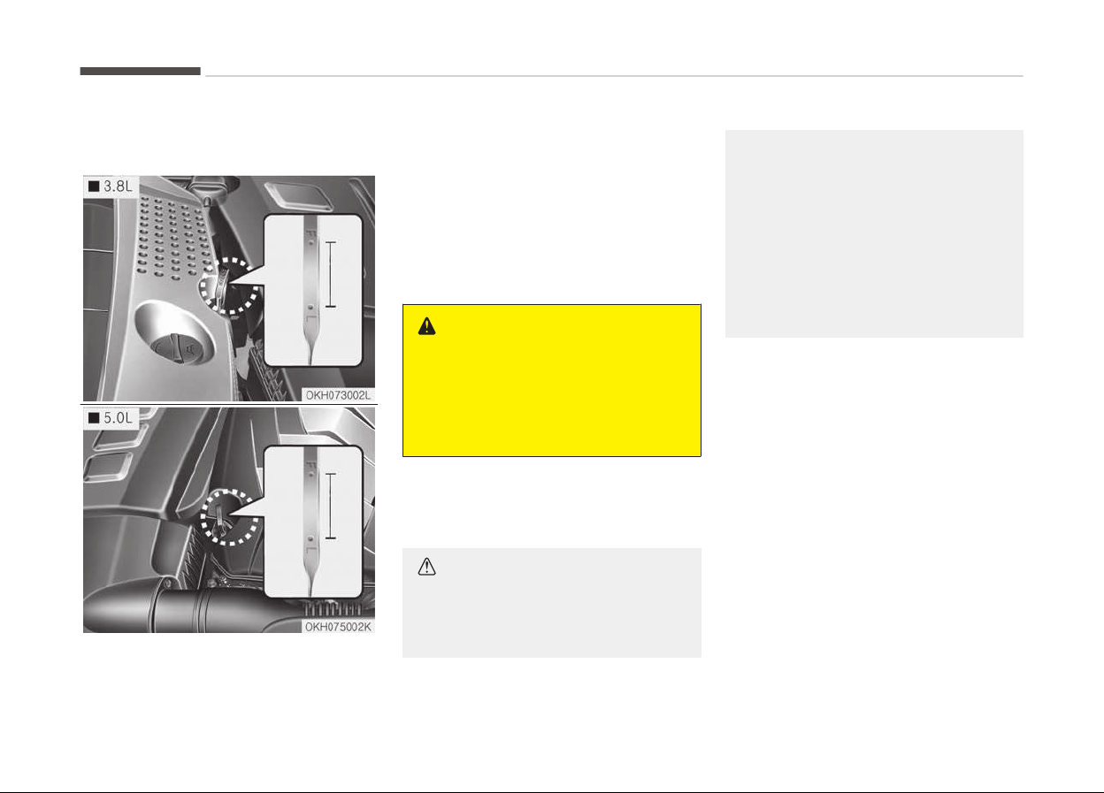
ENGINE OIL
Checking the engine oil level
1. Be sure the vehicle is on level
ground.
2. Start the engine and allow it to
reach normal operating tempera‐
ture.
3. Turn the engine off and wait for a
few minutes (about 5 minutes) for
the oil to return to the oil pan.
4. Pull the dipstick out, wipe it clean,
and re-insert it fully.
WARNING
n
Radiator hose
Be very careful not to touch the ra‐
diator hose when checking or adding
the engine oil as it may be hot
enough to burn you.
5. Pull the dipstick out again and
check the level. The level should be
between F and L.
CAUTION
• Do not overfill the engine oil. It
may damage the engine.
(Continued)
(Continued)
• Do not spill engine oil, when add‐
ing or changing engine oil. If you
drop the engine oil on the engine
room, wipe it off immediately.
• When you wipe the oil level
gauge, you should wipe it with a
clean cloth. When mixed with
debris, it can cause engine dam‐
age.
Maintenance
7-30
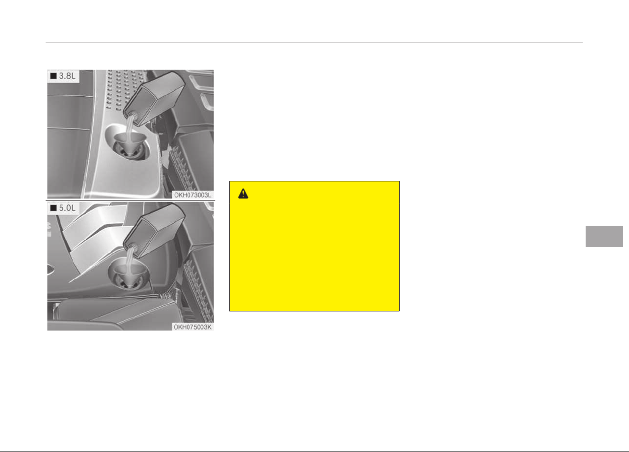
If it is near or at L, add enough oil to
bring the level to F. Do not overfill.
Use a funnel to help prevent oil from
being spilled on engine components.
Use only the specified engine oil. (Refer
to Recommended lubricants and ca‐
pacities on page 8-10.)
Changing the engine oil and
filter
Have the engine oil and filter replaced
by a professional workshop. Kia recom‐
mends to visit an authorized Kia dealer/
service partner.
WARNING
Used engine oil may cause skin irri‐
tation or cancer if left in contact
with the skin for prolonged periods
of time. Used engine oil contains
chemicals that have caused cancer in
laboratory animals. Always protect
your skin by washing your hands
thoroughly with soap and warm wa‐
ter as soon as possible after han‐
dling used oil.
7-31
7
Maintenance
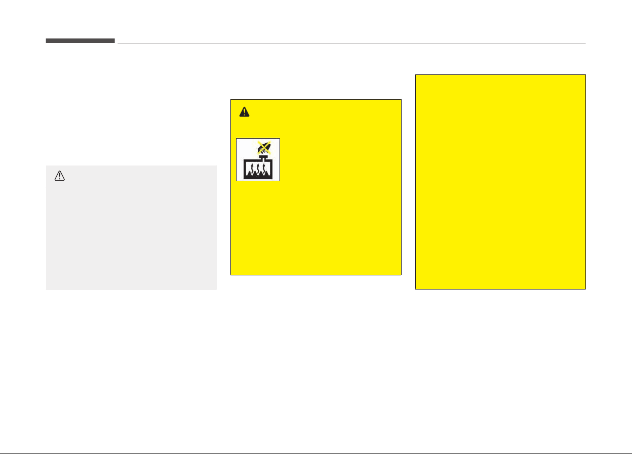
ENGINE COOLANT
The high-pressure cooling system has
a reservoir filled with year-round anti‐
freeze coolant. The reservoir is filled at
the factory.
Check the antifreeze protection and
coolant level at least once a year, at the
beginning of the winter season, and be‐
fore traveling to a colder climate.
CAUTION
• When the engine overheats from
low engine coolant, suddenly add‐
ing engine coolant may cause
cracks in the engine. To prevent
damage, add engine coolant slowly
in small quantities.
• Do not drive without engine cool‐
ant.
It may cause water pump fail‐
ure and engine seizure, etc.
Checking the coolant level
WARNING
Removing radiator cap
• Never attempt to remove the radi‐
ator
cap while the engine is oper‐
ating or hot. Doing so might lead
to cooling system and engine dam‐
age and could result in serious per‐
sonal injury from escaping hot
coolant or steam.
(Continued)
(Continued)
• Turn the engine off and wait until
it cools down. Use extreme care
when removing the radiator cap.
Wrap a thick towel around it, and
turn it counterclockwise slowly to
the first stop. Step back while the
pressure is released from the cool‐
ing system.
When you are sure all the pressure
has been released, press down on
the cap, using a thick towel, and
continue turning counterclockwise
to remove it.
• Even if the engine is not operating,
do not remove the radiator cap or
the drain plug while the engine and
radiator are hot. Hot coolant and
steam may still blow out under
pressure, causing serious injury.
Maintenance
7-32
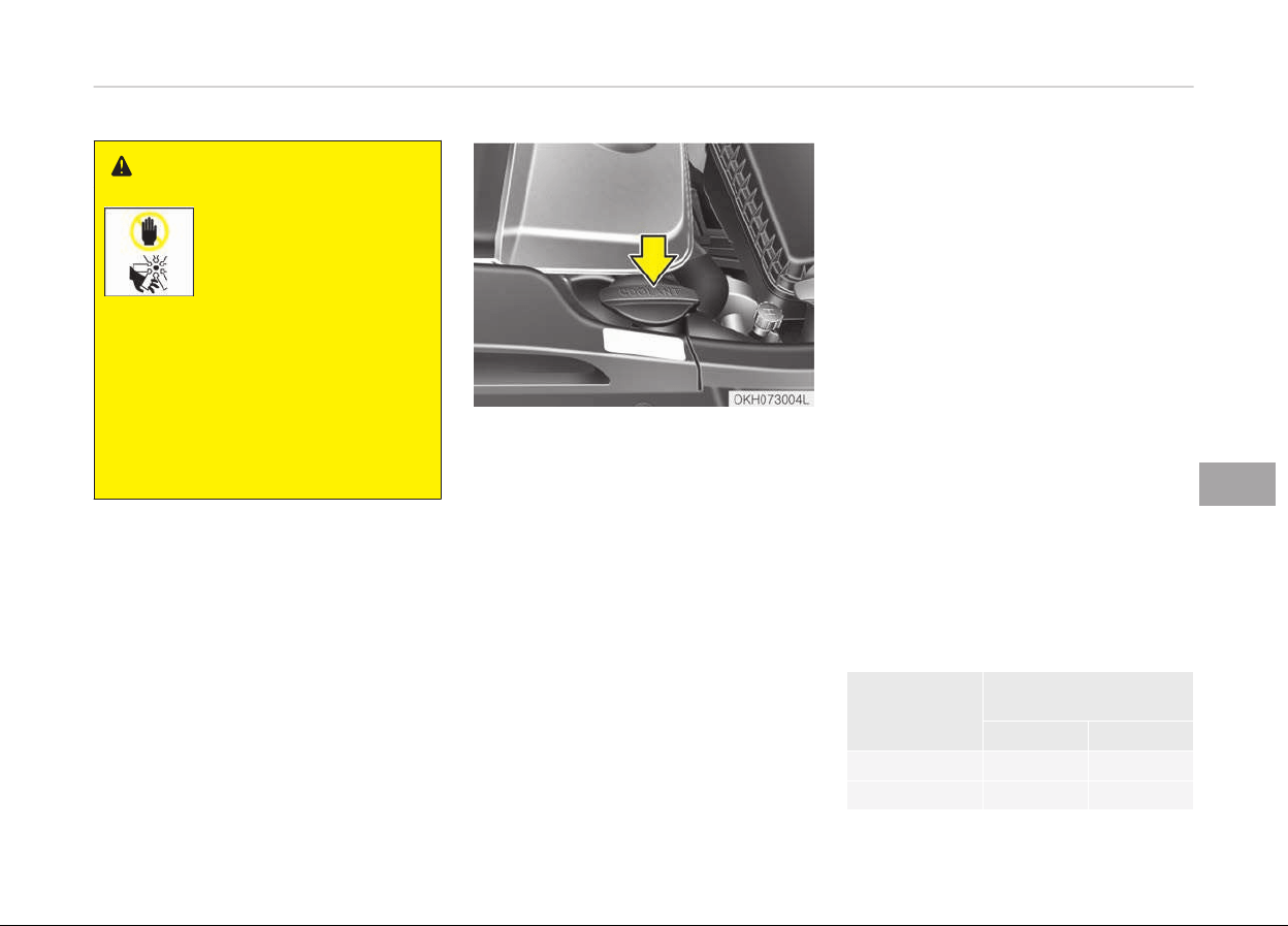
WARNING
The electric motor (cool‐
ing fan) is controlled by
engine coolant tempera‐
ture, refrigerant pressure
and vehicle speed.
It may sometimes operate even
when the engine is not running. Use
extreme caution when working near
the blades of the cooling fan so that
you are not injured by a rotating fan
blades. As the engine coolant tem‐
perature decreases, the electric mo‐
tor will automatically shut off. This
is a normal condition.
Check the condition and connections of
all cooling system hoses and heater ho‐
ses. Replace any swollen or deteriora‐
ted hoses.
The coolant level should be filled be‐
tween F and L marks on the side of the
coolant reservoir when the engine is
cool.
If the coolant level is low, add enough
distilled (deionized) water. Bring the
level to F (Full), but do not overfill.
If frequent additions are required, have
the system inspected by a professional
workshop. Kia recommends to visit an
authorized Kia dealer/service partner.
Recommended engine coolant
• When adding coolant, use only deion‐
ized water or soft water for your ve‐
hicle and never mix hard water in the
coolant filled at the factory. An im‐
proper coolant mixture can result in
serious malfunction or engine dam‐
age.
• The engine in your vehicle has alumi‐
num engine parts and must be pro‐
tected by an ethylene-glycol-based
coolant to prevent corrosion and
freezing.
• DO NOT USE alcohol or methanol
coolant or mix them with the speci‐
fied coolant.
• Do not use a solution that contains
more than 60% antifreeze or less
than 35% antifreeze, which would re‐
duce the effectiveness of the solu‐
tion.
For mixture percentage, refer to the
following table.
Ambient tem‐
peratur
e
Mixture percentage
(volume)
Antifreeze Water
-15 C (5 F) 35 65
25 C (-13 F) 40 60
7-33
7
Maintenance
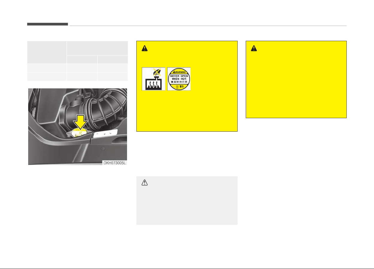
Ambient tem‐
peratur
e
Mixture percentage
(volume)
Antifreeze Water
35 C (-31 F) 50 50
45 C (-49 F) 60 40
WARNING
• Type A • Type B
Radiator cap
Do not remove the radiator cap
when the engine and radiator are
hot. Scalding hot coolant and steam
may blow out under pressure caus‐
ing serious injury.
Changing the coolant
Have the coolant replaced by a profes‐
sional workshop. Kia recommends to
visit an authorized Kia dealer/service
partner.
CAUTION
Put a thick cloth around the radiator
cap
before refilling the coolant in or‐
der to prevent the coolant from
overflowing into engine parts such
as the alternator.
WARNING
n
Coolant
• Do not use radiator coolant or an‐
tifreeze in the washer fluid reser‐
voir.
• Radiator coolant can severely ob‐
scure visibility when sprayed on
the windshield and may cause loss
of vehicle control or damage the
paint and body trim.
Maintenance
7-34
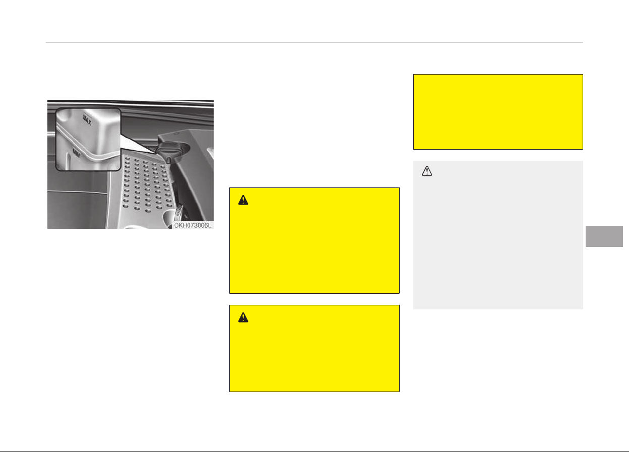
BRAKE FLUID
Checking the brake fluid level
Check the fluid level in the reservoir pe‐
riodically. The fluid level should be be‐
tween MAX and MIN marks on the side
of the reservoir.
Before removing the reservoir cap and
adding brake fluid, clean the area
around the reservoir cap thoroughly to
prevent brake fluid contamination.
If the level is low, add fluid to the MAX
level. The level will fall with accumula‐
ted mileage. This is a normal condition
associated with the wear of the brake
linings.
If the fluid level is excessively low, have
the system checked by a professional
workshop. Kia recommends to visit an
authorized Kia dealer/service partner.
Use only the specified brake fluid. (Re‐
fer to Recommended lubricants and
capacities on page 8-10.)
Never mix different types of fluid.
WARNING
n
Loss of brake fluid
In the event the brake/clutch system
requires frequent additions of fluid,
have the system Inspected by a pro‐
fessional workshop. Kia recommends
to visit an authorized Kia dealer/
service partner.
WARNING
n
Brake fluid
When changing and adding brake flu‐
id,
handle it carefully. Do not let it
come in contact with your eyes. If
(Continued)
(Continued)
brake fluid should come in contact
with your eyes, immediately flush
them with a large quantity of fresh
tap water. Have your eyes examined
by a doctor as soon as possible.
CAUTION
Do not allow brake fluid to contact
the vehicle's body paint, as paint
damage will result. Brake fluid,
which has been exposed to open air
for an extended time should never
be used as its quality cannot be
guaranteed. It should be disposed of
properly. Don't put in the wrong kind
of fluid. A few drops of mineral-
based oil, such as engine oil, in your
brake system can damage brake
system parts.
7-35
7
Maintenance
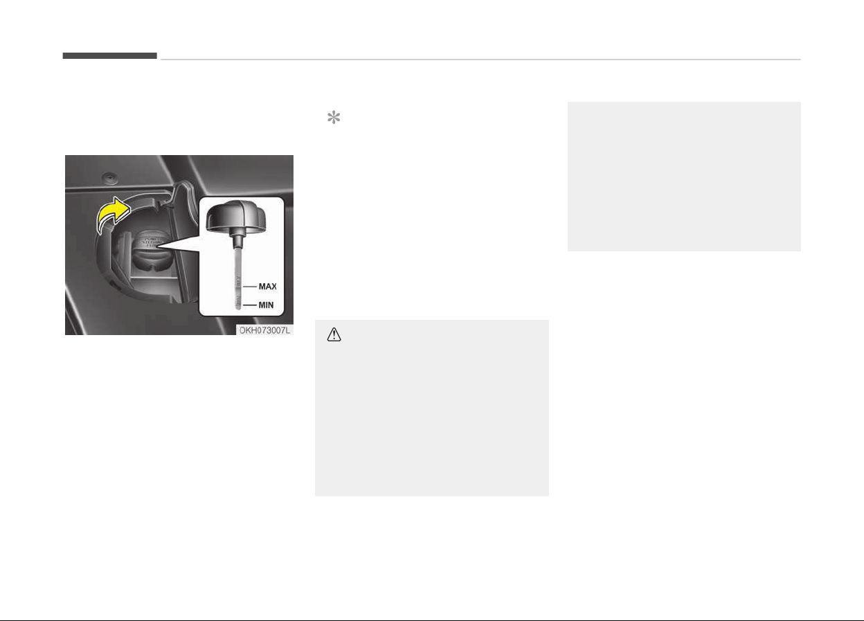
POWER STEERING FLUID
Checking the power steering
fluid level
With the vehicle on level ground, check
the fluid level in the power steering
reservoir periodically. The fluid should
be between MAX and MIN marks on the
side of the gauge at the normal tem‐
perature.
Before adding power steering fluid,
thoroughly clean the area around the
reservoir cap to prevent power steering
fluid contamination.
If the level is low, add fluid to the MAX
level.
NOTICE
Check that the fluid level is in the
"HOT" range on the gauge. If the flu‐
id is cold, check that it is in the
"COLD" range.
In the event the brake/clutch system
requires frequent additions of fluid,
have the system Inspected by a profes‐
sional workshop. Kia recommends to
visit an authorized Kia dealer/service
partner.
CAUTION
• To avoid damage to the power
steering pump, do not operate the
vehicle for prolonged periods with
a low power steering fluid level.
• Never start the engine when the
reservoir tank is empty.
• When adding fluid, be careful that
dirt does not get into the tank.
(Continued)
(Continued)
• Too little fluid can result in in‐
creased steering effort and/or
noise from the power steering
system.
• The use of the non-specified fluid
could reduce the effectiveness of
the power steering system and
cause damage to it.
Use only the specified power steering
fluid. (Refer to Recommended lubri‐
cants and capacities on page 8-10.)
Checking the power steering
hose
Check the connections for oil leaks,
damage and twists in the power steer‐
ing hose before driving.
Maintenance
7-36
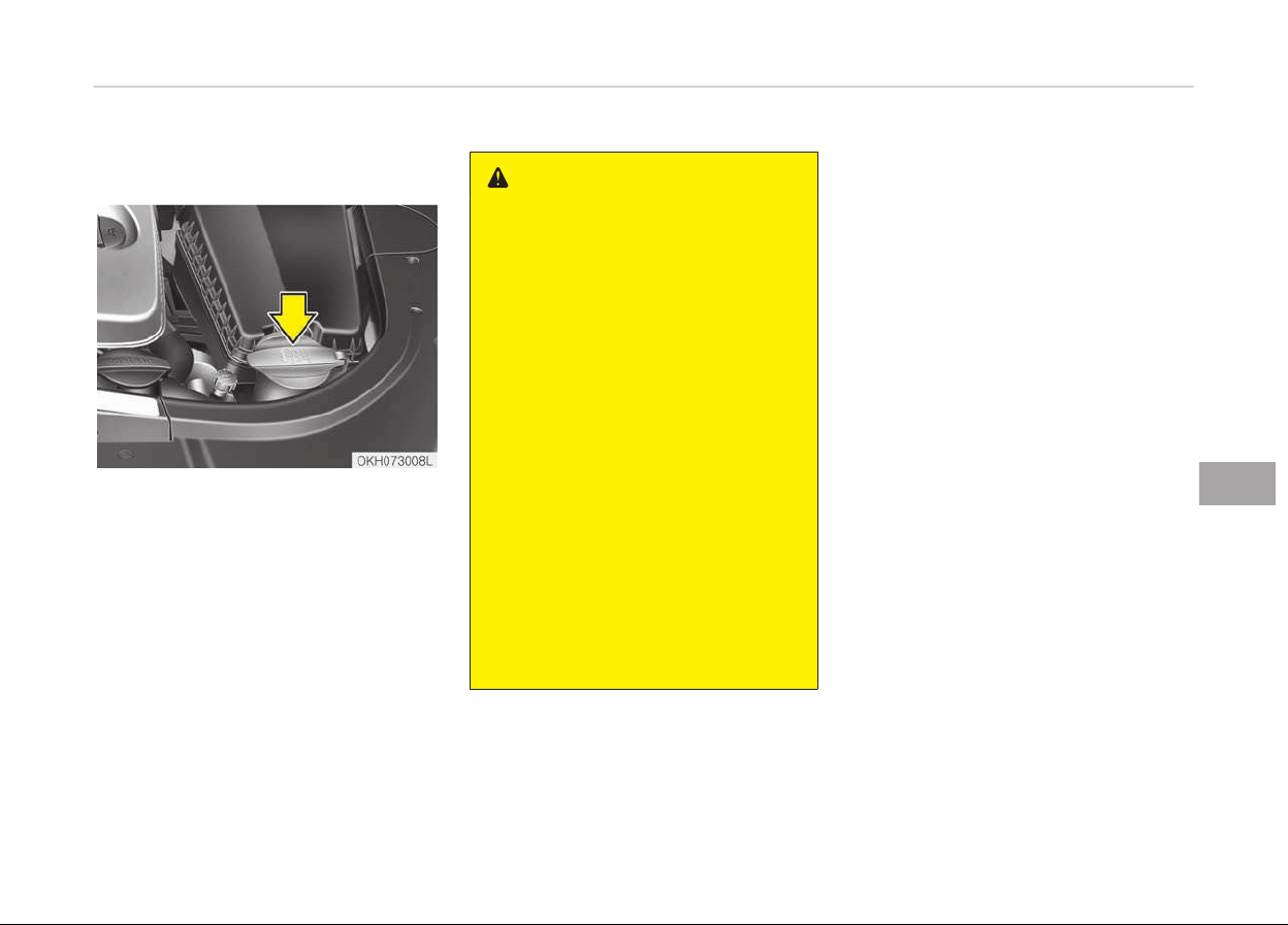
WASHER FLUID
Checking the washer fluid level
The reservoir is translucent so that you
can check the level with a quick visual
inspection.
Check the fluid level in the washer fluid
reservoir and add fluid if necessary.
Plain water may be used if washer fluid
is not available. However, use washer
solvent with antifreeze characteristics
in cold climates to prevent freezing.
WARNING
n
C
oolant
• Do not use radiator coolant or an‐
tifreeze in the washer fluid reser‐
voir.
• Radiator coolant can severely ob‐
scure visibility when sprayed on
the windshield and may cause loss
of vehicle control or damage to
paint and body trim.
• Windshield washer fluid agents
contain some amounts of alcohol
and can be flammable under cer‐
tain circumstances. Do not allow
sparks or flame to contact the
washer fluid or the washer fluid
reservoir. Damage to the vehicle or
occupants could occur.
• Windshield washer fluid is poison‐
ous to humans and animals. Do
not drink and avoid contacting
windshield washer fluid. Serious
injury or death could occur.
7-37
7
Maintenance
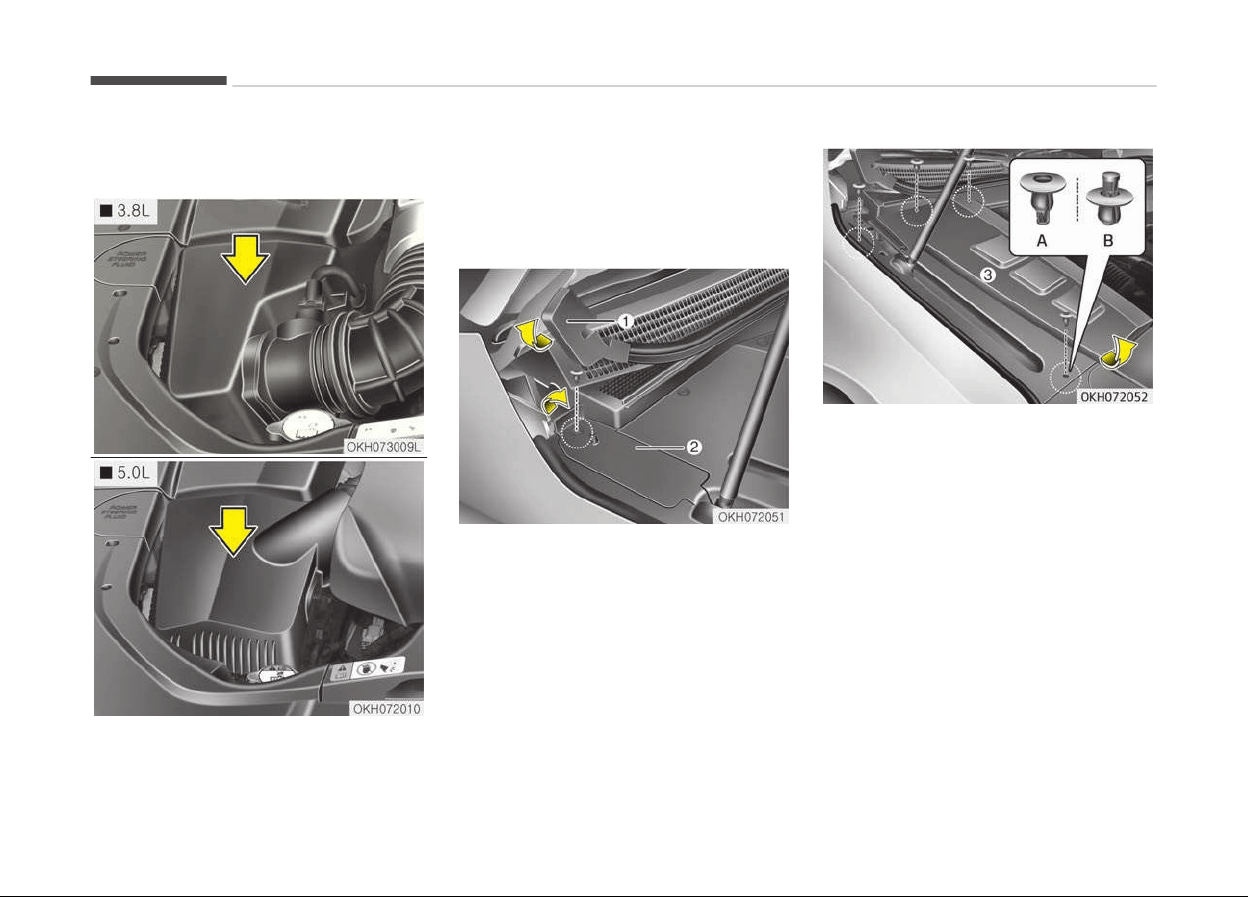
AIR CLEANER
Filter replacement
It must be replaced when necessary,
and should not be washed.
You can clean the filter when inspecting
the air cleaner element.
Clean the filter by using compressed
air.
Main air cleaner
1. Lift the end of strip (1) up.
2. Press the fastener head with screw
driver and then pull the fastener
out.
3. Lift the rear portion of small serv‐
ice cover (2) up and then remove
the service cover.
(A): for assemble
(B): for remove
4. Press the fastener head with screw
driver and then pull the fastener
out from main service cover (3).
5. Pull the main service cover over
7 mm to toward the front of the
vehicle.
6. Lift the main service cover up and
then remove the main service cov‐
er. Be careful not to damage the
holder under the main service cov‐
er.
Maintenance
7-38
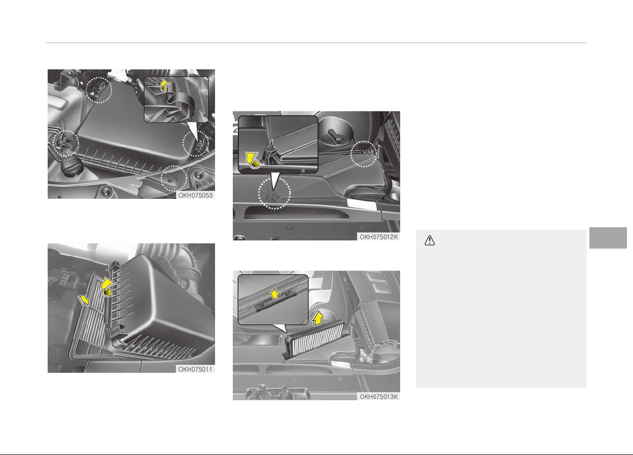
7. Loosen the air cleaner cover at‐
taching clips and open the cover.
8. Wipe the inside of the air cleaner.
9. Replace the air cleaner filter.
10. Lock
the cover with the cover at‐
taching clips.
Chamber air cleaner (if equipped)
1. Loosen the air cleaner cover at‐
taching clips and open the cover.
2. Replace the air cleaner filter after
pulling up the locking tab (1).
3. Lock the cover with the cover at‐
taching clips.
Replace the filter according to the
Maintenance Schedule.
If the vehicle is operated in extremely
dusty or sandy areas, replace the ele‐
ment more often than the usual rec‐
ommended intervals. (Refer to Main‐
tenance under severe usage conditions
on page 7-25.)
CAUTION
• Do not drive with the air cleaner
removed; this will result in exces‐
sive engine wear.
• When removing the air cleaner fil‐
ter, be careful that dust or dirt
does not enter the air intake, or
damage may result.
• Use parts for replacement from a
professional
workshop. Kia recom‐
mends to visit an authorized Kia
dealer/service partner.
(Continued)
7-39
7
Maintenance

(Continued)
• When you clean the filter, use the
c
ompressed air and blow the air
from the clean side to the dirty
side.
Maintenance
7-40
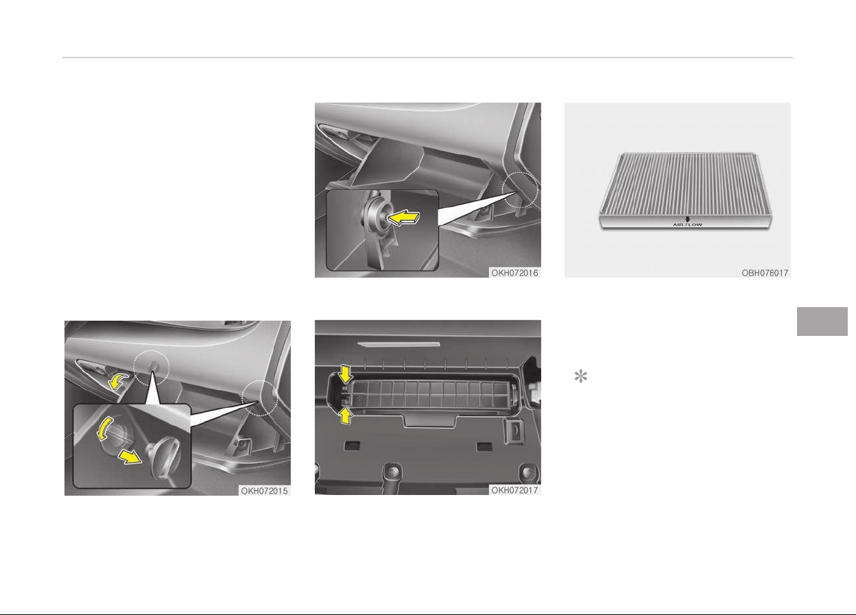
CLIMATE CONTROL AIR FILTER
Filter inspection
The climate control air filter should be
replaced according to the maintenance
schedule. If the vehicle is operated in
the severely air-polluted cities or on
dusty rough roads for a long period, it
should be inspected more frequently
and replaced earlier. When you, the
owner, replace the climate control air
filter, replace it performing the follow‐
ing procedure, and be careful to avoid
damaging other components.
Replace the filter according to the
maintenance Schedule.
Filter replacement
1. With the glove box open, remove
the stoppers on both sides.
2. Open the glove box and remove the
support strap (1).
3. Remove the climate control air fil‐
ter cover while pressing the lock on
the left side of the cover.
4. Replace the climate control air fil‐
ter.
5. Reassemble in the reverse order of
disassembly.
NOTICE
When replacing the climate control
air filter install it properly. Other‐
wise, the system may produce noise
and the effectiveness of the filter
may be reduced.
7-41
7
Maintenance
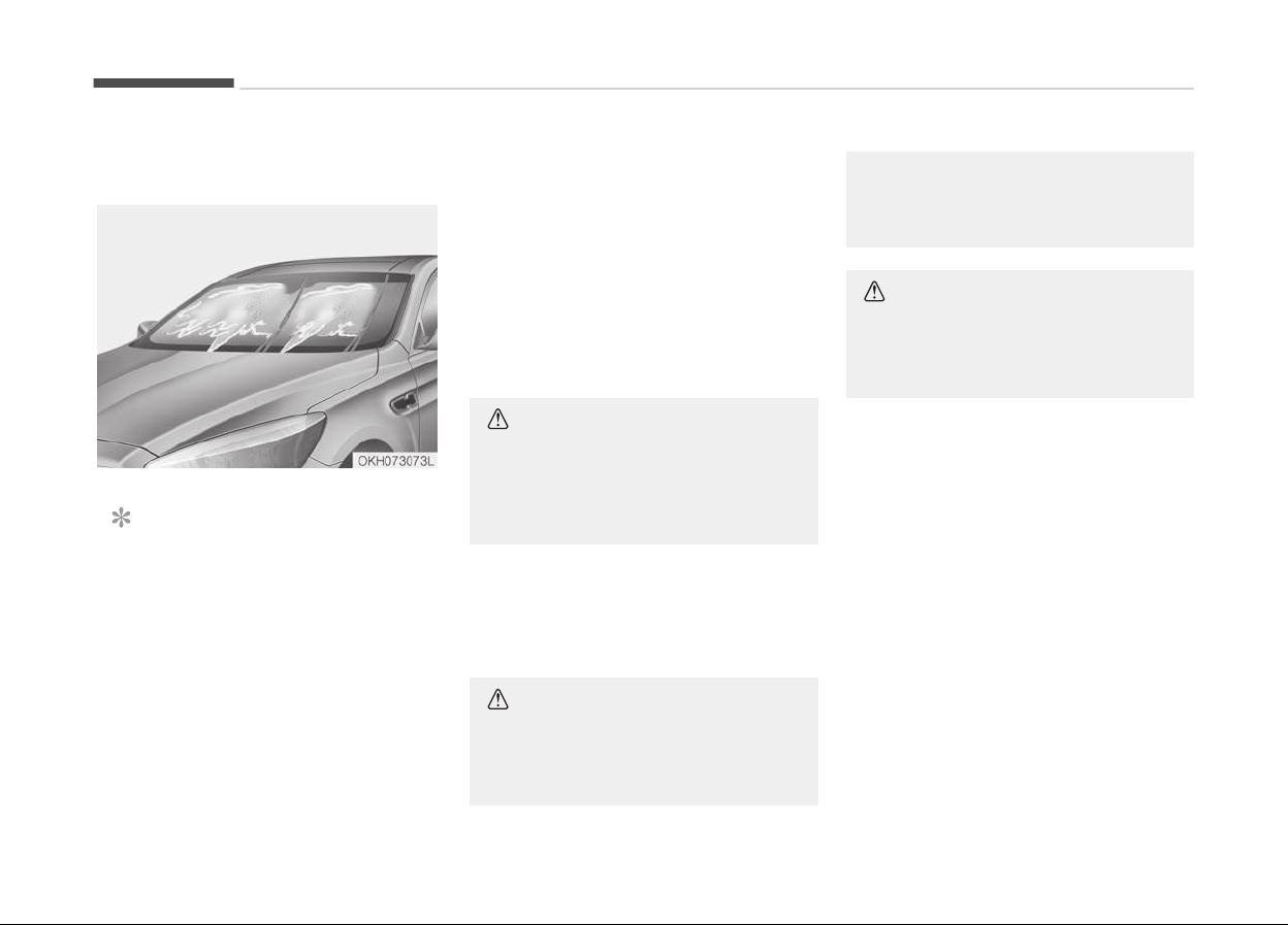
WIPER BLADES
Blade inspection
NOTICE
Commercial hot waxes applied by
automatic car washes have been
known to make the windshield diffi‐
cult to clean.
Contamination of either the windshield
or the wiper blades with foreign matter
can reduce the effectiveness of the
windshield wipers. Common sources of
contamination are insects, tree sap,
and hot wax treatments used by some
commercial car washes. If the blades
are not wiping properly, clean both the
window and the blades with a good
cleaner or mild detergent, and rinse
thoroughly with clean water.
CAUTION
To prevent damage to the wiper
blades, do not use gasoline, kero‐
sene, paint thinner, or other solvents
on or near them.
Blade replacement
When the wipers no longer clean ade‐
quately, the blades may be worn or
cracked, and require replacement.
CAUTION
To prevent damage to the wiper
arms or other components, do not
(Continued)
(Continued)
attempt to move the wipers man‐
ually.
CAUTION
The use of a non-specified wiper
blade could result in wiper malfunc‐
tion and failure.
Maintenance
7-42
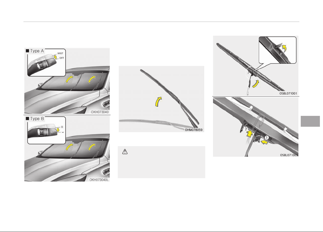
Front windshield wiper blade
For your convenience, move the wind‐
shield wiper blades to the service posi‐
tion as follows;
Turn off the engine.
Move the wiper switch to the single
wiping (MIST) position within
20 seconds and hold the switch until
the wiper blade is in the fully up posi‐
tion.
1. Raise the wiper arm.
CAUTION
Do not allow the wiper arm to fall
against the windshield, since it may
chip or crack the windshield.
2. Turn the wiper blade clip. Then lift
up the blade clip.
3. Push the clip (1) and push up the
wiper arm (2).
7-43
7
Maintenance
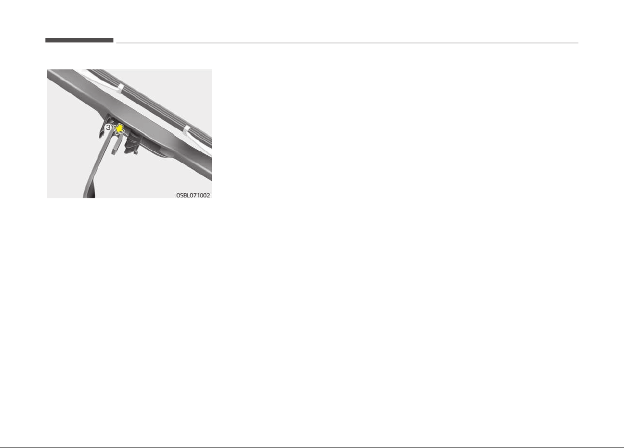
4. Push down the wiper arm (3) and
install the new blade assembly in
the reverse order of removal.
5. Return the wiper arm on the wind‐
shield.
Maintenance
7-44
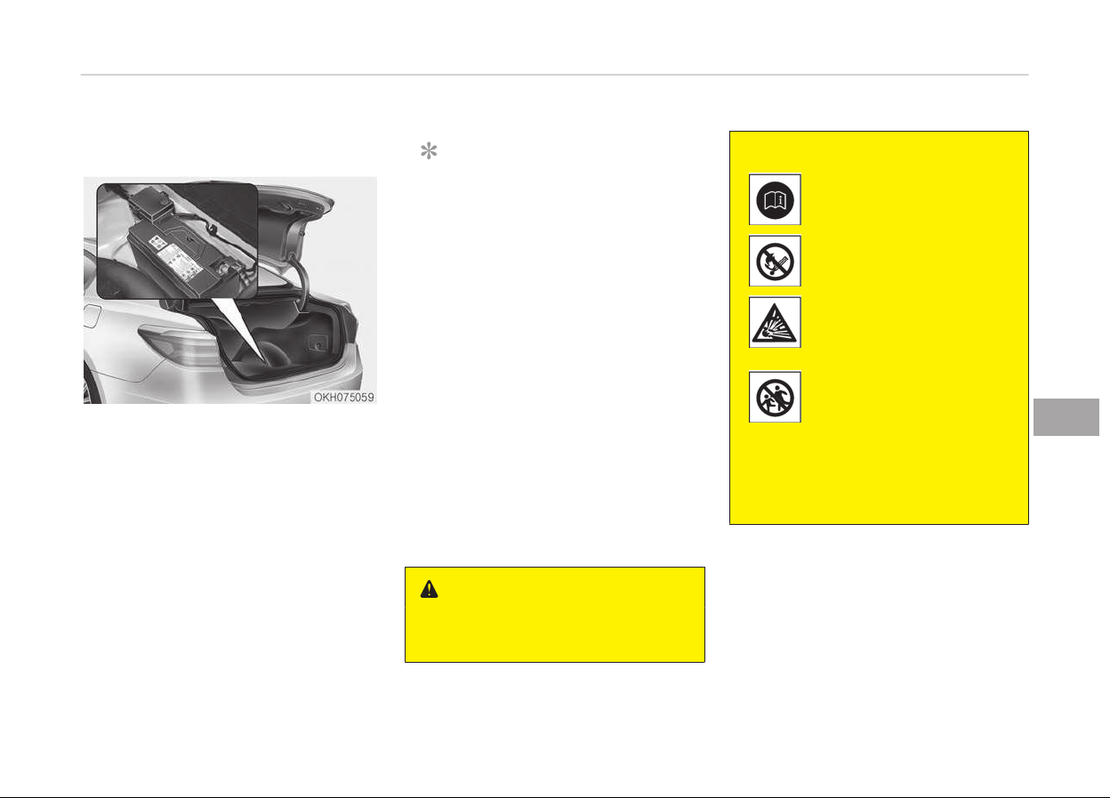
BATTERY
For best battery service
• Keep the battery securely mounted.
• Keep the battery top clean and dry.
• Keep the terminals and connections
clean, tight, and coated with petrole‐
um jelly or terminal grease.
• Rinse any spilled electrolyte from the
battery immediately with a solution
of water and baking soda.
• If the vehicle is not going to be used
for an extended time, disconnect the
battery cables.
NOTICE
Basically equipped battery is main‐
tenance free type. If your vehicle is
equipped with the battery marked
with LOWER and UPPER on the side,
you can check the electrolyte level.
The electrolyte level should be be‐
tween LOWER and UPPER. If the
electrolyte level is low, it needs to
add distilled (demineralized) water
(Never add sulfuric acid or other
electrolyte). When refill, be careful
not to splash the battery and adja‐
cent components. And do not overfill
the battery cells. It can cause corro‐
sion on other parts. After then en‐
sure that tighten the cell caps. Con‐
tact a professional workshop. Kia
recommends to visit an authorized
Kia dealer/service partner.
WARNING
n
Battery dangers
(Continued)
(Continued)
Always read the following
instructions carefully when
handling a battery.
Keep lighted cigarettes and
all other flames or sparks
away from the battery.
Hydrogen, a highly com‐
bustible gas, is always
present in battery cells and
may explode if ignited.
Keep batteries out of the
r
each of children because
batteries contain highly
corrosive SULFURIC ACID.
Do not allow battery acid
to contact your skin, eyes,
clothing or paint finish.
(Continued)
7-45
7
Maintenance
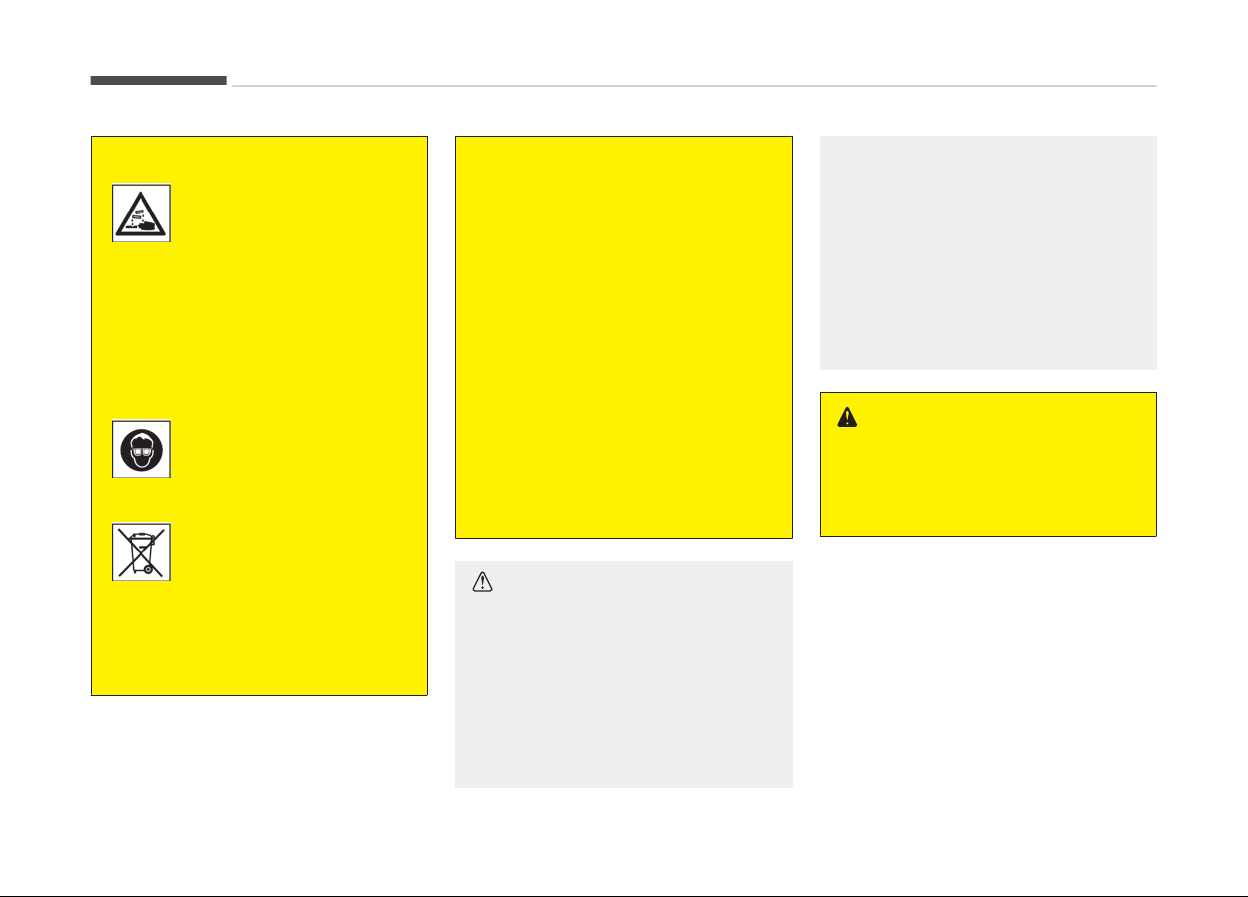
(Continued)
If any electrolyte gets into
your eyes, flush your eyes
with clean water for at
least 15 minutes and get
immediate medical atten‐
tion
.
If electrolyte gets on your
skin, thoroughly wash the
contacted area. If you feel
a pain or a burning sensa‐
tion, get medical attention
immediately.
Wear eye protection when
char
ging or working near a
battery. Always provide
ventilation when working
in an enclosed space.
An inappropriately dis‐
posed battery can be
harmful to the environ‐
ment and human health.
Dispose the battery ac‐
c
ording to your local law(s)
or regulation.
(Continued)
(Continued)
• When lifting a plastic-cased bat‐
tery,
excessive pressure on the
case may cause battery acid to
leak, resulting in personal injury.
Lift with a battery carrier or with
your hands on opposite corners.
• Never attempt to recharge the
battery
when the battery cables
are connected.
• The electrical ignition system
works with high voltage. Never
touch these components with the
engine running or the Engine
Start/Stop turned on.
Failure to follow the above warnings
can result in serious bodily injury or
death.
CAUTION
• When you don’t use the vehicle for
a long time in the low temperature
area, separate the battery and
keep it indoors.
• Always charge the battery fully to
pr
event battery case damage in
low temperature area.
(Continued)
(Continued)
• If you connect unauthorized elec‐
tronic
devices to the battery, the
battery may be discharged. Never
use unauthorized devices.
• Make sure the battery cap is
closed.
If the battery cap is not
closed securely, it can malfunction
because the electric components
are exposed to moisture.
WARNING
In this case, have the system serv‐
iced
by a professional workshop. Kia
recommends to visit an authorized
Kia dealer/service partner.
Maintenance
7-46
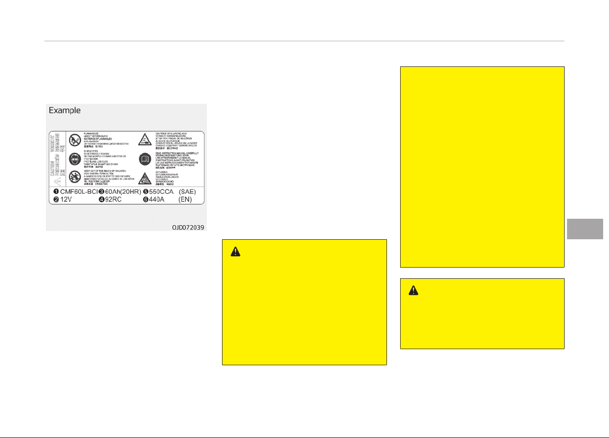
Battery capacity label (see the
example)
❈ The
actual battery label in the vehi‐
cle may differ from the illustration.
1. CMF60L-BCI: The Kia model name
of battery
2. 12V: The nominal voltage
3. 60Ah(20HR): The nominal capacity
(in Ampere hours)
4. 92RC: The nominal reserve capacity
(in min.)
5. 550CCA: The cold-test current in
amperes by SAE
6. 440A:
The cold-test current in am‐
peres by EN
Battery recharging
Your vehicle has a maintenance-free,
calcium-based battery.
• If the battery becomes discharged in
a short time (because, for example,
the headlights or interior lights were
left on while the vehicle was not in
use), recharge it by slow charging
(trickle) for 10 hours.
• If the battery gradually discharges
because of high electric load while
the vehicle is being used, recharge it
at 20-30A for two hours.
WARNING
n
Rechar
ging battery
When recharging the battery, ob‐
serve the following precautions:
• The battery must be removed
from the vehicle and placed in an
area with good ventilation.
• Do not allow cigarettes, sparks, or
flame near the battery.
(Continued)
(Continued)
• Watch the battery during charg‐
ing,
and stop or reduce the charg‐
ing rate if the battery cells begin
gassing (boiling) violently or if the
temperature of the electrolyte of
any cell exceeds 49°C (120°F) .
• Wear eye protection when check‐
ing the battery during char
ging.
• Disconnect the battery charger in
the following order.
1. Turn off the battery charger
main switch.
2. Unhook the negative clamp
from the negative battery ter‐
minal.
3. Unhook the positive clamp from
the positive battery terminal.
WARNING
• Before performing maintenance or
recharging the battery, turn off all
accessories and stop the engine.
(Continued)
7-47
7
Maintenance

(Continued)
• The negative battery cable must
be
removed first and installed last
when the battery is disconnected.
• In this case, have the system serv‐
iced
by a professional workshop.
Kia recommends to visit an au‐
thorized Kia dealer/service part‐
ner.
CAUTION
• Keep the battery away from wa‐
ter or any liquid.
• Use parts for replacement from a
professional
workshop. Kia recom‐
mends to visit an authorized Kia
dealer/service partner.
Reset items
Items should be reset after the battery
has been discharged or the battery has
been disconnected.
• Auto up/down window (see Chapter
5, Features of your vehicle)
• Sunroof (see Chapter 5, Features of
your vehicle)
• Driver position memory system (see
Chapter 5, Features of your vehicle)
• Trip computer (see Chapter 5, Fea‐
tures of your vehicle)
• Climate control system (see Chapter
5, Features of your vehicle)
• Clock (see Chapter 5, Features of
your vehicle)
• Audio (see Chapter 5, Features of
your vehicle)
Maintenance
7-48
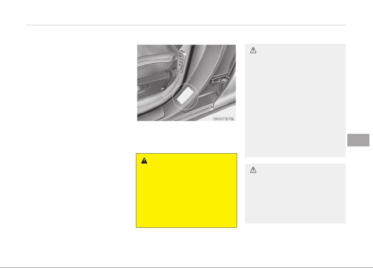
TIRES AND WHEELS
Tire care
For proper maintenance, safety, and
maximum fuel economy, you must al‐
ways maintain recommended tire infla‐
tion pressures and stay within the load
limits and weight distribution recom‐
mended for your vehicle.
Recommended cold tire inflation
pressures
All tire pressures (including the spare)
should be checked when the tires are
cold. Cold Tires means the vehicle has
not been driven for at least three hours
or driven less than 1.6 km .
Recommended pressures must be
maintained for the best ride, top vehi‐
cle handling, and minimum tire wear.
For recommended inflation pressure re‐
fer to Tire and wheels on page 8-07.
All specifications (sizes and pressures)
can be found on a label attached to the
vehicle.
WARNING
n
Tir
e underinflation
Severe underinflation can lead to se‐
vere heat build-up, causing blow‐
outs, tread separation and other tire
failures that can result in the loss of
vehicle control leading to severe in‐
jury or death. This risk is much high‐
er on hot days and when driving for
long periods at high speeds.
CAUTION
• Underinflation also results in ex‐
cessive wear, poor handling and
reduced fuel economy. Wheel de‐
formation also is possible. Keep
your tire pressures at the proper
levels.
If a tire frequently needs refilling,
have the system checked by a pro‐
fessional workshop. Kia recom‐
mends to visit an authorized Kia
dealer/service partner.
• Overinflation produces a harsh
ride, excessive wear at the center
of the tire tread, and a greater
possibility of damage from road
hazards.
CAUTION
• Warm tires normally exceed rec‐
ommended cold tire pressures by
28 to 41 kPa. Do not release air
from warm tires to adjust the
pressure or the tires will be under‐
inflated.
(Continued)
7-49
7
Maintenance
(Continued)
• Be sure to reinstall the tire infla‐
tion
valve caps. Without the valve
cap, dirt or moisture could get into
the valve core and cause air leak‐
age. If a valve cap is missing, in‐
stall a new one as soon as possi‐
ble.
WARNING
n
Tire inflation
Overinflation or underinflation can
reduce tire life, adversely affect ve‐
hicle handling, and lead to sudden
tire failure. This could result in loss
of vehicle control and potential in‐
jury.
CAUTION
n
Tire pressure
Always observe the following:
(Continued)
(Continued)
• Check tire pressure when the tires
ar
e cold. (After vehicle has been
parked for at least three hours or
hasn't been driven more than
1.6 km since startup.)
• Check the pressure of your spare
tir
e each time you check the pres‐
sure of other tires.
• Never overload your vehicle. Be
careful not to overload a vehicle
luggage rack if your vehicle is
equipped with one.
• Worn, old tires can cause acci‐
dents. If your tread is badly worn,
or if your tires have been dam‐
aged, replace them.
Checking tire inflation pressure
Check your tires once a month or more.
Also, check the tire pressure of the
spare tire.
How to check
Use a good quality gauge to check tire
pressure. You can not tell if your tires
are properly inflated simply by looking
at them. Radial tires may look properly
inflated even when they're underinfla‐
ted.
Check the tire's inflation pressure when
the tires are cold. - "Cold" means your
vehicle has been sitting for at least
three hours or driven no more than
1.6 km (1 mile).
Remove the valve cap from the tire
valve stem. Press the tire gauge firmly
onto the valve to get a pressure meas‐
urement. If the cold tire inflation pres‐
sure matches the recommended pres‐
sure on the tire and loading information
label, no further adjustment is necessa‐
ry. If the pressure is low, add air until
you reach the recommended amount.
If you overfill the tire, release air by
pushing on the metal stem in the cen‐
ter of the tire valve. Recheck the tire
pressure with the tire gauge. Be sure to
put the valve caps back on the valve
stems. They help prevent leaks by
keeping out dirt and moisture.
WARNING
• Inspect your tires frequently for
proper inflation as well as wear
and damage. Always use a tire
pressure gauge.
(Continued)
Maintenance
7-50
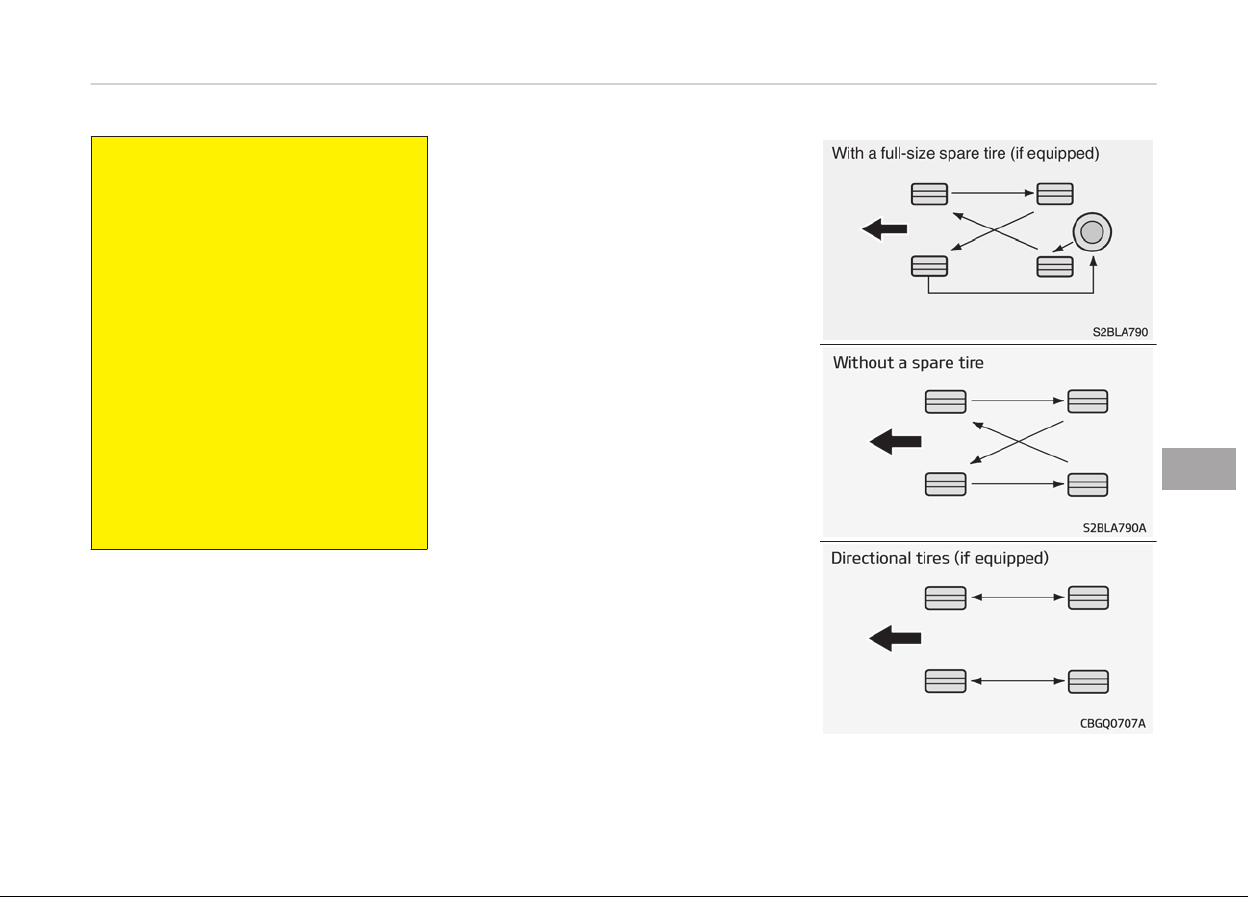
(Continued)
• Tires with too much or too little
pr
essure wear unevenly causing
poor handling, loss of vehicle con‐
trol, and sudden tire failure leading
to accidents, injuries, and even
death. The recommended cold tire
pressure for your vehicle can be
found in this manual and on the
tire label located on the driver's
side center pillar.
• Worn tires can cause accidents.
Replace
tires that are worn, show
uneven wear, or are damaged.
• Remember to check the pressure
of your spare tire. Kia recom‐
mends that you check the spare
every time you check the pressure
of the other tires on your vehicle.
Tire rotation
To equalize tread wear, it is recommen‐
ded that the tires be rotated every
12,000 km (7,500 miles) or sooner if ir‐
regular wear develops.
During rotation, check the tires for cor‐
rect balance.
When rotating tires, check for uneven
wear and damage. Abnormal wear is
usually caused by incorrect tire pres‐
sure, improper wheel alignment, out-
of-balance wheels, severe braking or
severe cornering. Look for bumps or
bulges in the tread or side of tire. Re‐
place the tire if you find either of these
conditions. Replace the tire if fabric or
cord is visible. After rotation, be sure to
bring the front and rear tire pressures
to specification and check lug nut tight‐
ness.
Refer to Tire and wheels on page
8-07.
7-51
7
Maintenance
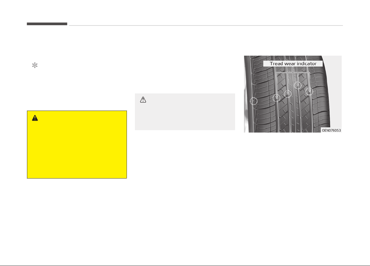
Disc brake pads should be inspected for
wear whenever tires are rotated.
NOTICE
Rotate radial tires that have an
asymmetric tread pattern only from
front to rear and not from right to
left.
WARNING
• Do not use the compact spare tire
for tire rotation.
• Do not mix bias ply and radial ply
tires under any circumstances.
This may cause unusual handling
characteristics that could result in
death, severe injury, or property
damage.
Wheel alignment and tire
balance
The wheels on your vehicle were
aligned and balanced carefully at the
factory to give you the longest tire life
and best overall performance.
In most cases, you will not need to have
your wheels aligned again. However, if
you notice unusual tire wear or your
vehicle pulling one way or the other,
the alignment may need to be reset.
If you notice your vehicle vibrating
when driving on a smooth road, your
wheels may need to be rebalanced.
CAUTION
Improper wheel weights can damage
your vehicle's aluminum wheels. Use
only approved wheel weights.
Tire replacement
If the tire is worn evenly, a tread wear
indicator
will appear as a solid band
across the tread. This shows there is
less than 1.6 mm of tread left on the
tire. Replace the tire when this hap‐
pens.
Do not wait for the band to appear
across the entire tread before replacing
the tire.
Maintenance
7-52
NOTICE
We recommend that when replacing
tires, use the same originally sup‐
plied with the vehicles.
If not, that affects driving perform‐
ance.
CAUTION
When replacing the tires, recheck
and tighten the wheel nuts after
driving about 1,000 km If the steer‐
ing wheel shakes or the vehicle vi‐
brates while driving, the tire is out of
balance. Align the tire balance. If the
problem is not solved, contact a pro‐
fessional workshop. Kia recommends
to visit an authorized Kia dealer/
service partner.
WARNING
n
Replacing tires
To reduce the chance of serious or
fatal injuries from an accident
(Continued)
(Continued)
caused by tire failure or loss of vehi‐
cle c
ontrol:
• Replace tires that are worn, show
une
ven wear, or are damaged.
Worn tires can cause loss of brak‐
ing effectiveness, steering control,
and traction.
• Do not drive your vehicle with too
little
or too much pressure in your
tires. This can lead to uneven wear
and tire failure.
• When replacing tires, never mix ra‐
dial and bias-ply tires on the same
car. You must replace all tires (in‐
cluding the spare) if moving from
radial to bias-ply tires.
• Using tires and wheels other than
the recommended sizes could
cause unusual handling character‐
istics and poor vehicle control, re‐
sulting in a serious accident.
• Wheels that do not meet Kia’s
specifications may fit poorly and
result in damage to the vehicle or
unusual handling and poor vehicle
control.
(Continued)
(Continued)
• The ABS works by comparing the
speed
of the wheels. The tire size
affects wheel speed. When replac‐
ing tires, all 4 tires must use the
same size originally supplied with
the vehicle. Using tires of a differ‐
ent size can cause the ABS (Anti-
lock Brake System) and ESC (Elec‐
tronic Stability Control) to work ir‐
regularly.
Wheel replacement
When replacing the metal wheels for
any reason, make sure the new wheels
are equivalent to the original factory
units in diameter, rim width and offset.
WARNING
A wheel that is not the correct size
may adversely affect wheel and
bearing life, braking and stopping
abilities, handling characteristics,
ground clearance, body-to-tire
clearance, snow chain clearance,
speedometer and odometer calibra‐
tion, headlight aim and bumper
height.
7-53
7
Maintenance
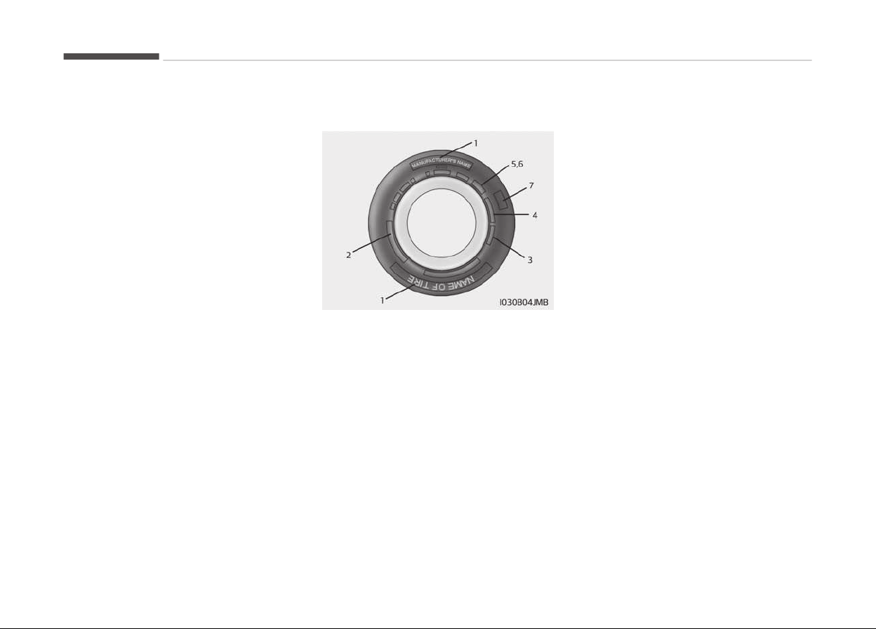
Tire traction
Tire traction can be reduced if you drive
on worn tires, tires that are improperly
inflated or on slippery road surfaces.
Tires should be replaced when tread
wear indicators appear. Slow down
whenever there is rain, snow or ice on
the road to reduce the possibility of
losing control of the vehicle.
Tire maintenance
In addition to proper inflation, correct
wheel alignment helps to decrease tire
wear. If you find a tire is worn uneven‐
ly, have a professional workshop check
the wheel alignment. Kia recommends
to visit an authorized Kia dealer/service
partner.
When you have new tires installed,
make sure they are balanced. This will
increase vehicle ride comfort and tire
life. Additionally, a tire should always
be rebalanced if it is removed from the
wheel.
Tire sidewall labeling
This information identifies and de‐
scribes the fundamental characteristics
of the tire and also provides the tire
identification number (TIN) for safety
standard certification. The TIN can be
used to identify the tire in case of a re‐
call.
1. Manufacturer or brand name
Manufacturer or Brand name is shown.
2. Tire size designation
A tire’s sidewall is marked with a tire
size designation. You will need this in‐
formation when selecting replacement
tires for your car. The following ex‐
plains what the letters and numbers in
the tire size designation mean.
Example tire size designation:
(These numbers are provided as an ex‐
ample only; your tire size designator
could vary depending on your vehicle.)
245/50R18 100V
245 -
Tire width in millimeters.
50 - Aspect ratio. The tire’s section
height as a percentage of its
width.
R - Tire construction code (Radial).
18 - Rim diameter in inches.
100 -
Load Index, a numerical code
associated with the maximum
load the tire can carry.
V - Speed Rating Symbol. See the
speed rating chart in this sec‐
tion for additional information.
Maintenance
7-54

Wheel size designation
Wheels are also marked with important
information that you need if you ever
have to replace one. The following ex‐
plains what the letters and numbers in
the wheel size designation mean.
Example wheel size designation:
7.5JX18
7.5 - Rim width in inches.
J - Rim contour designation.
18 - Rim diameter in inches.
Tire speed ratings
The chart below lists many of the dif‐
ferent speed ratings currently being
used for passenger car tires. The speed
rating is part of the tire size designa‐
tion on the sidewall of the tire. This
symbol corresponds to that tire's de‐
signed maximum safe operating speed.
Speed
Rating
Symbol
Maximum Speed
S 180 km/h (112 mph)
T 190 km/h (118 mph)
H 210 km/h (130 mph)
V 240 km/h (149 mph)
Z
Above 240 km/h (149
mph)
3. Checking tire life (TIN: Tire
Identification Number)
Any tires that are over 6 years old,
based on the manufacturing date, (in‐
cluding the spare tire) should be re‐
placed by new ones. You can find the
manufacturing date on the tire sidewall
(possibly on the inside of the wheel),
displaying the DOT Code. The DOT Code
is a series of numbers on a tire consist‐
ing of numbers and English letters. The
manufacturing date is designated by
the last four digits (characters) of the
DOT code.
DOT : XXXX XXXX OOOO
The front part of the DOT means a
plant code number, tire size and tread
pattern and the last four numbers indi‐
cate week and year manufactured.
For example:
DOT XXXX XXXX 1617 represents that
the tire was produced in the 16th week
of 2017.
WARNING
n
Tire age
(Continued)
(Continued)
Tires degrade over time, even when
they ar
e not being used.
Regardless of the remaining tread, it
is recommended that tires generally
be replaced after six (6) years of
normal service. Heat caused by hot
climates or frequent high loading
conditions can accelerate the aging
process. Failure to follow this warn‐
ing can result in sudden tire failure,
which could lead to a loss of control
and an accident involving serious in‐
jury or death.
4. Tire ply composition and material
The number of layers or plies of rub‐
ber-coated fabric are in the tire. Tire
manufacturers also must indicate the
materials in the tire, which include
steel, nylon, polyester, and others. The
letter "R" means radial ply construction;
the letter "D" means diagonal or bias
ply construction; and the letter "B"
means belted-bias ply construction.
7-55
7
Maintenance
5. Maximum permissible inflation
pressure
This number is the greatest amount of
air pressure that should be put in the
tire. Do not exceed the maximum per‐
missible inflation pressure. Refer to the
Tire and Loading Information label on
page 8-16 for recommended inflation
pressure.
6. Maximum load rating
This number indicates the maximum
load in kilograms and pounds that can
be carried by the tire. When replacing
the tires on the vehicle, always use a
tire that has the same load rating as
the factory installed tire.
7. Uniform tire quality grading
Quality grades can be found where ap‐
plicable on the tire sidewall between
tread shoulder and maximum chapter
width.
For example:
TREADWEAR 200
TRACTION AA
TEMPERATURE A
Tread wear
The tread wear grade is a comparative
rating based on the wear rate of the
tire when tested under controlled con‐
ditions on a specified government test
course. For example, a tire graded 150
would wear one-and-a-half times (1½)
as well on the government course as a
tire graded 100.
The relative performance of tires de‐
pends upon the actual conditions of
their use, however, and may depart sig‐
nificantly from the norm because of
variations in driving habits, service
practices and differences in road char‐
acteristics and climate.
These grades are molded on the side-
walls of passenger vehicle tires. The
tires available as standard or optional
equipment on your vehicles may vary
with respect to grade.
Traction - AA, A, B & C
The traction grades, from highest to
lowest, are AA, A, B and C. Those
grades represent the tires ability to
stop on wet pavement as measured
under controlled conditions on specified
government test surfaces of asphalt
and concrete. A tire marked C may have
poor traction performance.
WARNING
The traction grade assigned to this
tire is based on straight-ahead brak‐
ing traction tests, and does not in‐
clude acceleration, cornering, hydro‐
planing, or peak traction characteris‐
tics.
Temperature - A, B & C
The temperature grades are A (the
highest), B and C representing the tire’s
resistance to the generation of heat
and its ability to dissipate heat when
tested under controlled conditions on a
specified indoor laboratory test wheel.
Sustained high temperature can cause
the material of the tire to degenerate
and reduce tire life, and excessive tem‐
perature can lead to sudden tire failure.
Grades B and A represent higher levels
of performance on the laboratory test
wheel than the minimum required by
the law.
WARNING
n
Tire temperature
(Continued)
Maintenance
7-56

(Continued)
The temperature grade for this tire
is
established for a tire that is prop‐
erly inflated and not overloaded. Ex‐
cessive speed, underinflation, or ex‐
cessive loading, either separately or
in combination, can cause heat build-
up and possible sudden tire failure.
This can cause loss of vehicle control
and serious injury or death.
Low aspect ratio tire (if
equipped)
Low aspect ratio tires, whose aspect
ratio is lower than 50, are provided for
sporty looks.
Because the low aspect ratio tires are
optimized for handling and braking, it
may be more uncomfortable to ride in
and there is more noise compare with
normal tires.
CAUTION
Because the sidewall of the low as‐
pect ratio tire is shorter than the
normal, the wheel and tire of the
low aspect ratio tire is easier to be
(Continued)
(Continued)
damaged. So, follow the instructions
below.
- When driving on a rough road or
off
road, drive cautiously because
tires and wheels may be damaged.
And after driving, inspect tires and
wheels.
- When passing over a pothole,
speed
bump, manhole or curb
stone, drive slowly so that the
tires and wheels are not damaged.
- If the tire is impacted, inspect the
tire condition or contact a profes‐
sional workshop. Kia recommends
to visit an authorized Kia dealer/
service partner.
- To prevent damage to the tire, in‐
spect the tire condition and pres‐
sure every 3,000 km.
CAUTION
• It is not easy to recognize the tire
damage with your own eyes. But if
there is the slightest hint of tire
damage, even though you cannot
see the tire damage with your own
eyes, have the tire checked or re‐
placed because the tire damage
may cause air leakage from the
tire.
• If the tire is damaged by driving on
a rough road, off road, pothole,
manhole, or curb stone, it will not
be covered by the warranty.
• You can find out the tire informa‐
tion on the tire sidewall.
7-57
7
Maintenance
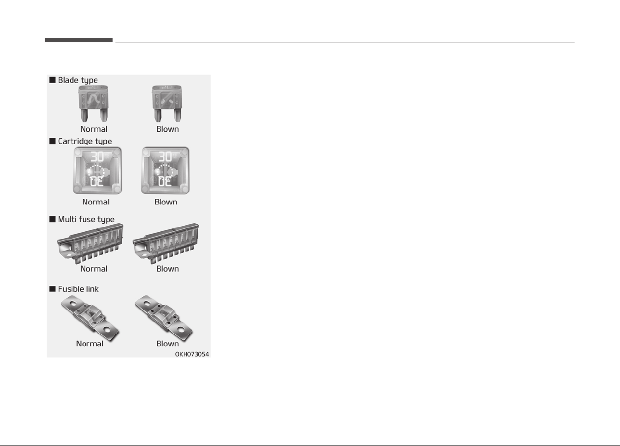
FUSES
A vehicle’s electrical system is protec‐
ted from electrical overload damage by
fuses.
This vehicle has 2 fuse panels, one loca‐
ted in the driver’s side panel bolster,
another is in the engine compartment.
If any of your vehicle’s lights, accesso‐
ries, or controls do not work, check the
appropriate circuit fuse. If a fuse has
blown, the element inside the fuse will
be melted.
If the electrical system does not work,
first check the driver’s side fuse panel.
Before replacing a blown fuse, discon‐
nect the negative battery cable.
Always replace a blown fuse with one
of the same rating.
If the replacement fuse blows, this indi‐
cates an electrical problem. Avoid using
the system involved and immediately
consult a professional workshop. Kia
recommends to consult an authorized
Kia dealer/service partner.
Maintenance
7-58
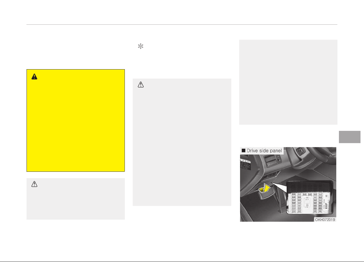
Three kinds of fuses are used: blade
type for lower amperage rating, car‐
tridge type, and fusible link for higher
amperage ratings.
WARNING
n
Fuse replacement
• Never replace a fuse with anything
but another fuse of the same rat‐
ing.
• A higher capacity fuse could cause
damage and possibly a fire.
• Never install a wire or aluminum
foil instead of the proper fuse
even as a temporary repair. It may
cause extensive wiring damage
and a possible fire.
• Do not arbitrarily modify or add-
on electric wiring of the vehicle.
CAUTION
Do not use a screwdriver or any oth‐
er metal object to remove fuses be‐
cause it may cause a short circuit
and damage the system.
NOTICE
The actual fuse/relay panel label
may differ from equipped items.
CAUTION
• When replacing a blown fuse or re‐
lay with a new one, make sure the
new fuse or relay fits tightly into
the clips. The incomplete fastening
fuse or relay may cause the vehi‐
cle wiring and electric systems
damage and a possible fire.
• Do not remove fuses, relays and
terminals
fastened with bolts or
nuts. The fuses, relays and termi‐
nals may be fastened incomplete‐
ly, and it may cause a possible fire.
If fuses, relays and terminals fas‐
tened with bolts or nuts are blown,
consult a professional workshop.
Kia recommends to consult an au‐
thorized Kia dealer/service part‐
ner.
(Continued)
(Continued)
• Do not input any other objects ex‐
cept fuses or r
elays into fuse/relay
terminals such as a driver or wir‐
ing. It may cause contact failure
and system malfunction.
• Do not plug in screwdrivers or af‐
termarket
wiring into the terminal
originally designed for fuse and re‐
lays only. The electrical system
and wiring of the vehicle interior
may be damaged or burned due to
contact failure.
Instrument panel fuse
replacement
7-59
7
Maintenance
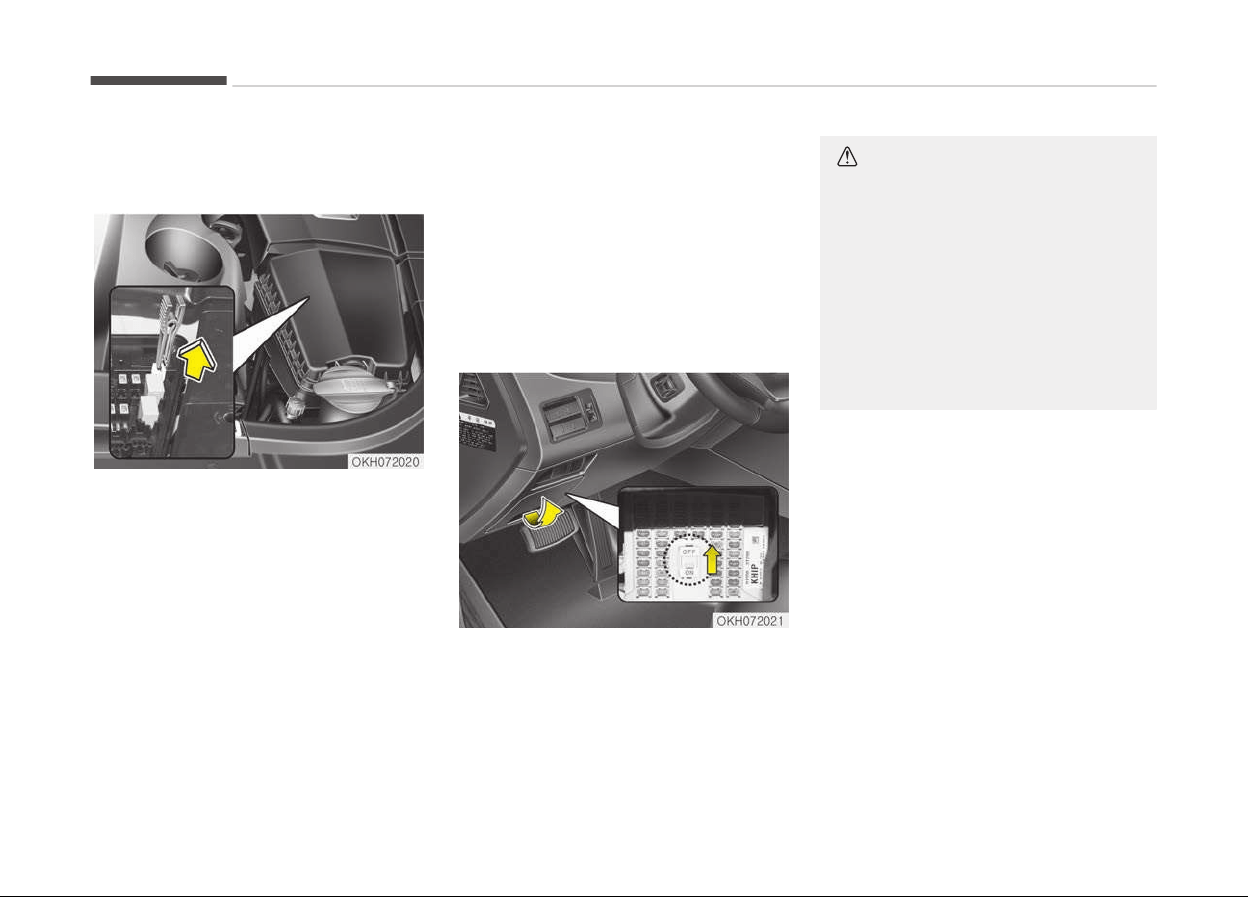
1. Turn the Engine Start/Stop button
and all other switches off.
2. Open the fuse panel cover.
3. Pull the suspected fuse straight
out. Use the removal tool provided
in the engine compartment fuse
panel.
4. Check the removed fuse; replace it
if it is blown.
5. Push in a new fuse of the same
rating, and make sure it fits tightly
in the clips.
If it fits loosely, consult a professional
workshop. Kia recommends to consult
an authorized Kia dealer/service part‐
ner.
If you do not have a spare, use a fuse
of
the same rating from a circuit you
may not need for operating the vehicle,
such as the cigarette lighter fuse.
If the headlights or other electrical
components do not work and the fuses
are OK, check the fuse panel in the en‐
gine compartment. If a fuse is blown, it
must be replaced.
Fuse switch
Always, put the fuse switch at the ON
position.
If you move the switch to the OFF posi‐
tion, some items such as audio and dig‐
ital clock must be reset and transmitter
(or smart key) may not work properly.
CAUTION
• Always place the fuse switch in
the ON position while driving the
vehicle.
• Do not move the transportation
fuse switch repeatedly. The fuse
switch may be worn out.
• Place fuse switch in the "OFF" po‐
sition to discharge the battery in
case of parking the vehicle more
than a month.
Maintenance
7-60
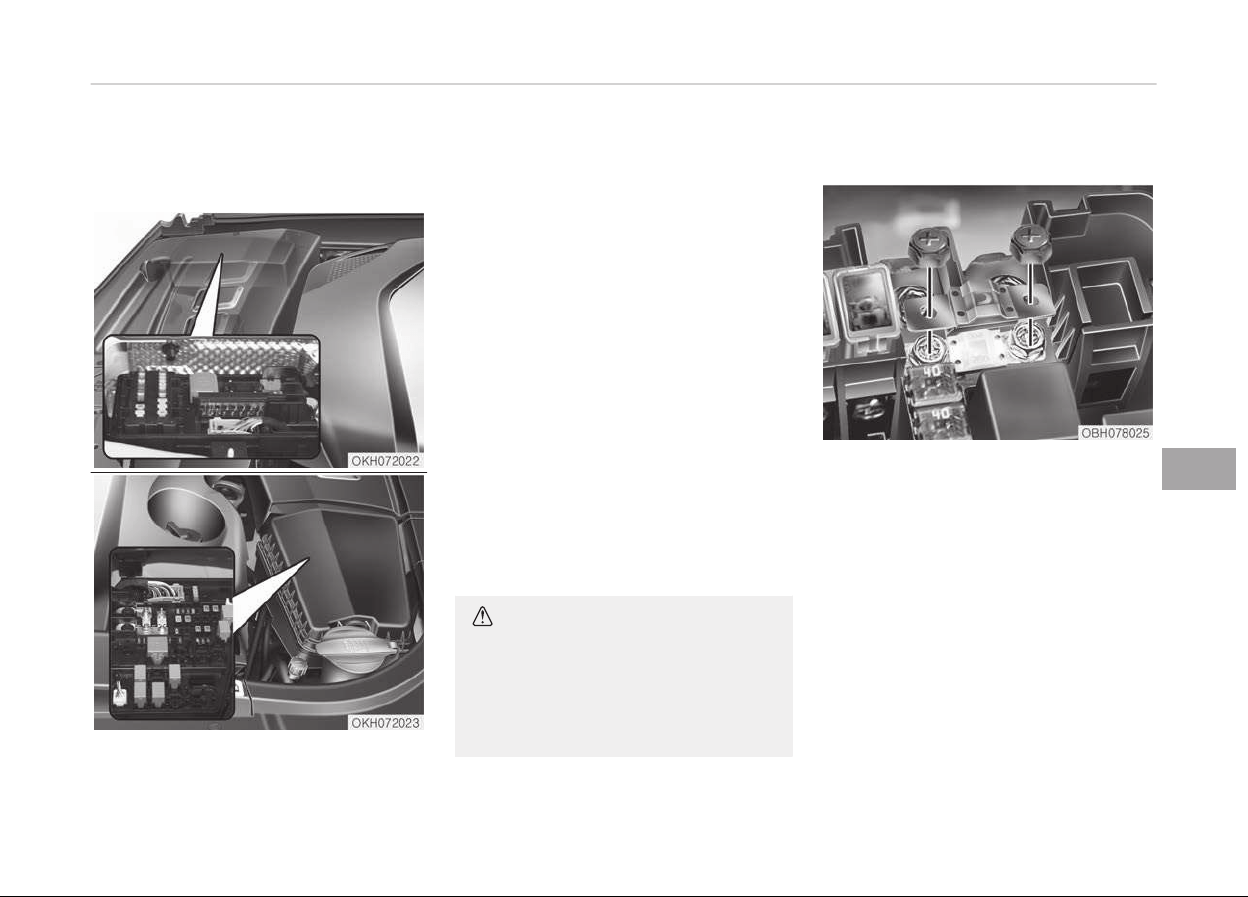
Engine compartment fuse
r
eplacement
1. Turn the Engine Start/Stop button
and all other switches off.
2. Remove the fuse panel cover by
pressing the tab and pulling the
cover up. When the blade type fuse
is disconnected, remove it by using
the clip designed for changing fuses
located in the engine room fuse
box. Upon removal, securely insert
reserve fuse of equal quantity.
3. Check the removed fuse; replace it
if it is blown. To remove or insert
the fuse, use the fuse puller in the
engine compartment fuse panel.
4. Push in a new fuse of the same
rating, and make sure it fits tightly
in the clips.
If it fits loosely, consult a professio‐
nal workshop. Kia recommends to
consult an authorized Kia dealer/
service partner.
CAUTION
After checking the fuse panel in the
engine compartment, securely install
the fuse panel cover. If not, electrical
failures may occur from water con‐
tact.
Main fuse
If the main fuse is blown, it must be re‐
moved as follows:
1. Turn off the engine.
2. Disconnect the negative battery
cable.
3. Remove the nuts shown in the pic‐
ture above.
4. Replace the fuse with a new one of
the same rating.
5. Reinstall in the reverse order of re‐
moval.
7-61
7
Maintenance
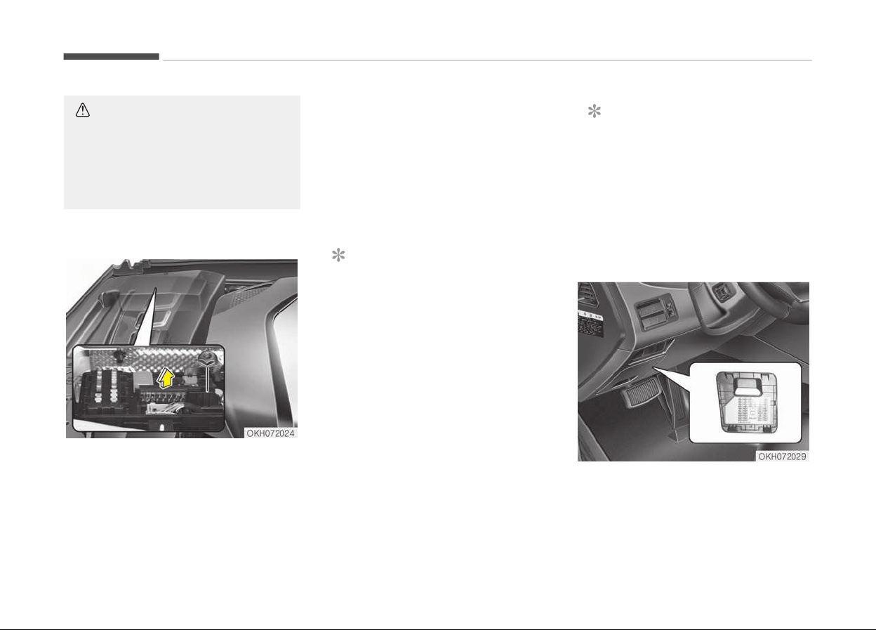
CAUTION
Visually inspect the battery cap for
secure closing. If the battery cap is
not securely latched, the electrical
system may be damaged to due in‐
flux of moisture into the system.
Multi fuse
If the multi fuse is blown, it must be re‐
moved as follows:
1. Disassemble the negative cable of
battery.
2. Remove the nuts shown in the pic‐
ture above.
3. Replace the fuse with a new one of
the same rating.
4. Reinstall in the reverse order of re‐
moval.
NOTICE
If the multi fuse is blown, consult a
professional workshop. Kia recom‐
mends to consult an authorized Kia
dealer/service partner.
Fuse/relay panel description
Inside the fuse/relay panel covers, you
can find the fuse/relay label describing
fuse/relay name and capacity.
NOTICE
Not all fuse panel descriptions in this
manual may be applicable to your
vehicle. It is accurate at the time of
printing. When you inspect the fuse
panel in your vehicle, refer to the
fuse panel label.
Instrument panel fuse panel
Maintenance
7-62
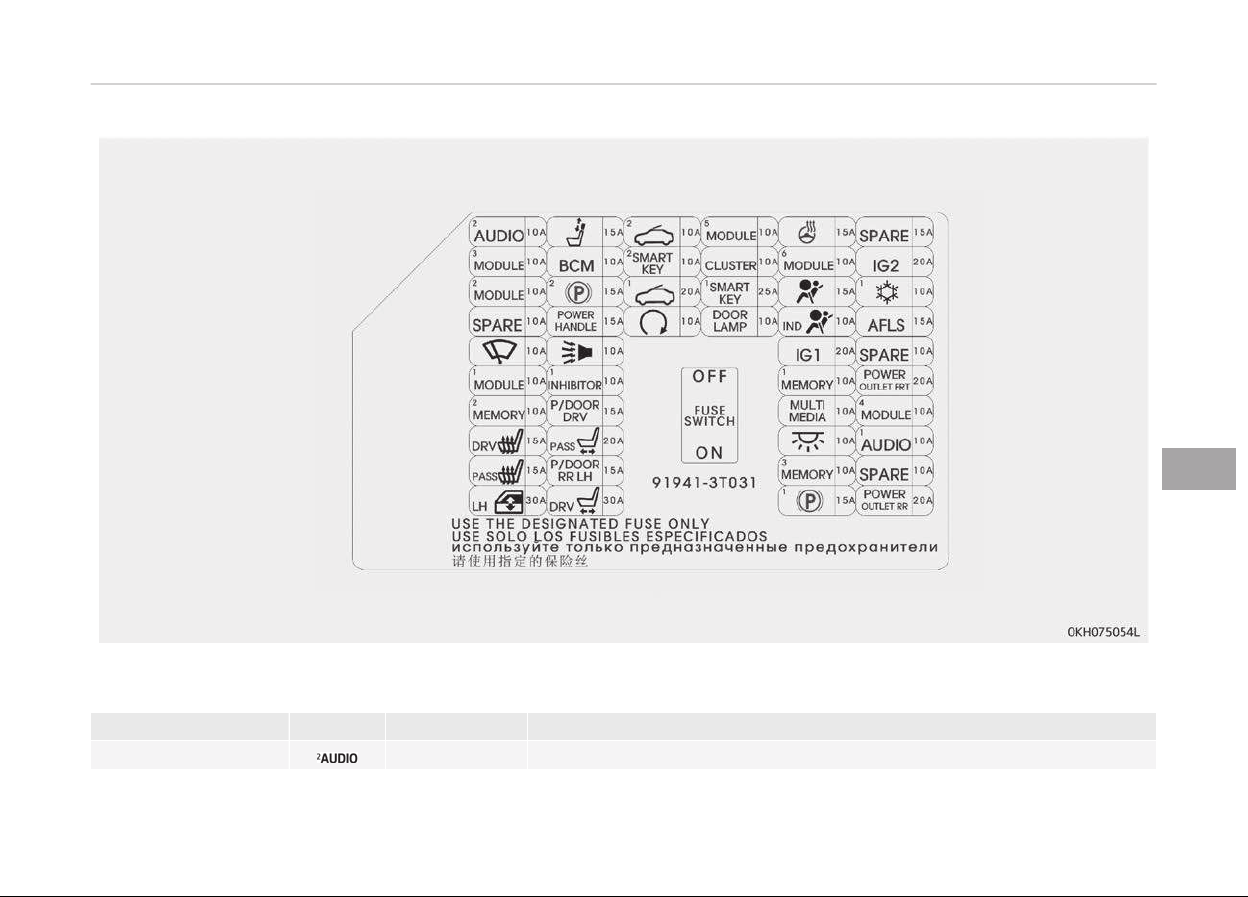
Fuse Name Symbol Fuse rating Circuit Protected
AUDIO 2 10A A/V & Navigation Head Unit
7-63
7
Maintenance
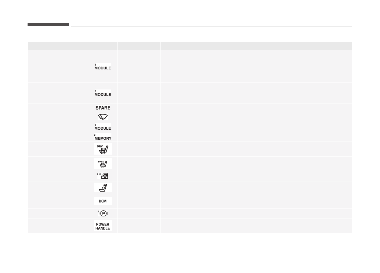
Fuse Name Symbol Fuse rating Circuit Protected
MODULE 3 10A
A/C Control Module, Electro Chromic Mirror, Rear Seat Console Switch,
Driver Haptic Control Module, Rear CCS Control Module LH/RH, Driver/
Passenger IMS Control Module, Driver Power Seat Module, Rear Seat
Warmer Control Module LH/RH, Rear Smart Junction Box (IPS Control
Module)
MODULE 2 10A
Steering Tilt & Telescopic Module, Crash Pad Switch, Stop Lamp Switch,
A/T Console Switch, Electric Parking Brake Switch, Console Switch, Smart
Cruse Control Radar, Air Sus, Active Air Flap, TPMS, PAS
SPARE 10A Spare
WIPER
10A Auto Light & Rain Sensor
MODULE 1
10A BCM, Trunk Lid Main Switch, Low Panel Switch
MEMORY 2
10A External Buzzer, Driver Smart Connector, Passenger Smart Connector
DRV HEAT
15A Driver Haptic Control Module, Driver CCS Module
PASS HEAT 15A Passenger CCS Module
WINDOW LH
30A Rear Power Window Module LH, Rear Power Window Module LH
HEADREST
15A Active Headrest Sensor
BCM
10A
BCM, Multifunction Switch, Driver/Passenger Power Seat Switch, Rear
Door Module LH/RH
EPB 2
15A Electric Parking Brake Module
P/HANDLE 15A Steering Tilt & Telescopic Module
Maintenance
7-64
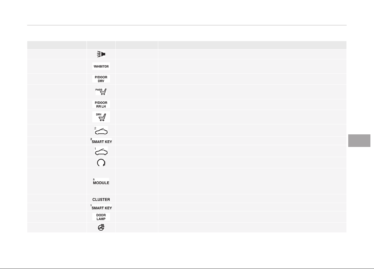
Fuse Name Symbol Fuse rating Circuit Protected
B/ALARM
10A BCM
INHIBITOR 1
10A
W/O Electric ATM Shift Lever : Sport Mode Switch
With Electric ATM Shift Lever : Electric ATM Shift Lever
P/DOOR DRV
15A Driver Door Latch
PASS P/SEAT 20A
W/O IMS : Passenger Seat Relay Box
With IMS : Passenger IMS Control Module
P/DOOR RR LH
15A Rear Door Latch LH
DRV P/SEAT 30A
Driver Lumbar Support Valve, Driver Lumbar Support Switch, Driver Pow‐
er Seat Module
S/ROOF 2
10A Sunroof Motor
SMART KEY 2
10A Metal Core Block (PCB #2) (P/N Relay), Smart Key Control Module
S/ROOF 1
20A Sunroof Motor
START
10A Start/Stop Button Switch
MODULE 5 10A
Around View Unit, Parking Guide Unit, Head-UP, Instrument Cluster, Driv‐
er Lumbar Support Valve, Rear Seat Console Switch, Rear Seat Warmer
Control Module LH/RH, Rear Massage Control Module LH/RH, Rear Smart
Junction Box (IPS Control Module)
CLUSTER 10A Instrument Cluster, Head-Up Display
SMART KEY 1
25A Smart Key Control Module
DOOR LAMP 10A Driver Door Module, Passenger Door Module
STR'G HTD
15A Clock Spring
7-65
7
Maintenance
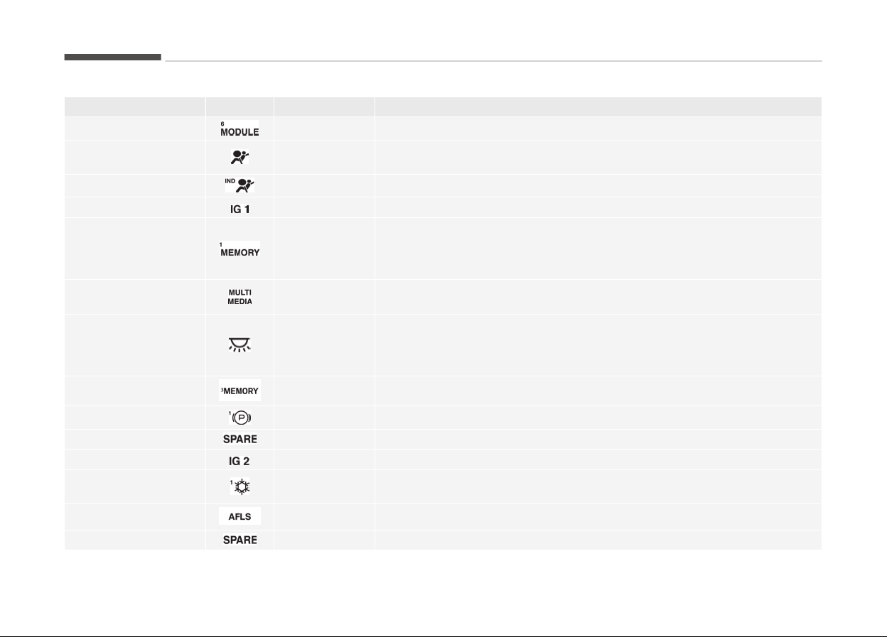
Fuse Name Symbol Fuse rating Circuit Protected
MODULE 6
10A Smart Key Control Module, BCM
A/BAG
15A
Driver Seat Belt Pretensioner, Passenger Seat Belt Pretensioner, SRS
Control Module
A/BAG IND
10A Instrument Cluster
IGN 1
20A E/R Fuse & Relay Box LH (FUSE : F20, F21, F23, F25, F26, F27)
MEMORY 1 10A
Passenger IMS Control Module, Driver/Passenger Door Module, Driver/
Passenger Power Seat Switch, Rear Door Module LH/RH, Power Trunk
Module, Instrument Cluster, BCM, Security Sensor, Analogue Clock, A/C
Control Module, Head-Up Display
MULTI MEDIA 10A
Rear Monitor Module, Keyboard, A/V Navigation Head Unit, Front Monitor,
Rear Monitor LH/RH, LVDS
ROOM LAMP 10A
Rear Seat Foot Lamp LH/RH, Trunk Room Lamp LH/RH, Driver/Passenger
Foot Lamp, Room Lamp, Overhead Console Lamp, Front Vanity Lamp
Switch LH/RH, Rear Vanity Lamp Switch LH/RH, Garnish Lamp LH/RH,
Garnish Center Lamp, Glove Box Lamp
MEMORY 3
10A RF Receiver
EPB 1
15A Electric Parking Brake Module
SPARE
15A Spare
IGN 2 20A E/R Fuse & Relay Box LH (Fuse : F29, F30)
A/CON 1 10A
A/C Control Module, Ionizer, AQS Sensor, Incar Sensor, Metal Core Block
(PCB #2) (Blower Relay)
AFLS
15A Adaptive Front Lighting Module, HEAD LAMP LH/RH
SPARE 10A Spare
Maintenance
7-66
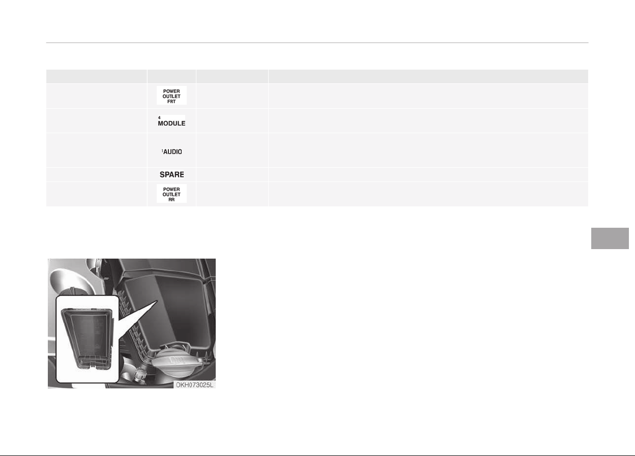
Fuse Name Symbol Fuse rating Circuit Protected
P/OUTLET FR 20A Front Cigarette Lighter
MODULE 4 10A
Electric ATM Shift Lever, Analogue Clock, BCM, Around View Unit, Over‐
head Console Lamp, Parking Guide Unit
AUDIO 1
10A
A/V & Navigation Head Unit, Front/Rear Monitor Module, Keyboard,
Smart Key Control Module, Rear Seat Audio Switch, AMP, Rear Monitor
LH/RH, LVDS
SPARE 10A Spare
P/OUTLET RR 20A P/OUTLET RR, Power Outlet
Engine compartment fuse panel
(Driver’s side)
7-67
7
Maintenance
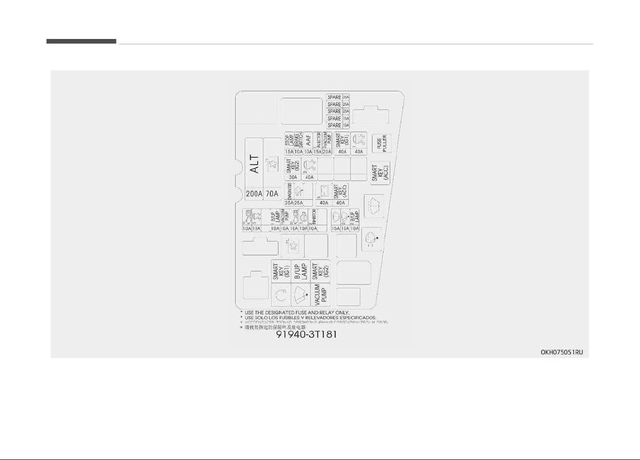
Maintenance
7-68
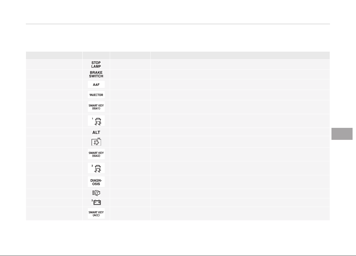
Fuse Name Symbol Fuse rating Circuit Protected
Stop Lamp
15A Stop Signal Electronic Module
Brake SW
10A Stop Lamp Switch, Smart Key Control Module
AAF
10A Not Used
Injector 1 15A IDB (Injector Drive Box)
SMK (IGN1) 40A E/R Fuse & Relay Box LH (RLY.5)
ESC 1 40A ESC Control Module
ALT 200A E/R Fuse & Relay Box LH (Fuse : F9, F15, F16, F18, F19), Alternator
Cooling
70A E/R Fuse & Relay Box LH (RLY.6)
SMK (IGN2)
30A E/R Fuse & Relay Box LH (RLY.3)
ESC 2 40A ESC Control Module
Diagnosis 25A Multipurpose Check Connector
H/Lamp Washer
25A E/R Fuse & Relay Box LH (RLY.7)
Battery 3
40A Smart Junction Box (Fuse : F5, F6, F8, F9, F10)
SMK (ACC)
40A E/R Fuse & Relay Box LH (RLY.9)
7-69
7
Maintenance
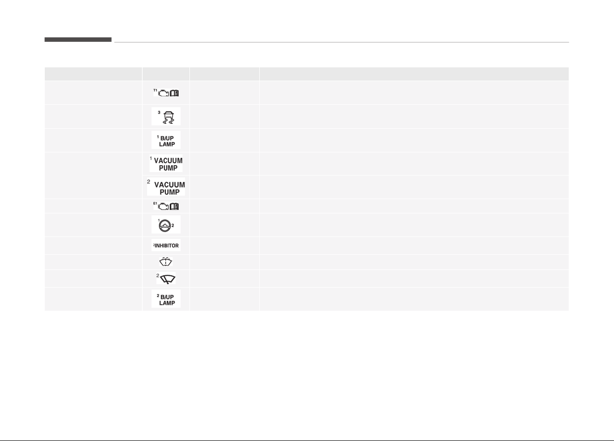
Fuse Name Symbol Fuse rating Circuit Protected
TCU 1 10A
ECM, Transmission Range Switch, Transmission Park Postilion Sensor &
Switch
ESC 3 10A Steering Angle Sensor, ESC Control Module
B/UP Lamp 1 10A E/R Fuse & Relay Box LH (RLY.4)
Vaccum
10A E/R Fuse & Relay Box LH (RLY.10), Vacuum Pump SW
20A E/R Fuse & Relay Box LH (RLY.10)
ECU 1 10A ECU
EHPS 1 10A EHPS Module
Inhibitor 2 10A A/T Console Switch, Electric ATM Shift Lever
Washer
15A E/R Fuse & Relay Box LH (RLY.8)
Wiper 2
10A E/R Fuse & Relay Box LH (RLY.1)
B/UP Lamp 2 10A
Back View Camera & Back-Up Lamp, A/T Console Switch, Electro Chromic
Mirror, A/V & Navigation Head Unit
Maintenance
7-70
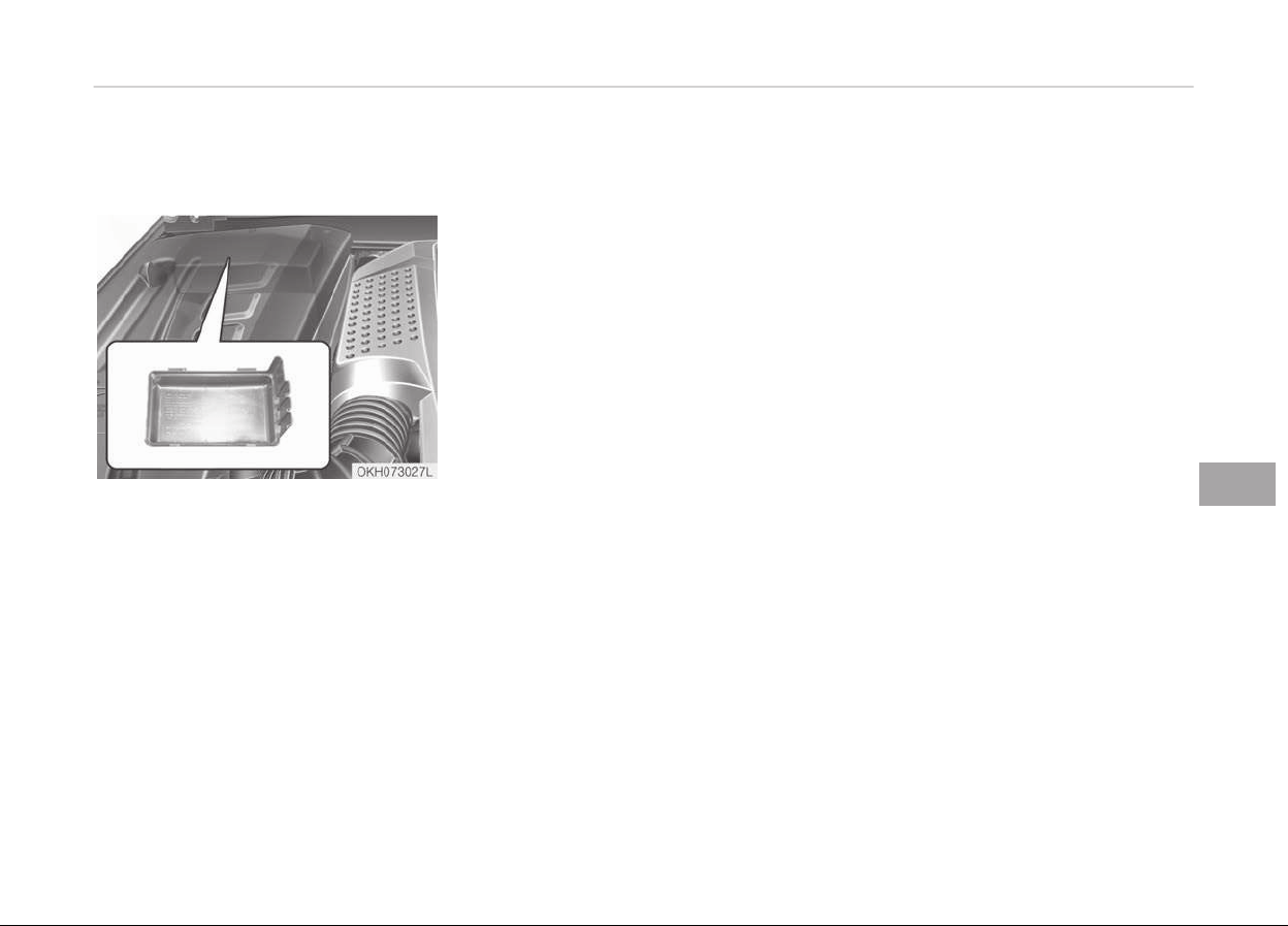
Engine compartment fuse panel
(Passenger’s side)
7-71
7
Maintenance
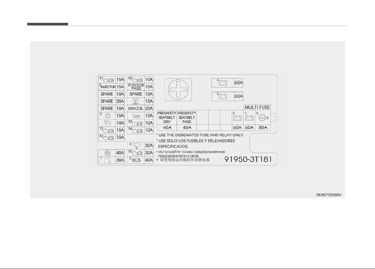
Maintenance
7-72
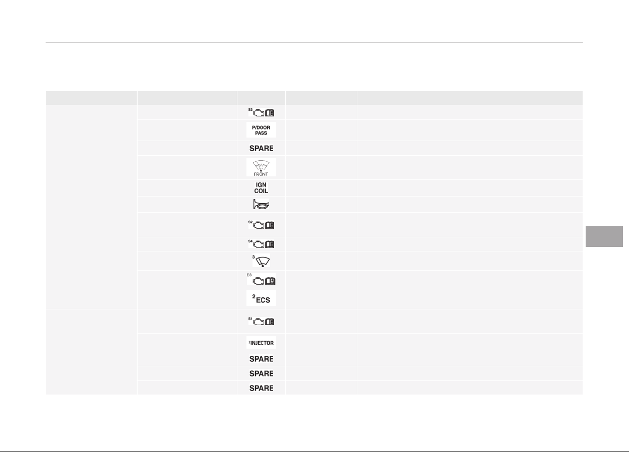
Fuse Fuse Name Symbol Fuse rating Circuit Protected
METAL CORE BLOCK
(PCB #1)
Sensor 3
10A Rear Smart Junction Box (Fuel Pump Relay)
P/Door PASS
15A Passenger Door Latch
SPARE
15A Spare
Deicer 15A Metal Core Block (PCB #1) (Front Deicer Relay)
Ignition
20A Ignition Coil #1~6, Condenser #1, #2
Horn
15A Metal Core Block (PCB #1) (Horn Relay)
Sensor 2
10A
Mass Air Flow Sensor, Oxygen Sensor #1~4, E/R
Fuse & Relay Box LH (RLY.6)
Sensor 4 10A Not Used
Wiper 3
30A Wiper Motor
ECU 3 30A Metal Core Block (PCB #1) (ECU Main Relay)
ECS 2
40A Metal Core Block (PCB #1) (Air ECS Relay)
METAL CORE BLOCK
(PCB #2)
Sensor 1
15A
Purge Control Solenoid Valve, ECM, Variable Intake
Solenoid Valve, Oil Control Valve #1~4
Injector 2
15A Injector #1~6
SPARE
10A Spare
SPARE 20A Spare
SPARE 10A Spare
7-73
7
Maintenance
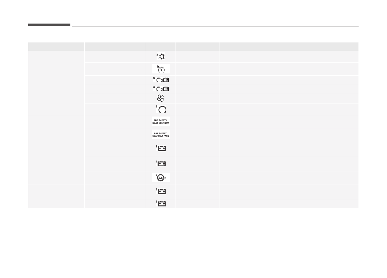
Fuse Fuse Name Symbol Fuse rating Circuit Protected
METAL CORE BLOCK
(PCB #2)
A/C 2 10A A/C Control Module
Cruise
10A Smart Cruise Control Radar
TCU 2
15A TCM
ECU 2 10A ECM
Blower
40A Metal Core Block(PCB) (Blower Relay)
Start 1
30A E/R Fuse Relay Box LH (RLY.2)
MULTI FUSE
Seat Belt LH
40A Driver Seat Belt Pretensioner
Seat Belt RH
40A Passenger Seat Belt Pretensioner
Battery 2
60A
Smart Junction Box (Fuse : F13~20, F23, F24, F27,
F28, IPS5~8, Arisu-LT2)
Battery 1
60A
Smart Junction Box (Fuse : F38, IPS1, 3, Arisu-LT1,
Leak Current Autocut Device)
EHPS 2
80A EHPS Module
FUSE
Battery 4
60A
Metal Core Block (PCB #1) (Fuse : F2, F4, F6, F10,
F11, F12)
Battery 5
60A Metal Core Block (PCB #2) (Fuse : F7, F11)
Maintenance
7-74

Trunk fuse panel
7-75
7
Maintenance
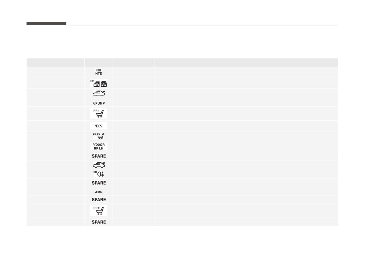
Trunk fuse panel
Fuse Name Symbol Fuse rating Circuit Protected
Rear HTD 40A Rear Defogger Relay
P/WDW RH
30A Passenger Power Window Module, Rear Power Window Module RH
P/Trunk
30A Power Trunk Module
F/Pump
20A Fuel Pump Relay
Rear P/Seat 1 20A Rear Seat Relay Box
ECS 1 20A ECS Unit
PASS P/Seat
15A Passenger IMS Control Module
P/Door RR RH
15A Rear Door Latch RH
Spare 15A Spare
Trunk
10A Trunk Lid Relay, Power Trunk Module Buzzer
Rear Fog Lamp
10A Rear Fog Lamp Relay
Spare
40A Spare
AMP 25A AMP
Spare 20A Spare
Rear P/Seat 2
10A
Rear Seat Relay Box LH, Rear Seat Relay RH, Rear Seat Massage Control
Module LH, Rear Seat Massage Control Module RH
Spare 10A Spare
Maintenance
7-76
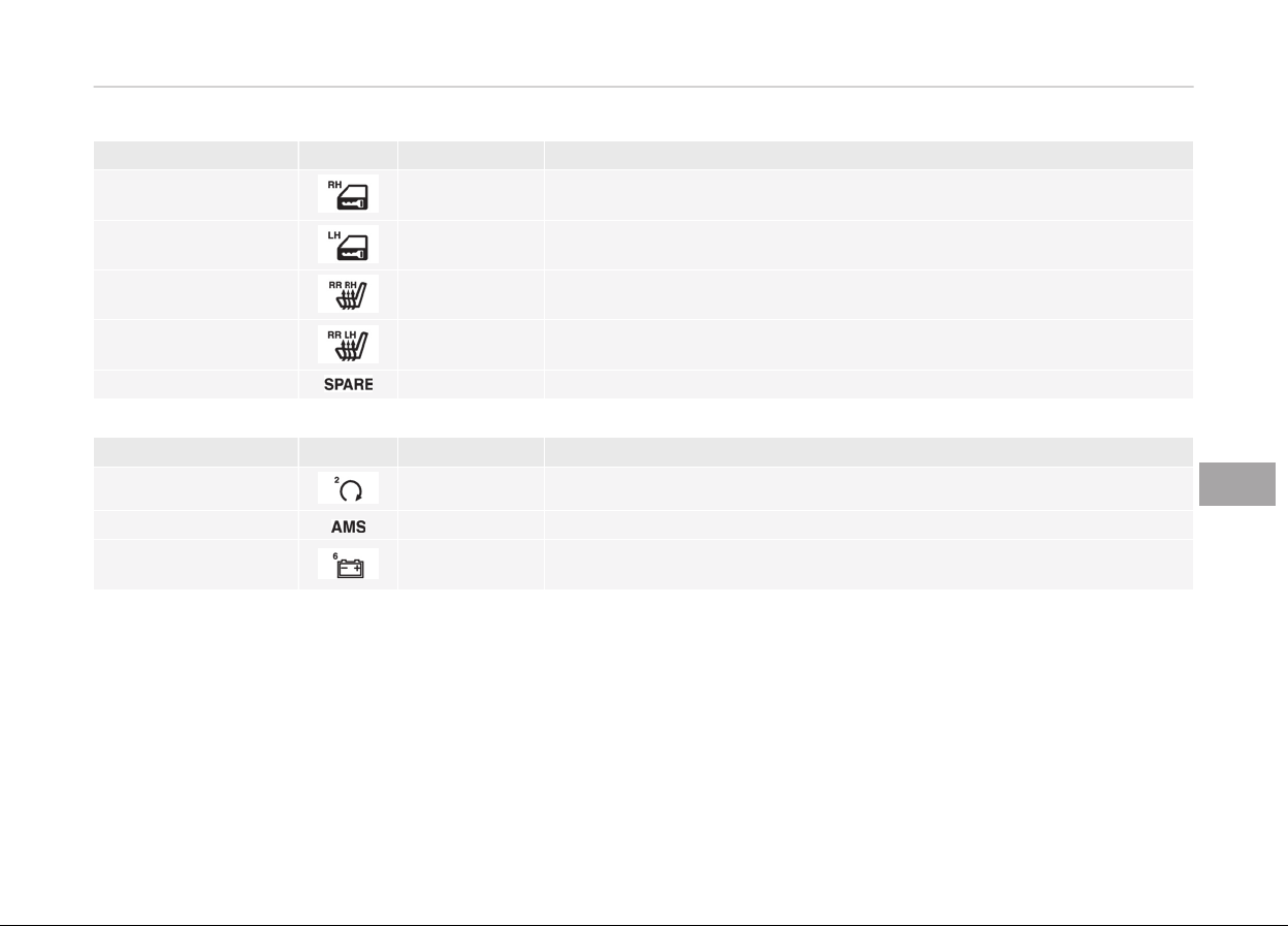
Fuse Name Symbol Fuse rating Circuit Protected
DR/Lock RH 10A Passenger Door Module, Rear Door Module RH
DR/Lock LH 10A Driver Door Module, Rear Door Latch LH
RR Seat HTD RH 15A Rear Seat Warmer Control Module RH, Rear CCS Control Module RH
RR Seat HTD LH 15A Rear Seat Warmer Control Module LH, Rear CCS Control Module LH
Spare 15A Spare
Battery box fuse panel
Fuse Name Symbol Fuse rating Circuit Protected
Start 2
40A Metal Core Block (PCB #2) (Fuse : F8, F9, F12)
AMS
10A Battery Sensor
Battery 6 100A
Rear Smart Junction Box (Fuse : F1, F2, F3, F4, F5, F6, F7, F8, F10, F11,
F13, F15, F17, F18, F19, F20)
7-77
7
Maintenance

LIGHT BULBS
WARNING
n
W
orking on the lights
Prior to working on the light, firmly
apply the parking brake, ensure that
the Engine Start/Stop button is in
the OFF position and turn off the
lights to avoid sudden movement of
the vehicle and burning your fingers
or receiving an electric shock.
Use only the bulbs of the specified wat‐
tage.
CAUTION
Be sure to replace the burned-out
bulb with one of the same wattage
rating. Otherwise, it may cause
damage to the fuse or electric wiring
system.
CAUTION
• If you don’t have necessary tools,
the correct bulbs and the exper‐
tise, consult a professional work‐
shop. Kia recommends to consult
an authorized Kia dealer/service
partner. In many cases, it is diffi‐
cult to replace vehicle light bulbs
because other parts of the vehicle
must be removed before you can
get to the bulb. This is especially
true if you have to remove the
headlight assembly to get to the
bulb(s). Removing/installing the
headlight assembly can result in
damage to the vehicle.
• Do not install additional bulb or
LED. If you install that, the lamp
may not be operated properly and
fuse box or electric wiring system
may have problem.
NOTICE
After driving in heavy rain or wash‐
ing the vehicle, headlight and taillight
(Continued)
(Continued)
lenses could appear frosty. This con‐
dition is caused by the temperature
difference between the lamp inside
and outside. This is similar to the
condensation on your windows in‐
side your vehicle during the rain and
doesn’t indicate a problem with your
vehicle. If the water leaks into the
lamp bulb circuitry, have the vehicle
checked by a professional workshop.
Kia recommends to visit an author‐
ized Kia dealer/service partner.
Maintenance
7-78
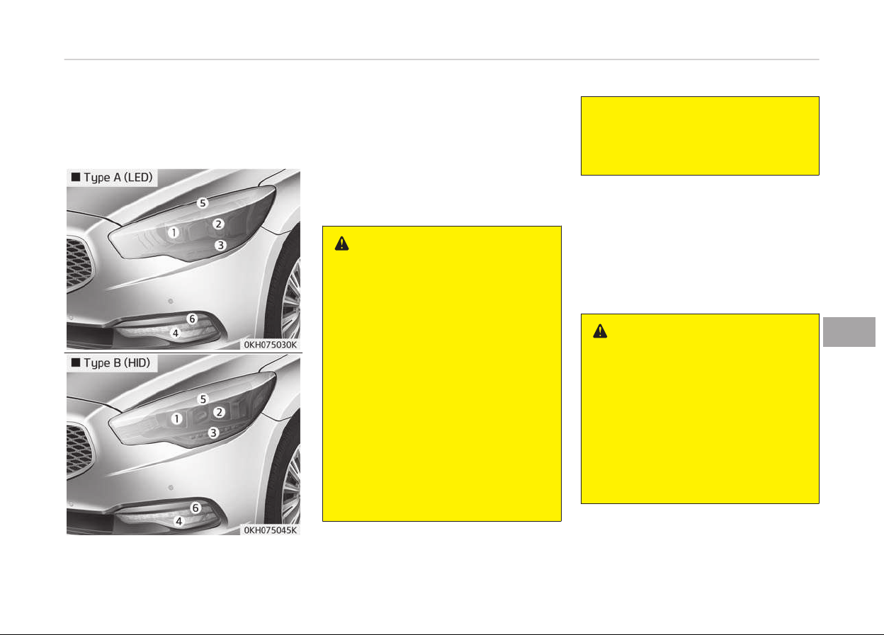
Headlight, front position light,
front turn signal light, front fog
light bulb r
eplacement
1. Headlight (High)
2. Headlight (Low)
3. Front turn signal light
4. Front fog light (if equipped)
5. Front position light
6. Daytime running lamp (if equipped)
WARNING
n
Halogen bulbs
• Halogen bulbs contain pressurized
gas that will produce flying pieces
of glass if broken.
• Always handle them carefully, and
avoid scratches and abrasions. If
the bulbs are lit, avoid contact
with liquids. Never touch the glass
with bare hands. Residual oil may
cause the bulb to overheat and
burst when lit.
A bulb should be operated only
when installed in a headlight.
• If a bulb becomes damaged or
cracked, replace it immediately
and carefully dispose of it.
(Continued)
(Continued)
• Wear eye protection when chang‐
ing
a bulb. Allow the bulb to cool
down before handling it.
Headlamp (HID/LED type), Front
position lamp, front turn signal
lamp, front fog lamp
If the light bulb does not operate, have
your vehicle checked by a professional
workshop. Kia recommends to visit an
authorized Kia dealer/service partner.
WARNING
n
HID/LED Headlight low beam
(if equipped)
Do not attempt to replace or inspect
the low beam (XENON bulb/LED) due
to electric shock danger. If the low
beam (XENON bulb/LED) is not work‐
ing, have your vehicle checked by a
professional workshop. Kia recom‐
mends to visit an authorized Kia
dealer/service partner.
7-79
7
Maintenance
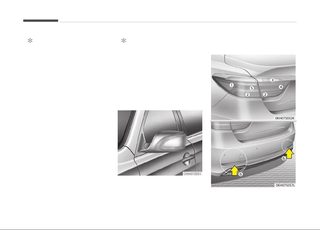
NOTICE
HID/LED lamps have superior per‐
formance vs. halogen bulbs.
HID/LED lamps are estimated by the
manufacturer to last twice as long
or longer than halogen bulbs de‐
pending on their frequency of use.
They will probably require replace‐
ment at some point in the life of the
vehicle. Cycling the headlamps on
and off more than typical use will
shorten HID/LED lamps life. HID/LED
lamps do not fail in the same man‐
ner as halogen incandescent lamps.
If a headlamp goes out after a peri‐
od of operation but will immediately
relight when the headlamp switch is
cycled it is likely the HID/LED lamp
needs to be replaced. HID/LED light‐
ing components are more complex
than conventional halogen bulbs
thus have higher replacement cost.
NOTICE
Have the headlight aiming adjusted
after an accident or after the head‐
light assembly is reinstalled by a
professional workshop. Kia recom‐
mends to visit an authorized Kia
dealer/service partner.
Side repeater light bulb
replacement
If the light bulb does not operate, have
your vehicle checked by a professional
workshop. Kia recommends to visit an
authorized Kia dealer/service partner.
Rear combination light bulb
replacement
1. Stop and tail light
Maintenance
7-80
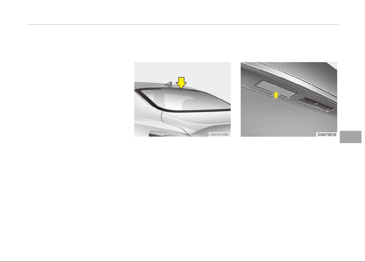
2. Rear turn signal light
3. Back-up light
4. Rear fog light (if equipped)
5. Stop lamp
6. Reflex reflector
Rear fog light, Stop and tail light,
Turn signal lamp, Back-up lamp
If the light does not operate, have your
vehicle checked by a professional work‐
shop. Kia recommends to visit an au‐
thorized Kia dealer/service partner.
High mounted stop light
r
eplacement
If the light does not operate, have your
vehicle checked by a professional work‐
shop. Kia recommends to visit an au‐
thorized Kia dealer/service partner.
License plate light bulb
replacement
If the light does not operate, have your
vehicle checked by a professional work‐
shop. Kia recommends to visit an au‐
thorized Kia dealer/service partner.
7-81
7
Maintenance
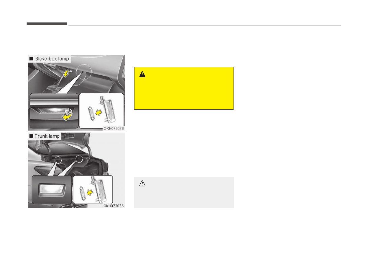
Interior light bulb replacement
1. Using a flat-blade screwdriver, gen‐
tly pry the lens from the interior
light housing.
2. Remove the bulb by pulling it
straight out.
3. Install a new bulb in the socket.
WARNING
Prior to working on the Interior
Lights, ensure that the OFF button
is depressed to avoid burning your
fingers or receiving an electric shock.
4. Align the lens tabs with the interior
light housing notches and snap the
lens into place.
5. If the map lamp and room lamp are
not operating, have the system
checked by a professional work‐
shop. Kia recommends to visit an
authorized Kia dealer/service part‐
ner.
CAUTION
Use care not to dirty or damage
lens, lens tab, and plastic housings.
Maintenance
7-82
APPEARANCE CARE
Exterior care
Exterior general caution
It is very important to follow the label
directions when using any chemical
cleaner or polish. Read all warning and
caution statements that appear on the
label.
Finish maintenance
Washing
To help protect your vehicle’s finish
from rust and deterioration, wash it
thoroughly and frequently at least once
a month with lukewarm or cold water.
If you use your vehicle for off-road
driving, you should wash it after each
off-road trip. Pay special attention to
the removal of any accumulation of
salt, dirt, mud, and other foreign mate‐
rials. Make sure the drain holes in the
lower edges of the doors and rocker
panels are kept clear and clean.
Insects, tar, tree sap, bird droppings, in‐
dustrial pollution and similar deposits
can damage your vehicle’s finish if not
removed immediately.
Even prompt washing with plain water
may not completely remove all these
deposits. A mild soap, safe for use on
painted surfaces, may be used.
After washing, rinse the vehicle thor‐
oughly with lukewarm or cold water. Do
not allow soap to dry on the finish.
CAUTION
• Do not use strong soap, chemical
detergents or hot water, and do
not wash the vehicle in direct sun‐
light or when the body of the vehi‐
cle is warm.
• Be careful when washing the side
windows
of your vehicle. Especial‐
ly, with high-pressure water, wa‐
ter may leak through the windows
and wet the interior.
• To prevent damage to plastic parts
and
lamps, do not clean with
chemical solvents or strong deter‐
gents.
WARNING
n
Wet brakes
After washing the vehicle, test the
brakes while driving slowly to see if
(Continued)
(Continued)
they have been affected by water. If
braking performance is impaired, dry
the brakes by applying them lightly
while maintaining a slow forward
speed.
High-pressure washing
• When using high-pressure washers,
make sure to maintain sufficient dis‐
tance from the vehicle.
Insufficient clearance or excessive
pressure can lead to component
damage or water penetration.
• Do not spray the camera, sensors or
its surrounding area directly with a
high pressure washer. Shock applied
from high pressure water may cause
the device to not operate normally.
• Do not bring the nozzle tip close to
boots (rubber or plastic covers) or
connectors as they may be damaged
if they come into contact with high
pressure water.
7-83
7
Maintenance
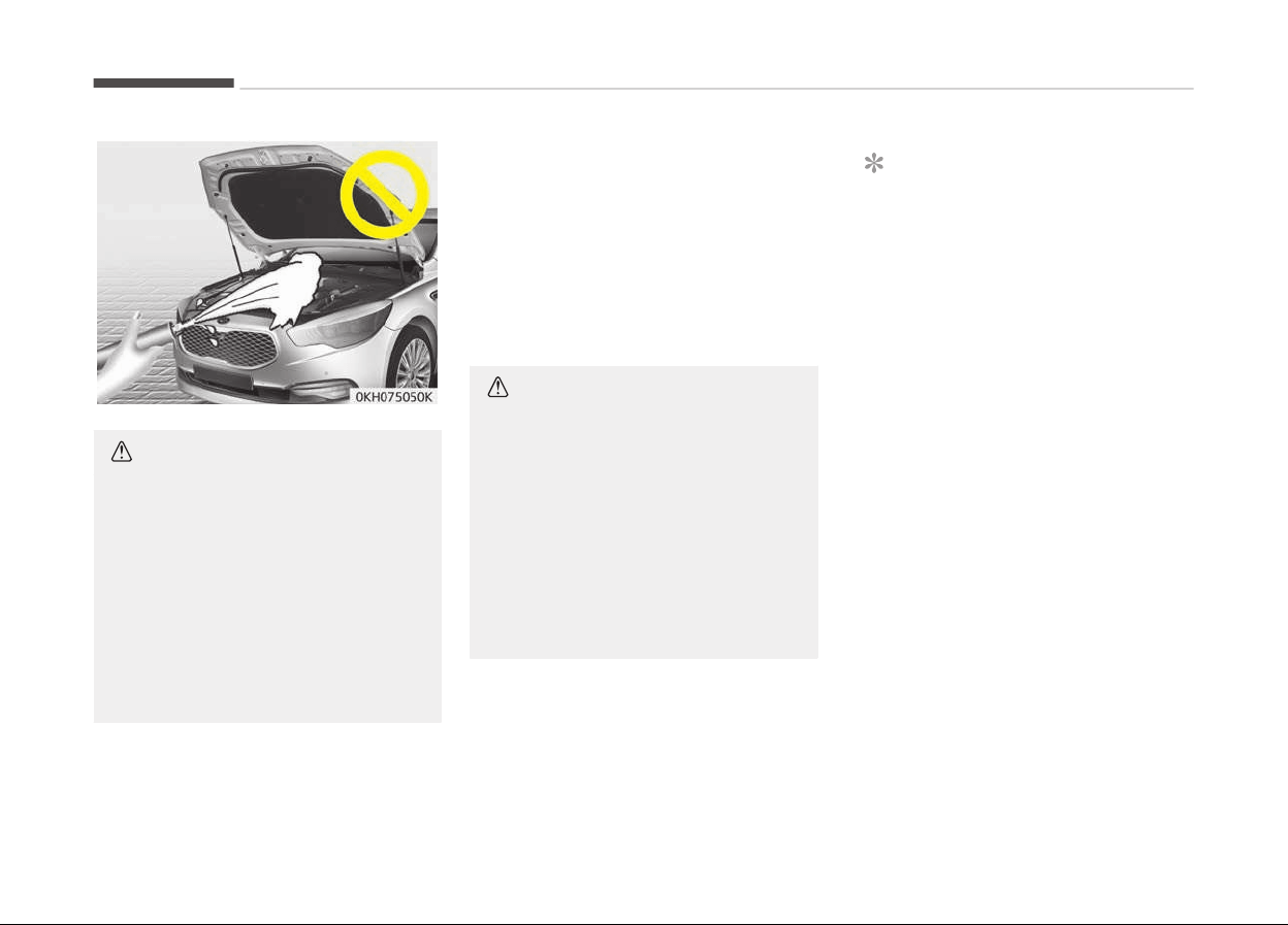
CAUTION
• Water washing in the engine com‐
partment including high pressure
water washing may cause the fail‐
ure of electrical circuits or engine
and related part located in the en‐
gine compartment.
• Never allow water or other liquids
to come in contact with electrical/
electronic components and air duct
inside the vehicle as this may
damage them.
Waxing
Wax the vehicle when water will no lon‐
ger bead on the paint.
Always wash and dry the vehicle before
waxing. Use a good quality liquid or
paste wax, and follow the manufactur‐
er’s instructions. Wax all metal trim to
protect it and to maintain its luster.
Removing oil, tar, and similar materials
with a spot remover will usually strip
the wax from the finish. Be sure to re-
wax these areas even if the rest of the
vehicle does not yet need waxing.
CAUTION
• Wiping dust or dirt off the body
with a dry cloth will scratch the
finish.
• Do not use steel wool, abrasive
cleaners, or strong detergents
containing high alkaline or caustic
agents on chrome-plated or ano‐
dized aluminum parts. This may
result in damage to the protective
coating and cause discoloration or
paint deterioration.
Finish damage repair
Deep scratches or stone chips in the
painted surface must be repaired
promptly. Exposed metal will quickly
rust and may develop into a major re‐
pair expense.
NOTICE
If your vehicle is damaged and re‐
quires any metal repair or replace‐
ment, be sure the body shop applies
anti-corrosion materials to the parts
repaired or replaced.
Bright-metal maintenance
• To remove road tar and insects, use a
tar remover, not a scraper or other
sharp object.
• To protect the surfaces of bright-
metal parts from corrosion, apply a
coating of wax or chrome preserva‐
tive and rub to a high luster.
• During winter weather or in coastal
areas, cover the bright metal parts
with a heavier coating of wax or
preservative. If necessary, coat the
parts with non-corrosive petroleum
jelly or other protective compound.
Maintenance
7-84

Underbody maintenance
Corrosive materials used for ice and
snow removal and dust control may
collect on the underbody. If these ma‐
terials are not removed, accelerated
rusting can occur on underbody parts
such as the fuel lines, frame, floor pan
and exhaust system, even though they
have been treated with rust protection.
Thoroughly flush the vehicle underbody
and wheel openings with lukewarm or
cold water once a month, after off-
road driving and at the end of each
winter. Pay special attention to these
areas because it is difficult to see all
the mud and dirt. It will do more harm
than good to wet down the road grime
without removing it. The lower edges
of doors, rocker panels, and frame
members have drain holes that should
not be allowed to clog with dirt; trap‐
ped water in these areas can cause
rusting.
WARNING
After washing the vehicle, test the
brakes while driving slowly to see if
they have been affected by water. If
braking performance is impaired, dry
(Continued)
(Continued)
the brakes by applying them lightly
while
maintaining a slow forward
speed.
Aluminum wheel maintenance
The aluminum wheels are coated with a
clear protective finish.
• Do not use any abrasive cleaner, pol‐
ishing compound, solvent, or wire
brushes on aluminum wheels. They
may scratch or damage the finish.
• Clean the wheel when it has cooled.
• Use only a mild soap or neutral deter‐
gent, and rinse thoroughly with wa‐
ter. Also, be sure to clean the wheels
after driving on salted roads. This
helps prevent corrosion.
• Avoid washing the wheels with high-
speed car wash brushes.
• Do not use any alkaline or acid deter‐
gent. It may damage and corrode the
aluminum wheels coated with a clear
protective finish.
Corrosion protection
Protecting your vehicle from corrosion
By using the most advanced design and
construction practices to combat corro‐
sion, we produces cars of the highest
quality. However, this is only part of
the job. To achieve the long-term cor‐
rosion resistance your vehicle can deliv‐
er, the owner's cooperation and assis‐
tance is also required.
Common causes of corrosion
The most common causes of corrosion
on your car are:
• Road salt, dirt and moisture that is
allowed to accumulate underneath
the car.
• Removal of paint or protective coat‐
ings by stones, gravel, abrasion or
minor scrapes and dents which leave
unprotected metal exposed to corro‐
sion.
High-corrosion areas
If you live in an area where your car is
regularly exposed to corrosive materi‐
als, corrosion protection is particularly
important. Some of the common cau‐
ses of accelerated corrosion are road
salts, dust control chemicals, ocean air
and industrial pollution.
Moisture breeds corrosion
7-85
7
Maintenance

Moisture creates the conditions in
which corrosion is most likely to occur.
For example, corrosion is accelerated
by high humidity, particularly when
temperatures are just above freezing.
In such conditions, the corrosive mate‐
rial is kept in contact with the car sur‐
faces by moisture that is slow to evap‐
orate.
Mud is particularly corrosive because it
is slow to dry and holds moisture in
contact with the vehicle. Although the
mud appears to be dry, it can still re‐
tain the moisture and promote corro‐
sion.
High temperatures can also accelerate
corrosion of parts that are not properly
ventilated so the moisture can be dis‐
persed. For all these reasons, it is par‐
ticularly important to keep your car
clean and free of mud or accumulations
of other materials. This applies not only
to the visible surfaces but particularly
to the underside of the car.
To help prevent corrosion
You can help prevent corrosion from
getting started by observing the fol‐
lowing:
Keep your car clean
The best way to prevent corrosion is to
keep your car clean and free of corro‐
sive materials. Attention to the under‐
side of the car is particularly important.
• If you live in a high-corrosion area
where road salts are used, near the
ocean, areas with industrial pollution,
acid rain, etc., you should take extra
care to prevent corrosion. In winter,
hose off the underside of your car at
least once a month and be sure to
clean the underside thoroughly when
winter is over.
• When cleaning underneath the car,
give particular attention to the com‐
ponents under the fenders and other
areas that are hidden from view. Do a
thorough job; just dampening the ac‐
cumulated mud rather than washing
it away will accelerate corrosion rath‐
er than prevent it. Water under high
pressure and steam are particularly
effective in removing accumulated
mud and corrosive materials.
• When cleaning lower door panels,
rocker panels and frame members,
be sure that drain holes are kept
open so that moisture can escape
and not be trapped inside to acceler‐
ate corrosion.
Keep your garage dry
Don't park your car in a damp, poorly
ventilated garage. This creates a favor‐
able environment for corrosion. This is
particularly true if you wash your car in
the garage or drive it into the garage
when it is still wet or covered with
snow, ice or mud. Even a heated garage
can contribute to corrosion unless it is
well ventilated so moisture is dispersed.
Keep paint and trim in good
condition
Scratches or chips in the finish should
be covered with "touch-up" paint as
soon as possible to reduce the possibili‐
ty of corrosion. If bare metal is showing
through, the attention of a qualified
body and paint shop is recommended.
Bird droppings: Bird droppings are high‐
ly corrosive and may damage painted
surfaces in just a few hours. Always re‐
move bird droppings as soon as possi‐
ble.
Maintenance
7-86

Don't neglect the interior
Moisture can collect under the floor
mats and carpeting to cause corrosion.
Check under the mats periodically to be
sure the carpeting is dry. Use particular
care if you carry fertilizers, cleaning
materials or chemicals in the car.
These should be carried only in proper
containers and any spills or leaks
should be cleaned up, flushed with
clean water and thoroughly dried.
Interior care
Interior general precautions
Prevent chemicals such as perfume,
cosmetic oil, sun cream, hand cleaner
and air freshener from contacting the
interior parts because they may cause
damage or discoloration. If they do con‐
tact the interior parts, wipe them off
immediately. If necessary, use a vinyl
cleaner, see instructions for correct us‐
age.
CAUTION
Never allow water or other liquids to
c
ome in contact with electrical/elec‐
(Continued)
(Continued)
tronic components inside the vehicle
as this may damage them.
Fabric seat cover (If equipped)
Please clean the fabric seats regularly
with a vacuum cleaner in consideration
of fabric material characteristics. If
they are heavily soiled with beverage
stains, etc., use a suitable interior
cleaner. To prevent damage to seat
covers, wipe off the seat covers down
to the seams with a large wiping mo‐
tion and moderate pressure using a
soft sponge or microfiber cloth.
Velcro closures on clothing or sharp ob‐
jects may cause snagging or scratches
on the surface of the seats.
Make sure not to rub such objects
against the surface.
Nappa leather seat cover (If
equipped)
Nappa leather retains the hide's own
soft texture with visible pores, scars or
blood vessels, etc. Pressure marks or
wrinkles may be made when used. Pro‐
longed exposure to sunlight or heat
may cause discoloration. These things
occur due to the natural characteristics
of cowhides. If the leather is exposed to
rain or gets wet, remove water with a
dry cloth and dry the leather in the
shade to minimize damage.
Make sure to keep sharp objects away
from the leather as these can create
scratches on the surface. For light-col‐
ored leather, be careful of spots or col‐
or transfer, such as from jeans.
Natural leather seat cover (If
equipped)
Natural leather has visible pores, scars
or blood vessels, etc. Pressure marks or
wrinkles may be made when used. Pro‐
longed exposure to sunlight or heat
may cause discoloration. These things
occur due to the natural characteristics
of cowhides. If the leather is exposed to
rain or gets wet, remove water with a
dry cloth and dry the leather in the
shade to minimize damage.
7-87
7
Maintenance

Make sure to keep sharp objects away
from the leather as these can create
scratches on the surface. For light-col‐
ored leather, be careful of spots or col‐
or transfer, such as from jeans.
CAUTION
When cleaning leather products
(steering wheel, seats etc.), use
neutral detergents or low alcohol
content solutions. If you use high al‐
cohol content solutions or acid/alka‐
line detergents, the color of the
leather may fade or the surface may
get stripped off.
Cleaning the upholstery and
interior trim
Vinyl
Remove dust and loose dirt from vinyl
with a whisk broom or vacuum cleaner.
Clean vinyl surfaces with a vinyl clean‐
er.
Fabric
Remove dust and loose dirt from fabric
with
a whisk broom or vacuum cleaner.
Clean with a mild soap solution recom‐
mended for upholstery or carpets. Re‐
move fresh spots immediately with a
fabric spot cleaner. If fresh spots do
not receive immediate attention, the
fabric can be stained and its color can
be affected. Also, its fire-resistant
properties can be reduced if the mate‐
rial is not properly maintained.
CAUTION
Using anything but recommended
cleaners and procedures may affect
the fabric’s appearance and fire-re‐
sistant properties.
Cleaning the lap/shoulder belt
webbing
Clean the belt webbing with any mild
soap solution recommended for clean‐
ing upholstery or carpet. Follow the in‐
structions provided with the soap. Do
not bleach or re-dye the webbing be‐
cause this may weaken it.
Cleaning the interior window glass
If the interior glass surfaces of the ve‐
hicle become fogged (that is, covered
with an oily, greasy or waxy film), they
should be cleaned with glass cleaner.
Follow the directions on the glass
cleaner container.
CAUTION
Do not scrape or scratch the inside
of the rear window. This may result
in damage to the rear window de‐
froster grid.
Maintenance
7-88

EMISSION CONTROL SYSTEM (IF EQUIPPED)
The emission control system of your
vehicle is covered by a written limited
warranty. Please see the warranty in‐
formation contained in the Service
Passport in your vehicle.
Your vehicle is equipped with an emis‐
sion control system to meet all applica‐
ble emission regulations.
There are three emission control sys‐
tems, as follows.
1. Crankcase emission control system
2. Evaporative emission control sys‐
tem
3. Exhaust emission control system
In order to assure the proper function
of the emission control systems, have
your vehicle inspected and maintained
by a professional workshop in accord‐
ance with the maintenance schedule in
this manual. Kia recommends to visit an
authorized Kia dealer/service partner.
Caution for the Inspection and Mainte‐
nance Test (With Electronic Stability
Control (ESC) system)
• To prevent the vehicle from misfiring
during dynamometer testing, turn
the Electronic Stability Control (ESC)
system off by pressing the ESC
switch.
•
After
dynamometer testing is com‐
pleted, turn the ESC system back on
by pressing the ESC switch again.
1. Crankcase emission control
system
The positive crankcase ventilation sys‐
tem is employed to prevent air pollu‐
tion caused by blow-by gases being
emitted from the crankcase. This sys‐
tem supplies fresh filtered air to the
crankcase through the air intake hose.
Inside the crankcase, the fresh air mix‐
es with blow-by gases, which then pass
through the PCV valve into the induc‐
tion system.
2. Evaporative emission control
system
The Evaporative Emission Control Sys‐
tem is designed to prevent fuel vapors
from escaping into the atmosphere.
Canister
Fuel vapors generated inside the fuel
tank are absorbed and stored in the on‐
board canister. When the engine is run‐
ning, the fuel vapors absorbed in the
canister are drawn into the surge tank
through the purge control solenoid
valve.
Purge Control Solenoid Valve (PCSV)
The purge control solenoid valve is con‐
trolled by the Engine Control Module
(ECM); when the engine coolant tem‐
perature is low during idling, the PCSV
closes so that evaporated fuel is not
taken into the engine. After the engine
warms-up during ordinary driving, the
PCSV opens to introduce evaporated
fuel to the engine.
3. Exhaust emission control
system
The Exhaust Emission Control System
is a highly effective system which con‐
trols exhaust emissions while maintain‐
ing good vehicle performance.
Vehicle modifications
This vehicle should not be modified.
Modification of your vehicle could affect
its performance, safety or durability
and may even violate governmental
safety and emissions regulations.
In addition, damage or performance
problems resulting from any modifica‐
tion may not be covered under warran‐
ty.
7-89
7
Maintenance

• If you use unauthorized electronic
devices, it may cause the vehicle to
operate abnormally, wire damage,
battery discharge and fire. For your
safety, do not use unauthorized elec‐
tronic devices.
Engine exhaust gas precautions
(carbon monoxide)
• Carbon monoxide can be present with
other exhaust fumes. Therefore, if
you smell exhaust fumes of any kind
inside your vehicle, have it inspected
and repaired immediately. If you ever
suspect exhaust fumes are coming
into your vehicle, drive it only with all
the windows fully open. Have your
vehicle checked and repaired immedi‐
ately.
WARNING
n
Exhaust
Engine
exhaust gases contain carbon
monoxide (CO). Though colorless and
odorless, it is dangerous and could
be lethal if inhaled. Follow the in‐
structions on this page to avoid CO
poisoning.
• Do not operate the engine in confined
or closed areas (such as garages) any
more than what is necessary to move
the vehicle in or out of the area.
• When the vehicle is stopped in an
open area for more than a short time
with the engine running, adjust the
ventilation system (as needed) to
draw outside air into the vehicle.
• Never sit in a parked or stopped vehi‐
cle for any extended time with the
engine running.
• When the engine stalls or fails to
start, excessive attempts to restart
the engine may cause damage to the
emission control system.
Operating precautions for catalytic
converters (if equipped)
WARNING
n
Fire
(Continued)
(Continued)
• A hot exhaust system can ignite
flammable
items under your vehi‐
cle. Do not park, idle, or drive the
vehicle over or near flammable ob‐
jects, such as grass, vegetation,
paper, leaves, etc.
• The exhaust system and catalytic
system
are very hot while the en‐
gine is running or immediately af‐
ter the engine is turned off. Keep
away from the exhaust system
and catalytic, you may get burned.
Also, do not remove the heat sink
around the exhaust system, do
not seal the bottom of the vehicle
or do not coat the vehicle for cor‐
rosion control. It may present a
fire risk under certain conditions.
Your vehicle is equipped with a catalytic
converter emission control device.
Therefore, the following precautions
must be observed:
• Make sure to refuel your vehicle ac‐
cording to the Fuel requirements on
page 1-03.
• Do not operate the vehicle when
there are signs of engine malfunction,
such as misfire or a noticeable loss of
performance.
Maintenance
7-90

• Do not misuse or abuse the engine.
Examples of misuse are coasting with
the engine off and descending steep
grades in gear with the engine off.
• Do not operate the engine at high idle
speed for extended periods
(5 minutes or more).
• Do not modify or tamper with any
part of the engine or emission control
system. Have the system Inspected
by a professional workshop. Kia rec‐
ommends to visit an authorized Kia
dealer/service partner.
• Avoid driving with an extremly low
fuel level. Running out of fuel could
cause the engine to misfire, damag‐
ing the catalytic converter.
Failure to observe these precautions
could result in damage to the catalytic
converter and to your vehicle. Addition‐
ally, such actions could void your war‐
ranties.
7-91
7
Maintenance


Dimensions................................................................................. 8-02
Engine..........................................................................................8-03
Bulb wattage..............................................................................8-04
Air conditioning system........................................................... 8-06
Tires and wheels....................................................................... 8-07
Weight/volume.......................................................................... 8-09
Recommended lubricants and capacities..............................8-10
Recommended SAE viscosity number...............................8-12
Vehicle identification number (VIN)........................................8-14
Vehicle certification label......................................................... 8-15
Tire specification and pressure label..................................... 8-16
Engine number.......................................................................... 8-17
Air conditioner compressor label............................................8-18
Refrigerant label ...................................................................... 8-19
Declaration of conformity....................................................... 8-20
Specifications & Consumer information
8

DIMENSIONS
Item mm (in)
Overall length 5,095 (200.59)
Overall width 1,900 (74.80)
Overall height
1,490 (58.66)/1,485 (58.46)
*1
Front tread
245/50 R18 1,616 (63.62)
245/45 R19 1,620 (63.78)
Rear tread
245/50 R18 1,634 (64.33)
245/45 R19 1,627 (64.06)
Wheelbase 3,045 (119.88)
*1
with air suspension
Specifications & Consumer information
8-02

ENGINE
Item Gasoline Lambda II 3.8 Gasoline Tau 5.0
Displacement
3,778 (230.54) 5,038 (307.3)
cc (cu. in)
Bore x Stroke
96 x 87 (3.78 x 3.42) 96 x 87 (3.78 x 3.42)
mm (in.)
Firing order 1-2-3-4-5-6 1-2-7-8-4-5-6-3
No. of cylinders 6, V - type 8, V - type
8-03
8
Specifications & Consumer informa‐
tion

BULB WATTAGE
Light Bulb Wattage Bulb type
Front
LED Type
Headlamps (Low) LED LED
Headlamps (High) LED LED
HID Type
Headlamps (Low) 35 D3S
Headlamps (High) 55 H7
Smart cornering lamps* 55 H11
Front turn signal lamps LED LED
Front position lamps* LED LED
Front fog lamps (LED)* LED LED
Side Repeater lamps (Outside Mirror)* LED LED
Puddle lamps LED LED
Daytime running lamps* LED LED
Rear
Rear Stop/tail lamps (Inside/outside) LED LED
Rear Stop lamps (Inside/outside) LED LED
Rear turn signal lamps (Inside/outside) LED LED
Back-up lamps 16 W16W
Rear fog lamps* LED LED
High mounted stop lamp LED LED
License plate lamps LED LED
Specifications & Consumer information
8-04

Light Bulb Wattage Bulb type
Interior
Map lamps LED LED
Room lamps LED LED
Vanity mirror lamps LED LED
Glove box lamp 5 FESTOON
Door courtesy lamps LED LED
Foot lamps LED LED
Mood lamps LED LED
Luggage lamp 5 FESTOON
* If equipped
8-05
8
Specifications & Consumer informa‐
tion

AIR CONDITIONING SYSTEM
Item Weight of volume Classification
Refrigerant 650 25g R-134a
Compressor lubricant 120 10g PAG
Specifications & Consumer information
8-06

TIRES AND WHEELS
Item Tire size Wheel size
Load capacity Speed capacity
Inflation pressure bar(psi, kPa) Wheel
lug nut
tor
que
Kgf·m
(lbf·ft,
N·m)
Normal load
*1
Maximum load
LI
*2
Kg
SS
*3
Km/h Front Rear Front Rear
Full size tire
245/50R18 7.5J×18 100 800 V 240
2.3
(33,
230)
2.3
(33,
230)
2.3
(33, 230)
2.3
(33,
230)
9~11
(65~79,
88~107)
245/45R19 8.0J×19 98 750 V 240
2.1
(31,
210)
2.1
(31,
210)
2.1
(31, 210)
2.1
(31,
210)
*1
Normal load : Up to 3 persons
*2
LI: Load index
*3
SS: Speed symbol
CAUTION
When replacing tires, use the same size originally supplied with the vehicle.
Using tires of a different size can damage the related parts or make it work irregularly.
8-07
8
Specifications & Consumer informa‐
tion

NOTICE
When driving in high altitude grades, it is natural for the atmospheric pressure to decrease. Therefore, please check the tire
pressure and add more air when necessary.
Additionally required tire air pressure per km above sea level: 1.5 psi/km
Specifications & Consumer information
8-08

WEIGHT/VOLUME
Item Gasoline Lambda II 3.8 (MPI) Gasoline Lambda II 3.8 (GDI) Gasoline Tau 5.0
Gross vehicle weight
2,430 (5,357) 2,480 (5,467) 2,580 (5,688)
kg (lbs.)
Luggage volume
455 (16.1) 455 (16.1) 450 (15.9)
l
(cu ft)
8-09
8
Specifications & Consumer informa‐
tion

RECOMMENDED LUBRICANTS AND CAPACITIES
To help achieve proper engine and powertrain performance and durability, use only lubricants of the proper quality.
The correct lubricants also help promote engine efficiency that results in improved fuel economy.
These lubricants and fluids are recommended for use in your vehicle.
Lubricant Volume Classification
Engine oil
*1
*2
(drain and r
efill) Rec‐
ommends
3.8L
MPI
*3
5.7
l
(6.02 US qt.)
API Service SM or above,
ILSAC GF-4 or above
ACEA A5 (or above)
GDI
*4
5.7
l
(6.02 US qt.)
ACEA A5 (or above)
5.0L
*4
7.2
l
(7.61 US qt.)
ACEA A5 (or above)
Engine oil consump‐
tion
Normal driving condition MAX. 1L / 1,500 km -
Severe driving condition MAX. 1L / 1,000 km -
Automatic transaxle
fluid
3.8L
MPI
9.6
l
(10.14 US qt.)
ATF SP-IV-RR
(Recommeded Kia genuine, GS)
GDI
9.6
l
(10.14 US qt.)
5.0L
9.6
l
(10.14 US qt.)
Power steering fluid With EHPS
0.9
l
(0.95 US qt.)
Pentosin CHF 202
Specifications & Consumer information
8-10

Lubricant Volume Classification
Coolant
3.8L
MPI
8.6
l
(9.1 US qt.)
Mixture of antifreeze and dis‐
tilled water
(Ethylene glycol base coolant
for aluminum radiator)
GDI
8.6
l
(9.1 US qt.)
5.0L
10.8
l
(11.4 US qt.)
Brake fluid
0.7~0.8
l
(0.74~0.85 US qt.)
FMVSS116 DOT-3 or DOT-4
Rear differential oil
1.4
l
(1.48 US qt.)
HYPOID GEAR OIL API GL-5,
SAE 75W/90
(Recommeded SHELL HD AXLE
OIL 75W/90 Equivalent)
Fuel
75
l
(19.81 US gal.)
Refer to Fuel requirements
on page 1-03
*1
Refer to Recommended SAE viscosity number on page 8-12.
*2
Engine oils labeled Energy Conserving Oil are now available. Along with other additional benefits, they contribute to fuel
economy by reducing the amount of fuel necessary to overcome engine friction. Often, these improvements are difficult to
measure in everyday driving, but in a year’s time, they can offer significant cost and energy savings.
*3
If the API service SM, ILSAC GF-4, ACEA A5 engine oil is not available in your country, you are able to use API service SL,
ILSAC GF-3, ACEA A3.
*4
If the ACEA A5 engine oil is not available in your country, you are able to use API service SL, ILSAC GF-3, ACEA A3.
8-11
8
Specifications & Consumer informa‐
tion

Recommended SAE viscosity number
CAUTION
Always be sure to clean the area around any filler plug, drain plug, or dipstick before checking or draining any lubricant.
This is especially important in dusty or sandy areas and when the vehicle is used on unpaved roads. Cleaning the plug and
dipstick areas will prevent dirt and grit from entering the engine and other mechanisms that could be damaged.
Engine oil viscosity (thickness) has an effect on fuel economy and cold weather operating (engine start and engine oil flowabil‐
ity). Lower viscosity engine oils can provide better fuel economy and cold weather performance, however, higher viscosity en‐
gine oils are required for satisfactory lubrication in hot weather.
Using oils of any viscosity other than those recommended could result in engine damage.
When choosing an oil, consider the range of temperature your vehicle will be operated in before the next oil change. Proceed
to select the recommended oil viscosity from the chart.
Specifications & Consumer information
8-12
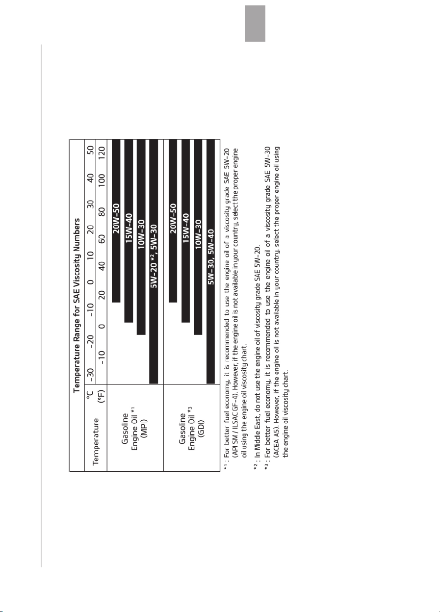
8-13
8
Specifications & Consumer informa‐
tion
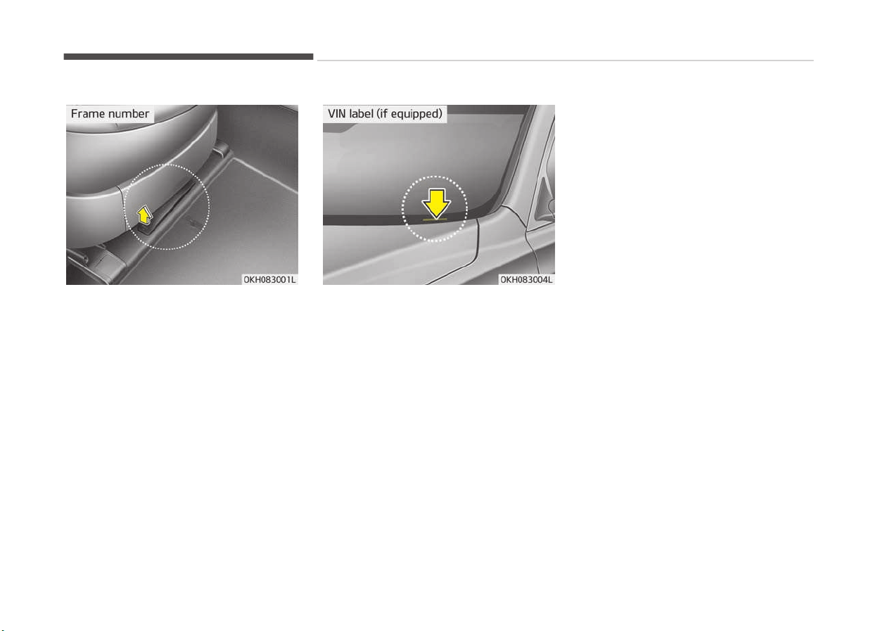
VEHICLE IDENTIFICATION NUMBER (VIN)
The vehicle identification number (VIN)
is the number used in registering your
car and in all legal matters pertaining
to its ownership, etc.
The VIN is also on a plate attached to
the top of the dashboard. The number
on the plate can easily be seen through
the windshield from outside.
Specifications & Consumer information
8-14
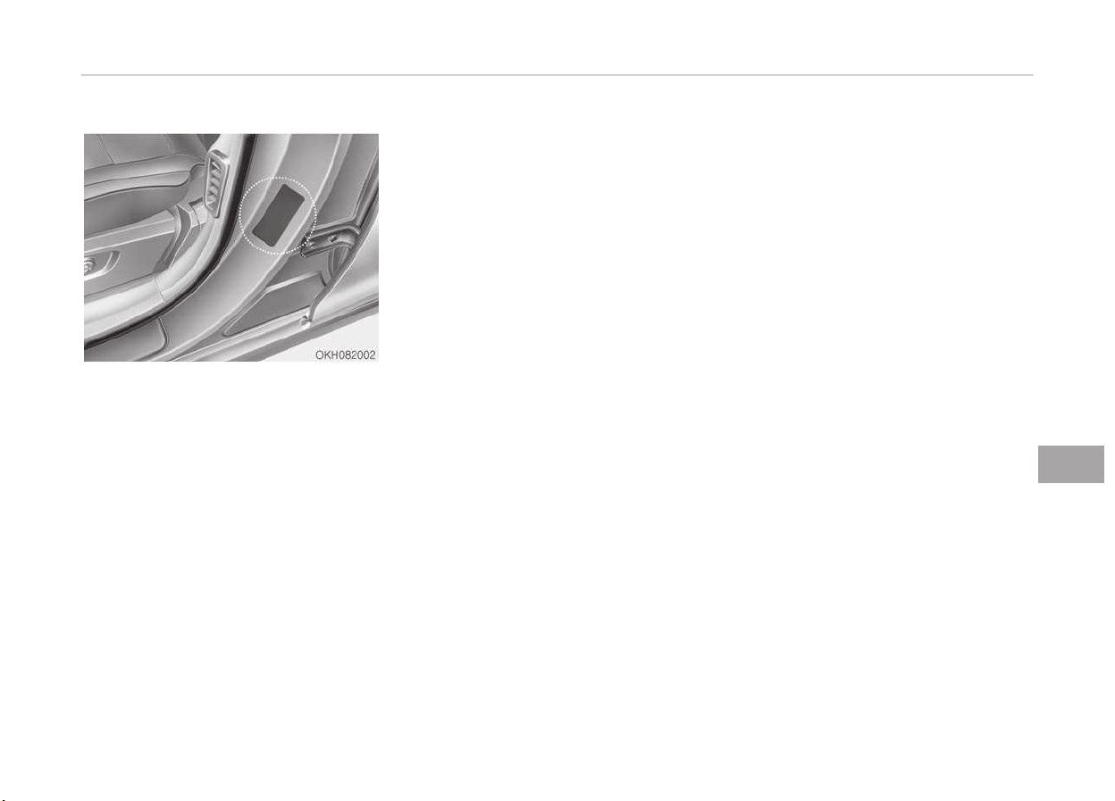
VEHICLE CERTIFICATION LABEL
The vehicle certification label attached
on the driver’s (or front passenger’s)
side center pillar gives the vehicle iden‐
tification number (VIN).
8-15
8
Specifications & Consumer informa‐
tion
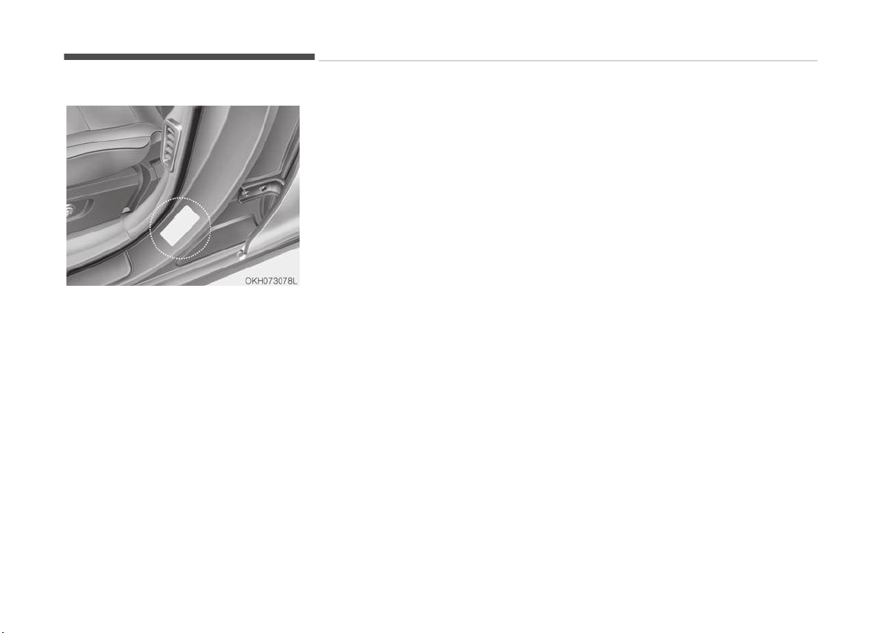
TIRE SPECIFICATION AND PRESSURE LABEL
The tires supplied on your new vehicle
are chosen to provide the best per‐
formance for normal driving.
The tire label located on the driver's
side center pillar gives the tire pres‐
sures recommended for your car.
Specifications & Consumer information
8-16
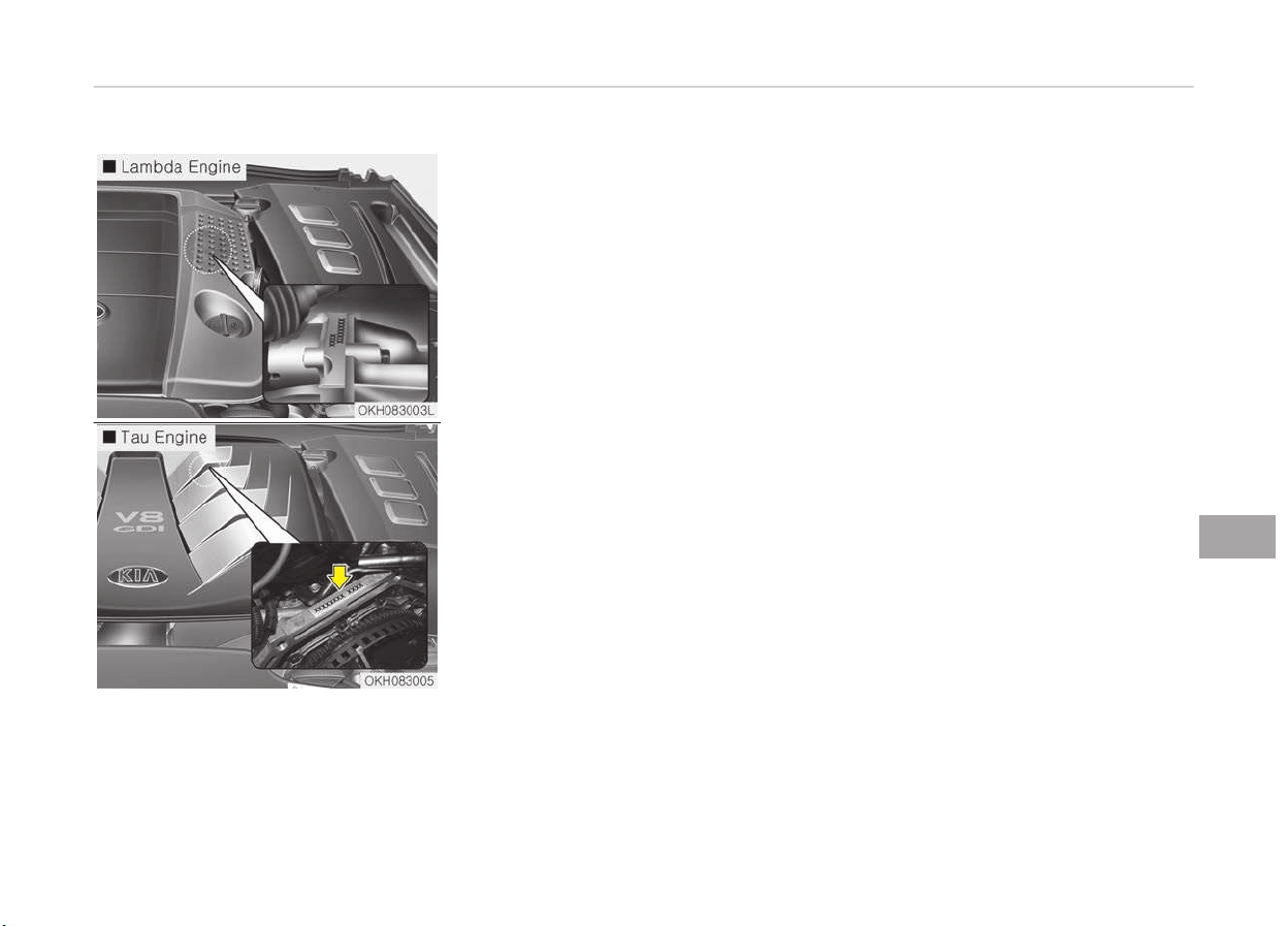
ENGINE NUMBER
The engine number is stamped on the
engine block as shown in the drawing.
8-17
8
Specifications & Consumer informa‐
tion
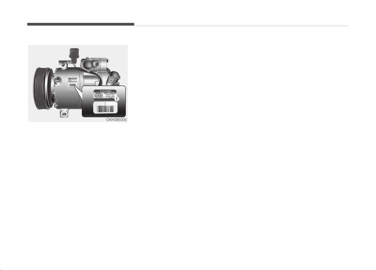
AIR CONDITIONER COMPRESSOR LABEL
A compressor label informs you the
type of compressor your vehicle is
equipped with such as model, supplier
part number, production number, and
refrigerant oil (1).
Specifications & Consumer information
8-18
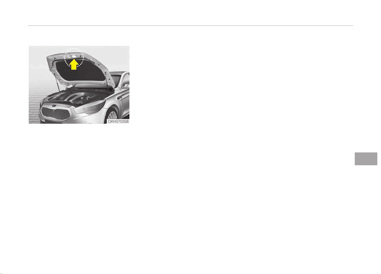
REFRIGERANT LABEL (IF EQUIPPED)
The refrigerant label is located on the
underside of the hood.
8-19
8
Specifications & Consumer informa‐
tion
DECLARATION OF CONFORMITY
The radio frequency components of the
vehicle comply with requirements and
other relevant provisions of Directive
1995/5/EC.
Further information including the man‐
ufacturer's declaration of conformity is
available on Kia web site as follows;
http://www.kia-hotline.com
Specifications & Consumer information
8-20

A
A/V mode..........................................................................4-58
Advanced smart cruise control system...................... 5-66
Limitations of the system........................................ 5-76
Speed setting.............................................................. 5-67
To convert to cruise control mode...........................5-75
Vehicle to vehicle distance setting...........................5-70
Advanced vehicle safety management (AVSM)......... 5-43
AEB Operation................................................................. 5-46
Air bag - Supplemental restraint system...................3-44
Air bag warning label......................................................3-64
Air bag warning light...................................................... 3-48
Air bags
Air bag inflation conditions....................................... 3-59
Air bag non-inflation conditions...............................3-60
Air bag warning label................................................. 3-64
Air bag warning light..................................................3-48
Curtain air bag.............................................................3-56
Driver's and passenger's front air bag....................3-51
How does the air bag system operate................... 3-45
Side air bag.................................................................. 3-54
SRS care....................................................................... 3-62
SRS components and functions............................... 3-48
Air cleaner........................................................................ 7-38
Filter replacement......................................................7-38
Air conditioner compressor label..................................8-18
Air c
onditioning system................................................. 8-06
Air ventilation seat....................................................... 4-145
Antenna..........................................................................4-154
Anti-lock brake system (ABS)...................................... 5-35
Appearance care............................................................. 7-83
Exterior care................................................................7-83
Interior care.................................................................7-87
ASCC mode....................................................................... 4-58
Ashtray...........................................................................4-140
Audio / Video / Navigation system (AVN).................4-152
AUTO HOLD...................................................................... 5-32
Automatic climate control system............................4-119
Automatic heating and air conditioning............... 4-120
Checking the amount of air conditioner re‐
frigerant and compressor lubricant.....................4-131
Climate control air filter..........................................4-130
Automatic heating and air conditioning....................4-120
Automatic transaxle
Shift-lock override......................................................5-14
Automatic transmission (shift by cable).................... 5-10
Automatic transmission (shift by wire)......................5-16
Automatic transmission operation..........................5-16
Good driving practices............................................... 5-23
Automatic transmission operation.............................. 5-16
Alphabetical index
I-1Alphabetical index

Automatic turn off function....................................... 4-114
Autonomous emergency braking (AEB)......................5-46
AEB Operation.............................................................5-46
Brake operation.......................................................... 5-47
Malfunction indicator................................................. 5-48
To cancel the AEB....................................................... 5-47
AUX and USB port.........................................................4-152
B
Bag hanger.....................................................................4-149
Battery............................................................................. 7-45
Battery replacement......................................................4-09
Battery saver function................................................ 4-105
Before driving.................................................................. 5-04
Before starting............................................................5-04
Before starting................................................................5-04
Blind spot detection system (BSD).............................. 5-80
BSD (Blind spot detection) / LCA (Lane
Change Assist)........................................................... 5-81
Non-operating condition........................................... 5-85
RCTA (Rear cross traffic alert).................................5-83
Bluetooth® wireless technology hands-free.......... 4-153
Bonnet: see "Hood".........................................................4-33
Brake fluid........................................................................ 7-35
Checking the brake fluid level...................................7-35
Brake operation...............................................................
5-47
Brake system.................................................................. 5-25
Anti-lock brake system (ABS).................................. 5-35
AUTO HOLD..................................................................5-32
Electric parking brake (EPB)..................................... 5-27
Electronic stability control (ESC)..............................5-37
Emergency braking.................................................... 5-31
Hill-start assist control (HAC).................................. 5-41
Power brakes.............................................................. 5-25
Bulb wattage................................................................... 8-04
Buttons on the smart key.............................................4-06
C
Capacities (Lubricants)...................................................8-10
Care of seat belts............................................................3-31
Care
SRS care....................................................................... 3-62
Tire care....................................................................... 7-49
Center console storage................................................4-137
Changing tires..................................................................6-15
Checking the amount of air conditioner refrig‐
erant and compressor lubricant................................4-131
Checking the brake fluid level....................................... 7-35
Checking the power steering fluid level...................... 7-36
Alphabetical index
I-2 Alphabetical index

Checking the power steering hose...............................7-36
Checking tire inflation pressure....................................7-50
Child restraint system..........................................3-33,3-36
Child-protector rear door lock......................................4-17
Cigarette lighter............................................................4-140
Climate control additional features...........................4-136
Cluster ionizer...........................................................4-136
Smart ventilation......................................................4-136
Climate control air filter.................................... 4-130,7-41
Clock................................................................................4-147
Closing the fuel filler lid..................................................4-35
Closing the hood..............................................................4-33
Closing the sunroof.........................................................4-39
Clothes hanger.............................................................. 4-147
Cluster ionizer............................................................... 4-136
Combined cluster: see "Instrument cluster"...............4-49
Conditions that limit active ECO mode........................5-51
Crankcase emission control system............................7-89
Cruise control system.................................................... 5-61
Cup holder...................................................................... 4-141
Curtain air bag.................................................................3-56
D
Dashboard: see "Instrument cluster".......................... 4-49
Daytime running light.................................................. 4-105
Declaration of conformity............................................. 8-20
Defogging (windshield)................................................ 4-132
Defogging logic..............................................................4-133
Defroster........................................................................4-118
Rear window defroster........................................... 4-118
Wiper deicer.............................................................. 4-118
Description....................................................................... 4-92
Dimensions.......................................................................8-02
Disarmed stage............................................................... 4-12
Displays: see "Instrument cluster"...............................4-49
Door courtesy lamp......................................................4-116
Door lock/unlock features............................................. 4-16
Door locks.........................................................................4-13
Child-protector rear door lock..................................4-17
Door lock/unlock features.........................................4-16
Operating door locks from outside the vehicle..... 4-13
Power door latch........................................................ 4-14
Drinks holder: see "Cup holder".................................. 4-141
Drive mode....................................................................... 4-81
Drive mode / Snow mode.............................................. 5-50
Alphabetical index
I-3Alphabetical index

DRIVE MODE Indicator Screen.......................................5-55
Drive mode integrated control system.......................5-50
Conditions that limit active ECO mode....................5-51
Drive mode / Snow mode.......................................... 5-50
DRIVE MODE Indicator Screen.................................. 5-55
ECO mode driving........................................................5-51
Driver information system (DIS)................................ 4-153
Driver position memory system
Driver position memory system.............................. 3-07
Driver's and passenger's front air bag........................ 3-51
Driving at night................................................................5-90
Driving in flooded areas................................................. 5-91
Driving in the rain............................................................5-91
Driving off-road.............................................................. 5-92
E
ECO mode driving............................................................5-51
Economical operation.....................................................5-87
ECS (electronic controlled suspension) mal‐
function warning message...........................................5-59
Electric parking brake (EPB)..........................................5-27
Electronic controlled suspension (ECS)....................... 5-58
ECS (electronic controlled suspension) mal‐
function warning message...................................... 5-59
To control the vehicle height.................................... 5-58
T
owing your vehicle....................................................5-60
Electronic Hydraulic Power Steering (EHPS)..............4-42
Electronic stability control (ESC).................................. 5-37
Emergency braking.........................................................5-31
Emergency fuel filler lid release................................... 4-37
Emergency starting........................................................6-05
Jump starting.............................................................. 6-05
Emergency towing..........................................................6-24
Emergency trunk safety release................................. 4-23
Emergency while driving................................................6-03
Emission control system............................................... 7-89
Crankcase emission control system........................7-89
Evaporative emission control system.....................7-89
Engine............................................................................... 8-03
Engine compartment............................................2-07,7-03
Engine coolant................................................................. 7-32
Changing the coolant................................................. 7-34
Engine coolant temperature gauge............................. 4-52
Engine number................................................................ 8-17
Engine oil.......................................................................... 7-30
Changing the engine oil and filter............................7-31
Engine start/stop button.............................................. 5-06
Engine start/stop button position...........................5-06
Illuminated engine start/stop button..................... 5-06
Alphabetical index
I-4 Alphabetical index

Starting the engine.................................................... 5-08
Engine will not start....................................................... 6-04
Evaporative emission control system......................... 7-89
Explanation of scheduled maintenance items........... 7-27
Exterior care.................................................................... 7-83
Exterior overview (Front).............................................. 2-02
Exterior overview (Rear)................................................2-03
F
Filter replacement.......................................................... 7-38
Floor mat anchor(s)......................................................4-148
Fluid
Washer fluid.................................................................7-37
Front blind spot monitoring system......................... 4-103
Front fog light............................................................... 4-109
Front lamp switch.........................................................4-114
Front seat adjustment...................................................3-05
Fuel economy.................................................................. 4-79
Fuel filler lid......................................................................4-35
Closing the fuel filler lid............................................. 4-35
Emergency fuel filler lid release...............................4-37
Opening the fuel filler lid........................................... 4-35
Fuel gauge........................................................................4-53
Fuel requirements...........................................................1-03
Fuse switch......................................................................
7-60
Fuse/relay panel description.........................................7-62
Fuses.................................................................................7-58
Fuse switch..................................................................7-60
Fuse/relay panel description.................................... 7-62
Instrument panel fuse..................................... 7-59,7-62
Multi fuse........................................................... 7-61,7-62
G
Gauges.............................................................................. 4-51
Glove box........................................................................4-138
Glove box lamp..............................................................4-116
Good driving practices....................................................5-23
H
Hazard warning flasher................................................. 6-02
Hazardous driving conditions........................................5-89
Head up display (HUD)....................................................4-92
Description...................................................................4-92
Head up display information.................................... 4-93
Head up display ON/OFF............................................4-93
Head up display setting.............................................4-93
Alphabetical index
I-5Alphabetical index

Head up display information.........................................4-93
Head up display ON/OFF................................................ 4-93
Head up display setting................................................. 4-93
Headlight........................................................................ 4-117
Headlight escort function............................................4-105
Headlight leveling device............................................. 4-110
Headlight position.........................................................4-108
Headlight washer..........................................................4-110
Headrest (for front seat).............................................. 3-09
Headrest (for rear seat)................................................ 3-18
Heated steering wheel...................................................4-43
High beam operation....................................................4-108
High mounted stop light replacement........................ 7-81
Highway driving...............................................................5-92
Hill-start assist control (HAC).......................................5-41
Hood.................................................................................. 4-33
Closing the hood......................................................... 4-33
Opening the hood....................................................... 4-33
Horn...................................................................................4-44
How to use this manual.................................................1-02
I
If the engine overheats..................................................6-08
If you have a flat tire......................................................6-14
Changing tires............................................................. 6-15
Jack and tools..............................................................6-14
Removing and storing the spare tire...................... 6-15
Illuminated engine start/stop button..........................5-06
Immobilizer system........................................................ 4-08
Indicator lights.................................................................4-88
Information mode...........................................................4-58
Inside rearview mirror....................................................4-45
Instrument cluster..........................................................4-49
Gauges..........................................................................4-51
Indicator lights............................................................ 4-88
Instrument cluster control........................................4-49
LCD display control.....................................................4-50
Trip computer..............................................................4-79
Trip modes................................................................... 4-79
Warning lights............................................................. 4-82
Warning messages..................................................... 4-68
Instrument panel fuse......................................... 7-59,7-62
Interior care..................................................................... 7-87
Interior features........................................................... 4-140
Air ventilation seat...................................................4-145
Ashtray...................................................................... 4-140
Bag hanger................................................................ 4-149
Cigarette lighter....................................................... 4-140
Clock............................................................................4-147
Alphabetical index
I-6 Alphabetical index

Clothes hanger..........................................................4-147
Cup holder..................................................................4-141
Floor mat anchor(s)................................................. 4-148
Luggage net (holder)............................................... 4-149
Power outlet............................................................. 4-142
Rear curtain...............................................................4-150
Rear mirror................................................................4-148
Seat warmer............................................................. 4-143
Side curtain................................................................4-151
Sunvisor..................................................................... 4-142
Interior light bulb replacement.....................................7-82
Interior light...................................................................4-117
Automatic turn off function...................................4-114
Door courtesy lamp................................................. 4-116
Front lamp switch.................................................... 4-114
Glove box lamp..........................................................4-116
Rear lamp switch......................................................4-115
Trunk room lamp......................................................4-115
Vanity mirror lamp...................................................4-116
Interior overview.............................................................2-04
J
Jack and tools.................................................................. 6-14
Jump starting.................................................................. 6-05
K
Keys
Record your key number...........................................4-04
L
Label
Air bag warning label.................................................
3-64
Air conditioner compressor label............................. 8-18
Refrigerant label.........................................................8-19
Tire sidewall labeling..................................................7-54
Tire specification and pressure label.......................8-16
Vehicle certification label.......................................... 8-15
Lap/shoulder belt............................................................3-23
LCD display.......................................................................4-56
A/V mode..................................................................... 4-58
ASCC mode...................................................................4-58
Indicator lights............................................................ 4-88
Information mode.......................................................4-58
LCD modes................................................................... 4-56
Trip computer..............................................................4-79
Trip computer mode.................................................. 4-57
Trip modes................................................................... 4-79
Turn by turn (TBT) mode.......................................... 4-58
User settings mode....................................................4-60
Warning lights............................................................. 4-82
Alphabetical index
I-7Alphabetical index

Warning messages..................................................... 4-68
LCD display control......................................................... 4-50
LCD modes....................................................................... 4-56
License plate light bulb replacement...........................7-81
Light bulbs........................................................................7-78
High mounted stop light replacement.................... 7-81
Interior light bulb replacement.................................7-82
License plate light bulb replacement...................... 7-81
Rear combination light bulb replacement.............. 7-80
Side repeater light bulb replacement......................7-80
Lighting...........................................................................4-105
Battery saver function............................................ 4-105
Daytime running light..............................................4-105
Front fog light...........................................................4-109
Headlight escort function....................................... 4-105
Headlight leveling device......................................... 4-110
Headlight position.................................................... 4-108
Headlight washer..................................................... 4-110
High beam operation............................................... 4-108
Parking light position............................................... 4-107
Rear fog light............................................................ 4-110
Traffic change (for Europe).................................... 4-105
Turn signals and lane change signals....................4-109
Limitations of the system.............................................5-76
Low tire pressure telltale.............................................. 6-10
Lubricants and capacities.............................................. 8-10
Luggage net (holder)....................................................4-149
M
Maintenance schedule....................................................
7-09
Maintenance services.....................................................7-05
Maintenance
Explanation of scheduled maintenance items.......7-27
Maintenance services................................................ 7-05
Scheduled maintenance service...............................7-09
Tire maintenance........................................................7-54
Malfunction indicator..................................................... 5-48
Map pocket.................................................................... 4-139
Mirrors.............................................................................. 4-45
Inside rearview mirror............................................... 4-45
Outside rearview mirror............................................4-45
Multi fuse............................................................... 7-61,7-62
Multimedia system.......................................................4-152
Antenna......................................................................4-154
Audio / Video / Navigation system (AVN).............4-152
AUX and USB port.................................................... 4-152
Bluetooth® wireless technology hands-free......4-153
Driver information system (DIS)............................4-153
Steering wheel audio control..................................4-155
Alphabetical index
I-8 Alphabetical index

N
Non-operating condition................................................5-85
Non-powered trunk........................................................4-18
O
Odometer......................................................................... 4-54
Oil (engine)....................................................................... 7-30
Opening the fuel filler lid................................................4-35
Opening the hood............................................................4-33
Opening the trunk with the alarm armed.................. 4-12
Operating door locks from outside the vehicle..........4-13
Operation of the parking assist system..................... 4-94
Outside rearview mirror................................................ 4-45
Outside temperature gauge..........................................4-54
P
Panorama sunroof..........................................................4-38
Closing the sunroof.................................................... 4-39
Resetting the sunroof............................................... 4-41
Sliding the sunroof..................................................... 4-39
Sunshade......................................................................4-41
Tilting the sunroof......................................................4-40
Panoramic sunroof
Sunroof open warning............................................... 4-38
Parallel parking..............................................................4-101
Parking assist system....................................................4-94
Operation of the parking assist system.................4-94
Self-diagnosis..............................................................4-98
Parking guide system.................................................. 4-100
Parallel parking......................................................... 4-101
Reverse parking (Back-in parking)........................ 4-100
Parking light position................................................... 4-107
Power brakes...................................................................5-25
Power door latch.............................................................4-14
Power outlet..................................................................4-142
Power steering fluid....................................................... 7-36
Checking the power steering fluid level..................7-36
Checking the power steering hose.......................... 7-36
Power trunk.....................................................................4-19
Power window lock button............................................4-31
Power windows...............................................................4-29
Pre-active seat belt (PSB)
Pre-active seat belt (PSB)........................................ 3-28
Pre-tensioner seat belt
Pre-tensioner seat belt.............................................3-26
Puddle lamp and door handle lamp........................... 4-117
Alphabetical index
I-9Alphabetical index

R
RCTA (Rear cross traffic alert)..................................... 5-83
Rear combination light bulb replacement...................7-80
Rear curtain...................................................................4-150
Rear fog light.................................................................4-110
Rear lamp switch.......................................................... 4-115
Rear mirror.................................................................... 4-148
Rear seat adjustment.................................................... 3-13
Rear seat storage.........................................................4-137
Rear window defroster................................................4-118
Rearview camera............................................................ 4-99
Recommended lubricants and capacities................... 8-10
Recommended SAE viscosity number.....................8-12
Record your key number...............................................4-04
Refrigerant label............................................................. 8-19
Removable towing hook................................................ 6-24
Removing and storing the spare tire...........................6-15
Resetting the sunroof....................................................4-41
Restrictions in handling keys........................................ 4-07
Reverse parking (Back-in parking)............................ 4-100
Road warning...................................................................6-02
Hazard warning flasher............................................. 6-02
Rocking the vehicle......................................................... 5-89
Rotation (Tir
e)................................................................. 7-51
S
Scheduled maintenance service................................... 7-09
Seat belt precautions..................................................... 3-29
Seat belt restraint system............................................3-21
Seat belt warning............................................................3-22
Seat belts......................................................................... 3-21
Lap/shoulder belt........................................................3-23
Seat belt precautions.................................................3-29
Seat belt restraint system....................................... 3-21
Seat belt warning....................................................... 3-22
Seat warmer..................................................................4-143
Seatback pocket............................................................4-139
Seats................................................................................. 3-02
Care of seat belts....................................................... 3-31
Front seat adjustment.............................................. 3-05
Headrest (for front seat).......................................... 3-09
Headrest (for rear seat)............................................3-18
Rear seat adjustment................................................3-13
Self-diagnosis..................................................................4-98
Shift-lock override - Automatic transaxle................. 5-14
Side air bag.......................................................................3-54
Alphabetical index
I-10 Alphabetical index

Side curtain....................................................................4-151
Side repeater light bulb replacement.......................... 7-80
Sliding the sunroof..........................................................4-39
Smart key.........................................................................4-04
Smart key function.........................................................4-04
Smart key precautions...................................................4-07
Smart trunk..................................................................... 4-25
Smart ventilation.......................................................... 4-136
Smooth cornering........................................................... 5-90
Snow tires........................................................................ 5-93
Special driving conditions...............................................5-89
Driving at night........................................................... 5-90
Driving in flooded areas.............................................5-91
Driving in the rain....................................................... 5-91
Driving off-road..........................................................5-92
Hazardous driving conditions................................... 5-89
Highway driving.......................................................... 5-92
Rocking the vehicle.....................................................5-89
Smooth cornering.......................................................5-90
Speed setting...................................................................5-67
Speedometer................................................................... 4-51
SRS care............................................................................3-62
SRS components and functions....................................3-48
Starting difficulties, see engine will not start............6-04
Starting the engine.........................................................5-08
Steering wheel.................................................................
4-42
Electronic Hydraulic Power Steering (EHPS)......... 4-42
Heated steering wheel.............................................. 4-43
Horn.............................................................................. 4-44
Tilt steering................................................................. 4-42
Steering wheel audio control......................................4-155
Storage compartment................................................. 4-137
Center console storage........................................... 4-137
Glove box................................................................... 4-138
Map pocket................................................................4-139
Rear seat storage.................................................... 4-137
Seatback pocket....................................................... 4-139
Sunglass holder.........................................................4-138
Sunglass holder.............................................................4-138
Sunroof open warning....................................................4-38
Sunshade.......................................................................... 4-41
Sunvisor..........................................................................4-142
Surround view monitoring system (SVM)................ 4-104
T
Tachometer......................................................................4-52
Theft-alarm system...................................................... 4-11
Tilt steering......................................................................4-42
Alphabetical index
I-11Alphabetical index

Tilting the sunroof..........................................................4-40
Tire care............................................................................7-49
Tire pressure monitoring system (TPMS).................. 6-09
Low tire pressure telltale.......................................... 6-10
TPMS (Tire pressure monitoring system)
malfunction indicator................................................6-12
Tire rotation.....................................................................7-51
Tire specification and pressure label........................... 8-16
Tires and wheels................................................... 7-49,8-07
Checking tire inflation pressure............................... 7-50
Low aspect ratio tire..................................................7-57
Tire care....................................................................... 7-49
Tire maintenance........................................................7-54
Tire replacement........................................................ 7-52
Tire rotation................................................................ 7-51
Tire sidewall labeling..................................................7-54
Tire traction.................................................................7-54
Wheel alignment and tire balance........................... 7-52
Wheel replacement.................................................... 7-53
To cancel the AEB........................................................... 5-47
To control the vehicle height.........................................5-58
To convert to cruise control mode...............................5-75
To defog inside windshield.......................................... 4-132
To defrost outside windshield.................................... 4-132
Towing...............................................................................6-22
Emergency towing..................................................... 6-24
Removable towing hook............................................
6-24
Towing service.............................................................6-22
Towing service................................................................. 6-22
Towing your vehicle........................................................ 5-60
TPMS (Tire pressure monitoring system) mal‐
function indicator...........................................................6-12
Traffic change (for Europe)........................................ 4-105
Trip A/B.............................................................................4-80
Trip computer..................................................................4-79
Drive mode...................................................................4-81
Fuel economy.............................................................. 4-79
Trip A/B.........................................................................4-80
Trip computer mode.......................................................4-57
Trip modes....................................................................... 4-79
Trunk................................................................................. 4-18
Emergency trunk safety release............................. 4-23
Non-powered trunk................................................... 4-18
Power trunk.................................................................4-19
Trunk room lamp.......................................................... 4-115
Turn by turn (TBT) mode.............................................. 4-58
Turn signals and lane change signals........................ 4-109
Alphabetical index
I-12 Alphabetical index

U
User settings mode........................................................ 4-60
Using a child restraint system......................................3-35
V
Vanity mirror lamp....................................................... 4-116
Vehicle break-in process................................................1-06
Vehicle certification label...............................................8-15
Vehicle identification number (VIN)............................. 8-14
Vehicle to vehicle distance setting...............................5-70
Vehicle weight..................................................................5-97
W
Warning lights..................................................................4-82
Warning messages......................................................... 4-68
Washer fluid.....................................................................7-37
Weight/volume................................................................ 8-09
Welcome system.......................................................... 4-117
Headlight....................................................................4-117
Interior light.............................................................. 4-117
Puddle lamp and door handle lamp.......................4-117
Wheel alignment and tire balance................................7-52
Wheel replacement.........................................................7-53
Windows...........................................................................
4-29
Power window lock button....................................... 4-31
Power windows...........................................................4-29
Windshield defrosting and defogging....................... 4-132
Defogging logic......................................................... 4-133
To defog inside windshield......................................4-132
To defrost outside windshield................................4-132
Windshield washers......................................................4-112
Windshield wipers.........................................................4-111
Winter driving.................................................................. 5-93
Snow tires....................................................................5-93
Wiper blades.................................................................... 7-42
Wiper deicer...................................................................4-118
Wipers and washers.....................................................4-111
Windshield washers................................................. 4-112
Windshield wipers.................................................... 4-111
Alphabetical index
I-13Alphabetical index