Loading ...
Loading ...
Loading ...
d. Connecttheneutralwireofthe
flexiblearmoredornonmetallic
sheathedcopperpowersupply
cabletothecentersilver-colored
terminalscrewoftheterminal
blockandconnecttheotherwires
totheouterterminals.SeeFigure
12.Forconnectingplain-end
fieldwire,seeFigure15.
Replacetheterminalblockcover.
ground screw
\
Neutral
Grounded neutral
Figure 12
DO NOT permit connection of"the
frame grounding conductor to the
neutral wire of the power supply
cord:
a. Remove terminal block cover.
b. Install U.L. approved strain relief"
(Figure 11) in one inch hole on
dryer back below terminal block
opening.
c. Install copper power supply
cable.
d. Remove the ground wire from the
green ground screw and f_sten
under center silver-colored
terminal block screw.
e. Connect the neutral wire of the
power supply cable to the center
silver-colored terminal of the
terminal block and connect the
other wires to the outer terminals.
See Figure 13. For connecting
plain-end wire see Figure 15.
e.
Green
ground
wire
Green Ground Green Conductor
Screw , Silver Terminal
Terminal Block
Ground
Wire
Connect ,,round wire
from externalground connector to
approved ground.
Ungrounded neutral
Figure 13
fi Connect a separate copper
ground wire (No. 10 minimum)
to a grounded cold water pipe*
by means of a clamp and then to
the frame of the appliance at the
green ground screw. Use Part
No. 685463 ground wire and
clamp assembly. Do not ground
to a gas supply pipe. Do not
connect the power supply cord
to electric power supply until
appliance is permanently
grounded.
g. Replace the terminal block
cover.
*Grounded cold water pipe must have
metal continuity to electrical ground and
not be interrupted by plastic, rubber or
other electrical insulating connectors
(such as hoses, fittings, washers or
gaskets, including water meter orpump).
Any electrical insulating connector
should bejumped as shown in Figure 9
with a length of" No. 4 wire securely
clamped to bare metal at both ends.
If connecting to a four-
wire electrical system
® (mobile home):
1. Remove the terminal block cover.
2. Install U.L. approved strain relief
(Figure 11) in one inch hole on duer
back below terminal block opening.
3, Install copper 4-wire power supply
cord.
Remove the ground wire from the
green ground screw and fasten
under center silver-colored terminal
block screw.
5. Connect the ground wire (green) of"
the copper 4-wire power supply cord
to the green ground screw.
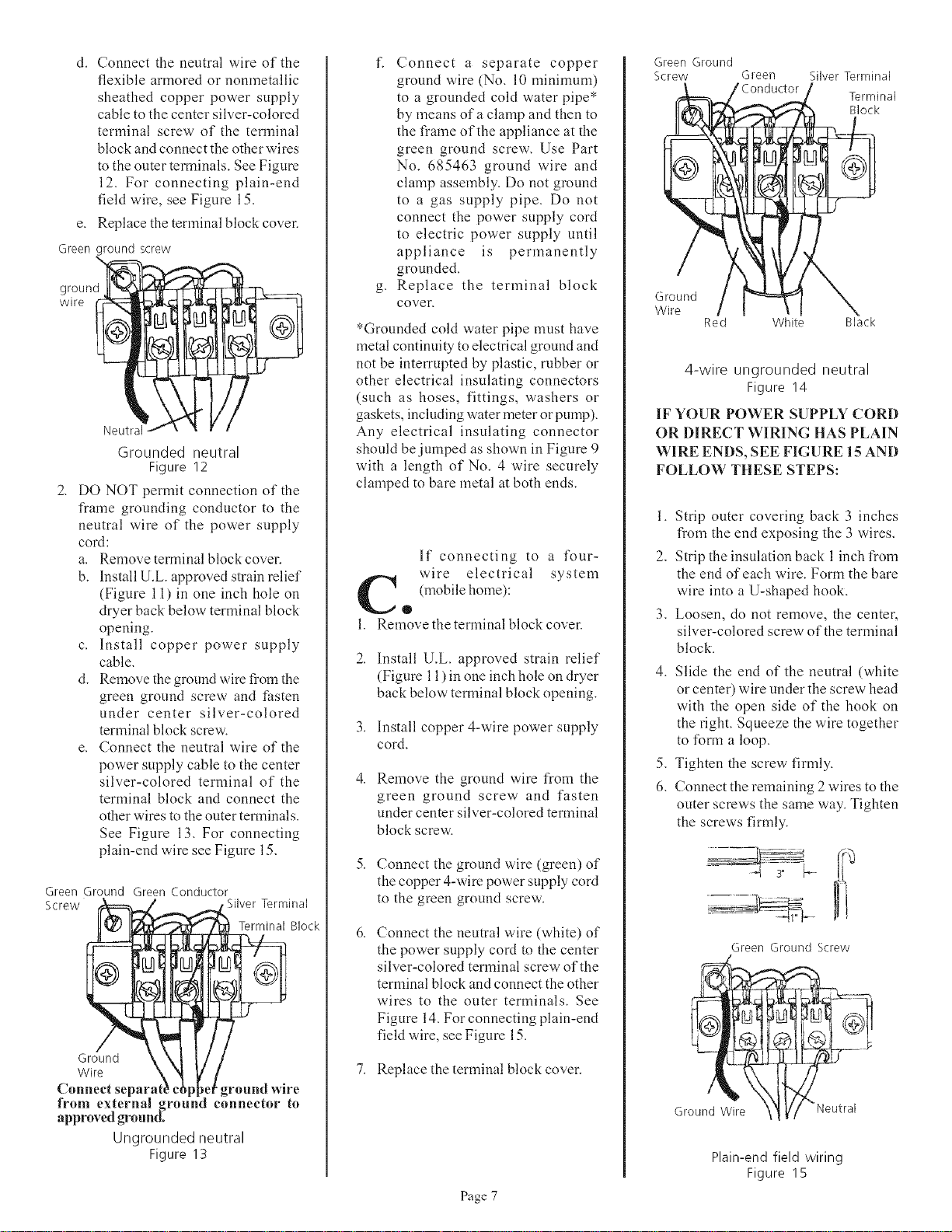
Connect the neutral wire (white) of
the power supply cord to the center
silver-colored terminal screw of the
terminal block and connect the other
wires to the outer terminals. See
Figure 14. For connecting plain-end
field wire, see Figure 15.
7, Replace the terminal block cover.
Page 7
Green Ground
Screw Green
€Conductor
Silver Terminal
Terminal
Block
Ground
Wire
Red White Black
4-wire ungrounded neutral
Figure 14
IF YOUR POWER SUPPLY CORD
OR DIRECT WIRING HAS PLAIN
WIRE ENDS, SEE FIGURE 15 AND
FOLLOW THESE STEPS:
1. Strip outer covering back 3 inches
from the end exposing the 3 wires.
2. Strip the insulation back 1 inch from
the end of each wire. Form the bare
wire into a U-shaped hook.
3. Loosen, do not remove, the center,
silver-colored screw of the terminal
block.
4. Slide the end of the neutral (white
or center) wire under the screw head
with the open side of"the hook on
the right. Squeeze the wire together
to form a loop.
5. Tighten the screw firmly.
6. Connect the remaining 2 wires to the
outer screws the same way. Tighten
the screws firmly.
)
Ground
Green Ground Screw
Wire "_ "Neutral
Plain-end field wiring
Figure 15
Loading ...
Loading ...
Loading ...