Loading ...
Loading ...
Loading ...
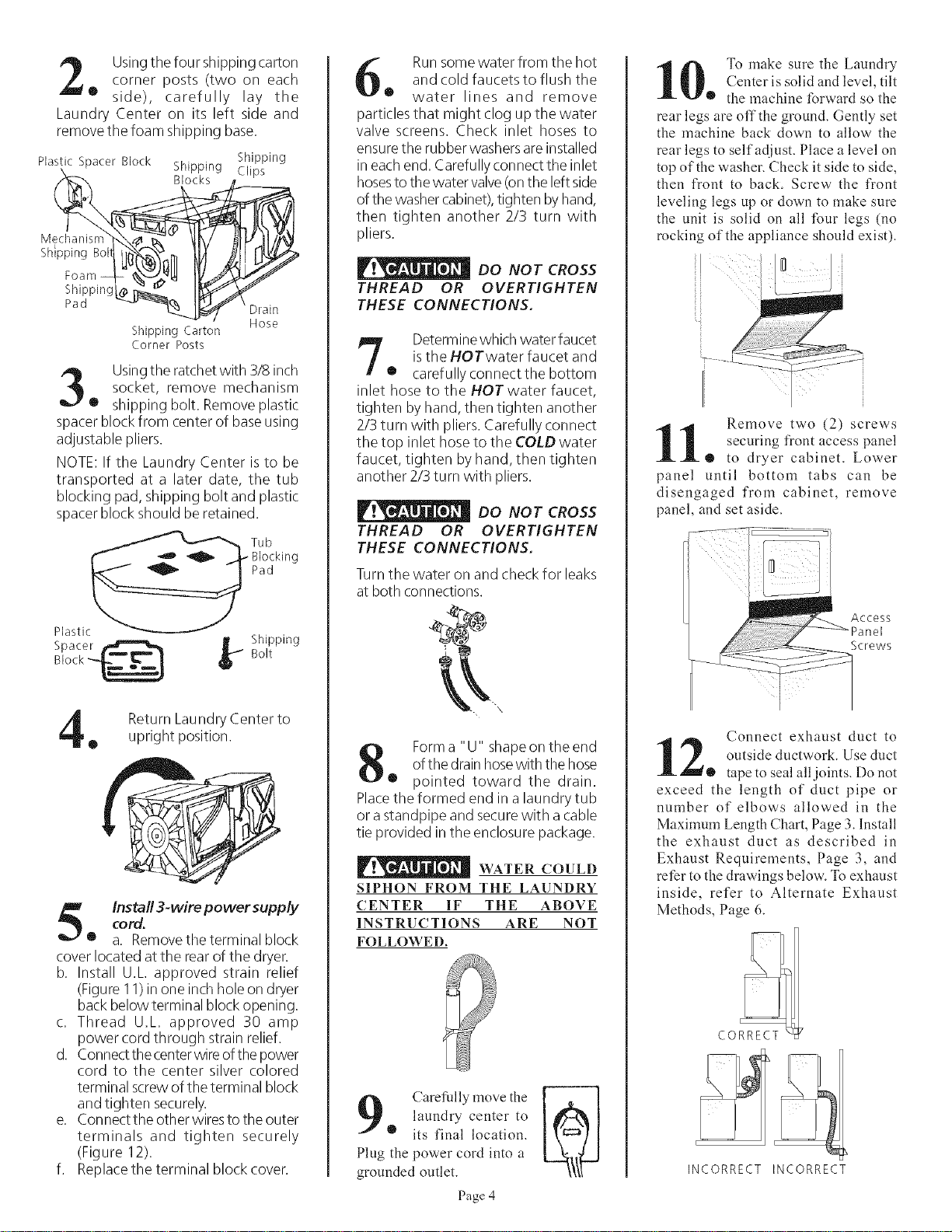
Usingthe four shipping cartoncorner posts (two on each
• side), carefully lay the
Laundry Center on its left side and
remove the foam shipping base.
Mechanisrn']_4_ _" _/
h,pping1
Shipping_g_ _
Pad _ __-'_
Shipping
Plastic Spacer Block Shipping Clips
Hose
Shipping Carton
Corner Posts
Usingtile ratchetwith 3/8 inch
socket, remove mechanism
• shipping bolt. Removeplastic
spacer block from center of baseusing
adjustable pliers.
NOTE: If the Laundry Center isto be
transported at a later date, the tub
blocking pad,shipping bolt and plastic
spacer block should be retained.
__"_"_ Tub
_ _ _ _BJocking
Plastic_
Spacer _ Shipping
Block-_ b B°lt
Return Laundry Center to
• upright position.
Install 3-wire power supply
cord.
® a. Removethe terminal block
cover located at the rear of the dryer.
b. Install U.L approved strain relief
(Figure11)in one inchhole on dryer
back below terminal block opening.
c. Thread U.L approved 30 amp
power cord through strain relief.
d. Connectthe centerwire ofthe power
cord to the center silver colored
terminal screwof the terminal block
and tighten securely.
e. Connectthe other wires to the outer
terminals and tighten securely
(Figure 12).
f. Replacethe terminal block cover.
Runsome water from tile hot
and cold faucets to flush the
• water lines and remove
particles that might clog up the water
valve screens. Check inlet hoses to
ensurethe rubber washersare installed
in eachend. Carefully connect the inlet
hosesto the water valve(onthe left side
of the washercabinet),tighten byhand,
then tighten another 2/3 turn with
pliers.
DO NOT CROSS
THREAD OR OVERTIGHTEN
THESE CONNECTIONS.
Determinewhich water faucet
istile HOTwater faucet and
® carefullyconnectthe bottom
inlet hose to the HOT water faucet,
tighten by hand, then tighten another
2/3 turn with pliers. Carefully connect
the top inlet hose to the COLD water
faucet, tighten byhand, then tighten
another 2/3 turn with pliers.
DO NOT CROSS
THREAD OR OVERTIGHTEN
THESE CONNECTIONS.
Turntile water on and check for leaks
at both connections.
__"X
Form a "U" shapeon the end
of the drainhosewith the hose
• pointed toward the drain.
Placethe formed end in a laundry tub
or astandpipe and securewith a cable
tie provided in the enclosure package.
WATER COIJLD
SIPHON FROM THE LAUNDRY
CENTER IF THE ABOVE
INSTRUCTIONS ARE NOT
FOLLOWED,
Carefully move the
laundry center to
• its final location.
Plug the power cord into a
grounded outlet.
Page 4
0 To make sure the Laundry
Center is solid and level, tilt
• the machine Ibrward so the
rear legs are offthe ground. Gently set
the machine back down to allow the
rear legs to self adjust. Place a level on
top of the washer. Check it side to side,
then front to back. Screw the front
leveling legs up or down to make sure
the unit is solid on all four legs (no
rocking of the appliance should exist).
i
1 Remove two (2) screws
securing front access panel
o to dryer cabinet. Lower
panel until bottom tabs can be
disengaged from cabinet, remove
panel, and set aside.
Access
Screws
Connect exhaust duct to
2 outside ductwork. Use duct
• tape to seal all.joints. Do not
exceed the length of duct pipe or
number of elbows allowed in the
Maximum Length Chart, Page 3. Install
the exhaust duct as described in
Exhaust Requirements, Page 3, and
refer to the drawings below. To exhaust
inside, refer to Alternate Exhaust
Methods, Page 6.
CORRECT
INCORRECT INCORRECT
Loading ...
Loading ...
Loading ...