
OOWWNNEERR''SS MMAANNUUAALL
OOppeerraattiioonn
MMaaiinntteennaannccee
S
Sppeecciiffiiccaattiioonnss
All information in this Owner's Manual is current at the time of publica-
tion. However, HYUNDAI reserves the right to make changes at any
time so that our policy of continual product improvement may be car-
ried out.
This manual applies to all models of this vehicle and includes descrip-
tions and explanations of optional as well as standard equipment.
As a result, you may find material in this manual that does not apply to
your specific vehicle.

F2
Your HYUNDAI should not be modified in any way. Such modifications may adversely affect
the performance, safety or durability of your HYUNDAI and may, in addition, violate condi-
tions of the limited warranties covering the vehicle. Certain modifications may also be in vio-
lation of regulations established by the Department of Transportation and other government
agencies in your country.
Your vehicle is equipped with electronic fuel injection and other electronic components. It is
possible for an improperly installed/adjusted two-way radio or cellular telephone to adversely
affect electronic systems. For this reason, we recommend that you carefully follow the radio
manufacturer's instructions or consult your HYUNDAI dealer for precautionary measures or
special instructions if you choose to install one of these devices.
CAUTION: MODIFICATIONS TO YOUR HYUNDAI
TWO-WAY RADIO OR CELLULAR TELEPHONE INSTALLATION
F3
This manual includes information titled as DANGER, WARNING, CAUTION and NOTICE.
These titles indicate the following:
SAFETY AND VEHICLE DAMAGE WARNING
DANGER indicates a hazardous situa-
tion which, if not avoided, will result
in death or serious injury.
DANGER
WARNING indicates a hazardous situ-
ation which, if not avoided, could
result in death or serious injury.
CAUTION indicates a hazardous situa-
tion which, if not avoided, could result
in minor or moderate injury.
CAUTION
NOTICE indicates a situation which, if
not avoided, could result in vehicle
damage.
NOTICE
WARNING

F4
FOREWORD
Thank you for choosing HYUNDAI. We are pleased to welcome you to the growing number of discriminating people who
drive HYUNDAI. The advanced engineering and high-quality construction of each HYUNDAI we build is something of
which we're very proud.
Your Owner's Manual will introduce you to the features and operation of your new HYUNDAI. It is suggested that you read
it carefully because the information it contains can contribute greatly to the satisfaction you receive from your new vehi-
cle.
The manufacturer also recommends that service and maintenance on your vehicle be performed by an authorized
HYUNDAI dealer.
HYUNDAI MOTOR COMPANY
Note : Because future owners will also need the information included in this manual, if you sell this HYUNDAI, please
leave the manual in the vehicle for their use. Thank you.
Copyright 2015 HYUNDAI Motor Company. All rights reserved. No part of this publication may be reproduced, stored
in any retrieval system or transmitted in any form or by any means without the prior written permission of HYUNDAI
Motor Company.
Severe engine and transmission damage may result from the use of poor quality fuels and lubricants that
do not meet HYUNDAI specifications. You must always use high quality fuels and lubricants that meet the
specifications listed on Page 8-6 in the Vehicle Specifications section of the Owner's Manual.
CAUTION
We want to help you get the greatest
possible driving pleasure from your
vehicle. Your Owner’s Manual can
assist you in many ways. We strong-
ly recommend that you read the
entire manual. In order to minimize
the chance of death or injury, you
must read the WARNING and CAU-
TION sections in the manual.
Illustrations complement the words
in this manual to best explain how to
enjoy your vehicle. By reading your
manual, you will learn about fea-
tures, important safety information,
and driving tips under various road
conditions.
The general layout of the manual is
provided in the Table of Contents.
Use the index when looking for a
specific area or subject; it has an
alphabetical listing of all information
in your manual.
Sections: This manual has eight
chapters plus an index. Each section
begins with a brief list of contents so
you can tell at a glance if that section
has the information you want.
Your safety, and the safety of others,
is very important. This Owner's
Manual provides you with many safe-
ty precautions and operating proce-
dures. This information alerts you to
potential hazards that may hurt you
or others, as well as damage to your
vehicle.
Safety messages found on vehicle
labels and in this manual describe
these hazards and what to do to
avoid or reduce the risks.
Warnings and instructions contained
in this manual are for your safety.
Failure to follow safety warnings and
instructions can lead to serious injury
or death.
Throughout this manual DANGER,
WARNING, CAUTION, NOTICE and
the SAFETY ALERT SYMBOL will
be used.
This is the safety alert sym-
bol. It is used to alert you to
potential physical injury haz-
ards. Obey all safety mes-
sages that follow this symbol
to avoid possible injury or
death. The safety alert sym-
bol precedes the signal words
DANGER, WARNING and
CAUTION.
HHOOWW TTOO UUSSEE TTHHIISS MMAANNUUAALL
F5
Introduction
DANGER indicates a hazardous
situation which, if not avoided,
will result in death or serious
injury.
DANGER
WARNING indicates a hazardous
situation which, if not avoided,
could result in death or serious
injury.
WARNING
NOTICE indicates a situation
which, if not avoided, could result
in vehicle damage.
Diesel engine
Diesel fuel
Diesel engine must be operated only
on commercially available diesel fuel
that complies with EN 590 or compa-
rable standard. (EN stands for
"European Norm"). Do not use
marine diesel fuel, heating oils, or
non-approved fuel additives, as this
will increase wear and cause dam-
age to the engine and fuel system.
The use of non-approved fuels and /
or fuel additives will result in a limita-
tion of your warranty rights.
Diesel fuel of above cetane 51 is
used in your vehicle. If two types of
diesel fuel are available, use summer
or winter fuel properly according to
the following temperature conditions.
• Above -5°C(23°F) ... Summer type
diesel fuel.
• Below -5°C(23°F) ... Winter type
diesel fuel.
Watch the fuel level in the tank very
carefully : If the engine stops through
fuel failure, the circuits must be com-
pletely purged to permit restarting.
NOTICE
F6
Introduction
CAUTION indicates a hazardous
situation which, if not avoided,
could result in minor or moder-
ate injury.
CAUTION
• Do not let any gasoline or
water enter the tank. This
would make it necessary to
drain it out and to bleed the
lines to avoid jamming the
injection pump and damaging
the engine.
• In winter, in order to cut down
incidents due to freezing,
paraffin oil may be added to
the fuel if the temperature
drops to below -10°C (14°F).
Never use more than 20%
paraffin oil.
CAUTION
FFUUEELL RREEQQUUIIRREEMMEENNTTSS

Biodiesel
Commercially supplied Diesel blends
of no more than 7% biodiesel, com-
monly known as "B7 Diesel" may be
used in your vehicle if Biodiesel
meets EN 14214 or equivalent spec-
ifications. (EN stands for "European
Norm"). The use of biofuels exceed-
ing 7% made from rapeseed methyl
ester (RME), fatty acid methyl ester
(FAME), vegetable oil methyl ester
(VME) etc. or mixing diesel exceed-
ing 7% with biodiesel will cause
increased wear or damage to the
engine and fuel system. Repair or
replacement of worn or damaged
components due to the use of non
approved fuels will not be covered by
the manufactures warranty.
F7
Introduction
•
Never use any fuel, whether
diesel, B7 biodiesel or other-
wise, that fails to meet the lat-
est petroleum industry specifi-
cation.
• Never use any fuel additives
or treatments that are not rec-
ommended or approved by the
vehicle manufacturer.
CAUTION
It is recommended to use the
regulated automotive diesel
fuel for diesel vehicle equipped
with the DPF system.
If you use diesel fuel including
high sulfur (more than 50 ppm
sulfur) and unspecified addi-
tives, it can cause the DPF sys-
tem to be damaged and white
smoke can be emitted.
CAUTION

F8
Introduction
As with other vehicles of this type,
failure to operate this vehicle correct-
ly may result in loss of control, an
accident or vehicle rollover.
Specific design characteristics (high-
er ground clearance, track, etc.) give
this vehicle a higher center of gravity
than other types of vehicles. In other
words they are not designed for cor-
nering at the same speeds as con-
ventional 2-wheel drive vehicles.
Avoid sharp turns or abrupt maneu-
vers. Again, failure to operate this
vehicle correctly may result in loss of
control, an accident or vehicle
rollover. Be sure to read the
"Reducing the risk of a rollover"
driving guidelines, in section 5 of
this manual.
No special break-in period is need-
ed. By following a few simple precau-
tions for the first 1,000 km (600
miles) you may add to the perform-
ance, economy and life of your vehi-
cle.
• Do not race the engine.
• While driving, keep your engine
speed (rpm, or revolutions per
minute) between 2,000 rpm and
4,000 rpm.
• Do not maintain a single speed for
long periods of time, either fast or
slow. Varying engine speed is
needed to properly break-in the
engine.
• Avoid hard stops, except in emer-
gencies, to allow the brakes to seat
properly.
• Don't tow a trailer during the first
2,000 km (1,200 miles) of opera-
tion.
HYUNDAI promotes an environmen-
tally sound treatment of end of life
vehicles and offers to take back your
Hyundai end of life vehicles in accor-
dance with the European Union (EU)
End of Life Vehicles Directive.
You can get the detailed information
from your national HYUNDAI home
page.
VVEEHHIICCLLEE HHAANNDDLLIINNGG
IINNSSTTRRUUCCTTIIOONNSS
VVEEHHIICCLLEE BBRREEAAKK--IINN PPRROOCCEESSSS RREETTUURRNNIINNGG UUSSEEDD VVEEHHIICCLLEESS
((FFOORR EEUURROOPPEE))

F9
1
2
3
4
5
6
7
8
I
Your vehicle at a glance
Safety system of your vehicle
Convenient features of your vehicle
Multimedia System
Driving your vehicle
What to do in an emergency
Maintenance
Specifications & Consumer information
Index
TABLE OF CONTENTS

Your vehicle at a glance
1
Your vehicle at a glance
1
Exterior overview (I) .............................................1-2
Exterior overview (II) ............................................1-3
Exterior overview (III) ...........................................1-4
Exterior overview (IV)...........................................1-5
Exterior overview (V)............................................1-6
Exterior overview (VI)...........................................1-7
Interior overview (Left side)................................1-8
Interior overview (Right side)..............................1-9
Engine compartment ...........................................1-10
1-2
Your vehicle at a glance
E
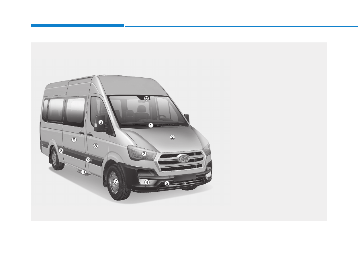
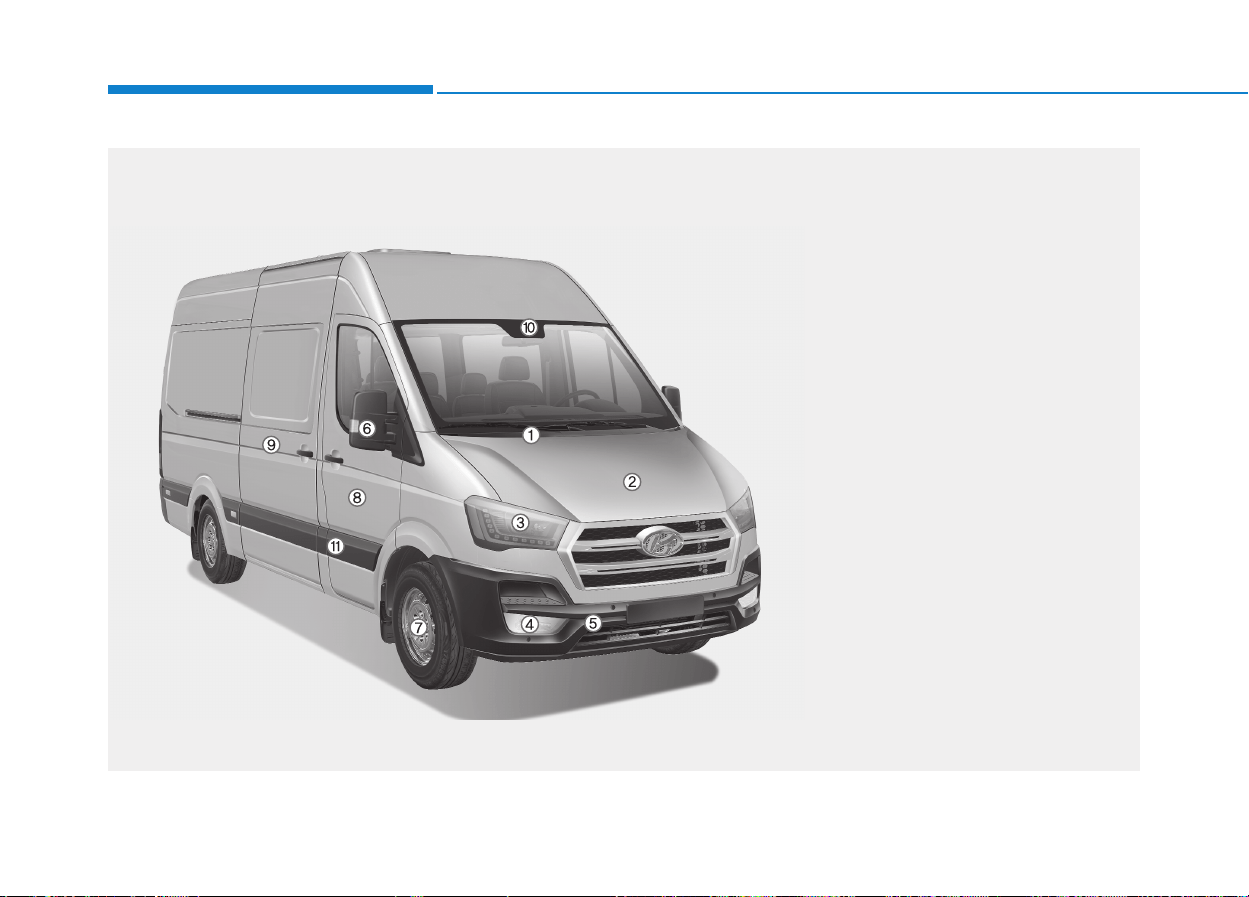
EXXTTEERRIIOORR OOVVEERRVVIIEEWW ((II))
OEU014001
The actual shape may differ from the illustration.
1. Front windshield wiper blades ...........7-34
2. Hood ..................................................3-30
3. Headlamp ..........................................7-68
4. Front fog light.....................................7-68
5. Towing hook.......................................6-19
6. Outside rearview mirror.....................3-41
7. Tires and wheels ...............................7-42
8. Front door ..........................................3-11
9. Mid sliding door .................................3-15
10. Urea solution filler lid .......................3-34
11. Electrical step ..................................3-17
12. Camera............................................5-37
13. Side marker light .............................7-75
■
■
Front view (BUS)
1-3
Your vehicle at a glance
1
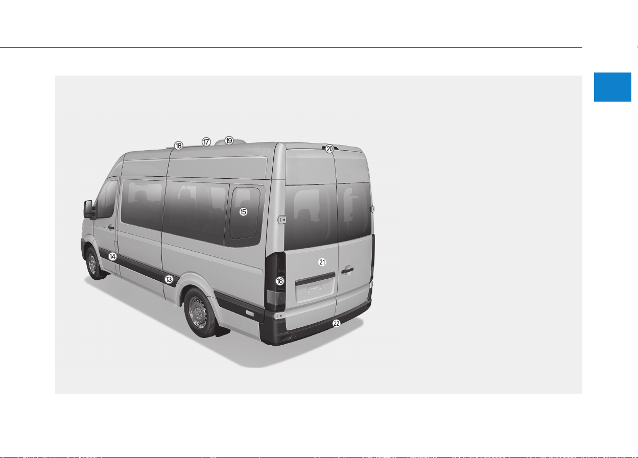
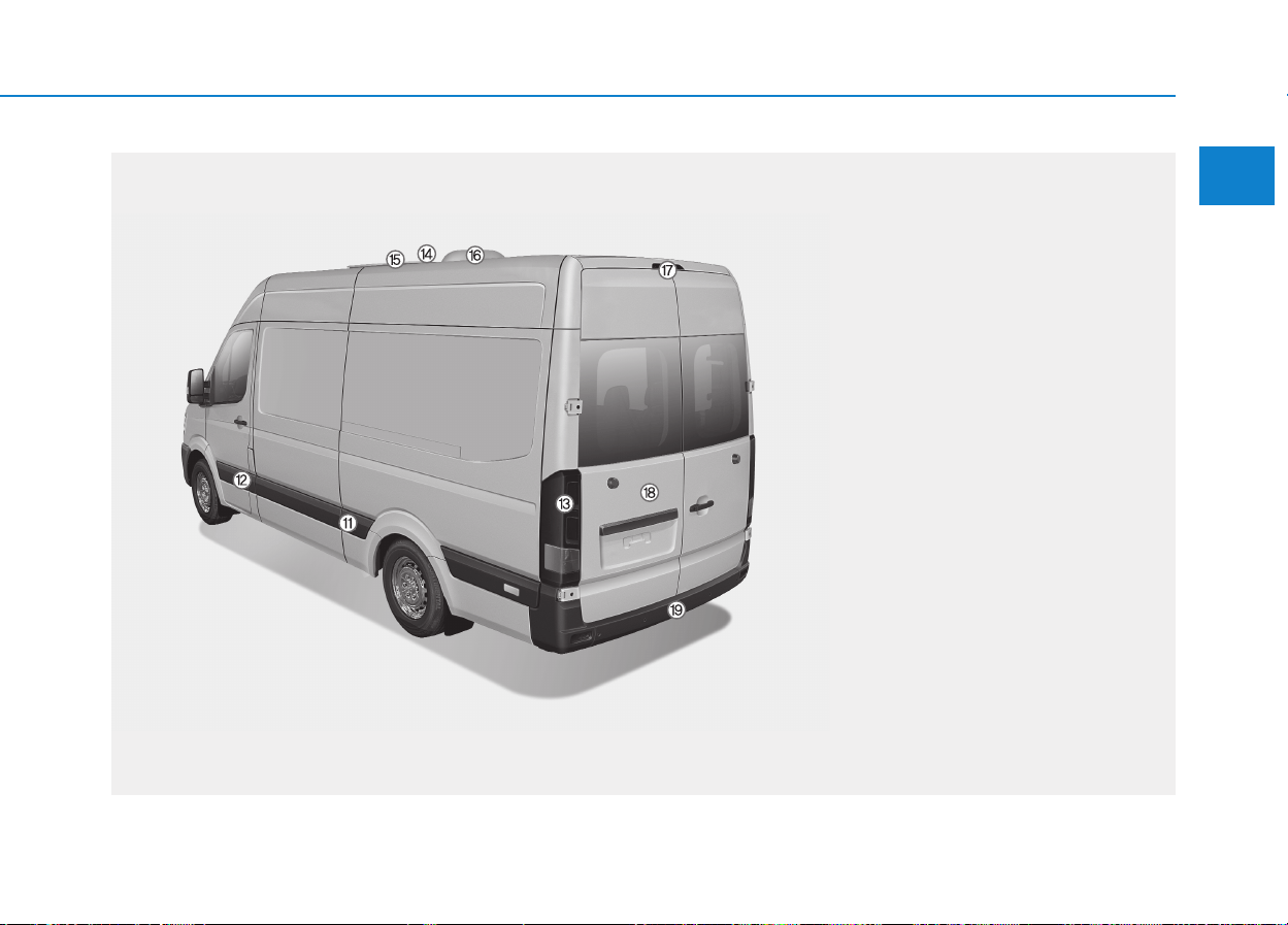
EEXXTTEERRIIOORR OOVVEERRVVIIEEWW ((IIII))
OEU014002
The actual shape may differ from the illustration.
14. Fuel filler lid .....................................3-32
15. Swivel glass.....................................3-29
16. Rear combination light.....................7-75
17. Antenna .............................................4-2
18. Emergence exit................................6-23
19. Ceiling ventilator ............................3-122
20. High mounted stop light ..................7-78
21. Rear doors.......................................3-22
22. Spare tire .........................................6-10
■
■
Rear view (BUS)
1-4
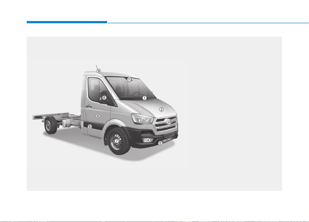
EEXXTTEERRIIOORR OOVVEERRVVIIEEWW ((IIIIII))
Your vehicle at a glance
OEU014007
The actual shape may differ from the illustration.
1. Front windshield wiper blades ...........7-34
2. Hood ..................................................3-30
3. Headlamp ..........................................7-68
4. Front fog light.....................................7-68
5. Towing hook.......................................6-19
6. Outside rearview mirror.....................3-41
7. Tires and wheels ...............................7-42
8. Front door ..........................................3-11
9. Mid sliding door .................................3-15
10. Camera............................................5-37
11. Side marker light .............................7-75
■■
Front view (VAN)
1-5
Your vehicle at a glance
EEXXTTEERRIIOORR OOVVEERRVVIIEEWW ((IIVV))
1
OEU014008
The actual shape may differ from the illustration.
12. Fuel filler lid .....................................3-32
13. Rear combination light.....................7-75
14. Antenna .............................................4-2
15. Emergence exit................................6-23
16. Ceiling ventilator ............................3-122
17. High mounted stop light ..................7-78
18. Rear doors.......................................3-22
19. Spare tire .........................................6-10
■■
Rear view (VAN)
1-6
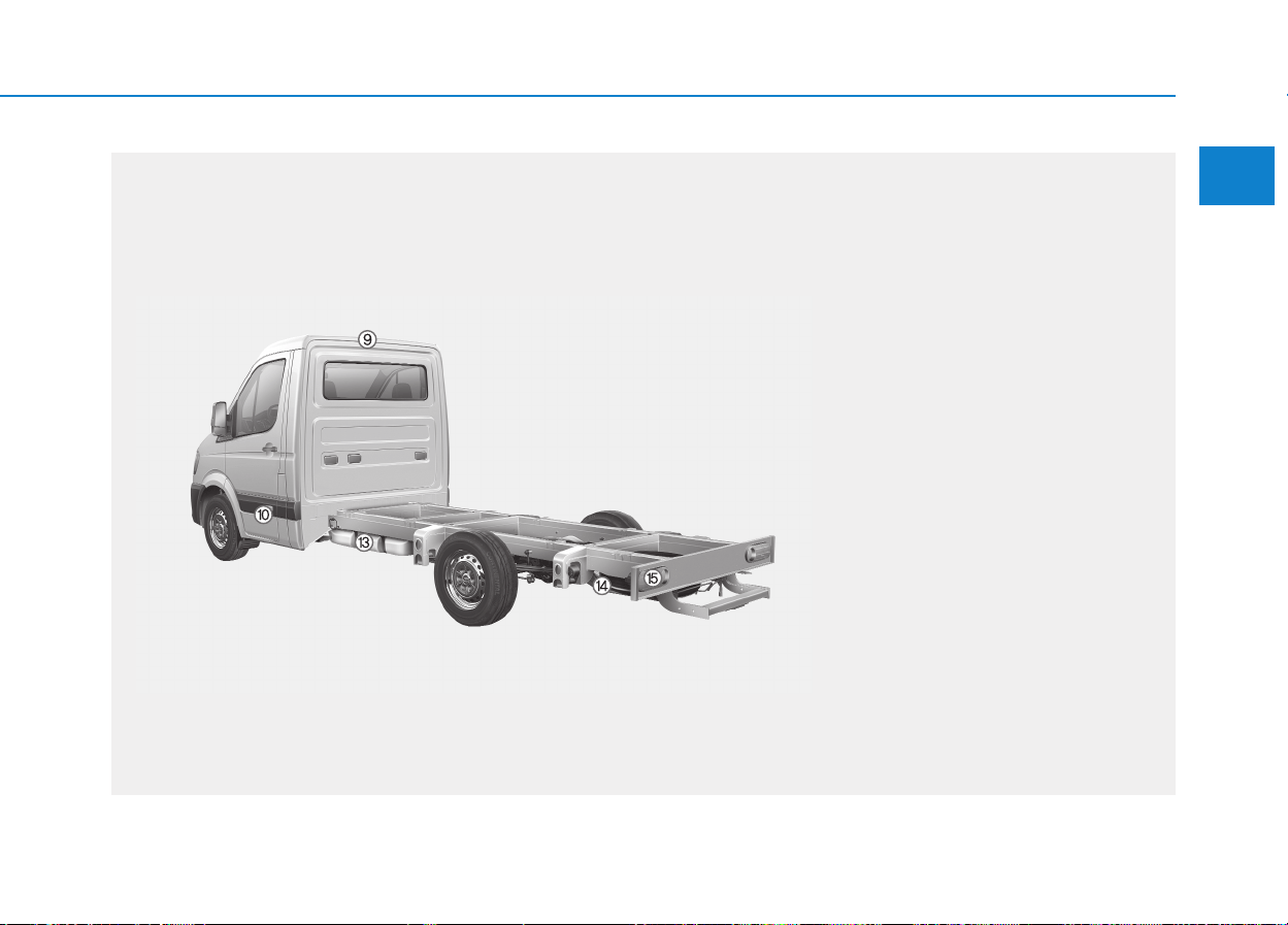
EEXXTTEERRIIOORR OOVVEERRVVIIEEWW ((VV))
Your vehicle at a glance
OEU014011
The actual shape may differ from the illustration.
1. Front windshield wiper blades ...........7-34
2. Hood ..................................................3-30
3. Headlamp ..........................................7-68
4. Front fog light.....................................7-68
5. Towing hook.......................................6-19
6. Outside rearview mirror.....................3-41
7. Tires and wheels ...............................7-42
8. Front door ..........................................3-11
9. Antenna ...............................................4-2
10. Side marker light .............................7-75
11. Camera............................................5-37
12. Urea soultion filler lid .......................3-34
■■
Front view (Truck)
1-7
Your vehicle at a glance
EEXXTTEERRIIOORR OOVVEERRVVIIEEWW ((VVII))
1
OEU014009
The actual shape may differ from the illustration.
13. Fuel filler lid .....................................3-32
14. Spare tire .........................................6-10
15. Rear combination light.....................7-75
■■
Rear view (Truck)
1-8
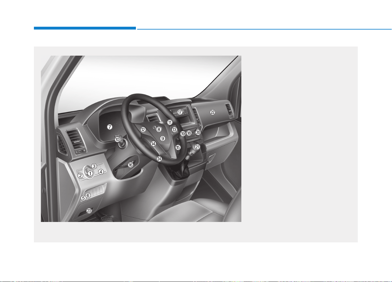
IINNTTEERRIIOORR OOVVEERRVVIIEEWW ((LLEEFFTT SSIIDDEE))
Your vehicle at a glance
1. Light control switch ..................................3-96
2. Front/Rear fog light switch .....................3-100
3. Head lamp leveling device switch ..........3-101
4.Instrument cluster illumination adjusting
switch........................................................3-44
5. ECO roll switch*.......................................5-40
6. VDC off switch* ........................................5-24
7. Instrument cluster ....................................3-43
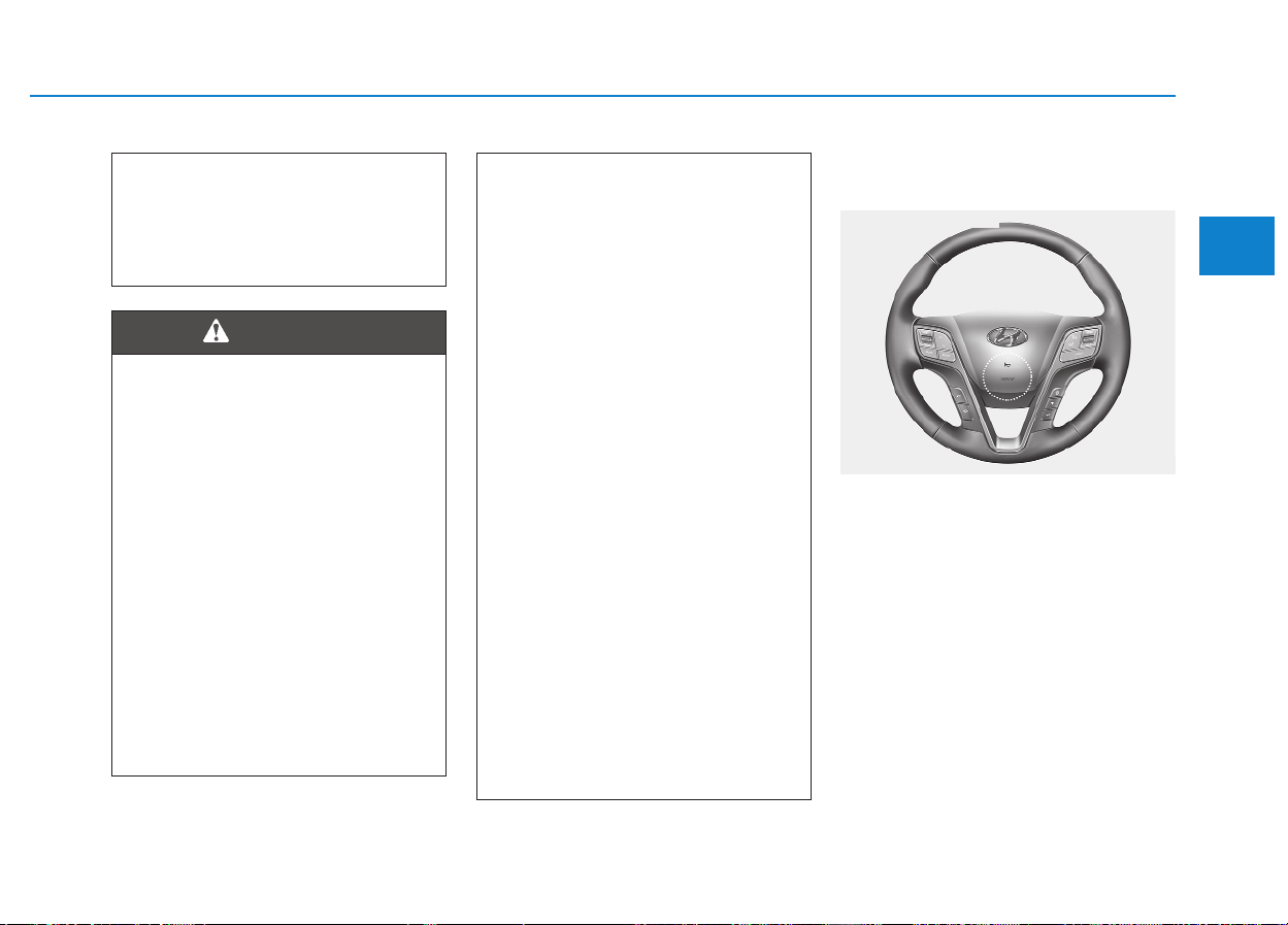
8. Horn .........................................................3-38
9. Driver's air bag* .......................................2-30
10. Turn signals/Passing switch ...................3-99
11. Wiper/Washer switch ...........................3-102
12. Steering wheel audio controls* ................4-3
13. Auto cruise controls*..............................5-31
14. Hands free controls* .......Refer to the audio
system in chaper 4
15. MDP (Multi Display) controls* .......................
Refer to the audio system in chaper 4
16. Steering column tilt & telescopic lock*...3-38
17. Audio .......................................................4-2
18. Climate control system* .......................3-110
19. Driver's seat warmer* .............................2-9
20. Front passenger's right hand seat
warmer*....................................................2-9
21. Manual transmission lever .....................5-14
22. Passenger's air bag*..............................2-30
23. Fuse box ................................................7-50
24. Steering wheel .......................................3-37
* : if equipped
OEU014003
The actual shape may differ from the illustration.

1-9
Your vehicle at a glance
IINNTTEERRIIOORR OOVVEERRVVIIEEWW ((RRIIGGHHTT SSIIDDEE))
1
1. Remote mirror controls* .......................3-41
2. Heated outside rear view mirror switch* /
Door lock switch ...........................3-41/3-12
3. Power window switches* ......................3-27
4. Ignition switch .........................................5-5
5. Passenger heat controls* ...................3-116
6. Electric step control* (Bus)...................3-17
7. Door lock control* .................................3-13
8. Door unlock control* ............................3-13
9. Hazard warning flasher switch .............3-95
10. LDWS switch* .....................................5-37
11. Idle Stop and Go system OFF switch* .5-8
12. Parking assist system ON/OFF switch* .3-89
13. PTO switch*(VAN, Truck)....................5-41
14. Cigarette lighter*...............................3-126
15. AUX, USB* ...........................................4-2
16. Power outlet* ....................................3-128
17. Cup holder ........................................3-127
18. Glove box..........................................3-125
19. Hood release lever .............................3-30
20. Clutch pedal
21. Brake pedal
22. Accelerator pedal
23. Parking brake lever.............................5-19
24. Ventilator switch* ..............................3-123
25. Room lamp switch (BUS) .................3-108
Cargo lamp switch (VAN)
Dumy switch (Trucks)
26. Sunglass holder* ..............................3-125
27. Interior mirror......................................3-39
28. Sunvisor............................................3-128
* : if equipped
OEU014004
The actual shape may differ from the illustration.
1-10
Your vehicle at a glance
E
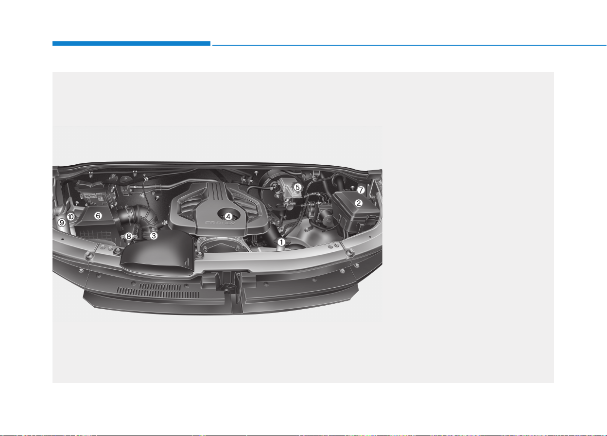
ENNGGIINNEE CCOOMMPPAARRTTMMEENNTT
1. Engine coolant reservoir....................7-28
2. Fuse box and positive battery
terminal ......................................7-52/6-4
3. Engine oil dipstick..............................7-22
4. Engine oil filler cap ............................7-23
5. Brake/clutch fluid cap ........................7-27
6. Air cleaner ........................................7-31
7. Negative battery terminal ....................6-4
8. Radiator cap ......................................7-26
9. Windshield washer fluid reservoir......7-29
10. Power steering fluid reservoir..........7-28
OEU014005
The actual shape may differ from the illustration.
■
■
Bus, Van, Truck (without auxiliary battery)
1-11
Your vehicle at a glance
1
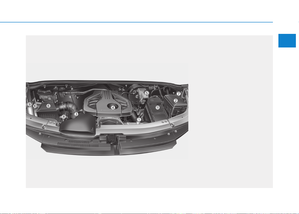
OEU014006
The actual shape may differ from the illustration.
■
■
Van, Truck (with auxiliary battery)
1. Engine coolant reservoir....................7-25
2. Fuse box and positive battery
terminal ......................................7-52/6-4
3. Engine oil dipstick..............................7-22
4. Engine oil filler cap ............................7-23
5. Brake/clutch fluid cap ........................7-27
6. Air cleaner ........................................7-31
7. Negative battery terminal ....................6-4
8. Radiator cap ......................................7-26
9. Windshield washer fluid reservoir......7-29
10. Power steering fluid reservoir..........7-28
11. Auxiliary battery ..............................7-37

Safety system of your vehicle
2
Important safety precautions...............................2-2
Always wear your seat belt............................................2-2
Air bag hazards..................................................................2-2
Driver's distraction............................................................2-2
Control your speed ...........................................................2-3
Keep your vehicle in safe conditions...........................2-3
Seats ........................................................................2-4
Safety precautions............................................................2-4
Front passenger's seats ..................................................2-5
Rear seats ........................................................................2-12
Passenger seat capacity label .....................................2-13
Seat belts .............................................................2-13
Seat belt restraint system ...........................................2-13
Lap/shoulder belt (for front passengers) ................2-16
2 point static belt (for rear passengers)...................2-18
Seat belt precautions.....................................................2-22
Air bag
- supplemental restraint system.....................2-25
How does the air bag operate? ..................................2-26
Do not install a child restraint on the front
passenger seat.................................................................2-27
Air bag warning light......................................................2-28
SRS components and functions ..................................2-29
Driver's and front passenger's air bag ....................2-31
SRS care ............................................................................2-39
Additional safety precautions......................................2-40
Air bag warning labels...................................................2-42
This chapter provides you with important information about how to protect yourself and your passengers.
It also explains how to properly use your seats, seat belts, and air bags.
Additionally, this chapter explains how to properly restrain infants and children in your vehicle.

2-2
You will read many safety precautions
and recommendations throughout
this chapter, and throughout this man-
ual. The safety precautions in this
chapter are among the most impor-
tant.
Always wear your seat belt
A seatbelt is the best protection in all
types of accidents. An air bag is
designed to supplement a seatbelt,
not replace it. So even though your
vehicle is equipped with air bag,
ALWAYS make sure you and your
passengers wear seatbelts in a prop-
er manner.
Restrain all children
All children under age 13 should ride
in your vehicle properly restrained in
a rear seat, not the front seat. Infants
and small children should be
restrained in an appropriate child
restraint. Larger children should use
a booster seat with the lap/shoulder
belt until they can use the seat belt
properly without a booster seat.
❇ The age requirements about the
child detrainment differ in each
country.
Air bag hazards
While air bags can save lives, they
can also cause serious or fatal
injuries to passengers, who sit too
close to them, or who are not prop-
erly restrained. Infants, young chil-
dren, and small adults are at the
greatest risk of being injured by an
inflating air bag. Follow all instruc-
tions and warnings in this manual.
Driver's distraction
Driver distraction presents a serious
and potentially deadly danger, espe-
cially for inexperienced drivers. Safety
should be the first concern, while driv-
ing. Drivers need to be aware of the
wide array of potential distractions,
such as drowsiness, reaching for
objects, eating, personal grooming,
other passengers, and using cellular
phones.
Drivers can become distracted when
they take their eyes and attention off
the road or their hands off the wheel,
caring for other activities to focus on
activities other than driving. To
reduce your risk of distraction and an
accident, follow the below instruc-
tions:
• ALWAYS use your mobile devices
(i.e., MP3 players, phones, naviga-
tion units, etc.), only when your vehi-
cle is safely parked or safely
stopped.
IIMMPPOORRTTAANNTT SSAAFFEETTYY PPRREECCAAUUTTIIOONNSS
Safety system of your vehicle

2-3
Safety system of your vehicle
• ONLY use your mobile device when
laws and conditions permit its safe
usage. NEVER text or email while
driving. Most countries have laws
prohibiting drivers from texting.
Some countries and cities also pro-
hibit drivers from using handheld
phones.
• NEVER distract yourself by using a
mobile device, while driving. You
have a responsibility to safely drive
for your passengers and others on
the road, with your hands on the
wheel as well as your eyes and
attention on the road.
Control your speed
Excessive speed is a major cause of
injuries and deaths. Generally, the
higher the speed, the greater the
risk. However, serious injuries may
also occur at lower speeds. Never
drive faster than it is safe to do so in
accordance with a road condition,
regardless of the maximum speed
limit.
Keep your vehicle in safe condi-
tions
A flat tire or a mechanical failure may
be extremely hazardous.To reduce the
possibility of such hazards, check your
tire pressures, and perform the mainte-
nance on a regular basis.
2

2-4
Safety system of your vehicle
S
SEEAATTSS
Safety precautions
Adjust your seat, so that you can sit in
a safe, comfortable position. It plays
an important role in protecting the
driver and passengers, together with
the seat belts and air bags in an acci-
dent.
Air bag
You can take steps to reduce the risk
of being injured by an inflating air
bag. Sitting too close to an air bag
greatly increases the risk of injury, as
the event the air bag inflates. Move
your seat as far back as possible
from front air bags, while still main-
taining control of the vehicle.
Seat belts
Always fasten your seat belt before
starting the vehicle.
At all times, passengers should sit
upright and be properly restrained.
Infants and small children must be
restrained in an appropriate child
restraint system. Children who out-
grow a booster seat and adults must
fasten their seat belts.
Do not use a cushion that
reduces friction between the
seat and the passenger. The
passenger's hips may slide
under the lap portion of the seat
belt during an accident or a
sudden stop. Serious or fatal
internal injuries may result
because the seat belt cannot
properly operate.
WARNING
To reduce the risk of serious
injury or death from an inflating
air bag, take the following pre-
cautions:
• Adjust the driver’s seat in the
rearmost position, while main-
taining the ability to fully con-
trol the vehicle.
• Hold the steering wheel with
both hands at the 9 o’clock
and 3 o’clock positions to
minimize the risk of injuries to
your hands and arms.
• NEVER place anything or any-
one on the air bags.
WARNING
Take the following precautions
to adjust your seat belt:
• NEVER use one seat belt to
fasten more than one occu-
pant.
• Always sit in an upright posi-
tion with the lap portion of the
seat belt snug and low across
the hips.
• NEVER allow children or
small infants to ride on a pas-
senger's laps.
(Continued)
WARNING

2-5
Safety system of your vehicle
2
Front passenger's seats
The front seat can be adjusted by
operating the control switches locat-
ed on the side of a seat cushion.
Before driving, adjust the seat to the
proper position so that you can easi-
ly reach the steering wheel, foot ped-
als and controls on the instrument
cluster.
Take the following precautions
while adjusting your seat:
• NEVER attempt to adjust the
seat when the vehicle is
motion.
The seat may inadvertently
move and may cause loss of
vehicle control, resulting in an
accident.
• Do not place anything under
the front seats. Loose objects
in the driver's foot area may
interfere with the pedal opera-
tion, causing an accident.
(Continued)
WARNING
(Continued)
• Do not fasten the seat belt
across your neck or over a
sharp edge. Always tightly
fasten the shoulder strap over
your body.
• Be careful that a seat belt
does not become caught or
jammed.
(Continued)
• Do not allow anything to inter-
fere with proper sitting and
proper locking of the seat-
back.
• Do not place a cigarette
lighter on the floor or seat.
When you operate the seat,
gas may leak, causing a fire.
• When occupants sit in the
rear seats, be careful not to
injure them, while adjusting
your seat position.
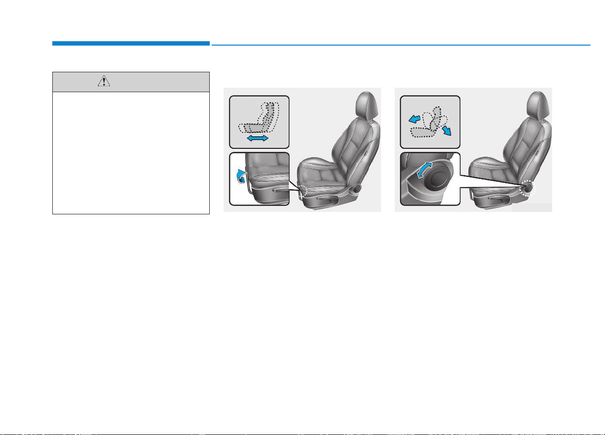
2-6
Safety system of your vehicle
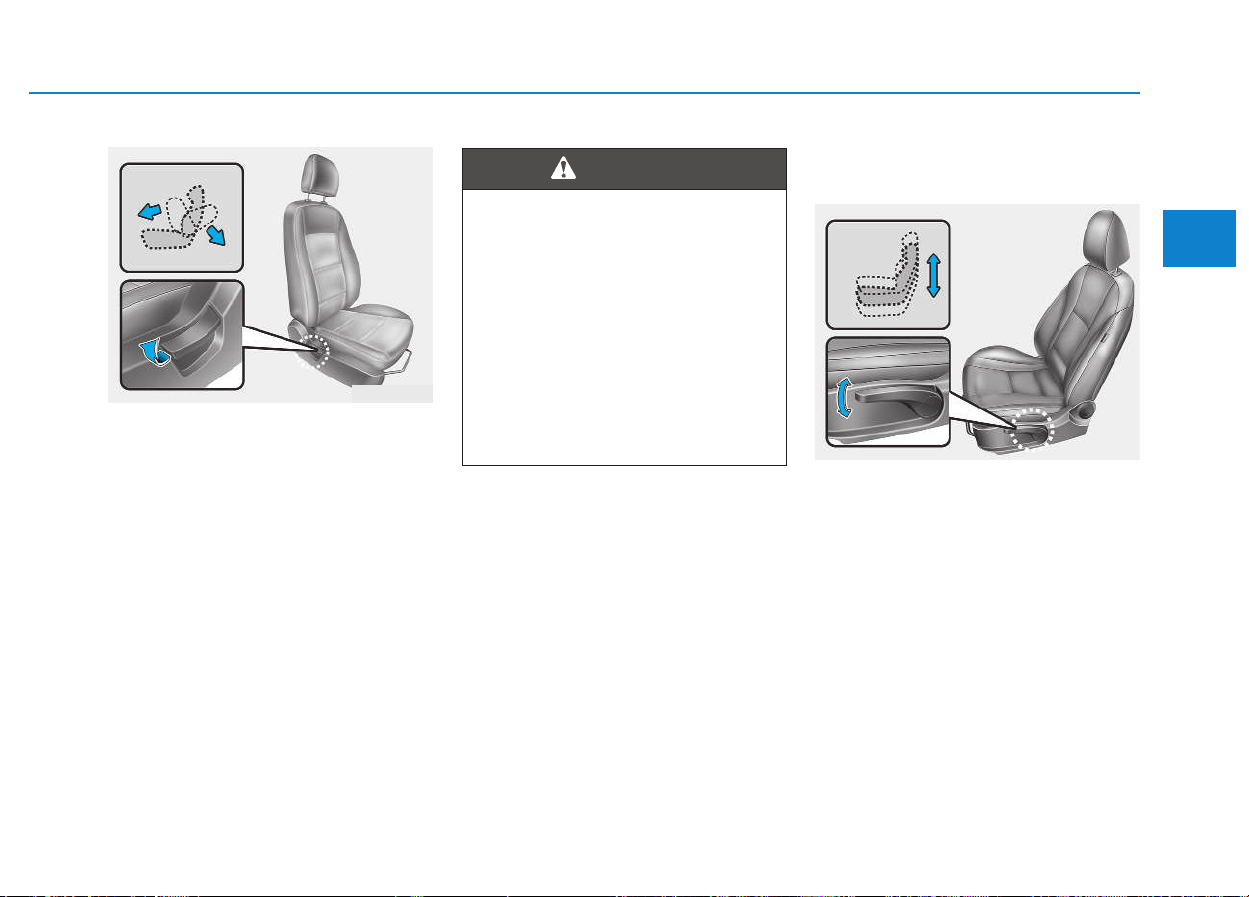
Forward and backward
To move the seat forward or back-
wards:
1.Pull up the seat adjustment lever
up and hold it.
2.Slide the seat to the desired posi-
tion.
3.Release the lever and make sure
the seat is locked in place.
Adjust the seat before driving, and
make sure the seat is securely
locked by attempting to move for-
ward and backwards without pulling
the lever. If the seat moves, it is not
securely locked.
Adjusting the seatback recliner
Driver's seat / Front passenger's
seat (if equipped)
To recline the seatback to the
desired angle, rotate the knob either
in the clockwise or in the counter-
clockwise direction.
To prevent injury:
• Do not adjust your seat while
wearing your seat belt.
Moving the seat cushion for-
ward may cause strong pres-
sure on your abdomen.
• Be careful that your hands or
fingers do not get caught in
the seat mechanisms, while
adjusting your seat.
CAUTION
OEU034036
OEU034035
2-7
Safety system of your vehicle
2
Front passenger's seat
To recline the seatback: (if equipped)
1.Slightly lean forward and pull up
the seatback lever.
2.Carefully lean back on the seat and
adjust the seatback angle to the
desired position.
3.Release the lever and make sure
the seatback is securely locked in
place. (The lever must return to its
original position to lock the seat-
back in place.)
Seat cushion height
(for driver's seat, if equipped)
1.To change the height of the seat
cushion, pull up the lever or pull it
down.
2.Release the lever, when the seat is
adjusted to the desired position.
OEU034026
NEVER sit in a reclined seat,
when the vehicle is in motion.
A reclined seatback increases
your risk of being seriously or
fatally injured in the event of a
collision or a sudden stop.
Drivers and passengers should
ALWAYS maintain a good sitting
posture – well back in the seat,
properly fastened, and straight
upright.
WARNING
OEU034034
2-8
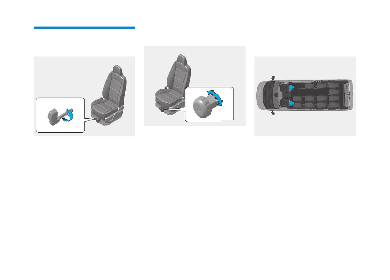
Adjusting the seat cushion
Suspension Fixing (if equipped)
The suspension is fixed by turning
the lever.
Spring Suspension (if equipped)
The driver can change the speed of
up-and-down motion to be suitable
for their weight by turning the knob.
Head restraint
The driver's and front passenger's
seats are equipped with a head
restraint for their safety and comfort.
The head restraint not only provides
comfort for the driver and front pas-
sengers, but also protects the head
and neck in the event of a collision.
Safety system of your vehicle
OEU034038
OEU034039
OEU034027
2-9
Safety system of your vehicle
2
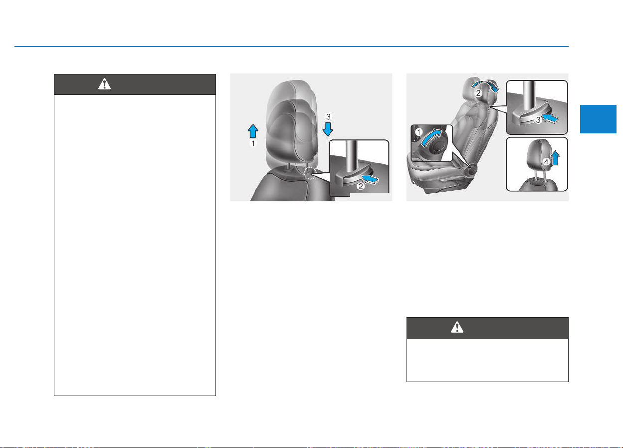
Adjusting the height up and down
To raise the head restraint, pull it up
to the desired height (1). To lower the
head restraint, hold the release but-
ton (2) on the head restraint support
and lower it down to the desired
height (3).
Removal
To remove the head restraint:
1.Recline the seatback (2) by pulling
up the seatback lever (1).
2.Raise up the head restraint to the
highest.
3.Press and hold the head restraint
release button (3) while pulling the
head restraint up (4).
• For maximum effects in case
of an accident, the head
restraint should be adjusted
so the middle of the head
restraint is at the same height
of the center of gravity of an
occupant's head. Generally,
the center of gravity of most
people's head is at the height
of the top of their eyes. Also,
adjust the Head restraint as
close to your head as possi-
ble. For this reason, the use of
a cushion that holds the body
away from the seat back is not
recommended.
• Do not operate the vehicle,
when any head restraint is
removed. Severe injury may
occur in the event of an acci-
dent. Head restraints may pro-
vide protection against neck
injuries, when they are prop-
erly adjusted.
• Do not adjust the head
restraint of the driver's seat,
when the vehicle is in motion.
WARNING
OEU034033 OEU034032
NEVER allow anyone to ride in a
seat with the head restraint
removed.
WARNING
2-10
Safety system of your vehicle
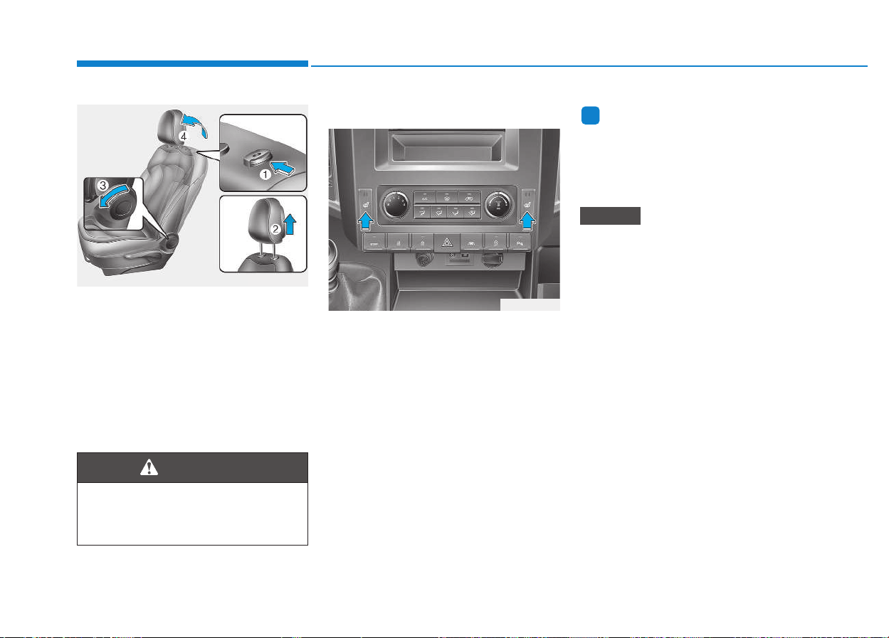
Reinstall
To reinstall the head restraint:
1.Put the head restraint poles (2) into
the holes while pressing the
release button (1).
2.Recline the seatback (4) by pulling
up the seatback lever (3).
3.Adjust the head restraint to the
desired height.
Seat warmer (if equipped)
The seat warmer is equipped to
warm the front seats during cold
weather.
With the ignition switch in the ON
position, push either of the switches
to warm the driver's seat or the front
passenger's seat.
In the mild weather or under condi-
tions where the operation of the seat
warmer is unnecessary, keep the
switches in the "OFF" position.
Information
Even with the seat warmer switch in
the ON position, the seat warmer
automatically turns ON and OFF
depending on the seat temperature.
• Do not use an organic solvent
such as thinner, benzene, alco-
hol and gasoline to clean the
seat. Doing so may damage the
surface of the heater or seats.
• To prevent the seat warmer from
being overheated, do not place
anything on the seats that
blocks the thermal emission,
such as blankets, cushions or
seat covers, when the seat
warmer is in operation.
• Do not place heavy or sharp
objects on the seats equipped
with seat warmers. Damage to
the seat warming components
may occur.
• Do not change the seat cover. It
may damage the seat warmer or
the air ventilation system.
NOTICE
i
OEU034031
Always make sure the head
restraint is locked into position
after reinstalling or adjusting it.
WARNING
OEU034025
2-11
Safety system of your vehicle
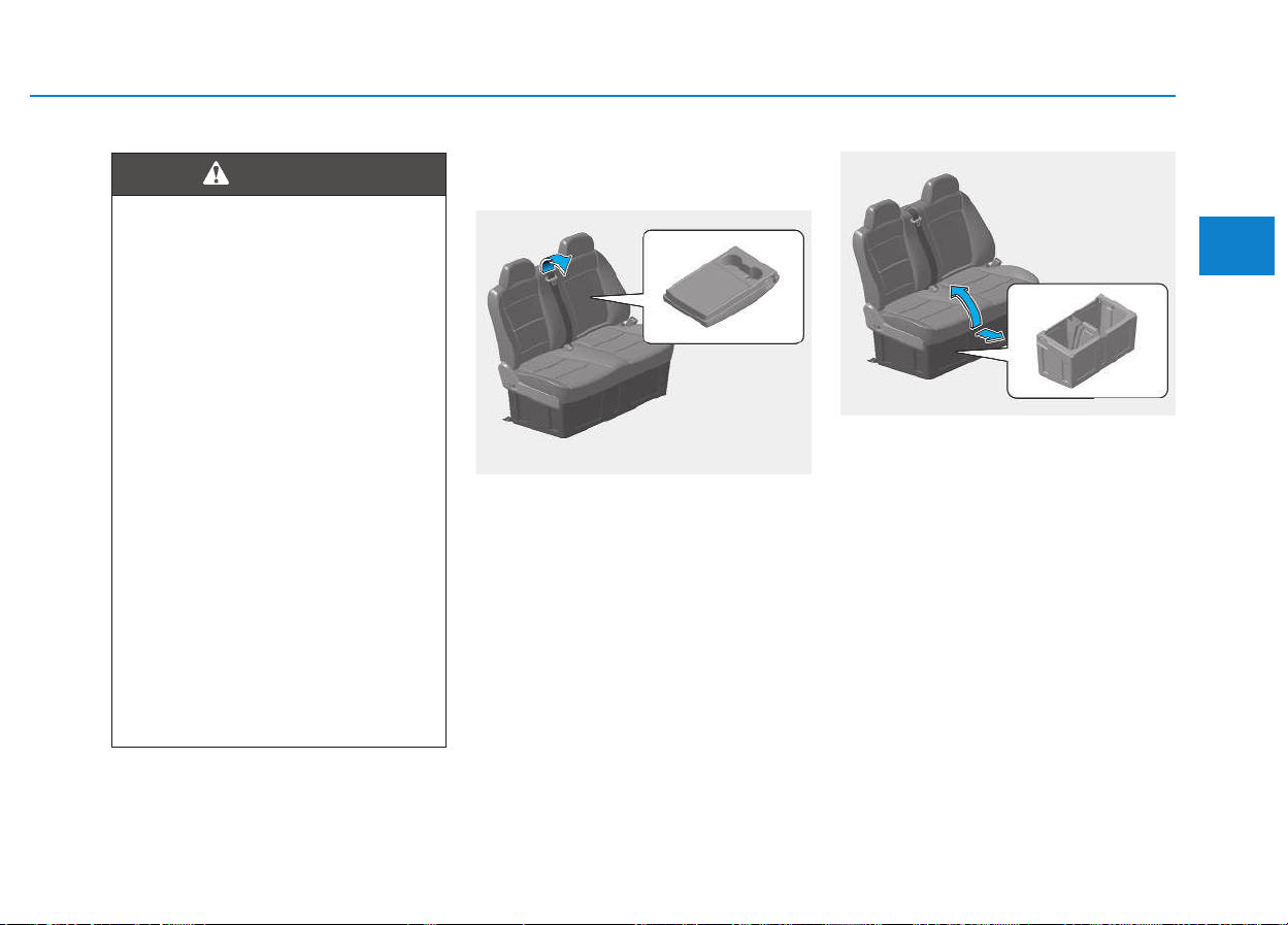
Front passenger seat
(VAN, Truck)
Center Seatback Console
(if equipped)
If you pull down the center seatback
console in the double passenger
seat, you can use it as a console.
Seat Lower Compartment
(if equipped)
If you lift up the cushion in the double
passenger seat and move it forward,
you can use the lower part of the
seat as a storage compartment.
2
Seat Warmer Burns
Passengers should pay extreme
caution while using seat warm-
ers due to the possibility of
excess heating or burns. The
seat warmer may cause burns
even at low temperatures, espe-
cially when it is used for a long
period of time. In particular, the
driver must exercise extreme
care for the below passengers:
1.Infants, children, elderly or
handicapped persons, or hos-
pital outpatients
2.Persons with sensitive skin or
those that burn easily
3.Fatigued individuals
4.Intoxicated individuals
5.Individuals taking medication
that can cause drowsiness or
sleepiness (sleeping pills,
cold tablets, etc.)
WARNING
OEU034040
OEU034041
2-12
Safety system of your vehicle
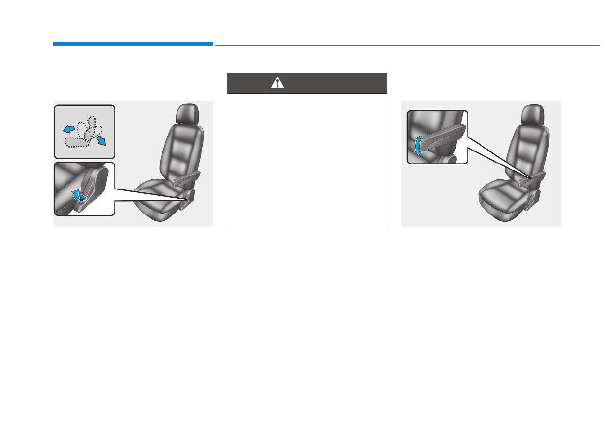
Rear seats
Adjusting seatback angle
To recline the seatback, lean forward
to take your weight off, and then pull
up the seatback lever on the side of
the seat. Now lean back to adjust the
seatback to the desired angle. To
lock the seatback in position, release
the seatback lever.
Adjusting the armrest angle
(if equipped)
The armrest will be raised or lowered
manually.
To raise the armrest, pull it up.
To lower it, press the armrest down.
OEU034003
NEVER ride in a reclined seat,
when the vehicle is in motion.
Riding in a reclined seat
increases your risk of being
seriously or fatally injured in
the event of a collision or sud-
den stop.
Drivers and passengers should
ALWAYS sit well back in their
seats, properly fastened, and in
a properly upright position.
WARNING
OEU034004
2-13
Safety system of your vehicle
2
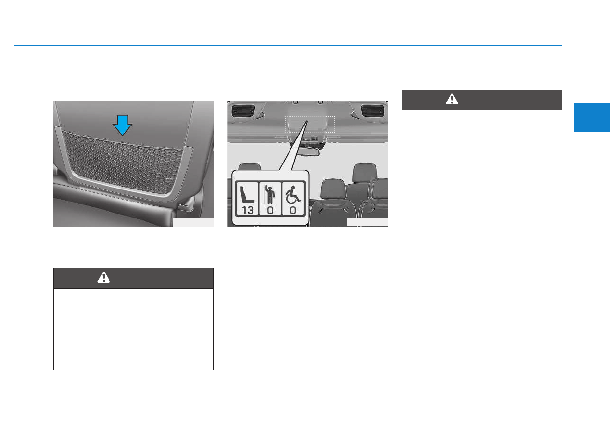
Seatback pocket
(for rear passengers)
The seatback pocket is provided on
the back of the rear passenger's
seats.
Passenger seat capacity label
(if equipped)
The passenger seat capacity label
specifies the number of passengers
the vehicle can carry.
Seat belt restraint system
OEU034005
Seatback Pockets
Do not put heavy or sharp
objects in the seatback pockets.
In an accident they could come
loose from the pocket and
injure vehicle occupants.
WARNING
OEU044059
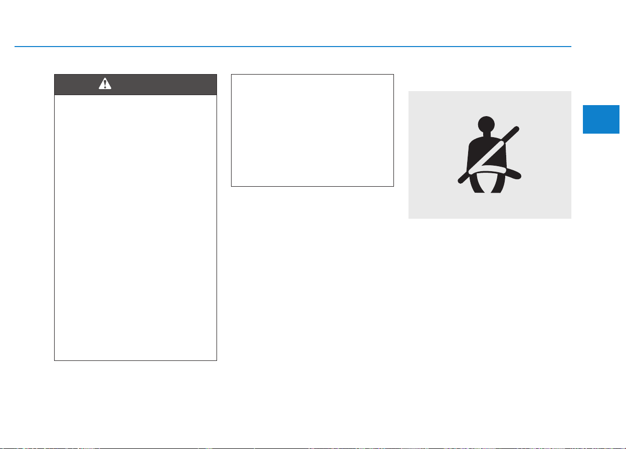
SSEEAATT BBEELLTTSS
•
For maximum restraint pro-
tection, the seat belts must
always be fastened whenever
the vehicle is in motion.
• Seat belts are the most effec-
tive when seatbacks are in the
upright position.
• Children at the age of 12 and
under must always be proper-
ly restrained in rear seats.
Never allow children to ride in
the front passenger's seat.
When a child at the age of 13
and over sits in the front pas-
senger's seat, he/she must be
properly fastened, and the
seat should be positioned in
the rearmost position.
(Continued)
WARNING

2-14
Safety system of your vehicle
(Continued)
• Never fasten the shoulder
portion of the seat belt under
your arm or behind your back.
An improperly positioned
shoulder portion of the seat
belt may cause serious
injuries in a crash. The shoul-
der portion of the seat belt
should be positioned midway
over your shoulder across
your collarbone.
• Never fasten a seat belt over
fragile objects. When there is
a sudden stop or impact, the
seat belt may be damaged.
• Be careful not to twist seat
belts. A twisted seat belt can-
not properly protect the pas-
senger. In a collision, it may
even cut into you. Make sure
the belt webbing is straight
and untwisted.
• Be careful not to damage the
seat belt webbing or hard-
ware. When the seat belt web-
bing or hardware is damaged,
immediately replace it.
Seat belts are designed to be
fastened upon the bony struc-
ture of the body, and should be
worn low across the front
pelvis, chest or shoulders, as
applicable; wearing the lap por-
tion of the seat belt across the
abdominal area must be avoid-
ed.
Seat belts should be adjusted
as firmly as possible, consis-
tent with comfort, to provide the
protection for which they are
designed.
A slack seat belt greatly reduce
the protection afforded to the
passengers.
Be careful not to contaminate
the webbing with polishes, oils
and chemicals, and particularly
battery acid.
Carefully clean it with mild soap
and water.
(Continued)
WARNING
(Continued)
The seat belt should be
replaced, when the webbing
becomes frayed, contaminated,
or damaged. It is essential to
replace the entire assembly
after a severe impact even if
damage to the assembly is not
obvious. Seat belts should not
be fastened with straps twisted.
Each belt assembly must be
fastened over only one occu-
pant; it is dangerous to fasten a
seat belt over a child, who sits
on an adult's laps.
2-15
Safety system of your vehicle
2
Seat belt warning
As a reminder to the driver, the seat
belt warning light is turned ON for
approximately 6 seconds each time
you turn the ignition switch ON
regardless of belt fastening.
When the vehicle start to move with-
out fastening the seat belt with the
ignition switch ON, the seat belt
warning light flashes until it stops.
When the vehicle drives faster than
20km/h without fastening the seat
belt with the ignition switch is ON, the
seat belt warning chime will sound
for approximately 100 seconds.
• No modifications or additions
should be made by the user,
as it may fail the seat belt
adjusting devices, or fail the
seat belt assembly from being
adjusted to remove slack to
be tightly fastened without
any slack.
• When you fasten the seat belt,
be careful not to latch the seat
belt tap in the buckles of other
seats.
It is very dangerous, and you
may not be properly protected
by the seat belt.
• Do not fasten or unfasten the
seat belt in a repetitive man-
ner, while driving. This may
result in loss of control, and
an accident, causing death,
serious injury, or property
damage.
(Continued)
WARNING
(Continued)
• While fastening the seat belt,
make sure that the seat belt is
not fastened over a hard or a
fragile object.
• Make sure that there is noth-
ing in the buckle. If so, the
seat belt may not be securely
fastened.
1GQA2083
2-16
Safety system of your vehicle
However, this chime will stop, when
the seat belt is fastened.
(if equipped)
Lap/shoulder belt
(for front passenger)
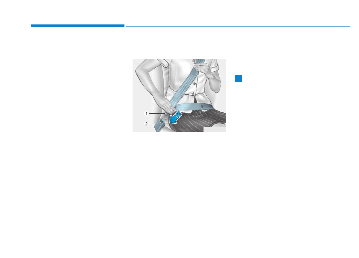
To fasten your seat belt:
To fasten your seat belt, pull it out of
the retractor and insert its metal tab
(1) into the buckle (2). There will be a
"clicking" sound, when the metal tab
is locked into the buckle.
The shoulder portion will be auto-
matically retracted to the proper
length, when the lap portion is man-
ually adjusted to fit snugly around
your hips. When you slowly lean for-
ward, the seat belt will extend in
accordance with your movement.
However, in a sudden stop or impact,
the seat belt will lock in position. It
will also lock in position, when you
try to lean forward too quickly.
Information
When the seat belt is not pulled out
from the retractor, firmly pull out the
seat belt and release it. Then, it will be
smoothly pulled out.
i
ODH033055
2-17
Safety system of your vehicle
2
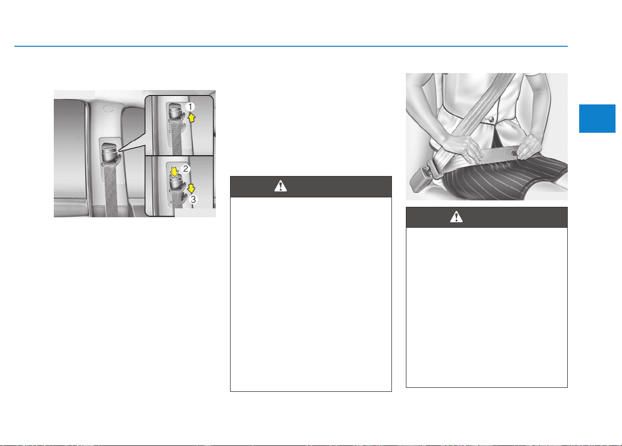
Height adjustment
You can adjust the height of the seat
belt anchor to one of 4 positions for
your comfort and safety.
When the height of the seat belt
anchor is too close to the occupant's
neck, the most effective protection is
not guaranteed.
The shoulder portion should befas-
tened across your chest and midway
over your shoulder nearest the door,
not over your neck.
To adjust the height of the seat belt
anchor, pull it up or pull it down to an
appropriate height.
To raise up the seat belt anchor, pull
it up (1). To lower it down, pull it down
(3) while pressing the release button
(2).
Release the button to lock the
anchor in position. Attempt to slide
up and down the anchor to make
sure that it is securely locked in posi-
tion.
OHD036019
■ Front seat
• Make the shoulder belt sure
that the anchor is locked in
position at the appropriate
height. Never fasten the
shoulder portion across your
neck or face. Improperly posi-
tioned seat belts may cause
serious injury in an accident.
• Failure to replace seat belts
after an accident may leave
you with damaged seat belts
that will not provide protec-
tion in the event of another
collision, resulting in personal
injury or death. Immediately
replace your seat belts after
an accident.
WARNING
B200A01NF
You should fasten the lap belt
as low as possible and snugly
across your hips, not across
your waist. When the lap belt is
located too high across your
waist, it may increase the
chance of injury in the event of
a collision. Both arms should
not be under or over the seat
belt. Rather, one should be over
and the other under, as shown
in the illustration. Never fasten
the seat belt under the arm
nearest the door.
WARNING
2-18
Safety system of your vehicle
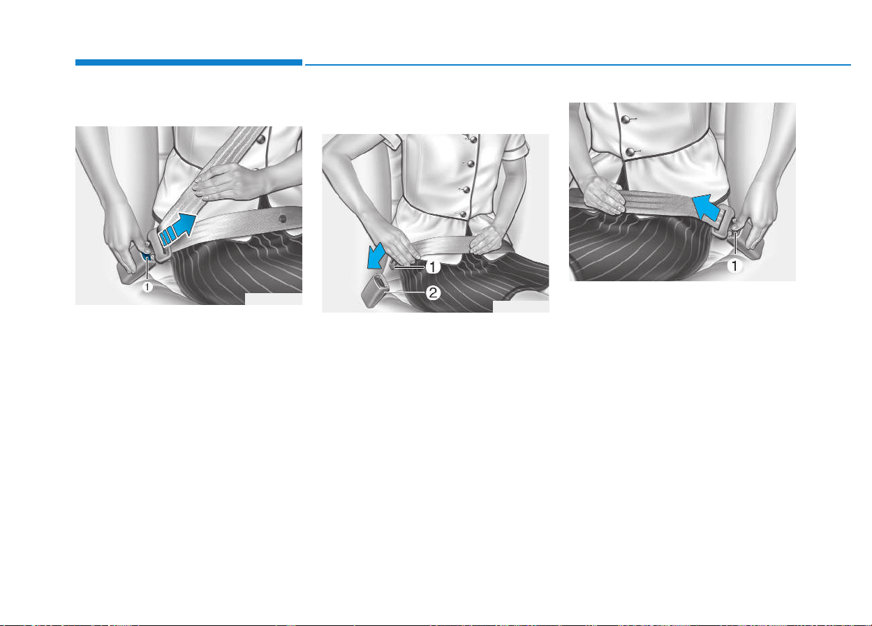
To release the seat belt:
The metal tap is released upon
pressing the release button (1) on
the buckle.
When it is released, the seat belt is
automatically retracted back into the
retractor.
When the metal tap is not released,
check the belt whether it is twisted or
not. Then, try it again.
2 point static belt
(for rear passengers)
To fasten your belt
To fasten the 2-point static belt,
insert the metal tab (1) into the buck-
le (2). There will be a "clicking"
sound, when the metal tab is locked
into the buckle. Make sure the seat
belt is securely locked and that the
seat belt is not twisted.
To release the seat belt
The metal tap is released upon
pressing the release button (1) on
the buckle.
When it is released, the seat belt is
automatically retracted back into the
retractor.
When the metal tap is not released,
check the belt whether it is twisted or
not. Then, try it again.
ODH033057
OEU034030
OEU034029
2-19
Safety system of your vehicle
2
Pregnant women/child
The use of a seat belt is recom-
mended for pregnant women/child to
reduce the risk of injury in an acci-
dent. The lap belt should be fastened
as low and snugly as possible across
the hips, not across the abdomen.
For specific recommendations, con-
sult a physician.
Pre-tensioner seat belt
(if equipped)
Your vehicle is equipped with driver's
and front passenger's pre-tensioner
seat belts. The purpose of the pre-
tensioner is to make sure that the
seat belts tightly fits against the
occupant's body in certain frontal
collisions. The pre-tensioner seat
belt is activated in a crash where the
frontal colliding impact is severe
enough.
When the vehicle suddenly stops, or
when the occupant lean forward too
quickly, the seat belt retractor will
lock in position. In a certain frontal
collision, the pre-tensioner will acti-
vate and slightly retract the seat belt
to tightly restrain the occupant's
body.
When the system detects excessive
tension on the driver's or the front
passenger's seat belt, the load lim-
iter inside the pre-tensioner releases
some pressure on the affected seat
belt. (if equipped)
OEU034037
For your safety, make sure that
the belt webbing is not loose or
twisted and always sit properly
on your seat.
WARNING
2-20
Safety system of your vehicle
• When the pre-tensioner seat belt
is activated, there will be a loud
noise and fine dusts. These may
appear to be smoke, and be vis-
ible in the passenger compart-
ment. These are normal operat-
ing conditions, and does not
indicate a problem.
• Although they are harmless sub-
stances, the fine dusts may
cause skin irritation. These
should not be inhaled for a pro-
longed period of time.
Thoroughly wash all the
exposed skin areas after an
accident, when the pre-tension-
er seat belt was activated.
• Because the sensor that acti-
vates the SRS air bag is con-
nected with the pre-tensioner
seat belt, the SRS air bag warn-
ing light on the instrument clus-
ter will illuminate for approxi-
mately 6 seconds after turning
ON the ignition switch, and then
it goes OFF.
NOTICE
To obtain maximum benefit
from a pre-tensioner seat belt:
1.The seat belt must be proper-
ly fastened and adjusted.
Please read and follow all of
the important safety informa-
tion and precautions about
your vehicle's occupant safe-
ty features - including seat
belts and air bags - that are
provided in this manual.
2.Make sure you and your pas-
sengers always and properly
fasten the seat belts.
WARNING
When the pre-tensioner seat
belt does not properly operate,
the SRS air bag warning light
illuminates even without a mal-
function of the SRS air bag.
When the SRS air bag warning
light does not illuminate after
turning ON the ignition switch,
when it remains ON longer than
6 seconds, or when it remains
ON while driving the vehicle, we
recommend that the system be
inspected by an authorized
HYUNDAI dealer.
CAUTION
2-21
Safety system of your vehicle
2
• Pre-tensioners are designed
to operate only one time. After
an activation, pre-tensioner
seat belts must be replaced.
All seat belts of any type must
be replaced, when they were
fastened during a collision.
• The pre-tensioner seat belt
assembly mechanisms beco-
me hot while being activated.
Do not touch the pre-tension-
er seat belt assembly for sev-
eral minutes, after it is activat-
ed.
• Do not attempt to inspect or
replace the pre-tensioner seat
belts by yourself. We recom-
mend that the system be serv-
iced by an authorized
HYUNDAI dealer.
• Do not strike the pre-tension-
er seat belt assemblies with a
strong impact.
(Continued)
WARNING
(Continued)
• Do not attempt to maintain or
repair the pre-tensioner seat
belt by yourself in any man-
ner.
• Improper handling of the pre-
tensioner seat belt assem-
blies, and failure to heed the
warnings not to strike, modify,
inspect, replace, maintain or
repair the pre-tensioner seat
belt assemblies may lead to
improper operation or inad-
vertent activation, or even
serious injury.
• Always fasten the seat belts
while driving or riding in vehi-
cle.
• Before scrapping your vehicle
or the pre-tensioner seat belt,
we recommend that you con-
tact an authorized HYUNDAI
dealer.
Repair works on the front area
of the vehicle may damage the
pre-tensioner seat belt system.
Therefore, we recommend that
the system be maintained and
repaired by an authorized
HYUNDAI dealer.
CAUTION
2-22
Safety system of your vehicle
Seat belt precautions
Larger children
Children who are too large for child
restraint systems should always sit in
a rear seat and use the available
lap/shoulder belts. The lap belt
should be fastened as low and snug-
gly as possible across the hips.
Frequently check the belt tightness.
A child's squirming may move the
belt out of position. Children are
afforded the most safety in the event
of an accident when they are
restrained by a proper restraint sys-
tem in a rear seat. When a large child
(at the age of 13 and over) must be
seated in the front seat, the child
should be securely restrained by the
available lap/shoulder belt, and the
seat should be placed in the rear-
most position. Children at the age of
12 and under should be restrained
securely in a rear seat. NEVER place
a child at the age of 12 and under in
a front seat.
NEVER place a rear facing child seat
in the front seat of a vehicle.
When the shoulder belt is fastened
slightly across the child's neck or
face, move the child closer to the
center of the vehicle. When the
shoulder belt is still fastened slightly
across their face or neck, they need
to be returned to a child restraint sys-
tem.
All occupants of the vehicle
must and always fasten their
seat belts. Seat belts and child
restraints reduce the risk of
serious or fatal injury in the
event of a collision or sudden
stop. Without a seat belt, occu-
pants may slide too close to a
deploying air bag, strike the
interior structure or be thrown
out of the vehicle. Properly
worn seat belts greatly reduce
these hazards.
Always follow the precautions
of this manual, about seat belts,
air bags and occupant seats.
WARNING
Shoulder belts on small chil-
dren
• Never fasten a shoulder even
slightly across a child's neck
or face, when the vehicle is in
motion.
• When seat belts are improper-
ly fastened over children,
there is a risk of death or seri-
ous injury.
WARNING

2-23
Safety system of your vehicle
2
Pregnant women
The use of a seat belt is recom-
mended for pregnant women to
lessen the chance of injury in an
accident. When a seat belt is used,
the lap belt portion should be placed
as low and snugly as possible on the
hips, not across the abdomen. For
specific recommendations, consult a
physician.
Injured person
A seat belt should be fastened when
an injured person is transported.
When this is necessary, you should
consult a physician for recommenda-
tions.
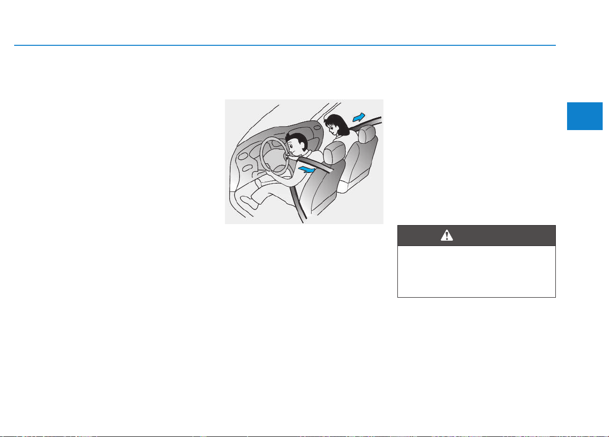
One person per belt
Two people (including children)
should never be fastened by a single
seat belt. This may increase the
severity of injury in case of an acci-
dent.
Do not lie down
To reduce the risk of injury in the
event of an accident and to guaran-
tee the maximum restraining effects,
all passengers should sit in an
upright position when the vehicle is
in motion. A seat belt cannot provide
proper protection, when the person
lies down in a rear seat or sit in a
reclined position in a front seat.
Pregnant women
Pregnant women must never
fasten the lap belt across the
abdomen area where they have
a baby. The belt may imply a
strong impact on their abdomen
in an accident.
WARNING
Riding in a reclined seat
increases your risk of serious
or fatal injury in the event of a
collision or a sudden stop.
The protection of your restraint
system (seat belts and air bags)
is greatly compromised, when
your seat is reclined. Seat belts
must be snugly fastened across
your hips and chest to properly
operate. The more the seatback
is reclined, the more likely an
occupant will slide under the
lap belt, getting serious internal
injury. Or, the shoulder belt may
apply a strong impact on an
occupant's neck. Drivers and
passengers should always sit
well back in their seats, proper-
ly belted, and in an upright posi-
tion.
WARNING

2-24
Safety system of your vehicle
Care of seat belts
Seat belt systems should never be
disassembled or modified. In addi-
tion, care should be taken not to
damage the seat belts and the hard-
ware with the seat hinges, doors or
others.
Periodic inspection
It is recommended that all seat belts
be periodically inspected for a wear-
out or a damage of any kind. Any
damaged parts should be immedi-
ately replaced.
Keep belts clean and dry
Seat belts should be kept clean and
dry. When the seat belts are contam-
inated, clean them with a mild soap
and warm water. Bleach, dye, strong
detergents or abrasives should not
be used, because they may damage
or weaken the fabric.
When to replace seat belts
An entire seat belt assembly should
be replaced, when the vehicle was
involved in an accident. This should
be done, even when a damage is
invisible. We recommend that you
ask additional questions concerning
seat belt operation to an authorized
HYUNDAI dealer.
When you fold up a rear seat-
back to its upright position,
after folding it down, be careful
not to damage the seat belt
webbing or the buckle. Make
sure that the webbing or buckle
does not get caught or pinched
inside the rear seat mechanism.
A damaged webbing or buckle
will not be strong and may fail
to protect an occupant during a
collision or sudden stop, result-
ing in serious injury. If the web-
bing or buckles are damaged,
immediately replace them.
WARNING
2-25
Safety system of your vehicle
2
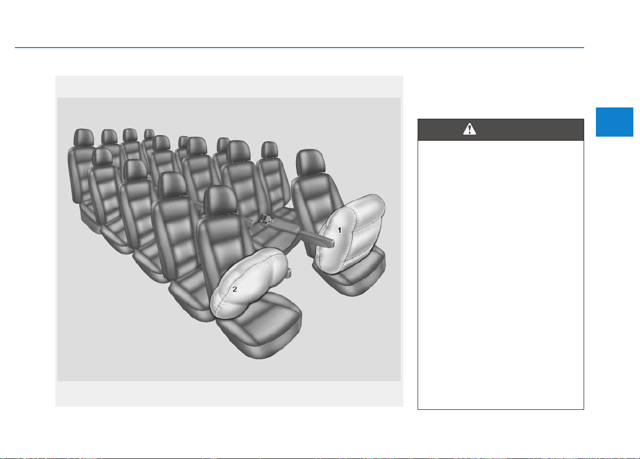
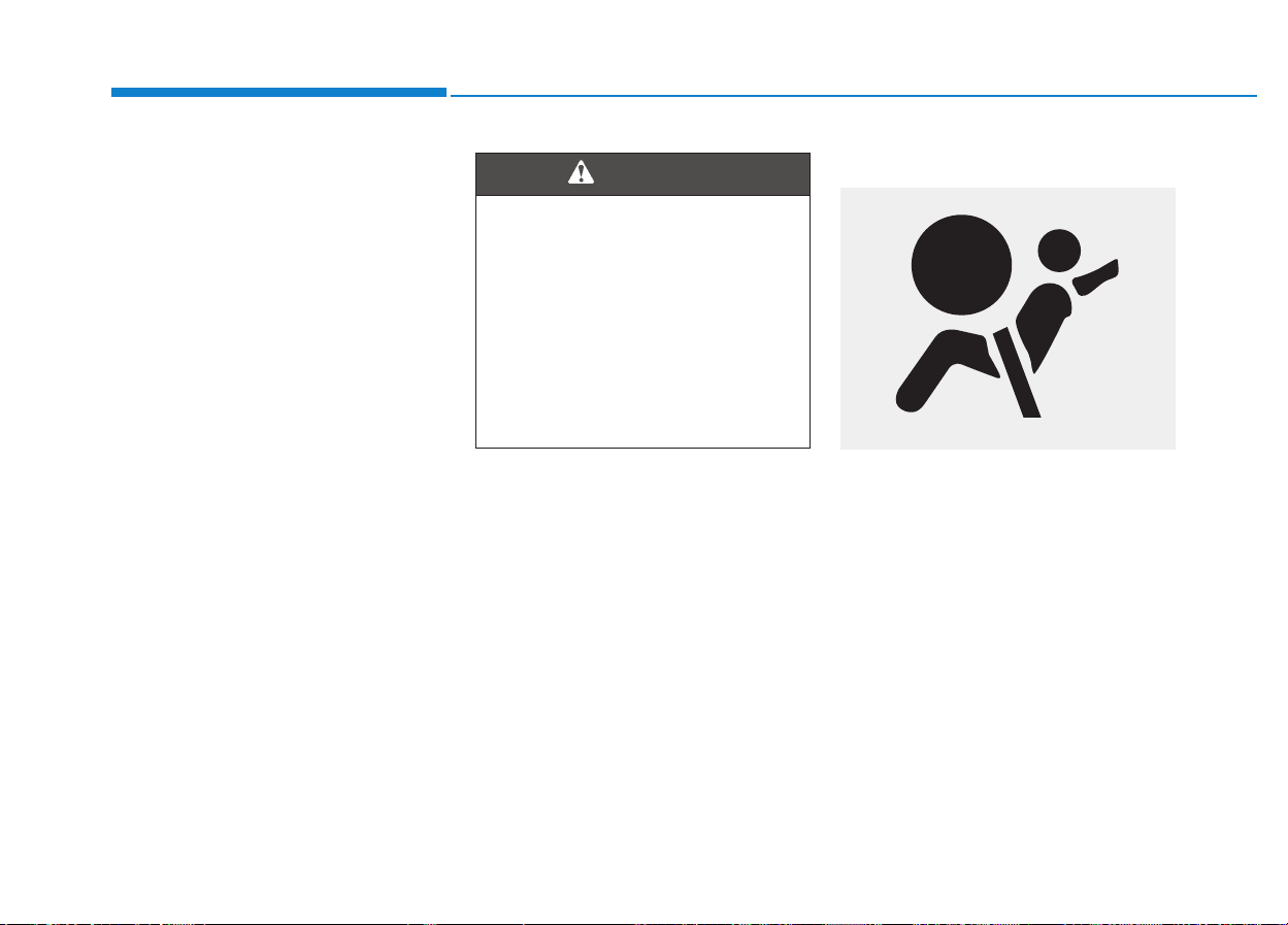
(1) Driver's front air bag
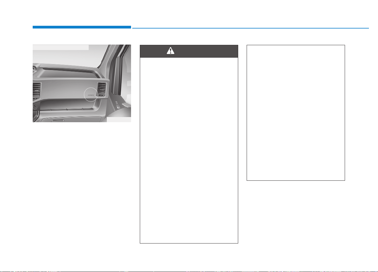
(2) Passenger's front air bag*
* : if equipped
AAIIRR BBAAGG -- SSUUPPPPLLEEMMEENNTTAALL RREESSTTRRAAIINNTT SSYYSSTTEEMM ((IIFF EEQQUUIIPPPPEEDD))
OEU034006
The actual air bags in the vehicle may differ from the illustration.
• Even your vehicle is equipped
with air bags, you and your
passengers must always fas-
ten the seat belts in order to
minimize the risk and severity
of injury in the event of a col-
lision or a rollover.
• The SRS and the pre-tension-
ers seat belt contain explo-
sive chemicals. When a vehi-
cle is scrapped without
removing the SRS or the pre-
tensioner seat belt, it may
cause a fire. Before scraping a
vehicle, we recommend that
you contact an authorized
HYUNDAI dealer.
• Keep the SRS parts and
wirings away from water or
any liquid. When those are
exposed to water or liquids,
the SRS components may
become inoperative, possibly
causing fire or severe injury.
WARNING

2-26
Safety system of your vehicle
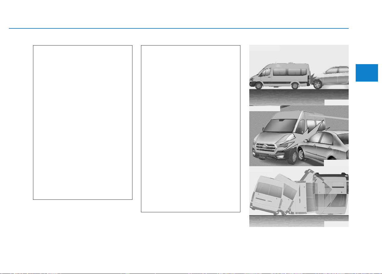
How does the air bag operate?
• Air bags are activated (able to
inflate if necessary) only when the
ignition switch is turned to the ON
or START position.
• Air bags instantly inflate in the
event of a serious frontal collision
in order to help protect the occu-
pants from serious physical injury.
• There is no single speed at which
the air bags will inflate.
Generally, air bags are designed to
inflate in accordance with the
severity of a collision and its direc-
tion. These two factors determine
whether the sensors produce an
electronic deployment/inflation sig-
nal.
• Air bag deployment depends on a
number of factors, including a driv-
ing speed, an impact angle, a vehi-
cle density/stiffness or a colliding
object, which your vehicle strikes
with in a collision. Those factors
are not limited to those mentioned
above.
• The front air bags will completely
inflate and deflate in an instant.
It is virtually impossible for you to
observe the inflation of the air bags
during an accident.
It is more likely that you will simply
see the deflated air bags hanging
out of the air-bag storage compart-
ments after a collision.
• In order to protect occupants in a
severe collision, the air bags must
rapidly inflate. The speed of air bag
inflation is a consequence of the
extremely short colliding time as
well as the necessity to inflate the
air bag between the occupant and
the vehicle structure before the
occupant strikes with the vehicle
structure. This fast inflating speed
reduces the risk of serious or life-
threatening injury in a severe colli-
sion. This is the core part in
designing an air bag.
However, air bag inflation may also
cause injury, such as a facial abra-
sion, a bruise and a broken bones,
because the air bags expand with
a great deal of force.
• There are certain circumstances
under which the air bag installed
in the steering wheel may cause
fatal injury, especially when the
occupant is positioned exces-
sively close to the steering
wheel.
• To avoid severe personal
injury or death caused by
deploying air bags in a colli-
sion, the driver should sit in
the rearmost position from
the air bag installed in the
steering wheel (at least 250
mm (10 inches) away). The
front passengers should
always move their seats as far
back as possible and sit back
in their seats.
• Air bags instantly inflate in
the event of a collision. Thus,
passengers may be injured by
the inflating air bag, when
they are in an improper posi-
tion.
• Air bag inflation may cause
injury, such as facial/bodily
abrasions, injuries by broken
glasses, or skin burns.
WARNING
2-27
Safety system of your vehicle
2
Noise and smoke
When the air bags inflate, they make
a loud noise, leaving smoke and
powder inside the vehicle. This is
normal and is a result of the ignition
of the air bag inflator.
After the air bag inflates, you may
feel substantial discomfort in breath-
ing due to the contact of your chest
with both the seat belt and the air
bag, as well as due to the inhaled
smoke and powder. Immediately
open the doors/windows after the
inflation of the air bag in order to
reduce discomfort and prevent a
prolonged exposure to the smoke
and powder.
Though the smoke and powder are
non-toxic, they may cause skin irrita-
tion (for eyes, nose and throat, etc).
In this case, immediately wash the
irritated area with cold water. Consult
a doctor, if the symptom persists.
Do not install a child restraint
on the front passenger seat
When the air bags deploy, the
air bag components inside the
steering wheel and/or the
instrument cluster become
extremely hot. To prevent injury,
do not touch the air bag compo-
nents, immediately after an air
bag inflates.
WARNING
1JBH3051
OYDESA2042
OLM034310
■ Type B
■ Type A
■ Type C
2-28
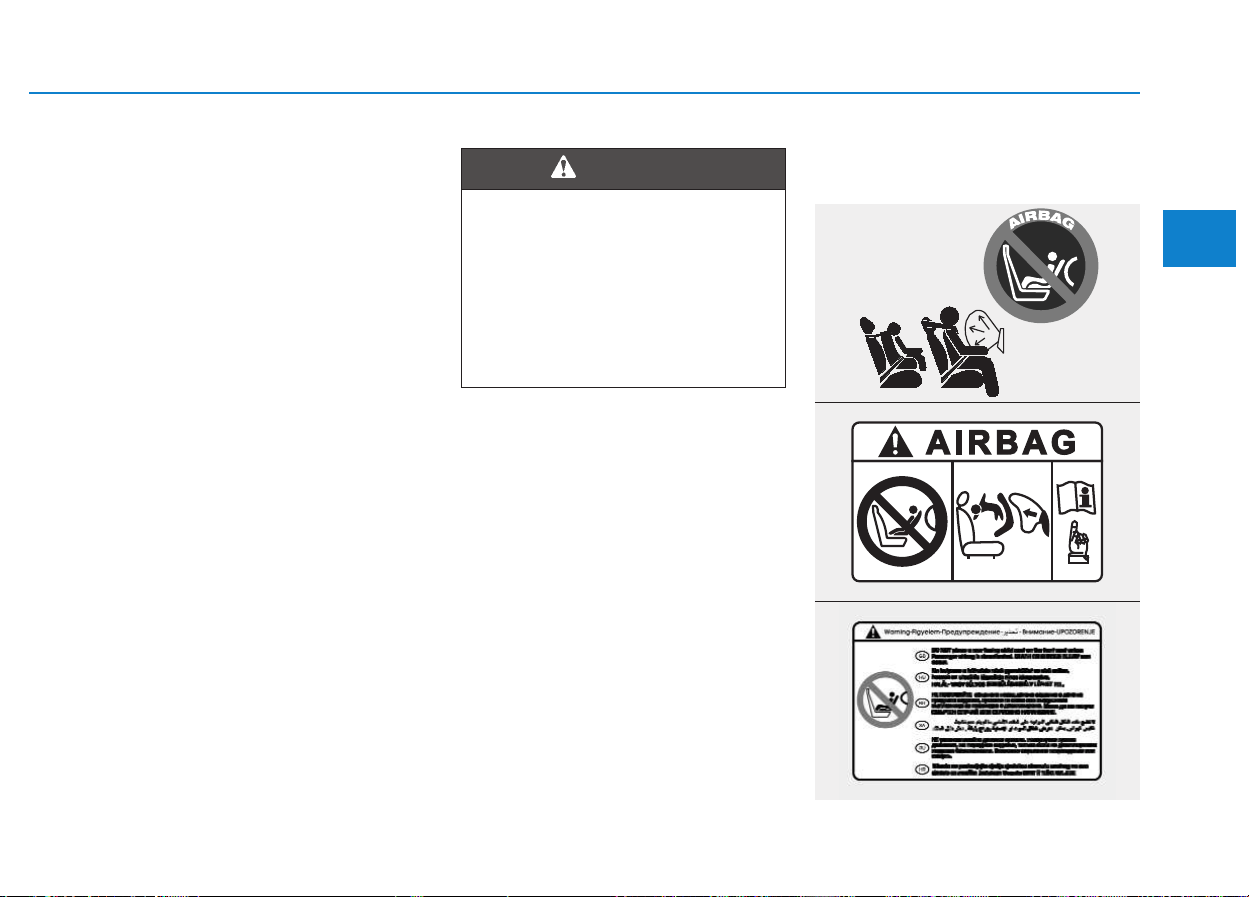
Never place a rear-facing child
restraint in the front passenger’s
seat. If the air bag deploys, it would
impact the rear-facing child restraint,
causing serious or fatal injury.
In addition, do not place front-facing
child restraints in the front passen-
ger’s seat either. If the front passen-
ger air bag inflates, it would cause
serious or fatal injuries to the child.
Air bag warning light
The purpose of the air bag warning
light on your instrument cluster is to
alert you of a potential problem with
your air bag - Supplemental
Restraint System (SRS). The warn-
ing light illuminates for approximately
6 seconds, after turning ON the igni-
tion switch. Then, it goes OFF.
Check the system for the below
symptoms:
• The light does not briefly illumi-
nate, after turning ON the ignition
switch.
• The light remains ON longer than
approximately 6 seconds.
• The light remains ON, when the
vehicle is in motion.
Safety system of your vehicle
• NEVER use a rearward facing
child restraint on a seat pro-
tected by an ACTIVE AIRBAG
in front of it, DEATH or SERI-
OUS INJURY to the CHILD can
occur.
• Never put a child restraint in
the front passenger’s seat. If
the front passenger air bag
inflates, it would cause seri-
ous or fatal injuries.
WARNING
W7-147
2-29
Safety system of your vehicle
2
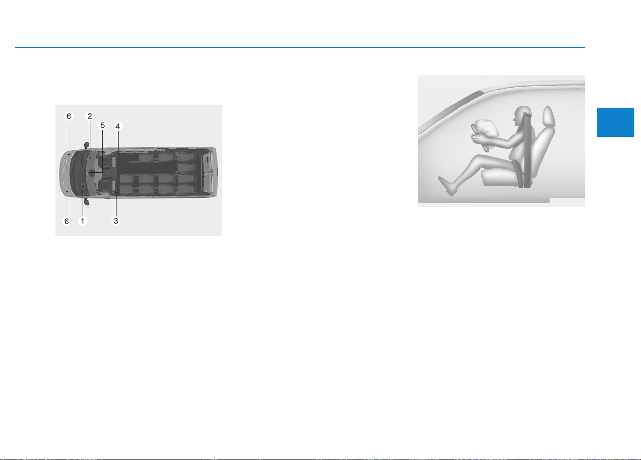
SRS components and func-
tions
The SRS consists of the following
components:
1.Driver's front airbag module
2.Passenger’s front airbag module
3.Driver's pre-tensioner assembly
4.Passenger's pre-tensioner assem-
bly
5.SRS control module (SRSCM)
6.Front impact sensors*
* : if equipped
When the ignition switch is turned
ON, the SRSCM continually moni-
tors all the SRS components, to
determine whether an impact is
severe enough to deploy an air bag
or a pre-tensioner seat belt.
The SRS air bag warning light on the
instrument cluster illuminates for
approximately 6 seconds after turn-
ing ON the ignition switch. Then, it
goes OFF.
When any of the following conditions
occurs, this indicates a SRS mal-
function. We recommend that the
system be inspected by an author-
ized HYUNDAI dealer.
• The light does not briefly illuminate
after turning ON the ignition switch.
• The light remains ON longer than 6
seconds.
• The light remains ON, when the
vehicle is in motion.
The front air bag modules are locat-
ed inside both the steering wheel
and the front panel above the glove
box. When the SRSCM detects a suf-
ficient impact at the frontal part of the
vehicle, it automatically deploys the
front air bags.
OEU034008
B240B01L
■ Driver's front air bag (1)
2-30
Safety system of your vehicle
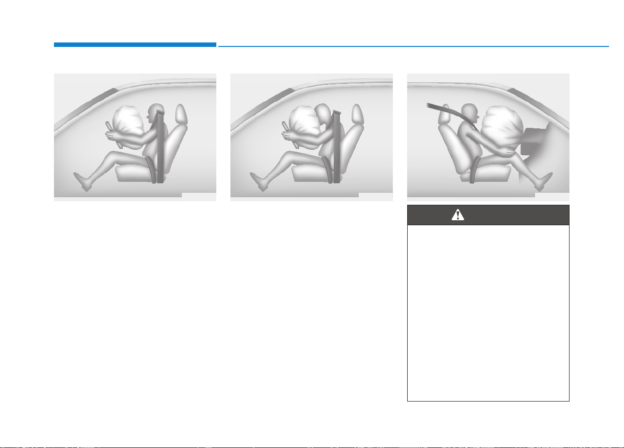
To deploy, the pad cover tears apart
under pressure of the air-bag inflat-
ing power. Further opening of the
covers then allows full inflation of the
air bags.
A fully inflated air bag, in combina-
tion with a properly fastened seat
belt, slows the speed of the driver's
or the front passenger's falling for-
ward, reducing the risk of head/chest
injury.
After complete inflation, the air bag
immediately starts deflating,
enabling the driver to maintain for-
ward visibility and the ability to steer
or operate other controls.
B240B02L B240B03L
■ Driver's front air bag (2) ■ Driver's front air bag (3)
B240B05L
■ Passenger's front air bag
• Do not install or place any
accessories (i.e. drink holder,
cassette holder, sticker, etc.)
on the front panel above the
glove box, where a front pas-
senger's air bag is installed.
Such accessories may
become dangerous projec-
tiles and cause injury, when a
front passenger's air bag
inflates.
• Do not install or place a con-
tainer of liquid air freshener
near or on the instrument
cluster.
(Continued)
WARNING
2-31
Safety system of your vehicle
2
Driver's and front passenger's
air bag (if equipped)
Your vehicle is equipped with a sup-
plemental restraint system (air bag)
and lap/shoulder belts for both the
driver and the front passenger. The
presence of the system is indicated
by the letters, "SRS AIR BAG," which
are embossed on the steering wheel
and the front panel above the glove
box.
The SRS consists of air bags, which
are installed under the pad cover of
the steering wheel and under the
front panel above the glove box.
(Continued)
It may become a dangerous
projectile and cause injury,
when a front passenger's air
bag inflates.
• When an air bag deploys,
there may be a loud noise as
well as fine dusts released in
the vehicle. These conditions
are normal and are not haz-
ardous - the air bags are
packed with fine powders.The
dust generated during air bag
deployment may cause
skin/eye irritation as well as
aggravate asthma for some
persons. Always wash all
exposed skin areas thorough-
ly with lukewarm water and a
mild soap after an accident in
which the air bags were
deployed.
(Continued)
WARNING
(Continued)
• The SRS operates, only after
turning ON the ignition
switch. When the SRS air bag
warning light does not illumi-
nate after turning ON the igni-
tion switch, when light contin-
uously remains ON longer
than approximately 6 sec-
onds, or when the light
remains ON while driving, the
SRS does not properly oper-
ate.
In this case, we recommend
that the system be inspected
by an authorized HYUNDAI
dealer.
• Before replacing a fuse or dis-
connecting a battery terminal,
turn the ignition switch to the
LOCK position and remove
the ignition key. Never remove
or replace the air bag related
fuse(s) when the ignition
switch is in the ON position.
Failure to heed this warning
will cause the SRS air bag
warning light to illuminate.
OEU034007
■ Driver's front air bag
2-32
Safety system of your vehicle
The purpose of the SRS is to provide
the driver and/or the front passenger
with additional protection than that
offered only by the seat belt system
in case of a frontal impact of suffi-
cient severity.
Always use seat belts and child
restraints – every trip, every
time, everyone! Air bags inflate
with considerable force and in
the blink of an eye. Seat belts
help keep occupants in proper
position to obtain maximum
benefit from the air bag. Even
with air bags, improperly and
unbelted occupants may be
severely injured when the air
bag inflates. Always follow the
precautions about seat belts, air
bags and occupant safety, as
specified in this manual.
To reduce the chance of serious
or fatal injuries and receive the
maximum safety benefit from
your restraint system:
• Never install a child restraint
or a booster seat in a front
seat to sit a child.
• ABC - Always Buckle Children
in a rear seat. It is the safest
place for children of any ages
to ride.
(Continued)
WARNING
OEU044068
■ Front passenger's air bag
(Continued)
• Front air bags may injure
occupants, who improperly sit
in a front seat.
• Locate your seat in the rear-
most position from the front
air bags, while still maintain-
ing control of the vehicle.
• You and your passengers
should never sit or lean
unnecessarily close to the air
bags. Improperly positioned
drivers and passengers may
be severely injured by inflat-
ing air bags.
• Never lean against the door or
center console - always sit in
an upright position.
(Continued)
2-33
Safety system of your vehicle
2
(Continued)
• No objects should be placed
over or near the air bag mod-
ules on the steering wheel,
the instrument cluster, and
the front panel above the
glove box. Such an object may
cause harm in a crash of
which impact is severe
enough to deploy an air bag.
• Do not modify or disconnect
the SRS wires or the SRS
components. Doing so may
result in injury by accidentally
deploying the air bags or by
deactivating the SRS.
• When the SRS air bag warning
light remains ON, while driv-
ing, we recommend that the
system be inspected by an
authorized HYUNDAI dealer.
(Continued)
(Continued)
• Air bags should be used only
once - we recommend that the
system be replaced by an
authorized HYUNDAI dealer
after an accident.
• The SRS is designed to
deploy the front air bags only
when an impact is sufficiently
severe and when the impact
angle is less than 30° from the
forward longitudinal axis of
the vehicle. Additionally, the
air bags will deploy only once.
Seat belts must and always be
fastened.
• Front air bags do not deploy
in a side-impact, a rear-impact
or a rollover. In addition, front
air bags will not deploy in a
frontal crash of which impact
is below the deployment
threshold.
(Continued)
OEU034023
OEU034009
OEU034010
■ Rear impact
■ Side impact
■ Rollover

2-34
Safety system of your vehicle
Why did not my air bag go off
in a collision? (Inflation and
non-inflation conditions of the
air bag)
There are many types of acci-
dents in which the air bag
would not inflate to provide
additional protection.
These include rear impacts,
second or third collisions in
multiple impact accidents, as
well as low speed impacts.
(Continued)
• A child restraint system must
never be installed in a front
seat. The infant or child may
be severely injured or killed
by a deploying air bag in an
accident.
• Children at the age of 12 and
under must always be proper-
ly restrained in a rear seat.
Never allow children to ride in
a front passenger's seat.
When a child at the age of 13
and over sits in a front seat,
he or she must be properly
fastened and the seat should
be located in the rearmost
position.
❇
❇
The age requirements
about the child detrainment
differ in each country.
• For the maximum protection
in all types of crashes, all
occupants including the driv-
er should always wear their
seat belts, regardless of the
air bag installment in their
seats.
(Continued)
(Continued)This is to minimize
the risk of severe injury or
death in the event of a crash.
Do not sit or lean unnecessar-
ily close to the air bag, when
the vehicle is in motion.
• Sitting improperly or out of
position may result in serious
or fatal injury in a crash. All
occupants should sit in an
upright position with the seat-
back in an upright position,
centered on the seat cushion
with their seat belt on, legs
comfortably extended and
their feet rested on the floor
until the vehicle is parked and
the ignition switch is turned
OFF.
• The SRS air bag rapidly
inflates to provide Protection
to occupants in a crash. When
an occupant is out of position
without fastening a seat belt,
the air bag may forcefully
strike the occupant, causing
serious or fatal injury.
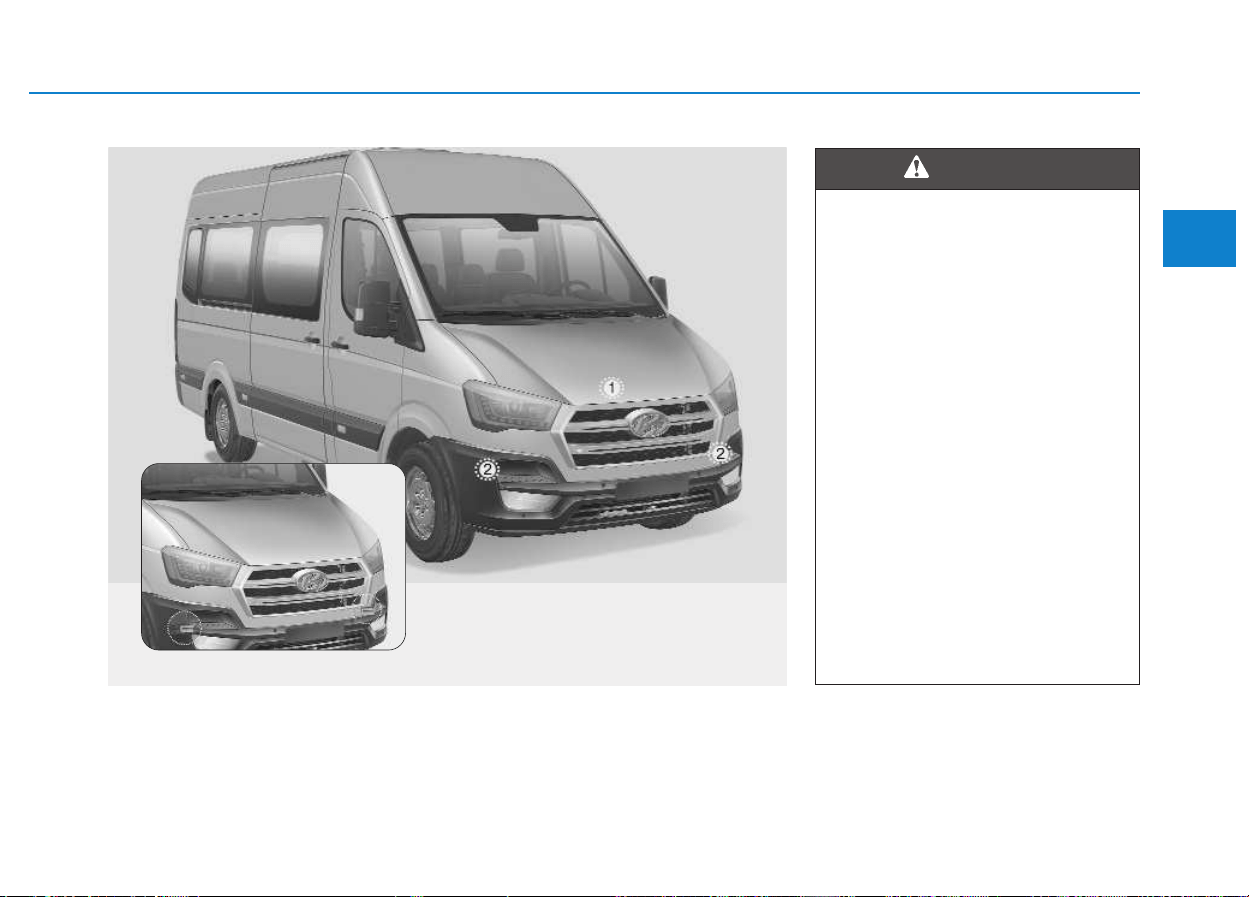
2-35
Safety system of your vehicle
2
OEU034011/OEU034013
Air bag collision sensors
(1) SRS control module
(2) Front impact sensor
• Do not hit or allow any objects
to impact the locations where
air bags or sensors are
installed.
This may cause unexpected
air bag deployment, resulting
in serious personal injury or
death.
• When the sensor is installed
out of position, the air bags
may deploy in an accident in
which they should not or may
not deploy, causing severe
injury or death.
Therefore, do not attempt to
maintain on or around the air
bag sensor area.
We recommend that the sys-
tem be serviced by an author-
ized HYUNDAI dealer.
(Continued)
WARNING
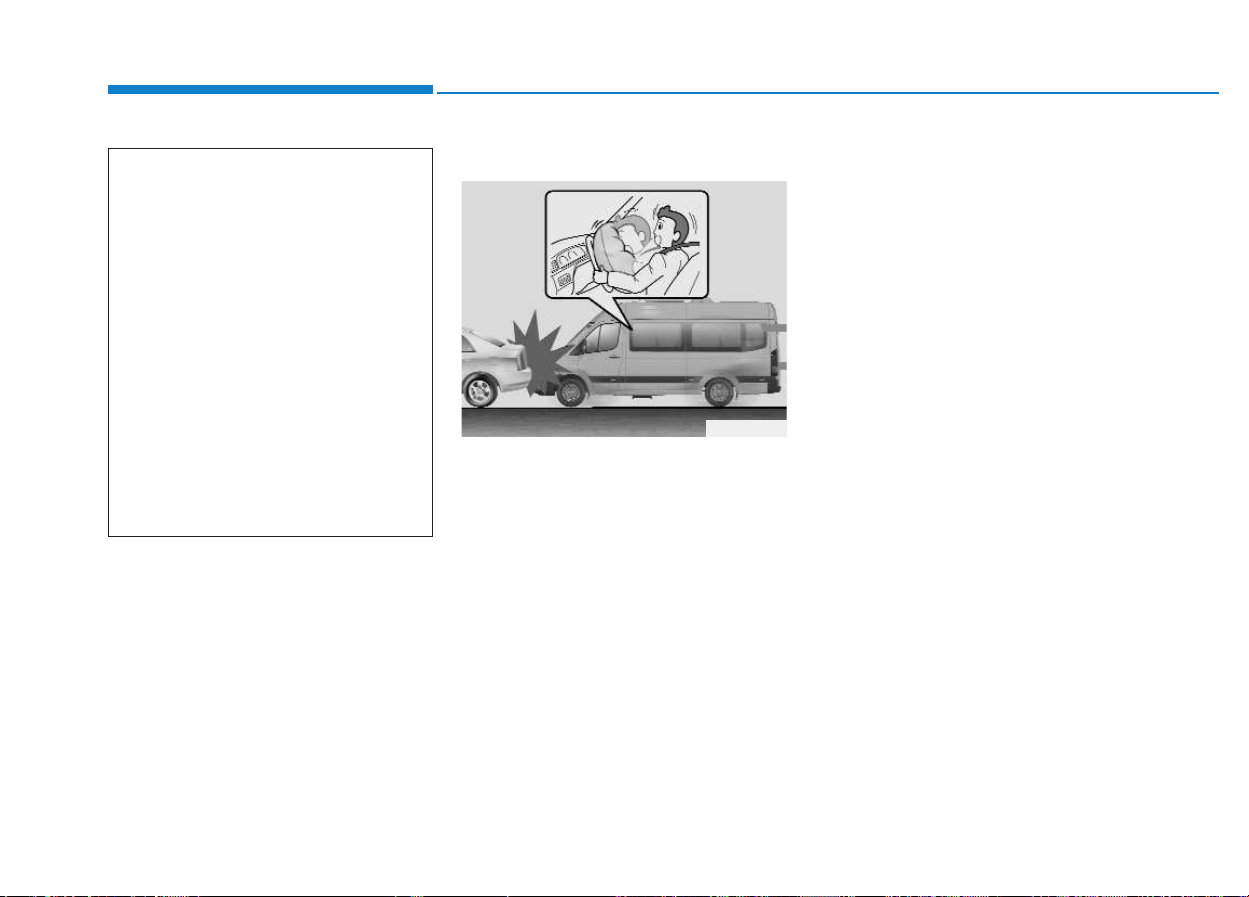
2-36
Safety system of your vehicle
Air bag inflation conditions
Front air bags
Front air bags are designed to inflate
in a frontal collision depending on an
intensity, a speed or an angles of of
the front collision.
Although the front air bags (driver's
and front passenger's air bags) are
designed to inflate only in frontal col-
lisions, they also may inflate in other
types of collisions, when a sufficient
impact is detected by the front
impact.
When the vehicle chassis is impact-
ed by bumps or objects on a rugged
road, the air bags may deploy.
Carefully drive on rugged roads or
off roads to prevent unintended air
bag deployment.
(Continued)
• Problems may arise, when the
installment angle of the sen-
sor is changed due to the
deformation of the front
bumper and the body. We rec-
ommend that the system be
serviced by an authorized
HYUNDAI dealer.
• Your vehicle has been
designed to absorb impact
and deploy the air bag(s) in
certain collisions. Installing
bumper guards or replacing
with an unauthorized bumper
may adversely affect the air
bag deployment performance.
OEU034014
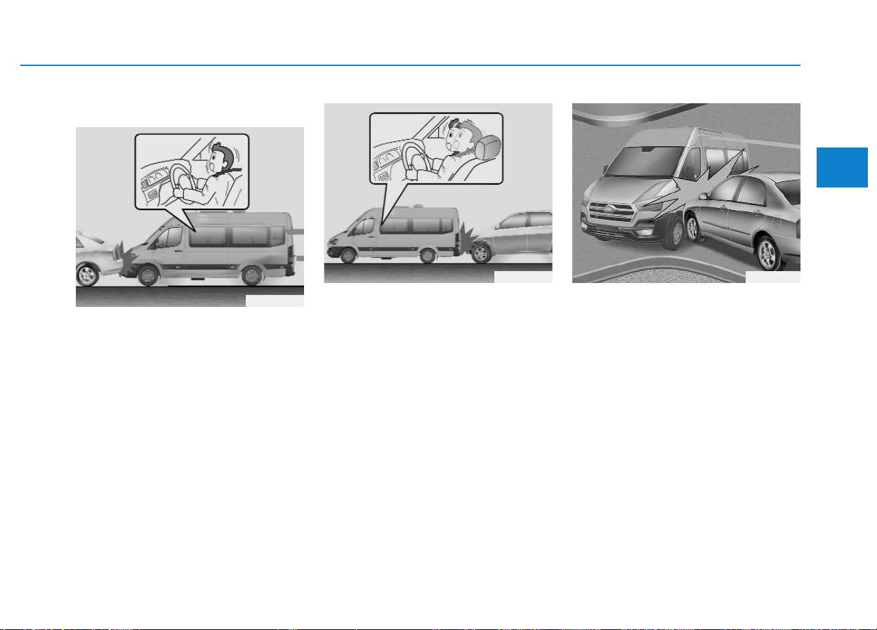
2-37
Safety system of your vehicle
2
Air bag non-inflation conditions
• In certain low-speed collisions, the
air bags may not deploy. The air
bags are not designed to deploy in
such cases where air bags cannot
provide benefits beyond the pro-
tection of the seat belts.
• Frontal air bags are not designed
to inflate in rear collisions, where
occupants are tilted backwards by
the force of the impact. In this case,
inflated air bags cannot provide
any additional benefit.
• Front air bags may not inflate in
side impact collisions, because
occupants move to the direction of
the collision. Thus, in side impacts,
frontal air bag deployment cannot
provide additional occupant pro-
tection.
OEU034015
OEU034016 OEU034009
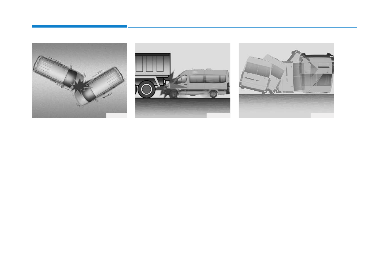
2-38
Safety system of your vehicle
• In an angled collision, the force of
impact may direct the occupants in
a direction where the air bags can-
not provide any additional benefit.
Thus, the sensors may not deploy
any air bags.
• Just before an impact, drivers often
brake heavily. Such heavy braking
lowers the front portion of the vehi-
cle, causing it to "ride" under a
vehicle ahead with a higher ground
clearance.
Air bags may not inflate in this
"under-ride" collision, because
deceleration may significantly
reduce the impact force, which is to
be detected by the sensor.
• Air bags may not inflate in rollover
accidents because air bag deploy-
ment cannot provide protection to
the occupants.
1TQA2089 OEU034019 OEU034010
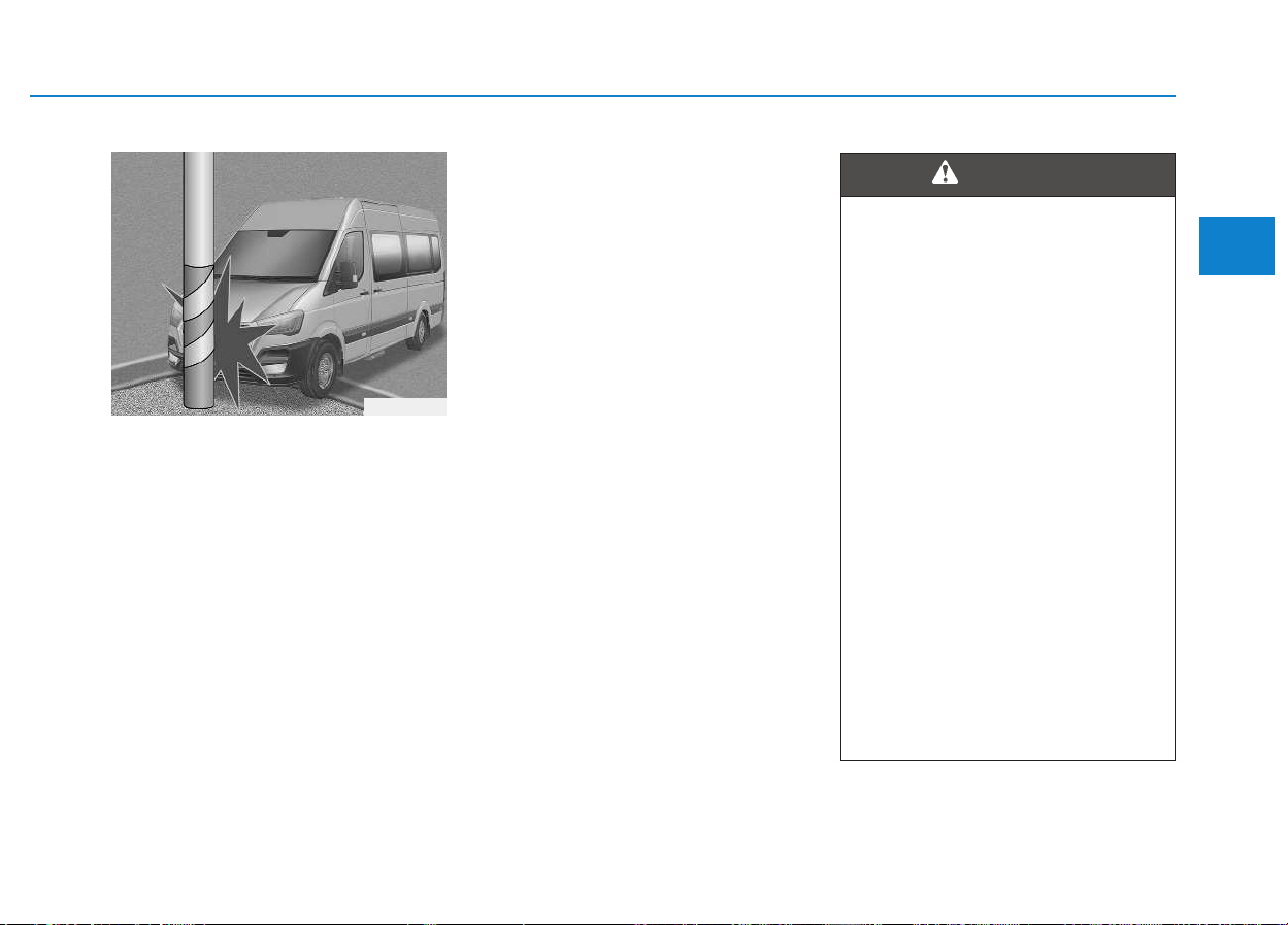
2-39
Safety system of your vehicle
2
• Air bags may not inflate, when the
vehicle collides with objects such
as utility poles or trees, where the
impacts are concentrated to one
point. This is because the full force
of the impact is not delivered to the
sensors.
SRS Care
The SRS is virtually maintenance-
free. Thus, you do not need to main-
tain any SRS parts by yourself. When
the SRS air bag warning light does
not Illuminate, or when it continuous-
ly remains ON, we recommend that
the system be inspected by an
authorized HYUNDAI dealer.
OEU034021
• Modification to SRS compo-
nents or wirings, such as
adding badges or the pad cov-
ers or body-structure modifi-
cations, may adversely affect
SRS performance and lead to
possible injury.
• Use only a soft, dry cloth or
the one moistened with plain
water to clean the air pad
cover. Solvents or cleaners
may adversely affect the air
bag covers and proper
deployment.
• No objects should be placed
over or near the air bag mod-
ules on the steering wheel,
the instrument cluster, and
the front panel above the
glove box. Any such object
may cause harm, when the
vehicle is in a crash severe
enough to inflate the air bags.
(Continued)
WARNING

2-40
Safety system of your vehicle
Additional safety precautions
• Never let passengers ride in the
trunk or on top of a foldeddown
seatback. All occupants should sit
upright, fully back in their seats
with their seat belts fastened and
their feet rested on the floor.
• Passengers should not move
out of their seats or change their
seat positions, when the vehicle
is in motion. A passenger, who
does not fasten a seat belt during a
crash or emergency stop, may be
thrown against the vehicle interior,
against other occupants, or out of
the vehicle.
• Each seat belt is designed to
restrain one occupant. When
more than one person uses the
same seat belt, they may be seri-
ously injured or killed in a collision.
• Do not use any accessories on
seat belts. Devices, which the
manufacturers claim to improve
occupants’ comfort, may reduce
the protection provided by the seat
belt and increase the risk of seri-
ous injury in a crash.
(Continued)
• When the air bags inflate, we
recommend that the system
be replaced by an authorized
HYUNDAI dealer.
• Do not modify or disconnect
SRS wirings or other SRS
components. Such attempts
may result in injury, because
an air bag may accidentally
inflate or deactivate the SRS
system.
• Observe any safety precau-
tions to discard the air bag
system or to scrape the vehi-
cle. An authorized HYUNDAI
dealer knows these precau-
tions and can give you the
necessary information.
Failure to follow these precau-
tions and procedures may
increase the risk of personal
injury.
(Continued)
(Continued)
• When your vehicle is flooded
or when the floor mats are
soaked with water, do not
attempt to start the engine. We
recommend that you contact
an authorized HYUNDAI deal-
er.

2-41
Safety system of your vehicle
2
• Passengers should not place
hard or sharp objects between
themselves and the air bags.
Carrying hard or sharp objects on
your laps or in your mouth may
result in injury, when an air bag
inflates.
• Keep occupants away from the
air bag covers. All occupants
should sit upright, fully back in their
seats with their seat belts fastened
and their feet rested on the floor.
When occupants are too close to
the air bag, they may be injured by
an inflating air bag.
• Do not attach or place objects
on or near the air bag covers.
Any object attached to or placed
on the front air bag covers may
interfere with the proper operation
of the air bags.
• Do not modify the front seats.
Modification of the front seats may
interfere with the sensing operation
of the supplemental restraint sys-
tem.
• Do not place items under the
front seats. Placing items under
the front seats may interfere with
the sensing operation of the sup-
plemental restraint system and
wiring harnesses.
• Never hold an infant or child on
your laps. The infant or child may
be seriously injured or killed in the
event of a crash. All infants and
children should be properly
restrained in appropriate child
safety seats or seat belts in a rear
seat.
• Sitting improperly or out of
position may cause occu-
pants to be shifted too close
to a deploying air bag, strike
the interior structure or be
thrown out of the vehicle,
resulting in serious injury or
death.
• Always sit upright with the
seatback in an upright posi-
tion, centered on the seat
cushion with your seat belt
on, legs comfortably extended
and feet rested on the floor.
WARNING
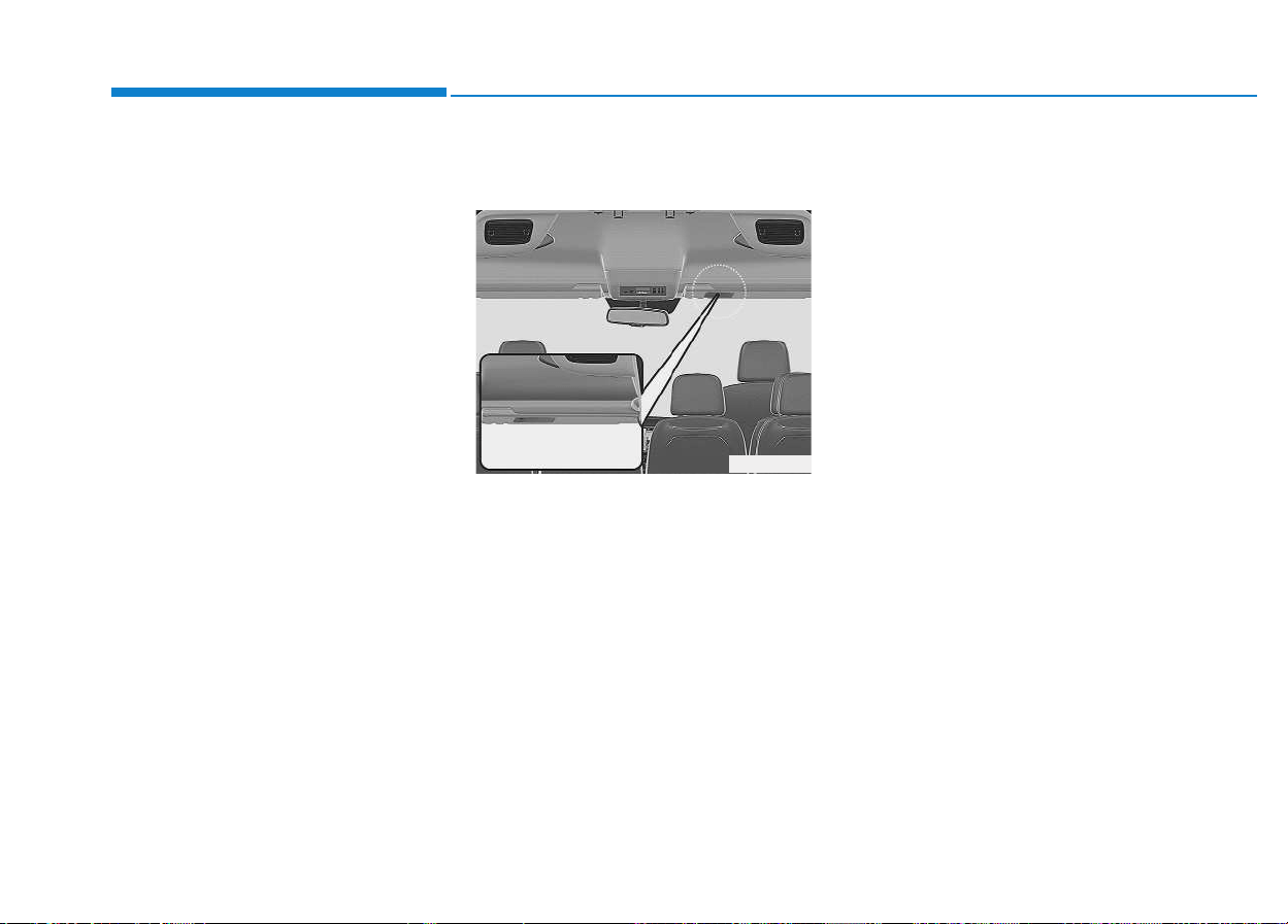
Adding equipment to or modi-
fying your air bag-equipped
vehicle
Modification of your vehicle struc-
tures, such as the frame, the
bumper, the front end, the side sheet
metal or the ride height, may affect
the operation of your vehicle's air
bag system.
Air bag warning label
(if equipped)
Air bag warning label is attached to
alert the passengers of potential risk
of air bag system.
Note that these government warn-
ings focus on the risk to children, we
also wants you to be aware of the
risks which adults are exposed to.
Those are specified on previous
pages.
OEU034022
Safety system of your vehicle
2-42

Convenient features of your vehicle
Keys .........................................................................3-4
Record your key number ................................................3-4
Key operations...................................................................3-4
Immobilizer system............................................................3-5
Remote keyless entry ...........................................3-6
Remote keyless entry system operations...................3-6
Transmitter precautions...................................................3-7
Battery replacement.........................................................3-8
Theft-alarm system...............................................3-9
Armed stage .....................................................................3-10
Theft-alarm stage...........................................................3-10
Disarmed stage ................................................................3-11
Door locks.............................................................3-11
Operating door locks from outside the vehicle ......3-11
Operating door locks from inside the vehicle .........3-12
Deadlocks..........................................................................3-14
Speed sensing door lock system ................................3-14
Mid sliding door ...................................................3-15
Opening/closing from the outside..............................3-15
Opening/closing from the inside.................................3-16
Child-protector mid sliding door lock........................3-16
Electrical step.......................................................3-17
Operation and obstacle detection ..............................3-19
Electrical step warning alarm ......................................3-19
Regular cleaning..............................................................3-21
Rear door ..............................................................3-22
Opening/closing from the outside..............................3-23
Opening/closing from the inside.................................3-23
Opening the left-hand rear door ...............................3-24
Opening the rear doors to an angle of
180° or 270°......................................................................3-24
Closing the rear doors from the outside ..................3-25
Child-protector rear door lock....................................3-25
Windows ................................................................3-26
Power windows................................................................3-27
Rear seat windows .........................................................3-29
Hood.......................................................................3-30
Opening the hood ...........................................................3-30
Closing the hood .............................................................3-31
Fuel filler lid .........................................................3-32
Closing the fuel filler lid................................................3-32
Urea solution filler lid .........................................3-34
Steering wheel......................................................3-37
Power steering.................................................................3-37
Tilt & telescopic steering ..............................................3-37
Horn....................................................................................3-38
Mirrors...................................................................3-39
Inside rearview mirror....................................................3-39
Outside rearview mirror ................................................3-41
3

Instrument cluster................................................3-43
Instrument panel illumination.......................................3-44
Gauges and indicators ...................................................3-44
Multi-display ........................................................3-50
Main display .....................................................................3-50
Function description.......................................................3-51
Trip computer...................................................................3-53
Drive info. mode ..............................................................3-53
AV information .................................................................3-53
Turn by turn navigation.................................................3-54
Information Mode ...........................................................3-54
User Settings Mode........................................................3-55
Warning Messages..........................................................3-57
Trip computer .......................................................3-60
Overview............................................................................3-60
Trip modes ........................................................................3-61
Driving distance/average vehicle speed/
elapsed time .....................................................................3-62
Fuel economy...................................................................3-63
Urea Solution Gauge ......................................................3-65
Total AUTO STOP Hour..................................................3-66
Driving Information.........................................................3-66
Warning and indicator lights..............................3-66
Digital tachograph................................................3-80
Type A................................................................................3-80
Type B................................................................................3-82
Parking assist system..........................................3-88
Rear parking assist system type.................................3-89
Front/rear parking assist system type......................3-92
Rearview camera..................................................3-94
Hazard warning flasher ......................................3-95
Lighting..................................................................3-95
Battery saver function ..................................................3-95
Headlight escort function .............................................3-96
Headlight welcome function.........................................3-96
Lighting control ...............................................................3-96
High - beam operation ..................................................3-98
Turn signals and lane change signals........................3-99
Front fog light ...............................................................3-100
Rear fog light.................................................................3-100
Daytime running light ..................................................3-101
Headlight leveling device ............................................3-101
Wipers and washers ..........................................3-102
Windshield wiper/washer ...........................................3-102
Windshield wipers .........................................................3-102
Windshield washers......................................................3-105
3

Convenient features of your vehicle
3
Interior light........................................................3-106
Map lamp.........................................................................3-106
Reading lamp..................................................................3-107
Room lamp ......................................................................3-108
Cargo bed lamp..............................................................3-108
Rear step lamp...............................................................3-108
Defroster.............................................................3-109
Outside rearview mirror heater ................................3-109
Climate control system......................................3-110
Heating and air conditioning......................................3-111
Rear heating and air conditioning............................3-116
System operation..........................................................3-117
Fuel-fired heater..........................................................3-119
Climate control air filter..............................................3-119
Checking the amount of air conditioner refrigerant
and compressor lubricant...........................................3-120
Windshield defrosting and defogging ............3-121
To defog inside windshield .........................................3-121
To defrost outside windshield ...................................3-122
Ceiling ventilator................................................3-122
Storage compartment........................................3-123
Overhead storage .........................................................3-123
Storage space above the headliner .........................3-124
Console storage.............................................................3-124
Glove box ........................................................................3-125
Sunglass holder .............................................................3-125
Interior features.................................................3-126
Cigarette lighter ............................................................3-126
Ashtray ............................................................................3-127
Cup holder.......................................................................3-127
Sunvisor...........................................................................3-128
Power outlet...................................................................3-128
Cargo bed (for van)...........................................3-129
As the driver, you are responsible for ensuring
that: ..................................................................................3-129
Luggage mass label ......................................................3-130
3
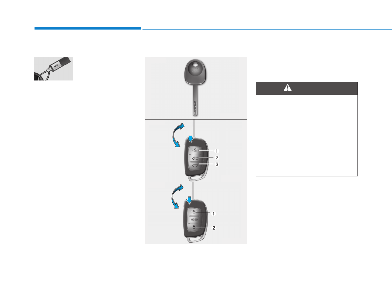
3-4
Convenient features of your vehicle
Record your key number
The key code number
is stamped on the
key code tag
attached to the key
set.
Should you lose your keys, we rec-
ommend that you contact an author-
ized HYUNDAI dealer. Remove the
key code tag and store it in a safe
place. Also, record the code number
and keep it in a safe and handy
place, but not in the vehicle.
Key operations
• Used to start the engine.
• Used to lock and unlock the doors.
• Used to lock and unlock the glove
box. (if equipped)
KKEEYYSS
We recommend that you use
parts for replacement from an
authorized HYUNDAI dealer. If
an aftermarket key is used, the
ignition switch may not return
to ON after START. If this hap-
pens, the starter will continue to
operate causing damage to the
starter motor and possible fire
due to excessive current in the
wiring.
WARNING
OQZ043001
OEU044001
OEU044069
■ Type A
■ Type B
■ Type C

3-5
Convenient features of your vehicle
Immobilizer system
Your vehicle may be equipped with
an electronic engine immobilizer sys-
tem to reduce the risk of unautho-
rized vehicle use.
Your immobilizer system is com-
prised of a small transponder in the
ignition key and electronic devices
inside the vehicle.
With the immobilizer system, when-
ever you insert your ignition key into
the ignition switch and turn it to ON,
it checks and determines and verifies
if the ignition key is valid or not.
If the key is determined to be valid,
the engine will start.
If the key is determined to be invalid,
the engine will not start.
To deactivate the immobilizer
system:
Insert the ignition key into the key
cylinder and turn it to the OFF posi-
tion.
To activate the immobilizer sys-
tem:
Turn the ignition key to the ON posi-
tion.
The immobilizer system activates
automatically. Without a valid ignition
key for your vehicle, the engine will
not start.
3
Ignition key
Leaving children unattended in
a vehicle with the ignition key is
dangerous even if the key is not
in the ignition or start is ACC or
ON position.
Children copy adults and they
could place the key in the igni-
tion.
The ignition key would enable
children to operate power win-
dows or other controls, or even
make the vehicle move, which
could result in serious bodily
injury or even death.
Never leave the keys in your
vehicle with unsupervised chil-
dren, when the engine is run-
ning.
WARNING
In order to prevent theft of your
vehicle, do not leave spare keys
anywhere in your vehicle. Your
immobilizer password is a cus-
tomer unique password and
should be kept confidential. Do
not leave this number anywhere
in your vehicle.
WARNING
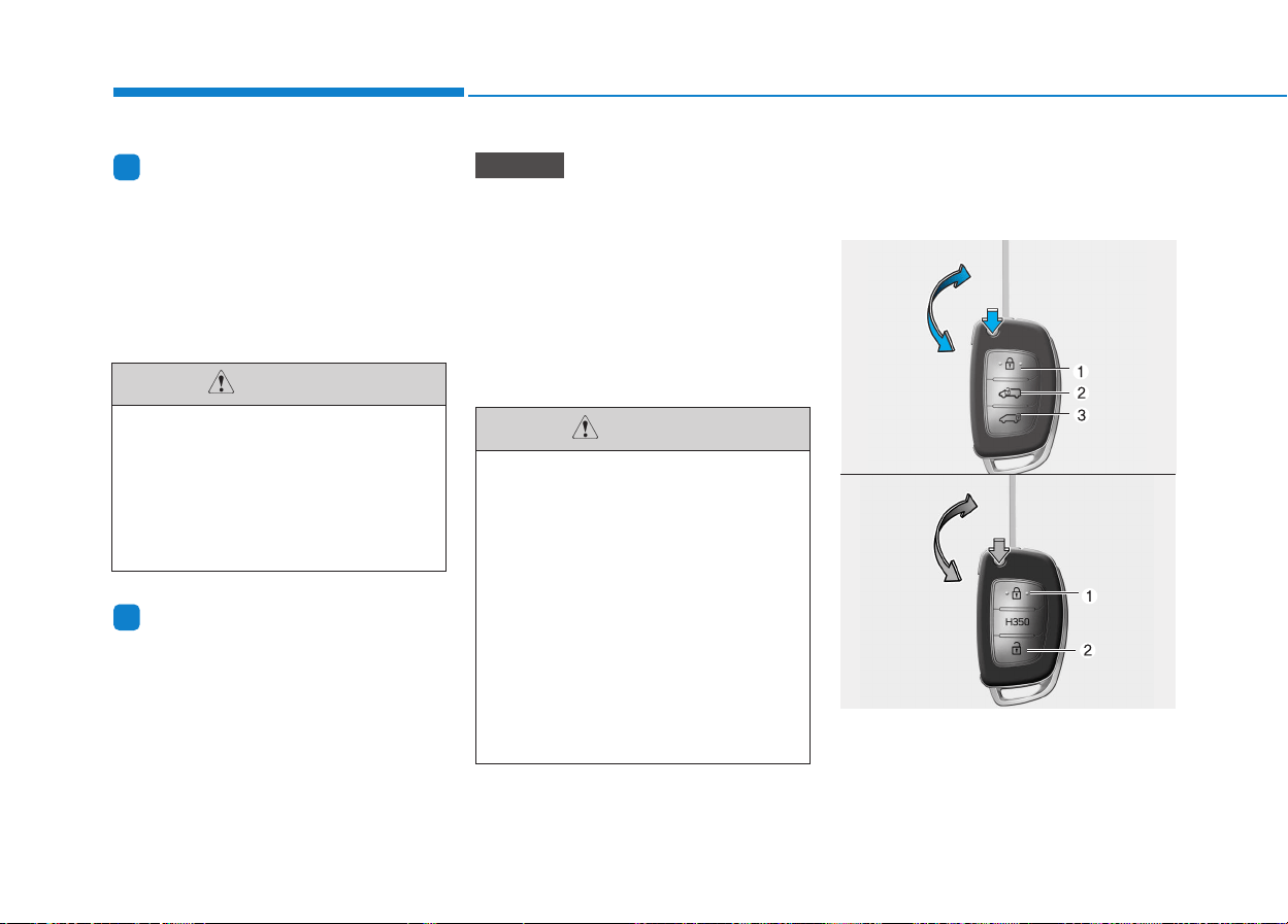
3-6
Information
When starting the engine, do not use
the key with other immobilizer keys
around. Otherwise the engine may not
start or may stop soon after it starts.
Keep each key separately not to have
any malfunction after you receive
your new vehicle.
Information
If you need additional keys or lose
your keys, we recommend that you
consult an authorized HYUNDAI
dealer.
The transponder in your ignition
key is an important part of the
immobilizer system. It is designed
to give years of trouble-free serv-
ice, however you should avoid
exposure to moisture, static elec-
tricity and rough handling.
Immobilizer system malfunction
could occur.
Remote keyless entry system
operations
To unfold the key, press the release
button then the key will unfold auto-
matically.
To fold the key, fold the key manually
while pressing the release button.
NOTICE
i
i
Convenient features of your vehicle
Do not put metal accessories
near the ignition switch.
The engine may not start for the
metal accessories may interrupt
the transponder signal from
normally transmitting.
CAUTION
Do not change, alter or adjust
the immobilizer system
because it could cause the
immobilizer system to malfunc-
tion. We recommend that the
system be serviced by an
authorized HYUNDAI dealer.
Malfunctions caused by
improper alterations, adjust-
ments or modifications to the
immobilizer system are not cov-
ered by your vehicle manufac-
turer warranty.
CAUTION
RREEMMOOTTEE KKEEYYLLEESSSS EENNTTRRYY
(
(IIFF EEQQUUIIPPPPEEDD))
OEU044069
OEU044001
■ Type A
■ Type B

3-7
Convenient features of your vehicle
Do not fold the key without press-
ing the release button. This may
damage the key.
Lock (1)
All doors (and rear door) are locked if
the lock button is pressed. If all doors
are closed, the hazard warning lights
blink once to indicate that all doors
are locked. However, if any door
remains open, the hazard warning
lights will not blink. Close the door
and try again to lock the doors.
Unlock (2)
Driver door and front passenger door
are unlocked if the unlock button is
pressed.
The hazard warning lights will blink
twice to indicate that driver door and
front passenger door are unlocked.
After depressing this button, the
doors will be locked automatically
unless you open any door within 30
seconds.
Rear door and mid sliding door
unlock (3) (if equipped)
The rear door and mid sliding door
are unlocked if the button is pressed
for more than 1 second.
The hazard warning lights will blink
twice to indicate that the rear door
and mid sliding door are unlocked.
However, after pressing this button,
the rear door and mid sliding door
will lock automatically unless you
open the rear door within 30 sec-
onds.
Also, once the rear door and mid
sliding door are opened and then
closed, the rear door will lock auto-
matically.
Transmitter precautions
The transmitter will not work if any of
following occur:
• The ignition key is in ignition
switch.
• You exceed the operating distance
limit (about 30 m [90 feet]).
• The battery in the transmitter is
weak.
• Other vehicles or objects may be
blocking the signal.
• The weather is extremely cold.
• The transmitter is close to a radio
transmitter such as a radio station
or an airport which can interfere
with normal operation of the trans-
mitter.
When the transmitter does not work
correctly, open and close the door
with the ignition key. If you have a
problem with the transmitter, we rec-
ommend that you contact an author-
ized HYUNDAI dealer.
NOTICE
3
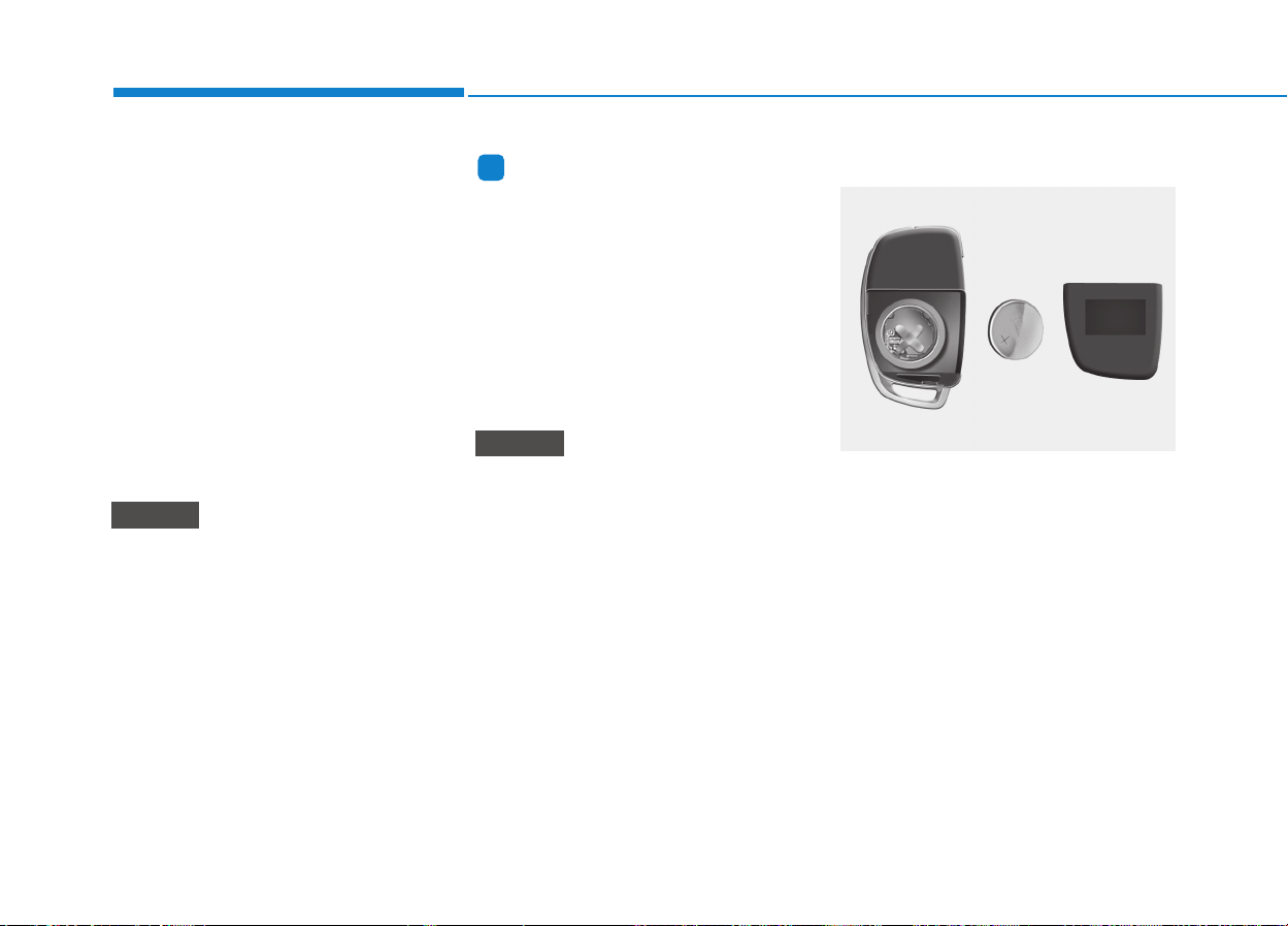
3-8
• If the transmitter is in close proxim-
ity to your cell phone or smart
phone, the signal from the trans-
mitter could be blocked by normal
operation of your cell phone or
smart phone. This is especially
important when the phone is active
such as making call, receiving
calls, text messaging, and/or send-
ing/ receiving emails. Avoid placing
the transmitter and your cell phone
or smart phone in the same pants
or jacket pocket and maintain ade-
quate distance between the two
devices.
Keep the transmitter away from
water or any liquid. If the keyless
entry system is inoperative due to
exposure to water or liquids, it will
not be covered by your manufac-
turer vehicle warranty.
Information
Changes or modifications not express-
ly approved by the party responsible
for compliance could void the user's
authority to operate the equipment. If
the keyless entry system is inoperative
due to changes or modifications not
expressly approved by the party
responsible for compliance, it will not
be covered by your manufacturer's
vehicle warranty.
Keep the transmitter away from
electromagnetic materials that
blocks electromagnetic waves to
the key surface.
Battery replacement
Transmitter uses a 3 volt lithium bat-
tery which will normally last for sev-
eral years. When replacement is
necessary, use the following proce-
dure.
1.Insert a slim tool into the slot and
gently pry open the transmitter
center cover.
2.Replace the battery with a new
battery (CR2032). When replacing
the battery, make sure the battery
position.
3.Install the battery in the reverse
order of removal.
NOTICE
i
NOTICE
Convenient features of your vehicle
OLM042302
3-9
Convenient features of your vehicle
For transmitter replacement, we rec-
ommend that you contact an author-
ized HYUNDAI dealer.
Information
An inappropriately disposed battery
can be harmful to the environment
and human health.
Dispose the battery according to your
local law(s) or regulation.
This system is designed to provide
protection from unauthorized entry
into the vehicle. This system is oper-
ated in three stages: the first is the
"Armed" stage, the second is the
"Theft-alarm" stage, and the third is
the "Disarmed" stage. If triggered,
the system provides an audible
alarm with blinking of the hazard
warning lights.
i
3
• The keyless entry system
transmitter is designed to
give you years of trouble-free
use, however it can malfunc-
tion if exposed to moisture or
static electricity. If you are
unsure how to use your trans-
mitter or replace the battery,
we recommend that you con-
tact an authorized HYUNDAI
dealer.
• Using the wrong battery can
cause the transmitter to mal-
function. Be sure to use the
correct battery.
• To avoid damaging the trans-
mitter, don't drop it, get it wet,
or expose it to heat or sun-
light.
CAUTION
TTHHEEFFTT--AALLAARRMM SSYYSSTTEEMM
(
(IIFF EEQQUUIIPPPPEEDD))
Armed
stage
Theft-alarm
stage
Disarmed
stage

3-10
Convenient features of your vehicle
Armed stage
Park the vehicle and stop the engine.
Arm the system as described below.
1.Remove the ignition key from the
ignition switch or turn off the
engine.
2.Make sure that all doors (and rear
door) and the engine hood are
closed and latched.
3.Lock the doors by depressing the
door lock button on the transmitter.
After completion of the steps
above, the hazard warning lights
will blink once to indicate that the
system is armed.
If any door, rear door remains
open, the hazard warning lights
won't operate and theft-alarm will
not arm. Close the door and try
again to lock the doors.
If any door (and rear door) remains
open, the hazard warning lights
won't operate and theft-alarm will
not arm. Close the door and try
again to lock the doors.
If engine hood remains open, the
hazard warning lights won't oper-
ate and theft-alarm will not arm.
Close the engine hood. The hazard
warning lights blink once and theft-
alarm arms.
• Do not arm the system until all
passengers have left the vehi-
cle. If the system is armed while
a passenger(s) remains in the
vehicle, the alarm may be acti-
vated when the remaining pas-
senger(s) leave the vehicle. If
any door, rear door or engine
hood is opened within 30 sec-
onds after entering the armed
stage, the system is disarmed to
prevent unnecessary alarm.
Theft-alarm stage
The alarm will be activated if any of
the following occurs while the system
is armed.
• A front or rear door is opened with-
out using transmitter.
• The rear door is opened without
using transmitter.
• The engine hood is opened.
The siren will sound and the hazard
warning lights will blink continuously
for 27 seconds, unless the system is
disarmed. To turn off the system,
unlock the doors with the transmitter.
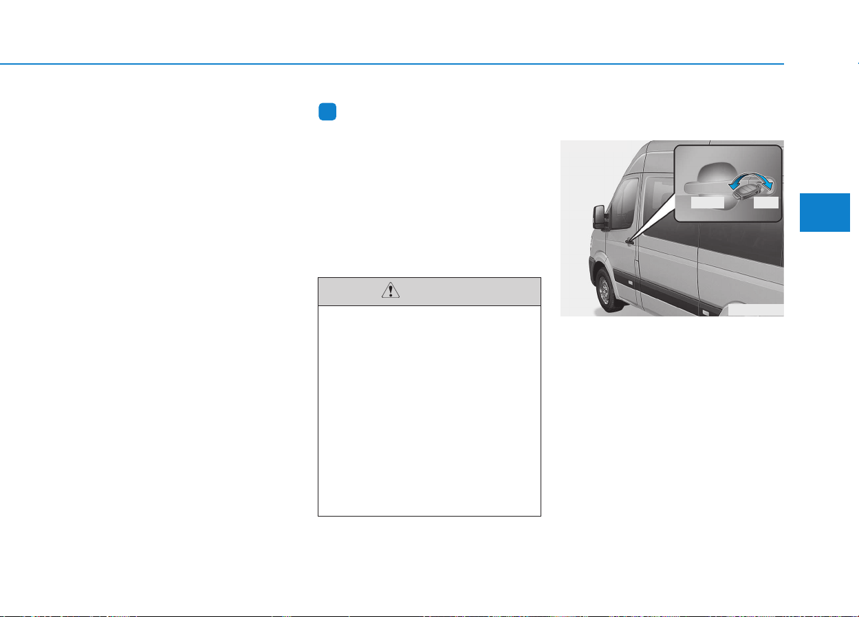
3-11
Convenient features of your vehicle
3
Disarmed stage
The system will be disarmed when:
Transmitter
- The door unlock button is pressed.
- The engine is started.
- The ignition switch is in the "ON"
position. (Armed stage status)
- The ignition switch is in the "ACC"
position for 27 seconds or more.
(Theft-alarm stage status)
After the doors are unlocked, the
hazard warning lights will blink twice
to indicate that the system is dis-
armed.
After pressing the unlock button, if
any door (or rear door) is not opened
within 30 seconds, the system will be
rearmed.
Information
Burglar alarm system
• If the system is not disarmed with
the transmitter, insert the key into
the ignition switch and start the
engine. Then the system will be dis-
armed.
• If you lose your keys, we recom-
mend that you consult an author-
ized HYUNDAI dealer.
Operating door locks from
outside the vehicle
• Turn the key toward rear of vehicle
to unlock and toward front of vehi-
cle to lock.
• If you lock/unlock the door with a
key, all vehicle doors will
lock/unlock automatically. (if
equipped)
• Doors can also be locked and
unlocked with the transmitter key.
• Once the doors are unlocked, they
may be opened by pulling the door
handle.
• When closing the door, push the
door by hand. Make sure that
doors are closed securely.
i
Do not change, alter or adjust
the theft-alarm system because
it could cause the theft-alarm
system to malfunction. We rec-
ommend that the system be
serviced by an authorized
HYUNDAI dealer.
Malfunctions caused by
improper alterations, adjust-
ments or modifications to the
theft-alarm system are not cov-
ered by your vehicle manufac-
turer warranty.
CAUTION
DDOOOORR LLOOCCKKSS
OEU044002
Lock
Unlock
■ Front doors
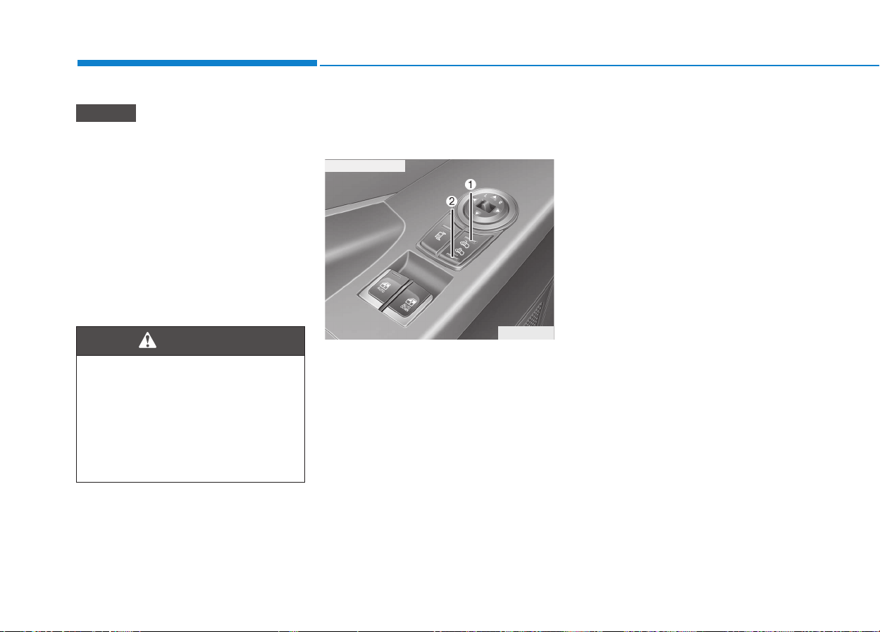
3-12
Convenient features of your vehicle
• In cold and wet climates, door
lock and door mechanisms may
not work properly due to freez-
ing conditions.
• If the door is locked/unlocked
multiple times in rapid succes-
sion with either the vehicle key
or door lock switch, the system
may stop operating temporarily
in order to protect the circuit
and prevent damage to system
components.
Operating door locks from
inside the vehicle
With the door lock button
• To unlock front driver's door and
front passenger's door, press the
unlock switch (1).
• To lock front driver's door and front
passenger's door, press the lock
switch (2).
• To open a door, pull the door han-
dle outward.
• If the inner door handle of all doors
are pulled when the door lock but-
ton is in the lock position, the but-
ton will unlock and the door will
open. (if equipped)
• Front doors cannot be locked if the
ignition key is in the ignition switch
and any front door is opened.
NOTICE
• If you don't close the door
securely, the door may open
again.
• Be careful that someone's
body and hands are not
trapped when closing the
door.
WARNING
OEU045008
■ Driver’s doors
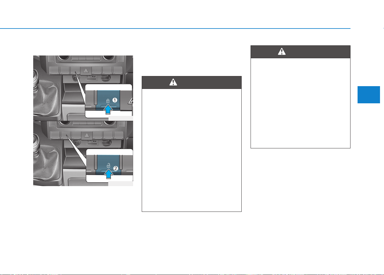
3-13
Convenient features of your vehicle
3
With central door lock switch
Operate by depressing the central
door lock switch.
• When pushing down lock button
(1), all vehicle doors will lock.
• When pushing down unlock button
(2), all vehicle doors will unlock.
• However, if any door (and rear
door) is open, the doors will not
lock even though the central door
lock switch is pressed.
OEU044190
OEU044189
Doors
• The doors should always be
fully closed and locked while
the vehicle is in motion to pre-
vent accidental opening of the
door. Locked doors will also
discourage potential intruders
when the vehicle stops or
slows.
• Be careful when opening
doors and watch for vehicles,
motorcycles, bicycles or
pedestrians approaching the
vehicle in the path of the door.
Opening a door when some-
thing is approaching can
cause damage or injury.
WARNING
Unlocked vehicles
Must be locked the outside door
by using key or remote key.
Leaving your vehicle unlocked
can invite theft or possible harm
to you or others from someone
hiding in your vehicle while you
are gone. Always remove the
ignition key, engage the parking
brake, close all windows and
lock all doors when leaving
your vehicle unattended.
WARNING
3-14
Deadlocks (if equipped)
Some vehicles are equipped with a
deadlocking system. Deadlocks pre-
vent opening of a door from either
inside or outside the vehicle once the
deadlocks have been activated pro-
viding an additional measure of vehi-
cle security.
To lock the vehicle using the dead-
lock function, the doors must be
locked using the Remote keyless
entry transmitter. To unlock the vehi-
cle, the transmitter must again be
used.
Speed sensing door lock sys-
tem (if equipped)
All doors will be automatically locked
after the vehicle speed exceeds 15
km/h. And all doors will be automati-
cally unlocked when you turn the
engine off or when you remove the
ignition key. (if equipped)
Convenient features of your vehicle
Unattended children
An enclosed vehicle can
become extremely hot, causing
death or severe injury to unat-
tended children or animals who
cannot escape the vehicle.
Furthermore, children might
operate features of the vehicle
that could injure them, or they
could encounter other harm,
possibly from someone gaining
entry to the vehicle. Never leave
children or animals unattended
in your vehicle.
WARNING
Do not lock the doors with the
transmitter with anybody left in
the vehicle. The passenger in
the vehicle cannot unlock the
doors with the door lock button.
For example, if the door is
locked with the transmitter, the
passenger in the vehicle cannot
unlock the door without the
transmitter.
WARNING
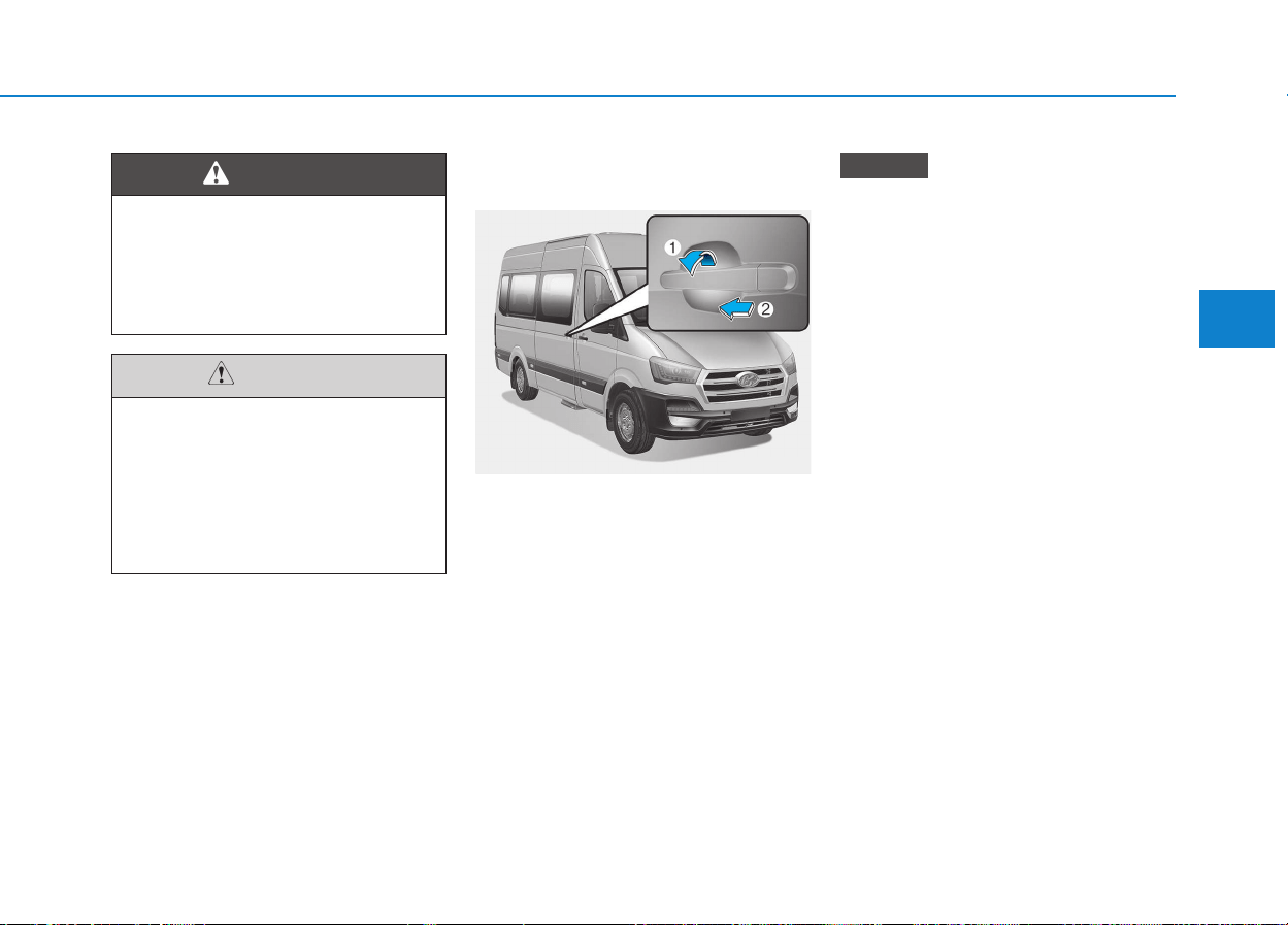
3-15
Convenient features of your vehicle
Your vehicle's sliding door may be
equipped with an electrical step.
When opening and closing the slid-
ing door, observe the notes on the
electrical step. (if equipped)
Opening/closing from the out-
side
The sliding door is equipped with an
active retainer, which engages the
door at the end stop when opened.
Your vehicle may be equipped
with a long sliding door with an
intermediate detent.
You can also lock the sliding door
in place around halfway when
opening/closing. If you do this, the
door does not have to be opened
fully when getting into or out of
the vehicle. The sliding door is not
fully engaged when in the interme-
diate detent.
To open: Pull door handle (1).
Push back the sliding door using
door handle (1) until it engages.
Check the sliding door detent.
To close: Slide the sliding door firm-
ly forwards by handle (1) until it clos-
es.
NOTICE
3
Your vehicle's sliding door may
be equipped with an electrical
step. When opening and closing
the sliding doors, observe the
notes on the electrical step.
WARNING
MMIIDD SSLLIIDDIINNGG DDOOOORR ((IIFF EEQQUUIIPPPPEEDD))
Only open the door, when vehi-
cle is parked on a flat ground.
Make sure that there is suffi-
cient clearance when opening
the doors. Otherwise, It may
cause damage of your vehicle
or other vehicles.
CAUTION
OEU044004
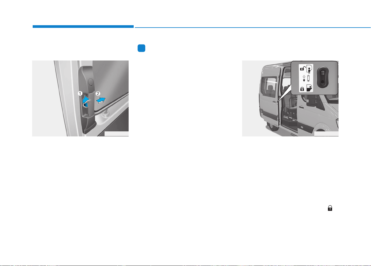
3-16
Opening/closing from the
inside
The sliding door is equipped with an
active retainer, which engages the
door at the end stop when opened.
You can only open a sliding door
from the inside if the child-proof locks
have not been activated. Locking
knob (2) pops up when you open a
locked door. Only this sliding door is
unlocked. The other doors remain
locked.
Information
Your vehicle may be equipped with a
long sliding door with an intermediate
detent.
You can also lock the sliding door in
place around halfway when
opening/closing. If you do this, the
door does not have to be opened fully
when getting into or out of the vehicle.
The sliding door is not fully engaged
when in the intermediate detent.
To open: Slide the sliding door by
handle (1) back to the stop.
Check the sliding door detent.
The sliding door must be engaged.
To close: Slide the sliding door firm-
ly forwards by handle (1) until it
engages.
Child-protector mid sliding
door lock (if equipped)
The child safety lock is provided to
help prevent children from acciden-
tally opening the mid sliding door
from inside the vehicle. The mid slid-
ing door safety locks should be used
whenever children are in the vehicle.
1.Open the sliding door.
2.Push the child safety lock located on
the mid sliding edge of the door to
the "Lock" position. When the child
safety lock is in the "Lock ( )"
position, mid sliding door will not
open even though the inner door
handle is pulled inside the vehicle.
i
Convenient features of your vehicle
OEU044005 OEU044003
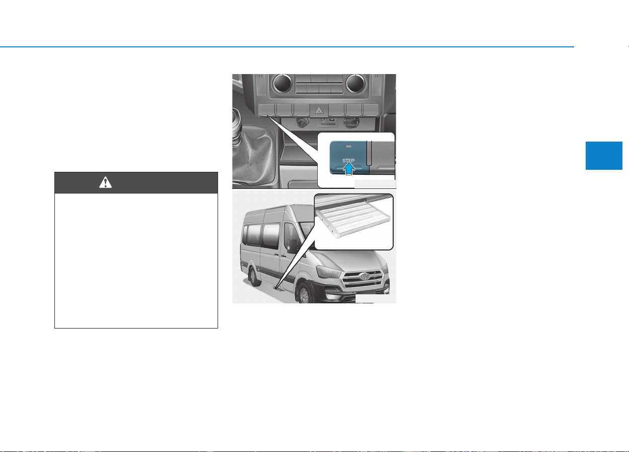
3-17
Convenient features of your vehicle
3. Close the mid sliding door.
To open the mid sliding door, pull the
outside door handle.
Even though the door may be
unlocked, the mid sliding door will
not open by pulling the inner door
handle until mid sliding door child
safety lock is unlocked.
Your vehicle's mid sliding door may
be equipped with an electrical step.
When getting in and out of the vehi-
cle, use the grab handles and electri-
cal step.
If you turn on the step switch to oper-
ate the electrical step, the electrical
step automatically extends when the
mid sliding door is opened and
retracts when it is closed. When the
electrical step is either in operation
or extended out, the electrical step
indicator illuminates on the instru-
ment cluster.
3
Mid sliding door lock
If children accidentally open the
mid sliding door while the vehi-
cle is in motion, they could fall
out and be severely injured or
killed. To prevent children from
opening the mid sliding door
from the inside, the mid sliding
door safety lock should be used
whenever children are in the
vehicle.
WARNING
OEU044188
OEU044048
EELLEECCTTRRIICCAALL SSTTEEPP ((IIFF EEQQUUIIPPPPEEDD))
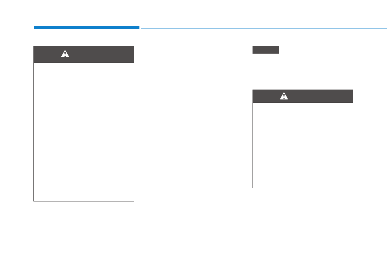
3-18
The default setting of the STEP
switch is the ON position.
Press the STEP switch, when the
electrical step is not in use in regard-
less of opening/closing of the mid-
sliding door.
In this case, the LED indicator on the
STEP switch goes OFF.
To use the electrical step, re-press
the STEP switch. Then, the LED indi-
cator on the STEP switch will illumi-
nate.
Conditions to extend the electrical
step:
1) The vehicle is stopped.
2) The shift gear is in N (Neutral).
3) Either the parking brake or the
foot brake is applied.
The electrical step automatically
retracts in from the “extending-out”
position, when the conditions 1 and 2
are unsatisfied.
When the electrical step is extend-
ed out, the accelerator inter-lock
operates to block the vehicle
acceleration for your safety.
NOTICE
Convenient features of your vehicle
Never move the shift lever,
when any passengers exit or
enter the vehicle through the
mid sliding door. In this situa-
tion, shifting the gear out of N
(Neutral) causes the electrical
step to abruptly retract and the
passengers to fall from it, caus-
ing the serious body injury.
Always make sure that all pas-
sengers enter or exit the vehi-
cle, before shifting the gear.
WARNING
If you do not use the grab han-
dle and the step, you could
injure yourself when getting in
and out of the vehicle.
To prevent risks:
• Draw the passengers' atten-
tion to the electrical step. Wait
until the electrical step is fully
extended.
• Do not jump out of the vehi-
cle.
• Only use the grab handle and
step. Only they are designed
for such a load.
• Keep grab handles, access
steps and entry sills free from
dirt, e.g. mud, clay, snow and
ice.
WARNING

3-19
Convenient features of your vehicle
Operation and obstacle detec-
tion
The electrical step (1) is equipped
with a device to detect an obstacle in
front.
When the electrical step comes into
contact with an obstacle while
extending out, its movement auto-
matically stops with 'short but repeti-
tive' warning alarms.
To fully extend out the electrical step
again, take the following steps. First,
remove the obstacle. Second, close
and then re-open the mid-sliding
door. Finally, repetitively press the
STEP switch to turn OFF and turn
ON the electrical step.
If the electrical step hinders load-
ing, you can block the step when
opening the sliding door by using
the obstruction detection. This
means that the electrical step
remains retracted and a fork-lift
truck or another lifting vehicle can
move closer to the load compart-
ment.
Electrical step warning alarm
1.Continuous beeping sound
You will hear this type of alarm,
whenever the electrical step oper-
ates.
2.Short beeping sound (short &
repetitive)
You will hear this type of alarm,
when the parking/foot brakes are
released.
In this case, apply the parking/foot
brakes for your safety.
3.Long beeping sound (long & repet-
itive)
You will hear this type of alarm,
when the operation of the electrical
step temporarily fails due to opera-
tional/electrical problems.
In this case, remove foreign sub-
stances, such as sand, mud, and
ice. Then, re-press the STEP
switch to operate the electrical
step.
However, if the problem persists,
manually push in the electrical step
as a safety measure. Still, we rec-
ommend you to have the electrical
step repaired by an authorized
HYUNDAI dealer.
NOTICE
3
Never drive your vehicle, when
the electrical step is extended
out. It may cause an accident,
strike with other vehicles, and
even injure passers-by. Always
drive your vehicle with the elec-
trical step fully retracted in.
WARNING
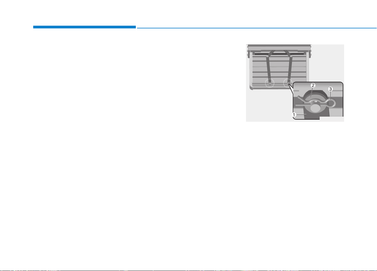
3-20
The emergency measures,
which you may take in case of
the electrical-step failures.
The step friction surface is con-
taminated with the foreign sub-
stances.
The electrical step may not normally
operate, when its friction surface is
contaminated. Repetitively operate
either the step switch or the mid-slid-
ing door 2-to-3 times. When the step
operation completely stops for the
same reason, manually push in the
step and turn OFF the switch.
Remove the foreign substances with
washing equipment at a vehicle
wash (Refer to the regular cleaning
in the chapter 3). Then, turn ON the
step switch, and operate the mid-
sliding door. When the electrical step
does not still normally operate, we
recommend that the electrical step
be checked by an authorized
HYUNDAI dealer.
Step does not operate, after
being extended out.
Hold the step in position with the R-
clip, as explained below. Then, turn
OFF the switch and visit a near-by
Hyundai dealer for repair services.
When you hear the warning alarm
while driving, you may stop the alarm
by disconnecting the electrical step
fuse located in the fuse box under
the left side of the driver's seat.
Hold the step in position with the
R-clip
1. Pull R-clips (3) on both rods (1) on
the underside of the step out of
their respective pins. Remove
washers (2) and detach both rods
(1).
Convenient features of your vehicle
OEU044078
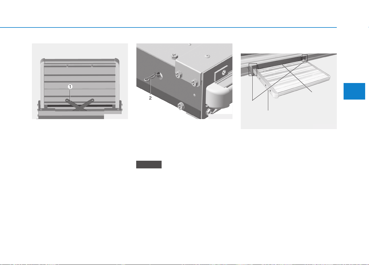
3-21
Convenient features of your vehicle
2. Fold rods (1) into the housing in
the step.
Push the step into its housing
3. Insert R-clips (2) into the step as
far as they will go through the
holes on both sides of the hous-
ing.
The step is secured in its housing.
When securing the step for the
first time, you must pierce a film
with the spring cotters.
Regular cleaning
Steps should be cleaned at least
once per month and more often if
conditions dictate.
By using a power hose or even a
standard hose frequently ensure no
build up of material inside the step.
The step will “self-clean” if the mud
and dirt is lubricated with a power
wash.
Remember to clean not just the tread
(the bit you stand on) but the side of
the step too.
NOTICE
3
OEU044079 OEU044226
OEU044077
Electric step
side rail
Lower entrance
Upper entrance
3-22
After cleaning the step should be
allowed to dry. When dry, a day or
two later perhaps, apply silicons
spray to help lubricate the movement
of the step.
Do not use grease. Avoid use of oil, it
will simply wash away.
If the conditions are particularly bad
daily cleaning may be required.
Failure to clean the step regularly or
to service the steps may result in the
failure of the step in service. This will
not be covered under warranty.
We recommend that mud flaps are
fitted to your vehicle.
Convenient features of your vehicle
RREEAARR DDOOOORR ((IIFF EEQQUUIIPPPPEEDD))
If you open a rear door, you
could:
• endanger other people or road
users
• be caught by oncoming traffic.
This is particularly the case if
you open the rear door more
than 90°. There is a risk of an
accident and injury.
Only open the rear doors when
traffic conditions permit.
Always make sure that the rear
door is properly locked.
WARNING
The rear lights will be covered if
you open the rear doors to the
90° detent position.
The vehicle will then be unsafe
as its rear lights will not be vis-
ible for approaching traffic.
Other road users may not real-
ize until too late that it is an
obstruction. This could lead to
an accident.
You should ensure that the
vehicle is visible from the rear
in accordance with the relevant
national regulations, by using
the warning triangle for
instance.
WARNING
Make sure that there is suffi-
cient clearance when opening
the rear doors. You could other-
wise damage the vehicle and
objects in close range of the
rear doors.
CAUTION
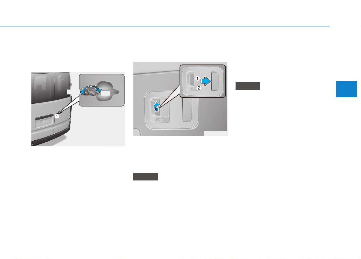
3-23
Convenient features of your vehicle
3
Opening/closing from the out-
side
Opening the right-hand rear
door
Pull handle (1) .
Swing the rear door to the side until
it engages.
Opening/closing from the
inside
Opening the right-hand rear
door
Release the lever on the inside of the
right rear door.
You can only open the locked rear
doors from the inside if the child-
proof locks have not been activat-
ed.
To unlock: Slide latch (2) to the
right. You will see a allow mark.
To open: Pull opening lever (1) up
and open the rear door.
Latch (2) slides to the right when
you open a locked rear door from
the inside. The white section is
visible. Only the rear door
unlocks. The other doors remain
locked.
To close: Make sure that the left-
hand rear door is closed.
Pull the rear door firmly by the door
handle to close it.
To lock: Slide latch (2) to the left.
NOTICE
NOTICE
OEU044010
OEU044006
Unlock
Lock
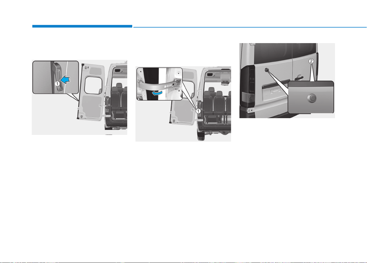
3-24
Convenient features of your vehicle
Opening the left-hand rear
door
Make sure that the right-hand rear
door is open and engaged.
Push release handle (1) in the direc-
tion of the arrow.
Swing the rear door to the side until
it engages.
Opening the rear doors to an
angle of 180° or 270°
(if equipped)
Open the rear door to about 45°.
Pull and hold door retainer (1) in the
direction of the arrow.
Open the rear door more than 90°,
so that the door retainer cannot
engage.
Release the door retainer and open
the door to an angle of 180° or 270°.
With the rear door opened to an
angle of 270°, push it against mag-
netic door retainer (2) on the side
wall.
When the magnet on the rear door is
in contact with magnetic door retain-
er (2) , the rear door is held in this
position.
OEU044053
OEU044054
OEU044007
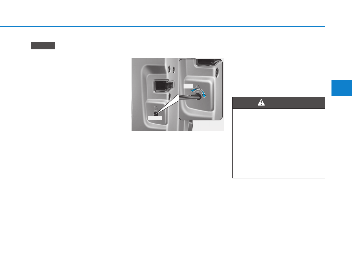
3-25
Convenient features of your vehicle
3
Vehicles with 270° pivoting rear
doors:
If door retainer (1) malfunctions
while loading, you can swivel it
180° against the spring force and
onto the door and engage it. The
door retainer remains in this posi-
tion and will not swivel back to its
original position.
Before closing the door, release
door retainer (1) from the detent
and return it to its original posi-
tion.
Closing the rear doors from
the outside (if equipped)
Pull the rear door away from mag-
netic door retainer.
Close the left-hand rear door firmly
from the outside.
Child-protector rear door lock
(if equipped)
The child safety lock is provided to
help prevent children from acciden-
tally opening the rear door from
inside the vehicle. The rear door
safety locks should be used whenev-
er children are in the vehicle.
1.Open the rear door.
2.Turn the child safety lock located on
the rear edge of right side door to
the "Lock" position. When the child
safety lock is position, rear door will
not open even though the inner door
handle is pulled inside the vehicle.
3. Close the rear door.
To open the rear door, pull the out-
side door handle.
Even though the door may be
unlocked, the rear door will not open
by pulling the inner door handle until
rear door child safety lock is
unlocked.
NOTICE
OEU044073
Rear door lock
If children accidentally open the
rear door while the vehicle is in
motion, they could fall out and
be severely injured or killed. To
prevent children from opening
the rear door from the inside,
the rear door safety lock should
be used whenever children are
in the vehicle.
WARNING
Lock
Unlock
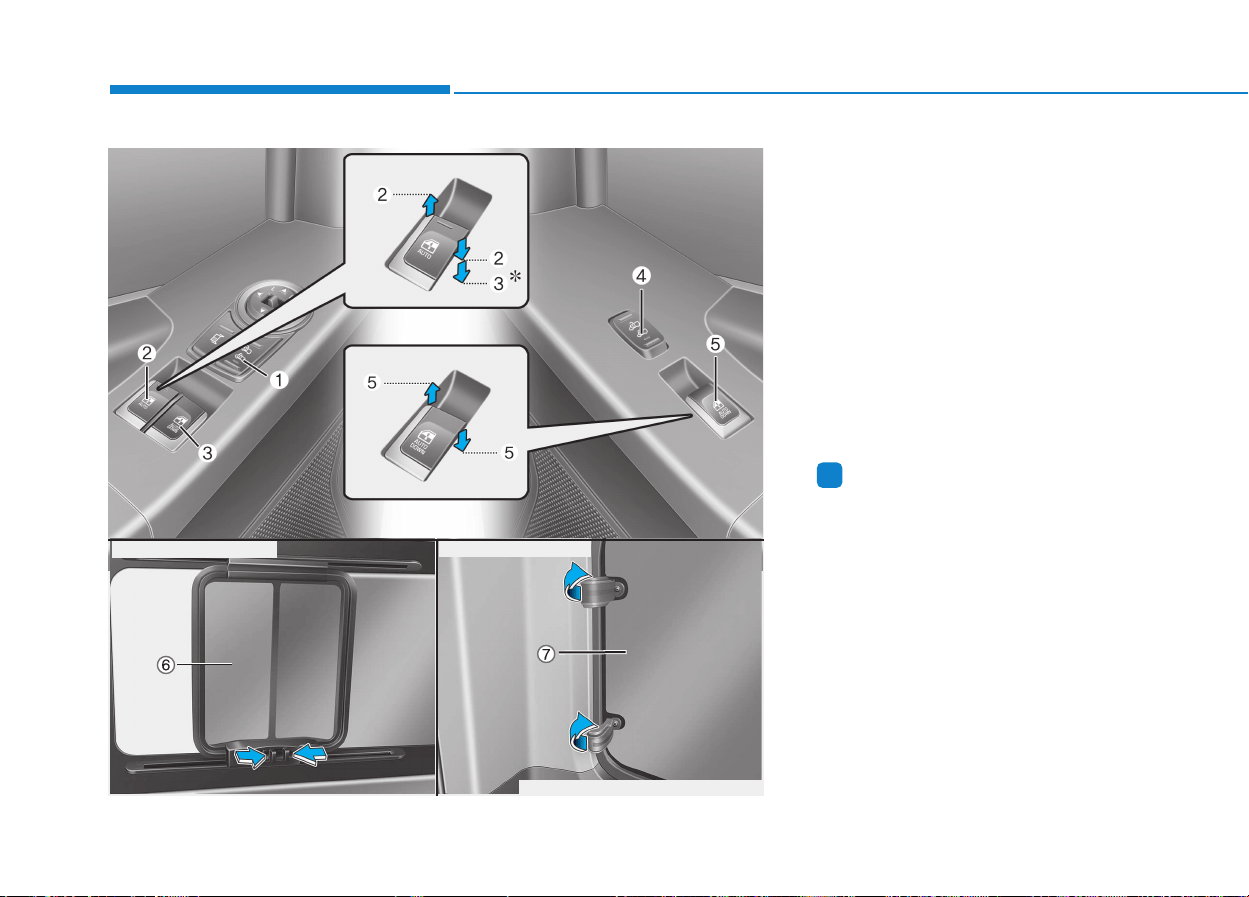
3-26
Convenient features of your vehicle
(1) Driver's door unlock/lock switch
(2) Automatic power window up */
down switch (Driver's side)
(3) Automatic power window down
switch (Driver's side)
(4) Passenger's door unlock /
lock switch
(5) Automatic power window
down switch (Passenger's side)
(6) Rear seat window (Type A)
(7) Rear seat window (Type B)
*: if equipped
Information
In cold and wet climates, power win-
dows may not work properly due to
freezing conditions.
i
WWIINNDDOOWWSS
OEU045046/OEU044080/OEU044014
■ Type A (if equipped)
■ Type B (if equipped)
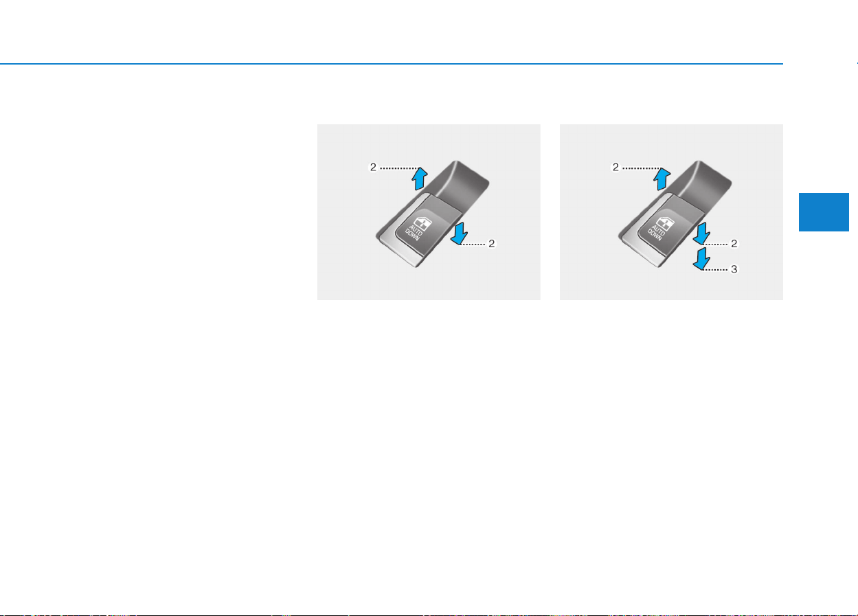
3-27
Convenient features of your vehicle
3
Power windows
The ignition switch must be in the ON
position for power windows to oper-
ate. Each door has a power window
switch that controls the door's win-
dow. The driver has a power window
lock switch which can block the oper-
ation of front passenger windows.
The power windows can be operated
for approximately 30 seconds after
the ignition key is removed or turned
to the ACC or LOCK position.
However, if the front doors are
opened, the power windows cannot
be operated even within the 30 sec-
onds period.
Window opening and closing
To open or close a window, press
down or pull up the front portion of
the corresponding switch to the first
detent position (2).
Auto down window
Pressing the power window switch
momentarily to the second detent
position (3) completely lowers the
driver's window even when the
switch is released. To stop the win-
dow at the desired position while the
window is in operation, pull up the
switch momentarily to the opposite
direction of the window movement.
OEU044044 OEU044012
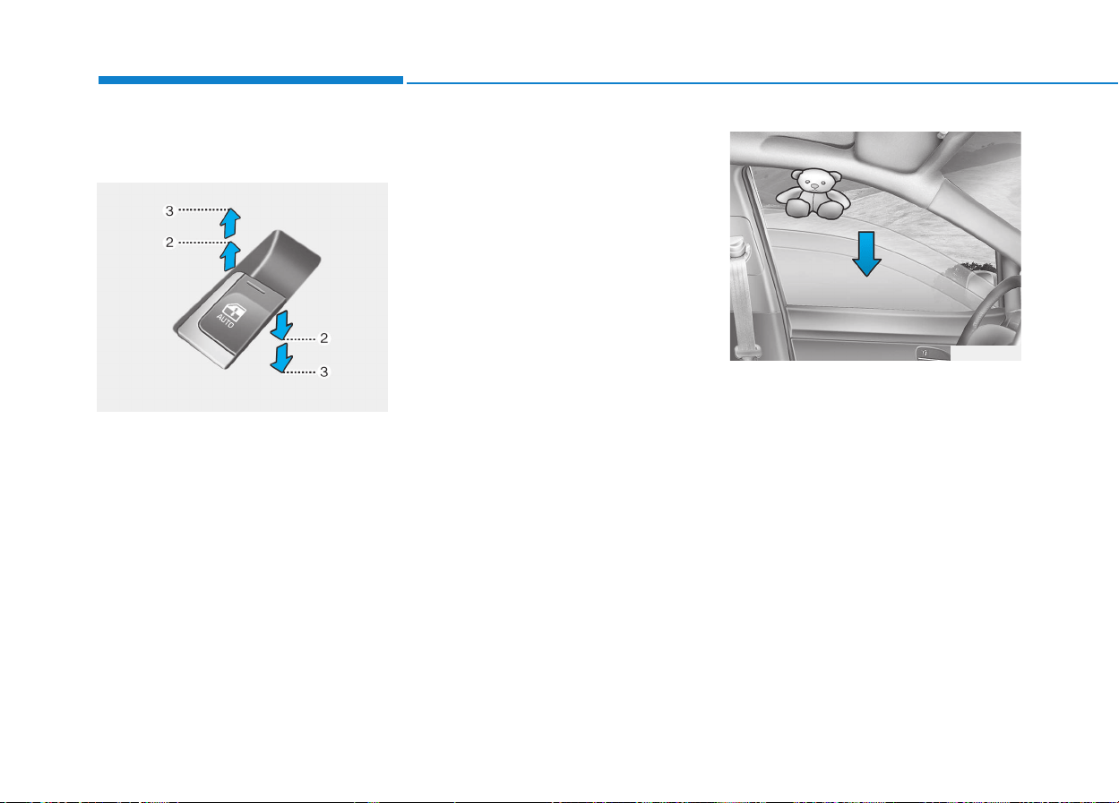
3-28
Convenient features of your vehicle
Auto up/down window
(if equipped) (Driver's window)
Pressing or pulling up the power win-
dow switch momentarily to the sec-
ond detent position (3) completely
lowers or lifts the window even when
the switch is released. To stop the
window at the desired position while
the window is in operation, pull up or
press down and release the switch.
If the power window does not oper-
ate normally, the automatic power
window system must be reset as fol-
lows:
1.Turn the ignition switch to the ON
position.
2.Close the driver's window and con-
tinue pulling up the driver's power
window switch for at least 1 second
after the window is completely
closed.
Automatic reversal (if equipped)
If the upward movement of the win-
dow is blocked by an object or part of
the body, the window will detect the
resistance and will stop upward
movement. The window will then
lower approximately 30 cm (11.8 in.)
to allow the object to be cleared.
If the window detects the resistance
while the power window switch is
pulled up continuously, the window
will stop upward movement then
lower approximately 2.5 cm (1 in.).
OEU044013
OEU034028
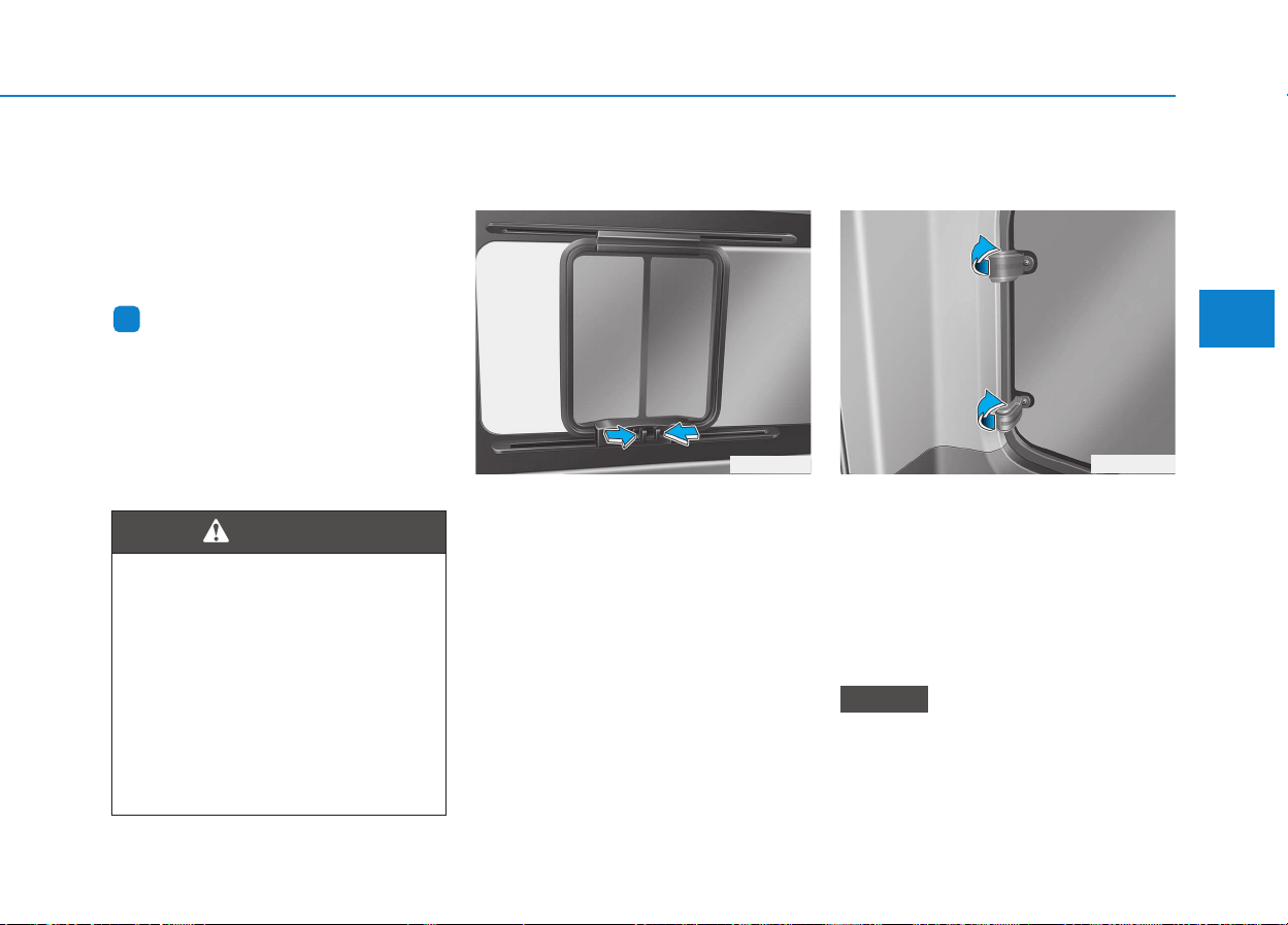
3-29
Convenient features of your vehicle
3
And if the power window switch is
pulled up continuously again within 5
seconds after the window is lowered
by the automatic window reversal
feature, the automatic window rever-
sal will not operate.
Information
The automatic reverse feature for the
driver's window is only active when
the "auto up" feature is used by fully
pulling up the switch. The automatic
reverse feature will not operate if the
window is raised using the halfway
position on the power window switch.
Rear seat window
(Type A, if equipped)
To open the window, move the win-
dow while pressing the handle the
direction of the arrow.
Rear seat window
(Type B, if equipped)
To open the windows, pull the rear
portion of the latch out. Swing the
latch forward and out, then lock it into
the open position by pushing out-
ward until you hear a click. To close
the windows, pull the handle inward.
Then push the handle rearward until
you hear a click.
In cold and wet climates, rear
quarter panel windows may not
work properly due to freezing con-
ditions.
NOTICE
i
OEU044080
Always check for obstructions
before raising any window to
avoid injuries or vehicle dam-
age. If an object less than 4 mm
(0.16 in.) in diameter is caught
between the window glass and
the upper window channel, the
automatic reverse window may
not detect the resistance and
will not stop and reverse direc-
tion.
WARNING
OEU044014
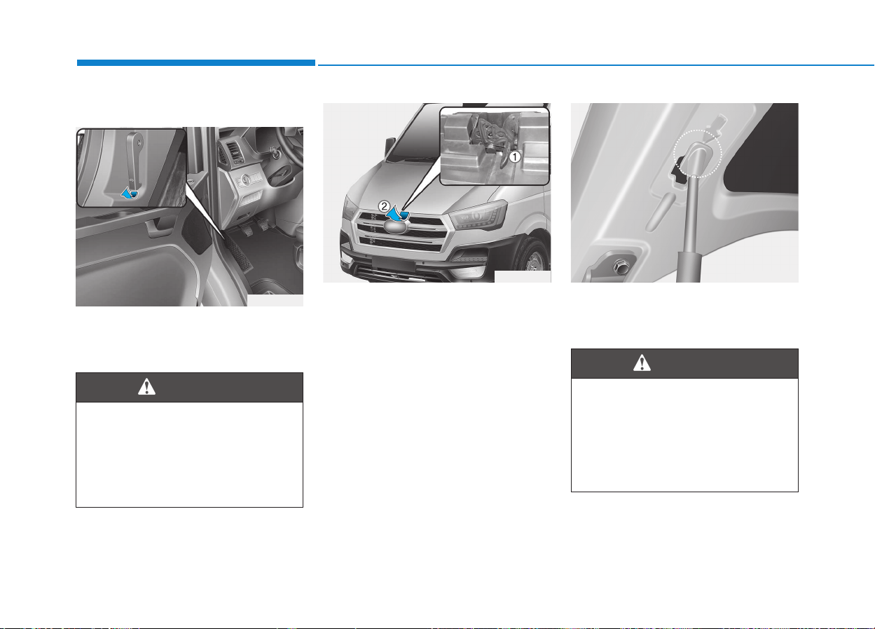
3-30
Convenient features of your vehicle
Opening the hood
1.Pull the release lever to unlatch the
hood. The hood should pop open
slightly.
2.Go to the front of the vehicle, raise
the hood slightly, pull the second-
ary latch (1) inside of the hood
center and lift the hood (2).
3.Pull out the support rod.
4.Hold the hood opened with the
support rod.
Open the hood after turning off
the engine on a flat surface,
shifting the shift lever to
R(Reverse) for manual trans-
mission, and setting the parking
brake.
WARNING
HHOOOODD
OEU044015
Hot parts
Grasp the support rod in the
area wrapped in plastic. The
plastic will help prevent you
from being burned by hot metal
when the engine is hot.
WARNING
OEU044036 OEU044016

3-31
Convenient features of your vehicle
3
Closing the hood
1.Before closing the hood, check the
following:
• All filler caps in engine compart-
ment must be correctly installed.
• Gloves, rags or any other com-
bustible material must be
removed from the engine com-
partment.
2.Return the support rod to its clip to
prevent it from rattling.
3.Lower the hood until it is about 30
cm (1 ft.) above the closed position
and let it drop. Make sure that it
locks into place.
Hood
• Before closing the hood,
ensure that all obstructions
are removed from the hood
opening. Closing the hood
with an obstruction present in
the hood opening may result
in property damage or severe
personal injury.
• Do not leave gloves, rags or
any other combustible materi-
al in the engine compartment.
Doing so may cause a heat-
induced fire.
WARNING
• Always double check to be
sure that the hood is firmly
latched before driving away. If
it is not latched, the hood
could fly open while the vehi-
cle is being driven, causing a
total loss of visibility, which
might result in an accident.
• The support rod must be
inserted completely into the
hole whenever you inspect
the engine compartment. This
will prevent the hood from
falling and possibly injuring
you.
• Do not move the vehicle with
the hood raised. The view will
be blocked and the hood
could fall or be damaged.
WARNING
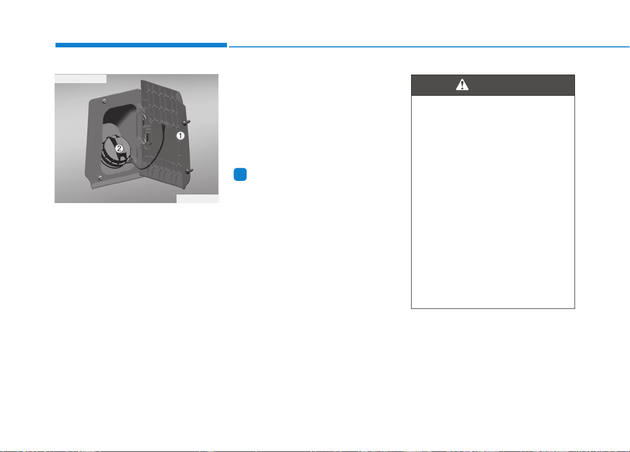
3-32
Convenient features of your vehicle
Open the driver's door, before open-
ing the fuel filler lid
1.Stop the engine
2.Fully open the fuel filler lid (1) by
pulling it out.
3.Turn the fuel tank cap in the coun-
terclockwise direction to open it.
4.Refuel the vehicle.
Closing the fuel filler lid
1.To install the cap, turn it clockwise
until it "clicks". This indicates that
the cap is securely tightened.
2.Close the fuel filler lid and push it
lightly and make sure that it is
securely closed.
Information
If the fuel-filler lid does not open
because ice has formed around it, tap
lightly or push on the lid to break the
ice and release the lid. Do not pry on
the lid. If necessary, spray around the
lid with an approved de-icer fluid (do
not use radiator anti-freeze) or move
the vehicle to a warm place and allow
the ice to melt.
i
FFUUEELL FFIILLLLEERR LLIIDD
OEU044017
■ Driver’s side
Refueling
• If pressurized fuel sprays out,
it can cover your clothes or
skin and thus subject you to
the risk of fire and burns.
Always remove the fuel cap
carefully and slowly. If the cap
is venting fuel or if you hear a
hissing sound, wait until the
condition stops before com-
pletely removing the cap.
• Do not "top off" after the noz-
zle automatically shuts off
when refueling.
• Always check that the fuel cap
is installed securely to pre-
vent fuel spillage in the event
of an accident.
WARNING

3-33
Convenient features of your vehicle
3
Refueling dangers
Automotive fuels are flammable
materials. When refueling,
please note the following guide-
lines carefully. Failure to follow
these guidelines may result in
severe personal injury, severe
burns or death by fire or explo-
sion.
• Read and follow all warning
posted at the gas station facil-
ity.
• Before touching the fuel noz-
zle, you should eliminate
potentially dangerous static
electricity discharge by touch-
ing another metal part of the
vehicle, a safe distance away
from the fuel filler neck, noz-
zle, or other gas source.
(Continued)
WARNING
(Continued)
• Do not get back into a vehicle
once you have begun refuel-
ing since you can generate
static electricity by touching,
rubbing or sliding against any
item or fabric (polyester, satin,
nylon, etc.) capable of produc-
ing static electricity. Static
electricity discharge can
ignite fuel vapors resulting in
rapid burning. If you must re-
enter the vehicle, you should
once again eliminate poten-
tially dangerous static elec-
tricity discharge by touching a
metal part of the vehicle, away
from the fuel filler neck, noz-
zle or other diesel source.
• When using an approved
portable fuel container, be
sure to place the container on
the ground prior to refueling.
(Continued)
(Continued)
Static electricity discharge
from the container can ignite
fuel vapors causing a fire.
Once refueling has begun,
contact with the vehicle
should be maintained until the
filling is complete.
Use only portable plastic fuel
containers designed to carry
and store diesel.
• Do not use cellular phones
while refueling. Electric cur-
rent and/or electronic interfer-
ence from cellular phones can
potentially ignite fuel vapors
causing a fire.
• When refueling, always shut
the engine off. Sparks pro-
duced by electrical compo-
nents related to the engine
can ignite fuel vapors causing
a fire. Once refueling is com-
plete, check to make sure the
filler cap and filler door are
securely closed, before start-
ing the engine.
(Continued)
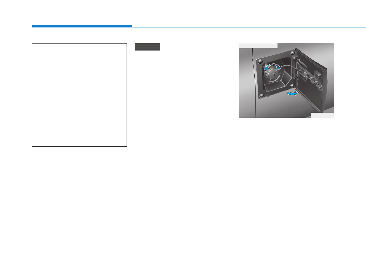
3-34
Convenient features of your vehicle
• Make sure to refuel your vehicle
according to the "Fuel require-
ments" suggested in section 1.
• If the fuel filler cap requires
replacement, we recommend
that you use parts for replace-
ment from an authorized
HYUNDAI dealer. An incorrect
fuel filler cap can result in a seri-
ous malfunction of the fuel sys-
tem or emission control system.
• Do not spill fuel on the exterior
surfaces of the vehicle. Any type
of fuel spilled on painted sur-
faces may damage the paint.
• After refueling, make sure the
fuel cap is installed securely to
prevent fuel spillage in the event
of an accident.
The urea level warning lamp illumi-
nates, when the urea solution vol-
ume falls below 12% or less of the
tank. Without adding the urea solu-
tion, when the urea solution volume
drops to 6%, urea level warning lamp
will start blinking. When the urea
solution volume drops 4% or under,
both urea level warning lamp and
urea system warning lamp will simul-
taneously blink with limited torque.
When the urea volume falls below
1%, both lamps will stay blinking sta-
tus with limited vehicle speed.
When the urea level warning lamp
illuminates, the urea solution must
be added.
NOTICE
(Continued)
• DO NOT use matches or a
lighter and DO NOT SMOKE or
leave a lit cigarette in your
vehicle while at a gas station
especially during refueling.
Automotive fuel is highly
flammable and can, when
ignited, result in fire.
• If a fire breaks out during refu-
eling, leave the vicinity of the
vehicle, and immediately con-
tact the manager of the gas
station and then contact the
local fire department.
UURREEAA SSOOLLUUTTIIOONN FFIILLLLEERR LLIIDD
OEU044018
■ Passenger’s side
3-35
Convenient features of your vehicle
To open the urea solution filler lid;
1.Open the urea solution filler lid.
2.To remove the cap, turn the urea
solution tank cap counterclock-
wise.
3.Refill as needed.
After completely filling, urea solu-
tion in the tank, refill urea solution
every 10,000 km.
NOTICE
3
• If the vehicle is driven with
urea solution volume less
than 4%, engine output will be
limited.
REFILL IN GOOD TIME
The reducing agent must be
replenished as soon as the
urea level warning lamp illu-
minates or blinks, otherwise
either engine torque or vehi-
cle speed can be limited.
(Continued)
CAUTION
• When opening the urea solu-
tion tank cap at high outside
temperatures, ammonia
vapors may escape. Ammonia
vapors have a pungent smell
and primarily cause irritation
of the:
- Skin
- Mucous membranes
- Eyes
You may experience a burning
sensation in your eyes, nose
and throat, as well as cough-
ing and watering of the eyes.
Do not inhale ammonia
vapors. Do not allow urea
solution to come in direct
contact with your skin. It is
hazardous to your health.
Wash any affected areas off
with plenty of clean water. If
necessary, consult a doctor.
(Continued)
WARNING
(Continued)
• Liquid that are not recom-
mended such as diesel, gaso-
line, and alcohol shall never
be used other than the recom-
mended urea solution that
satisfy ISO22241 or DIN70070.
• Driver must use with a reduc-
ing agent UREA solution for
the SCR system working
properly. In order to comply
with emissions regulations,
the vehicle must be operated
using UREA solution.
If driver is driving a vehicle
without using a UREA solu-
tion, driving permit may be
revoked, in some countries
you may be a criminal
offense, such as road traffic
offenses.
3-36
Urea solution consumption
depends on operation and driving
conditions. If the urea level warn-
ing lamp illuminates, you should
refill before the next scheduled
service to replenish the fluid.
NOTICE
Convenient features of your vehicle
• In case the vehicle was
parked with very low ambient
temperature (below 11 degree
Celcius) for a long time, the
urea solution will be frozen in
the urea solution tank. With
frozen urea, the tank level may
not be detected correctly until
the urea solution will be
defrosted by activated heater.
• To conform to emission regu-
lation, you must operate the
vehicle with urea solution and
refill the supply regularly.
WARNING
If defective urea solution or liq-
uid that is not recommended is
supplied, there may be damage
on the parts of the vehicle such
as processing device. If defec-
tive fuel is used, foreign objects
will be accumulated to SCR cat-
alyst and cause catalyst pushed
away or breaking.
After adding the incorrect urea
solution, please visit the closest
service center as early as possi-
ble.
CAUTION
(Continued)
• When handling with urea
solution in closed space,
ensure good ventilation.
When the bottle of urea solu-
tion container is opened, pun-
gent smelling fumes may
escape.
• Keep urea solution out of
reach of children.
• When urea solution overflows
into vehicle surface, wash out
vehicle surface with clean
water to prohibit corrosion
from occurring.
3-37
Convenient features of your vehicle
3
Power steering
Power steering uses energy from the
engine to assist you in steering the
vehicle. If the engine is off or if the
power steering system becomes
inoperative, the vehicle may still be
steered, but it will require increased
steering effort.
Should you notice any change in the
effort required to steer during normal
vehicle operation, have the power
steering checked by an authorized
HYUNDAI dealer.
If the power steering drive belt
breaks or if the power steering
pump malfunctions, the steering
effort will greatly increase.
If the vehicle is parked for extend-
ed periods outside in cold weath-
er (below -10°C/14°F), the power
steering may require increased
effort when the engine is first
started. This is caused by
increased fluid viscosity due to
the cold weather and does not
indicate a malfunction.
When this happens, increase the
engine RPM by depressing accel-
erator until the RPM reaches 1,500
rpm then release or let the engine
idle for two or three minutes to
warm up the fluid.
Tilt & telescopic steering
A tilt steering column allows you to
adjust the steering wheel before you
drive. You can also raise it to give
your legs more room when you exit
and enter the vehicle (if equipped).
The steering wheel should be posi-
tioned so that it is comfortable for
you to drive, while permitting you to
see the instrument panel warning
lights and gauges.
NOTICE
NOTICE
SSTTEEEERRIINNGG WWHHEEEELL
Never hold the steering wheel
against a stop (extreme right or
left turn) for more than 5 sec-
onds with the engine running.
Holding the steering wheel for
more than 5 seconds in either
position may cause damage to
the power steering pump.
CAUTION
• Never adjust the angle and
height of steering wheel while
driving. You may lose your
steering control and cause
severe personal injury or acci-
dents.
• After adjusting, push the
steering wheel both up and
down to be certain it is locked
in position.
WARNING
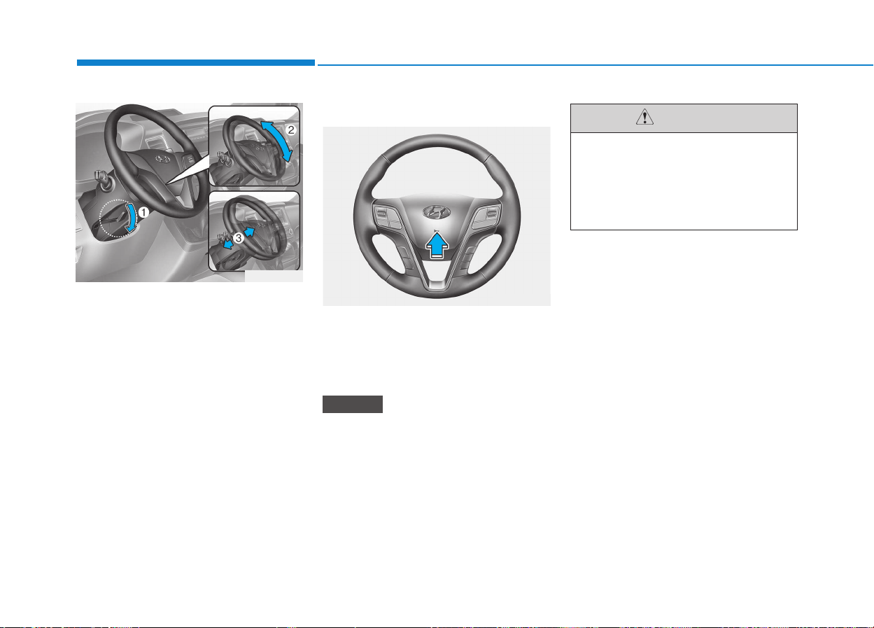
3-38
Convenient features of your vehicle
To change the steering column
angle, pull down the lock release
lever (1), adjust the steering column
to the desired angle (2) and height
(3, if equipped), then pull up the lock-
release lever to lock the steering
wheel in place. Be sure to adjust the
steering column to the desired posi-
tion before driving.
Horn
To sound the horn, press the horn
symbol on your steering wheel.
Check the horn regularly to be sure it
operates properly.
To sound the horn, press the area
indicated by the horn symbol on
your steering wheel (see illustra-
tion). The horn will operate only
when this area is pressed.
NOTICE
Do not strike the horn severely
to operate it, or hit it with your
fist.
Do not press on the horn with a
sharp-pointed object.
CAUTION
OEU044020
OEU044019
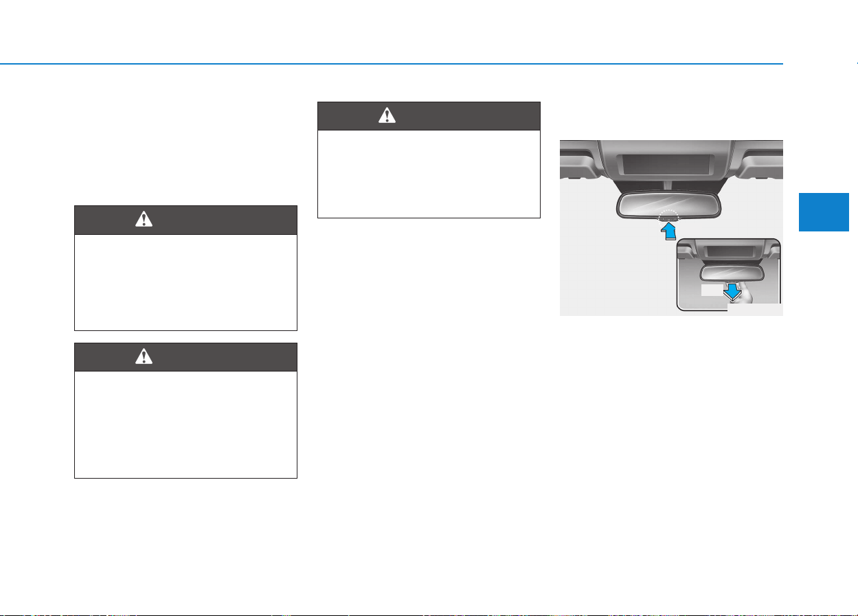
3-39
Convenient features of your vehicle
3
Inside rearview mirror
(if equipped)
Adjust the rearview mirror to center
on the view through the rear window.
Make this adjustment before you
start driving.
Day/night rearview mirror
(if equipped)
Make this adjustment before you
start driving and while the day/night
lever is in the day position.
Pull the day/night lever toward you to
reduce glare from the headlights of
vehicles behind you during night
driving.
Remember that you lose some
rearview clarity in the night position.
Rear visibility
Do not place objects in the rear
seat or cargo area which would
interfere with your vision out
the rear window.
WARNING
Do not adjust the rearview mir-
ror while the vehicle is moving.
This could result in loss of con-
trol, and an accident which
could cause death, serious
injury or property damage.
WARNING
MMIIRRRROORRSS
Do not modify the inside mirror
and do not install a wide mirror.
It could result in injury, during
an accident or deployment of
the air bag.
WARNING
OEU044074
Day
Night
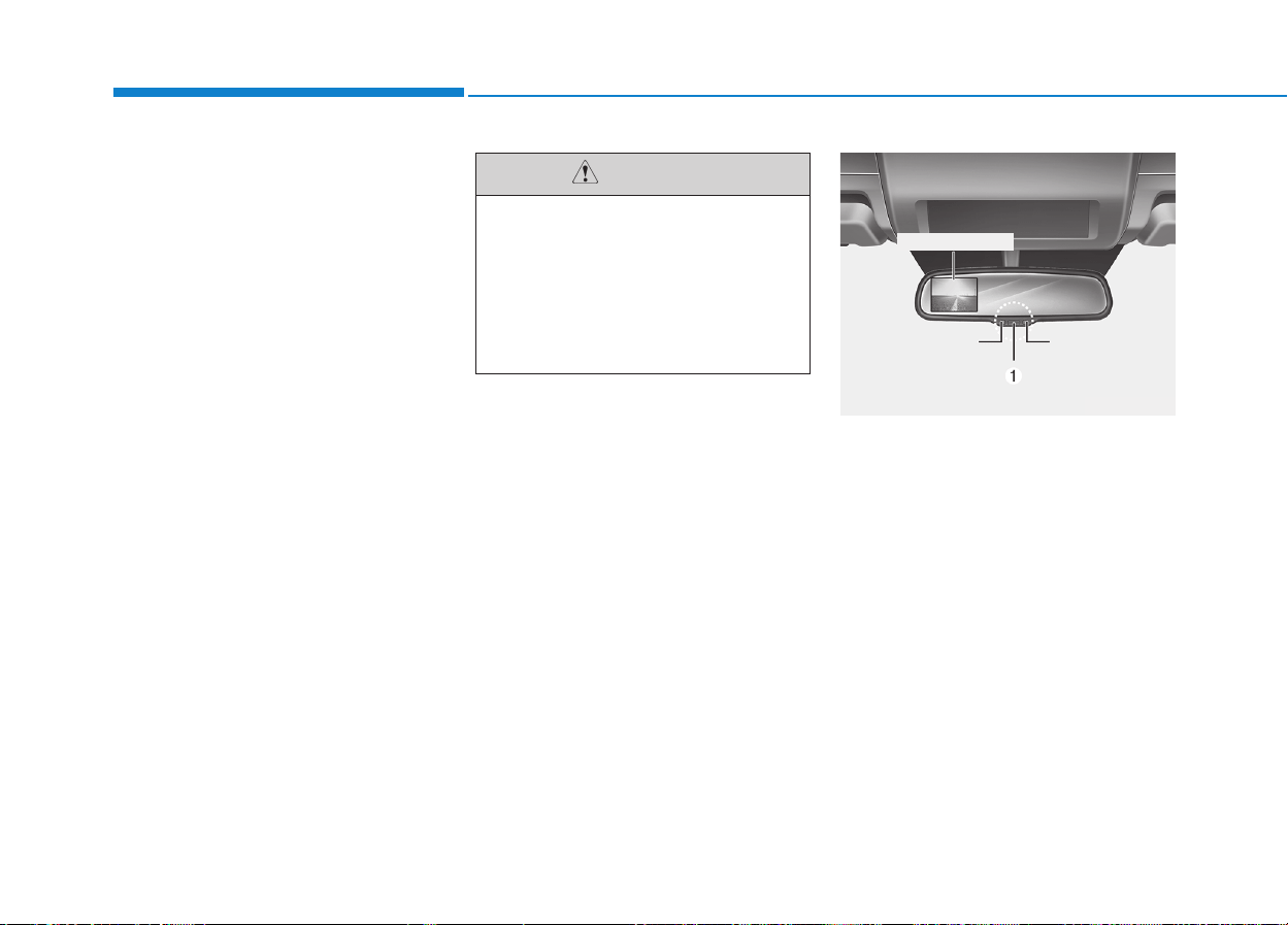
3-40
Electric chromic mirror (ECM)
(if equipped)
The electric rearview mirror automat-
ically controls the glare from the
headlights of the car behind you in
nighttime or low light driving condi-
tions. The sensor mounted in the mir-
ror senses the light level around the
vehicle, and automatically controls
the headlight glare from vehicles
behind you.
When the engine is running, the
glare is automatically controlled by
the sensor mounted in the rearview
mirror.
Whenever the shift lever is shifted
into R (Reverse), the mirror will auto-
matically go to the brightest setting in
order to improve the drivers view
behind the vehicle.
To operate the electric rearview
mirror:
• Press the on/off button (1) to turn
the automatic dimming function on.
The mirror indicator light will illumi-
nate.
Press the on/off button to turn the
automatic dimming function off.
The mirror indicator light will turn
off.
• The mirror defaults to the ON posi-
tion whenever the ignition switch is
turned on.
Convenient features of your vehicle
OEU044075
Indicator
Sensor
Rearview display
When cleaning the mirror, use a
paper towel or similar material
dampened with glass cleaner.
Do not spray glass cleaner
directly on the mirror as that
may cause the liquid cleaner to
enter the mirror housing.
CAUTION
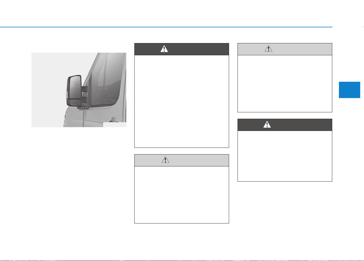
3-41
Convenient features of your vehicle
3
Outside rearview mirror
Be sure to adjust mirror angles
before driving.
Your vehicle is equipped with both
left-hand and right-hand outside
rearview mirrors. The mirrors can be
adjusted remotely with the remote
switch. The mirror heads can be fold-
ed back to prevent damage during an
automatic vehicle wash or when
passing in a narrow street.
If the mirror is jammed with ice,
do not adjust the mirror by
force. Use an approved spray
de-icer (not radiator antifreeze)
to release the frozen mecha-
nism or move the vehicle to a
warm place and allow the ice to
melt.
CAUTION
Do not adjust or fold the outside
rearview mirrors while the vehi-
cle is moving. This could result
in loss of control, and an acci-
dent which could cause death,
serious injury or property dam-
age.
WARNING
OEU044021
Rearview mirrors
• The right outside rearview
mirror is convex. In some
countries, the left outside
rearview mirror is also con-
vex. Objects seen in the mir-
ror are closer than they
appear.
• Use your interior rearview
mirror or direct observation to
determine the actual distance
of following vehicles when
changing lanes.
WARNING
Do not scrape ice off the mirror
face; this may damage the sur-
face of the glass. If ice should
restrict movement of the mirror,
do not force the mirror for
adjustment. To remove ice, use
a deicer spray, or a sponge or
soft cloth with very warm water.
CAUTION
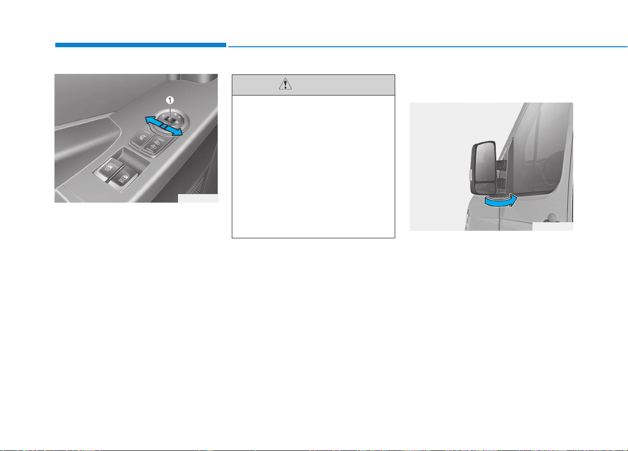
3-42
Convenient features of your vehicle
Remote control
Electric type (if equipped)
The electric remote control mirror
switch allows you to adjust the posi-
tion of the left and right outside
rearview mirrors. To adjust the posi-
tion of either mirror, move the lever
(1) to R (Right) or L (Left) to select
the right side mirror or the left side
mirror, then press a corresponding
point on the mirror adjustment con-
trol to position the selected mirror up,
down, left or right.
After adjustment, put the lever into
neutral position to prevent the inad-
vertent adjustment.
Folding the outside rearview
mirror
Manual type
To fold outside rearview mirror, grasp
the housing of mirror and then fold it
toward the rear of the vehicle.
OEU044023
• The mirrors stop moving
when they reach the maxi-
mum adjusting angles, but the
motor continues to operate
while the switch is depressed.
Do not depress the switch
longer than necessary, the
motor may be damaged.
• Do not attempt to adjust the
outside rearview mirror by
hand. Doing so may damage
the parts.
CAUTION
OEU045022
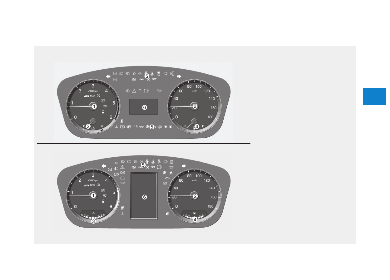
3-43
Convenient features of your vehicle
3
IINNSSTTRRUUMMEENNTT CCLLUUSSTTEERR
1. Tachometer
2. Speedometer
3. Engine temperature gauge
4. Fuel gauge
5. Warning and indicator lights (if equipped)
6. Multi display (Including trip computer)
OEU044200/OEU044197
* The actual cluster in the vehicle may differ
from the illustration.
For more details refer to the "Gauges" in
the next pages.
■■
Type A
■■
Type B
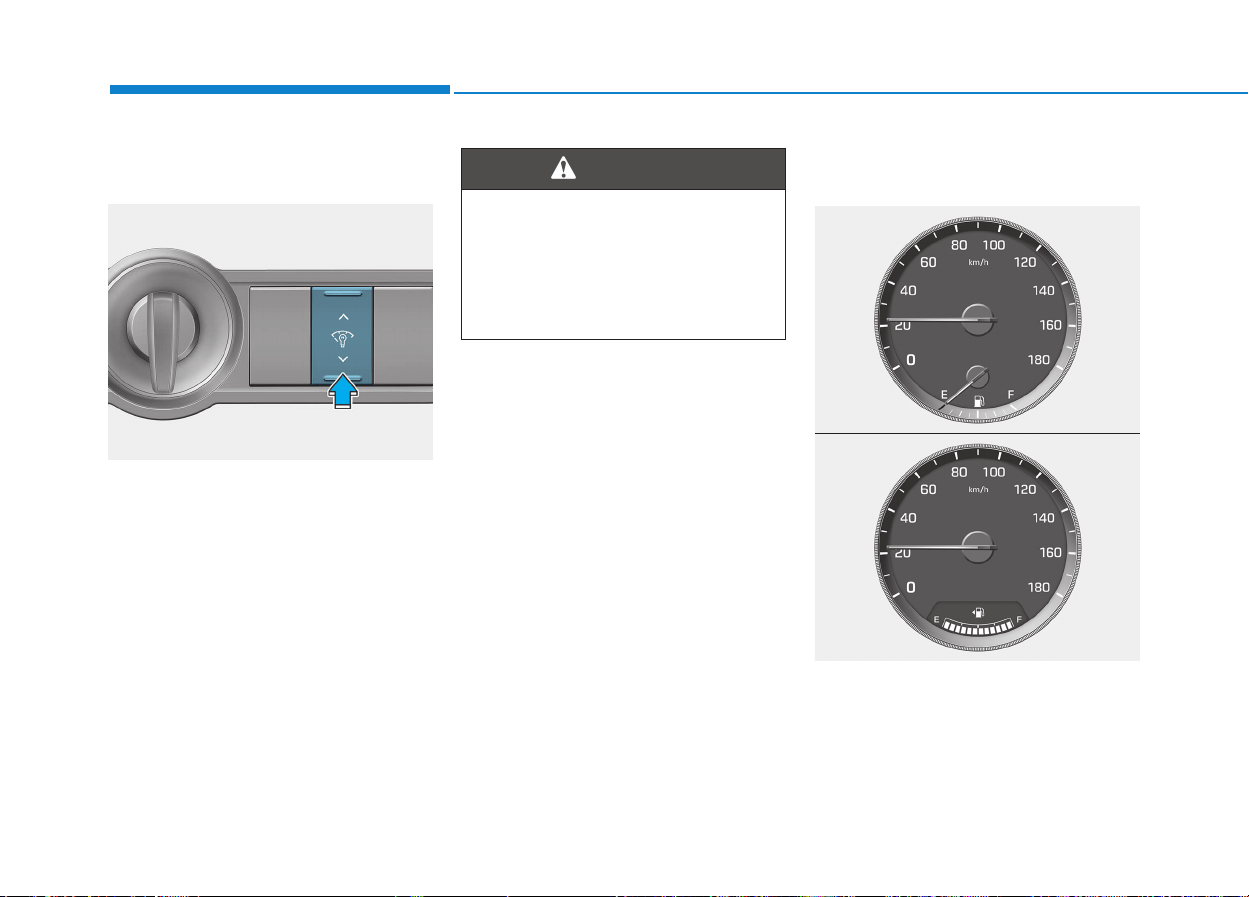
3-44
Convenient features of your vehicle
Instrument panel illumination
(if equipped)
The brightness of instrument panel
illumination can be adjusted by
pressing the illumination control
switch ("upward" or "downward"),
after turning ON the ignition switch
and the tail lights.
While the switch is being pressed, its
illumination level keeps changing.
Gauges and indicators
Speedometer
The speedometer indicates the for-
ward speed of the vehicle.
The speedometer is calibrated in
kilometers per hour.
Never adjust the instrument
panel illumination while driving.
This could result in loss of con-
trol and lead to an accident that
may cause death, serious
injury, or property damage.
WARNING
OEU044187
■ Type A (km/h)
OEU044199
■ Type B (km/h)
OEU044202
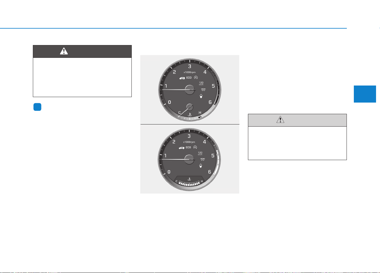
3-45
Convenient features of your vehicle
3
Information
The law regulates a speedometer
to display the information in a
smaller font than the navigation (if
equipped) does.
Tachometer
The tachometer indicates the
approximate number of engine revo-
lutions per minute (rpm).
Use the tachometer to select the cor-
rect shift points and to prevent lug-
ging and/or over-revving the engine.
The tachometer pointer may move
slightly when the ignition switch is in
ACC or ON position with the engine
OFF. This movement is normal and
will not affect the accuracy of the
tachometer once the engine is run-
ning.
i
In a speed-limit zone, such as
the Child Protection Zone, obey
the relevant speed limit (The
speed limit may differ in each
region).
WARNING
Do not operate the engine with-
in the tachometer's RED ZONE.
This may cause severe engine
damage.
CAUTION
■ Type A
OEU044198
■ Type B
OEU044201
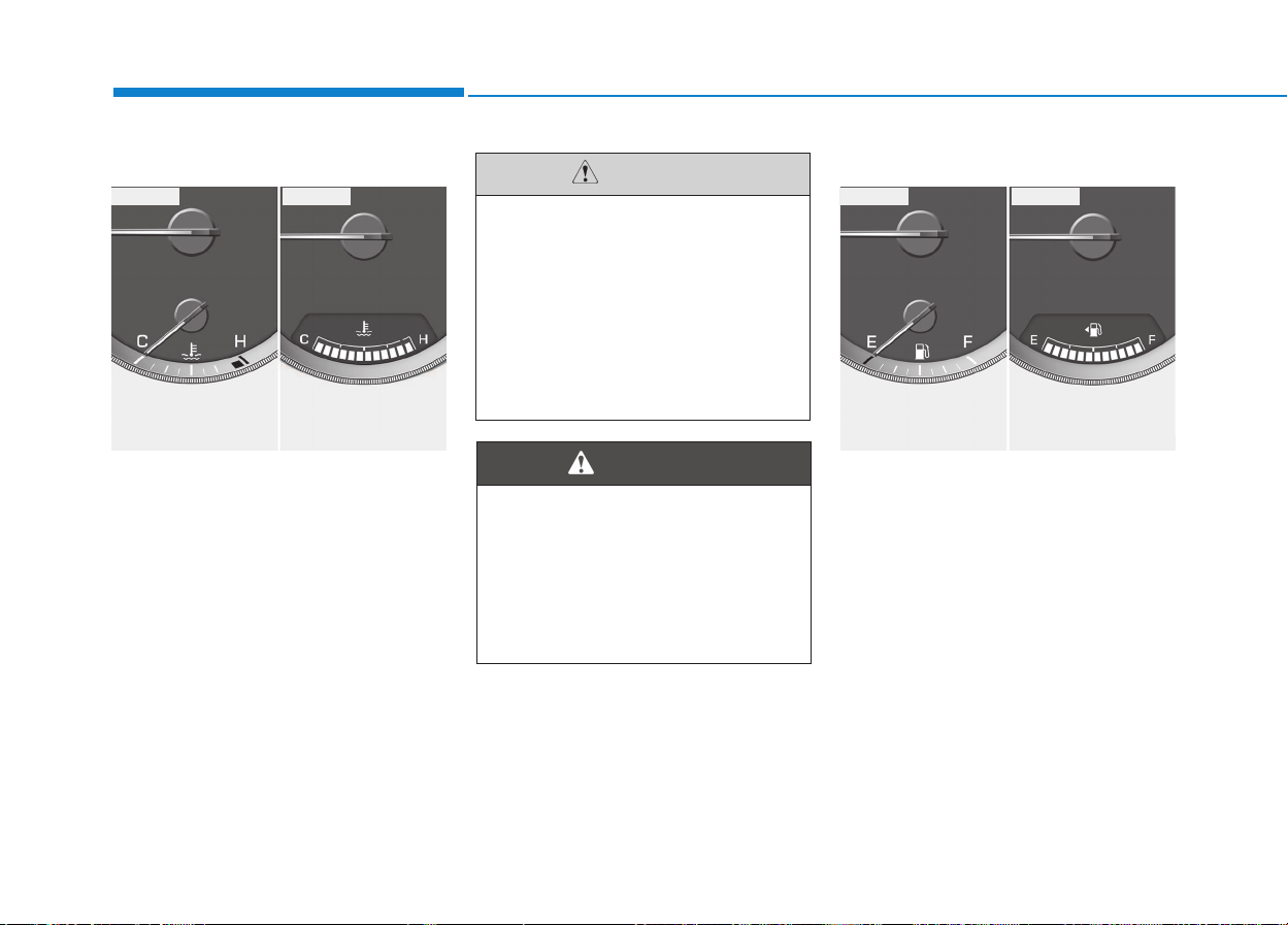
3-46
Convenient features of your vehicle
Engine temperature gauge
This gauge shows the temperature
of the engine coolant when the igni-
tion switch is ON.
Fuel gauge
The fuel gauge indicates the approx-
imate amount of fuel remaining in the
fuel tank.
Do not continue driving with an
overheated engine. If your vehi-
cle overheats, refer to "If the
engine overheats" in section 6.
If the gauge pointer moves
beyond the normal range area
toward the red zone, it indicates
overheating that may damage
the engine.
CAUTION
Never remove the radiator cap
when the engine is hot. The
engine coolant is under pres-
sure and could cause severe
burns. Wait until the engine is
cool before adding coolant to
the reservoir.
WARNING
OEU044203
■ Type A ■ Type B
OEU044204
■ Type A ■ Type B
3-47
Convenient features of your vehicle
3
Information
• The fuel tank capacity is given in
section 8.
• The fuel gauge is supplemented by a
low fuel warning light, which will
illuminate when the fuel tank is
nearly empty.
• On inclines or curves, the fuel gauge
pointer may fluctuate or the low fuel
warning light may come on earlier
than usual due to the movement of
fuel in the tank.
i
Fuel vapors are dangerous.
Before refueling, always stop
the engine and never allow
sparks or open flames near the
filler area. If you need to replace
the filler cap, we recommend
that you use parts for replace-
ment from an authorized
HYUNDAI dealer. If you open the
fuel filler cap during high ambi-
ent temperatures, a slight “pres-
sure sound” may be heard. This
is normal and not a cause for
concern.
Whenever you open the fuel
filler cap, turn it slowly.
WARNING
Fuel gauge
Running out of fuel can expose
vehicle occupants to danger.
You must stop and obtain addi-
tional fuel as soon as possible
after the warning light comes
on or when the gauge indicator
comes close to the O (Empty)
level.
WARNING
Avoid driving with a extremely
low fuel level. Running out of
fuel could cause the engine to
misfire damaging the catalytic
converter.
CAUTION
• Be sure to fill with the speci-
fied fuel.(Diesel)
• Be sure to lock the fuel filler
cap with the key after filling
with the specified fuel.
CAUTION
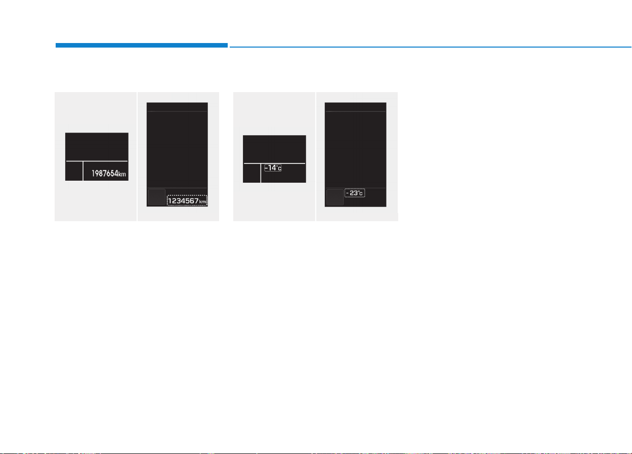
3-48
Convenient features of your vehicle
Odometer
The odometer Indicates the total dis-
tance that the vehicle has been driv-
en and should be used to determine
when periodic maintenance should
be performed.
- Odometer range : 0 ~ 1,999,999
kilometers.
Outside temperature
This gauge indicates the current out-
side air temperatures by 1°C (1°F).
- Temperature range : -40°C ~ 60°C
(-40°F ~ 140°F)
The outside temperature on the dis-
play may not change immediately
like a general thermometer to pre-
vent the driver from being inattentive.
The temperature unit (from °C to °F
or from °F to °C) can be changed by
using the “User Settings” mode of the
LCD display.
❈ For more details, refer to “LCD
Display” in this chapter.
■ Type A
OEU044110/OEU044134
■ Type B ■ Type A
OEU044112/OEU044136
■ Type B
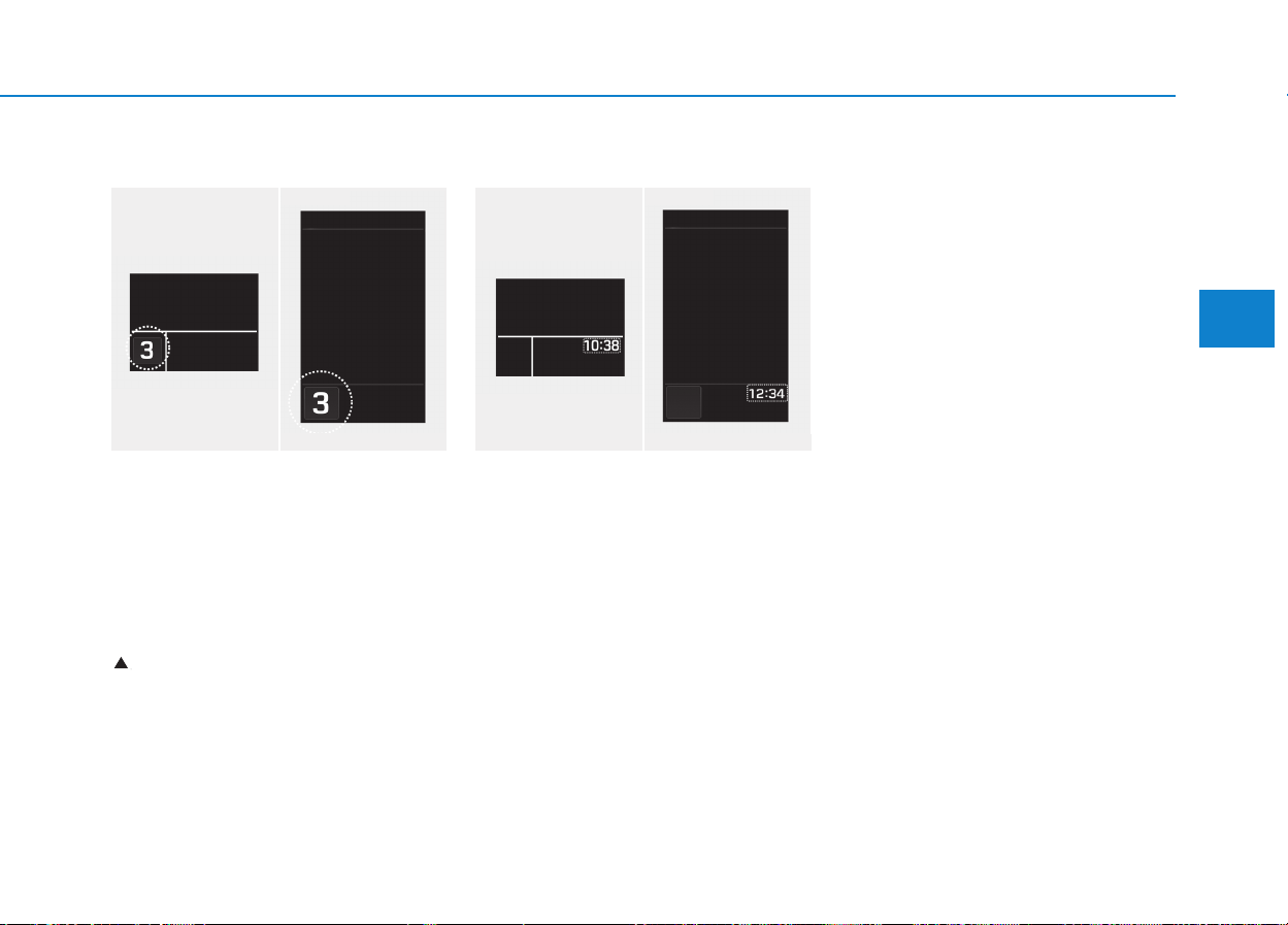
3-49
Convenient features of your vehicle
3
Gear shift indicator
This indicator informs current gear
position and up-shift timing while
driving to save fuel.
• Shifting down :
1, , 2, , 3, , 4, , 5, ,6
For example
: Indicates that shifting up to the 3rd
gear is desired (currently the shift
lever is in the 2nd or 1st gear).
When the system is not working prop-
erly, the indicator is not displayed.
Clock indicator
This displays the time. This can be
set either in the 12-hour unit or in the
24-hour unit in the user mode of the
cluster. This clock can be reset, when
it is incorrect.
• When the DTG is applied, the clock
is operated by the DTG. When "-- :
--" illuminates, there is a telecom-
munication error.
• When the DTG is not applied, the
clock is operated by the cluster
system.
DTG : Digital TachoGraph
❈
↑↑↑↑↑
■ Type A
OEU044115/OEU044137
■ Type B ■ Type A
OEU044113/OEU044138
■ Type B

3-50
Convenient features of your vehicle
Main display
MMUULLTTII--DDIISSPPLLAAYY ((IIFF EEQQUUIIPPPPEEDD))
Modes Symbol Explanation
Trip Computer
or
This mode displays driving information like the tripmeter, fuel economy, and so on.
For more details, refer to “Trip Computer” in this chapter.
Drive Info.
(if equipped)
This mode displays the state of Cruise Control System (CC) or the Lane Departure
Warning System (LDWS). For more details, refer to the chapter 5.
AVN
(if equipped)
This mode displays the state of the A/V (Radio, CD USB, AUX, etc.) system.
Turn By Turn (TBT)
(if equipped)
This mode displays the state of the navigation.
Information
• This mode informs of service interval and warning messages related the lamp dis-
connection.
• It indicates system failures, such as fuel consumption, engine-idling hour and major
ECUs.
User Settings On this mode, you can change settings of the doors, lamps, and so on.
❈ For controlling the LCD modes, refer to "LCD Display Control" in this chapter.

3-51
Convenient features of your vehicle
3
Function description
Main menu
Sub menu
Type A Type B
Trip computer
Trip A
Trip B
Range
Avg. Fuel Eco.
Inst. Fuel Eco.
UREA gauge
Range / Ave. Fuel Eco. / Inst. Fuel Eco.
UREA gauge
Trip A / Average speed / Elapsed Time
Trip B / Average speed / Elapsed Time
AUTO STOP
Drive Info -
LDWS (Lane Departure Warning System)
CC (Cruise control)
AVN - AVN
TBT - TBT NAVI
Information
Service
Warning message
Service notifications
Warning message
Service notifications
Drive Info.
Total Fuel Consumption (T.F.C)
Total Idle RPM Time (T.I.T)
Average Speed
Elapsed Time
AUTO STOP
Total Fuel Consumption (T.F.C)
Total Idle RPM Time (T.I.T)
Diagnostics
ABS/VDC
CM
SJB
CLUSTER
LDWS
ACU
ABS/VDC
CM
SJB
CLUSTER
LDWS
ACU

3-52
Convenient features of your vehicle
Main menu
Sub menu
Type A Type B
Set
Door
Automatic door lock (Enable on speed)
Automatic door unlock (On Key Out (power off), Drive door unlock)
Light
Head Lamp delay
Welcome Light
Auto Triple Turn
External Lamp Check*
Sound Sound Settings (Level1~3, OFF)
Cluster
Shift Indicator (ON/OFF)
Unit Settings (Time-12hour or 24 hour, Temperature unit-°C or °F)
AFC Settings (Auto reset, Manual reset)
Language Settings (English, Deutsch, etc.)
Current Time (00:00)
Alarm (Alarm time, Idle RPM, Break Time-ON/OFF)
Equipment Cycle
(Maintenance)
Engine Oil (OFF, ON, Distance setting)
Fuel Filter(OFF, ON, Distance setting)
User Menu (OFF, ON, Distance setting)
* It monitors all external lights, except the back-up lights.
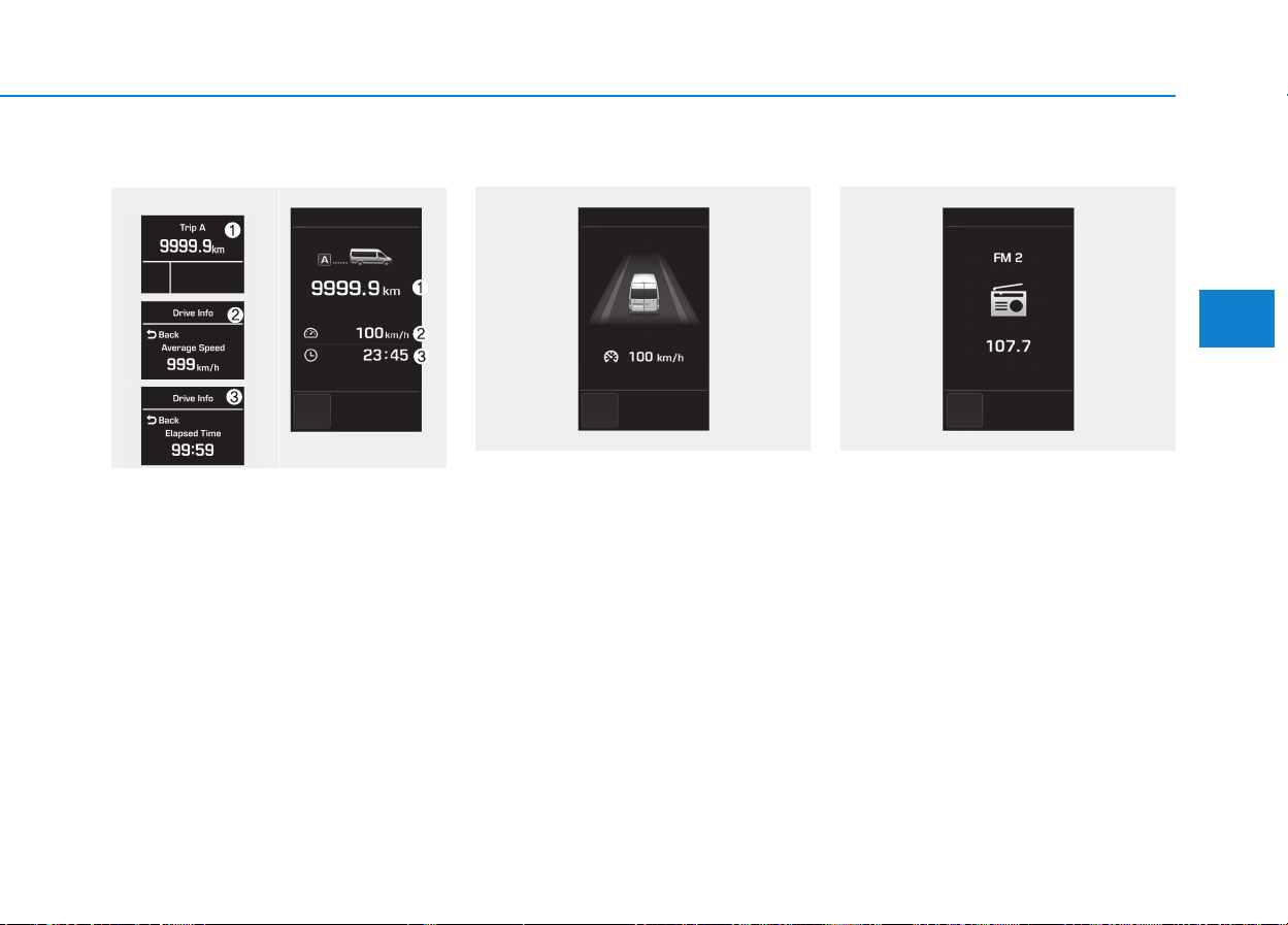
3-53
Convenient features of your vehicle
3
Trip computer
This displays the drive information
like as the driving distance, average
fuel economy, etc. For detail, refer to
the “Trip computer” in the chapter 3.
Drive info. mode (If equipped)
This mode displays the state of the
CC or LDWS. For more details, refer
to the chapter 5.
AV information (If equipped)
This mode displays the state of the
AV (Radio, CD, USB, AUX etc.).
OEU044123/OEU044124/
OEU044125/OEU044148
■ Type A ■ Type B
OEU044212 OEU044213
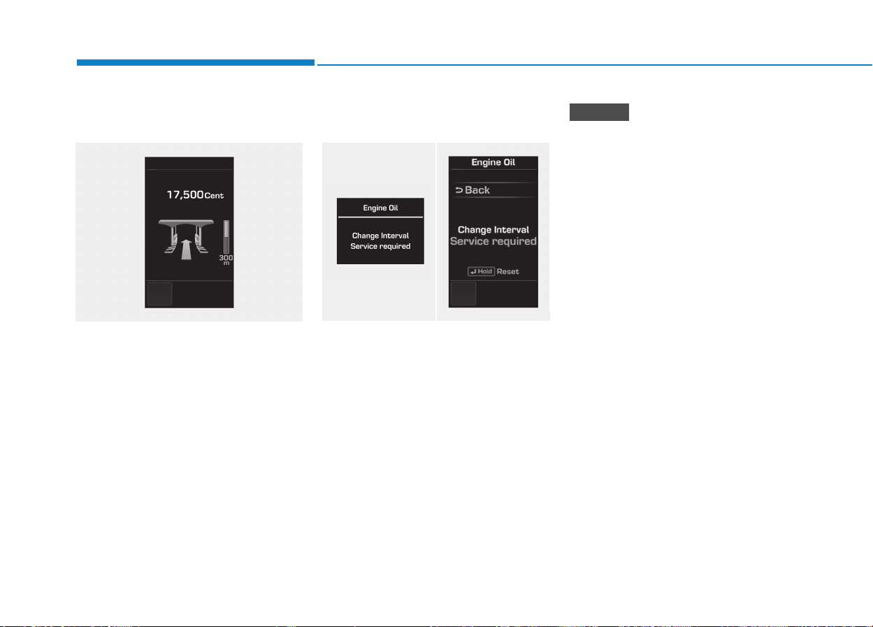
3-54
Convenient features of your vehicle
Turn by turn navigation
(if equipped)
This mode displays the information
of the navigation.
Information Mode
Service required
If you do not have your vehicle serv-
iced according to the already
inputted service interval, “Service
required” message is displayed for
several seconds each time you set
the ignition switch to the ON position.
If any of the following conditions
occurs, the mileage may be incor-
rect.
- The battery cable is disconnect-
ed.
- The fuse switch is turned off.
- The battery is discharged.
NOTICE
■ Type A
OEU044214/OEU044215
■ Type B
OEU044211
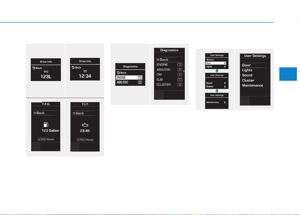
3-55
Convenient features of your vehicle
3
Drive Info
It indicates the accumulated fuel
consumption amounts as well as the
accumulated engine-idling hours.
Diagnostics
It monitors and diagnoses failures of
each vehicle unit, displaying the
information, such as the number of
failures the failure code.
User Settings Mode
Description
On this mode, you can change set-
ting of the doors, lamps, and so on.
■ Type A
OEU044216/OEU044217/OEU044218/OEU044219
■ Type B
■ Type A
OEU044220/OEU044221
■ Type B
■ Type A
OEU044222/OEU044223
■ Type B

3-56
Convenient features of your vehicle
Door
Auto Door Lock (if equipped)
• Off:
The auto door lock operation will
be deactivated.
• Enable on speed:
All doors will be automatically
locked when the vehicle speed
exceeds 15km/h (9.3mph).
Auto Door Unlock (if equipped)
• Key Out or Power Off:
All doors will be automatically
unlocked when the ignition key is
removed from ignition switch to the
OFF position.
• Driver Door Unlock:
All doors will be automatically
unlocked if the driver's door is
unlocked.
Light
Head Lamp Delay (if equipped)
If this item is checked, the headlamp
delay will be activated.
Welcome Light (if equipped)
When it is selected, the headlamp
welcome function automatically acti-
vates.
Auto Triple Turn (if equipped)
When it is selected, the auto triple
turn function activates.
External Lamp Check (if equipped)
When it is selected, the external
lamps automatically activate.
* It monitors all external lamps,
except the back-up lights.
Sound
The sound volume can be adjusted
from level 0 (OFF) to 3.
Cluster
Shift gear
It is turned ON or OFF.
Unit Settings
Time unit
The time unit can be converted from
12 hours to 24 hours, and vice versa.
Temperature unit
The temperature unit can be convert-
ed from °C to °F, and vice versa.

3-57
Convenient features of your vehicle
3
AFC setting
It can be automatically or manually
reset to the default.
❇ AFC : Average Fuel Consumption
Language setting
A preferred language can be chosen
on the LCD display.
Current time
The time can be adjusted.
Alarm
The alarm, idle-rpm time, break time
can be set in.
Equipment cycle(Maintenance)
Engine oil, fuel filter
The maintenance alarm can be
turned ON or OFF. Also, the driving
distance for an oil/filter maintenance
alarm can be set in.
User Menu
The maintenance alarm message
displays on the LCD display, as arbi-
trarily set in.
Warning Messages
In below cases, the warning mes-
sage displays for 10 seconds. Some
messages will be saved in the infor-
mation group after few seconds dis-
playing for future reference.
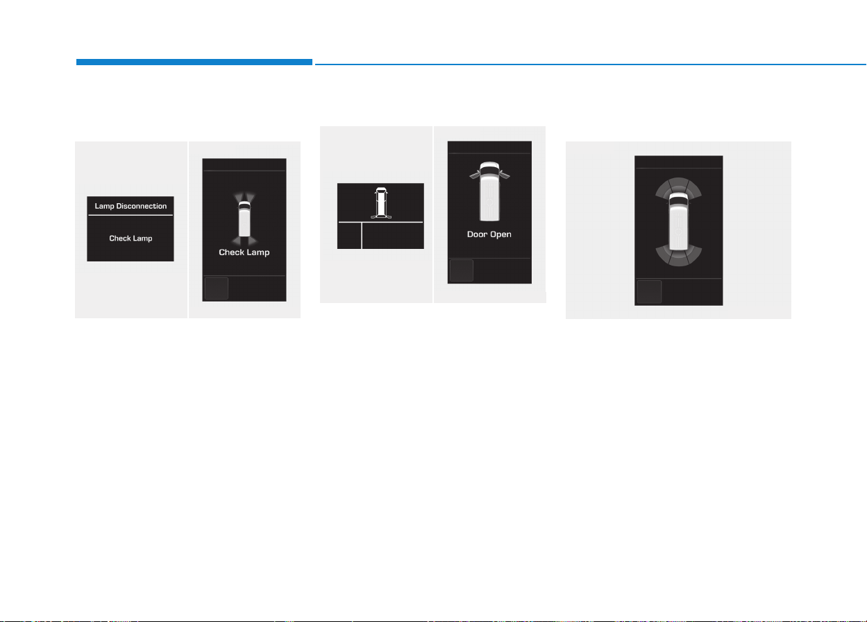
3-58
Convenient features of your vehicle
Lamp disconnection
(CHECK LAMP)
This indicator displays which lamp is
disconnected.
Doors open
This indicator displays which doors
are opened.
Parking Assist System (PAS)
(if equipped)
When the engine is turned ON, and
when the PAS sensor detects an
obstacle, while driving either for-
wards or backwards, the PAS
informs the driver of a location and a
distance of/with the obstacle.
For further information, refer to the
Parking Assist System in the chapter
3.
■ Type A
OEU044118/OEU044143
■ Type B
■ Type A
OEU044114/OEU044139
■ Type B
OEU044141
■ Type B
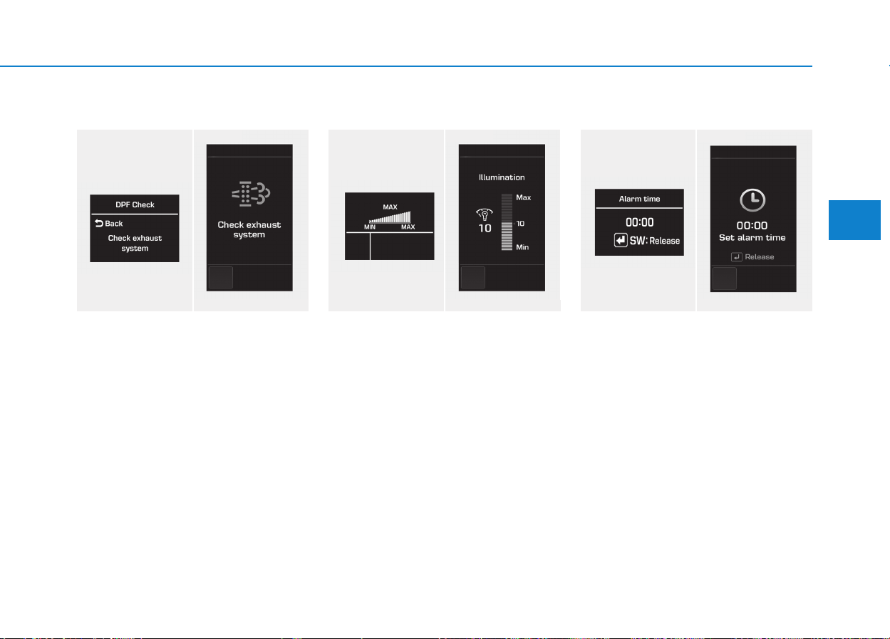
3-59
Convenient features of your vehicle
3
DPF Check (if equipped)
The warning message is displayed,
as above, when there is a DPF prob-
lem with your diesel vehicle. In this
case, have the DPF system checked
by an authorized HYUNDAI dealer.
❇ DPF: Diesel Particulate Filter
Illumination (if equipped)
The illumination intensity of the
instrument panel is shown when
adjusting it with the illumination con-
trol switch.
Alarm time
It display the alarm time, as set in the
user-setting mode.
■ Type A
OEU044119/OEU044144
■ Type B ■ Type A
OEU044116/OEU044140
■ Type B ■ Type A
OEU044120/OEU044145
■ Type B
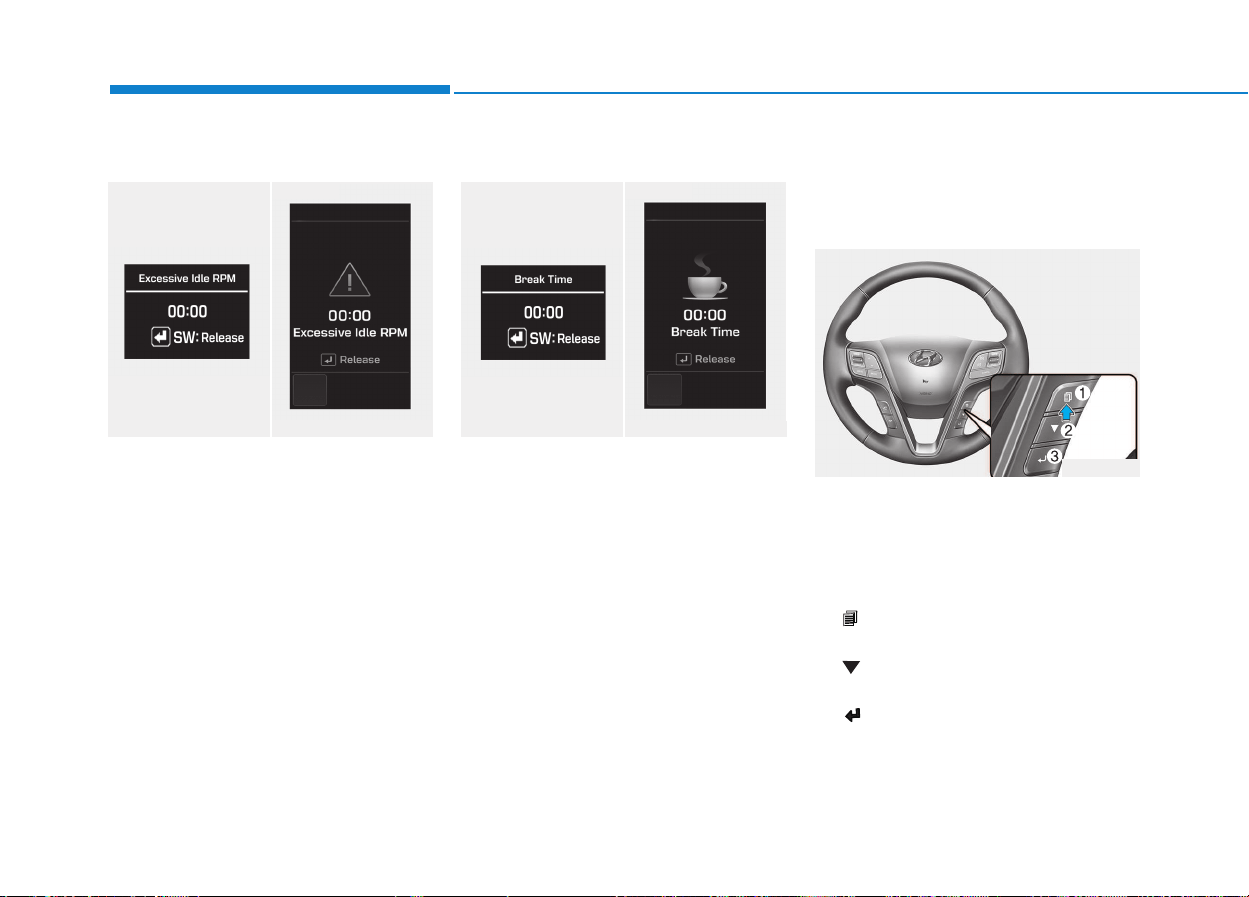
3-60
Convenient features of your vehicle
Excessive Idle RPM
It displays the idle-rpm hour, as set in
the user-setting mode.
Brake time
It displays the breaking hour, as set
in the user-setting mode.
Overview
Description
The trip computer is a microcomput-
er-controlled driver information sys-
tem that displays information related
to driving.
1. ( ) Mode button for changing
modes
2. ( ) Move button for changing
items
3. ( ) Select / Reset button
■ Type A
OEU044121/OEU044146
■ Type B ■ Type A
OEU044122/OEU044147
■ Type B
OEU044052
TTRRIIPP CCOOMMPPUUTTEERR
(
(IIFF EEQQUUIIPPPPEEDD))
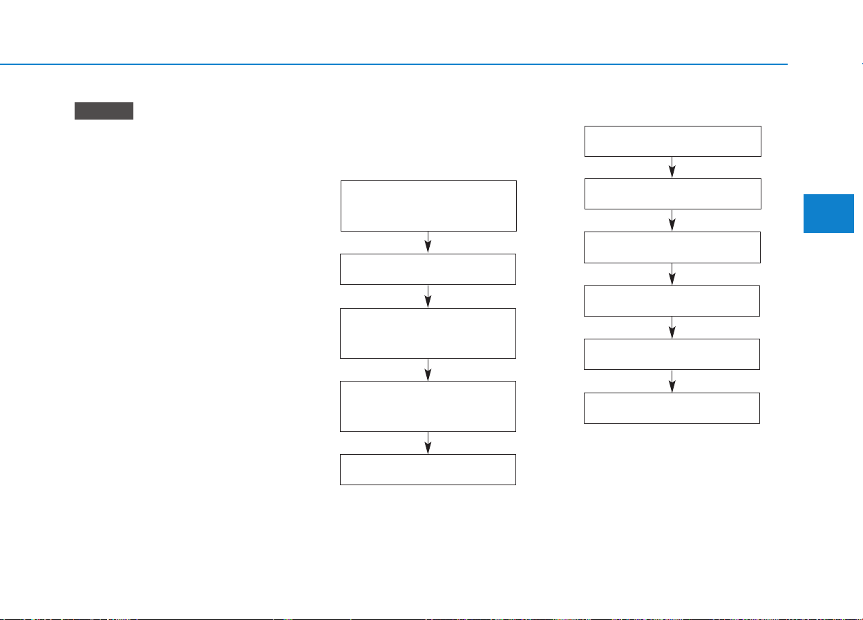
3-61
Convenient features of your vehicle
3
Some driving information stored
in the trip computer (for example
Average Vehicle Speed) resets if
the battery is disconnected.
Trip Modes
Trip mode is changed as below
whenever pushing the button shortly.
• Trip Mode (High-end Type)
• Trip mode (Standard Type))
NOTICE
Distance to empty/
Average Fuel Economy/
Instant Fuel Economy
Distance to empty A/
Average vehicle speed A/
Elapsed time A
The total AUTO STOP time*
2
Distance to empty B/
Average vehicle speed B/
Elapsed time B
Urea solution gauge*
1
*
1
: When applying the SCR system
*
2
: When applying the ISG system
Driving distance B
Distance to empty A
Average fuel economy
Instant fuel economy
Urea solution gauge*
1
Distance to empty
❈ You may check the average driv-
ing speed/Elapsed time/total
AUTO STOP hours*
2
in the infor-
mation group.
*
1
: When applying the SCR system
*
2
: When applying the ISG system
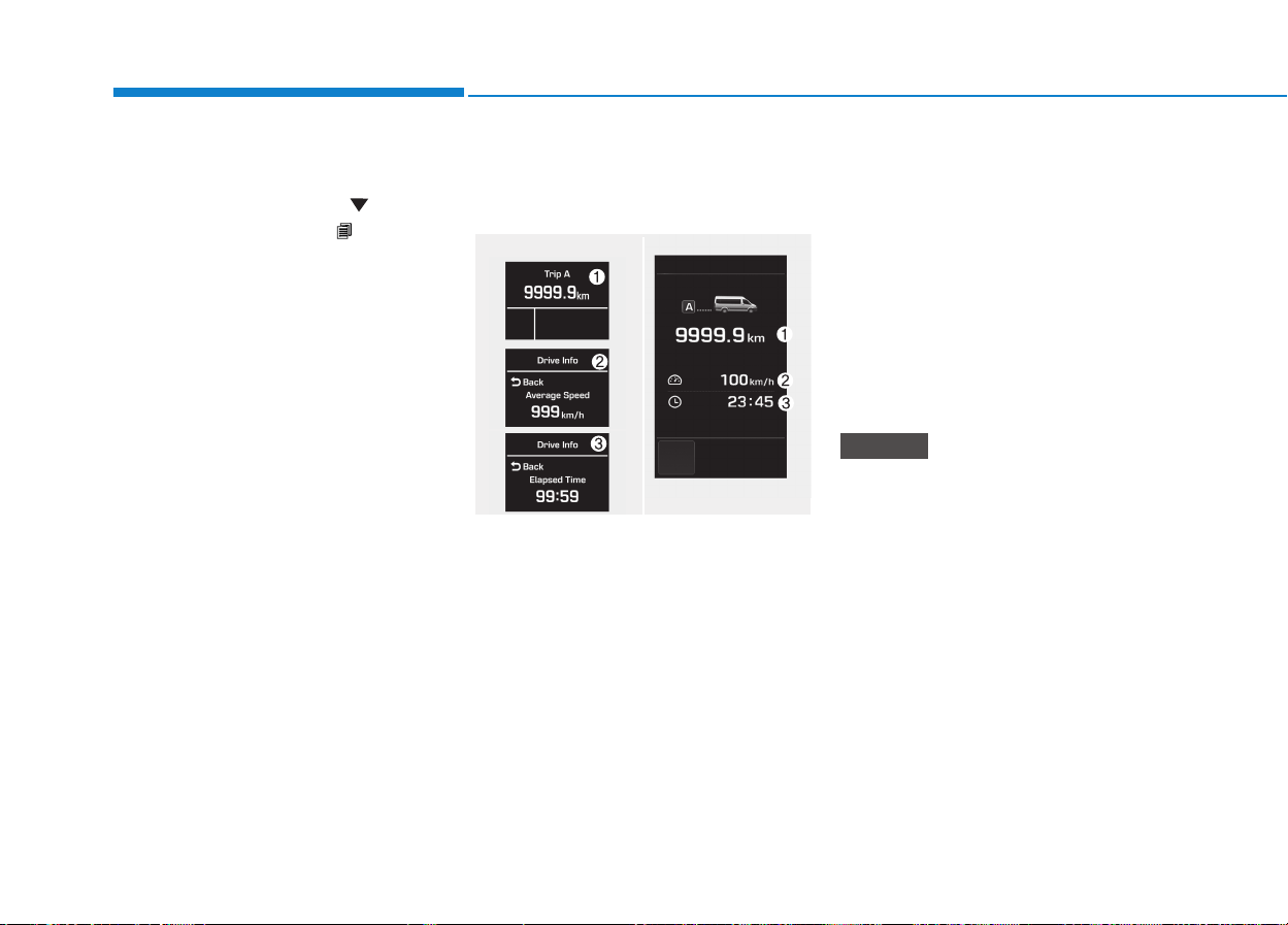
3-62
Convenient features of your vehicle
In the trip computer mode on the
LCD display, the trip mode can be
adjusted by pressing the ( ) button.
By pressing the button ( ), you can
select the desired trip mode.
❈ For controlling the LCD modes,
refer to "LCD Display Control" in
this chapter.
Driving distance / Average
vehicle speed / Elapsed time
Driving distance (1)
This displays the total driving dis-
tance from the default setting (0.0)
• Pressing the “Select” button for 1
second or over, when the driving
distance is displayed, resets the
driving distance. This also resets
the driving hours and the average
speed (Type B).
• Distance range: 0 .0 ~ 9999.9 km
Average Vehicle Speed (2)
• The average vehicle speed is cal-
culated by the total driving dis-
tance and driving time since the
last average vehicle speed reset.
- Speed range: 0 ~ 999 km/h
• To reset the average vehicle
speed, press the SET button for
more than 1 second when the
average vehicle speed is dis-
played.
Even if the vehicle is not in
motion, the average vehicle speed
keeps going while the engine is
running.
NOTICE
OEU044123/OEU044124/
OEU044125/OEU044148
■ Type A ■ Type B
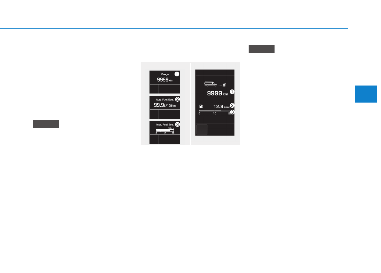
3-63
Convenient features of your vehicle
3
Elapsed Time (3)
• The elapsed time is the total driv-
ing time since the last elapsed time
reset.
- Time range (hh:mm): 00:00 ~
99:59
• To reset the elapsed time, press
the SET button for more than 1
second when the elapsed time is
displayed.
Even if the vehicle is not in
motion, the elapsed time keeps
going while the engine is running.
Fuel Economy
Distance To Empty (1)
• The distance to empty is the esti-
mated distance the vehicle can be
driven with the remaining fuel.
- Distance range: 50 ~ 9999 km or
30 ~ 9999 mi.
• If the estimated distance is below
50 km (30 mi.), the trip computer
will display “---” as distance to
empty.
• If the vehicle is not on level
ground or the battery power has
been interrupted, the distance to
empty function may not operate
correctly.
• The distance to empty may differ
from the actual driving distance
as it is an estimate of the avail-
able driving distance.
• The trip computer may not regis-
ter additional fuel if less than 6
liters (1.6 gallons) of fuel are
added to the vehicle.
• The fuel economy and distance
to empty may vary significantly
based on driving conditions,
driving habits, and condition of
the vehicle.
NOTICE
NOTICE
OEU044126/OEU044127/
OEU044128/OEU044149
■ Type A ■ Type B

3-64
Convenient features of your vehicle
Average Fuel Economy (2)
• The average fuel economy is cal-
culated by the total driving dis-
tance and fuel consumption since
the last average fuel economy
reset.
- Fuel economy range: 0.0 ~ 99.9
km/L (L/100km)
• The average fuel economy can be
reset both manually and automati-
cally.
Manual reset
To clear the average fuel economy
manually, press the SET button for
more than 1 second when the aver-
age fuel economy is displayed.
Automatic reset
The average fuel economy will be
cleared to zero (---) when the vehicle
speed exceeds 1 km/h after refueling
more than 6 liters (1.6 gallons).
The average fuel economy is not
displayed for more accurate cal-
culation if the vehicle does not
drive more than 300 meters since
the ignition switch is turned to
ON.
Information
When the average fuel efficiency
is set to be automatically reset in
the user-setting mode, the aver-
age fuel efficiency and the fuel
gauge may automatically reset to
the default, while driving on a
slope or going down/up on a flat
road from a slope. Such situations
make the fuels in a tank abruptly
fluctuate and cause the system to
misrecognize it as the refueling.
Thus, it is automatically reset to
the default. This is not a system
failure.
When the automatic reset function
is cancelled in the user-setting
mode, the average fuel efficiency
will not be automatically reset, any
longer.
i
NOTICE
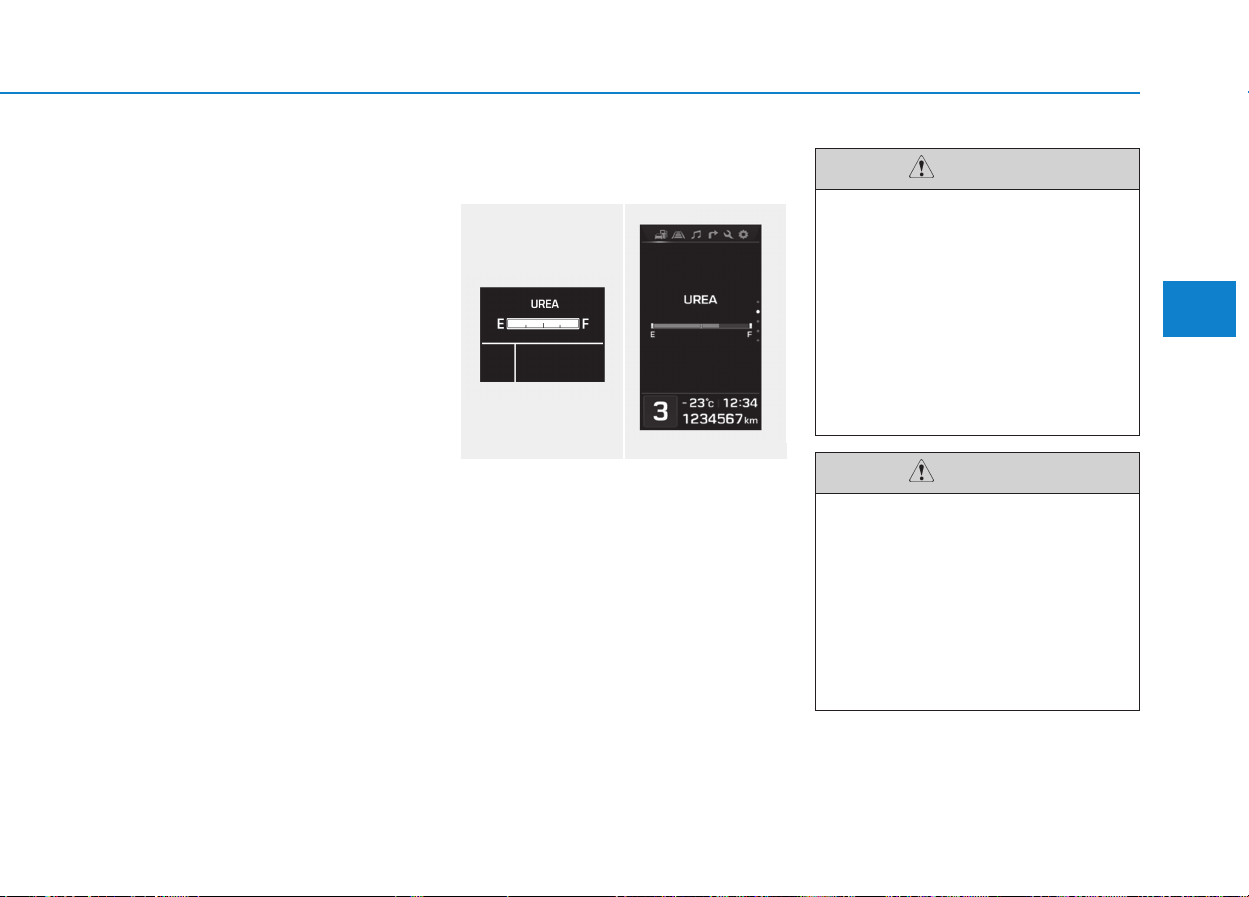
3-65
Convenient features of your vehicle
3
Instant fuel economy (3)
• This mode displays the instant fuel
economy during the last few sec-
onds when the vehicle speed is
more than 10 km/h (6.2 MPH).
- Fuel economy range:
0 ~ 20 km/L (L/100 km)
Urea Solution Gauge
(if equipped)
The urea solution gauge indicates
the approximate amount of urea
solution remaining in the urea tank.
■ Type A
OEU044111/OEU044135
■ Type B
• If the vehicle is driven with
urea solution volume less
than 4%, engine output will be
limited.
• Liquid that are not recom-
mended such as diesel, gaso-
line, and alcohol shall never
be used other than the recom-
mended urea solution that
satisfy ISO22241 or DIN70070.
CAUTION
If defective urea solution or liq-
uid that is not recommended is
supplied, there may be damage
on the parts of the vehicle such
as processing device. If defec-
tive fuel is used, foreign objects
will be accumulated to SCR cat-
alyst and cause catalyst pushed
away or breaking.
CAUTION
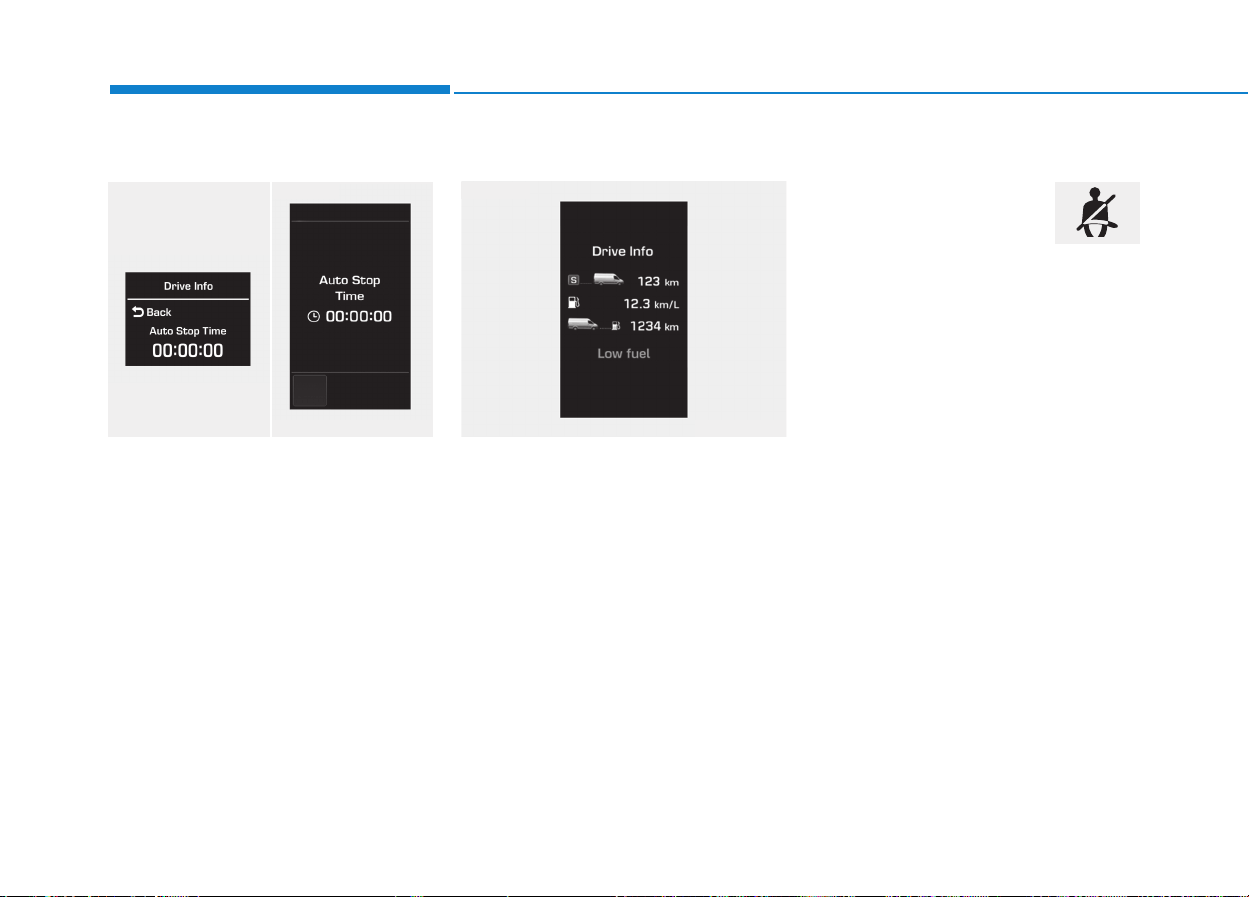
3-66
Convenient features of your vehicle
Total AUTO STOP Hour
When the AUTO STOP operates, the
total AUTO STOP hour displays on
the LCD display.
Stop Hour Range: 00:00~99:59:59
Pressing the “Select” button for 1
second or over resets the total AUTO
STOP hour.
For further information, refer to the
ISG (Idle stop and go) system in the
chapter 5.
Driving Information
The driving information may display
on the cluster for a few seconds after
turning OFF the engine.
When the fuel is insufficient, "Low
Fuel" message will display. In this
case, immediately refuel the tank.
Seat Belt Warning Light
This warning light informs the driver
that the seat belt is not fastened.
For more details, refer to the “Seat
Belts” in chapter 2.
OEU044151
■ Type B
■ Type A
OEU044129/OEU044150
■ Type B
WWAARRNNIINNGG AANNDD IINNDDIICCAATTOORR
L
LIIGGHHTTSS
3-67
Convenient features of your vehicle
3
Engine Overheat
Warning Light
This indicates a coolant temperature.
When a temperature is above the
normal range, the engine overheat
warning light illuminates.
When there is a telecommunication
error, the engine overheat warning
light blinks.
Air bag Warning Light
(if equipped)
This warning light illuminates:
• Once you set the ignition switch to
the ON position.
- It illuminates for approximately 6
seconds and then goes off.
• When there is a malfunction with
the SRS.
In this case, we recommend that
you have the vehicle inspected by
an authorized HYUNDAI dealer.
Low Fuel Level
Warning Light
This warning light illuminates:
When the fuel tank is nearly empty.
This warning light blinks:
When the fuel sensor is disconnect-
ed.
If the fuel tank is nearly empty:
Add fuel as soon as possible.
- Low Fuel Level
Driving with the Low Fuel Level
warning light on or with the fuel
level below “0 or E” can cause the
engine to misfire and damage the
catalytic converter (if equipped).
NOTICE
The illumination of the engine
overheat warning light indicates
that the engine is over-heated.
Refer to the chapter 6, "What to
Do in an Emergency."
WARNING
3-68
Convenient features of your vehicle
Immobilizer Indicator
Light (if equipped)
This indicator light illuminates:
When the vehicle detects the immo-
bilizer in your key properly while the
ignition switch is ON.
- At this time, you can start the engine.
- The indicator light goes off after
starting the engine.
This indicator light blinks:
When there is a malfunction with the
immobilizer system.
In this case, we recommend that you
have the vehicle inspected by an
authorized HYUNDAI dealer.
Turn Signal Indicator
Light
This indicator light blinks:
• When you turn the turn signal light
on.
If any of the following occurs, there
may a malfunction with the turn signal
system. In this case, we recommend
that you have the vehicle inspected by
an authorized HYUNDAI dealer.
- The indicator light does not blink
but illuminates.
- The indicator light blinks more
rapidly.
- The indicator light does not illumi-
nate at all.
Low Beam Indicator
Light (if equipped)
This indicator light illuminates:
• When the headlights are on.
High Beam Indicator
Light
This indicator light illuminates:
• When the headlights are on and in
the high beam position
• When the turn signal lever is pulled
into the Flash-to-Pass position.
Do not use high beam when
there are other vehicles. Using
high beam could obstruct the
other driver's vision.
WARNING
3-69
Convenient features of your vehicle
3
Light ON indicator light
This indicator illuminates when the
tail lights or headlights are on or
when the lights switch is turned to
“AUTO” position.
Front Fog Indicator
Light (if equipped)
This indicator light illuminates:
• When the front fog lights are on.
Rear Fog Indicator
Light (if equipped)
This indicator light illuminates:
• When the rear fog lights are on.
Parking brake warning
light
The parking brake warning light
should come on when the parking
brake is applied and the ignition
switch is turned to "ON" or "START".
After the engine is started, the light
should go out when the parking
brake is released.
If the parking brake is not applied,
the warning light should come on
and warning buzzer sounds when
the ignition switch is turned to "ON"
or "START" with specified speed,
then go out when the engine starts. If
the light comes on at any other time,
you should slow the vehicle and
bring it to a complete stop in a safe
location off the roadway.
If you drive while parking brake is
applied, the parking brake warning
light comes on and warning buzzer
sounds simultaneously.
Low brake fluid level
warning light
If you suspect brake trouble, we
recommend that the system be
checked by an authorized
HYUNDAI dealer. Driving your
vehicle with a problem in either
the brake electrical system or
brake hydraulic system is dan-
gerous, and could result in a
serious injury or death.
WARNING

3-70
Convenient features of your vehicle
Warning light operation
The brake fluid level warning light
indicates that the brake fluid level in
the brake master cylinder is low and
hydraulic brake fluid conforming to
SAE J1703 specifications should be
added. After adding fluid, if no other
trouble is found, we recommend that
the system be inspected by an
authorized HYUNDAI dealer. If fur-
ther trouble is experience, we recom-
mend that you contact an authorized
HYUNDAI dealer.
Anti-lock Brake System
(ABS) Warning Light
This warning light illuminates:
• Once you set the ignition switch to
the ON position.
- It illuminates for approximately 3
seconds and then goes off.
• When there is a malfunction with
the ABS (The normal braking sys-
tem will still be operational without
the assistance of the anti-lock
brake system).
In this case, we recommend that
you have the vehicle inspected by
an authorized HYUNDAI dealer.
Electronic Brake force
Distribution (EBD)
System Warning Light
These two warning lights illuminate
at the same time while driving:
• When the ABS and regular brake
system may not work normally.
In this case, we recommend that
you have the vehicle inspected by
an authorized HYUNDAI dealer.
3-71
Convenient features of your vehicle
3
Information
- Electronic
Brake force Distribution (EBD)
System Warning Light
When the ABS Warning Light is on or
both ABS and EBD are on, the
speedometer, odometer, or tripmeter
may not work.
In this case, we recommend you have
the vehicle inspected by an authorized
HYUNDAI dealer as soon as possible.
Vehicle Dynamic
Control (VDC) Indicator
Light
This indicator light illuminates:
• Once you set the ignition switch to
the ON position.
- It illuminates for approximately 3
seconds and then goes off.
• When there is a malfunction with
the VDC system.
In this case, we recommend that
you have the vehicle inspected by
an authorized HYUNDAI dealer.
This indicator light blinks:
While the VDC is operating.
For more details, refer to “Vehicle
Dynamic Control (VDC)” in chapter
5.
i
Electronic Brake force
Distribution (EBD) System
Warning Light
When both ABS and EBD are
on, the brake system will not
work normally and you may
experience an unexpected and
dangerous situation during
sudden braking.
In this case, avoid high speed
driving and abrupt braking.
We recommend you have the
vehicle inspected by an author-
ized HYUNDAI dealer as soon
as possible.
WARNING
3-72
Convenient features of your vehicle
Vehicle Dynamic
Control (VDC) OFF
Indicator Light
This indicator light illuminates:
Once you set the ignition switch to
the ON position.
- It illuminates for approximately
3 seconds and then goes off.
For more details, refer to “Vehicle
Dynamic Control (VDC)” in chapter
5.
ECO Mode Indicator
Light (if equipped)
This indicator light illuminates:
• When you select “ECO” mode as
drive mode.
Cruise Indicator Light
(if equipped)
This indicator light illuminates:
• When the cruise control system is
enabled.
For more details, refer to “Cruise
Control System” in chapter 5.
Cruise SET Indicator
Light (if equipped)
This indicator light illuminates:
• When the cruise control speed is
set.
For more details, refer to “Cruise
Control System” in chapter 5.
ECO
SET
Do not watch the ECO indicator
light while driving. This will dis-
tract you and may cause an
accident that results in severe
personal injury.
WARNING
3-73
Convenient features of your vehicle
3
Auto stop indicator
(if equipped)
This indicator will illuminate when the
engine enters the Idle Stop mode of
the ISG (Idle Stop and Go) system.
When the automatic starting occurs,
the auto stop indicator on the cluster
will blink for few seconds.
For more details, refer to the ISG
(Idle Stop and Go) system in the
chapter 5.
Information
When the engine automatically starts
by the ISG system, some warning
lights (ABS/EBD/VDC/VDC OFF)
may turn on for a few seconds.
This happens because of the low bat-
tery voltage. It does not mean the sys-
tem is malfunctioning.
Engine Oil Pressure
Warning Light
This warning light illuminates:
• Once you set the ignition switch to
the ON position.
- It remains on until the engine is
started.
• When the engine oil pressure is low.
If the engine oil pressure is low:
1. Drive carefully to the nearest safe
location and stop your vehicle.
2. Turn the engine off and check the
engine oil level (For more details,
refer to “Engine Oil” in chapter 7).
If the level is low, add oil as required.
If the warning light remains on
after adding oil or if oil is not avail-
able, we recommend that you
have the vehicle inspected by an
authorized HYUNDAI dealer as
soon as possible.
Malfunction indicator
lamp (MIL)
(check engine light)
This indicator light is part of the
Engine Control System which moni-
tors various emission control system
components. If this light illuminates
while driving, it indicates that a
potential problem has been detected
somewhere in the emission control
system.
This light will also illuminate when
the ignition switch is turned to the
ON position, and will go out in a few
seconds after the engine is started. If
it illuminates while driving, or does
not illuminate when the ignition key is
turned to the ON position, we recom-
mend that the system be checked by
an authorized HYUNDAI dealer.
Generally, your vehicle will continue
to be drivable, but we recommend
that the system be checked by an
authorized HYUNDAI dealer.
i

3-74
Convenient features of your vehicle
Prolonged driving with the
Emission Control System
Malfunction Indicator Light illumi-
nated may cause damage to the
emission control systems which
could effect drivability and/or fuel
economy.
Diesel engine
If the Emission Control System
Malfunction Indicator Light blinks,
some error related to the injection
quantity adjustment occurs which
could result in loss of engine
power, combustion noise and
poor emission. We recommend
that the system be inspected by
an authorized HYUNDAI dealer.
Charging System
Warning Light
This warning light illuminates:
• Once you set the ignition switch to
the ON position.
- It remains on until the engine is
started.
• When there is a malfunction with
either the alternator or electrical
charging system.
If there is a malfunction with either
the alternator or electrical charging
system:
1. Drive carefully to the nearest safe
location and stop your vehicle.
2. Turn the engine off and check the
alternator drive belt for looseness
or breakage.
If the belt is adjusted properly,
there may be a problem in the
electrical charging system.
In this case, we recommend that
you have the vehicle inspected by
an authorized HYUNDAI dealer as
soon as possible.
NOTICE
NOTICE
3-75
Convenient features of your vehicle
3
Lane departure warn-
ing system (LDWS)
(if equipped)
The warning light illuminates, if
LDWS cannot identify any lane
departure due to a system malfunc-
tion, snow, or dirt.
In case of a communications fail-
ure, the warning light flashes in
the amber color.
Tachograh
(if equipped)
The warning light illuminates, if an
error in a tachograph is detected.
Have your vehicle inspected by an
HYUNDAI authorized dealer.
Master Warning Light
The Master Warning Light illumi-
nates, when one of the following sys-
tem malfunctions occurs. More
details about a malfunction will be
displayed on the LCD display.
The Master Warning Light illumi-
nates, when there is a malfunction
with one of the followings:
- Lamp disconnection
- DPF check-up
- Service alarm
Situations, where the Master
Warning Light illuminates, may be
various. When a warning situation is
settled, the Master Warning Light
turns OFF.
In addition, for a malfunction with the
major units, such as CM and SJB,
the Master Warning Light also illumi-
nates.
❈ DPF : Diesel Particular Filter
❈ CM : Central Module
❈ SJB : Smart Junction Box
❈
• There will be a warning sound
if you change the lane without
turning ON the turn signal
switch.
• Change the lane after turning
ON the turn signal switch,
when required.
WARNING
T
3-76
Convenient features of your vehicle
Door ajar warning light
This warning light illuminates when a
door and the electrical step (for bus)
are not closed securely with the igni-
tion in any position.
Fuel filter warning light
This warning light illuminates for 3
seconds after the ignition switch is
set to the ON position and then it will
go out. If it lights up while the engine
is running, it indicates that water has
accumulated inside the fuel filter. If
this happens, remove the water from
the fuel filter. For more information,
refer to “Fuel filter” in section 7.
Diesel preheat indica-
tor light
The indicator light illuminates amber
when the ignition switch is placed at
the "ON" position. The engine can be
started after the preheat indicator
light goes off. The illuminating time
varies with the water temperature, air
temperature and battery condition.
If the engine were not started
within 10 seconds after the pre-
heating is completed, turn the
ignition key once more to the
"LOCK" position, and then to the
"ON" position, in order to preheat
again.
NOTICE
When the fuel filter warning
light is illuminated, engine
power (vehicle speed & idle
speed) may decrease. If you
keep driving with the warning
light on, you can damage your
vehicle's engine parts and
injection system. If this occurs,
we recommend that the system
be checked by an authorized
HYUNDAI dealer.
CAUTION
• Before driving, make sure that
all doors and the electrical
step are securely closed, and
that all warning lights are
turned OFF.
• While any warning light illumi-
nates, turning OFF the engine
may discharge the battery and
fail the engine starting.
• Before leaving the vehicle,
securely close all doors and
lock them.
WARNING
3-77
Convenient features of your vehicle
3
DPF (Diesel Particulate
Filter) Warning
Indicator
The Diesel Particulate Filter (DPF)
system removes the soot emitted
from the vehicle.
Unlike a disposable air filter, the DPF
system automatically burns (oxi-
dizes) and removes the accumulated
soot while driving.
However, if the vehicle continues to
be driven in short distance repeated-
ly or at low speed for a long time, the
accumulated soot may not be auto-
matically removed because of low
exhaust gas temperature. In this par-
ticular case, if the amount of soot is
out of detection limit, the DPF warn-
ing indicator ( ) will illuminate. In
order to start the DPF regeneration
and to stop the DPF warning lamp
illuminating, drive the vehicle in a
safety driving circumstance with
more than 60km/h (37 mph) vehicle
speed or with more than second
gear engaged and 1500 ~ 2000
engine rpm for a certain time (for
about 25 minutes).
If the DPF warning indicator( )
continues to blink or "check emission
system" message comes on in the
cluster in spite of the above proce-
dure, we recommend that the system
be checked by an authorized
HYUNDAI dealer.
If you continue to drive with the indi-
cator light blinking for a long time, the
DPF system can be damaged and
fuel consumption can be worsen.
Urea Level Warning
lamp
The urea level warning lamp illumi-
nates, when the urea solution vol-
ume falls below 12% or less of the
tank. Without adding the urea solu-
tion, when the urea solution volume
drops to 6%, urea level warning lamp
will start blinking. When the urea
solution volume drops 4% or under,
both urea level warning lamp and
urea system warning lamp will simul-
taneously blink with limited torque.
When the urea volume falls below
1%, both lamps will stay blinking sta-
tus with limited vehicle speed.
When the urea level warning lamp
illuminates, the urea solution must
be added.
The urea level warning lamp will still
illuminate with the remaining driving
distance after replenishment, and
then the lamp will go out after sever-
al minutes driving or after several
minutes ignition on status.
3-78
Convenient features of your vehicle
Urea system warning
lamp
When the vehicle has critical prob-
lems such as incorrect urea replen-
ishment, urea consumption devia-
tion, urea dosing interruption or
EGR(exhaust gas recirculation) sys-
tem malfunction, the urea system
warning lamp will start blink with lim-
ited engine torque or vehicle speed.
Engine oil level warn-
ing light (if equipped)
The engine oil level warning light illu-
minates when the engine oil level
should be checked.
If the warning light comes on, check
the engine oil level as soon as possi-
ble and add engine oil as required.
Slowly pour the recommended oil lit-
tle by little into a funnel.
Use only the specified engine oil.
(Refer to "Recommended lubricants
and capacities" in section 8.)
Do not overfill the engine oil to
ensure the oil level is not above F
mark on the dipstick.
Information
• If you travel approximately 50~100
km after the engine warms up, after
adding the engine oil, the warning
light will go off.
• Cycle the ignition from OFF to ON 3
times within 10 seconds, the warn-
ing light will go off immediately.
However, when you turn off the
warning light without adding the
engine oil, the light will come on
again after traveling approximately
50~100 km after the engine warms
up.
If the light comes on continuously
after adding the engine oil and
traveling approximately 50~100
km after the engine warms up, we
recommend that the system be
checked by an authorized
HYUNDAI dealer.
Even if this light doesn't come on
after the engine has started, the
engine oil should be checked and
supplied periodically.
NOTICE
i
3-79
Convenient features of your vehicle
3
PTO (Power take off)
indicator light
(If equipped)
The PTO indicator light will be illumi-
nated when the PTO switch is on.
Lining wear warning
light
(if equipped)
If the wheel brake are(is) worn, the
light will come on. If the sensor of
wheel brake is defective, the light will
blink.
Hill-start assist system
indicator (if equipped)
The main intend is to prevent the
vehicle from rolling backwards while
driving off uphill on an inclined sur-
face. The braking pressure is
reduced as soon as the system
detects the driver's intention to drive
off.
Mirror heater indicator
light (If equipped)
The mirror heater indicator will be
illuminated when mirror heater
switch is turned “ON”.
We recommend that the system
be inspected by an authorized
HYUNDAI dealer. Replace right
and left pads with new ones
simultaneously when replacing
brake pads.
CAUTION
Be sure not to operate the
switch while driving as this may
cause damage to each power
train parts.
CAUTION
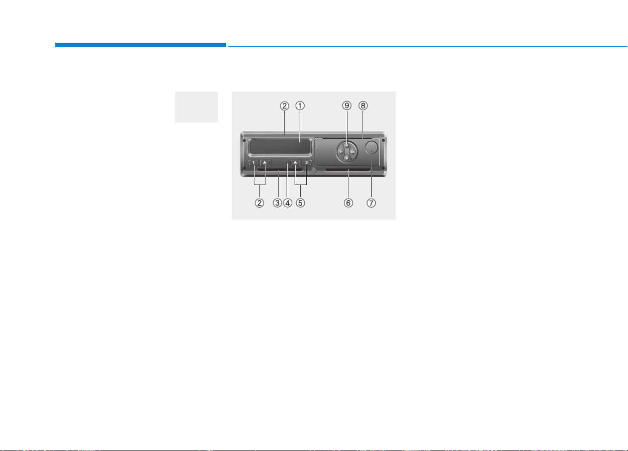
3-80
Convenient features of your vehicle
Warning sound
Overspeed warning
(if equipped)
Overspeed warning light
If you drive with the speed of
120km/h or more, the overspeed
warning light will blink. This is to pre-
vent from driving your vehicle with
overspeed.
Overspeed warning chime
If you drive with the speed of
120km/h or more, the overspeed
warning chime will sound for about 5
seconds. This is to prevent you from
driving your vehicle with overspeed.
■■
Type A
(1) Display
(2) Driver 1 keypad
(3) Card slot 1
(4) Download interface
(5) Driver 2 keypad
(6) Card slot 2
(7) Unlock button printer drawer
(8) Cutting edge
(9) Menu buttons
(a) Symbol " " for ADR variant*
(ADR=European Agreement con-
cerning the international carriage of
dangerous goods by road)
The DTCO 1381 can be remotely
controlled by the corresponding
accessories.
DDIIGGIITTAALL TTAACCHHOOGGRRAAPPHH ((IIFF EEQQUUIIPPPPEEDD))
OEU044072
120
km/h

3-81
Convenient features of your vehicle
3
Description
Display (1)
Depending on the vehicle's opera-
tional condition, different displays will
appear or data can be displayed.
Driver 1 keypad (2)
( ) activity button for driver 1
( ) ejection button for card slot 1
Card slot 1 (3)
Driver 1, who will drive the vehicle at
this moment in time, inserts his driv-
er card into slot 1.
Download interface (4)
The download interface is located
under the cover. The access rights of
this interface are regulated according
to the inserted tachograp card.
Driver 2 keypad (5)
( ) activity button for driver 2
( ) ejection button for card slot 2
Card slot 2 (6)
Driver 2, who is not driving the vehi-
cle at this moment in time, inserts his
driver card into slot 2 (crew opera-
tion).
Unlock button (7)
Use this button to unlock the printer
drawer, for example when inserting a
roll of paper.
Cutting edge (8)
You can use the cutting edge to tear
off a printout generated by integrated
printer.
Menu buttons (9)
Use the following buttons to enter,
display, or print out data.
(
/
) Use the paging function to
select the desired function or
selection.(This is possible by
pressing and holding down
the auto-repeat function key.)
( ) Confirm or acknowledge desired
function/selection.
( ) Press and hold, repeatedly until
the last entry field.
( ) Back to the last entry field, abort
the entry of a country, or leave
the menu one step at a time.
OK
OK
2
2
2
1
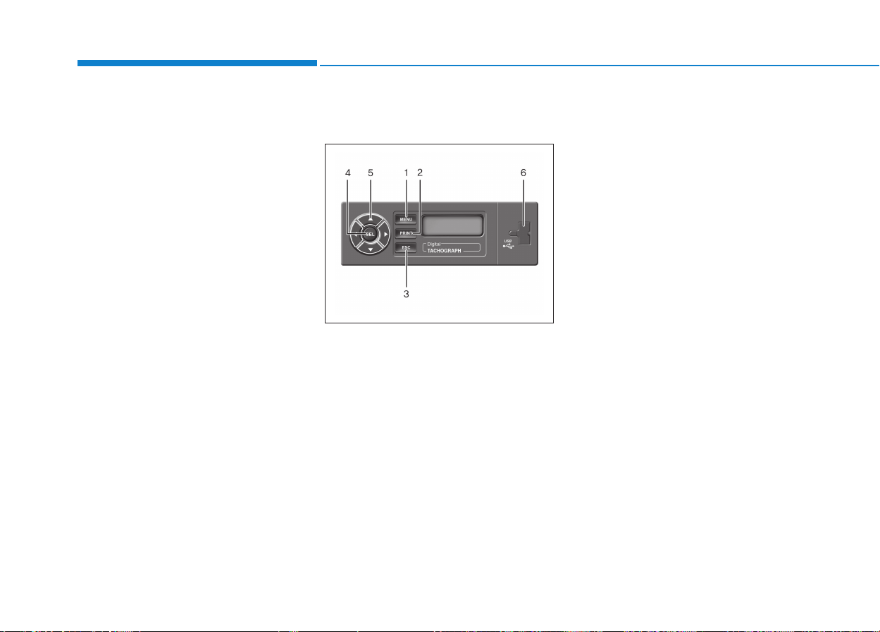
3-82
Convenient features of your vehicle
ADR variant*(a)
- Some functions, such as insertion
or removal of the tachograph
cards, printing or display of data
are possible only while the ignition
is switched on.
- The download interface dap on the
DTCO 1381 must be closed during
loading and unloading of haz-
ardous materials.
❈ For more detail information,
refer to operating instructions
(book or CD) from the manufac-
turing company.
■■
Type B
Name and function (If equipped)
1. MENU
- This button is used to move from
initial screen to Menus.
2. PRINT
- This button is used to move from
initial screen to Choose Printing
Date.
3. VDC
- This button is used to escape the
moving and move to the previous
menu.
- This button is used to escape
USB Download & Printing and
move to the previous menu.
4.SEL
Select the menu and move to the
next menu.
5.Direction key
- This key is used for moving
between Menus.
- It is also used to enter and modi-
fy the info in the setting menu.
6.USB
Travel Info can be saved in a USB
device using this key .
OEG028021
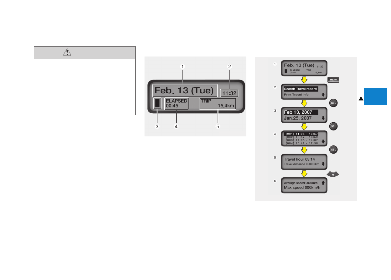
3-83
Convenient features of your vehicle
3
LCD Display
1.It displays the current date infor-
mation.
2.It displays the current time.
3.It displays the current driving con-
dition.
- IGN ON for vehicle stop
- Vehicle Driving
- Vehicle IDLE
4.It displays the time from Key On to
now.
5.It displays the distance from Key
On to the current location.
Search travel information
1.Initial screen
It displays Date, Time, Driving con-
dition, Travel hour, Travel distance.
2.Search travel info
❙❙
❚
OCY28401M
OCY28402M
• Do not use the USB devices
not qualified certificate
because of compatibility.
• The product records informa-
tion while the vehicle is run-
ning. No key or menu will be
working.
CAUTION
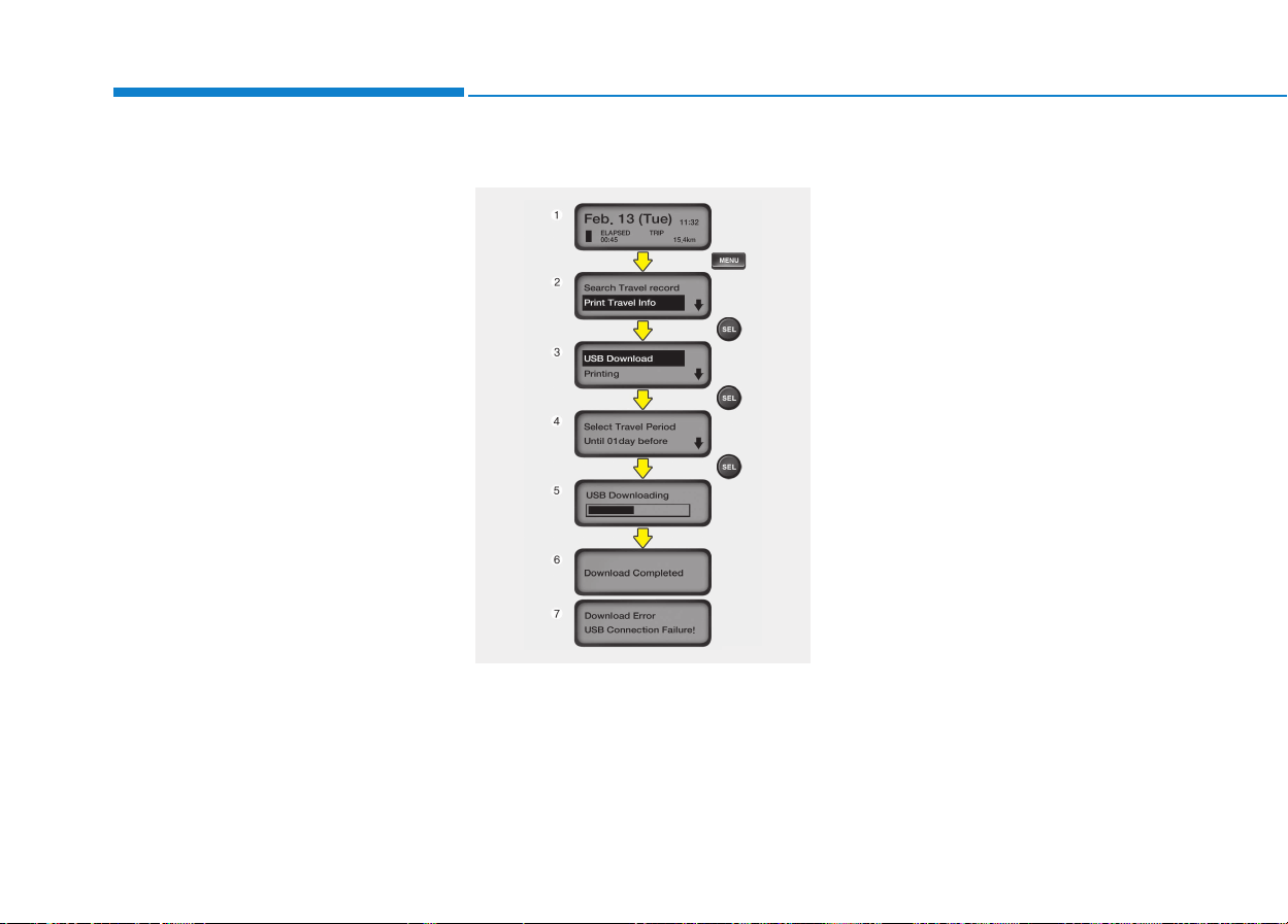
3-84
Convenient features of your vehicle
3.Select travel data you want to
inquire:
Nothing displays when there is no
travel info recorded.
4.Select travel time you want to
inquire:
Displays the time elapsed from Key
On to Key Off.
5.Displays travel time info you
inquired:
The travel info calculated above (4)
will be displayed.
USB Download
1.Initial screen
It displays Date, Time, Driving con-
dition, Travel hour, Travel distance.
2.Select print travel info mode
3.Select USB download mode
4.Set and select travel period:
Select (Total, Day 1 ~ 99) by using
the direction (UP, down) key.
5.Check USB and download pro-
gression is displayed.
- Click VDC in the downloading to
escape and it goes to (3).
- If USB is not inserted, it goes to
page (7).
- Don’t remove USB while down-
load is in process.
6.Display the completion of data
storage to USB device.
- If download is completed, remove
the USB device.
7.Error massage is displayed when
no USB is inserted.
OCY28403M
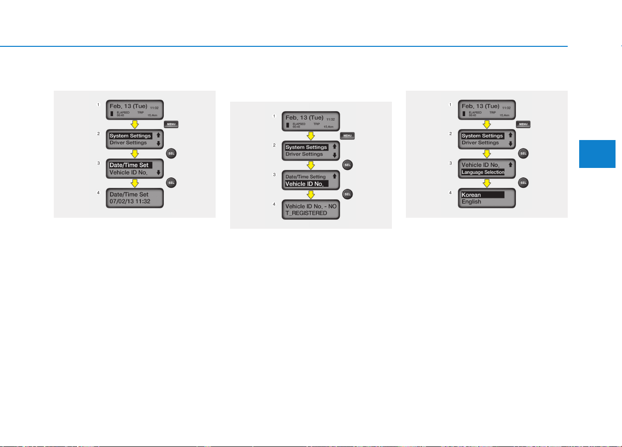
3-85
Convenient features of your vehicle
3
Date/Time setting
1.Initial screen
It displays Date, Time, Driving con-
dition, Travel hour, Travel distance.
2.Select system setting mode
3.Select date/time setting mode
4.Inquire and modify date/time set:
- Use direction key to modify and
save it with SEL key.
- Click VDC to escape the saving
and it goes to (3).
Inquiry of vehicle identification
number
1.Initial screen
It displays Date, Time, Driving con-
dition, Travel hour, Travel distance.
2.Select system setting mode
3.Select vehicle ID No. mode
4.Inquiring vehicle ID No. mode:
Modification is not available.
Setting brightness
1.Initial screen
It displays Date, Time, Driving con-
dition, Travel hour, Travel distance.
2. Select system setting mode
3. Select language selection mode
4. Inquire and set language selection
- Use direction key to select and
save it with SEL key.
- Click VDC to escape the saving
and it goes to (3).
OCY28406M
OCY28407MOCY28405M
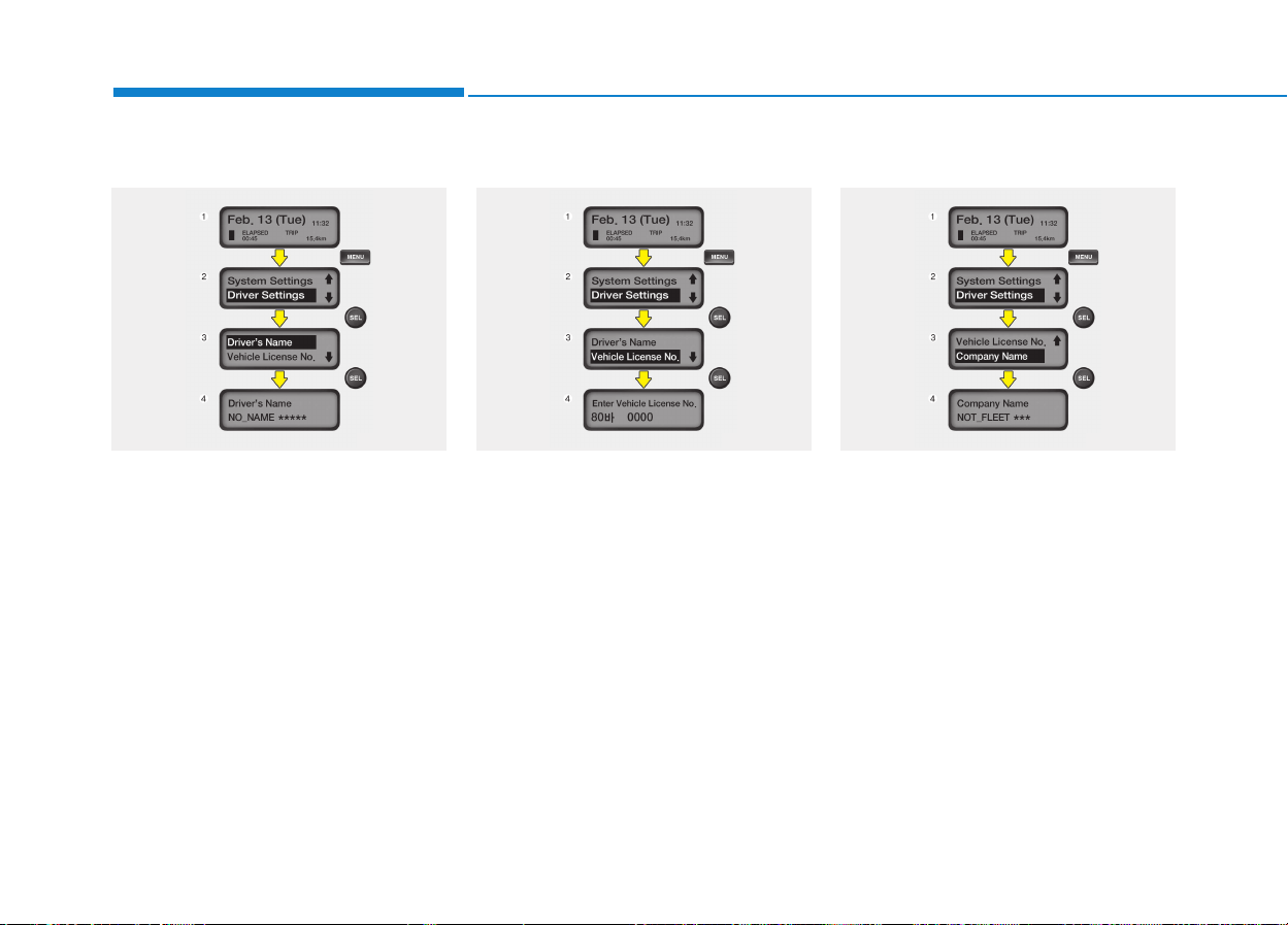
3-86
Convenient features of your vehicle
Driver’s name
1.Initial screen
It displays Date, Time, Driving con-
dition, Travel hour, Travel distance.
2.Select driver settings mode
3. Select driver’s name mode
4. Driver’s Name : Inquiry & modifica-
tion
- Use direction key to select and
save it with SEL key.
- Click VDC to escape the saving
and it goes to (3).
Vehicle license number
1.Initial screen
It displays Date, Time, Driving con-
dition, Travel hour, Travel distance.
2.Select driver settings mode
3.Select vehicle license No. mode
4.Vehicle license No.: Inquiry & mod-
ification
- Use direction key to select and
save it with SEL key.
- Click VDC to escape the saving
and it goes to (3).
Company name
1.Initial screen
It displays Date, Time, Driving con-
dition, Travel hour, Travel distance.
2.Select driver settings mode
3.Select company name mode
4.Vehicle license No.: Inquiry & mod-
ification
- Use direction key to select and
save it with SEL key.
- Click VDC to escape the saving
and it goes to (3).
OCY28412M OCY28408MOCY28411M
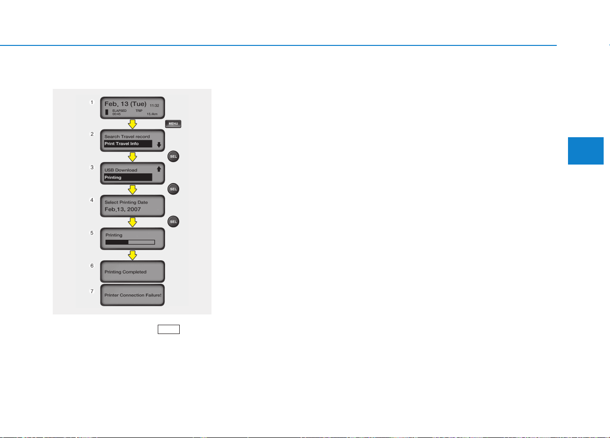
3-87
Convenient features of your vehicle
3
Printing
Shortcut setting: Press key to
move to (4).
1.Initial screen
It displays Date, Time, Driving con-
dition, Travel hour, Travel distance.
2.Select print travel info mode
3.Select printing mode
4.Select print date
- All date can be set.
- No travel record will be displayed
when no record is available.
5.Displays progression in USB print-
er
- Click VDC key to escape the
process and to move to (3).
- Don’t remove printer while it is
printing.
6.Displays printing completed in
USB printer
- Don’t remove USB printer.
7.Error message is displayed when
USB printer is disconnected.
Printing type
- Displays the printing type printed in
portable printer integrated version
is printed. The printer is based on
(48mm, 384dots) Report - Graph.
- Time axis is set 1dot/min. The axis
displays 1 minute’s average speed
as 2dots for 1km/h. If the speed
exceeds 150km/h, it displays
150km/h.
PRINT
OCY28409M
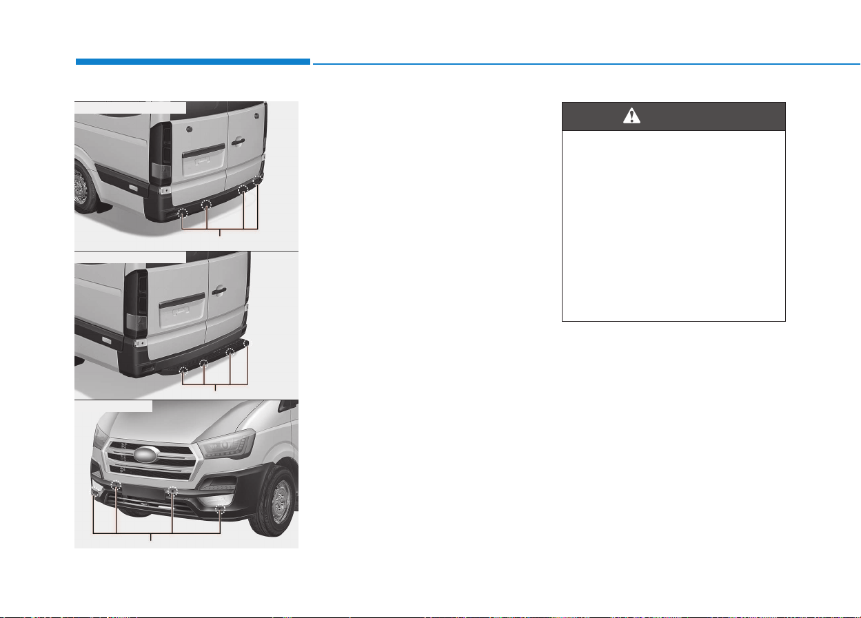
3-88
Convenient features of your vehicle
This is the parking assist system to
warn the driver of object which are
detected by front, rear and side sen-
sors with range of distance of sen-
sors operation as warning sound or
indicator (LCD) when the vehicle is
moved back or forward.
This system is a supplemental sys-
tem and it is not intended to nor does
it replace the need for extreme care
and attention of the driver.
The sensing range and objects
detectable by the sensors are limit-
ed.
Whenever getting forward or back-
ing-up, pay as much attention to
what is front or behind you as you
would in a vehicle without a parking
assist system.
The parking assist system
should only be considered as a
supplementary function. The
driver must check the front and
rear view. The operational func-
tion of the parking assist sys-
tem can be affected by many
factors and conditions of the
surroundings and can not be
operated normally, so the
responsibility rests always with
the driver.
WARNING
PPAARRKKIINNGG AASSSSIISSTT SSYYSSTTEEMM ((IIFF EEQQUUIIPPPPEEDD))
OEU044049
OEU044050
■ Rear sensors (A type)
Sensors
Sensors
OEU044070
■ Rear sensors (B type)
■ Front Sensors
Sensors
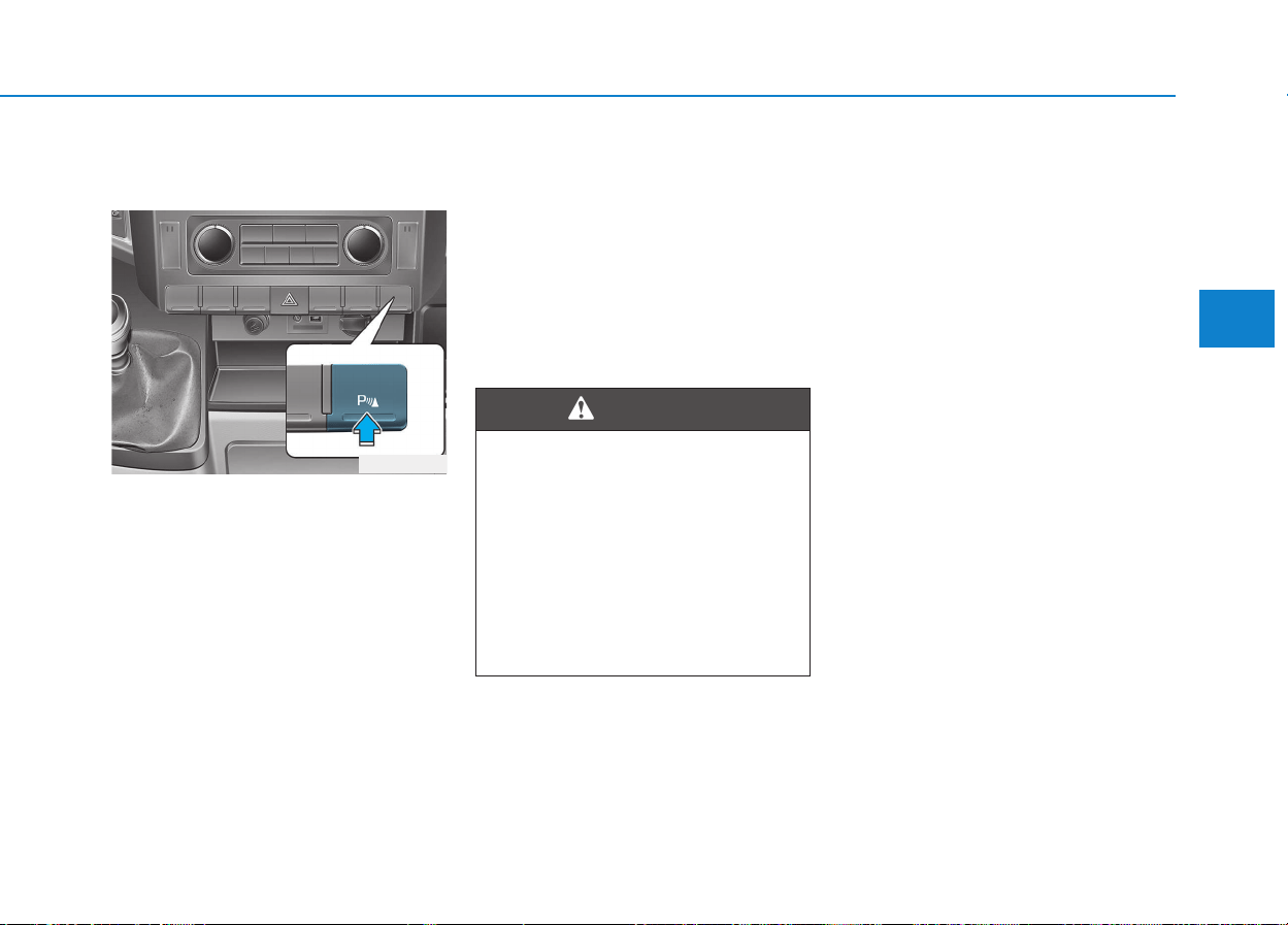
3-89
Convenient features of your vehicle
Rear parking assist system
type (if equipped)
The rear sensor detects the distance
between vehicle and object. The rear
parking assist system assists the
driver during backward movement of
the vehicle by chiming if any object is
sensed within a distance of 120 cm
(47 in.) behind the vehicle.
This system is a supplemental sys-
tem and it is not intended to nor does
it replace the need for extreme care
and attention of the driver. The sens-
ing range and objects detectable by
the back sensors are limited.
Whenever backing-up, pay as much
attention to what is behind you as
you would in a vehicle without a rear
parking assist system.
Operating condition
• This system will activate when
backing up with the ignition switch
ON.
If the vehicle is moving at a speed
over 10 km/h (6 mph), the system
may not be activated correctly.
• This system will activate when the
indicator on the rear parking assist
ON button. If you desire to deacti-
vate the rear parking assist sys-
tem, press the rear parking assist
button again. To turn the system
on, press the button again. (The
indicator on the button will go on.)
• The sensing distance while the
rear parking assist system is in
operation is approximately 120 cm
(47 in.).
• When more than two objects are
sensed at the same time, the clos-
est one will be recognized first.
3
OEU044194
The rear parking assist system
is a supplementary function
only. The operation of the rear
parking assist system can be
affected by several factors
(including environmental condi-
tions). It is the responsibility of
the driver to always check the
area behind the vehicle before
and while backing up.
WARNING

3-90
Convenient features of your vehicle
Types of warning sound
• When an object is 120 cm to 61 cm
(47.2 in. to 24 in.) from the rear
bumper:
Buzzer beeps intermittently.
• When an object is 60 cm to 31 cm
(23.6 in. to 12.2 in.) from the rear
bumper:
Buzzer beeps more frequently.
• When an object is within 30 cm
(11.8 in.) of the rear bumper:
Buzzer sounds continuously.
Non-operational conditions
The rear parking assist system may
not operate properly when:
1. Moisture is frozen to the sensor. (It
will operate normally when the
moisture has been cleared.)
2. The sensor is covered with foreign
matter, such as snow or water, or
the sensor cover is blocked. (It will
operate normally when the materi-
al is removed or the sensor is no
longer blocked.)
3. Driving on uneven road surfaces.
(unpaved roads, gravel, bumps,
gradient)
4. Objects generating excessive
noise (vehicle horns, loud motor-
cycle engines, or truck air brakes)
are within range of the sensor.
5. Heavy rain or water spray exists.
6. Wireless transmitters or mobile
phones are within range of the
sensor.
7. The sensor is covered with snow.
8. Trailer towing.
9. The place light the fluorescent
lamp.
The detecting range may decrease
when:
1. The sensor is stained with foreign
matter such as snow or water.
(The sensing range will return to
normal when removed.)
2. Outside air temperature is
extremely hot or cold.
The following objects may not be rec-
ognized by the sensor:
1. Sharp or slim objects such as
ropes, chains or small poles.
2. Objects which tend to absorb the
sensor frequency such as clothes,
spongy material or snow.
3. Undetectable objects smaller than
1 m (40 in.) in height and narrower
than 14 cm (6 in.) in diameter.

3-91
Convenient features of your vehicle
3
Rear parking assist system pre-
cautions
• The rear parking assist system
may not sound sequentially
depending on the speed and
shapes of the objects detected.
• The rear parking assist system
may malfunction if the vehicle
bumper height or sensor installa-
tion has been modified or dam-
aged. Any non-factory installed
equipment or accessories may
also interfere with the sensor per-
formance.
• The sensor may not recognize
objects less than 30 cm (11.8 in.)
from the sensor, or it may sense an
incorrect distance. Use caution.
• When the sensor is frozen or
stained with snow, dirt, or water,
the sensor may be inoperative until
the stains are removed using a soft
cloth.
• Do not push, scratch or strike the
sensor. Sensor damage could
occur.
This system can only sense
objects within the range and loca-
tion of the sensors; It can not
detect objects in other areas
where sensors are not installed.
Also, small or slim objects, such
as poles or objects located
between sensors may not be
detected by the sensors.
Always visually check behind the
vehicle when backing up.
Be sure to inform any drivers of
the vehicle that may be unfamiliar
with the system regarding the sys-
tems capabilities and limitations.
NOTICE
Pay close attention when the
vehicle is driven close to
objects on the road, particularly
pedestrians, and especially
children. Be aware that some
objects may not be detected by
the sensors, due to the object’s
distance, size or material, all of
which can limit the effective-
ness of the sensor. Always per-
form a visual inspection to
make sure the vehicle is clear of
all obstructions before moving
the vehicle in any direction.
WARNING
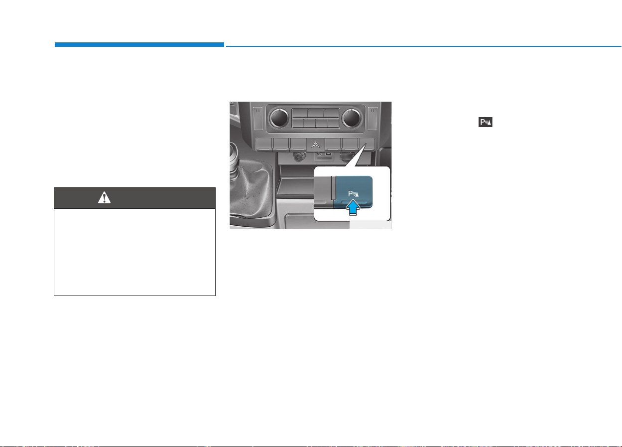
3-92
Convenient features of your vehicle
Self-diagnosis
If you don’t hear an audible warning
sound or if the buzzer sounds inter-
mittently when shifting the gear to
the R (Reverse) position, this may
indicate a malfunction in the rear
parking assist system. If this occurs,
we recommend that the system be
checked by an authorized HYUNDAI
dealer.
Front/Rear parking assist sys-
tem type (if equipped)
The front/rear parking assist system
detects the object distance by using
the front/rear sensor and front side
sensor.
When you select the parking assist
system*, the front/rear parking assist
system will be operated.
Operating condition
• This parking assist system acti-
vates and the indicator on the but-
ton illuminates when the parking
assist button ( ) is pressed with
the ignition switch ON. And it oper-
ates in forward, reverse and neu-
tral position of the shift lever.
The parking assist button turns on
automatically and activates the
parking assist system when you
shift the gear to the R (Reverse)
position. If you drive the vehicle
above 10km/h, the warning will not
activate.
• When more than two objects are
sensed at the same time, warning
indicator is displayed all.
• When more than two objects are
sensed at the same time, the clos-
est one will be warned by warning
sound.
• While backing up, if the front and
rear sensor recognizes an object at
the same distance, the rear will be
warned first.
• The warnings by side sensors are
operated when the shift lever is in
R (Reverse) position.
Your new vehicle warranty does
not cover any accidents or dam-
age to the vehicle or injuries to
its occupants due to a rear
parking assist system malfunc-
tion. Always drive safely and
cautiously.
WARNING
OEU044194

3-93
Convenient features of your vehicle
3
Types of warning sound
When driving forward
• When an object is 100 cm to 61 cm
(39 in. to 24 in.) from the bumper:
Buzzer beeps intermittently.
• When an object is 60 cm to 31 cm
(23 in. to 12 in.) from the bumper:
Buzzer beeps more frequently.
• When an object is within 30 cm (11
in.) of the bumper:
Buzzer sounds continuously.
When driving rearward
• When an object is 120 cm to 61 cm
(47.2 in. to 24 in.) from the bumper:
Buzzer beeps intermittently.
• When an object is 60 cm to 31 cm
(23 in. to 12 in.) from the bumper:
Buzzer beeps more frequently.
• When an object is within 30 cm (11
in.) of the bumper:
Buzzer sounds continuously.
• This system can only sense
objects within the range and
location of the sensors;
It can not detect objects in
other areas where sensors are
not installed. Also, small or
slim objects, such as poles or
objects located between sen-
sors may not be detected by
the sensors.
Always visually check front or
behind the vehicle when get-
ting forward or backing up.
• Be sure to inform any drivers
of the vehicle that may be
unfamiliar with the system
regarding the systems capa-
bilities and limitations.
CAUTION
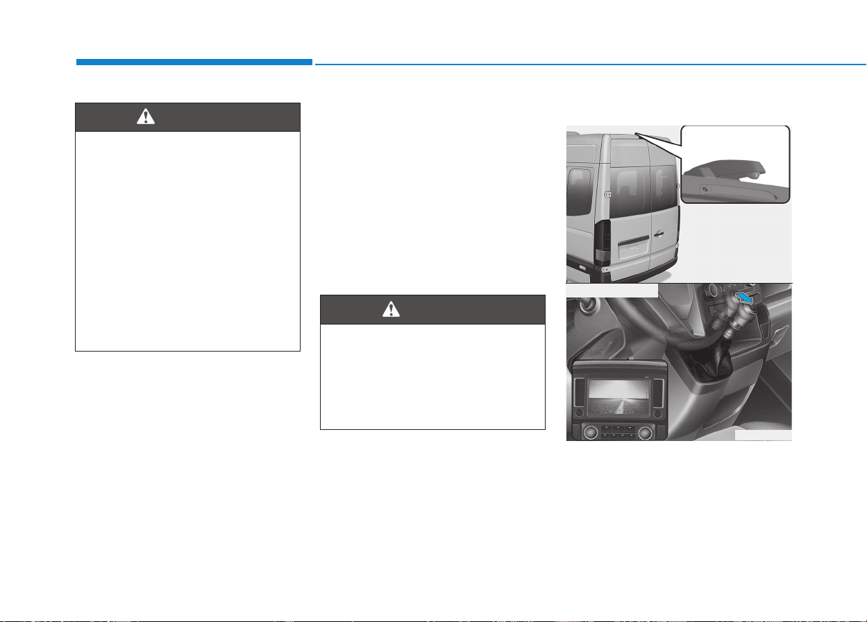
3-94
Convenient features of your vehicle
Self-diagnosis
When the front/rear parking assist
system has a malfunction, if you
operate the system, the warning
sound sounds 3 times. In this time,
the indicator on switch will blink and
the warning on the cluster will blink.
However, the warning regarding
object will not sound.
In this time, we recommend that the
system be checked by an authorized
HYUNDAI dealer.
The rearview camera will activate
when the back-up light is ON with the
ignition switch ON and the shift lever
in the R (Reverse) position.
Pay close attention when the
vehicle is driven close to
objects on the road, particularly
pedestrians, and especially
children. Be aware that some
objects may not be detected by
the sensors, due to the object's
distance, size or material, all of
which can limit the effective-
ness of the sensor. Always per-
form a visual inspection to
make sure the vehicle is clear of
all obstructions before moving
the vehicle in any direction.
WARNING
RREEAARRVVIIEEWW CCAAMMEERRAA
(
(IIFF EEQQUUIIPPPPEEDD))
OEU044038
OEU044037
■ Rear view display
Your new vehicle warranty does
not cover any accidents or dam-
age to the vehicle or injuries to
its occupants related to a park-
ing assist system. Always drive
safely and cautiously.
WARNING
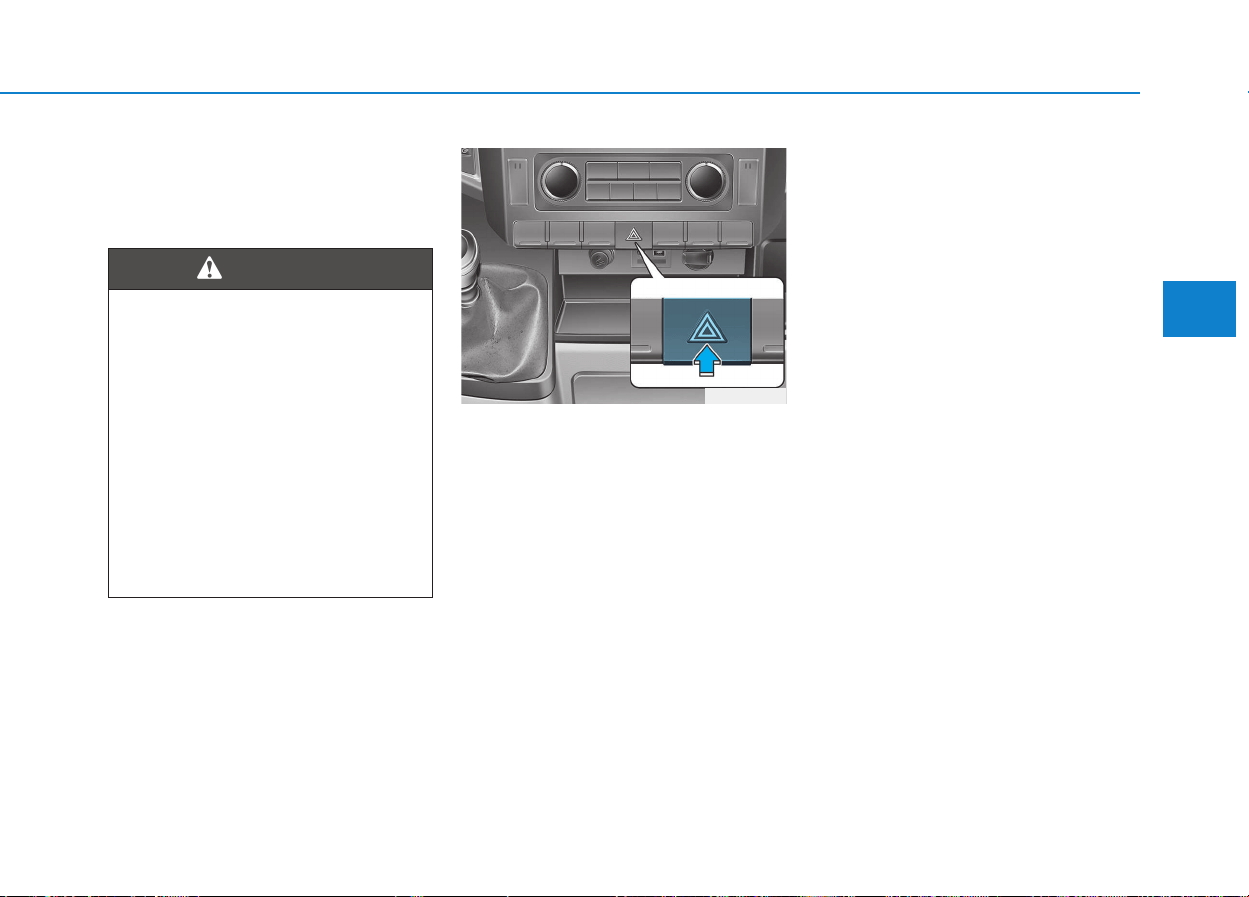
3-95
Convenient features of your vehicle
3
This system is a supplemental sys-
tem that shows behind the vehicle
through the rearview display mirror
while backing-up.
The hazard warning flasher should
be used whenever you find it neces-
sary to stop the vehicle in a haz-
ardous location. When you must
make such an emergency stop,
always pull off the road as far as pos-
sible.
The hazard warning lights are turned
on by pushing in the hazard switch.
This causes all turn signal lights to
blink. The hazard warning lights will
operate even though the key is not in
the ignition switch.
To turn the hazard warning lights off,
push the switch a second time.
Battery saver function
• The purpose of this feature is to
prevent the battery from being dis-
charged. The system automatically
turns off the parking lights when
the driver removes the ignition key
and opens the driver- side door.
• With this feature, the parking lights
will be turned off automatically if
the driver parks on the side of road
at night.
If necessary, to keep the lights on
when the ignition key is removed,
perform the following :
1) Open the driver-side door.
2) Turn the parking lights OFF and
ON again using the light switch
on the steering column.
• This system is a supplemen-
tary function only. It is the
responsibility of the driver to
always check the inside/out-
side rearview mirror and the
area behind the vehicle before
and while backing up because
there is a dead zone that can't
see through the camera.
• Always keep the camera lens
clean. If lens is covered with
foreign matter, the camera
may not operate normally.
WARNING
HHAAZZAARRDD WWAARRNNIINNGG FFLLAASSHHEERR
OEU044191
LLIIGGHHTTIINNGG
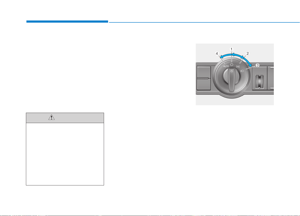
3-96
Convenient features of your vehicle
Headlight escort function
(if equipped)
The headlights (and/or taillights)
remain on for approximately 5 min-
utes after the ignition key is removed
or turned to the ACC or LOCK posi-
tion. However, if the driver’s door is
opened and closed, the headlights
are turned off after 30 seconds.
The headlights can be turned off by
pressing the lock button on the trans-
mitter twice or turning off the light
switch from the headlight or Auto
light position.
Headlight welcome function
(if equipped)
When the headlight switch is in the
ON or AUTO position and all doors
(and tailgate) are closed and locked,
if you press the door unlock button
on the transmitter the headlights will
come on for about 15 seconds.
If the headlight switch is in the AUTO
position, the function can only oper-
ate at night.
At this time, if you press the door
unlock button again or door lock but-
ton on the transmitter, the headlights
will turn off immediately.
Lighting control
The light switch has a Headlight and
a Parking light position.
To operate the lights, turn the knob at
the end of the control lever to one of
the following positions:
(1) OFF position
(2) Parking light position
(3) Headlight position
(4) Auto light position (if equipped)
If the driver gets out of the vehi-
cle through other doors (except
driver’s door), the battery saver
function does not operate and
the headlight escort function
does not turn off automatically.
Therefore, it causes the battery
to be discharged. In this case,
make sure to turn off the lamp
before getting out of the vehi-
cle.
CAUTION
OEU044176
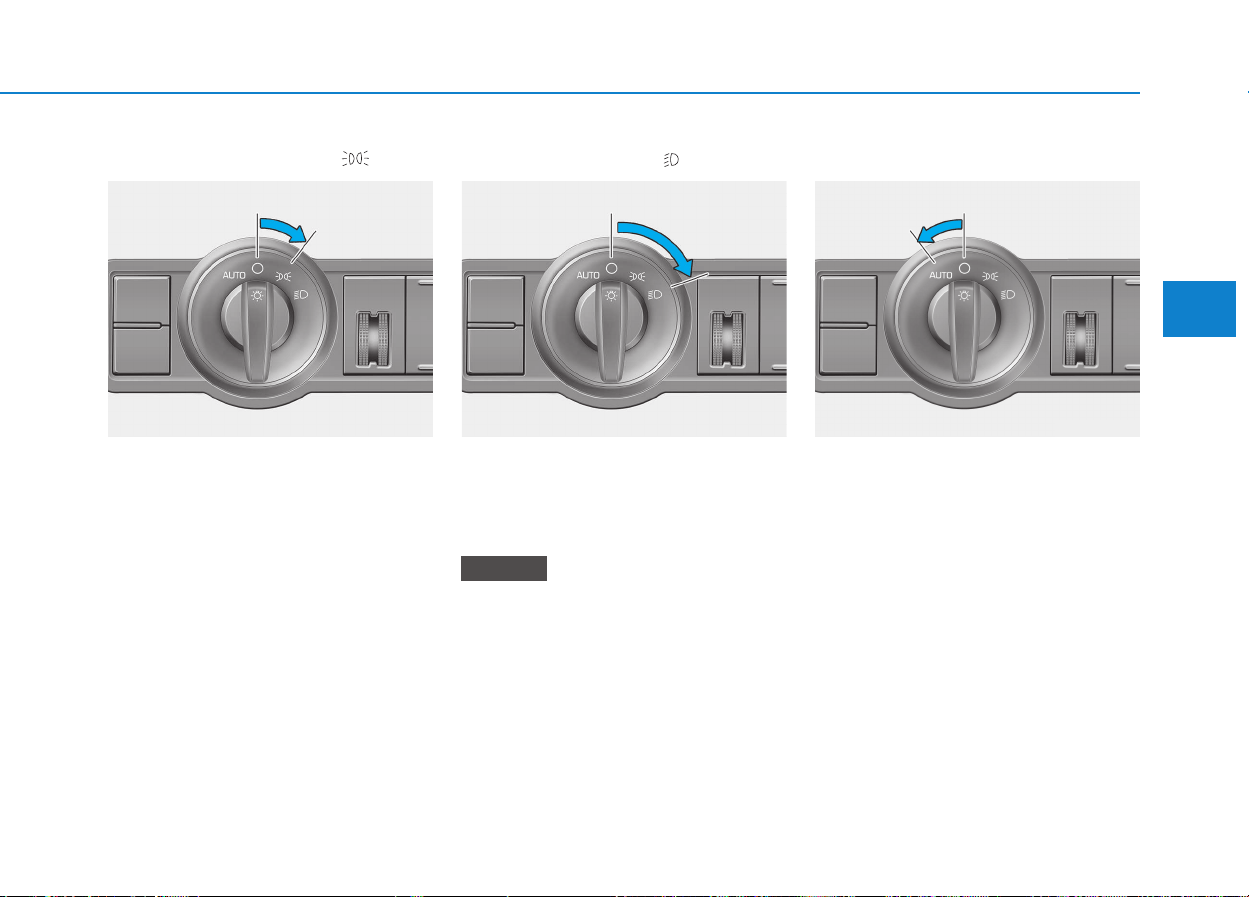
3-97
Convenient features of your vehicle
3
Parking light position ( )
When the light switch is in the park-
ing light position, the tail, position,
license and instrument panel lights
are ON.
Headlight position ( )
When the light switch is in the head-
light position the head, tail, position,
license and instrument panel lights
are ON.
The ignition switch must be in the
ON position to turn on the head-
lights.
Auto light position (if equipped)
When the light switch is in the AUTO
light position, the taillights and head-
lights will be turned ON or OFF auto-
matically depending on the amount
of light outside the vehicle.
If you turn on the auto light switch
and operate the wiper for more than
20 seconds in the daytime, the tail-
light and headlight are turned on low.
NOTICE
OEU044183 OEU044185OEU044184
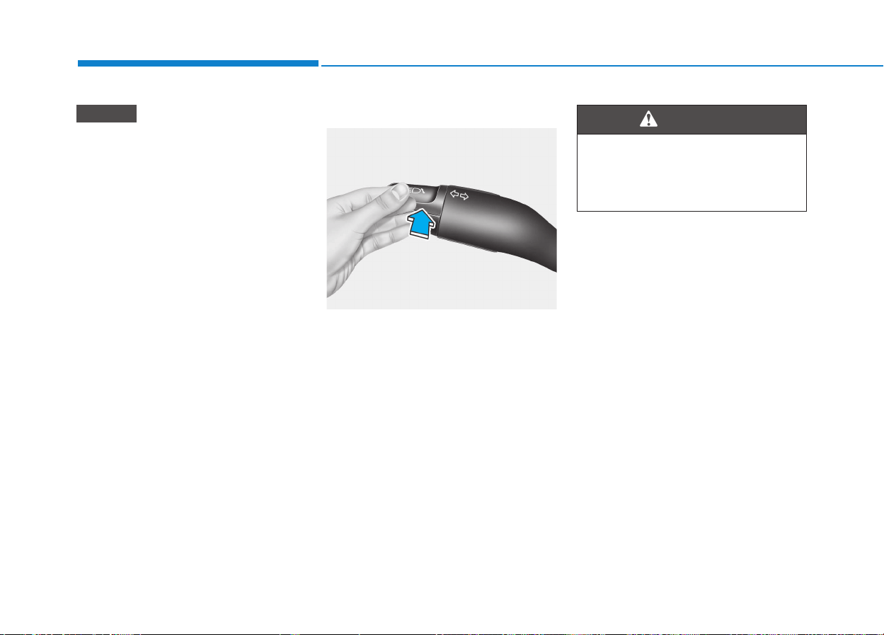
3-98
Convenient features of your vehicle
• Don’t clean the sensor using a
window cleaner, the cleaner may
leave a light film which could
interfere with sensor operation.
• If your vehicle has window tint
or other types of coating on the
front windshield, the Auto light
system may not work properly.
High - beam operation
To turn on the high beam headlights,
push the lever away from you. Pull it
back for low beams.
The high-beam indicator will light
when the headlight high beams are
switched on.
To prevent the battery from being
discharged, do not leave the lights
on for a prolonged time while the
engine is not running.
NOTICE
OEU044207
Do not use high beam when
there are other vehicles. Using
high beam could obstruct the
other driver's vision.
WARNING
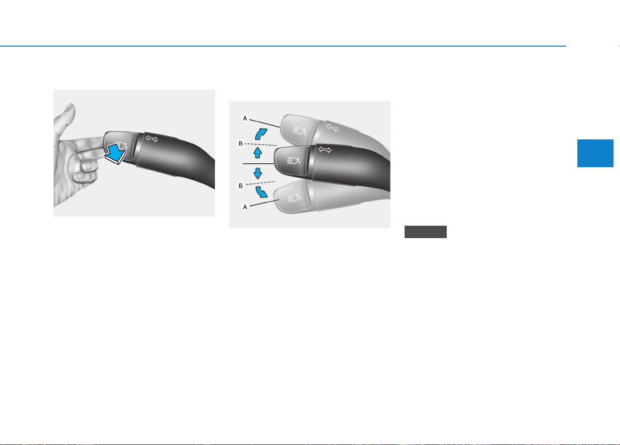
3-99
Convenient features of your vehicle
3
Flashing headlights
To flash the headlights, pull the lever
towards you. It will return to the nor-
mal (low-beam) position when
released. The headlight switch does
not need to be on to use this flashing
feature.
Turn signals and lane change
signals
The ignition switch must be on for the
turn signals to function. To turn on
the turn signals, move the lever up or
down (A). Green arrow indicators on
the instrument panel indicate which
turn signal is operating.
They will self-cancel after a turn is
completed. If the indicator continues
to flash after a turn, manually return
the lever to the OFF position.
To signal a lane change, move the
turn signal lever slightly and hold it in
position (B). The lever will return to
the OFF position when released.
If an indicator stays on and does not
flash or if it flashes abnormally, one
of the turn signal bulbs may be
burned out and will require replace-
ment.
One-touch lane change function
(if equipped)
To activate an one-touch lane
change function, move the turn sig-
nal lever slightly and then release it.
The lane change signals will blink 3
times.
If an indicator flash is abnormally
quick or slow, bulb may be burned
out or have a poor electrical con-
nection in the circuit.
NOTICE
OEU044209
OEU044208
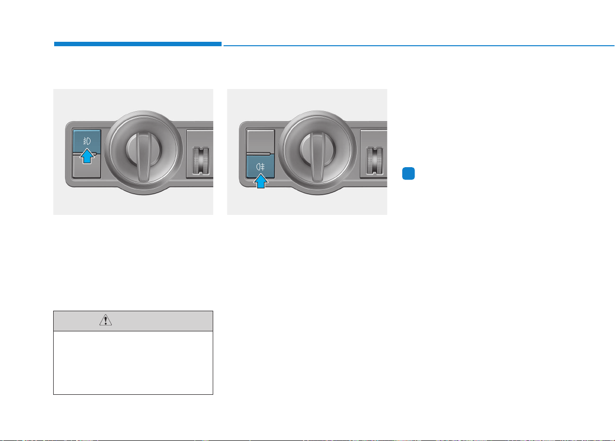
3-100
Convenient features of your vehicle
Front fog light (if equipped)
Fog lights are used to provide
improved visibility when visibility is
poor due to fog, rain or snow, etc.
The fog lights will turn on when
pressing the fog light switch after the
parklight is turned on.
To turn off the fog lights, press the
fog light switch again.
Rear fog light (if equipped)
To turn the rear fog lights on, turn the
headlight switch to the headlight on
position and press the rear fog light
switch.
The rear fog lights turn on when the
rear fog light switch is turned on after
the front fog light switch (if equipped)
is turned on and the headlight switch
is in the parklight position.
To turn the rear fog lights off, press
the rear fog light switch again or turn
the headlight switch off.
Information
To turn on the rear fog light switch,
the ignition switch must be in the ON
position.
i
When in operation, the fog
lights consume large amounts
of vehicle electrical power. Only
use the fog lights when visibili-
ty is poor.
CAUTION
OEU044181OEU044180
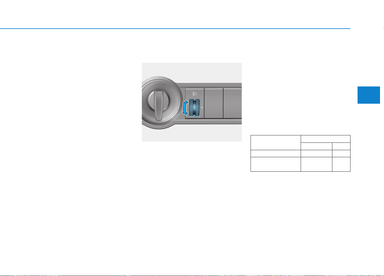
3-101
Convenient features of your vehicle
3
Daytime running light
(if equipped)
Daytime Running Lights (DRL) can
make it easier for others to see the
front of your vehicle during the day.
DRL can be helpful in many different
driving conditions, and it is especial-
ly helpful after dawn and before sun-
set.
The DRL system will make the head-
lights turn OFF when:
1. The parklight switch is ON.
2. Engine stops.
Headlight leveling device
(if equipped)
To adjust the headlight beam level
according to the number of the pas-
sengers and the loading weight in
the luggage area, turn the beam lev-
eling switch.
The higher the number of the switch
position, the lower the headlight
beam level. Always keep the head-
light beam at the proper leveling
position, or headlights may dazzle
other road users.
Listed below are the examples of
proper switch settings. For loading
conditions other than those listed
below, adjust the switch position so
that the beam level may be the near-
est as the condition obtained accord-
ing to the list.
OEU044186
Loading condition
Switch position
VAN/TRUCK BUS
Driver only 0 0
Maximum permissible
mass
31
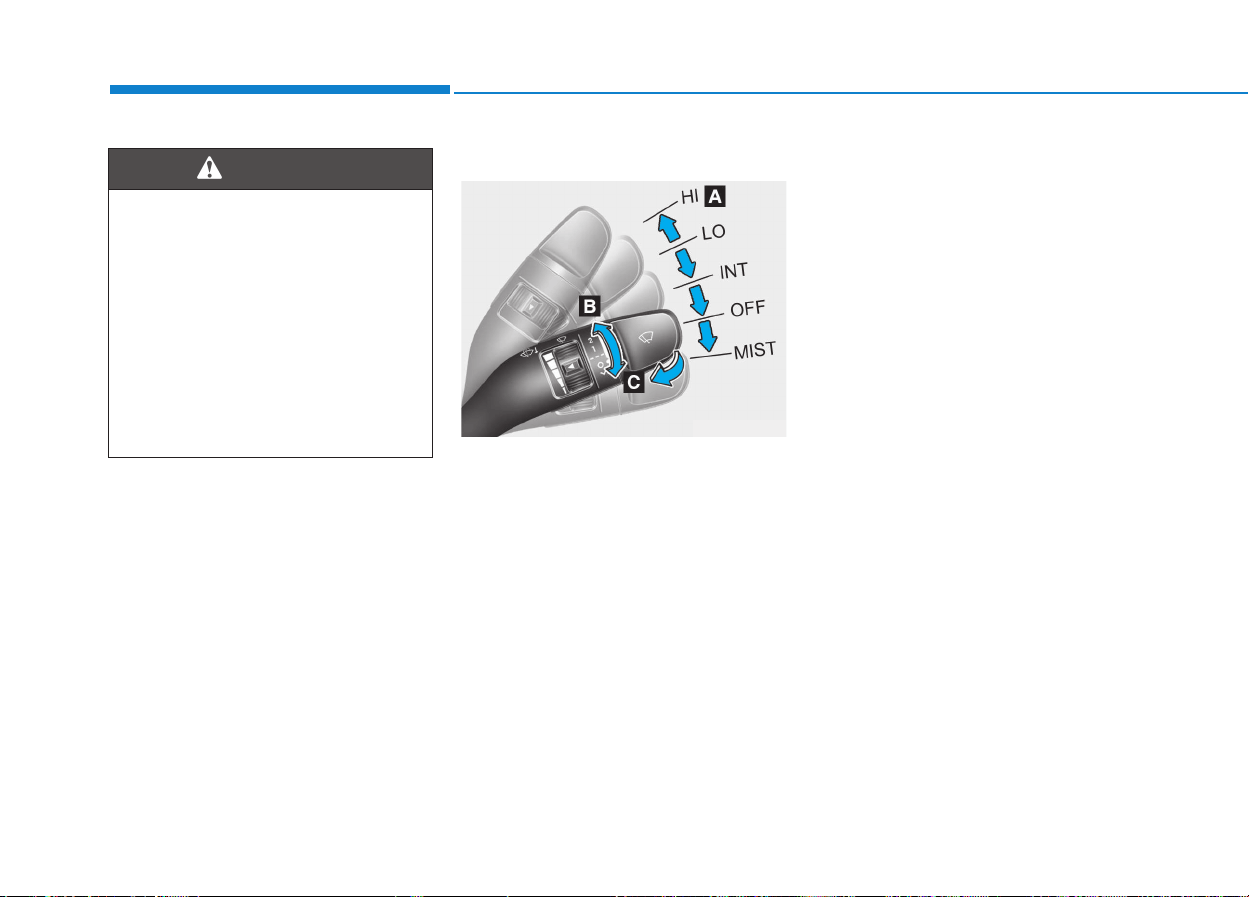
3-102
Convenient features of your vehicle
Windshield wiper/washer
A : Wiper speed control (front)
(MIST) – Single wipe
O (OFF) – Off
--- (INT) – Intermittent wipe
AUTO - Automatic control wipe (if
equipped)
1 (LO)– Low wiper speed
2 (HI) – High wiper speed
B : Intermittent control wipe time
adjustment
C : Wash with brief wipes (front)
Windshield wipers
Operates as follows when the igni-
tion switch is turned ON.
(MIST) : For a single wiping cycle,
move the lever to this
(MIST) position and
release it. The wipers will
operate continuously if
the lever is held in this
position.
O (OFF) : Wiper is not in operation
--- (INT) : Wiper operates intermit-
tently at the same wiping
intervals. Use this mode in
light rain or mist. To vary
the speed setting, turn the
speed control knob.
AUTO : The rain sensor located on
the upper end of the wind-
shield glass senses the
amount of rainfall and con-
trols the wiping cycle for the
proper interval. The more it
rains, the faster the wiper
operates. When the rain
stops, the wiper stops. To
vary the speed setting, turn
the speed control knob (B).
∧
∧
If it does not work properly even
though your vehicle is inclined
backward according to passen-
ger's posture, or the headlight
beam is irradiated to the high or
low position, we recommend
that you have your vehicle
inspected by an authorized
HYUNDAI dealer.
Do not attempt to inspect or
replace the wiring yourself.
WARNING
WWIIPPEERRSS AANNDD WWAASSHHEERRSS
OEU045240
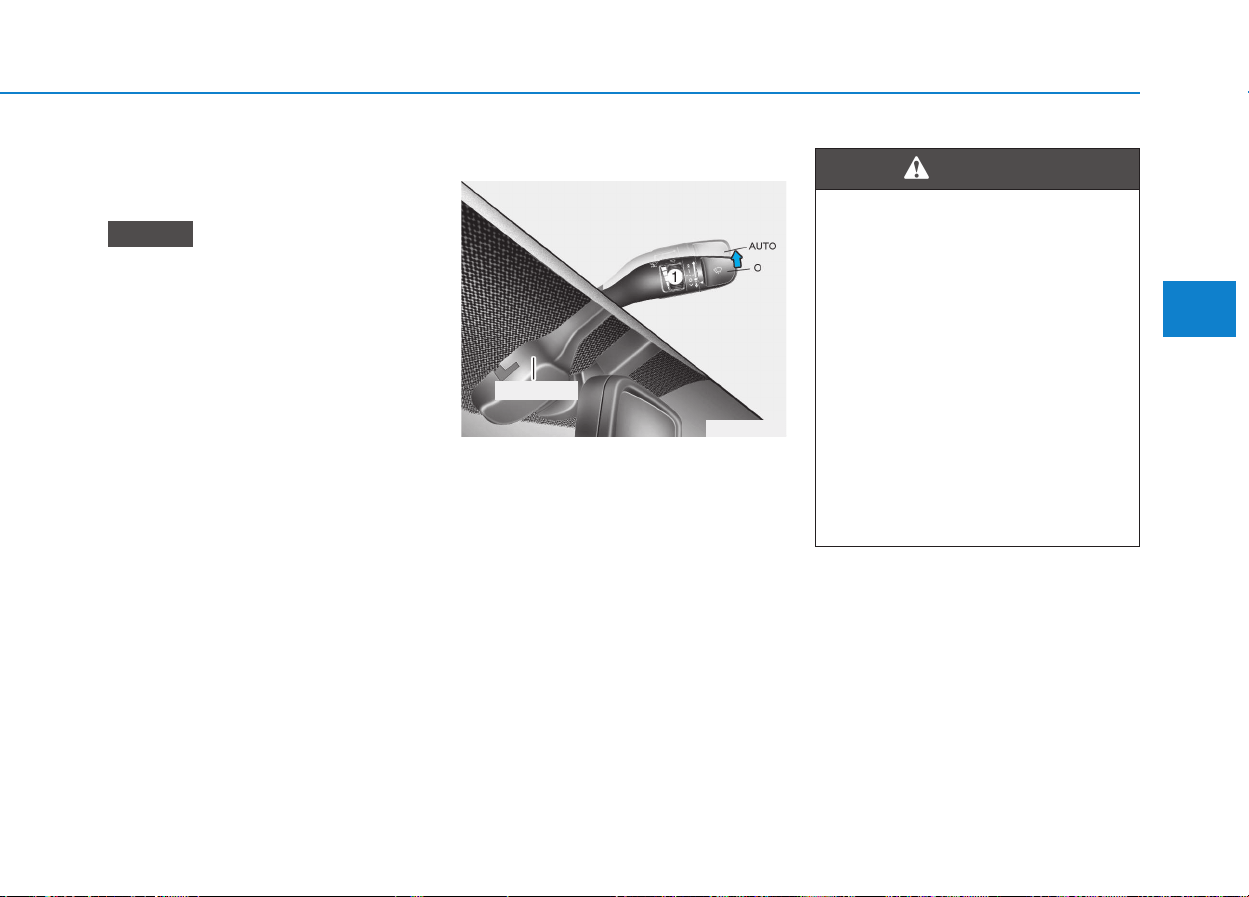
3-103
Convenient features of your vehicle
3
1 (LO) : Normal wiper speed
2 (HI) : Fast wiper speed
• If there is heavy accumulation of
snow or ice on the windshield,
defrost the windshield for about
10 minutes, or until the snow
and/or ice is removed before
using the windshield wipers to
ensure proper operation.
If you do not remove the snow
and/or ice before using the
wiper and washer, it may dam-
age the wiper and washer sys-
tem.
• When the wipers do not properly
wipe out the front windshield,
they may be worn out or
cracked. In this case, replace the
wipers with the new ones.
Auto control (if equipped)
The rain sensor located on the upper
end of the windshield glass senses
the amount of rainfall and controls
the wiping cycle for the proper inter-
val. The more it rains, the faster the
wiper operates.
When the rain stops, the wiper stops.
To vary the speed setting, turn the
speed control knob (1).
If the wiper switch is set in AUTO
mode when the ignition switch is ON,
the wiper will operate once to per-
form a self-check of the system. Set
the wiper to OFF position when the
wiper is not in use.
NOTICE
When the ignition switch is ON
and the windshield wiper switch
is placed in the AUTO mode,
use caution in the following sit-
uations to avoid any injury to
the hands or other parts of the
body:
• Do not touch the upper end of
the windshield glass facing
the rain sensor.
• Do not wipe the upper end of
the windshield glass with a
damp or wet cloth.
• Do not put pressure on the
windshield glass.
WARNING
OEU044076
Rain sensor
3-104
Convenient features of your vehicle
When washing the vehicle, set
the wiper switch in the OFF
position to stop the auto wiper
operation.
The wiper may operate and be
damaged if the switch is set in
the AUTO mode while washing
the vehicle.
Do not remove the sensor cover
located on the upper end of the
passenger side windshield
glass. Damage to system parts
could occur and may not be
covered by your vehicle warran-
ty.
When starting the vehicle in
winter, set the wiper switch in
the OFF position. Otherwise,
wipers may operate and ice may
damage the windshield wiper
blades. Always remove all snow
and ice and defrost the wind-
shield properly prior to operat-
ing the windshield wipers.
CAUTION
(Continued)
Activation of the Safe Mode
• Automatic change to LO from
HI
• Automatic change to INT from
LO
• Automatic stop from INT
❈
❈
The safe mode function is
installed in the automatic
wiper motor. This is to protect
wiper components from the
system overload, which may
be caused by snow or other
foreign substances on a
windshield.
Those do not signify a problem
with the wiper system. In this
case, take the below measures.
• Stop the engine and the wiper
operation after stopping or
parking a vehicle
(Continued)
Some wiper operation modes
may be changed, while operat-
ing, as the wiper-motor protect-
ing function activates (in the
safe mode) under the below
conditions:
• Wiper operation for an extend
period of time while
parking/stopping a vehicle
with the engine running
• Wiper operation in the HI posi-
tion for an extend period of
time, while driving at a low
speed or driving with high
RPM
• Wiper operation for an extend
period of time on the wind-
shield that is dry without rain
water or window washer
(Continued)
CAUTION
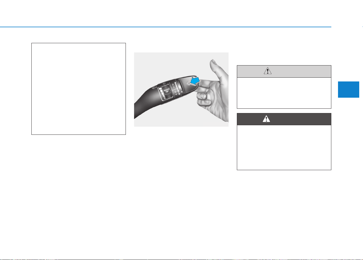
3-105
Convenient features of your vehicle
3
Windshield washers
In the OFF position, pull the lever
gently toward you to spray washer
fluid on the windshield and to run the
wipers 1-3 cycles.
Use this function when the wind-
shield is dirty.
The spray and wiper operation will
continue until you release the lever.
If the washer does not work, check
the washer fluid level. If the fluid level
is not sufficient, you will need to add
appropriate non-abrasive windshield
washer fluid to the washer reservoir.
The reservoir filler neck is located in
the front of the engine compartment
on the passenger side.
(Continued)
• Control of the wiper speed
below the HI position, as the
situation allows, while driving
at a low speed
• Stop the wiper operation on a
dry windshield
• Although the rain stops dur-
ing driving with the wiper
switch in AUTO, the wiper may
continuously operate if the
rainwater remains on the win-
dows.
To prevent possible damage to
the washer pump, do not oper-
ate the washer when the fluid
reservoir is empty.
CAUTION
Do not use the washer in freez-
ing temperatures without first
warming the windshield with
the defrosters; the washer solu-
tion could freeze on the wind-
shield and obscure your vision.
WARNING
OEU045241
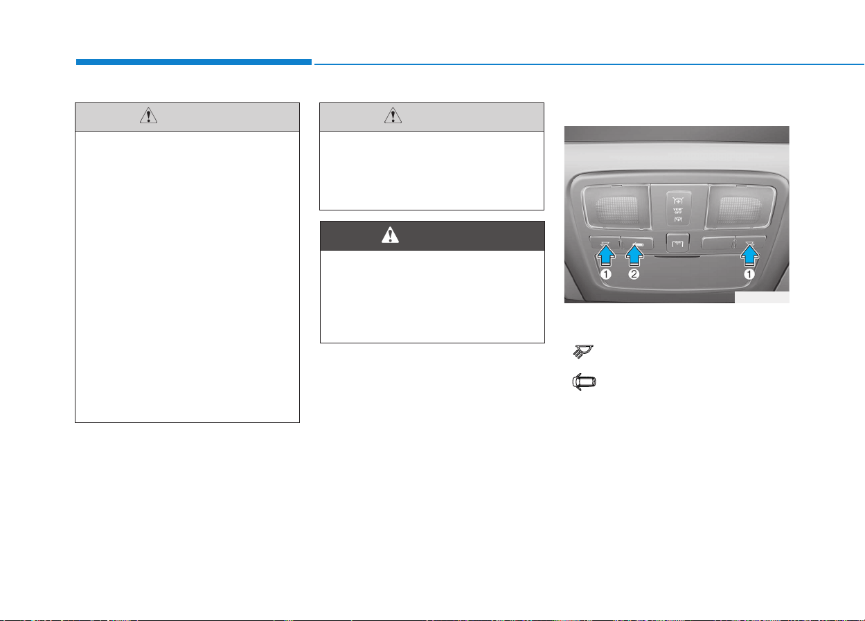
3-106
Convenient features of your vehicle
Map lamp
Push the switch (1) to turn the map
lamp on or off.
• : The light (with room lamp)
stays on at all times.
• : The light (with room lamp)
comes on when any door
(except rear door) is opened
regardless of the ignition
switch position. When doors
(except rear door) are
unlocked by the transmitter,
the light (with room lamp)
comes on for approximately
30 seconds as long as any
door (except rear door) is not
opened.
• To prevent possible damage
to the wipers or windshield,
do not operate the wipers
when the windshield is dry.
• To prevent damage to the
wiper blades, do not use
gasoline, kerosene, paint thin-
ner, or other solvents on or
near them.
• To prevent damage to the
wiper arms and other compo-
nents, do not attempt to move
the wipers manually.
• To prevent possible damage
to the wipers and washer sys-
tem, use anti-freezing washer
fluids in the winter season or
cold weather.
CAUTION
OEU044039
Do not use the interior lights for
extended periods when the
engine is not running.
It may cause battery discharge.
CAUTION
Do not use the interior lights
when driving in the dark.
Accidents could happen
because the view may be
obscured by interior lights.
WARNING
IINNTTEERRIIOORR LLIIGGHHTT
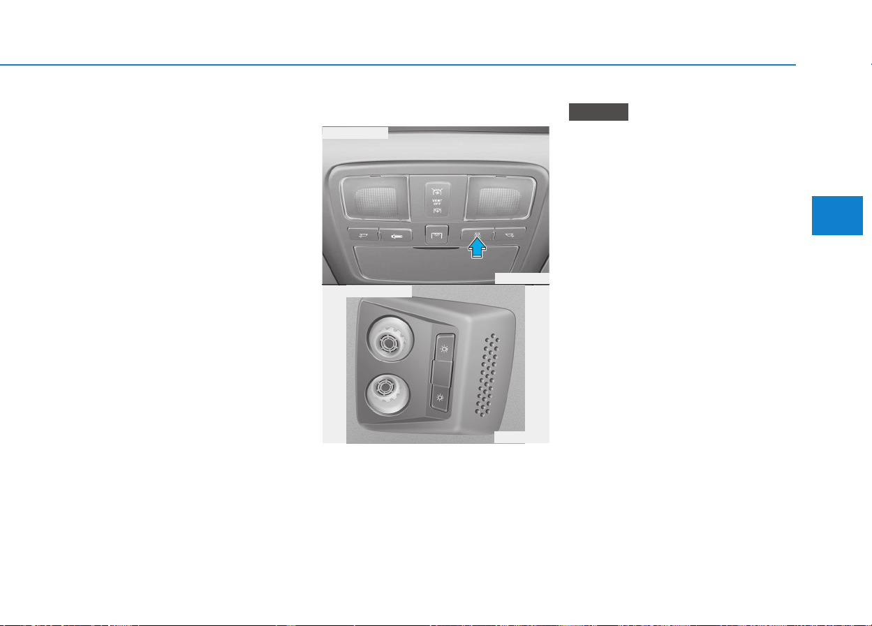
3-107
Convenient features of your vehicle
3
Also, the light (with room
lamp) goes out gradually
after approximately 30 sec-
onds if the door (except rear
door) is closed. However, if
the ignition switch is ON or
all doors (except rear door)
are locked, the light will turn
off immediately.
If a door (except rear door) is
opened with the ignition
switch in the ACC or LOCK
position, the light (with room
lamp) stays on for about 20
minutes. However, if a door
(except rear door) is opened
with the ignition switch in the
ON position, the light (with
room lamp) stays on contin-
uously.
Reading lamp (if equipped)
The reading lamp is turned on by
pushing switch and if the switch is
pushed on more the reading lamp
will be turned off.
To use the reading lamp, push the
main switch with the ignition
switch "ON" position.
NOTICE
OEU044227
OEU044071
■ Main switch
■ Passenger's side
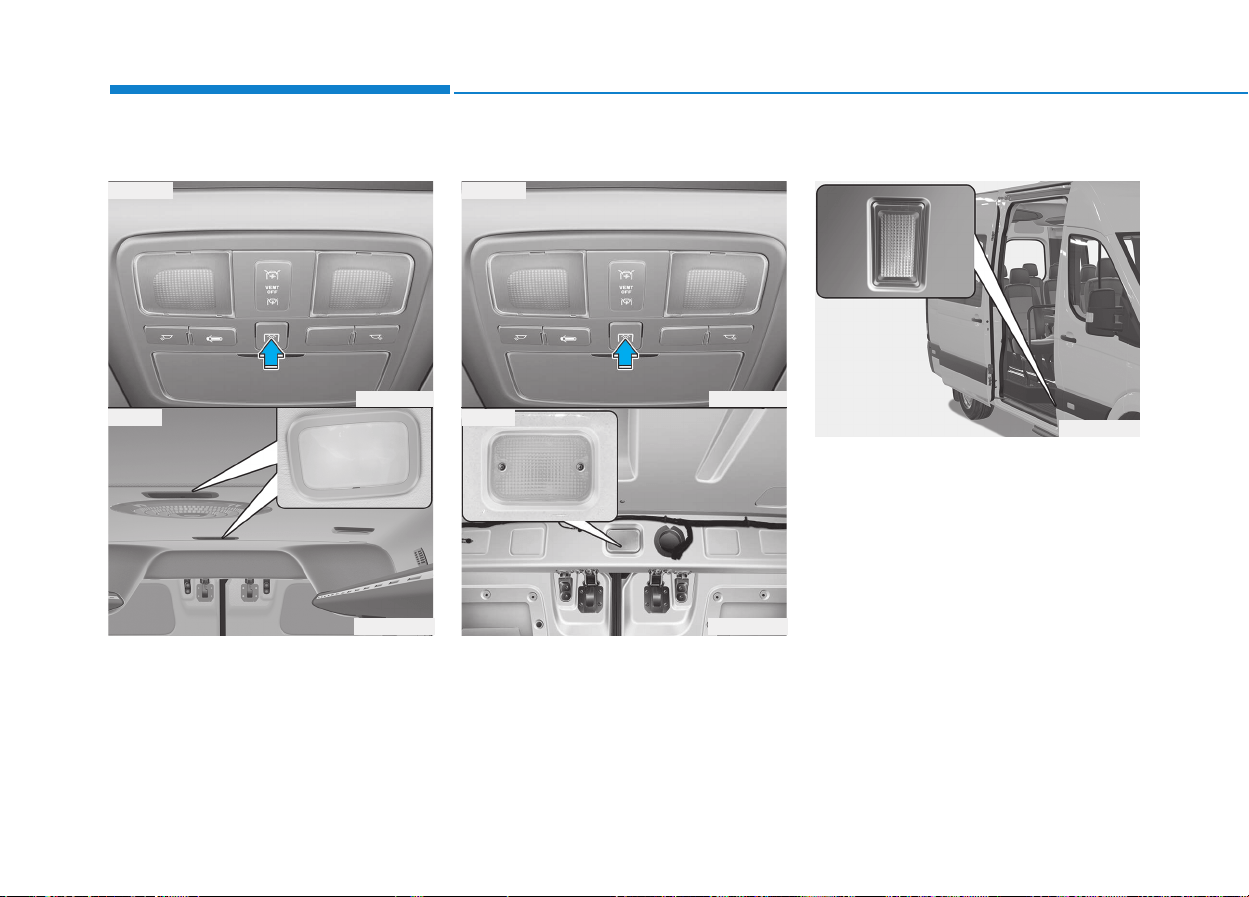
3-108
Convenient features of your vehicle
Room lamp (if equipped)
If you press the switch, the room
lamp turns on. When you want to turn
it off, press that switch once more.
Cargo lamp (if equipped)
The cargo bed lamp comes on when
the mid sliding door and rear door is
opened, or the cargo lamp switch is
on.
Rear step lamp (if equipped)
The rear step lamp comes on when
the mid sliding door is opened.
OEU044061
OEU044045
OEU044055
■ Switch
■ Bus
OEU044045
OEU044056
■ Switch
■ Van
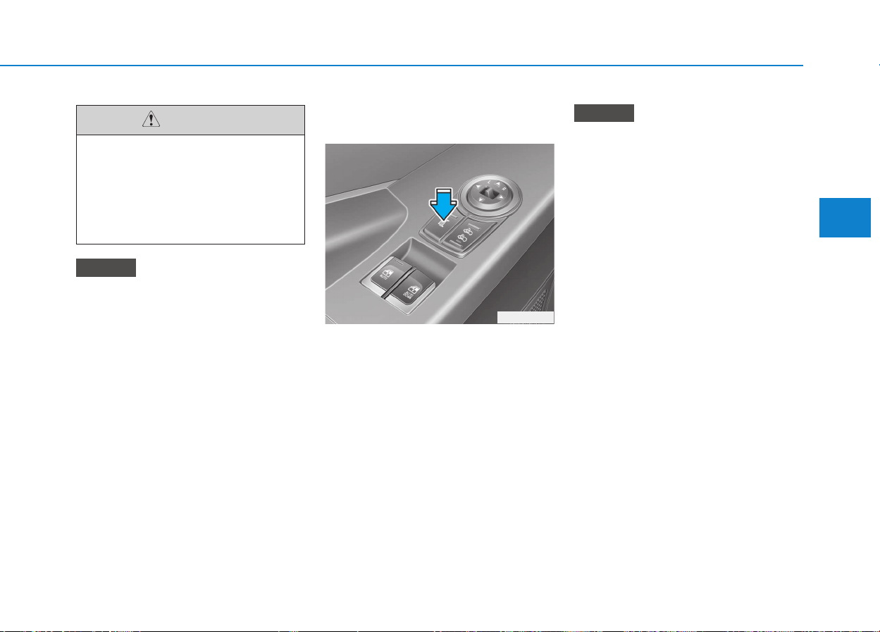
3-109
Convenient features of your vehicle
3
If you want to defrost and defog
on the front windshield, refer to
“Windshield Defrosting and
Defogging” in this section.
Outside rearview mirror heater
(if equipped)
To heat the outside rearview mirror
glass, push the switch. The rearview
mirror glass will be heated for
defrosting or defogging and will give
you improved rear vision in inclement
weather conditions. Push the switch
again to turn the heater off. The out-
side rearview mirror heater automat-
ically turns itself off after 20 minutes.
The ignition switch must be in the
"ON" (Engine is started) position
for the heated outside rearview
mirror.
NOTICE
NOTICE
OEU045040
To prevent damage to the con-
ductors bonded to the inside
surface of the rear window,
never use sharp instruments or
window cleaners containing
abrasives to clean the window.
CAUTION
DDEEFFRROOSSTTEERR
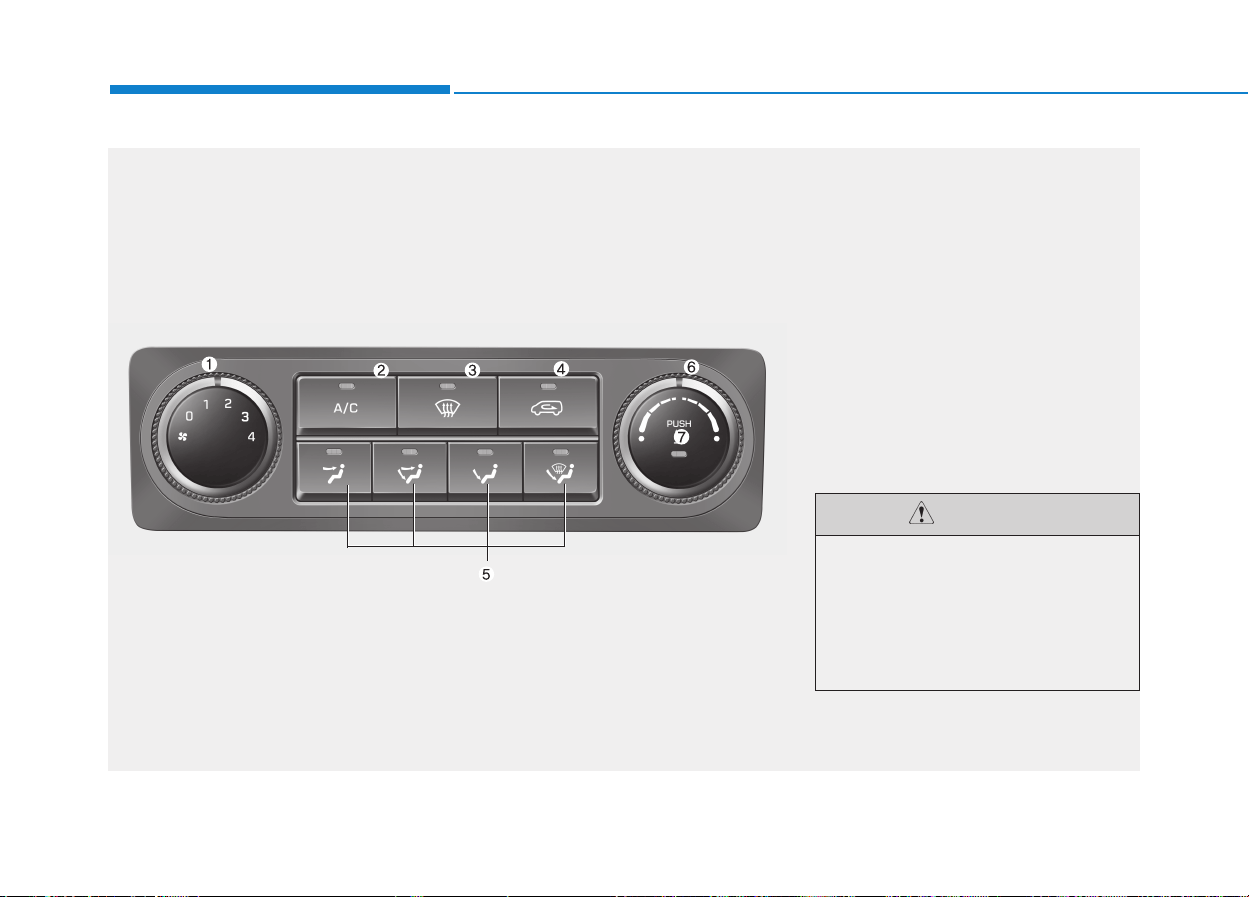
3-110
Convenient features of your vehicle
C
CLLIIMMAATTEE CCOONNTTRROOLL SSYYSSTTEEMM ((IIFF EEQQUUIIPPPPEEDD))
OEU044165
1. Fan speed control knob
2. Air conditioning button (if equipped)
3. Defroster button (Front windshield
defroster)
4. Air intake control button
5. Mode selection button
6. Temperature control knob
7. Fuel-fired heater button
(if equipped)
Operating the blower when the
ignition switch is in the ON
position could cause the bat-
tery to discharge. Operate the
blower when the engine is run-
ning.
CAUTION
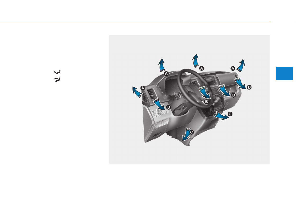
3-111
Convenient features of your vehicle
3
Heating and air conditioning
1. Start the engine.
2. Set the mode to the desired posi-
tion.
For improving the effectiveness of
heating and cooling;
- Heating:
- Cooling:
3. Set the temperature control to the
desired position.
4. Set the air intake control to the
outside (fresh) air position.
5. Set the fan speed control to the
desired speed.
6. If air conditioning is desired, turn
the air conditioning system (if
equipped) on.
OEU044041
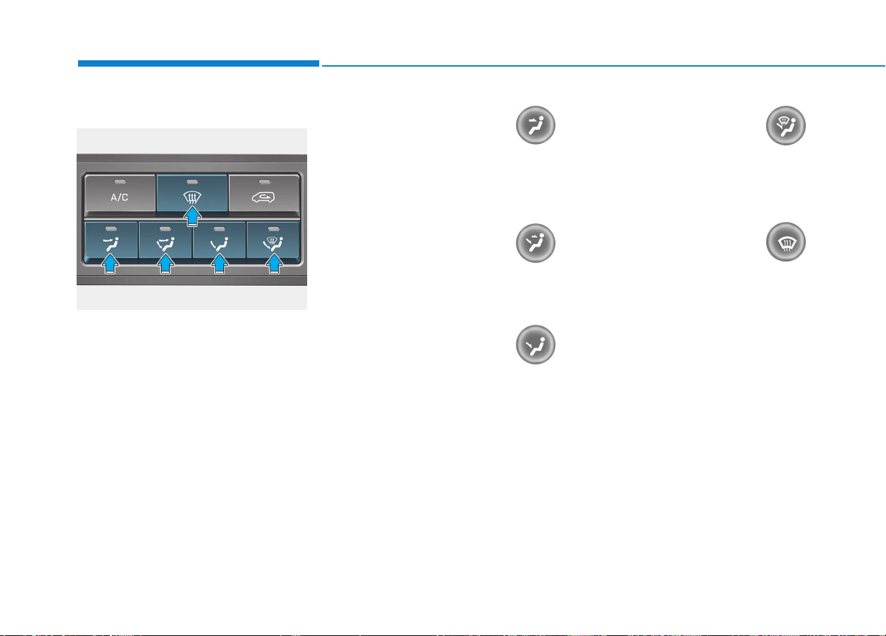
3-112
Convenient features of your vehicle
Mode selection
The mode selection buttons controls
the direction of the air flow through
the ventilation system.
Face-Level (B, D)
Selecting the “Face” mode will cause
air to be discharged through the face
level vents.
Bi-Level (B, C, D)
Air is discharged through the face
vents and the floor vents.
Floor-Level (A, C, D)
Air is discharged through the floor
vents.
Floor-Defrost Level
(A, C, D)
Air is discharged through the wind-
shield defrost vents and the floor
vents.
Defrost-Level
Air is discharged through the wind-
shield defrost vents.
OEU044166
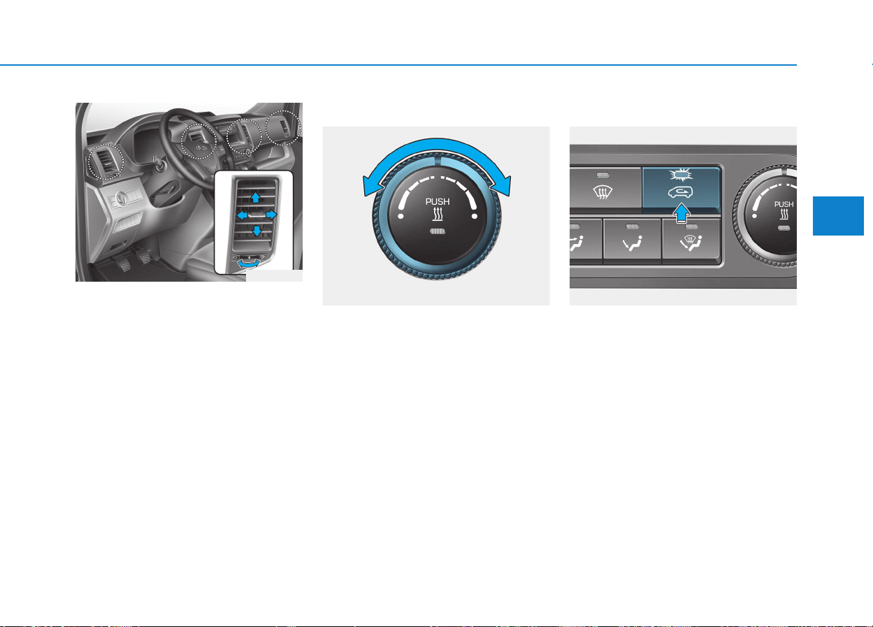
3-113
Convenient features of your vehicle
3
Instrument panel vents
The outlet vents can be opened or
closed separately using the thumb-
wheel.
Also, you can adjust the direction of
air delivery from these vents using
the vent control lever as shown.
Temperature control
The temperature control knob allows
you to control the temperature of the
air flowing from the ventilation sys-
tem. To change the air temperature in
the passenger compartment, turn
the knob to the right position for
warm and hot air or left position for
cooler air.
Air intake control
The air intake control is used to
select the outside (fresh) air position
or recirculated air position.
To change the air intake control posi-
tion, press the control button.
OEU044042
OEU044167 OEU044168
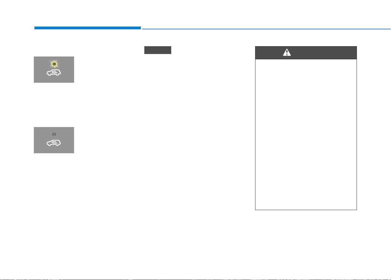
3-114
Convenient features of your vehicle
Recirculated air position
With the recirculated
air position selected,
air from the passenger
compartment will be
drawn through the
heating system and
heated or cooled
according to the func-
tion selected.
Outside (fresh) air position
With the outside (fresh)
air position selected,
air enters the vehicle
from outside and is
heated or cooled
according to the func-
tion selected.
Prolonged operation of the heater
in the recirculated air position
(without air conditioning selected)
may cause fogging of the wind-
shield and side windows and the
air within the passenger compart-
ment may become stale.
In addition, prolonged use of the
air conditioning with the recircu-
lated air position selected will
result in excessively dry air in the
passenger compartment.
NOTICE
• Continue using the climate
control system in the recircu-
lated air position may allow
humidity to increase inside
the vehicle which may fog the
glass and obscure visibility.
• Do not sleep in a vehicle with
the air conditioning or heating
system on. It may cause seri-
ous harm or death due to a
drop in the oxygen level
and/or body temperature.
• Continue using the climate
control system in the recircu-
lated air position can cause
drowsiness or sleepiness,
and loss of vehicle control.
Set the air intake control to
the outside (fresh) air position
as much as possible while
driving.
WARNING
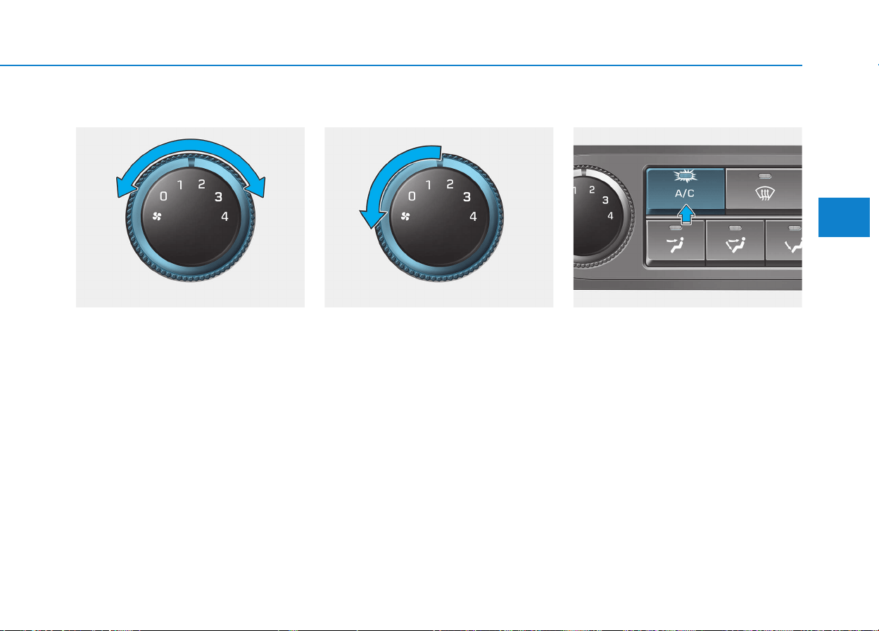
3-115
Convenient features of your vehicle
3
Fan speed control
The ignition switch must be in the ON
position for fan operation.
The fan speed control knob allows
you to control the fan speed of the air
flowing from the ventilation system.
To change the fan speed, turn the
knob to the right for higher speed or
left for lower speed.
Setting the fan speed control knob to
the “0” position turns off the fan.
To turn off the blowers
To turn off the blowers, turn the fan
speed control knob to the "0" posi-
tion.
Air conditioning (if equipped)
Press the A/C button to turn the air
conditioning system on (indicator
light will illuminate). Press the button
again to turn the air conditioning sys-
tem off.
OEU044169 OEU044170 OEU044171
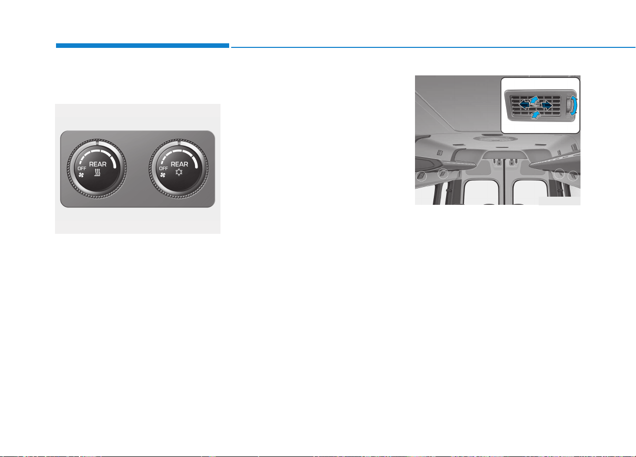
3-116
Convenient features of your vehicle
Rear heating and air condi-
tioning (if equipped)
The temperature, fan speed and
mode of the rear climate control sys-
tem can be controlled independently
regardless of the front climate control
system operation.
However, the front climate control
system should be operated together
for rear air conditioning;
1. Set the front fan speed to the
desired position.
2. Turn the air conditioning button
and set the rear temperature, fan
speed to the desired position.
Rear vents
The lower vent can be adjusted by
rotating the thumb wheel.
OEU044182
OEU044026

3-117
Convenient features of your vehicle
3
System operation
Ventilation
1. Set the mode to the position.
2. Set the air intake control to the
outside (fresh) air position.
3. Set the temperature control to the
desired position.
4. Set the fan speed control to the
desired speed.
Heating
1. Set the mode to the position.
2. Set the air intake control to the
outside (fresh) air position.
3. Set the temperature control to the
desired position.
4. Set the fan speed control to the
desired speed.
5. If dehumidified heating is desired,
turn the air conditioning system (if
equipped) on.
• If the windshield fogs up, set the
mode to the or position.
Operation Tips
• To keep dust or unpleasant fumes
from entering the vehicle through
the ventilation system, temporarily
set the air intake control to the
recirculated air position. Be sure to
return the control to the fresh air
position when the irritation has
passed to keep fresh air in the
vehicle. This will help keep the driv-
er alert and comfortable.
• Air for the heating/cooling system
is drawn in through the grilles just
ahead of the windshield. Care
should be taken that these are not
blocked by leaves, snow, ice or
other obstructions.
• To prevent interior fog on the wind-
shield, set the air intake control to
the fresh air position and fan speed
to the desired position, turn on the
air conditioning system, and adjust
the temperature control to desired
temperature.
Air conditioning (if equipped)
HYUNDAI Air Conditioning Systems
are filled with environmentally friend-
ly R-134a refrigerant.
1. Start the engine. Push the air con-
ditioning button.
2. Set the mode to the position.
3. Set the air intake control to the
outside air or recirculated air posi-
tion.
4. Adjust the fan speed control and
temperature control to maintain
maximum comfort.
• When maximum cooling is desired,
set the temperature control to the
extreme left position, then set the
fan speed control to the highest
speed.

3-118
Convenient features of your vehicle
• When using the air conditioning
system, monitor the temperature
gauge closely while driving up
hills or in heavy traffic when out-
side temperatures are high. Air
conditioning system operation
may cause engine overheating.
Continue to use the blower fan
but turn the air conditioning sys-
tem off if the temperature gauge
indicates engine overheating.
• When opening the windows in
humid weather air conditioning
may create water droplets inside
the vehicle. Since excessive
water droplets may cause dam-
age to electrical equipment, air
conditioning should only be run
with the windows closed.
Air conditioning system operation
tips
• If the vehicle has been parked in
direct sunlight during hot weather,
open the windows for a short time
to let the hot air inside the vehicle
escape.
• To help reduce moisture inside of
the windows on rainy or humid
days, decrease the humidity inside
the vehicle by operating the air
conditioning system.
• During air conditioning system
operation, you may occasionally
notice a slight change in engine
speed as the air conditioning com-
pressor cycles. This is a normal
system operation characteristic.
• Use the air conditioning system
every month only for a few minutes
to ensure maximum system per-
formance.
• When using the air conditioning
system, you may notice clear water
dripping (or even puddling) on the
ground under the passenger rear
side of the vehicle. This is a normal
system operation characteristic.
• Operating the air conditioning sys-
tem in the recirculated air position
provides maximum cooling, how-
ever, continual operation in this
mode may cause the air inside the
vehicle to become stale.
• During cooling operation, you may
occasionally notice a misty air flow
because of rapid cooling and
humid air intake. This is a normal
system operation characteristics.
NOTICE
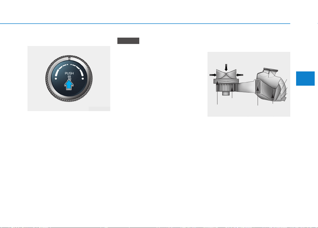
3-119
Convenient features of your vehicle
3
Fuel-fired Heater (if equipped)
This fuel-fired heater supplies addi-
tional heat to the interior compart-
ment with a low fuel consumption to
compensate the heat provided by
engine alone.
A cleaning process of the fuel-fired
heater will be performed automati-
cally when the heater is not operated
due to increase of coolant tempera-
ture and ignition off.
During cleaning process, supplied
fuel in the heater will be burnt com-
pletely and any smoke will be
expelled. It is a necessary process
for next operation and durability of
the heater and takes about 1~3 min-
utes.
• The following symptoms will
occur and it is normal.
- A white smoke may come out
from the fuel-fired heater
exhaust pipe during operation
of the heater. However, when
an excessive black smoke is
discharged, the fuel-fired
heater should be inspected.
- A “buk-buk” noise from the
heater is a noise to form flame
for combustion.
- When the heater is operated at
full load, a “Wooing” noise
occurs.
- When shutting off the engine
during heater operation, a
“Wing” noise occurs to per-
form the cleaning process.
• When refueling, stop operation
of the fuel-fired heater by shut-
ting off the engine.
Climate control air filter
(if equipped)
The climate control air filter installed
behind the glove box filters the dust
or other pollutants that come into the
vehicle from the outside through the
heating and air conditioning system.
If dust or other pollutants accumulate
in the filter over a period of time, the
air flow from the air vents may
decrease, resulting in moisture accu-
mulation on the inside of the wind-
shield even when the outside (fresh)
air position is selected. If this hap-
pens, we recommend that the cli-
mate control air filter be replaced by
an authorized HYUNDAI dealer.
NOTICE
1LDA5047
Outside air
Recirculated
air
Climate control
air filter
Blower
Evaporator
core
Heater core
OEU044225

3-120
Convenient features of your vehicle
• Replace the filter according to
the Maintenance Schedule.
If the vehicle is being driven in
severe conditions such as dusty
or rough roads, more frequent
air conditioner filter inspections
and changes are required.
• When the air flow rate suddenly
decreases, we recommend that
the system be checked by an
authorized HYUNDAI dealer.
Checking the amount of air
conditioner refrigerant and
compressor lubricant
When the amount of refrigerant is
low, the performance of the air con-
ditioning is reduced. Overfilling also
has a negative impact on the air con-
ditioning system.
Therefore, we recommend that the
system be inspected by an author-
ized HYUNDAI dealer.
It is important when servicing the
air conditioning system that the
correct type and amount of oil and
refrigerant is used. Otherwise,
damage to the compressor and
abnormal system operation may
occur.
NOTICE
NOTICE
Improper service may cause
serious injury to the person per-
forming the service. For more
detailed information, we recom-
mend that you contact an
authorized HYUNDAI dealer.
WARNING
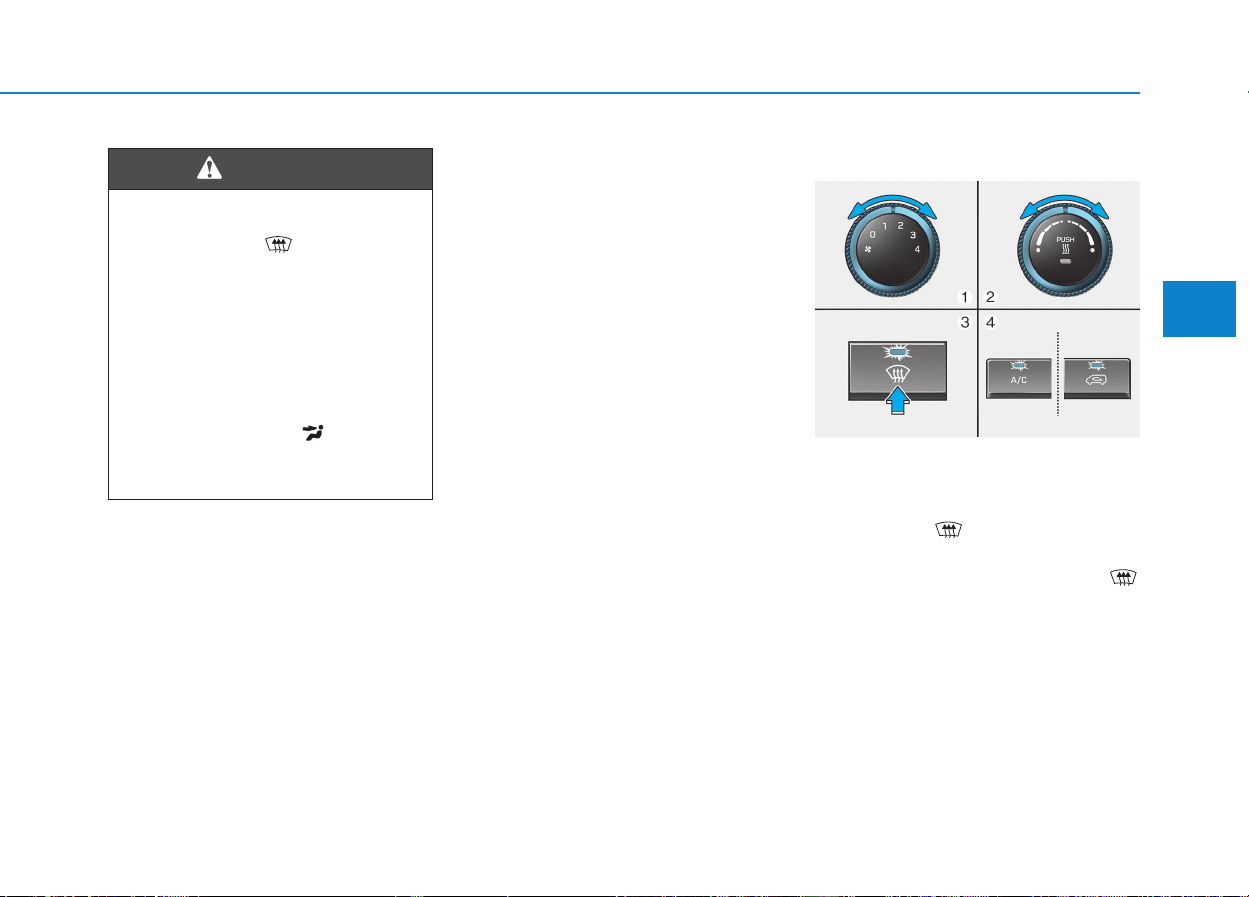
3-121
Convenient features of your vehicle
3
• For maximum defrosting, set the
temperature control to the extreme
right/hot position and the fan speed
control to the highest speed.
• If warm air to the floor is desired
while defrosting or defogging, set
the mode to the floor-defrost posi-
tion.
• Before driving, clear all snow and
ice from the windshield, rear win-
dow, outside rear view mirrors, and
all side windows.
• Clear all snow and ice from the
hood and air inlet in the cowl grill to
improve heater and defroster effi-
ciency and to reduce the probabili-
ty of fogging up the inside of the
windshield.
To defog inside windshield
1. Set the fan speed to the desired
position.
2. Select desired temperature.
3. Select the position.
4. The outside (fresh) air will be
selected automatically. If the
position is selected, air condition-
ing (if equipped) will also be
selected automatically.
If the air conditioning (if equipped)
and/or outside (fresh) air position are
not selected automatically, press the
corresponding button manually.
Windshield heating
Do not use the position dur-
ing cooling operation in
extremely humid weather. The
difference between the temper-
ature of the outside air and the
windshield could cause the
outer surface of the windshield
to fog up, causing loss of visi-
bility. In this case, set the mode
selection to the position
and fan speed control to the
lower speed.
WARNING
WWIINNDDSSHHIIEELLDD DDEEFFRROOSSTTIINNGG AANNDD DDEEFFOOGGGGIINNGG
OEU044172
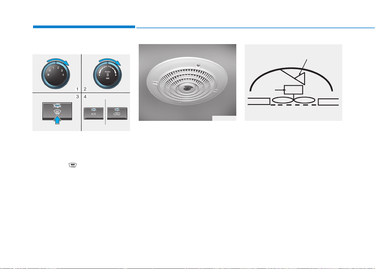
3-122
Convenient features of your vehicle
To defrost outside windshield
1. Set the fan speed to the highest
position.
2. Set the temperature to the
extreme hot position.
3. Select the position.
4. The outside (fresh) air and air con-
ditioning (if equipped) will be
selected automatically.
The ventilator is located on the ceil-
ing. It is designed with multiple fea-
tures.
Forced ventilator
The motor fan has the outside intake,
inner air exhaust.
Automatic open/close
The system to open or close the
shutter when the motor fan on or off.
OEU044173
CCEEIILLIINNGG VVEENNTTIILLAATTOORR
OGD040063 060702-A
Automatic
open/close
Forced
ventilation
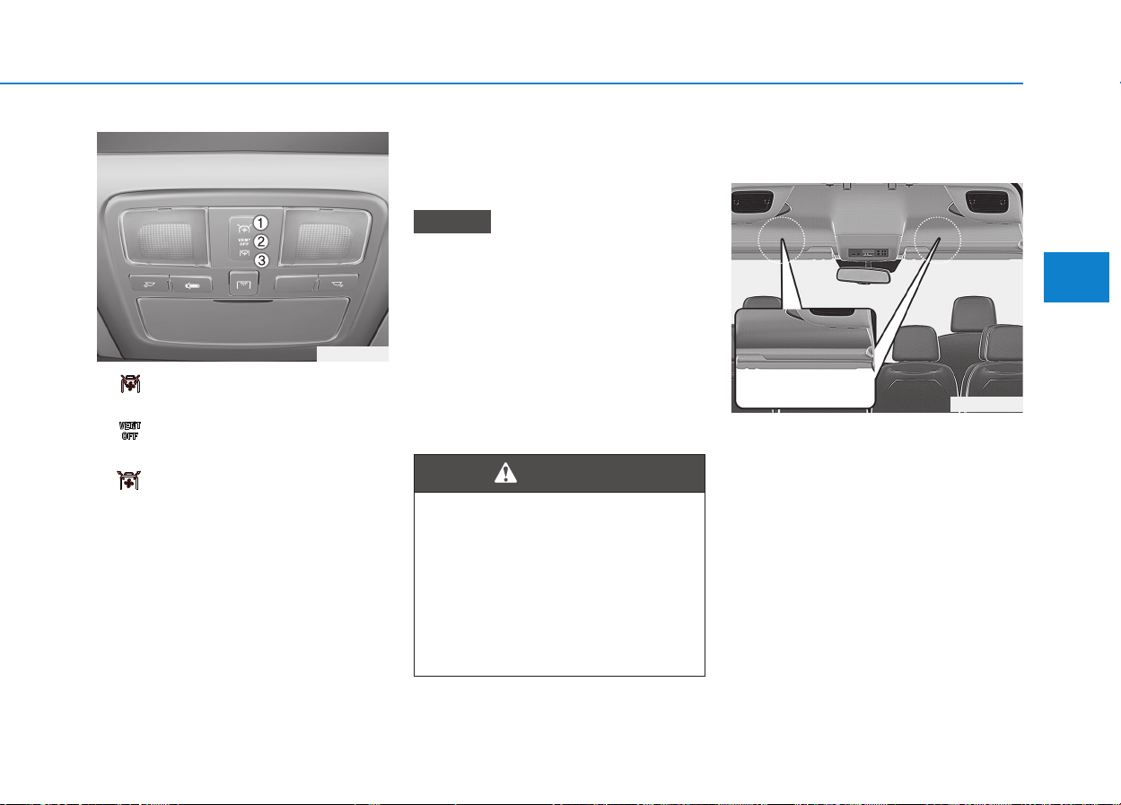
3-123
Convenient features of your vehicle
3
SSTTOORRAAGGEE CCOOMMPPAARRTTMMEENNTT
1. : Indoor air exhaustion
(Air shutter: Open)
2. : Fan non-operation
(Air shutter: Close)
3. : Outdoor fresh air inflow to
indoor
(Air shutter: Open)
These compartments can be used to
store small items required by the
driver or passengers.
• To avoid possible theft, do not
leave valuables in the storage
compartment.
• Always keep the storage com-
partment covers closed while
driving. Do not attempt to place
so many items in the storage
compartment that the storage
compartment cover can not
close securely.
Overhead storage
(if equipped)
The storage compartment above the
windshield.
The right and left storage space may
be loaded with a maximum of
5.5lbs(2.5kg) each.
NOTICE
Flammable materials
Do not store cigarette lighters,
propane cylinders, or other
flammable/explosive materials
in the vehicle. These items may
catch fire and/or explode if the
vehicle is exposed to hot tem-
peratures for extended periods.
WARNING
OEU044063
OEU044057
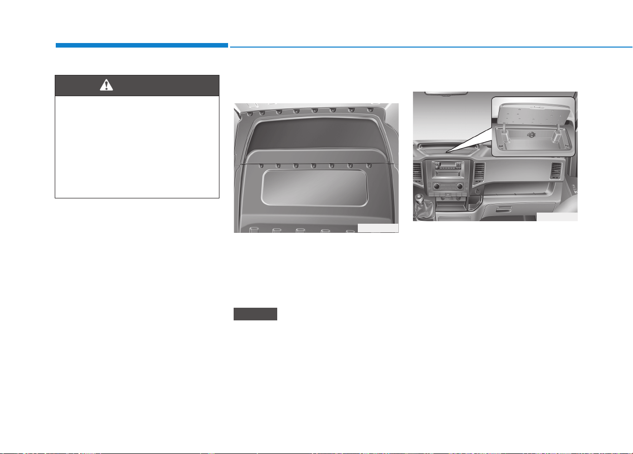
3-124
Storage space above the
headliner (if equipped)
On vehicle with a partition, storage
space can be loaded from the cargo
compartment.
The entire storage space may be
loaded with maximum 44lbs(20kg).
Do not place high, bulky loads in
the storage space. Otherwise, you
may damage the headliner in the
event of sharp braking.
Console storage (if equipped)
These compartments can be used to
store small items required by the
driver or front passenger.
To open the center console storage
pull up the lever.
NOTICE
Convenient features of your vehicle
Do not keep objects like as
heavy or sharp things inside the
storage.
Such objects can be thrown from
the storage in the event of a sud-
den stop or an accident, possibly
injuring the passengers in the
vehicle.
WARNING
OEU044025
OEU044233
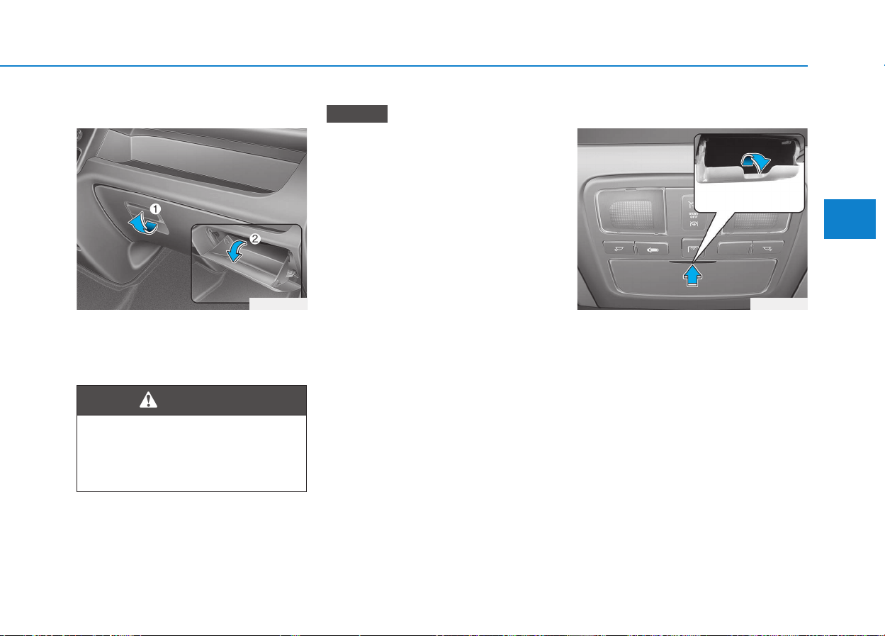
3-125
Convenient features of your vehicle
3
Glove box
To open the glove box, pull the han-
dle and the glove box will automati-
cally open. Close the glove box after
use.
Do not keep food in the glove box
for a long time.
Sunglass holder
To open the sunglass holder, press
the cover and the holder will slowly
open. Place your sunglasses in the
compartment door with the lenses
facing out. Push to close.
NOTICE
OEU044027
To reduce the risk of injury in an
accident or sudden stop, always
keep the glove box door closed
while driving.
WARNING
OEU044028
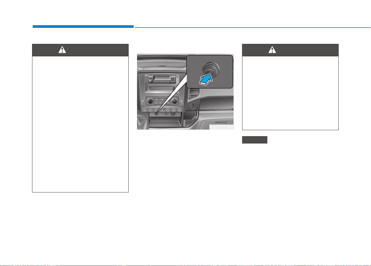
3-126
Convenient features of your vehicle
Cigarette lighter (if equipped)
For the cigarette lighter to work, the
ignition switch must be in the ACC
position or the ON position.
To use the cigarette lighter, push it all
the way into its socket. When the ele-
ment has heated, the lighter will pop
out to the "ready" position.
Do not hold the cigarette lighter
pressed in. This can damage the
heating element and create a fire
hazard.
The use of plug-in accessories
(shavers, hand-held vacuums, and
coffee pots, for example) may
damage the socket or cause elec-
trical failure.
NOTICE
• Do not keep objects except
sunglasses inside the sun-
glass holder. Such objects
can be thrown from the holder
in the event of a sudden stop
or an accident, possibly injur-
ing the passengers in the
vehicle.
• Do not open the sunglasses
holder while the vehicle is
moving. The rear view mirror
of the vehicle can be blocked
by an open sunglass holder.
• Do not put the glasses
forcibly into a sunglass holder
to prevent breakage or defor-
mation of glasses. It may
cause personal injury if you
try to open it forcibly when the
glasses are jammed in holder.
WARNING
IINNTTEERRIIOORR FFEEAATTUURREESS
OEU044029
• Do not hold the lighter in after
it is already heated because it
will overheat.
• If the lighter does not pop out
within 30 seconds, remove it
to prevent overheating.
• Do not insert foreign objects
into the socket of the cigarette
lighter. It may damage the cig-
arette lighter.
WARNING

3-127
Convenient features of your vehicle
3
Ashtray (if equipped)
To use the ashtray, open the cover.
To clean or empty the ashtray, pull it
out.
Cup holder
Do not place uncovered cups in
the cup holder while the vehicle is
in motion. If the liquid spills, elec-
tric systems may malfunction.
NOTICE
Ashtray use
• Do not use the vehicle’s ash-
trays as waste receptacles.
• Putting lit cigarettes or match-
es in an ashtray with other
combustible materials may
cause a fire.
WARNING
Hot liquids
• Do not place uncovered cups
of hot liquid in the cup holder
while the vehicle is in motion.
If the hot liquid spills, you
burn yourself. Such a burn to
the driver could lead to loss of
control of the vehicle.
• To reduce the risk of personal
injury in the event of sudden
stop or collision, do not place
uncovered or unsecured bot-
tles, glasses, cans, etc., in the
cup holder while the vehicle is
in motion.
WARNING
Keep cans or bottles out of
direct sun light and do not put
them in a vehicle that is heated
up. It may explode.
WARNING
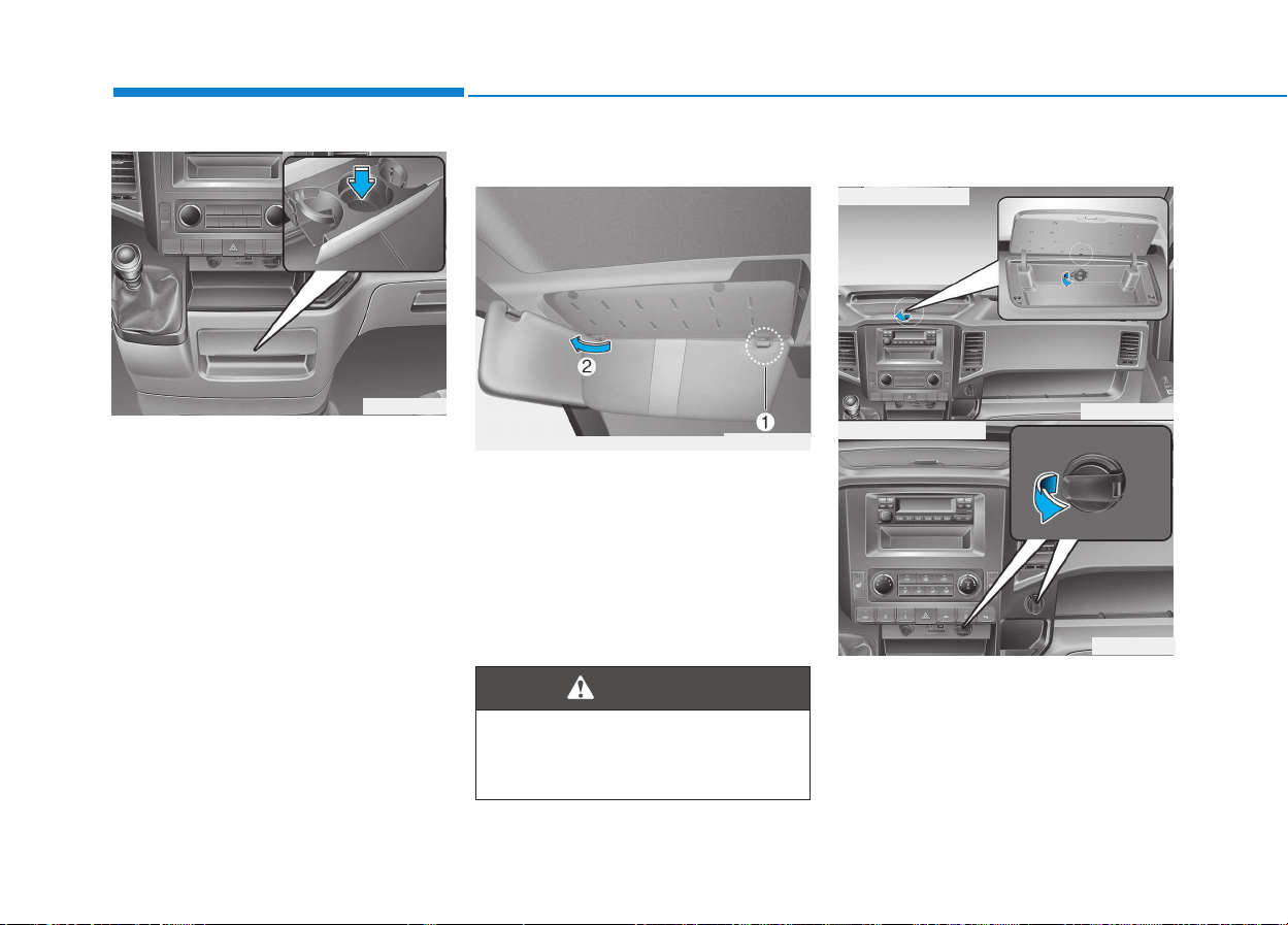
3-128
Convenient features of your vehicle
Cups or small beverage cans may be
placed in the cup holders.
Sunvisor
Use the sunvisor to shield direct light
through the front or side windows.
To use the sunvisor, pull it down-
ward.
To use the sunvisor for the side win-
dow, pull it downward, unsnap it from
the bracket (1) and swing it to the
side (2).
Power outlet (if equipped)
The power outlet is designed to pro-
vide power for mobile telephones or
other devices designed to operate
with vehicle electrical systems.
The devices should draw less than
10 amps with the engine running.
OEU044043
For your safety, do not obstruct
your vision when using the sun-
visor.
WARNING
OEU044031
OEU045032K
OEU044033
■ Crash-pad upper
■ Center fascia panel
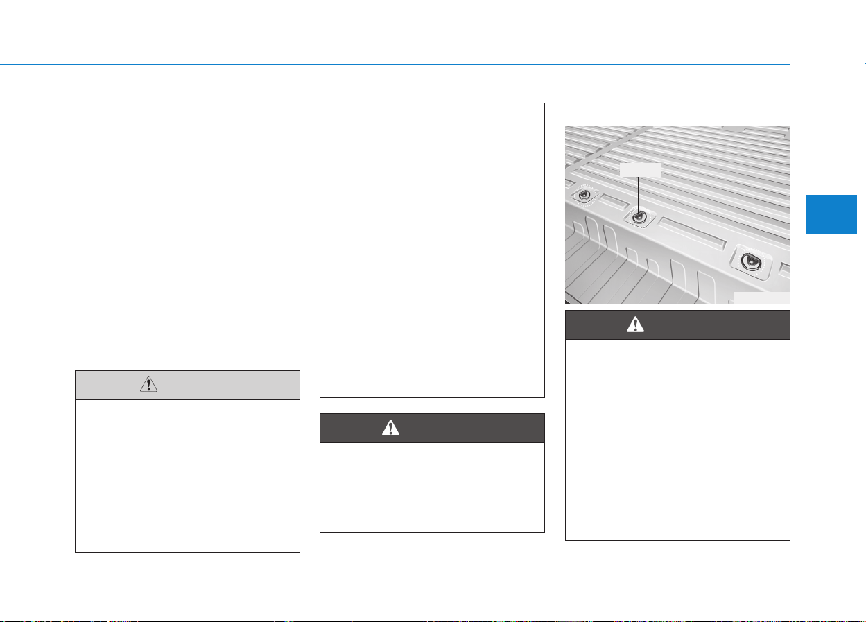
3-129
Convenient features of your vehicle
3
❇There is a cable hole which
enables the use of the power outlet
with the crash-pad console storage
cover being closed. To allow a
cable to pass through the hole,
open the crash-pad console stor-
age, connect to the power outlet,
and fit the cable into the hole
before closing the crash-pad con-
sole storage cover.
Some thick connectors may not
pass from the crash-pad to the
crash-pad console storage cover.
Do not store any volatile or inflam-
mable substance or liquid inside
the crash-pad console storage
while using the power outlet with
the cover closed. The heat gener-
ated by the power outlet may
cause a fire.
• Use power outlet only when
the engine is running and
remove the accessory plug
after use. Using the accessory
plug for prolonged periods of
time with the engine off could
cause the battery to dis-
charge.
(Continued)
CAUTION
(Continued)
• Only use 12V electric acces-
sories which are less than
10A in electric capacity.
• Adjust the air-conditioner or
heater to the lowest operating
level when using the power
outlet.
• Close the cover when not in
use.
• Some electronic devices can
cause electronic interference
when plugged into a vehicle’s
power outlet. These devices
may cause excessive audio
static and malfunctions in
other electronic systems or
devices used in your vehicle.
Do not put a finger or a foreign
element (pin, etc.) into a power
outlet and do not touch with a
wet hand. You may get an elec-
tric shock.
WARNING
CCAARRGGOO BBEEDD((FFOORR VVAANN))
OEU044058
• If you attach the lashing strap
incorrectly when securing the
load, the following may occur
in the event of abrupt changes
in direction, braking manoeu-
vres or an accident
- The lashing tie points may
become detached or the
lashing strap may tear if the
permissible load is exceed-
ed.
(Continued)
WARNING
Tie point
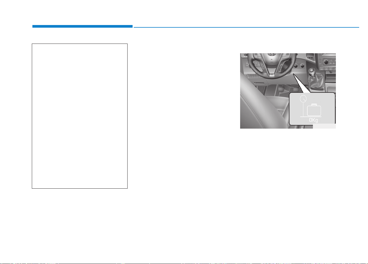
3-130
Convenient features of your vehicle
❈ If your vehicle is equipped with
loading rails in the load compart-
ment floor, you can place lashing
rods directly in front of and behind
the load.
As the driver, you are respon-
sible for ensuring that:
• The applicable requirements and
guidelines relating to load-securing
practices must be met.
If this is not the case, this may con-
stitute a punishable offence,
depending on local legislation and
any ensuing consequences.
You should therefore observe the
respective legal requirements for
the relevant country.
- Make sure that the load is secure
before every journey and at regu-
lar intervals during a long journey.
Adjust the load as necessary
Luggage mass label
The luggage mass label informs you
the weight of cargo you to be able to
load.
(Continued)
- The load may not be
restrained.
This may cause the load to
slip, tip over or be tossed
about, striking vehicle occu-
pants. There is a risk of an
accident and injury.
Always tension the lashing
straps in the proper manner
and only between the
described lashing tie points.
Always use lashing straps
designed specifically for the
loads.
• Observe the notes regarding
the maximum load capacity of
individual lashing points.
• Spread the load evenly
between the lashing points or
eyelets.
OEU044060

Multimedia System
4
Multimedia System
Multimedia system.................................................4-2
Aux, usb and ipod
®
...........................................................4-2
Antenna ...............................................................................4-2
Audio remote control .......................................................4-3
How vehicle audio works ................................................4-4
Caring for disc....................................................................4-7
CD player (for RDS model) : AC210MDEE ................4-13
CD player : AC110MDGG, AC110MDGN,
AC110MDGL......................................................................4-14
Radio, set up, volume control : AM210MDEE,
AMB00MDGL, AMB00MDGN, AMB00MDGG.............4-47
CD player (for RDS model) : AC210MDEE
(for turkey).......................................................................4-56
4
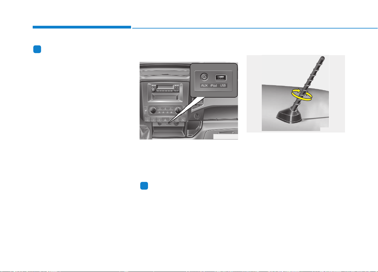
4-2
Multimedia System
Information
• If you install an aftermarket HID
headlamp, your vehicle’s audio and
electronic device may malfunction.
• Prevent chemicals such as perfume,
cosmetic oil, sun cream, hand clean-
er, and air freshener from contacting
the interior parts because they may
cause damage or discoloration.
Aux, USB and iPod
®
(if equipped)
If your vehicle has an aux and/or
USB(universal serial bus) port, you
can use an aux port to connect audio
devices and an USB port to plug in
an USB.
Information
When using a portable audio device
connected to the power outlet, noise
may occur during playback. If this
happens, use the power source of the
portable audio device.
❈ iPod
®
is a trademark of Apple Inc.
Antenna
Roof antenna
Your vehicle uses a roof antenna to
receive both AM and FM broadcast
signals. This antenna is a removable
type. To remove the antenna, turn it
counterclockwise. To install the
antenna, turn it clockwise.
i
i
MMUULLTTIIMMEEDDIIAA SSYYSSTTEEMM
OLM043373
OEU044035
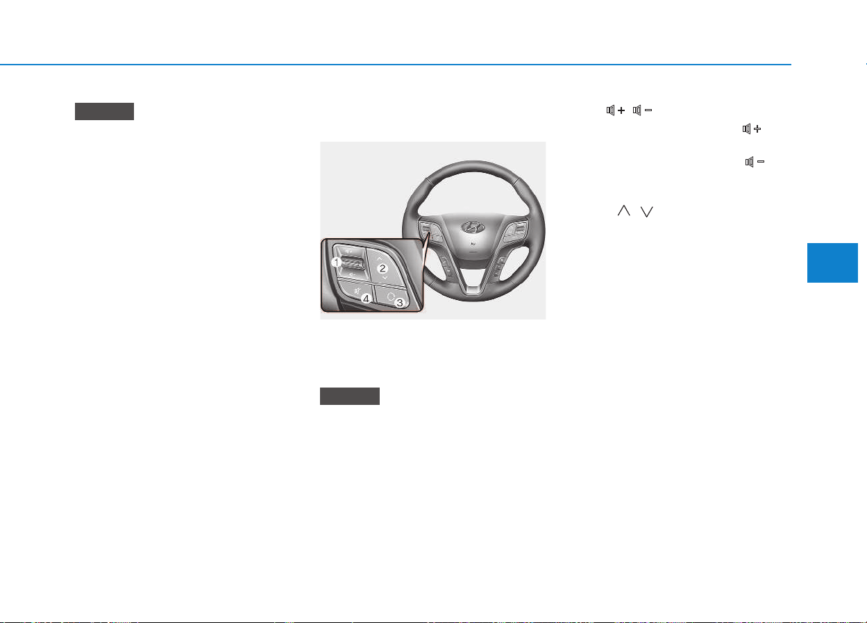
4-3
Multimedia System
4
• Before entering a place with a
low height clearance or a vehicle
wash, remove the antenna by
rotating it counterclockwise. If
not, the antenna may be dam-
aged.
• When reinstalling your antenna,
it is important that it is fully
tightened and adjusted to the
upright position to ensure prop-
er reception. But it could be fold-
ed or removed when parking the
vehicle or when loading cargo
on the roof rack.
• When cargo is loaded on the
roof rack, do not place the cargo
near the antenna pole to ensure
proper reception.
Audio remote control
(if equipped)
The steering wheel audio remote con-
trol button is installed to promote safe
driving.
Do not operate audio remote con-
trol buttons simultaneously.
VOL ( / ) (1)
• Press the up button ( ) to
increase volume.
• Press the down button ( ) to
decease volume.
SEEK ( / ) (2)
If the SEEK button is pressed for 0.8
second or more, it will work as fol-
lows in each mode.
RADIO mode
It will function as the AUTO SEEK
select button.
CDP mode
It will function as the FF/REW button.
CDC mode
It will function as the DISC
UP/DOWN button.
If the SEEK button is pressed for less
than 0.8 second, it will work as fol-
lows in each mode.
NOTICE
NOTICE
OEU045242
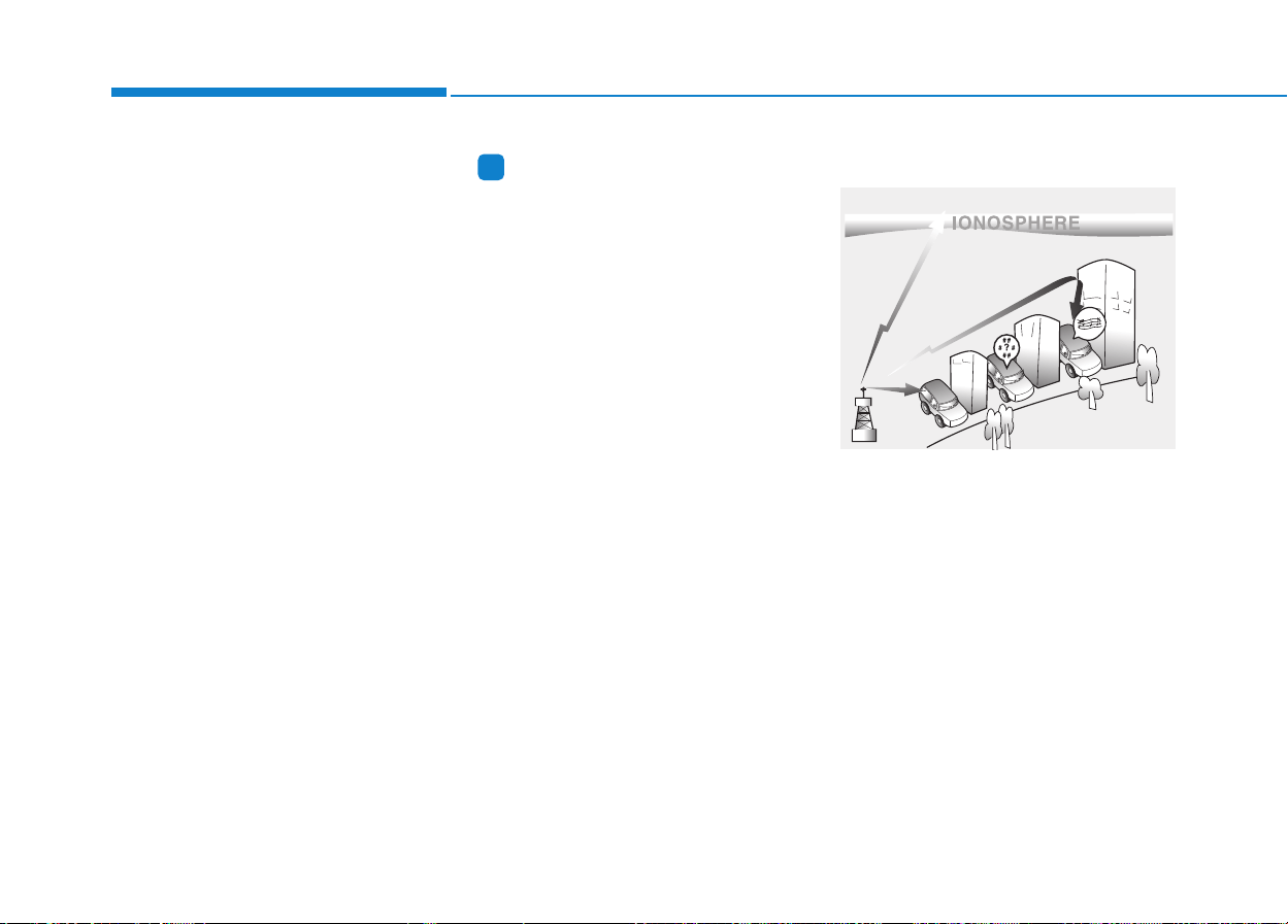
4-4
Multimedia System
RADIO mode
It will function as the PRESET STA-
TION select buttons.
CDP mode
It will function as the TRACK
UP/DOWN button.
CDC mode
It will function as the TRACK
UP/DOWN button.
Detailed information for audio control
buttons is described in the following
pages in this section.
MODE (3)
Press the button to select Radio or
CD (compact disc).
MUTE (4)
• Press the MUTE button to cancel
the sound.
• Press the MUTE button again to
activate the sound.
Information
Detailed information for audio control
buttons are described in the following
pages in this chapter.
How vehicle audio works
AM and FM radio signals are broad-
cast from transmitter towers located
around your city. They are intercept-
ed by the radio antenna on your vehi-
cle. This signal is then processed by
the radio and sent to your vehicle
speakers.
When a strong radio signal has
reached your vehicle, the precise
engineering of your audio system
ensures the best possible quality
reproduction. However, in some
cases the signal coming to your vehi-
cle may not be strong and clear.
i
JBM001
FM reception
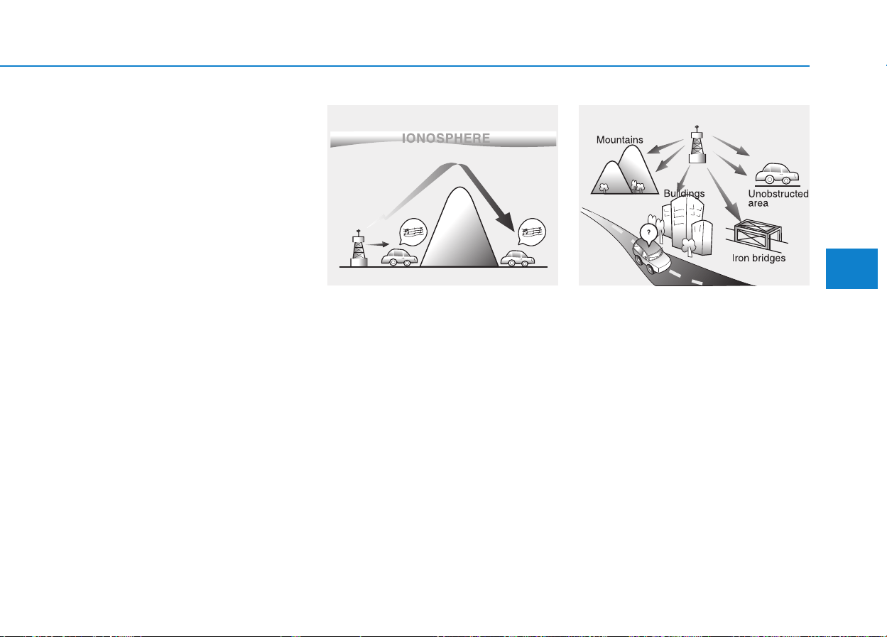
4-5
Multimedia System
4
This can be due to factors, such as
the distance from the radio station,
closeness of other strong radio sta-
tions or the presence of buildings,
bridges or other large obstructions in
the area.
AM broadcasts can be received at
greater distances than FM broad-
casts. This is because AM radio
waves are transmitted at low fre-
quencies. These long distance, low
frequency radio waves can follow the
curvature of the earth rather than
travelling straight. In addition, they
curve around obstructions resulting
in better signal coverage.
FM broadcasts are transmitted at
high frequencies and do not bend to
follow the earth's surface. Because
of this, FM broadcasts generally
begin to fade within short distances
from the station. Also, FM signals are
easily affected by buildings, moun-
tains, and obstructions. This can lead
to undesirable or unpleasant listen-
ing conditions which might lead you
to believe a problem exists with your
radio. The following conditions are
normal and do not indicate radio
trouble:
JBM002
AM reception
JBM003
FM radio station
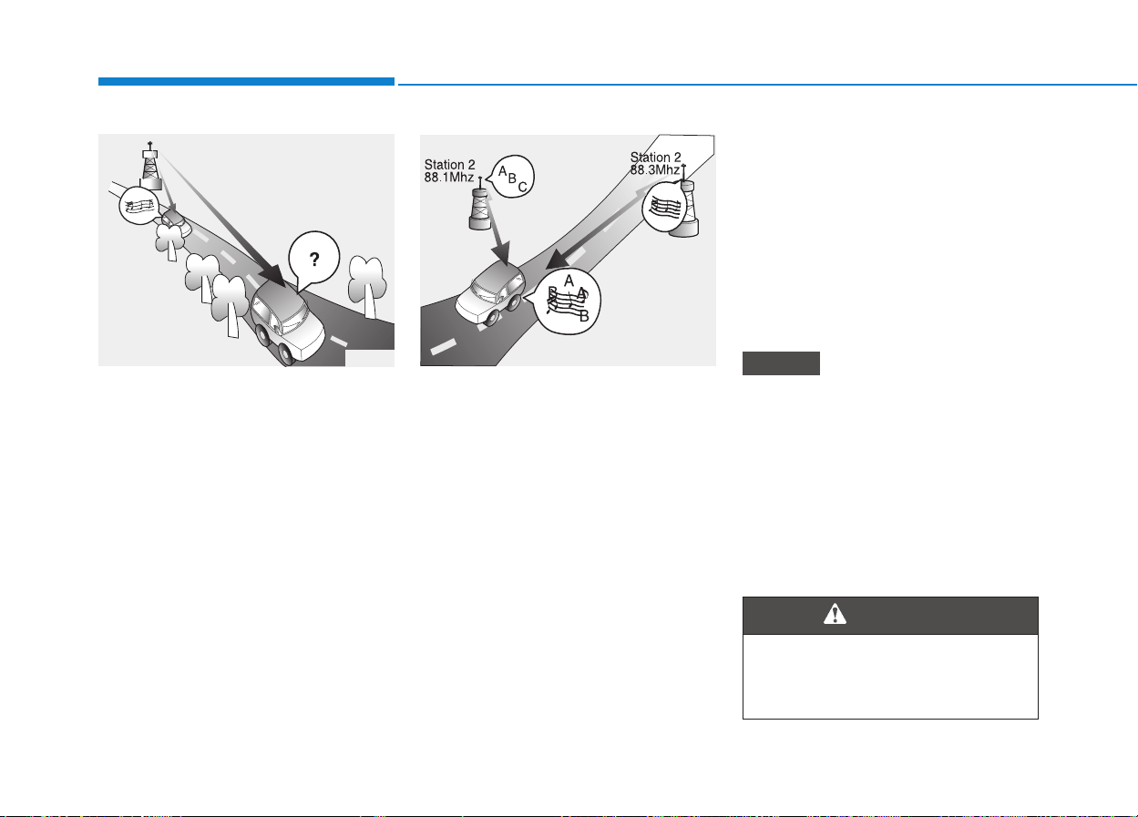
4-6
Multimedia System
• Fading - As your vehicle moves
away from the radio station, the
signal will weaken and sound will
begin to fade. When this occurs,
we suggest that you select another
stronger station.
• Flutter/Static - Weak FM signals or
large obstructions between the
transmitter and your radio can dis-
turb the signal causing static or
fluttering noises to occur. Reducing
the treble level may lessen this
effect until the disturbance clears.
• Station Swapping - As an FM signal
weakens, another more powerful
signal near the same frequency
may begin to play. This is because
your radio is designed to lock onto
the clearest signal. If this occurs,
select another station with a
stronger signal.
• Multi-Path Cancellation - Radio sig-
nals being received from several
directions can cause distortion or
fluttering. This can be caused by a
direct and reflected signal from the
same station, or by signals from two
stations with close frequencies. If
this occurs, select another station
until the condition has passed.
Using a cellular phone or a two-
way radio
When a cellular phone is used inside
the vehicle, noise may be produced
from the audio system. This does not
mean that something is wrong with
the audio equipment. In such a case,
use the cellular phone at a place as
far as possible from the audio equip-
ment.
When using a communication
system such as a cellular phone
or a radio set inside the vehicle, a
separate external antenna must be
fitted. When a cellular phone or a
radio set is used with an internal
antenna alone, it may interfere
with the vehicle's electrical sys-
tem and adversely affect safe
operation of the vehicle.
NOTICE
Do not use a cellular phone
while driving. Stop at a safe
location to use a cellular phone.
WARNING
JBM004 JBM005
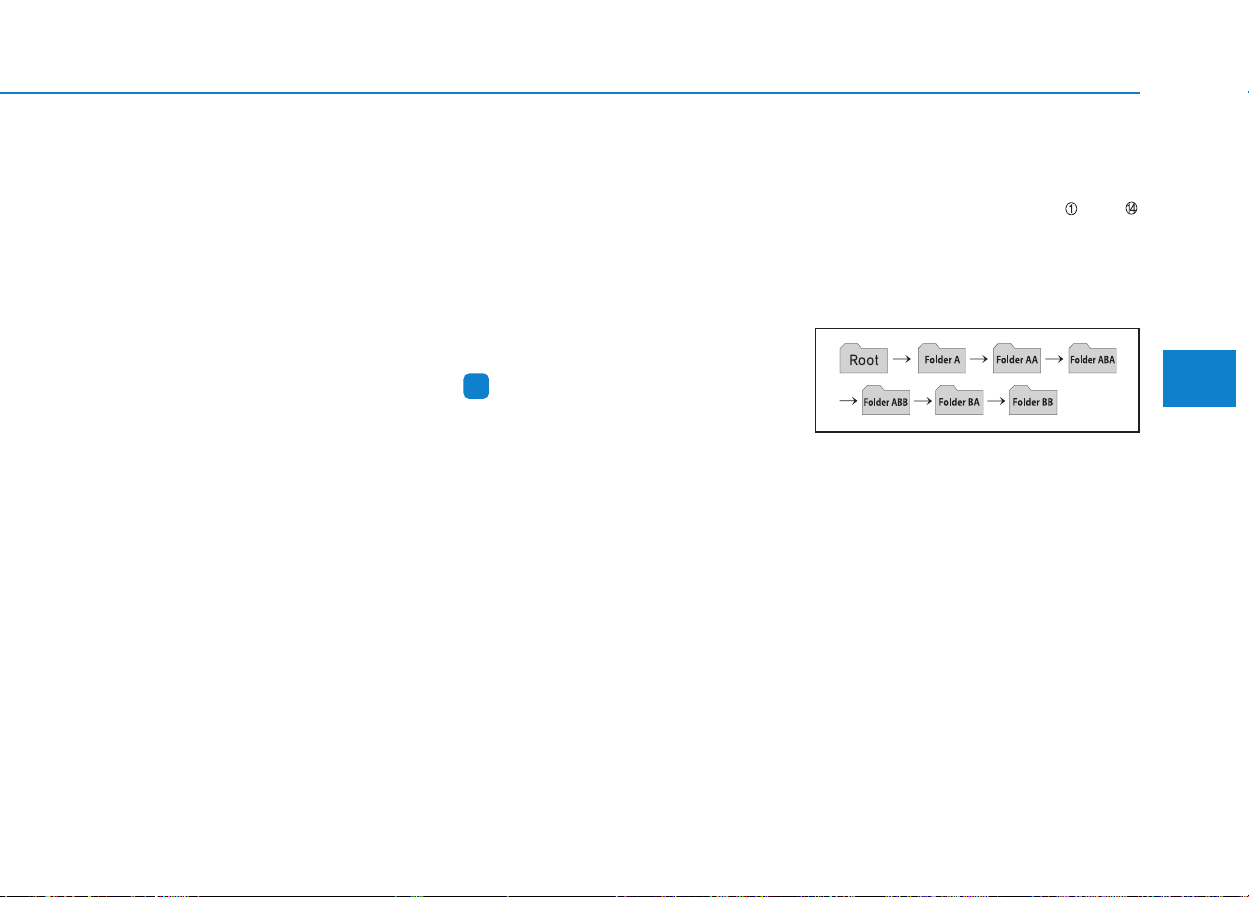
4-7
Multimedia System
4
Caring for disc
• If the temperature inside the vehicle
is too high, open the vehicle windows
to ventilate before using the system.
• It is illegal to copy and use
MP3/WMA files without permission.
Use CDs that are created only by
lawful means.
• Do not apply volatile agents, such as
benzene and thinner, normal clean-
ers and magnetic sprays made for
analogue disc onto CDs.
• To prevent the disc surface from get-
ting damaged, hold CDs by the
edges or the center hole only.
• Clean the disc surface with a piece of
soft cloth before playback (wipe it
from the center to the outside edge).
• Do not damage the disc surface or
attach pieces of sticky tape or paper.
• Make certain only CDs are inserted
into the CD player (Do not insert
more than one CD at a time).
• Keep CDs in their cases after use to
protect them from scratches or dirt.
• Depending on the type of CD-R/CD-
RW CDs, certain CDs may not oper-
ate normally according to manufac-
turing companies or making and
recording methods. In such circum-
stances, continued use may cause
malfunctions to your audio system.
Information
-
Playing an Incompatible
Copy Protected Audio CD
Some copy protected CDs, which do
not comply with international audio
CD standards (Red Book), may not
play on your vehicle audio. Please note
that inabilities to properly play a copy
protected CD may indicate that the
CD is defective, not the CD player.
NOTICE:
Order of playing files (folders) :
1. Song playing order : to
sequentially.
2. Folder playing order :
❋ If no song file is contained in the
folder, that folder is not displayed.
i
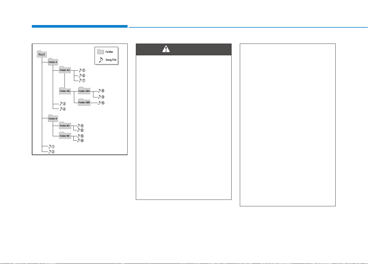
4-8
Multimedia System
(Continued)
• Please refrain from use if the
screen is blank or no sound
can be heard as these signs
may indicate product mal-
function. Continued use in
such conditions could lead to
accidents(fires, electric
shock) or product malfunc-
tions.
• Do not touch the antenna dur-
ing thunder or lightening as
such acts may lead to light-
ning induced electric shock.
• Do not stop or park in park-
ing-restricted areas to operate
the product. Such acts could
lead to traffic accidents.
• Use the system with the vehi-
cle ignition turned on.
Prolonged use with the igni-
tion turned off could result in
battery discharge.
(Continued)
• Do not stare at the screen
while driving. Staring at the
screen for prolonged periods
of time could lead to traffic
accidents.
• Do not disassemble, assem-
ble, or modify the audio sys-
tem. Such acts could result in
accidents, fire, or electric
shock.
• Obey the applicable regula-
tions relevant to the mobile-
phone usage. If not, it is clear-
ly the violation against the
traffic laws.
• Heed caution not to spill water
or introduce foreign objects
into the device. Such acts
could lead to smoke, fire, or
product malfunction.
(Continued)
WARNING

4-9
Multimedia System
4
• Operating the device while driv-
ing could lead to accidents due
to a lack of attention to external
surroundings. First park the
vehicle before operating the
device.
• Adjust the volume to levels that
allow the driver to hear sounds
from outside of the vehicle.
Driving in a state where external
sounds cannot be heard may
lead to accidents.
• Pay attention to the volume set-
ting when turning the device on.
A sudden output of extreme vol-
ume upon turning the device on
could lead to hearing impair-
ment. (Adjust the volume to a
suitable levels before turning off
the device.)
(Continued)
(Continued)
• Turn on the vehicle ignition
before using this device. Do not
operate the audio system for
long periods of time with the
ignition turned off as such oper-
ations may lead to battery dis-
charge.
• Do not subject the device to
severe shock or impact. Direct
pressure onto the front side of
the monitor may cause damage
to the LCD or touch screen.
• When cleaning the device, make
sure to turn off the device and
use a dry and smooth cloth.
Never use tough materials,
chemical cloths, or solvents
(alcohol, benzene, thinners, etc.)
as such materials may damage
the device panel or cause
color/quality deterioration
(Continued)
NOTICE
(Continued)
• Driving while distracted can
result in a loss of vehicle con-
trol that may lead to an acci-
dent, severe personal injury,
and death. The driver's pri-
mary responsibility is in the
safe and legal operation of a
vehicle, and use of any hand-
held devices, other equip-
ment, or vehicle systems
which take the driver's eyes,
attention and focus away from
the safe operation of a vehicle
or which are not permissible
by law should never be used
during operation of the vehi-
cle.

4-10
Multimedia System
(Continued)
• Do not place beverages close to
the audio system. Spilling bever-
ages may lead to system mal-
function.
• In case of product malfunction,
please contact your place of
purchase or After Service cen-
ter.
• Placing the audio system within
an electromagnetic environment
may result in noise interference.
• Prevent caustic solutions such
as perfume and cosmetic oil
from contacting the dashboard
because they may cause dam-
age or discoloration.
Information
-
Using the USB device
• To use an external USB device,
make sure the device is not connect-
ed when starting up the vehicle.
Connect the device after starting up.
• If you connect any external device
while driving, it may lose the vehicle
control and increase the accident
risk. Park the vehicle before con-
necting any external devices.
• Park the vehicle on a safe location
before connecting any external USB
device.
• If you start the engine when the
USB device is connected, it may
damage the USB device. (USB flash-
drives are very sensitive to electric
shock.)
• If the engine is started up or turned
off while the external USB device is
connected, the external USB device
may not work.
• The System may not play inauthen-
tic MP3 or WMA files.
1) It can only play MP3 files with
the compression rate between
8Kbps ~ 320Kbps.
(Continued)
(Continued)
2) It can only play WMA music files
with the compression rate
between 8Kbps ~ 320Kbps.
• Take precautions for static electrici-
ty when connecting or disconnecting
the external USB device.
• An encrypted MP3 PLAYER is not
recognizable.
• Depending on the condition of the
external USB device, the connected
external USB device can be unrec-
ognizable.
• When the formatted byte/sector set-
ting of External USB device is not
either 512BYTE or 2048BYTE, then
the device will not be recognized.
• Use only a USB device formatted to
FAT 12/16/32.
• USB devices without USB I/F
authentication may not be recogniz-
able.
• Make sure the USB connection ter-
minal does not come in contact with
the human body or other objects.
• If you repeatedly connect or discon-
nect the USB device in a short peri-
od of time, it may break the device.
(Continued)
i
4-11
Multimedia System
4
(Continued)
• You may hear a strange noise when
connecting or disconnecting a USB
device.
• If you disconnect the external USB
device during playback in USB
mode, the external USB device can
be damaged or may malfunction.
Therefore, disconnect the external
USB device when the audio is
turned off or in another mode. (e.g,
Radio, CD)
• Depending on the type and capacity
of the external USB device or the
type of the files stored in the device,
there is a difference in the time
taken for recognition of the device.
• Do not use the USB device for pur-
poses other than playing music files.
• Playing videos through the USB is
not supported.
• Use of USB accessories such as
rechargers or heaters using USB I/F
may lower performance or cause
trouble.
(Continued)
(Continued)
• If you use devices such as a USB hub
purchased separately, the vehicle's
audio system may not recognize the
USB device. In that case, connect
the USB device directly to the multi-
media terminal of the vehicle.
• If the USB device is divided by logi-
cal drives, only the music files on the
highest-priority drive are recog-
nized by vehicle audio.
• Devices such as MP3 Player/
Cellular phone/Digital
camera can be unrecog-
nizable by standard
USB I/F can be unrecog-
nizable.
• Charging through the USB may not
be supported in some mobile
devices.
• USB HDD or USB types liable to
connection failures due to vehicle
vibrations are not supported. (i-
stick type)
• Some non-standard USB devices
(METAL COVER TYPE USB) can
be unrecognizable.
(Continued)
(Continued)
• Some USB flash memory readers
(such as CF, SD, micro SD, etc.) or
external-HDD type devices can be
unrecognizable.
• Music files protected by DRM
(DIGITAL RIGHTS MANAGE-
MENT) are not recognizable.
• The data in the USB memory may
be lost while using this audio.
Always back up important data on a
personal storage device.
• Please avoid using USB memory
products which can be used as key
chains or cellular phone accessories
as they could cause damage to the
USB jack. Please make certain only
to use plug type connector products.

4-12
Multimedia System
Information
-
Using the iPod
®
device
• Some iPod
®
models may not sup-
port communication protocol and
files may not properly play.
Supported iPod
®
models:
- iPod
®
Mini
- iPod
®
4th (Photo) ~ 6th (Classic)
generation
- iPod
®
Nano 1st~4th generation
- iPod
®
Touch 1st~2nd generation
• The order of search or playback of
songs in the iPod
®
can be different
from the order searched in the audio
system.
• If the iPod
®
disabled due to its own
malfunction, reset the iPod
®
. (Reset:
Refer to iPod
®
manual)
• An iPod
®
may not operate normally
on low battery.
• If you connect any external device
while driving, it may lose the vehicle
control and increase the accident
risk. Park the vehicle before con-
necting any external devices.
• Park the vehicle on a safe location
before connecting an iPod
®
.
(Continued)
(Continued)
• Some iPod
®
devices, such as the
iPhone
®
, can be connected through
the Bluetooth
®
Wireless Technology
interface. The device must have
audio Bluetooth
®
Wireless
Technology capability (such as for
stereo headphone Bluetooth
®
Wireless Technology ). The device
can play, but it will not be controlled
by the audio system.
• To use iPod
®
features within the
audio, use the cable provided upon
purchasing an iPod
®
device.
• Skipping or improper operation
may occur depending on the charac-
teristics of your iPod
®
/iPhone
®
device.
• If your iPhone
®
is connected to both
the Bluetooth
®
Wireless Technology
and USB, the sound may not be
properly played. In your iPhone
®
,
select the Dock connector or
Bluetooth
®
Wireless Technology to
change the sound output (source).
(Continued)
(Continued)
• When connecting iPod
®
with the
iPod
®
Power Cable, insert the con-
nector to the multimedia socket
completely. If not inserted complete-
ly, communications between iPod
®
and audio may be interrupted.
• When adjusting the sound effects of
the iPod
®
and the audio system, the
sound effects of both devices will
overlap and might reduce or distort
the quality of the sound.
• Deactivate (turn off) the equalizer
function of an iPod
®
when adjusting
the audio system's volume, and turn
off the equalizer of the audio system
when using the equalizer of an
iPod
®
.
• When not using iPod
®
with vehicle
audio, detach the iPod
®
cable from
iPod
®
. Otherwise, iPod
®
may
remain in accessory mode, and may
not work properly.
i
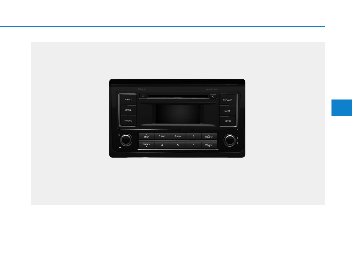
4-13
Multimedia System
4
■■
CD Player (for RDS model) : AC210MDEE
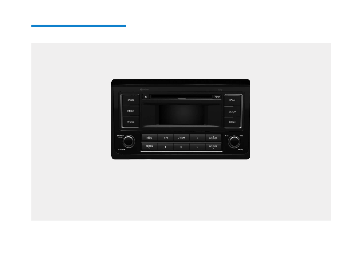
4-14
Multimedia System
■■
CD Player : AC110MDGG, AC110MDGN, AC110MDGL
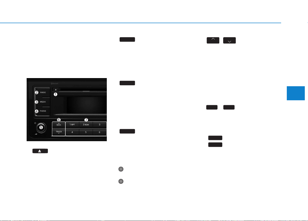
4-15
Multimedia System
4
SSYYSSTTEEMM CCOONNTTRROOLLLLEERRSS AANNDD
F
FUUNNCCTTIIOONNSS
❈ Display and settings may differ
depending on the selected audio.
Audio Head Unit
(for RDS model)
1. (EJECT)
• Ejects the disc.
2.
• Changes to FM/AM mode.
• Each time the key is pressed,the
mode is changed in order of FM1
➟ FM2 ➟ FMA ➟ DAB1 ➟ DAB2 ➟
AM.
3.
• Changes to CD, USB(iPod
®
), AUX,
My Music, BT Audio mode.
• Each time the key is pressed, the
mode is changed in order of CD,
USB(iPod
®
), AUX, My Music, BT
Audio.
4. (if equipped)
• Operates Phone Screen
❈ When a phone is not connected,
the connection screen is displayed.
5. PWR/VOL knob
• Power Knob: Turns power
On/Off by pressing the knob
• Volume Knob: Sets volume by
turning the knob left/right
6. ,
• Radio Mode : Automatically search-
es for broadcast frequencies.
• CD, USB, iPod
®
, My Music modes
- Shortly press the key (under 0.8
seconds): Moves to next or previ-
ous song (file)
- Press and hold the key (over 0.8
seconds): Rewinds or fast-for-
wards the current song.
7.
~
(Preset)
• Radio Mode: Saves frequencies
(channels) or receives saved fre-
quencies (channels)
• CD, USB, iPod
®
, My Music mode
- : Repeat
- : Random
• In the Radio, Media, Setup, and
Menu pop up screen, the number
menu is selected.
2 RDM
1 RPT
61
TRACK
SEEK
PHONE
MEDIA
RADIO

4-16
Multimedia System
8.
• Each time the button is shortly
pressed (under 0.8 seconds), sets
screen Off ➟ Screen On ➟ Screen
Off
❈ Audio operation is maintained and
only the screen will be turned Off.
In the screen Off state, press any
key to turn the screen On again.
9.
• Radio Mode
- Shortly press the key (under
0.8seconds): TA On/Off- Press
and hold the key (over 0.8sec-
onds): Previews each broadcast
for 5 seconds each.
• Media mode
- Press and hold the key (over
0.8seconds): Previews each
song (file) for 10 seconds each.
❈ Press and holding the key again to
continue listening to the current
song (file).
10.
• Shortly press the key (under 0.8
seconds) : Moves to the Display,
Sound, Phone, System setting
modes
• Press and hold the key (over 0.8
seconds) : Move to the Time set-
ting screen
11.
Displays menus for the current
mode.
❈ iPod
®
List : Move to parent category
12. ,
• CD MP3, USB mode : Folder
Search
13. TUNE knob
• Radio mode : Changes frequency
by turning the knob left/right
• CD, USB, iPod
®
, My Music mode:
Searches .songs (files) by turning
the knob left/right
❈ When the desired song is dis-
played, press the knob to play the
song.
• Moves focus in all selection menus
and selects menus
FOLDER
FOLDER
MENU
SETUP
TA/SCAN
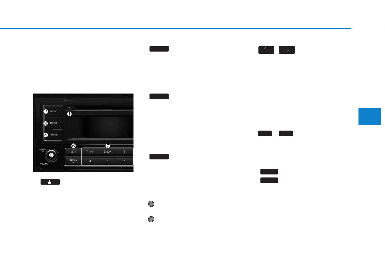
4-17
Multimedia System
4
SSYYSSTTEEMM CCOONNTTRROOLLLLEERRSS AANNDD
F
FUUNNCCTTIIOONNSS
❈Display and settings may differ
depending on the selected audio.
Audio Head Unit
1. (EJECT)
• Ejects the disc.
2.
• Changes to FM/AM mode.
• Each time the key is pressed,the
mode is changed in order of FM1
➟ FM2 ➟ AM.
3.
• Changes to CD, USB(iPod
®
), AUX,
My Music, BT Audio mode.
• Each time the key is pressed, the
mode is changed in order of CD,
USB(iPod
®
), AUX, My Music, BT
Audio.
4. (if equipped)
• Operates Phone Screen
❈ When a phone is not connected,
the connection screen is displayed.
5. PWR/VOL knob
• Power Knob: Turns power
On/Off by pressing the knob
• Volume Knob: Sets volume by
turning the knob left/right
6. ,
• Radio Mode : Automatically search-
es for broadcast frequencies.
• CD, USB, iPod
®
, My Music modes
- Shortly press the key (under 0.8
seconds): Moves to next or previ-
ous song (file)
- Press and hold the key (over 0.8
seconds): Rewinds or fast-for-
wards the current song.
7.
~
(Preset)
• Radio Mode: Saves frequencies
(channels) or receives saved fre-
quencies (channels)
• CD, USB, iPod
®
, My Music mode
- : Repeat
- : Random
• In the Radio, Media, Setup, and
Menu pop up screen, the number
menu is selected.
2 RDM
1 RPT
61
TRACK
SEEK
PHONE
MEDIA
RADIO
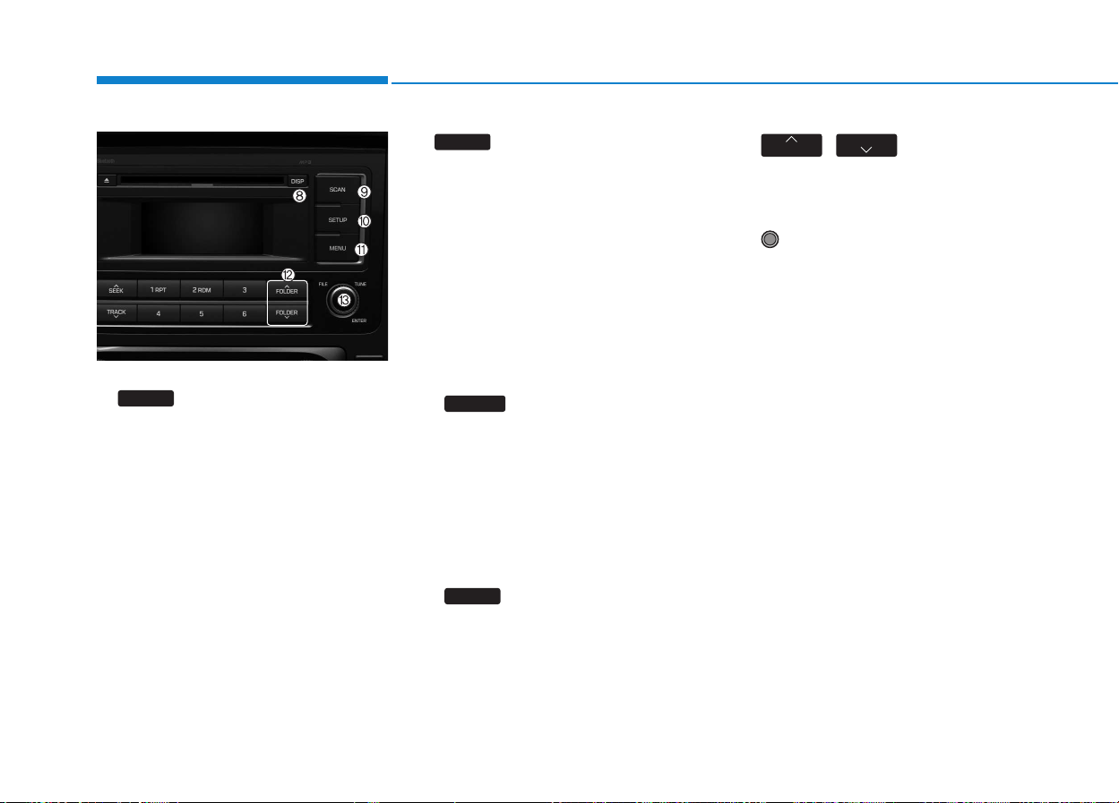
4-18
Multimedia System
8.
• Each time the button is shortly
pressed (under 0.8 seconds), sets
screen Off ➟ Screen On ➟ Screen
Off
❈ Audio operation is maintained and
only the screen will be turned Off.
In the screen Off state, press any
key to turn the screen On again.
9.
• Radio Mode
- Press the key (under 0.8 sec-
onds): Previews each broadcast
for 5 seconds each
• CD, USB, My Music mode
- Press the key (under 0.8 sec-
onds): Previews each song (file)
for 10 seconds each
❈ Press the key again to continue
listening to the current song (file).
10.
• Shortly press the key (under 0.8
seconds) : Moves to the Display,
Sound, Clock, Phone, System set-
ting modes
• Press and hold the key (over 0.8
seconds) : Move to the Time set-
ting screen
11.
Displays menus for the current
mode.
❈ iPod
®
List : Move to parent category
12. ,
• CD MP3, USB mode : Folder
Search
13. TUNE knob
• Radio mode : Changes frequency
by turning the knob left/right
• CD, USB, iPod
®
, My Music mode:
Searches .songs (files) by turning
the knob left/right
❈ When the desired song is dis-
played, press the knob to play the
song.
• Moves focus in all selection menus
and selects menus
FOLDER
FOLDER
MENU
SETUP
SCAN
DISP

4-19
Multimedia System
4
SSEETTUUPP ((FFOORR RRDDSS MMOODDEELL))
- AC210MDEE
Display Settings
Press the key Select
[Display] through TUNE knob or
key Select menu through
Mode Pop up
[Mode Pop up] Changes .
selection mode
• During On state, press the
or key to display the mode
change pop up screen.
• When the pop up screen is dis-
played, use the TUNE knob or
keys ~ to select the
desired mode.
Scroll text
[Scroll text] Set /
• : Maintains scroll
• : Scrolls only one (1) time.
Song Info
When playing an MP3 file, select the
desired display info from ‘Folder/File’
or ‘Album/Artist/Song’.
Off
On
Off
On
61
MEDIA
RADIO
On
1 RPT
SETUP
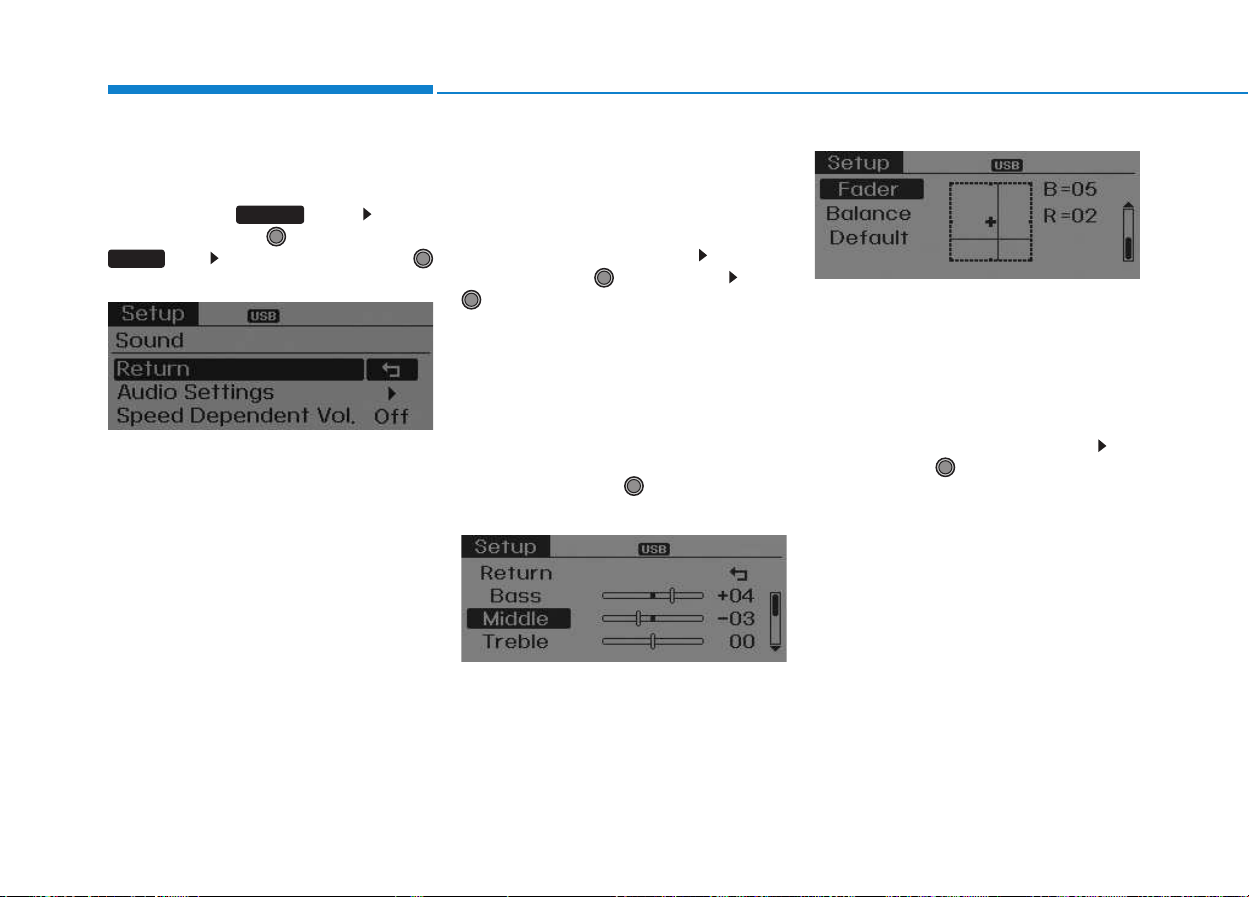
4-20
Multimedia System
Sound Settings
Press the key Select
[Sound] through TUNE knob or
key Select menu through
TUNE knob
Audio Settings
This menu allows you to set the
‘Bass, Middle, Treble’ and the Sound
Fader and Balance.
Select [Audio Settings] Select
menu through TUNE knob Turn
TUNE knob left/right to set
• Bass, Middle, Treble : Selects the
sound tone.
• Fader, Balance : Moves the sound
fader and balance.
• Default : Restores default settings.
❈ Return : While adjusting values,
re-pressing the TUNE knob will
restore the parent menu.
Speed Dependent Volume
Control
This feature is used to automatically
control the volume level according to
the speed of the vehicle.
Select [Speed Dependent Vol.] Set
in [On/Off] of
TUNE
knob
2 RDM
SETUP

4-21
Multimedia System
4
System Settings
Press the key Select
[System] through tune knob or
key Select menu through TUNE
knob
Memory Information
(if equipped)
Displays currently used memory and
total system memory.
Select [Memory Information] OK
The currently used memory is dis-
played on the left side while the total
system memory is displayed on the
right side.
Language
This menu is used to set the display
and voice recognition language.
Select [Language] Set through
TUNE knob
❈ The system will reboot after the
language is changed.
❈ Language support by region
-
5
SETUP
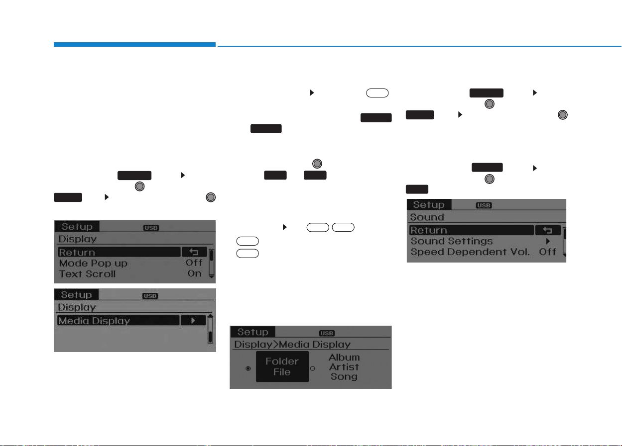
4-22
Multimedia System
S
SEETTUUPP
- AC110MDGG, AC110MDGN, AC110MDGL
Display Settings
Press the key Select
[Display] through TUNE knob or
key Select menu through
TUNE knob
Mode Pop up
[Mode Pop up] Changes .
selection mode
• During On state, press the
or key to display the mode
change pop up screen.
• When the pop up screen is dis-
played, use the TUNE knob or
keys ~ to select the
desired mode.
Text Scroll
[Text Scroll] Set /
• : Maintains scroll
• : Scrolls only one (1) time.
Media Display
When playing an MP3 file, select the
desired display info from ‘Folder/File’
or ‘Album/Artist/Song’.
Sound Settings
Press the key Select
[Sound] through TUNE knob or
key Select menu through
TUNE knob
Sound Settings
Press the key Select
[Sound] through TUNE knob or
key
2
SETUP
2 RDM
SETUP
Off
On
Off
On
61
MEDIA
RADIO
On
1 RPT
SETUP
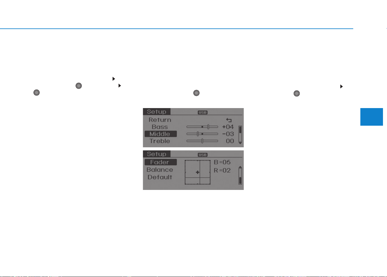
4-23
Multimedia System
4
Sound Settings
This menu allows you to set the
‘Bass, Middle, Treble’ and the Sound
Fader and Balance.
Select [Sound Settings] Select
menu through TUNE knob Turn
TUNE knob left/right to set
• Bass, Middle, Treble : Selects the
sound tone.
• Fader, Balance : Moves the sound
fader and balance.
• Default : Restores default settings.
❈ Return : While adjusting values,
re-pressing the TUNE knob will
restore the parent menu.
Speed Dependent Volume
Control
This feature is used to automatically
control the volume level according to
the speed of the vehicle.
Select [Speed Dependent Vol.] Set
in [On / Off] of TUNE knob
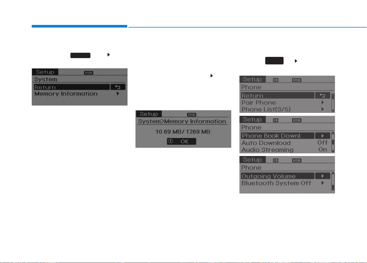
4-24
Multimedia System
System Settings
Press the key Select
[System]
Memory Information
(if equipped)
Displays currently used memory and
total system memory.
Select [Memory Information] OK
The currently used memory is dis-
played on the left side while the total
system memory is displayed on the
right side.
Phone Setup (if equipped)
Press the key Select [Phone]
(for RDS model)
SETUP
CLOCK
SETUP
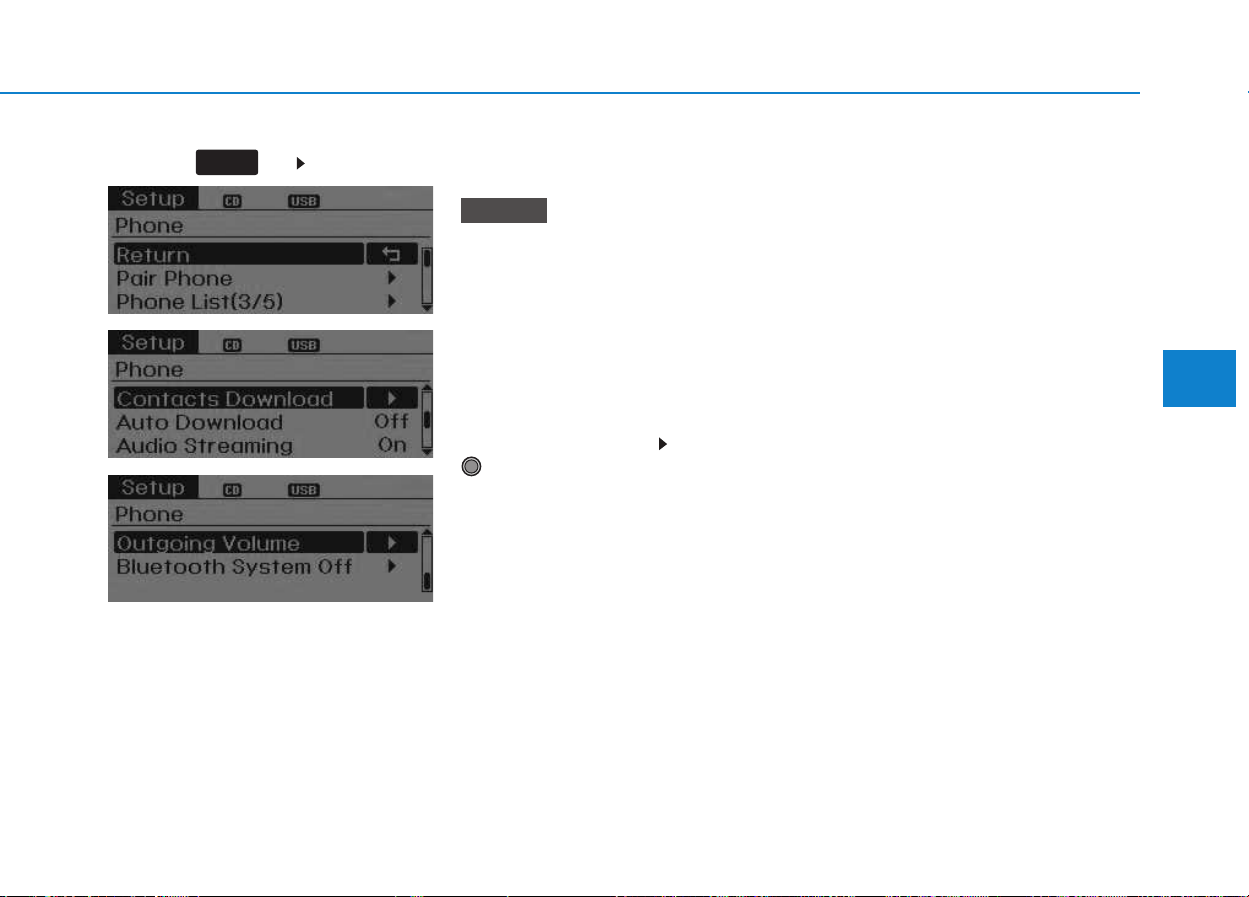
4-25
Multimedia System
4
Press the key Select [Phone]
Pair Phone
To pair a
Bluetooth
®
Wireless
Technology enabled mobile
phone, authentication and con-
nection processes are first
required. As a result, you cannot
pair your mobile phone while driv-
ing the vehicle. First park your
vehicle before use.
Select [Pair Phone] Set through
TUNE knob
➀ Search for device names as dis-
played on your mobile phone and
connect.
➁ Input the passkey displayed on the
screen. (Passkey : 0000)
❈ The device name and passkey will
be displayed on the screen for up
to 3 minutes. If pairing is not com-
pleted within the 3 minutes, the
mobile phone pairing process will
automatically be canceled.
➂ Pairing completion is displayed.
❈ In some mobile phones, pairing
will automatically be followed by
connection.
❈ It is possible to pair up to five
Bluetooth
®
Wireless Technology
enabled mobile phones.
NOTICE
SETUP
CLOCK
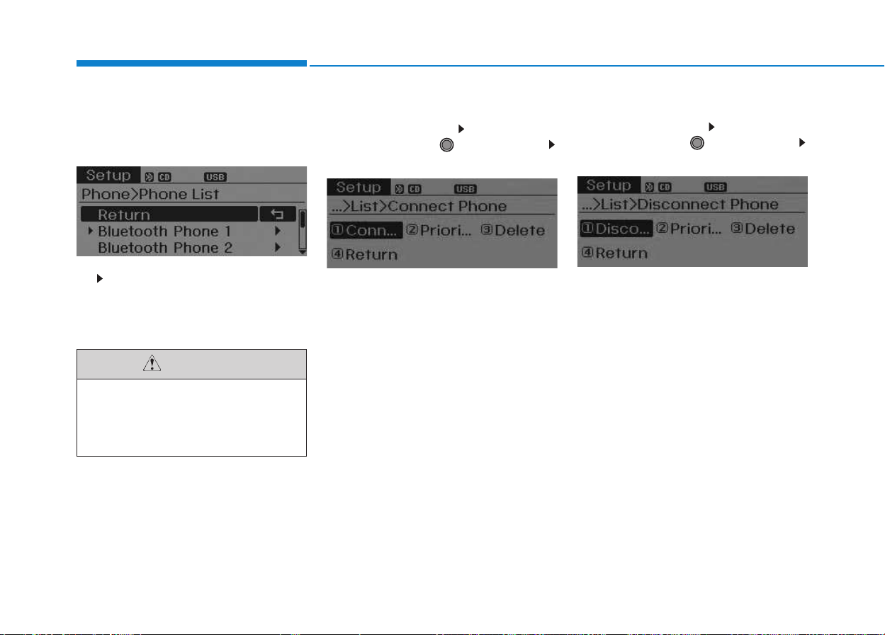
4-26
Multimedia System
Phone List
The names of up to 5 paired phones
will be displayed.
A [ ] is displayed in front of the cur-
rently connected phone.
Select the desired name to setup the
selected phone.
• Connecting a phone
Select [Phone List] Select mobile
phone through TUNE knob
Select [Connect Phone]
➀ Select a mobile phone that is not
currently connected.
➁ Connect the selected mobile
phone.
➂ Connection completion is dis-
played.
❈ If a phone is already connected,
disconnect the currently connect-
ed phone and select a new phone
to connect.
• Disconnecting a connected phone
Select [Phone List] Select mobile
phone through TUNE knob
Select [Disconnect Phone]
➀ Select the currently connected
mobile phone.
➁ Disconnect the selected mobile
phone.
➂ Disconnection completion is dis-
played.
Do not use the cell phone or
other peripherals (i.e. audio
device) while driving. If not, it
may cause an accident.
CAUTION

4-27
Multimedia System
4
• Changing connection sequence
(Priority)
This is used to change the order (pri-
ority) of automatic connection for the
paired mobile phones.
Select [Phone List] Select [Priority]
through TUNE knob Select No. 1
Priority mobile phone
➀ Select [Priority].
➁ From the paired phones, select
the phone desired for No.1 priority.
➂ The changed priority sequence is
displayed.
❈ Once the connection sequence
(priority) is changed, the new no. 1
priority mobile phone will be con-
nected.
-When the no. 1 priority cannot be
connected: Automatically attempts
to connect the most recently con-
nected phone.
-Cases when the most recently
connected phone cannot be con-
nected: Attempts to connect in the
order in which paired phones are
listed.
-The connected phone will automati-
cally be changed to No. 1 priority.
• Delete
Select [Phone List] Select mobile
phone through TUNE knob
Select [Delete]
➀ Select the desired mobile phone.
➁ Delete the selected mobile phone.
➂ Deletion completion is displayed.
❈ When attempting to delete a cur-
rently connected phone, the
phone is first disconnected.
• When you delete a mobile
phone, the mobile phone con-
tacts will also be erased.
• For stable
Bluetooth
®
Wireless
Technology communication,
delete the mobile phone from
the audio and also delete the
audio from your mobile phone.
Phone book Download (for
RDS model)
This feature is used to download
phone book and call histories into
the audio system.
Select [Phone book Download]
Select through TUNE knob.
• The download feature may not
be supported in some mobile
phones.
• If a different operation is per-
formed while phone book is
being downloaded, downloading
will be discontinued. Phone
book already downloaded will
be saved.
• When downloading new phone
book, delete all previously saved
phone book before starting
download.
NOTICE
NOTICE
4-28
Multimedia System
Auto Download
When connecting a mobile phone, it
is possible to automatically download
new Contacts and Call Histories.
Select [Auto Download] Set /
through TUNE knob
Contacts Download
This feature is used to download
contacts and call histories into the
audio system.
Select [Contacts Download] Select
through TUNE knob
• The download feature may not
be supported in some mobile
phones.
• If a different operation is per-
formed while Contacts are being
downloaded, downloading will
be discontinued. Contacts
already downloaded will be
saved.
• When downloading new
Contacts, delete all previously
saved Contacts before starting
download.
Audio Streaming
Songs (files) saved in your
Bluetooth
®
Wireless Technology
enabled mobile phone can be played
through the audio system.
Select [Audio Streaming] Set /
through TUNE knob
The
Bluetooth
®
Wireless Technology
audio streaming feature may not be
supported in some mobile phones.
Outgoing Volume
This is used to set the volume of your
voice as heard by the other party
while on a
Bluetooth
®
Wireless
Technology enabled handsfree call.
Select [Outgoing Volume] Set vol-
ume through TUNE knob
❈ While on a call, the volume can be
changed by using the key.
SEEK
TRACK
NOTICE
Off
On
NOTICE
Off
On

4-29
Multimedia System
4
Bluetooth
®
Wireless
Technology System Off
This feature is used when you do not
wish to use the
Bluetooth
®
Wireless
Technology system.
Select [Bluetooth System Off] Set
through TUNE knob
❈ If a phone is already connected,
disconnect the currently connect-
ed phone and turn the
Bluetooth
®
Wireless Technology system off.
Using the
Bluetooth
®
Wireless
Technology System
To use
Bluetooth
®
Wireless Technology
when the system is currently off, fol-
low these next steps.
• Turning On Bluetooth
®
Wireless
Technology through the
Key
Press the key Screen
Guidance
❈ Moves to the screen where
Bluetooth
®
Wireless Technology
functions can be used and dis-
plays guidance.
• Turning On Bluetooth
®
Wireless
Technology through the
Key
Press the key Select
[Phone]
➀ A screen asking whether to turn on
Bluetooth
®
Wireless Technology will
be displayed.
➁ On the screen, select to turn
on
Bluetooth
®
Wireless Technology
and display guidance.
❈ If the Bluetooth
®
Wireless
Technology system is turned on,
the system will automatically try to
connect the most recently con-
nected Bluetooth
®
Wireless
Technology mobile phone.
•
Bluetooth
®
Wireless Technology
connection may become inter-
mittently disconnected in some
mobile phones. Follow these
next steps to try again.
1) Turn the
Bluetooth
®
Wireless
Technology function within the
mobile phone ON/OFF and try
to connect again.
2) Turn the mobile phone power
ON/OFF and try to connect
again.
3) Completely remove the mobile
phone battery, reboot, and then
try to connect again.
4) Reboot the audio system and
try to connect again
5) Delete all paired devices in your
mobile phone and the audio
system and pair again for use.
NOTICE
YES
SETUP
CLOCK
SETUP
CLOCK
PHONE
PHONE
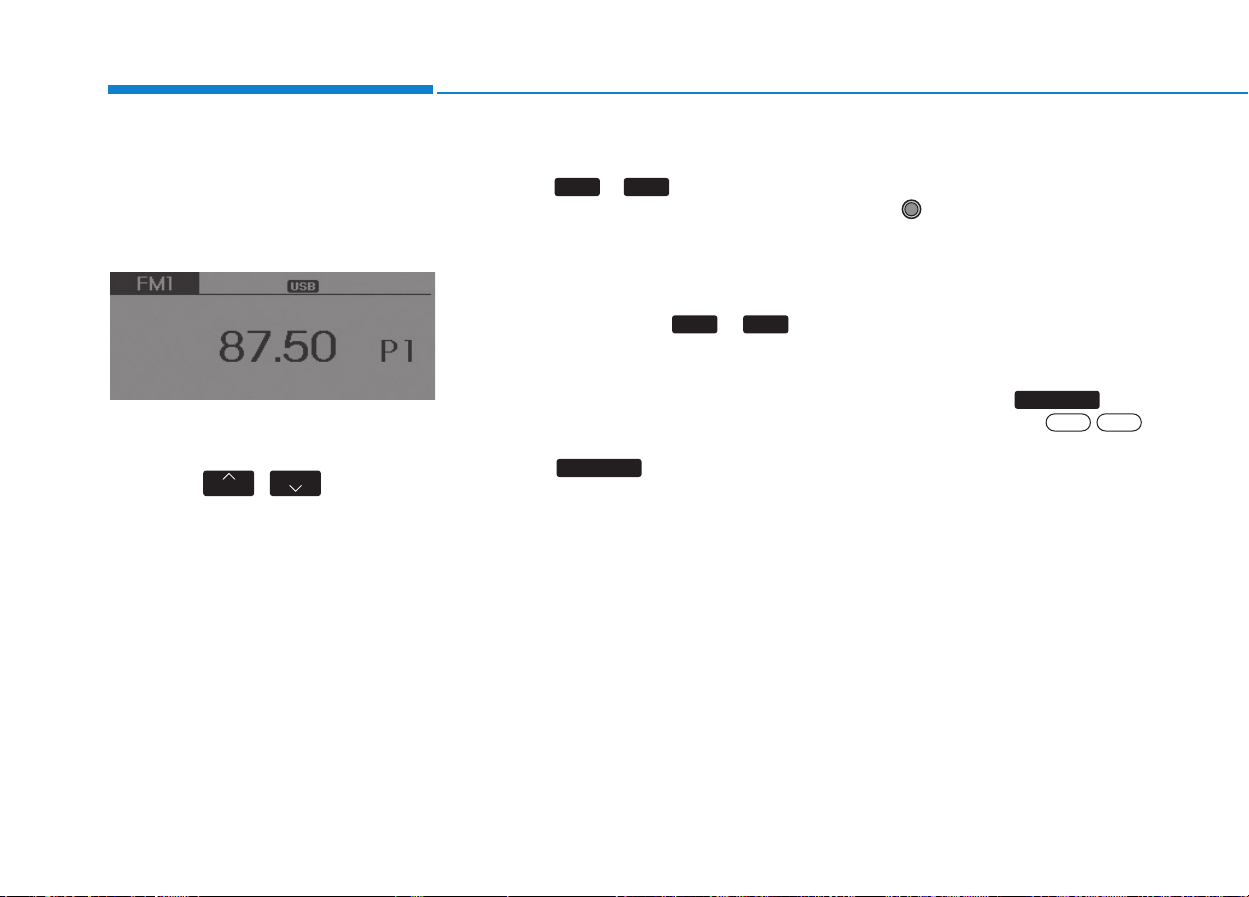
4-30
Multimedia System
RRAADDIIOO ((FFOORR RRDDSS MMOODDEELL)) ::
F
FMM,, AAMM
Changing RADIO mode
SEEK
Press the , key
• Shortly pressing the key (under 0.8
seconds): Changes the frequency.
• Pressing and holding the key (over
0.8 seconds): Automatically
searches for the next frequency.
Preset SEEK
Press the ~ key
• Shortly pressing the key (under 0.8
seconds): Plays the frequency
saved in the corresponding key.
• Pressing and holding the key (over
0.8 seconds): Pressing and holding
the desired key from ~
will save the currently playing
broadcast to the selected key and
sound a BEEP.
SCAN
Press the key
• Pressing and holding the key (over
0.8 seconds): The broadcast fre-
quency increases and previews
each broadcast for 5 seconds each.
After scanning all frequencies,
returns and plays the current
broadcast frequency.
Selecting through manual
search
Turn the TUNE knob left/right to
adjust the frequency.
• AC210MDEE
- FM : Changes by 50KHz
- AM : Changes by 9khz
Traffic Announcement (TA)
Shortly pressing the key
(under 0.8 seconds): Set /
TA Traffic Announcement) mode.
OffOn
TA/SCAN
TA/SCAN
61
61
TRACK
SEEK
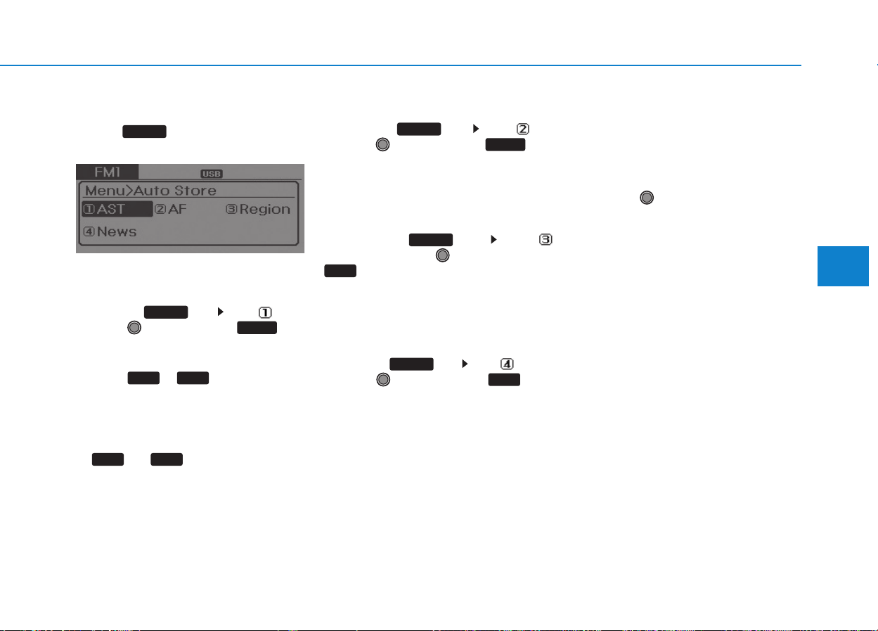
4-31
Multimedia System
4
MENU
Within key are the A.Store
(Auto Store) and Info functions.
AST (Auto Store)
Press the key Set [ AST]
through TUNE knob or key.
Select AST (Auto Store) to save fre-
quencies with superior reception to
presets ~ . If no frequen-
cies are received, then the most
recently received frequency will be
broadcast.
❈ Saves only to the Preset memory
~ of FMA or AMA
mode.
AF (Alternative Frequency)
Press the key Set [ AF]
through TUNE knob or key.
The Alternative Frequency option
can be turned On/Off.
Region
Press the key Set [
Region] through TUNE knob or
key.
The Region option can be turned
On/Off.
News
Press the key Set [ News]
through TUNE knob or key.
The News option can be turned
On/Off.
Info Volume
Info Volume refers to the sound vol-
ume upon receiving News or Traffic
information.
The info volume can be controlled by
turning the VOL knob left/right while
a news or traffic broadcast is playing.
❈ AF, Region, and News are RDS
Radio menus.
4
MENU
3
MENU
2 RDM
MENU
61
61
1 RPT
MENU
MENU
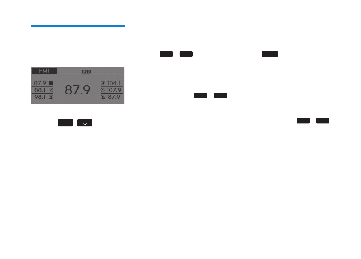
4-32
Multimedia System
RRAADDIIOO
Changing RADIO mode
SEEK
Press the , key
• Shortly pressing the key (under 0.8
seconds): Changes the frequency.
• Pressing and holding the key (over
0.8 seconds): Automatically search-
es for the next frequency.
Preset SEEK
Press the ~ key
• Shortly pressing the key (under 0.8
seconds): Plays the frequency
saved in the corresponding key.
• Pressing and holding the key (over
0.8 seconds): Pressing and holding
the desired key from ~
will save the currently playing
broadcast to the selected key and
sound a BEEP.
SCAN
Press the key
• Shortly pressing the key (under 0.8
seconds): The broadcast frequen-
cy increases and previews each
broadcast for 5 seconds each.
After scanning all frequencies,
returns and plays the current
broadcast frequency.
• Pressing and holding the key (over
0.8 seconds): Previews the broad-
casts saved in Preset ~
for 5 seconds each.
61
SCAN
61
61
TRACK
SEEK

4-33
Multimedia System
4
Selecting through manual
search
Turn the TUNE knob left/right to
adjust the frequency.
• AC110MDGG
- FM : Changes by 100KHz
- AM : Changes by 9KHz
• AC110MDGN
- FM : Changes by 200KHz
- AM : Changes by 10KHz
• AC110MDGL
- FM : Changes by 100KHz
- AM : Changes by 9KHz
MENU
Within key are the A.Store
(Auto Store) and Info functions.
AST (Auto Store)
Press the key Set [ AST]
through TUNE knob or key.
Select AST (Auto Store) to save fre-
quencies with superior reception to
presets ~ . If no frequen-
cies are received, then the most
recently received frequency will be
broadcast.
61
1
RPT
MENU
MENU
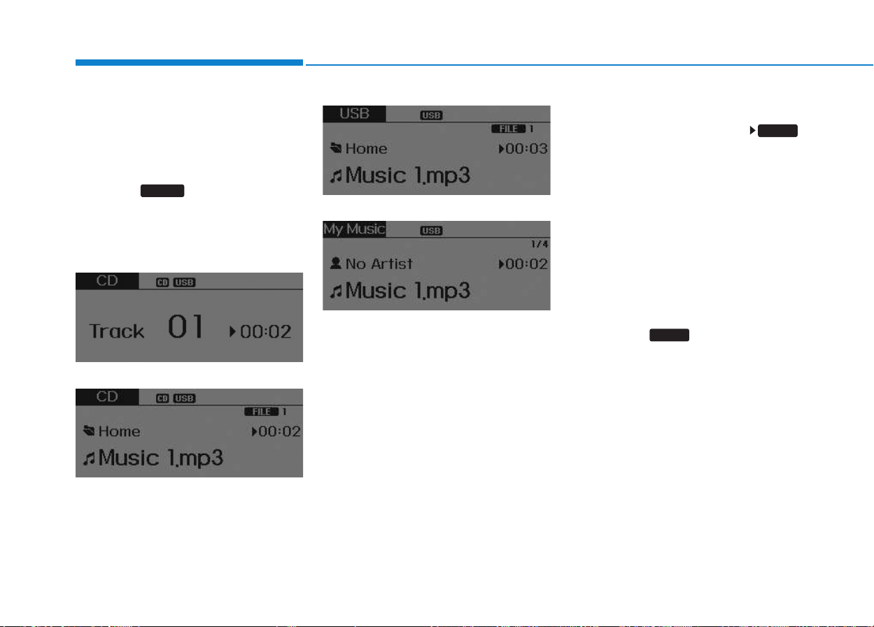
4-34
Multimedia System
BBAASSIICC MMEETTHHOODD OOFF UUSSEE ::
A
AUUDDIIOO CCDD // MMPP33 CCDD // UUSSBB //
I
IPPOODD
®
®
/
/ MMYY MMUUSSIICC
Press the key to change the
mod mode in order of CD ➟ USB(iPod
®
)
➟ AUX ➟ My Music ➟ BT Audio.
The folder/file name is displayed on
the screen.
<Audio CD>
<CD MP3>
<USB>
<My Music>
❈ The CD is automatically played
when a CD is inserted.
❈ The USB music is automatically
played when a USB is connected.
Repeat
While song (file) is playing
(RPT) key
Audio CD, MP3 CD, USB, iPod
®
, My
Music mode: RPT on screen
• To repeat one song (Shortly press-
ing the key (under 0.8 seconds)):
Repeats the current song.
MP3 CD, USB mode: FLD.RPT on
screen
• To repeat folder (pressing twice):
repeats all files within the current
folder.
❈ Press the key again to turn
off repeat.
1 RPT
1 RPT
MEDIA

4-35
Multimedia System
4
Random
While song (file) is playing
(RDM) key
Audio CD, My Music mode: RDM on
screen
• Random (Shortly pressing the key ):
Plays all songs in random order.
MP3 CD, USB mode: FLD.RDM on
screen
• Folder Random (Shortly pressing
the key): Plays all files within the
current folder in random order.
MP3 CD, USB mode: RDM on
screen
• Random (pressing twice): Plays all
files in random order.
iPod
®
mode: RDM on screen
• Random (press the key) : Plays all
files in random order.
❈ Press the key again to turn
off random.
Changing Song/File
While song (file) is playing
key
• Shortly pressing the key: Plays the
current song from the beginning.
❈ If the key is pressed again
within 1 second, the previous song
is played.
• Pressing and holding the key (over
0.8 seconds): Rewinds the song.
While song (file) is playing
,key
• Shortly pressing the key: Plays the
next song.
• Pressing and holding the key (over
0.8 seconds): Fast forwards the
song.
Scan (for RDS model)
While song (file) is playing
key
• Pressing and holding the key (over
0.8 seconds) : Scans all songs for
10 seconds starting from the next
song.
❈ Pressing and holding the
key again to turn off.
Scan
While song (file) is playing
key
• Shortly pressing the key (under 0.8
seconds) : Scans all songs from
the next song for 10 seconds each.
❈ Press the key again to turn
off.
❈ The SCAN function is not support-
ed in iPod
®
mode.
SCAN
SCAN
TA/SCAN
TA/SCAN
SEEK
TRACK
TRACK
2 RDM
2 RDM
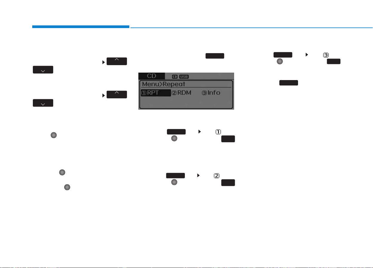
4-36
Multimedia System
Folder Search : MP3 CD, USB
Mode
While file is playing /
(Folder Up) key
• Searches the next folder.
While file is playing /
(Folder Down) key
• Searches the parent folder.
❈ If a folder is selected by pressing
the TUNE knob, the first file
within the selected folder will be
played.
Searching Songs (File)
• Turning TUNE knob : Searches
for songs (files)
• Pressing TUNE knob : Plays
selected song (file).
MENU : Audio CD
Press the CD MP3 mode key
to set the Repeat, Random,
Information features.
Information features.
Repeat
Press the key Set [ RPT]
through the TUNE knob or
key to repeat the current song.
❈ Press RPT again to turn off.
Random
Press the key Set [ RDM]
through the TUNE knob or
key to randomly play songs within
the current folder.
❈ Press RDM again to turn off.
Information
Press the key Set [ Info]
through the TUNE knob or
key to display information of the cur-
rent song.
❈ Press the key to turn off
info display.
MENU
3
MENU
2
RDM
MENU
1
RPT
MENU
MENU
FOLDER
FOLDER
FOLDER
FOLDER
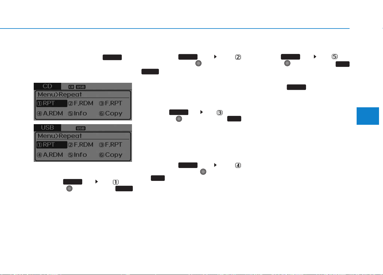
4-37
Multimedia System
4
MENU : MP3 CD / USB
Press the CD MP3 mode key
to set the Repeat, Folder Random,
Folder Repeat, All Random,
Information, and Copy features.
Information, and Copy features.
Repeat
Press the key Set [ RPT]
through the TUNE knob or
key to repeat the current song.
❈ Press RPT again to turn off.
Folder Random
Press the key Set [
F.RDM] through the TUNE knob or
key to randomly play songs
within the current folder.
❈ Press F.RDM again to turn off.
Folder Repeat
Press the key Set [ F.RPT]
through the TUNE knob or
key to repeat songs within the cur-
rent folder.
❈ Press F.RPT again to turn off.
All Random
Press the key Set [
A.RDM] through the TUNE knob
or key to randomly play all
songs within the CD.
❈ Press A.RDM again to turn off.
Information
Press the key Set [ Info]
through the TUNE knob or
key to display information of the cur-
rent song.
❈ Press the key to turn off
info display.
MENU
5
MENU
4
MENU
3
MENU
2 RDM
MENU
1 RPT
MENU
MENU
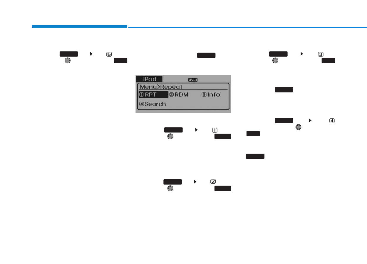
4-38
Multimedia System
Copy
Press the key Set [ Copy]
through the TUNE knob or
key.
This is used to copy the current
song into My Music. You can play
the copied Music in My Music
mode.
❈ If another key is pressed while
copying is in progress, a pop up
asking you whether to cancel
copying is displayed.
❈ If another media is connected or
inserted (USB, CD, iPod
®
, AUX)
while copying is in progress, copy-
ing is canceled.
❈ Music will not be played while
copying is in progress.
MENU : iPod
®
In iPod
®
mode, press the key to
set the Repeat, Random, Information
and Search features.
Repeat
Press the key Set [ RPT]
through the TUNE knob or
key to repeat the current song.
❈ Press RPT again to turn repeat
off.
Random
Press the key Set [ RDM]
through the TUNE knob or
key.
Plays all songs within the currently
playing category in random order.
❈ Press RDM again to turn off.
Information
Press the key Set [ Info]
through the TUNE knob or
key.
Displays information of the current
song.
❈ Press the key to turn off
info display.
Search
Press the key Set [
Search] through the TUNE knob
or key.
Displays iPod
®
category list.
❈ Searching iPod
®
category is
key pressed, move to par-
ent category.
MENU
4
MENU
MENU
3
MENU
2 RDM
MENU
1 RPT
MENU
MENU
6
MENU
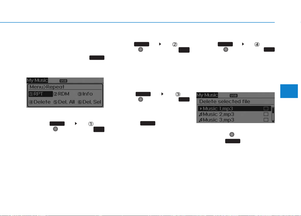
4-39
Multimedia System
4
MENU : My Music Mode
(if equipped)
In My Music mode, press the
key to set the Repeat, Random,
Information, Delete, Delete All, and
Delete Selection features.
Repeat
Press the key Set [ RPT]
through the TUNE knob or
key.
Repeats the currently playing song.
❈ Press RPT again to turn repeat off.
Random
Press the key Set [ RDM]
through the TUNE knob or
key.
Plays all songs in random order.
❈ Press RDM again to turn random
off.
Information
Press the key Set [ Info]
through the TUNE knob or
key.
Displays information of the current
song.
❈ Press the key to turn off
info display.
Delete
Press the key Set [ Delete]
through the TUNE knob or
key.
Deletes currently playing file
In the play screen, pressing delete
will delete the currently playing
song.
Deletes file from list
➀ Select the file you wish to delete
by using the TUNE knob.
➁ Press the key and select
the delete menu to delete the
selected file.
MENU
4
MENU
MENU
3
MENU
2
RDM
MENU
1
RPT
MENU
MENU
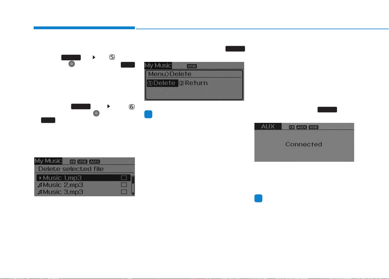
4-40
Multimedia System
Delete All
Press the key Set [ Del.All]
through the TUNE knob or
key.
Deletes all songs of My Music.
Delete Selection
Press the key Set [
Del.Sel] through the TUNE knob
or key.
Songs within My Music are selected
and deleted.
➀ Select the songs you wish to
delete from the list.
➁ After selecting, press the
key and select the delete menu.
Information
- Using the My Music
• Even if memory is available, a maxi-
mum of 6,000 songs can be stored.
• The same song can be copied up to
1,000 times.
• Memory info can be checked in the
System menu of Setup.
AUX
AUX is used to play external MEDIA
currently connected with the AUX
terminal.
AUX mode will automatically start
when an external device is connect-
ed with the AUX terminal.
If an external device is connected,
you can also press the key to
change to AUX mode.
❈ AUX mode cannot be started
unless there is an external device
connected to the AUX terminal.
Information
- Using the AUX
Fully insert the AUX cable into the
AUX terminal for use.
i
MEDIA
i
MENU
6
MENU
5
MENU
4-41
Multimedia System
4
BBlluueettooootthh
®®
WWiirreelleessss
T
Teecchhnnoollooggyy AAUUDDIIOO
(
(iiff eeqquuiippppeedd))
What is
Bluetooth
®
Wireless
Technology?
Bluetooth
®
Wireless Technology
allows devices to be connected in a
short distance, including hands-free
devices, stereo headsets, wireless
remote controllers, etc. For more
information, visit the
Bluetooth
®
Wireless Technology website at
www.Bluetooth.com
Before using
Bluetooth
®
Wireless
Technology audio features
•
Bluetooth
®
Wireless Technology
audio may not be supported
depending on the compatibility of
your
Bluetooth
®
Wireless
Technology mobile phone.
• In order to use
Bluetooth
®
Wireless
Technology audio, you must first
pair and connect the
Bluetooth
®
Wireless Technology mobile
phone.
• The
Bluetooth
®
word mark and
logos are registered trademarks
owned by
Bluetooth
®
SIG, Inc. and
any use of such marks is under
license. Other trademarks and trade
names are those of their respective
owners. A
Bluetooth
®
enabled cell
phone is required to use
Bluetooth
®
Wireless Technology
•
Bluetooth
®
Wireless Technology
audio can be used only when the
[Audio Streaming] of Phone is
turned On.
❈ Setting
Bluetooth
®
Wireless
Technology Audio Streaming :
Press the key Select
[Phone] through the tune knob
Select [Audio Streaming] through
the TUNE knob Set /
Starting
Bluetooth
®
Wireless
Technology Audio
• Press the key to change
the mode in order of CD ➟ USB ➟
AUX ➟ My Music ➟ BT Audio.
• If BT Audio is selected,
Bluetooth
®
Wireless Technology audio will
start playing.
❈ Audio may not automatically start
playing in some mobile phones.
MEDIA
OffOn
SETUP
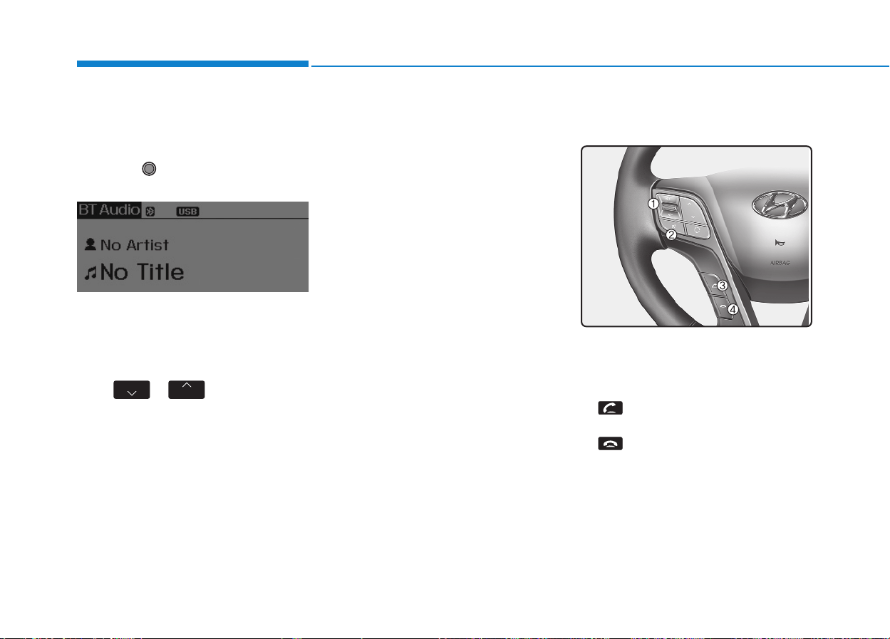
4-42
Multimedia System
Using the
Bluetooth
®
Wireless
Technology audio features
• Play / Pause
Press the TUNE knob to play and
pause the current song.
❈ The title / artist info may not be
supported in some mobile phone.
When it is not supported, no title /
no artist will be displayed.
• Previous / Next song
Press of to play previous or
next song.
❈ The previous song / next song /
play / pause functions may not be
supported in some mobile
phones.
PPHHOONNEE ((iiff eeqquuiippppeedd))
Before using the
Bluetooth
®
Wireless
Technology
phone features
• In order to use
Bluetooth
®
Wireless
Technology
phone, you must first
pair and connect the
Bluetooth
®
Wireless Technology
mobile phone.
• If the mobile phone is not paired or
connected, it is not possible to
enter Phone mode. Once a phone
is paired or connected, the guid-
ance screen will be displayed.
• If Priority is set upon vehicle igni-
tion (IGN/ACC ON), the
Bluetooth
®
Wireless Technology
phone will be
automatically connected. Even if
you are outside, the
Bluetooth
®
Wireless Technology
phone will be
automatically connected once you
are in the vicinity of the vehicle. If you
do not want automatic
Bluetooth
®
Wireless Technology
phone connec-
tion, set the
Bluetooth
®
Wireless
Technology
power to OFF.
Making a call using the Steering
wheel remote controller
1. VOLUME button : Raises or low-
ers speaker volume.
2. MUTE button : Mute the micro-
phone during a call.
3. button : Places and transfers
calls.
4. button : Ends calls or cancels
functions.
SEEK
TRACK

4-43
Multimedia System
4
• Check call history and making call
➀ Shortly press (under 0.8 seconds)
the key on the steering
remote controller.
➁ The call history list will be dis-
played on the screen.
➂ Press the key again to con-
nect a call to the selected number.
• Redialing the most recently called
number
➀ Press and hold (over 0.8 seconds)
the key on the steering
remote controller.
➁ The most recently called number
is redialed.
Phone MENU (for RDS model)
Press the key to display three
menus (Call History, Phone Book,
Phone Setup).
Call history
Press the key Set [
History] through the TUNE knob
or key.
The call history is displayed and can
be used to select a number and
make a call.
If call history does not exist, a screen
asking whether to download call his-
tory is displayed. (The download fea-
ture may not be supported in some
mobile phones)
Phone Book
Press the key Set [ P.
Book] through the TUNE knob or
key.
The phone book is displayed and
can be used to select a number and
make a call.
❈ If more than one number is saved
to one contact, then a screen
showing the mobile phone num-
ber, Home and office number is
displayed. Select the desired num-
ber to make the call.
❈ If phone book do not exist, a
screen asking whether to down-
load phone book is displayed.
(The download feature may not be
supported in some mobile
phones)
2 RDM
PHONE
1 RPT
PHONE
PHONE
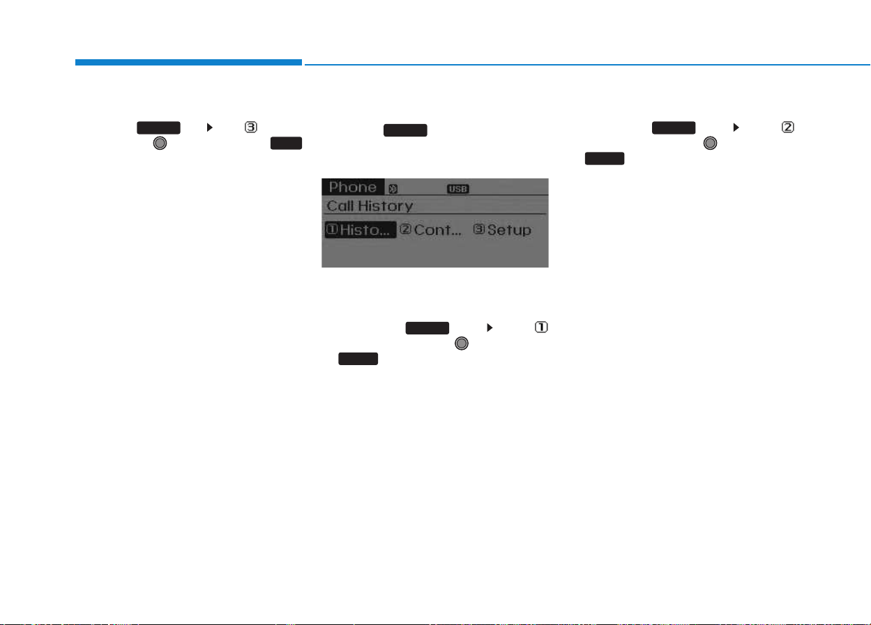
4-44
Multimedia System
Phone Setup
Press the key Set [ Setup]
through the TUNE knob or
key.
The
Bluetooth
®
Wireless Technology
mobile phone setup screen is dis-
played. For more information, refer to
“Phone Setup”.
Phone MENU
Press the key to display three
menus (Call History, Contacts,
Phone Setup).
Call history
Press the key Set [
History] through the TUNE knob
or key.
The call history is displayed and can
be used to select a number and
make a call.
If call history does not exist, a screen
asking whether to download call his-
tory is displayed. (The download fea-
ture may not be supported in some
mobile phones)
Contacts
Press the key Set [
Contacts] through the TUNE knob
or key.
The Contacts are displayed and can
be used to select a number and
make a call.
❈ If more than one number is saved
to one contact, then a screen
showing the mobile phone num-
ber, Home and office number is
displayed. Select the desired num-
ber to make the call.
❈ If Contacts do not exist, a screen
asking whether to download
Contacts is displayed. (The down-
load feature may not be supported
in some mobile phones)
2 RDM
PHONE
1 RPT
PHONE
PHONE
3
PHONE

4-45
Multimedia System
4
Phone Setup
Press the key Set [
Setup] through the TUNE knob or
key.
The
Bluetooth
®
Wireless Technology
mobile phone setup screen is dis-
played. For more information, refer to
“Phone Setup”.
Information
- Using the
Bluetooth
®
Wireless Technology CELLU-
AR PHONE
• Do not use a cellular phone or per-
form Bluetooth
®
Wireless Technology
settings (e.g. pairing a phone) while
driving.
• Some Bluetooth
®
Wireless Technology
-enabled phones may not be recog-
nized by the system or fully compati-
ble with the system.
• Before using Bluetooth
®
Wireless
Technology related features of the
audio system, refer your phone's
User's Manual for phone-side
Bluetooth
®
Wireless Technology oper-
ations.
• The phone must be paired to the
audio system to use Bluetooth
®
Wireless Technology related features.
• You will not be able to use the hands-
free feature when your phone (in the
vehicle) is outside of the cellular serv-
ice area (e.g. in a tunnel, in a under-
ground, in a mountainous area, etc.).
(Continued)
(Continued)
• If the cellular phone signal is poor or
the vehicles interior noise is too loud,
it may be difficult to hear the other
person's voice during a call.
• Do not place the phone near or inside
metallic objects, otherwise communi-
cations with Bluetooth
®
Wireless
Technology system or cellular service
stations can be disturbed.
• While a phone is connected through
Bluetooth
®
Wireless Technology your
phone may discharge quicker than
usual for additional Bluetooth
®
Wireless Technology-related opera-
tions.
• Some cellular phones or other devices
may cause interference noise or mal-
function to audio system. In this case,
store the device in a different location
may resolve the condition.
• Phone contact names should be saved
in English or they may not be dis-
played correctly.
(Continued)
i
3
PHONE

4-46
Multimedia System
(Continued)
• If Priority is set upon vehicle igni-
tion(IGN/ACC ON), the Bluetooth
®
Wireless Technology phone will be
automatically connected.
Even if you are outside, the
Bluetooth
®
Wireless Technology
phone will be automatically connect-
ed once you are in the vicinity of the
vehicle.
If you do not want automatic
Bluetooth
®
Wireless Technology con-
nection, turn the Bluetooth
®
Wireless
Technology feature off.
• The hands-free call volume and qual-
ity may differ depending on the
mobile phone type.
• Bluetooth
®
Wireless Technology fea-
tures can be used only when the
mobile phone has been paired and
connected with the device. For more
information on pairing and connect-
ing Bluetooth
®
Wireless Technology
enabled mobile phones, refer to the
"Phone Setup" section.
(Continued)
(Continued)
• When a Bluetooth
®
Wireless
Technology mobile phone is connect-
ed, a ( ) icon will appear at the top
of the screen. If a ( ) icon is not dis-
played, this indicates that a
Bluetooth
®
Wireless Technology
enabled device has not been connect-
ed. You must connect the device
before use. For more information on
Bluetooth
®
Wireless Technology
mobile phones, refer to the "Phone
Setup" section.
• Pairing and connecting a Bluetooth
®
Wireless Technology enabled mobile
phone will work only when the
Bluetooth
®
Wireless Technology
option within your mobile phone has
been turned on. (Methods of turning
on the Bluetooth
®
Wireless
Technology enabled feature may dif-
fer depending on the mobile phone.)
(Continued)
(Continued)
• In some mobile phones, starting the
ignition while talking through
Bluetooth
®
Wireless Technology
enabled handsfree call will result in
the call becoming disconnected.
(Switch the call back to your mobile
phone when starting the ignition.)
• Some features may not be supported
in some Bluetooth
®
Wireless
Technology mobile phone and
devices.
• Bluetooth
®
Wireless Technology
enabled operation may be unstable
depending on the communication
state.
• Placing the audio system within an
electromagnetic environment may
result in noise interference.
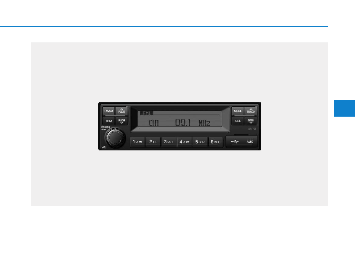
4-47
Multimedia System
4
■■
RADIO, SET UP, VOLUME CONTROL : AM210MDEE, AMB00MDGL, AMB00MDGN, AMB00MDGG
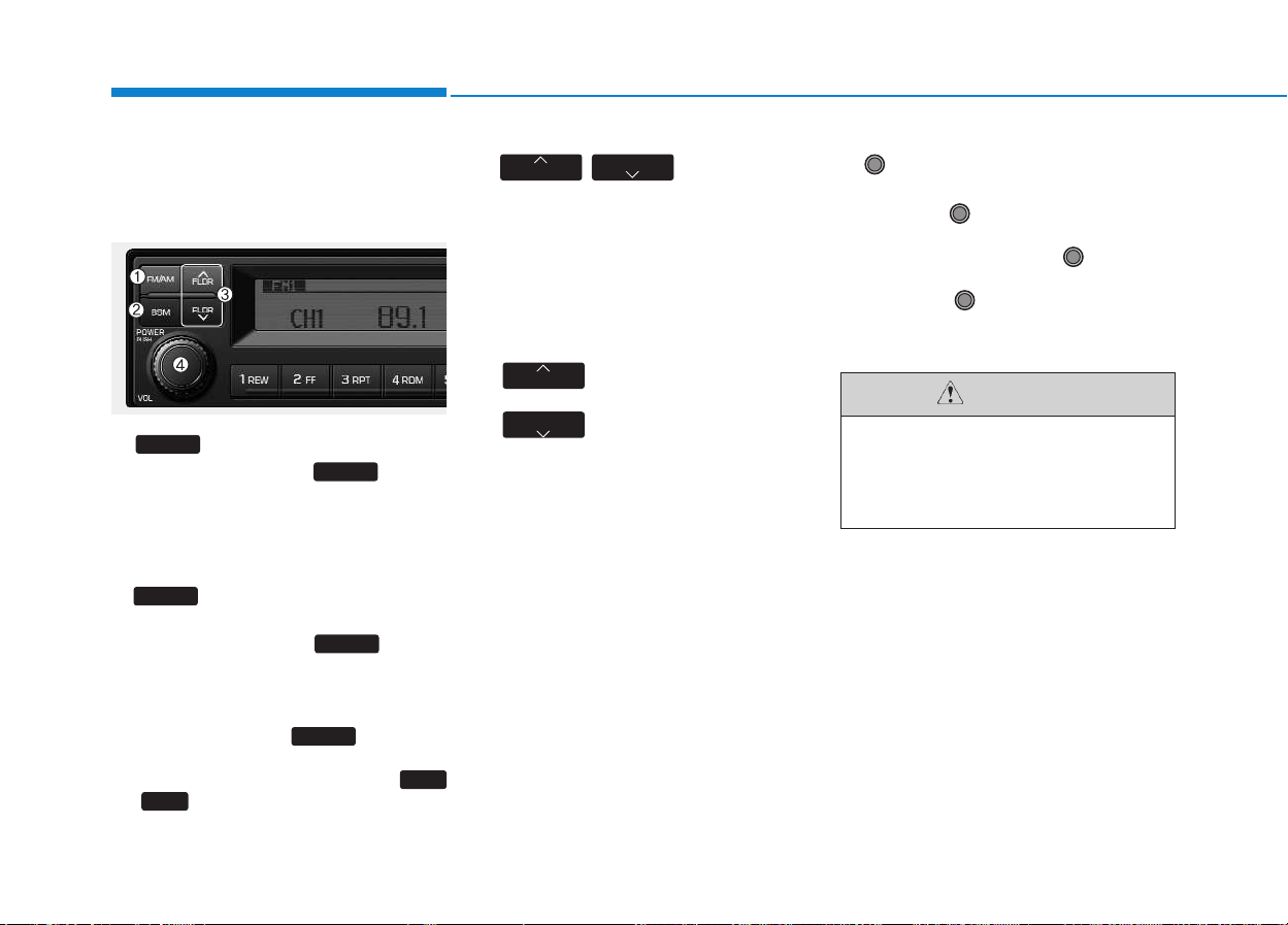
4-48
Multimedia System
RRAADDIIOO,, SSEETT UUPP,, VVOOLLUUMMEE
C
COONNTTRROOLL
1. FM/AM Button
• Each press of the button
will change the radio mode in the
following order.
- FM1
➟ FM2 ➟ AM
2. BSM (Best Station
Memory) Button
• Press and hold the button
to listen to the presets saved in FM
BAND FM1, FM2, and AM BAND
AM for 5 seconds each.
Shortly press the button to
automatically save frequencies with
superior reception in presets (
~ ).
3.
/
Broadcast
Manual Search (FLDR) Button
• As button used to search frequen-
cies manually, a press of the SEEK
STEP will change the frequency.
Pressing and holding the button will
continue changing the frequency.
Releasing the button will stop the
search at the current frequency.
-
: Searches frequencies
higher than current frequency
- :
Searches frequencies
lower than current frequency
4. POWER/VOL
/Sound Setting Knob
• Press the POWER Knob to turn
on the audio. While the audio is
operating, press the Knob to
turn the power off.
Turn the Knob clockwise to
increase the volume and counter-
clockwise to decrease the volume.
FLDR
FLDR
FLDR
FLDR
6
INFO
1
REW
BSM
BSM
BSM
FM/AM
FM/AM
Do not turn up the volume to the
level that it covers the sur-
rounding traffic noises. If not, it
may cause an accident.
CAUTION
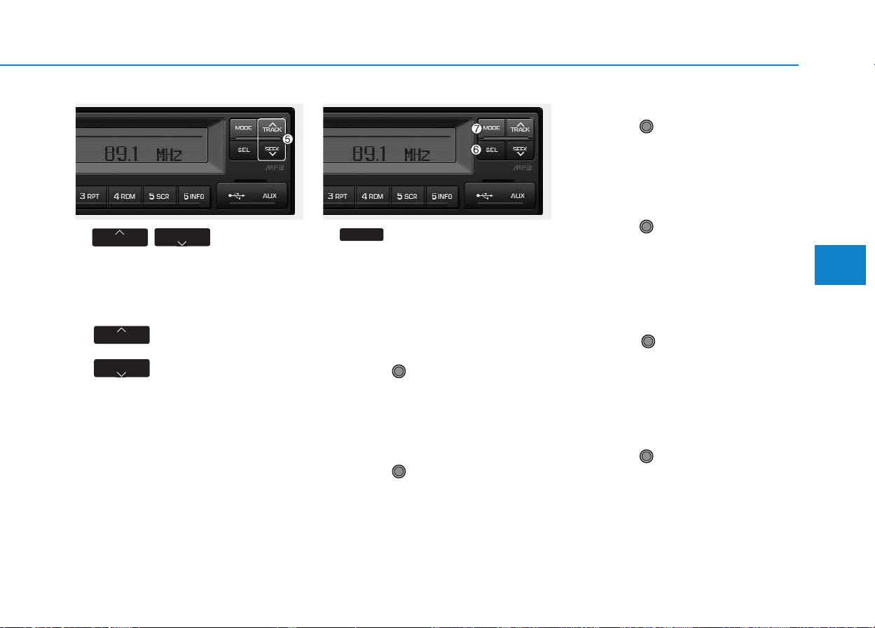
4-49
Multimedia System
4
5. / Button
• As buttons used to automatically
search broadcasts, pressing the
button will automatically search and
stop at a frequency with superior
reception.
-
: Searches frequencies
higher than current frequency
- :
Searches frequencies
lower than current frequency
6. Button
• Each press of the button will
change the sound and language
settings in the following order.
- Bass
➟ Middle ➟ Treble ➟ Balance ➟
Fader ➟ EQ ➟ Beep ➟ Language
BASS Control
• Turn the VOLUME Knob clock-
wise to increase the bass and
counter-clockwise to decrease the
bass.
MIDDLE Control
• Turn the VOLUME Knob clock-
wise to increase the middle and
counter-clockwise to decrease the
middle.
TREBLE Control
• Turn the VOLUME Knob clock-
wise to increase the treble and
counter-clockwise to decrease the
treble.
BALANCE Control
• Turn the VOLUME Knob clock-
wise to increase the right-side
speaker volume and counter-clock-
wise to increase the left-side
speaker volume.
FADER Control
• Tune the VOLUME Knob clock-
wise to increase the front-side
speaker volume and counter-clock-
wise to increase the rear-side
speaker volume
EQ(EQUALIZER) Control
• Turn the VOLUME Knob clock-
wise/counter-clockwise to select
the desired EQ.
EQ settings are as shown below.
- Cls(Classic)
➟ Pop ➟ Rock ➟ Jazz
➟ off
SEL
SEEK
TRACK
SEEK
TRACK
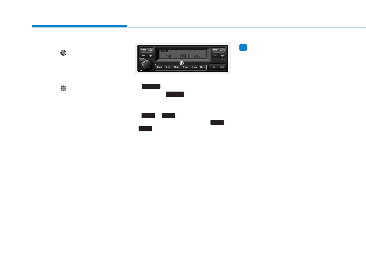
4-50
Multimedia System
BEEP Control
• Turn the VOLUME Knob clock-
wise/counter-clockwise to the
BEEP sound ON/OFF.
LANGUAGE (Only AM210MDEE)
• Turn the VOLUME Knob clock-
wise/counter-clockwise to the
select the desired Language
Language setting are as shown
below
- English
➟➟Türkçe
7. Button
• Press the button to change
to RADIO/USB/AUX/iPod
®
modes.
8. ~ Button (Preset)
• Select the preset button ( ~
) to which you wish to save the
selected frequency. Press and hold
the preset button. The frequency
will be saved to the preset button to
a sound of a beeXp. The saved fre-
quency number will be displayed on
the LCD DISPLAY.
Information
- Using USB device
• When using the external USB device,
make sure to keep the device discon-
nected and connect only some time
after turning on the vehicle ignition.
The USB device may be damaged if
the USB device already connected
when the ignition is turned on. (A
USB device is not an electric automo-
tive part.)
• The external USB device may not
operate if the USB device already
connected when vehicle ignition is
turned on or off.
• The device will not operate when
playing a format which is not MP3 or
WMA file formats.
• Be cautious of static electricity when
connecting/disconnecting the exter-
nal USB device.
• Encoded MP3 Players will not be
recognized when connected as the
external device.
(Continued)
i
6
INFO
1
REW
61
MODE
MODE
Póññêèé

4-51
Multimedia System
4
(Continued)
• When connecting an external USB
device, the device may not be proper-
ly recognize the USB when the USB
is in some states.
• When formatting the external USB
device, the device may not be proper-
ly recognize a Byte/Sector selection
other than 512Byte or 2048Byte.
• The device will only recognize USB
devices formatted in FAT 12/16/32.
• Some USB devices may not operate
properly because of compatibility
issues. Verify that the external device
is supported by the device before
starting use.
• Avoid contact between the USB con-
nector with bodily parts and foreign
substances.
• Repeatedly connecting/disconnecting
the USB in a short period of time
may cause damage to the device.
• When disconnecting the USB, an
abnormal sound may occur occasion-
ally.
(Continued)
(Continued)
• Abruptly disconnecting the external
USB device while the USB is operat-
ing may cause the device to become
damaged or function abnormally. -
Make sure to disconnect the USB
device only after the audio power is
turned off or when the audio is oper-
ating in a different mode.
• The amount of time required to rec-
ognize the external USB device may
differ depending on the type, size, or
file formats stored on the USB. Such
differences in the required time are
not indications of malfunction.
• The song name (ID3Tag) or com-
mand icons (RPT/RDM) may take
time to be displayed on the LCD
DISPLAY depending the complexity
of the USB memory/folder structure.
• Please wait the period of time
required to recognize the device. The
device supports only USB devices
used to play music files.
(Continued)
(Continued)
• Do not use the USB I/F to charge bat-
teries or USB accessories which gen-
erate heat. Such acts may lead to
deteriorated performance or damage
to the device.
• The device may not recognize the
USB device if separately purchased
USB hubs and extension cables are
being used. Connect the USB direct-
ly to the multimedia terminal of the
vehicle.
• In the case of high capacity USB
devices, there are instances where the
logical drives are partitioned for user
convenience. - In this case, only the
USB music in the top-level logical
drive will be possible to play.
When using partitioned drives, save
the songs desired to play on the
device only in the top-level logical
drive. In addition, certain UBS
devices are configured with a sepa-
rate drive used to install application
programs and songs from such
drives may not be possible to play for
the reasons as described above.
(Continued)
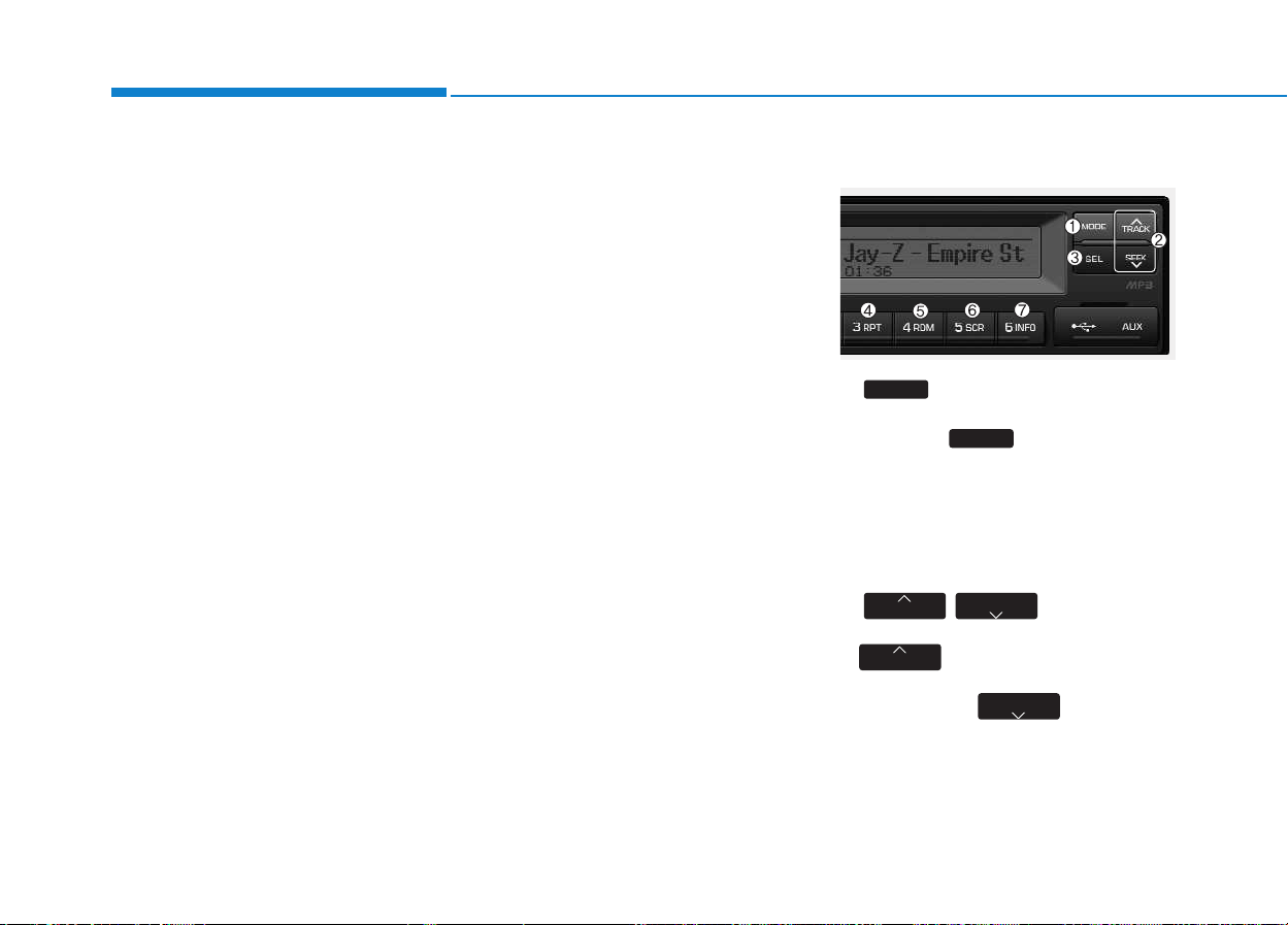
4-52
Multimedia System
(Continued)
• The device may not support normal
operation if MP3 Players, cellular
phones, digital cameras, or other
electronic devices (USB devices not
recognized as portable disk drives)
are connected to the device.
• This product does guarantees proper
operation of only standard (METAL
COVER TYPE) USB MEMORY.
• The device may not support normal
operation when using formats such
as HDD Type, CF, or SD Memory.
• The device will not support files
locked by DRM (Digital Rights
Management).
• This product does not recognize SD
Type USB MEMORY STICK, CF
Type USB MEMORY STICK and
other USB MEMORY STICKS con-
nected to a different Adaptor.
(Continued)
(Continued)
• This product does not guarantee
proper operation of USB HDD or
USB MEMORY with defective con-
nection caused by vehicle vibrations.
UBS memory products used as key
chains and mobile phone accessories
(i-stick type) may cause damage to
the USB Jack. Refrain from using
such products.
• USB CONNECTOR PIN wear and
tear can lead to inferior USB signal
delivery with the SET.
UUSSIINNGG UUSSBB//AAUUXX
1. USB Selection Button
• While playing a different mode,
press the button to convert
to USB/AUX mode. Connecting a
USB/AUX to the audio will auto-
matically convert to USB/AUX
mode even if another mode is play-
ing and automatically play the
songs within the USB/AUX.
2. / Button
•
While playing USB, press the
button to play the begin-
ning of the next song.
Press the button to
return to the beginning of the cur-
rent song. Press the button again
to play the beginning of the previ-
ous song.
SEEK
TRACK
SEEK
TRACK
MODE
MODE

4-53
Multimedia System
4
3. Finding and Playing File
Button
• While USB is playing, press and
hold the button for over 1
seconds to enter FILE BROWER
MODE and search for desired files.
After entering FILE BROWSER
MODE, turn the VOLUME Knob
left/right to find the desired folder.
After finding the folder, press the
button to select the folder.
Turn the VOLUME Knob
left/right to find the desired song
and press the button to
play.
4. RPT/FOLDER RPT Button
• While music is playing, shortly
press the button to repeat the
currently playing song. (RPT func-
tion)
Press and hold the RTP button to
sequentially repeat all songs within
the current folder. (FOLDER RPT,
however, music files in the USB
must be saved in folder format.)
5. RDM/FOLDER RDM
Button
• While music is playing, shortly
press the button to randomly
play the songs in the current folder.
(RDM)
While music is playing, press and
hold the button to randomly
play the songs in the current folder.
(FOLDER RDM, however, music
files in the USB must be saved in
folder format.)
6. SCROLL (SCR) Button
• Press the button to turn
ON/OFF the scroll function which
scrolls the file name of the current-
ly playing song on the LCD from
right to left.
7. View Music Info (INFO)
Button
• Each time the button is
pressed, the info on the currently
playing song will be displayed in the
following order.
- FILE NAME
➟ TITLE ➟ ARTIST
➟ ALBUM ➟ DIR
8. SCAN Button (BSM)
• While music is playing, shortly
press the button to scan
each song within the USB for 10
seconds in sequential order. (SCN)
Press and hold the button
to scan each song within the cur-
rent folder for 10 seconds in
sequential order. (FOLDER SCN,
however, music files in the USB
must be saved in folder format.)
BSM
BSM
BSM
6
INFO
6
INFO
5
SCR
5
SCR
4
RDM
4
RDM
4
RDM
3
RPT
3
RPT
SEL
SEL
SEL
SEL
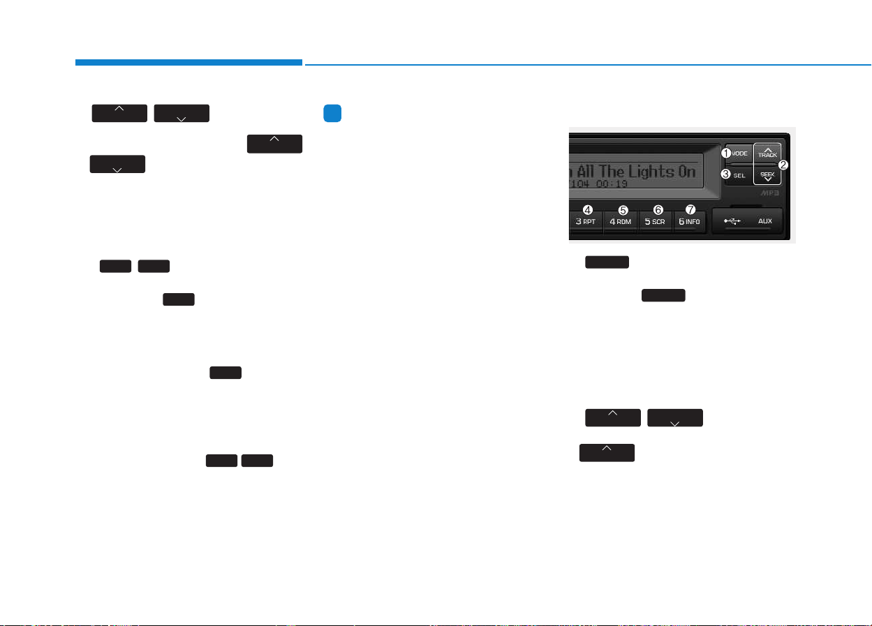
4-54
Multimedia System
9.
/
•
If there are more than 2 folders in
the USB, pressing the
/
button will move to the
previous or next folder.
If there are no folders in the USB,
then pressing the button will move
up/down within the folder in 10 file
increments.
10. / FF/REW Button
• While a USB is operating, press
and hold the button to fast-for-
ward the song. When fast-forward is
complete, the next song will proper-
ly play from the beginning even if
you continue holding the button.
Press and hold the button to
rewind the song. When rewind is
complete, the current song will
properly play from the beginning
even if you continue holding the
button. Shortly pressing the buttons
will not operate the / .
Information
- Using the iPod
®
device
• The iPod
®
device will charge by
connecting an iPod
®
connector
cable to the iPod
®
in ACC ON state.
• When connecting with an iPod
®
cable, insert the JACK all the way
in the terminal to prevent communi-
cation interference.
• The song name (ID3Tag) or com-
mand icons (RPT/RDM) may take
time to be displayed depending on
the iPod
®
model and model software
version. This is not a sign of mal-
function. Please wait.
• iPod
®
Shuffle device does not work.
UUSSIINNGG iiPPoodd
®®
1. iPod
®
Selection Button
• While playing a different mode,
press the button to convert
to iPod
®
mode. Connecting an
iPod
®
to the audio will automatical-
ly convert to iPod
®
mode even if
another mode is playing and auto-
matically play the songs within the
iPod
®
.
2. / Button
• While playing music, press the
button to play the begin-
ning of the next song.
TRACK
SEEK
TRACK
MODE
MODE
i
2
FF
1
REW
1
REW
2
FF
2
FF
1
REW
FLDR
FLDR
FLDR
FLDR
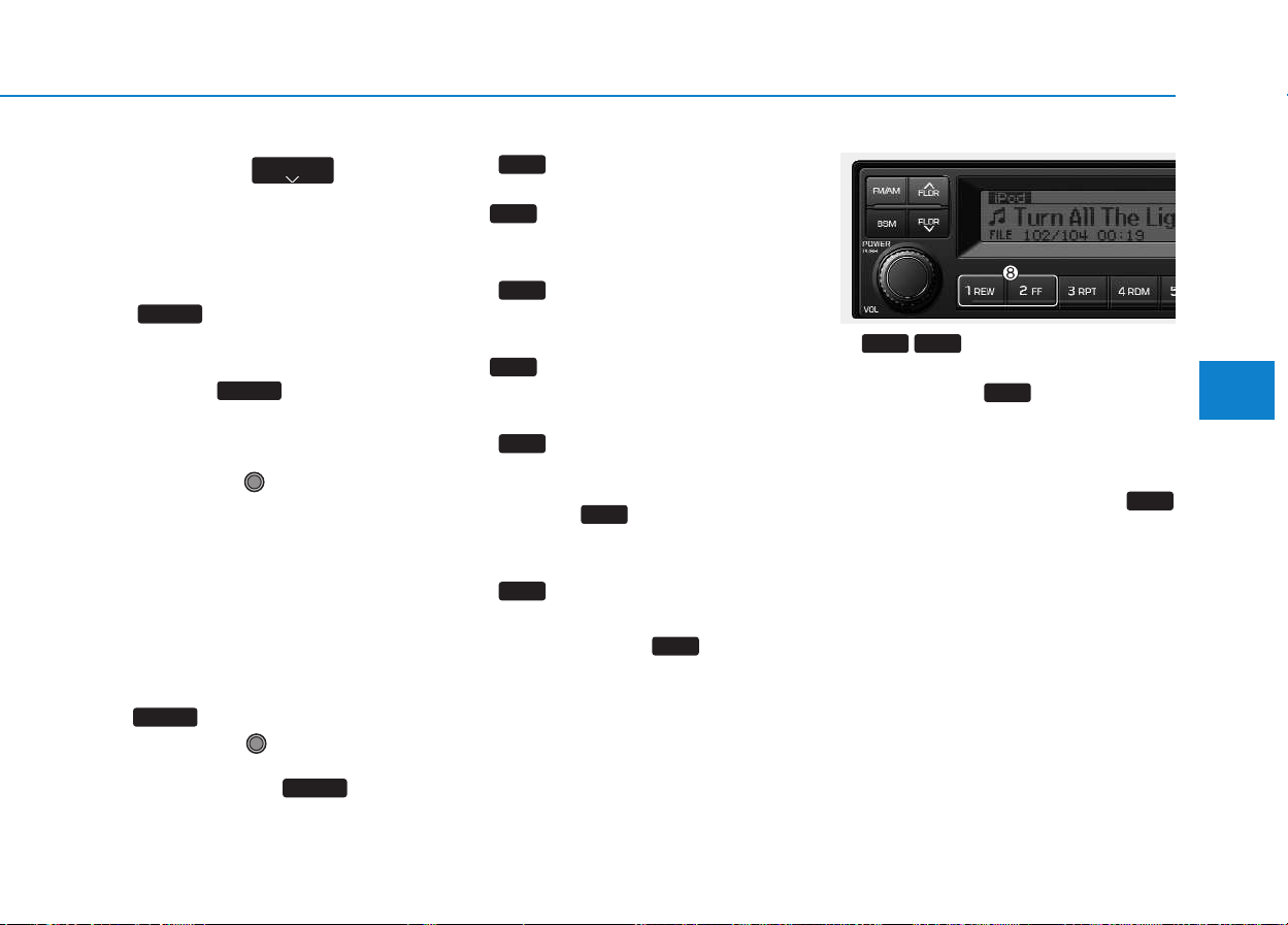
4-55
Multimedia System
4
Press the button to
return to the beginning of the cur-
rent song. Press the button again
to play the beginning of the previ-
ous song.
3. Finding and Playing File
(SEL) Button
• While iPod
®
is playing, press and
hold the button for over 1
seconds to enter CATEGORY
MODE and search for desired files.
After entering CATEGORY MODE,
turn the VOLUME Knob
left/right to find the desired catego-
ry.
Category will be displayed in the
following order.
- PLAYLISTS
➟ ARTISTS ➟
ALBUMS ➟ GENRES ➟ SONGS
➟ COMPOSERS ➟ AUDIO-
BOOKS ➟ PODCACSTS
After finding the category, press the
button to select the category.
Turn the VOLUME Knob
left/right to find the desired song
and press the button to
play.
4. REPEAT (RPT) Button
• While music is playing, press the
button to repeat the currently
playing song.
5. RANDOM PLAY (RDM)
Button
• While music is playing, press the
button to randomly play the
songs.
6. SCROLL (SCR) Button
• Displays the file name of the cur-
rently playing song on the LCD.
Here, the button turns the file
name SCROLL ON/OFF.
7. View Music Info (INFO)
Button
• Each time the button is
pressed, the info on the currently
playing song will be displayed in
order of FILE
➟ ALBUM ➟ ARTIST
➟ TITLE.
8. / Button
• While an iPod
®
is operating, press
and hold the button to fast-
forward the song. When fast-for-
ward is complete, the next song will
properly play from the beginning
even if you continue holding the
button. Press and hold the
button to rewind the song. When
rewind is complete, the current
song will properly play from the
beginning even if you continue
holding the button.
1
REW
2
FF
2
FF
1
REW
6
INFO
6
INFO
5
SCR
5
SCR
4
RDM
4
RDM
3
RPT
3
RPT
SEL
SEL
SEL
SEL
SEEK
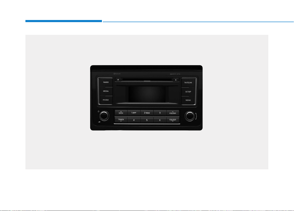
4-56
Multimedia System
■■
CCDD PPLLAAYYEERR ((FFOORR RRDDSS MMOODDEELL)) :: AACC221100MMDDEEEE ((FFOORR TTUURRKKEEYY))
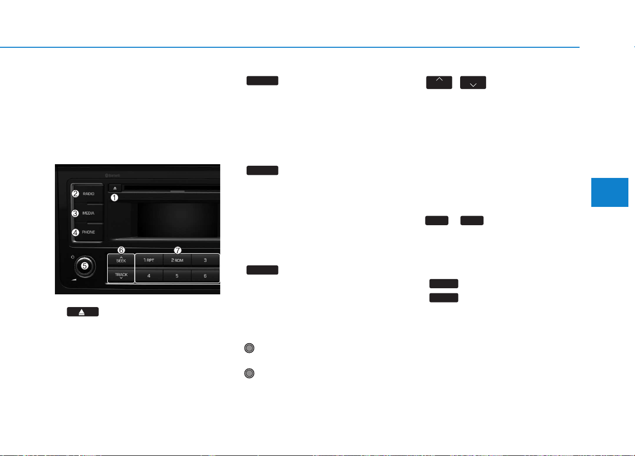
4-57
Multimedia System
4
SSYYSSTTEEMM CCOONNTTRROOLLLLEERRSS AANNDD
F
FUUNNCCTTIIOONNSS
❈ Display and settings may differ
depending on the selected audio.
Audio Head Unit
(for RDS model)
1. (EJECT)
• Ejects the disc.
2.
• Changes to FM/AM mode.
• Each time the key is pressed,the
mode is changed in order of FM1
➟ FM2 ➟ FMA ➟ DAB1 ➟ DAB2 ➟
AM.
3.
• Changes to CD, USB(iPod
®
), AUX,
My Music, BT Audio mode.
• Each time the key is pressed, the
mode is changed in order of CD,
USB(iPod
®
), AUX, My Music, BT
Audio.
4. (if equipped)
• Operates Phone Screen
❈ When a phone is not connected,
the connection screen is displayed.
5. PWR/VOL knob
• Power Knob: Turns power
On/Off by pressing the knob
• Volume Knob: Sets volume by
turning the knob left/right
6. ,
• Radio Mode : Automatically search-
es for broadcast frequencies.
• CD, USB, iPod
®
, My Music modes
- Shortly press the key (under 0.8
seconds): Moves to next or previ-
ous song (file)
- Press and hold the key (over 0.8
seconds): Rewinds or fast-for-
wards the current song.
7.
~
(Preset)
• Radio Mode: Saves frequencies
(channels) or receives saved fre-
quencies (channels)
• CD, USB, iPod
®
, My Music mode
- : Repeat
- : Random
• In the Radio, Media, Setup, and
Menu pop up screen, the number
menu is selected.
2 RDM
1 RPT
61
TRACK
SEEK
PHONE
MEDIA
RADIO
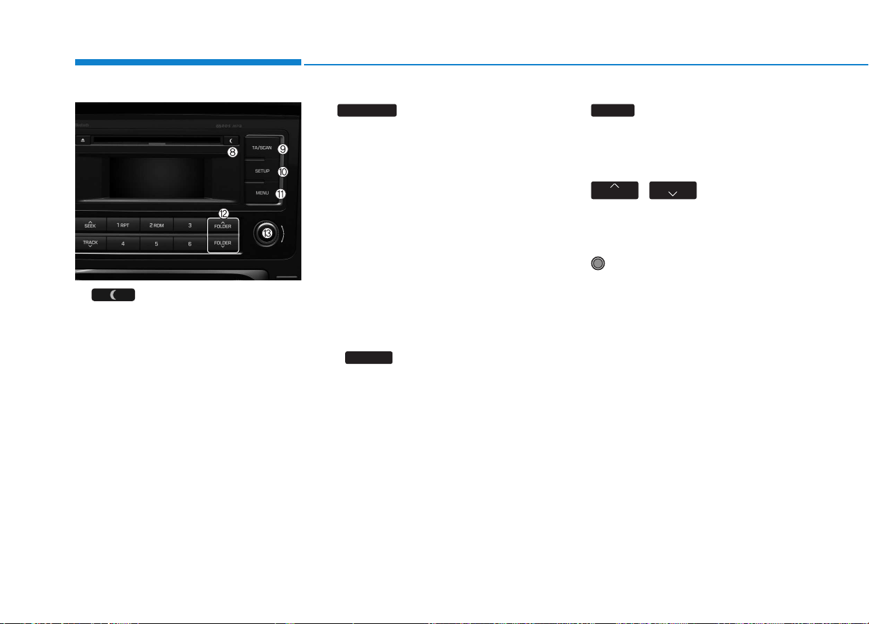
4-58
Multimedia System
8.
• Each time the button is shortly
pressed (under 0.8 seconds), sets
screen Off ➟ Screen On ➟ Screen
Off
❈ Audio operation is maintained and
only the screen will be turned Off.
In the screen Off state, press any
key to turn the screen On again.
9.
• Radio Mode
- Shortly press the key (under
0.8seconds): TA On/Off- Press
and hold the key (over 0.8sec-
onds): Previews each broadcast
for 5 seconds each.
• Media mode
- Press and hold the key (over
0.8seconds): Previews each
song (file) for 10 seconds each.
❈ Press and holding the key again to
continue listening to the current
song (file).
10.
• Shortly press the key (under 0.8
seconds) : Moves to the Display,
Sound, Phone, System setting
modes
• Press and hold the key (over 0.8
seconds) : Move to the Time set-
ting screen
11.
Displays menus for the current
mode.
❈ iPod
®
List : Move to parent category
12. ,
• CD MP3, USB mode : Folder
Search
13. TUNE knob
• Radio mode : Changes frequency
by turning the knob left/right
• CD, USB, iPod
®
, My Music mode:
Searches .songs (files) by turning
the knob left/right
❈ When the desired song is dis-
played, press the knob to play the
song.
• Moves focus in all selection menus
and selects menus
FOLDER
FOLDER
MENU
SETUP
TA/SCAN
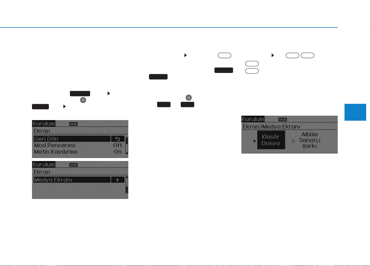
4-59
Multimedia System
4
SSEETTUUPP ((ffoorr RRDDSS mmooddeell))
- AC210MDEE
Display Settings
Press the key Select
[Display] through TUNE knob or
key Select menu through
Mode Pop up
[Mode Pop up] Changes .
selection mode
• During On state, press the
or key to display the mode
change pop up screen.
• When the pop up screen is dis-
played, use the TUNE knob or
keys ~ to select the
desired mode.
Scroll text
[Scroll text] Set /
• : Maintains scroll
• : Scrolls only one (1) time.
Song Info
When playing an MP3 file, select the
desired display info from ‘Folder/File’
or ‘Album/Artist/Song’.
Off
On
Off
On
61
MEDIA
RADIO
On
1 RPT
SETUP
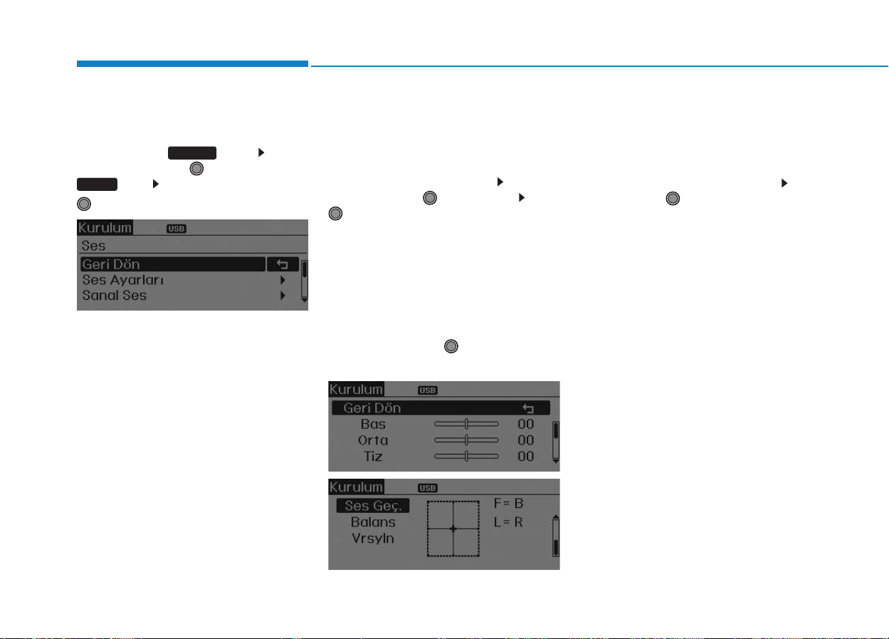
4-60
Multimedia System
Sound Settings
Press the key Select
[Sound] through TUNE knob or
key Select menu through
TUNE knob
Audio Settings
This menu allows you to set the
‘Bass, Middle, Treble’ and the Sound
Fader and Balance.
Select [Audio Settings] Select
menu through TUNE knob Turn
TUNE knob left/right to set
• Bass, Middle, Treble : Selects the
sound tone.
• Fader, Balance : Moves the sound
fader and balance.
• Default : Restores default settings.
❈ Return : While adjusting values,
re-pressing the TUNE knob will
restore the parent menu.
Speed Dependent Volume Control
This feature is used to automatically
control the volume level according to
the speed of the vehicle.
Select [Speed Dependent Vol.] Set
in [On/Off] of
TUNE
knob
2 RDM
SETUP
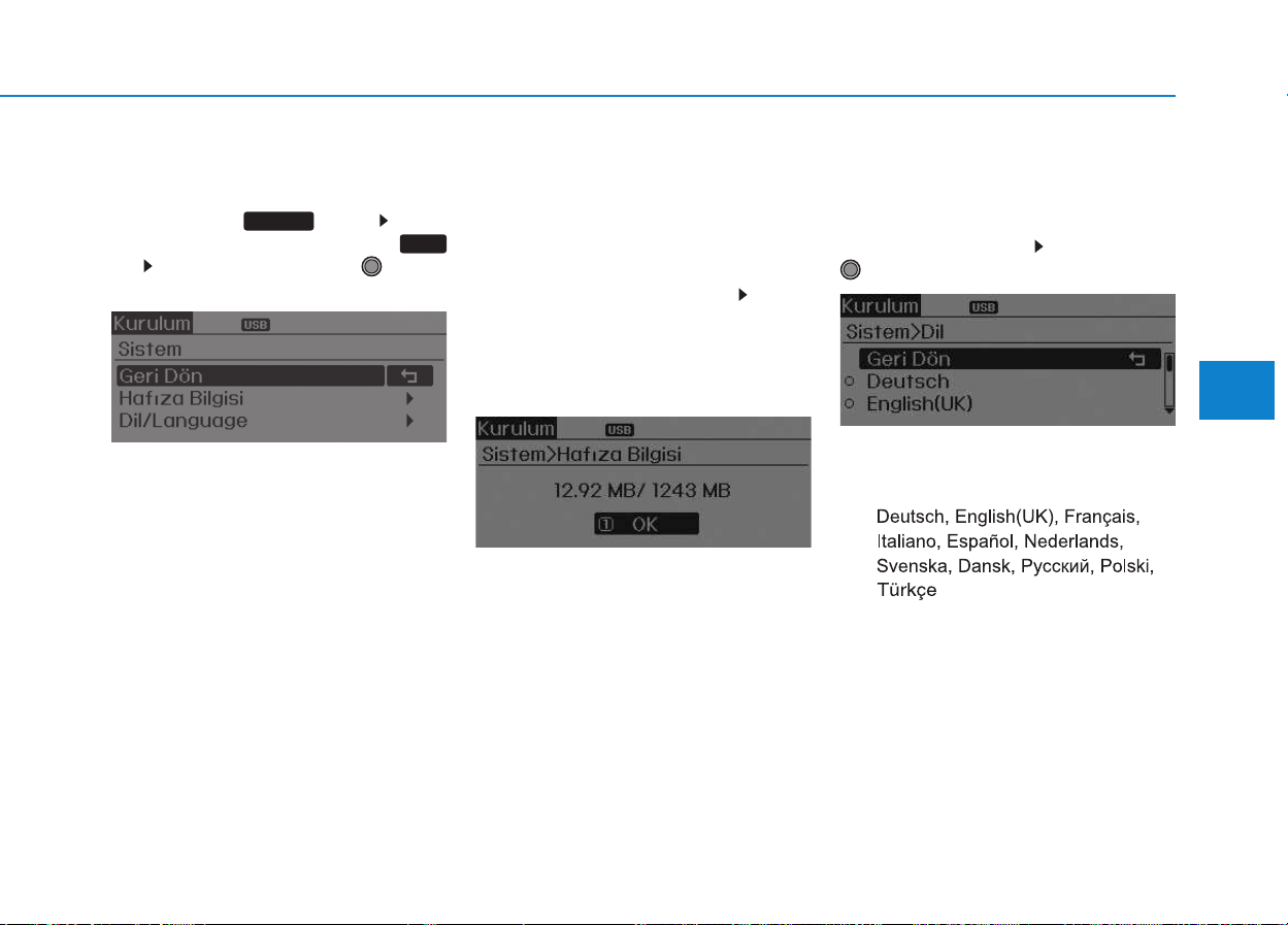
4-61
Multimedia System
4
System Settings
Press the key Select
[System] through tune knob or
key Select menu through TUNE
knob
Memory Information
(if equipped)
Displays currently used memory and
total system memory.
Select [Memory Information] OK
The currently used memory is dis-
played on the left side while the total
system memory is displayed on the
right side.
Language
This menu is used to set the display
and voice recognition language.
Select [Language] Set through
TUNE knob
❈ The system will reboot after the
language is changed.
❈ Language support by region
-
5
SETUP
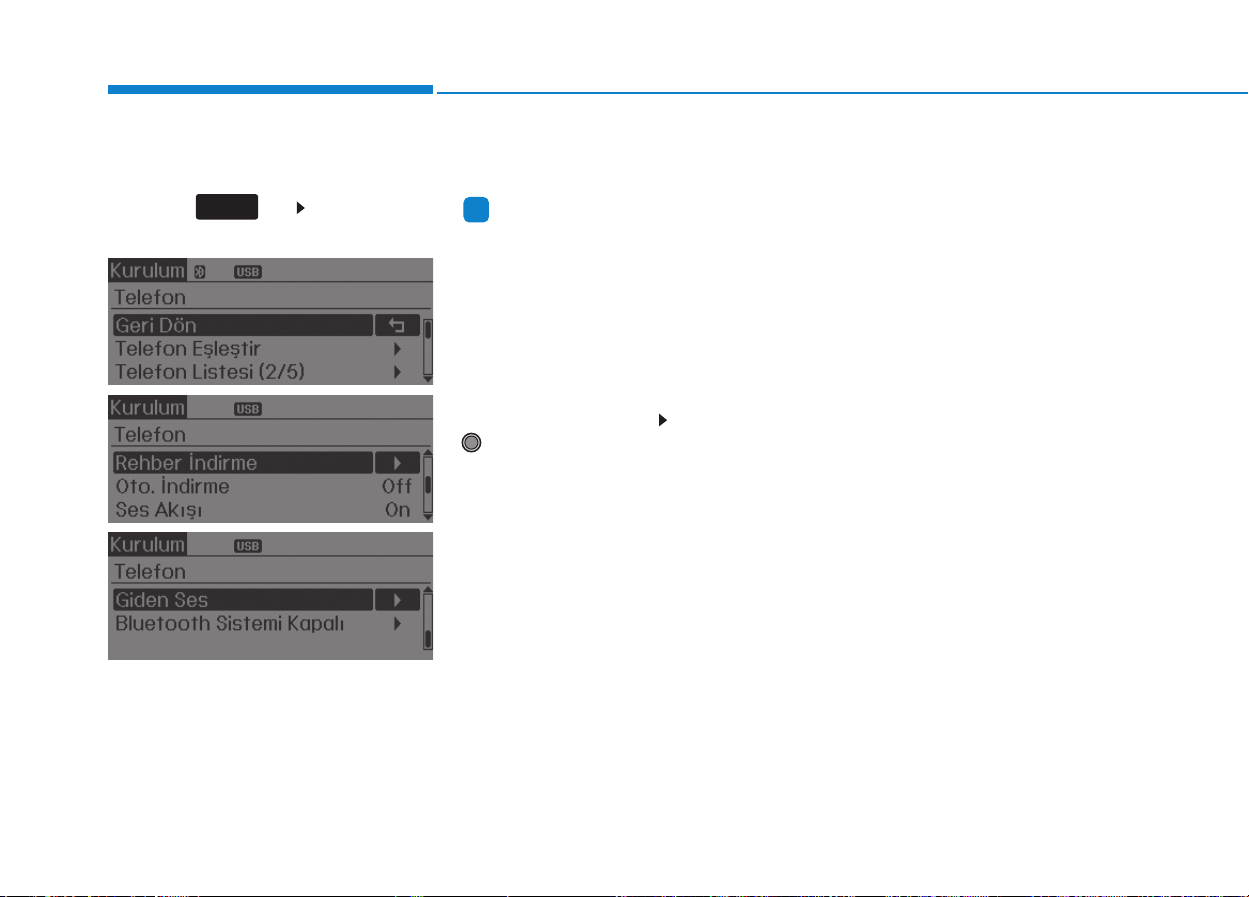
4-62
Multimedia System
Phone Setup (if equipped)
Press the key Select [Phone]
(for RDS model)
Pair Phone
Information
To pair a Bluetooth
®
Wireless
Technology enabled mobile phone,
authentication and connection
processes are first required. As a
result, you cannot pair your mobile
phone while driving the vehicle. First
park your vehicle before use.
Select [Pair Phone] Set through
TUNE knob
➀ Search for device names as dis-
played on your mobile phone and
connect.
➁ Input the passkey displayed on the
screen. (Passkey : 0000)
❈ The device name and passkey will
be displayed on the screen for up
to 3 minutes. If pairing is not com-
pleted within the 3 minutes, the
mobile phone pairing process will
automatically be canceled.
➂ Pairing completion is displayed.
❈ In some mobile phones, pairing
will automatically be followed by
connection.
❈ It is possible to pair up to five
Bluetooth
®
Wireless Technology
enabled mobile phones.
i
SETUP
CLOCK
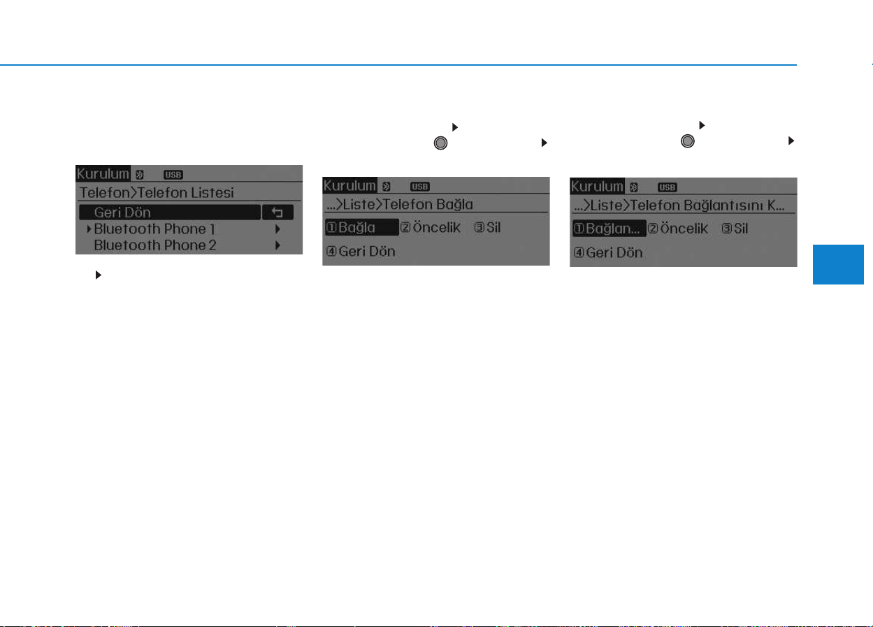
4-63
Multimedia System
4
Phone List
The names of up to 5 paired phones
will be displayed.
A [ ] is displayed in front of the cur-
rently connected phone.
Select the desired name to setup the
selected phone.
• Connecting a phone
Select [Phone List] Select mobile
phone through TUNE knob
Select [Connect Phone]
➀ Select a mobile phone that is not
currently connected.
➁ Connect the selected mobile
phone.
➂ Connection completion is dis-
played.
❈ If a phone is already connected,
disconnect the currently connect-
ed phone and select a new phone
to connect.
• Disconnecting a connected phone
Select [Phone List] Select mobile
phone through TUNE knob
Select [Disconnect Phone]
➀ Select the currently connected
mobile phone.
➁ Disconnect the selected mobile
phone.
➂ Disconnection completion is dis-
played.

4-64
Multimedia System
• Changing connection sequence
(Priority)
This is used to change the order (pri-
ority) of automatic connection for the
paired mobile phones.
Select [Phone List] Select [Priority]
through TUNE knob Select No. 1
Priority mobile phone
➀ Select [Priority].
➁ From the paired phones, select
the phone desired for No.1 priority.
➂ The changed priority sequence is
displayed.
❈ Once the connection sequence
(priority) is changed, the new no. 1
priority mobile phone will be con-
nected.
-when the no. 1 priority cannot be
connected: Automatically attempts
to connect the most recently con-
nected phone.
-Cases when the most recently
connected phone cannot be con-
nected: Attempts to connect in the
order in which paired phones are
listed.
-The connected phone will auto-
matically be changed to No. 1 pri-
ority.
• Delete
Select [Phone List] Select mobile
phone through TUNE knob
Select [Delete]
➀ Select the desired mobile phone.
➁ Delete the selected mobile phone.
➂ Deletion completion is displayed.
❈ When attempting to delete a cur-
rently connected phone, the
phone is first disconnected.
Information
• When you delete a mobile phone,
the mobile phone contacts will also
be erased.
• For stable Bluetooth
®
Wireless
Technology communication, delete
the mobile phone from the audio
and also delete the audio from your
mobile phone.
Phone book Download
(for RDS model)
This feature is used to download
phone book and call histories into
the audio system.
Select [Phone book Download]
Select through TUNE knob.
Information
• The download feature may not be
supported in some mobile phones.
• If a different operation is performed
while phone book is being down-
loaded, downloading will be discon-
tinued. Phone book already down-
loaded will be saved.
• When downloading new phone
book, delete all previously saved
phone book before starting down-
load.
Auto Download
When connecting a mobile phone, it
is possible to automatically download
new Contacts and Call Histories.
Select [Auto Download] Set /
through TUNE knob
Off
On
i
i

4-65
Multimedia System
4
Audio Streaming
Songs (files) saved in your
Bluetooth
®
Wireless Technology
enabled mobile phone can be played
through the audio system.
Select [Audio Streaming] Set /
through TUNE knob
Information
The Bluetooth
®
Wireless Technology
audio streaming feature may not be
supported in some mobile phones.
Outgoing Volume
This is used to set the volume of your
voice as heard by the other party
while on a
Bluetooth
®
Wireless
Technology enabled handsfree call.
Select [Outgoing Volume] Set vol-
ume through TUNE knob
❈ While on a call, the volume can be
changed by using the key.
Bluetooth
®
Wireless
Technology System Off
This feature is used when you do not
wish to use the
Bluetooth
®
Wireless
Technology system.
Select [Bluetooth System Off] Set
through TUNE knob
❈ If a phone is already connected,
disconnect the currently connect-
ed phone and turn the
Bluetooth
®
Wireless Technology system off.
Using the
Bluetooth
®
Wireless
Technology System
To use
Bluetooth
®
Wireless
Technology when the system is cur-
rently off, follow these next steps.
• Turning On
Bluetooth
®
Wireless
Technology through the
Key
Press the key Screen
Guidance
❈ Moves to the screen where
Bluetooth
®
Wireless Technology
functions can be used and dis-
plays guidance.
• Turning On
Bluetooth
®
Wireless
Technology through the
Key
Press the key Select
[Phone]
➀ A screen asking whether to turn on
Bluetooth
®
Wireless Technology will
be displayed.
➁ On the screen, select to turn
on
Bluetooth
®
Wireless Technology
and display guidance.
❈ If the
Bluetooth
®
Wireless
Technology system is turned on,
the system will automatically try to
connect the most recently con-
nected
Bluetooth
®
Wireless
Technology mobile phone.
YES
SETUP
CLOCK
SETUP
CLOCK
PHONE
PHONE
SEEK
TRACK
i
Off
On
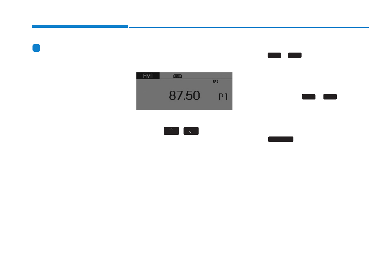
4-66
Multimedia System
Information
Bluetooth
®
Wireless Technology con-
nection may become intermittently
disconnected in some mobile phones.
Follow these next steps to try again.
1)Turn the Bluetooth
®
Wireless
Technology function within the
mobile phone ON/OFF and try to
connect again.
2)Turn the mobile phone power
ON/OFF and try to connect again.
3)Completely remove the mobile
phone battery, reboot, and then try
to connect again.
4)Reboot the audio system and try to
connect again
5)Delete all paired devices in your
mobile phone and the audio system
and pair again for use.
RRAADDIIOO ((ffoorr RRDDSS mmooddeell))
Changing RADIO mode
SEEK
Press the , key
• Shortly pressing the key (under 0.8
seconds): Changes the frequency.
• Pressing and holding the key (over
0.8 seconds): Automatically search-
es for the next frequency.
Preset SEEK
Press the ~ key
• Shortly pressing the key (under 0.8
seconds): Plays the frequency
saved in the corresponding key.
• Pressing and holding the key (over
0.8 seconds): Pressing and holding
the desired key from ~
will save the currently playing
broadcast to the selected key and
sound a BEEP.
SCAN
Press the key
• Pressing and holding the key (over
0.8 seconds): The broadcast fre-
quency increases and previews
each broadcast for 5 seconds each.
After scanning all frequencies,
returns and plays the current
broadcast frequency.
TA/SCAN
61
61
TRACK
SEEK
i
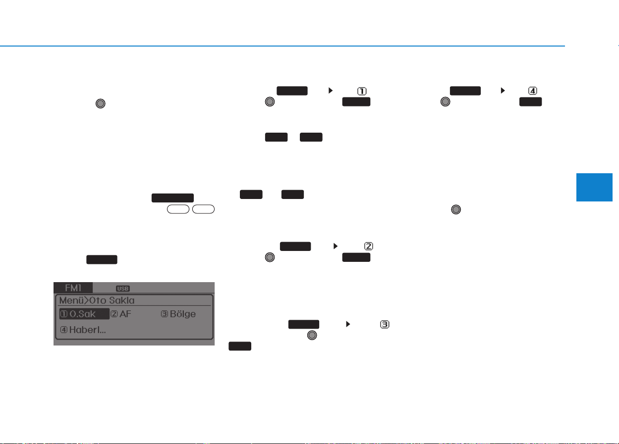
4-67
Multimedia System
4
Selecting through manual
search
Turn the TUNE knob left/right to
adjust the frequency.
• AC210MDEE
- FM : Changes by 50KHz
- AM : Changes by 9khz
Traffic Announcement (TA)
Shortly pressing the key
(under 0.8 seconds): Set /
TA Traffic Announcement) mode.
MENU
Within key are the A.Store
(Auto Store) and Info functions.
AST (Auto Store)
Press the key Set [ AST]
through TUNE knob or key.
Select AST (Auto Store) to save fre-
quencies with superior reception to
presets ~ . If no frequen-
cies are received, then the most
recently received frequency will be
broadcast.
❈ Saves only to the Preset memory
~ of FMA or AMA
mode.
AF (Alternative Frequency)
Press the key Set [ AF]
through TUNE knob or key.
The Alternative Frequency option
can be turned On/Off.
Region
Press the key Set [
Region] through TUNE knob or
key.
The Region option can be turned
On/Off.
News
Press the key Set [ News]
through TUNE knob or key.
The News option can be turned
On/Off.
Info Volume
Info Volume refers to the sound vol-
ume upon receiving News or Traffic
information.
The info volume can be controlled by
turning the VOL knob left/right while
a news or traffic broadcast is playing.
❈ AF, Region, and News are RDS
Radio menus.
4
MENU
3
MENU
2 RDM
MENU
61
61
1 RPT
MENU
MENU
OffOn
TA/SCAN
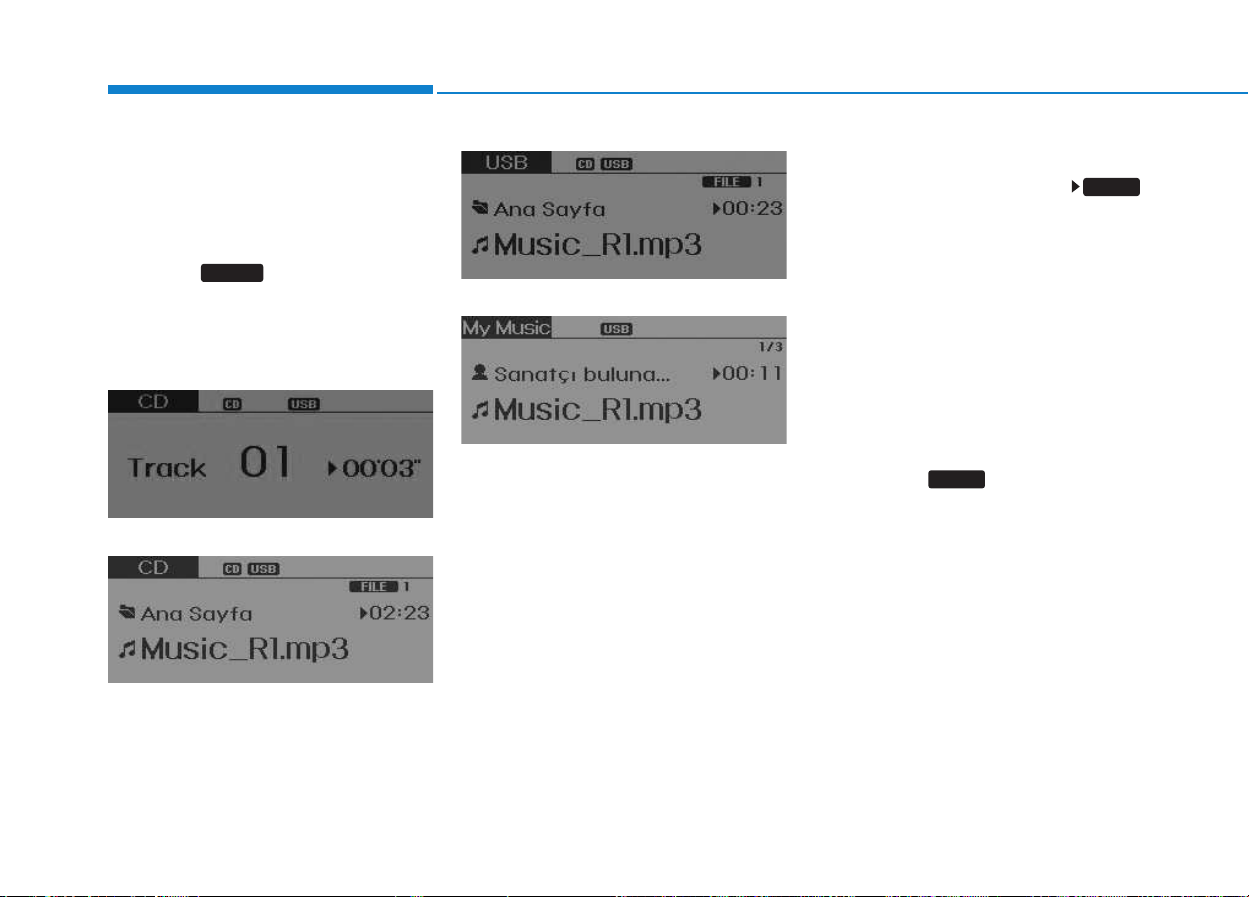
4-68
Multimedia System
BBAASSIICC MMEETTHHOODD OOFF UUSSEE ::
A
Auuddiioo CCDD // MMPP33 CCDD // UUSSBB //
i
iPPoodd
®®
// MMyy MMuussiicc
Press the key to change the
mod mode in order of CD ➟ USB(iPod
®
)
➟ AUX ➟ My Music ➟ BT Audio.
The folder/file name is displayed on
the screen.
<Audio CD>
<CD MP3>
<USB>
<My Music>
❈ The CD is automatically played
when a CD is inserted.
❈ The USB music is automatically
played when a USB is connected.
Repeat
While song (file) is playing
(RPT) key
Audio CD, MP3 CD, USB, iPod
®
, My
Music mode: RPT on screen
• To repeat one song (Shortly press-
ing the key (under 0.8 seconds)):
Repeats the current song.
MP3 CD, USB mode: FLD.RPT on
screen
• To repeat folder (pressing twice):
repeats all files within the current
folder.
❈ Press the key again to turn
off repeat.
1 RPT
1 RPT
MEDIA

4-69
Multimedia System
4
Random
While song (file) is playing
(RDM) key
Audio CD, My Music mode: RDM on
screen
• Random (Shortly pressing the key ):
Plays all songs in random order.
MP3 CD, USB mode: FLD.RDM on
screen
• Folder Random (Shortly pressing
the key): Plays all files within the
current folder in random order.
MP3 CD, USB mode: RDM on
screen
• Random (pressing twice): Plays all
files in random order.
iPod
®
mode: RDM on screen
• Random (press the key) : Plays all
files in random order.
❈ Press the key again to turn
off random.
Changing Song/File
While song (file) is playing
key
• Shortly pressing the key: Plays the
current song from the beginning.
❈ If the key is pressed again
within 1 second, the previous song
is played.
• Pressing and holding the key (over
0.8 seconds): Rewinds the song.
While song (file) is playing
,key
• Shortly pressing the key: Plays the
next song.
• Pressing and holding the key (over
0.8 seconds): Fast forwards the
song.
Scan (for RDS model)
While song (file) is playing
key
• Pressing and holding the key (over
0.8 seconds) : Scans all songs for
10 seconds starting from the next
song.
❈ Pressing and holding the
key again to turn off.
Scan
While song (file) is playing
key
• Shortly pressing the key (under 0.8
seconds) : Scans all songs from
the next song for 10 seconds each.
❈ Press the key again to turn
off.
❈ The SCAN function is not support-
ed in iPod
®
mode.
SCAN
SCAN
TA/SCAN
TA/SCAN
SEEK
TRACK
TRACK
2 RDM
2 RDM

4-70
Multimedia System
Folder Search : MP3 CD, USB
Mode
While file is playing /
(Folder Up) key
• Searches the next folder.
While file is playing /
(Folder Down) key
• Searches the parent folder.
❈ If a folder is selected by pressing
the TUNE knob, the first file
within the selected folder will be
played.
Searching Songs (File)
• Turning TUNE knob : Searches
for songs (files)
• Pressing TUNE knob : Plays
selected song (file).
MENU : Audio CD
Press the CD MP3 mode key
to set the Repeat, Random,
Information features.
Information features.
Repeat
Press the key Set [ RPT]
through the TUNE knob or
key to repeat the current song.
❈ Press RPT again to turn off.
Random
Press the key Set [ RDM]
through the TUNE knob or
key to randomly play songs within
the current folder.
❈ Press RDM again to turn off.
Information
Press the key Set [ Info]
through the TUNE knob or
key to display information of the cur-
rent song.
❈ Press the key to turn off
info display.
MENU
3
MENU
2
RDM
MENU
1
RPT
MENU
MENU
FOLDER
FOLDER
FOLDER
FOLDER
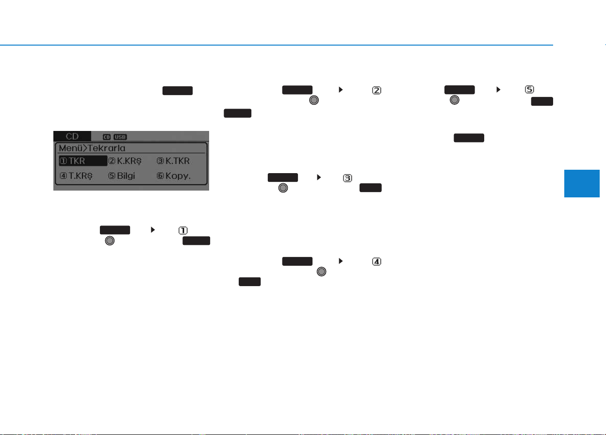
4-71
Multimedia System
4
MENU : MP3 CD / USB
Press the CD MP3 mode key
to set the Repeat, Folder Random,
Folder Repeat, All Random,
Information, and Copy features.
Information, and Copy features.
Repeat
Press the key Set [ RPT]
through the TUNE knob or
key to repeat the current song.
❈ Press RPT again to turn off.
Folder Random
Press the key Set [
F.RDM] through the TUNE knob or
key to randomly play songs
within the current folder.
❈ Press F.RDM again to turn off.
Folder Repeat
Press the key Set [ F.RPT]
through the TUNE knob or
key to repeat songs within the cur-
rent folder.
❈ Press F.RPT again to turn off.
All Random
Press the key Set [
A.RDM] through the TUNE knob
or key to randomly play all
songs within the CD.
❈ Press A.RDM again to turn off.
Information
Press the key Set [ Info]
through the TUNE knob or
key to display information of the cur-
rent song.
❈ Press the key to turn off
info display.
MENU
5
MENU
4
MENU
3
MENU
2 RDM
MENU
1 RPT
MENU
MENU
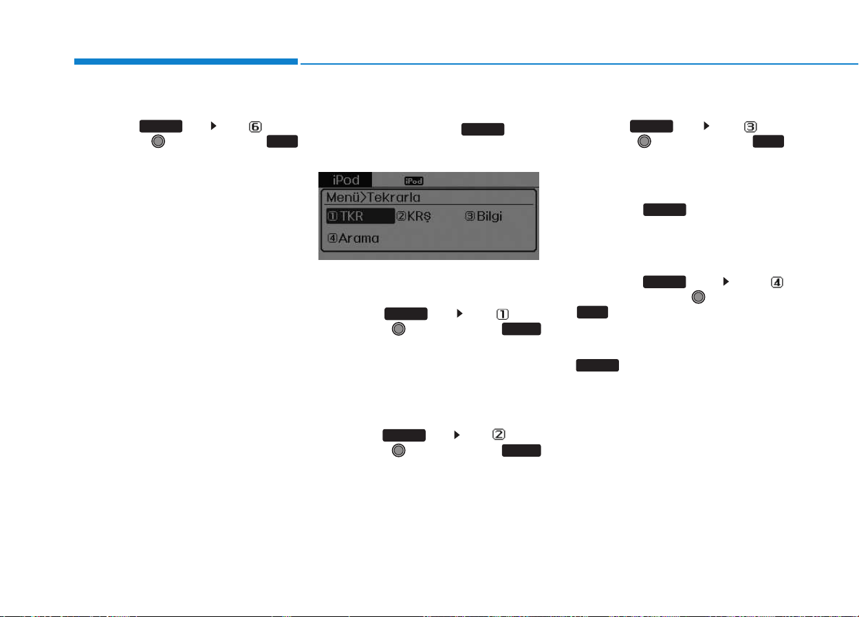
4-72
Multimedia System
Copy
Press the key Set [ Copy]
through the TUNE knob or
key.
This is used to copy the current
song into My Music. You can play
the copied Music in My Music
mode.
❈ If another key is pressed while
copying is in progress, a pop up
asking you whether to cancel
copying is displayed.
❈ If another media is connected or
inserted (USB, CD, iPod
®
, AUX)
while copying is in progress, copy-
ing is canceled.
❈ Music will not be played while
copying is in progress.
MENU : iPod
®
In iPod
®
mode, press the key to
set the Repeat, Random, Information
and Search features.
Repeat
Press the key Set [ RPT]
through the TUNE knob or
key to repeat the current song.
❈ Press RPT again to turn repeat
off.
Random
Press the key Set [ RDM]
through the TUNE knob or
key.
Plays all songs within the currently
playing category in random order.
❈ Press RDM again to turn off.
Information
Press the key Set [ Info]
through the TUNE knob or
key.
Displays information of the current
song.
❈ Press the key to turn off
info display.
Search
Press the key Set [
Search] through the TUNE knob
or key.
Displays iPod
®
category list.
❈ Searching iPod
®
category is
key pressed, move to par-
ent category.
MENU
4
MENU
MENU
3
MENU
2 RDM
MENU
1 RPT
MENU
MENU
6
MENU

4-73
Multimedia System
4
MENU : My Music Mode
(if equipped)
In My Music mode, press the
key to set the Repeat, Random,
Information, Delete, Delete All, and
Delete Selection features.
Repeat
Press the key Set [ RPT]
through the TUNE knob or
key.
Repeats the currently playing song.
❈ Press RPT again to turn repeat off.
Random
Press the key Set [ RDM]
through the TUNE knob or
key.
Plays all songs in random order.
❈ Press RDM again to turn random
off.
Information
Press the key Set [ Info]
through the TUNE knob or
key.
Displays information of the current
song.
❈ Press the key to turn off
info display.
Delete
Press the key Set [ Delete]
through the TUNE knob or
key.
Deletes currently playing file
In the play screen, pressing delete
will delete the currently playing
song.
Deletes file from list
➀ Select the file you wish to delete
by using the TUNE knob.
➁ Press the key and select
the delete menu to delete the
selected file.
MENU
4
MENU
MENU
3
MENU
2
RDM
MENU
1
RPT
MENU
MENU
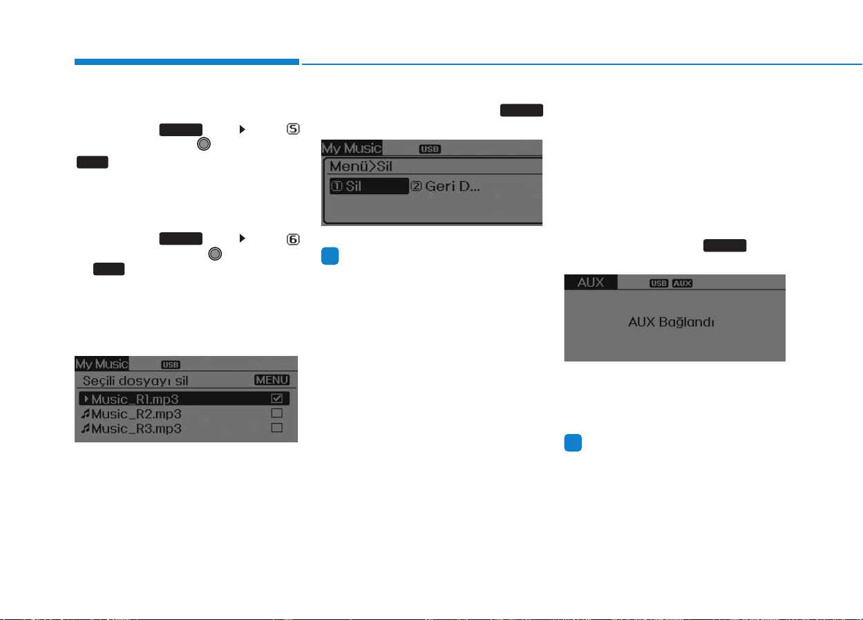
4-74
Multimedia System
Delete All
Press the key Set [
Del.All] through the TUNE knob or
key.
Deletes all songs of My Music.
Delete Selection
Press the key Set [
Del.Sel] through the TUNE knob
or key.
Songs within My Music are selected
and deleted.
➀ Select the songs you wish to
delete from the list.
➁ After selecting, press the
key and select the delete menu.
Information
- Using the My Music
• Even if memory is available, a max-
imum of 6,000 songs can be stored.
• The same song can be copied up to
1,000 times.
• Memory info can be checked in the
System menu of Setup.
AUX
AUX is used to play external MEDIA
currently connected with the AUX
terminal.
AUX mode will automatically start
when an external device is connect-
ed with the AUX terminal.
If an external device is connected,
you can also press the key to
change to AUX mode.
❈ AUX mode cannot be started
unless there is an external device
connected to the AUX terminal.
Information
- using THE AUX
Fully insert the AUX cable into the
AUX terminal for use.
i
MEDIA
i
MENU
6
MENU
5
MENU

4-75
Multimedia System
4
BBlluueettooootthh
®®
WWiirreelleessss
T
Teecchhnnoollooggyy AAUUDDIIOO MMOODDEE
(
(IIff eeqquuiippppeedd))
What is
Bluetooth
®
Wireless
Technology?
Bluetooth
®
Wireless Technology
allows devices to be connected in a
short distance, including hands-free
devices, stereo headsets, wireless
remote controllers, etc. For more
information, visit the
Bluetooth
®
Wireless Technology website at
www.Bluetooth.com
Before using
Bluetooth
®
Wireless
Technology audio features
•
Bluetooth
®
Wireless Technology
audio may not be supported
depending on the compatibility of
your
Bluetooth
®
Wireless
Technology mobile phone.
• In order to use
Bluetooth
®
Wireless
Technology audio, you must first
pair and connect the
Bluetooth
®
Wireless Technology mobile
phone.
• The
Bluetooth
®
word mark and
logos are registered trademarks
owned by
Bluetooth
®
SIG, Inc. and
any use of such marks is under
license. Other trademarks and trade
names are those of their respective
owners. A
Bluetooth
®
enabled cell
phone is required to use
Bluetooth
®
Wireless Technology
•
Bluetooth
®
Wireless Technology
audio can be used only when the
[Audio Streaming] of Phone is
turned On.
❈ Setting
Bluetooth
®
Wireless
Technology Audio Streaming :
Press the key Select
[Phone] through the tune knob
Select [Audio Streaming] through
the TUNE knob Set /
Starting
Bluetooth
®
Wireless
Technology Audio
• Press the key to change
the mode in order of CD ➟ USB ➟
AUX ➟ My Music ➟ BT Audio.
• If BT Audio is selected,
Bluetooth
®
Wireless Technology audio will
start playing.
❈ Audio may not automatically start
playing in some mobile phones.
MEDIA
OffOn
SETUP
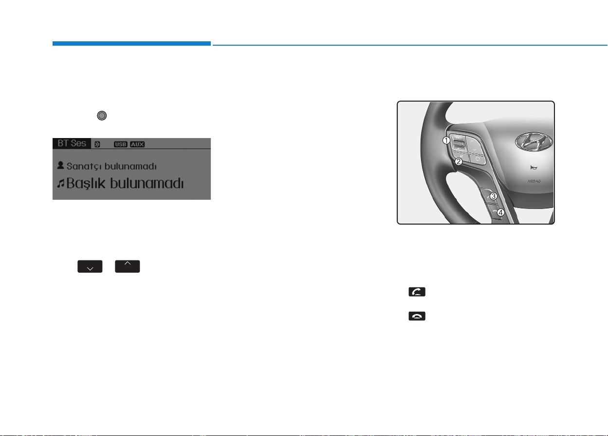
4-76
Multimedia System
Using the
Bluetooth
®
Wireless
Technology audio features
• Play / Pause
Press the TUNE knob to play and
pause the current song.
❈ The title / artist info may not be
supported in some mobile phone.
When it is not supported, no title /
no artist will be displayed.
• Previous / Next song
Press of to play previous or
next song.
❈ The previous song / next song /
play / pause functions may not be
supported in some mobile
phones.
PPHHOONNEE ((iiff eeqquuiippppeedd))
Before using the
Bluetooth
®
Wireless
Technology
phone features
• In order to use
Bluetooth
®
Wireless
Technology
phone, you must first
pair and connect the
Bluetooth
®
Wireless Technology
mobile phone.
• If the mobile phone is not paired or
connected, it is not possible to
enter Phone mode. Once a phone
is paired or connected, the guid-
ance screen will be displayed.
• If Priority is set upon vehicle igni-
tion (IGN/ACC ON), the
Bluetooth
®
Wireless Technology
phone will be
automatically connected. Even if
you are outside, the
Bluetooth
®
Wireless Technology
phone will be
automatically connected once you
are in the vicinity of the vehicle. If you
do not want automatic
Bluetooth
®
Wireless Technology
phone connec-
tion, set the
Bluetooth
®
Wireless
Technology
power to OFF.
Making a call using the Steering
wheel remote controller
1. VOLUME button : Raises or low-
ers speaker volume.
2. MUTE button : Mute the micro-
phone during a call.
3. button : Places and transfers
calls.
4. button : Ends calls or cancels
functions.
SEEK
TRACK
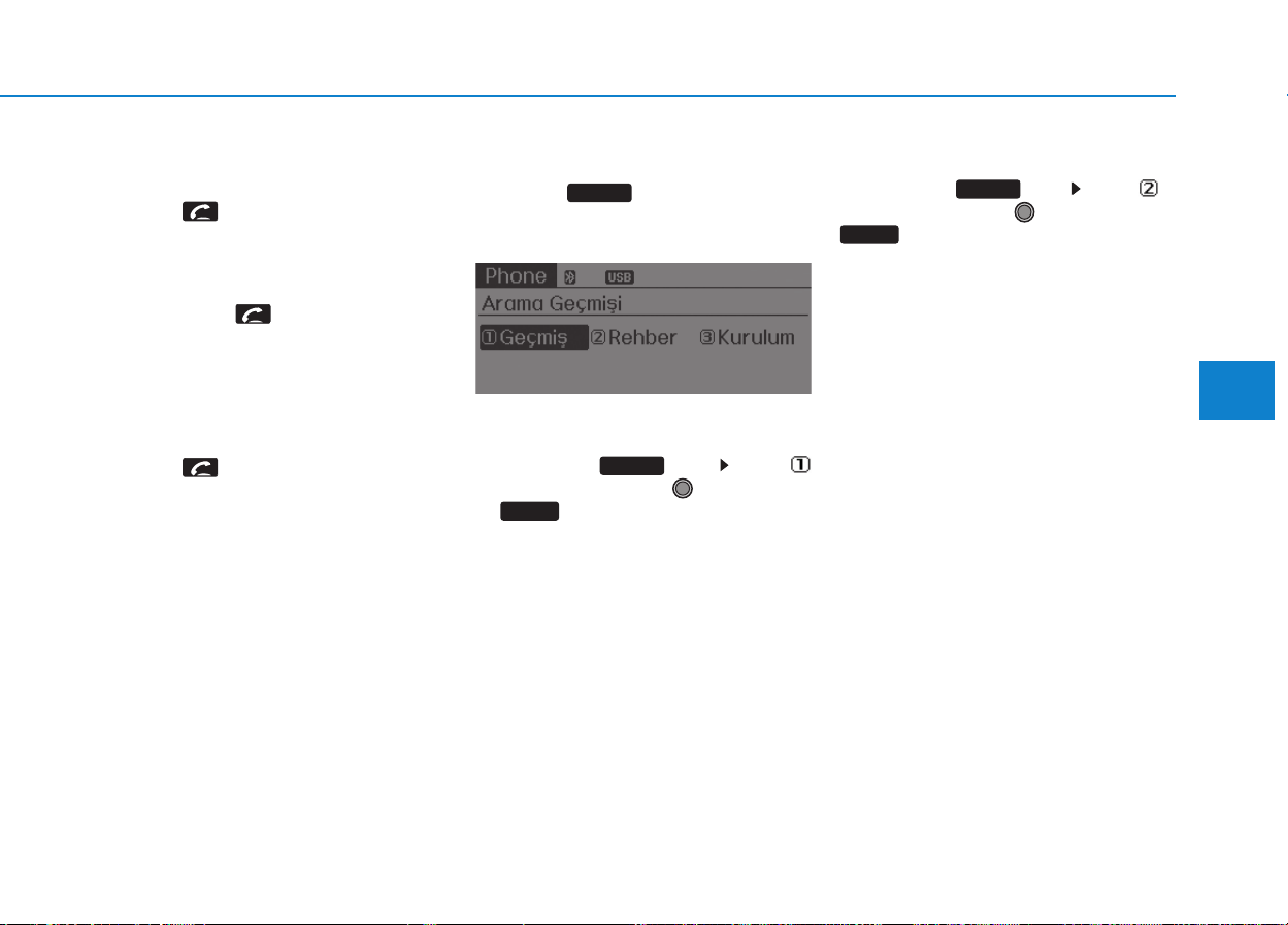
4-77
Multimedia System
4
• Check call history and making call
➀ Shortly press (under 0.8 seconds)
the key on the steering
remote controller.
➁ The call history list will be dis-
played on the screen.
➂ Press the key again to con-
nect a call to the selected number.
• Redialing the most recently called
number
➀ Press and hold (over 0.8 seconds)
the key on the steering
remote controller.
➁ The most recently called number
is redialed.
Phone MENU (for RDS model)
Press the key to display three
menus (Call History, Phone Book,
Phone Setup).
Call
histo
ry
Press the key Set [
History] through the TUNE knob
or key.
The call history is displayed and can
be used to select a number and
make a call.
If call history does not exist, a screen
asking whether to download call his-
tory is displayed. (The download fea-
ture may not be supported in some
mobile phones)
Phone Book
Press the key Set [ P.
Book] through the TUNE knob or
key.
The phone book is displayed and
can be used to select a number and
make a call.
❈ If more than one number is saved
to one contact, then a screen
showing the mobile phone num-
ber, Home and office number is
displayed. Select the desired num-
ber to make the call.
❈ If phone book do not exist, a
screen asking whether to down-
load phone book is displayed.
(The download feature may not be
supported in some mobile
phones)
2 RDM
PHONE
1 RPT
PHONE
PHONE

4-78
Multimedia System
Phone Setup
Press the key Set [ Setup]
through the TUNE knob or
key.
The
Bluetooth
®
Wireless Technology
mobile phone setup screen is dis-
played. For more information, refer to
“Phone Setup”.
Information
- using THE
Bluetooth
®
Wireless Technology CELLU-
LAR PHONE
• Do not use a cellular phone or per-
form Bluetooth
®
Wireless Technology
settings (e.g. pairing a phone) while
driving.
• Some Bluetooth
®
Wireless
Technology -enabled phones may not
be recognized by the system or fully
compatible with the system.
• Before using Bluetooth
®
Wireless
Technology related features of the
audio system, refer your phone’s
User’s Manual for phone-side
Bluetooth
®
Wireless Technology oper-
ations.
• The phone must be paired to the
audio system to use Bluetooth
®
Wireless Technology related features.
• You will not be able to use the hands-
free feature when your phone (in the
vehicle) is outside of the cellular serv-
ice area (e.g. in a tunnel, in a under-
ground, in a mountainous area, etc.).
(Continued)
(Continued)
• If the cellular phone signal is poor or
the vehicles interior noise is too loud,
it may be difficult to hear the other
person’s voice during a call.
• Do not place the phone near or inside
metallic objects, otherwise communi-
cations with Bluetooth
®
Wireless
Technology system or cellular service
stations can be disturbed.
• While a phone is connected through
Bluetooth
®
Wireless Technology your
phone may discharge quicker than
usual for additional Bluetooth
®
Wireless Technology-related opera-
tions.
• Some cellular phones or other devices
may cause interference noise or mal-
function to audio system. In this case,
store the device in a different location
may resolve the condition.
• Phone contact names should be saved
in English or they may not be dis-
played correctly.
(Continued)
i
3
PHONE

4-79
Multimedia System
4
(Continued)
• If Priority is set upon vehicle igni-
tion(IGN/ACC ON), the Bluetooth
®
Wireless Technology phone will be
automatically connected.
Even if you are outside, the
Bluetooth
®
Wireless Technology
phone will be automatically connect-
ed once you are in the vicinity of the
vehicle.
If you do not want automatic
Bluetooth
®
Wireless Technology con-
nection, turn the Bluetooth
®
Wireless
Technology feature off.
• The hands-free call volume and qual-
ity may differ depending on the
mobile phone type.
• Bluetooth
®
Wireless Technology fea-
tures can be used only when the
mobile phone has been paired and
connected with the device. For more
information on pairing and connect-
ing Bluetooth
®
Wireless Technology
enabled mobile phones, refer to the
“Phone Setup” section.
(Continued)
(Continued)
• When a Bluetooth
®
Wireless
Technology mobile phone is connect-
ed, a ( ) icon will appear at the top
of the screen. If a ( ) icon is not dis-
played, this indicates that a
Bluetooth
®
Wireless Technology
enabled device has not been connect-
ed. You must connect the device
before use. For more information on
Bluetooth
®
Wireless Technology
mobile phones, refer to the “Phone
Setup” section.
• Pairing and connecting a Bluetooth
®
Wireless Technology enabled mobile
phone will work only when the
Bluetooth
®
Wireless Technology
option within your mobile phone has
been turned on. (Methods of turning
on the Bluetooth
®
Wireless
Technology enabled feature may dif-
fer depending on the mobile phone.)
(Continued)
(Continued)
• In some mobile phones, starting the
ignition while talking through
Bluetooth
®
Wireless Technology
enabled handsfree call will result in
the call becoming disconnected.
(Switch the call back to your mobile
phone when starting the ignition.)
• Some features may not be supported
in some Bluetooth
®
Wireless
Technology mobile phone and
devices.
• Bluetooth
®
Wireless Technology
enabled operation may be unstable
depending on the communication
state.
• Placing the audio system within an
electromagnetic environment may
result in noise interference.

Driving your vehicle
Before driving.........................................................5-3
Before entering the vehicle ...........................................5-3
Necessary inspections .....................................................5-3
Before starting...................................................................5-3
Key positions ..........................................................5-5
Illuminated ignition switch...............................................5-5
Ignition switch position....................................................5-5
Starting the engine...........................................................5-6
ISG (Idle stop and go) system..............................5-8
Auto stop.............................................................................5-9
Auto start..........................................................................5-10
Condition of ISG system operation.............................5-11
ISG system deactivation ................................................5-12
ISG system malfunction.................................................5-13
Manual transmission............................................5-14
Manual transmission operation ...................................5-14
Using the clutch...............................................................5-16
Downshifting ....................................................................5-16
Good driving practices...................................................5-17
Brake system........................................................5-18
Power brakes ...................................................................5-18
Parking brake...................................................................5-19
Anti-lock brake system (ABS) .....................................5-21
Vehicle dynamic control (VDC) ....................................5-24
Hill-start assist control (HAC)......................................5-27
Emergency stop signal (ESS) .......................................5-28
Good braking practices..................................................5-29
Cruise control system..........................................5-30
Cruise control operation................................................5-31
Adjustable speed limit device (ASLD)...............3-34
To set speed limit ............................................................5-34
To turn off the speed limit control, do one of
the following ....................................................................5-36
Lane departure warning system (LWDS) .........5-37
LDWS operation...............................................................5-38
Warning indicator............................................................5-39
Active eco system................................................5-40
Active eco operation ......................................................5-40
When active eco is activated: ......................................5-41
Limitation of active eco operation: ............................5-41
PTO switch ............................................................5-41
To activate the P.T.O system ........................................5-41
To deactivate the P.T.O system....................................5-41
Economical operation..........................................5-42
Special driving conditions...................................5-44
Winter driving.......................................................5-48
Trailer towing .......................................................5-52
Safety chains ...................................................................5-54
Trailer brakes ...................................................................5-54
Driving with a trailer ......................................................5-55
Maintenance when trailer towing...............................5-58
If you do decide to pull a trailer.................................5-59
Vehicle weight ......................................................5-62
Locking differential .............................................5-63
5

5-2
Driving your vehicle
ENGINE EXHAUST CAN BE DANGEROUS!
Engine exhaust fumes can be extremely dangerous. If, at any time, you smell exhaust fumes inside the vehicle,
open the windows immediately.
Do not inhale exhaust fumes.
Exhaust fumes contain carbon monoxide, a colorless, odorless gas that can cause unconsciousness and death by
asphyxiation.
Be sure the exhaust system does not leak.
The exhaust system should be checked whenever the vehicle is raised to change the oil or for any other purpose.
If you hear a change in the sound of the exhaust or if you drive over something that strikes the underneath side of
the vehicle, we recommend that the system be checked by an authorized HYUNDAI dealer.
Do not run the engine in an enclosed area.
Letting the engine idle in your garage, even with the garage door open, is a hazardous practice. Never run the
engine in your garage any longer than it takes to start the engine and back the vehicle out.
Avoid idling the engine for prolonged periods with people inside the vehicle.
If it is necessary to idle the engine for a prolonged period with people inside the vehicle, be sure to do so only in
an open area with the air intake set at "Fresh" and fan operating at one of the higher speeds so fresh air is drawn
into the interior.
If you must drive with the tailgate open because you are carrying objects that make this necessary:
1. Close all windows.
2. Open side vents.
3. Set the air intake control at "Fresh", the air flow control at "Floor" or "Face" and the fan at one of the higher
speeds.
To assure proper operation of the ventilation system, be sure the ventilation air intakes located just in front of the
windshield are kept clear of snow, ice, leaves or other obstructions.
WARNING

5-3
Driving your vehicle
BBEEFFOORREE DDRRIIVVIINNGG
5
Before entering the vehicle
• Be sure that all windows, outside
mirror(s), and outside lights are
clean.
• Check the condition of the tires.
• Check under the vehicle for any
sign of leaks.
• Be sure there are no obstacles
behind you if you intend to back up.
Necessary inspections
Fluid levels, such as engine oil,
engine coolant, power steering fluid,
brake fluid, and washer fluid should
be checked on a regular basis, with
the exact interval depending on the
fluid. Further details are provided in
Section 7, “Maintenance”.
Before starting
• Close and lock all doors.
• Position the seat so that all con-
trols are easily reached.
• Adjust the inside and outside
rearview mirrors.
• Be sure that all lights work.
• Check all gauges.
• Check the operation of warning
lights when the ignition switch is
turned to the ON position.
• Release the parking brake and
make sure the brake warning light
goes out.
For safe operation, be sure you are
familiar with your vehicle and its
equipment.
Driving while distracted can
result in a loss of vehicle con-
trol, that may lead to an acci-
dent, severe personal injury,
and death. The driver’s primary
responsibility is in the safe and
legal operation of a vehicle, and
use of any handheld devices,
other equipment, or vehicle sys-
tems which take the driver’s
eyes, attention and focus away
from the safe operation of a
vehicle or which are not permis-
sible by law should never be
used during operation of the
vehicle.
WARNING
5-4
Driving your vehicle
Always check the surrounding
areas near your vehicle for peo-
ple, especially children, before
putting a vehicle into “Drive” or
“Reverse”.
WARNING
Driving under the influence of
alcohol or drugs
Drinking and driving is danger-
ous. Drunk driving is the num-
ber one contributor to the high-
way death toll each year. Even a
small amount of alcohol will
affect your reflexes, percep-
tions and judgment. Driving
while under the influence of
drugs is as dangerous or more
dangerous than driving drunk.
You are much more likely to
have a serious accident if you
drink or take drugs and drive.
If you are drinking or taking
drugs, don’t drive. Do not ride
with a driver who has been
drinking or taking drugs.
Choose a designated driver or
call a cab.
WARNING
All passengers must be proper-
ly belted whenever the vehicle
is moving. Refer to “Seat belts”
in section 3 for more informa-
tion on their proper use.
WARNING
• When you intend to park or
stop the vehicle with the
engine on, be careful not to
depress the accelerator pedal
for a long period of time. It
may overheat the engine or
exhaust system and cause
fire.
• When you make a sudden
stop or turn the steering
wheel rapidly, loose objects
may drop on the floor and it
could interfere with the opera-
tion of the foot pedals, possi-
bly causing an accident. Keep
all things in the vehicle safely
stored.
• If you do not focus on driving,
it may cause an accident. Be
careful when operating what
may disturb driving such as
audio or heater. It is the
responsibility of the driver to
always drive safely.
WARNING

5-5
Driving your vehicle
Illuminated ignition switch
(if equipped)
Whenever a front door is opened, the
ignition switch will be illuminated for
your convenience, provided the igni-
tion switch is not in the ON position.
The light will go off immediately
when the ignition switch is turned on
or go off after about 30 seconds
when the door is closed.
Ignition switch position
LOCK
The steering wheel locks to protect
against theft. The ignition key can be
removed only in the LOCK position.
When turning the ignition switch to
the LOCK position, push the key
inward at the ACC position and turn
the key toward the LOCK position.
ACC (Accessory)
The steering wheel is unlocked and
electrical accessories are operative.
If difficulty is experienced turning
the ignition switch to the ACC
position, turn the key while turn-
ing the steering wheel right and
left to release the tension.
ON
The warning lights can be checked
before the engine is started. This is
the normal running position after the
engine is started.
Do not leave the ignition switch ON if
the engine is not running to prevent
battery discharge.
START
Turn the ignition key to the START
position to start the engine. The
engine will crank until you release
the key; then it returns to the ON
position. The brake warning lamp
can be checked in this position.
NOTICE
5
KKEEYY PPOOSSIITTIIOONNSS
OTF050002

5-6
Starting the engine
Driving your vehicle
Ignition key
• Never turn the ignition switch
to LOCK or ACC while the vehi-
cle is moving. This would result
in loss of directional control
and braking function, which
could cause an accident.
• The anti-theft steering column
lock is not a substitute for the
parking brake. Before leaving
the driver’s seat, always make
sure the shift lever is engaged
in 1st gear for the manual
transmission, set the parking
brake fully and shut the
engine off. Unexpected and
sudden vehicle movement
may occur if these precau-
tions are not taken.
(Continued)
WARNING
(Continued)
• Never reach for the ignition
switch, or any other controls
through the steering wheel
while the vehicle is in motion.
The presence of your hand or
arm in this area could cause a
loss of vehicle control, an
accident and serious bodily
injury or death.
• Do not place any movable
objects around the driver’s
seat as they may move while
driving, interfere with the driv-
er and lead to an accident.
• Always wear appropriate
shoes when operating your
vehicle. Unsuitable shoes
(high heels, ski boots,etc.)
may interfere with your ability
to use the brake and accelera-
tor pedal, and the clutch.
• Do not start the vehicle with
the accelerator pedal
depressed. The vehicle can
move and lead to an accident.
• Wait until the engine rpm is
normal. The vehicle may sud-
denly move if the brake padel
is released when the rpm is
high.
WARNING

5-7
Driving your vehicle
Kick down mechanism
(if equipped)
If your vehicle is equipped with a
kick down mechanism in the
accelerator pedal, it prevents you
from driving at full throttle unin-
tentionally by making the driver
require increased effort to
depress the accelerator pedal.
However, if you depress the pedal
more than approximately 80%, the
vehicle can be at full throttle and
the accelerator pedal will be easi-
er to depress. This is not a mal-
function but a normal condition.
To start the diesel engine when the
engine is cold, it has to be pre-heat-
ed before starting the engine and
then have to be warmed up before
starting to drive.
1. Make sure the parking brake is
applied.
2. Depress the clutch pedal fully and
shift the transmission into Neutral.
Keep the clutch pedal and brake
pedal depressed while turning the
ignition switch to the start position.
3. Turn the ignition switch to the ON
position to pre-heat the engine.
Then the glow indicator light will
illuminate.
4. If the glow indicator light goes out,
turn the ignition switch to the
START position and hold it there
until the engine starts (a maximum
of 10 seconds), then release the
key.
NOTICE
5
W-60
Glow indicator light
5-8
If the engine were not started
within 10 seconds after the pre-
heating is completed, turn the
ignition key once more to the
LOCK position during 10 seconds,
and then to the ON position, in
order to preheat again.
Starting and stopping the engine
for turbocharger intercooler
1. Do not race or accelerate the
engine immediately after starting.
If the engine is cold, idle for sever-
al seconds before sufficient lubri-
cation is ensured in the tur-
bocharger unit.
2. After high speed or extended driv-
ing, requiring a heavy engine load,
idle the engine about 1 minute
before turning it off.
This idle time will allow the tur-
bocharger to cool prior to shutting
the engine off.
Your vehicle may be equipped with
the ISG system, which reduces fuel
consumption by automatically shut-
ting down the engine, when the vehi-
cle is at a standstill. (For example :
red light, stop sign and traffic jam)
The engine starts automatically as
soon as the starting conditions are
met.
The ISG system is ON whenever the
engine is running.
When the engine automatically
starts by the ISG system, some
warning lights (ABS, VDC, VDC
OFF, EBD) may turn on for a few
seconds.
This happens because of low bat-
tery voltage. It does not mean the
system is malfunctioning.
NOTICE
NOTICE
Driving your vehicle
Do not turn the engine off
immediately after it has been
subjected to a heavy load.
Doing so may cause severe
damage to the engine or turbo
charger unit.
CAUTION
IISSGG ((IIDDLLEE SSTTOOPP AANNDD GGOO))
S
SYYSSTTEEMM ((IIFF EEQQUUIIPPPPEEDD))
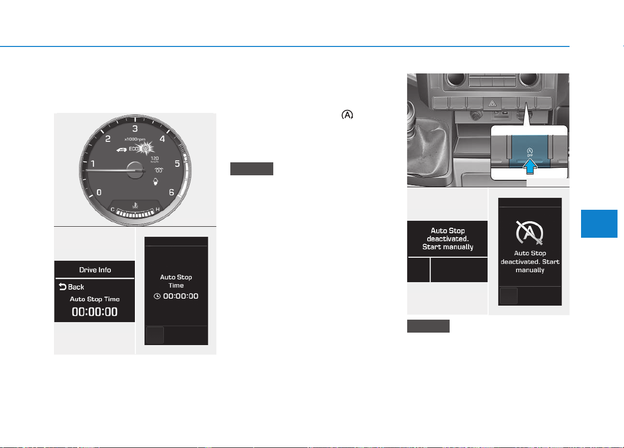
5-9
Driving your vehicle
Auto stop
To stop the engine in idle stop
mode
1. Decrease the vehicle speed to
less than 5 km/h.
2. Shift into N (Neutral) position.
3. Release the clutch pedal.
The engine will stop and the green
AUTO STOP indicator ( ) on the
instrument cluster will illuminate.
Also, a message "Auto Stop Time"
will appear on the LCD display.
You must reach a speed of at least
10km/h since last idle stop.
If you unfasten the seat belt or
open the driver's door(or engine
hood) in auto stop mode, the light
on the ISG OFF button will illumi-
nate and ISG system is deactivat-
ed. (continued)
NOTICE
NOTICE
5
OEU044193
■ Type A ■ Type B
OEU044133/OEU044156
OEU054019
■ Type A ■ Type B
OEU044129/OEU044150

5-10
Driving your vehicle
(continued)
Also, a message "Auto Stop deac-
tivated. start manually will appear
on the LCD display. Turn the igni-
tion switch to the START position
to start the engine manually. Or if
you fasten the seat belt or close
the driver's door(or engine hood),
ISG system will be activate.
Auto start
To restart the engine from idle
stop mode
• Press the clutch pedal when the
shift lever is in the N (Neutral) posi-
tion.
The engine will start and the green
AUTO STOP indicator ( ) on the
instrument cluster will go out.
The engine will also restart
automatically without the dri-
ver’s any actions if the following
occurs:
- The fan speed of manual climate
control system is set above the 3rd
position when the air conditioning is
on.
- When a certain amount of time has
passed with the climate control sys-
tem on.
- The fan speed of manual climate
control system is set above the 1st
position when the defroster is on.
- The brake vacuum pressure is low.
- The battery charging status is low.
- The vehicle speed exceeds 5 km/h.
The green AUTO STOP indicator
( ) on the instrument cluster will
blink for 5 seconds and a message
"Auto Start" will appear on the LCD
display.
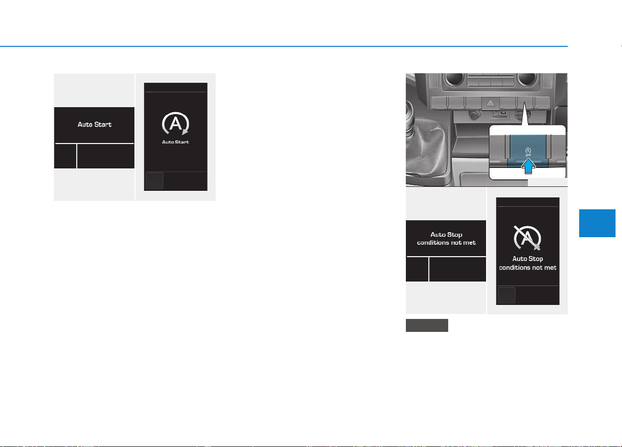
5-11
Driving your vehicle
Also, a message "Auto Stop deacti-
vated. Start manually" will appear on
the LCD display.
Condition of ISG system oper-
ation
The ISG system will operate
under the following condition:
- The driver’s seat belt is fastened.
- The driver’s door and hood are
closed.
- The brake vacuum pressure is ade-
quate.
- The battery is sufficiently charged.
- The outside temperature is
between 2°C to 35°C.
- The engine coolant temperature is
not too low.
- The fan speed of manual climate
control system is set below the 3rd
position when the air conditioning is
on.
- The defroster is off
• If the ISG system does not meet
that operation condition, the ISG
system is deactivated.
(continued)
NOTICE
5
■ Type A ■ Type B
OEU044234/OEU044235
OEU044193
■ Type A ■ Type B
OEU044236/OEU044237
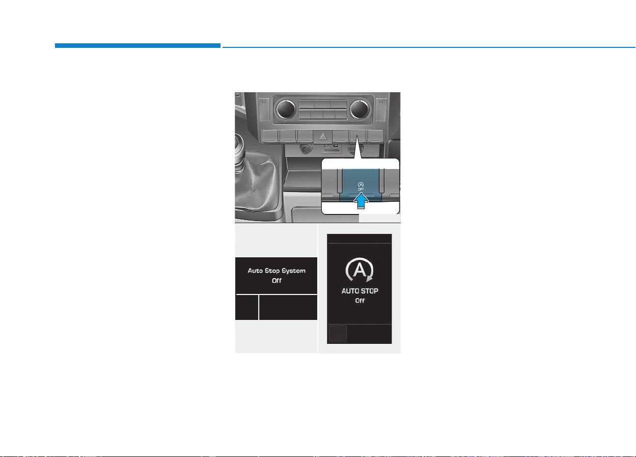
5-12
Driving your vehicle
(continued)
The light on the ISG OFF button
will illuminate and a message
"Auto Stop condition not met"
will appear on the LCD display.
• If the light or notice is come on
continuously, please check the
operation condition.
ISG system deactivation
• If you desire to deactivate the ISG
system, press the ISG OFF button.
The light on the ISG OFF button
will illuminate and a message
"Auto Stop System Off" will appear
on the LCD display.
• If you press the ISG OFF button
again, the system will be activated
and the light on the ISG OFF but-
ton will turn off.
OEU044193
■ Type A ■ Type B
OEU044238/OEU044239

5-13
Driving your vehicle
5
ISG system malfunction
The system may not operate
when:
- The ISG related sensors or system
error occurs.
The yellow AUTO STOP indicator
( ) on the instrument cluster will
stay on after blinking for 5 seconds
and the light on the ISG OFF button
will illuminate.
• If the ISG OFF button light is not
turned off by pressing the ISG
OFF button again or if the ISG
system continuously does not
work correctly, we recommend
that you contact an authorized
HYUNDAI dealer.
(Continued)
(Continued)
• When the ISG OFF button light
comes on, it may stop illuminat-
ing after driving your vehicle at
approximately 80 km/h for a
maximum of two hours and set-
ting the fan speed control knob
below the 2nd position. If the
ISG OFF button light continues
to be illuminated in spite of the
procedure, we recommend that
you contact an authorized
HYUNDAI dealer.
NOTICE
When the engine is in Idle Stop
mode, it's possible to restart the
engine without the driver taking
any action.
Before leaving the vehicle or
doing anything in the engine
room area, stop the engine by
turning the ignition switch to
the LOCK(OFF) position or
removing the ignition key.
WARNING
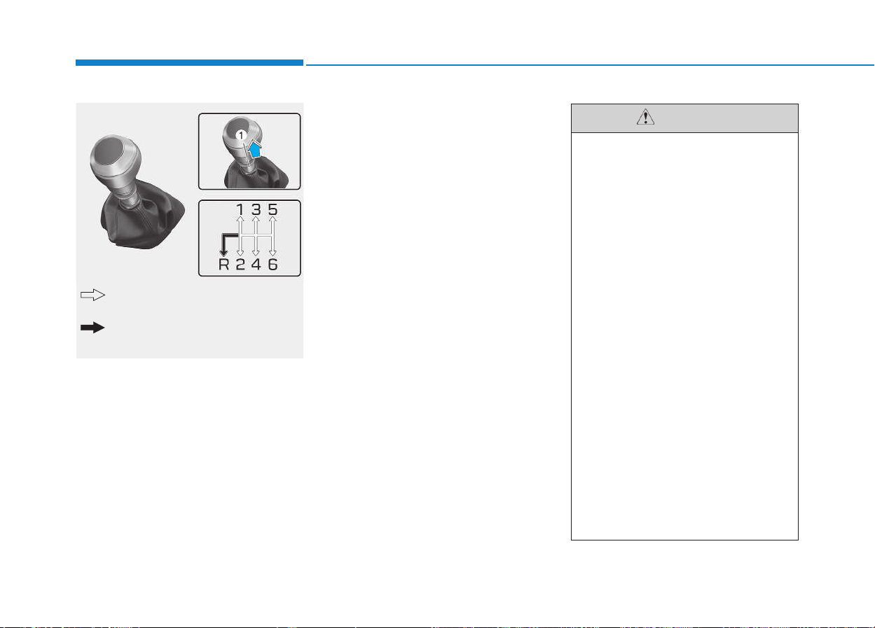
5-14
Driving your vehicle
Manual transmission opera-
tion
The manual transmission has 6 for-
ward gears.
This shift pattern is imprinted on the
shift knob. The transmission is fully
synchronized in all forward gears so
shifting to either a higher or a lower
gear is easily accomplished.
Press the clutch pedal down fully
while shifting, then release it slowly.
If your vehicle is equipped with an
ignition lock system, the engine will
not start when starting the engine
without depressing the clutch pedal.
The gearshift lever must be returned
to the neutral position before shifting
into R (Reverse). The ring located
immediately below the shift knob
must be pulled upward while moving
the shift lever to the R position. (Type
A)
Make sure the vehicle is completely
stopped before shifting into R
(Reverse).
Never operate the engine with the
tachometer (rpm) in the red zone.
MMAANNUUAALL TTRRAANNSSMMIISSSSIIOONN ((IIFF EEQQUUIIPPPPEEDD))
OEU054001
The ring (1) must be pulled up while
moving the shift lever.
The shift lever can be moved without
pulling the ring (1).
• When downshifting from fifth
gear to fourth gear, caution
should be taken not to inad-
vertently press the gear shift
lever sideways in such a man-
ner that second gear is
engaged. Such a drastic
downshift may cause the
engine speed to increase to
the point that the tachometer
will enter the red-zone. Such
over-revving of the engine
may possibly cause engine
damage.
• When upshifting from fifth
gear to sixth gear, caution
should be taken not to inad-
vertently press the gear shift
lever sideways in such a man-
ner that fourth gear is
engaged. Such a drastic
downshift may cause the
engine speed to increase to
the point that the tachometer
will enter the red-zone.
(Continued)
CAUTION
5-15
Driving your vehicle
5
• During cold weather, shifting may
be difficult until the transmission
lubricant has warmed up. This is
normal and not harmful to the
transmission.
• If you've come to a complete stop
and it's hard to shift into 1st or R
(Reverse), put the shift lever in N
(Neutral) position and release the
clutch. Press the clutch pedal back
down, and then shift into 1st or R
(Reverse) gear position.
• To avoid premature clutch
wear and damage, do not
drive with your foot resting on
the clutch pedal. Also, don’t
use the clutch to hold the
vehicle stopped on an uphill
grade, while waiting for a traf-
fic light, etc.
• Do not use the shift lever as a
handrest during driving, as
this can result in premature
wear of the transmission shift
forks.
• When operating the clutch
pedal, press the clutch pedal
down fully. If you don’t press
the clutch pedal fully, the
clutch may be damaged or
noise may occur.
• To prevent possible damage
to the clutch system, do not
start with the 2nd (second)
gear engaged except when
you start on a slippery road.
CAUTION
• Before leaving the driver’s
seat, always set the parking
brake fully and shut the
engine off. Then make sure
the transmission is shifted
into 1st gear when the vehicle
is parked on a level or uphill
grade, and shifted into R
(Reverse) on a downhill
grade. Unexpected and sud-
den vehicle movement can
occur if these precautions are
not followed in the order iden-
tified.
• If your vehicle has a manual
transmission not equipped
with an ignition lock switch, it
may move and cause a seri-
ous accident when starting
the engine without depress-
ing the clutch pedal while the
parking brake is released and
the shift lever not in the
N(Neutral) position.
(Continued)
WARNING
(Continued)
Such over-revving of the
engine may possibly cause
engine damage.
• Do not downshift more than 2
gears or downshift the gear
when the engine is running at
high speed (5,000 RPM or
higher). Such a downshifting
may damage the engine,
clutch and the transmission.
5-16
Driving your vehicle
Using the clutch
The clutch should be pressed all the
way to the floor before shifting, then
released slowly. The clutch pedal
should always be fully released while
driving. Do not rest your foot on the
clutch pedal while driving. This can
cause unnecessary wear. Do not
partially engage the clutch to hold
the vehicle on an incline. This causes
unnecessary wear. Use the foot
brake or parking brake to hold the
vehicle on an incline. Do not operate
the clutch pedal rapidly and repeat-
edly.
Downshifting
When you must slow down in heavy
traffic or while driving up steep hills,
downshift before the engine starts to
labor. Downshifting reduces the
chance of stalling and gives better
acceleration when you again need to
increase your speed. When the vehi-
cle is traveling down steep hills,
downshifting helps maintain safe
speed and prolongs brake life.
(Continued)
• Do not use the engine brake
(shifting from a high gear to
lower gear) rapidly on slip-
pery roads. The vehicle may
slip causing an accident.
When operating the clutch
pedal, press the clutch pedal
down fully. If you don’t press
the clutch pedal fully, the clutch
may be damaged or noise may
occur.
CAUTION

5-17
Driving your vehicle
5
Good driving practices
• Never take the vehicle out of gear
and coast down a hill. This is
extremely hazardous. Always leave
the vehicle in gear.
• Don't "ride" the brakes. This can
cause them to overheat and mal-
function. Instead, when you are
driving down a long hill, slow down
and shift to a lower gear. When you
do this, engine braking will help
slow down the vehicle.
• Slow down before shifting to a
lower gear. This will help avoid
over-revving the engine, which can
cause damage.
• Slow down when you encounter
cross winds. This gives you much
better control of your vehicle.
• Be sure the vehicle is completely
stopped before you attempt to shift
into reverse. The transmission can
be damaged if you do not. To shift
into reverse, depress the clutch,
move the shift lever to neutral, wait
three seconds, then shift to the
reverse position.
• Exercise extreme caution when
driving on a slippery surface. Be
especially careful when braking,
accelerating or shifting gears. On a
slippery surface, an abrupt change
in vehicle speed can cause the
drive wheels to lose traction and
the vehicle to go out of control.
• Always buckle-up! In a colli-
sion, an unbelted occupant is
significantly more likely to be
seriously injured or killed
than a properly belted occu-
pant.
• Avoid high speeds when cor-
nering or turning.
• Do not make quick steering
wheel movements, such as
sharp lane changes or fast,
sharp turns.
• The risk of rollover is greatly
increased if you lose control
of your vehicle at highway
speeds.
(Continued)
WARNING
(Continued)
• Loss of control often occurs if
two or more wheels drop off
the roadway and the driver
oversteers to reenter the road-
way.
• In the event your vehicle
leaves the roadway, do not
steer sharply. Instead, slow
down before pulling back into
the travel lanes.
• Never exceed posted speed
limits.
5-18
Driving your vehicle
Power brakes
Your vehicle has power-assisted
brakes that adjust automatically
through normal usage.
In the event that the power-assisted
brakes lose power because of a
stalled engine or some other reason,
you can still stop your vehicle by
applying greater force to the brake
pedal than you normally would. The
stopping distance, however, will be
longer.
When the engine is not running, the
reserve brake power is partially
depleted each time the brake pedal
is applied. Do not pump the brake
pedal when the power assist has
been interrupted.
Pump the brake pedal only when
necessary to maintain steering con-
trol on slippery surfaces.
BBRRAAKKEE SSYYSSTTEEMM
Brakes
• Do not drive with your foot
resting on the brake pedal.
This will create abnormal high
brake temperatures, exces-
sive brake lining and pad
wear, and increased stopping
distances.
• When descending a long or
steep hill, shift to a lower gear
and avoid continuous applica-
tion of the brakes. Continuous
brake application will cause
the brakes to overheat and
could result in a temporary
loss of braking performance.
• Wet brakes may impair the
vehicle’s ability to safely slow
down; the vehicle may also
pull to one side when the
brakes are applied. Applying
the brakes lightly will indicate
whether they have been
affected in this way.
(Continued)
WARNING
(Continued)
Always test your brakes in
this fashion after driving
through deep water.To dry the
brakes, apply them lightly
while maintaining a safe for-
ward speed until brake per-
formance returns to normal.
• Always, confirm the position
of the brake and accelerator
pedal before driving. If you
don't check the position of the
accelerator and brake pedal
before driving, you may
depress the accelerator
instead of the brake pedal. It
may cause a serious accident.
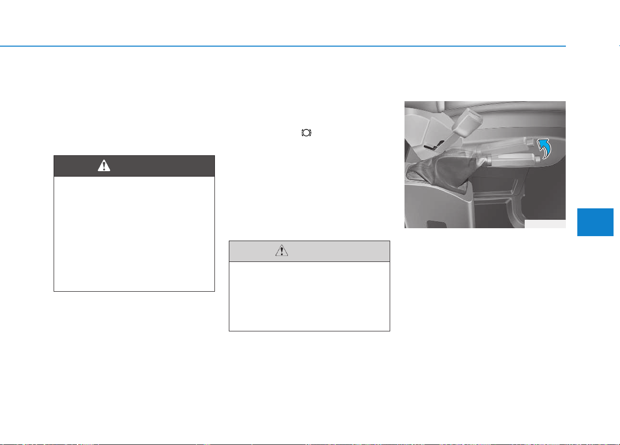
5-19
Driving your vehicle
5
In the event of brake failure
If service brakes fail to operate while
the vehicle is in motion, you can
make an emergency stop with the
parking brake. The stopping dis-
tance, however, will be much greater
than normal.
Disc brakes wear indicator
When your brake pads are worn and
new pads are required, you will hear
a high-pitched warning sound from
your front/rear brakes or the brake
lining indicator ( ) will illuminate in
the cluster. You may hear this sound
and see this illuminate whenever you
depress the brake pedal.
Please remember that some driving
conditions or climates may cause a
brake squeal when you first apply (or
lightly apply) the brakes. This is nor-
mal and does not indicate a problem
with your brakes.
Parking brake
Applying the parking brake
To engage the parking brake, first
apply the foot brake and then pull up
the parking brake lever as far as pos-
sible.
In addition it is recommended that
when parking the vehicle on a gradi-
ent, the shift lever should be in a low
gear on manual transmission vehi-
cles.
Parking brake
Applying the parking brake
while the vehicle is moving at
normal speeds can cause a
sudden loss of control of the
vehicle. If you must use the
parking brake to stop the vehi-
cle, use great caution in apply-
ing the brake.
WARNING
• To avoid costly brake repairs,
do not continue to drive with
worn brake pads.
• Always replace the front or
rear brake pads as pairs.
CAUTION
OEU054002
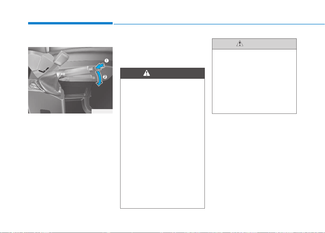
5-20
Driving your vehicle
Releasing the parking brake
To release the parking brake, first
apply the foot brake and pull up the
parking brake lever slightly. Secondly
depress the release button (1) and
lower the parking brake lever (2)
while holding the button.
If the parking brake does not release
or does not release all the way, we
recommend that the system be
checked by an authorized HYUNDAI
dealer.
OEU054003
• To prevent unintentional
movement when stopped and
leaving the vehicle, do not use
the gearshift lever in place of
the parking brake. Set the
parking brake AND make sure
the gearshift lever is securely
positioned in 1st (First) gear
or R (Reverse) for manual
transmission equipped vehi-
cles.
• Never allow anyone who is
unfamiliar with the vehicle to
touch the parking brake. If the
parking brake is released
unintentionally, serious injury
may occur.
• All vehicles should always
have the parking brake fully
engaged when parking to
avoid inadvertent movement
of the vehicle which can injure
occupants or pedestrians.
WARNING
• Driving with the parking brake
applied will cause excessive
brake pad and brake rotor
wear.
• Do not operate the parking
brake while the vehicle is
moving except in an emer-
gency situation. It could dam-
age the vehicle system and
make endanger driving safety.
CAUTION
5-21
Driving your vehicle
5
Check the brake warning light by
turning the ignition switch ON (do not
start the engine). This light will be
illuminated when the parking brake is
applied with the ignition switch in the
START or ON position.
Before driving, be sure the parking
brake is fully released and the brake
warning light is off.
If the brake warning light remains on
after the parking brake is released
while engine is running, there may
be a malfunction in the brake sys-
tem. Immediate attention is neces-
sary.
If at all possible, cease driving the
vehicle immediately. If that is not pos-
sible, use extreme caution while
operating the vehicle and only con-
tinue to drive the vehicle until you
can reach a safe location or repair
shop.
If you drive while parking brake is
applied, the parking brake warning
light comes on and warning buzzer
sounds simultaneously.
Anti-lock brake system (ABS)
WP-009
ABS (or VDC) will not prevent
accidents due to improper or
dangerous driving maneuvers.
Even though vehicle control is
improved during emergency
braking, always maintain a safe
distance between you and
objects ahead. Vehicle speeds
should always be reduced dur-
ing extreme road conditions.
The braking distance for vehicle
equipped with an anti-lock brak-
ing system (Electronic Stability
Program System) may be longer
than for those without it in the
following road conditions.
During these conditions the
vehicle should be driven at
reduced speeds:
(Continued)
WARNING

5-22
Driving your vehicle
The ABS continuously senses the
speed of the wheels. If the wheels
are going to lock, the ABS system
repeatedly modulates the hydraulic
brake pressure to the wheels.
When you apply your brakes under
conditions which may lock the
wheels, you may hear a “tik-tik’’
sound from the brakes, or feel a cor-
responding sensation in the brake
pedal. This is normal and it means
your ABS is active.
In order to obtain the maximum ben-
efit from your ABS in an emergency
situation, do not attempt to modulate
your brake pressure and do not try to
pump your brakes. Press your brake
pedal as hard as possible or as hard
as the situation warrants and allow
the ABS to control the force being
delivered to the brakes.
A click sound may be heard in the
engine compartment when the
vehicle begins to move after the
engine is started. These condi-
tions are normal and indicate that
the anti-lock brake system is func-
tioning properly.
• Even with the anti-lock brake sys-
tem, your vehicle still requires suf-
ficient stopping distance. Always
maintain a safe distance from the
vehicle in front of you.
• Always slow down when cornering.
The anti-lock brake system cannot
prevent accidents resulting from
excessive speeds.
• On loose or uneven road surfaces,
operation of the anti-lock brake
system may result in a longer stop-
ping distance than for vehicles
equipped with a conventional
brake system.
NOTICE
(Continued)
• Rough, gravel or snow-cov-
ered roads.
• With tire chains installed.
• On roads where the road sur-
face is pitted or has different
surface height.
The safety features of an ABS
(or VDC) equipped vehicle
should not be tested by high
speed driving or cornering. This
could endanger the safety of
yourself or others.
5-23
Driving your vehicle
5
When you jump start your vehicle
because of a drained battery, the
engine may not run as smoothly
and the ABS warning light may
turn on at the same time. This hap-
pens because of the low battery
voltage. It does not mean your
ABS is malfunctioning.
• Do not pump your brakes!
• Have the battery recharged
before driving the vehicle.
NOTICE
W-78
• If the ABS warning light is on
and stays on, you may have a
problem with the ABS. In this
case, however, your regular
brakes will work normally.
• The ABS warning light will
stay on for approximately 3
seconds after the ignition
switch is ON. During that time,
the ABS will go through self-
diagnosis and the light will go
off if everything is normal.
(Continued)
CAUTION
• When you drive on a road hav-
ing poor traction, such as an
icy road, and operate your
brakes continuously, the ABS
will be active continuously
and the ABS warning light
may illuminate. Pull your vehi-
cle over to a safe place and
stop the engine.
• Restart the engine. If the ABS
warning light is off, then your
ABS system is normal.
Otherwise, you may have a
problem with the ABS. We rec-
ommend that you contact an
authorized HYUNDAI dealer.
CAUTION
(Continued)
If the light stays on, you may
have a problem with your
ABS. We recommend that you
contact an authorized
HYUNDAI dealer.
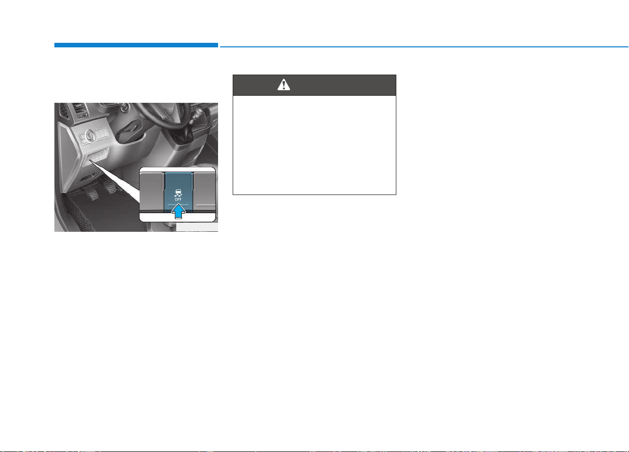
5-24
Driving your vehicle
Vehicle Dynamic Control
(VDC) (if equipped)
The Vehicle Dynamic Control (VDC)
system helps to stabilize the vehicle
during cornering maneuvers.
VDC checks where you are steering
and where the vehicle is actually
going. VDC applies braking pressure
to any one of the vehicle’s brakes
and intervenes in the engine man-
agement system to assist the driver
with keeping the vehicle on the
intended path. It is not a substitute
for safe driving practices. Always
adjust your speed and driving to the
road conditions.
VDC operation
VDC ON condition
When the ignition switch is in the ON
position, the VDC and the VDC OFF
indicator lights illuminate for approxi-
mately three seconds and goes off,
then the VDC is turned on.
OEU044196
Never drive too fast for the road
conditions or too quickly when
cornering. The VDC system will
not prevent accidents.
Excessive speed in turns, abrupt
maneuvers, and hydroplaning
on wet surfaces can result in
severe accidents.
WARNING
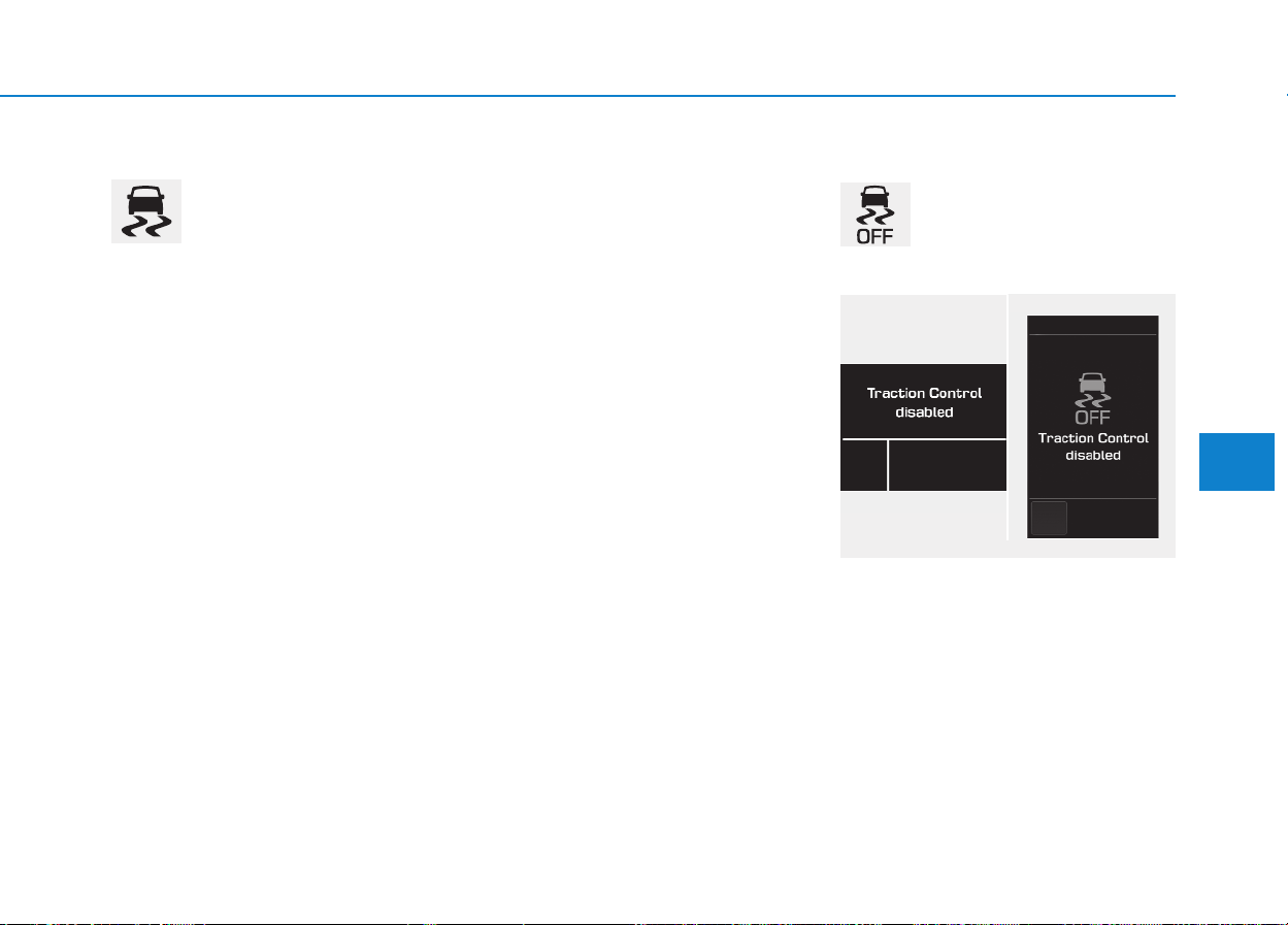
5-25
Driving your vehicle
5
When operating
When the VDC is in opera-
tion, the VDC indicator light
blinks:
• When you apply your brakes under
conditions which may lock the
wheels, you may hear sounds from
the brakes, or feel a corresponding
sensation in the brake pedal.This is
normal and it means your VDC is
active.
• When the VDC activates, the
engine may not respond to the
accelerator as it does under routine
conditions.
• If the Cruise Control was in use
when the VDC activates, the Cruise
Control automatically disengages.
The Cruise Control can be reen-
gaged when the road conditions
allow. See “Cruise Control System”
later in this chapter. (if equipped)
• When moving out of the mud or
driving on a slippery road, the
engine rpm (revolutions per minute)
may not increase even if you press
the accelerator pedal deeply.This is
to maintain the stability and traction
of the vehicle and does not indicate
a problem.
VDC OFF condition
To cancel VDC operation :
• State 1
Press the VDC OFF button shortly
(VDC OFF indicator light and mes-
sage illuminates). At this state, the
engine control function does not
operate. In other words, the traction
control function does not operate but
only the brake control function oper-
ates.
■ Type A ■ Type B
OEU044130/OEU044152
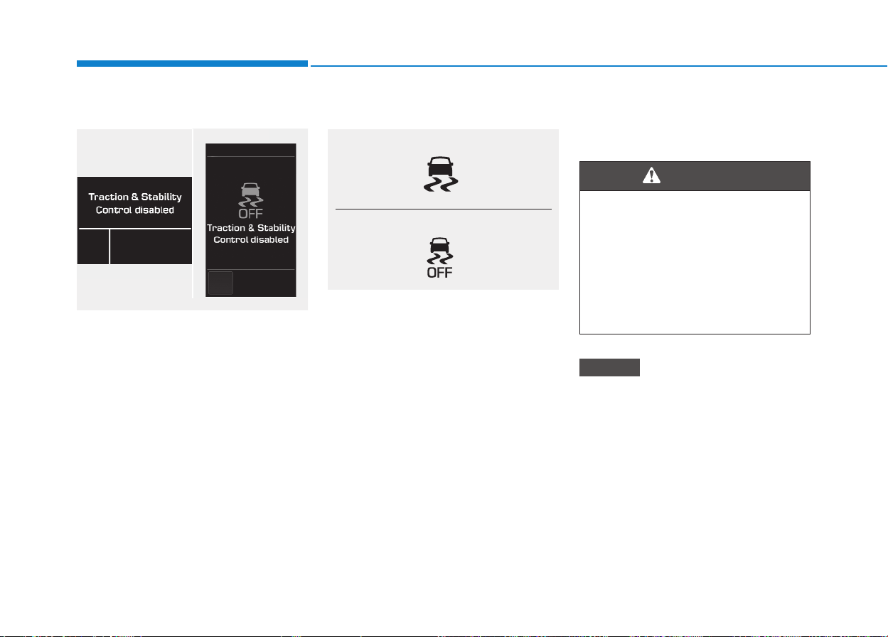
5-26
Driving your vehicle
• State 2
Press the VDC OFF button for more
than 3 seconds. VDC OFF indicator
light and message illuminates and
VDC OFF warning chime will sound.
At this state, the engine control func-
tion and brake control function does
not operate. In other words, the vehi-
cle stability control function does not
operate any more.
If the ignition switch is placed to the
LOCK/OFF position when VDC is off,
VDC remains off. Upon restarting the
engine, the VDC will automatically
turn on again.
Indicator lights
When the ignition switch is pressed
to the ON position, the VDC indicator
light illuminates, then goes off if the
VDC system is operating normally.
The VDC indicator light blinks when-
ever the VDC is operating.
If VDC indicator light stays on, your
vehicle may have a malfunction with
the VDC system. When this warning
light illuminates we recommend that
the vehicle be checked by an author-
ized HYUNDAI dealer as soon as
possible.
The VDC OFF indicator light comes
on when the VDC is turned off with
the button.
Driving with varying tire or wheel
sizes may cause the VDC system
to malfunction. When replacing
tires, make sure they are the same
size as your original tires for this
vehicle.
NOTICE
■ Type A ■ Type B
OEU044131/OEU044210
■ VDC indicator light (blinks)
■ VDC OFF indicator light (comes on)
When the VDC is blinking, this
indicates the VDC is active:
Drive slowly and NEVER
attempt to accelerate. NEVER
turn the VDC off while the VDC
indicator light is blinking or you
may lose control of the vehicle
resulting in an accident.
WARNING

5-27
Driving your vehicle
5
VDC OFF usage
When Driving
The VDC OFF mode should only be
used briefly to help free the vehicle if
stuck in snow or mud by temporarily
stopping operation of the VDC to
maintain wheel torque.
To turn VDC off while driving, press
the VDC OFF button while driving on
a flat road surface.
To prevent damage to the
transaxle:
• Do not allow wheel(s) of one
axle to spin excessively while
the VDC, ABS, and brake warn-
ing lights are displayed. The
repairs would not be covered by
the vehicle warranty. Reduce
engine power and do not spin
the wheel(s) excessively while
these lights are displayed.
• When operating the vehicle on a
dynamometer, ensure the VDC is
turned off (VDC OFF light illumi-
nated).
Information
Turning the VDC off does not affect
ABS or standard brake system opera-
tion.
Hill-Start Assist Control (HAC)
(if equipped)
The Hill-Start Assist Control (HAC)
prevents the vehicle from rolling
backwards when starting a vehicle
from a stop on a hill. The system
operates the brakes automatically for
approximately 2 seconds and releas-
es the brake when the accelerator
pedal is depressed or after 2 sec-
onds.
i
NOTICE
Always be ready to depress the
accelerator pedal when starting
off on an incline. The HAC acti-
vates only for approximately 2
seconds.
WARNING

5-28
Driving your vehicle
Information
• The HAC does not operate when the
shift lever is in P (Park) or N
(Neutral)
• The HAC activates even though the
VDC (Vehicle Dynamic Control) is
off but does not activate when the
VDC has malfunctioned but can not
activate when the VDC has mal-
functioned.
Emergency Stop Signal (ESS)
(if equipped)
The Emergency Stop Signal system
alerts the driver behind by blinking
the stop light when the vehicle is
braked rapidly and severely.
The system is activated when:
• The vehicle suddenly stops (vehi-
cle speed is over 55km/h and the
vehicle deceleration is greater than
7 m/s
2
(Van/Truck) and 5 m/s
2
(BUS))
• The ABS is activating
When vehicle speed is under 40
km/h and the ABS deactivates or the
sudden stop situation is over, the
stop light will stop blinking. Instead,
the hazard warning flasher will turn
on automatically.
The hazard warning flasher will turn
off when vehicle speed is over
10km/h after the vehicle has
stopped. Also, it will turn off when the
vehicle is driven at low speed for
some time. You can turn it off manu-
ally by pushing the hazard warning
flasher switch.
Information
The Emergency Stop Signal (ESS) sys-
tem will not work if the hazard warn-
ing flasher is already on.
ii

5-29
Driving your vehicle
5
Good braking practices
Wet brakes can be dangerous! The
brakes may get wet if the vehicle is
driven through standing water or if it
is washed. Your vehicle will not stop
as quickly if the brakes are wet. Wet
brakes may cause the vehicle to pull
to one side.
To dry the brakes, apply the brakes
lightly until the braking action returns
to normal, taking care to keep the
vehicle under control at all times. If
the braking action does not return to
normal, stop as soon as it is safe to
do so and we recommend that you
call an authorized HYUNDAI dealer
for assistance.
DO NOT drive with your foot resting
on the brake pedal. Even light, but
constant pedal pressure can result in
the brakes overheating, brake wear,
and possibly even brake failure.
If a tire goes flat while you are driv-
ing, apply the brakes gently and
keep the vehicle pointed straight
ahead while you slow down. When
you are moving slowly enough for it
to be safe to do so, pull off the road
and stop in a safe location.
Keep your foot firmly on the brake
pedal when the vehicle is stopped to
prevent the vehicle from rolling for-
ward.
Whenever leaving the vehicle or
parking, always come to a com-
plete stop and continue to
depress the brake pedal. Move
the shift lever into the P (Park)
position, then apply the parking
brake, and place the Engine
Start/Stop button in the OFF
position.
Vehicles with the parking brake
not fully engaged are at risk for
moving inadvertently and caus-
ing injury to yourself or others.
WARNING
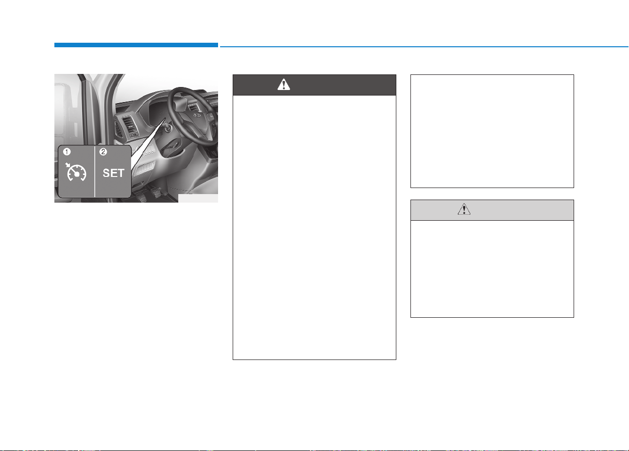
5-30
Driving your vehicle
1. Cruise indicator
2. Cruise set indicator
The cruise control system allows you
to program the vehicle to maintain a
constant speed without pressing the
accelerator pedal.
This system is designed to function
above approximately 40 km/h (25
mph).
CCRRUUIISSEE CCOONNTTRROOLL SSYYSSTTEEMM ((IIFF EEQQUUIIPPPPEEDD))
OEU054004
• If the cruise control is left on,
(CRUISE indicator light in the
instrument cluster illuminat-
ed), the cruise control can be
switched on accidentally.
Keep the cruise control sys-
tem off (CRUISE indicator
light OFF) when the cruise
control is not in use, to avoid
inadvertently setting a speed.
• Use the cruise control system
only when traveling on open
highways in good weather.
• Do not use the cruise control
when it may not be safe to
keep the vehicle at a constant
speed, for instance, driving in
heavy or varying traffic, or on
slippery (rainy, icy or snow-
covered) or winding roads or
over 6% up-hill or down-hill
roads.
(Continued)
(Continued)
• Pay particular attention to the
driving conditions whenever
using the cruise control sys-
tem.
• Be careful when driving
downhill using the cruise con-
trol system, which may
increase the vehicle speed.
WARNING
During cruise-speed driving of
a manual transmission vehicle,
do not shift into neutral without
depressing the clutch pedal,
since the engine will be over-
revved. If this happens, depress
the clutch pedal or release the
cruise control ON-OFF switch.
CAUTION
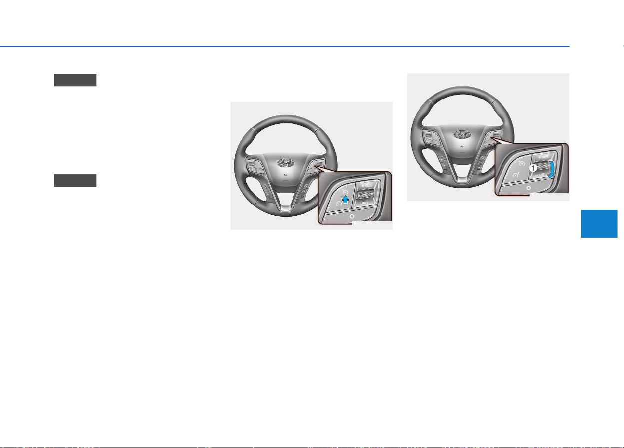
5-31
Driving your vehicle
5
During normal cruise control
operation, when the SET switch is
activated or reactivated after
applying the brakes, the cruise
control will energize after approxi-
mately 3 seconds. This delay is
normal.
To activate cruise control, depress
the brake pedal at least once after
turning the ignition switch to the
ON position or starting the
engine. This is to check if the
brake switch which is important
part to cancel cruise control is in
normal condition.
Cruise control operation
To set cruise control speed:
1. Push the Cruise ON-OFF symbol
button on the steering wheel to
turn the system on. The Cruise
indicator light in the instrument
cluster will illuminate.
2. Accelerate to the desired speed,
which must be more than 40 km/h
(25 mph).
3. Move the lever (1) down (to -SET),
and release it at the desired
speed. The SET indicator light in
the instrument cluster will illumi-
nate. Release the accelerator
pedal. The desired speed will
automatically be maintained.
On
a steep grade, the vehicle may
slow down or speed up slightly while
going downhill.
NOTICE
NOTICE
OEU055023
OEU055024
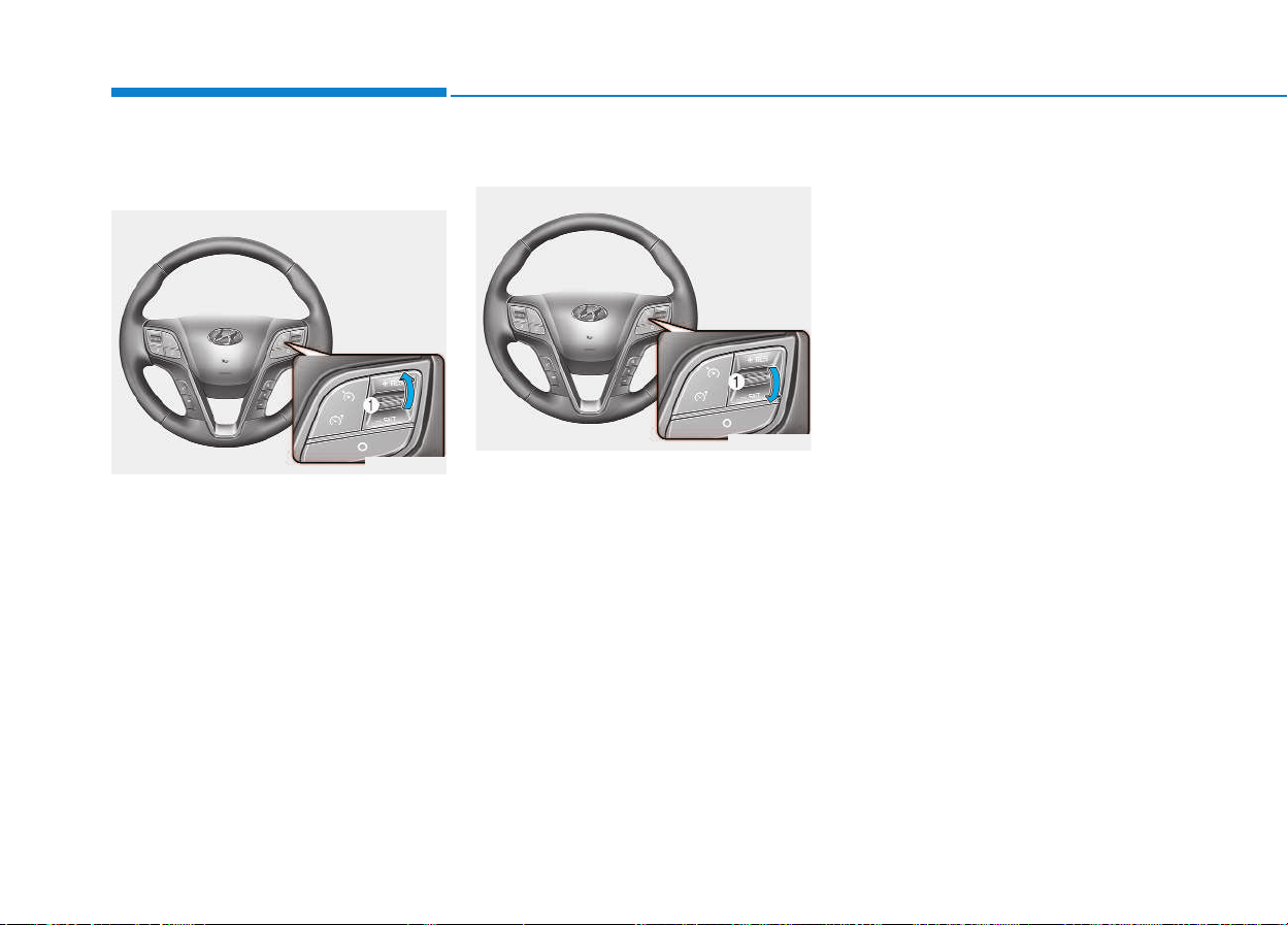
5-32
Driving your vehicle
To increase cruise control set
speed:
Follow either of these procedures:
• Move the lever (1) up (to +RES)
and hold it. Your vehicle will accel-
erate. Release the lever at the
speed you want.
• Move the lever (1) up (to +RES)
and release it immediately. The
cruising speed will increase by 2.0
km/h (1.2 mph) or 1.6 km/h (1.0
mph) each time you move the lever
up (to +RES) in this manner.
To decrease the cruising speed:
Follow either of these procedures:
• Move the lever (1) down (to -SET)
and hold it. Your vehicle will gradu-
ally slow down. Release the lever
at the speed you want to maintain.
• Move the lever (1) down (to -SET)
and release it immediately. The
cruising speed will decrease by 2.0
km/h (1.2 mph) or 1.6 km/h (1.0
mph) each time you move the lever
down (to -SET) in this manner.
To temporarily accelerate with
the cruise control on:
If you want to speed up temporarily
when the cruise control is on,
depress the accelerator pedal.
Increased speed will not interfere
with cruise control operation or
change the set speed.
To return to the set speed, take your
foot off the accelerator.
OEU055025
OEU055024
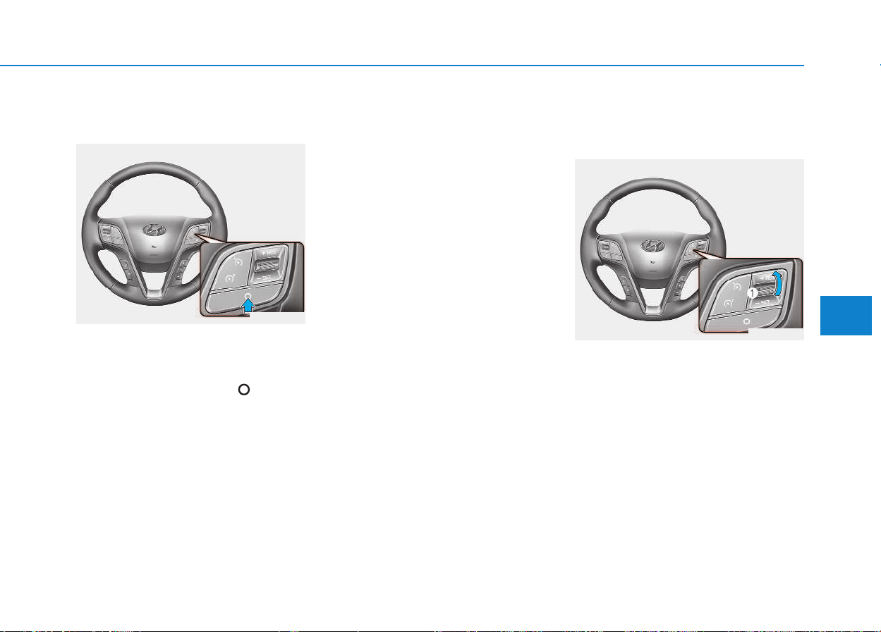
5-33
Driving your vehicle
5
To cancel cruise control, do one
of the following:
• Press the brake pedal.
• Press the clutch pedal with a man-
ual transmission.
• Press the CANCEL ( ) switch
located on the steering wheel.
• Decrease the vehicle speed lower
than the memory speed by 15
km/h (9 mph).
• Decrease the vehicle speed to less
than approximately 40 km/h (25
mph).
Each of these actions will cancel
cruise control operation (the SET
indicator light in the instrument clus-
ter will go off), but it will not turn the
system off. If you wish to resume
cruise control operation, move up the
lever (to +RES) located on your
steering wheel.You will return to your
previously preset speed.
To resume cruising speed at
more than approximately 40
km/h (25 mph):
If any method other than the cruise
ON/OFF symbol switch was used to
cancel cruising speed and the sys-
tem is still activated, the most recent
set speed will automatically resume
when you move the lever (1) up (to +
RES).
It will not resume, however, if the
vehicle speed has dropped below
approximately 40 km/h (25 mph).
OEU055026
OEU055025
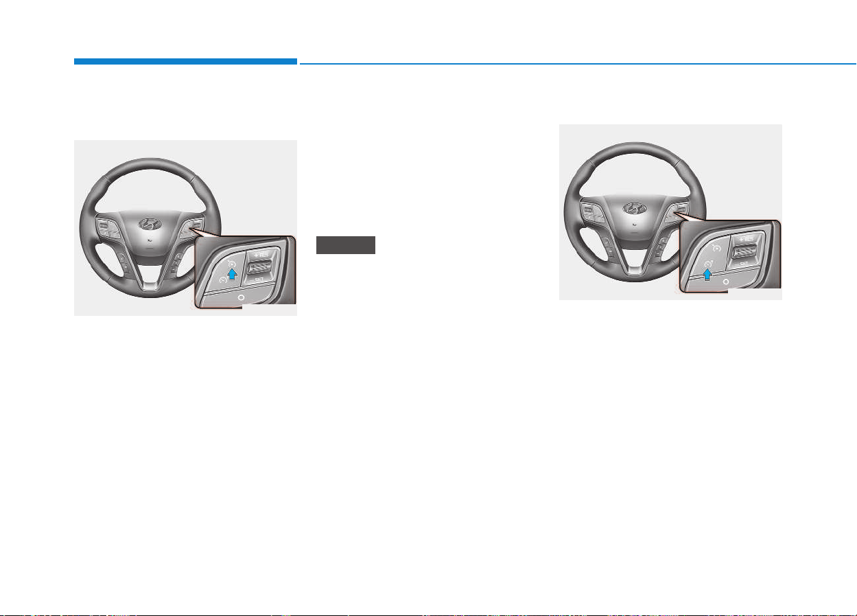
5-34
Driving your vehicle
To turn cruise control off, do
one of the following:
• Push the Cruise ON-OFF symbol
button (the Cruise indicator light in
the instrument cluster will go off).
• Turn the ignition off.
Both of these actions cancel cruise
control operation. If you want to
resume cruise control operation,
repeat the steps provided in “To set
cruise control speed” on the previous
page.
You can set the speed limit when you
do not want to drive over a specific
speed.
If you drive over the preset speed
limit, the warning system operates
(set speed limit will blink and chime
will sound) until the vehicle speed
returns within the speed limit.
While speed limit control is in
operation, the cruise control sys-
tem cannot be activated.
To set speed limit :
1. Press ASLD set button twice on
the steering wheel, to turn the sys-
tem on.
NOTICE
OEU055023
AADDJJUUSSTTAABBLLEE SSPPEEEEDD LLIIMMIITT DDEEVVIICCEE ((AASSLLDD)) ((IIFF EEQQUUIIPPPPEEDD))
OEU055027
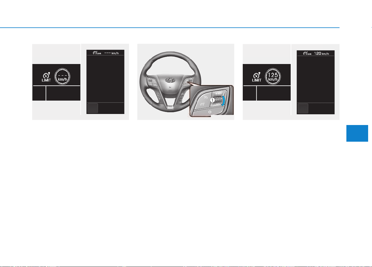
5-35
Driving your vehicle
5
The speed limit indicator light will illu-
minate.
2. Move the lever down (to -SET).
3. Move the lever up (to +RES) or
down (to -SET), and release it at
the desired speed. Move the lever
up (to +RES) or down (to -SET)
and hold it. The speed will
increase or decrease by 10 km/h
(6 mph).
Move the lever up (to +RES) or
down (to -SET) and release it
immediately. The speed will
increase or decrease by 1 km/h.
The set speed limit will display on
the instrument cluster.
The set speed limit will be displayed.
To drive over the preset speed limit
temporally, you must release and
then depress on the accelerator
pedal again quickly. Then the set
speed limit will blink and chime will
sound until you return the vehicle
speed within the speed limit.
OEU055024
■ Type A ■ Type B
OEU044231/OEU044229
■ Type A ■ Type B
OEU044230/OEU044228
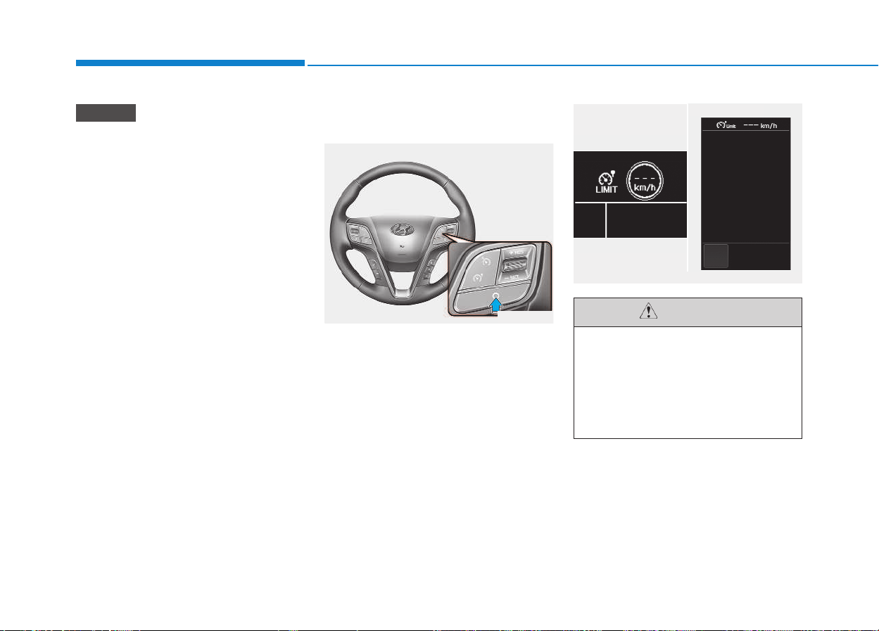
5-36
Driving your vehicle
• Depressing the accelerator
pedal less than approximately
50%, the vehicle will not speed
over the preset speed limit but
maintain the vehicle speed with-
in the speed limit.
• A clicking noise heard from the
kick down mechanism by
depressing the accelerator
pedal fully is a normal condition.
To turn off the speed limit con-
trol, do one of the following:
• Press the cruise switch.
• Turn the ignition off.
If you press the cancel switch once,
the set speed limit will cancel, but it
will not turn the system off. If you
wish to reset the speed limit, move
the lever up (to +RES) or down (to -
SET) to the desired speed.
NOTICE
OEU055026
The “---” indicator will blink if
there is a problem with speed
limit control system.
If this occurs, we recommend
that the system be checked by
an authorized HYUNDAI dealer.
CAUTION
■ Type A ■ Type B
OEU044231/OEU044229
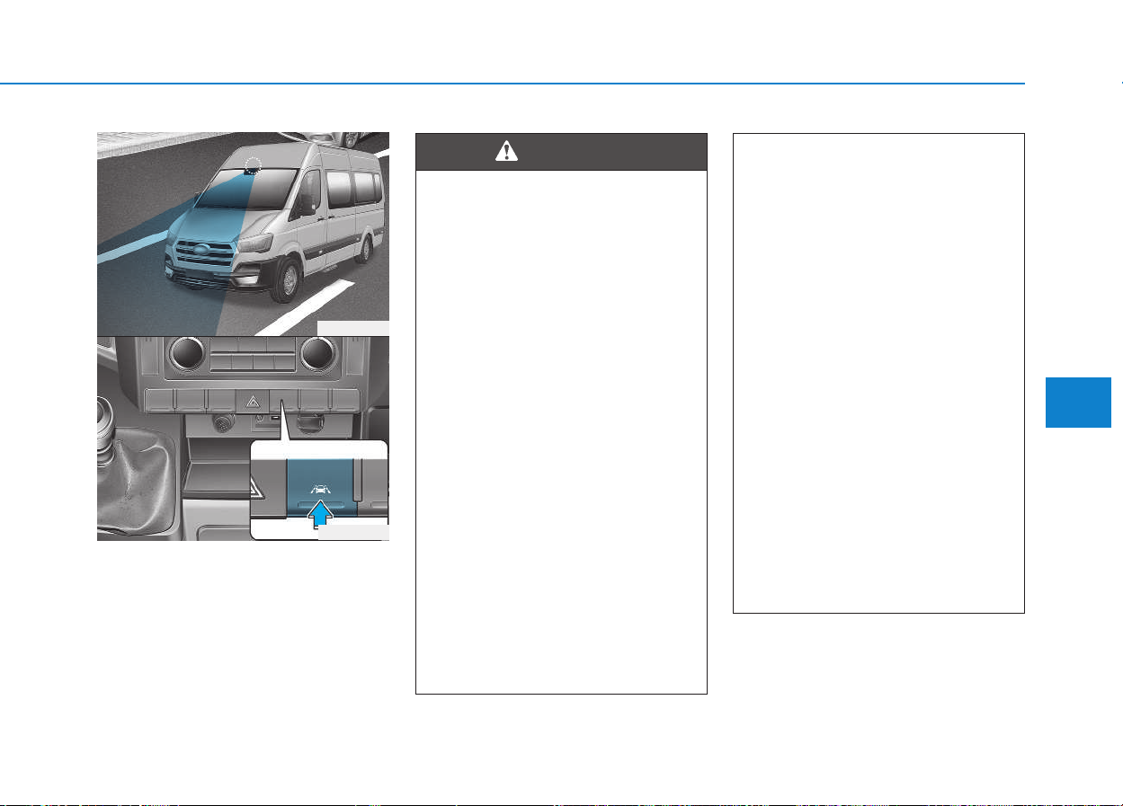
5-37
Driving your vehicle
5
This Lane Departure Warning
System detects the lane with the
sensor at the front windshield and
warns you when your vehicle leaves
the lane.
LLAANNEE DDEEPPAARRTTUURREE WWAARRNNIINNGG SSYYSSTTEEMM ((LLDDWWSS)) ((IIFF EEQQUUIIPPPPEEDD))
OEU054015
OEU044192
Take the following precautions
when using the Lane Departure
Warning System (LDWS):
• The LDWS is only the supple-
mental system. Pay attention
to the road conditions while
driving with the LDWS activat-
ed. It is the driver's responsi-
bility to control and steer the
vehicle.
• ALWAYS check the road con-
ditions. The LDWS does not
make the vehicle change
lanes.
• Do not turn the steering wheel
suddenly if the LDWS warns
that your vehicle is leaving the
lane.
• If the sensor cannot detect the
lane or if the vehicle speed
does not exceed 60 km/h (38
mph), the LDWS will not be
able to notify you if the vehi-
cle leaves the lane.
(Continued)
WARNING
(Continued)
• If your vehicle has window tint
or other types of coating and
accessory on the front wind-
shield, the LDWS may not
work properly.
• Do not allow any water or liq-
uid to contact the LDWS sen-
sor or the sensor may be dam-
aged.
• Do not remove the LDWS
parts and do not damage the
sensor by a strong impact.
• Do not put objects that reflect
light on the dash board.
• The operation of the LDWS
can be affected by several fac-
tors (including environmental
conditions). It is the responsi-
bility of the driver to pay
attention to the roadway and
to maintain the vehicle in its
lane at all times.
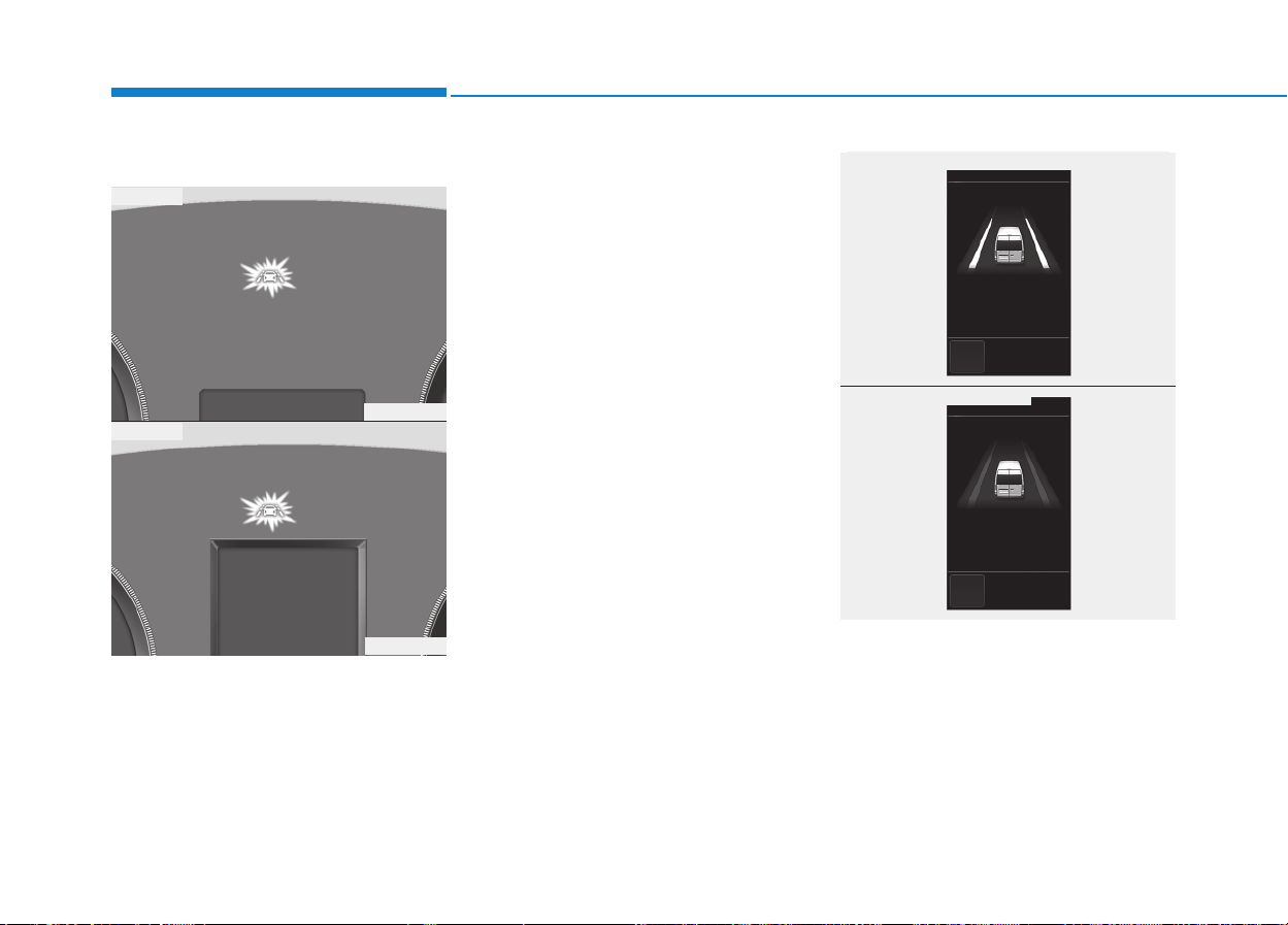
5-38
Driving your vehicle
LDWS operation
To operate:
When the key is ON position, the
LDWS is operated.
To cancel:
Press the LDWS button, the LDWS is
not operated. The indicator on the
cluster will go on. (amber)
If the system detects that your vehi-
cle is leaving the lane when the
LDWS is operating and vehicle
speed exceeds 60km/h, the warning
operates as follows:
OEU054016
OEU054017
■ Type A
■ Type B
OEU044153
OEU044154
■ Lane line detected
■ Lane line undetected
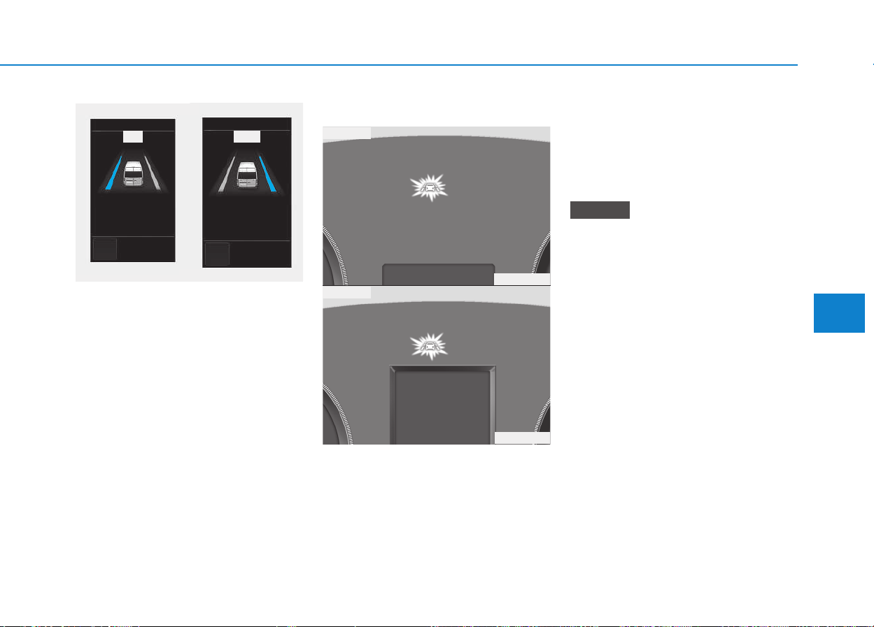
5-39
Driving your vehicle
5
1.Visual warning
If you leave the lane, the lane line
you leave on the LCD display blinks
yellow.
Warning indicator
If the LDWS fails, the warning indica-
tor (yellow) comes on indicating the
LDWS is not working properly. We
recommend that you take your vehi-
cle to an authorized HYUNDAI deal-
er and have the system checked.
The LDWS does not operate when:
• The driver turns on the turn signal
to change lanes or operates the
hazard warning flasher.
• Driving on the lane line.
Always operate the turn signal
before changing lanes.
NOTICE
OEU044155/OEU044157
■ Lane Departure Warning
Right Left
OEU054016
OEU054017
■ Type A
■ Type B
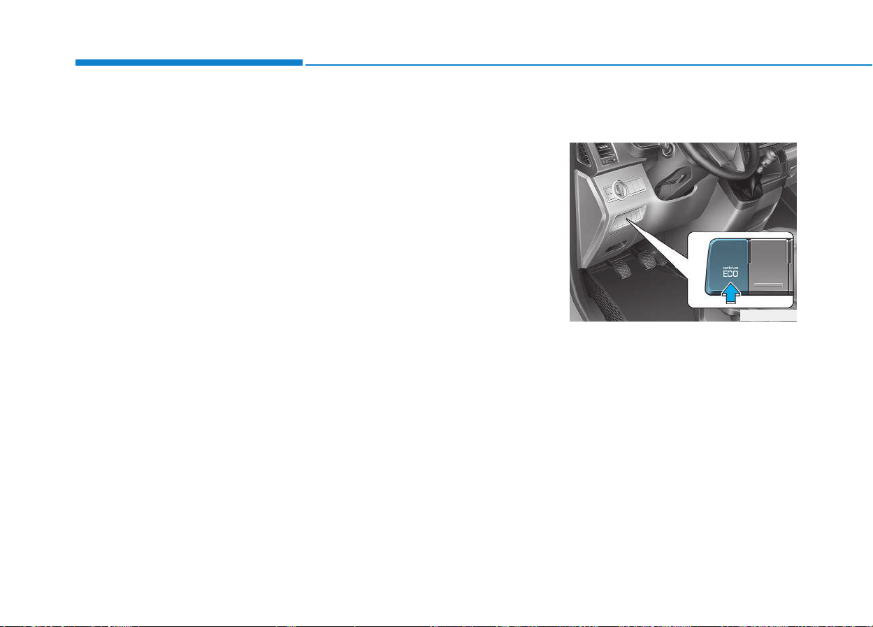
5-40
Driving your vehicle
DRIVER'S ATTENTION
The LDWS may not warn you even
if the vehicle leaves the lane, or may
warn you even if the vehicle does not
leave the lane when:
• The lane can't be visible due to
snow, rain, stain, a puddle or other
factors.
• The brightness outside changes
suddenly such as tunnel enter/exit.
• The headlamps are not on at night
or in a tunnel, or light level is low.
• It is difficult to distinguish the
color of the lane marking from the
road or the lane line is damaged or
indistinct.
• Driving on a steep grade or a
curve.
• Light such as street light, sunlight
or oncoming vehicle light reflects
from the water on the road.
• The lens or windshield is covered
with foreign matter.
• The sensor cannot detect the lane
because of fog, heavy rain, or
heavy snow.
(Continued)
(Continued)
• The surrounding of the inside rear
view mirror temperature is high
due to direct sun light.
• The lane is very wide or narrow.
• The windshield is fogged by
humid air in the vehicle.
• A shadow is on the lane line.
• There is a mark that looks like a
lane line.
• There is a boundary structure,
such as a concrete barrier.
• The distance from the vehicle
ahead is very short or the vehicle
ahead drives covering the lane
line.
• The vehicle vibrates heavily due to
road conditions.
• The number of lanes increases or
decreases or the lane lines are
crossing.
• Putting something on the dash-
board.
• Driving with the sun in front of
you.
• Driving in areas under construc-
tion.
• There are more than two lane
lines.
Active ECO operation
Active ECO helps improve fuel effi-
ciency by controlling the engine. But
fuel-efficiency can be changed by
the driver's driving habits and road
conditions.
• When the Active ECO button is
pressed the ECO indicator (green)
will illuminate to show that the
Active ECO is operating.
AACCTTIIVVEE EECCOO SSYYSSTTEEMM
(
(IIFF EEQQUUIIPPPPEEDD))
OEU044195
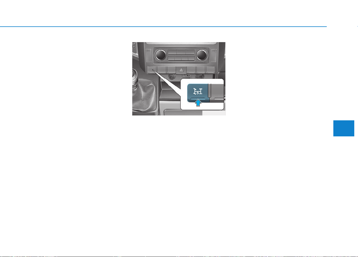
5-41
Driving your vehicle
5
• When the Active ECO is activated,
it does not turn off even though the
engine is restarted again. To turn
off the system, press the active
ECO button again.
• If Active ECO is turned off, it will
return to the ECO mode.
When Active ECO is activated:
• Vehicle speed may drop.
• When driving up a hill, you may
feel the engine torque change.
Limitation of Active ECO oper-
ation :
If the following conditions occur while
Active ECO is operating, the system
operation is limited even though
there is no change in the ECO indi-
cator.
• When the coolant temperature is
low:
The system will be limited until
engine performance becomes nor-
mal.
• When driving up a hill:
The system will be limited to gain
power when driving uphill because
the engine torque is restricted.
This is the switch of the PTO (Power
Take Off) which takes off the power
from the transmission.
To activate the P.T.O. system
1.Stop the vehicle. Then, apply the
parking brake.
2.Depress the clutch pedal to dis-
connect the power. Wait for 2 to 3
seconds. Press ON the P.T.O.
switch. Then, slowly take your foot
off the clutch pedal.
3.Make sure that the P.T.O indicator
illuminates on the cluster.
To deactivate the P.T.O. sys-
tem
1.Depress the clutch pedal. Press
OFF the P.T.O. switch. Then, slowly
take your foot off the clutch pedal.
2.Make sure that the P.T.O indicator
goes OFF on the cluster.
PPTTOO SSWWIITTCCHH ((IIFF EEQQUUIIPPPPEEDD))
OEU044062

5-42
Driving your vehicle
E
ECCOONNOOMMIICCAALL OOPPEERRAATTIIOONN
Your vehicle's fuel economy depends
mainly on your style of driving, where
you drive and when you drive.
Each of these factors affects how
many kilometers (miles) you can get
from a liter (gallon) of fuel.To operate
your vehicle as economically as pos-
sible, use the following driving sug-
gestions to help save money in both
fuel and repairs:
• Drive smoothly. Accelerate at a
moderate rate. Don't make "jack-
rabbit" starts or full-throttle shifts
and maintain a steady cruising
speed. Don't race between stop-
lights. Try to adjust your speed to
the traffic so you don't have to
change speeds unnecessarily.
Avoid heavy traffic whenever pos-
sible. Always maintain a safe dis-
tance from other vehicles so you
can avoid unnecessary braking.
This also reduces brake wear.
• Drive at a moderate speed. The
faster you drive, the more fuel your
vehicle uses. Driving at a moderate
speed, especially on the highway,
is one of the most effective ways to
reduce fuel consumption.
• Don't "ride" the brake or clutch
pedal. This can increase fuel con-
sumption and also increase wear
on these components. In addition,
driving with your foot resting on the
brake pedal may cause the brakes
to overheat, which reduces their
effectiveness and may lead to
more serious consequences.
• Take care of your tires. Keep them
inflated to the recommended pres-
sure. Incorrect inflation, either too
much or too little, results in unnec-
essary tire wear. Check the tire
pressures at least once a month.
• Be sure that the wheels are
aligned correctly. Improper align-
ment can result from hitting curbs
or driving too fast over irregular
surfaces. Poor alignment causes
faster tire wear and may also result
in other problems as well as
greater fuel consumption.
• When the power is still con-
nected, activating the P.T.O.
system may incur deadly dam-
age to the gear.
• The P.T.O. system should be
activated within the permissi-
ble toque.
- Activation of the P.T.O., going
beyond the permissible maxi-
mum toque, may incur deadly
damage to the P.T.O. gear and
transmission.
• Before activating the P.T.O.
system, depress the clutch
pedal, when the P.T.O switch is
pressed OFF. (For the manual
transmission.)
- The P.T.O. gear may be dam-
aged and become uncontrol-
lable.
WARNING

5-43
Driving your vehicle
5
• Keep your vehicle in good condi-
tion. For better fuel economy and
reduced maintenance costs, main-
tain your vehicle in accordance
with the maintenance schedule in
Section 7. If you drive your vehicle
in severe conditions, more frequent
maintenance is required (see
Section 7 for details).
• Keep your vehicle clean. For maxi-
mum service, your vehicle should
be kept clean and free of corrosive
materials. It is especially important
that mud, dirt, ice, etc. not be
allowed to accumulate on the
underside of the vehicle. This extra
weight can result in increased fuel
consumption and also contribute to
corrosion.
• Travel lightly. Don't carry unneces-
sary weight in your vehicle. Weight
reduces fuel economy.
• Don't let the engine idle longer
than necessary. If you are waiting
(and not in traffic), turn off your
engine and restart only when
you're ready to go.
• Remember, your vehicle does not
require extended warm-up. After
the engine has started, allow the
engine to run for 10 to 20 seconds
prior to placing the vehicle in gear.
In very cold weather, however, give
your engine a slightly longer warm-
up period.
• Don't "lug" or "over-rev" the engine.
Lugging is driving too slowly in too
high a gear resulting engine buck-
ing. If this happens, shift to a lower
gear. Over-revving is racing the
engine beyond its safe limit. This
can be avoided by shifting at the
recommended speeds.
• Use your air conditioning sparingly.
The air conditioning system is
operated by engine power so your
fuel economy is reduced when you
use it.
• Open windows at high speeds can
reduce fuel economy.
• Fuel economy is less in crosswinds
and headwinds. To help offset
some of this loss, slow down when
driving in these conditions.
Keeping a vehicle in good operating
condition is important both for econ-
omy and safety. Therefore, we rec-
ommend that you contact an author-
ized HYUNDAI dealer to perform
scheduled inspections and mainte-
nance.
Engine off during motion
Never turn the engine off to
coast down hills or anytime the
vehicle is in motion. The power
steering and power brakes will
not function properly without
the engine running. Instead,
keep the engine on and down-
shift to an appropriate gear for
engine braking effect. In addi-
tion, turning off the ignition
while driving could engage the
steering wheel lock resulting in
loss of vehicle steering which
could cause serious injury or
death.
WARNING

5-44
Driving your vehicle
Hazardous driving conditions
When hazardous driving conditions
are encountered such as water,
snow, ice, mud, sand, or similar haz-
ards, follow these suggestions:
• Drive cautiously and allow extra
distance for braking.
• Avoid sudden braking or steering.
• When braking with non-ABS
brakes pump the brake pedal with
a light up-and-down motion until
the vehicle is stopped.
• If stalled in snow, mud, or sand,
use second gear. Accelerate slow-
ly to avoid spinning the drive
wheels.
• Use sand, rock salt, tire chains, or
other non-slip material under the
drive wheels to provide traction
when stalled in ice, snow, or mud.
Rocking the vehicle
If it is necessary to rock the vehicle
to free it from snow, sand, or mud,
first turn the steering wheel right and
left to clear the area around your
front wheels. Then, shift back and
forth between 1st (First) and R
(Reverse) in vehicles equipped with
a manual transmission. Do not race
the engine, and spin the wheels as
little as possible. If you are still stuck
after a few tries, have the vehicle
pulled out by a tow vehicle to avoid
engine overheating and possible
damage to the transmission.
Prolonged rocking may cause
engine over-heating, transmission
damage or failure, and tire dam-
age.
Information
The VDC system (if equipped) should
be turned OFF prior to rocking the
vehicle.
i
NOTICE
SSPPEECCIIAALL DDRRIIVVIINNGG CCOONNDDIITTIIOONNSS
Spinning tires
Do not spin the wheels, espe-
cially at speeds more than 56
km/h (35 mph). Spinning the
wheels at high speeds when the
vehicle is stationary could
cause a tire to overheat which
could result in tire damage that
may injure bystanders.
WARNING

5-45
Driving your vehicle
5
Smooth cornering
Avoid braking or gear changing in
corners, especially when roads are
wet. Ideally, corners should always
be taken under gentle acceleration. If
you follow these suggestions, tire
wear will be held to a minimum.
Driving at night
Because night driving presents more
hazards than driving in the daylight,
here are some important tips to
remember:
• Slow down and keep more dis-
tance between you and other vehi-
cles, as it may be more difficult to
see at night, especially in areas
where there may not be any street
lights.
• Adjust your mirrors to reduce the
glare from other driver's head-
lights.
• Keep your headlights clean and
properly aimed on vehicles not
equipped with the automatic head-
light aiming feature. Dirty or
improperly aimed headlights will
make it much more difficult to see
at night.
• Avoid staring directly at the head-
lights of oncoming vehicles. You
could be temporarily blinded, and it
will take several seconds for your
eyes to readjust to the darkness.
If your vehicle becomes stuck in
snow, mud, sand, etc., then you
may attempt to rock the vehicle
free by moving it forward and
backward. Do not attempt this
procedure if people or objects
are anywhere near the vehicle.
During the rocking operation
the vehicle may suddenly move
forward or backward as it
becomes unstuck, causing
injury or damage to nearby peo-
ple or objects.
WARNING
ABS
Do not pump the brake pedal on
a vehicle equipped with ABS.
WARNING

5-46
Driving your vehicle
Driving in the rain
Rain and wet roads can make driving
dangerous, especially if you’re not
prepared for the slick pavement.
Here are a few things to consider
when driving in the rain:
• A heavy rainfall will make it harder
to see and will increase the dis-
tance needed to stop your vehicle,
so slow down.
• Keep your windshield wiping
equipment in good shape. Replace
your windshield wiper blades when
they show signs of streaking or
missing areas on the windshield.
• If your tires are not in good condi-
tion, making a quick stop on wet
pavement can cause a skid and
possibly lead to an accident. Be
sure your tires are in good shape.
• Turn on your headlights to make it
easier for others to see you.
• Driving too fast through large pud-
dles can affect your brakes. If you
must go through puddles, try to
drive through them slowly.
• If you believe you may have gotten
your brakes wet, apply them lightly
while driving until normal braking
operation returns.
Driving in flooded areas
Avoid driving through flooded areas
unless you are sure the water is no
higher than the bottom of the wheel
hub. Drive through any water slowly.
Allow adequate stopping distance
because brake performance may be
affected.
After driving through water, dry the
brakes by gently applying them sev-
eral times while the vehicle is moving
slowly.
Driving off-road
Drive carefully off-road because your
vehicle may be damaged by rocks of
roots of trees. Become familiar with
the off-road conditions where you
are going to drive before you begin
driving.

5-47
Driving your vehicle
5
Highway driving
Tires:
Adjust the tire inflation pressures to
specification. Low tire inflation pres-
sures will result in overheating and
possible failure of the tires.
Avoid using worn or damaged tires
which may result in reduced traction
or tire failure.
Never exceed the maximum tire
inflation pressure shown on the
tires.
Fuel, engine coolant and engine
oil:
High speed travel consumes more
fuel than urban motoring. Do not for-
get to check both engine coolant and
engine oil.
Drive belt:
A loose or damaged drive belt may
result in overheating of the engine.
NOTICE
• Underinflated or overinflated
tires can cause poor handling,
loss of vehicle control, and
sudden tire failure leading to
accidents, injuries, and even
death. Always check the tires
for proper inflation before
driving. For proper tire pres-
sures, refer to section 8,
“Tires and wheels”.
• Driving on tires with no or
insufficient tread is danger-
ous. Worn-out tires can result
in loss of vehicle control, col-
lisions, injury, and even death.
Worn-out tires should be
replaced as soon as possible
and should never be used for
driving. Always check the tire
tread before driving your vehi-
cle. For further information
and tread limits, refer to sec-
tion 7, “Tires and wheels”.
WARNING

5-48
Driving your vehicle
The more severe weather conditions
of winter result in greater wear and
other problems. To minimize the
problems of winter driving, you
should follow these suggestions:
Snowy or Icy conditions
To drive your vehicle in deep snow, it
may be necessary to use snow tires
or to install tire chains on your tires.
If snow tires are needed, it is neces-
sary to select tires equivalent in size
and type of the original equipment
tires. Failure to do so may adversely
affect the safety and handling of your
vehicle. Furthermore, speeding,
rapid acceleration, sudden brake
applications, and sharp turns are
potentially very hazardous practices.
During deceleration, use engine
braking to the fullest extent. Sudden
brake applications on snowy or icy
roads may cause skids to occur. You
need to keep sufficient distance
between the vehicle in operation in
front and your vehicle. Also, apply
the brake gently. It should be noted
that installing tire chains on the tire
will provide a greater driving force,
but will not prevent side skids.
Information
Tire chains are not legal in all coun-
tries. Check the country laws before
fitting tire chains.
Snow tires
If you mount snow tires on your vehi-
cle, make sure they are radial tires of
the same size and load range as the
original tires. Mount snow tires on all
four wheels to balance your vehicle’s
handling in all weather conditions.
Keep in mind that the traction provid-
ed by snow tires on dry roads may
not be as high as your vehicle's orig-
inal equipment tires.You should drive
cautiously even when the roads are
clear. Check with the tire dealer for
maximum speed recommendations.
Do not install studded tires without
first checking local, state and munic-
ipal regulations for possible restric-
tions against their use.
i
WWIINNTTEERR DDRRIIVVIINNGG
Snow tire size
Snow tires should be equivalent
in size and type to the vehicle's
standard tires. Otherwise, the
safety and handling of your
vehicle may be adversely affect-
ed.
WARNING
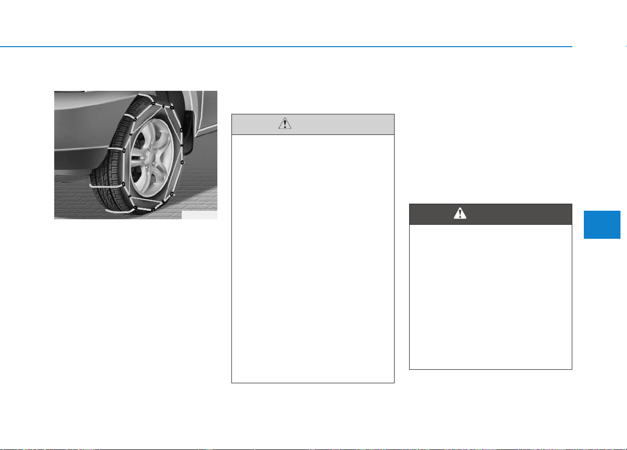
5-49
Driving your vehicle
5
Tire chains
Since the sidewalls of radial tires are
thinner, they can be damaged by
mounting some types of snow chains
on them. Therefore, the use of snow
tires is recommended instead of
snow chains. Do not mount tire
chains on vehicles equipped with
aluminum wheels; snow chains may
cause damage to the wheels. If snow
chains must be used, use wire-type
chains with a thickness of less than
15 mm (0.59 in). Damage to your
vehicle caused by improper snow
chain use is not covered by your
vehicle manufacturers warranty.
When using tire chains, attach them
to the drive wheels as follows.
2WD : Rear wheels
Chain installation
When installing chains, follow the
manufacturer's instructions and
mount them as tightly as you can.
Drive slowly with chains installed. If
you hear the chains contacting the
body or chassis, stop and tighten
them. If they still make contact, slow
down until it stops. Remove the
chains as soon as you begin driving
on cleared roads.
1VQA3007
• Make sure the snow chains
are the correct size and type
for your tires. Incorrect snow
chains can cause damage to
the vehicle body and suspen-
sion and may not be covered
by your vehicle manufacturer
warranty. Also, the snow
chain connecting hooks may
be damaged from contacting
vehicle components causing
the snow chains to come
loose from the tire. Make sure
the snow chains are SAE
class “S” certified.
• Always check chain installa-
tion for proper mounting after
driving approximately 0.5 to 1
km (0.3 to 0.6 miles) to ensure
safe mounting. Retighten or
remount the chains if they are
loose.
CAUTION
Mounting chains
When mounting snow chains,
park the vehicle on level ground
away from traffic. Turn on the
vehicle Hazard Warning flashers
and place a triangular emer-
gency warning device behind
the vehicle if available. Always
place the vehicle in P (park),
apply the parking brake and
turn off the engine before
installing snow chains.
WARNING

5-50
Driving your vehicle
• Chains that are the wrong size
or improperly installed can dam-
age your vehicle's brake lines,
suspension, body and wheels.
• Stop driving and retighten the
chains any time you hear them
hitting the vehicle.
Winter precautions
Use high quality ethylene glycol
coolant
Your vehicle is delivered with high
quality ethylene glycol coolant in the
cooling system. It is the only type of
coolant that should be used because
it helps prevent corrosion in the cool-
ing system, lubricates the water
pump and prevents freezing. Be sure
to replace or replenish your coolant
in accordance with the maintenance
schedule in section 7. Before winter,
have your coolant tested to assure
that its freezing point is sufficient for
the temperatures anticipated during
the winter.
Check battery and cables
Winter puts additional burdens on
the battery system. Visually inspect
the battery and cables as described
in section 7. We recommend that the
system be checked by an authorized
HYUNDAI dealer.
Change to "winter weight" oil if
necessary
In some climates it is recommended
that a lower viscosity "winter weight"
oil be used during cold weather. See
section 8 for recommendations. If
you aren't sure what weight oil you
should use, we recommend that you
consult an authorized HYUNDAI
dealer.
Check spark plugs and ignition
system
Inspect your spark plugs as
described in section 7 and replace
them if necessary. Also check all
ignition wiring and components to be
sure they are not cracked, worn or
damaged in any way.
NOTICE
Tire chains
• The use of chains may
adversely affect vehicle han-
dling.
• Do not exceed 30 km/h (20
mph) or the chain manufactur-
er’s recommended speed
limit, whichever is lower.
• Drive carefully and avoid
bumps, holes, sharp turns,
and other road hazards, which
may cause the vehicle to
bounce.
• Avoid sharp turns or locked-
wheel braking.
WARNING

5-51
Driving your vehicle
5
To keep locks from freezing
To keep the locks from freezing,
squirt an approved de-icer fluid or
glycerin into the key opening. If a
lock is covered with ice, squirt it with
an approved de-icing fluid to remove
the ice. If the lock is frozen internally,
you may be able to thaw it out by
using a heated key. Handle the heat-
ed key with care to avoid injury.
Use approved window washer
anti-freeze in system
To keep the water in the window
washer system from freezing, add an
approved window washer anti-freeze
solution in accordance with instruc-
tions on the container. Window wash-
er anti-freeze is available from an
authorized HYUNDAI dealer and
most auto parts outlets. Do not use
engine coolant or other types of anti-
freeze as these may damage the
paint finish.
Don't let your parking brake
freeze
Under some conditions your parking
brake can freeze in the engaged
position. This is most likely to hap-
pen when there is an accumulation
of snow or ice around or near the
rear brakes or if the brakes are wet.
If there is a risk the parking brake
may freeze, apply it only temporarily
while you put the shift lever in first or
reverse gear and block the rear
wheels so the vehicle cannot roll.
Then release the parking brake.
Don't let ice and snow accumu-
late underneath
Under some conditions, snow and
ice can build up under the fenders
and interfere with the steering. When
driving in severe winter conditions
where this may happen, you should
periodically check underneath the
vehicle to be sure the movement of
the front wheels and the steering
components is not obstructed.
Carry emergency equipment
Depending on the severity of the
weather, you should carry appropri-
ate emergency equipment. Some of
the items you may want to carry
include tire chains, tow straps or
chains, flashlight, emergency flares,
sand, a shovel, jumper cables, a win-
dow scraper, gloves, ground cloth,
coveralls, a blanket, etc.
5-52
Driving your vehicle
If you are considering to tow with
your vehicle, you should first check
with your country's Department of
Motor Vehicles to determine legal
requirements. Since laws vary the
requirements for towing trailers, vehi-
cles, or other types of vehicles or
apparatus may differ. Ask an author-
ized HYUNDAI dealer for further
details before towing.
Remember that trailering is different
than just driving your vehicle by itself.
Trailering means changes in han-
dling, durability, and fuel economy.
Successful, safe trailering requires
correct equipment, and it has to be
used properly. Damage to your vehi-
cle caused by improper trailer towing
is not covered by your vehicle manu-
facturer’s warranty.
This section contains many time-
tested, important trailering tips and
safety rules. Many of these are
important for your safety and that of
your passengers. Please read this
section carefully before you pull a
trailer.
Take the following precautions:
• If you don't use the correct
equipment and/or drive
improperly, you can lose con-
trol of the vehicle when you
are pulling a trailer. For exam-
ple, if the trailer is too heavy,
the braking performance may
be reduced.You and your pas-
sengers could be seriously or
fatally injured. Pull a trailer
only if you have followed all
the steps in this section.
• Before towing, make sure the
total trailer weight, GCW
(Gross Combination Weight),
GVW (Gross Vehicle Weight),
GAW (Gross Axle Weight ) and
trailer tongue load are all with-
in the limits.
WARNING
TTRRAAIILLEERR TTOOWWIINNGG
•
Pulling a trailer improperly
can damage your vehicle and
result in costly repairs not
covered by your warranty. To
pull a trailer correctly, follow
the advice in this section.
• The driver should check the
rearview, which is blocked by
the load compartment, while
driving backward. If you are
not sure about the safety, you
should ask another person to
check the rearview and guide
your driving.
CAUTION

5-53
Driving your vehicle
5
Your vehicle can tow a trailer. To
identify what the vehicle trailering
capacity is for your vehicle, you
should read the information in
“Weight of the trailer” that appears
later in this section.
Remember that trailering is different
than just driving your vehicle by itself.
Trailering means changes in han-
dling, durability, and fuel economy.
Successful, safe trailering requires
correct equipment, and it has to be
used properly.
This section contains many time-
tested, important trailering tips and
safety rules. Many of these are
important for your safety and that of
your passengers. Please read this
section carefully before you pull a
trailer.
Load-pulling components such as
the engine, transmission, wheel
assemblies, and tires are forced to
work harder against the load of the
added weight. The engine is required
to operate at relatively higher speeds
and under greater loads. This addi-
tional burden generates extra heat.
The trailer also adds considerably to
wind resistance, increasing the
pulling requirements.
Tow bar wiring(if equipped)
In combination with genuine tow bar
wiring harness, the Factory-installed
Rear Park Distance control (Rear
PDC) get switched off, as soon as a
trailer is connected to the towing
hitch wiring connector and driving
backwards (only for Vehicles with
prepared connector).
5-54
Driving your vehicle
Safety chains (if equipped)
You should always attach chains
between your vehicle and your trail-
er. Cross the safety chains under the
tongue of the trailer so that the
tongue will not drop to the road if it
becomes separated from the hitch.
Instructions about safety chains may
be provided by the hitch manufactur-
er or by the trailer manufacturer.
Follow the manufacturer’s recom-
mendation for attaching safety
chains. Always leave just enough
slack so you can turn with your trail-
er. And, never allow safety chains to
drag on the ground.
Trailer brakes
If your trailer is equipped with a brak-
ing system, make sure it conforms to
your country’s regulations and that it
is properly installed and operating
correctly.
If your trailer weight exceeds the
maximum allowed weight without
trailer brakes, then the trailer will also
require its own brakes as well. Be
sure to read and follow the instruc-
tions for the trailer brakes so you’ll be
able to install, adjust and maintain
them properly.
• Don’t tap into or modify your vehi-
cle's brake system.
The trailer brake should be mount-
ed to the fixation point at the trail-
er tow bar.
NOTICE
Do not use a trailer with its own
brakes unless you are absolute-
ly certain that you have proper-
ly set up the brake system. This
is not a task for amateurs. Use
an experienced, competent
trailer shop for this work.
WARNING

5-55
Driving your vehicle
Driving with a trailer
Towing a trailer requires a certain
amount of experience. Before setting
out for the open road, you must get
to know your trailer. Acquaint your-
self with the feel of handling and
braking with the added weight of the
trailer. And always keep in mind that
the vehicle you are driving is now a
good deal longer and not nearly so
responsive as your vehicle is by
itself.
Before you start, check the trailer
hitch and platform, safety chains,
electrical connector(s), lights, tires
and mirror adjustment. If the trailer
has electric brakes, start your vehicle
and trailer moving and then apply the
trailer brake controller by hand to be
sure the brakes are working.This lets
you check your electrical connection
at the same time.
During your trip, check occasionally
to be sure that the load is secure,
and that the lights and any trailer
brakes are still working.
Following distance
Stay at least twice as far behind the
vehicle ahead as you would when
driving your vehicle without a trailer.
This can help you avoid situations
that require heavy braking and sud-
den turns.
Passing
You’ll need more passing distance
up ahead when you’re towing a trail-
er. And, because of the increased
vehicle length, you’ll need to go
much farther beyond the passed
vehicle before you can return to your
lane.
Backing up
Hold the bottom of the steering
wheel with one hand. Then, to move
the trailer to the left, just move your
hand to the left. To move the trailer to
the right, move your hand to the
right. Always back up slowly and, if
possible, have someone guide you.
Making turns
When you’re turning with a trailer,
make wider turns than normal. Do
this so your trailer won’t strike soft
shoulders, curbs, road signs, trees,
or other objects. Avoid jerky or sud-
den maneuvers. Signal well in
advance.
5
5-56
Driving your vehicle
Turn signals when towing a
trailer
When you tow a trailer, your vehicle
has to have a different turn signal
flasher and extra wiring. The green
arrows on your instrument panel will
flash whenever you signal a turn or
lane change. Properly connected,
the trailer lights will also flash to alert
other drivers you’re about to turn,
change lanes, or stop.
When towing a trailer, the green
arrows on your instrument panel will
flash for turns even if the bulbs on
the trailer are burned out. Thus, you
may think drivers behind you are
seeing your signals when, in fact,
they are not. It’s important to check
occasionally to be sure the trailer
bulbs are still working. You must also
check the lights every time you dis-
connect and then reconnect the
wires.
The ECU of the tow bar wiring har-
ness warns the driver about the
burned-out bulbs on the trailer by
flashing the green arrows on the
instrument panel with the warning
sound.
Do not connect a trailer lighting sys-
tem directly to your vehicle’s lighting
system. Use only an approved trailer
wiring harness.
An authorized HYUNDAI dealer can
assist you in installing the wiring har-
ness.
Driving on grades
Reduce speed and shift to a lower
gear before you start down a long or
steep downgrade. If you don’t shift
down, you might have to use your
brakes so much that they would get
hot and no longer operate efficiently.
On a long uphill grade, shift down
and reduce your speed to around 70
km/h (45 mph) to reduce the possi-
bility of engine and transmission
overheating.
If your trailer weighs more than the
maximum trailer weight without trail-
er brakes.
Failure to use an approved trail-
er wiring harness could result
in damage to the vehicle electri-
cal system and/or personal
injury.
WARNING
5-57
Driving your vehicle
5
Parking on hills
Generally, if you have a trailer
attached to your vehicle, you should
not park your vehicle on a hill. People
can be seriously or fatally injured,
and both your vehicle and the trailer
can be damaged if unexpectedly roll
down hill.
However, if you ever have to park
your trailer on a hill, here's how to do
it:
1. Pull the vehicle into the parking
space. Turn the steering wheel in
the direction of the curb (right if
headed down hill, left if headed up
hill).
2. If the vehicle has a manual trans-
mission, place the vehicle in neu-
tral.
3. Set the parking brake and shut off
the vehicle.
4. Place chocks under the trailer
wheels on the down hill side of the
wheels.
5. Start the vehicle, hold the brakes,
shift to neutral, release the parking
brake and slowly release the
brakes until the trailer chocks
absorb the load.
6. Reapply the brakes, reapply the
parking brake and shift the vehicle
to R (Reverse) for manual trans-
mission.
7. Shut off the vehicle and release
the vehicle brakes but leave the
parking brake set.
• When towing a trailer on steep
grades (in excess of 6%) pay
close attention to the engine
coolant temperature gauge to
ensure the engine does not
overheat.
If the needle of the coolant
temperature gauge moves
across the dial towards “H”
(HOT), pull over and stop as
soon as it is safe to do so, and
allow the engine to idle until it
cools down. You may proceed
once the engine has cooled
sufficiently.
• You must decide driving
speed depending on trailer
weight and uphill grade to
reduce the possibility of
engine and transmission
overheating.
CAUTION
Parking on a hill
Parking your vehicle on a hill
with a trailer attached could
cause serious injury or death,
should the trailer break loose.
WARNING

5-58
Driving your vehicle
When you are ready to leave after
parking on a hill
1. With the manual transmission in
Neutral, apply your brakes and
hold the brake pedal down while
you:
• Start your engine;
• Shift into gear; and
• Release the parking brake.
2. Slowly remove your foot from the
brake pedal.
3. Drive slowly until the trailer is clear
of the chocks.
4. Stop and have someone pick up
and store the chocks.
Maintenance when trailer tow-
ing
Your vehicle will need service more
often when you regularly pull a trail-
er. Important items to pay particular
attention to include engine oil, axle
lubricant and cooling system fluid.
Brake condition is another important
item to frequently check. Each item is
covered in this manual, and the
Index will help you find them quickly.
If you’re trailering, it’s a good idea to
review these sections before you
start your trip.
Don’t forget to also maintain your
trailer and hitch. Follow the mainte-
nance schedule that accompanied
your trailer and check it periodically.
Preferably, conduct the check at the
start of each day’s driving. Most
importantly, all hitch nuts and bolts
should be tight.
Parking brake
It can be dangerous to get out
of your vehicle if the parking
brake is not firmly set.
If you have left the engine run-
ning, the vehicle can move sud-
denly. You or others could be
seriously or fatally injured.
WARNING

5-59
Driving your vehicle
5
If you do decide to pull a trail-
er
Here are some important points if
you decide to pull a trailer:
• Consider using a sway control. You
can ask a hitch dealer about sway
control.
• Do not do any towing with your
vehicle during its first 2,000 km
(1,200 miles) in order to allow the
engine to properly break in. Failure
to heed this caution may result in
serious engine or transmission
damage.
• When towing a trailer, we recom-
mend that you consult an author-
ized HYUNDAI dealer on addition-
al requirements such as a towing
kit, etc.
• Always drive your vehicle at a mod-
erate speed (Max speed for stan-
dard trailer is 80 km/h (50 mph)).
❇ Special trailer 100 km/h (60
mph) is allowed but trailer need
special approval from TÜV.
• On a long uphill grade, do not
exceed 70 km/h (45 mph) or the
posted towing speed limit,
whichever is lower.
• Fuel consumption will increase due
to the additional required power to
tow trailer and additional trans-
portation weight at the trailer.
To prevent vehicle damage :
• Due to higher load during
trailer usage, overheating
might occur in hot days or
during uphill driving. If the
coolant gauge indicates over-
heating, switch off the A/C
and stop the vehicle in a safe
area to cool down the engine.
• When towing check transmis-
sion fluid more frequently.
• If your vehicle is not equipped
with the air conditioner, you
should install a condenser fan
to improve engine perform-
ance when towing a trailer.
CAUTION

5-60
Driving your vehicle
Item
Bus
Van
Truck
N1*
1
N2*
1
Long Long Short Long Short Long Short
Overall length mm(inch)
6,195
(243.9)
6,195
(243.9)
5,515
(217.1)
6,195
(243.9)
5,515
(217.1)
6,167
(242.8)
5,724
(225.4)
Maximum trailer
weight kg(lbs.)
Without
brake
System
750 (1,653) 750 (1,653) 750 (1,653) 750 (1,653) 750 (1,653) 750 (1,653) 750 (1,653)
With brake
System
2,500
(5,511)
3,000
(6,613)
3,000
(6,613)
2,500
(5,511)
2,500
(5,511)
3,000
(6,613)
3,000
(6,613)
Maximum permissible
static vertical load on
the coupling device kg(lbs.)
100 (220) 120 (264) 120 (264) 100 (220) 100 (220) 120 (264) 120 (264)
Recommended distance from
rear wheel center to coupling
point mm(inch)
1,686 (66.4) 1,686 (66.4) 1,241 (48.9) 1,686 (66.4) 1,241 (48.9) 1,756 (69.1) 1,548 (60.9)
• The chart contains important considerations that have to do with weight:
❇ *
1
: N1:GVW 3.5 ton, N2 : 3.5 ton < GVW <12 ton
≥
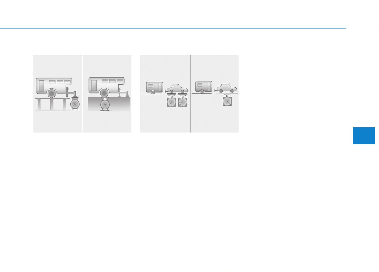
5-61
Driving your vehicle
5
Trailer weight
How heavy can a trailer safely be? It
should never weigh more than the
maximum trailer weight with trailer
brakes. But even that can be too
heavy.
It depends on how you plan to use
your trailer. For example, speed, alti-
tude, road grades, outside tempera-
ture and how often your vehicle is
used to pull a trailer are all important.
The ideal trailer weight can also
depend on any special equipment
that you have on your vehicle.
Tongue load
The tongue load of any trailer is an
important weight to measure
because it affects the total gross
vehicle weight (GVW) of your vehi-
cle. This weight includes the curb
weight of the vehicle, any cargo you
may carry in it, and the people who
will be riding in the vehicle. And if you
will tow a trailer, you must add the
tongue load to the GVW because
your vehicle will also be carrying that
weight.
The trailer tongue should weigh a
maximum of 10% of the total loaded
trailer weight, within the limits of the
maximum permissible trailer tongue
load. After you've loaded your trailer,
weigh the trailer and then the tongue,
separately, to see if the weights are
proper. If they aren’t, you may be
able to correct them simply by mov-
ing some items around in the trailer.
C190E01JM
Tongue Load Total Trailer Weight
C190E02JM
Gross Axle Weight
Gross Vehicle Weight

5-62
Driving your vehicle
This section will guide you in the
proper loading of your vehicle and/or
trailer, to keep your loaded vehicle
weight within its design rating capa-
bility, with or without a trailer.
Properly loading your vehicle will
provide maximum return of the vehi-
cle design performance. Before load-
ing your vehicle, familiarize yourself
with the following terms for determin-
ing your vehicle's weight ratings, with
or without a trailer, from the vehicle's
specifications and the certification
label:
Base curb weight
This is the weight of the vehicle
including a full tank of fuel and all
standard equipment. It does not
include passengers, cargo, or option-
al equipment.
Vehicle curb weight
This is the weight of your new vehicle
when you picked it up from your deal-
er plus any aftermarket equipment.
Cargo weight
This figure includes all weight added
to the Base Curb Weight, including
cargo and optional equipment.
GAW (Gross axle weight)
This is the total weight placed on
each axle (front and rear) - including
vehicle curb weight and all payload.
GAWR (Gross axle weight rat-
ing)
This is the maximum allowable
weight that can be carried by a single
axle (front or rear). These numbers
are shown on the certification label.
The total load on each axle must
never exceed its GAWR.
GVW (Gross vehicle weight)
This is the Base Curb Weight plus
actual Cargo Weight plus passen-
gers.
Take the following precautions:
• Never load a trailer with more
weight in the rear than in the
front. The front should be
loaded with approximately
60% of the total trailer load;
the rear should be loaded with
approximately 40% of the total
trailer load.
• Never exceed the maximum
weight limits of the trailer or
trailer towing equipment.
Improper loading can result in
damage to your vehicle and/or
personal injury. Check
weights and loading at a com-
mercial scale or highway
patrol office equipped with
scales.
• An improperly loaded trailer
can cause loss of vehicle con-
trol.
WARNING
VVEEHHIICCLLEE WWEEIIGGHHTT

5-63
Driving your vehicle
5
GVWR (Gross vehicle weight
rating)
This is the maximum allowable
weight of the fully loaded vehicle
(including all options, equipment,
passengers and cargo). The GVWR
is shown on the certification label.
Overloading
A locking differential, if equipped, is
for the rear wheel differential only.
The features of this locking differen-
tial are described below:
Just as with a conventional differen-
tial, the wheel on one side is allowed
to turn at a different speed from the
wheel on the other side when the
vehicle is cornering. The difference
between the locking differential and a
conventional differential is that if the
wheel on one side of the vehicle
loses traction, a greater amount of
torque is applied to the rear wheel on
the other side to improve traction.
Information
In a stationary position, the LD
(Locking Differential) will operate
when the difference of the revolution
speed between the rear right wheel
and the rear left wheel occurs.
i
The gross axle weight rating
(GAWR) and the gross vehicle
weight rating (GVWR) for your
vehicle are on the certification
label attached to the driver's (or
front passenger’s) door.
Exceeding these ratings can
cause an accident or vehicle
damage. You can calculate the
weight of your load by weighing
the items (and people) before
putting them in the vehicle. Be
careful not to overload your
vehicle.
WARNING
LLOOCCKKIINNGG DDIIFFFFEERREENNTTIIAALL
(
(IIFF EEQQUUIIPPPPEEDD))

5-64
Driving your vehicle
The following procedures can be
used to confirm that the locking dif-
ferential is functioning properly:
(1) Position the vehicle so that one
wheel is on a dry paved surface
and the other on ice, snow, mud,
etc. Drive the vehicle, and
observe the operation of the lock-
ing differential. The vehicle
should not become stuck if the
differential is functioning properly.
(2) Depress the accelerator pedal
gradually, and then when traction
is good, depress it forcefully. If
the vehicle accelerates well, the
differential is functioning properly.
Information
Usually a locking differential will
operate and release automatically but
occasionally it may not release auto-
matically.
At this time you will feel the tire is
dragged when you are driving or cor-
nering. You can release it manually by
slightly turning the steering wheel
right and left while the vehicle is mov-
ing slowly.
i
• Never start the engine with
the gearshift lever placed in
the forward or reverse while
one of the rear wheels is
jacked up and the other in
contact with the ground;
doing so may cause the vehi-
cle to jump forward.
• If one of the rear wheels
begins to spin in mud, snow,
etc., the vehicle can some-
times be driven out by
depressing the accelerator
pedal further; however, avoid
running the engine continu-
ously at high rpm because
doing so could damage the
locking differential.
CAUTION

What to do in an emergency
Hazard warning flasher ........................................6-2
In case of an emergency while driving ..............6-2
If the engine stalls while driving...................................6-2
If the engine stalls at a crossroad or crossing .........6-3
If you have a flat tire while driving..............................6-3
If the engine will not start ...................................6-3
If the engine doesn't turn over or turns over
slowly....................................................................................6-3
If the engine turns over normally but doesn't
start.......................................................................................6-4
Emergency starting ...............................................6-4
Jump starting......................................................................6-4
Push-starting .....................................................................6-7
If the engine overheats ........................................6-7
Removing and storing the spare tire ..................6-9
Jacking instructions ..........................................................6-9
A type...................................................................................6-9
B type.................................................................................6-11
Changing tires ..................................................................6-14
Towing ...................................................................6-22
Towing service .................................................................6-22
Removable towing hook ................................................6-23
Emergency towing ..........................................................6-24
Glass break hammer............................................6-26
Emergency exit.....................................................6-26
Emergency commodity........................................6-27
Fire extinguisher .............................................................6-27
First aid kit ......................................................................6-27
Triangle reflector ............................................................6-28
Tire pressure gauge .......................................................6-28
6
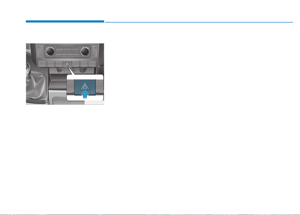
6-2
Hazard warning flasher
The hazard warning flasher serves
as a warning to other drivers to exer-
cise extreme caution when
approaching, overtaking, or passing
your vehicle.
It should be used whenever emer-
gency repairs are being made or
when the vehicle is stopped near the
edge of a roadway.
Depress the flasher switch with the
ignition switch in any position. The
flasher switch is located in the center
console switch panel. All turn signal
lights will flash simultaneously.
• The hazard warning flasher oper-
ates whether your vehicle is run-
ning or not.
• The turn signals are available with-
out turning off the hazard.
• Care must be taken when using
the hazard warning flasher while
the vehicle is being towed.
If the engine stalls at a cross-
road or crossing
• If the engine stalls at a crossroad
or crossing, set the shift lever in the
N (Neutral) position and then push
the vehicle to a safe place.
• If your vehicle has a manual trans-
mission not equipped with a igni-
tion lock switch, the vehicle can
move forward by shifting to the
2(second) or 3(third) gear and then
turning the starter without depress-
ing the clutch pedal.
RROOAADD WWAARRNNIINNGG
What to do in an emergency
I
INN CCAASSEE OOFF AANN EEMMEERRGGEENNCCYY
W
WHHIILLEE DDRRIIVVIINNGG
OEU044191

6-3
What to do in an emergency
If you have a flat tire while
driving
If a tire goes flat while you are driv-
ing:
1.Take your foot off the accelerator
pedal and let the vehicle slow
down while driving straight ahead.
Do not apply the brakes immedi-
ately or attempt to pull off the road
as this may cause a loss of control.
When the vehicle has slowed to
such a speed that it is safe to do
so, brake carefully and pull off the
road. Drive off the road as far as
possible and park on firm, level
ground. If you are on a divided
highway, do not park in the median
area between the two traffic lanes.
2.When the vehicle is stopped, turn
on your emergency hazard flash-
ers, set the parking brake and put
the transmission in reverse.
3.Have all passengers get out of the
vehicle. Be sure they all get out on
the side of the vehicle that is away
from traffic.
4.When changing a flat tire, follow
the instruction provided later in this
section.
If engine stalls while driving
1.Reduce your speed gradually,
keeping a straight line. Move cau-
tiously off the road to a safe place.
2.Turn on your emergency flashers.
3.Try to start the engine again. If your
vehicle will not start, we recom-
mend that you contact an author-
ized HYUNDAI dealer.
If engine doesn't turn over or
turns over slowly
1.Check the battery connections to
be sure they are clean and tight.
2.Turn on the interior light. If the light
dims or goes out when you operate
the starter, the battery is dis-
charged.
3.Check the starter connections to
be sure they are securely tight-
ened.
4.Do not push or pull the vehicle to
start it. See instructions for "Jump
starting".
6
IIFF TTHHEE EENNGGIINNEE WWIILLLL NNOOTT
S
STTAARRTT
If the engine will not start, do
not push or pull the vehicle to
start it. This could result in a
collision or cause other dam-
age. In addition, push or pull
starting may cause the catalytic
converter to be overloaded and
create a fire hazard.
WARNING

6-4
If engine turns over normally
but does not start
1.Check fuel level.
2.With the ignition switch in the
LOCK/ OFF position, check all
connectors at ignition, coil and
spark plugs. Reconnect any that
may be disconnected or loose.
3.Check the fuel line in the engine
compartment.
4.If the engine still does not start, we
recommend that you call an
authorized HYUNDAI dealer.
Connect cables in numerical order
and disconnect in reverse order.
Jump starting
Jump starting can be dangerous if
done incorrectly. Therefore, to avoid
harm to yourself or damage to your
vehicle or battery, follow the jump
starting procedures. If in doubt, we
strongly recommend that you have a
competent technician or towing serv-
ice jump start your vehicle.
What to do in an emergency
E
EMMEERRGGEENNCCYY SSTTAARRTTIINNGG
OEU074071
Jumper Cables
Main fuse box
Booster battery
Use only a 12-volt jumper sys-
tem. You can damage a 12-volt
starting motor, ignition system,
and other electrical parts
beyond repair by use of a 24-
volt power supply (either two
12-volt batteries in series or a
24-volt motor generator set).
CAUTION
(+)
(+)
(-)
(-)

6-5
What to do in an emergency
6
Battery
• Never attempt to check the
electrolyte level of the battery
as this may cause the battery
to rupture or explode causing
serious injury.
• Never attempt to open the
AGM type battery.
WARNING
Battery
• Keep all flames or sparks
away from the battery. The
battery produces hydrogen
gas which may explode if
exposed to flame or sparks.
If these instructions are not
followed exactly, serious per-
sonal injury and damage to
the vehicle may occur! If you
are not sure how to follow this
procedure, seek qualified
assistance. Automobile bat-
teries contain sulfuric acid.
This is poisonous and highly
corrosive. When jump start-
ing, wear protective glasses
and be careful not to get acid
on yourself, your clothing or
on the vehicle.
• Do not attempt to jump start
the vehicle if the discharged
battery is frozen or if the elec-
trolyte level is low; the battery
may rupture or explode.
(Continued)
WARNING
(Continued)
• Do not allow the (+) and (-)
jumper cables to touch. It may
cause sparks.
• The battery may rupture or
explode when you jump start
with a low or frozen battery.

6-6
What to do in an emergency
Jump starting procedure
1.Make sure the booster battery is
12-volt and that its negative termi-
nal is grounded.
2.If the booster battery is in another
vehicle, do not allow the vehicles to
touch.
3.Turn off all unnecessary electrical
loads.
4.Connect the jumper cables in the
exact sequence shown in the illus-
tration. First connect one end of a
jumper cable to the positive termi-
nal of the main fuse box (1), then
connect the other end to the posi-
tive terminal on the booster battery
(2).
Proceed to connect one end of the
other jumper cable to the negative
terminal of the booster battery (3),
then the other end to a solid, sta-
tionary, metallic point (for example,
the engine lifting bracket) away
from the negative battery terminal
(4). Do not connect it to or near any
part that moves when the engine is
cranked.
Do not allow the jumper cables to
contact anything except the correct
battery terminals or the correct
ground. Do not lean over the bat-
tery when making connections.
AGM battery (if equipped)
• Absorbent Glass Matt (AGM)
batteries are maintenance-
free and we recommend that
the system be serviced by an
authorized HYUNDAI dealer.
For charging your AGM bat-
tery, use only fully automatic
battery chargers that are spe-
cially developed for AGM bat-
teries.
• When replacing the AGM bat-
tery, we recommend that you
use parts for replacement
from an authorized HYUNDAI
dealer.
• Do not open or remove the
cap on top of the battery. This
may cause leaks of internal
electrolyte that could result in
severe injury.
(Continued)
(Continued)
• If the AGM battery is recon-
nected or replaced, ISG func-
tion will not operate immedi-
ately.
If you want to use the ISG
function, the battery sensor
needs to be calibrated for
approximately 4 hours with
the ignition off.
• During the period, the dark
current must be under 100 mA.
CAUTION
Battery cables
Do not connect the jumper
cable from the negative terminal
of the booster battery to the
negative terminal of the dis-
charged battery. This can cause
the discharged battery to over-
heat and crack, releasing bat-
tery acid.
CAUTION
6-7
What to do in an emergency
5.Start the engine of the vehicle with
the booster battery and let it run at
2,000 rpm, then start the engine of
the vehicle with the discharged
battery.
If the cause of your battery discharg-
ing is not apparent, we recommend
that the system be checked by an
authorized HYUNDAI dealer.
Push-starting
Your manual transmission-equipped
vehicle should not be push-started
because it might damage the emis-
sion control system.
If your temperature gauge indicates
overheating, you experience a loss
of power, or hear loud pinging or
knocking, the engine is probably too
hot. If this happens, you should:
1.Pull off the road and stop as soon
as it is safe to do so.
2.Place the shift lever in neutral and
set the parking brake. If the air con-
ditioning is on, turn it off.
3.If engine coolant is running out
under the vehicle or steam is com-
ing out from the hood, stop the
engine. Do not open the hood until
the coolant has stopped running
or the steaming has stopped. If
there is no visible loss of engine
coolant and no steam, leave the
engine running and check to be
sure the engine cooling fan is oper-
ating. If the fan is not running, turn
the engine off.
6
Never tow a vehicle to start it
because the sudden surge for-
ward when the engine starts
could cause a collision with the
tow vehicle.
WARNING
IIFF TTHHEE EENNGGIINNEE OOVVEERRHHEEAATTSS
6-8
4.Check to see if the water pump
drive belt is missing. If it is not
missing, check to see that it is
tight. If the drive belt seems to be
satisfactory, check for coolant leak-
ing from the radiator, hoses or
under the vehicle. (If the air condi-
tioning had been in use, it is nor-
mal for cold water to be draining
from it when you stop).
5.If the water pump drive belt is bro-
ken or engine coolant is leaking
out, stop the engine immediately
and we recommend that you call
an authorized HYUNDAI dealer.
6.If you cannot find the cause of the
overheating, wait until the engine
temperature has returned to nor-
mal. Then, if coolant has been lost,
carefully add coolant to the reser-
voir to bring the fluid level in the
reservoir up to the halfway mark.
7.Proceed with caution, keeping
alert for further signs of overheat-
ing. If overheating happens again,
we recommend that you call an
authorized HYUNDAI dealer.
What to do in an emergency
While the engine is running,
keep hair, hands and clothing
away from moving parts such
as the fan and drive belts to pre-
vent injury.
WARNING
Do not remove the radiator cap
when the engine is hot. This can
allow coolant to be blown out of
the opening and cause serious
burns.
WARNING
• Serious loss of coolant indi-
cates there is a leak in the
cooling system and we rec-
ommend that the system be
checked by an authorized
HYUNDAI dealer.
• When the engine overheats
from low engine coolant, sud-
denly adding engine coolant
may cause cracks in the
engine. To prevent damage,
add engine coolant slowly in
small quantities.
CAUTION
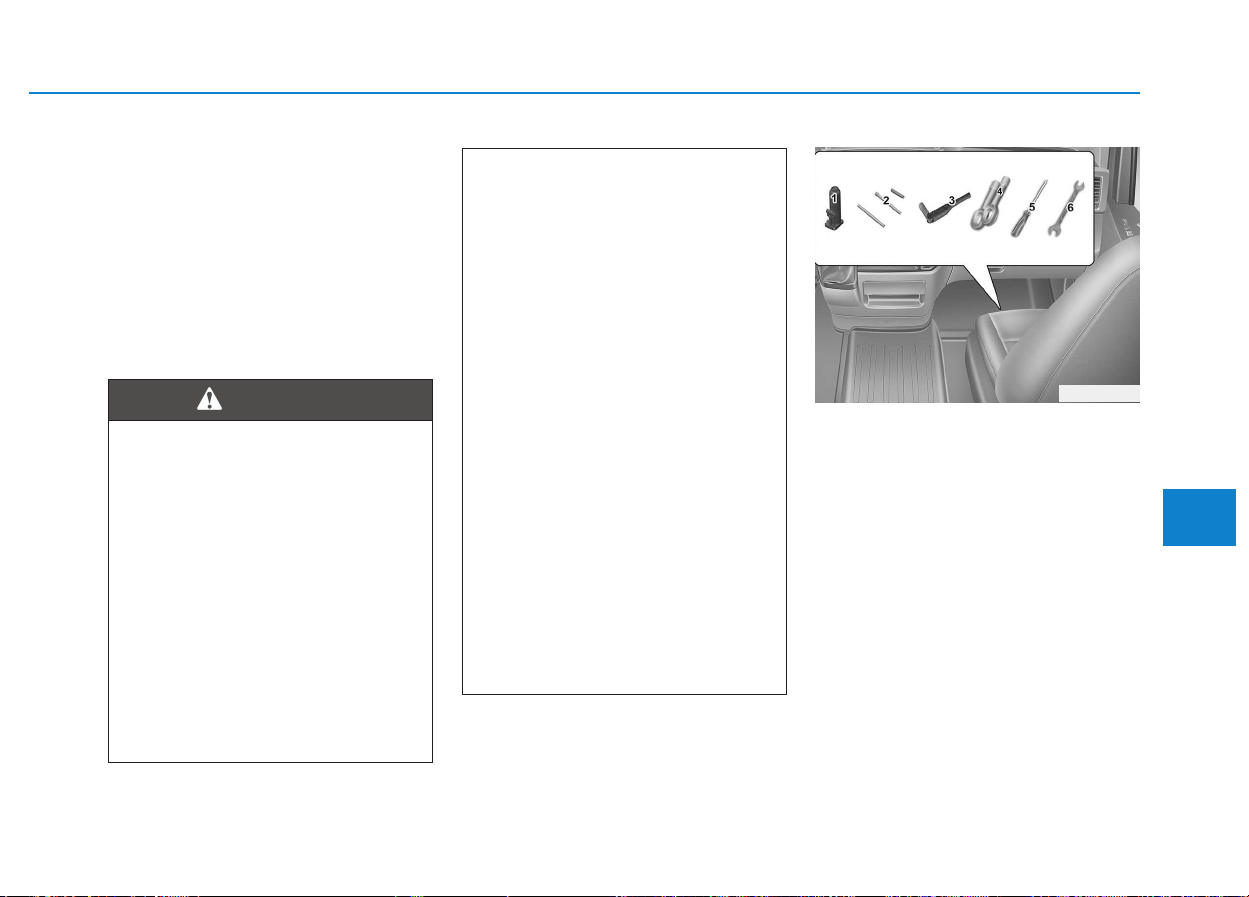
6-9
What to do in an emergency
6
■■
Jacking instructions
The jack is provided for emergency
tire changing only.
To prevent the jack from “rattling”
while the vehicle is in motion, store it
properly and fasten the jack screw
fully.
Follow jacking instructions to reduce
the possibility of personal injury.
■■
A type
Jack and tools
The jack, wheel lug nut wrench are
stored in the front passenger's door
step side.
(1) Jack
(2) Jack handle and extension bars
(3) Wheel lug nut wrench
(4) Towing hook
(5) Screwdriver (VAN/BUS Only)
(6) 14 x 17 Spanner (TRUCK Only)
RREEMMOOVVIINNGG AANNDD SSTTOORRIINNGG TTHHEE SSPPAARREE TTIIRREE
OEU066041
Changing tires
• Never attempt vehicle repairs
in the traffic lanes of a public
road or highway.
• Always move the vehicle com-
pletely off the road and onto
the shoulder before trying to
change a tire. The jack should
be used on firm level ground.
If you cannot find a firm level
place off the road, call a tow-
ing service company for
assistance.
(Continued)
(Continued)
• Be sure to use the correct
front and rear jacking posi-
tions on the vehicle; never
use the bumpers or any other
part of the vehicle for jacking
support.
• The vehicle can easily roll off
the jack causing serious
injury or death.
• Do not get under a vehicle
that is supported by a jack.
• Do not start or run the engine
while the vehicle is on the
jack.
• Do not allow anyone to remain
in the vehicle while it is on the
jack.
• Make sure any children pres-
ent are in a secure place away
from the road and from the
vehicle to be raised with the
jack.
WARNING
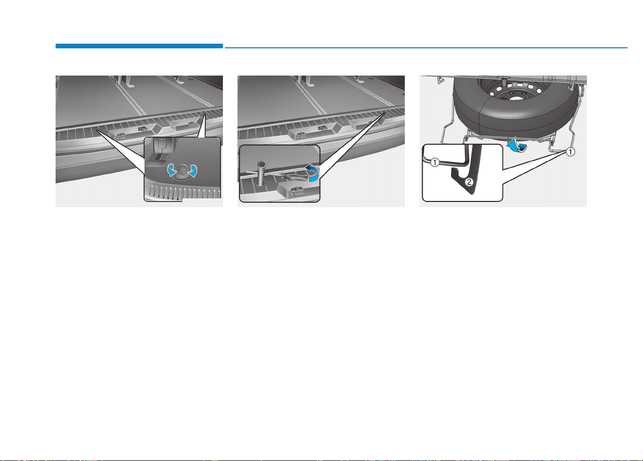
6-10
What to do in an emergency
VAN/BUS
Your spare tire is stored underneath
your vehicle, directly below the cargo
area.
To remove the spare tire:
1.Open the rear doors.
2.Find the plastic hex bolt cover and
remove the cover.
3.Using the extension bar and the
screwdriver, unscrew the bolts
counter-clockwise. Be careful not
to drop the carrier rapidly.
4.After the spare tire carrier reaches
the ground, remove the spare tire
outside from the carrier.
To store the spare tire:
1.Carefully place the spare tire onto
the spare tire carrier (1) with the
valve stem facing down.
2.Raise the spare tire carrier with the
hold bolt assemblies.
3.Turn the hold bolt (2) assemblies
clockwise until it tighten the speci-
fied torque.
[9.6~14.4 kgf.m(69~104 lb.ft)]
OEU064022 OEU066023 OEU065051
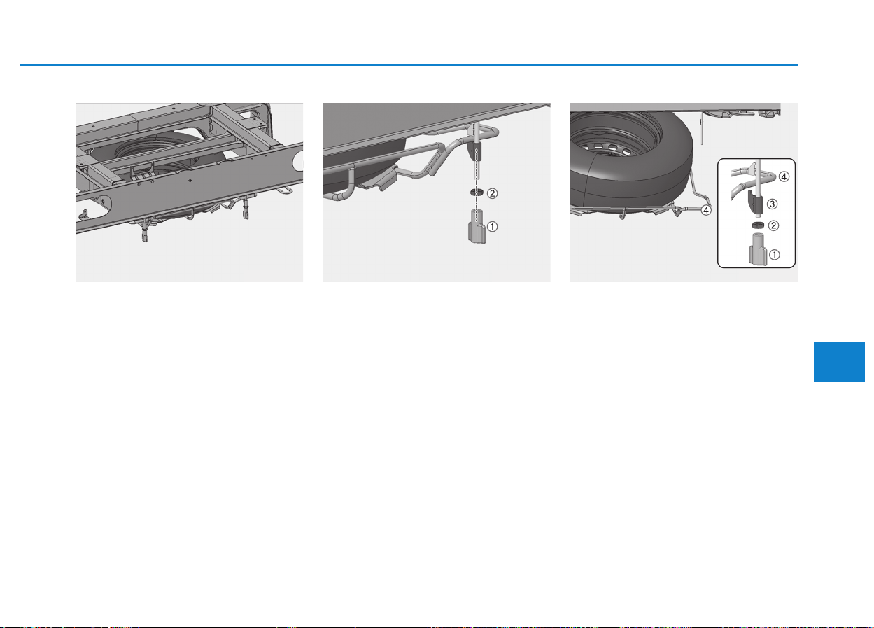
6-11
What to do in an emergency
Truck
Your spare tire is stored underneath
your vehicle, directly below the cargo
area.
To remove the spare tire:
1.Loosen fender nuts (1) manually
and then remove them.
2.Using the spanner, unscrew the
nuts (2) counter-clockwise.
Be careful not to drop the carrier
rapidly.
3.After the spare tire carrier reaches
the ground, remove the spare tire
outside from the carrier.
To store the spare tire:
1.Carefully place the spare tire onto
the spare tire carrier (4) with the
valve stem facing down.
2.Raise the spare tire carrier with the
hook assemblies (3).
3.Turn the nuts (2) clockwise until it
tighten the specified torque.
[1.2~1.8 kgf.m (8.7~13.0 lb.ft)]
4.Put fender nuts (1) in place and
tighten them.
6
OEU065052 OEU065053 OEU065054
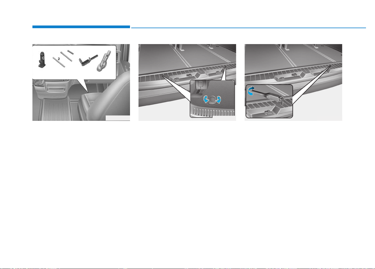
6-12
■■
B type
Jack and tools
The jack, wheel lug nut wrench are
stored in the front passenger's door
step side.
(1) Jack
(2) Jack handle and extension bars
(3) Wheel lug nut wrench
(4) Towing hook
VAN/BUS
Your spare tire is stored underneath
your vehicle, directly below the cargo
area.
To remove the spare tire:
1.Open the rear doors.
2.Find the plastic hex bolt cover and
remove the cover.
3.Using the wheel lug nut wrench,
unscrew the bolts counter-clock-
wise. Be careful not to drop the
carrier rapidly.
4.After the spare tire carrier reaches
the ground, remove the spare tire
outside from the carrier.
What to do in an emergency
OEU064041
OEU064022 OEU064023
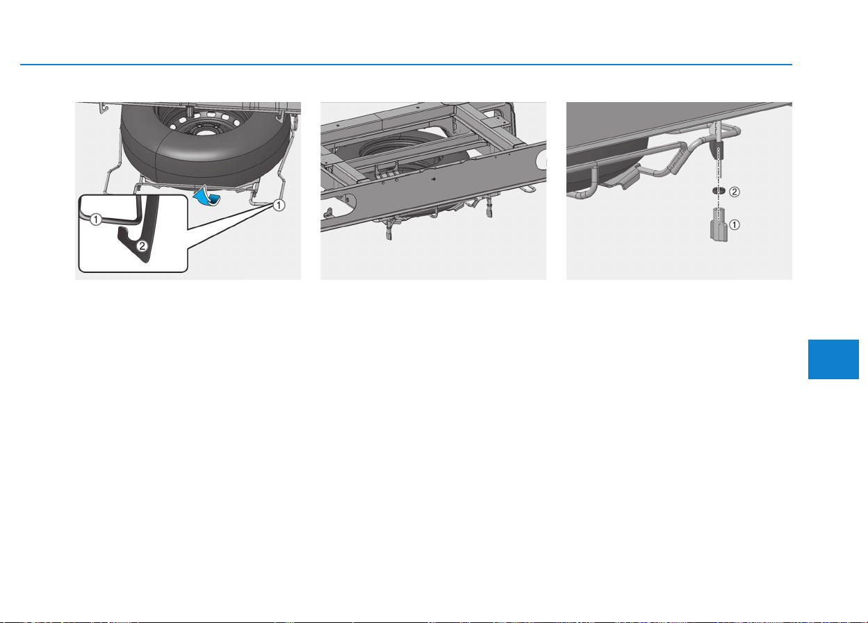
6-13
What to do in an emergency
To store the spare tire:
1.Carefully place the spare tire onto
the spare tire carrier (1) with the
valve stem facing down.
2.Raise the spare tire carrier with the
hold bolt assemblies.
3.Turn the hold bolt (2) assemblies
clockwise until it tighten the speci-
fied torque.
[9.6~14.4 kgf.m(69~104 lb.ft)]
Truck
Your spare tire is stored underneath
your vehicle, directly below the cargo
area.
To remove the spare tire:
1.Loosen fender nuts (1) manually
and then remove them.
2.Using the wheel lug nut wrench,
unscrew the nuts (2) counter-clock-
wise.
Be careful not to drop the carrier
rapidly.
3.After the spare tire carrier reaches
the ground, remove the spare tire
outside from the carrier.
6
OEU065051 OEU065052 OEU065053
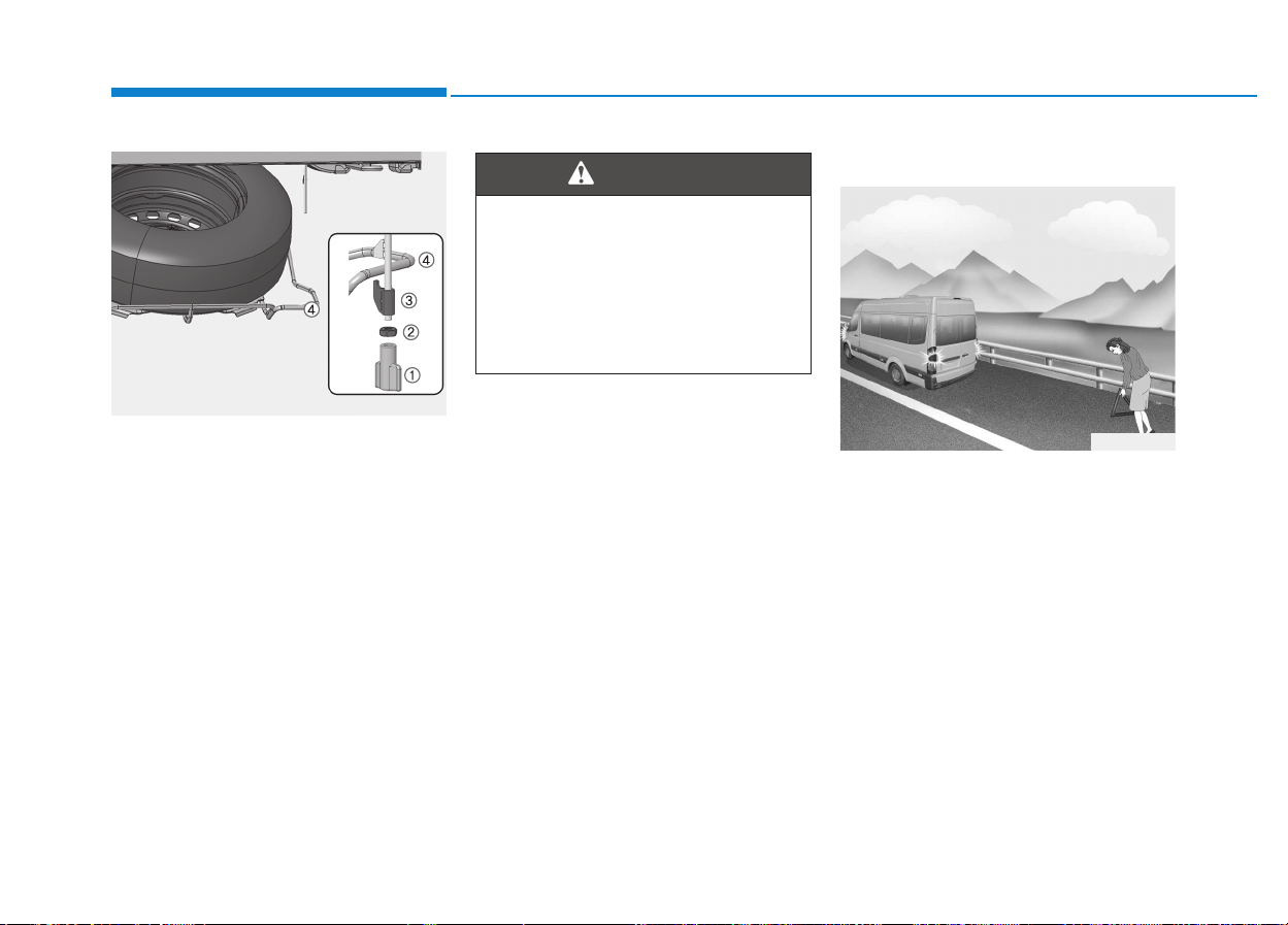
6-14
To store the spare tire:
1.Carefully place the spare tire onto
the spare tire carrier (4) with the
valve stem facing down.
2.Raise the spare tire carrier with the
hook assemblies (3).
3.Turn the nuts (2) clockwise until it
tighten the specified torque.
[1.2~1.8 kgf.m (8.7~13.0 lb.ft)]
4.Put fender nuts (1) in place and
tighten them.
Changing tires
1.Park on a level surface and apply
the parking brake firmly.
2.Shift the shift lever into R
(Reverse) with manual transmis-
sion.
3.Activate the hazard warning flash-
er.
4.Remove the wheel lug nut wrench,
jack, jack handle, and spare tire
from the vehicle.
5.Block both the front and rear of the
wheel that is diagonally opposite
the jack position.
What to do in an emergency
OEU065054
OEU064032
Ensure the spare tire carrier is
properly aligned with the center
of the spare tire to prevent the
spare tire “rattling”. Otherwise,
it may cause the spare tire to
fall off the carrier and lead to an
accident.
WARNING
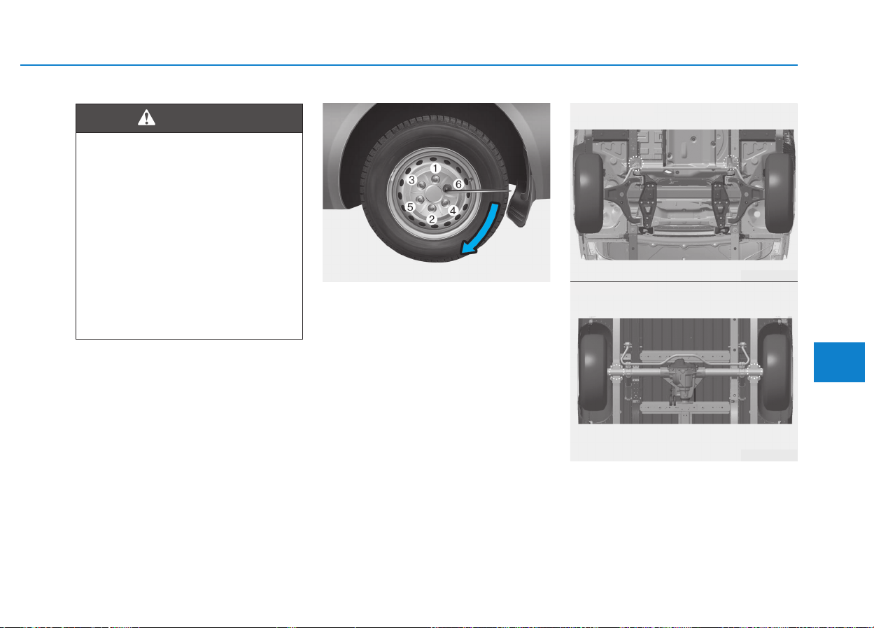
6-15
What to do in an emergency
6
6.Loosen the wheel lug nuts counter-
clockwise one turn each, but do
not remove any nut until the tire
has been raised off the ground.
7.Place the jack at the front or rear
jacking position closest to the tire
you are changing. The jack should
be positioned as shown in the
drawing.
Changing a tire
• To prevent vehicle movement
while changing a tire, always
set the parking brake fully,
and always block the wheel
diagonally opposite the wheel
being changed.
• We recommend that the
wheels of the vehicle be
chocked, and that no person
remain in a vehicle that is
being jacked.
WARNING
OEU064012
OEU064024
■ FRONT TIRE
OEU064025
■REAR TIRE
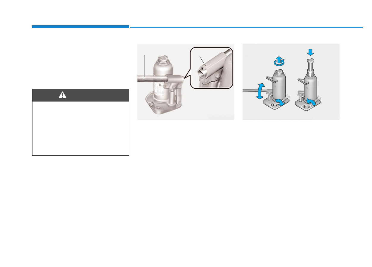
6-16
What to do in an emergency
- Front : Position the jack under lon-
gitudinal member in rear of
front sub frame assembly.
- Rear : Position the jack under rear
axle, as near the wheel
being jacked as possible.
8.Fit the jack handle into the jack
socket and then move the jack
handle up and down.
9.Raising the vehicle
If the jack-up point is too high, extend
the jack by turning the jack head
counterclockwise. Using the spanner
wrench or jack handle, turn the
release valve clockwise fully.
Move the jack handle up and down to
raise the ram until just before the
jack contacts the jacking point of the
vehicle.
Position the jack with the jack han-
dle. Position it only at the specified
points indicated in the "Put the Jack
in Place".
Use of the jack at other points could
damage the vehicle.
Moving the jack handle up and down
to raise the ram.
Jack location
To reduce the possibility of
injury, be sure to use only the
jack provided with the vehicle
and in the correct jack position;
never use any other part of the
vehicle for jack support.
WARNING
OEU064039
Jack handle
Holder
OEU064040
6-17
What to do in an emergency
6
10. Changing wheels
Loosen the wheel nuts and remove
them with your fingers. Slide the
wheel off the studs and lay it flat so it
cannot roll away. To put the wheel on
the hub, pick up the spare tire, line
up the holes with the studs and slide
the wheel onto them. If this is diffi-
cult, tip the wheel slightly and get the
top hole in the wheel lined up with
the top stud. Then jiggle the wheel
back and forth until the wheel can be
slid over the other studs.
On a double-tire vehicle, first
remove the outside tire, then
remove the inner tire.
NOTICE
• Use only the jack included
with the vehicle and use it
only for changing a wheel.
• Position the jack on a hard
level surface.
• If the release valve is loos-
ened by turning it 2 or more
times in the counterclockwise
direction, the jack cannot be
used.
• This jack is hydraulic, and the
ram is a two-stage type. When
both rams are raised and the
stop mark of the upper ram
becomes visible, stop jacking
immediately.
Further extension of the ram
may damage the jack.
• When jacking up the vehicle,
do so only until the tires are
slightly lifted from the ground.
It is dangerous to jack up the
vehicle more than that much.
(Continued)
CAUTION
(Continued)
• It is very dangerous if the jack
somehow slips, so never
leave the vehicle in the
jacked-up position, and never
shake the vehicle while it is
raised.
Do not get under the vehicle
when it is supported by the
jack! This is very dangerous as
the vehicle could fall and cause
serious injury or death. No one
should stay in the vehicle while
the jack is being used.
WARNING
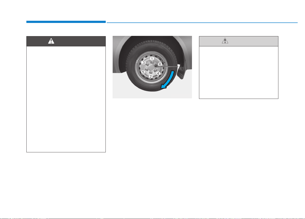
6-18
What to do in an emergency
11. Reinstall wheel nuts
To reinstall the wheel, hold it on the
studs, put the wheel nuts on the
studs and tighten them finger tight.
Jiggle the tire to be sure it is com-
pletely seated, then tighten the nuts
as much as possible with your fin-
gers again.
Wheel and wheel covers may
have sharp edges. Handle them
carefully to avoid possible
severe injury.
Before putting the wheel into
place, be sure that there is noth-
ing on the hub or wheel (such
as mud, tar, gravel, etc.) that
interferes with the wheel from
fitting solidly against the hub. If
there is, remove it. If there is not
good contact on the mounting
surface between the wheel and
hub, the wheel nuts could
loosen and cause the loss of a
wheel. Loss of a wheel may
result in loss of control of the
vehicle. This may cause serious
injury or death.
WARNING
OEU064012
Note that the wheel nuts "R"
mark on the right tires are right-
hand screw and those "L" mark
on the left tires are left-hand
screw, as viewed to the front of
vehicle. To tighten the nuts, turn
clockwise for the right-hand
side and counterclockwise for
the left-hand side.
CAUTION
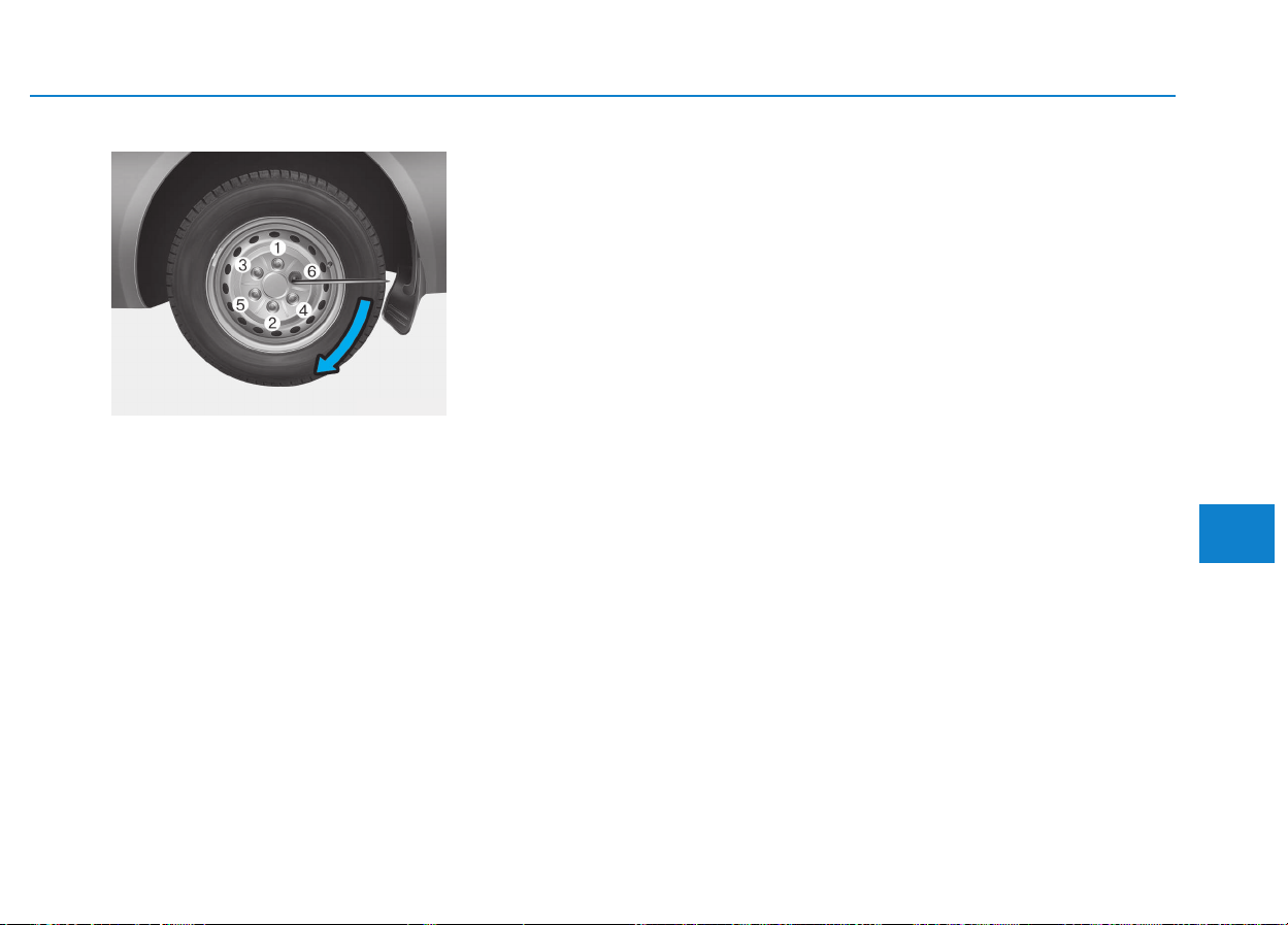
6-19
What to do in an emergency
6
12. Lower vehicle and tighten nuts
Lower the vehicle to the ground by
turning the release valve on the jack
counterclockwise. Then position the
wrench as shown in the drawing and
tighten the wheel nuts. Be sure the
socket is seated completely over the
nut. Do not stand on the wrench han-
dle or use an extension pipe over the
wrench handle.
Go around the wheel tightening
every other nut until they are all tight.
Then double-check each nut for
tightness. After changing wheels,
have a technician tighten the wheel
nuts to their proper torque as soon
as possible.
Wheel nut tightening torque:
Steel wheel & aluminum alloy wheel:
9~11 kg.m (67~81 lb.ft)
If you have a tire gauge, remove the
valve cap and check the air pressure.
If the pressure is lower than recom-
mended, drive slowly to the nearest
service station and inflate to the cor-
rect pressure. If it is too high, adjust
it until it is correct. Always reinstall
the valve cap after checking or
adjusting tire pressure. If the cap is
not replaced, air may leak from the
tire. If you lose a valve cap, buy
another and install it as soon as pos-
sible.
After you have changed wheels,
always secure the flat tire in its place
and return the jack and tools to their
proper storage locations.
After changing wheels
If you have a tire gauge, remove the
valve cap and check the air pressure.
If the pressure is lower than recom-
mended, we recommend that you
contact an authorized HYUNDAI
dealer. If it is too high, adjust it until it
is correct. Always reinstall the valve
cap after checking or adjusting tire
pressure. If the cap is not replaced,
air may leak from the tire. If you lose
a valve cap, buy another and install it
as soon as possible.
After you have changed wheels,
always secure the flat tire in its place
and return the jack and tools to their
proper storage locations.
OEU064012
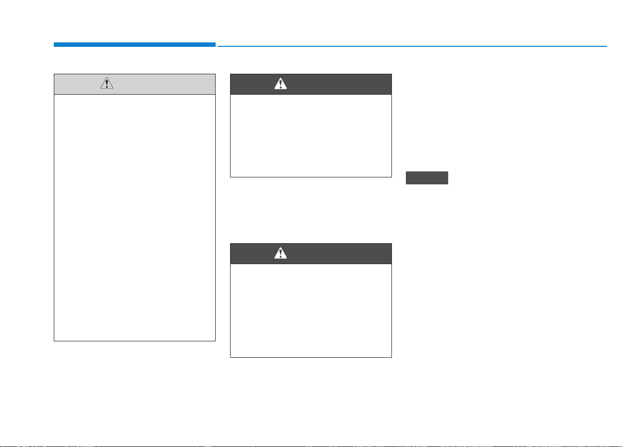
6-20
What to do in an emergency
To prevent the jack, jack handle,
wheel lug nut wrench and spare tire
from rattling while the vehicle is in
motion, store them properly.
Important - use of compact
spare tire (if equipped)
Your vehicle is equipped with a com-
pact spare tire. This compact spare
tire takes up less space than a regu-
lar-size tire. This tire is smaller than a
conventional tire and is designed for
temporary use only.
• You should drive carefully when
the compact spare is in use. The
compact spare should be
replaced by the proper conven-
tional tire and rim at the first
opportunity.
• The operation of this vehicle is
not recommended with more
than one compact spare tire in
use at the same time.
NOTICE
Your vehicle has metric threads
on the wheel studs and nuts.
Make certain during wheel
removal that the same nuts that
were removed are reinstalled -
or, if replaced, that nuts with
metric threads and the same
chamfer configuration are used.
Installation of a non-metric
thread nut on a metric stud or
vice-versa will not secure the
wheel to the hub properly and
will damage the stud so that it
must be replaced.
Note that most lug nuts do not
have metric threads. Be sure to
use extreme care in checking
for thread style before installing
aftermarket lug nuts or wheels.
If in doubt, we recommend that
you consult an authorized
HYUNDAI dealer.
CAUTION
Inadequate spare tire pressure
Check the inflation pressures
as soon as possible after
installing the spare tire. Adjust
it to the specified pressure, if
necessary. Refer to “Tires and
wheels” in section 8.
WARNING
Wheel studs
If the studs are damaged, they
may lose their ability to retain
the wheel. This could lead to the
loss of the wheel and a collision
resulting in serious injuries.
WARNING

6-21
What to do in an emergency
6
The compact spare should be inflat-
ed to 420 kPa (60 psi).
Information
Check the inflation pressure after
installing the spare tire. Adjust it to
the specified pressure, as necessary.
When using a compact spare tire,
observe the following precautions:
• Under no circumstances should
you exceed 80 km/h (50 mph); a
higher speed could damage the
tire.
• Ensure that you drive slowly
enough for the road conditions to
avoid all hazards. Any road hazard,
such as a pothole or debris, could
seriously damage the compact
spare.
• Any continuous road use of this tire
could result in tire failure, loss of
vehicle control, and possible per-
sonal injury.
• Do not exceed the vehicle’s maxi-
mum load rating or the load-carry-
ing capacity shown on the sidewall
of the compact spare tire.
• Avoid driving over obstacles. The
compact spare tire diameter is
smaller than the diameter of a con-
ventional tire and reduces the
ground clearance approximately
25 mm (1 inch), which could result
in damage to the vehicle.
• Do not take this vehicle through an
automatic car wash while the com-
pact spare tire is installed.
• Do not use tire chains on the com-
pact spare tire. Because of the
smaller size, a tire chain will not fit
properly. This could damage the
vehicle and result in loss of the
chain.
• The compact spare tire should not
be installed on the front axle if the
vehicle must be driven in snow or
on ice.
• Do not use the compact spare tire
on any other vehicle because this
tire has been designed especially
for your vehicle.
• The compact spare tire’s tread life
is shorter than a regular tire.
Inspect your compact spare tire
regularly and replace worn com-
pact spare tires with the same size
and design, mounted on the same
wheel.
i
The compact spare tire is for
emergency use only. Do not
operate your vehicle on this
compact spare at speeds over
80 km/h (50 mph). The original
tire should be repaired or
replaced as soon as is possible
to avoid failure of the spare
possibly leading to personal
injury or death.
WARNING
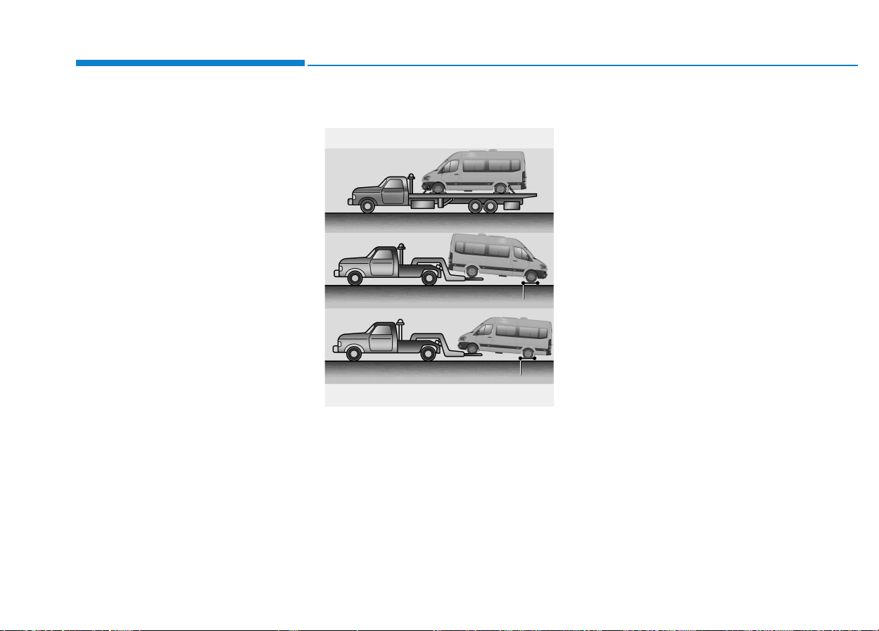
6-22
What to do in an emergency
• The compact spare tire should not
be used on any other wheels, nor
should standard tires, snow tires,
wheel covers or trim rings be used
with the compact spare wheel. If
such use is attempted, damage to
these items or other car compo-
nents may occur.
• Do not use more than one compact
spare tire at a time.
• Do not tow a trailer while the com-
pact spare tire is installed.
Towing service
If emergency towing is necessary,
we recommend having it done by an
authorized HYUNDAI dealer or a
commercial tow-truck service.
Proper lifting and towing procedures
are necessary to prevent damage to
the vehicle. The use of wheel dollies
or flatbed is recommended.
On 2WD vehicles, it is acceptable to
tow the vehicle with the rear wheels
on the ground (without dollies) and
the front wheels off the ground.
If any of the loaded wheels or sus-
pension components are damaged
or the vehicle is being towed with the
front wheels on the ground, use a
towing dolly under the front wheels.
When being towed by a commercial
tow truck and wheel dollies are not
used, the front of the vehicle should
always be lifted, not the rear.
TTOOWWIINNGG
OEU064015
dolly
dolly
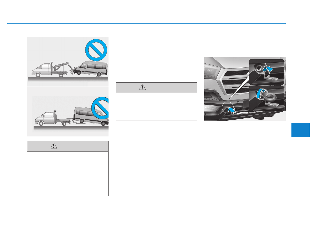
6-23
What to do in an emergency
6
When towing your vehicle in an
emergency without wheel dollies :
1.Set the ignition switch in the ACC
position.
2.Place the transmission shift lever in
N (Neutral).
3.Release the parking brake.
Removable towing hook
(if equipped)
Front towing hook
1.Remove the towing hook from the
tool store of front passenger’s door
step side.
2.Remove the hole cover pressing
the upper part of the cover on the
front bumper.
3.Install the towing hook by turning it
clockwise into the hole until it is
fully secured.
4.Remove the towing hook and
install the cover after use.
OEU064026
OEU064027
• Do not tow the vehicle back-
wards with the front wheels
on the ground as this may
cause damage to the vehicle.
• Do not tow with sling-type
equipment. Use wheel lift or
flatbed equipment.
CAUTION
Failure to place the transmis-
sion shift lever in N (Neutral)
may cause internal damage to
the transmission.
CAUTION
OEU064033
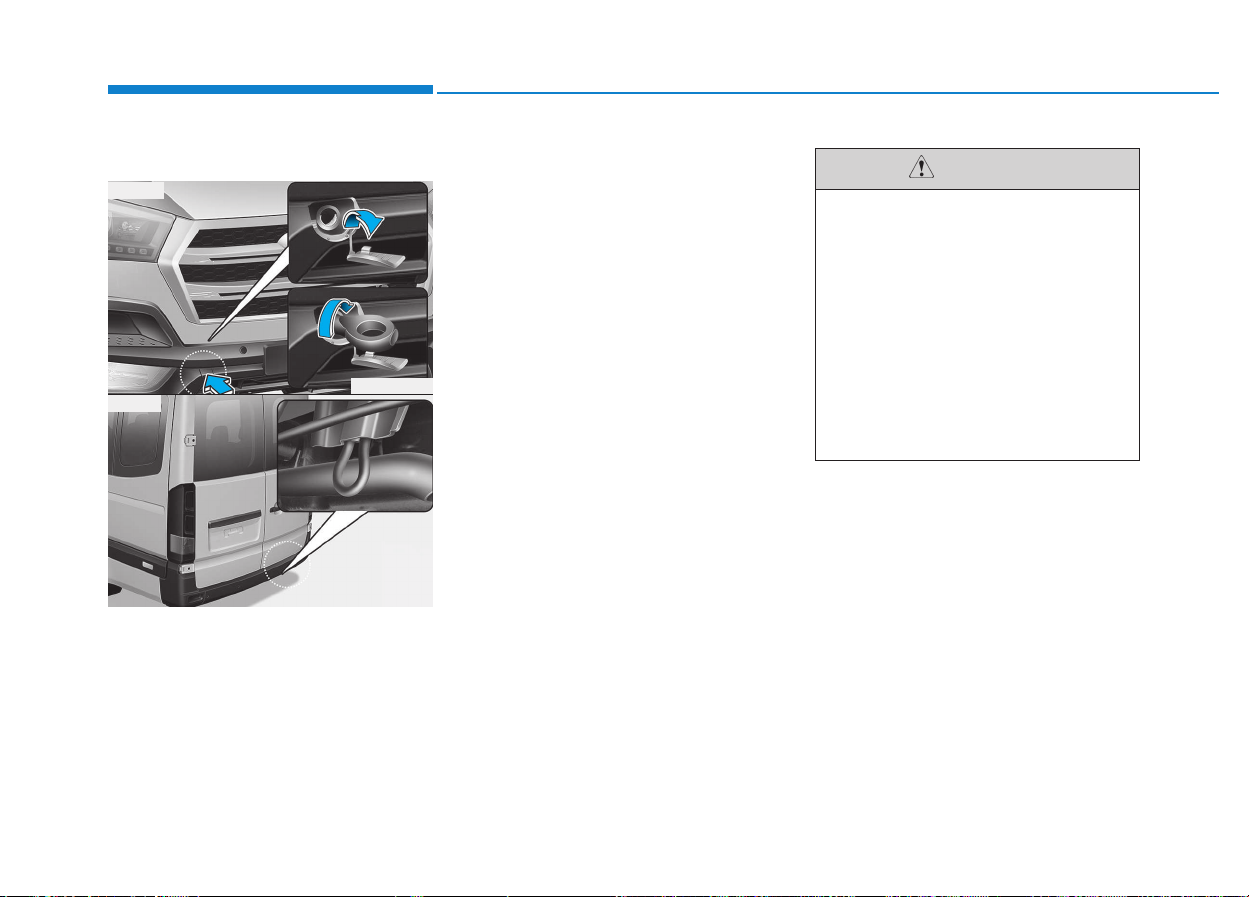
6-24
What to do in an emergency
Emergency towing
If towing is necessary, we recom-
mend you to have it done by an
authorized HYUNDAI dealer or a
commercial tow truck service.
If towing service is not available in an
emergency, your vehicle may be
temporarily towed using a cable or
chain secured to the emergency tow-
ing hook under the front (or rear) of
the vehicle. Use extreme caution
when towing the vehicle. A driver
must be in the vehicle to steer it and
operate the brakes.
Towing in this manner may be done
only on hard-surfaced roads for a
short distance and at low speed.
Also, the wheels, axles, power train,
steering and brakes must all be in
good condition.
• Do not use the towing hooks to pull
a vehicle out of mud, sand or other
conditions from which the vehicle
cannot be driven out under its own
power.
• Avoid towing a vehicle heavier than
the vehicle doing the towing.
• The drivers of both vehicles should
communicate with each other fre-
quently.
• Before emergency towing, check
that the hook is not broken or dam-
aged.
• Fasten the towing cable or chain
securely to the hook.
• Do not jerk the hook. Apply steady
and even force.
• To avoid damaging the hook, do
not pull from the side or at a verti-
cal angle. Always pull straight
ahead.
OEU064033
OEU064035
■ Front
■ Rear
• Attach a towing strap to the
tow hook.
• Using a portion of the vehicle
other than the tow hooks for
towing may damage the body
of your vehicle.
• Use only a cable or chain
specifically intended for use
in towing vehicles. Securely
fasten the cable or chain to
the towing hook provided.
CAUTION
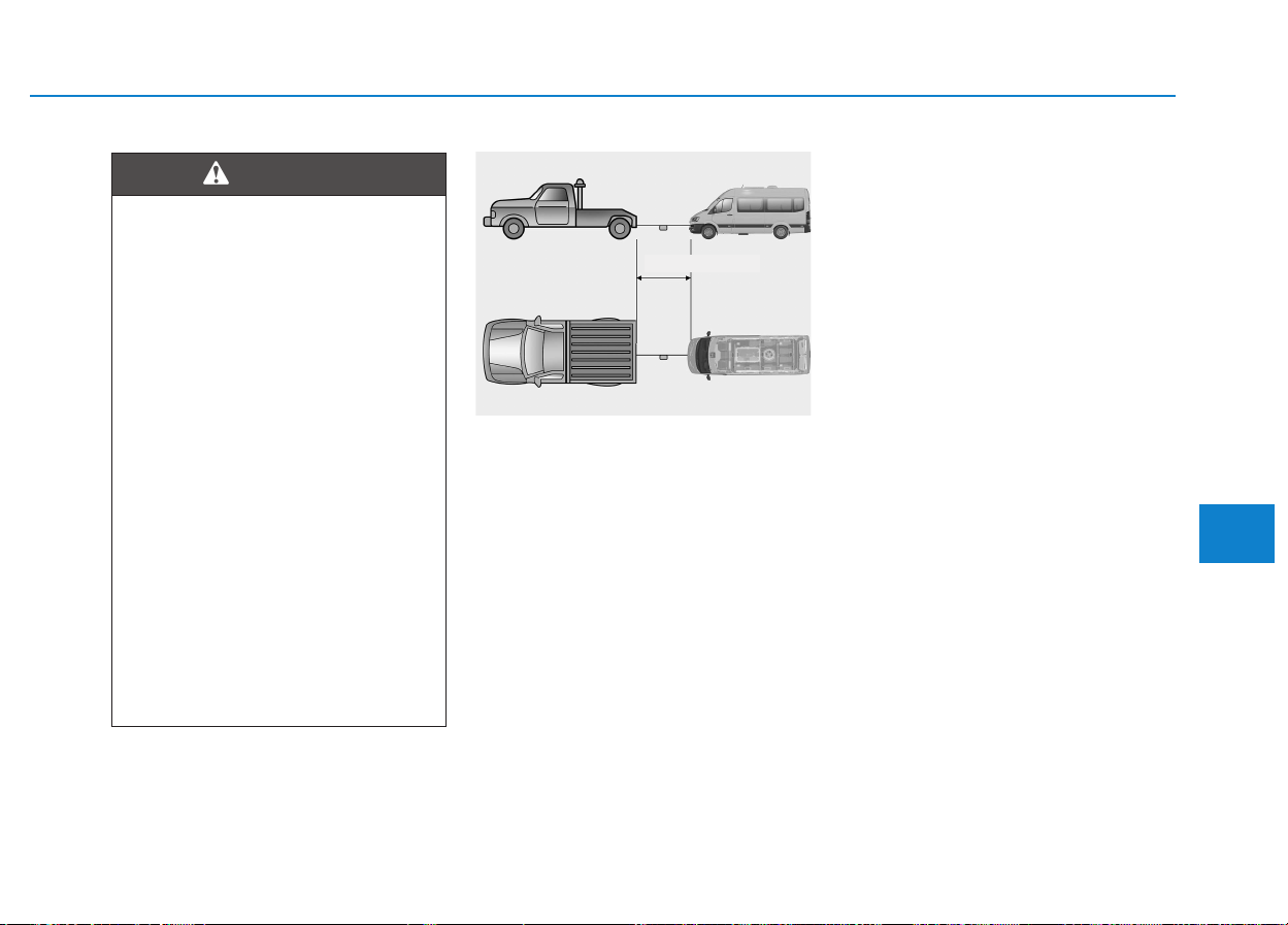
6-25
What to do in an emergency
6
• Use a towing strap less than 5 m
(16 feet) long. Attach a white or red
cloth (about 30 cm (12 inches)
wide) in the middle of the strap for
easy visibility.
• Drive carefully so that the towing
strap is not loosened during tow-
ing.
Emergency towing precautions
• Turn the ignition switch to ACC so
the steering wheel isn’t locked.
• Place the transmission shift lever in
N (Neutral).
• Release the parking brake.
• Press the brake pedal with more
force than normal since you will
have reduced brake performance.
• More steering effort will be
required because the power steer-
ing system will be disabled.
• If you are driving down a long hill,
the brakes may overheat and brake
performance will be reduced. Stop
often and let the brakes cool off.
Use extreme caution when tow-
ing the vehicle.
• Avoid sudden starts or erratic
driving maneuvers which
would place excessive stress
on the emergency towing
hook and towing cable or
chain. The hook and towing
cable or chain may break and
cause serious injury or dam-
age.
• If the disabled vehicle is
unable to be moved, do not
forcibly continue the towing.
Contact an authorized
HYUNDAI dealer or a commer-
cial tow truck service for
assistance.
• Tow the vehicle as straight
ahead as possible.
• Keep away from the vehicle
during towing.
WARNING
OEU064028
less 5 m (16 feet)
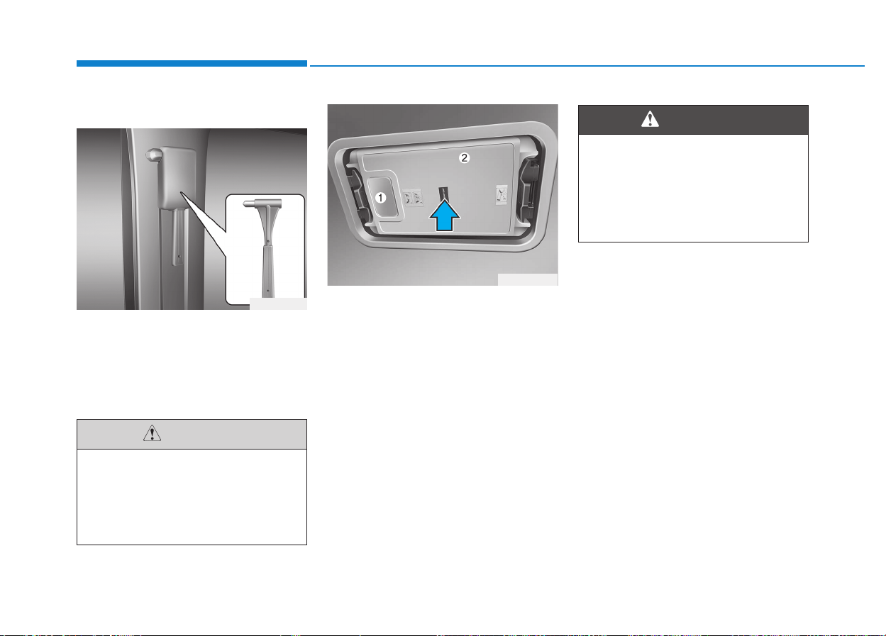
6-26
What to do in an emergency
Break the glass and escape using
the glass break hammer installed in
the vehicle in case of emergency.
You can take out glass break ham-
mer after holding on to the knob and
lifting up.
In case of an emergency
Remove the red plastic cover (1) and
the inner trim (2) to take out the
glass-breaking hammer.
With this glass-breaking hammer,
break the glass of the emergency
exit and escape from the vehicle.
The emergency exit assembly may
fall on the floor, when you break the
glass.
GGLLAASSSS BBRREEAAKK HHAAMMMMEERR
(
(IIFF EEQQUUIIPPPPEEDD))
OEU064029
Be careful that splinters of
glass do not shatter when
breaking glass. Splinters of
glass may cause damage to
human body.
CAUTION
OEU064030
EEMMEERRGGEENNCCYY EEXXIITT ((IIFF EEQQUUIIPPPPEEDD))
Be careful that splinters of
glass do not shatter when
breaking glass. Splinters of the
glass or then emergency exit
assembly may cause damage to
human body.
WARNING
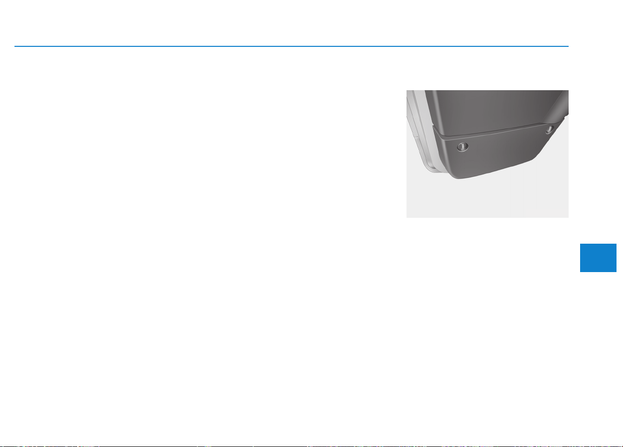
6-27
What to do in an emergency
6
There are some emergency com-
modities in the vehicle to help you
respond to the emergency situation.
Fire extinguisher
If there is small fire and you know
how to use the fire extinguisher, take
the following steps carefully.
❈ Location of a fire extinguisher
Bus : Behind of front passenger’s
seat and behind right side of
passenger’s seat
Van : Behind of front passenger’s
seat
1.Pull the pin at the top of the extin-
guisher that keeps the handle from
being accidentally pressed.
2.Aim the nozzle toward the base of
the fire.
3.Stand approximately 2.5 m (8 ft)
away from the fire and squeeze the
handle to discharge the extinguish-
er. If you release the handle, the
discharge will stop.
4.Sweep the nozzle back and forth at
the base of the fire. After the fire
appears to be out, watch it careful-
ly since it may re-ignite.
First aid kit (if equipped)
There are some items such as scis-
sors, bandage and adhesive tape
and etc. in the kit to give first aid to
an injured person.
EEMMEERRGGEENNCCYY CCOOMMMMOODDIITTYY ((IIFF EEQQUUIIPPPPEEDD))
OEU044064
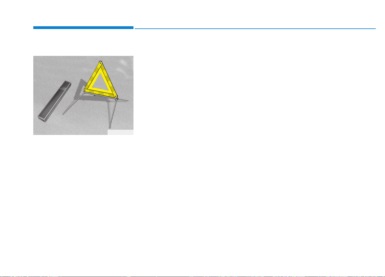
Triangle reflector (if equipped)
Place the triangle reflector on the
road to warn oncoming vehicles dur-
ing emergencies, such as when the
vehicle is parked by the roadside due
to any problems.
Tire pressure gauge
(If equipped)
Tires normally lose some air in day-
to-day use, and you may have to add
a few pounds of air periodically and it
is not usually a sign of a leaking tire,
but of normal wear. Always check tire
pressure when the tires are cold
because tire pressure increases with
temperature.
To check the tire pressure, take the
following steps;
1.Unscrew the inflation valve cap
that is located on the rim of the tire.
2.Press and hold the gauge against
the tire valve. Some air will escape
as you begin and more will escape
if you don't press the gauge in firm-
ly.
3.A firm non-leaking push will acti-
vate the gauge.
4. Read the tire pressure on the
gauge to know whether the tire
pressure is low or high.
5.Adjust the tire pressures to the
specified pressure. Refer to “Tires
and wheels” in section 8.
6.Reinstall the inflation valve cap.
OEA060013
What to do in an emergency
6-28

7
Maintenance
7
Maintenance
Engine compartment .............................................7-3
Maintenance services ...........................................7-5
Owner's responsibility......................................................7-5
Owner maintenance precautions ..................................7-5
Engine compartment precautions (Diesel engine)....7-7
Owner maintenance...............................................7-8
Owner maintenance schedule........................................7-8
Scheduled maintenance services ......................7-10
Normal maintenance schedule (for Europe) ............7-11
Normal maintenance schedule (except Europe) .....7-14
Maintenance under severe usage conditions..........7-17
Explanation of scheduled maintenance items ..7-19
Engine oil ..............................................................7-22
Checking the engine oil level ....................................7-22
Changing the engine oil and filter..............................7-23
Engine coolant......................................................7-24
Checking the coolant level ...........................................7-24
Changing the coolant.....................................................7-26
Brake/Clutch fluid ..............................................7-27
Checking the brake/clutch fluid level........................7-27
Power steering fluid............................................7-28
Checking the power steering fluid level ...................2-28
Checking the power steering hose.............................2-29
Washer fluid .........................................................7-29
Checking the washer fluid level ...............................7-29
Parking brake .......................................................7-30
Checking the parking brake .........................................7-30
Fuel filter (For diesel).........................................7-30
Draining water from fuel filter....................................7-30
Fuel filter cartridge replacement................................7-30
Manual transmission and rearaxle oil ..............7-31
Check and adding oil......................................................7-31
Change the gear oil........................................................7-31
Air cleaner ............................................................7-31
Filter replacement...........................................................7-31
Climate control air filter .....................................7-33
Filter inspection...............................................................7-33
Filter replacement...........................................................7-33
Wiper blades.........................................................7-34
Blade inspection ..............................................................7-34
Blade replacement ..........................................................7-35
Battery...................................................................7-37
For best battery service................................................7-37
Battery capacity label ...................................................7-40
Battery recharging .......................................................7-40
Reset items .......................................................................7-41
Tires and wheels..................................................7-42
Tire care............................................................................7-42
Recommended cold tire inflation pressures.............7-42
Checking tire inflation pressure..................................7-43
7

7
Tire rotation ....................................................................7-44
Wheel alignment and tire balance ..............................7-45
Tire replacement .............................................................7-46
Wheel replacement ........................................................7-47
Tire traction......................................................................7-47
Tire maintenance ...........................................................7-47
Tire sidewall labeling......................................................7-48
Fuses......................................................................7-50
Inner panel fuse replacement......................................7-52
Alternator fuse ................................................................7-54
Multi fuse..........................................................................7-54
Fuse/Relay panel description ......................................7-55
Light bulbs.............................................................7-67
Headlight, position light, turn signal light, front fog
light bulb replacement ...................................................7-68
Headlight and front fog light aiming (for Europe)..7-70
Side marker lamp ............................................................7-75
Rear combination light bulbs replacement ...............7-75
High mounted stop light bulb replacement ..............7-78
License plate light bulb replacement .........................7-78
Interior light bulb replacement ....................................7-78
Appearance care..................................................7-79
Exterior care ....................................................................7-79
Interior care......................................................................7-85
Emission control system .....................................7-87
Crankcase emission control system...........................7-87
Evaporative emission control system.........................7-87
Exhaust emission control system ...............................7-88
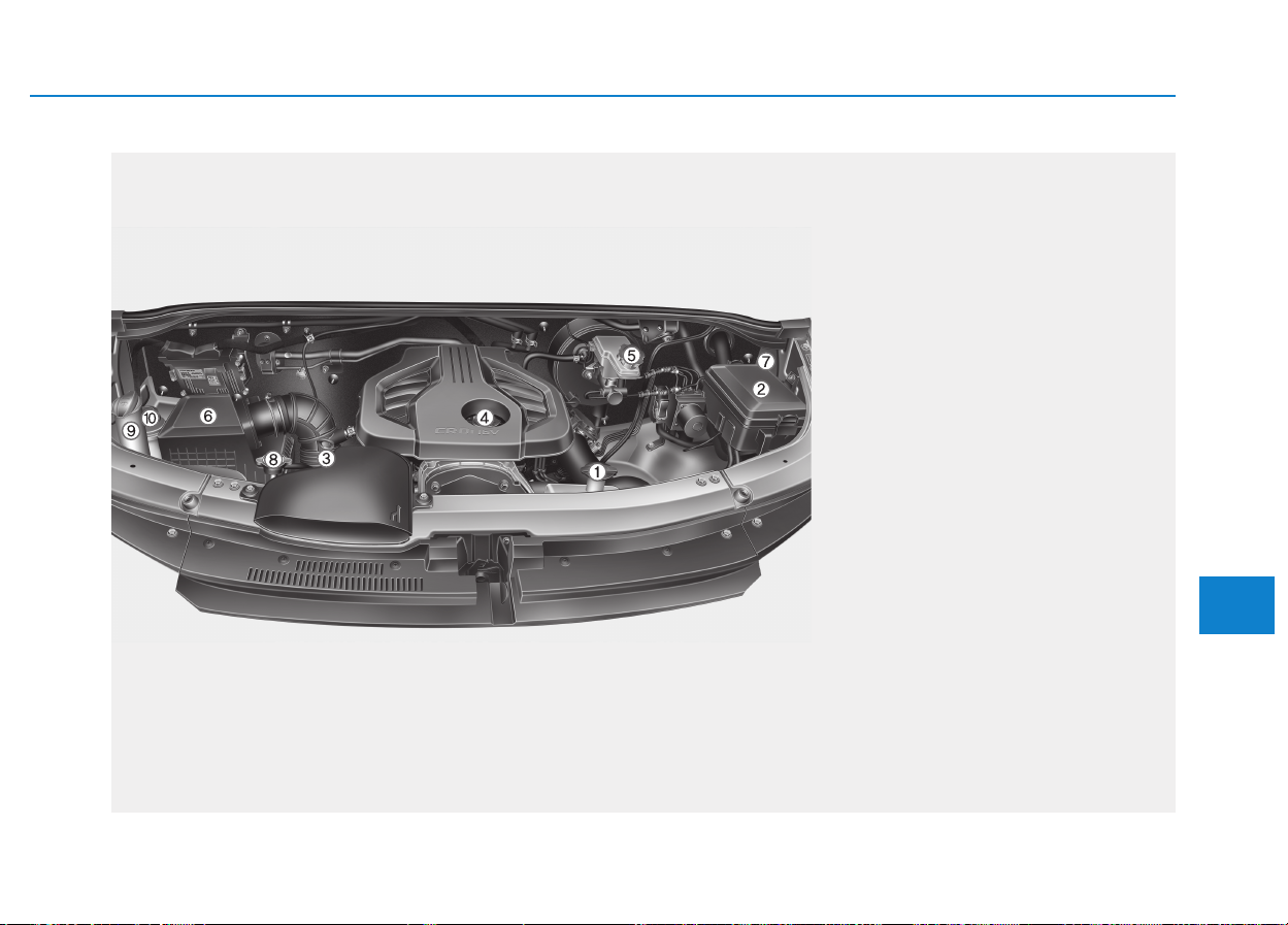
7-3
7
Maintenance
EENNGGIINNEE CCOOMMPPAARRTTMMEENNTT
1. Engine coolant reservoir
2. Fuse box and positive battery terminal
3. Engine oil dipstick
4. Engine oil filler cap
5. Brake/clutch fluid cap
6. Air cleaner
7. Negative battery terminal
8. Radiator cap
9. Windshield washer fluid reservoir
10. Power steering fluid reservoir
OEU014005
The actual shape may differ from the illustration.
■■
Bus, Van, Truck (without auxiliary battery)
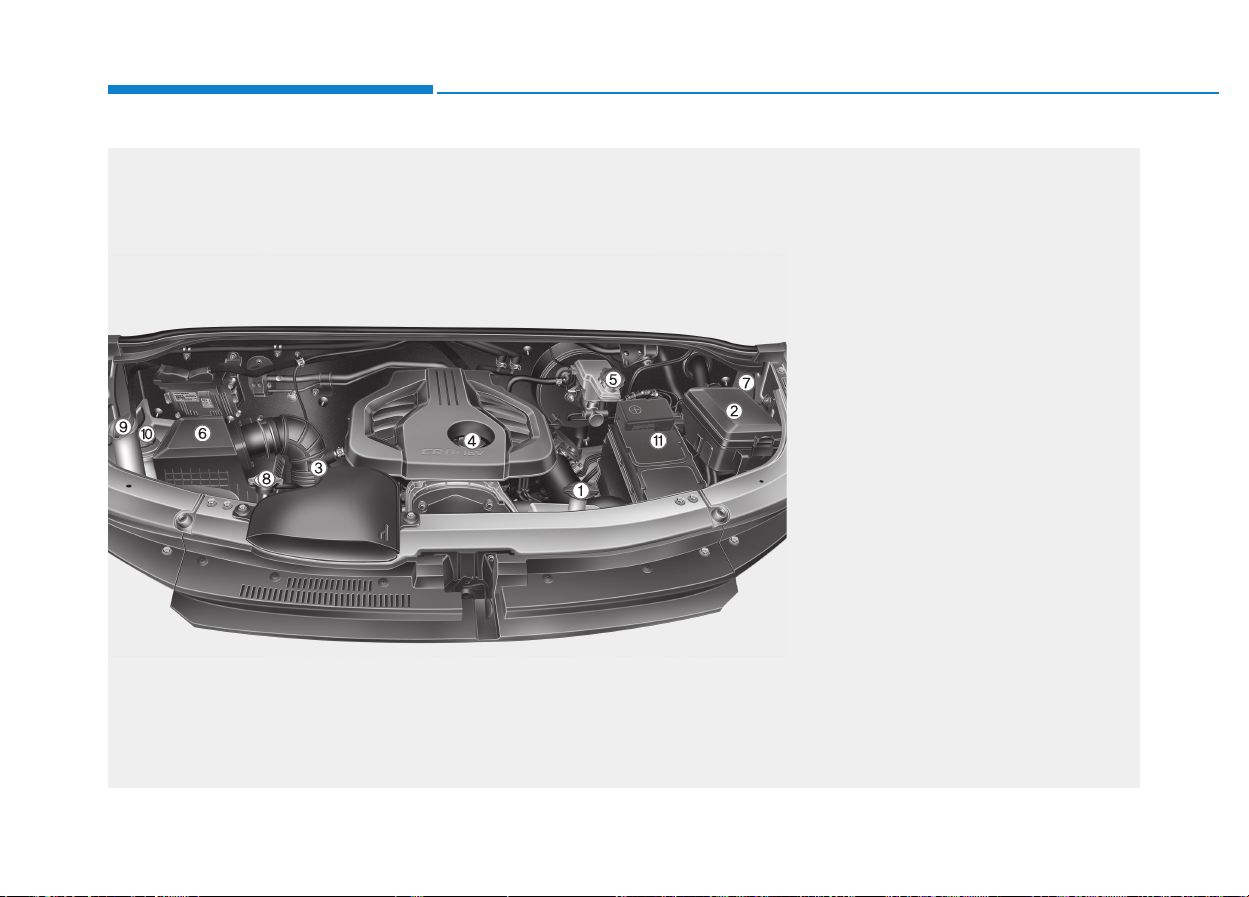
7-4
Maintenance
OEU014006
The actual shape may differ from the illustration.
■
■
Van, Truck (with auxiliary battery)
1. Engine coolant reservoir
2. Fuse box and positive battery terminal
3. Engine oil dipstick
4. Engine oil filler cap
5. Brake/clutch fluid cap
6. Air cleaner
7. Negative battery terminal
8. Radiator cap
9. Windshield washer fluid reservoir
10. Power steering fluid reservoir
11. Auxiliary battery

7-5
7
Maintenance
MMAAIINNTTEENNAANNCCEE SSEERRVVIICCEESS
You should exercise the utmost care
to prevent damage to your vehicle
and injury to yourself whenever per-
forming any maintenance or inspec-
tion procedures.
Inadequate, incomplete or insuffi-
cient servicing may result in opera-
tional problems with your vehicle that
could lead to vehicle damage, an
accident, or personal injury.
Owner’s responsibility
Maintenance Service and Record
Retention are the owner's respon-
sibility.
We recommend in general that you
have your vehicle serviced by an
authorized HYUNDAI dealer. You
should retain documents that show
proper maintenance has been per-
formed on your vehicle in accor-
dance with the scheduled mainte-
nance service charts shown on the
following pages. You need this infor-
mation to establish your compliance
with the servicing and maintenance
requirements of your vehicle war-
ranties. Detailed warranty informa-
tion is provided in your Service
Passport. Repairs and adjustments
required as a result of improper
maintenance or a lack of required
maintenance are not covered when
your vehicle is covered by warranty.
Owner maintenance precautions
Improper or incomplete service may
result in problems. This section gives
instructions only for the maintenance
items that are easy to perform.
Improper owner maintenance dur-
ing the warranty period may affect
warranty coverage. For details,
read the separate Service
Passport provided with the vehi-
cle. If you're unsure about any
servicing or maintenance proce-
dure, we recommend that the sys-
tem be serviced by an authorized
HYUNDAI dealer.
NOTICE
NOTICE

7-6
Maintenance
Maintenance work
• Performing maintenance work
on a vehicle can be danger-
ous. You can be seriously
injured while performing
some maintenance proce-
dures. If you lack sufficient
knowledge and experience or
the proper tools and equip-
ment to do the work, we rec-
ommend that the system be
serviced by an authorized
HYUNDAI dealer.
• Working under the hood with
the engine running is danger-
ous. It becomes even more
dangerous when you wear
jewelry or loose clothing.
These can become entangled
in moving parts and result in
injury.
(Continued)
WARNING
Continued)
Therefore, if you must run the
engine while working under
the hood, make certain that
you remove all jewelry (espe-
cially rings, bracelets, watch-
es, and necklaces) and all
neckties, scarves, and similar
loose clothing before getting
near the engine or cooling
fans.
• Do not put heavy objects or
apply excessive force on top
of the engine cover (if
equipped) or fuel related
parts.
• When you inspect the fuel
system (fuel lines and fuel
injection devices), we recom-
mend that you contact an
authorized HYUNDAI dealer.
• Do not drive long time with
the engine cover (if equipped)
removed.
• When checking the engine
room, do not go near fire.
Fuel, washer fluid, etc. are
flammable oils that may cause
fire.
• Before touching the battery,
ignition cables and electrical
wiring, you should disconnect
the battery "-" terminal. You
may get an electric shock
from the electric current.
(Continued)
CAUTION

7-7
7
Maintenance
Continued)
• When you remove the interior
trim cover with a flat head (-)
driver, be careful not to dam-
age the cover.
• Be careful when you replace
and clean bulbs to avoid
burns or electrical shock.
Engine compartment precau-
tions (Diesel engine)
• Follow the safety tips provided
below, when you are checking the
engine room while the engine is
running.
- Do not touch the injector, injector
wirings, and the engine computer
while the engine is running.
- Do not remove the injector con-
nector while the engine is run-
ning.
- People using pacemakers must
not go near the engine while the
engine is starting or running.
Diesel Engine
Never work on injection system
with engine running or within 30
seconds after shutting off
engine. High-pressure pump,
rail, injectors and high-pressure
pipes are subject to high pres-
sure even after the engine
stopped. The fuel jet produced
by fuel leaks may cause serious
injury, if it touches the body.
People using pacemakers
should not move than 30cm
closer to the ECU or wiring har-
ness within the engine room
while engine is running, since
the high currents in the elec-
tronic engine control system
produce considerable magnetic
fields.
WARNING
7-8
Maintenance
The following lists are vehicle checks
and inspections that should be per-
formed at the frequencies indicated
to help ensure safe, dependable
operation of your vehicle. If you have
any question, we recommend that
you consult an authorized HYUNDAI
dealer.
These Owner Maintenance Checks
are generally not covered by war-
ranties and you may be charged for
labor, parts and lubricants used.
Owner maintenance schedule
When you stop for fuel:
• Check the engine oil level.
• Check coolant level in coolant
reservoir.
• Check the windshield washer fluid
level.
• Look for low or under-inflated tires.
While operating your vehicle:
• Note any changes in the sound of
the exhaust or any smell of
exhaust fumes in the vehicle.
• Check for vibrations in the steering
wheel. Notice any increased steer-
ing effort or looseness in the steer-
ing wheel, or change in its straight-
ahead position.
• Notice if your vehicle constantly
turns slightly or “pulls” to one side
when traveling on smooth, level
road.
• When stopping, listen and check
for unusual sounds, pulling to one
side, increased brake pedal travel
or “hard-to-push” brake pedal.
• If any slipping or changes in the
operation of your transmission
occurs, check the transmission
fluid level.
• Check manual transmission opera-
tion, including clutch operation.
• Check parking brake.
• Check for fluid leaks under your
vehicle (water dripping from the air
conditioning system during or after
use is normal).
OOWWNNEERR MMAAIINNTTEENNAANNCCEE
Be careful when checking your
engine coolant level when the
engine is hot. Scalding hot
coolant and steam may blow
out under pressure. This could
cause burns or other serious
injury.
WARNING

7-9
7
Maintenance
At least monthly:
• Check coolant level in the engine
coolant reservoir.
• Check the operation of all exterior
lights, including the stoplights, turn
signals and hazard warning flash-
ers.
• Check the inflation pressures of all
tires including the spare.
At least twice a year
(i.e., every Spring and Fall) :
• Check radiator, heater and air con-
ditioning hoses for leaks or dam-
age.
• Check windshield washer spray
and wiper operation. Clean wiper
blades with clean cloth dampened
with washer fluid.
• Check headlight alignment.
• Check muffler, exhaust pipes,
shields and clamps.
• Check the lap/shoulder belts for
wear and function.
• Check for worn tires and loose
wheel lug nuts.
At least once a year :
• Clean body, door and hood drain
holes.
• Clean and lubricate door hinges
and checks, and hood hinges.
• Clean and lubricate door and hood
locks and latches.
• Clean and lubricate door rubber
weatherstrips.
• Check the air conditioning system.
• Check the power steering fluid
level.
• Clean battery and terminals.
• Check the brake and clutch fluid
level.

7-10
Maintenance
S
SCCHHEEDDUULLEEDD MMAAIINNTTEENNAANNCCEE SSEERRVVIICCEESS
Follow Normal Maintenance Schedule if the vehicle is usually operated where none of the following conditions apply.
If any of the following conditions apply, you must follow the Maintenance Under Severe Usage Conditions.
• Repeated short distance driving.
• Driving in dusty conditions or sandy areas.
• Extensive use of brakes.
• Driving in areas where salt or other corrosive materials are used.
• Driving on rough or muddy roads.
• Driving in mountainous areas.
• Extended periods of idling or low speed operation.
• Driving for a prolonged period in cold temperatures and/or extremely humid climates.
• More than 50% driving in heavy city traffic during hot weather above 32°C (90°F).
If your vehicle is operated under the above conditions, you should inspect, replace or refill more frequently than the
following Normal Maintenance Schedule. After the periods or distance shown in the chart, continue to follow the pre-
scribed maintenance intervals.

7-11
7
Maintenance
NORMAL MAINTENANCE SCHEDULE (FOR EUROPE)
I : Inspect and if necessary, adjust, correct, clean or replace.
R : Replace or change.
*
1
: Adjust alternator and power steering (and water pump drive belt) and air conditioner drive belt (if equipped).
Inspect and if necessary correct or replace.
*
2
: Check the engine oil level and leak every 500 km (350 miles) or before starting a long trip.
*
3
: This maintenance schedule depends on fuel quality. It is applicable only when using a qualified fuel <"EN590 or equivalent">.
If the diesel fuel specification doesn't meet the EN590, it must be replaced more frequently. If there are some important safety
matters like fuel flow restriction, surging, loss of power, hard starting problem etc, replace the fuel filter immediately regardless
of maintenance schedule and we recommend that you consult an authorized HYUNDAI dealer.
*
4
: Fuel filter warning light comes on, you should replace fuel filter before the next scheduled service.
Number of months or driving distance, whichever comes first
Months 24 48 72 96 120 144 168 192
Miles×1,000 20 37.5 60 75 90 110 130 150
Km×1,000 30 60 90 120 150 180 210 240
Drive Belts *
1
and idler
At first, inspect 60,000 km (37,500 miles) or 48 months
After that, inspect every 30,000 km (20,000 miles) or 24 months
Engine oil and engine oil filter *
2
Except Russia
Replace every 30,000 km (20,000 miles) or 24 months
For Russia Replace every 15,000 km (1,000 miles) or 12 months
Air cleaner filter I R I R I R I R
Vapor hose and fuel filter cap I I I I I I I I
Vacuum hose (for EGR & throttle body) (if equipped) I I I I I I I I
Fuel Filter Cartridge *
3
*
4
I R I R I R I R
Fuel line hoses and connections I I I I I I I I
MAINTENANCE
INTERVALS
MAINTENANCE
ITEM

7-12
Maintenance
NORMAL MAINTENANCE SCHEDULE (FOR EUROPE)
Number of months or driving distance, whichever comes first
Months 24 48 72 96 120 144 168 192
Miles×1,000 20 37.5 60 75 90 110 130 150
Km×1,000 30 60 90 120 150 180 210 240
Cooling system
Inspect "Coolant level and leak" every day
Inspect "Water pump" when replacing the drive belt
Raidator pressure cap I I I I I I I I
Engine coolant *
5
At first, replace at 210,000 km (130,000 miles) or 10 years :
after that, replace every 30,000 km (20,000 miles) or 24 months *
6
Battery Condition I I I I I I I I
Brake lines, hoses and connections I I I I I I I I
Brake pedal I I I I I I I I
Parking brake I I I I I I I I
Brake/Clutch fluid I
R
I
R
I
R
I
R
Disc brakes and pads I I I I I I I I
Power steering fluid I
R
I
R
I
R
I
R
Power steering hoses I I I I I I I I
MAINTENANCE
INTERVALS
MAINTENANCE
ITEM
I : Inspect and if necessary, adjust, correct, clean or replace.
R : Replace or change.
*
5
: When adding coolant, use only deionized water or soft water for your vehicle and never mix hard water in the coolant filled at
the factory. An improper coolant mixture can result in serious malfunction or engine damage.
*
6
: For your convenience, it can be replaced prior to its interval when you do maintenance of other items.

7-13
7
Maintenance
Number of months or driving distance, whichever comes first
Months 24 48 72 96 120 144 168 192
Miles×1,000 20 37.5 60 75 90 110 130 150
Km×1,000 30 60 90 120 150 180 210 240
Steering gear rack, linkage and boots I I I I I I I I
Propeller shaft I I I I I I I I
Tire (pressure & tread wear) I I I I I I I I
Front suspension ball joints I I I I I I I I
Bolt and nuts on chassis and body I I I I I I I I
Air conditioner refrigerant (if equipped) I I I I I I I I
Air conditioner compressor (if equipped) Inspect every 30,000 km (20,000 miles) or 2 years
Climate control air filter (if equipped)
R R R R R R R R
Manual transmission fluid (if equipped)
Inspect every 60,000 km (37,500 miles) or 2 years
If necessary, refill transmission oil
At first, replace 90,000 km (60,000 miles) :
after that, repalce every 150,000 km (93,000 miles)
Rear axle oil *
7
R R R R R R R R
MAINTENANCE
INTERVALS
MAINTENANCE
ITEM
NORMAL MAINTENANCE SCHEDULE (FOR EUROPE)
I : Inspect and if necessary, adjust, correct, clean or replace.
R : Replace or change.
*
7
: Rear axle oil should be changed anytime they have been submerged in water.
Note : Number of months or during distance, whichever comes first.

7-14
Maintenance
NORMAL MAINTENANCE SCHEDULE (EXCEPT EUROPE)
Number of months or driving distance, whichever comes first
Months 12 24 36 48 60 72 84 96
Miles×1,000 12.5 25 37.5 50 62.5 75 87.5 100
Km×1,000 20 40 60 80 100 1120 140 160
Drive belts *
1
and idler
At first, inspect 60,000 km (37,500 miles) or 48 months
After that, inspect every 30,000 km (20,000 miles) or 24 months
Engine oil and engine oil filter *
2
Replace every 10,000 km (6,200 miles) or 12 months
Air cleaner filter I R I R I R I R
Vapor hose and fuel filler cap I I I I I I I I
Vacuum hose (for EGR & throttle body) (if equipped) I I I I I I I I
Fuel filter cartridge *
3
*
4
I R I R I R I R
MAINTENANCE
INTERVALS
MAINTENANCE
ITEM
I : Inspect and if necessary, adjust, correct, clean or replace.
R : Replace or change.
*
1
: Adjust alternator and power steering (and water pump drive belt) and air conditioner drive belt (if equipped).
Inspect and if necessary correct or replace.
*
2
: Check the engine oil level and leak every 500 km (350 miles) or before starting a long trip.
*
3
: This maintenance schedule depends on fuel quality. It is applicable only when using a qualified fuel < "EN590 or equivalent">.
If the diesel fuel specification doesn't meet the EN590, it must be replaced more frequently. If there are some important safety
matters like fuel flow restriction, surging, loss of power, hard starting problem etc, replace the fuel filter immediately regardless
of maintenance schedule and we recommend that you consult an authorized HYUNDAI dealer.
*
4
: Fuel filter warning light comes on, you should replace fuel filter before the next scheduled service.

7-15
7
Maintenance
NORMAL MAINTENANCE SCHEDULE (EXCEPT EUROPE)
Number of months or driving distance, whichever comes first
Months 12 24 36 48 60 72 84 96
Miles×1,000 12.5 25 37.5 50 62.5 75 87.5 100
Km×1,000 20 40 60 80 100 120 140 160
Fuel lines, hoses and connections I I I I I I I I
Cooling system
Inspect “Coolant level and leak”every day
Inspect “Water pump”when replacing the drive belt
Engine coolant *
5
At first, replace at 200,000 km (120,000 miles) or 10 years:
after that, replace every 40,000 km (25,000 miles) or 24 months *
6
Battery condition I I I I I I I I
Brake lines, hoses and connections I I I I I I I I
Brake pedal I I I I I I I I
Parking brake I I I I I I I I
Brake fluid I I I I I I I I
Disc brakes and pads I I I I I I I I
Power steering hoses I I I I I I I I
Power steering fluid I R I R I R I R
MAINTENANCE
INTERVALS
I : Inspect and if necessary, adjust, correct, clean or replace.
R : Replace or change.
*
5
: When adding coolant, use only deionized water or soft water for your vehicle and never mix hard water in the coolant filled at
the factory. An improper coolant mixture can result in serious malfunction or engine damage.
*
6
: For your convenience, it can be replaced prior to it's interval when you do maintenance of other items.
MAINTENANCE
ITEM

7-16
Maintenance
NORMAL MAINTENANCE SCHEDULE (EXCEPT EUROPE)
Number of months or driving distance, whichever comes first
Months 12 24 36 48 60 72 84 96
Miles×1,000 12.5 25 37.5 50 62.5 75 87.5 100
Km×1,000 20 40 60 80 100 120 140 160
Steering gear rack, linkage and boots I I I I I I I I
Propeller shaft I I I I I I I I
Tire (pressure & tread wear) I I I I I I I I
Front suspension ball joints I I I I I I I I
Bolt and nuts on chassis and body I I I I I I I I
Air conditioner refrigerant (if equipped) I I I I I I I I
Air conditioner compressor (if equipped) Inspect every 30,000 km (20,000 miles) or 2 years
Climate control air filter (if equipped) R R R R R R R R
Manual transmission fluid
Inspect every 60,000 km (37,500 miles) or 2 years
If necessary, refill transmission oil
At first, replace at 140,000 km (85,000 miles) :
after that, replace 160,000 km (100,000 miles)
Rear axle oil *
7
R R R R R R R R
MAINTENANCE
INTERVALS
I : Inspect and if necessary, adjust, correct, clean or replace.
R : Replace or change.
*
7
: Rear axle oil should be changed anytime they have been submerged in water.
Note : Number of months or during distance, whichever comes first.
MAINTENANCE
ITEM

7-17
7
Maintenance
MAINTENANCE UNDER SEVERE USAGE CONDITIONS
The following items must be serviced more frequently on vehicles mainly used under severe driving conditions.
Refer to the chart below for the appropriate maintenance intervals.
R : Replace I : Inspect and if necessary, adjust, correct, clean or replace
Maintenance item
Maintenance
operation
Maintenance intervals
Driving
condition
Engine oil and
engine oil filter
For Europe R Every 15,000 km (10,000 miles) or 12 months
A, B, C, D, F, G,
H, I, J, L, M
Except Europe and Russia R Every 5,000 km (3,000 miles) or 6 months
A, B, C, D, F, G,
H, I, J, L, M
For Russia R Every 7,500 km (4,650 miles) or 6 months
A, B, C, D, F, G,
H, I, J, L, M
Air cleaner filter R
Replace more frequently
depending on the condition
C, E
Manual transmission fluid R
Replace initial 90,000 km (60,000 miles) after
that replace 150,000 km (93,000 miles)
C, D, E, G,
H, I, L
Rear axle oil R Every 30,000 km (20,000 miles) C, E, G, H, I, L
Steering gear rack, linkage and boots I
Inspect more frequently
depending on the condition
C, D, E, F, G
Propeller shaft
For Europe I Every 20,000 km (12,500 miles) or 12 months
C, E
Except Europe I Every 15,000 km (10,000 miles) or 12 months
Front suspension ball joints I
Inspect more frequently
depending on the condition
C, D, E, F, G
Disc brakes and pads, calipers and rotors I
Inspect more frequently
depending on the condition
C, D, E, G, H

7-18
Maintenance
Severe driving conditions
A : Repeated short distance driving
B : Extensive idling
C : Driving in dusty, rough roads
D : Driving in areas using salt or other corrosive
materials or in very cold weather
E : Driving in sandy areas
F : More than 50 % driving in heavy city traffic during hot
weather above 32°C (90°F)
G : Driving on uphill, downhill or mountain roads
H : Towing a trailer or using a camper on roof rack
(if equipped)
I : Driving for patrol vehicle, taxi, commercial vehicle or vehi-
cle towing
J : Driving in very cold weather
K : Driving over 140 km/h (87 mile/h)
L : Driving over 170 km/h (106 mile/h)
M : Frequently driving in stop - and - go conditions
Maintenance item
Maintenance
operation
Maintenance intervals
Driving
condition
Parking brake R
Replace more frequently
depending on the condition
C, D, G, H
Climate control air filter (if equipped) R
Replace more frequently
depending on the condition
C, E, G
Note : Number of months or during distance, whichever comes first.
7-19
7
Maintenance
EEXXPPLLAANNAATTIIOONN OOFF SSCCHHEEDDUULLEEDD MMAAIINNTTEENNAANNCCEE IITTEEMMSS
Engine oil and filter
The engine oil and filter should be
changed at the intervals specified in
the maintenance schedule. If the
vehicle is being driven in severe con-
ditions, more frequent oil and filter
changes are required.
Drive belts
Inspect all drive belts for evidence of
cuts, cracks, excessive wear or oil
saturation and replace if necessary.
Drive belts should be checked peri-
odically for proper tension and
adjusted as necessary.
Fuel filter (cartridge)
A clogged filter can limit the speed at
which the vehicle may be driven,
damage the emission system and
cause multiple issues such as hard
starting. If an excessive amount of
foreign matter accumulates in the
fuel tank, the filter may require
replacement more frequently.
After installing a new filter, run the
engine for several minutes, and
check for leaks at the connections.
We recommend that the fuel filter be
replaced by an authorized HYUNDAI
dealer.
Fuel lines, fuel hoses and con-
nections
Check the fuel lines, fuel hoses and
connections for leakage and dam-
age. We recommend that the fuel
lines, fuel hoses and connection be
replaced by an authorized HYUNDAI
dealer.
When you are inspecting the
belt, place the ignition switch in
the LOCK/OFF or ACC position.
CAUTION
In case the fuel filter is clogged
due to not conforming to the
maintenance period, the fuel
injection equipment may supply
the fuel insufficiently, which
may damage the fuel injection
equipment and cause the
engine to stall at worst cases.
CAUTION
Diesel only
Never work on injection system
with engine running or within 30
seconds after shutting off
engine. High pressure pump,
rail, injectors and high pressure
pipes are subject to high pres-
sure even after the engine
stopped. The fuel jet produced
by fuel leaks may cause serious
injury, if it touch the body.
People using pacemakers
should not move than 30cm
closer to the ECU or wiring har-
ness within the engine room
while engine is running, since
the high currents in the
Common Rail system produce
considerable magnetic fields.
WARNING

7-20
Maintenance
Vapor hose and fuel filler cap
The vapor hose and fuel filler cap
should be inspected at those inter-
vals specified in the maintenance
schedule. Make sure that a new
vapor hose or fuel filler cap is cor-
rectly replaced.
Vacuum crankcase ventilation
hoses (if equipped)
Inspect the surface of hoses for evi-
dence of heat and/or mechanical
damage. Hard and brittle rubber,
cracking, tears, cuts, abrasions, and
excessive swelling indicate deterio-
ration. Particular attention should be
paid to examine those hose surfaces
nearest to high heat sources, such
as the exhaust manifold.
Inspect the hose routing to assure
that the hoses do not come in con-
tact with any heat source, sharp
edges or moving component which
might cause heat damage or
mechanical wear. Inspect all hose
connections, such as clamps and
couplings, to make sure they are
secure, and that no leaks are pres-
ent. Hoses should be replaced
immediately if there is any evidence
of deterioration or damage.
Air cleaner filter
We recommend that the air cleaner
filter be replaced by an authorized
HYUNDAI dealer.
Cooling system
Check cooling system components,
such as radiator, coolant reservoir,
hoses and connections for leakage
and damage. Replace any damaged
parts.

7-21
7
Maintenance
Coolant
The coolant should be changed at
the intervals specified in the mainte-
nance schedule.
Manual transmission fluid
(if equipped)
Inspect the manual transmission
fluid according to the maintenance
schedule.
Brake hoses and lines
Visually check for proper installation,
chafing, cracks, deterioration and
any leakage. Replace any deteriorat-
ed or damaged parts immediately.
Brake fluid
Check brake fluid level in the brake
fluid reservoir. The level should be
between “MIN” and “MAX” marks on
the side of the reservoir. Use only
hydraulic brake fluid conforming to
DOT 4 specification.
Parking brake
Inspect the parking brake system
including the parking brake lever and
cables.
Brake discs, pads, calipers
and rotors
Check the pads for excessive wear,
discs for run out and wear, and
calipers for fluid leakage.
For more information on checking
the pads or lining wear limit, refer to
the HYUNDAI web site.
(http://brakemanual.hmc.co.kr)
Suspension mounting bolts
Check the suspension connections
for looseness or damage. Retighten
to the specified torque.
Steering gear box, linkage &
boots/lower arm ball joint
With the vehicle stopped and engine
off, check for excessive free-play in
the steering wheel.
Check the linkage for bends or dam-
age. Check the dust boots and ball
joints for deterioration, cracks, or
damage. Replace any damaged
parts.
Power steering pump, belt and
hoses
Check the power steering pump and
hoses for leakage and damage.
Replace any damaged or leaking
parts immediately. Inspect the power
steering belt (or drive belt) for evi-
dence of cuts, cracks, excessive
wear, oiliness and proper tension.
Replace or adjust it if necessary.
Air conditioning refrigerant
(if equipped)
Check the air conditioning lines and
connections for leakage and dam-
age.
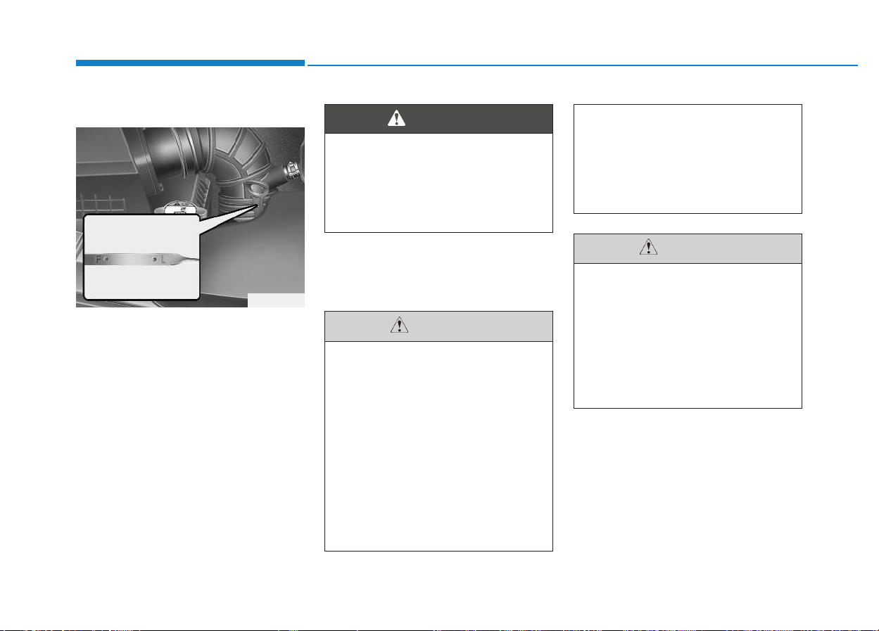
7-22
Maintenance
Checking the engine oil level
1.Be sure the vehicle is on level
ground.
2.Start the engine and allow it to
reach normal operating tempera-
ture.
3.Turn the engine off and wait for a
few minutes (about 5 minutes) for
the oil to return to the oil pan.
4.Pull the dipstick out, wipe it clean,
and re-insert it fully.
5.Pull the dipstick out again and
check the level. The level should be
between F and L.
EENNGGIINNEE OOIILL
OEU074010
Radiator hose
Be very careful not to touch the
radiator hose when checking or
adding the engine oil as it may
be hot enough to burn you.
WARNING
• Do not drive the vehicle, when
the engine oil reservoir is
empty. If not, it may damage
the engine.
• Do not overfill with engine oil.
Engine damage may result.
• Do not spill engine oil, when
adding or changing engine
oil. If you drop the engine oil
on the engine room, wipe it off
immediately.
(Continued)
(Continued)
• When you wipe the oil level
gauge, you should wipe it with
a clean cloth. When mixed
with debris, it can cause
engine damage.
CAUTION
Diesel engine
Overfilling the engine oil may
cause severe dieseling due to
churning effect. It may lead to
engine damage accompanied
with abrupt engine speed incre-
ment, combustion noise and
white smoke emission.
CAUTION
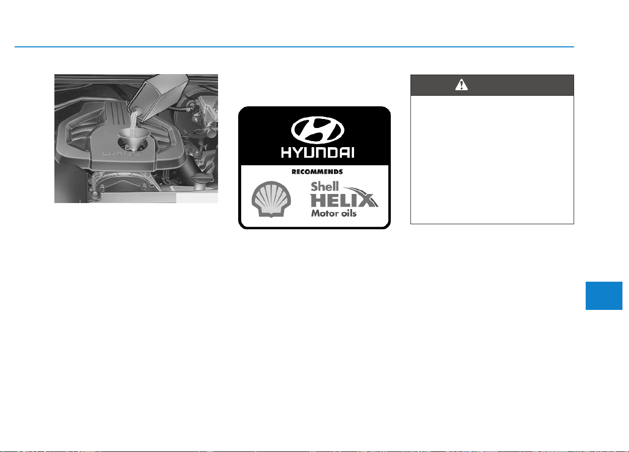
7-23
7
Maintenance
If it is near or at L, add enough oil to
bring the level to F. Do not overfill.
Use a funnel to help prevent oil
from being spilled on engine com-
ponents.
Use only the specified engine oil.
(Refer to “Recommended lubricants
and capacities” in section 8.)
Changing the engine oil and
filter
We recommend that the engine oil
and filter be replaced by an author-
ized HYUNDAI dealer.
OEU074011
Used engine oil may cause irri-
tation or cancer of the skin if
left in contact with the skin for
prolonged periods of time. Used
engine oil contains chemicals
that have caused cancer in lab-
oratory animals. Always protect
your skin by washing your
hands thoroughly with soap
and warm water as soon as pos-
sible after handling used oil.
WARNING
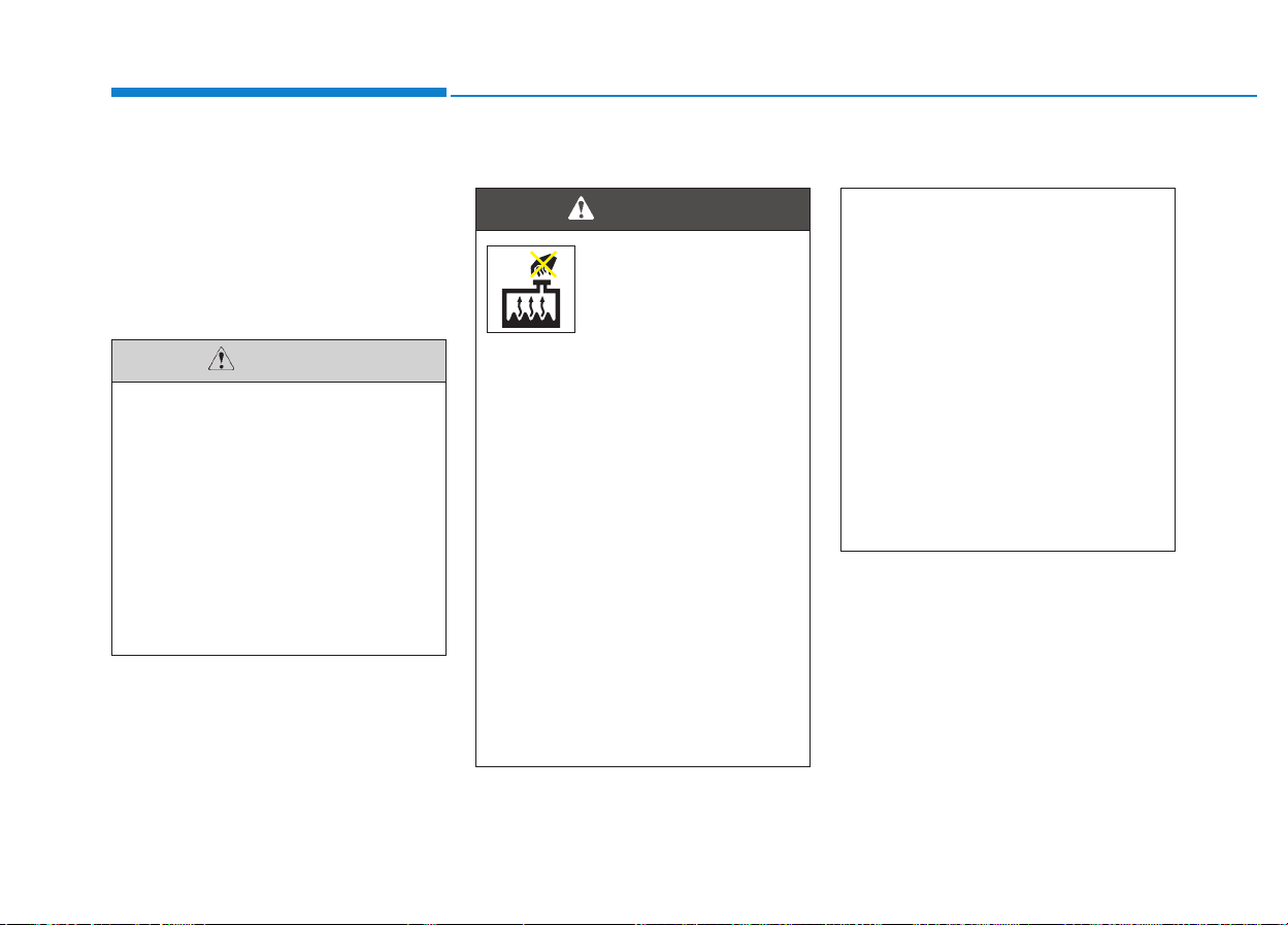
7-24
Maintenance
The high-pressure cooling system
has a reservoir filled with year-round
antifreeze coolant. The reservoir is
filled at the factory. Check the
antifreeze protection and coolant
level at least once a year, at the
beginning of the winter season, and
before traveling to a colder climate.
Checking the coolant level
EENNGGIINNEE CCOOOOLLAANNTT
• Do not drive with no engine
coolant. It may cause water
pump failure and engine
seizure, etc.
• When the engine overheats
from low engine coolant, sud-
denly adding engine coolant
may cause cracks in the
engine. To prevent damage,
add engine coolant slowly in
small quantities.
CAUTION
Removing radiator
cap
• Never attempt to remove the
radiator cap while the engine
is operating or hot. Doing so
might lead to cooling system
and engine damage and could
result in serious personal
injury from escaping hot
coolant or steam.
• Turn the engine off and wait
until it cools down. Use
extreme care when removing
the radiator cap. Wrap a thick
towel around it, and turn it
counterclockwise slowly to
the first stop. Step back while
the pressure is released from
the cooling system.
(Continued)
WARNING
(Continued)
When you are sure all the
pressure has been released,
press down on the cap, using
a thick towel, and continue
turning counterclockwise to
remove it.
• Even if the engine is not oper-
ating, do not remove the radi-
ator cap or the drain plug
while the engine and radiator
are hot. Hot coolant and
steam may still blow out
under pressure, causing seri-
ous injury.
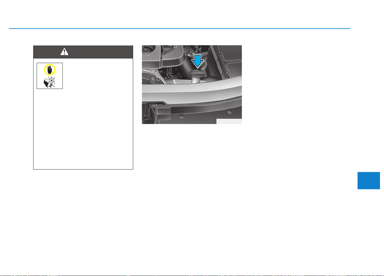
7-25
7
Maintenance
Check the condition and connections
of all cooling system hoses and
heater hoses. Replace any swollen
or deteriorated hoses.
The coolant level should be filled
between F and L marks on the side
of the coolant reservoir when the
engine is cool.
If the coolant level is low, add enough
specified coolant to provide protec-
tion against freezing and corrosion.
Bring the level to F, but do not over-
fill. If frequent additions are required,
we recommend that the system be
inspected by an authorized
HYUNDAI dealer.
Recommended engine coolant
• When adding coolant, use only
deionized water or soft water for
your vehicle and never mix hard
water in the coolant filled at the fac-
tory. An improper coolant mixture
can result in serious malfunction or
engine damage.
• The engine in your vehicle has alu-
minum engine parts and must be
protected by an ethylene-glycol-
based coolant to prevent corrosion
and freezing.
• DO NOT USE alcohol or methanol
coolant or mix them with the spec-
ified coolant.
• Do not use a solution that contains
more than 60% antifreeze or less
than 35% antifreeze, which would
reduce the effectiveness of the
solution.
The electric motor
(cooling fan) is con-
trolled by engine
coolant temperature,
refrigerant pressure
and vehicle speed. It may some-
times operate even when the
engine is not running. Use
extreme caution when working
near the blades of the cooling
fan so that you are not injured
by a rotating fan blades. As the
engine coolant temperature
decreases, the electric motor
will automatically shut off. This
is a normal condition.
WARNING
OEU074014
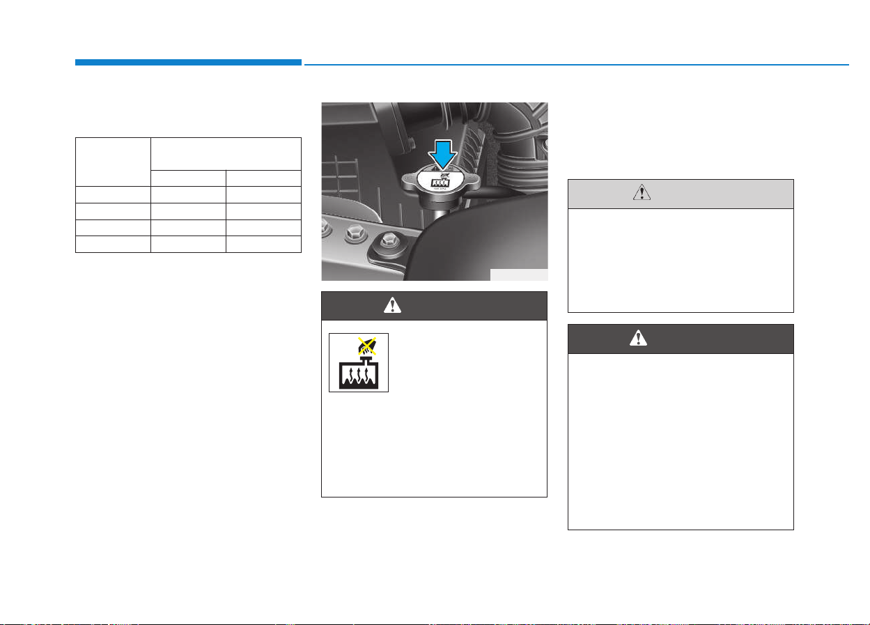
7-26
Maintenance
For mixture percentage, refer to the
following table.
Changing the coolant
We recommend that the coolant be
replaced by an authorized HYUNDAI
dealer.
Ambient
Temperature
Mixture Percentage
(volume)
Antifreeze Water
-15°C (5°F) 35 65
-25°C (-13°F) 40 60
-35°C (-31°F) 50 50
-45°C (-49°F) 60 40
OEU074013
Radiator cap
Do not remove the radiator cap
when the engine and radiator
are hot. Scalding hot coolant
and steam may blow out under
pressure causing serious
injury.
WARNING
Put a thick cloth around the
radiator cap before refilling the
coolant in order to prevent the
coolant from overflowing into
engine parts such as the gener-
ator.
CAUTION
Coolant
• Do not use radiator coolant or
antifreeze in the washer fluid
reservoir.
• Radiator coolant can severely
obscure visibility when
sprayed on the windshield
and may cause loss of vehicle
control or damage to paint
and body trim.
WARNING
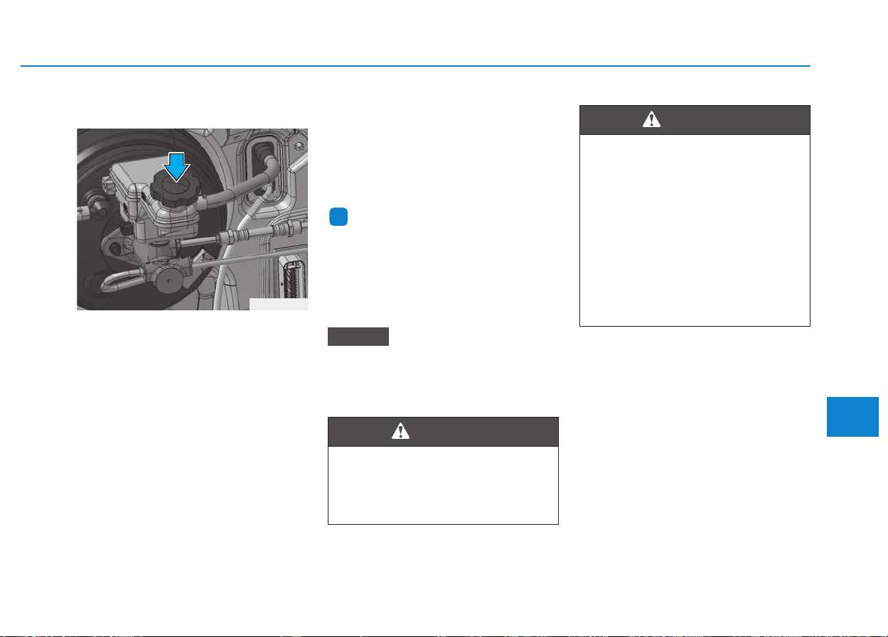
7-27
7
Maintenance
Checking the brake fluid level
Check the fluid level in the reservoir
periodically. The fluid level should be
between MAX and MIN marks on the
side of the reservoir.
Before removing the reservoir cap
and adding brake fluid, clean the
area around the reservoir cap thor-
oughly to prevent brake fluid contam-
ination.
If the level is low, add fluid to the
MAX level. The level will fall with
accumulated mileage.
This is a normal condition associated
with the wear of the brake linings. If
the fluid level is excessively low, we
recommend that the system be
checked by an authorized HYUNDAI
dealer.
Information
Use only the specified brake fluid.
(Refer to “Recommended lubricants
or capacities” in section 8.)
Never mix different types of fluid.
Before removing the brake/clutch
filler cap, read the warning on the
cap.
NOTICE
i
BBRRAAKKEE AANNDD CCLLUUTTCCHH FFLLUUIIDD
OEU074072
Brake fluid
When changing and adding
brake fluid, handle it carefully.
Do not let it come in contact
with your eyes. If brake fluid
should come in contact with
your eyes, immediately flush
them with a large quantity of
fresh tap water. Have your eyes
examined by a doctor as soon
as possible.
WARNING
Clean filler cap before remov-
ing. Use only DOT4 brake/
clutch fluid from a sealed con-
tainer.
WARNING
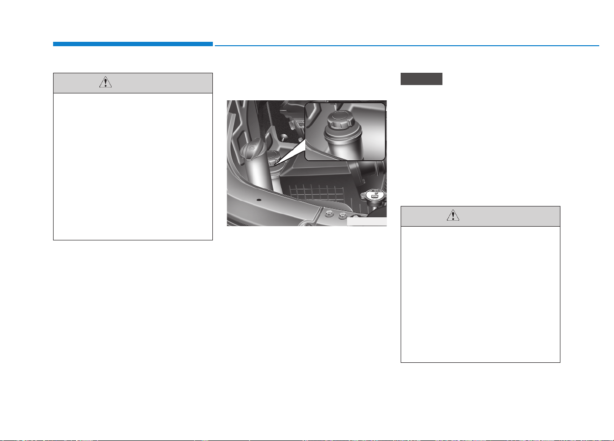
7-28
Maintenance
Checking the power steering
fluid level
With the vehicle on level ground,
check the fluid level in the power
steering reservoir periodically. The
fluid should be between MAX and
MIN marks on the side of the reser-
voir at the normal temperature.
Before adding power steering fluid,
thoroughly clean the area around the
reservoir cap to prevent power steer-
ing fluid contamination.
If the level is low, add fluid to the
MAX level.
Check that the fluid level is in the
"HOT" range on the reservoir. If
the fluid is cold, check that it is in
the "COLD" range.
In the event the power steering sys-
tem requires frequent additions of
fluid, we recommend that the system
be inspected by an authorized
HYUNDAI dealer.
NOTICE
Do not allow brake fluid to con-
tact the vehicle's body paint, as
paint damage will result. Brake
fluid, which has been exposed
to open air for an extended time
should never be used as its
quality cannot be guaranteed. It
should be disposed of properly.
Don't put in the wrong kind of
fluid. A few drops of mineral-
based oil, such as engine oil, in
your brake system can damage
brake system parts.
CAUTION
PPOOWWEERR SSTTEEEERRIINNGG FFLLUUIIDD
OEU074017
• To avoid damage to the power
steering pump, do not operate
the vehicle for prolonged peri-
ods with a low power steering
fluid level.
• Never start the engine when
the reservoir tank is empty.
• When adding fluid, be careful
that dirt does not get into the
reservoir.
(Continued)
CAUTION
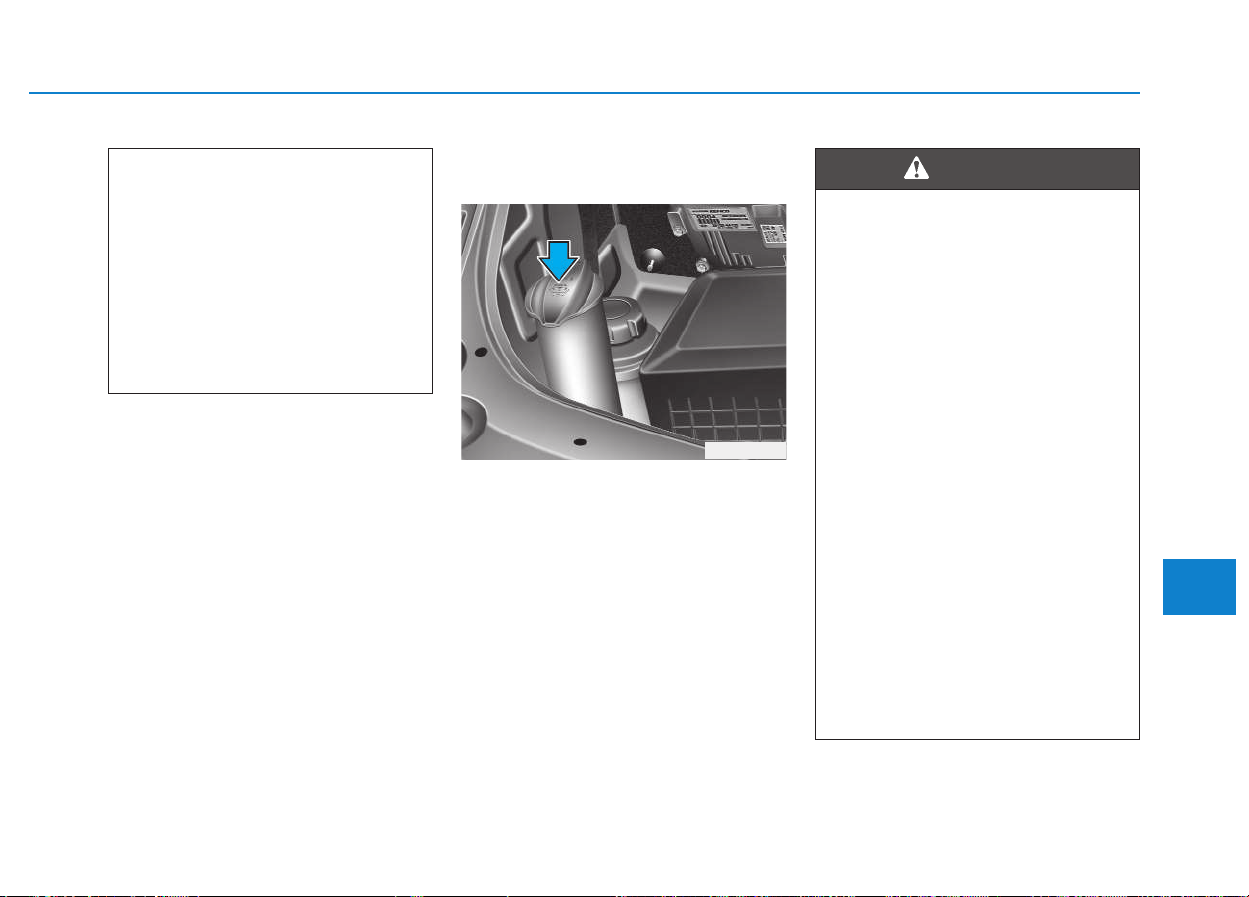
7-29
7
Maintenance
Use only the specified power steer-
ing fluid. (Refer to "Recommended
lubricants or capacities" in section
9.)
Checking the power steering
hose
Check the connections for oil leaks,
damage and twists in the power
steering hose before driving.
Checking the washer fluid
level
Check the fluid level in the washer
fluid reservoir and add fluid if neces-
sary.
Plain water may be used if washer
fluid is not available. However, use
washer solvent with antifreeze char-
acteristics in cold climates to prevent
freezing.
(Continued)
• Too little fluid can result in
increased steering effort
and/or noise from the power
steering system.
• The use of the non-specified
fluid could reduce the effec-
tiveness of the power steering
system and cause damage to
it.
WWAASSHHEERR FFLLUUIIDD
OEU074015
• Do not use radiator coolant or
antifreeze in the washer fluid
reservoir.
• Radiator coolant can severely
obscure visibility when
sprayed on the windshield
and may cause loss of vehicle
control or damage to paint
and body trim.
• Windshield Washer fluid
agents contain some amounts
of alcohol and can be flamma-
ble under certain circum-
stances. Do not allow sparks
or flame to contact the washer
fluid or the washer fluid reser-
voir. Damage to the vehicle or
occupants could occur.
• Windshield washer fluid is
poisonous to humans and
animals. Do not drink and
avoid contacting windshield
washer fluid. Serious injury or
death could occur.
WARNING
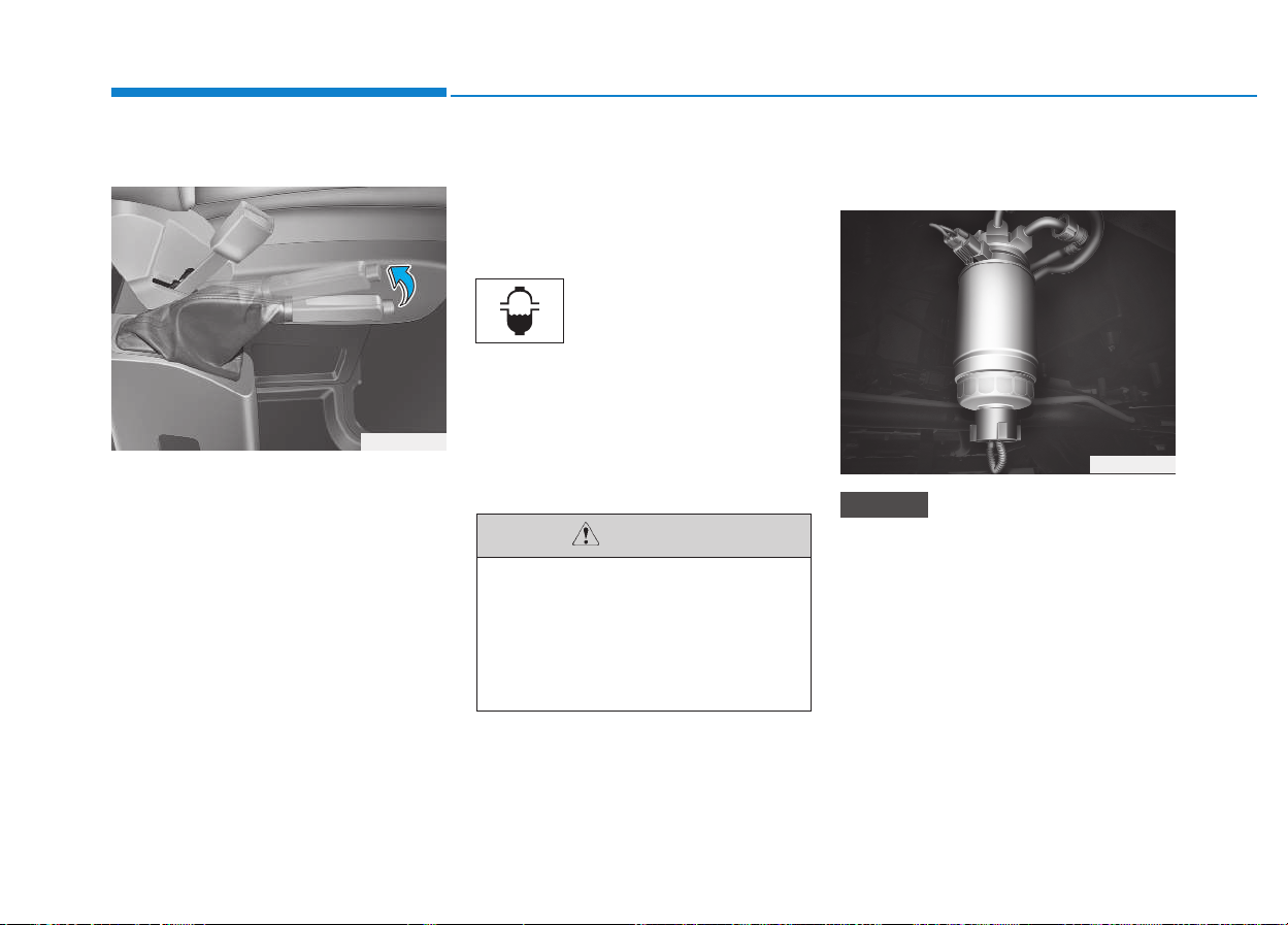
7-30
Maintenance
Checking the parking brake
Check the stroke of the parking
brake by counting the number of
“clicks’’ heard while fully applying it
from the released position. Also, the
parking brake alone should securely
hold the vehicle on a fairly steep
grade. If the stroke is more or less
than specified, we recommend that
the system be serviced by an author-
ized HYUNDAI dealer.
Stroke : 7 “clicks’’ at a force of
20 kg (44 lbs, 196 N).
Draining water from fuel filter
The fuel filter for diesel engine plays
an important role of separating water
from fuel and accumulating the water
in its bottom.
If water accumulates in
the fuel filter, the warning
light comes on when the
ignition switch is in the ON
position.
If this warning light turned
on, we recommend that
the system be serviced by
an authorized HYUNDAI
dealer.
Fuel filter cartridge replace-
ment
When replacing the fuel filter car-
tridge, we recommend that you
use parts for replacement from an
authorized HYUNDAI dealer.
NOTICE
PPAARRKKIINNGG BBRRAAKKEE FFUUEELL FFIILLTTEERR ((FFOORR DDIIEESSEELL))
OEU054002
If the water accumulated in the
fuel filter is not drained at prop-
er times, damages to the major
parts such as the fuel system
can be caused by water perme-
ation in the fuel filter.
CAUTION
OEU074016
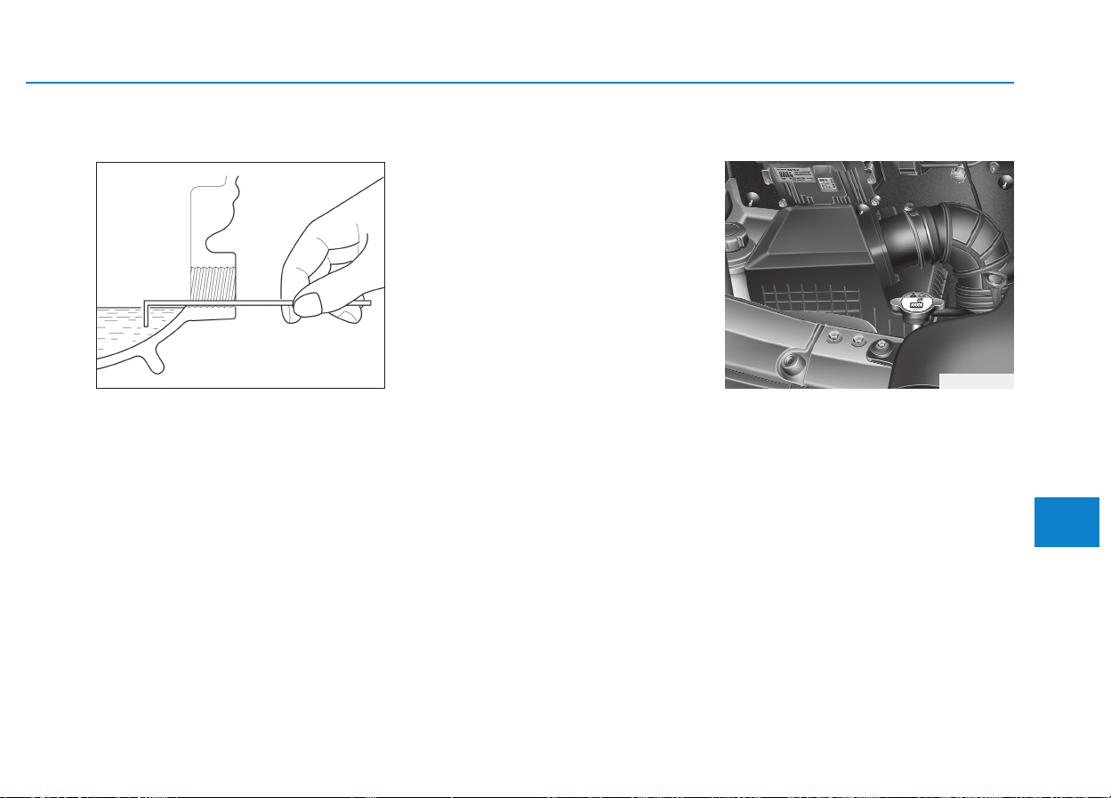
7-31
7
Maintenance
Check and adding oil
Loosen the inspection plug and
inspect the oil is under the inspection
plug.
If the oil level is low, add the gear oil.
Change the gear oil
1.After driving, drain the gear oil by
loosening the drain plug before the
gear oil become cool.
2.Install the drain plug.
3.Refill the gear oil up to check plug
inlet.
Filter replacement
It must be replaced when necessary,
and should not be cleaned and
reused.
MMAANNUUAALL TTRRAANNSSMMIISSSSIIOONN AANNDD RREEAARRAAXXLLEE OOIILL ((IIFF EEQQUUIIPPPPEEDD))
G100B01L
OEU074018
AAIIRR CCLLEEAANNEERR
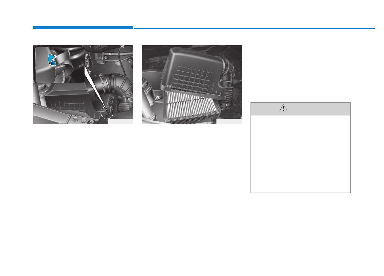
7-32
Maintenance
1.Loosen the air cleaner cover
attaching clips (4EA) and open the
cover.
2.Replace the air cleaner filter.
3.Lock the cover with the cover
attaching clips.
Replace the filter according to the
Maintenance Schedule.
If the vehicle is operated in extreme-
ly dusty or sandy areas, replace the
element more often than the usual
recommended intervals. (Refer to
“Maintenance under severe usage
conditions” in this section.)
OEU074019 OEU074020
• Do not drive with the air clean-
er removed; this will result in
excessive engine wear.
• When removing the air clean-
er filter, be careful that dust or
dirt does not enter the air
intake, or damage may result.
• We recommend that you use
parts for replacement from an
authorized HYUNDAI dealer.
CAUTION
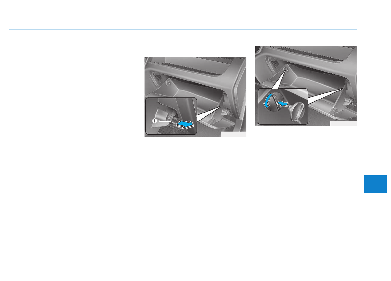
7-33
7
Maintenance
Filter inspection
The climate control air filter should
be replaced according to the mainte-
nance schedule. If the vehicle is
operated in severely air-polluted
cities or on dusty rough roads for a
long period, it should be inspected
more frequently and replaced earlier.
When you replace the climate control
air filter, replace it performing the fol-
lowing procedure, and be careful to
avoid damaging other components.
Filter replacement
1.Open the glove box and remove
the support rod (1).
2.With the glove box open, remove
the stoppers on both sides to allow
the glove box to hang freely on the
hinges.
CCLLIIMMAATTEE CCOONNTTRROOLL AAIIRR FFIILLTTEERR ((IIFF EEQQUUIIPPPPEEDD))
OEU074021
OEU074022
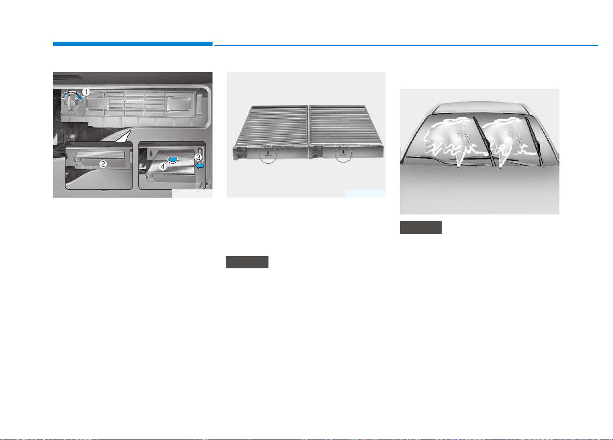
7-34
Maintenance
3.Remove the climate control air fil-
ter cover by turning the cover stop-
per (1) and then remove the air fil-
ters.
4.Replace the climate control air fil-
ter.
5.Reassemble in the reverse order of
disassembly.
When replacing the climate con-
trol air filter install it properly.
Otherwise, the system may pro-
duce noise and the effectiveness
of the filter may be reduced.
Blade inspection
Commercial hot waxes applied by
automatic vehicle washes have
been known to make the wind-
shield difficult to clean.
NOTICE
NOTICE
OEU074023 OTQ077021
WWIIPPEERR BBLLAADDEESS
1JBA5122
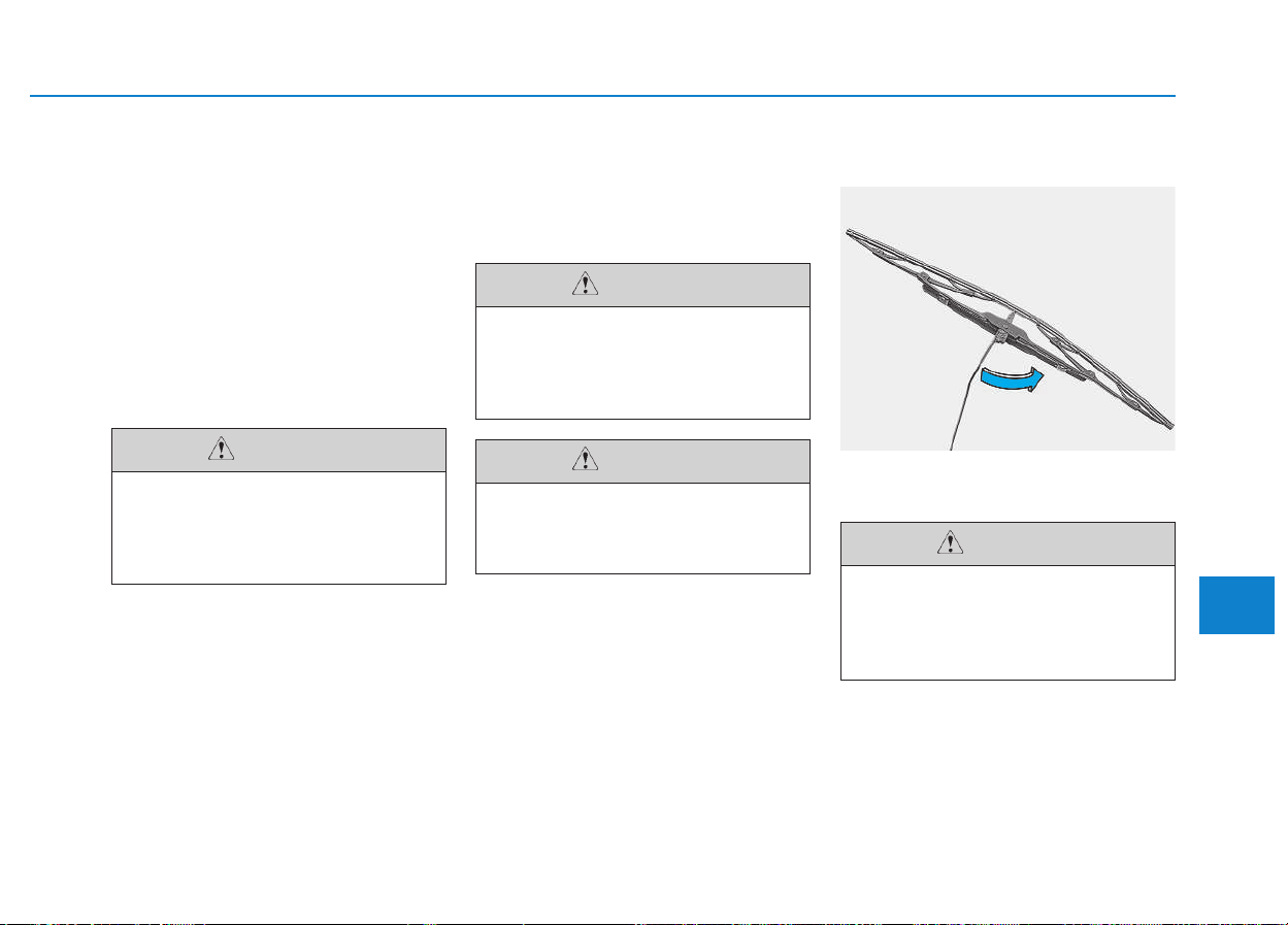
7-35
7
Maintenance
Contamination of either the wind-
shield or the wiper blades with for-
eign matter can reduce the effective-
ness of the windshield wipers.
Common sources of contamination
are insects, tree sap, and hot wax
treatments used by some commer-
cial vehicle washes. If the blades are
not wiping properly, clean both the
window and the blades with a good
cleaner or mild detergent, and rinse
thoroughly with clean water.
Blade replacement
When the wipers no longer clean
adequately, the blades may be worn
or cracked, and require replacement.
Front windshield wiper blade
■■
Type A
1.Raise the wiper arm.
To prevent damage to the wiper
blades, do not use gasoline,
kerosene, paint thinner, or other
solvents on or near them.
CAUTION
To prevent damage to the wiper
arms or other components, do
not attempt to move the wipers
manually.
CAUTION
The use of a non-specified
wiper blade could result in
wiper malfunction and failure.
CAUTION
OEU074067
Do not allow the wiper arm to
fall against the windshield,
since it may chip or crack the
windshield.
CAUTION
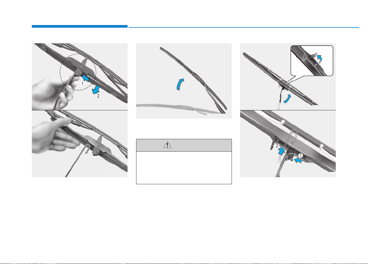
7-36
Maintenance
2.Compress the clip and slide the
blade assembly downward.
3.Lift it off the arm.
4.Install the blade assembly in the
reverse order of removal.
■■
Type B
1.Raise the wiper arm.
2.Turn the wiper blade clip. Then lift
up the blade clip.
3.Push the clip (1) and push up the
wiper arm (2).
Do not allow the wiper arm to
fall against the windshield,
since it may chip or crack the
windshield.
CAUTION
OEU074069
OEU074068
OEU074066
OEU074065
OEU074063
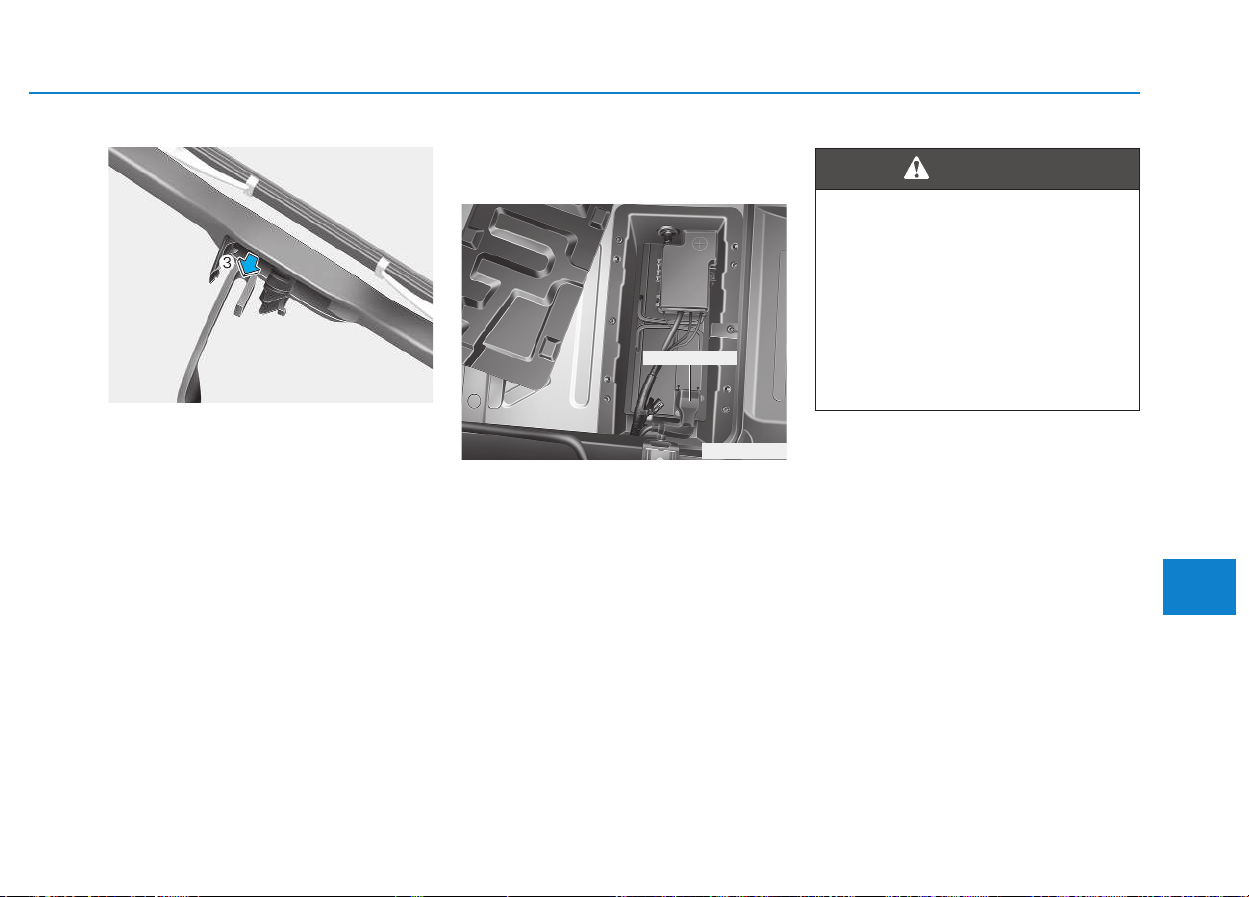
7-37
7
Maintenance
4.Push down the wiper arm (3) and
install the new blade assembly in
the reverse order of removal.
5.Return the wiper arm on the wind
For best battery service
Main battery
The main battery is located in the
battery case in the driver's footwell.
- To remove the battery, remove
the floor mat and loosen 4 bolts
of the service cover.
OEU074024
BBAATTTTEERRYY
•
Objects cannot enter the dri-
ver's footwell. Fit the floor mat
securely as specified in order
to ensure sufficient clearance
for the pedals. Do not use
loose floor mats.
• Be careful not to damage the
battery sensor when you han-
dle the main battery.
WARNING
OEU074064
Battery sensor
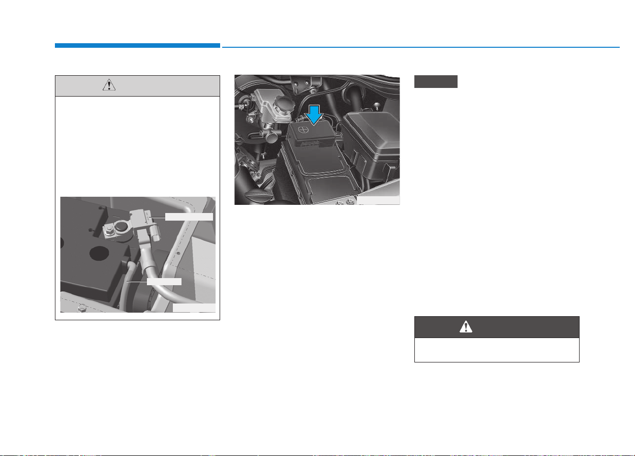
7-38
Maintenance
Auxiliary battery (VAN/Truck)
The auxiliary battery is located in
engine room. (if equipped)
• Keep the battery securely mount-
ed.
• Keep the battery top clean and dry.
• Keep the terminals and connec-
tions clean, tight, and coated with
petroleum jelly or terminal grease.
• Rinse any spilled electrolyte from
the battery immediately with a
solution of water and baking soda.
Basically equipped battery is
maintenance free type. If your
vehicle is equipped with the bat-
tery marked with LOWER and
UPPER on the side, you can check
the electrolyte level. The elec-
trolyte level should be between
LOWER and UPPER. If the elec-
trolyte level is low, it needs to add
distilled (demineralized) water
(Never add sulfuric acid or other
electrolyte). When refill, be careful
not to splash the battery and adja-
cent components. And do not
overfill the battery cells. It can
cause corrosion on other parts.
After then ensure that tighten the
cell caps. We recommend that you
contact an authorized HYUNDAI
dealer.
NOTICE
Do not open the AGM battery.
WARNING
OEU074025
• When replacing the battery,
we recommend that you use
parts replacement from an
authorized HYUNDAI dealer.
• There is a vent hose for
degasing. You must check the
connection for venting when
you change the battery.
CAUTION
OEU075075
Battery sensor
Vent hose
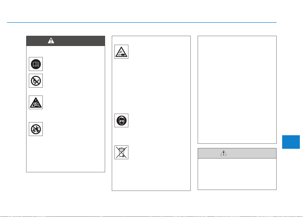
7-39
7
Maintenance
(Continued)
If any electrolyte gets
into your eyes, flush
your eyes with clean
water for at least 15 min-
utes and get immediate
medical attention.
If electrolyte gets on
your skin, thoroughly
wash the contacted
area. If you feel a pain or
a burning sensation, get
medical attention imme-
diately.
Wear eye protection
when charging or work-
ing near a battery.
Always provide ventila-
tion when working in an
enclosed space.
An inappropriately dis-
posed battery can be
harmful to the environ-
ment and human health.
Dispose the battery
according to your local
law(s) or regulation.
(Continued)
(Continued)
• When lifting a plastic-cased
battery, excessive pressure
on the case may cause battery
acid to leak, resulting in per-
sonal injury. Lift with a battery
carrier or with your hands on
opposite corners.
• Never attempt to recharge the
battery when the battery
cables are connected.
• The electrical ignition system
works with high voltage.
Never touch these compo-
nents with the engine running
or the ignition switched on.
Failure to follow the above
warnings can result in serious
bodily injury or death.
If you connect unauthorized
electronic devices to the bat-
tery, the battery may be dis-
charged. Never use unautho-
rized devices.
CAUTION
Battery dangers
Always read the follow-
ing instructions carefully
when handling a battery.
Keep lighted cigarettes
and all other flames or
sparks away from the
battery.
Hydrogen, a highly com-
bustible gas, is always
present in battery cells
and may explode if ignit-
ed.
Keep batteries out of the
reach of children
because batteries con-
tain highly corrosive
SULFURIC ACID. Do not
allow battery acid to
contact your skin, eyes,
clothing or paint finish.
(Continued)
WARNING
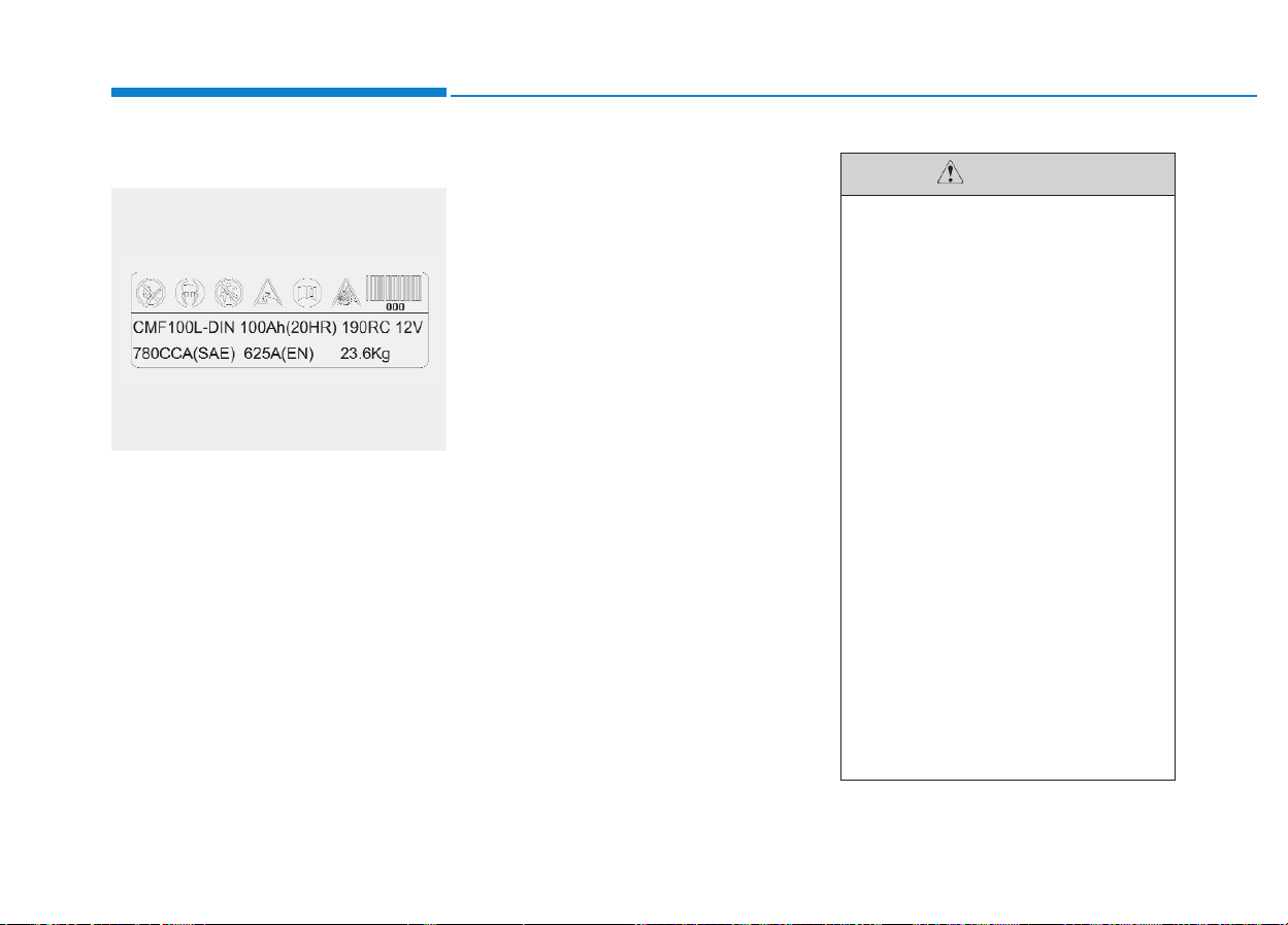
7-40
Maintenance
Battery capacity label
❈ The actual battery label in the vehicle
may differ from the illustration.
1. CMF100L-DIN : The HYUNDAI
model name of battery
2. 12V : The nominal voltage
3. 100Ah(20HR) : The nominal
capacity (in
Ampere hours)
4. 190RC : The nominal reserve
capacity (in min.)
5. 780CCA (SAE) : The cold-test cur-
rent in amperes by SAE
6. 625A (EN) : The cold-test current
in amperes by EN
Battery recharging
Your vehicle has a maintenance-free,
calcium-based battery.
• If the battery becomes discharged
in a short time (because, for exam-
ple, the headlights or interior lights
were left on while the vehicle was
not in use), recharge it by slow
charging (trickle) for 10 hours.
• If the battery gradually discharges
because of high electric load while
the vehicle is being used, recharge
it at 20-30A for two hours.
For the vehicle equipped with
ISG system (AGM battery), be
careful not to damage the bat-
tery sensor when the battery is
replaced or recharged.
1) When replacing the battery, it
should be same one (type,
capacity and brand) that is
originally installed on your
vehicle. If a battery of a dif-
ferent type is replaced, bat-
tery sensor may recognize
the battery to be abnormal.
2) When installing the ground
cable on the negative post of
battery, tighten the clamp
with specified torque of 4.0 ~
6.0 N.m (0.4 ~ 0.6 kgf.m, 3.0 ~
4.41 lb-ft). An excessive tight-
ening torque can damage the
PCB internal circuit.
3) When recharging the battery,
ground the negative terminal
of the booster battery to the
vehicle body.
CAUTION
OEU074074
■ Example

7-41
7
Maintenance
Reset items
Items should be reset after the bat-
tery has been discharged or the bat-
tery has been disconnected.
• Auto up/down window
(See section 3)
• Trip computer (See section 3)
• Climate control system
(See section 3)
• Clock (See section 3)
• Audio (See section 4)
(Continued)
• Disconnect the battery charg-
er in the following order.
1. Turn off the battery charger
main switch.
2. Unhook the negative clamp
from the negative battery ter-
minal.
3. Unhook the positive clamp
from the positive battery ter-
minal.
4. After recharging, park the
vehicle for about 5 hours with
the hood and all doors
closed. During this period,
the dark current must be
under 100mA.(AGM battery
only)
• Before performing mainte-
nance or recharging the bat-
tery, turn off all accessories
and stop the engine.
• The negative battery cable
must be removed first and
installed last when the battery
is disconnected.
• Do not open the AGM battery.
WARNING
Recharging battery
When recharging the battery,
observe the following precau-
tions:
• The battery must be removed
from the vehicle and placed in
an area with good ventilation.
• Do not allow cigarettes,
sparks, or flame near the bat-
tery.
• Watch the battery during
charging, and stop or reduce
the charging rate if the battery
cells begin gassing (boiling)
violently or if the temperature
of the electrolyte of any cell
exceeds 49°C (120°F).
• Do not charge the AGM bat-
tery with over 14.5V. No quick-
charging routines
• Wear eye protection when
checking the battery during
charging.
(Continued)
WARNING
7-42
Maintenance
Tire care
For proper maintenance, safety, and
maximum fuel economy, you must
always maintain recommended tire
inflation pressures and stay within
the load limits and weight distribution
recommended for your vehicle.
Recommended cold tire infla-
tion pressures
All tire pressures (including the
spare) should be checked when the
tires are cold. “Cold Tires” means the
vehicle has not been driven for at
least three hours or driven less than
1.6 km (1 mile).
Recommended pressures must be
maintained for the best ride, top vehi-
cle handling, and minimum tire wear.
For recommended inflation pressure
refer to “Tire and wheels” in section
8.
TTIIRREESS AANNDD WWHHEEEELLSS
•
Overinflation or underinfla-
tion can reduce tire life,
adversely affect vehicle han-
dling, and lead to sudden tire
failure. You must always main-
tain recommended tire pres-
sures.
Warm tires normally exceed
recommended cold tire pres-
sures by 28 to 41 kPa (4 to 6
psi). Do not release air from
warm tires to adjust the pres-
sure or the tires will be under-
inflated.
• Tire underinflation
If the tire pressure drops
repeatedly, the wheel, valve or
tire may be damaged.
Underinflation results in
reducing fitness of tire and
wheel, excessive wear, poor
handling and reduced fuel
economy.
(Continued)
(Continued)
And it can lead to deformation
or abnormal wear of wheel,
severe heat build-up, causing
blowouts, tread separation
and other tire failures that can
result in the loss of vehicle
control leading to severe
injury or death. This risk is
much higher on hot days and
when driving for long periods
at high speeds.
If the problem is not solved (a
tire frequently needs refilling),
we recommend that the sys-
tem be checked by an author-
ized HYUNDAI dealer.
• Tire overinflation
Tires with excessively high
pressure can burst because
they are damaged more easily
by road debris, potholes etc.
In addition, they also produce
a harsh ride, excessive wear
at the center of the tire tread,
and a greater possibility of
damage from road hazards.
WARNING
7-43
7
Maintenance
Checking tire inflation pres-
sure
Check your tires once a month or
more.
Also, check the tire pressure of the
spare tire.
How to check
Use a good quality gage to check tire
pressure. You can not tell if your tires
are properly inflated simply by look-
ing at them. Radial tires may look
properly inflated even when they're
underinflated.
Check the tire's inflation pressure
when the tires are cold. - "Cold"
means your vehicle has been sitting
for at least three hours or driven no
more than 1.6 km (1 mile).
Tire pressure
Always observe the following:
• Check tire pressure when the
tires are cold. (After vehicle
has been parked for at least
three hours or hasn't been
driven more than 1.6 km (1
mile) since startup.)
• Check the pressure of your
spare tire each time you check
the pressure of other tires.
• Never overload your vehicle.
Be careful not to overload a
vehicle luggage rack if your
vehicle is equipped with one.
• Worn, old tires can cause
accidents. If your tread is
badly worn, or if your tires
have been damaged, replace
them.
CAUTION
Tire inflation
Overinflation or underinflation
can reduce tire life, adversely
affect vehicle handling, and
lead to sudden tire failure. This
could result in loss of vehicle
control and potential injury.
WARNING
• Warm tires normally exceed
recommended cold tire pres-
sures by 28 to 41 kPa (4 to 6
psi). Do not release air from
warm tires to adjust the pres-
sure or the tires will be under-
inflated.
• Be sure to reinstall the tire
inflation valve caps. Without
the valve cap, dirt or moisture
could get into the valve core
and cause air leakage. If a
valve cap is missing, install a
new one as soon as possible.
CAUTION

7-44
Maintenance
Remove the valve cap from the tire
valve stem. Press the tire gage firm-
ly onto the valve to get a pressure
measurement. If the cold tire inflation
pressure matches the recommended
pressure on the tire and loading
information label, no further adjust-
ment is necessary. If the pressure is
low, add air until you reach the rec-
ommended amount.
If you overfill the tire, release air by
pushing on the metal stem in the
center of the tire valve. Recheck the
tire pressure with the tire gage. Be
sure to put the valve caps back on
the valve stems. They help prevent
leaks by keeping out dirt and mois-
ture.
Tire rotation
To equalize tread wear, it is recom-
mended that the tires be rotated
every 12,000 km (7,500 miles) or
sooner if irregular wear develops.
During rotation, check the tires for
correct balance.
When rotating tires, check for uneven
wear and damage. Abnormal wear is
usually caused by incorrect tire pres-
sure, improper wheel alignment, out-
of-balance wheels, severe braking or
severe cornering. Look for bumps or
bulges in the tread or side of tire.
Replace the tire if you find either of
these conditions. Replace the tire if
fabric or cord is visible. After rotation,
be sure to bring the front and rear tire
pressures to specification and check
lug nut tightness.
Refer to “Tire and wheels” in section
8.
• Inspect your tires frequently
for proper inflation as well as
wear and damage. Always use
a tire pressure gauge.
• Tires with too much or too lit-
tle pressure wear unevenly
causing poor handling, loss of
vehicle control, and sudden
tire failure leading to acci-
dents, injuries, and even
death. The recommended cold
tire pressure for your vehicle
can be found in this manual
and on the tire label located
on the driver's side center pil-
lar.
• Worn tires can cause acci-
dents. Replace tires that are
worn, show uneven wear, or
are damaged.
• Remember to check the pres-
sure of your spare tire.
HYUNDAI recommends that
you check the spare every
time you check the pressure
of the other tires on your vehi-
cle.
WARNING
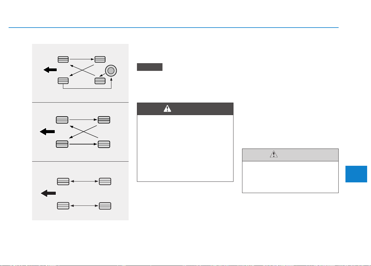
7-45
7
Maintenance
Disc brake pads should be inspected
for wear whenever tires are rotated.
Rotate radial tires that have an
asymmetric tread pattern only
from front to rear and not from
right to left.
Wheel alignment and tire bal-
ance
The wheels on your vehicle were
aligned and balanced carefully at the
factory to give you the longest tire life
and best overall performance.
In most cases, you will not need to
have your wheels aligned again.
However, if you notice unusual tire
wear or your vehicle pulling one way
or the other, the alignment may need
to be reset.
If you notice your vehicle vibrating
when driving on a smooth road, your
wheels may need to be rebalanced.
NOTICE
• Do not use the compact spare
tire for tire rotation.
• Do not mix bias ply and radial
ply tires under any circum-
stances. This may cause
unusual handling characteris-
tics that could result in death,
severe injury, or property
damage.
WARNING
Improper wheel weights can
damage your vehicle's alu-
minum wheels. Use only
approved wheel weights.
CAUTION
S2BLA790
S2BLA790A
CBGQ0707A
Without a spare tire
With a full-size spare tire (if equipped)
Directional tires (if equipped)
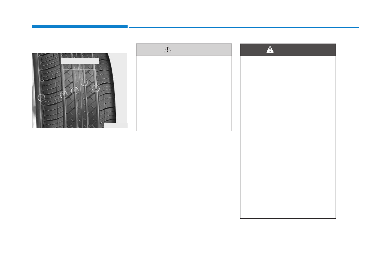
7-46
Maintenance
Tire replacement
If the tire is worn evenly, a tread wear
indicator will appear as a solid band
across the tread. This shows there is
less than 1.6 mm (1/16 in.) of tread
left on the tire. Replace the tire when
this happens.
Do not wait for the band to appear
across the entire tread before replac-
ing the tire.
When replacing the tires,
recheck and tighten the wheel
nuts after driving about 1,000
km (620miles). If the steering
wheel shakes or the vehicle
vibrates while driving, the tire is
out of balance. Align the tire
balance. If the problem is not
solved, we recommend that you
contact an authorized HYUNDAI
dealer.
CAUTION
Replacing tires
• Driving on worn-out tires is
very hazardous and will
reduce braking effectiveness,
steering accuracy, and trac-
tion.
• Your vehicle is equipped with
tires designed to provide for
safe ride and handling capa-
bility. Do not use a size and
type of tire and wheel that is
different from the one that is
originally installed on your
vehicle. It can affect the safety
and performance of your vehi-
cle, which could lead to han-
dling failure or rollover and
serious injury. When replacing
the tires, be sure to equip all
four tires with the tire and
wheel of the same size, type,
tread, brand and load-carrying
capacity.
(Continued)
WARNING
OEN076053
Tread wear indicator

7-47
7
Maintenance
Wheel replacement
When replacing the metal wheels for
any reason, make sure the new
wheels are equivalent to the original
factory units in diameter, rim width
and offset.
Tire traction
Tire traction can be reduced if you
drive on worn tires, tires that are
improperly inflated or on slippery
road surfaces. Tires should be
replaced when tread wear indicators
appear. To reduce the possibility of
losing control, slow down whenever
there is rain, snow or ice on the road.
Tire maintenance
In addition to proper inflation, correct
wheel alignment helps to decrease
tire wear. If you find a tire is worn
unevenly, have your dealer or other
repair shops that use qualified tech-
nicians check the wheel alignment.
When you have new tires installed,
make sure they are balanced. This
will increase vehicle ride comfort and
tire life. Additionally, a tire should
always be rebalanced if it is removed
from the wheel.
A wheel that is not the correct
size may adversely affect wheel
and bearing life, braking and
stopping abilities, handling
characteristics, ground clear-
ance, body-to-tire clearance,
snow chain clearance,
speedometer and odometer cal-
ibration, headlight aim and
bumper height.
WARNING
(Continued)
• The use of any other tire size
or type may seriously affect
ride, handling, ground clear-
ance, stopping distance, body
to tire clearance, snow tire
clearance, and speedometer
reliability.
• It is best to replace all four
tires at the same time. If that
is not possible, or necessary,
then replace the two front or
two rear tires as a pair.
Replacing just one tire can
seriously affect your vehicle’s
handling.
• The ABS works by comparing
the speed of the wheels. Tire
size can affect wheel speed.
When replacing tires, all 4
tires must use the same size
originally supplied with the
vehicle. Using tires of a differ-
ent size can cause the ABS
(Anti-lock Brake System) and
ESP (Electronic Stability
Program) (if equipped) to
work irregularly.
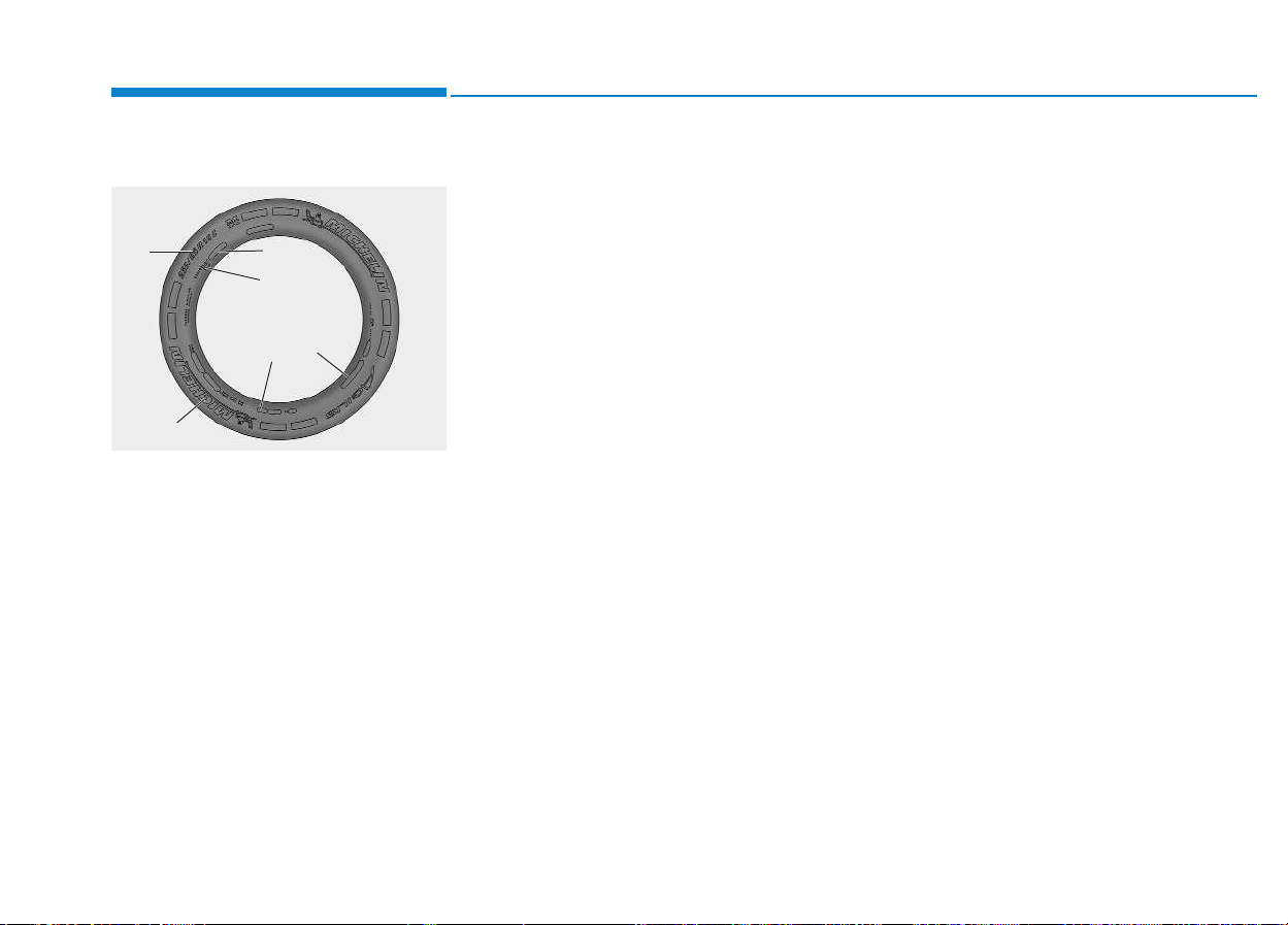
7-48
Maintenance
Tire sidewall labeling
This information identifies and
describes the fundamental charac-
teristics of the tire and also provides
the tire identification number (TIN)
for safety standard certification. The
TIN can be used to identify the tire in
case of a recall.
1. Manufacturer or brand name
Manufacturer or Brand name is
shown.
2. Tire size designation
A tire’s sidewall is marked with a tire
size designation. You will need this
information when selecting replace-
ment tires for your vehicle. The fol-
lowing explains what the letters and
numbers in the tire size designation
mean.
Example tire size designation:
(These numbers are provided as an
example only; your tire size designa-
tor could vary depending on your
vehicle.)
235/65R16 115/113R
235 - Tire width in millimeters.
65 - Aspect ratio. The tire’s section
height as a percentage of its
width.
R - Tire construction code (Radial).
16 - Rim diameter in inches.
113 - Load Index, a numerical code
associated with the maximum
load the tire can carry. (Dual
Trie)
115 - Load Index, a numerical code
associated with the maximum
load the tire can carry. (Single
Tire)
R - Speed Rating Symbol. See the
speed rating chart in this section
for additional information.
Wheel size designation
Wheels are also marked with impor-
tant information that you need if you
ever have to replace one. The follow-
ing explains what the letters and
numbers in the wheel size designa-
tion mean.
Example wheel size designation:
16X6.5J
16 - Rim diameter in inches.
6.5 - Rim width in inches.
J - Rim contour designation.
OEU064042
1
2
3
4
6
5
7-49
7
Maintenance
Tire speed ratings
The chart below lists many of the dif-
ferent speed ratings currently being
used for passenger vehicles. The
speed rating is part of the tire size
designation on the sidewall of the
tire. This symbol corresponds to that
tire's designed maximum safe oper-
ating speed.
3. Checking tire life
(TIN : Tire Identification
Number)
Any tires that are over 6 years, based
on the manufacturing date, tire
strength and performance, decline
with age naturally (even unused
spare tires). Therefore, the tires
(including the spare tire) should be
replaced by new ones. You can find
the manufacturing date on the tire
sidewall (possibly on the inside of the
wheel), displaying the DOT Code.
The DOT Code is a series of num-
bers on a tire consisting of numbers
and English letters. The manufactur-
ing date is designated by the last four
digits (characters) of the DOT code.
DOT : XXXX XXXX OOOO
The front part of the DOT means a
plant code number, tire size and
tread pattern and the last four num-
bers indicate week and year manu-
factured.
For example:
DOT XXXX XXXX 1615 represents
that the tire was produced in the 16th
week of 2015.
Tire age
Tires degrade over time, even
when they are not being used.
Regardless of the remaining
tread, it is recommended that
tires generally be replaced after
six (6) years of normal service.
Heat caused by hot climates or
frequent high loading condi-
tions can accelerate the aging
process. Failure to follow this
Warning can result in sudden
tire failure, which could lead to
a loss of control and an acci-
dent involving serious injury or
death.
WARNING
Speed Rating
Symbol
Maximum Speed
Q 160
km/h (99 mph)
R 170
km/h (106 mph)
S 180
km/h (112 mph)
T 190
km/h (118 mph)
U 200
km/h (124 mph)
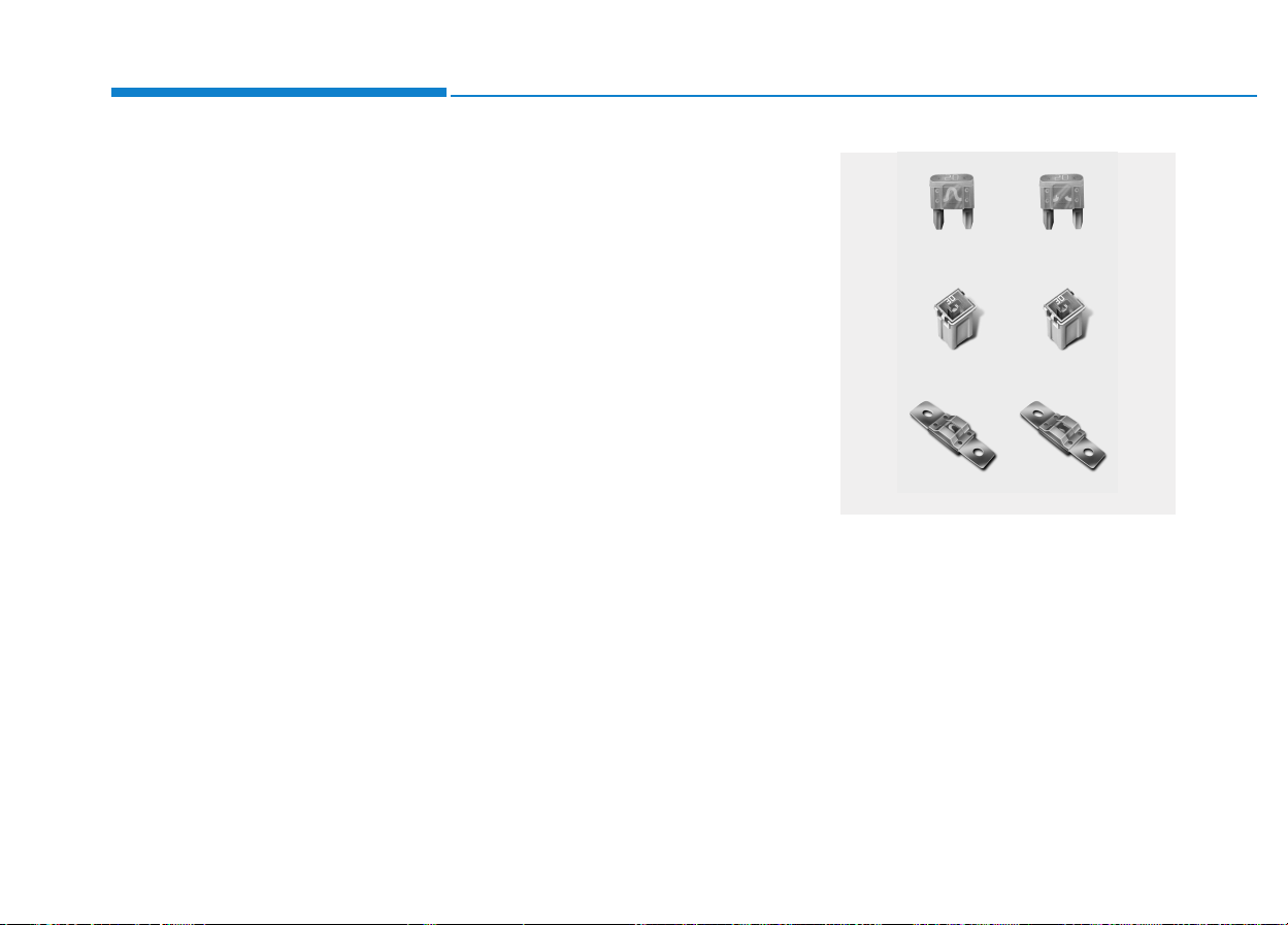
7-50
Maintenance
4. Tire ply composition and
material
The number of layers or plies of rub-
ber-coated fabric are in the tire. Tire
manufacturers also must indicate the
materials in the tire, which include
steel, nylon, polyester, and others.
The letter "R" means radial ply con-
struction; the letter "D" means diago-
nal or bias ply construction; and the
letter "B" means belted-bias ply con-
struction.
5. Maximum permissible infla-
tion pressure
This number is the greatest amount
of air pressure that should be put in
the tire. Do not exceed the maximum
permissible inflation pressure. Refer
to the Tire and Loading Information
label for recommended inflation
pressure.
6. Maximum load rating
This number indicates the maximum
load in kilograms and pounds that
can be carried by the tire. When
replacing the tires on the vehicle,
always use a tire that has the same
load rating as the factory installed
tire.
A vehicle’s electrical system is pro-
tected from electrical overload dam-
age by fuses.
This vehicle has 3 fuse panels, one
located in the driver’s side panel bol-
ster, the other in the engine compart-
ment near the battery.
If any of your vehicle’s lights, acces-
sories, or controls do not work, check
the appropriate circuit fuse. If a fuse
has blown, the element inside the
fuse will be melted.
FFUUSSEESS
1VQA4037
Normal
Normal
Normal
Blown
Blown
Blown
7-51
7
Maintenance
If the electrical system does not
work, first check the driver’s side
fuse panel.
Before replacing a blown fuse, dis-
connect the negative battery cable.
Always replace a blown fuse with
one of the same rating.
If the replacement fuse blows, this
indicates an electrical problem. Avoid
using the system involved and we
recommend that you consult an
authorized HYUNDAI dealer.
Three kinds of fuses are used: blade
type for lower amperage rating, car-
tridge type, and fusible link for higher
amperage ratings.
The actual fuse/relay panel label
may differ from equipped items.
NOTICE
Fuse replacement
• Never replace a fuse with any-
thing but another fuse of the
same rating.
• A higher capacity fuse could
cause damage and possibly a
fire.
• Never install a wire or alu-
minum foil instead of the
proper fuse - even as a tem-
porary repair. It may cause
extensive wiring damage and
a possible fire.
WARNING
Do not use a screwdriver or any
other metal object to remove
fuses because it may cause a
short circuit and damage the
system.
CAUTION
• When replacing a blown fuse
or relay with a new one, make
sure the new fuse or relay fits
tightly into the clips. The
incomplete fastening fuse or
relay may cause the vehicle
wiring and electric systems
damage and a possible fire.
• Do not remove fuses, relays
and terminals fastened with
bolts or nuts. The fuses,
relays and terminals may be
fastened incompletely, and it
may cause a possible fire. If
fuses, relays and terminals
fastened with bolts or nuts are
blown, consult with an author-
ized HYUNDAI dealer.
• Do not input any other objects
except fuses or relays into
fuse/relay terminals such as a
driver or wiring. It may cause
contact failure and system
malfunction.
CAUTION
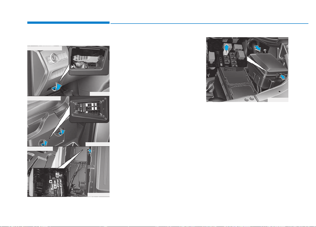
7-52
Maintenance
Inner panel fuse replacement
1.Turn the ignition switch and all
other switches off.
2.Open the fuse panel cover.
3.Pull the suspected fuse straight
out. Use the removal tool provided
in the engine compartment fuse
panel.
4.Check the removed fuse; replace it
if it is blown.
5.Push in a new fuse of the same rat-
ing, and make sure it fits tightly in
the clips.
If it fits loosely, we recommend that
you consult an authorized HYUNDAI
dealer.
If you do not have a spare, use a
fuse of the same rating from a circuit
you may not need for operating the
vehicle, such as the cigar lighter
fuse.
OEU074027
OEU074026
OEU074028
■ Driver’s seat side
■ Driver’s side panel
■ Main battery
OEU074029
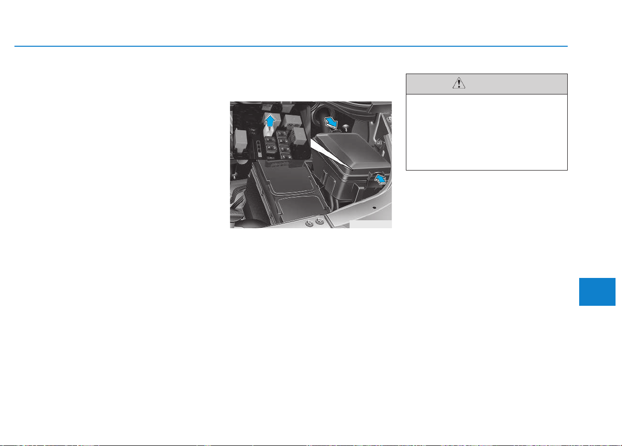
7-53
7
Maintenance
If the headlights or other electrical
components do not work and the
fuses are OK, check the fuse block in
the engine compartment. If a fuse is
blown, it must be replaced.
Engine compartment panel fuse
replacement
1.Turn the ignition switch and all
other switches off.
2.Remove the fuse box cover by
pressing the tap and pulling up.
3.Check the removed fuse; replace it
if it is blown. To remove or insert
the fuse, use the fuse puller in the
engine compartment fuse panel.
4.Push in a new fuse of the same rat-
ing, and make sure it fits tightly in
the clips.
If it fits loosely, we recommend that
you consult an authorized
HYUNDAI dealer.
OEU074029
After checking the fuse box in
the engine compartment,
securely install the fuse box
cover. If not, electrical failures
may occur from water leaking
in.
CAUTION
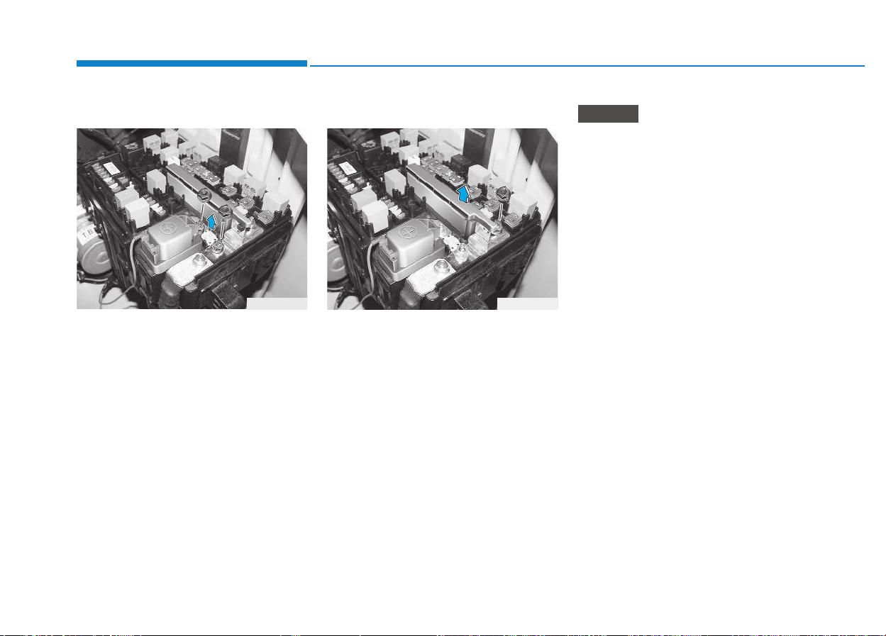
7-54
Maintenance
Alternator fuse
If the main fuse is blown, it must be
removed as follows:
1.Turn off the engine.
2.Disconnect the negative battery
cable.
3.Remove the nuts shown in the pic-
ture above.
4.Replace the fuse with a new one of
the same rating.
5.Reinstall in the reverse order of
removal.
Multi fuse
If the multi fuse is blown, it must be
removed as follows:
1.Turn off the engine.
2.Disconnect the negative battery
cable.
3.Remove the fuse panel on the right
side in the engine compartment.
4.Remove the nuts shown in the pic-
ture above.
5.Replace the fuse with a new one of
the same rating.
6.Reinstall in the reverse order of
removal.
If the main fuse is blown, we rec-
ommend that you consult an
authorized HYUNDAI dealer.
NOTICE
OEU074036
OEU074037
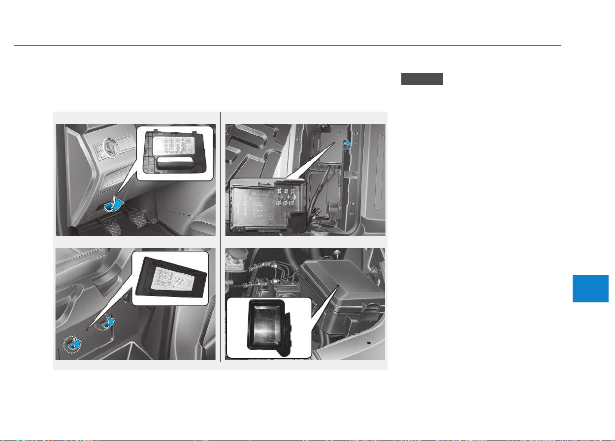
7-55
7
Maintenance
Not all fuse panel descriptions in
this manual may be applicable to
your vehicle. It is accurate at the
time of printing.
When you inspect the fuse box on
your vehicle, refer to the fuse box
label.
NOTICE
■ Inner fuse box (Driver’s seat side)
OEU074059/OEU074060/OEU074058/OEU074039
■ Inner fuse box (Instrument panel)
■ Main fuse box
■ Battery fuse box
Fuse/Relay panel description
Inside the fuse/relay box covers, you can find the fuse/relay label describing
fuse/relay name and capacity.

7-56
Maintenance
Inner fuse panel (Instrument panel)
No. Fuse rating Fuse Name Circuit Protected
1 15A
WIPER &
WASHER
Front Wiper Motor, Washer Motor
2 7.5A
2
A/CON
BLOWER M/HI SIG
3 7.5A
1
EMERGENCY
CALL
Emergency-Call (ACC)
4 25A P/WDW LH P/WDW Motor Left
5 20A DDM Drive Door Module (B+ MIRR)
6 25A P/WDW RH P/WDW Motor Right
7 15A
P/OUTLET
(FR_LH)
Power Outlet (Front Left)
8 7.5A
1
CM
CM (B+)
9 15A MULTIMEDIA AUDIO E300/E800(B+), AVN(B+), LDC Module(B+)
10 20A ADM Assist Door Module (B+ MIRR)
11 7.5A START START SIG

7-57
7
Maintenance
No. Fuse rating Fuse Name Circuit Protected
12 10A MEMORY
Cluster (B+), A/C Control Module(B+), Drive Door Module(B+ECU), Assist Door Module(B+ECU),
DTG(B+), OBDII (B+)
13 7.5A BRAKE SW Brake Switch, Stop Lamp
14 10A MODULE E-3
Cluster, Drive Door Module, Assist Door Module, A/C Control Module, Seat HTD Switch
Left/Right, VDC off Switch, AVN, Seat HTD Module Left/Right, DTG, LDWS Module, RPAS
Sensor, Yaw Rate Sensor, Fuel Water Sensor
15 10A
MIDDLE
DR LOCK
Middle Door Lock Actuator
16 10A
TAILGATE
DR LOCK
Tailgate Door Lock Actuator
17 10A MODULE E-4 AUDIO E300/E800(ACC), AVN(ACC), LDC Module(ACC), CM(ACC)
18 20A
ENG BOX
(IG1)
UH BOX (ABS3 7.5A, SNSR5 7.5A, INHIBITOR 7.5A, BACK UP LAMP 7.5A)
19 10A DCU SEAT BOX (DCU SNSR Relay 'S')
20 7.5A
2
CM
CM (IG1)
21 7.5A MODULE-1 Rain Sensor
22 10A INTERIOR LAMP
SEAT BOX(PASS ROOM LAMP Relay 'S'), Key Warning Switch, Step Lamp(MID/ASS),
OH_CONSOLE Lamp, Map Lamp, Passenger Reading Lamp, Cargo_Lamp(Middle / TGAT)

7-58
Maintenance
No. Fuse rating Fuse Name Circuit Protected
23 10A MODULE-2
HLLD Actuator Left/Right, Glow Relay Module(IG1), Brake Switch, FPAS Sensor, C/PAD Switch,
BEZEL Switch, LDC Module(IG1)
24 7.5A MODULE-5
I_S_MIRR(IG2), CM(IG2), Passenger Heater Module(IG2), Seat HTD Module Left/Right(IG2),
F/FILTER Relay 'S'
25 10A
2
IMMO
Immobilizer Module(B+), Key Warning Switch
26 7.5A
1
IMMO
Immobilizer Module(IG1)
27 20A
SEAT BOX
(IG2)
SEAT BOX (ELECTRIC VENTILATOR2 10A, A/CON RR(IG2) 10A, IG2 10A(AUX POWER(IG2)
Relay 'S'))
28 7.5A
1
A/CON
A/C Control Module(IG2)
29 15A A/BAG A/BAG Control Module(IG1)
30 7.5
2
EMERGENCY
CALL
Emergency-Call(IG1)

7-59
7
Maintenance
Inner fuse panel (Driver's seat side)
No. Fuse rating Fuse Name Circuit Protected
1 30A
PASS A/CON
BLOW LH
Passenger A/CON Blower Motor Left
2 20A E/POWER STEP Electric Step Module(B+)
3 30A
PASS A/CON
BLOW RH
Passenger A/CON Blower Motor Right
4 7.5A
1
ELECTRIC
VENTILATOR
Ventilator Control Module(B+)
5 10A
ROOM LAMP
PASS
Room Lamp(Front/Center/Rear)
6 15A
AUX POWER
(IG2)
AUX BOX (AUX IG2)
7 30A
1
TRAILER
Trailer Module(B+)
8 25A
SEAT
HEATER
Seat HTD Module Left/Right (Warm B+)
9 10A
AUX POWER
(ENGINE RUN)
AUX BOX (ENGINE RUN)
10 15A
2
TRAILER
Trailer Module(B+)
11 20A PRE HEATER 1 Pre Heater Module
12 25A
AUX POWER
(B+)
AUX BOX (AUX B+)

7-60
Maintenance
No. Fuse rating Fuse Name Circuit Protected
13 15A
3
TRAILER
Trailer Module(B+)
14 30A
PASS A/CON
C/FAN LH
Passenger A/CON Blower Motor Left
15 10A
BATTERY
SENSOR
Battery Sensor
16 30A FUEL HTR Fuel Filter HTR
17 7.5A
PASS HTR/BLOW
SIG FR
Passenger Heater Control Module (Blower Motor SIG Front)
18 15A
DCU
SENSOR
PM Sensor, NOX Sensor (front/Rear), Dosing Control Module (IG1 INPUT)
19 20A
1
DCU
Dosing Control Module(B+)
20 7.5A
PASS HTR/BLOW
SIG RR
Passenger Heater Control Module (Blower Motor SIG Rear)
21 10A
2
ELECTRIC
VENTILATOR
Ventilator Control Module (IG2)
22 7.5A
PASS A/CON
BLOW SIG LH
A/C Control Module Rear (Blower Motor SIG Left)
23 7.5A
PASS A/CON
BLOW SIG RH
A/C Control Module Rear (Blower Motor SIG Right)
24 10A
A/CON RR
(IG2)
A/C Control module Rear

7-61
7
Maintenance
No. Fuse rating Fuse Name Circuit Protected
25 20A
2
DCU
Dosing Control Module(B+)
26 20A
3
DCU
Dosing Control Module(B+)
27 10A IG2 Electric Step Module, SEAT BOX(AUX POWER (IG2) Relay 'S')
28 30A
PASS A/CON
C/FAN RH
Passenger A/CON Blower Motor Right
29 25A
PASS HTR
FRT
Passenger Heater Blower Motor Front
30 25A
PASS HTR
RR
Passenger Heater Blower Motor Rear

7-62
Maintenance
Engine compartment main fuse panel
No. Fuse rating Fuse Name Circuit Protected
1 10A
2
A/CON
A/C Compressor PASS
2 15A
4
ECU
Engine Control Module (Permanent Battery (+))
3 10A
1
A/CON
A/C Compressor CAB
4 10A
1
SENSOR
Electric VGT Actuator, EGR Cooling Bypass, UH_BOX(Fuel Pump Relay 'S')
5 10A SPARE
6 20A
1
ECU
Engine Control Module (Battery (+))
7 10A
2
SENSOR
UH_BOX(A/CON1 Relay 'S', A/CON2 Relay 'S', CONDENSER FAN Relay LH,RH1/2 'S')
8 20A
2
ECU
Engine Control Module (Battery (+))
9 10A
3
SENSOR
LAMBDA Sensor
10 7.5A
BACK UP
LAMP
Rear Combi Lamp Left/Right (Back Up), Inside Mirror (Reverse), Trailer Module (Back Up),
Vehicle Dynamic Control Module (Reverse Gear Switch), Reverse Warning Buzzer
11 7.5A
3
ABS
Anti-Lock Brake Module (IG1), Vehicle Dynamic Control Module (IG1), Steering Angle Sensor
(IG1)
12 7.5A
5
SENSOR
Air Flow Sensor, Engine Control Module (TERMINAL15(IG1 INPUT))

7-63
7
Maintenance
No. Fuse rating Fuse Name Circuit Protected
13 7.5A INHIBITOR UH_BOX(Start Inhibit Relay 'S')
14 60A
3
B+
Smart Junction Box (B+3)
15 60A VDC Vehicle Dynamic Control Module (B+ Pump Motor)
16 40A
2
ABS
Anti-Lock Brake Module (B+ Solenoid Valve), Vehicle Dynamic Control Module(B+ Solenoid
Valve)
17 40A
1
ABS
Anti-Lock Brake Module (B+ Pump Motor)
18 60A
2
B+
Smart Junction Box (B+2)
19 80A GLOW Glow Relay Module (Plus Direct)
20 50A
4
B+
Smart Junction Box (B+4)
21 50A EMS Engine Management System Block (B+)
22 15A HORN HORN
23 10A PTO PTO Magnetic Valve
24 20A F/PUMP Fuel Pump Sender (Fuel Pump Motor(+))

7-64
Maintenance
No. Fuse rating Fuse Name Circuit Protected
25 15A B/A HORN Burglar Alarm Horn
26 25A
C/LIGHTER
P/OUTLET
RR
Cigar Lighter, luggage Room Power Outlet
27 25A
P/OUTLET
CTR & RH
Power Outlet (Center, front Right)
28 20A DEICER DEICER
29 40A CONDENSER FAN A/C Condenser Fan Motor Left/Right
30 30A
WIPER
FRT
Front Wiper Motor
31 50A
4
PTC
HEATER
PTC Heater EXTN (PTC4+)
32 50A
3
PTC
HEATER
PTC Heater EXTN (PTC3+)
33 50A
2
PTC
HEATER
PTC Heater EXTN (PTC2+)
34 50A
1
PTC
HEATER
PTC Heater EXTN (PTC1+)

7-65
7
Maintenance
No. Fuse rating Fuse Name Circuit Protected
35 40A IG2 IGN_Switch (B2), Start Solenoid
36 50A IG1 IGN_Switch (B1)
37 50A
1
B+
Smart Junction Box (B+1)
38 50A BLOWER Blower Motor
39
150A ALT ALTERNATOR
200A ALT ALTERNATOR

7-66
Maintenance
Battery fuse panel
No. Fuse rating Fuse Name Circuit Protected
1 40A DCU_MAIN Dosing Control Module (B+)
2 150A
PASS,HTR(BUS)
PASS,A/CON(BUS)
AUX,BATT(TRK/VAN)
1. BUS : SEAT BOX (PASS HTR FRT 25A, PASS HTR/BLOW SIG FR 7.5A, PASS HTR RR 25A,
PASS HTR/BLOW SIG RR 7.5A, PASS A/CON C/FAN LH 30A, PASS A/CON C/FAN RH 30A,
PASS A/CON BLOW LH 30A, PASS A/CON BLOW SIG LH 7.5A, PASS A/CON BLOW RH 30A,
PASS A/CON BLOW SIG RH 7.5A)
2. VAN/TRUCK : AUX Battery
3 70A
2
SEAT_F/BOX
SEAT BOX (B+2/B+3), PM Sensor, NOX Sensor (front/Rear), Dosing Control Module (IG1
INPUT)
4 70A
1
SEAT_F/BOX
SEAT BOX (B+1/B+4)
7-67
7
Maintenance
Use only the bulbs of the specified
wattage.
After heavy, driving rain or wash-
ing, headlight and taillight lenses
could appear frosty. This condi-
tion is caused by the temperature
difference between the lamp
inside and outside. This is similar
to the condensation on your win-
dows inside your vehicle during
the rain and doesn’t indicate a
problem with your vehicle. If
water leaks into the lamp bulb cir-
cuitry, we recommend that the
system be checked by an author-
ized HYUNDAI dealer.
NOTICE
LLIIGGHHTT BBUULLBBSS
Working on the lights
Prior to working on the light,
firmly apply the parking brake,
ensure that the ignition switch
is turned to the “LOCK” position
and turn off the lights to avoid
sudden movement of the vehi-
cle and burning your fingers or
receiving an electric shock.
WARNING
Be sure to replace the burned-
out bulb with one of the same
wattage rating. Otherwise, it
may cause damage to the fuse
or electric wiring system.
CAUTION
If you don’t have necessary
tools, the correct bulbs and the
expertise, we recommend that
you consult an authorized
HYUNDAI dealer. In many cases,
it is difficult to replace vehicle
light bulbs because other parts
of the vehicle must be removed
before you can get to the bulb.
This is especially true if you
have to remove the headlight
assembly to get to the bulb(s).
Removing/installing the head-
light assembly can result in
damage to the vehicle.
CAUTION
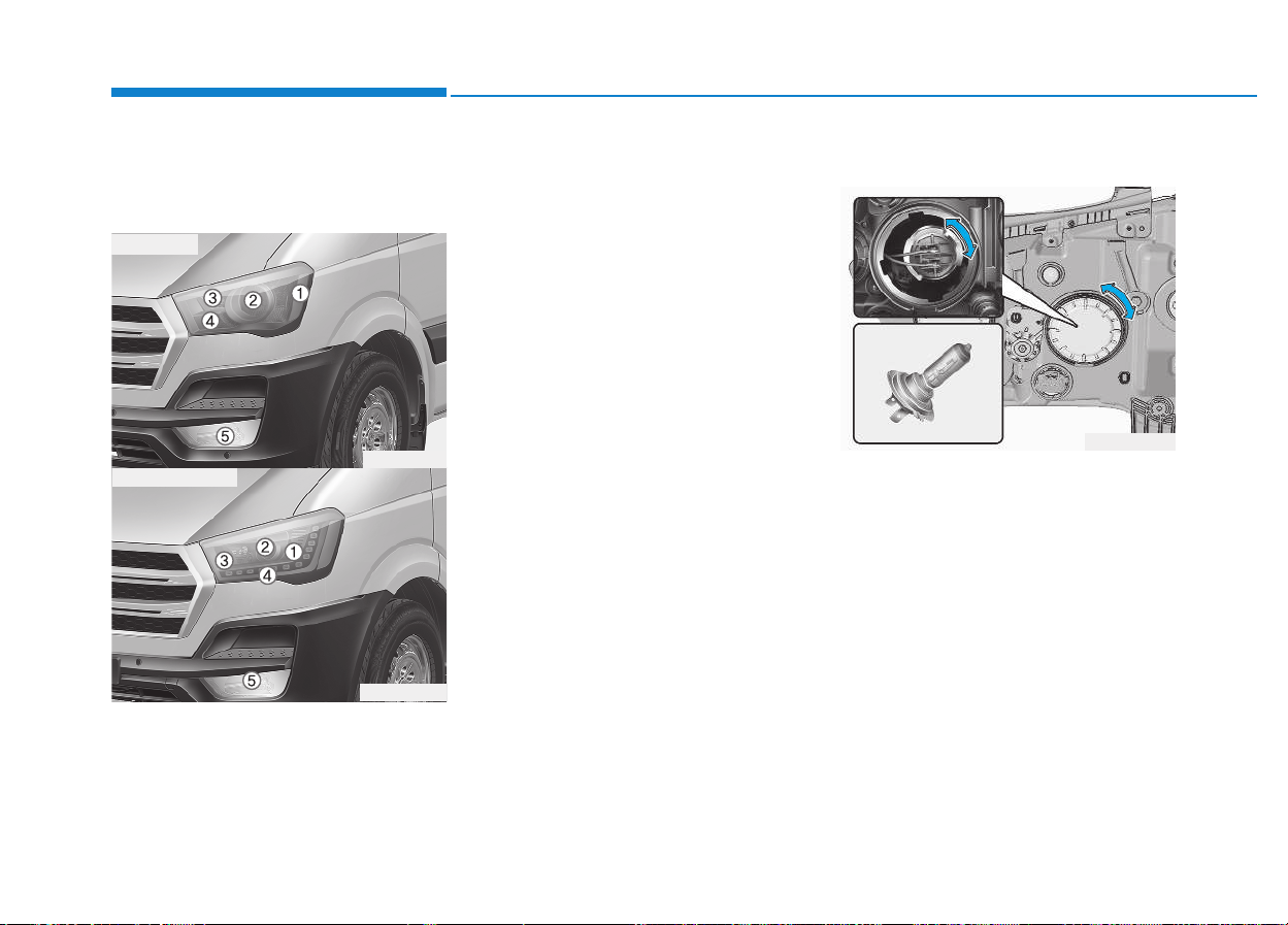
7-68
Maintenance
Headlight, position light, turn
signal light, front fog light bulb
replacement
(1) Front turn signal light
(2) Headlight (Low)
(3) Headlight (High)
(4) Position light and DRL (LED)
(if equipped)
(5) Front fog light (if equipped)
Headlight (Replacement)
MFR type (High / Low) and projec-
tion type (High)
1.Open the hood.
2.Remove the headlight bulb cover
by turning it counterclockwise.
3.Disconnect the headlight bulb
socket-connector.
4.Unsnap the headlight bulb retain-
ing wire by depressing the end and
pushing it upward.
5.Remove the bulb from the head-
light assembly.
OEU074048
OEU074047
OEU074070
■■
MFR type
■■
Projection type
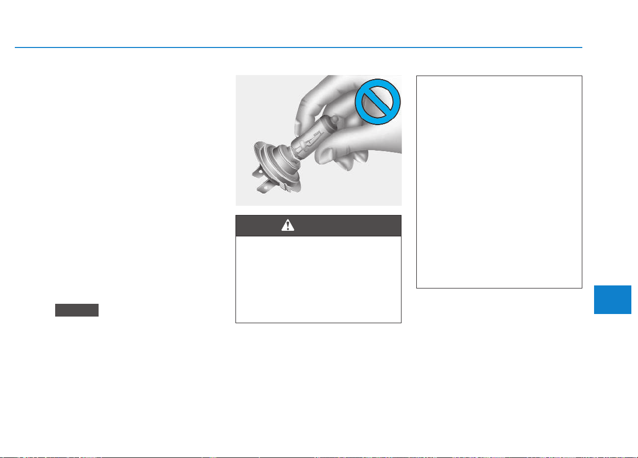
7-69
7
Maintenance
6.Install a new headlight bulb and
snap the headlight bulb retaining
wire into position by aligning the
wire with the groove on the bulb.
7.Connect the headlight bulb socket-
connector.
8.Install the headlight bulb cover by
turning it clockwise.
Projection type (Low)
1.Open the hood.
2.Remove the headlight bulb cover
by turning it counterclockwise.
3.Remove the bulb socket by turning
it counterclockwise and remove by
pulling the bulb.
4.Install is the reverse order of
removal.
We recommend that the headlight
aiming be adjusted after an acci-
dent or after the headlight assem-
bly is reinstalled at an authorized
HYUNDAI dealer.
NOTICE
Halogen bulbs
• Halogen bulbs contain pres-
surized gas that will produce
flying pieces of glass if bro-
ken.
(Continued)
(Continued)
• Always handle them carefully,
and avoid scratches and abra-
sions. If the bulbs are lit, avoid
contact with liquids. Never
touch the glass with bare
hands. Residual oil may cause
the bulb to overheat and burst
when lit. A bulb should be
operated only when installed
in a headlight.
• If a bulb becomes damaged or
cracked, replace it immediate-
ly and carefully dispose of it.
• Wear eye protection when
changing a bulb. Allow the
bulb to cool down before han-
dling it.
WARNING
OEU074062
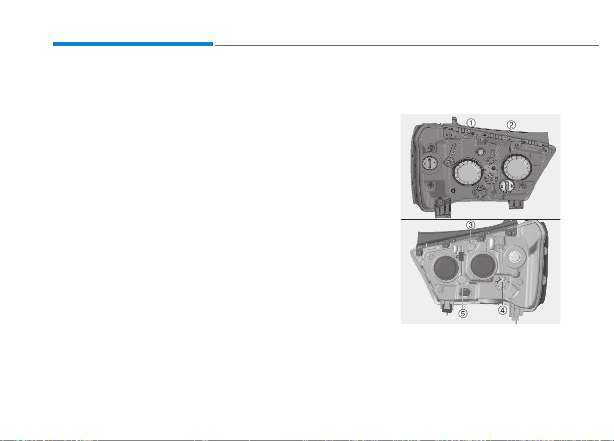
7-70
Maintenance
Turn signal light/Position light
Turn signal light
1.Turn off the engine and open the
hood.
2.Remove the socket from the
assembly by turning the socket
counterclockwise until the tabs on
the socket align with the slots on
the assembly.
3.Remove the bulb from the socket
by pressing it in and rotating it
counterclockwise until the tabs on
the bulb align with the slots in the
socket. Pull the bulb out of the
socket
4.Insert a new bulb by inserting it into
the socket and rotating it until it
locks into place.
5.Install the socket in the assembly
by aligning the tabs on the socket
with the slots in the assembly.
Push the socket into the assembly
and turn the socket clockwise.
Position light
If the light bulb does not operate, we
recommend that the system be
checked by an authorized HYUNDAI
dealer.
Front fog light bulbs
(if equipped)
1.Remove the front bumper under
cover.
2.Reach your hand into the back of
the front bumper.
3.Disconnect the power connector
from the socket.
4.Remove the bulb-socket from the
housing by turning the socket
counter clockwise until the tabs on
the socket align with the slots on
the housing.
5.Install the new bulb-socket into the
housing by aligning the tabs on the
socket with the slots in the hous-
ing. Push the socket into the hous-
ing and turn the socket clockwise.
6.Connect the power connector to
the socket.
7.Reinstall the front bumper under
cover.
Headlight and front fog light
aiming (for Europe)
Headlight aiming
1.Inflate the tires to the specified
pressure and remove any loads
from the vehicle except the driver,
spare tire, and tools.
OEU074061
OEU074049
■■
Projection type
■■
MFR type
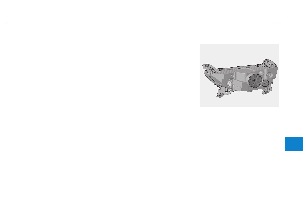
7-71
7
Maintenance
2.The vehicle should be placed on a
flat floor.
3.Draw vertical lines (Vertical lines
passing through respective head
lamp centers) and a horizontal line
(Horizontal line passing through
center of head lamps) on the
screen.
4.With the head lamp and battery in
normal condition, aim the head
lamps so the brightest portion falls
on the horizontal and vertical lines.
5-1. MFR type
To aim the low/high beam left or
right, turn the screw (1) clockwise
or counterclockwise. To aim the
low/high beam up or down, turn the
screw (2) clockwise or counter-
clockwise.
5-2. Projection type
1) Low beam aiming
To aim the low beam left or
right, turn the screw (3) clock-
wise or counterclockwise.
To aim the low beam up or
down, turn the screw (4) clock-
wise or counterclockwise.
2) High beam aiming
High beam aiming is available
up direction or down.
To aim the high beam up or
down, turn the screw (5) clock-
wise or counterclockwise.
Front fog light aiming
The front fog light can be aimed as
the same manner of the head lamps
aiming.
With the front fog lights and battery
normal condition, aim the front fog
lights. To aim the front fog light up or
down, turn the bolt clockwise or
counterclockwise.
OEU074050
■■
Fog light aiming
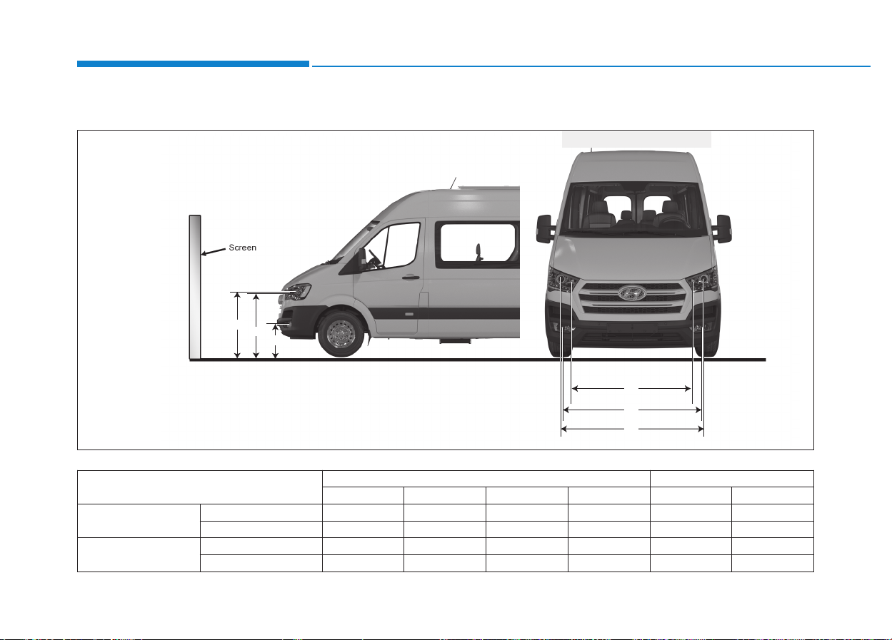
7-72
Maintenance
H1
H2
H3
W1
W3
W2
Vehicle condition
Head light Fog light
H1 H2 W1 W2 H3 W3
Projection type
Without driver 960.5 (37.8) 942 (37) 1,488 (58.6) 1,274 (50.2) 456.5 (18) 1,480 (58.3)
With driver 960.5 (37.8) 942 (37) 1,488 (58.6) 1,274 (50.2) 456.5 (18) 1,480 (58.3)
MFR type
Without driver 948 (37.3) 944 (37.2) 1,540(60.2) 1,280 (50.4) 456.5 (18) 1,480 (58.3)
With driver 948 (37.3) 944 (37.2) 1,540(60.2) 1,280 (50.4) 456.5 (18) 1,480 (58.3)
Unit: mm (in)
<Ground Height>
<Distance between lamps>
H1 : Height between the head light (Low beam) bulb center and ground
H2 : Height between the head light (High beam) the high beam bulb center and ground
H3 : Height between the fog light bulb center and ground
W1 : Distance between the two head light (Low beam) bulbs centers
W2 : Distance between the two head light (High beam) high beam bulbs centers.
W3 : Distance between the two fog light bulbs centers
Aiming point
OEU074055-A
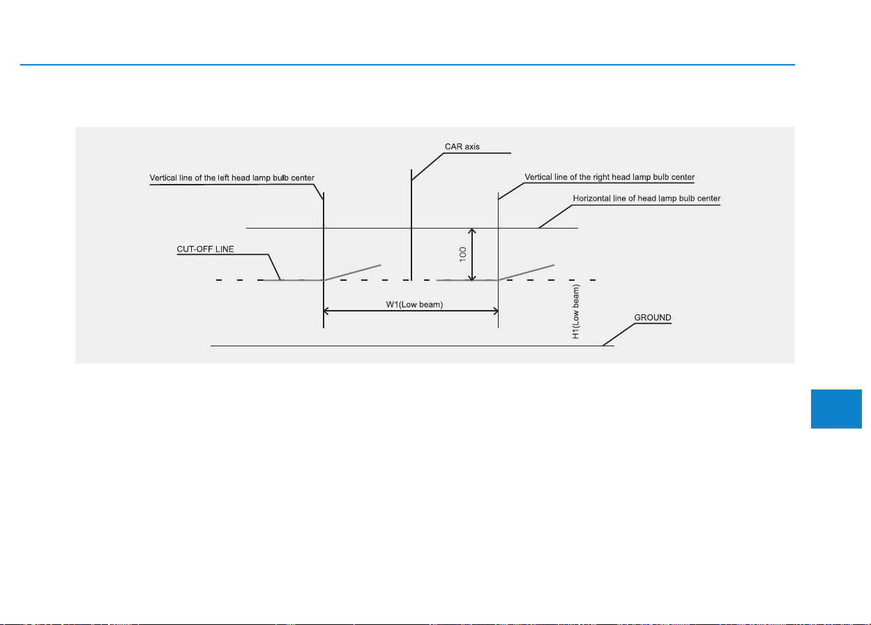
7-73
7
Maintenance
Head light low beam
1. Turn the low beam on without driver aboard.
2. The cut-off line should be projected in the cut-off line shown in the picture.
3. When aiming the low beam, vertical aiming should be adjusted after adjusting the horizontal aiming.
4. If head light leveling device is equipped, adjust the head light leveling device switch with 0 positions.
OMD051054L-1
■ Based on 10m screen
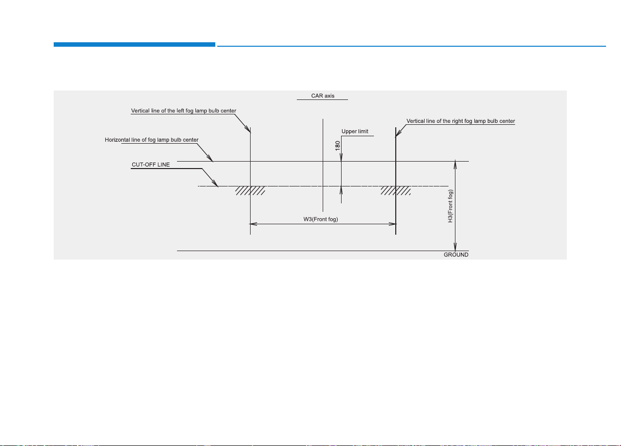
7-74
Maintenance
Front fog light
1. Turn the front fog lamp on with the driver (75 kg) aboard.
2. The cut-off line should be projected in the allowable range (shaded region).
OEU074055-B
■ Based on 10m screen
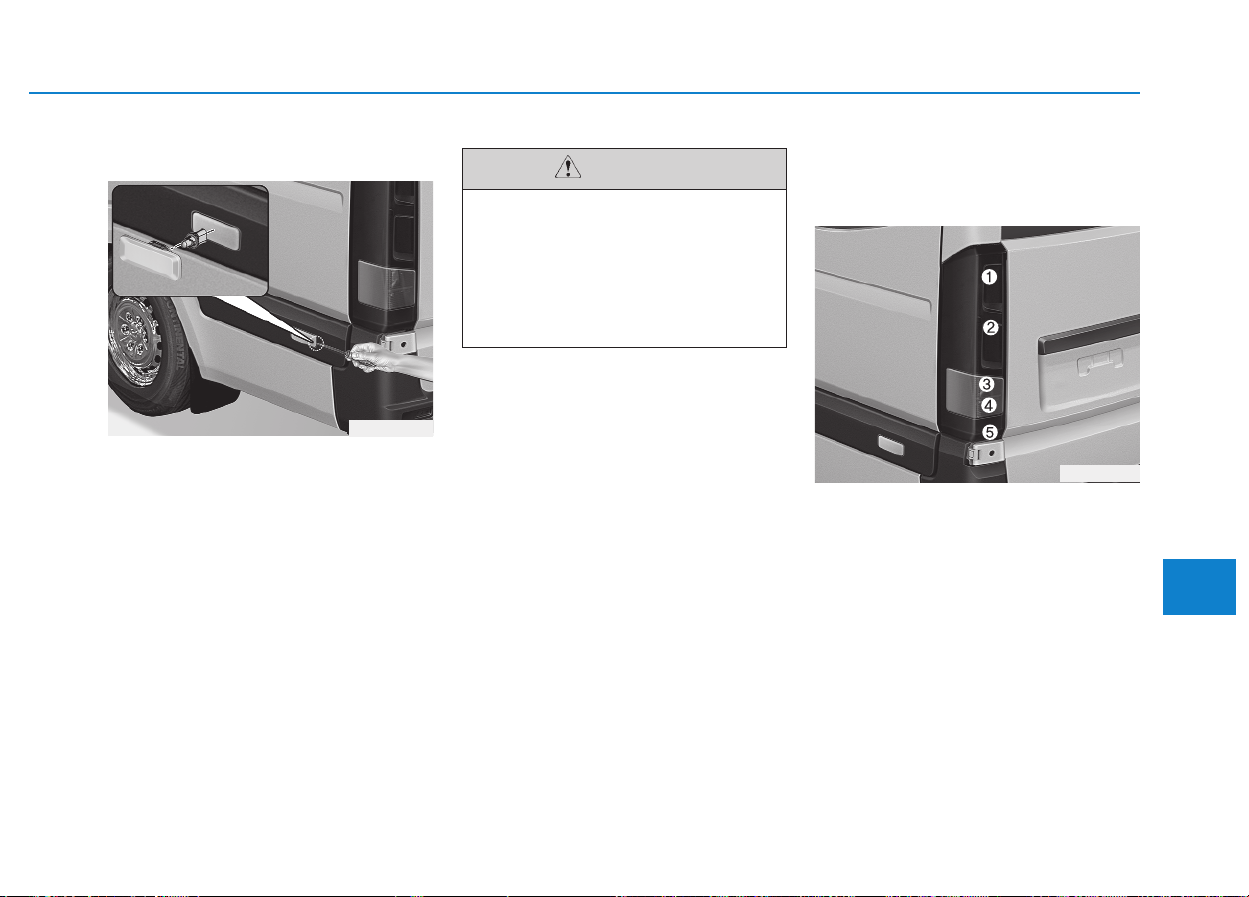
7-75
7
Maintenance
Side marker lamp
1.To remove the lamp, pry the lamp
with a flat-tip screwdriver and push
it rearward.
2.Disconnect the wiring connector,
and remove the bulb by turning the
bulb socket counterclockwise.
3.To install the bulb, reverse the
removal procedure.
Rear combination light bulbs
replacement
BUS, VAN
1. Tail/stop light
2. Tail/stop light
3. Turn signal light
4. Back up light
5. Rear fog light
OEU074046
OEU074073
• When prying with a flat-tip
screwdriver, wrap it with pro-
tective tape to prevent dam-
age.
• Put on gloves to protect your
hands.
CAUTION
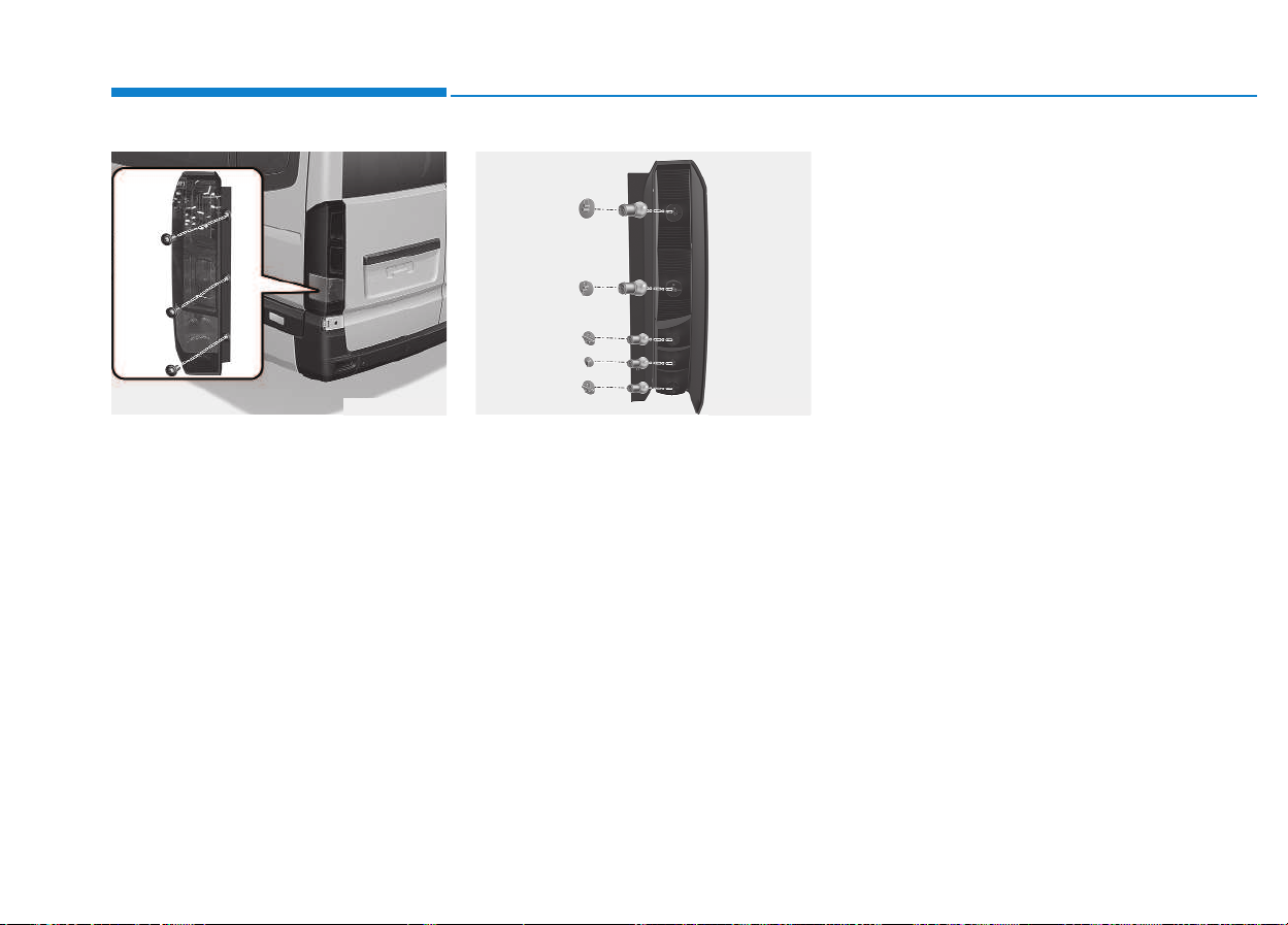
1.Open the rear door.
2.Loosen the light assembly retain-
ing screws with a cross-tip screw-
driver.
3.Remove the rear combination light
assembly from the body of the
vehicle.
4.Remove the socket from the
assembly by turning the socket
counter clockwise until the tabs on
the socket align with the slots on
the assembly.
5.Remove the bulb from the socket
by pressing it in and rotating it
counter clockwise until the tabs on
the bulb align with the slots in the
socket. Pull the bulb out of the
socket.
6.Insert a new bulb by inserting it into
the socket and rotating it until it
locks into place.
7.Install the socket in the assembly
by aligning the tabs on the socket
with the slots in the assembly.
Push the socket into the assembly
and turn the socket clockwise.
8.Reinstall the light assembly to the
body of the vehicle.
7-76
Maintenance
OEU074053OEU074051
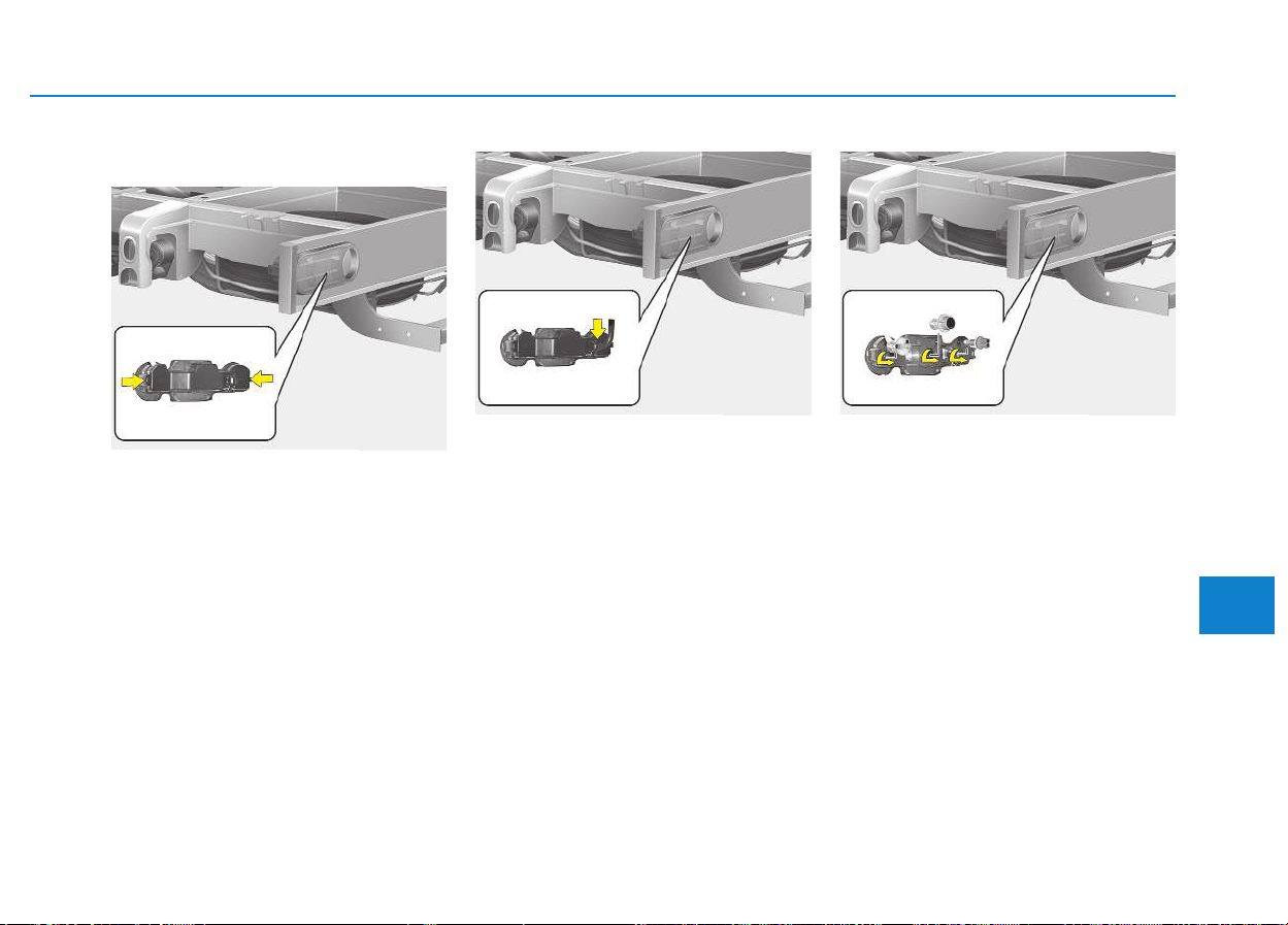
7-77
7
Maintenance
VAN
1.Disconnect the power cord from
the bulb.
2.Remove the cover by pressing the
both sides of the cover.
3.To replace the rear combination
light (stop/tail light, turn signal light
or back-up light), take it out from
the bulb holder by turning it coun-
terclockwise.
(1) Turn Signal Light
(2) Stop/Tail Light
(3) Back-up Light
4.Install the new bulb.
OEU054020
OEU054021 OEU054022
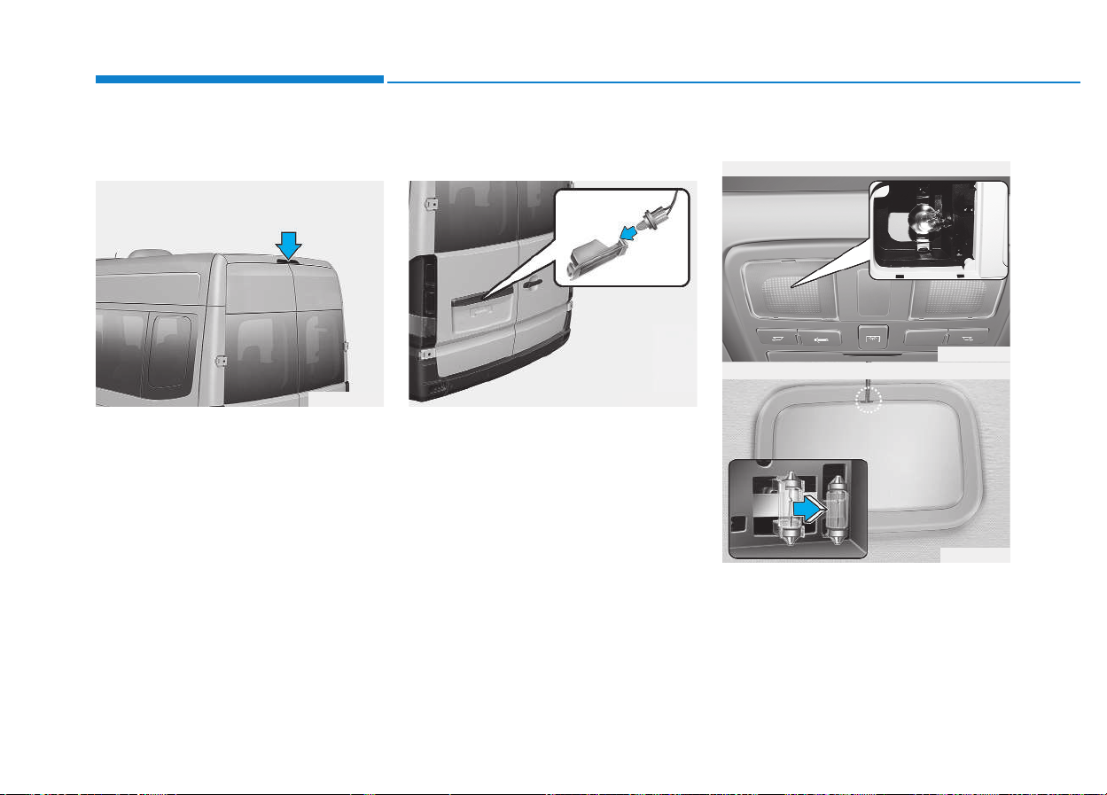
7-78
Maintenance
High mounted stop light bulb
replacement (if equipped)
If the light does not operate, we rec-
ommend that the system be checked
by an authorized HYUNDAI dealer.
License plate light bulb
replacement (if equipped)
1.Remove the lens by pressing the
tabs.
2.Remove the socket from the lens.
3.Remove the bulb by pulling it
straight out.
4.Install a new bulb in the socket and
install the socket to the lens.
5.Reinstall the lens securely.
Interior light bulb replacement
1.Using a flat-blade screwdriver,
gently pry the lens from the interior
light housing.
2.Remove the bulb by pulling it
straight out.
OEU074052 OEU074054
OEU074031
OEU074032
■ Map lamp
■ Room lamp
7-79
7
Maintenance
3.Install a new bulb in the socket.
4.Align the lens tabs with the interior
light housing notches and snap the
lens into place.
Exterior care
Exterior general caution
It is very important to follow the label
directions when using any chemical
cleaner or polish. Read all warning
and caution statements that appear
on the label.
Finish maintenance
Washing
To help protect your vehicle’s finish
from rust and deterioration, wash it
thoroughly and frequently at least
once a month with lukewarm or cold
water.
If you use your vehicle for off-road
driving, you should wash it after each
off-road trip. Pay special attention to
the removal of any accumulation of
salt, dirt, mud, and other foreign
materials. Make sure the drain holes
in the lower edges of the doors and
rocker panels are kept clear and
clean.
Insects, tar, tree sap, bird droppings,
industrial pollution and similar
deposits can damage your vehicle’s
finish if not removed immediately.
Even prompt washing with plain
water may not completely remove all
these deposits.
A mild soap, safe for use on painted
surfaces, may be used.
After washing, rinse the vehicle thor-
oughly with lukewarm or cold water.
Do not allow soap to dry on the fin-
ish.
Prior to working on the Interior
Lights, ensure that the “OFF”
button is depressed to avoid
burning your fingers or receiv-
ing an electric shock.
WARNING
Use care not to dirty or damage
lens, lens tab, and plastic hous-
ings.
CAUTION
AAPPPPEEAARRAANNCCEE CCAARREE
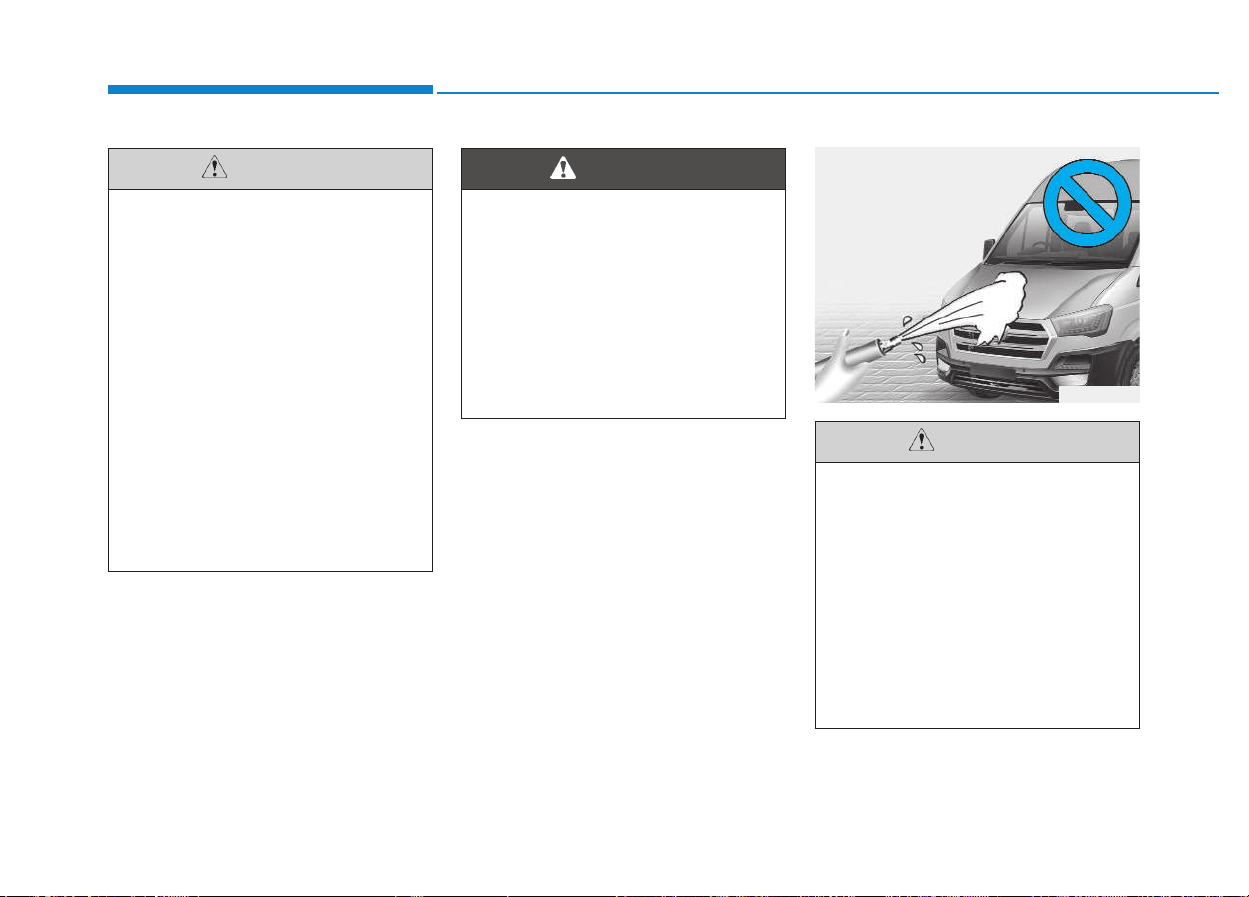
7-80
Maintenance
• Do not use strong soap,
chemical detergents or hot
water, and do not wash the
vehicle in direct sunlight or
when the body of the vehicle
is warm.
• Be careful when washing the
side windows of your vehicle.
Especially, with high-pressure
water, water may leak through
the windows and wet the inte-
rior.
• To prevent damage to the
plastic parts and lamps, do
not clean with chemical sol-
vents or strong detergents.
CAUTION
Wet brakes
After washing the vehicle, test
the brakes while driving slowly
to see if they have been affected
by water. If braking performance
is impaired, dry the brakes by
applying them lightly while
maintaining a slow forward
speed.
WARNING
OEU064036
• Water washing in the engine
compartment including high
pressure water washing may
cause the failure of electrical
circuits located in the engine
compartment.
• Never allow water or other liq-
uids to come in contact with
electrical/electronic compo-
nents inside the vehicle as
this may damage them.
CAUTION
7-81
7
Maintenance
Waxing
Wax the vehicle when water will no
longer bead on the paint.
Always wash and dry the vehicle
before waxing. Use a good quality
liquid or paste wax, and follow the
manufacturer’s instructions. Wax all
metal trim to protect it and to main-
tain its luster.
Removing oil, tar, and similar materi-
als with a spot remover will usually
strip the wax from the finish. Be sure
to re-wax these areas even if the rest
of the vehicle does not yet need wax-
ing.
Finish damage repair
Deep scratches or stone chips in the
painted surface must be repaired
promptly. Exposed metal will quickly
rust and may develop into a major
repair expense.
If your vehicle is damaged and
requires any metal repair or
replacement, be sure the body
shop applies anti-corrosion mate-
rials to the parts repaired or
replaced.
NOTICE
• Wiping dust or dirt off the
body with a dry cloth will
scratch the finish.
• Do not use steel wool, abra-
sive cleaners, or strong deter-
gents containing highly alka-
line or caustic agents on
chrome-plated or anodized
aluminum parts. This may
result in damage to the pro-
tective coating and cause dis-
coloration or paint deteriora-
tion.
CAUTION

7-82
Maintenance
Bright-metal maintenance
• To remove road tar and insects,
use a tar remover, not a scraper or
other sharp object.
• To protect the surfaces of bright-
metal parts from corrosion, apply a
coating of wax or chrome preser-
vative and rub to a high luster.
• During winter weather or in coastal
areas, cover the bright metal parts
with a heavier coating of wax or
preservative. If necessary, coat the
parts with non-corrosive petroleum
jelly or other protective compound.
Underbody maintenance
Corrosive materials used for ice and
snow removal and dust control may
collect on the underbody. If these
materials are not removed, acceler-
ated rusting can occur on underbody
parts such as the fuel lines, frame,
floor pan and exhaust system, even
though they have been treated with
rust protection.
Thoroughly flush the vehicle under-
body and wheel openings with luke-
warm or cold water once a month,
after off-road driving and at the end
of each winter. Pay special attention
to these areas because it is difficult
to see all the mud and dirt. It will do
more harm than good to wet down
the road grime without removing it.
The lower edges of doors, rocker
panels, and frame members have
drain holes that should not be
allowed to clog with dirt; trapped
water in these areas can cause rust-
ing.
After washing the vehicle, test
the brakes while driving slowly
to see if they have been affected
by water. If braking performance
is impaired, dry the brakes by
applying them lightly while
maintaining a slow forward
speed.
WARNING

7-83
7
Maintenance
Aluminum or chrome wheel
maintenance
The aluminum or chrome wheels are
coated with a clear protective finish.
• Do not use any abrasive cleaner,
polishing compound, solvent, or
wire brushes on aluminum or
chrome wheels. They may scratch
or damage the finish.
• Clean the wheel when it has
cooled.
• Use only a mild soap or neutral
detergent, and rinse thoroughly
with water. Also, be sure to clean
the wheels after driving on salted
roads. This helps prevent corro-
sion.
• Avoid washing the wheels with
high-speed vehicle wash brushes.
• Do not use any alkaline or acid
detergent. It may damage and cor-
rode the aluminum or chrome
wheels coated with a clear protec-
tive finish.
Corrosion protection
Protecting your vehicle from corro-
sion
By using the most advanced design
and construction practices to combat
corrosion, we produces vehicles of
the highest quality. However, this is
only part of the job. To achieve the
long-term corrosion resistance your
vehicle can deliver, the owner's
cooperation and assistance is also
required.
Common causes of corrosion
The most common causes of corro-
sion on your vehicle are:
• Road salt, dirt and moisture that is
allowed to accumulate underneath
the vehicle.
• Removal of paint or protective
coatings by stones, gravel, abra-
sion or minor scrapes and dents
which leave unprotected metal
exposed to corrosion.
High-corrosion areas
If you live in an area where your vehi-
cle is regularly exposed to corrosive
materials, corrosion protection is
particularly important. Some of the
common causes of accelerated cor-
rosion are road salts, dust control
chemicals, ocean air and industrial
pollution.
Moisture breeds corrosion
Moisture creates the conditions in
which corrosion is most likely to
occur. For example, corrosion is
accelerated by high humidity, partic-
ularly when temperatures are just
above freezing. In such conditions,
the corrosive material is kept in con-
tact with the vehicle surfaces by
moisture that is slow to evaporate.
Mud is particularly corrosive
because it is slow to dry and holds
moisture in contact with the vehicle.
Although the mud appears to be dry,
it can still retain the moisture and
promote corrosion.

7-84
Maintenance
High temperatures can also acceler-
ate corrosion of parts that are not
properly ventilated so the moisture
can be dispersed. For all these rea-
sons, it is particularly important to
keep your vehicle clean and free of
mud or accumulations of other mate-
rials. This applies not only to the vis-
ible surfaces but particularly to the
underside of the vehicle.
To help prevent corrosion
You can help prevent corrosion from
getting started by observing the fol-
lowing:
Keep your vehicle clean
The best way to prevent corrosion is
to keep your vehicle clean and free
of corrosive materials. Attention to
the underside of the vehicle is partic-
ularly important.
• If you live in a high-corrosion area
- where road salts are used, near
the ocean, areas with industrial
pollution, acid rain, etc.-, you
should take extra care to prevent
corrosion. In winter, hose off the
underside of your vehicle at least
once a month and be sure to clean
the underside thoroughly when
winter is over.
• When cleaning underneath the
vehicle, give particular attention to
the components under the fenders
and other areas that are hidden
from view. Do a thorough job; just
dampening the accumulated mud
rather than washing it away will
accelerate corrosion rather than
prevent it. Water under high pres-
sure and steam are particularly
effective in removing accumulated
mud and corrosive materials.
• When cleaning lower door panels,
rocker panels and frame mem-
bers, be sure that drain holes are
kept open so that moisture can
escape and not be trapped inside
to accelerate corrosion.
Keep your garage dry
Don't park your vehicle in a damp,
poorly ventilated garage. This cre-
ates a favorable environment for cor-
rosion. This is particularly true if you
wash your vehicle in the garage or
drive it into the garage when it is still
wet or covered with snow, ice or
mud. Even a heated garage can con-
tribute to corrosion unless it is well
ventilated so moisture is dispersed.

7-85
7
Maintenance
Keep paint and trim in good
condition
Scratches or chips in the finish
should be covered with "touch-up"
paint as soon as possible to reduce
the possibility of corrosion. If bare
metal is showing through, the atten-
tion of a qualified body and paint
shop is recommended.
Bird droppings : Bird droppings are
highly corrosive and may damage
painted surfaces in just a few hours.
Always remove bird droppings as
soon as possible.
Don't neglect the interior
Moisture can collect under the floor
mats and carpeting to cause corro-
sion. Check under the mats periodi-
cally to be sure the carpeting is dry.
Use particular care if you carry fertil-
izers, cleaning materials or chemi-
cals in the vehicle.
These should be carried only in
proper containers and any spills or
leaks should be cleaned up, flushed
with clean water and thoroughly
dried.
Interior care
Interior general precautions
Prevent chemicals such as perfume,
cosmetic oil, sun cream, hand clean-
er, and air freshener from contacting
the interior parts because they may
cause damage or discoloration. If
they do contact the interior parts,
wipe them off immediately. See the
instructions that follow for the proper
way to clean vinyl.
Never allow water or other liq-
uids to come in contact with
electrical/electronic compo-
nents inside the vehicle as this
may damage them.
CAUTION
7-86
Maintenance
Cleaning the upholstery and
interior trim
Vinyl
Remove dust and loose dirt from
vinyl with a whisk broom or vacuum
cleaner. Clean vinyl surfaces with a
vinyl cleaner.
Fabric
Remove dust and loose dirt from fab-
ric with a whisk broom or vacuum
cleaner. Clean with a mild soap solu-
tion recommended for upholstery or
carpets. Remove fresh spots imme-
diately with a fabric spot cleaner. If
fresh spots do not receive immediate
attention, the fabric can be stained
and its color can be affected. Also, its
fire-resistant properties can be
reduced if the material is not proper-
ly maintained.
Cleaning the lap/shoulder belt
webbing
Clean the belt webbing with any mild
soap solution recommended for
cleaning upholstery or carpet. Follow
the instructions provided with the
soap. Do not bleach or re-dye the
webbing because this may weaken
it.
Cleaning the interior window
glass
If the interior glass surfaces of the
vehicle become fogged (that is, cov-
ered with an oily, greasy or waxy
film), they should be cleaned with
glass cleaner. Follow the directions
on the glass cleaner container.
Using anything but recom-
mended cleaners and proce-
dures may affect the fabric’s
appearance and fire-resistant
properties.
CAUTION
When cleaning leather products
(steering wheel, seats etc.), use
neutral detergents or low alco-
hol content solutions. If you use
high alcohol content solutions
or acid/alkaline detergents, the
color of the leather may fade or
the surface may get stripped
off.
CAUTION
Do not scrape or scratch the
inside of the rear window. This
may result in damage to the rear
window defroster grid.
CAUTION

7-87
7
Maintenance
The emission control system of your
vehicle is covered by a written limited
warranty. Please see the warranty
information contained in the Service
Passport in your vehicle.
Your vehicle is equipped with an
emission control system to meet all
emission regulations.
There are three emission control
systems which are as follows.
(1) Crankcase emission control sys-
tem
(2) Evaporative emission control sys-
tem
(3) Exhaust emission control system
In order to assure the proper function
of the emission control systems, it is
recommended that you have your
vehicle inspected and maintained by
an authorized HYUNDAI dealer or
other repair shops that use qualified
technicians in accordance with the
maintenance schedule in this manu-
al.
1. Crankcase emission control
system
The positive crankcase ventilation
system is employed to prevent air
pollution caused by blow-by gases
being emitted from the crankcase.
This system supplies fresh filtered air
to the crankcase through the air
intake hose. Inside the crankcase,
the fresh air mixes with blow-by
gases, which then pass through the
PCV valve into the induction system.
2. Evaporative emission con-
trol System
The Evaporative Emission Control
System is designed to prevent fuel
vapors from escaping into the atmos-
phere.
Canister
Fuel vapors generated inside the fuel
tank are absorbed and stored in the
onboard canister. When the engine is
running, the fuel vapors absorbed in
the canister are drawn into the surge
tank through the purge control sole-
noid valve.
Purge Control Solenoid Valve
(PCSV)
The purge control solenoid valve is
controlled by the Engine Control
Module (ECM); when the engine
coolant temperature is low during
idling, the PCSV closes so that evap-
orated fuel is not taken into the
engine. After the engine warms-up
during ordinary driving, the PCSV
opens to introduce evaporated fuel to
the engine.
EEMMIISSSSIIOONN CCOONNTTRROOLL SSYYSSTTEEMM
7-88
Maintenance
3. Exhaust emission control
system
The Exhaust Emission Control
System is a highly effective system
which controls exhaust emissions
while maintaining good vehicle per-
formance.
Vehicle modifications
• This vehicle should not be modi-
fied. Modification of your vehicle
could affect its performance, safety
or durability and may even violate
governmental safety and emis-
sions regulations.
In addition, damage or perform-
ance problems resulting from any
modification may not be covered
under warranty.
• If you use unauthorized electronic
devices, it may cause the vehicle to
operate abnormally, wire damage,
battery discharge and fire. For your
safety, do not use unauthorized
electronic devices.
Engine exhaust gas precautions
(carbon monoxide)
• Carbon monoxide can be present
with other exhaust fumes.
Therefore, if you smell exhaust
fumes of any kind inside your vehi-
cle, have it inspected and repaired
immediately. If you ever suspect
exhaust fumes are coming into
your vehicle, drive it only with all
the windows fully open. Have your
vehicle checked and repaired
immediately.
• Do not operate the engine in con-
fined or closed areas (such as
garages) any more than what is
necessary to move the vehicle in or
out of the area.
• When the vehicle is stopped in an
open area for more than a short
time with the engine running,
adjust the ventilation system (as
needed) to draw outside air into the
vehicle.
• Never sit in a parked or stopped
vehicle for any extended time with
the engine running.
• When the engine stalls or fails to
start, excessive attempts to restart
the engine may cause damage to
the emission control system.
Exhaust
Engine exhaust gases contain
carbon monoxide (CO). Though
colorless and odorless, it is
dangerous and could be lethal if
inhaled. Follow the instructions
following to avoid CO poison-
ing.
WARNING

7-89
7
Maintenance
Operating precautions for cat-
alytic converters (if equipped)
Your vehicle is equipped with a cat-
alytic converter emission control
device.
Therefore, the following precautions
must be observed:
• Do not operate the vehicle when
there are signs of engine malfunc-
tion, such as misfire or a noticeable
loss of performance.
• Do not misuse or abuse the
engine. Examples of misuse are
coasting with the ignition off and
descending steep grades in gear
with the ignition off.
• Do not operate the engine at high
idle speed for extended periods (5
minutes or more).
• Do not modify or tamper with any
part of the engine or emission con-
trol system. We recommend that
the system be inspected by an
authorized HYUNDAI dealer.
• Avoid driving with a extremely low
fuel level. Running out of fuel
cause the engine to misfire, dam-
aging the catalytic converter.
Failure to observe these precautions
could result in damage to the catalyt-
ic converter and to your vehicle.
Additionally, such actions could void
your warranties.
Fire
• A hot exhaust system can
ignite flammable items under
your vehicle. Do not park,
idle, or drive the vehicle over
or near flammable objects,
such as dry grass, paper,
leaves, etc.
• The exhaust system and cat-
alytic system are very hot
while the engine is running or
immediately after the engine
is turned off. Keep away from
the exhaust system and cat-
alytic, you may get burned.
Also, do not remove the heat
sink around the exhaust sys-
tem, do not seal the bottom of
the vehicle or do not coat the
vehicle for corrosion control.
It may present a fire risk under
certain conditions.
WARNING

7-90
Maintenance
Diesel Particulate Filter
(if equipped)
The Diesel Particulate Filter (DPF)
system removes the soot emitted
from the vehicle.
Unlike a disposable air filter, the DPF
system automatically burns (oxi-
dizes) and removes the accumulated
soot according to the driving condi-
tion. In other words, the active burn-
ing by engine control system and
high exhaust gas temperature
caused by normal/high driving condi-
tion burns and removes the accumu-
lated soot.
However, if the vehicle continues to
be driven in short distance repeated-
ly or at low speed for a long time, the
accumulated soot may not be auto-
matically removed because of low
exhaust gas temperature. In this par-
ticular case, if the amount of soot is
out of detection limit, the DPF warn-
ing indicator ( ) will illuminate.
In order to start the DPF regenera-
tion and to stop the DPF warning
lamp illuminating, drive the vehicle in
a safety driving circumstance with
more than 60km/h (37 mph) vehicle
speed or with more than second
gear engaged and 1500 ~ 2000
engine rpm for a certain time (for
about 25 minutes).
If the DPF warning indicator( )
continues to blink or "check emission
system" message comes on in the
cluster in spite of the above proce-
dure, we recommend that the system
be checked by an authorized
HYUNDAI dealer.
If you continue to drive with the indi-
cator light blinking for a long time, the
DPF system can be damaged and
fuel consumption can be worsen.
Diesel Fuel
(if equipped with DPF)
It is recommended to use the
regulated automotive diesel
fuel for diesel vehicle equipped
with the DPF system.
If you use diesel fuel including
high sulfur (more than 50 ppm
sulfur) and unspecified addi-
tives, it can cause the DPF sys-
tem to be damaged and white
smoke can be emitted.
CAUTION

8
Specifications & Consumer information
8
Specifications & Consumer information
8
Dimensions..............................................................8-2
Engine......................................................................8-3
Air conditioning system ........................................8-3
Bulb wattage...........................................................8-4
Tires and wheels....................................................8-5
Load and speed capacity tires.............................8-5
Gross vehicle weight .............................................8-6
Recommended lubricants and capacities ...........8-7
Available engine oil (For Europe)..................................8-8
Recommended SAE viscosity number..........................8-9
Vehicle identification number (VIN)..................8-10
Vehicle certification label...................................8-10
Tire specification and pressure label ...............8-11
Engine number .....................................................8-11
Air conditioner compressor label ......................8-11
Declaration of conformity ..................................8-12

8-2
Specifications & Consumer information
D
DIIMMEENNSSIIOONNSS
unit : mm (in)
ITEM BUS
VAN Tr uck
Long Short Long Short
Overall length
[With rear step]
6,195 (243.9)
6,195 (243.9)
[6,365 (250.6)]
5,515 (217.1)
[5,685 (223.9)]
6,167 (242.8) 5,724 (225.4)
Overall width
[With outside rear view mirror]
2,038 (80.2)
[2,436 (96.0)]
2,038 (80.2)
[2,436 (96.0)]
2,038 (80.2)
[2,436 (96.0)]
2,038 (80.2)
[2,436 (96.0)]
2,038 (80.2)
[2,436 (96.0)]
Overall height
Roof panel 2,665 (105.0) 2,690 (106.0) 2,685 (105.7) 2,320 (91.3) 2,320 (91.3)
Roof hatch 2,673 (105.2) - - - -
Electric vent 2,777 (109.3) - - - -
A/CON 2,856 (111.6) - - - -
Front tread 1,712 (67.4) 1,712 (67.4) 1,712 (67.4) 1,712 (67.4) 1,712 (67.4)
Rear tread 1,718 (67.6) 1,718 (67.6) 1,718 (67.6) 1,718 (67.6) 1,718 (67.6)
Wheelbase 3,670 (144.5) 3,670 (144.5) 3,435 (135.2) 3,670 (144.5) 3,435 (135.2)

8-3
8
Specifications & Consumer information
EENNGGIINNEE
AAIIRR CCOONNDDIITTIIOONNIINNGG SSYYSSTTEEMM
Item D4CB
Displacement
cc (cu. in)
2,497 (152.38)
Bore x Stroke
mm (in.)
91X96 (3.58X3.77)
Firing order
1-3-4-2
No. of cylinders
4. In-line
Item
Bus VAN, Truck
Driver Driver + Passenger
Driver + Passenger
(Twin compressor)
Driver
Refrigerant
Weight of volume 700 1,150 2,100 (700 +1,400) 700
Classification R134a
Compressor lubricant
Weight of volume 130 270 Driver (130), Passenger (270) 130
Classification PAG oil
unit : g

8-4
Specifications & Consumer information
B
BUULLBB WWAATTTTAAGGEE
* If equipped
Light Bulb
Wattage
MFR Projection
Headlights (Low/High) 55
Front fog lights* 35
Front turn signal lights 21 21
Front position lights 5 LED
DRL lights* 21 LED
Side repeater LED
Side marker lights* 5
Rear stop / tail lamp 21/5
Back up lamp 16
Rear turn signal lamp 21
Rear fog lights 21
License plate light 5
High mounted stop light LED
Over head console lamps 10
Room lamps* LED (if equipped) 10
Step lamp* 5
Cargo lamps* 10
Reading lamps* LED
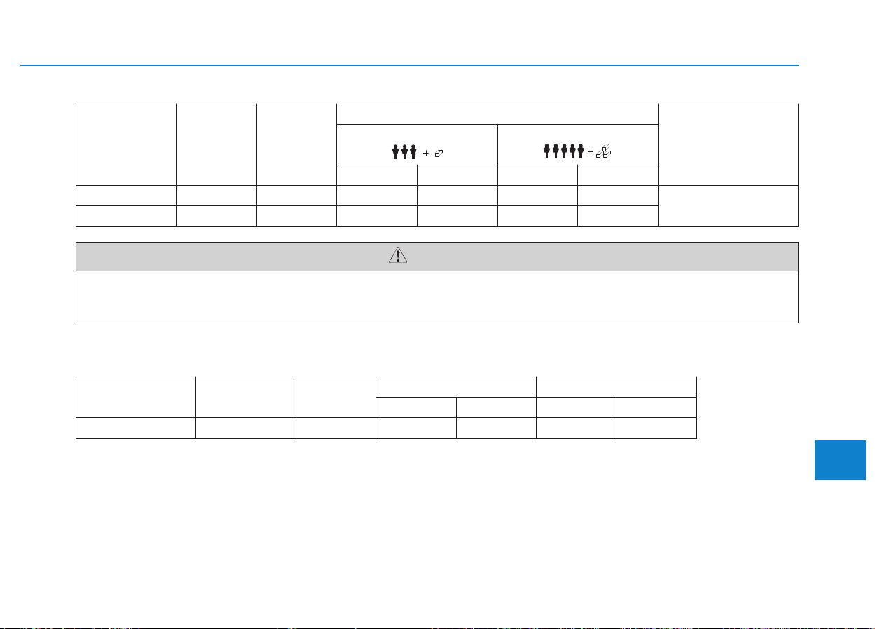
8-5
8
Specifications & Consumer information
TTIIRREESS AANNDD WWHHEEEELLSS
When replacing tires, use the same size originally supplied with the vehicle.
Using tires of a different size can damage the related parts or make it work irregularly.
CAUTION
LLOOAADD AANNDD SSPPEEEEDD CCAAPPAACCIITTYY TTIIRREESS
Item Tire size Wheel size
Inflation pressure bar (psi, kPa)
Wheel lug nut torque
kg•m (lb•ft, N•m)
Normal load
()
Maximum load
()
Front Rear Front Rear
VAN, Truck 235/65R16C 16x6.5J 49 (338) 64 (442) 49 (338) 64 (442)
9~11
(67~81, 90~110)
BUS 235/65R16C 16x6.5J 49 (338) 69 (476) 49 (338) 69 (476)
*
1
LI : LOAD INDEX
*
2
SS : SPEED SYMBOL
Item Tire size Wheel size
Load Capacity Speed Capacity
LI *
1
kg SS *
2
km/h
Full size tire 235/65R16C 16x6.5J 115/113 1,215/1,150 R 170

8-6
Specifications & Consumer information
G
GRROOSSSS VVEEHHIICCLLEE WWEEIIGGHHTT
Item BUS
VAN
Truck
N1*
1
N2*
1
BUS, VAN, Truck 4,000 (8,818) 3,500 (7,716) 4,100 (9,039) 3,500 (7,716)
unit : kg (lbs)
❇ *
1
: N1:GVW 3.5 ton, N2 : 3.5 ton < GVW <12 ton
≥
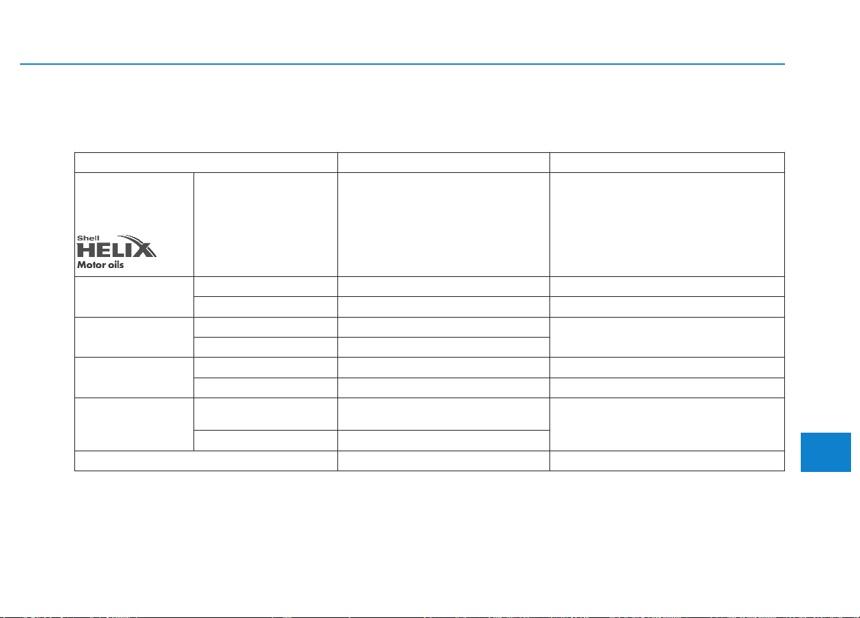
8-7
8
Specifications & Consumer information
RREECCOOMMMMEENNDDEEDD LLUUBBRRIICCAANNTTSS AANNDD CCAAPPAACCIITTIIEESS
To help achieve proper engine and powertrain performance and durability, use only lubricants of the proper quality.
The correct lubricants also help promote engine efficiency that results in improved fuel economy.
These lubricants and fluids are recommended for use in your vehicle.
Lubricant Volume Classification
Engine oil
*1 *2
(drain and refill)
Recommends
Diesel Engine
8.7 l (9.19 US qt.)
ACEA C2
SAE 15W-40 : -15°C above
SAE 10W-30/40 : -20°C above
SAE 5W-30/40 : -25°C above
SAE 0W-30/40 : -30°C below
Engine Oil
Consumption
Normal driving condition MAX. 1L /1500 Km -
Severe driving condition MAX. 1L /1000 Km -
Manual transmission
fluid
With PTO
3.5 l (3.7 US qt.)
API GL-4, SAE 75W/85 (Synthetic)
Without PTO
3.2 l (3.38 US qt.)
Rear axle oil
Tropical zone
2.5 ± 0.25 l (2.64 ± 0.26 US qt.)
API GL-5, SAE 140
Temperated/frigid zone
2.5 ± 0.25 l (2.64 ± 0.26 US qt.)
API GL-5, SAE 80W90
Coolant
BUS
15 l (15.9 US qt.)
15.2 l (16.1 US qt.) (with preheat)
Mixture of antifreeze and distilled water
(Ethylene glycol base coolant for
aluminum radiator)
VAN, Truck
11.2 l (11.8 US qt.)
Power steering fluid
1.15 l (1.2 US qt.)
PSF-3
*
1
Refer to the recommended SAE viscosity numbers on 8-9 page.
*
2
Engine oils labeled Energy Conserving Oil are now available. Along with other additional benefits, they contribute to fuel econo-
my by reducing the amount of fuel necessary to overcome engine friction. Often, these improvements are difficult to measure in
everyday driving, but in a year’s time, they can offer significant cost and energy savings.

8-8
Specifications & Consumer information
Lubricant Volume Classification
Brake/clutch fluid
0.984 l (1.04 US qt.)
FMVSS116 DOT-4
Urea solution
22 l (23.2 US qt.)
AUS 32 DIN V70070, ISO/DIS 22241-1 (If the vehicle is driven with
urea solution volume less than 4%, engine output will be limited.
And if it is less than 1%, vehicle speed will be limited to 20 km/h.)
Fuel
75 l (79.3 US gal.)
Refer to “Fuel requirements” in foreword
Urea consumption per liter 580 km
Available Engine oil (For Europe)
Supplier
Product
Diesel Engine
Shell HELIX ULTRA AP-L 5W-30
8-9
8
Specifications & Consumer information
Recommended SAE viscosity
number
Always be sure to clean the area
around any filler plug, drain
plug, or dipstick before check-
ing or draining any lubricant.
This is especially important in
dusty or sandy areas and when
the vehicle is used on unpaved
roads. Cleaning the plug and
dipstick areas will prevent dirt
and grit from entering the
engine and other mechanisms
that could be damaged.
CAUTION
Temperature Range for SAE Viscosity Numbers
Temperature
°C
(°F)
-30 -20 -10 0 10 20 30 40 50
-10 0 20 40 60 80 100 120
Diesel
Engine Oil
5W-30/40
15W-40
10W-30/40
0W-30/40
Engine oil viscosity (thickness) has an effect on fuel economy and cold
weather operating (engine start and engine oil flowability). Lower viscosity
engine oils can provide better fuel economy and cold weather performance,
however, higher viscosity engine oils are required for satisfactory lubrication
in hot weather.
Using oils of any viscosity other than those recommended could result in
engine damage.
When choosing an oil, consider the range of temperature your vehicle will be
operated in before the next oil change. Proceed to select the recommended
oil viscosity from the chart.

8-10
Specifications & Consumer information
The vehicle identification number
(VIN) is the number used in register-
ing your vehicle and in all legal mat-
ters pertaining to its ownership, etc.
The number is punched on the
engine compartment bulkhead.
The VIN is also on a plate attached
to the top of the dashboard. The
number on the plate can easily be
seen through the windshield from
outside.
The vehicle certification label
attached on the driver’s (or front pas-
senger’s) side center pillar gives the
vehicle identification number (VIN).
VVEEHHIICCLLEE IIDDEENNTTIIFFIICCAATTIIOONN NNUUMMBBEERR ((VVIINN)) VVEEHHIICCLLEE CCEERRTTIIFFIICCAATTIIOONN
L
LAABBEELL
OEU074057
Frame number
OEU084002
VIN label (if equipped)
OEU084003
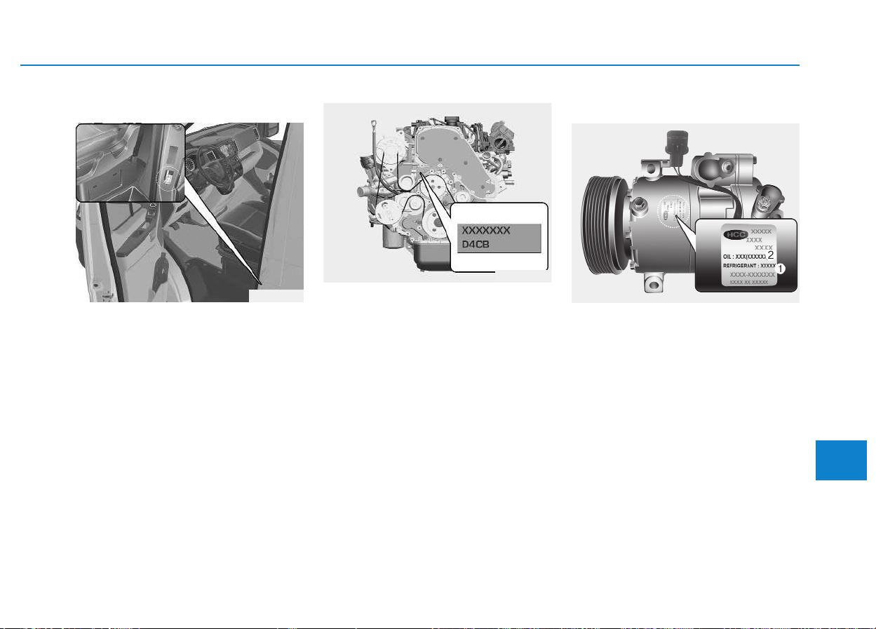
8-11
8
Specifications & Consumer information
The tires supplied on your new vehi-
cle are chosen to provide the best
performance for normal driving.
The tire label located on the driver's
side center pillar gives the tire pres-
sures recommended for your vehicle.
The engine number is stamped on
the engine block as shown in the
drawing.
A compressor label informs you the
type of compressor your vehicle is
equipped with such as model, suppli-
er part number, production number,
refrigerant (1) and refrigerant oil (2).
TTIIRREE SSPPEECCIIFFIICCAATTIIOONN AANNDD
P
PRREESSSSUURREE LLAABBEELL
E
ENNGGIINNEE NNUUMMBBEERR
OEU084004
OEU084005
OHC081001
AAIIRR CCOONNDDIITTIIOONNEERR
C
COOMMPPRREESSSSOORR LLAABBEELL

The radio frequency components of
the vehicle comply with requirements
and other relevant provisions of
Directive 1995/5/EC.
Further information including the
manufacturer's declaration of con-
formity is available on HYUNDAI web
site as follows;
http://service.hyundai-motor.com
DDEECCLLAARRAATTIIOONN OOFF
C
COONNFFOORRMMIITTYY
Specifications & Consumer information
8-12
CE0678
■ Example

I
Index
I

I-2
Active eco system.........................................................5-40
Active eco operation..................................................5-40
Limitation of active eco operation:............................5-41
When active eco is activated: ....................................5-41
Adjustable speed limit device (ASLD) ........................3-34
Air bag - supplemental restraint system.......................2-25
Air bag warning light.................................................2-28
Do not install a child restraint on the front
passenger seat ..........................................................2-27
Driver's and front passenger's air bag........................2-31
How does the air bag operate? ..................................2-26
SRS care.....................................................................2-39
SRS components and functions .................................2-29
Additional safety precautions .......................................2-40
Air bag warning labels .................................................2-42
Air cleaner ....................................................................7-31
Air conditioner compressor label .................................8-11
Air conditioning system .................................................8-3
Appearance care ...........................................................7-79
Battery...........................................................................7-37
Battery capacity label ................................................7-40
Battery recharging......................................................7-40
For best battery service..............................................7-37
Reset items.................................................................7-41
Before driving.................................................................5-3
Before entering the vehicle..........................................5-3
Before starting .............................................................5-3
Necessary inspections..................................................5-3
Brake system.................................................................5-18
Anti-lock brake system (ABS) ..................................5-21
Emergency stop signal (ESS) ....................................5-28
Good braking practices..............................................5-29
Hill-start assist control (HAC)...................................5-27
Parking brake .............................................................5-19
Power brakes..............................................................5-18
Vehicle dynamic control (VDC)................................5-24
Brake/Clutch fluid ........................................................7-27
Bulb wattage ...................................................................8-4
Cargo bed (for van) ....................................................3-129
Caring for disc ................................................................4-5
CD Player (For RDS Model)........................................4-13
CD Player .....................................................................4-16
Ceiling ventilator ........................................................3-122
Climate control air filter ...............................................7-33
Climate control system ...............................................3-110
Checking the amount of air conditioner refrigerant
and compressor lubricant.......................................3-120
Climate control air filter ..........................................3-119
Fuel-fired heater.......................................................3-119
Heating and air conditioning....................................3-111
Index
A
C
B

I-3
Rear heating and air conditioning............................3-116
System operation......................................................3-117
Cruise control system ...................................................5-30
Declaration of conformity ............................................8-12
Defroster .....................................................................3-109
Digital tachograph ........................................................3-80
Dimensions .....................................................................8-2
Door lock ......................................................................3-11
Deadlocks...................................................................3-14
Operating door locks from inside the vehicle ...........3-12
Operating door locks from outside the vehicle .........3-11
Speed sensing door lock system................................3-14
Economical operation ...................................................5-42
Electrical step.............................................................3-17
Electrical step warning alarm ....................................3-19
Operation and obstacle detection...............................3-19
Regular cleaning ........................................................3-21
Emergency commodity.................................................6-27
Fire extinguisher ........................................................6-27
First aid kit.................................................................6-27
Tire pressure gauge....................................................6-28
Triangle reflector .......................................................6-28
Emergency exit .............................................................6-26
Emergency starting .........................................................6-4
Emission control system...............................................7-87
Crankcase emission control system...........................7-87
Evaporative emission control system ........................7-87
Exhaust emission control system...............................7-88
Engine compartment .............................................1-10, 7-3
Engine coolant ..............................................................7-24
Changing the coolant .................................................7-26
Checking the coolant level ........................................7-24
Engine number..............................................................8-11
Engine oil......................................................................7-22
Changing the engine oil and filter .............................7-23
Checking the engine oil level ....................................7-22
Engine.............................................................................8-3
Explanation of scheduled maintenance items ..............7-19
Exterior overview (I) .....................................................1-2
Exterior overview (II).....................................................1-3
Exterior overview (III) ...................................................1-4
Exterior overview (IV) ...................................................1-5
Exterior overview (V).....................................................1-6
Exterior overview (VI) ...................................................1-7
Fuel filler lid .................................................................3-32
Fuel filter (For diesel)...................................................7-30
Draining water from fuel filter ..................................7-30
Fuel filter cartridge replacement................................7-30
I
Index
D
E
F

I-4
Fuses .............................................................................7-50
Alternator fuse ...........................................................7-54
Fuse/Relay panel description.....................................7-55
Inner panel fuse replacement.....................................7-52
Multi fuse...................................................................7-54
Glass break hammer .....................................................6-26
Gross vehicle weight ......................................................8-6
Hazard warning flasher .........................................3-95, 6-2
Hood .............................................................................3-30
Closing the hood........................................................3-31
Opening the hood.......................................................3-30
How vehicle audio works ...............................................4-2
If the engine overheats ...................................................6-7
If the engine will not start ..............................................6-3
Important safety precautions ..........................................2-2
Air bag hazards............................................................2-2
Always wear your seat belt..........................................2-2
Control your speed.......................................................2-3
Driver's distraction.......................................................2-2
Keep your vehicle in safe conditions ..........................2-3
In case of an emergency while driving ..........................6-2
If the engine stalls at a crossroad or crossing..............6-3
If the engine stalls while driving .................................6-2
If you have a flat tire while driving.............................6-3
Instrument cluster .........................................................3-43
Gauges and indicators................................................3-44
Instrument panel illumination....................................3-44
Interior features...........................................................3-126
Ashtray.....................................................................3-127
Cigarette lighter .......................................................3-126
Cup holder ...............................................................3-127
Power outlet .............................................................3-128
Sunvisor ...................................................................3-128
Interior light................................................................3-106
Cargo bed lamp........................................................3-108
Map lamp .................................................................3-106
Reading lamp ...........................................................3-107
Rear step lamp .........................................................3-108
Room lamp...............................................................3-108
Interior overview (Left side) ..........................................1-8
Interior overview (Right side) ........................................1-9
ISG (Idle stop and go) system........................................5-8
Auto start ...................................................................5-10
Auto stop......................................................................5-9
Condition of ISG system operation ...........................5-11
ISG system deactivation ............................................5-12
ISG system malfunction ............................................5-13
Index
G
H
I

I-5
Key positions ..................................................................5-5
Ignition switch position ...............................................5-5
Illuminated ignition switch..........................................5-5
Starting the engine .......................................................5-6
Keys ................................................................................3-4
Immobilizer system .....................................................3-5
Key operations .............................................................3-4
Record your key number .............................................3-4
Lane departure warning system (LWDS).....................5-37
Light bulbs....................................................................7-67
Headlight and front fog light aiming (for Europe)....7-70
Headlight, position light, turn signal light,
front fog light bulb replacement..............................7-68
High mounted stop light bulb replacement ...............7-78
Interior light bulb replacement ..................................7-78
License plate light bulb replacement.........................7-78
Rear combination light bulbs replacement ................7-75
Side marker lamp.......................................................7-75
Lighting.........................................................................3-95
Battery saver function................................................3-95
Daytime running light..............................................3-101
Front fog light..........................................................3-100
Headlight escort function...........................................3-96
Headlight leveling device ........................................3-101
Headlight welcome function......................................3-96
High - beam operation ...............................................3-98
Lighting control .........................................................3-96
Rear fog light ...........................................................3-100
Turn signals and lane change signals ........................3-99
Load and speed capacity tires.........................................8-5
Locking differential ......................................................5-63
Maintenance services......................................................7-5
Engine compartment precautions (Diesel engine).......7-7
Owner's responsibility .................................................7-5
Owner maintenance precautions..................................7-5
Manual transmission and rearaxle oil...........................7-31
Change the gear oil....................................................7-31
Check and adding oil .................................................7-31
Manual transmission.....................................................5-14
Downshifting .............................................................5-16
Good driving practices...............................................5-17
Manual transmission operation..................................5-14
Using the clutch .........................................................5-16
Mid sliding door ...........................................................3-15
Child-protector mid sliding door lock .......................3-16
Opening/closing from the inside ...............................3-16
Opening/closing from the outside .............................3-15
Mirrors ..........................................................................3-39
Inside rearview mirror ...............................................3-39
Outside rearview mirror.............................................3-41
I
Index
K
L
M

I-6
Multi-display.................................................................3-50
AV information ..........................................................3-53
Drive info. mode........................................................3-53
Function description ..................................................3-51
Information Mode......................................................3-54
Main display ..............................................................3-50
Trip computer ............................................................3-53
Turn by turn navigation .............................................3-54
User Settings Mode ...................................................3-55
Warning Messages .....................................................3-57
Multimedia system .........................................................4-2
Owner maintenance ........................................................7-8
Parking assist system....................................................3-88
Front/rear parking assist system type ........................3-92
Rear parking assist system type.................................3-89
Parking brake................................................................7-30
Power steering fluid......................................................7-28
Checking the power steering fluid level....................2-28
Checking the power steering hose.............................2-29
PTO switch ...................................................................5-41
RADIO 1 (RADIO,AUX) ...........................................4-45
RADIO 2 (RADIO,USB,AUX) (Except RDS Model) ..4-49
RADIO 2 (RADIO,USB,AUX) (For RDS Model)......4-48
Rear door ......................................................................3-22
Child-protector rear door lock ...................................3-25
Closing the rear doors from the outside ....................3-25
Opening the left-hand rear door ................................3-24
Opening the rear doors to an angle of 180° or 270° ..3-24
Opening/closing from the inside ...............................3-23
Opening/closing from the outside .............................3-23
Rearview camera ..........................................................3-94
Recommended lubricants and capacities........................8-7
Remote keyless entry......................................................3-6
Battery replacement .....................................................3-8
Remote keyless entry system operations.....................3-6
Transmitter precautions ...............................................3-7
Removing and storing the spare tire...............................6-9
Jacking instructions .....................................................6-9
A type...........................................................................6-9
B type.........................................................................6-11
Changing tires............................................................6-14
Index
R
P
O

I-7
Scheduled maintenance services ..................................7-10
Maintenance under severe usage conditions .............7-17
Normal maintenance schedule (except Europe) ........7-14
Normal maintenance schedule (for Europe)..............7-11
Seat belts ......................................................................2-13
2 point static belt (for rear passengers.......................2-18
Lap/shoulder belt (for front passengers)....................2-16
Seat belt precautions..................................................2-22
Seat belt restraint system ...........................................2-13
Seats................................................................................2-4
Front passenger's seats.................................................2-5
Passenger seat capacity label.....................................2-13
Rear seats ...................................................................2-12
Safety precautions........................................................2-4
Special driving conditions ............................................5-44
Steering wheel ..............................................................3-37
Horn ...........................................................................3-38
Power steering ...........................................................3-37
Tilt & telescopic steering...........................................3-37
Storage compartment..................................................3-123
Console storage........................................................3-124
Glove box.................................................................3-125
Overhead storage .....................................................3-123
Storage space above the headliner...........................3-124
Sunglass holder........................................................3-125
Theft-alarm system .........................................................3-9
Armed stage ...............................................................3-10
Disarmed stage...........................................................3-11
Theft-alarm stage .......................................................3-10
Tire specification and pressure label ............................8-11
Tires and wheels ...........................................................7-42
Checking tire inflation pressure.................................7-43
Recommended cold tire inflation pressures ..............7-42
Tire care .....................................................................7-42
Tire maintenance........................................................7-47
Tire replacement ........................................................7-46
Tire rotation ...............................................................7-44
Tire sidewall labeling.................................................7-48
Tire traction................................................................7-47
Wheel alignment and tire balance .............................7-45
Wheel replacement ....................................................7-47
Tires and wheels .............................................................8-5
Towing ..........................................................................6-19
Emergency towing .....................................................6-20
Removable towing hook............................................6-20
Towing service...........................................................6-19
Trailer towing ...............................................................5-52
Driving with a trailer .................................................5-55
If you do decide to pull a trailer ................................5-59
Maintenance when trailer towing ..............................5-58
Safety chains .............................................................5-54
I
Index
TS

I-8
Trailer brakes ............................................................5-54
Trip computer ..............................................................3-60
Driving distance/average vehicle speed/
elapsed time ............................................................3-62
Driving Information...................................................3-66
Fuel economy.............................................................3-63
Overview....................................................................3-60
Total AUTO STOP Hour ...........................................3-66
Trip modes .................................................................3-61
Urea solution filler lid ...............................................3-34
Urea Solution Gauge .................................................3-65
Urea solution filler lid ..................................................3-34
Vehicle certification label .............................................8-10
Vehicle identification number (VIN)............................8-10
Vehicle weight ..............................................................5-62
Warning and indicator lights ........................................3-66
Washer fluid..................................................................7-29
Windows .......................................................................3-26
Power windows..........................................................3-27
Rear seat windows .....................................................3-29
Windshield defrosting and defogging ........................3-121
Winter driving...............................................................5-48
Wiper blades .................................................................7-34
Wipers and washers ....................................................3-102
Windshield washers .................................................3-105
Windshield wiper/washer.........................................3-102
Windshield wipers ......................................................3-102
Index
V
W
U