Before Start .....................................................................2
What's in the box ...............................................................2
Part Names ......................................................................3
Part Names........................................................................3
Install ................................................................................7
Installation procedure ........................................................7
Step1: Speaker Layout.......................................................8
Step2: Connect the Speakers ..........................................15
Step3: Connect the TV & AV Components ......................17
Initial Setup ...................................................................23
Initial Setup with Auto Start-up Wizard ............................23
Playback ........................................................................25
AV Component Playback.................................................25
BLUETOOTH
®
Playback .................................................25
Network Functions...........................................................26
USB Storage Device........................................................27
Listening To the AM/FM Radio.........................................28
Multi-zone ........................................................................30
Listening Mode ................................................................31
VSX-LX302 / AV RECEIVER
For details about the Network Functions and listening modes,
and information regarding the advanced settings, refer to the
"Advanced Manual" available on our website.
http://jp.pioneer-audiovisual.com/manual/vsxlx302elite/adv/en.html
En
F
r
Es
SN29403015A_VSX-LX302_BAS_En_1711xx.book 1 ページ 2017年10月27日 金曜日 午後2時0分
2
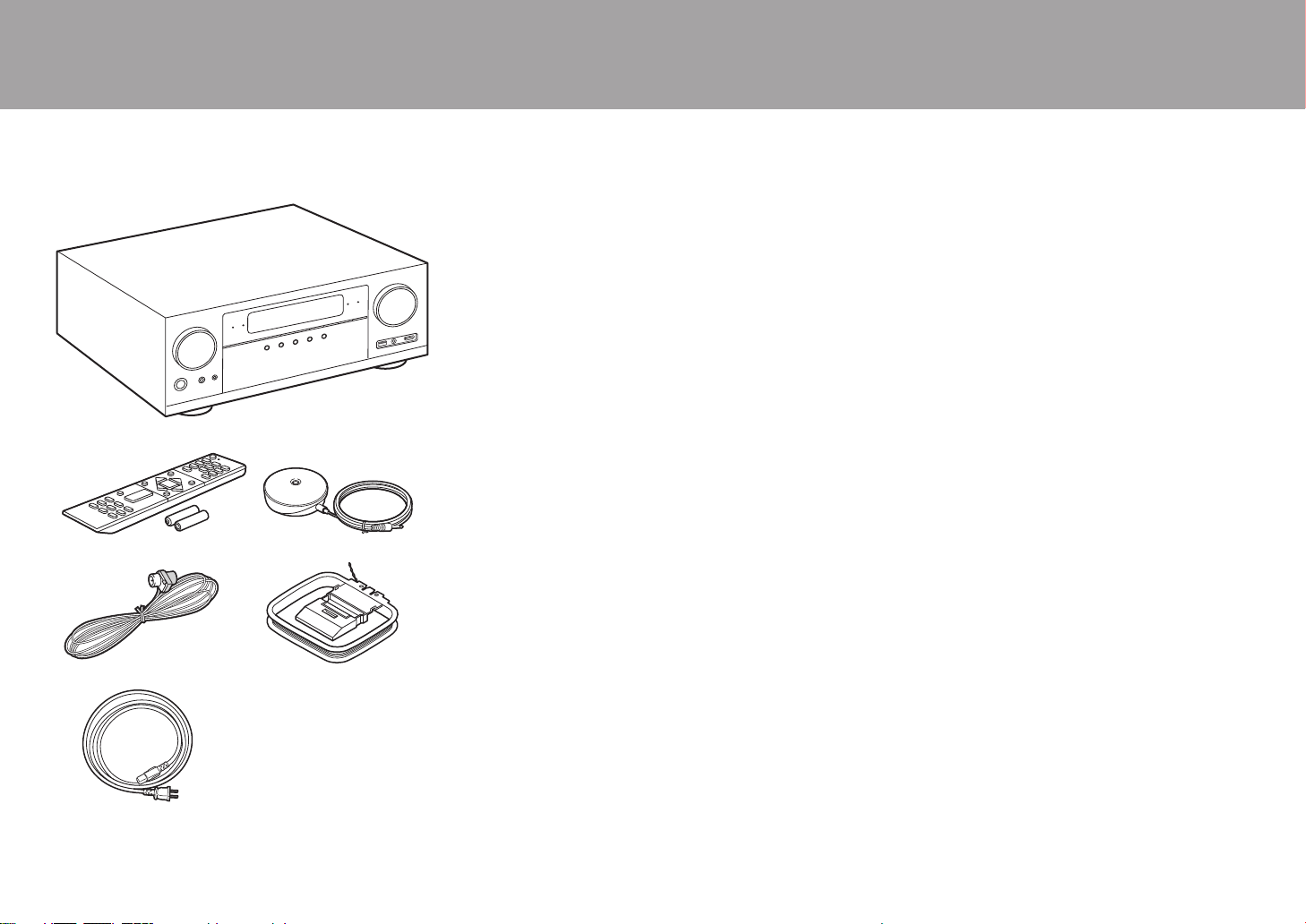
What's in the box
1. Main unit (1)
2. Remote controller (RC-957R) (1), Batteries (AAA/R03)
(2)
3. Speaker setup microphone (1)
0 Used during Initial Setup.
4. Indoor FM antenna (1)
5. AM loop antenna (1)
6. Power cord (1)
0 Quick Start Guide (1)
0 Basic Manual (This manual)
0 Connect speakers with 4 Ω to 16 Ω impedance.
0 The power cord must be connected only after all other
cable connections are completed.
0 We will not accept responsibility for damage arising from
the connection of equipment manufactured by other
companies.
0 Functionality may be introduced by firmware updates
and service providers may cease services, meaning that
some network services and content may become
unavailable in the future. Furthermore, available services
may vary depending on your area of residence.
0 Details on the firmware update will be posted on our
website and through other means at a later date.
0 Specifications and appearance are subject to change
without prior notice.
> Before Start > Part Names > Install > Initial Setup > Playback
1
32
54
6
SN29403015A_VSX-LX302_BAS_En_1711xx.book 2 ページ 2017年10月27日 金曜日 午後2時0分

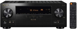
3
Part Names
Front Panel
1. INPUT SELECTOR dial: Switch the input to be played.
2. MCACC indicator: This lights when you have enabled the speaker calibration made with
MCACC (P23).
3. FL OFF indicator: This lights when you have pressed DIMMER repeatedly to turn the
display off.
4. DIMMER button: You can switch the display off or adjust the brightness of the display in
three steps.
5. ZONE 2-ON/OFF button: Switches the multi-zone function on/off (P30).
6. ZONE 2-CONTROL button: Controls the multi-zone function (P30).
7. HOME MENU button: Displays the Home. (*)
8. Display (P4)
9. Cursor buttons ( / / / ) and ENTER button: Select the item with the cursors and
press ENTER to confirm. Use them to tune to stations when using TUNER (P28).
10.
NETWORK indicator: This lights when "NET" is selected with the input selector and the
unit is connected to the network. If the unit is in standby mode, this lights when functions
such as HDMI CEC and network standby are enabled. It does not light when ZONE 2 is
on, however.
11.
WIRELESS indicator: Lights when the unit is connected to the wireless network and when
connected to a BLUETOOTH enabled device.
12.
Remote control sensor: Receives signals from the remote controller.
0 The signal range of the remote controller is within about 16´/5 m, at an angle of 20° on
the perpendicular axis and 30° to either side.
13.
RETURN button: Returns the display to the previous state.
14.
MASTER VOLUME
15.
Í STANDBY/ON button
16.
PHONES jack: Headphones with a standard plug (Ø1/4"/6.3 mm) are connected.
> Before Start >Part Names > Install > Initial Setup > Playback
En
(*)You can find details in the Advanced Manual.
SN29403015A_VSX-LX302_BAS_En_1711xx.book 3 ページ 2017年10月27日 金曜日 午後2時0分

4
> Before Start >Part Names > Install > Initial Setup > Playback
17.
MCACC SETUP MIC jack: The supplied speaker setup
microphone is connected.
18.
Listening mode button: Press "AUTO/DIRECT",
"SURROUND" or "STEREO" to switch the listening
mode (P31). (*)
19.
SOUND RETRIEVER button: Turns on/off the Sound
Retriever function that provides better sound quality for
compressed audio.
20.
PURE DIRECT button: Switches to the Pure Direct
mode (P31).
21.
USB port: A USB storage device is connected so that
music files stored in it can be played. You can also
supply power (5 V/500 mA) to USB devices with a USB
cable.
22.
AUX INPUT AUDIO/HDMI jack: Connect a video
camera, etc., using a stereo mini plug cable (Ø1/8"/
3.5 mm) or a HDMI cable.
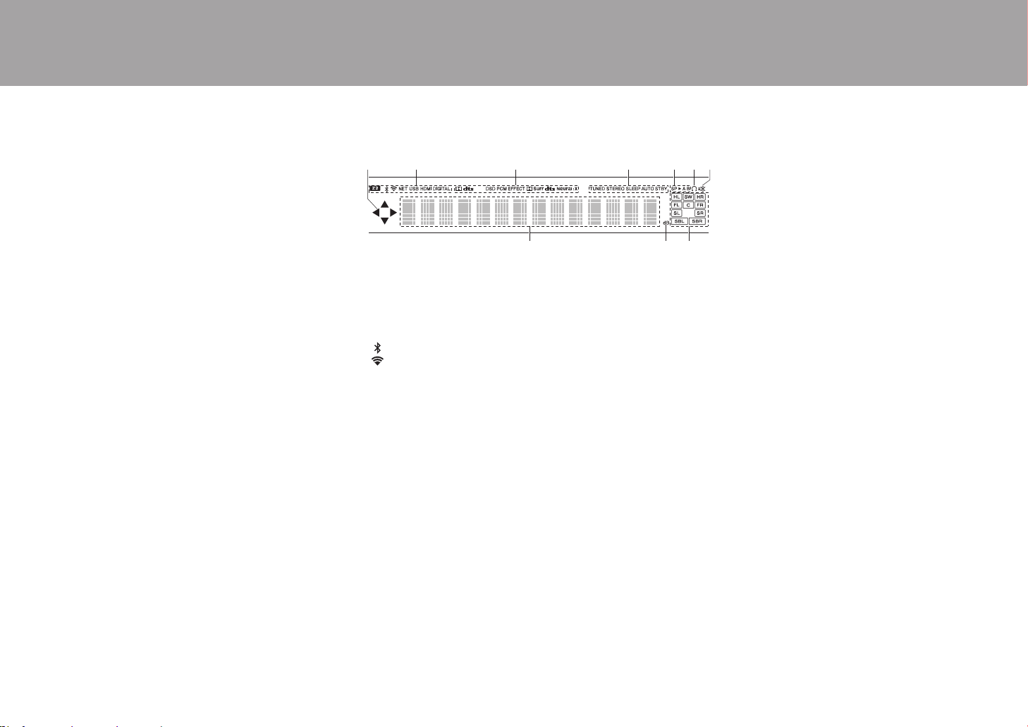
Display
1. This may light when performing operations with the "NET", "USB" input
selector.
2. Lights in the following conditions.
Z2: When ZONE 2 is on.
: When connected by BLUETOOTH.
: When connected by Wi-Fi.
NET: When "NET" is selected with the input selector and the unit is
connected to the network. It will flash if the connection to the network is
not correct.
USB: When "USB" is selected with the input selector and the unit is
connected by USB and the USB device is selected. Flashes if the USB
is not properly connected.
HDMI: When HDMI signals are input and the HDMI input is selected.
DIGITAL: When digital signals are input and the digital input is
selected.
3. Lights according to the type of input digital audio signals and the
listening mode.
4. Lights in the following conditions.
TUNED: Receiving AM/FM radio.
STEREO: Receiving FM stereo.
SLEEP: When the sleep timer is set.
AUTO STBY: Auto Standby is on.
5. The currently selected speaker system lights.
6. Lights when headphones are connected.
7. Flashes when muting is on.
8. Displays various information of the input signals.
9. Lights when adjusting the volume.
10.
Speaker/Channel display: Displays the output channel that
corresponds to the selected listening mode.
(*)You can find details in the Advanced Manual.
SN29403015A_VSX-LX302_BAS_En_1711xx.book 4 ページ 2017年10月27日 金曜日 午後2時0分

5
Rear Panel
1. DIGITAL AUDIO IN OPTICAL/COAXIAL jacks: Input TV or AV component digital audio
signals with a digital optical cable or digital coaxial cable.
2. ANTENNA AM LOOP/FM UNBAL 75Ω terminal: The supplied antennas are connected.
3. VIDEO IN jacks: Input the AV component video signals with an analog video cable.
4. USB port: A USB storage device is connected so that music files stored in it can be
played. You can also supply power (5 V/500 mA) to USB devices with a USB cable.
5. COMPONENT VIDEO IN jacks: Input the AV component video signals with a component
video cable. (Compatible only with 480i or 576i resolution.)
6. NETWORK port: Connect to the network with an Ethernet cable.
7. Wireless antenna: Used for Wi-Fi connection or when using a BLUETOOTH enabled
device. Adjust their angles according to the connection status.
8. HDMI OUT jacks: Transmit video signals and audio signals with a HDMI cable connected
to a monitor such as a TV or projector.
9. HDMI IN jacks: Transmit video signals and audio signals with a HDMI cable connected to
an AV component.
10.
RS-232C port: For connection to the home control system. (*)
11.
AC IN: The supplied power cord is connected.
12.
SIGNAL GND terminal: The ground wire of the turntable is connected.
13.
AUDIO IN jacks: Input AV component audio signal with an analog audio cable.
14.
SPEAKERS terminals: Connect speakers with speaker cables. (Compatible with banana
plugs)
15.
ZONE 2 PRE/LINE OUT jacks: Output audio signals with an analog audio cable to a pre-
main amplifier or a power amplifier in a separate room (ZONE 2).
16.
SUBWOOFER PRE OUT jack: Connect a powered subwoofer with a subwoofer cable.
Up to two powered subwoofers can be connected. The same signal is output from each of
the SUBWOOFER PRE OUT jacks.
> Before Start >Part Names > Install > Initial Setup > Playback
180°
90°
En
(*)You can find details in the Advanced Manual.
SN29403015A_VSX-LX302_BAS_En_1711xx.book 5 ページ 2017年10月27日 金曜日 午後2時0分

6
> Before Start >Part Names > Install > Initial Setup > Playback
17.
IR IN/OUT port: Allows you to connect a multiroom
remote control kit. (*)
18.
12V TRIGGER OUT A/B jack: Allows you to connect a
device with 12V trigger input jack to enable link
operation between the device and the unit. (*)
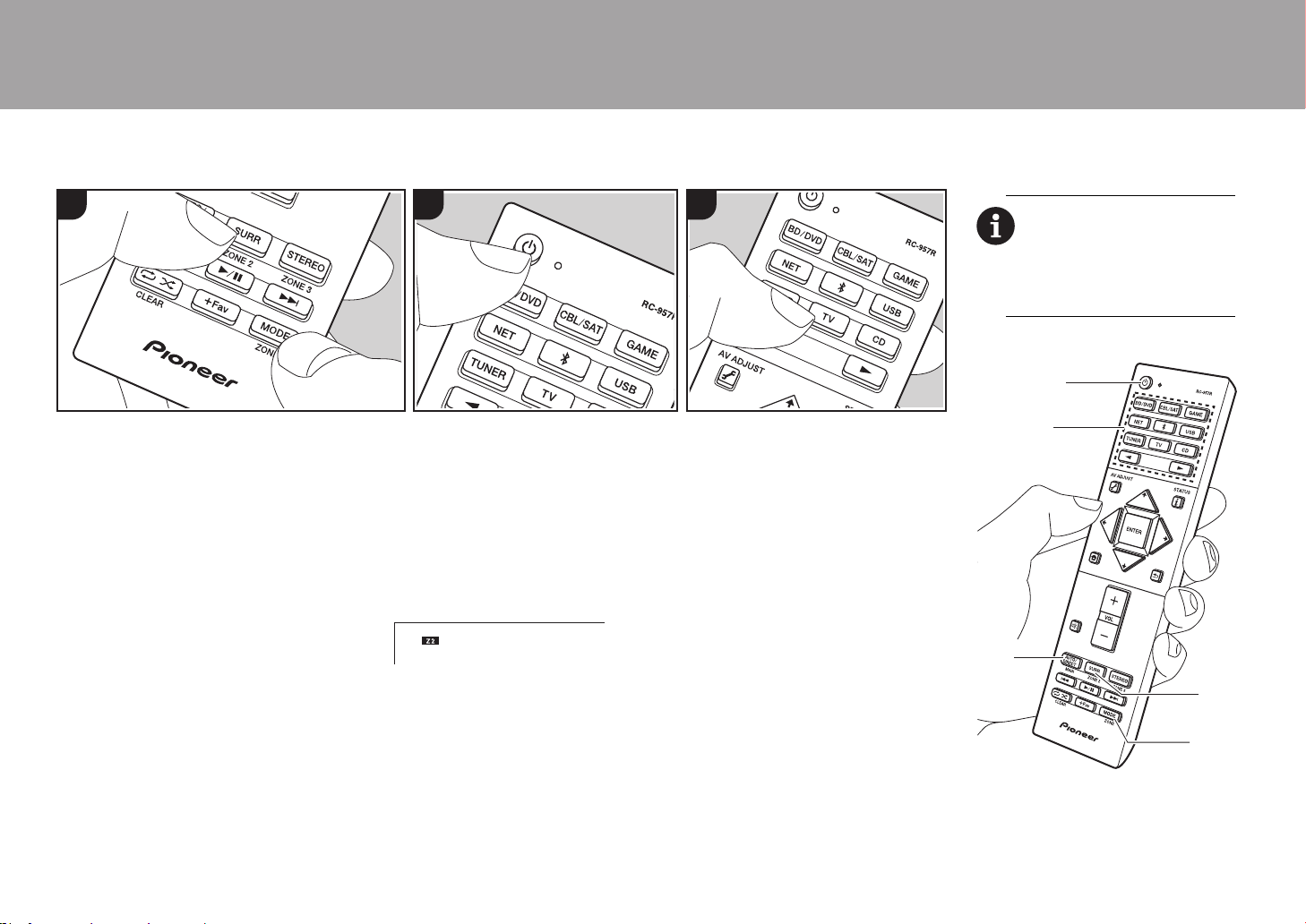
Remote Controller
1. Í STANDBY/ON button
2. Input selector buttons: Switches the input to be played.
3. 21 buttons: Select the input to be played.
4. (AV ADJUST) button: Settings such as "Tone" and "Level" can be made
quickly during play on the TV screen. "Other" has settings to switch the speakers
given priority for output (P15) and to switch HDMI output (P17). Note that there is
no display on the TV screen when the input selector is "CD", "TV", "PHONO",
"AM", or "FM", so follow the display on the main unit while doing the operations.
(*)
5. Cursor buttons and ENTER button: Select the item with the cursors and press
ENTER to confirm your selection. When the folder or file lists are not shown on
one screen on the TV, press / to change the screen.
6. button: Displays the Home. (*)
7. Volume buttons
8. button: Temporarily mutes audio. Press again to cancel muting.
9. LISTENING MODE buttons: Allows you to select the listening mode (P31). (*)
MAIN/ZONE 2 buttons: Controls the multi-zone function (P30). (The ZONE 3
button is not used with this unit.)
10.
Play buttons: Used for play operations when playing Music Server or USB.
11.
button: Used for repeat or random play operations when playing Music
Server or USB. Each time you press the button, the mode switches from (1-
track repeat), to (folder repeat), to (random).
CLEAR button: Deletes all characters you have entered when entering text on
the TV screen.
12.
(STATUS) button: Switches the information on the display.
13.
button: Returns the display to the previous state.
14.
MODE button: Switches tuning to an AM/FM radio station between automatic
tuning and manual tuning.
15.
+Fav button: Used to register AM/FM radio stations.
Tips
When the remote controller isn't working: The
remote controller may have switched to the mode
for controlling ZONE 2. While holding down
MODE, press MAIN for 3 seconds or more until
the remote indicator flashes once to switch it to
the mode to control the main room.
(*)You can find details in the Advanced Manual.
SN29403015A_VSX-LX302_BAS_En_1711xx.book 6 ページ 2017年10月27日 金曜日 午後2時0分
7
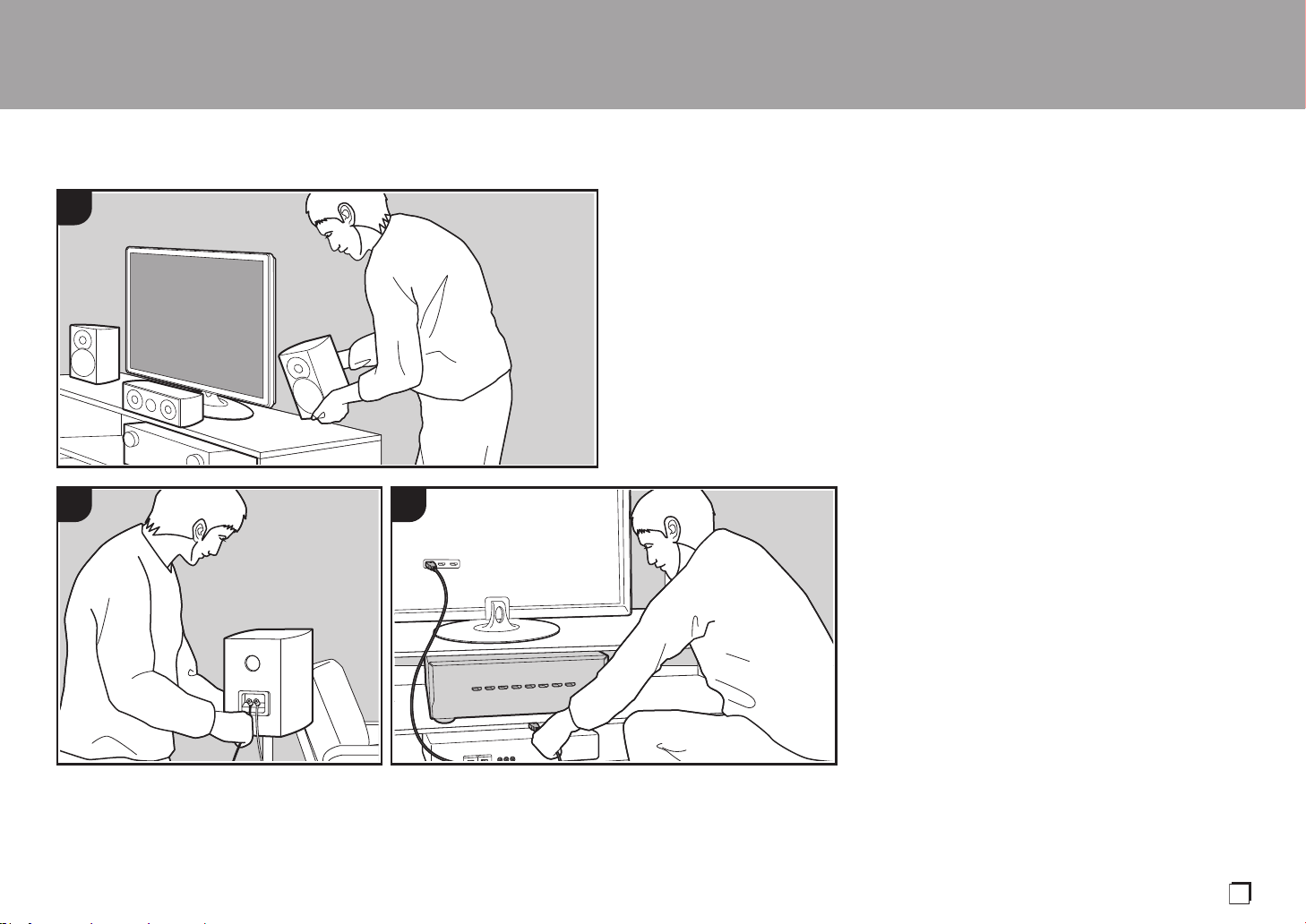
Installation procedure
This unit can be used in a number of ways, depending on
the layout of the speakers you are installing, and the
connections made to external devices. Read the following
to help make the installation process smoother.
Step1: Speaker Layout
Select the speaker layout that suits the types of speakers
you have and the conditions they will be used in from the
choices presented on pages P8 to P13, then install the
speakers by referring to the illustrations and explanations
on the relevant page. Speaker layouts include systems that
use surround back speakers, systems that use height
speakers, and systems that use Bi-Amping speakers. Also
refer to the combinations available in "Speaker
combinations" on P14.
Step2: Connect the Speakers
To connect the speaker systems to this unit, refer to P15 if
you are using a speaker layout described on one of P8 to
P12, and to P16 to use a speaker layout using Bi-Amping
speakers described on P13. The connection process will be
smoother if you refer to the illustrations and explanations
and prepare the required cables before hand.
Step3: Connect the TV & AV Components
Refer to P17 to P22 to connect your external devices such
as your TV, Blu-ray Disc Player, and also supplied
accessories such as the antennas. Also, P21 introduces
the Multi-zone Connection option that allows you to play
audio into rooms other than the main room. The connection
process will be smoother if you refer to the illustrations and
explanations, confirm the connection types on the external
devices, and prepare the required cables before hand.
> Before Start > Part Names >Install > Initial Setup > Playback
1
2 3
En
SN29403015A_VSX-LX302_BAS_En_1711xx.book 7 ページ 2017年10月27日 金曜日 午後2時0分

8
Step1: Speaker Layout
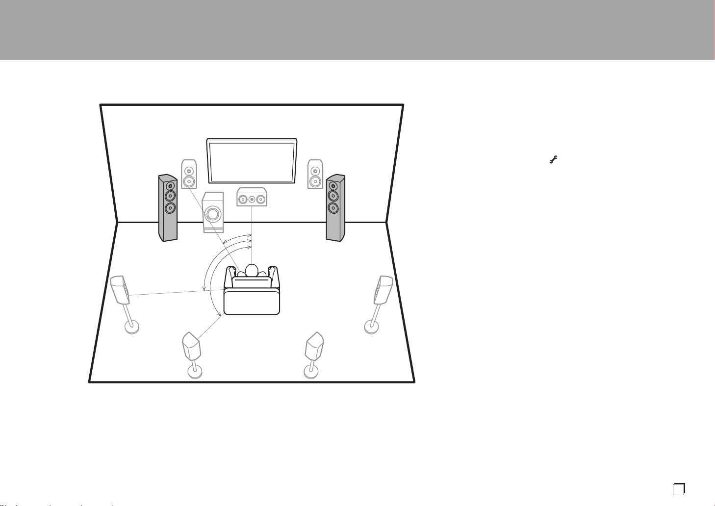
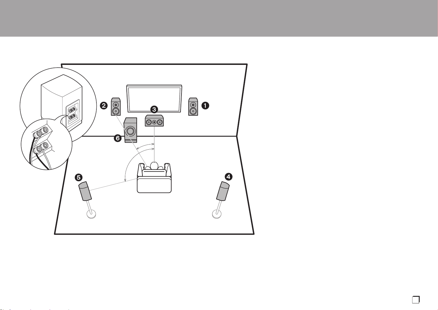
7.1 Channel System
Front speakers output front stereo sound and a center
speaker outputs center sound such as dialogs and vocals.
Surround speakers create back sound field. Powered
subwoofer reproduces bass sounds and creates rich sound
field.
This basic 5.1 Channel System with surround back
speakers added is called a 7.1 Channel System. The
connection of surround back speakers improves the sense
of envelopment and connectivity of sound created by the
back sound field and provides a more real sound field.
Furthermore, by installing surround back speakers, you can
select the Dolby Atmos listening mode, which realizes the
most up-to-date 3D sound, when the input format is Dolby
Atmos.
The front speakers should be positioned at ear height, while
the surround speakers should be positioned just above ear
height. Center speaker should be set up facing the listening
position. Placing the powered subwoofer between the
center speaker and a front speaker gives you a natural
sound even when playing music. The optimal positioning is
for surround back speakers to be at ear height.
0 If you are including surround back speakers in the setup,
surround speakers are required.
0 "Speaker combinations" (P14) introduces some detailed
examples of speaker combinations.
1,2 Front Speakers
3 Center Speaker
4,5 Surround Speakers
6 Powered Subwoofer
7,8 Surround Back Speakers
> Before Start > Part Names >Install > Initial Setup > Playback
*
1
*
2
*
3
½1: 22e to 30e, ½2: 90e to 110e, ½3: 135e to 150e
SN29403015A_VSX-LX302_BAS_En_1711xx.book 8 ページ 2017年10月27日 金曜日 午後2時0分
9
Speaker B System
With a 7.1 channel system (P8), you can connect one more
set of front speakers to use as a Speaker B System. In this
state, the 7.1 channel system becomes the Speaker A
System and you can switch the same audio to output from
A, B, or A+B. Press on the remote control (P6) and use
"Other" - "Speakers" to switch. Note that no sound is played
from the surround back speakers when playing from A+B.
0 "Speaker combinations" (P14) introduces some detailed
examples of speaker combinations.
> Before Start > Part Names >Install > Initial Setup > Playback
*
1
*
2
*
3
Speaker B Speaker B
½1: 22e to 30e, ½2: 90e to 110e, ½3: 135e to 150e
En
SN29403015A_VSX-LX302_BAS_En_1711xx.book 9 ページ 2017年10月27日 金曜日 午後2時0分

10
5.1.2 Channel System-1
(Front High Speakers/Rear High Speakers)
This is a basic 5.1 channel system consisting of front
speakers, a center speaker, surround speakers, and a
powered subwoofer, with the addition of front height
speakers or rear high speakers, which are both types of
height speakers. By installing height speakers, you can
select the Dolby Atmos listening mode, which realizes the
most up-to-date 3D sound including overhead sounds,
when the input format is Dolby Atmos. Front high speakers
or rear high speakers should be situated at least 3´/0.9 m
higher than the front speakers. Front high speakers should
be situated directly above the front speakers and the
distance between the rear high speakers should match the
distance between the front speakers. Both should be set up
facing the listening position.
0 "Speaker combinations" (P14) introduces some detailed
examples of speaker combinations.
9,10 Height Speakers
Choose one of the following:
0Front High Speakers
0Rear High Speakers
> Before Start > Part Names >Install > Initial Setup > Playback
*
1
*
2
3´ (0.9 m)
or more
3´ (0.9 m)
or more
½1: 22e to 30e, ½2: 120e
SN29403015A_VSX-LX302_BAS_En_1711xx.book 10 ページ 2017年10月27日 金曜日 午後2時0分
11
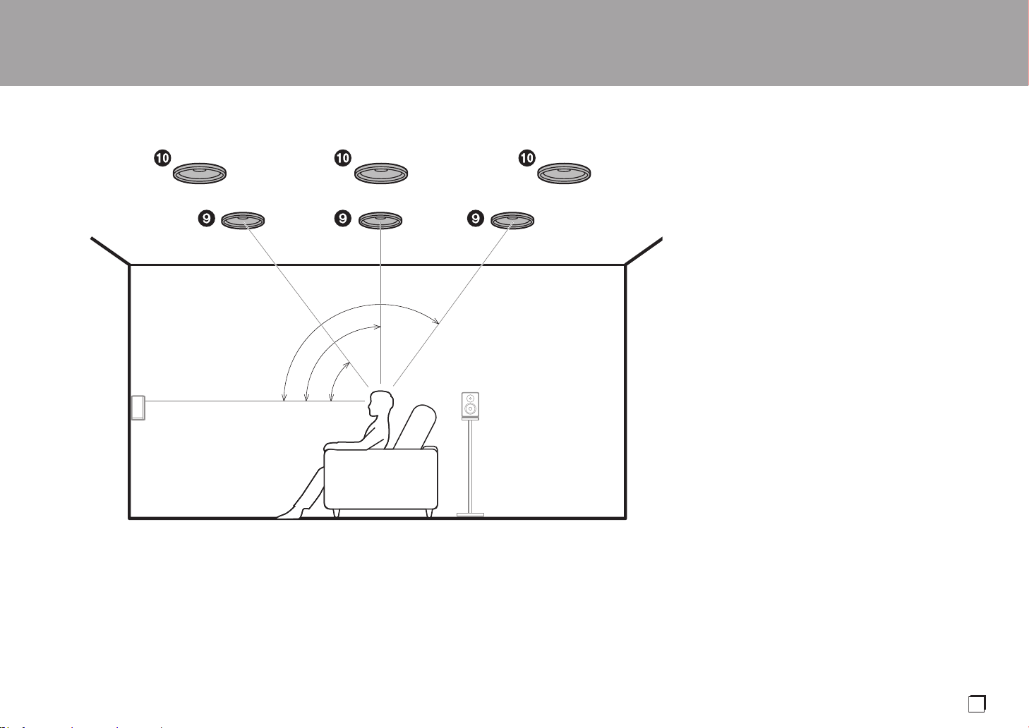
5.1.2 Channel System-2
(Ceiling Speakers)
This is a basic 5.1 channel system consisting of front
speakers, a center speaker, surround speakers, and a
powered subwoofer, with the addition of top front speakers,
top middle speakers, or top rear speakers, which are types
of height speakers. By installing height speakers, you can
select the Dolby Atmos listening mode, which realizes the
most up-to-date 3D sound including overhead sounds,
when the input format is Dolby Atmos. Fit top front speakers
on the ceiling forward of the seating position, top middle
speakers on the ceiling directly above the seating position,
and top rear speakers on the ceiling behind the seating
position. The distance between each pair should match the
distance between the two front speakers.
0 Dolby Laboratories recommends placing this type of
height speakers to obtain the best Dolby Atmos effect.
0 "Speaker combinations" (P14) introduces some detailed
examples of speaker combinations.
9,10 Height Speakers
Choose one of the following:
0Top Front Speakers
0Top Middle Speakers
0Top Rear Speakers
> Before Start > Part Names >Install > Initial Setup > Playback
*
1
*
2
*
3
½1: 30e to 55e, ½2: 65e to 100e, ½3: 125e to 150e
En
SN29403015A_VSX-LX302_BAS_En_1711xx.book 11 ページ 2017年10月27日 金曜日 午後2時0分

12
5.1.2 Channel System-3
(Dolby Enabled Speakers (Dolby Speakers))
This is a basic 5.1 channel system consisting of front
speakers, a center speaker, surround speakers, and a
powered subwoofer, with the addition of Dolby enabled
speakers (front), Dolby enabled speakers (surround) or
Dolby enabled speakers (surround back) which are both
types of height speakers. Dolby enabled speakers are
special speakers designed to face the ceiling so that sound
is heard after bouncing off the ceiling so that sound appears
to be coming from overhead. By installing height speakers,
you can select the Dolby Atmos listening mode, which
realizes the most up-to-date 3D sound including overhead
sounds, when the input format is Dolby Atmos.
Place them either above the front speakers, above the
surround speakers or above surround back speakers.
0 "Speaker combinations" (P14) introduces some detailed
examples of speaker combinations.
9,10 Height Speakers
Choose one of the following:
0 Dolby Enabled Speakers (Front)
0 Dolby Enabled Speakers (Surround)
0 Dolby Enabled Speakers (Surround Back)
> Before Start > Part Names >Install > Initial Setup > Playback
*
1
*
2
*
3
½1: 22e to 30e, ½2: 90e to 120e, ½3: 135e to 150e
SN29403015A_VSX-LX302_BAS_En_1711xx.book 12 ページ 2017年10月27日 金曜日 午後2時0分
13
Bi-Amping the Speakers
With a 5.1 channel system, it is possible to connect front
speakers that support Bi-Amping to improve the quality of
the bass and treble. Bi-Amping compatible speakers need
their terminals for the tweeters connected to one amplifier
and their terminals for woofers connected to another
amplifier, so it is not possible to connect height speakers
and surround back speakers with this connection. Other
than front speakers, you can also connect a center speaker,
surround speakers, and a powered subwoofer.
0 "Speaker combinations" (P14) introduces some detailed
examples of speaker combinations.
1,2 Front Speakers (Bi-Amping)
3 Center Speaker
4,5 Surround Speakers
6 Powered Subwoofer
> Before Start > Part Names >Install > Initial Setup > Playback
*
1
*
2
½1: 22e to 30e, ½2: 120e
En
SN29403015A_VSX-LX302_BAS_En_1711xx.book 13 ページ 2017年10月27日 金曜日 午後2時0分
14
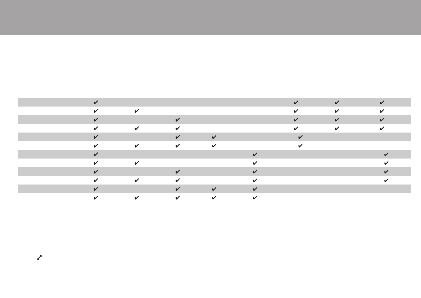
Speaker combinations
0 In any of the combinations, up to two powered subwoofers can be connected.
(*1) You can select one of Speaker B, Bi-AMP, or ZONE SPEAKER.
(*2) When using Speakers B, no sound is played from the surround back speakers when
playing from A+B.
(*3) No sound is played from the height speakers when playing audio from ZONE
SPEAKER.
(*4) You can connect both surround back speakers and height speakers. However, you can
only output audio from one of these at a time. When both are connected, you can set
which speakers to prioritize.
0 Press on the remote control (P6) and use "Other" - "Speakers" to switch speakers A
and B and to switch between surround back speakers and height speakers.
> Before Start > Part Names >Install > Initial Setup > Playback
Speaker Channels FRONT CENTER SURROUND
SURROUND
BACK HEIGHT
SP B
(Speaker B)
Bi-AMP
ZONE 2
(ZONE SPEAKER)
(P21)
2.1 ch
(*1) (*1) (*1)
3.1 ch
(*1) (*1) (*1)
4.1 ch
(*1) (*1) (*1)
5.1 ch
(*1) (*1) (*1)
6.1 ch
(*2)
7.1 ch
(*2)
2.1.2 ch
(*3)
3.1.2 ch
(*3)
4.1.2 ch
(*3)
5.1.2 ch
(*3)
6.1.2 ch
(*4) (*4)
7.1.2 ch
(*4) (*4)
SN29403015A_VSX-LX302_BAS_En_1711xx.book 14 ページ 2017年10月27日 金曜日 午後2時0分
15
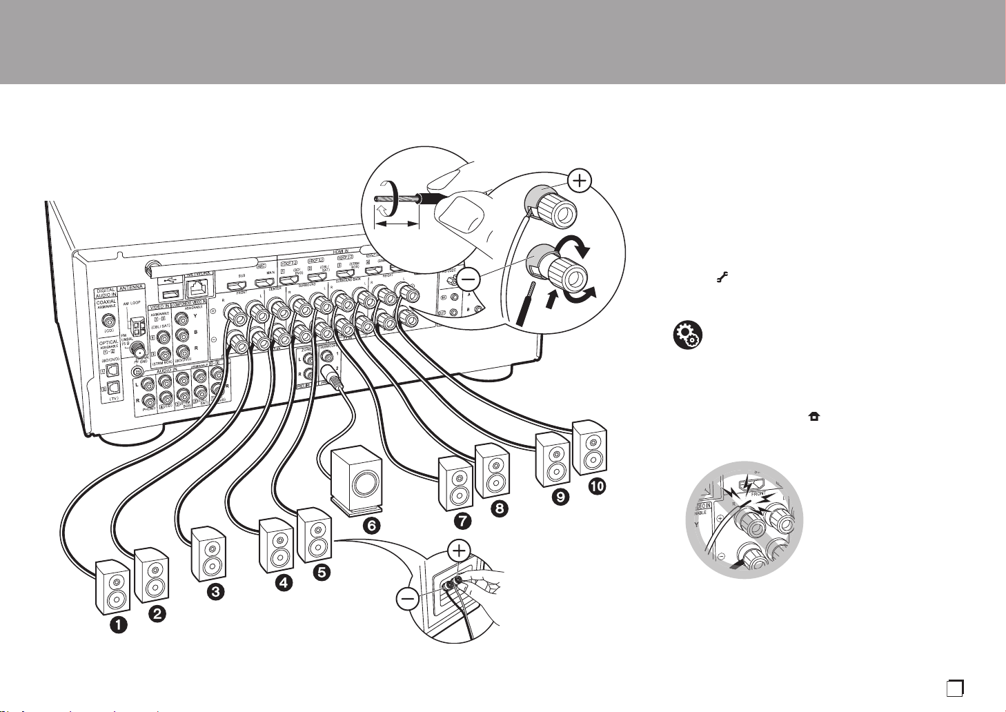
Step2: Connect the Speakers
Standard Connections (Pages 8 to 12)
Connect 12345678 for a 7.1 channel system.
Connect 1234569: for a 5.1.2 channel system. Up
to two powered subwoofers can be connected. The same
signal is output from each of the SUBWOOFER PRE OUT
jacks.
0
You can also connect both
78
and
9:
. However, you can
only output audio from one of these at a time. When both
are connected, you can switch which speakers to prioritize.
Press on the remote control (P6) and use "Other" -
"Speakers" to switch between surround back speakers and
height speakers and to switch speakers A and B.
Make sure the exposed wires of the speakers do
not stick out of the speaker terminals when
connecting. If the exposed wires of the speakers
touch the rear panel or the + and – wires touch
each other, the protection circuit will be activated.
> Before Start > Part Names >Install > Initial Setup > Playback
a
b
OR
Speaker B
1/2˝
(12 mm)
a Speaker cable, b Subwoofer cable
Setup
0 Settings for the speaker configuration you have
connected need to be made in "1. Full Auto
MCACC" in Initial Setup (P23).
0
If any of the connected speakers have an impedance of
4 Ω or more to less than 6 Ω, after completing Initial
Setup, you need to make some settings in the System
Setup menu. Press on the remote controller, and in
the Home displayed set "System Setup" - "Speaker" -
"Configuration" - "Speaker Impedance" to "4ohms".
En
SN29403015A_VSX-LX302_BAS_En_1711xx.book 15 ページ 2017年10月27日 金曜日 午後2時0分
16
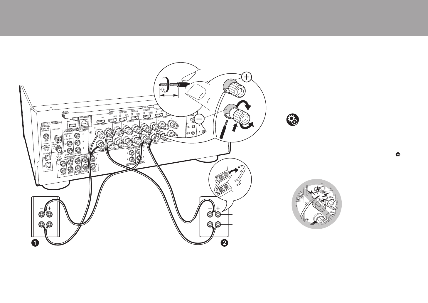
Connecting with Bi-Amping Speakers (Page 13)
Make sure you remove the jumper bar fitted between the
woofer jacks and tweeter jacks of the front speakers.
Refer
to "Standard Connections (Pages 8 to 12)" (P15) to connect
the center speaker, surround speakers, and powered
subwoofer.
0 Also refer to the instruction manual for your speakers
when using connections for Bi-Amping.
Make sure the exposed wires of the speakers
do not stick out of the speaker terminals when
connecting. If the exposed wires of the
speakers touch the rear panel or the + and –
wires touch each other, the protection circuit
will be activated.
> Before Start > Part Names >Install > Initial Setup > Playback
a
1/2˝
(12 mm)
For high-
frequency
For low-
frequency
a Speaker cable
Setup
0 Settings for the speaker configuration you have
connected need to be made in "1. Full Auto
MCACC" in Initial Setup (P23).
0 If any of the connected speakers have an
impedance of 4 Ω or more to less than 6 Ω, after
completing Initial Setup, you need to make some
settings in the System Setup menu. Press on
the remote controller, and in the Home displayed
set "System Setup" - "Speaker" - "Configuration" -
"Speaker Impedance" to "4ohms".
SN29403015A_VSX-LX302_BAS_En_1711xx.book 16 ページ 2017年10月27日 金曜日 午後2時0分
17
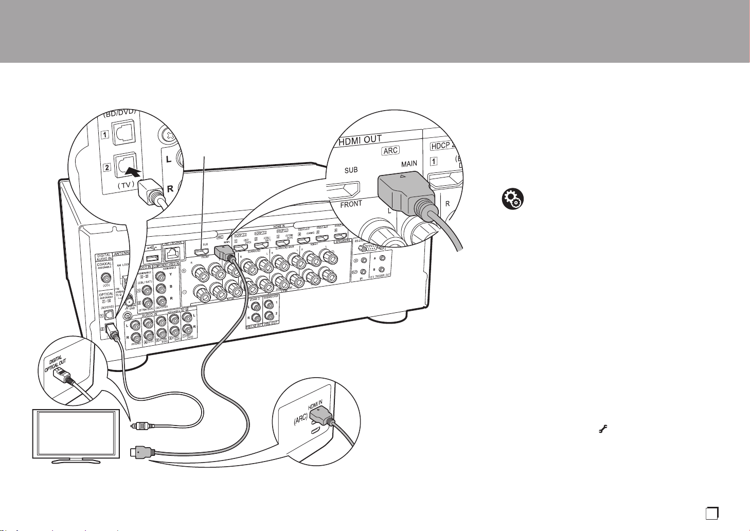
Step3: Connect the TV & AV Components
1. Connect the TV
To ARC TV
For a TV that supports the ARC (Audio Return Channel)
feature (*1), use an HDMI cable and connect according to
illustration "a". Choose an HDMI IN jack on the TV that
supports ARC when connecting.
To Non-ARC TV
For a TV that does not support the ARC (Audio Return
Channel) feature (*1), connect both the HDMI cable in
illustration "a" and the digital optical cable in "b".
0 Connection with a digital optical cable is not necessary if
you will watch TV through a device such as a cable set-
top box (that is, not use a tuner built into the TV) that you
have connected to the input jack on this unit.
(*1) The ARC feature: This feature transfers TV audio
signals via HDMI cable so that you can play the audio
from the TV through this unit. Connection to an ARC
compatible TV is complete with one HDMI cable. Refer
to the instruction manual for your TV to see if it
supports ARC.
(*2) Another TV or projector can be connected to the HDMI
OUT SUB jack. Press (P6) on the remote control
and use "Other" - "HDMI Out" to switch between MAIN
and SUB. Note that this jack does not support ARC.
> Before Start > Part Names >Install > Initial Setup > Playback
TV
*2
a
b
a HDMI cable, b Digital optical cable
Setup
0 Settings are required to use the ARC function.
Select "Yes" in "5. Audio Return Channel" (P24)
in the Initial Setup.
0 Refer to the instruction manual for the TV for TV
connections and instructions regarding settings
for CEC features and audio output.
En
SN29403015A_VSX-LX302_BAS_En_1711xx.book 17 ページ 2017年10月27日 金曜日 午後2時0分

18
2. Connect the HDMI AV Component
This is an example of connection with an AV component
that has an HDMI jack. With connection to an AV
component that conforms with the CEC (Consumer
Electronics Control) standard, you can use features such as
the HDMI CEC feature (*) that links with the input selector,
and the HDMI Standby Through feature which allows you to
play video and audio from AV components on the TV even
when this unit is in standby mode.
0 To play 4K or 1080p video, use a high speed HDMI
cable.
(*)The HDMI CEC feature: You can control features such
as linking input switching with the input selector and
players conforming to the CEC standard, switching audio
to output it from the TV or from this unit, and adjusting
the volume using the remote controller of a CEC-
compliant TV, and automatically switching this unit to
standby when the TV is turned off.
> Before Start > Part Names >Install > Initial Setup > Playback
BD/DVD
GAME
a
Cable/Satellite set-top
box
Streaming media
player
a HDMI cable
Setup
0 When "Yes" is selected for "5. Audio Return
Channel" in Initial Setup (P24), the HDMI CEC
function and HDMI Standby Through function are
automatically enabled. If "No, Skip" is selected,
settings are required in the System Setup menu
after Initial Setup is complete. Settings are made
in "System Setup" - "Hardware" - "HDMI" in Home
displayed by pressing on the remote
controller.
0 To enjoy digital surround sound including Dolby
Digital, audio output should be set to "Bitstream
output" on the connected Blu-ray Disc player or
other device.
SN29403015A_VSX-LX302_BAS_En_1711xx.book 18 ページ 2017年10月27日 金曜日 午後2時0分
19
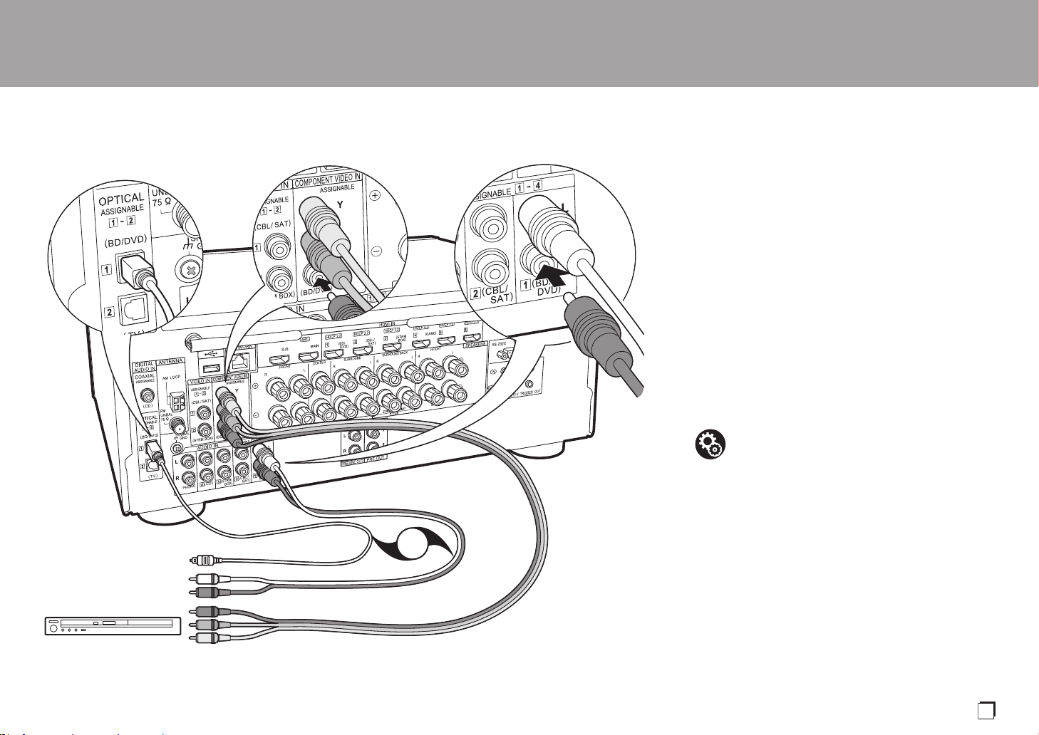
3. Connect the Non-HDMI AV Component
This is an example of connection with an AV component
that does not have an HDMI jack. Make the connections to
the AV component to match the jacks it has. When video
input connection is to the BD/DVD jack, the audio input
connection should also be to the BD/DVD jacks, and so on,
so that you connect the video input jacks to the jacks with
the same name as the audio input jacks.
Note that video signals input to the VIDEO IN jack or the
COMPONENT VIDEO IN jack will be converted to HDMI
video signals and then output from the HDMI OUT jack.
0 To enjoy digital surround playback in formats such as
Dolby Digital, you need to make a connection for audio
signals with a digital coaxial cable or a digital optical
cable.
0 It is possible to change assignment of the input jacks you
see in the illustration at left, so you can also connect to
any jack other than BD/DVD. For details, see the
Advanced Manual.
> Before Start > Part Names >Install > Initial Setup > Playback
BD/DVD
OR
a
b
c
a Component video cable, b Digital optical cable, c Analog audio cable
Setup
0 The COMPONENT VIDEO IN jacks are
compatible only with 480i or 576i resolution.
When you connect to the COMPONENT VIDEO
IN jacks, set the output resolution of the player to
480i or 576i. Select interlace if there is no option
for 480i, etc. If your player does not support 480i
or 576i output, use the VIDEO IN jack.
0 To enjoy digital surround sound including Dolby
Digital, audio output should be set to "Bitstream
output" on the connected Blu-ray Disc player or
other device.
En
SN29403015A_VSX-LX302_BAS_En_1711xx.book 19 ページ 2017年10月27日 金曜日 午後2時0分
20
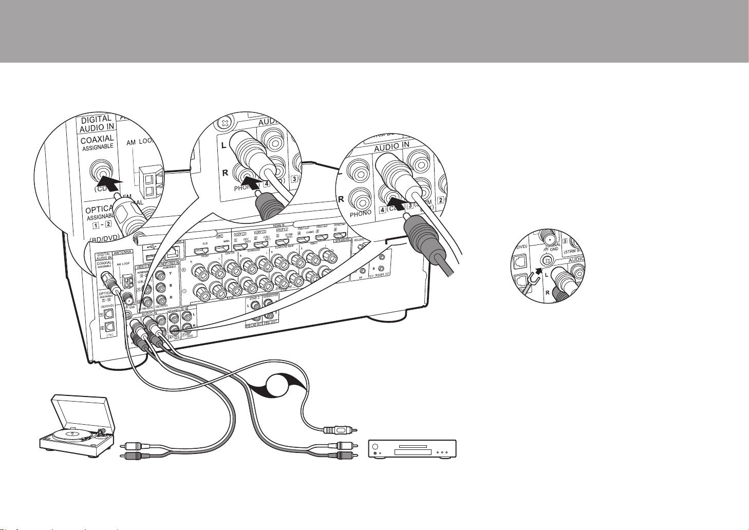
4. Connect the Audio Component
Example of a connection with an audio component.
Connect a CD player using a digital coaxial cable or an
analog audio cable. You can also connect a turntable that
has an MM-type cartridge to the PHONO jack.
0 If the turntable has a built-in audio equalizer, connect it to
another AUDIO IN jack. Further, if the turntable uses an
MC type cartridge, install an audio equalizer compatible
with the MC type cartridge between the unit and the
turntable, then connect to any AUDIO IN jack other than
the PHONO jack.
If the turntable has a ground wire,
connect it to the SIGNAL GND terminal of this unit.
> Before Start > Part Names >Install > Initial Setup > Playback
CD
OR
a
b
Turntable
a Digital coaxial cable, b Analog audio cable
SN29403015A_VSX-LX302_BAS_En_1711xx.book 20 ページ 2017年10月27日 金曜日 午後2時0分

21
5. Multi-zone Connection
You can enjoy audio in the separate room by, for example, playing
a Blu-ray Disc player in the main room (where this unit is located)
and listening to internet radio in the separate room (ZONE 2).
0 DSD and Dolby TrueHD audio signals are not output to
ZONE 2 when selected with the "NET" input selector.
Connections with an AV component
When outputting the audio of an externally connected AV
component to ZONE 2, you need to connect using a digital
coaxial cable, digital optical cable, or analog audio cable.
ZONE 2 PRE/LINE OUT
It is possible to play 2 ch source in a separate room while 7.1 ch source
is being played in the main room. Connect the ZONE 2 PRE/LINE OUT
jacks of the unit and the LINE IN jacks of the pre-main amplifier or
power amplifier in a separate room with an analog audio cable.
ZONE SPEAKER
It is possible to connect speakers in a separate room and
play 2 ch sources.
0 You cannot use ZONE SPEAKER if you have connected
the front speakers using Bi-Amping connection or if you
have connected a Speakers B System.
0 No sound is played from the height speakers when
playing audio from ZONE SPEAKER.
> Before Start > Part Names >Install > Initial Setup > Playback
ZONE2 PRE/LINE OUT
ZONE SPEAKER
ZONE2
LINE
IN
BD/DVD
OR
MAIN ROOM
c
a
b
a Digital optical cable, b Analog audio cable, c Speaker cable
Setup
0 Settings are required in Initial Setup, "4. Multi
Zone Setup" (P24) to enjoy this feature.
0
The audio from externally connected AV components
can only be played in ZONE 2 when the audio is analog
or 2ch PCM audio. If you have connected to this unit
with a digital coaxial cable or digital optical cable, it may
be necessary to change the audio output of the AV
component to PCM output.
En
SN29403015A_VSX-LX302_BAS_En_1711xx.book 21 ページ 2017年10月27日 金曜日 午後2時0分

22
6. Connect Other Cables
Antenna Hookup
Move the antenna around while playing the radio to find the
position with the best reception. Use a thumb tack or similar
to attach the indoor FM antenna to a wall.
Network Hookup
Connect this unit to the network using wired LAN or Wi-Fi
(wireless LAN). You can enjoy network features such as
internet radio by connecting the unit to the network. If you
connect by wired LAN, connect with an Ethernet cable to
the NETWORK port as shown in the illustration. To connect
by Wi-Fi, then after selecting "Wireless" in "3. Network
Connection" (P24) in Initial Setup, select the desired setting
method and follow the onscreen instructions to configure
the connection.
Power Cord Hookup
This unit includes removable power cords. Connect the
power cord to the power outlet after completing all other
connections. Connect the power cord to AC IN of the unit
and then connect to the outlet. Always disconnect the outlet
side first when disconnecting the power cord.
> Before Start > Part Names >Install > Initial Setup > Playback
a
c
d
b
a Indoor FM antenna, b AM loop antenna, c Ethernet cable, d Power cord
SN29403015A_VSX-LX302_BAS_En_1711xx.book 22 ページ 2017年10月27日 金曜日 午後2時0分
23
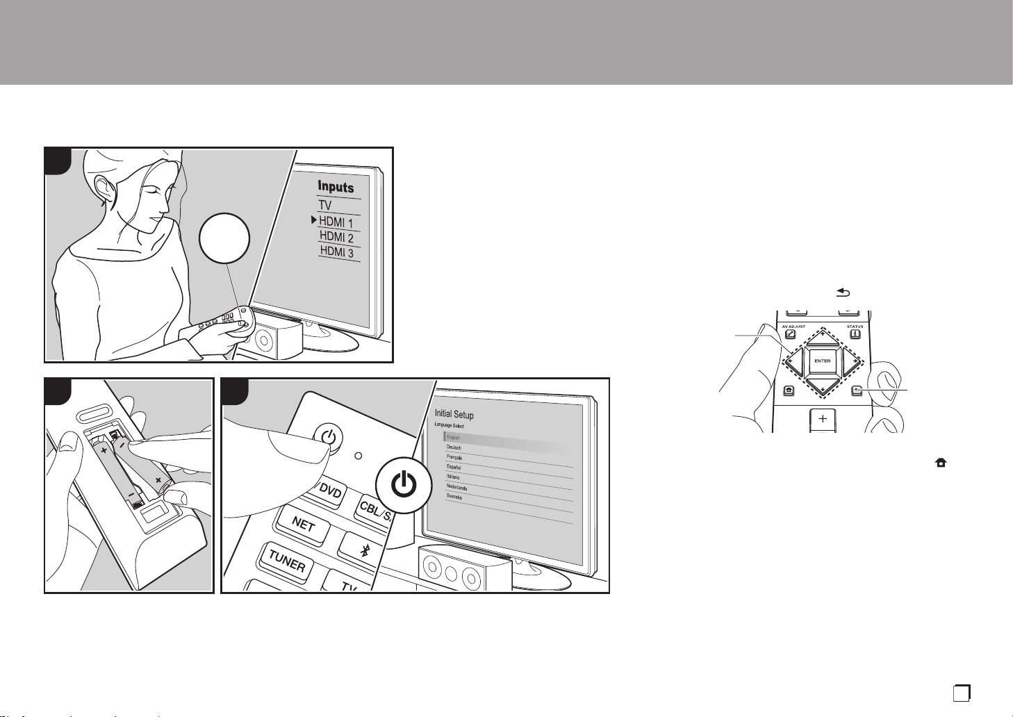
Initial Setup with Auto Start-up Wizard
Initial Setup Starts Automatically
When you turn the unit on for the first time after purchasing
it, Initial Setup is automatically shown on the TV to enable
you to make settings required for startup using simple
operations following onscreen guidance.
1. Switch the input on the TV to that assigned to the unit.
2. Put batteries into the remote controller of this unit.
3. Press Í on the remote controller to turn the unit on.
4. Select the item with the cursors of the remote controller
and press ENTER (a) to confirm your selection. To return
to the previous screen, press (b).
0 If you terminate the procedure on the way or want to
change a setting made during Initial Setup, press on
the remote controller, and from the Home select "System
Setup" - "Miscellaneous" - "Initial Setup", and press
ENTER.
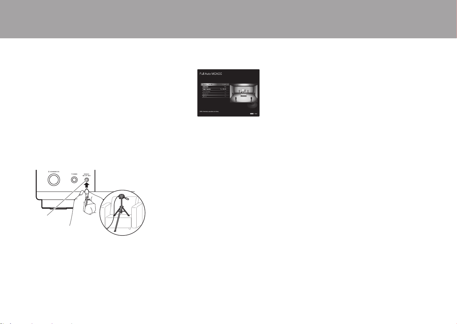
∫ 1. Full Auto MCACC
Place the supplied speaker setup microphone in the
listening position, measure the test tones emitted by the
speakers, then the unit automatically sets the optimum
volume level for each speaker, the crossover frequencies,
and the distance from the listening position. This also
automatically adjusts the equalizers for the speakers and
enables correction of distortion caused by the acoustic
environment of the room.
> Before Start > Part Names > Install > Initial Setup > Playback
1
2 3
TV
INPUT
a
b
En
SN29403015A_VSX-LX302_BAS_En_1711xx.book 23 ページ 2017年10月27日 金曜日 午後2時0分
24
0 Calibration takes between 3 and 12 minutes to be
completed. The speakers emit the test tone at high
volume during measurement, so be careful of your
surroundings. Keep the room as quiet as possible during
measurement.
0 If you have connected a subwoofer, check the power and
volume of the subwoofer. Set the subwoofer volume to
more than halfway.
0 If the power of this unit suddenly turns off, the wires in
the speaker cables may have touch the rear panel or
other wires and tripped the protection circuit. Twist the
wires again properly and make sure they do not stick out
of the speaker terminals when connecting.
1. Place the supplied speaker setup microphone in the
listening position, and connect to the MCACC SETUP
MIC jack on the main unit.
When putting the speaker setup microphone on a tripod,
refer to the illustration when putting it in place.
2. Select the connected speaker configuration.
The image on the screen changes as you choose the
number of channels in "Speaker Channels", so refer to it
when performing the settings.
3. Test tones are emitted by the speakers, and firstly the
unit detects the speakers connected and the noise in the
environment.
4. After the results of the above measurements are
displayed, select "Next", press ENTER on the remote
controller, and the test tones are emitted again, and the
unit automatically makes settings such as the optimum
volume level and the crossover frequency.
5. When the measurement is completed, the measurement
result is displayed. Press the cursors / on the
remote controller to check the settings. Press ENTER
when "Save" is selected to save the settings.
6. Disconnect the speaker setup microphone.
∫ 2. Source Connection
Check that each input source is connected correctly. Follow
the guidance, select the input you want to confirm, start
play of the selected player, and confirm that the images
appear on the TV and that sound is played.
∫ 3. Network Connection
Set up Wi-Fi connection with an access point such as a
wireless LAN router. There are the following two methods of
connecting by Wi-Fi:
"Scan Networks": Search for an access point from this
unit. Find out the SSID of the access point beforehand.
"Use iOS Device (iOS7 or later)": Share the iOS device's
Wi-Fi settings with this unit.
If you select "Scan Networks", there are a further two
choices of connection method. Check the following.
"Enter Password": Enter the password (or key) of the
access point to connect.
"Push Button": If the access point has an automatic
connection button, you can connect without entering a
password.
0 If the SSID of the access point is not displayed, then in
the screen listing the SSIDs, select "Other..." with the
cursor on the remote controller and press ENTER, then
follow the onscreen instructions.
Keyboard Input
To switch between upper and lower case, select "A/a" on
the screen and press ENTER. To select whether to mask
the password with "½" or display it in plain text, press +Fav
on the remote controller. Press CLEAR to delete all the
input characters.
0 A confirmation screen asking you to agree to the privacy
policy is displayed during network setting. Select
"Accept" and press ENTER to indicate agreement.
∫ 4. Multi Zone Setup
When you want to enjoy audio in a room other than the main room, set
the audio output method for the separate room (ZONE 2). If you have
connected speakers in a separate room with speaker cable, select
"Using AV Receiver". If you have connected a pre-main amplifier in a
separate room with an analog audio cable, select "with External
Premain Amplifier". If you have connected a power amplifier, select
"with External Power Amplifier".
∫ 5. Audio Return Channel
If you have connected a TV that supports ARC, select
"Yes". This unit's ARC setting turns on and you can listen to
the TV's audio through this unit.
MCACC
SETUP MIC
> Before Start > Part Names > Install > Initial Setup > Playback
SN29403015A_VSX-LX302_BAS_En_1711xx.book 24 ページ 2017年10月27日 金曜日 午後2時0分
25
Playback
> Before Start > Part Names > Install > Initial Setup > Playback
AV Component Playback
Basic Operations
You can play the audio from AV components
such as Blu-ray Disc players through this unit.
0
When a TV is connected to the HDMI OUT
SUB jack, press (P6) on the remote
controller and use "Other" - "HDMI Out" to
switch between MAIN and SUB.
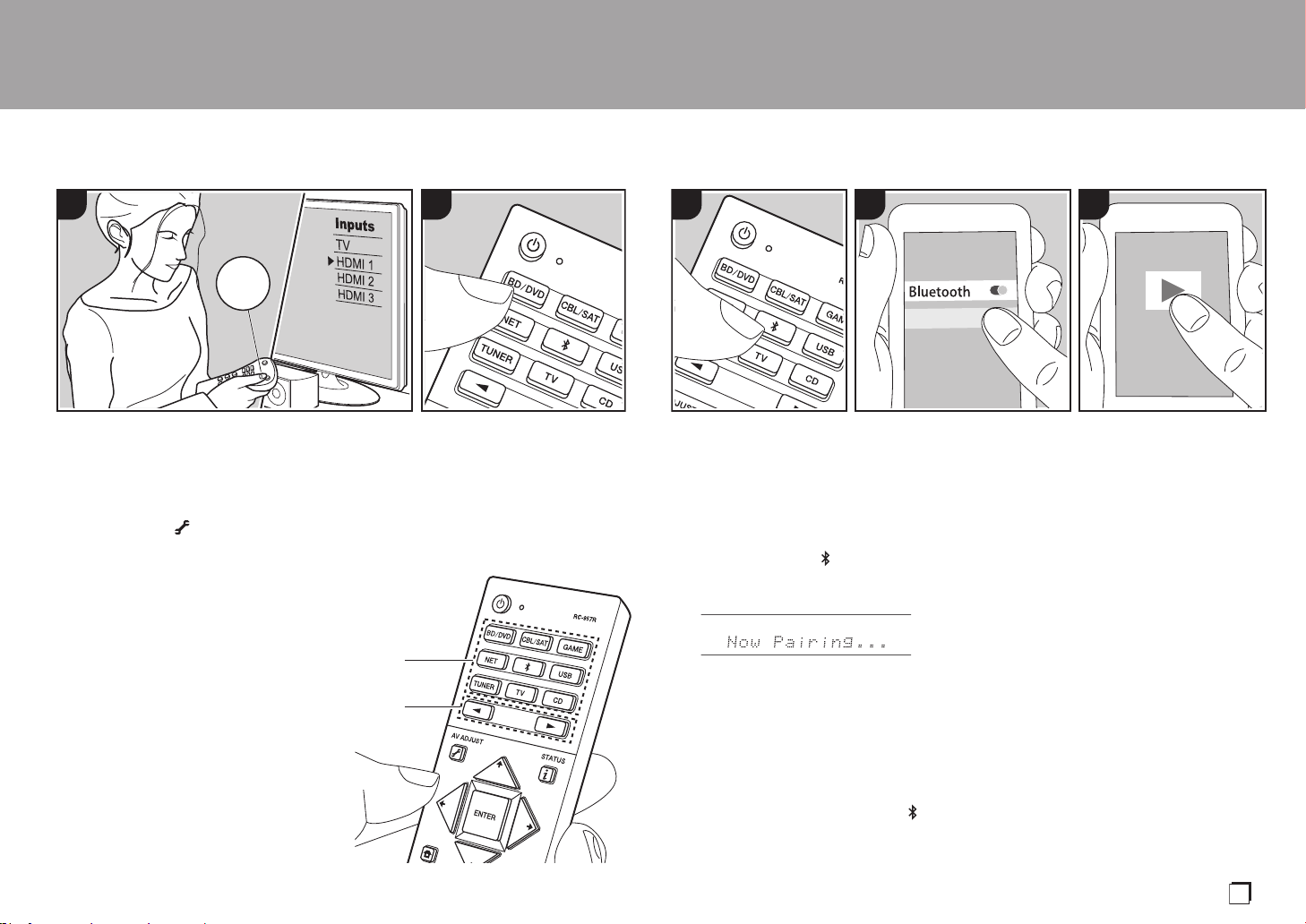
Perform the following procedure when the
unit is on.
1. Switch the input on the TV to that
assigned to the unit.
2. Press the input selector (a) on the
remote controller with the same name as
the jack to which you connected the
player to switch the input.
For example, press BD/DVD to play the
player connected to the BD/DVD jack.
Press TV to listen the TV's sound. To play
a device connected to the STRM BOX,
PHONO, HDMI5, HDMI6 jack or the AUX
INPUT AUDIO/HDMI jack on the front
panel, press
21
(b) repeatedly to select
the input.
0 When the CEC link function works,
the input switches automatically when
you have connected a CEC compliant
TV and player to this unit using HDMI
connection.
3. Start play on the AV component.
1 2
TV
INPUT
b
a
BLUETOOTH
®
Playback
You can wirelessly play music on a
smartphone or other BLUETOOTH
enabled device. Perform the following
procedure when the unit is on.
Pairing
1. When you press the button, "Now
Pairing..." is displayed on this unit's
display, and the pairing mode is enabled.
2. Enable (turn on) the BLUETOOTH
function of the BLUETOOTH enabled
device, then select this unit from
amongst the devices displayed. If a
password is requested, enter "0000".
0 This unit is displayed as "Pioneer
VSX-LX302 XXXXXX".
0 To connect another BLUETOOTH
enabled device, press and hold
until "Now Pairing..." is displayed,
then perform step 2. This unit can
store the data of up to 8 paired
devices.
0 The coverage area is 48´/15 m. Note
that connection is not always
guaranteed with all BLUETOOTH
enabled devices.
Playing Back
1. Perform the connection procedure on
the BLUETOOTH enabled device.
The input on this unit automatically
switches to "BLUETOOTH".
2. Play music. Increase the volume of the
BLUETOOTH enabled device to an
appropriate level.
0 Due to the characteristics of
BLUETOOTH wireless technology, the
sound produced on this unit may slightly
be behind the sound played on the
BLUETOOTH enabled device.
PioneerVSX-LX302XXX
1 2 3
En
SN29403015A_VSX-LX302_BAS_En_1711xx.book 25 ページ 2017年10月27日 金曜日 午後2時0分

26
Network Functions
Basic Operations
By connecting this unit to the network you
can enjoy internet radio services such as
TuneIn, streaming from Spotify Connect,
and wireless playback using AirPlay
®
features. Furthermore, you can use the
Music Server feature to stream music files
stored on PCs or NAS devices that support
the home network feature. The basic
operations for Network Functions are
introduced in the Basic Manual. For more
advanced operations, see the Advanced
Manual. There may also be additional
network functions provided through
firmware updates for this unit. Also see the
Advanced Manual for information about
new features.
0 The network needs to be connected to
the internet in order to play internet radio
services.
0 Depending on the internet radio service,
the user may need to register from their
computer first.
0 To enable Spotify Connect, install the
Spotify application on your smartphone
or tablet and create a Spotify premium
account.
– Refer to the following for Spotify
settings:
www.spotify.com/connect/
0 The network servers compatible with the
Music Server feature are those PCs with
players installed that have the server
functionality of Windows Media
®
Player
11 or 12, or NAS that are compatible
with home network functionality. Note
that with PCs, only music files registered
in the library of Windows Media
®
Player
can be played.
0 You may need to make some settings on
the PC in advance to use Windows
Media
®
Player 11 or 12 with the Music
Server feature.
Perform the following procedure when the
unit is on.
1. Switch the input on the TV to that
assigned to the unit.
2. Press NET (a) on the remote controller
to display a list of Network Functions on
the TV.
3. Select the Network Function with the
cursors of the remote controller and
press ENTER (b) to confirm your
selection.
With internet radio services, follow the
on-screen instructions, using the cursors
to select radio stations and programs,
then press ENTER to play. With Spotify
or AirPlay, select this unit with your
smartphone to play. With Music Server,
select the server with the cursors, then
select the desired music file and press
ENTER to play.
0 To return to the previous screen, press
(c).
> Before Start > Part Names > Install > Initial Setup > Playback
321
TV
INPUT
b
a
c
SN29403015A_VSX-LX302_BAS_En_1711xx.book 26 ページ 2017年10月27日 金曜日 午後2時0分
27
USB Storage Device
Basic Operations
You can play music files stored on a USB
storage device.
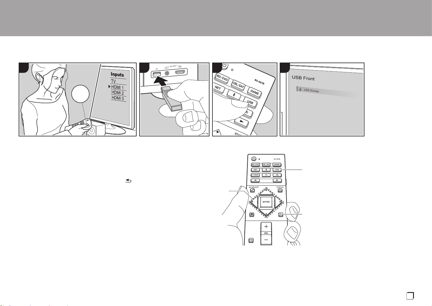
Perform the following procedure when the
unit is on.
1. Switch the input on the TV to that
assigned to the unit.
2. Plug your USB storage device with the
music files into the USB port either on
the front panel or rear panel of this unit.
3. Press USB (b) on the remote controller
and select "USB Front" or "USB Rear".
0 If the "USB" indicator flashes on the
display, check whether the USB
storage device is plugged in properly.
0 Do not unplug the USB storage
device while "Connecting···" is
appeared on the display. This may
cause data corruption or malfunction.
4. Press ENTER on the remote controller in
the next screen. The list of folders and
music files on the USB storage device
are displayed. Select the folder with the
cursors and press ENTER to confirm
your selection (a).
5. With the cursors on the remote
controller, select the music file, and then
press ENTER to start playback.
0 To return to the previous screen, press
(c).
0 The USB port of this unit conforms with
the USB 2.0 standard. The transfer
speed may be insufficient for some
content you play, which may cause
some interruption in sound.
0 Operation cannot be guaranteed for all
USB storage devices.
0 This unit can use USB storage devices
that comply with the USB mass storage
class standard. The unit is also
compatible with USB storage devices
using the FAT16 or FAT32 file system
formats.
> Before Start > Part Names > Install > Initial Setup > Playback
4321
TV
INPUT
a
b
c
En
SN29403015A_VSX-LX302_BAS_En_1711xx.book 27 ページ 2017年10月27日 金曜日 午後2時0分
28
Listening To the AM/FM Radio
You can receive AM and FM radio stations
on this unit with the built-in tuner. Perform
the following procedure when the unit is on.
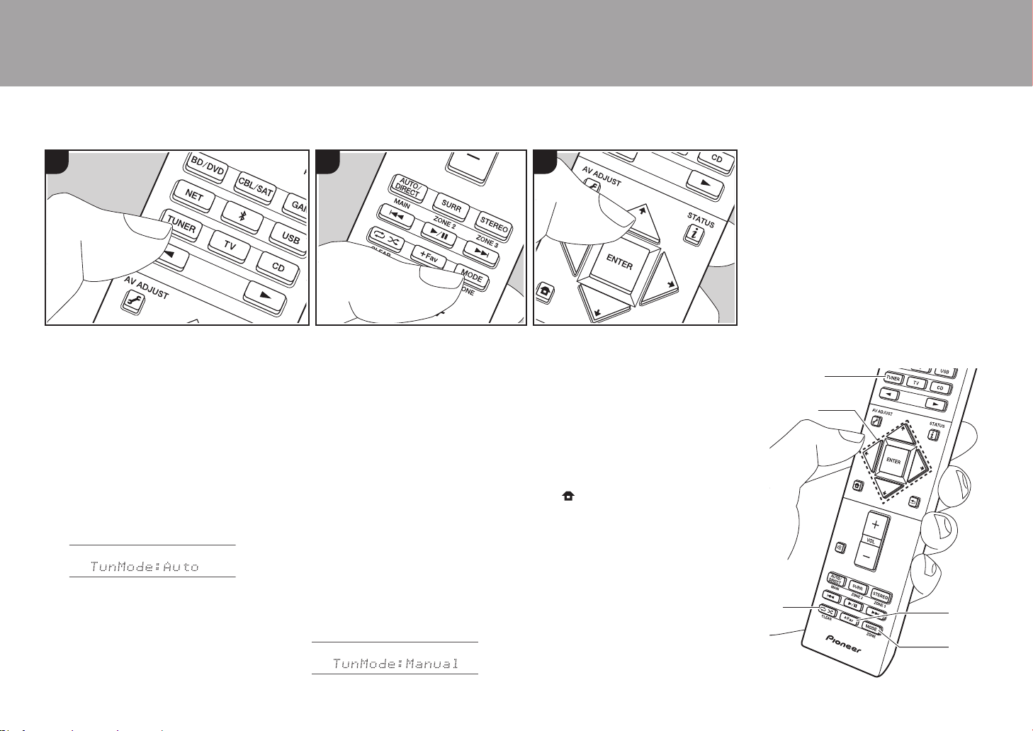
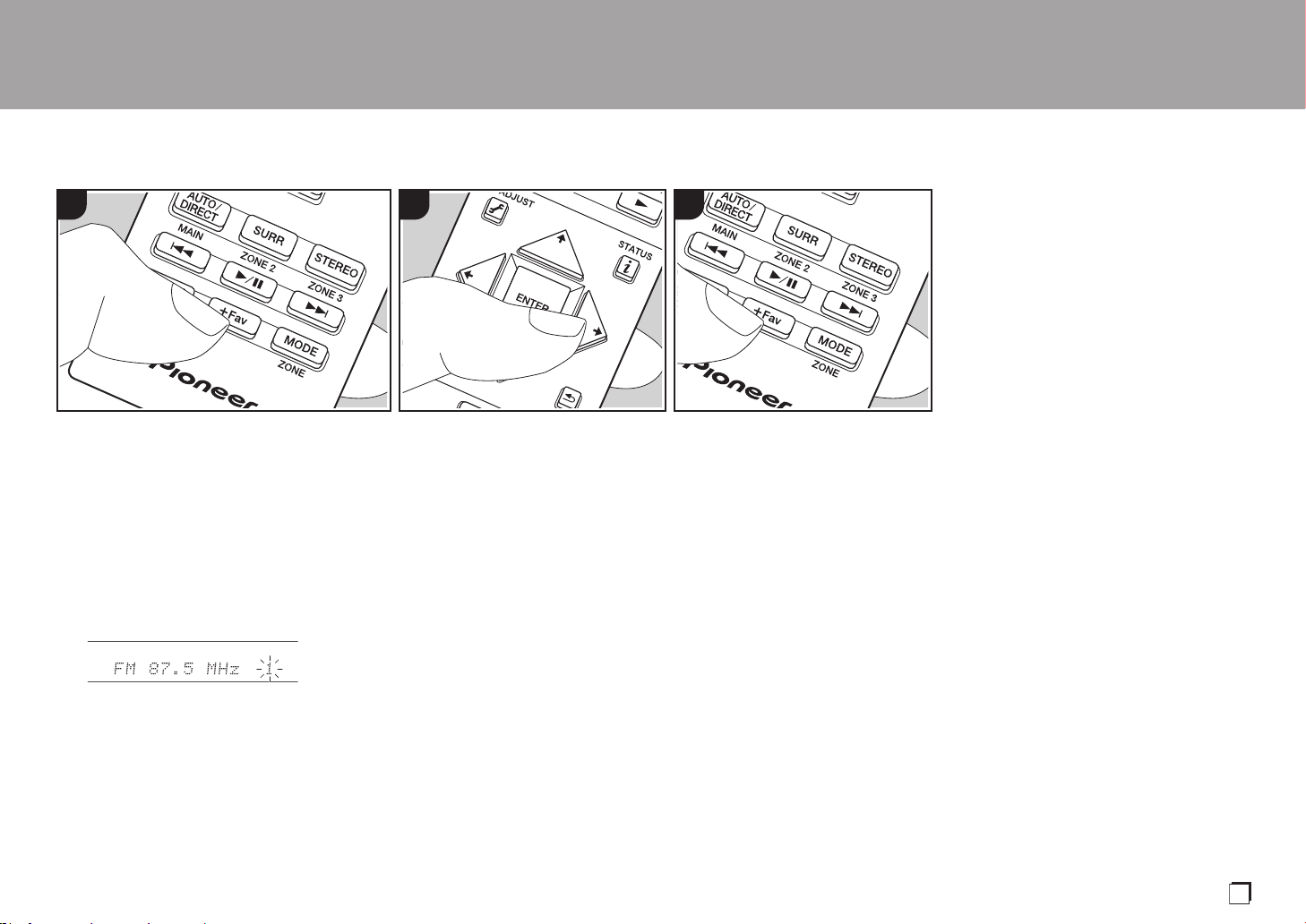
∫ Tuning into a Radio Station
Tuning Automatically
1. Press TUNER (a) on the remote
controller repeatedly to select either
"AM" or "FM" on the display.
2. Press MODE (e) on the remote
controller, so that the "TunMode: Auto" is
displayed on the display.
3. When you press the cursors /
buttons (b) on the remote controller,
automatic tuning starts, and searching
stops when a station is found. When
tuned into a radio station, the "TUNED"
indicator on the display lights. When
tuned into an FM stereo station, the
"STEREO" indicator lights.
When FM broadcasts reception is poor:
Perform the procedure for "Tuning
Manually" in the following section. Note
that if you tune manually, the reception for
FM broadcasts will be monaural rather than
stereo, irrespective of the sensitivity of the
reception.
Tuning Manually
Note that if you tune manually, the
reception for FM broadcasts will be
monaural rather than stereo, irrespective of
the sensitivity of the reception.
1. Press TUNER (a) on the remote
controller repeatedly to select either
"AM" or "FM" on the display.
2. Press MODE (e) on the remote
controller, so that the "TunMode:
Manual" is displayed on the display.
3. While pressing the cursors / (b) on
the remote controller, select the desired
radio station.
0 The frequency changes by 1 step
each time you press the cursors /
. The frequency changes
continuously if the button is held down
and stops when the button is
released.
Frequency step setting:
Press on the remote controller, and
from Home displayed select "System
Setup" - "Miscellaneous" - "Tuner" - "AM/
FM Frequency Step", and select the
frequency step for your region. Note that
when this setting is changed, all radio
presets are deleted.
> Before Start > Part Names > Install > Initial Setup > Playback
1 2 3
a
b
c
d
e
SN29403015A_VSX-LX302_BAS_En_1711xx.book 28 ページ 2017年10月27日 金曜日 午後2時0分
29
> Before Start > Part Names > Install > Initial Setup > Playback
∫ Presetting a Radio Station
You can preset up to 40 stations.
Registration Procedure
After tuning into the AM/FM radio station
you want to register, perform the following
procedure.
1. Press +Fav (d) on the remote controller
so that the preset number on the display
flashes.
2. While the preset number is flashing
(about 8 seconds), repeatedly press the
cursors / (b) on the remote
controller to select a number between 1
and 40.
3. Press +Fav again on the remote
controller to register the station.
When registered, the preset number
stops flashing. Repeat this procedure for
all of your favorite AM/FM radio stations.
Selecting a Preset Radio Station
1. Press TUNER (a) on the remote
controller.
2. Press cursors / (b) on the remote
controller to select a preset number.
Deleting a Preset Radio Station
1. Press TUNER (a) on the remote
controller.
2. Press cursors / (b) on the remote
controller to select the preset number to
delete.
3. After pressing +Fav (d) on the remote
controller, press CLEAR (c) while the
preset number is flashing to delete the
preset number. When deleted, the
number on the display goes off.
1 2 3
En
SN29403015A_VSX-LX302_BAS_En_1711xx.book 29 ページ 2017年10月27日 金曜日 午後2時0分
30
Multi-zone
> Before Start > Part Names > Install > Initial Setup > Playback
Basic Operations
You can enjoy audio in the separate room
by, for example, playing a Blu-ray Disc
player in the main room (where this unit is
located) and listening to internet radio in
the separate room (ZONE 2).
0 DSD and Dolby TrueHD audio signals
are not output to ZONE 2 when selected
with the "NET" or "USB" input selector.
0 You can only select the same inputs for
the main room and separate room with
the "NET", "BLUETOOTH", or "USB"
input selector. If you have "NET"
selected in the main room and then
select "BLUETOOTH" in the separate
room, the main room also switches to
"BLUETOOTH". You cannot select
different stations for the main room and
separate room with the AM/FM radio.
0 If ZONE 2 is on, power consumption
during standby becomes larger than
normal.
Perform the following procedure when the
unit is on.
1. While holding down MODE (e) on the
remote controller, press ZONE 2 (d) for 3
or more seconds until the remote
indicator blinks twice.
0 The remote controller switches to the
mode for controlling ZONE 2.
2. Point the remote controller at the main
unit and press Í (a).
"Z2" lights on the main unit display.
3. Press the input selector button (b) of the
input to be played in the separate room.
0 On the main unit, after pressing ZONE
2-CONTROL, within 8 seconds turn
the input selector dial to select the
input to be played in the separate
room.
4. To adjust the volume on the power
amplifier in the separate room or the
ZONE speaker, adjust with VOL+/– on
the remote controller.
0 To control on the main unit, press
ZONE 2-CONTROL and adjust with
the MASTER VOLUME control within
8 seconds.
To turn off the function:
Press Í while in the mode for controlling
ZONE 2 on the remote controller.
Alternatively press ZONE 2-ON/OFF on the
main unit.
Playing in ZONE 2 only:
If you turn the unit to standby during multi-
zone playback, the Z2 indicator is dimmed
and the playback mode is switched to
playback in a separate room only. Setting
ZONE 2 to on while this unit is in standby
will also switch the playback mode to the
same setting.
1 2 3
To return the remote controller
to main room control mode:
While holding down MODE on the
remote controller, press MAIN (c)
for 3 seconds or more until the
remote indicator flashes once.
c
d
e
a
b
SN29403015A_VSX-LX302_BAS_En_1711xx.book 30 ページ 2017年10月27日 金曜日 午後2時0分
31
Listening Mode
> Before Start > Part Names > Install > Initial Setup > Playback
This unit is equipped with a variety of
listening modes. The basic operations are
introduced in the Basic Manual. For more
details, see the Advanced Manual.
0 The listening mode last selected for the
source is remembered for each of the
AUTO/DIRECT, SURR, and STEREO
buttons. If content you play is not
supported by the listening mode you
selected last, the listening mode that is
standard for that content is selected
automatically.
AUTO/DIRECT button (a)
Press repeatedly and the listening modes
suited to the input signal are switched
between "Auto Surround", "Direct", and
"Pure Direct". After selecting one of them,
"Auto Surround" (or "Direct" or "Pure
Direct") is displayed on the display of the
main unit, then the listening mode selected
automatically (Dolby Digital for multi-
channel input signals, Stereo for 2 channel
input signals, etc.) is displayed.
The "Direct" mode shuts down some
processing that can affect sound quality,
such as the tone control features, so you
can enjoy even better sound quality. The
"Pure Direct" mode shuts down even more
processes that affects sound quality, so
you get a more faithful reproduction of the
original sound. In this case, the speaker
calibration made with MCACC is disabled.
0 Depending on the input signal and
speaker configuration, the Dolby
Surround and DTS Neural:X modes that
expand 2 channel and 5.1 channel input
signals to 5.1 channel and 7.1 channel
may be automatically selected.
SURR button (c)
You can select a variety of listening modes
to suit your taste. There are the Dolby
Digital, DTS-HD Master Audio, and Stereo
modes that you can choose to suit the input
signal, or the Dolby Surround and DTS
Neural:X modes that can expand 2 channel
and 5.1 channel input signals to 5.1 or
7.1 channels. You can also enjoy original
surround modes such as Ext.Stereo and
Drama modes.
a
b
c
d
STEREO button (d)
You can select the "Stereo" mode to
playback only from the front speakers and
subwoofer.
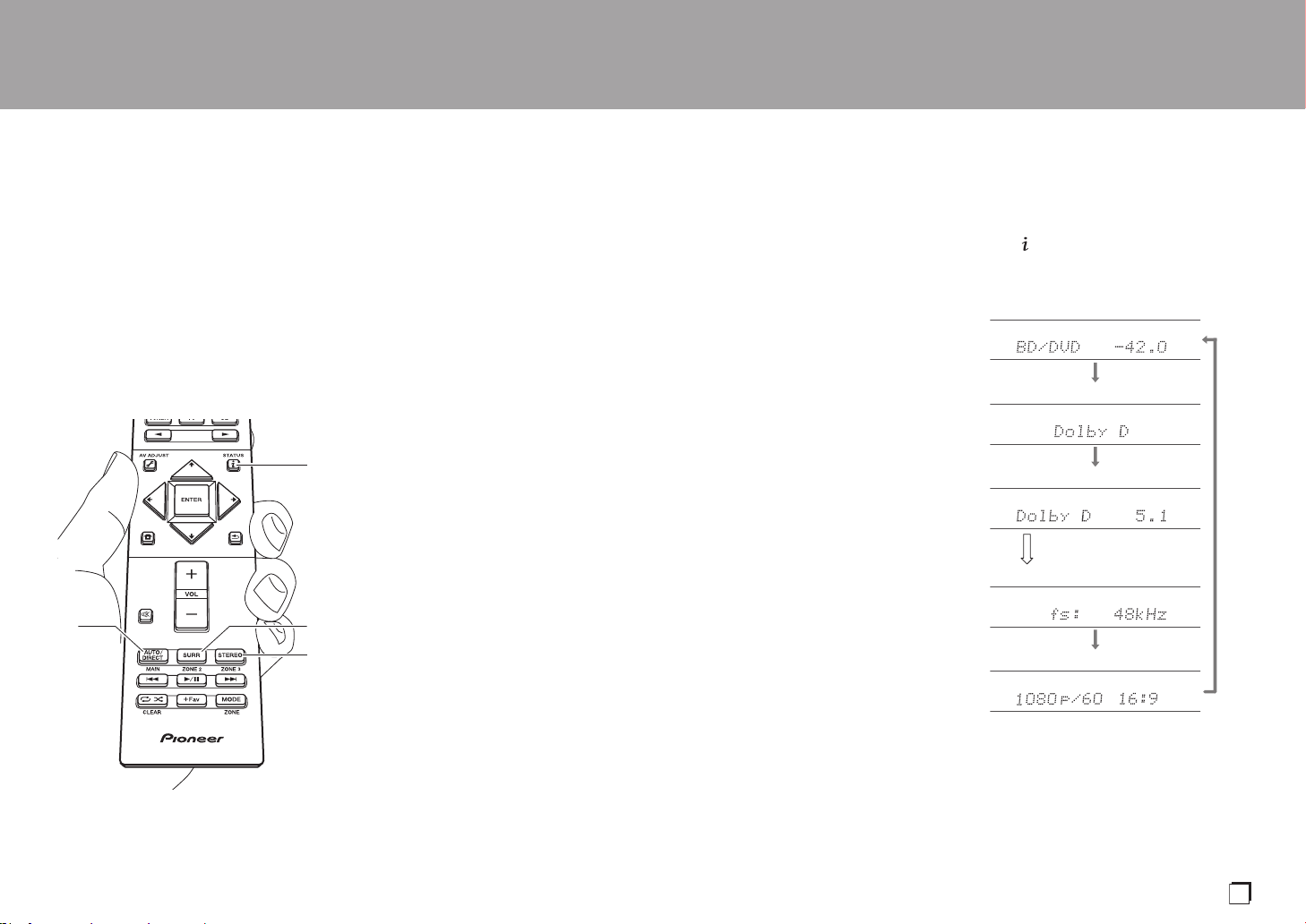
Checking the Input Format and
Listening Mode
Press (b) on the remote controller
several times to switch the display of the
main unit as follows.
Input source & volume
Listening mode
Signal format
Sampling frequency
Input signal resolution
The display changes few
seconds later.
En
SN29403015A_VSX-LX302_BAS_En_1711xx.book 31 ページ 2017年10月27日 金曜日 午後2時0分

32
License and Trademark
Manufactured under license from Dolby Laboratories. Dolby, Dolby Atmos,
Dolby Surround, Dolby Vision and the double-D symbol are trademarks of
Dolby Laboratories.
For DTS patents, see http://patents.dts.com. Manufactured under license from
DTS, Inc. DTS, the Symbol, DTS in combination with the Symbol, DTS:X, and
the DTS:X logo are registered trademarks or trademarks of DTS, Inc. in the
United States and/or other countries. © DTS, Inc. All Rights Reserved.
The terms HDMI and HDMI High-Definition Multimedia Interface, and the HDMI
Logo are trademarks or registered trademarks of HDMI Licensing LLC in the
United States and other countries.
The Wi-Fi CERTIFIED Logo is a certification mark of Wi-Fi Alliance
®
.
AirPlay, iPad, iPhone, iPod, iPod classic, iPod nano and iPod touch are
trademarks of Apple Inc., registered in the U.S. and other countries.
iPad Air and iPad mini are trademarks of Apple Inc.
“Made for iPod”, “Made for iPhone” and “Made for iPad” mean that an electronic
accessory has been designed to connect specifically to iPod, iPhone, or iPad,
respectively, and has been certified by the developer to meet Apple
performance standards. Apple is not responsible for the operation of this device
or its compliance with safety and regulatory standards.
Please note that the use of this accessory with iPod, iPhone or iPad may affect
wireless performance.
AirPlay works with iPhone, iPad, and iPod touch with iOS 4.3.3 or later, Mac
with OS X Mountain Lion or later, and PC with iTunes 10.2.2 or later.
PANDORA, the PANDORA logo, and the Pandora trade dress are trademarks
or registered trademarks of Pandora Media, Inc. Used with permission.
The BLUETOOTH
®
word mark and logos are registered trademarks owned by
Bluetooth SIG, Inc.
The Spotify software is subject to third party licenses found here:
https://developer.spotify.com/esdk-third-party-licenses/
This product is protected by certain intellectual property rights of Microsoft. Use
or distribution of such technology outside of this product is prohibited without a
license from Microsoft.
Windows 7, Windows Media, and the Windows logo are trademarks or
registered trademarks of Microsoft Corporation in the United States and/or
other countries.
DSD and the Direct Stream Digital logo are trademarks of Sony Corporation.
“All other trademarks are the property of their respective owners.”
“Toutes les autres marques commerciales sont la propriété de leurs détenteurs
respectifs.”
“El resto de marcas comerciales son propiedad de sus respectivos
propietarios”.
®
SN29403015A_VSX-LX302_BAS_En_1711xx.book 32 ページ 2017年10月27日 金曜日 午後2時0分

Avant de démarrer ..........................................................2
Ce que contient la boîte.....................................................2
Nom des pièces ..............................................................3
Nom des pièces.................................................................3
Installation .......................................................................7
Procédure d'installation......................................................7
Étape 1 : Disposition d'enceinte.........................................8
Étape 2 : Raccorder les enceintes...................................15
Étape 3 : Raccorder le téléviseur et les appareils AV......17
Configuration initiale ....................................................23
Initial Setup avec l'assistant de démarrage automatique..... 23
Lecture ...........................................................................25
Lecture d'un appareil AV..................................................25
Lecture BLUETOOTH
®
....................................................25
Fonctions réseau .............................................................26
Périphérique de stockage USB........................................27
Écoute de la radio AM/FM ...............................................28
Multizone .........................................................................30
Mode d'écoute .................................................................31
VSX-LX302 / RECEPTEUR AV
Pour avoir des détails sur les Fonctions Réseau et les modes
d'écoute ainsi que des informations à propos des réglages avancés,
consultez le "Mode d'emploi avancé" disponible sur notre site Web.
http://jp.pioneer-audiovisual.com/manual/vsxlx302elite/adv/fr.html
Fr
SN29403015A_VSX-LX302_BAS_Fr_1711xx.book 1 ページ 2017年10月27日 金曜日 午後2時1分

2
Ce que contient la boîte
1. Appareil principal (1)
2. Télécommande (RC-957R) (1), Piles (AAA/R03) (2)
3. Microphone de configuration d'enceintes (1)
0 Utilisé durant la Initial Setup.
4. Antenne FM intérieure (1)
5. Antenne cadre AM (1)
6. Cordon d'alimentation (1)
0 Guide de démarrage rapide (1)
0 Mode d'Emploi Base (Ce manuel)
0 Raccordez des enceintes ayant une valeur d'impédance
comprise entre 4 Ω et 16 Ω.
0 Le cordon d'alimentation devra être branché uniquement
lorsque tous les autres raccordements seront effectués.
0 Nous déclinons toute responsabilité concernant des
dommages résultant d'une connexion à des
équipements fabriqués par d'autres sociétés.
0 Des fonctionnalités peuvent être mises en place par des
mises à jour du micrologiciel et des services de
fournisseurs pourraient cesser, ce qui signifie que
certains services réseau et leurs contenus pourraient
devenir inaccessibles dans le futur. De plus, les services
disponibles peuvent être différents en fonction de votre
lieu de résidence.
0 Les détails concernant la mise à jour du micrologiciel
seront publiés sur notre site internet et par d'autres
moyens à une date ultérieure.
0 Les spécifications et l'aspect peuvent changer sans
préavis.
> Avant de démarrer > Nom des pièces > Installation > Configuration initiale > Lecture
1
32
54
6
SN29403015A_VSX-LX302_BAS_Fr_1711xx.book 2 ページ 2017年10月27日 金曜日 午後2時1分

3
Nom des pièces
Panneau frontal
1. Molette INPUT SELECTOR : Change l'entrée à lire.
2. Témoin MCACC : Il s'allume quand vous avez activé le mode de réglage d'enceinte par
MCACC (P23).
3. Témoin FL OFF : Il s'allume quand vous avez appuyé sur DIMMER plusieurs fois pour
éteindre l'écran.
4. Touche DIMMER : Vous pouvez désactiver l'afficheur ou régler sa luminosité sur trois
niveaux.
5. Touche ZONE 2-ON/OFF : Permet de désactiver la fonction multizone (P30).
6. Touche ZONE 2-CONTROL : Contrôle la fonction multizone (P30).
7. Touche HOME MENU : Affiche le Home. (*)
8. Afficheur (P4)
9. Touches du curseur ( / / / ) et touche ENTER : Permet de sélectionner l’élément à
l’aide des touches du curseur et d'appuyer sur ENTER pour valider. Utilisez-les pour
syntoniser les stations en utilisant TUNER (P28).
10.
Témoin NETWORK : Il s'allume si "NET" est sélectionné avec le sélecteur d'entrée et que
l'appareil est connecté au réseau. Si l'appareil est en mode veille, il s'allume quand les
fonctions comme HDMI CEC et veille réseau sont activées. Mais il ne s'allume pas
lorsque ZONE 2 est active.
11.
Témoin WIRELESS : S'allume lorsque l'appareil est connecté au réseau sans fil et
lorsqu'il est connecté à un périphérique compatible BLUETOOTH.
12.
Capteur de la télécommande : Reçoit les signaux de la télécommande.
0 La portée du signal de la télécommande est d'environ 16´/5 m, à un angle de 20° de
l'axe perpendiculaire et à un angle de 30° de chaque côté.
13.
Touche RETURN : Permet à l'affichage de retourner à son état précédent.
14.
MASTER VOLUME
15.
Touche Í STANDBY/ON
> Avant de démarrer > Nom des pièces > Installation > Configuration initiale > Lecture
Fr
(*)Vous pouvez trouver des détails dans le Mode d'emploi avancé.
SN29403015A_VSX-LX302_BAS_Fr_1711xx.book 3 ページ 2017年10月27日 金曜日 午後2時1分
4
> Avant de démarrer > Nom des pièces > Installation > Configuration initiale > Lecture
16.
Prise PHONES : Permet de brancher un casque avec
une fiche standard (Ø1/4"/6,3 mm).
17.
Prise MCACC SETUP MIC : Le micro de réglage
d'enceinte fourni est connecté.
18.
Touche Mode d’écoute : Appuyez sur "AUTO/DIRECT",
"SURROUND" ou sur "STEREO" pour changer le
mode d'écoute (P31). (*)
19.
Touche SOUND RETRIEVER : Démarre/arrête la
fonction Sound Retriever qui améliore la qualité du son
compressé.
20.
Touche PURE DIRECT : Passe au mode Pure Direct
(P31).
21.
Port USB : Un appareil de stockage USB est connecté
afin que les fichiers musicaux qu'il contient puissent
être lus. Vous pouvez également fournir l'alimentation
(5 V/500 mA) aux périphériques USB avec un câble
USB.
22.
Prise AUX INPUT AUDIO/HDMI : Permet de brancher
une caméra vidéo, etc. à l'aide d'un câble à mini-fiche
stéréo (Ø1/8"/3,5 mm) ou un câble HDMI.
Afficheur
1. Ceci peut s'allumer lors des commandes effectuées avec le sélecteur
d'entrée "NET", "USB".
2. S'allume sous les conditions suivantes.
Z2: Lorsque la ZONE 2 est active.
: Lorsque raccordé par BLUETOOTH.
: Lorsque connecté par Wi-Fi.
NET: Lorsque "NET" est sélectionné avec le sélecteur d'entrée et que
l'appareil est connecté au réseau. Il clignotera si la connexion au
réseau n’est pas correcte.
USB: Lorsque "USB" est sélectionné avec le sélecteur d'entrée et que
l'appareil est raccordé par USB et que le périphérique USB est
sélectionné. Clignote si l'USB n’est pas correctement branché.
HDMI : Lors de l'entrée des signaux HDMI et lorsque l'entrée HDMI est
sélectionnée.
DIGITAL : Lors de l'entrée de signaux numériques et lorsque l'entrée
numérique est sélectionnée.
3. S'allume en fonction du type de l'entrée des signaux audio numériques
et du mode d'écoute.
4. S'allume sous les conditions suivantes.
TUNED : Réception de la radio AM/FM.
STEREO : Réception en FM stéréo.
SLEEP : Lorsque la minuterie de veille est définie.
AUTO STBY : La veille automatique est activée.
5. Le système d’enceinte actuellement sélectionné s’allume.
6. S'allume lorsque le casque audio est connecté.
7. Clignote lorsque le mode sourdine est activé.
8. Affiche différentes informations sur les signaux d'entrée.
9. Il s'allume quand on règle le volume.
10.
Affichage de l'Enceinte/Canal : Affiche le canal de sortie
correspondant au mode d'écoute
sélectionné.
(*)Vous pouvez trouver des détails dans le Mode d'emploi avancé.
SN29403015A_VSX-LX302_BAS_Fr_1711xx.book 4 ページ 2017年10月27日 金曜日 午後2時1分

5
Panneau arrière
1. Prises DIGITAL AUDIO IN OPTICAL/COAXIAL : Entrée des signaux audio numérique
composante TV ou AV avec un câble optonumérique ou un câble coaxial numérique.
2. Borne ANTENNA AM LOOP/FM UNBAL 75Ω : Les antennes fournies sont connectées.
3. Prises VIDEO IN : Entrée des signaux vidéo composante AV avec un câble vidéo analogique.
4. Port USB : Un appareil de stockage USB est connecté afin que les fichiers musicaux qu'il
contient puissent être lus. Vous pouvez également fournir l'alimentation (5 V/500 mA) aux
périphériques USB avec un câble USB.
5. Prises COMPONENT VIDEO IN : Entrée des signaux vidéo composante AV avec un
câble vidéo composante. (Uniquement compatible avec les résolutions 480i ou 576i.)
6. Port NETWORK : Pour se connecter au réseau à l'aide d'un câble Ethernet.
7. Antenne sans fil : Utilisée pour la connexion Wi-Fi ou pour utiliser un périphérique
compatible BLUETOOTH. Réglez leurs angles en fonction de l’état de la connexion.
8. Prises HDMI OUT : Transmet les signaux vidéo et les signaux audio avec un câble HDMI
raccordé à un écran comme un téléviseur ou un projecteur.
9. Prises HDMI IN : Transmet les signaux vidéo et les signaux audio avec un câble HDMI
raccordé à un appareil AV.
10.
Port RS-232C : Pour la connexion au système de commande de la maison. (*)
11.
AC IN : Le cordon d'alimentation fourni y est branché.
12.
Borne SIGNAL GND : Le fil de terre de la platine disque est branché.
13.
Prises AUDIO IN : Entrée des signaux audio composante AV avec un câble audio
analogique.
14.
Bornes SPEAKERS : Raccordez les enceintes avec les câbles d'enceinte. (Compatible
avec les fiches banane)
15.
Prises ZONE 2 PRE/LINE OUT : Sortie des signaux audio avec un câble audio
analogique vers un amplificateur principal ou un amplificateur sous tension dans une
autre pièce (ZONE 2).
> Avant de démarrer > Nom des pièces > Installation > Configuration initiale > Lecture
180°
90°
Fr
(*)Vous pouvez trouver des détails dans le Mode d'emploi avancé.
SN29403015A_VSX-LX302_BAS_Fr_1711xx.book 5 ページ 2017年10月27日 金曜日 午後2時1分

6
> Avant de démarrer > Nom des pièces > Installation > Configuration initiale > Lecture
16.
Prise SUBWOOFER PRE OUT : Connectez un caisson
de basse sous tension avec un câble pour caisson de
basse. Il est possible de raccorder jusqu'à deux
caissons de basse sous tension. Le même signal est
reproduit par chacune des prises SUBWOOFER PRE
OUT.
17.
Port IR IN/OUT : Vous permet de connecter un kit de
télécommande multi-pièce. (*)
18.
Prises 12V TRIGGER OUT A/B : Vous permet de
connecter un appareil doté d’une prise d'entrée de
déclenchement 12V pour permettre le fonctionnement
de la liaison entre le périphérique et l'appareil. (*)
Télécommande
1. Touche Í STANDBY/ON
2. Sélecteurs d'entrée : Change l'entrée à lire.
3. Touches 21 : Sélectionnez l'entrée à lire.
4. Touche (AV ADJUST) : Les réglages comme "Tone" et "Level" peuvent être effectués rapidement
durant la lecture sur l'écran du téléviseur. "Other" contient les réglages pour donner la priorité de
sortie aux enceintes (P15) et pour passer sur la sortie HDMI (P17). Notez qu’il n’y a aucun affichage
sur l’écran du téléviseur lorsque le sélecteur d’entrée est sur "CD", "TV", "PHONO", "AM", ou "FM",
suivez donc l’affichage sur l’appareil principal pour effectuer les actions. (*)
5. Touches du curseur et touche ENTER : Sélectionnez l'élément à l'aide des
touches du curseur et appuyez sur ENTER pour confirmer votre sélection. Si les
listes de dossiers ou fichiers ne sont pas entièrement visibles sur un seul écran
du téléviseur, appuyez sur / pour changer l'écran.
6. Touche : Affiche le Home. (*)
7. Touche volume
8. Touche : Mise temporaire de l'audio en sourdine. Appuyez de nouveau pour
annuler la mise en sourdine.
9. Touches LISTENING MODE : Permet de sélectionner le mode d'écoute (P31). (*)
Boutons MAIN/ZONE 2 : Contrôle la fonction multi-zone (P30). (La touche ZONE
3 ne peut pas être utilisée avec cet appareil.)
10.
Touches Lecture : Utilisé pour les commandes de lecture en lisant sur Music Server ou par USB.
11.
Touche : Utilisé pour les commandes de répétition de lecture ou de lecture aléatoire
en lisant sur Music Server ou par USB. Chaque fois que vous appuyez sur la touche, le mode
permute entre (1-répétition de piste), (répétition dossier), (aléatoire).
Touche CLEAR : Supprime tous les caractères que vous avez saisis sur l'écran du téléviseur.
12.
Touche (STATUS) : Modifie l'information affichée.
13.
Touche : Permet à l'affichage de retourner à son état précédent.
14.
Touche MODE : Permute entre la syntonisation automatique et la syntonisation
manuelle d'une station AM/FM.
15.
Touche +Fav : Utilisé pour mémoriser les stations de radio AM/FM.
Tips
Lorsque la télécommande ne fonctionne pas :
La télécommande peut avoir été passée sur le
mode contrôlant la ZONE 2. Tout en appuyant sur
MODE, appuyez sur MAIN pendant 3 secondes
ou plus jusqu'à ce que le témoin à distance
clignote une fois, pour la passer sur le mode qui
contrôle la pièce principale.
(*)Vous pouvez trouver des détails dans le Mode d'emploi avancé.
SN29403015A_VSX-LX302_BAS_Fr_1711xx.book 6 ページ 2017年10月27日 金曜日 午後2時1分

7
Procédure d'installation
Cet appareil peut être utilisé de nombreuses manières, en
fonction de la disposition des enceintes que vous avez installées
et des raccordements effectués vers des dispositifs externes.
Lisez ce qui suit pour faciliter le procédé d'installation.
Étape 1 : Disposition d’enceinte
Choisissez la disposition qui correspond aux types
d'enceintes que vous possédez et aux conditions dans
lesquelles elles seront utilisées parmi les choix présentés
de la P8 à la P13, puis installez les enceintes en vous
référant aux illustrations et aux explications de la page
correspondante. Les dispositions d'enceinte incluent des
systèmes qui utilisent des enceintes surround arrière, des
systèmes qui utilisent des enceintes en hauteur et des
systèmes qui utilisent la bi-amplification des enceintes.
Consultez également les combinaisons disponibles dans
"Combinaisons d'enceintes" à la P14.
Étape 2 : Raccorder les enceintes
Pour raccorder les systèmes d'enceinte à cet appareil,
consultez la P15 si vous utilisez l'une des dispositions
décrites de la P8 à la P12, et la P16 pour utiliser une
disposition qui utilise la bi-amplification décrite à la P13. Le
procédé d'installation sera facilité si vous consultez les
illustrations et les explications et si vous préparez les
câbles nécessaires au préalable.
Étape 3 : Raccorder le téléviseur et les appareils AV
Lisez de la P17 à la P22 pour raccorder vos dispositifs
externes comme votre téléviseur, lecteur de Blu-ray Disc ainsi
que les accessoires fournis comme les antennes. De plus, la
P21 présente l'option de raccordement Multizone qui vous
permet d'écouter le son dans les autres pièces en dehors de la
pièce principale. Le procédé de raccordement sera facilité si
vous consultez les illustrations et les explications, si vous
vérifiez les types de raccordement des dispositifs externes et
si vous préparez les câbles nécessaires au préalable.
> Avant de démarrer > Nom des pièces > Installation > Configuration initiale > Lecture
1
2 3
Fr
SN29403015A_VSX-LX302_BAS_Fr_1711xx.book 7 ページ 2017年10月27日 金曜日 午後2時1分

8
Étape 1 : Disposition d'enceinte
Système 7.1
Les enceintes avant reproduisent le son stéréo avant et
l'enceinte centrale reproduit le son central comme les
dialogues et les voix. Les enceintes surround produisent un
champ sonore arrière. Le caisson de basse sous tension
reproduit les sons graves et crée un riche champ sonore.
Ce système 5.1 de base auquel ont été rajoutées des
enceintes surround arrière est appelé système 7.1. Le
raccordement des enceintes surround arrière améliore la
sensation d'immersion et de connectivité du son créée par
le champ sonore arrière qui en devient plus réaliste. De
plus, en installant des enceintes surround arrière, vous
pouvez sélectionner le mode d'écoute Dolby Atmos, qui
crée le son en 3D le plus actuel, lorsque le format d’entrée
est Dolby Atmos.
Les enceintes avant devront être positionnées à hauteur
d'oreille, tandis que les enceintes surround devront être
positionnées juste au-dessus de la hauteur d'oreille.
L'enceinte centrale devra faire face à la position d'écoute.
En plaçant le caisson de basse sous tension entre
l'enceinte centrale et une enceinte avant, vous obtiendrez
un son naturel même en écoutant de la musique. La
position optimale des enceintes surround arrière est à
hauteur d'oreilles.
0 Si vous incluez les enceintes surround arrière dans la
configuration, les enceintes surround sont nécessaires.
0 "Combinaisons d'enceintes" (P14) présente certains
exemples détaillés de combinaisons d'enceintes.
1,2 Enceintes avant
3 Enceinte centrale
4,5 Enceintes surround
6 Caisson de basse sous tension
7,8 Enceintes surround arrière
> Avant de démarrer > Nom des pièces > Installation > Configuration initiale > Lecture
*
1
*
2
*
3
½1: 22e à 30e, ½2 : 90e à 110e, ½3 : 135e à 150e
SN29403015A_VSX-LX302_BAS_Fr_1711xx.book 8 ページ 2017年10月27日 金曜日 午後2時1分
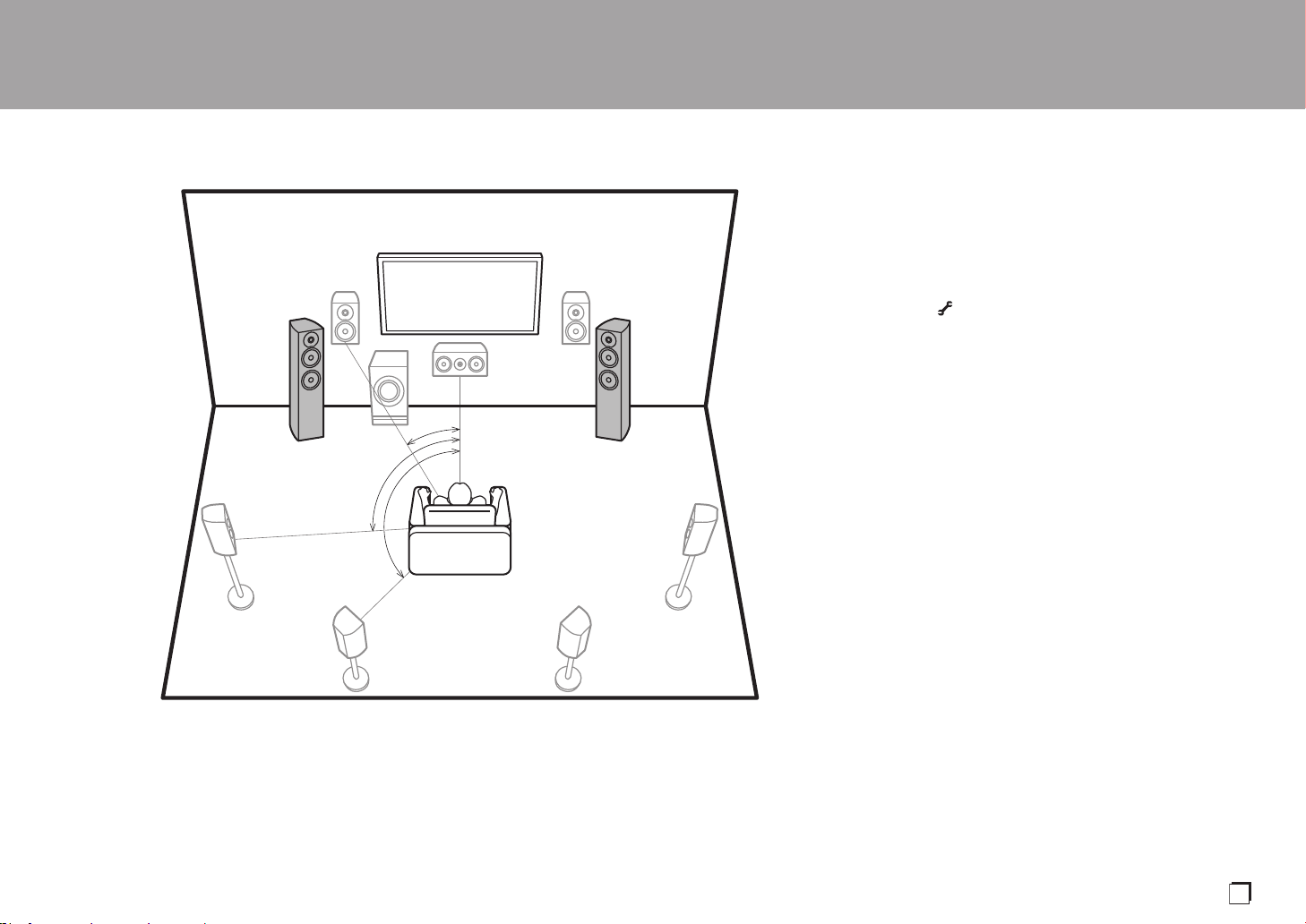
9
Speaker B System
Avec un Système 7.1 (P8), vous pouvez raccorder un ou
plusieurs ensembles d’enceintes avant à utiliser comme
Système d’Enceinte B. Dans ce cas, le Système 7.1
devient le Système d’Enceinte A et vous pouvez basculer le
même son à reproduire depuis A, B, ou A+B. Appuyez sur
la touche de la télécommande (P6) et utilisez "Other" -
"Speakers" pour basculer. Notez qu'aucun son n'est lu par
les enceintes surround arrière lorsqu'il est reproduit par
A+B.
0 "Combinaisons d'enceintes" (P14) présente certains
exemples détaillés de combinaisons d'enceintes.
> Avant de démarrer > Nom des pièces > Installation > Configuration initiale > Lecture
*
1
*
2
*
3
Speaker B Speaker B
½1: 22e à 30e, ½2: 90e à 110e, ½3: 135e à 150e
Fr
SN29403015A_VSX-LX302_BAS_Fr_1711xx.book 9 ページ 2017年10月27日 金曜日 午後2時1分

10
Système 5.1.2 - 1
(Enceintes en hauteur avant/Enceintes en
hauteur arrière)
Il s'agit d'un système 5.1 de base constitué d'enceintes
avant, d'une enceinte centrale, d'enceintes surround et d'un
caisson de basse sous tension avec en plus des enceintes
en hauteur avant ou des enceintes en hauteur arrière, qui
sont deux types d'enceintes en hauteur. En installant des
enceintes en hauteur, vous pouvez sélectionner le mode
d'écoute Dolby Atmos, qui crée le son en 3D le plus actuel
en incluant des sons au-dessus de la tête, lorsque le format
d’entrée est Dolby Atmos. Les enceintes en hauteur avant
ou les enceintes en hauteur arrière devront être
positionnées à au moins 3´/0,9 m au-dessus des enceintes
avant. Les enceintes en hauteur avant devront être
positionnées directement au-dessus des enceintes avant et
la distance entre les enceintes en hauteur arrière devra
correspondre à la distance entre les enceintes avant. Les
deux devront faire face à la position d'écoute.
0 "Combinaisons d'enceintes" (P14) présente certains
exemples détaillés de combinaisons d'enceintes.
9,10 Enceintes en hauteur
Choisissez l'une des options suivantes :
0 Enceintes en hauteur avant
0 Enceintes en hauteur arrière
> Avant de démarrer > Nom des pièces > Installation > Configuration initiale > Lecture
*
1
*
2
3´ (0.9 m)
or more
3´ (0.9 m)
or more
½1: 22e à 30e, ½2: 120e
SN29403015A_VSX-LX302_BAS_Fr_1711xx.book 10 ページ 2017年10月27日 金曜日 午後2時1分

11
Système 5.1.2 - 2
(Enceintes pour plafond)
Il s'agit d'un système 5.1 de base constitué d'enceintes
avant, d'une enceinte centrale, d'enceintes surround et d'un
caisson de basse sous tension avec en plus des enceintes
pour plafond avant, des enceintes pour plafond centrales
ou des enceintes pour plafond arrière, qui sont des types
d'enceintes en hauteur. En installant des enceintes en
hauteur, vous pouvez sélectionner le mode d'écoute Dolby
Atmos, qui crée le son en 3D le plus actuel en incluant des
sons au-dessus de la tête, lorsque le format d’entrée est
Dolby Atmos. Positionnez les enceintes pour plafond avant
devant la position d'écoute, les enceintes pour plafond
centrales directement au-dessus de la position d'écoute, et
les enceintes pour plafond arrière derrière la position
d'écoute. La distance entre chaque paire d'enceintes devra
être la même que celle entre les deux enceintes avant.
0 Dolby Laboratories conseille le positionnement de ce
type d'enceinte en hauteur pour obtenir le meilleur effet
Dolby Atmos.
0 "Combinaisons d'enceintes" (P14) présente certains
exemples détaillés de combinaisons d'enceintes.
9,10 Enceintes en hauteur
Choisissez l'une des options suivantes :
0 Enceintes pour plafond avant
0 Enceintes pour plafond centrales
0 Enceintes pour plafond arrière
> Avant de démarrer > Nom des pièces > Installation > Configuration initiale > Lecture
*
1
*
2
*
3
½1: 30e à 55e, ½2: 65e à 100e, ½3: 125e à 150e
Fr
SN29403015A_VSX-LX302_BAS_Fr_1711xx.book 11 ページ 2017年10月27日 金曜日 午後2時1分

12
Système 5.1.2 - 3
(Enceintes Dolby activé (Enceintes Dolby))
Il s'agit d'un système 5.1 de base constitué d'enceintes
avant, d'une enceinte centrale, d'enceintes surround et d'un
caisson de basse sous tension avec en plus des enceintes
Dolby activé (avant), des enceintes Dolby activé
(surround), ou des enceintes Dolby activé (surround
arrière) qui sont deux types d'enceintes en hauteur. Les
enceintes Dolby activé sont des enceintes spéciales
conçues pour être face au plafond afin que le son soit perçu
après avoir rebondi sur le plafond et semble provenir d’en
haut. En installant des enceintes en hauteur, vous pouvez
sélectionner le mode d'écoute Dolby Atmos, qui crée le son
en 3D le plus actuel en incluant des sons au-dessus de la
tête, lorsque le format d’entrée est Dolby Atmos.
Placez-les sur les enceintes avant ou sur les enceintes
surround.
0 "Combinaisons d'enceintes" (P14) présente certains
exemples détaillés de combinaisons d'enceintes.
9,10 Enceintes en hauteur
Choisissez l'une des options suivantes :
0 Enceintes Dolby Activé (Avant)
0 Enceintes Dolby Activé (Surround)
0 Enceintes Dolby Activé (Surround arrière)
> Avant de démarrer > Nom des pièces > Installation > Configuration initiale > Lecture
*
1
*
2
*
3
½1: 22e à 30e, ½2: 90e à 120e, ½2: 135e à 150e
SN29403015A_VSX-LX302_BAS_Fr_1711xx.book 12 ページ 2017年10月27日 金曜日 午後2時1分

13
Bi-amplification des enceintes
Avec un système 5.1, il est possible de raccorder des
enceintes avant qui prennent en charge la bi-amplification
pour améliorer la qualité des graves et des aiguës. Les
enceintes compatibles avec la bi-amplification nécessitent
que les bornes de leur haut-parleur d'aigus (tweeter) soient
raccordées à un amplificateur et que les bornes de leur
haut-parleur de graves (woofer) soient raccordées à un
autre amplificateur, c'est pourquoi il n'est pas possible de
raccorder des enceintes en hauteur et des enceintes
surround arrière dans cette configuration. En dehors des
enceintes avant, vous pouvez également raccorder une
enceinte centrale, des enceintes surround ainsi qu'un
caisson de basse sous tension.
0 "Combinaisons d'enceintes" (P14) présente certains
exemples détaillés de combinaisons d'enceintes.
1,2 Enceintes avant (bi-amplification)
3 Enceinte centrale
4,5 Enceintes surround
6 Caisson de basse sous tension
> Avant de démarrer > Nom des pièces > Installation > Configuration initiale > Lecture
*
1
*
2
½1: 22e à 30e, ½2: 120e
Fr
SN29403015A_VSX-LX302_BAS_Fr_1711xx.book 13 ページ 2017年10月27日 金曜日 午後2時1分
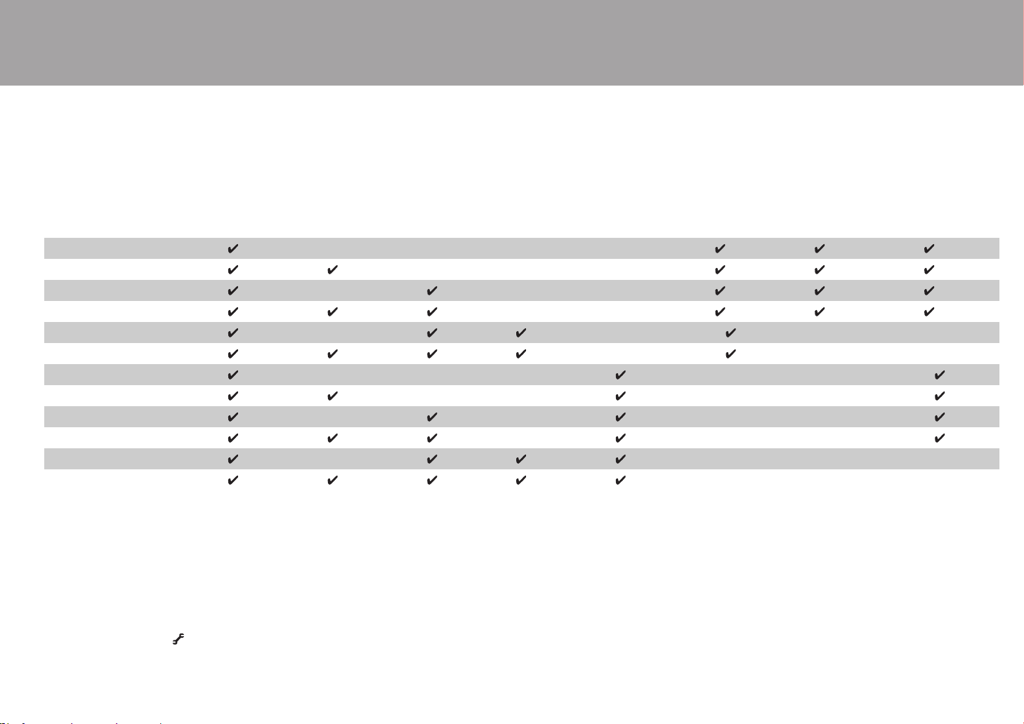
14
Combinaisons d'enceintes
0 Avec chacune des combinaisons, il est possible de raccorder jusqu'à deux caissons de basse sous tension.
(*1) Vous pouvez choisir une enceinte parmi B, Bi-AMP et ZONE SPEAKER.
(*2) En utilisant les Enceintes B, aucun son n'est lu par les enceintes surround arrière
lorsqu'il est reproduit par A+B.
(*3) Aucun son n'est lu par les enceintes en hauteur lorsqu'il est reproduit par ZONE
SPEAKER.
(*4) Vous pouvez raccorder les enceintes surround arrière ainsi que les enceintes en
hauteur. Toutefois, vous ne pouvez reproduire le son que d’une seule de ces paires
d'enceintes à la fois. Si les deux sont connectées, vous pouvez déterminer quelles
enceintes auront la priorité.
0 Appuyez sur la touche de la télécommande (P6) et utilisez "Other" - "Speakers" pour
basculer entre les enceintes A et B et pour basculer entre les enceintes surround arrière
et les enceintes en hauteur.
> Avant de démarrer > Nom des pièces > Installation > Configuration initiale > Lecture
Canaux d’enceinte FRONT CENTER SURROUND
SURROUND
BACK HEIGHT
SP B
(Speaker B)
Bi-AMP
ZONE 2
(ZONE SPEAKER)
(P21)
2.1 ch
(*1) (*1) (*1)
3.1 ch
(*1) (*1) (*1)
4.1 ch
(*1) (*1) (*1)
5.1 ch
(*1) (*1) (*1)
6.1 ch
(*2)
7.1 ch
(*2)
2.1.2 ch
(*3)
3.1.2 ch
(*3)
4.1.2 ch
(*3)
5.1.2 ch
(*3)
6.1.2 ch
(*4) (*4)
7.1.2 ch
(*4) (*4)
SN29403015A_VSX-LX302_BAS_Fr_1711xx.book 14 ページ 2017年10月27日 金曜日 午後2時1分

15
Étape 2 : Raccorder les enceintes
Raccordements standards (Pages 8 à 12)
Raccordez 12345678 pour un système 5.1.
Raccordez 1234569: pour un système 5.1.2. Il est
possible de raccorder jusqu'à deux caissons de basse sous
tension. Le même signal est reproduit par chacune des
prises SUBWOOFER PRE OUT.
0
Vous pouvez également raccorder
78
ainsi que
9:
. Toutefois, vous ne
pouvez reproduire le son que d’une seule de ces paires d'enceintes à la fois.
Si les deux sont connectées, vous pouvez changer quelles enceintes auront la
priorité. Appuyez sur la touche de la télécommande (P6) et utilisez
"Other" - "Speakers" pour basculer entre les enceintes surround arrière et les
enceintes en hauteur et pour basculer entre les enceintes A et B.
Vérifiez que les fils dénudés des enceintes ne
dépassent pas des bornes d'enceinte lors du
raccordement. Si les fils dénudés des enceintes
entrent en contact avec le panneau arrière ou si les fils
+ et – se touchent, le circuit de protection sera activé.
> Avant de démarrer > Nom des pièces > Installation > Configuration initiale > Lecture
a
b
OR
Speaker B
1/2˝
(12 mm)
a Câble d'enceinte, b Câble du caisson de basse
Configuration
0
Les réglages pour la configuration de l’enceinte que vous avez raccordée
doivent être faits dans "1. Full Auto MCACC" dans la Initial Setup (P23).
0
Si l'une des enceintes raccordées possède une
impédance située entre 4 Ω et moins de 6 Ω, après la
réalisation de la Initial Setup, vous devrez effectuer
quelques réglages dans le menu System Setup. Appuyez
sur la touche de la télécommande, et dans le menu
Home affiché réglez "System Setup" - "Speaker" -
"Configuration" - "Speaker Impedance" sur "4ohms".
Fr
SN29403015A_VSX-LX302_BAS_Fr_1711xx.book 15 ページ 2017年10月27日 金曜日 午後2時1分
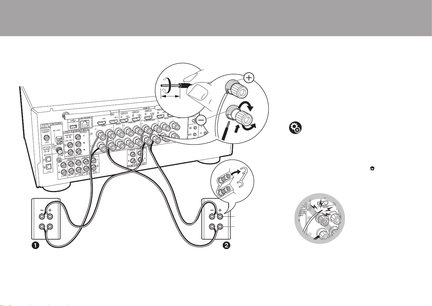
16
Raccordement d'enceintes prenant en charge la
bi-amplification (Page 13)
Assurez-vous de retirer le cavalier se trouvant entre les
prises des graves et les prises des aigus des enceintes
avant. Consultez "Raccordements standards (Pages 8 à
12)" (P15) pour raccorder l'enceinte centrale, les enceintes
surround et le caisson de basse sous tension.
0 Consultez également le mode d'emploi de vos enceintes
pour effectuer la configuration par amplification.
Vérifiez que les fils dénudés des enceintes ne
dépassent pas des bornes d'enceinte lors du
raccordement. Si les fils dénudés des
enceintes entrent en contact avec le panneau
arrière ou si les fils + et – se touchent, le circuit
de protection sera activé.
> Avant de démarrer > Nom des pièces > Installation > Configuration initiale > Lecture
a
1/2˝
(12 mm)
Pour la haute
fréquence
Pour la basse
fréquence
a Câble d'enceinte
Configuration
0 Les réglages pour la configuration de l’enceinte
que vous avez raccordée doivent être faits dans
"1. Full Auto MCACC" dans la Initial Setup (P23).
0
Si l'une des enceintes raccordées possède une
impédance située entre 4 Ω et moins de 6 Ω, après
la réalisation de la Initial Setup, vous devrez
effectuer quelques réglages dans le menu System
Setup. Appuyez sur la touche de la
télécommande, et dans le menu Home affiché
réglez "System Setup" - "Speaker" - "Configuration"
- "Speaker Impedance" sur "4ohms".
SN29403015A_VSX-LX302_BAS_Fr_1711xx.book 16 ページ 2017年10月27日 金曜日 午後2時1分

17
Étape 3 : Raccorder le téléviseur et les appareils AV
1. Raccorder le téléviseur
Vers un téléviseur ARC
Avec un téléviseur qui prend en charge la fonctionnalité ARC
(Audio Return Channel) (*1), utilisez un câble HDMI et raccordez
selon le croquis "a". Pour raccorder, choisissez sur le téléviseur
une prise HDMI IN qui prend en charge la fonctionnalité ARC.
Vers un téléviseur non compatible ARC
Avec un téléviseur qui ne prend pas en charge la
fonctionnalité ARC (Audio Return Channel) (*1), raccordez
un câble HDMI selon le croquis "a" ainsi qu’un câble
optonumérique selon le croquis "b".
0 Le raccordement d'un câble optonumérique n'est pas
nécessaire si vous regardez la télévision via un
décodeur (qui n'utilise pas le tuner du téléviseur) que
vous avez branché à la prise d'entrée de cet appareil.
(*1) La fonctionnalité ARC : Cette fonctionnalité transfère les signaux
audio du téléviseur via un câble HDMI pour que vous puissiez lire
le son du téléviseur avec cet appareil. Le raccordement à un
téléviseur compatible ARC ne nécessite qu'un seul câble HDMI.
Consultez le mode d'emploi de votre téléviseur pour savoir s'il
prend en charge la fonctionnalité ARC.
(*2) Un autre téléviseur ou projecteur peut être raccordé à
la prise HDMI OUT SUB. Appuyez sur la touche
(P6) de la télécommande et utilisez "Other" - "HDMI
Out" pour basculer entre MAIN et SUB. Notez que cette
prise ne prend pas en charge la fonctionnalité ARC.
> Avant de démarrer > Nom des pièces > Installation > Configuration initiale > Lecture
TV
*2
a
b
a Câble HDMI, b Câble optonumérique
Configuration
0
Des réglages sont nécessaires pour utiliser la
fonctionnalité ARC. Sélectionnez "Yes" dans
"5. Audio Return Channel" (P24) dans la Initial Setup.
0 Consultez le mode d'emploi du téléviseur pour
connaitre les raccordements TV et les
instructions concernant les paramètres des
fonctionnalités CEC et de la sortie audio.
Fr
SN29403015A_VSX-LX302_BAS_Fr_1711xx.book 17 ページ 2017年10月27日 金曜日 午後2時1分
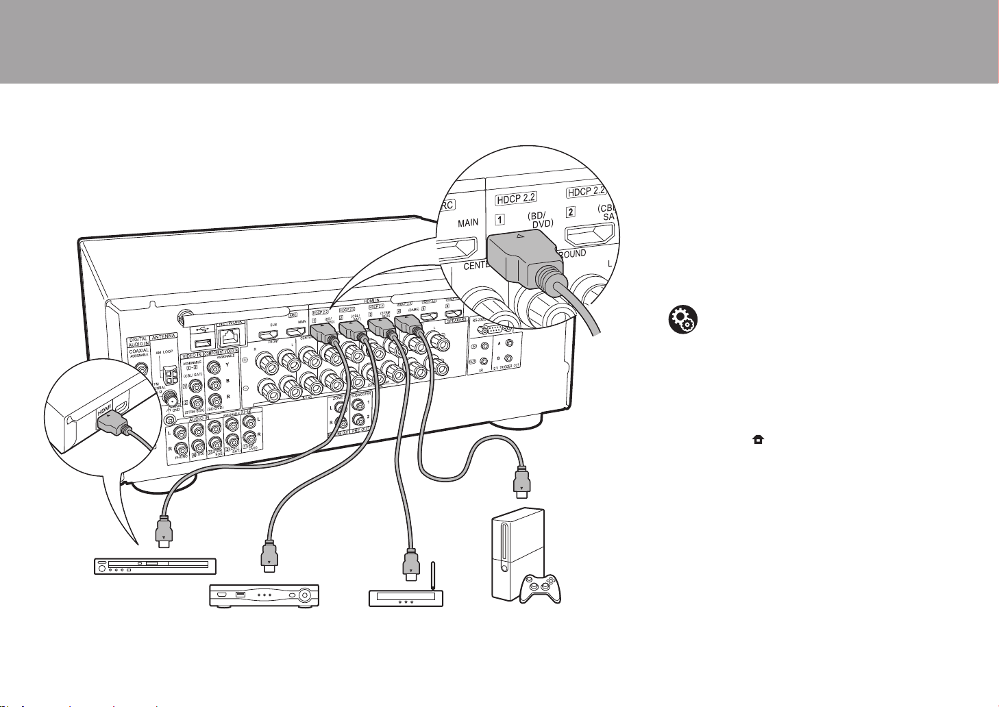
18
2. Raccorder l'appareil AV HDMI
Il s'agit d'un exemple de raccordement avec un appareil AV
possédant une prise HDMI. En raccordant un appareil AV
conforme à la norme CEC (Consumer Electronics Control),
vous pouvez utiliser des fonctionnalités comme le HDMI
CEC (*) qui établit une liaison avec le sélecteur d'entrée, et
le HDMI Standby Through qui vous permet de lire la vidéo
et le son provenant d'un appareil AV sur le téléviseur même
si cet appareil est en veille.
0 Pour lire une vidéo en 4K ou en 1080p, utilisez un câble
HDMI haute vitesse.
(*)La fonctionnalité HDMI CEC : Vous pouvez contrôler des
fonctionnalités telles que la liaison de commutation
d'entrée avec le sélecteur d'entrée et les lecteurs en
conformité avec la norme CEC, pour changer le son à
reproduire par le téléviseur ou par cet appareil, pour
régler le volume à l'aide de la télécommande d'un
téléviseur conforme CEC et pour mettre
automatiquement en veille cet appareil lorsque le
téléviseur est éteint.
> Avant de démarrer > Nom des pièces > Installation > Configuration initiale > Lecture
BD/DVD
GAME
a
Décodeur câble/
satellite
Lecteur de contenu
multimédia en flux
a Câble HDMI
Configuration
0 Lorsque "Yes" est sélectionné pour "5. Audio
Return Channel" dans Initial Setup (P24), la
fonction HDMI CEC et la fonction HDMI Standby
Through sont automatiquement activées. Si "No,
Skip" est sélectionné, des réglages sont
nécessaires dans le menu System Setup une fois
que la Initial Setup a été effectuée. Les réglages
sont effectués dans "System Setup" - "Hardware"
- "HDMI" sous Home affiché en appuyant sur la
touche ode la télécommande.
0 Pour bénéficier du son surround numérique, y
compris Dolby Digital, la sortie audio devra être
réglée sur "Bitstream output" sur le lecteur de
Blu-ray Disc ou un autre appareil raccordé.
SN29403015A_VSX-LX302_BAS_Fr_1711xx.book 18 ページ 2017年10月27日 金曜日 午後2時1分
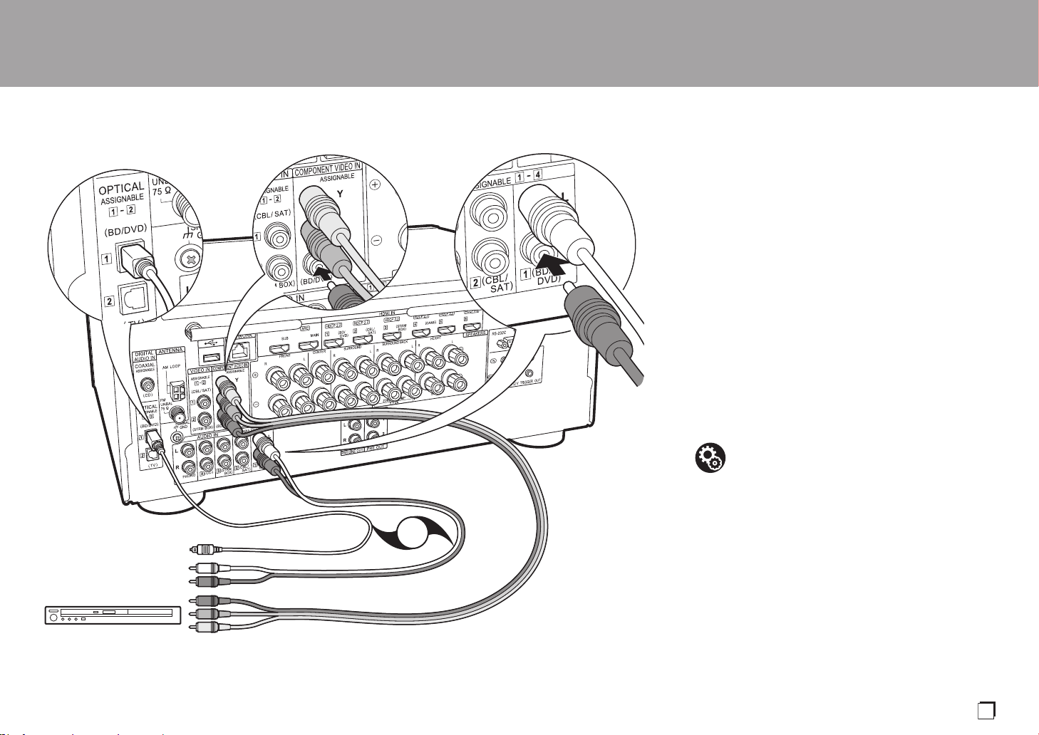
19
3. Raccorder l'appareil AV non HDMI
Il s'agit d'un exemple de raccordement avec un appareil AV
ne possédant pas de prise HDMI. Effectuez les
raccordements de l'appareil AV en fonction des prises qu'il
possède. Si le raccordement pour l'entrée vidéo est
effectué à la prise BD/DVD, le raccordement pour l'entrée
audio devra également se faire aux prises BD/DVD, et ainsi
de suite, de manière à raccorder les entrées vidéo et les
entrées audio portant le même nom.
Notez que les signaux vidéo entrant par la prise VIDEO IN
ou la prise COMPONENT VIDEO IN seront convertis en
signaux vidéo HDMI puis reproduit par la prise HDMI OUT.
0 Pour profiter de la lecture surround numérique dans des
formats comme le Dolby Digital, vous devez effectuer un
raccordement avec un câble coaxial numérique ou un
câble optonumérique pour les signaux audio.
0 Il est possible de changer l'affectation des prises d'entrée
que vous voyez sur l'illustration de gauche, pour que
vous puissiez raccorder une prise autre que BD/DVD.
Pour plus de détails, consultez le Mode d'emploi avancé.
> Avant de démarrer > Nom des pièces > Installation > Configuration initiale > Lecture
BD/DVD
OR
a
b
c
a Câble vidéo composante, b Câble optonumérique, c Câble audio analogique
Configuration
0 Les prises COMPONENT VIDEO IN ne sont
compatibles qu'avec les résolutions 480i ou 576i.
Lorsque vous raccordez les prises COMPONENT
VIDEO IN, réglez la résolution de sortie du lecteur
sur 480i ou 576i. Sélectionnez entrelacé s'il n'y a
pas d'option 480i, etc. Si votre lecteur ne prend
pas en charge la sortie 480i ou 576i, utilisez la
prise VIDEO IN.
0 Pour bénéficier du son surround numérique, y
compris Dolby Digital, la sortie audio devra être
réglée sur "Bitstream output" sur le lecteur de
Blu-ray Disc ou un autre appareil raccordé.
Fr
SN29403015A_VSX-LX302_BAS_Fr_1711xx.book 19 ページ 2017年10月27日 金曜日 午後2時1分
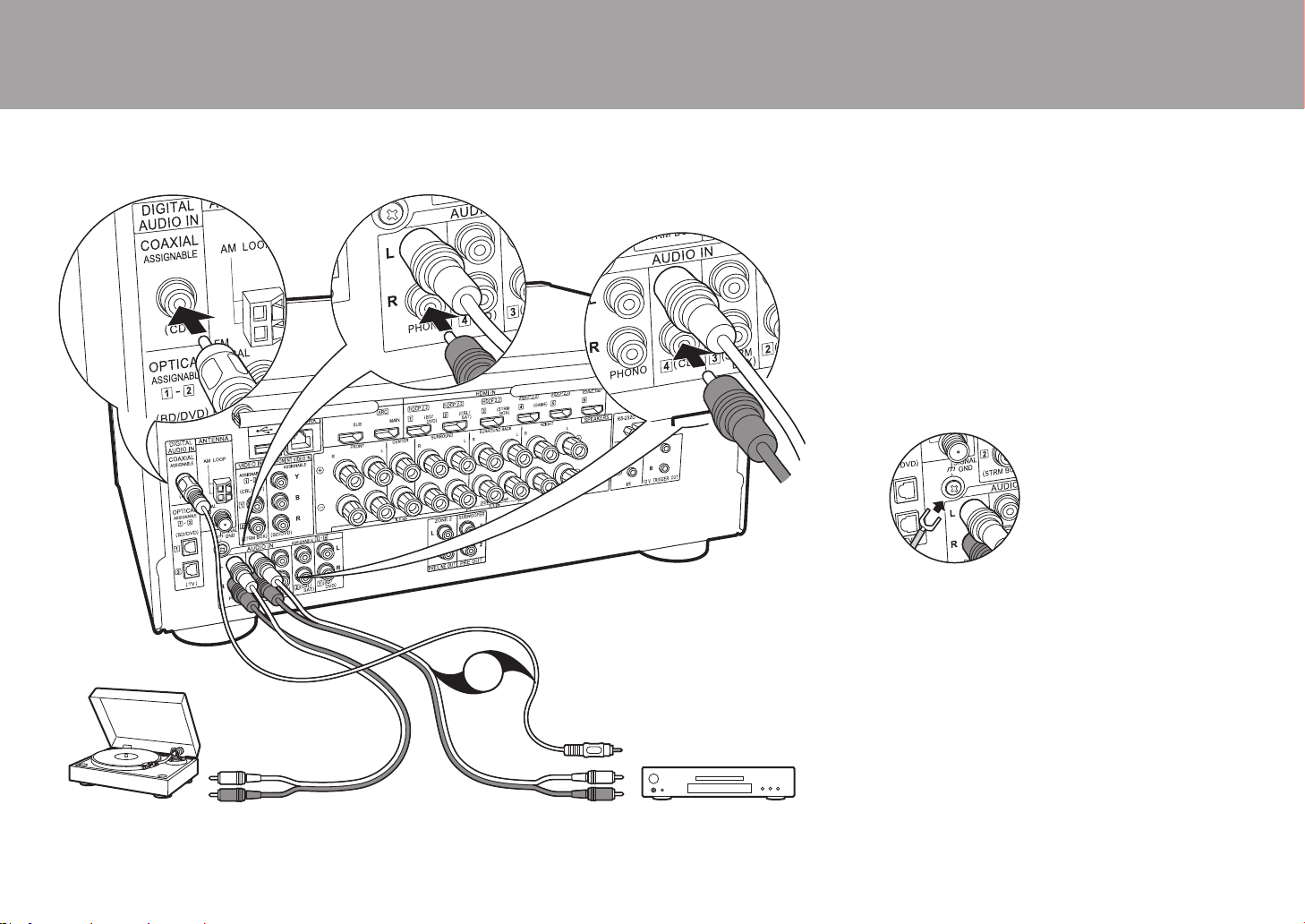
20
4. Raccorder l'appareil Audio
Exemple de raccordement avec un appareil audio.
Raccordez un lecteur CD à l'aide d'un câble coaxial
numérique ou d'un câble audio analogique. Vous pouvez
également raccorder une platine disque possédant une
cartouche de type MM à la prise PHONO.
0 Si la platine disque possède un égaliseur audio intégré,
branchez-la à une autre prise AUDIO IN. De plus, si la
platine disque utilise une cartouche de type MC, installez
un égaliseur audio compatible avec les cartouches de
type MC entre l'appareil et la platine disque, puis
raccordez n'importe quelle prise AUDIO IN autre que la
prise PHONO.
Si la platine disque a un fil de mise à la terre,
branchez-le à la borne SIGNAL GND de cet appareil.
> Avant de démarrer > Nom des pièces > Installation > Configuration initiale > Lecture
CD
OR
a
b
Platine disque
a Câble coaxial numérique, b Câble audio analogique
SN29403015A_VSX-LX302_BAS_Fr_1711xx.book 20 ページ 2017年10月27日 金曜日 午後2時1分

21
5. Raccordement multizone
Vous pouvez écouter le son dans une pièce différente, par exemple, en faisant
jouer un lecteur de Blu-ray Disc dans la pièce principale (là où cet appareil est
situé) et en écoutant la radio Internet dans une autre pièce (ZONE 2).
0
Les signaux audio DSD et Dolby TrueHD ne sont pas reproduits vers la
ZONE 2 si sélectionnés avec le sélecteur d'entrée "NET".
Raccordements avec un appareil AV
Pour reproduire le son d'un appareil AV raccordé à l'extérieur vers la
ZONE 2, vous devez effectuer le raccordement à l'aide d'un câble coaxial
numérique, d'un câble optonumérique, ou d'un câble audio analogique.
ZONE 2 PRE/LINE OUT
Il est possible de lire une source à 2 voies dans une autre pièce
pendant qu'une source 7.1 est lue dans la pièce principale. Branchez
les prises ZONE 2 PRE/LINE OUT de l'appareil et les prises LINE IN
de l'amplificateur principal ou l'amplificateur de puissance situé dans
une pièce différente à l'aide d'un câble audio analogique.
ZONE SPEAKER
Il est possible de raccorder les enceintes situées dans une
autre pièce et de lire des sources à 2 voies.
0
Vous ne pouvez pas utiliser ZONE SPEAKER si vous avez
raccordé les enceintes avant en utilisant la bi-amplification ou
si vous avez raccordé un système d'Enceintes B.
0
Aucun son n'est lu par les enceintes en hauteur lorsqu'il est reproduit par ZONE SPEAKER.
> Avant de démarrer > Nom des pièces > Installation > Configuration initiale > Lecture
ZONE2 PRE/LINE OUT
ZONE SPEAKER
ZONE2
LINE
IN
BD/DVD
OR
MAIN ROOM
c
a
b
a Câble optonumérique, b Câble audio analogique, c Câble d'enceinte
Configuration
0
Des réglages sont nécessaires dans la Initial Setup, "4. Multi
Zone Setup" (P24) pour bénéficier de cette fonctionnalité.
0
Le son provenant des appareils AV raccordés à l'extérieur
peut seulement être lu dans la ZONE 2 lorsque le son est
analogique ou qu'il est 2ch PCM. Si vous avez raccordé cet
appareil avec un câble coaxial numérique ou un câble
optonumérique, il peut être nécessaire de changer la sortie
audio de l'appareil AV pour la sortie PCM.
Fr
SN29403015A_VSX-LX302_BAS_Fr_1711xx.book 21 ページ 2017年10月27日 金曜日 午後2時1分
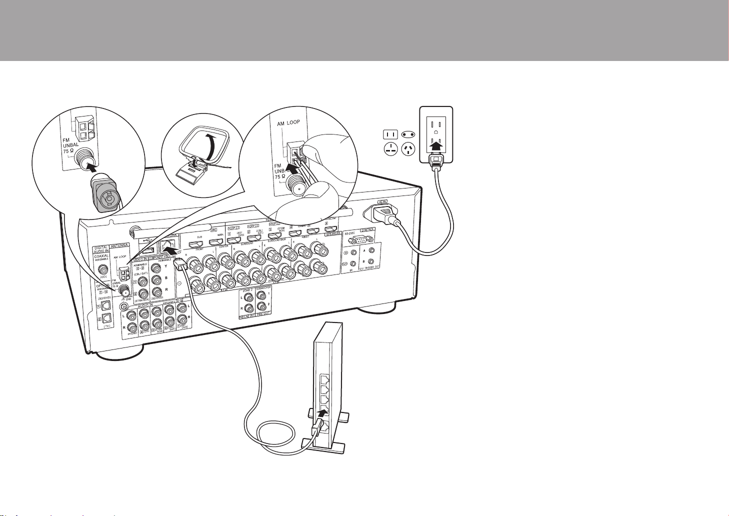
22
6. Raccordement des autres câbles
Raccordement de l'antenne
Déplacez l’antenne tout en écoutant la radio pour trouver la
meilleure position de réception. Utilisez une punaise ou
quelque chose de similaire pour accrocher le fil de
l'antenne FM intérieure au mur.
Raccordement au réseau
Connectez cet appareil au réseau à l'aide du LAN filaire ou
du Wi-Fi (LAN sans fil). Vous pouvez profiter des
fonctionnalités réseau comme la radio Internet en
connectant l'appareil au réseau. Si vous connectez par LAN
filaire, raccordez un câble Ethernet au port NETWORK
comme montré sur l'illustration. Pour vous connecter par
Wi-Fi, après avoir sélectionné "Wireless" dans "3. Network
Connection" (P24) de la Initial Setup, sélectionnez la
méthode de réglage désirée et suivez les instructions à
l'écran pour configurer la connexion.
Branchement du cordon d'alimentation
Cet appareil dispose de cordons d’alimentation amovibles.
Branchez le cordon d'alimentation à la prise électrique
après avoir effectué tous les autres raccordements.
Branchez le cordon d'alimentation à la prise AC IN de
l'appareil et à la prise électrique. Toujours débrancher de la
prise en premier lorsque vous retirez le cordon
d'alimentation.
> Avant de démarrer > Nom des pièces > Installation > Configuration initiale > Lecture
a
c
d
b
a Antenne FM intérieure, b Antenne cadre AM, c Câble Ethernet, d Cordon d'alimentation
SN29403015A_VSX-LX302_BAS_Fr_1711xx.book 22 ページ 2017年10月27日 金曜日 午後2時1分
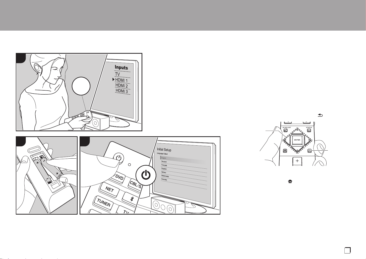
23
Initial Setup avec l'assistant de démarrage automatique
La Initial Setup démarre automatiquement
Lorsque vous mettez l'appareil en marche pour la première fois
après son achat, la Initial Setup s'affiche automatiquement sur
le téléviseur pour vous permettre d'effectuer les réglages
nécessaires au démarrage en utilisant des commandes
simples en suivant le guide à l'écran.
1. Réglez l'entrée du téléviseur sur celle assignée à l'appareil.
2. Mettez des piles dans la télécommande de cet appareil.
3. Appuyez sur la touche Í de la télécommande pour
mettre l'appareil en marche.
4. Sélectionnez l'élément grâce aux curseurs de la télécommande
et appuyez sur ENTER (a) pour valider votre sélection. Pour
revenir sur l'écran précédent, appuyez sur (b).
0
Si vous interrompez la procédure en cours ou si vous
désirez modifier un réglage effectué lors de la Initial Setup,
appuyez sur la touche de la télécommande, et à partir
de Home sélectionnez "System Setup" - "Miscellaneous" –
"Initial Setup", puis appuyez sur ENTER.
∫ 1. Full Auto MCACC
Positionnez le microphone de configuration d'enceinte fourni sur
la position d'écoute, mesurez les tonalités de test émises par les
enceintes, l'appareil règle alors automatiquement le niveau de
volume optimal pour chaque enceinte, les fréquences de
croisement, et la distance depuis la position d'écoute. Ceci règle
également automatiquement les égaliseurs des enceintes et
> Avant de démarrer > Nom des pièces > Installation > Configuration initiale > Lecture
1
2 3
TV
INPUT
a
b
Fr
SN29403015A_VSX-LX302_BAS_Fr_1711xx.book 23 ページ 2017年10月27日 金曜日 午後2時1分
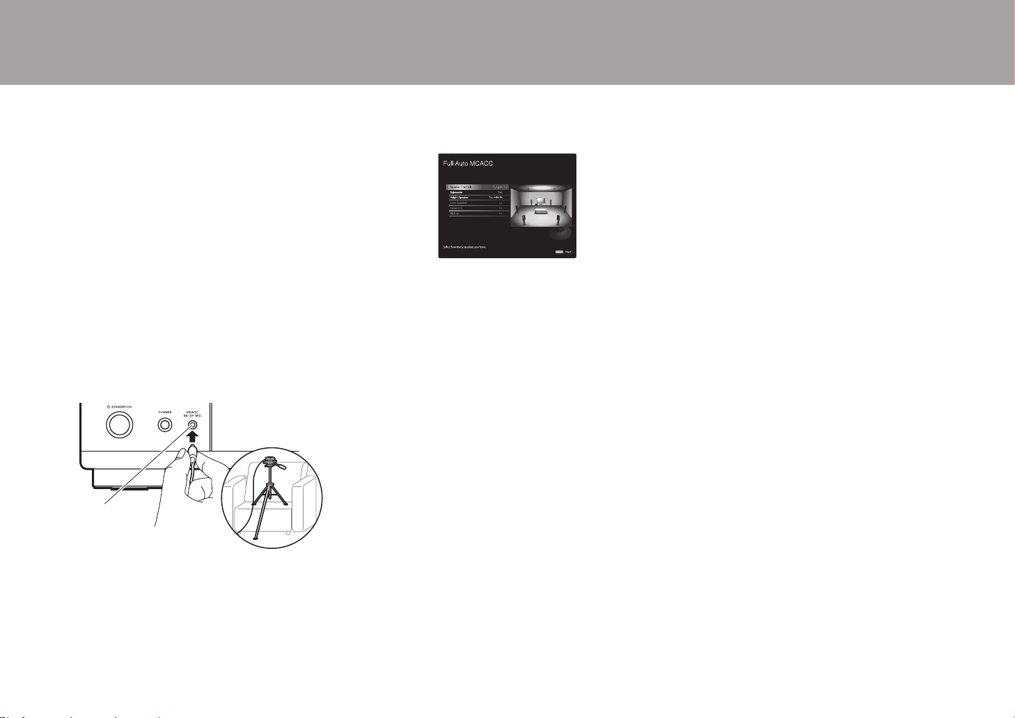
24
permet la correction de la déformation causée par l'environnement
acoustique de la pièce.
0
Le calibrage prend entre 3 et 12 minutes. Les enceintes
émettent la tonalité de test à haut volume durant les mesures,
soyez donc prudent avec votre entourage. Gardez la pièce
aussi silencieuse que possible lors des mesures.
0 Si vous avez raccordé un caisson de basse, vérifiez la
puissance et le volume de celui-ci. Réglez le volume du
caisson de basse à plus de la moitié.
0 Si cet appareil n'est soudainement plus alimenté, les fils
se trouvant à l'intérieur des câbles peuvent avoir touché
le panneau arrière ou d'autres fils et déclenché le circuit
de protection. Entortillez une nouvelle fois correctement
les fils et vérifiez qu'ils ne dépassent pas des bornes
d'enceinte lors du branchement.
1. Placez le micro de configuration d'enceinte fourni en
position d'écoute et raccordez-le à la prise MCACC
SETUP MIC de l'appareil principal.
Pour mettre un microphone de configuration d'enceinte sur un
trépied, consultez l'illustration en le mettant en place.
2. Choisissez la configuration des enceintes raccordées.
L'image à l'écran change lorsque vous choisissez le nombre de canaux
dans "Speaker Channels", donc référez-vous y pour effectuer les réglages.
3. Des tonalités de test sont émises par les enceintes et, en
premier lieu, l'appareil détecte les enceintes connectées
ainsi que les bruits de l'environnement.
4. Une fois que les résultats des mesures ci-dessus
s'affichent, sélectionnez "Next", appuyez sur ENTER de
la télécommande, et les tonalités de test se font de
nouveau entendre, et l'appareil effectue
automatiquement les réglages comme le niveau de
volume optimal et la fréquence de croisement.
5. Lorsque les mesures sont effectuées, les résultats des mesures
s'affichent. Appuyez sur les touches du curseur
/
de la
télécommande pour vérifier les réglages. Appuyez sur ENTER
lorsque "Save" est sélectionné pour sauvegarder les réglages.
6. Débranchez le microphone de configuration d'enceinte.
∫ 2. Source Connection
Vérifiez que chaque source d'entrée est correctement raccordée. Suivez le
guide, sélectionnez l'entrée que vous désirez vérifier, démarrez la lecture
sur le lecteur sélectionné, et vérifiez que les images apparaissent sur le
téléviseur et que le son est lu.
∫ 3. Network Connection
Configurez la connexion Wi-Fi avec un point d'accès tel qu'un routeur LAN
sans fil. Il existe les deux méthodes de connexion au Wi-Fi suivantes :
"Scan Networks" :
Recherchez un point d'accès depuis cet
appareil. Récupérez le SSID du point d'accès au préalable.
"Use iOS Device (iOS7 or later)" : Partagez les
paramètres Wi-Fi du dispositif iOS avec cet appareil.
Si vous sélectionnez "Scan Networks", il y a deux choix de
méthode de connexion supplémentaires. Vérifiez ce qui suit :
"Enter Password" : Saisissez le mot de passe (ou clé) du
point d'accès à connecter.
"Push Button" :
Si le point d'accès est muni d'une touche de connexion
automatique, vous pouvez vous connecter sans saisir de mot de passe.
0 Si le SSID du point d'accès ne s'affiche pas, alors dans
la liste des SSID, sélectionnez "Other..." avec les
touches du curseur de la télécommande et appuyez
sur ENTER, puis suivez les instructions à l'écran.
Saisie clavier
Pour permuter entre les majuscules et les minuscules,
sélectionnez "A/a" sur l'écran et appuyez sur ENTER. Pour choisir
de masquer le mot de passe par des "
½
" ou de l'afficher
textuellement, appuyez sur la touche +Fav de la télécommande.
Appuyez sur CLEAR pour supprimer tous les caractères saisis.
0
Un écran de confirmation vous demandant d'accepter la politique
de confidentialité s'affiche pendant la configuration du réseau.
Sélectionnez "Accept" et appuyez sur ENTER pour accepter.
∫ 4. Multi Zone Setup
Lorsque vous désirez bénéficier du son dans une autre pièce que
la pièce principale, réglez la méthode de sortie audio pour la pièce
séparée (ZONE 2). Si vous avez raccordé des enceintes dans une
pièce différente à l'aide d'un câble d'enceinte, sélectionnez "Using
AV Receiver". Si vous avez raccordé un amplificateur principal
dans une pièce différente à l'aide d'un câble audio analogique,
sélectionnez "with External Premain Amplifier". Si vous avez
raccordé un amplificateur de puissance, sélectionnez "with
External Power Amplifier".
∫ 5. Audio Return Channel
Si vous avez raccordé un téléviseur qui prend en charge la fonctionnalité
ARC, sélectionné "Yes". Le paramètre ARC de cet appareil s'active et
vous pouvez écouter le son du téléviseur via cet appareil.
> Avant de démarrer > Nom des pièces > Installation > Configuration initiale > Lecture
MCACC
SETUP MIC
SN29403015A_VSX-LX302_BAS_Fr_1711xx.book 24 ページ 2017年10月27日 金曜日 午後2時1分

25
Lecture
> Avant de démarrer > Nom des pièces > Installation > Configuration initiale > Lecture
Lecture d'un appareil AV
Commandes de base
Vous pouvez écouter le son provenant des appareils AV
tels que des lecteurs de Blu-ray Disc avec cet appareil.
0
Si un téléviseur est raccordé à la prise HDMI
OUT SUB, appuyez sur la touche (P6) de
la télécommande et utilisez "Other" - "HDMI
Out" pour basculer entre MAIN et SUB.
Effectuez la procédure suivante lorsque
l'appareil est en marche.
1. Réglez l'entrée du téléviseur sur celle
assignée à l'appareil.
2. Appuyez sur le sélecteur d'entrée (a) de la
télécommande portant le même nom que la
prise à laquelle vous avez raccordé le lecteur
pour changer l'entrée.
Par exemple, appuyez sur la touche BD/DVD
pour lire le lecteur raccordé à la prise BD/
DVD. Appuyez sur TV pour écouter le son du
téléviseur. Pour lire un périphérique raccordé
aux prises STRM BOX, PHONO
, HDMI5,
HDMI6
ou
AUX INPUT AUDIO/HDMI
du
panneau frontal, appuyez plusieurs fois sur
21
(b) pour sélectionner l'entrée.
0
Lorsque la fonction de liaison CEC
marche, l'entrée change automatiquement
si vous avez raccordé un téléviseur et un
lecteur conformes CEC à cet appareil à
l'aide d'un raccordement HDMI.
3. Démarrez la lecture sur l'appareil AV.
1 2
TV
INPUT
b
a
Lecture BLUETOOTH
®
Vous pouvez lire à distance la musique d'un
smartphone ou d'un autre périphérique compatible
BLUETOOTH. Effectuez la procédure suivante
lorsque l'appareil est en marche.
Jumelage
1. Lorsque vous appuyez sur la touche ,
"Now Pairing..." apparait sur l'afficheur
de cet appareil et le mode appairage
s'active.
2. Activez (mettez en marche) la fonction
BLUETOOTH du périphérique
compatible BLUETOOTH, puis
sélectionnez cet appareil parmi les
périphériques affichés. Si un mot de
passe est requis, entrez "0000".
0 Cet appareil s'affiche sous le nom
"Pioneer VSX-LX302 XXXXXX".
0 Pour connecter un autre périphérique
compatible BLUETOOTH, appuyez
sur jusqu'à ce que "Now Pairing..."
s'affiche, puis effectuez l'étape 2. Cet
appareil peut mémoriser les données
de 8 périphériques appairés.
0
La zone de couverture est d'environ 48´/
15 m. Notez que la connexion n'est pas
toujours garantie avec tous les
périphériques compatibles BLUETOOTH.
Écouter
1. Effectuez la procédure de connexion sur
le périphérique compatible
BLUETOOTH.
L'entrée de cet appareil passe
automatiquement sur "BLUETOOTH".
2. Lisez la musique. Augmentez le volume
du périphérique compatible
BLUETOOTH jusqu'à un niveau correct.
0 À cause des caractéristiques de la
technologie sans fil BLUETOOTH, le son
produit par cet appareil peut être
légèrement en retard par rapport au son
lu par le périphérique compatible
BLUETOOTH.
PioneerVSX-LX302XXX
1 2 3
Fr
SN29403015A_VSX-LX302_BAS_Fr_1711xx.book 25 ページ 2017年10月27日 金曜日 午後2時1分
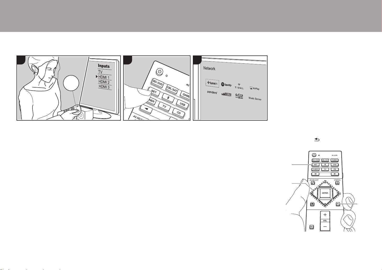
26
Fonctions réseau
Commandes de base
En connectant cet appareil au réseau vous
pouvez bénéficier de la radio Internet
comme TuneIn, de la diffusion en flux
depuis Spotify Connect et de la lecture
sans fil en utilisant les fonctionnalités
AirPlay
®
. De plus, vous pouvez utiliser la
fonctionnalité Music Server pour diffuser en
flux les fichiers musicaux présents sur les
ordinateurs ou dispositifs NAS qui prennent
en charge la fonction de réseau
domestique. Les commandes de base des
Fonctionnalités Réseau sont présentées
dans le Mode d'Emploi Base. Pour des
commandes plus avancées, lisez le Mode
d'emploi avancé. Il pourrait également y
avoir des fonctionnalités réseau
supplémentaires fournies par les mises à
jour du micrologiciel de cet appareil. Lisez
le Mode d'emploi avancé pour avoir des
informations sur les nouvelles
fonctionnalités.
0 Le réseau doit être connecté à Internet
pour avoir accès aux services de radio
Internet.
0 Selon le service de radio Internet, il se
peut que l’utilisateur doive s’inscrire
d’abord sur l’ordinateur.
0 Pour utiliser Spotify Connect, installez
l'application Spotify sur votre
smartphone ou votre tablette et créez un
compte Spotify Premium.
– Consultez ce qui suit pour configurer
Spotify :
www.spotify.com/connect/
0 Les serveurs réseau compatibles avec la
fonction Music Server sont des
ordinateurs ayant la fonctionnalité
serveur de Windows Media
®
Player 11
ou 12 installée, ou les NAS compatibles
avec la fonctionnalité réseau
domestique. Notez qu'avec ces
ordinateurs, seuls les fichiers musicaux
mémorisés dans la bibliothèque de
Windows Media
®
Player peuvent être
lus.
0 Vous devez effectuer au préalable
certains réglages sur votre ordinateur
pour utiliser Windows Media
®
Player 11
ou 12 avec la fonction Music Server.
Effectuez la procédure suivante lorsque
l'appareil est en marche.
1. Réglez l'entrée du téléviseur sur celle
assignée à l'appareil.
2. Appuyez sur la touche NET (a) de la
télécommande pour afficher une liste
des fonctions réseau sur le téléviseur.
3. Sélectionnez la fonction réseau grâce
aux curseurs de la télécommande et
appuyez sur ENTER (b) pour valider
votre sélection.
Avec les services de radio Internet,
suivez les instructions à l'écran, en
utilisant les touches du curseur pour
sélectionner les stations de radio et les
programmes, puis appuyez sur ENTER
pour écouter. Avec Spotify ou AirPlay,
sélectionnez cet appareil à l'aide de
votre smartphone pour lancer la lecture.
Avec Music Server, sélectionnez le
serveur avec les touches du curseur
puis sélectionnez le fichier musical
désiré et appuyez sur ENTER pour
lancer la lecture.
0 Pour revenir sur l’écran précédent,
appuyez sur (c).
> Avant de démarrer > Nom des pièces > Installation > Configuration initiale > Lecture
321
TV
INPUT
b
a
c
SN29403015A_VSX-LX302_BAS_Fr_1711xx.book 26 ページ 2017年10月27日 金曜日 午後2時1分

27
Périphérique de stockage USB
Commandes de base
Vous pouvez lire des fichiers musicaux
stockés sur un périphérique de stockage
USB.
Effectuez la procédure suivante lorsque
l'appareil est en marche.
1. Réglez l'entrée du téléviseur sur celle
assignée à l'appareil.
2. Branchez votre périphérique de
stockage USB contenant les fichiers de
musique au port USB situé à l'avant ou à
l’arrière de cet appareil.
3. Appuyez sur la touche USB (b) de la
télécommande et sélectionnez "USB
Front" ou "USB Rear".
0 Si le témoin "USB" clignote sur
l'afficheur, vérifiez si le périphérique
de stockage USB est branché
correctement.
0 Ne débranchez pas le périphérique de
stockage USB pendant que
"Connecting···" est affiché à l'écran.
Cela risque d'entraîner la corruption
des données ou un mauvais
fonctionnement.
4. Appuyez sur la touche ENTER de la
télécommande sur l'écran suivant. La
liste des dossiers et des fichiers de
musique sur le périphérique de stockage
USB s'affiche. Sélectionnez le dossier à
l'aide des touches du curseur et
appuyez sur ENTER pour confirmer
votre sélection (a).
5. Avec les touches du curseur de la
télécommande, sélectionnez le fichier de
musique, puis appuyez sur ENTER pour
lancer la lecture.
0 Pour revenir sur l’écran précédent,
appuyez sur (c).
0 Le port USB de cet appareil est
conforme à la norme USB 2.0. La
vitesse de transfert peut être insuffisante
pour certains des contenus que vous
lisez, ce qui peut causer des coupures
du son.
0 Cette commande n'est pas garantie pour
tous les périphériques de stockage USB.
0 Cet appareil peut utiliser les
périphériques de stockage USB
conformes à la norme USB MSC.
L'appareil est également compatible
avec les périphériques de stockage USB
utilisant les formats de système de
fichier FAT16 ou FAT32.
> Avant de démarrer > Nom des pièces > Installation > Configuration initiale > Lecture
4321
TV
INPUT
a
b
c
Fr
SN29403015A_VSX-LX302_BAS_Fr_1711xx.book 27 ページ 2017年10月27日 金曜日 午後2時1分

28
Écoute de la radio AM/FM
Vous pouvez réceptionner des stations de
radio AM et FM sur cet appareil grâce au
tuner intégré. Effectuez la procédure
suivante lorsque l'appareil est en marche.
∫ Réglage d'une station de
radio
Syntonisation automatique
1. Appuyez plusieurs fois sur la touche
TUNER (a) de la télécommande pour
sélectionner "AM" ou "FM" sur l'afficheur.
2. Appuyez sur la touche MODE (e) de la
télécommande pour que "TunMode:
Auto" apparaisse sur l'afficheur.
3. Lorsque vous appuyez sur les touches
/ du curseur (b) de la
télécommande, la syntonisation
automatique démarre et la recherche
s'arrête lorsqu'une station est trouvée.
Lorsqu'une station de radio est
syntonisée, le témoin "TUNED" s'allume
sur l'afficheur. Lorsqu'une station de
radio FM est syntonisée, le témoin
"STEREO" s'allume.
Lorsque la réception des émissions FM
est faible :
Effectuez la procédure "Syntonisation
manuelle" dans le chapitre suivant. Notez
que si vous effectuez la syntonisation
manuelle, la réception des émissions FM
sera monophonique plutôt que stéréo,
quelle que soit la sensibilité de la réception.
Syntonisation manuelle
Notez que si vous effectuez la
syntonisation manuelle, la réception des
émissions FM sera monophonique plutôt
que stéréo, quelle que soit la sensibilité de
la réception.
1. Appuyez plusieurs fois sur la touche
TUNER (a) de la télécommande pour
sélectionner "AM" ou "FM" sur l'afficheur.
2. Appuyez sur la touche MODE (e) de la
télécommande pour que "TunMode:
Manual" apparaisse sur l'afficheur.
3. Tout en appuyant sur les touches du
curseur / (b) de la télécommande,
sélectionnez la station de radio désirée.
0 La fréquence change de 1 pas
chaque fois que vous appuyez sur les
touches / du curseur. La
fréquence change en continu si le
bouton est maintenu enfoncé, et
s'arrête lorsque le bouton est relâché.
Réglage du pas de fréquence :
Appuyez sur la touche de la
télécommande, et à partir de Home
sélectionnez "System Setup" –
"Miscellaneous" – "Tuner" – "AM/FM
Frequency Step" puis sélectionnez le pas
de fréquence de votre région. Notez que
lorsque ce paramètre est modifié, toutes
les radios préréglées sont supprimées.
> Avant de démarrer > Nom des pièces > Installation > Configuration initiale > Lecture
1 2 3
a
b
c
d
e
SN29403015A_VSX-LX302_BAS_Fr_1711xx.book 28 ページ 2017年10月27日 金曜日 午後2時1分

29
> Avant de démarrer > Nom des pièces > Installation > Configuration initiale > Lecture
∫ Présélection d'une station de
radio
Vous pouvez prérégler jusqu'à 40 stations.
Procédure d'enregistrement
Après être syntonisé sur la station radio
AM/FM que vous voulez mémoriser,
effectuez la procédure suivante.
1. Appuyez sur la touche +Fav (d) de la
télécommande pour que le numéro de
préréglage clignote sur l'afficheur.
2. Pendant que le numéro de préréglage
clignote (environ 8 secondes), appuyez
plusieurs fois sur les touches / du
curseur (b) de la télécommande pour
sélectionner un numéro entre 1 et 40.
3. Appuyez de nouveau sur la touche +Fav
de la télécommande pour mémoriser la
station. Lorsqu'il est enregistré, le
numéro de préréglage s'arrête de
clignoter. Répétez cette procédure pour
toutes vos stations AM/FM préférées.
Sélectionner une station de radio
préréglée
1. Appuyez sur la touche TUNER (a) de la
télécommande.
2. Appuyez sur les touches / du
curseur (b) de la télécommande pour
sélectionner un numéro de préréglage.
Supprimer une station de radio
préréglée
1. Appuyez sur la touche TUNER (a) de la
télécommande.
2. Appuyez sur les touches / du
curseur (b) de la télécommande pour
sélectionner le numéro prédéfini à
supprimer.
3. Après avoir appuyé sur la touche +Fav
(d) de la télécommande, appuyez sur la
touche CLEAR (c) pendant que le
numéro de préréglage clignote pour le
supprimer. Lors de la suppression, le
nombre sur l'écran s'éteint.
1 2 3
Fr
SN29403015A_VSX-LX302_BAS_Fr_1711xx.book 29 ページ 2017年10月27日 金曜日 午後2時1分
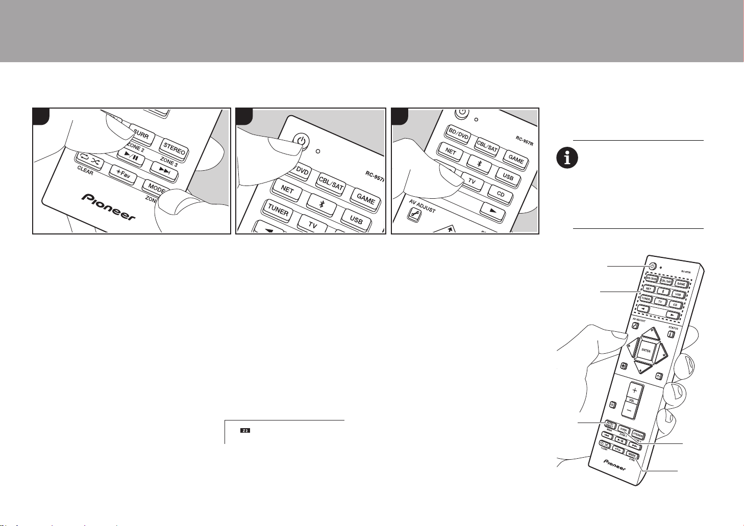
30
Multizone
> Avant de démarrer > Nom des pièces > Installation > Configuration initiale > Lecture
Commandes de base
Vous pouvez écouter le son dans une
pièce différente, par exemple, en faisant
jouer un lecteur de Blu-ray Disc dans la
pièce principale (là où cet appareil est
situé) et en écoutant la radio Internet dans
une autre pièce (ZONE 2).
0 Les signaux audio DSD et Dolby
TrueHD ne sont pas reproduits vers la
ZONE 2 si sélectionnés avec le
sélecteur d'entrée "NET" ou "USB".
0 Vous ne pouvez pas sélectionner des
entrées différentes pour la pièce
principale et l'autre pièce avec le
sélecteur d'entrée "NET",
"BLUETOOTH" ou "USB". Si vous avez
"NET" sélectionné dans la pièce
principale et vous sélectionnez
"BLUETOOTH" dans l'autre pièce, la
pièce principale passe à "BLUETOOTH".
Vous ne pouvez pas sélectionner de
stations différentes pour la pièce
principale et l'autre pièce avec la radio
AM/FM.
0 Si la ZONE 2 est activée, la
consommation d'énergie durant la veille
augmente par rapport à la normale.
Effectuez la procédure suivante lorsque
l'appareil est en marche.
1. Tout en appuyant sur la touche MODE
(e) de la télécommande, appuyez sur
ZONE 2 (d) pendant 3 secondes ou plus
jusqu'à ce que le témoin à distance
clignote deux fois.
0 La télécommande passe sur le mode
de contrôle de la ZONE 2.
2. Pointez la télécommande vers l'appareil
principal et appuyez sur Í (a).
"Z2" s'allume sur l'afficheur de l’appareil
principal.
3. Appuyez sur le sélecteur d'entrée (b) de
l'entrée à lire dans l'autre pièce.
0 Sur l'appareil principal, après avoir
appuyé sur ZONE 2-CONTROL, dans
les 8 secondes qui suivent, tournez la
molette du sélecteur pour
sélectionner l'entrée devant être
utilisée dans l’autre pièce.
4. Pour régler le volume de l'amplificateur
de puissance situé dans une pièce
différente ou l'enceinte ZONE, utilisez la
touche VOL+/– de la télécommande.
0 Pour contrôler avec l'appareil
principal, appuyez sur ZONE 2-
CONTROL et réglez avec la
commande MASTER VOLUME dans
les 8 secondes.
Pour désactiver la fonction :
Appuyez sur Í durant le mode de contrôle
de la ZONE 2 sur la télécommande.
Alternativement, appuyez sur la touche
ZONE 2-ON/OFF de l'appareil principal.
Lecture uniquement dans la ZONE 2 :
Si vous mettez l’appareil en mode veille
pendant une lecture multi-zone, le témoin
Z2 est grisé et le mode de lecture bascule
sur lecture dans une pièce séparée
1 2 3
uniquement. Activer la ZONE 2 tandis que
cet appareil est en veille règlera le mode
lecture sur le même paramètre.
Pour passer de nouveau la
télécommande sur le mode de
contrôle de la pièce principale :
Tout en appuyant sur MODE de la
télécommande, appuyez sur
MAIN (c) pendant 3 secondes ou
plus jusqu'à ce que le témoin à
distance clignote une fois.
c
d
e
a
b
SN29403015A_VSX-LX302_BAS_Fr_1711xx.book 30 ページ 2017年10月27日 金曜日 午後2時1分
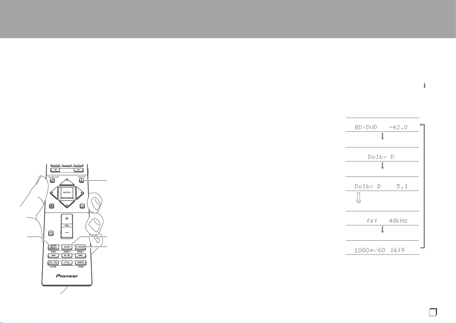
31
Mode d'écoute
> Avant de démarrer > Nom des pièces > Installation > Configuration initiale > Lecture
Cet appareil est équipé de plusieurs modes
d'écoute. Les commandes de base sont
présentées dans le Mode d'Emploi Base.
Pour plus de détails, lisez le Mode d'emploi
avancé.
0 Le mode d'écoute que vous avez
sélectionné en dernier pour la source est
gardé en mémoire pour chacune des
touches AUTO/DIRECT, SURR et
STEREO. Si le contenu que vous lisez
n'est pas pris en charge par le mode
d'écoute que vous avez sélectionné en
dernier, le mode d'écoute normal pour le
contenu en question est
automatiquement sélectionné.
Touche AUTO/DIRECT (a)
Appuyez plusieurs fois et les modes
d'écoute adaptés au signal d'entrée
commutent entre "Auto Surround", "Direct",
et "Pure Direct". Après en avoir sélectionné
un, "Auto Surround" (ou "Direct" ou "Pure
Direct") s'affiche sur l'afficheur de l'appareil
principal, puis le mode d'écoute
sélectionné automatiquement (Dolby
Digital pour les signaux d'entrée
multicanaux, Stereo pour les signaux
entrant sur 2 voies, etc.) s'affiche.
Le mode "Direct" coupe certaines fonctions
qui peuvent affecter la qualité du son,
comme les commandes de tonalité, ce qui
vous fera profiter d'une qualité sonore
encore meilleure. Le mode "Pure Direct"
coupe plusieurs fonctions qui peuvent
affecter la qualité du son, vous aurez ainsi
une reproduction plus fidèle du son
original. Dans ce cas, le réglage d'enceinte
par MCACC est désactivé.
0 En fonction du signal entrant et de la
configuration de l'enceinte, peuvent être
automatiquement sélectionnés les
modes Dolby Surround et DTS Neural:X
qui étendent les signaux d'entrée
2 canaux et 5.1 aux formats 5.1 et 7.1.
Touche SURR (c)
Vous pouvez sélectionner plusieurs modes
d'écoute selon votre goût. Il y a les modes
Dolby Digital, DTS-HD Master Audio, et
Stereo que vous pouvez choisir selon le
signal en entrée, ou les modes Dolby
Surround et DTS Neural:X qui étendent les
signaux d'entrée 2 canaux et 5.1 aux
formats 5.1 ou 7.1. Vous pouvez
également bénéficier des modes surround
a
b
c
d
originaux comme les modes Ext.Stereo et
Drama.
Touche STEREO (d)
Vous pouvez sélectionner le mode "Stereo"
pour lire uniquement depuis les enceintes
avant et le caisson de basse.
Vérification du format d'entrée et du
mode d'écoute
Appuyez plusieurs fois sur la touche (b)
de la télécommande pour commuter
l'affichage de l'appareil principal comme
suit.
Source d'entrée & volume
Mode d'écoute
Format du signal
Échantillonnage de la fréquence
Résolution du signal d'entrée
L'affichage change au bout
de quelques secondes.
Fr
SN29403015A_VSX-LX302_BAS_Fr_1711xx.book 31 ページ 2017年10月27日 金曜日 午後2時1分

32
Licence et marque commerciale
Manufactured under license from Dolby Laboratories. Dolby, Dolby Atmos,
Dolby Surround, Dolby Vision and the double-D symbol are trademarks of
Dolby Laboratories.
For DTS patents, see http://patents.dts.com. Manufactured under license from
DTS, Inc. DTS, the Symbol, DTS in combination with the Symbol, DTS:X, and
the DTS:X logo are registered trademarks or trademarks of DTS, Inc. in the
United States and/or other countries. © DTS, Inc. All Rights Reserved.
The terms HDMI and HDMI High-Definition Multimedia Interface, and the HDMI
Logo are trademarks or registered trademarks of HDMI Licensing LLC in the
United States and other countries.
The Wi-Fi CERTIFIED Logo is a certification mark of Wi-Fi Alliance
®
.
AirPlay, iPad, iPhone, iPod, iPod classic, iPod nano and iPod touch are
trademarks of Apple Inc., registered in the U.S. and other countries.
iPad Air and iPad mini are trademarks of Apple Inc.
“Made for iPod”, “Made for iPhone” and “Made for iPad” mean that an electronic
accessory has been designed to connect specifically to iPod, iPhone, or iPad,
respectively, and has been certified by the developer to meet Apple
performance standards. Apple is not responsible for the operation of this device
or its compliance with safety and regulatory standards.
Please note that the use of this accessory with iPod, iPhone or iPad may affect
wireless performance.
AirPlay works with iPhone, iPad, and iPod touch with iOS 4.3.3 or later, Mac
with OS X Mountain Lion or later, and PC with iTunes 10.2.2 or later.
PANDORA, the PANDORA logo, and the Pandora trade dress are trademarks
or registered trademarks of Pandora Media, Inc. Used with permission.
The BLUETOOTH
®
word mark and logos are registered trademarks owned by
Bluetooth SIG, Inc.
The Spotify software is subject to third party licenses found here:
https://developer.spotify.com/esdk-third-party-licenses/
This product is protected by certain intellectual property rights of Microsoft. Use
or distribution of such technology outside of this product is prohibited without a
license from Microsoft.
Windows 7, Windows Media, and the Windows logo are trademarks or
registered trademarks of Microsoft Corporation in the United States and/or
other countries.
DSD and the Direct Stream Digital logo are trademarks of Sony Corporation.
“All other trademarks are the property of their respective owners.”
“Toutes les autres marques commerciales sont la propriété de leurs détenteurs
respectifs.”
“El resto de marcas comerciales son propiedad de sus respectivos
propietarios”.
®
SN29403015A_VSX-LX302_BAS_Fr_1711xx.book 32 ページ 2017年10月27日 金曜日 午後2時1分

Antes de empezar ...........................................................2
Qué se encuentra en la caja..............................................2
Nombres de las piezas ...................................................3
Nombres de las piezas ......................................................3
Instalación .......................................................................7
Procedimiento de instalación.............................................7
Paso 1: Disposición de los altavoces ................................8
Paso 2: Conexión de los altavoces..................................15
Paso 3: Conexión de los componentes del TV y los
componentes de AV.........................................................17
Configuración inicial ....................................................23
Initial Setup con el asistente de arranque automático.....23
Reproducción ................................................................25
Reproducción de componente AV ...................................25
BLUETOOTH
®
Reproducción..........................................25
Funciones de red.............................................................26
Dispositivo de almacenamiento USB...............................27
Escuchar la radio AM/FM ................................................28
Multizona .........................................................................30
Modo de audición ............................................................31
VSX-LX302 / AV RECEIVER
Para obtener detalles sobre las Funciones de red y los modos de
audición, así como la información referente a la configuración avanzada,
consulte el "Manual avanzado" disponible en nuestro sitio web.
http://jp.pioneer-audiovisual.com/manual/vsxlx302elite/adv/es.html
Es
SN29403015A_VSX-LX302_BAS_Es_1711xx.book 1 ページ 2017年10月27日 金曜日 午後2時3分

2
Qué se encuentra en la caja
1. Unidad principal (1)
2. Mando a distancia (RC-957R) (1), Pilas (AAA/R03) (2)
3. Micrófono para la configuración de altavoces (1)
0 Usado durante la Initial Setup.
4. Antena de FM para interiores (1)
5. Antena en bucle de AM (1)
6. Cable de alimentación (1)
0 Guía de inicio rápido (1)
0 Manual Básico (Este manual)
0 Conecte los altavoces con una impedancia de entre 4 Ω
y 16 Ω.
0 El cable de alimentación no debe conectarse hasta que
no se hayan completado todas las otras conexiones.
0 No aceptamos ninguna responsabilidad por daño
causado debido a la conexión de equipos fabricados por
otras compañías.
0 Puede que se amplíen las funcionalidades mediante
actualizaciones de firmware y que los proveedores de
servicios cesen su actividad, lo que significa que algunos
servicios de red y contenidos puede que no estén
disponibles en el futuro. Además, los servicios
disponibles podrían variar dependiendo de su zona de
residencia.
0 En el futuro se publicarán más detalles sobre la
actualización de firmware en nuestra página web y
mediante otros medios.
0 Las especificaciones y las características están sujetas a
cambios sin previo aviso.
> Antes de empezar > Nombres de las piezas > Instalación > Configuración inicial > Reproducción
1
32
54
6
SN29403015A_VSX-LX302_BAS_Es_1711xx.book 2 ページ 2017年10月27日 金曜日 午後2時3分
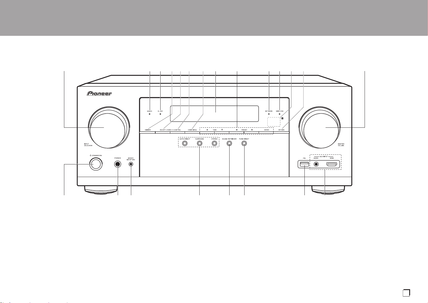
3
Nombres de las piezas
Panel frontal
1. Mando INPUT SELECTOR: Cambian la entrada a reproducir.
2. Indicador MCACC: Éste se enciende cuando ha activado la calibración hecha con
MCACC (P23).
3. Indicador FL OFF: Éste se enciende cuando ha pulsado DIMMER repetidamente para
apagar la pantalla.
4. Botón DIMMER: Puede apagar la pantalla o ajustar su brillo en tres pasos.
5. Botón ZONE 2-ON/OFF: Desactiva la función multizona (P30).
6. Botón ZONE 2-CONTROL: Controla la función multizona (P30).
7. Botón HOME MENU: Muestra el Home. (*)
8. Pantalla (P4)
9. Botones del cursor ( / / / ) y botón ENTER: Seleccione el elemento con los
cursores y pulse ENTER para confirmar. Úselos para sintonizar emisoras de radio
cuando use TUNER (P28).
10.
Indicador NETWORK: Éste se enciende cuando se selecciona "NET" con el selector de
entrada y la unidad está conectada a la red. Si la unidad está en el modo de espera, éste
se enciende cuando están activadas las funciones como HDMI CEC y la espera de red.
Sin embargo, no se enciende cuando está activada la ZONE 2.
11.
Indicador WIRELESS: Se ilumina cuando la unidad está conectada a una red inalámbrica
y cuando está conectada a un dispositivo habilitado con BLUETOOTH.
12.
Sensor del mando a distancia: Recibe señales del mando a distancia.
0 El rango de señal del mando a distancia es de unos 16´/5 m, a un ángulo de 20º en el
eje perpendicular y 30º a ambos lados.
13.
Botón RETURN: Regresa la pantalla al estado anterior.
14.
MASTER VOLUME
15.
Botón Í STANDBY/ON
> Antes de empezar > Nombres de las piezas > Instalación > Configuración inicial > Reproducción
Es
(*)Puede encontrar más información en el Manual avanzado.
SN29403015A_VSX-LX302_BAS_Es_1711xx.book 3 ページ 2017年10月27日 金曜日 午後2時3分

4
> Antes de empezar > Nombres de las piezas > Instalación > Configuración inicial > Reproducción
16.
Conector PHONES: Se conectan auriculares con una
clavija estándar (Ø1/4"/6,3 mm).
17.
Conector MCACC SETUP MIC: El micrófono para la
configuración de los altavoces suministrado está
conectado.
18.
Botón de modo de audición: Pulse "AUTO/DIRECT",
"SURROUND" o "STEREO" para cambiar el modo de
audición (P31). (*)
19.
Botón SOUND RETRIEVER: Activa/desactiva la
función Sound Retriever que proporciona una mejor
calidad del sonido del audio comprimido.
20.
Botón PURE DIRECT: Cambia al modo Pure Direct
(P31).
21.
Puerto USB: Un dispositivo de almacenamiento USB
está conectado de manera que los archivos de música
almacenados se pueden reproducir. También puede
suministrar alimentación (5 V/500 mA) a dispositivos
USB con un cable USB.
22.
Conector AUX INPUT AUDIO/HDMI: Conecte una
cámara de vídeo, etc., usando un cable mini plug
estéreo (Ø1/8"/3,5 mm) o un cable HDMI.
Pantalla
1. Puede iluminarse cuando se realizan operaciones con el selector de
entrada "NET" o "USB".
2. Se ilumina en las siguientes condiciones.
Z2: Cuando ZONE 2 está activado.
: Cuando se conecta mediante BLUETOOTH.
: Cuando se conecta mediante Wi-Fi.
NET: Cuando "NET" está seleccionado con el selector de entrada y la
unidad está conectada a la red. Parpadeará si la conexión a la red no
es correcta.
USB: Cuando "USB" está seleccionado con el selector de entrada y la
unidad está conectada por USB y el dispositivo USB está
seleccionado. Parpadea si el dispositivo USB no está conectado
correctamente.
HDMI: Cuando entran señales HDMI y la entrada HDMI está
seleccionada.
DIGITAL: Cuando entran señales digitales y la entrada digital está
seleccionada.
3. Se ilumina de acuerdo al tipo de señales digitales de entrada de audio
y al modo de audición.
4. Se ilumina en las siguientes condiciones.
TUNED: Recepción de radio AM/FM.
STEREO: Recepción de FM estéreo.
SLEEP: Cuando el temporizador de apagado está activado.
AUTO STBY: El modo de espera automático está activado.
5. El sistema de altavoces actualmente seleccionado se ilumina.
6. Se ilumina cuando se conectan unos auriculares.
7. Parpadea cuando se encuentra silenciado.
8. Muestra información varia sobre las señales de entrada.
9. Se enciende cuando ajusta el volumen.
10.
Visualización de altavoz/canal: Muestra el
canal de salida que corresponde al modo de
audición seleccionado.
(*)Puede encontrar más información en el Manual avanzado.
SN29403015A_VSX-LX302_BAS_Es_1711xx.book 4 ページ 2017年10月27日 金曜日 午後2時3分
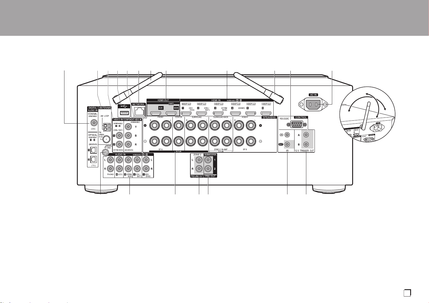
5
Panel trasero
1. Conectores DIGITAL AUDIO IN OPTICAL/COAXIAL: Introduzca señales de audio digital
desde un componente AV o un TV con un cable óptico digital o un cable coaxial digital.
2. Terminal ANTENNA AM LOOP/FM UNBAL 75Ω: Las antenas suministradas están
conectadas.
3. Conectores VIDEO IN: Introduzca señales de vídeo de un componente AV con un cable
de vídeo analógico.
4. Puerto USB: Un dispositivo de almacenamiento USB está conectado de manera que los
archivos de música almacenados se pueden reproducir. También puede suministrar
alimentación (5 V/500 mA) a dispositivos USB con un cable USB.
5. Conectores COMPONENT VIDEO IN: Introduzca señales de vídeo de un componente
AV con un cable de vídeo componente. (Compatible únicamente con una resolución 480i
o 576i.)
6. Puerto NETWORK: Conecte con la red a través de un cable Ethernet.
7. Antena inalámbrica: Se usa para la conexión Wi-Fi o al utilizar un dispositivo habilitado
con BLUETOOTH. Ajuste los ángulos de acuerdo con el estado de la conexión.
8. Conectores HDMI OUT: Transmita señales de vídeo y señales de audio con un cable
HDMI conectado a un monitor como un TV o un proyector.
9. Conectores HDMI IN: Transmita señales de vídeo y señales de audio con un cable HDMI
conectado a un componente AV.
10.
Puerto RS-232C: Para la conexión con el sistema de control del hogar. (*)
11.
AC IN: El cable de alimentación suministrado está conectado.
12.
Terminal SIGNAL GND: Está conectado el cable de puesta a tierra de la tornamesa.
13.
Conectores AUDIO IN: Introduzca la señal de audio de un componente AV con un cable
de audio analógico.
14.
Terminales SPEAKERS: Conecte los altavoces con cables de altavoz. (Compatible con
conectores de banana)
> Antes de empezar > Nombres de las piezas > Instalación > Configuración inicial > Reproducción
180°
90°
Es
(*)Puede encontrar más información en el Manual avanzado.
SN29403015A_VSX-LX302_BAS_Es_1711xx.book 5 ページ 2017年10月27日 金曜日 午後2時3分
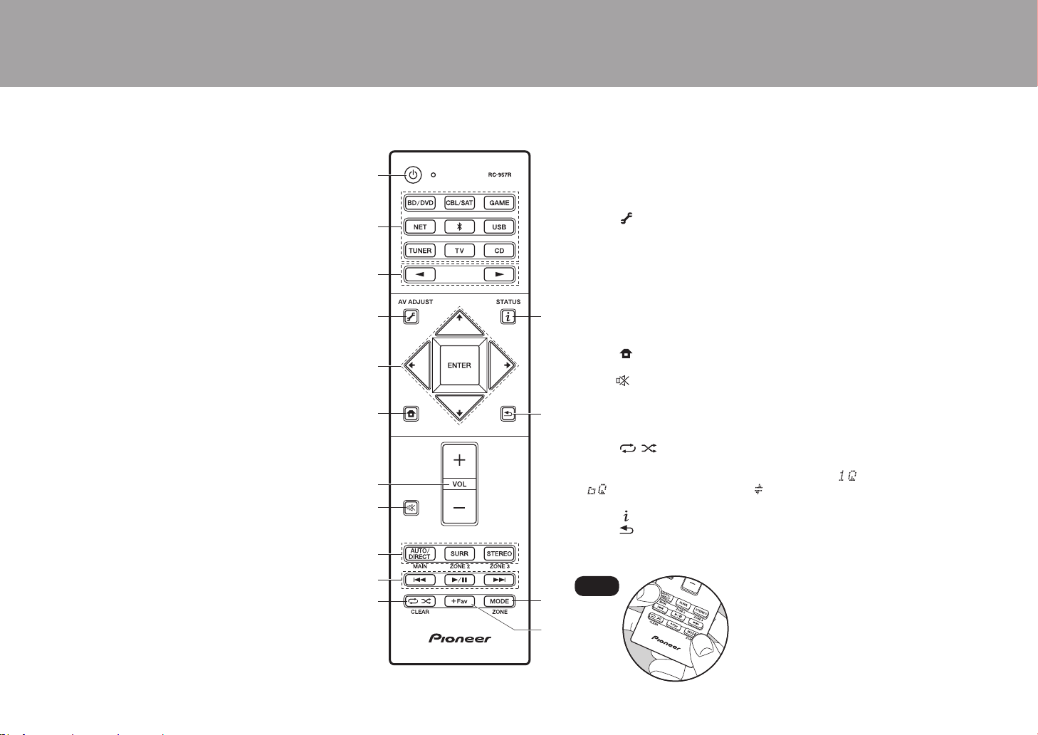
6
> Antes de empezar > Nombres de las piezas > Instalación > Configuración inicial > Reproducción
15.
Conectores ZONE 2 PRE/LINE OUT: Transmita
señales de audio con un cable de audio analógico a un
preamplificador principal en una habitación separada
(ZONE 2).
16.
Conector SUBWOOFER PRE OUT: Conecte un
subwoofer con alimentación propia con un cable de
subwoofer. Se pueden conectar hasta dos subwoofers
con alimentación propia. Se emite la misma señal
desde cada uno de los conectores SUBWOOFER PRE
OUT.
17.
Puerto IR IN/OUT: Le permite conectar un kit de
mando a distancia multihabitación. (*)
18.
Conectores 12V TRIGGER OUT A/B: Le permite
conectar un dispositivo con conector de entrada de
gatillo de 12V para habilitar el funcionamiento enlazado
entre el dispositivo y la unidad. (*)
Mando a distancia
1. Botón Í STANDBY/ON
2. Botones del selector de entrada: Cambia la entrada a reproducir.
3. Botones 21: Selecciona la entrada a reproducir.
4. Botón (AV ADJUST): Algunos ajustes como "Tone" y "Level" se pueden
realizar rápidamente durante la reproducción en la pantalla del TV. "Other"
contiene ajustes para cambiar la prioridad de emisión dada a los altavoces (P15)
y para cambiar la salida HDMI (P17). Tenga en cuenta que no se visualizará
nada en la pantalla del televisor cuando el selector de entrada se encuentre en
"CD", "TV", "PHONO", "AM" o "FM"; por lo tanto, siga la pantalla de la unidad
principal mientras lleva a cabo las operaciones. (*)
5. Botones del cursor y botón ENTER: Seleccione el elemento con los cursores y
pulse ENTER para confirmar su selección. Si la carpeta o las listas de archivos
no se muestran en una pantalla en el TV, pulse / para cambiar la pantalla.
6. Botón : Muestra el Home. (*)
7. Botones de volumen
8. Botón : Silencia el audio temporalmente. Pulse de nuevo para cancelar el silencio.
9. Botones LISTENING MODE: Le permite seleccionar el modo de audición (P31). (*)
Botones MAIN/ZONE 2: Controla la función multizona. (P30). (El botón ZONE 3
no se usa con esta unidad.)
10.
Botones de reproducción: Utilizado para operaciones de reproducción cuando se reproduce Music Server o un USB.
11.
Botón : Utilizado para operaciones de reproducción repetida/aleatoria
cuando se reproduce Music Server o un USB.
Cada vez que pulsa el botón, el modo cambia de (repetición de 1 pista), a
(repetición de la carpeta), a (aleatorio).
Botón CLEAR: Borra todos los caracteres que ha introducido al introducir texto en la pantalla del TV.
12.
Botón (STATUS): Cambia la información en la pantalla.
13.
Botón : Regresa la pantalla al estado anterior.
14.
Botón MODE: Cambia la sintonización de una emisora AM/FM entre la sintonización automática y la sintonización manual.
15.
Botón +Fav: Se utiliza para registrar emisoras de radio AM/FM.
Tips
Cuando el mando a distancia no funciona:
Puede que el mando distancia haya pasado al
modo para controlar la ZONE 2. Para cambiarlo al
modo de control de la habitación principal,
mientras mantiene pulsado MODE, pulse MAIN
durante 3 segundos o más hasta que el indicador
remoto parpadee una vez.
(*)Puede encontrar más información en el Manual avanzado.
SN29403015A_VSX-LX302_BAS_Es_1711xx.book 6 ページ 2017年10月27日 金曜日 午後2時3分

7
Procedimiento de instalación
Esta unidad se puede usar de diversas maneras, según la
disposición de los altavoces que instale y de las
conexiones hechas a dispositivos externos. Lea los
siguientes puntos para hacer el proceso de instalación más
sencillo.
Paso 1: Disposición de los altavoces
Seleccione la disposición de altavoces que se ajuste a los
suyos y las condiciones en que serán usados entre las
opciones presentadas en las páginas P8 a P13, después
instale los altavoces consultando las ilustraciones y
explicaciones en la página correspondiente. Las
disposiciones de altavoces incluyen sistemas que usan
altavoces envolventes traseros, sistemas que usan
altavoces de altura y sistemas que usan altavoces de
biamplificación. También consulte las disposiciones
disponibles en "Combinaciones de altavoces" en P14.
Paso 2: Conexión de los altavoces
Para conectar los sistemas de altavoces a esta unidad, consulte
la P15 si está usando una disposición de altavoces descrita en las
páginas P8 a P12, y consulte la P16 para usar una disposición
con altavoces de biamplificación según lo descrito en la P13. El
proceso de conexión será más sencillo si consulta las
ilustraciones, las explicaciones y prepara los cables necesarios
con antelación.
Paso 3: Conexión de los componentes del TV y
los componentes de AV
Consulte las páginas P17 a P22 para conectar sus dispositivos externos
tales como su TV, reproductor de discos Blu-ray, así como los accesorios
suministrados, por ejemplo, las antenas. En la P21 también se presenta la
opción de conexión multizona que permite reproducir audio en otras
habitaciones además de la habitación principal. El proceso de conexión
será más sencillo si consulta las ilustraciones y las explicaciones, si
confirma los tipos de conexión en los dispositivos externos y si prepara los
cables necesarios con antelación.
> Antes de empezar > Nombres de las piezas > Instalación > Configuración inicial > Reproducción
1
2 3
Es
SN29403015A_VSX-LX302_BAS_Es_1711xx.book 7 ページ 2017年10月27日 金曜日 午後2時3分
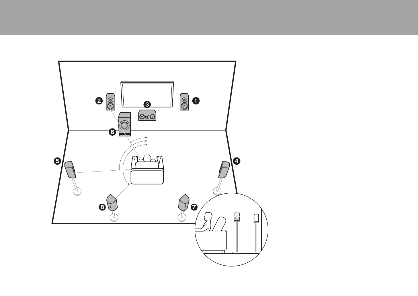
8
Paso 1: Disposición de los altavoces
Sistema de 7.1 canales
Los altavoces delanteros emiten sonidos delanteros en
estéreo y el altavoz central emite sonidos centrales como
diálogos y voces. Los altavoces de sonido envolvente
crean un campo de sonido trasero. El subwoofer con fuente
de alimentación propia reproduce sonidos bajos y crea un
campo de sonido rico.
Este sistema básico de 5.1 canales con altavoces
envolventes traseros añadidos se denomina sistema de
7.1 canales. La conexión de los altavoces traseros
envolventes mejora la sensación de envolvimiento y
conectividad de sonido creada por el campo de sonido
trasero y proporciona un campo sonoro más real. Además,
instalando los altavoces traseros envolventes, cuando el
formato de entrada es Dolby Atmos, puede seleccionar el
modo de audición Dolby Atmos, que proporciona el sonido
3D más actual
Los altavoces delanteros deberían colocarse a la altura de
la oreja, mientras que los altavoces envolventes deberían
ubicarse justo por encima de la altura de la oreja. El altavoz
central debería instalarse orientado hacia la posición de
audición. Colocar el subwoofer con alimentación propia
entre el altavoz central y el altavoz delantero produce un
sonido natural incluso cuando se reproduce música. En
una disposición óptima, los altavoces traseros envolventes
están a la altura de la oreja.
0 Si incluye altavoces traseros envolventes en la
configuración, se necesitan altavoces envolventes.
0 "Combinaciones de altavoces" (P14) describe algunos
ejemplos detallados de combinaciones de altavoces.
1,2 Altavoces delanteros
3 Altavoz central
4,5 Altavoces envolventes
6 Subwoofer con fuente de alimentación propia
7,8 Altavoces traseros envolventes
> Antes de empezar > Nombres de las piezas > Instalación > Configuración inicial > Reproducción
*
1
*
2
*
3
½1: 22e a 30e, ½2: 90e a 110e, ½3: 135e a 150e
SN29403015A_VSX-LX302_BAS_Es_1711xx.book 8 ページ 2017年10月27日 金曜日 午後2時3分
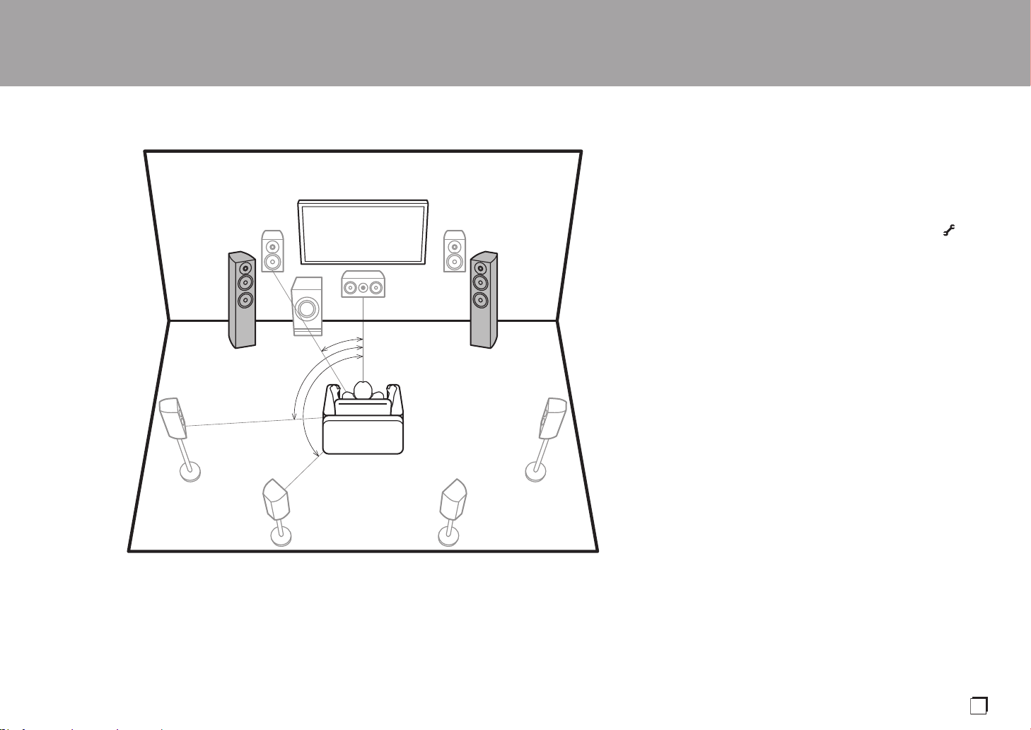
9
Speaker B System
Con un sistema de 7.1 canales (P8), puede conectar un set
más de altavoces delanteros para usarlos como sistema de
altavoces B. En este caso, el sistema de 7.1 canales se
convierte en el sistema de altavoces A y puede elegir que
el mismo audio se emita desde A, B, o A+B. Pulse en el
mando a distancia (P6) y utilice "Other" - "Speakers" para
cambiarlo. Tenga en cuenta que, cuando se reproduce
desde A+B, no se reproduce sonido desde los altavoces
envolventes traseros.
0 "Combinaciones de altavoces" (P14) describe algunos
ejemplos detallados de combinaciones de altavoces.
> Antes de empezar > Nombres de las piezas > Instalación > Configuración inicial > Reproducción
*
1
*
2
*
3
Speaker B Speaker B
½1: 22e a 30e, ½2: 90e a 110e, ½3: 135e a 150e
Es
SN29403015A_VSX-LX302_BAS_Es_1711xx.book 9 ページ 2017年10月27日 金曜日 午後2時3分
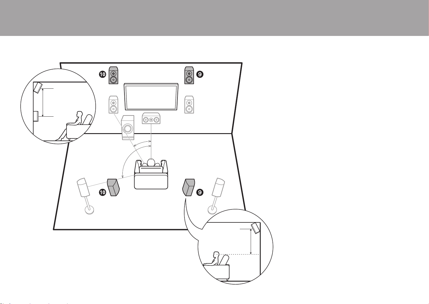
10
5.1.2 Sistema de canal 1
(altavoces altos delanteros/altavoces altos
traseros)
Este es un sistema básico de 5.1 canales formado por
altavoces delanteros, un altavoz central, altavoces
envolventes y un subwoofer con fuente de alimentación
propia, al que se le han añadido altavoces de altura
delanteros o altavoces altos traseros, que ambos son tipos
de altavoces de altura. Instalando altavoces de altura,
cuando el formato de entrada es Dolby Atmos, puede
seleccionar el modo de audición Dolby Atmos, que
proporciona el sonido 3D más actual incluyendo sonidos
por arriba. Los altavoces altos delanteros o traseros
deberían ubicarse al menos 3´/0,9 m más altos que los
altavoces delanteros. Los altavoces altos delanteros
deberían ubicarse directamente por encima de los
altavoces delanteros y la distancia entre los altavoces altos
traseros debería ser igual a la distancia entre los altavoces
delanteros. Ambos deberían instalarse orientados hacia la
posición de audición.
0 "Combinaciones de altavoces" (P14) describe algunos
ejemplos detallados de combinaciones de altavoces.
9,10 Altavoces de altura
Elija uno de los siguientes:
0 Altavoces altos delanteros
0 Altavoces altos traseros
> Antes de empezar > Nombres de las piezas > Instalación > Configuración inicial > Reproducción
*
1
*
2
3´ (0.9 m)
or more
3´ (0.9 m)
or more
½1: 22e a 30e, ½2: 120e
SN29403015A_VSX-LX302_BAS_Es_1711xx.book 10 ページ 2017年10月27日 金曜日 午後2時3分

11
5.1.2 Sistema de canal 2
(altavoces de techo)
Este es un sistema básico de 5.1 canales formado por
altavoces delanteros, un altavoz central, altavoces
envolventes y un subwoofer con fuente de alimentación
propia, al que se le han añadido altavoces delanteros
superiores, altavoces medios superiores o altavoces
traseros superiores, que son tipos de altavoces de altura.
Instalando altavoces de altura, cuando el formato de
entrada es Dolby Atmos, puede seleccionar el modo de
audición Dolby Atmos, que proporciona el sonido 3D más
actual incluyendo sonidos por arriba. Ponga los altavoces
delanteros superiores en el techo orientados hacia la
posición de asiento, los altavoces medios superiores en el
techo directamente encima de la posición de asiento, y los
altavoces traseros superiores en el techo detrás de la
posición de asiento. La distancia entre cada par debería
ser igual a la distancia entre los dos altavoces delanteros.
0 Dolby Laboratories recomienda colocar este tipo de
altavoces de altura para conseguir el mejor efecto Dolby
Atmos.
0 "Combinaciones de altavoces" (P14) describe algunos
ejemplos detallados de combinaciones de altavoces.
9,10 Altavoces de altura
Elija uno de los siguientes:
0 Altavoces delanteros superiores
0 Altavoces medios superiores
0 Altavoces traseros superiores
> Antes de empezar > Nombres de las piezas > Instalación > Configuración inicial > Reproducción
*
1
*
2
*
3
½1: 30e a 55e, ½2: 65e a 100e, ½3: 125e a 150e
Es
SN29403015A_VSX-LX302_BAS_Es_1711xx.book 11 ページ 2017年10月27日 金曜日 午後2時3分
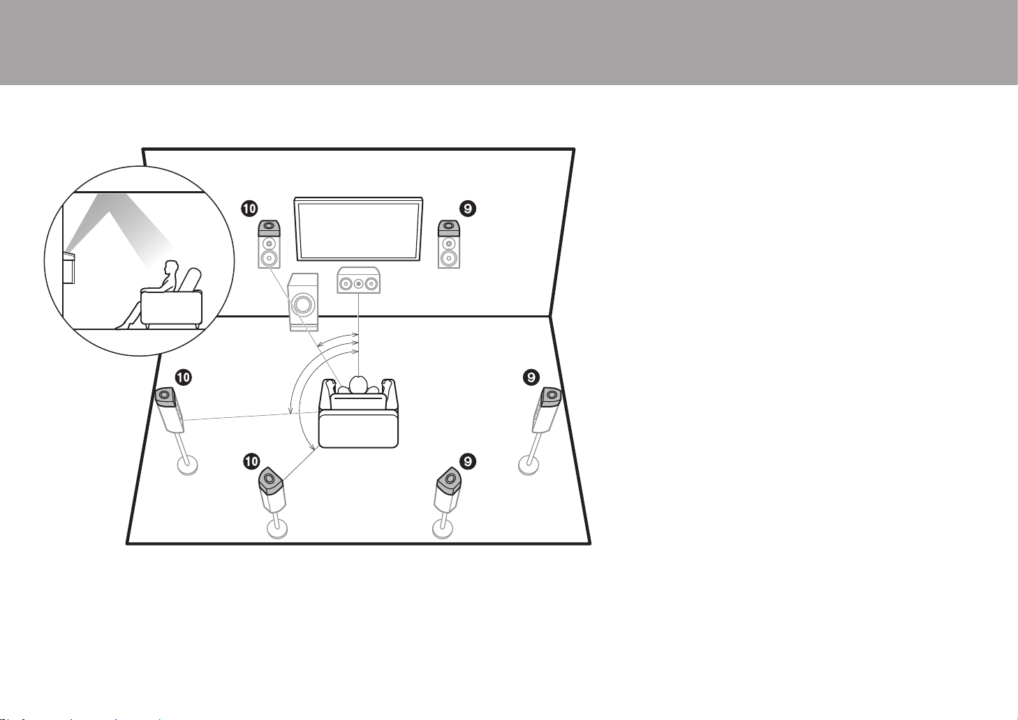
12
5.1.2 Sistema de canal 3
(altavoces habilitados para Dolby (Altavoces
Dolby))
Este es un sistema básico de 5.1 canales formado por
altavoces delanteros, un altavoz central, altavoces
envolventes y un subwoofer con fuente de alimentación
propia, al que se le han añadido altavoces habilitados con
Dolby (delanteros), altavoces habilitados con Dolby
(envolventes), o altavoces habilitados con Dolby
(Envolventes traseros) que ambos son tipos de altavoces
de altura. Los altavoces habilitados con Dolby son
altavoces especiales diseñados para estar orientados hacia
el techo de modo que el sonido se escuche tras rebotar
contra el techo y así parezca que el sonido viene de arriba.
Instalando altavoces de altura, cuando el formato de
entrada es Dolby Atmos, puede seleccionar el modo de
audición Dolby Atmos, que proporciona el sonido 3D más
actual incluyendo sonidos por arriba.
Colóquelos por encima de los altavoces delanteros o de los
altavoces envolventes.
0 "Combinaciones de altavoces" (P14) describe algunos
ejemplos detallados de combinaciones de altavoces.
9,10 Altavoces de altura
Elija uno de los siguientes:
0 Altavoces habilitados con Dolby (Delanteros)
0 Altavoces habilitados con Dolby (Envolventes)
0 Altavoces habilitados con Dolby (Envolventes
traseros)
> Antes de empezar > Nombres de las piezas > Instalación > Configuración inicial > Reproducción
*
1
*
2
*
3
½1: 22e a 30e, ½2: 90e a 120e, ½3: 135e a 150e
SN29403015A_VSX-LX302_BAS_Es_1711xx.book 12 ページ 2017年10月27日 金曜日 午後2時3分

13
Biamplificación de los altavoces
Con un sistema de 5.1 canales, es posible conectar
altavoces delanteros compatibles con biamplificación para
mejorar la calidad de los tonos graves y agudos. Es
necesario que los terminales de los tweeters de los
altavoces compatibles con biamplificación se conecten a un
amplificador y los terminales de los woofers a otro
amplificador, así que no es posible conectar altavoces de
altura y altavoces envolventes traseros con esta conexión.
Además de los altavoces delanteros, también puede
conectar un altavoz central, altavoces envolventes y un
subwoofer con fuente de alimentación propia.
0 "Combinaciones de altavoces" (P14) describe algunos
ejemplos detallados de combinaciones de altavoces.
1,2 Altavoces delanteros (Biamplificación)
3 Altavoz central
4,5 Altavoces envolventes
6 Subwoofer con fuente de alimentación propia
> Antes de empezar > Nombres de las piezas > Instalación > Configuración inicial > Reproducción
*
1
*
2
½1: 22e a 30e, ½2: 120e
Es
SN29403015A_VSX-LX302_BAS_Es_1711xx.book 13 ページ 2017年10月27日 金曜日 午後2時3分

14
Combinaciones de altavoces
0 En cualquiera de las combinaciones, se pueden conectar hasta dos subwoofers con alimentación propia.
(*1) Puede seleccionar uno entre Speaker B, Bi-AMP o ZONE SPEAKER.
(*2) Cuando se utilizan Altavoces B, no se emite sonido desde los altavoces envolventes
traseros cuando se está reproduciendo desde A+B.
(*3) No se emite ningún sonido desde los altavoces de altura cuando se reproduce está
reproduciendo audio desde el ZONE SPEAKER.
(*4) Puede conectar tanto altavoces envolventes traseros como altavoces de altura. Sin
embargo, solo puede emitir audio desde unos de ellos a la vez. Cuando ambos tipos
están conectados, puede establecer qué altavoces priorizar.
0 Pulse en el mando a distancia (P6) y use "Other" - "Speakers" para cambiar entre los
altavoces A y B y para cambiar entre altavoces envolventes traseros y altavoces de
altura.
> Antes de empezar > Nombres de las piezas > Instalación > Configuración inicial > Reproducción
Canales de los
altavoces FRONT CENTER SURROUND
SURROUND
BACK HEIGHT
SP B
(Speaker B)
Bi-AMP
ZONE 2
(ZONE SPEAKER)
(P21)
2.1 ch
(*1) (*1) (*1)
3.1 ch
(*1) (*1) (*1)
4.1 ch
(*1) (*1) (*1)
5.1 ch
(*1) (*1) (*1)
6.1 ch
(*2)
7.1 ch
(*2)
2.1.2 ch
(*3)
3.1.2 ch
(*3)
4.1.2 ch
(*3)
5.1.2 ch
(*3)
6.1.2 ch
(*4) (*4)
7.1.2 ch
(*4) (*4)
SN29403015A_VSX-LX302_BAS_Es_1711xx.book 14 ページ 2017年10月27日 金曜日 午後2時3分

15
Paso 2: Conexión de los altavoces
Conexiones estándar (Páginas 8 a 12)
Conecte
12345678
para un sistema de 5.1 canales. Conecte
1234569:
para un sistema de 5.1.2 canales. Se pueden conectar
hasta dos subwoofers con fuente de alimentación propia. Se emite la misma
señal desde cada uno de los conectores SUBWOOFER PRE OUT.
0 También puede conectar ambos 78 y 9:. Sin
embargo, solo puede emitir audio desde unos de ellos a
la vez. Cuando ambos están conectados, puede cambiar
qué altavoces priorizar. Pulse en el mando a
distancia (P6) y use "Other" - "Speakers" para cambiar
entre los altavoces envolventes traseros y los altavoces
de altura y para cambiar entre los altavoces A y B.
Asegúrese de que los cables expuestos de los
altavoces no sobresalgan de los terminales de los
altavoces al conectarlos. Si los cables expuestos de
los altavoces tocan el panel trasero o los cables + y –
se tocan entre sí, el circuito de protección se activará.
> Antes de empezar > Nombres de las piezas > Instalación > Configuración inicial > Reproducción
a
b
OR
Speaker B
1/2˝
(12 mm)
a Cable de altavoz, b Cable de subwoofer
Configuración
0 Es necesario realizar ajustes para la
configuración de los altavoces que ha conectado
en "1. Full Auto MCACC" en Initial Setup (P23).
0
Si cualquiera de los altavoces conectados tiene una impedancia
de 4 Ω o superior hasta menos de 6 Ω, después de completar la
Initial Setup, es necesario que realice algunos ajustes en el menú
System Setup. Pulse en el mando a distancia y, en la pantalla
Home, configure "System Setup" - "Speaker" - "Configuration" -
"Speaker Impedance" como "4ohms".
Es
SN29403015A_VSX-LX302_BAS_Es_1711xx.book 15 ページ 2017年10月27日 金曜日 午後2時3分

16
Conexión con altavoces de biamplificación (Página 13)
Asegúrese de quitar el puente encajado entre los
conectores del woofer y los conectores del tweeter de los
altavoces delanteros. Consulte "Conexiones estándar
(Páginas 8 a 12)" (P15) para conectar el altavoz central, los
altavoces envolventes y el subwoofer con fuente de
alimentación propia.
0
Consulte también el manual de instrucciones de sus
altavoces cuando utilice conexiones para biamplificación.
Asegúrese de que los cables expuestos de los
altavoces no sobresalgan de los terminales de
los altavoces al conectarlos. Si los cables
expuestos de los altavoces tocan el panel
trasero o los cables + y – se tocan entre sí, el
circuito de protección se activará.
> Antes de empezar > Nombres de las piezas > Instalación > Configuración inicial > Reproducción
a
1/2˝
(12 mm)
Para alta
frecuencia
Para baja
frecuencia
a Cable de altavoz
Configuración
0 Es necesario realizar ajustes para la
configuración de los altavoces que ha conectado
en "1. Full Auto MCACC" en Initial Setup (P23).
0 Si cualquiera de los altavoces conectados tiene
una impedancia de 4 Ω o superior hasta menos
de 6 Ω, después de completar la Initial Setup, es
necesario que realice algunos ajustes en el menú
System Setup. Pulse en el mando a distancia
y, en la pantalla Home, configure "System Setup"
- "Speaker" - "Configuration" - "Speaker
Impedance" como "4ohms".
SN29403015A_VSX-LX302_BAS_Es_1711xx.book 16 ページ 2017年10月27日 金曜日 午後2時3分

17
Paso 3: Conexión de los componentes del TV y los componentes de AV
1. Conexión del TV
Con un televisor compatible con ARC
Para un televisor compatible con la función ARC (Audio
Return Channel) (*1), utilice un cable HDMI y conéctelo
siguiendo la ilustración “a”. Elija un conector HDMI IN en el
TV compatible con ARC al realizar la conexión.
Con un televisor incompatible con ARC
Para un televisor incompatible con la función ARC (Audio
Return Channel) (*1), conecte tanto el cable HDMI de la
ilustración "a" como el cable óptico digital en "b".
0 La conexión con un cable óptico digital no es necesaria
si va a ver el televisor mediante un dispositivo, como una
caja descodificadora de cable (es decir, sin usar el
sintonizador integrado en el televisor), conectado al
conector input de la unidad.
(*1) La función ARC: Esta función transmite las señales de
audio del TV a través de un cable HDMI de modo que
pueda reproducir el audio del TV mediante esta unidad. La
conexión a una TV compatible con ARC se completa con
un cable HDMI. Consulte el manual de instrucciones de su
TV para ver si es compatible con ARC.
(*2) Se puede conectar otro TV o proyector al conector
HDMI OUT SUB. Pulse (P6) en el mando a
distancia y use "Other" - "HDMI Out" para cambiar
entre MAIN y SUB. Tenga en cuenta que este conector
no es compatible con ARC.
> Antes de empezar > Nombres de las piezas > Instalación > Configuración inicial > Reproducción
TV
*2
a
b
a Cable HDMI, b Cable óptico digital
Configuración
0 Para usar la función ARC se requieren algunos
ajustes. Seleccione "Yes" en "5. Audio Return
Channel" (P24) en la Initial Setup.
0 Consulte el manual de instrucciones del TV para
información sobre las conexiones del TV e
instrucciones sobre los ajustes de las funciones
CEC y la salida de audio.
Es
SN29403015A_VSX-LX302_BAS_Es_1711xx.book 17 ページ 2017年10月27日 金曜日 午後2時3分
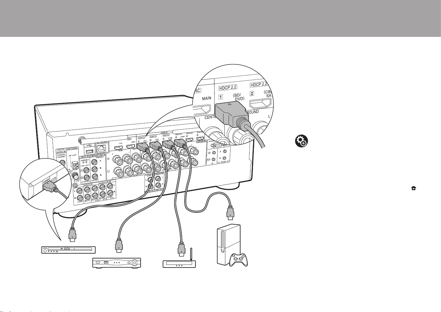
18
2. Conecte el componente AV HDMI
Este es un ejemplo de conexión con un componente AV que
cuenta con un conector HDMI. Con la conexión a un
componente AV que cumpla con el estándar CEC (Consumer
Electronics Control), puede usar funciones como la función
HDMI CEC (*) que vincula con el selector de entrada, y la
función HDMI Standby Through que le permite reproducir
vídeo y audio desde componentes AV en el TV incluso cuando
esta unidad está en modo de espera.
0 Para reproducir vídeo 4K o 1080p, use un cable HDMI
de alta velocidad.
(*)La función HDMI CEC: Puede controlar funciones tales
como la vinculación del cambio de entrada con el
selector de entrada y los reproductores que cumplen con
el estándar CEC, cambiando la salida para que el audio
se emita desde el televisor o desde esta unidad y
ajustando el volumen usando el mando a distancia de un
TV compatible con CEC y cambiando automáticamente
esta unidad al modo de espera cuando el TV está
apagado.
> Antes de empezar > Nombres de las piezas > Instalación > Configuración inicial > Reproducción
BD/DVD
GAME
a
Decodificador de
cable/satélite
Reproductor multimedia
de flujo de datos continuo
a Cable HDMI
Configuración
0 Cuando se selecciona "Yes" para "5. Audio
Return Channel" en Initial Setup (P24), la función
HDMI CEC y la función HDMI Standby Through
se activan automáticamente. Si se selecciona
"No, Skip", es necesario realizar ajustes en el
menú System Setup después de que se haya
completado la Initial Setup. Los ajustes se
realizan en "System Setup" - "Hardware" -
"HDMI" en Home, que se visualiza al pulsar
en el mando a distancia.
0 Para disfrutar de sonido envolvente digital
incluyendo Dolby Digital, la salida de audio debe
ser ajustada en "Bitstream output" en el
reproductor de discos Blu-ray u otros dispositivos
conectados.
SN29403015A_VSX-LX302_BAS_Es_1711xx.book 18 ページ 2017年10月27日 金曜日 午後2時3分
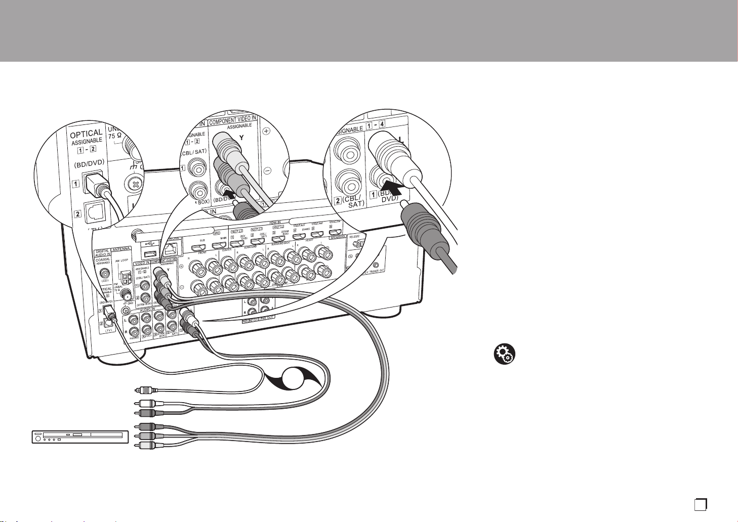
19
3. Conexión del componente AV no HDMI
Este es un ejemplo de conexión con un componente AV
que no tiene un conector HDMI. Realice las conexiones
con el componente AV para coincidir con los conectores
que este tiene. Cuando la conexión de entrada de vídeo se
hace en el conector BD/DVD, la conexión de entrada de
audio también debería hacerse en los conectores BD/DVD,
y así sucesivamente, de modo que conecte los conectores
de entrada de vídeo a los conectores con el mismo nombre
que los conectores de entrada de audio.
Tenga en cuenta que las señales de vídeo que entran al
conector VIDEO IN o al conector COMPONENT VIDEO IN
se convertirán a señales de vídeo HDMI y, a continuación,
se enviarán desde el conector HDMI OUT.
0 Para disfrutar de una reproducción envolvente digital en
formatos como Dolby Digital, es necesario que realice
una conexión para señales de audio con un cable
coaxial digital o un cable óptico digital.
0 Puede modificar la asignación de los conectores de
entrada que se muestran en la ilustración de la izquierda
para poder conectar también cualquier conector distinto
de BD/DVD. Para más información, consulte el Manual
avanzado.
> Antes de empezar > Nombres de las piezas > Instalación > Configuración inicial > Reproducción
BD/DVD
OR
a
b
c
a Cable de vídeo componente, b Cable óptico digital, c Cable de audio analógico
Configuración
0
Los conectores COMPONENT VIDEO IN solo son
compatibles con una resolución 480i o 576i. Cuando lo
conecte a los conectores COMPONENT VIDEO IN,
establezca la resolución de salida del reproductor en
480i o 576i. Seleccione intercalar si no hay una opción
para 480i, etc. Si su reproductor no es compatible con
una salida de 480i o 576i, utilice el conector VIDEO IN.
0 Para disfrutar de sonido envolvente digital
incluyendo Dolby Digital, la salida de audio debe
ser ajustada en “Bitstream output” en el
reproductor de discos Blu-ray u otros dispositivos
conectados.
Es
SN29403015A_VSX-LX302_BAS_Es_1711xx.book 19 ページ 2017年10月27日 金曜日 午後2時3分

20
4. Conexión del componente de audio
Ejemplo de una conexión con un componente de audio.
Conecte un reproductor de CD utilizando un cable coaxial
digitalo un cable de audio analógico. También puede
conectar una tornamesa que tenga un cartucho de tipo MM
al conector PHONO.
0 Si la tornamesa tiene un ecualizador de audio integrado,
conéctelo a otro conector AUDIO IN. Además, si la
tornamesa usa un cartucho de tipo MC, instale un
ecualizador de audio compatible con el cartucho de tipo
MC entre la unidad y el tocadiscos, después conéctelo a
cualquier conector AUDIO IN excepto al conector
PHONO.
Si la tornamesa tiene un cable de toma a tierra,
conéctelo al terminal SIGNAL GND de esta unidad.
> Antes de empezar > Nombres de las piezas > Instalación > Configuración inicial > Reproducción
CD
OR
a
b
Tornamesa
a Cable coaxial digital, b Cable de audio analógico
SN29403015A_VSX-LX302_BAS_Es_1711xx.book 20 ページ 2017年10月27日 金曜日 午後2時3分
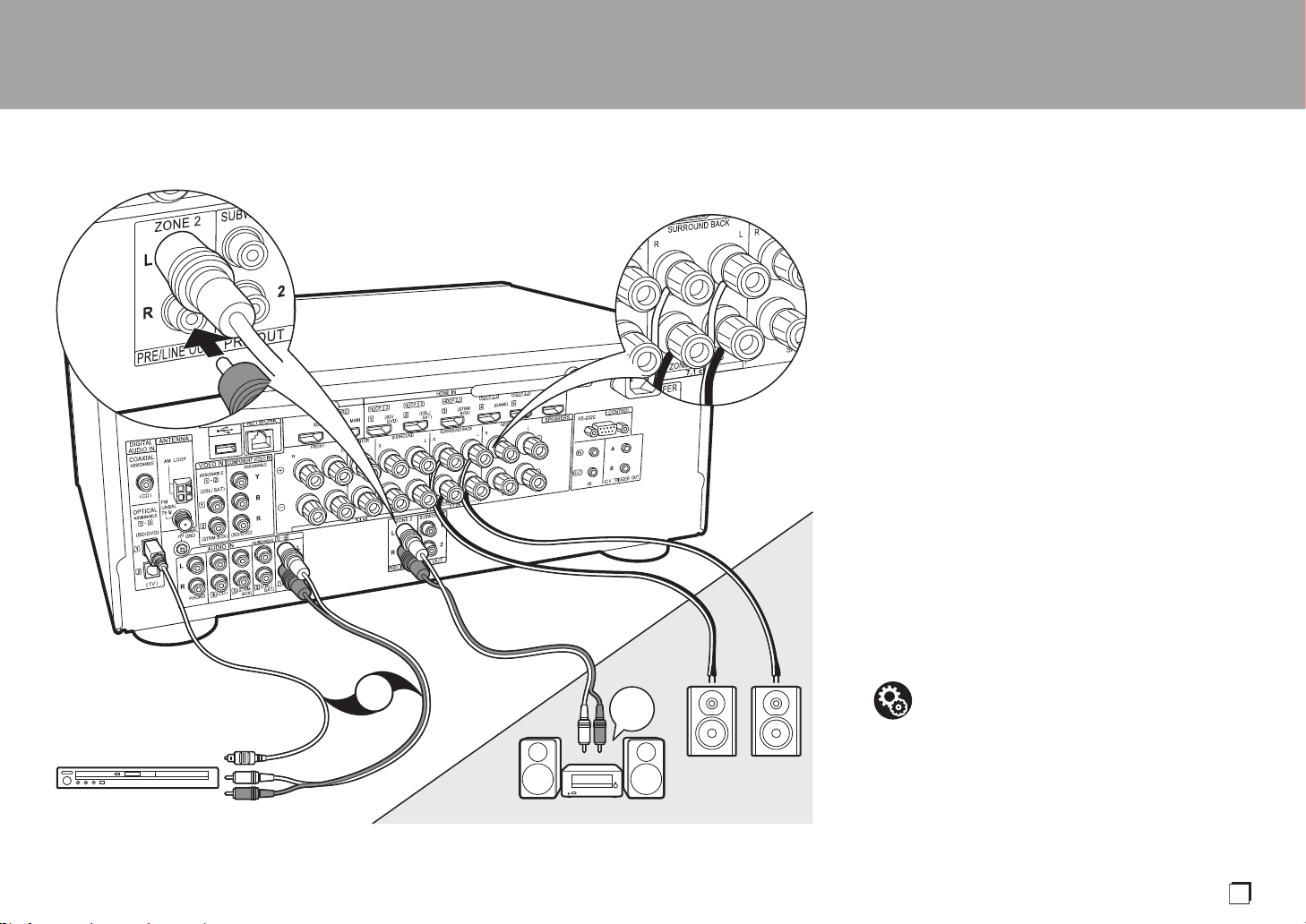
21
5. Conexión multizona
Puede disfrutar de audio en otra habitación, por ejemplo,
reproduciendo un reproductor de discos Blu-ray en la habitación
principal (en la que está ubicada esta unidad) y escuchando la
radio por internet en la otra habitación (ZONE 2).
0
Las señales de audio DSD y Dolby TrueHD no se transmiten a la
ZONE 2 cuando están seleccionadas con el selector de entrada "NET".
Conexiones con un componente AV
Cuando se transmite el audio de un componente AV conectado externamente a
la ZONE 2, es necesario que establezca la conexión usando un cable coaxial
digital, un cable óptico digital o un cable de audio analógico.
ZONE 2 PRE/LINE OUT
Es posible reproducir una fuente de 2 canales en otra habitación mientras reproduce
una fuente de 7.1 canales en la habitación principal. Conecte las conexiones ZONE 2
PRE/LINE OUT de la unidad y las conexiones LINE IN del preamplificador principal o
del
amplificador
de potencia
en otra habitación con un cable de audio analógico.
ZONE SPEAKER
Es posible conectar los altavoces en otra habitación y
reproducir fuentes de 2 canales.
0
Si no ha conectado los altavoces delanteros usando una conexión de biamplificación o
si ha conectado un sistema de altavoces B, no puede usar el ZONE SPEAKER.
0 No se emite ningún sonido desde los altavoces de altura
cuando se reproduce audio desde el ZONE SPEAKER.
> Antes de empezar > Nombres de las piezas > Instalación > Configuración inicial > Reproducción
ZONE2 PRE/LINE OUT
ZONE SPEAKER
ZONE2
LINE
IN
BD/DVD
OR
MAIN ROOM
c
a
b
a Cable óptico digital, b Cable de audio analógico, c Cable de altavoz
Configuración
0
Para disfrutar de esta función, se requieren ajustes
en Initial Setup, "4. Multi Zone Setup" (P24).
0
El audio de componentes AV conectados externamente solo
se puede reproducir en la ZONE 2 cuando el audio es
analógico o es audio PCM de 2 canales. Si ha establecido la
conexión con la unidad mediante un cable coaxial digital o un
cable óptico digital, puede que sea necesario cambiar la
salida de audio del componente AV a una salida PCM.
Es
SN29403015A_VSX-LX302_BAS_Es_1711xx.book 21 ページ 2017年10月27日 金曜日 午後2時3分

22
6. Conexión de otros cables
Conexión de antenas
Mueva la antena mientras reproduce la radio para
encontrar la posición con mejor recepción. Utilice una
chincheta o similar para fijar la antena FM para interiores a
la pared.
Conexión de red
Conecte esta unidad a la red usando una LAN con cable o
Wi-Fi (LAN sin cables). Podrá disfrutar de funciones de red,
como la radio por internet, si conecta la unidad a la red. Si
realiza la conexión mediante LAN con cable, conecte un
cable Ethernet al puerto NETWORK como se muestra en la
ilustración Para realizar la conexión mediante Wi-Fi,
después de seleccionar "Wireless" en "3. Network
Connection" (P24) en Initial Setup, seleccione el método de
ajuste deseado y siga las instrucciones en pantalla para
configurar la conexión.
Conexión del cable de alimentación
Esta unidad incluye cables de alimentación extraíbles.
Conecte el cable de alimentación a la toma de corriente
después de completar las otras conexiones. Conecte el
cable de alimentación a AC IN de la unidad y luego
conéctelo a la toma. Desconecte siempre el cable de
alimentación del lado de la toma de corriente primero
cuando desconecte el cable de alimentación.
> Antes de empezar > Nombres de las piezas > Instalación > Configuración inicial > Reproducción
a
c
d
b
a
Antena de FM para interiores,
b
Antena en bucle de AM,
c
Cable Ethernet,
d
Cable de alimentación
SN29403015A_VSX-LX302_BAS_Es_1711xx.book 22 ページ 2017年10月27日 金曜日 午後2時3分

23
Initial Setup con el asistente de arranque automático
Initial Setup se inicia automáticamente
Cuando encienda la unidad por primera vez después de la
compra, la Initial Setup se mostrará automáticamente en el
televisor. De este modo podrá realizar los ajustes
necesarios para la puesta en marcha mediante
operaciones sencillas, siguiendo las indicaciones en
pantalla.
1. Cambie la entrada en la TV a aquella asignada a la unidad.
2. Instale pilas en el mando a distancia de la unidad.
3. Pulse
Í
en el mando a distancia para encender la unidad.
4. Seleccione el elemento con los cursores del mando a
distancia y pulse ENTER (a) para confirmar su selección.
Para volver a la pantalla anterior, pulse (b).
0 Si finaliza el procedimiento durante su curso o desea
cambiar un ajuste realizado durante la Initial Setup,
pulse en el mando a distancia y, desde Home,
seleccione "System Setup" - "Miscellaneous" - "Initial
Setup" y pulse ENTER.
∫ 1. Full Auto MCACC
Coloque el micrófono de configuración de altavoces
suministrado en la posición de escucha y mida los tonos de
prueba emitidos por los altavoces, a continuación la unidad
establecerá automáticamente el nivel de volumen óptimo
para cada altavoz, las frecuencias de cruce y la distancia
desde la posición de escucha. Esto también ajusta
> Antes de empezar > Nombres de las piezas > Instalación > Configuración inicial > Reproducción
1
2 3
TV
INPUT
a
b
Es
SN29403015A_VSX-LX302_BAS_Es_1711xx.book 23 ページ 2017年10月27日 金曜日 午後2時3分
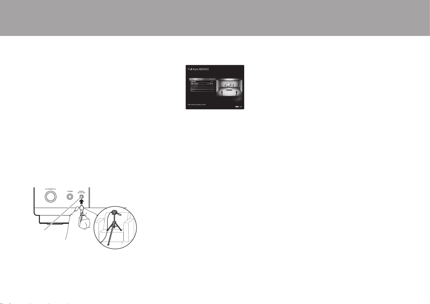
24
automáticamente los ecualizadores de los altavoces y hace
posible la corrección de la distorsión causada por el
ambiente acústico de la habitación.
0 La calibración tarda entre 3 y 12 minutos en
completarse. Los altavoces emiten el tono de prueba a
alto volumen durante la medición, de modo que tenga
cuidado con el entorno. Mantenga la habitación en el
mayor silencio posible durante la medición.
0 Si ha conectado un subwoofer, compruebe la
alimentación y el volumen del subwoofer. Establezca el
volumen del subwoofer en más de las mitad.
0 Si la alimentación de la unidad se corta de repente,
puede que se deba a que los hilos de los cables del
altavoz han entrado en contacto con el panel posterior o
con otros hilos, activando así el circuito de protección.
Retuerza los hilos de nuevo convenientemente y
asegúrese de que no sobresalgan de los terminales de
los altavoces al conectarlos.
1. Coloque el micrófono de configuración de los altavoces
provisto en la posición de escucha y conéctelo al
conector MCACC SETUP MIC de la unidad principal.
Si va a colocar el micrófono de configuración del altavoz
en un trípode, consulte la ilustración.
2. Seleccione la configuración de los altavoces conectados.
La imagen en la pantalla cambia cuando elige el número de
canales en "Speaker Channels", de modo que consúltela
cuando realice los ajustes.
3. Los altavoces emiten tonos de prueba y en primer lugar la
unidad detecta los altavoces conectados y el ruido ambiental.
4. Tras mostrar los resultados de las mediciones
anteriores, seleccione "Next", pulse ENTER en el mando
a distancia, y los tonos de prueba se emiten de nuevo y
la unidad automáticamente realiza ajustes como el nivel
de volumen y la frecuencia de cruce óptimos.
5. Cuando se ha completado, se muestra el resultado de la
medición. Pulse los cursores
/
en el mando a distancia
para comprobar los ajustes. Pulse ENTER cuando "Save"
esté seleccionado para guardar los ajustes.
6. Desconecte el micrófono de configuración del altavoz.
∫ 2. Source Connection
Compruebe que cada fuente de entrada está conectada correctamente.
Siga la guía, seleccione la entrada que quiere confirmar, inicie la
reproducción del reproductor seleccionado y confirme que las imágenes
aparecen en el TV y que se reproduce el sonido.
∫ 3. Network Connection
Configure la conexión Wi-Fi con un punto de acceso tal
como un enrutador de LAN inalámbrico. Existen los
siguientes dos métodos de conexión por Wi-Fi:
"Scan Networks":
Busque un punto de acceso desde esta
unidad. Entérese del SSID del punto de acceso de antemano.
"Use iOS Device (iOS7 or later)": Comparta los ajustes
de Wi-Fi del dispositivo iOS con esta unidad.
Si selecciona "Scan Networks", existen otras dos posibilidades
más de métodos de conexión. Compruebe lo siguiente.
"Enter Password": Introduzca la contraseña (o clave) del
punto de acceso al que conectarse.
"Push Button": Si el punto de acceso tiene un botón de
conexión automática, puede conectarse sin introducir una
contraseña.
0 Si no se muestra el SSID del punto de acceso, en la
pantalla del listado de SSIDs seleccione "Other..." con el
cursor del mando a distancia y pulse ENTER,
después siga las instrucciones en pantalla.
Entrada de teclado
Para cambiar entre mayúsculas y minúsculas, seleccione
"A/a" en la pantalla y pulse ENTER. Para seleccionar si
enmascarar la contraseña con "½" o mostrarla en texto sin
formato, pulse +Fav en el mando a distancia. Pulse CLEAR
para borrar todos los caracteres introducidos.
0 Durante el ajuste de red se visualiza una ventana de
confirmación pidiéndole aceptar la política de privacidad.
Seleccione "Accept" y pulse ENTER para indicar su
conformidad.
∫ 4. Multi Zone Setup
Cuando quiera disfrutar de audio en otra habitación que no sea la
habitación principal, establezca el método de salida de audio para la otra
habitación (ZONE 2). Si ha conectado altavoces en otra habitación con un
cable de altavoz, seleccione "Using AV Receiver". Se ha conectado un
preamplificador principal en otra habitación con un cable de audio
analógico, seleccione "with External Premain Amplifier". Si ha conectado
un amplificador de potencia, seleccione "with External Power Amplifier".
∫ 5. Audio Return Channel
Si ha conectado un TV compatible con ARC, seleccione
"Yes". El ajuste ARC de esta unidad se activa y puede
escuchar el audio del TV a través de esta unidad.
> Antes de empezar > Nombres de las piezas > Instalación > Configuración inicial > Reproducción
MCACC
SETUP MIC
SN29403015A_VSX-LX302_BAS_Es_1711xx.book 24 ページ 2017年10月27日 金曜日 午後2時3分
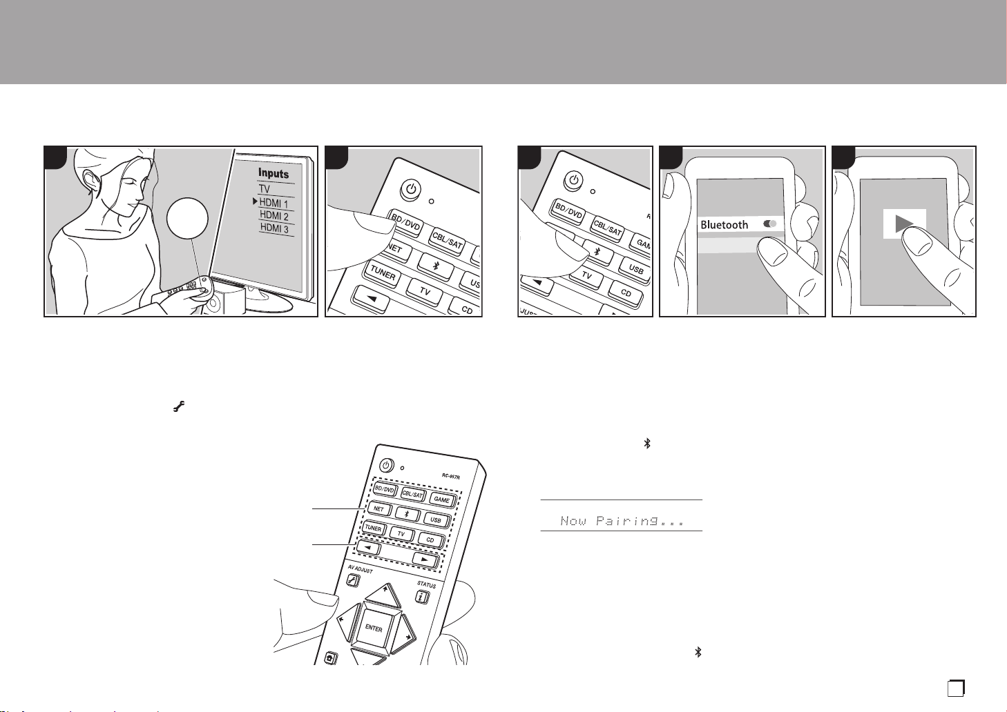
25
Reproducción
> Antes de empezar > Nombres de las piezas > Instalación > Configuración inicial > Reproducción
Reproducción de componente AV
Operaciones básicas
Puede reproducir el audio desde componentes AV como
reproductores de discos blu-ray a través de esta unidad.
0 Cuando se conecta un TV al conector
HDMI OUT SUB, pulse (P6) en el
mando a distancia y utilice "Other" -
"HDMI Out" para cambiar entre MAIN y
SUB.
Realice el siguiente procedimiento cuando
la unidad esté encendida.
1. Cambie la entrada en la TV a aquella
asignada a la unidad.
2. Pulse el selector de entrada (a) en el mando a
distancia con el mismo nombre que el conector al que
ha conectado el reproductor para cambiar la entrada.
Por ejemplo, pulse BD/DVD para reproducir el
reproductor conectado al conector BD/DVD. Pulse TV
para escuchar el sonido de la TV. Para reproducir un
dispositivo conectado al conector STRM BOX,
PHONO, HDMI5, HDMI6 o AUX INPUT AUDIO/HDMI
en el panel frontal, pulse
21
(b) repetidamente para
seleccionar la entrada.
0
Cuando la función de vínculo CEC está en
funcionamiento, la entrada cambia
automáticamente cuando ha conectado
un TV que cumple con el estándar CEC y
un reproductor a esta unidad usando una
conexión HDMI.
3. Inicie la reproducción en el componente AV.
1 2
TV
INPUT
b
a
BLUETOOTH
®
Reproducción
Puede reproducir música en un teléfono
inteligente u otros dispositivos con
BLUETOOTH de forma inalámbrica.
Realice el siguiente procedimiento cuando
la unidad esté encendida.
Emparejado
1. Cuando pulsa el botón , en la pantalla
de esta unidad se muestra "Now
Pairing..." y el modo de emparejamiento
se activa.
2. Active (encienda) la función BLUETOOTH
del dispositivo con BLUETOOTH, después
seleccione esta unidad entre los dispositivos
mostrados. Si se le pide una contraseña,
introduzca
"
0000
"
.
0 Esta unidad se muestra como
"Pioneer VSX-LX302 XXXXXX".
0
Para conectar otro dispositivo con
BLUETOOTH, mantenga pulsado
hasta que se muestre "Now Pairing...",
después realice el paso 2. Esta unidad
puede almacenar la información de hasta
8 dispositivos emparejados.
0
El área de cobertura es de 48´/15 m.
Tenga en cuenta que la conexión con
todos los dispositivos que tengan
BLUETOOTH no siempre está
garantizada.
Reproducción
1. Realice el procedimiento de conexión en el
dispositivo habilitado con BLUETOOTH.
La entrada en esta unidad cambia
automáticamente a "BLUETOOTH".
2. Reproduzca música. Suba el volumen
del dispositivo con BLUETOOTH hasta
un nivel adecuado.
0 Debido a las características de la
tecnología inalámbrica BLUETOOTH, el
sonido producido en esta unidad puede
llevar un ligero retraso respecto al
sonido reproducido en el dispositivo con
BLUETOOTH activado.
PioneerVSX-LX302XXX
1 2 3
Es
SN29403015A_VSX-LX302_BAS_Es_1711xx.book 25 ページ 2017年10月27日 金曜日 午後2時3分
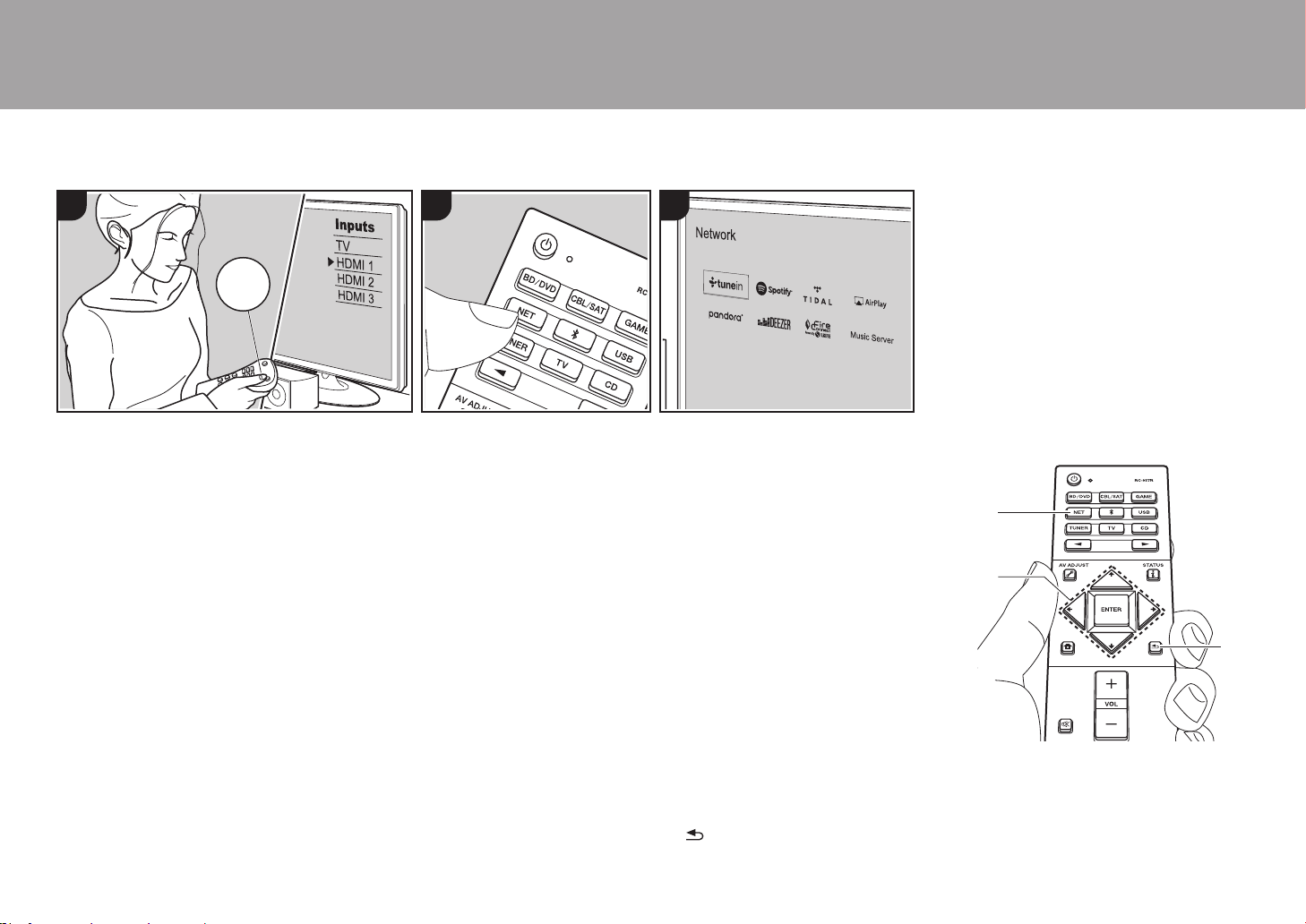
26
Funciones de red
Operaciones básicas
Conectando esta unidad a la red, puede
disfrutar de servicios de radio por internet
como TuneIn, transmisión desde Spotify
Connect y reproducción inalámbrica
usando funciones AirPlay
®
. Además,
puede usar la función Music Server para
transmitir archivos de música almacenados
en ordenadores o dispositivos NAS
compatibles con la función de red
doméstica. Las operaciones básicas para
las funciones de red se describen en el
Manual Básico. Para operaciones más
avanzadas consulte el Manual avanzado.
Puede que se ofrezcan funciones de red
adicionales mediante actualizaciones de
firmware para esta unidad. Consulte
también el Manual avanzado para
información sobre nuevas funciones.
0 Es necesario que la red esté conectada
a internet para reproducir servicios de
radio por internet.
0 Dependiendo del servicio de radio por
internet, puede que sea necesario que el
usuario se registre antes desde su
ordenador.
0 Para activar Spotify Connect, debe
instalar la aplicación de Spotify y en su
teléfono inteligente o tableta y crear una
cuenta de Spotify Premium.
– Consulte el siguiente enlace para
configurar Spotify:
www.spotify.com/connect/
0 Los servidores de red compatibles con
la función Music Server son aquellos PC
con reproductores instalados que
tengan la funcionalidad de servidor de
Windows Media
®
Player 11 o 12, o
aquellos NAS compatibles con
funcionalidad de red doméstica. Tenga
en cuenta que con los PC, únicamente
pueden reproducirse los archivos de
música registrados en la biblioteca de
Windows Media
®
Player.
0 Puede que tenga que realizar algunos
ajustes en el PC antes de usar Windows
Media
®
Player 11 o 12 con la función
Music Server.
Realice el siguiente procedimiento cuando
la unidad esté encendida.
1. Cambie la entrada en la TV a aquella
asignada a la unidad.
2. Pulse NET (a) en el mando a distancia
para visualizar una lista de Funciones de
red en el TV.
3. Seleccione la Función de red con los
cursores del mando a distancia y pulse
ENTER (b) para confirmar su selección.
Con servicios de radio por internet, siga
las instrucciones en pantalla, use los
cursores para seleccionar emisoras y
programas de radio y después pulse
ENTER para reproducir. Con Spotify o
AirPlay, seleccione esta unidad con su
teléfono inteligente para reproducirla.
Con Music Server, seleccione el
servidor con los cursores, después
seleccione el archivo de música
deseado y pulse ENTER para
reproducir.
0 Para volver a la pantalla anterior, pulse
(c).
> Antes de empezar > Nombres de las piezas > Instalación > Configuración inicial > Reproducción
321
TV
INPUT
b
a
c
SN29403015A_VSX-LX302_BAS_Es_1711xx.book 26 ページ 2017年10月27日 金曜日 午後2時3分
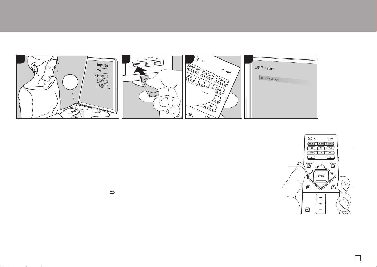
27
Dispositivo de almacenamiento USB
Operaciones básicas
Puede reproducir archivos de música
almacenados en un dispositivo de
almacenamiento USB.
Realice el siguiente procedimiento cuando
la unidad esté encendida.
1. Cambie la entrada en la TV a aquella
asignada a la unidad.
2. Conecte el dispositivo de
almacenamiento USB con los archivos
de música en el puerto USB en el panel
frontal o trasero de la unidad.
3. Pulse USB (b) en el mando a distancia y
seleccione "USB Front" o "USB Rear".
0 Si el indicador "USB" parpadea en la
pantalla, compruebe que el
dispositivo de almacenamiento USB
esté conectado correctamente.
0 No desconecte el dispositivo de
almacenamiento USB mientras en la
pantalla aparezca el mensaje
"Connecting···". Esto podría
ocasionar un mal funcionamiento o
corrupción de datos.
4. Pulse ENTER en el mando a distancia
en la siguiente pantalla. La lista de
carpetas y archivos de música en el
dispositivo de almacenamiento USB son
visualizados. Seleccione la carpeta con
los cursores y pulse ENTER para
confirmar su selección (a).
5. Con los cursores en el mando a
distancia, seleccione el archivo de
música y, a continuación, pulse ENTER
para comenzar la reproducción.
0 Para volver a la pantalla anterior, pulse
(c).
0 El puerto USB de esta unidad cumple
con el estándar USB 2.0. Puede que la
velocidad de transferencia sea
insuficiente para algunos de los
contenidos que reproduzca, lo que
podría causar interrupciones en el
sonido.
0 No se puede garantizar el
funcionamiento de todos los dispositivos
de almacenamiento USB.
0 Esta unidad puede utilizar dispositivos
de almacenamiento USB que cumplan
con los estándares de la clase de
dispositivos de almacenamiento. Esta
unidad también es compatible con
dispositivos de almacenamiento USB
que usan formatos de sistemas de
archivos FAT16 o FAT32.
> Antes de empezar > Nombres de las piezas > Instalación > Configuración inicial > Reproducción
4321
TV
INPUT
a
b
c
Es
SN29403015A_VSX-LX302_BAS_Es_1711xx.book 27 ページ 2017年10月27日 金曜日 午後2時3分
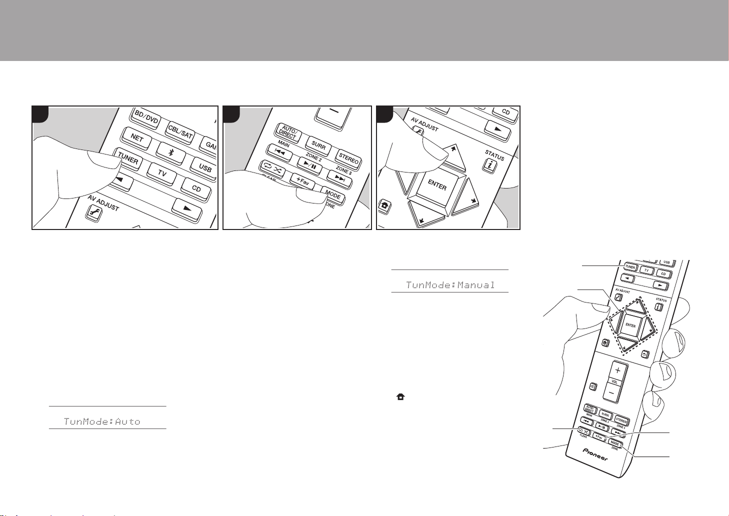
28
Escuchar la radio AM/FM
Con el sintonizador integrado, puede
recibir emisoras de radio AM y FM en esta
unidad. Realice el siguiente procedimiento
cuando la unidad esté encendida.
∫ Sintonización de una emisora
de radio
Sintonización automática
1. Pulse TUNER (a) del mando a distancia
repetidamente para seleccionar "AM" o
"FM" en la pantalla.
2. Pulse MODE (e) en el mando a
distancia, de modo que "TunMode:
Auto" se muestre en la pantalla.
3. Al pulsar los botones de cursor / (b)
del mando a distancia, se inicia la
sintonización automática y la búsqueda
se detiene cuando se encuentra una
emisora. Cuando se sintoniza una
emisora de radio, el indicador "TUNED"
se enciende en la pantalla. Cuando se
sintoniza una emisora de radio FM, el
indicador "STEREO" se ilumina.
Cuando la recepción de las emisiones
FM es de mala calidad:
Siga el procedimiento para "Sintonización
manual" de la siguiente sección. Tenga en
cuenta que si sintoniza manualmente, la
recepción de transmisiones FM será en
monoaural en vez de estéreo,
independientemente de la sensibilidad de
recepción.
Sintonización manual
Tenga en cuenta que si sintoniza
manualmente, la recepción de
transmisiones FM será en monoaural en
vez de estéreo, independientemente de la
sensibilidad de recepción.
1. Pulse TUNER (a) del mando a distancia
repetidamente para seleccionar "AM" o
"FM" en la pantalla.
2. Pulse MODE (e) en el mando a
distancia, de modo que "TunMode:
Manual" se muestre en la pantalla.
3. Mientras pulsa los cursores / (b) en
el mando a distancia, seleccione la
emisora de radio deseada.
0 La frecuencia cambia en 1 paso cada
vez que se pulsan los cursores / .
La frecuencia cambia continuamente
si se mantiene pulsado el botón y se
detiene cuando el botón se suelta.
Ajuste del paso de frecuencia:
Pulse en el mando a distancia y, desde
la pantalla Home, seleccione "System
Setup" - "Miscellaneous" - "Tuner" - "AM/
FM Frequency Step" y seleccione el paso
de frecuencia para su región. Tenga en
cuenta que cuando se cambia este ajuste,
se borran todos los preajustes de radio.
> Antes de empezar > Nombres de las piezas > Instalación > Configuración inicial > Reproducción
1 2 3
a
b
c
d
e
SN29403015A_VSX-LX302_BAS_Es_1711xx.book 28 ページ 2017年10月27日 金曜日 午後2時3分

29
> Antes de empezar > Nombres de las piezas > Instalación > Configuración inicial > Reproducción
∫ Programación de una
emisora de radio
Puede predefinir hasta 40 emisoras.
Procedimiento de registro
Después de sintonizar la emisora de radio
AM/FM que desea registrar, siga el
siguiente procedimiento.
1. Pulse +Fav (d) en el mando a distancia
de modo que el número preestablecido
parpadee en la pantalla.
2. Mientras el número preajustado está
parpadeando (unos 8 segundos), pulse
repetidamente los cursores / (b) en
el mando a distancia para seleccionar
un número entre 1 y 40.
3.
Pulse +Fav de nuevo en el mando a
distancia para registrar la emisora.
Cuando se ha finalizado el registro, el
número preestablecido deja de
parpadear. Repita este procedimiento
para todas sus emisoras de radio
favoritas AM/FM.
Selección de una emisora de radio
preajustada
1. Pulse TUNER (a) en el mando a
distancia.
2. Pulse los cursores / (b) en el
mando a distancia para seleccionar un
número preestablecido.
Borrar una emisora de radio
preajustada
1. Pulse TUNER (a) en el mando a
distancia.
2. Pulse los cursores / (b) en el
mando a distancia para seleccionar el
número preestablecido a borrar.
3. Después de pulsar +Fav (d) en el mando
a distancia, pulse CLEAR (c) mientras el
número preestablecido está
parpadeando para borrar dicho número
preestablecido. Una vez borrado, el
número de la pantalla se apaga.
1 2 3
Es
SN29403015A_VSX-LX302_BAS_Es_1711xx.book 29 ページ 2017年10月27日 金曜日 午後2時3分
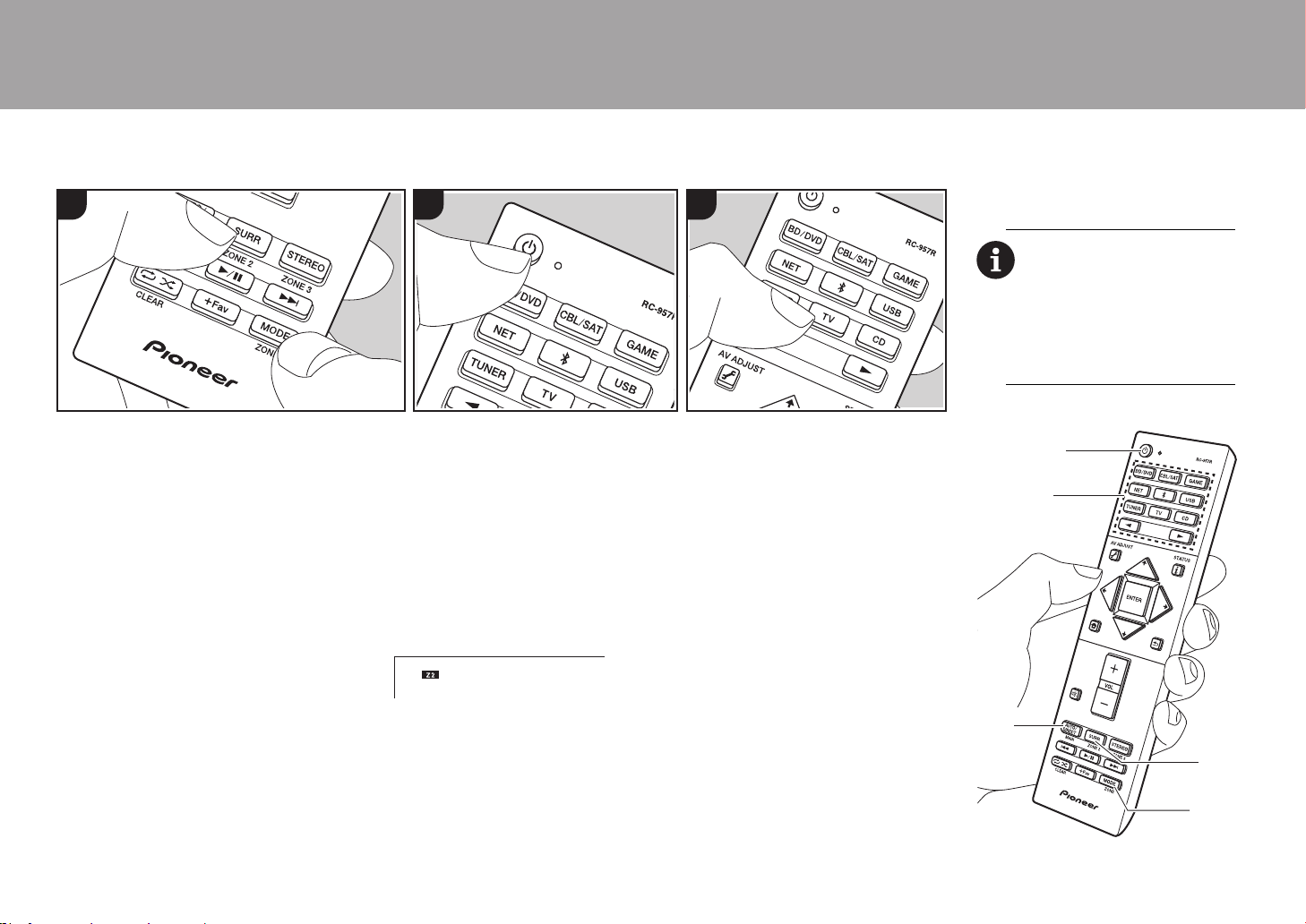
30
Multizona
> Antes de empezar > Nombres de las piezas > Instalación > Configuración inicial > Reproducción
Operaciones básicas
Puede disfrutar de audio en otra habitación, por
ejemplo, reproduciendo un reproductor de discos
Blu-ray en la habitación principal (en la que está
ubicada esta unidad) y escuchando la radio por
internet en la otra habitación (ZONE 2).
0 Las señales de audio DSD y Dolby
TrueHD no se transmiten a la ZONE 2
cuando están seleccionadas con el
selector de entrada "NET"
o
"USB".
0
Sólo puede seleccionar las mismas entradas
para la habitación principal y la habitación
separada con el selector de entrada "NET",
"
BLUETOOTH
"
o "
USB
". Si ha seleccionado
"NET" en la habitación principal y luego
selecciona "BLUETOOTH" en la habitación
separada, cambia también a "BLUETOOTH" la
habitación principal. No puede seleccionar
diferentes emisoras para la habitación principal
y la habitación separada con la radio AM/FM.
0 Si ZONE 2 está activado, el consumo de
energía durante el modo de espera será
mayor de lo normal.
Realice el siguiente procedimiento cuando
la unidad esté encendida.
1. Mientras mantiene pulsado MODE (e)
en el mando a distancia, pulse ZONE 2
(d) durante 3 o más segundos hasta que
el indicador remoto parpadee dos veces.
0 El controlador remoto cambia al modo
para controlar la ZONE 2.
2. Apunte el mando a distancia hacia la
unidad principal y pulse Í (a).
"Z2" se ilumina en la pantalla de la
unidad principal.
3. Pulse el botón del selector de entrada
(b) de la entrada que quiera reproducir
en la habitación separada.
0 En la unidad principal, después de
pulsar ZONE 2-CONTROL, en los
siguientes 8 segundos gire el mando
selector de entrada para seleccionar
la entrada que quiere reproducir en la
otra habitación.
4. Para ajustar el volumen en el
amplificador de potencia en la otra
habitación o en el altavoz ZONE,
ajústelo con VOL+/– en el mando a
distancia.
0 Para controlar la unidad principal,
pulse ZONE 2-CONTROL y ajuste
con el control MASTER VOLUME
dentro de los siguientes 8 segundos.
Para desactivar la función:
Pulse Í mientras está en el modo para
controlar la ZONE 2 con el mando a
distancia. O pulse ZONE 2-ON/OFF en la
unidad principal.
Reproducción solo en la ZONE 2:
Si pone la unidad en modo de espera
durante la reproducción multizona, el
indicador Z2 se atenúa y el modo de
reproducción se cambia al modo de
reproducción sólo en una habitación
separada. Activar ZONE 2 mientras esta
unidad está en modo de espera también
1 2 3
cambiará el modo de reproducción al
mismo ajuste.
Para restablecer el mando a
distancia al modo de control de
la habitación principal: Mientras
mantiene pulsado MODE en el
mando a distancia, pulse MAIN
(c) durante 3 o más segundos
hasta que el indicador remoto
parpadee una vez.
c
d
e
a
b
SN29403015A_VSX-LX302_BAS_Es_1711xx.book 30 ページ 2017年10月27日 金曜日 午後2時3分
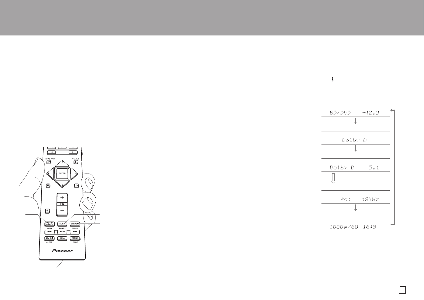
31
Modo de audición
> Antes de empezar > Nombres de las piezas > Instalación > Configuración inicial > Reproducción
Esta unidad está equipada con una
variedad de modos de audición. Las
operaciones básicas se describen en el
Manual Básico. Para más información,
consulte el Manual avanzado.
0 El último modo de audición
seleccionado para la fuente se recuerda
para cada uno de los botones AUTO/
DIRECT, SURR y STEREO. Si el
contenido que reproduce no es
compatible con el último modo de
audición que seleccionó, se selecciona
automáticamente el modo de audición
estándar para el contenido.
Botón AUTO/DIRECT (a)
Púlselo repetidamente y los modos de
audición adecuados a la señal de entrada
alternarán entre "Auto Surround", "Direct",
y "Pure Direct". Una vez que haya
seleccionado uno de ellos, aparecerá
"Auto Surround" (o "Direct" o "Pure Direct")
en la pantalla de la unidad principal. A
continuación se mostrará el modo de
audición seleccionado automáticamente
(Dolby Digital para las señales de entrada
multicanal, Stereo para las señales de dos
canales, etc.).
El modo "Direct" apaga los procesos que
pueden afectar a la calidad del sonido,
como las funciones de control del tono, de
modo que pueda disfrutar de una calidad
de sonido aún mejor. El modo "Pure Direct"
apaga más procesos que afectan a la
calidad del sonido para una reproducción
fiel al sonido original. En este caso, se
desactiva la calibración hecha con
MCACC.
0 Según sean la señal de entrada y la
configuración del altavoz, pueden
seleccionarse automáticamente los
modos Dolby Surround y DTS Neural:X
que amplían la señales de entrada del
canal 2 y del 5.1 al canal 5.1 y 7.1.
Botón SURR (c)
Puede seleccionar una serie de modos de
audición para adecuarlo a su deseo.
Existen los modos Dolby Digital, DTS-HD
Master Audio, y Stereo que pueden ser
elegidos para adecuar la señal de entrada,
o bien los modos Dolby Surround y DTS
Neural:X que pueden ampliar las señales
del canal 2 y del 5.1 a los canales 5.1 o
a
b
c
d
7.1. También puede disfrutar de modos
envolventes originales como los modos
Ext.Stereo y Drama.
Botón STEREO (d)
Puede seleccionar el modo "Stereo" para
reproducir solo desde los altavoces
delanteros y el subwoofer.
Comprobación del formato de
entrada y el modo de audición
Pulse (b) en el mando a distancia varias
veces para cambiar la pantalla de la unidad
principal como se describe a continuación.
Fuente de entrada y volumen
Modo de audición
Formato de señal
Frecuencia de muestreo
Resolución de la señal de entrada
La visualización cambiará
pocos segundos después
Es
SN29403015A_VSX-LX302_BAS_Es_1711xx.book 31 ページ 2017年10月27日 金曜日 午後2時3分

32
Licencias y marcas comerciales
Manufactured under license from Dolby Laboratories. Dolby, Dolby Atmos,
Dolby Surround, Dolby Vision and the double-D symbol are trademarks of
Dolby Laboratories.
For DTS patents, see http://patents.dts.com. Manufactured under license from
DTS, Inc. DTS, the Symbol, DTS in combination with the Symbol, DTS:X, and
the DTS:X logo are registered trademarks or trademarks of DTS, Inc. in the
United States and/or other countries. © DTS, Inc. All Rights Reserved.
The terms HDMI and HDMI High-Definition Multimedia Interface, and the HDMI
Logo are trademarks or registered trademarks of HDMI Licensing LLC in the
United States and other countries.
The Wi-Fi CERTIFIED Logo is a certification mark of Wi-Fi Alliance
®
.
AirPlay, iPad, iPhone, iPod, iPod classic, iPod nano and iPod touch are
trademarks of Apple Inc., registered in the U.S. and other countries.
iPad Air and iPad mini are trademarks of Apple Inc.
“Made for iPod”, “Made for iPhone” and “Made for iPad” mean that an electronic
accessory has been designed to connect specifically to iPod, iPhone, or iPad,
respectively, and has been certified by the developer to meet Apple
performance standards. Apple is not responsible for the operation of this device
or its compliance with safety and regulatory standards.
Please note that the use of this accessory with iPod, iPhone or iPad may affect
wireless performance.
AirPlay works with iPhone, iPad, and iPod touch with iOS 4.3.3 or later, Mac
with OS X Mountain Lion or later, and PC with iTunes 10.2.2 or later.
PANDORA, the PANDORA logo, and the Pandora trade dress are trademarks
or registered trademarks of Pandora Media, Inc. Used with permission.
The BLUETOOTH
®
word mark and logos are registered trademarks owned by
Bluetooth SIG, Inc.
The Spotify software is subject to third party licenses found here:
https://developer.spotify.com/esdk-third-party-licenses/
This product is protected by certain intellectual property rights of Microsoft. Use
or distribution of such technology outside of this product is prohibited without a
license from Microsoft.
Windows 7, Windows Media, and the Windows logo are trademarks or
registered trademarks of Microsoft Corporation in the United States and/or
other countries.
DSD and the Direct Stream Digital logo are trademarks of Sony Corporation.
“All other trademarks are the property of their respective owners.”
“Toutes les autres marques commerciales sont la propriété de leurs détenteurs
respectifs.”
“El resto de marcas comerciales son propiedad de sus respectivos
propietarios”.
®
SN29403015A_VSX-LX302_BAS_Es_1711xx.book 32 ページ 2017年10月27日 金曜日 午後2時3分

33
Es
SN29403015A_VSX-LX302_BAS_Es_1711xx.book 33 ページ 2017年10月27日 金曜日 午後2時3分

34
SN29403015A_VSX-LX302_BAS_Es_1711xx.book 34 ページ 2017年10月27日 金曜日 午後2時3分

35
Es
SN29403015A_VSX-LX302_BAS_Es_1711xx.book 35 ページ 2017年10月27日 金曜日 午後2時3分

Register your product on
http://www.pioneerelectronics.com (US)
http://www.pioneerelectronics.ca (Canada)
Enregistrez votre produit sur :
http://www.pioneerelectronics.com (États-Unis)
http://www.pioneerelectronics.ca (Canada)
“Pioneer” and “ELITE” are trademarks of Pioneer Corporation, and are used under license.
Printed in Malaysia / Imprimé en Malaisie
© 2017 Onkyo & Pioneer Corporation. All rights reserved.
© 2017 Onkyo & Pioneer Corporation. Tous droits de reproduction et de traduction réservés.
*29403015A*
F1711-1
SN 29403015A
<Germany>
Hanns-Martin-Schleyer-Straße 35, 47877 Willich, Germany
Tel: +49(0)8142 4208 188 (Product Support)
<UK>
Anteros Building, Odyssey Business Park, West End Road, South Ruislip,
Middlesex, HA4 6QQ United Kingdom
Tel: +44(0)208 836 3612
<France>
6, Avenue de Marais F - 95816 Argenteuil Cedex FRANCE
Tel: +33(0)969 368 050
1-10-5 Yokoami, Sumida-ku, Tokyo 130-0015 Japan
<U.S.A.>
18 PARK WAY, UPPER SADDLE RIVER, NEW JERSEY 07458, U.S.A.
Tel: 1-201-785-2600
Te l : 1-844-679-5350
http://pioneer-audiovisual.com/privacy/
SN29403015A_VSX-LX302_BAS_Es_1711xx.book 36 ページ 2017年10月27日 金曜日 午後2時3分