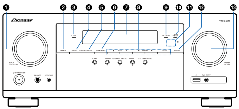
1. INPUT SELECTOR dial: Switch the input to be played.
2. DIMMER button: You can switch the display off or adjust the brightness of the display in three steps.
3. FL OFF indicator: This lights when you have pressed DIMMER repeatedly to turn the display off.
4. ZO NE 2-ON/OFF button: Switches the multizone function on/off.
5. ZONE 2-CONTROL button: Controls the multizone function.
6. HOME MENU button: Displays the Home.
7. Display
8. Cursor buttons ( / / / ) and ENTER button: Select the item with the cursors, and press ENTER to confirm. Use them to tune to stations when using TUNER.
9. NETWORK indicator: This lights when "NET" is selected with the input selector and the unit is connected to the network. Lights up when any of the following functions is working or enabled in standby state of this unit. When this indicator is lighting, the power consumption in standby state increases, however, the increase in power consumption is minimized by entering the HYBRID STANDBY mode where only the essential circuits operate. It does not light when ZONE 2 is on, however.
HDMI CEC
HDMI Standby Through
USB Power Out at Standby
Network Standby
Bluetooth Wakeup
10. MCACC indicator: This lights when you have enabled the speaker calibration made with MCACC.
11. Remote control sensor: Receives signals from the remote controller.
The signal range of the remote controller is within about 16´/5 m, at an angle of 20° on the perpendicular axis and 30° to either side.
12. RETURN button: Returns the display to the previous state.
13. MASTER VOLUME
14. STANDBY/ON button
15. PHONES jack: Headphones with a standard plug (ø1/4"/6.3 mm) are connected.
16. SETUP MIC jack: Connect the supplied speaker setup microphone.
17. TUNER button: Switches the input to be played to "TUNER". Also, pressing this button repeatedly switches the input between "AM" and "FM".
18. PERSONAL PRESET 1/2/3 buttons: Registers the current setting conditions such as input selector, listening mode, etc. or call the registered settings.
19. LISTENING MODE button: Switches the listening mode.
20. USB port: A USB storage device is connected so that music files stored in it can be played.
21. AUX INPUT jack: Connect a mobile music player, etc. using a stereo mini plug cable
Display
1. / / / : These may light when performing operations while "NET" or "USB" is selected with the input selector. / light when there are multiple folders or files that are available to be selected. / light when text information does not fit with the range provided by "8".
2. Lights in the following conditions.
Z2: ZONE 2 is on.
: Connected by BLUETOOTH.
: Connected by Wi-Fi.
NET: Lights when connected to the network with the "NET" input selector. It will blink if incorrectly connected to the network.
USB: Lights when the "USB" input selector is selected, a USB device is connected and the USB input is selected. It will blink if the USB device is not properly connected.
HDMI: HDMI signals are input and the HDMI input is selected.
DIGITAL: Digital signals are input and the digital input is selected.
3. Lights according to the type of input digital audio signal and the listening mode.
4. Lights in the following conditions.
TUNED: Receiving AM/FM radio.
STEREO: Receiving FM stereo.
SLEEP: Sleep timer is set.
AUTO STBY: Auto Standby is set.
5. Displays the audio output destination.
A: Outputs audio only to ZONE A.
B: Outputs audio only to ZONE B.
AB: Outputs audio to both ZONE A and ZONE B.
6. Lights when headphones are connected.
7. Blinks when muting is on.
8. Displays various information of the input signals.
9. Lights when adjusting the volume.
10. Speaker/Channel display: Displays the output channel that corresponds to the selected listening mode.
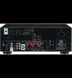
Rear Panel
1. DIGITAL AUDIO IN OPTICAL/COAXIAL jacks: Input TV or AV component digital audio signals with a digital optical cable or digital coaxial cable.
2. ANTENNA AM LOOP/FM UNBAL 75 Ω terminal: Connect the supplied antennas.
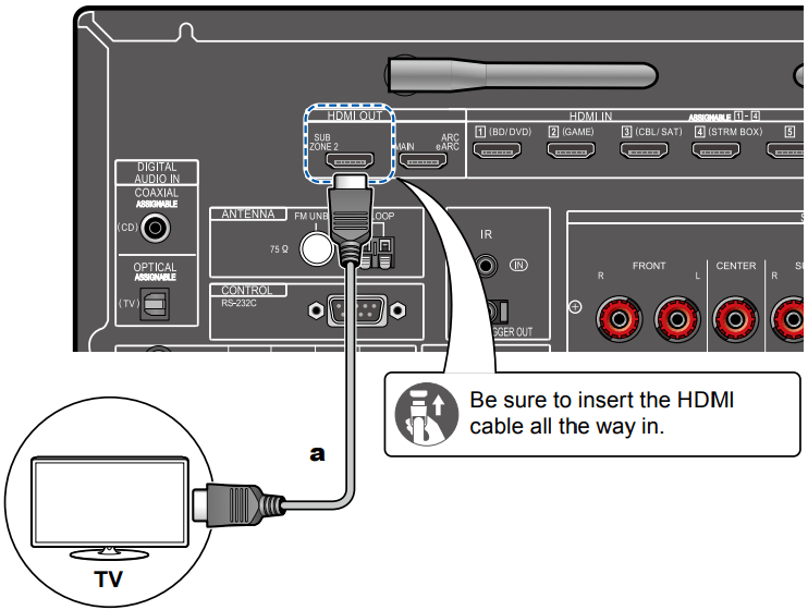
3. HDMI OUT jacks: Transmit video signals and audio signals with an HDMI cable connected to a monitor such as a TV or projector.
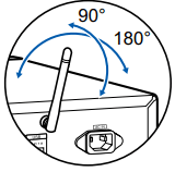
4. Wireless antenna: Used for Wi-Fi connection or when using a BLUETOOTH enabled device. Adjust the angles according to the connection status.
5. HDMI IN jacks: Transmit video signals and audio signals with an HDMI cable connected to an AV component.
6. NETWORK port: Connect to the network with an Ethernet cable.
7. USB port: Connect a USB storage device to play music files. You can also supply power (5 V/1 A) to USB devices with a USB cable.
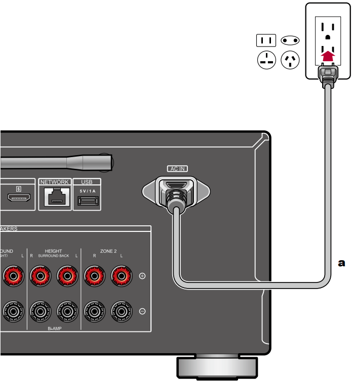
8. AC IN: Connect the supplied power cord.
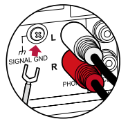
9. SIGNAL GND terminal: Connect the ground wire of the turntable.
10. RS-232C port: Connect a home control system equipped with an RS-232C port. For adopting a home control system, contact the specialized stores.
11. AUDIO IN jacks: Input AV component audio signals with an analog audio cable.
12. IR IN port: Connect a remote control receiver unit.
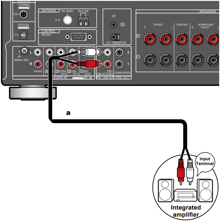
13. ZONE 2 PRE/LINE OUT jacks: Output audio signals with an analog audio cable connected to an integrated amplifier in a separate room (ZONE 2).
ZONE B LINE OUT jacks: Simultaneously output the same audio source as the speakers (ZONE A) connected to this unit by connecting this unit to wireless headphones, wireless speaker transmitter, etc., using an analog audio cable.
14. SUBWOOFER PRE OUT jacks: Connect a powered subwoofer with a subwoofer cable. Up to two powered subwoofers can be connected. The same signal is output from each of the SUBWOOFER PRE OUT jacks.
15. 12V TRIGGER OUT jack: Connect a device equipped with a 12V trigger input jack to enable power link operation between the device and this unit.
16. SPEAKERS terminals: Connect speakers with speaker cables. (Support banana plugs. Use a plug 4 mm in diameter. Y plug connection is not supported.)
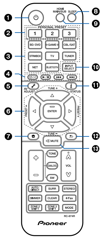
Remote Controller
1. STANDBY/ON button
2. PERSONAL PRESET 1/2/3 buttons: Registers the current setting conditions such as input selector, listening mode, etc. or call the registered settings.
3. Input selector buttons: Switches the input to be played.
4. Play buttons: Used for playback operations for the Music Server or USB device. Also, switching to "CEC MODE" with "21. MODE button" allows you to operate an HDMI CEC function-enabled AV component. (Some devices may not be operated.)
5. (AV ADJUST) button: Settings such as "HDMI" and "Audio" can be made quickly during play on the TV screen.
6. Cursor buttons and ENTER button: Select the item with the cursors, and press ENTER to confirm your selection. When the folder or file lists are not shown on one screen on the TV, press / to change the screen.
7. button: Displays the Home.
8. SLEEP button: You can allow the unit to enter standby automatically when the specified time has elapsed. Select the time from "30 min", "60 min", "90 min" and "Off". When you do not want to turn the unit to standby automatically, select "Off". You can also set this by pressing the button on the remote controller to display the Home screen and selecting "System Setup" - "Hardware" - "Power Management" - "Sleep Timer"
9. HDMI MAIN/SUB button: Select the HDMI OUT jack to output video signals from "MAIN", "SUB", and "MAIN+SUB"
10. INPUT SELECT button: Switches the input to be played.
11. (STATUS) button: Switches the information on the display.
12. button: Returns the display to the previous state.
13. button: Temporarily mutes audio. Press the button again to cancel muting.
14. TONE/DIALOG/SW buttons: Adjusts the sound quality of the speakers and volume level of the subwoofer.
TONE button: You can adjust the sound quality of the speakers.
1. Press TONE repeatedly to select Treble or Bass and adjust the content.
Treble: Enhances or moderates the high-tone range of the speakers.
Bass: Enhances or moderates the low-tone range of the speakers.
2. Press + or - for adjustment.
DIALOG button: Emphasizes movie dialogues and music vocals to listen to them more easily. It is effective to movie lines in particular. Also, it exerts the effect even if the center speaker is not used. Select a desired level from "1" (low) to "5" (high).
1. Press DIALOG.
2. Press + or - for adjustment.
Depending on the input source or listening mode setting, selection is not possible, or the desired effect may not be achieved.
SW button: Adjust the speaker level of the subwoofer while listening to the sound.
1. Press SW.
2. Press + or - to adjust the level between "-15.0 dB" and "+12.0 dB".
If you set the unit to the standby mode, the adjustments you made will be restored to the previous statuses.
15. LISTENING MODE buttons: Selects a listening mode
16. DIMMER button: You can switch the display off or adjust the brightness of the display in three steps.
17. ZONE 2 SHIFT button: Used to control the multi-zone function. (The ZONE 3 SHIFT button cannot be used with this unit.)
18. Volume buttons
19. CLEAR button: Deletes all characters you have entered when entering text on the TV screen.
20. +Fav button: Used to register AM/FM radio stations.
21. MODE button: Switches between automatic tuning and manual tuning for AM/FM stations. Also, when an HDMI CEC functionenabled AV component is connected to this unit, you can switch "4. Play buttons" between "CEC MODE" and "RCV MODE" (normal mode).
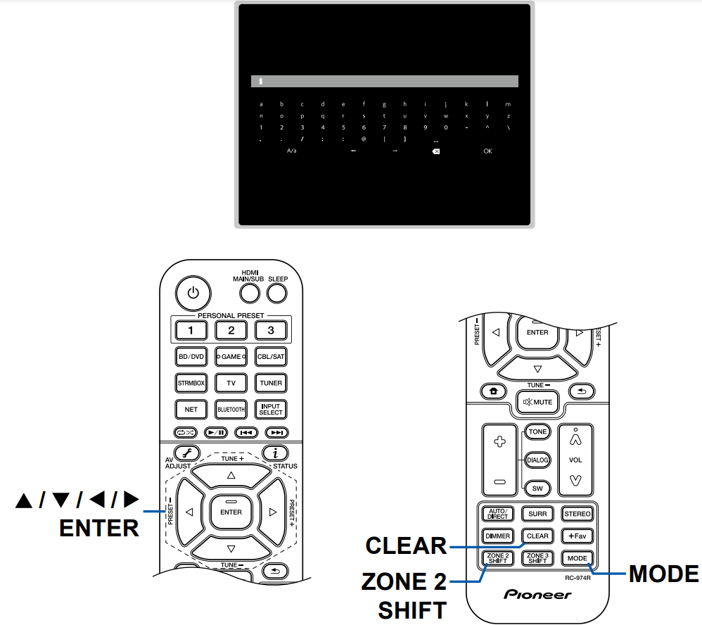
Inputting Characters
You can input characters or symbols on the keyboard displayed on the TV screen such as when inputting a password for Wi-Fi Setup or naming a preset radio station.
1. Select a character or symbol with the cursors / / / on the remote controller and press the ENTER button.
2. When saving characters after input, select "OK" and press the ENTER button.
Select "A/a" to switch between upper and lower cases. (Can also be switched with the MODE button on the remote controller.)
To enter a space, select " ".
To delete a character on the left of the cursor, select " ".
To delete all the input characters, press the CLEAR button on the remote control.
On the ZONE 2 playback screen, operate the remote controller while pressing and holding the ZONE 2 SHIFT button. To delete all the input characters, only press the CLEAR button without pressing the ZONE 2 SHIFT button.
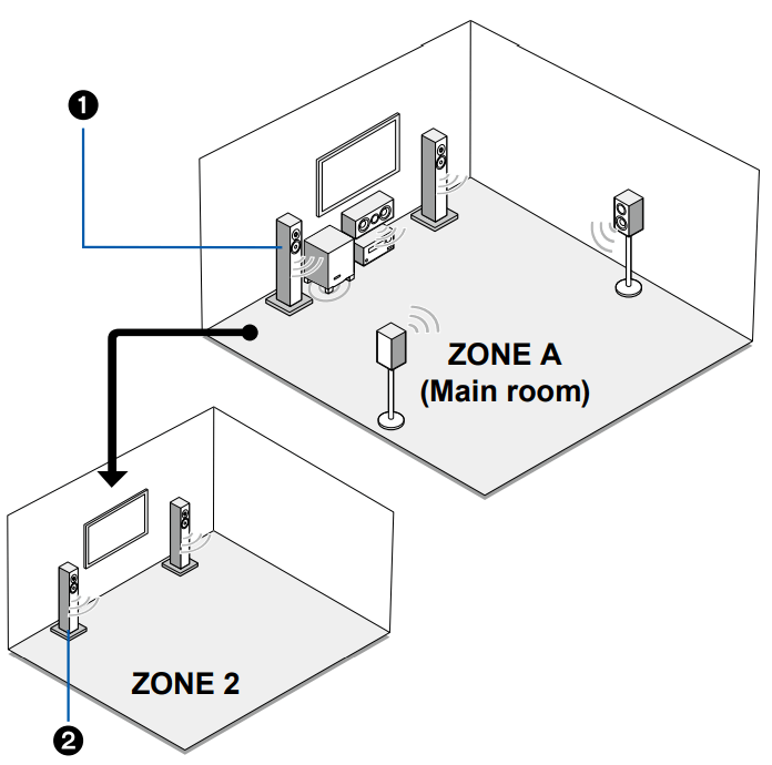
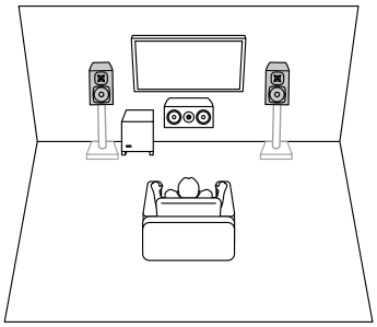
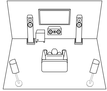
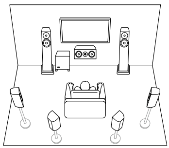
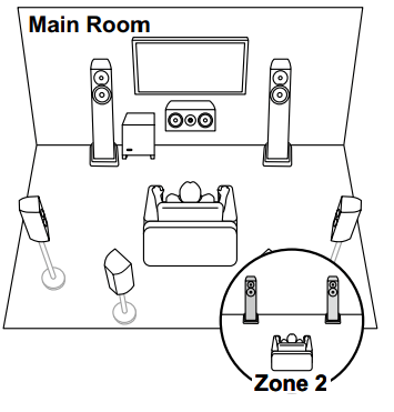
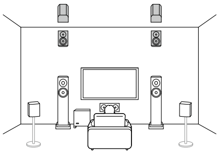
Speaker Layout
The listening room and the speaker layout
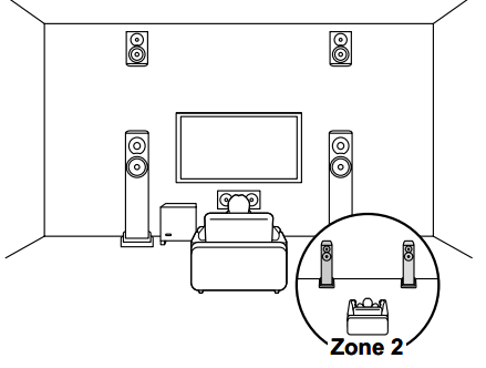
1. ZONE A Speakers
The speaker system set up in the main room (where this unit is located).
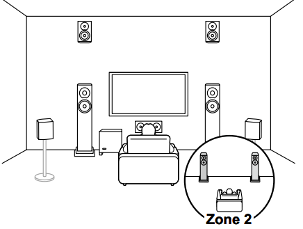
2. ZONE 2 Speakers
The 2 ch speaker system set up in a separate room (ZONE 2). This enables you to play the same source in the main room and the separate at the same time, or to play separate sources.
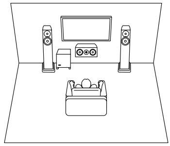
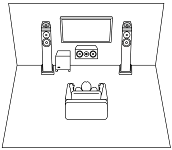
3.1 Channel System
A 3.1 Channel System that combines front speakers with a center speaker and a subwoofer
Basic system
3.1 ch + ZONE 2
3.1 ch (Bi-Amping (Front))
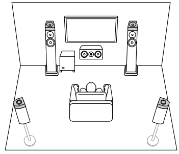
5.1 Channel System
Basic system
5.1 ch ZONE 2
5.1 ch (Bi-Amping (Front))
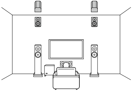
7.1 Channel System
Basic system
7.1 ch + ZONE 2
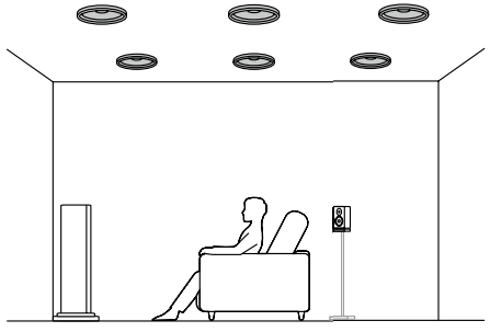
3.1.2 Channel System
3.1.2 ch (Front High or Rear High)
3.1.2 ch (Top Front or Top Middle or Top Rear)
3.1.2 ch (Dolby Enabled Speakers (Front))
3.1.2 ch + ZONE 2
3.1.2 ch (Bi-Amping (Front))
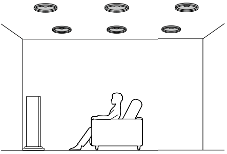
5.1.2 Channel System
5.1.2 ch (Front High or Rear High)
5.1.2 ch (Top Front or Top Middle or Top Rear)
5.1.2 ch (Dolby Enabled Speakers (Front or Surround))
5.1.2 ch + ZONE 2
Connections
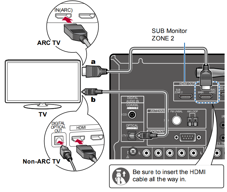
Connecting the TV
By connecting a TV to this unit, you can show the video from AV devices connected to this unit on the TV and also play the sound from the TV through this unit.
To ARC/eARC TV
If the TV supports the ARC (Audio Return Channel) function(*), use only the HDMI cable to connect with the TV. Use the ARC-compatible HDMI IN jack of the TV for connection. You connect the HDMI cable to the HDMI OUT MAIN jack labeled "ARC" on the receiver side.
To Non-ARC TV
If the TV does not support the ARC (Audio Return Channel) function(*), connect an HDMI cable and digital optical cable.
If you use a cable set-top box, etc. connected to the input jack of this unit to watch TV (without using a TV’s built-in tuner), connection with a digital optical cable is not required.
Setup
When not using the ARC function, in the Home screen, set "System Setup" - "Hardware" - "HDMI" - "Audio Return Channel (eARC supported)" to "Off".
(*)The ARC function and eARC function transmit the audio signals of the TV via an HDMI cable, and plays the audio of the TV on this unit. To check if the TV supports the ARC function and eARC function, refer to the instruction manual of the TV, etc.
ARC/eARC compatible audio formats
Settings are required when 4K or 8K high-quality video is to be played. Also, use an HDMI cable that supports 4K or 8K video.
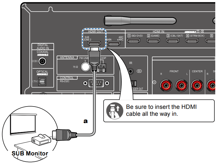
Connecting the SUB Monitor
SUB Monitor
This unit has multiple HDMI OUT jacks, and another TV or projector can be connected to the HDMI OUT SUB jack.
Switch between MAIN and SUB using the HDMI MAIN/SUB button on the remote controller ( →p15) or “AV Adjust”. Note that this jack is not ARC-compatible.
If devices with different resolutions are connected to HDMI OUT MAIN jack and SUB jack, images are output with the lower resolution.
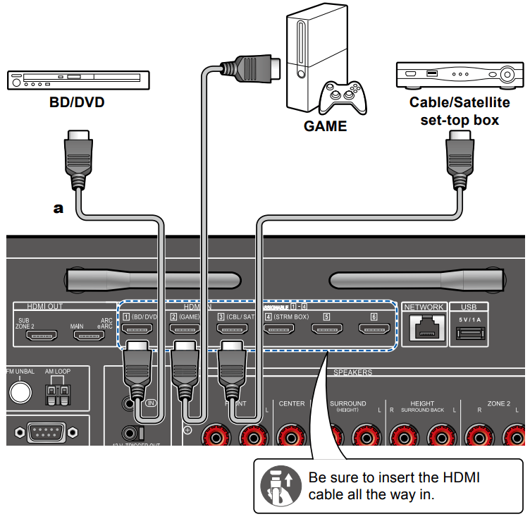
Connecting Playback Devices
Connecting an AV Component with HDMI Jack Mounted
This is a connection example of an AV component equipped with an HDMI jack. When connecting with an AV component that conforms to the CEC (Consumer Electronics Control) standard, you can use the HDMI CEC function (*) that enables linking with input selectors, etc. and the HDMI Standby Through function that can transmit video and audio signals of the AV component to the TV even if this unit is in standby mode.
Settings are required when 4K or 8K high-quality video is to be played. Also, use an HDMI cable that supports 4K or 8K video.
The corresponding resolution is different depending on the HDMI jack connected.
To enjoy digital surround sound including Dolby Digital, set the audio output of the connected Blu-ray Disc player etc. to the Bitstream output.
(*)The HDMI CEC function: This function enables various linking operations with CEC-compliant devices, such as switching input selectors interlocking with a CEC-compliant player, switching audio output between TV and this unit or adjusting the volume using the remote controller of a CEC-compliant TV, and automatically switching this unit to standby when the TV is turned off.
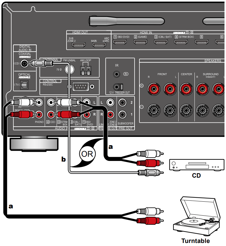
Connecting an Audio Component
This is a connection example of an audio component. Connect a CD player using a digital coaxial cable or analog audio cable. You can also connect a turntable that has an MM-type cartridge to the PHONO jack.
If the turntable has a built-in phono equalizer, connect it to any of the AUDIO IN jacks other than the PHONO jack. Further, if the turntable uses an MC type cartridge, install a phono equalizer compatible with the MC type cartridge between the unit and the turntable, and then connect it to any of the AUDIO IN jacks other than the PHONO jack.
If the turntable has a ground wire, connect it to the SIGNAL GND terminal of this unit.
Connecting an AV Component in a Separate Room (Multi-zone Connection)
Connecting a TV (ZONE 2)
While a disc is played on a Blu-ray Disc player in the main room (where this unit is located), you can play the video and audio of the same Blu-ray Disc player or another AV component on the TV equipped with an HDMI IN jack in a separate room (ZONE 2). Note that only the devices connected to the HDMI IN1 to IN3 jacks can be played on the TV in the separate room.
The audio from externally connected AV components can be output only when the signal is 2 ch PCM audio. It may also be necessary to convert the audio output of the AV component to PCM output.
Setup
When video and audio via HDMI input are output to ZONE 2, set "Input/ Output Assign" - "TV Out / OSD" - "Zone 2 HDMI" to "Use" on the System Setup menu. Note that when "Zone 2 HDMI" is set to "Use", the resolution of the video that can be output by the HDMI OUT SUB/ZONE 2 jack will be limited to "4K Standard".
Connecting an Integrated Amplifier (ZONE 2)
You can enjoy 2 ch audio in the separate room (ZONE 2) while performing playback in the main room (where this unit is located). Use an analog audio cable to connect the ZONE 2 PRE/LINE OUT terminal on this unit to the input jack on an integrated amplifier in the separate room.
To output audio from an externally connected AV component to ZONE 2, connect it to any of HDMI IN1 to IN3 jacks. If the AV component is not equipped with an HDMI jack, use a digital coaxial cable, digital optical cable or analog audio cable. Also, the audio from externally connected AV components can be output to ZONE 2 only when the audio is analog or 2 ch PCM signal. When the AV component is connected to this unit with a digital coaxial cable or digital optical cable, change the audio output of the AV component to the PCM output.
Setup
Settings are required to output audio to ZONE 2. Press on the remote controller to display the Home screen, then set "System Setup" - "Speaker" - "Configuration" - "Zone 2 Preout" to "Zone 2".
When connecting an integrated amplifier that does not have a volume control, in the System Setup menu, set "Multi Zone" - "Zone 2" - "Output Level" to "Variable (Default Value: Fixed)". If you do not set this, the volume output will be very loud and there is a danger of damage to the integrated amplifier, speakers, etc. When connecting an integrated amplifier that has a volume control, leave this as "Fixed".
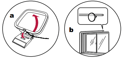
Connecting Antennas
Connect the antenna to this unit, and set up the antenna at the best position for listening while receiving radio signals. Attach the indoor FM antenna to the wall using push pins or adhesive tape.
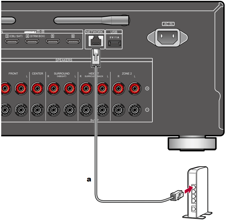
Network Connection
This unit can be connected to the network using a wired LAN or Wi-Fi (wireless LAN). You can enjoy network functions such as Internet radio by network connection. If connection is made by the wired LAN, connect the router and the NETWORK jack with the Ethernet cable as shown in the illustration. To connect by Wi-Fi, select your desired setting method in “Network Connection” of Initial Setup, and then follow the on-screen instructions. To set in the System Setup menu after completing Initial Setup, press on the remote controller, then from the Home screen displayed, set in "Network/Bluetooth" - “Network”. For the Wi-Fi connection, stand the wireless antenna for use.
Connecting External Control Devices
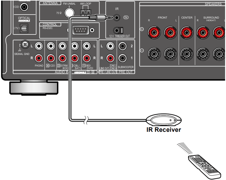
IR IN port
When connecting a remote control receiver unit consisting of an IR Receiver, etc. to this unit, operation using the remote controller is possible even if the remote control signal is difficult to reach (due to installation in the cabinet, etc.). You can also operate the unit using the remote controller from a separate room such as ZONE 2. For adopting a remote control receiver unit, contact the specialized stores.
For the type of cable required for connection, refer to the operation manual, etc. of the remote control receiver unit.
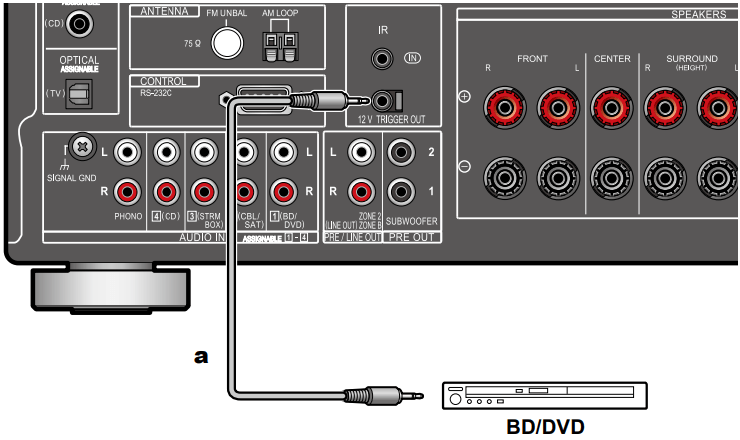
12V TRIGGER OUT jack
When connecting a device equipped with a TRIGGER IN jack such as a BD/ DVD player to this unit, the device can be turned on or set to standby by interlocking the operation on this unit. When any input is selected, this unit outputs a maximum of 12 V/100 mA control signal from the 12V TRIGGER OUT jack, and controls the power link operation of the external device.
For connection, use a monaural mini plug cable (ø1/8″/3.5 mm) without resistance. Do not use a stereo mini plug cable.
Setup: Settings are required to outputs control signal from the 12V TRIGGER OUT jack. Press on the remote controller to display the Home screen, then set any input selector to "Main" or "Zone 2" in "System Setup" - "Hardware" - "12V Trigger".
Connecting the Power Cord
Connect the power cord after all the connections are completed.
This model includes a removable power cord. Be sure to connect the power cord to the AC IN of the unit first, and then connect it to the outlet. Always disconnect the outlet side first when disconnecting the power cord.
Setup
Initial Setup with Auto Start-up Wizard
When you turn the unit on for the first time after purchase, the Initial Setup screen is automatically displayed on the TV to allow you to make settings required for startup using simple operations following on-screen guidance.
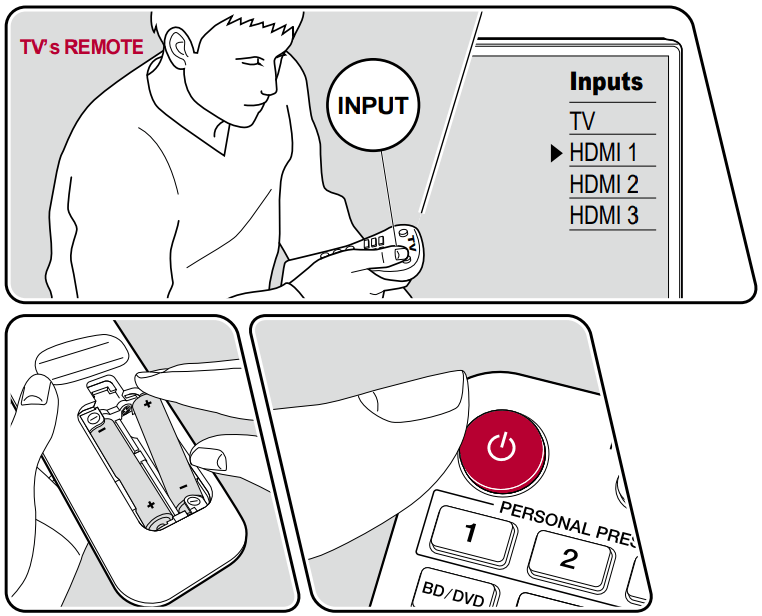
1. Switch the input of the TV to the input connected to the unit.
2. Put batteries into the remote controller of this unit.
3. Press on the remote controller to turn the unit on.
4. When the language selection screen is displayed on TV, select the language with the cursors / and press ENTER.
5. To make the network connection settings, select "Yes" and press ENTER.
Select the item with the cursors of the remote controller, and press ENTER to confirm your selection. To return to the previous screen, press .
If you have terminated the Initial Setup halfway, turn this unit to standby mode. Then turning the power on again can display the Initial Setup again. Unless you do the Initial Setup to the end or select "Never Show Again" in the screen shown after setting the Network Connection, the wizard screen is shown every time the power is turned on.
To perform the Initial Setup again after the setting is completed, press , select "System Setup" - "Miscellaneous" - "Initial Setup", and press ENTER.
Network Connection
1. A confirmation screen asking you whether to agree to the privacy statement is displayed during network setting. If you agree, select "Accept" and press ENTER.
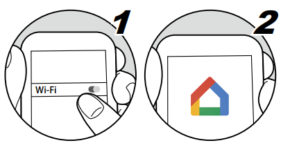
2. Select the type of connection to the network. To use the Chromecast built-in function to connect, select "Yes" and press ENTER. The Google Home app is required to use the Chromecast built-in function. Download the Google Home app from Google Play or the App Store to your smart phone or tablet.
Google Home app can be used on the following operating systems. (As of April 2020)
Android™: Android 4.4 or later.
iOS: iOS 10.0 or later. Compatible with iPhone® , iPad® , and iPod touch® .
If you select "No", you can connect using either wired LAN or Wi-Fi.
"Wired": Use a wired LAN to connect to a network.
"Wireless": Wi-Fi connection using an access point such as a wireless LAN router.
There are two methods for Wi-Fi connection.
"Scan Networks": Search for an access point from this unit. Find out the SSID of the access point beforehand.
"Use iOS Device (iOS7 or later)": Share the Wi-Fi settings of your iOS device with this unit.
If you select "Scan Networks", there are another two types of connection methods. Check the following.
"Enter Password": Enter the password (or key) of the access point to connect.
"Push Button": If the access point is equipped with an automatic setting button, you can connect without entering the password.
If the SSID of the access point is not displayed, select "Other..." with the cursor on the SSID list screen, press ENTER, and then follow the onscreen instructions.
Keyboard Input
To switch between upper and lower cases, select "A/a" on the screen, and press ENTER on the remote controller.
Press +Fav on the remote controller to select whether to mask the password with "" or display it in plain text. Pressing CLEAR on the remote controller will remove all the input characters.
1. Speaker Setup
1. Select the connected speaker configuration, and press ENTER. Note that the image on the screen changes each time you select the number of channels in "Speaker Channels".
(1) Select to suit the number of speaker channels connected.
(2) Set whether a subwoofer is connected or not.
(3) Set the speaker type if height speakers are connected to the HEIGHT terminals.
(4) Set the connection of speakers to Zone 2 speaker terminals.
(5) Set an output destination of the audio output from ZONE 2 PRE/LINE OUT/ ZONE B LINE OUT jack.
(6) Set whether the front speakers are bi-amp connected.
(7) Set the impedance of the connected speakers.
2. The speaker combination selected in step 1 is displayed. "Yes" is displayed for the selected speakers. If the setting is correct, press ENTER.
3. Select "Next" and press ENTER. Then a test tone is output from each speaker to confirm the connection. Selecting each speaker with the cursors / will output the test tone. Press ENTER after confirmation.
4. If there is no problem with the speaker connection, select "Next" and press ENTER. To return to "Speaker Setup", select "Back to Speaker Setup" and press ENTER.
2. Multi Zone Sound Check
Output test tones to ZONE 2 to enjoy audio in a separate room (ZONE 2) in addition to the main room.
3. ARC Setup
If you have connected a TV that supports ARC, select "Yes" and press ENTER.
4. Full Auto MCACC
Place the supplied speaker setup microphone in the listening position, measure the test tones emitted by the speakers, then the unit automatically sets the optimum volume level for each speaker, the crossover frequencies, and the distance from the listening position. This also automatically adjusts the equalizers for the speakers, and enables correction of distortion caused by the acoustic environment of the room.
It takes between 3 and 12 minutes for calibration to be completed. Each speaker outputs the test tone at high volume during measurement, so be careful of your surroundings. Also, keep the room as quiet as possible during measurement.
If you connect a subwoofer, check the power and volume of the subwoofer. Set the subwoofer volume to more than half.
If the power of this unit suddenly turns off, the wires in the speaker cables have touched the rear panel or other wires, and the protection circuit is working. Twist the wires again securely, and make sure they do not stick out of the speaker terminals when connecting.
1. Place the supplied speaker setup microphone at the listening position, and connect it to the SETUP MIC jack on the main unit. SETUP MIC
When placing the speaker setup microphone on a tripod, refer to the illustration.
2. Confirm a test tone is output from the subwoofer and press ENTER.
3. Press ENTER to output test tones from each speaker, and the connected speakers and the noise in the surrounding environment are automatically measured.
4. The measurement results in step 3 are displayed. If there is no problem in the detection result of the speaker, select "Next" and press ENTER to output the test tone again to automatically set the settings such as volume level, crossover frequency, etc., to their optimum. (The test tone is automatically output when 10 seconds has elapsed without any operation.)
5. When the measurement is completed, the measurement results are displayed. You can check each setting using the cursors / . Select "Save" and press ENTER to save the settings.
6. Disconnect the speaker setup microphone.
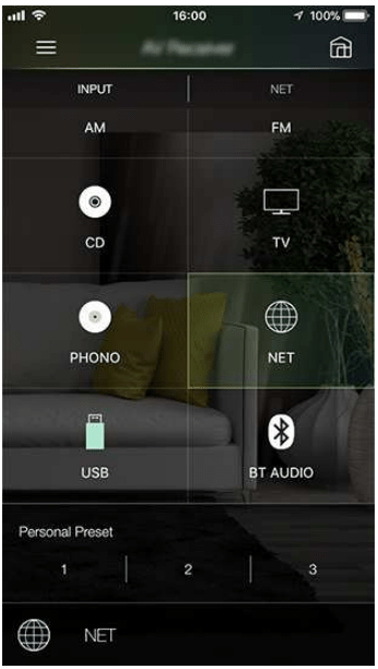
Pioneer Remote App
Pioneer Remote App (available on iOS and Android™ handsets) is a dedicated app available for free which allows you to use your handset as a remote controller. Along with basic operations such as switching input and adjusting the volume, you can also select a radio station or network service (internet radio or play of a music file) without looking at the TV.
To use Pioneer Remote App, this unit needs to be connected to the same network as the mobile device.
Main features
Turning the power On/Off, switching input, adjusting the volume, and other such basic remote controller operations.
When using Multi-zone, you can not only control with the app in the main room (where this unit is located), but also in the separate room (ZONE 2).
Playing internet radio services (TuneIn Radio, etc.) and selecting stations. Control in the palm of your hands without looking at the TV.
Play the music files saved on the mobile device via Wi-Fi.
Play Amazon Music (compatible models only)
Initial Setup
1. Download the Pioneer Remote App from the App Store or Google Play™ Store.
2. Connect the mobile device to the same network as the unit.
3. Start the Pioneer Remote App. This unit is displayed automatically when the app is started, so tap the unit when displayed to select it.
Troubleshooting
When the unit is operating erratically
Try restarting the unit
Restarting this unit may solve the problem. Set the main unit to standby, then after waiting for 5 seconds or more, press and hold the STANDBY/ON button of the main unit for at least 5 seconds, and then restart the unit. (The settings on this unit are kept.) If the problem persists after restarting the unit, unplug and plug the power cords or HDMI cable of this unit and connected devices.
Resetting the unit (this resets the unit settings to the default)
If the restart of the unit does not solve the problem, reset the unit, and restore all the settings to the factory default at the time of purchase. This may solve the problem. If the unit is reset, your settings are restored to the default values. Be sure to note down your setting contents before performing the following operations. Note that it is not possible to reset the unit during the Initial Setup process. Before doing the following procedures, press to exit Initial Setup.
1. While pressing and holding ZONE 2-CONTROL of the input selector on the main unit with the unit turned on, press the STANDBY/ON button.
2. "Clear" is displayed on the display, and the unit returns to the standby state. Do not remove the power cord until "Clear" disappears from the display.
To reset the remote controller, while pressing and holding MODE, press the CLEAR button at least 3 seconds.
Power
When the power is turned on, "AMP Diag Mode" appears on the display of the main unit
The protection circuit function may have operated. If the unit suddenly enters the standby state and "AMP Diag Mode" appears on the display of the main unit when the power is turned on again, this function is diagnosing whether or not the main unit is malfunctioning or there is an abnormality with the speaker cable connection. When the diagnosis is complete, the following messages are displayed.
If the unit returns to the normal ON state after "CH SP WIRE" appears on the display, the speaker cable may have been short-circuited. After setting the power of this unit to standby state, connect the speaker cable again. Twist the wires exposed from the tip of the speaker cable so that the wires do not stick out of the speaker terminal.
If the operation has stopped with "NG" displayed on the display, set the power of this unit to standby state immediately and remove the power plug from the outlet. The unit may be malfunctioning. Consult a dealer.
The unit turns off unexpectedly
The unit automatically switches to standby when the "System Setup" - "Hardware" - "Power Management" - "Auto Standby" setting in the Home screen functions.
The protection circuit function may have operated due to an abnormal rise in temperature of the unit. In such a case, the power turns off repeatedly even if the power is turned on each time. Secure sufficient ventilation space around the unit, wait for a while until the temperature of the unit decreases. Then, turn the power on again.
WARNING: If smoke, smell or abnormal noise is produced by the unit, unplug the power cord from the outlet immediately, and contact the dealer or our company's support.
Audio
Make sure that the speaker setup microphone is no longer connected.
Confirm that the connection between the output jack on the connected device and the input jack on this unit is correct.
Make sure that none of the connecting cables are bent, twisted, or damaged.
If "MUTING" is displayed on the display and is blinking, press on the remote controller to cancel muting.
While headphones are connected to the PHONES jack, no sound is output from the speakers.
When "System Setup" - "Source" - "Audio Select" - "Fixed PCM" in the Home Menu is set to "On", no sound is played when signals other than PCM are input. Change the setting to "Off".
Check the following if the problem persists after you have confirmed the above.
No sound from the TV
Change the input selector on this unit to the position of the terminal to which the TV is connected.
If the TV doesn't support the ARC function, along with connection by HDMI, connect the TV and this unit using a digital optical cable.
No sound from a connected player
Change the input selector on this unit to the position of the jack to which the player is connected.
Check the digital audio output setting on the connected device. On some game consoles, such as those supporting DVD, the default setting may be off.
For some DVD-Video discs, you need to select an audio output format from a menu.
A speaker produces no sound
Make sure that the polarity (+/-) of the speaker cables is correct, and that no bare wires are in contact with the metal part of speaker terminals.
Make sure that the speaker cables are not shorting out.
Check “Connect the Speaker Cables” to see if the speaker connections have been made correctly. Settings for the speaker connection environment need to be made in "Speaker Setup" in Initial Setup. Check "Initial Setup with Auto Start-up Wizard"
Depending on the input signal and listening mode, not much sound may be output from speakers. Select another listening mode to see if sound is output.
If surround back speakers are installed, be sure to install surround speakers as well.
A maximum of 5.1 ch playback is possible when Bi-Amping connection is used. Be sure to remove the jumper bar on the speakers when using Bi-Amping connection.
The subwoofer produces no sound
If the setting of the front speakers is "Large", the low range elements will be output from the front speakers instead of from the subwoofer during 2 ch audio input of TV or music. To output the sound from the subwoofer, make one of the following settings.
1. Change the front speakers settings to "Small". The low range elements will be output from the subwoofer rather than the front speakers. We do not recommend changing this if your front speakers have good low range reproduction capabilities.
2. Change "Double Bass" to "On". The low range elements of the front speakers will be output from both the front speakers and the subwoofer. Due to this, the bass sound may be emphasized too much. In such a case, do not change the setting, or make the setting with the above option 1.
For the setting details, refer to "System Setup" - "Speaker" - "Crossover".
If the input signals do not contain subwoofer audio elements (LFE), the subwoofer may produce no sound.
Noise can be heard
Using cable ties to bundle audio pin cables, power cords, speaker cables, etc. may degrade the audio performance. Do not bundle the cords.
An audio cable may be picking up interference. Change the position of the cables.
The beginning of audio received by an HDMI IN cannot be heard
Since it takes longer to identify the format of an HDMI signal than it does for other digital audio signals, audio output may not start immediately.
Sound suddenly reduces
When using the unit for extended periods with the temperature inside the unit exceeding a certain temperature, the volume may be reduced automatically to protect the circuits.
Listening Modes
To enjoy digital surround playback in formats such as Dolby Digital, you need to make a connection for audio signals with an HDMI cable, digital coaxial cable or digital optical cable. Also, audio output need to be set to Bitstream output on the connected Blu-ray Disc player, etc.
Press on the remote controller several times to switch the display of the main unit, and you can check the input format. Check the following if the problem persists after you have confirmed the above.
Cannot select a desired listening mode
Depending on the connection status of the speaker, some listening modes may not be selected. Check “Speaker Layouts and Selectable Listening Modes” or "Input Formats and Selectable Listening Modes".
Cannot listen to the sound in Dolby TrueHD, Dolby Atmos or DTS-HD Master Audio format
If the audio in Dolby TrueHD, Dolby Atmos or DTS-HD Master Audio format cannot be output correctly in the source format, set "BD video supplementary sound" (or reencode, secondary sound, video additional audio, etc.) to "Off" in the setting of a connected Blu-ray Disc player, etc. After changing the setting, switch the listening mode to that for each source, and confirm.
About Dolby signals
When surround back speakers are included in the speaker layout, and software that is recorded with the 5.1 channel Dolby audio format is played, the surround channel audio may be output from the surround back speakers.
Some Dolby Atmos audio format that is used on games, etc., may be recognized as "Multichannel PCM". If this occurs, check the firmware updates for the game console.
About DTS signals
With media that switches suddenly from DTS to PCM, PCM playback may not start immediately. In such a case, stop playback on the player side for approx. 3 seconds or more. Then, resume playback. The playback will be performed normally.
DTS playback may not be performed normally on some CD and LD players even if the player and this unit are digitally connected. If some processing (e.g., output level adjustment, sampling frequency conversion, or frequency characteristic conversion) has been executed for the DTS signal being output, this unit cannot recognize it as a genuine DTS signal, and noise may occur.
While playing a DTS-compatible disc, if a pause or skip operation is performed on your player, noise may occur for a short period. This is not a malfunction.
Video
Confirm that the connection between the output jack on the connected device and the input jack on this unit is correct.
Make sure that none of the connecting cables are bent, twisted, or damaged.
When the TV image is blurry or unclear, the power cord or connection cables of the unit may have interfered. In such a case, keep distance between TV antenna cable and cables of the unit.
Check the switching of the input screen on the monitor side such as a TV.
Check the following if the problem persists after you have confirmed the above.
No image appears
Change the input selector on this unit to the position of the jack to which the player is connected.
No image from a device connected to HDMI IN jack
To display video from the connected player on the TV while the unit is in standby, you need to enable "System Setup" - "Hardware" - "HDMI" - "HDMI Standby Through" on the Home screen. For details of the HDMI Standby Through function, refer to "System Setup" - "Hardware" - "HDMI".
To output video to a TV connected to the HDMI OUT SUB jack, press the button on the remote controller to display "AV Adjust" and select "HDMI" - "HDMI Out", or press the HDMI MAIN/SUB button on the remote controller. Then, select the HDMI OUT jack for output.
Check if "Resolution Error" is displayed on the main unit display when video input via HDMI IN jack is not displayed. In this case, the TV does not support the resolution of the video input from the player. Change the setting on the player.
Normal operation with an HDMI-DVI adapter is not guaranteed. In addition, video signals output from a PC are not guaranteed.
Try switching off the Deep Color function. To turn off the Deep Color function, simultaneously press the PERSONAL PRESET 2 and STANDBY/ON buttons on the main unit.
While holding down PERSONAL PRESET 2, press STANDBY/ON repeatedly until "Deep Color:Off" appears on the display. To reactivate the Deep Color function, repeat the above described step until "Deep Color:On" is appeared on the display.
Images flicker
The output resolution of the player may not be compatible with the resolution of the TV. If the player is connected to this unit with an HDMI cable, change the output resolution on the player. Also this may be solved by changing the screen mode on the TV.
Video and audio are out of synch
Depending on the settings on your TV and connection environment, the video may be behind the audio. To adjust, press on the remote controller, and adjust in "HDMI" - "Sound Delay" in the "AV Adjust".
Linked operation
HDMI linked operation does not work with CEC-compliant devices, such as a TV
In the Home screen of the unit, set "System Setup" - "Hardware" - "HDMI" - "HDMI CEC" to "On".
It is also necessary to set HDMI linking on the CEC-compliant device. Check the instruction manual.
When connecting a Sharp brand player or recorder to the HDMI IN jacks, set "System Setup" - "Hardware" - "HDMI" - "HDMI Standby Through" to "Auto".
Tuner
Poor reception or much noise
Recheck the antenna connection.
Move the antenna away from the speaker cord or power cord.
Move the unit away from your TV or PC.
Passing cars or airplanes in the vicinity can cause interference.
If radio waves are blocked by concrete walls, etc., radio reception may be poor.
Change the reception mode to mono
When listening to an AM station, operating the remote controller may cause noise.
FM reception may be clearer if you use the antenna jack on the wall used for the TV.
BLUETOOTH function
Unplug and plug the power cord of the unit, or turn off and on the BLUETOOTH enabled device. Restart of the BLUETOOTH enabled device may be effective.
BLUETOOTH enabled devices must support the A2DP profile.
Because a radio wave interference will occur, this unit may not be used near devices such as a microwave oven or cordless phone which use the radio wave in the 2.4 GHz range.
A metallic object near the unit can affect on the radio wave, and BLUETOOTH connection may not be possible.
Check the following if the problem persists after you have confirmed the above.
Cannot connect a BLUETOOTH wireless technology enabled device (PC, smartphone, etc.) to this unit
Check if the BLUETOOTH function of the BLUETOOTH enabled device is enabled.
Initialize the pairing information and perform pairing again.
Firstly delete all the pairing information saved on this unit. In the Home screen, select "Network/Bluetooth" - "Bluetooth" - "Bluetooth Receiver" - "Pairing Information", then press ENTER while "Clear" is displayed.
Next, delete the pairing information of this unit that is saved on the BLUETOOTH wireless technology enabled device. For information on how to clear the pairing information, refer to the BLUETOOTH enabled device's instruction manual.
Finally, perform pairing again. Refer to “Playing audio from BLUETOOTH wireless technology enabled devices with this unit” for pairing instructions.
Cannot connect this unit to a BLUETOOTH wireless technology enabled device (wireless headphones, etc.)
Check if the BLUETOOTH function of the BLUETOOTH enabled device is enabled.
Initialize the pairing information and perform pairing again.
Firstly delete all the pairing information saved on this unit. In the Home screen, select "Network/Bluetooth" - "Bluetooth" - "Bluetooth Transmitter" - "Pairing Information", then press ENTER while "Clear" is displayed.
Next, delete the pairing information of this unit that is saved on the BLUETOOTH wireless technology enabled device. For information on how to clear the pairing information, refer to the BLUETOOTH enabled device's instruction manual.
Finally, perform pairing again. Refer to "Transmitting audio from this unit to BLUETOOTH wireless technology enabled devices" for pairing instructions.
Music playback is unavailable on the unit even after successful BLUETOOTH connection
When the audio volume of your BLUETOOTH enabled device is set low, the audio may not be played back. Turn up the volume of the BLUETOOTH enabled device.
Depending on the BLUETOOTH enabled device, the Send/Receive selector switch may be equipped. Select Send mode.
Depending on the characteristics or specifications of the BLUETOOTH enabled device, music may not be played back on this unit.
Sound is interrupted
There maybe a problem with the BLUETOOTH enabled device. Check the information on a web page.
The audio quality is poor after connection with a BLUETOOTH enabled device
The BLUETOOTH reception is poor. Move the BLUETOOTH enabled device closer to the unit, or remove any obstacle between the BLUETOOTH enabled device and this unit.
Network function
If you cannot select a network service, start up the network function to select it. It may take approx. one minute to start it up.
When the NET indicator is blinking, this unit is not properly connected to the home network.
Unplug and plug the power cords of this unit and the router, or restart the router.
If the desired router is not displayed in the access point list, it may be set to hide SSID, or the ANY connection may be off. Change the setting and try again.
Check the following if the problem persists after you have confirmed the above.
Cannot access the Internet radio
In the case the service provider has terminated the service, the network service or contents may not be used on this unit.
Check if your modem and router are properly connected, and they are both turned on.
Check if the LAN side port on the router is properly connected to this unit.
Check if connecting to Internet from other devices is possible. If it is not possible, turn off all devices connected to the network, wait for a while, and then turn on the devices again.
Depending on ISP, setting the proxy server is required.
Check if the router and modem you are using are supported by your ISP.
Cannot access the network server
This unit needs to be connected to the same router as the network server.
This unit supports the Windows Media® Player 12 network servers, or NASes that support the home network function.
Windows Media® Player may require some settings. Refer to "Music Server".
When using a PC, only the music files registered in the library of Windows Media ® Player can be played.
Sound is interrupted when playing music files on the network server
Check if the network server meets the requirements for operation.
When the PC is serving as the network server, quit application software other than the server software (Windows Media® Player 12, etc.).
If the PC is downloading or copying large files, the playback sound may be interrupted.
USB storage device
USB storage device is not displayed
Check if the USB storage device or USB cable is securely inserted to the USB port of the unit.
Disconnect the USB storage device once from the unit, and then reconnect it.
Performance of the hard disk that receive power from the USB port of the unit is not guaranteed.
Depending on the type of content, the playback may not be performed normally. Check the types of supported file formats.
Operations of USB storage devices equipped with security functions are not guaranteed.
Wireless LAN Network
Unplug and plug the power cords of this unit and the wireless LAN router, check the power-on status of the wireless LAN router, or restart the wireless LAN router.
Check the following if the problem persists after you have confirmed the above.
Cannot access wireless LAN network
The wireless LAN router setting may be switched to Manual. Restore the setting to Auto.
Try the manual set-up. The connection may succeed.
When the wireless LAN router is in stealth mode (mode to hide SSID) or when the ANY connection is off, the SSID is not displayed. Change the setting and try again.
Check if the SSID and encryption settings (WEP, etc.) are correct. Match the network settings with the settings of this unit.
Connection to an SSID that includes multi-byte characters is not supported. Set the SSID of the wireless LAN router using single-byte alphanumeric characters only, and try again.
Connected to an SSID different from the selected SSID
Some wireless LAN routers allow you to set multiple SSIDs for one unit. If connecting to such a router using the automatic setting button, you may end up connecting to an SSID different from the SSID you want to connect to. If this occurs, use the connection method requiring you to enter a password.
Playback sound is interrupted, or communication is not possible
You may not receive radio waves due to poor radio wave conditions. Shorten the distance from the wireless LAN router, or remove obstacles to improve visibility, and connect again. Install the unit away from microwave ovens or other access points. It is recommended to install the wireless LAN router and the unit in the same room.
If there is a metallic object near the unit, wireless LAN connection may not be possible because the metal affects the radio wave.
When other wireless LAN devices are used near the unit, other symptoms may occur, such as interrupted playback and impossible communication. You can avoid those problems by changing the channel of your wireless LAN router. For instructions on changing channels, refer to the instruction manual supplied with your wireless LAN router.
There may not be enough bandwidth available in wireless LAN. Use a wired LAN for connection.
ZONE B function
Cannot output audio to ZONE B
To output audio to ZONE B, set the audio output destination for "Audio" - "Zone B" on AV Adjust to "On (A+B)" or "On (B)" and also set "Speaker" - "Configuration" - "Zone 2 Preout" on the System Setup menu to "Zone B".
Multi-zone function
Cannot ZONE-output the audio of externally connected AV components
To output audio from an externally connected AV component to ZONE 2, connect it to any of HDMI IN1 to IN3 jacks. If the AV component is not equipped with an HDMI jack, use a digital coaxial cable, digital optical cable or analog audio cable. Also, the audio from externally connected AV components can be output to ZONE 2 only when the audio is analog or 2 ch PCM signal. When the AV component is connected to this unit with an HDMI cable, digital coaxial cable or digital optical cable, change the audio output of the AV component to the PCM output.
When video and audio via HDMI input are output to ZONE 2, set "Input/Output Assign" - "TV Out / OSD" - “Zone 2 HDMI” to "Use" on the System Setup menu.
Others
If the audio signal is from the NET or USB input selector, zone output is not possible for DSD audio signals.
Remote Controller
Make sure that the batteries are inserted with the correct polarity.
Insert new batteries. Do not mix different types of batteries, or old and new batteries.
Make sure that the sensor of the main unit is not subjected to direct sunlight or inverter-type fluorescent lights. Relocate it if necessary.
If the main unit is installed in a rack or cabinet with colored-glass doors, or if the doors are closed, the remote controller may not work normally.
Display
The display does not light up
When the Dimmer function is working, the display may go dim or turn off. Press the DIMMER button, and change the brightness level of the display.
Others
Strange noise can be heard from the unit
If you have connected another device to the same outlet as this unit, strange noise may occur under the influence of the device. If the symptom is remedied by removing the power plug of the other device from the outlet, use different outlets for this unit and the device.
The message "Noise Error" appears during Full Auto MCACC •
This can be caused by a malfunction in your speaker unit. Check the speaker output, etc.
The measurement results of Full Auto MCACC show different distances to the speakers from the actual ones
Depending on the speakers you are using, some errors may occur in the measurement results. If this is the case, make the settings in "System Setup" - "Speaker" - "Distance".
The measurement results of Full Auto MCACC show that the volume level of the subwoofer has been corrected to the lower limit
The volume level correction of the subwoofer may not have been completed. Lower the volume of the subwoofer before Full Auto MCACC measurement.
Cannot operate the Full Auto MCACC screen with the Pioneer Remote App (available on iOS and Android™)
Start the Pioneer Remote App before connecting the speaker setup microphone.
 /
/  /
/  /
/  ) and ENTER button: Select the item with the cursors, and press ENTER to confirm. Use them to tune to stations when using TUNER.
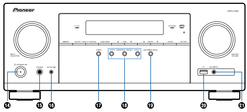
 STANDBY/ON button
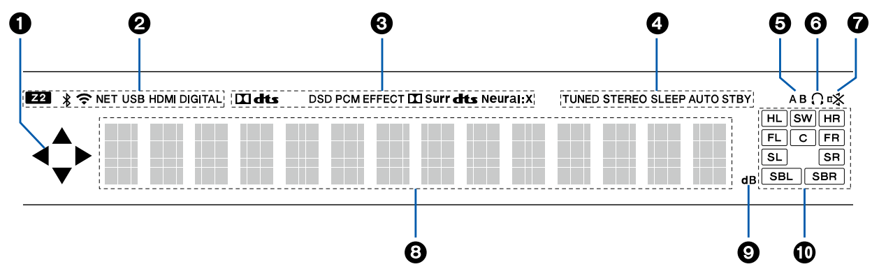
 /
/  /
/  /
/  : These may light when performing operations while "NET" or "USB" is selected with the input selector.
  : Connected by BLUETOOTH.
 : Connected by Wi-Fi.
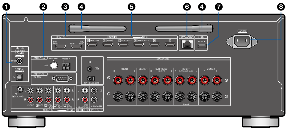

 STANDBY/ON button
 (AV ADJUST) button: Settings such as "HDMI" and "Audio" can be made quickly during play on the TV screen.
 button: Displays the Home.
 (STATUS) button: Switches the information on the display.
 button: Returns the display to the previous state.
 button: Temporarily mutes audio. Press the button again to cancel muting.
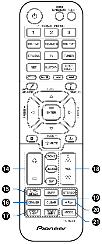
 ".
". ".
".


 on the remote controller to display the Home screen, then set "System Setup" - "Speaker" - "Configuration" - "Zone 2 Preout" to "Zone 2".
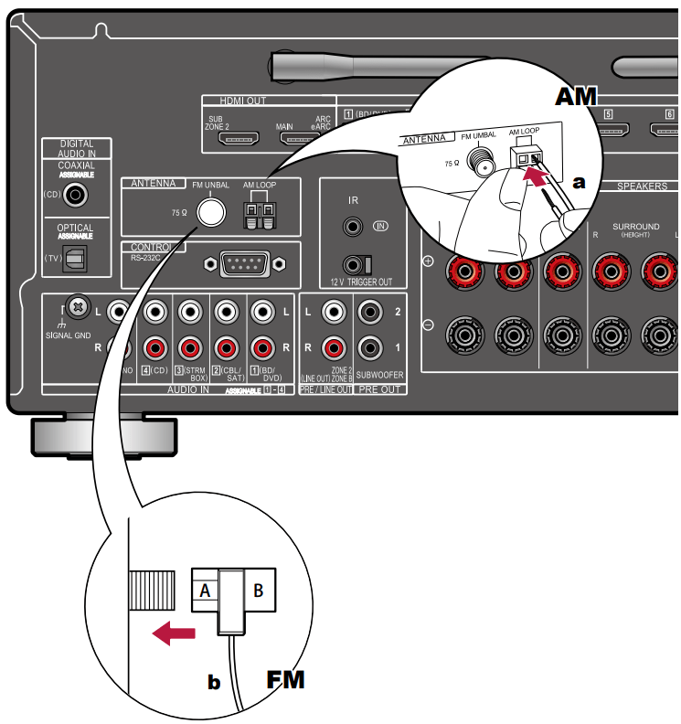
 /
/  and press ENTER.
 .
. , select "System Setup" - "Miscellaneous" - "Initial Setup", and press ENTER.
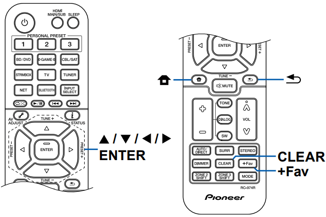
 on the SSID list screen, press ENTER, and then follow the onscreen instructions.
 " or display it in plain text. Pressing CLEAR on the remote controller will remove all the input characters.
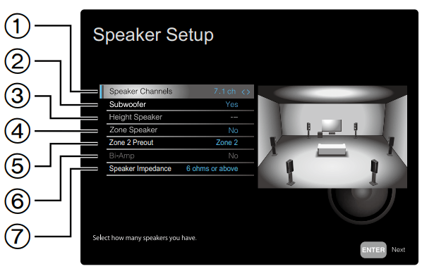
 /
/  will output the test tone. Press ENTER after confirmation.
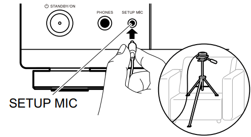
 /
/  . Select "Save" and press ENTER to save the settings.
 STANDBY/ON button of the main unit for at least 5 seconds, and then restart the unit. (The settings on this unit are kept.) If the problem persists after restarting the unit, unplug and plug the power cords or HDMI cable of this unit and connected devices.
 to exit Initial Setup.


 is blinking, press
  on the remote controller several times to switch the display of the main unit, and you can check the input format. Check the following if the problem persists after you have confirmed the above.
 button on the remote controller to display "AV Adjust" and select "HDMI" - "HDMI Out", or press the HDMI MAIN/SUB button on the remote controller. Then, select the HDMI OUT jack for output.
 STANDBY/ON buttons on the main unit.