
Online Edition for Part no. 01402667083 - VI/19

WELCOME TO MINI.
OWNER'S MANUAL.
MINI HARDTOP 2 DOOR / 4 DOOR.
Thank you for choosing a MINI.
The more familiar you are with your vehicle, the better control you will have
on the road. We therefore strongly suggest:
Read this Owner's Manual before starting off in your new MINI. It contains
important information on vehicle operation that will help you make full use of
the technical features available in your MINI. The manual also contains
information designed to enhance operating reliability and road safety, and to
contribute to maintaining the value of your MINI.
Any updates made after the editorial deadline can be found in the appendix of
the printed Owner's Manual for the vehicle.
Get started now. We wish you driving fun and inspiration with your MINI.
3
Online Edition for Part no. 01402667083 - VI/19

TABLE OF CONTENTS
NOTES
Information............................................................................................................................10
QUICK REFERENCE
Entering..................................................................................................................................20
Set-up and use.......................................................................................................................23
On the road............................................................................................................................ 26
AT A GLANCE
Cockpit.................................................................................................................................... 36
Central Information Display (CID)..................................................................................40
General settings...................................................................................................................45
Owner's Manual media.......................................................................................................54
CONTROLS
Opening and closing........................................................................................................... 58
Seats, mirrors, and steering wheel.................................................................................76
Transporting children safely............................................................................................86
Driving.................................................................................................................................... 91
Displays................................................................................................................................115
Lights.................................................................................................................................... 131
Safety.....................................................................................................................................137
Driving stability control systems.................................................................................157
Driving comfort................................................................................................................. 162
Climate control...................................................................................................................182
Interior equipment............................................................................................................190
Storage compartments.....................................................................................................198
Cargo area............................................................................................................................202
4
Online Edition for Part no. 01402667083 - VI/19

DRIVING TIPS
Things to remember when driving..............................................................................210
Saving fuel...........................................................................................................................215
ENTERTAINMENT
General information......................................................................................................... 224
Tone.......................................................................................................................................226
Radio..................................................................................................................................... 228
Audio.....................................................................................................................................236
COMMUNICATION
Telephone............................................................................................................................ 242
MINI Connected................................................................................................................ 246
MOBILITY
Refueling..............................................................................................................................252
Fuel........................................................................................................................................254
Wheels and tires................................................................................................................256
Engine compartment........................................................................................................279
Engine oil.............................................................................................................................282
Coolant..................................................................................................................................286
Maintenance....................................................................................................................... 288
Replacing components.................................................................................................... 290
Breakdown assistance..................................................................................................... 299
Care........................................................................................................................................307
REFERENCE
Technical data.................................................................................................................... 314
Appendix..............................................................................................................................318
License Texts and Certifications..................................................................................319
Everything from A to Z....................................................................................................328
5
Online Edition for Part no. 01402667083 - VI/19

© 2019 Bayerische Motoren Werke
Aktiengesellschaft
Munich, Germany
Reprinting, including excerpts, only with the written consent of BMW AG, Munich.
US English ID5 VI/19, 07 19 490
Printed on environmentally friendly paper, bleached without chlorine, suitable for recycling.
6
Online Edition for Part no. 01402667083 - VI/19

7
Online Edition for Part no. 01402667083 - VI/19

8
Online Edition for Part no. 01402667083 - VI/19

NOTES
Information ................................................................................................ 10
9
Online Edition for Part no. 01402667083 - VI/19
Information
Using this Owner's Manual
Orientation
The fastest way to find information on a
particular topic is by using the index.
An initial overview of the vehicle is pro-
vided in the first chapter.
Updates made after the editorial
deadline
Due to updates after the editorial deadline,
differences may exist between the printed
Owner's Manual and the Integrated Owner's
Manual in the vehicle.
Notes on updates can be found in the ap-
pendix of the printed Owner's Manual for
the vehicle.
Additional sources of informa-
tion
Service center
A service center will be glad to answer
questions at any time.
Internet
Vehicle information and general informa-
tion on MINI, e.g., on technology, are availa-
ble on the Internet: www.mini.jp.
Vehicle information and general informa-
tion on MINI, e.g., on technology, are availa-
ble on the Internet: www.miniusa.com.
MINI Motorer’s Guide app
The Owner's Manual is available in many
countries as an app for iOS or Android in
the respective Store.
MINI Driver’s Guide Web
Driver’s Guide Web shows the most suita-
ble information for the selected vehicle. If
possible, only equipment and functions that
are actually installed in the vehicle will be
explained. Driver’s Guide Web can be dis-
played in any current browser.
Symbols and displays
Symbols in the Owner's Manual
Sym-
bol
Meaning
Precautions that must be
followed in order to avoid the
possibility of injury to yourself
and to others as well as serious
damage to the vehicle.
Measures that can be taken to
help protect the environment.
"..." Control Display texts used to
select individual functions.
Action steps
Action steps to be carried out are presented
as a numbered list. The steps must be car-
ried out in the defined order.
1. First action step.
2. Second action step.
Enumerations
Enumerations without mandatory order or
alternative possibilities are presented as a
list with bullet points.
– First possibility.
Seite 10
NOTES Information
10
Online Edition for Part no. 01402667083 - VI/19

– Second possibility.
Symbols on vehicle components
This symbol on a vehicle component
indicates that further information on the
component is available in the Owner's
Manual.
Vehicle features and options
This Owner's Manual describes all models
and all standard, country-specific and op-
tional equipment that is offered in the
model series. Therefore, this Owner's
Manual also describes and illustrates fea-
tures and functions that are not available in
a vehicle, for example because of the se-
lected optional features or the country-spe-
cific version.
This also applies to safety-related functions
and systems.
When using these functions and systems,
the applicable laws and regulations must be
observed.
For any options and equipment not descri-
bed in this Owner's Manual, refer to the
Supplementary Owner's Manuals.
Your dealer’s service center is happy to an-
swer any questions that you may have
about the features and options applicable to
your vehicle.
Status of the Owner's Manual
Basic information
The manufacturer of your vehicle pursues a
policy of constant development that is con-
ceived to ensure that our vehicles continue
to embody the highest quality and safety
standards. In rare cases, therefore, the fea-
tures described in this Owner's Manual may
differ from those in your vehicle.
Updates made after the editorial
deadline
Due to updates after the editorial deadline,
differences may exist between the printed
Owner's Manual and the Integrated Owner's
Manual in the vehicle.
Notes on updates can be found in the ap-
pendix of the printed Owner's Manual for
the vehicle.
For Your Own Safety
Manufacturer
The manufacturer of this MINI is Bayeri-
sche Motoren Werke Aktionengesellschaft,
BMW AG.
Intended use
Heed the following when using the vehicle:
– Owner's Manual.
– Information on the vehicle. Do not re-
move stickers.
– Technical vehicle data.
– The traffic, speed, and safety laws where
the vehicle is driven.
– Vehicle documents and statutory docu-
ments.
Warranty
Your vehicle is technically configured for
the operating conditions and registration
requirements applying in the country of
first delivery, also known as homologation.
If your vehicle is to be operated in a differ-
ent country it might be necessary to adapt
your vehicle to potentially differing operat-
ing conditions and registration require-
ments. If your vehicle does not comply with
Seite 11
Information NOTES
11
Online Edition for Part no. 01402667083 - VI/19

the homologation requirements in a certain
country you may not be able to lodge war-
ranty claims for your vehicle there. Further
information on warranty is available from a
service center.
Maintenance and repairs
Advanced technology, for instance the use
of modern materials and high-performance
electronics, requires suitable maintenance
and repair work.
The manufacturer of your vehicle recom-
mends that you entrust corresponding pro-
cedures to a MINI dealer’s service center. If
you choose to use another service facility,
the manufacturer of your vehicle recom-
mends use of a facility that performs work,
e.g., maintenance and repair, according to
MINI specifications with properly trained
personnel, referred to in the Owner's
Manual as "another qualified service center
or repair shop".
If work is performed improperly, for in-
stance maintenance and repair, there is a
risk of subsequent damage and related
safety risks.
Improperly performed work on the vehicle
paint can lead to a failure or malfunction of
components, e.g., the radar sensors, and
thereby result in a safety risk.
Parts and accessories
The manufacturer of your vehicle recom-
mends the use of parts and accessory prod-
ucts approved by the manufacturer of the
MINI.
Approved parts and accessories, and advice
on their use and installation are available
from a MINI dealer's service center.
MINI parts and accessories were tested by
the manufacturer of the MINI for their
safety and suitability in MINI vehicles.
The manufacturer of your vehicle warrants
genuine MINI parts and accessories.
The manufacturer of your vehicle does not
evaluate whether each individual product
from another manufacturer can be used
with MINI vehicles without presenting a
safety hazard, even if a country-specific of-
ficial approval was issued. The manufac-
turer of your vehicle does not evaluate
whether these products are suitable for
MINI vehicles under all usage conditions.
California Proposition 65 Warning
For vehicles sold in California, the law re-
quires vehicle manufacturers to provide the
following warning:
Warning
Engine exhaust and a wide variety of Au-
tomobile components and parts, including
components found in the interior furnish-
ings in a vehicle, contain or emit chemi-
cals known to the State of California to
cause cancer and birth defects and repro-
ductive harm. In addition, certain fluids
contained in vehicles and certain products
of component wear contain or emit chemi-
cals known to the State of California to
cause cancer and birth defects or other re-
productive harm. Battery posts, terminals
and related accessories contain lead and
lead compounds. Batteries also contain
other chemicals known to the State of Cali-
fornia to cause cancer. Wash your hands
after handling. Used engine oil contains
chemicals that have caused cancer in labo-
ratory animals. Always protect your skin
by washing thoroughly with soap and wa-
ter. For more information go to
www.P65Warnings.ca.gov/passenger-ve-
hicle.
Seite 12
NOTES Information
12
Online Edition for Part no. 01402667083 - VI/19

Warning
Operating, servicing and maintaining a
passenger vehicle or off-highway motor
vehicle can expose you to chemicals in-
cluding engine exhaust, carbon monoxide,
phthalates, and lead, which are known to
the State of California to cause cancer and
birth defects or other reproductive harm.
To minimize exposure, avoid breathing ex-
haust, do not idle the engine except as
necessary, service your vehicle in a well-
ventilated area and wear gloves or wash
your hands frequently when servicing
your vehicle. For more information go to
www.P65Warnings.ca.gov/passenger-ve-
hicle.
Service and warranty
We recommend that you read this publica-
tion thoroughly. Your vehicle is covered by
the following warranties:
– New Vehicle Limited Warranty.
– Rust Perforation Limited Warranty.
– Federal Emissions System Defect War-
ranty.
– Federal Emissions Performance War-
ranty.
– California Emission Control System Lim-
ited Warranty.
Detailed information about these warranties
is listed in the Service and Warranty Infor-
mation Booklet for US models or in the War-
ranty and Service Guide Booklet for Cana-
dian models.
Your vehicle has been specifically adapted
and designed to meet the particular operat-
ing conditions and homologation require-
ments in your country and continental re-
gion in order to deliver the full driving
pleasure while the vehicle is operated under
those conditions. If you wish to operate
your vehicle in another country or region,
you may be required to adapt your vehicle
to meet different prevailing operating con-
ditions and homologation requirements.
You should also be aware of any applicable
warranty limitations or exclusions for such
country or region. In such case, please con-
tact Customer Relations for further informa-
tion.
Maintenance
Maintain the vehicle regularly to sustain
the road safety, operational reliability and
the New Vehicle Limited Warranty.
Specifications for required maintenance
measures:
– MINI Maintenance system.
– Service and Warranty Information Book-
let for US models.
– Warranty and Service Guide Booklet for
Canadian models.
If the vehicle is not maintained according to
these specifications, this could result in
damaging the vehicle. Such damage is not
covered by the MINI New Vehicle Limited
Warranty.
Data memory
General information
Electronic control devices are installed in
the vehicle. Electronic control units process
data they receive from vehicle sensors, self-
generate or exchange with each other. Some
control units are necessary for the vehicle
to function safely or provide assistance dur-
ing driving, for instance driver assistance
systems. Furthermore, control units facili-
tate comfort or infotainment functions.
Information about stored or exchanged data
can be requested from the manufacturer of
the vehicle, in a separate booklet, for exam-
ple.
Seite 13
Information NOTES
13
Online Edition for Part no. 01402667083 - VI/19

Personal reference
Each vehicle is marked with a unique vehi-
cle identification number. Depending on the
country, the vehicle owner can be identified
with the vehicle identification number, li-
cense plate and corresponding authorities.
In addition, there are other options to track
data collected in the vehicle to the driver or
vehicle owner, for instance via utilized
services.
Operating data in the vehicle
Control units process data to operate the ve-
hicle.
For example, this includes:
– Status messages for the vehicle and its
individual components, e.g., wheel rota-
tional speed, wheel speed, deceleration,
transverse acceleration, engaged safety
belt indicator.
– Ambient conditions, e.g., temperature,
rain sensor signals.
The processed data is only processed in the
vehicle itself and generally volatile. The
data is not stored beyond the operating pe-
riod.
Electronic components, e.g. control units
and ignition keys, contain components for
storing technical information. Information
about the vehicle condition, component us-
age, maintenance requirements events or
faults can be stored temporarily or perma-
nently.
This information generally records the state
of a component, a module, a system, or the
environment, for instance:
– Operating states of system components,
for instance, fill levels, tire inflation
pressure, battery status.
– Malfunctions and faults in important
system components, for instance lights
and brakes.
– Responses by the vehicle to special sit-
uations such as airbag deployment or
engagement of the driving stability con-
trol systems.
– Information on vehicle-damaging
events.
The data is required to perform the control
unit functions. Furthermore, it also serves
to recognize and correct malfunctions, and
helps the vehicle manufacturer to optimize
vehicle functions.
The majority of this data is volatile and is
only processed within the vehicle itself.
Only a small share of data is stored in event
or fault memories based on an event.
When servicing, for instance during repairs,
service processes, warranty cases, and qual-
ity assurance measures, this technical infor-
mation can be read out from the vehicle to-
gether with the vehicle identification
number.
A dealer’s service center or another quali-
fied service center or repair shop can read
out the information. The socket for OBD On-
board Diagnosis required by law in the ve-
hicle is used to read out the data.
The data is collected, processed, and used
by the relevant organizations in the service
network. The data documents technical con-
ditions of the vehicle, helps with the identi-
fication of the fault, compliance with war-
ranty obligations and quality improvement.
Furthermore, the manufacturer has product
monitoring duties to meet in line with prod-
uct liability law. To fulfill these duties, the
vehicle manufacturer needs technical data
from the vehicle. The data from the vehicle
can also be used to check customer claims
for warranty and guaranty.
Fault and event memories in the vehicle can
be reset when a dealer’s service center or
another qualified service center or repair
shop performs repair or servicing work.
Seite 14
NOTES Information
14
Online Edition for Part no. 01402667083 - VI/19

Data entry and data transfer into
the vehicle
General information
Depending on the vehicle equipment, com-
fort and individual settings can be stored in
the vehicle and modified or reset at any
time.
For example, this includes:
– Settings for the seat and steering wheel
positions.
– Suspension and climate control settings.
If necessary, data can be transferred to the
entertainment and communication system
of the vehicle, for instance via smartphone.
This includes the following depending on
the respective equipment:
– Multimedia data such as music, films or
photos for playback in an integrated
multimedia system.
– Address book data for use in conjunc-
tion with an integrated hands-free sys-
tem or an integrated navigation system.
– Entered navigation destinations.
– Data on the use of Internet services.
This data can be stored locally in the vehicle
or is found on a device that has been con-
nected to the vehicle, e.g., a smartphone,
USB stick or MP3 player. If this data is
stored in the vehicle, it can be deleted at
any time.
This data is only transmitted to third parties
upon personal request as part of the use of
online services. The transmission depends
on the selected settings for the use of the
services.
Incorporation of mobile devices
Depending on the vehicle equipment, mo-
bile devices connected to the vehicle, for in-
stance smartphones, can be controlled via
the vehicle control elements.
The sound and picture from the mobile de-
vice can be played back and displayed
through the multimedia system. Certain in-
formation is transferred to the mobile de-
vice at the same time. Depending on the
type of incorporation, this includes, for in-
stance position data and other general vehi-
cle information. This optimizes the way in
which selected apps, for instance navigation
or music playback, work.
There is no further interaction between the
mobile device and the vehicle, such as ac-
tive access to vehicle data.
How the data will be processed further is
determined by the provider of the particular
app being used. The extent of the possible
settings depends on the respective app and
the operating system of the mobile device.
Services
General information
If the vehicle has a wireless network con-
nection, this enables data to be exchanged
between the vehicle and other systems. The
wireless network connection is realized via
an in-vehicle transmitter and receiver unit
or via personal mobile devices brought into
the vehicle, for instance smartphones. This
wireless network connection enables 'online
functions' to be used. These include online
services and apps supplied by the vehicle
manufacturer or by other providers.
Services from the vehicle
manufacturer
Where online services from the vehicle
manufacturer are concerned, the corre-
sponding functions are described in the ap-
propriate place, for instance the Owner's
Manual or manufacturer's website. The rele-
vant legal information pertaining to data
protection is provided there too. Personal
data may be used to perform online serv-
ices. Data is exchanged over a secure con-
Seite 15
Information NOTES
15
Online Edition for Part no. 01402667083 - VI/19
nection, for instance with the IT systems of
the vehicle manufacturer intended for this
purpose.
Any collection, processing, and use of per-
sonal data above and beyond that needed to
provide the services must always be based
on a legal permission, contractual arrange-
ment or consent. It is also possible to acti-
vate or deactivate the data connection as a
whole. That is, with the exception of func-
tions and services required by law such as
Assist systems.
Services from other providers
When using online services from other pro-
viders, these services are the responsibility
of the relevant provider and subject to their
data privacy conditions and terms of use.
The vehicle manufacturer has no influence
on the content exchanged during this proc-
ess. Information on the way in which per-
sonal data is collected and used in relation
to services from third parties, the scope of
such data, and its purpose, can be obtained
from the relevant service provider.
Event Data Recorder EDR
This vehicle is equipped with an event data
recorder EDR. The main purpose of an EDR
is to record, in certain crash or near crash-
like situations, such as an air bag deploy-
ment or hitting a road obstacle, data that
will assist in understanding how a vehicle’s
systems performed. The EDR is designed to
record data related to vehicle dynamics and
safety systems for a short period of time,
typically 30 seconds or less.
The EDR in this vehicle is designed to re-
cord such data as:
– How various systems in your vehicle
were operating.
– Whether or not the driver and passen-
ger safety belts were fastened.
– How far, if at all, the driver was depress-
ing the accelerator and/or brake pedal.
– How fast the vehicle was traveling.
This data can help provide a better under-
standing of the circumstances in which
crashes and injuries occur.
EDR data is recorded by your vehicle only if
a nontrivial crash situation occurs; no data
is recorded by the EDR under normal driv-
ing conditions and no personal data, for in-
stance name, gender, age, and crash loca-
tion, are recorded.
However, other parties, such as law enforce-
ment, could combine the EDR data with the
type of personally identifying data routinely
acquired during a crash investigation.
To read data recorded by an EDR, special
equipment is required, and access to the ve-
hicle or the EDR is needed. In addition to
the vehicle manufacturer, other parties,
such as law enforcement, that have the spe-
cial equipment, can read the information if
they have access to the vehicle or the EDR.
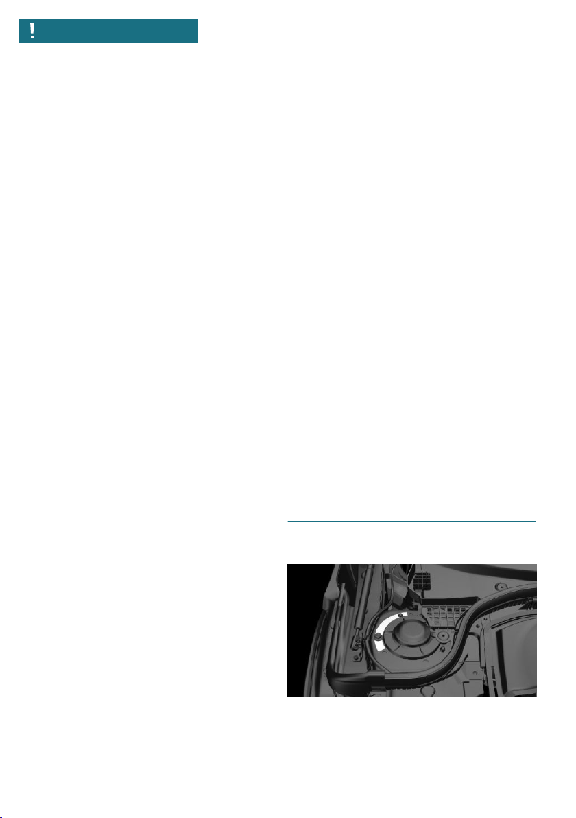
Vehicle identification number
Engine compartment
The vehicle identification number can be
found in the engine compartment, on the
right-hand side of the vehicle.
Seite 16
NOTES Information
16
Online Edition for Part no. 01402667083 - VI/19

Windshield
The vehicle identification number can also
be found behind the windshield.
Reporting safety defects
For US customers
The following only applies to vehicles
owned and operated in the US.
If you believe that your vehicle has a defect
which could cause a crash or could cause in-
jury or death, you should immediately in-
form the National Highway Traffic Safety
Administration NHTSA, in addition to noti-
fying MINI of North America, LLC, P.O. Box
1227, Westwood, New Jersey 07675-1227,
Telephone 1-800-831-1117.
If NHTSA receives similar complaints, it
may open an investigation, and if it finds
that a safety defect exists in a group of ve-
hicles, it may order a recall and remedy
campaign.
However, NHTSA cannot become involved
in individual problems between you, your
dealer, or MINI of North America, LLC.
To contact NHTSA, you may call the Vehicle
Safety Hotline toll-free at 1-888-327-4236
(TTY: 1-800-424-9153); go to http://
www.safercar.gov; or write to: Administra-
tor, NHTSA, 400 Seventh Street, SW.,
Washington, DC 20590. You can also obtain
other information about motor vehicle
safety from http://www.safercar.gov
For Canadian customers
Canadian customers who wish to report a
safety-related defect to Transport Canada,
Defect Investigations and Recalls, may call
the toll-free hotline 1-800-333-0510. You
can also obtain other information about mo-
tor vehicle safety from http://www.tc.gc.ca/
roadsafety.
Seite 17
Information NOTES
17
Online Edition for Part no. 01402667083 - VI/19

18
Online Edition for Part no. 01402667083 - VI/19

QUICK REFERENCE
Entering ...................................................................................................... 20
Set-up and use ........................................................................................... 23
On the road ................................................................................................. 26
19
Online Edition for Part no. 01402667083 - VI/19
Entering
Opening and closing
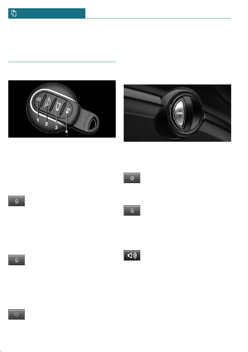
Buttons on the vehicle key
1 Unlocking
2 Locking
3 Unlocking the tailgate
4 Panic mode
Unlocking the vehicle
Press the button on the vehicle key.
Depending on the settings, either only the
driver's door or all vehicle access points are
unlocked.
If only the driver's door is unlocked, press
the button on the vehicle key again to un-
lock the other vehicle access points.
Press and hold the button on the ve-
hicle key after unlocking.
The windows and the glass sunroof are
opened, as long as the button on the vehicle
key is pressed.
Locking the vehicle
Press the button on the vehicle key.
All vehicle access points are locked.
Buttons for the central locking
system
Overview
Buttons for the central locking system.
Locking
Pressing the button locks the vehi-
cle if the front doors are closed.
Unlocking
Pressing the button unlocks the ve-
hicle.
Panic mode
You can trigger the alarm system if you find
yourself in a dangerous situation.
Press the button on the vehicle key
and hold for at least 3 seconds.
To switch off the alarm: press any button.
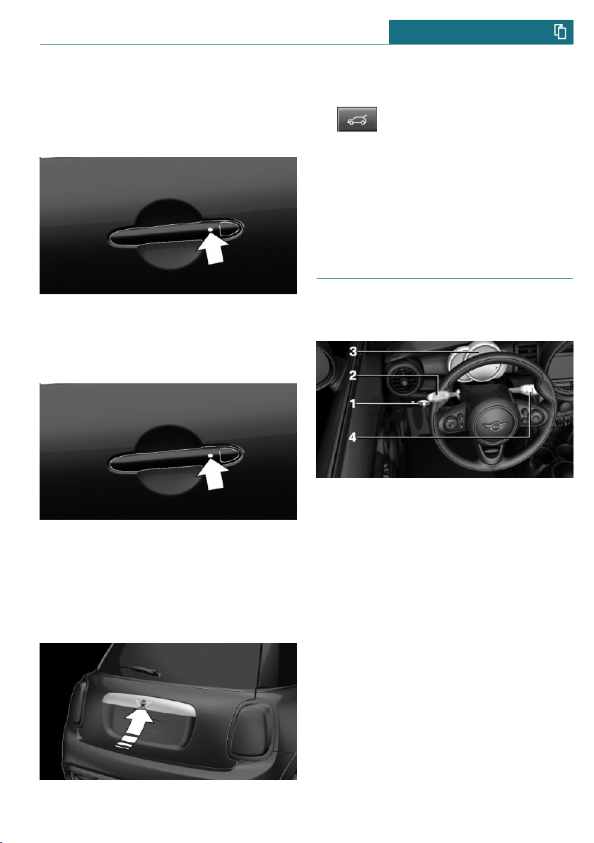
Comfort Access
Concept
The vehicle can be accessed without operat-
ing the vehicle key.
Carrying the vehicle key with you, e.g., in
your pants pocket, is sufficient.
Seite 20
QUICK REFERENCE Entering
20
Online Edition for Part no. 01402667083 - VI/19
The vehicle automatically detects the vehi-
cle key when it is in close proximity or in
the car's interior.
Unlocking the vehicle
On the driver's or front passenger's door
handle, press the button.
Locking the vehicle
On the driver's or front passenger's door
handle, press the button.
Tailgate
unlocking
– Unlock the vehicle and then press the
button on the outside of the tailgate.
– Press and hold the button on the
vehicle key for approx. 1 second.
Depending on the setting, the doors may
also be unlocked.
Closing
Closing the tailgate manually.
Displays and control elements
In the vicinity of the steering
wheel
1 Low beams, fog lights
2 High beams, headlight flasher, turn sig-
nal
3 Instrument cluster
4 Wiper system
Indicator/warning lights
Instrument cluster
The indicator/warning lights can light up in
a variety of combinations and colors.
Several of the lights are checked for proper
functioning and light up temporarily when
the engine is started or the ignition is
switched on.
Seite 21
Entering QUICK REFERENCE
21
Online Edition for Part no. 01402667083 - VI/19
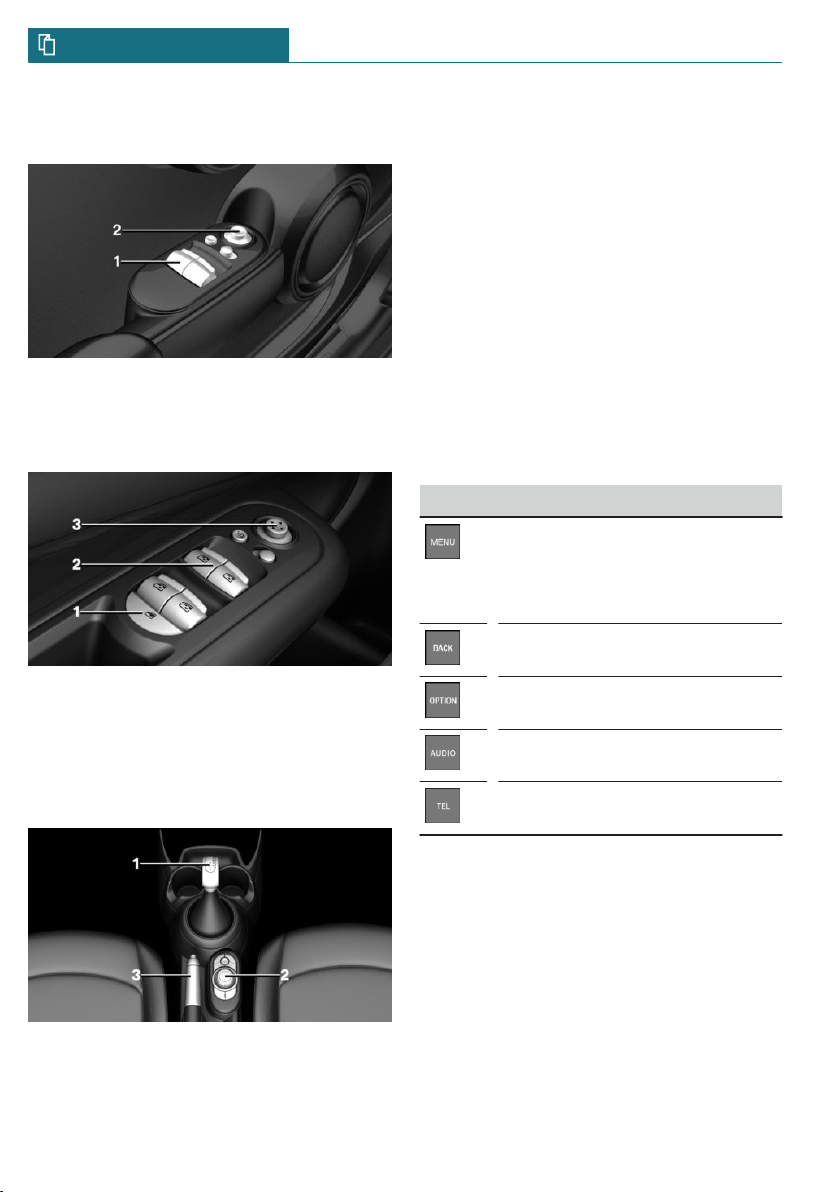
Driver's door
For 3-door models:
1 Power windows
2 Exterior mirrors
For 5-door models:
1 Safety switch
2 Power windows
3 Exterior mirrors
All around the selector lever
1 Selector lever
2 Controller with buttons
3 Parking brake
Central Information Display (CID)
Concept
The Central Information Display (CID) com-
bines the functions of a multitude of
switches. These functions can be operated
via the Controller.
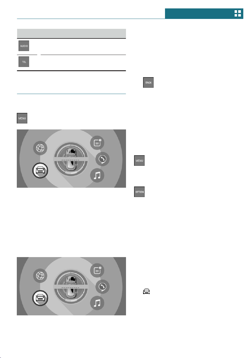
Controller
General information
The buttons can be used to open the menus
directly. The Controller can be used to se-
lect menu items and enter the settings.
Buttons on the Controller
Button Function
Press once: calls up the main
menu.
Press twice: open recently used
menus.
Opens the previous display.
Opens the Options menu.
Open the Audio menu.
Opens the Phone menu.
Seite 22
QUICK REFERENCE Entering
22
Online Edition for Part no. 01402667083 - VI/19
Set-up and use
Seats, mirrors, and steering
wheel
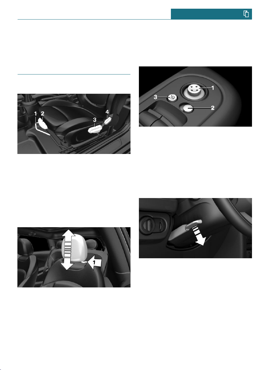
Manually adjustable seats
1 Forward/backward
2 Thigh support
3 Height
4 Backrest tilt
Adjusting the head restraint
Height
– To raise: push the head restraint up.
– To lower: press the button, arrow 1, and
push the head restraint down.
Adjusting the exterior mirrors
1 Adjusting
2 Selecting a mirror, Automatic Curb Mon-
itor
3 Folding in and out
Adjusting the steering wheel
In four directions
1. Fold the lever down.
2. Move the steering wheel to the prefer-
red height and angle to suit your seating
position.
3. Fold the lever back up.
Seite 23
Set-up and use QUICK REFERENCE
23
Online Edition for Part no. 01402667083 - VI/19
Entering the rear
1. Pull lever up to the stop.
2. Fold backrest forward.
3. Push the seat forward.
Original position
1. Push the seat back into the original po-
sition.
2. Fold back the backrest to lock the seat.
Infotainment
Radio
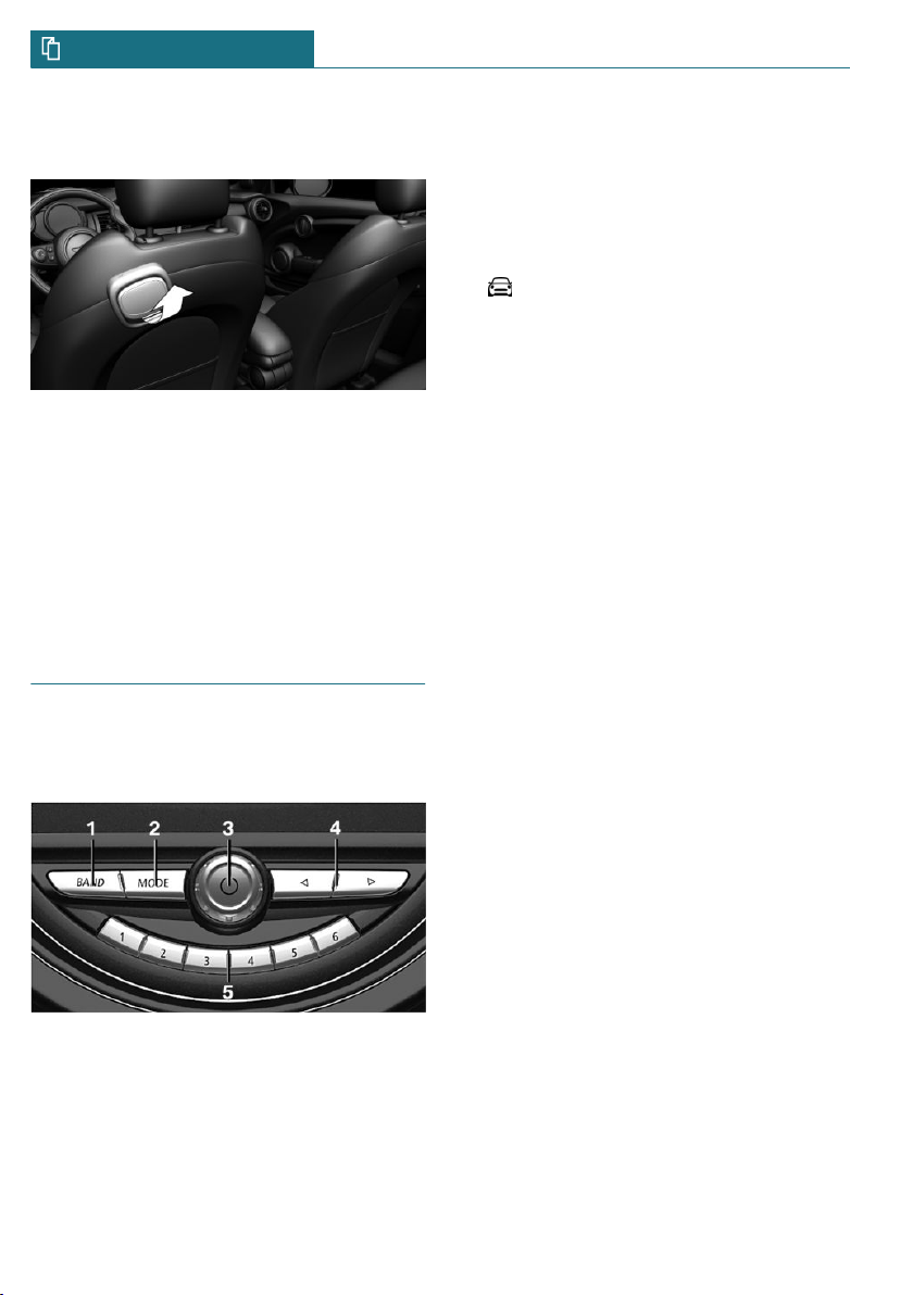
Control elements
1 Changing the waveband
2 Changing the entertainment source
3 Sound output on/off, volume
4 Changing the station/track
5 Programmable memory buttons
Pairing the mobile phone
After the mobile phone is paired once with
the vehicle, the mobile phone can be oper-
ated using the Central Information Display
(CID), the steering wheel buttons and spo-
ken instructions.
1. "My MINI"
2. "System settings"
3. "Mobile devices"
4. "Connect new device"
The vehicle's Bluetooth name is dis-
played on the Control Display.
5. To perform additional steps on the mo-
bile phone, refer to the mobile phone
owner's manual: e.g., search for or con-
nect the Bluetooth device or a new de-
vice.
The Bluetooth name of the vehicle ap-
pears on the mobile phone display. Se-
lect the Bluetooth name of the vehicle.
6. Depending on the mobile device, a con-
trol number is displayed or the control
number must be entered.
– Compare the control number dis-
played on the Control Display with
the control number on the display of
the device.
Confirm the control number on the
device and on the Control Display.
– Enter and confirm the same control
number on the device and via the
Central Information Display (CID).
The device is connected and displayed
in the device list.
The mobile phone is connected and will ap-
pear at the top of the list of mobile phones.
Seite 24
QUICK REFERENCE Set-up and use
24
Online Edition for Part no. 01402667083 - VI/19

Using the phone
Accepting a call
Incoming call can be accepted via the Cen-
tral Information Display (CID) or the button
on the steering wheel.
Via the Central Information Display (CID)
"Accept"
Via the button on the steering wheel
Press the button.
Dialing a number
1. "Communication"
2. "Dial number"
3. Select the numbers individually.
4. Select the symbol.
Seite 25
Set-up and use QUICK REFERENCE
25
Online Edition for Part no. 01402667083 - VI/19
On the road
Driving
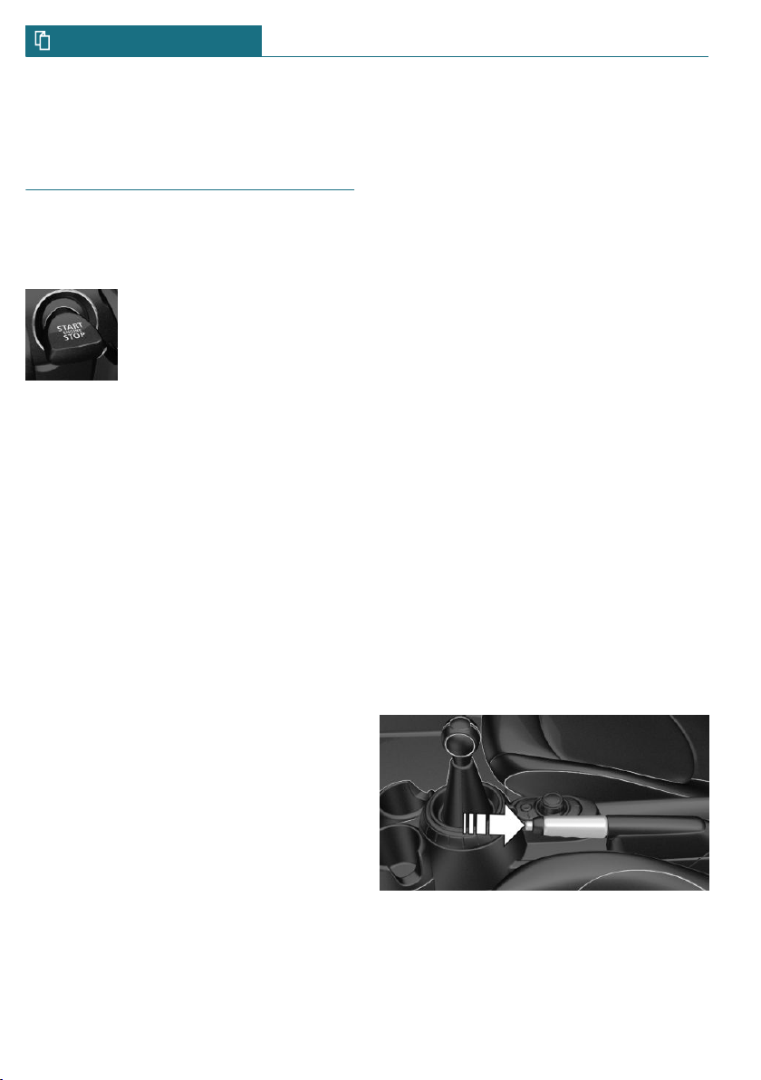
Starting and stopping the engine
Ignition on/off
– On: press the Start/Stop
button.
Most of the indicator/
warning lights light up for
a varied length of time.
– Off: press the Start/Stop button again.
All indicator lights go out.
– Radio-ready state: when the ignition is
switched off, press the ON/OFF button
on the radio or when the engine is run-
ning, press the Start/Stop button.
Some electronic systems/power con-
sumers remain ready for operation.
Start/stop engine
Steptronic transmission: starting
1. Depress the brake pedal.
2. Engage selector lever position P or N.
3. Press the Start/Stop button.
Manual transmission: starting
1. Depress the brake pedal.
2. Press on the clutch pedal and shift to
neutral.
3. Press the Start/Stop button.
Steptronic transmission: switching off
1. When the vehicle is stationary, apply
the parking brake.
2. Engage selector lever position P.
3. Press the Start/Stop button.
Manual transmission: switching off
1. With the vehicle at a standstill, press
the Start/Stop button.
2. Shift into first gear or reverse.
3. Set the parking brake.
Auto Start/Stop function
Steptronic transmission: switches the en-
gine off automatically while stationary to
save fuel. The engine starts automatically
when the brake pedal is released.
Manual transmission: switches the engine
off automatically while stationary to save
fuel. As soon as the clutch pedal is de-
pressed, the engine starts automatically.
Parking brake
Applying
The lever automatically engages after being
pulled up.
Releasing
Raise lever slightly, press the button and
guide the lever down.
Seite 26
QUICK REFERENCE On the road
26
Online Edition for Part no. 01402667083 - VI/19
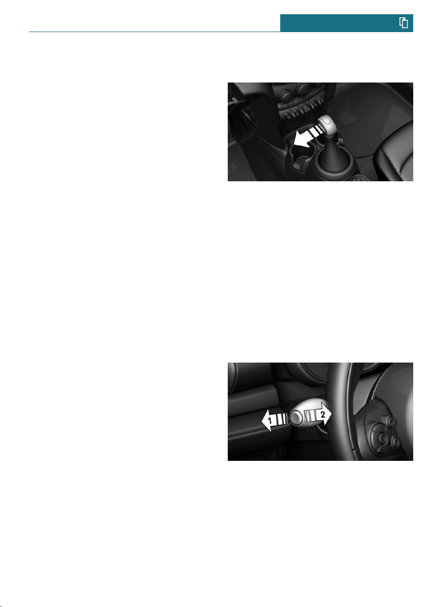
Manual transmission
Shifting
When shifting into 5th or 6th gear, push
the gearshift lever to the right in order to
prevent inadvertent shifting into the 3rd or
4th gear.
Reverse gear
Select only when the vehicle is stationary.
To overcome the resistance push the gear-
shift lever dynamically to the left and en-
gage reverse gear with a forward shifting
movement.
Steptronic transmission
Selector lever positions
Parking position P.
R is reverse.
Neutral N.
Drive mode D.
Engage selector lever position P or R only
when the vehicle is stationary.
To prevent the vehicle from creeping after
you select a drive mode or reverse, maintain
pressure on the brake pedal until you are
ready to start.
Selector lever lock
A lock prevents an inadvertent change from
selector lever position P to another selector
lever position and, depending on the trans-
mission version, inadvertent switching to
selector lever position P or R.
To release the lock: with the brake pedal de-
pressed, press the button on the front or
side of the selector lever.
Steptronic transmission, Sport and
manual mode
Sport program:
Press the selector lever to the left from se-
lector lever position D.
Manual mode:
– To shift down: press the selector lever
forward.
– To shift up: pull the selector lever rear-
wards.
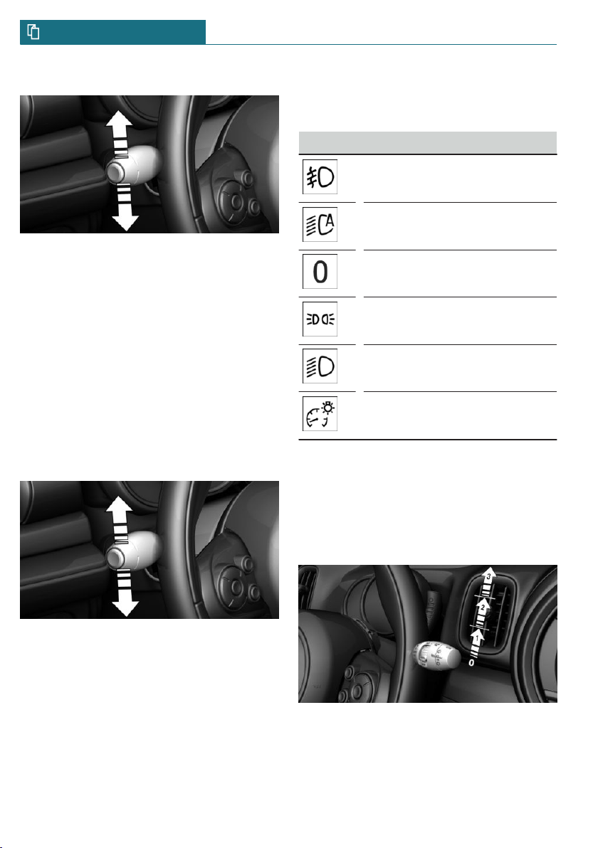
High beams, headlight flasher, turn
signal, roadside parking light
High beams, headlight flasher
Push the lever forward or pull it backward.
– High beams on, arrow 1.
The high beams light up when the low
beams are switched on.
– High beams off/headlight flasher, ar-
row 2.
Seite 27
On the road QUICK REFERENCE
27
Online Edition for Part no. 01402667083 - VI/19
Turn signal
– On: press the lever past the resistance
point.
– Off: lightly tap the lever to the resist-
ance point.
– Off: press the lever past the resistance
point in the opposite direction.
– Triple turn signal activation: lightly tap
the lever up or down.
– Brief signaling: press the lever to the re-
sistance point and hold it there for as
long as you want the turn signal to flash.
Canada: roadside parking light
To illuminate the vehicle on one side.
– On: with the ignition switched off, press
the lever either up or down past the re-
sistance point for approx. 2 seconds.
– Off: briefly press the lever to the resist-
ance point in the opposite direction.
Lights and lighting
Light functions
Symbol Function
Front fog lights.
Automatic headlight control.
Lights off.
Daytime running lights.
Parking lights.
Low beams.
Instrument lighting.
Wiper system
Switching the wipers on/off and brief
wipe
Switching on
Press the lever up until the desired position
is reached.
– Resting position of the wipers: posi-
tion 0.
Seite 28
QUICK REFERENCE On the road
28
Online Edition for Part no. 01402667083 - VI/19
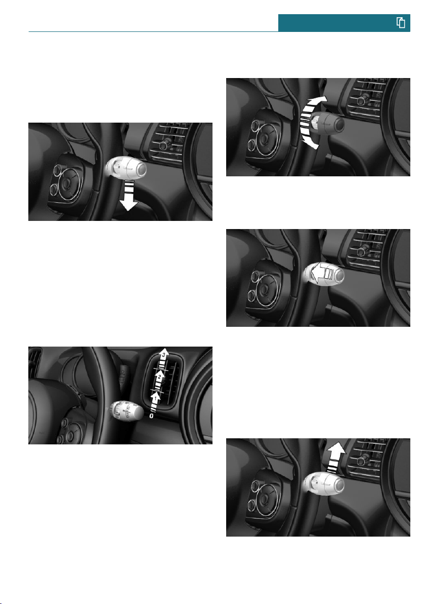
– Rain sensor: position 1.
– Normal wiper speed: position 2.
– Fast wiper speed: position 3.
Brief wipe and switching off
Press the lever down.
– Switching off: press the lever down until
it reaches its standard position.
– Brief wipe: press the lever down from
the standard position.
Rain sensor
Activating/deactivating
To activate: press the lever up once from its
standard position, arrow 1.
To deactivate: press the lever back into the
standard position.
Set interval or sensitivity of the rain
sensor
Turn the thumbwheel on the wiper lever.
Cleaning the windshield
Pull the lever.
Canada: wiper system
Switching the wipers on/off and brief
wipe
Switching on
Tap up the lever or press it past the resist-
ance point.
Seite 29
On the road QUICK REFERENCE
29
Online Edition for Part no. 01402667083 - VI/19
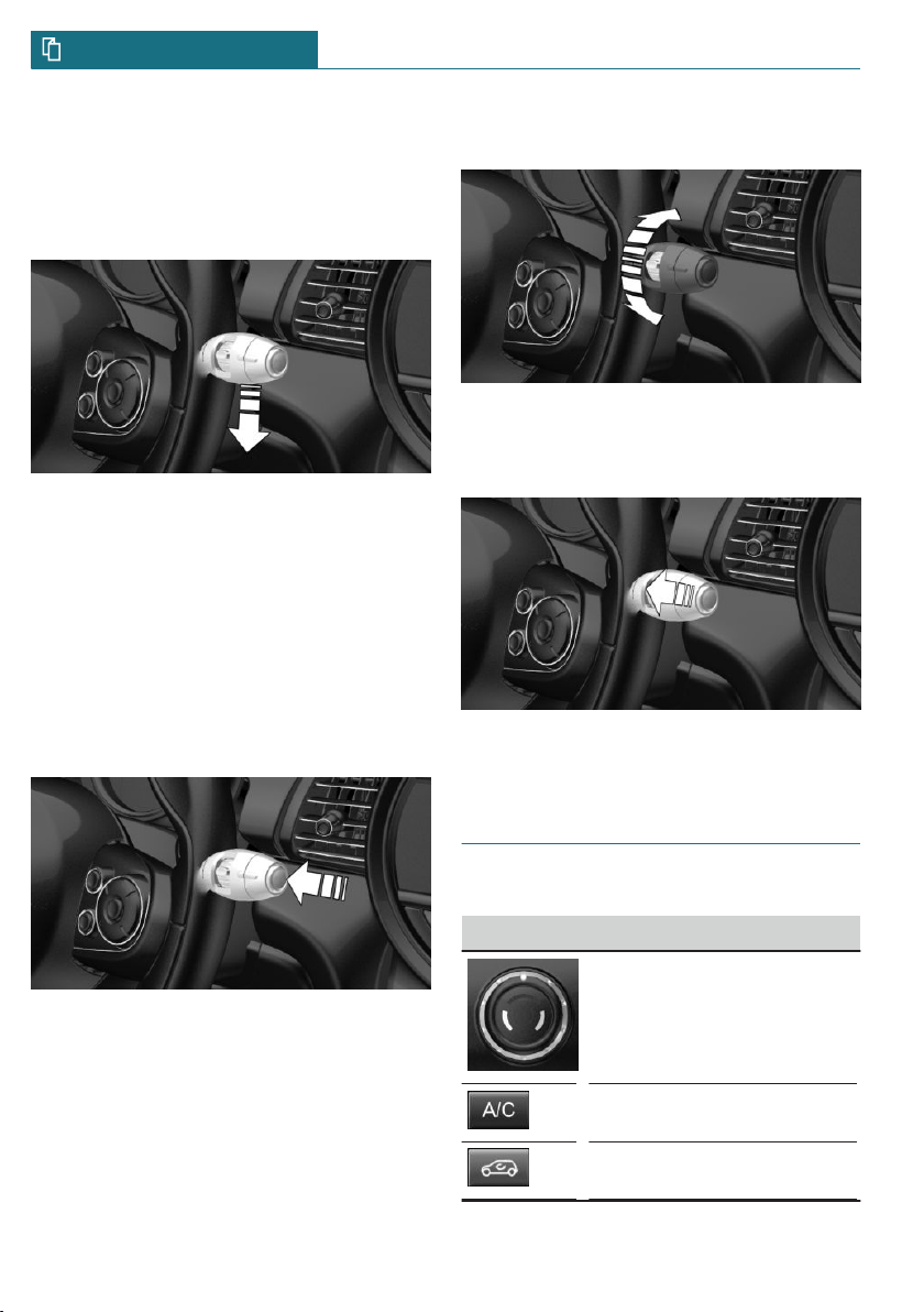
– Normal wiper speed: tap up once.
– Fast wiper speed: tap up twice or tap
once beyond the resistance point.
Brief wipe and switching off
Press the lever down.
– To switch off fast wipe: press down
twice.
– To switch off normal wipe: press down
once.
– Brief wipe: press down once.
Rain sensor
Activating/deactivating
Press the button on the wiper lever.
Set interval or sensitivity of the rain
sensor
Turn the thumbwheel on the wiper lever.
Cleaning the windshield
Pull the lever.
Climate control
Air conditioner
Button Function
Temperature.
Air conditioning.
Recirculated-air mode.
Seite 30
QUICK REFERENCE On the road
30
Online Edition for Part no. 01402667083 - VI/19
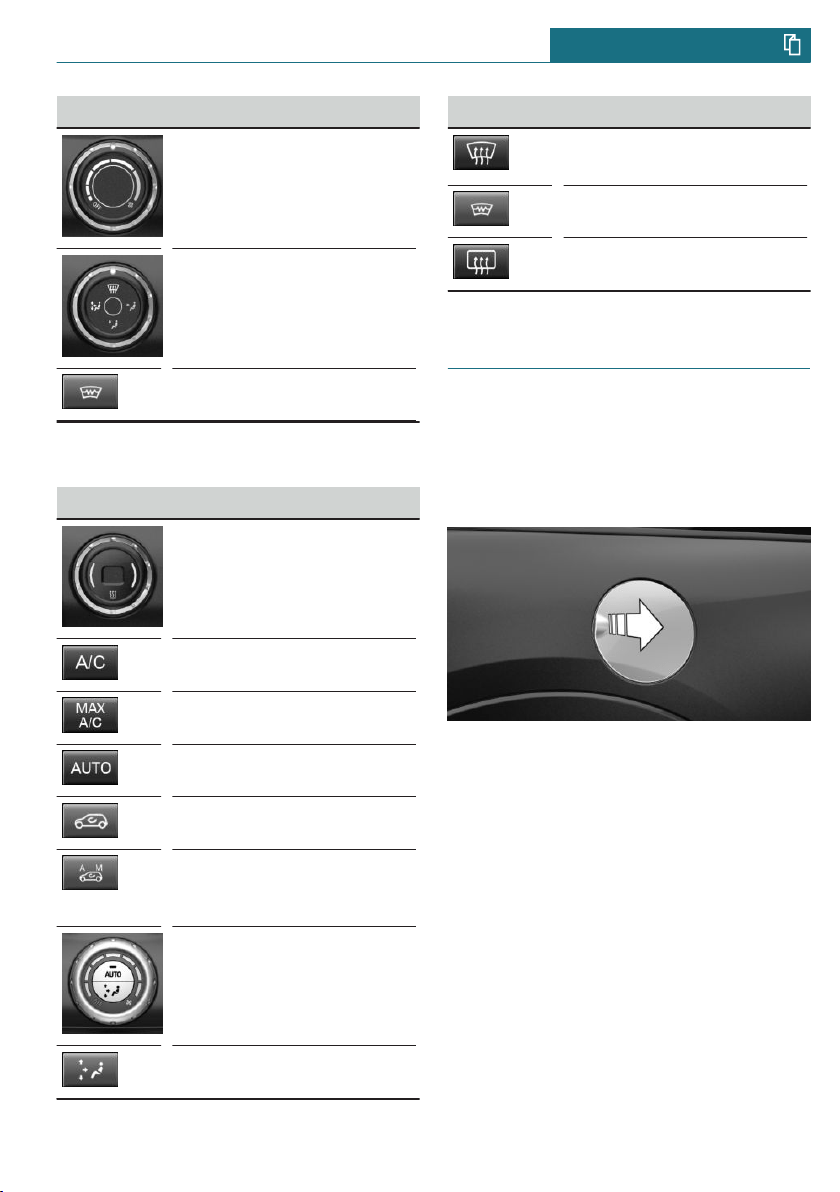
Button Function
Controls the air flow,
manual.
Controls the air distribution
manually.
Windshield defroster.
Automatic climate control
Button Function
Temperature.
Air conditioning.
Maximum cooling.
AUTO program.
Recirculated-air mode.
Automatic recirculated-air
control AUC/recirculated-
air mode.
Controls the air flow,
manual.
Air distribution, manual.
Button Function
Defrosts and defogs the
windows.
Windshield defroster.
Rear window defroster.
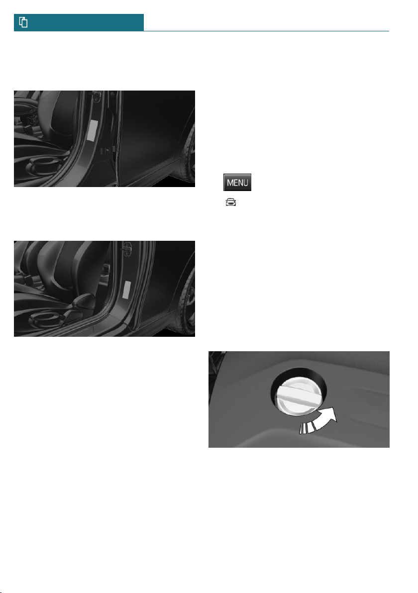
Refueling
Refueling
Fuel cap
1. Grasp the fuel filler flap at the rear edge
and open it.
2. Turn the fuel cap counterclockwise.
3. Place the fuel cap in the bracket at-
tached to the fuel filler flap.
Gasoline
For the best fuel efficiency, the gasoline
should be sulfur-free or very low in sulfur
content.
Refuel only with unleaded gasoline without
metallic additives.
Information on the recommended fuel grade
can be found in the Owner's Manual.
Seite 31
On the road QUICK REFERENCE
31
Online Edition for Part no. 01402667083 - VI/19
Wheels and tires
Tire inflation pressure specifications
For 5-door models:
The tire inflation pressure values can be
found on the sign on the door pillar.
For 3-door models:
The tire inflation pressure values can be
found on the sign on the door pillar.
Checking the tire inflation pressure
Regularly check the tire inflation pressure
and correct it as needed:
– At least twice a month.
– Before embarking on an extended trip.
After correcting the tire inflation
pressure
Reinitialize the Flat Tire Monitor.
Reset the Tire Pressure Monitor.
Electronic oil measurement
Requirements
A current measured value is available after
approx. 30 minutes of driving. During a
shorter trip, the status of the last, suffi-
ciently long trip is displayed.
Displaying the engine oil level
On the radio:
1. Press the button.
2. "Vehicle Info"
3. "Vehicle status"
4. "Engine oil level"
The engine oil level is displayed.
Adding engine oil
General information
Switch off the ignition and safely park the
vehicle before engine oil is added.
Adding
Only add engine oil when the message is
displayed in the instrument cluster.
Observe the quantity to be added in the
message.
Take care not to add too much engine oil.
Observe recommended engine oil types.
Seite 32
QUICK REFERENCE On the road
32
Online Edition for Part no. 01402667083 - VI/19
Providing assistance
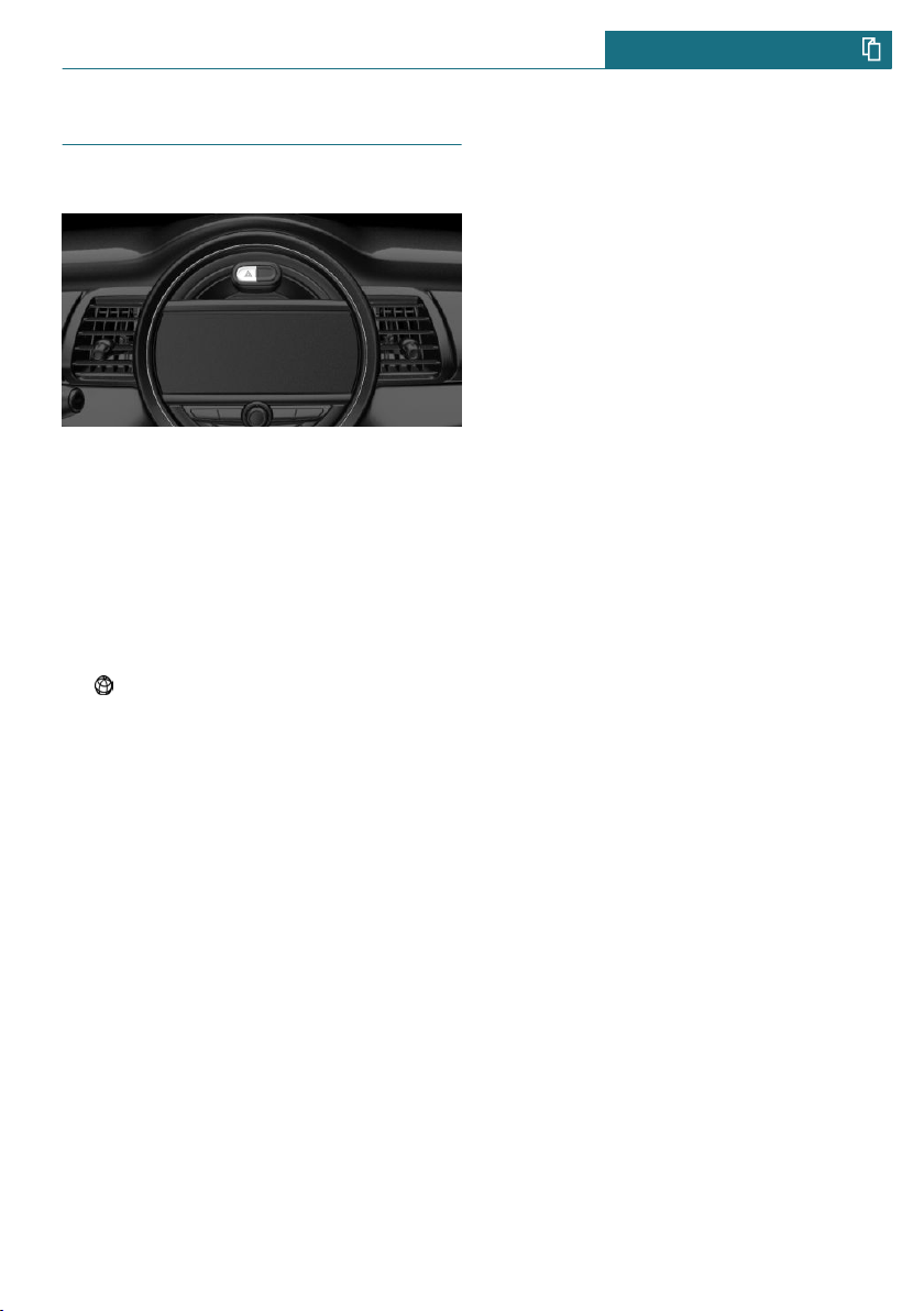
Hazard warning flashers
The button is located above the Control Dis-
play.
Breakdown assistance
MINI Roadside Assistance
This service can be reached around the
clock in many countries.
1. "MINI Connected"
2. "MINI Assist"
3. "MINI Roadside Assistance"
The contact to the MINI Roadside Assis-
tance is established.
A telephone number is displayed, if
needed. Select to dial the telephone
number on a connected mobile phone.
Seite 33
On the road QUICK REFERENCE
33
Online Edition for Part no. 01402667083 - VI/19

34
Online Edition for Part no. 01402667083 - VI/19

AT A GLANCE
Cockpit ........................................................................................................ 36
Central Information Display (CID) ...................................................... 40
General settings ....................................................................................... 45
Owner's Manual media ........................................................................... 54
35
Online Edition for Part no. 01402667083 - VI/19
Cockpit
Vehicle features and options
This chapter describes all standard, country-
specific and optional features offered with
the series. It also describes features that are
not necessarily available in your vehicle, for
instance, due to the selected options or
country versions. This also applies to safety-
related functions and systems. When using
these functions and systems, the applicable
laws and regulations must be observed.
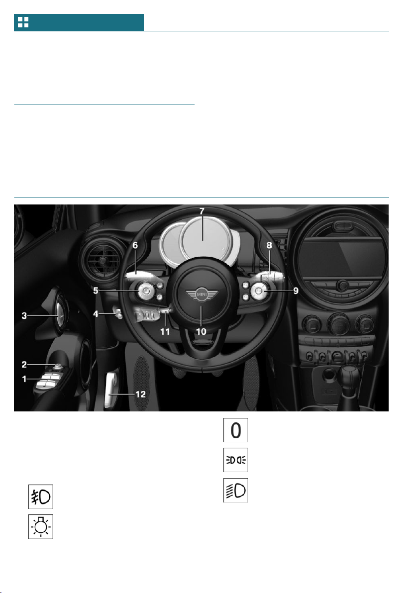
In the vicinity of the steering wheel
1 Power windows 71
2 Exterior mirror operation 82
3 Buttons of the central locking sys-
tem 63
4 Lights
Front fog lights 134
Light switch 131
Lights off
Daytime running lights 133
Parking lights 131
Low beams 131
Seite 36
AT A GLANCE Cockpit
36
Online Edition for Part no. 01402667083 - VI/19
Automatic headlight con-
trol 132
Cornering light 133
High-beam Assistant 133
Instrument lighting 135
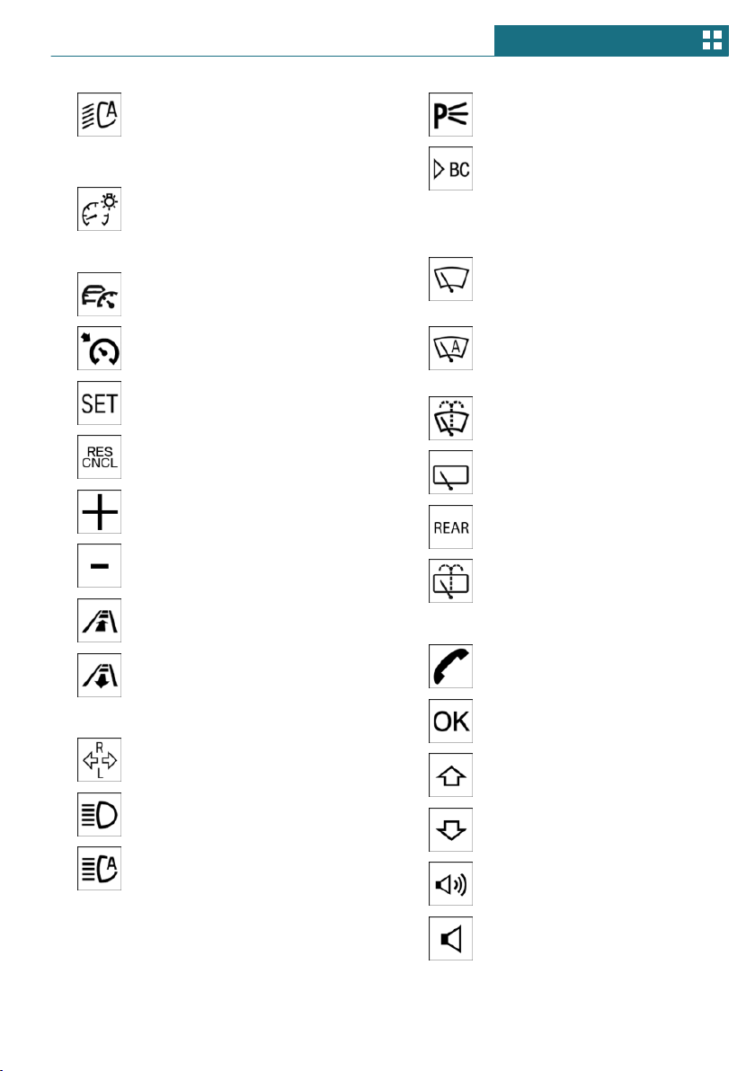
5 Steering wheel buttons, left
Camera-based cruise control
on/off 162
Cruise control on/off 168
Cruise control: to store the
speed
Pausing, continuing cruise
control
Cruise control: increase speed
Cruise control: reduce speed
Camera-based cruise control:
reduce distance
Camera-based cruise control:
increase distance
6 Steering column stalk, left
Turn signal 97
High beams, head-
light flasher 97
High-beam Assistant 133
Roadside parking lights 132
Onboard Computer 125
7 Instrument cluster 115
8 Steering column stalk, right
Wipers 98
Wiper on Canadian mod-
els 102
Rain sensor 99
Rain sensor on Canadian mod-
els 102
Cleaning windows 100
Rear window wiper in Cana-
dian models 100
Rear window wiper 100
Clean the rear window 100
9 Steering wheel buttons, right
Telephone 242
Confirm the selection 125
Selection back 125
Selection next 125
Increase volume
Reduce volume
Seite 37
Cockpit AT A GLANCE
37
Online Edition for Part no. 01402667083 - VI/19
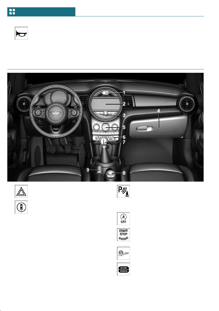
10 Horn, entire surface 11 Adjusting the steering wheel 84
12 Unlocking the hood 280
In the vicinity of the center console
1 Hazard warning system 299
Intelligent Safety 148
2 Control Display 40
3 Radio/Multimedia
4 Glove compartment 198
5 Climate control 182
6 PDC Park Distance Con-
trol 170
Rearview camera 173
Parking assistant 177
Auto Start/Stop func-
tion 94
Start/stop the engine and
switch the ignition on/
off 91
DSC Dynamic Stability Control
157
MINI Driving Modes
switch 159
Seite 38
AT A GLANCE Cockpit
38
Online Edition for Part no. 01402667083 - VI/19
7 Steptronic transmission selector
lever 107
Manual transmission selector
lever 106
8 Controller with buttons 42
9 Parking brake 97
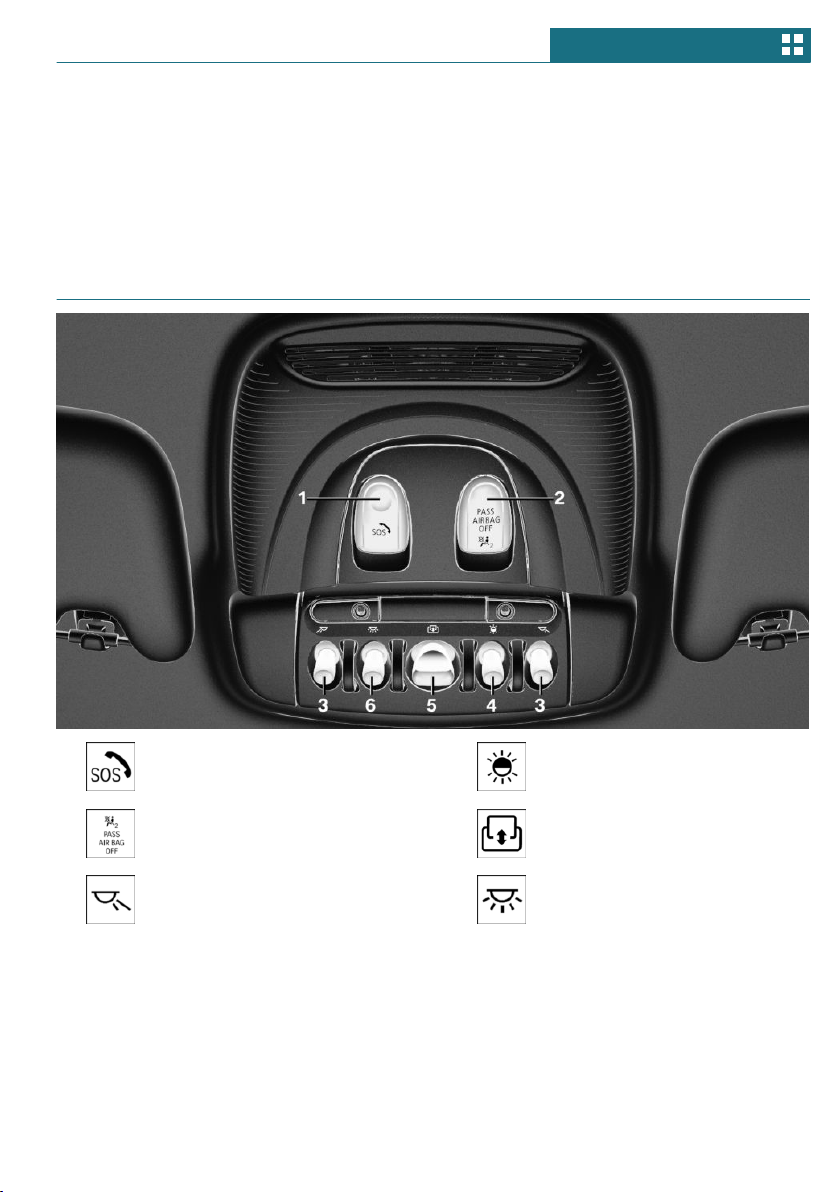
In the vicinity of the roofliner
1 Emergency Request,
SOS 300
2 Indicator light, front-seat pas-
senger airbag 140
3 Reading lights 135
4 Ambient light 135
5 Panoramic glass sunroof 73
6 Interior lights 135
Seite 39
Cockpit AT A GLANCE
39
Online Edition for Part no. 01402667083 - VI/19
Central Information Display (CID)
Vehicle features and options
This chapter describes all standard, country-
specific and optional features offered with
the series. It also describes features that are
not necessarily available in your vehicle, for
instance, due to the selected options or
country versions. This also applies to safety-
related functions and systems. When using
these functions and systems, the applicable
laws and regulations must be observed.
Concept
The Central Information Display (CID) com-
bines the functions of a multitude of
switches. These functions can be operated
via the Controller.
Safety information
Warning
Operating the integrated information sys-
tems and communication devices while
driving can distract from traffic. It is pos-
sible to lose control of the vehicle. There is
a risk of accident. Only use the systems or
devices when the traffic situation allows.
As warranted, stop and use the systems
and devices while the vehicle is stationary.
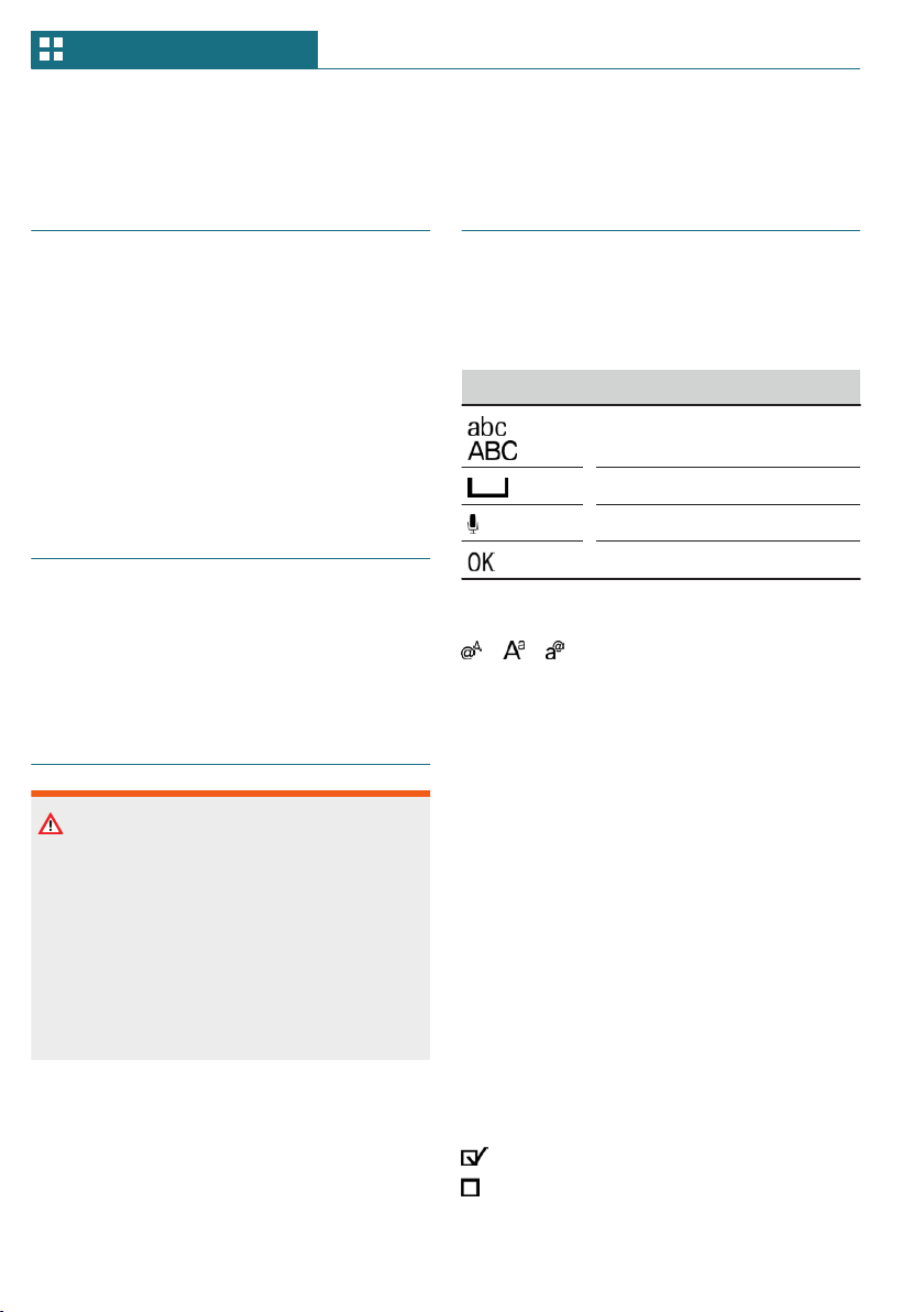
Input and display
Letters and numbers
Depending on the menu, you can switch be-
tween entering upper and lower case let-
ters, numbers and characters:
Symbol Function
or
Change between capital and
lower-case letters.
Insert blank space.
Use voice activation.
Confirm entry.
Without navigation system
Select the symbol.
Entry comparison
When entering names and addresses, the
choice is narrowed down with every letter
entered and letters may be added automati-
cally.
Entries are continuously compared with
data stored in the vehicle.
Only those letters are offered during entry
for which data is available.
Activating/deactivating the
functions
Several menu items are preceded by a
checkbox. The checkbox indicates whether
the function is activated or deactivated. Se-
lecting the menu item activates or deacti-
vates the function.
Function is activated.
Function is deactivated.
Seite 40
AT A GLANCE Central Information Display (CID)
40
Online Edition for Part no. 01402667083 - VI/19
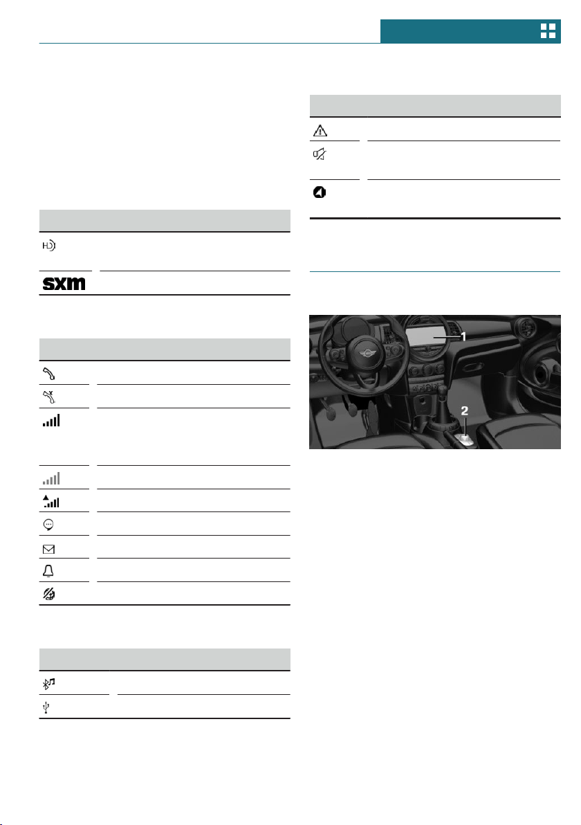
Status information
General information
The status field can be found in the upper
area of the Control Display. Status informa-
tion is displayed in the form of symbols.
Radio
Symbol Meaning
HD Radio station is being re-
ceived.
Satellite radio is switched on.
Telephone
Symbol Meaning
Incoming or outgoing call.
Missed call.
Signal strength of cellular net-
work.
Symbol flashes: network search.
Cellular network is not available.
Roaming is active.
SMS text message received.
Message received.
Reminder.
Sending not possible.
Entertainment
Symbol Meaning
Bluetooth audio.
USB audio interface.
Other symbols
Symbol Meaning
Check Control message.
The sound output has been
switched off.
Checking the current vehicle po-
sition.
Control elements
Overview
1 Control Display
2 Controller with buttons
Control Display
General information
To clean the Control Display, follow the care
instructions, refer to page 310.
In the case of very high temperatures on
the Control Display, for instance due to in-
tense solar radiation, the brightness may be
reduced down to complete deactivation.
Once the temperature is reduced, for in-
stance through shade or air conditioning,
the normal functions are restored.
Seite 41
Central Information Display (CID) AT A GLANCE
41
Online Edition for Part no. 01402667083 - VI/19
Safety information
NOTICE
Objects in the area in the front of the Con-
trol Display can shift and damage the Con-
trol Display. There is a risk of damage to
property. Do not place objects in the area
in front of the Control Display.
Switching on/off automatically
The Control Display is switched on automat-
ically after unlocking.
In certain situations, the Control Display is
switched off automatically, for instance if
no operation is performed on the vehicle for
several minutes.
Switching on/off manually
The Control Display can also be switched off
manually.
1. Press the button.
2. "Turn off control display"
Press the Controller or any button on the
Controller to switch it back on again.
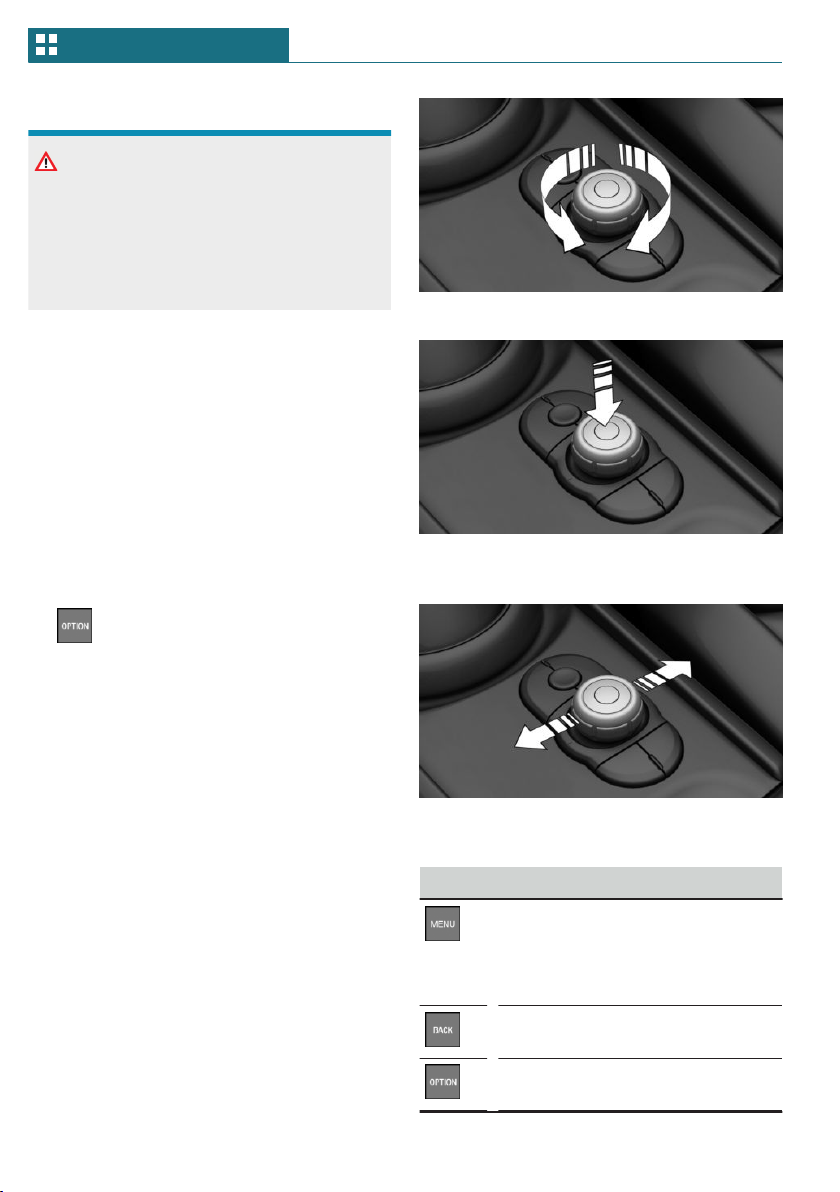
Controller
General information
The buttons can be used to open the menus
directly. The Controller can be used to se-
lect menu items and enter the settings.
Operation
– Turn to switch between menu items, for
example.
– Press to select a menu item, for example.
– Tilt in two directions to switch between
displays, for example.
Buttons on the Controller
Button Function
Press once: calls up the main
menu.
Press twice: open recently used
menus.
Opens the previous display.
Opens the Options menu.
Seite 42
AT A GLANCE Central Information Display (CID)
42
Online Edition for Part no. 01402667083 - VI/19
Button Function
Open the Audio menu.
Opens the Phone menu.
Operating via the Controller
Opening the main menu
Press the button.
The main menu is displayed.
All Central Information Display (CID) func-
tions can be called up via the main menu.
Selecting menu items
Highlighted menu items can be selected.
1. Turn the Controller until the desired
menu item is highlighted.
2. Press the Controller.
Changing between displays
After a menu item is selected, for instance
"System settings", a new display appears.
– Move the Controller to the left.
The current display closes and the previ-
ous display is shown.
– Press the button.
The previous display re-opens.
– Move the Controller to the right.
The new display opens.
An arrow indicates that additional displays
can be opened.
Opening recently used menus
The recently used menus can be displayed.
Press the button twice.
Opening the Options menu
Press the button.
The "Options" menu is displayed.
The menu consists of various areas:
– Control options for the selected main
menu, for instance for "Media/Radio".
– If applicable, further operating options
for the selected menu, for instance "Save
station".
Changing settings
Settings, such as brightness, can be entered.
Via the Central Information Display (CID):
1. "My MINI"
2. "System settings"
3. "Displays"
4. "Control display"
5. "Brightness at night"
Seite 43
Central Information Display (CID) AT A GLANCE
43
Online Edition for Part no. 01402667083 - VI/19
6. Turn the Controller until the desired set-
ting is displayed.
7. Press the Controller.
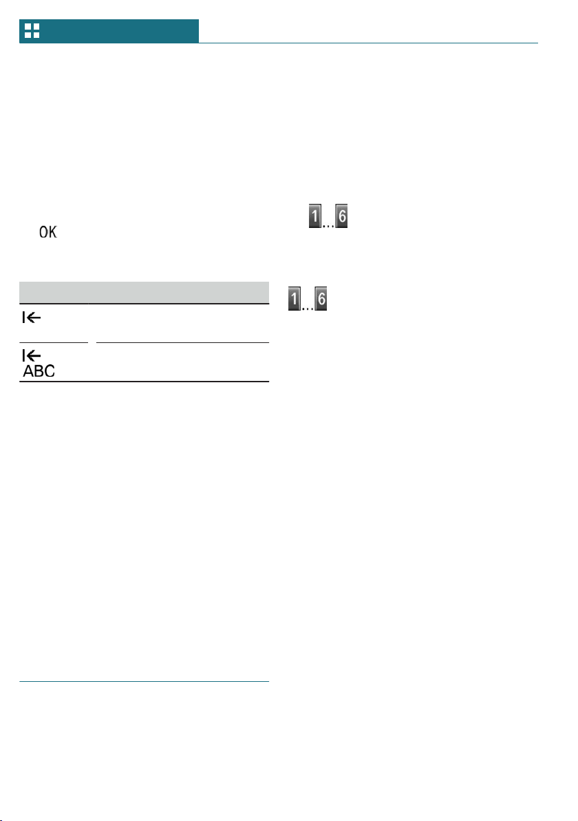
Entering letters and numbers
Input
1. Turn the Controller: select letters or
numbers.
2. : confirm entry.
Deleting
Symbol Function
Press the Controller: delete
letters or number.
or
Hold the Controller down: de-
lete all letters or numbers.
Using alphabetical lists
For alphabetical lists with more than 30 en-
tries, the letters for which there is an entry
are displayed at the left edge.
1. Turn the Controller to the left or right
quickly.
All letters for which there are entries
are displayed on the left edge.
2. Select the first letter of the desired en-
try.
The first entry of the selected letter is
displayed.
Programmable memory but-
tons
General information
The Central Information Display (CID) func-
tions can be stored on the programmable
memory buttons and called up directly, for
instance radio stations, phone numbers, and
menu entries.
Settings are stored for the driver profile
currently used.
Storing a function
1. Select the function via the Central Infor-
mation Display (CID).
2. Press and hold the desired but-
ton, until a signal sounds.
Executing a function
Press the button.
The function will work immediately.
This means, for instance that the number is
dialed when a phone number is selected.
Displaying the key assignment
Touch buttons with finger. Do not wear
gloves or use objects.
The button assignment is displayed at the
top edge of screen.
Deleting the button assignments
1. Press buttons 1 and 6 simultaneously
for approx. 5 seconds.
2. "OK"
Seite 44
AT A GLANCE Central Information Display (CID)
44
Online Edition for Part no. 01402667083 - VI/19

General settings
Vehicle features and options
This chapter describes all standard, country-
specific and optional features offered with
the series. It also describes features that are
not necessarily available in your vehicle, for
instance, due to the selected options or
country versions. This also applies to safety-
related functions and systems. When using
these functions and systems, the applicable
laws and regulations must be observed.
Language
Setting the language
Via the Central Information Display (CID):
1. "My MINI"
2. "System settings"
3. If necessary, "Language"
4. "Language:"
5. Select the desired setting.
The setting is stored for the driver profile
currently used.
Time
Setting the time
Via the Central Information Display (CID):
1. "My MINI"
2. "System settings"
3. "Date and time"
4. "Time:"
5. Turn the Controller until the desired
hours are displayed.
6. Press the Controller.
7. Turn the Controller until the desired mi-
nutes are displayed.
8. Press the Controller.
Setting the time format
Via the Central Information Display (CID):
1. "My MINI"
2. "System settings"
3. "Date and time"
4. "Time format:"
5. Select the desired setting.
The setting is stored for the driver profile
currently used.
Date
Setting the date
Via the Central Information Display (CID):
1. "My MINI"
2. "System settings"
3. "Date and time"
4. "Date:"
5. Turn the Controller until the desired day
is displayed.
6. Press the Controller.
7. Make the settings for the month and
year.
Seite 45
General settings AT A GLANCE
45
Online Edition for Part no. 01402667083 - VI/19

Setting the date format
Via the Central Information Display (CID):
1. "My MINI"
2. "System settings"
3. "Date and time"
4. "Date format:"
5. Select the desired setting.
The setting is stored for the driver profile
currently used.
Setting the units of measure-
ment
You can set the units of measurement for
some values, for example, consumption, dis-
tances and temperature.
Via the Central Information Display (CID):
1. "My MINI"
2. "System settings"
3. "Units"
4. Select the desired menu item.
5. Select the desired setting.
The setting is stored for the driver profile
currently used.
Activating/deactivating the
display of the current vehicle
position
Concept
If vehicle tracking has been activated, the
current vehicle position can be displayed in
the MINI Connected app.
Activating/deactivating
Via the Central Information Display (CID):
1. "My MINI"
2. "Vehicle settings"
3. "Vehicle tracking"
4. "Vehicle tracking"
5. Select the desired setting.
Activating/deactivating
popup windows
For some functions, popup windows are dis-
played automatically on the Control Display.
Some of these popup windows can be acti-
vated or deactivated.
Via the Central Information Display (CID):
1. "My MINI"
2. "System settings"
3. "Pop-ups"
4. Select the desired setting.
The setting is stored for the driver profile
currently used.
Control Display
Brightness
Via the Central Information Display (CID):
1. "My MINI"
2. "System settings"
3. "Displays"
4. "Control display"
5. "Brightness at night"
6. Turn the Controller until the desired
brightness is set.
7. Press the Controller.
Seite 46
AT A GLANCE General settings
46
Online Edition for Part no. 01402667083 - VI/19
The setting is stored for the driver profile
currently used.
Depending on the light conditions, the
brightness settings may not be clearly visi-
ble.
Screensaver
If no entries are made via the Central Infor-
mation Display (CID), a screensaver can be
displayed after an adjustable time.
Via the Central Information Display (CID):
1. "My MINI"
2. "System settings"
3. "Displays"
4. "Control display"
5. "Screensaver"
6. Select the desired setting.
The setting is stored for the driver profile
currently used.
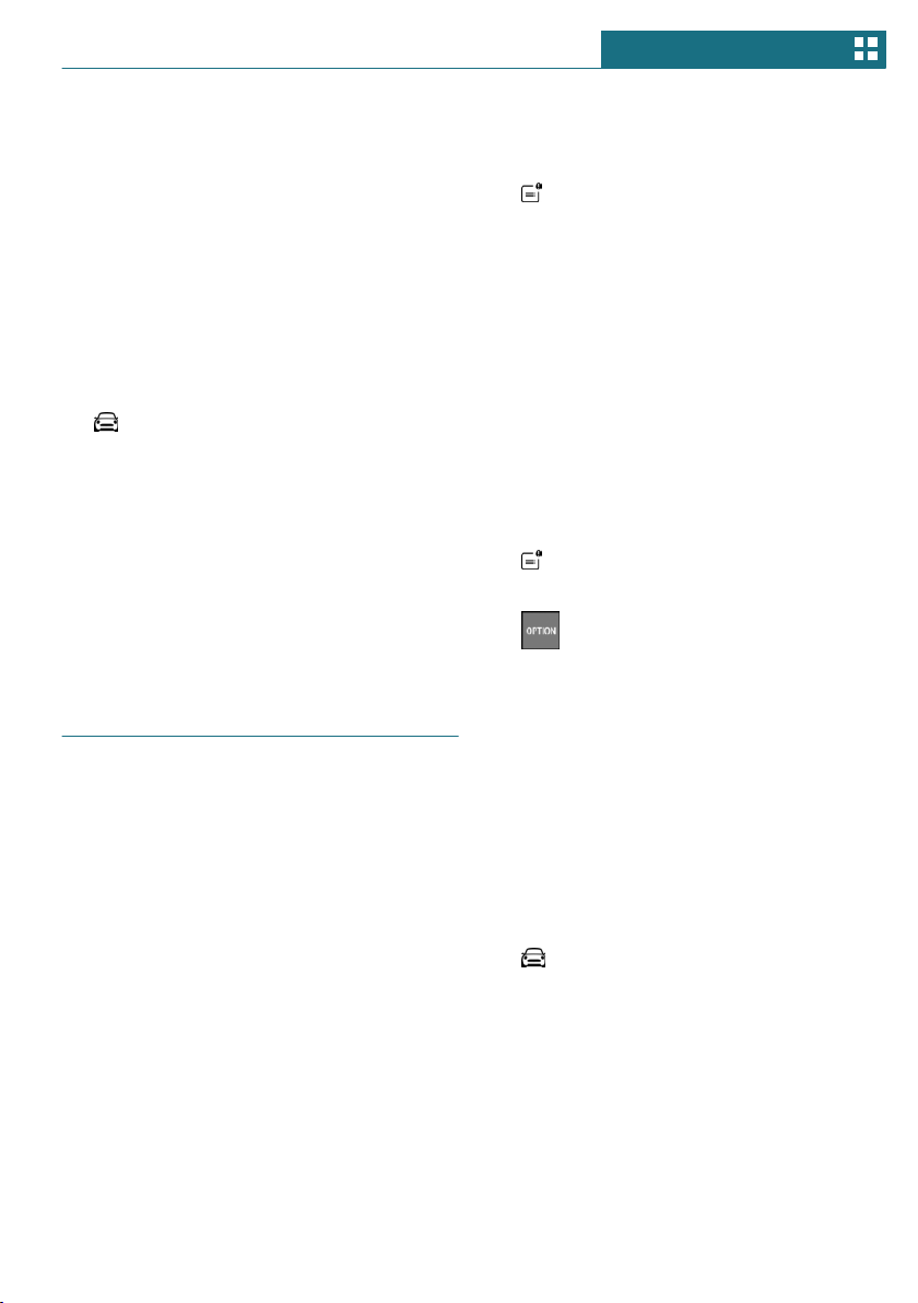
Messages
Concept
The menu centrally displays all messages ar-
riving in the vehicle in list form.
General information
The following messages can be displayed:
– Traffic messages.
– Check Control messages.
– Service requirements messages.
– Messages from the vehicle manufac-
turer.
Messages are additionally displayed in the
status field.
Retrieving messages
Via the Central Information Display (CID):
1. "Notifications"
2. Select the desired message.
The respective menu is opened, where the
message is displayed.
Deleting messages
All messages, except Check Control mes-
sages or messages from the vehicle manu-
facturer, can be deleted from the list.
Check Control messages or messages from
the vehicle manufacturer are displayed as
long as they are relevant.
Via the Central Information Display (CID):
1. "Notifications"
2. Select the desired message.
3. Press the button.
4. "Delete this notification" or "Delete all
notifications"
Adjusting
The following settings can be adjusted:
– Select the applications, from which mes-
sages will be permitted.
– Sort the messages according to date or
priority.
Via the Central Information Display (CID):
1. "My MINI"
2. "System settings"
3. "Notifications"
4. Select the desired setting.
Seite 47
General settings AT A GLANCE
47
Online Edition for Part no. 01402667083 - VI/19

Data protection
Data transfer
Concept
The vehicle offers various functions which
require data to be transferred to MINI or a
service provider. The data transfer can be
deactivated for some functions.
General information
With data transfer deactivated, the respec-
tive function cannot be used.
Only make these settings while stationary.
Activating/deactivating
Follow the instructions on the Control Dis-
play.
Via the Central Information Display (CID):
1. "My MINI"
2. "System settings"
3. "Data privacy"
4. Select the desired setting.
Deleting personal data in the
vehicle
Concept
Depending on the usage, the vehicle stores
personal data, such as stored radio stations.
This personal data can be permanently de-
leted via the Central Information Display
(CID).
General information
Depending on the vehicle equipment, the
following data is deleted:
– Driver profile settings.
– Stored radio stations.
– Stored programmable memory buttons.
– Travel and Onboard Computer informa-
tion.
– Phone book.
Altogether, the deletion of the data can take
up to 15 minutes.
Functional requirement
Data can only be deleted while stationary.
Deleting data
Note and follow the instructions on the Con-
trol Display.
Via the Central Information Display (CID):
1. Switch on the ignition.
2. "My MINI"
3. "System settings"
4. "Data privacy"
5. "Delete personal data"
6. "Delete personal data"
7. "OK"
8. Exit and lock the vehicle.
The deletion process takes 15 minutes to
complete.
If not all data was deleted, repeat the dele-
tion.
Canceling deletion
Start the engine to cancel deletion of the
data.
Connections
Concept
Various connection types are available for
using mobile devices in the vehicle. The
connection type to select depends on the
mobile device and the desired function.
Seite 48
AT A GLANCE General settings
48
Online Edition for Part no. 01402667083 - VI/19
General information
The following overview shows possible
functions and the suitable connection types
for them. The scope of functions depends on
the mobile device.
Function Connec-
tion type
Making calls via the hands-
free system.
Using phone functions via
the Central Information Dis-
play (CID).
Bluetooth.
Playing music from the
smartphone or the audio
player.
Bluetooth
or USB.
USB storage device:
Playing music.
USB.
The following connection types require one-
time pairing with the vehicle:
– Bluetooth.
Paired devices are automatically recognized
later on and connected to the vehicle.
Safety information
Warning
Operating the integrated information sys-
tems and communication devices while
driving can distract from traffic. It is pos-
sible to lose control of the vehicle. There is
a risk of accident. Only use the systems or
devices when the traffic situation allows.
As warranted, stop and use the systems
and devices while the vehicle is stationary.
Compatible devices
General information
Malfunctions may occur with devices not
listed or deviating software versions.
Displaying the vehicle identification
number and software part number
When looking for compatible devices, you
may have to state the vehicle identification
number and the software part number.
These numbers can be displayed in the ve-
hicle.
Via the Central Information Display (CID):
1. "My MINI"
2. "System settings"
3. "Mobile devices"
4. "Settings"
5. "Bluetooth® info"
6. "System information"
Bluetooth connection
Functional requirements
– Compatible device, refer to page 49,
with Bluetooth interface.
– The vehicle key is in the vehicle.
– The device is ready for operation.
– Bluetooth is activated on the device and
in the vehicle, refer to page 49.
– Bluetooth presettings, such as visibility,
may be required on the device; refer to
the owner's manual of the device.
Switching on Bluetooth
Via the Central Information Display (CID):
1. "My MINI"
2. "System settings"
3. "Mobile devices"
Seite 49
General settings AT A GLANCE
49
Online Edition for Part no. 01402667083 - VI/19

4. "Settings"
5. "Bluetooth®"
Pairing the mobile device with the
vehicle
Via the Central Information Display (CID):
1. "My MINI"
2. "System settings"
3. "Mobile devices"
4. "Connect new device"
5. Select the functions for which the de-
vice will be used:
– "Telephone"
– "Bluetooth® audio"
The vehicle's Bluetooth name is dis-
played on the Control Display.
6. On the mobile device, search for Blue-
tooth devices in the vicinity.
The Bluetooth name of the vehicle ap-
pears on the mobile device display.
Select the Bluetooth name of the vehi-
cle.
7. Depending on the mobile device, a con-
trol number is displayed or the control
number must be entered.
– Compare the control number dis-
played on the Control Display with
the control number on the display of
the device.
Confirm the control number on the
device and on the Control Display.
– Enter and confirm the same control
number on the device and via the
Central Information Display (CID).
The device is connected and displayed
in the device list.
If connection was not successful: Fre-
quently Asked Questions, refer to page 50.
Frequently Asked Questions
All requirements are met and all required
steps were completed in the specified order.
Despite that, the mobile device does not
function as expected.
In this case, the following explanations can
help:
Why could the mobile phone not be paired
or connected?
– There are too many Bluetooth devices
connected to the mobile phone or vehi-
cle.
In the vehicle, delete Bluetooth connec-
tions with other devices.
Delete all known Bluetooth connections
from the device list on the mobile phone
and start a new device search.
– The mobile phone is in power-save mode
or has only a limited remaining battery
life.
Charge the mobile phone.
Why does the mobile phone no longer re-
act?
– The applications on the mobile phone do
not function anymore.
Switch the mobile phone off and on
again.
– Possibly too high or too low ambient
temperatures for mobile phone opera-
tion.
Do not subject the mobile phone to ex-
treme ambient temperatures.
Why can phone functions not be used via
the Central Information Display (CID)?
– The mobile phone may not be properly
configured, for instance as Bluetooth au-
dio device.
Connect the mobile phone with the tele-
phone function.
Why are no or not all phone book entries
displayed or why are they incomplete?
Seite 50
AT A GLANCE General settings
50
Online Edition for Part no. 01402667083 - VI/19

– Transmission of the phone book entries
is not yet complete.
– It is possible that only the phone book
entries of the mobile phone or the SIM
card are transmitted.
– It may not be possible to display phone
book entries with special characters.
– It may not be possible to transmit con-
tacts from social networks.
– The number of phone book entries to be
stored is too high.
– Data volume of the contact too large, for
instance due to stored information such
as notes.
Reduce the data volume of the contact.
– A mobile phone is only connected as an
audio source.
Reconfigure the mobile phone and con-
nect it with the telephone function.
How can the phone connection quality be
improved?
– The strength of the Bluetooth signal on
the mobile phone can be adjusted, de-
pending on the mobile phone.
If all points in this list have been checked
and the required function is still not availa-
ble, contact the hotline, a dealer’s service
center or another qualified service center or
repair shop.
USB connection
General information
Mobile devices with a USB port are con-
nected to the USB interface.
– Mobile phones.
– Audio devices with USB port, for in-
stance MP3 players.
– USB storage devices.
Common file systems are supported.
FAT32 and exFAT are the recommended
formats.
A connected USB storage device will be
supplied with charge current via the USB
interface if the device supports this. Follow
the maximum charge current of the USB in-
terface.
USB interfaces with data transfer can be
used to play the music files via USB Audio.
Follow the following when connecting:
– Do not use force when plugging the con-
nector into the USB interface.
– Use a flexible adapter cable.
– Protect the USB storage device against
mechanical damage.
– Due to the large number of USB storage
devices available on the market, it can-
not be guaranteed that every device is
operable on the vehicle.
– Do not expose USB storage devices to
extreme environmental conditions, such
as very high temperatures; refer to the
owner's manual of the device.
– Due to the many different compression
techniques, proper playback of the me-
dia stored on the USB storage device
cannot be guaranteed in all cases.
– To ensure proper transmission of the
stored data, do not charge a USB storage
device via the onboard socket, when it
is connected to the USB interface.
– Depending on how the USB storage de-
vice is being used, settings may be re-
quired on the USB storage device, refer
to the owner's manual of the device.
Not compatible USB media:
– USB hard drives.
– USB hubs.
– USB memory card readers with multiple
slots.
– HFS-formatted or NTFS-formatted USB
storage devices.
– Devices such as fans or lamps.
Seite 51
General settings AT A GLANCE
51
Online Edition for Part no. 01402667083 - VI/19
Functional requirement
Compatible device, refer to page 49, with
USB interface.
Connecting the device
Connect the USB storage device using a
suitable adapter cable to a USB interface,
refer to page 197.
The USB storage device is connected to the
vehicle and displayed in the device list.
Managing mobile devices
General information
– After one-time pairing, the devices are
automatically recognized and recon-
nected when the ignition is switched on.
– The data stored on the SIM card or in
the mobile phone is transferred to the
vehicle after recognition.
– For some devices, certain settings may
be necessary, for instance authorization,
see owner's manual of the device.
Displaying the device list
All devices paired and/or connected with
the vehicle are displayed in the device list.
Via the Central Information Display (CID):
1. "My MINI"
2. "System settings"
3. "Mobile devices"
A symbol indicates, for which function a de-
vice is used.
Symbol Function
"Telephone"
"Bluetooth® audio"
Configuring the device
Functions can be activated or deactivated
for paired and connected devices.
Via the Central Information Display (CID):
1. "My MINI"
2. "System settings"
3. "Mobile devices"
4. Select the desired device.
5. Select the desired setting.
If a function is assigned to a device, the
function will be deactivated where appro-
priate for a device that is already connected
and the device will be disconnected.
Disconnecting the device
The device's connection to the vehicle is
disconnected.
The device remains paired and can be con-
nected again, refer to page 52.
Via the Central Information Display (CID):
1. "My MINI"
2. "System settings"
3. "Mobile devices"
4. Select device.
5. "Disconnect device"
Connecting the device
A disconnected device can be reconnected.
Via the Central Information Display (CID):
1. "My MINI"
2. "System settings"
3. "Mobile devices"
4. Select device.
5. "Connect device"
The functions that were assigned to the de-
vice before disconnecting are assigned to
the device when it is reconnected. The func-
tions may be deactivated on a device al-
ready connected.
Seite 52
AT A GLANCE General settings
52
Online Edition for Part no. 01402667083 - VI/19

Deleting the device
Via the Central Information Display (CID):
1. "My MINI"
2. "System settings"
3. "Mobile devices"
4. Select device.
5. "Delete device"
The device is disconnected and removed
from the device list.
Seite 53
General settings AT A GLANCE
53
Online Edition for Part no. 01402667083 - VI/19

Owner's Manual media
Vehicle features and options
This chapter describes all standard, country-
specific and optional features offered with
the series. It also describes features that are
not necessarily available in your vehicle, for
instance, due to the selected options or
country versions. This also applies to safety-
related functions and systems. When using
these functions and systems, the applicable
laws and regulations must be observed.
General information
You can use the following media formats to
call up the content in the Owner's Manual:
– Printed Owner's Manual, refer to
page 54.
Printed Owner's Manual
Concept
The printed Owner's Manual describes all
standard, country-specific, and optional fea-
tures offered with the series.
General information
The Owner's Manual for Navigation, Enter-
tainment, and Communication can be ob-
tained as a printed book from the service
center.
Supplementary Owner's Manuals
Also follow the Supplementary Owner's
Manuals, which are included in addition to
the onboard literature.
Seite 54
AT A GLANCE Owner's Manual media
54
Online Edition for Part no. 01402667083 - VI/19

Seite 55
Owner's Manual media AT A GLANCE
55
Online Edition for Part no. 01402667083 - VI/19

56
Online Edition for Part no. 01402667083 - VI/19

CONTROLS
Opening and closing ................................................................................ 58
Seats, mirrors, and steering wheel ..................................................... 76
Transporting children safely ................................................................ 86
Driving ........................................................................................................ 91
Displays .................................................................................................... 115
Lights ........................................................................................................ 131
Safety ......................................................................................................... 137
Driving stability control systems ..................................................... 157
Driving comfort ...................................................................................... 162
Climate control ....................................................................................... 182
Interior equipment ................................................................................ 190
Storage compartments ......................................................................... 198
Cargo area ................................................................................................ 202
57
Online Edition for Part no. 01402667083 - VI/19

Opening and closing
Vehicle features and options
This chapter describes all standard, country-
specific and optional features offered with
the series. It also describes features that are
not necessarily available in your vehicle, for
instance, due to the selected options or
country versions. This also applies to safety-
related functions and systems. When using
these functions and systems, the applicable
laws and regulations must be observed.
Vehicle key
General information
The vehicle is supplied with two vehicle
keys with integrated key.
Each vehicle key contains a replaceable bat-
tery, refer to page 61.
Depending on the equipment and country
version, various settings, refer to page 68,
can be configured for the button functions.
A personal driver profile, refer to page 67,
for each vehicle key is stored in the vehicle.
To provide information on maintenance re-
quirements, the service data is stored in the
vehicle key, refer to page 288.
To prevent possible locking in of the vehicle
key, take the vehicle key with you when ex-
iting the vehicle.
Safety information
Warning
People or animals in the vehicle can lock
the doors from the inside and lock them-
selves in. In this case, the vehicle cannot
be opened from the outside. There is a risk
of injury. Take the vehicle key with you so
that the vehicle can be opened from the
outside.
Warning
Unlocking from the inside is only possible
with special knowledge.
Persons who spend a lengthy time in the
vehicle while being exposed to extreme
temperatures are at risk of injury or death.
Do not lock the vehicle from the outside
when there are people in it.
Warning
Unattended children or animals in the ve-
hicle can cause the vehicle to move and
endanger themselves and traffic, for in-
stance due to the following actions:
– Pressing the Start/Stop button.
– Releasing the parking brake.
– Opening and closing the doors or
windows.
– Engaging selector lever position N.
– Using vehicle equipment.
There is a risk of accidents or injuries. Do
not leave children or animals unattended
in the vehicle. Take the vehicle key with
you when exiting and lock the vehicle.
Seite 58
CONTROLS Opening and closing
58
Online Edition for Part no. 01402667083 - VI/19
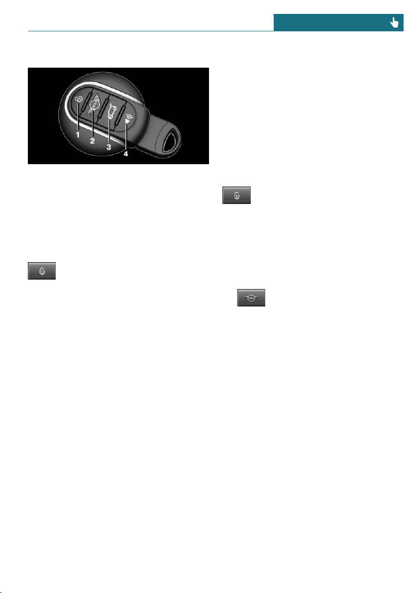
Overview
1 Unlocking
2 Locking
3 Unlocking the tailgate
4 Panic mode
Unlocking
Press the button on the vehicle key.
Depending on the settings, refer to
page 68, the following access points are
unlocked.
– Driver's door and fuel filler flap.
Press the button on the vehicle key
again to unlock the other vehicle access
points.
– All doors, tailgate, and fuel filler flap.
In addition, the following functions are exe-
cuted:
– Unlocking is confirmed by the turn sig-
nals and the horn. This function must be
activated in the settings, refer to
page 68.
– The settings stored in the driver profile,
refer to page 67, are applied.
– The interior lights, refer to page 135,
and the MINI logo projection are
switched on, provided that the interior
lights were not switched off manually.
– Depending on the settings, the welcome
light and headlight courtesy delay fea-
ture, refer to page 132, are switched on.
– Exterior mirrors folded through conven-
ient closing are folded open.
– The alarm system, refer to page 69, is
switched off.
The light functions may depend on the am-
bient brightness.
Convenient opening
Press and hold the button on the ve-
hicle key after unlocking.
The windows and the glass sunroof are
opened, as long as the button on the vehicle
key is pressed.
Locking
1. Close the driver's door.
2. Press the button on the vehicle
key.
The following functions are executed:
– All doors, the tailgate, and the fuel filler
flap are locked.
– Locking is confirmed by the turn signals
and the horn. This function must be ac-
tivated in the settings, refer to
page 68.
– The alarm system, refer to page 69, is
switched on.
If the engine or ignition is still switched on
when you lock the vehicle, the vehicle horn
honks twice. In this case, the engine or ig-
nition must be switched off by means of the
Start/Stop button.
Seite 59
Opening and closing CONTROLS
59
Online Edition for Part no. 01402667083 - VI/19
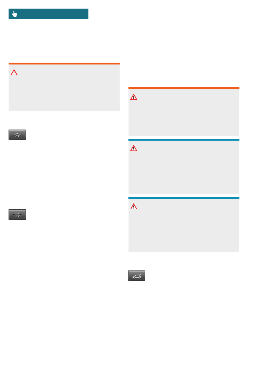
With Comfort Access: convenient
closing
Safety information
Warning
With convenient closing, body parts can
be jammed. There is a risk of injury. Make
sure that the area of movement of the
doors is clear during convenient closing.
Closing
Press and hold the button on the ve-
hicle key in the area close to the ve-
hicle.
The windows and the glass sunroof are
closed, as long as the button on the vehicle
key is pressed.
The exterior mirrors are folded in.
Switch on interior lights and
courtesy light
Press the button on the vehicle key
with the vehicle locked.
The MINI logo projection is also switched
on.
These functions are not available if the inte-
rior lights were switched off manually.
The light functions may depend on the am-
bient brightness.
After locking, wait 10 seconds before press-
ing the button again.
Tailgate
General information
To avoid locking the vehicle key in the vehi-
cle, do not place the remote control in the
cargo area.
Depending on the vehicle equipment and
country version, it is possible to specify
whether the tailgate can be unlocked with
the vehicle key and how the vehicle doors
will respond to this. To perform settings, re-
fer to page 68.
Safety information
Warning
Body parts can be jammed when operating
the tailgate. There is a risk of injury. Make
sure that the area of movement of the tail-
gate is clear during opening and closing.
NOTICE
The tailgate swings back and up when it
opens. There is a risk of damage to prop-
erty. Make sure that the area of movement
of the tailgate is clear during opening and
closing.
NOTICE
Sharp-edged or pointed objects can hit the
windows and heat conductors while driv-
ing. There is a risk of damage to property.
Cover the edges and ensure that pointed
objects do not hit the windows.
Opening
Press and hold the button on the ve-
hicle key for approx. 1 second.
The tailgate is unlocked and can be swung
upward.
Panic mode
You can trigger the alarm system if you find
yourself in a dangerous situation.
Seite 60
CONTROLS Opening and closing
60
Online Edition for Part no. 01402667083 - VI/19
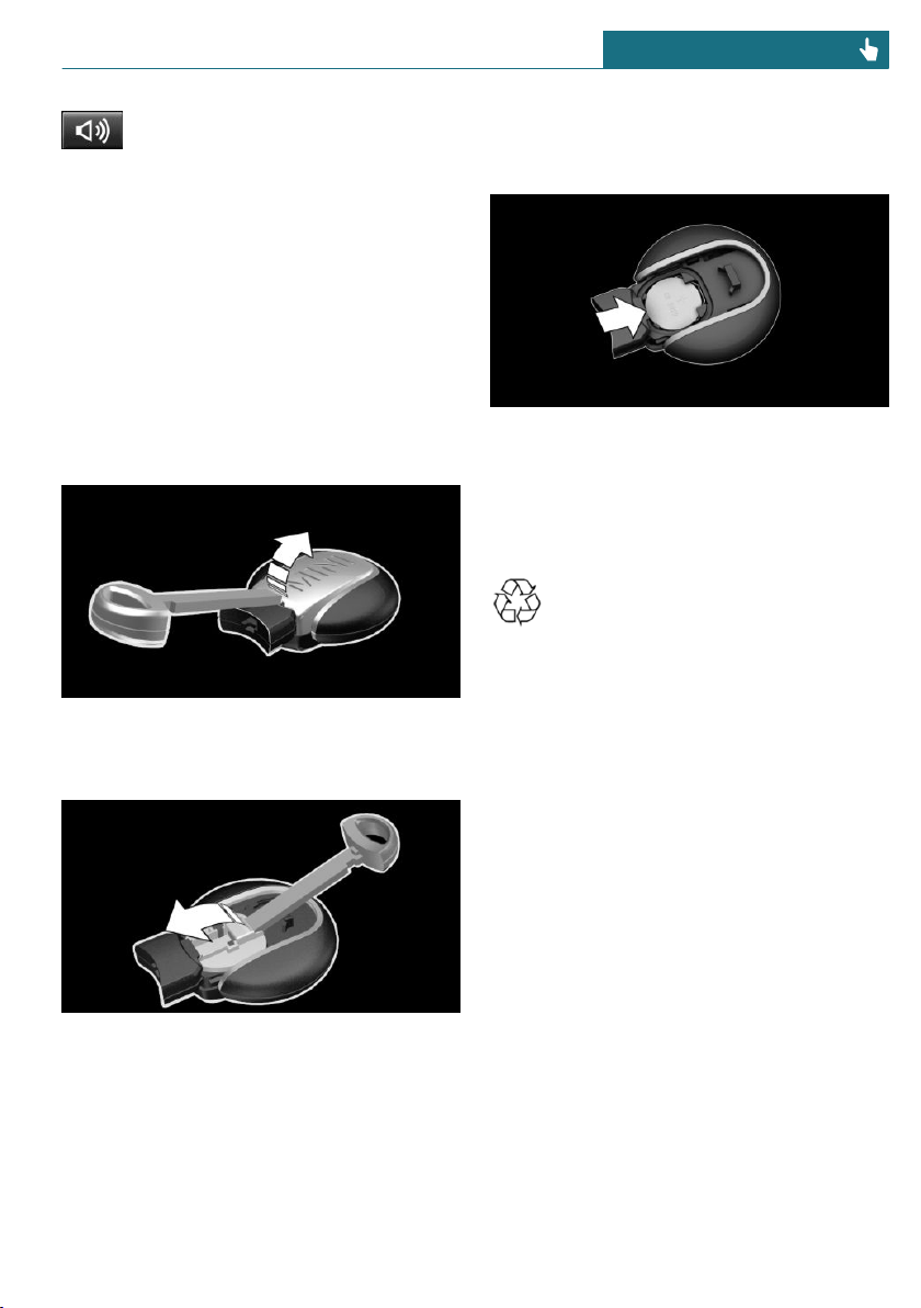
– Press the button on the vehicle
key and hold for at least 3 sec-
onds.
– Briefly press the button on the vehicle
key three times in succession.
To switch off the alarm: press any button.
Replacing the battery
1. Remove the integrated key from the ve-
hicle key, refer to page 63.
2. Slide the integrated key into the open-
ing and raise the cover.
The battery compartment is accessible.
3. Slide the integrated key in the cover of
the battery compartment and raise the
cover.
4. Push battery in the direction of the ar-
row using a pointed object and lift it
out.
5. Insert a type CR 2032 battery with the
positive side facing up.
6. Insert lid and cover.
7. Push the integrated key into the vehicle
key until it engages.
Have old batteries disposed of by a
dealer’s service center or another
qualified service center or repair
shop or take them to a collection point.
Additional vehicle keys
Additional vehicle keys are available from a
service center or another qualified service
center or repair shop.
Loss of vehicle keys
A lost vehicle key can be blocked and re-
placed by a dealer’s service center or an-
other qualified service center or repair
shop.
Malfunction
General information
A Check Control message is displayed.
Vehicle key recognition by the vehicle may
malfunction under the following circum-
stances:
Seite 61
Opening and closing CONTROLS
61
Online Edition for Part no. 01402667083 - VI/19
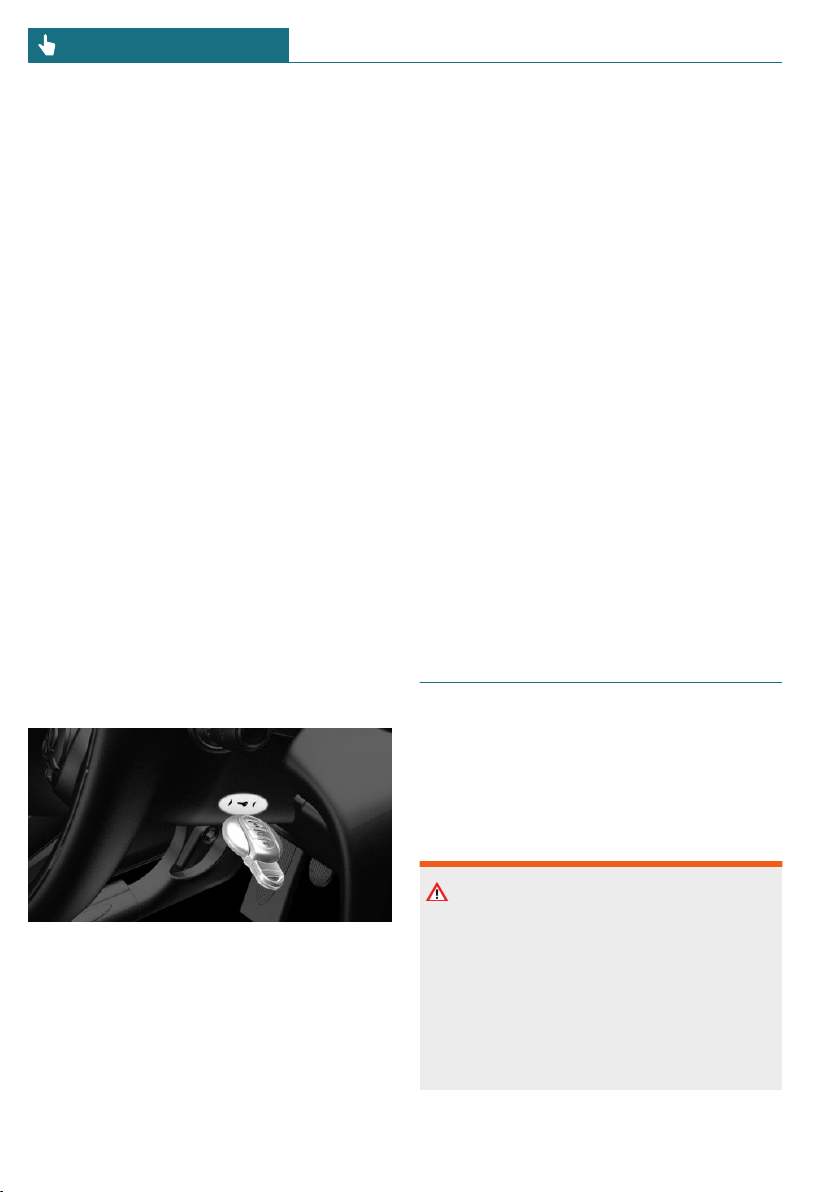
– The battery of the vehicle key is dis-
charged. For replacing the battery, refer
to page 61.
– Interference of the radio connection
from transmission towers or other
equipment with high transmitting
power.
– Shielding of the vehicle key due to metal
objects.
Do not transport the vehicle key to-
gether with metal objects.
– Interference of the radio connection
from mobile phones or other electronic
devices in direct proximity to the vehi-
cle key.
Do not transport the vehicle key to-
gether with electronic devices.
– Interference of radio transmission by a
charging process of mobile devices, for
instance charging of a mobile phone.
In the case of interference, the vehicle can
be unlocked and locked from the outside
with the integrated key, refer to page 62.
Starting the engine via emergency
detection of the Vehicle key
It is not possible to start the engine if the
vehicle key has not been detected.
Proceed as follows in this case:
1. Hold the vehicle key against the mark
on the steering column as shown. Pay
attention to the display in the instru-
ment cluster.
2. If the vehicle key is detected:
Start the engine within 10 seconds.
If the vehicle key is not recognized, slightly
change the position of the vehicle key and
repeat the procedure.
Frequently Asked Questions
What precautions can be taken to be able to
open a vehicle with an accidentally locked
in vehicle key?
– The options provided by the Remote
Services of the MINI Connected app in-
clude the ability to lock and unlock a ve-
hicle.
This requires an active MINI Connected
contract and the MINI Connected app
must be installed on a smartphone.
– Unlocking the vehicle can be requested
via the MINI Connected Call Center.
An active MINI Connected contract is
required.
Integrated key
General information
The driver's door can be locked and un-
locked without the vehicle key using the
integrated key.
Safety information
Warning
Unlocking from the inside is only possible
with special knowledge.
Persons who spend a lengthy time in the
vehicle while being exposed to extreme
temperatures are at risk of injury or death.
Do not lock the vehicle from the outside
when there are people in it.
Seite 62
CONTROLS Opening and closing
62
Online Edition for Part no. 01402667083 - VI/19
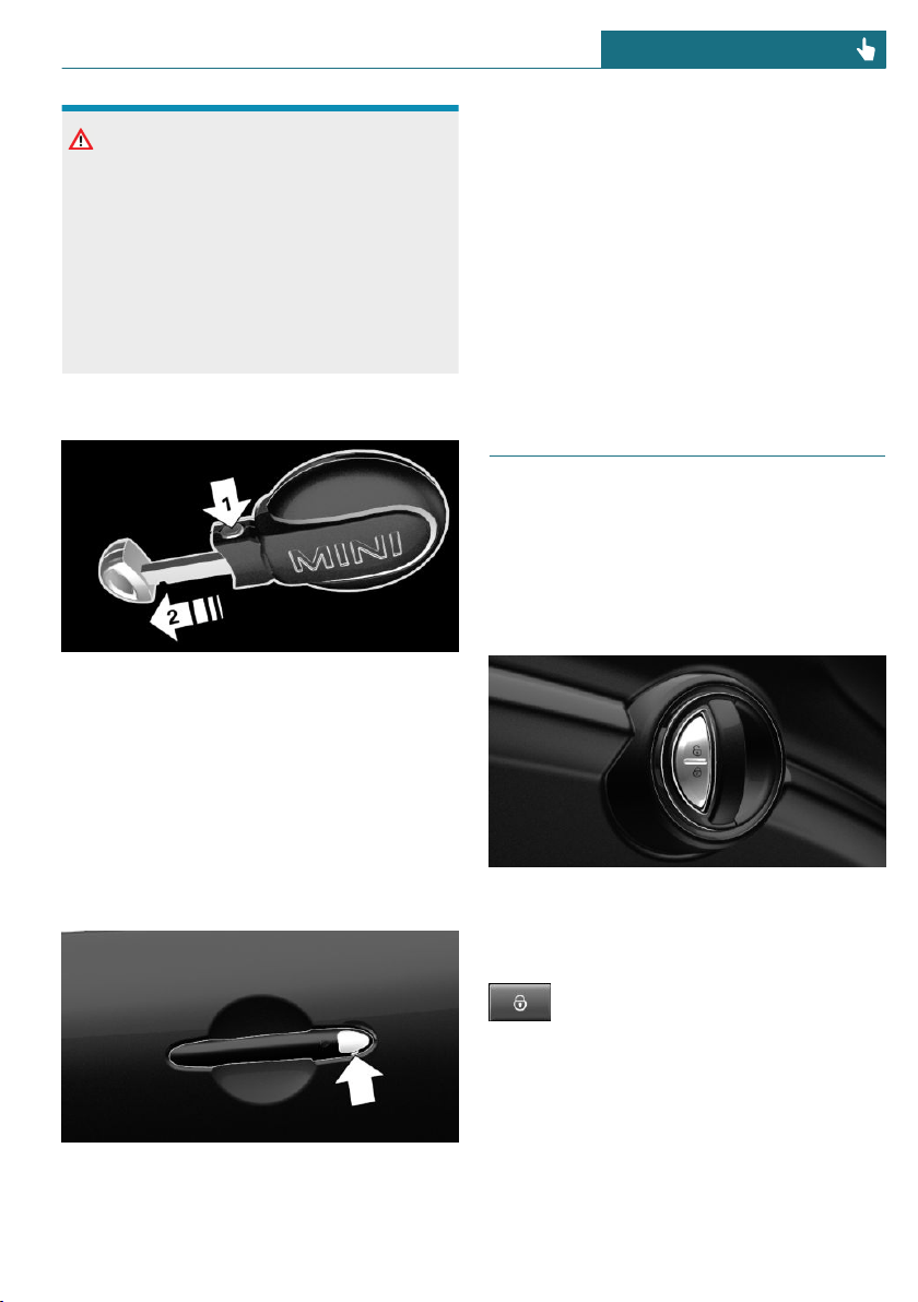
NOTICE
The door lock is permanently joined with
the door. The door handle can be moved.
When pulling the door handle with the
integrated key inserted, paint or the
integrated key can be damaged. There is a
risk of damage to property. Remove the
integrated key before pulling the outside
door handle.
Removing
Press the button, arrow 1, and pull out the
integrated key, arrow 2.
Locking/unlocking via the door
lock
1. Remove lid on the door lock.
To do this, slide the integrated key into
the opening from below and remove the
lid.
2. Unlock or lock the door lock using the
integrated key.
The other doors must be unlocked or locked
from the inside.
Alarm system
The alarm system is not switched on if the
vehicle is locked with the integrated key.
The alarm system is triggered when the
door is opened, if the vehicle has been un-
locked via the door lock.
Buttons for the central locking
system
General information
In the event of a severe accident, the vehi-
cle is automatically unlocked. The hazard
warning system and interior lights come on.
Overview
Buttons for the central locking system.
Locking
Press the button with the front
doors closed.
– The fuel filler flap remains unlocked.
– The vehicle is not secured against theft
when locking.
Seite 63
Opening and closing CONTROLS
63
Online Edition for Part no. 01402667083 - VI/19
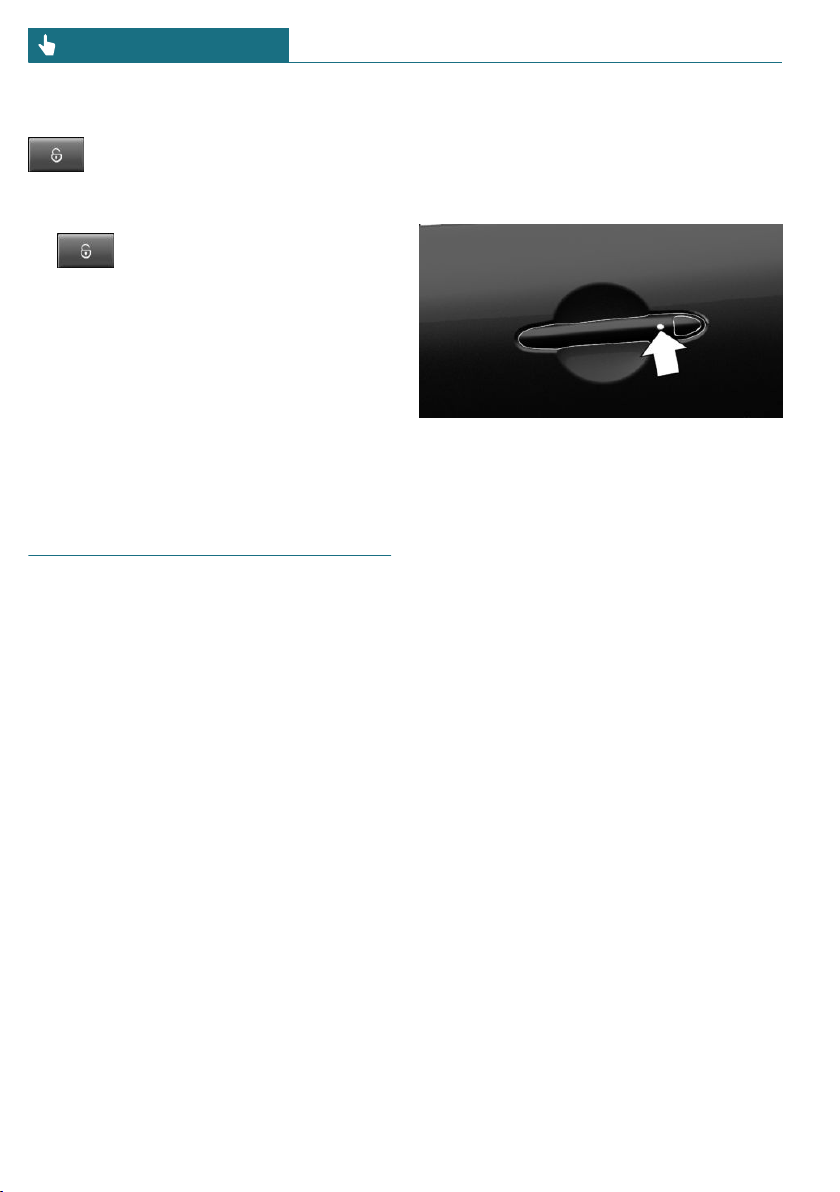
Unlocking
Press the button.
Opening
– Press button to unlock the doors
together, and then pull the door handle
above the armrest.
– Front doors: pull the door handle on the
door to open the door. The other doors
remain locked.
– Back doors: pull twice on the door han-
dle on the door to be opened; the first
time unlocks the door, the second time
opens it. The other doors remain locked.
Comfort Access
Concept
The vehicle can be accessed without operat-
ing the vehicle key.
Carrying the vehicle key with you, e.g., in
your pants pocket, is sufficient.
The vehicle automatically detects the vehi-
cle key when it is in close proximity or in
the car's interior.
General information
Comfort Access supports the following
functions:
– Unlocking and locking the vehicle.
– Convenient closing.
– Open the tailgate.
Functional requirements
– To lock the vehicle, the vehicle key must
be outside of the vehicle near the doors.
– The next unlocking and locking cycle is
not possible until after approx. 2 sec-
onds.
Unlocking
On the driver's or front passenger's outer
door handle, press the button.
Depending on the settings, refer to
page 68, only the driver's door and the
fuel filler flap may be unlocked. Unlike
when unlocking with the vehicle key, press-
ing the button on the outer door handle
again does not unlock the other vehicle ac-
cess points. Rather, the vehicle is locked
again.
If the vehicle was locked automatically after
driving off or with the button of the central
locking system from the inside, note the fol-
lowing: if a door on a locked vehicle is
opened from the inside with the door
opener, pressing the button on the outer
door handle will first lock the vehicle again.
To unlock, the button on the outer door han-
dle must be pressed again.
Seite 64
CONTROLS Opening and closing
64
Online Edition for Part no. 01402667083 - VI/19
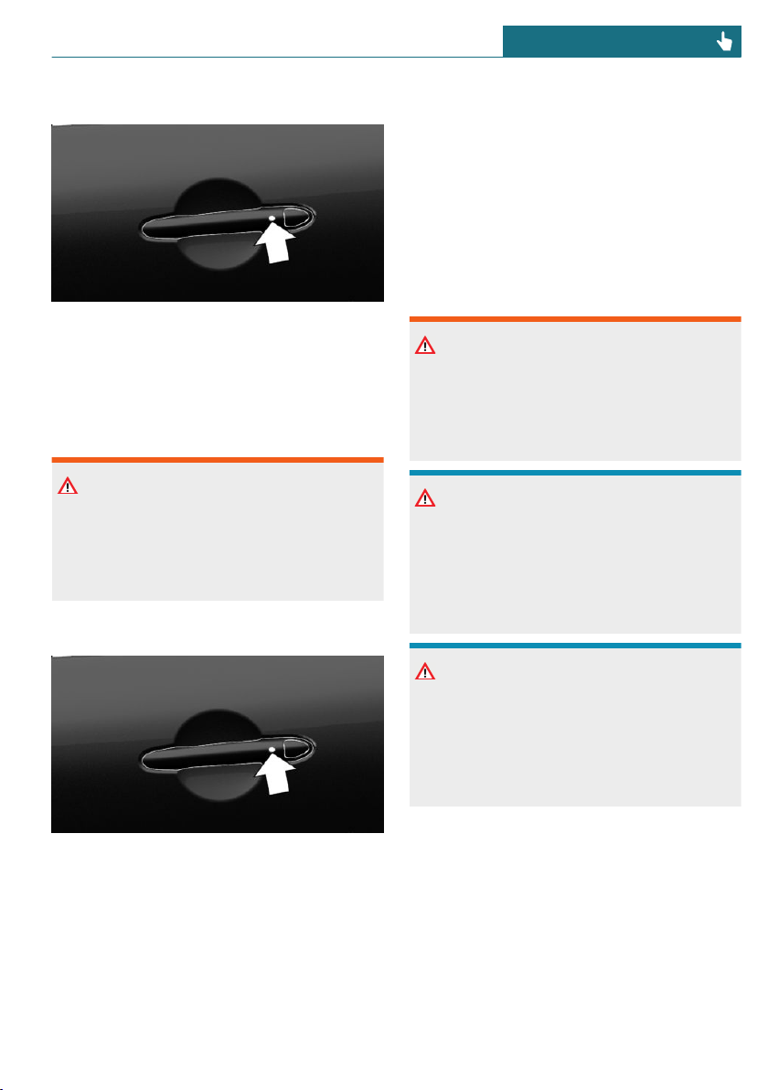
Locking
On the driver's or front passenger's outer
door handle, press the button.
Convenient closing
Safety information
Warning
With convenient closing, body parts can
be jammed. There is a risk of injury. Make
sure that the area of movement of the
doors is clear during convenient closing.
Closing
Press and hold down the button on the driv-
er's or front passenger's outer door handle.
In addition to locking, the windows and
glass sunroof will be closed.
The exterior mirrors are folded in.
To open the tailgate
General information
If the tailgate is opened via Comfort Access,
locked doors are not unlocked.
To avoid locking the vehicle key in the vehi-
cle, do not place the vehicle key in the cargo
area.
Safety information
Warning
Body parts can be jammed when operating
the tailgate. There is a risk of injury. Make
sure that the area of movement of the tail-
gate is clear during opening and closing.
NOTICE
The tailgate swings back and up when it
opens. There is a risk of damage to prop-
erty. Make sure that the area of movement
of the tailgate is clear during opening and
closing.
NOTICE
Sharp-edged or pointed objects can hit the
windows and heat conductors while driv-
ing. There is a risk of damage to property.
Cover the edges and ensure that pointed
objects do not hit the windows.
Seite 65
Opening and closing CONTROLS
65
Online Edition for Part no. 01402667083 - VI/19
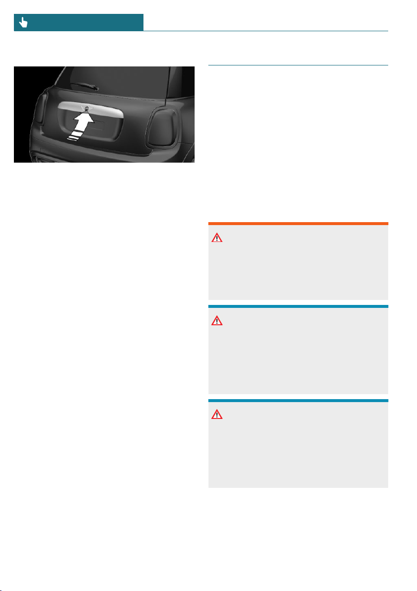
Opening
Press button next on tailgate.
The tailgate is unlocked and can be swung
upward.
Malfunction
Vehicle key recognition by the vehicle may
malfunction under the following circum-
stances:
– The battery of the vehicle key is dis-
charged. For replacing the battery, refer
to page 61.
– Interference of the radio connection
from transmission towers or other
equipment with high transmitting
power.
– Shielding of the vehicle key due to metal
objects.
Do not transport the vehicle key to-
gether with metal objects.
– Interference of the radio connection
from mobile phones or other electronic
devices in direct proximity to the vehi-
cle key.
Do not transport the vehicle key to-
gether with electronic devices.
Wet or snowy conditions may disrupt the
locking request recognition function on the
door handles.
In the case of a malfunction, unlock and
lock the vehicle using the buttons of the ve-
hicle key or use the integrated key, refer to
page 62.
Tailgate
General information
To avoid locking the vehicle key in the vehi-
cle, do not place the remote control in the
cargo area.
Depending on the vehicle equipment and
country version, it is possible to specify
whether the tailgate can be unlocked with
the vehicle key and how the vehicle doors
will respond to this. To perform settings, re-
fer to page 68.
Safety information
Warning
Body parts can be jammed when operating
the tailgate. There is a risk of injury. Make
sure that the area of movement of the tail-
gate is clear during opening and closing.
NOTICE
The tailgate swings back and up when it
opens. There is a risk of damage to prop-
erty. Make sure that the area of movement
of the tailgate is clear during opening and
closing.
NOTICE
Sharp-edged or pointed objects can hit the
windows and heat conductors while driv-
ing. There is a risk of damage to property.
Cover the edges and ensure that pointed
objects do not hit the windows.
Seite 66
CONTROLS Opening and closing
66
Online Edition for Part no. 01402667083 - VI/19
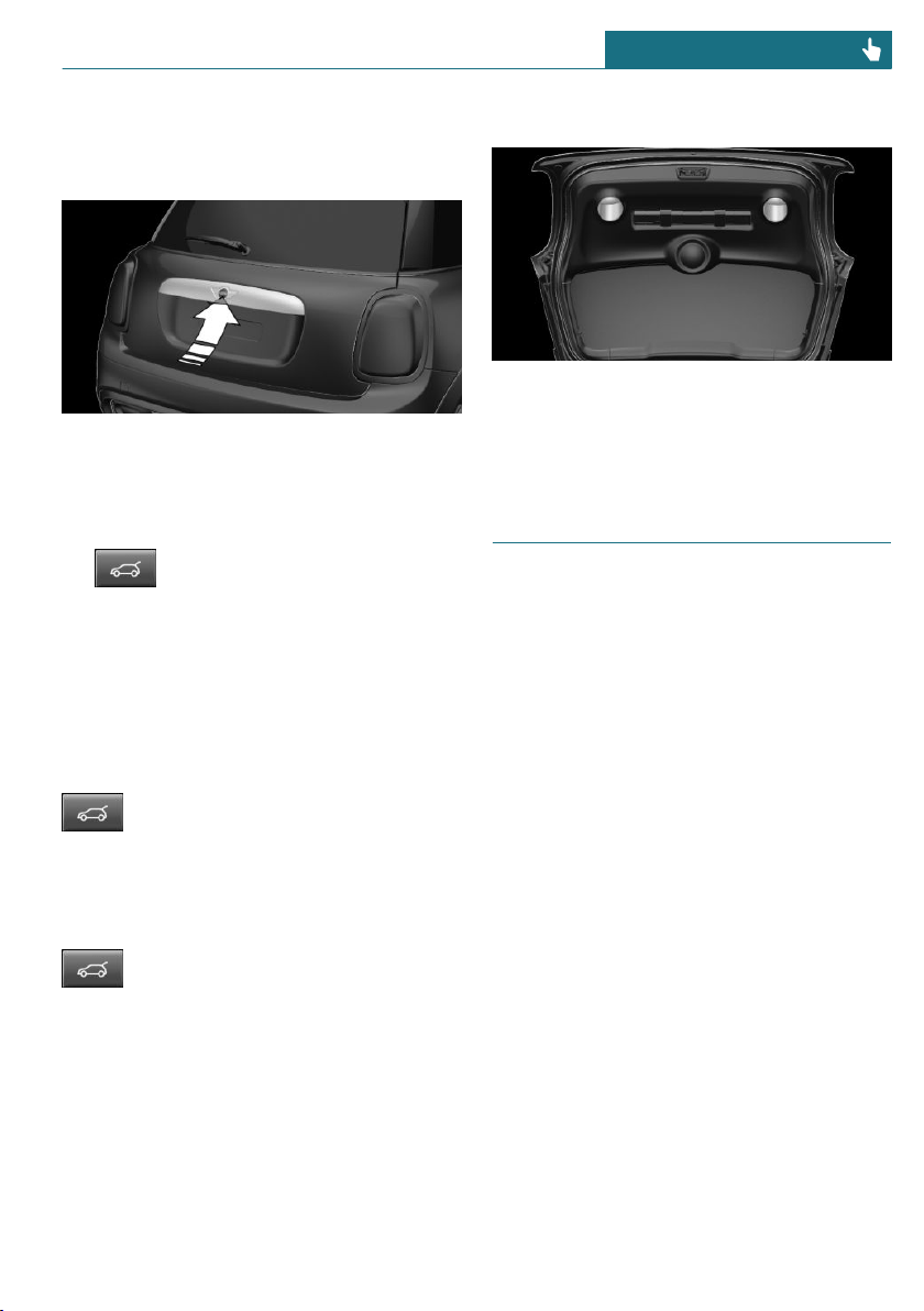
Opening and closing
Opening from the outside
– Without Comfort Access: unlock vehicle.
With Comfort Access: unlock the vehi-
cle or have the vehicle key with you.
Press button next on tailgate.
– Press and hold the button on the
vehicle key for approx. 1 second.
Depending on the setting, the doors may
also be unlocked. Unlocking with the ve-
hicle key, refer to page 60.
The tailgate is unlocked and can be swung
upward.
Opening from the inside
With Steptronic transmission:
With the vehicle stationary, press
the button in the driver's floor area.
If the vehicle is locked, selector lever posi-
tion P must be engaged first.
With manual transmission:
With the vehicle stationary, press
the button in the driver's floor area twice in
quick succession.
Closing
Recessed grips on the interior trim of the
tailgate can be used to conveniently pull
down the tailgate.
Driver profiles
Concept
In the driver profiles, individual settings for
several drivers can be stored and called up
again when required.
General information
There are three driver profiles with which
personal vehicle settings can be stored. Ev-
ery vehicle key has been assigned one of
these driver profiles.
If the vehicle is unlocked using the vehicle
key, the assigned personal driver profile will
be activated. All settings stored in the
driver profile are automatically applied.
If several drivers use their own vehicle
keys, the vehicle will apply the personal set-
tings as it is being unlocked. These settings
are also restored, if the vehicle has been
used in the meantime by a person with a
different vehicle key.
Changes to the settings are automatically
stored in the driver profile currently acti-
vated.
Seite 67
Opening and closing CONTROLS
67
Online Edition for Part no. 01402667083 - VI/19

Functional requirements
For the system to be able to identify the
driver profile associated to a particular
driver, the detected vehicle key must be
clearly allocated to the driver.
This is the case when:
– The driver is only carrying his or her
own vehicle key.
– The driver unlocks the vehicle.
– The driver gets into the vehicle through
the driver's door.
Adjusting
The settings for the following systems and
functions are stored in the active profile.
The scope of storable settings depends on
country and equipment.
– Unlocking and locking.
– Lights.
– Radio.
– Instrument cluster.
– Programmable memory buttons.
– Volumes, tone.
– Control Display.
– Climate control.
– PDC Park Distance Control.
– Rearview camera.
– MINI Driving Modes.
– Intelligent Safety.
System limits
A clear assignment between the vehicle key
and driver may not be possible in the fol-
lowing cases, for example.
– The passenger unlocks the vehicle with
his or her own vehicle key, but another
person is driving.
– The driver unlocks the vehicle via Com-
fort Access and has multiple vehicle
keys with him or her.
– The driver changes, but the vehicle is
not locked and unlocked.
– Multiple vehicle keys are located out-
side of the vehicle.
Adjusting
General information
Depending on the package and country ver-
sion, various settings are available for the
vehicle key functions.
These settings are stored for the driver pro-
file, refer to page 67, currently used.
Unlocking
Doors
Via the Central Information Display (CID):
1. "My MINI"
2. "Vehicle settings"
3. "Doors/Key"
4. "Driver's door" or "All doors"
5. Select the desired setting:
– "Driver's door only"
Only the driver's door and the fuel
filler flap are unlocked. Pressing
again unlocks the entire vehicle.
– "All doors"
The entire vehicle is unlocked.
Tailgate
Via the Central Information Display (CID):
1. "My MINI"
2. "Vehicle settings"
3. "Doors/Key"
4.
Seite 68
CONTROLS Opening and closing
68
Online Edition for Part no. 01402667083 - VI/19

The text next to the symbol indicates
the current setting.
5. Select the desired setting:
– "Tailgate"
Only the tailgate is unlocked.
– "Tailgate and door(s)"
The tailgate and the doors are un-
locked.
– "Tailgate opens after unlocking"
The vehicle must be unlocked before
the tailgate can be used with the ve-
hicle key.
– "Button lock"
It is not possible to use the tailgate
via the vehicle key.
Depending on the vehicle equipment and
country version, this setting may not be of-
fered.
Automatic locking
Via the Central Information Display (CID):
1. "My MINI"
2. "Vehicle settings"
3. "Doors/Key"
4. Select the desired setting:
– "Lock automatically"
The vehicle locks automatically after
a while if no door is opened after un-
locking.
– "Lock after starting to drive"
The vehicle locks automatically after
you drive off.
Automatic unlocking
Via the Central Information Display (CID):
1. "My MINI"
2. "Vehicle settings"
3. "Doors/Key"
4. "Unlock at end of trip"
After the engine is switched off by
pressing the Start/Stop button, the
locked vehicle is automatically un-
locked.
Confirmation signals from the
vehicle
Via the Central Information Display (CID):
1. "My MINI"
2. "Vehicle settings"
3. "Doors/Key"
4. Deactivate or activate the desired con-
firmation signals.
– "Flash for lock/unlock"
Unlocking is signaled by two flashes,
locking by one.
– With alarm system:
"Acoustic signal for lock/unlock"
Unlocking is signaled by one honk of
the horn.
Alarm system
General information
When the vehicle is locked, the vehicle
alarm system reacts to the following
changes:
– Unauthorized opening of a door, the
hood or the tailgate.
– Movements in the car's interior.
– Changes in the vehicle tilt, for instance,
during attempts at stealing a wheel or
when towing the vehicle.
– Disconnected battery voltage.
– Improper use of the socket for Onboard
Diagnosis.
Seite 69
Opening and closing CONTROLS
69
Online Edition for Part no. 01402667083 - VI/19
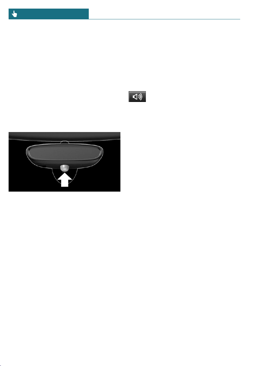
– Locking the vehicle while a device is
connected to the socket for the OBD On-
board-Diagnosis. For socket for the OBD
Onboard Diagnosis, refer to page 289.
The alarm system signals these changes vis-
ually and acoustically:
– Acoustic alarm:
Depending on local regulations, the
acoustic alarm may be suppressed.
– Visual alarm:
By flashing the exterior lighting.
Overview
Indicator light on the interior mirror.
Switching on/off
When you unlock and lock the vehicle, ei-
ther with the vehicle key or via Comfort Ac-
cess, the alarm system is switched off and
on at the same time.
Opening the doors with the alarm
system switched on
The alarm system is triggered when a door
is opened if the door was unlocked using
the integrated key in the door lock.
Switching off the alarm, refer to page 71.
Opening the tailgate with the alarm
system switched on
The tailgate can be opened even when the
alarm system is switched on.
After the tailgate is closed, it is locked and
monitored again provided the doors are
locked. The hazard warning system flashes
once.
Panic mode
You can trigger the alarm system if you find
yourself in a dangerous situation.
– Press the button on the vehicle
key and hold for at least 3 sec-
onds.
– Briefly press the button on the vehicle
key three times in succession.
To switch off the alarm: press any button.
Signals of the indicator light
– The indicator light flashes briefly every
2 seconds:
The alarm system is switched on.
– Indicator light flashes for approx.
10 seconds, then it flashes briefly every
2 seconds:
Interior motion sensor and tilt alarm
sensor are not active, as doors, hood, or
tailgate are not correctly closed. Cor-
rectly closed access points are secured.
When the still open access points are
closed, the interior motion sensor and
tilt alarm sensor will be switched on.
– The indicator light goes out after un-
locking:
The vehicle has not been tampered with.
– The indicator light flashes after unlock-
ing until the engine ignition is switched
on, but no longer than approx. 5 mi-
nutes:
An alarm has been triggered.
Tilt alarm sensor
The tilt of the vehicle is monitored.
Seite 70
CONTROLS Opening and closing
70
Online Edition for Part no. 01402667083 - VI/19
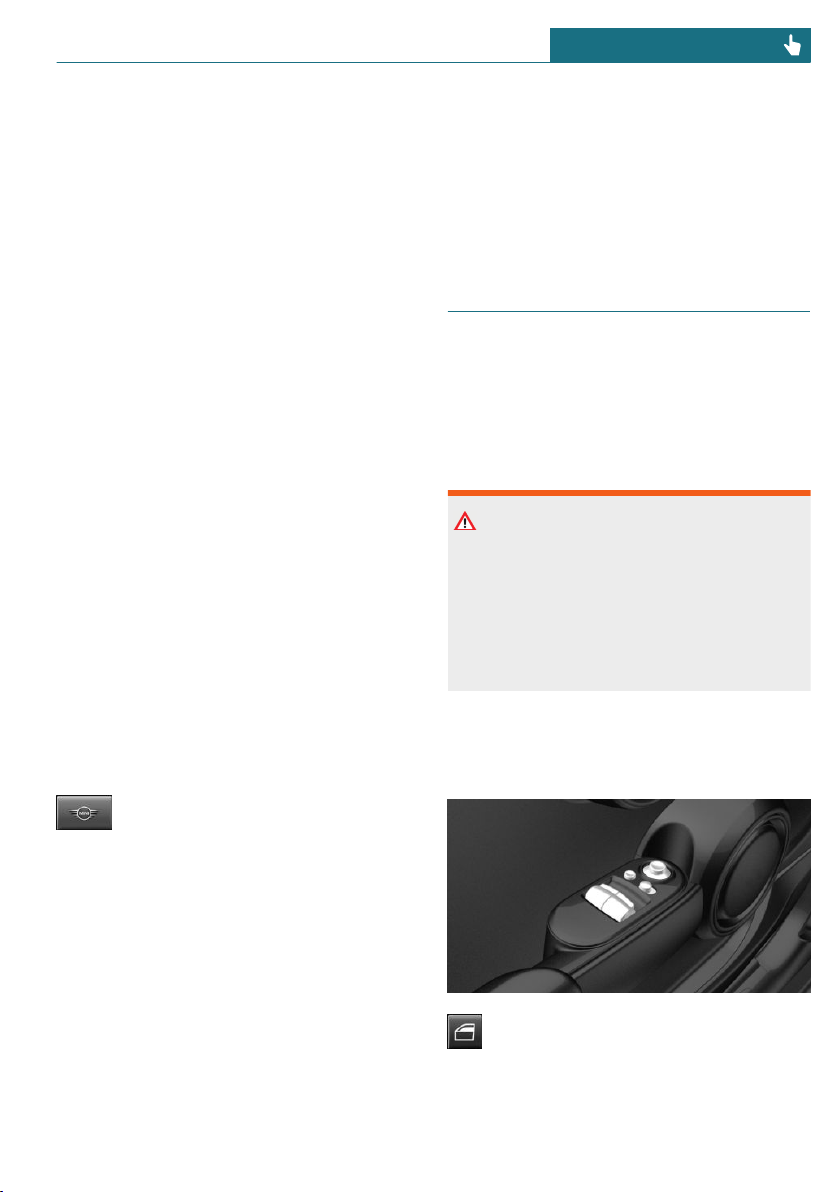
The alarm system responds in situations
such as attempts to steal a wheel or when
the vehicle is towed.
Interior motion sensor
The windows and the glass sunroof must be
closed for the system to function properly.
Avoiding unintentional alarms
General information
The tilt alarm sensor and interior motion
sensor can trigger an alarm, although no un-
authorized action occurred.
Possible situations for an unwanted alarm:
– In automatic vehicle washes.
– In duplex garages.
– During transport on trains carrying ve-
hicles, at sea or on a trailer.
– With animals in the vehicle.
– When the vehicle is locked after start of
fueling.
The tilt alarm sensor and the interior mo-
tion sensor can be switched off in such sit-
uations.
Switching off the tilt alarm sensor and
interior motion sensor
Press the button on the vehicle key
within 10 seconds as soon as the
vehicle is locked.
The indicator light lights up for approx.
2 seconds and then continues to flash.
The tilt alarm sensor and interior motion
sensor are switched off until the vehicle is
locked again.
Switching off the alarm
– Unlock the vehicle with the vehicle key.
– Unlock the vehicle with the integrated
remote control or switch on the ignition
using the emergency detection of re-
mote control, refer to page 61.
– With Comfort Access: if you have the
vehicle key with you, unlock the vehicle
using the button on the driver's side or
passenger side door.
Power windows
General information
If an accident of a certain severity occurs,
the windows are automatically closed ex-
cept a gap.
Safety information
Warning
When operating the windows, body parts
and objects can be jammed. There is a risk
of injury or risk of damage to property.
Make sure that the area of movement of
the windows is clear during opening and
closing.
Overview
On 3-door models
Power windows
Seite 71
Opening and closing CONTROLS
71
Online Edition for Part no. 01402667083 - VI/19
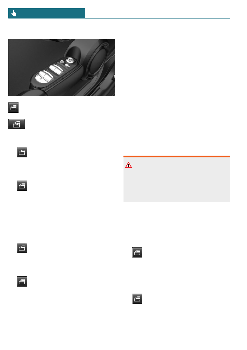
On 5-door models
Power windows
Safety switch
Opening
– Press the switch to the resistance
point.
The window opens while the switch is
being held.
– Press the switch beyond the resist-
ance point.
The window opens automatically. Press-
ing the switch again stops the motion.
Convenient opening with the vehicle key,
refer to page 59.
Closing
– Pull the switch to the resistance
point.
The window closes while the switch is
being held.
– Pull the switch beyond the resist-
ance point.
The window closes automatically if the
door is closed. Pulling the switch again
stops the motion.
Convenient closing with the vehicle key, re-
fer to page 60.
Closing via Comfort Access, refer to
page 65.
Jam protection system
Concept
The jam protection prevents objects or body
parts becoming jammed between the door
frame and window while a window is being
closed.
General information
If resistance or a blockage is detected while
a window is being closed, the closing action
is interrupted.
The window opens slightly.
Safety information
Warning
Accessories on the windows such as an-
tennas can impact jam protection. There is
a risk of injury. Do not install accessories
in the area of movement of the windows.
Closing without the jam protection
system
In case of danger from the outside or if ice
might prevent normal closing, proceed as
follows:
1. Pull the switch past the resistance
point and hold it there.
The window closes with limited jam pro-
tection. If the closing force exceeds a
specific threshold, closing is inter-
rupted.
2. Pull the switch past the resistance
point again within approx. 4 seconds
and hold it there.
Seite 72
CONTROLS Opening and closing
72
Online Edition for Part no. 01402667083 - VI/19
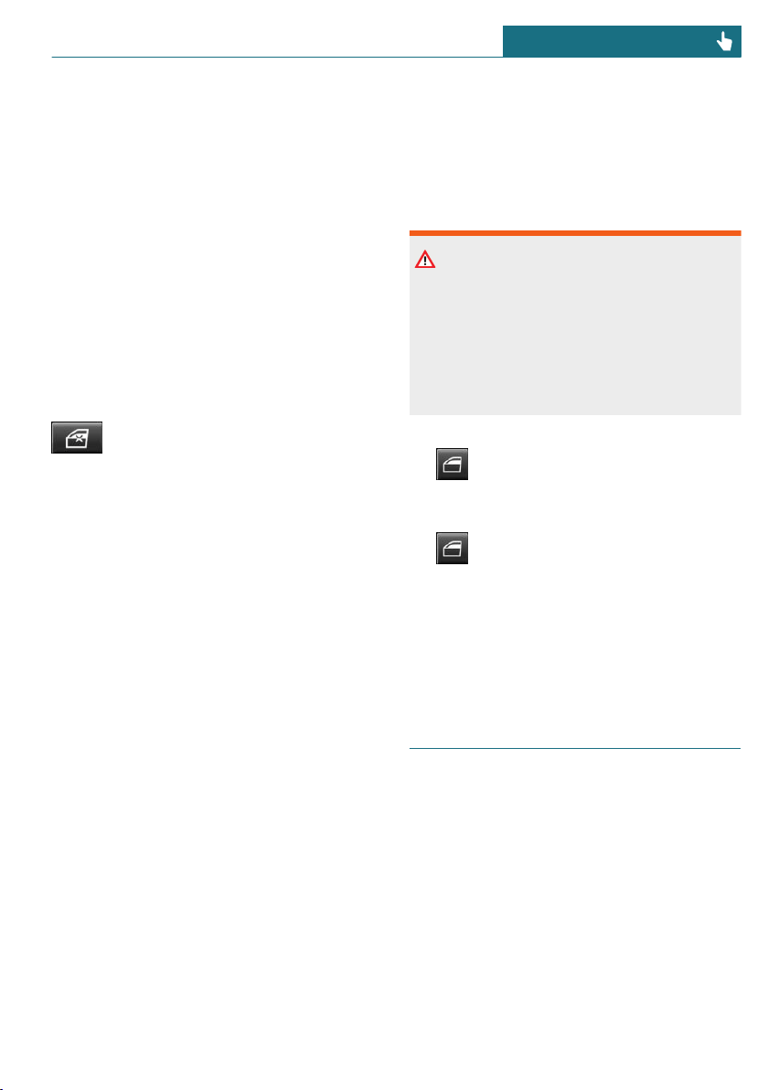
The window closes without jam protec-
tion.
On 5-door models: safety switch
General information
The safety switch can be used to prevent
children, for instance from opening and
closing the rear windows using the
switches in the rear.
If an accident of a certain severity occurs,
the safety function is switched off automati-
cally.
Switching on/off
Press the button.
The LED lights up if the safety func-
tion is switched on.
Malfunction
General information
In certain situations a window can only be
operated to a limited extent.
– After a power failure during the opening
or closing process, the a window can
only be operated to a limited extent. The
system must be initialized in this case.
– The power window motors are equipped
with overheating protection. If a win-
dow is opened and closed several times
within a short period of time, the over-
heating protection switches the motor
off temporarily. Depending on the de-
gree of overheating, it may only be pos-
sible to close the window or it may not
be possible to operate it at all.
In this case: allow the power window
motor to cool down.
Initializing the system
The system can be initialized when the ve-
hicle is stationary and the engine is run-
ning.
During initialization, the affected window
closes without jam protection.
Warning
When operating the windows, body parts
and objects can be jammed. There is a risk
of injury or risk of damage to property.
Make sure that the area of movement of
the windows is clear during opening and
closing.
1. Open the affected window completely.
2. Pull the switch to the resistance
point and hold.
The window closes.
3. Continue holding the switch pulled
to the resistance point.
The window opens and closes once or
twice after approx. 15 seconds, depend-
ing on the vehicle's equipment.
4. Release switch.
Panoramic glass sunroof
General information
In the event of a severe accident, the glass
sunroof is automatically closed.
Seite 73
Opening and closing CONTROLS
73
Online Edition for Part no. 01402667083 - VI/19
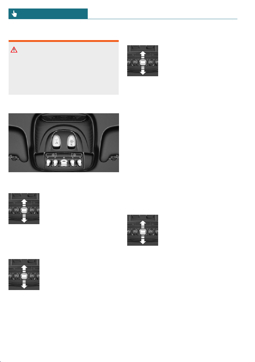
Safety information
Warning
Body parts can be jammed when operating
the glass sunroof. There is a risk of injury.
Make sure that the area of movement of
the glass sunroof is clear during opening
and closing.
Overview
Tilting the glass sunroof
Press back the switch up to or
beyond the resistance point
and release it.
The glass sunroof is raised.
Opening glass sunroof
When the glass sunroof is closed
Press the switch back beyond
the resistance point and re-
lease it twice.
The glass sunroof is opened.
Pressing the switch again
stops the motion.
With the glass sunroof completely
raised
– Slide switch back to the re-
sistance point and hold.
The glass sunroof is
opened as long as the
switch is pressed.
– Press the switch back beyond the resist-
ance point and release it.
The glass sunroof is opened.
Pressing the switch again stops the mo-
tion.
Comfort position
In some models, the wind noises in the car's
interior are lowest when the glass sunroof
is not fully open. In these models, the auto-
matic function initially only opens the glass
sunroof up to this comfort position.
Pressing the switch again opens the glass
sunroof fully.
Closing glass sunroof
With the glass sunroof open
– Slide switch forward to the
resistance point and hold.
The glass sunroof is closed
as long as the switch is
pressed and stops in the
raised position.
– Press the switch forward beyond the re-
sistance point and release it.
The glass sunroof is closed and stops in
the raised position.
Pressing the switch again stops the mo-
tion.
– Press the switch forward beyond the re-
sistance point and release it twice.
The glass sunroof is closed.
Seite 74
CONTROLS Opening and closing
74
Online Edition for Part no. 01402667083 - VI/19
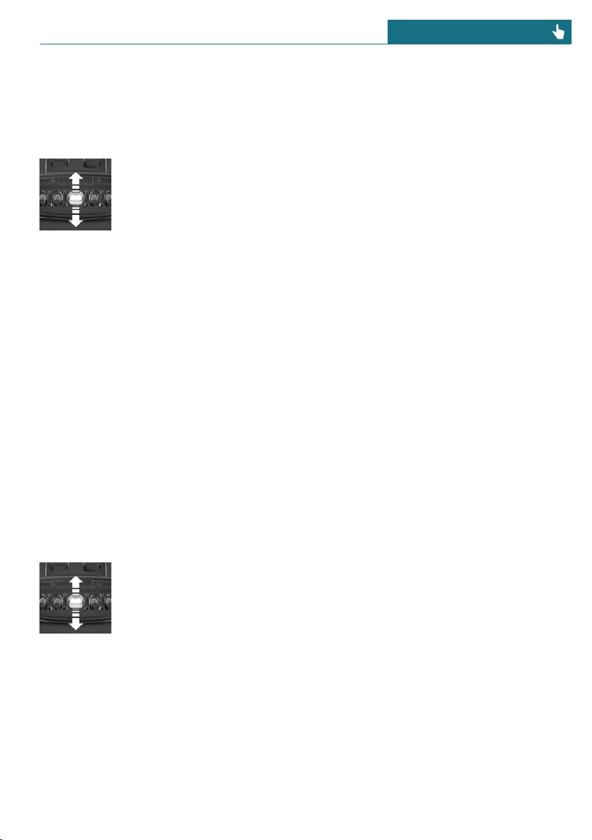
Pressing the switch again stops the mo-
tion.
With the glass sunroof completely
raised
Press the switch forward be-
yond the resistance point and
release it.
The glass sunroof is closed.
Jam protection system
Concept
The jam protection prevents objects or body
parts from becoming jammed between the
roof and glass sunroof while the glass sun-
roof is closing.
General information
If resistance or a blockage is detected while
the glass sunroof is being closed, the clos-
ing action is interrupted.
The glass sunroof opens slightly.
Closing without the jam protection
system
If there is an external danger, proceed as
follows:
1. Push the switch forward past the resist-
ance point and hold it.
The glass sunroof closes with limited
jam protection. If the closing force ex-
ceeds a specific threshold, closing is in-
terrupted.
2. Push the switch forward again past the
resistance point and hold until the glass
sunroof closes without jam protection.
Make sure that the closing area is clear.
Initializing after a power
interruption
After a power failure during the opening or
closing process, the glass sunroof can only
be operated to a limited extent. The system
must be initialized in this case. MINI rec-
ommends having this work performed only
by a dealer's service center or another quali-
fied service center or repair shop.
Seite 75
Opening and closing CONTROLS
75
Online Edition for Part no. 01402667083 - VI/19
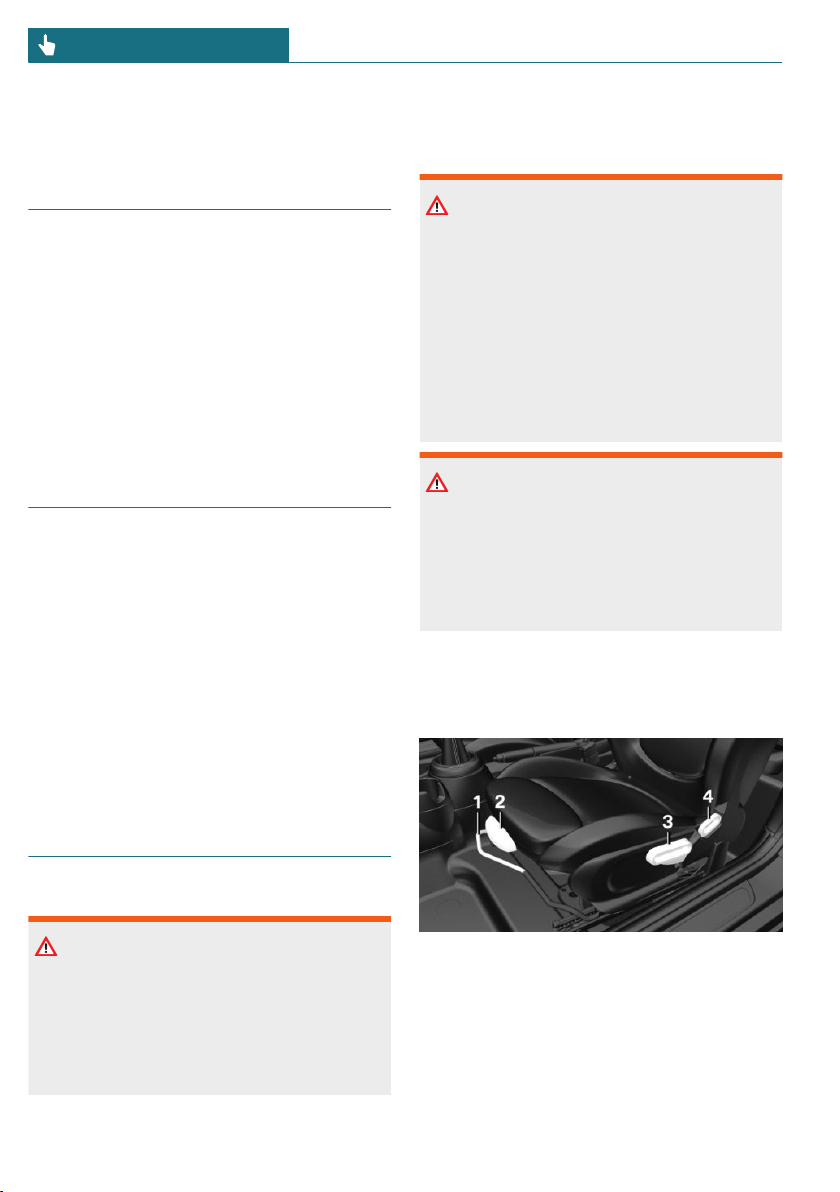
Seats, mirrors, and steering wheel
Vehicle features and options
This chapter describes all standard, country-
specific and optional features offered with
the series. It also describes features that are
not necessarily available in your vehicle, for
instance, due to the selected options or
country versions. This also applies to safety-
related functions and systems. When using
these functions and systems, the applicable
laws and regulations must be observed.
Sitting safely
An ideal seating position that meets the
needs of the occupants can make a vital
contribution to relaxed, fatigue-free driving.
In the event of an accident, the correct seat-
ing position plays an important role. Follow
the information in the following chapters:
– Seats, refer to page 76.
– Safety belts, refer to page 78.
– Head restraints, refer to page 80.
– Airbags, refer to page 137.
Front seats
Safety information
Warning
Seat adjustments while driving can lead to
unexpected movements of the seat. Vehi-
cle control could be lost. There is a risk of
accident. Only adjust the seat on the driv-
er's side when the vehicle is stationary.
Warning
With a backrest inclined too far to the
rear, the efficacy of the safety belt can no
longer be ensured. There is a risk of slid-
ing under the safety belt in an accident.
There is a risk of injuries or danger to life.
Adjust the seat prior to starting the trip.
Adjust the backrest so that it is in the
most upright position as possible and do
not adjust again while driving.
Warning
There is a risk of jamming when moving
the seats. There is a risk of injury or risk
of damage to property. Make sure that the
area of movement of the seat is clear prior
to any adjustment.
Adjusting seats
Overview
1 Forward/backward
2 Thigh support
3 Height
4 Backrest tilt
Seite 76
CONTROLS Seats, mirrors, and steering wheel
76
Online Edition for Part no. 01402667083 - VI/19
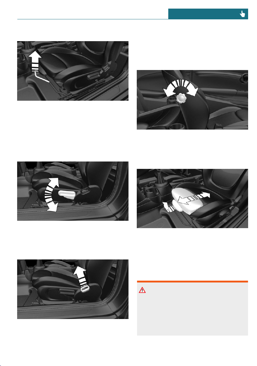
Forward/backward
Pull the lever and slide the seat in the de-
sired direction.
After releasing the lever, move the seat for-
ward or back slightly making sure it en-
gages properly.
Height
Pull the lever up or press it down as often as
needed to reach the desired height.
Backrest tilt
Pull the lever, and apply your weight to the
backrest or lift it off, as necessary.
Lumbar support
The curvature of the seat backrest can be
adjusted in a way that it supports the lum-
bar region of the spine. The lower back and
the spine are supported for upright posture.
Turn the wheel in order to increase or de-
crease the curvature.
Thigh support
Pull the lever at the front of the seat and ad-
just the thigh support.
In 3-door models: entering the rear
Safety information
Warning
There is a risk of jamming when moving
the seats. There is a risk of injury or risk
of damage to property. Make sure that the
area of movement of the seat is clear prior
to any adjustment.
Seite 77
Seats, mirrors, and steering wheel CONTROLS
77
Online Edition for Part no. 01402667083 - VI/19
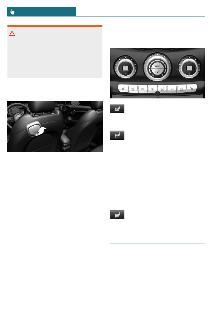
Warning
Unexpected movements of the rear seat
backrest while driving may occur if the
rear seat backrest is unlocked. Vehicle
control could be lost. There is a risk of in-
jury. Fold back and lock the rear seat back-
rests before driving.
Fold the rear seat backrest down
1. Pull lever up to the stop.
2. Fold the rear seat backrest forward.
3. Push the seat forward.
Original position
The driver's seat features a mechanical
memory function for forward/back and
backrest adjustment.
1. Push the seat back into the original po-
sition.
2. Fold back the backrest to lock the seat.
If the backrest is folded back when the seat
is not yet in the original position, the seat
engages in the current position. In this
case, manually adjust longitudinal direction,
refer to page 77.
Front seat heating
Overview
Seat heating
Switching on
Press the button once for each tem-
perature level.
The maximum temperature is reached when
three LEDs are lit.
If the trip is continued within approx.
15 minutes after a stop, seat heating is acti-
vated automatically with the temperature
selected last.
When GREEN Mode is activated, refer to
page 216, the heating output is reduced.
Switching off
Press and hold the button until the
LEDs go out.
Safety belts
Number of safety belts and safety
belt buckles
The vehicle is fitted with four or five safety
belts to ensure occupants' safety. However,
they can only offer protection when ad-
justed correctly.
Seite 78
CONTROLS Seats, mirrors, and steering wheel
78
Online Edition for Part no. 01402667083 - VI/19

The two outer safety belt buckles of the rear
seat are intended for the persons sitting on
the left and right.
The center safety belt buckle of the rear
seat is intended for the person sitting in the
middle.
General information
Always make sure that safety belts are be-
ing worn by all occupants before driving off.
Although airbags enhance safety by provid-
ing added protection, they are not a substi-
tute for safety belts.
If needed, disengage the safety belt in the
rear from the belt buckle on the side.
The upper shoulder strap's anchorage point
will be correct for adult seat occupants of
every build if the seat is correctly adjusted.
Safety information
Warning
Use of a safety belt to buckle more than
one person will potentially defeat the abil-
ity of the safety belt to serve its protective
function. There is a risk of injuries or dan-
ger to life. Do not allow more than one per-
son to wear a single safety belt. Infants
and children are not allowed on an occu-
pant's lap, but must be transported and se-
cured in designated child restraint sys-
tems.
Warning
The efficacy of safety gear, including
safety belts, can be limited or lost when
safety belts are fastened incorrectly. An
incorrectly fastened safety belt can cause
additional injuries, for instance in the
event of an accident or during braking and
evasive maneuvers. There is a risk of inju-
ries or danger to life. Make sure that all
occupants are wearing safety belts cor-
rectly.
Warning
With a rear backrest that is not locked, the
protective function of the middle safety
belt is not guaranteed. There is a risk of
injuries or danger to life. If you are using
the middle safety belt, lock the wider rear
seat backrest.
Warning
The efficacy of safety gear, including
safety belts, may not be fully functional or
fail in the following situations:
– The safety belts or safety belt buckles
are damaged, soiled, or changed in
any other way.
– Belt tensioners or belt retractors
were modified.
Safety belts can be imperceptibly damaged
in the event of an accident. There is a risk
of injuries or danger to life. Do not modify
safety belts, safety belt buckles, belt ten-
sioners, belt retractors or belt anchors and
keep them clean. Have the safety belts
checked after an accident at the dealer’s
service center or another qualified service
center or repair shop.
Correct use of safety belts
– Wear the safety belt twist-free and tight
to your body over your lap and should-
ers.
– Wear the safety belt deep on your hips
over your lap. The safety belt may not
press on your stomach.
– Do not rub the safety belt against sharp
edges, or guide it or jam it in across
hard or fragile objects.
Seite 79
Seats, mirrors, and steering wheel CONTROLS
79
Online Edition for Part no. 01402667083 - VI/19
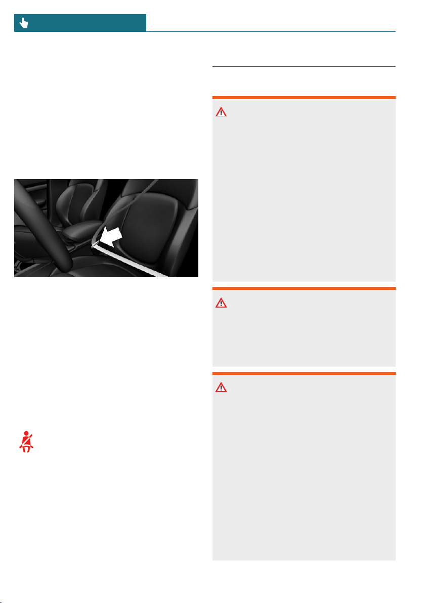
– Avoid thick clothing.
– Re-tighten the safety belt frequently up-
ward around your upper body.
Buckling the safety belt
1. Guide the safety belt slowly over
shoulder and hip to put it on.
2. Insert the tongue plate into the safety
belt buckle. The safety belt buckle must
engage audibly.
Unbuckling the safety belt
1. Hold the safety belt firmly.
2. Press the red button in the belt buckle.
3. Guide the safety belt back into its roll-
up mechanism.
Safety belt reminder for driver's
seat and front passenger seat
Display in the instrument cluster
The indicator light lights up and a
signal sounds. Make sure that the
safety belts are positioned correctly.
The safety belt reminder can also be acti-
vated if objects are placed on the front pas-
senger seat.
Front head restraints
Safety information
Warning
A missing protective effect due to re-
moved or not correctly adjusted head re-
straints can cause injuries in the head and
neck area. There is a risk of injury.
– Before driving, install the removed
head restraints on the occupied seats.
– Adjust the head restraint so its center
supports the back of the head at as
close to eye level as possible.
– Adjust the distance so that the head
restraint is as close as possible to the
back of the head. Adjust the distance
via the backrest tilt as needed.
Warning
Body parts can be jammed when moving
the head restraint. There is a risk of injury.
Make sure that the area of movement is
clear when moving the head restraint.
Warning
Objects on the head restraint reduce the
protective effect in the head and neck
area. There is a risk of injury.
– Do not use seat or head restraint cov-
ers.
– Do not hang objects, for instance
clothes hangers, directly on the head
restraint.
– Only use accessories that have been
determined to be safe for attachment
to a head restraint.
– Do not use any accessories, for in-
stance pillows, while driving.
Seite 80
CONTROLS Seats, mirrors, and steering wheel
80
Online Edition for Part no. 01402667083 - VI/19
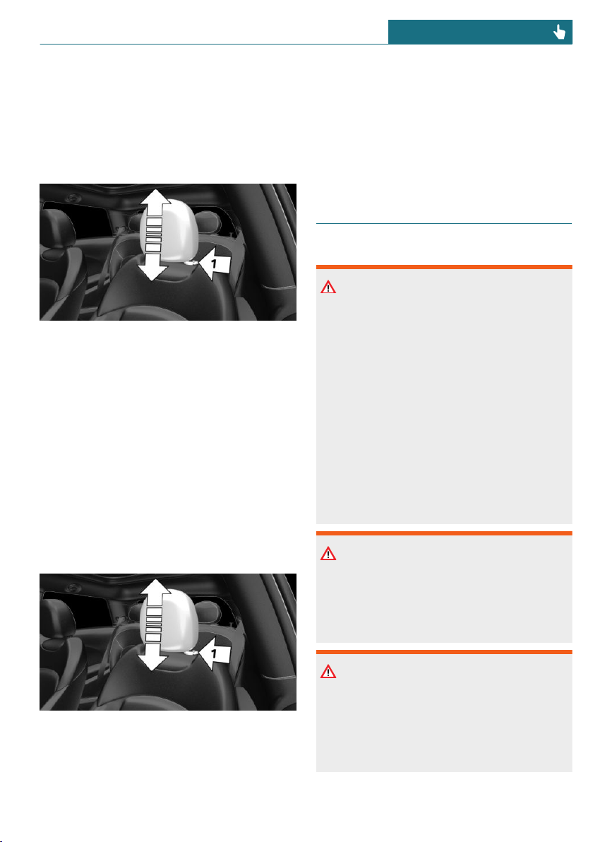
Adjusting the height: John Cooper
Works sport seat
The height of the head restraints cannot be
adjusted.
Adjusting the height
– To lower: press the button, arrow 1, and
push the head restraint down.
– To raise: push the head restraint up.
After setting the height, make sure that the
head restraint engages correctly.
Removing: John Cooper Works
sport seat
The head restraints cannot be removed.
Removing
Only remove the head restraint if no one
will be sitting in the seat in question.
1. If necessary, fold the rear seat backrest
forward.
2. Pull head restraint up as far as possible.
3. Press the button, arrow 1, and pull the
head restraint out completely.
Installing
Proceed in the reverse order to install the
head restraint.
Rear head restraints
Safety information
Warning
A missing protective effect due to re-
moved or not correctly adjusted head re-
straints can cause injuries in the head and
neck area. There is a risk of injury.
– Before driving, install the removed
head restraints on the occupied seats.
– Adjust the head restraint so its center
supports the back of the head at as
close to eye level as possible.
– Adjust the distance so that the head
restraint is as close as possible to the
back of the head. Adjust the distance
via the backrest tilt as needed.
Warning
Body parts can be jammed when moving
the head restraint. There is a risk of injury.
Make sure that the area of movement is
clear when moving the head restraint.
Warning
Objects on the head restraint reduce the
protective effect in the head and neck
area. There is a risk of injury.
– Do not use seat or head restraint cov-
ers.
Seite 81
Seats, mirrors, and steering wheel CONTROLS
81
Online Edition for Part no. 01402667083 - VI/19
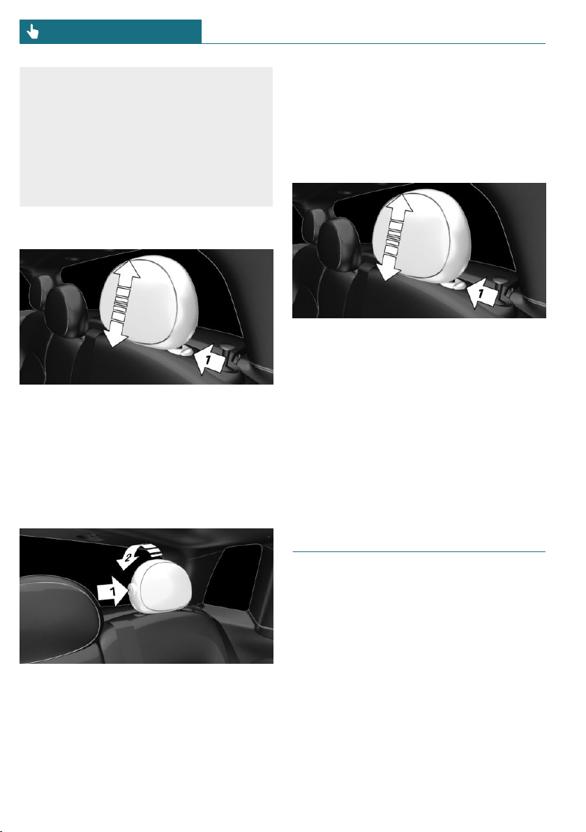
– Do not hang objects, for instance
clothes hangers, directly on the head
restraint.
– Only use accessories that have been
determined to be safe for attachment
to a head restraint.
– Do not use any accessories, for in-
stance pillows, while driving.
Adjusting the height
– To lower: press the button, arrow 1, and
push the head restraint down.
– To raise: push the head restraint up.
After setting the height, make sure that the
head restraint engages correctly.
Fold down
– To fold down: press the button, arrow 1,
and press down the head restraint, ar-
row 2.
– Forward: fold the head restraint toward
the front as far as it will go. Make sure
that the head restraint engages cor-
rectly.
Removing
Only remove the head restraint if no one
will be sitting in the seat in question.
1. Fold down the rear seat backrest, refer
to page 204, in question.
2. Pull head restraint up against the resist-
ance.
3. Press the button, arrow 1, and pull the
head restraint out completely.
Installing
Proceed in the reverse order to install the
head restraint.
Mirrors
Exterior mirrors
General information
The mirror on the front passenger side is
more curved than the driver's side mirror.
Seite 82
CONTROLS Seats, mirrors, and steering wheel
82
Online Edition for Part no. 01402667083 - VI/19
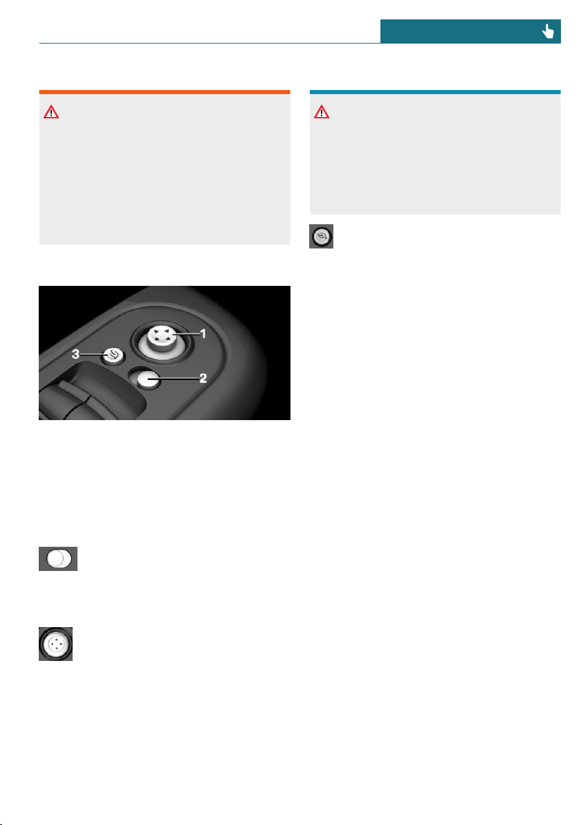
Safety information
Warning
Objects reflected in the mirror are closer
than they appear. The distance to the traf-
fic behind could be incorrectly estimated,
for instance while changing lanes. There is
a risk of accident. Estimate the distance to
the traffic behind by looking over your
shoulder.
Overview
1 Adjusting
2 Selecting a mirror, Automatic Curb Mon-
itor
3 Folding in and out
Selecting a mirror
To change over to the other mirror:
Slide the switch.
Adjusting electrically
Press the button.
The mirror movement follows the
button movement.
Malfunction
In case of an electrical malfunction, adjust
the mirror by pressing the edges of the mir-
ror glass.
Folding in and out
NOTICE
Depending on the vehicle width, the vehi-
cle can be damaged in vehicle washes.
There is a risk of damage to property. Be-
fore washing, fold in the mirrors by hand
or with the button.
Press the button.
Folding is only possible up to a speed of ap-
prox. 15 mph/20 km/h.
Folding the mirrors in and out is helpful in
the following situations:
– In vehicle washes.
– On narrow roads.
Mirrors that were folded in are folded out
automatically at a speed of approx.
25 mph/40 km/h.
Automatic heating
Both exterior mirrors are automatically
heated as needed and when the ignition is
switched on.
Automatic dimming feature
The exterior mirror on the driver's side is
automatically dimmed. Photocells in the
car's interior mirror, refer to page 84, are
used to control this.
Automatic Curb Monitor, exterior
mirror
Concept
If reverse gear is engaged, the mirror glass
on the front passenger side is tilted down-
ward. This improves your view of the curb
and other formatting issue - low-lying ob-
stacles when parking, for instance.
Seite 83
Seats, mirrors, and steering wheel CONTROLS
83
Online Edition for Part no. 01402667083 - VI/19
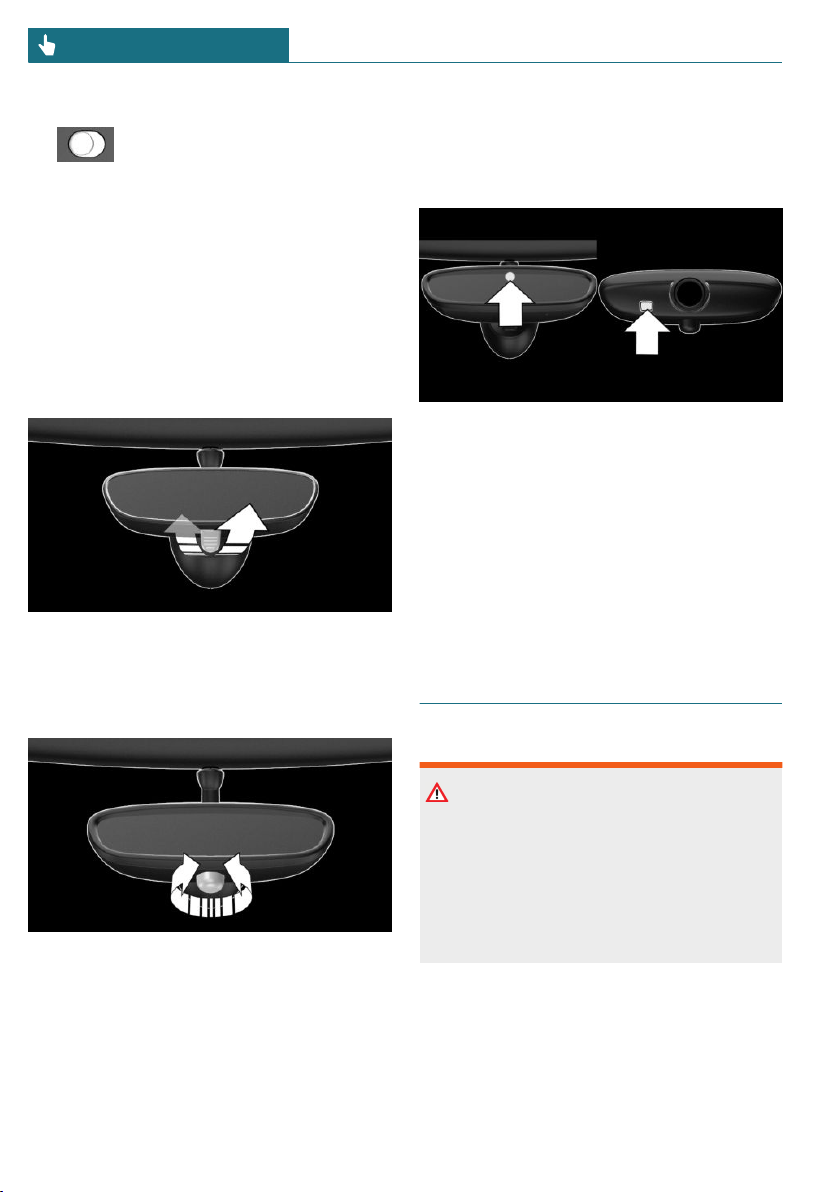
Activating
1. slide the switch to the driver's
side mirror position.
2. Engage selector lever position R.
Deactivating
Slide the switch to the passenger's side mir-
ror position.
Interior mirror, manually dimmable
Flip lever
To reduce the blinding effect of the interior
mirror, flip the lever forward.
Turn knob
Turn the knob to reduce the blinding effect
by the interior mirror.
Interior mirror, automatic dimming
feature
Overview
Photocells are used for control:
– In the mirror glass.
– On the back of the mirror.
Functional requirements
– Keep the photocells clean.
– Do not cover the area between the inte-
rior mirror and the windshield.
Steering wheel
Safety information
Warning
Steering wheel adjustments while driving
can lead to unexpected steering wheel
movements. Vehicle control could be lost.
There is a risk of accident. Adjustng the
steering wheel while the vehicle is sta-
tionary only.
Seite 84
CONTROLS Seats, mirrors, and steering wheel
84
Online Edition for Part no. 01402667083 - VI/19

Adjusting
1. Fold the lever down.
2. Move the steering wheel to the prefer-
red height and angle to suit your seating
position.
3. Fold the lever back up.
Seite 85
Seats, mirrors, and steering wheel CONTROLS
85
Online Edition for Part no. 01402667083 - VI/19
Transporting children safely
Vehicle features and options
This chapter describes all standard, country-
specific and optional features offered with
the series. It also describes features that are
not necessarily available in your vehicle, for
instance, due to the selected options or
country versions. This also applies to safety-
related functions and systems. When using
these functions and systems, the applicable
laws and regulations must be observed.
The right place for children
Safety information
Warning
Unattended children or animals in the ve-
hicle can cause the vehicle to move and
endanger themselves and traffic, for in-
stance due to the following actions:
– Pressing the Start/Stop button.
– Releasing the parking brake.
– Opening and closing the doors or
windows.
– Engaging selector lever position N.
– Using vehicle equipment.
There is a risk of accidents or injuries. Do
not leave children or animals unattended
in the vehicle. Take the vehicle key with
you when exiting and lock the vehicle.
Always transport children in the
rear seat
General information
Accident research shows that the safest
place for children is in the rear seat.
Transport children younger than 13 years of
age or shorter than 5 ft/150 cm only in the
rear seat in suitable child restraint systems
designed for the age, weight and size of the
child. Children 13 years of age or older must
wear a safety belt as soon as a suitable child
restraint system can no longer be used due
to their age, weight, or size.
Safety information
Warning
The safety belt cannot be fastened cor-
rectly on children shorter than 5 ft,
150 cm without suitable additional child
restraint systems. The efficacy of safety
gear, including safety belts, can be limited
or lost when safety belts are fastened in-
correctly. An incorrectly fastened safety
belt can cause additional injuries, for in-
stance in the event of an accident or dur-
ing braking and evasive maneuvers. There
is a risk of injuries or danger to life. Se-
cure children shorter than 5 ft, 150 cm us-
ing suitable child restraint systems.
Children on the front passenger
seat
General information
Before using a child restraint system on the
front passenger seat, ensure that the front,
knee, and side airbags on the front passen-
ger side are deactivated. For automatic de-
Seite 86
CONTROLS Transporting children safely
86
Online Edition for Part no. 01402667083 - VI/19
activation of front-seat passenger airbags,
refer to page 139.
Safety information
Warning
Active front-seat passenger airbags can in-
jure a child in a child restraint system
when the airbags are activated. There is a
risk of injury. Make sure that the front-
seat passenger airbags are deactivated and
that the PASSENGER AIRBAG OFF indica-
tor light lights up.
Warning
The stability of the child restraint system
is limited or compromised with incorrect
seat adjustment or improper installation of
the child seat. There is a risk of injuries or
danger to life. Make sure that the child re-
straint system fits securely against the
backrest. If possible, adjust the backrest
tilt for all affected backrests and correctly
adjust the seats. Make sure that seats and
backrests are securely engaged or locked.
If possible, adjust the height of the head
restraints or remove them.
Installing child restraint sys-
tems
General information
Pay attention to the specifications of the
child restraint system manufacturer when
selecting, installing, and using child re-
straint systems.
In order to facilitate the installation of a
back-facing child restraint system in the
rear:
Move the front passenger seat as far up as
possible before folding down the backrest.
Safety information
Warning
The protective effect of child restraint sys-
tems and their fastening systems which
have been damaged or exposed to an acci-
dent can be limited or lost. A child cannot
be properly restrained in the event of an
accident or braking and evasive maneu-
vers. There is a risk of injuries or danger
to life.
Do not use child restraint systems which
have been damaged or exposed to an acci-
dent.
If a child restraint system and its fasten-
ing system has been damaged or exposed
to an accident, have these systems
checked and replaced by the dealer's serv-
ice center or another qualified service cen-
ter or repair shop.
Warning
The stability of the child restraint system
is limited or compromised with incorrect
seat adjustment or improper installation of
the child seat. There is a risk of injuries or
danger to life. Make sure that the child re-
straint system fits securely against the
backrest. If possible, adjust the backrest
tilt for all affected backrests and correctly
adjust the seats. Make sure that seats and
backrests are securely engaged or locked.
If possible, adjust the height of the head
restraints or remove them.
On the rear seats
In order to facilitate the installation of a
back-facing child restraint system:
Seite 87
Transporting children safely CONTROLS
87
Online Edition for Part no. 01402667083 - VI/19
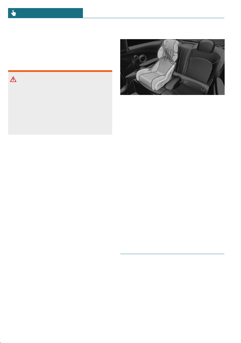
Move the front passenger seat as far up as
possible before folding down the backrest.
On the front passenger seat
Deactivating airbags
Warning
Active front-seat passenger airbags can in-
jure a child in a child restraint system
when the airbags are activated. There is a
risk of injury. Make sure that the front-
seat passenger airbags are deactivated and
that the PASSENGER AIRBAG OFF indica-
tor light lights up.
Before installing a child restraint system in
the front passenger seat, make sure that the
front, knee and side airbags on the front
passenger side are deactivated.
Deactivate the front-seat passenger airbags
automatically, refer to page 139.
Seat position and height
Before installing a child restraint system,
move the front passenger seat as far back as
possible and adjust its height to the highest
and thus best possible position for the belt
and to offer optimal protection in the event
of an accident.
If the upper anchorage of the safety belt is
located in front of the belt guide of the child
seat, move the front passenger seat care-
fully forward until the best possible belt
guide position is reached.
Child seat security
The rear safety belts and the front passen-
ger safety belt can be permanently locked to
fasten child restraint systems.
Locking the safety belt
1. Pull out the belt strap completely.
2. Secure the child restraint system with
the safety belt.
3. Allow the belt strap to be pulled in and
pull it tight against the child restraint
system. The safety belt is locked.
Unlocking the safety belt
1. Unbuckle the safety belt buckle.
2. Remove the child restraint system.
3. Allow the belt strap to be pulled in com-
pletely.
LATCH child restraint fixing
system
General information
LATCH: Lower Anchors and Tether for Chil-
dren.
Pay attention to the operating and safety in-
formation from the child restraint system
manufacturer when installing and using
LATCH child restraint fixing systems.
Seite 88
CONTROLS Transporting children safely
88
Online Edition for Part no. 01402667083 - VI/19
Mounts for the lower LATCH
anchors
The lower anchors may be used to attach
the CRS to the vehicle seat up to a com-
bined child and CRS weight of 65 lbs/30 kg
when the child is restrained by the internal
harnesses.
Safety information
Warning
If the LATCH child restraint fixing sys-
tems are not correctly engaged, the protec-
tive effect of the LATCH child restraint
fixing system can be limited. There is a
risk of injuries or danger to life. Make sure
that the lower anchors are securely en-
gaged and that the LATCH child restraint
fixing system fits securely against the
backrest.
Position
Symbol Meaning
The corresponding symbol
shows the mounts for the
lower LATCH anchors.
Seats equipped with lower
anchors are marked with a
pair, (2), of LATCH symbols.
For vehicles equipped with
a middle seat:
It is not recommended to
use the inner lower anchors
of standard outer LATCH
positions to fasten a child
restraint system on the
middle seat. Use the vehicle
safety belt instead for the
middle seat.
Before installing LATCH child
restraint fixing systems
Pull the safety belt away from the area of
the child restraint system.
Assembly of LATCH child restraint
fixing systems
1. Install child restraint system, see manu-
facturer's information.
2. Ensure that both LATCH anchors are
properly connected.
Child restraint systems with tether
strap
Safety information
Warning
If the upper retaining strap is incorrectly
used for the child restraint system, the
protective effect can be reduced. There is
a risk of injury. Make sure that the upper
retaining strap does not run over sharp
edges and is not twisted as it passes the
upper anchor.
Warning
If the rear backrest is not locked, the pro-
tective effect of the child restraint system
is limited or there is none. In certain situa-
tions, for instance braking maneuvers or
in case of an accident, the rear backrest
can fold forward. There is a risk of injuries
or danger to life. Make sure that the rear
backrests are locked.
Seite 89
Transporting children safely CONTROLS
89
Online Edition for Part no. 01402667083 - VI/19
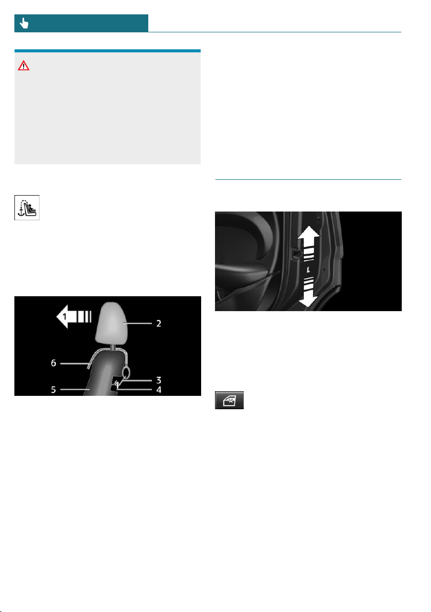
NOTICE
The anchors for the upper retaining straps
of child restraint systems are only pro-
vided for these retaining straps. When
other objects are mounted, the anchors
can be damaged. There is a risk of damage
to property. Only mount child restraint
systems to the upper anchors.
Anchors
The respective symbol shows the an-
chor for the upper retaining strap.
Seats with an upper top tether are
marked with this symbol. It can be found on
the rear seat backrest or the rear window
shelf.
Routing the retaining strap
1 Direction of travel
2 Head restraint
3 Hook for upper retaining strap
4 Anchor
5 Seat backrest
6 Upper retaining strap
Attaching the upper retaining strap to
the anchor
1. Raise the head restraint, if needed.
2. On the rear seat: Guide the upper retain-
ing strap between or along both sides of
the supports of the head restraint to the
anchor.
3. Attach the hook of the retaining strap to
the anchor on the rear seat.
4. Tighten the retaining strap by pulling it
down.
ON 5-door models: Locking
the doors and windows
Doors
Push the locking lever on the rear doors up.
The door can now be opened from the out-
side only.
Safety switch for the rear
Press the button on the driver's
door if children are being trans-
ported in the rear.
This locks various functions so that they
cannot be operated from the rear: safety
switch, refer to page 73.
Seite 90
CONTROLS Transporting children safely
90
Online Edition for Part no. 01402667083 - VI/19
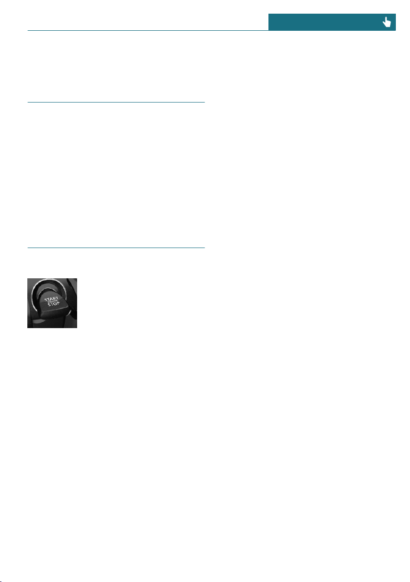
Driving
Vehicle features and options
This chapter describes all standard, country-
specific and optional features offered with
the series. It also describes features that are
not necessarily available in your vehicle, for
instance, due to the selected options or
country versions. This also applies to safety-
related functions and systems. When using
these functions and systems, the applicable
laws and regulations must be observed.
Start/Stop button
Concept
Pressing the Start/Stop button
switches the ignition on or off
and starts the engine.
Steptronic transmission: the
engine starts in selector lever
position P or N with the brake pedal pressed
when you press the Start/Stop button.
Manual transmission: the engine starts with
the clutch pedal pressed when the Start/
Stop button is pressed.
Ignition on
Manual transmission: press the Start/Stop
button without stepping on the clutch
pedal.
Steptronic transmission: press the Start/
Stop button, but do not press on the brake
pedal at the same time.
All vehicle systems are ready for operation.
Most of the indicator/warning lights in the
instrument cluster light up for a varied
length of time.
To save battery power when the engine is
off, switch off the ignition and any unneces-
sary electronic systems/power consumers.
Ignition off
Manual transmission: press the Start/Stop
button again without stepping on the clutch
pedal.
Steptronic transmission: shift to selector
lever position P, press the Start/Stop button
again without stepping on the brake.
All indicator lights in the instrument cluster
go out.
To save battery power when the engine is
off, switch off the ignition and any unneces-
sary electronic systems/power consumers.
Safety measures
The ignition is switched off automatically in
the following situations while the vehicle is
stationary and the engine is off:
– When locking the vehicle, even if the
low beams are switched on.
– Shortly before the battery is discharged
completely, so that the engine can still
be started. This function is only availa-
ble when the low beams are switched
off.
– When opening or closing the driver
door, if the driver's safety belt is un-
buckled and the low beams are switched
off.
– While the driver's safety belt is unbuck-
led with driver's door open and low
beams off.
– When the front doors are opened if
there is no other person sitting in the
front seats.
Seite 91
Driving CONTROLS
91
Online Edition for Part no. 01402667083 - VI/19
– The low beams switch to parking lights
after some minutes of no use.
Steptronic transmission with a tap-operated
selector lever, refer to page 107: when
switching off the ignition, the selector lever
position P is engaged automatically if the
selector lever position R, D or M/S is en-
gaged.
Radio-ready state
General information
In the radio-ready state, certain power con-
sumers remain ready for operation.
Activating
With the engine running, press the Start/
Stop button.
If the engine is not running and the ignition
is switched on: the system automatically ac-
tivates radio-ready state when the door is
opened if the lights are switched off or the
daytime running lights are switched on.
Radio-ready state remains active if, for in-
stance the ignition is automatically
switched off for the following reasons:
– Opening or closing the driver's door.
– Unfastening of the driver's safety belt.
– When automatically switching from low
beams to parking lights.
Switching off automatically
The radio-ready state is switched off auto-
matically in the following situations:
– If the driver's or front passenger door is
opened when exiting the vehicle, with
the engine switched off manually.
– If the ignition is switched off manually
with the Start/Stop button.
– After approx. 8 minutes.
– When the vehicle is locked using the
central locking system.
– Shortly before the battery is discharged
completely, so that the engine can still
be started.
Starting the engine
Safety information
DANGER
If the exhaust pipe is blocked or ventila-
tion is insufficient, harmful exhaust gases
can enter into the vehicle. The exhaust
gases contain pollutants which are color-
less and odorless. In enclosed areas, ex-
haust gases can also accumulate outside of
the vehicle. There is danger to life. Keep
the exhaust pipe free and ensure sufficient
ventilation.
Warning
An unsecured vehicle can begin to move
and possibly roll away. There is a risk of
accident. Before exiting, secure the vehi-
cle against rolling.
In order to ensure that the vehicle is se-
cured against rolling away, follow the fol-
lowing:
– Set the parking brake.
– On uphill grades or on a downhill
slope, turn the front wheels in the di-
rection of the curb.
– On uphill grades or on a downhill
slope, also secure the vehicle, for in-
stance with a wheel chock.
NOTICE
In the case of repeated starting attempts
or repeated starting in quick succession,
the fuel is not burned or is inadequately
burned. The catalytic converter can over-
Seite 92
CONTROLS Driving
92
Online Edition for Part no. 01402667083 - VI/19

heat. There is a risk of damage to property.
Avoid repeated starting in quick succes-
sion.
Gasoline engine
Depending on the motorization, the full
drive power may not be available for ap-
proximately 30 seconds after starting the
engine. In this case, the vehicle will not ac-
celerate as usual.
Steptronic transmission
Starting the engine
1. Depress the brake pedal.
2. Engage selector lever position P or N.
3. Press the Start/Stop button.
The ignition is activated automatically for a
brief time and is stopped as soon as the en-
gine starts.
Manual transmission
Starting the engine
1. Depress the brake pedal.
2. Press on the clutch pedal and shift to
neutral.
3. Press the Start/Stop button.
The ignition is activated automatically for a
brief time and is stopped as soon as the en-
gine starts.
Engine stop
Safety information
Warning
Unattended children or animals in the ve-
hicle can cause the vehicle to move and
endanger themselves and traffic, for in-
stance due to the following actions:
– Pressing the Start/Stop button.
– Releasing the parking brake.
– Opening and closing the doors or
windows.
– Engaging selector lever position N.
– Using vehicle equipment.
There is a risk of accidents or injuries. Do
not leave children or animals unattended
in the vehicle. Take the vehicle key with
you when exiting and lock the vehicle.
Warning
An unsecured vehicle can begin to move
and possibly roll away. There is a risk of
accident. Before exiting, secure the vehi-
cle against rolling.
In order to ensure that the vehicle is se-
cured against rolling away, follow the fol-
lowing:
– Set the parking brake.
– On uphill grades or on a downhill
slope, turn the front wheels in the di-
rection of the curb.
– On uphill grades or on a downhill
slope, also secure the vehicle, for in-
stance with a wheel chock.
Seite 93
Driving CONTROLS
93
Online Edition for Part no. 01402667083 - VI/19

Steptronic transmission
Switching off the engine
1. When the vehicle is stationary, apply
the parking brake.
2. Engage selector lever position P.
3. Press the Start/Stop button.
The engine is switched off.
The radio-ready state is switched on.
Manual transmission
Switching off the engine
1. With the vehicle at a standstill, press
the Start/Stop button.
The engine is switched off.
The radio-ready state is switched on.
2. Shift into first gear or reverse.
3. Set the parking brake.
Auto Start/Stop function
Concept
The Auto Start/Stop function helps save
fuel. The system switches off the engine
during a stop, for instance in traffic conges-
tion or at traffic lights. The ignition remains
switched on. The engine starts automati-
cally for driving off.
After each engine start using the Start/Stop
button, the Auto Start/Stop function is
ready and is activated at speeds faster than
about 3 mph/5 km/h.
Depending on the selected driving mode, re-
fer to page 159, the system is automatically
activated or deactivated.
Engine stop
Functional requirements
The engine is switched off automatically
during a stop under the following condi-
tions:
Manual transmission:
– Neutral is engaged and the clutch pedal
is not pressed.
– The driver's safety belt is buckled or the
driver's door is closed.
Steptronic transmission:
– The selector lever is in selector lever po-
sition D.
– The brake pedal remains depressed
while the vehicle is stopped.
– The driver's safety belt is buckled or the
driver's door is closed.
In order to be able to release the brake
pedal, engage the selector lever in position
P. The engine remains off.
To continue driving depress the brake
pedal. When a gear is engaged, the engine
starts automatically.
The air flow from the air conditioner is re-
duced when the engine is switched off.
Steptronic transmission: manual
engine stop
Depending on the vehicle equipment and
country version, the engine can be switched
off manually, if the engine was not switched
off automatically when the vehicle stopped:
– Press the brake pedal forcefully again
from the current pedal position.
– Engage selector lever position P.
If all functional preconditions are fulfilled,
the engine switches off.
Seite 94
CONTROLS Driving
94
Online Edition for Part no. 01402667083 - VI/19

Displays in the instrument cluster
The display indicates that the
Auto Start/Stop function is
ready for an Automatic engine
start.
The display indicates that the
conditions for an automatic
engine stop have not been
met.
Functional limitations
The engine is not switched off automatically
in the following situations:
– External temperature too low.
– The external temperature is high and au-
tomatic climate control is running.
– The car's interior has not yet been
heated or cooled to the required level.
– The engine is not yet at operating tem-
perature.
– The wheels are at a sharp angle or the
steering wheel is being turned.
– After driving in reverse.
– Fogging of the windows when the auto-
matic climate control is switched on.
– The vehicle battery charge is very low.
– At higher elevations.
– The hood is unlocked.
– The parking assistant is activated.
– Stop-and-go traffic.
– Selector lever in selector lever position
R, N or M/S.
Starting the engine
The engine starts automatically under the
following conditions:
– Manual transmission: clutch pedal is
pressed.
– Steptronic transmission: by releasing
the brake pedal.
After the engine starts, accelerate as usual.
Safety mode
After the engine switches off automatically,
it will not start again automatically if any
one of the following conditions are met:
– The driver's safety belt is unbuckled and
the driver's door is open.
– The hood was unlocked.
Some indicator lights light up for a varied
length of time.
The engine can only be started via the
Start/Stop button.
Functional limitations
Even if driving off was not intended, the de-
activated engine starts up automatically in
the following situations:
– Excessive warming of the car's interior
when the air conditioning is switched
on.
– The steering wheel is turned.
– Steptronic transmission: change from
selector lever position D to R, N or M/S.
– Steptronic transmission: change from
selector lever position P to R, N, D or
M/S.
– The vehicle begins rolling.
– Fogging of the windows when the auto-
matic climate control is switched on.
– The vehicle battery charge is very low.
– Excessive cooling of the car's interior
when the heating is switched on.
– Manual transmission: low brake vacuum
pressure; this can occur, for instance if
the brake pedal is depressed a number
of times in succession.
Seite 95
Driving CONTROLS
95
Online Edition for Part no. 01402667083 - VI/19
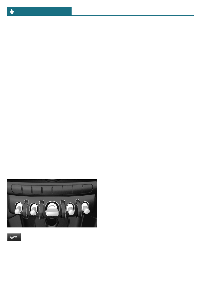
Intelligent Auto Start/Stop function
Depending on the vehicle equipment and
country-specific version, the vehicle fea-
tures a variety of sensors for assessing the
traffic situation. The Intelligent Auto Start/
Stop function uses this information to adapt
to various traffic situations in a proactive
manner.
For instance, this applies to the following
situations:
– If a situation is detected in which the
stopping time is expected to be very
short, the engine is not switched off au-
tomatically. A message appears on the
Control Display, depending on the situa-
tion.
– If a situation is detected in which the
vehicle needs to drive off immediately,
the engine is started automatically.
The function may be restricted if the navi-
gation data is invalid, outdated or not avail-
able, for example.
Switching the system on/off
Using the button
Press the button.
– LED comes on: auto Start/Stop function
is deactivated.
The engine is started during an auto-
matic engine stop.
The engine can only be stopped or
started via the Start/Stop button.
– LED goes out: auto Start/Stop function
is activated.
Switching off the vehicle during an
automatic engine stop
During an automatic engine stop, the vehi-
cle can be switched off permanently, for in-
stance when leaving it.
Steptronic transmission:
1. Engage selector lever position P.
2. Press the Start/Stop button. The ignition
is switched off. The Auto Start/Stop
function is deactivated.
3. Set the parking brake.
Manual transmission:
1. Press the Start/Stop button. The ignition
is switched off. The Auto Start/Stop
function is deactivated.
2. Shift into first gear or reverse.
3. Set the parking brake.
Engine start as usual via Start/Stop button.
Automatic deactivation
In certain situations, the Auto Start/Stop
function is deactivated automatically for
safety reasons, for instance if no driver is
detected.
Malfunction
The Auto Start/Stop function no longer
switches off the engine automatically. A
Check Control message is displayed. It is
possible to continue driving. Have the sys-
tem checked by a dealer's service center or
another qualified service center or repair
shop.
Seite 96
CONTROLS Driving
96
Online Edition for Part no. 01402667083 - VI/19
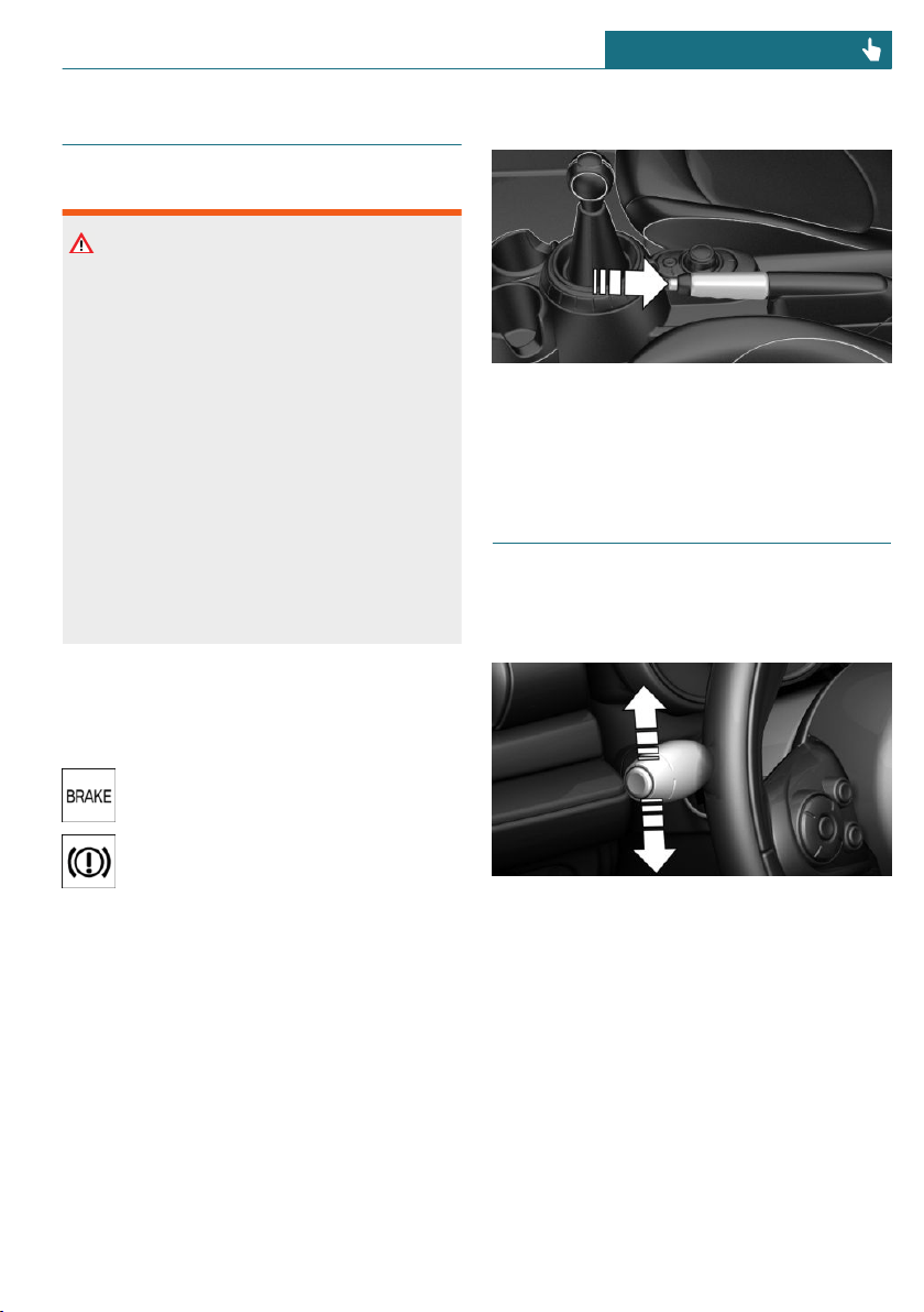
Parking brake
Safety information
Warning
An unsecured vehicle can begin to move
and possibly roll away. There is a risk of
accident. Before exiting, secure the vehi-
cle against rolling.
In order to ensure that the vehicle is se-
cured against rolling away, follow the fol-
lowing:
– Set the parking brake.
– On uphill grades or on a downhill
slope, turn the front wheels in the di-
rection of the curb.
– On uphill grades or on a downhill
slope, also secure the vehicle, for in-
stance with a wheel chock.
Applying
The lever automatically engages after being
pulled up.
The indicator light lights up red. The
parking brake is set.
Lower light: indicator light in Cana-
dian models
If for once use during driving is required,
engage the parking brake slightly and hold
the button down.
To prevent corrosion and one-sided brake
action, lightly apply the parking brake peri-
odically while coasting, if traffic conditions
permit.
The brake lights will not light up if the park-
ing brake is set.
Releasing
Raise lever slightly, press the button and
guide the lever down.
Turn signal, high beams, head-
light flasher
Turn signal
Using turn signals
Press the lever past the resistance point.
Canada: the lever returns into its starting
position after actuation. To switch off man-
ually, slightly tap the lever to the resistance
point.
Triple turn signal activation
Lightly tap the lever up or down.
The triple turn signal duration can be ad-
justed.
Seite 97
Driving CONTROLS
97
Online Edition for Part no. 01402667083 - VI/19
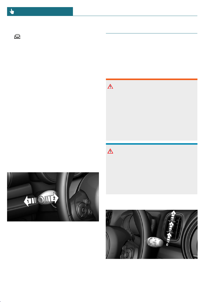
Via the Central Information Display (CID):
1. "My MINI"
2. "Vehicle settings"
3. "Lighting"
4. "Exterior lighting"
5. "One-touch turn signal"
6. Select the desired setting.
Settings are stored for the profile currently
used.
Signaling briefly
Press the lever to the resistance point and
hold it there for as long as you want the
turn signal to flash.
Malfunction
Unusually rapid flashing of the indicator
light indicates that a turn signal bulb has
failed.
High beams, headlight flasher
Push the lever forward or pull it backward.
– High beams on, arrow 1.
The high beams light up when the low
beams are switched on.
– High beams off/headlight flasher, ar-
row 2.
Wiper system
General information
Do not use the wipers if the windshield is
dry, as this may damage the wiper blades or
cause them to become worn more quickly.
Safety information
Warning
If the wipers start moving in the folded
away state, body parts can be jammed or
damage may occur to parts of the vehicle.
There is a risk of injury or risk of damage
to property. Make sure that the vehicle is
switched off when the wipers are in the
folded away state and the wipers are
folded in when switching on.
NOTICE
If the wipers are frozen to the windshield,
the wiper blades can be torn off and the
wiper motor can overheat when switching
on. There is a risk of damage to property.
Defrost the windshield prior to switching
the wipers on.
Switching on
Press the lever up until the desired position
is reached.
Seite 98
CONTROLS Driving
98
Online Edition for Part no. 01402667083 - VI/19
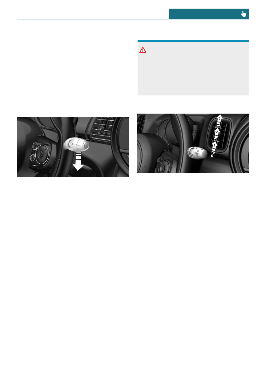
– Resting position of the wipers, posi-
tion 0.
– Intermittent operation or rain sensor,
position 1.
– Normal wiper speed, position 2.
– Fast wiper speed, position 3.
When travel is interrupted with the wiper
system switched on: when travel continues,
the wipers resume at their previous speed.
Switching off and brief wipe
Press the lever down.
– Switching off: press the lever down until
it reaches its standard position.
– Brief wipe: press the lever down from
the standard position.
The lever automatically returns to its in-
itial position when released.
Interval mode or rain sensor
Concept
The rain sensor automatically controls the
time between wipes depending on the in-
tensity of the rainfall.
General information
The sensor is located on the windshield, di-
rectly in front of the interior mirror. With-
out the rain sensor, the frequency of the
wiper operation is preset.
Safety information
NOTICE
If the rain sensor is activated, the wipers
can accidentally start moving in vehicle
washes. There is a risk of damage to prop-
erty. Deactivate the rain sensor in vehicle
washes.
Activating
Press the lever up once from its standard
position, arrow 1.
Wiping is started.
The LED in the wiper lever is illuminated.
In frosty conditions, wiper operation may
not start.
Deactivating
Press the lever back into the standard posi-
tion.
Seite 99
Driving CONTROLS
99
Online Edition for Part no. 01402667083 - VI/19
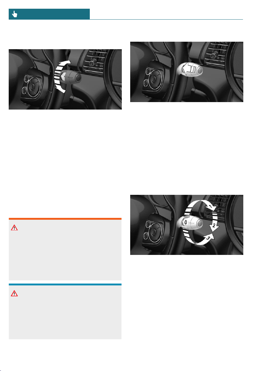
Setting the frequency or sensitivity of
the rain sensor
Turn the thumbwheel.
With deactivated rain sensor: set the inter-
val.
With activated rain sensor: set the rain sen-
sor sensitivity.
Up: short interval or high sensitivity of the
rain sensor.
Down: long interval or low sensitivity of the
rain sensor.
Windshield washer system
Safety information
Warning
The washer fluid can freeze onto the win-
dow at low temperatures and obstruct the
view. There is a risk of accident. Only use
the washer systems, if the washer fluid
cannot freeze. Use washer fluid with anti-
freeze, if needed.
NOTICE
When the washer fluid reservoir is empty,
the wash pump cannot work as intended.
There is a risk of damage to property. Do
not use the washer system when the
washer fluid reservoir is empty.
Cleaning the windshield
Pull the lever.
The system sprays washer fluid on the
windshield and activates the wipers briefly.
Windshield washer nozzles
The washer jets are automatically heated
whenever the ignition is switched on.
Rear window wiper
Overview
Switching on
Turn the outer switch upward.
– Resting position of the wiper, posi-
tion 0.
– Intermittent mode, arrow 1. When re-
verse gear is engaged, the system
switches to continuous operation.
Clean the rear window
Turn the outer switch in the desired direc-
tion.
Seite 100
CONTROLS Driving
100
Online Edition for Part no. 01402667083 - VI/19
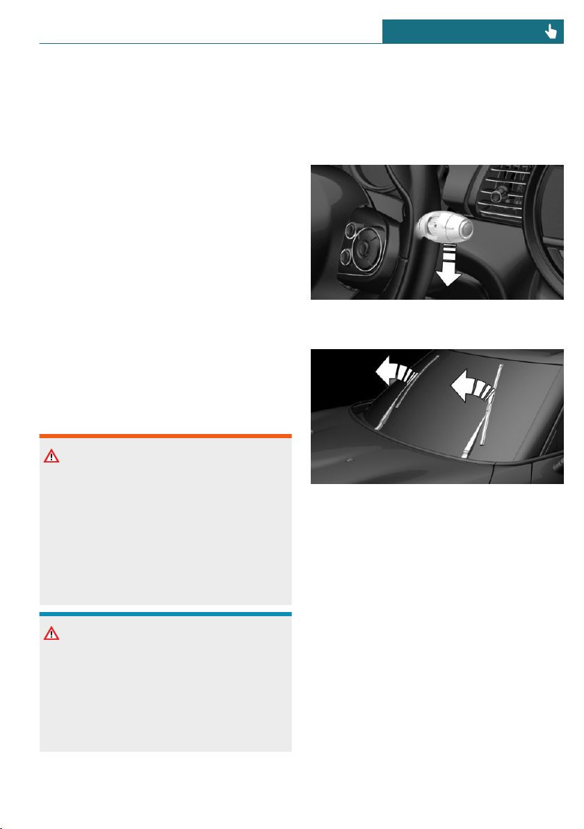
– In resting position: turn the switch
downward, arrow 3. The switch auto-
matically returns to its idle position
when released.
– In intermittent mode: turn the switch
further, arrow 2. The switch automati-
cally returns to its interval position
when released.
The function is deactivated if the washer
fluid reservoir level is low.
Fold-away position of the wipers
Concept
The fold-away position enables the wipers
to be folded away from the windshield.
General information
Helpful when changing the wiper blades or
under frosty conditions, for instance.
Safety information
Warning
If the wipers start moving in the folded
away state, body parts can be jammed or
damage may occur to parts of the vehicle.
There is a risk of injury or risk of damage
to property. Make sure that the vehicle is
switched off when the wipers are in the
folded away state and the wipers are
folded in when switching on.
NOTICE
If the wipers are frozen to the windshield,
the wiper blades can be torn off and the
wiper motor can overheat when switching
on. There is a risk of damage to property.
Defrost the windshield prior to switching
the wipers on.
Folding away the wipers
1. Switch the ignition on and off again.
2. Press and hold the wiper lever down, un-
til the wipers stop in a close to vertical
position.
3. Fold the wipers all the way away from
the windshield.
Folding down the wipers
After the wipers are folded back down, the
wiper system must be reactivated.
1. Fold the wipers back down onto the
windshield.
2. Switch on the ignition.
3. Push wiper lever down. Wipers return
to their resting position and are ready
again for operation.
Seite 101
Driving CONTROLS
101
Online Edition for Part no. 01402667083 - VI/19
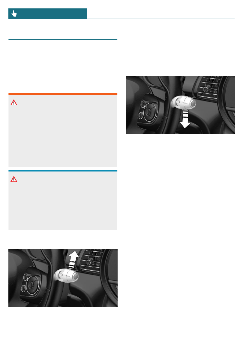
Canada: wiper system
General information
Do not use the wipers if the windshield is
dry, as this may damage the wiper blades or
cause them to become worn more quickly.
Safety information
Warning
If the wipers start moving in the folded
away state, body parts can be jammed or
damage may occur to parts of the vehicle.
There is a risk of injury or risk of damage
to property. Make sure that the vehicle is
switched off when the wipers are in the
folded away state and the wipers are
folded in when switching on.
NOTICE
If the wipers are frozen to the windshield,
the wiper blades can be torn off and the
wiper motor can overheat when switching
on. There is a risk of damage to property.
Defrost the windshield prior to switching
the wipers on.
Switching on
Tap up the lever or press it past the resist-
ance point.
– Normal wiper speed: tap up once.
– Fast wiper speed: tap up twice or tap
once beyond the resistance point.
The lever automatically returns to its initial
position when released.
Switching off and brief wipe
Press the lever down.
– To switch off from fast wiper speed:
press down twice.
– To switch off from normal wiper speed:
press down once.
– Brief wipe: press down once.
The lever automatically returns to its initial
position when released.
Interval mode or rain sensor
Concept
The rain sensor automatically controls the
time between wipes depending on the in-
tensity of the rainfall.
General information
The sensor is located on the windshield, di-
rectly in front of the interior mirror. With-
out the rain sensor, the frequency of the
wiper operation is preset.
Seite 102
CONTROLS Driving
102
Online Edition for Part no. 01402667083 - VI/19
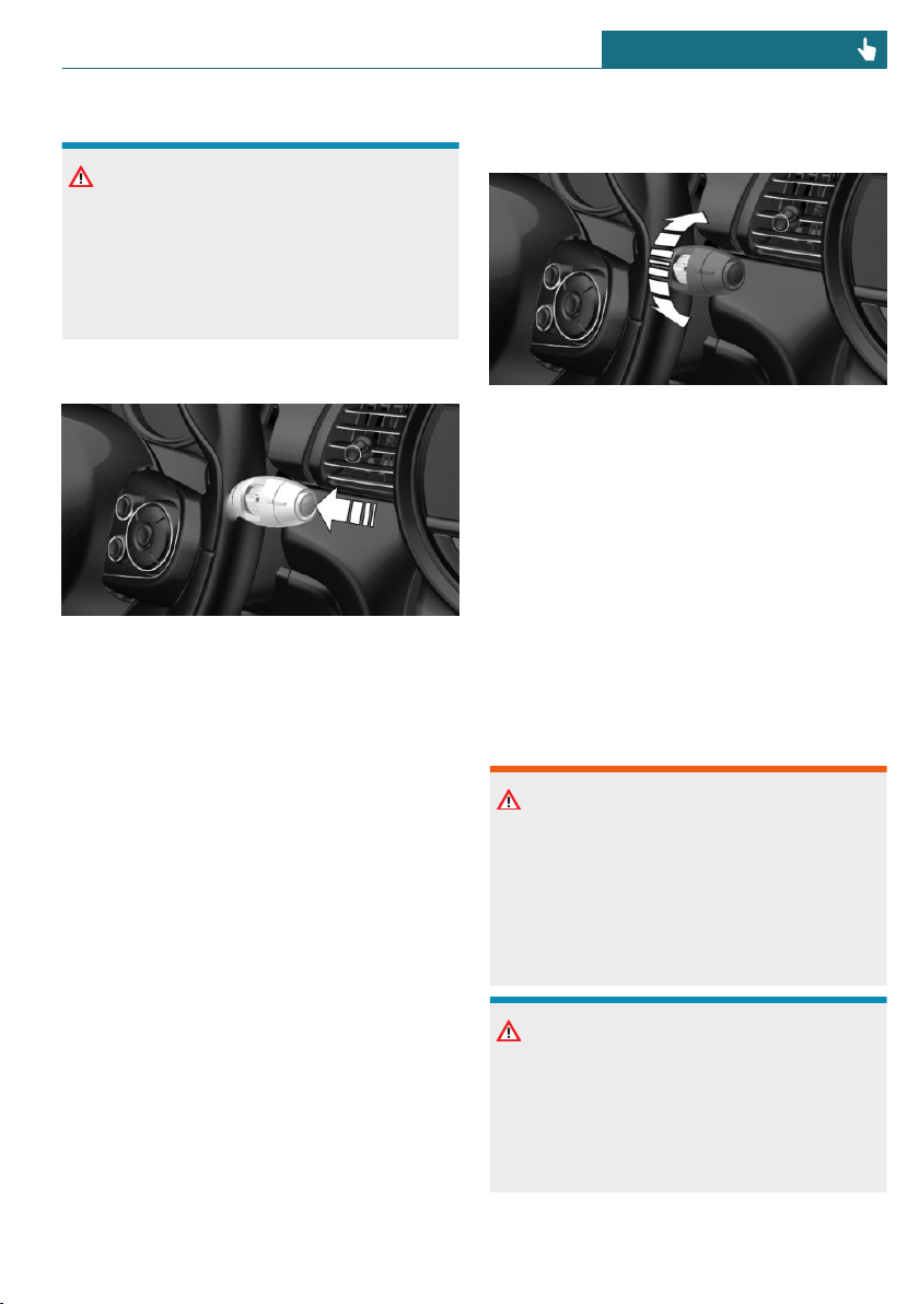
Safety information
NOTICE
If the rain sensor is activated, the wipers
can accidentally start moving in vehicle
washes. There is a risk of damage to prop-
erty. Deactivate the rain sensor in vehicle
washes.
Activating/deactivating
Press the button on the wiper lever.
Wiping is started.
If the vehicle is equipped with a rain sensor:
the LED in the wiper lever is illuminated.
In frosty conditions, wiper operation may
not start.
If a journey is interrupted with the rain sen-
sor switched on: if the trip is resumed
within approx. 15 minutes, the rain sensor
is automatically activated again.
Setting the frequency or sensitivity of
the rain sensor
Turn the thumbwheel.
With deactivated rain sensor: set the inter-
val.
With activated rain sensor: set the rain sen-
sor sensitivity.
Up: short interval or high sensitivity of the
rain sensor.
Down: long interval or low sensitivity of the
rain sensor.
Windshield washer system
Safety information
Warning
The washer fluid can freeze onto the win-
dow at low temperatures and obstruct the
view. There is a risk of accident. Only use
the washer systems, if the washer fluid
cannot freeze. Use washer fluid with anti-
freeze, if needed.
NOTICE
When the washer fluid reservoir is empty,
the wash pump cannot work as intended.
There is a risk of damage to property. Do
not use the washer system when the
washer fluid reservoir is empty.
Seite 103
Driving CONTROLS
103
Online Edition for Part no. 01402667083 - VI/19
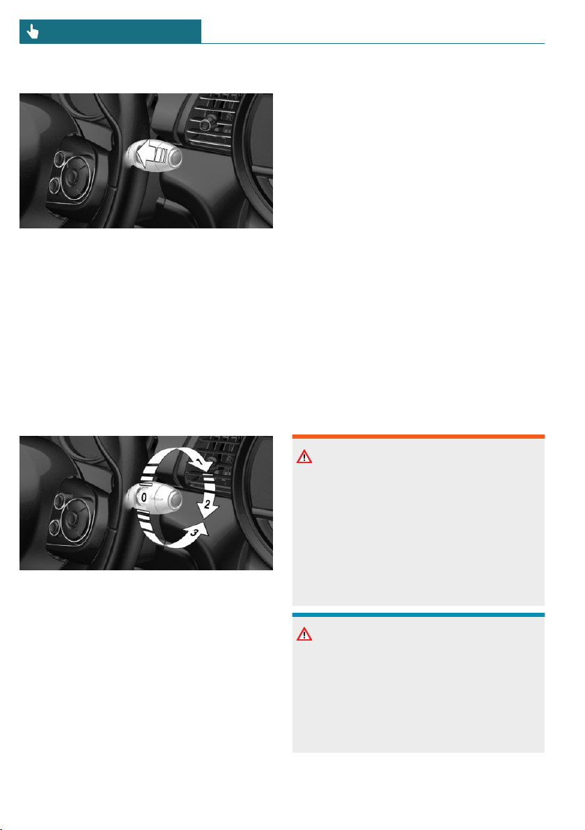
Cleaning the windshield
Pull the lever.
The system sprays washer fluid on the
windshield and activates the wipers briefly.
Windshield washer nozzles
The washer jets are automatically heated
whenever the ignition is switched on.
Rear window wiper
Overview
Switching on
Turn the outer switch upward.
– Resting position of the wiper, posi-
tion 0.
– Intermittent mode, arrow 1. When re-
verse gear is engaged, the system
switches to continuous operation.
Clean the rear window
Turn the outer switch in the desired direc-
tion.
– In resting position: turn the switch
downward, arrow 3. The switch auto-
matically returns to its idle position
when released.
– In intermittent mode: turn the switch
further, arrow 2. The switch automati-
cally returns to its interval position
when released.
The function is deactivated if the washer
fluid reservoir level is low.
Fold-away position of the wipers
Concept
The fold-away position enables the wipers
to be folded away from the windshield.
General information
Helpful when changing the wiper blades or
under frosty conditions, for instance.
Safety information
Warning
If the wipers start moving in the folded
away state, body parts can be jammed or
damage may occur to parts of the vehicle.
There is a risk of injury or risk of damage
to property. Make sure that the vehicle is
switched off when the wipers are in the
folded away state and the wipers are
folded in when switching on.
NOTICE
If the wipers are frozen to the windshield,
the wiper blades can be torn off and the
wiper motor can overheat when switching
on. There is a risk of damage to property.
Defrost the windshield prior to switching
the wipers on.
Seite 104
CONTROLS Driving
104
Online Edition for Part no. 01402667083 - VI/19
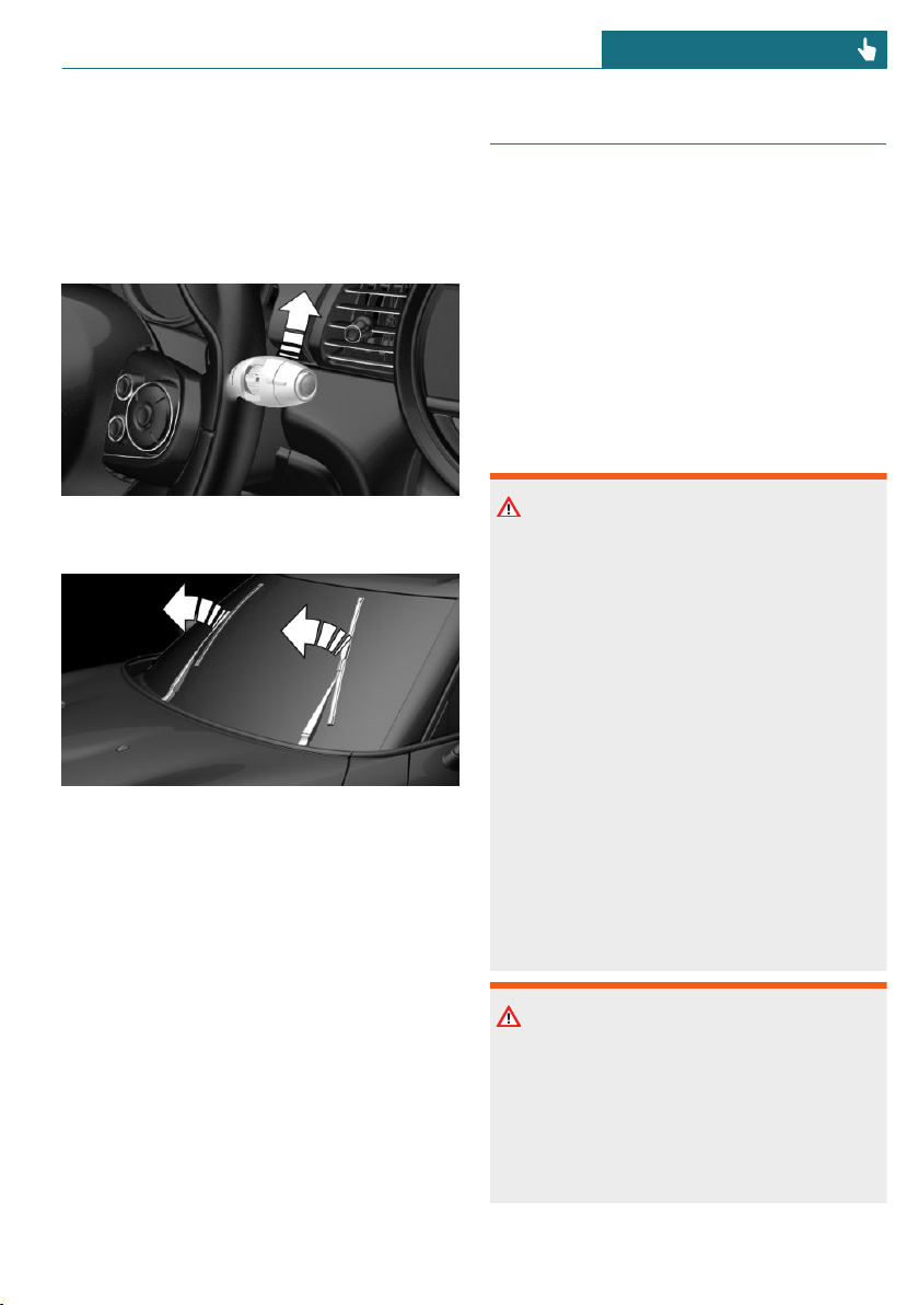
Folding away the wipers
1. Switch the ignition on and off again.
2. Press the wiper lever up past the point
of resistance and hold it for approx.
3 seconds, until the wipers remain in a
nearly vertical position.
3. Fold the wipers all the way away from
the windshield.
Folding down the wipers
After the wipers are folded back down, the
wiper system must be reactivated.
1. Fold the wipers back down onto the
windshield.
2. Switch on the ignition.
3. Push wiper lever down. Wipers return
to their resting position and are ready
again for operation.
Washer fluid
General information
All washer nozzles are supplied from one
reservoir.
Use a mixture of tap water and windshield
washer concentrate. If desired, a windshield
washer concentrate containing antifreeze
can be used.
Recommended minimum fill quantity:
0.2 US gal/1 liter.
Safety information
Warning
Some antifreeze agents can contain harm-
ful substances and are flammable. There is
a risk of fire and a risk of injury. Follow
the instructions on the containers. Keep
antifreeze away from ignition sources. Do
not refill operating materials into different
bottles. Store operating materials out of
reach of children.
United States: the washer fluid mixture ra-
tio is regulated by the U.S. EPA and many
individual states; do not exceed the allow-
able washer fluid dilution ratio limits that
apply. Follow the usage instructions on the
washer fluid container.
Use of BMW’s Windshield Washer Con-
centrate or the equivalent is recom-
mended.
Warning
Washer fluid can ignite and catch fire on
contact with hot engine parts. There is a
risk of injury or risk of damage to prop-
erty. Only add washer fluid when the en-
gine is cooled down. Next, fully close the
lid of the washer fluid reservoir.
Seite 105
Driving CONTROLS
105
Online Edition for Part no. 01402667083 - VI/19
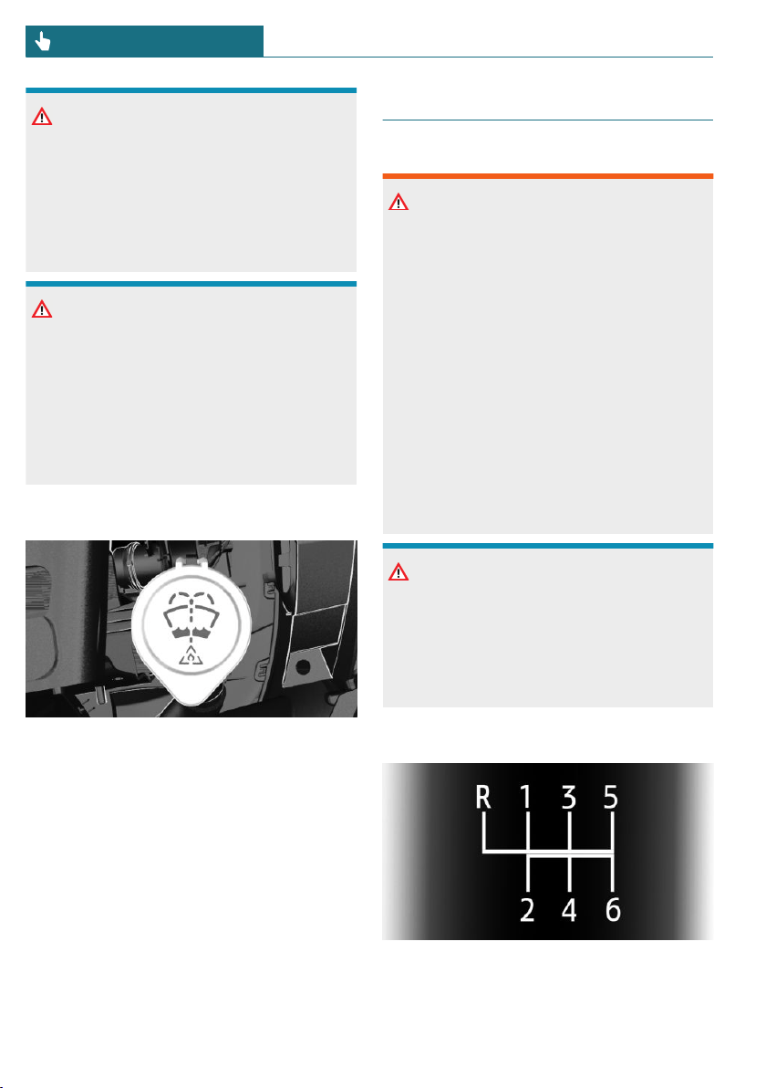
NOTICE
Silicon-containing additives in the washer
fluid for the water-repelling effect on the
windows can lead to damage to the wash-
ing system. There is a risk of damage to
property. Do not add silicon-containing ad-
ditives to the washer fluid.
NOTICE
Mixing different windshield washer con-
centrates or antifreeze can damage the
washing system. There is a risk of damage
to property. Do not mix different wind-
shield washer concentrates or antifreeze.
Follow the information and mixing ratios
provided on the containers.
Overview
The washer fluid reservoir is located in the
engine compartment.
Malfunction
The use of undiluted windshield washer
concentrate or alcohol-based antifreeze can
lead to incorrect readings at temperatures
below +5 ℉/-15 ℃.
Manual transmission
Safety information
Warning
An unsecured vehicle can begin to move
and possibly roll away. There is a risk of
accident. Before exiting, secure the vehi-
cle against rolling.
In order to ensure that the vehicle is se-
cured against rolling away, follow the fol-
lowing:
– Set the parking brake.
– On uphill grades or on a downhill
slope, turn the front wheels in the di-
rection of the curb.
– On uphill grades or on a downhill
slope, also secure the vehicle, for in-
stance with a wheel chock.
NOTICE
When shifting to a lower gear, excessive
speeds can damage the engine. There is a
risk of damage to property. When shifting
into 5th or 6th gear, press the gearshift
lever to the right.
Schematic diagram
– 1 – 6: forward gears
– R: reverse
Seite 106
CONTROLS Driving
106
Online Edition for Part no. 01402667083 - VI/19
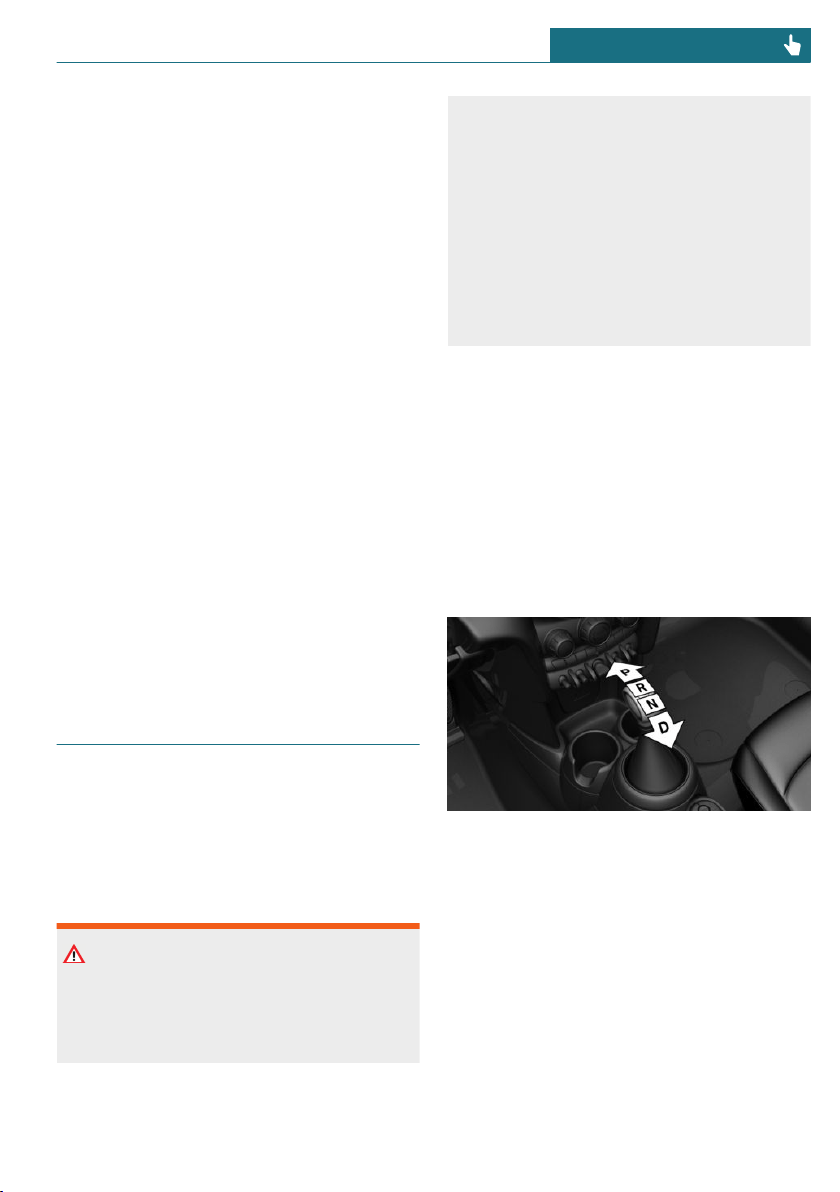
Shifting
General information
Depending on the engine installation, the
engine speed during a shifting operation is
adjusted automatically as required for har-
monious and dynamic gear shifting.
Reverse gear
Select only when the vehicle is stationary.
To overcome the resistance push the gear-
shift lever dynamically to the left and en-
gage reverse gear with a forward shifting
movement.
Rolling or pushing the vehicle
In some situations, the vehicle is to roll
without its own power, for instance in a ve-
hicle wash, or be pushed.
1. Switch on the ignition.
2. Press on the clutch pedal and shift out
of a forward gear or reverse.
3. Release the parking brake.
Steptronic transmission
Concept
The Steptronic transmission combines the
functions of an automatic transmission with
the possibility of manual shifting, if needed.
Safety information
Warning
An unsecured vehicle can begin to move
and possibly roll away. There is a risk of
accident. Before exiting, secure the vehi-
cle against rolling.
In order to ensure that the vehicle is se-
cured against rolling away, follow the fol-
lowing:
– Set the parking brake.
– On uphill grades or on a downhill
slope, turn the front wheels in the di-
rection of the curb.
– On uphill grades or on a downhill
slope, also secure the vehicle, for in-
stance with a wheel chock.
Selector lever version
General information
Depending on the vehicle equipment, a
transmission with either a latching selector
lever or a tap-operated selector lever is in-
stalled.
Transmission with a latching selector
lever
The selector lever positions P, R, N, and D
are selected by moving the selector lever
into the respective selector lever position.
The selector lever engages in the selector
lever positions.
Seite 107
Driving CONTROLS
107
Online Edition for Part no. 01402667083 - VI/19

Transmission with a tap-operated
selector lever
The selector lever positions P, R, N, and D
are selected by tapping the selector lever
forward or back. The selector lever automat-
ically returns to the center position when
released.
Selector lever position P is engaged auto-
matically, refer to page 108, in certain sit-
uations.
Selector lever positions
Drive mode D
Selector lever position for normal vehicle
operation. All gears for forward travel are
activated automatically.
R is reverse
Engage selector lever position R only when
the vehicle is stationary.
Neutral N
The vehicle may be pushed or roll without
engine power in selector lever position N,
for instance in vehicle washes, refer to
page 110.
Parking position P
General information
Selector lever position, for instance for
parking the vehicle.
The transmission blocks the drive wheels in
selector lever position P.
Engage selector lever position P only when
the vehicle is stationary.
Before exiting the vehicle, make sure that
selector lever position P is set. Otherwise,
the vehicle may begin to move.
Automatic parking position for a
transmission with a tap-operated selector
lever
Selector lever position P is engaged auto-
matically in situations such as the follow-
ing:
– After the engine is switched off when
the vehicle is in the radio-ready state,
refer to page 92, or when the ignition is
switched off, refer to page 91, while se-
lector lever position R, D or M/S is en-
gaged.
– If the driver's safety belt is unbuckled,
the driver's door is opened, and the
brake pedal is not pressed while the ve-
hicle is stationary and selector lever po-
sition D, M/S or R is engaged.
– After the ignition has been switched off
while selector lever position N is en-
gaged.
Engaging selector lever positions:
with a latching selector lever
General information
To prevent the vehicle from creeping after
you select a drive mode, maintain pressure
on the brake pedal until you are ready to
start.
Functional requirements
The selector lever can only be taken out of
selector lever position P if the ignition is on
or the engine is running.
Seite 108
CONTROLS Driving
108
Online Edition for Part no. 01402667083 - VI/19
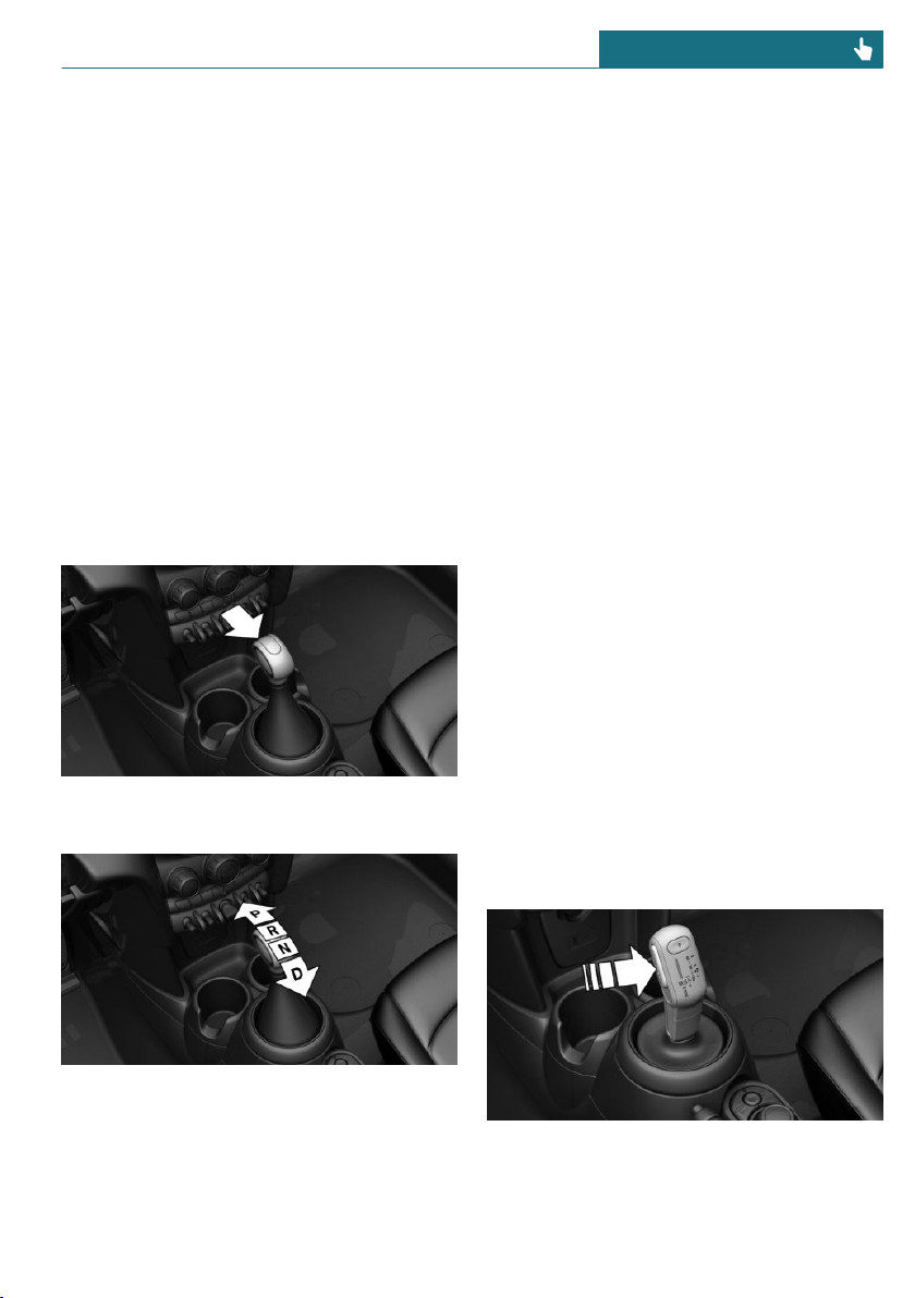
Engaging selector lever position D, N,
R, or P
With the vehicle stationary, depress the
brake pedal before shifting out of selector
lever position P or N; otherwise, the shift
block will not be deactivated and the shift
command will not be executed.
A selector lever lock prevents the following
faulty operation:
– Unintentional shifting into selector
lever position P or R.
– Unintentional shifting from selector
lever position P into another selector
lever position.
1. To release the selector lever lock: with
the brake pedal depressed, press the
button on the front of the selector lever.
2. Move the selector lever into the desired
position.
Engaging selector lever positions:
with a tap-operated selector lever
General information
To prevent the vehicle from creeping after
you select a drive mode, maintain pressure
on the brake pedal until you are ready to
start.
Functional requirements
Only when the brake pedal is depressed is it
possible to change from selector lever posi-
tion P to another selector lever position.
Depending on the transmission version, the
engine may have to be running too.
The selection lever position P cannot be
changed until all technical requirements are
met.
Engaging selector lever position D, N,
R
A selector lever lock prevents the following
faulty operation:
– Unintentional shifting into selector
lever position R.
– Unintentional shifting from selector
lever position P into another selector
lever position.
1. Press and hold the button to release the
selector lever lock.
2. With the driver's safety belt fastened,
briefly push the selector lever in the de-
sired direction, past a resistance point,
Seite 109
Driving CONTROLS
109
Online Edition for Part no. 01402667083 - VI/19
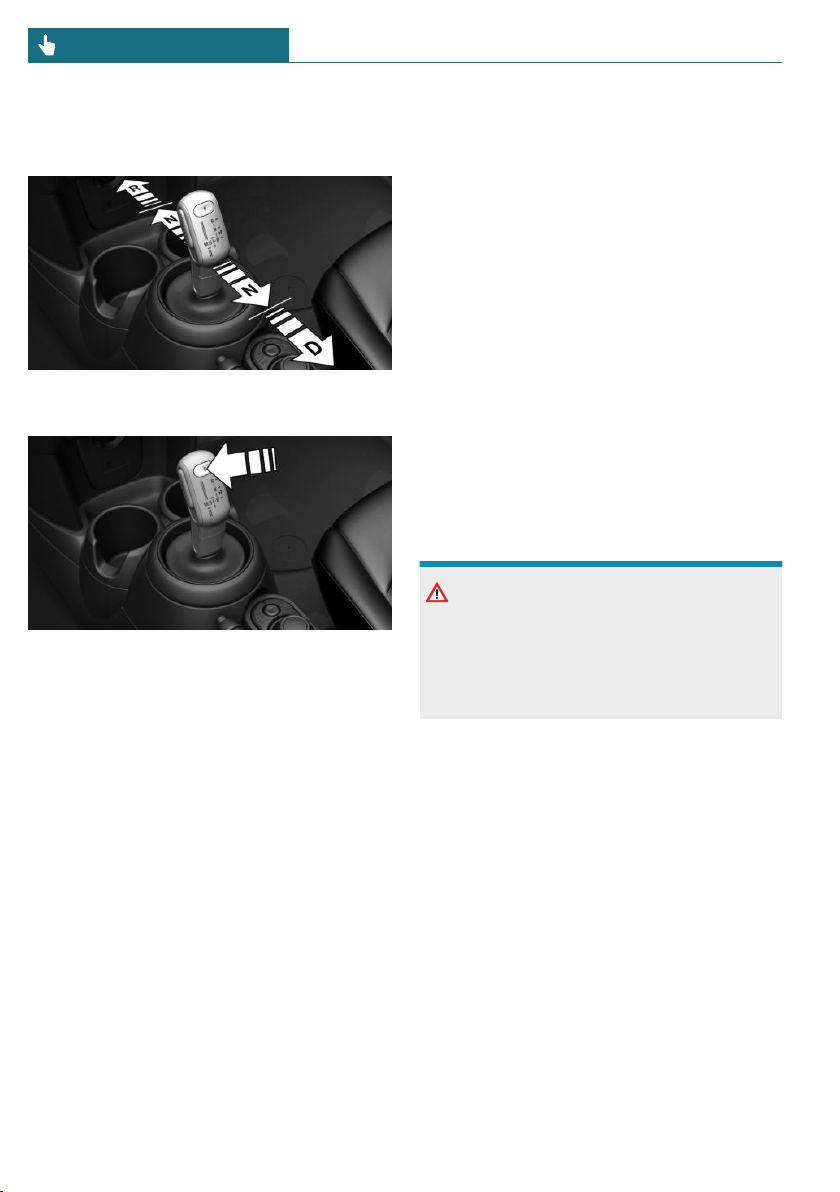
if needed. The selector lever automati-
cally returns to the center position when
released.
Engaging selector lever position P
Press button P.
Rolling or pushing the vehicle
General information
In some situations, the vehicle is to roll
without its own power for a short distance,
for instance in a vehicle wash, or be pushed.
Engaging selector lever position N:
with a latching selector lever
1. Switch on the ignition.
2. If necessary, release the parking brake.
3. Depress the brake pedal.
4. Touch the selector lever lock and en-
gage selector lever position N.
5. Release brake.
The vehicle can roll.
If there is a malfunction, you may not be
able to change the selector lever position.
Manually unlock the transmission lock, if
needed, refer to page 113.
Engaging selector lever position N:
with a tap-operated selector lever
1. Start the engine while pressing on the
brake pedal.
2. If necessary, release the parking brake.
3. Depress the brake pedal.
4. Touch the selector lever lock and en-
gage selector lever position N.
5. Switch the engine off.
In this way, the ignition remains
switched on, and a Check-Control mes-
sage is displayed.
The vehicle can roll.
NOTICE
Selector lever position P is automatically
engaged when the ignition is switched off.
There is a risk of damage to property. Do
not switch ignition off in vehicle washes.
Irrespective of the ignition, the selector
lever position P is automatically engaged af-
ter approx. 15 minutes.
If there is a malfunction, you may not be
able to change the selector lever position.
Electronically unlock the transmission lock,
if needed, refer to page 113.
Kickdown
Kickdown is used to achieve maximum driv-
ing performance. Step on the accelerator
pedal beyond the resistance point at the full
throttle position.
Seite 110
CONTROLS Driving
110
Online Edition for Part no. 01402667083 - VI/19
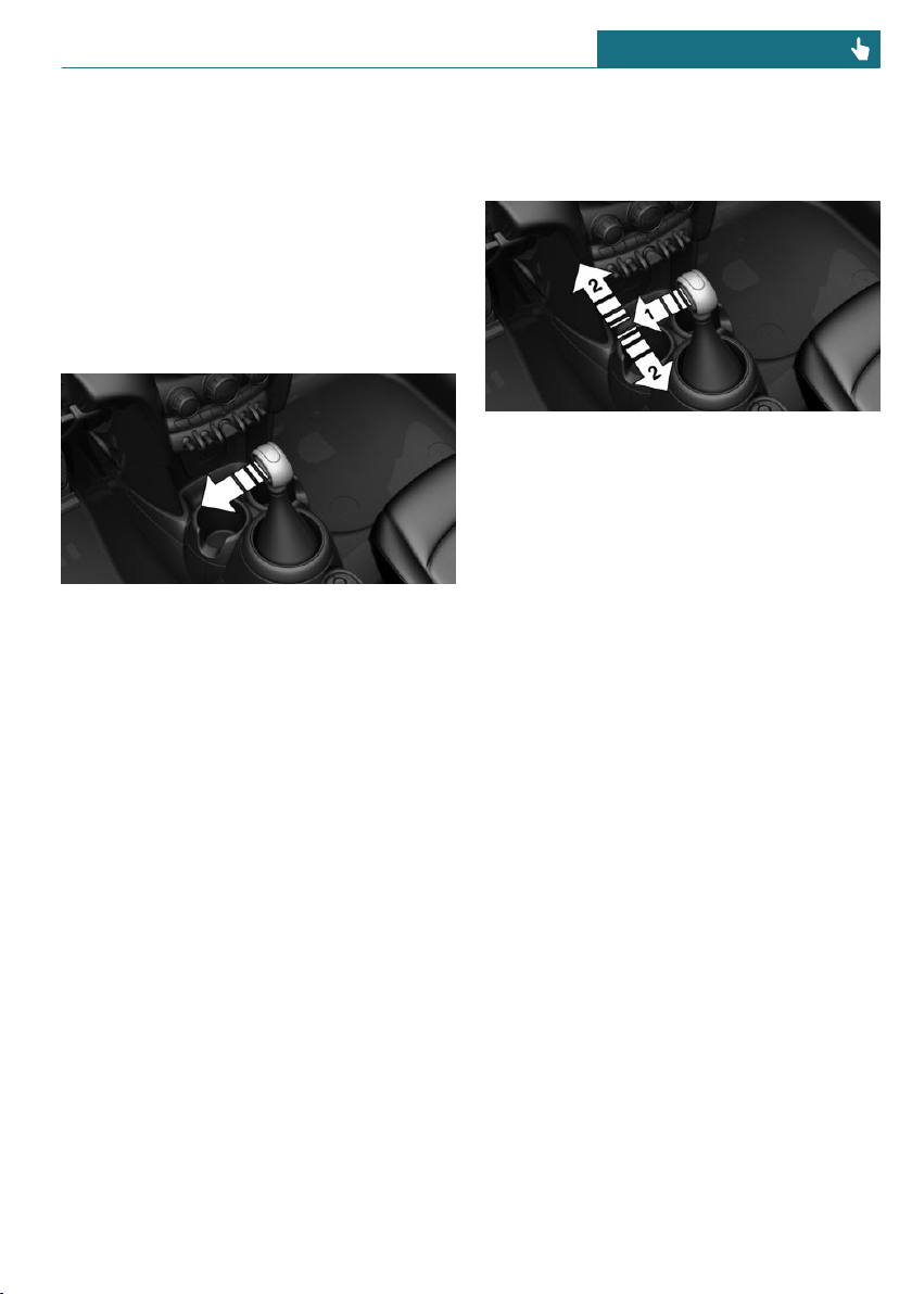
Sport program M/S
Concept
The shifting points and shifting times in the
Sport program are designed for a sportier
driving style. The transmission, for instance
shifts up later and the shifting times are
shorter.
Activating the Sport program
Press the selector lever to the left from se-
lector lever position D.
The engaged gear is displayed in the instru-
ment cluster, for instance S1.
The sport program of the transmission is ac-
tivated.
Ending the Sport program
Push the selector lever to the right.
D is displayed in the instrument cluster.
Manual mode M/S
Concept
Manual gear-shifting is possible in manual
mode.
Activating manual mode
1. Press the selector lever to the left from
selector lever position D, arrow 1.
2. Push the selector lever forward or pull it
backward, arrows 2.
Manual mode M/S becomes active and the
gear is changed.
The engaged gear is displayed in the instru-
ment cluster, for instance M1.
Shifting
– To shift down: press the selector lever
forward.
– To shift up: pull the selector lever rear-
wards.
The Steptronic transmission continues
shifting automatically in certain situations,
for instance when certain engine speed lim-
its are reached.
With a tap-operated selector lever: when
M2 is set manually while the vehicle is sta-
tionary, the transmission will no longer
shift back to M1. This shifting behavior is
retained until you engage M1 manually or
exit M.
Avoiding automatic upshifting
Once a particular engine speed is attained,
M/S manual mode is automatically up-
shifted as needed.
MINI John Cooper Works: once particular
engine speeds are attained, upshifting is not
Seite 111
Driving CONTROLS
111
Online Edition for Part no. 01402667083 - VI/19
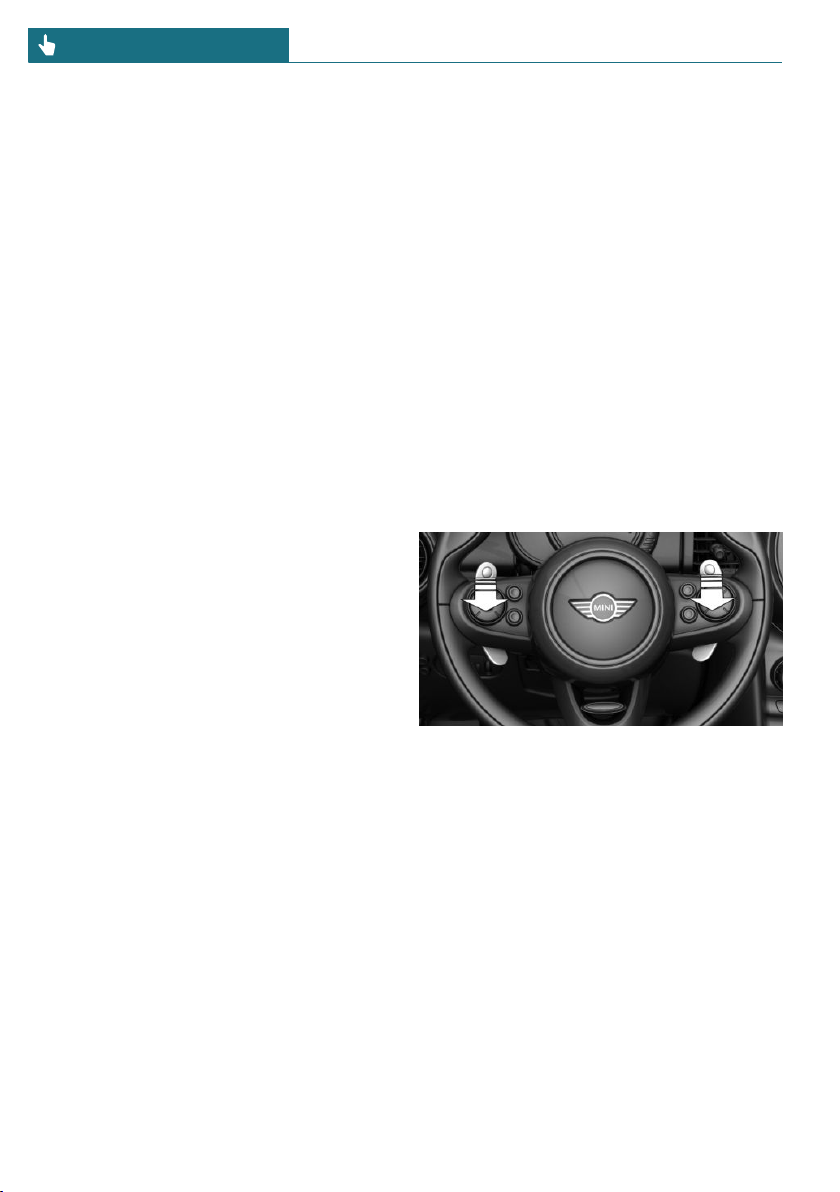
automatically performed in M/S manual
mode.
For vehicles with Steptronic Sport transmis-
sion, automatic shift operations are not per-
formed if one of the following conditions is
met:
– DSC is deactivated.
– TRACTION is activated.
In addition, there is no downshifting for
kickdown.
With the appropriate transmission version,
the lowest possible gear can be selected by
simultaneously activating kickdown and op-
erating the left shift paddles. This is not
possible by switching briefly via the shift
paddles from selector lever position D to
manual mode M/S.
Ending the manual mode
Push the selector lever to the right.
D is displayed in the instrument cluster.
Shift paddles for Steptronic Sport
transmission
Concept
The shift paddles on the steering wheel al-
low you to shift gears quickly while keeping
both hands on the steering wheel.
General information
Shifting
Gears will only be shifted at appropriate en-
gine and road speeds, for instance down-
shifting is not possible if the engine speed
is too high.
Short-term manual mode
In selector lever position D, actuating a
shift paddle switches into manual mode
temporarily.
After conservative driving in manual mode
without acceleration or shifting via the shift
paddles for a certain amount of time, the
transmission switches back to automatic
mode.
It is possible to switch into automatic mode
as follows:
– Pull and hold right shift paddle.
– In addition to the briefly pulled right
shift paddle, briefly pull the left shift
paddle.
Continuous manual mode
In selector lever position S, actuating a shift
paddle switches into manual mode perma-
nently.
Shifting
– To shift up: briefly pull right shift pad-
dle.
– To shift down: briefly pull left shift pad-
dle.
– The lowest possible gear can be selected
by pulling and holding the left shift pad-
dle.
The selected gear is briefly displayed in the
instrument cluster, followed by the current
gear.
Seite 112
CONTROLS Driving
112
Online Edition for Part no. 01402667083 - VI/19
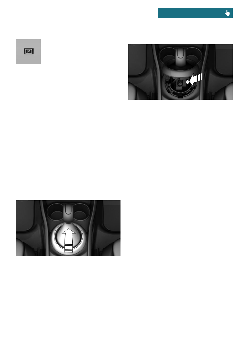
Displays in the instrument cluster
The selector lever position is
displayed, for example P.
Releasing the transmission lock
manually: with a latching selector
lever
If the selector lever is locked in selector
lever position P despite the ignition being
switched on, the brake pedal being de-
pressed and the button on the selector lever
being pressed, the transmission lock can be
unlocked manually:
Before unlocking the transmission lock
manually, engage the parking brake force-
fully to prevent the vehicle from rolling
away.
1. Loosen the selector lever sleeve, to-
gether with the lower retaining ring,
from the center console. To do so, pull
the retaining ring upward at the rear
edge.
2. Lift the sleeve. Unplug the cable connec-
tor, if needed.
3. Using the screwdriver from the onboard
vehicle tool kit, refer to page 290, press
the yellow release lever downward, see
arrow.
4. Press the button on the front of the se-
lector lever and move the selector lever
back slightly.
Release the release lever.
5. Bring the selector lever into the desired
position.
For additional information, see the chapter
on tow-starting and towing.
Releasing the transmission lock
electronically: with a tap-operated
selector lever
General information
Electronically unlock the transmission lock
to maneuver vehicle from a danger area.
Before unlocking the transmission lock, set
the parking brake to prevent the vehicle
from rolling away.
Engaging selector lever position N
Unlocking is possible, if the starter can spin
the engine.
1. Press and hold down brake pedal.
2. Press the Start/Stop button. The starter
must audibly start.
3. Press the button on the selector lever,
arrow 1, and press and hold the selector
lever into selector lever position N, ar-
Seite 113
Driving CONTROLS
113
Online Edition for Part no. 01402667083 - VI/19
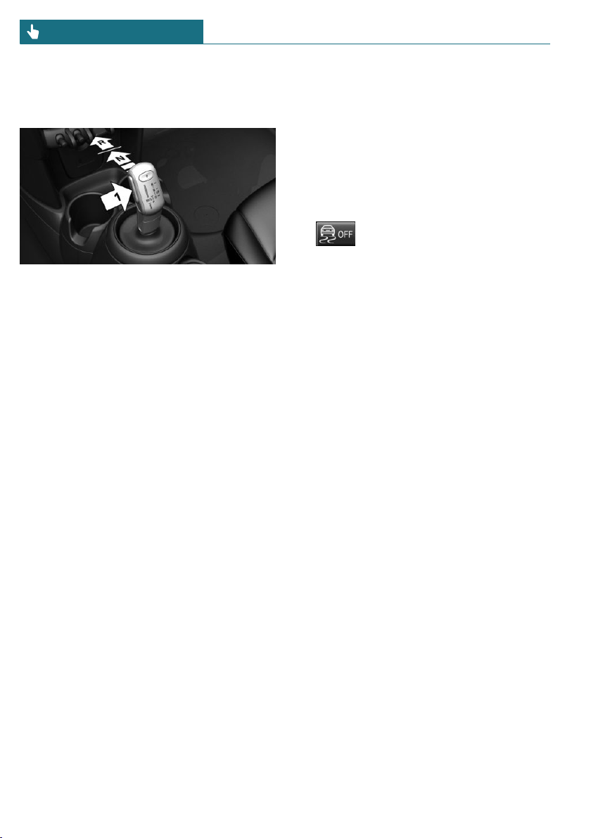
row N, until selector lever position N is
displayed in the instrument cluster.
A Check Control message is displayed.
4. Release the selector lever.
5. Release brake, as soon as the starter
stops.
6. Maneuver the vehicle from the danger
area and secure it against moving on its
own.
For additional information, see the chapter
on tow-starting and towing.
Steptronic Sport transmission:
Launch Control
Concept
Launch Control enables optimum accelera-
tion on surfaces with good traction under
dry surrounding conditions.
General information
The use of Launch Control causes prema-
ture component wear since this function
represents a very heavy load for the vehicle.
Do not use Launch Control during the
break-in, refer to page 210, period.
Do not turn the steering wheel when driv-
ing away with Launch Control.
Functional requirements
Launch Control is available as soon as the
engine and transmission are at operating
temperature.
Depending on the external temperature and
driving style, the engine and transmission
require an interrupted trip of up to
30 miles/50 km in order to reach the oper-
ating temperature needed for Launch Con-
trol.
Start with launch control
While the engine is running:
1. Press button and select SPORT
with the MINI Driving Modes switch.
The instrument cluster displays TRAC-
TION in combination with SPORT. The
DSC OFF indicator light lights up.
2. Engage selector lever position S.
3. With the left foot, forcefully press down
on the brake.
4. Step on the accelerator pedal beyond the
resistance point at the full throttle posi-
tion, kickdown.
A flag symbol is displayed in the instru-
ment cluster.
5. The starting engine speed adjusts.
Within 3 seconds, release the brake.
Repeated use during a trip
After Launch Control has been used, the
transmission must cool down for approx.
5 minutes before Launch Control can be
used again.
After using Launch Control
To increase vehicle stability, activate DSC
Dynamic Stability Control again.
System limits
An experienced driver may be able to ach-
ieve better acceleration values in DSC OFF
mode.
Seite 114
CONTROLS Driving
114
Online Edition for Part no. 01402667083 - VI/19
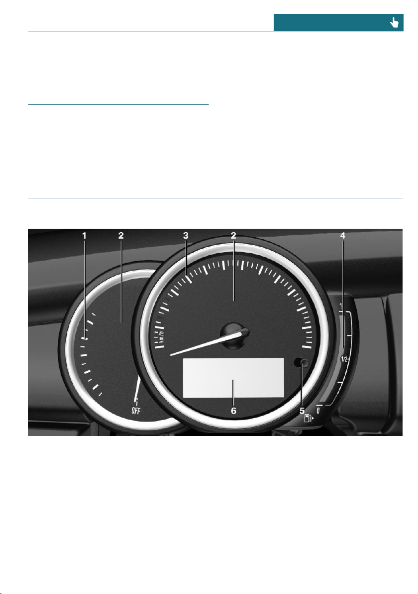
Displays
Vehicle features and options
This chapter describes all standard, country-
specific and optional features offered with
the series. It also describes features that are
not necessarily available in your vehicle, for
instance, due to the selected options or
country versions. This also applies to safety-
related functions and systems. When using
these functions and systems, the applicable
laws and regulations must be observed.
Instrument cluster
Overview
1 Tachometer 120
2 Indicator/warning lights
3 Speedometer
4 Fuel gauge 120
5 Display/reset miles 120
6 Electronic displays 116
Seite 115
Displays CONTROLS
115
Online Edition for Part no. 01402667083 - VI/19
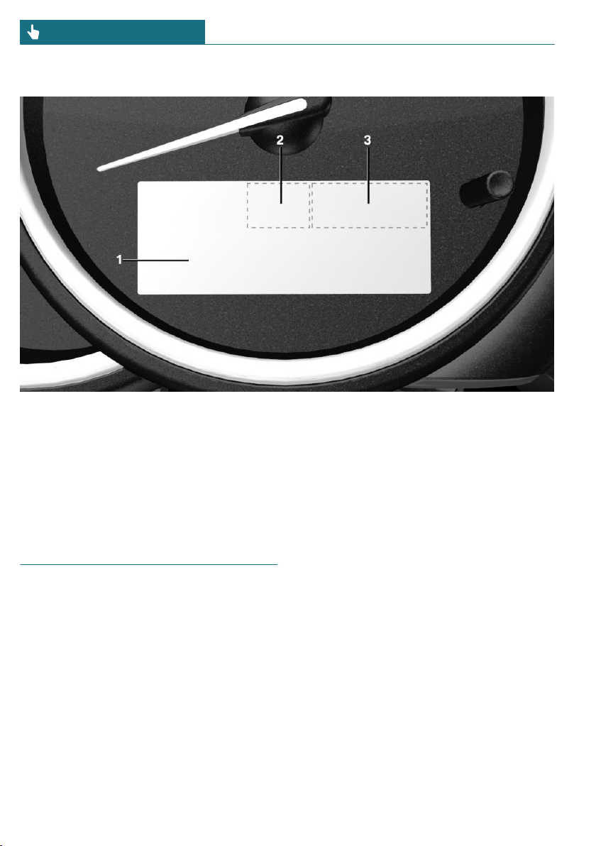
Electronic displays
1 Driver assistance systems
Messages, for instance Check Control
Time 121
External temperature 121
Selection lists 125
Total miles/trip odometer 120
Onboard Computer 125
2 Selector lever position 107
Gear shift indicator 123
3 MINI Driving Modes switch sta-
tus 159
Check Control
Concept
The Check Control system monitors func-
tions in the vehicle and notifies you of mal-
functions in the monitored systems.
General information
A Check Control message is displayed as a
combination of indicator or warning lights
and text messages in the instrument cluster.
In addition, an acoustic signal may be out-
put and a SMS text message may appear on
the Control Display.
Indicator/warning lights
General information
The indicator/warning lights can light up in
a variety of combinations and colors.
Several of the lights are checked for proper
functioning and light up temporarily when
the engine is started or the ignition is
switched on.
Seite 116
CONTROLS Displays
116
Online Edition for Part no. 01402667083 - VI/19
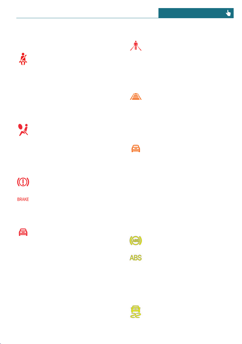
Red lights
Safety belt reminder
Indicator light flashes or is illumi-
nated: safety belt on the driver or
passenger side is not buckled. The
safety belt reminder can also be activated if
objects are placed on the front passenger
seat.
Make sure that the safety belts are posi-
tioned correctly.
Airbag system
Airbag system and belt tensioner
may not be working.
Have the vehicle checked immedi-
ately by a dealer's service center or another
qualified service center or repair shop.
Parking brake
The parking brake is set.
For releasing the parking brake, re-
fer to page 97.
Approach control warning
Indicator light illuminates: advance
warning is issued, for example when
there is the impending danger of a
collision or the distance to the vehicle
ahead is too small.
Increase the distance.
Indicator light flashes: acute warning of the
imminent danger of a collision when the ve-
hicle approaches another vehicle at a rela-
tively high differential speed.
Intervene by braking or make an evasive
maneuver.
Person warning
If a collision with a detected person
is imminent, the symbol lights up
and a signal sounds.
Orange lights
Active Cruise Control
The number bars shows the selected
distance from the vehicle driving
ahead.
Camera-based cruise control, refer to
page 162.
Vehicle detection, Active Cruise Control
Indicator light illuminates: a vehicle
has been detected ahead of you.
Indicator light flashes: the condi-
tions are not adequate for the system to
work.
The system was deactivated but applies the
brakes until the driver actively resumes
control of the vehicle by pressing on the
brake pedal or accelerator pedal.
Yellow lights
Anti-lock Braking System ABS
The Brake Assistant function may
not activate. Avoid abrupt braking.
Take the longer braking distance
into account.
Have the system immediately
checked by a dealer's service center
or another qualified service center or repair
shop.
DSC Dynamic Stability Control
The indicator light flashes: DSC con-
trols the drive and braking forces.
The vehicle is stabilized. Reduce
Seite 117
Displays CONTROLS
117
Online Edition for Part no. 01402667083 - VI/19
speed and modify your driving style to the
driving circumstances.
The indicator light lights up: DSC has mal-
functioned.
Have the system checked by a dealer's serv-
ice center or another qualified service cen-
ter or repair shop.
DSC, refer to page 157.
DSC Dynamic Stability Control is
deactivated or DTC Dynamic Traction
Control is activated
DSC is deactivated or DTC is acti-
vated.
DSC, refer to page 157, and DTC, re-
fer to page 158.
Flat Tire Monitor FTM
The Flat Tire Monitor signals a loss
of tire inflation pressure in a tire.
Reduce your speed and stop cau-
tiously. Avoid sudden braking and steering
maneuvers.
Flat Tire Monitor, refer to page 145.
Tire Pressure Monitor TPM
The indicator light lights up: the Tire
Pressure Monitor reports a low tire
inflation pressure or a flat tire. Fol-
low the information in the Check Control
message.
The indicator light flashes and then contin-
uously lights up: no flat tire or loss of tire
inflation pressure can be detected.
– Interference caused by systems or devi-
ces with the same radio frequency: after
leaving the area of the interference, the
system automatically becomes active
again.
– TPM was unable to complete the reset.
Reset the system again.
– A wheel without TPM wheel electronics
is mounted: have it checked by a deal-
er’s service center or another qualified
service center or repair shop as needed.
– Malfunction: have the system checked
by a dealer’s service center or another
qualified service center or repair shop.
Tire Pressure Monitor, refer to page 141.
Steering system
Steering system may not be working.
Have the system checked by a deal-
er's service center or another quali-
fied service center or repair shop.
Emissions
– The warning light lights up:
Emissions are deteriorating.
Have the vehicle checked as soon
as possible.
– The warning light flashes under certain
circumstances:
This indicates that there is excessive
misfiring in the engine.
Reduce the vehicle speed and have the
system checked immediately; otherwise,
serious engine misfiring within a brief
period can seriously damage emission
control components, in particular the
catalytic converter.
Socket for Onboard Diagnosis, refer to
page 289.
Green lights
Turn signal
Turn signal switched on.
Unusually rapid flashing of the indi-
cator light indicates that a turn sig-
nal bulb has failed.
Seite 118
CONTROLS Displays
118
Online Edition for Part no. 01402667083 - VI/19
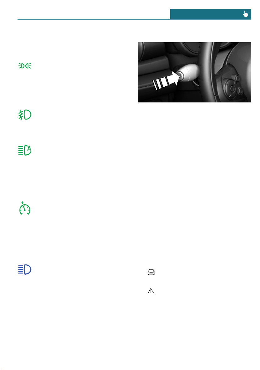
Turn signal, refer to page 97.
Parking lights, headlight
Parking lights or headlights are
switched on.
Parking lights/low beams, headlight
control, refer to page 131.
Front fog lights
Front fog lights are switched on.
Front fog lights, refer to page 134.
High-beam Assistant
High-beam Assistant is switched on.
High beams are switched on and off
automatically depending on the traf-
fic situation.
High-beam Assistant, refer to page 133.
Cruise control
The system is switched on. It main-
tains the speed that was set using
the control elements on the steering
wheel.
Blue lights
High beams
High beams are switched on.
High beams, refer to page 98.
Hiding Check Control messages
Press the button on the turn signal lever.
Continuous display
Some Check Control messages are displayed
continuously and are not cleared until the
malfunction is eliminated. If several mal-
functions occur at once, the messages are
displayed consecutively.
The messages can be hidden for approx.
8 seconds. After this time, they are dis-
played again automatically.
Temporary display
Some Check Control messages are hidden
automatically after approx. 20 seconds. The
Check Control messages are stored and can
be displayed again later.
Displaying stored Check Control
messages
Via the Central Information Display (CID):
1. "My MINI"
2. "Vehicle status"
3. "Check Control"
4. Select the SMS text message.
Seite 119
Displays CONTROLS
119
Online Edition for Part no. 01402667083 - VI/19
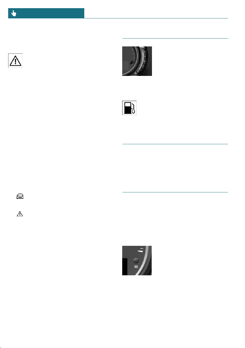
Display
Check Control
At least one Check Control message
is displayed or stored.
SMS text messages
SMS text messages in combination with a
symbol in the instrument cluster explain a
Check Control message and the meaning of
the indicator/warning lights.
Supplementary SMS text messages
Additional information, such as on the
cause of an error or the required action, can
be called up via Check Control.
With urgent messages the added text will
be automatically displayed on the Control
Display.
Depending on the Check Control message,
further help can be selected.
Via the Central Information Display (CID):
1. "My MINI"
2. "Vehicle status"
3. "Check Control"
4. Select the desired text message.
5. Select the desired setting.
Messages after trip completion
Certain messages displayed while driving
are displayed again after the ignition is
switched off.
Fuel gauge
The arrow beside the fuel
pump symbol shows which
side of the vehicle the fuel
filler flap is on.
Vehicle tilt position may cause
the display to vary.
Information on refueling, refer to page 252.
The yellow indicator light illumi-
nates, once the fuel reserve is
reached.
Tachometer
Always avoid engine speeds in the red
warning field. In this range, the fuel supply
is reduced to protect the engine.
Odometer and trip odometer
Concept
The total mileage driven and the mileage
driven since the last reset are displayed in
the instrument cluster.
Reset the trip odometer
Press the button.
– The odometer is displayed
when the ignition is
switched off.
– When the ignition is
switched on, the trip od-
ometer is reset.
Seite 120
CONTROLS Displays
120
Online Edition for Part no. 01402667083 - VI/19
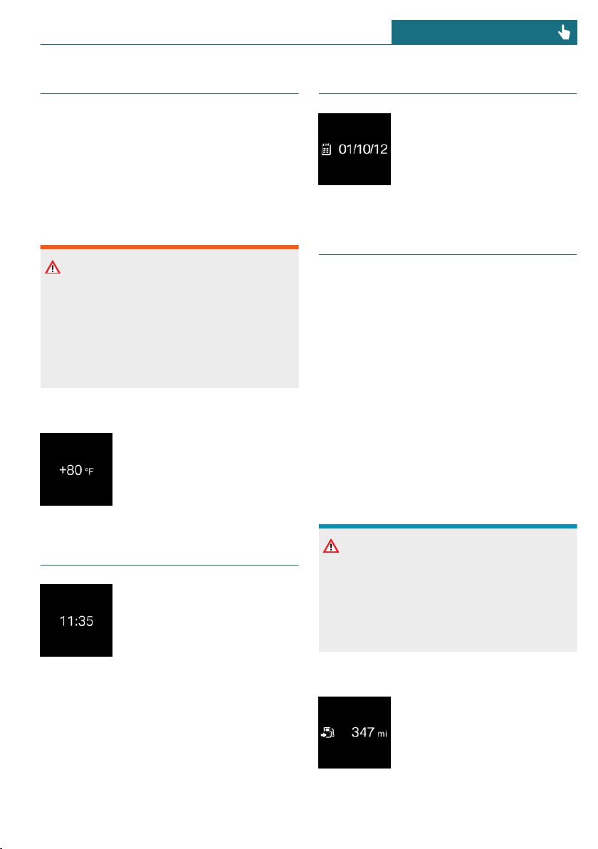
External temperature
General information
If the indicator drops to +37 ℉/+3 ℃, a sig-
nal sounds.
A Check Control message is displayed.
There is an increased risk of ice on roads.
Safety information
Warning
Even at temperatures above +37 ℉/+3 ℃
there can be a risk of icy roads, for in-
stance on bridges or shady sections of the
road. There is a risk of accident. Modify
your driving style to the weather condi-
tions at low temperatures.
Display
The external temperature is
displayed in the instrument
cluster.
Time
The time is displayed in the
instrument cluster.
The time can be set via the
Central Information Display
(CID).
Date
The date is displayed in the in-
strument cluster.
The date can be set via the
Central Information Display
(CID).
Range
General information
When the remaining range is low:
– A Check Control message is displayed
briefly.
– The remaining range is shown on the
Onboard Computer.
– With a dynamic driving style, for in-
stance fast cornering, the engine func-
tion is not always ensured.
The Check Control message appears contin-
uously below a range of approx.
30 miles/50 km.
Safety information
NOTICE
With a driving range of less than
30 miles/50 km the engine may no longer
have sufficient fuel. Engine functions are
not ensured anymore. There is a risk of
damage to property. Refuel promptly.
Display
The current range is displayed
in the instrument cluster.
Seite 121
Displays CONTROLS
121
Online Edition for Part no. 01402667083 - VI/19
Displaying the cruising range
Via the Central Information Display (CID):
1. "My MINI"
2. "System settings"
3. "Displays"
4. "Instrument panel"
5. "Range"
Current consumption
Concept
Displays the current fuel consumption.
Check whether you are currently driving in
an efficient and environmentally-friendly
manner.
Displaying the current
consumption
Via the Central Information Display (CID):
1. "My MINI"
2. "System settings"
3. "Displays"
4. "Instrument panel"
5. "Current consumption"
Service requirements
Concept
The function displays the service require-
ments and the corresponding maintenance
scopes.
General information
After the ignition is switched on the instru-
ment cluster briefly displays available driv-
ing distance or time to the next scheduled
maintenance.
A service advisor can read out the current
service requirements from your vehicle key.
Display
Detailed information on service
requirements
More information on the type of service re-
quired may be displayed on the Control Dis-
play.
Via the Central Information Display (CID):
1. "My MINI"
2. "Vehicle status"
3. "Service required"
Required maintenance procedures and
legally mandated inspections are dis-
played.
4. Select an entry to call up detailed infor-
mation.
Symbols
Symbols Description
No service is currently re-
quired.
The deadline for scheduled
maintenance or a legally
mandated inspection is ap-
proaching.
The service deadline has al-
ready passed.
Entering appointment dates
Enter the dates for the mandatory vehicle
inspections.
Make sure that the vehicle's date and time
are set correctly.
Seite 122
CONTROLS Displays
122
Online Edition for Part no. 01402667083 - VI/19
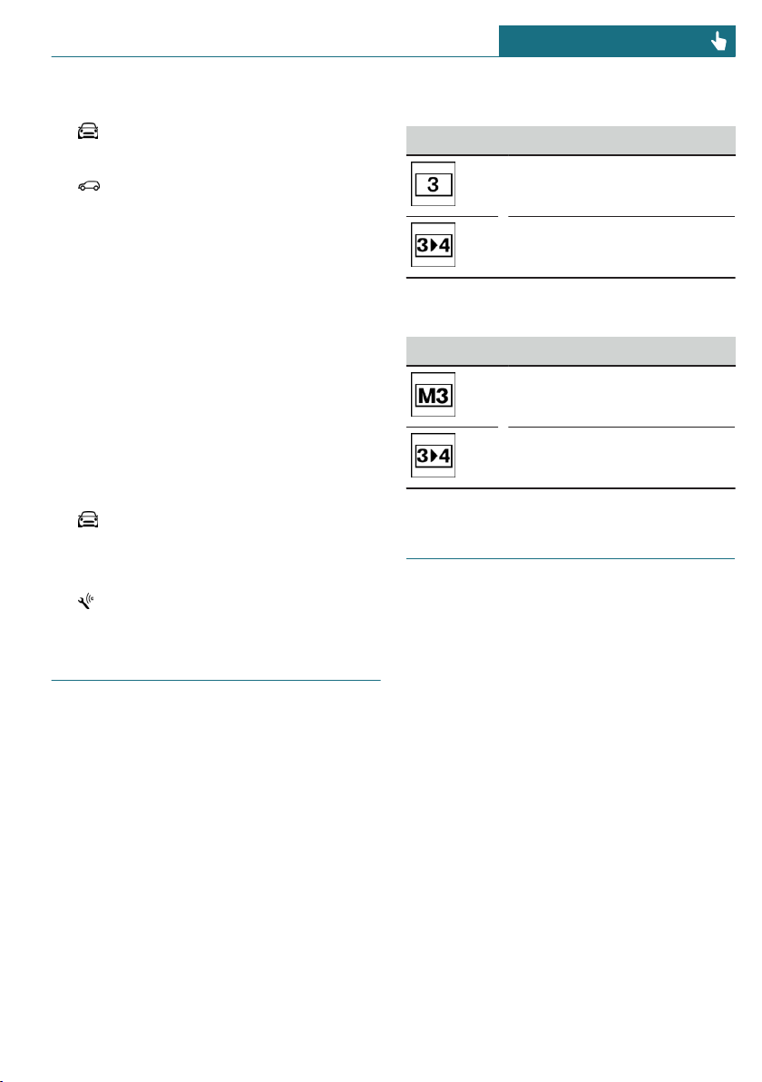
Via the Central Information Display (CID):
1. "My MINI"
2. "Vehicle status"
3. "Service required"
4. "Vehicle inspection"
5. "Date:"
6. Select the desired setting.
Automatic Service Request
Data regarding the service status or legally
mandated vehicle inspections is automati-
cally transmitted to your dealer’s service
center before your vehicle is due for serv-
ice.
You can check when your dealer’s service
center was notified.
Via the Central Information Display (CID):
1. "My MINI"
2. "Vehicle status"
3. Move the Controller to the left.
4. "Teleservice Call"
Gear shift indicator
Concept
The system recommends the most efficient
gear for the current driving situation.
General information
Depending on the vehicle equipment and
country version, the gear shift indicator is
active in the manual mode of the Steptronic
transmission and with manual transmission.
Suggestions to shift up or down are dis-
played in the instrument cluster.
Manual transmission: displaying
Example Description
Efficient gear is set.
Shift into efficient gear.
Steptronic transmission: displaying
Example Description
Efficient gear is set.
Shift into efficient gear.
Speed Limit Info
Speed Limit Info
Concept
Speed Limit Info shows the current maxi-
mum permitted speed in the instrument
cluster.
General information
The camera at the base of the interior mir-
ror detects traffic signs at the edge of the
road as well as variable overhead sign posts.
Traffic signs with extra symbols for wet
road conditions, etc., are also detected and
compared with the vehicle's onboard data,
such as from the rain sensor, and will be
displayed depending on the situation.
Without a navigation system, the system is
subject to limitations imposed by technol-
ogy. Traffic signs with speed limitations are
detected and displayed only. Speed limita-
Seite 123
Displays CONTROLS
123
Online Edition for Part no. 01402667083 - VI/19
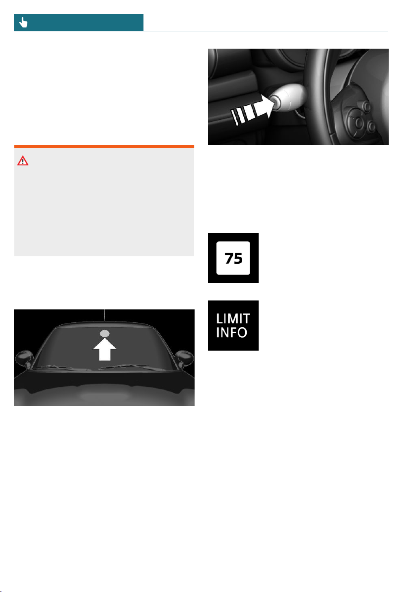
tions due to entering or exiting towns, high-
way signs, etc. are not displayed. Speed lim-
its with extra text characters are always
displayed.
Speed limits when towing a trailer are not
shown.
Safety information
Warning
The system cannot serve as a substitute
for the driver’s personal judgment in as-
sessing visibility and traffic situation.
There is a risk of accident. Adjust driving
style to traffic conditions. Watch traffic
closely and actively intervene where ap-
propriate.
Overview
Camera
The camera is installed near the interior
mirror.
Keep the windshield in front of the interior
mirror clean and clear.
Display
Speed Limit Info is displayed via the On-
board Computer.
Press button on the turn signal lever several
times, if needed.
Speed Limit Info is displayed on the Info
Display in the instrument cluster.
Speed Limit Info
The last speed limit detected.
Without a navigation system
the traffic signals are grayed
out after curves or longer
stretches of roadway.
Without navigation system:
no speed limit or cancellation
is detected.
System limits
The system may not be fully functional and
may provide incorrect information in the
following situations:
– In heavy fog, wet conditions, or snow-
fall.
– When signs are fully or partially con-
cealed by objects, stickers or paint.
– When driving very close to the vehicle
in front of you.
– When driving toward bright lights or
strong reflections.
– When the windshield in front of the in-
terior mirror is fogged over, dirty or cov-
ered by a sticker, etc.
Seite 124
CONTROLS Displays
124
Online Edition for Part no. 01402667083 - VI/19
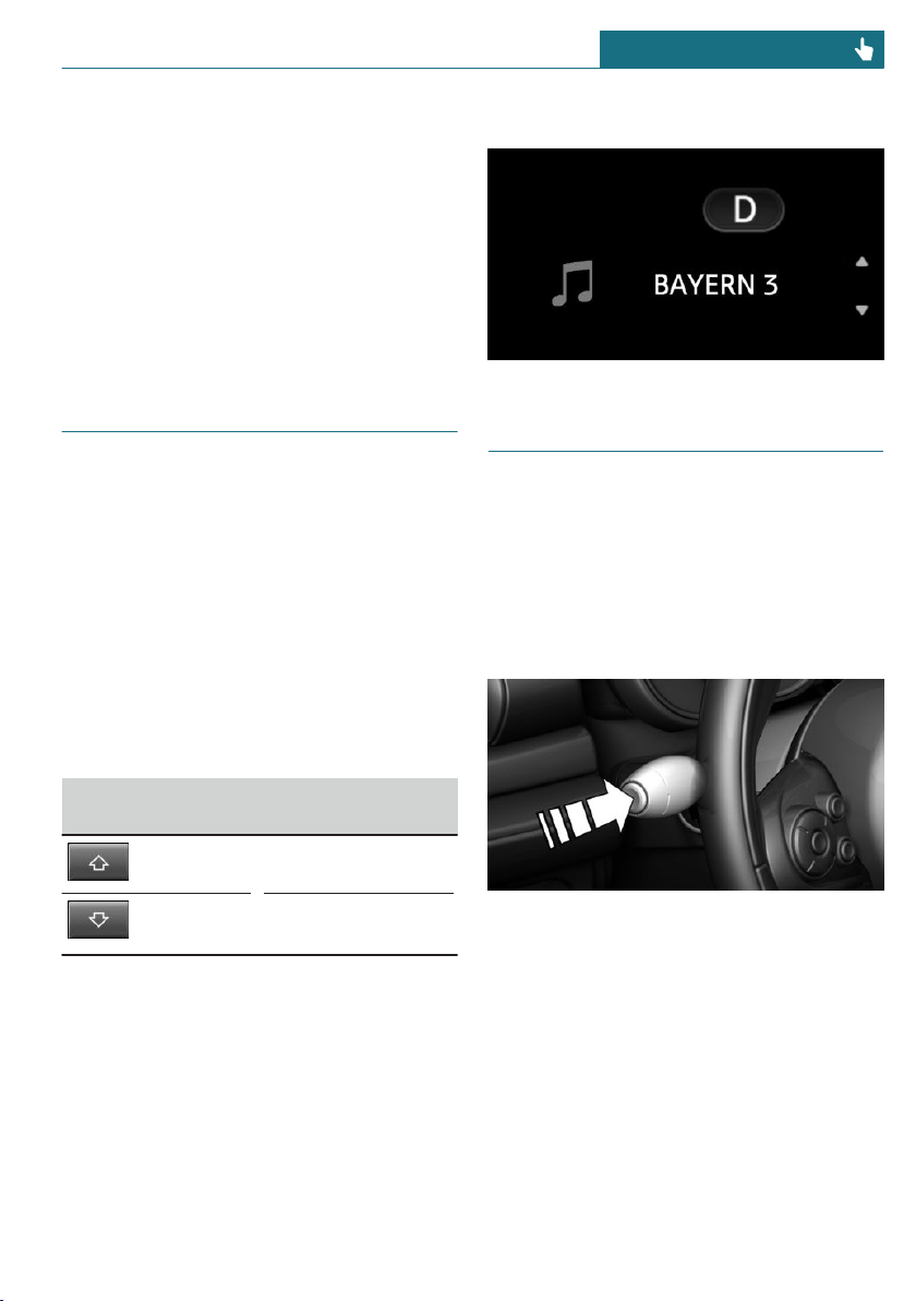
– In the event of incorrect detection by
the camera.
– When passing buses or trucks with a
speed sticker.
– If the traffic signs are non-conforming.
– When signs that are valid for a parallel
road are detected.
– During calibration of the camera imme-
diately after vehicle delivery.
Selection lists
General information
Depending on the vehicle equipment, the
buttons on the steering wheel and the dis-
play in the instrument cluster can be used
to display or use the following:
– Current audio source.
– Phone redial.
– Turn on voice activation system.
Activating a list and adjusting the
setting
Button on the
steering wheel
Function
Move selection up.
Move selection
down.
Display
Onboard Computer
Concept
The Onboard Computer displays different
vehicle data in the instrument cluster, such
as average values.
Calling up information on the Info
Display
Press the button on the turn signal lever.
Information is displayed in the Info Display
of the instrument cluster.
Seite 125
Displays CONTROLS
125
Online Edition for Part no. 01402667083 - VI/19
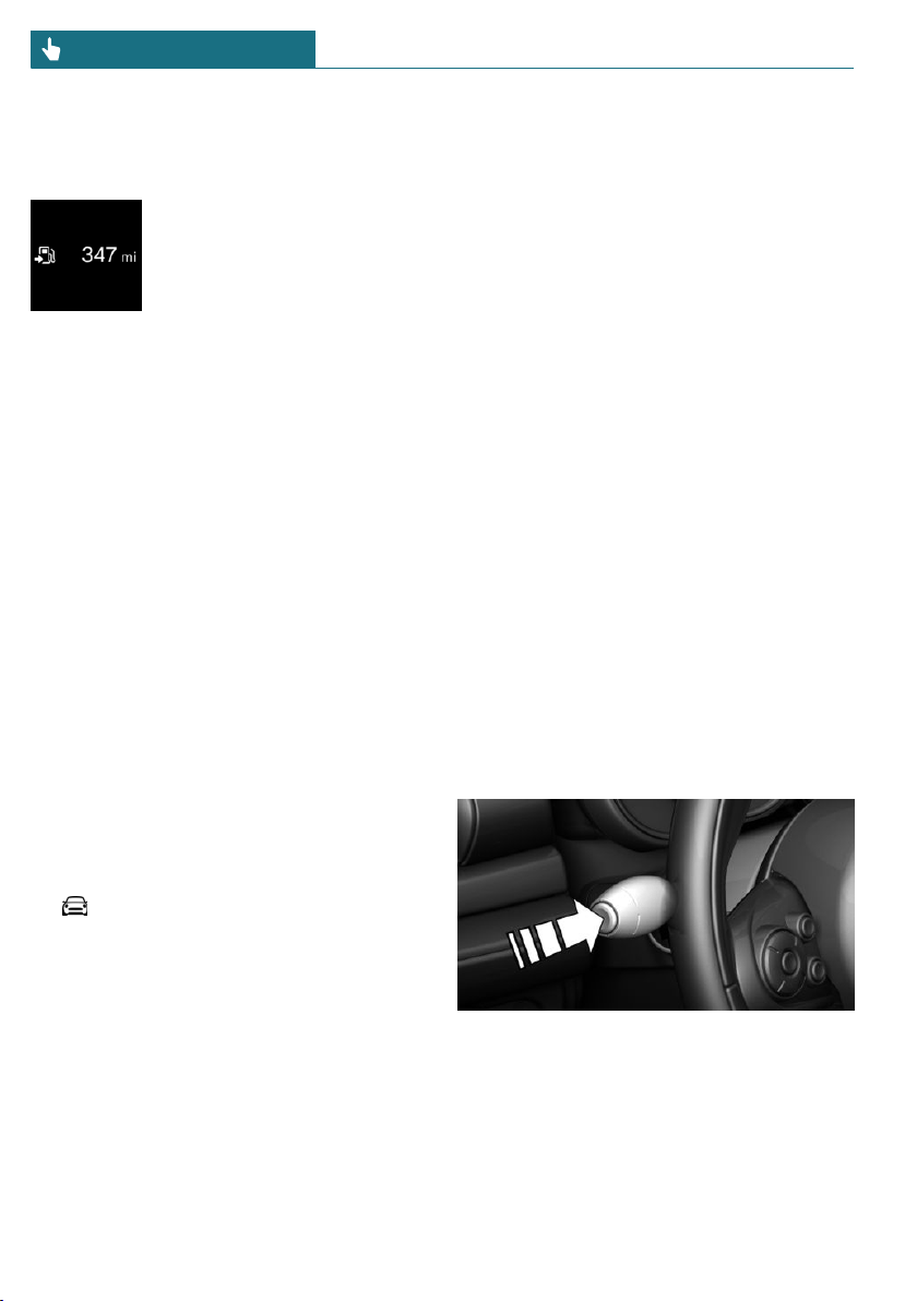
Information at a glance
Info Display
Repeatedly pressing the but-
ton on the turn signal lever
calls up the following informa-
tion in the Info Display:
– Range.
– GREEN Info.
When GREEN Mode is activated.
– Average consumption, fuel.
– Current consumption, fuel.
– Average speed.
– Date.
– Engine temperature display.
– Speed Limit Info.
– Vehicle speed.
The unit of some information can be
changed.
Setting units, refer to page 46.
Selecting information
Depending on the vehicle equipment, you
can select what information from the On-
board Computer can be displayed on the
Info Display of the instrument cluster.
Via the Central Information Display (CID):
1. "My MINI"
2. "System settings"
3. "Displays"
4. "Instrument panel"
5. Select the desired setting.
Settings are stored for the profile currently
used.
Information in detail
Range
Displays the estimated cruising range avail-
able with the remaining fuel.
The range is calculated based on your driv-
ing style over the last 20 miles/30 km.
GREEN info
The achieved range extension may be dis-
played as a bonus range.
Average consumption
This is calculated for the period while the
engine is running.
The average consumption is calculated for
the distance traveled since the last reset by
the Onboard Computer.
Average speed
Periods in which the vehicle is parked with
the engine manually stopped are not in-
cluded in the calculation of the average
speed.
Resetting average values
Press and hold the button on the turn signal
lever.
Seite 126
CONTROLS Displays
126
Online Edition for Part no. 01402667083 - VI/19
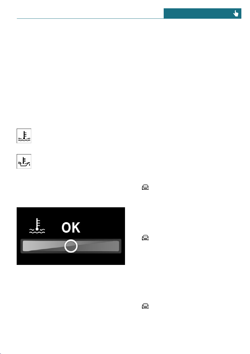
Engine temperature display
Concept
Displays the current engine temperature,
based on a combination of coolant and en-
gine oil temperature. As soon as the opti-
mum operating temperature has been at-
tained, the indicator is in the center
position.
General information
If the engine oil or coolant, and thus the en-
gine, become too hot, a Check Control mes-
sage is displayed too.
When the engine temperature is too
high, a red indicator light is dis-
played.
When the engine oil temperature is
too high, a red indicator light is dis-
played.
To check the coolant level, refer to
page 286.
Display
Speed Limit Info
Speed Limit Info shows the current maxi-
mum permitted speed in the instrument
cluster.
Onboard Computer on the Control
Display
Concept
The Onboard Computer displays different
vehicle data on the Control Display, such as
average values.
General information
Two types of Onboard Computers are availa-
ble on the Control Display:
– "Onboard info": average values, such as
the consumption, are displayed. The val-
ues can be reset individually.
– "Trip computer": the values deliver an
overview of a specific route and can be
reset as often as necessary.
Calling up the Onboard Computer or
trip computer
Via the Central Information Display (CID):
1. "My MINI"
2. "Driving information"
3. "Onboard info" or "Trip computer"
Resetting the Onboard Computer
Via the Central Information Display (CID):
1. "My MINI"
2. "Driving information"
3. "Onboard info"
4. "Consumption" or "Speed"
5. "OK"
Resetting the trip computer
Via the Central Information Display (CID):
1. "My MINI"
2. "Driving information"
3. "Trip computer"
Seite 127
Displays CONTROLS
127
Online Edition for Part no. 01402667083 - VI/19

4. Move the Controller to the left, if
needed.
– "Reset": all values are reset.
– "Automatic reset": all values are
reset approx. 4 hours after the vehi-
cle has come to a standstill.
5. If necessary, "OK"
Driving Excitement
Concept
On the Control Display, sport instruments
can be displayed, and the vehicle state can
be checked before the use of the SPORT
program.
Sport instruments
General information
On the Control Display, values for power
and torque are displayed.
Displaying sport instruments
Via the Central Information Display (CID):
1. "My MINI"
2. "Technology in action"
3. "Sport displays"
4. "Sports instruments"
Via MINI Driving Modes switch:
1. Activate SPORT.
2. "Sport displays"
3. "Sports instruments"
Speed warning
Concept
A speed limit can be set that when reached
will cause a warning to be issued.
General information
The warning is repeated if the vehicle speed
exceeds the set speed limit again, after it
has dropped below it by 3 mph/5 km/h.
Adjusting
Via the Central Information Display (CID):
1. "My MINI"
2. "Vehicle settings"
3. "Speed warning"
4. "Warning at:"
5. Turn the Controller until the desired
speed is displayed.
6. Press the Controller.
Activating/deactivating
Via the Central Information Display (CID):
1. "My MINI"
2. "Vehicle settings"
3. "Speed warning"
4. "Speed warning"
Setting your current speed as the
speed warning
Via the Central Information Display (CID):
1. "My MINI"
2. "Vehicle settings"
3. "Speed warning"
4. "Select current speed"
Seite 128
CONTROLS Displays
128
Online Edition for Part no. 01402667083 - VI/19
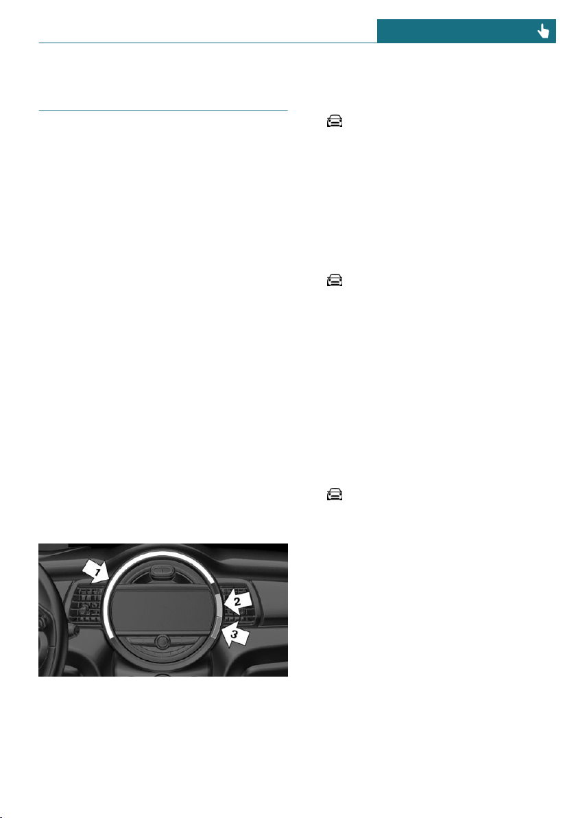
LED ring on the central in-
strument cluster
Concept
The LED ring displays light animations to
represent specific functions.
Basic displays
Basic functions, for instance the tachome-
ter, can be set to be displayed continually if
so desired.
Event displays
Functions that are only displayed tempora-
rily, for instance the volume or temperature
settings, can be set as event displays.
Several vehicle assistance functions can
also be displayed on the LED ring. This dis-
play corresponds with the displays of the
function in the respective display.
Example: tachometer
Like the tachometer in the instrument clus-
ter, the light animations of the tachometer's
basic display show the current RPMs and
the respective RPM warning thresholds.
Display
– Arrow 1: current RPM.
– Arrow 2: prewarning field.
– Arrow 3: warning field.
Switching on/off LED ring
Via the Central Information Display (CID):
1. "My MINI"
2. "System settings"
3. "Displays"
4. "Center Instrument"
5. "Center Instrument"
Adjusting the LED ring
Via the Central Information Display (CID):
1. "My MINI"
2. "System settings"
3. "Displays"
4. "Center Instrument"
5. "Basic display" or "Event display"
6. Select the desired setting.
Setting the brightness
The brightness can be adjusted when night
lighting is active in the instrument cluster.
Via the Central Information Display (CID):
1. "My MINI"
2. "System settings"
3. "Displays"
4. "Center Instrument"
5. "Brightness at night"
6. Turn the Controller until the desired
brightness is set.
7. Press the Controller.
The setting is stored for the driver profile
currently used.
Seite 129
Displays CONTROLS
129
Online Edition for Part no. 01402667083 - VI/19
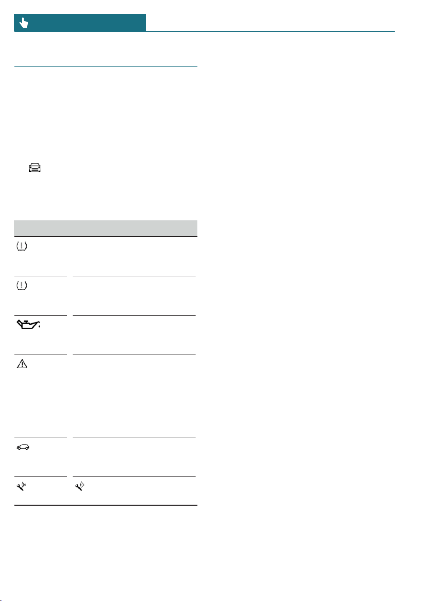
Vehicle status
General information
The status can be displayed and actions per-
formed for several systems.
Opening the vehicle status
Via the Central Information Display (CID):
1. "My MINI"
2. "Vehicle status"
Information at a glance
Symbols Description
"Flat Tire Monitor": status of
the Flat Tire Monitor, refer
to page 145.
"Tire Pressure Monitor": sta-
tus of the Tire Pressure
Monitor, refer to page 141.
"Engine oil level": Electronic
engine oil level check, refer
to page 282.
"Check Control": Check Con-
trol messages are stored in
the background and can be
displayed on the Control
Display. Displaying stored
Check Control messages, re-
fer to page 119.
"Service required": display-
ing service requirements,
refer to page 122.
"Teleservice Call": Serv-
ice Request.
Seite 130
CONTROLS Displays
130
Online Edition for Part no. 01402667083 - VI/19
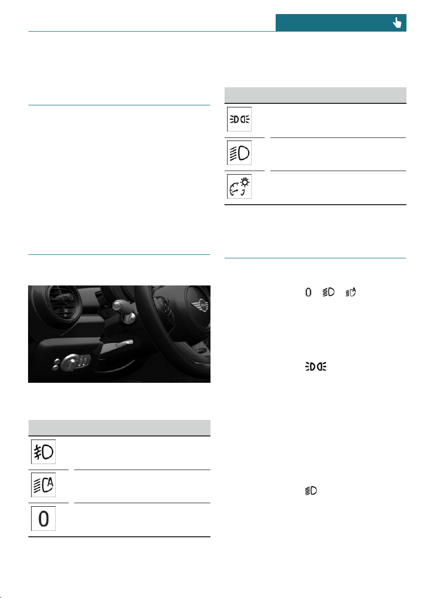
Lights
Vehicle features and options
This chapter describes all standard, country-
specific and optional features offered with
the series. It also describes features that are
not necessarily available in your vehicle, for
instance, due to the selected options or
country versions. This also applies to safety-
related functions and systems. When using
these functions and systems, the applicable
laws and regulations must be observed.
Overview
Switches in the vehicle
The light switch element is located next to
the steering wheel.
Symbol Function
Front fog lights.
Automatic headlight control.
Cornering light.
Lights off.
Daytime running lights.
Symbol Function
Parking lights.
Low beams.
Instrument lighting.
Parking lights, low beams and
roadside parking lights
General information
Position of switch: , ,
If the driver's door is opened when the igni-
tion is switched off, the exterior lighting is
automatically switched off.
Parking lights
Position of switch:
The vehicle is illuminated on all sides.
Do not use the parking lights for extended
periods; otherwise, the battery may become
discharged and it would then be impossible
to start the engine.
When parking, switch on the one-sided
roadside parking light, refer to page 132.
Low beams
Position of switch:
The low beams light up when the ignition is
switched on.
Seite 131
Lights CONTROLS
131
Online Edition for Part no. 01402667083 - VI/19
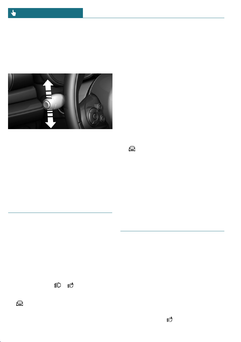
Canada: roadside parking light
Concept
The vehicle can be illuminated on one side.
Switching on
With radio-ready state switched off, press
the lever either up or down past the resist-
ance point for approx. 2 seconds.
Switching off
Briefly press the lever to the resistance
point in the opposite direction.
Welcome lights and headlight
courtesy delay feature
Welcome lights
General information
Depending on the vehicle equipment and
the ambient brightness, individual light
functions may be switched on briefly when
the vehicle is unlocked.
Activating/deactivating
Position of switch: ,
Via the Central Information Display (CID):
1. "My MINI"
2. "Vehicle settings"
3. "Lighting"
4. "Exterior lighting"
5. "Welcome lights"
The setting is stored for the driver profile
currently used.
Headlight courtesy delay feature
General information
The low beams stay lit for a short while if
the headlight flasher is switched on after
the vehicle's radio-ready state is switched
off.
Setting the duration
Via the Central Information Display (CID):
1. "My MINI"
2. "Vehicle settings"
3. "Lighting"
4. "Exterior lighting"
5. "Pathway lighting"
6. Set length of time.
The setting is stored for the driver profile
currently used.
Automatic headlight control
Concept
The low beams are switched on and off au-
tomatically depending on the ambient
brightness, for example in tunnels, in twi-
light or if there is precipitation.
General information
A blue sky with the sun low on the horizon
can cause the lights to be switched on.
Activating
Position of switch:
Seite 132
CONTROLS Lights
132
Online Edition for Part no. 01402667083 - VI/19
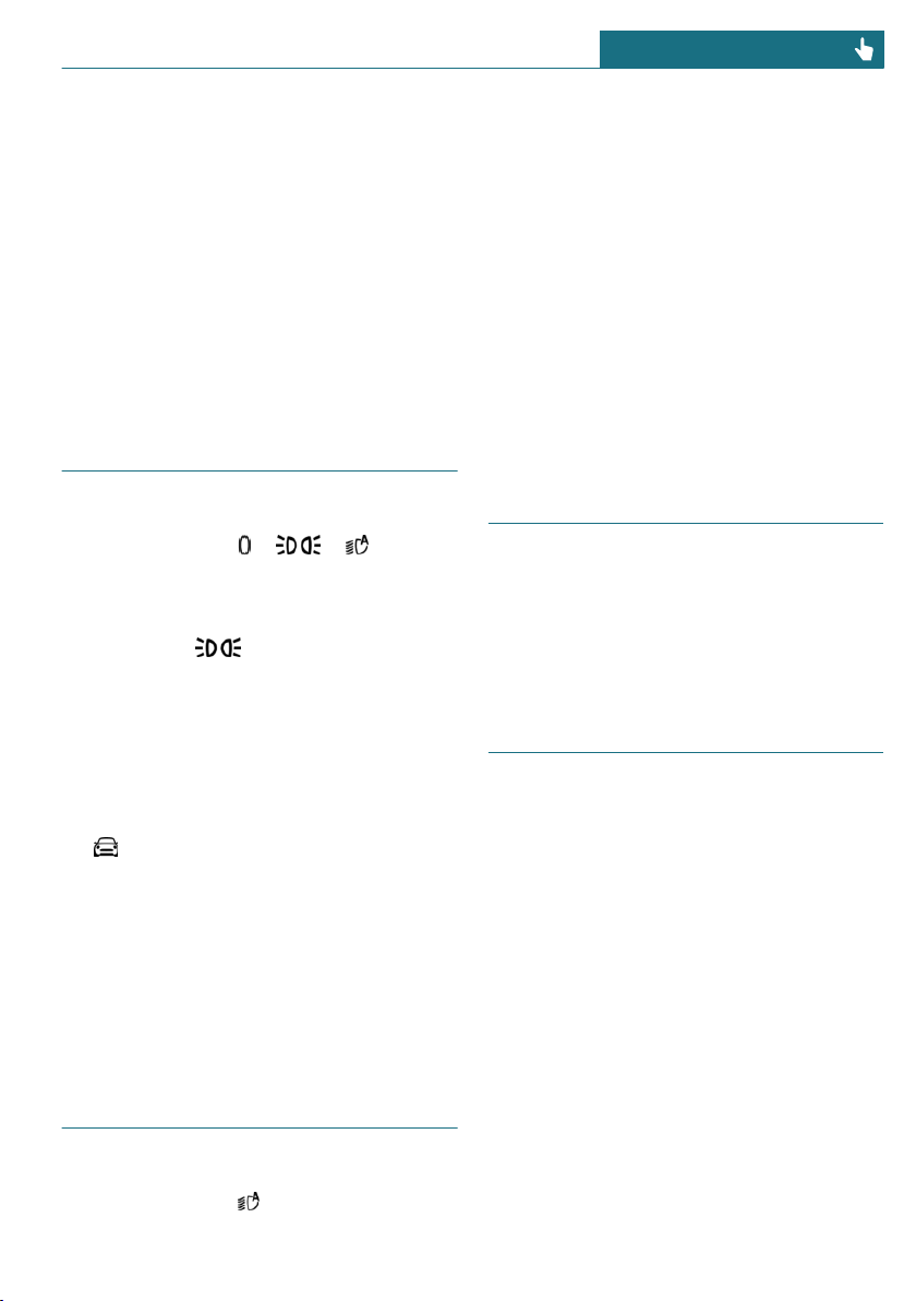
The indicator light in the instrument cluster
is illuminated when the low beams are
switched on.
System limits
The automatic headlight control cannot
serve as a substitute for your personal judg-
ment of lighting conditions.
For example, the sensors are unable to de-
tect fog or hazy weather. In these situa-
tions, switch the lights on manually.
Daytime running lights
General information
Position of switch: , ,
The daytime running lights light up when
the ignition is switched on. After the igni-
tion is switched off, the parking lights light
up in position .
Activating/deactivating
In some countries, daytime running lights
are mandatory, so it may not be possible to
deactivate the daytime running lights.
Via the Central Information Display (CID):
1. "My MINI"
2. "Vehicle settings"
3. "Lighting"
4. "Exterior lighting"
5. Select the desired setting.
Settings are stored for the currently used
vehicle key.
Cornering light
General information
Position of switch:
In tight curves, for instance on mountain-
ous roads or when turning, an additional,
cornering light is switched on that lights up
the inside of the curve when the vehicle is
moving below a certain speed.
The cornering light is automatically
switched on depending on the steering an-
gle or, where applicable, the use of turn sig-
nals.
When driving in reverse, the cornering
lights may be automatically switched on re-
gardless of the steering angle.
Adaptive headlight range con-
trol
The adaptive headlight range control fea-
ture balances out acceleration and braking
processes as well as the vehicle load condi-
tions in order to avoid dazzling oncoming
traffic. Illumination of the road is optimized.
High-beam Assistant
Concept
The high-beam Assistant detects other traf-
fic participants early on and automatically
switches the high beams on or off depend-
ing on the traffic situation.
General information
The high-beam Assistant ensures that the
high beams are switched on, whenever the
traffic situation allows. In the low speed
range, the high beams are not switched on
by the system.
The system responds to light from oncom-
ing traffic and traffic driving ahead of you,
and to ambient lighting, for instance in
towns and cities.
Seite 133
Lights CONTROLS
133
Online Edition for Part no. 01402667083 - VI/19
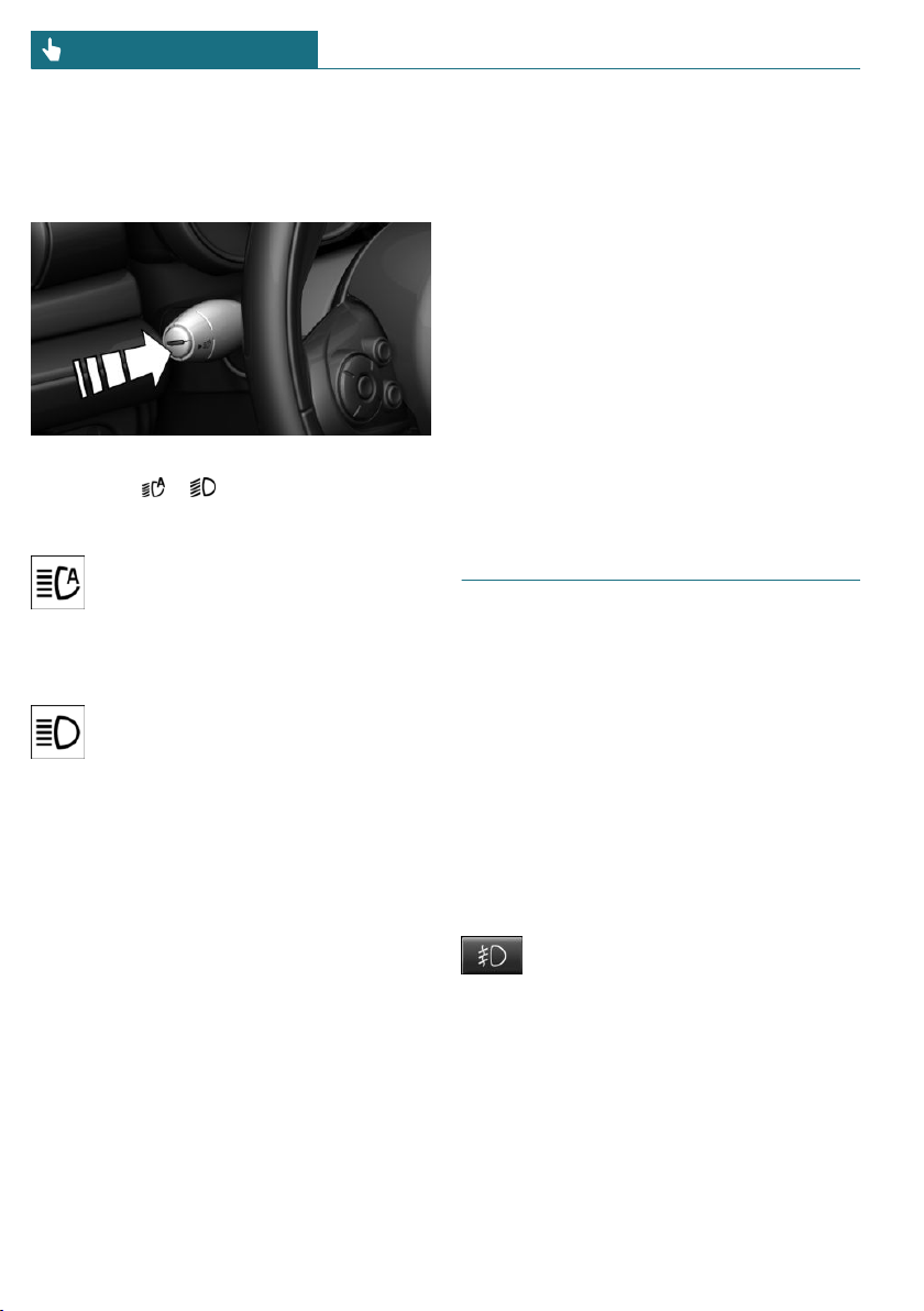
The high beams can be switched on and off
manually at any time.
Activating/deactivating
Position of switch, depending on the vehicle
equipment: ,
Press the button on the turn signal lever.
The indicator light in the instrument
cluster is illuminated when the low
beams are switched on.
The headlights are automatically switched
between low beams and high beams.
The blue indicator light in the instru-
ment cluster lights up when the sys-
tem switches on the high beams.
The high-beam Assistant is deactivated
when manually switching the high beams
on and off, refer to page 98.
To reactivate the high-beam Assistant,
press the button on the turn signal lever.
System limits
The high-beam Assistant cannot serve as a
substitute for the driver's personal judg-
ment of when to use the high beams. In sit-
uation that require this, therefore switch off
manually.
The system is not fully functional in the fol-
lowing situations, and driver intervention
may be necessary:
– In very unfavorable weather conditions,
such as fog or heavy precipitation.
– When detecting poorly-lit road users
such as pedestrians, cyclists, horseback
riders and wagons; when driving close
to train or ship traffic; or at animal
crossings.
– In tight curves, on hilltops or in depres-
sions, in crossing traffic or half-ob-
scured oncoming traffic on highways.
– In poorly-lit towns and cities or in the
presence of highly reflective signs.
– When the windshield in front of the in-
terior mirror is fogged over, dirty or cov-
ered with stickers, etc.
Fog lights
Front fog lights
Concept
The front fog lights work alongside the low
beams to illuminate a wider area of the
roadway.
Functional requirement
The low beams must be switched on before
switching on the front fog lights.
Switching on/off
Press the button.
The green indicator light lights up if
the front fog lights are switched on.
If the automatic headlight control, refer to
page 132, is activated, the low beams will
come on automatically when you switch on
the front fog lights.
When the high beams or headlight flasher
are activated, the front fog lights are not
switched on.
Seite 134
CONTROLS Lights
134
Online Edition for Part no. 01402667083 - VI/19
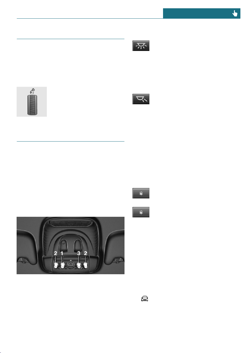
Instrument lighting
Functional requirement
The parking lights or low beams must be
switched on to adjust the brightness.
Adjusting
Adjust the brightness with the
thumbwheel.
Interior lights
General information
Depending on the equipment, the interior
lights, footwell lights, entry lights, and cour-
tesy lights are controlled automatically.
The thumbwheel for the instrument lighting
controls brightness of some of these fea-
tures.
Overview
1 Interior lights
2 Reading lights
3 Ambient light
Switching the interior lights on/off
Press the button.
To switch off permanently: press the button
and hold for approx. 3 seconds.
Switching the reading lights on and
off manually
Press the button.
The reading lights are located in the front
next to the interior light.
Ambient light
General information
Depending on the equipment version, light-
ing can be adjusted for some lights in the
car's interior.
Changing color
Push the switch forward or back:
manual color change.
Press the switch forward or back-
ward and hold for approx. 3 seconds,
until the ambient light illuminates
several times: automatic color change. Push
the switch again to end color changes.
Setting the brightness
Depending on the equipment, the bright-
ness of the ambient light can be adjusted
via the thumbwheel for the instrument
lighting or on the Control Display.
Via the Central Information Display (CID):
1. "My MINI"
2. "Vehicle settings"
3. "Lighting"
4. "Interior lighting"
Seite 135
Lights CONTROLS
135
Online Edition for Part no. 01402667083 - VI/19

5. "Brightness"
6. Adjust the brightness.
Seite 136
CONTROLS Lights
136
Online Edition for Part no. 01402667083 - VI/19
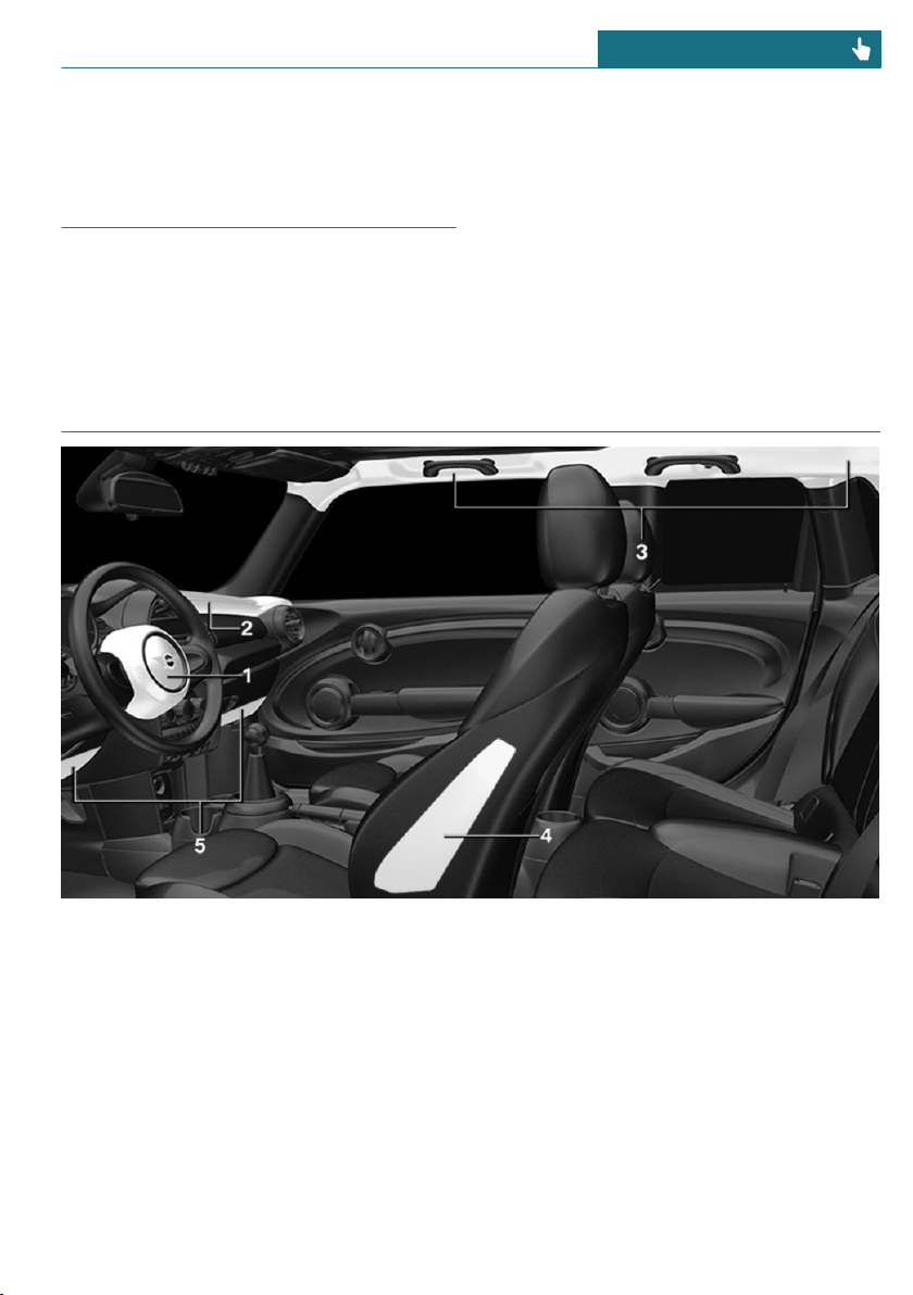
Safety
Vehicle features and options
This chapter describes all standard, country-
specific and optional features offered with
the series. It also describes features that are
not necessarily available in your vehicle, for
instance, due to the selected options or
country versions. This also applies to safety-
related functions and systems. When using
these functions and systems, the applicable
laws and regulations must be observed.
Airbags
1 Front airbag, driver
2 Front airbag, front passenger
3 Head airbag
4 Side airbag
5 Knee airbag
Front airbags
Front airbags help protect the driver and
the front passenger by responding to frontal
impacts in which safety belts alone would
not provide adequate protection.
Side airbag
In the event of a side impact, the side air-
bag protects the side of the body in the
chest and lap area.
Seite 137
Safety CONTROLS
137
Online Edition for Part no. 01402667083 - VI/19

Head airbag
In the event of a side impact, the head air-
bag protects the head.
Ejection Mitigation
The head airbag system is designed as an
ejection mitigation countermeasure to re-
duce the likelihood of ejections of vehicle
occupants through side windows during
rollovers or side impact events.
Knee airbag
The knee airbag protects the legs in the
event of a frontal impact.
Protective effect
Airbags are not triggered in every impact
situation, for instance in less severe acci-
dents or rear-end collisions.
Information on optimum effect of the
airbags
Warning
If the seat position is incorrect or the de-
ployment area of the airbags is impaired,
the airbag system cannot provide protec-
tion as intended and may cause additional
injuries due to triggering. There is a risk
of injuries or danger to life. Follow the in-
formation on achieving the optimum pro-
tective effect of the airbag system.
– Keep a distance from the airbags.
– Always grasp the steering wheel on the
steering wheel rim. Hold your hands at
the 3 o'clock and 9 o'clock positions, to
keep the risk of injury to your hands or
arms as low as possible when the airbag
is triggered.
– Make sure that the front passenger is
sitting correctly, i.e., keeps his or her
feet and legs in the floor area and does
not support them on the dashboard.
– Make sure that occupants keep their
heads away from the side airbag.
– There should be no additional persons,
animals or objects between an airbag
and a person.
– Dashboard and windshield on the front
passenger side must stay clear - do not
attach adhesive labels or coverings and
do not attach brackets or cables, for in-
stance for GPS devices or mobile
phones.
– Do not apply adhesive materials to the
airbag cover panels, do not cover them
or modify them in any way.
– Do not use the cover of the front airbag
on the front passenger side as a storage
area.
– Do not attach slip covers, seat cushions
or other objects to the front passenger
seat that are not specifically suited for
seats with integrated side airbags.
– Do not place seat cushions or other ob-
jects on the front seats that are not spe-
cifically suited for seats with integrated
side airbags.
– Do not hang pieces of clothing, such as
jackets, over the backrests.
– Never modify either the individual com-
ponents or the wiring in the airbag sys-
tem. This also applies to steering wheel
covers, the dashboard, and the seats.
– Do not remove the airbag system.
Even when you follow all instructions very
closely, injury from contact with the airbags
cannot be fully ruled out in certain situa-
tions.
The ignition and inflation noise may lead to
short-term and, in most cases, temporary
hearing impairment in sensitive occupants.
Vehicle modifications for a person with dis-
abilities may affect the air bag system; con-
Seite 138
CONTROLS Safety
138
Online Edition for Part no. 01402667083 - VI/19
tact MINI Customer Relations for further in-
formation.
Warnings and information on the airbags
are also found on the sun visors.
Functional readiness of the airbag
system
Safety information
Warning
Individual components can be hot after
triggering of the airbag system. There is a
risk of injury. Do not touch individual
components.
Warning
Improperly executed work can lead to fail-
ure, malfunction or unintentional trigger-
ing of the airbag system. In the case of a
malfunction, the airbag system might not
trigger as intended despite the accident
severity. There is a risk of injuries or dan-
ger to life. Have the airbag system
checked, repaired, dismantled and scrap-
ped by a dealer’s service center or another
qualified service center or repair shop.
Correct function
When the ignition is switched on,
the warning light in the instrument
cluster lights up briefly and thereby
indicates the operational readiness of the
entire airbag system and the belt tensioner.
Airbag system malfunctioning
– Warning light does not come on when
the ignition is switched on.
– The warning light lights up continu-
ously.
Automatic deactivation of the
front-seat passenger airbags
Concept
The system reads if the front passenger seat
is occupied by measuring the human body's
resistance.
Front, knee, and side airbag on the front
passenger's side are activated or deacti-
vated.
General information
Before transporting a child on the front pas-
senger seat, refer to the safety information
and instructions for children on the front
passenger seat, see Children.
Safety information
Warning
To ensure the front-seat passenger airbag
function, the system must be able to de-
tect whether a person is sitting in the
front passenger seat. The entire seat cush-
ion area must be used for this purpose.
There is a risk of injuries or danger to life.
Make sure that the front passenger keeps
his or her feet in the floor area.
Malfunction of the automatic
deactivation system
When transporting older children and
adults, the front-seat passenger airbags may
be deactivated in certain sitting positions.
In this case, the indicator light for the front-
seat passenger airbags lights up.
In this case, change the sitting position so
that the front-seat passenger airbags are ac-
tivated and the indicator light goes out.
If it is not possible to activate the airbags,
have the person sit in the rear.
Seite 139
Safety CONTROLS
139
Online Edition for Part no. 01402667083 - VI/19
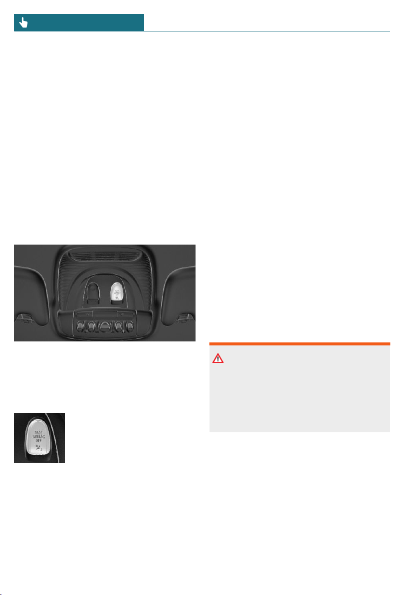
To enable correct recognition of the occu-
pied seat cushion.
– Do not attach covers, cushions, ball mats
or other items to the front passenger
seat unless they are specifically deter-
mined to be safe for use on the front
passenger seat.
– Do not place any electronic devices on
the front passenger seat if a child re-
straint system is to be installed on it.
– Do not place objects under the seat that
could press against the seat from below.
– No moisture in or on the seat.
Indicator light for the front-seat
passenger airbags
The indicator light for the front-seat passen-
ger airbags indicates the operating state of
the front-seat passenger airbags.
The light indicates whether the airbags are
either activated or deactivated.
– The indicator light lights
up when a child is properly
seated in a child restraint
system or when the seat is
empty. The airbags on the
front passenger side are
not activated.
– The indicator light does not light up
when, for instance a correctly seated
person of sufficient size is detected on
the seat. The airbags on the front pas-
senger side are activated.
Detected child restraint systems
The system generally detects children
seated in a child restraint system, particu-
larly in child restraint systems required by
NHTSA at the point in time when the vehi-
cle was manufactured. After installing a
child restraint system, make sure that the
indicator light for the front-seat passenger
airbags lights up. This indicates that the
child restraint system has been detected
and the front-seat passenger airbags are not
activated.
Strength of the driver's and front-
seat passenger airbag
The explosive power that activates driver's/
front-seat passenger airbags very much de-
pends on the positions of the driver's/front
passenger seat.
To maintain the accuracy of this function
over the long-term, calibrate the front seats
as soon as a relevant Check Control mes-
sage is displayed.
Calibrating the front seats
Warning
There is a risk of jamming when moving
the seats. There is a risk of injury or risk
of damage to property. Make sure that the
area of movement of the seat is clear prior
to any adjustment.
An appropriate Check Control message is
displayed.
1. Move the respective seat all the way for-
ward.
2. Move the respective seat forward again.
The seat moves forward briefly.
3. Readjust the seat to the desired posi-
tion.
Seite 140
CONTROLS Safety
140
Online Edition for Part no. 01402667083 - VI/19
The calibration procedure is completed
when the Check Control message disap-
pears.
If the message continues to be displayed,
repeat the calibration.
If the message does not disappear after a re-
peat calibration, have the system checked
as soon as possible.
Tire Pressure Monitor TPM
Concept
The system monitors tire inflation pressure
in the four mounted tires. The system warns
you if there is a significant loss of pressure
in one or more tires.
General information
Sensors in the tire valves measure the tire
inflation pressure and, depending on the
model, the tire temperature.
Further information and instructions on us-
ing the system can also be found under Tire
inflation pressure, refer to page 256.
Functional requirements
The following conditions must be met for
the system; otherwise, reliable flagging of a
loss of tire inflation pressure is not assured:
– After a tire or wheel replacement, a re-
set was performed with the correct tire
inflation pressure.
– After the tire inflation pressure was ad-
justed to a new value, a reset was per-
formed.
– Wheels with TPM wheel electronics.
Status display
Current status
The system status can be displayed on the
Control Display, e.g., whether or not the sys-
tem is active.
Via the Central Information Display (CID):
1. "My MINI"
2. "Vehicle status"
3. "Tire Pressure Monitor"
The current status is displayed.
Additional information
The current tire inflation pressures are dis-
played too. The values shown are instanta-
neous measurements and may vary depend-
ing on driving style or weather conditions.
Resetting the system
Via the Central Information Display (CID):
1. "My MINI"
2. "Vehicle status"
3. "Tire Pressure Monitor"
4. Start the engine but do not drive off.
5. Reset the tire inflation pressure using
"Perform reset".
6. Drive away.
The following is displayed: "Resetting Tire
Pressure Monitor…".
After a travel time of several minutes, the
set tire inflation pressures are accepted as
reference values. The resetting process is
completed automatically while driving.
After a successfully completed reset, the fol-
lowing is displayed: "Tire Pressure Monitor
active. See label for recommended
pressures.".
Seite 141
Safety CONTROLS
141
Online Edition for Part no. 01402667083 - VI/19
You may interrupt this trip at any time.
When you continue the reset resumes auto-
matically.
Messages
General information
A low tire inflation pressure may cause the
DSC Dynamic Stability Control to be
switched on.
Safety information
Warning
A damaged regular tire with low or miss-
ing tire inflation pressure impacts han-
dling, such as steering and braking re-
sponse. Run-flat tires can maintain limited
stability. There is a risk of accident. Do not
continue driving if the vehicle is equipped
with normal tires. Follow the information
on run-flat tires and continued driving
with these tires.
If a tire inflation pressure check is
required
Message
A symbol with a Check Control message ap-
pears on the Control Display.
Symbol Possible cause
The system has detected a
wheel change, but no reset was
done.
No reset was performed for the
system. The system issues a
warning based on the tire infla-
tion pressures stored during the
last reset.
Inflation was not carried out ac-
cording to specifications.
The tire inflation pressure has
fallen below the level of the last
reset.
Measure
1. Check the tire pressure and correct as
needed.
2. Reset the system.
If the tire inflation pressure is too low
Message
A yellow warning light is illuminated
in the instrument cluster.
In addition, a symbol with a Check Control
message appears on the Control Display.
Symbol Possible cause
There is a tire inflation pressure
loss.
No reset was performed for the
system. The system issues a
warning based on the tire infla-
tion pressures stored during the
last reset.
Measure
1. Reduce your speed and drive moder-
ately. Do not exceed a speed of
80 mph/130 km/h.
Seite 142
CONTROLS Safety
142
Online Edition for Part no. 01402667083 - VI/19
2. At the next opportunity, for instance gas
station, check and correct the tire infla-
tion pressure in all four tires, if neces-
sary.
3. Reset the system.
If there is a significant loss of tire
inflation pressure
Message
A yellow warning light is illuminated
in the instrument cluster.
In addition, a symbol with the affected tire
appears in a Check Control message on the
Control Display.
Symbol Possible cause
There is a flat tire or a major
loss in tire inflation pressure.
No reset was performed for the
system. The system issues a
warning based on the tire infla-
tion pressures stored during the
last reset.
Measure
1. Reduce your speed and stop cautiously.
Avoid sudden braking and steering ma-
neuvers.
2. Check whether the vehicle is fitted with
normal tires or run-flat tires.
Run-flat tires, refer to page 267, are la-
beled with a circular symbol containing
the letters RSC marked on the tire's
sidewall.
Actions in the event of a flat tire
Normal tires
1. Identify the damaged tire.
To do this, check the tire inflation pres-
sure in all four tires, for instance using
the tire pressure gage of a flat tire kit.
If the tire inflation pressure in all four
tires is correct, the Tire Pressure Moni-
tor may not have been reset. In this
case, perform the reset.
If the tire inflation pressure in all four
tires is correct, the Flat Tire Monitor
may not have been initialized. In this
case, initialize the system.
If identification of flat tire damage is
not possible, please contact a dealer’s
service center or another qualified serv-
ice center or repair shop.
2. Repair the flat tire, e.g., with a flat tire
kit or by changing the wheel.
Use of sealant, for instance from the flat tire
kit, may damage the TPM wheel electronics.
In this case, have the electronics checked
and replaced at the next opportunity.
Run-flat tires
Safety information
Warning
Your vehicle handles differently with a
run-flat tire with no or low inflation pres-
sure; for instance, your lane stability when
braking is reduced, braking distances are
longer and the self-steering properties will
change. There is a risk of accident. Drive
moderately and do not exceed a speed of
50 mph/80 km/h.
Maximum speed
You may continue driving with a damaged
tire at speeds up to 50 mph/80 km/h.
Seite 143
Safety CONTROLS
143
Online Edition for Part no. 01402667083 - VI/19

Continued driving with a flat tire
If continuing to drive with a damaged tire:
1. Avoid sudden braking and steering ma-
neuvers.
2. Do not exceed a speed of
50 mph/80 km/h.
3. Check the tire inflation pressure in all
four tires at the next opportunity.
If the tire inflation pressure in all four
tires is correct, the Tire Pressure Moni-
tor may not have been reset. In this
case, perform the reset.
Possible driving range with a
depressurized tire
The distance for which it may be possible to
drive safely varies depending on how the
vehicle is loaded and used, e.g., speed, road
conditions, external temperature. The driv-
ing range may be less but may also be more
if an economical driving style is used.
If the vehicle is loaded with an average
weight and used under favorable conditions,
the distance for which it may be safe to
drive may be up to 50 miles/80 km.
Vehicle handling with damaged tires
Vehicles driven with a damaged tire will
handle differently, potentially leading to
conditions such as the following:
– Greater likelihood of swerving off
course.
– Longer braking distances.
– Changed self-steering properties.
Modify your driving style. Avoid abrupt
steering maneuvers or driving over obsta-
cles, for instance curbs or potholes.
Final tire failure
Vibrations or loud noises while driving can
indicate the final failure of a tire.
Reduce speed and stop; otherwise, pieces of
the tire could come loose and cause an acci-
dent.
Do not continue driving. Contact a dealer’s
service center or another qualified service
center or repair shop.
System limits
Temperature
The tire inflation pressure depends on the
tire's temperature.
Driving or exposure to the sun will increase
the tire's temperature, thus increasing the
tire inflation pressure.
The tire inflation pressure is reduced when
the tire temperature falls again.
These circumstances may cause a warning
when temperatures fall very sharply.
Sudden tire pressure loss
The system cannot indicate sudden serious
tire damage caused by external circumstan-
ces.
Failure performing a reset
The system does not function properly if a
reset has not been carried out, for instance
a flat tire is reported though tire inflation
pressures are correct.
Malfunction
The yellow warning light flashes and
is then illuminated continuously. A
Check Control message is displayed.
It may not be possible to identify tire pres-
sure losses.
Examples and recommendations in the fol-
lowing situations:
– A wheel without TPM wheel electronics,
for instance an emergency wheel, is
mounted: have it checked by a dealer’s
Seite 144
CONTROLS Safety
144
Online Edition for Part no. 01402667083 - VI/19

service center or another qualified serv-
ice center or repair shop as needed.
– Malfunction: have system checked by a
dealer’s service center or another quali-
fied service center or repair shop.
– The system was unable to complete the
reset. Perform a system reset again.
– Interference caused by systems or devi-
ces with the same radio frequency: after
leaving the area of the interference, the
system automatically becomes active
again.
Declaration according to NHTSA/
FMVSS 138 Tire Pressure Monitoring
System
Each tire, including the spare (if provided)
should be checked monthly when cold and
inflated to the inflation pressure recom-
mended by the vehicle manufacturer on the
vehicle placard or tire inflation pressure la-
bel. (If your vehicle has tires of a different
size than the size indicated on the vehicle
placard or tire inflation pressure label, you
should determine the proper tire inflation
pressure for those tires.) As an added safety
feature, your vehicle has been equipped
with a tire pressure monitoring system
(TPMS) that illuminates a low tire pressure
telltale when one or more of your tires is
significantly under-inflated. Accordingly,
when the low tire pressure telltale illumi-
nates, you should stop and check your tires
as soon as possible, and inflate them to the
proper pressure. Driving on a significantly
under-inflated tire causes the tire to over-
heat and can lead to tire failure. Under-infla-
tion also reduces fuel efficiency and tire
tread life, and may affect the vehicle's han-
dling and stopping ability. Please note that
the TPMS is not a substitute for proper tire
maintenance, and it is the driver's responsi-
bility to maintain correct tire pressure, even
if under-inflation has not reached the level
to trigger illumination of the TPMS low tire
pressure telltale. Your vehicle has also been
equipped with a TPMS malfunction indica-
tor to indicate when the system is not oper-
ating properly. The TPMS malfunction indi-
cator is combined with the low tire pressure
telltale. When the system detects a mal-
function, the telltale will flash for approxi-
mately one minute and then remain contin-
uously illuminated. This sequence will
continue upon subsequent vehicle start-ups
as long as the malfunction exists. When the
malfunction indicator is illuminated, the
system may not be able to detect or signal
low tire pressure as intended. TPMS mal-
functions may occur for a variety of rea-
sons, including the installation of replace-
ment or alternate tires or wheels on the
vehicle that prevent the TPMS from func-
tioning properly. Always check the TPMS
malfunction telltale after replacing one or
more tires or wheels on your vehicle to en-
sure that the replacement or alternate tires
and wheels allow the TPMS to continue to
function properly.
Flat Tire Monitor FTM
Concept
The system detects tire inflation pressure
loss on the basis of rotation speed differen-
ces between the individual wheels while
driving.
In the event of a tire inflation pressure loss,
the diameter and therefore the rotational
speed of the corresponding wheel changes.
The difference will be detected and reported
as a flat tire.
The system does not measure the actual in-
flation pressure in the tires.
Seite 145
Safety CONTROLS
145
Online Edition for Part no. 01402667083 - VI/19
Functional requirements
The following conditions must be met for
the system; otherwise, reliable flagging of a
loss of tire inflation pressure is not assured:
– After a tire or wheel replacement, an ini-
tialization was performed with the cor-
rect tire inflation pressure.
– After the tire pressure was adjusted to a
new value, an initialization was per-
formed.
Status display
The current status of the flat tire monitor
can be displayed, for instance whether the
RPA is active.
Via the Central Information Display (CID):
1. "My MINI"
2. "Vehicle status"
3. "Flat Tire Monitor"
The status is displayed.
Initialization required
An initialization must be performed in the
following situations:
– After the tire inflation pressure has
been adjusted.
– After a tire or wheel replacement.
Performing initialization
When initializing, the set tire inflation
pressures serve as reference values in order
to detect a flat tire. Initialization is started
by confirming the tire inflation pressures.
Do not initialize the system when driving
with snow chains.
Via the Central Information Display (CID):
1. "My MINI"
2. "Vehicle status"
3. "Flat Tire Monitor"
4. Start the engine but do not drive off.
5. Start the initialization with: "Perform
reset".
6. Drive away.
The initialization is completed while driv-
ing, which can be interrupted at any time.
The initialization automatically continues
when driving resumes.
Messages
General information
When a flat tire is indicated, DSC Dynamic
Stability Control is switched on, if needed.
Safety information
Warning
A damaged regular tire with low or miss-
ing tire inflation pressure impacts han-
dling, such as steering and braking re-
sponse. Run-flat tires can maintain limited
stability. There is a risk of accident. Do not
continue driving if the vehicle is equipped
with normal tires. Follow the information
on run-flat tires and continued driving
with these tires.
Indication of a flat tire
A yellow warning light is illuminated
in the instrument cluster.
In addition, a symbol with a Check Control
message appears on the Control Display.
Symbol Possible cause
There is a flat tire or a major
loss in tire inflation pressure.
Seite 146
CONTROLS Safety
146
Online Edition for Part no. 01402667083 - VI/19

Measure
1. Reduce your speed and stop cautiously.
Avoid sudden braking and steering ma-
neuvers.
2. Check whether the vehicle is fitted with
normal tires or run-flat tires.
Run-flat tires, refer to page 267, are la-
beled with a circular symbol containing
the letters RSC marked on the tire's
sidewall.
Actions in the event of a flat tire
Normal tires
1. Identify the damaged tire.
To do this, check the tire inflation pres-
sure in all four tires, for instance using
the tire pressure gage of a flat tire kit.
If the tire inflation pressure in all four
tires is correct, the Tire Pressure Moni-
tor may not have been reset. In this
case, perform the reset.
If the tire inflation pressure in all four
tires is correct, the Flat Tire Monitor
may not have been initialized. In this
case, initialize the system.
If identification of flat tire damage is
not possible, please contact a dealer’s
service center or another qualified serv-
ice center or repair shop.
2. Repair the flat tire, e.g., with a flat tire
kit or by changing the wheel.
Use of sealant, for instance from the flat tire
kit, may damage the TPM wheel electronics.
In this case, have the electronics checked
and replaced at the next opportunity.
Run-flat tires
Safety information
Warning
Your vehicle handles differently with a
run-flat tire with no or low inflation pres-
sure; for instance, your lane stability when
braking is reduced, braking distances are
longer and the self-steering properties will
change. There is a risk of accident. Drive
moderately and do not exceed a speed of
50 mph/80 km/h.
Maximum speed
You may continue driving with a damaged
tire at speeds up to 50 mph/80 km/h.
Continued driving with a flat tire
If continuing to drive with a damaged tire:
1. Avoid sudden braking and steering ma-
neuvers.
2. Do not exceed a speed of
50 mph/80 km/h.
3. Check the tire inflation pressure in all
four tires at the next opportunity.
If the tire inflation pressure in all four
tires is correct, the Flat Tire Monitor
may not have been initialized. In this
case, initialize the system.
Possible driving range with a
depressurized tire
The distance for which it may be possible to
drive safely varies depending on how the
vehicle is loaded and used, e.g., speed, road
conditions, external temperature. The driv-
ing range may be less but may also be more
if an economical driving style is used.
If the vehicle is loaded with an average
weight and used under favorable conditions,
Seite 147
Safety CONTROLS
147
Online Edition for Part no. 01402667083 - VI/19
the distance for which it may be safe to
drive may be up to 50 miles/80 km.
Vehicle handling with damaged tires
Vehicles driven with a damaged tire will
handle differently, potentially leading to
conditions such as the following:
– Greater likelihood of swerving off
course.
– Longer braking distances.
– Changed self-steering properties.
Modify your driving style. Avoid abrupt
steering maneuvers or driving over obsta-
cles, for instance curbs or potholes.
Final tire failure
Vibrations or loud noises while driving can
indicate the final failure of a tire.
Reduce speed and stop; otherwise, pieces of
the tire could come loose and cause an acci-
dent.
Do not continue driving. Contact a dealer’s
service center or another qualified service
center or repair shop.
System limits
The system could be delayed or malfunction
in the following situations:
– A natural, even tire inflation pressure
loss in all four tires will not be recog-
nized. Therefore, check the tire inflation
pressure regularly.
– Sudden serious tire damage caused by
external circumstances cannot be recog-
nized in advance.
– When the system has not been initial-
ized.
– When driving on a snowy or slippery
road surface.
– Sporty driving style: spinning traction
wheels, high lateral acceleration (drift-
ing).
– When driving with snow chains.
Intelligent Safety
Concept
Intelligent Safety enables central operation
of the driver assistance systems.
The intelligent safety systems can help pre-
vent an imminent collision.
– Approach control warning with City
light braking function, refer to
page 149.
– Daytime pedestrian collision mitigation,
refer to page 153.
Safety information
Warning
The system cannot serve as a substitute
for the driver’s personal judgment in as-
sessing visibility and traffic situation.
There is a risk of accident. Adjust driving
style to traffic conditions. Watch traffic
closely and actively intervene where ap-
propriate.
Warning
Indicators and warnings cannot serve as a
substitute for the driver’s personal judg-
ment. Due to its limits, the system may not
issue warnings or reactions, or these may
be issued late or in a manner that is not
consistent with their normal use. There is
a risk of accident. Adjust driving style to
traffic conditions. Watch traffic closely
and actively intervene where appropriate.
Seite 148
CONTROLS Safety
148
Online Edition for Part no. 01402667083 - VI/19
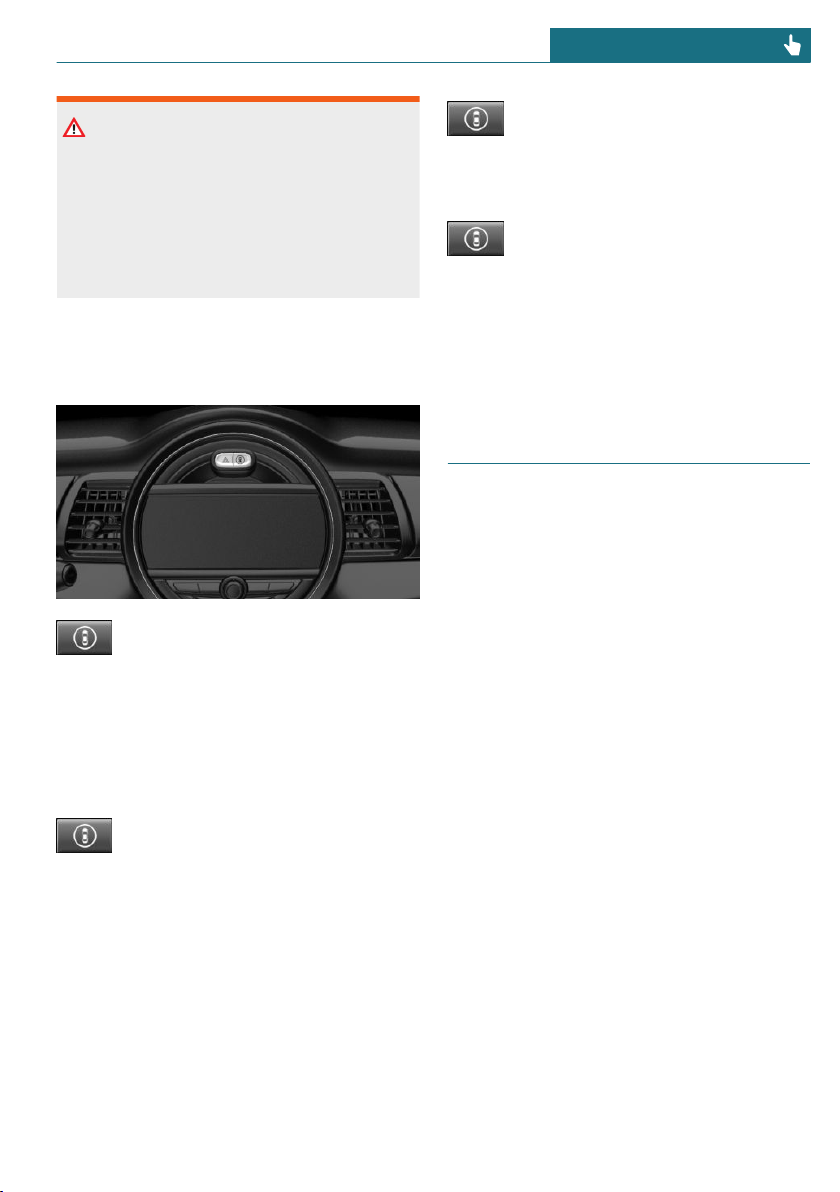
Warning
Due to system limits, individual functions
can malfunction during tow-starting/
towing with the Intelligent Safety systems
activated. There is a risk of accident.
Switch all Intelligent Safety systems off
prior to tow-starting/towing.
Overview
Button in the vehicle
Intelligent Safety button
Switching on/off
Some Intelligent Safety systems are auto-
matically active after every departure. Some
Intelligent Safety systems activate accord-
ing to the last setting.
Press button briefly:
– The menu for the Intelligent
Safety system is displayed. The
systems are individually
switched off according to their
respective settings.
– LED lights up orange or goes out respec-
tive to their individual settings.
Adjust the settings as needed. The individ-
ual settings are stored for the driver profile
currently in use.
Press button again:
– All Intelligent Safety systems
are switched on.
– The LED lights up green.
Hold down button:
– All Intelligent Safety systems
are switched off.
– The LED goes out.
Approach control warning
with city light braking func-
tion
Concept
The system may prevent some accidents. In
the event of an accident, the system may re-
duce impact speed.
The system sounds a warning before an im-
minent collision and activates brakes inde-
pendently, if needed.
The Brake Assistant function activates and
applies the brakes with limited force and
duration.
A camera at the base of the interior mirror
controls the system.
The approach control warning is available
even if cruise control has been deactivated.
With the vehicle approaching another vehi-
cle intentionally, the approach control warn-
ing and braking are delayed in order to
avoid false system reactions.
General information
The system warns at two levels of an immi-
nent danger of collision at speeds from ap-
prox. 3 mph/5 km/h. The timing of warn-
ings may vary with the current driving
situation.
Seite 149
Safety CONTROLS
149
Online Edition for Part no. 01402667083 - VI/19
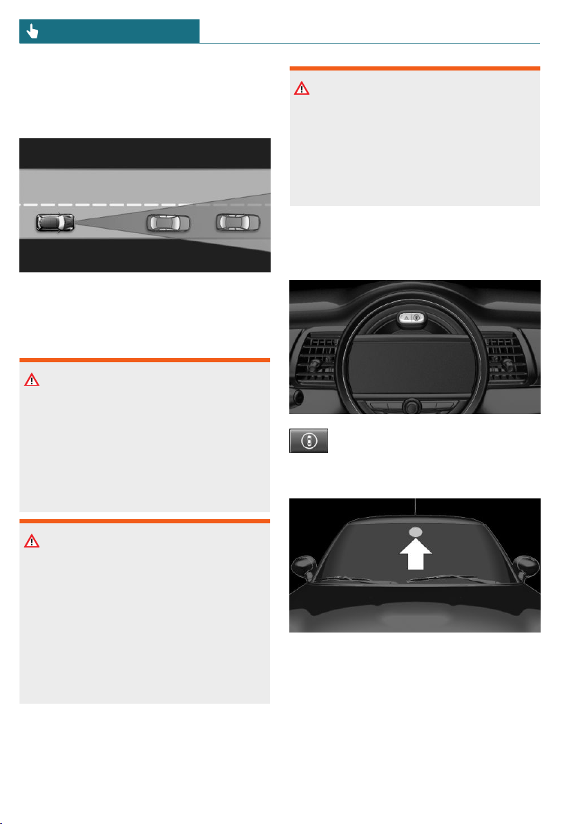
Braking is performed at speeds up to ap-
proximately 35 mph/60 km/h.
Detection range
Objects that the system can detect are
taken into account.
Safety information
Warning
The system cannot serve as a substitute
for the driver’s personal judgment in as-
sessing visibility and traffic situation.
There is a risk of accident. Adjust driving
style to traffic conditions. Watch traffic
closely and actively intervene where ap-
propriate.
Warning
Indicators and warnings cannot serve as a
substitute for the driver’s personal judg-
ment. Due to its limits, the system may not
issue warnings or reactions, or these may
be issued late or in a manner that is not
consistent with their normal use. There is
a risk of accident. Adjust driving style to
traffic conditions. Watch traffic closely
and actively intervene where appropriate.
Warning
Due to system limits, individual functions
can malfunction during tow-starting/
towing with the Intelligent Safety systems
activated. There is a risk of accident.
Switch all Intelligent Safety systems off
prior to tow-starting/towing.
Overview
Button in the vehicle
Intelligent Safety button
Camera
The camera is installed near the interior
mirror.
Keep the windshield in front of the interior
mirror clean and clear.
Seite 150
CONTROLS Safety
150
Online Edition for Part no. 01402667083 - VI/19
Switching on/off
Switching on automatically
The system is automatically active after ev-
ery driving off.
Switching on/off manually
Press button briefly:
– The menu for the Intelligent
Safety system is displayed. The
systems are individually
switched off according to their
respective settings.
– LED lights up orange or goes out respec-
tive to their individual settings.
Adjust the settings as needed. The individ-
ual settings are stored for the driver profile
currently in use.
Press button again:
– All Intelligent Safety systems
are switched on.
– The LED lights up green.
Hold down button:
– All Intelligent Safety systems
are switched off.
– The LED goes out.
Setting the warning time
The warning time can be set via the Central
Information Display (CID).
1. "My MINI"
2. "Vehicle settings"
3. "Intelligent Safety"
4. "Warning time"
5. Select the desired setting.
The selected warning time is stored for the
driver profile currently in use.
Warning with braking function
Display
If a collision with a vehicle detected in this
way is imminent, a warning symbol appears
on the instrument cluster.
Symbol Measure
Symbol lights up red: prewarn-
ing.
Brake and increase distance.
Symbol flashes red and an
acoustic signal sounds: acute
warning.
Brake and make an evasive ma-
neuver, if necessary.
Prewarning
This warning is provided, for instance when
there is impending danger of a collision or
the distance to the vehicle ahead is too
small.
If a prewarning is provided, respond by
braking as warranted.
Acute warning with braking function
An acute warning is displayed when there
is an imminent danger of collision due to
the vehicle approaching another object at a
high speed.
The driver must intervene actively when
there is an acute warning. If necessary, the
driver is assisted by a minor automatic
braking intervention in a possible risk of
collision.
Acute warnings may be provided even when
there has been no prior warning.
Braking intervention
The warning prompts the driver to inter-
vene. During a warning, the maximum brak-
ing force is used. In order to activate the
Seite 151
Safety CONTROLS
151
Online Edition for Part no. 01402667083 - VI/19

Brake Assistant function, you must apply
the brakes quickly and forcefully. If there is
a risk of collision, the system may assist
with braking. When the vehicle is traveling
at a low speed, the vehicle may come to a
complete stop.
Manual transmission: during a braking in-
tervention up to a complete stop, the engine
may be shut down.
The braking intervention occurs only if ve-
hicle stability has not been restricted,
for instance by deactivating the DSC Dy-
namic Stability Control.
The driver may interrupt the braking inter-
vention function by stepping on the acceler-
ator pedal or by actively moving the steer-
ing wheel.
The system’s ability to detect objects may
be limited in some circumstances. Refer to
the information in this Owner’s Manual re-
garding the limitations of the system and
actively intervene as warranted.
System limits
Safety information
Warning
The system is designed to operate in cer-
tain conditions and circumstances. Due to
conditions or other factors, the system
may not respond. There may be a risk of
accident or risk of damage to property. Ac-
tively intervene as warranted. Refer to the
information in this Owner’s Manual re-
garding the scope of the system’s opera-
tion and limitations.
Detection range
The system's detection potential is limited.
Thus, a system reaction might not come or
might come late.
The following situations may not be de-
tected, for example:
– Slow moving vehicles when you ap-
proach them at high speed.
– Vehicles that suddenly swerve in front
of you, or sharply decelerating vehicles.
– Vehicles with an unusual rear appear-
ance.
– Two-wheeled vehicles ahead of you.
Functional limitations
The system may not be fully functional in
the following situations:
– In heavy fog, wet conditions, or snow-
fall.
– In tight curves.
– If the field of view of the camera or the
windshield is dirty or covered.
– If the driving stability control systems
are deactivated, for instance DSC OFF.
– Up to 10 seconds after the start of the
engine via the Start/Stop button.
– During calibration of the camera imme-
diately after vehicle delivery.
– If there are constant blinding effects be-
cause of oncoming light, for instance
from the sun low in the sky.
Warning sensitivity
The more sensitive the warning settings
are, the more warnings are displayed.
Therefore, there may also be an excess of
premature or unjustified warnings and reac-
tions.
Seite 152
CONTROLS Safety
152
Online Edition for Part no. 01402667083 - VI/19
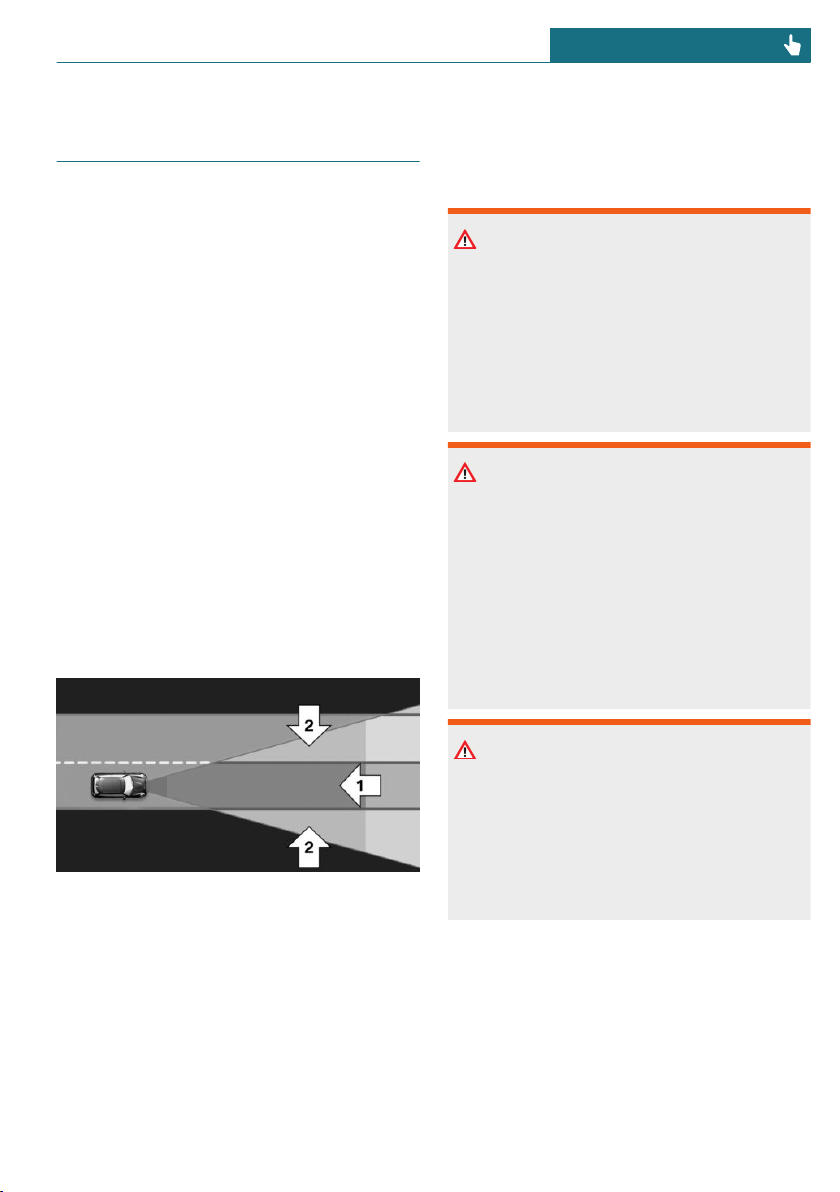
Daytime pedestrian collision
mitigation
Concept
The system may prevent some accidents
with pedestrians.
When driving at city speeds, the system
will issue a warning if there is imminent
risk of a collision with pedestrians, and sup-
port this with a light braking function.
The camera at the base of the interior mir-
ror controls the system.
General information
In sufficiently bright conditions, the system
issues a warning of a possible risk of colli-
sion with pedestrians in the speed range
from approx. 6 mph/10 km/h to approx.
35 mph/60 km/h
The system reacts to people who are within
the detection range of the system.
Detection range
The detection area in front of the vehicle is
divided into two areas:
– Central area, arrow 1, directly in front of
the vehicle.
– Expanded area, arrow 2, to the right and
left of the central area.
A collision is imminent if pedestrians are lo-
cated within the central area. A warning is
issued about pedestrians who are located
within the extended area only if they are
moving in the direction of the central area.
Safety information
Warning
The system cannot serve as a substitute
for the driver’s personal judgment in as-
sessing visibility and traffic situation.
There is a risk of accident. Adjust driving
style to traffic conditions. Watch traffic
closely and actively intervene where ap-
propriate.
Warning
Indicators and warnings cannot serve as a
substitute for the driver’s personal judg-
ment. Due to its limits, the system may not
issue warnings or reactions, or these may
be issued late or in a manner that is not
consistent with their normal use. There is
a risk of accident. Adjust driving style to
traffic conditions. Watch traffic closely
and actively intervene where appropriate.
Warning
Due to system limits, individual functions
can malfunction during tow-starting/
towing with the Intelligent Safety systems
activated. There is a risk of accident.
Switch all Intelligent Safety systems off
prior to tow-starting/towing.
Seite 153
Safety CONTROLS
153
Online Edition for Part no. 01402667083 - VI/19
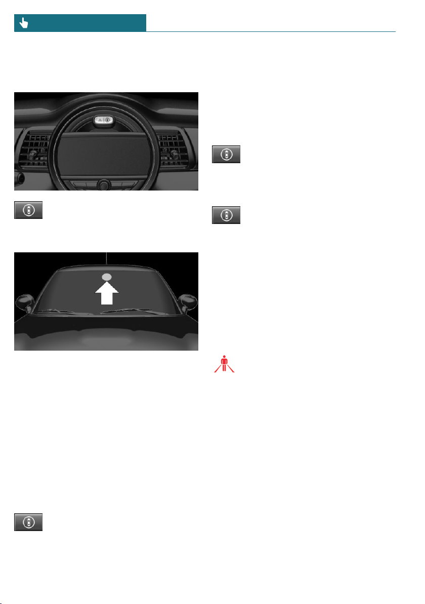
Overview
Button in the vehicle
Intelligent Safety button
Camera
The camera is installed near the interior
mirror.
Keep the windshield in front of the interior
mirror clean and clear.
Switching on/off
Switching on automatically
The system is automatically active after ev-
ery driving off.
Switching on/off manually
Press button briefly:
– The menu for the Intelligent
Safety system is displayed. The
systems are individually
switched off according to their
respective settings.
– LED lights up orange or goes out respec-
tive to their individual settings.
Adjust the settings as needed. The individ-
ual settings are stored for the driver profile
currently in use.
Press button again:
– All Intelligent Safety systems
are switched on.
– The LED lights up green.
Hold down button:
– All Intelligent Safety systems
are switched off.
– The LED goes out.
Warning with braking function
Display
If a collision with a person detected in this
way is imminent, a warning symbol appears
on the instrument cluster.
The red symbol is displayed and a
signal sounds.
Intervene immediately by braking or
make an evasive maneuver.
Braking intervention
The warning prompts the driver to inter-
vene. During a warning, the maximum brak-
ing force is used. In order to activate the
Brake Assistant function, you must apply
the brakes quickly and forcefully. If there is
a risk of collision, the system may assist
with braking. When the vehicle is traveling
at a low speed, the vehicle may come to a
complete stop.
Manual transmission: during a braking in-
tervention up to a complete stop, the engine
may be shut down.
Seite 154
CONTROLS Safety
154
Online Edition for Part no. 01402667083 - VI/19

The braking intervention occurs only if ve-
hicle stability has not been restricted,
for instance by deactivating the DSC Dy-
namic Stability Control.
The driver may interrupt the braking inter-
vention function by stepping on the acceler-
ator pedal or by actively moving the steer-
ing wheel.
The system’s ability to detect objects may
be limited in some circumstances. Refer to
the information in this Owner’s Manual re-
garding the limitations of the system and
actively intervene as warranted.
System limits
Safety information
Warning
The system is designed to operate in cer-
tain conditions and circumstances. Due to
conditions or other factors, the system
may not respond. There may be a risk of
accident or risk of damage to property. Ac-
tively intervene as warranted. Refer to the
information in this Owner’s Manual re-
garding the scope of the system’s opera-
tion and limitations.
Detection range
The detection potential of the camera is lim-
ited.
Thus, a warning might not be issued or be
issued late.
The following situations may not be de-
tected, for example:
– Partially covered pedestrians.
– Pedestrians that are not detected as
such because of the viewing angle or
contour.
– Pedestrians outside of the detection
range.
– Pedestrians having a body size less than
32 in/80 cm.
Functional limitations
The system may not be fully functional or
may not be available in the following situa-
tions:
– In heavy fog, wet conditions, or snow-
fall.
– In tight curves.
– If the field of view of the camera or the
windshield is dirty or covered.
– If the driving stability control systems
are deactivated, for instance DSC OFF.
– Up to 10 seconds after the start of the
engine via the Start/Stop button.
– During calibration of the camera imme-
diately after vehicle delivery.
– If there are constant blinding effects be-
cause of oncoming light, for instance
from the sun low in the sky.
– When it is dark outside.
Brake force display
Concept
Additional brake lights indicate emergency
braking to the traffic behind. This can re-
duce the risk of a rear-end collision.
Seite 155
Safety CONTROLS
155
Online Edition for Part no. 01402667083 - VI/19

General information
– During normal brake application, the
brake lights light up.
– During heavy brake application, the
flashers additionally light up.
PostCrash – iBrake
Concept
In the event of an accident, the system can
bring the vehicle to a halt automatically
without intervention by the driver in cer-
tain situations. This can reduce the risk of a
further collision and the consequences
thereof.
At standstill
After coming to a halt, the brake is released
automatically. Secure the vehicle against
rolling.
Harder vehicle braking
In certain situations, it can be necessary to
bring the vehicle to a halt more quickly than
the Brake Assistant allows.
To do this, quickly apply extra force to the
brake. For a brief period, the braking pres-
sure will be higher than the braking pres-
sure that is achieved by the automatic brak-
ing function. This interrupts automatic
braking.
Interrupting automatic braking
It can be necessary to interrupt automatic
braking in certain situations, for instance
for an evasive maneuver.
Interrupt automatic braking:
– By pressing the brake pedal.
– By pressing the accelerator pedal.
Seite 156
CONTROLS Safety
156
Online Edition for Part no. 01402667083 - VI/19

Driving stability control systems
Vehicle features and options
This chapter describes all standard, country-
specific and optional features offered with
the series. It also describes features that are
not necessarily available in your vehicle, for
instance, due to the selected options or
country versions. This also applies to safety-
related functions and systems. When using
these functions and systems, the applicable
laws and regulations must be observed.
Anti-lock Braking System ABS
ABS prevents locking of the wheels during
braking.
The vehicle maintains its steering power
even during full brake applications, thus in-
creasing active safety.
ABS is operational every time you start the
engine.
Brake assistant
When you apply the brakes rapidly, this sys-
tem automatically boosts the vehicle brak-
ing capability to the furthest possible ex-
tent. It reduces the braking distance to a
minimum during an emergency stop. This
system utilizes all of the capabilities pro-
vided by the Antilock Brake System ABS.
Do not reduce the pressure on the brake
pedal for the duration of the emergency
stop.
DSC Dynamic Stability Control
Concept
Within the physical limits, the system helps
to keep the vehicle on a steady course by
reducing engine speed and by applying
brakes to the individual wheels.
General information
DSC detects the following unstable driving
conditions, for instance:
– Fishtailing, which can lead to oversteer-
ing.
– Loss of traction of the front wheels,
which can lead to understeering.
Dynamic Traction Control DTC, refer to
page 158, is a version of the DSC where for-
ward momentum is optimized.
Safety information
Warning
The system cannot serve as a substitute
for the driver’s personal judgment in as-
sessing the traffic conditions. Based on
the limits of the system, it cannot inde-
pendently react to all traffic situations.
There is a risk of accident. Adjust driving
style to traffic conditions. Watch traffic
closely and actively intervene where ap-
propriate.
Warning
When driving with a roof load, for in-
stance with roof-mounted luggage rack,
the vehicle's center of gravity is higher,
which increases the risk of the vehicle tip-
ping in critical driving situations. There
Seite 157
Driving stability control systems CONTROLS
157
Online Edition for Part no. 01402667083 - VI/19
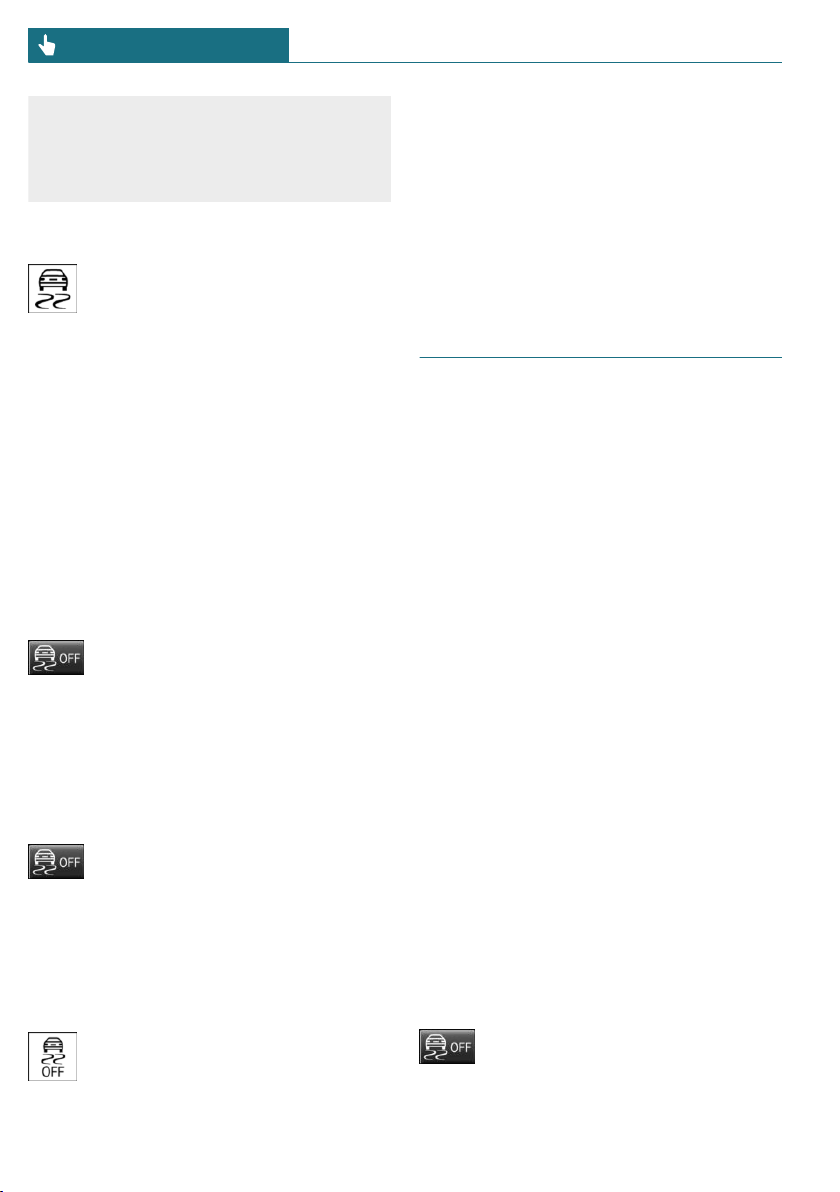
may be a risk of accident or risk of damage
to property. Do not deactivate DSC Dy-
namic Stability Control when driving with
roof load.
Indicator/warning lights
The indicator light flashes: DSC con-
trols the drive and braking forces.
The indicator light lights up: DSC has
malfunctioned.
Deactivating DSC: DSC OFF
General information
When DSC is deactivated, driving stability
is reduced during acceleration and when
driving in curves.
To increase vehicle stability, activate DSC
again as soon as possible.
Deactivating DSC
Press and hold this button but not
longer than approx. 10 seconds, un-
til the indicator light for DSC OFF
lights up in the instrument cluster and dis-
plays DSC OFF.
DSC is switched off.
Activating DSC
Press the button.
DSC OFF and the DSC OFF indicator
light go out.
Indicator/warning lights
When DSC is deactivated, DSC OFF is dis-
played in the instrument cluster.
The indicator light lights up: DSC is
deactivated.
Automatic activation
When DSC is deactivated, automatic activa-
tion occurs in the following situations:
– The vehicle has a flat tire.
– When activating cruise control in
TRACTION or DSC OFF mode.
DTC Dynamic Traction Con-
trol
Concept
DTC is a version of the DSC Dynamic Stabil-
ity Control where forward momentum is op-
timized.
The system ensures maximum headway on
special road conditions, for instance unp-
lowed snowy roads or loose road surfaces,
but with somewhat limited vehicle stability.
When DTC is activated, the vehicle has
maximum traction. Driving stability is lim-
ited during acceleration and when driving
in curves.
Drive carefully.
You may find it useful to briefly activate
DTC under the following special circum-
stances:
– When driving in slush or on uncleared,
snow-covered roads.
– When driving off from deep snow or
loose ground.
– When driving with snow chains.
Deactivating/activating DTC
Dynamic Traction Control
Activating DTC
Press the button.
Seite 158
CONTROLS Driving stability control systems
158
Online Edition for Part no. 01402667083 - VI/19
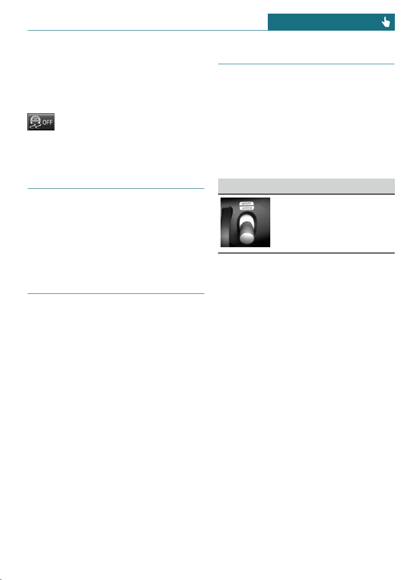
TRACTION is displayed in the instrument
cluster and the indicator light for DSC OFF
lights up.
Deactivating DTC
Press the button again.
TRACTION and the DSC OFF indica-
tor light go out.
Performance Control
Performance Control enhances the agility of
the vehicle.
To increase maneuverability, wheels are
braked individually when a sporty driving
style is used.
Adaptive chassis
Concept
The tuning of the suspension can be
changed with the system.
The system offers several different pro-
grams.
The programs are selected via the MINI
Driving Modes switch.
Programs
MID/GREEN
Balanced tuning of the shock absorbers for
more comfort.
SPORT
Consistently sporty tuning of the shock ab-
sorbers for greater driving agility.
MINI Driving Modes switch
Concept
The MINI Driving Modes switch helps to
fine-tune the vehicle's settings and features.
Choose between three different programs.
Pressing the MINI Driving Modes switch
will activate the particular program.
Operating the programs
MINI Driving Modes switch Program
SPORT
MID
GREEN
MID
MID provides balanced tuning.
With each starting operation, MID is acti-
vated using the Start/Stop button.
GREEN
Concept
GREEN, refer to page 216, provides consis-
tent tuning to maximize range.
Activating GREEN
Press the MINI Driving Modes switch
downward until GREEN is displayed in the
instrument cluster.
Configuring GREEN
Via MINI Driving Modes switch
1. Activate GREEN.
2. "Configure GREEN"
3. Configure the program.
Seite 159
Driving stability control systems CONTROLS
159
Online Edition for Part no. 01402667083 - VI/19
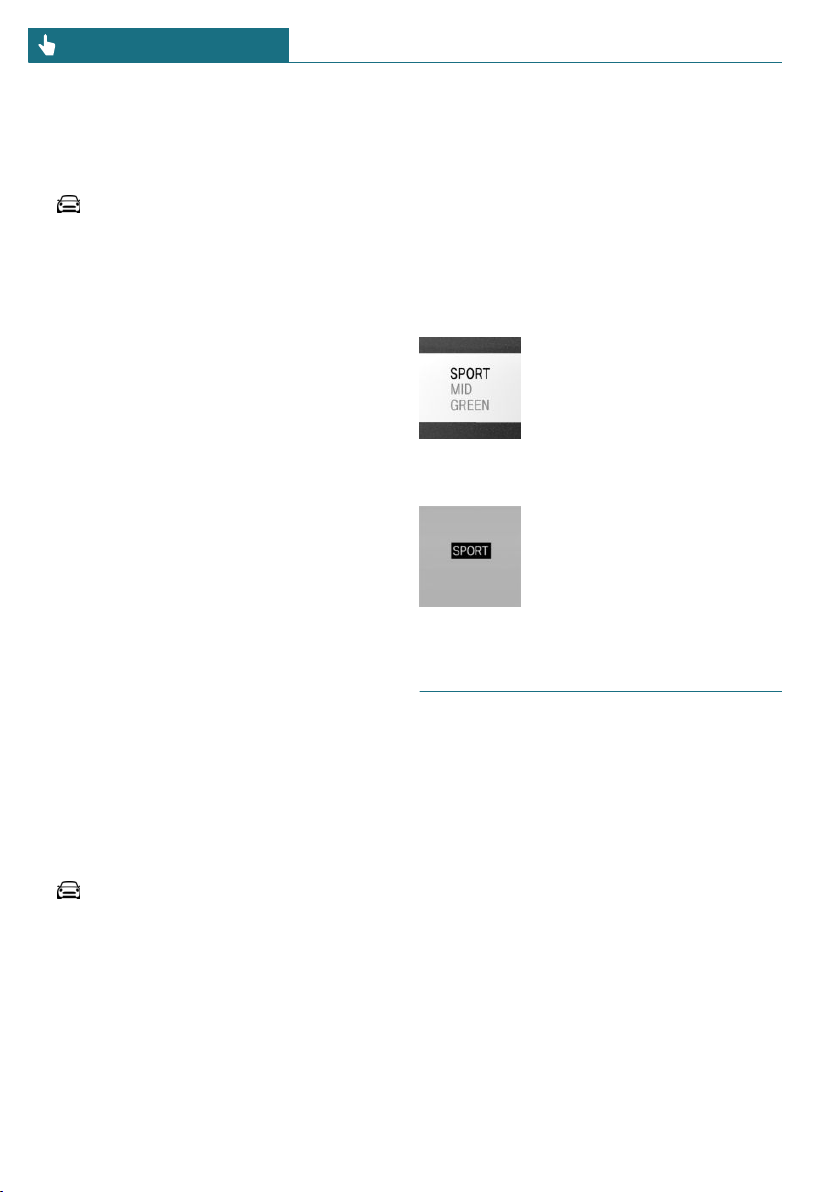
This configuration is retrieved when
GREEN is activated.
Via the Central Information Display (CID)
1. "My MINI"
2. "Vehicle settings"
3. If necessary, "Driving mode"
4. "Configure GREEN"
5. Select the desired setting.
This configuration is retrieved when
GREEN is activated.
SPORT
Concept
Consistently sporty tuning of the drivetrain
for greater driving agility.
Depending on the vehicle equipment, the
tuning of the chassis and suspension also
changes and SPORT can be individually
configured.
The configuration is stored for the driver
profile currently in use.
Activating SPORT
Press the MINI Driving Modes switch up-
ward until SPORT is displayed in the instru-
ment cluster.
Configuring SPORT
Via the Central Information Display (CID):
1. "My MINI"
2. "Vehicle settings"
3. If necessary, "Driving mode"
4. "Configure SPORT"
5. Select the desired setting.
This configuration is retrieved when SPORT
is activated.
Configuring driving program
Settings can be made for the following driv-
ing programs in Driving mode:
– GREEN, refer to page 159.
– SPORT, refer to page 160.
Displays
Program selection
Pressing the MINI Driving
Modes switch displays a list of
programs, which can be se-
lected.
Selected program
The instrument cluster dis-
plays the selected program.
Drive-off assistant
Concept
This system supports driving off on uphill
grades. The parking brake is not required.
Driving off with the drive-off
assistant
1. Hold the vehicle in place with the foot
brake.
2. Release the foot brake and drive off
without delay.
After the foot brake is released, the vehicle
is held in place for approx. 2 seconds.
Seite 160
CONTROLS Driving stability control systems
160
Online Edition for Part no. 01402667083 - VI/19

Servotronic
Servotronic is a speed-dependent power
steering function.
The system provides the steering force with
more support at low speeds than at higher
ones. This makes it easier to park, for in-
stance, and makes steering firmer when
driving at faster speeds.
Furthermore, the steering force adapts ac-
cording to the driving program, so that a
firm, sporty feel or a comfortable steering
response is conveyed.
Seite 161
Driving stability control systems CONTROLS
161
Online Edition for Part no. 01402667083 - VI/19
Driving comfort
Vehicle features and options
This chapter describes all standard, country-
specific and optional features offered with
the series. It also describes features that are
not necessarily available in your vehicle, for
instance, due to the selected options or
country versions. This also applies to safety-
related functions and systems. When using
these functions and systems, the applicable
laws and regulations must be observed.
Camera-based cruise control
Concept
Using this system, a desired speed and a
distance to a vehicle ahead can be adjusted
using the buttons on the steering wheel.
The system maintains the desired speed on
clear roads. For this purpose, the vehicle ac-
celerates or brakes automatically.
If a vehicle is driving ahead of you, the sys-
tem adjusts the speed of your vehicle so
that the set distance to the vehicle ahead is
maintained. The speed is adjusted as far as
the given situation allows.
The distance can be adjusted in several
steps. For safety reasons, it depends on the
respective speed.
General information
A camera on the interior mirror is used to
detect vehicles driving ahead.
Depending on the settings, the characteris-
tics of cruise control many change in cer-
tain ranges.
Safety information
Warning
The system cannot serve as a substitute
for the driver’s personal judgment in as-
sessing the traffic conditions. Based on
the limits of the system, it cannot inde-
pendently react to all traffic situations.
There is a risk of accident. Adjust driving
style to traffic conditions. Watch traffic
closely and actively intervene where ap-
propriate.
Warning
The desired speed can be incorrectly ad-
justed or called up by mistake. There is a
risk of accident. Adjust the desired speed
to the traffic conditions. Watch traffic
closely and actively intervene where ap-
propriate.
Warning
Risk of accident due to too high speed dif-
ferences to other vehicles, for instance in
the following situations:
– When fast approaching a slowly mov-
ing vehicle.
– Vehicle suddenly swerving into own
lane.
– When fast approaching standing ve-
hicles.
There is a risk of injuries or danger to life.
Watch traffic closely and actively inter-
vene where appropriate.
Seite 162
CONTROLS Driving comfort
162
Online Edition for Part no. 01402667083 - VI/19
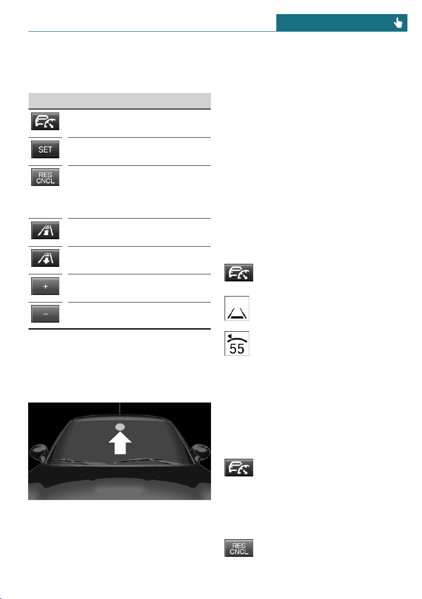
Overview
Buttons on the steering wheel
Button Function
Cruise control on/off, refer to
page 163.
Store/maintain speed, refer to
page 164.
Pause cruise control, refer to
page 163.
Continue cruise control with the
last setting, refer to page 165.
Reduce distance, refer to
page 164.
Increase the distance, refer to
page 164.
Increase speed, refer to
page 164.
Reduce speed, refer to page 164.
Buttons are arranged according to vehicle's
series, optional features and country speci-
fications.
Camera
The camera is installed near the interior
mirror.
Keep the windshield in front of the interior
mirror clean and clear.
Functional requirements
Speed range
The system is best used on well-constructed
roads.
The system is functional at speeds begin-
ning at approx. 20 mph/30 km/h.
The max. speed that can be set is
85 mph/140 km/h.
Active cruise control is paused below ap-
prox. 20 mph/30 km/h. The system does not
brake to a stop.
Switching on/off and interrupting
cruise control
Switching on
Press the button on the steering
wheel.
Display in the instrument cluster
lights up.
Display in the instrument cluster
lights up. The current speed is
adopted as desired speed and dis-
played with symbol.
Cruise control is active and maintains the
set speed.
DSC Dynamic Stability Control is switched
on, if necessary.
Switching off
Press the button on the steering
wheel.
The displays go out. The stored desired
speed is deleted.
Interrupting manually
Press the button on the steering
wheel.
Seite 163
Driving comfort CONTROLS
163
Online Edition for Part no. 01402667083 - VI/19

Interrupting automatically
The system is automatically interrupted in
the following situations:
– When the driver applies the brakes.
– Manual transmission: when the clutch
pedal is depressed for a few seconds or
released while a gear is not engaged.
– If selector lever position N is set.
– Dynamic Traction Control DTC is acti-
vated or DSC Dynamic Stability Control
is deactivated.
– If DSC Dynamic Stability Control inter-
venes.
– If the detection range of the camera is
impaired, for instance by soiling, heavy
precipitation or glare effects from the
sun.
– If the vehicle in front decelerates below
a speed of approx. 20 mph/30 km/h.
Setting the speed
Maintaining/storing the speed
Press or button in the interrupted
state.
When the system is switched on, the cur-
rent speed is maintained and stored as the
desired speed.
The stored speed is displayed on the
symbol.
DSC Dynamic Stability Control is
switched on, if necessary.
The speed can also be stored as follows:
Press the button.
Changing the speed
or button: press until the desired
speed is set.
If active, the displayed speed is stored and
the vehicle reaches the stored speed when
the road is clear.
– or button: each time it is pressed
to the point of resistance, the desired
speed increases or decreases by approx.
1 mph/1 km/h.
– or button: each time it is pressed
past the resistance point, the desired
speed changes by a maximum of 5 mph/
10 km/h.
or button: hold down to repeat the
action.
Adjusting the distance
Safety information
Warning
The system cannot serve as a substitute
for the driver’s personal judgment. Due to
the system limits, braking can be late.
There may be a risk of accident or risk of
damage to property. Be aware to the traffic
situation at all times. Adjust the distance
to the traffic and weather conditions and
maintain the prescribed safety distance,
possibly by braking.
Reduce distance
Press the button repeatedly until
the desired distance is set.
The set distance is briefly displayed
in the left part of the instrument
cluster.
Increase the distance
Press the button repeatedly until
the desired distance is set.
Seite 164
CONTROLS Driving comfort
164
Online Edition for Part no. 01402667083 - VI/19
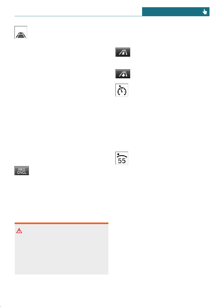
The set distance is briefly displayed
in the left part of the instrument
cluster.
Continuing cruise control
General information
An interrupted cruise control can be contin-
ued by calling up the stored speed.
Make sure that the difference between cur-
rent speed and stored speed is not too large
before calling up the stored speed. Other-
wise, unintentional braking or accelerating
may occur.
In the following cases, the stored speed
value is deleted and cannot be called up
again:
– When the system is switched off.
– When the ignition is switched off.
Calling up the stored speed and
distance
Press the button with the system in-
terrupted. Cruise control is contin-
ued with the stored values. The se-
lected distance is briefly displayed in the
Info Display.
Switching distance control on/off
Safety information
Warning
The system does not react to traffic driv-
ing ahead of you, but instead maintains
the stored speed. There may be a risk of
accident or risk of damage to property. Ad-
just the desired speed to the traffic condi-
tions and brake as needed.
Switching distance control off
Distance control can be switched off and on
when driving with cruise control activated.
Press and hold this button.
Or:
Press and hold this button.
The indicator light in the instrument
cluster lights up.
To switch distance control back on, press
one of the two buttons again briefly.
After changing over distance control, a
Check Control message is displayed.
Displays in the instrument cluster
Desired speed and stored speed
In addition to the indicator light, the
desired speed is displayed in the Info
Display.
– Display lights up green: system is active,
the display indicates the desired speed.
– Display lights up orange: system is in-
terrupted, the display indicates the
stored speed.
– No display: system is switched off.
If no speed is indicated, it is possible that
the conditions necessary for operation are
not currently fulfilled.
Distance to vehicle ahead of you
Selected distance from the vehicle driving
ahead is briefly displayed in the left hand
portion of the Info Display.
Seite 165
Driving comfort CONTROLS
165
Online Edition for Part no. 01402667083 - VI/19
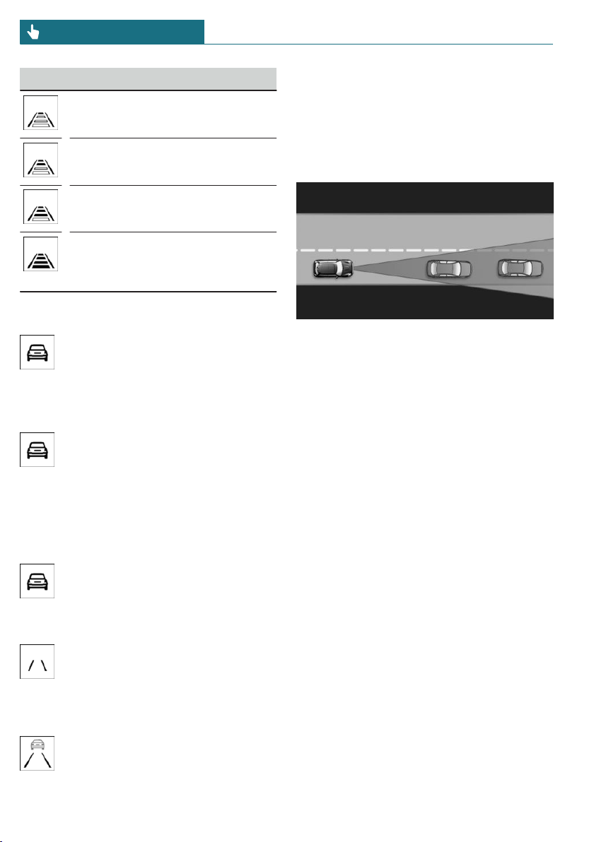
Distance display
Distance 1
Distance 2
Distance 3
Distance 4
This value is set automatically af-
ter the system is switched on.
Detected vehicle
Symbol lights up orange:
A vehicle has been detected ahead of
you.
Indicator/warning lights
Symbol flashes orange:
The conditions are not adequate for
the system to work.
The system was deactivated but applies the
brakes until you actively resume control by
pressing on the brake pedal or accelerator
pedal.
Symbol flashes red and a signal
sounds:
Brake and make an evasive maneu-
ver, if necessary.
The system has been interrupted or
distance control is temporarily sup-
pressed because the accelerator
pedal is being pressed; a vehicle was not de-
tected.
Distance control is temporarily sup-
pressed because the accelerator
pedal is being pressed; a vehicle was de-
tected.
System limits
Detection range
The detection capacity of the system and
the automatic braking capacity are limited.
Two-wheeled vehicles for instance might
not be detected.
Deceleration
The system does not decelerate in the fol-
lowing situations:
– For pedestrians, cyclists or similarly
slow-moving road users.
– For red traffic lights.
– For cross traffic.
– For oncoming traffic.
– Unlit vehicles or vehicles with nonwork-
ing lighting at night.
Seite 166
CONTROLS Driving comfort
166
Online Edition for Part no. 01402667083 - VI/19
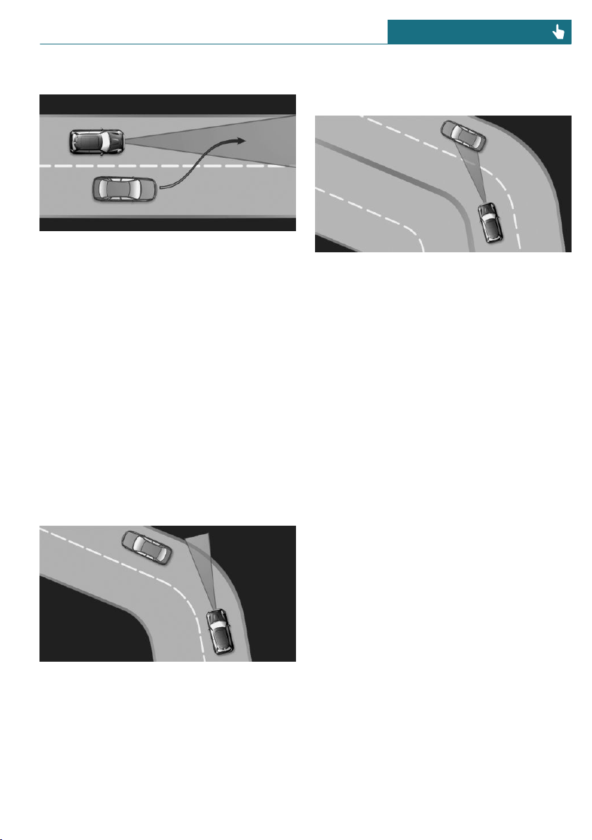
Swerving vehicles
A vehicle driving in front of you is not de-
tected until it is completely within the same
lane as your vehicle.
If a vehicle driving ahead of you suddenly
swerves into your lane, the system may not
be able to automatically restore the selected
distance. It may not be possible to restore
the selected distance in certain situations,
including if you are driving significantly
faster than vehicles driving ahead of you,
for instance when rapidly approaching a
truck. When a vehicle driving ahead of you
is reliably detected, the system requests
that the driver intervene by braking and
carrying out evasive maneuvers, if needed.
Cornering
If the desired speed is too high for a curve,
the speed is reduced slightly, although
curves cannot be anticipated in advance.
Therefore, drive into a curve at an appropri-
ate speed.
The system has a limited detection range.
Situations can arise in tight curves where a
vehicle driving ahead will not be detected
or will be detected very late.
When you approach a curve the system may
briefly report vehicles in the next lane due
to the bend of the curve. If the system de-
celerates you may compensate it by briefly
accelerating. After releasing the accelerator
pedal the system is reactivated and controls
speed independently.
Weather
The following restrictions can occur under
unfavorable weather or light conditions:
– Poorer vehicle recognition.
– Short-term interruptions for vehicles
that are already recognized.
Examples of unfavorable weather or light
conditions:
– Wet conditions.
– Snowfall.
– Slush.
– Fog.
– Glare.
Drive attentively, and react to the current
traffic situation. If necessary, intervene ac-
tively, for instance by braking, steering or
evading.
Engine power
The desired speed may not be maintained
on uphill grades if engine power is insuffi-
cient.
Seite 167
Driving comfort CONTROLS
167
Online Edition for Part no. 01402667083 - VI/19
Malfunction
A Check Control message is displayed if the
system fails or was automatically deacti-
vated.
The system may not be fully functional in
the following situations:
– When an object was not correctly de-
tected.
– In heavy fog, wet conditions, or snow-
fall.
– In tight curves.
– If the field of view of the camera or the
windshield is dirty or covered.
– When driving toward bright lights.
– Up to 20 seconds after the start of the
engine, via the Start/Stop button.
– During calibration of the camera imme-
diately after vehicle delivery.
Cruise control
Concept
Using this system, a desired speed can be
adjusted using the buttons on the steering
wheel. The system maintains the desired
speed. The system accelerates and brakes
automatically as needed.
General information
The system is functional at speeds begin-
ning at approx. 20 mph/30 km/h.
Depending on the settings, the cruise con-
trol settings many change under certain
conditions.
Safety information
Warning
The system cannot serve as a substitute
for the driver’s personal judgment in as-
sessing the traffic conditions. Based on
the limits of the system, it cannot inde-
pendently react to all traffic situations.
There is a risk of accident. Adjust driving
style to traffic conditions. Watch traffic
closely and actively intervene where ap-
propriate.
Warning
The use of the system can lead to an in-
creased risk of accidents in the following
situations, for instance:
– On winding roads.
– In heavy traffic.
– On slippery roads, in fog, snow, or
wet conditions, or on a loose road
surface.
There may be a risk of accident or risk of
damage to property. Only use the system if
driving at constant speed is possible.
Overview
Buttons on the steering wheel
Button Function
Cruise control on/off, refer to
page 169.
Store speed, refer to page 169.
Pause cruise control, refer to
page 169.
Continue cruise control with the
last setting, refer to page 170.
Seite 168
CONTROLS Driving comfort
168
Online Edition for Part no. 01402667083 - VI/19
Button Function
Increase speed, refer to
page 169.
Reduce speed, refer to page 169.
Switching on/off and interrupting
cruise control
Switching on
Press the button on the steering
wheel.
The indicator light in the instrument
cluster lights up.
The current speed is adopted as the
desired speed and is displayed with
the symbol in the instrument cluster.
Cruise control is active and maintains the
set speed.
DSC Dynamic Stability Control is switched
on, if necessary.
Switching off
Press the button on the steering
wheel.
The displays go out. The stored desired
speed is deleted.
Interrupting manually
When active, press the button on
the steering wheel.
Interrupting automatically
The system is automatically interrupted in
the following situations:
– When the driver applies the brakes.
– If the clutch pedal is depressed for a few
seconds or released while a gear is not
engaged.
– If the gear engaged is too high for the
current speed.
– If selector lever position N is set.
– Dynamic Traction Control DTC is acti-
vated or DSC Dynamic Stability Control
is deactivated.
– If DSC Dynamic Stability Control inter-
venes.
Setting the speed
Maintaining/storing the speed
Press or button in the interrupted
state.
When the system is switched on, the cur-
rent speed is maintained and stored as the
desired speed.
The stored speed is displayed in the instru-
ment cluster.
DSC Dynamic Stability Control is switched
on, if necessary.
The speed can also be stored as follows:
Press the button.
Changing the speed
or button: press until the desired
speed is set.
If active, the displayed speed is stored and
the vehicle reaches the stored speed when
the road is clear.
– or button: each time it is pressed
to the point of resistance, the desired
speed increases or decreases by approx.
1 mph/1 km/h.
– or button: each time it is pressed
past the resistance point, the desired
Seite 169
Driving comfort CONTROLS
169
Online Edition for Part no. 01402667083 - VI/19
speed changes by a maximum of 5 mph/
10 km/h.
– or button: pressing it to the re-
sistance point and holding it accelerates
or decelerates the vehicle without re-
quiring pressure on the accelerator
pedal. After the button is released, the
vehicle maintains its final speed. Press-
ing the switch beyond the resistance
point causes the vehicle to accelerate
more rapidly.
Continuing cruise control
General information
An interrupted cruise control can be contin-
ued by calling up the stored speed.
Make sure that the difference between cur-
rent speed and stored speed is not too large
before calling up the stored speed. Other-
wise, unintentional braking or accelerating
may occur.
Calling up the stored speed
Press the button on the steering
wheel.
The stored speed is reached again and main-
tained.
Displays in the instrument cluster
Indicator light
Depending on how the vehicle is
equipped, the indicator light in the
instrument cluster indicates whether
the system is switched on.
Desired speed and stored speed
The desired speed is displayed to-
gether with the symbol.
– Display lights up green: system is active,
the display indicates the desired speed.
– Display lights up orange: system is in-
terrupted, the display indicates the
stored speed.
– No display: system is switched off.
If no speed is indicated, it is possible that
the conditions necessary for operation are
not currently fulfilled.
System limits
Engine power
The desired speed is also maintained down-
hill, but may not be maintained on uphill
grades if engine power is insufficient.
PDC Park Distance Control
Concept
PDC is a support when parking. The system
detects objects behind the vehicle. If the ve-
hicle is equipped with front PDC, objects in
front of the vehicle are detected too. Ob-
jects that you are approaching slowly are in-
dicated by signal tones and a visual display.
General information
The ultrasound sensors for measuring the
distances are located in the bumpers.
The delete range, depending on obstacles
and environmental conditions, is approx.
6 ft/2 m.
An acoustic warning is first given in the fol-
lowing situations:
– By the front middle sensors and the two
corner sensors at approx. 24 in/60 cm
from the object.
– By the rear middle sensors at ap-
prox. 5 ft/1.50 m from the object.
– When a collision is imminent.
Seite 170
CONTROLS Driving comfort
170
Online Edition for Part no. 01402667083 - VI/19
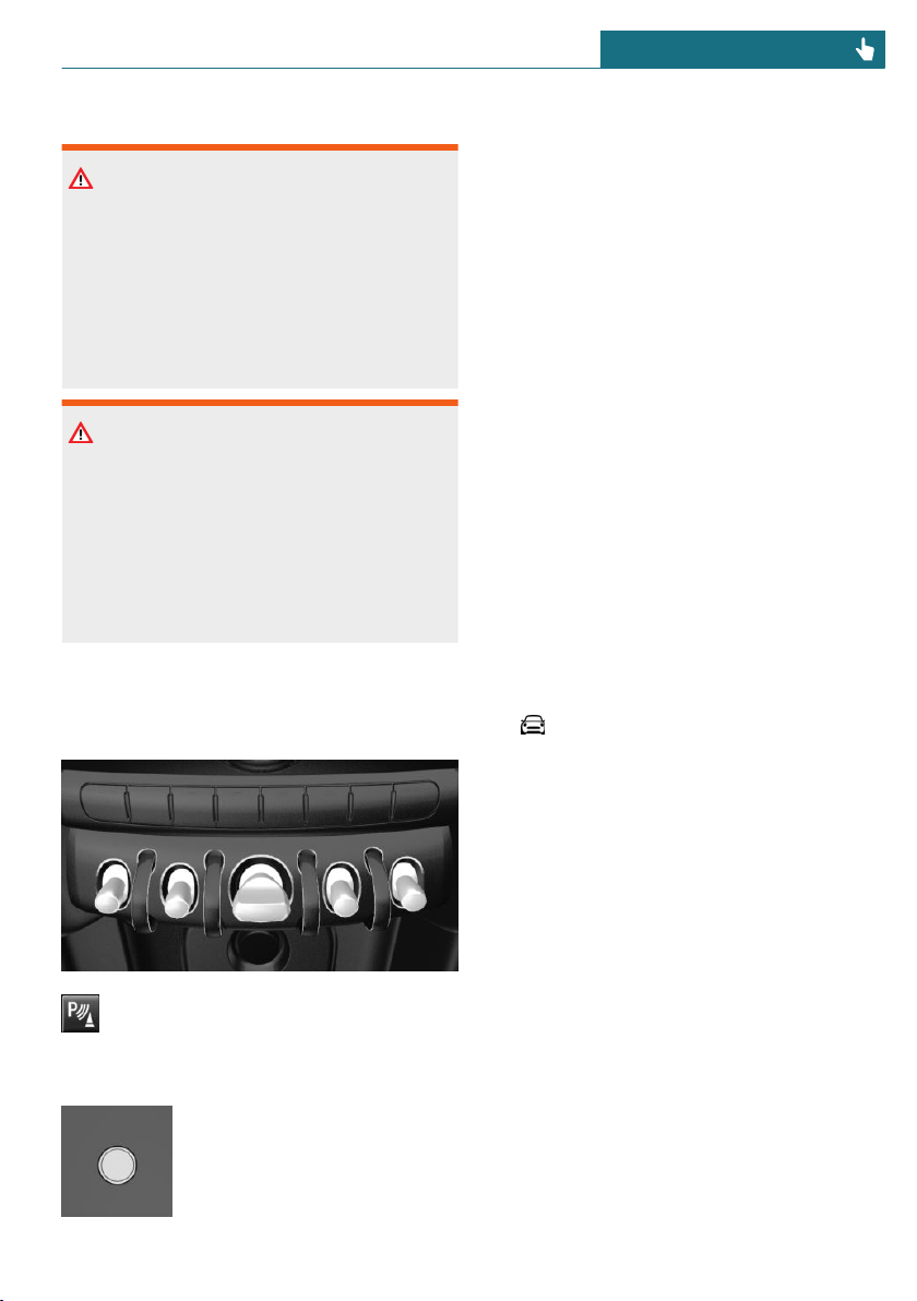
Safety information
Warning
The system cannot serve as a substitute
for the driver’s personal judgment in as-
sessing the traffic conditions. There is a
risk of accident. Adjust driving style to
traffic conditions. Watch traffic and vehi-
cle surroundings closely and actively in-
tervene where appropriate.
Warning
Due to high speeds when PDC Park Dis-
tance Control is activated, the warning can
be delayed due to physical circumstances.
There is a risk of injury or risk of damage
to property. Avoid approaching an object
too fast. Avoid driving off fast while PDC
Park Distance Control is not yet active.
Overview
With front PDC: button in vehicle
Park assistance button
Ultrasound sensors
Ultrasound sensors of the
PDC, for instance in the bump-
ers.
Functional requirements
Ensure full functionality:
– Do not cover sensors, for instance with
stickers, bicycle racks.
– Keep the sensors clean and unob-
structed.
Switching on/off
Switching on automatically
The system switches on automatically in the
following situations:
– If selector lever position R is engaged
when the engine is running.
The rearview camera also switches on.
– With front PDC: when obstacles are de-
tected behind or in front of the vehicle
by PDC and the speed is slower than ap-
prox. 2.5 mph/4 km/h.
With front PDC: automatic activation on ob-
stacle detection can be switched off. Via the
Central Information Display (CID):
1. "My MINI"
2. "Vehicle settings"
3. "Parking"
4. "Automatic PDC activation": depending
on the vehicle equipment.
5. "Automatic PDC activation"
The setting is stored for the driver pro-
file currently used.
Automatic deactivation during
forward travel
The system switches off when a certain
driving distance or speed is exceeded.
Switch the system back on, if needed.
Seite 171
Driving comfort CONTROLS
171
Online Edition for Part no. 01402667083 - VI/19
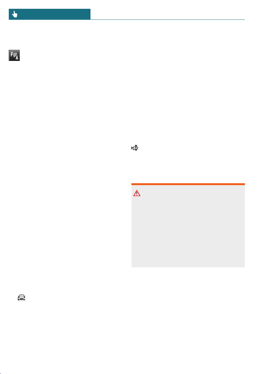
With front PDC: switching on/off
manually
Press the park assistance button.
– On: the LED lights up.
– Off: the LED goes out.
The rearview camera image is displayed if
the reverse gear is engaged when pressing
the park assistance button.
Warning
Signal tones
An intermittent tone indicates when the ve-
hicle is approaching an object. For instance,
if an object is detected to the left rear of the
vehicle, a signal tone sounds from the left
rear speaker.
The shorter the distance to the object, the
shorter the intervals.
If the distance to a detected object is less
than approx. 10 inches/25 cm, a continuous
tone is sounded.
With front PDC: if objects are simultane-
ously located both in front of and behind
the vehicle, an alternating continuous sig-
nal is sounded.
The signal tone is switched off, when selec-
tor lever position P is engaged on vehicles
with Steptronic transmission.
Volume
The ratio of the PDC signal tone volume to
the entertainment volume can be adjusted.
1. "My MINI"
2. "System settings"
3. "Tone"
4. "Volume settings"
5. "PDC"
6. Set the desired value.
The setting is stored for the driver profile
currently used.
Visual warning
The approach of the vehicle to an object can
be shown on the Control Display. Objects
that are farther away are already displayed
on the Control Display before a signal
sounds.
A display appears as soon as Park Distance
Control (PDC) is activated.
The range of the sensors is represented in
colors: red, green and yellow.
When the image of the rearview camera is
displayed, the switch can be made to PDC:
"Rear view camera"
System limits
Safety information
Warning
The system is designed to operate in cer-
tain conditions and circumstances. Due to
conditions or other factors, the system
may not respond. There may be a risk of
accident or risk of damage to property. Ac-
tively intervene as warranted. Refer to the
information in this Owner’s Manual re-
garding the scope of the system’s opera-
tion and limitations.
With rear luggage rack or when the
trailer power socket is in use
The rear PDC functions are switched off.
Limits of ultrasonic measurement
Ultrasonic measuring might not function
under the following circumstances:
– For small children and animals.
Seite 172
CONTROLS Driving comfort
172
Online Edition for Part no. 01402667083 - VI/19

– For persons with certain clothing, for in-
stance coats.
– With external interference of the ultra-
sound, for instance from passing vehi-
cles or loud machines.
– When sensors are dirty, iced over, dam-
aged or out of position.
– If cargo protrudes.
– Under certain weather conditions such
as high relative humidity, wet condi-
tions, snowfall, extreme heat, or strong
wind.
– With tow bars and trailer couplings of
other vehicles.
– With thin or wedge-shaped objects.
– With moving objects.
– With elevated, protruding objects such
as ledges or cargo.
– With objects with corners and sharp
edges.
– With objects with a fine surface struc-
ture such as fences.
– For objects with porous surfaces.
– Low objects already displayed, for in-
stance curbs, can move into the blind
area of the sensors before or after a con-
tinuous tone sounds.
False warnings
The system may issue a warning under the
following conditions even though there is
no obstacle within the detection range:
– In heavy rain.
– When sensors are very dirty or covered
with ice.
– When sensors are covered in snow.
– On rough road surfaces.
– On uneven surfaces, such as speed
bumps.
– In large buildings with right angles and
smooth walls, for instance in under-
ground garages.
– In automatic vehicle washes.
– Due to heavy exhaust.
– Due to other ultrasound sources, for in-
stance sweeping machines, high pres-
sure steam cleaners or neon lights.
The malfunction is signaled by a contin-
uous tone alternating between the front
and rear speakers. As soon as the mal-
function due to other ultrasound sources
is no longer present, the system is again
fully functional.
With front PDC: to reduce false alarms,
switch off automatic PDC activation on ob-
stacle detection, for instance in vehicle
washes; see Switching on/off.
Malfunction
A Check Control message is displayed in the
instrument cluster.
Red symbol is displayed, and the
range of the sensors is dimmed on
the Control Display.
PDC has failed. Have the system checked by
a dealer's service center or another qualified
service center or repair shop.
Rearview camera
Concept
The rearview camera provides assistance in
parking and maneuvering backwards. The
area behind the vehicle is shown on the
Control Display.
Seite 173
Driving comfort CONTROLS
173
Online Edition for Part no. 01402667083 - VI/19
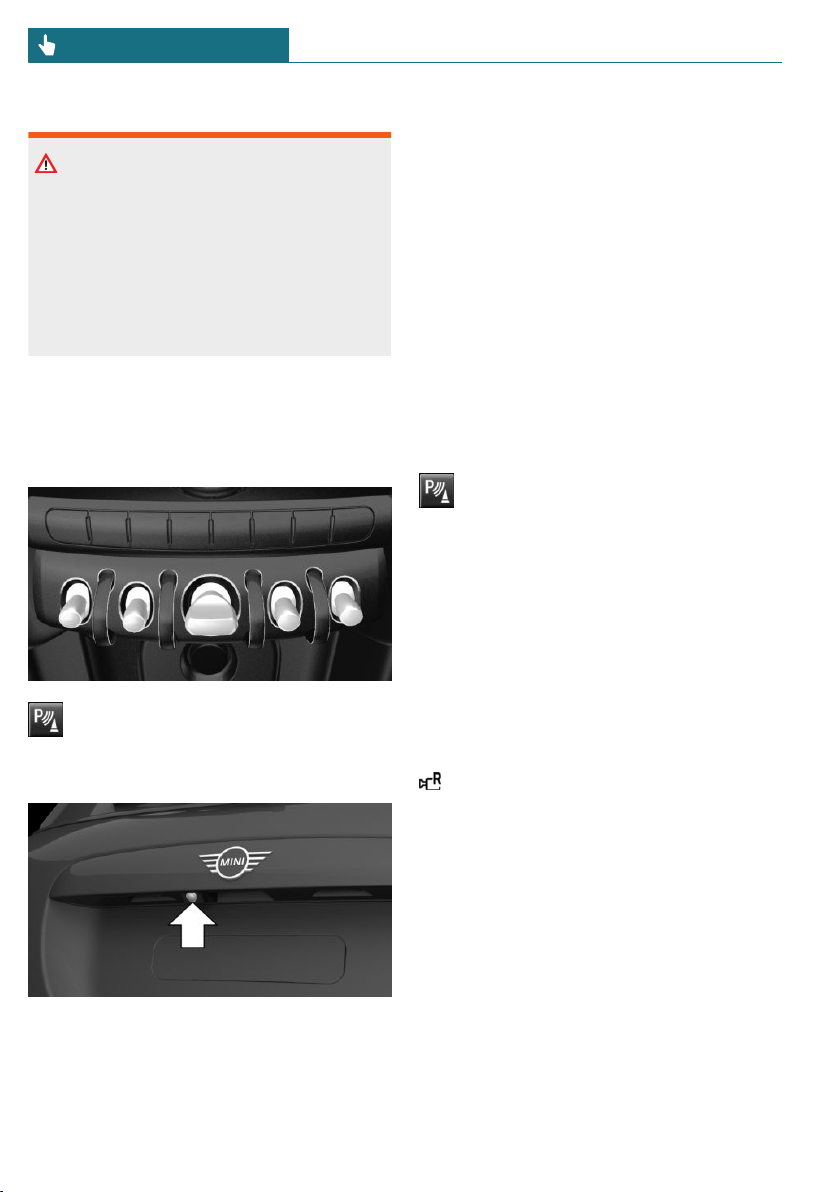
Safety information
Warning
The system cannot serve as a substitute
for the driver’s personal judgment in as-
sessing the traffic conditions. There is a
risk of accident. Adjust driving style to
traffic conditions. Watch traffic and vehi-
cle surroundings closely and actively in-
tervene where appropriate.
Overview
Depending on the vehicle equipment:
button in the vehicle
Park assistance button
Camera
The camera lens is located in the handle of
the tailgate.
The image quality may be impaired by dirt.
If necessary, clean the camera lens.
Switching on/off
Switching on automatically
The system is switched on automatically if
selector lever position R is engaged when
the engine is running.
Automatic deactivation during
forward travel
The system switches off when a certain
driving distance or speed is exceeded.
Switch the system back on, if needed.
Depending on the vehicle equipment:
switching on/off manually
Press the park assistance button.
– On: the LED lights up.
– Off: the LED goes out.
The parking assistance functions are shown
on the Control Display.
Switching the view via the Central
Information Display (CID)
If the rearview camera view is not dis-
played, change the view via the Central In-
formation Display (CID):
"Rear view camera"
The rearview camera image is displayed.
Display on the Control Display
Functional requirement
– The rearview camera is switched on.
– The tailgate is fully closed.
– Keep the recording range of the camera
clear.
Protruding cargo or carrier systems that
are not connected to a trailer power
socket can lead to malfunctions.
Seite 174
CONTROLS Driving comfort
174
Online Edition for Part no. 01402667083 - VI/19
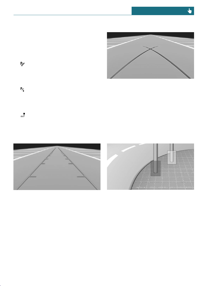
Activating assistance functions
More than one assistance function can be
active at the same time.
The zoom function for trailer operation can
only be activated separately.
– Parking aid lines
"Parking aid lines"
Lanes and turning radius lines are indi-
cated.
– Obstacle marking
"Obstacle marking"
Obstacles are marked, depending on the
vehicle equipment.
– Trailer hitch
"Trailer hitch - zoom"
A zoomed image of the trailer hitch is
shown.
Pathway lines
Pathway lines can be superimposed on the
image of the rearview camera.
Pathway lines help you to estimate the
space required when parking and maneu-
vering on level roads.
Pathway lines depend on the current steer-
ing angle and are continuously adjusted to
the steering wheel movements.
Turning radius lines
Turning radius lines can be superimposed
on the image of the rearview camera.
Turning radius lines show the course of the
smallest possible turning radius on a level
road.
Only one turning radius line is displayed af-
ter the steering wheel is turned past a cer-
tain angle.
Obstacle marking
Depending on the vehicle equipment, obsta-
cle markings can be faded into the image of
the rearview camera.
The colored thresholds of the obstacle mark-
ings match the markings of the PDC Park
Distance Control.
Zoom on trailer hitch
To make it easier to attach a trailer, you can
zoom in on the view of the trailer hitch.
Seite 175
Driving comfort CONTROLS
175
Online Edition for Part no. 01402667083 - VI/19
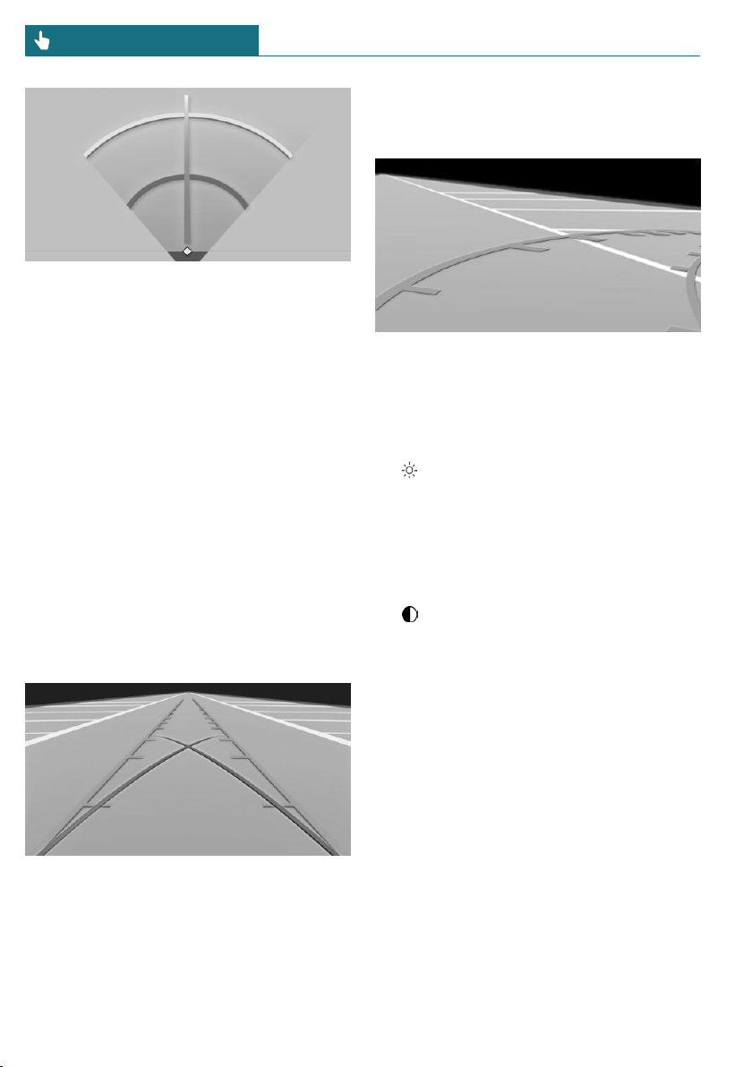
Two static circle segments show the dis-
tance between the trailer and the trailer
hitch.
A docking line dependent on the steering
angle helps with aiming for the trailer with
the trailer hitch.
The zoom function can be activated when
the camera is switched on.
When zooming in, remember that the view
may no longer show certain obstacles.
If necessary, the zoom function can also be
activated when a rear luggage rack is used.
Parking using pathway and turning
radius lines
1. Position the vehicle so that the turning
radius lines lead to within the limits of
the parking space.
2. Turn the steering wheel to the point
where the pathway line covers the cor-
responding turning radius line.
Display settings
Brightness
With the rearview camera switched on:
1. Select the symbol.
2. Turn the Controller until the desired set-
ting is reached and press the Controller.
Contrast
With the rearview camera switched on:
1. Select the symbol.
2. Turn the Controller until the desired set-
ting is reached and press the Controller.
System limits
Detection of objects
Very low obstacles or high, protruding ob-
jects such as ledges may not be recognized
by the system.
Depending on the vehicle equipment, some
assistance functions also consider data from
the PDC Park Distance Control.
Follow the notes in the PDC Park Distance
Control chapter.
The objects displayed on the Control Dis-
play may be closer than they appear. There-
Seite 176
CONTROLS Driving comfort
176
Online Edition for Part no. 01402667083 - VI/19
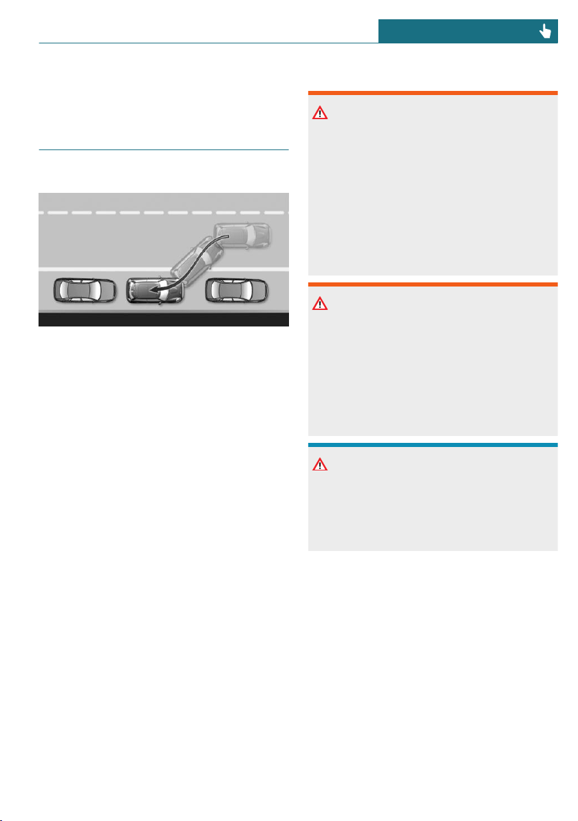
fore, do not estimate the distance from the
objects on the display.
Parking assistant
Concept
This system assists the driver in parking
parallel to the road.
General information
Parking assistant handling is divided into
three steps:
– Switching on and activating.
– Parking space search.
– Parking.
Ultrasound sensors measure parking spaces
on both sides of the vehicle.
The parking assistant calculates the best
possible parking line and takes control of
steering during the parking procedure.
System status and instructions on required
actions are displayed on the Control Dis-
play.
A component of the parking assistant is the
PDC Park Distance Control.
Safety information
Warning
The system cannot serve as a substitute
for the driver’s personal judgment in as-
sessing the traffic conditions. Based on
the limits of the system, it cannot inde-
pendently react to all traffic situations.
There is a risk of accident. Adjust driving
style to traffic conditions. Watch traffic
closely and actively intervene where ap-
propriate.
Warning
If the trailer hitch is used, the parking as-
sistant can cause damage due to covered
sensors. There may be a risk of accident or
risk of damage to property. The parking as-
sistant should not be used during trailer
towing or if the trailer hitch is used, for in-
stance bicycle rack.
NOTICE
The parking assistant can steer the vehicle
over or onto curbs. There is a risk of dam-
age to property. Watch traffic closely and
actively intervene where appropriate.
The safety information of the PDC Park Dis-
tance Control applies in addition.
Seite 177
Driving comfort CONTROLS
177
Online Edition for Part no. 01402667083 - VI/19
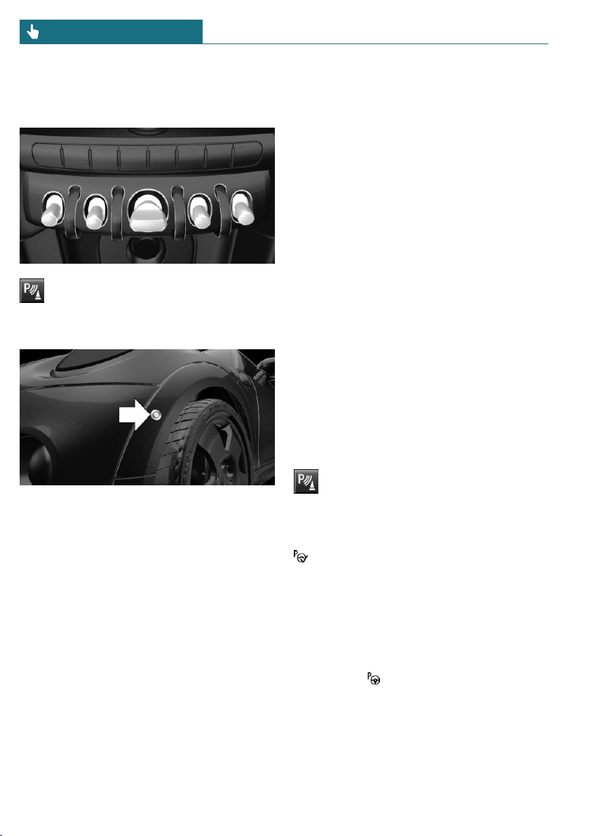
Overview
Button in the vehicle
Park assistance button
Ultrasound sensors
The ultrasound sensors for measuring park-
ing spaces are located on the wheel hous-
ing.
Functional requirements
Ultrasound sensors
Ensure full functionality:
– Do not cover sensors, for instance with
stickers.
– Keep the sensors clean and unob-
structed.
For measuring parking spaces
– Maximum speed while driving forward
approx. 22 mph/35 km/h.
– Maximum distance to row of parked ve-
hicles: 5 ft/1.5 m.
Suitable parking space
– Gaps behind an object that has a min.
length of 5 ft/1.5 m.
– Gap between two objects with a mini-
mum length of approx. 5 ft/1.5 m.
– Min. length of gap between two objects:
your vehicle's length plus approx.
3.3 ft/1.0 m.
– Minimum depth: approx. 5 ft/1.5 m.
For parking
– Doors and tailgate are closed.
– The parking brake is released.
– When parking in parking spaces on the
driver's side, the corresponding turn sig-
nal must be switched on.
Switching on and activating
Switching on with the button
Press the park assistance button.
The LED lights up.
The current status of the parking space
search is indicated on the Control Display.
Parking assistant is activated automati-
cally.
Switching on with reverse gear
Shift into reverse.
The current status of the parking space
search is indicated on the Control Display.
To activate: "Parking Assistant"
Seite 178
CONTROLS Driving comfort
178
Online Edition for Part no. 01402667083 - VI/19
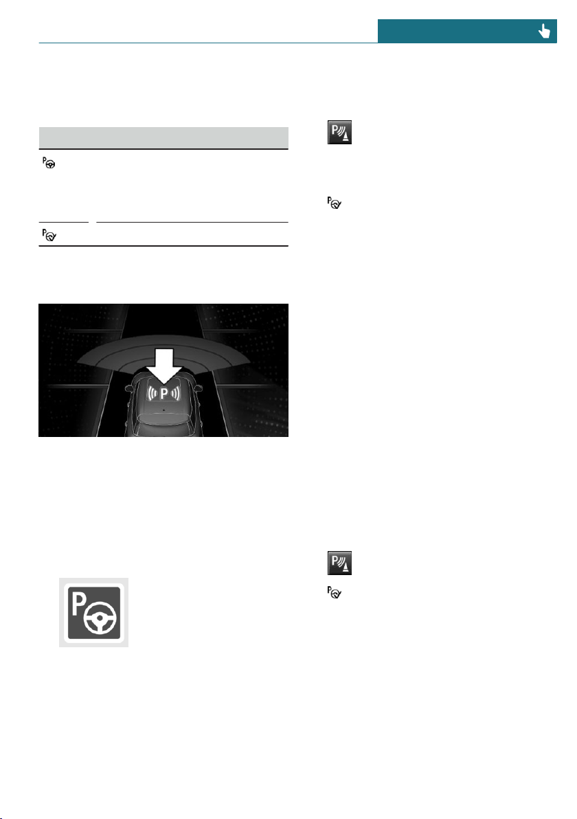
Display on the Control Display
System activated/deactivated
Symbol Meaning
Gray: the system is not availa-
ble.
White: the system is available
but not activated.
The system is activated.
Parking space search and system
status
– Symbol P on the vehicle image: the park-
ing assistant is activated and the park-
ing space search is active.
– Control Display shows suitable parking
spaces at the edge of the road next to
the vehicle symbol. When the parking
assistant is active, suitable parking
spaces are highlighted.
– The parking procedure is
active. Steering control
has been taken over by
system.
– Parking space search is always active
whenever the vehicle is moving forward
slow and straight, even if the system is
deactivated. When the system is deacti-
vated, the displays on the Control Dis-
play are shown in gray.
Parking using the parking assistant
Parking
1. Press the park assistance button or
shift into reverse gear to switch on the
parking assistant, refer to page 178. Ac-
tivate the parking assistant, if needed.
Parking assistant is activated.
2. Pass the row of parked vehicles at a
speed of up to approx. 22 mph/35 km/h
and at a distance of maximum
5 ft/1.5 m.
The status of the parking space search
and possible parking spaces are dis-
played on the display, refer to page 179.
3. Follow the instructions on the display.
The best possible parking position will
come after gear change on the station-
ary vehicle - wait for the automatic
steering wheel move.
The end of the parking procedure is in-
dicated on the display.
4. Adjust the parking position yourself, if
needed.
Interrupting manually
The parking assistant can be interrupted at
any time:
– Press the park assistance button.
– "Parking Assistant"
Interrupting automatically
The system is interrupted automatically in
the following situations:
– If the driver grasps the steering wheel
or takes over steering.
– If a gear is selected that does not match
the instruction on the display.
Seite 179
Driving comfort CONTROLS
179
Online Edition for Part no. 01402667083 - VI/19

– If the vehicle speed exceeds approx.
6 mph/10 km/h.
– Possibly on snow-covered or slippery
road surfaces.
– If a maximum number of parking at-
tempts or the time taken for parking is
exceeded.
– If the PDC Park Distance Control dis-
plays clearances that are too small.
– When switching into other functions of
the radio.
A Check Control message is displayed.
Resuming
An interrupted parking procedure can be
continued, if needed.
Reactivate the parking assistant, refer to
page 178, and follow the instructions on the
display.
Switching off
The system can be switched off as follows:
– Press the park assistance button.
– Switching off the ignition.
System limits
Safety information
Warning
The system is designed to operate in cer-
tain conditions and circumstances. Due to
conditions or other factors, the system
may not respond. There may be a risk of
accident or risk of damage to property. Ac-
tively intervene as warranted. Refer to the
information in this Owner’s Manual re-
garding the scope of the system’s opera-
tion and limitations.
No parking assistance
The parking assistant does not offer assis-
tance in the following situations:
– In tight curves.
– With mounted rear luggage rack.
Functional limitations
The system may not be fully functional in
the following situations:
– On bumpy road surfaces such as gravel
roads.
– On slippery ground.
– With accumulations of leaves/snow in
the parking space.
– With a mounted emergency wheel.
– With ditches or edges, for instance an
edge of a port.
Limits of ultrasonic measurement
Ultrasonic measuring might not function
under the following circumstances:
– For small children and animals.
– For persons with certain clothing, for in-
stance coats.
– With external interference of the ultra-
sound, for instance from passing vehi-
cles or loud machines.
– When sensors are dirty, iced over, dam-
aged or out of position.
– If cargo protrudes.
– Under certain weather conditions such
as high relative humidity, wet condi-
tions, snowfall, extreme heat, or strong
wind.
– With tow bars and trailer couplings of
other vehicles.
– With thin or wedge-shaped objects.
– With moving objects.
– With elevated, protruding objects such
as ledges or cargo.
Seite 180
CONTROLS Driving comfort
180
Online Edition for Part no. 01402667083 - VI/19

– With objects with corners and sharp
edges.
– With objects with a fine surface struc-
ture such as fences.
– For objects with porous surfaces.
– Low objects already displayed, for in-
stance curbs, can move into the blind
area of the sensors before or after a con-
tinuous tone sounds.
– The parking assistant may identify park-
ing spaces that are not suitable for park-
ing.
Tire size
The parking position may vary depending
on the tire size.
Malfunction
A Check Control message is displayed.
The parking assistant failed. Have the sys-
tem checked by a dealer's service center or
another qualified service center or repair
shop.
Seite 181
Driving comfort CONTROLS
181
Online Edition for Part no. 01402667083 - VI/19
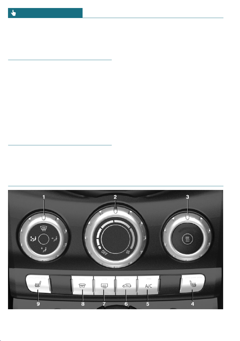
Climate control
Vehicle features and options
This chapter describes all standard, country-
specific and optional features offered with
the series. It also describes features that are
not necessarily available in your vehicle, for
instance, due to the selected options or
country versions. This also applies to safety-
related functions and systems. When using
these functions and systems, the applicable
laws and regulations must be observed.
Interior air quality
The air quality in the vehicle is improved by
the following components:
– Emission tested passenger compart-
ment.
– Microfilter.
– Air conditioning system to control the
temperature, air flow and recirculated-
air mode.
Depending on the equipment specification:
– Microfilter/activated-charcoal filter.
– Automatic climate control.
– Parked-car ventilation.
Air conditioner
1 Air distribution settings 2 Air flow
Seite 182
CONTROLS Climate control
182
Online Edition for Part no. 01402667083 - VI/19
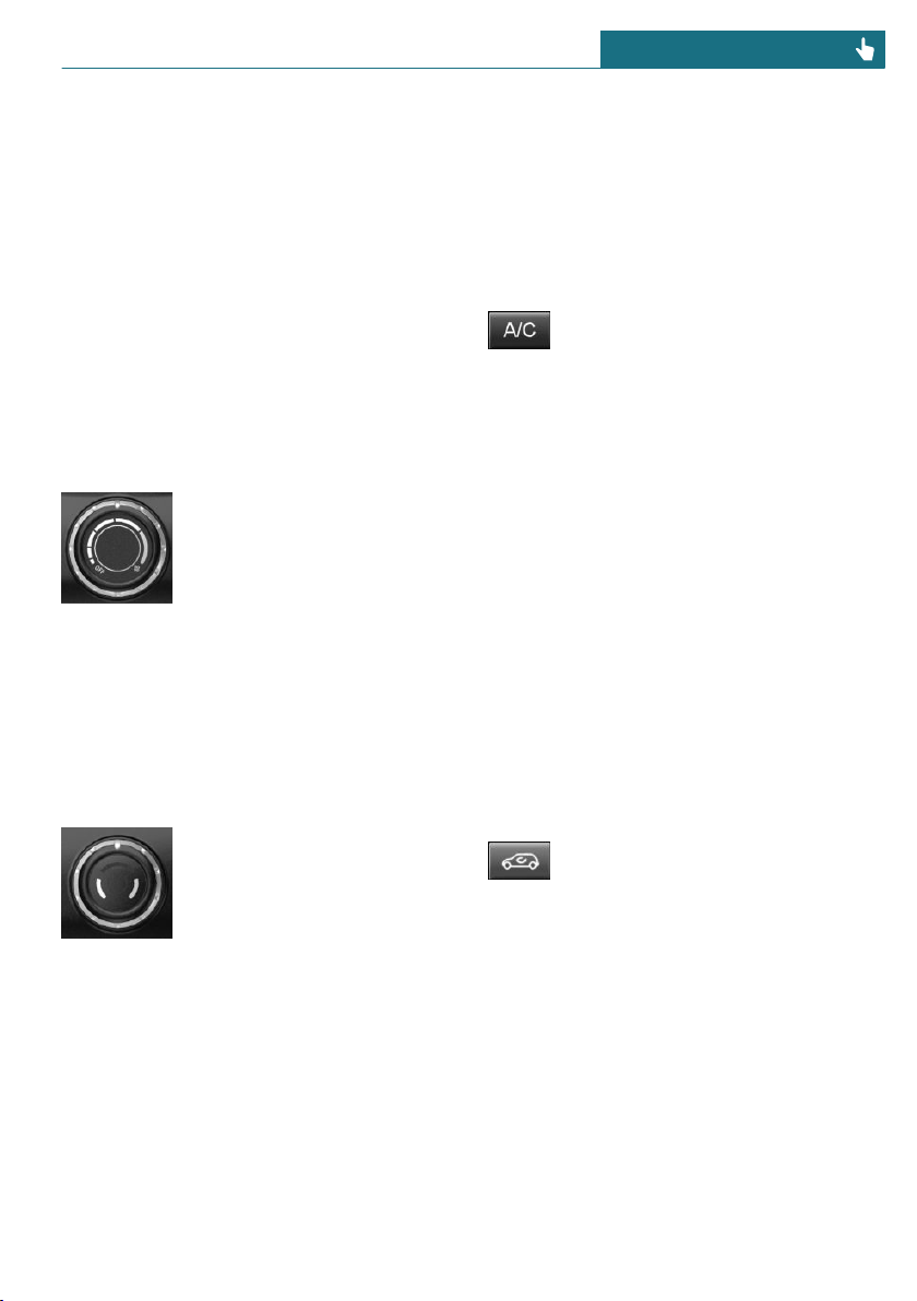
3 Temperature
4 Seat heating, right 78
5 Air conditioning
6 Recirculated-air mode
7 Rear window defroster
8 Windshield defroster
9 Seat heating, left 78
Climate control functions in detail
Switching the system on/off
Switching on
Set any air flow.
Switching off
Turn the wheel for air flow all
the way to the left.
Temperature
Concept
The system heats or cools, depending on the
set temperature.
Adjusting
Turn the wheel to set the de-
sired temperature.
Air conditioning
Concept
The air in the car's interior will be cooled
and dehumidified and, depending on the
temperature setting, warmed again.
The car's interior can only be cooled with
the engine running.
Switching on/off
Press the button.
The LED is illuminated with air con-
ditioning switched on.
Depending on the weather, the windshield
may fog up briefly when the engine is
started.
The air conditioner produces condensation
water, refer to page 213, that will exit from
below the vehicle.
Recirculated-air mode
Concept
You may react to unpleasant odors or pollu-
tants in the immediate environment by tem-
porarily suspending the supply of outside
air. The system then recirculates the air
flow within the vehicle.
Operation
Press the button:
The LED is illuminated when recir-
culated-air mode is switched on. The supply
of outside air is shut off.
When recirculated-air mode is switched off,
fresh air is directed into the vehicle's inte-
rior.
To prevent window condensation, recircu-
lated-air mode switches off automatically af-
ter a certain amount of time, depending on
the external temperature.
With constant recirculated-air mode, the air
quality in the car's interior deteriorates and
window fogging increases.
Seite 183
Climate control CONTROLS
183
Online Edition for Part no. 01402667083 - VI/19
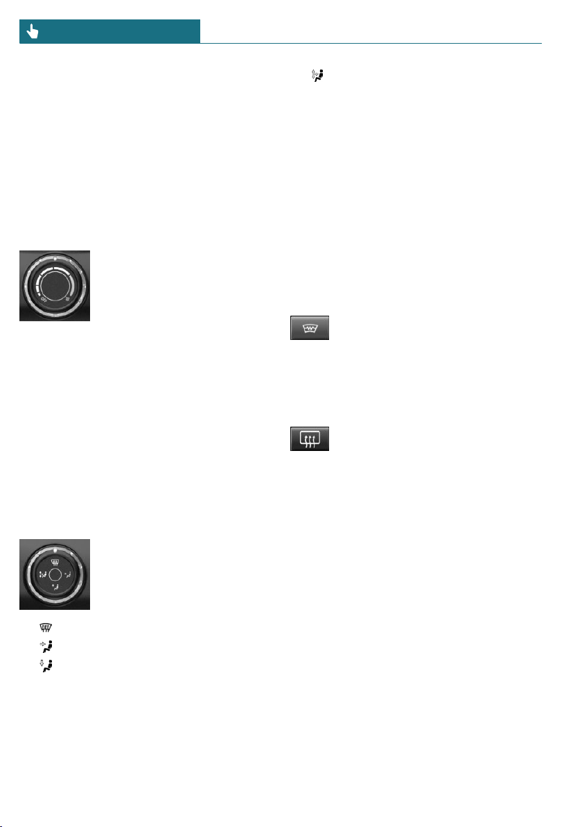
If the windows fog over, switch off recircu-
lated-air mode and increase the air flow, if
needed.
Controlling the air flow manually
Concept
The air flow for climate control can be ad-
justed manually.
Operation
Turn the ring to set the de-
sired air flow.
The higher the air flow, the
more effective the heating or
cooling will be.
The air flow from the air conditioner may be
reduced automatically to save battery
power.
Controlling the air distribution
manually
Concept
The air distribution for climate control can
be adjusted manually.
Operation
Turn the wheel to select the
desired program or the desired
intermediate setting.
– Windows.
– Upper body region.
– Floor area.
– Windows, upper body region, and
floor area.
To defrost windows and remove
condensation
Make the following settings to defrost the
windows and remove condensation:
– Direct the air distribution onto the win-
dows.
– Increasing the air flow.
– Increase the temperature.
– Switch on the air conditioning if needed.
Windshield defroster
Press the button. The LED lights up.
The front window defroster
switches off automatically after a certain
period of time.
Rear window defroster
Press the button. The LED lights up.
The rear window defroster switches
off automatically after a certain period of
time.
When GREEN Mode is activated, the heat-
ing output is reduced.
Microfilter
In external and recirculated-air mode, the
microfilter filters dust and pollen from the
air.
Have this filter changed during vehicle
maintenance, refer to page 288.
Seite 184
CONTROLS Climate control
184
Online Edition for Part no. 01402667083 - VI/19
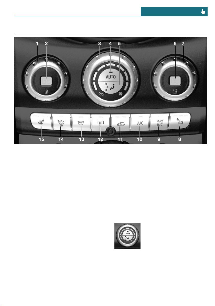
Automatic climate control
1 Temperature, left
2 Display
3 Air flow, AUTO intensity
4 AUTO program
5 Air distribution, manual
6 Display
7 Temperature, right
8 Seat heating, right 78
9 Maximum cooling
10 Air conditioning
11 Recirculated-air mode
12 Rear window defroster
13 Windshield defroster
14 To defrost windows and remove conden-
sation
15 Seat heating, left 78
Climate control functions in detail
Switching the system on/off
Switching on
Set any air flow.
Switching off
Turn wheel for air flow to the
left until the control switches
off.
Temperature
Concept
The automatic climate control achieves the
set temperature as quickly as possible, if
Seite 185
Climate control CONTROLS
185
Online Edition for Part no. 01402667083 - VI/19
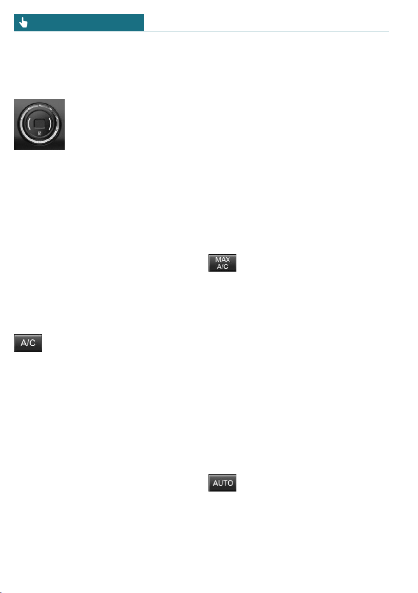
necessary by using the maximum cooling or
heating power, and then keeps it constant.
Adjusting
Turn the wheel to set the de-
sired temperature.
Do not rapidly switch between different
temperature settings. The automatic climate
control will not have sufficient time to ad-
just the set temperature.
Air conditioning
Concept
The air in the car's interior will be cooled
and dehumidified and, depending on the
temperature setting, warmed again.
The car's interior can only be cooled with
the engine running.
Switching on/off
Press the button.
The LED is illuminated with air con-
ditioning switched on.
Depending on the weather, the windshield
may fog up briefly when the engine is
started.
The cooling function is switched on auto-
matically with the AUTO program.
When using the automatic climate control,
condensation water, refer to page 213, de-
velops and drains underneath the vehicle.
This is normal.
Maximum cooling
Concept
The system is set to the lowest temperature,
maximum air flow and recirculated-air
mode.
General information
The function is available with external tem-
peratures beyond approx. 32 ℉/0 ℃ and
with the engine running.
Air flows out of the vents to the upper body
region. The vents need to be open for this.
The air flow can be adjusted with the pro-
gram active.
Switching on/off
Press the button.
The LED is illuminated with the
system switched on.
The system is set to the lowest temperature,
optimum air flow and air circulation mode.
AUTO program
Concept
The AUTO program cools, ventilates or
heats the car's interior automatically.
The air distribution and temperature are
controlled automatically depending on the
temperature in the car's interior and the de-
sired temperature setting including the se-
lected intensity of the air flow.
Switching on/off
Press the button.
The LED is illuminated with the
AUTO program switched on.
Depending on the selected temperature,
AUTO intensity and outside influences, the
Seite 186
CONTROLS Climate control
186
Online Edition for Part no. 01402667083 - VI/19
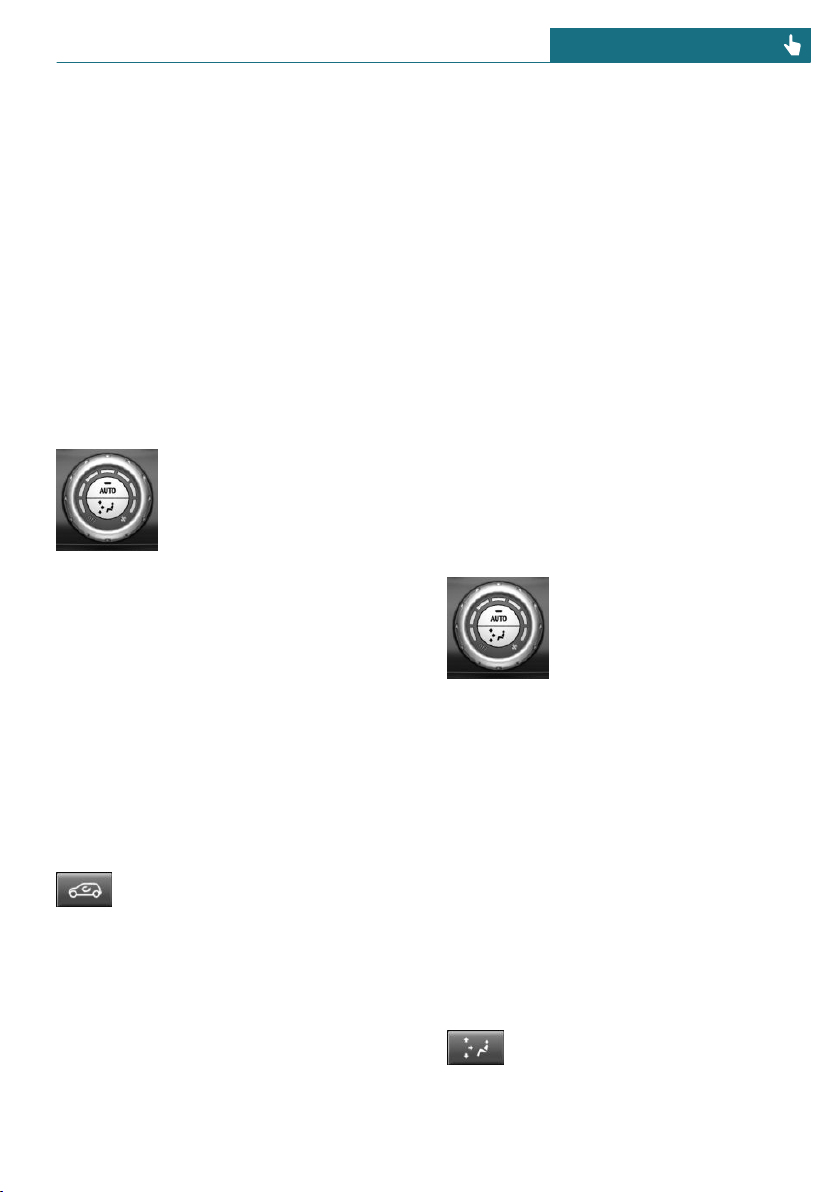
air is directed to the windshield, side win-
dows, upper body, and into the floor area.
Point the side vents toward the side win-
dows.
The following features are switched on au-
tomatically with the AUTO program:
– The air conditioning, refer to page 186.
To switch off the program: press the button
again or manually adjust the air distribu-
tion.
Intensity
With the AUTO program activated, the au-
tomatic intensity control can be changed.
Turn the ring to set the de-
sired intensity from soft to in-
tensive.
The set intensity is displayed via the posi-
tion of the illuminated LED segment.
Recirculated-air mode
Concept
You may react to unpleasant odors or pollu-
tants in the immediate environment by tem-
porarily suspending the supply of outside
air. The system then recirculates the air
flow within the vehicle.
Operation
Press the button:
The LED is illuminated when recir-
culated-air mode is switched on. The supply
of outside air is shut off.
When recirculated-air mode is switched off,
fresh air is directed into the vehicle's inte-
rior.
To prevent window condensation, recircu-
lated-air mode switches off automatically af-
ter a certain amount of time, depending on
the external temperature.
With constant recirculated-air mode, the air
quality in the car's interior deteriorates and
window fogging increases.
If the windows fog over, switch off recircu-
lated-air mode and increase the air flow, if
needed.
Adjusting the air flow manually
Concept
The air flow for climate control can be ad-
justed manually.
General information
To adjust the air flow manually switch off
AUTO program first.
Operation
Turn the ring to set the de-
sired air flow.
The manually adjusted air flow is displayed
via illuminated LED segments.
The air flow of the automatic climate con-
trol may be reduced automatically to save
battery power.
Adjusting the air distribution
manually
Concept
The air distribution for climate control can
be adjusted manually.
Operation
Press the button repeatedly to se-
lect a program:
Seite 187
Climate control CONTROLS
187
Online Edition for Part no. 01402667083 - VI/19
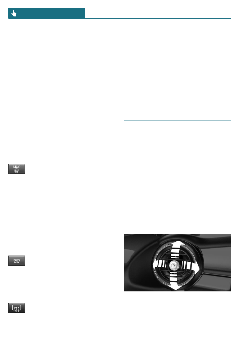
– Windows, upper body region, and floor
area.
– Upper body region and floor area.
– Floor area.
– Windows and floor area.
– Windows.
– Windows and upper body region.
– Upper body region.
To defrost windows and remove
condensation
Concept
Ice and condensation are quickly removed
from the windshield and the front side win-
dows.
Switching on/off
Press the button.
The LED is illuminated with the
system switched on.
Ice and condensation are quickly removed
from the windshield and the front side win-
dows.
The air flow can be adjusted with the pro-
gram active.
If there is window condensation, switch on
the air conditioning too.
Windshield defroster
Press the button. The LED lights up.
The front window defroster
switches off automatically after a certain
period of time.
Rear window defroster
Press the button. The LED lights up.
The rear window defroster switches
off automatically after a certain period of
time.
When GREEN Mode is activated, the heat-
ing output is reduced.
Microfilter/activated-charcoal filter
In external and recirculated-air mode, the
microfilter/activated charcoal filter filters
dust, pollen, and gaseous pollutants out of
the air.
Have this filter changed during vehicle
maintenance, refer to page 288.
Ventilation
Setting
The air flow directions can be individually
adjusted:
– Direct ventilation:
The air flow is directly pointed onto the
person. The air flow heats or cools no-
ticeably, depending on the adjusted tem-
perature.
– Indirect ventilation:
If the vents are fully or partly closed, the
air is directly routed into the car's inte-
rior.
Front ventilation
– Turn knob for continuous opening and
closing of the vents.
– Swivel the vents to alter the direction of
the vent flow, arrows.
Seite 188
CONTROLS Climate control
188
Online Edition for Part no. 01402667083 - VI/19

Parked-car ventilation
Concept
The parked-car ventilation ventilates the
car's interior and lowers its temperature, if
needed.
General information
The parked-car ventilation can be switched
on and off directly or by using two preset
activation times. The system remains
switched on for 30 minutes.
The parked-car ventilation system is oper-
ated via the Central Information Display
(CID).
Functional requirements
– Direct operation: vehicle is in radio-
ready state.
– Direct operation or preset activation
time: does not depend on external tem-
perature.
– Battery is sufficiently charged.
If parked-car ventilation is switched on,
the vehicle battery will be discharged.
Thus, limit the maximum activation time
to save the vehicle battery. The system
will be available again after the engine
is started or after a short trip.
– Make sure that the vehicle's date and
time are set correctly.
– Open the vents to allow air to flow out.
Switching on/off directly
Via the Central Information Display (CID):
1. "My MINI"
2. "Vehicle settings"
3. If necessary, "Climate functions"
4. "Activate comfort ventilation now"
The symbol on the automatic climate
control flashes if the system is switched on.
Preselecting the activation time
Via the Central Information Display (CID):
1. "My MINI"
2. "Vehicle settings"
3. If necessary, "Climate functions"
4. "Comfort ventilation"
5. Select the desired activation time.
6. Set the desired time.
Activating the activation time
Via the Central Information Display (CID):
1. "My MINI"
2. "Vehicle settings"
3. If necessary, "Climate functions"
4. "For start time at:"
Activate the desired activation time.
The symbol on the automatic climate
control lights up when the activation time is
activated.
The symbol on the automatic climate
control flashes when the system has been
switched on.
The system will only be switched on within
the next 24 hours. After that, it needs to be
reactivated.
Seite 189
Climate control CONTROLS
189
Online Edition for Part no. 01402667083 - VI/19

Interior equipment
Vehicle features and options
This chapter describes all standard, country-
specific and optional features offered with
the series. It also describes features that are
not necessarily available in your vehicle, for
instance, due to the selected options or
country versions. This also applies to safety-
related functions and systems. When using
these functions and systems, the applicable
laws and regulations must be observed.
Integrated Universal Remote
Control
Concept
The integrated Universal Remote Control in
the interior mirror can operate up to 3 func-
tions of remote-controlled systems such as
garage door drives, barriers, or lighting sys-
tems.
General information
The Integrated Universal Remote Control
replaces up to 3 different hand-held trans-
mitters. To operate the remote control, the
buttons on the interior mirror must be pro-
grammed with the desired functions. The
hand-held transmitter for the particular sys-
tem is required in order to program the re-
mote control.
Before selling the vehicle, delete the stored
functions for the sake of security.
If possible, do not install the antenna of the
remote-controlled system, e.g. the garage
door drive, near metal objects to ensure the
best possible operation.
Safety information
Warning
The operation of remote-controlled sys-
tems with the integrated universal remote
control, such as the garage door, may re-
sult in injury, for example, body parts be-
coming jammed in a garage door. There is
a risk of injury or risk of damage to prop-
erty. Make sure that the area of movement
of the respective system is clear during
programming and operation. Also follow
the safety information of the hand-held
transmitter.
Compatibility
If this symbol is printed on the pack-
aging or in the owner's manual of the
system to be controlled, the system
is generally compatible with the integrated
Universal Remote Control.
Additional questions are answered by:
– A dealer's service center or another
qualified service center or repair shop.
– www.homelink.com on the Internet.
HomeLink is a registered trademark of Gen-
tex Corporation.
Seite 190
CONTROLS Interior equipment
190
Online Edition for Part no. 01402667083 - VI/19

Overview
1 LED
2 Programmable keys
3 Hand-held transmitters of the system
Programming
General information
The battery of the hand-held transmitter
must be fully charged at the time of pro-
gramming to ensure an optimal range of the
integrated universal remote control.
1. Switch on the ignition.
2. Initial setup:
Press and hold the two outer buttons on
the interior mirror simultaneously for
approximately 10 seconds until the LED
flashes green rapidly. This erases all pro-
gramming of the buttons on the interior
mirror.
3. Press the interior mirror button to be
programmed. The LED on the interior
mirror will slowly begin flashing orange.
4. Hold the hand-held transmitter for the
system to be used approx. 1 to 12 in/2.5
to 30 cm away from the buttons on the
interior mirror. The required distance
depends on the hand-held transmitter.
5. Press and hold the button of the desired
function on the hand-held transmitter.
Canada: if programming with the hand-
held transmitter was interrupted, hold
down the interior mirror button and re-
peatedly press and release the hand-held
transmitter button for 2 seconds.
6.
– The LED lights up green: program-
ming completed.
Release the button.
– The LED flashes fast: programming
is not complete.
Press the button on the interior mir-
ror for 2 seconds and release. Per-
form this procedure three times to
complete the programming proce-
dure.
If the integrated universal remote
control remains nonoperational, con-
tinue with the special features for
change code wireless systems.
– LED does not flash green after
60 seconds: programming not com-
pleted.
Repeat steps 3 to 6.
To program other functions on other but-
tons, repeat steps 3 to 5.
Special feature of the rolling code
wireless system
If you are unable to operate the system af-
ter repeated programming, please check if
the system to be controlled features a roll-
ing code radio system.
Refer to the owner's manual for the system.
For systems with a rolling code radio sys-
tem, the integrated Universal Remote Con-
trol and the system also have to be
synchronized.
Please read the owner's manual to find out
how to synchronize the system.
Synchronizing is easier with the aid of a
second person.
Seite 191
Interior equipment CONTROLS
191
Online Edition for Part no. 01402667083 - VI/19

Synchronizing the universal remote control
with the system:
1. Park the vehicle within range of the re-
mote-controlled system.
2. Program the relevant button on the inte-
rior mirror as described.
3. Locate and press the synchronizing but-
ton on the system being programmed,
e.g. at the garage gate. You have approx.
30 seconds for the next step.
4. Hold down the programmed button on
the interior mirror for approximately
3 seconds and then release it. If neces-
sary, repeat this step up to three times
in order to finish synchronization. Once
synchronization is complete, the pro-
grammed function will be carried out.
Reprogramming individual buttons
1. Switch on the ignition.
2. Press and hold the interior mirror but-
ton to be programmed.
3. As soon as the LED on the interior mir-
ror flashes orange after approx. 20 sec-
onds, release the button.
4. Hold the hand-held transmitter for the
system to be used approx. 1 to 12 in/2.5
to 30 cm away from the buttons on the
interior mirror. The required distance
depends on the hand-held transmitter.
5. Press and hold the button of the desired
function on the hand-held transmitter.
Canada: if programming with the hand-
held transmitter was interrupted, hold
down the interior mirror button and re-
peatedly press and release the hand-held
transmitter button for 2 seconds.
6. The LED can light up in different ways.
– The LED lights up green: the pro-
gramming procedure is completed.
Release the button.
– The LED flashes fast: the hand-held
transmitter was detected but pro-
gramming is not complete.
Press the button on the interior mir-
ror for 2 seconds and release. Per-
form this procedure three times to
complete the programming proce-
dure.
If the integrated universal remote
control remains nonoperational, con-
tinue with the special features for
change code wireless systems.
– LED does not flash green after
60 seconds: programming not com-
pleted.
Repeat steps 3 to 6.
If the programming procedure is not com-
pleted, the previous programming will re-
main unchanged.
Operation
Warning
The operation of remote-controlled sys-
tems with the integrated universal remote
control, such as the garage door, may re-
sult in injury, for example, body parts be-
coming jammed in a garage door. There is
a risk of injury or risk of damage to prop-
erty. Make sure that the area of movement
of the respective system is clear during
programming and operation. Also follow
the safety information of the hand-held
transmitter.
The system, such as the garage door, can be
operated using the button on the interior
mirror while the engine is running or when
the ignition is started. To do this, hold down
the button within receiving range of the
system until the function is activated. The
interior mirror LED stays lit while the wire-
less signal is being transmitted.
Seite 192
CONTROLS Interior equipment
192
Online Edition for Part no. 01402667083 - VI/19
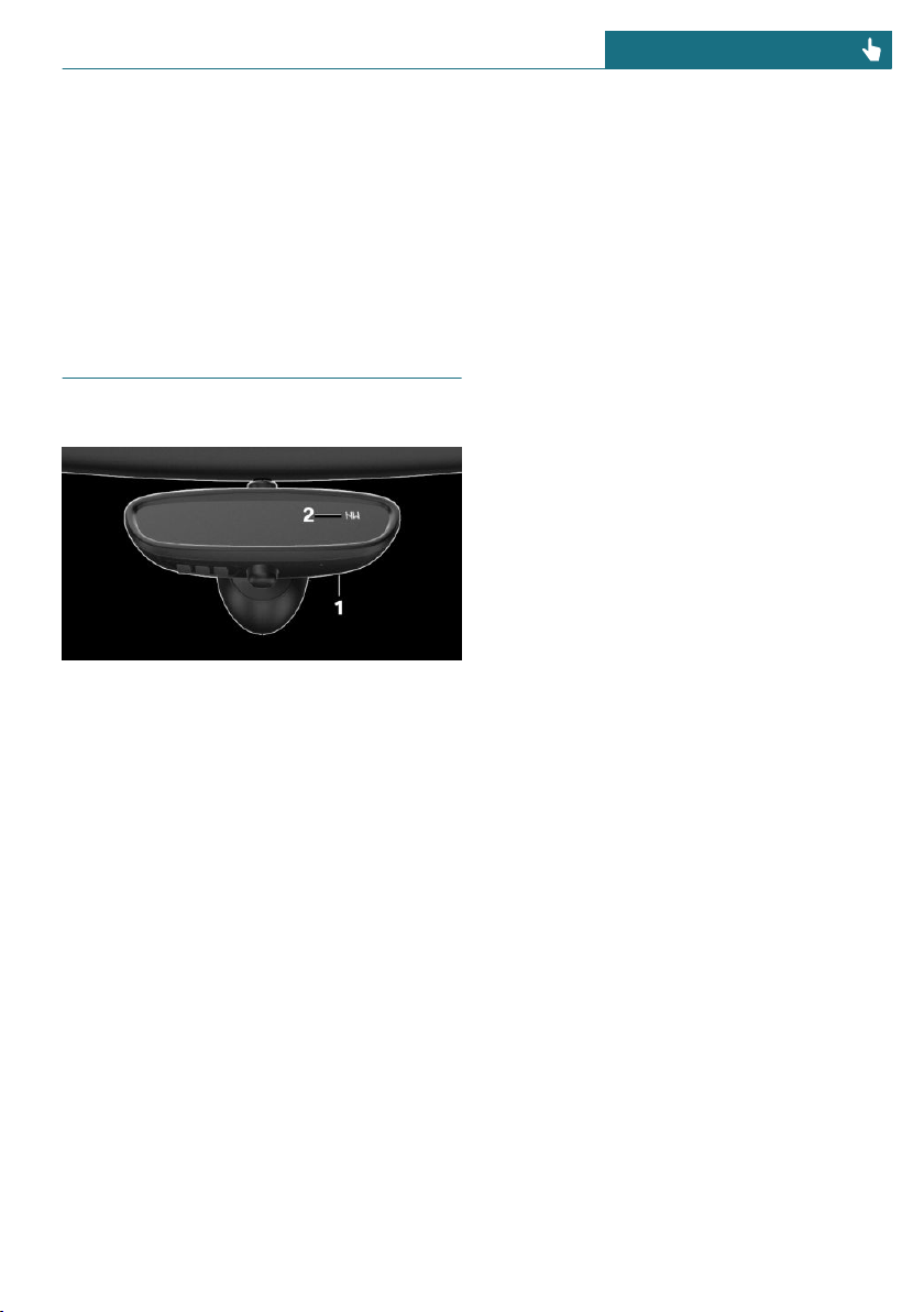
Deleting stored functions
All stored functions will be deleted. The
functions cannot be deleted individually.
Press and hold the two outer buttons on the
interior mirror simultaneously for approxi-
mately 10 seconds until the LED on the in-
terior mirror flashes green rapidly.
Digital compass
Overview
1 Control button
2 Mirror display
Mirror display
The point of the compass is displayed in the
mirror when driving straight.
Operating concept
Various functions can be called up by press-
ing the control button with a pointed object,
such as the tip of a ballpoint pen or similar
object. The following setting options are
displayed in succession, depending on how
long the control button is pressed:
– Pressed briefly: turns display on/off.
– 3 to 6 seconds: compass zone setting.
– 6 to 9 seconds: compass calibration.
– 9 to 12 seconds: left/right-hand steering
setting.
– 12 to 15 seconds: language setting.
Setting the compass zones
Sets the particular compass zones on the ve-
hicle so that the compass operates correctly;
refer to World map with compass zones.
Seite 193
Interior equipment CONTROLS
193
Online Edition for Part no. 01402667083 - VI/19
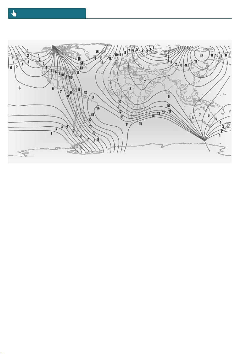
World map with magnetic zones
Procedure
1. Press and hold the control button for ap-
prox. 3 to 4 seconds. The number of the
set compass zone appears in the mirror.
2. To change the zone setting, press the
control button quickly and repeatedly
until the number of the compass zone
that corresponds with your location ap-
pears in the mirror.
The set zone is stored automatically. The
compass is ready for use again after approx-
imately 10 seconds.
Calibrating the digital compass
The digital compass must be calibrated in
the event of the following:
– The wrong compass point is displayed.
– The point of the compass displayed does
not change despite changing the direc-
tion of travel.
– Not all points of the compass are dis-
played.
Procedure
1. Make sure that there are no large metal-
lic objects or overhead power lines near
the vehicle and that there is sufficient
room to drive around in a circle.
2. Set the currently applicable compass
zone.
3. Press and hold the control button for ap-
prox. 6 to 7 seconds so that "C" appears
on the display. Next, drive in a complete
circle at least once at a speed of no more
than 4 mph/7 km/h. If calibration is suc-
cessful, the "C" is replaced by the points
of the compass.
Left/right-hand steering
The digital compass is already set for right
or left-hand steering at the factory.
Setting the language
Press and hold the control button for ap-
prox. 12 to 13 seconds. Briefly press the
Seite 194
CONTROLS Interior equipment
194
Online Edition for Part no. 01402667083 - VI/19
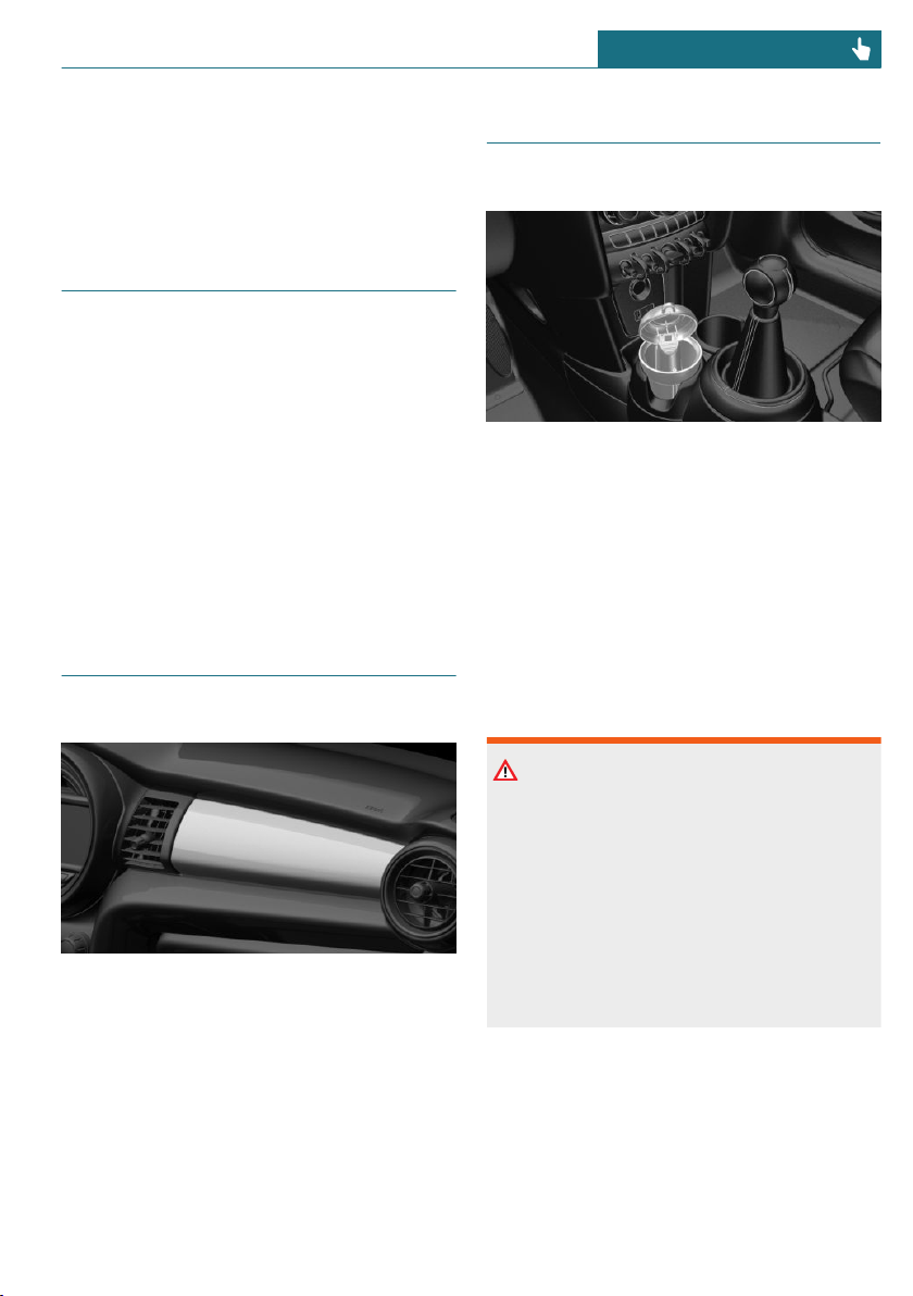
control button again to switch between
English "E" and German "O".
Settings are stored automatically after ap-
proximately 10 seconds.
Sun visor
Glare shield
To provide protection against glare, fold the
sun visor down or pivot it to the side.
Vanity mirror
A vanity mirror is located in the sun visor
behind a cover.
When the cover is opened, the mirror light-
ing switches on.
Front passenger side dash-
board
Decorative trim
Customized decorative trim panels for the
dashboard on the front passenger side are
available as original MINI accessories de-
pending on the equipment specification.
Follow the assembly instructions.
Ashtray/cigarette lighter
Overview
The ashtray is located in one of the frontal
cup holders, the cigarette lighter above it in
the center console.
Ashtray
In order to empty the ashtray, remove the
ashtray from the cup holder.
Cigarette lighter
Safety information
Warning
Contact with the hot heating element or
the hot socket of the cigarette lighter can
cause burns. Flammable materials can ig-
nite if the cigarette lighter falls down or is
held against the objects. There is a risk of
fire and injuries. There is a risk of damage
to property. Take hold of the cigarette
lighter by its handle. Make sure that chil-
dren do not use the cigarette lighter.
Seite 195
Interior equipment CONTROLS
195
Online Edition for Part no. 01402667083 - VI/19
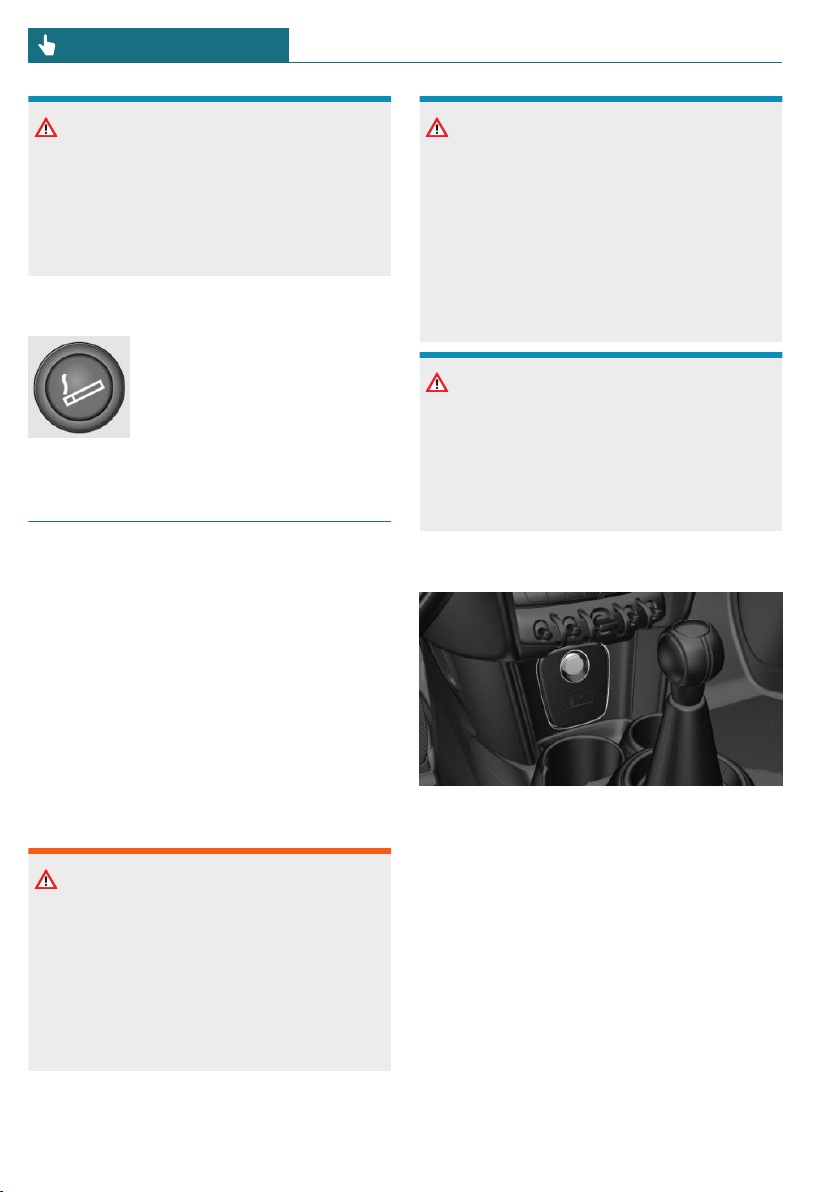
NOTICE
If metal objects fall into the socket, they
can cause a short circuit. There is a risk of
damage to property. Replace the cigarette
lighter or socket cover again after using
the socket.
Operation
Push in the cigarette lighter.
The cigarette lighter can be
removed as soon as it pops
back out.
Sockets
Concept
The lighter socket can be used as a socket
for electrical equipment while the ignition
is switched on or the engine is running.
General information
The total load of all sockets must not exceed
140 watts at 12 volts.
Do not damage the socket by using non-
compatible connectors.
Safety information
Warning
Devices and cables in the unfolding area of
the airbags, such as portable navigation
devices, can hinder the unfolding of the
airbag or be thrown around in the car's in-
terior during unfolding. There is a risk of
injury. Make sure that devices and cables
are not in the airbag's area of unfolding.
NOTICE
Battery chargers for the vehicle battery
can work with high voltages and currents,
which means that the 12 volt on-board
network can be overloaded or damaged.
There is a risk of damage to property. Only
connect battery chargers for the vehicle
battery to the starting aid terminals in the
engine compartment.
NOTICE
If metal objects fall into the socket, they
can cause a short circuit. There is a risk of
damage to property. Replace the cigarette
lighter or socket cover again after using
the socket.
In the center console
Remove the cover or cigarette lighter.
Seite 196
CONTROLS Interior equipment
196
Online Edition for Part no. 01402667083 - VI/19
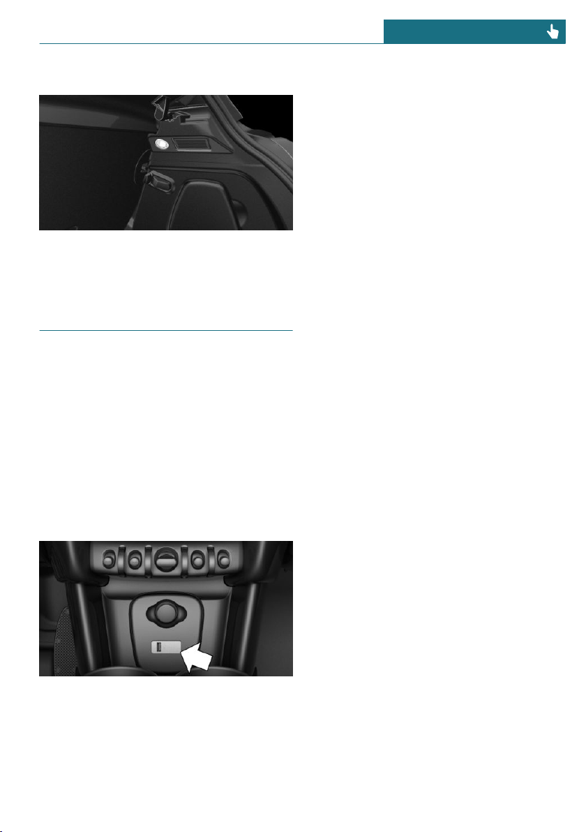
In the cargo area
The socket is located on the right side in
the cargo area.
USB interface
Concept
Mobile devices with a USB port can be con-
nected to the USB interface.
General information
Follow the information regarding the con-
nection of mobile devices to the USB inter-
face in the section on USB connections, re-
fer to page 51.
In the center console
The USB interface is located in the front of
the center console.
Properties:
– USB port Type A.
– For charging mobile devices and for
data transfer.
– Charge current: max. 1.5 A.
Seite 197
Interior equipment CONTROLS
197
Online Edition for Part no. 01402667083 - VI/19
Storage compartments
Vehicle features and options
This chapter describes all standard, country-
specific and optional features offered with
the series. It also describes features that are
not necessarily available in your vehicle, for
instance, due to the selected options or
country versions. This also applies to safety-
related functions and systems. When using
these functions and systems, the applicable
laws and regulations must be observed.
Safety information
Warning
Loose objects or devices with a cable con-
nection to the vehicle, for instance mobile
phones, can be thrown into the car's inte-
rior while driving, for instance in the
event of an accident or during braking and
evasive maneuvers. There is a risk of in-
jury. Secure loose objects or devices with
a cable connection to the vehicle in the
car's interior.
NOTICE
Anti-slip pads such as anti-slip mats can
damage the dashboard. There is a risk of
damage to property. Do not use anti-slip
pads.
Overview
The following storage compartments are
available in the car's interior:
– Glove compartment on the front passen-
ger side.
– Compartments in the doors.
– Storage compartment in the center arm-
rest.
– Storage compartment in front of the cup
holders.
– Clothes hooks
– Storage tray in the center console.
– Pockets on the backrests of the front
seats.
Glove compartment
Safety information
Warning
Folded open, the glove compartment pro-
trudes in the car's interior. Objects in the
glove compartment can be thrown into the
car's interior while driving, for instance in
the event of an accident or during braking
and evasive maneuvers. There is a risk of
injury. Always close the glove compart-
ment immediately after using it.
Seite 198
CONTROLS Storage compartments
198
Online Edition for Part no. 01402667083 - VI/19
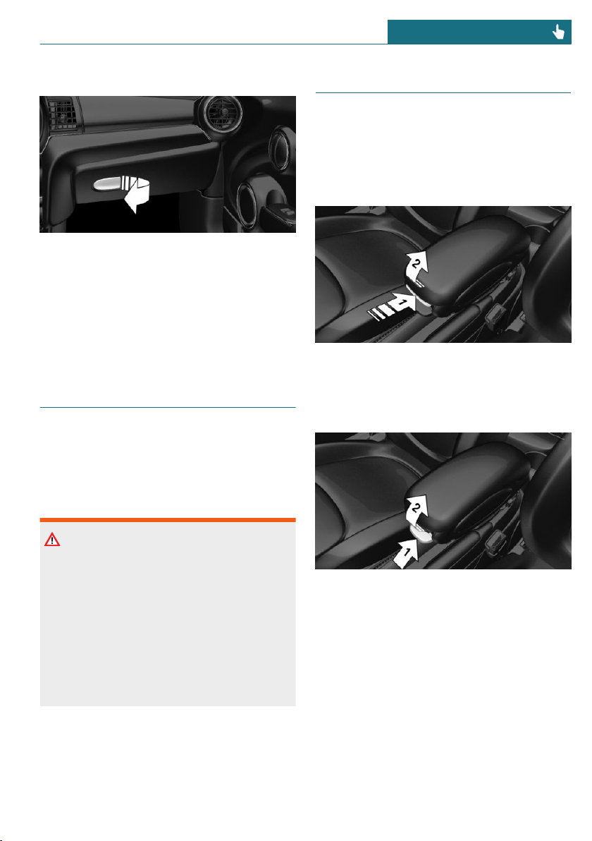
Opening
Pull the handle.
The light in the glove compartment
switches on.
Closing
Fold up the cover.
Compartments in the doors
General information
There are storage compartments in the
doors.
Safety information
Warning
Breakable objects, such as glass bottles or
glasses, can break in the event of an acci-
dent or a braking or evasive maneuver.
Broken glass can be scattered in the car's
interior. There is a risk of injury or risk of
damage to property. Do not use any break-
able objects while driving. Only stow
breakable objects in closed storage com-
partments.
Center armrest
General information
The center armrest contains a storage com-
partment.
Opening
Press button, arrow 1, and open center arm-
rest upward, arrow 2.
Adjusting the height
Press button, arrow 1, and swing center
armrest upward or downward into the de-
sired height, arrow 2.
Seite 199
Storage compartments CONTROLS
199
Online Edition for Part no. 01402667083 - VI/19
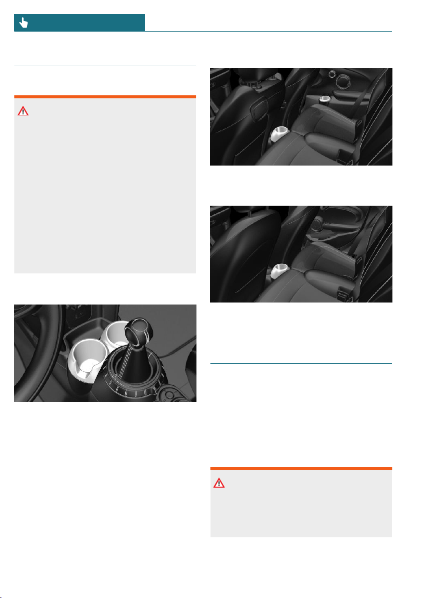
Cup holders
Safety information
Warning
Unsuitable containers in the cup holders
may damage the cup holders or be thrown
about the car’s interior in the event of an
accident, an evasive maneuver, or forceful
braking. Spilled liquids can distract from
the traffic conditions and lead to an acci-
dent. Hot drinks can damage the cup
holder or lead to scalding. There is a risk
of injury or risk of damage to property. Do
not force objects into the cup holder. Use
lightweight, shatterproof, and sealable
containers. Do not transport hot bever-
ages.
Front
In the center console.
Rear
For 3-door models: in front of the rear seats
and in the side armrests.
For 5-door models: in front of the rear seats.
Clothes hooks
General information
3-door models: The clothes hooks are lo-
cated above the side windows in the rear.
5-door models: The clothes hooks are lo-
cated above the rear doors.
Safety information
Warning
Clothing articles on the clothes hooks can
obstruct the view while driving. There is a
risk of accident. When suspending cloth-
ing articles from the clothes hooks, ensure
Seite 200
CONTROLS Storage compartments
200
Online Edition for Part no. 01402667083 - VI/19

that they will not obstruct the driver's
view.
Warning
Improper use of the clothes hooks can lead
to a risk of objects flying about during
braking and evasive maneuvers. There is a
risk of injury and risk of damage to prop-
erty. Only hang lightweight objects, for in-
stance clothing articles, from the clothes
hooks.
Seite 201
Storage compartments CONTROLS
201
Online Edition for Part no. 01402667083 - VI/19

Cargo area
Vehicle features and options
This chapter describes all standard, country-
specific and optional features offered with
the series. It also describes features that are
not necessarily available in your vehicle, for
instance, due to the selected options or
country versions. This also applies to safety-
related functions and systems. When using
these functions and systems, the applicable
laws and regulations must be observed.
Loading
Safety information
Warning
High gross weight can overheat the tires,
damage them internally and cause a sud-
den drop in tire inflation pressure. Driving
characteristics may be negatively im-
pacted, reducing lane stability, lengthen-
ing the braking distances and changing
the steering response. There is a risk of
accident. Pay attention to the permitted
load capacity of the tires and never exceed
the permitted gross weight.
Warning
Loose objects or devices with a cable con-
nection to the vehicle, for instance mobile
phones, can be thrown into the car's inte-
rior while driving, for instance in the
event of an accident or during braking and
evasive maneuvers. There is a risk of in-
jury. Secure loose objects or devices with
a cable connection to the vehicle in the
car's interior.
Warning
Improperly stowed objects can shift and
be thrown into the car's interior, for in-
stance in the event of an accident or dur-
ing braking and evasive maneuvers. Vehi-
cle occupants can be hit and injured. There
is a risk of injury. Stow and secure objects
and cargo properly.
NOTICE
Fluids in the cargo area can cause damage.
There is a risk of damage to property.
Make sure that no fluids leak in the cargo
area.
Steps for Determining Correct Load
Limit
1. Locate the statement “The combined
weight of occupants and cargo should
never exceed XXX kg or XXX lbs” on
your vehicle’s placard.
2. Determine the combined weight of the
driver and passengers that will be riding
in your vehicle.
3. Subtract the combined weight of the
driver and passengers from XXX kg or
XXX lbs
4. The resulting figure equals the available
amount of cargo and luggage load ca-
pacity. For example, if the “XXX”
amount equals 1,400 lbs and there will
be five 150 lbs passengers in your vehi-
cle, the amount of available cargo and
Seite 202
CONTROLS Cargo area
202
Online Edition for Part no. 01402667083 - VI/19
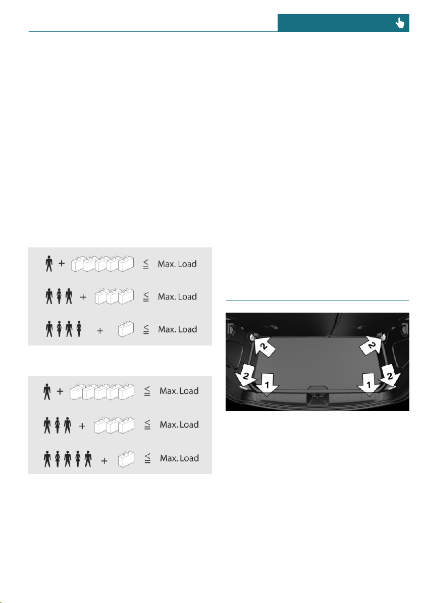
luggage load capacity is 650 lbs (1,400 -
750 (5 x 150) = 650 lbs)
5. Determine the combined weight of lug-
gage and cargo being loaded on the ve-
hicle. That weight may not safely exceed
the available cargo and luggage load ca-
pacity calculated in Step 4.
6. If your vehicle will be towing a trailer,
load from your trailer will be transferred
to your vehicle. Consult this manual to
determine how this reduces the availa-
ble cargo and luggage load capacity of
your vehicle.
Load
On 3-door models
On 5-door models
The maximum load is the sum of the weight
of the occupants and the cargo.
The greater the weight of the occupants,
the less cargo that can be transported.
Stowing and securing cargo
– Cover sharp edges and corners on the
cargo.
– Heavy cargo: stow as far forward as pos-
sible, directly behind and at the bottom
of the rear passenger seat backrests.
– Very heavy cargo: when the rear seat is
not occupied, secure each of the outer
safety belts in the opposite buckle.
– If necessary, fold down the rear back-
rests to stow large cargo.
– Do not stack cargo above the top edge of
the backrests.
– Small and light cargo: secure with
ratchet straps or draw straps.
– Larger and heavy cargo: secure with
cargo straps.
Lashing eyes in the cargo area
Without storage compartment package: to
secure the cargo there are two lashing eyes,
arrow 1, in the cargo area.
With storage compartment package: to se-
cure the cargo there are six lashing eyes, ar-
rows 1 and 2, in the cargo area.
Attach load securing aids, such as lashing
straps, tensioning straps, draw straps or
cargo nets, to the lashing eyes in the cargo
area.
Seite 203
Cargo area CONTROLS
203
Online Edition for Part no. 01402667083 - VI/19
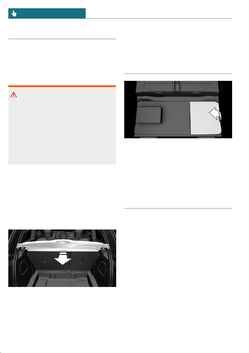
Cargo cover
General information
When the tailgate is opened, the cargo
cover is raised.
Safety information
Warning
Loose objects or devices with a cable con-
nection to the vehicle, for instance mobile
phones, can be thrown into the car's inte-
rior while driving, for instance in the
event of an accident or during braking and
evasive maneuvers. There is a risk of in-
jury. Secure loose objects or devices with
a cable connection to the vehicle in the
car's interior.
Removing
For storing bulky objects the cargo cover
can be removed.
1. Detach the left and right retaining
straps at the tailgate.
2. Pull the cargo cover out of the brackets
on the left and right.
Installing
1. Slide the cargo cover forward horizon-
tally into the two side brackets until it
audibly engages.
2. Attach the left and right retaining straps
at the tailgate.
Storage space under cargo
floor panel
Located under the cargo floor panel on the
right side is a trough for the onboard vehi-
cle tool kit.
Fold the right side of the cargo floor panel
upward to remove the onboard vehicle tool
kit.
Enlarging the cargo area
Concept
The cargo area can be enlarged as follows:
– The rear seat backrests can be folded
down.
– The rear seat backrests can be moved
into an upright loading position using
the cargo setting.
General information
The rear seat backrest is divided into two
parts at a ratio of 60 to 40. The left rear seat
backrest is connected to the center section.
The rear seat backrests can be folded down
from the rear.
Seite 204
CONTROLS Cargo area
204
Online Edition for Part no. 01402667083 - VI/19
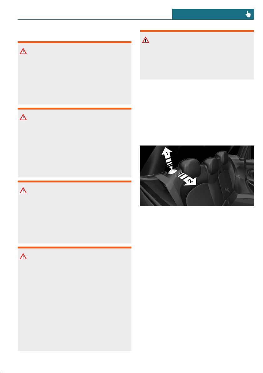
Safety information
Warning
Danger of jamming with folding down the
backrests. There is a risk of injury or risk
of damage to property. Make sure that the
area of movement of the rear backrest and
the of the head restraint is clear prior to
folding down.
Warning
If a rear seat backrest is not locked, unse-
cured cargo can be thrown about the car’s
interior; for instance, in the event of an ac-
cident, braking or an evasive maneuver.
There is a risk of injury. Make sure that
the rear seat backrest is locked after fold-
ing it back.
Warning
With a rear backrest that is not locked, the
protective function of the middle safety
belt is not guaranteed. There is a risk of
injuries or danger to life. If you are using
the middle safety belt, lock the wider rear
seat backrest.
Warning
The stability of the child restraint system
is limited or compromised with incorrect
seat adjustment or improper installation of
the child seat. There is a risk of injuries or
danger to life. Make sure that the child re-
straint system fits securely against the
backrest. If possible, adjust the backrest
tilt for all affected backrests and correctly
adjust the seats. Make sure that seats and
backrests are securely engaged or locked.
If possible, adjust the height of the head
restraints or remove them.
Warning
Body parts can be jammed when moving
the head restraint. There is a risk of injury.
Make sure that the area of movement is
clear when moving the head restraint.
Folding down the rear seat
backrest from the rear
1. Before the rear seat backrest is folded
down, hook the corresponding safety
belt into the belt buckle on the side.
2. Pull the lever up, arrow 1, and fold the
rear seat backrest forward, arrow 2.
Cargo position
Concept
The rear seat backrests can be moved into
an upright loading position.
Adjusting
1. Release the backrest, and tilt it forward.
Seite 205
Cargo area CONTROLS
205
Online Edition for Part no. 01402667083 - VI/19
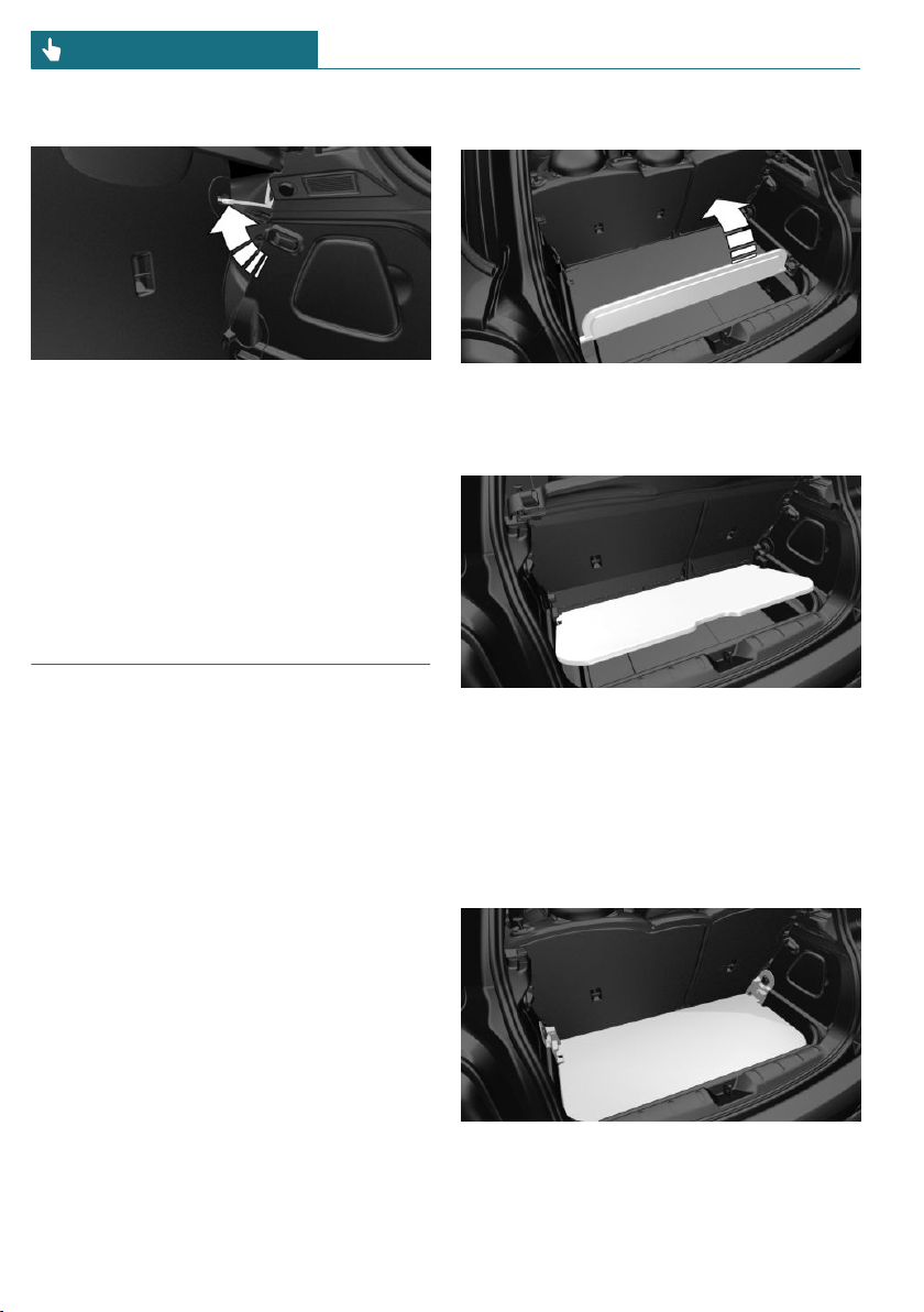
2. Fold the frame up until it engages.
3. Fold back and engage the rear seat
backrest.
Folding back the backrest
Fold up the backrest and press it into the
latch. Make sure that the safety belt is not
caught behind the backrest or in between
the backrest and the rear seats.
Variable cargo area floor
Concept
With the variable cargo area floor, the cargo
area can be configured corresponding to
transport requirements.
General information
Follow instructions on securing cargo, refer
to page 202.
Removing the cargo floor panel
5-door models: To change the position of
the cargo area floor, first fold up the rear
part of the cargo area floor.
Grasp the cargo floor panel in the rear and
fold slightly upward. Next, pull it backward
from the supports.
The cargo floor panel can be removed from
the cargo area above the tail lights.
Lower position
– Larger objects can be transported.
Seite 206
CONTROLS Cargo area
206
Online Edition for Part no. 01402667083 - VI/19
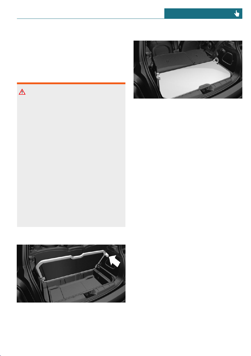
– Space for smaller objects remains be-
tween the fixed and variable cargo area
floor.
Folded up position
Safety information
Warning
Improper use of the variable cargo floor
panel can lead to a danger of objects flying
about during braking and evasive maneu-
vers. There is a risk of injury and risk of
damage to property.
– Do not use the variable cargo floor
panel to separate the cargo area and
car's interior in the sense of a parti-
tion net.
– Only use the variable cargo floor
panel in the folded-up position when
the backrests are folded up and
locked.
– Fold down the variable cargo floor
panel before driving off.
– Always secure cargo against shifting,
using straps, belts and lashing eyes,
for instance.
Fold up the cargo floor panel
Fold up the cargo floor panel in the lower
position and push it behind the locks, arrow.
You've reached the maximum cargo height.
Upper position
– With the backrests folded down, a long,
flat loading surface is produced.
– For 3-door models:
Maximum load in this position:
330 lbs/150 kg.
– For 5-door models:
Maximum load in this position:
441 lbs/200 kg.
– Space for objects remains between the
fixed and variable cargo area floor.
Seite 207
Cargo area CONTROLS
207
Online Edition for Part no. 01402667083 - VI/19

208
Online Edition for Part no. 01402667083 - VI/19

DRIVING TIPS
Things to remember when driving .................................................. 210
Saving fuel ............................................................................................... 215
209
Online Edition for Part no. 01402667083 - VI/19

Things to remember when driving
Vehicle features and options
This chapter describes all standard, country-
specific and optional features offered with
the series. It also describes features that are
not necessarily available in your vehicle, for
instance, due to the selected options or
country versions. This also applies to safety-
related functions and systems. When using
these functions and systems, the applicable
laws and regulations must be observed.
Breaking-in period
General information
Moving parts need to begin working to-
gether smoothly.
The following instructions will help you to
achieve a long vehicle life and good effi-
ciency.
During break-in, do not use the Launch
Control, refer to page 114.
Safety information
Warning
Due to new parts and components, safety
and driver assistance systems can react
with a delay. There is a risk of accident.
After installing new parts or with a new
vehicle, drive conservatively and inter-
vene early if necessary. Observe the break-
in procedures of the respective parts and
components.
Engine, transmission, and axle
drive
Up to 1,200 miles/2,000 km
Do not exceed the maximum engine and
road speed:
– For gasoline engine 4,500 rpm and
100 mph/160 km/h.
Avoid full load or kickdown under all cir-
cumstances.
From 1,200 miles/2,000 km
The engine and vehicle speed can gradually
be increased.
Tires
Tire traction is not optimal due to manufac-
turing circumstances when tires are brand-
new; they achieve their full traction poten-
tial after a break-in time.
Drive conservatively for the first
200 miles/300 km.
Brake system
Brake discs and brake pads only reach their
full effectiveness after ap-
prox. 300 miles/500 km. Drive moderately
during this break-in period.
Clutch
The function of the clutch reaches its opti-
mal level only after a distance driven of ap-
prox. 300 miles/500 km. During this break-
in period, engage the clutch gently.
Following part replacement
The same break-in procedures should be ob-
served if any of the components mentioned
Seite 210
DRIVING TIPS Things to remember when driving
210
Online Edition for Part no. 01402667083 - VI/19

above have to be renewed in the course of
the vehicle's operating life.
General driving notes
Closing the tailgate
Safety information
Warning
An open tailgate protrudes from the vehi-
cle and can endanger occupants and other
traffic participants or damage the vehicle
in the event of an accident, braking or eva-
sive maneuvers. In addition, exhaust
fumes may enter the car's interior. There
is a risk of injury or risk of damage to
property. Do not drive with the tailgate
open.
Driving with the tailgate open
If driving with the tailgate open cannot be
avoided:
– Close all windows and the glass sunroof.
– Greatly increase the air flow from the
vents.
– Drive moderately.
Hot exhaust gas system
Warning
During driving operation, high tempera-
tures can occur underneath the vehicle
body, for instance caused by the exhaust
gas system. If combustible materials, such
as leaves or grass, come in contact with
hot parts of the exhaust gas system, these
materials can ignite. There is a risk of in-
jury or risk of damage to property. Do not
remove the heat shields installed and
never apply undercoating to them. Make
sure that no combustible materials can
come in contact with hot vehicle parts in
driving operation, idle or during parking.
Do not touch the hot exhaust gas system.
Mobile communication devices in
the vehicle
Warning
Vehicle electronics and mobile phones can
influence one another. There is radiation
due to the transmission operations of mo-
bile phones. There is a risk of injury or
risk of damage to property. If possible, in
the car's interior use only mobile phones
with direct connections to an exterior an-
tenna in order to exclude mutual interfer-
ence and deflect the radiation from the
car's interior.
Hydroplaning
On wet or slushy roads, a wedge of water
can form between the tires and road sur-
face.
This phenomenon is referred to as hydro-
planing. It is characterized by a partial or
complete loss of contact between the tires
and the road surface, ultimately undermin-
ing your ability to steer and brake the vehi-
cle.
Driving through water
General information
When driving through water, follow the fol-
lowing:
– Drive through calm water only.
– Drive through water only if it is not
deeper than maximum 9.8 inches/25 cm.
– Drive through water no faster than
walking speed, up to 3 mph/5 km/h.
Seite 211
Things to remember when driving DRIVING TIPS
211
Online Edition for Part no. 01402667083 - VI/19
Safety information
NOTICE
When driving too quickly through too
deep water, water can enter into the en-
gine compartment, the electrical system or
the transmission. There is a risk of damage
to property. When driving through water,
do not exceed the maximum indicated wa-
ter level and the maximum speed for driv-
ing through water.
Braking safely
General information
The vehicle is equipped with ABS as a
standard feature.
Perform an emergency stop in situations
that require such.
Steering is still responsive. You can still
avoid any obstacles with a minimum of
steering effort.
Pulsation of the brake pedal and sounds
from the hydraulic circuits indicate that
ABS is in its active mode.
Objects in the area around the pedals
Warning
Objects in the driver's floor area can limit
the pedal distance or block a depressed
pedal. There is a risk of accident. Stow ob-
jects in the vehicle such that they are se-
cured and cannot enter into the driver's
floor area. Use floor mats that are suitable
for the vehicle and can be safely attached
to the floor. Do not use loose floor mats
and do not layer several floor mats. Make
sure that there is sufficient clearance for
the pedals. Ensure that the floor mats are
securely fastened again after they were re-
moved, for instance for cleaning.
Driving in wet conditions
When roads are wet, salted, or in heavy
rain, gently press the brake pedal every few
miles.
Ensure that this action does not endanger
other traffic.
The heat generated during braking dries
brake discs and brake pads and protects
them against corrosion.
In this way braking efficiency will be avail-
able when you need it.
Hills
General information
Drive long or steep downhill gradients in
the gear that requires least braking effort.
Otherwise, the brakes may overheat and re-
duce brake efficiency.
You can increase the engine's braking effect
by shifting down, going all the way to first
gear, if needed.
Safety information
Warning
Light but consistent brake pressure can
lead to high temperatures, brakes wearing
out and possibly even brake failure. There
is a risk of accident. Avoid placing exces-
sive stress on the brake system.
Warning
In idle state or with the engine switched
off, safety functions, for instance engine
braking effect, braking assistance and
steering assistance, may not be available.
There is a risk of accident. Do not attempt
Seite 212
DRIVING TIPS Things to remember when driving
212
Online Edition for Part no. 01402667083 - VI/19
to drive in idle state or with the engine
switched off.
Brake disc corrosion
Corrosion on the brake discs and contami-
nation on the brake pads are increased by
the following circumstances:
– Low mileage.
– Extended periods when the vehicle is
not used at all.
– Infrequent use of the brakes.
– Aggressive, acidic, or alkaline cleaning
agents.
Corrosion buildup on the brake discs will
cause a pulsating effect on the brakes in
their response - generally this cannot be
corrected.
Condensation water under the
parked vehicle
When using the automatic climate control,
condensation water develops and collects
underneath the vehicle.
Ground clearance
NOTICE
If the ground clearance is insufficient, e.g.,
curbs or underground garage entrances,
contact with vehicle parts, e.g., spoiler,
and the underbody may occur. There is a
risk of damage to property. Ensure that
there is sufficient ground clearance availa-
ble.
Roof-mounted luggage rack
General information
Installation only possible with roof rack.
Roof racks are available as special accesso-
ries.
Securing
Follow the installation instructions of the
roof rack.
Loading
Because roof-mounted luggage racks raise
the vehicle's center of gravity when loaded,
they have a major effect on vehicle handling
and steering response.
Therefore, note the following when loading
and driving:
– Do not exceed the approved roof/axle
loads and the approved gross vehicle
weight.
– Be sure that adequate clearance is main-
tained for tilting and opening the glass
sunroof.
– Distribute the roof load uniformly.
– The roof load should not extend past the
loading area.
– Always place the heaviest pieces on the
bottom.
– Secure the roof luggage firmly, for in-
stance using ratchet straps.
– Do not let objects project into the open-
ing path of the tailgate.
– Drive cautiously and avoid sudden ac-
celeration and braking maneuvers. Take
corners gently.
Rear luggage rack
General information
Installation only possible with rear luggage
rack preparation.
Rear racks are available as special accesso-
ries.
Seite 213
Things to remember when driving DRIVING TIPS
213
Online Edition for Part no. 01402667083 - VI/19
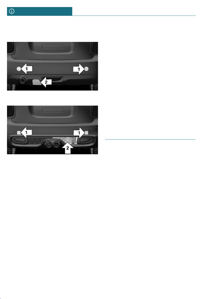
Securing
COOPER
COOPER S
The fixing points, arrow 1, and the socket,
arrow 2, are located below the covers in the
bumper.
Remove the covers before installing the
rear luggage rack.
Loading
Because rear luggage racks raise the vehi-
cle's center of gravity when loaded, they
have a major effect on vehicle handling and
steering response.
Therefore, note the following when loading
and driving:
– Do not exceed the approved axle load
and the approved gross vehicle weight.
– Drive smoothly. Avoid sudden accelera-
tion and braking maneuvers. Take cor-
ners gently.
Power consumption
Before starting to drive, check the function
of the rear luggage rack lights. Before start-
ing to drive, check the function of the
trailer tail lights.
The rear luggage rack lights must not con-
sume more than:
– Turn signals: 42 watts per side.
– Rear lights: 50 watts per side.
– Brake lights: 84 watts in total.
– Rear fog lights: 42 watts in total.
– Backup light: 42 watts in total.
Keep activation times of power consumers
short with the engine switched off to pro-
tect the vehicle battery.
Driving on racetracks
Higher mechanical and thermal loads during
racetrack operation lead to increased wear.
This wear is not covered by the warranty.
The vehicle is not designed for use in motor
sports competition.
Seite 214
DRIVING TIPS Things to remember when driving
214
Online Edition for Part no. 01402667083 - VI/19

Saving fuel
Vehicle features and options
This chapter describes all standard, country-
specific and optional features offered with
the series. It also describes features that are
not necessarily available in your vehicle, for
instance, due to the selected options or
country versions. This also applies to safety-
related functions and systems. When using
these functions and systems, the applicable
laws and regulations must be observed.
General information
The vehicle contains advanced technologies
for the reduction of consumption and emis-
sion values.
Fuel consumption depends on a number of
different factors.
The implementation of certain measures,
driving style and regular maintenance can
influence fuel consumption and environ-
mental impact.
Remove unnecessary cargo
Additional weight increases fuel consump-
tion.
Remove attached parts follow-
ing use
Remove roof-mounted or rear luggage racks
which are no longer required following use.
Attached parts on the vehicle impair the
aerodynamics and increase the fuel con-
sumption.
Close the windows and glass
sunroof
Driving with the glass sunroof and windows
open results in increased air resistance and
raises fuel consumption.
Tires
General information
Tires can affect consumption in various
ways, for instance tire size may influence
consumption.
Check the tire inflation pressure
regularly
Check and, if needed, correct the tire infla-
tion pressure at least twice a month and be-
fore starting on a long trip.
Low tire inflation pressure increases rolling
resistance and thus raises fuel consumption
and tire wear.
Drive away without delay
Do not wait for the engine to warm-up
while the vehicle remains stationary. Start
driving right away, but at moderate engine
speeds.
This is the fastest way for the cold engine
to reach its operating temperature.
Seite 215
Saving fuel DRIVING TIPS
215
Online Edition for Part no. 01402667083 - VI/19

Look well ahead when driving
Driving smoothly and proactively reduces
fuel consumption.
Avoid unnecessary acceleration and brak-
ing.
By maintaining a suitable distance to the
vehicle driving ahead of you.
Avoid high engine speeds
Driving at low engine speeds lowers fuel
consumption and reduces wear.
If necessary, observe the vehicle's gear shift
indicator, refer to page 123.
Use coasting conditions
When approaching a red light, take your
foot off the accelerator and let the vehicle
coast to a halt.
For going downhill take your foot off the ac-
celerator and let the vehicle roll.
The flow of fuel is interrupted while coast-
ing.
Switch off the engine during
longer stops
Switching off the engine
Switch off the engine during longer stops,
for instance at traffic lights, railroad cross-
ings or in traffic congestion.
Auto Start/Stop function
The Auto Start/Stop function of the vehicle
automatically switches off the engine dur-
ing a stop.
If the engine is switched off and then re-
started rather than leaving the engine run-
ning constantly, fuel consumption and emis-
sions are reduced. Savings can begin within
a few seconds of switching off the engine.
In addition, fuel consumption is also deter-
mined by other factors, such as driving
style, road conditions, maintenance or envi-
ronmental factors.
Switch off any functions that
are not currently needed
Functions such as seat heating and the rear
window defroster require a lot of energy
and consume additional fuel, especially in
city and stop-and-go traffic.
Switch off these functions if they are not
needed.
Have maintenance carried out
Have the vehicle maintained regularly to
achieve optimal vehicle efficiency and serv-
ice life. MINI recommends that mainte-
nance work be performed by a MINI service
center.
Also note the MINI maintenance systems,
refer to page 288.
GREEN Mode
Concept
GREEN Mode supports a driving style that
saves on consumption. For this purpose, the
engine control and comfort features, for in-
stance the climate control output, are ad-
justed.
For Steptronic transmission:
Seite 216
DRIVING TIPS Saving fuel
216
Online Edition for Part no. 01402667083 - VI/19
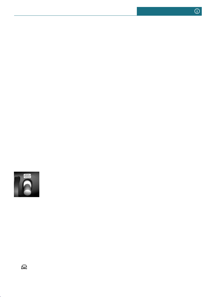
Under certain conditions the engine is auto-
matically decoupled from the transmission
in the D selector lever position. The vehicle
continues traveling with the engine idling
to reduce consumption. The D selector lever
position remains engaged.
In addition, context-sensitive instructions
are displayed to assist with an efficient
driving style.
The achieved extended range is displayed in
the instrument cluster as bonus range.
General information
The system includes the following functions
and displays:
– GREEN bonus range, refer to page 218.
– GREEN tip, driving instruction, refer to
page 218.
– GREEN climate control, refer to
page 217.
– Coasting driving condition, refer to
page 219.
Activating GREEN Mode
Press the MINI Driving Modes
switch downward until
GREEN is displayed in the in-
strument cluster.
Configuring GREEN
Via MINI Driving Modes switch
1. Activating GREEN Mode.
2. "Configure GREEN"
3. Select the desired setting.
Via the Central Information Display
(CID)
1. "My MINI"
2. "Vehicle settings"
3. If necessary, "Driving mode"
4. "Configure GREEN"
5. Select the desired setting.
Activating/deactivating the functions
The following functions can be activated/
deactivated:
– "GREEN speed warning"
– "GREEN climate control"
– "Coasting"
Settings are stored for the driver profile
currently used.
GREEN Limit
– Activate the GREEN Limit:
"GREEN speed warning":
A GREEN tip is displayed if the speed of
the set GREEN Limit is exceeded.
– Setting the speed for the GREEN Limit:
"Tip at:"
Select the desired speed.
GREEN climate control
Climate control is set to be efficient.
By making a slight change to the set tem-
perature, or adjusting the rate of heating or
cooling of the car's interior consumption
can be economized.
The power output to the seat heater and ex-
terior mirror is reduced.
Coasting
Efficiency can be optimized by disengaging
the engine and coasting, refer to page 219,
with the engine idling.
This function is only available in GREEN
Mode.
Deactivate the function to use the braking
effect of the engine when traveling down-
hill.
Seite 217
Saving fuel DRIVING TIPS
217
Online Edition for Part no. 01402667083 - VI/19
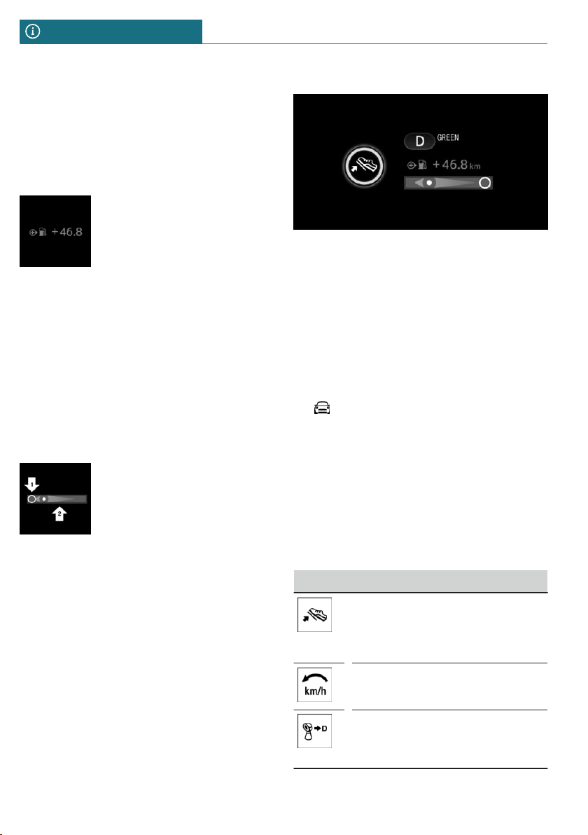
GREEN potential savings
Shows potential savings with the current
settings in percentages.
Display in the instrument cluster
GREEN bonus range
A modified driving style helps
you extend your driving range.
The range extension can be
displayed as the bonus range
in the instrument cluster.
The bonus range is shown in the range dis-
play.
The bonus range is automatically reset ev-
ery time the vehicle is refueled.
– Green display: efficient driving style.
– Gray display: modify driving style, for
instance by backing off the accelerator
pedal.
Efficiency display
A bar display in the instru-
ment cluster indicates your
current driving efficiency.
Mark in the left area, arrow 1:
display for energy recovered
by coasting or when braking.
Mark in the right area, arrow 2: display
when accelerating.
The efficiency of your driving style is
shown by the position of the mark:
– Mark inside the green range: efficient
driving style.
– Mark outside the green range: modify
driving style, for example by backing off
the accelerator.
GREEN tip, driving instruction
The GREEN tip indicates that your driving
style can be modified to be more efficient,
for example by backing off the accelerator.
Activating/deactivating the display
Activate information relating to the driving
style and GREEN tips in the instrument
cluster using the Central Information Dis-
play (CID):
1. "My MINI"
2. "System settings"
3. "Displays"
4. "Instrument panel"
5. "GREEN info"
GREEN tip, symbols
An additional symbol and text instructions
are displayed.
Symbol Measure
For an efficient driving style,
look well ahead when driving,
accelerate conservatively, and
delay accelerating.
Reduce speed to the selected
GREEN speed.
Steptronic transmission:
Switch from M/S to D and avoid
manual shift interventions.
Seite 218
DRIVING TIPS Saving fuel
218
Online Edition for Part no. 01402667083 - VI/19
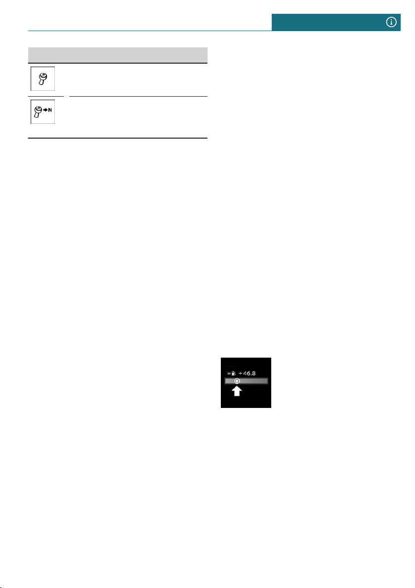
Symbol Measure
Manual transmission:
Follow the shift instructions.
Manual transmission:
Engage neutral for an engine
stop.
Coasting
Concept
The function helps to conserve fuel.
To do this, under certain conditions the en-
gine is automatically decoupled from the
transmission when selector lever position D
is set. The vehicle continues traveling with
the engine idling to reduce consumption.
Selector lever position D remains engaged.
This driving condition is referred to as
coasting.
As soon as you step on the brake or acceler-
ator pedal, the engine is automatically cou-
pled again.
General information
Coasting is a component of the GREEN driv-
ing mode.
Coasting is automatically activated when
the GREEN driving mode is called via the
MINI Driving Modes switch, refer to
page 159.
A proactive driving style helps the driver to
use the function often and supports the effi-
cient effect of coasting.
Functional requirements
The function is available in the speed range
from approx. 15 mph/25 km/h up to
100 mph/160 km/h.
– Accelerator pedal and brake pedal are
not operated.
– The selector lever is in selector lever po-
sition D.
– Engine and transmission are at operat-
ing temperature.
– With a camera in the area of the interior
mirror: the system does not detect any
vehicles ahead of you.
Operation via shift paddles
Concept
Depending on your vehicle's equipment, the
coasting mode can be influenced with the
shift paddles.
Activating/deactivating coasting via shift
paddles
1. Shift to the highest gear by pulling the
right shift paddle.
2. To activate coasting mode, actuate the
right shift paddle again.
To deactivate, actuate the left shift paddle.
Display
Display in the instrument cluster
The bar display below the
tachometer is filled in green
and the mark appears at the
zero point. The tachometer
shows the idle speed.
System limits
The function is not available if one of the
following conditions applies:
– DSC OFF and TRACTION are activated.
– Cruise control is activated.
– If driving in the dynamic limit range.
– If driving on steep uphill or downhill
grades.
Seite 219
Saving fuel DRIVING TIPS
219
Online Edition for Part no. 01402667083 - VI/19

– The battery charge state is temporarily
too low.
– The vehicle electrical system is drawing
excessive current.
Seite 220
DRIVING TIPS Saving fuel
220
Online Edition for Part no. 01402667083 - VI/19

Seite 221
Saving fuel DRIVING TIPS
221
Online Edition for Part no. 01402667083 - VI/19

222
Online Edition for Part no. 01402667083 - VI/19

ENTERTAINMENT
General information .............................................................................. 224
Tone ........................................................................................................... 226
Radio .......................................................................................................... 228
Audio ......................................................................................................... 236
223
Online Edition for Part no. 01402667083 - VI/19
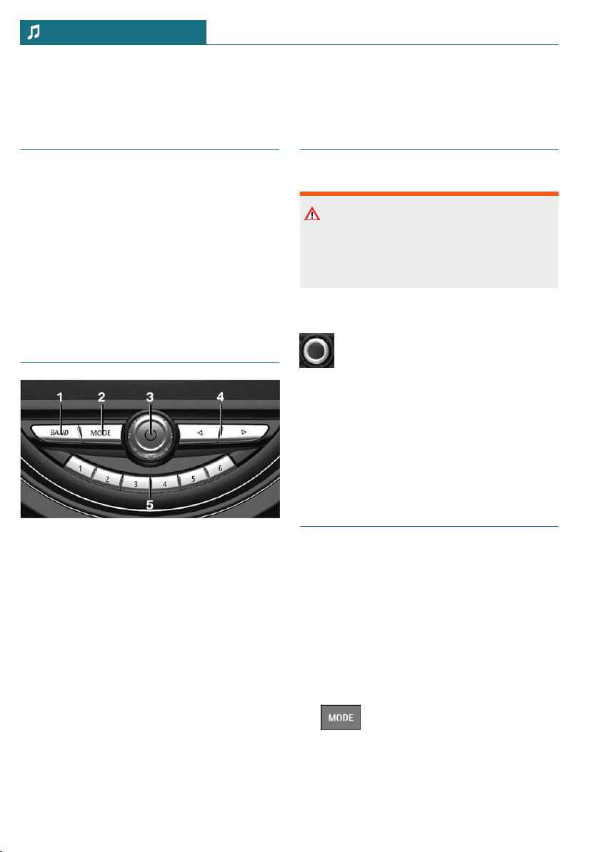
General information
Vehicle features and options
This chapter describes all standard, country-
specific and optional features offered with
the series. It also describes features that are
not necessarily available in your vehicle, for
instance, due to the selected options or
country versions. This also applies to safety-
related functions and systems. When using
these functions and systems, the applicable
laws and regulations must be observed.
Control elements
1 Waveband/satellite radio
2 Change entertainment sources
3 Sound output on/off, volume
4 Changing the station/track
5 Programmable memory buttons
Sound output
Safety information
Warning
A high sound output volume can damage
your hearing. There is a risk of injury. Do
not adjust the volume too high.
Volume and sound output
– Turn the button to adjust the vol-
ume.
– Press the button to switch off the
sound output. Pressing the but-
ton again restores the previous
volume setting.
Audio recording playback is stopped during
muting.
Entertainment sources
General information
Possible entertainment sources:
– Radio, refer to page 228.
– USB audio, refer to page 236.
– Bluetooth audio, refer to page 236.
Changing the entertainment source
On the radio:
1. Press the button.
A list of all currently available entertain-
ment sources is displayed.
Seite 224
ENTERTAINMENT General information
224
Online Edition for Part no. 01402667083 - VI/19

2. Press the button again to select
an entertainment source.
Via the Central Information Display (CID):
1. "Media/Radio"
A list of all possible entertainment sour-
ces is displayed.
2. Select the desired entertainment source.
Via the button on the Controller:
1. Press the button.
The most recently selected entertain-
ment source is played.
2. Press the button again.
A list of all currently available entertain-
ment sources is displayed.
3. Select the desired entertainment source.
Adjusting the selection list of
entertainment sources
It is possible to select which entertainment
sources are displayed in the selection list.
The entertainment source currently being
played cannot be removed from the selec-
tion list.
1. "Media/Radio"
A list of all possible entertainment sour-
ces is displayed.
2. "Personalize menu"
3. Select the desired setting.
Seite 225
General information ENTERTAINMENT
225
Online Edition for Part no. 01402667083 - VI/19

Tone
Vehicle features and options
This chapter describes all standard, country-
specific and optional features offered with
the series. It also describes features that are
not necessarily available in your vehicle, for
instance, due to the selected options or
country versions. This also applies to safety-
related functions and systems. When using
these functions and systems, the applicable
laws and regulations must be observed.
General information
The settings are stored in the currently
used driver profile.
Treble, bass, balance, and
fader
1. "Media/Radio"
2. "Tone"
3. Select the desired setting:
– "Treble": treble adjustment.
– "Bass": depth adjustment.
– "Balance": left/right volume distribu-
tion.
– "Fader": front/rear volume distribu-
tion.
4. To adjust: turn the Controller.
5. To store: press the Controller.
Volume equalization
Concept
An automatic increase of the volume can be
set to compensate for the increasing driving
noises at higher speeds.
Set automatic volume increase
1. "Media/Radio"
2. "Tone"
3. "Volume settings"
4. Select the desired setting:
– "Speed volume": ratio of entertain-
ment volume to speed.
– "PDC": ratio of the volume of the PDC
signal tone to the entertainment vol-
ume.
The basic setting ensures that the
signal tone is audible at any volume.
– "Gong": ratio of the volume of the
signal tone, for instance for safety
belt reminder, to the entertainment
volume.
The basic setting ensures that the
signal tone is audible at any volume.
– "Microphone": sensitivity of the mi-
crophone during a phone call.
The setting is adjusted while calling
and is stored for the mobile phone
used.
– "Speakers": volume of the loudspeak-
ers during a phone call.
Audio recording playback is stopped
during muting.
The setting is adjusted while calling
and is stored for the mobile phone
used.
Seite 226
ENTERTAINMENT Tone
226
Online Edition for Part no. 01402667083 - VI/19

Reset the tone settings
The tone settings are reset to the factory
settings.
1. "Media/Radio"
2. "Tone"
3. "Reset"
Seite 227
Tone ENTERTAINMENT
227
Online Edition for Part no. 01402667083 - VI/19
Radio
Vehicle features and options
This chapter describes all standard, country-
specific and optional features offered with
the series. It also describes features that are
not necessarily available in your vehicle, for
instance, due to the selected options or
country versions. This also applies to safety-
related functions and systems. When using
these functions and systems, the applicable
laws and regulations must be observed.
General information
The settings are stored in the currently
used driver profile.
AM/FM station
General information
Depending on the vehicle equipment and
country version, it may not be possible to
receive AM stations.
Radio Data System RDS
Concept
RDS broadcasts additional information,
such as the station name, in the FM wave-
band.
It is recommended to switch on RDS.
Switching on/off
1. "Media/Radio"
2. "FM"
3. Press the button.
4. "RDS"
Selecting a station
1. "Media/Radio"
2. "FM" or "AM"
The last station listened to will be
played and the station list displayed.
3. Select the desired station.
Changing the station
On the radio:
Press the left or right button.
The previous or next station from the list of
stations is played.
Storing a station
General information
A symbol on the highlighted channel indi-
cates whether the channel has already been
stored.
Symbol Meaning
Station is not stored.
Station is already stored.
Storing the station being played
1. "Media/Radio"
2. "FM" or "AM"
3. Move the Controller to the left.
4. "Save station"
The storage list is displayed.
5. Select the desired memory location.
Seite 228
ENTERTAINMENT Radio
228
Online Edition for Part no. 01402667083 - VI/19

Storing a station that is not being
played
1. "Media/Radio"
2. "FM" or "AM"
3. Highlight the desired station.
4. Press the Controller and hold until the
storage list is displayed.
5. Select the desired memory location.
The stations can also be stored on the pro-
grammable memory buttons, refer to
page 44.
Selecting a station manually
Station selection via the frequency.
1. "Media/Radio"
2. "FM" or "AM"
3. Move the Controller to the left.
4. "Manual search"
5. To select the frequency: turn the Con-
troller.
6. To store the frequency: press the Con-
troller.
Renaming a station
When storing a station with RDS signal, the
RDS information transferred during storing
is accepted as the station name. The station
name can be changed.
1. "Media/Radio"
2. "FM"
3. Select the desired station.
4. Press the button.
5. "Rename to:"
If necessary, wait until the name of the
desired station appears.
6. Press the Controller to store this name.
Additional station information
Concept
If a radio station broadcasts radio text or
radio text plus, this information can be dis-
played, for instance the track or performer
of the music. Availability, content and se-
quence are set by the radio station.
Displaying additional station
information
1. "Media/Radio"
2. "FM"
3. Select the desired station.
4. Press the button.
5. "Station info"
HD Radio™ reception
Concept
Many radio stations broadcast both analog
and digital signals.
General information
When setting a station with a digital signal,
it may take a few seconds before the station
plays in digital quality.
Information about HD Radio stations whose
station name ends with ...HD or with ...HD1:
In areas in which the station is not continu-
ously received in digital mode, the playback
switches between analog and digital recep-
tion. In this case, switch off digital radio re-
ception.
Information about HD Radio multicast sta-
tions whose station name ends
with ...HD2, ...HD3, ...:
In areas in which the station is not continu-
ously received in digital mode, there may be
interruptions of the audible signal lasting
Seite 229
Radio ENTERTAINMENT
229
Online Edition for Part no. 01402667083 - VI/19
several seconds. The duration of the inter-
ruption depends on the reception.
Activating/deactivating digital radio
reception
1. "Media/Radio"
2. "FM" or "AM"
3. Press the button.
4. "HD Radio reception"
This symbol is displayed in the status
line when the audio signal is digital.
Displaying additional information
Some stations broadcast additional informa-
tion on the current track, such as the name
of the artist.
1. "Media/Radio"
2. "FM" or "AM"
3. Select a station.
4. Press the button.
5. "Station info"
License conditions
HD Radio Technology manu-
factured under license from
iBiquity Digital Corporation. U. S. and For-
eign Patents. HD Radio™ and the HD, HD
Radio, and “Arc” logos are proprietary
trademarks of iBiquity Digital Corp.
Satellite radio
General information
Before a channel can be played, you must
subscribe to it via telephone. Several chan-
nels can be combined into specified pack-
ages.
Managing a subscription
General information
In order to enable or unsubscribe from
channels, you must have reception. It is
usually at its best when you have an unob-
structed view of the sky. The channel name
is displayed in the status line.
Enabling channels
1. "Media/Radio"
2. "Satellite radio"
3. Press the button.
4. "Show subscription info"
The phone number and identification
number of the radio are displayed.
5. Call the phone number to have the chan-
nel enabled.
You can unsubscribe from the channels
again via this phone number.
Unsubscribing from channels
1. "Media/Radio"
2. "Satellite radio"
3. Press the button.
4. "Show subscription info"
The phone number and identification
number of the radio are displayed.
5. Call the phone number to cancel your
subscription to the channel.
Selecting channels
You can only listen to enabled channels.
1. "Media/Radio"
2. "Satellite radio"
The last channel played will be played
back and the channel list displayed.
Seite 230
ENTERTAINMENT Radio
230
Online Edition for Part no. 01402667083 - VI/19
3. Select the desired channel from the
channel list.
To display information about the selected
channel:
1. Highlight a channel.
2. Press the button.
3. "Channel information"
Adjusting display of the channel
list
The display of the playback list can be ad-
justed.
1. "Media/Radio"
2. "Satellite radio"
3. Move the Controller to the left.
4. "Change view"
5. Select the desired display:
– "Channel"
The name of the channel will be dis-
played.
– "Artist"
The name of the artist playing will
be displayed.
– "Titles"
The name of the track playing will be
displayed.
Changing the channel
Press the button on the radio.
The next and/or previous channel from the
channel list is played.
Storing a channel
1. "Media/Radio"
2. "Satellite radio"
A symbol on the highlighted channel indi-
cates whether the channel has already been
stored.
Symbol Meaning
Channel is not stored.
Channel is already stored.
To store the channel played:
1. Move the Controller to the left.
2. "Save station"
The storage list is displayed.
3. Select the desired memory location.
Or:
1. Highlight the played channel.
2. Press the Controller.
The storage list is displayed.
3. Select the desired memory location.
To store a channel other than the one
played:
1. Highlight the desired channel.
2. Press the Controller and hold until the
storage list is displayed.
3. Select the desired memory location.
Or:
1. Highlight the desired channel.
2. Press the button.
3. "Save in presets"
The storage list is displayed.
4. Select the desired memory location.
The stations can also be stored on the pro-
grammable memory buttons.
Selecting a category
1. "Media/Radio"
2. "Satellite radio"
Seite 231
Radio ENTERTAINMENT
231
Online Edition for Part no. 01402667083 - VI/19
3. Move the Controller to the left.
4. "Category"
5. Select the desired category.
The subscribed channels from this cate-
gory are displayed.
6. Select the desired channel.
Timeshift
General information
The channel you are currently listening to is
stored in a buffer for up to an hour.
Prerequisite: the signal must be available.
The stored audio track can be played with a
delay following the live broadcast. When
the memory is full, the older tracks are over-
written. The memory is cleared when a new
channel is selected or when the vehicle is
switched off.
Opening the timeshift function
1. "Media/Radio"
2. "Satellite radio"
3. Move the Controller to the left.
4. "Time shift"
Time shift forward/reverse
Within the stored recording, it is possible
to jump to any point in time.
Press the button on the radio or
turn the Controller.
You can jump to the next or the previous
track.
Press and hold the button on the
radio.
The recording is spooled forward or back.
Timeshift menu
Symbol Function
Go to the live broadcast.
Automatic timeshift deacti-
vated/activated.
/ Playback/pause.
Automatic timeshift
With automatic timeshift, audio playback is
paused for the following events.
– Incoming and outgoing telephone calls.
– Activation of the voice activation sys-
tem.
– Muting.
After that, audio playback is continued from
the time of the interruption.
1. Move the Controller to the left.
2. To activate:
"Automatic time shift"
Deactivate:
"Automatic time shift".
Smart Favorites
General information
A maximum of 6 channels can be stored as
Smart Favorites.
If a stored channel is selected, the current
track will be played from the beginning.
Adding the current channel to Smart
Favorites
1. Press the button.
2. "Add to Smart Favorites"
Seite 232
ENTERTAINMENT Radio
232
Online Edition for Part no. 01402667083 - VI/19
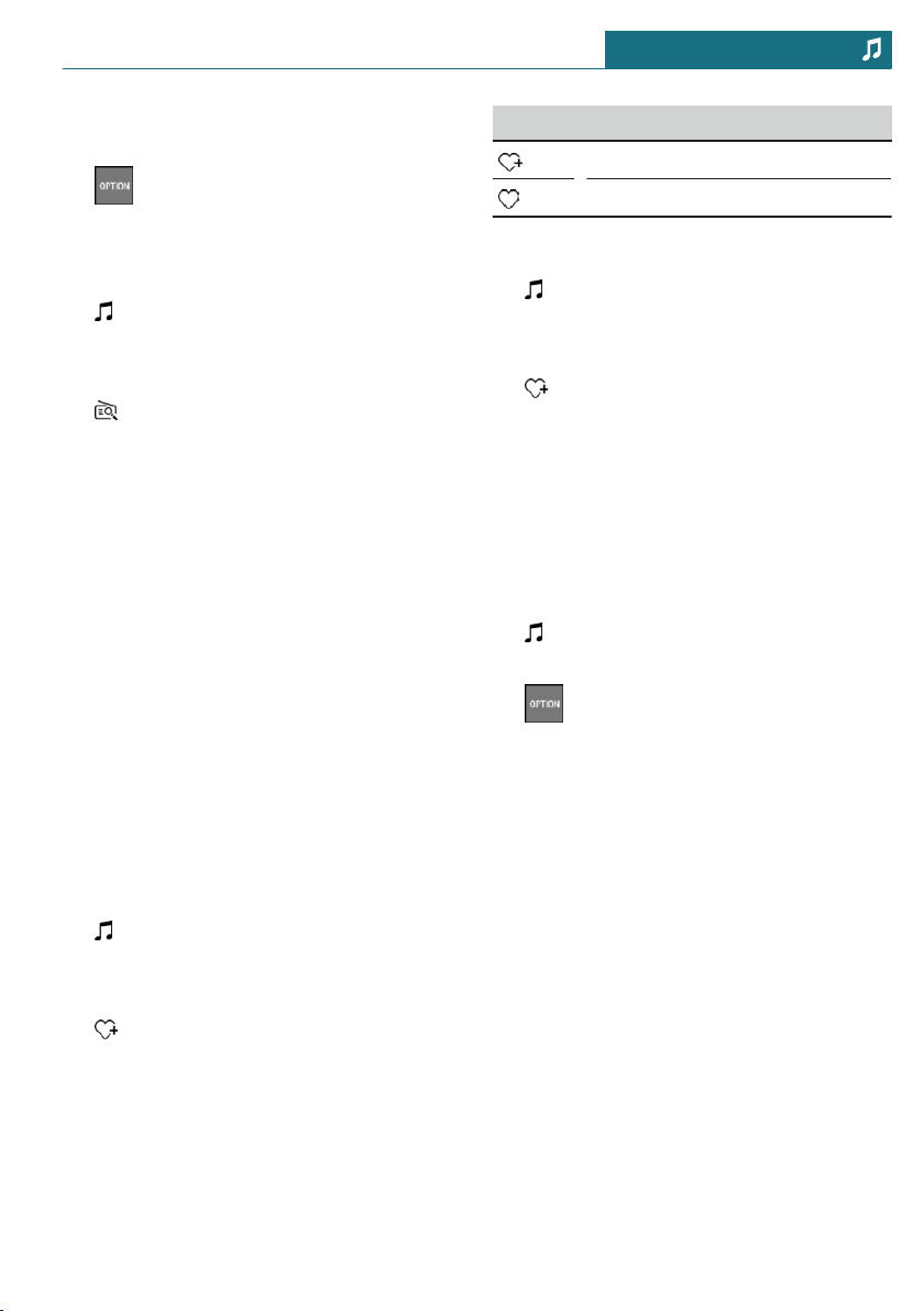
Removing the current channel from
Smart Favorites
1. Press the button.
2. "Remove from Smart Favorites"
Selecting Smart Favorite
1. "Media/Radio"
2. "Satellite radio"
3. Move the Controller to the left.
4. "Category"
5. Select a Smart Favorite.
The subscribed channels from this cate-
gory are displayed.
6. Select the desired channel.
Favorites
General information
A performer, a track, a league or a team can
be stored as a favorite. If the stored favorite
is played on a channel, a message appears
on the Control Display. Up to 30 Favorites
can be stored.
Storing the artist or track
It is only possible to store Favorites that are
currently being broadcast. The channel in-
formation must be available.
1. "Media/Radio"
2. "Satellite radio"
3. Move the Controller to the left.
4. "Add to favorites"
5. Highlight the performer or track, and
press the Controller.
A symbol indicates whether the artist and
track were already stored.
Symbol Meaning
Artist/track is not stored.
Artist/track was already stored.
Storing the league or team
1. "Media/Radio"
2. "Satellite radio"
3. Move the Controller to the left.
4. "Add to favorites"
5. "Add sports information"
6. Select the type of sport desired.
7. Select the desired team.
Activating/deactivating a notification
A notification can be displayed when a se-
lected favorite is being played.
1. "Media/Radio"
2. "Satellite radio"
3. Press the button.
4. "Manage favorites"
The stored Favorites are displayed.
5. "Activate alert"
Set a check mark to activate notification
for the selected Favorites.
Remove the check mark to deactivate
notification for the selected Favorites.
6. Select the desired Favorites.
Opening the Favorites
If an activated favorite is played back, the
following message is displayed for approx.
20 seconds: "Favorite on air!".
To change to the played Favorites:
Tap on the message on the Control Display.
Or:
1. Move the Controller to the left.
Seite 233
Radio ENTERTAINMENT
233
Online Edition for Part no. 01402667083 - VI/19

2. "Favorite alert"
Select the symbol while the message is
shown.
The displayed favorite is played.
When the message disappears, the list of
channels that is currently playing one of the
stored Favorites can be displayed.
1. Move the Controller to the left.
2. "Category"
3. Select the Favorites list.
The channels that are currently playing
a favorite are displayed.
4. Select the channel that you would like to
change to.
Deleting Favorites
1. "Media/Radio"
2. "Satellite radio"
3. Press the button.
4. "Manage favorites"
The stored Favorites are displayed.
5. Highlight the desired favorites.
6. Press the button.
7. "Delete entry"
Traffic Jump
General information
Traffic and weather information for a se-
lected region is broadcast every few mi-
nutes.
Selecting a region
1. "Media/Radio"
2. "Satellite radio"
3. Press the button.
4. "Configure jump"
5. Select the desired region.
Activating/deactivating Traffic Jump
You must have reception in order to acti-
vate or deactivate.
1. "Media/Radio"
2. "Satellite radio"
3. Press the button.
4. "Configure jump"
5. "Jump to:"
Place a check mark to activate Traffic
Jump.
Information for the selected region is
broadcast as soon as it is available.
Remove the check mark to deactivate
Traffic Jump.
Channel magazine
In the channel magazine, the current and
subsequent program for each channel
booked is displayed.
1. "Media/Radio"
2. "Satellite radio"
3. Move the Controller to the left.
4. "SiriusXM program guide"
Automatic update
About twice a year, Sirius performs an up-
date of the channel names and positions.
The update takes place automatically and
may take several minutes.
System limits
– Reception may not be available in some
situations, such as under certain envi-
ronmental or topographical conditions.
The satellite radio has no influence on
this.
Seite 234
ENTERTAINMENT Radio
234
Online Edition for Part no. 01402667083 - VI/19

– Graphical contents can be received un-
der certain circumstances.
– The signal may not be available in tun-
nels or underground garages next to tall
buildings or near trees, mountains or
other powerful sources of radio interfer-
ence.
Stored stations
General information
Up to 40 stations can be stored.
Selecting a station
1. "Media/Radio"
2. "Presets"
3. Select the desired station.
Deleting a station
1. "Media/Radio"
2. "Presets"
3. Highlight the station you want to delete.
4. Press the button.
5. "Delete entry"
Seite 235
Radio ENTERTAINMENT
235
Online Edition for Part no. 01402667083 - VI/19
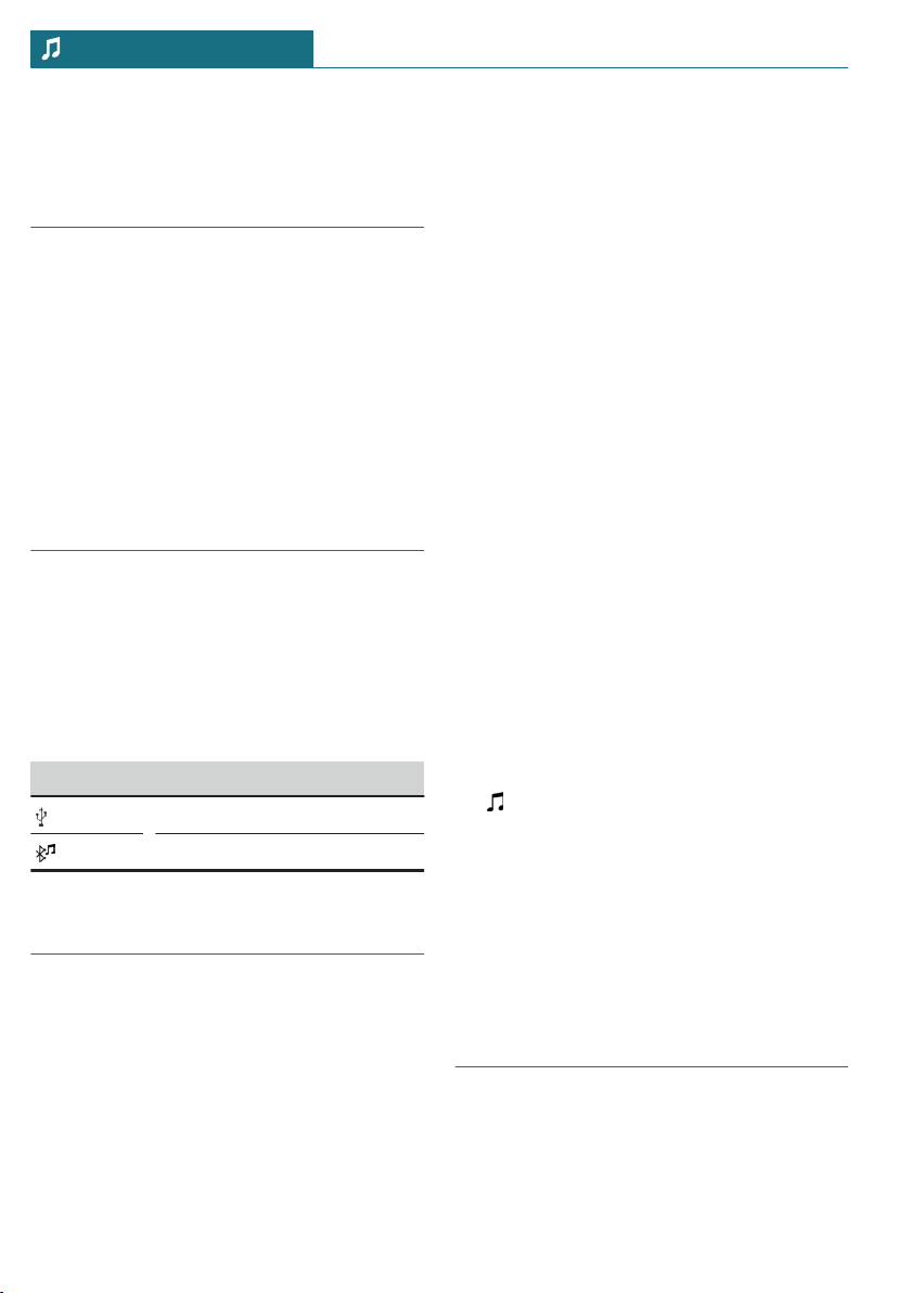
Audio
Vehicle features and options
This chapter describes all standard, country-
specific and optional features offered with
the series. It also describes features that are
not necessarily available in your vehicle, for
instance, due to the selected options or
country versions. This also applies to safety-
related functions and systems. When using
these functions and systems, the applicable
laws and regulations must be observed.
General information
Music tracks, audio books, and podcasts can
be played back. Sound is played back
through the vehicle loudspeakers.
Settings are stored for the driver profile
currently used.
Depending on the vehicle equipment, the
following audio sources can be used:
Symbol Meaning
USB storage device.
Bluetooth audio.
USB storage device
Playable formats
Popular audio formats such as MP3, AAC or
WMA can be played.
Apple iPod/iPhone
The music search and playback of Apple
iPod/iPhone are supported.
Audio player and storage media
with USB port
Information on all music tracks, for instance
artist, genre or track, as well as playback
lists, are transmitted into the vehicle. This
may take some time, depending on the USB
storage device, file size, and number of
tracks.
During the transfer, the tracks can be called
up via the file directory.
The information for approx. 10,000 tracks
can be stored in the vehicle.
Music tracks with integrated Digital Rights
Management DRM cannot be played.
Selecting the USB storage device
Information on the USB interface, refer to
page 197.
1. Connect the USB storage device to the
USB interface.
The adapter cable supplied with the USB
storage device would be ideal.
2. "Media/Radio"
3. "USB"
Or:
Select the name of the USB storage de-
vice.
Further playback descriptions, refer to
page 237.
Bluetooth audio
General information
– Playback of music files on external devi-
ces such as audio devices or mobile
phones via Bluetooth.
Seite 236
ENTERTAINMENT Audio
236
Online Edition for Part no. 01402667083 - VI/19
– The volume of the sound output depends
on the device. If necessary, adjust the
volume on the device.
– Up to four external devices can be con-
nected to the vehicle.
Functional requirements
– Bluetooth device is connected to the ve-
hicle.
– Bluetooth audio playback was activated.
Selecting the Bluetooth device
1. "Media/Radio"
2. Select the desired Bluetooth device from
the list.
Further playback descriptions, refer to
page 237.
If the Bluetooth device is not listed in the
device list, Bluetooth audio playback may
have not been activated. To activate Blue-
tooth audio playback, proceed as follows:
1. "Media/Radio"
2. "Manage mobile devices"
3. Select the desired Bluetooth device.
4. "Bluetooth® audio"
Playback
General information
Once an audio source has been selected, in-
formation on playback appears on the Con-
trol Display.
Information available for the current track
followed by the playback list is shown on
the Control Display. Content and scope of
the playback list depend on the type of the
selected playback source and the search cri-
teria applied.
For USB and Bluetooth devices, the selected
playback list is displayed. This can be the
result of a search or of a previously stored
playback list.
Further functions are displayed by moving
the Controller to the left. The scope of these
functions depends on the selected audio
source.
Depending on the supported Bluetooth ver-
sion, some Bluetooth device functions may
not be available when using the Central In-
formation Display (CID). If necessary, the
missing functions can be accessed directly
on the device itself.
Selecting a track
Select the desired track from the playlist.
Starting with the selected track, all tracks of
the playback list are played.
Changing the track
On the radio:
Press the left or right button.
The previous or next track from the playlist
is played.
Fast forward/reverse
On the radio:
Press and hold the left or right but-
ton.
Search criteria
General information
The possible search criteria depend on the
selected audio source.
Seite 237
Audio ENTERTAINMENT
237
Online Edition for Part no. 01402667083 - VI/19

Searching for track information
The following search criteria refer to the
data stored in the track information.
1. Move the Controller to the left.
2. "Media search"
3. Select the desired setting:
– "Search"
All the tracks containing the search
string are displayed. Entering more
characters will continue to narrow
down the search results.
Tilt the Controller to the right to dis-
play the list of results.
– "Genres"
A list of all available genres is dis-
played.
Select a genre to display all respec-
tive artists.
– "Artists"
A list of all available artists is dis-
played.
Select an artist to display all respec-
tive albums and tracks.
– "Albums"
A list of all available albums is dis-
played.
Select an album to display all respec-
tive tracks.
– "Titles"
A list of all available tracks is dis-
played.
4. Select album, if needed.
5. Select the track at which the playback is
going to begin.
The search for artists and titles can also be
selected directly.
1. Move the Controller to the left.
2. "Artists" or "Titles"
Tracks where the selected search criterion
is not stored are summarized under "un-
known". Tracks without track information
can only be found via the directory struc-
ture.
Search playlists
1. Move the Controller to the left.
2. "Media search"
3. "Playlists"
A list of all available playback lists is
displayed.
4. Select the playback list.
5. Select the track at which the playback is
going to begin.
Information on playback appears on the
Control Display. A playback list is cre-
ated from the search results.
Search audio books and podcasts
Depending on the USB storage device and
equipment, separate audio book and podcast
searches are possible.
1. Move the Controller to the left.
2. "Media search"
3. Select the desired setting:
– "Podcasts"
A list of all available podcasts is dis-
played.
– "Audio books"
A list of all available audio books is
displayed.
4. Select the track at which the playback is
going to begin.
Information on playback appears on the
Control Display. A playback list is cre-
ated from the search results.
Seite 238
ENTERTAINMENT Audio
238
Online Edition for Part no. 01402667083 - VI/19

Search directory structure
It is possible to search the USB storage de-
vices via the directory structure.
The names of folders and tracks correspond
to folder and file names. The folder and file
names can deviate from the names in the
track information.
1. Move the Controller to the left.
2. "Media search"
3. "Browse folder"
4. Change into a sub folder, if needed.
Select the track at which the playback is
going to begin.
Information on playback appears on the
Control Display. A playback list is cre-
ated from the search results.
Random playback
Concept
The current playlist or all tracks of the se-
lected audio source are played back in ran-
dom order.
Select random
1. Move the Controller to the left.
2. "Shuffle"
Seite 239
Audio ENTERTAINMENT
239
Online Edition for Part no. 01402667083 - VI/19

240
Online Edition for Part no. 01402667083 - VI/19

COMMUNICATION
Telephone ................................................................................................. 242
MINI Connected ..................................................................................... 246
241
Online Edition for Part no. 01402667083 - VI/19
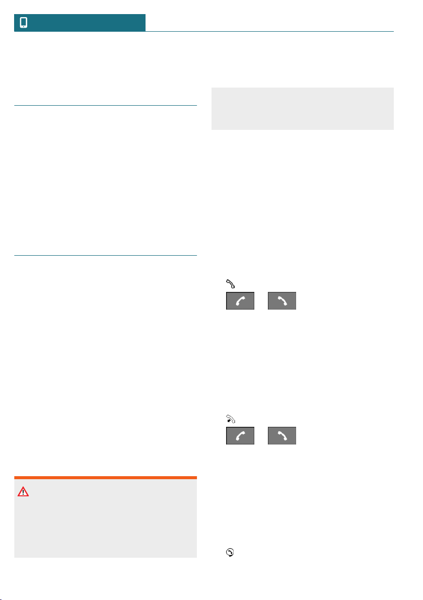
Telephone
Vehicle features and options
This chapter describes all standard, country-
specific and optional features offered with
the series. It also describes features that are
not necessarily available in your vehicle, for
instance, due to the selected options or
country versions. This also applies to safety-
related functions and systems. When using
these functions and systems, the applicable
laws and regulations must be observed.
Telephone functions
General information
Mobile phones can be connected to the ve-
hicle via Bluetooth. Pair and connect the
mobile phone with the vehicle, refer to
page 49.
At high temperatures, the charge function
of the mobile phone can be limited where
appropriate and functions are no longer exe-
cuted.
Do not operate a mobile phone that is con-
nected to the vehicle on the mobile phone
keypad, as this may lead to a malfunction.
When the mobile phone is used via the ve-
hicle, refer to the owner's manual of the mo-
bile phone.
Safety information
Warning
Operating the integrated information sys-
tems and communication devices while
driving can distract from traffic. It is pos-
sible to lose control of the vehicle. There is
a risk of accident. Only use the systems or
devices when the traffic situation allows.
As warranted, stop and use the systems
and devices while the vehicle is stationary.
Incoming call
If the number of the caller is stored in the
phone book and is transmitted by the net-
work, the name of the contact is displayed.
Otherwise, only the phone number is dis-
played.
Accepting a call
Incoming calls can be answered in several
ways.
– Via Central Information Display (CID):
"Accept"
– /
Press the corresponding button on the
steering wheel.
Rejecting a call
"Reject"
Ending a call
– Via Central Information Display (CID):
"End call"
– /
Press the corresponding button on the
steering wheel.
Last calls
The last outgoing, missed, and incoming
calls are transferred to the vehicle.
Displays
1. "Communication"
Seite 242
COMMUNICATION Telephone
242
Online Edition for Part no. 01402667083 - VI/19

2. "Recent calls"
3. The 20 last calls are displayed.
Filtering call list
1. "Calls:"
2. Select the desired setting.
Selecting number from list
Select from list. Call is established via the
mobile phone.
To cancel: "End call"
Active calls
Adjusting the volume
Turn the volume button on the radio during
the call, until the desired volume is reached.
The setting is stored for the driver profile
currently used.
Automatic volume equalization
1. "My MINI"
2. "System settings"
3. "Tone"
4. "Volume settings"
5. "Microphone" or "Speakers"
6. To adjust: turn the Controller.
7. To store: press the Controller.
Dialing a number
1. "Communication"
2. "Dial number"
3. Enter the numbers.
4. Select the symbol.
Holding, resuming
An active call can be put on hold and re-
sumed later on.
– "Hold/Resume"
Call is put on hold.
– "Hold/Resume"
Call is resumed.
Muting the microphone
When a call is active, the microphone can
be muted.
"Microphone"
The muted microphone is automatically ac-
tivated:
– When a new connection is established.
– When switching between call parties.
DTMF suffix dialing
DTMF suffix dialing can be used for gaining
access to network services or for control-
ling devices, for instance to make a remote
inquiry of an answering machine. The
DTMF code is needed for this purpose.
1. "Keypad dialing"
2. Enter DTMF code.
Calls with multiple parties
General information
You can switch between calls or connect
two calls to a single conference call. These
functions must be supported by the mobile
phone and service provider.
Accepting a call while speaking to
another party
If a second call comes in during an ongoing
call, a call waiting signal sounds where ap-
propriate.
"Accept"
The call is accepted and the existing call is
put on hold.
Seite 243
Telephone COMMUNICATION
243
Online Edition for Part no. 01402667083 - VI/19

Establishing a second call
An additional call can be established while a
call is active.
1. "Contacts"
2. Select new number.
The call is started and the first call is put
on hold.
Switching between two calls, hold call
You can switch between two calls.
1. Establish two calls.
2. "Resume"
The call on hold is resumed.
Establishing a conference call
Two calls can be connected to a single tele-
phone conference call. The calls must be
made from the same mobile phone.
1. Establish two calls.
2. "Conference call"
Hands-free system
General information
Calls that are being made on the hands-free
system can be continued on the mobile
phone and vice versa.
From the mobile phone to the hands-
free system
Calls that were begun outside of the Blue-
tooth range of the vehicle can be continued
on the hands-free system with standby state
or the ignition switched on. The vehicle key
must be located in the vehicle for this to
work.
Depending on the mobile phone, the system
automatically switches to the hands-free
system.
If the system does not switch over automat-
ically, follow the instructions on the display
of the mobile phone. Refer also to the own-
er's manual of the mobile phone.
From the hands-free system to the
mobile phone
Calls that are made on the hands-free sys-
tem can in some cases be continued on the
mobile phone; this depends on the mobile
phone.
Follow the instructions on the display of the
mobile phone. Refer also to the owner's
manual of the mobile phone.
Contacts
General information
Contacts from the mobile phone are trans-
ferred and displayed. Contact pictures can
be displayed, if the mobile phone supports
this function.
Displaying all contacts
1. "Communication"
2. "Contacts"
The contacts are listed in alphabetical
order. Depending on the number of con-
tacts, contact search and quick search
are offered.
Contact search
Contact search is available with more than
30 contacts.
1. "Search"
2. Enter the letters.
The hits are displayed on the right side.
3. Move the Controller to the right.
4. Select the contact to display it.
Seite 244
COMMUNICATION Telephone
244
Online Edition for Part no. 01402667083 - VI/19

Quick search in lists
Quick search is available starting from
30 contacts. All letters, for which there are
entries, are displayed in alphabetical order
on the left of the Control Display.
1. Turn the Controller to the left or right
quickly.
All letters, for which contacts are stored,
are displayed on the left.
2. Select the first letter of the desired con-
tact.
The first entry of the selected letter is
displayed.
Sorting contacts
Contact names can be displayed in a differ-
ent order. Depending on how the contacts
were stored on the mobile phone, the sort-
ing order of the contacts may differ from
the selected sorting order.
1. Press the button.
2. "Sort contacts"
3. "Last name" or "First name"
Voice command response
A connected smartphone can be used via
voice operation.
Activate voice command response on the
smartphone for this purpose.
Button on
the steering
wheel
Function
Press the button for at
least 3 seconds. Voice
command response is acti-
vated on the smartphone.
The symbol indicates that the voice
command response is active. Depending
on your vehicle's optional features, the sym-
bol can be displayed on the Control Display,
in the instrument cluster or on the Head-up
Display.
Seite 245
Telephone COMMUNICATION
245
Online Edition for Part no. 01402667083 - VI/19
MINI Connected
Vehicle features and options
This chapter describes all standard, country-
specific and optional features offered with
the series. It also describes features that are
not necessarily available in your vehicle, for
instance, due to the selected options or
country versions. This also applies to safety-
related functions and systems. When using
these functions and systems, the applicable
laws and regulations must be observed.
Safety information
Warning
Operating the integrated information sys-
tems and communication devices while
driving can distract from traffic. It is pos-
sible to lose control of the vehicle. There is
a risk of accident. Only use the systems or
devices when the traffic situation allows.
As warranted, stop and use the systems
and devices while the vehicle is stationary.
Teleservices
Concept
Teleservices are services that help to main-
tain vehicle mobility.
General information
The offering depends on the equipment ver-
sion of the vehicle and the country-specific
variant.
For further information on the available
services, the vehicle manufacturer recom-
mends contacting a service center or cus-
tomer support.
Teleservices can comprise the following
services:
– Service Request, refer to page 246.
– Teleservice Report, refer to page 247.
– Teleservice Battery Guard, refer to
page 247.
– Your dealer’s service center, refer to
page 247.
– Roadside Assistance, refer to page 299.
Requirements
– Active MINI Connected contract or
equipment version with intelligent
emergency call.
– Cellular network reception.
– Ignition or standby state is switched on.
Service Request
Automatic Service Request
The Teleservice data on the vehicle's serv-
ice requirements is sent automatically to
the service center by MINI prior to the
service deadline. If feasible, the service cen-
ter will contact the customer about arrang-
ing a service appointment.
This way, the dealer’s service center can
plan the necessary work in advance. This
shortens the duration of the service ap-
pointment.
Manual Service Request
Concept
Using a manually initiated Service Request,
data on the vehicle's service requirements
is directly sent by MINI to the service cen-
Seite 246
COMMUNICATION MINI Connected
246
Online Edition for Part no. 01402667083 - VI/19

ter. If possible, the service center will con-
tact you to arrange a service appointment.
General information
A Service Request can be started via a
Check Control message, refer to page 116.
Carry out service registration via the Check
Control message: "Service request".
Starting a Service Request
1. "MINI Connected"
2. "MINI Assist"
3. "Teleservice Call"
Last Service Request
Concept
The last Service Request, for instance the
last report to the dealer’s service center, can
be displayed on the Control Display.
Displaying the last Service Request
Check to see when the last Service Request
was transmitted.
1. "My MINI"
2. "Vehicle status"
3. Move the Controller to the left.
4. "Teleservice Call"
Teleservice Report
Concept
Transmits technical data that is evaluated
for the ongoing development of MINI prod-
ucts from the vehicle to MINI in regular in-
tervals, if needed.
General information
The Teleservice Report is free of charge and
is activated in vehicles that meet the follow-
ing requirements:
– Certain technical requirements are met.
– Active MINI Connected contract.
– Equipped with intelligent emergency
call.
Neither personal data nor position data is
transmitted.
Teleservice Battery Guard
Concept
If the battery charge state falls below cer-
tain values, MINI will inform you or your
dealer’s service center directly in defined
cases or the next time the vehicle is started.
General information
If necessary and possible, the dealer's serv-
ice center will contact you to arrange a
service appointment.
The Battery Guard Teleservice is available
on a country-specific basis and under the
following conditions:
– Certain technical requirements are met.
– Active MINI Connected contract.
– To receive information from the Battery
Guard Teleservice, your contact data
must be stored in the MINI Connected
customer portal.
Your dealer’s service center
Concept
The preset service center is displayed and is
possible to contact the service center.
General information
To use Service Partner management in the
vehicle, log in with the MINI Connected ac-
cess data in the MINI Connected customer
portal. In addition, your vehicle must be as-
signed to your account in the MINI Con-
nected customer portal.
Seite 247
MINI Connected COMMUNICATION
247
Online Edition for Part no. 01402667083 - VI/19

Displaying service centers
The service center that is currently as-
signed to the vehicle is displayed as a con-
tact in the vehicle.
1. "MINI Connected" or
"Communication"
2. "MINI Assist"
3. "Your service center" or select service
partner management if necessary.
The assigned service center is displayed
along with all its contact information.
Depending on the vehicle equipment, the
following functions are available in a con-
tact:
– Call contact.
Updating MINI Assist
Concept
Starts the manual update of all services
available in the vehicle.
Updating services
1. "MINI Connected"
2. Press the button.
3. "Update MINI Services"
Customer support
Concept
Contact customer support for information
on all aspects of your vehicle.
Calling customer support
1. "MINI Connected"
2. "MINI Assist"
3. "Customer support"
The customer support is displayed and a
voice connection is established. If a
voice connection is not established, dial
the number manually.
Seite 248
COMMUNICATION MINI Connected
248
Online Edition for Part no. 01402667083 - VI/19

Seite 249
MINI Connected COMMUNICATION
249
Online Edition for Part no. 01402667083 - VI/19

250
Online Edition for Part no. 01402667083 - VI/19

MOBILITY
Refueling .................................................................................................. 252
Fuel ............................................................................................................ 254
Wheels and tires .................................................................................... 256
Engine compartment ............................................................................ 279
Engine oil ................................................................................................. 282
Coolant ...................................................................................................... 286
Maintenance ........................................................................................... 288
Replacing components ......................................................................... 290
Breakdown assistance .......................................................................... 299
Care ............................................................................................................ 307
251
Online Edition for Part no. 01402667083 - VI/19
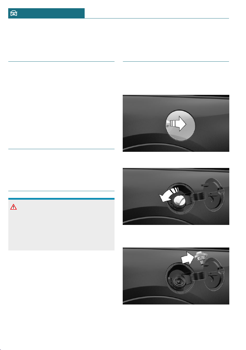
Refueling
Vehicle features and options
This chapter describes all standard, country-
specific and optional features offered with
the series. It also describes features that are
not necessarily available in your vehicle, for
instance, due to the selected options or
country versions. This also applies to safety-
related functions and systems. When using
these functions and systems, the applicable
laws and regulations must be observed.
General information
Follow the fuel recommendation, refer to
page 254, prior to refueling.
Safety information
NOTICE
With a driving range of less than
30 miles/50 km the engine may no longer
have sufficient fuel. Engine functions are
not ensured anymore. There is a risk of
damage to property. Refuel promptly.
Fuel cap
Opening
1. Grasp the fuel filler flap at the rear edge
and open it.
2. Turn the fuel cap counterclockwise.
3. Place the fuel cap in the bracket at-
tached to the fuel filler flap.
Seite 252
MOBILITY Refueling
252
Online Edition for Part no. 01402667083 - VI/19

Closing
Warning
The retaining strap of the fuel cap can be
jammed and crushed during closing. The
cap cannot be correctly closed. Fuel or fuel
vapors can escape. There is a risk of injury
or risk of damage to property. Pay atten-
tion that the retaining strap is not jammed
or crushed when closing the cap.
1. Fit the cap and turn it clockwise until
you clearly hear a click.
2. Press on the fuel filler flap until it en-
gages.
Emergency unlocking
It may be necessary in certain situations to
unlock the fuel filler flap manually, for in-
stance with an electrical fault.
Have fuel filler flap unlocked by a dealer’s
service center or another qualified service
center or repair shop.
Follow the following when re-
fueling
General information
When refueling, insert the filler nozzle
completely into the filler pipe. Lifting up the
fuel pump nozzle during refueling causes:
– Premature switching off.
– Reduced return of the fuel vapors.
The fuel tank is full when the filler nozzle
clicks off the first time.
Make sure that the fuel cap is closed prop-
erly after refueling, otherwise the emissions
warning light may light up.
Follow safety regulations posted at the gas
station.
Safety information
NOTICE
Fuels are toxic and aggressive. Overfilling
of the fuel tank can damage the fuel sys-
tem. Painted surfaces may be damaged by
contact with fuel. Escaping fuel can harm
the environment. There is a risk of damage
to property. Avoid overfilling.
Seite 253
Refueling MOBILITY
253
Online Edition for Part no. 01402667083 - VI/19
Fuel
Vehicle features and options
This chapter describes all standard, country-
specific and optional features offered with
the series. It also describes features that are
not necessarily available in your vehicle, for
instance, due to the selected options or
country versions. This also applies to safety-
related functions and systems. When using
these functions and systems, the applicable
laws and regulations must be observed.
Fuel recommendation
General information
Depending on the region, many gas stations
sell fuel that has been customized to winter
or summer conditions. Fuel that is available
in winter, for instance helps make a cold
start easier.
Gasoline
General information
For the best fuel efficiency, the gasoline
should be sulfur-free or very low in sulfur
content.
Fuels that are marked on the gas pump as
containing metal must not be used.
Fuels with a maximum ethanol content of
25 %, i. e. E10 or E25, may be used for refu-
eling.
Ethanol should meet the following quality
standards:
US: ASTM 4806–xx
CAN: CGSB-3.511–xx
xx: comply with the current standard in
each case.
Safety information
NOTICE
Even small quantities of the wrong fuel or
wrong fuel additives can damage the fuel
system and engine. Furthermore, the cata-
lytic converter is permanently damaged.
There is a risk of damage to property. Do
not refuel or add the following in the case
of gasoline engines:
– Leaded gasoline.
– Metallic additives, for instance man-
ganese or iron.
Do not press the Start/Stop button after
refueling with the wrong fuel. Contact a
dealer’s service center or another qualified
service center or repair shop.
NOTICE
Incorrect fuels can damage the fuel system
and the engine. There is a risk of damage
to property. Do not use fuels with a higher
percentage of ethanol than recommended.
Do not refuel with fuels containing metha-
nol, e.g. M5 to M100.
NOTICE
Fuel that does not comply with the mini-
mum quality can compromise engine func-
tion or cause engine damage. There is a
risk of damage to property. Do not fill with
fuel that does not comply with the mini-
mum quality.
Seite 254
MOBILITY Fuel
254
Online Edition for Part no. 01402667083 - VI/19

CAUTION
The use of poor-quality fuels may result in
harmful engine deposits or damage. Addi-
tionally, problems relating to drivability,
starting and stalling, especially under cer-
tain environmental conditions such as
high ambient temperature and high alti-
tude, may occur.
If drivability problems are encountered,
we recommend switching to a high quality
gasoline brand and a higher octane grade
— AKI number — for a few tank fills. To
avoid harmful engine deposits, it is highly
recommended to purchase gasoline from
Top Tier retailers.
Failure to comply with these recommenda-
tions may result in the need for unsched-
uled maintenance.
Recommended fuel grade
MINI recommends AKI 91.
John Cooper Works:
MINI recommends AKI 93.
Refuel with this gasoline to achieve the
rated performance and consumption values.
Minimum fuel grade
MINI recommends AKI 89.
John Cooper Works:
MINI recommends AKI 91.
If you use gasoline with this minimum AKI
Rating, the engine may produce knocking
sounds when starting at high external tem-
peratures. This has no effect on the engine
life.
Seite 255
Fuel MOBILITY
255
Online Edition for Part no. 01402667083 - VI/19

Wheels and tires
Vehicle features and options
This chapter describes all standard, country-
specific and optional features offered with
the series. It also describes features that are
not necessarily available in your vehicle, for
instance, due to the selected options or
country versions. This also applies to safety-
related functions and systems. When using
these functions and systems, the applicable
laws and regulations must be observed.
Tire inflation pressure
General information
The tire characteristics and tire inflation
pressure influence the following:
– The service life of the tires.
– Road safety.
– Driving comfort.
– Fuel consumption.
Safety information
Warning
A tire with too little or no tire inflation
pressure may heat up significantly and
sustain damage. This will have a negative
impact on aspects of handling, such as
steering and braking response. There is a
risk of accident. Regularly check the tire
inflation pressure, and correct it as
needed, for instance twice a month and be-
fore a long trip.
Tire inflation pressure
specifications
In the tire inflation pressure table
The tire inflation pressure table, refer to
page 258, contains all tire inflation pres-
sure specifications for the specified tire
sizes at the ambient temperature. The tire
inflation pressure values apply to tire sizes
approved by the manufacturer of the vehicle
for the vehicle type.
To identify the correct tire inflation pres-
sure, please note the following:
– Tire sizes of your vehicle.
– Maximum permitted driving speed.
Checking the tire inflation pressure
General information
Tires heat up while driving. The tire infla-
tion pressure increases with the tire tem-
perature.
Tires have a natural, consistent loss of tire
inflation pressure.
The displays of inflation devices may under-
read by up to 0.1 bar/2 psi.
Checking using tire inflation pressure
specifications in the tire inflation
pressure table
The tire inflation pressure specifications in
the tire inflation pressure table only relate
to cold tires or tires at the same tempera-
ture as the ambient temperature.
Only check the tire inflation pressure levels
when the tires are cold, i.e.:
– Driving range of max. 1.25 miles/2 km
has not been exceeded.
Seite 256
MOBILITY Wheels and tires
256
Online Edition for Part no. 01402667083 - VI/19
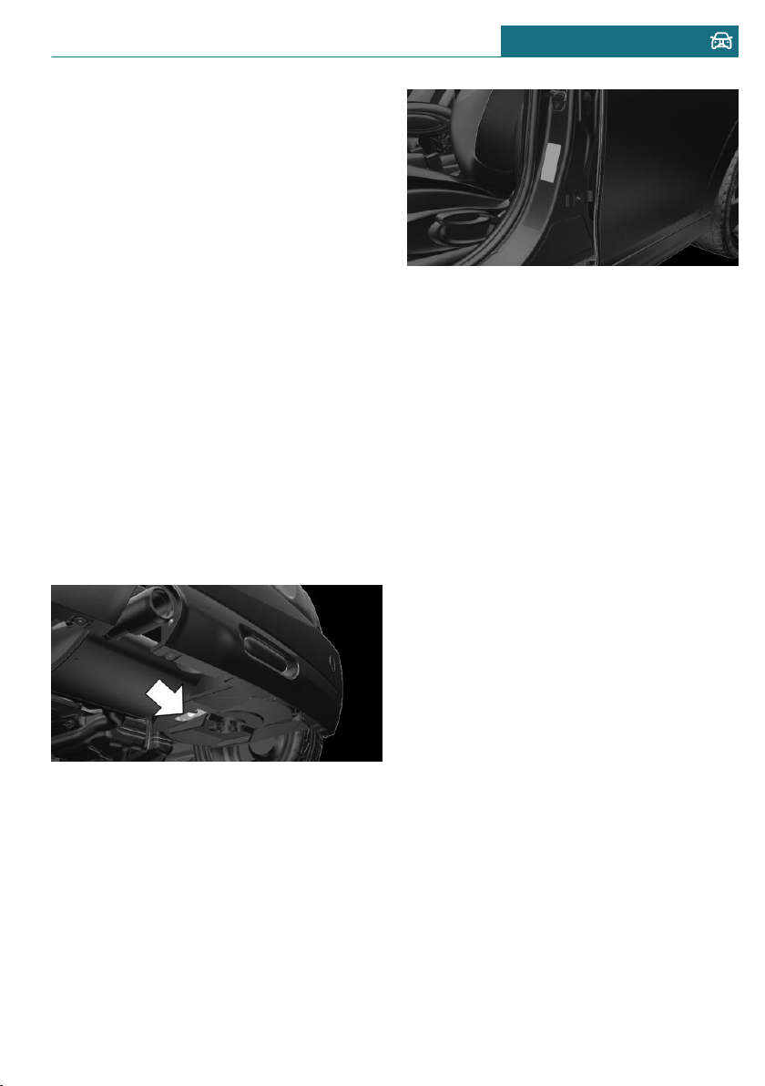
– If the vehicle has not moved again for at
least 2 hours after a trip.
1. Determine the intended tire inflation
pressure levels for the mounted tires.
2. Check the tire inflation pressure in all
four tires, using a pressure gage, for ex-
ample.
3. Correct the tire inflation pressure if the
actual tire inflation pressure deviates
from the intended tire inflation pres-
sure.
4. Check whether all valve caps are
screwed onto the tire valves.
After correcting the tire inflation
pressure
For run-flat tires: reinitialize run-flat tires.
For the Tire Pressure Monitor TPM: reset
the Tire Pressure Monitor TPM.
Checking the tire inflation pressure of
the emergency wheel
Located behind the bumper on the under-
side of the vehicle is an opening for check-
ing the tire inflation pressure.
Tire inflation pressures up to
100 mph/160 km/h
For speeds of up to 100 mph/160 km/h and
for optimum driving comfort, note the pres-
sure values in the tire inflation pressure ta-
ble, refer to page 258, and adjust as neces-
sary.
These pressure values can also be found on
the tire inflation pressure label on the driv-
er's door pillar.
Do not exceed a speed of 100 mph/
160 km/h.
Seite 257
Wheels and tires MOBILITY
257
Online Edition for Part no. 01402667083 - VI/19
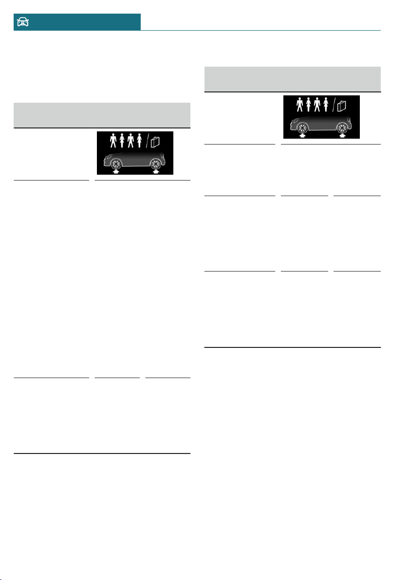
Tire pressure values up to
100 mph/160 km/h
On 3-door models: COOPER
Tire size Pressure specifica-
tions in bar/PSI
Specifications in
bar/PSI with cold
tires
175/65 R 15 84
H A/S
195/55 R 16 87
V A/S
205/45 R 17 88
V XL A/S
195/55 R 16 87
W
205/45 R 17 88
W XL
175/65 R 15 88
H XL M+S
195/55 R 16 87
H M+S
205/45 R 17 88
V XL M+S
2.4 / 35 2.2 / 32
205/40 R 18 86
W XL
175/60 R 16 86
H XL M+S
185/50 R 17 86
H XL M+S
2.6 / 38 2.3 / 33
On 3-door models: COOPER S
Tire size Pressure specifica-
tions in bar/PSI
Specifications
in bar/PSI with
cold tires
195/55 R 16 87
V A/S
195/55 R 16 87
H M+S
2.4 / 35 2.2 / 32
205/45 R 17 88
V XL A/S
205/45 R 17 88
W XL
205/45 R 17 88
V XL M+S
2.5 / 36 2.2 / 32
205/40 R 18 86
W XL
175/60 R 16 86
H XL M+S
185/50 R 17 86
H XL M+S
2.7 / 39 2.3 / 33
Seite 258
MOBILITY Wheels and tires
258
Online Edition for Part no. 01402667083 - VI/19
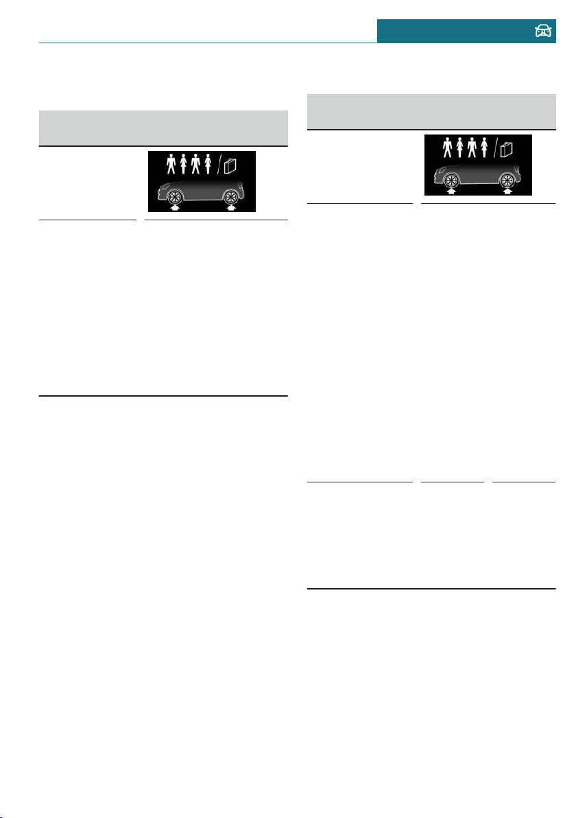
On 3-door models: JOHN COOPER
WORKS
Tire size Pressure specifications
in bar/PSI
Specifications
in bar/PSI with
cold tires
205/45 R 17 88
V XL A/S
205/45 R 17 88
W XL
205/40 R 18 86
W XL
185/50 R 17 86
H XL M+S
205/45 R 17 88
V XL M+S
2.8 / 41 2.4 / 35
On 5-door models: COOPER
Tire size Pressure specifica-
tions in bar/PSI
Specifications in
bar/PSI with cold
tires
175/65 R 15 84
H A/S
195/55 R 16 87
V A/S
205/45 R 17 88
V XL A/S
195/55 R 16 87
W
205/45 R 17 88
W XL
175/65 R 15 88
H XL M+S
195/55 R 16 87
H M+S
205/45 R 17 88
V XL M+S
2.5 / 36 2.3 / 33
205/40 R 18 86
W XL
175/60 R 16 86
H XL M+S
185/50 R 17 86
H XL M+S
2.7 / 39 2.5 / 36
Seite 259
Wheels and tires MOBILITY
259
Online Edition for Part no. 01402667083 - VI/19
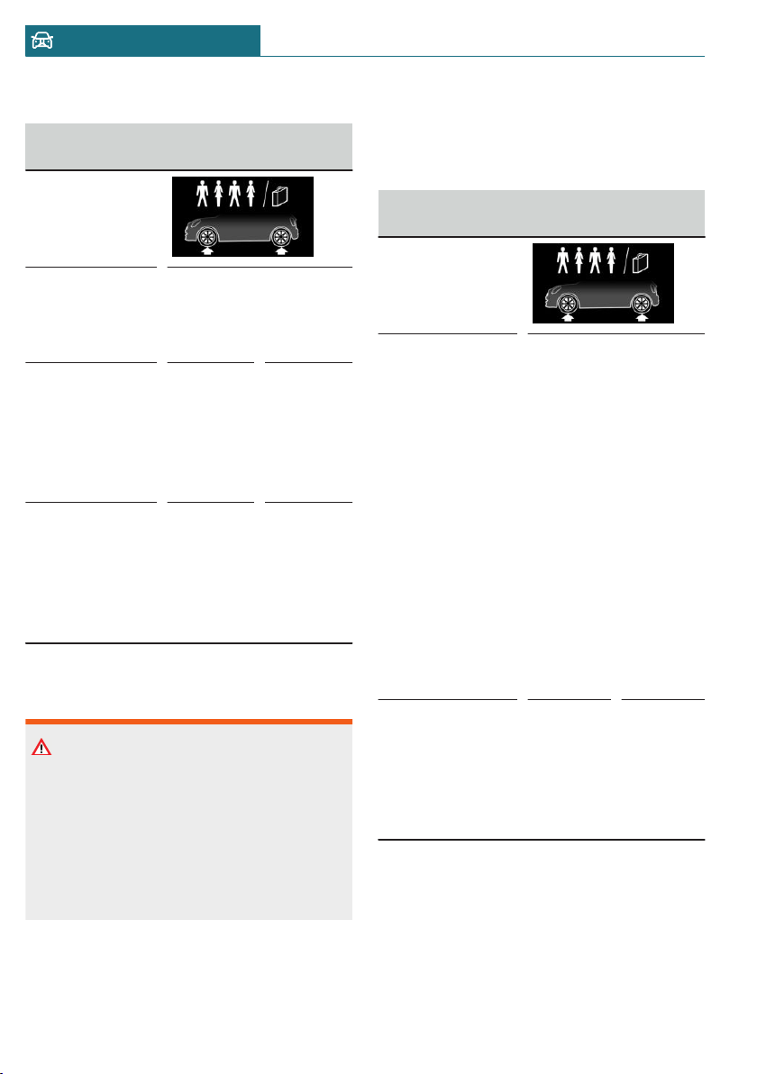
On 5-door models: COOPER S
Tire size Pressure specifica-
tions in bar/PSI
Specifications
in bar/PSI with
cold tires
195/55 R 16 87
V A/S
195/55 R 16 87
H M+S
2.3 / 33 2.2 / 32
205/45 R 17 88
V XL A/S
205/45 R 17 88
W XL
205/45 R 17 88
V XL M+S
2.6 / 38 2.4 / 35
205/40 R 18 86
W XL
175/60 R 16 86
H XL M+S
185/50 R 17 86
H XL M+S
2.7 / 39 2.5 / 36
Tire inflation pressures at max.
speeds above 100 mph/160 km/h
Warning
In order to drive at maximum speeds in ex-
cess of 100 mph/160 km/h, please ob-
serve, and, if necessary, adjust tire pres-
sures for speeds exceeding 100 mph/
160 km/h from the relevant table on the
following pages. Otherwise, tire damage
and accidents could occur.
For speeds over 100 mph/160 km/h and for
optimum driving comfort, note the pressure
values in the tire inflation pressure table,
refer to page 260, and adjust as necessary.
Tire inflation pressure values over
100 mph/160 km/h
On 3-door models: COOPER
Tire size Pressure specifica-
tions in bar/PSI
Specifications in
bar/PSI with cold
tires
175/65 R 15 84
H A/S
195/55 R 16 87
V A/S
205/45 R 17 88
V XL A/S
195/55 R 16 87
W
205/45 R 17 88
W XL
175/65 R 15 88
H XL M+S
195/55 R 16 87
H M+S
205/45 R 17 88
V XL M+S
2.7 / 39 2.5 / 36
205/40 R 18 86
W XL
175/60 R 16 86
H XL M+S
185/50 R 17 86
H XL M+S
2.9 / 42 2.5 / 36
Seite 260
MOBILITY Wheels and tires
260
Online Edition for Part no. 01402667083 - VI/19
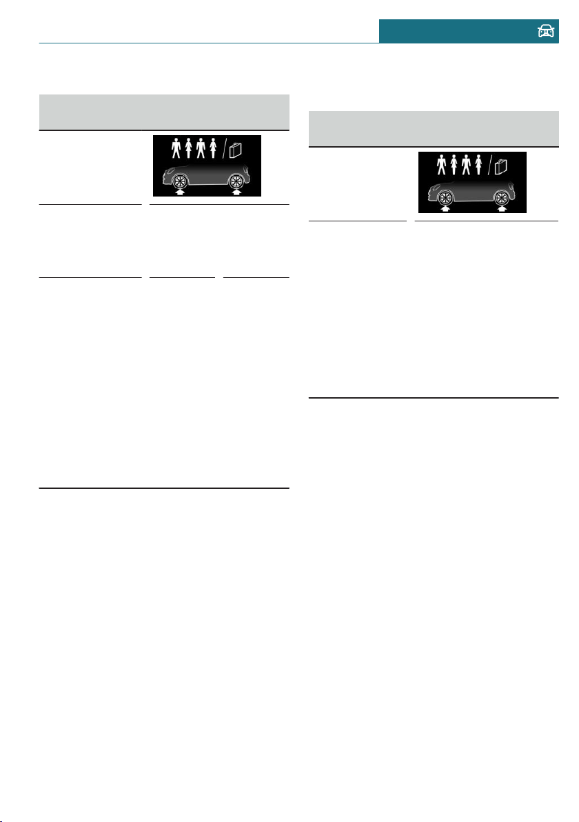
On 3-door models: COOPER S
Tire size Pressure specifica-
tions in bar/PSI
Specifications in
bar/PSI with
cold tires
195/55 R 16 87
V A/S
195/55 R 16 87
H M+S
2.8 / 41 2.4 / 35
205/45 R 17 88
V XL A/S
205/45 R 17 88
W XL
205/45 R 17 88
V XL M+S
205/40 R 18 86
W XL
175/60 R 16 86
H XL M+S
185/50 R 17 86
H XL M+S
3.1 / 45 2.7 / 39
On 3-door models: JOHN COOPER
WORKS
Tire size Pressure specifications
in bar/PSI
Specifications
in bar/PSI with
cold tires
205/45 R 17 88
V XL A/S
205/45 R 17 88
W XL
205/40 R 18 86
W XL
185/50 R 17 86
H XL M+S
205/45 R 17 88
V XL M+S
3.4 / 49 3.0 / 44
Seite 261
Wheels and tires MOBILITY
261
Online Edition for Part no. 01402667083 - VI/19
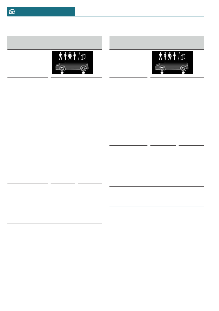
On 5-door models: COOPER
Tire size Pressure specifica-
tions in bar/PSI
Specifications in
bar/PSI with cold
tires
175/65 R 15 84
H A/S
195/55 R 16 87
V A/S
205/45 R 17 88
V XL A/S
195/55 R 16 87
W
205/45 R 17 88
W XL
175/65 R 15 88
H XL M+S
195/55 R 16 87
H M+S
205/45 R 17 88
V XL M+S
2.8 / 41 2.6 / 38
205/40 R 18 86
W XL
175/60 R 16 86
H XL M+S
185/50 R 17 86
H XL M+S
3.0 / 44 2.7 / 39
On 5-door models: COOPER S
Tire size Pressure specifica-
tions in bar/PSI
Specifications
in bar/PSI with
cold tires
195/55 R 16 87
V A/S
195/55 R 16 87
H M+S
2.9 / 42 2.7 / 39
205/45 R 17 88
V XL A/S
205/45 R 17 88
W XL
205/45 R 17 88
V XL M+S
3.2 / 46 2.9 / 42
205/40 R 18 86
W XL
175/60 R 16 86
H XL M+S
185/50 R 17 86
H XL M+S
3.2 / 46 2.9 / 42
Tire identification marks
Tire size
205/45 R 17 84 V
205: nominal width in mm
45: aspect ratio in %
R: radial tire code
17: rim diameter in inches
84: load rating, not for ZR tires
V: speed rating, before the R on ZR tires
Seite 262
MOBILITY Wheels and tires
262
Online Edition for Part no. 01402667083 - VI/19

Maximum tire load
Maximum tire load is the maximum permis-
sible weight for which the tire is approved.
Locate the maximum tire load on the tire
sidewall and the Gross Axle Weight Rating
– GAWR – on the certification label on the
driver’s door pillar. Divide the tire load by
1.1. It must be greater than one-half of the
vehicle’s Gross Axle Weight Rating –
GAWR. Note, front vs. rear GAWR and tire
loads, respectively.
Speed letter
Designation Maximum speed
Q up to 100 mph/160 km/h
R: up to 106 mph/170 km/h
S up to 112 mph/180 km/h
T up to 118 mph/190 km/h
H up to 131 mph/210 km/h
V up to 150 mph/240 km/h
W up to 167 mph/270 km/h
Y up to 186 mph/300 km/h
Tire Identification Number
DOT-Code: DOT xxxx xxx 2119
xxxx: manufacturer code for the tire brand
xxx: tire size and tire design
2119: tire age
Tires with DOT codes meet the guidelines
of the U.S. Department of Transportation.
Tire age
Recommendation
Regardless of the tire tread, replace tires at
least every 6 years.
Manufacture date
You can find the manufacture date of the
tire on the tire's sidewall.
Designation Manufacture date
DOT … 2119 21st week, 2019
Uniform Tire Quality Grading
Quality grades can be found where applica-
ble on the tire sidewall between tread
shoulder and maximum section width.
E.g.: Treadwear 200; Traction AA; Tempera-
ture A
DOT Quality Grades
Treadwear
Traction AA A B C
Temperature A B C
All passenger vehicle tires must conform to
Federal Safety Requirements in addition to
these grades.
Treadwear
The treadwear grade is a comparative rating
based on the wear rate of the tire when
tested under controlled conditions on a
specified government test course. E.g., a
tire graded 150 would wear one and one-
half, 1 g, times as well on the government
course as a tire graded 100. The relative
performance of tires depends upon the ac-
tual conditions of their use, however, and
may depart significantly from the norm due
to variations in driving habits, service prac-
tices and differences in road characteristics
and climate.
Traction
The traction grades, from highest to lowest,
are AA, A, B, and C.
Those grades represent the tire's ability to
stop on wet pavement as measured under
Seite 263
Wheels and tires MOBILITY
263
Online Edition for Part no. 01402667083 - VI/19
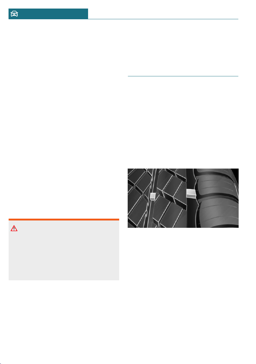
controlled conditions on specified govern-
ment test surfaces of asphalt and concrete.
A tire marked C may have poor traction per-
formance.
The traction grade assigned to this tire is
based on straight-ahead braking traction
tests, and does not include acceleration,
cornering, hydroplaning, or peak traction
characteristics.
Temperature
The temperature grades are A, the highest,
B, and C, representing the tire's resistance
to the generation of heat and its ability to
dissipate heat when tested under controlled
conditions on a specified indoor laboratory
test wheel. Sustained high temperature can
cause the material of the tire to degenerate
and reduce tire life, and excessive tempera-
ture can lead to sudden tire failure. The
grade C corresponds to a level of perform-
ance which all passenger car tires must
meet under the Federal Motor Vehicle
Safety Standard No. 109. Grades Band A
represent higher levels of performance on
the laboratory test wheel than the minimum
required by law.
Warning
The temperature grade for this tire is es-
tablished for a tire that is properly inflated
and not overloaded. Excessive speed, un-
derinflation, or excessive loading, either
separately or in combination, can cause
heat buildup and possible tire failure.
RSC – Run-flat tires
Run-flat tires, refer to page 267, are labeled
with a circular symbol containing the let-
ters RSC marked on the sidewall.
M+S
Winter and all-season tires with better cold
weather performance than summer tires.
Tire tread
Summer tires
Do not drive with a tire tread of less than
0.12 in/3 mm, otherwise there is an in-
creased risk of hydroplaning.
Winter tires
Do not drive with a tire tread of less than
0.16 in/4 mm, as such tires are less suitable
for winter operation.
Minimum tread depth
Wear indicators are distributed around the
tire's circumference and have the legally re-
quired minimum height of 0.063 in-
ches/1.6 mm.
The positions of the wear indicators are
marked on the tire sidewall with TWI, Tread
Wear Indicator.
Seite 264
MOBILITY Wheels and tires
264
Online Edition for Part no. 01402667083 - VI/19

Tire damage
General information
Inspect your tires regularly for damage, for-
eign objects lodged in the tread, and tread
wear.
Driving over rough or damaged road surfa-
ces, as well as debris, curbs and other obsta-
cles can cause serious damage to wheels,
tires and suspension parts. This is more
likely to occur with low-profile tires, which
provide less cushioning between the wheel
and the road. Be careful to avoid road haz-
ards and reduce your speed, especially if
your vehicle is equipped with low-profile
tires.
Indications of tire damage or other vehicle
malfunctions:
– Unusual vibrations.
– Unusual tire or running noises.
– Unusual handling such as a strong ten-
dency to pull to the left or right.
Damage can be caused by the following sit-
uations, for instance:
– Driving over curbs.
– Road damage.
– Tire inflation pressure too low.
– Vehicle overloading.
– Incorrect tire storage.
Safety information
Warning
Damaged tires can lose tire inflation pres-
sure, which can lead to loss of vehicle con-
trol. There is a risk of accident. If tire dam-
age is suspected while driving,
immediately reduce speed and stop. Have
wheels and tires checked. For this pur-
pose, drive carefully to the nearest dealer’s
service center or another qualified service
center or repair shop. Have vehicle towed
or transported as needed. Do not repair
damaged tires, but have them replaced.
Warning
Tires can become damaged by driving over
obstacles, e.g., curbs or road damage, at
high speed. Larger wheels have a smaller
tire cross-section. The smaller the tire
cross-section, the higher the risk of tire
damage. There is a danger of accidents and
property damage. If possible, avoid driving
over objects or road conditions that may
damage tires, or drive over them slowly
and carefully.
Changing wheels and tires
Mounting and wheel balancing
Have mounting and wheel balancing carried
out by a dealer’s service center or another
qualified service center or repair shop.
Wheel and tire combination
General information
You can ask the dealer's service center or
another qualified service center or repair
shop about the correct wheel/tire combina-
tion and wheel rim versions for the vehicle.
Safety information
Warning
Wheels and tires which are not suitable
for your vehicle can damage parts of the
vehicle, for instance due to contact with
the body due to tolerances despite the
same official size rating. There is a risk of
an accident. The manufacturer of your ve-
Seite 265
Wheels and tires MOBILITY
265
Online Edition for Part no. 01402667083 - VI/19
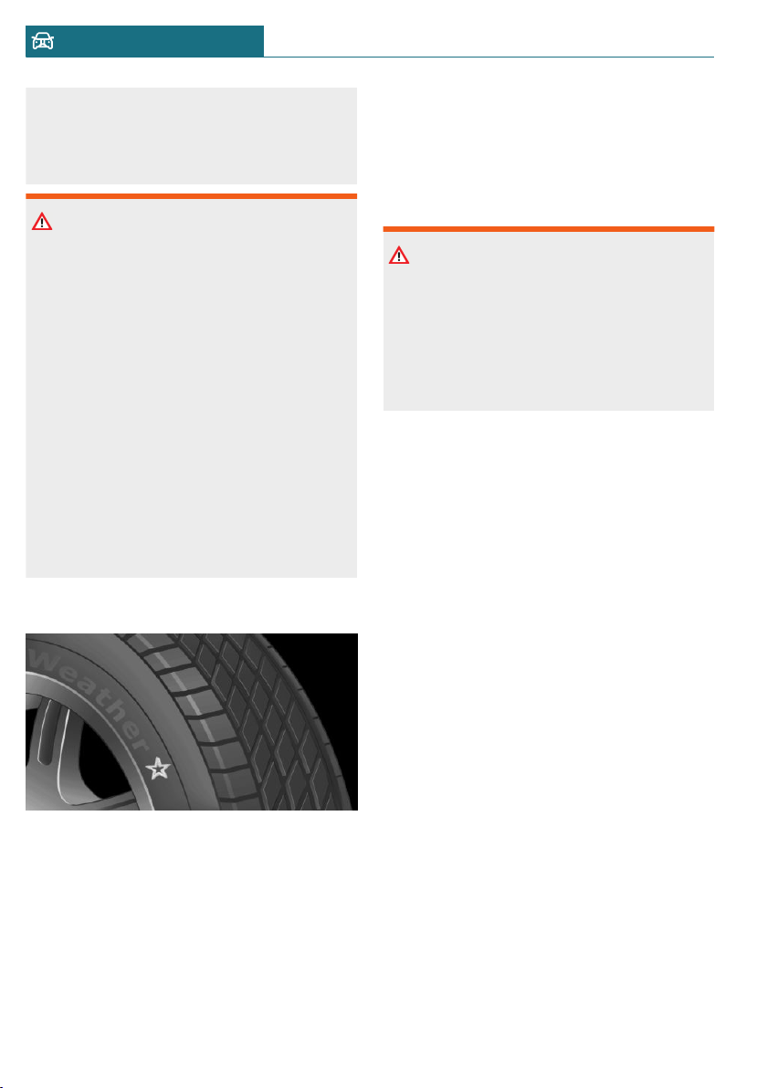
hicle strongly suggests that you use
wheels and tires that have been recom-
mended by the vehicle manufacturer for
your vehicle type.
Warning
Incorrect wheel/tire combinations will
have a negative impact on the vehicle's
handling and on the function of a variety
of systems, such as the Anti-lock Brake
System or Dynamic Stability Control.
There is a risk of accident. To maintain
good handling and vehicle response, use
only tires with a single tread configuration
from a single manufacturer. The manufac-
turer of the vehicle recommends that you
use wheels and tires that have been rec-
ommended by the vehicle manufacturer
for your vehicle type. Following tire dam-
age, have the original wheel/tire combina-
tion remounted on the vehicle as soon as
possible.
Recommended tire brands
For each tire size, the manufacturer of the
vehicle recommends certain tire brands.
The tire brands can be identified by a star
on the tire sidewall.
New tires
Tire traction is not optimal due to manufac-
turing circumstances when tires are brand-
new; they achieve their full traction poten-
tial after a break-in time.
Drive conservatively for the first
200 miles/300 km.
Retreaded tires
Warning
Retreaded tires can have different tire cas-
ing structures. With advanced age the
service life can be limited. There is a risk
of an accident. The manufacturer of your
vehicle does not recommend the use of re-
treaded tires.
The manufacturer of the vehicle does not
recommend the use of retreaded tires.
Winter tires
Winter tires are recommended for operat-
ing on winter roads.
Although so-called all-season M+S tires pro-
vide better winter traction than summer
tires, they usually do not provide the same
level of performance as winter tires.
Maximum speed of winter tires
If the maximum speed of the vehicle is
higher than the permissible speed for the
winter tires, then attach a label showing the
permissible maximum speed in the field of
view. The label is available from a dealer's
service center or another qualified service
center or repair shop.
With winter tires mounted, observe and do
not exceed the permissible maximum speed.
Changing runflat tires
For your own safety, use only runflat tires.
No spare tire is available in the case of a flat
tire. Further information is available from a
dealer's service center or another qualified
service center or repair shop.
Seite 266
MOBILITY Wheels and tires
266
Online Edition for Part no. 01402667083 - VI/19
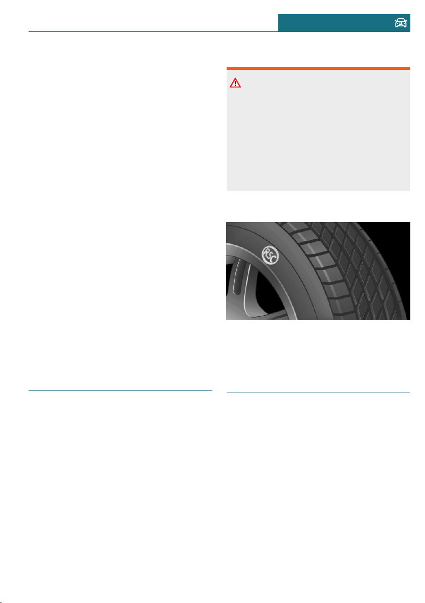
Rotating wheels between axles
Different wear patterns can occur on the
front and rear axles depending on individual
driving conditions. The tires can be rotated
in pairs between the axles to achieve even
wear. Further information is available from
a dealer's service center or another qualified
service center or repair shop. After rotating,
check the tire pressure and correct, if
needed.
Storing tires
Tire inflation pressure
Do not exceed the maximum tire inflation
pressure indicated on the side wall of the
tire.
Storage
Store wheels and tires in a cool, dry and
dark place.
Always protect tires against all contact with
oil, grease, and solvents.
Do not leave tires in plastic bags.
Remove dirt from wheels or tires.
Run-flat tires
Concept
Run-flat tires permit continued driving un-
der restricted conditions even in the event
of a complete loss of tire inflation pressure.
General information
The wheels are composed of tires that are
self-supporting to a limited degree.
The support of the sidewall allows the tire
to remain drivable to a restricted degree in
the event of a tire inflation pressure loss.
Follow the instructions for continued driv-
ing with a flat tire.
Safety information
Warning
Your vehicle handles differently with a
run-flat tire with no or low inflation pres-
sure; for instance, your lane stability when
braking is reduced, braking distances are
longer and the self-steering properties will
change. There is a risk of accident. Drive
moderately and do not exceed a speed of
50 mph/80 km/h.
Label
The tires are marked on the tire sidewall
with RSC Run-flat System Component.
Repairing a flat tire
Safety measures
– Park the vehicle as far away as possible
from passing traffic and on solid ground.
– Switch on the hazard warning system.
– Secure the vehicle against rolling away
by setting the parking brake.
– Turn the steering wheel until the front
wheels are in the straight-ahead posi-
tion and engage the steering wheel lock.
– Have all vehicle occupants get out of the
vehicle and ensure that they remain out-
Seite 267
Wheels and tires MOBILITY
267
Online Edition for Part no. 01402667083 - VI/19
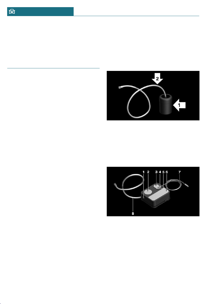
side the immediate area in a safe place,
such as behind a guardrail.
– If necessary, set up a warning triangle
at an appropriate distance.
Mobility System
Concept
With the Mobility System, minor tire dam-
age can be sealed temporarily to enable con-
tinued travel. To accomplish this, sealant is
pumped into the tires, which seals the dam-
age from the inside.
General information
– Follow the instructions on using the
Mobility System found on the compres-
sor and sealant container.
– Use of the Mobility System may be inef-
fective if the tire puncture measures ap-
prox. 1/8 inches/4 mm or more.
– Contact a dealer's service center or an-
other qualified service center or repair
shop if the tire cannot be made drivable.
– Do not remove foreign bodies that have
penetrated the tire. Only remove foreign
objects if they are visibly protruding
from the tire.
– Pull the speed limit sticker off the seal-
ant container and apply it to the steer-
ing wheel.
– The use of a sealant can damage the
TPM wheel electronics. In this case,
have the TPM wheel electronics re-
placed at the next opportunity.
– The compressor can be used to check
the tire inflation pressure.
Overview
Storage
The Mobility System is located under the
cargo floor panel.
Sealant container
– Sealant container, arrow 1.
– Filling hose, arrow 2.
Observe use-by date on the sealant con-
tainer.
Compressor
1 Sealant container unlocking
2 Sealant container holder
3 Tire pressure gage
4 Reduce tire inflation pressure button
5 On/off switch
6 Compressor
7 Connector/cable for socket
8 Connection hose
Seite 268
MOBILITY Wheels and tires
268
Online Edition for Part no. 01402667083 - VI/19
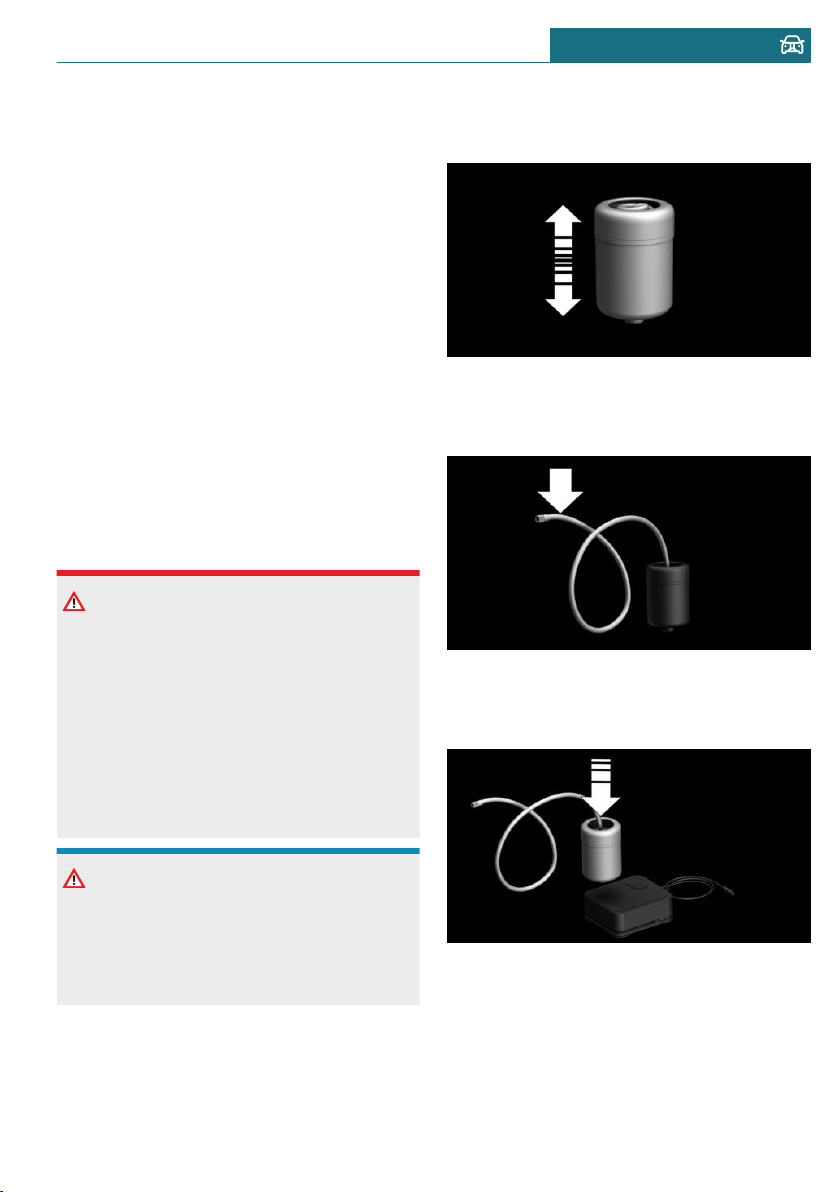
Safety measures
– Park the vehicle as far away as possible
from passing traffic and on solid ground.
– Switch on the hazard warning system.
– Secure the vehicle against rolling away
by setting the parking brake.
– Turn the steering wheel until the front
wheels are in the straight-ahead posi-
tion and engage the steering wheel lock.
– Have all vehicle occupants get out of the
vehicle and ensure that they remain out-
side the immediate area in a safe place,
such as behind a guardrail.
– If necessary, set up a warning triangle
at an appropriate distance.
Filling the tire with sealant
Safety information
DANGER
If the exhaust pipe is blocked or ventila-
tion is insufficient, harmful exhaust gases
can enter into the vehicle. The exhaust
gases contain pollutants which are color-
less and odorless. In enclosed areas, ex-
haust gases can also accumulate outside of
the vehicle. There is danger to life. Keep
the exhaust pipe free and ensure sufficient
ventilation.
NOTICE
The compressor can overheat during ex-
tended operation. There is a risk of dam-
age to property. Do not run the compres-
sor for more than 10 minutes.
Filling
1. Shake the sealant container.
2. Pull filling hose completely out of the
cover of the sealant container. Do not
kink the hose.
3. Slide the sealant container into the
holder on the compressor housing, en-
suring that it engages audibly.
Seite 269
Wheels and tires MOBILITY
269
Online Edition for Part no. 01402667083 - VI/19
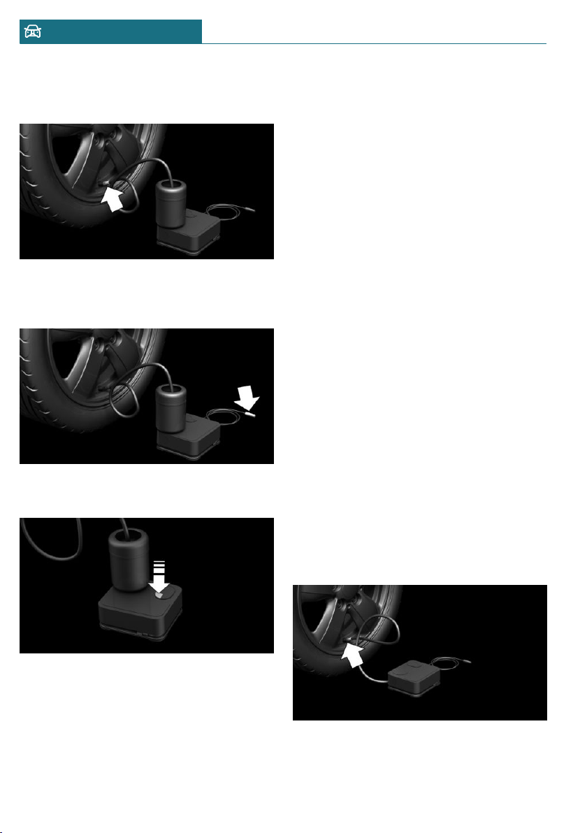
4. Screw the filling hose of the sealant con-
tainer onto the tire valve of the non-
working wheel.
5. With the compressor switched off, in-
sert the plug into the power socket in-
side the vehicle.
6. With the ignition switched on or the en-
gine running, switch on the compressor.
Let the compressor run for max. 10 minutes
to fill the tire with sealant and achieve a
tire inflation pressure of approx. 2.5 bar.
While the tire is being filled with sealant,
the tire inflation pressure may sporadically
reach approx. 5 bar. Do not switch off the
compressor at this point.
Checking and adjusting the tire
inflation pressure
Checking
1. Switch off the compressor.
2. Read the tire inflation pressure on the
tire pressure gage.
To continue the trip, a tire inflation pres-
sure of at least 2 bar must be reached.
Removing and stowing the sealant
container
1. Unscrew the filling hose of the sealant
container from the tire valve.
2. Press the red unlocking device.
3. Remove the sealant container from the
compressor.
4. Wrap and store the sealant container in
suitable material to avoid dirtying the
cargo area.
Minimum tire inflation pressure is not
reached
1. Pull the connector out of the power
socket inside the vehicle.
2. Drive 33 ft/10 m forward and back to
distribute the sealant in the tire.
3. Screw the connection hose of the com-
pressor directly onto the tire valve stem.
Seite 270
MOBILITY Wheels and tires
270
Online Edition for Part no. 01402667083 - VI/19
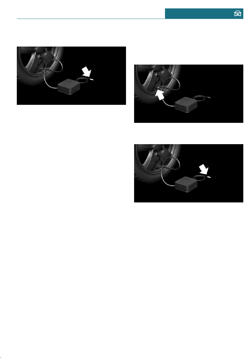
4. Insert the connector into the power
socket inside the vehicle.
5. With the ignition switched on or the en-
gine running, switch on the compressor.
If a tire inflation pressure of at least
2 bar cannot be reached, contact your
dealer's service center or another quali-
fied service center or repair shop.
If a tire inflation pressure of at least
2 bar is reached, see Minimum tire infla-
tion pressure is reached.
6. Unscrew the connection hose of the
compressor from the tire valve.
7. Pull the connector out of the power
socket inside the vehicle.
8. Stow the Mobility System in the vehicle.
Minimum tire inflation pressure is
reached
1. Unscrew the connection hose of the
compressor from the tire valve.
2. Pull the connector out of the power
socket inside the vehicle.
3. Stow the Mobility System in the vehicle.
4. Immediately drive approx.
5 miles/10 km to ensure that the sealant
is evenly distributed in the tire.
Do not exceed a speed of
50 mph/80 km/h.
If possible, do not drive at speeds less
than 12 mph/20 km/h.
Adjustment
1. Stop at a suitable location.
2. Screw the connection hose of the com-
pressor directly onto the tire valve stem.
3. Insert the connector into the power
socket inside the vehicle.
4. Correct the tire inflation pressure to at
least 2.0 bar.
– Increase tire inflation pressure: with
the ignition switched on or the en-
gine running, switch on the com-
pressor.
– Reduce tire inflation pressure: press
the button on the compressor.
5. Unscrew the connection hose of the
compressor from the tire valve.
6. Pull the connector out of the power
socket inside the vehicle.
7. Stow the Mobility System in the vehicle.
Continuing the trip
Do not exceed the maximum permissible
speed of 50 mph/80 km/h.
Seite 271
Wheels and tires MOBILITY
271
Online Edition for Part no. 01402667083 - VI/19
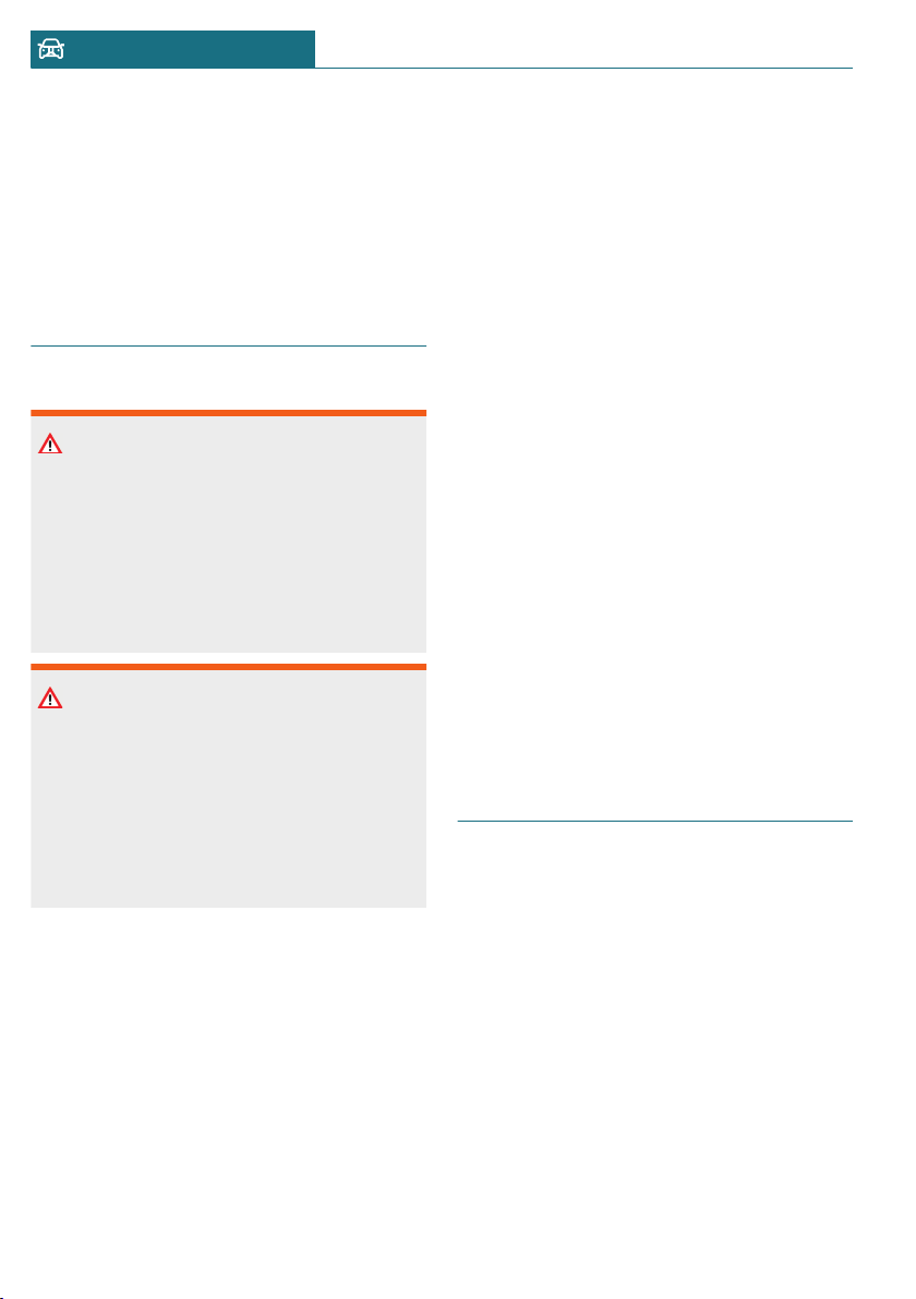
Reinitialize the Flat Tire Monitor, refer to
page 145.
Reset the Tire Pressure Monitor, refer to
page 141.
Replace the nonworking tire and the sealant
container of the Mobility System promptly.
Snow chains
Safety information
Warning
With the mounting of snow chains on un-
suitable tires, the snow chains can come
into contact with vehicle parts. There may
be a risk of accident or risk of damage to
property. Only mount snow chains on tires
that are designated by their manufacturer
as suitable for the use of snow chains.
Warning
Insufficiently tight snow chains may dam-
age tires and vehicle components. There
may be a risk of accident or risk of damage
to property. Make sure that the snow
chains are always sufficiently tight. Re-
tighten as needed according to the snow
chain manufacturer's instructions.
Fine-link snow chains
The manufacturer of the vehicle recom-
mends the use of fine-link snow chains. Cer-
tain types of fine-link snow chains have
been tested by the manufacturer of the ve-
hicle and recommended as road-safe and
suitable.
Information regarding suitable snow chains
is available from a dealer’s service center or
another qualified service center or repair
shop.
Use
Use only in pairs on the front wheels, equip-
ped with the tires of the following size:
– 175/65 R 15.
– 175/60 R 16.
– 185/50 R 17.
John Cooper Works:
185/50 R 17.
Follow the snow chain manufacturer's in-
structions.
Do not initialize the Flat Tire Monitor after
mounting snow chains, as doing so may re-
sult in incorrect readings.
Do not reset the Tire Pressure Monitor TPM
after mounting snow chains, as doing so
may result in incorrect readings.
When driving with snow chains, briefly ac-
tivate Dynamic Traction Control DTC, if
needed.
Maximum speed with snow chains
Do not exceed a speed of 30 mph/50 km/h
when using snow chains.
Changing wheels/tires
General information
When using run-flat tires or a flat tire kit, a
wheel does not always need to be changed
immediately when there is a loss of tire in-
flation pressure due to a flat tire.
If needed, the tools for changing wheels are
available as accessories from a dealer’s
service center or another qualified service
center or repair shop.
Seite 272
MOBILITY Wheels and tires
272
Online Edition for Part no. 01402667083 - VI/19
Safety information
DANGER
The vehicle jack is only provided for short-
term lifting of the vehicle for wheel
changes. Even if all safety measures are
observed, there is a risk of the raised vehi-
cle falling, if the vehicle jack tips over.
There is a risk of injuries or danger to life.
If the vehicle is raised, do not lie under the
vehicle and do not start the engine.
DANGER
Supports such as wooden blocks under the
vehicle jack reduce the capacity of the ve-
hicle jack to bear weight. They have the
potential to exert too much strain on the
vehicle jack, causing it to tip over and the
vehicle to fall. There is a risk of injuries or
danger to life. Do not place supports under
the vehicle jack.
Warning
The jack, issued by the vehicle manufac-
turer, is provided in order to perform a
wheel change in the event of a breakdown.
The jack is not designed for frequent use;
for example, changing from summer to
winter tires. Using the jack frequently may
cause it to become jammed or damaged.
There is a risk of injury and risk of damage
to property. Only use the jack to attach an
emergency or spare wheel in the event of
a breakdown.
Warning
On soft, uneven or slippery ground, for ex-
ample snow, ice, tiles, etc., the vehicle jack
can slip away. There is a risk of injury. If
possible, change the wheel on a flat, solid,
and slip-resistant surface.
Warning
The vehicle jack is optimized for lifting
the vehicle and for the jacking points on
the vehicle only. There is a risk of injury.
Do not lift any other vehicle or cargo using
the vehicle jack.
Warning
If the vehicle jack is not inserted into the
jacking point provided for this purpose,
the vehicle may be damaged or the vehicle
jack may slip when it is being cranked up.
There is a risk of injury or risk of damage
to property. When cranking up the vehicle
jack, ensure that it is inserted in the jack-
ing point next to the wheel housing.
Warning
A vehicle that is raised on a vehicle jack
may fall off of the jack if lateral forces are
exerted on it. There is a risk of injury and
risk of damage to property. While the ve-
hicle is raised, do not exert lateral forces
on the vehicle or pull abruptly on the vehi-
cle. Have a stuck wheel removed by a deal-
er’s service center or another qualified
service center or repair shop.
Seite 273
Wheels and tires MOBILITY
273
Online Edition for Part no. 01402667083 - VI/19
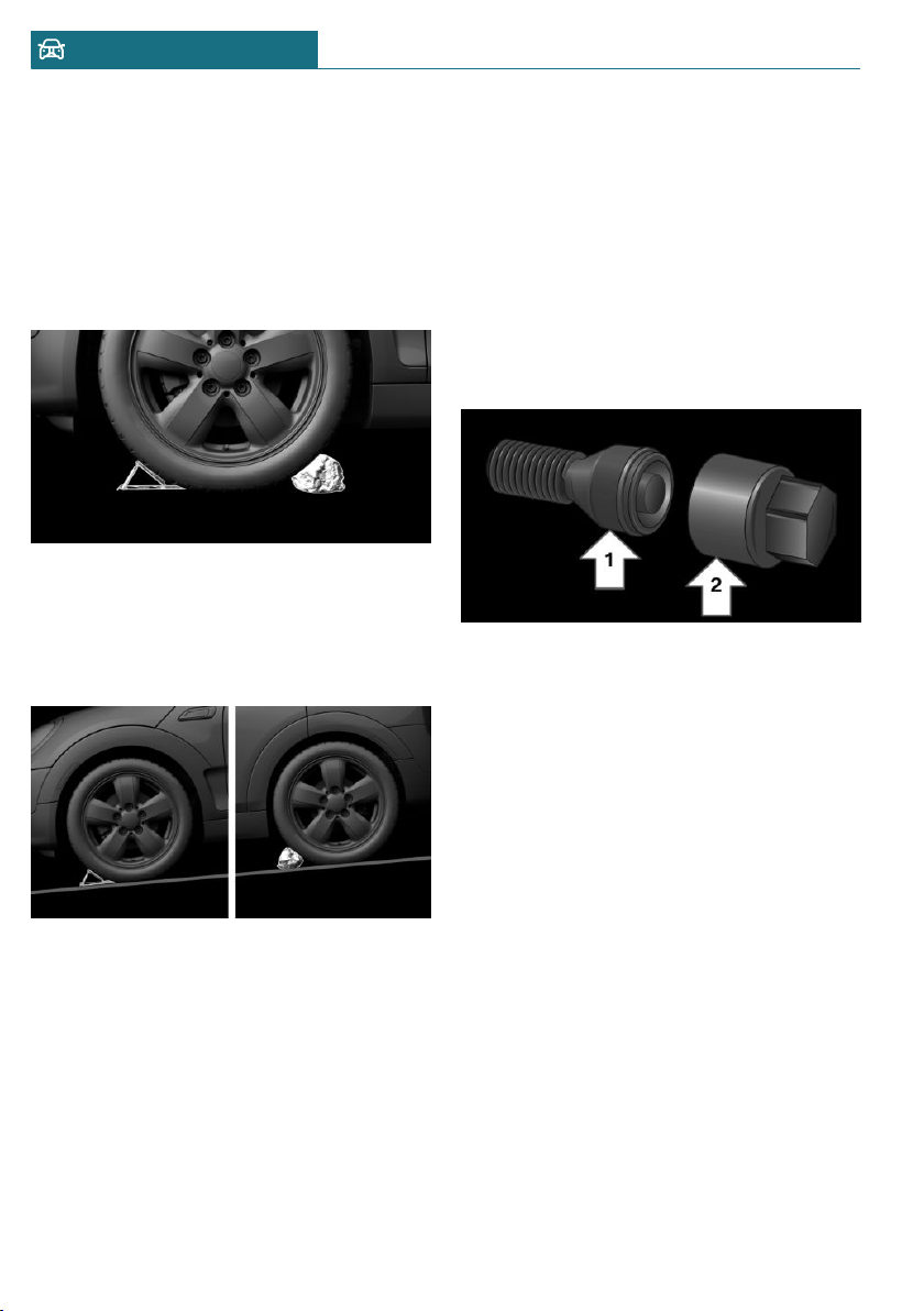
Securing the vehicle against rolling
General information
The vehicle manufacturer recommends to
additionally secure the vehicle against roll-
ing away when changing a wheel.
On a level surface
Place wheel chocks or other suitable objects
in front and behind the wheel that is diago-
nal to the wheel to be changed.
On a slight downhill gradient
If you need to change a wheel on a slight
downhill grade, place chocks and other suit-
able objects, for instance a rock, under the
wheels of both the front and rear axles
against the rolling direction.
Lug bolt lock
Concept
The wheel lug bolts have a special coding.
The lug bolts can only be released with the
adapter which matches the coding.
Overview
The adapter of the lug bolt lock is located in
the onboard vehicle tool kit, refer to
page 290.
– Lug bolt, arrow 1.
– Adapter, arrow 2.
Unscrewing
1. Attach the adapter to the lug bolt.
2. Unscrew the lug bolt.
3. Remove the adapter after unscrewing
the lug bolt.
Screwing on
1. Attach the adapter to the lug bolt. If
necessary, turn the adapter until it fits
on the lug bolt.
2. Screw on the lug bolt. The tightening
torque is 140 Nm.
3. Remove the adapter and stow it after
screwing on the lug bolt.
Preparing the vehicle
– Park the vehicle on solid and non-slip
ground at a safe distance from traffic.
Seite 274
MOBILITY Wheels and tires
274
Online Edition for Part no. 01402667083 - VI/19
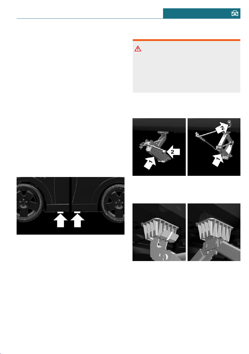
– Switch on the hazard warning system.
– Set the parking brake.
– Engage a gear or move the selector lever
to position P.
– As soon as permitted by the traffic flow,
have all vehicle occupants get out of the
vehicle and ensure that they remain out-
side the immediate area in a safe place,
such as behind a guardrail.
– Depending on the vehicle equipment,
get wheel change tools and, if necessary,
the emergency wheel from the vehicle.
– If necessary, set up a warning triangle
or portable hazard warning light at an
appropriate distance.
– Secure the vehicle additionally against
rolling.
– Loosen the lug bolts a half turn.
Jacking points for the vehicle jack
The jacking points for the vehicle jack are
located at the marked positions.
Jacking up the vehicle
Warning
Hands and fingers can be jammed when
using the vehicle jack. There is a risk of
injury. Comply with the described hand
position and do not change this position
while using the vehicle jack.
1. Hold the vehicle jack with one hand, ar-
row 1, and grasp the vehicle jack crank
or lever with your other hand, arrow 2.
2. Insert the vehicle jack into the rectan-
gular recess of the jacking point closest
to the wheel to be changed.
Seite 275
Wheels and tires MOBILITY
275
Online Edition for Part no. 01402667083 - VI/19
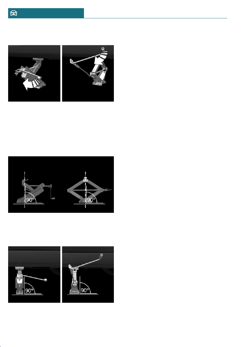
3. Extend the vehicle jack by turning the
vehicle jack crank or lever clockwise.
4. Take your hand away from the vehicle
jack as soon as the vehicle jack is under
load and continue turning the vehicle
jack crank or lever with one hand.
5. Make sure that the vehicle jack foot
stands vertically and at a right angle be-
neath the jacking point.
6. Make sure that the vehicle jack foot
stands vertically and perpendicularly be-
neath the jacking point after extending
the vehicle jack.
7. Crank the vehicle up, until the vehicle
jack is with the entire surface on the
ground and the relevant wheel is maxi-
mum 1.2 inches/3 cm above ground.
Mounting a wheel
Mount one emergency wheel only, as re-
quired.
1. Unscrew the lug bolts.
2. Remove the wheel.
3. Put the new wheel or emergency wheel
on and screw in at least two lug bolts in
a crosswise pattern until hand-tight.
If non-original light-alloy wheels of the
vehicle manufacturer are mounted, the
accompanying lug bolts may have to be
used as well.
4. Hand-tighten the remaining lug bolts
and tighten all lug bolts well in a cross-
wise pattern.
5. Turn the vehicle jack crank counter-
clockwise to retract the vehicle jack and
lower the vehicle.
6. Remove the vehicle jack and stow it se-
curely.
After the wheel change
1. Tighten the lug bolts crosswise. The
tightening torque is 101 lbs ft/140 Nm.
2. Stow the nonworking wheel in the cargo
area, if necessary.
The nonworking wheel cannot be stored
under the cargo floor panel because of
its size.
3. Check tire inflation pressure at the next
opportunity and correct as needed.
4. Reinitialize the Flat Tire Monitor.
Reset the Tire Pressure Monitor TPM.
5. Check to make sure the lug bolts are
tight with a calibrated torque wrench.
6. Have the damaged tire replaced at the
nearest dealer's service center or an-
Seite 276
MOBILITY Wheels and tires
276
Online Edition for Part no. 01402667083 - VI/19
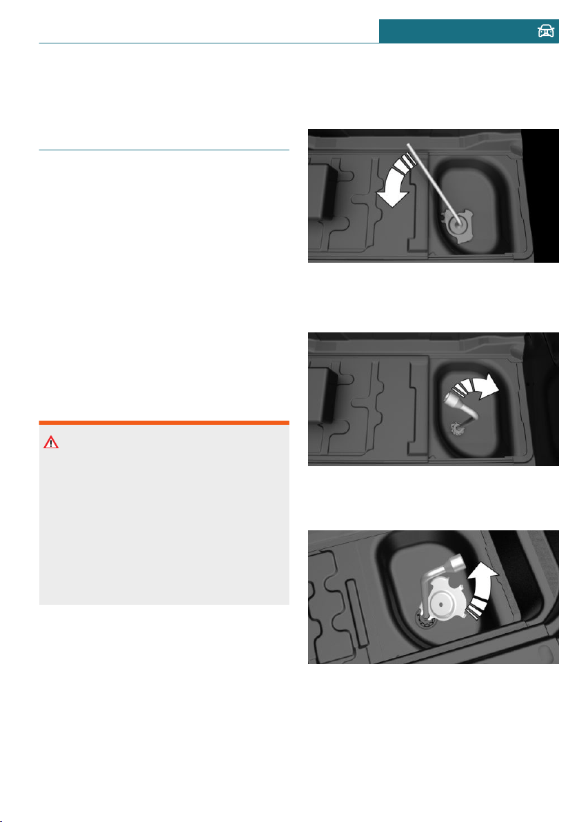
other qualified service center or repair
shop.
Emergency wheel
Concept
In the event of a flat tire, the emergency
wheel can be used in place of the wheel
with the defective tire. The emergency
wheel is only intended for temporary use
until the defective tire/wheel has been re-
placed.
General information
Mount one emergency wheel only.
Also check the tire inflation pressure of the
emergency wheel in the cargo area regu-
larly, and correct it as needed.
Safety information
Warning
The emergency wheel has particular di-
mensions. When driving with an emer-
gency wheel, changed driving properties
may occur, for instance reduced lane sta-
bility when braking, longer braking dis-
tance, and changed self-steering proper-
ties in the limit area. There is a risk of
accident. Drive moderately and do not ex-
ceed a speed of 50 mph/80 km/h.
Overview
The emergency wheel is housed in a well on
the underbody of the vehicle. The screw
connection of the emergency wheel is under
the cargo floor panel, on the floor of the
storage compartment for the onboard vehi-
cle tool kit.
The wheel change tools are under the cargo
floor panel.
Removing the emergency wheel
1. Loosen the nut using the wheel wrench
from the onboard vehicle tool kit.
2. Remove the retaining plate.
3. Screw wheel lug wrench onto the thread
and hold in place with one hand.
4. Unlock the locking hexagon of the emer-
gency wheel well using the hexagon at-
tached to retaining plate.
5. Lower the emergency wheel with the
wheel wrench.
6. Unscrewing the wheel wrench
7. Pull out the well with emergency wheel
under the vehicle toward the rear.
Seite 277
Wheels and tires MOBILITY
277
Online Edition for Part no. 01402667083 - VI/19

8. Remove the spacer and emergency
wheel from the well.
9. Stow the well and spacer in the vehicle.
Replacing the tires
1. Have the damaged tire replaced.
2. Replace the emergency wheel with the
new wheel.
Installing the emergency wheel
Have the emergency wheel installed back
into the vehicle by a dealer’s service center
or another qualified service center or repair
shop.
Seite 278
MOBILITY Wheels and tires
278
Online Edition for Part no. 01402667083 - VI/19
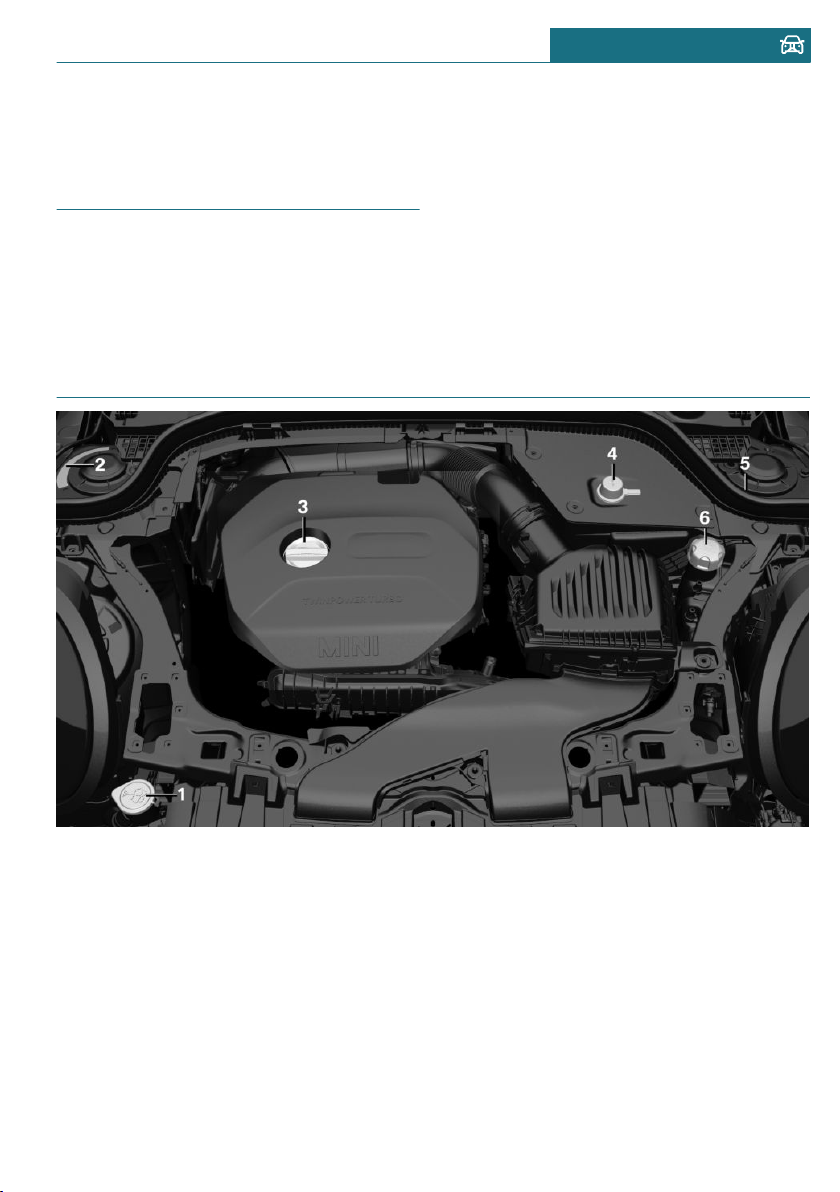
Engine compartment
Vehicle features and options
This chapter describes all standard, country-
specific and optional features offered with
the series. It also describes features that are
not necessarily available in your vehicle, for
instance, due to the selected options or
country versions. This also applies to safety-
related functions and systems. When using
these functions and systems, the applicable
laws and regulations must be observed.
Overview
1 Filler neck for washer fluid
2 Vehicle identification number
3 Oil filler neck
4 Jump-starting, positive terminal
5 Jump-starting, negative terminal
6 Coolant reservoir
Seite 279
Engine compartment MOBILITY
279
Online Edition for Part no. 01402667083 - VI/19
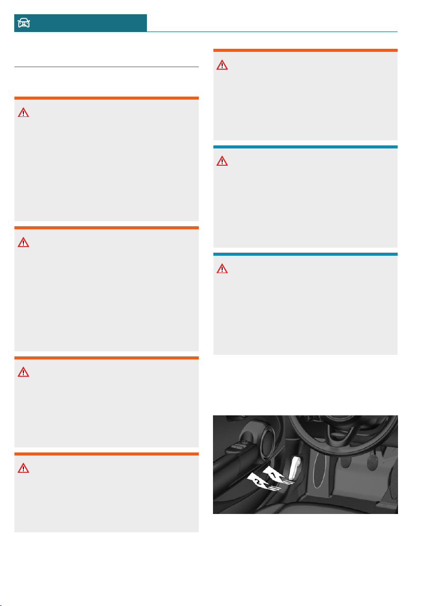
Hood
Safety information
Warning
Improperly executed work in the engine
compartment can damage vehicle compo-
nents and impair vehicle functions. There
is a risk of an accident and damage to
property. Have work in the engine com-
partment performed by a dealer’s service
center or another qualified service center
or repair shop.
Warning
The engine compartment accommodates
moving components. Certain components
in the engine compartment can also move
with the vehicle switched off, for instance
the radiator fan. There is a risk of injury.
Do not reach into the area of moving parts.
Keep articles of clothing and hair away
from moving parts.
Warning
There are protruding parts, for instance
locking hook, on the inside of the hood.
There is a risk of injury. If the hood is
open, pay attention to protruding parts
and keep clear of these areas.
Warning
An incorrectly locked hood can open while
driving and restrict visibility. There is a
risk of accident. Stop immediately and cor-
rectly close the hood.
Warning
Body parts can be jammed when opening
and closing the hood. There is a risk of in-
jury. Make sure that the area of movement
of the hood is clear during opening and
closing.
NOTICE
Folded-away wipers can be jammed when
the hood is opened. There is a risk of dam-
age to property. Make sure that the wipers
with the wiper blades mounted are folded
down onto the windshield before opening
the hood.
NOTICE
When the hood is closed, it must engage
on both sides. Pressing again can damage
the hood. There is a risk of damage to
property. Open the hood again and then
close it energetically. Avoid pressing
again.
Opening the hood
1. Pull lever, arrow 1.
Hood is unlocked.
2. After the lever is released, pull the lever
again, arrow 2.
Hood can be opened.
Seite 280
MOBILITY Engine compartment
280
Online Edition for Part no. 01402667083 - VI/19
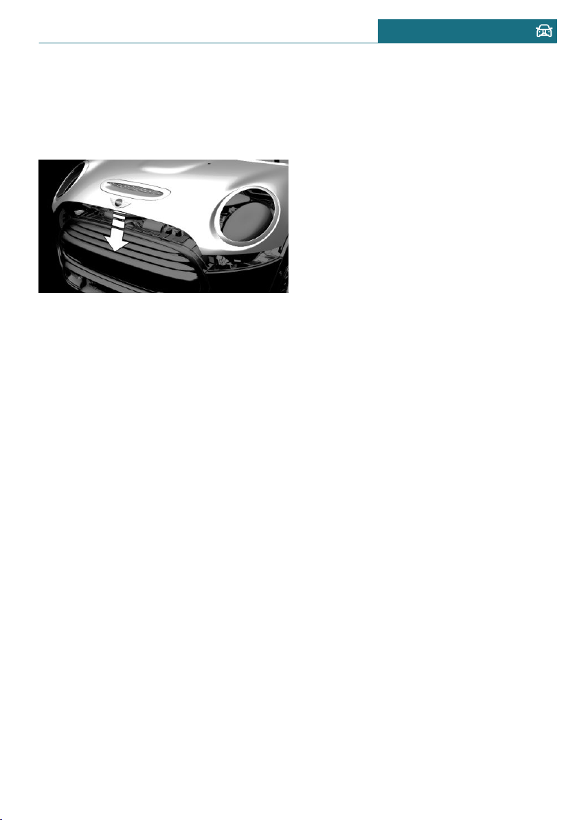
Indicator/warning lights
When the hood is opened, a Check Control
message is displayed.
Closing the hood
Energetically close the hood from approx.
20 in/50 cm.
The hood must engage on both sides.
Seite 281
Engine compartment MOBILITY
281
Online Edition for Part no. 01402667083 - VI/19
Engine oil
Vehicle features and options
This chapter describes all standard, country-
specific and optional features offered with
the series. It also describes features that are
not necessarily available in your vehicle, for
instance, due to the selected options or
country versions. This also applies to safety-
related functions and systems. When using
these functions and systems, the applicable
laws and regulations must be observed.
General information
The engine oil consumption is dependent on
your driving style and driving conditions.
Therefore, regularly check the engine oil
level after refueling by taking a detailed
measurement.
The engine oil consumption can increase in
the following situations, for instance:
– Sporty driving style.
– Break-in of the engine.
– Idling of the engine.
– With use of engine oil types that are
classified as not suitable.
Different Check Control messages appear,
depending on the engine oil level.
Safety information
NOTICE
An engine oil level that is too low causes
engine damage. There is a risk of damage
to property. Immediately add engine oil.
NOTICE
Too much engine oil can damage the en-
gine or the catalytic converter. There is a
risk of damage to property. Do not add too
much engine oil. When too much engine
oil is added, have the engine oil level cor-
rected by a dealer’s service center or an-
other qualified service center or repair
shop.
Electronic oil measurement
General information
The electronic oil measurement has two
measuring principles:
– Monitoring.
– Detailed measurement.
When making frequent short-distance trips
or using a dynamic driving style, for in-
stance when taking curves aggressively,
regularly perform a detailed measurement.
Monitoring
Concept
The engine oil level is monitored electroni-
cally while driving and can be shown on the
Control Display.
If the engine oil level is outside its permis-
sible operating range, a Check Control mes-
sage is displayed.
A red indicator light indicates that
the engine oil pressure is too low.
Seite 282
MOBILITY Engine oil
282
Online Edition for Part no. 01402667083 - VI/19
Functional requirements
A current measured value is available after
approx. 30 minutes of normal driving.
Displaying the engine oil level
Via the Central Information Display (CID):
1. "My MINI"
2. "Vehicle status"
3. "Engine oil level"
The engine oil level is displayed.
System limits
When making frequent short-distance trips
or using a dynamic driving style, it may not
be possible to calculate a measured value.
In this case, the measured value for the last,
sufficiently long trip is displayed.
Detailed measurement
Concept
The engine oil level is checked when the ve-
hicle is stationary and displayed via a scale.
If the engine oil level is outside its permis-
sible operating range, a Check Control mes-
sage is displayed.
General information
During the measurement, the idle speed is
increased somewhat.
Functional requirements
– Vehicle is parked in a horizontal posi-
tion.
– Manual transmission: shift lever in neu-
tral position, clutch and accelerator ped-
als not depressed.
– Steptronic transmission: selector lever
in selector lever position N or P and ac-
celerator pedal not depressed.
– Engine is running and is at operating
temperature.
Performing a detailed measurement
Via the Central Information Display (CID):
1. "My MINI"
2. "Vehicle status"
3. "Engine oil level"
4. "Measure engine oil level"
5. "Start measurement"
The engine oil level is checked and dis-
played via a scale.
Adding engine oil
General information
Only add engine oil when the message is
displayed in the instrument cluster. The
quantity to be added is indicated in the
message displayed in the instrument clus-
ter.
Only add suitable types of engine oil, refer
to page 284.
Safely park the vehicle and switch off the
ignition before adding engine oil.
Take care not to add too much engine oil.
Safety information
Warning
Operating materials, for instance oils,
greases, coolants, fuels, can contain harm-
ful ingredients. There is a risk of injuries
or danger to life. Follow the instructions
on the containers. Avoid the contact of ar-
ticles of clothing, skin or eyes with operat-
ing materials. Do not refill operating mate-
rials into different bottles. Store operating
materials out of reach of children.
Seite 283
Engine oil MOBILITY
283
Online Edition for Part no. 01402667083 - VI/19
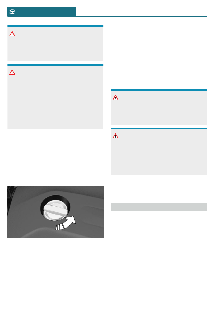
NOTICE
An engine oil level that is too low causes
engine damage. There is a risk of damage
to property. Immediately add engine oil.
NOTICE
Too much engine oil can damage the en-
gine or the catalytic converter. There is a
risk of damage to property. Do not add too
much engine oil. When too much engine
oil is added, have the engine oil level cor-
rected by a dealer’s service center or an-
other qualified service center or repair
shop.
Overview
The oil filler neck is located in the engine
compartment, refer to page 279.
Adding engine oil
1. Open the hood, refer to page 280.
2. Open the lid counterclockwise.
3. Add engine oil.
4. Close the lid.
Engine oil types to add
General information
The engine oil quality is critical for the life
of the engine.
Only add the types of engine oil which are
listed.
Safety information
NOTICE
Oil additives can damage the engine.
There is a risk of damage to property. Do
not use oil additives.
NOTICE
Incorrect engine oil can cause malfunc-
tions in the engine or damage it. There is a
risk of damage to property. When select-
ing an engine oil, make sure that the en-
gine oil has the correct oil rating.
Suitable engine oil types
Add engine oils that meet the following oil
rating standards:
Gasoline engine
BMW Longlife-01 FE.
BMW Longlife-14 FE+.
BMW Longlife-17 FE+.
Alternative engine oil types
If an engine oil suitable for continuous use
is not available, up to 1 US quart/liter of an
engine oil with the following oil rating can
be added:
Seite 284
MOBILITY Engine oil
284
Online Edition for Part no. 01402667083 - VI/19
Oil rating
API SL.
API SM.
API SN.
Viscosity grades
When selecting an engine oil, make sure
that the engine oil belongs to one of the fol-
lowing viscosity grades:
Viscosity grades
SAE 0W-20.
SAE 0W-30.
More information about suitable oil ratings
and viscosity grades of engine oils can be
requested from a dealer’s service center or
another qualified service center or repair
shop.
Engine oil change
NOTICE
Engine oil that is not changed in timely
fashion can cause increased engine wear
and thus engine damage. There is a risk of
damage to property. Do not exceed the
service data indicated in the vehicle.
The vehicle manufacturer recommends that
you have a dealer's service center or an-
other qualified service center or repair shop
change the engine oil.
Seite 285
Engine oil MOBILITY
285
Online Edition for Part no. 01402667083 - VI/19
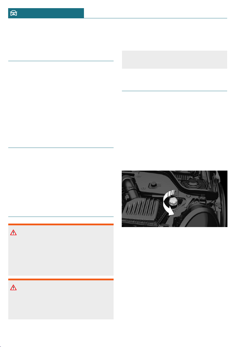
Coolant
Vehicle features and options
This chapter describes all standard, country-
specific and optional features offered with
the series. It also describes features that are
not necessarily available in your vehicle, for
instance, due to the selected options or
country versions. This also applies to safety-
related functions and systems. When using
these functions and systems, the applicable
laws and regulations must be observed.
General information
Coolant consists of water and additives.
Not all commercially available additives are
suitable for the vehicle. Information about
suitable additives is available from a deal-
er’s service center or another qualified serv-
ice center or repair shop.
Safety information
Warning
With the engine hot and the cooling sys-
tem open, coolant can escape and lead to
scalding. There is a risk of injury. Only
open the cooling system with the engine
cooled down.
Warning
Additives are harmful and incorrect addi-
tives can damage the engine. There is a
risk of injury and risk of damage to prop-
erty. Do not allow additives to come into
contact with skin, eyes or articles of cloth-
ing. Use suitable additives only.
Coolant level
Checking
There are yellow Min and Max marks in the
coolant reservoir.
1. Let the engine cool.
2. Open the hood, refer to page 280.
3. Turn the lid of the coolant reservoir
slightly counterclockwise to allow any
excess pressure to dissipate, then open
it.
4. Open the coolant reservoir lid.
Seite 286
MOBILITY Coolant
286
Online Edition for Part no. 01402667083 - VI/19
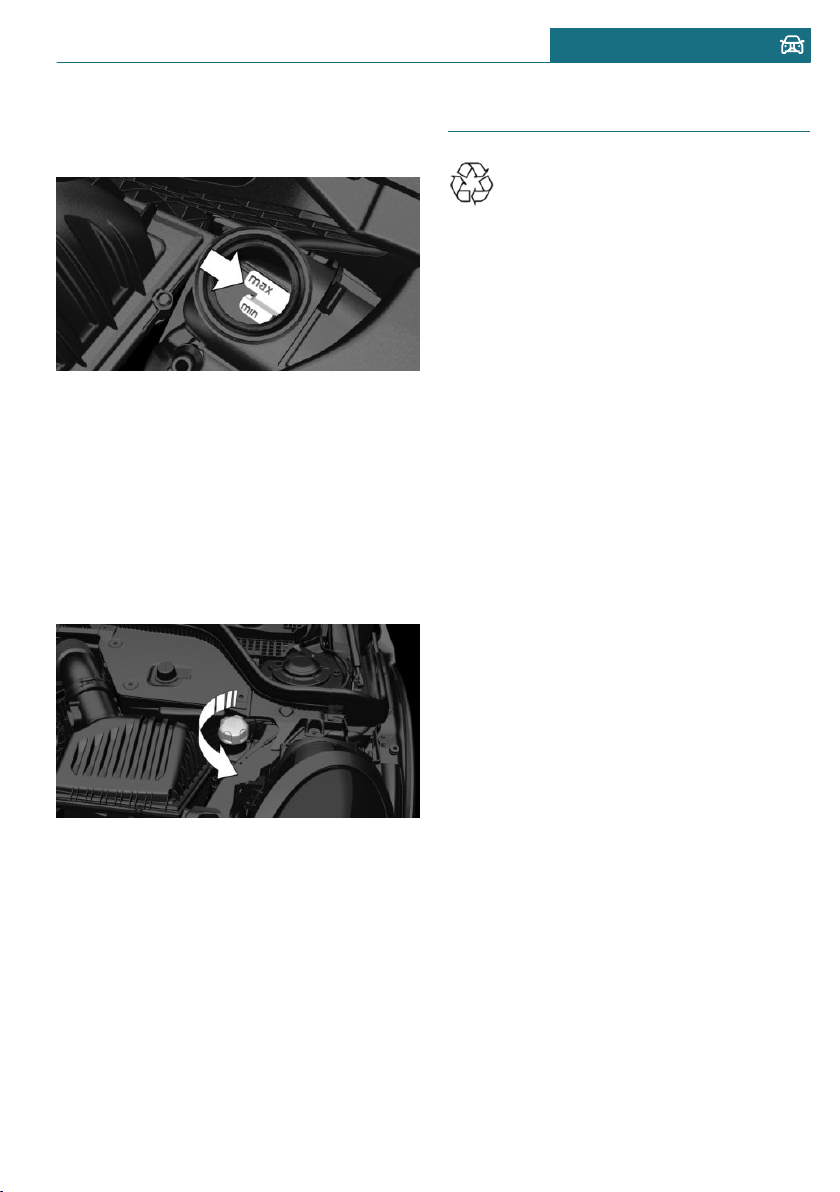
5. The coolant level is correct if it lies be-
tween the minimum and maximum
marks in the filler neck.
6. Close the lid.
Adding
1. Let the engine cool.
2. Open the hood, refer to page 280.
3. Turn the lid of the coolant reservoir
slightly counterclockwise to allow any
excess pressure to dissipate, then open
it.
4. Open the coolant reservoir lid.
5. If the coolant is low, slowly add coolant
up to the specified level; do not overfill.
6. Close the lid.
7. Have the cause of the coolant loss elimi-
nated as soon as possible.
Disposal
Comply with the relevant environ-
mental protection regulations when
disposing of coolant and coolant ad-
ditives.
Seite 287
Coolant MOBILITY
287
Online Edition for Part no. 01402667083 - VI/19

Maintenance
Vehicle features and options
This chapter describes all standard, country-
specific and optional features offered with
the series. It also describes features that are
not necessarily available in your vehicle, for
instance, due to the selected options or
country versions. This also applies to safety-
related functions and systems. When using
these functions and systems, the applicable
laws and regulations must be observed.
MINI maintenance system
The maintenance system indicates required
maintenance measures, and thereby pro-
vides support in maintaining road safety
and the operational reliability of the vehicle.
In some cases, scopes and intervals of the
maintenance system may vary according to
the country version. Replacement work,
spare parts, fuels and lubricants, and wear
materials are calculated separately. Further
information is available from a dealer's serv-
ice center or another qualified service cen-
ter or repair shop.
Condition Based Service CBS
Concept
Sensors and special algorithms take into ac-
count the driving conditions of the vehicle.
CBS uses these to calculate the need for
maintenance.
The system makes it possible to adapt the
amount of maintenance corresponding to
your user profile.
General information
Information on service requirements, refer
to page 122, can be displayed on the radio.
Service data in the vehicle key
Information on the required maintenance is
continuously stored in the vehicle key. The
dealer’s service center can read this data
out and suggest an optimized maintenance
scope for the vehicle.
Therefore, hand the service advisor the ve-
hicle key with which the vehicle was driven
most recently.
Storage periods
Storage periods during which the vehicle
battery was disconnected are not taken into
account.
If this occurs, have a dealer's service center
or another qualified service center or repair
shop update the time-dependent mainte-
nance procedures, such as checking brake
fluid and, if necessary, changing the engine
oil and the microfilter/activated-charcoal
filter.
Service and Warranty Infor-
mation Booklet for US models
and Warranty and Service
Guide Booklet for Canadian
models
Please consult your Service and Warranty
Information Booklet for US models and
Warranty and Service Guide Booklet for
Canadian models for additional information
on service requirements.
Seite 288
MOBILITY Maintenance
288
Online Edition for Part no. 01402667083 - VI/19
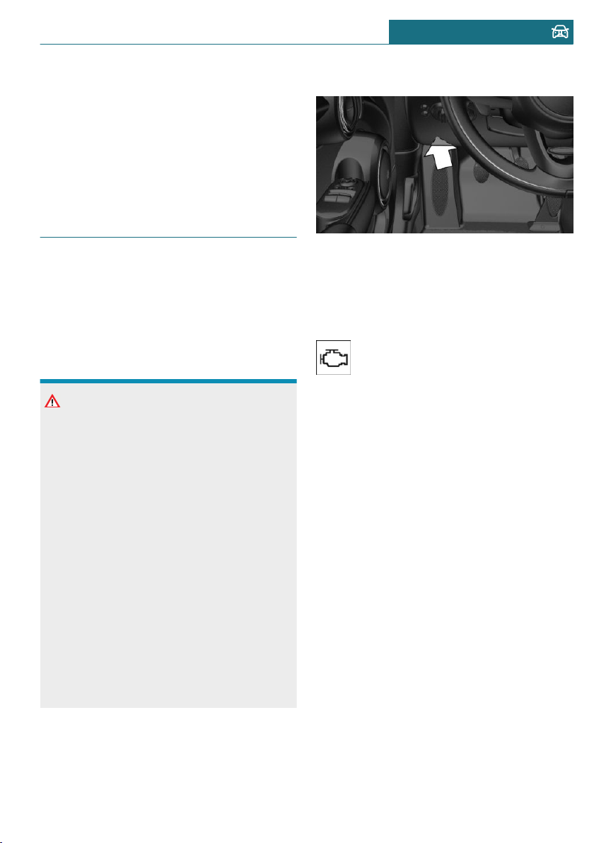
The manufacturer of your vehicle recom-
mends that maintenance and repair be per-
formed by a service center or another quali-
fied service center or repair shop. Records
of regular maintenance and repair work
should be retained.
Socket for OBD Onboard Diag-
nosis
General information
Devices connected to the OBD socket trig-
ger the alarm system when the vehicle is
locked. Remove any devices connected at
the OBD socket before locking the vehicle.
Safety information
NOTICE
The socket for Onboard Diagnosis is an in-
tricate component intended to be used in
conjunction with specialized equipment to
check the vehicle’s primary emissions sys-
tem. Improper use of the socket for On-
board Diagnosis, or contact with the
socket for Onboard Diagnosis for other
than its intended purpose, can cause vehi-
cle malfunctions and creates risks of per-
sonal and property damage. Given the fore-
going, the manufacture of your vehicle
strongly recommends that access to the
socket for Onboard Diagnosis be limited to
a dealer's service center or another quali-
fied service center or repair shop or other
persons that have the specialized training
and equipment for purposes of properly
utilizing the socket for Onboard Diagnosis.
Position
There is an OBD socket on the driver's side
for checking the primary components in the
vehicle's emissions.
Emissions
– The warning light lights up:
Emissions are deteriorating.
Have the vehicle checked as soon
as possible.
– The warning light flashes under certain
circumstances:
This indicates that there is excessive
misfiring in the engine.
Reduce the vehicle speed and have the
system checked immediately; otherwise,
serious engine misfiring within a brief
period can seriously damage emission
control components, in particular the
catalytic converter.
Seite 289
Maintenance MOBILITY
289
Online Edition for Part no. 01402667083 - VI/19
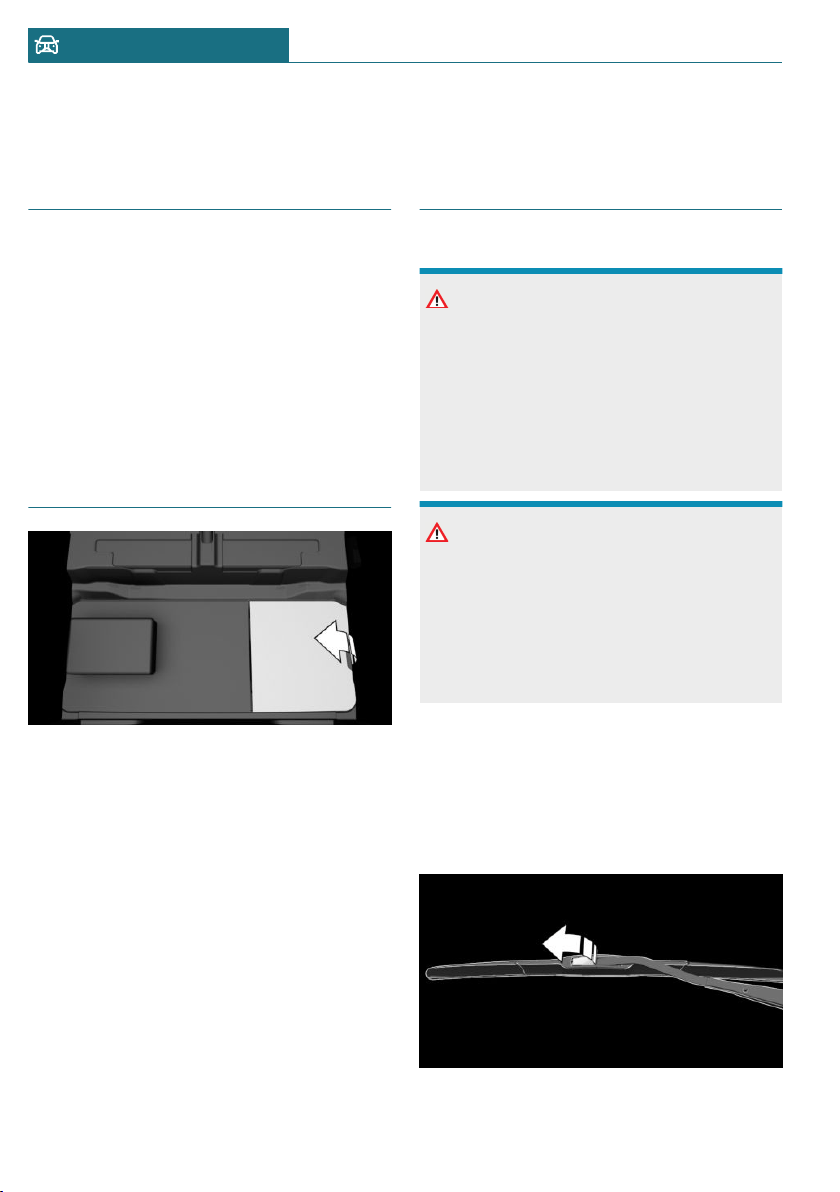
Replacing components
Vehicle features and options
This chapter describes all standard, country-
specific and optional features offered with
the series. It also describes features that are
not necessarily available in your vehicle, for
instance, due to the selected options or
country versions. This also applies to safety-
related functions and systems. When using
these functions and systems, the applicable
laws and regulations must be observed.
Vehicle tool kit
Depending on the vehicle equipment, the
onboard vehicle tool kit is located on the
right side under the cargo floor panel or in a
bag on the right side of the cargo area.
After use, secure the bag with the onboard
vehicle tool kit on a lashing eye again.
Wiper blades
Safety information
NOTICE
The window may sustain damage if the
wiper falls onto it without the wiper blade
installed. There is a risk of damage to
property. Hold the wiper firmly when
changing the wiper blade. Do not fold or
switch on the wiper without a wiper blade
installed.
NOTICE
Folded-away wipers can be jammed when
the hood is opened. There is a risk of dam-
age to property. Make sure that the wipers
with the wiper blades mounted are folded
down onto the windshield before opening
the hood.
Replacing the front wiper blades
1. To change the wiper blades, fold up the
wiper arms.
2. Fold up and hold the wiper arm firmly.
3. Open the wiper blade lock, arrow.
Seite 290
MOBILITY Replacing components
290
Online Edition for Part no. 01402667083 - VI/19
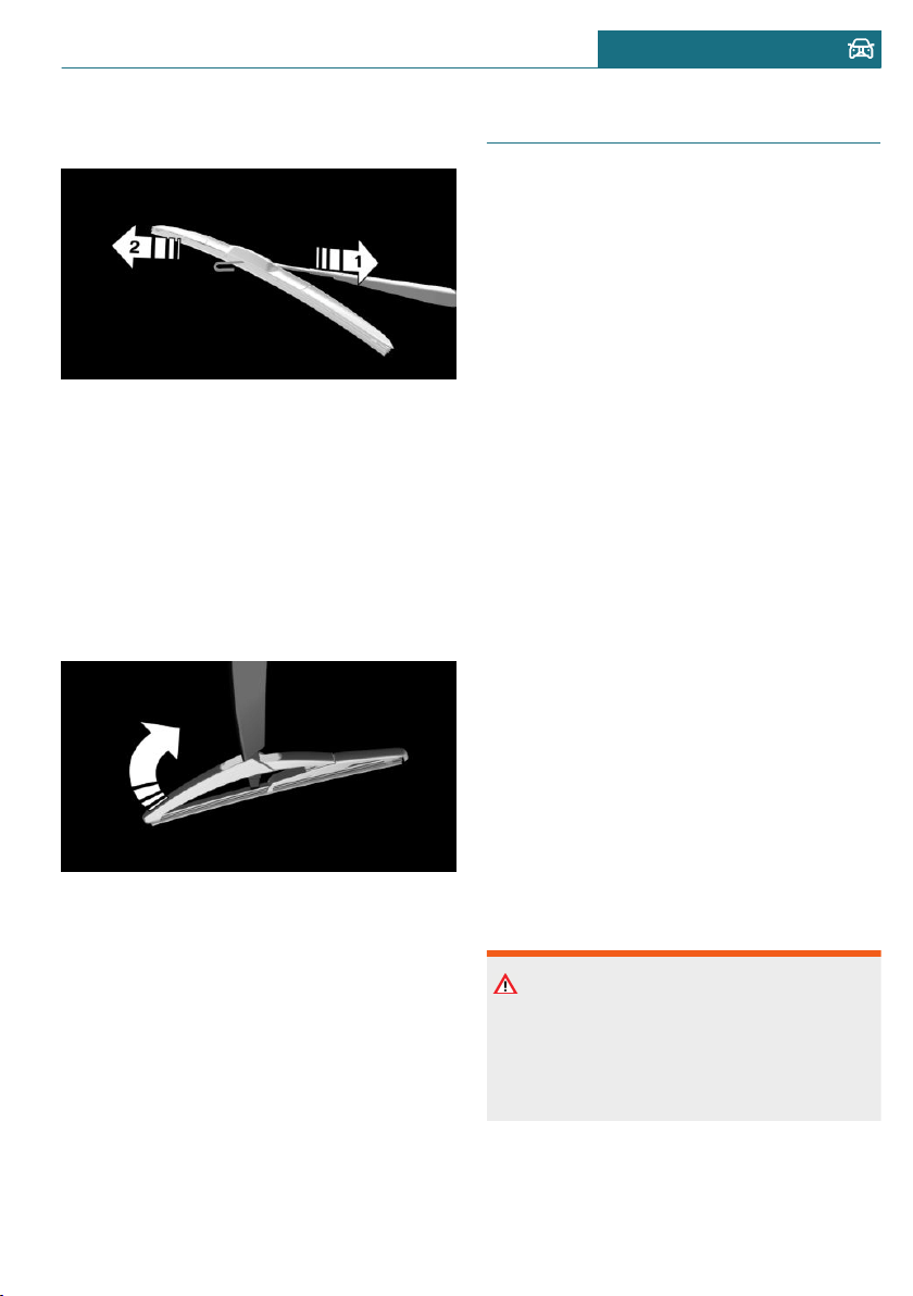
4. Pull the wiper blade down out of the
holder on the wiper arm, arrow 1.
5. Pull the wiper blade free from the holder
of the wiper arm, arrow 2.
6. Insert and latch a new wiper blade in re-
verse order.
7. Fold down the wiper arm.
Replacing the rear wiper blade
1. Fold up and hold the wiper arm firmly.
2. Turn the wiper blade all the way back.
3. Push the wiper blade out of the fasten-
ing by continuing to turn it all the way.
4. Insert the new wiper blade by following
the steps in reverse order. The wiper
blade must engage audibly.
5. Fold down the wiper arm.
Light and bulb replacement
General information
Lights and bulbs
Lights and bulbs make an essential contri-
bution to vehicle safety.
The manufacturer of the vehicle recom-
mends that you have appropriate work per-
formed by a dealer’s service center or an-
other qualified service center or repair shop
if you are unfamiliar with it or if it has not
been described here.
A spare light box is available from a dealer's
service center or another qualified service
center or repair shop.
Follow the safety information, refer to
page 291.
Light-emitting diodes (LEDs)
Some items of equipment use light-emitting
diodes installed behind a cover as a light
source. These light-emitting diodes are re-
lated to conventional lasers and are offi-
cially designated as Class 1 light-emitting
diodes.
Follow the safety information, refer to
page 291.
Safety information
Lights and bulbs
Warning
Bulbs can get hot during operation. Con-
tact with the bulbs can cause burns. There
is a risk of injury. Only change bulbs after
they have cooled off.
Seite 291
Replacing components MOBILITY
291
Online Edition for Part no. 01402667083 - VI/19
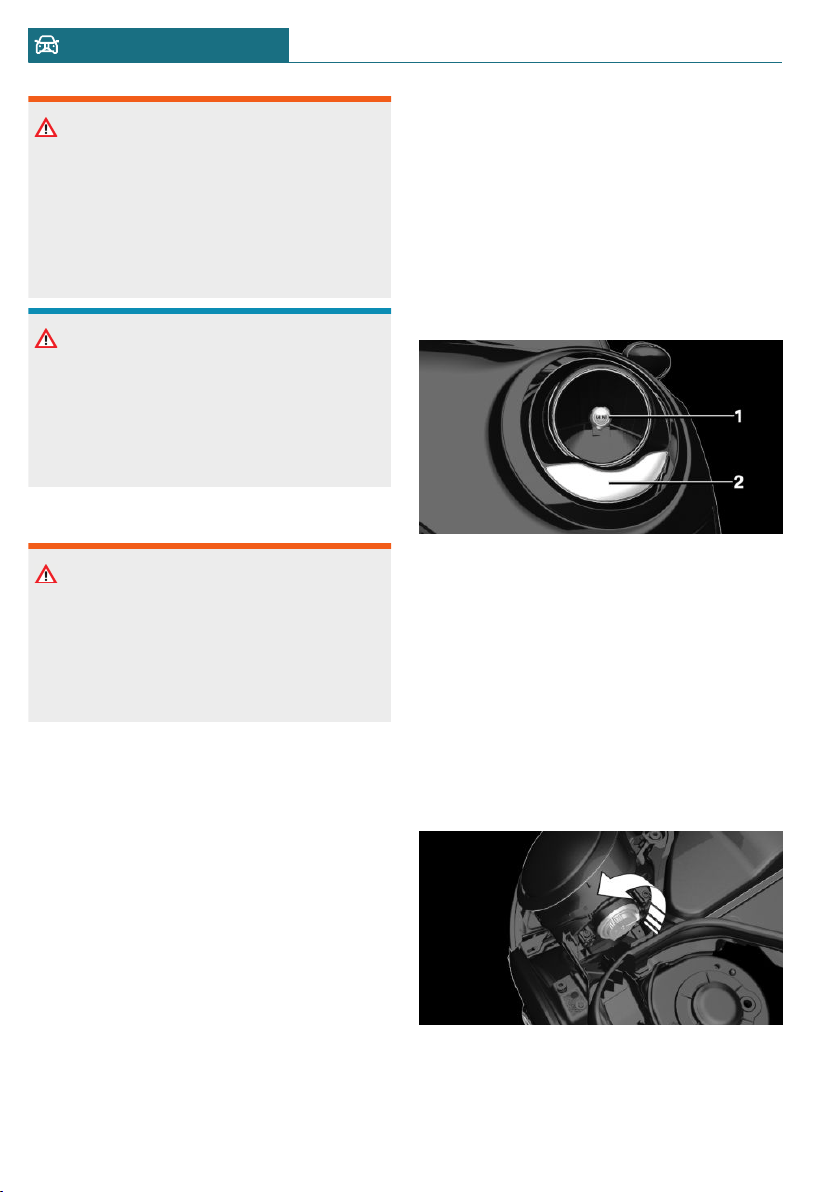
Warning
Work on switched-on lighting systems can
cause short circuits. There is a risk of in-
jury or risk of damage to property. When
working on the lighting system, switch off
the lights in question. If necessary, heed
the bulb manufacturer's instructions.
NOTICE
Dirty bulbs have a reduced service life.
There is a risk of damage to property. Do
not hold new bulbs with your bare hands.
Use a clean cloth or something similar, or
hold the bulb by its base.
Light-emitting diodes (LEDs)
Warning
Intensive brightness can irritate or dam-
age the retina of the eye. There is a risk of
injury. Do not look directly into the head-
lights or other light sources. Do not re-
move the LED covers.
Headlight glass
Condensation can form on the inside of the
headlight glass in cool or humid weather.
When driving with the lights switched on,
the condensation evaporates after a short
time. The headlight glass does not need to
be changed.
If despite driving with the headlights
switched on, increasing humidity forms, for
instance water droplets in the light, have
the headlights checked.
Headlight setting
The headlight adjustments can be affected
by changing lights and bulbs. After the
headlight adjustment was changed, have it
checked and, if necessary, corrected by a
dealer’s service center or another qualified
service center or repair shop.
Front halogen lights, bulb
replacement
Overview
Halogen headlights
1 Low beams/high beams
2 Turn signal
Low beams/high beams
Follow the general instructions on lights
and bulbs, refer to page 291.
55-watt bulb, HB2.
1. Open the hood, refer to page 280.
2. Turn the lid counterclockwise, arrow,
and remove.
3. Pull off the connector.
Seite 292
MOBILITY Replacing components
292
Online Edition for Part no. 01402667083 - VI/19
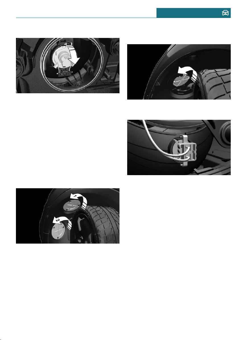
4. Unclip spring clip, arrow, and fold down.
5. Remove the bulb from the headlight
housing.
6. Insert the new bulb and install the cover
in the reverse order.
Turn signal
Follow the general instructions on lights
and bulbs, refer to page 291.
21-watt bulb, PY21W.
1. Turn the steering wheel.
2. Turn the lid counterclockwise, arrow 1,
and remove.
3. Unscrew the inner cover counterclock-
wise, and remove it.
4. Turn the bulb socket counterclockwise
and remove it from the bulb housing.
5. Pull the bulb out of the fixture.
6. Insert the new bulb and install the cover
in the reverse order.
LED front lights, bulb replacement
All lights feature LED technology.
In the case of a malfunction, contact a deal-
er's service center or another qualified serv-
ice center or repair shop.
LED front fog lights
These front fog lights are made using LED
technology. In the case of a malfunction,
contact a dealer's service center or another
qualified service center or repair shop.
Seite 293
Replacing components MOBILITY
293
Online Edition for Part no. 01402667083 - VI/19
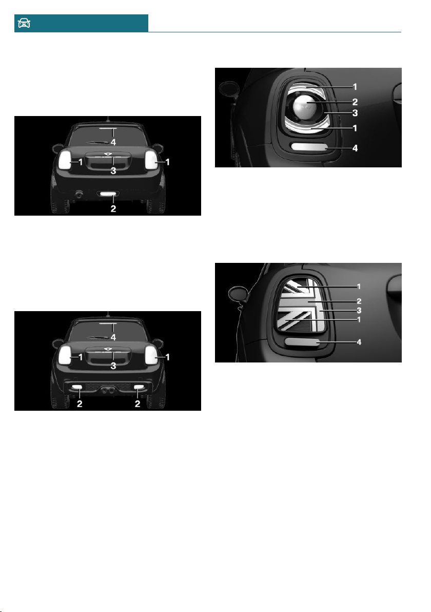
Tail lights, bulb replacement
Overview
Vehicles with a rear fog light
1 Side tail lights
2 Rear fog light
3 License plate light
4 Center brake light
Vehicle with two rear fog lights
1 Side tail lights
2 Rear fog lights
3 License plate light
4 Center brake light
Side tail lights
1 Tail lights
2 Turn signal
3 Brake light
4 Reversing lights
Side tail lights with Union Jack
1 Tail lights
2 Turn signals/brake lights
3 Turn signals/brake lights
4 Reversing lights
Side tail lights
Without Union Jack
Follow the general instructions on lights
and bulbs, refer to page 291.
– Bulb, brake lights: H21W.
– Bulb, turn signals: P21W.
Seite 294
MOBILITY Replacing components
294
Online Edition for Part no. 01402667083 - VI/19
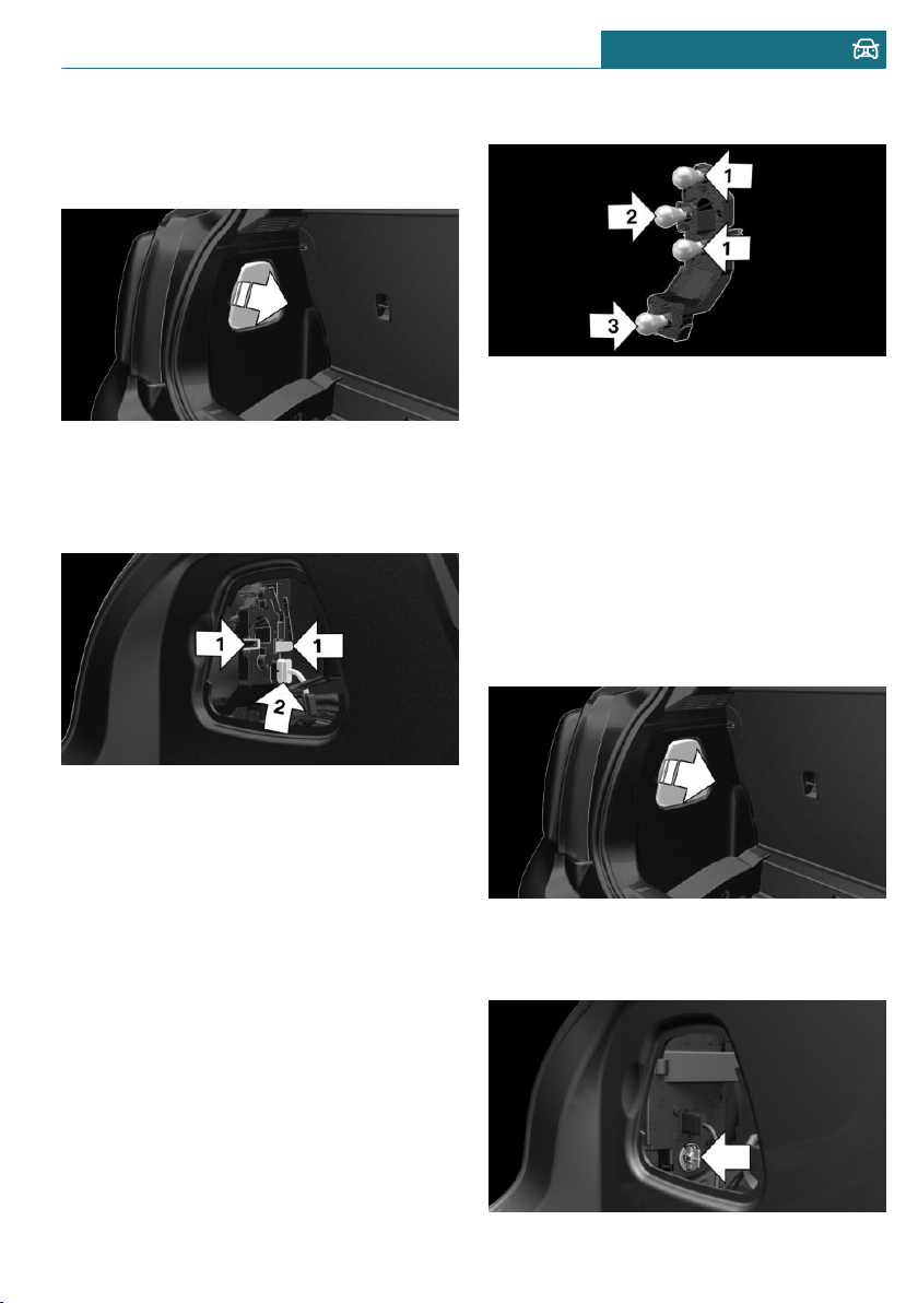
– Bulb, reversing lights: P21W.
1. Open the tailgate.
2. Remove left or right cover.
3. Through the opening, loosen the plug
connector, arrow 2 on the bulb holder.
Press the latches together, arrows 1, and
remove the bulb holder.
4. Remove the bulb holder from the open-
ing.
5. Press the nonworking bulb gently into
the socket, turn counterclockwise and
remove.
– Arrow 1: brake lights
– Arrow 2: turn signal
– Arrow 3: reversing light
6. Proceed in the reverse order to insert
the new bulb and attach the bulb holder.
Make sure that the bulb holder engages
in all fasteners.
With Union Jack
Follow the general instructions on lights
and bulbs, refer to page 291.
Bulb, reversing lights: P21W.
1. Open the tailgate.
2. Remove left or right cover.
3. Turn the bulb holder for the reversing
light, arrow, counterclockwise and re-
move it.
Seite 295
Replacing components MOBILITY
295
Online Edition for Part no. 01402667083 - VI/19
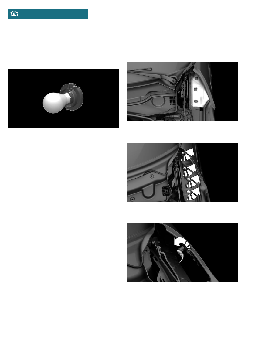
4. Remove the bulb holder from the open-
ing.
5. Press the nonworking bulb gently into
the socket, turn counterclockwise and
remove.
6. Proceed in the reverse order to insert
the new bulb and attach the bulb holder.
Make sure that the bulb holder engages
in all fasteners.
Central brake light and license plate
lights
Follow the general instructions on lights
and bulbs, refer to page 291.
The lights feature LED technology. In the
case of a malfunction, contact a dealer's
service center or another qualified service
center or repair shop.
Side turn signal, bulb replacement
Follow the general instructions on lights
and bulbs, refer to page 291.
Bulbs:
– With white lens: WY5W.
1. Open the hood. The covers of the side
turn signal lights are on the left and
right next to the hinges of the hood.
2. Loosen nuts of the cover by hand and re-
move the cover.
3. Turn the bulb socket counterclockwise
and remove.
4. Replace the bulb.
5. To insert the new bulb, proceed in re-
verse order of removal. Insert the nuts
of the cover and press down.
Seite 296
MOBILITY Replacing components
296
Online Edition for Part no. 01402667083 - VI/19
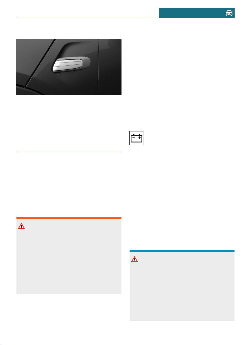
Side scuttles
Individual side scuttles for clicking into the
side turn signals are available as original
MINI accessories.
Follow the assembly instructions.
Vehicle battery
General information
The battery is maintenance-free.
More information about the battery can be
requested from a dealer's service center or
another qualified service center or repair
shop.
Safety information
Warning
Vehicle batteries that are not compatible
can damage vehicle systems and impair
vehicle functions. There is a risk of an ac-
cident and damage to property. Only vehi-
cle batteries that are compatible with your
vehicle type should be installed in your ve-
hicle. Information on compatible vehicle
batteries is available at your dealer’s serv-
ice center.
Register the battery to the vehicle
The manufacturer of the vehicle recom-
mends that you have a service center or an-
other qualified service center or repair shop
register the vehicle battery to the vehicle
after the battery has been replaced. Once
the battery has been registered again, all
comfort features will be available without
restriction and any Check Control messages
displayed which relate to comfort features
will disappear.
Charging the battery
General information
Make sure that the battery is always suffi-
ciently charged to guarantee that the bat-
tery remains usable for its full service life.
A discharged battery is indicated by
a red indicator light.
Charge the battery in the following situa-
tions:
– When the inspection glass on the top of
the battery is black.
– When the take-off performance is insuf-
ficient.
The following circumstances can have a
negative effect on the performance of the
battery:
– Frequent short-distance drives.
– The vehicle is not used for more than a
month.
Safety information
NOTICE
Battery chargers for the vehicle battery
can work with high voltages and currents,
which means that the 12 volt on-board
network can be overloaded or damaged.
There is a risk of damage to property. Only
connect battery chargers for the vehicle
battery to the starting aid terminals in the
engine compartment.
Seite 297
Replacing components MOBILITY
297
Online Edition for Part no. 01402667083 - VI/19
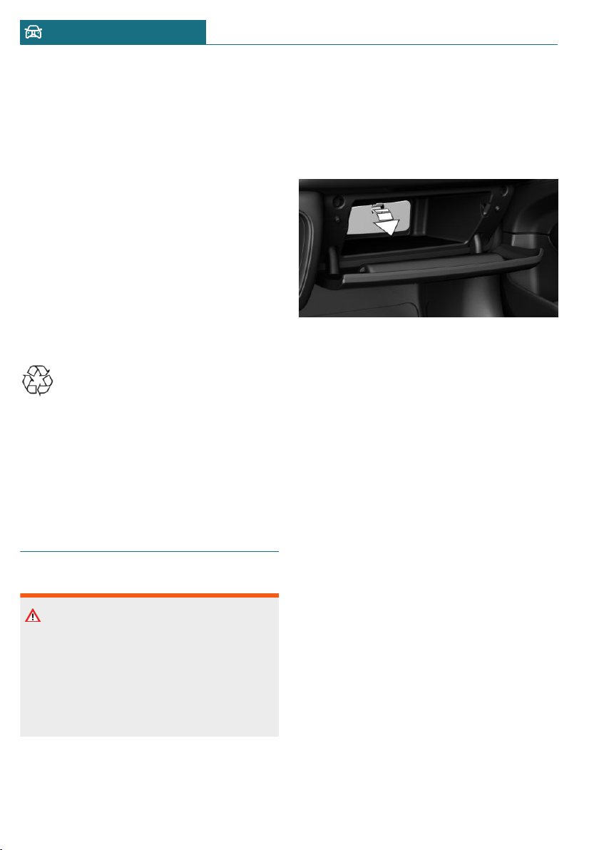
Charging the battery
Charge the battery only when the engine is
off and via the starting aid terminals, refer
to page 302, in the engine compartment.
Power failure
After a power loss, some equipment needs
to be newly initialized or individual settings
updated, for example:
– Memory function: store the positions
again.
– Time: update.
– Date: update.
– Glass sunroof: initialize the system.
Disposing of old batteries
Have old batteries disposed of by a
dealer’s service center or another
qualified service center or repair
shop or take them to a collection point.
Maintain the filled battery in an upright po-
sition for transport and storage. Secure the
battery so that it does not tip over during
transport.
Fuses
Safety information
Warning
Incorrect and repaired fuses can overload
electrical lines and components. There is a
risk of fire. Never attempt to repair a
blown fuse. Do not replace a nonworking
fuse with a substitute of another color or
amperage rating.
Accessing the fuses
The fuses are located in the glove compart-
ment.
1. Open the glove compartment.
2. Swing the cover down, arrow.
Information on the fuse types and locations,
as well as the positions of any other fuse
boxes, is available on the Internet:
www.mini.com/fusecard.
Where applicable, information on the fuse
types and locations is also found on a sepa-
rate sheet in the fuse box.
Replacing fuses
The vehicle manufacturer recommends that
you have a dealer's service center or an-
other qualified service center or repair shop
replace the fuses.
Seite 298
MOBILITY Replacing components
298
Online Edition for Part no. 01402667083 - VI/19
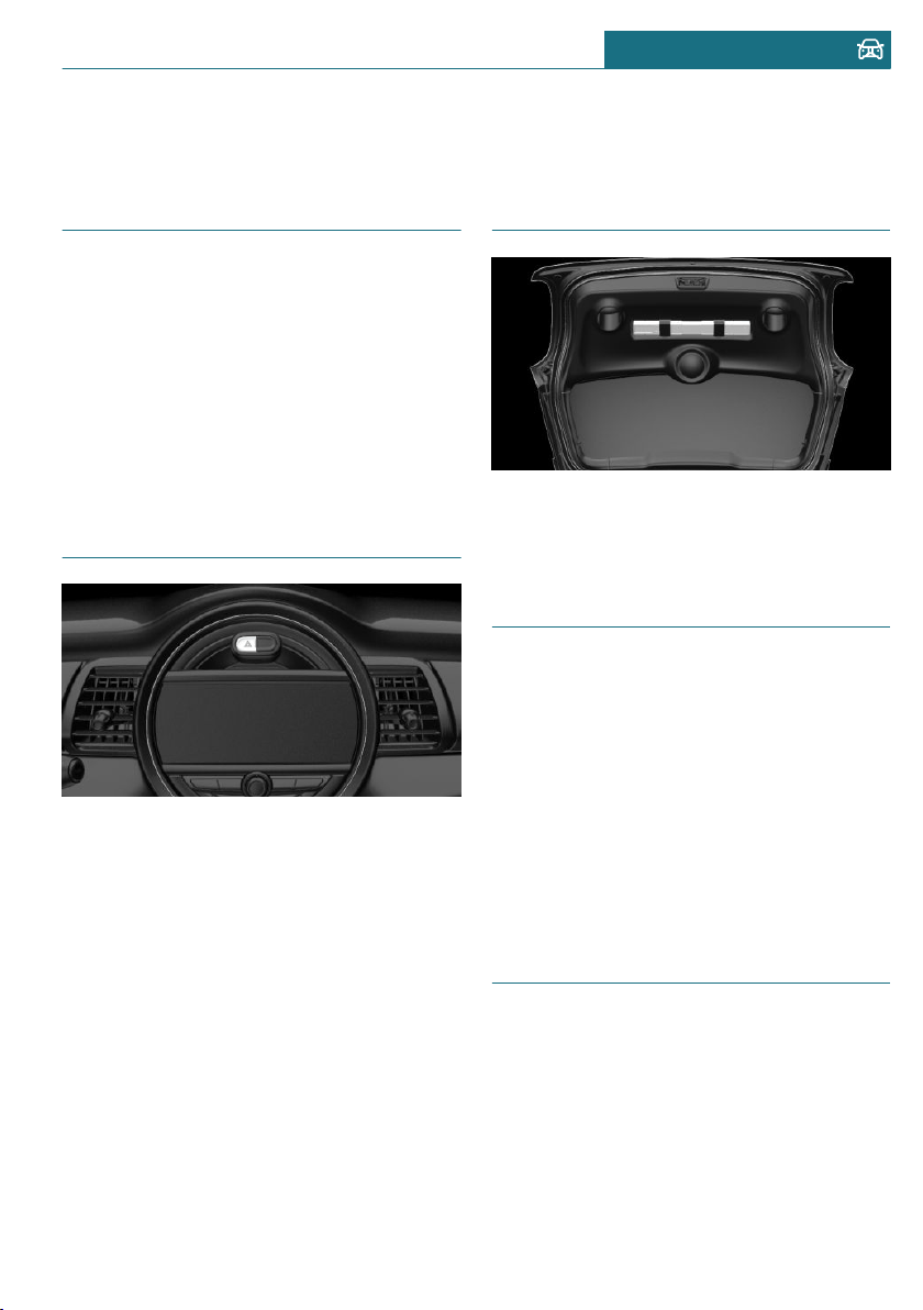
Breakdown assistance
Vehicle features and options
This chapter describes all standard, country-
specific and optional features offered with
the series. It also describes features that are
not necessarily available in your vehicle, for
instance, due to the selected options or
country versions. This also applies to safety-
related functions and systems. When using
these functions and systems, the applicable
laws and regulations must be observed.
Hazard warning flashers
The button is located above the Control Dis-
play.
The red light in the button flashes when the
hazard warning flashers are activated.
Warning triangle
The warning triangle is located in the tail-
gate. To remove, loosen the brackets.
First-aid kit
General information
Some of the articles have a limited service
life.
Check the expiration dates of the contents
regularly and replace any expired items
promptly.
Storage
The first-aid kit is located in the cargo area.
MINI Roadside Assistance
Concept
MINI Roadside Assistance can be contacted
if assistance is needed in the event of a
breakdown.
Seite 299
Breakdown assistance MOBILITY
299
Online Edition for Part no. 01402667083 - VI/19

General information
In the event of a breakdown, data on the ve-
hicle's condition is sent to the vehicle man-
ufacturer.
There are various ways of making contact.
– Via a Check Control message, refer to
page 116.
– Calling with a mobile phone.
Requirements
– Active MINI Connected contract or
equipment version with intelligent
emergency call.
– Cellular network reception.
– The ignition is switched on.
Starting
If the vehicle is equipped with Teleservices,
support is offered through Teleservice Diag-
nosis.
Via the Central Information Display (CID):
1. "MINI Connected"
2. "MINI Assist"
3. "MINI Roadside Assistance"
The contact to the Roadside Assistance
of the manufacture is established.
A telephone number is displayed, if
needed. Select to dial the telephone
number on a connected mobile phone.
Teleservice Diagnosis
Teleservice Diagnosis enables the wireless
transmission of detailed vehicle data that is
important for vehicle diagnosis. This data is
transmitted automatically.
Teleservice Help
Depending on the country, the Teleservice
Help enables a more in-depth diagnosis of
the vehicle via wireless transmission.
You can launch Teleservice Help by re-
questing it through the Service Specialist.
1. Park the vehicle in a safe place.
2. Set the parking brake.
3. Control Display is switched on.
4. "Teleservice Help"
The driving ability of the vehicle can be re-
stored for specific functions.
If this is not possible, further measures will
be initiated, for instance Roadside Assis-
tance will be informed.
Emergency Request
Intelligent emergency call
Concept
In case of an emergency, an Emergency Re-
quest can be triggered automatically by the
system or manually.
General information
Only press the SOS button in an emergency.
The Intelligent Assist system establishes a
connection with the MINI Response Center.
For technical reasons, the Emergency Re-
quest cannot be guaranteed under unfavora-
ble conditions.
Seite 300
MOBILITY Breakdown assistance
300
Online Edition for Part no. 01402667083 - VI/19
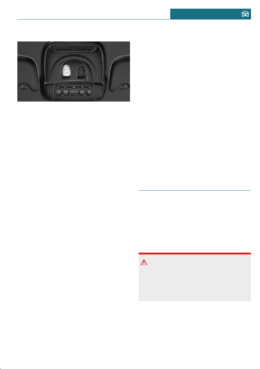
Overview
SOS button in the roofliner
Functional requirements
– The ignition is switched on.
– The Assist system is functional.
– If the vehicle is equipped with intelli-
gent emergency call: the SIM card
integrated in the vehicle has been acti-
vated.
Automatic triggering
Under certain conditions, for instance if the
airbags trigger, an Emergency Request is
automatically initiated immediately after an
accident of corresponding severity. Auto-
matic Collision Notification is not affected
by pressing the SOS button.
Manual triggering
1. Press the cover briefly to open it.
2. Press the SOS button until the LED at
the button lights up green.
– The LED is illuminated green when an
Emergency Request has been initiated.
If the situation allows, wait in your vehi-
cle until the voice connection has been
established.
– The LED flashes green when a connec-
tion to the MINI Response Center has
been established.
The MINI Response Center then makes
contact with you and takes further steps
to help you.
Even if you are unable to respond, the
MINI Response Center can take further
steps to help you under certain circum-
stances.
For this, data is transmitted to the MINI
Response Center which serve to deter-
mine the necessary rescue measures.
For instance, the current position of the
vehicle, if it can be established.
If you can no longer hear the MINI Re-
sponse Center through the loudspeakers,
the hands-free system, for instance, may
be broken. However, the MINI Response
Center may still be able to hear you.
The MINI Response Center ends the Emer-
gency Request.
Jump-starting
General information
If the battery is discharged, the engine can
be started using the battery of another vehi-
cle and two jumper cables. Only use jumper
cables with fully insulated clamp handles.
Safety information
DANGER
Contact with live components can lead to
an electric shock. There is a risk of inju-
ries or danger to life. Do not touch any
components that are under voltage.
Seite 301
Breakdown assistance MOBILITY
301
Online Edition for Part no. 01402667083 - VI/19
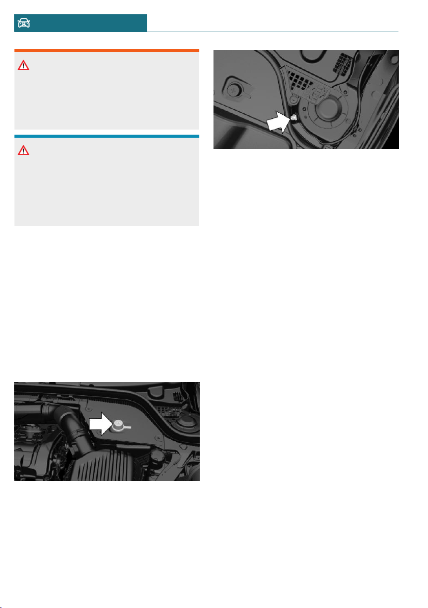
Warning
If the jumper cables are connected in the
incorrect order, sparking may occur. There
is a risk of injury. Pay attention to the cor-
rect order during connection.
NOTICE
In the case of body contact between the
two vehicles, a short circuit can occur dur-
ing jump-starting. There is a risk of dam-
age to property. Make sure that no body
contact occurs.
Preparation
1. Check whether the battery of the other
vehicle has a voltage of 12 volts. The
voltage information can be found on the
battery.
2. Switch off the engine of the assisting
vehicle.
3. Switch off any electronic systems/power
consumers in both vehicles.
Starting aid terminals
The starting aid terminal in the engine com-
partment acts as the battery's positive ter-
minal.
Open the cover of the starting aid terminal.
The body ground or a special nut acts as the
battery negative terminal.
Connecting the cables
To prevent personal injury or damage to
both vehicles, adhere strictly to the follow-
ing procedure.
1. Pull off the lid of the starting aid termi-
nal.
2. Attach one terminal clamp of the posi-
tive jumper cable to the positive termi-
nal of the battery, or to the correspond-
ing starting aid terminal of the vehicle
providing assistance.
3. Attach the terminal clamp on the other
end of the cable to the positive terminal
of the battery, or to the corresponding
starting aid terminal of the vehicle to be
started.
4. Attach one terminal clamp of the nega-
tive jumper cable to the negative termi-
nal of the battery, or to the correspond-
ing engine or body ground of assisting
vehicle.
5. Attach the second terminal clamp to the
negative terminal of the battery, or to
the corresponding engine or body
ground of the vehicle to be started.
Seite 302
MOBILITY Breakdown assistance
302
Online Edition for Part no. 01402667083 - VI/19
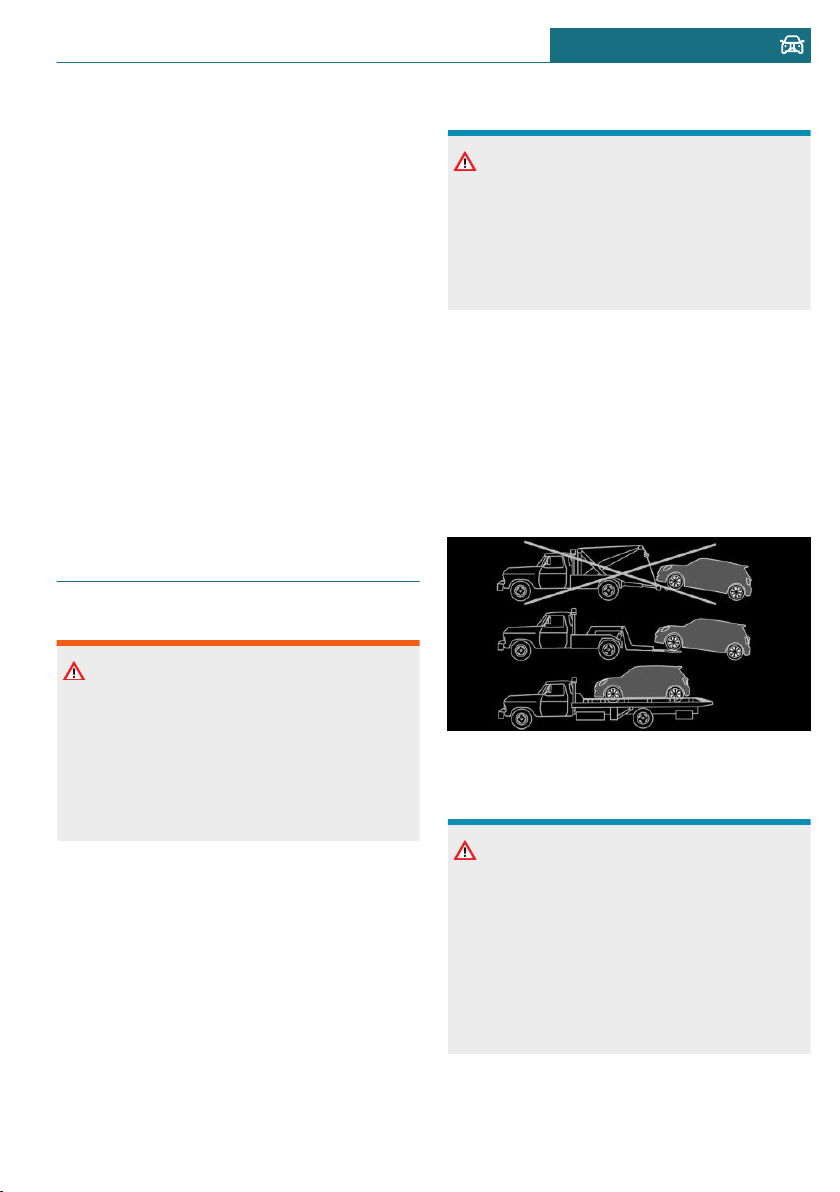
Starting the engine
Never use spray fluids to start the engine.
1. Start the engine of the assisting vehicle
and let it run for several minutes at an
increased idle speed.
2. Start the engine of the vehicle that is to
be started in the usual way.
If the first starting attempt is not suc-
cessful, wait a few minutes before mak-
ing another attempt in order to allow the
discharged battery to recharge.
3. Let both engines run for several mi-
nutes.
4. Disconnect the jumper cables in the re-
verse order.
Check the battery and recharge, if needed.
Tow-starting and towing
Safety information
Warning
Due to system limits, individual functions
can malfunction during tow-starting/
towing with the Intelligent Safety systems
activated. There is a risk of accident.
Switch all Intelligent Safety systems off
prior to tow-starting/towing.
Steptronic transmission with
driven front axle: transporting the
vehicle
General information
The vehicle must not be towed if the front
wheels are touching the ground.
Safety information
NOTICE
The vehicle can be damaged when towing
the vehicle with a lifted rear axle. There is
a risk of damage to property. Have vehicle
transported only with lifted front axle or
on a loading platform.
Pushing the vehicle
To remove a broken-down vehicle from the
danger area, it can be pushed for a short
distance.
For rolling or pushing the vehicle, refer to
page 110.
Tow truck
Your vehicle should be transported with a
tow truck with a so-called lift bar or on a
flat bed.
NOTICE
The vehicle can become damaged when
lifting and securing it.
There is a risk of damage to property.
– Lift the vehicle using suitable means.
– Do not lift or secure the vehicle by its
tow fitting, body parts, or suspension
parts.
Seite 303
Breakdown assistance MOBILITY
303
Online Edition for Part no. 01402667083 - VI/19
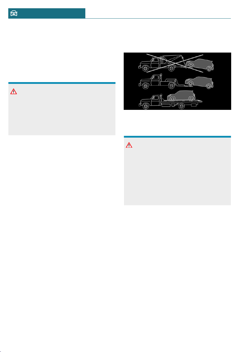
Manual transmission
Towing or pushing the vehicle
A broken-down vehicle can be towed or
pushed.
For rolling or pushing the vehicle, refer to
page 107.
NOTICE
If manual unlocking of the parking brake
is not possible, the vehicle cannot be
moved or towed. There is a risk of damage
to property. The vehicle should only be
transported on a loading platform.
Follow the following instructions:
– Make sure that the ignition is switched
on; otherwise, the low beams, tail lights,
turn signals, and wipers may be unavail-
able.
– Do not tow the vehicle with the rear
axle tilted, as the front wheels could
turn.
– When the engine is stopped, there is no
power assist. Consequently, more force
needs to be applied when braking and
steering.
– Larger steering wheel movements are
required.
– The towing vehicle must not be lighter
than the vehicle being towed; otherwise,
it will not be possible to control the ve-
hicle's response.
– Do not exceed a towing speed of
30 mph/50 km/h.
– Do not exceed a towing distance of
30 miles/50 km.
Tow truck
With driven front axle
Your vehicle should be transported with a
tow truck with a so-called lift bar or on a
flat bed.
NOTICE
The vehicle can become damaged when
lifting and securing it.
There is a risk of damage to property.
– Lift the vehicle using suitable means.
– Do not lift or secure the vehicle by its
tow fitting, body parts, or suspension
parts.
Towing other vehicles
General information
Switch on the hazard warning system, de-
pending on local regulations.
If the electrical system has failed, clearly
identify the vehicle being towed by placing
a sign or a warning triangle in the rear win-
dow.
Seite 304
MOBILITY Breakdown assistance
304
Online Edition for Part no. 01402667083 - VI/19
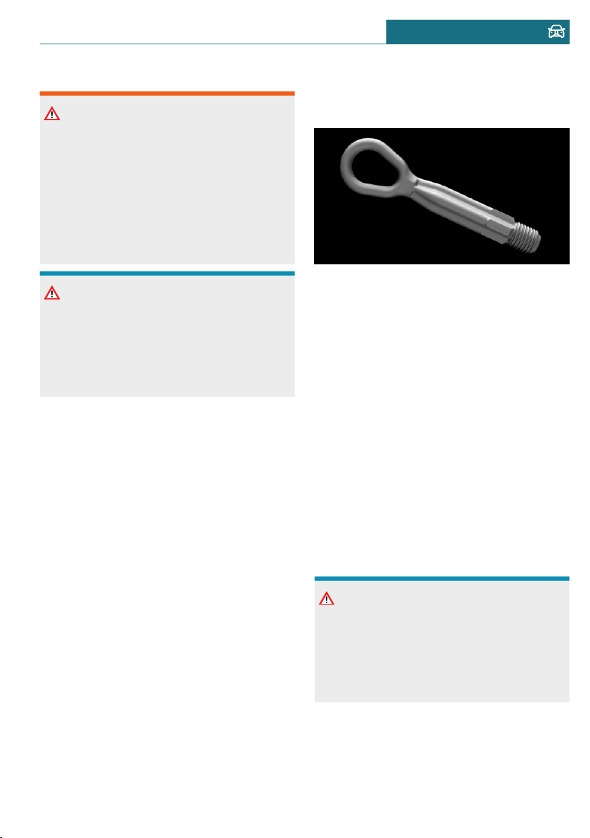
Safety information
Warning
If the approved gross vehicle weight of the
towing vehicle is lighter than the vehicle
to be towed, the tow fitting can tear off or
it will not be possible to control the vehi-
cle's response. There is a risk of accident.
Make sure that the gross vehicle weight of
the towing vehicle is heavier than the ve-
hicle to be towed.
NOTICE
If the tow bar or tow rope is attached in-
correctly, damage to other vehicle parts
can occur. There is a risk of damage to
property. Correctly attach the tow bar or
tow rope to the tow fitting.
Tow bar
The tow fittings used should be on the same
side on both vehicles.
Should it prove impossible to avoid mount-
ing the tow bar at an offset angle, please fol-
low the following:
– Maneuvering capability is limited going
around corners.
– The tow bar will generate lateral forces
if it is secured with an offset.
Tow rope
When starting to tow the vehicle, make
sure that the tow rope is taut.
Use nylon ropes or straps, which will enable
the vehicle to be towed without jerking.
Tow fitting
General information
The screw-in tow fitting should always be
carried in the vehicle.
The tow fitting can be screwed in at the
front or rear of the vehicle.
The tow fitting and the onboard vehicle tool
kit, refer to page 290, are together in the
cargo area.
Use of the tow fitting:
– Use only the tow fitting provided with
the vehicle and screw it all the way in.
– Use the tow fitting for towing on paved
roads only.
– Avoid lateral loading of the tow fitting,
for instance do not lift the vehicle by the
tow fitting.
Safety information
NOTICE
If the tow fitting is not used as intended,
there may be damage to the vehicle or to
the tow fitting. There is a risk of damage
to property. Follow the notes on using the
tow fitting.
Seite 305
Breakdown assistance MOBILITY
305
Online Edition for Part no. 01402667083 - VI/19

Screw thread for tow fitting
Threaded holes for the tow fitting are lo-
cated in the front and rear of the vehicle on
the right side with respect to the direction
of travel.
Press on the mark on the edge of the cover
to push it out.
Tow-starting
Steptronic transmission
Do not tow-start the vehicle.
Tow-starting the engine is not possible due
to the Steptronic transmission.
Have the reasons for the starting difficulties
corrected by a dealer’s service center or an-
other qualified service center or repair
shop.
Manual transmission
If possible, do not tow-start the vehicle but
start the engine by jump-starting, refer to
page 301. If the vehicle is equipped with a
catalytic converter, only tow-start while the
engine is cold.
1. Switch on the hazard warning system
and comply with local regulations.
2. Switch on the ignition, refer to page 91.
3. Engage third gear.
4. Have the vehicle tow-started with the
clutch pedal pressed and slowly release
the pedal. After the engine starts, imme-
diately press on the clutch pedal again.
5. Stop at a suitable location, remove the
tow bar or rope, and switch off the haz-
ard warning system.
6. Have the vehicle checked by a dealer's
service center or another qualified serv-
ice center or repair shop.
Seite 306
MOBILITY Breakdown assistance
306
Online Edition for Part no. 01402667083 - VI/19

Care
Vehicle features and options
This chapter describes all standard, country-
specific and optional features offered with
the series. It also describes features that are
not necessarily available in your vehicle, for
instance, due to the selected options or
country versions. This also applies to safety-
related functions and systems. When using
these functions and systems, the applicable
laws and regulations must be observed.
Washing the vehicle
General information
Regularly remove foreign objects such as
leaves in the area below the windshield
when the hood is raised.
Wash your vehicle frequently, particularly
in winter. Intense soiling and road salt can
damage the vehicle.
Steam jets or high-pressure
washers
Safety information
NOTICE
When cleaning with high-pressure wash-
ers, components can be damaged due to
the pressure or temperatures being too
high. There is a risk of damage to property.
Maintain sufficient distance and do not
spray too long continuously. Follow the
operating instructions for the high-pres-
sure washer.
Distances and temperature
– Maximum temperature: 140 ℉/60 ℃.
– Minimum distance from sensors, cam-
eras, seals: 12 inches/30 cm.
– Minimum distance from glass sunroof:
31.5 in/80 cm.
Automatic vehicle washes
Safety information
NOTICE
Water can penetrate in the windshield
area due to high-pressure washers. There
is a risk of damage to property. Avoid
high-pressure washers.
NOTICE
Improper use of automatic vehicle washes
can cause damage to the vehicle. There is
a risk of damage to property. Follow the
following instructions:
– Give preference to cloth vehicle
washes or those that use soft brushes
in order to avoid paint damage.
– Avoid vehicle washes with guide rails
higher than 4 in/10 cm to avoid dam-
age to the chassis.
– Observe the tire width of the guide
rail to avoid damage to tires and rims.
– Fold in exterior mirrors to avoid dam-
age to the exterior mirrors.
– Unscrew the rod antenna to avoid the
rod antenna breaking off.
– Deactivate the wiper and, if neces-
sary, rain sensor to avoid damage to
the wiper system.
Seite 307
Care MOBILITY
307
Online Edition for Part no. 01402667083 - VI/19
Driving into a vehicle wash with a
manual transmission
In vehicle washes, the vehicle must be able
to roll freely.
Rolling or pushing the vehicle, refer to
page 107.
Driving into a vehicle wash with a
Steptronic transmission
In vehicle washes, the vehicle must be able
to roll freely.
Rolling or pushing the vehicle, refer to
page 110.
Some vehicle washes do not permit persons
in the vehicle. The vehicle cannot be locked
from the outside when in selector lever po-
sition N. A signal is sounded when an at-
tempt is made to lock the vehicle.
Driving out of a vehicle wash
Ensure that the vehicle key is in the car.
Start the engine, refer to page 92.
Headlights
Do not rub wet headlights dry and do not
use abrasive or acidic cleaning agents.
Soak areas that have been dirtied, for in-
stance from insects, with shampoo and
wash off with water.
Thaw ice with de-icing spray; do not use an
ice scraper.
After washing the vehicle
After washing the vehicle, apply the brakes
briefly to dry them; otherwise, braking ac-
tion can be reduced. The heat generated
during braking dries brake discs and brake
pads and protects them against corrosion.
Completely remove all residues on the win-
dows, to minimize loss of visibility due to
smearing and to reduce wiper noises and
wiper blade wear.
Vehicle care
Vehicle care products
General information
MINI recommends using vehicle care and
cleaning products from MINI. Suitable care
products are available from a dealer’s serv-
ice center or another qualified service cen-
ter or repair shop.
Safety information
Warning
Cleansers can contain substances that are
dangerous and harmful to your health.
There is a risk of injury. When cleaning
the interior, open the doors or windows.
Only use products intended for cleaning
vehicles. Follow the instructions on the
container.
Vehicle paint
General information
Regular care contributes to driving safety
and value retention. Environmental influen-
ces in areas with elevated air pollution or
natural contaminants, such as tree resin or
pollen can affect the vehicle's paintwork.
Tailor the frequency and extent of your ve-
hicle care to these influences.
Aggressive substances such as spilled fuel,
oil, grease or bird droppings, must be re-
moved immediately to prevent the finish
from being altered or discolored.
Matte finish
Only use cleaning and care products suita-
ble for vehicles with matte finish.
Seite 308
MOBILITY Care
308
Online Edition for Part no. 01402667083 - VI/19

Leather care
Remove dust from the leather regularly, us-
ing a cloth or vacuum cleaner.
Otherwise, particles of dust and road grime
chafe in pores and folds, and lead to in-
creased wear and premature degradation of
the leather surface.
To guard against discoloration, such as from
clothing, clean leather and provide leather
care roughly every two months.
Clean light-colored leather more frequently
because soiling on such surfaces is substan-
tially more visible.
Use leather care products; otherwise, dirt
and grease will gradually break down the
protective layer of the leather surface.
Upholstery material care
General information
Vacuum the upholstery regularly with a
vacuum cleaner.
If upholstery is very dirty, for instance with
beverage stains, use a soft sponge or micro-
fiber cloth with a suitable interior cleaner.
Clean the upholstery down to the seams us-
ing large sweeping motions. Avoid rubbing
the material vigorously.
Safety information
NOTICE
Open Velcro® fasteners on articles of
clothing can damage the seat covers.
There is a risk of damage to property. En-
sure that any Velcro® fasteners are closed.
Caring for special components
Light-alloy wheels
When cleaning the vehicle, use only neutral
wheel cleaners having a pH value from 5 to
9. Do not use abrasive cleaning agents or
steam jets above 140 ℉/60 ℃. Follow the
manufacturer's instructions.
Aggressive, acidic or alkaline cleaning
agents can destroy the protective layer of
adjacent components, such as the brake
disc.
After cleaning, apply the brakes briefly to
dry them. The heat generated during brak-
ing dries brake discs and brake pads and
protects them against corrosion.
Chrome surfaces
Carefully clean components such as the ra-
diator grille or door handles with plenty of
water, possibly with shampoo added, partic-
ularly when they have been exposed to road
salt.
Rubber components
Environmental influences can cause surface
soiling of rubber parts and a loss of gloss.
Use only water and suitable cleaning agents
for cleaning.
Treat especially worn rubber parts with rub-
ber care agents at regular intervals. When
cleaning rubber seals, do not use any sili-
con-containing vehicle care products in or-
der to avoid damage or noises.
Fine wood parts
Clean fine wood facing and fine wood com-
ponents only with a moist rag. Then dry
with a soft cloth.
Seite 309
Care MOBILITY
309
Online Edition for Part no. 01402667083 - VI/19

Plastic components
NOTICE
Cleansers that contain alcohol or solvents,
such as lacquer thinners, heavy-duty
grease removers, fuel, or such, can damage
plastic parts. There is a risk of damage to
property. Clean with a microfiber cloth.
Dampen the cloth lightly with water, if
needed.
Clean with a microfiber cloth.
Dampen the cloth lightly with water, if
needed.
Do not soak the roofliner.
Safety belts
Warning
Chemical cleansers can destroy the safety
belt webbing. Missing protective effect of
the safety belts. There is a risk of injuries
or danger to life. Use only a mild soapy sol-
ution for cleaning the safety belts.
Dirty belt straps impede the reeling action
and thus have a negative impact on safety.
Use only a mild soapy solution, with the
safety belts clipped into their buckles.
Safety belts should only be allowed to re-
tract if they are dry.
Carpets and floor mats
Warning
Objects in the driver's floor area can limit
the pedal distance or block a depressed
pedal. There is a risk of accident. Stow ob-
jects in the vehicle such that they are se-
cured and cannot enter into the driver's
floor area. Use floor mats that are suitable
for the vehicle and can be safely attached
to the floor. Do not use loose floor mats
and do not layer several floor mats. Make
sure that there is sufficient clearance for
the pedals. Ensure that the floor mats are
securely fastened again after they were re-
moved, for instance for cleaning.
Floor mats can be removed from the car's
interior for cleaning.
If the floor carpets are very dirty, clean with
a microfiber cloth and water or a textile
cleaner. To prevent matting of the carpet,
rub back and forth in the direction of travel
only.
Sensor/camera lenses
To clean sensors and camera lenses, use a
cloth moistened with a small amount of
glass detergent.
Displays/Screens
NOTICE
Chemical cleansers, moisture or fluids of
any kind can damage the surface of dis-
plays and screens. There is a risk of dam-
age to property. Clean with a clean, anti-
static microfiber cloth.
NOTICE
The surface of displays can be damaged
with improper cleaning. There is a risk of
damage to property. Avoid pressure that is
too high and do not use any scratching
materials.
Clean with a clean, antistatic microfiber
cloth.
Long-term vehicle storage
When the vehicle is shut down for longer
than three months, special measures must
Seite 310
MOBILITY Care
310
Online Edition for Part no. 01402667083 - VI/19

be taken. Further information is available
from a dealer's service center or another
qualified service center or repair shop.
Seite 311
Care MOBILITY
311
Online Edition for Part no. 01402667083 - VI/19

312
Online Edition for Part no. 01402667083 - VI/19

REFERENCE
Technical data ......................................................................................... 314
Appendix .................................................................................................. 318
License Texts and Certifications ...................................................... 319
Everything from A to Z ........................................................................ 328
313
Online Edition for Part no. 01402667083 - VI/19
Technical data
Vehicle features and options
This chapter describes all standard, country-
specific and optional features offered with
the series. It also describes features that are
not necessarily available in your vehicle, for
instance, due to the selected options or
country versions. This also applies to safety-
related functions and systems. When using
these functions and systems, the applicable
laws and regulations must be observed.
General information
The technical data and specifications in the
Owner's Manual are used as guidance val-
ues. The vehicle-specific data can deviate
from this, for instance due to the selected
special equipment, country version or coun-
try-specific measurement method. Detailed
values can be found in the approval docu-
ments, on labels on the vehicle or can be ob-
tained from a dealer’s service center or an-
other qualified service center or repair
shop.
Dimensions
The dimensions can vary depending on the
model version, equipment or country-spe-
cific measurement method.
The specified heights do not take into ac-
count attached parts, for instance a roof an-
tenna, roof racks or spoiler. The heights can
deviate, for instance due to the selected
special equipment, tires, load and chassis
version.
MINI 3-door
Width with mirrors in/mm 76.1/1,932
Width without mirrors in/mm 68/1,727
Height in/mm 55.7/1,414
Length in/mm 151.1-152.5/3,837-3,874
Wheelbase in/mm 98.2/2,495
Smallest turning radius diam. ft/m 35.4/10.8
Seite 314
REFERENCE Technical data
314
Online Edition for Part no. 01402667083 - VI/19
MINI 5-door
Width with mirrors in/mm 76.1/1,932
Width without mirrors in/mm 68/1,727
Height in/mm 56.1/1,425
Length in/mm 157.4-158/3,998-4,013
Wheelbase in/mm 101.1/2,567
Smallest turning radius diam. ft/m 36.1/11.0
Weights
MINI Cooper, 3-door
Approved gross vehicle weight
Manual transmission lbs/kg 3,627/1,645
Steptronic transmission lbs/kg 3,627/1,645
Load
Manual transmission lbs/kg 818/371
Steptronic transmission lbs/kg 763/346
Approved front axle load
Manual transmission lbs/kg 1,962/890
Steptronic transmission lbs/kg 2,028/920
Approved rear axle load
Manual transmission lbs/kg 1,731/785
Steptronic transmission lbs/kg 1,687/765
MINI Cooper, 5-door
Approved gross vehicle weight
Manual transmission lbs/kg 3,814/1,730
Steptronic transmission lbs/kg 3,814/1,730
Load
Manual transmission lbs/kg 884/401
Seite 315
Technical data REFERENCE
315
Online Edition for Part no. 01402667083 - VI/19

MINI Cooper, 5-door
Steptronic transmission lbs/kg 840/381
Approved front axle load
Manual transmission lbs/kg 2,039/925
Steptronic transmission lbs/kg 2,094/950
Approved rear axle load
Manual transmission lbs/kg 1,885/855
Steptronic transmission lbs/kg 1,863/845
MINI Cooper S, 3-door
Approved gross vehicle weight
Manual transmission lbs/kg 3,682/1,670
Steptronic transmission lbs/kg 3,726/1,690
Load
Manual transmission lbs/kg 809/367
Steptronic transmission lbs/kg 816/370
Approved front axle load
Manual transmission lbs/kg 2,039/925
Steptronic transmission lbs/kg 2,083/945
Approved rear axle load
Manual transmission lbs/kg 1,731/785
Steptronic transmission lbs/kg 1,731/785
MINI Cooper S, 5-door
Approved gross vehicle weight
Manual transmission lbs/kg 3,858/1,750
Steptronic transmission lbs/kg 3,902/1,770
Load
Manual transmission lbs/kg 864/392
Steptronic transmission lbs/kg 866/393
Seite 316
REFERENCE Technical data
316
Online Edition for Part no. 01402667083 - VI/19

MINI Cooper S, 5-door
Approved front axle load
Manual transmission lbs/kg 2,105/955
Steptronic transmission lbs/kg 2,150/975
Approved rear axle load
Manual transmission lbs/kg 1,885/855
Steptronic transmission lbs/kg 1,885/855
MINI John Cooper Works, 3-door
Approved gross vehicle weight
Manual transmission lbs/kg 3,726/1,690
Steptronic transmission lbs/kg 3,770/1,710
Load
Manual transmission lbs/kg 847/384
Steptronic transmission lbs/kg 814/369
Approved front axle load
Manual transmission lbs/kg 2,072/940
Steptronic transmission lbs/kg 2,127/965
Approved rear axle load
Manual transmission lbs/kg 1,753/795
Steptronic transmission lbs/kg 1,753/795
Capacities
MINI
Fuel tank, approx. US gal/liters 11.6/44.0
Observe further information on fuel quality,
refer to page 254.
Seite 317
Technical data REFERENCE
317
Online Edition for Part no. 01402667083 - VI/19

Appendix
Any updates to the Owner's Manual of the
vehicle are listed here.
Updates made after the edito-
rial deadline
The following chapters were updated in the
printed version of the Owner's Manual after
the editorial deadline for the Integrated
Owner's Manual in the vehicle had closed:
– Replacing components: Light and bulb
replacement: Front halogen lights, bulb
replacement.
Seite 318
REFERENCE Appendix
318
Online Edition for Part no. 01402667083 - VI/19
License Texts and Certifications
Headunit
Brazil
Este equipamento opera em caráter secun-
dário, isto é, não tem direito a proteção con-
tra interferência prejudicial, mesmo de esta-
ções do mesmo tipo, e não pode causar
interferência a sistemas operando em
caráter primário.
Europe
European Union: Declaration of
Conformity
Hereby, Alpine Electronics , Inc. declares
that the radio equipment type BIS01 is in
compliance with Directive 2014/53/EU.
The full text of the EU declaration of con-
formity is avallable at the following internet
address: http://www.alpine.com/e/
research/
Technical information
Frequency Band: 2.5 GHz
Output Power : 8 dBm
Manufacturer and Address
Manufacturer: Alpine Electronics, Inc.
Address: 20-1, Yoshima Industrial Park,
Iwaki, Fukushima 970-1192 Japan
Phone: +81-246-36-4111
Български
С настоящото Alpine Electronics
декларира, че този тип
радиосъоръжение BIS01 е в
съответствие с Директива 2014/53/ЕС.
Цялостният текст на ЕС декларацията за
съответствие може да се намери на
следния интернет адрес: http://
www.alpine.com/e/research/
Čeština
Tímto Alpine Electronics prohlašuje, že typ
rádiového zařízení BIS01 je v souladu se
směrnicí 2014/53/EU. Úplné znění EU
prohlášení o shodě je k dispozici na této in-
ternetové adrese: http://www.alpine.com/e/
research/
Dansk
Hermed erklærer Alpine Electronics, at radi-
oudstyrstypen BIS01 er i overensstemmelse
med direktiv 2014/53/EU. EU-overensstem-
melseserklæringens fulde tekst kan findes
på følgende internetadresse: http://
www.alpine.com/e/research/
Deutsch
Hiermit erklärt Alpine Electronics, dass der
Funkanlagentyp BIS01 der Richtlinie
2014/53/EU entspricht. Der vollständige
Seite 319
License Texts and Certifications REFERENCE
319
Online Edition for Part no. 01402667083 - VI/19

Text der EU-Konformitätserklärung ist un-
ter der folgenden Internetadresse verfüg-
bar: http://www.alpine.com/e/research/
Eesti
Käesolevaga deklareerib Alpine Electronics,
et käesolev raadioseadme tüüp BIS01
vastab direktiivi 2014/53/EL nõuetele. ELi
vastavusdeklaratsiooni täielik tekst on kät-
tesaadav järgmisel internetiaadressil:
http://www.alpine.com/e/research/
English
Hereby, Alpine Electronics declares that the
radio equipment type BIS01 is in compli-
ance with Directive 2014/53/EU. The full
text of the EU declararation of conformity is
avilable at the following internet ad-
dress :http://www.alpine.com/e/research/
Español
Por la presente, Alpine Electronics declara
que el tipo de equipo radioeléctrico BIS01
es conforme con la Directiva 2014/53/UE.
El texto completo de la declaración UE de
conformidad está disponible en la dirección
Internet siguiente: http://
www.alpine.com/e/research/
Ελληνική
Με την παρούσα ο/η Alpine Electronics,
δηλώνει ότι ο ραδιοεξοπλισμός BIS01 πληροί
την οδηγία 2014/53/ΕΕ. Το πλήρες κείμενο
της δήλωσης συμμόρφωσης ΕΕ διατίθεται
στην ακόλουθη ιστοσελίδα στο διαδίκτυο:
http://www.alpine.com/e/research/
Français
Le soussigné, Alpine Electronics, déclare
que l'équipement radioélectrique du type
BIS01 est conforme à la directive
2014/53/UE. Le texte complet de la déclara-
tion UE de conformité est disponible à
l'adresse internet suivante: http://
www.alpine.com/e/research/
Hrvatski
Alpine Electronics ovime izjavljuje da je
radijska oprema tipa BIS01 u skladu s Dir-
ektivom 2014/53/EU. Cjeloviti tekst EU iz-
jave o sukladnosti dostupan je na sljedećoj
internetskoj adresi: http://
www.alpine.com/e/research/
Íslenska
Hér, Alpine Electronics lýsir yfir að radíó-
búnaður gerð BIS01 er í samræmi við tilski-
pun 2014/53 / ESB. The fullur texti af ESB
declararation á samræmi er avilable á eftir-
farandi veffangi: http://www.alpine.com/e/
research/
Italiano
Il fabbricante, Alpine Electronics , dichiara
che il tipo di apparecchiatura radio BIS01 è
conforme alla direttiva 2014/53/UE. Il testo
completo della dichiarazione di conformità
UE è disponibile al seguente indirizzo Inter-
net: http://www.alpine.com/e/research/
Latviski
Ar šo Alpine Electronics deklarē, ka radioie-
kārta BIS01 atbilst Direktīvai 2014/53/ES.
Pilns ES atbilstības deklarācijas teksts ir
pieejams šādā interneta vietnē: http://
www.alpine.com/e/research/
Lietuvių
Aš, Alpine Electronics, patvirtinu, kad radijo
įrenginių tipas BIS01 atitinka Direktyvą
2014/53/ES. Visas ES atitikties deklaracijos
tekstas prieinamas šiuo interneto adresu:
http://www.alpine.com/e/research/
Nederlands
Hierbij verklaar ik, Alpine Electronics, dat
het type radioapparatuur BIS01 conform is
Seite 320
REFERENCE License Texts and Certifications
320
Online Edition for Part no. 01402667083 - VI/19

met Richtlijn 2014/53/EU. De volledige
tekst van de EU-conformiteitsverklaring kan
worden geraadpleegd op het volgende inter-
netadres: http://www.alpine.com/e/
research/
Malti
B'dan, Alpine Electronics, niddikjara li dan
it-tip ta' tagħmir tar-radju BIS01 huwa kon-
formi mad-Direttiva 2014/53/UE. It-test
kollu tad-dikjarazzjoni ta' konformità tal-UE
huwa disponibbli f'dan l-indirizz tal-Internet
li ġej: http://www.alpine.com/e/research/
Magyar
Alpine Electronics igazolja, hogy a BIS01 tí-
pusú rádióberendezés megfelel a
2014/53/EU irányelvnek. Az EU-megfelelő-
ségi nyilatkozat teljes szövege elérhető a
következő internetes címen: http://
www.alpine.com/e/research/
Norsk
Erklærer herved Alpine Electronics at radio-
utstyr typen BIS01 er i samsvar med direk-
tiv 2014/53 / EU. Den fullstendige teksten i
EU declararation samsvars er avilable på
følgende internettadresse: http://
www.alpine.com/e/research/
Polski
Alpine Electronics niniejszym oświadcza, że
typ urządzenia radiowego BIS01 jest
zgodny z dyrektywą 2014/53/UE. Pełny
tekst deklaracji zgodności UE jest dostępny
pod następującym adresem internetowym:
http://www.alpine.com/e/research/
Português
O(a) abaixo assinado(a) Alpine Electronics
declara que o presente tipo de equipamento
de rádio BIS01 está em conformidade com a
Diretiva 2014/53/UE. O texto integral da
declaração de conformidade está disponível
no seguinte endereço de Internet: http://
www.alpine.com/e/research/
Română
Prin prezenta, Alpine Electronics declară că
tipul de echipamente radio BIS01 este în
conformitate cu Directiva 2014/53/UE.
Textul integral al declarației UE de confor-
mitate este disponibil la următoarea adresă
internet: http://www.alpine.com/e/
research/
Slovensko
Alpine Electronics potrjuje, da je tip radi-
jske opreme BIS01 skladen z Direktivo
2014/53/EU. Celotno besedilo izjave EU o
skladnosti je na voljo na naslednjem splet-
nem naslovu: http://www.alpine.com/e/
research/
Slovenský
Alpine Electronics týmto vyhlasuje, že rádi-
ové zariadenie typu BIS01 je v súlade so
smernicou 2014/53/EÚ. Úplné EÚ vyhláse-
nie o zhode je k dispozícii na tejto interne-
tovej adrese: http://www.alpine.com/e/
research/
Suomi
Alpine Electronics vakuuttaa, että radiolai-
tetyyppi BIS01 on direktiivin 2014/53/EU
mukainen. EU-vaatimustenmukaisuusva-
kuutuksen täysimittainen teksti on saata-
villa seuraavassa internetosoitteessa:
http://www.alpine.com/e/research/
Svenska
Härmed försäkrar Alpine Electronics att
denna typ av radioutrustning BIS01 över-
ensstämmer med direktiv 2014/53/EU. Den
fullständiga texten till EU-försäkran om
överensstämmelse finns på följande webba-
dress: http://www.alpine.com/e/research/
Seite 321
License Texts and Certifications REFERENCE
321
Online Edition for Part no. 01402667083 - VI/19
Japan
Mexico
La operación de este equipo está sujeta a las
siguientes dos condiciones:
(1) es posible que este equipo o dispositivo
no cause interferencia perjudicial y
(2) este equipo o dispositivo debe aceptar
cualquier interferencia, incluyendo la que
pueda causar su operación no deseada.
Russia, Kazakhstan, Belarus
South Korea
해당 무선설비는 전파혼신 가능성이 있으
므로 인명안전과 관련된 서비스는 할 수
없습니다
A 급 기기 (업무용 방송통신기자재)
이 기기는 업무용(A 급) 전자파적합기기
로서 판매자
또는 사용자는 이 점을 주의하시기 바라
며, 가정외의
지역에서 사용하는 것을 목적으로 합니
다.
Taiwan
本產品符合低功率電波輻射性電機管理辦
法 第十二條、第十四條等條文規定
1.
經型式認證合格之低功率射頻電機,非經
許可,公司、商號或使用者均不得擅自變
更頻率、加大功率或變更原設計之特性及
功能。
Low Power radio frequency electric machi-
nery was qualified by Type Approval, not
get permission from authority; the company,
business or user can’t arbitrarily change
frequency, increase power or modify feature
or function of original design.
2.
低功率射頻電機之使用不得影響飛航安全
及干擾合法通信;經發現有干擾現象時,
應立即停用,並改善至無干擾時方得繼續
使用。
前項合法通信,指依電信法規定作業之無
線電通信。
Seite 322
REFERENCE License Texts and Certifications
322
Online Edition for Part no. 01402667083 - VI/19

低功率射頻電機須忍受合法通信或工業、
科學及醫療用電波輻射性電機設備之干
擾。
Use of low power radio frequency electric
machinery can’t affect flight safety and in-
terfere with legal communication; once dis-
cover the interfered phenomenon, it should
stop immediately and improve to no inter-
ference and then could continue to use.
The preceding legal communication is radio
communication which follows Telecommu-
nication Act to operate.
Low power radio frequency electric machi-
nery must tolerate interference from legal
communication or electric machinery appa-
ratus of industry, science and medical radia-
tion.
USA, Canada
USA (FCC) and Canada (IC)
Register model name:BIS01
Product code: RB00010A
FCC CAUTION
Changes or modifications not expressly ap-
proved by the party responsible for compli-
ance could void the user’s authority to oper-
ate the equipment. This transmitter must
not be co-located or operated in conjunction
with any other antenna or transmitter. This
device complies with part 15 of FCC Rules
and Industry Canada’s licence-exempt RSSs.
Operation is subject to the following two
conditions: (1) this device may not cause
harmful interference, and (2) this device
must accept any interference received, in-
cluding interference that may cause unde-
sired operation.
Le présent appareil est conforme à la partie
15 des règles de la FCC et aux normes des
CNR d'Industrie Canada applicables aux ap-
pareils radio exempts de licence. L'exploita-
tion est autorisée aux deux conditions sui-
vantes : (1) l'appareil ne doit pas produire de
brouillage, et (2) l'appareil doit accepter tout
brouillage subi, même si le brouillage est
susceptible d'en compromettre le fonc-
tionnement.
This equipment complies with FCC/IC radi-
ation exposure limits set forth for an uncon-
trolled environment and meets the FCC
radio frequency (RF) Exposure Guidelines
and RSS-102 of the IC radio frequency (RF)
Exposure rules. This equipment has very
low levels of RF energy that is deemed to
comply without maximum permissive expo-
sure evaluation (MPE). (產)
Cet équipement est conforme aux limites
d’exposition aux rayonnements énoncées
pour un environnement non contrôlé et re-
specte les règles les radioélectriques (RF)
de la FCC lignes directrices d'exposition et
d’exposition aux fréquences radioélectri-
ques (RF) CNR-102 de l’IC. Cet équipement
émet une énergie RF très faible qui est con-
sidérée comme conforme sans évaluation de
l’exposition maximale autorisée (MPE). (產)
Zambia
Information regarding Open
Source Software Licenses
The “IwIP – A Lightweight TCP/IP stack”
included in some products is licensed under
the “BSD licence”. A copy of that license in
the English original version with a copy-
Seite 323
License Texts and Certifications REFERENCE
323
Online Edition for Part no. 01402667083 - VI/19

right notice, a disclaimer of warranty, and
an exclusion of liability is included below.
Copyright (c) 2001-2004 Swedish Institute
of Computer Science. All rights reserved.
Redistribution and use in source and binary
forms, with or without modification, are
permitted provided that the following condi-
tions are met: 1. Redistributions of source
code must retain the above copyright no-
tice, this list of conditions and the following
disclaimer. 2. Redistributions in binary form
must reproduce the above copyright notice,
this list of conditions and the following dis-
claimer in the documentation and/or other
materials provided with the distribution. 3.
The name of the author may not be used to
endorse or promote products derived from
this software without specific prior written
permission. THIS SOFTWARE IS PRO-
VIDED BY THE AUTHOR ``AS IS`` AND ANY
EXPRESS OR IMPLIED WARRANTIES, IN-
CLUDING, BUT NOT LIMITED TO, THE IM-
PLIED WARRANTIES OF MERCHANTA-
BILITY AND FITNESS FOR A PARTICULAR
PURPOSE ARE DISCLAIMED. IN NO
EVENT SHALL THE AUTHOR BE LIABLE
FOR ANY DIRECT, INDIRECT, INCIDEN-
TAL, SPECIAL, EXEMPLARY, OR CONSE-
QUENTIAL DAMAGES (INCLUDING, BUT
NOT LIMITED TO, PROCUREMENT OF
SUBSTITUTE GOODS OR SERVICES; LOSS
OF USE, DATA, OR PROFITS; OR BUSINESS
INTERRUPTION) HOWEVER CAUSED AND
ON ANY THEORY OF LIABILITY,
WHETHER IN CONTRACT, STRICT LIABIL-
ITY, OR TORT (INCLUDING NEGLIGENCE
OR OTHERWISE) ARISING IN ANY WAY
OUT OF THE USE OF THIS SOFTWARE,
EVEN IF ADVISED OF THE POSSIBILITY
OF SUCH DAMAGE.
Remote Control
Mexico
COFETEL: RLVBHEID13–0912
Marca: Hella
Modelo (s): IDGNG1
La operación de este equipo está sujeta a las
siguientes dos condiciones:
(1) es posible que este equipo o dispositivo
no cause interferencia perjudicial y
(2) este equipo o dispositivo debe aceptar
cualquier interferencia, incluyendo la que
pueda causar su operación no deseada.
USA/Canada
FCC § 15.19 Labelling requirements
This device complies with Part 15 of the
FCC Rules and with Industry Canada li-
cence-exempt RSS. Operation is subject to
the following two conditions:
(1) This device may not cause harmful inter-
ference, and
(2) this device must accept any interference
received, including interference that may
cause undesired operation.
FCC § 15.21 Information to user
Changes or modifications not expressly ap-
proved by the party responsible for compli-
ance could void the user's authority to oper-
ate the equipment.
Le présent appareil est conforme aux CNR
d'Industrie Canada applicables aux appareils
radio exempts de licence. L'exploitation est
autorisée aux deux conditions suivantes :
(1) l'appareil ne doit pas produire de brouil-
lage, et
(2) tl'utilisateur de l'appareil doit accepter
tout brouillage radioélectrique subi, même
si le brouillage est susceptible d'en compro-
mettre le fonctionnement.
FCC § 15.19 Labelling requirements
Seite 324
REFERENCE License Texts and Certifications
324
Online Edition for Part no. 01402667083 - VI/19

This device complies with Part 15 of the
FCC Rules and with Industry Canada li-
cence-exempt RSS. Operation is subject to
the following two conditions:
(1) This device may not cause harmful inter-
ference, and
(2) this device must accept any interference
received, including interference that may
cause undesired operation.
FCC § 15.21 Information to user
Changes or modifications not expressly ap-
proved by the party responsible for compli-
ance could void the user's authority to oper-
ate the equipment.
Tire Pressure Monitoring Sys-
tem
Canada
IC: 7812D-TIS07
Operation is subject to the following two
conditions:
(1) this device may not cause harmful inter-
ference, and
(2) this device must accept any interference
received, including interference that may
cause undesired operation.
USA
FCC ID: KR5TIS-07
This device complies with Part 15 of the
FCC Rules. Operation is subject to the fol-
lowing two conditions:
(1) this device may not cause harmful inter-
ference, and
(2) this device must accept any interference
received, including interference that may
cause undesired operation.
Transmitter/Receiver
Mexico
IFETEL: RLVCOA213-1447
A2C35029700
Continental Automotive GmbH
Siemensstrasse 12
93055 Regensburg
Germany
Para su uso en México, la operación de este
equipo está sujeta a las siguientes dos con-
diciones:
(1) es posible que este equipo o dispositivo
no cause interferencia perjudicial y
(2) este equipo o dispositivo debe aceptar
cualquier interferencia, incluyendo la que
pueda causar su operación no deseada.
Canada/USA
Model: A2C35029700
IC: 7812D-35029700
This device complies with Industry Canada
license-exempt RSS standard(s). Operation
is subject to the following two conditions:
(1) this device may not cause harmful inter-
ference, and
(2) this device must accept any interference
received, including interference that may
cause undesired operation.
Le présent appareil est conforme aux CNR
d'Industrie Canada applicables aux appareils
radio exempts de licence. L'exploitation est
autorisée aux deux conditions suivantes :
(1) l'appareil ne doit pas produire de brouil-
lage, et
(2) l'utilisateur de l'appareil doit accepter
tout brouillage radioélectrique subi, même
si le brouillage est susceptible d'en compro-
mettre le fonctionnement.
Model: A2C35029700
Seite 325
License Texts and Certifications REFERENCE
325
Online Edition for Part no. 01402667083 - VI/19

FCC ID:KR5A2C35029700
This device complies with Part 15 of the
FCC Rules. Operation is subject to the fol-
lowing two conditions:
(1) This device may not cause harmful inter-
ference, and
(2) this device must accept any interference
received, including interference that may
cause undesired operation.
Seite 326
REFERENCE License Texts and Certifications
326
Online Edition for Part no. 01402667083 - VI/19

Seite 327
License Texts and Certifications REFERENCE
327
Online Edition for Part no. 01402667083 - VI/19

Everything from A to Z
Index
A
A/C button, see Air conditioning 186
ABS, Antilock Brake System 157
Acceleration Assistant, see Launch Con-
trol 114
Accessories and parts 12
ACC, see Camera-based cruise control 162
Activated-charcoal filter 188
Activation times, parked-car ventila-
tion 189
Active Cruise Control, see Camera-based
cruise control 162
Active Guard, see Intelligent Safety 148
Adaptive brake lights, see Brake force dis-
play 155
Adaptive chassis 159
Additives, engine oil types 284
Adjustments, steering wheel 84
After washing vehicle 308
Airbags 137
Airbags, indicator and warning light 139
Air circulation, see Recirculated-air
mode 183, 187
Air conditioner 182
Air conditioning 183, 186
Air distribution, manual 184, 187
Air flow, air conditioner 184
Air flow, automatic climate control 187
Air pressure, tires 256
Air vents, see Ventilation 188
Alarm system 69
Alarm triggering 69
Alarm, unintentional 71
All-season tires, see Winter tires 266
AM/FM station 228
Antifreeze, washer fluid 105
Antilock Brake System, ABS 157
Anti-slip control, see DSC 157
Anti-theft protection, lug bolts 274
Approach control warning with city light
braking function 149
Approved axle load 315
Ash tray 195
Assistance when driving off 160
Audio 236
Audio playback, Bluetooth 236
Audio playback, pause 224
AUTO intensity 187
Automatic climate control 185
Automatic Curb Monitor 83
Automatic deactivation, front-seat passen-
ger airbags 139
Automatic headlight control 132
Automatic locking 69
Automatic Service Request 246
Automatic transmission with Step-
tronic 107
Automatic unlocking 69
Automatic vehicle wash 307
AUTO program, automatic climate con-
trol 186
AUTO program, intensity 187
Auto Start/Stop function 94
Auto washing 307
Average consumption 126
Average speed 126
Axle loads, weights 315
B
Backrest curvature, see Lumbar support 77
Backrest, seats 76
Balance, sound settings 226
Band-aids, see First-aid kit 299
Bass, sound settings 226
Battery, disposing of 298
Battery Guard, Teleservice 247
Battery, vehicle 297
Seite 328
REFERENCE Everything from A to Z
328
Online Edition for Part no. 01402667083 - VI/19

Being towed, see Tow-starting and tow-
ing 303
Belts, safety belts 78
Beverage holder, cup holder 200
Blocking, power window 73
Bluetooth audio 236
Bluetooth connection 49
Bonus range, GREEN Mode 218
Bottle holder, see Cup holder 200
Brake assistant 157
Brake discs, break-in 210
Brake force display 155
Brake lights, brake force display 155
Brake pads, break-in 210
Braking, information 212
Breakdown assistance 299
Break-in 210
Brightness of Control Display 46
Bulb replacement 291
Bulb replacement, front 292, 293
Bulb replacement, rear 294
Bulb replacement, side 296
Bulbs and lights 291
Button, SOS 300
Button, Start/Stop 91
Bypassing, see Jump-starting 301
C
California Proposition 65 Warning 12
Camera-based assistance systems, see Intel-
ligent Safety 148
Camera-based cruise control 162
Camera lenses, care 310
Camera, rearview camera 174
Can holder, see Cup holder 200
Care, displays 310
Care, vehicle 308
Care, washing the vehicle 307
Cargo area 202
Cargo area, adapting size 206
Cargo area, enlarging 204
Cargo area lid 66
Cargo area, loading 203
Cargo area, storage compartments 204
Cargo cover 204
Cargo position, rear seat backrest 204
Cargo, stowing and securing 203
Cargo straps 203
Carpet, care 310
Catalytic converter, see Hot exhaust gas
system 211
CBS Condition Based Service 288
Center armrest 199
Center console 38
Central Information Display (CID) 40
Central instrument cluster, LED ring 129
Central locking system, unlocking, from in-
side 63
Central screen, see Control Display 41
Changes, technical, see For Your Own
Safety 11
Changing parts 290
Changing wheels 272
Changing wheels/tires 265
Chassis number, see Vehicle identification
number 16
Check Control 116
Checking the oil level electronically 282
Children, seating position 86
Children, transporting safely 86
Child restraint system 86
Child restraint system LATCH 88
Child restraint systems, mounting 87
Child safety locks 90
Child seat, mounting 87
Child seats 86
Chrome parts, care 309
Cigarette lighter 195
Cleaning, displays 310
Climate control 182, 185
Clothes hooks 200
Coasting 219
Coasting with engine decoupled, coast-
ing 219
Coasting with idling engine 219
Combination switch, see Turn signals 97
Combi switch, see Wiper system 98, 102
Comfort Access 64
Comfort entry 59
Compartments in the doors 199
Compass 193
Seite 329
Everything from A to Z REFERENCE
329
Online Edition for Part no. 01402667083 - VI/19

Compatible devices, see Suitable devi-
ces 49
Compressor 268
Computer, see Onboard Computer 125
Condensation on windows 188
Condensation under the vehicle 213
Condition Based Service CBS 288
Conference, see Calls with multiple par-
ties 243
Configuring driving program 160
Confirmation signal 69
Connecting device 48
Connecting mobile phone 48
Connecting smartphone 48
Connecting telephone 48
Connections 48
Consumption, see Average consump-
tion 126
Consumption, see Current consump-
tion 122
Contacts 244
Continued driving with a flat tire 144, 147
Control Display 41
Control Display, settings 45
Controller 42
Control systems, driving stability 157
Convenient closing 60
Convenient opening 59
Coolant 286
Cooling, maximum 186
Cooling system 286
Cornering light 133
Corrosion on brake discs 213
Cosmetic mirror 195
Coupling, see Pairing 48
Courtesy lights during unlocking 59
Courtesy lights with the vehicle locked 60
Cruise control 168
Cruise control, active 162
Cruise control with distance control, see
Camera-based cruise control 162
Cruise control without distance control, see
Cruise control 168
Cruising range 121
Cup holder 200
Current consumption 122
Customer support 248
D
Damage, tires 265
Dashboard 195
Data memory 13
Data protection, settings 48
Data, technical 314
Date 45
Date display 121
Daytime pedestrian collision mitiga-
tion 153
Daytime running lights 133
DCC, see Cruise control 168
Decorative trim 195
Defrosting, see Defrosting the win-
dows 184
Defrosting, see Windows, defrosting 188
Defrosting the windows 184
Deleting personal data 48
Deletion of personal data 48
Device list 48
Digital clock 121
Digital compass 193
Digital radio, see HD Radio reception 229
Dimensions 314
Dimmable exterior mirrors 83
Dimmable interior mirror 84
Direction indicator, see Turn signals 97
Display and input 40
Display, electronic, instrument cluster 116
Display, engine temperature 127
Display, GREEN Mode 216
Display lighting, see Instrument light-
ing 135
Displays 115
Displays, care 310
Disposal, coolant 287
Disposal, vehicle battery 298
Distance control, see PDC 170
Drive-off assistant 160
Drive-off assistant, see DSC 157
Driver assistance, see Intelligent
Safety 148
Driver profiles 67
Seite 330
REFERENCE Everything from A to Z
330
Online Edition for Part no. 01402667083 - VI/19

Driving Dynamics Control, see MINI Driv-
ing Modes switch 159
Driving Excitement, SPORT 128
Driving instructions 0
Driving instructions, break-in 210
Driving mode, GREEN 216
Driving modes 159
Driving notes, general 211
Driving on racetracks 214
Driving stability control systems 157
Driving tip, GREEN tip 218
Driving tips 211
Drying air, see Air conditioning 183, 186
DSC Dynamic Stability Control 157
DTC Dynamic Traction Control 158
Dynamic damping, see Adaptive chas-
sis 159
Dynamic Stability Control DSC 157
Dynamic Traction Control DTC 158
E
Electronic displays, instrument cluster 116
Electronic oil measurement 282
Electronic Stability Program ESP, see
DSC 157
Emergency release, fuel filler flap 253
Emergency Request 300
Emergency service, see Breakdown assis-
tance 299
Emergency unlocking, transmission
lock 113
Emergency wheel, compact wheel, see
Emergency wheel 277
Energy control 122
Engine, automatic Start/Stop function 94
Engine, automatic switch-off 94
Engine compartment 279
Engine compartment, working in 280
Engine coolant 286
Engine idling when driving, coasting 219
Engine oil 282
Engine oil, adding 283
Engine oil change 285
Engine oil filler neck 283
Engine oil types to add 284
Engine start, jump-starting 301
Engine start, see Starting the engine 92
Engine stop 93
Engine temperature, display 127
Entering a vehicle wash 307
Entertainment, control elements 224
Entertainment source, changing 224
Equipment, interior 190
Error displays, see Check Control 116
ESP Electronic Stability Program, see
DSC 157
Exchanging wheels/tires 265
Exhaust gas system 211
Exiting a vehicle wash 307
Exterior mirror, automatic dimming fea-
ture 83
Exterior mirrors 82
Exterior mirrors, Automatic Curb Moni-
tor 83
Exterior mirrors, malfunction 83
External start 301
External temperature display 121
External temperature warning 121
Eyes for securing cargo 203
F
Fader, sound settings 226
Failure message, see Check Control 116
False alarm, see Unintentional alarm 71
Fan, see Air flow 184, 187
Fastening safety belts, see Safety belts 78
Filler neck for engine oil 283
Filter, see Microfilter 184
Filter, see Microfilter/activated-charcoal fil-
ter 188
Fine wood, care 309
First-aid kit 299
Flat tire, changing wheels 272
Flat Tire Monitor FTM 145
Flat tire, repairing 267
Flat tire, Tire Pressure Monitor TPM 141
Flat tire, warning light 142, 146
Flooding 211
Floor carpet, care 310
Floor mats, care 310
Seite 331
Everything from A to Z REFERENCE
331
Online Edition for Part no. 01402667083 - VI/19

FM/AM station 228
Fogged up windows 184
Fold-away position, windshield wip-
ers 101, 104
Fold back rear seat backrests 204
Foot brake 212
For Your Own Safety 11
Front airbags 137
Front fog lights 134
Front fog lights, LED, bulb replace-
ment 293
Front-seat passenger airbags, automatic de-
activation 139
Front-seat passenger airbags, indicator
light 140
Front seats 76
FTM Flat Tire Monitor 145
Fuel 254
Fuel cap 252
Fuel filler flap 252
Fuel gauge 120
Fuel quality 254
Fuel recommendation 254
Fuel, tank capacity 317
Fuse 298
G
Garage door opener, see Integrated Univer-
sal Remote Control 190
Gasoline 254
Gear shift indicator 123
General driving notes 211
General settings 45
Glare shield 195
Glass sunroof, initialize the system 75
Glass sunroof, see Panoramic glass sun-
roof 73
Glove compartment 198
Gong, volume equalization 226
GPS geolocation, vehicle position 46
GREEN bonus range 218
GREEN Mode 216
GREEN - program, driving dynamics 159
GREEN tip, driving tip 218
Gross vehicle weight, approved 315
Ground clearance 213
H
Halogen headlights 292
Handbrake, see Parking brake 97
Hand-held transmitter, alternating
code 191
Hands-free system 244
Hazard warning flashers 299
HD Radio 229
Head airbag 138
Headlight control, automatic 132
Headlight courtesy delay feature 132
Headlight flasher 98
Headlight glass 292
Headlights, care 308
Head restraints, front 80
Head restraints, rear 81
Heavy cargo, stowing cargo 203
High-beam Assistant 133
High beams 98
High beams/low beams, see High-beam As-
sistant 133
Hills 212
Hill start assistant, see Drive-off assis-
tant 160
Holder for beverages 200
HomeLink, see Integrated Universal Remote
Control 190
Homepage 10
Hood 280
Horn 36
Hot exhaust gas system 211
Hotline, see Customer support 248
Hydroplaning 211
I
Ice warning, see External temperature
warning 121
Icy roads, see External temperature warn-
ing 121
Identification marks, tires 262
Seite 332
REFERENCE Everything from A to Z
332
Online Edition for Part no. 01402667083 - VI/19

Identification number, see Vehicle identifi-
cation number 16
Ignition off 91
Ignition on 91
Illuminated ring, central instrument clus-
ter 129
Indication of a flat tire 142, 146
Indicator light, see Check Control 116
Individual air distribution 184, 187
Individual settings, see Driver profiles 67
Inflation pressure, tires 256
Inflation pressure warning, tires 145
Info Display, see Onboard Computer 125
Information 10
Initialize, Tire Pressure Monitor TPM 141
Initializing, Flat Tire Monitor FTM 146
Input and display 40
Instrument cluster 115
Instrument cluster, electronic displays 116
Instrument lighting 135
Integrated key 62
Integrated Universal Remote Control 190
Intelligent Auto Start/Stop function 96
Intelligent emergency call 300
Intelligent Safety 148
Intended use 11
Intensity, AUTO program 187
Interior equipment 190
Interior lights 135
Interior lights during unlocking 59
Interior lights with the vehicle locked 60
Interior mirror 82
Interior mirror, automatic dimming fea-
ture 84
Interior mirror, compass 193
Interior mirror, manually dimmable 84
Interior motion sensor 71
Internet site 10
Interval display, service requirements 122
Interval mode 99, 102
In the vicinity of the center console 38
In the vicinity of the roofliner 39
In the vicinity of the steering wheel 36
iPod/iPhone 236
J
Jacking points for the vehicle jack 275
Jam protection system, glass sunroof 75
Jam protection system, windows 72
Jump-starting 301
K
Keyless Go, see Comfort Access 64
Key, see Integrated key 62
Key, see Vehicle key 58
Kickdown, Steptronic transmission 110
Knee airbag 138
L
Label on recommended tires 266
Label, runflat tires 267
Language, on the Control Display 45
Lashing eyes 203
LATCH child restraint fixing system 88
Launch Control 114
Leather, care 309
LED ring, central instrument cluster 129
LEDs, light-emitting diodes 291
Letters and numbers, entering 44
Light 131
Light-alloy wheels, care 309
Light-emitting diodes, LEDs 291
Lighter 195
Lighting 131
Light replacement 291
Light replacement, front 292, 293
Light replacement, rear 294
Light replacement, side 296
Lights and bulbs 291
Light switch 131
List of all messages 47
Load 203
Loading 202
Loading position 204
Location, vehicle position 46
Locking, automatic 69
Locking, from inside 63
Seite 333
Everything from A to Z REFERENCE
333
Online Edition for Part no. 01402667083 - VI/19

Locking, see Opening and Closing 58
Locking, settings 68
Low beams 131
Low beams, automatic, see High-beam As-
sistant 133
Lower back support, mechanical 77
Lug bolt lock 274
Luggage rack, see Roof-mounted luggage
rack 213
Lumbar support, mechanical 77
M
Maintenance 288
Maintenance requirements 288
Maintenance, service requirements 122
Maintenance system, MINI 288
Make-up mirror 195
Malfunction displays, see Check Con-
trol 116
Manual air distribution 184, 187
Manual air flow 184, 187
Manual mode, transmission 111
Manual operation, fuel filler flap 253
Manual operation, PDC Park Distance Con-
trol 172
Manual operation, rearview camera 174
Manual transmission 106
Manufacturer of the MINI 11
Matte finish 308
Maximum cooling 186
Maximum speed, display 123
Maximum speed, winter tires 266
Measurement, units of 46
Mechanical key 62
Media of the Owner's Manual 54
Medical kit 299
Menu in instrument cluster 125
Menus, Central Information Display
(CID) 43
Messages 47
Messages, see Check Control 116
Microfilter 184, 188
MID - program, driving dynamics 159
MINI driving modes 159
MINI logo projection during unlocking 59
MINI maintenance system 288
Minimum tread, tires 264
MINI Teleservices 246
Mirrors 82
Mobile communication devices in the vehi-
cle 211
Mobile phone 242
Mobile phone, operation 242
Mobility System 268
Modifications, technical, see For Your Own
Safety 11
Moisture in headlight 292
Monitor, see Control Display 41
Mounting of child restraint systems 87
MP3 player, see Audio 236
Multifunction steering wheel, buttons 36
N
Neck restraints, front, see Head re-
straints 80
Neck restraints, rear, see Head re-
straints 81
Neutral cleaner, see Wheel cleaner 309
New wheels and tires 265
O
OBD Onboard Diagnostics 289
Obstacle marking, rearview camera 175
Octane rating, see Recommended fuel
grade 255
Odometer 120
Oil 282
Oil, adding 283
Oil change 285
Oil change interval, service require-
ments 122
Oil filler neck 283
Oil types to add, engine 284
Onboard Computer 125
Onboard Diagnostics OBD 289
Onboard literature, printed 54
Onboard vehicle tool kit 290
Seite 334
REFERENCE Everything from A to Z
334
Online Edition for Part no. 01402667083 - VI/19

On-call service, see Breakdown assis-
tance 299
Opening and Closing 58
Opening, from inside 63
Operating concept Central Information Dis-
play (CID) operating concept 40
Operating menus, Central Information Dis-
play (CID) 40
Operation via the Controller 43
Optional equipment 11
Owner's Manual, printed 54
P
Paint, vehicle 308
Panic alarm, see Panic mode 70
Panic mode 70
Panoramic glass sunroof 73
Parallel parking assistant 177
Park Distance Control PDC 170
Parked-car ventilation 189
Parked vehicle, condensation 213
Parking aid, see PDC 170
Parking assistant 177
Parking brake 97
Parking lights 131
Parts and accessories 12
Passenger's side mirror, tilting 83
Pathway lines, rearview camera 175
Pause, audio playback 224
PDC Park Distance Control 170
Performance Control 159
Personal profile, see Driver profiles 67
Phone conference, see Calls with multiple
parties 243
Plastic, care 310
PostCrash — iBrake 156
Power failure 298
Power windows 71
Pressure, tires 256
Pressure warning, tires 145
Printed onboard literature 54
Profiles, see Driver profiles 67
Programmable memory buttons, Central In-
formation Display (CID) 44
Protective function, glass sunroof 75
Protective function, windows 72
Push-and-turn reel, see Controller 42
R
Racetrack operation 214
Radiator fluid 286
Radio 228
Radio, adjusting the volume 224
Radio, control elements 224
Radio Data System RDS 228
Radio, muting 224
Radio-ready state 92
Radio, see Changing the entertainment
source 224
Radio, tone settings 226
Rain sensor 99, 102
Ratchet straps 203
RDS Radio Data System 228
Rear lights 294
Rear luggage rack 213
Rearview camera 173
Rear window defroster 184, 188
Rear window wiper, operation 100, 104
Recirculated-air filter 188
Recirculated-air mode 183, 187
Recommended fuel grade 255
Recommended tire brands 266
Refueling 252
Remaining range 121
Remote control, universal 190
Renaming a station 229
Replacing parts 290
Replacing the battery, vehicle key 61
Replacing wheels/tires 265
Reporting safety malfunctions 17
RES CNCL button, see Camera-based cruise
control 162
RES CNCL button, see Cruise control 168
Reserve warning, see Range 121
Reset, Tire Pressure Monitor TPM 141
Retreaded tires 266
Roadside Assistance, see Breakdown assis-
tance 299
Roadside parking lights 132
Rolling code hand-held transmitter 191
Seite 335
Everything from A to Z REFERENCE
335
Online Edition for Part no. 01402667083 - VI/19

RON recommended fuel grade 255
Roofliner 39
Roof-mounted luggage rack 213
RSC Runflat System Component, see Runflat
tires 267
Rubber components, care 309
Runflat tires 267
S
Safe braking 212
Safety belt reminder for driver's seat and
front passenger seat 80
Safety belts 78
Safety belts, care 310
Safety locks, doors, and windows 90
Safety switch, windows 73
Safety systems, airbags 137
Satellite radio 230
Saving fuel 215
Screen, see Control Display 41
Screwdriver 290
Sealant, see Mobility System 268
Seat heating, front 78
Seating position for children 86
Seats, front 76
Securing cargo 203
Selection list in instrument cluster 125
Sensors, care 310
Service and warranty 13
Service Request 246
Service requirements, Condition Based
Service CBS 288
Service requirements, display 122
Servotronic 161
SET button, see Camera-based cruise con-
trol 162
SET button, see Cruise control 168
Settings, locking/unlocking 68
Settings, mirrors 82
Settings on the Control Display 45
Shift gate rotary switch 159
Shift paddles on the steering wheel 112
Side airbag 137
Signaling, horn 36
Signals when unlocking 69
Sitting safely 76
Size 314
Slide/tilt glass roof 73
Smartphone, operation 242
SMS text messages, supplementary 120
Snow chains 272
Socket 196
Socket, OBD Onboard Diagnostics 289
SOS button 300
Sound output 224
Spare tire, see Emergency wheel 277
Speed, average 126
Speed Limit Info 123
Speed Limit Info, Onboard Computer 127
Speed limits, display 123
Speed Volume, volume equalization 226
Speed warning 128
Sport displays 128
SPORT program, driving dynamics 160
Sport program, transmission 111
Stability control systems 157
Standard equipment 11
Start/stop, automatic function 94
Start/Stop button 91
Starting the engine 92
Station, AM/FM 228
Stations, stored 235
Station, storing 228
Status information, Central Information Dis-
play (CID) 41
Status of Owner's Manual 11
Status, vehicle 130
Steering assistance 161
Steering wheel, adjusting 84
Steptronic Sport transmission, see Step-
tronic transmission 107
Steptronic Sport transmission with double
clutch, see Steptronic transmission 107
Steptronic transmission 107
Steptronic transmission with double clutch,
see Steptronic transmission 107
Stopping the engine 93
Storage compartments 198
Storage, tires 267
Storing the vehicle 310
Stowing and securing cargo 203
Seite 336
REFERENCE Everything from A to Z
336
Online Edition for Part no. 01402667083 - VI/19

Suitable devices 49
Suitable mobile phones 49
Summer tires, tread 264
Sun visor 195
Supplementary Owner's Manuals 54
Supplementary SMS text messages 120
Switch for driving dynamics 159
Switching calls, see Calls with multiple par-
ties 243
Switch, see Cockpit 36
Symbols 10
T
Tachometer 120
Tailgate 66
Tailgate via remote control 60
Tail lights 294
Technical changes, see For Your Own
Safety 11
Technical data 314
Telephone 242
Telephone conference, see Calls with multi-
ple parties 243
Telephone, operation 242
Teleservice Battery Guard 247
Teleservice Report 247
Teleservices 246
Temperature, air conditioner 183
Temperature, automatic climate con-
trol 185
Temperature display for external tempera-
ture 121
Temperature, engine 127
Terminal, starting aid 302
Theft alarm system, see Alarm system 69
Thigh support 77
Tilt alarm sensor 70
Tilting, passenger's side mirror 83
Time 45
Tire damage 265
Tire identification marks 262
Tire inflation pressure 256
Tire inflation pressure monitor, see
FTM 145
Tire pressure 256
Tire Pressure Monitor TPM 141
Tire repair kit, see Mobility System 268
Tires, changing 265
Tire sealant, see Mobility System 268
Tires, everything on wheels and tires 256
Tires, runflat 267
Tire tread 264
Tone 226
Tools 290
Total vehicle weight 315
Towing 303
Tow-starting 303
TPM Tire Pressure Monitor 141
Traction control 158
TRACTION driving mode, driving dynam-
ics 158
Transmission lock, electronic unlock-
ing 113
Transmission lock, releasing manually 113
Transmission, manual transmission 106
Transmission, see Steptronic transmis-
sion 107
Transporting children safely 86
Tread, tires 264
Treble, sound settings 226
Trip computer 127
Triple turn signal activation 97
Trip odometer 120
Trip recorder, see Trip odometer 120
Turning radius lines, rearview camera 175
Turn signal, front 292, 293
Turn signal, indicator light 118
Turn signal, side 296
Turn signals, operation 97
Turn signals, rear, bulb replacement 294
U
Unintentional alarm 71
Units of measurement 46
Universal remote control 190
Unlocking, automatic 69
Unlocking, see Opening and Closing 58
Unlocking, settings 68
Updates made after the editorial dead-
line 11
Seite 337
Everything from A to Z REFERENCE
337
Online Edition for Part no. 01402667083 - VI/19

Upholstery care 309
USB audio interface 236
USB connection 51
USB interface, position in vehicle 197
USB port, see USB interface 197
Used battery, disposing of 298
Use, intended 11
V
Vanity mirror 195
Vehicle battery 297
Vehicle, break-in 210
Vehicle care 308
Vehicle care products 308
Vehicle features and options 11
Vehicle identification number 16
Vehicle jack 275
Vehicle key, additional 61
Vehicle key, loss 61
Vehicle key, malfunction 61
Vehicle key, opening/closing 58
Vehicle key, replacing the battery 61
Vehicle key, see Vehicle key 58
Vehicle paint 308
Vehicle position, vehicle location 46
Vehicle status 130
Vehicle storage 310
Vehicle wash 307
Vehicle wash, automatic 307
Vehicle, washing 307
Ventilation 188
Ventilation, see Parked-car ventilation 189
VIN, see Vehicle identification number 16
Voice command response 245
Volume equalization 226
W
Warning and indicator lights, see Check
Control 116
Warning displays, see Check Control 116
Warning messages, see Check Control 116
Warning triangle 299
Warranty 11
Washer fluid 105
Washer nozzles, windshield 100, 104
Washing the vehicle 307
Water on roads 211
Weights 315
Welcome lights 132
Welcome lights during unlocking 59
Wheel cleaner 309
Wheels, changing 265
Wheels, everything on wheels and
tires 256
Wheels, Flat Tire Monitor FTM 145
Wheels, Tire Pressure Monitor TPM 141
Windows, powered 71
Windshield cleaning system 98, 102
Windshield defroster 184, 188
Windshield washer fluid 105
Windshield washer nozzles 100, 104
Windshield wipers, fold-away posi-
tion 101, 104
Windshield wipers, see Wiper sys-
tem 98, 102
Winter storage, care 310
Winter tires, suitable tires 266
Winter tires, tread 264
Wiper blades, replacing 290
Wiper fluid 105
Wiper system 98, 102
Wood, care 309
Word match concept, navigation 40
Wrench 290
Y
Your dealer's service center 247
Seite 338
REFERENCE Everything from A to Z
338
Online Edition for Part no. 01402667083 - VI/19

01402667083 ue
*BL2667083000*

California Proposition 65
Warning
For vehicles sold in California:
Online Edition for Part no. 01402667083 - VI/19

MINI MOTORER'S GUIDE APP.
Your customized information about the vehicle in an app.
Optimized for smartphones & tablets. Can be used offline.
01402667083 ue
*BL2667083000*
Online Edition for Part no. 01402667083 - VI/19