Loading ...
Loading ...
Loading ...
13
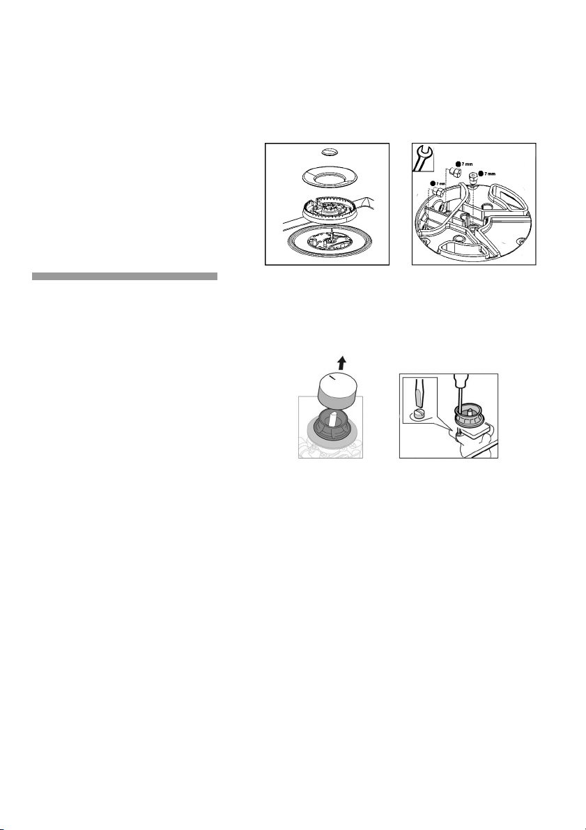
- Change the nozzles using the spanner provided by our
Service Centre (code 340847, for double and triple flame
burners code 340808), taking special care to ensure that
the nozzle does not fall when it is removed from the
burner or when fitted. Fig. 8.
Ensure that it is completely tightened in order to
guarantee the seal.
Adjustment of the
taps
Set the control knobs to minimum.
Remove the control knobs from the taps. Fig. 9.
It has a flexible rubber valve reinforcing ring. Simply press
on this seal with the tip of a screwdriver to allow access
to the tap adjusting screw.
Never remove the valve reinforcing ring.
Adjust the minimum ring setting by turning the by-pass
screw using a flat head screwdriver.
To adjust the minimum flame for N.G. replace the control
knob onto the spindle, light the gas and turn the control
knob to the small flame position. Screw the adjustment
screw anti-clockwise to estabilish a minimum stable
flame position. The flame should remain alight and not
burn back to the injector when the valve is turned
quickcly from ‘Full On’ to the “Minimum flame” position
and back a few times. To adjust the minimum flame
position for ULPG the screw must be fully tightened down
clockwise.
If the by-pass screw cannot be accessed, disassemble
the grease splash tray, which is fixed to the rest of the
hob using a clip and screw mounting system. The
following steps must be taken to remove the grease
splash tray:
- Remove all the burner covers, pan supports and
control knobs.
- Loosen the screws on the burners.
Use the disassembly lever 483196 available from our
Fig. 8
Fig. 9
Loading ...
Loading ...
Loading ...