Loading ...
Loading ...
Loading ...
12
Names and Functions of Parts
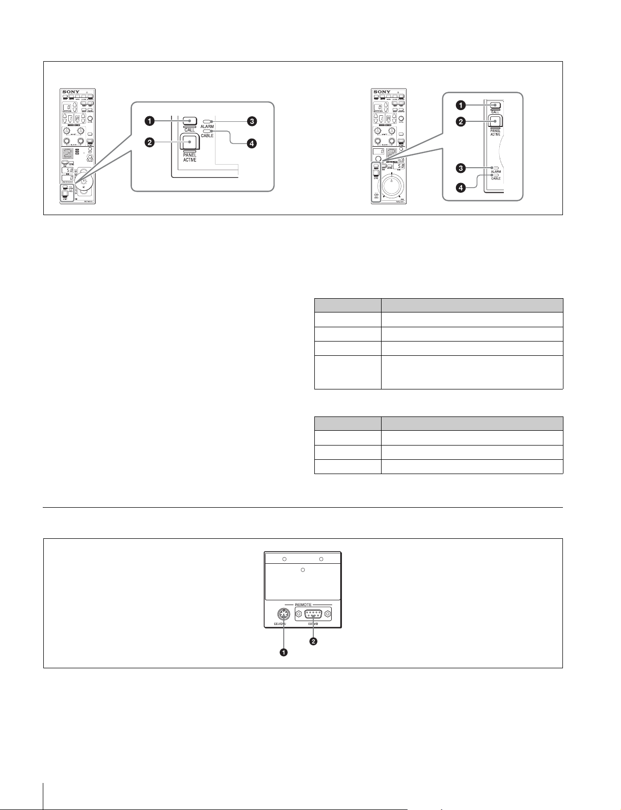
Panel control/status display block
a CALL button
This button is for communication. If it is pressed, the tally state
for the camera or CCU changes, and a call signal is sent.
Likewise, a call signal can be received from another device.
When a call signal is sent (or received), this button lights and
the call sound plays. The call sound can be selected in the
menu.
For details on setting the call sound, see “ Setting the Call
Sound” on page 14.
b PANEL ACTIVE button
This button is for the control permission. It also serves as a
function for preventing unintentional operation because a
camera cannot be controlled from this control panel when this
button and the PARA button are not lit.
c ALARM indicator
This lights red when a system error occurs and the self-
diagnosis function is operating on the camera head or CCU/
HDCU.
d CABLE indicator
This indicates the communication state of the camera head
and CCU.
During fiber cable connections
Indicates the communication state of the camera head and
CCU based on the optical receiver levels on the CHU (camera)
side and the CCU side. If there is a difference between the
optical receiver levels of both sides, the communication state
of the side with the lower level is indicated.
During triaxial cable connections
Connector Panel
a CCU/CNU REMOTE (CCU/CNU remote) connector
(8-pin multi-connector, female)
This is for connecting to the RCP/CNU connector of the CCU
or the RCP connector of the CNU.
b EXT I/O connector (D-sub 9-pin, female)
This is used for external interface connections.
RCP-1000 RCP-1001
Lighting state Meaning
On (green) The reception state is good.
On (yellow) The reception level is low.
On (red) The reception level is extremely low.
Off The power of the camera or CCU is off.
Alternatively, a connected device is not
recognized.
Lighting state Meaning
On (green) The reception state is good.
On (red) The reception level is extremely low.
Off Other
Loading ...
Loading ...
Loading ...