Loading ...
Loading ...
Loading ...
10
Installation instructions
Leak-testing and flame-testing the cooktop
1
After connecting the gas supply, check the piping and connections for leaks using a soap and
water solution. The presence of bubbles indicates a leak. Tighten or replace connections as
appropriate.
Important!
Do not use any naked flame to check for leaks.
2
The operation of the appliance MUST be tested before leaving.
3
Adjust the test point pressure or supply pressure to the value which is appropriate for the gas
type.
4
Turn on the appliance gas controls and light each burner. Check for a well defined blue flame
without any yellow tipping. If any abnormality is evident, check that the burner cap is located
properly and the injector nipple is aligned correctly.
5
Check the minimum burner setting by quickly rotating the gas control knob from the maximum
to the minimum position. The flame must not go out. If adjustment is required, see ‘Adjusting the
minimum burner setting’ section following.
6
If satisfactory performance cannot be obtained, the installer shall check the installation and
notify the local gas supply authority about a gas supply problem, or if it is an appliance problem,
our Customer Service Centre should be called to obtain the nearest authorised Service Agent.
7
Where the appliance data plate cannot be easily read with the appliance installed, the duplicate
data plate must be attached to an adjacent surface and the duplicate Natural gas or LPG
conversion label should also be included where a Natural gas or LPG conversion has been
completed.
Installation with a flexible hose assembly
If this appliance has to be installed with a hose assembly, the installer must refer to the network
operator or gas supplier for confirmation of the gas type, if in doubt.
When used with a flexible hose, the connector on the wall should be between 800 mm to 850
mm above the floor and in the region outside the width of the appliance to a distance of 250
mm. The supply connection point shall be accessible with the appliance installed.
Flexible hose assemblies should be AS/NZS 1869 Class B or Class D certified. The thread
connection shall be Rp 1/2” (ISO 7-1) male.
The hose assembly must be as short as practicable and comply with relevant AS 5601/NZS 5261
requirements.
Important!
After connection, the installer must check that the hose is not kinked, subjected to abrasion or
permanently deformed. The installer must check also that the hose is not near (or in contact) with
any hot surfaces eg. base of metal hotplate, underbench oven etc.
The installer shall ensure the hose assembly is restrained from accidental contact with the flue
outlet of an underbench oven.
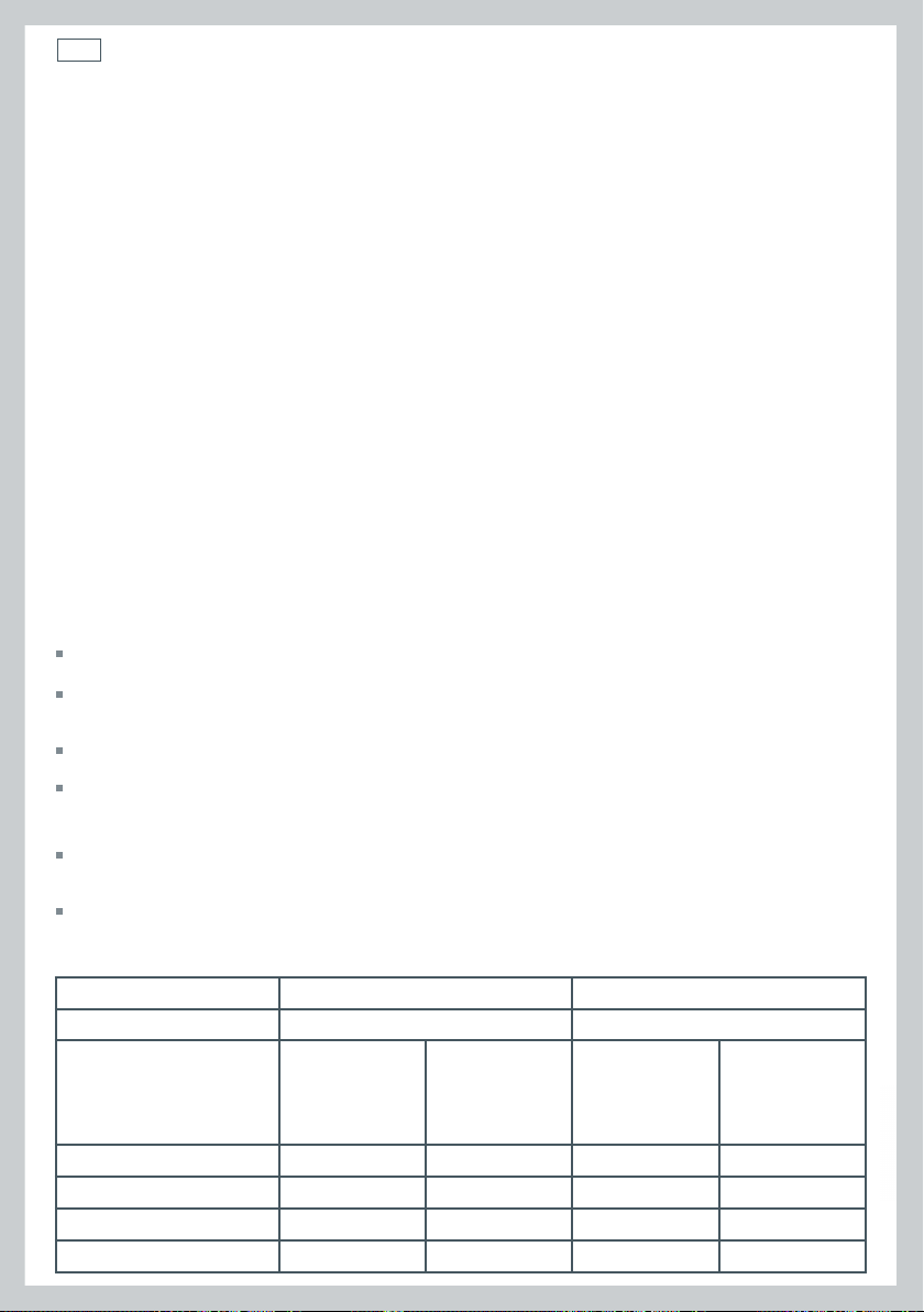
Table for the choice of injectors
Natural Gas LPG
Test point Pressure [kPa] 1.0 2.75
BURNER
Injector
Ori ce Dia.
[mm]
Gas
Consumption
[MJ/h]
Injector
Ori ce Dia.
[mm]
Gas
Consumption
[MJ/h]
Auxiliary 0.85 3.60 0.53 3.60
Semi-rapid 1.12 6.30 0.70 6.30
Rapid 1.45 10.30 0.91 10.80
Triple-ring wok 1.60 12.70 0.95 11.90
Loading ...
Loading ...
Loading ...