
W E B E D I T I O N
O W N E R ' S M A N U A L


DEAR VOLVO OWNER
THANK YOU FOR CHOOSING VOLVO
We hope you will enjoy many years of driving
pleasure in your Volvo. The car has been
designed for the safety and comfort of you and
your passengers. Volvo is one of the safest cars in
the world. Your Volvo has also been designed to
satisfy all current safety and environmental
requirements.
In order to increase your enjoyment of the car, we
recommend that you familiarise yourself with the
equipment, instructions and maintenance infor-
mation contained in this owner's manual.

Table of contents
2
* Option/accessory, for more information, see Introduction.
01
01 Introduction
Owner's Manual in the car's screen......... 13
Reading the owner's manual.................... 13
Digital owner's manual in the car.............. 16
Recording data......................................... 18
Accessories and extra equipment............ 19
Support and information about the car on
the Internet................................................ 20
Volvo ID..................................................... 21
Environmental philosophy......................... 22
The owner's manual and the environ-
ment.......................................................... 24
Laminated glass........................................ 24
02
02 Safety
General information on seatbelts.............. 26
Seatbelt - putting on................................. 27
Seatbelt - loosening.................................. 28
Seatbelt - pregnancy................................ 28
Seatbelt reminder...................................... 29
Seatbelt tensioner..................................... 29
Safety - warning symbol........................... 30
Airbag system........................................... 31
Driver airbag.............................................. 32
Passenger airbag...................................... 32
Passenger airbag - activating/deactivat-
ing*............................................................ 33
Side airbag (SIPS)..................................... 35
Side airbag (SIPS) - child seat/booster
cushion..................................................... 36
Inflatable Curtain (IC)................................ 36
General information on WHIPS (whiplash
protection)................................................. 37
WHIPS - child seats.................................. 38
WHIPS - seating position.......................... 38
When the systems deploy......................... 39
General information on safety mode......... 40
Safety mode - attempting to start the
car............................................................. 41
Safety mode - moving the car.................. 42
02
General information on child safety.......... 42
Child seats................................................ 44
Child seats - location................................ 48
Child seat - ISOFIX................................... 49
ISOFIX - size classes................................ 49
ISOFIX - types of child seat...................... 51
Child seats - upper mounting points........ 53
Table of contents
* Option/accessory, for more information, see Introduction.
3
03
03 Instruments and controls
Instruments and controls, left-hand drive
car - overview........................................... 55
Instruments and controls, right-hand
drive car - overview................................... 58
Combined instrument panel...................... 61
Analogue combined instrument panel -
overview.................................................... 61
Digital combined instrument panel -
overview.................................................... 62
Eco guide & Power guide*........................ 65
Combined instrument panel - meaning of
indicator symbols...................................... 66
Combined instrument cluster - meaning
of warning symbols................................... 68
Outside temperature gauge...................... 70
Trip meter.................................................. 70
Clock......................................................... 71
Combined instrument panel - license
agreement................................................. 71
Symbols in the display.............................. 72
Volvo Sensus............................................ 75
Key positions............................................ 76
Key positions - functions at different lev-
els.............................................................. 76
Seats, front................................................ 78
Seats, front - electrically operated*.......... 79
03
Seats, rear................................................. 80
Steering wheel.......................................... 82
Heating* of the steering wheel.................. 83
Light switches........................................... 84
Position/parking lamps............................. 86
Daytime running lights.............................. 86
Tunnel detection*...................................... 87
Main/dipped beam.................................... 87
Active main beam*.................................... 88
Active Xenon headlamps*......................... 91
Rear fog lamp........................................... 92
Brake lights............................................... 92
Hazard warning flashers........................... 93
direction indicators................................... 93
Interior lighting.......................................... 94
Home safe light duration........................... 95
Approach lighting...................................... 96
Headlamps - adjusting headlamp pat-
tern............................................................ 96
Wipers and washers................................. 96
Power windows......................................... 98
Sun blind*.................................................. 99
Door mirrors............................................ 100
03
Windows and rearview and door mirrors
- heating.................................................. 101
Rearview mirror - interior........................ 102
Compass*............................................... 102
Sunroof*.................................................. 104
Menu navigation - combined instrument
panel....................................................... 105
Menu overview - combined instrument
panel....................................................... 106
Messages................................................ 107
Messages - handling............................... 108
MY CAR.................................................. 108
Trip computer......................................... 109
Trip computer - analogue combined
instrument panel..................................... 111
Trip computer - digital combined instru-
ment panel.............................................. 115
Trip computer - supplementary informa-
tion.......................................................... 119
Trip computer - trip statistics*................ 120
Table of contents
4
* Option/accessory, for more information, see Introduction.
04
04 Climate control
General information on climate control... 122
Actual temperature................................. 123
Sensors - climate control........................ 123
Air quality................................................ 123
Air quality - passenger compartment fil-
ter............................................................ 124
Air quality - Clean Zone Interior Package
(CZIP)*..................................................... 124
Air quality - IAQS*................................... 125
Air quality - material................................ 125
Menu settings - climate control.............. 125
Air distribution in the passenger com-
partment.................................................. 126
Electronic climate control - ECC............. 128
Heated front seats*................................. 129
Heated rear seat*.................................... 129
Fan.......................................................... 130
Auto-regulation....................................... 130
Temperature control in the passenger
compartment.......................................... 131
Air conditioning....................................... 131
Demisting and defrosting the wind-
screen..................................................... 132
Air distribution - recirculation.................. 133
Air distribution - table............................. 134
04
Engine block heater and passenger com-
partment heater*..................................... 136
Engine block heater and passenger com-
partment heater* - direct start................ 137
Engine block heater and passenger com-
partment heater* - immediate stop......... 138
Engine block heater and passenger com-
partment heater* - timer.......................... 138
Engine block heater and passenger com-
partment heater* - messages................. 140
Additional heater*.................................... 142
Fuel-driven additional heater*................. 142
Electric additional heater*....................... 143
05
05 Loading and storage
Storage spaces....................................... 145
Tunnel console........................................ 147
Tunnel console - cigarette lighter and
ashtray*................................................... 147
Glovebox................................................. 147
Inlay mats*.............................................. 148
Vanity mirror............................................ 148
Tunnel console - 12 V-sockets............... 148
Loading................................................... 149
Loading - long load................................. 150
Loading - ski hatch................................. 151
Roof load................................................. 151
Load retaining eyelets............................. 152
Loading - bag holder*............................. 152
12 V electrical socket, cargo area*......... 153

Table of contents
* Option/accessory, for more information, see Introduction.
5
06
06 Locks and alarm
Remote control key................................. 155
Remote control key - losing ................... 155
Remote control key - personalisation*.... 156
Locking/unlocking - indicator................. 157
Lock indicator......................................... 157
Immobiliser.............................................. 158
Remote-controlled immobiliser with
tracking system*..................................... 158
Remote control key - functions............... 159
Remote control key - range.................... 160
Remote control key with PCC* - unique
functions................................................. 161
Remote control key with PCC* - range... 162
Detachable key blade............................. 162
Detachable key blade - detaching/
attaching................................................. 163
Detachable key blade - unlocking doors 163
Privacy locking*....................................... 164
Remote control key - replacing the bat-
tery.......................................................... 165
Keyless drive*.......................................... 166
Keyless Drive* - remote control key
range....................................................... 167
Keyless drive* - secure handling of the
remote control key.................................. 167
06
Keyless drive* - interference to remote
control key function................................ 168
Keyless drive* - locking........................... 168
Keyless drive* - unlocking....................... 169
Keyless drive* - unlocking with the key
blade ...................................................... 169
Keyless Drive* - lock settings................. 170
Keyless Drive* - antenna location........... 170
Locking/unlocking - from the outside..... 171
Manual locking of the door..................... 171
Locking/unlocking - from the inside....... 172
Global opening........................................ 173
Locking/unlocking - glovebox................. 173
Locking/unlocking - boot lid................... 174
Deadlocks*.............................................. 176
Child safety locks - manual activation.... 177
Child safety locks - electrical activation* 177
Alarm....................................................... 178
Alarm indicator........................................ 179
Alarm - automatic re-arming................... 179
Alarm - remote control key not working. 180
Alarm signals........................................... 180
Reduced alarm level............................... 180
06
Type approval - remote control key sys-
tem.......................................................... 181

Table of contents
6
* Option/accessory, for more information, see Introduction.
07
07 Driver support
Active chassis - Four C*.......................... 183
Adjustable steering force*....................... 183
Electronic stability control (ESC) - gen-
eral.......................................................... 184
Electronic stability control (ESC) - opera-
tion.......................................................... 185
Electronic stability control (ESC) - sym-
bols and messages................................. 186
Road Sign Information (RSI)*.................. 188
Road sign information (RSI)* - operation 188
Road sign information (RSI)* - limitations 190
Speed limiter*.......................................... 191
Speed limiter* - getting started............... 191
Speed limiter* - changing speed............. 192
Speed limiter* - temporary deactivation
and standby mode.................................. 192
Speed limiter* - alarm for speed excee-
ded.......................................................... 193
Speed limiter* - deactivation................... 193
Cruise control*........................................ 194
Cruise control* - managing speed.......... 195
Cruise control* temporary deactivation
and standby mode.................................. 195
Cruise control* - resume set speed........ 196
Cruise control* - deactivate.................... 197
07
Adaptive cruise control - ACC*............... 197
Adaptive cruise control* - function......... 198
Adaptive cruise control* - overview........ 200
Adaptive cruise control* - managing
speed...................................................... 201
Adaptive cruise control* - set time inter-
val............................................................ 202
Adaptive cruise control* - temporary
deactivation, and standby mode............ 202
Adaptive cruise control* - overtaking
another vehicle........................................ 203
Adaptive cruise control* - deactivate...... 204
Adaptive Cruise Control* - queue assis-
tance....................................................... 204
Adaptive cruise control* - switch cruise
control functionality................................ 206
Radar sensor........................................... 206
Radar sensor - limitations....................... 207
Adaptive cruise control* - fault tracing
and action............................................... 209
Adaptive cruise control* - symbols and
messages................................................ 210
Distance Warning*.................................. 212
Distance Warning* - limitations............... 213
Distance Warning* - symbols and mes-
sages....................................................... 214
07
City Safety™........................................... 215
City Safety™ - function........................... 215
City Safety™ - operation........................ 216
City Safety™ - limitations....................... 217
City Safety™ - laser sensor.................... 219
City Safety™ - symbols and messages.. 221
Collision warning system*....................... 222
Collision warning system* - function...... 223
Collision warning system* - detection of
cyclists.................................................... 224
Collision warning system* - detection of
pedestrians............................................. 225
Collision warning system* - operation.... 226
Collision warning system* - limitations... 227
Collision warning system* - camera sen-
sor limitations.......................................... 228
Collision warning system* - symbols and
messages................................................ 230
Driver Alert System*................................ 232
Driver Alert Control (DAC)*...................... 232
Driver Alert Control (DAC)* - operation... 233
Driver Alert Control (DAC)* - symbols and
messages................................................ 234
Lane Departure Warning (LDW)*............. 235
Table of contents
* Option/accessory, for more information, see Introduction.
7
07
Lane Departure Warning (LDW) - func-
tion.......................................................... 236
Lane Departure Warning (LDW) - opera-
tion.......................................................... 237
Lane Departure Warning (LDW) - limita-
tions........................................................ 237
Lane Departure Warning (LDW) - sym-
bols and messages................................. 238
Lane Keeping Aid (LKA)*......................... 239
Lane Keeping Aid (LKA) - function.......... 240
Lane Keeping Aid (LKA) - operation....... 241
Lane Keeping Aid (LKA) - limitations...... 242
Lane Keeping Aid (LKA) - symbols and
messages................................................ 243
Park Assist*............................................. 244
Park assist syst* - function..................... 244
Park assist syst* - backward.................. 245
Park assist syst* - forward...................... 246
Park assist syst* - fault indication........... 247
Park assist syst* - cleaning the sensors. 247
Park assist camera*................................ 248
Park assist camera - settings................. 250
Park assist camera - limitations.............. 251
Park Assist Pilot (PAP)*........................... 251
Park Assist Pilot (PAP)* - function.......... 252
07
Park Assist Pilot (PAP)* - operation........ 253
Park Assist Pilot (PAP)* - limitations....... 254
Park Assist Pilot (PAP)* - symbols and
messages................................................ 256
BLIS*....................................................... 256
BLIS* - operation.................................... 257
CTA* ....................................................... 259
BLIS - symbols and messages............... 261
Type approval - radar system................. 261
08
08 Starting and driving
Alcohol lock*........................................... 263
Alcohol lock* - functions and operation.. 263
Alcohol lock* - storage............................ 264
Alcohol lock* - before starting the engine 264
Alcohol lock* - to bear in mind................ 266
Alcohol lock* - symbols and text mes-
sages....................................................... 267
Starting the engine.................................. 268
Switching off the engine......................... 269
Steering lock........................................... 269
Remote start (ERS)*................................ 270
Remote start (ERS) - operation............... 270
Remote start (ERS) - symbols and mes-
sages....................................................... 272
Jump starting with battery...................... 273
Gearboxes............................................... 274
Manual gearbox...................................... 274
Gear shift indicator*................................ 275
Automatic gearbox -- Geartronic*........... 276
Automatic gearbox -- Powershift*.......... 279
Gear selector inhibitor............................. 281
Hill start assist (HSA)*............................. 282
All-wheel drive - (AWD)*.......................... 282
Hill Descent Control (HDC)*.................... 283

Table of contents
8
* Option/accessory, for more information, see Introduction.
08
Start/Stop*.............................................. 284
Start/Stop* - function and operation....... 285
Start/Stop* - the engine does not stop... 286
Start/Stop* - the engine auto-starts........ 287
Start/Stop* - the engine does not auto-
start......................................................... 288
Start/Stop* - involuntary stop manual
gearbox................................................... 289
Start/Stop* - settings.............................. 289
Start/Stop* - symbols and messages..... 291
ECO*....................................................... 293
Foot brake............................................... 295
Foot brake - anti-lock braking system.... 296
Foot brake - emergency brake lights and
automatic hazard warning flashers......... 297
Foot brake - emergency brake assis-
tance....................................................... 297
Parking brake.......................................... 298
Driving in water....................................... 302
Overheating............................................. 302
Driving with open tailgate/boot lid.......... 303
Overload - starter battery........................ 303
Before a long journey.............................. 304
Winter driving.......................................... 304
Fuel filler flap - Opening/closing............. 305
08
Fuel filler flap - manual opening.............. 305
Filling up with fuel................................... 305
Fuel - handling........................................ 306
Fuel - petrol............................................. 307
Fuel - diesel............................................. 307
Diesel particle filter (DPF)........................ 309
Catalytic converters................................ 309
Economical driving.................................. 310
Driving with a trailer*............................... 311
Driving with a trailer* - manual gearbox.. 312
Driving with a trailer* - automatic gear-
box.......................................................... 312
Towing bracket/Towbar*......................... 313
Detachable towbar* - storage................. 313
Detachable towbar* - specifications....... 314
Detachable towbar* - attachment/
removal................................................... 314
Trailer Stability Assist - TSA.................... 317
Towing.................................................... 318
Towing eye.............................................. 319
Recovery................................................. 320
09
09 Wheels and tyres
Tyres - maintenance............................... 322
Tyres - direction of rotation.................... 323
Tyres - tread wear indicators.................. 324
Tyres - air pressure................................. 324
Wheel and wheel rim dimensions........... 326
Tyres - dimensions.................................. 326
Tyres - load index................................... 327
Tyres - speed ratings.............................. 327
Wheel bolts............................................. 328
Winter tyres............................................. 328
Changing wheels - removing wheels...... 329
Changing wheels - fitting........................ 332
Warning triangle...................................... 333
Tools....................................................... 333
Jack*....................................................... 334
First aid kit*............................................. 334
Tyre pressure monitoring*....................... 335
Tyre pressure monitoring system
(TPMS)* - general.................................... 335
Tyre pressure monitoring (TPMS)* -
adjust (recalibration)................................ 336
Tyre pressure monitoring system
(TPMS)* - status...................................... 337
Tyre pressure monitoring (TPMS)* - acti-
vate/deactivate....................................... 338

Table of contents
* Option/accessory, for more information, see Introduction.
9
09
Tyre pressure monitoring (TPMS)* - rec-
ommendations........................................ 338
Tyre pressure monitoring (TPMS)* - recti-
fying low tyre pressure............................ 339
Tyre pressure monitoring (TM)*............... 339
Emergency puncture repair.................... 341
Emergency puncture repair kit - location 342
Emergency puncture repair kit - over-
view......................................................... 342
Emergency puncture repair - operation.. 343
Emergency puncture repair - rechecking 345
Emergency puncture repair kit - inflating
the tyres.................................................. 346
Emergency puncture repair kit - sealant. 347
Type approval - tyre pressure monitoring
(TPMS).................................................... 348
10
10 Maintenance and service
Volvo service programme....................... 355
Book service and repair*......................... 355
Raising the car........................................ 358
Bonnet - opening and closing................. 360
Engine compartment - overview............. 360
Engine compartment - checking............. 361
Engine oil - general................................. 362
Engine oil - checking and filling.............. 363
Coolant - level......................................... 367
Brake and clutch fluid - level.................. 368
Power steering fluid - level...................... 368
Climate control system - fault tracing and
repair....................................................... 369
Lamp replacement - general................... 369
Lamp replacement - headlamps............. 370
Lamp replacement - cover for main/
dipped beam bulbs................................. 371
Lamp replacement - dipped beam......... 372
Lamp replacement - main beam............. 372
Lamp replacement - extra main beam.... 373
Lamp replacement - direction indicators
front......................................................... 373
Lamp replacement - rear lamp............... 373
Lamp replacement - location of rear
lamps...................................................... 374
10
Lamp replacement - number plate light-
ing........................................................... 374
Lamp replacement - lighting in cargo
area......................................................... 375
Lamp replacement - vanity mirror light-
ing........................................................... 375
Lamps - specifications ........................... 376
Wiper blades........................................... 376
Washer fluid - filling................................ 378
Starter battery - general.......................... 379
Battery - symbols.................................... 380
Starter battery - replacement.................. 381
Battery - Start/Stop................................. 383
Electrical system..................................... 385
Fuses - general....................................... 386
Fuses - in engine compartment.............. 387
Fuses - under glovebox.......................... 391
Fuses - in the control module under the
glovebox................................................. 393
Fuses - in cargo area.............................. 395
Fuses - in the engine compartment's
cold zone................................................ 396
Car wash................................................. 398
Polishing and waxing.............................. 399
Water and dirt-repellent coating............. 400
Table of contents
10
10
Rustproofing........................................... 401
Cleaning the interior................................ 401
Paint damage.......................................... 402
11
11 Specifications
Type designations................................... 405
Dimensions............................................. 408
Weights................................................... 409
Towing capacity and towball load.......... 410
Engine specifications.............................. 412
Engine oil - adverse driving conditions... 414
Engine oil - grade and volume................ 415
Coolant - grade and volume................... 417
Transmission fluid - grade and volume... 418
Brake fluid - grade and volume............... 420
Power steering fluid - grade.................... 420
Fuel tank - volume.................................. 421
Specifications for air conditioning.......... 422
Fuel consumption and CO2 emissions... 422
Tyres - approved tyre pressures............. 423
12
12 Alphabetical Index
Alphabetical Index.................................. 426

Table of contents
11
INTRODUCTION
01 Introduction
01
}}
13
Owner's Manual in the car's screen
A digital version of the owner's manual is
available
1
on the car's screen. The owner's
manual provides information about how the
car works.
For cars with owner information in the screen,
the printed owner's manual is a supplement
and contains important text, the latest
updates, as well as instructions that can be
useful when, for practical reasons, it is not
possible to read the information on the
screen.
The owner's manual is also available on Vol-
vo's support page and can be downloaded as
a mobile app.
Changing the screen's language may mean
that certain information is no longer in
accordance with national or local laws and
regulations.
IMPORTANT
The driver is always responsible that the
vehicle is driven safely in traffic and that
applicable laws and regulations are fol-
lowed. It is also important that the car is
maintained and handled in accordance
with Volvo's recommendations in the
owner's information.
If there should be a difference between the
information on the screen and in the prin-
ted manual then it is always the printed
information that applies.
Reading the owner's manual
A good way of getting to know your new car
is to read the owner's manual, ideally before
your first journey.
Reading the owner's manual is a good way to
become familiar with new functions, get
advice on how best to handle the car in differ-
ent situations and learn how to make the best
use of all the car's features. Please pay atten-
tion to the safety instructions contained in the
owner's manual.
The specifications, design features and illus-
trations in the owner's manual are not bind-
ing. We reserve the right to make modifica-
tions without prior notice.
© Volvo Car Corporation
IMPORTANT
Do not remove this manual from the car -
should a problem arise then the informa-
tion required about where and how to seek
professional help would be missing.
1
Applies to certain car models.
||
01 Introduction
01
14
* Option/accessory, for more information, see Introduction.
Owner's Manual in mobile devices
NOTE
The Owner's manual is available for down-
load as a mobile application (applies for
certain car models and mobile devices),
see www.volvocars.com.
The mobile application also includes video
and searchable content and easy naviga-
tion between different sections.
Options/accessories
All types of option/accessory are marked with
an asterisk*.
In addition to standard equipment, the
owner's manual also describes options (fac-
tory fitted equipment) and certain accessories
(retrofitted extra equipment).
The equipment described in the owner's
manual is not available in all cars - they have
different equipment depending on adapta-
tions for the needs of different markets and
national or local laws and regulations.
In the event of uncertainty over what is stand-
ard or an option/accessory, contact a Volvo
dealer.
Special texts
WARNING
Warning texts appear if there is a risk of
injury.
IMPORTANT
"Important" texts appear if there is a risk of
damage.
NOTE
NOTE texts give advice or tips that facili-
tate the use of e.g. features and functions.
Footnote
There is footnote information in the owner's
manual that is located at the bottom of the
page. This information is an addition to the
text that it refers to via a number. If the foot-
note refers to text in a table then letters are
used instead of numbers for referral.
Message texts
In the car there are displays that show menu
texts and message texts. In the owner's man-
ual the appearance of these texts differs from
the normal text. Examples of menu texts and
message texts:
Media, Sending location.
Decals
The car contains different types of decal
which are designed to convey important
information in a simple and clear manner. The
decals in the car have the following descend-
ing degree of importance for the warning/
information.
Warning for personal injury
G031590
Black ISO symbols on yellow warning field,
white text/image on black message field.
Used to indicate the presence of danger
which, if the warning is ignored, may result in
serious personal injury or fatality.
01 Introduction
01
}}
15
Risk of property damage
G031592
White ISO symbols and white text/image on
black or blue warning field and message field.
Used to indicate the presence of danger
which, if the warning is ignored, may result in
damage to property.
Information
G031593
White ISO symbols and white text/image on
black message field.
NOTE
It is not intended that the decals illustrated
in the owner's manual should be exact
replicas of those in the car. They are
included to show their approximate
appearance and location in the car. The
information that applies to your particular
car can be found on the decal on the car.
Procedure lists
Procedures where action must be taken in a
certain sequence are numbered in the
owner's manual.
When there is a series of illustrations for
step-by-step instructions each step is
numbered in the same way as the corres-
ponding illustration.
Lists of letters appear adjacent to the ser-
ies of illustrations where the order of the
instructions is not significant.
Arrows appear numbered and unnum-
bered and are used to illustrate a move-
ment.
Arrows with letters are used to clarify a
movement when the reciprocal order is of
no relevance.
If there is no series of illustrations for step-by-
step instructions then the different steps are
numbered with normal numbers.
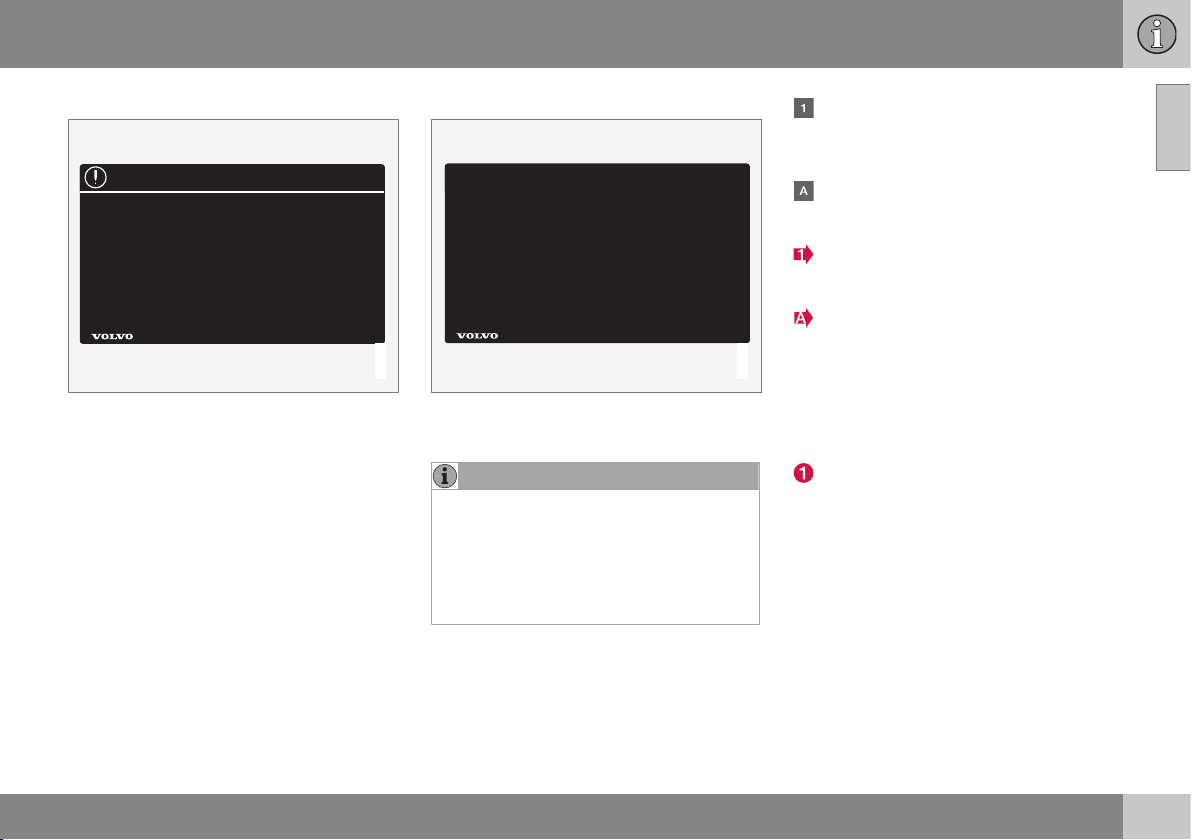
Position lists
Red circles containing a number are used
in overview images where different com-
ponents are pointed out. The number
recurs in the position list featured in con-
nection with the illustration that describes
the item.
Bulleted lists
A bulleted list is used when there is a list of
points in the owner's manual.
Example:
•
Coolant
•
Engine oil
||
01 Introduction
01
16
Related information
Related information refers to other articles
containing closely-associated information.
Images
The manual's images are sometimes sche-
matic and may deviate from the car's appear-
ance depending on equipment level and mar-
ket.
To be continued
}} This symbol is located furthest down to
the right when an article continues on the fol-
lowing page.
Continued from previous page
|| This symbol is located furthest up to the
left when an article continues from the previ-
ous page.
Related information
•
The owner's manual and the environment
(p. 24)
•
Support and information about the car on
the Internet (p. 20)
Digital owner's manual in the car
The owner's manual can be read on the
screen in the car
2
. The content is searchable
and it is easy to navigate between different
sections.
Open the digital owner's manual - press the
MY CAR button in the centre console, press
OK/MENU and select
Owner's manual.
For basic navigation, see Operating the sys-
tem. See below for a more detailed descrip-
tion.
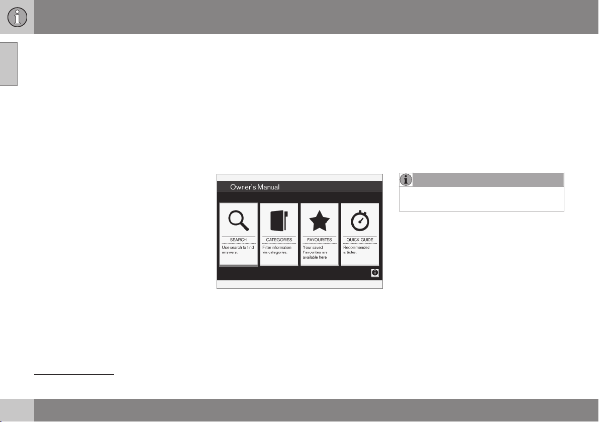
Owner's manual, start page.
There are four options for finding information
in the digital owner's manual:
•
Search - Search function for finding an
article.
•
Categories - All articles sorted into cate-
gories.
•
Favourites - Quick access to favourite-
bookmarked articles.
•
Quick Guide - A selection of articles for
common functions.
Select the information symbol in the lower
right-hand corner in order to obtain informa-
tion about the digital owner's manual.
NOTE
The digital owner's manual is not available
while driving.
2
Applies to certain car models.

01 Introduction
01
}}
17
Search
Searching using the character wheel.
Character list.
Changing the input mode (see following
table).
Use the character wheel to enter a search
term, e.g. "seatbelt".
1. Turn TUNE to the desired letter, press
OK/MENU to confirm. The number and
letter buttons on the control panel in the
centre console can also be used.
2. Continue with the next letter and so on.
3. To change the input mode to numbers or
special characters, or to perform a
search, turn TUNE to one of the options
(see explanation in the following table) in
the list for changing the input mode (2),
press OK/MENU.
123/AB
C
Change between letters and
numbers with OK/MENU.
MORE
Change to special characters
with OK/MENU.
OK
Perform the search. Turn TUNE
to select a search result article,
press OK/MENU to go to the
article.
a|A
Changes between lowercase
and uppercase letters with OK/
MENU.
| | }
Changes from the character
wheel to the search field. Move
the cursor with TUNE. Delete
any misspelling with EXIT. To
return to the character wheel,
press OK/MENU.
Note that the digit and letter
buttons on the control panel
can be used for editing in the
search field.
Enter with the numerical keyboard
Numerical keyboard.
Another way of entering characters is to use
the centre console's buttons 0-9, * and #.
When e.g. 9 is pressed, a bar appears with all
characters
3
under the button, e.g.
W, x, y, z
and 9. Quick presses on the button move the
cursor through these characters.
•
Stop with the cursor on the desired char-
acter in order to select it - the character is
shown on the enter line.
•
Delete/undo using EXIT.
To enter a number, hold in the corresponding
number key.
Categories
The articles in the owner's manual are struc-
tured into main categories and subcategories.
3
The character for each button may vary depending on market/country/language.

||
01 Introduction
01
18
The same article can be in several appropri-
ate categories in order to be found more
easily.
Turn TUNE to navigate in the category tree
and press OK/MENU to open a category -
selected
- or article - selected . Press
EXIT to go back to the previous view.
Favourites
Located here are the articles that are saved
as favourites. To select an article as a favour-
ite, see the heading "Navigating in an article"
below.
Turn TUNE to navigate in the favourite list
and press OK/MENU to open an article.
Press EXIT to go back to the previous view.
Quick Guide
Located here is a selection of articles for get-
ting to know the car's most common func-
tions. The articles can also be accessed via
categories, but are collected here for quick
access.
Turn TUNE to navigate in the Quick Guide
and press OK/MENU to open an article.
Press EXIT to go back to the previous view.
Navigating in an article
Home - leads to the start page for the
owner's manual.
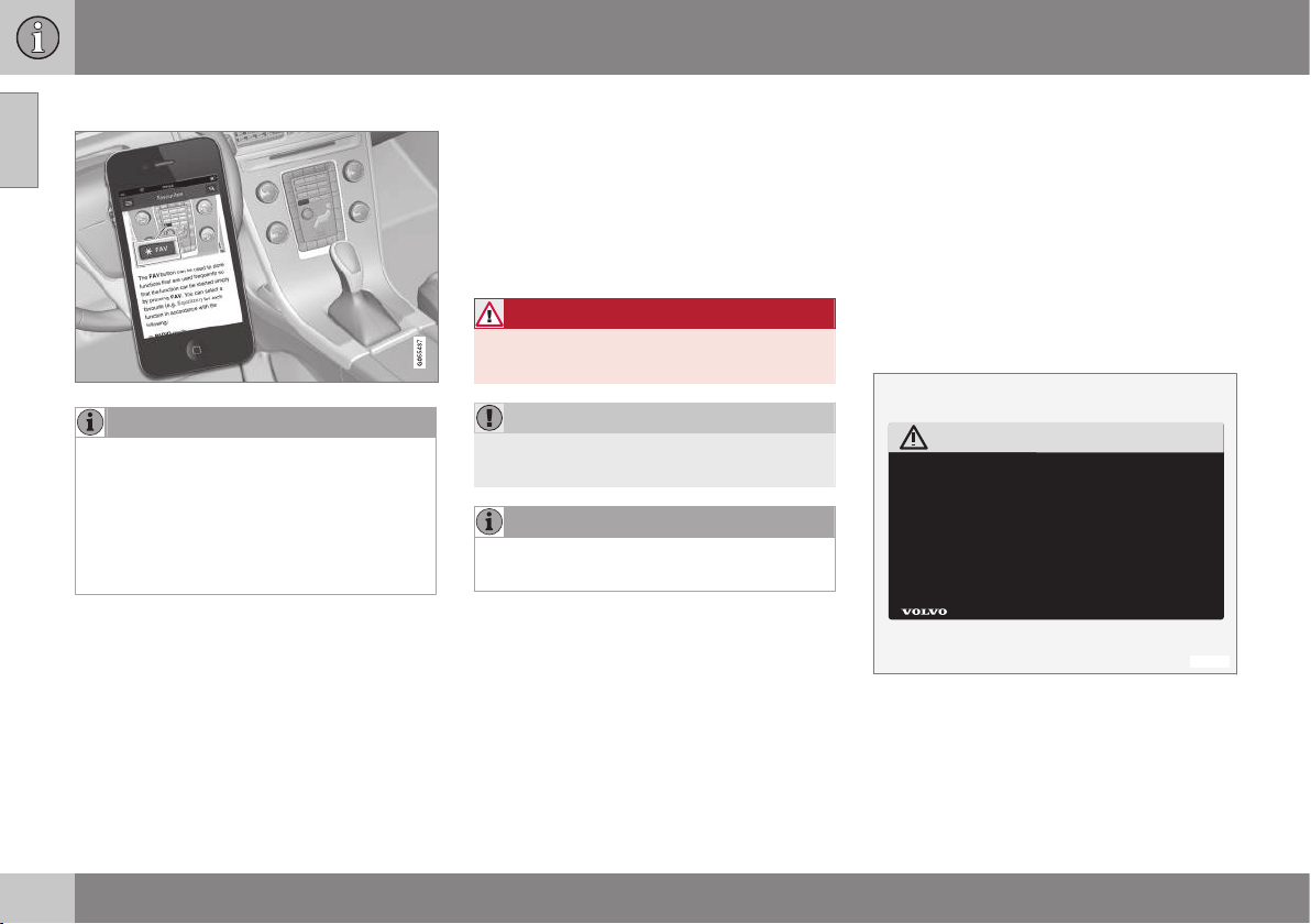
Favourite - adds/removes an article as a
favourite. You can also press the FAV
button in the centre console to add/
remove an article as a favourite.
Highlighted link - leads to linked article.
Special texts - if the article contains
warnings, important or note texts then an
associated symbol is shown here as well
as the number of such texts in the article.
Turn TUNE to navigate between the links or
scroll in an article. When the screen has
scrolled to the start/end of an article the
home and favourite options are accessed by
scrolling a further step up/down. Press OK/
MENU to activate the selection/highlighted
link. Press EXIT to go back to the previous
view.
Recording data
Certain information about the vehicle's opera-
tion and functionality, and any incidents, are
recorded in the car.
Your vehicle contains a number of computers
whose function is to continuously check and
monitor the vehicle's operation and function-
ality. Some of the computers can record
information during normal driving if they
detect an error. In addition, information is
recorded in the event of a collision or inci-
dent. Parts of the recorded information are
required so that technicians can diagnose
and rectify faults in the vehicle during servic-
ing and maintenance and so that Volvo can
fulfil legal requirements and other regulations.
In addition to this, the information is used for
research purposes by Volvo in order to con-
tinually develop quality and safety, as the
information can contribute to a better under-
standing of the factors that cause accidents
and injuries.
The information includes details of the status
and functionality of various systems and
modules in the vehicle with regard to engine,
throttle, steering and brake systems, amongst
other things. This information may include
details regarding the way the driver drives the
vehicle, such as vehicle speed, brake and
accelerator pedal use, steering wheel move-
ment and whether or not the driver and pas-
sengers have used their seatbelts. For the
01 Introduction
01
* Option/accessory, for more information, see Introduction.
19
reasons given this information may be stored
in the vehicle's computers for a certain length
of time, but also as a result of a collision or
incident. This information may be stored by
Volvo as long as it can help to further develop
and further enhance safety and quality and as
long as there are legal requirements and
other regulations that Volvo needs to con-
sider.
Volvo will not contribute to the above-descri-
bed information being disclosed to third par-
ties without the vehicle owner's consent.
However, due to national legislation and reg-
ulations Volvo may be required to disclose
such information to authorities such as police
authorities, or others who may assert a legal
right to have access to it.
To be able to read and interpret the informa-
tion recorded by the computers in the vehicle
requires special technical equipment that
Volvo, and workshops that have entered into
agreements with Volvo, have access to. Volvo
is responsible that the information, which is
transferred to Volvo during servicing and
maintenance, is stored and handled in a
secure manner and that the handling com-
plies with applicable legal requirements. For
further information - contact a Volvo dealer.
Accessories and extra equipment
The incorrect connection and installation of
accessories and extra equipment can nega-
tively affect the car's electronic system.
Certain accessories only function when asso-
ciated software is installed in the car's com-
puter system. Volvo therefore recommends
that you always contact an authorised Volvo
workshop before installing accessories or
extra equipment which are connected to or
affect the electrical system.
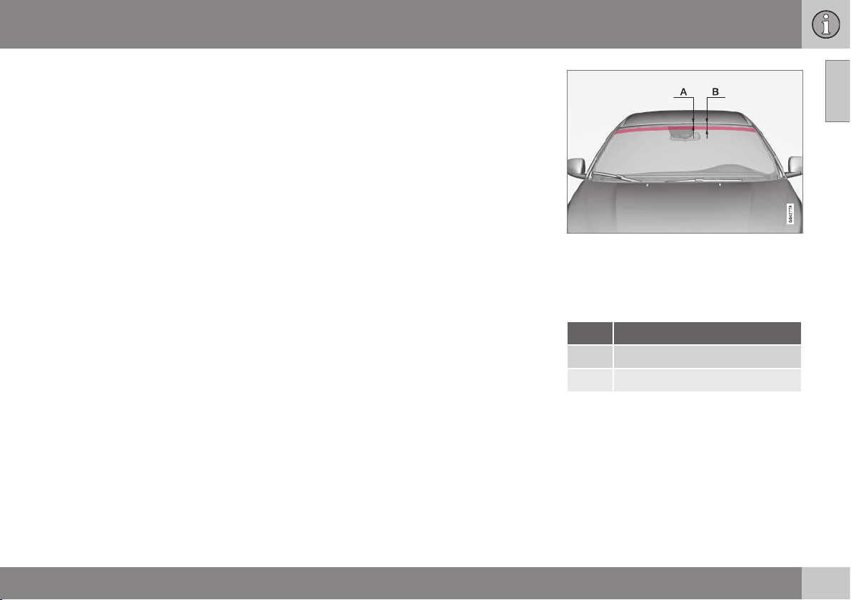
Heat-reflecting windscreen*
The windscreen is equipped with a heat-
reflecting film (IR) that reduces the solar heat
radiation into the passenger compartment.
The positioning of electronic equipment, such
as a transponder, behind a glass surface with
heat-reflecting film may affect its function and
performance.
For the optimal function of electronic equip-
ment, it should be positioned on the part of
the windscreen with no heat-reflecting film
(see the highlighted area in the illustration).
Areas where IR film is not applied.
A is the distance from the top edge of the
windscreen down to the start of the field. B is
the distance from the top edge of the wind-
screen down to the end of the field.
Dimensions
A 40 mm
B 80 mm

01 Introduction
01
20
* Option/accessory, for more information, see Introduction.
Support and information about the car
on the Internet
There is additional information regarding your
car on the Volvo Cars website and support
page. From the website, it is also possible to
navigate through to My Volvo, a personal web
page for you and your car.
Support on the Internet
Go to support.volvocars.com or use the QR
code below to visit the page. The support
page is available for most markets.
QR code that leads to the support page.
The information on the support page is
searchable and can also be subdivided into
different categories. Available here is support
for options related to e.g. Internet connected
services and functions, Volvo On Call (VOC)*,
the navigation system* and apps. Video and
step-by-step instructions explain different
procedures, e.g. how the car is connected to
the Internet via a mobile phone.
Downloadable information from the
support page
Maps
For cars equipped with Sensus Navigation*,
there is the facility to download maps from
the support page.
Mobile apps
For selected Volvo models from model year
2014 and 2015, the owner's manual is availa-
ble in the form of an app. The VOC* app can
also be accessed from here.
Owner's manuals from previous model
years
Owner's manuals from previous model years
are available here in PDF format. The Quick
Guide and supplement can also be accessed
from the support page. Select car model and
model year in order to download the publica-
tion required.
Contact
On the support page there is contact informa-
tion for customer support and the nearest
Volvo dealer.
My Volvo on the Internet
4
From www.volvocars.com it is possible to
navigate through to My Volvo Web which is a
personal Web page for you and your car.
Create a personal Volvo ID, log in to My Volvo
Web and get an overview of service, agree-
ments and warranties, amongst other things.
At My Volvo Web there is also information
about accessories and software adapted for
your car model.
Related information
•
Volvo ID (p. 21)
4
Applies to certain markets.

01 Introduction
01
* Option/accessory, for more information, see Introduction.
21
Volvo ID
Volvo ID is your personal ID that provides
access to various services
5
.
Examples of services:
•
My Volvo - Your personal web page for
you and your car.
•
In an Internet-connected car* - Certain
functions and services require that you
have registered your car to a personal
Volvo ID, for example to be able to send a
new address from a map service on the
Internet directly to the car.
•
Volvo On Call, VOC* - Volvo ID is used
when logging in to the Volvo On Call
mobile app.
Advantages of Volvo ID
•
One user name and one password to
access online services, i.e. only one user-
name and one password to remember.
•
When changing the username/password
for a service (e.g. VOC) it will also be
changed automatically for other services
(e.g. My Volvo)
Create a Volvo ID
To create a Volvo ID you need to enter a per-
sonal e-mail address. Then follow the instruc-
tions in the e-mail message that is automati-
cally sent to the specified address in order to
complete the registration. It is possible to cre-
ate a Volvo ID via one of the following serv-
ices:
•
My Volvo - Enter your e-mail address and
follow the instructions.
•
For an Internet-connected car* - Enter
your e-mail address in the app that
requires Volvo ID and follow the instruc-
tions. Alternatively, press the Connect
button
in the centre console twice and
select
Apps Settings and follow the
instructions.
•
Volvo On Call, VOC* - Download the lat-
est version of the VOC app. Choose to
create a Volvo ID from the start page,
enter e-mail address and follow the
instructions.
Related information
•
Support and information about the car on
the Internet (p. 20)
5
The services available may vary over time and vary depending on equipment level and market.
01 Introduction
01
22
* Option/accessory, for more information, see Introduction.
Environmental philosophy
Your Volvo complies with strict international
environmental standards and is also manufac-
tured in one of the cleanest and most
resource-efficient plants in the world. Volvo
Car Corporation is constantly working on the
development of safer and more efficient prod-
ucts and solutions in order to reduce the neg-
ative impact on the environment.
Environmental care is one of Volvo Cars' core
values, which influence all operations. We
also believe that our customers share our
consideration for the environment.
Volvo Cars has global ISO certification, which
includes the environmental standard ISO
14001 covering all factories and several of
our other units. We also set requirements for
our partners so that they work systematically
with environmental issues.
Fuel consumption
Volvo cars have competitive fuel consump-
tion in each of their respective classes. Lower
fuel consumption generally results in lower
emission of the greenhouse gas, carbon diox-
ide.
It is possible for the driver to influence fuel
consumption. For more information, read
under the heading "Contributing to a better
environment".
Efficient emission control
Your Volvo is manufactured following the
concept "Clean inside and out" – a concept
that encompasses a clean interior environ-
ment as well as highly efficient emission con-
trol. In many cases the exhaust emissions are
well below the applicable standards.
Clean air in the passenger
compartment
A passenger compartment filter prevents dust
and pollen from entering the passenger com-
partment via the air intake.
A sophisticated air quality system Interior Air
Quality System* (IAQS) ensures that the
incoming air is cleaner than the air in the traf-
fic outside.
The system consists of an electronic sensor
and a carbon filter. The incoming air is moni-
tored continuously and if there is an increase
in the level of certain unhealthy gases, such

01 Introduction
01
* Option/accessory, for more information, see Introduction.
23
as carbon monoxide, then the air intake is
closed. Such a situation may arise in heavy
traffic, queues and tunnels for example.
The entry of nitrous oxides, ground-level
ozone and hydrocarbons is prevented by the
carbon filter.
Interior
The interior of a Volvo is designed to be plea-
sant and comfortable, even for people with
contact allergies and for asthma sufferers.
Extreme attention has been given to choosing
environmentally-compatible materials.
Volvo workshops and the environment
Regular maintenance creates the conditions
for a long service life and low fuel consump-
tion for your car. In this way you contribute to
a cleaner environment. When Volvo's work-
shops are entrusted with the service and
maintenance of your car it becomes part of
our system. Volvo makes clear demands
regarding the way in which our workshops
are designed in order to prevent spills and
discharges into the environment. Our work-
shop staff have the knowledge and the tools
required to guarantee good environmental
care.
Contributing to a better environment
It is easy to contribute to a better environ-
ment - here are a few tips:
•
Avoid letting the engine idle - switch off
the engine when stationary for longer
periods. Pay attention to local regula-
tions.
•
Drive economically - think ahead.
•
Perform service and maintenance in
accordance with the instructions in the
owner's manual - follow the Service and
Warranty Booklet's recommended inter-
vals.
•
If the car is equipped with an engine
block heater*, use it before starting from
cold - it improves starting capacity and
reduces wear in cold weather and the
engine reaches normal operating tem-
perature more quickly, which lowers con-
sumption and reduces emissions.
•
High speed increases consumption con-
siderably due to increased wind resis-
tance - a doubling of speed increases
wind resistance 4 times.
•
Always dispose of environmentally hazar-
dous waste, such as batteries and oils, in
an environmentally safe manner. Consult
a workshop in the event of uncertainty
about how this type of waste should be
discarded - an authorised Volvo work-
shop is recommended.
Following this advice can save money, the
planet's resources are saved, and the car's
durability is extended. For more information
and further advice see Eco guide (p. 65),
Economical driving (p. 310) and Fuel con-
sumption (p. 422).
Recycling
As a part of Volvo's environmental work, it is
important that the car is recycled in an envi-
ronmentally sound manner. Almost all of the
car can be recycled. The last owner of the car
is therefore requested to contact a dealer for
referral to a certified/approved recycling
facility.
Related information
•
The owner's manual and the environment
(p. 24)
01 Introduction
01
24
* Option/accessory, for more information, see Introduction.
The owner's manual and the
environment
The paper pulp in a printed owner's manual
comes from Forest Stewardship Council
®
cer-
tified forests or other controlled sources.
The FSC
®
symbol shows that the paper pulp
in a printed owner's manual comes from
FSC
®
certified forests or other controlled
sources.
Related information
•
Environmental philosophy (p. 22)
Laminated glass
The glass is reinforced which pro-
vides better protection against
break-ins and improved sound insu-
lation in the passenger compart-
ment. The windscreen and the side windows*
have laminated glass.
SAFETY
02 Safety
02
26
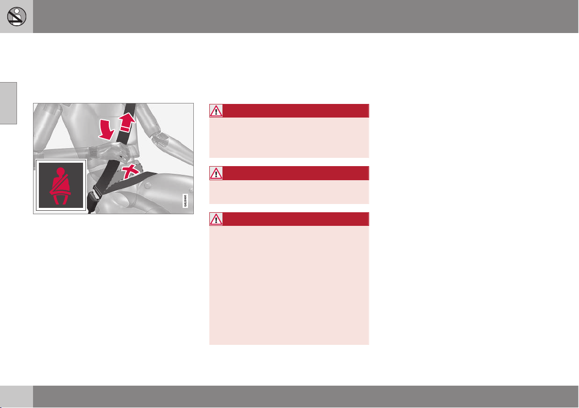
General information on seatbelts
Heavy braking can have serious consequen-
ces if the seatbelts are not used. Ensure that
all passengers are using their seatbelts during
the journey.
Tension the hip strap over the lap by pulling the
diagonal shoulder belt up towards the shoulder.
The hip strap must be positioned low down (not
over the abdomen).
It is important that the seatbelt lies against
the body so it can provide maximum protec-
tion. Do not lean the backrest too far back.
The seatbelt is designed to protect in a nor-
mal seating position.
Unbelted occupants will be reminded to fas-
ten their (p. 27) seatbelt by means of an
audio and visual reminder (p. 29).
Remember
•
Do not use clips or anything else that can
prevent the seatbelt from fitting properly.
•
The seatbelt must not be twisted or
caught on anything.
WARNING
The seatbelts and airbags interact. If a
seatbelt is not used or is used incorrectly,
this may diminish the protection provided
by the airbag in the event of a collision.
WARNING
Each seatbelt is designed for only one per-
son.
WARNING
Never modify or repair the seatbelts your-
self. Volvo recommends that you contact
an authorised Volvo workshop.
If a seatbelt has been subjected to a major
load, such as in conjunction with a colli-
sion, the entire seatbelt must be replaced.
Some of the protective characteristics of
the seatbelt may have been lost, even if it
appears to be undamaged. In addition,
replace the seatbelt if the belt is worn or
damaged. The new seatbelt must be type-
approved and intended for installation in
the same position as the replaced seatbelt.
Related information
•
Seatbelt - pregnancy (p. 28)
•
Seatbelt - loosening (p. 28)
•
Seatbelt tensioner (p. 29)
02 Safety
02
27
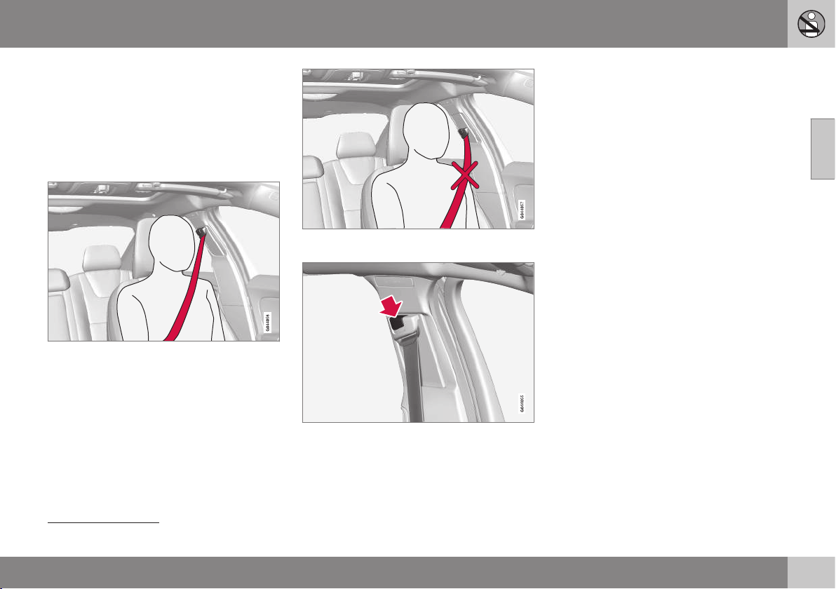
Seatbelt - putting on
Put on the seatbelt (p. 26) before driving
starts.
Pull the belt out slowly and secure it by
pressing its locking tab into the seatbelt
buckle. A loud "click" indicates that the belt
has locked.
Correctly fitted seatbelt.
Incorrectly fitted seatbelt. The belt must rest on
the shoulder.
Seatbelt height adjustment. Press the button and
move the belt vertically. Position the belt as high
as possible without it chafing against your throat.
The buckles only fit the intended lock in the
rear seat
1
.
Remember
The seatbelt locks and cannot be withdrawn:
•
if it is pulled out too quickly
•
during braking and acceleration
•
if the car leans heavily.
Related information
•
Seatbelt - pregnancy (p. 28)
•
Seatbelt - loosening (p. 28)
•
Seatbelt tensioner (p. 29)
•
Seatbelt reminder (p. 29)
1
Certain markets.
02 Safety
02
28
Seatbelt - loosening
Loosen the seatbelt (p. 26) when the car is
stationary.
Press the red button on the seatbelt buckle
and then let the belt retract. If the seatbelt
does not retract fully, feed it in by hand so
that it does not hang loose.
Related information
•
Seatbelt - putting on (p. 27)
•
Seatbelt reminder (p. 29)
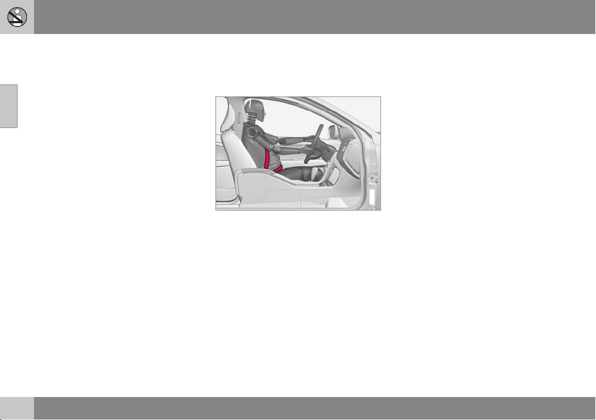
Seatbelt - pregnancy
Seatbelt (p. 26) must always be worn during
pregnancy. But it is crucial that it be worn in
the correct way.
G020998
The diagonal section should wrap over the
shoulder then be routed between the breasts
and to the side of the abdomen.
The lap section should lay flat over the thighs
and as low as possible under the abdomen. –
It must never be allowed to ride upward.
Remove the slack from the seatbelt and
ensure that it fits as close to the body as pos-
sible. In addition, check that there are no
twists in the seatbelt.
As the pregnancy progresses, pregnant dri-
vers must adjust the seat (p. 78) and steer-
ing wheel (p. 82) such that they can easily
maintain control of the vehicle as they drive
(which means that they must be able to easily
operate the foot pedals and steering wheel).
The aim should be to position the seat with as
large a distance as possible between abdo-
men and steering wheel.
Related information
•
Seatbelt - putting on (p. 27)
•
Seatbelt - loosening (p. 28)
02 Safety
02
29
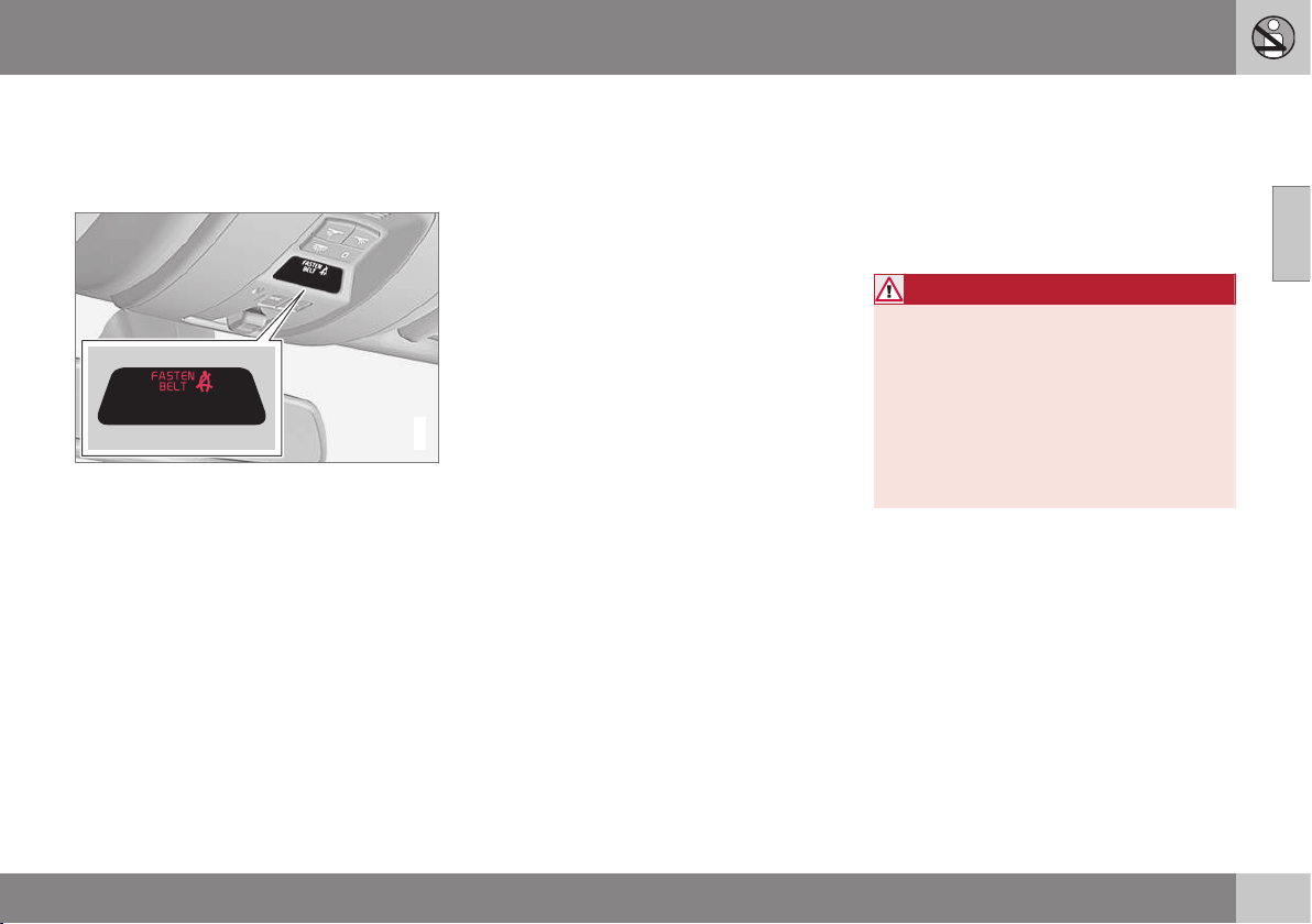
Seatbelt reminder
Unbelted occupants will be reminded to fas-
ten their (p. 27) seatbelt by means of an audio
and visual reminder.
G017726
The audio reminder is speed dependent, and
in some cases time dependent. The visual
reminder is located in the roof console and in
the combined instrument panel (p. 61).
Child seats are not covered by the seatbelt
reminder system.
Rear seat
The seatbelt reminder in the rear seat has two
subfunctions:
•
Provides information on which seatbelts
(p. 26) are being used in the rear seat. A
message appears in the combined instru-
ment panel when the seatbelts are in use,
or if one of the rear doors has been
opened. The message is cleared auto-
matically after driving for approximately
30 seconds or after pressing the indicator
stalk OK button (p. 105).
•
Provides a warning if one of the rear seat-
belts is unfastened during travel. This
warning takes the form of a message in
the combined instrument panel along with
the audio/visual signal. The warning stops
when the seatbelt is re-fastened, or it can
also be acknowledged manually by
pressing the OK button.
The message in the combined instrument
panel showing which seatbelts are in use is
always shown. Press the OK button to see
stored messages.
Certain markets
An acoustic signal and indicator lamp remind
the driver and front seat passenger to use a
seatbelt if either of them is not wearing one.
At low speed, the audio reminder will sound
for the first 6 seconds.
Seatbelt tensioner
All the seatbelts (p. 26) are equipped with belt
tensioners. A mechanism in the seatbelt ten-
sioner tightens the seatbelt in the event of a
sufficiently violent collision. The seatbelt then
provides more effective restraint for the occu-
pants.
WARNING
Never insert the tongue of the passenger's
seatbelt into the buckle on the driver's
side. Always insert the tongue of the seat-
belt into the buckle on the correct side. Do
not make any damages on seatbelts nor
insert any foreign objects into a buckle.
The seatbelts and buckles would then
possibly not function as intended in the
event of a collision. There is a risk of
serous injury.
02 Safety
02
30
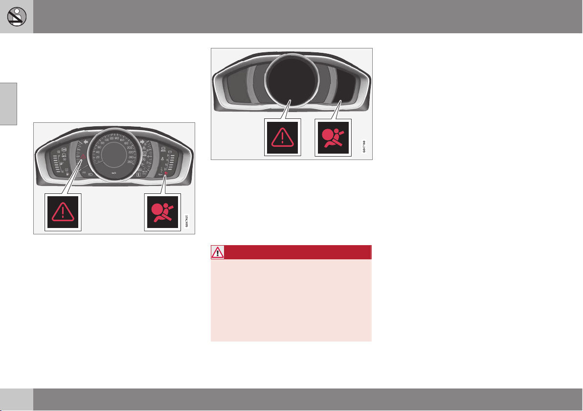
Safety - warning symbol
The warning symbol is shown if a fault is
detected during fault tracing or if a system
has been activated. Where required, the
warning symbol is shown together with a
message in the combined instrument panel
(p. 61) information display.
Warning triangle and warning symbol for the air-
bag system (p. 31) in the analogue combined
instrument panel.
Warning triangle and warning symbol for the air-
bag system in the digital combined instrument
panel.
The warning symbol in the combined instru-
ment panel illuminates when the remote con-
trol key is in key position II (p. 76). The sym-
bol clears after approx. 6 seconds provided
the airbag system is fault-free.
WARNING
If the warning symbol for the airbag sys-
tem remains illuminated or illuminates
while driving, it means that the airbag sys-
tem does not have full functionality. The
symbol indicates a fault in the seatbelt ten-
sioner system, SIPS, the IC system or
some other fault in the system. Volvo rec-
ommends that you contact an authorised
Volvo workshop immediately.
If the warning symbol malfunctions, the warn-
ing triangle illuminates and
SRS airbag
Service required
or SRS airbag Service
urgent appears in the display. Volvo recom-
mends that you contact an authorised Volvo
workshop immediately.
Related information
•
General information on safety mode
(p. 40)
02 Safety
02
31
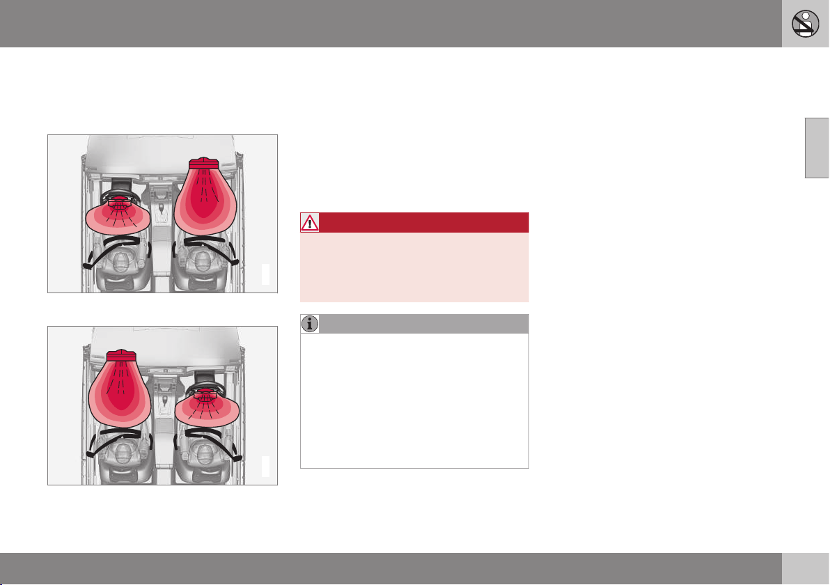
Airbag system
In the event of a frontal collision the airbag
system helps to protect the head, face and
chest of the driver and passenger.
G018665
Airbag system viewed from above, left-hand-
drive car.
G018666
Airbag system viewed from above, right-hand-
drive car.
The system consists of airbags and sensors.
A sufficiently violent collision trips the sensors
and the airbag(s) are inflated and become
hot. The airbag cushions the initial collision
impact for the occupant. The airbag deflates
when compressed by the collision. When this
occurs, smoke escapes into the car. This is
completely normal. The entire process,
including inflation and deflation of the airbag,
occurs within tenths of a second.
WARNING
Volvo recommends that you contact an
authorised Volvo workshop for repair.
Defective work in the airbag system could
cause malfunction and result in serious
personal injury.
NOTE
The detectors react differently depending
on the nature of the collision and whether
or not the seatbelts are fastened. Applies
to all belt positions.
It is therefore possible that only one (or
none) of the airbags may inflate in a colli-
sion. The detectors sense the force of the
collision on the vehicle and the action is
adapted accordingly so that one or more
airbags are deployed.
Related information
•
Driver airbag (p. 32)
•
Passenger airbag (p. 32)
•
Safety - warning symbol (p. 30)
02 Safety
02
32
Driver airbag
To supplement the protection afforded by the
seatbelt (p. 26) the car is equipped on the
driver's side with an airbag (p. 31).
This airbag is fitted into the centre of the
steering wheel. The steering wheel is marked
AIRBAG.
WARNING
The seatbelts and airbags interact. If the
belt is not used or is used incorrectly, this
may diminish the protection provided by
the airbag in the event of a collision.
Related information
•
Passenger airbag (p. 32)
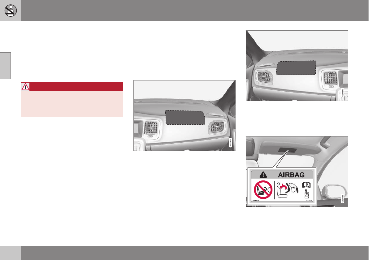
Passenger airbag
To supplement the protection afforded by the
seatbelt (p. 26) on the passenger side, the car
is equipped with an airbag (p. 31).
The airbag is folded up into a compartment
above the glovebox. Its cover panel is
marked AIRBAG.
Location of the front passenger airbag in a left-
hand drive car.
Location of the front passenger airbag in a right-
hand drive car.
The warning label for the passenger airbag is
fitted in one of the following two locations in
the car:
Alternative 1: Position of airbag label on passen-
ger side sun visor.
02 Safety
02
}}
* Option/accessory, for more information, see Introduction.
33
Alternative 2: Position of airbag label on passen-
ger side door pillar. The label becomes visible
when the passenger door is opened.
WARNING
Never use a rear-facing child seat on a
seat protected by an activated airbag. Fail-
ure to follow this advice can lead to death
or serious injury to the child.
WARNING
The seatbelts and airbags interact. If the
belt is not used or is used incorrectly, this
may diminish the protection provided by
the airbag in the event of a collision.
To minimise the risk of injury if the airbag
deploys, passengers must sit as upright as
possible with their feet on the floor and
backs against the backrest. Seatbelts
must be secured.
WARNING
Do not put objects in front of or above the
dashboard where the passenger airbag is
located.
WARNING
Never place a child in a child seat or on a
booster cushion in the front seat if the air-
bag is activated.
Never allow anybody to stand or sit in front
of the front passenger seat.
No one shorter than 140 cm should ever
sit in the front passenger seat if the airbag
is activated.
Failure to follow the advice given above
can endanger life.
Switch - PACOS*
The front passenger airbag can be deacti-
vated (p. 33) if the car is equipped with a
switch, PACOS (Passenger Airbag Cut Off
Switch).
WARNING
If the car is equipped with a front passen-
ger airbag, but does not have a PACOS
switch (Passenger Airbag Cut Off Switch),
then the airbag will always be activated.
Related information
•
Driver airbag (p. 32)
•
Child seats (p. 44)
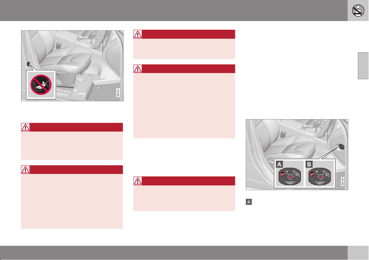
Passenger airbag - activating/
deactivating*
Front passenger airbag (p. 32) can be deacti-
vated if the car is equipped with a switch,
PACOS (Passenger Airbag Cut Off Switch).
Switch - PACOS
The switch for the passenger airbag (PACOS)
is located on the passenger end of the instru-
ment panel and is accessible when the pas-
senger door is open.
Check that the switch is in the required posi-
tion. The remote control key's key blade
(p. 163) should be used to change position.
Location of airbag switch.
The airbag is activated. With the switch in
this position, persons taller than 140 cm
can sit in the front passenger seat, but
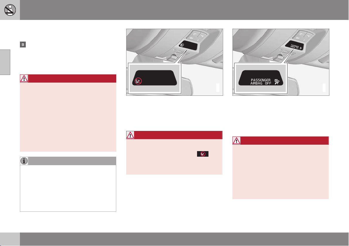
||
02 Safety
02
34
never children in a child seat or on a
booster cushion.
The airbag is deactivated. With the switch
in this position, children in a child seat or
on a booster cushion can sit in the front
passenger seat, but never persons taller
than 140 cm.
WARNING
Activated airbag (passenger seat):
Never place a child in a child seat or on a
booster cushion on the front passenger
seat when the airbag is activated. This
applies to everyone shorter than 140 cm.
Deactivated airbag (passenger seat):
No one taller than 140 cm should ever sit
in the front passenger seat when the air-
bag is deactivated.
Failure to follow the advice given above
can endanger life.
NOTE
When the remote control key is in key
position II (p. 76) the warning symbol
(p. 30) for the airbag is shown in the com-
bined instrument panel for
approx. 6 seconds.
Following which, the indicator in the roof
console is illuminated showing the correct
status for the front passenger seat airbag.
G017800
Indicator showing that the passenger airbag is
activated.
A warning symbol in the roof console indi-
cates that the airbag for the front passenger
seat is activated (see preceding illustration).
WARNING
Never place a child in a child seat or on a
booster cushion in the front seat if the air-
bag is activated and the symbol
in
the roof console is illuminated. Failure to
follow this advice could endanger the life
of the child.
2
2
G017724
Indicator showing that the passenger airbag is
deactivated.
A text message and a symbol in the roof con-
sole indicate that the airbag for the front pas-
senger seat is deactivated (see preceding
illustration).
WARNING
Do not allow anyone to sit in the front pas-
senger seat if the message in the roof con-
sole indicates that the airbag is deacti-
vated, and if the warning symbol (p. 30) for
the airbag system is also displayed on the
combined instrument panel. This indicates
that there has been a severe malfunction.
Visit a workshop as soon as possible.
Volvo recommends that you contact an
authorised Volvo workshop.
02 Safety
02
}}
35
WARNING
Failure to follow the advice given above
can endanger the lives of passengers in
the car.
Related information
•
Child seats (p. 44)
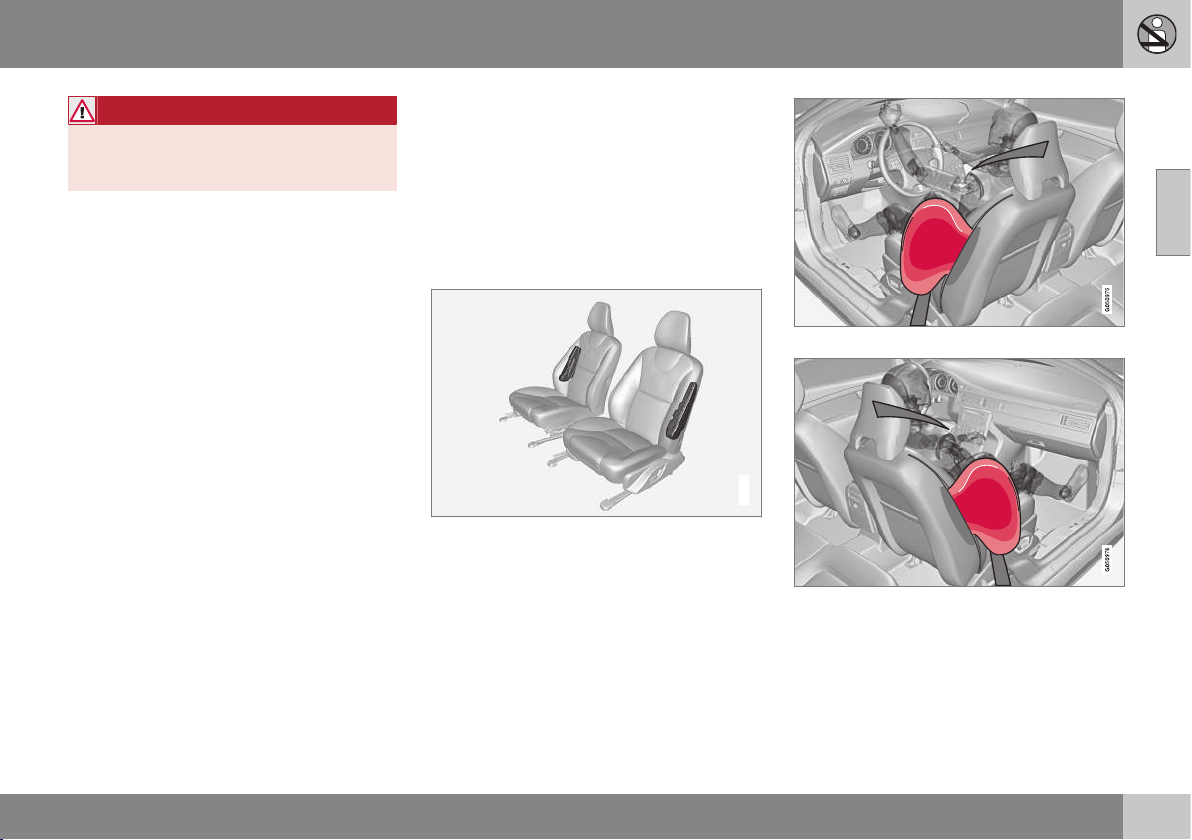
Side airbag (SIPS)
In a side impact collision a large proportion of
the collision force is transferred by the SIPS
(Side Impact Protection System) to beams,
pillars, the floor, the roof and other structural
parts of the body. The side airbags at the driv-
er's and front passenger seats protect the
chest area and the hip and are an important
part of the SIPS.
G032949
The SIPS bag system consists of two main
components, side airbag and sensors. The
side airbags are located in the front seat's
backrests.
A sufficiently violent collision trips the sensors
and the side airbags are inflated. The airbag
inflates between the occupant and the door
panel and thereby cushions the initial impact.
The airbag deflates when compressed by the
collision. The side airbag is normally only
deployed on the side of the collision.
Driver's seat, left-hand drive.
Front passenger seat, left-hand drive.
||
02 Safety
02
36
WARNING
•
Volvo recommends that repairs are
only carried out by an authorised Volvo
workshop. Defective work in the SIPS-
bag system could cause malfunction
and result in serious personal injury.
•
Do not put objects in the area between
the outside of the seat and the door
panel, since this area is required by
the side airbag.
•
Volvo recommends the use only of car
seat covers approved by Volvo. Other
seat covers may impede the operation
of the side airbags.
•
Side airbags are a supplement the
seatbelts. Always use a seatbelt.
Related information
•
Driver airbag (p. 32)
•
Passenger airbag (p. 32)
•
Side airbag (SIPS) - child seat/booster
cushion (p. 36)
•
Inflatable Curtain (IC) (p. 36)
Side airbag (SIPS) - child seat/booster
cushion
The protection provided by the car to children
seated in a child seat or on a booster cushion
is not diminished by the side airbag (p. 35).
Child seat/booster cushion (p. 44) can be
placed on the front passenger seat provided
that the car does not have an activated airbag
(p. 33) on the front passenger side.
Related information
•
Passenger airbag (p. 32)
•
General information on child safety
(p. 42)
Inflatable Curtain (IC)
The inflatable curtain helps to prevent the
driver and passengers from striking their
heads on the inside of the car during a colli-
sion.
Inflatable curtain IC (Inflatable Curtain) is part
of the SIPS system (p. 35) and the airbag sys-
tem (p. 31). It is fitted along both sides of the
headlining and helps protect the driver and
passengers in the car's outer seats. A suffi-
ciently violent collision trips the sensors and
the inflatable curtain is inflated.
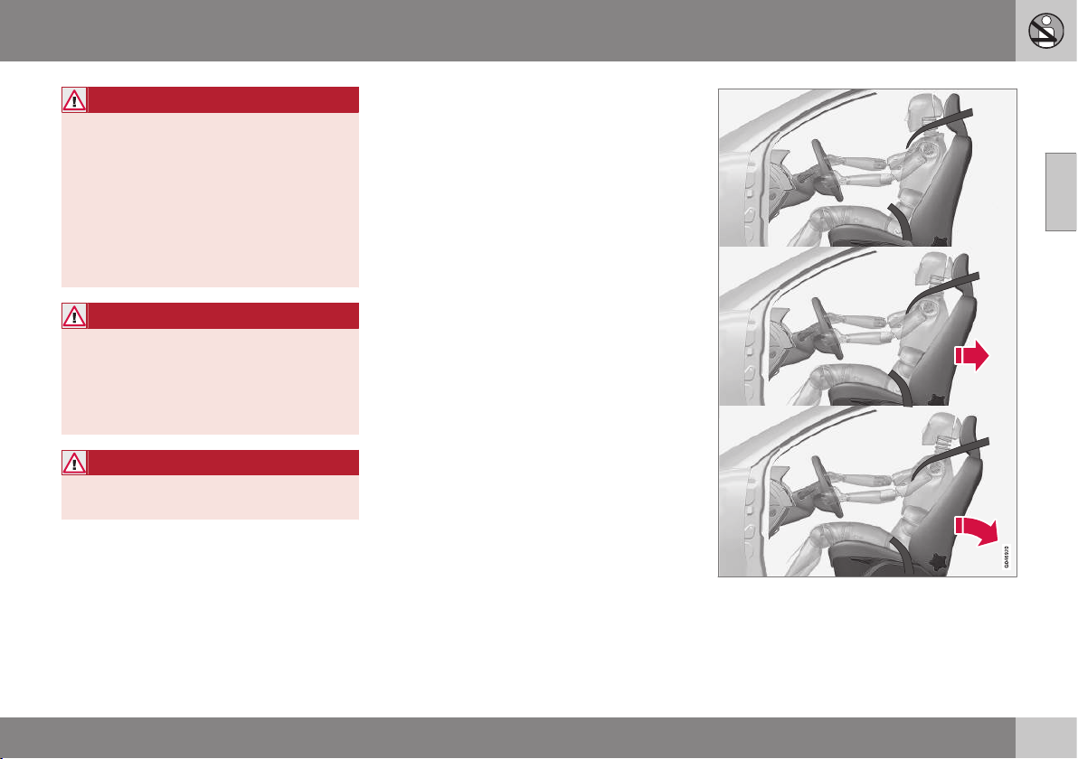
02 Safety
02
}}
37
WARNING
Never hang or attach heavy items onto the
handles in the roof. The hook is only
designed for light clothing (not for solid
objects such as umbrellas for example).
Do not screw or install anything onto the
car's headlining, door pillars or side pan-
els. This could compromise the intended
protection. Volvo recommends that you
only ever use Volvo genuine parts that are
approved for placement in these areas.
WARNING
Do not load the car higher than 50 mm
under the top edge of the windows in the
doors. Otherwise, the intended protection
of the inflatable curtain, which is con-
cealed in the headlining, may be compro-
mised.
WARNING
The inflatable curtain is a supplement to
the seatbelts. Always use a seatbelt.
Related information
•
General information on seatbelts (p. 26)
General information on WHIPS
(whiplash protection)
WHIPS (Whiplash Protection System) is a pro-
tection against whiplash injuries. The system
consists of energy absorbing backrests and
specially designed head restraints in the front
seats.
The WHIPS system is actuated by a rear-end
collision, where the angle and speed of the
collision, and the nature of the colliding vehi-
cle all have an influence.
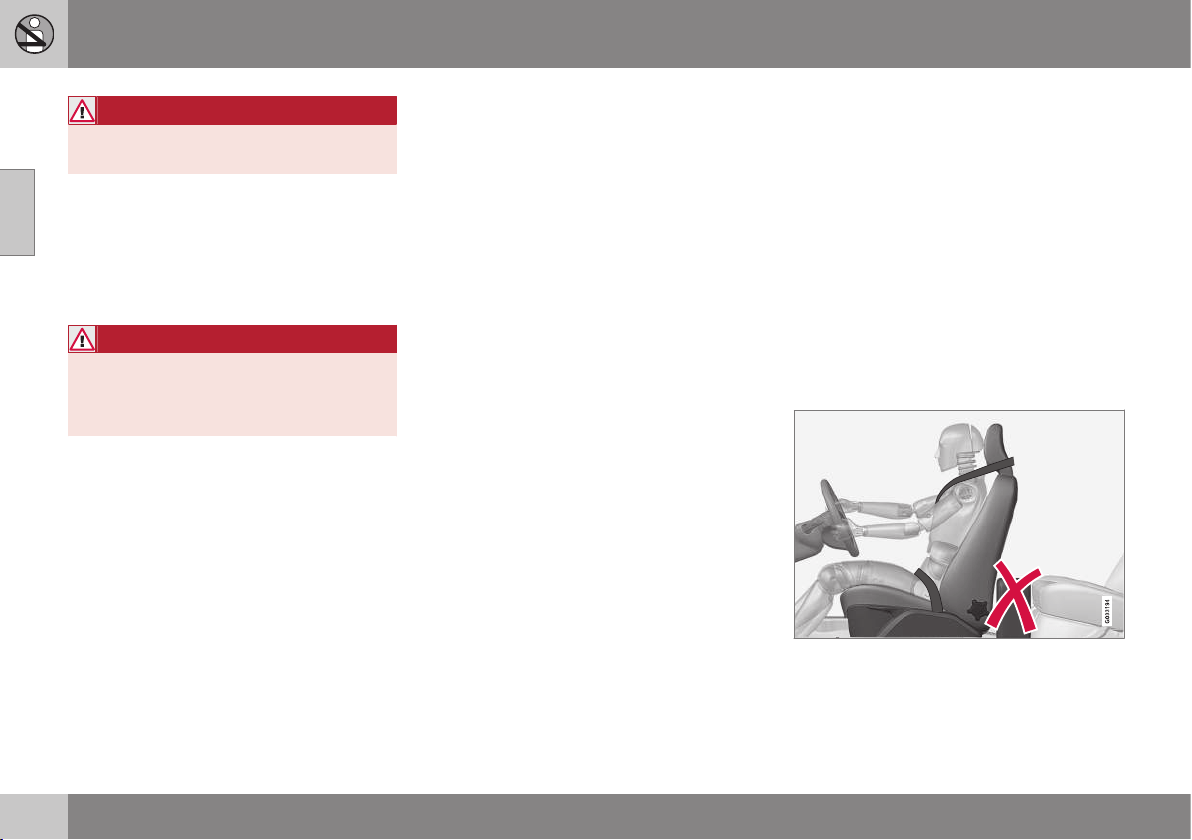
||
02 Safety
02
38
WARNING
The WHIPS system is a supplement to the
seatbelts. Always use a seatbelt.
Seat properties
When the WHIPS system is deployed, the
front seat backrests are lowered backward to
change the seating position of the driver and
front seat passenger. This reduces the risk of
whiplash injury.
WARNING
Never modify or repair the seat or WHIPS
system yourself. Volvo recommends that
you contact an authorised Volvo work-
shop.
Related information
•
WHIPS - child seats (p. 38)
•
WHIPS - seating position (p. 38)
•
General information on seatbelts (p. 26)
WHIPS - child seats
The protection provided by the car to children
seated in a child seat or on a booster cushion
is not diminished by the WHIPS system
(p. 37).
Child seat/booster cushion (p. 44) can be
placed on the front passenger seat provided
that the car does not have an activated airbag
(p. 33) on the front passenger side.
Related information
•
General information on child safety
(p. 42)
WHIPS - seating position
For optimum protection from the WHIPS sys-
tem (p. 37) the driver and passenger must
have the correct seating position and make
sure that the system's function is not obstruc-
ted.
Seating position
Set the correct seating position in the front
seat (p. 78) before driving starts.
Driver and front seat passenger should sit in
the centre of the seat with as little space as
possible between the head and the head
restraint.
Function
Do not leave any objects on the floor behind the
driver's seat/passenger seat that may prevent the
WHIPS system from functioning.
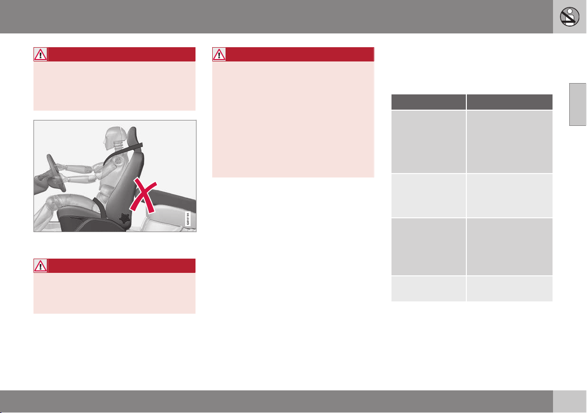
02 Safety
02
}}
39
WARNING
Do not squeeze rigid objects between the
rear seat cushion and the front seat's
backrest. Make sure you do not to
obstruct the function of the WHIPS sys-
tem.
Do not place objects on the rear seat that may
prevent the WHIPS system from functioning.
WARNING
If a rear seat backrest is folded down, the
corresponding front seat must be moved
forward so that it does not make contact
with the folded backrest.
WARNING
If a seat has been subjected to extreme
forces, such as due to a rear-end collision,
the WHIPS system must be checked.
Volvo recommends that it is checked by
an authorised Volvo workshop.
Part of the WHIPS system's protective
capacity may have been lost even if the
seat appears to be undamaged.
Volvo recommends that you contact an
authorised Volvo workshop to have the
system checked even after a minor rear-
end collision.
When the systems deploy
In the event of a collision Volvo's different
personal safety systems work together in
order to minimise injury.
System Triggered
Seatbelt ten-
sioner (p. 29) front
seat
In the event of a
frontal collision,
and/or side-impact
collision, and/or rear-
end collision and/or
overturning
Seatbelt tensioner,
rear seat
In a frontal collision
and/or side-impact
accident and/or over-
turning
Airbags
(Steering wheel
(p. 32) and pas-
senger airbag
(p. 32))
In a frontal collision
A
Side airbags
(SIPS) (p. 35)
In a side-impact acci-
dent
A
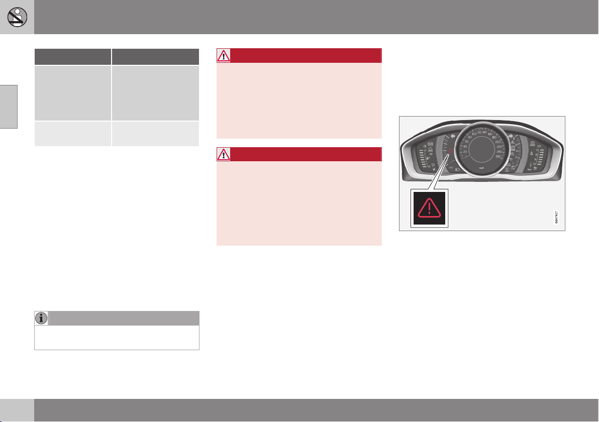
02 Safety
02
40
System Triggered
Inflatable Curtain
IC (p. 36)
In the event of a side
impact collision
and/or overturning
and/or some frontal
collisions
A
Whiplash protec-
tion WHIPS (p. 37)
In a rear-end collision
A
The bodywork of the car could be greatly deformed in a
collision without airbag deployment. A number of factors
such as the rigidity and weight of the object hit, the speed
of the car, the angle of the collision etc. affects how the
different safety systems of the car are activated.
If the airbags (p. 31) have deployed, the fol-
lowing is recommended:
•
Recovering the car. Volvo recommends
that you have it conveyed to an author-
ised Volvo workshop. Do not drive with
deployed airbags.
•
Volvo recommends that you engage an
authorised Volvo workshop to handle the
replacement of components in the car's
safety systems.
•
Always contact a doctor.
NOTE
The airbags and belt tensioner system are
deployed only once during a collision.
WARNING
The airbag system's control module is
located in the centre console. If the centre
console is drenched with water or other
liquid, disconnect the battery cables. Do
not attempt to start the car since the air-
bags may deploy. Recovering the car.
Volvo recommends that you have it con-
veyed to an authorised Volvo workshop.
WARNING
Never drive with deployed airbags. They
can make steering difficult. Other safety
systems may also be damaged. The
smoke and dust created when the airbags
are deployed can cause skin and eye irrita-
tion/injury after intensive exposure. In case
of irritation, wash with cold water. The
rapid deployment sequence and airbag
fabric may cause friction and skin burns.
General information on safety mode
Safety mode is a protective state that is
enforced when the collision may have dam-
aged any of the car's vital functions, such as
the fuel lines, sensors for one of the safety
systems, or the brake system.
Warning triangle in the analogue combined
instrument panel.
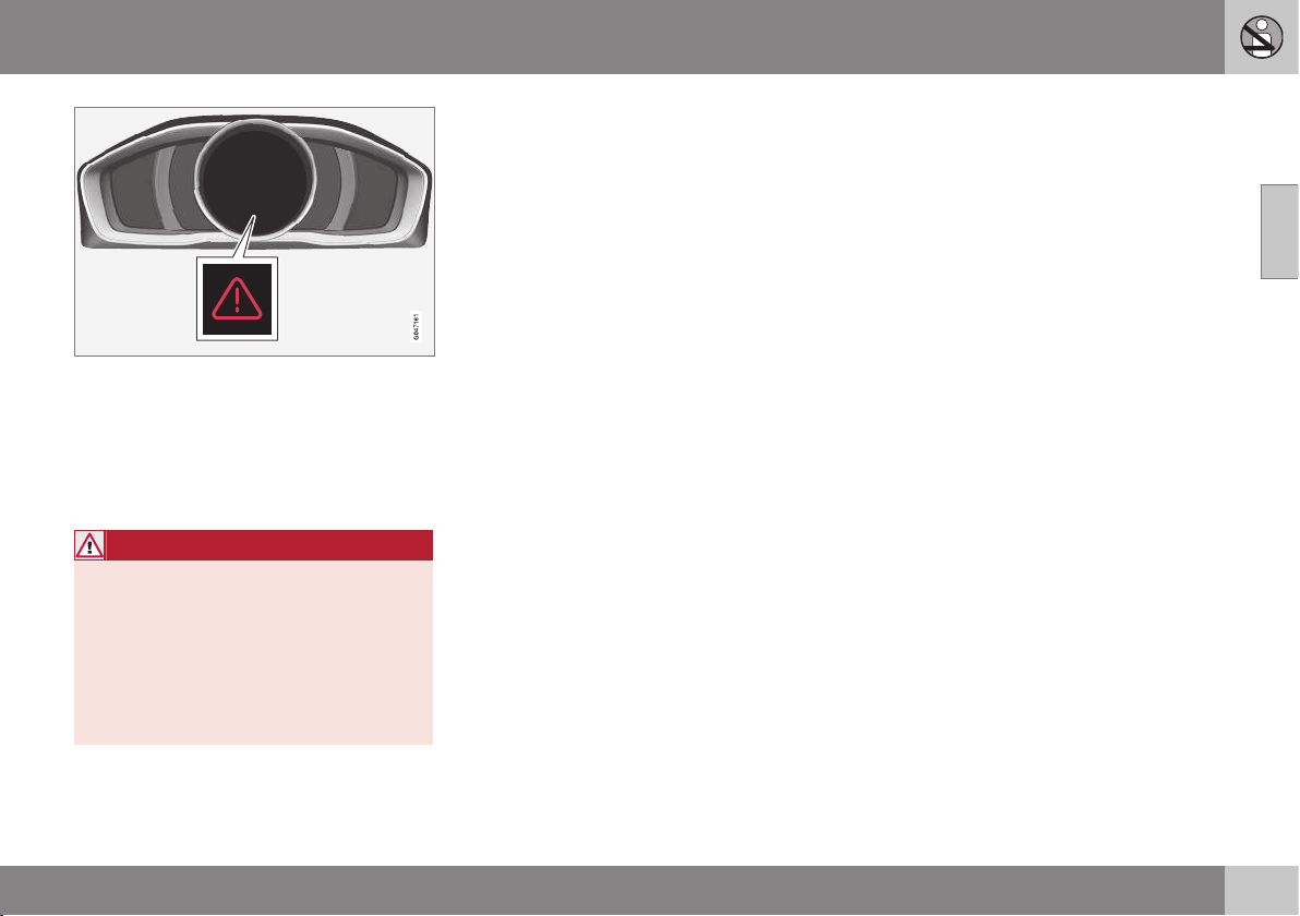
02 Safety
02
}}
41
Warning triangle in the digital combined instru-
ment panel.
If the car is involved in a collision, the text
Safety mode See manual may appear in the
combined instrument panel (p. 61) informa-
tion display. This means that the car has
reduced functionality.
WARNING
Never attempt to repair your car or reset
the electronics yourself if the car has been
in safety mode. This could result in per-
sonal injury or the car not functioning as
normal. Volvo recommends that you
engage an authorised Volvo workshop to
check and restore the car to normal status
after
Safety mode See manual has been
displayed.
Related information
•
Safety mode - attempting to start the car
(p. 41)
•
Safety mode - moving the car (p. 42)
Safety mode - attempting to start the
car
If the car is set in safety mode (p. 40) then an
attempt to start the car can be made if every-
thing seems normal and the absence of fuel
leakage has been checked.
First, check that no fuel is leaking from the
car. There must be no smell of fuel either.
If everything seems normal and you have
checked for indications of fuel leakage, you
may attempt to start the car.
Remove the remote control key and open the
driver's door. If a message is now shown to
the effect that the ignition is on, press the
start button. Then close the door and reinsert
the remote control key. The car's electronics
will now try to reset themselves to normal
mode. Then try to start the car.
If the message
Safety mode See manual is
still shown on the display then the car must
not be driven or towed but a vehicle recovery
service (p. 320) used instead. Even if the car
appears to be driveable, hidden damage may
make the car impossible to control once mov-
ing.
||
02 Safety
02
42
WARNING
Never, under any circumstances, attempt
to restart the car if it smells of fuel when
the
Safety mode See manual message
is displayed. Leave the car at once.
WARNING
If the car is in safety mode it must not be
towed. It must be transported from its
location. Volvo recommends that it is
transported to an authorised Volvo work-
shop.
Related information
•
Safety mode - moving the car (p. 42)
Safety mode - moving the car
If Normal mode is shown after Safety mode
See manual has been reset after attempting
to start the car (p. 41) , the car can be moved
carefully out of a dangerous position.
Do not move the car further than necessary.
Related information
•
General information on safety mode
(p. 40)
General information on child safety
Children of all ages and sizes must always sit
correctly secured in the car. Never allow a
child to sit on the knee of a passenger.
Volvo recommends that children travel in
rear-facing child seats until as late an age as
possible, at least until 3-4 years of age, and
then front-facing booster cushions/child seats
until up to 10 years of age.
The position of a child in the car and the
choice of equipment are dictated by the
child's weight and size; see Child seats
(p. 44).
NOTE
Regulations regarding the placement of
children in cars vary from country to coun-
try. Check what does apply.
Volvo has child safety equipment (child seats,
booster cushions & attachment devices)
which is designed for your particular car.
Using Volvo's child safety equipment pro-
vides you with optimum conditions for your
child to travel safely in the car. Furthermore,
the child safety equipment fits and is easy to
use.

02 Safety
02
* Option/accessory, for more information, see Introduction.
43
NOTE
In the event of questions when fitting child
safety products, contact the manufacturer
for clearer instructions.
Child safety locks
The rear doors and rear door windows* can
be blocked manually (p. 177) or electronically
(p. 177)* from opening from the inside.
Related information
•
Child seats - location (p. 48)
•
Child seat - ISOFIX (p. 49)
•
Child seats - upper mounting points
(p. 53)
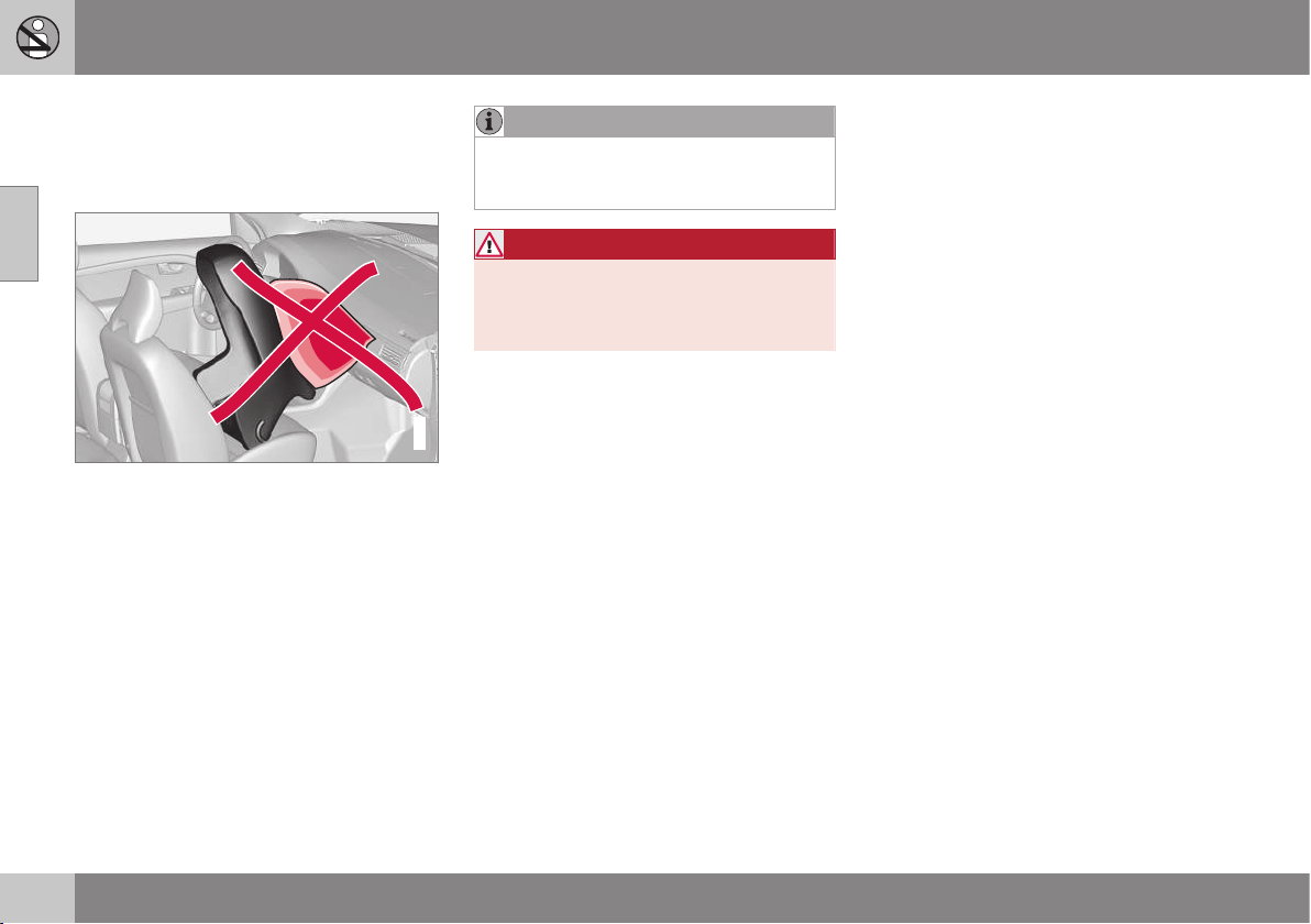
02 Safety
02
44
Child seats
Children should sit comfortably and safely.
Make sure that the child seat is being used
correctly.
G020739
Child seats and airbags are not compatible.
NOTE
When using child safety products it is
important to read the installation instruc-
tions included.
WARNING
Do not secure the straps of the child seat
to the seat's horizontal adjustment bar,
springs or the rails and beams under the
seat. Sharp edges may damage the straps.
Look in the installation instructions for the
child seat for the correct fitting.

02 Safety
02
}}
45
Recommended child seats
2
Weight Front seat (with deactivated airbag) Outer rear seat Centre rear seat
Group 0
max 10 kg
Group 0+
max 13 kg
Volvo infant seat (Volvo Infant Seat) - rear-facing
child seat, secured with the ISOFIX fixture system.
Type approval: E1 04301146
(L)
Group 0
max 10 kg
Group 0+
max 13 kg
Volvo infant seat (Volvo Infant Seat) - rear-fac-
ing child seat, secured with the car's seatbelt.
Type approval: E1 04301146
(U)
Volvo infant seat (Volvo Infant Seat) - rear-facing
child seat, secured with the car's seatbelt.
Type approval: E1 04301146
(U)
Volvo infant seat (Volvo
Infant Seat) - rear-facing
child seat, secured with
the car's seatbelt.
Type approval: E1
04301146
(U)
Group 0
max 10 kg
Group 0+
max 13 kg
Child seats which are universally approved.
(U)
Child seats which are universally approved.
(U)
Child seats which are uni-
versally approved.
(U)
Group 1
9-18 kg
Volvo rear-facing/turnable child seat (Volvo
Convertible Child Seat) - rear-facing child seat,
secured with the car's seatbelt and straps.
Type approval: E5 04192
(L)
Volvo rear-facing/turnable child seat (Volvo
Convertible Child Seat) - rear-facing child seat,
secured with the car's seatbelt and straps.
Type approval: E5 04192
(L)
2
With regard to other child seats your car should be included in the manufacturer's enclosed list of vehicles or be universally approved in accordance with the ECE R44 legal requirement.

||
02 Safety
02
46
Weight Front seat (with deactivated airbag) Outer rear seat Centre rear seat
Group 1
9-18 kg
Child seats which are universally approved.
(U)
Child seats which are universally approved.
(U)
Child seats which are uni-
versally approved.
(U)
Group 2
15-25 kg
Volvo rear-facing/turnable child seat (Volvo
Convertible Child Seat) - rear-facing child seat,
secured with the car's seatbelt and straps.
Type approval: E5 04192
(L)
Volvo rear-facing/turnable child seat (Volvo
Convertible Child Seat) - rear-facing child seat,
secured with the car's seatbelt and straps.
Type approval: E5 04192
(L)
Group 2
15-25 kg
Volvo rear-facing/turnable child seat (Volvo
Convertible Child Seat) - front-facing child
seat, secured with the car's seatbelt.
Type approval: E5 04191
(U)
Volvo rear-facing/turnable child seat (Volvo
Convertible Child Seat) - front-facing child seat,
secured with the car's seatbelt.
Type approval: E5 04191
(U)
Group 2/3
15-36 kg
Volvo booster seat with backrest (Volvo
Booster Seat with backrest).
Type approval: E1 04301169
(UF)
Volvo booster seat with backrest (Volvo Booster
Seat with backrest).
Type approval: E1 04301169
(UF)
Volvo booster seat with
backrest (Volvo Booster
Seat with backrest).
Type approval: E1
04301169
(UF)

02 Safety
02
47
Weight Front seat (with deactivated airbag) Outer rear seat Centre rear seat
Group 2/3
15-36 kg
Booster cushion with and without backrest
(Booster Cushion with and without backrest).
Type approval: E5 04216
(UF)
Booster cushion with and without backrest (Booster
Cushion with and without backrest).
Type approval: E5 04216
(UF)
Booster cushion with and
without backrest (Booster
Cushion with and without
backrest).
Type approval: E5 04216
(UF)
L: Suitable for specific child seats. These child seats may be intended for use in a special car model, limited or semi-universal categories.
U: Suitable for universally approved child seats in this weight class.
UF: Suitable for front-facing universally approved child seats in this weight class.
Related information
•
Child seats - location (p. 48)
•
Child seats - upper mounting points
(p. 53)
•
Child seat - ISOFIX (p. 49)
•
General information on child safety (p. 42)
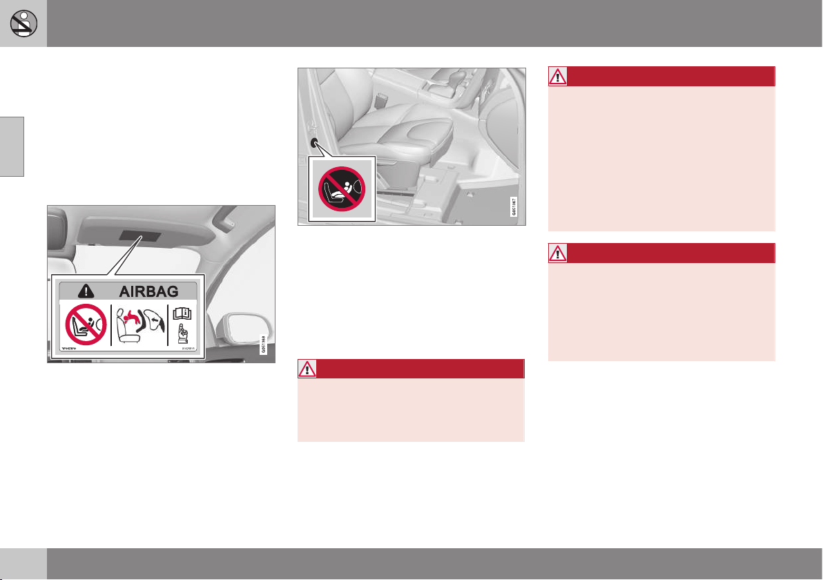
02 Safety
02
48
Child seats - location
Always fit child seats/booster cushions (p. 44)
in the rear seat if the passenger airbag is acti-
vated (p. 33). If a child is sitting on the front
passenger seat then he/she could suffer seri-
ous injury if the airbag deploys.
The warning label for the passenger airbag is
fitted in one of the following two locations in
the car:
Alternative 1: Position of airbag label on passen-
ger side sun visor.
Alternative 2: Position of airbag label on passen-
ger side door pillar. The label becomes visible
when the passenger door is opened.
You may place:
•
a child seat/booster cushion on the front
passenger seat provided there is no acti-
vated airbag on the front passenger side.
•
one or more child seats/booster cushions
in the rear seat.
WARNING
Never use a rear-facing child seat on a
seat protected by an activated airbag. Fail-
ure to follow this advice can lead to death
or serious injury to the child.
WARNING
Never place a child in a child seat or on a
booster cushion in the front seat if the air-
bag is activated.
Never allow anybody to stand or sit in front
of the front passenger seat.
No one shorter than 140 cm should ever
sit in the front passenger seat if the airbag
is activated.
Failure to follow the advice given above
can endanger life.
WARNING
Booster cushions/child seats with steel
braces or some other design that could
rest on the seatbelt buckle's opening but-
ton must not be used, as they could cause
the seatbelt buckle to open accidentally.
Do not allow the upper section of the child
seat to rest against the windscreen.
Related information
•
General information on child safety (p. 42)
•
Child seats - upper mounting points
(p. 53)
•
Child seat - ISOFIX (p. 49)
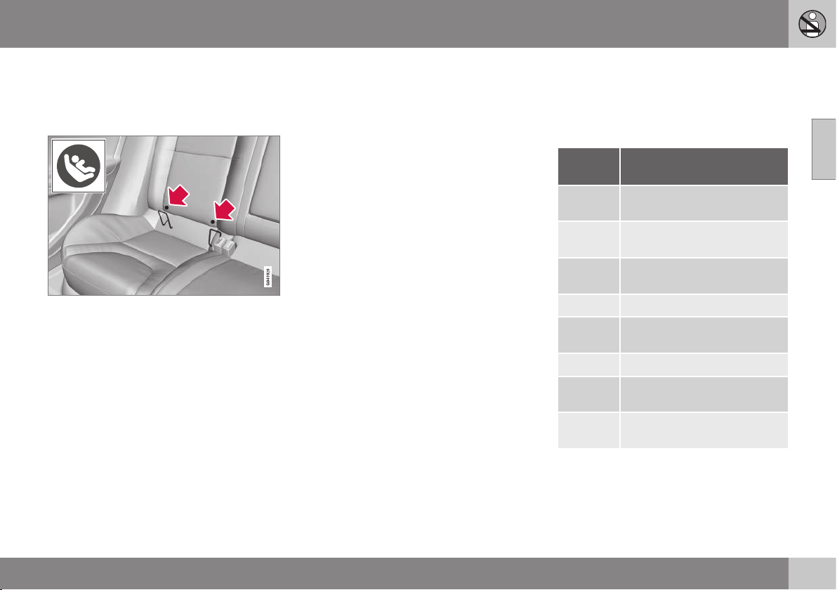
02 Safety
02
}}
49
Child seat - ISOFIX
ISOFIX is a fixture system for car child seats
(p. 44) that is based on an international stand-
ard.
Mounting points for the ISOFIX fixture system
are concealed behind the lower section of the
rear seat backrest, in the outer seats.
The location of the mounting points is indi-
cated by symbols in the backrest upholstery
(see preceding illustration).
Press the seat cushion down to access the
mounting points.
Always follow the manufacturer's installation
instructions when connecting a child seat to
the ISOFIX mounting points.
Related information
•
ISOFIX - size classes (p. 49)
•
ISOFIX - types of child seat (p. 51)
•
General information on child safety (p. 42)
ISOFIX - size classes
There is a size classification for child seats
using the ISOFIX (p. 49) fixture system in
order to assist users in choosing the correct
type of child seat (p. 51).
Size
class
Description
A Full size, front-facing child
seat
B Reduced size (alt. 1), front-
facing child seat
B1 Reduced size (alt.2), front-fac-
ing child seat
C Full size, rear-facing child seat
D Reduced size, rear-facing
child seat
E Rear-facing infant seat
F Transverse infant seat, left-
hand
G Transverse infant seat, right-
hand
||
02 Safety
02
50
WARNING
Never place the child in the passenger
seat if the car is fitted with an activated air-
bag.
NOTE
If an ISOFIX child seat has no size classifi-
cation, the car model must be included on
the vehicle list for the child seat.
NOTE
Volvo recommends that you contact an
authorised Volvo dealer for recommenda-
tions about which ISOFIX child seats Volvo
recommends.

02 Safety
02
}}
51
ISOFIX - types of child seat
Child seats are in different sizes – cars are in
different sizes. This means that not all child
seats are suitable for all seats in all car mod-
els.
Type of child seat Weight Size class Passenger seats for ISOFIX installation of child seats
Front seat Outer rear seat
Infant seat transverse max 10 kg F X X
G X X
Infant seat, rear-facing max 10 kg E X OK
(IL)
Infant seat, rear-facing max 13 kg E X OK
(IL)
D X
OK
A
(IL)
C X
OK
A
(IL)
Child seat, rear-facing 9-18 kg D X
OK
A
(IL)
C X
OK
A
(IL)

||
02 Safety
02
52
Type of child seat Weight Size class Passenger seats for ISOFIX installation of child seats
Front seat Outer rear seat
Front-facing child seat 9-18 kg B X
OK
B
(IUF)
B1 X
OK
B
(IUF)
A X
OK
B
(IUF)
X: The ISOFIX position is not suitable for ISOFIX child seats in this weight class and/or size class.
IL: Suitable for specific ISOFIX child seats. These child seats may be intended for a particular car model, limited or semi-universal categories.
IUF: Suitable for front-facing ISOFIX child seats that are universally approved in this weight class.
A
For the infant/child seat to have space in the rear seat the seat in front must be adjusted longitudinally to a position in front of centre position.
B
Volvo recommends rear-facing child seats for this group.
Make sure you select the right size class
(p. 49) of child seat with ISOFIX (p. 49) fixture
system.
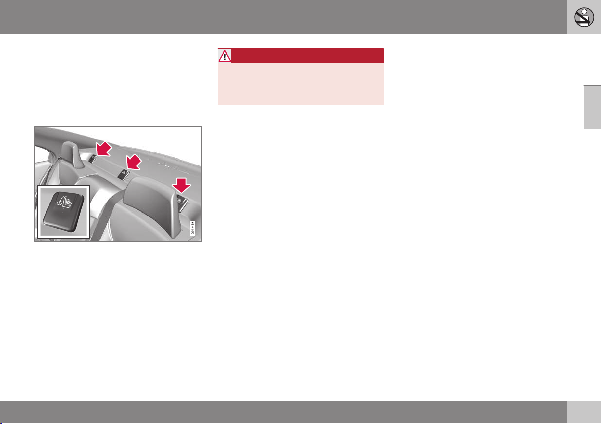
02 Safety
02
53
Child seats - upper mounting points
The car is equipped with upper mounting
points for child seats (p. 44). These mounting
points are located on the parcel shelf and are
concealed by plastic covers. Bend aside the
plastic covers to access each respective
mounting point.
For cars with folding head restraints on the
outside seats the head restraints should be
folded to facilitate installation.
The upper mounting points are primarily
intended for use with front-facing child seats.
Volvo recommends that small children should
sit in rear-facing child seats for as long as
possible.
For detailed information on how the child seat
should be tensioned in the upper mounting
points, see the seat manufacturer's instruc-
tions.
WARNING
The child seat's straps must always be
drawn through the hole in the head
restraint leg before they are tensioned at
the attachment point.
Related information
•
General information on child safety (p. 42)
•
Child seats - location (p. 48)
•
Child seat - ISOFIX (p. 49)
INSTRUMENTS AND CONTROLS

03 Instruments and controls
03
}}
55
Instruments and controls, left-hand
drive car - overview
The overview shows where the car's displays
and controls are located.
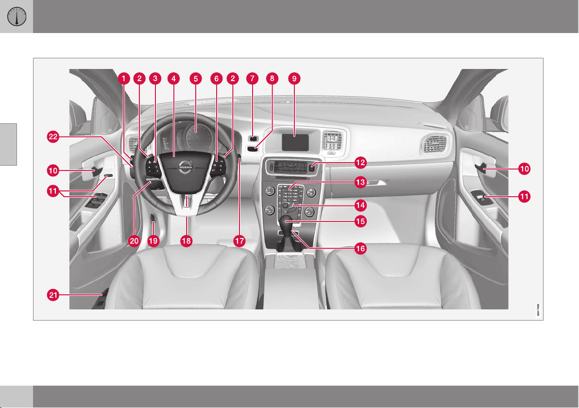
||
03 Instruments and controls
03
56
Overview, left-hand drive cars
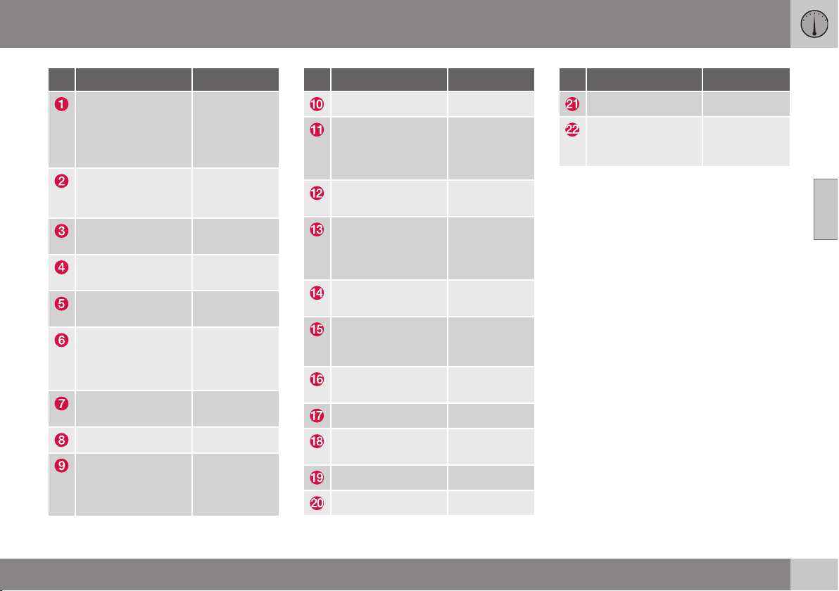
03 Instruments and controls
03
* Option/accessory, for more information, see Introduction.
57
Function See
Menus and mes-
sages, direction
indicators, main/
dipped beam, trip
computer
(p. 105),
(p. 108),
(p. 93),
(p. 87) and
(p. 119).
Manual gear chang-
ing in an automatic
gearbox*
(p. 276).
Cruise control* (p. 194) and
(p. 197).
Horn, airbags (p. 82) and
(p. 31).
Combined instru-
ment panel
(p. 61).
Menu navigation,
audio control,
phone control*
(p. 108) and
the Sensus
Infotainment
supplement.
START/STOP
ENGINE button
(p. 268).
Ignition switch (p. 76).
Screen for infotain-
ment system and
display of menus
(p. 108) and
the Sensus
Infotainment
supplement.
Function See
Door handle -
Control panel (p. 172),
(p. 177),
(p. 98) and
(p. 100).
Hazard warning
flashers
(p. 93).
Control panel for
infotainment system
and menu naviga-
tion
(p. 108) and
the Sensus
Infotainment
supplement.
Control panel for cli-
mate control
(p. 128).
Gear selector (p. 274),
(p. 276) or
(p. 279).
Controls for active
chassis (Four-C)*
(p. 183).
Wipers and washing (p. 96).
Steering wheel
adjustment
(p. 82).
Bonnet opener (p. 360).
Parking brake (p. 298).
Function See
Seat adjustment* (p. 79).
Headlamp control,
opener for fuel filler
flap and boot lid
(p. 84),
(p. 305) and
(p. 174).
Related information
•
Outside temperature gauge (p. 70)
•
Trip meter (p. 70)
•
Clock (p. 71)

03 Instruments and controls
03
58
Instruments and controls, right-hand
drive car - overview
The overview shows where the car's displays
and controls are located.
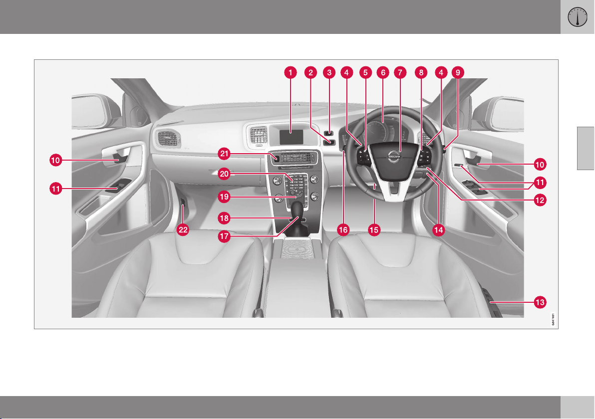
03 Instruments and controls
03
}}
59
Overview, right-hand drive cars
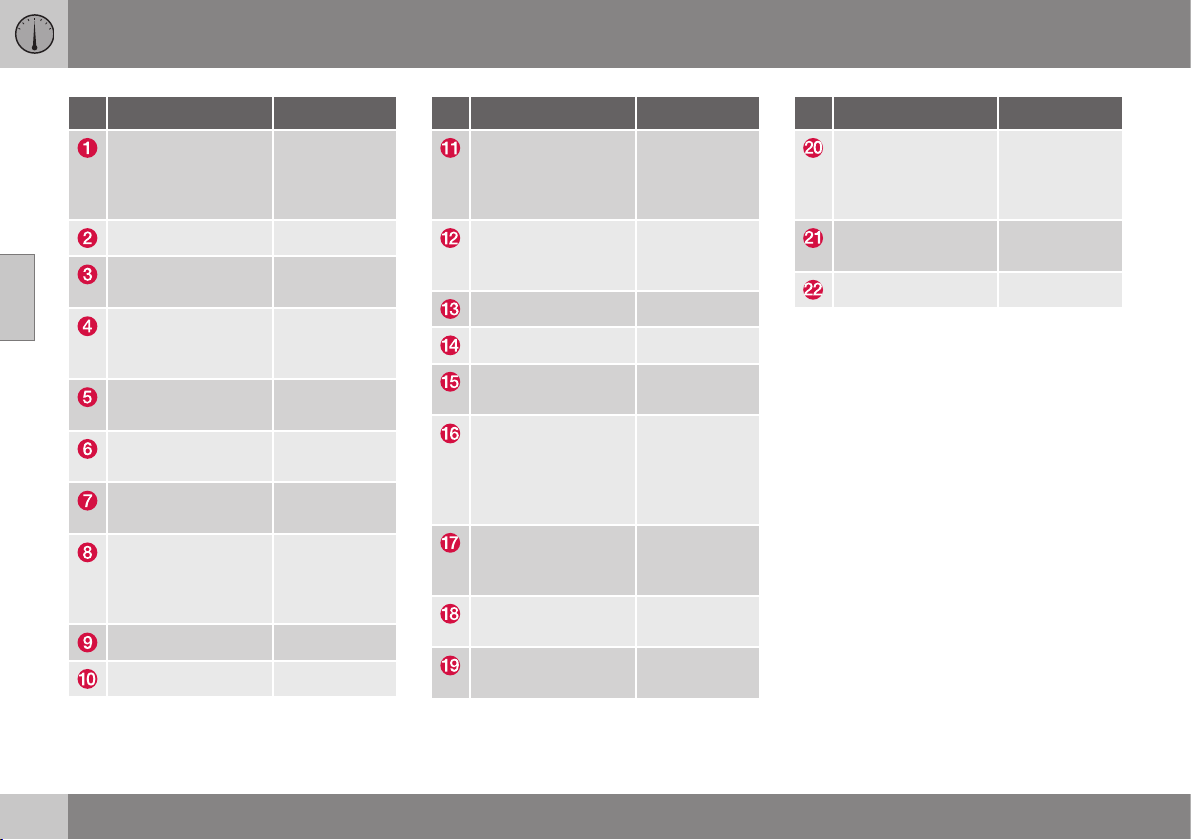
||
03 Instruments and controls
03
60
* Option/accessory, for more information, see Introduction.
Function See
Screen for infotain-
ment system and
display of menus
(p. 108) and
the Sensus
Infotainment
supplement.
Ignition switch (p. 76).
START/STOP
ENGINE button
(p. 268).
Manual gear chang-
ing in an automatic
gearbox*
(p. 276).
Cruise control* (p. 194) and
(p. 197).
Combined instru-
ment panel
(p. 61).
Horn, airbags (p. 82) and
(p. 31).
Menu navigation,
audio control,
phone control*
(p. 108) and
the Sensus
Infotainment
supplement.
Wipers and washing (p. 96).
Door handle -
Function See
Control panel (p. 172),
(p. 177),
(p. 98) and
(p. 100).
Headlamp control,
opener for fuel filler
flap and boot lid
(p. 84),
(p. 305) and
(p. 174).
Seat adjustment* (p. 79).
Parking brake (p. 298).
Steering wheel
adjustment
(p. 82).
Menus and mes-
sages, direction
indicators, main/
dipped beam, trip
computer
(p. 105),
(p. 108),
(p. 93),
(p. 87) and
(p. 119).
Gear selector (p. 274),
(p. 276) or
(p. 279).
Controls for active
chassis (Four-C)*
(p. 183).
Control panel for cli-
mate control
(p. 128).
Function See
Control panel for
infotainment system
and menu naviga-
tion
(p. 108) and
the Sensus
Infotainment
supplement.
Hazard warning
flashers
(p. 93).
Bonnet opener (p. 360).
Related information
•
Outside temperature gauge (p. 70)
•
Trip meter (p. 70)
•
Clock (p. 71)
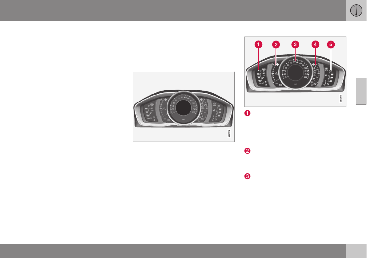
03 Instruments and controls
03
}}
61
Combined instrument panel
The combined instrument panel's information
display shows information on some of the
car's functions, as well as messages.
•
Analogue combined instrument panel -
overview (p. 61)
•
Digital combined instrument panel - over-
view (p. 62)
•
Combined instrument panel - meaning of
indicator symbols (p. 66)
•
Combined instrument cluster - meaning
of warning symbols (p. 68)
Analogue combined instrument panel
- overview
The combined instrument panel's information
display shows information on some of the
car's functions, as well as messages.
Information display
Information display, analogue instrument panel.
The combined instrument panel's information
display shows information on some of the
car's functions, e.g. cruise control and trip
computer, as well as messages. The informa-
tion is shown with symbols and text. There
are further descriptions under the functions
that use the display.
Gauges and indicators
Fuel gauge. When the indicator lowers to
only one white marking
1
, the yellow indi-
cator symbol for low level in the fuel tank
is illuminated. See also Trip computer -
supplementary information (p. 119) and
Filling up with fuel (p. 305).
Eco meter The meter provides an indica-
tion of how economically the car is being
driven. The higher the reading on the
scale, the more economical it is.
Speedometer
1
When the display's message "Distance to empty fuel tank:" starts to show "
----", the marking becomes red.
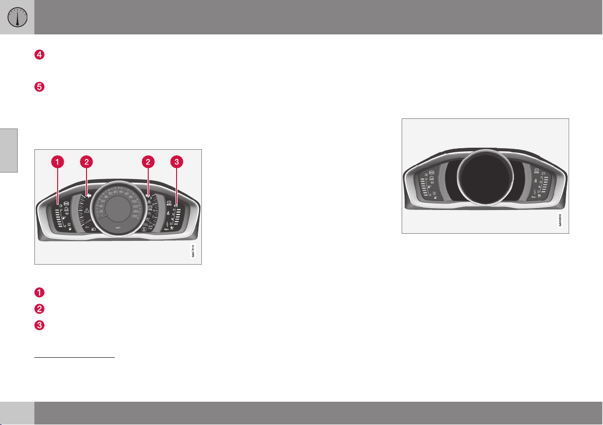
||
03 Instruments and controls
03
62
* Option/accessory, for more information, see Introduction.
Tachometer. The meter indicates engine
speed in thousands of revolutions per
minute (rpm).
Gear shift indicator
2
/Gear position indica-
tor
3
See also Gear shift indicator*
(p. 275), Automatic gearbox --
Geartronic* (p. 276) or Automatic gear-
box -- Powershift* (p. 279).
Indicator and warning symbols
Indicator and warning symbols, analogue instru-
ment panel.
Indicator symbols
Indicator and warning symbols
Warning symbols
4
Functionality check
All indicator and warning symbols, apart from
symbols in the centre of the information dis-
play, illuminate in key position II or when the
engine is started. When the engine has
started, all the symbols should go out except
the parking brake symbol, which only goes
out when the brake is disengaged.
If the engine does not start or if the function-
ality check is carried out in key position II
then all symbols go out within a few seconds
except the symbol for faults in the car's emis-
sions system and the symbol for low oil pres-
sure.
Related information
•
Combined instrument panel (p. 61)
•
Combined instrument panel - meaning of
indicator symbols (p. 66)
•
Combined instrument cluster - meaning
of warning symbols (p. 68)
Digital combined instrument panel -
overview
The combined instrument panel's information
display shows information on some of the
car's functions, as well as messages.
Information display
Information display, digital instrument panel*.
The combined instrument panel's information
display shows information on some of the
car's functions, e.g. cruise control and trip
computer, as well as messages. The informa-
tion is shown with symbols and text. There
are further descriptions under the functions
that use the display.
2
Manual gearbox.
3
Automatic gearbox.
4
Certain engine variants do not have systems to warn of oil pressure loss. In cars with these variants the symbol for low oil pressure is not used. Warning for low oil level is via display text. For
more information, see Engine oil - general (p. 362).
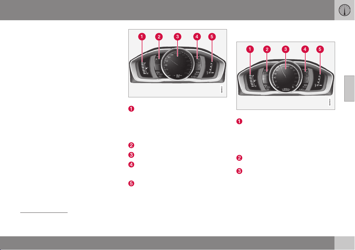
03 Instruments and controls
03
}}
* Option/accessory, for more information, see Introduction.
63
Gauges and indicators
Alternative themes can be selected for the
digital combined instrument panel. Possible
themes are "Elegance", "Eco" and
"Performance".
A theme can only be selected when the
engine is running.
To select the theme, press the left-hand stalk
switch's OK button and select the
Themes
menu option by turning the thumbwheel on
the lever. Press the OK button. Turn the
thumbwheel to select the theme and confirm
the selection by pressing the OK button.
On certain model variants, the appearance of
the centre console's screen follows the theme
selected for the combined instrument panel.
The contrast mode and colour mode for the
instrument can also be set using the left-hand
stalk switch.
For more information on menu navigation,
see Menu navigation - combined instrument
panel (p. 105).
The choice of theme and setting of contrast
mode and colour mode can be stored for
each remote control key in the car key mem-
ory*, see Remote control key - personalisa-
tion* (p. 156).
Gauges and indicators, theme "Elegance".
Fuel gauge. When the indicator lowers to
only one white marking
5
, the yellow indi-
cator symbol for low level in the fuel tank
is illuminated. See also Trip computer -
supplementary information (p. 119) and
Filling up with fuel (p. 305).
Temperature gauge for engine coolant
Speedometer
Tachometer. The meter indicates engine
speed in thousands of revolutions per
minute (rpm).
Gear shift indicator
6
/Gear position indica-
tor
7
See also Gear shift indicator*
(p. 275), Automatic gearbox --
Geartronic* (p. 276) or Automatic gear-
box -- Powershift* (p. 279).
Gauges and indicators, theme "Eco".
Fuel gauge. When the indicator lowers to
only one white marking
5
, the yellow indi-
cator symbol for low level in the fuel tank
is illuminated. See also Trip computer -
supplementary information (p. 119) and
Filling up with fuel (p. 305).
Eco guide. See also Eco guide & Power
guide* (p. 65).
Speedometer
5
When the display's message "Distance to empty fuel tank:" starts to show "
----", the marking becomes red.
6
Manual gearbox.
7
Automatic gearbox.
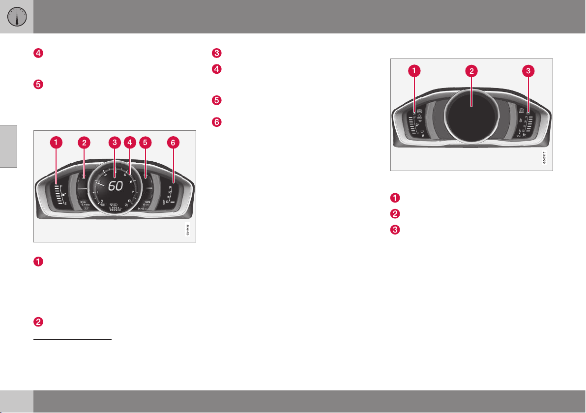
||
03 Instruments and controls
03
64
* Option/accessory, for more information, see Introduction.
Tachometer. The meter indicates engine
speed in thousands of revolutions per
minute (rpm).
Gear shift indicator
6
/Gear position indica-
tor
7
. See also Gear shift indicator*
(p. 275), Automatic gearbox --
Geartronic* (p. 276) or Automatic gear-
box -- Powershift* (p. 279).
Gauges and indicators, theme "Performance".
Fuel gauge. When the indicator lowers to
only one white marking
5
, the yellow indi-
cator symbol for low level in the fuel tank
is illuminated. See also Trip computer -
supplementary information (p. 119) and
Filling up with fuel (p. 305).
Temperature gauge for engine coolant
Speedometer
Tachometer. The meter indicates engine
speed in thousands of revolutions per
minute (rpm).
Power guide. See also Eco guide &
Power guide* (p. 65).
Gear shift indicator
6
/Gear position indica-
tor
7
. See also Gear shift indicator*
(p. 275), Automatic gearbox --
Geartronic* (p. 276) or Automatic gear-
box -- Powershift* (p. 279).
Indicator and warning symbols
Indicator and warning symbols, digital instrument
panel.
Indicator symbols
Indicator and warning symbols
Warning symbols
8
6
Manual gearbox.
7
Automatic gearbox.
5
When the display's message "Distance to empty fuel tank:" starts to show "
----", the marking becomes red.
8
Certain engine variants do not have systems to warn of oil pressure loss. In cars with these variants the symbol for low oil pressure is not used. Warning for low oil level is via display text. For
more information, see Engine oil - general (p. 362).
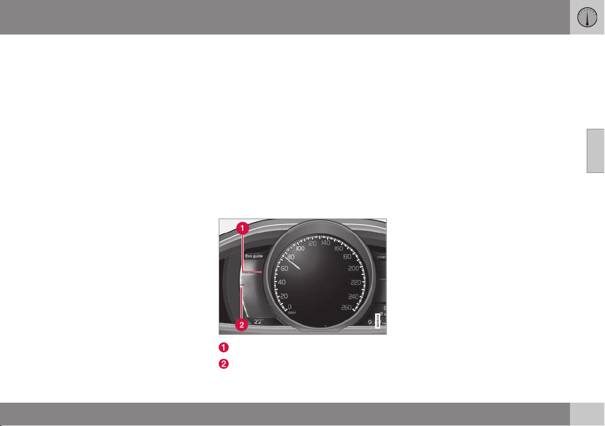
03 Instruments and controls
03
}}
* Option/accessory, for more information, see Introduction.
65
Functionality check
All indicator and warning symbols, apart from
symbols in the centre of the information dis-
play, illuminate in key position II or when the
engine is started. When the engine has
started, all the symbols should go out except
the parking brake symbol, which only goes
out when the brake is disengaged.
If the engine does not start or if the function-
ality check is carried out in key position II
then all symbols go out within a few seconds
except the symbol for faults in the car's emis-
sions system and the symbol for low oil pres-
sure.
Related information
•
Combined instrument panel (p. 61)
•
Combined instrument panel - meaning of
indicator symbols (p. 66)
•
Combined instrument cluster - meaning
of warning symbols (p. 68)
Eco guide & Power guide*
Eco guide and Power guide are two com-
bined instrument panel (p. 61) instruments
which help the driver to drive the car with
optimum driving economy.
The car also stores statistics of journeys
made, which can be viewed in the form of a
block diagram; see Trip computer - trip statis-
tics* (p. 120).
Eco guide
This instrument provides an indication of how
economically the car is being driven.
To view this function, select the theme "Eco";
see Digital combined instrument panel - over-
view (p. 62).
Instantaneous value
Average value
Instantaneous value
The instantaneous value is shown here - the
higher the reading on the scale, the better.
The instantaneous value is calculated based
on speed, engine speed, engine power uti-
lised plus use of the foot brake.
Optimum speed (50-80 km/h) and low engine
speeds are encouraged. The pointers fall dur-
ing acceleration and braking.
Very low instantaneous values illuminate the
red zone on the meter (with a short delay),
which means poor driving economy and
hence should be avoided.
Average value
The average value slowly follows the instanta-
neous value and describes how the car has
been driven most recently. The higher the
pointers on the scale, the better the economy
achieved by the driver.
Power guide
This instrument shows the relationship
between how much power (Power) is being
taken from the engine and how much power
is available.
To view this function, select the theme
"Performance"; see Digital combined instru-
ment panel - overview (p. 62).
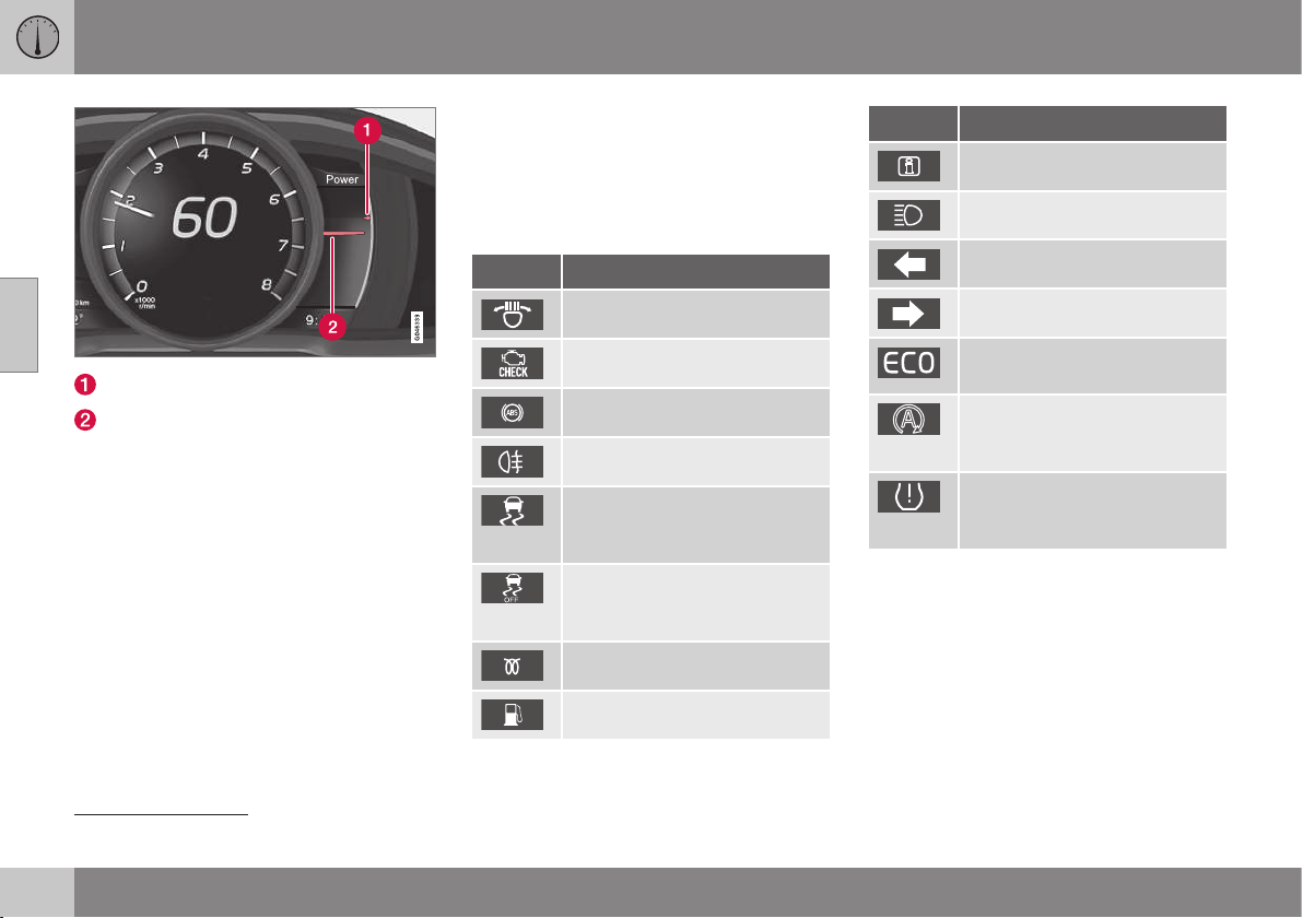
||
03 Instruments and controls
03
66
* Option/accessory, for more information, see Introduction.
Available engine power
Engine power utilised
Available engine power
The smaller, upper pointer shows the availa-
ble engine power
9
. The higher the reading on
the scale, the more power is available in the
current gear.
Engine power utilised
The larger, lower pointer shows the engine
power utilised
9
. The higher the reading on the
scale, the more power is being taken from the
engine.
A large gap between the two pointers indi-
cates a large power reserve.
Combined instrument panel -
meaning of indicator symbols
The indicator symbols alert the driver that a
function is activated, that the system is oper-
ating, or that an error or failure has occurred.
Indicator symbols
Symbol Specification
ABL fault
Emissions system
ABS fault
Rear fog lamp on
Stability system, see Electronic
stability control (ESC) - general
(p. 184)
Stability system, sport mode,
see Electronic stability control
(ESC) - operation (p. 185)
Engine preheater (diesel)
Low level in fuel tank
Symbol Specification
Information, read display text
Main beam On
Left-hand direction indicator
Right-hand direction indicator
Eco- function on, see ECO*
(p. 293)
Start/Stop, the engine auto-
stopped; see Start/Stop* -
function and operation (p. 285)
Tyre pressure system , see
Tyre pressure monitoring*
(p. 335)
ABL fault
The symbol illuminates if a fault has arisen in
the ABL function (Active Bending Lights).
Emissions system
If the symbol illuminates after the engine has
been started then it may be due to a fault in
the car's emissions system. Drive to a work-
shop for checking. Volvo recommends that
you seek assistance from an authorised Volvo
workshop.
9
Power is dependent on engine speed.
03 Instruments and controls
03
}}
67
ABS fault
If this symbol illuminates then the system is
not working. The car's regular brake system
continues to work, but without the ABS func-
tion.
1. Stop the car in a safe place and turn off
the engine.
2. Restart the engine.
3. If the symbol remains illuminated, drive to
a workshop to have the ABS system
checked. Volvo recommends that you
seek assistance from an authorised Volvo
workshop.
Rear fog lamp on
This symbol illuminates when the rear fog
lamp is switched on.
Stability system
A flashing symbol indicates that the stability
system is operating. If the symbol illuminates
with constant glow then there is a fault in the
system.
Stability system, sport mode
Sport mode allows for a more active driving
experience. The system then detects whether
the accelerator pedal, steering wheel move-
ments and cornering are more active than in
normal driving and then allows controlled
skidding of the rear section up to a certain
level before it intervenes and stabilises the
car. The symbol illuminates when the sport
mode is activated.
Engine preheater (diesel)
This symbol illuminates during engine pre-
heating. Preheating takes place mostly due to
low temperature.
Low level in fuel tank
When the symbol illuminates the level in the
fuel tank is low, refuel as soon as possible.
Information, read display text
When one of the car's systems does not
behave as intended, this information symbol
illuminates and a text appears on the informa-
tion display. The message text is cleared with
the OK button, see Menu navigation - com-
bined instrument panel (p. 105), or it disap-
pears automatically after a time (time
depending on which function is indicated).
The information symbol can also illuminate in
conjunction with other symbols.
NOTE
When a service message is shown, the
symbol and message are cleared using the
OK button, or disappear automatically
after a time.
Main beam On
The symbol illuminates when main beam is on
and with main beam flash.
Left/right-hand direction indicator
Both direction indicator symbols flash when
the hazard warning flashers are used.
Eco function on
This symbol illuminates when the Eco func-
tion is activated.
Start/Stop
The symbol shines when the engine is auto-
stopped.
Tyre pressure system
The symbol illuminates in the event of low
tyre pressure, or if a fault arises in the tyre
pressure system.
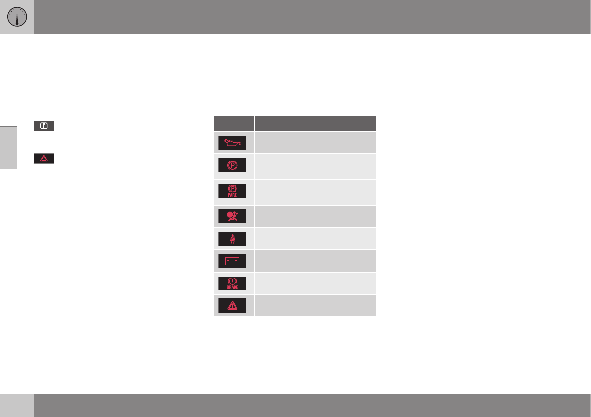
||
03 Instruments and controls
03
68
* Option/accessory, for more information, see Introduction.
Reminder – doors not closed
If one of the doors is not closed properly then
the information or warning symbol illuminates
together with an explanatory image in the
information display. Stop the car in a safe
place as soon as possible and close the door
that is open.
If the car is driven at a speed lower
than approx. 7 km/h then the informa-
tion symbol illuminates.
If the car is driven at a speed higher
than approx. 7 km/h then the warning
symbol illuminates.
If the bonnet
10
is not closed properly then the
warning symbol illuminates together with an
explanatory image in the information display.
Stop the car in a safe place as soon as possi-
ble and close the bonnet.
If the boot lid is not closed properly then the
information symbol illuminates together with
an explanatory image in the information dis-
play. Stop the car in a safe place as soon as
possible and close the boot lid.
Related information
•
Combined instrument panel (p. 61)
•
Combined instrument cluster - meaning
of warning symbols (p. 68)
•
Digital combined instrument panel - over-
view (p. 62)
Combined instrument cluster -
meaning of warning symbols
The warning symbols alert the driver that an
important function is activated, or that a seri-
ous error or a serious failure has occurred.
Warning symbols
Symbol Specification
Low oil pressure
A
Parking brake applied, digital
instrument panel
Parking brake applied, ana-
logue instrument panel
Airbags – SRS
Seatbelt reminder
Alternator not charging
Fault in brake system
Warning
A
Certain engine variants do not have systems to warn of oil
pressure loss. In cars with these variants the symbol for
low oil pressure is not used. Warning for low oil level is via
display text. For more information, see Engine oil - general
(p. 362).
Low oil pressure
If this symbol illuminates during driving then
the engine's oil pressure is too low. Stop the
engine immediately and check the engine oil
level, top up if necessary. If the symbol illumi-
nates and the oil level is normal, contact a
workshop. Volvo recommends that you seek
assistance from an authorised Volvo work-
shop.
Parking brake applied
This symbol illuminates with a constant glow
when the parking brake is applied. The sym-
bol flashes during application, and then
changes over to a constant glow.
A flashing symbol in any other situation
means that a fault has arisen. Read the mes-
sage on the information display.
For more information, see Parking brake
(p. 298).
Airbags – SRS
If this symbol remains illuminated or illumi-
nates while driving, it means a fault has been
detected in the seatbelt buckle, SRS, SIPS, or
IC systems. Drive immediately to a workshop
to have the system checked. Volvo recom-
mends that you seek assistance from an
authorised Volvo workshop.
Seatbelt reminder
This symbol flashes if someone in a front seat
has not put on their seatbelt or if someone in
a rear seat has taken off their seatbelt.
10
Only cars with alarm*.
03 Instruments and controls
03
}}
* Option/accessory, for more information, see Introduction.
69
Alternator not charging
This symbol illuminates during driving if a
fault has occurred in the electrical system.
Visit a workshop. Volvo recommends that you
seek assistance from an authorised Volvo
workshop.
Fault in brake system
If this symbol illuminates, the brake fluid level
may be too low. Stop the car in a safe place
and check the level in the brake fluid reser-
voir; see Brake and clutch fluid - level
(p. 368).
If the brake and ABS symbols illuminate at
the same time, there may be a fault in the
brake force distribution system.
1. Stop the car in a safe place and turn off
the engine.
2. Restart the engine.
•
If both symbols extinguish, continue
driving.
•
If the symbols remain illuminated,
check the level in the brake fluid reser-
voir; see Brake and clutch fluid - level
(p. 368). If the brake fluid level is nor-
mal but the symbols are still illumi-
nated, the car can be driven, with great
care, to a workshop to have the brake
system checked. Volvo recommends
that you seek assistance from an
authorised Volvo workshop.
WARNING
If the brake fluid is under the MIN level in
the brake fluid reservoir, do not drive fur-
ther before topping up the brake fluid.
The loss of brake fluid must be investiga-
ted by a workshop. Volvo recommends
that you contact an authorised Volvo
workshop.
WARNING
If the BRAKE and ABS symbols are lit at
the same time, there is a risk that the rear
end will skid during heavy braking.
Warning
The red warning symbol illuminates when a
fault has been indicated which could affect
the safety and/or driveability of the car. An
explanatory text is shown on the information
display at the same time. The symbol remains
visible until the fault has been rectified but the
text message can be cleared with the OK
button; see Menu navigation - combined
instrument panel (p. 105). The warning sym-
bol can also illuminate in conjunction with
other symbols.
Action:
1. Stop in a safe place. Do not drive the car
further.
2. Read the information on the information
display. Implement the action in accord-
ance with the message in the display.
Clear the message using the OK button.
Reminder – doors not closed
If one of the doors is not closed properly then
the information or warning symbol illuminates
together with an explanatory image in the
information display. Stop the car in a safe
place as soon as possible and close the door
that is open.
If the car is driven at a speed lower
than approx. 7 km/h then the informa-
tion symbol illuminates.
If the car is driven at a speed higher
than approx. 7 km/h then the warning
symbol illuminates.
If the bonnet
11
is not closed properly then the
warning symbol illuminates together with an
explanatory image in the information display.
Stop the car in a safe place as soon as possi-
ble and close the bonnet.
If the boot lid is not closed properly then the
information symbol illuminates together with
an explanatory image in the information dis-
play. Stop the car in a safe place as soon as
possible and close the boot lid.
11
Only cars with alarm*.
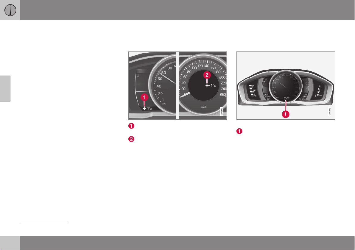
||
03 Instruments and controls
03
70
Related information
•
Combined instrument panel (p. 61)
•
Combined instrument panel - meaning of
indicator symbols (p. 66)
•
Digital combined instrument panel - over-
view (p. 62)
Outside temperature gauge
The display for the outside temperature gauge
appears in the combined instrument panel.
Display for outside temperature gauge,
digital instrument panel
Display for outside temperature gauge,
analogue instrument panel
When the temperature lies between +2 °C to
-5 °C a snowflake symbol illuminates in the
display. This warns of icy roads. If the car has
been stationary, the gauge may display a
reading that is too high.
Related information
•
Combined instrument panel (p. 61)
Trip meter
The trip meter display appears in the com-
bined instrument panel.
Trip meter, digital instrument panel.
Display for trip meter
12
Both trip meters
T1 and T2 are used to meas-
ure short distances. The distance is shown in
the display.
Turn the left-hand stalk switch's thumbwheel
to show the required meter.
A long press (until the change occurs) on the
left-hand stalk switch RESET button resets
the trip meter shown. For more information,
see Trip computer - supplementary informa-
tion (p. 119).
Related information
•
Combined instrument panel (p. 61)
12
Display appearance may differ depending on instrument variant.
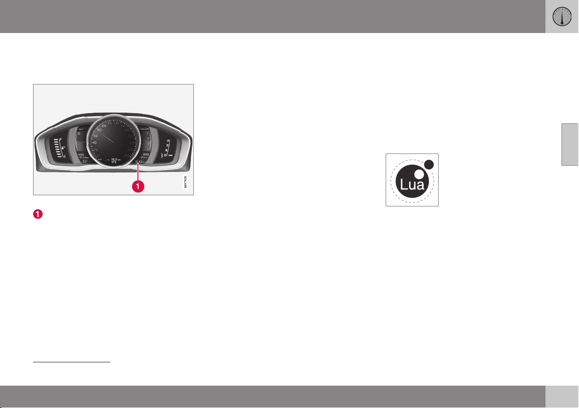
03 Instruments and controls
03
}}
71
Clock
The clock display appears in the combined
instrument panel.
Clock, digital instrument panel.
Display for showing the time
13
Setting the clock
The clock can be adjusted in the menu sys-
tem MY CAR, see MY CAR (p. 108).
Related information
•
Combined instrument panel (p. 61)
Combined instrument panel - license
agreement
A license is an agreement for the right to
operate a certain activity or the right to use
someone else's entitlement according to the
terms and conditions in the agreement. The
following text is Volvo's agreement with the
manufacturer/developer.
Combined Instrument Panel Software
Open Source Software Notice
This product uses certain free / open source
and other software originating from third
parties, that is subject to the GNU Lesser
General Public License version 2 (LGPLv2),
The FreeType Project License ("FreeType
License") and other different and/or additional
copy right licenses, disclaimers and notices.
The links to access the exact terms of
LGPLv2, and the other open source software
licenses, disclaimers, acknowledgements and
notices are provided to you below. Please
refer to the exact terms of the relevant
License, regarding your rights under said
licenses. Volvo Car Corporation (VCC) offers
to provide the source code of said free/open
source software to you for a charge covering
the cost of performing such distribution, such
as the cost of media, shipping and handling,
upon written request. Please contact your
nearest Volvo Dealer.
The offer is valid for a period of at least three
(3) years from the date of the distribution of
this product by VCC / or for as long as VCC
offers spare parts or customer support.
Portions of this product uses software
copyrighted © 2007 The FreeType Project
(www.freetype.org). All rights reserved.
Portions of this product uses software with
Copyright © 1994–2013 Lua.org, PUC-Rio
(http://www.lua.org/)
This product includes software under
following licenses:
LGPL v2.1: http://www.gnu.org/licenses/old-
licenses/lgpl-2.1.html
•
GNU FriBidi
•
DevIL
The FreeType Project License: http://
git.savannah.gnu.org/cgit/freetype/
freetype2.git/tree/docs/FTL.TXT
•
FreeType 2
13
The time is shown in the centre of an analogue instrument panel.
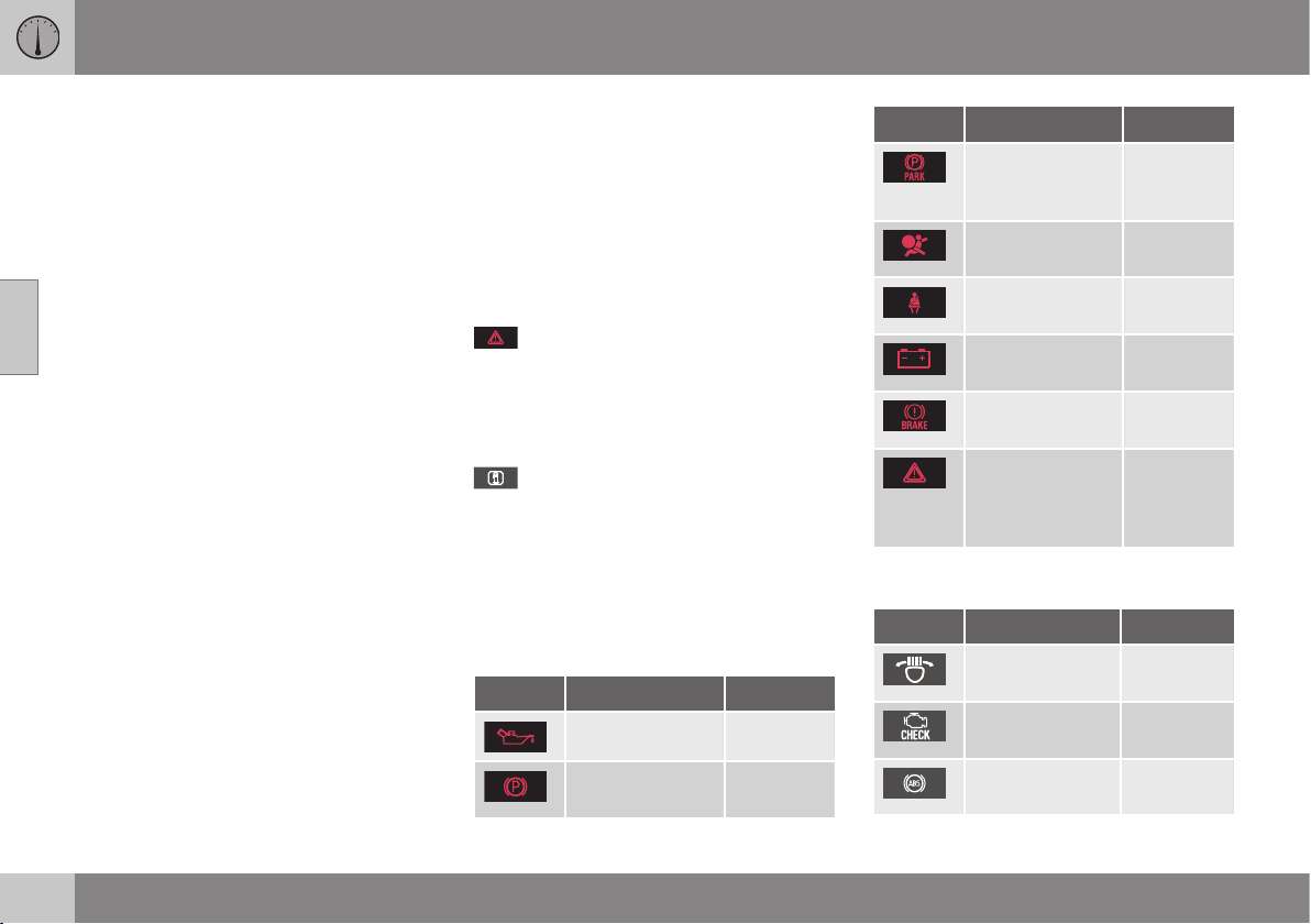
03 Instruments and controls
03
72
* Option/accessory, for more information, see Introduction.
MIT License: http://opensource.org/licenses/
mit-license.html
•
Lua
Symbols in the display
There are a variety of different symbols in the
display in the car. The symbols are divided
into warning, indicator and information sym-
bols.
Shown below are the most common symbols
with their meanings and a reference to where
in the manual further information can be
found.
- Red warning symbol, illuminates
when a fault has been indicated which could
affect the safety and/or driveability of the car.
An explanatory text is shown in the informa-
tion display in the combined instrument panel
at the same time.
- Information symbol, illuminates in
combination with text in the information dis-
play in the combined instrument panel, when
a deviation in any of the car's systems has
occurred. The information symbol can also
illuminate in conjunction with other symbols.
Warning symbols in the combined
instrument panel
Symbol Specification See
Low oil pressure (p. 68)
Parking brake
applied
(p. 68),
(p. 298)
Symbol Specification See
Parking brake
applied, alterna-
tive symbol
(p. 68)
Airbags – SRS (p. 30),
(p. 68)
Seatbelt
reminder
(p. 26),
(p. 68)
Alternator not
charging
(p. 68)
Fault in brake
system
(p. 68),
(p. 295)
Warning, safety
mode
(p. 30),
(p. 40),
(p. 68),
(p. 279)
Control symbols in the combined
instrument panel
Symbol Specification See
ABL fault* (p. 66),
(p. 91)
Emissions sys-
tem
(p. 66)
ABS fault (p. 66),
(p. 295)
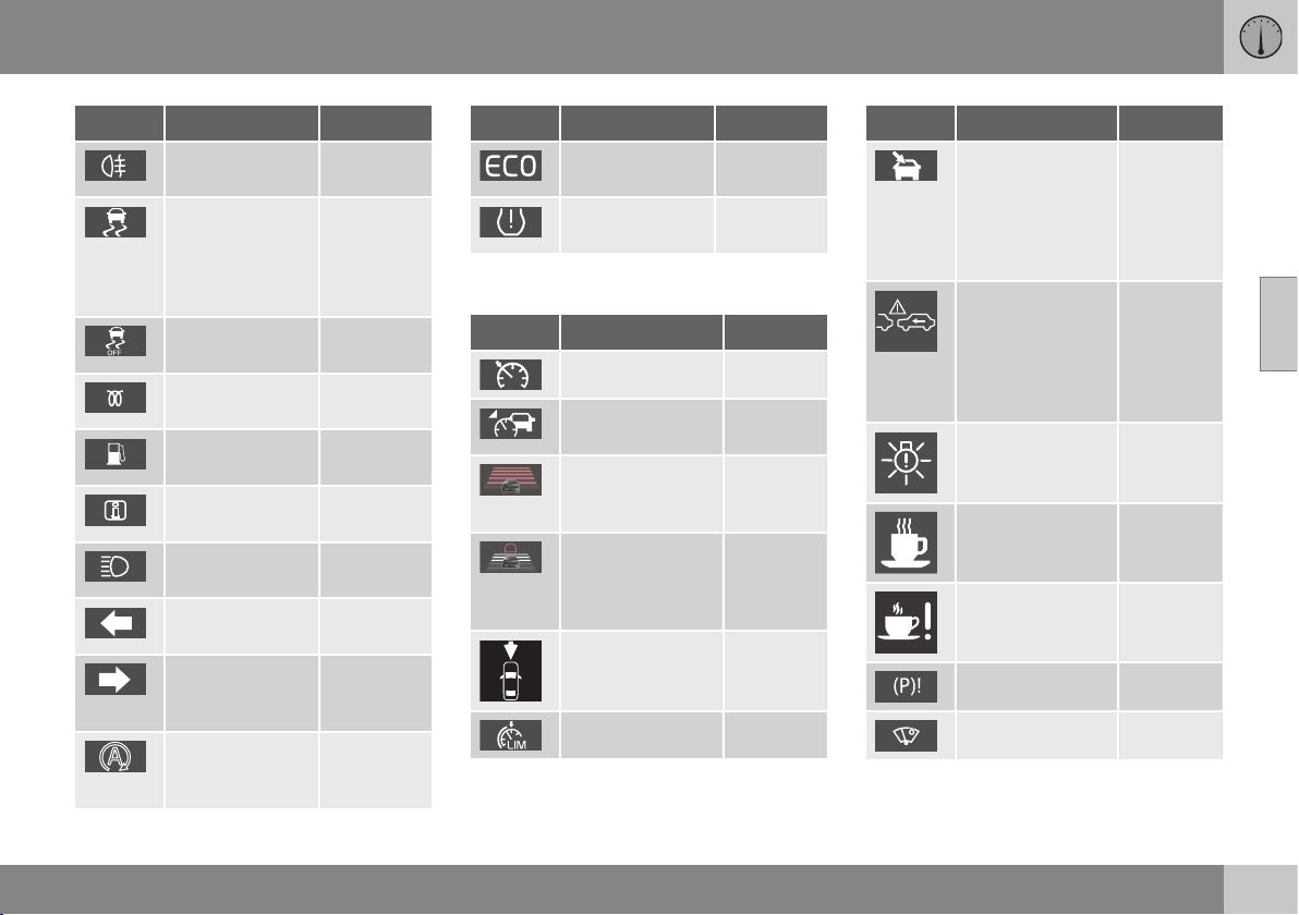
03 Instruments and controls
03
}}
* Option/accessory, for more information, see Introduction.
73
Symbol Specification See
Rear fog lamp on (p. 66),
(p. 92)
Stability system,
ESC (Electronic
Stability Control),
Trailer stability
assist
(p. 66),
(p. 186),
(p. 317)
Stability system,
sport mode
(p. 66),
(p. 186)
Engine preheater
(diesel)
(p. 66)
Low level in fuel
tank
(p. 66),
(p. 140)
Information, read
display text
(p. 66)
Main beam On (p. 66),
(p. 87)
Left-hand direc-
tion indicators
(p. 66)
Right-hand
direction indica-
tors
(p. 66)
Start/Stop*,
engine auto-
stopped
(p. 66),
(p. 291)
Symbol Specification See
ECO function*
on
(p. 66),
(p. 293)
Tyre pressure
system*
(p. 66),
(p. 335)
Information symbols in the combined
instrument panel
Symbol Specification See
Cruise control* (p. 194)
Adaptive cruise
control*
(p. 210)
Adaptive cruise
control*, time
interval
(p. 197),
(p. 200)
Adaptive cruise
control*, Distance
Warning* (Dis-
tance Alert)
(p. 202),
(p. 212)
Radar sensor* (p. 210),
(p. 214),
(p. 230)
Speed limiter (p. 191)
Symbol Specification See
Windscreen sen-
sor*, Camera sen-
sor*, Laser sen-
sor*
(p. 88),
(p. 221),
(p. 230),
(p. 234),
(p. 238),
(p. 243)
Auto Brake*, Dis-
tance Warning*
(Distance Alert),
City Safety
TM
,
Collision warning
system*
(p. 214),
(p. 221),
(p. 230)
ABL system* (p. 91)
Driver Alert Sys-
tem*, Time for a
break
(p. 233)
Driver Alert Sys-
tem*, Time for a
break
(p. 234)
Parking brake (p. 298)
Rain sensor* (p. 96)
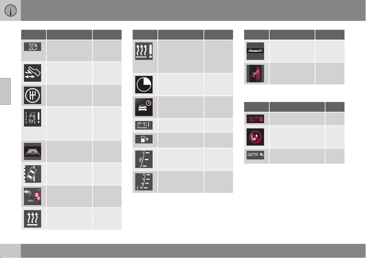
||
03 Instruments and controls
03
74
* Option/accessory, for more information, see Introduction.
Symbol Specification See
Active high beam,
AHB (Active High
Beam)*
(p. 88)
Start/Stop* (p. 291)
Start/Stop* (p. 291)
Driver Alert Sys-
tem*, Lane Depar-
ture Warning
(LDW), Lane
Keeping Aid (LKA)
(p. 234),
(p. 238),
(p. 243)
Driver Alert Sys-
tem*, Lane Depar-
ture Warning*
(p. 237)
Driver Alert Sys-
tem*, Lane Depar-
ture Warning*
(p. 238),
(p. 243)
Recorded speed
information*
(p. 188)
Engine block and
passenger com-
partment heater*
(p. 140)
Symbol Specification See
Engine block
heater and pas-
senger compart-
ment heater*
Service required
(p. 140)
Activated timer* (p. 140)
Activated timer* (p. 140)
Low battery (p. 140)
Fuel filler flap,
right-hand side
(p. 305)
Gear shift indica-
tor
(p. 275)
Gear positions (p. 276)
Symbol Specification See
Measuring the oil
level
(p. 363)
Park Assist Pilot -
PAP*
(p. 251)
Information symbols in the roof console
display
Symbol Specification See
Seatbelt reminder (p. 29)
Airbag, passenger
seat, activated
(p. 33)
Airbag, passenger
seat, deactivated
(p. 33)
Related information
•
Combined instrument panel - meaning of
indicator symbols (p. 66)
•
Combined instrument cluster - meaning
of warning symbols (p. 68)
•
Messages - handling (p. 108)
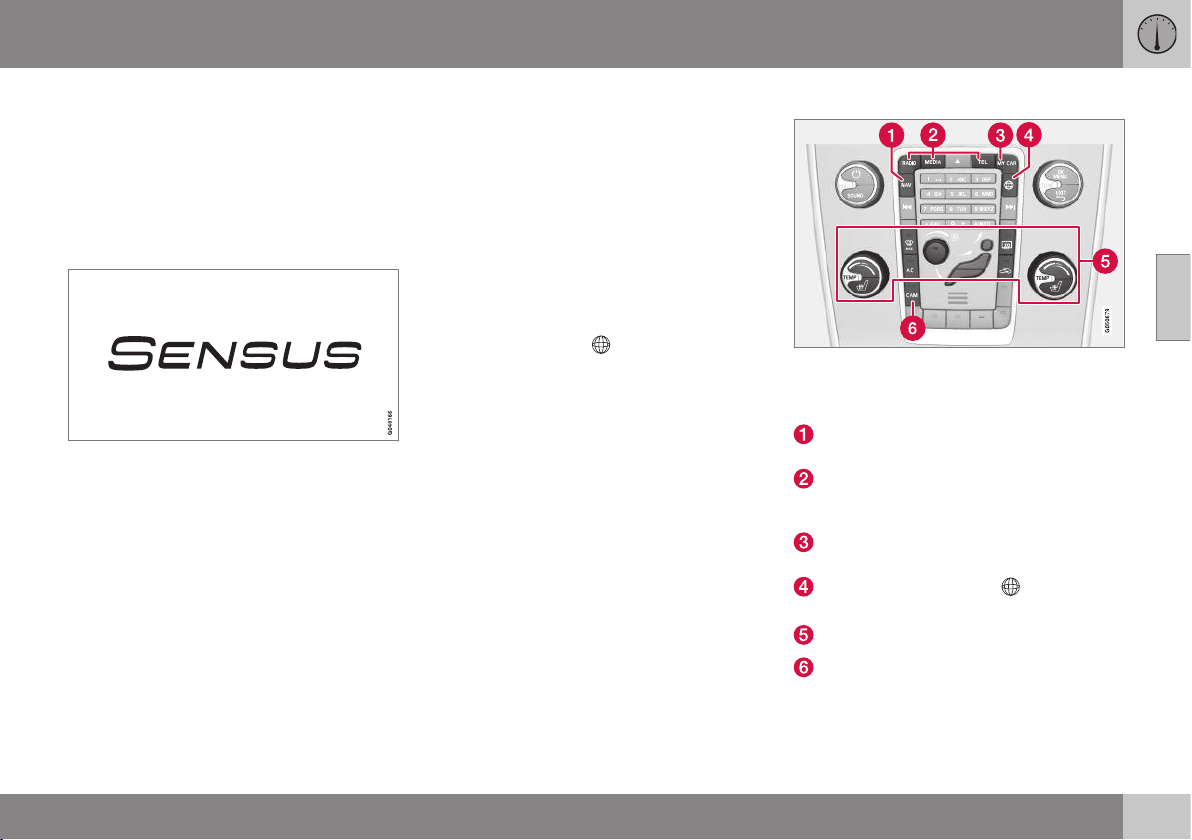
03 Instruments and controls
03
* Option/accessory, for more information, see Introduction.
75
Volvo Sensus
Volvo Sensus is the heart of the personal
Volvo experience and connects you with the
car and outside world. Sensus provides infor-
mation, entertainment and assistance when it
is needed. Sensus consists of intuitive func-
tions that both enhance the car journey and
simplifies ownership of the car.
An intuitive navigation structure makes it pos-
sible to receive relevant support, information
and entertainment when it is necessary, with-
out distracting the driver.
Sensus covers all the car's solutions that
enable connection* to the outside world and
provides you with intuitive control over all the
car's capabilities.
Volvo Sensus combines and presents many
functions in several of the car's systems on
the centre console's display screen. With
Volvo Sensus the car can be personalised by
means of an intuitive user interface. Settings
can be made in Car settings, Audio and
media, Climate control, etc.
With the centre console buttons and controls
or the steering wheel's right-hand keypad*
functions can be activated or deactivated and
many different settings can be made.
With a press on MY CAR all settings related
to the driving and control of the car are pre-
sented, such as City Safety, locks and alarm,
automatic fan speed, setting the clock, etc.
With a press on the respective function
RADIO, MEDIA, TEL,
*, NAV* and CAM*
other sources, systems and functions can be
activated, e.g. AM, FM, CD, DVD*, TV*,
Bluetooth
®
*, navigation* and park assist cam-
era*.
For more information about all functions/
systems, see the relevant section in the
owner's manual or its supplement.
Overview
Control panel in centre console. The figure is
schematic - the number of functions and layout
of the buttons both vary, depending on the
equipment selected and the market.
Navigation* - NAV, see separate supple-
ment (Sensus Navigation).
Audio and media - RADIO, MEDIA, TEL*,
see separate supplement (Sensus Info-
tainment).
Function settings - MY CAR, see MY
CAR (p. 108).
Internet-connected car - *, see sepa-
rate supplement (Sensus Infotainment).
Climate control system (p. 122).
Park assist camera* (p. 248) – CAM*.
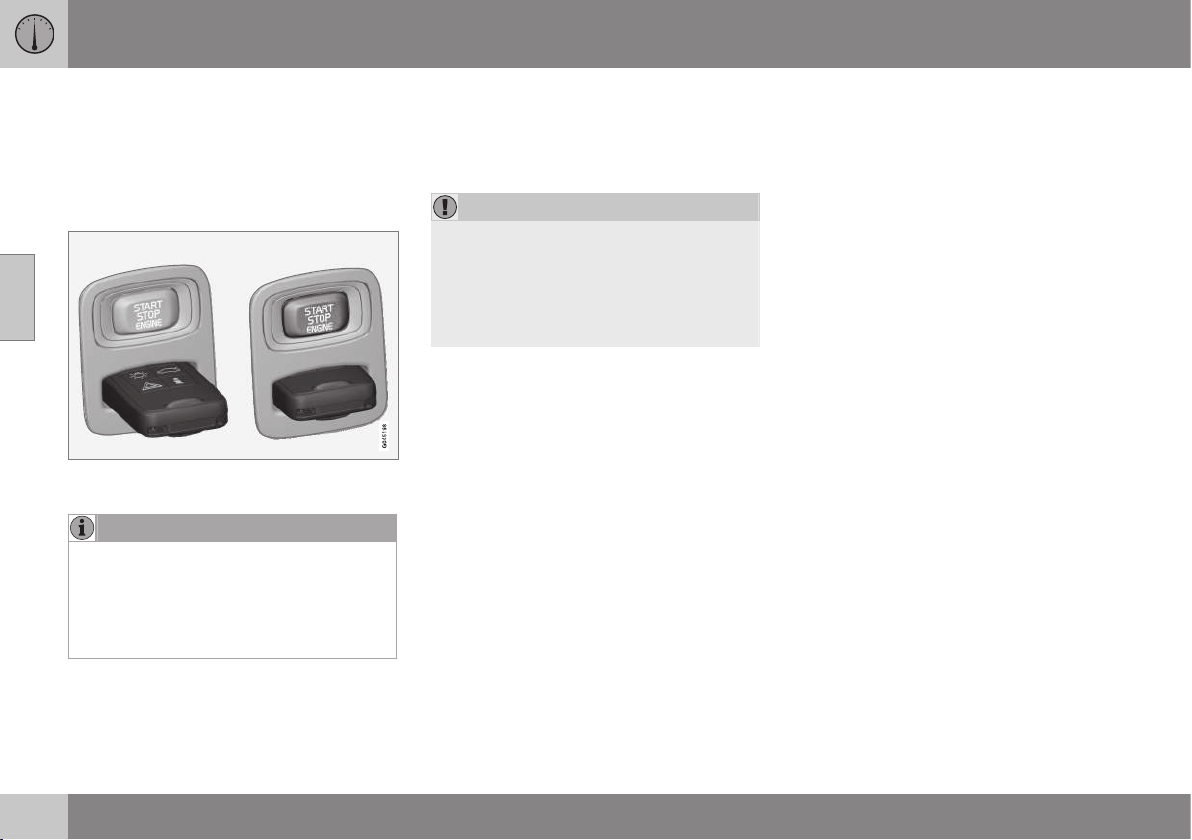
03 Instruments and controls
03
76
* Option/accessory, for more information, see Introduction.
Key positions
The remote control key can be used to set the
vehicle's electrical system in different modes/
levels so that different functions are available;
see Key positions - functions at different lev-
els (p. 76).
Ignition switch with remote control key extrac-
ted/inserted.
NOTE
For cars with the Keyless* function the
remote control key does not need to be
inserted into the ignition switch but can be
stored in e.g. a pocket. For more informa-
tion on Keyless functions, see Keyless
drive* (p. 166).
Insert the remote control key
1. Hold the end of the remote control key
with the detachable key blade and insert
the remote control key in the ignition
switch.
2. Then press the remote control key in the
lock up to its end position.
IMPORTANT
Foreign objects in the ignition switch can
impair the function or destroy the lock.
Do not press in the remote control key
incorrectly turned - hold the end with the
detachable key blade, see Detachable key
blade - detaching/attaching (p. 163).
Remove the remote control key
Push the remote control key, allow it to eject,
then pull it out from the ignition switch.
Key positions - functions at different
levels
To enable the use of a limited number of
functions with the engine switched off, the
car's electrical system can be set in 3 differ-
ent levels - 0, I and II - with the remote con-
trol key. This owner's manual describes these
levels throughout using the denomination
"key positions".
The following table shows the functions avail-
able in each key position/level.
03 Instruments and controls
03
* Option/accessory, for more information, see Introduction.
77
Level Functions
0
•
Odometer, clock and tem-
perature gauge are illumi-
nated.
•
Electrically operated seats
can be adjusted.
•
The audio system can be
used for a limited time - see
the Sensus Infotainment sup-
plement.
I
•
Sunroof, power windows, 12
V socket in the passenger
compartment, navigation,
phone, ventilation fan and
windscreen wipers can be
used.
Level Functions
II
•
The headlamps come on.
•
Warning/indicator lamps illu-
minate for 5 seconds.
•
Several other systems are
activated. However, electric
heating in seat cushions and
the rear window can only be
activated after starting the
engine.
This key position consumes a
lot of current from the starter
battery and should therefore be
avoided!
Selecting key position/level
•
Key position 0 - Unlock the car - This
means that the car's electrical system is
at level 0.
NOTE
To reach level I or II without starting the
engine - do not depress the brake/clutch
pedal when these key positions are due to
be selected.
•
Key position I - With the remote control
key fully inserted into the ignition switch
14
- Briefly press START/STOP ENGINE.
•
Key position II - With the remote control
key fully inserted into the ignition switch
14
- Give a long
15
press on START/STOP
ENGINE.
•
Back to key position 0 - To return to key
position 0 from position II and I - Briefly
press on START/STOP ENGINE.
Audio system
For information on audio system functions
with remote control key removed, see the
Sensus Infotainment supplement.
Starting and stopping the engine
For information about starting/stopping the
engine, see Starting the engine (p. 268).
Towing
For important information about the remote
control key during towing, see Towing
(p. 318).
Related information
•
Key positions (p. 76)
14
Not required for cars with the Keyless* function.
15
Approx. 2 seconds.
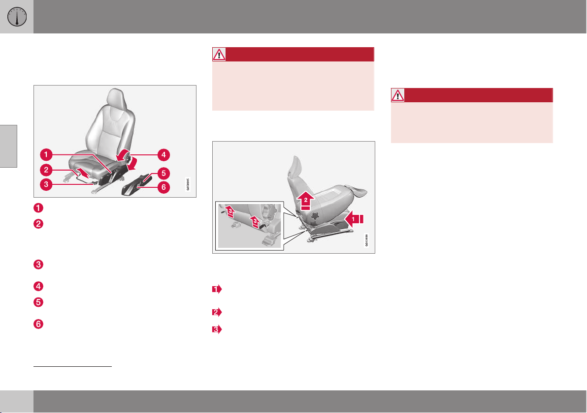
03 Instruments and controls
03
78
* Option/accessory, for more information, see Introduction.
Seats, front
The car's front seats have different setting
options for optimum seating comfort.
Raise/lower the seat, pump up/down.
Forward/backward: lift the handle to
adjust the distance to the steering wheel
and pedals. Check that the seat is locked
after changing position.
Raise/lower* front edge of seat cushion,
pump up/down.
Adjust backrest rake, turn the wheel.
Change the lumbar support*, press the
button.
Control panel for power seat*, see Seats,
front - electrically operated* (p. 79).
WARNING
Adjust the position of the driver's seat
before setting off, never while driving.
Make sure that the seat is in locked posi-
tion in order to avoid personal injury in the
event of heavy braking or an accident.
Lowering the passenger seat
backrest*
16
The passenger seat's backrest can be folded
forward to make room for long loads.
Move the seat as far back/down as possi-
ble.
Adjust the backrest to an upright position.
Lift the catches on the rear of the back-
rest and fold it forward.
4. Push the seat forward so that the head
restraint "locks" in under the glovebox.
Raising takes place in reverse order.
WARNING
Grasp the backrest and make sure that it
is properly locked after being folded up in
order to avoid personal injury in the event
of sudden braking or an accident.
Related information
•
Seats, front - electrically operated*
(p. 79)
•
Seats, rear (p. 80)
16
Only applies to comfort seats.
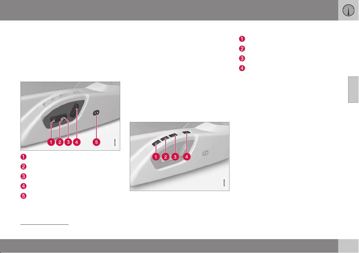
03 Instruments and controls
03
}}
* Option/accessory, for more information, see Introduction.
79
Seats, front - electrically operated*
The car's front seats have different setting
options for optimum seating comfort. The
power seat can be moved forward/backward
and up/down. The front edge of the seat
cushion can be raised/lowered. The backrest
angle and lumbar support* can be changed.
Power seat
Front edge of seat cushion up/down
Raise/lower seat
Seat, forward/backward
Backrest rake
Lumbar support* is adjusted inward and
outward
The power seats have overload protection
which is tripped if a seat is blocked by an
object. If this should happen, set the car's
electrical system in key position I or 0 and
wait a short time before adjusting the seat
again.
Only one movement (forward/back/up/down/
inward/outward) can be made at a time.
Preparations
The seat can be adjusted for a certain time
after unlocking the door with the remote con-
trol key without the key in the ignition switch.
Seat adjustment is normally made in key
position I and can always be made when the
engine is running.
Seat with memory function*
The memory function stores settings for the
seat and the door mirrors.
Store setting
Memory button
Memory button
Memory button
Button for storing settings
1. Adjust the seat and the door mirrors.
2. Press and hold button M while pressing
button 1, 2 or 3 simultaneously. Hold the
buttons depressed until the acoustic sig-
nal is heard and text is shown in the com-
bined instrument panel.
The seat must be adjusted again before a
new memory can be set.
The setting for lumbar support is not stored.
Using a stored setting
Press one of the memory buttons 1-3 until the
seat and the door mirrors stop. If the button
is released, the movement of the seat and
door mirrors will be interrupted.
Key memory* in remote control key
All remote control keys can be used by differ-
ent drivers to store the settings for the driv-
er's seat and door mirrors
17
, see Remote
control key - personalisation* (p. 156).
17
Only if the car is equipped with power seat with memory and retractable power rearview and door mirrors. The setting for lumbar support is not stored.
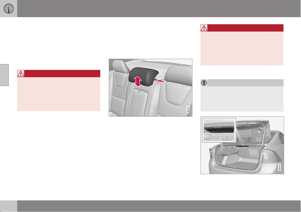
||
03 Instruments and controls
03
80
* Option/accessory, for more information, see Introduction.
Emergency stop
If the seat accidentally begins to move, press
one of the setting buttons for the seat or
memory buttons in order to stop the seat.
Restarting to reach the seat position stored in
the key memory is performed by pressing the
unlock button on the remote control key. The
driver's door must then be open.
WARNING
Risk of crushing! Make sure that children
do not play with the controls. Check that
there are no objects in front of, behind or
under the seat during adjustment. Make
sure that none of the passengers in the
rear seat is in danger of becoming trap-
ped.
Heated seats
For heated seats, see Heated front seats*
(p. 129) and Heated rear seat* (p. 129).
Related information
•
Seats, front (p. 78)
•
Seats, rear (p. 80)
Seats, rear
The rear seat backrest and the outer seat
head restraints can be folded. The centre seat
head restraint can be adjusted to suit the
height of the passenger.
Head restraint, centre seat, rear
Adjust the head restraint according to pas-
senger height so that the whole of the back of
the head is covered if possible. Slide it up as
required.
To lower the head restraint again, the button
by the left-hand shaft must be pressed in
while the head restraint is pressed down
carefully.
WARNING
The centre seat head restraint must be in
its lowest position when the centre seat is
not used. When the centre seat is used,
the head restraint must be correctly
adjusted to the height of the passenger so
that it covers the whole of the back of the
head if possible.
Lowering the rear seat backrest
IMPORTANT
There must be no objects on the rear seat
when the backrest is to be folded down.
The seat belts must not be connected
either. Otherwise there is a risk of damag-
ing the rear seat upholstery.
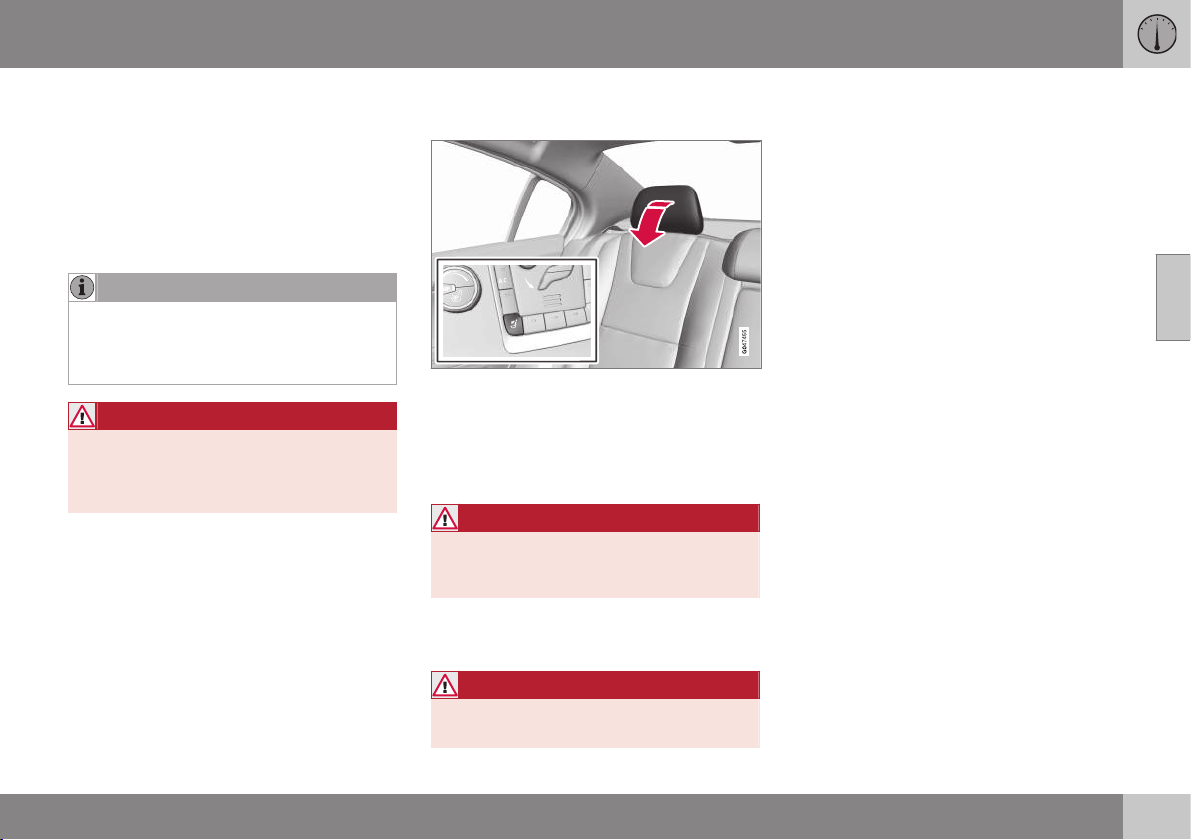
03 Instruments and controls
03
* Option/accessory, for more information, see Introduction.
81
The backrest is in two parts. The parts can be
folded forward, together or separately.
1. Pull on the required handle. They are
located just inside the hatch opening.
2. Fold the backrest forward.
Lower the centre head restraint fully if the
backrest's wide section shall be lowered.
NOTE
When the backrests have been lowered
the head restraints must be moved for-
ward slightly so as not to make contact
with the seat cushion.
WARNING
Check that the backrests and head
restraints are securely locked after raising
to avoid personal injury in the event of
sudden braking or an accident.
Electrical lowering of the rear seat's
outer head restraints*
1. The remote control key must be in key
position II.
2. Press the button to lower the rear outer
head restraints to improve rearward visi-
bility.
WARNING
Do not lower the outer head restraints if
there are passengers in any of the outer
seats.
Move the head restraint back manually until a
click is heard.
WARNING
The head restraints must be in locked
position after being raised.
Related information
•
Seats, front (p. 78)
•
Seats, front - electrically operated* (p. 79)
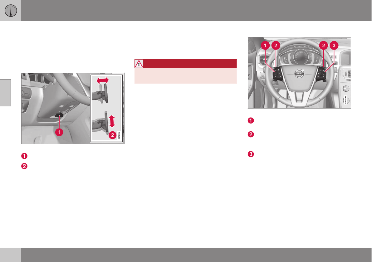
03 Instruments and controls
03
82
* Option/accessory, for more information, see Introduction.
Steering wheel
The steering wheel can be adjusted in differ-
ent positions and has controls for horn and
cruise control, as well as menu, audio and
phone control.
Adjusting
Adjusting the steering wheel.
Lever - releasing the steering wheel
Possible steering wheel positions
The steering wheel can be adjusted for both
height and depth:
1. The lever is pulled towards the driver to
release the steering wheel.
2. Adjust the steering wheel to the position
that suits you.
3. Push back the lever to fix the steering
wheel in place. If the lever is stiff, press
the steering wheel lightly at the same time
as you push the lever back.
WARNING
Adjust the steering wheel and fix it before
driving away.
With speed related power steering* the level
of steering force can be adjusted, see Adjust-
able steering force* (p. 183).
Keypads* and paddles*
Keypads and paddles in the steering wheel.
Cruise control* (p. 194)* and Adaptive
cruise control - ACC* (p. 197)*.
Paddle for manual gear changing in an
automatic gearbox, see Automatic gear-
box -- Geartronic* (p. 276).
Audio and phone control, see supple-
ment, Sensus Infotainment.
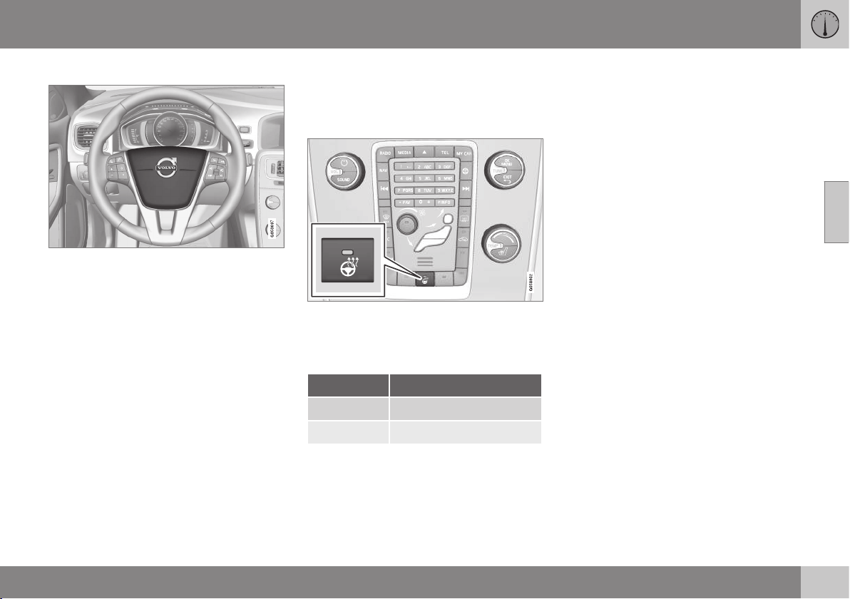
03 Instruments and controls
03
* Option/accessory, for more information, see Introduction.
83
Horn
Horn.
Press the centre of the steering wheel to sig-
nal.
Related information
•
Heating* of the steering wheel (p. 83)
Heating* of the steering wheel
The steering wheel can be heated with elec-
tric heating.
Function
Button position may vary depending on equip-
ment selected and market.
Repeatedly press the button to switch
between the following functions:
Function Indicator
Switched off Button lamp extinguished
Heating Button lamp illuminated
Automatic steering wheel heating
With activated automatic start of steering
wheel heating, the heating of the steering
wheel starts when the engine is started. Auto-
matic start takes place when the car is cold
and the ambient temperature is below
approx. 10 °C. Activate/deactivate the func-
tion in the menu system MY CAR (p. 108).
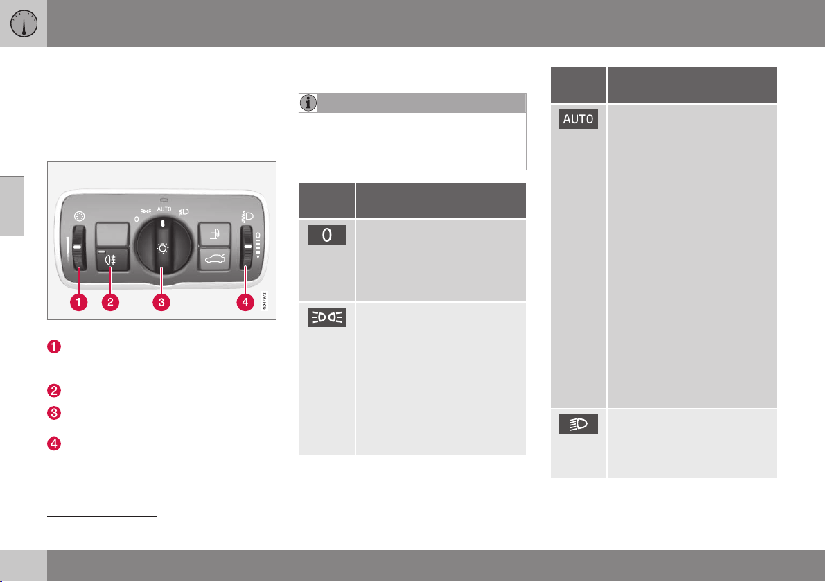
03 Instruments and controls
03
84
* Option/accessory, for more information, see Introduction.
Light switches
The headlamp control activates and adjusts
the external lighting. It is also used to adjust
display and instrument lighting and ambience
lights (p. 94).
Overview, light switches
Overview, light switches.
Thumbwheel for adjusting display and
instrument lighting as well as ambience
lights*
Button for rear fog lamp
Knob for daytime running lights and park-
ing lamps
Thumbwheel
18
for headlamp levelling
Knob positions
NOTE
The same lamps are used for daytime run-
ning lights and position/parking lamps
front. The brightness is higher when the
lamps are used as daytime running lights.
Posi-
tion
Specification
Daytime running lights
A
when
the car's electrical system is in
key position II or the engine is
running.
Main beam flash can be used.
Daytime running lights, posi-
tion/parking lamps rear and
side marker lamps when the
car's electrical system is in key
position II or the engine is run-
ning.
Position/parking lamps/side
marker lamps when the car is
parked.
Main beam flash can be used.
Posi-
tion
Specification
Daytime running lights, posi-
tion/parking lamps rear and
side marker lamps in daylight
when the car's electrical sys-
tem is in key position II or the
engine is running.
Dipped beam and position/
parking lamps/side marker
lamps in weak daylight or dark-
ness, or when the rear fog lamp
or windscreen wipers with con-
tinuous wiping are activated.
The tunnel detection (p. 87)*
function is activated.
The Active main beam (p. 88)*
function can be used.
Main beam can be activated
when dipped beam is switched
on.
Main beam flash can be used.
Dipped beam and position/
parking lamps/side marker
lamps.
Main beam can be activated.
18
Not available for cars equipped with active Xenon headlamps*.
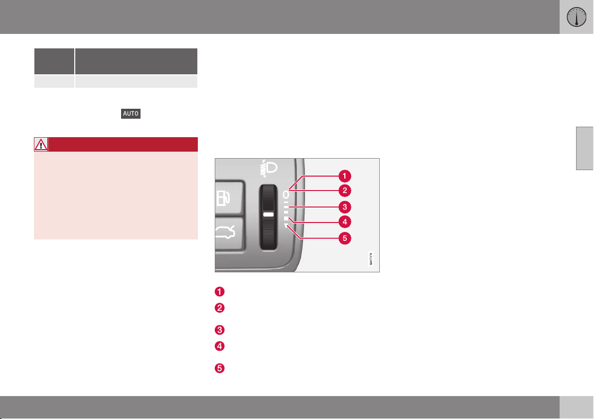
03 Instruments and controls
03
* Option/accessory, for more information, see Introduction.
85
Posi-
tion
Specification
Main beam flash can be used.
A
Fitted in or under the front bumper.
Volvo recommends that
mode is used
when the car is driven.
WARNING
The car's audio system is not able to
determine when daylight is too weak or
sufficiently strong, e.g. in fog and rain, in
all situations.
The driver is always responsible for ensur-
ing that the car is driven with a beam pat-
tern suitable for the traffic situation and in
accordance with applicable traffic regula-
tions.
Instrument lighting
Different display and instrument lighting is
switched on depending on key position; see
Key positions - functions at different levels
(p. 76).
The display lighting is automatically subdued
in darkness - the sensitivity is set with the
thumbwheel.
The intensity of the instrument lighting is
adjusted with the thumbwheel.
Headlamp levelling
The load in the car changes the vertical align-
ment of the headlamp beam, which could
dazzle oncoming motorists. Avoid this by
adjusting the height of the beam. Lower the
beam if the car is heavily laden.
1. Leave the engine running, or have the
car's electrical system in key position I.
2. Roll the thumbwheel up/down to raise/
lower beam alignment.
Thumbwheel positions for different load cases.
Only driver
Driver and passenger in the front passen-
ger seat
Occupants in all seats
Occupants in all seats and maximum load
in the cargo area
The driver and maximum load in the
cargo area
Cars with active Xenon headlamps* have
automatic headlamp levelling and are there-
fore not equipped with the thumbwheel.
Related information
•
Position/parking lamps (p. 86)
•
Daytime running lights (p. 86)
•
Main/dipped beam (p. 87)
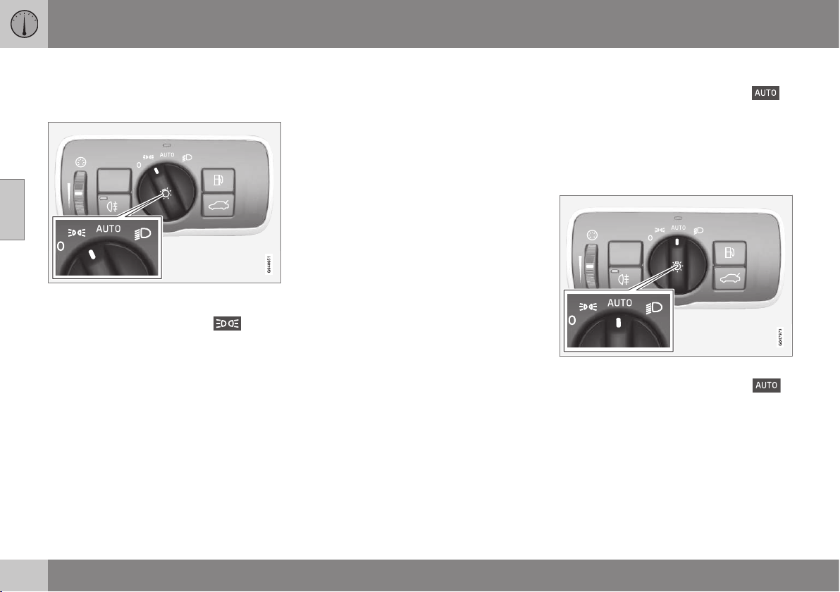
03 Instruments and controls
03
86
Position/parking lamps
Position/parking lamps are switched on with
the headlamp control's knob.
Knob for headlamp control in the position for
position/parking lamps.
Turn the knob to the position for
(num-
ber plate lighting is switched on at the same
time).
If the car's electrical system is in key position
II or the engine is running then the daytime
running lights switch on instead of the front
position/parking lamps.
When it is dark outside and the boot lid is
opened the rear position/parking lamps are
switched on in order to alert traffic behind.
This takes place irrespective of what position
the knob is in or what key position the car's
electrical system is in.
Related information
•
Light switches (p. 84)
Daytime running lights
With the knob for headlamp control in
position, and the car's electrical system in key
position II or the engine running, the daytime
running lights are activated automatically in
daylight.
Daytime running lights during the day.
DRL
Knob for headlamp control in AUTO position.
With the knob for headlamp control in
position the daytime running lights (Daytime
Running Lights - DRL) are activated automati-
cally when the car is driven in daylight. A light
sensor on the top of the instrument panel
changes from daytime running lights to
dipped beam at twilight or when daylight
becomes too weak. Switching to dipped
beam also takes place when the windscreen
wipers or rear fog lamps are activated.

03 Instruments and controls
03
}}
* Option/accessory, for more information, see Introduction.
87
WARNING
This system help to save energy - it cannot
determine in all situations when daylight is
too weak or sufficiently strong, e.g. in mist
and rain.
The driver is always responsible for ensur-
ing that the car is driven with the correct
beam pattern for the traffic situation and in
accordance with applicable traffic regula-
tions.
Tunnel detection*
Tunnel detection changes the lighting from
daytime running lights to dipped beam when
the car is driven into a tunnel. Approx. 20 sec-
onds after the car has left the tunnel, the light-
ing returns to daytime running lights.
The tunnel detection function is available in
cars with rain sensor*. The sensor detects the
entrance to a tunnel and resets the lighting
from daytime running lights to dipped beam.
Approx. 20 seconds after the car has left the
tunnel, the lighting returns to daytime running
lights. If the car is driven into another tunnel
within this time period then dipped beam is
kept switched on. This avoids repeated
changes to the car's lighting.
Note that the headlamp control's knob must
remain in
position for tunnel detection
to work.
Related information
•
Main/dipped beam (p. 87)
•
Light switches (p. 84)
Main/dipped beam
With the knob for headlamp control in posi-
tion
and the car's electrical system in
key position II or the engine running, the
dipped beam is activated automatically in
poor light conditions.
With the knob for headlamp control in posi-
tion
dipped beam is always switched on
when the engine is running or when key posi-
tion II is active.
Stalk switch and knob for headlamp control.
Position for main beam flash
Position for main beam
Dipped beam
With the knob in position, dipped beam
is activated automatically at twilight or when
daylight becomes too weak. Dipped beam is

||
03 Instruments and controls
03
88
* Option/accessory, for more information, see Introduction.
also activated automatically if the windscreen
wipers or rear fog lamps are activated.
With the knob in position
dipped beam
is always switched on when the engine is run-
ning or when key position II is active.
Main beam flash
Move the stalk switch gently towards the
steering wheel to the position for main beam
flash. Main beam comes on until the stalk
switch is released.
Main beam
Main beam can be activated when the knob
is in position
19
or
. Activate/deac-
tivate main beam by moving the stalk switch
towards the steering wheel to the end posi-
tion and then releasing. Alternatively, the
main beam can be deactivated by a light
press of the stalk switch toward the steering
wheel.
When main beam has been activated the
symbol illuminates in the combined
instrument panel.
Auxiliary lamps*
If the car has auxiliary lamps, the driver can
use the MY CAR menu system to choose
whether they should be deactivated or
switched on/off simultaneously with the main
beam
20
, see MY CAR (p. 108).
Related information
•
Active Xenon headlamps* (p. 91)
•
Active main beam* (p. 88)
•
Light switches (p. 84)
•
Headlamps - adjusting headlamp pattern
(p. 96)
•
Tunnel detection* (p. 87)
Active main beam*
Active main beam function is available with
on/off functionality, or adaptive functionality,
depending on headlamp variant. The function
detects the headlamp beams from oncoming
traffic or the rear lights of vehicles in front,
and switches the lighting from main beam to
dipped beam. Active main beam with adap-
tive functionality only dims the part of the light
beam that points directly to the vehicle. The
lighting returns to main beam when the
incoming light has stopped.
Active main beam - AHB
Active main beam (Active High Beam - AHB)
is a function which uses a camera sensor at
the top edge of the windscreen to detect the
headlamp beams from oncoming traffic or the
rear lights of vehicles in front, and then
switches from main beam to dipped beam.
The function can also take streetlights into
account.
Car with halogen headlamps
The lighting returns to main beam about a
second after the camera sensor no longer
detects the headlamp beams from oncoming
traffic or the rear lights from vehicles in front.
Car with active Xenon headlamps
If the active main beam has the on/off func-
tionality then the lighting returns to main
19
When dipped beam is switched on.
20
Auxiliary lamps must be connected to the electrical system by a workshop. Volvo recommends that you contact an authorised Volvo workshop.
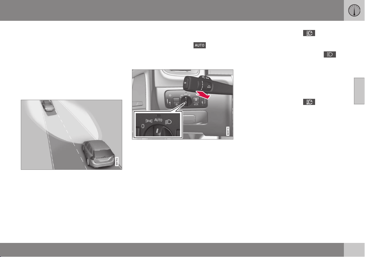
03 Instruments and controls
03
}}
89
beam about a second after the camera sen-
sor no longer detects the headlamp beams
from oncoming traffic the rear lights of vehi-
cles in front.
If the active main beam has adaptive func-
tionality then, unlike what happens during
conventional dimming, the light beam contin-
ues to illuminate with main beam on both
sides of oncoming traffic or vehicles ahead -
only the part of the light beam that points
directly to the vehicle is dimmed.
Adaptive functionality: Dipped beam directly
toward oncoming vehicles, but continued main
beam on both sides of the vehicle.
The lighting returns to full main beam about a
second after the camera sensor no longer
detects the headlamp beams from oncoming
traffic or the rear lights from vehicles in front.
Activating/deactivating
AHB can be activated when the headlamp
control's knob is in position
(provided
that the function has not been deactivated in
the menu system MY CAR, see MY CAR
(p. 108)).
Stalk switch and knob for headlamp control in
AUTO position.
The function can start while driving in the
dark when the car's speed is 20 km/h or
higher.
Activate/deactivate AHB by moving the left-
hand stalk switch towards the steering wheel
to the end position and then releasing. Deac-
tivation when main beam is on means that the
lights are reset directly to dipped beam.
Car with analogue combined instrument
panel
When AHB is activated the
symbol illu-
minates in the instrument's information dis-
play.
When main beam is switched on the
symbol also illuminates in the combined
instrument panel. This also applies for active
Xenon headlamps if the main beam is partially
dimmed, i.e. as soon as the light beam shines
with slightly more than dipped beam.
Car with digital combined instrument panel
When AHB is activated the
symbol
turns white in the instrument's information
display.
When main beam is activated, the symbol
turns blue. This also applies for active Xenon
headlamps if the main beam is partially
dimmed, i.e. as soon as the light beam shines
with slightly more than dipped beam.
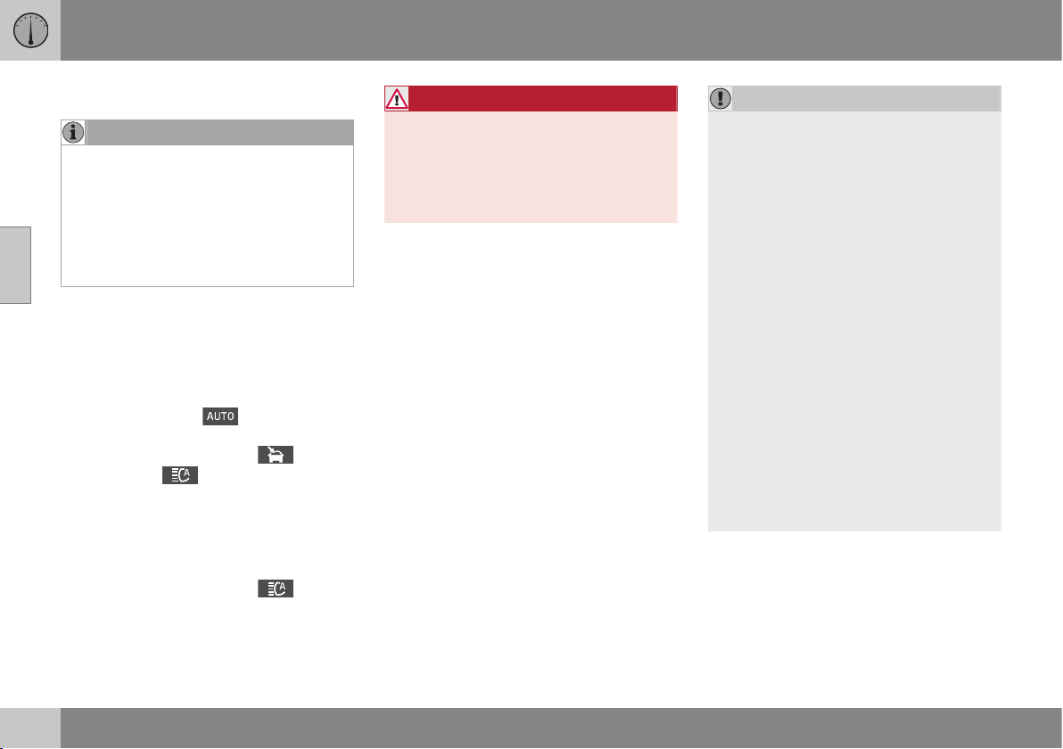
||
03 Instruments and controls
03
90
* Option/accessory, for more information, see Introduction.
Manual operation
NOTE
Keep the windscreen surface in front of the
camera sensor free from ice, snow, mist
and dirt.
Do not stick or attach anything to the
windscreen in front of the camera sensor
as this may reduce effectiveness or cause
one or more of the systems dependent on
the camera to stop working.
If the message Active main beam
Temporary unavailable Switch manually is
shown in the combined instrument panel's
information display then you have to switch
manually between main and dipped beam.
However, the knob for headlamp control can
still remain in position
. The same
applies if the message
Windscreen sensors
blocked See manual
and the symbol
are shown. The
symbol goes out when
these messages are shown.
AHB may be temporarily unavailable e.g. in
situations with dense fog or heavy rain. When
AHB becomes available again, or the wind-
screen sensors are no longer blocked, the
message extinguishes and the
symbol
illuminates.
WARNING
AHB is an aid for using the optimum beam
pattern when conditions are favourable.
The driver always bears responsibility for
manually switching between main and
dipped beam when traffic situations or
weather conditions so require.
IMPORTANT
Examples of when manual switching
between main and dipped beam may be
required:
•
In heavy rain or dense fog
•
In freezing rain
•
In snow flurries or slush
•
In moonlight
•
When driving in poorly lit built-up
areas
•
When the traffic ahead has weak light-
ing
•
If there are pedestrians on or beside
the road
•
If there are highly reflective objects
such as signs in the vicinity of the road
•
When the lighting from oncoming traf-
fic is obscured by e.g. a crash barrier
•
When there is traffic on connecting
roads
•
On the brow of a hill or in a hollow
•
In sharp bends.
For more information on the limitations of the
camera sensor, see Collision warning system*
- camera sensor limitations (p. 228).
Related information
•
Main/dipped beam (p. 87)
•
Light switches (p. 84)
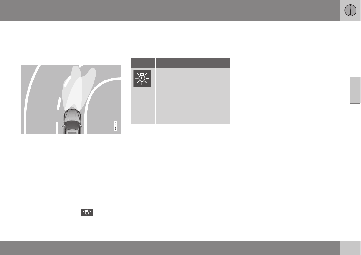
03 Instruments and controls
03
* Option/accessory, for more information, see Introduction.
91
Active Xenon headlamps*
Active Xenon headlamps are designed to pro-
vide maximum illumination in bends and junc-
tions and so provide increased safety.
Active Xenon headlamps ABL
Headlamp pattern with function deactivated (left)
and activated (right) respectively.
If the car is equipped with active Xenon head-
lamps (Active Bending Lights – ABL) the light
from the headlamps follows the steering
wheel movement in order to provide maxi-
mum lighting in bends and junctions and so
provide increased safety.
The function is activated automatically when
the car is started (provided that it has not
been deactivated in the menu system
MY CAR, see MY CAR (p. 108)). In the event
of a fault in the function the
symbol illu-
minates in the combined instrument panel at
the same time as the information display
shows an explanatory text and a further illu-
minated symbol.
Symbol Message Specification
Headlamp
system
malfunc-
tion Serv-
ice
required
The system is
disengaged. Visit
a workshop if
the message
remains. Volvo
recommends
that you contact
an authorised
Volvo workshop.
The function is only active in twilight or dark-
ness and only when the car is moving.
The function
21
can be deactivated/activated
in the menu system MY CAR, see MY CAR
(p. 108).
For headlamp pattern adjustment, see Head-
lamps - adjusting headlamp pattern (p. 96).
Cornering lights*
Active Xenon headlamps with the Active main
beam function of the adaptive type (Active
main beam with adaptive functionality) are
equipped with cornering lights that temporar-
ily illuminate the area diagonally in front of the
car in the direction the steering wheel is
turned in a sharp bend, or in the direction the
direction indicators are being used.
The function is activated when main beam or
dipped beam is used and the car's speed is
lower than approx. 30 km/h.
In addition, both cornering lights are switched
on as a supplement to the reversing lamp
during reversing.
Related information
•
Main/dipped beam (p. 87)
•
Active main beam* (p. 88)
•
Light switches (p. 84)
21
Activated on delivery from the factory.
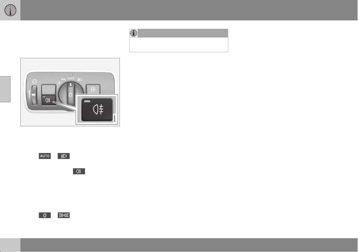
03 Instruments and controls
03
92
Rear fog lamp
When visibility is reduced by fog the rear fog
lamp can be used so that other road users
shall notice vehicles in front at an early stage.
Button for rear fog lamp.
The rear fog lamp can only be switched on
when key position II is active or the engine is
running and the headlamp control's knob is in
position
or .
Press the button for On/Off. The rear fog
lamp's indicator symbol in the com-
bined instrument panel and the light in the
button both illuminate when the rear fog lamp
is switched on.
The rear fog lamp is switched off automati-
cally when the engine is switched off or when
the headlamp control's knob is turned to
position
or .
NOTE
Regulations on the use of rear fog lamps
vary from country to country.
Related information
•
Light switches (p. 84)
Brake lights
The brake light automatically comes on during
braking.
The brake light is switched on when the brake
pedal is depressed. In addition, it is switched
on when one of driving support systems
Adaptive cruise control (p. 197), City Safety
(p. 215) or Collision warning system (p. 222)
brakes the car.
Related information
•
Foot brake - emergency brake lights and
automatic hazard warning flashers
(p. 297)
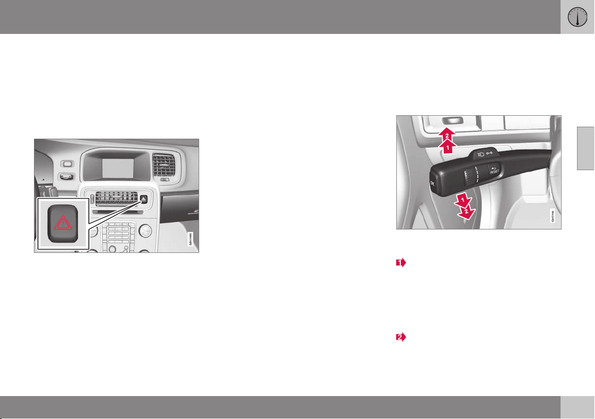
03 Instruments and controls
03
}}
93
Hazard warning flashers
The hazard warning flashers warn other road
users by means of all of the car's direction
indicator lamps flashing simultaneously when
this function is activated.
When the hazard warning flashers are acti-
vated both direction indicator symbols flash in
the combined instrument panel.
Button for hazard warning flashers.
Press the button to activate the hazard warn-
ing flashers. Both direction indicator symbols
in the combined instrument panel flash when
the hazard warning flashers are used.
The hazard warning flashers are activated
automatically when the car has been braked
so suddenly that the emergency brake lights
have been activated at a speed below
10 km/h. The hazard warning flashers remain
on when the car has stopped and are deacti-
vated automatically when the car is driven off
again or the button is depressed.
Related information
•
direction indicators (p. 93)
•
Foot brake - emergency brake lights and
automatic hazard warning flashers
(p. 297)
direction indicators
The car's direction indicators are operated
with the left-hand stalk switch. The direction
indicator lamps flash three times or continu-
ously, depending on how far up or down the
stalk switch is moved.
Direction indicators.
Short flash sequence
Move the stalk switch up or down to the
first position and release. The direction
indicator lamps flash three times. The
function can be activated/deactivated in
the menu system MY CAR, see MY
CAR (p. 108).
Continuous flash sequence
Move the stalk switch up or down to the
outer position.

||
03 Instruments and controls
03
94
The stalk switch remains in its position and is
moved back manually, or automatically by the
steering wheel movement.
Direction indicator symbols
For direction indicator symbols, see Com-
bined instrument panel - meaning of indicator
symbols (p. 66).
Related information
•
Hazard warning flashers (p. 93)
Interior lighting
The passenger compartment lighting is acti-
vated/deactivated with the buttons in the con-
trols above the front seats and the rear seat.
G021149
Controls in roof console for the front reading
lamps and passenger compartment lighting.
Reading lamp, left-hand side
Reading lamp, right-hand side
Interior lighting
All lighting in the passenger compartment can
be switched on and off manually within
30 minutes from when:
•
the engine has been switched off and the
car's electrical system is in key position 0
•
the car has been unlocked but the engine
has not been started.
Front roof lighting
The front reading lamps are switched on or
off by pressing the relevant button in the roof
console.
Rear roof lighting
G021150
Rear roof lighting.
The lamps are switched on or off by pressing
each respective button.
Courtesy lighting
Courtesy lighting (and passenger compart-
ment lighting) is switched on and off respec-
tively when a side door is opened or closed.
Glovebox lighting
Glovebox lighting is switched on and off
respectively when the lid is opened or closed.
Vanity mirror lighting
The lighting for the vanity mirror (p. 148) is
switched on and off respectively when the
cover is opened or closed.

03 Instruments and controls
03
* Option/accessory, for more information, see Introduction.
95
Automatic lighting
The switch for passenger compartment light-
ing has three positions for the lighting in the
passenger compartment:
•
Off – right-hand side pressed in, auto-
matic lighting deactivated.
•
Neutral position – automatic lighting
activated.
•
On – left-hand side pressed in, passenger
compartment lighting switched on.
Neutral position
When the button is in neutral position the
passenger compartment lighting is switched
on and off automatically in accordance with
the following.
The passenger compartment lighting is
switched on and remains on for 30 seconds
if:
•
the car is unlocked with the remote con-
trol key or key blade, see Remote control
key - functions (p. 159) or Detachable
key blade - unlocking doors (p. 163)
•
the engine has been switched off and the
car's electrical system is in key position
0.
Passenger compartment lighting is switched
off when:
•
the engine is started
•
the car is locked.
The passenger compartment lighting comes
on and remains on for two minutes if one of
the doors is open.
If any lighting is switched on manually and
the car is locked then it will be switched off
automatically after two minutes.
Ambience lights*
When the normal passenger compartment
lighting is switched off and the engine is run-
ning, a number of LEDs illuminate, including
one in the ceiling lighting, in order to provide
a low-light and enhance the mood while driv-
ing. The light also makes it easier to see
objects in storage compartments etc. during
the darker hours of the day. This lighting goes
out for a little while after the normal passen-
ger compartment lighting when the car is
locked. The brightness is controlled using the
thumbwheel on the headlamp control (p. 84).
Home safe light duration
Home safe lighting consists of dipped beam,
parking lamps, lamps in the door mirrors,
number plate lighting, interior roof lighting as
well as courtesy lighting.
Some of the exterior lighting can be kept
switched on to work as home safe lighting
after the car has been locked.
1. Remove the remote control key from the
ignition switch.
2. Move the left-hand stalk switch toward
the steering wheel to the end position and
release it. The function can be activated
in the same way as with main beam flash;
see Main/dipped beam (p. 87).
3. Get out of the car and lock the door.
When the function is activated, dipped beam,
parking lamps, door mirror lamps, number
plate lighting, interior roof lamps and courtesy
lighting are switched on.
The length of time for which the home safe
lighting should be kept on can be set in the
menu system MY CAR, see MY CAR (p. 108).
Related information
•
Approach lighting (p. 96)
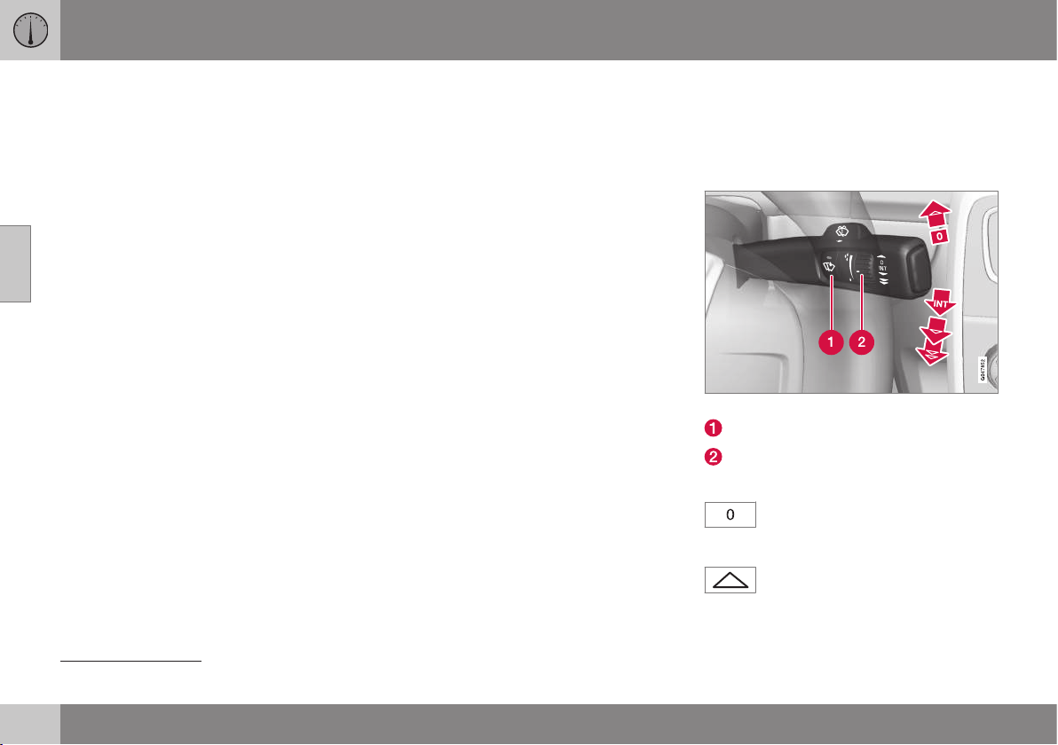
03 Instruments and controls
03
96
* Option/accessory, for more information, see Introduction.
Approach lighting
Approach lighting consists of parking lamps,
lamps in the door mirrors, number plate light-
ing, interior roof lighting as well as courtesy
lighting.
Approach lighting is switched on with the
remote control key, see Remote control key -
functions (p. 159), and is used to switch on
the car's lighting at a distance.
When the function is activated with the
remote control, the parking lamps, door mir-
ror lamps, number plate lighting, interior roof
lamps and courtesy lighting are switched on.
The length of time for which the approach
lighting should be kept on can be set in the
menu system MY CAR, see MY CAR (p. 108).
Related information
•
Home safe light duration (p. 95)
Headlamps - adjusting headlamp
pattern
If the car is equipped with active Xenon head-
lamps and has the Active main beam function
then the headlamp pattern must be reset
when changing from right to left-hand traffic,
and vice versa.
Active Xenon headlamps*
No adjustment of the headlamp pattern is
necessary for cars without the Active main
beam* function. The headlamp pattern is
designed in such a way that oncoming traffic
is not dazzled.
Adjustment of the headlamp pattern is
required for cars with Active main beam. The
car must be stationary with the engine run-
ning when the headlamp pattern is shifted
between right and left-hand traffic.
The headlamp pattern is changed in the menu
system MY CAR, see MY CAR (p. 108).
Halogen headlamps
No adjustment of the headlamp pattern is
necessary. The headlamp pattern is designed
in such a way that oncoming traffic is not
dazzled.
Wipers and washers
Wipers and washers clean the windscreen
and rear window. The headlamps are cleaned
with high-pressure washing.
Windscreen wipers
22
Windscreen wipers and windscreen washers.
Rain sensor, On/Off
Thumbwheel sensitivity/frequency
Windscreen wipers off
Move the stalk switch to position 0
to switch off the windscreen wipers.
Single sweep
Raise the stalk switch and release to
make one sweep.
22
For replacing the wiper blades and service position wiper blades, see Wiper blades (p. 376). For filling washer fluid, see Washer fluid - filling (p. 378).
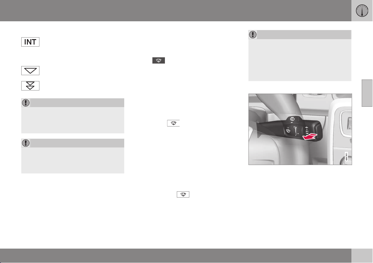
03 Instruments and controls
03
}}
* Option/accessory, for more information, see Introduction.
97
Intermittent wiping
Set the number of sweeps per time
unit with the thumbwheel when
intermittent wiping is selected.
Continuous wiping
The wipers sweep at normal speed.
The wipers sweep at high speed.
IMPORTANT
Before activating the wipers during winter -
ensure that the wiper blades are not frozen
in, and that any snow or ice on the wind-
screen is scraped away.
IMPORTANT
Use plenty of washer fluid when the wipers
are cleaning the windscreen. The wind-
screen must be wet when the windscreen
wipers are operating.
Service position wiper blade
For cleaning the windscreen/wiper blades
and replacement of wiper blades, see Car
wash (p. 398) and Wiper blades (p. 376).
Rain sensor*
The rain sensor automatically starts the wind-
screen wipers based on how much water it
detects on the windscreen. The sensitivity of
the rain sensor can be adjusted using the
thumbwheel.
When the rain sensor is activated a lamp in
the button is illuminated and the rain sensor
symbol
is shown in the combined
instrument panel.
Activating and setting the sensitivity
When activating the rain sensor, the car must
be running or the remote control key in posi-
tion I or II while the windscreen wiper stalk
switch must be in position 0 or in the position
for a single sweep.
Activate the rain sensor by pressing the rain
sensor button
. The windscreen wipers
make one sweep.
Press the stalk switch up for the wipers to
make an extra sweep.
Turn the thumbwheel upward for higher sen-
sitivity and downward for lower sensitivity.
(An extra sweep is made when the thumb-
wheel is turned upward.)
Deactivate
Deactivate the rain sensor by pressing the
rain sensor button
or move the stalk
switch down to another wiper program.
The rain sensor is automatically deactivated
when the remote control key is removed from
the ignition switch or five minutes after the
engine has been switched off.
IMPORTANT
The windscreen wipers could start and be
damaged in an automatic car wash.
Switch off the rain sensor while the car is
in motion or when the remote control key
is in position I or II. The symbol in the
combined instrument panel and the lamp
in the button go out.
Washing the headlamps and windows
Washing function.
Washing the windscreen
Move the stalk switch toward the steering
wheel to start the windscreen and headlamp
washers.
The windscreen wipers will make several
more sweeps and the headlamps are washed
once the stalk switch has been released.
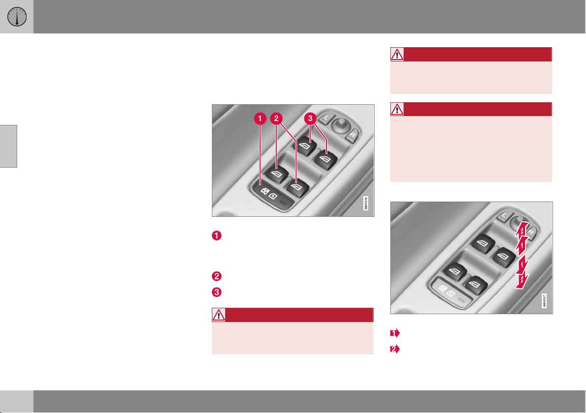
||
03 Instruments and controls
03
98
* Option/accessory, for more information, see Introduction.
Heated washer nozzles*
The washer nozzles are heated automatically
in cold weather to prevent the washer fluid
freezing solid.
High-pressure headlamp washing*
High-pressure headlamp washing consumes
a large quantity of washer fluid. To save fluid,
the headlamps are washed automatically at
every fifth windscreen wash cycle.
Reduced washing
If only approx. 1 litre of washer fluid remains
in the reservoir and the message that you
should fill the washer fluid is shown in the
combined instrument panel, then the supply
of washer fluid to the headlamps is switched
off. This is in order to prioritise cleaning the
windscreen and the visibility through it.
Related information
•
Washer fluid - filling (p. 378)
Power windows
All power windows can be operated using the
control panel for the driver's door - the con-
trol panels for the other doors operate their
respective power window.
Driver's door control panel.
Switch for electric child safety locks* and
disengaging rear power window buttons;
see Child safety locks - electrical activa-
tion* (p. 177).
Rear window controls
Front window controls
WARNING
Check that children or other passengers
are not trapped when the windows are
closed from the driver's door.
WARNING
Check that no children or other passen-
gers are trapped if/when the windows are
closed using the remote control key.
WARNING
If there are children in the car - remember
to always switch off the power supply to
the power windows by selecting key posi-
tion 0 and then take the remote control key
with you when leaving the car. For infor-
mation on key positions - see Key posi-
tions - functions at different levels (p. 76).
Operating
Operating the power windows.
Operating without auto
Operating with auto
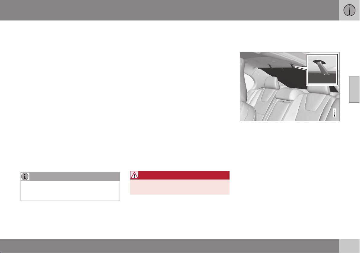
03 Instruments and controls
03
* Option/accessory, for more information, see Introduction.
99
All power windows can be operated using the
control panel for the driver's door - the con-
trol panels for the other doors can only each
operate their respective power window. Only
one control panel can be operated at a time.
In order for the power windows to be used,
the key position must be at least I - see Key
positions - functions at different levels (p. 76).
The power windows can be operated for a
few minutes after the engine has been
switched off and after the remote control key
has been removed - although not after a door
has been opened.
Closing of the windows is stopped and the
window is opened if anything prevents its
movement. It is possible to override the pinch
protection when closing has been interrupted,
e.g. if there is ice forming. After two succes-
sive closing interruptions the pinch protection
will be forced and the automatic function
deactivated for a short while, now it is possi-
ble to close by continually holding the button
pulled up.
NOTE
One way to reduce the pulsating wind
noise when the rear windows are open is
to also open the front windows slightly.
Operating without auto
Move one of the controls up/down gently.
The power windows move up/down as long
as the control is held in position.
Operating with auto
Move one of the controls up/down to the end
position and release it. The window runs
automatically to its end position.
Operating with the remote control key
and central locking
To remotely operate the power windows from
the outside with the remote control key or
from inside with central locking, see Remote
control key (p. 155) and Locking/unlocking -
from the inside (p. 172).
Resetting
If the battery is disconnected then the func-
tion for automatic opening must be reset so
that it can work correctly.
1. Gently raise the front section of the but-
ton to raise the window to its end position
and hold it there for one second.
2. Release the button briefly.
3. Raise the front section of the button again
for one second.
WARNING
A reset must take place for pinch protec-
tion to work.
Sun blind*
There is a sun blind built into the rear parcel
shelf.
– Pull up the sun blind and hook it into the
roof clip using the two hooks for the
blind.
> The spring force in the blind keeps the
hooks in position.
When the sun blind is not in use - unhook it,
hold onto the handle and allow the blind to
roll up slowly.
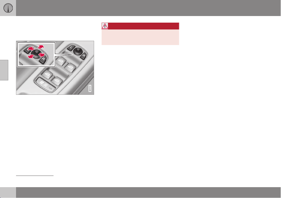
03 Instruments and controls
03
100
* Option/accessory, for more information, see Introduction.
Door mirrors
The door mirror positions are adjusted with
the joystick in the driver's door controls.
Door mirror controls.
Adjusting
1. Press the L button for the left-hand door
mirror or the R button for the right-hand
door mirror. The light in the button illumi-
nates.
2. Adjust the position with the joystick in the
centre.
3. Press the L or R button again. The light
should no longer be illuminated.
WARNING
Both mirrors are the wide-angle type to
provide optimal vision. Objects may
appear further away than they actually are.
Storing settings
23
The settings for the rearview and door mirrors
and the positions of the driver's seat can be
stored for each remote control key in the car
key memory*, see Remote control key - per-
sonalisation* (p. 156).
Angling the door mirror when parking
23
The door mirror can be angled down for the
driver to view the side of the road when park-
ing for example.
– Engage reverse gear and press the L or R
button.
When reverse gear is disengaged the mirror
automatically returns to its original position
after approx. 10 seconds, or earlier by press-
ing the button labelled L or R respectively.
Automatic angling of the door mirror
when parking
23
When reverse gear is engaged the door mirror
is automatically angled down so that the
driver can see the side of the road when
parking for example. When reverse gear is
disengaged the mirror automatically returns
to its original position after a short time.
The function can be activated/deactivated in
the menu system MY CAR, see MY CAR
(p. 108).
Automatic retraction when locking
23
When the car is locked/unlocked with the
remote control key the door mirrors are auto-
matically retracted/extended.
The function can be activated/deactivated in
the menu system MY CAR, see MY CAR
(p. 108).
Resetting to neutral
Mirrors that have been moved out of position
by an external force must be reset electrically
to the neutral position for electric retracting/
extending to work correctly:
1. Retract the mirrors with the L and R but-
tons.
2. Fold them out again with the L and R but-
tons.
3. Repeat the above procedure as neces-
sary.
The mirrors are now reset in neutral position.
Automatic dimming*
For the door mirrors to be fitted with this
function requires that the interior rearview
mirror also has automatic dimming, see Rear-
view mirror - interior (p. 102).
23
Only in combination with power seat with memory, see Seats, front - electrically operated* (p. 79).
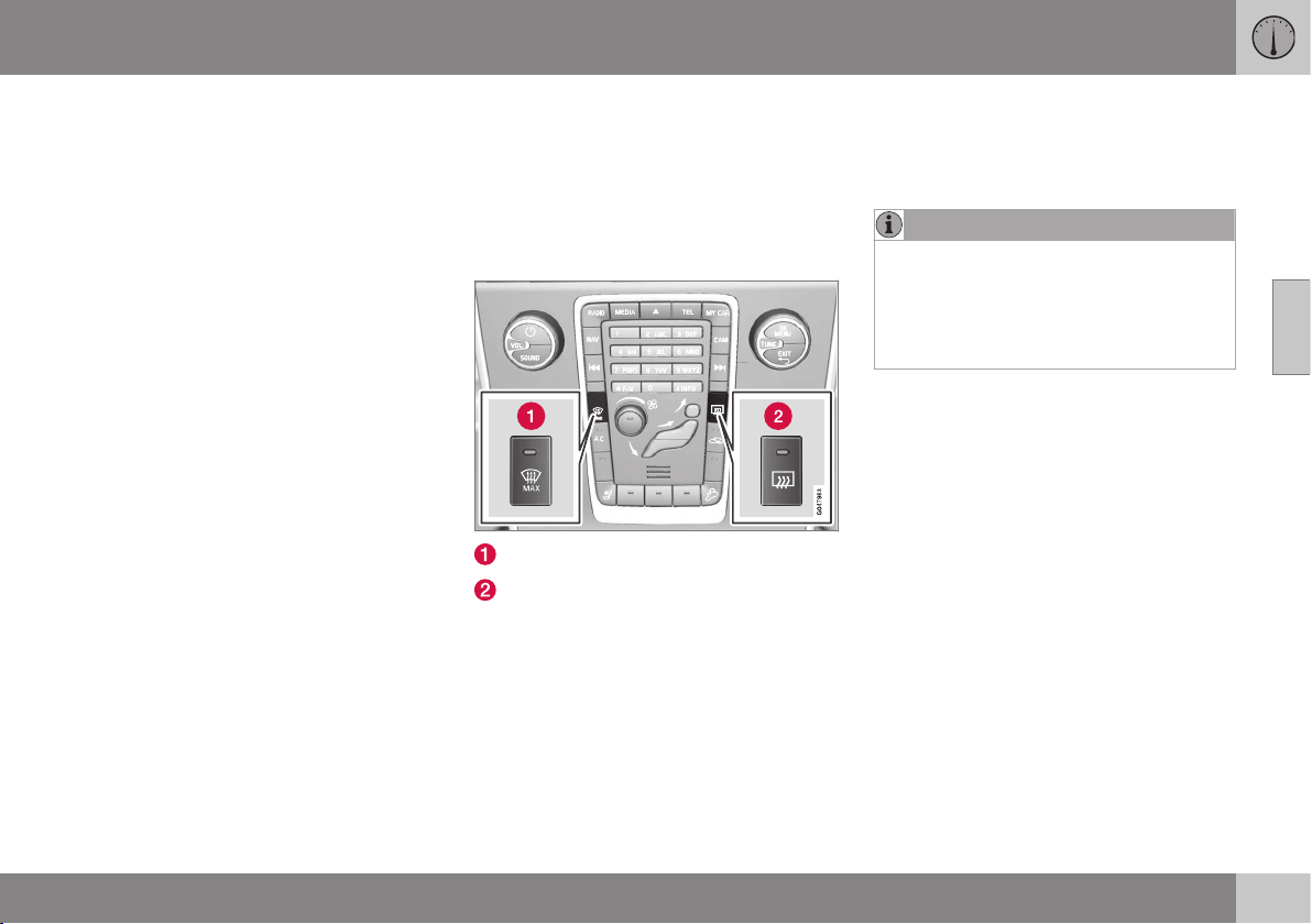
03 Instruments and controls
03
* Option/accessory, for more information, see Introduction.
101
Retractable power door mirrors*
The mirrors can be retracted for parking/driv-
ing in narrow spaces:
1. Depress the L and R buttons simultane-
ously (key position must be at least I).
2. Release them after approximately
1 second. The mirrors automatically stop
in the fully retracted position.
Fold out the mirrors by pressing down the L
and R buttons simultaneously. The mirrors
automatically stop in the fully extended posi-
tion.
Home safe and approach lighting
The lamp on the door mirrors illuminates
when approach lighting (p. 96) or home safe
lighting (p. 95) is selected.
Related information
•
Rearview mirror - interior (p. 102)
•
Windows and rearview and door mirrors -
heating (p. 101)
Windows and rearview and door
mirrors - heating
The defroster is used to quickly remove mist-
ing and ice from the windscreen, rear window
and door mirrors.
Heated windscreen*, rear window and
door mirrors
Heating, windscreen
Heating, rear window and door mirrors
The function is used to remove ice and mist-
ing from the windscreen, rear window and
door mirrors.
One press of the respective button starts the
heating. The light in the button indicates that
the function is active. Switch off the heating
as soon as the ice/misting is cleared in order
not to load the battery unnecessarily. How-
ever, the function is switched off automati-
cally after a certain time. Following which,
rear window heating is switched on and off
automatically as long as the outside tempera-
ture is lower than +7 °C.
NOTE
Rear window heating is not switched on
and off automatically if the Eco function is
activated, but then remains switched off,
even in outside temperatures below +7 °C.
For information about the Eco function,
see ECO* (p. 293).
See also Demisting and defrosting the wind-
screen (p. 132).
The door mirrors and rear window are demis-
ted/defrosted automatically if the car is
started in an outside temperature lower than
+7 °C. Automatic defrosting can be selected
in the menu system MY CAR, see MY CAR
(p. 108).
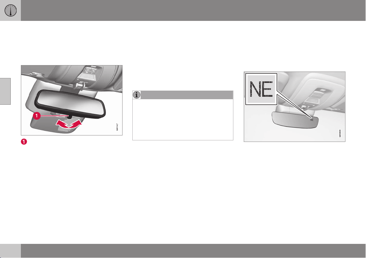
03 Instruments and controls
03
102
* Option/accessory, for more information, see Introduction.
Rearview mirror - interior
The interior rearview mirror can be dimmed
with a control in the mirror's lower edge.
Alternatively, the rearview mirror dims auto-
matically.
Control for dimming
Manual dimming
Bright light from behind could be reflected in
the rearview mirror and dazzle the driver. Use
dimming with the dimming control when
lights from behind are distracting:
1. Use dimming by moving the control in
towards the passenger compartment.
2. Return to normal position by moving the
control towards the windscreen.
Automatic dimming*
Bright light from behind is automatically
dimmed by the rearview mirror. The control
for manual dimming is not available on mir-
rors with automatic dimming.
The rearview mirror contains two sensors -
one forward facing and one rearward facing -
that work together to identify and eliminate
dazzling light. The forward facing sensor
detects ambient light, while the rearward fac-
ing sensor detects the light from vehicle
headlights behind.
NOTE
If the sensors are obscured by e.g. parking
permits, transponders, sun visors or
objects in the seats or on the parcel shelf
in such a way that light is prevented from
reaching the sensors, then the dimming
function of the interior rearview and door
mirrors is reduced.
Only rearview mirror with automatic dimming
can be equipped with compass (p. 102).
Related information
•
Door mirrors (p. 100)
Compass*
The upper right-hand corner of the rearview
mirror contains a display that shows the com-
pass direction in which the front of the car is
pointing.
Operation
Rearview mirror with compass.
Eight different directions are shown with Eng-
lish abbreviations:
N (north), NE (north east),
E (east), SE (south east), S (south), SW (south
west), W (west) and NW (north west).
The compass is activated automatically when
the car is started or when key position II is
active, see Key positions - functions at differ-
ent levels (p. 76). To deactivate/activate the
compass - press in the button on the under-
side of the mirror using a paper clip for exam-
ple.

03 Instruments and controls
03
* Option/accessory, for more information, see Introduction.
103
Calibration
The compass may need calibrating to show
the correct compass direction.
The earth is divided into 15 magnetic zones.
The compass should be calibrated if the car
is moved across several magnetic zones.
Proceed as follows to perform calibration:
1. Stop the car in a large open area free
from steel structures and high-voltage
power lines.
2. Start the car and switch off all electrical
equipment (air conditioning, wipers, etc.)
and ensure that all doors are closed.
NOTE
Calibration may fail or not start at all if
electrical equipment is not switched off.
3. Hold the button on the underside of the
rearview mirror depressed (use a paper
clip or similar) for approx. 3 seconds. The
number of the current magnetic zone is
shown.
Magnetic zones.
4. Press the button repeatedly until the
required magnetic zone (
1–15) is shown.
See the map of magnetic zones for the
compass.
5. Wait until the display returns to showing
the character
C, or hold the button on the
underside of the rearview mirror
depressed for approx. 6 seconds until the
character C is shown.
6. Drive slowly in a circle at a speed of no
more than 10 km/h until a compass direc-
tion is shown in the display, indicating
that calibration is complete. Then drive a
further 2 circles to fine-tune calibration.
7. Cars with heated windscreen*: If the
character
C is shown in the display when
the heated windscreen is activated, per-
form the calibration in accordance with
point 6 above with the heated windscreen
activated, see Demisting and defrosting
the windscreen (p. 132).
8. Repeat the above procedure as neces-
sary.
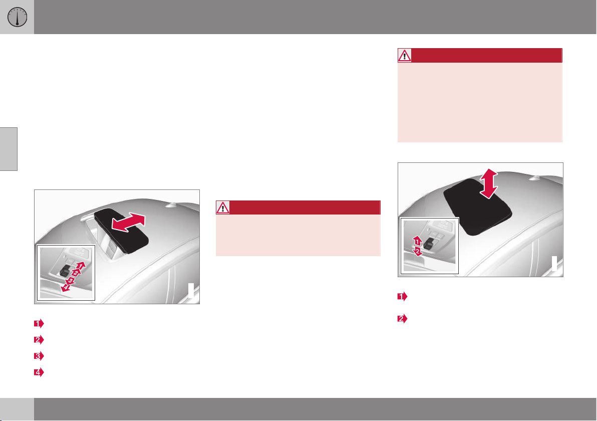
03 Instruments and controls
03
104
* Option/accessory, for more information, see Introduction.
Sunroof*
The sunroof can be operated with a control in
the roof panel.
The sunroof's inner sunscreen is closed man-
ually.
The sunroof has a wind deflector.
The sunroof controls are located in the roof
panel. The sunroof can be opened vertically
at the rear edge and horizontally. Key position
I or II is required for the sunroof to be
opened.
Horizontal opening
G021343
Horizontal opening, backward/forward.
Opening, automatic
Opening, manual
Closing, manual
Closing, automatic
Opening
For maximum sunroof opening, move the
control back to the position for automatic
opening and release.
Open manually by pulling the control back-
wards to the point of resistance for manual
opening. The sunroof moves to maximum
open position as long as the button is kept
depressed.
Closing
Close manually by pushing the control for-
wards to the point of resistance for manual
closing. The sunroof moves to closed posi-
tion as long as the button is kept depressed.
WARNING
Risk of crushing when the sunroof is
closed. The sunroof's pinch-protection
function only operates during automatic
closing, not manual.
Close automatically by pressing the control to
the position for automatic closing and then
release it.
The power supply to the sunroof is switched
off by selecting key position 0 and removing
the remote control key from the ignition
switch.
WARNING
If there are children in the car:
Remember to always switch off the power
supply to the sunroof by selecting key
position 0 and then take the remote con-
trol key with you when leaving the car. For
information on key positions - see Key
positions - functions at different levels
(p. 76).
Vertical opening
G028899
Vertical opening, raised at the rear edge.
Open by pressing the rear edge of the
control upward.
Close by pulling the rear edge of the con-
trol down.
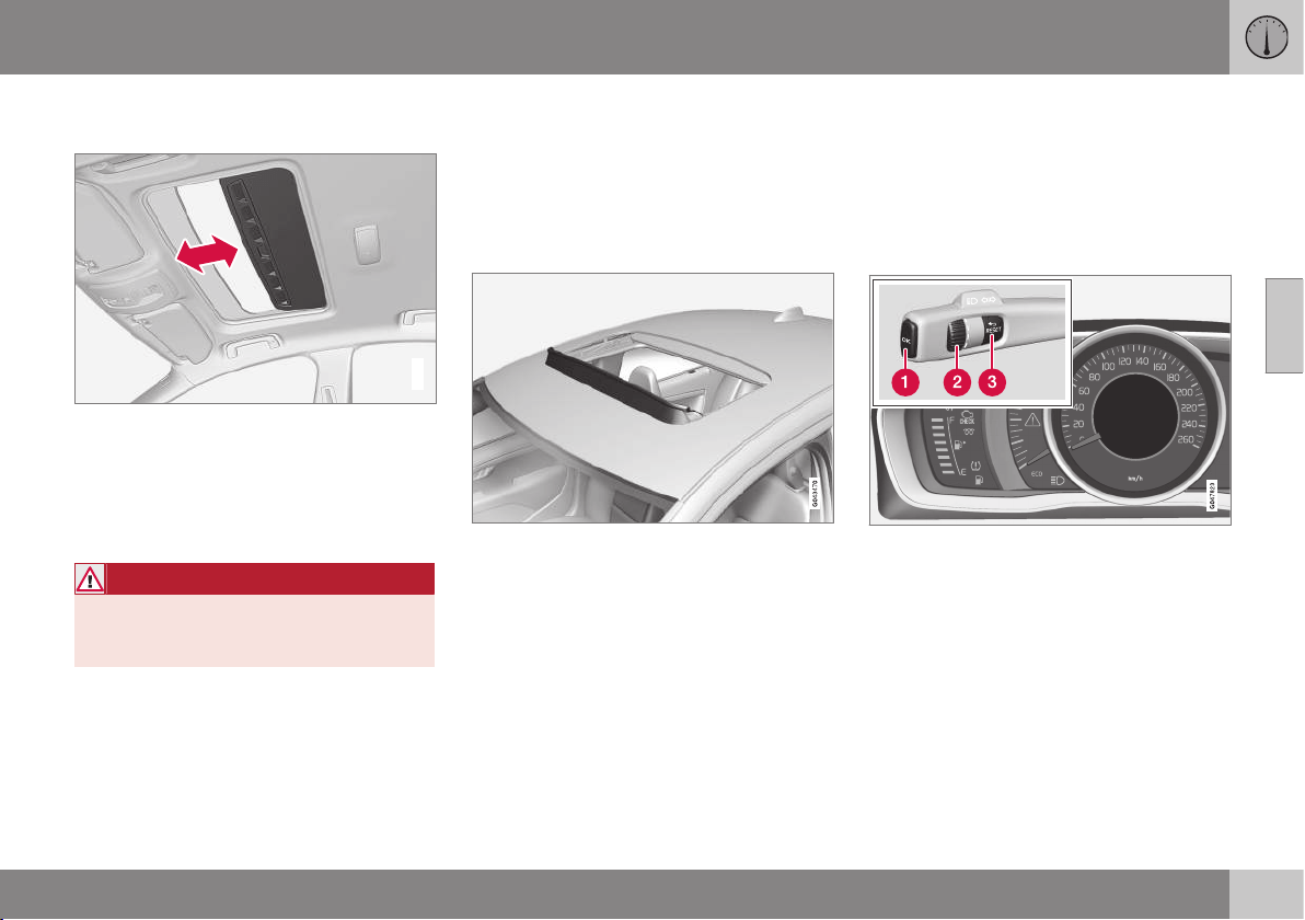
03 Instruments and controls
03
}}
105
Closing using the remote control key or
central locking button
G021345
One long press on the lock button closes the
sunroof and all the windows, see Remote
control key - functions (p. 159) and Locking/
unlocking - from the inside (p. 172). The
doors and the boot lid are locked. To inter-
rupt closing, press the lock button again.
WARNING
If the sunroof is closed with the remote
control key, check that no one risks being
trapped.
Sunscreen
The sunroof features a manual, sliding interior
sunscreen. The sunscreen slides back auto-
matically when the sunroof is opened. Grip
the handle and slide the screen forward to
close it.
Pinch protection
The sunroof's pinch protection function is
triggered if it is blocked by an object during
automatic closing. If blocked, the sunroof will
stop and automatically open to the previous
position.
Wind deflector
The sunroof has a wind deflector that is
folded up when the sunroof is in the open
position.
Menu navigation - combined
instrument panel
The left-hand stalk controls the menus
(p. 106) shown on the information display in
the combined instrument panel (p. 61). Which
menus are shown depends on the key posi-
tion (p. 76).
Display (analogue combined instrument panel)
and controls for menu navigation.
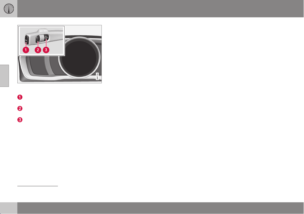
||
03 Instruments and controls
03
106
* Option/accessory, for more information, see Introduction.
Display (digital combined instrument panel) and
controls for menu navigation.
OK – access to message list and mes-
sage confirmation.
Thumbwheel – browse between menu
options.
RESET – reset the active function. Used
in certain cases to select/activate a func-
tion, see the explanation under each
respective function.
If there is a message (p. 107) then it must be
acknowledged with OK in order that the
menus shall be shown.
Related information
•
Messages - handling (p. 108)
Menu overview - combined
instrument panel
Which menus are shown in the combined
instrument panel's information display
depends on the key position (p. 76).
Some of the following menu options require
the function and hardware to be installed in
the car.
Analogue combined instrument panel
Digital speed
Parking heater*
Additional heater*
TC options
Service status
Oil level
24
Messages (##)
25
Digital combined instrument panel
Settings*
Themes
Contrast mode/Colour mode
Service status
Messages
25
Oil level
24
Parking heater*
Trip computer reset
Related information
•
Analogue combined instrument panel -
overview (p. 61)
•
Digital combined instrument panel - over-
view (p. 62)
•
Menu navigation - combined instrument
panel (p. 105)
24
Certain engines.
25
The number of messages is indicated in brackets.

03 Instruments and controls
03
* Option/accessory, for more information, see Introduction.
107
Messages
When a warning, information or indicator
symbol illuminates, a corresponding message
appears on the information display.
Message Specification
Stop safely
A
Stop and switch off the
engine. Serious risk of
damage - consult a work-
shop
B
.
Stop engine
A
Stop and switch off the
engine. Serious risk of
damage - consult a work-
shop
B
.
Service
urgent
A
Contact a workshop
B
to
check the car immedi-
ately.
Service
required
A
Contact a workshop
B
to
check the car as soon as
possible.
See manual
A
Read the owner's man-
ual.
Book time
for mainte-
nance
Time to book regular
service - contact a work-
shop
B
.
Message Specification
Time for reg-
ular mainte-
nance
Time for regular service -
contact a workshop
B
. The
timing is determined by
the number of kilometres
driven, number of months
since the last service,
engine running time and
oil grade.
Maintenance
overdue
If the service intervals are
not followed then the
warranty does not cover
any damaged parts -
contact a workshop
B
.
Transmission
Oil change
needed
Contact a workshop
B
to
check the car as soon as
possible.
Transmission
Reduced
performance
The gearbox cannot han-
dle full capacity. Drive
carefully until the mes-
sage clears
C
.
If shown repeatedly -
contact a workshop
B
.
Transmission
hot Reduce
speed
Drive more smoothly or
stop the car in a safe
manner. Disengage the
gear and run the engine
at idling speed until the
message clears
C
.
Message Specification
Transmission
hot Stop
safely Wait
for cooling
Critical fault. Stop the car
immediately in a safe
manner and contact a
workshop
B
.
Temporarily
off
A
A function has been tem-
porarily switched off and
is reset automatically
while driving or after star-
ting again.
Low battery
charge
Power save
mode
The audio system is
switched off to save
energy. Charge the bat-
tery.
A
Part of message, shown together with information on
where the problem has arisen.
B
An authorised Volvo workshop is recommended.
C
For more information regarding the automatic gearbox, see
Automatic gearbox -- Geartronic* (p. 276).
Related information
•
Messages - handling (p. 108)
•
Menu navigation - combined instrument
panel (p. 105)
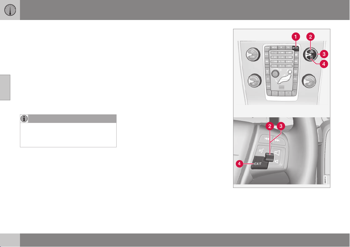
03 Instruments and controls
03
108
* Option/accessory, for more information, see Introduction.
Messages - handling
Use the left-hand stalk switch to acknowledge
and browse among messages (p. 107) that
are shown in the information display of the
combined instrument panel.
When a warning, information or indicator
symbol illuminates, a corresponding message
appears in the display at the same time. An
error message is stored in a memory list until
the fault has been rectified.
Press OK on the left-hand stalk switch to
acknowledge a message. Scroll through mes-
sages with the thumbwheel (p. 105).
NOTE
If a warning message appears while you
are using the trip computer, the message
must be read (press OK) before the previ-
ous activity can be resumed.
Related information
•
Menu overview - combined instrument
panel (p. 106)
MY CAR
MY CAR is a menu source that handles many
of the car's functions, e.g. City Safety™, locks
and alarm, automatic fan speed, setting the
clock, etc.
Certain functions are standard, others are
optional - the range also varies depending on
the market.
Operation
Navigation in the menus is carried out using
buttons in the centre console or with the
steering wheel's right-hand keypad*.
Control panel in centre console and steering
wheel keypad. The figure is schematic - the num-
ber of functions and layout of the buttons both
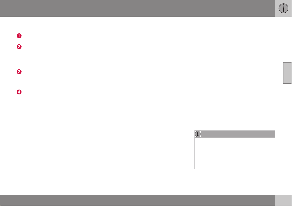
03 Instruments and controls
03
}}
109
vary, depending on the equipment selected and
the market.
MY CAR - opens the menu system MY
CAR.
OK/MENU - press the button in the cen-
tre console or the thumbwheel on the
steering wheel to select/tick in the high-
lighted menu option or store the selected
function in the memory.
TUNE - turn the knob in the centre con-
sole or the thumbwheel on the steering
wheel to scroll up/down through the
menu options.
EXIT
EXIT functions
Depending on the function the cursor is on
when EXIT is depressed briefly, and on which
menu level, one of the following may occur:
•
phone call is rejected
•
current function is interrupted
•
input characters are deleted
•
most recent selections are undone
•
leads up in the menu system.
A long press on EXIT leads to the normal
view for MY CAR or if you are in the normal
view, to the highest menu level (main source
menu).
Menu options and search paths
For a description of the menu options and
search paths in MY CAR, see the Sensus
Infotainment supplement.
Trip computer
The car's trip computer can record, calculate
and show information while driving.
Trip computer content and appearance varies
depending on whether the combined instru-
ment panel is analogue or digital:
•
Trip computer - analogue combined
instrument panel (p. 111)
•
Trip computer - digital combined instru-
ment panel (p. 115)
Checking and settings of the trip computer
can be made immediately after the combined
instrument panel is automatically illuminated
in connection with unlocking. If none of the
trip computer's controls are actuated within
approx. 30 seconds after the driver's door
has been opened then the instrument extin-
guishes, after which either key position II
(p. 76) or starting the engine is required in
order to operate the trip computer.
NOTE
If a warning message appears when the
trip computer is used then the message
must first be acknowledged before the trip
computer can be reactivated.
•
Acknowledge the message by briefly
pressing the indicator stalk OK button.

||
03 Instruments and controls
03
110
* Option/accessory, for more information, see Introduction.
Group menus
The trip computer has two different group
menus:
•
Functions
•
Heading in combined instrument panel
The trip computer's functions or headings
are each listed in an infinite loop.
Related information
•
Trip computer - trip statistics* (p. 120)
•
Trip computer - supplementary informa-
tion (p. 119)
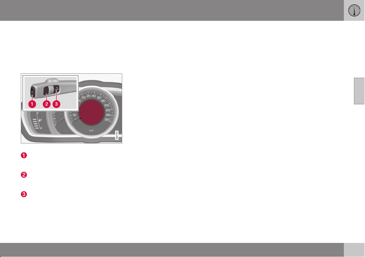
03 Instruments and controls
03
}}
111
Trip computer - analogue combined
instrument panel
The trip computer's menu is in a variable
loop. One of the alternatives is that the trip
computer's display extinguishes - this also
marks the start/end of the loop.
Information display and controls.
OK - Opens the loop with the trip com-
puter's functions + Activates the selected
option.
Thumbwheel - Opens the loop with the
trip computer's headings + Scrolls
through the options.
RESET - Undoes, zeroes or backs out of
a function after making a selection.
Functions
Proceed as follows to open and check/adjust
functions:
1. To ensure that no control is in the middle
of a sequence - "Reset" them first with
two presses on RESET.
2. Press OK - the loop with all functions
opens.
3. Browse through the functions with the
thumbwheel and select/confirm with OK.
4. Finish by pressing twice on RESET after
completed checking/adjustment.
The different functions of the trip computer
are listed in the following table:

||
03 Instruments and controls
03
112
* Option/accessory, for more information, see Introduction.
Functions Information
Digital speed
•
km/h
•
mph
•
No display
Shows the car's speed digitally in the centre of the combined instrument panel:
•
Open with OK, select with the thumbwheel, confirm with OK and back out with RESET.
Parking heater*
•
DIRECT START
•
- Timer 1 - leads to the menu for select-
ing time.
•
- Timer 2 - leads to the menu for select-
ing time.
For a description of programming the timer, see Engine block heater and passenger compart-
ment heater* - timer (p. 138).
Additional heater*
•
Auto On
•
Off
For more information, see Additional heater* (p. 142).
TC options
•
Distance to empty tank
•
Fuel consumption
•
Average speed
•
Trip meter
T1 and total dist.
•
Trip meter
T2 and total dist.
Here you can select/activate the options that you want to be available as selectable headings in
the trip computer. The symbols for the items already selected are WHITE with a "tick" - others are
GREY and have no "tick":
1. Open the function with OK, scroll through the symbols for the options with the thumbwheel
and select/stop on the desired symbol.
2. Confirm with OK - the symbol changes colour from GREY to WHITE and is marked with a
"tick".
3. Continue to select the function symbols with the thumbwheel or finish with RESET.
Service status
Shows the number of months and mileage to next service.

03 Instruments and controls
03
}}
113
Functions Information
Oil level
A
For more information, see Engine oil - checking and filling (p. 363).
Messages (##)
For more information, see Messages - handling (p. 108).
A
Certain engines.
Headings
One of the headings in the following table can
be selected for constant display in the com-
bined instrument panel. Proceed as follows to
determine which:
1. To ensure that no control is in the middle
of a sequence - "Reset" them first with
two presses on RESET.
2. Turn the thumbwheel - selectable head-
ings for the trip computer are shown in a
loop.
3. Stop on desired heading.
Trip computer heading in combined instrument
panel
Information
Trip meter T1 and total dist.
•
Long press on RESET resets trip meter T1.
Trip meter T2 and total dist.
•
Long press on RESET resets trip meter T2.
Distance to empty
For more information - see the section "Range - distance to empty tank" (p. 119).
Fuel consumption
Current consumption.
Average speed
•
Long press on RESET resets
Average speed.
No trip computer information. This option shows a blank display - it also marks the beginning/end of the loop.
The combined instrument panel's trip com-
puter can be changed to another option at
any time during the journey. Proceed as fol-
lows:
•
Turn the thumbwheel - stop on the
desired heading.
Resetting - Trip meter and Average
speed
With the current trip computer heading - T1
and total dist.,T2 and total dist. or

||
03 Instruments and controls
03
114
* Option/accessory, for more information, see Introduction.
Average speed - shown in the combined
instrument panel:
•
Give a long press on RESET - selected
heading is zeroed.
Each heading must be zeroed individually.
Related information
•
Trip computer (p. 109)
•
Trip computer - supplementary informa-
tion (p. 119)
•
Trip computer - trip statistics* (p. 120)
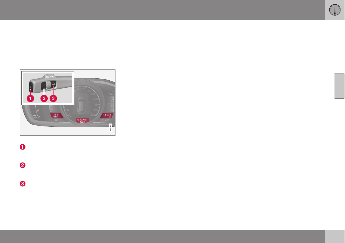
03 Instruments and controls
03
}}
115
Trip computer - digital combined
instrument panel
The trip computer's menu is in a variable
loop. One of the alternatives is that the trip
computer's three displays extinguish - this
also marks the start/end of the loop.
Information displays and stalk switch controls.
OK - Opens the loop with the trip com-
puter's functions + Activates the selected
option.
Thumbwheel - Opens the loop with the
trip computer's headings + Scrolls
through the options.
RESET - Undoes, zeroes or backs out of
a function after making a selection.
Functions
Proceed as follows to open and check/adjust
functions:
1. To ensure that no control is in the middle
of a sequence - "Reset" them first with
two presses on RESET.
2. Press OK - loop with all functions opens.
3. Browse through the functions with the
thumbwheel and select/confirm with OK.
4. Finish by pressing twice on RESET after
completed checking/adjustment.
The different functions of the trip computer
are listed in the following table:

||
03 Instruments and controls
03
116
* Option/accessory, for more information, see Introduction.
Functions Information
Trip computer reset
•
Average
•
Average speed
Note that this function does not reset both trip meters T1 and T2 - see table under next section
"Headings" and section "Resetting - Average speed/consumption" for information on the proc-
ess.
Messages
For more information, see Messages - handling (p. 108).
Themes
The appearance of the combined instrument panel (p. 61) is selected here.
Settings* Select Auto On or Off.
For more information, see Additional heater* (p. 142).
Contrast mode/Colour mode
Adjusting the combined instrument panel's brightness and colour intensity.
Parking heater*
•
Direct start
•
- Symbol Timer 1 - leads to the menu for
selecting time.
•
- Symbol Timer 2 - leads to the menu for
selecting time.
For a description of programming the timer, see Engine block heater and passenger compart-
ment heater* - timer (p. 138).
Service status
Shows the number of months and mileage to next service.
Oil level
A
For more information, see Engine oil - checking and filling (p. 363).
A
Certain engines.
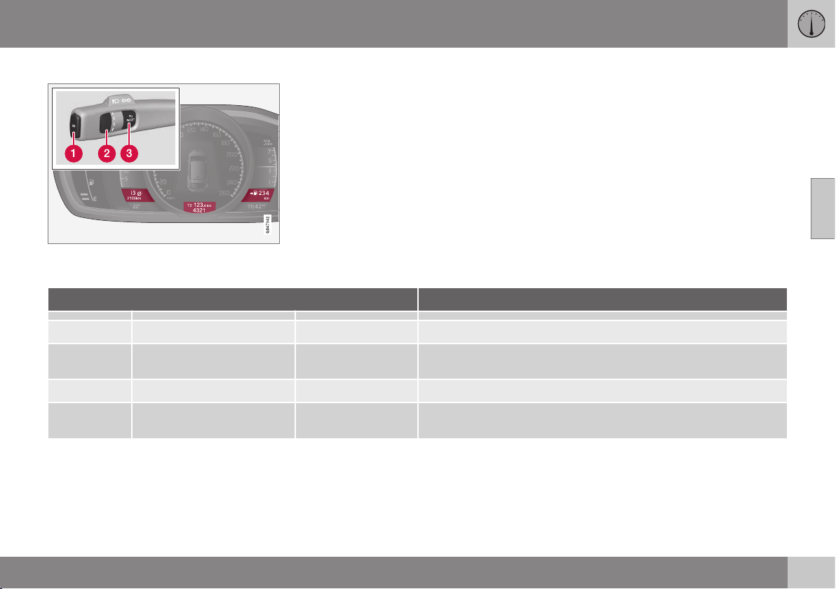
03 Instruments and controls
03
}}
117
Headings
Three trip computer headings can be displayed
simultaneously - one in each "window".
One of the heading combinations in the fol-
lowing table can be selected for constant dis-
play in the combined instrument panel. Pro-
ceed as follows to determine which:
1. To ensure that no control is in the middle
of a sequence - "Reset" them first with
two presses on RESET.
2. Turn the thumbwheel - selectable head-
ing combinations are shown in a loop.
3. Stop on desired heading combination.
Heading combinations Information
Average Trip meter T1 + Meter reading Average speed
•
Long press on RESET resets trip meter T1.
Instantaneous Trip meter T2 + Meter reading Distance to empty
tank
•
Long press on RESET resets trip meter T2.
Instantaneous Meter reading kmh<>mph kmh<>mph - see section "Digital speed display" (p. 119).
No trip computer information. This option extinguishes all three trip computer displays - it also marks
the beginning/end of the loop.
The combined instrument panel's heading
combination for the trip computer can be
changed to another option at any time during
the journey. Proceed as follows:
•
Turn the thumbwheel - stop on the
desired heading.
Resetting - Trip meter
Turn with the thumbwheel to the heading
combination containing the trip meter to be
reset:
•
Give a long press on RESET - selected
trip meter is zeroed.

||
03 Instruments and controls
03
118
* Option/accessory, for more information, see Introduction.
Resetting - Average speed/
consumption
1.
Select function
Trip computer
reset and activate with OK.
2. Select one of the following options with
the thumbwheel and activate with OK:
•
l/100 km
•
km/h
•
Reset both
3. Finish with RESET.
Related information
•
Trip computer - supplementary informa-
tion (p. 119)
•
Trip computer - trip statistics* (p. 120)
03 Instruments and controls
03
* Option/accessory, for more information, see Introduction.
119
Trip computer - supplementary
information
Supplementary information covering several
functions follows below.
Average
Average fuel consumption is calculated from
the last resetting.
NOTE
There may be a slight deviation if a fuel-
driven heater* has been used.
Average speed
The average speed is calculated for the driv-
ing distance driven since the last reset to
zero.
Instantaneous
The information for current fuel consumption
is updated continuously - approximately once
per second. When the car is driven at low
speed the consumption is shown per time
unit - at a higher speed it is shown related to
mileage.
Different units (km/miles) can be selected for
the display - see section "Change unit"
(p. 119).
Range - distance to empty tank
The trip computer shows the approximate
distance that can be driven with the fuel
quantity remaining in the tank.
No guaranteed range remains when the head-
ing
Distance to empty shows "----".
•
In which case, refuel as soon as possible.
The calculation is based on the average fuel
consumption over the last 30 km and the
remaining driveable fuel quantity.
NOTE
There may be a slight deviation if the driv-
ing style has been changed.
An economic driving style generally results in
a longer driving distance. For more informa-
tion on how fuel consumption can be influ-
enced, see Volvo Car Corporation 's Environ-
mental Philosophy (p. 22).
Digital speed display
26
The speed is shown in the opposite unit
(kmh/mph) in relation to the main instrument.
If it is calibrated in mph then the trip com-
puter shows the corresponding speed in
km/h and vice versa.
Change unit
You can change unit (km/miles) for distance
and speed in the menu system MY CAR, see
MY CAR (p. 108).
NOTE
In addition to in the trip computer, these
units are also changed in Volvo's naviga-
tion system*.
Related information
•
Trip computer - trip statistics* (p. 120)
26
Only with combined instrument panel "Digital".
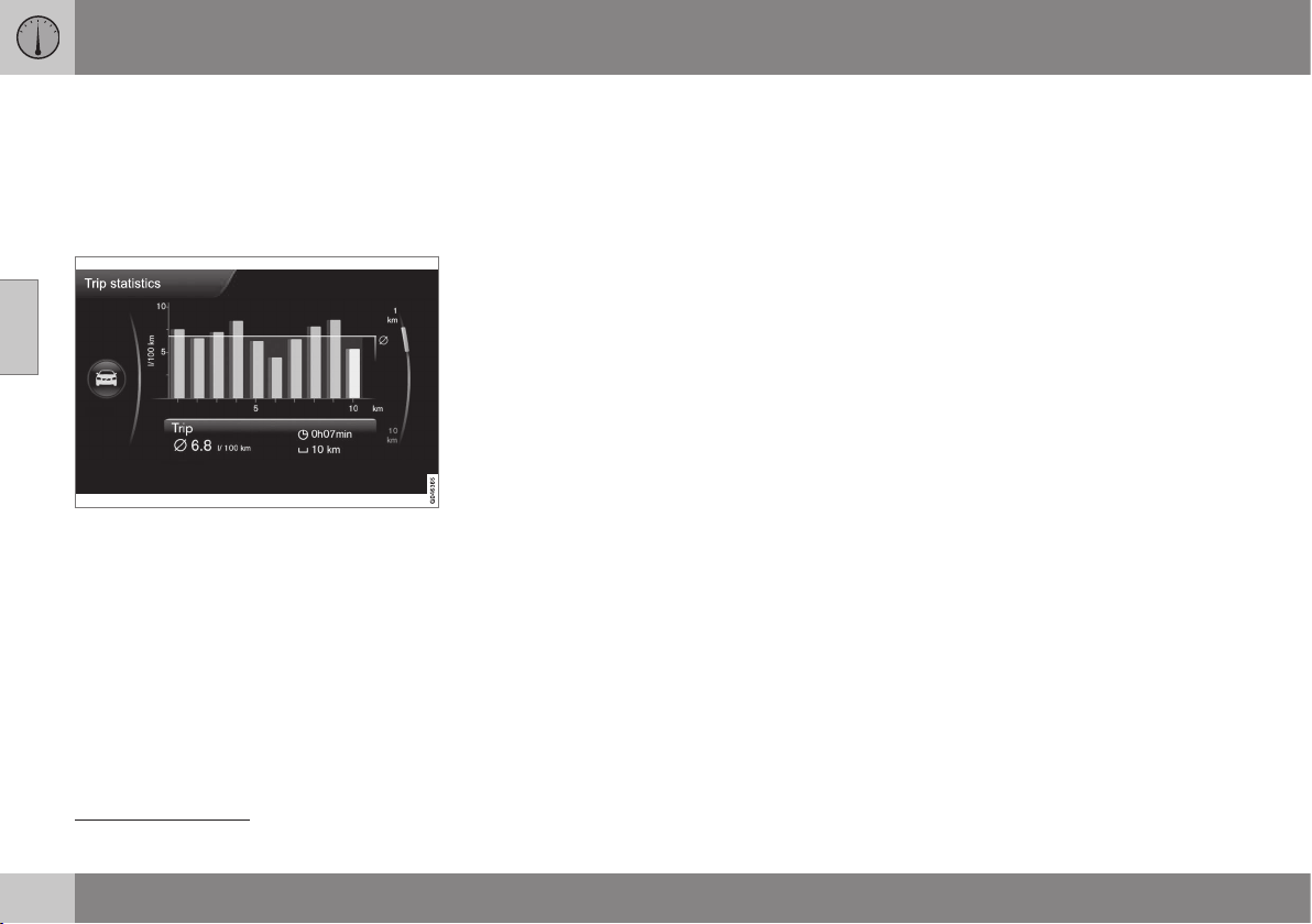
03 Instruments and controls
03
120
* Option/accessory, for more information, see Introduction.
Trip computer - trip statistics*
Information is stored about completed trips
containing average fuel consumption and
average speed, which can be viewed in the
centre console's screen as a bar chart.
Function
Trip statistics
27
Each bar symbolises 1 km or 10 km driven
distance, depending on the scale selected -
the bar at the far right shows the value for the
current kilometre or 10 km.
Using the TUNE control, the scale for the
bars can be changed between 1 km and
10 km - the cursor on the far right changes
position between up and down in relation to
the scale selected.
Operation
Different settings can be made in the menu
system MY CAR, see MY CAR (p. 108) -
there, find
Trip statistics.
With the "Reset when vehicle has been off
for minimum 4h" option highlighted, all sta-
tistics are deleted automatically once driving
is complete and the car has been stopped for
4 hours. Trip statistics start again from zero
the next time the engine is started.
•
Reset when vehicle has been off for
minimum 4h - highlight the box by
selecting ENTER and go back out of the
menu by selecting EXIT.
If a new driving cycle is started before
4 hours have elapsed then the current period
must first be deleted manually using the
"
Start new trip" option.
•
Start new trip - ENTER is used to delete
all previous statistics, go back out of the
menu by selecting EXIT.
See also information on Eco guide (p. 65).
Related information
•
Trip computer - supplementary informa-
tion (p. 119)
27
The figure is schematic - layout may vary depending on car model or updated software.
CLIMATE CONTROL

04 Climate control
04
122
* Option/accessory, for more information, see Introduction.
General information on climate
control
The car is equipped with electronic climate
control (p. 128). The climate control system
cools or heats as well as dehumidifies the air
in the passenger compartment.
NOTE
Air conditioning (AC) (p. 131) can be
switched off, but to ensure the best possi-
ble climate comfort in the passenger com-
partment, and to prevent the windows
from misting, it should always be switched
on.
To bear in mind
•
To ensure that the air conditioning works
optimally, the side windows, and sunroof*
should be closed.
•
Global opening (p. 173) opens/closes all
side windows simultaneously and can be
used for example to quickly air the car
during hot weather.
•
Remove ice and snow from the climate
control system air intake (the grille
between the bonnet and the windscreen).
•
In warm weather, condensation from the
air conditioning may drip under the car.
This is normal.
•
When the engine requires full power, e.g.
for full acceleration, the air conditioning
can be temporarily switched off. There
may then be a temporary increase in tem-
perature in the passenger compartment.
•
Remove misting on the insides of the win-
dows primarily by using the defroster
function (p. 132). To reduce the risk of
misting, keep the windows clean and use
window cleaner.
NOTE
To avoid misting on the rear window, do
not block the ventilation holes at the back
of the parcel shelf with articles of clothing
or other objects.
Cars with Start/Stop*
With an auto-stopped (p. 284) engine certain
equipment may have its function temporarily
reduced, e.g. climate control fan speed
(p. 130).
Cars with ECO*
Certain equipment may have its function tem-
porarily reduced or deactivated when the
ECO (p. 293) function is activated, e.g. the air
conditioning (p. 131).
NOTE
When the ECO function is activated, sev-
eral parameters in the climate control sys-
tem's settings are changed, and several
electricity consumer functions are
reduced. Certain settings can be reset
manually, but full functionality is only
restored by deactivating the ECO function.
Related information
•
Actual temperature (p. 123)
•
Menu settings - climate control (p. 125)
•
Electronic climate control - ECC (p. 128)
•
Air distribution in the passenger compart-
ment (p. 126)
•
Air quality (p. 123)
04 Climate control
04
* Option/accessory, for more information, see Introduction.
123
Actual temperature
The temperature you select in the passenger
compartment corresponds to the physical
experience with reference to factors such as
ambient temperature, air speed, humidity and
solar radiation etc. in and around the car at
the time.
The system includes a sun sensor (p. 123)
which detects on which side the sun is shin-
ing into the passenger compartment. This
means that the temperature can differ
between the right and left-hand air vents
despite the controls being set for the same
temperature on both sides.
Related information
•
General information on climate control
(p. 122)
•
Temperature control in the passenger
compartment (p. 131)
Sensors - climate control
The climate control system has a number of
sensors to help control the temperature
(p. 123) in the car.
•
The sun sensor is located on the top side
of the dashboard.
•
The temperature sensor for the passen-
ger compartment is located below the cli-
mate control panel.
•
The outside temperature sensor is
located in the door mirror.
•
The humidity sensor* is located by the
interior rearview mirror.
NOTE
Do not cover or block the sensors with
clothing or other objects.
Related information
•
General information on climate control
(p. 122)
Air quality
The interior in a passenger compartment is
designed to be pleasant and comfortable,
even for people with contact allergies and for
asthma sufferers.
•
Passenger compartment filter (p. 124)
•
Material in the passenger compartment
(p. 125)
•
Clean Zone Interior Package (CZIP)
(p. 124)*
•
Interior Air Quality System (IAQS)
(p. 125)*
Related information
•
General information on climate control
(p. 122)

04 Climate control
04
124
* Option/accessory, for more information, see Introduction.
Air quality - passenger compartment
filter
All air entering the car's passenger compart-
ment is cleaned with a filter.
The filter must be replaced at regular inter-
vals. Follow the Volvo Service Programme for
the recommended replacement intervals. If
the car is used in a severely contaminated
environment, it may be necessary to replace
the filter more often.
NOTE
There are different types of passenger
compartment filter. Make sure that the cor-
rect filter is fitted.
Related information
•
Air quality (p. 123)
Air quality - Clean Zone Interior
Package (CZIP)*
CZIP comprises a series of modifications that
keep the passenger compartment even
clearer from allergy and asthma-inducing sub-
stances.
The following is included:
•
An enhanced fan function that means that
the fan starts when the car is opened with
the remote control key. The fan fills the
passenger compartment with fresh air.
The function starts when required and is
disengaged automatically after a time or
when one of the passenger compartment
doors is opened. The amount of time the
fan runs is reduced gradually due to
reduced need up until the car is 4 years
old.
•
The air quality system IAQS (p. 125) is a
fully automatic system that cleans the air
in the passenger compartment from con-
taminants such as particles, hydrocar-
bons, nitrous oxides and ground-level
ozone.
NOTE
To keep the CZIP standard in cars with
CZIP the IAQS filter must be changed after
15 000 km or once per year depending on
whichever occurs first. However, up to
75 000 km over 5 years. In cars without
CZIP and where the customer does not
want to keep the CZIP standard the IAQS
filter must be changed at a regular service.
For more information on CZIP, see the bro-
chure included with the purchase of the car.
Related information
•
General information on climate control
(p. 122)
•
Air quality (p. 123)

04 Climate control
04
* Option/accessory, for more information, see Introduction.
125
Air quality - IAQS*
The air quality system IAQS separates gases
and particles to reduce the levels of odours
and pollution in the passenger compartment.
If the outside air is contaminated then the air
intake is closed and the air is recirculated.
It is possible to activate/deactivate the func-
tion in the menu system MY CAR. For a
description of the menu system, see MY CAR
(p. 108).
NOTE
The air quality sensor must always be ena-
bled to ensure the best air in the passen-
ger compartment.
In a cold climate recirculation is limited so
as to prevent misting.
In the event of misting, the air quality sen-
sor should be disengaged, and the
defroster functions for the windscreen and
side windows, as well as the rear window,
should be used.
Related information
•
General information on climate control
(p. 122)
•
Air quality (p. 123)
•
Air quality - Clean Zone Interior Package
(CZIP)* (p. 124)
Air quality - material
Tested materials have been developed in
order to minimise the quantity of dust in the
passenger compartment and to contribute to
making the passenger compartment easier to
keep clean.
The carpets in both the passenger compart-
ment and the cargo area are removable and
easy to remove and clean. Use cleaning
agents and car care products recommended
by Volvo to clean the interior (p. 401).
Related information
•
Air quality (p. 123)
Menu settings - climate control
It is possible to activate/deactivate or change
the default settings for six of the climate con-
trol system's functions via the centre console.
•
Fan level during automatic climate control
(p. 130).
•
Recirculation timer (p. 133).
•
Automatic start of rear window defroster
(p. 101).
•
Interior air quality system* (p. 125).
•
Automatic start of seat heating driver
(p. 129).
•
Automatic start of steering wheel heating
(p. 83).
More information is available in the descrip-
tion of the menu system (p. 108).
The climate control system's functions can be
reset in the menu system MY CAR to the
default settings. For a description of the
menu system, see MY CAR (p. 108).
Related information
•
General information on climate control
(p. 122)
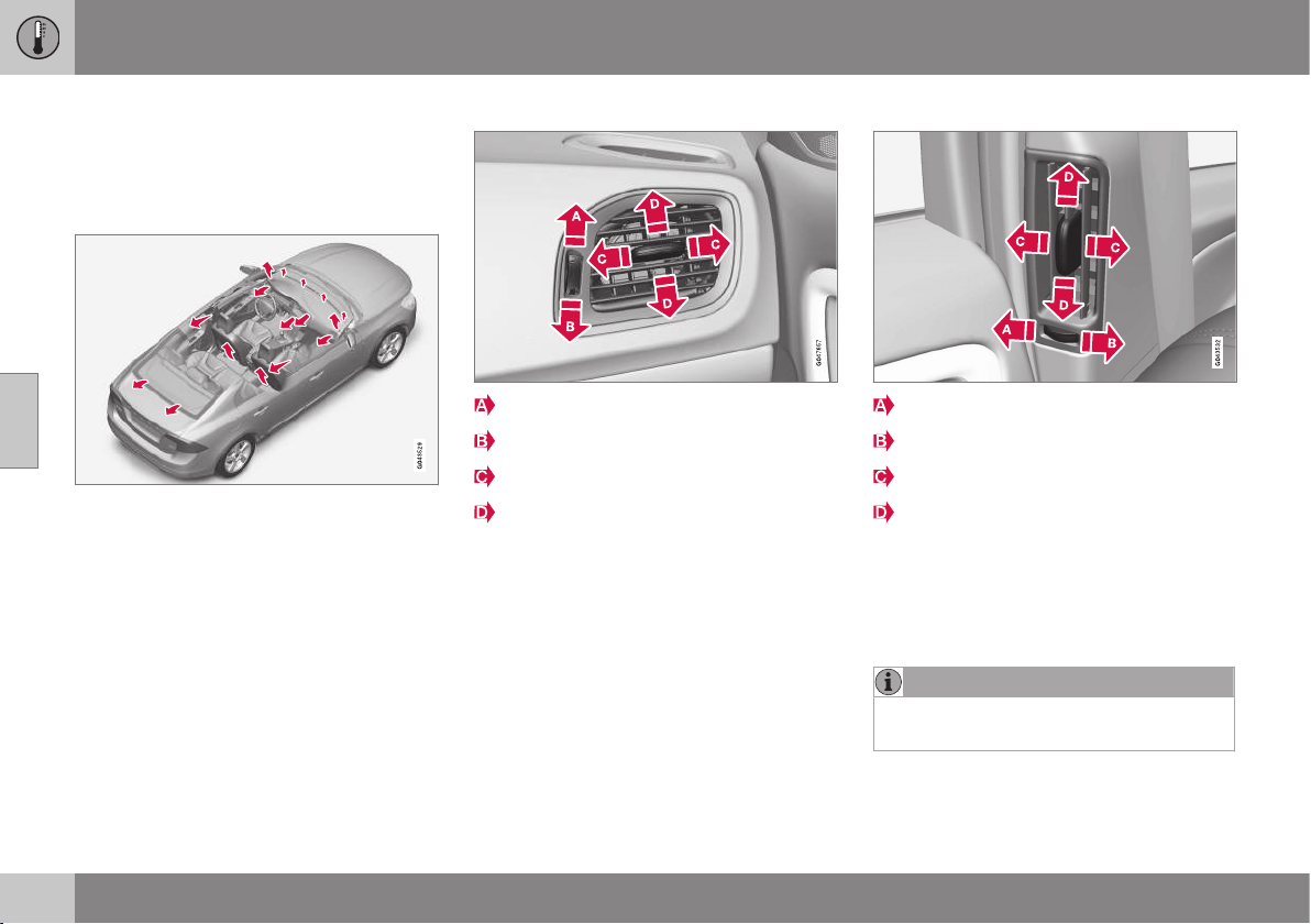
04 Climate control
04
126
Air distribution in the passenger
compartment
The incoming air is divided between a number
of different vents in the passenger compart-
ment.
Air distribution is fully automatic in AUTO
mode.
If necessary it can be controlled manually;
see the air distribution table (p. 134).
Air vents in the dashboard
Open
Closed
Lateral airflow
Vertical airflow
Aim the outer vents at the side windows to
remove misting.
Air vents in the door pillars
Closed
Open
Lateral airflow
Vertical airflow
Aim the vents at the windows to remove mist-
ing in cold weather.
Aim the vents into the passenger compart-
ment to maintain a comfortable climate in the
rear seat in hot weather.
NOTE
Remember that small children may be sen-
sitive to air flows and draughts.
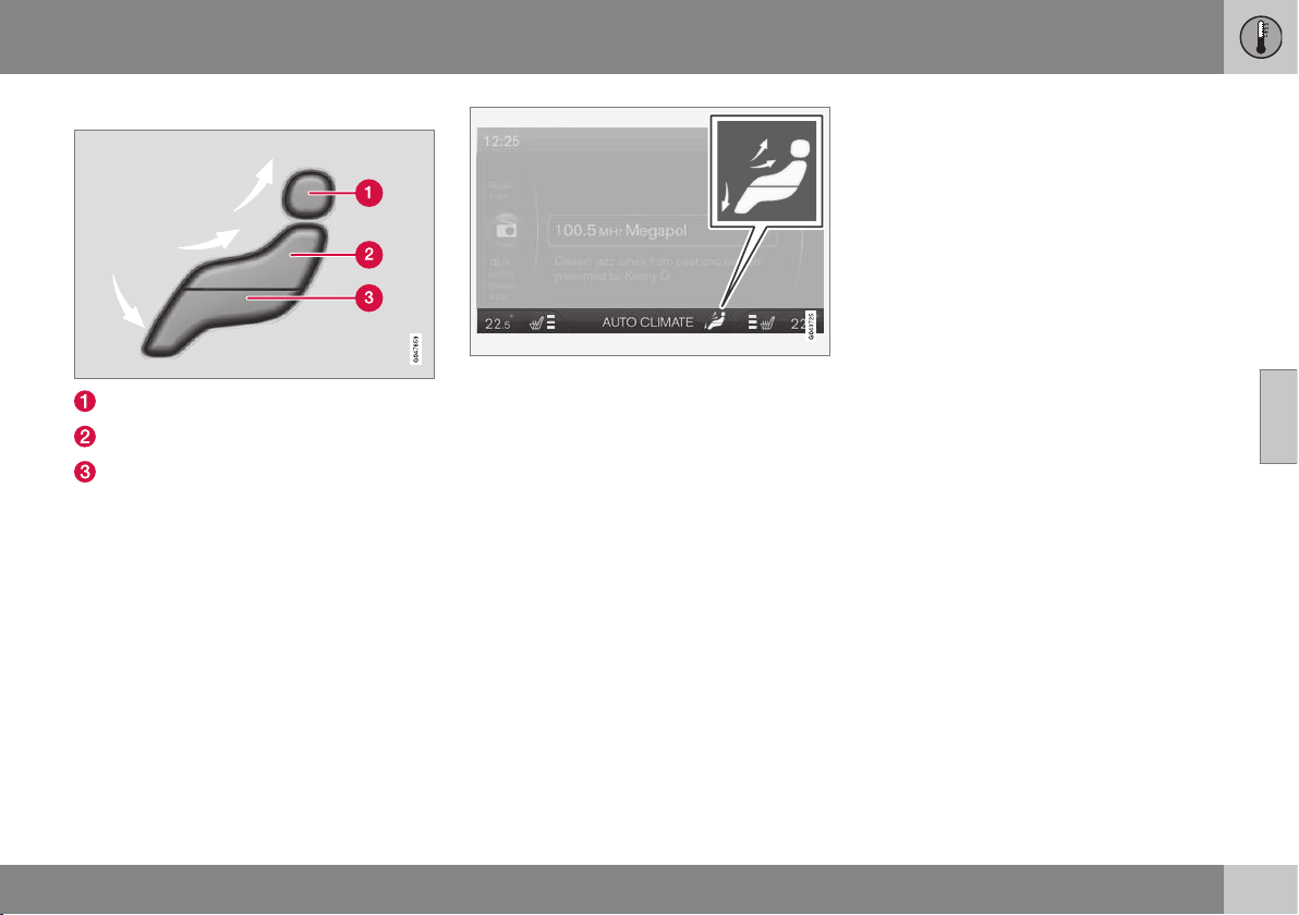
04 Climate control
04
127
Air distribution
Air distribution - defroster windscreen
Air distribution - air vent instrument panel
Air distribution - ventilation floor
The figure consists of three buttons. When
pressing the buttons the corresponding figure
is illuminated in the screen (see following fig-
ure) and an arrow in front of each part of the
figure shows the air distribution that is
selected. For more information, see the air
distribution table (p. 134).
The selected air distribution is shown in the cen-
tre console display screen.
Related information
•
General information on climate control
(p. 122)
•
Auto-regulation (p. 130)
•
Air distribution - recirculation (p. 133)
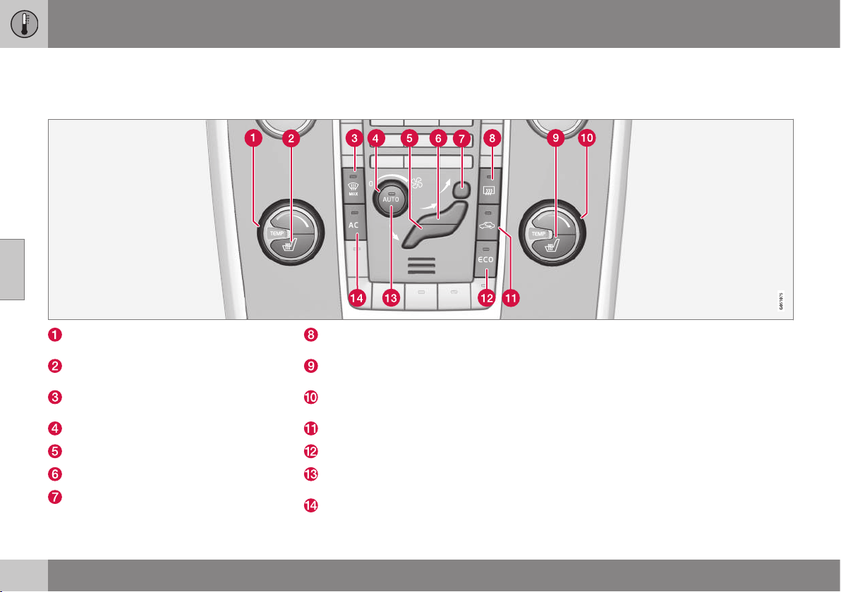
04 Climate control
04
128
* Option/accessory, for more information, see Introduction.
Electronic climate control - ECC
ECC (Electronic Climate Control) maintains
the temperature selected in the passenger
compartment and can be set separately for
the driver's side and passenger side.
The auto function is used to automatically
control temperature, air conditioning, fan
speed, recirculation and air distribution.
Temperature control (p. 131), left-hand
side
Electrically heated front seat (p. 129), left
side
Heated windscreen* and max. defroster
(p. 132)
Fan (p. 130)
Air distribution (p. 126) - ventilation floor
Air distribution - air vent instrument panel
Air distribution - defroster windscreen
Rear window and door mirror defrosters
(p. 101)
Electrically heated front seat (p. 129),
right side
Temperature control (p. 131), right-hand
side
Recirculation (p. 133)
ECO* (p. 293)
AUTO - Automatic climate control
(p. 130)
AC - Air conditioning on/off (p. 131)
Related information
•
General information on climate control
(p. 122)

04 Climate control
04
}}
* Option/accessory, for more information, see Introduction.
129
Heated front seats*
The front seat heating has three positions for
increasing the comfort for driver and passen-
ger when it is cold.
Current heat level is shown in the centre console
display screen.
Press the button repeatedly in order to acti-
vate the function:
•
Highest heat level - three orange fields
illuminate in the centre console's screen
(see figure above).
•
Lower heat level - two orange fields illu-
minate in the screen.
•
Lowest heat level - one orange field illu-
minates in the screen.
•
Switch off the heat - no field illuminates.
WARNING
Heated seats must not be used by people
who find it difficult to perceive an increase
in temperature due to a lack of sensation
or who otherwise have problems operating
the controls for the heated seats. Other-
wise they may suffer burn injuries.
Automatic start of driver's seat heating
With the automatic start of the driver's seat
heating activated, the driver's seat will have
the highest heat level when the engine is
started.
Automatic start takes place when the car is
cold and the ambient temperature is lower
than approx. +10 °C.
It is possible to activate/deactivate the func-
tion in the menu system MY CAR. For a
description of the menu system, see MY CAR
(p. 108).
Related information
•
General information on climate control
(p. 122)
•
Heated rear seat* (p. 129)
Heated rear seat*
The heating for the rear seat's outer positions
has three positions for increasing the comfort
for passengers when it is cold.
Current heat level is shown in the pushbutton's
lamps.
Press the button repeatedly in order to acti-
vate the function:
•
Highest heat level - three lamps illumi-
nate.
•
Lower heat level - two lamps illuminate.
•
Lowest heat level - one lamp illuminates.
•
Switch off the heat - no lamp illuminates.
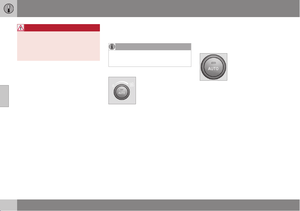
||
04 Climate control
04
130
* Option/accessory, for more information, see Introduction.
WARNING
Heated seats must not be used by people
who find it difficult to perceive an increase
in temperature due to a lack of sensation
or who otherwise have problems operating
the controls for the heated seats. Other-
wise they may suffer burn injuries.
Related information
•
General information on climate control
(p. 122)
•
Heated front seats* (p. 129)
Fan
The fan should always be activated in order to
avoid misting on the windows.
NOTE
If the fan is fully switched off then the air
conditioning is not engaged - which can
cause a risk of misting on the windows.
Fan knob
Turn the knob to increase or
decrease fan speed. If AUTO
is selected, then the fan
speed is regulated automati-
cally (p. 130) - the fan speed
previously set is disengaged.
Related information
•
General information on climate control
(p. 122)
•
Electronic climate control - ECC (p. 128)
Auto-regulation
The auto function automatically regulates
temperature (p. 131), air conditioning
(p. 131), fan speed (p. 130), recirculation
(p. 133) and air distribution (p. 126).
If you select one or more
manual functions, the other
functions continue to be
controlled automatically. All
manual settings are disen-
gaged when AUTO is
pressed. The display screen
shows
AUTO CLIMATE.
Fan speed in automatic mode can be set in
the menu system MY CAR. For a description
of the menu system, see MY CAR (p. 108).
Related information
•
General information on climate control
(p. 122)
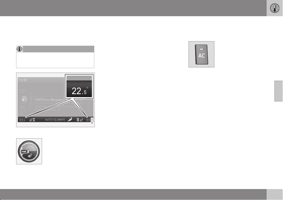
04 Climate control
04
131
Temperature control in the passenger
compartment
When the car is started, the most recent tem-
perature setting is resumed.
NOTE
Heating or cooling cannot be hastened by
selecting a higher or lower temperature
than the actual desired temperature.
Current temperature for each side is shown in
the centre console's display screen.
The temperature can be
adjusted with the knob -
separately for the driver's
side and the passenger side.
Related information
•
General information on climate control
(p. 122)
•
Actual temperature (p. 123)
•
Electronic climate control - ECC (p. 128)
Air conditioning
The air conditioning cools and dehumidifies
incoming air as required.
When the lamp in the AC
button illuminates, the air
conditioning is controlled by
the system's automatic func-
tion.
When the lamp in the AC
button is switched off the air conditioning is
disconnected. Other functions are still con-
trolled automatically. When the max.
defroster function (p. 132) is activated, the air
conditioning is switched on automatically so
that the air is dehumidified at the maximum
setting.
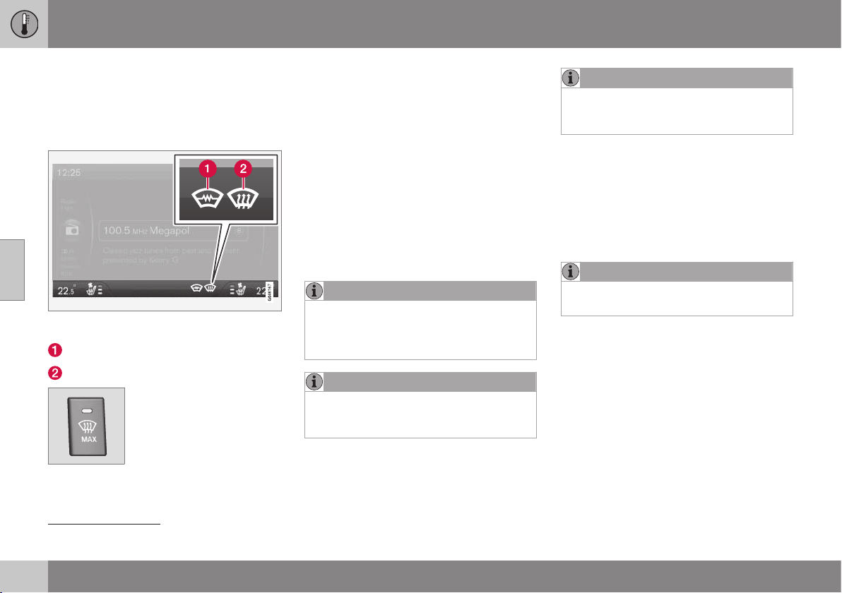
04 Climate control
04
132
* Option/accessory, for more information, see Introduction.
Demisting and defrosting the
windscreen
Heated windscreen* and max. defroster are
used to quickly remove misting and ice from
the windscreen and side windows.
The selected setting is shown in the centre con-
sole's screen.
Heated windscreen*
Max. defroster
The light in the defroster but-
ton illuminates when the
function is active.
Press the button repeatedly
in order to activate the func-
tion.
For cars without heated windscreen:
•
Air flows to the windows - symbol (2) illu-
minates in the screen.
•
Switch off the function - no symbol illumi-
nates.
For cars with heated windscreen:
•
Start the heating for the windscreen
1
-
symbol (1) illuminates in the screen.
•
Start the heating for the windscreen
1
and
air flow to the windows - symbols (1) and
(2) illuminate in the screen.
•
Switch off the function - no symbol illumi-
nates.
NOTE
Heated windscreen and IR window (p. 19)
may have an impact on the performance of
transponders and other communication
equipment.
NOTE
A triangular area at the end of each side of
the windscreen is not electrically heated,
where de-icing may take longer.
NOTE
Electrically heated windscreen is not avail-
able when the engine is auto-stopped
(p. 284).
The following also takes place in order to pro-
vide maximum dehumidification in the pas-
senger compartment:
•
the air conditioning is automatically
engaged
•
recirculation and the air quality system
are automatically disengaged.
NOTE
The noise level increases as the fan is
operating at max.
When the defroster is switched off the climate
control returns to the previous settings.
Related information
•
General information on climate control
(p. 122)
1
If the character
C is shown in the rearview mirror when the heated windscreen is activated then the compass (p. 102)* must be recalibrated.
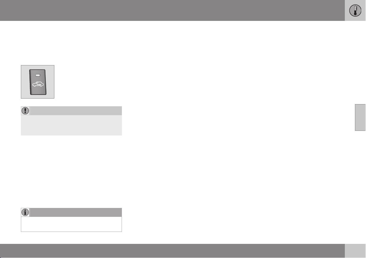
04 Climate control
04
133
Air distribution - recirculation
Select recirculation to shut out bad air,
exhaust gases etc. from the passenger com-
partment, i.e. no outside air is taken into the
car when this function is activated.
When recirculation is
engaged the orange lamp in
the button illuminates.
IMPORTANT
If the air in the car is recirculated for too
long then there is a risk of misting on the
insides of the windows.
Timer
With the timer function activated the system
will exit manually activated recirculation mode
according to a time that depends on the out-
side temperature. This reduces the risk of ice,
misting and bad air.
It is possible to activate/deactivate the func-
tion in the menu system MY CAR. For a
description of the menu system, see MY CAR
(p. 108).
NOTE
When max. defroster is selected, recircula-
tion is always deactivated.
Related information
•
General information on climate control
(p. 122)
•
Air distribution in the passenger compart-
ment (p. 126)
•
Air distribution - table (p. 134)
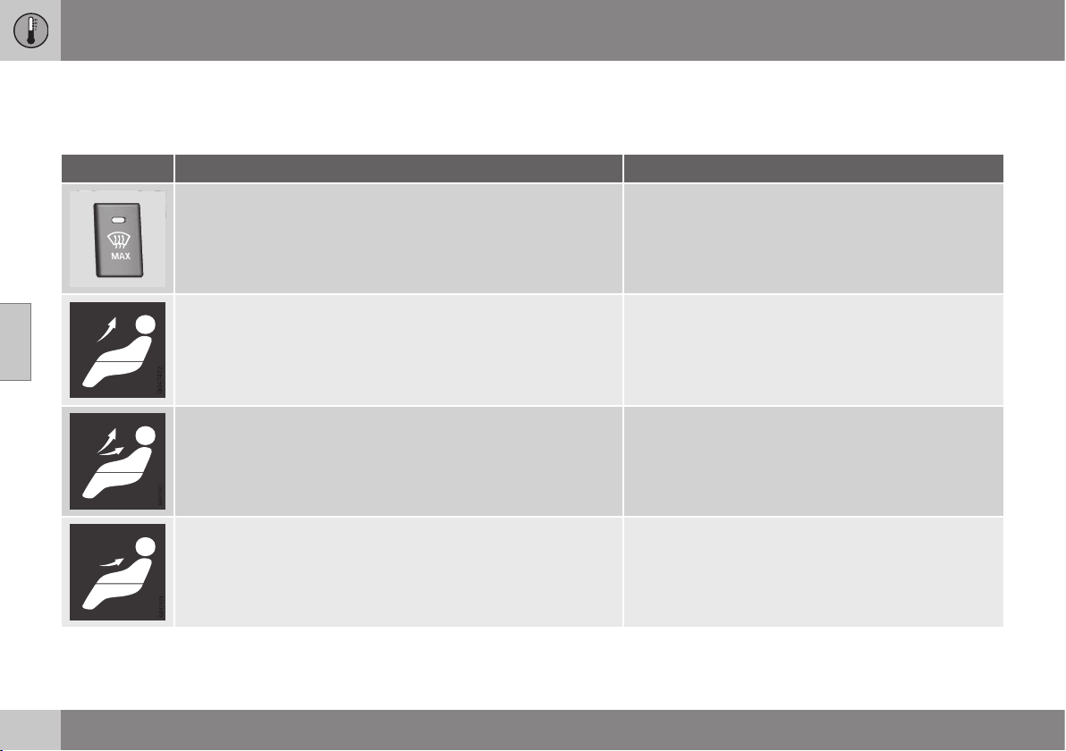
04 Climate control
04
134
Air distribution - table
Three buttons are used to select the distribu-
tion (p. 126) of the air.
Air distribution Use
Air to windows. Some air flows from the air vents. The air is not
recirculated. Air conditioning is always engaged.
to remove ice and misting quickly.
Air to windscreen, via defroster vent, and side windows. Some air
flows from the air vents.
to avoid misting and icing in a cold and humid climate
(to achieve this the fan level must not be too low).
Airflow to windows and from dashboard air vents. to ensure good comfort in warm, dry weather.
Airflow to the head and chest from dashboard air vents. to ensure efficient cooling in warm weather.
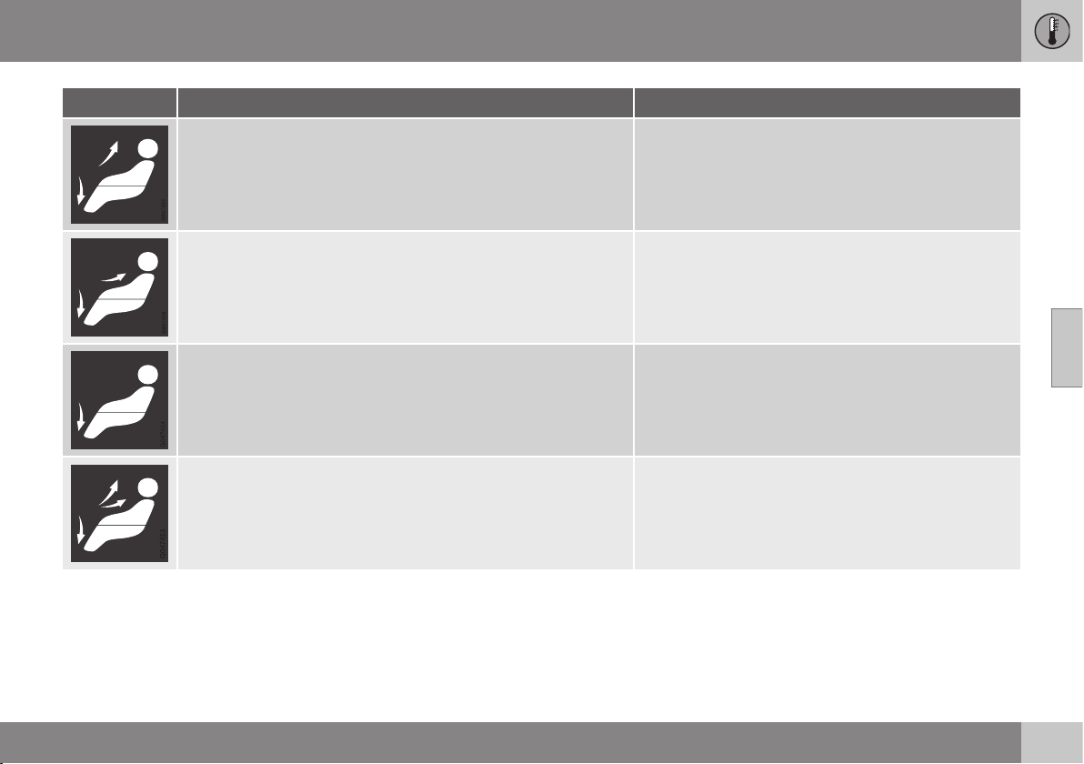
04 Climate control
04
135
Air distribution Use
Air to the floor and windows. Some air flows from the dashboard
air vents.
to ensure comfortable conditions and good demisting in
cold or humid weather.
Air to floor and from dashboard air vents. in sunny weather with cool outside temperatures.
Air to floor. Some air flows to the dashboard air vents and win-
dows.
to direct heat or cold to the floor.
Airflow to windows, from dashboard air vents and to the floor. to provide cooling along the floor in hot, dry weather or
warming upwards in cold weather.
Related information
•
General information on climate control
(p. 122)
•
Air distribution - recirculation (p. 133)
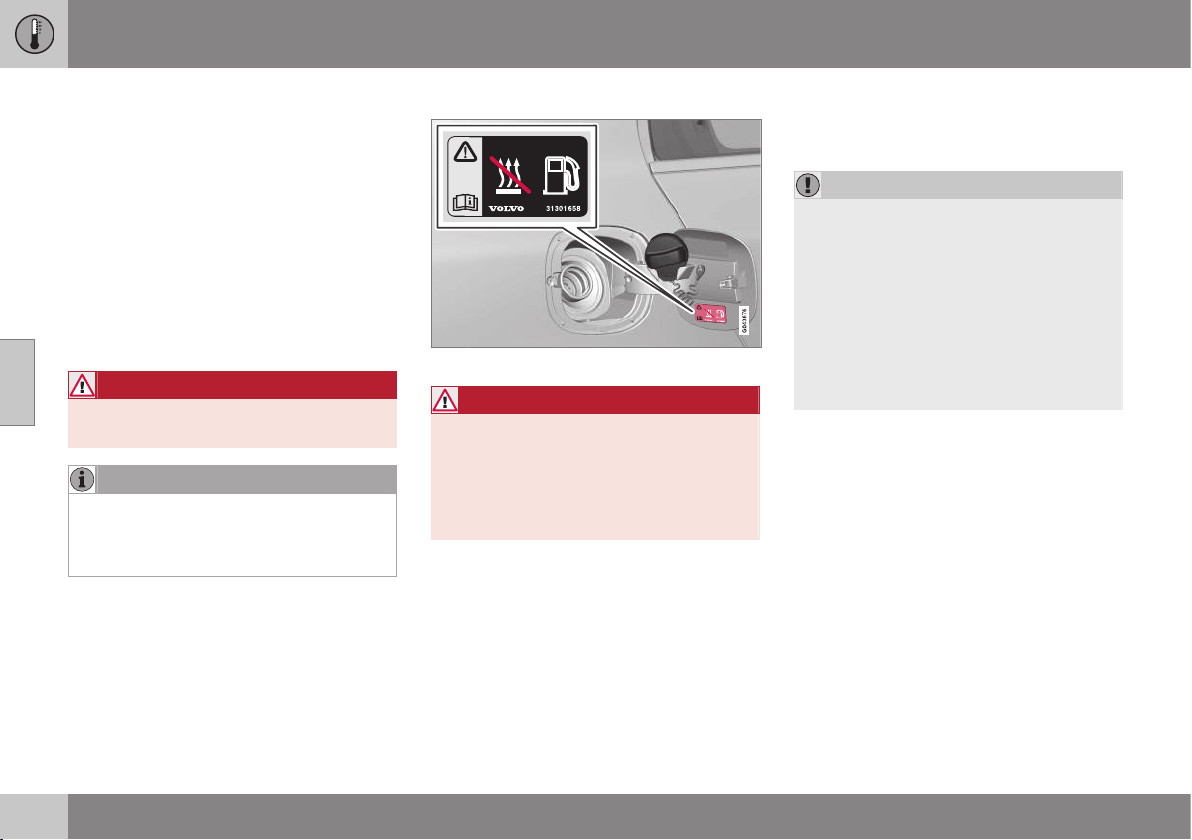
04 Climate control
04
136
* Option/accessory, for more information, see Introduction.
Engine block heater and passenger
compartment heater*
Preconditioning prepares the heater, engine
and passenger compartment before depar-
ture so that both wear and energy needs dur-
ing the journey are reduced.
The heater can be started directly (p. 137) or
with a timer (p. 138).
The heater cannot start if the outside tem-
perature exceeds 15 °C. At –5 °C or lower the
maximum running time of the heater is 50
minutes.
WARNING
Do not use the fuel-driven heater indoors.
Exhaust gases are secreted.
NOTE
When the fuel-driven auxiliary heater is
active there may be smoke from the right-
hand wheel housing, which is perfectly
normal.
Refuelling
Warning label on fuel filler flap.
WARNING
Fuel which spills out could be ignited.
Switch off the fuel-driven auxiliary heater
before starting to refuel.
Check in the combined instrument panel
that the heater is switched off. The heat
symbol is shown when it is operating.
Parking on a hill
If the car is parked on a steep hill, the front of
the car should point downhill to ensure that
there is a supply of fuel to the fuel-driven
heater.
Battery and fuel
If the battery has insufficient charge or the
fuel level is too low, the heater will be
switched off automatically and a message
appears on the information display. Acknowl-
edge the message by pressing the indicator
stalk (p. 105) OK button once.
IMPORTANT
Repeated use of the heater combined with
short journeys leads to the battery dis-
charging and consequential starting prob-
lems.
The car should be driven for the same time
as the heater is used to ensure that the
car's battery is recharged adequately to
replace the energy consumed by the
heater when it is used on a regular basis.
The heater is used for a maximum of 50
minutes each time.
Related information
•
Engine block heater and passenger com-
partment heater* - messages (p. 140)
•
Additional heater* (p. 142)
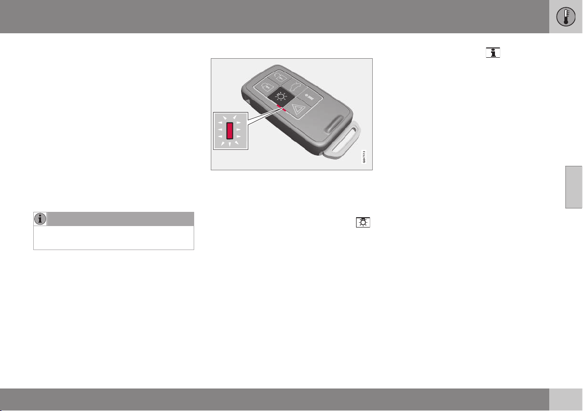
04 Climate control
04
* Option/accessory, for more information, see Introduction.
137
Engine block heater and passenger
compartment heater* - direct start
The engine block heater and passenger com-
partment heater can be started directly.
Direct start can be performed via:
•
information display
•
remote control key*
•
mobile*.
Upon direct start of the engine block and
passenger compartment heater (p. 136), it will
run for 50 minutes.
Heating of the passenger compartment will
begin as soon as the engine coolant has
reached the correct temperature.
NOTE
The car can be started and driven while
the heater is running.
Direct start via the information display
1. Press OK to access the menu.
2.
Scroll with the thumbwheel to
Parking
heater and select with OK.
3.
Scroll forward in the next menu to
Direct
start
in order to activate the heater and
select with OK.
4. Exit the menu with RESET.
Direct start via the remote control key*
Indicator lamp on remote control key with PCC*.
The engine block heater and passenger com-
partment heater can be activated via the
remote control key:
–
Hold the button for approach lighting
depressed for 2 seconds.
Hazard warning flashers provide informa-
tion in accordance with the following:
•
5 short flashes followed by a constant
glow for approx. 3 seconds - the signal
has reached the car and the heater has
been activated.
•
5 short flashes - the signal has
reached the car but the heater has not
been activated.
•
Hazard warning flashers remain
switched off - the signal has not
reached the car.
If the button for information
is depressed
when the heater is active then the indicator
lamp will show the status for this - at the
same time the car's lock status (p. 161) is
shown. While the status is being investigated
the indicator lamp emits a pair of short
flashes followed by a constant glow if the
heater is active.
Status is also shown in the trip computer dur-
ing heating.
Direct start via a mobile*
Activation and information about the selected
settings that can be managed from a mobile
phone will be available via the Volvo On Call*
mobile app.
Related information
•
Engine block heater and passenger com-
partment heater* - timer (p. 138)
•
Engine block heater and passenger com-
partment heater* - immediate stop
(p. 138)
•
Engine block heater and passenger com-
partment heater* - messages (p. 140)
04 Climate control
04
138
* Option/accessory, for more information, see Introduction.
Engine block heater and passenger
compartment heater* - immediate
stop
The engine block heater and passenger com-
partment heater can be deactivated directly
via the information display.
1. Press OK to access the menu.
2.
Scroll with the thumbwheel to
Parking
heater and select with OK.
3.
Scroll forward in the next menu to
Stop in
order to deactivate the heater and select
with OK.
4. Exit the menu with RESET.
Related information
•
Engine block heater and passenger com-
partment heater* - direct start (p. 137)
•
Engine block heater and passenger com-
partment heater* - timer (p. 138)
•
Engine block heater and passenger com-
partment heater* - messages (p. 140)
Engine block heater and passenger
compartment heater* - timer
The timer of the engine block and passenger
compartment heater (p. 136) is connected to
the car's clock.
Two different times can be selected using the
timer. Here, time refers to the time when the
car is heated and ready. The car's electronic
system calculates when heating should be
started based on the outside temperature.
NOTE
All timer programming will be cleared if the
car's clock is reset.
Adjusting
2
1. Press OK to access the menu.
2. Use the thumbwheel (p. 105) to scroll to
one of the timers
Parking heater and
select with OK.
3. Select one of the two timers using the
thumbwheel and confirm with OK.
4. Briefly press OK to move to the lit hours
setting.
5. Select the required hour using the thumb-
wheel.
6. Briefly press OK to move to the flashing
minutes setting.
7. Select the required minute using the
thumbwheel.
8.
Press OK
3
to confirm the setting.
9. Go back in the menu structure using
RESET.
10. Select the other time (continue from step
2) or exit the menu with RESET.
Starting
1. Press OK to access the menu.
2.
Scroll with the thumbwheel to
Parking
heater and select with OK.
3. Select one of the two timers using the
thumbwheel and activate with OK.
4. Exit the menu with RESET.
Switching off
A timer-started heater can be switched off
manually before the set time has elapsed.
Proceed as follows:
1. Press OK to access the menu.
2
Setting the timer is only possible with the engine switched off.
3
Press OK again to activate the timer.

04 Climate control
04
* Option/accessory, for more information, see Introduction.
139
2.
Scroll with the thumbwheel to
Parking
heater and select with OK.
> If a timer is set but not activated then a
clock icon is shown beside the set
time.
3. Select one of the two timers using the
thumbwheel and confirm with OK.
4. Deactivate the timer as follows:
•
long press on OK or
•
short press on OK to continue in the
menu. Then select to stop the timer
and confirm with OK.
5. Exit the menu with RESET.
A timer-started heater can be switched off
directly (p. 138).
Related information
•
Engine block heater and passenger com-
partment heater* - messages (p. 140)
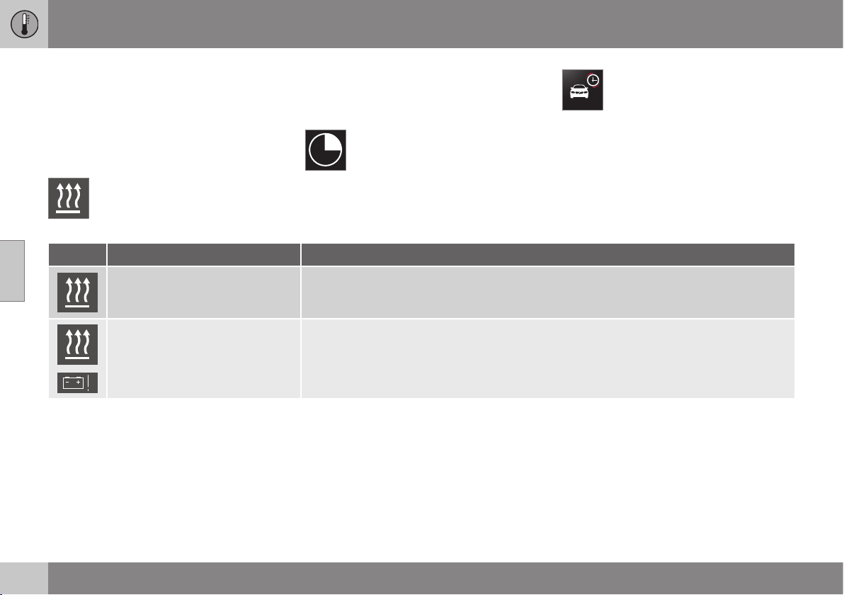
04 Climate control
04
140
* Option/accessory, for more information, see Introduction.
Engine block heater and passenger
compartment heater* - messages
Symbols and display messages regarding the
engine block and passenger compartment
heater (p. 136) differ depending on whether
the combined instrument panel (p. 61) is ana-
logue or digital.
When the heater has been activated
the heat symbol illuminates in the
information display.
When one of the timers has been activated,
the symbol for activated timer illuminates in
the display at the same time as the set time is
shown next to the symbol.
Symbol for activated timer in ana-
logue combined instrument panel.
Symbol for activated timer in digital
combined instrument panel.
The table shows symbols and display texts
that appear.
Symbol Message Specification
The heater is switched on and running.
Fuel operated heater stopped
Battery saving mode
The heater has been stopped by the car's electronics in order to facilitate starting the engine.

04 Climate control
04
141
Symbol Message Specification
Fuel operated heater stopped
Low fuel level
Starting the heater is not possible due to fuel level being too low - this is in order to facilitate
starting the engine as well as approx. 50 km driving.
Fuel operated heater Service
required
Heater not working. Contact a workshop for repair. Volvo recommends that you contact an
authorised Volvo workshop.
A display text clears automatically after a time
or after one press on the indicator stalk
(p. 105) OK button.

04 Climate control
04
142
* Option/accessory, for more information, see Introduction.
Additional heater*
In cold climate zones
4
an additional heater
may be required to obtain the correct operat-
ing temperature in the engine and to obtain
sufficient heating in the passenger compart-
ment.
A fuel-driven additional heater (p. 142) is fit-
ted in cars with diesel engines.
In a semi-cold
4
climate zone diesel-driven
cars have an electric additional heater
(p. 143) instead of a fuel-driven version.
Cars with certain petrol engines
5
have an
electric additional heater integrated into the
car's climate control system.
Related information
•
Engine block heater and passenger com-
partment heater* (p. 136)
Fuel-driven additional heater*
The car is equipped with either an electric
(p. 143) or a fuel-driven additional heater
(p. 142).
The heater starts automatically when extra
heat is required when the engine is running.
The heater is switched off automatically when
the correct temperature is reached or when
the engine is switched off.
NOTE
When the additional heater is active there
may be smoke from the right-hand wheel
housing, which is perfectly normal.
Auto mode or shutdown
The additional heater's automatic start
sequence can be switched off if required.
NOTE
Volvo recommends that the fuel-driven
additional heater should be switched off
for short distances.
1. Before starting the engine: Select key
position I (p. 76).
2. Press OK to access the menu.
3.
Scroll with the thumbwheel to
Additional
heater
6
or
Settings
7
and select with OK.
4.
Select one of the options
ON or OFF
using the thumbwheel and confirm with
OK.
5. Exit the menu with RESET.
NOTE
The menu options are only visible in key
position I - any adjustments must therefore
be made before starting the engine.
Passenger compartment heater*
If the additional heater is supplemented with
a timer function then it can be used as a pas-
senger compartment heater (p. 136).
4
An authorised Volvo dealer has information regarding the geographical areas concerned.
5
An authorised Volvo dealer has information regarding the engines concerned.
6
Analogue combined instrument panel.
7
Digital combined instrument panel.

04 Climate control
04
* Option/accessory, for more information, see Introduction.
143
Electric additional heater*
The car is equipped with either a fuel-driven
(p. 142) or an electric additional heater
(p. 142).
The heater cannot be controlled manually, but
is instead activated automatically after the
engine has been started in outside tempera-
tures below 14 °C and is switched off after
the set passenger compartment temperature
has been reached.
Related information
•
Engine block heater and passenger com-
partment heater* (p. 136)
LOADING AND STORAGE
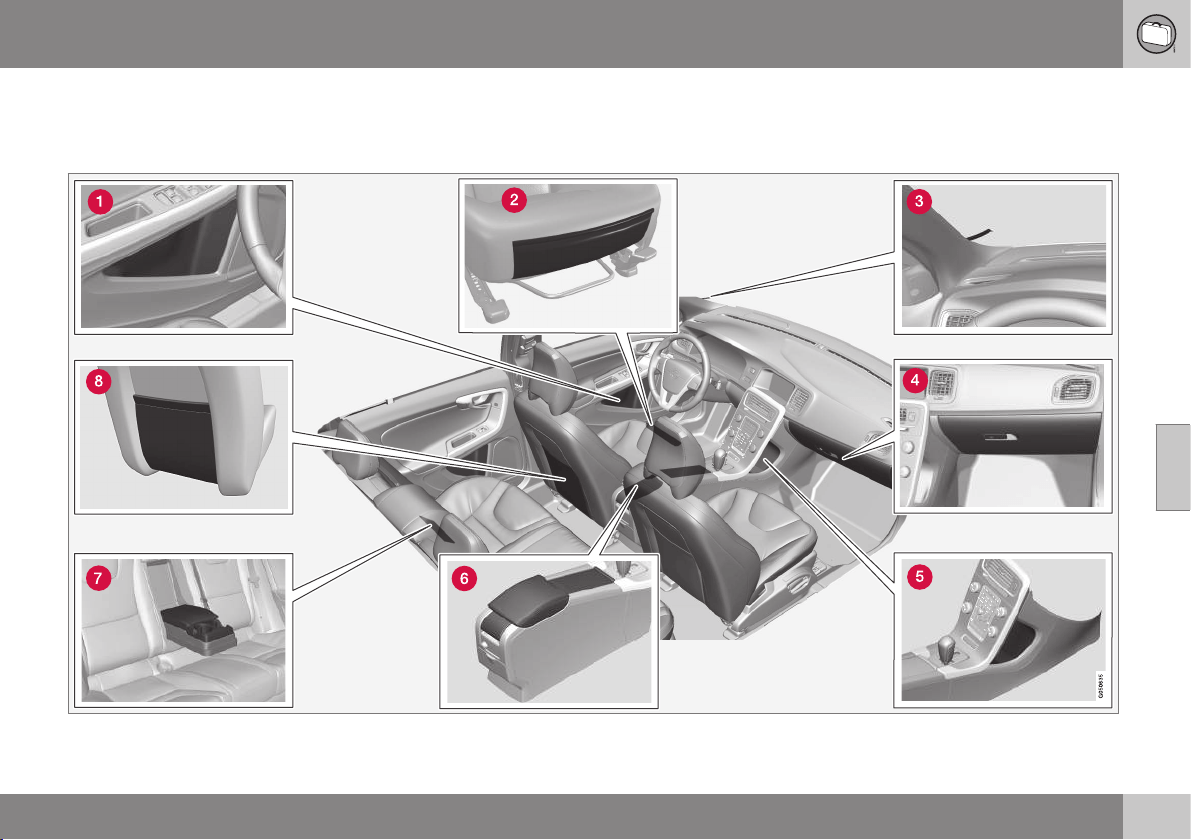
05 Loading and storage
05
}}
145
Storage spaces
Overview of storage spaces in the passenger
compartment.

||
05 Loading and storage
05
146
* Option/accessory, for more information, see Introduction.
Storage compartment in door panel
Storage pocket* on front edge of front
seat cushions
Ticket clip
Glovebox (p. 147)
Storage compartment
Storage compartment, cup holder
(p. 147)
Cup holder* in armrest, rear seat
Storage pocket
WARNING
Keep loose objects such as mobile
phones, cameras, remote controls for
accessories, etc. in the glove compartment
or other compartments. Otherwise they
may injure people in the car in the event of
sudden braking or a collision.
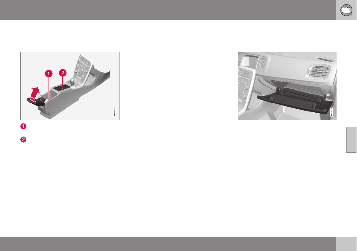
05 Loading and storage
05
* Option/accessory, for more information, see Introduction.
147
Tunnel console
The tunnel console is located between the
front seats.
Storage compartment (e.g. for CDs) and
USB*/AUX input under the armrest.
Includes cup holder for driver and pas-
senger. If ashtray and cigarette lighter
(p. 147) are specified, then there is a cig-
arette lighter in the 12 V socket (p. 148)
for the front seat, and a detachable ash-
tray in the cup holder.
Related information
•
Storage spaces (p. 145)
•
Tunnel console - cigarette lighter and
ashtray* (p. 147)
Tunnel console - cigarette lighter and
ashtray*
A detachable ashtray is fitted in the cup
holder under the armrest. The cigarette lighter
is fitted in the 12 V socket (p. 148) for the
front seat.
The ashtray in the tunnel console (p. 147) is
detached by lifting the tray straight up.
Activate the lighter by pushing in the button.
The button pops out when the lighter is hot.
Pull out the lighter and light a cigarette on the
heated coils.
Related information
•
Storage spaces (p. 145)
Glovebox
The glovebox is located on the passenger
side.
The owner's manual and maps can be kept in
here for example. There are also holders for
pens on the inside of the lid. The glovebox
can be locked* (p. 173) using the key blade
(p. 163).
Related information
•
Storage spaces (p. 145)
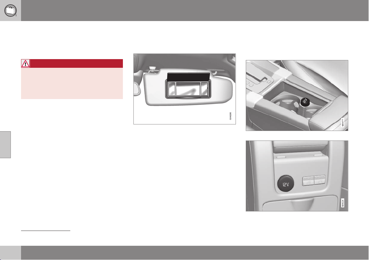
05 Loading and storage
05
148
* Option/accessory, for more information, see Introduction.
Inlay mats*
Inlay mats collect e.g. rubbish and slush.
Volvo supplies specially manufactured inlay
mats.
WARNING
Only use one inlaid mat at each seat, and
check before setting off that the mat by
the driver's seat is firmly affixed and
secured in the pins so that it does not get
caught adjacent to and under the pedals.
Related information
•
Cleaning the interior (p. 401)
Vanity mirror
The vanity mirror is located on the rear of the
sun visor.
Vanity mirror with lighting.
The light illuminates automatically when the
cover is lifted.
Related information
•
Lamp replacement - vanity mirror lighting
(p. 375)
Tunnel console - 12 V-sockets
The electrical sockets (12 V) are located next
to the cup holder
1
and rear of the tunnel con-
sole.
12 V socket in tunnel console, front seat.
12 V socket in tunnel console, rear seat.
1
If ashtray and cigarette lighter are specified then there is no cup holder and adjacent 12 V socket.
05 Loading and storage
05
}}
* Option/accessory, for more information, see Introduction.
149
The electrical socket can be used for various
accessories designed for 12 V, e.g. TV
screens, music players and mobile phones.
For the socket to supply current, the remote
control key must be in at least key position I
(p. 76).
WARNING
Always leave the plug in the socket when
the socket is not in use.
NOTE
Optional equipment and accessories - e.g.
display screens, music players and mobile
phones - which are connected to one of
the passenger compartment's 12V electri-
cal sockets, could be activated by the cli-
mate control system, even when the
remote control key has been removed or
when the car is locked, for example, when
the parking heater is activated at a preset
time.
For this reason remove the plugs from the
electrical sockets for optional equipment
or accessories when not in use because
the battery could be drained in the event of
such an occurrence!
IMPORTANT
Max. socket is 10 A (120 W) if one socket
is used at a time. If both sockets in the
tunnel console are used simultaneously,
7.5 A (90 W) per socket is applicable.
If the compressor for emergency puncture
repair is connected to one of the two sock-
ets, no other current consumer must be
connected to the other one.
NOTE
The compressor for emergency puncture
repair (p. 341) has been tested and
approved by Volvo.
Related information
•
Tunnel console - cigarette lighter and
ashtray* (p. 147)
•
12 V electrical socket, cargo area*
(p. 153)
Loading
Payload depends on the car's kerb weight.
Payload depends on the car's kerb weight.
The total of the weight of the passengers and
all accessories reduces the car's payload by
a corresponding weight.
For more detailed information on weights, see
Weights (p. 409).
The boot lid is opened via a button
on the lighting panel or the remote
control key, see Locking/unlocking -
boot lid (p. 174).
WARNING
The car’s driving properties change
depending on the weight and positioning
of the load.
To bear in mind when loading
•
Position the load firmly against the rear
seat's backrest.
Note that objects must not prevent the func-
tion of the WHIPS system for the front seats if
any of the rear seat's backrests is folded
down, see WHIPS - seating position (p. 38).
•
Centre the load.
•
Heavy objects should be placed as low
as possible. Avoid placing heavy loads on
lowered backrests.
||
05 Loading and storage
05
150
* Option/accessory, for more information, see Introduction.
•
Cover sharp edges with something soft to
avoid damaging the upholstery.
•
Secure all loads to the load retaining eye-
lets with straps or web lashings.
WARNING
A loose object weighing 20 kg can, in a
frontal collision at a speed of 50 km/h,
carry the impact of an item weighing
1000 kg.
WARNING
The protection provided by the inflatable
curtain in the headlining may be compro-
mised or eliminated by high loads.
•
Never load cargo above the backrest.
WARNING
Always secure the load. During heavy
braking the load may otherwise shift, caus-
ing injury to the car's occupants.
Cover sharp edges and sharp corners with
something soft.
Switch off the engine and apply the park-
ing brake when loading/unloading long
items. Otherwise you may accidentally
knock the gear lever or gear selector with
the load into a drive position - and the car
could then move off.
Related information
•
Load retaining eyelets (p. 152)
•
Loading - long load (p. 150)
•
Roof load (p. 151)
Loading - long load
To simplify loading (p. 149) in the cargo area,
the rear seat backrest can be folded down.
The passenger seat
2
backrest can also be
folded for an extra long load*.
Lowering the rear seat backrest
If the rear seat backrest needs to be lowered,
see Seats, rear (p. 80).
2
Only applies to comfort seats.
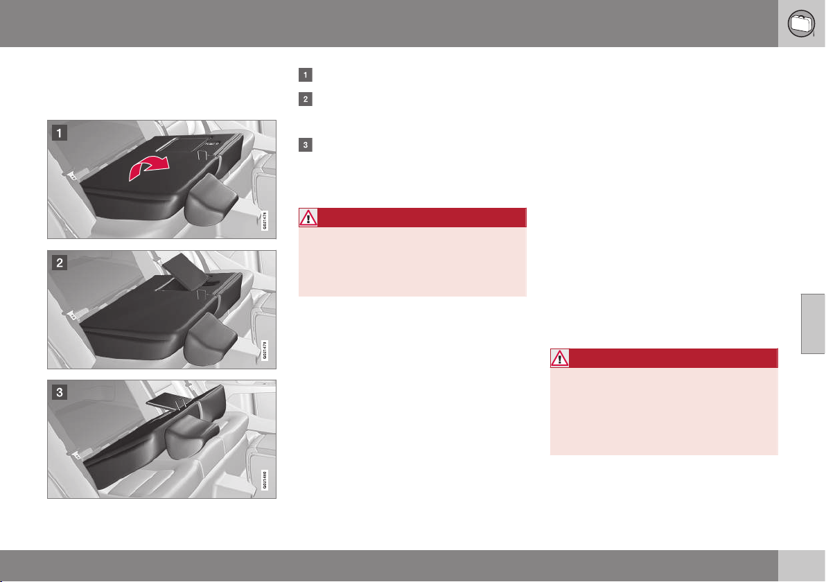
05 Loading and storage
05
151
Loading - ski hatch
The hatch in the backrest can be opened to
transport long narrow items.
Fold the right-hand backrest forward.
Release the hatch in the rear seat back-
rest by sliding the bolt up while pressing
the hatch down/forward.
Fold back the backrest with the hatch
open.
Use the seatbelt to prevent the load from
moving.
WARNING
Stop the engine and apply the parking
brake when loading and unloading. Other-
wise the gear lever/selector can acciden-
tally be knocked and moved to a driving
position.
Removing the hatch
After the hatch has been released and the
backrest folded backwards, open the hatch
approx. 30 degrees and pull it straight up.
Attaching the hatch
Refit the hatch in the grooves behind the
upholstery and close the hatch.
Related information
•
Loading (p. 149)
Roof load
The load carriers recommended for roof loads
are the ones developed by Volvo. This is in
order to avoid damage to the car and in order
to achieve the maximum possible safety dur-
ing a journey.
Carefully follow the installation instructions
supplied with the carriers.
•
Check periodically that the load carriers
and load are properly secured. Lash the
load securely with retaining straps.
•
Distribute the load evenly over the load
carriers. Put the heaviest objects at the
bottom.
•
The size of the area exposed to the wind,
and therefore fuel consumption, increase
with the size of the load.
•
Drive gently. Avoid quick acceleration,
heavy braking and hard cornering.
WARNING
The car's centre of gravity and driving cha-
racteristics are altered by roof loads.
For information about the maximum per-
mitted load on the roof, including load car-
riers and any space box, see Weights
(p. 409).
Related information
•
Loading (p. 149)
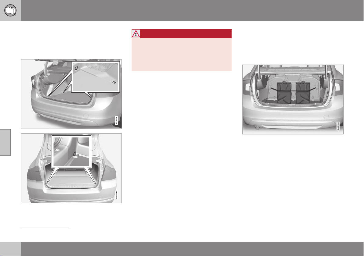
05 Loading and storage
05
152
* Option/accessory, for more information, see Introduction.
Load retaining eyelets
The folding load retaining eyelets
3
are used to
fasten straps in order to anchor items in the
cargo area.
WARNING
Hard, sharp and/or heavy objects which
protrude may cause injury under violent
braking.
Always secure large and heavy objects
with a seatbelt or cargo retaining straps.
Related information
•
Loading (p. 149)
Loading - bag holder*
The bag holder keeps carrier bags in place
and prevents them from overturning and
spreading their contents across the cargo
area.
Bag holder under folding hatch in the floor.
1. Fold up the holder, which is part of the
floor hatch.
2. Fasten the bags with strap and secure
the carrying handle in the hooks.
Related information
•
Loading (p. 149)
3
Number of eyes and their locations varies depending on market.
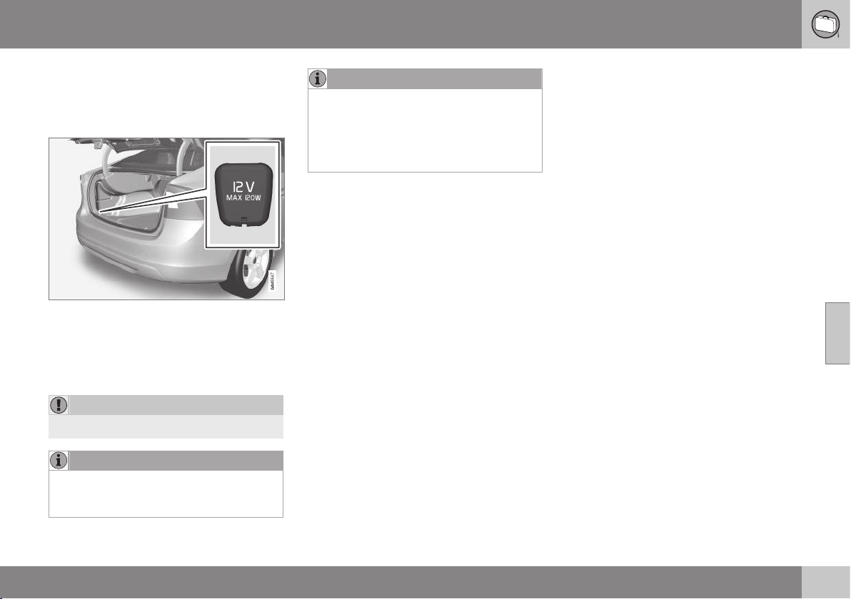
05 Loading and storage
05
* Option/accessory, for more information, see Introduction.
153
12 V electrical socket, cargo area*
The electrical socket can be used for various
accessories designed for 12 V, e.g. screens,
music players and mobile phones.
Raise the cover to access the electrical
socket.
•
The socket also provides voltage when
the remote control key is not in the igni-
tion switch.
IMPORTANT
Max. power takeoff is 10 A (120 W).
NOTE
Remember that using the electrical socket
with the engine switched off involves the
risk of discharging the car's starter battery.
NOTE
The compressor for temporary emergency
puncture repair has been tested and
approved by Volvo. For information on the
use of Volvo's recommended temporary
emergency puncture repair (TMK), see
Emergency puncture repair (p. 341).
LOCKS AND ALARM

06 Locks and alarm
06
* Option/accessory, for more information, see Introduction.
155
Remote control key
Amongst other things, the remote control key
is used for locking/unlocking and starting the
engine.
There are two variants of remote control key -
Remote control key in basic version and
Remote control key with PCC (Personal Car
Communicator)*.
Functionality
Basic
A
with
PCC
B
Locking/unlocking
and detachable key
blade
x x
Keyless locking/
unlocking
x
Keyless engine star-
ting
x
Information button
and indicator lamps
x
A
5-button key
B
6-button key
Remote control key with PCC has extended
functionality compared with the remote con-
trol key in the basic version - e.g. support for
Keyless Drive (p. 166) and certain unique
functions (p. 161).
All remote control keys have a detachable key
blade (p. 162) made of metal. The visible
section is available in two versions so that it
is possible to distinguish between the remote
control keys.
More remote control keys can be ordered -
but not variants other than the one supplied
with the car. Up to six keys can be pro-
grammed and used for one single car.
The car is supplied with two remote control
keys
WARNING
If there are children in the car:
Remember to switch off the supply to the
power windows and sunroof by removing
the remote control key if the driver leaves
the car.
Related information
•
Remote control key - functions (p. 159)
Remote control key - losing
If you lose a remote control key then a new
one can be ordered at a workshop - an
authorised Volvo workshop is recommended.
The remaining remote control keys must be
taken to the Volvo workshop. The code of the
missing remote control key must be erased
from the system as a theft prevention meas-
ure.
The current number of keys registered to the
car can be checked in the menu system MY
CAR. For a description of the menu system,
see MY CAR (p. 108).
Related information
•
Remote control key - functions (p. 159)
06 Locks and alarm
06
156
* Option/accessory, for more information, see Introduction.
Remote control key - personalisation*
The key memory in the remote control key
(p. 155) means that certain settings in the car
can be individually adapted for different peo-
ple.
The key memory function is available in com-
bination with power* driver's seat.
Settings for door mirrors (p. 100), driver's
seat, steering force (p. 183) and the com-
bined instrument panel's theme, contrast and
colour mode (p. 62) can be stored in the
memory, depending on the car's equipment
level.
The function
1
can be activated/deactivated in
the menu system MY CAR. For a description
of the menu system, see MY CAR (p. 108).
When the function is activated, the settings
are automatically linked to the key memory.
This means that a change in a setting will
automatically be saved to the specific remote
control key's memory.
Storing settings
Make sure that the key memory function is
activated in the menu system MY CAR.
Proceed as follows in order to store the set-
tings and use the key memory in the remote
control key:
1. Unlock the car with the remote control
key in whose memory the setting
2
shall
be stored.
2. Make the desired settings for e.g. the
seat and the door mirrors.
3. The settings are stored in the current
remote control key's memory.
The next time the car is unlocked with the
same remote control key, the positions that
are stored in the key memory will be set auto-
matically - providing that they have been
changed since the last time the current
remote control key was used.
Emergency stop
If the seat accidentally begins to move, press
one of the setting buttons for the seat or
memory buttons in order to stop the seat.
Restarting to reach the seat position stored in
the key memory is performed by pressing the
unlock button on the remote control key. The
driver's door must then be open.
WARNING
Risk of crushing! Make sure that children
do not play with the controls. Check that
there are no objects in front of, behind or
under the seat during adjustment. Make
sure that none of the passengers in the
rear seat is in danger of becoming trap-
ped.
Changing settings
If several people each with a remote control
key approach the car, then the settings for
e.g. seat and door mirrors are implemented
for the person whose remote control key
unlocks the driver's door.
If the driver's door has been opened by
person A with remote control key A, but
person B with remote control key B shall
drive, then the settings can be changed as
follows:
•
Standing by the driver's door, or sitting
behind the steering wheel, person B
presses the button for unlocking on
his/her remote control key, see Remote
control key - functions (p. 159).
•
Select one of three possible memories for
seat adjustment with seat button 1-3, see
1
Called Car key memory in MY CAR.
2
This setting does not affect settings that have been stored in the power seat's memory function.
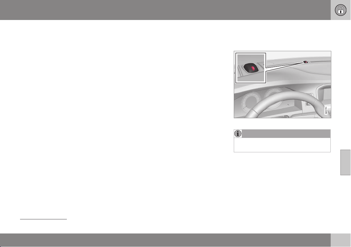
06 Locks and alarm
06
* Option/accessory, for more information, see Introduction.
157
Seats, front - electrically operated*
(p. 79).
•
Adjust seat and door mirrors manually,
see Seats, front - electrically operated*
(p. 79) and Door mirrors (p. 100).
Reactivation of settings
When the car is locked or after 30 minutes if
the car is left unlocked, the key memory will
be deactivated and a standard driver profile
will be set. To reactivate the key memory for
the current remote control key, the following
is required.
For cars without Keyless Drive
The settings that are stored in the key mem-
ory are activated if the car is unlocked by
pressing the remote control key's unlock but-
ton.
For cars with Keyless Drive
The key memory is activated if:
1. The car is unlocked either by pressing the
remote control key's unlock button or via
keyless unlocking.
2. If the car is unlocked, a key scan is made
when the driver's door is opened. If a
unique remote control key is found, its
stored settings will be activated. If the car
is locked, see the previous point.
Related information
•
Remote control key with PCC* - unique
functions (p. 161)
Locking/unlocking - indicator
When the car is locked or unlocked using the
remote control key (p. 155) the direction indi-
cators confirm that locking/unlocking was
correctly performed.
•
Locking - one flash and the door mirrors
are folded
3
in.
•
Unlocking - two flashes and the door mir-
rors are folded
3
out.
After locking the indication is only given if all
locks are activated once the doors have been
closed.
Selecting the function
Different options for indicating locking/
unlocking with light can be set in the car's
menu system MY CAR. For a description of
the menu system, see MY CAR (p. 108).
Related information
•
Keyless drive* (p. 166)
•
Lock indicator (p. 157)
•
Alarm indicator (p. 179)
Lock indicator
A flashing LED by the windscreen verifies that
the car is locked.
Same LED as alarm indicator (p. 179).
NOTE
Cars that are not equipped with alarm also
have this indicator.
Related information
•
Locking/unlocking - indicator (p. 157)
3
Only for cars with retractable power door mirrors.

06 Locks and alarm
06
158
* Option/accessory, for more information, see Introduction.
Immobiliser
The electronic immobiliser is a theft protec-
tion system that prevents an unauthorised
person from starting the car.
Each remote control key (p. 155) has a unique
code. The car can only be started with the
correct remote control key with the correct
code.
The following error messages in the com-
bined instrument panel's information display
are related to the electronic immobiliser:
Mes-
sage
Specification
Insert car
key
Error when reading the
remote control key during
starting - Remove the key
from the ignition switch, press
it in again and make a new
start attempt.
Car key
not found
Error reading the remote con-
trol key during starting - Try
to start again.
If the error persists: Insert the
remote control key into the
ignition switch and try to start
again.
Immobi-
liser Try
to start
again
Error in immobiliser system
during starting. If the error
persists: Contact a workshop
- an authorised Volvo work-
shop is recommended.
For starting the car, see Starting the engine
(p. 268).
Related information
•
Remote-controlled immobiliser with
tracking system* (p. 158)
Remote-controlled immobiliser with
tracking system*
Remote-controlled immobiliser with tracking
system
4
makes it possible to track and locate
the car, and to remotely activate the immobi-
liser to switch off the engine.
Contact your nearest Volvo dealer for more
information and assistance with activating the
system.
Related information
•
Remote control key (p. 155)
•
Immobiliser (p. 158)
4
Only certain markets and in combination with Volvo On Call*.
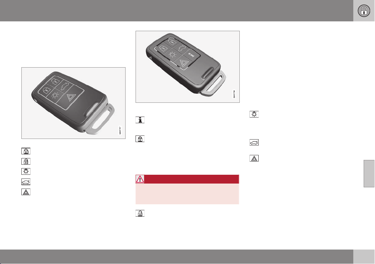
06 Locks and alarm
06
}}
* Option/accessory, for more information, see Introduction.
159
Remote control key - functions
The remote control key in basic version has
functions such as locking and unlocking the
doors.
Functions
Remote control key in basic version.
Locking
Unlocking
Approach light duration
Boot lid
Panic function
Remote control key with PCC*( Personal Car
Communicator).
Information
Function buttons
Locking – Locks the doors and boot lid
while the alarm is activated.
Press and hold to close all the windows and
sunroof* simultaneously. For more informa-
tion, see Global opening (p. 173).
WARNING
If the sunroof and windows are closed
using the remote control key, check that
nobody's hands are trapped.
Unlocking – Unlocks the doors and boot
lid while the alarm is deactivated.
Press and hold to open all windows simulta-
neously. For more information, see Global
opening (p. 173).
The function can be changed from unlocking
all doors simultaneously, to unlocking the
driver's door only with one press of the but-
ton and, after a further press of the button -
within ten seconds - unlocking the remaining
doors.
The function can be changed in the menu
system MY CAR. For a description of the
menu system, see MY CAR (p. 108).
Approach light duration – Used to
switch on the car's lighting at a distance. For
more information, see Approach lighting
(p. 96).
Boot lid (p. 174) - Unlocks and disarms
the alarm for the boot lid only.
Panic function – Used to attract atten-
tion in an emergency.
Press and hold the button for at least 3 sec-
onds or press it twice within 3 seconds to
activate the direction indicators and the horn.
The function can be turned off with the same
button once it has been active for at least
5 seconds. Otherwise the function switches
off automatically after approx. 3 minutes.
||
06 Locks and alarm
06
160
* Option/accessory, for more information, see Introduction.
Related information
•
Remote control key (p. 155)
•
Remote control key with PCC* - unique
functions (p. 161)
•
Locking/unlocking - from the outside
(p. 171)
Remote control key - range
Remote control key functions (in its basic ver-
sion) have a range of approx. 20 metres from
the car.
If the car does not verify a button being
pressed - move closer and try again.
NOTE
The remote control key functions may be
disrupted by surrounding radio waves,
buildings, topographical conditions, etc.
The car can always be locked/unlocked
with the key blade (p. 163).
If the remote control key is removed from the
car when the engine is running or key position
I or II (p. 76) is active, and if all doors are
closed, then a warning message is shown in
the information display in the combined
instrument panel and an audio reminder sig-
nal sounds at the same time.
The message is extinguished and the audible
reminder signal stops when the remote con-
trol key is brought back to the car after
either/or:
•
The remote control key has been inserted
in the ignition switch.
•
Speed exceeds 30 km/h.
•
The OK button has been pressed.
Related information
•
Remote control key (p. 155)
•
Remote control key - functions (p. 159)
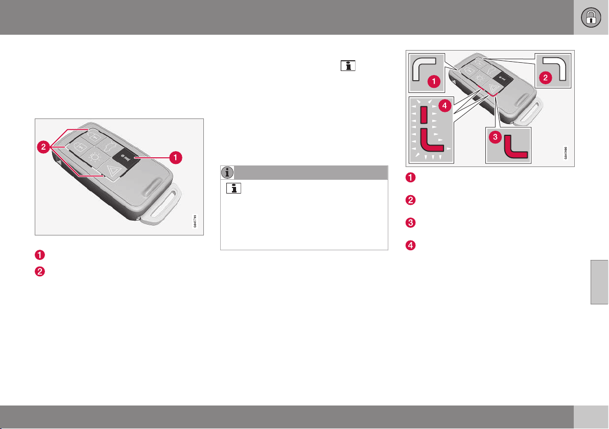
06 Locks and alarm
06
* Option/accessory, for more information, see Introduction.
161
Remote control key with PCC* -
unique functions
A remote control key with PCC has enhanced
functionality compared with a remote control
key in basic version (p. 155) in the form of an
information button and indicator lamps.
Remote control key with PCC.
Information button
Indicator lamps
Using the information button enables access
to certain information from the car via the
indicator lamps.
Using the information button
–
Press the information button .
> All indicator lamps flash for approxi-
mately 7 seconds and the light travels
around on the remote control key. This
indicates that information from the car
is being scanned.
If any of the other buttons are pressed
during this time then the reading is
interrupted.
NOTE
If none of the indicator lamps illumi-
nates with repeated use of the information
button and in different locations (as well as
after 7 seconds and after the light has
travelled around on the PCC), contact a
workshop - an authorised Volvo workshop
is recommended.
Indicator lamps display information in accord-
ance with the following illustration:
Green continuous light – the car is
locked.
Yellow continuous light – the car is
unlocked.
Red continuous light – the alarm has
been triggered since the car was locked.
Red light flashing alternately in both indi-
cator lamps – The alarm was triggered
less than 5 minutes ago.
Related information
•
Remote control key with PCC* - range
(p. 162)

06 Locks and alarm
06
162
* Option/accessory, for more information, see Introduction.
Remote control key with PCC* - range
The range of a remote control key with PCC
(Personal Car Communicator) for locking,
unlocking the doors and boot lid is approx. 20
metres from the car - the other functions are
up to approx. 100 metres.
If the car does not verify a button being
pressed - move closer and try again.
NOTE
The information button function may be
disrupted by surrounding radio waves,
buildings, topographical conditions, etc.
Outside the remote control key's range
If the remote control key is too far away from
the car for the information to be read then the
status the car was last left in is shown, with-
out the light in the indicator lamps travelling
around on the remote control key.
If several remote control keys are used for the
car then it is only the one last used for lock-
ing/unlocking that shows the correct status.
NOTE
If no indicator lamps illuminate when
the information button is used within range
then this may be because the last commu-
nication between the remote control key
and the car was disrupted by surrounding
radio waves, buildings, topographical con-
ditions, etc.
Related information
•
Keyless Drive* - remote control key range
(p. 167)
•
Remote control key - range (p. 160)
Detachable key blade
A remote control key contains a detachable
key blade of metal with which some functions
can be activated and some operations carried
out.
The key blade's unique code is provided by
authorised Volvo workshops, which are rec-
ommended when ordering new key blades.
Key blade functions
Using the remote control key's detachable
key blade:
•
the left-hand front door can be opened
manually if central locking cannot be acti-
vated with the remote control key, see
Detachable key blade - unlocking doors
(p. 163).
•
the rear doors' mechanical child safety
locks can be activated/deactivated
(p. 177).
•
the right-hand front door and the rear
doors can be locked manually (p. 171),
e.g. in the event of power failure.
•
access to the glovebox and cargo area (
privacy locking * (p. 164)) can be
blocked.
•
the airbag for front passenger seat
(PACOS*) can be activated/deactivated
(p. 33).
Related information
•
Remote control key - functions (p. 159)
•
Remote control key (p. 155)

06 Locks and alarm
06
* Option/accessory, for more information, see Introduction.
163
Detachable key blade - detaching/
attaching
Detaching/attaching the detachable key blade
(p. 162) is carried out as follows:
Removing the key blade
Slide the spring-loaded catch to the side.
At the same time pull the key blade
straight out backwards.
Attaching the key blade
Carefully refit the key blade into its location in
the remote control key (p. 155).
1. Hold the remote control key with the slot
pointed up and lower the key blade into
its slot.
2. Lightly press the key blade. You should
hear a "click" when the key blade is
locked in.
Related information
•
Detachable key blade - unlocking doors
(p. 163)
•
Child safety locks - manual activation
(p. 177)
•
Passenger airbag - activating/deactivat-
ing* (p. 33)
Detachable key blade - unlocking
doors
The detachable key blade (p. 162) can be
used if central locking cannot be activated
with the remote control key (p. 155), e.g. if the
key's battery has run out.
If central locking cannot be activated with the
remote control key - e.g. if the batteries are
discharged - then the left-hand front door can
be opened as follows:
1. Unlock the left-hand front door with the
key blade in the door handle's lock cylin-
der. For illustration and more information,
see Keyless drive* - unlocking with the
key blade (p. 169).
NOTE
When the door has been unlocked using
the key blade and is opened, the alarm is
triggered.
2. Deactivate the alarm by inserting the
remote control key in the ignition switch.
For cars with the Keyless system, see Key-
less drive* - unlocking with the key blade
(p. 169).
Related information
•
Remote control key (p. 155)
•
Remote control key - replacing the bat-
tery (p. 165)
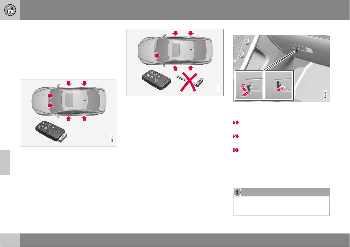
06 Locks and alarm
06
164
* Option/accessory, for more information, see Introduction.
Privacy locking*
Privacy locking is intended for when the car is
left for service, with a hotel parking valet or
similar. The glovebox is then locked and the
boot lid lock is disconnected from the central
locking - the boot lid cannot be opened with
either the central locking button in the front
doors or the remote control key (p. 155).
Active locks for remote control key with key
blade.
G021084
Active locks for remote control key, without key
blade and privacy locking activated.
This means that the remote control key with-
out key blade can only be used to activate/
deactivate the alarm (p. 178), to open the
doors and to drive the car.
The remote control key without key blade can
then be handed over to the service or hotel
staff - the loose key blade is retained by the
car owner.
Activate/deactivate
Activating privacy locking.
To activate privacy locking:
Insert the key blade in the glovebox lock
cylinder.
Turn the key blade 180 degrees clock-
wise.
Pull out the key blade. The combined
instrument panel's information display
shows a message at the same time.
The glovebox is then locked and the boot lid
can no longer be unlocked with the remote
control key or the central locking button.
NOTE
Do not reinsert the key blade into the
remote control key, but keep it in a safe
place instead.
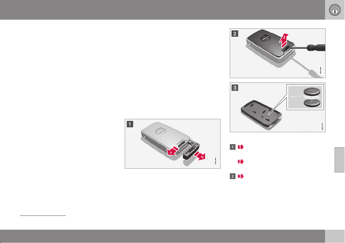
06 Locks and alarm
06
}}
165
•
Deactivation takes place in reverse order.
For information on locking the glovebox only,
see Locking/unlocking - glovebox (p. 173).
Remote control key - replacing the
battery
The battery
5
for the remote control key may
need to be replaced.
The battery for the remote control key should
be replaced if:
•
the information symbol in the combined
instrument panel illuminates and the dis-
play shows
Car key battery low See
manual
and/or
•
the locks repeatedly do not react to sig-
nals from the remote control key within
20 metres from the car.
Opening
Slide the spring-loaded catch to the
side.
At the same time pull the key blade
straight out backwards.
Insert a 3 mm slot screwdriver in the
hole behind the spring-loaded catch and
gently prize the remote control key up.
5
Remote control key with PCC has two batteries.
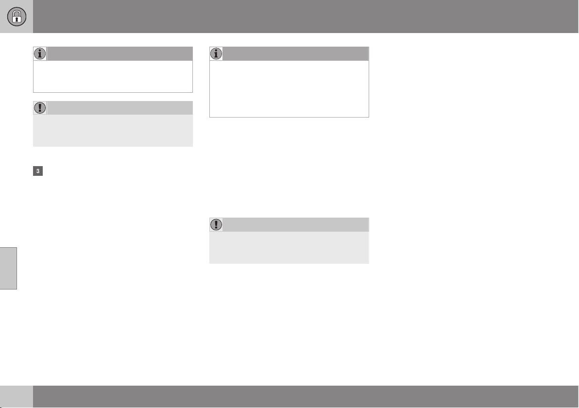
||
06 Locks and alarm
06
166
* Option/accessory, for more information, see Introduction.
NOTE
Turn the remote control key over with the
buttons facing up, this is to avoid the bat-
teries falling out when it is opened.
IMPORTANT
Avoid touching new batteries and their
contact surfaces with your fingers as this
may impair their function.
Battery replacement
Closely study how the battery/batteries
are secured on the inside of the cover,
with regard to their (+) and (–) sides.
Remote control key (one battery)
1. Carefully prize out the battery.
2. Install a new one with the (+) side down.
Remote control key with PCC* (two
batteries)
1. Carefully prize out the batteries.
2. First install one new one with the (+) side
up.
3. Position the white plastic tab in between
and finally install a second new battery
with the (+) side down.
Battery type
Use batteries with the designation
CR2430, 3V - one in the remote control key,
two in the remote control key with PCC.
NOTE
Volvo recommends that the batteries to be
used in the remote control key/PCC fulfil
UN Manual of Test and Criteria, Part III,
sub-section 38.3. Batteries fitted in the
factory or replaced by an authorised Volvo
workshop fulfil the above criteria.
Assembly
1. Press the remote control key together.
2. Hold the remote control key with the slot
pointed up and lower the key blade into
its slot.
3. Lightly press the key blade. You should
hear a "click" when the key blade is
locked in.
IMPORTANT
Make sure that exhausted batteries are
disposed of in a manner which is kind to
the environment.
Related information
•
Remote control key (p. 155)
•
Remote control key - functions (p. 159)
Keyless drive*
Cars equipped with Keyless Drive have a star-
ting and locking system that can be operated
keylessly.
With the keyless starting and locking system
the car can be started, locked and unlocked
without the remote control key (p. 155)
6
inserted in the ignition switch. It is enough to
have the remote control key with you in a
pocket. The system makes it easier and more
convenient to e.g. open the car when your
hands are full.
Both of the remote control keys included with
the car have Keyless functionality. It is possi-
ble to order more remote control keys.
The car's electrical system can be set to
three different levels - key position 0, I and II
(p. 76) - with the remote control key.
Related information
•
Keyless Drive* - remote control key range
(p. 167)
•
Keyless drive* - secure handling of the
remote control key (p. 167)
•
Keyless drive* - interference to remote
control key function (p. 168)
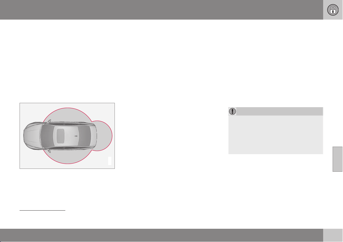
06 Locks and alarm
06
* Option/accessory, for more information, see Introduction.
167
Keyless Drive* - remote control key
range
In order to unlock the doors or boot lid auto-
matically without pressing a button on the
remote control key
7
, a remote control key
must be within approx. 1.5 metres from the
car's door handle or boot lid.
The person who wishes to lock or unlock a
door must have the remote control key with
him or her. It is not possible to lock or unlock
a door if the remote control key is on the
opposite side of the car.
G020577
The red rings in the above figure indicate the
range covered by the system's antennas.
If all remote control keys are removed from
the car when the engine is running or key
position I or II (p. 76) is active, and if all doors
are closed, then a warning message is shown
in the information display in the combined
instrument panel and an audio reminder sig-
nal sounds at the same time.
When the remote control key has been
returned to the car, the warning message
goes off and the audible reminder ceases
once either/or:
•
a door has been opened and closed
•
the remote control key has been inserted
in the ignition switch
•
The OK button has been pressed.
Related information
•
Keyless drive* (p. 166)
•
Keyless Drive* - antenna location (p. 170)
Keyless drive* - secure handling of
the remote control key
It is important to handle the car's remote con-
trol keys with great care.
If one of the remote control keys
8
has been
left in the car then the Keyless functionality is
deactivated in case the car is e.g. locked with
the other remote control key that belongs to
the car. This prevents unauthorised entry.
The next time the car is unlocked with the
other remote control key the forgotten remote
control key is reactivated again.
IMPORTANT
Avoid leaving the remote control key with
PCC behind in the car. If someone breaks
into your car and takes the remote control
key, it will e.g. be possible to start the car
by pressing the remote control key in the
ignition switch and then pressing the
START/STOP ENGINE button.
Related information
•
Keyless drive* (p. 166)
6
Only applies to Remote Control Key with PCC.
7
Applies to remote control key with PCC (Personal Car Communicator).

06 Locks and alarm
06
168
* Option/accessory, for more information, see Introduction.
Keyless drive* - interference to
remote control key function
Electromagnetic fields and screening can
interfere with the remote control key's Keyless
functions (p. 166).
NOTE
Do not place/store the PCC near a mobile
phone or metal object - no closer than
10-15 cm.
If interference is experienced nonetheless,
use the remote control key and the key blade
like a remote control key in basic version, see
Remote control key - functions (p. 159).
Related information
•
Remote control key - replacing the bat-
tery (p. 165)
•
Keyless drive* - secure handling of the
remote control key (p. 167)
•
Keyless Drive* - remote control key range
(p. 167)
Keyless drive* - locking
Cars equipped with Keyless drive have a
touch-sensitive area on the outer handle of
the doors and a rubberised button next to the
boot lid's rubberised pressure plate for lock-
ing/unlocking.
The touch-sensitive area on the outer door han-
dles and a rubberised button next to the boot
lid's rubberised pressure plate.
Lock the doors and the boot lid with one long
press on any of the door handles' touch-sen-
sitive areas or press the smaller of the boot
lid's two rubberised buttons - the lock indica-
tor (p. 157) in the windscreen confirms that
locking has been completed by starting to
flash.
All doors and the boot lid must be closed
before the car can be locked - otherwise the
car is not locked.
NOTE
In cars with automatic gearbox selectors,
the gear selector must be set to the P
position; otherwise the car can be neither
locked nor alarmed.
Related information
•
Keyless drive* (p. 166)
•
Alarm indicator (p. 179)
8
Applies to remote control key with PCC (Personal Car Communicator).
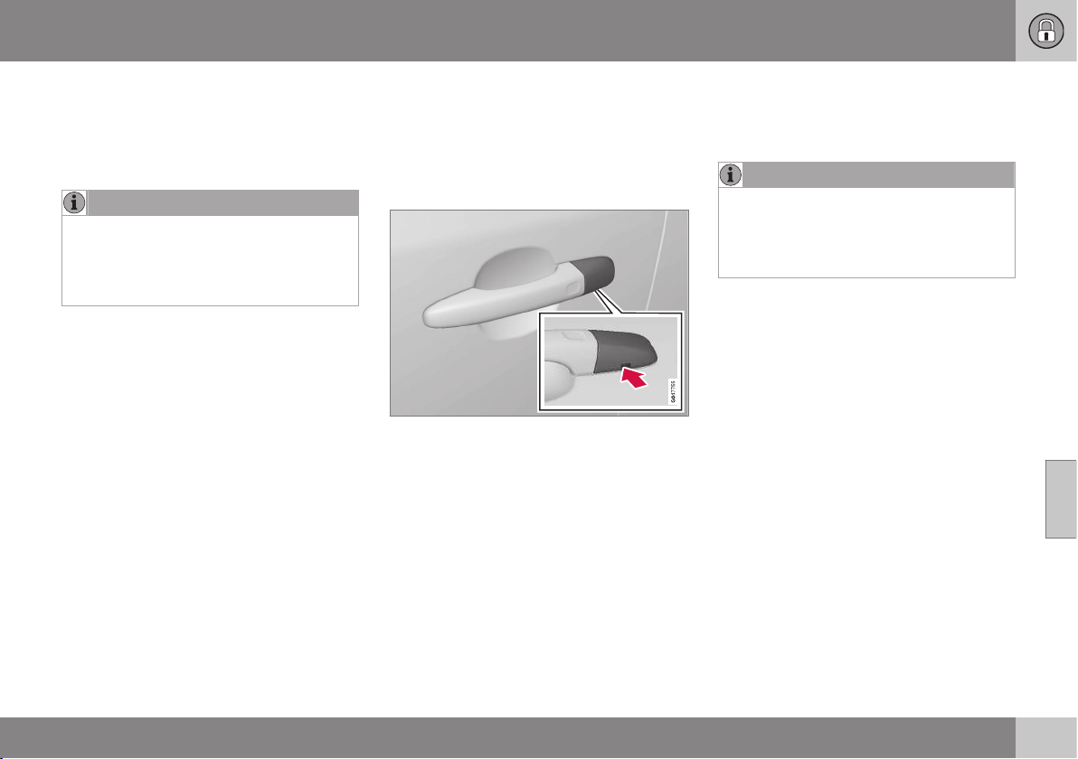
06 Locks and alarm
06
* Option/accessory, for more information, see Introduction.
169
Keyless drive* - unlocking
Unlocking takes place when a hand grasps a
door handle or the boot lid's rubberised pres-
sure plate is actuated - open the door or boot
lid as normal.
NOTE
The door handles normally register a hand
that takes hold of the handle, but with
thick gloves on or after a very quick hand
movement a second attempt may be
required, or with the glove taken off.
Related information
•
Keyless drive* (p. 166)
•
Keyless drive* - locking (p. 168)
Keyless drive* - unlocking with the
key blade
If central locking cannot be unlocked with the
remote control key, e.g. if the batteries are
discharged, then the left-hand front door can
be opened using the detachable key blade.
Hole for key blade - to loosen the cover.
To access the lock cylinder, the door handle's
plastic cover must be removed - this is also
done with the key blade:
1. Press the key blade approx. 1 cm straight
up into the hole on the underside of the
door handle/cover - do not prize.
> The plastic cover loosens automati-
cally by means of the torque when the
blade is pushed straight up and into
the opening.
2. Then insert the key blade in the lock cyl-
inder and unlock the door.
3. Refit the plastic cover after unlocking.
NOTE
When the driver's door is unlocked using
the key blade and is opened, the alarm is
triggered. It is switched off by inserting the
PCC in the ignition switch, see Alarm -
remote control key not working (p. 180).
Related information
•
Keyless drive* (p. 166)
•
Detachable key blade - detaching/attach-
ing (p. 163)
•
Alarm (p. 178)
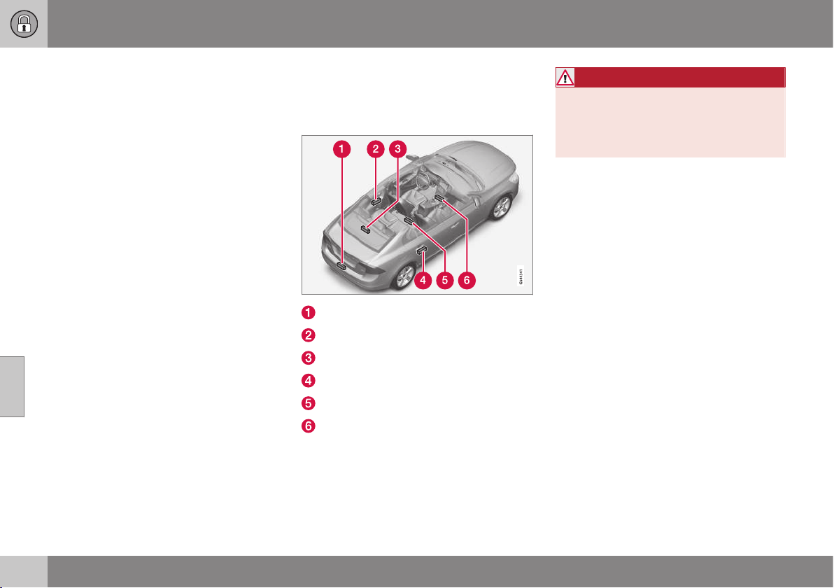
06 Locks and alarm
06
170
* Option/accessory, for more information, see Introduction.
Keyless Drive* - lock settings
Lock settings for cars equipped with Keyless
Drive can be adapted by indicating in the
menu system MY CAR which doors are to be
unlocked.
For a description of the menu system, see
MY CAR (p. 108).
Related information
•
Keyless drive* (p. 166)
Keyless Drive* - antenna location
Cars equipped with Keyless Drive have a
number of built-in antennas positioned at dif-
ferent locations in the car.
Rear bumper, centre
Door handle, left rear
Parcel shelf, centre, underside
Door handle, right rear
Centre console, under the rear section
Centre console, under the front section.
WARNING
People with pacemaker operations should
not come closer than 22 cm to the keyless
system's antennae with their pacemaker.
This is to prevent interference between the
pacemaker and the keyless system.
Related information
•
Keyless drive* (p. 166)
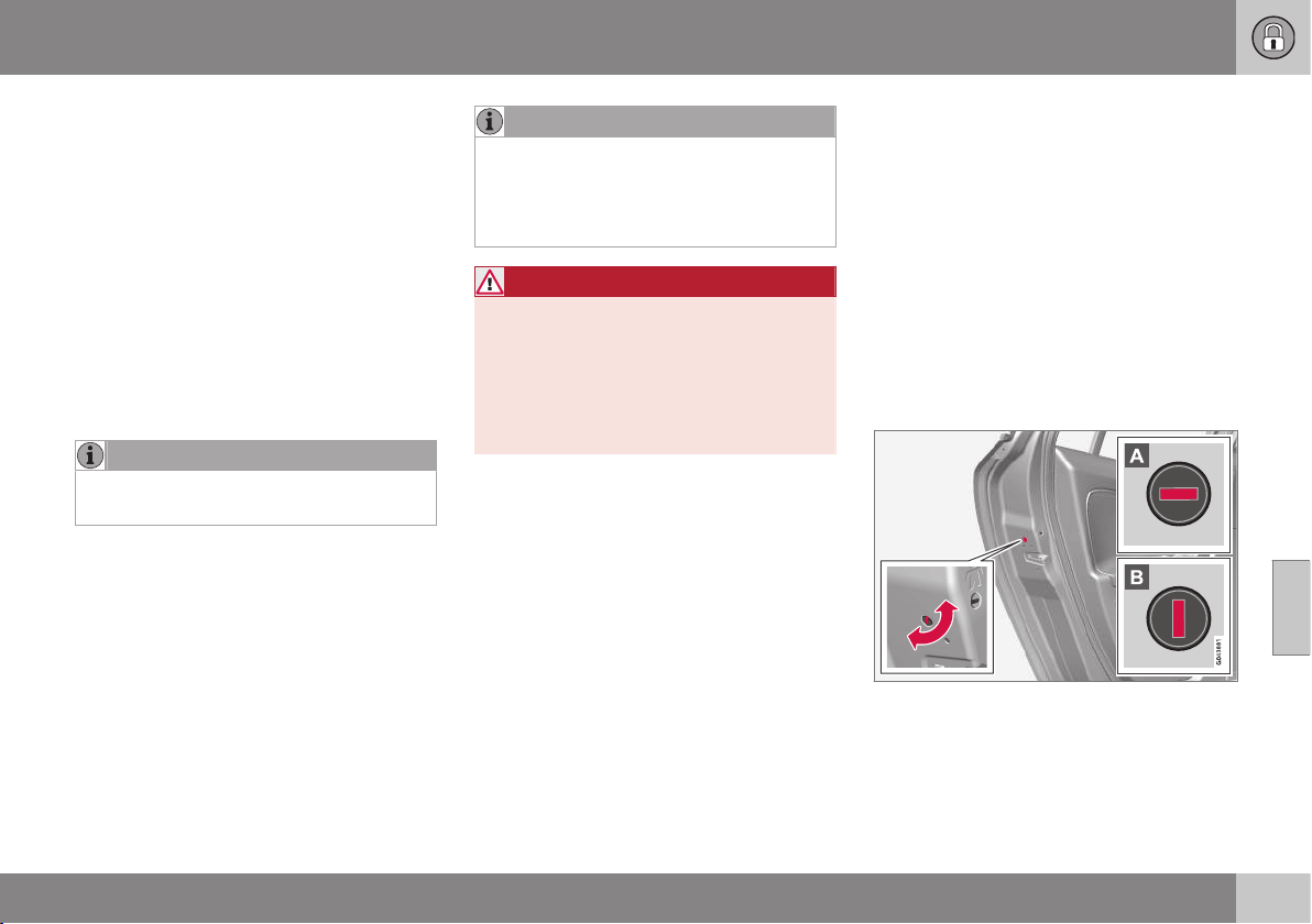
06 Locks and alarm
06
}}
* Option/accessory, for more information, see Introduction.
171
Locking/unlocking - from the outside
Locking/unlocking from the outside is carried
out using the remote control key (p. 155). The
remote control key can lock/unlock all doors
and the boot lid simultaneously. Different
sequences for unlocking can be selected, see
Remote control key - functions (p. 159).
In order that the lock sequence can be acti-
vated, the driver's door must be closed - if
any of the other doors or the boot lid is open,
then it/they is/are locked and the alarm is
activated only when it/they are closed. For
cars equipped with keyless locking system*
all doors and the boot lid must be closed.
NOTE
Be aware of the risk of locking the remote
control key in the car.
If it is not possible to lock/unlock with the
remote control key, the battery may be dis-
charged - lock or unlock the left-hand front
door with the detachable key blade, see
Detachable key blade - detaching/attaching
(p. 163).
NOTE
Remember that the alarm is triggered
when the door is opened after being
unlocked with the key blade - the alarm is
switched off when the remote control key
is inserted into the ignition switch.
WARNING
Be aware of the risk of being locked in the
car when it is locked from the outside
using the remote control key - it is then not
possible to open any of the doors from the
inside with the door controls.
For more information, see Deadlocks*
(p. 176).
Automatic relocking
If none of the doors or the boot lid is opened
within two minutes of unlocking, all are
locked again automatically. This function
reduces the risk that the car is left unlocked
unintentionally. (For cars with alarm, see
Alarm (p. 178).)
Related information
•
Locking/unlocking - from the inside
(p. 172)
•
Keyless drive* (p. 166)
Manual locking of the door
In certain situations the car must be lockable
manually, e.g. in the event of power failure.
The left-hand front door can be locked with
its lock cylinder and the remote control key's
detachable key blade, see Keyless drive* -
unlocking with the key blade (p. 169).
Other doors do not have lock cylinders and
instead have lock knobs on each door's end
face which must be re-turned - then they are
mechanically locked/blocked against opening
from the outside. The doors can still be
opened from the inside.
Manual locking of the door. Not to be mixed up
with child safety locks (p. 177).
– Use the remote control key's detachable
key blade to turn the knob, see Detacha-
ble key blade - detaching/attaching
(p. 163).
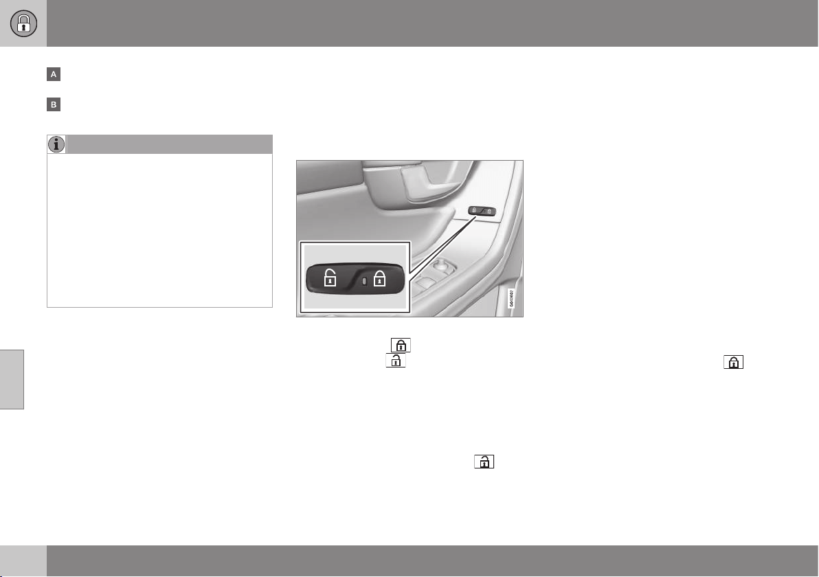
||
06 Locks and alarm
06
172
* Option/accessory, for more information, see Introduction.
The door is blocked against opening from
the outside.
The door can be opened from both the
outside and the inside.
NOTE
•
A door's knob control only locks that
particular door - not all doors simulta-
neously.
•
A manually locked rear door with an
activated manual child safety lock can-
not be opened from either the outside
or the inside, see Child safety locks -
manual activation (p. 177). A rear door
that is locked in this way can only be
unlocked with the remote control key
or central locking button.
Related information
•
Remote control key - replacing the bat-
tery (p. 165)
Locking/unlocking - from the inside
All of the doors and the boot lid can be
locked or unlocked simultaneously using the
central locking button on the driver's door
and passenger door*.
Central locking
Central locking.
•
Press one side
of the button to lock -
the other side
to unlock.
Press and hold to also open all side windows*
simultaneously.
Unlocking
A door can be unlocked from the inside in
two different ways:
•
Press the central locking button
.
A long press also opens all the side windows*
simultaneously (see also Global opening
(p. 173)).
•
Pull the door handle and open the door -
the door is unlocked and opened in one
operation.
Lamp in lock button
Central locking is available in two variants -
the lamp in the central locking button for the
driver's door has different meanings depend-
ent on the variant.
With central locking button only in the driver's
door, other doors have no button:
•
Illuminated lamp means that all doors are
locked.
With central locking button on both front
doors and electric lock button in each rear
door:
•
Illuminated lamp means that only that
particular door is locked. When all but-
tons are illuminated all doors are locked.
Locking
•
Press the central locking button
- all
closed doors are locked.
A long press also closes all side windows and
sunroof simultaneously (see also Global
opening (p. 173)).

06 Locks and alarm
06
}}
* Option/accessory, for more information, see Introduction.
173
Lock button* rear doors
The button's lamp illuminates when the door is
locked.
The rear door lock buttons only lock their
respective rear door.
To unlock the door:
•
Pull the door handle - the door is
unlocked and opened.
Automatic locking
The doors and boot lid are locked automati-
cally when the car starts to move.
The function can be activated/deactivated in
the menu system MY CAR. For a description
of the menu system, see MY CAR (p. 108).
Related information
•
Locking/unlocking - from the outside
(p. 171)
•
Alarm (p. 178)
•
Remote control key - functions (p. 159)
Global opening
The global opening function opens or closes
all side windows simultaneously and can be
used for example to quickly air the car during
hot weather.
Central locking button
A long press on the
symbol in the central
locking button opens all side windows simul-
taneously. The same procedure on the
symbol closes all side windows simultane-
ously.
Related information
•
Locking/unlocking - from the inside
(p. 172)
•
Power windows (p. 98)
Locking/unlocking - glovebox
The glovebox (p. 147) can only be locked/
unlocked using the remote control key's
detachable key blade.
For information on the key blade, see Detach-
able key blade - detaching/attaching (p. 163).
Locking the glovebox:
Insert the key blade in the glovebox lock
cylinder in accordance with the illustration
above.
Turn the key blade 90 degrees clockwise.
Pull out the key blade.
•
Unlock by carrying this out in reverse
order.
For information on privacy locking, see Pri-
vacy locking* (p. 164).
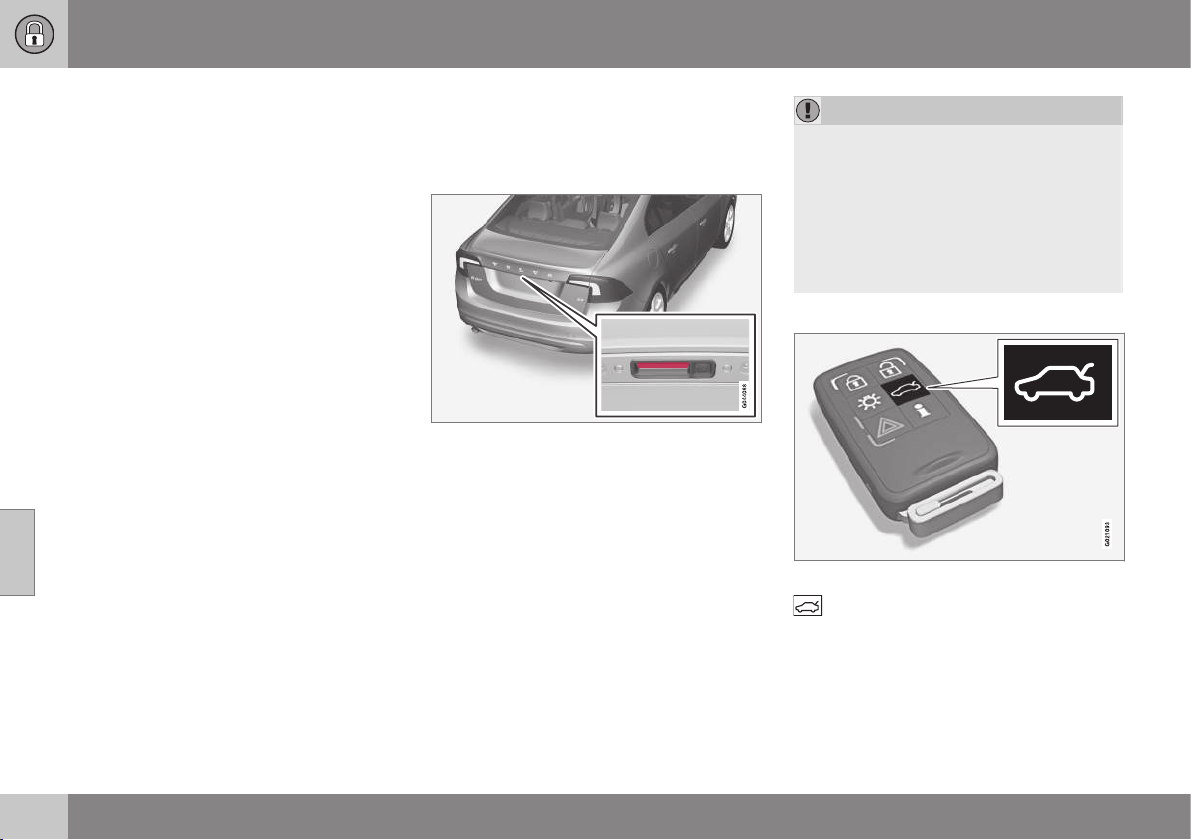
||
06 Locks and alarm
06
174
* Option/accessory, for more information, see Introduction.
Related information
•
Remote control key (p. 155)
Locking/unlocking - boot lid
The boot lid can be opened, locked and
unlocked in several ways.
Manual opening
Rubber plate with electrical contact.
The boot lid is held closed by an electrical
lock. To open:
1. Push down gently on the wide rubberised
pressure plate under the outer handle -
the lock is released.
2. Lift the outside handle in order to fully
open the tailgate.
IMPORTANT
•
Minimal force is required to release the
boot lid's lock - just gently press the
rubberised panel.
•
Do not place the lift force on the rub-
ber panel when opening the boot lid -
lift the handle. Using too much force
may damage the electrical contacts on
the rubber panel.
Unlocking with the remote control key
The alarm for the boot lid can be disarmed
and the boot lid unlocked on its own by
using the remote control key's *button.
The lock indicator on the instrument panel
stops flashing which indicates that not all of
the car is locked and the alarm's* level and
movement sensors and the sensors for open-
ing the boot lid are disconnected.
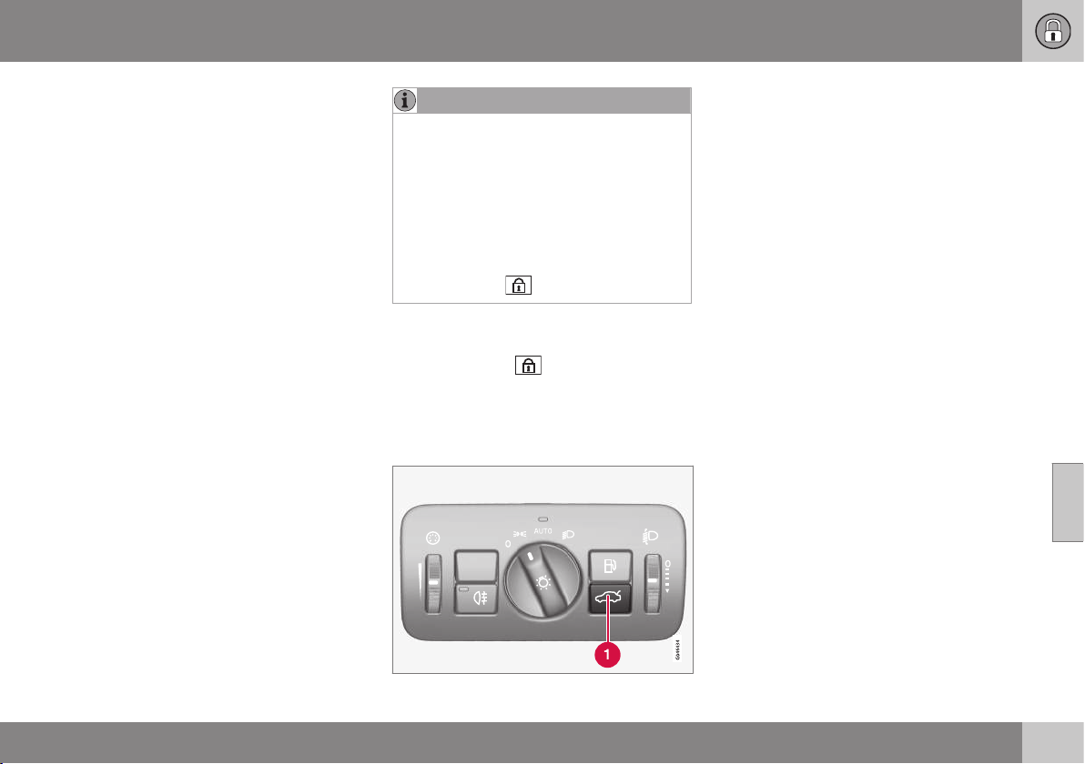
06 Locks and alarm
06
* Option/accessory, for more information, see Introduction.
175
The doors remain locked and armed.
•
The boot lid is unlocked, but remains
closed - press lightly on the rubberised
pressure plate under the outer handle and
lift the boot lid.
If the boot lid is not opened within two
minutes then it is relocked and the alarm is
re-armed.
The boot lid can be opened in two
different ways
One press - The boot lid is unlocked, but
remains closed - press lightly on the rubber-
ised pressure plate under the outer handle
and lift the boot lid.
If the boot lid is not opened within two
minutes then it is relocked and the alarm is
re-armed.
Two presses - The boot lid is unlocked and
the lock is disengaged at which the boot lid
opens about a centimetre - lift the outer han-
dle to open. Rain, cold, frost or snow could
however prevent the tailgate from disengag-
ing from the lock.
NOTE
•
When the boot lid/tailgate is unlocked
with 2 presses, automatic relocking
does not take place because the boot
lid/tailgate is open - it must be closed
manually.
•
After the boot lid/tailgate has been
closed it is unlocked and the alarm is
not armed - relock it and re-arm the
alarm with the remote control key's
lock button
.
Locking with the remote control key
•
Press the remote control key (p. 159) but-
ton for locking
.
The lock indicator on the instrument panel
starts flashing, which means that the car is
locked and the alarm* has been activated.
Unlocking the car from inside
To unlock the boot lid:
– Press the lighting panel button. (1)
> The lock releases and the tailgate
opens by a few centimetres.
Related information
•
Locking/unlocking - from the inside
(p. 172)
•
Locking/unlocking - from the outside
(p. 171)
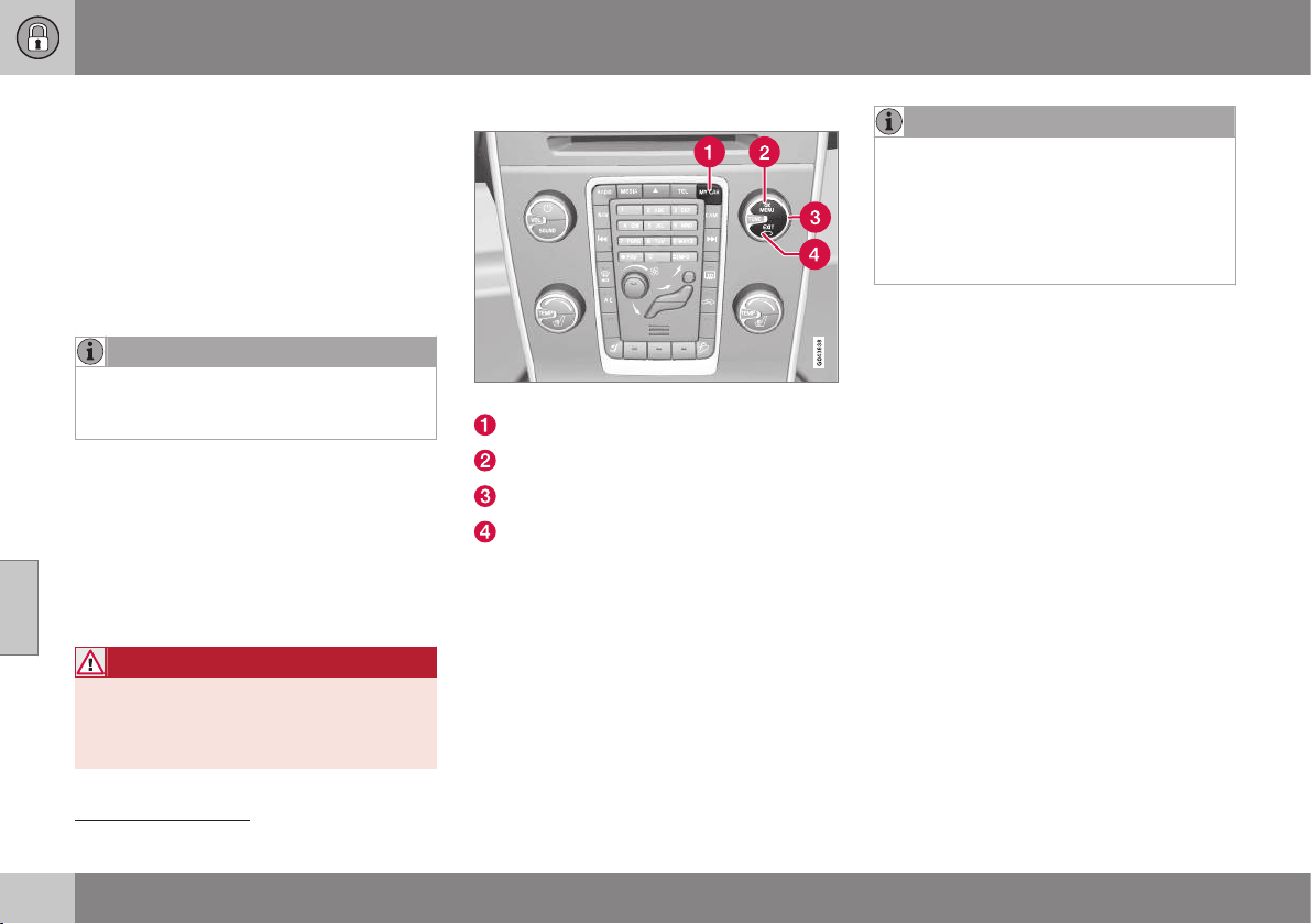
06 Locks and alarm
06
176
* Option/accessory, for more information, see Introduction.
Deadlocks*
Deadlocks
9
means that all door handles are
mechanically disengaged, which prevents
doors being opened from both inside and
outside.
The deadlocks are activated with the remote
control key (p. 155) and are set after an
approx. ten seconds delay after the doors
have been locked.
NOTE
If a door is opened within the delay time
then the sequence is interrupted and the
alarm is deactivated.
The car can only be unlocked with the remote
control key when the deadlocks function is
activated. The front left door can also be
unlocked with the detachable key blade
(p. 162). In addition, it is possible to unlock
and open the doors and boot lid on cars
equipped with the Keyless Drive* by touching
door handles or the handle on the boot lid.
WARNING
Do not allow anyone to remain in the car
without first deactivating the deadlocks in
order to avoid the risk of anyone being
locked in.
Temporary deactivation
Active menu options are indicated with a cross.
MY CAR
OK MENU
TUNE knob control
EXIT
If someone is going to stay in the car but the
doors must be locked from the outside, then
the deadlocks function can be temporarily
switched off. This takes place the menu sys-
tem MY CAR. For a description of the menu
system, see MY CAR (p. 108).
NOTE
•
Remember that the alarm is activated
when the car is locked.
•
If any of the doors are opened from
the inside then the alarm is triggered.
The above applies if the deadlocks have
not been deactivated temporarily.
Related information
•
Keyless drive* - unlocking with the key
blade (p. 169)
•
Remote control key (p. 155)
9
Only in combination with alarm.
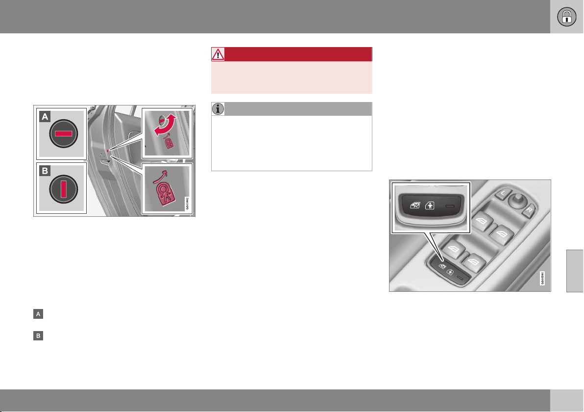
06 Locks and alarm
06
}}
* Option/accessory, for more information, see Introduction.
177
Child safety locks - manual activation
The child safety locks prevent children from
being able to open a rear door from the
inside.
Activate/deactivate child safety locks
Manual child safety locks. Not to be mixed up
with manual door lock (p. 171).
The child safety locks are located on the trail-
ing edge of the rear doors and are only
accessible when the doors are open.
To activate/deactivate the child safety locks:
– Use the remote control key's detachable
key blade (p. 162) to turn the knob.
The door is blocked against opening from
the inside.
The door can be opened from both the
outside and the inside.
WARNING
Each rear door has two knob controls - do
not mix up the child safety locks with man-
ual door locks.
NOTE
•
A door's knob control only blocks that
particular door - not both rear doors
simultaneously.
•
Cars with an electric child safety lock
do not have a manual child lock.
Related information
•
Child safety locks - electrical activation*
(p. 177)
•
Locking/unlocking - from the inside
(p. 172)
•
Locking/unlocking - from the outside
(p. 171)
Child safety locks - electrical
activation*
Child safety locks with electrical activation
prevent children from opening the rear doors
or windows from the inside.
Activation
The child safety locks can be activated/deac-
tivated in all key positions (p. 76) higher than
0. Activation/deactivation can be performed
up to 2 minutes after switching off the engine,
provided that no door is opened.
To activate the child safety locks:
Control panel driver's door.
1. Start the engine or choose a key position
higher than 0.

||
06 Locks and alarm
06
178
* Option/accessory, for more information, see Introduction.
2. Press the button in the driver's door con-
trol panel.
> The combined instrument panel's
information display shows the mes-
sage
Rear child lock activated and
the button's lamp illuminates - the
locks are active.
When the child safety lock is active then the
rear:
•
windows can only be opened with the
driver's door control panel
•
doors cannot be opened from inside.
The current setting is stored when the engine
is switched off - if the child safety locks are
activated at engine shutdown, the function
will remain activated the next time the engine
is started.
Related information
•
Child safety locks - manual activation
(p. 177)
•
Locking/unlocking - from the inside
(p. 172)
Alarm
The alarm is a device that warns in the event
of e.g. a break-in in the car.
Activated alarm is triggered if:
•
a door, the bonnet or the boot lid is
opened
•
a movement is detected in the passenger
compartment (if fitted with a movement
detector*)
•
the car is raised or towed away (if fitted
with a tilt detector*)
•
the starter battery's cable is discon-
nected
•
the siren is disconnected.
If there is a fault in the alarm system then the
information display in the combined instru-
ment panel shows a message. In which case,
contact a workshop - an authorised Volvo
workshop is recommended.
NOTE
The movement sensors trigger an alarm in
the event of movement in the passenger
compartment - air currents are also regis-
tered. For this reason the alarm is trig-
gered if the car is left with a window or the
sunroof open or if the passenger compart-
ment heater is used.
To avoid this: Close the window/sunroof
when leaving the car. If the car's inte-
grated passenger compartment heater (or
a portable electric heater) shall be used -
direct the airflow from the air vents so that
they are not pointing upwards in the pas-
senger compartment. Alternatively,
reduced alarm level can be used, see
Reduced alarm level (p. 180).
NOTE
Do not attempt to repair or alter compo-
nents in the alarm system yourself. Any
such attempts may affect the terms of the
insurance.
Arming the alarm
– Press the remote control key lock button.
Deactivate the alarm
– Press the remote control key unlock but-
ton.
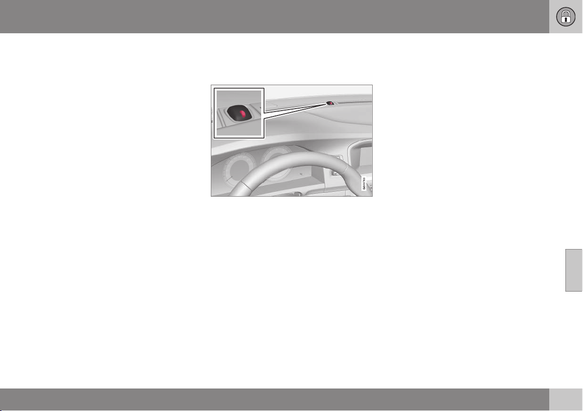
06 Locks and alarm
06
179
Deactivating a triggered alarm
– Press the remote control key unlock but-
ton or insert the remote control key in the
ignition switch.
Related information
•
Alarm indicator (p. 179)
•
Alarm - automatic re-arming (p. 179)
•
Alarm - remote control key not working
(p. 180)
Alarm indicator
The alarm indicator shows alarm system
(p. 178) status.
Same LED as lock indicator (p. 157).
A red LED on the instrument panel indicates
the alarm system's status:
•
LED not lit – Alarm not armed
•
The LED flashes once every other second
– Alarm is armed
•
The LED flashes rapidly after disarming
the alarm (and until the remote control
key is inserted in the ignition switch and
key position I is selected) – Alarm has
been triggered.
Alarm - automatic re-arming
Automatic re-arming of the alarm (p. 178) pre-
vents the car being left with the alarm dis-
armed unintentionally.
If the car is unlocked with the remote control
key (and the alarm is disarmed) but none of
the doors or the boot lid is opened within 2
minutes, then the alarm is automatically re-
armed. The car is relocked at the same time.
Related information
•
Reduced alarm level (p. 180)
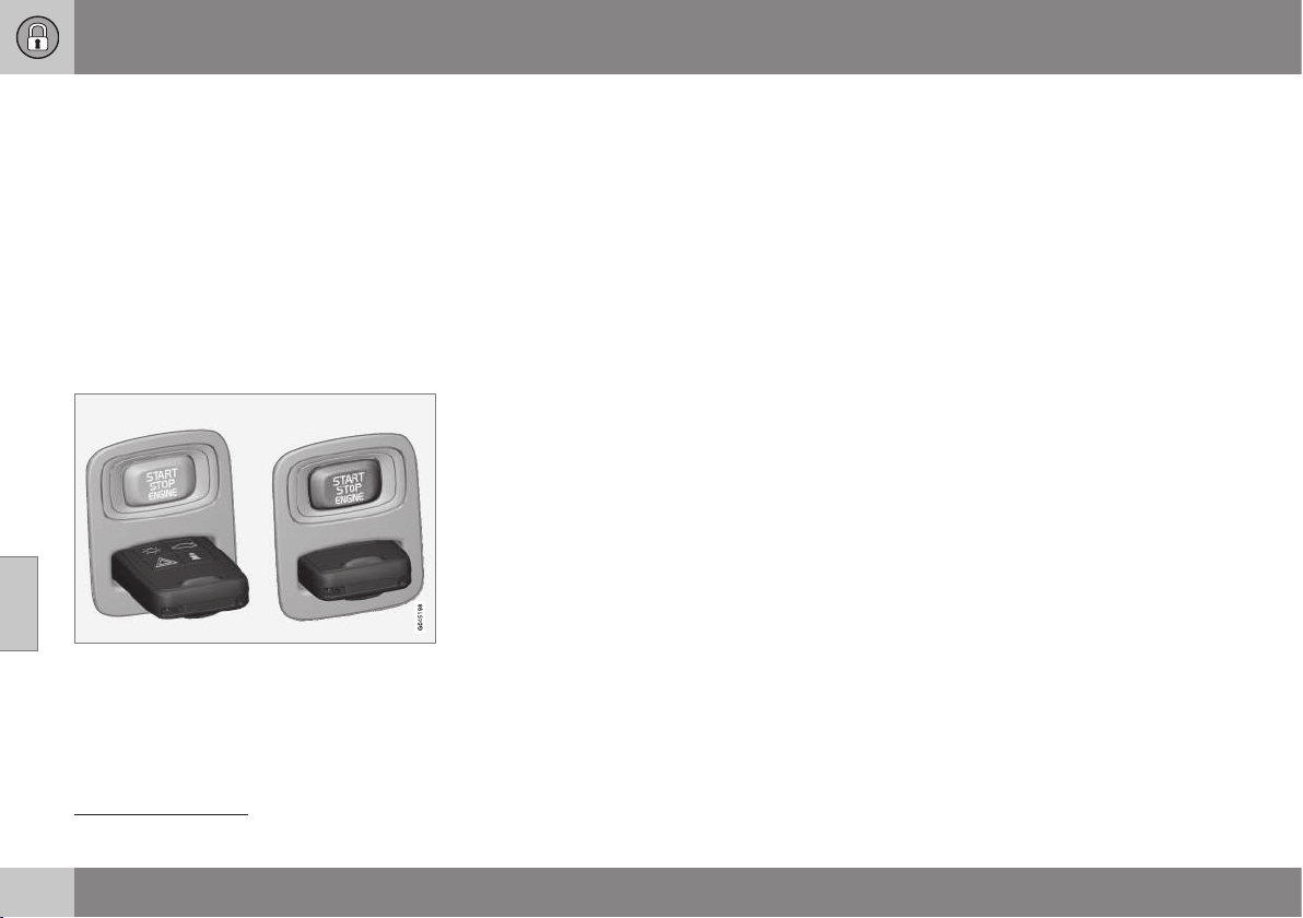
06 Locks and alarm
06
180
Alarm - remote control key not
working
If the alarm (p. 178) cannot be deactivated
with the remote control key, e.g. if the key's
battery (p. 165) is discharged - the car can be
unlocked, disarmed and the engine started as
follows:
1. Open the driver's door with the detacha-
ble key blade (p. 169).
> The alarm is triggered, the alarm indi-
cator (p. 179) flashes rapidly and the
siren sounds.
2. Insert the remote control key in the igni-
tion switch.
> The alarm is deactivated and the alarm
indicator goes out.
3. Start the engine.
Alarm signals
When the alarm (p. 178) is triggered a siren
sounds and all direction indicators flash.
•
A siren sounds for 30 seconds or until the
alarm is switched off. The siren has its
own battery and works independently of
the car battery.
•
The direction indicators flash for 5
minutes or until the alarm is switched off.
Reduced alarm level
Reduced guard means that the movement
and tilt detectors can be temporarily deacti-
vated.
To avoid accidental triggering of the alarm
(p. 178) - e.g. if a dog is left in a locked car or
during transport on a car train or car ferry -
temporarily deactivate the movement and tilt
detectors.
The procedure is the same as with the tem-
porary disengaging of deadlocks (p. 176)
10
.
Related information
•
Alarm indicator (p. 179)
10
Only in combination with alarm.
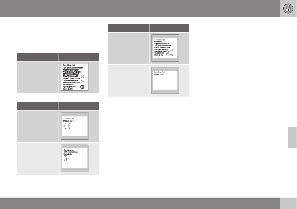
06 Locks and alarm
06
181
Type approval - remote control key
system
Type approval for the remote control key sys-
tem can be read in the table.
Lock system, standard
Country/Area
EU, China
Keyless lock system (Keyless drive)
Country/Area
EU
Korea
Country/Area
China
Hong Kong
Related information
•
Remote control key (p. 155)
DRIVER SUPPORT
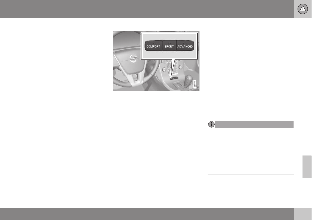
07 Driver support
07
* Option/accessory, for more information, see Introduction.
183
Active chassis - Four C*
Active chassis "Four-C" (Continously
Controlled Chassis Concept), regulates the
characteristics of the shock absorbers so that
the car's driving characteristics can be
adjusted. There are three settings: Comfort,
Sport and Advanced.
Comfort
This setting means that the car is perceived
as being more comfortable on rough and
uneven road surfaces. Shock absorption is
soft and the movement of the body is smooth
and gentle.
Sport
This setting means that the car is perceived
as being more sporty and is recommended
for more active driving. Steering response is
faster than in the Comfort mode. Shock
absorption is harder and the body follows the
road in order to reduce rolling during corner-
ing.
Advanced
This setting is only recommended on very
even and smooth road surfaces.
The shock absorbers are optimised for maxi-
mum roadholding and rolling in bends is fur-
ther minimised.
Operation
Control buttons.
The required chassis setting is selected using
the centre console buttons. The setting used
when the engine was switched off is re-acti-
vated when the engine is next started. The
exception is Advanced - it is restarted as
Sport.
Adjustable steering force*
Speed related power steering causes the
steering wheel force to increase with the
speed of the car in order to give the driver
enhanced sensitivity.
On motorways the steering feels firmer.
Steering is light and requires no extra effort
when parking and at low speed.
The driver can choose between three differ-
ent levels of steering force for road respon-
siveness or steering sensitivity in the menu
system MY CAR, MY CAR (p. 108):
•
Once there, search for
Steering force
level and select Low, Medium or High.
This setting is not accessible when the car is
moving.
NOTE
In certain situations the power steering
may become too hot and then needs to be
temporarily cooled - during this time the
power steering operates with reduced
power and turning the steering wheel may
then be perceived to be slightly heavier.
In parallel with the temporarily reduced
steering assistance the combined instru-
ment panel shows a message.
Related information
•
MY CAR (p. 108)
07 Driver support
07
184
* Option/accessory, for more information, see Introduction.
Electronic stability control (ESC) -
general
Stability system ESC (Electronic Stability
Control) helps the driver to avoid skidding and
improves the car's traction.
The activation of the ESC system
during braking may be noticed as a
throbbing sound. The car may
accelerate slower than expected
when the accelerator pedal is depressed.
WARNING
The stability system ESC is supplementary
assistance - it cannot handle all situations
in all road conditions.
The driver always bears responsibility that
the vehicle is driven safely and that appli-
cable road traffic rules and regulations are
followed.
The ESC system consists of the following
functions:
•
Active Yaw Control
•
Spin Control
•
Traction control system
•
Engine drag control - EDC
•
Corner Traction Control - CTC
•
Trailer Stability Assist - TSA
Active Yaw Control
The function checks the driving and brake
force of the wheels individually in order to
stabilise the car.
Spin Control
The function prevents the driving wheels from
spinning against the road surface during
acceleration.
Traction control system
The function is active at low speed and trans-
fers power from the driving wheel that is spin-
ning to the one that is not.
Engine drag control - EDC
EDC (Engine Drag Control) prevents involun-
tary wheel locking, e.g. after shifting down or
engine braking when driving in low gears on
slippery road surfaces.
Involuntary wheel locking while driving can,
amongst other things, impair the driver's abil-
ity to steer the car.
Corner Traction Control - CTC*
CTC compensates for understeer and allows
higher than normal acceleration in a bend
without wheelspin on the inner wheel, e.g. on
an arcing motorway entrance road to quickly
reach the prevailing traffic speed.
Trailer Stability Assist* - TSA
1
Trailer stability assist (p. 317) function is to
stabilise the car and trailer combination if it
begins to snake. For more information, see
Driving with a trailer* (p. 311).
NOTE
The function is deactivated if the driver
selects Sport mode.
Related information
•
Electronic stability control (ESC) - opera-
tion (p. 185)
•
Electronic stability control (ESC) - sym-
bols and messages (p. 186)
1
Trailer Stability Assist is included in the installation of Volvo genuine towbar.
07 Driver support
07
185
Electronic stability control (ESC) -
operation
Selection of level - Sport mode
The ESC system is always activated - it can-
not be deactivated.
However, the driver can
select the Sport mode,
which allows for a more
active driving experience.
Sport mode is selected in
the menu system MY CAR.
For a description of the menu system, see
MY CAR (p. 108).
In Sport mode the system detects whether
the accelerator pedal, steering wheel move-
ments and cornering are more active than in
normal driving and then allows controlled
skidding with the rear section up to a certain
level before it intervenes and stabilises the
car.
If, for example, the driver stops a controlled
skid by releasing the accelerator pedal, then
the ESC system intervenes and stabilises the
car.
With Sport mode, maximum traction is also
obtained if the car has become stuck, or
when driving on a loose surface - e.g. sand or
deep snow.
Sport mode is indicated in the com-
bined instrument panel by means of
this symbol illuminating with a con-
stant glow until the driver deselects
the function or until the engine is switched off
- after the next time the engine is started the
ESC system is back in its normal mode again.
Related information
•
Electronic stability control (ESC) - general
(p. 184)
•
Electronic stability control (ESC) - sym-
bols and messages (p. 186)
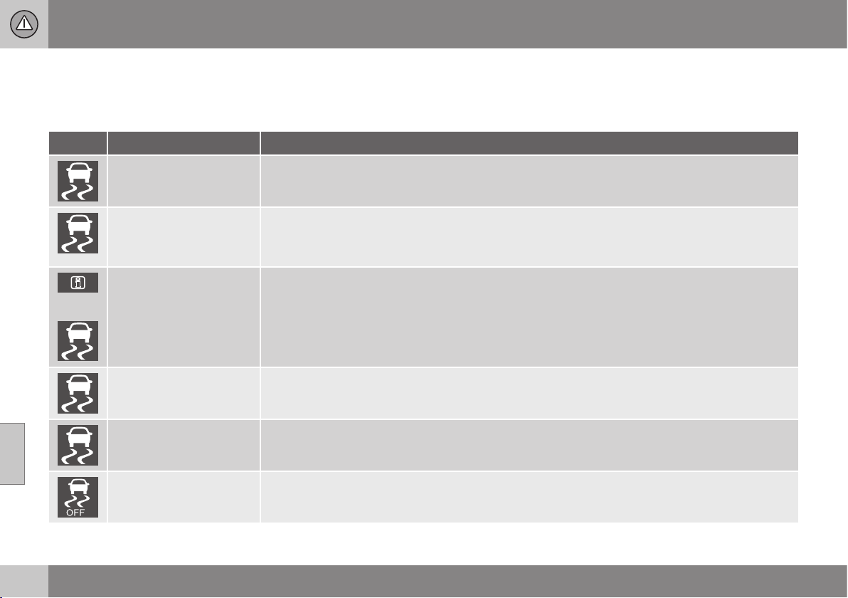
07 Driver support
07
186
Electronic stability control (ESC) -
symbols and messages
Table
Symbol Message Specification
ESC Temporarily OFF
ESC system has been temporarily reduced due to excessive brake disc temperature - the function is
reactivated automatically when the brakes have cooled.
ESC Service required
ESC system disengaged.
•
Stop the car in a safe place, switch off the engine and start it again.
•
Visit a workshop if the message remains - an authorised Volvo workshop is recommended.
and
"Message"
There is a text message in the combined instrument panel (p. 61) - Read it!
Constant glow for
2 seconds.
System check when the engine is started.
Flashing light. ESC system is being activated.
Constant glow. Sport mode is activated.
NOTE: The ESC system is not deactivated in this mode - it is partially reduced.

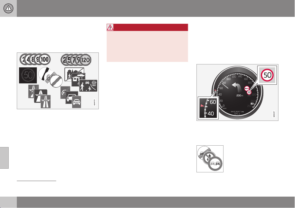
07 Driver support
07
188
* Option/accessory, for more information, see Introduction.
Road Sign Information (RSI)*
The road sign information function (RSI –
Road Sign Information) helps the driver to
remember which speed-related road signs the
car has passed.
Examples of readable speed related signs
2
.
The RSI function gives information on current
speed, e.g. that a motorway or road is star-
ting/ending and when overtaking is prohibi-
ted.
If both a sign for motorway/road for motor-
ised traffic and a sign showing the maximum
permitted speed are passed, RSI decides to
show the sign symbol for maximum permitted
speed.
WARNING
RSI does not work in all situations but is
designed merely as a supplementary aid.
The driver always bears ultimate responsi-
bility for ensuring that the vehicle is driven
safely and that applicable road traffic rules
and regulations are followed.
Related information
•
Road sign information (RSI)* - operation
(p. 188)
•
Road sign information (RSI)* - limitations
(p. 190)
Road sign information (RSI)* -
operation
The road sign information function (RSI –
Road Sign Information) helps the driver to
remember which speed-related road signs the
car has passed.
The function is operated as follows:
Recorded speed information
3
.
When RSI has recorded a road sign with an
imposed speed, the combined instrument
panel displays the sign as a symbol.
Together with the symbol for
the current speed limit, a
sign showing that overtaking
is prohibited may also be
displayed where appropriate.
2
Road signs shown in the combined instrument panel are market-dependent - the illustrations in these instructions only show a few examples.
3
Road signs shown in the combined instrument panel are market-dependent - the illustrations in these instructions only show a few examples.
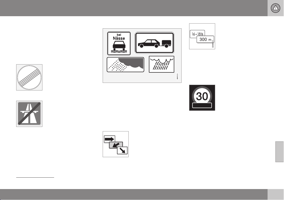
07 Driver support
07
}}
189
End of restriction or motorway
A corresponding road sign is shown in the
combined instrument panel for
approx. 10 seconds in situations where RSI
detects a sign that involves the end of a
speed limit - or other speed-related informa-
tion, e.g. end of a motorway.
Examples of such signs are:
End of all restrictions.
End of motorway.
Following which, the sign information is hid-
den until the next speed-related sign is
detected.
Additional signs
Examples of additional signs
3
.
Sometimes different speed limits are signpos-
ted for the same road - an additional sign
then indicates the circumstances under which
the different speeds apply. The road section
may be particularly susceptible to accidents
in rain and/or fog, for example.
An additional sign relating to rain is displayed
only if the windscreen wipers are in use.
The speed applicable on an
exit is indicated in certain
markets by means of an
additional sign containing an
arrow.
Speed signs linked to this
type of additional sign are displayed only if
the driver is using the direction indicator.
Some speeds are applicable only after e.g. a
specific distance or at a certain time of day.
The driver's attention is drawn to the situation
by means of a symbol for an additional sign
under the symbol showing speed.
Display of additional information
A symbol for additional sign in the form of an
empty frame under the combined instrument
panel's speed symbol means that the RSI has
detected an additional sign with supplemen-
tary information for the current speed limit.
Setting in MY CAR
There are options for RSI in the MY CAR
menu system; see MY CAR (p. 108).
3
Road signs shown in the combined instrument panel are market-dependent - the illustrations in these instructions only show a few examples.
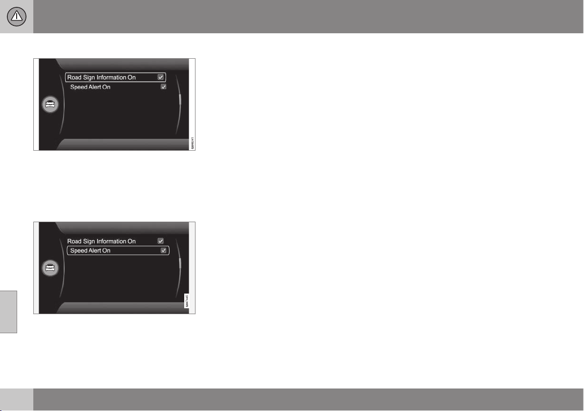
||
07 Driver support
07
190
* Option/accessory, for more information, see Introduction.
Road sign information On/Off
The combined instrument panel's speed sym-
bol display can be disabled. The function can
be activated/deactivated in the menu system
MY CAR. For a description of the menu sys-
tem, see MY CAR (p. 108).
Speed warning
The driver can opt to receive a warning when
the applicable speed limit is exceeded by
5 km/h or more. This warning is given by the
symbol showing the applicable maximum
speed temporarily flashing when this speed is
exceeded. The function can be activated/
deactivated in the menu system MY CAR. For
a description of the menu system, see MY
CAR (p. 108).
Related information
•
Road Sign Information (RSI)* (p. 188)
•
Road sign information (RSI)* - limitations
(p. 190)
•
MY CAR (p. 108)
Road sign information (RSI)* -
limitations
The road sign information function (RSI –
Road Sign Information) helps the driver to
remember which speed-related road signs the
car has passed. The function has the follow-
ing limitations.
The RSI function's camera sensor has limita-
tions just like the human eye - read more
about camera sensor limitations (p. 228)).
Signs which indirectly provide information on
a prevailing speed limit, e.g. name signs for
towns/districts, are not recorded by the RSI
function.
Here are several examples of what can dis-
rupt the function:
•
Faded signs
•
Signs positioned on bends
•
Rotated or damaged signs
•
Concealed or poorly positioned signs
•
Signs completely or partly covered with
frost, snow and/or dirt.
Related information
•
Road Sign Information (RSI)* (p. 188)
•
Road sign information (RSI)* - operation
(p. 188)
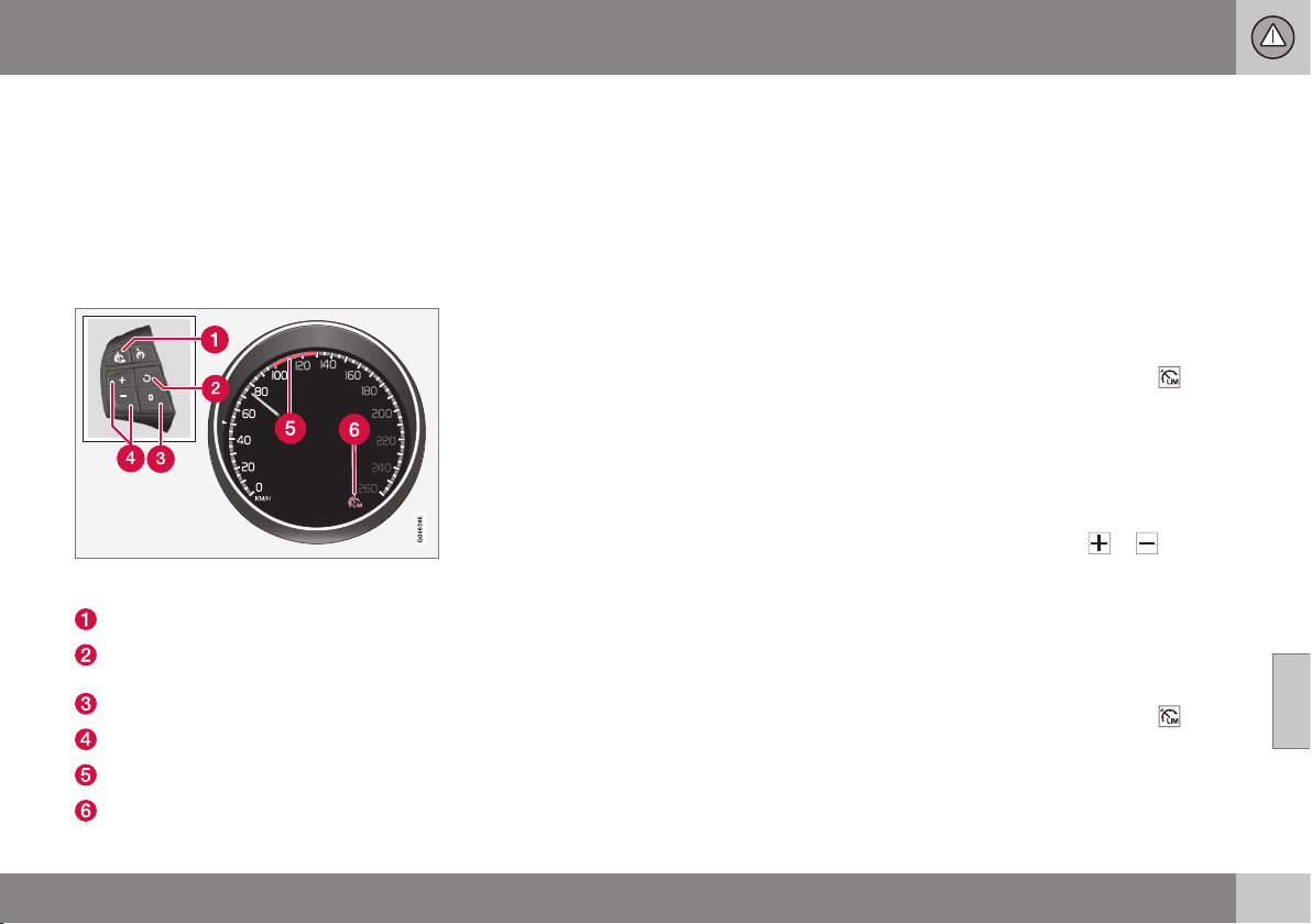
07 Driver support
07
}}
* Option/accessory, for more information, see Introduction.
191
Speed limiter*
A Speed Limiter (Speed Limiter) can be regar-
ded as a reverse cruise control - the driver
regulates the speed using the accelerator
pedal but is prevented from accidentally
exceeding a pre-selected/set speed by the
speed limiter.
Overview
Steering wheel keypad and combined instrument
panel.
Speed limiter - On/Off.
Standby mode ceases and the stored
speed is resumed.
Standby mode.
Activate and adjust the max. speed.
Selected speed.
Speed limiter active.
Related information
•
Speed limiter* - getting started (p. 191)
•
Speed limiter* - temporary deactivation
and standby mode (p. 192)
•
Speed limiter* - alarm for speed excee-
ded (p. 193)
•
Speed limiter* - deactivation (p. 193)
Speed limiter* - getting started
Switch on and activate
When the speed limiter is active, its symbol
(6) is shown in combination with a mark (5) by
the set maximum speed in the combined
instrument panel.
Selection and storage of the highest possible
speed in the memory can be made both dur-
ing a journey and while stationary.
While driving
1.
Press the steering wheel button
to
switch on the speed limiter.
> The symbol (6) for speed limiter illumi-
nates in the combined instrument
panel.
2. When the car is moving at the desired
highest possible speed: Press one of the
steering wheel buttons
or until the
combined instrument panel shows a
mark (5) by the desired maximum speed.
> The speed limiter is then active and the
selected max. speed is stored in the
memory.
When stationary
1.
Press the steering wheel button to
switch on the speed limiter.
||
07 Driver support
07
192
* Option/accessory, for more information, see Introduction.
2.
Scroll with the
button until the com-
bined instrument panel shows a mark (5)
by the desired maximum speed.
> The speed limiter is then active and the
selected max. speed is stored in the
memory.
Related information
•
Speed limiter* (p. 191)
Speed limiter* - changing speed
Changing the stored speed
Stored max. speed is changed with short or
long presses on the
or steering wheel
button.
To adjust +/- 5 km/h:
•
Use short presses - each press gives
+/- 5 km/h.
To adjust +/- 1 km/h:
•
Hold down the button and release it at
the required max. speed.
Last press made is stored in the memory.
Related information
•
Speed limiter* (p. 191)
Speed limiter* - temporary
deactivation and standby mode
A Speed Limiter (Speed Limiter) can be regar-
ded as a reverse cruise control - the driver
regulates the speed using the accelerator
pedal but is prevented from accidentally
exceeding a pre-selected/set speed by the
speed limiter.
Temporary deactivation - standby mode
To temporarily deactivate the speed limiter
and set it in standby mode:
–
Press .
> The mark (5) in the combined instru-
ment panel changes colour from
GREEN to WHITE and the driver can
temporarily exceed the set maximum
speed.
The speed limiter is reactivated with
one press on
. The mark (5) then
changes colour from WHITE to GREEN
and the car's maximum speed is lim-
ited once again.
Temporary deactivation with the
accelerator pedal
The speed limiter can also be set in standby
mode with the accelerator pedal, e.g. for rap-
idly accelerating the car out of a situation:
07 Driver support
07
* Option/accessory, for more information, see Introduction.
193
– Depress the accelerator pedal fully.
> The combined instrument panel shows
the stored maximum speed with a col-
oured mark (5) and the driver can tem-
porarily exceed the set maximum
speed - the mark (5) changes colour
during this time from GREEN to
WHITE.
The speed limiter is automatically reac-
tivated after the release of the acceler-
ator pedal and the car's speed is
slowed down to below the selected/
stored maximum speed - the display's
mark (5) changes colour from WHITE
to GREEN and the car's maximum
speed is again limited.
Related information
•
Speed limiter* (p. 191)
•
Speed limiter* - getting started (p. 191)
•
Speed limiter* - changing speed (p. 192)
•
Speed limiter* - deactivation (p. 193)
•
Speed limiter* - alarm for speed excee-
ded (p. 193)
Speed limiter* - alarm for speed
exceeded
A Speed Limiter (Speed Limiter) can be regar-
ded as a reverse cruise control - the driver
regulates the speed using the accelerator
pedal but is prevented from accidentally
exceeding a pre-selected/set speed by the
speed limiter.
On a steep downhill gradient the speed limit-
er's engine braking effect may be inadequate
and the selected maximum speed is excee-
ded. The driver is alerted about this with an
acoustic signal.
The signal is active until the driver has slowed
to below the selected maximum speed.
NOTE
The alarm is only activated after 5 seconds
if the speed has been exceeded by at least
3 km/h, provided that neither of the
or
buttons has been depressed during the
last half minute.
Related information
•
Speed limiter* (p. 191)
•
Speed limiter* - changing speed (p. 192)
•
Speed limiter* - getting started (p. 191)
•
Speed limiter* - temporary deactivation
and standby mode (p. 192)
•
Speed limiter* - deactivation (p. 193)
Speed limiter* - deactivation
A Speed Limiter (Speed Limiter) can be regar-
ded as a reverse cruise control - the driver
regulates the speed using the accelerator
pedal but is prevented from accidentally
exceeding a pre-selected/set speed by the
speed limiter.
To deactivate the speed limiter:
–
Press the steering wheel button .
> The combined instrument panel's sym-
bol for speed limiter (6) and the selec-
tion of the set speed (5) both extin-
guish - the set/stored speed is thus
cleared and cannot then be resumed
with the
button.
The driver can then use the accelerator
pedal to choose a speed without limi-
tation.
Related information
•
Speed limiter* (p. 191)
•
Speed limiter* - getting started (p. 191)
•
Speed limiter* - temporary deactivation
and standby mode (p. 192)
•
Speed limiter* - alarm for speed excee-
ded (p. 193)
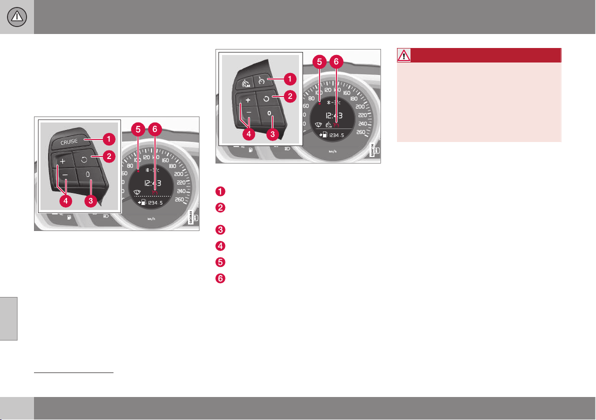
07 Driver support
07
194
* Option/accessory, for more information, see Introduction.
Cruise control*
The cruise control (CC – Cruise Control) helps
the driver maintain an even speed, resulting in
a more relaxed driving on motorways and
long, straight roads in regular traffic flows.
Overview
The steering wheel buttons and combined instru-
ment panel in cars without speed limiter
4
.
The steering wheel buttons and combined instru-
ment panel in cars with speed limiter
4
.
Cruise control - On/Off.
Standby mode ceases and the stored
speed is resumed.
Standby mode
Activate and adjust the speed.
Selected speed (GREY = Standby mode).
Cruise control active - WHITE symbol
(GREY = Standby mode).
WARNING
The driver must always be observant with
regard to the traffic conditions and inter-
vene when the cruise control is not main-
taining a suitable speed and/or suitable
distance.
The driver always bears ultimate responsi-
bility for ensuring that the vehicle is driven
safely.
Related information
•
Cruise control* - managing speed
(p. 195)
•
Cruise control* temporary deactivation
and standby mode (p. 195)
•
Cruise control* - resume set speed
(p. 196)
•
Cruise control* - deactivate (p. 197)
•
Adaptive cruise control - ACC* (p. 197)
4
A Volvo dealer has updated information about what applies in each respective market.
07 Driver support
07
}}
* Option/accessory, for more information, see Introduction.
195
Cruise control* - managing speed
It is possible to activate, set and change the
stored speed.
Activating and setting the speed
To start the cruise control:
•
Press the steering wheel button for
CRUISE (without speed limiter) or
(with speed limiter).
> The cruise control symbol (6) in the com-
bined instrument panel illuminates -
cruise control is in standby mode.
To activate cruise control:
•
At the required speed - press the steering
wheel button
or .
> The current speed is stored in memory
and the combined instrument panel's
marking (5) illuminates at the selected
speed and the symbol (6) changes from
GREY to WHITE - the car then follows the
stored speed.
NOTE
Cruise Control cannot be enabled at
speeds below 30 km/h.
Changing the stored speed
Stored speed is changed with short or long
presses on the or steering wheel but-
ton.
To adjust +/- 5 km/h:
•
Use short presses - each press gives
+/- 5 km/h.
To adjust +/- 1 km/h:
•
Hold down the button and release it at
the required speed.
Last press made is stored in the memory.
If speed is increased using the accelerator
pedal prior to pressing the
/ button,
then it is the car's current speed when the
button is pressed that is stored.
A temporary increase in speed with the accel-
erator pedal, e.g. during overtaking, does not
affect the cruise control setting - the car
returns to the last stored speed when the
accelerator pedal is released.
NOTE
If any of the Cruise Control buttons are
held depressed for several minutes then it
is blocked and deactivated. To be able to
reactivate Cruise Control, the car must be
stopped and the engine restarted.
Related information
•
Cruise control* (p. 194)
Cruise control* temporary
deactivation and standby mode
The function can be temporarily deactivated
and set in standby mode.
Temporary deactivation - standby mode
To temporarily disengage cruise control and
set it in standby mode:
•
Press the steering wheel button
.
> The combined instrument panel's
marking (5) and symbol (6) change colour
from WHITE to GREY - cruise control is
temporarily disengaged.
||
07 Driver support
07
196
* Option/accessory, for more information, see Introduction.
Standby mode due to driver intervention
Cruise control is temporarily disengaged and
automatically set in standby mode if:
•
the foot brake is used
•
the clutch pedal is depressed for longer
than 1 minute
5
•
the gear lever/selector is moved to N
position
•
the driver maintains speed higher than
the stored speed for longer than
1 minute.
The driver must then regulate the speed.
A temporary increase in speed with the accel-
erator pedal, e.g. during overtaking, does not
affect the setting - the car returns to the last
stored speed when the accelerator pedal is
released.
Automatic standby mode
Cruise control is temporarily disengaged and
set in standby mode if:
•
wheels lose traction
•
engine speed is too low/high
•
speed falls below approx. 30 km/h.
The driver must then regulate the speed.
Related information
•
Cruise control* (p. 194)
•
Cruise control* - managing speed (p. 195)
•
Cruise control* - resume set speed
(p. 196)
•
Cruise control* - deactivate (p. 197)
Cruise control* - resume set speed
The cruise control (CC – Cruise Control) helps
the driver to maintain an even speed.
After temporary deactivation and standby
mode (p. 195) it is possible to resume the set
speed.
To reactivate the cruise control from standby
mode:
•
Press the steering wheel button
.
> The combined instrument panel's
marking (5) and symbol (6) change colour
from GREY to WHITE - the car then fol-
lows the last stored speed.
NOTE
A marked speed increase may occur once
the speed has been resumed by selecting
the
button.
Related information
•
Cruise control* (p. 194)
•
Cruise control* - managing speed (p. 195)
•
Cruise control* temporary deactivation
and standby mode (p. 195)
•
Cruise control* - deactivate (p. 197)
5
Disengaging and selecting a higher or lower gear does not involve standby mode.
07 Driver support
07
}}
* Option/accessory, for more information, see Introduction.
197
Cruise control* - deactivate
How it is deactivated is described here.
Cruise control is switched off with the steer-
ing wheel button (1) or by switching off the
engine - the set/stored speed is thus cleared
and cannot then be resumed with the
but-
ton.
Related information
•
Cruise control* (p. 194)
•
Cruise control* - managing speed (p. 195)
•
Cruise control* temporary deactivation
and standby mode (p. 195)
•
Cruise control* - resume set speed
(p. 196)
Adaptive cruise control - ACC*
The adaptive cruise control (ACC – Adaptive
Cruise Control) helps the driver to maintain an
even speed combined with a pre-selected
time interval to the vehicle ahead.
The adaptive cruise control provides a more
relaxing driving experience on long journeys
on motorways and long straight main roads in
smooth traffic flows.
The driver sets the desired speed (p. 201)
and time interval (p. 202) to the car in front.
When the radar detector detects a slower
vehicle in front of the car, the speed is auto-
matically adapted to that. When the road is
clear again the car returns to the selected
speed.
If the adaptive cruise control is switched off
or set to standby mode (p. 202) and the car
comes too close to a vehicle in front, then the
driver is warned instead by the Distance
Warning (p. 212) function about the short
distance.
WARNING
The driver must always be observant with
regard to the traffic conditions and inter-
vene when the adaptive cruise control is
not maintaining a suitable speed or suita-
ble distance.
The adaptive cruise control cannot handle
all traffic, weather and road conditions.
Read all the sections about the adaptive
cruise control in the owner's manual in
order to learn about its limitations, of
which the driver should be aware before it
is used.
The driver always bears responsibility for
maintaining the correct distance and
speed, even when the adaptive cruise con-
trol is being used.
IMPORTANT
Maintenance of adaptive cruise control
components must only be performed at a
workshop - an authorised Volvo workshop
is recommended.
For a limited time after the service, the
ACC function can have a somewhat lim-
ited range. The system is calibrated whilst
driving and full function returns automati-
cally.
Automatic gearbox
Cars with automatic gearbox have enhanced
functionality with the adaptive cruise control's
Queue assistance (p. 204) function.
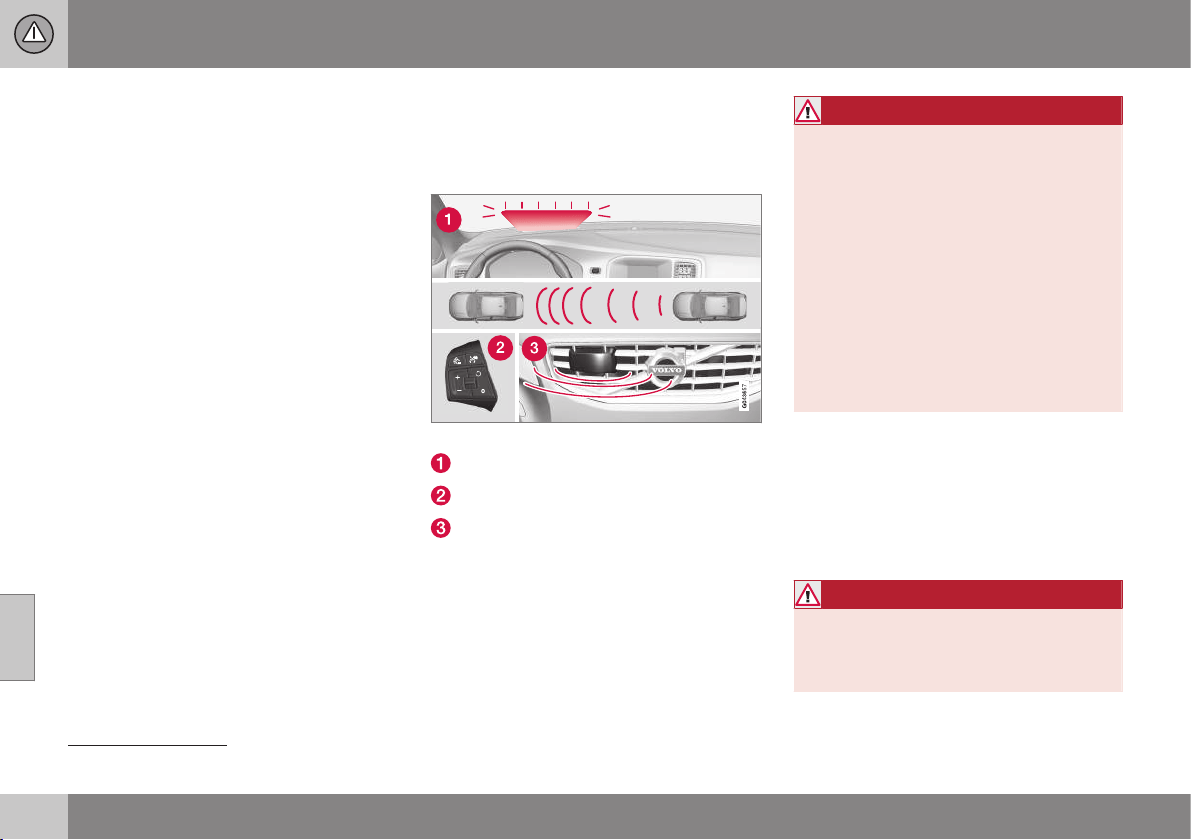
||
07 Driver support
07
198
* Option/accessory, for more information, see Introduction.
Related information
•
Adaptive cruise control* - function
(p. 198)
•
Adaptive cruise control* - overview
(p. 200)
•
Adaptive cruise control* - managing
speed (p. 201)
•
Adaptive cruise control* - set time interval
(p. 202)
•
Adaptive cruise control* - temporary
deactivation, and standby mode (p. 202)
•
Adaptive cruise control* - overtaking
another vehicle (p. 203)
•
Adaptive cruise control* - deactivate
(p. 204)
•
Adaptive Cruise Control* - queue assis-
tance (p. 204)
•
Adaptive cruise control* - switch cruise
control functionality (p. 206)
•
Radar sensor (p. 206)
•
Radar sensor - limitations (p. 207)
•
Adaptive cruise control* - fault tracing
and action (p. 209)
•
Adaptive cruise control* - symbols and
messages (p. 210)
Adaptive cruise control* - function
It consists of a cruise control system and a
coordinated spacing system.
Function overview
Function overview
6
.
Warning lamp - braking by driver required
Steering wheel keypad (p. 200)
Radar sensor (p. 206)
WARNING
Adaptive cruise control is not a collision
avoidance system. The driver must inter-
vene if the system does not detect a vehi-
cle in front.
The adaptive cruise control does not brake
for humans or animals, and not for small
vehicles such as bicycles and motorcy-
cles. Nor for low trailers, oncoming, slow
or stationary vehicles and objects.
Do not use the adaptive cruise control, for
example, in city traffic, in dense traffic, at
junctions, on slippery surfaces, with a lot
of water or slush on the road, in heavy
rain/snow, in poor visibility, on winding
roads or on slip roads.
Distance to the vehicle ahead (p. 202) is
measured primarily by a radar sensor
(p. 206). The cruise control function regulates
the speed with acceleration and braking. It is
normal for the brakes to emit a low sound
when they are being used by the adaptive
cruise control.
WARNING
The brake pedal moves when the adaptive
cruise control brakes. Do not rest your foot
beneath the brake pedal - it may then
become trapped.
6
NOTE: The illustration is schematic - details may differ depending on car model.
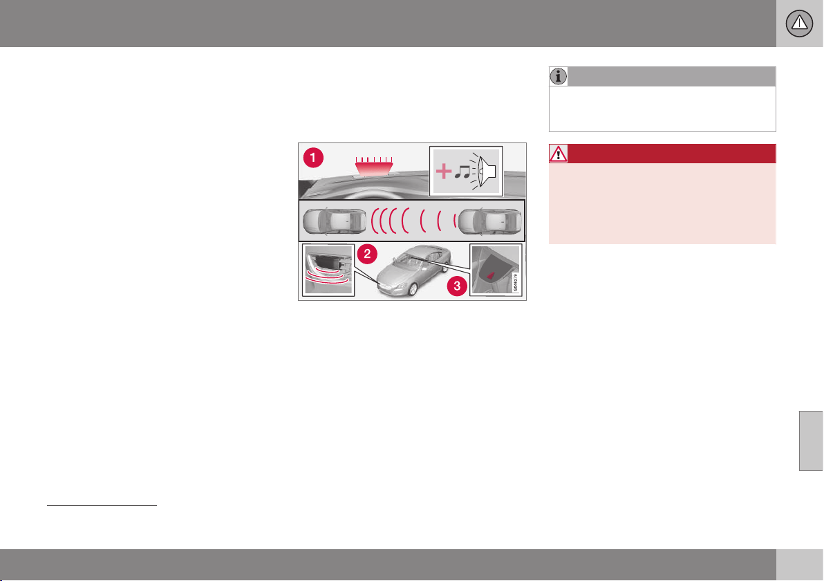
07 Driver support
07
* Option/accessory, for more information, see Introduction.
199
The adaptive cruise control aims to follow the
vehicle ahead in the same lane according to
what the driver set for time interval (p. 202). If
the radar sensor cannot see any vehicle in
front then the car will instead maintain the
speed set and stored by the driver. This also
takes place if the speed of the vehicle in front
exceeds the stored speed.
The adaptive cruise control aims to control
the speed in a smooth way. In situations that
demand sudden braking the driver must
brake himself/herself. This applies with large
differences in speed, or if the vehicle in front
brakes heavily. Due to limitations in the radar
sensor (p. 207) braking may come unexpect-
edly or not at all.
The adaptive cruise control can be activated
to follow another vehicle at speeds from
30 km/h
7
up to 200 km/h. If the speed falls
below 30 km/h or if the engine speed
becomes too low, the cruise control is set in
standby mode (p. 202) at which automatic
braking ceases - the driver must then take
over himself/herself to maintain a safe dis-
tance to the vehicle ahead.
Warning lamp - braking by driver
required
Adaptive cruise control has a braking
capacity that is equivalent to approx. 40% of
the car's braking capacity.
1. Collision warning system warning lamp and
warning sound
8
.
If the car needs to be braked more heavily
than the adaptive cruise control capacity and
the driver does not brake, then the warning
lamp and warning sound from the Collision
warning system (p. 222) are used in order to
alert the driver that immediate intervention is
required.
NOTE
The warning lamp may be difficult to see in
strong sunlight or when wearing sun-
glasses.
WARNING
The adaptive cruise control only warns of
vehicles which its radar unit has detected -
hence a warning may not be given, or it
may be given with a certain delay. Do not
wait for a warning without braking when so
required.
Steep roads and/or heavy load
Bear in mind that the adaptive cruise control
is primarily intended for use when driving on
level road surfaces. It may have difficulty in
keeping the correct distance from the vehicle
ahead when driving on steep downhill slopes,
with a heavy load or with a trailer - in which
case, be extra attentive and ready to slow
down.
Related information
•
Adaptive cruise control - ACC* (p. 197)
•
Adaptive cruise control* - deactivate
(p. 204)
•
Adaptive cruise control* - overtaking
another vehicle (p. 203)
7
Queue Assist (p. 204) (in cars with automatic gearbox) can operate in the range 0-200 km/h.
8
NOTE: The illustration is schematic - details may vary depending on car model.
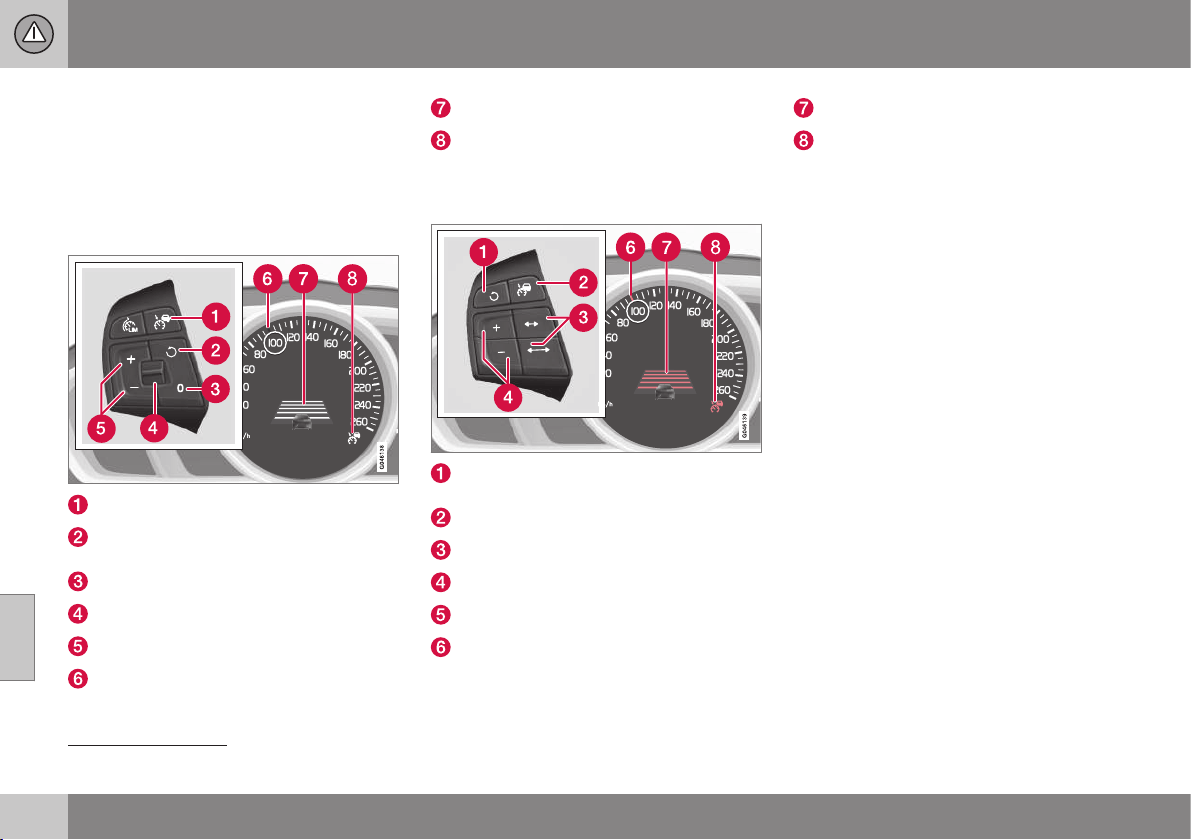
07 Driver support
07
200
* Option/accessory, for more information, see Introduction.
Adaptive cruise control* - overview
Operation of the adaptive cruise control and
steering wheel keypad varies depending on
whether or not the car is equipped with speed
limiter
9
.
Adaptive cruise control with Speed
limiter
Cruise control - On/Off.
Standby mode ceases and the stored
speed is resumed.
Standby mode
Time interval - Increase/decrease.
Activate and adjust the speed.
Green marking at stored speed (WHITE =
standby mode).
Time distance
ACC is active at the GREEN symbol
(WHITE = standby mode).
Adaptive cruise control without Speed
limiter
Standby mode ceases and the stored
speed is resumed.
Cruise control - On/Off or Standby mode.
Time interval - Increase/decrease.
Activate and adjust the speed.
(Not used)
Green marking at stored speed (WHITE =
standby mode).
Time distance
ACC is active at the GREEN symbol
(WHITE = standby mode).
Related information
•
Adaptive cruise control - ACC* (p. 197)
•
Adaptive cruise control* - function
(p. 198)
•
Adaptive cruise control* - symbols and
messages (p. 210)
9
A Volvo dealer has updated information about what applies in each respective market.
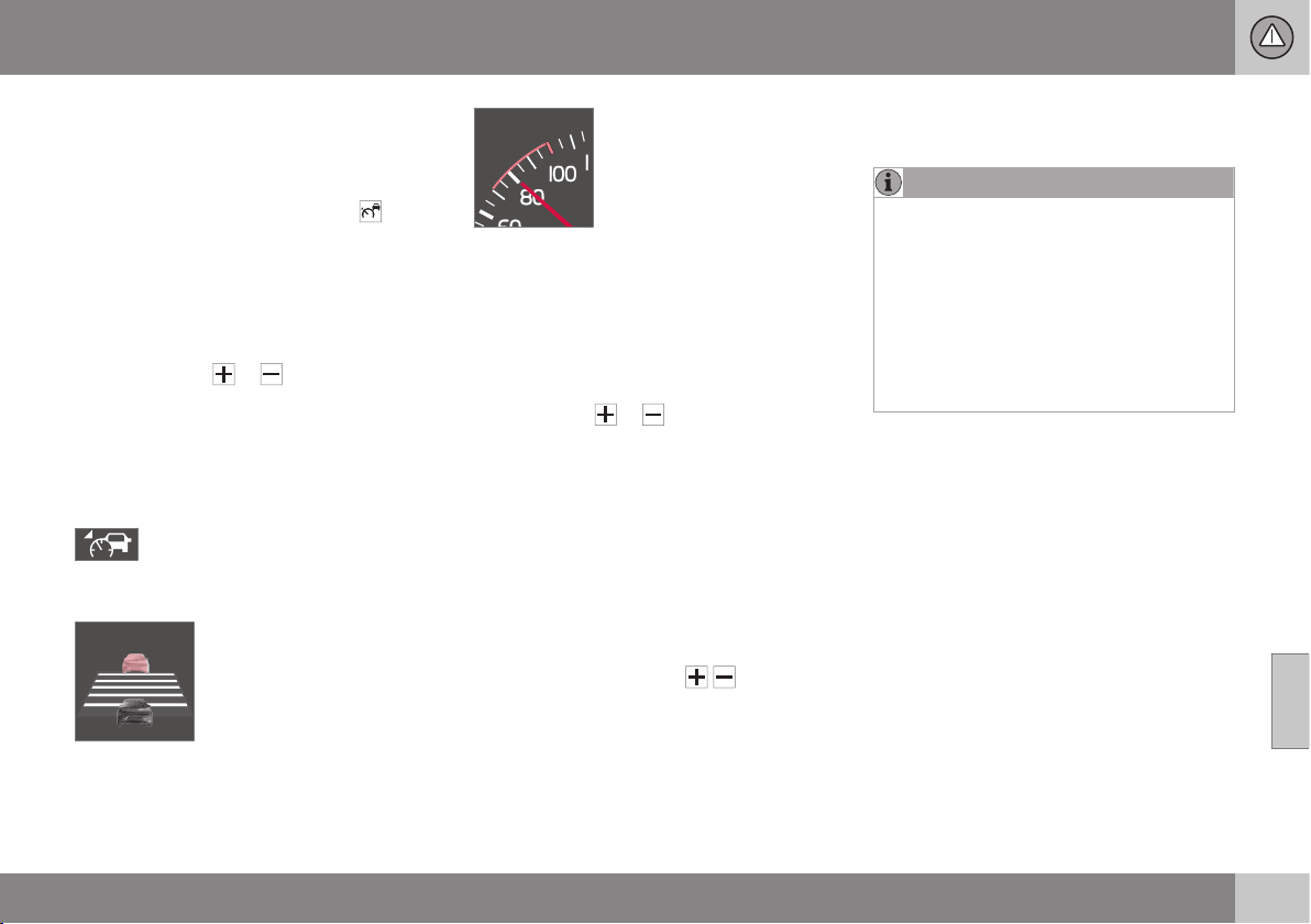
07 Driver support
07
* Option/accessory, for more information, see Introduction.
201
Adaptive cruise control* - managing
speed
To start the ACC:
•
Press the steering wheel button
- a
similar WHITE symbol illuminates in the
combined instrument panel (8) which
shows that the adaptive cruise control is
in standby mode (p. 202).
To activate ACC:
•
At the required speed - press the steering
wheel button
or .
> The current speed is stored in the mem-
ory, the combined instrument panel
shows a "magnifying glass" (6) around
the stored speed for a second or so and
its marking changes from WHITE to
GREEN.
When this symbol changes colour
from WHITE to GREEN, the ACC is
active and the car maintains the
stored speed.
Only when the symbol shows
an image of another vehicle
is the distance to the vehicle
in front controlled by the
ACC.
At the same time a speed
range is marked:
•
the higher speed with GREEN marking is
the pre-programmed speed
•
the lower speed is the speed of the vehi-
cle in front.
Changing the stored speed
Stored speed is changed with short or long
presses on the
or steering wheel but-
ton.
To adjust +/- 5 km/h:
•
Use short presses - each press gives
+/- 5 km/h.
To adjust +/- 1 km/h:
•
Hold down the button and release it at
the required speed.
Last press made is stored in the memory.
If speed is increased using the accelerator
pedal prior to pressing the
/ button,
then it is the car's current speed when the
button is pressed that is stored.
A temporary increase in speed with the accel-
erator pedal, e.g. during overtaking, does not
affect the setting - the car returns to the last
stored speed when the accelerator pedal is
released.
NOTE
If any of the adaptive cruise control but-
tons are held depressed for several
minutes then the function is blocked and
deactivated. To be able to reactivate it, the
car must be stopped and the engine
restarted.
In certain situations it cannot be reactiva-
ted - in which case, the combined instru-
ment panel (p. 210) shows
Adaptive
cruise control unavailable.
Related information
•
Adaptive cruise control - ACC* (p. 197)
•
Adaptive cruise control* - overview
(p. 200)
•
Adaptive cruise control* - function
(p. 198)
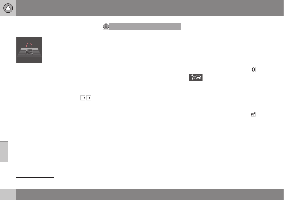
07 Driver support
07
202
* Option/accessory, for more information, see Introduction.
Adaptive cruise control* - set time
interval
Different time intervals to the
vehicle in front can be
selected and shown in the
combined instrument panel
as 1-5 horizontal lines - the
more lines the longer the
time interval. One line corre-
sponds to approximately 1 second to the
vehicle in front, 5 lines approximately
3 seconds.
To set/change the time distance:
•
Turn the thumbwheel on the steering
wheel keypad (p. 200) (or use the
/
buttons for cars without Speed limiter).
At low speed, when the distances are short,
the adaptive cruise control increases the time
interval slightly.
The adaptive cruise control allows the time
interval to vary noticeably in certain situations
in order to allow the car to follow the vehicle
in front smoothly and comfortably.
Note that a short time interval only allows the
driver a short time to react and take action if
any unforeseen traffic problem should arise.
The same symbol is also shown when Dis-
tance Warning (p. 212) function is activated.
NOTE
Only use the time intervals permitted by
local traffic regulations.
If the adaptive cruise control does not
appear to react when activated, this may
be because the time distance to the vehi-
cle in front is preventing an increase in
speed.
The higher the speed the longer the calcu-
lated distance in metres for a given time
interval.
Read more how speed is handled (p. 201).
Related information
•
Adaptive cruise control - ACC* (p. 197)
•
Adaptive cruise control* - overview
(p. 200)
•
Adaptive cruise control* - function
(p. 198)
•
Adaptive cruise control* - deactivate
(p. 204)
Adaptive cruise control* - temporary
deactivation, and standby mode
The adaptive cruise control can be temporar-
ily deactivated and set in standby mode.
Temporary deactivation/standby mode -
with speed limiter
To temporarily disengage the adaptive cruise
control and set it in standby mode:
•
Press the steering wheel button
This symbol and the stored speed's
marking then change colour from
GREEN to WHITE.
Temporary deactivation/standby mode -
without speed limiter
To temporarily disengage the adaptive cruise
control and set it in standby mode:
•
Press the steering wheel button
Standby mode due to driver intervention
The adaptive cruise control is temporarily dis-
engaged and set automatically in standby
mode if:
•
the foot brake is used
•
the clutch pedal is depressed for longer
than 1 minute
10
10
Disengaging and selecting a higher or lower gear does not involve standby mode.
07 Driver support
07
* Option/accessory, for more information, see Introduction.
203
•
the gear selector is moved to N position
(automatic gearbox)
•
the driver maintains speed higher than
the stored speed for longer than
1 minute.
The driver must then regulate the speed.
A temporary increase in speed with the accel-
erator pedal, e.g. during overtaking, does not
affect the setting - the car returns to the last
stored speed when the accelerator pedal is
released.
Automatic standby mode
The adaptive cruise control is dependent on
other systems, e.g. Stability system ESC
(p. 184). If any of these systems stops work-
ing, the adaptive cruise control is deactivated
automatically.
In the event of automatic deactivation a signal
will sound and the message
Adaptive cruise
control cancelled is shown in the combined
instrument panel. The driver must then inter-
vene and adapt the speed and distance to
the vehicle ahead.
An automatic deactivation can be due to:
•
the driver opens the door
•
the driver takes off his seatbelt
•
engine speed is too low/high
•
speed has fallen below 30 km/h
11
•
wheels lose traction
•
brake temperature is high
•
the radar sensor is covered e.g. by wet
snow or heavy rain (radar waves blocked).
Resume set speed
Adaptive cruise control in standby mode is
reactivated with one press on the steering
wheel button
- the speed is then set to the
last stored speed.
NOTE
A pronounced increase in speed may
occur after the cruise control has been
reactivated with the
button.
Related information
•
Adaptive cruise control - ACC* (p. 197)
•
Adaptive cruise control* - overview
(p. 200)
•
Cruise control* (p. 194)
Adaptive cruise control* - overtaking
another vehicle
When the car is following another vehicle and
the driver indicates an impending overtaking
manoeuvre with the direction indicator
12
, the
adaptive cruise control helps to briefly accel-
erate the car towards the vehicle in front.
This function is active at speeds
above 70 km/h.
WARNING
Be aware that this function can be acti-
vated in more situations other than during
overtaking, e.g. when a direction indicator
is used to indicate a change of lane or exit
to another road - the car will then acceler-
ate briefly.
Related information
•
Adaptive cruise control - ACC* (p. 197)
•
Adaptive cruise control* - overview
(p. 200)
•
Adaptive cruise control* - function
(p. 198)
11
Does not apply to a car with Queue assistance - it can go all the way down to 0 km/h.
12
On left flash only in left-hand-drive car, or right flash in right-hand-drive car.
07 Driver support
07
204
* Option/accessory, for more information, see Introduction.
Adaptive cruise control* - deactivate
Keypad with Speed limiter
The adaptive cruise control is switched off
with the steering wheel button
in the
steering wheel keypad (p. 200) - the set/
stored speed is thus cleared and cannot then
be resumed with the
button.
Keypad without Speed limiter
With a short press on the steering wheel but-
ton
the adaptive cruise control is set in
standby mode (p. 202). It is switched off with
an additional short press - the set/stored
speed is thus cleared and cannot then be
resumed with the
button.
Related information
•
Adaptive cruise control - ACC* (p. 197)
•
Adaptive cruise control* - function
(p. 198)
•
Adaptive cruise control* - symbols and
messages (p. 210)
Adaptive Cruise Control* - queue
assistance
Queue assistance also provides the adaptive
cruise control with enhanced functionality at
speeds below 30 km/h.
In cars with automatic gearbox the adaptive
cruise control is supplemented with the
queue assistance function (also referred to as
"Queue Assist").
Queue assistance has the following functions:
•
Extended speed range - also below
30 km/h and when stationary
•
Change of target
•
Automatic braking ceases when station-
ary
•
Automatic activation parking brake.
Note that the lowest programmable speed for
the adaptive cruise control is 30 km/h - even
though it is capable of following another vehi-
cle down to a standstill, a speed lower than
30 km/h cannot be selected/stored.
Extended speed range
NOTE
In order to activate the adaptive cruise
control, the driver's door must be closed
and the driver must be wearing the seat-
belt.
With an automatic gearbox, the adaptive
cruise control can follow another vehicle
within the range 0-200 km/h.
NOTE
A vehicle in front must be within a reason-
able distance in order to enable activation
of the adaptive cruise control at a speed
lower than 30 km/h.
For shorter stops in connection with inching
in slow traffic or at traffic lights driving is
automatically resumed if the stops do not
exceed about 3 seconds - if it takes longer
before the car in front starts moving again
then the Adaptive cruise control is set in
standby mode with automatic braking. The
driver must then reactivate it in one of the fol-
lowing ways:
•
Press the steering wheel button
.
or
•
Depress the accelerator pedal.
> The adaptive cruise control will then
resume following the vehicle in front.

07 Driver support
07
* Option/accessory, for more information, see Introduction.
205
NOTE
The Queue Assist function can hold the car
stationary for a maximum of 4 minutes -
then the parking brake is applied and the
adaptive cruise control is disengaged.
•
The parking brake must be released
before the adaptive cruise control can
be reactivated.
Change of target
If the target vehicle in front suddenly turns then
there may be stationary traffic in front.
When the adaptive cruise control is following
another vehicle at speeds below 30 km/h and
changes target from a moving to a stationary
vehicle, the adaptive cruise control will slow
down for the stationary vehicle.
WARNING
When the adaptive cruise control is follow-
ing another vehicle at speeds in excess of
30 km/h and the target is changed from a
moving vehicle to a stationary vehicle, the
adaptive cruise control will ignore the sta-
tionary vehicle and instead select the
stored speed.
•
The driver must intervene him/herself
and brake.
Automatic standby mode with change
of target
The adaptive cruise control is disengaged
and set in standby mode:
•
when the speed is below 5 km/h and the
adaptive cruise control is uncertain
whether the target object is a stationary
vehicle or some other object, e.g. a speed
bump.
•
when the speed is below 5 km/h and the
vehicle in front turns off so the adaptive
cruise control no longer has a vehicle to
follow.
Termination of automatic braking at a
standstill
In certain situations, queue assistance stops
automatic braking at a standstill. This means
that the brakes are released and the car may
start to roll - the driver must therefore inter-
vene and brake the car himself/herself in
order to maintain its position.
Queue assistance releases the foot brake and
sets the adaptive cruise control in standby
mode in the following situations:
•
the driver puts his/her foot on the brake
pedal
•
the parking brake is applied
•
the gear selector is moved to P, N or R
position
•
the driver sets the adaptive cruise control
in standby mode.
Automatic activation parking brake
In certain situations queue assistance applies
the parking brake in order to keep the car
remaining stationary.
This takes place if:
•
the driver opens the door or takes off
his/her seatbelt
•
ESC is changed from Normal to Sport
mode
•
Queue assistance has held the car sta-
tionary for more than 4 minutes
•
the engine is switched off
•
the brakes have overheated.
Related information
•
Adaptive cruise control - ACC* (p. 197)
•
Adaptive cruise control* - overview
(p. 200)
•
Adaptive cruise control* - function
(p. 198)
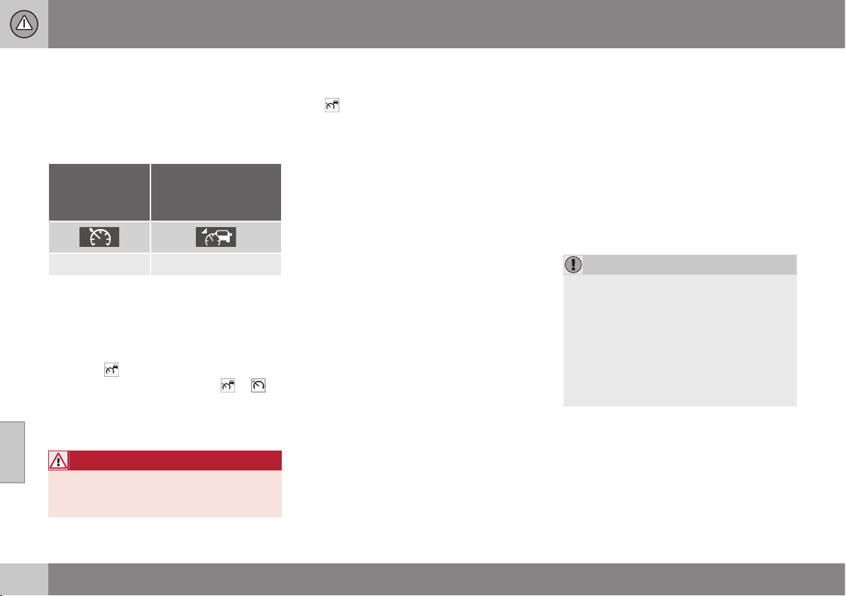
07 Driver support
07
206
* Option/accessory, for more information, see Introduction.
Adaptive cruise control* - switch
cruise control functionality
Changing from ACC to CC
A symbol for active cruise control is shown in
the combined instrument panel:
CC
Cruise Control
ACC
Adaptive Cruise
Control
Cruise control Adaptive cruise control
With one press of the button the adaptive
part (spacing system) in the cruise control is
deactivated, at which point the car just fol-
lows the set/stored speed.
•
Give a long press on the steering wheel
button
- the combined instrument
panel's symbol changes from
to .
> By these means the standard cruise con-
trol (p. 194) CC (Cruise
Control) is activated.
WARNING
The car no longer brakes automatically
after switching from ACC to CC - it merely
follows the set speed.
Changing back from CC to ACC
Switch off cruise control with 1-2 presses on
the
button in accordance with the deacti-
vation instructions (p. 204). The next time the
system is switched on it is the Adaptive
cruise control that is activated.
Related information
•
Adaptive cruise control - ACC* (p. 197)
•
Adaptive cruise control* - overview
(p. 200)
•
Adaptive cruise control* - function
(p. 198)
Radar sensor
The function of the radar sensor is to detect
cars or larger vehicles in the same direction,
in the same lane.
The radar sensor is used by the following
functions:
•
Distance Warning*
•
Adaptive cruise control*
•
Collision Warning System with Auto
Brake and Cyclist and Pedestrian Detec-
tion*
IMPORTANT
In the event of visible damage to the car's
grille, or if you suspect that the radar sen-
sor may be damaged:
•
Contact a workshop - an authorised
Volvo workshop is recommended.
The function may completely or partially
disappear - or malfunction - if the grille,
the radar sensor or its bracket is damaged
or has loosened.
Modification of the radar sensor could result
in it being illegal to use.
Related information
•
Radar sensor - limitations (p. 207)
•
Adaptive cruise control - ACC* (p. 197)
•
Collision warning system* (p. 222)
•
Distance Warning* (p. 212)
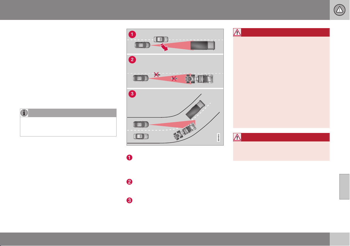
07 Driver support
07
}}
207
Radar sensor - limitations
A radar sensor (p. 206) has certain limitations
- due to its limited field of vision for example.
The capacity of the adaptive cruise control to
detect a vehicle in front is significantly
reduced if:
•
the speed of vehicles in front is signifi-
cantly different from your own speed
•
its radar sensor becomes blocked - e.g.
in heavy rain or slush, or if other objects
have collected in front of the radar sen-
sor.
NOTE
Keep the area in front of the radar sensor
clean - see subheading "Maintenance"
(p. 226).
Field of vision
The radar sensor has a limited field of vision.
In some situations another vehicle is not
detected, or the detection is made later than
expected.
ACC field of vision.
Sometimes the radar sensor is late at
detecting vehicles at close distances -
e.g. a vehicle that drives in between the
car and vehicles in front.
Small vehicles, such as motorcycles, or
vehicles not driving in the centre of the
lane can remain undetected.
In bends the radar sensor may detect the
wrong vehicle or lose a detected vehicle
from view.
WARNING
The driver must always be observant with
regard to the traffic conditions and inter-
vene when the adaptive cruise control is
not maintaining a suitable speed or suita-
ble distance.
The adaptive cruise control cannot handle
all traffic, weather and road conditions.
Read all the sections about the adaptive
cruise control in the owner's manual in
order to learn about its limitations, of
which the driver should be aware before it
is used.
The driver always bears responsibility for
maintaining the correct distance and
speed, even when the adaptive cruise con-
trol is being used.
WARNING
Accessories or other objects such as auxil-
iary lamps must not be fitted in front of the
grille.

||
07 Driver support
07
208
* Option/accessory, for more information, see Introduction.
WARNING
Adaptive cruise control is not a collision
avoidance system. The driver must inter-
vene if the system does not detect a vehi-
cle in front.
The adaptive cruise control does not brake
for humans or animals, and not for small
vehicles such as bicycles and motorcy-
cles. Nor for oncoming, slow or stationary
vehicles and objects.
Do not use the adaptive cruise control, for
example, in city traffic, in dense traffic, at
junctions, on slippery surfaces, with a lot
of water or slush on the road, in heavy
rain/snow, in poor visibility, on winding
roads or on slip roads.
Related information
•
Adaptive cruise control - ACC* (p. 197)
•
Collision warning system* (p. 222)
•
Distance Warning* (p. 212)

07 Driver support
07
* Option/accessory, for more information, see Introduction.
209
Adaptive cruise control* - fault tracing
and action
If the combined instrument panel shows the
message
Radar blocked See manual then it
means that the adaptive cruise control's radar
sensor (p. 206) cannot detect other vehicles
in front of the car.
This message indicates that neither of the
functions for Distance Alert (p. 212) or Colli-
sion Warning with Auto Brake (p. 222) are
working.
The following table presents examples of
possible causes for a message being shown
along with the appropriate action:
Cause Action
The radar surface in the grille is dirty or covered with ice or snow. Clean the radar surface in the grille from dirt, ice and snow.
Heavy rain or snow blocking the radar signals. No action. Sometimes the radar does not work during heavy rain or snowfall.
Water or snow from the road surface swirls up and blocks the
radar signals.
No action. Sometimes the radar does not work on a very wet or snowy road
surface.
The radar surface has been cleaned but the message remains. Wait. It could take several minutes for the radar to sense that it is no longer
blocked.
Related information
•
Adaptive cruise control* - overview
(p. 200)
•
Adaptive cruise control* - function
(p. 198)
•
Adaptive cruise control* - symbols and
messages (p. 210)
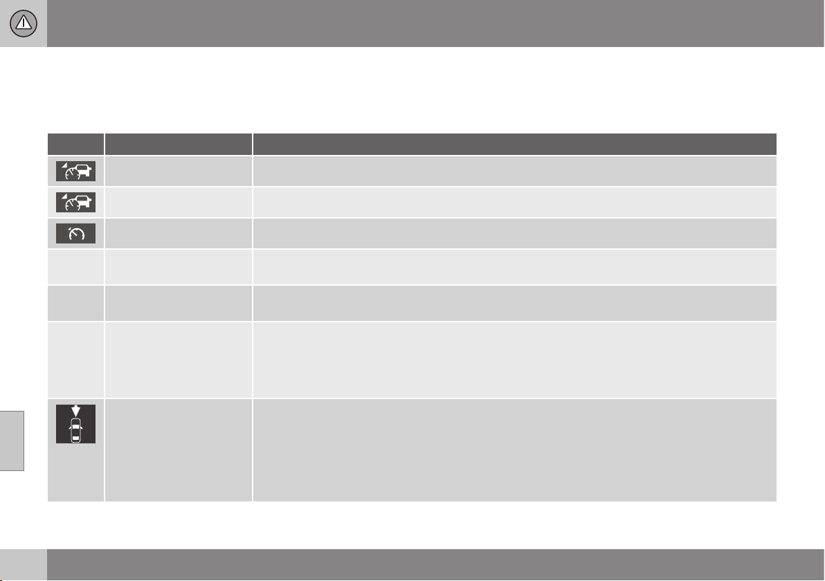
07 Driver support
07
210
* Option/accessory, for more information, see Introduction.
Adaptive cruise control* - symbols
and messages
Sometimes the adaptive cruise control may
display a symbol and/or text message. Here
are some examples - follow the recommenda-
tion given if appropriate:
Symbol Message Specification
The symbol is GREEN The car maintains the stored speed.
The symbol is WHITE Adaptive cruise control is set to standby mode.
Standard cruise control is selected manually.
Set ESC to Normal to
enable Cruise
The adaptive cruise control cannot be activated until the Stability system (ESC) (p. 184) has been set in
Normal mode.
Adaptive cruise control
cancelled
The adaptive cruise control has been deactivated - the driver has to regulate the speed himself.
Adaptive cruise control
unavailable
The adaptive cruise control cannot be activated.
This could be due to:
•
brake temperature is high
•
the radar sensor is blocked by e.g. wet snow or rain.
Radar blocked See man-
ual
The adaptive cruise control is temporarily disengaged.
•
The radar sensor is blocked and cannot detect other vehicles. For example, in the event of heavy
rain or if slush has collected in front of the radar sensor.
The driver can then choose to switch to (p. 206) normal Cruise control (CC) - a text message provides
information on appropriate alternatives.
Read about radar sensor limitations (p. 207).

07 Driver support
07
* Option/accessory, for more information, see Introduction.
211
Symbol Message Specification
Adaptive cruise control
Service required
The adaptive cruise control is disengaged.
•
Contact a workshop - an authorised Volvo workshop is recommended.
Press brake to hold
vehicle
+ acoustic alarm
A
The car is stationary and the cruise control will release the foot brake to allow the parking brake to take
over and hold the car, but a fault in the parking brake means the car will shortly begin to roll.
•
The driver must brake himself/herself. The message remains and the alarm sounds until the driver
depresses the brake pedal or uses the accelerator pedal.
Below 30 km/h Lead
vehicle required
A
Shown in the event of attempts to activate the adaptive cruise control at speeds below 30 km/h with-
out a vehicle in front within the activation distance.
A
Only with Queue Assist.
Related information
•
Adaptive cruise control - ACC* (p. 197)
•
Adaptive cruise control* - overview
(p. 200)
•
Adaptive cruise control* - function
(p. 198)
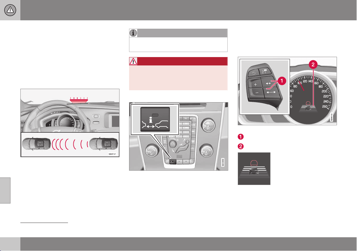
07 Driver support
07
212
* Option/accessory, for more information, see Introduction.
Distance Warning*
The Distance Warning function (Distance
Alert) warns the driver if the time interval to
the vehicle ahead becomes too short.
Distance Warning is active at speeds above
30 km/h and only reacts to vehicles driving in
front of the car, in the same direction. No dis-
tance information is provided for oncoming,
slow or stationary vehicles.
Orange-coloured warning lamp
13
.
An orange-coloured warning lamp in the
windscreen illuminates with a constant glow if
the distance to the vehicle in front is shorter
than the set time interval.
NOTE
Distance warning is deactivated during the
time the adaptive cruise control is active.
WARNING
Distance warning only reacts if the dis-
tance to the vehicle ahead is shorter than
the preset value - the speed of the driver's
vehicle is not affected.
Operation
Press the button in the centre console to
switch the function on or off. The function is
switched on if one lamp is illuminated in the
button.
Some combinations of the selected equip-
ment leave no vacant space for a button in
the centre console - in which case the func-
tion is operated in the car's menu system MY
CAR (p. 108) - there, search for and locate
the function
Distance Alert.
Set time interval
Controls and symbol for time interval.
Time interval - Increase/decrease.
Time interval - On.
Different time intervals to the
vehicle in front can be
selected and shown in the
combined instrument panel
as 1-5 horizontal lines - the
more lines the longer the
time interval. One line corre-
sponds to approximately 1 second to the
vehicle in front, 5 lines approximately
3 seconds.
13
NOTE: The illustration is schematic - details may vary depending on car model.
07 Driver support
07
* Option/accessory, for more information, see Introduction.
213
The same symbol is also shown when Adap-
tive cruise control (p. 198) is activated.
NOTE
The higher the speed the longer the calcu-
lated distance in metres for a given time
interval.
The set time interval is also used by the
function adaptive cruise control (p. 198).
Only use the time intervals permitted by
local traffic regulations.
Related information
•
Distance Warning* - limitations (p. 213)
•
Distance Warning* - symbols and mes-
sages (p. 214)
Distance Warning* - limitations
This function, which uses the same radar
sensor as Adaptive cruise control (p. 197) and
Collision warning with auto brake (p. 222),
has certain limitations.
NOTE
Strong sunlight, reflections or strong varia-
tions in light intensity, as well as wearing
sunglasses, could mean that the warning
light in the windscreen cannot be seen.
Poor weather or winding roads could
affect the radar sensor's capacity to detect
vehicles in front.
The size of other vehicles could also affect
detection capacity, e.g. motorcycles. This
could mean that the warning lamp illumi-
nates at a shorter distance than the setting
or that the warning is temporarily absent.
Extremely high speeds can also cause the
lamp to illuminate at a shorter distance
than that set due to limitations in sensor
range.
For further information on radar sensor limita-
tions, see Radar sensor - limitations (p. 207)
and (p. 227).
Related information
•
Distance Warning* (p. 212)
•
Distance Warning* - symbols and mes-
sages (p. 214)

07 Driver support
07
214
* Option/accessory, for more information, see Introduction.
Distance Warning* - symbols and
messages
The function has certain symbols and mes-
sages that can be shown in the combined
instrument panel if the function is reduced
due to its limitations.
Symbol
A
Message Specification
Radar blocked See
manual
Distance Warning temporarily disengaged.
The radar sensor is blocked and cannot detect other vehicles, e.g. in the event of heavy rain or if slush
has collected in front of the radar sensor.
Read about radar sensor limitations (p. 207).
Collision warning
Service required
Distance Warning and Collision Warning with Auto Brake fully or partially disengaged.
Visit a workshop if the message remains - an authorised Volvo workshop is recommended.
A
Symbols are schematic - may vary by market and car model.
Related information
•
Distance Warning* (p. 212)
•
Distance Warning* - limitations (p. 213)
07 Driver support
07
}}
* Option/accessory, for more information, see Introduction.
215
City Safety™
City Safety™ is a function for helping the
driver to avoid a collision when driving in
queues, amongst other things, when changes
in the traffic ahead, combined with a lapse in
attention, could lead to an incident.
The City Safety™ function is active at speeds
under 50 km/h and it helps the driver by auto-
matically braking the car in the event of immi-
nent risk of collision with vehicles in front,
should the driver not react in time by braking
and/or steering away.
City Safety™ is activated in situations where
the driver should have started braking earlier,
which is why it cannot help the driver in every
situation.
City Safety™ is designed to be activated as
late as possible in order to avoid unnecessary
intervention.
City Safety™ must not be used as an excuse
for the driver to change his/her driving style. If
the driver solely relies on City Safety™ to do
the braking, there will be a collision sooner or
later.
The driver or passengers normally only notice
City Safety™ if a situation arises where the
car is extremely close to being in a collision.
If the car is also equipped with Collision
Warning with Auto Brake (p. 222)* these two
systems complement each other.
IMPORTANT
Maintenance and replacement of City
Safety™ components must only be per-
formed by a workshop - an authorised
Volvo workshop is recommended.
WARNING
City Safety™ does not engage in all driv-
ing situations or traffic, weather or road
conditions.
City Safety™ does not react to vehicles
driving in a different direction from the car,
to small vehicles and motorcycles or to
humans and animals.
City Safety™ can prevent collision at a
speed difference of less than 15 km/h - at
a higher speed difference, it is only possi-
ble to reduce collision speed. In order to
obtain full brake function, the driver must
depress the brake pedal.
Never wait for City Safety™ to engage.
The driver always bears responsibility for
maintaining the proper distance and
speed.
Related information
•
City Safety™ - limitations (p. 217)
•
City Safety™ - function (p. 215)
•
City Safety™ - operation (p. 216)
•
City Safety™ - laser sensor (p. 219)
•
City Safety™ - symbols and messages
(p. 221)
City Safety™ - function
City Safety detects the traffic in front of the
car with a laser sensor fitted in the top edge
of the windscreen. If there is an imminent risk
of collision, City Safety will automatically
brake the car, which may be experienced as
heavy braking.

||
07 Driver support
07
216
Laser sensor transmitter and receiver window
14
.
If the speed difference is 4-15 km/h in relation
to the vehicle in front then City Safety can
completely avoid a collision.
City Safety activates a short, sharp braking
procedure and stops the car in normal cir-
cumstances, just behind the vehicle in front.
For most drivers this is well outside normal
driving style and may be experienced as
being uncomfortable.
If the difference in speed between the vehi-
cles is greater than 15 km/h then City Safety
may not avoid the collision on its own - to
obtain full brake force, the driver must
depress the brake pedal and this could then
make it possible to avoid a collision, even at
speed differences above 15 km/h.
When the function is activated and brakes,
the combined instrument panel shows a text
message to the effect that the function is/has
been active.
NOTE
When City Safety™ brakes, the brake
lights come on.
Related information
•
City Safety™ - limitations (p. 217)
•
City Safety™ (p. 215)
•
City Safety™ - operation (p. 216)
•
City Safety™ - laser sensor (p. 219)
•
City Safety™ - symbols and messages
(p. 221)
City Safety™ - operation
City Safety™ is a function for helping the
driver to avoid a collision when driving in
queues, amongst other things, when changes
in the traffic ahead, combined with a lapse in
attention, could lead to an incident.
On and Off
NOTE
The City Safety™ function is activated
automatically when the engine is started.
In certain situations, it may advisable to disa-
ble City Safety™, e.g. where leafy branches
could sweep over the bonnet and/or wind-
screen.
City Safety™ handled in the menu system
MY CAR (p. 108) and after starting the engine
the function can be deactivated as follows:
•
Search in MY CAR for
Driver support
system and select the Off option at City
Safety.
However, the function will be enabled the
next time the engine is started, regardless
of whether the system was enabled or
disabled when the engine was switched
off.
14
NOTE: The illustration is schematic - details may vary depending on car model.

07 Driver support
07
}}
217
WARNING
The laser sensor also transmits laser light
when City Safety™ is disabled manually.
Related information
•
City Safety™ (p. 215)
•
City Safety™ - limitations (p. 217)
•
City Safety™ - function (p. 215)
•
City Safety™ - laser sensor (p. 219)
•
City Safety™ - symbols and messages
(p. 221)
•
MY CAR (p. 108)
City Safety™ - limitations
The sensor in City Safety is designed to
detect cars and other large vehicles in front of
the car irrespective of whether it is day or
night.
However, the function does have some limita-
tions.
The sensor's limitations mean that City Safety
has poorer functionality - or none at all - in
e.g. heavy snowfall or rain, dense fog, dust
storms or white-out situations. Misting, dirt,
ice or snow on the windscreen may also dis-
rupt the function.
Low-hanging objects, e.g. a flag/pennant for
projecting load, or accessories such as auxili-
ary lamps and bull bars that are higher than
the bonnet limit the function.
The laser beam from the sensor in City Safety
measures how the light is reflected. The sen-
sor cannot detect objects with low reflection
capacity. The rear sections of the vehicle
generally reflect the light sufficiently thanks to
the number plate and rear light reflectors.
On slippery road surfaces the braking dis-
tance is extended, which may reduce the
capacity of City Safety to avoid a collision. In
such situations the ABS
15
and ESC
16
systems
will provide best possible braking force with
maintained stability.
When your own car is reversing, City Safety is
temporarily deactivated.
City Safety is not activated at low speeds -
under 4 km/h, which is why the system does
not intervene in situations where a vehicle in
front is being approached very slowly, e.g.
when parking.
Driver commands are always prioritised,
which is why City Safety does not intervene in
situations where the driver is steering or
accelerating in a clear manner, even if a colli-
sion is unavoidable.
When City Safety has prevented a collision
with a stationary object the car remains sta-
tionary for a maximum of 1.5 seconds. If the
car is braked for a vehicle in front that is mov-
ing, then speed is reduced to the same speed
as that maintained by the vehicle in front.
On a car with manual gearbox the engine
stops when City Safety has stopped the car,
unless the driver manages to depress the
clutch pedal beforehand.
15
(Anti-lock Braking System) - Anti-lock braking system.
16
(Electronic Stability Control) - Stability system.
||
07 Driver support
07
218
NOTE
•
Keep the windscreen surface in front
of the laser sensor free from ice, snow
and dirt (see the illustration for sensor
location (p. 215)).
•
Do not affix or mount anything on the
windscreen in front of the laser sensor.
•
Remove ice and snow from the bonnet
- snow and ice must not exceed a
height of 5 cm.
Fault tracing and action
If the message Windscreen sensors
blocked See manual is shown in the com-
bined instrument panel it indicates that the
laser sensor is blocked and cannot detect
vehicles in front of the car. This means in turn
that City Safety is not operational.
The
Windscreen sensors blocked See
manual message is not shown for all situa-
tions in which the laser sensor is blocked.
The driver must therefore be diligent about
keeping the windscreen and area in front of
the laser sensor clean.
The following table presents possible causes
for the message being shown, along with
suggestions for appropriate action.
Cause Action
The windscreen sur-
face in front of the
laser sensor is dirty or
covered with ice or
snow.
Clean the wind-
screen surface in
front of the sensor
from dirt, ice and
snow.
The laser sensor field
of vision is blocked.
Remove the
blocking object.
IMPORTANT
If there are cracks, scratches or stone
chips in the windscreen in front of either of
the laser sensor's "windows" and they
cover a surface of approx. 0.5 x 3.0 mm
(or larger), then a workshop must be con-
tacted for replacement of the windscreen
(see the illustration for sensor location
(p. 215)) - an authorised Volvo workshop is
recommended.
Failure to take action may result in
reduced performance for City Safety™.
To avoid the risk of failed, deficient or
reduced operation for City Safety™, the
following also applies:
•
Volvo recommends that you do not
repair cracks, scratches or stone chips
in the area in front of the laser sensor -
instead, the whole windscreen should
be replaced.
•
Before replacing a windscreen, con-
tact an authorised Volvo workshop to
verify that the correct windscreen is
ordered and fitted.
•
The same type or Volvo-approved
windscreen wipers must be fitted dur-
ing replacement.
Related information
•
City Safety™ (p. 215)
•
City Safety™ - function (p. 215)
•
City Safety™ - operation (p. 216)
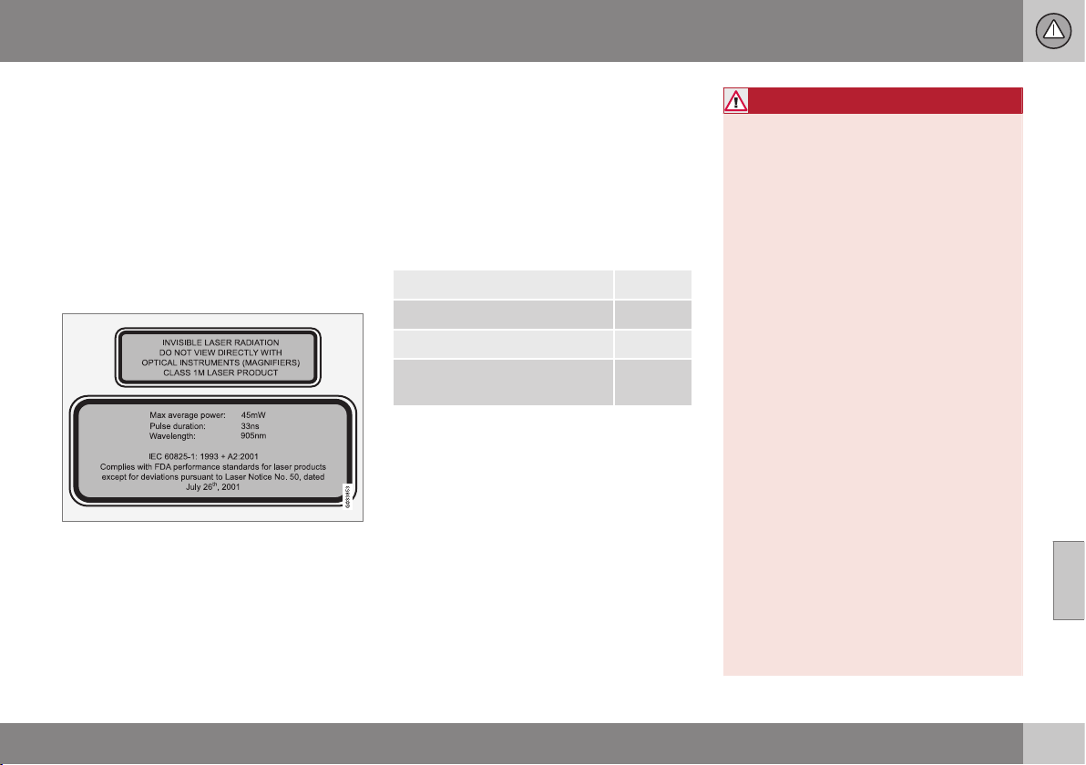
07 Driver support
07
}}}}
219
City Safety™ - laser sensor
The City Safety™ function includes a sensor
which transmits laser light (see illustration
(p. 215) for sensor location). Contact a quali-
fied workshop in the event of a fault or if the
laser sensor needs servicing - an authorised
Volvo workshop is recommended. It is abso-
lutely essential to follow the prescribed
instructions when handling the laser sensor.
The following two labels relate to the laser
sensor:
The upper label in the figure describes the
laser beam's classification:
•
Laser radiation - Do not look into the
laser beam with optical instruments -
Class 1M laser product.
The lower label in the figure describes the
laser beam's physical data:
•
IEC 60825-1:1993 + A2:2001. Complies
with FDA (U.S. Food Administration)
standards for laser product design with
the exception of deviations in accordance
with "Laser Notice No. 50" from
26 July 2001.
Radiation data for the laser sensor
The following table specifies the laser sen-
sor's physical data.
Maximum pulse energy 2.64 µJ
Maximum average output 45 mW
Pulse duration 33 ns
Divergence (horizontal x verti-
cal)
28° × 12°
WARNING
If any of these instructions are not followed
then there is a risk of eye injury!
•
Never look into the laser sensor (which
emits spreading invisible laser radia-
tion) at a distance of 100 mm or closer
with magnifying optics such as a mag-
nifying glass, microscope, lens or simi-
lar optical instruments.
•
Testing, repair, removal, adjustment
and/or replacement of the laser sen-
sor's spare parts must only be carried
out by a qualified workshop - we rec-
ommend an authorised Volvo work-
shop.
•
To avoid exposure to harmful radia-
tion, do not carry out any readjust-
ments or maintenance other than
those specified here.
•
The repairer must follow specially
drawn up workshop information for the
laser sensor.
•
Do not remove the laser sensor (this
includes removing the lenses). A
removed laser sensor does not fulfil
laser class 3B as per standard IEC
60825-1. Laser class 3B is not eye-
safe and therefore entails a risk of
injury.
•
The laser sensor's connector must be
unplugged before removal from the
windscreen.

||
07 Driver support
07
220
•
The laser sensor must be fitted onto
the windscreen before the sensor's
connector is plugged in.
•
The laser sensor transmits a laser light
when the remote control key is in key
position II (p. 76) even if the engine is
switched off.
Related information
•
City Safety™ (p. 215)
•
City Safety™ - limitations (p. 217)
•
City Safety™ - function (p. 215)
•
City Safety™ - operation (p. 216)
•
City Safety™ - symbols and messages
(p. 221)
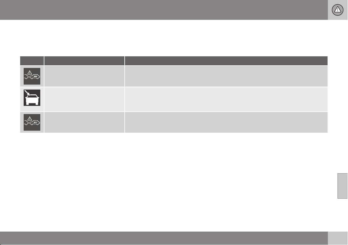
07 Driver support
07
221
City Safety™ - symbols and
messages
In conjunction with automatic braking by the
City Safety™ (p. 215) system, one or more
symbols may illuminate in the combined
instrument panel and a text message may be
shown. A text message can be acknowledged
by briefly pressing the OK button on the
direction indicator stalk.
Symbol Message Meaning/Action
Auto braking by City Safety
City Safety™ is braking or has automatically braked.
Windscreen sensors blocked
See manual
The laser sensor is temporarily non-operational because something is blocking it.
•
Remove the object blocking the sensor and/or clean the windscreen in front of the sensor.
Read about laser sensor limitations (p. 217).
City Safety Service required
City Safety™ is not operational.
•
Visit a workshop if the message remains - an authorised Volvo workshop is recommended.
Related information
•
City Safety™ (p. 215)
•
City Safety™ - limitations (p. 217)
•
City Safety™ - function (p. 215)
•
City Safety™ - operation (p. 216)
•
City Safety™ - laser sensor (p. 219)
07 Driver support
07
222
* Option/accessory, for more information, see Introduction.
Collision warning system*
"Collision Warning with Auto Brake and
Cyclist and Pedestrian Detection" is an aid to
assist the driver when there is a risk of collid-
ing with a pedestrian, cyclist or vehicle in
front that are stationary or moving in the same
direction.
"Collision Warning with Auto Brake and
Cyclist and Pedestrian Detection" is activated
in situations where the driver should have
started braking earlier, which is why it cannot
help the driver in every situation.
"Collision Warning with Auto Brake and
Cyclist and Pedestrian Detection" is designed
to be activated as late as possible in order to
avoid unnecessary intervention.
"Collision Warning with Auto Brake and
Cyclist and Pedestrian Detection" can pre-
vent a collision or reduce collision speed.
"Collision Warning with Auto Brake and
Cyclist and Pedestrian Detection" must not
be used as an excuse for the driver to change
his/her driving style. If the driver solely relies
on Collision Warning with Auto Brake to do
the braking, there might be a risk of a colli-
sion sooner or later.
Two system levels
Depending on how the car is equipped, the
"Collision Warning with Auto Brake and
Cyclist and Pedestrian Detection" function
may appear in two variants:
Level 1
The driver is merely warned
17
of occurring
obstacles by means of visual and acoustic
signals - no automatic braking intervenes, the
driver must himself brake.
Level 2
The driver is warned of occurring obstacles
by means of visual and acoustic signals - the
car is braked automatically if the driver him-
self does not act within a reasonable time.
IMPORTANT
Maintenance of the internal components of
the "Collision Warning with Auto Brake
and Cyclist and Pedestrian Detection"
must only be performed at a workshop -
an authorised Volvo workshop is recom-
mended.
Related information
•
Collision warning system* - function
(p. 223)
•
Collision warning system* - detection of
pedestrians (p. 225)
•
Collision warning system* - detection of
cyclists (p. 224)
•
Collision warning system* - operation
(p. 226)
•
Collision warning system* - limitations
(p. 227)
•
Collision warning system* - camera sen-
sor limitations (p. 228)
•
Collision warning system* - symbols and
messages (p. 230)
17
No warning for cyclists with "Level 1".
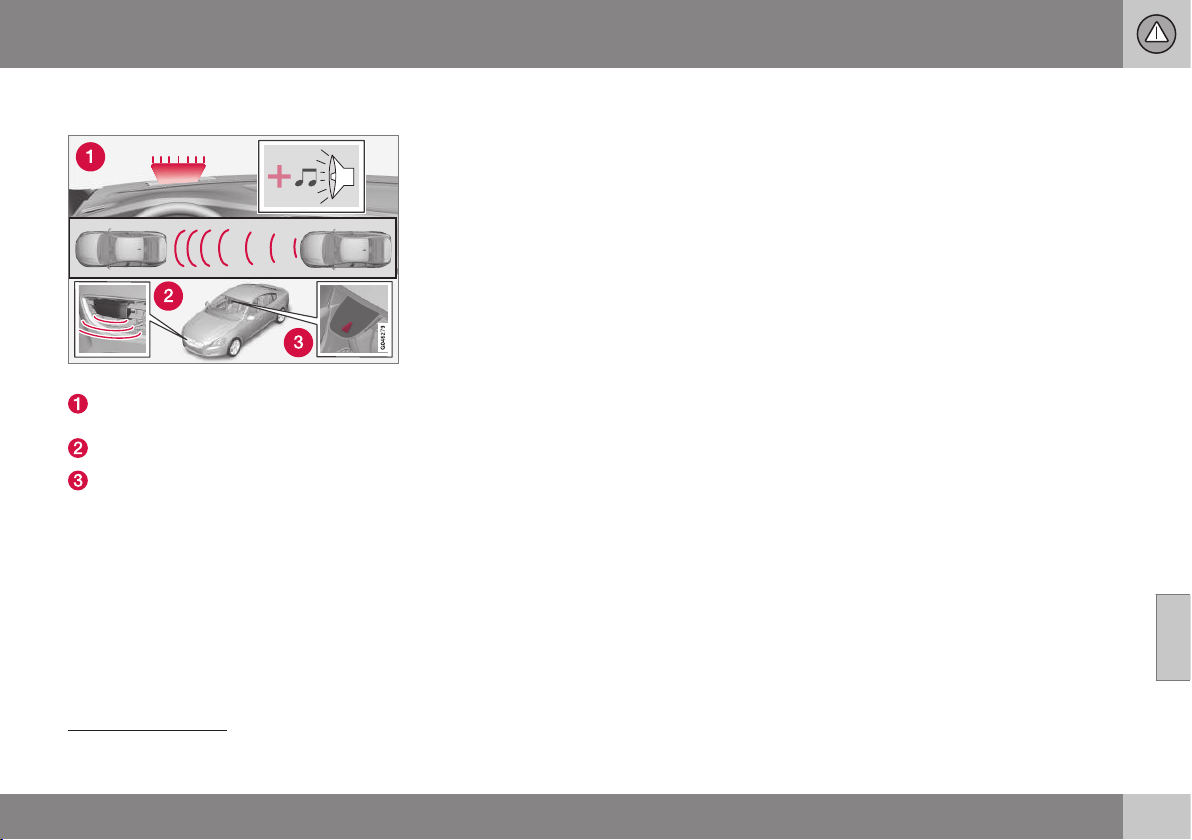
07 Driver support
07
}}
* Option/accessory, for more information, see Introduction.
223
Collision warning system* - function
Function overview
18
.
Audio-visual warning signal in the event
of a collision risk.
Radar sensor
19
Camera sensor
Collision Warning with Auto Brake executes
three steps in the following order:
1.
Collision warning
2.
Brake support
19
3.
Auto Brake
19
The collision warning system and City
Safety™ (p. 215) complement each other.
1 - Collision warning
The driver is first warned of a potentially
imminent collision.
The collision warning system can detect
pedestrians, cyclists or vehicles that are sta-
tionary or moving in the same direction in
front of the driver's vehicle.
If there is a risk of collision with a pedestrian,
cyclist or a vehicle then the driver's attention
is attracted with a flashing red warning signal
(1) and an acoustic signal.
2 - Brake support
19
If the risk of collision has increased further
after the collision warning then the brake sup-
port is activated.
This means that the brake system is prepared
for rapid braking by applying the brakes
lightly, which may feel like a slight jolt.
If the brake pedal is depressed sufficiently
quickly then full brake function is imple-
mented.
Brake support also reinforces the driver's
braking if the system considers that the brak-
ing is not sufficient to avoid a collision.
3 - Auto Brake
19
The automatic brake function is activated
last.
If in this situation the driver has not yet
started to take evasive action and the risk of
collision is imminent then the automatic brak-
ing function is deployed - this takes place
irrespective of whether or not the driver
brakes. Braking then takes place with full
brake force in order to reduce collision speed,
or with limited brake force if it is sufficient to
avoid a collision. For cyclists, the warning and
full brake intervention may come very late or
simultaneously.
18
NOTE: The illustration is schematic - details may vary depending on car model.
19
With system Level 2 only.
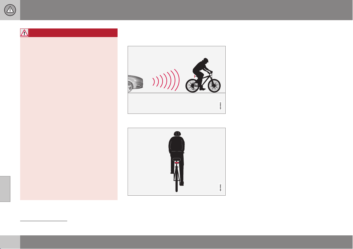
||
07 Driver support
07
224
* Option/accessory, for more information, see Introduction.
WARNING
The collision warning system does not
engage in all driving situations or traffic,
weather or road conditions. The collision
warning system does not react to vehicles
or cyclists driving in another direction to
the car or to animals.
Warning only activated in the event of a
high risk for collision. This section "Func-
tion" and the section "Limitations" inform
about limitations that the driver must be
aware of before using the Collision Warn-
ing system with Auto Brake.
Warnings and brake interventions for
pedestrians and cyclists are deactivated at
a vehicle speed exceeding 80 km/h.
Warnings and brake interventions for
pedestrians and cyclists do not work in
darkness and tunnels - not even when
streetlights are lit.
The auto-brake function can prevent a col-
lision or reduce collision speed. To ensure
full brake performance, the driver should
always depress the brake pedal - even
when the car auto-brakes.
Never wait for a collision warning. The
driver is always responsible that the cor-
rect distance and speed are maintained -
even when the collision warning system
with auto-brake is used.
Related information
•
Collision warning system* (p. 222)
Collision warning system* - detection
of cyclists
The function only "sees" cyclists from behind,
who are travelling in the same direction.
Optimum examples of what the system interprets
as a cyclist - with clear body and bicycle con-
tours, directly from behind and in the car's cen-
tre line.
Optimal performance of the system requires
that the system function that detects a cyclist
receives as unambiguous information as pos-
sible about the body and bicycle contours -
this implies the opportunity to identify the
bicycle, head, arms, shoulders, legs, upper
and lower body combined with a normal
human pattern of movement.
If large parts of the cyclist's body or bicycle
are not visible to the function's camera then
the system cannot detect a cyclist.
•
For the function to be able to detect a
cyclist, he/she must be an adult and rid-
ing an "adult bicycle".
•
The bicycle must be equipped with a
highly visible and approved
20
rearward-
facing red reflector, fitted at least 70 cm
above the roadway.
•
The function can only detect cyclists
directly from behind and who are travel-
ling in the same direction - not at an
angle from behind, not from the side.
•
Cyclists travelling on the left or right-hand
edge of the car's imagined/extended side
lines may be detected late or not at all.
•
The function's capacity to detect cyclists
at dusk and dawn is limited - just like the
human eye.
20
The reflector must fulfil the recommendations and conditions of the traffic authority in the market in question.
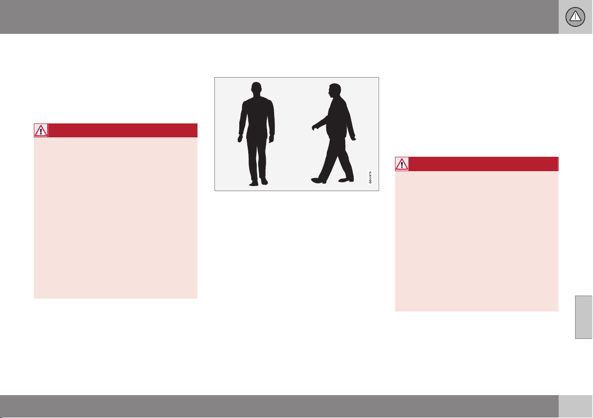
07 Driver support
07
* Option/accessory, for more information, see Introduction.
225
•
The function's capacity to detect cyclists
is deactivated when driving in darkness
and tunnels - even when streetlights are
lit.
•
For optimum bicycle detection, the City
Safety™ function must be activated, see
City Safety™ (p. 215).
WARNING
Collision Warning with Auto Brake &
Cyclist Detection is a means of assistance.
The function cannot detect:
•
all cyclists in all situations and does
not see partially obscured cyclists, for
example.
•
cyclists in clothing that obscures the
contours of the body or who are
approaching from the side.
•
bicycles that have no rearward-facing
red reflector.
•
bicycles loaded with large objects.
The driver is always responsible that the
vehicle is driven properly and with a safety
distance adapted to the speed.
Related information
•
Collision warning system* (p. 222)
Collision warning system* - detection
of pedestrians
Optimal examples of what the system regards as
pedestrians with clear body contours.
Optimal performance of the system requires
that the system function that detects pedes-
trians receives as unambiguous information
as possible about the contours of the body -
this implies the opportunity to identify the
head, arms, shoulders, legs, upper and lower
body combined with a normal human pattern
of movement.
If large parts of the body are not visible to the
function's camera then the system cannot
detect a pedestrian.
•
In order for a pedestrian to be detected
he/she must appear full-length and have
a height of at least 80 cm.
•
The camera sensor's ability to see pedes-
trians at dusk and dawn is limited - just
like the human eye.
•
The camera sensor's capacity to detect
pedestrians is deactivated when driving in
darkness and tunnels - even when street-
lights are lit.
WARNING
"Collision Warning with Auto Brake and
Cyclist and Pedestrian Detection" is a
means of assistance. The function cannot
detect all pedestrians in all situations and
does not see, for example:
•
partially obscured pedestrians, people
in clothing that hides their body con-
tour or pedestrians shorter than
80 cm.
•
pedestrians who are carrying larger
objects.
The driver is always responsible that the
vehicle is driven properly and with a safety
distance adapted to the speed.
Related information
•
Collision warning system* (p. 222)
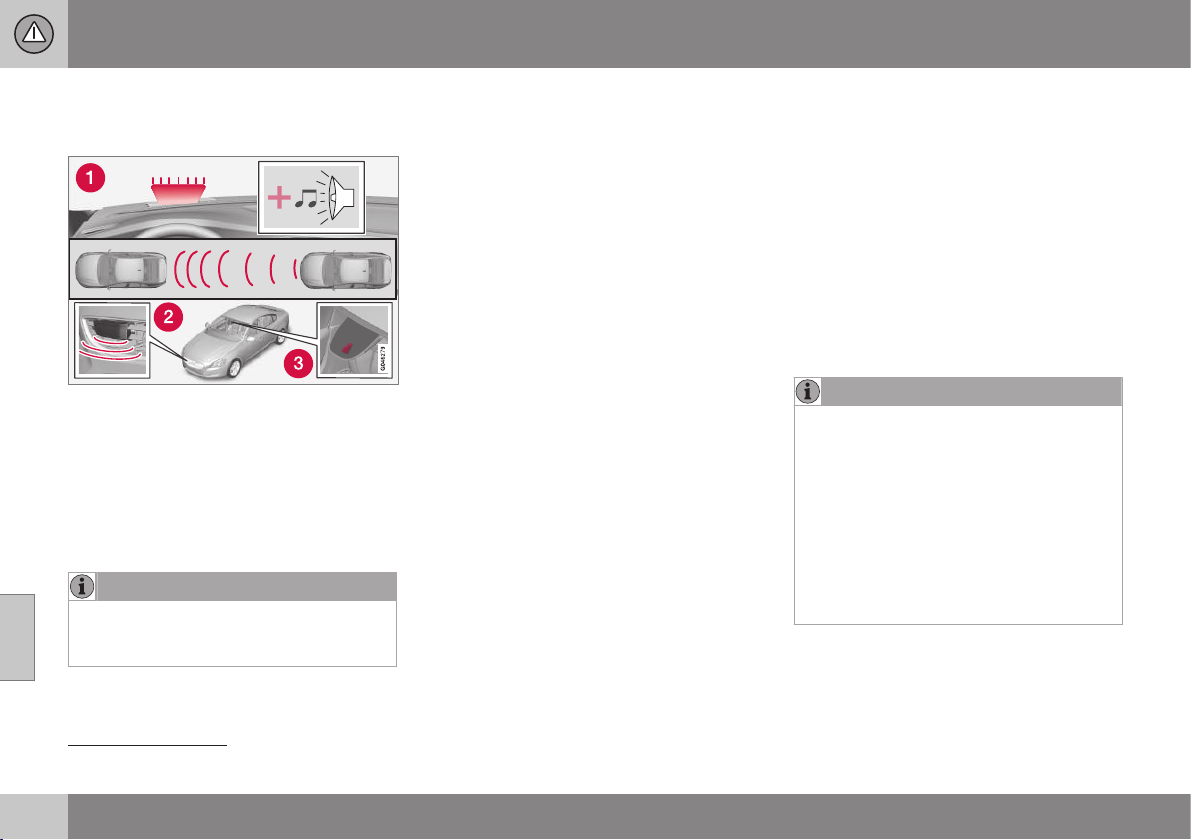
07 Driver support
07
226
* Option/accessory, for more information, see Introduction.
Collision warning system* - operation
Warning signals On and Off
1. Acoustic and visual warning signal in the event
of a collision risk.
21
You can select whether the collision warning
system's acoustic and visual warning signals
should be switched on or off.
When starting the engine, the setting that was
selected when the engine was switched off is
obtained automatically.
NOTE
The Brake Support and Auto Brake func-
tions are always enabled - they cannot be
deactivated.
Settings for the collision warning system are
made via the centre console's screen and the
menu system MY CAR, see (p. 108).
Light and acoustic signals
When the collision warning system's light and
acoustic warnings are activated, the warning
lamp (no. [1] in previous illustration) is tested
each time the engine is started by briefly illu-
minating the warning lamp's separate points
of light.
After starting the engine, both the light and
acoustic signals can be switched off:
•
Search for
Collision warning in Driver
support system in the menu system MY
CAR (p. 108) - and there select to
uncheck the function.
Acoustic signal
After starting the engine the warning sound
can be activated/deactivated separately:
•
Search for
Warning sound in Collision
warning in the menu system MY CAR
(p. 108) - and there select On or Off.
Following which, the collision warning system
is only indicated with a light signal.
Set warning distance
The warning distance regulates the distance
at which the visual and acoustic warnings are
deployed.
•
Search for
Warning distance in
Collision warning in the menu system
MY CAR (p. 108) - and there select Long,
Normal or Short.
The warning distance determines the sys-
tem's sensitivity. Warning distance
Long pro-
vides an earlier warning. First test with Long
and if this setting produces too many warn-
ings, which could be perceived as irritating in
certain situations, then change to warning
distance
Normal.
Only use warning distance Short in excep-
tional cases, e.g. for dynamic driving.
NOTE
When the adaptive cruise control is in use
the warning lamp and warning sound will
be used by the cruise control even if the
collision warning system is switched off.
The collision warning system warns the
driver in the event of a risk of a collision,
but the function cannot shorten driver
reaction time.
In order for the collision warning system to
be effective, always drive with Distance
Warning (p. 212) set at time interval 4–5.
21
The illustration is schematic - car model and details may differ.
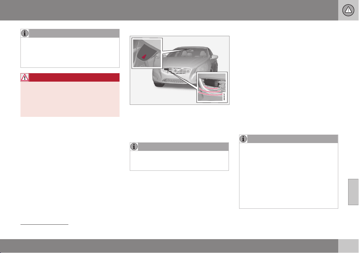
07 Driver support
07
}}
* Option/accessory, for more information, see Introduction.
227
NOTE
Even if the warning distance has been set
to
Long warnings could be perceived as
being late in certain situations, e.g. when
there are large differences in speed or if
vehicles in front brake heavily.
WARNING
No automatic system can guarantee
100 % correct function in all situations.
Therefore, never test Collision Warning
with Auto Brake by driving at people or
vehicles - this may cause severe damage
and injury and risk lives.
Checking settings
The current settings can be controlled via the
centre console's screen and the menu sys-
tem (p. 108) MY CAR.
Maintenance
Camera and radar sensor
22
.
For the sensors to work correctly, they must
be kept clear of dirt, ice and snow, and be
cleaned regularly with water and car sham-
poo.
NOTE
Dirt, ice and snow covering the sensors
will reduce their function and may prevent
measurement.
Related information
•
Collision warning system* (p. 222)
Collision warning system* - limitations
The function has certain limitations - for
example, it is not active until approx. 4 km/h.
The collision warning system's visual warning
signal (see (1) in the illustration (p. 223)) may
be difficult to notice in the event of strong
sunlight, reflections, when sunglasses are
being worn or if the driver is not looking
straight ahead. The warning sound should
therefore always be activated.
On slippery road surfaces the braking dis-
tance is extended, which may reduce the
capacity to avoid a collision. In such situa-
tions the ABS and ESC (p. 184) systems will
provide best possible braking force with
maintained stability.
NOTE
The visual warning signal can be temporar-
ily disengaged in the event of high passen-
ger compartment temperature caused by
strong sunlight for example. If this occurs
then the warning sound is activated even if
it is deactivated in the menu system.
•
Warnings may not appear if the dis-
tance to the vehicle in front is small or
if steering wheel and pedal move-
ments are large, e.g. a very active driv-
ing style.
22
NOTE: The illustration is schematic - details may vary depending on car model.
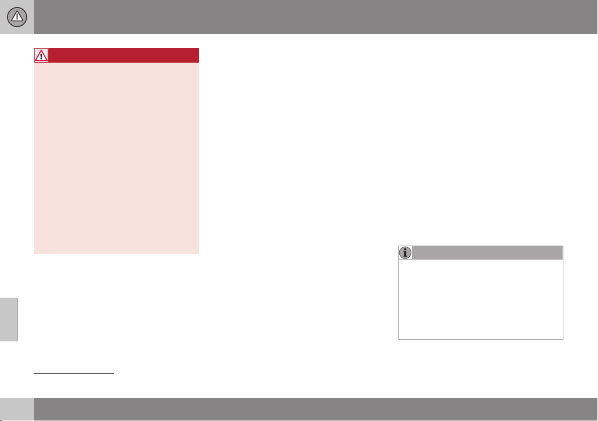
||
07 Driver support
07
228
* Option/accessory, for more information, see Introduction.
WARNING
Warnings and brake interventions could be
implemented late or not at all if the traffic
situation or external influences mean that
the radar or camera sensor cannot detect
a pedestrian, a vehicle or a cyclist in front
correctly.
The sensor system has a limited range for
pedestrians and cyclists
23
- the system
can provide effective warnings and brake
interventions for them at vehicle speeds up
to 50 km/h. For stationary or slow-moving
vehicles, warnings and brake interventions
are effective at vehicle speeds up to
70 km/h.
Warnings for stationary or slow-moving
vehicles could be disengaged due to dark-
ness or poor visibility.
Warnings and brake interventions for
pedestrians and cyclists are deactivated at
vehicle speeds exceeding 80 km/h.
The collision warning system uses the same
radar sensors as the Adaptive cruise control
(p. 197). Read more about radar sensor limi-
tations (p. 207).
If warnings are perceived as being too fre-
quent or disturbing then the warning distance
can be reduced (p. 226). This would lead to
the system warning at a later stage, which
reduces the total number of warnings.
Collision Warning with Auto Brake is tempo-
rarily deactivated with reverse gear engaged.
Collision Warning with Auto Brake is not acti-
vated at low speeds - under 4 km/h, which is
why the system does not intervene in situa-
tions where the car is approaching a vehicle
in front very slowly, e.g. when parking.
In situations where the driver demonstrates
active, aware driving behaviour, a collision
warning may be postponed slightly in order to
keep unnecessary warnings to a minimum.
When Auto Brake has prevented a collision
with a stationary object the car remains sta-
tionary for a maximum of 1.5 seconds. If the
car is braked for a vehicle in front that is mov-
ing, then speed is reduced to the same speed
as that maintained by the vehicle in front.
On a car with manual gearbox the engine
stops when Auto Brake has stopped the car,
unless the driver manages to depress the
clutch pedal beforehand.
Related information
•
Collision warning system* (p. 222)
Collision warning system* - camera
sensor limitations
"Collision Warning with Auto Brake and
Cyclist and Pedestrian Detection" is an aid to
assist the driver when there is a risk of collid-
ing with a pedestrian, bicycle or vehicle in
front that are stationary or moving in the same
direction.
The function uses the car's camera sensor,
which has certain limitations.
The car’s camera sensor is also used - as
well as by Collision Warning with Auto Brake
- by the functions:
•
Active main beam (p. 88)
•
Road sign information (p. 188)
•
Driver Alert Control - DAC (p. 232)
•
Lane assistance (p. 235)
NOTE
Keep the windscreen surface in front of the
camera sensor free from ice, snow, mist
and dirt.
Do not stick or attach anything to the
windscreen in front of the camera sensor
as this may reduce effectiveness or cause
one or more of the systems dependent on
the camera to stop working.
23
For cyclists, the warning and full brake intervention may come very late or simultaneously.

07 Driver support
07
* Option/accessory, for more information, see Introduction.
229
The camera sensors have limitations similar
to the human eye, i.e. they "see" worse in
darkness, heavy snowfall or rain and in thick
fog for example. Under such conditions the
functions of camera-dependent systems
could be significantly reduced or temporarily
disengaged.
Strong oncoming light, reflections in the car-
riageway, snow or ice on the road surface,
dirty road surfaces or unclear lane markings
could also significantly reduce camera sensor
function when it is used to scan the carriage-
way and detect pedestrians and other vehi-
cles.
The field of vision of the camera sensor is lim-
ited, which is why pedestrians, cyclists and
vehicles cannot be detected in some situa-
tions, or they are detected later than anticipa-
ted.
During very high temperatures the camera is
temporarily switched off for about 15 minutes
after the engine is started in order to protect
camera functionality.
Fault tracing and action
If the display shows the message
Windscreen sensors blocked See manual
then this means that the camera sensor is
blocked and cannot detect pedestrians,
cyclists, vehicles or road markings in front of
the car.
At the same time, this means that - besides
Collision Warning with Auto Brake - the fol-
lowing functions will not have full functionality
either:
•
Active main beam
•
Driver Alert Control
•
Lane Keeping Aid
•
Road sign information
The following table presents possible causes
for a message being shown along with the
appropriate action.
Cause Action
The windscreen
surface in front of
the camera is dirty
or covered with ice
or snow.
Clean the wind-
screen surface in
front of the camera
from dirt, ice and
snow.
Thick fog, heavy
rain or snow means
that the camera
does not work suffi-
ciently well.
No action. At times
the camera does
not work during
heavy rain or snow-
fall.
Cause Action
The windscreen
surface in front of
the camera has
been cleaned but
the message
remains.
Wait. It may take
several minutes for
the camera to
measure the visibil-
ity.
Dirt has appeared
between the inside
of the windscreen
and the camera.
Visit a workshop to
have the wind-
screen inside the
camera cover
cleaned - an author-
ised Volvo work-
shop is recom-
mended.
Related information
•
Collision warning system* (p. 222)
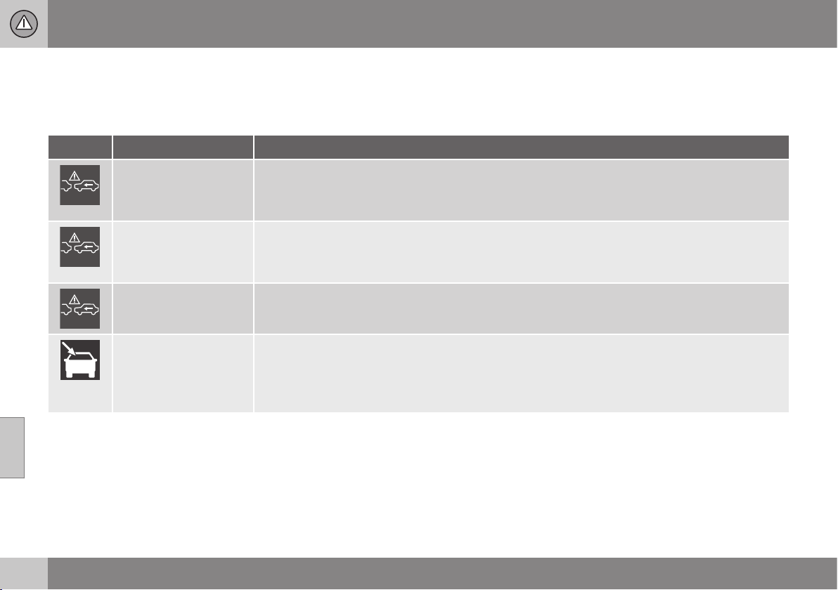
07 Driver support
07
230
* Option/accessory, for more information, see Introduction.
Collision warning system* - symbols
and messages
"Collision Warning with Auto Brake and
Cyclist and Pedestrian Detection" is an aid to
assist the driver when there is a risk of collid-
ing with a pedestrian, bicycle or vehicle in
front that are stationary or moving in the same
direction.
Symbol
A
Message Specification
Collision warning sys-
tem OFF
Collision warning system switched off.
Shown when the engine is started.
The message clears after about 5 seconds or after one press of the OK button.
Collision warning sys-
tem Unavailable
The collision warning system cannot be activated.
Shown when the driver attempts to activate the function.
The message clears after about 5 seconds or after one press of the OK button.
Auto Braking was acti-
vated
Auto Brake has been active.
The message clears after one press of the OK button.
Windscreen sensors
blocked See manual
The camera sensor is temporarily disengaged.
Shown in the event of snow, ice or dirt on the windscreen for example.
•
Clean the windscreen surface in front of the camera sensor.
Read about camera sensor limitations (p. 228).

07 Driver support
07
* Option/accessory, for more information, see Introduction.
231
Symbol
A
Message Specification
Radar blocked See
manual
Collision Warning with Auto Brake is temporarily disengaged.
The radar sensor is blocked and cannot detect other vehicles. For example, in the event of heavy rain or
if slush has collected in front of the radar sensor.
Read about radar sensor limitations (p. 207).
Collision warning Serv-
ice required
Collision Warning with Auto Brake is fully or partially disengaged.
•
Visit a workshop if the message remains - an authorised Volvo workshop is recommended.
A
Symbols are schematic - may vary by market and car model.
Related information
•
Collision warning system* (p. 222)
•
Collision warning system* - function
(p. 223)
•
Collision warning system* - detection of
pedestrians (p. 225)
•
Collision warning system* - detection of
cyclists (p. 224)
•
Collision warning system* - operation
(p. 226)
•
Collision warning system* - limitations
(p. 227)
•
Collision warning system* - camera sen-
sor limitations (p. 228)
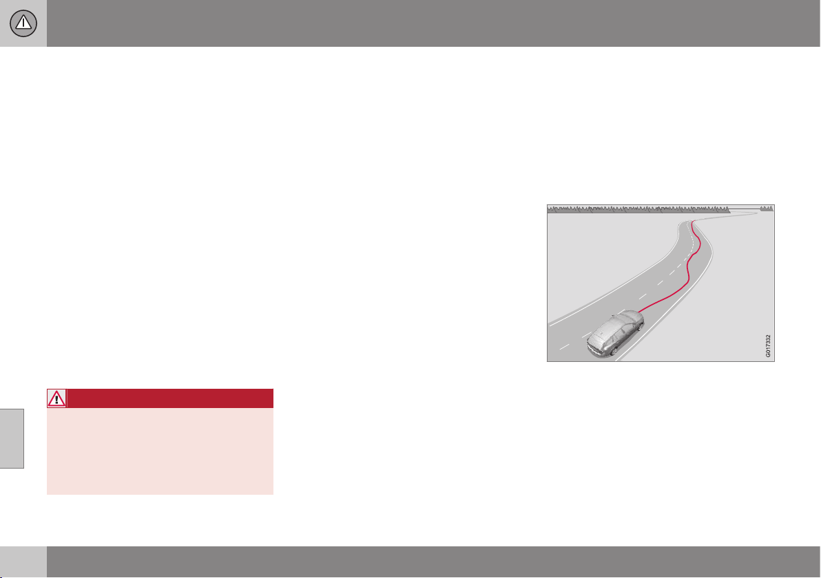
07 Driver support
07
232
* Option/accessory, for more information, see Introduction.
Driver Alert System*
The Driver Alert System is intended to assist
drivers whose driving ability is deteriorating or
who are inadvertently leaving the lane they are
driving on.
The Driver Alert System consists of different
functions which can either be switched on at
the same time or individually:
•
Driver Alert Control - DAC (p. 233).
•
Lane Departure Warning - LDW (p. 235).
or
•
Lane Keeping Aid - LKA (p. 239)
A switched-on function is set in standby
mode and is not activated automatically until
speed exceeds 65 km/h.
The function is deactivated again when speed
decreases to below 60 km/h.
Both functions use a camera which is
dependent on the lane having side markings
painted on each side.
WARNING
Driver Alert System does not work in all
situations but is designed merely as a sup-
plementary aid.
The driver always bears ultimate responsi-
bility for ensuring that the vehicle is driven
safely.
Related information
•
Driver Alert Control (DAC)* (p. 232)
•
Lane Departure Warning (LDW)* (p. 235)
•
Lane Keeping Aid (LKA)* (p. 239)
Driver Alert Control (DAC)*
The DAC function is intended to attract the
driver's attention when he/she starts to drive
less consistently, e.g. if he/she becomes dis-
tracted or starts to fall asleep.
The objective for DAC is to detect slowly
deteriorating driving ability and it is primarily
intended for major roads. The function is not
intended for city traffic.
A camera detects the side markings painted
on the carriageway and compares the section
of the road with the driver's steering wheel
movements. The driver is alerted if the vehicle
does not follow the carriageway evenly.
In some cases driving ability is not affected
despite driver fatigue. In which case there
may not be any warning issued for the driver.
For this reason it is always important to stop
and take a break in the event of any signs of
07 Driver support
07
* Option/accessory, for more information, see Introduction.
233
driver fatigue, irrespective of whether or not
DAC issues a warning.
NOTE
The function must not be used to extend a
period of driving. Always plan breaks at
regular intervals, and make sure you are
well rested.
Limitation
In some cases the system may issue a warn-
ing despite driving ability not deteriorating, for
example:
•
in strong side winds
•
on rutted road surfaces.
NOTE
The camera sensor has certain limitations
(p. 228).
Related information
•
Driver Alert System* (p. 232)
•
Driver Alert Control (DAC)* - operation
(p. 233)
•
Driver Alert Control (DAC)* - symbols and
messages (p. 234)
Driver Alert Control (DAC)* - operation
Settings are made from the centre console
display screen and its menu system.
On/Off
The Driver Alert function can be set in
standby mode via the menu system MY CAR
(p. 108):
•
Checked box - function activated.
•
Unchecked box - the function is deacti-
vated.
Function
Driver Alert is activated when speed exceeds
65 km/h and remains active as long as the
speed is over 60 km/h.
If the vehicle is being driven errati-
cally, the driver is notified by an
acoustic signal plus the text mes-
sage
Driver Alert Time for a break
- the linked symbol is illuminated in the com-
bined instrument panel at the same time. The
warning is repeated after a time if driving abil-
ity does not improve.
The warning symbol can go off:
•
Press the left stalk switch OK button.
WARNING
An alarm should be taken very seriously,
as a sleepy driver is often not aware of
his/her own condition.
In the event of an alarm or a feeling of
tiredness; stop the car in a safe manner as
soon as possible and rest.
Studies have shown that it is equally as
dangerous to drive while tired as it is under
the influence of alcohol.
Related information
•
Driver Alert System* (p. 232)
•
Driver Alert Control (DAC)* (p. 232)
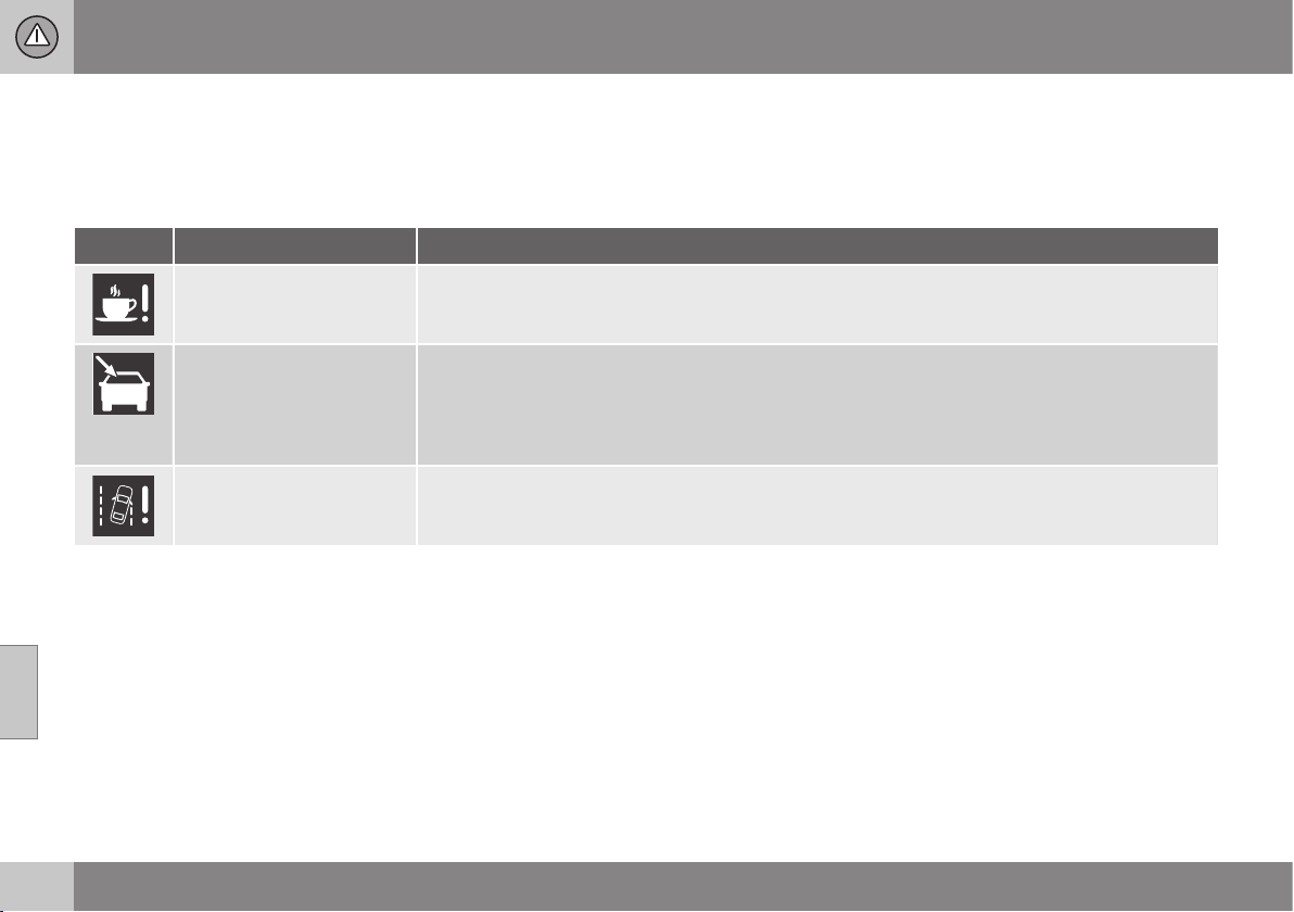
07 Driver support
07
234
* Option/accessory, for more information, see Introduction.
Driver Alert Control (DAC)* - symbols
and messages
DAC (p. 232) can show symbols and text
messages on the combined instrument panel
or in the centre console's display screen in
different situations.
Here are some examples:
Symbol
A
Message Specification
Driver Alert Time for a
break
The vehicle has been driven inconsistently - the driver is alerted by an acoustic warning signal + text.
Windscreen sensors
blocked See manual
The camera sensor is temporarily disengaged.
Shown in the event of snow, ice or dirt on the windscreen for example.
•
Clean the windscreen surface in front of the camera sensor.
Read about camera sensor limitations (p. 228).
Driver Alert system Serv-
ice required
The system is disengaged.
•
Visit a workshop if the message remains - an authorised Volvo workshop is recommended.
A
Symbols are schematic - may vary by market and car model.
Related information
•
Driver Alert System* (p. 232)
•
Driver Alert Control (DAC)* (p. 232)
•
Driver Alert Control (DAC)* - operation
(p. 233)
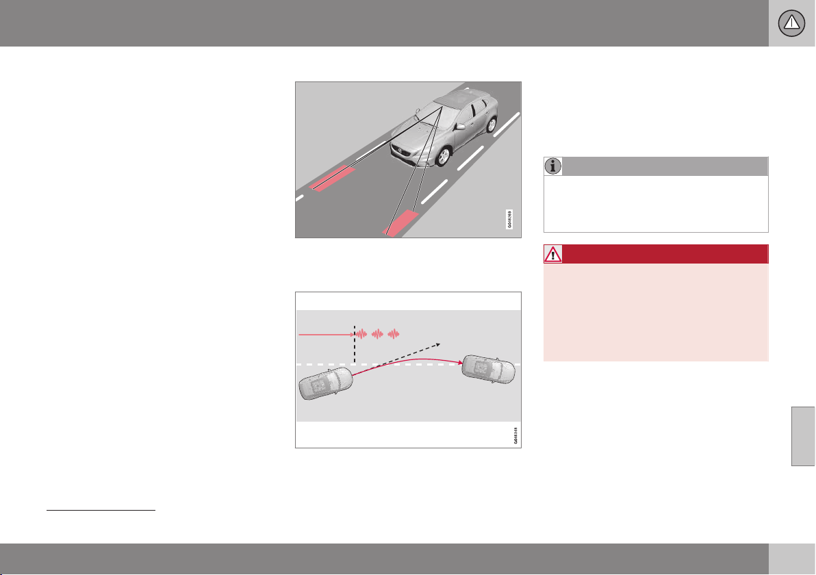
07 Driver support
07
}}
* Option/accessory, for more information, see Introduction.
235
Lane Departure Warning (LDW)*
The purpose of Lane Departure Warning
(Lane Departure Warning) is to help the driver
to reduce the risk of the vehicle accidentally
leaving its own lane in certain situations on
motorways and similar major routes.
Lane Departure Warning LDW or LKA
There are two versions of Lane assistance:
•
LDW -
Lane Departure Warning - alerts
the driver with an acoustic signal or vibra-
tion in the steering wheel.
•
LKA -
Lane Keeping Aid
(Lane Keeping Aid) - steers the car back
into its lane and/or alerts the driver with
an acoustic signal or vibration in the
steering wheel.
The car is supplied with one of these two sys-
tems - market and engine alternative deter-
mine which of the systems the car is equip-
ped with.
In the event of uncertainty whether the car
has LDW or LKA:
•
Open the menu system MY CAR and
locate
Driver support system - which
specifies Lane Departure Warning if the
car has LDW or
Lane Keeping Aid for
LKA.
Principle for LDW
(The figure is schematic - not model specific.)
A camera reads the side lines of the road/
lane.
Warning with steering wheel vibration
24
.
If the car crosses one of the side lines the
driver is alerted with an acoustic signal or
vibration in the steering wheel. Steering wheel
vibration varies - the longer the time for which
the car has crossed the side line, the longer
the vibration.
NOTE
The driver is only warned once each time
the wheels cross a line. So there is no
acoustic alarm when there is a line
between the car's wheels.
WARNING
Lane assistance is merely a driver aid and
does not engage in all driving situations or
traffic, weather or road conditions.
The driver always bears ultimate responsi-
bility for ensuring that the vehicle is driven
safely and that applicable laws and road
traffic regulations are followed.
Related information
•
Lane Departure Warning (LDW) - function
(p. 236)
•
Lane Departure Warning (LDW) - opera-
tion (p. 237)
•
Lane Departure Warning (LDW) - limita-
tions (p. 237)
24
The figure shows 3 vibrations when the side line is crossed.
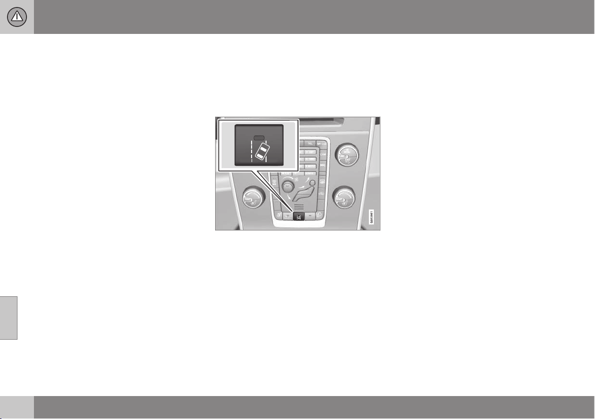
07 Driver support
07
236
* Option/accessory, for more information, see Introduction.
•
Lane Departure Warning (LDW) - symbols
and messages (p. 238)
•
Lane Keeping Aid (LKA)* (p. 239)
•
Driver Alert System* (p. 232)
Lane Departure Warning (LDW) -
function
Certain settings can be made for the Lane
Departure Warning (Lane Departure Warning)
function.
Off & On
Press the centre console's button to activate
or deactivate the function. The button's lamp
illuminates when the function is switched on.
This function is complemented in the com-
bined instrument panel with intuitive graphics
in different situations.
Personal preferences
Settings are made from the centre console's
screen via the menu system in MY CAR. For
a description of the menu system, see MY
CAR (p. 108).
Select from the options:
•
On at startup - The function is set in
standby mode each time the engine is
started. Otherwise the same value as
when the engine was switched off is
obtained.
•
Increased sensitivity - The sensitivity
increases, an alarm is triggered earlier
and fewer limitations apply.
Related information
•
Lane Departure Warning (LDW)* (p. 235)
•
Lane Keeping Aid (LKA)* (p. 239)

07 Driver support
07
* Option/accessory, for more information, see Introduction.
237
Lane Departure Warning (LDW) -
operation
Lane Departure Warning (Lane Departure
Warning) is complemented in the combined
instrument panel with intuitive graphics in dif-
ferent situations. Here are some examples:
LDW function side lines.
•
The LDW symbol has WHITE side lines -
the function is active and detects/"sees"
one side line, or both.
•
The LDW symbol has GREY side lines -
the function is active but detects neither
left nor right side line.
or
•
The LDW symbol has GREY side lines -
the function is in standby mode because
the speed is below 65 km/h.
•
The LDW symbol has no side lines - the
function is deactivated.
Related information
•
Lane Departure Warning (LDW)* (p. 235)
•
Lane Keeping Aid (LKA)* (p. 239)
Lane Departure Warning (LDW) -
limitations
Lane Departure Warning (Lane Departure
Warning) camera sensor has limitations in a
similar way to the human eye.
For more information, read about camera
sensor limitations (p. 228).
NOTE
There are some situations where LDW
does not give any warning, such as:
•
Direction indicators are switched on
•
The driver has his/her foot on the
brake pedal
25
•
In the event of rapid depression of the
accelerator pedal
25
•
In the event of rapid steering wheel
movements
25
•
If turning is so sharp that the car rolls.
Related information
•
Lane Departure Warning (LDW)* (p. 235)
•
Lane Keeping Aid (LKA)* (p. 239)
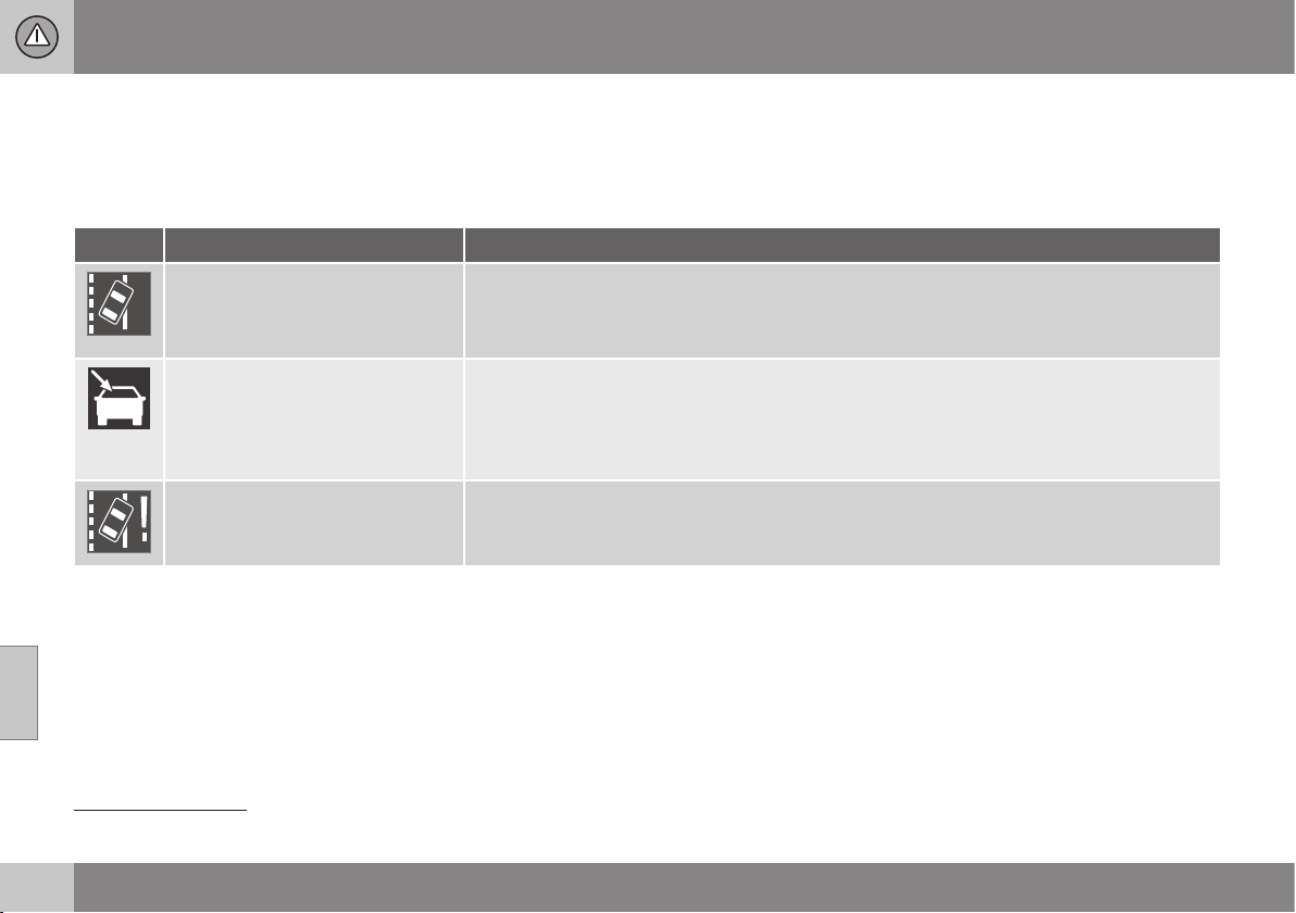
07 Driver support
07
238
* Option/accessory, for more information, see Introduction.
Lane Departure Warning (LDW) -
symbols and messages
In situations where there is no Lane assis-
tance function, a symbol may be shown in the
combined instrument panel in combination
with an explanatory message - follow the rec-
ommendation given if appropriate.
Message examples:
Symbol Message Specification
Lane Departure Warning ON/
Lane Departure Warning OFF
The function is switched on/off.
Shown at switch-on/off.
The text disappears after approx. 5 seconds.
Windscreen sensors blocked
See manual
The camera sensor is temporarily disengaged.
Shown in the event of snow, ice or dirt on the windscreen for example.
•
Clean the windscreen in front of the camera sensor.
Read about camera sensor limitations (p. 228).
Driver Alert system Service
required
The system is disengaged.
•
Visit a workshop if the message remains - an authorised Volvo workshop is recommended.
Related information
•
Lane Departure Warning (LDW)* (p. 235)
•
Lane Keeping Aid (LKA)* (p. 239)
25
When "Increased sensitivity" is selected a warning is still given, see Lane Departure Warning (LDW) - function (p. 236).
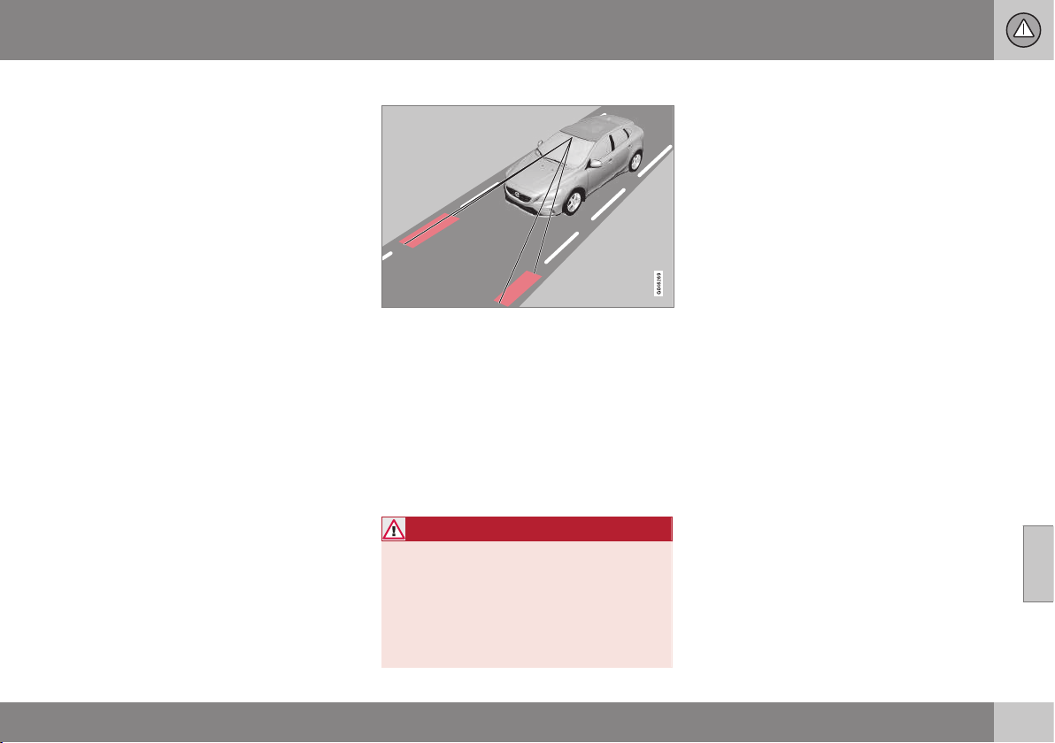
07 Driver support
07
* Option/accessory, for more information, see Introduction.
239
Lane Keeping Aid (LKA)*
The purpose of Lane Departure Warning is to
help the driver to reduce the risk of the vehi-
cle accidentally leaving its own lane in certain
situations on motorways and similar major
routes.
Lane Departure Warning LDW or LKA
There are two versions of Lane assistance:
•
LDW -
Lane Departure Warning - alerts
the driver with an acoustic signal or vibra-
tion in the steering wheel.
•
LKA -
Lane Keeping Aid
(Lane Keeping Aid) - steers the car back
into its lane and/or alerts the driver with
an acoustic signal or vibration in the
steering wheel.
The car is supplied with one of these two sys-
tems - market and engine alternative deter-
mine which of the systems the car is equip-
ped with.
In the event of uncertainty whether the car
has LDW or LKA:
•
Open the menu system MY CAR and
locate
Driver support system - which
specifies Lane Departure Warning if the
car has LDW or
Lane Keeping Aid for
LKA.
Principle for LKA
(The figure is schematic - not model specific.)
A camera reads the side lines of the road/
lane.
If the car is about to cross a side line then
Lane Keeping Aid will actively steer the car
back into the lane with a slight steering tor-
que in the steering wheel.
If the car reaches or crosses a side line then
Lane Keeping Aid will also alert the driver with
vibration in the steering wheel.
WARNING
Lane assistance is merely a driver aid and
does not engage in all driving situations or
traffic, weather or road conditions.
The driver always bears ultimate responsi-
bility for ensuring that the vehicle is driven
safely and that applicable laws and road
traffic regulations are followed.
Related information
•
Lane Keeping Aid (LKA) - function
(p. 240)
•
Lane Keeping Aid (LKA) - operation
(p. 241)
•
Lane Keeping Aid (LKA) - limitations
(p. 242)
•
Lane Keeping Aid (LKA) - symbols and
messages (p. 243)
•
Lane Departure Warning (LDW)* (p. 235)
•
Driver Alert System* (p. 232)
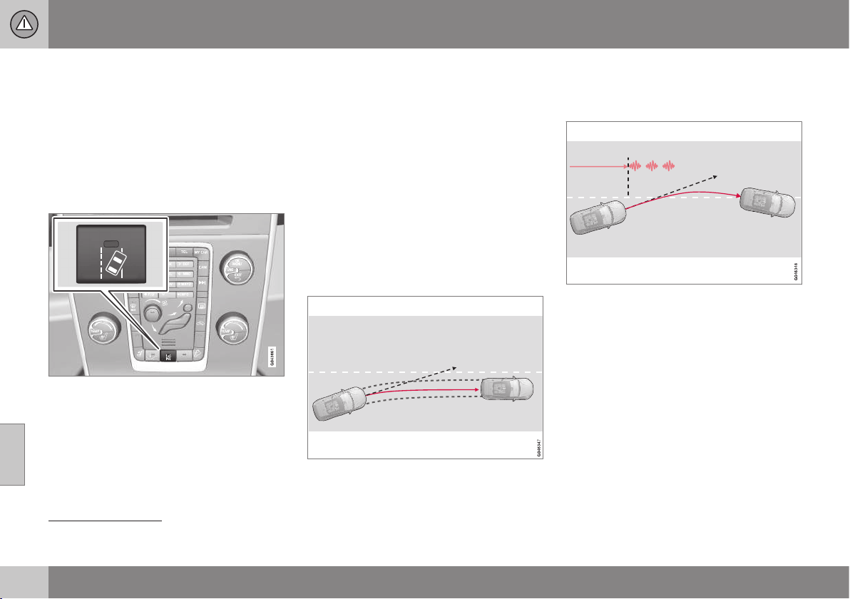
07 Driver support
07
240
Lane Keeping Aid (LKA) - function
Certain settings can be made for the Lane
Keeping Aid (Lane Keeping Aid) function.
Off & On
Lane Keeping Aid is active within the speed
range 65-200 km/h on roads with clearly visi-
ble side lines. The function is temporarily
deactivated on narrow roads with less than
2.6 metres between the lane's side lines.
Press the centre console's button to activate
or deactivate the function. The button's lamp
illuminates when the function is switched on.
Some combinations of the selected equip-
ment leave no vacant space for an On/Off
button in the centre console - in which case
the function is instead handled in the car's
menu system MY CAR. For a description of
the menu system, see MY CAR (p. 108).
In addition, the following selections can be
made in MY CAR:
•
Warning with vibration in the steering
wheel:
Vibration only - On or Off.
•
Active steering:
Steering assist only- On
or Off.
•
Both Warning with vibration in the steer-
ing wheel and Active steering:
Full
function - On or Off.
Active steering
Lane Keeping Aid strives to keep the car
within the side lines for the lane.
LKA intervenes and steers away.
If the car approaches the left or right side line
of the lane and the direction indicator is not
activated, the car is steered back into the
lane.
Warning with vibration in steering wheel
LKA steers and alerts with steering wheel vibra-
tion
26
.
If the car crosses a side line then Lane Keep-
ing Aid will alert the driver with vibration in the
steering wheel
27
. This occurs regardless of
whether the car is actively steered back by
applying a slight steering torque.
26
The figure shows 3 vibrations when the side line is crossed.
27
Steering wheel vibration varies - the longer the time for which the car has crossed the side line, the more pulses there are.
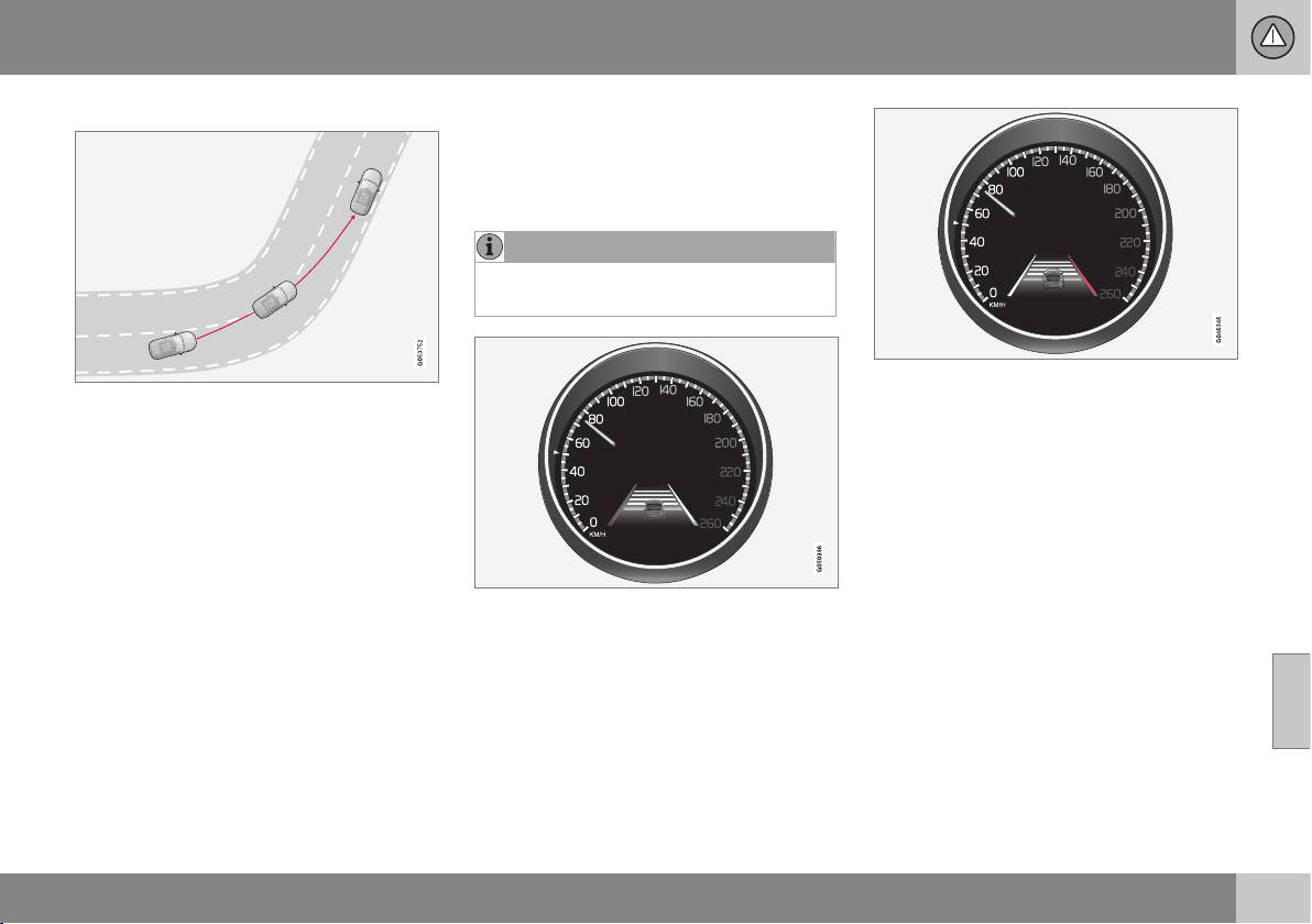
07 Driver support
07
* Option/accessory, for more information, see Introduction.
241
Dynamic cornering
LKA does not intervene in sharp inside bends.
In certain cases Lane assistance will allow the
car to cross lane lines without engaging
active steering or activating a warning. Using
an adjacent lane for cutting a corner when
there is a clear line of vision is an example of
this.
Related information
•
Lane Keeping Aid (LKA)* (p. 239)
•
Lane Departure Warning (LDW)* (p. 235)
Lane Keeping Aid (LKA) - operation
Lane Keeping Aid (Lane Keeping Aid) is com-
plemented in the combined instrument panel
with intuitive graphics in different situations.
Here are some examples:
NOTE
LKA is temporarily deactivated for as long
as the direction indicator is switched on.
LKA "sees" and follows the side lines.
If Lane Keeping Aid is active and
detects/"sees" the side lines, the LKA symbol
indicates this with WHITE lines.
•
GREY side line - Lane Keeping Aid does
not see a line on that side of the car.
LKA intervenes on the right-hand side.
Lane Keeping Aid intervenes and steers away
from the side line - this is indicated with:
•
RED line for the side in question.
Related information
•
Lane Keeping Aid (LKA)* (p. 239)
•
Lane Departure Warning (LDW)* (p. 235)

07 Driver support
07
242
* Option/accessory, for more information, see Introduction.
Lane Keeping Aid (LKA) - limitations
Lane Keeping Aid (Lane Keeping Aid) camera
sensor has limitations in a similar way to the
human eye.
For more information, read about camera
sensor limitations (p. 228) and see Collision
warning system* - operation (p. 226).
NOTE
In certain demanding situations Lane
assistance may have difficulty assisting the
driver in the right way - in which case it is
recommended to deactivate the function.
Examples of such situations may be:
•
roadworks
•
winter road conditions
•
poor road surface
•
very sporty driving style
•
poor weather with reduced visibility.
Hands on the steering wheel
In order for Lane Keeping Aid to operate, the
driver must have his/her hands on the steer-
ing wheel. LKA continually monitors this. If
hands are not detected on the steering wheel
then a text message is shown, prompting the
driver to actively steer the car.
If the driver does not follow the request to
begin steering then Lane Keeping Aid goes
into standby mode and will remain in this
mode until the driver begins to steer the car
again.
Related information
•
Lane Keeping Aid (LKA)* (p. 239)
•
Lane Departure Warning (LDW)* (p. 235)
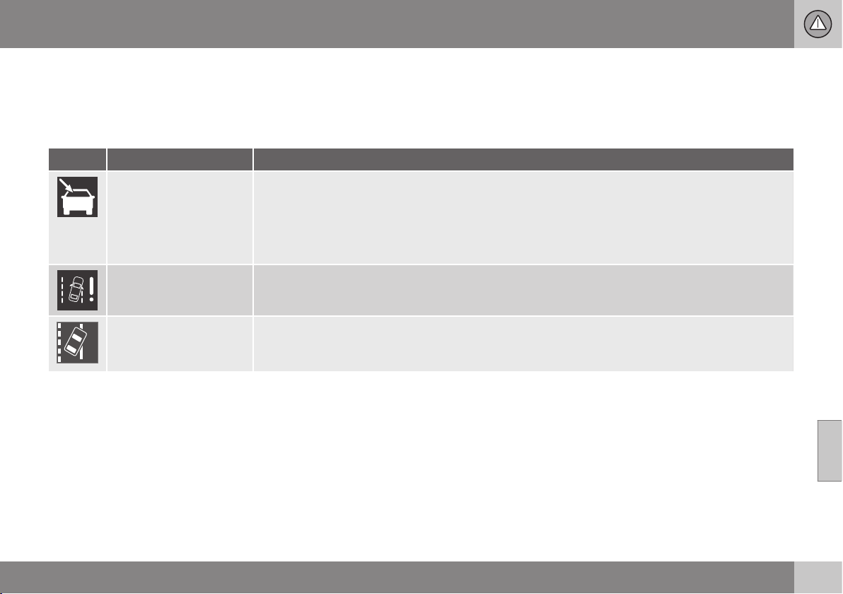
07 Driver support
07
* Option/accessory, for more information, see Introduction.
243
Lane Keeping Aid (LKA) - symbols and
messages
In situations where there is no Lane assis-
tance function, a symbol may be shown in the
combined instrument panel in combination
with an explanatory message - follow the rec-
ommendation given if appropriate.
Message examples:
Symbol Message Specification
Windscreen sensors
blocked See manual
The camera sensor is temporarily disengaged.
Shown in the event of snow, ice or dirt on the windscreen for example.
•
Clean the windscreen in front of the camera sensor.
Read about the limitations of the camera sensor, see Collision warning system* - camera sensor limita-
tions (p. 228) and Collision warning system* - operation (p. 226).
Lane Keeping Aid Serv-
ice required
The system is disengaged.
•
Visit a workshop if the message remains - an authorised Volvo workshop is recommended.
Lane Keeping Aid Inter-
rupted
LKA has been set to standby mode. The lines of the LKA symbol indicate when the function is active
again.
Related information
•
Lane Keeping Aid (LKA)* (p. 239)
•
Lane Departure Warning (LDW)* (p. 235)
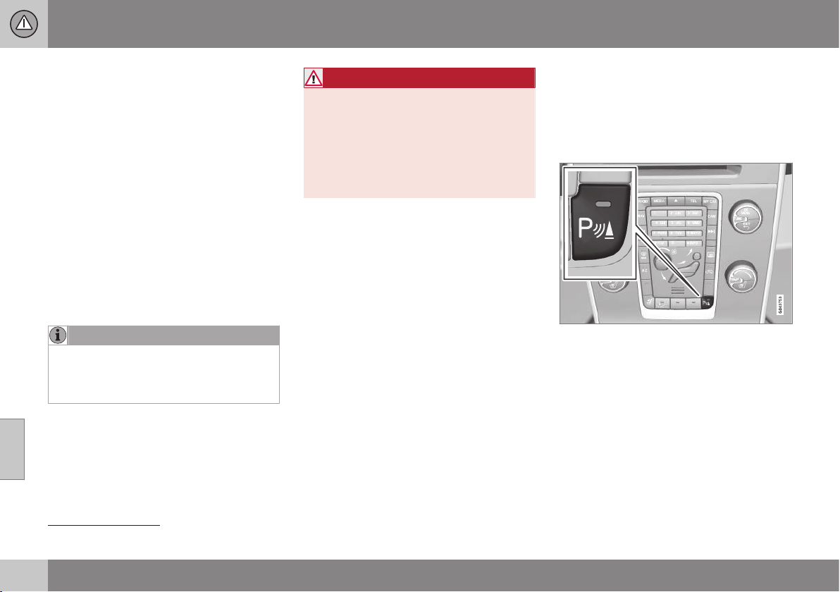
07 Driver support
07
244
* Option/accessory, for more information, see Introduction.
Park Assist*
Parking assistance is used as an aid to park-
ing. An acoustic signal as well as symbols on
the centre console's screen indicate the dis-
tance to the detected obstacle.
Parking assistance sound level can be
adjusted during the ongoing acoustic signal
using the centre console's VOL knob. The
sound level can also be adjusted in the audio
settings menu, which is accessed by pressing
SOUND or in the car's menu system (p. 108)
MY CAR
28
.
Parking assistance is available in two vari-
ants:
•
Rear only
•
Both front and rear.
NOTE
When a towbar is configured with the car's
electrical system, the protrusion of the
towbar is included when the function
measures the parking space.
WARNING
•
Parking assistance does not relinquish
the driver's own responsibility during
parking.
•
The sensors have blind spots where
obstacles cannot be detected.
•
Be aware of e.g. people or animals
near the car.
Related information
•
Park assist syst* - function (p. 244)
•
Park assist syst* - forward (p. 246)
•
Park assist syst* - backward (p. 245)
•
Park assist syst* - cleaning the sensors
(p. 247)
•
Park assist syst* - fault indication (p. 247)
•
Park assist camera* (p. 248)
Park assist syst* - function
The parking assistance system is automati-
cally activated when the engine is started -
the switch's On/Off lamp is illuminated. If
parking assistance is switched off with the
button, the lamp goes out.
On/Off for parking assistance and CTA*.
If the car is equipped with CTA (p. 259) the
indicator lamps flash for BLIS (p. 256) once,
then parking assistance is activated using the
button.
28
Depending on the audio and media system.
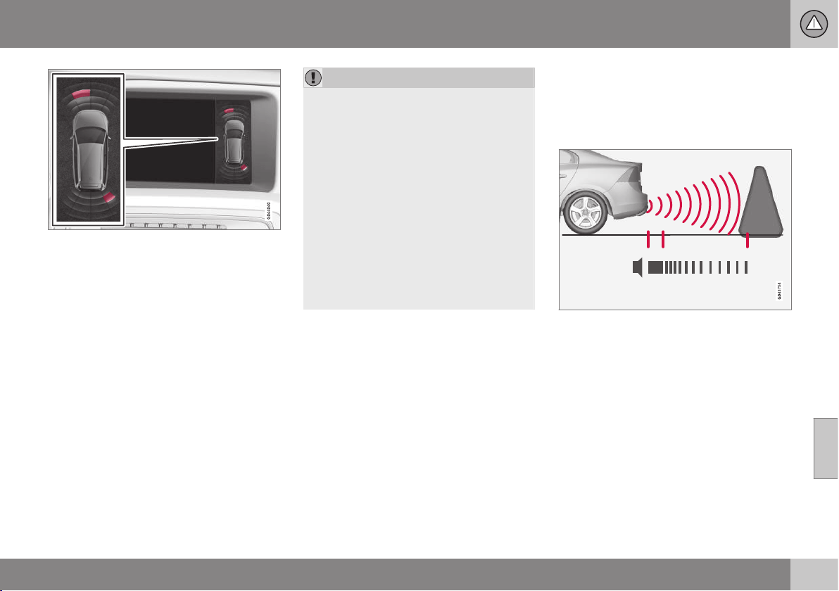
07 Driver support
07
}}
* Option/accessory, for more information, see Introduction.
245
Display screen view - showing an obstacle left
front and right rear.
The centre console's display screen shows
an overview of the relationship between the
car and detected obstacle.
Marked sectors show which of the four sen-
sor(s) detected an obstacle. The closer to the
car symbol a selected sector box is, the
shorter the distance between the car and a
detected obstacle.
The frequency of the signal increases the
shorter the distance to an obstacle, in front of
or behind the car. Other sound from the audio
system is muted automatically.
When the distance is within 30 cm the tone is
constant and the active sensor's field nearest
the car is filled in. If the detected obstacle is
within the distance for the constant tone both
behind and in front of the car, then the tone
sounds alternately from the loudspeakers.
IMPORTANT
Objects e.g. chains, thin glossy poles or
low barriers may be in the "signal shadow"
and are then temporarily not detected by
the sensors - the pulsating tone may then
unexpectedly stop instead of changing
over to the expected constant tone.
The sensors cannot detect high objects,
such as projecting loading docks.
•
In such situations, pay extra attention
and manoeuvre/reposition the car par-
ticularly slowly or stop the current
parking manoeuvre - there may be a
high risk of damage to vehicles or
other objects since the sensors are
temporarily unable to function opti-
mally.
Related information
•
Park Assist* (p. 244)
•
Park assist syst* - forward (p. 246)
•
Park assist syst* - backward (p. 245)
•
Park assist syst* - cleaning the sensors
(p. 247)
•
Park assist syst* - fault indication (p. 247)
•
Park assist camera* (p. 248)
Park assist syst* - backward
Parking assistance is used as an aid to park-
ing. An acoustic signal as well as symbols on
the centre console's screen indicate the dis-
tance to the detected obstacle.
The distance covered to the rear of the car is
about 1.5 metres. The acoustic signal for
obstacles behind comes from one of the rear
loudspeakers.
Rear parking assistance is activated when
reverse gear is engaged.
When reversing with e.g. a trailer on the tow-
bar, rear parking assistance is switched off
automatically - otherwise the sensors would
react to the trailer.
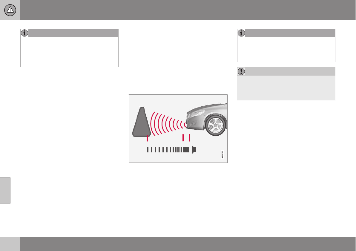
||
07 Driver support
07
246
* Option/accessory, for more information, see Introduction.
NOTE
When reversing with e.g. a trailer or bike
carrier on the towbar - without Volvo genu-
ine trailer wiring - parking assistance may
need to be switched off manually in order
that the sensors do not react to them.
Related information
•
Park Assist* (p. 244)
•
Park assist syst* - function (p. 244)
•
Park assist syst* - forward (p. 246)
•
Park assist syst* - cleaning the sensors
(p. 247)
•
Park assist syst* - fault indication (p. 247)
•
Park assist camera* (p. 248)
Park assist syst* - forward
Parking assistance is used as an aid to park-
ing. An acoustic signal as well as symbols on
the centre console's screen indicate the dis-
tance to the detected obstacle.
The parking assistance system is automati-
cally activated when the engine is started -
the switch's On/Off lamp is illuminated. If
parking assistance is switched off with the
button, the lamp goes out.
The distance covered in front of the car is
about 0.8 metres. The acoustic signal for
obstacles in front comes from one of the front
loudspeakers.
Front park assist is active up to
approx. 10 km/h. The lamp in the button is
illuminated in order to indicate that the sys-
tem is activated. When the speed is below
10 km/h the system is reactivated.
NOTE
Front parking assistance is deactivated
when the parking brake is applied or P
mode is selected in a car with an auto-
matic gearbox.
IMPORTANT
When auxiliary lamps are fitted: Remember
that these must not obscure the sensors -
the auxiliary lamps may then be perceived
as an obstacle.
Related information
•
Park Assist* (p. 244)
•
Park assist syst* - function (p. 244)
•
Park assist syst* - backward (p. 245)
•
Park assist syst* - cleaning the sensors
(p. 247)
•
Park assist syst* - fault indication (p. 247)
•
Park assist camera* (p. 248)
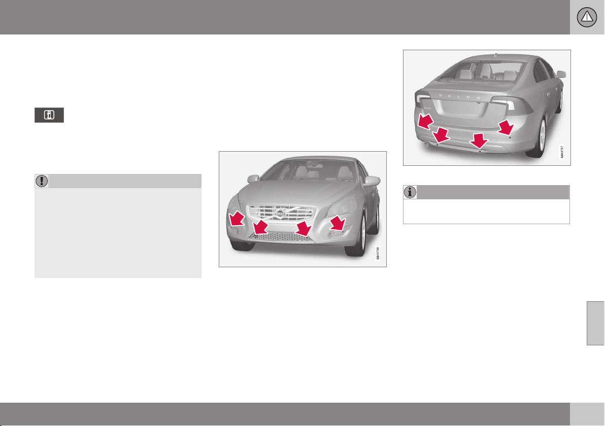
07 Driver support
07
* Option/accessory, for more information, see Introduction.
247
Park assist syst* - fault indication
Parking assistance is used as an aid to park-
ing. An acoustic signal as well as symbols on
the centre console's display screen indicate
the distance to the detected obstacle.
If the combined instrument panel's
information symbol illuminates with
constant glow and the text message
Park Assist System Service required is
shown then parking assistance is disen-
gaged.
IMPORTANT
In certain conditions the parking assis-
tance system may produce incorrect warn-
ing signals that are caused by external
sound sources that emit the same ultra-
sonic frequencies that the system works
with.
Examples of such sources include horns,
wet tyres on asphalt, pneumatic brakes
and exhaust noises from motorcycles etc.
Related information
•
Park Assist* (p. 244)
•
Park assist syst* - cleaning the sensors
(p. 247)
•
Park assist syst* - function (p. 244)
•
Park assist syst* - forward (p. 246)
•
Park assist syst* - backward (p. 245)
•
Park assist camera* (p. 248)
Park assist syst* - cleaning the
sensors
Parking assistance is used as an aid to park-
ing. An acoustic signal as well as symbols on
the centre console's screen indicate the dis-
tance to the detected obstacle.
The sensors must be cleaned regularly to
ensure that they work properly. Clean them
with water and car shampoo.
Sensor location, front.
Sensor location, rear.
NOTE
Dirt, ice and snow covering the sensors
may cause incorrect warning signals.
Related information
•
Park Assist* (p. 244)
•
Park assist syst* - function (p. 244)
•
Park assist syst* - forward (p. 246)
•
Park assist syst* - backward (p. 245)
•
Park assist syst* - fault indication (p. 247)
•
Park assist camera* (p. 248)
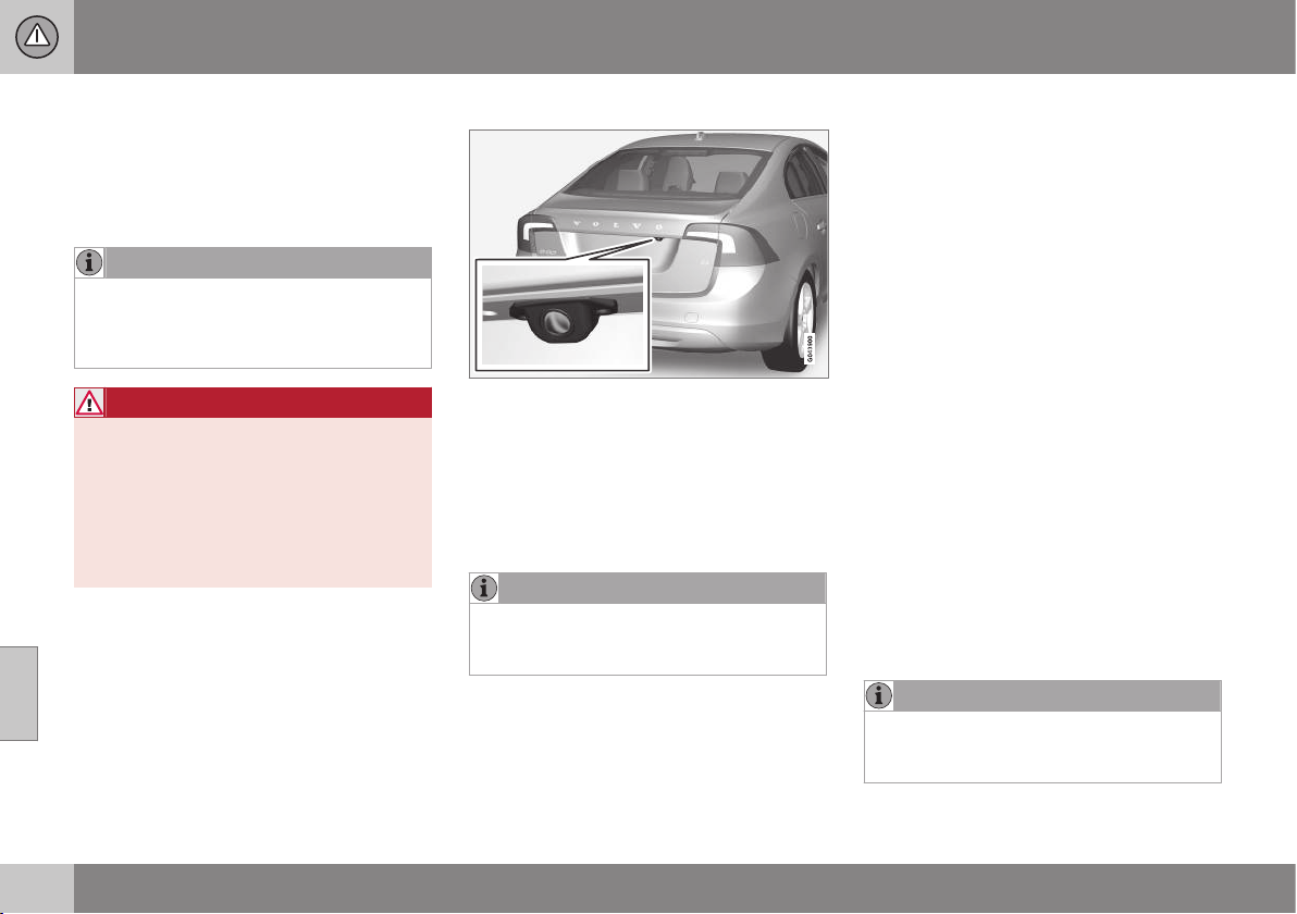
07 Driver support
07
248
* Option/accessory, for more information, see Introduction.
Park assist camera*
Parking camera is an auxiliary system, which
is activated when the reverse gear is selected.
The camera image is shown on the centre
console's screen.
NOTE
When a towbar is configured with the car's
electrical system, the protrusion of the
towbar is included when the function
measures the parking space.
WARNING
•
The parking camera serves as an aid.
It does not relieve the driver of respon-
sibility when reversing.
•
The camera has blind spots, where
obstacles cannot be detected.
•
Be aware of people and animals in the
vicinity of the car.
Function and operation
Camera location next to the opening handle.
The camera shows what is behind the car
and if something appears from the sides.
The camera shows a wide area behind the
car and part of the bumper and any towbar.
Objects on the screen may appear to tilt
slightly - this is normal.
NOTE
Objects on the display screen may be
closer to the car than they appear to be on
the screen.
If another view is active then the parking
camera system takes over automatically and
its camera image is displayed on the screen.
When reverse gear is selected, two unbroken
lines are shown graphically which illustrate
where the car's rear wheels will roll with the
current steering wheel angle - this facilitates
parallel parking, reversing into tight spaces
and for hitching a trailer. The car's approxi-
mate external dimensions are illustrated by
means of dashed lines. The park assist lines
can be deactivated - see section Settings
(p. 250).
If the car is also equipped with Parking assis-
tance sensors (p. 244)* then their information
is shown graphically as coloured areas in
order to illustrate distances to detected
obstacles, see heading "Cars with reversing
sensors" later in the text.
The camera is active approx. 5 seconds after
reverse gear has been disengaged or until the
car's speed exceeds 10 km/h forward or
35 km/h backward.
Light conditions
The camera image is adjusted automatically
according to prevailing light conditions.
Because of this, the image may vary slightly
in brightness and quality. Poor light condi-
tions can result in a slightly reduced image
quality.
NOTE
Keep the camera lens clear of dirt, snow
and ice to ensure optimum function. This
is particularly important in poor light.
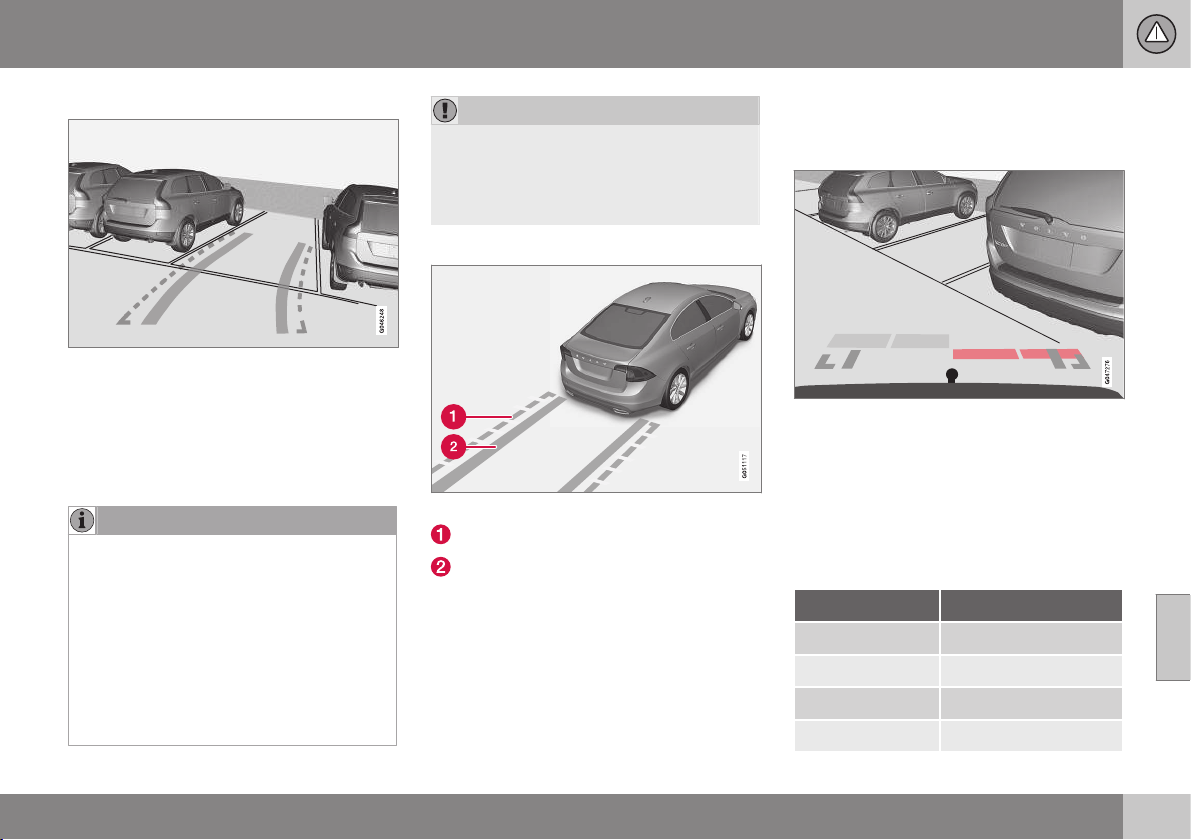
07 Driver support
07
}}
* Option/accessory, for more information, see Introduction.
249
Park assist lines
Examples of how the park assist lines can be dis-
played for the driver.
The lines on the screen are projected as if
they were at ground level behind the car and
are directly related to steering wheel move-
ment, which shows the driver the path the car
will then take - also when the car is turning.
NOTE
•
When reversing with a trailer which is
not connected electrically to the car,
the lines on the display show the route
the car will take - not the trailer.
•
The screen shows no lines when a
trailer is connected electrically to the
car's electrical system.
•
The parking camera is deactivated
automatically when towing a trailer if a
Volvo genuine trailer cable is used.
IMPORTANT
Remember, that with the rear camera view
selected, the monitor only displays the
area behind the car. Be aware of the sides
and front of the car when manoeuvring in
reverse.
Boundary lines
The system's different lines.
Boundary line, free reversing zone
"Wheel tracks"
The dashed line (1) frames in a zone up to
about 1.5 m back from the bumper. It is also
the limit of the car's most protruding parts,
such as door mirrors and corners - also when
the car is turning.
The wide "wheel tracks" (2) between the side
lines indicate where the wheels will roll and
can extend about 3.2 m back from the
bumper if no obstacle is in the way.
Cars with reversing sensors*
Coloured fields (one per sensor) show distance.
If the car is also equipped with Parking assis-
tance (p. 244) the distance is shown with col-
oured fields for each sensor that registers an
obstacle.
The colour of the areas changes with
decreasing distance to the obstacle - from
light yellow to yellow, via orange to red.
Colour / paint Distance (metres)
Light yellow 0,7–1,5
Yellow 0,5–0,7
Orange 0,3–0,5
Red 0–0.3
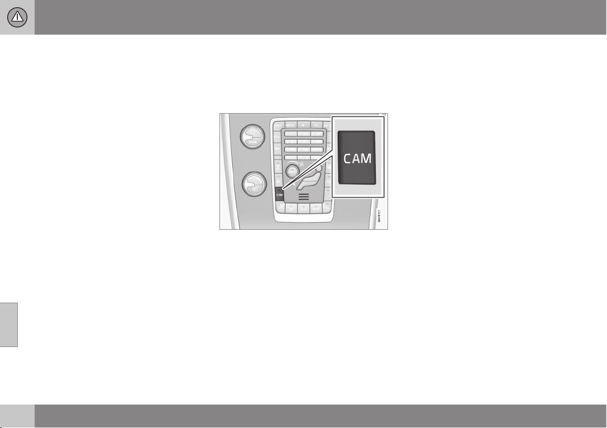
||
07 Driver support
07
250
* Option/accessory, for more information, see Introduction.
Related information
•
Park assist camera - settings (p. 250)
•
Park assist camera - limitations (p. 251)
•
Park Assist* (p. 244)
•
Park Assist Pilot (PAP)* (p. 251)
Park assist camera - settings
Activate switched-off camera
If the camera function is switched off when
reverse gear is selected, it is activated in the
following way:
•
Press CAM - the screen shows the cur-
rent camera view.
Change setting
The default setting is that the camera is acti-
vated when reverse gear is selected.
The settings for the parking camera can be
changed when the screen shows a camera
view:
1. Press OK/MENU when a camera view is
shown - the screenchanges to a menu
with various options.
2. Turn to reach the desired option with
TUNE.
3. Highlight the option by pressing OK/
MENU once and go back out with EXIT.
Towbar
The camera can be used to advantage when
hitching a trailer. A park assist line for the
towbar's intended "trajectory" toward the
trailer can be shown on the screen - exactly
as for the "wheel tracks".
A choice can be made between showing the
"wheel tracks" or the towbar's trajectory
- both options cannot be shown simultane-
ously.
1. Press OK/MENU when a camera view is
shown.
2.
Turn to reach the
Tow bar trajectory
guide line option with TUNE.
3. Highlight the option by pressing OK/
MENU once and go back out with EXIT.
Zoom
If precise manoeuvring is required then the
camera view can be zoomed in:
•
Press CAM or turn TUNE - repeated
press/turn changes back to the normal
view.
If more options are available, they are in a
loop - press/turn until the desired camera
view is shown.
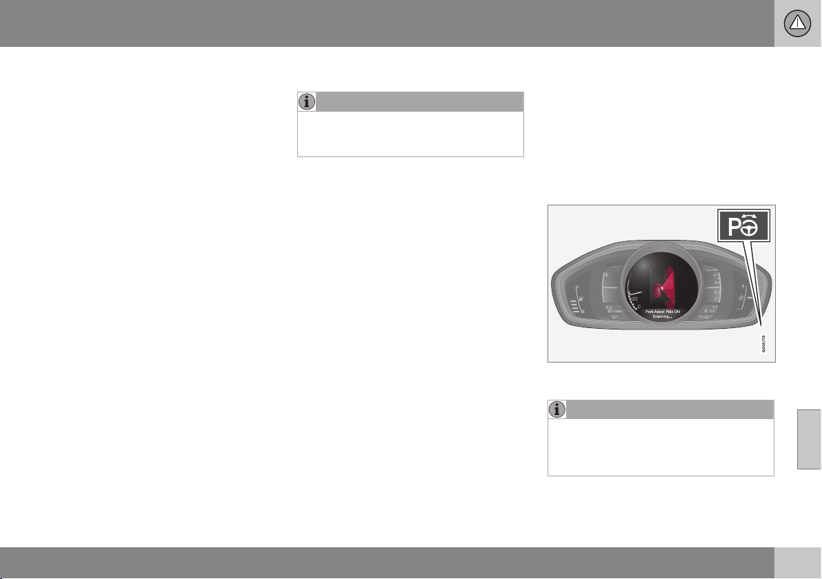
07 Driver support
07
}}
* Option/accessory, for more information, see Introduction.
251
Automatic zoom
In cars with Parking assistance (p. 244) and
towbar,
Automatic zoom is also available as
an option in the camera menu. With this
option selected, the camera zooms into the
towbar automatically when the car
approaches an object/trailer.
See the earlier heading "Change setting" for
how a menu option is activated.
Related information
•
Park assist camera* (p. 248)
•
Park Assist* (p. 244)
•
Park Assist Pilot (PAP)* (p. 251)
Park assist camera - limitations
NOTE
A bike carrier or other accessory mounted
on the rear of the car could obscure the
camera's view.
To bear in mind
Pay attention to the possibility that, even if it
only looks like a relatively small part of the
image is obscured, it could be a relatively
large sector that is hidden from view. Obsta-
cles could thereby go undetected until they
are very close to the car.
•
Keep the camera lens free from dirt, ice
and snow.
•
Clean the camera lens regularly with luke-
warm water and car shampoo - take care
not to scratch the lens.
Related information
•
Park assist camera* (p. 248)
•
Park assist camera - settings (p. 250)
•
Park Assist* (p. 244)
Park Assist Pilot (PAP)*
The Park Assist Pilot (PAP – Park Assist Pilot)
helps the driver to park by first checking
whether a space is sufficiently large and then
turning the steering wheel and steering the
car into the space.
The combined instrument panel uses sym-
bols, graphics and text for when the different
steps are to be carried out.
The On/Off button is on located the centre con-
sole.
NOTE
When a towbar is configured with the car's
electrical system, the protrusion of the
towbar is included when the function
measures the parking space.
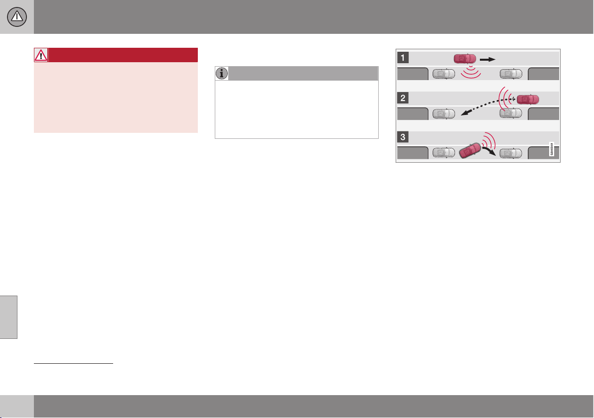
||
07 Driver support
07
252
* Option/accessory, for more information, see Introduction.
WARNING
PAP does not work in all situations but is
designed merely as a supplementary aid.
The driver always has the final responsibil-
ity for driving the vehicle in a safe manner
and for paying attention to the surround-
ings and other road users approaching or
passing during parking.
Related information
•
Park Assist Pilot (PAP)* - symbols and
messages (p. 256)
•
Park Assist Pilot (PAP)* - operation
(p. 253)
•
Park Assist Pilot (PAP)* - function
(p. 252)
•
Park Assist Pilot (PAP)* - limitations
(p. 254)
•
Park Assist* (p. 244)
•
Park assist camera* (p. 248)
Park Assist Pilot (PAP)* - function
NOTE
The PAP function measures the space and
turns the steering wheel - the driver's task
is to follow the combined instrument pan-
el's instructions and select the gear
(reverse/forward), control the speed, brake
and stop.
PAP can be activated if the following criteria
are met once the engine has been started:
•
The functions ABS
29
or ESC
30
must not
intervene when the PAP function is acti-
vated - these can be activated in the
event of e.g. steep and slippery surfaces,
see the sections on Foot brake and Sta-
bility system ESC (p. 184) for more infor-
mation.
•
A trailer must not be connected to the
car.
•
Speed must be below 50 km/h.
Principle for PAP.
PAP The function parks the car using the fol-
lowing steps:
1. The function searches for a parking space
and measures it - during measurement,
speed must not exceed 30 km/h.
2. The car is steered into the space during
reversing.
3. The car is positioned in the space by driv-
ing forward and back.
Related information
•
Park Assist Pilot (PAP)* (p. 251)
•
Park Assist* (p. 244)
•
Park assist camera* (p. 248)
29
(Anti-lock Braking System) - Anti-lock braking system.
30
(Electronic Stability Control) - Stability system.
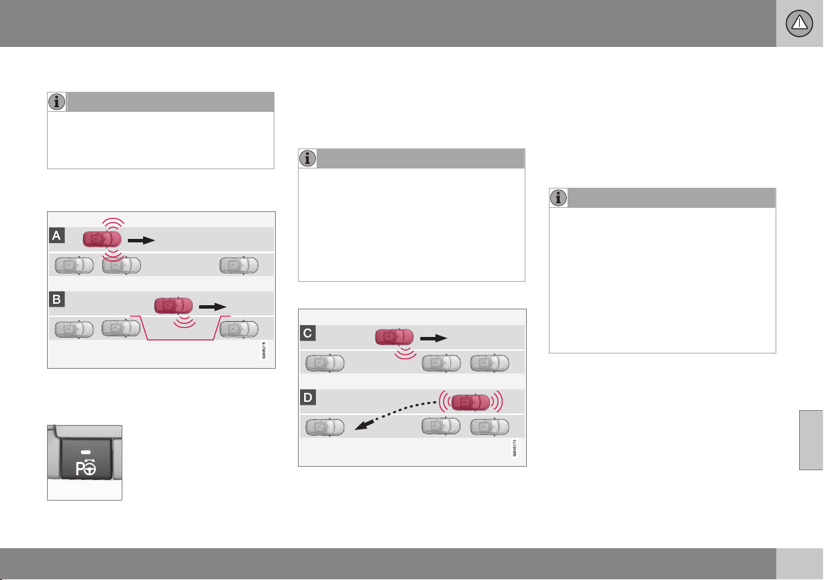
07 Driver support
07
}}
* Option/accessory, for more information, see Introduction.
253
Park Assist Pilot (PAP)* - operation
NOTE
Remember that certain steering wheel
positions may obstruct the combined
instrument panel's instructions when you
turn it during the parking manoeuvre.
1 - Searching and checking
measurements
The PAP function searches for a parking
space and checks whether it is big enough.
Proceed as follows:
1. Activate PAP by pressing
this button and do not drive
faster than 30 km/h.
2. Keep an eye on the combined instrument
panel and be prepared to stop the car
when the graphics and text so request.
3. Stop the car when the graphics and text
so request.
NOTE
PAP searches the area for a parking
space, displays instructions and guides
the car in on its passenger side. But if
required the car can also be parked on the
driver's side of the street:
•
Activate the direction indicator for the
driver's side - the car is then parked
on that side of the street instead.
2 - Reversing in
During the Reversing step, PAP will steer the
car into the parking space. Proceed as fol-
lows:
1. Check that the area behind the car is
clear, then engage reverse gear.
2. Reverse slowly and carefully without
touching the steering wheel - and no
faster than approx. 7 km/h.
3. Keep an eye on the combined instrument
panel and be prepared to stop the car
when the graphics and text so request.
NOTE
•
Keep your hands away from the steer-
ing wheel when the PAP function is
activated.
•
Make sure that the steering wheel is
not hindered in any way and can rotate
freely.
•
To achieve optimum results - wait until
the steering wheel is fully turned
before starting to drive backward/
forward.
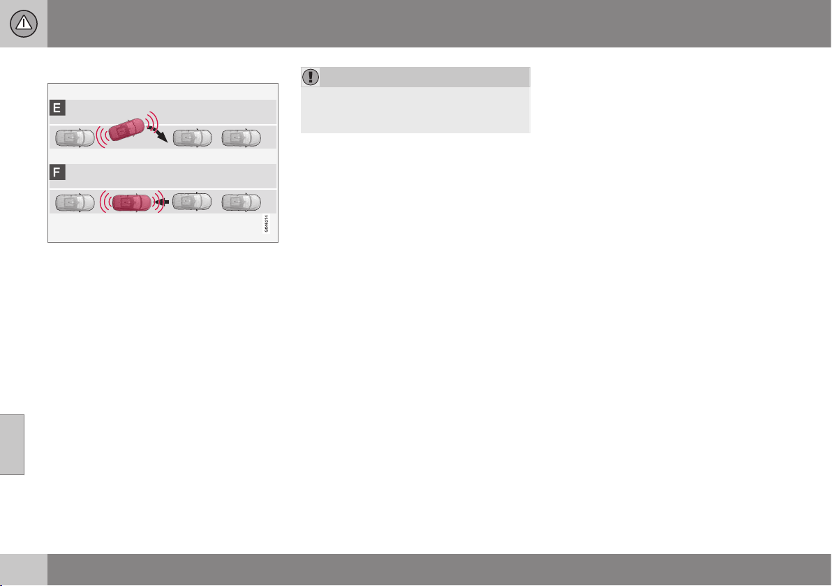
||
07 Driver support
07
254
* Option/accessory, for more information, see Introduction.
3 - Straightening up
When the car has reversed into the parking
space, it must be straightened up and stop-
ped.
1. Engage first gear or D position, wait until
the steering wheel has been turned, then
drive slowly forwards.
2. Stop the car when the graphics and text
message so request.
3. Engage reverse gear and drive back-
wards slowly until the graphics and text
message tell you to stop.
The function is disengaged automatically
when parking is complete, and the graphics
and text message show that parking is com-
plete. It may be necessary for the driver to
correct the positioning. Only the driver can
determine whether the car is properly parked.
IMPORTANT
The warning distance is shorter when the
sensors are used by PAP compared with
when Park Assist uses the sensors.
Related information
•
Park Assist Pilot (PAP)* - symbols and
messages (p. 256)
•
Park Assist Pilot (PAP)* - function (p. 252)
•
Park Assist Pilot (PAP)* - limitations
(p. 254)
•
Park Assist* (p. 244)
•
Park assist camera* (p. 248)
•
Park Assist Pilot (PAP)* (p. 251)
Park Assist Pilot (PAP)* - limitations
The PAP sequence is stopped:
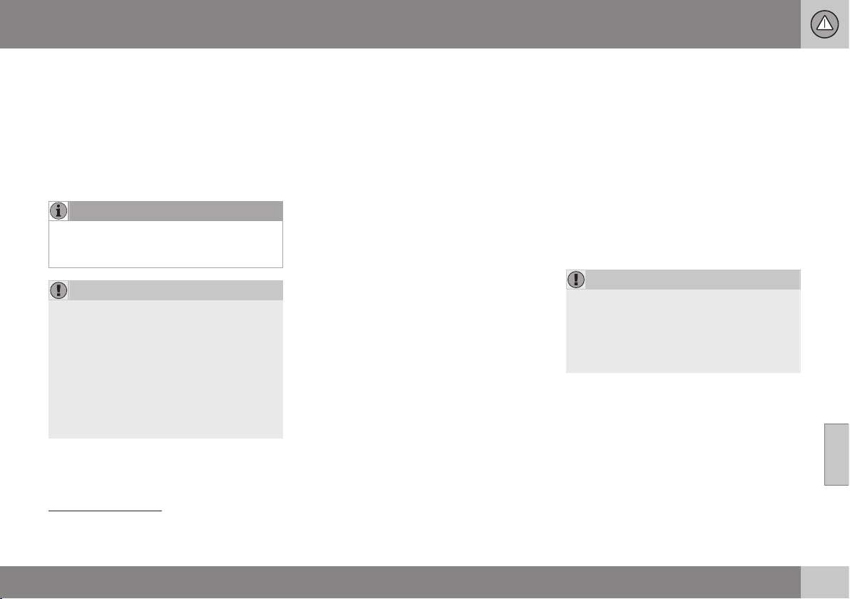
07 Driver support
07
}}
255
•
if the car is driven too quickly - above
7 km/h
•
if the driver touches the steering wheel
•
if the ABS
31
or ESC
32
function is engaged
- e.g. if a wheel loses grip on a slippery
road surface.
A text message indicates where the PAP
sequence was stopped.
NOTE
Dirt, ice and snow covering the sensors
will reduce their function and may prevent
measurement.
IMPORTANT
Under certain circumstances, PAP is
unable to find parking spaces - one reason
for this may be the fact that there is inter-
ference with the sensors from external
sound sources which emit the same ultra-
sound frequencies as those with which the
system works.
Examples of such sources include horns,
wet tyres on asphalt, pneumatic brakes
and exhaust noises from motorcycles etc.
To bear in mind
The driver should bear in mind that the Park
Assist Pilot is an aid – not an infallible, fully-
automatic function. The driver must therefore
be prepared to intervene. There are also a
few details to bear in mind while parking, e.g.:
•
PAP starts out from the current location
of the parked vehicles - if they are inap-
propriately parked then the car's tyres
and wheel rims may be damaged against
kerbs.
•
PAP is designed for parking on straight
streets, not sharp curves or bends. For
this reason, make sure the car is parallel
to the parking space when PAP measures
the space.
•
It is not always possible to find parking
spaces on narrow streets since there is
not enough space for manoeuvring. In
such parking situations, it helps the sys-
tem to drive as close to the side of the
road as possible where you intend to
park.
•
Bear in mind that the front of the car may
swing out towards oncoming traffic while
being parked.
•
Objects situated higher than the detection
areas of the sensors are not included
when calculations are made for the park-
ing manoeuvre. This may cause PAP to
swing into the parking space too early,
and hence such parking spaces should
be avoided.
•
The driver is responsible for determining
whether the space selected by PAP is
suitable for parking.
•
Use approved tyres
33
with the correct tyre
pressure - this affects PAP's ability to
park the car.
•
Heavy rain or snow may cause the sys-
tem to measure the parking space incor-
rectly.
•
Do not use PAP if snow chains or a spare
wheel are fitted.
•
Do not use PAP if loaded objects are pro-
truding from the car.
IMPORTANT
The PAP system's parameters may need
to be updated when changing to another
approved wheel rim size involving changed
tyre circumference. Consult a workshop -
an authorised Volvo workshop is recom-
mended.
31
(Anti-lock Braking System) - Anti-lock braking system.
32
(Electronic Stability Control) - Electronic stability control.
33
"Approved tyres" refers to tyres of the same type and make as those fitted new on delivery from the factory.
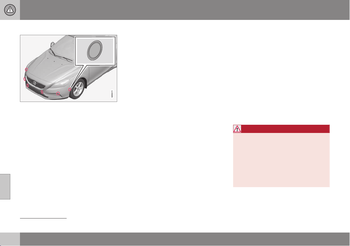
||
07 Driver support
07
256
* Option/accessory, for more information, see Introduction.
Maintenance
The PAP sensors are located in the bumpers
34
-
6 front and 4 rear.
For the PAP function to work correctly, its
sensors must be cleaned regularly with water
and car shampoo - these are the same sen-
sors as are used by parking assistance, see
Park assist syst* - cleaning the sensors
(p. 247).
Related information
•
Park Assist* (p. 244)
•
Park assist camera* (p. 248)
•
Park Assist Pilot (PAP)* (p. 251)
Park Assist Pilot (PAP)* - symbols and
messages
The combined instrument panel uses sym-
bols, graphics and text for when the different
steps are to be carried out.
The combined instrument panel may display
different combinations of symbols and text
with varying meaning - sometimes with self-
explanatory advice on appropriate action.
If a message indicates that PAP is inoperative
then contact with an authorised Volvo work-
shop is recommended.
Related information
•
Park Assist Pilot (PAP)* - operation
(p. 253)
•
Park Assist Pilot (PAP)* - function (p. 252)
•
Park Assist Pilot (PAP)* - limitations
(p. 254)
•
Park Assist* (p. 244)
•
Park assist camera* (p. 248)
•
Park Assist Pilot (PAP)* (p. 251)
BLIS*
BLIS (Blind Spot Information) is a function
designed for providing support for the driver
when driving in dense traffic on roads with
several lanes in the same direction.
BLIS is a driver's aid intended to provide a
warning about:
•
vehicles in the car's blind spot
•
rapidly approaching vehicles in the left
and right-hand lanes closest to the car.
The BLIS function CTA (p. 259) (Cross Traffic
Alert) is a driver's aid intended to provide a
warning about:
•
crossing traffic when the car is reversed.
WARNING
BLIS is a supplementary aid and does not
work in all situations.
BLIS is no substitute for a safe driving
style and the use of rearview and door mir-
rors.
BLIS can never replace the driver's
responsibility and attention - it is always
the driver's responsibility to change lanes
in a safe manner.
34
NOTE: The illustration is schematic - details may differ depending on car model.
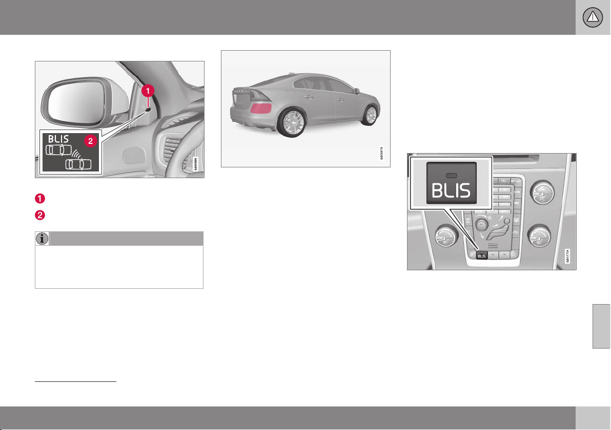
07 Driver support
07
}}
* Option/accessory, for more information, see Introduction.
257
Overview
BLIS lamp location
35
.
Indicator lamp
BLIS symbol
NOTE
The lamp illuminates on the side of the car
where the system has detected the vehi-
cle. If the car is overtaken on both sides at
the same time then both lamps illuminate.
Maintenance
The sensors for the BLIS functions are
located inside the rear wing/bumper on each
corner of the car.
Keep this surface clean - also on the left-hand
side.
•
To ensure optimal functionality the areas
in front of the sensors must be kept
clean.
Related information
•
BLIS* - operation (p. 257)
•
BLIS - symbols and messages (p. 261)
•
CTA* (p. 259)
BLIS* - operation
BLIS (Blind Spot Information) is a function
designed for providing support for the driver
when driving in dense traffic on roads with
several lanes in the same direction.
Activate/deactivate BLIS
BLIS is activated when the engine is started.
This is confirmed by the indicator lamps in
the door panels flashing once.
Button for activating/deactivating.
The BLIS function can be deactivated/acti-
vated by pressing the BLIS button on the
centre console.
Some combinations of the selected equip-
ment leave no vacant space for a button in
the centre console - in which case the func-
tion is handled by the car's menu system MY
CAR (p. 108).
35
NOTE: The illustration is schematic - details may vary depending on car model.
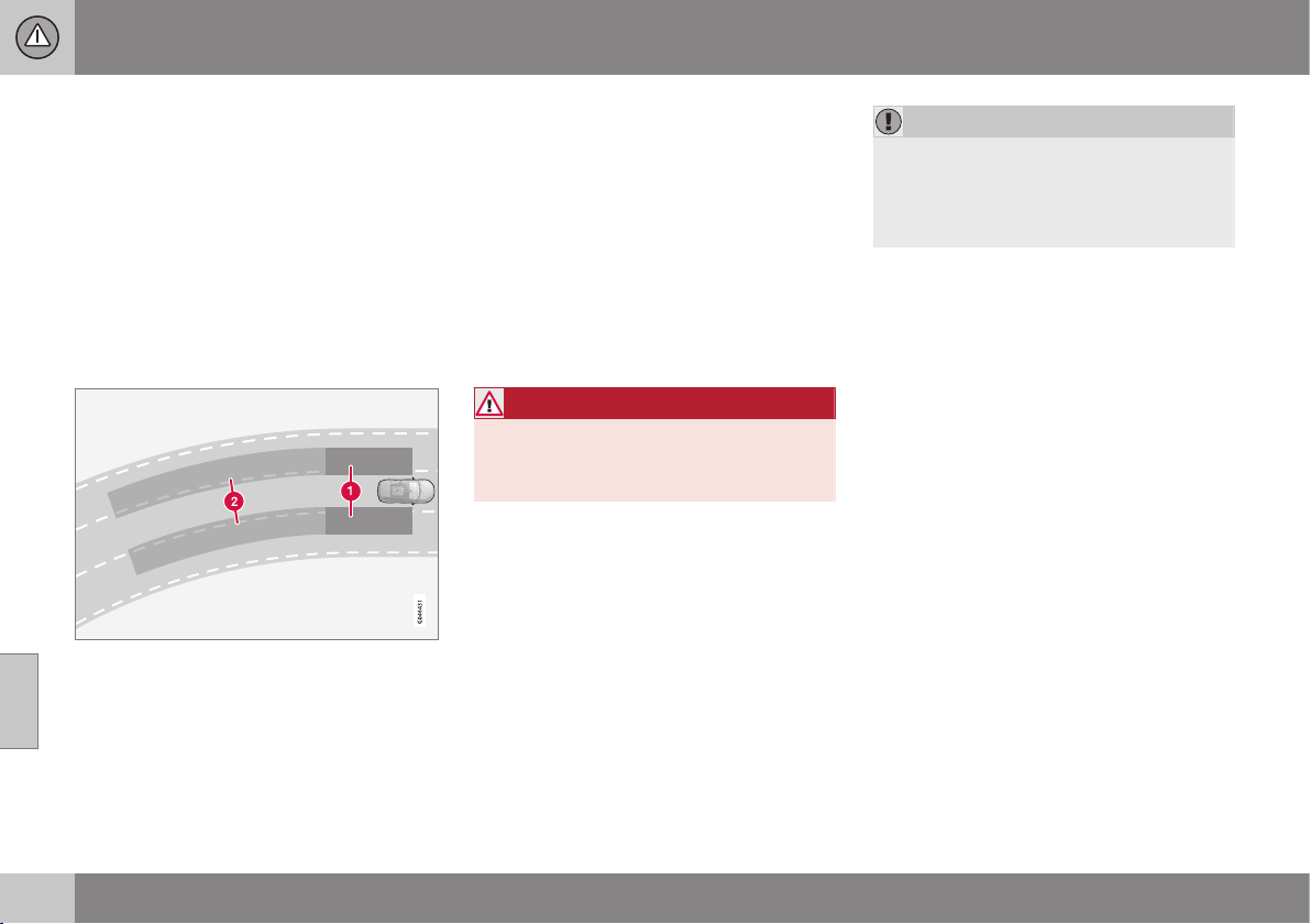
||
07 Driver support
07
258
* Option/accessory, for more information, see Introduction.
When BLIS is deactivated/activated the lamp
in the button extinguishes/illuminates and the
combined instrument panel confirms the
change with a text message. The door panel
indicator lamps flash once upon activation.
To extinguish the message:
•
Press the left stalk switch OK button.
or
•
Wait approx. 5 seconds - the message
extinguishes.
When BLIS operates
Principle for BLIS: 1. Zone in blind spot. 2. Zone
for rapidly approaching vehicle.
The BLIS function is active at speeds above
approx. 10 km/h.
The system is designed to react when:
•
the driver's vehicle is overtaken by other
vehicles
•
the driver's vehicle is rapidly caught up
by another vehicle.
When BLIS detects a vehicle in zone 1 or a
quickly approaching vehicle in zone 2, the
door panel BLIS lamp illuminates with a con-
stant glow. If the driver activates the direction
indicator on the same side as the warning in
this situation then the BLIS lamp will change
from a constant glow to flashing with a more
intense light.
WARNING
BLIS does not work in sharp bends.
BLIS does not work when the car is being
reversed.
Limitations
•
Dirt, ice and snow covering sensors can
reduce functionality and make it impossi-
ble to provide warnings. BLIS cannot
detect hazards if it is covered.
•
Do not affix any objects, tape or labels in
the area of the sensors.
•
BLIS is deactivated when a trailer is con-
nected to the car's electrical system.
IMPORTANT
Repair of the BLIS and CTA functions'
components or repainting the bumpers
must only be performed by a workshop -
an authorised Volvo workshop is recom-
mended.
Related information
•
BLIS* (p. 256)
•
BLIS - symbols and messages (p. 261)
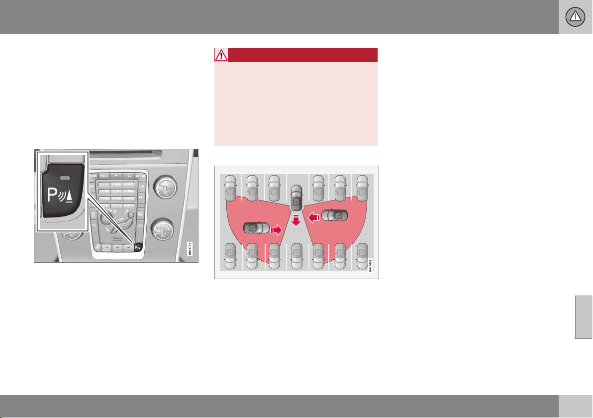
07 Driver support
07
}}
* Option/accessory, for more information, see Introduction.
259
CTA*
The BLIS function CTA (Cross Traffic Alert) is
a driver aid intended to warn about crossing
traffic when the car is reversing. CTA is a sup-
plement to BLIS (p. 256).
Activate/deactivate CTA
CTA is activated when the engine is started.
This is confirmed by the indicator lamps for
BLIS in the door panels flashing once.
On/Off for parking assistance and CTA sensors.
The CTA function can be deactivated/acti-
vated separately with the Parking assistance
(p. 244) On/Off button. The BLIS lamps flash
once on reactivation.
However, the BLIS function remains activated
after the CTA has been deactivated.
WARNING
CTA is a supplementary aid and does not
work in all situations.
CTA is no substitute for a safe driving style
and the use of rearview and door mirrors.
CTA can never replace the driver's respon-
sibility and attention - it is always the driv-
er's responsibility to reverse in a safe man-
ner.
When CTA operates
Principle for CTA.
CTA supplements the BLIS function by being
able to see crossing traffic from the side dur-
ing reversing, such as when reversing out of a
parking space.
CTA is primarily designed to detect vehicles.
In favourable conditions, it may also be able
to detect smaller objects, such as cyclists
and pedestrians.
CTA is only active during reversing and is
activated automatically when the gearbox's
reverse position is selected.
•
If CTA detects something approaching
from the side, an acoustic warning signal
sounds. The signal comes from either the
left or the right-hand speaker, depending
on the direction from which the object is
approaching.
•
CTA also warns by illuminating the BLIS
lamps.
•
An additional warning is provided in the
form of an illuminated icon in the display
screen's PAS graphics (p. 244).
Limitations
CTA does not perform optimally in all situa-
tions, but has a certain limitation - for exam-
ple, the CTA sensors cannot "see" through
other parked vehicles or obstructing objects.
Here are some examples of when CTA's "field
of vision" may be limited from the beginning
and approaching vehicles cannot therefore be
detected until they are very close:
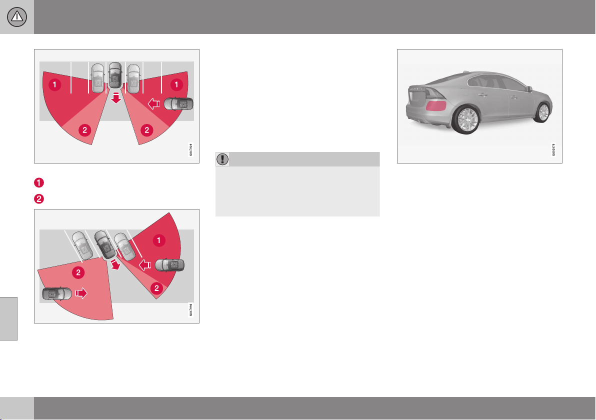
||
07 Driver support
07
260
* Option/accessory, for more information, see Introduction.
The car is parked deep inside a parking slot.
Blind CTA sector.
Sector where CTA can detect/"see".
In an angled parking slot CTA can be completely
"blind" on one side.
However, when the driver is slowly reversing
the car, the angle is changed in relation to the
vehicle/object that is blocking, at which the
blind sector rapidly decreases.
Examples of further limitations:
•
Dirt, ice and snow covering sensors can
reduce functionality and make it impossi-
ble to provide warnings. CTA cannot
detect hazards if it is covered.
•
CTA is deactivated when a trailer is con-
nected to the car’s electrical system.
IMPORTANT
Repair of the BLIS and CTA functions'
components or repainting the bumpers
must only be performed by a workshop -
an authorised Volvo workshop is recom-
mended.
Maintenance
The sensors for the BLIS and CTA functions
are located inside the rear wing/bumper on
each corner of the car.
Keep this surface clean - also on the left-hand
side.
•
To ensure optimal functionality the areas
in front of the sensors must be kept
clean.
•
Do not affix any objects, tape or labels in
the area of the sensors.
Related information
•
BLIS* (p. 256)
•
BLIS - symbols and messages (p. 261)
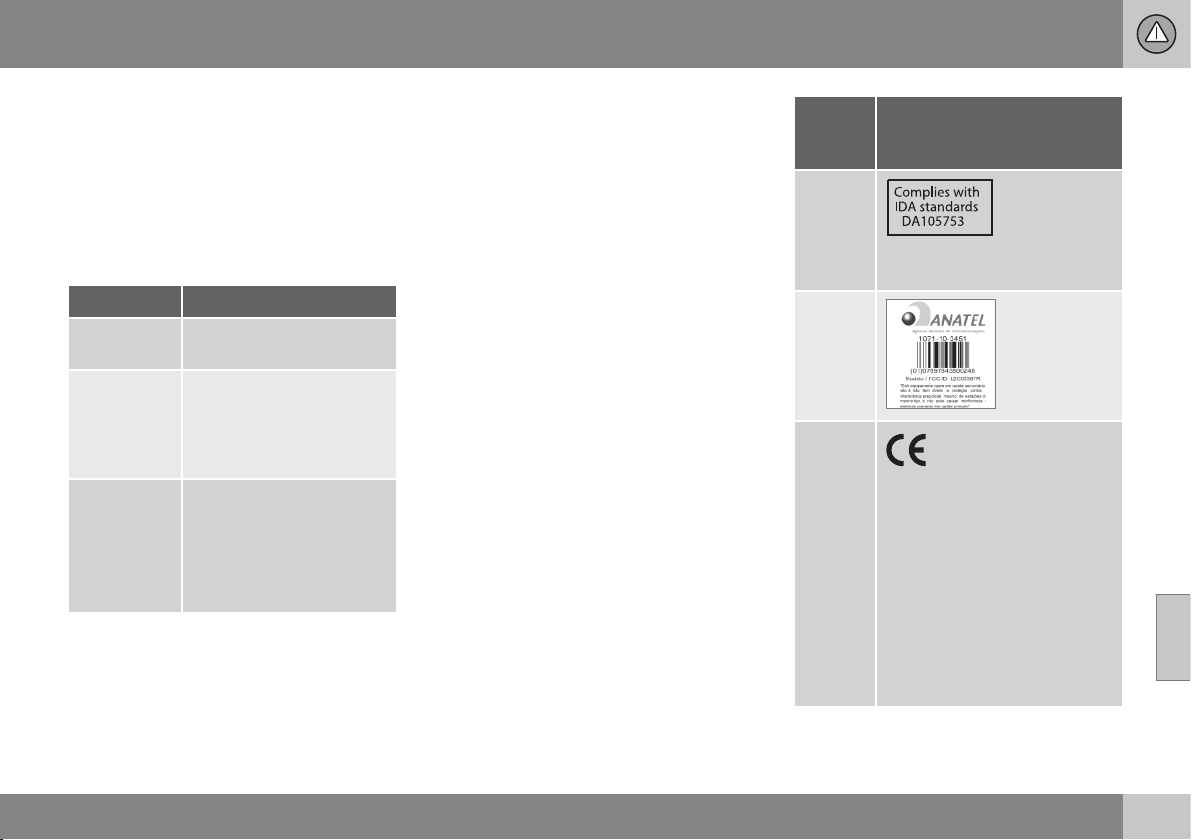
07 Driver support
07
* Option/accessory, for more information, see Introduction.
261
BLIS - symbols and messages
In situations where the BLIS (Blind Spot
Information) (p. 256) and CTA (Cross Traffic
Alert) (p. 259) functions fail or are interrupted,
the combined instrument panel may show a
symbol, supplemented by an explanatory
message. Follow any recommendation given.
Message examples:
Message Specification
CTA OFF
CTA is manually switched
off - BLIS is active.
BLIS and
CTA OFF
Trailer
attached
BLIS and CTA are tempo-
rarily non-operational
because a trailer is con-
nected to the car's electri-
cal system.
BLIS and
CTA Serv-
ice required
BLIS and CTA are non-
operational.
•
Visit a workshop if the
message remains - an
authorised Volvo work-
shop is recommended.
A text message can be acknowledged by
briefly pressing the OK button on the direc-
tion indicator stalk.
Related information
•
BLIS* (p. 256)
Type approval - radar system
Type approval for the radar system can be
read in the table.
Coun-
try/
Area
Singa-
pore
IDA: Infocomm Development
Authority of Singapore.
Brazil
Europe
Delphi Electronics &
Safety hereby declares that
L2C0038TR and L2C0049TR
are in compliance with the
essential requirements and
other relevant provisions of
Directive 1999/5/EC. This dec-
laration of conformity may, if
necessary, be consulted with
Delphi Electronics & Safety /
One Corporate Center /
Kokomo, Indiana 46904-9005
USA.
Related information
•
Radar sensor (p. 206)
STARTING AND DRIVING
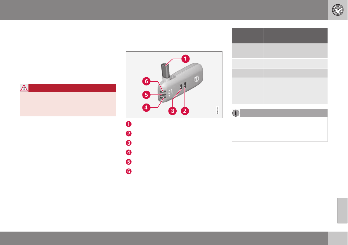
08 Starting and driving
08
* Option/accessory, for more information, see Introduction.
263
Alcohol lock*
The function of the alcohol lock is to prevent
the car from being driven by individuals under
the influence of alcohol. Before the engine
can be started the driver must take a breath
test that verifies that he/she is not under the
influence of alcohol. Alcohol lock calibration
takes place in accordance with each market's
limit value in force for driving legally.
WARNING
The alcohol lock is an aid and does not
exempt the driver from responsibility. It is
always the responsibility of the driver to be
sober and to drive the car safely.
Related information
•
Alcohol lock* - functions and operation
(p. 263)
•
Alcohol lock* - storage (p. 264)
•
Alcohol lock* - before starting the engine
(p. 264)
•
Alcohol lock* - to bear in mind (p. 266)
•
Alcohol lock* - symbols and text mes-
sages (p. 267)
Alcohol lock* - functions and
operation
Functions
Nozzle for breath test.
Switch.
Transmission button.
Lamp for battery status.
Lamp for result of breath test.
Lamp indicates ready for breath test.
Operation - battery
Alcohol lock indicator lamp (4) shows battery
status:
Indicator
lamp (4)
Battery status
Flashing
green
Charging in progress
Green Fully charged
Yellow Semi-charged
Red Discharged - fit the charger
in the holder or connect the
power supply cable from
the glovebox.
NOTE
Store the alcohol lock in its holder. This
will keep the built-in battery fully charged
and the alcohol lock is activated automati-
cally when the car is opened.
Related information
•
Alcohol lock* (p. 263)
•
Alcohol lock* - storage (p. 264)
•
Alcohol lock* - before starting the engine
(p. 264)
•
Alcohol lock* - to bear in mind (p. 266)
•
Alcohol lock* - symbols and text mes-
sages (p. 267)
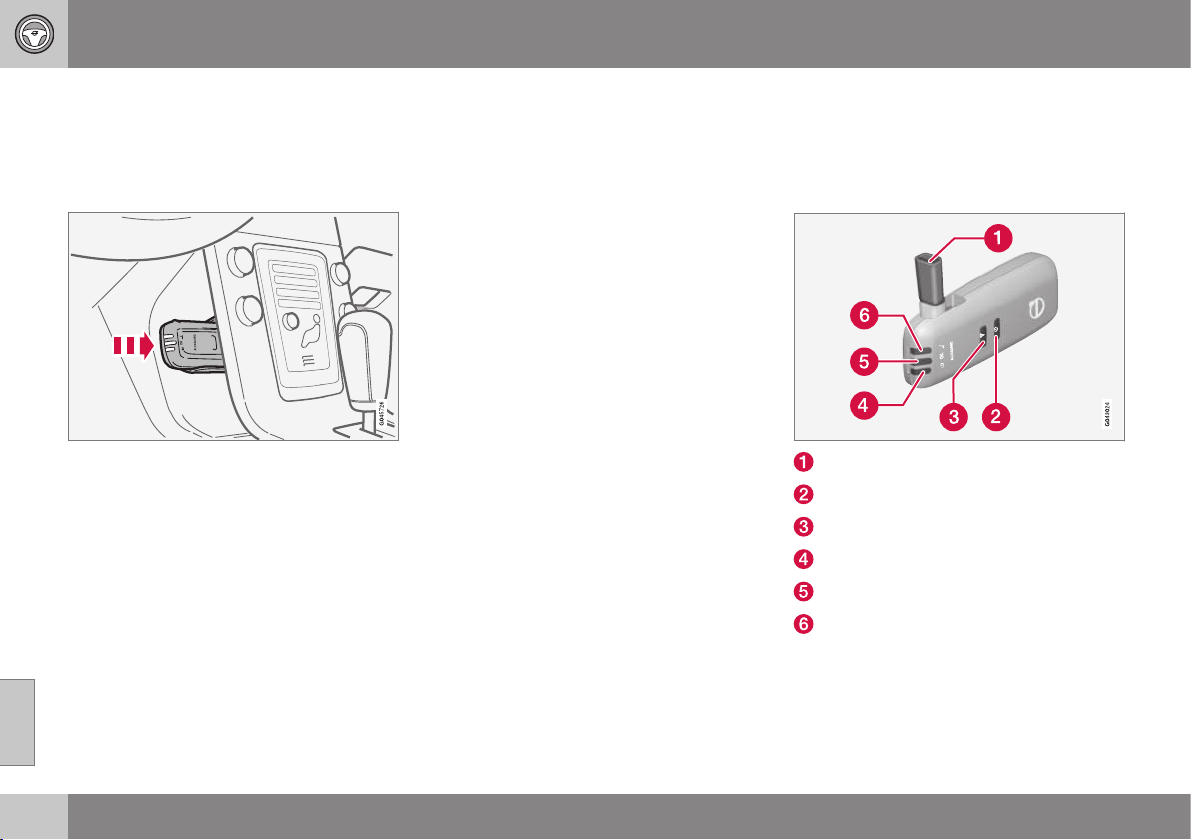
08 Starting and driving
08
264
* Option/accessory, for more information, see Introduction.
Alcohol lock* - storage
Store the alcohol lock in its holder. Release
the handheld unit by depressing it slightly in
its holder and releasing it - it then springs out
and can be removed from the holder.
Handheld unit storage and charging station.
•
Replace the handheld unit in the holder
by pushing it in until it engages.
•
Store the handheld unit in the holder -
this provides it with the best protection
and keeps its batteries fully charged.
Related information
•
Alcohol lock* (p. 263)
•
Alcohol lock* - functions and operation
(p. 263)
•
Alcohol lock* - before starting the engine
(p. 264)
•
Alcohol lock* - to bear in mind (p. 266)
•
Alcohol lock* - symbols and text mes-
sages (p. 267)
Alcohol lock* - before starting the
engine
The alcohol lock is activated automatically
and is then ready for use when the car is
opened.
Nozzle for breath test.
Switch.
Transmission button.
Lamp for battery status.
Lamp for result of breath test.
Lamp indicates ready for breath test.
1. When the indicator lamp (6) is green the
alcohol lock is ready for use.
2. Withdraw the alcohol lock from its holder.
If the alcohol lock is outside the car when
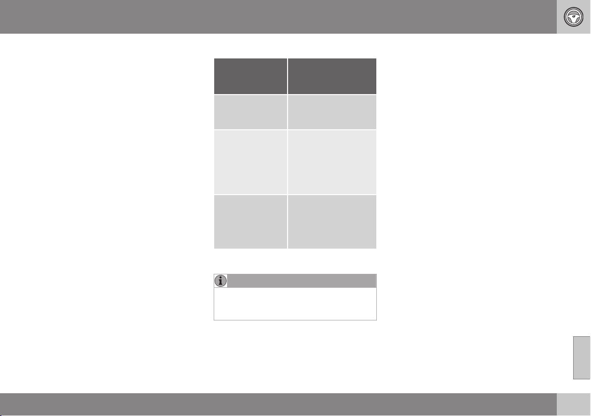
08 Starting and driving
08
* Option/accessory, for more information, see Introduction.
265
it is unlocked then it must first be acti-
vated with the switch (2).
3. Lift up the nozzle (1), take a deep breath
and blow with an even pressure until a
"click" is heard after approx. 5 seconds.
The result will be one of the alternatives in
the following table Result after breath
test.
4. If no message is shown then the trans-
mission to the car may have failed - in
which case, press the button (3) to trans-
mit the result to the car manually.
5. Fold down the nozzle and refit the alcohol
lock in its holder.
6. Start the engine following an approved
breath test within 5 minutes - otherwise it
must be repeated.
Result after breath test
Indicator lamp
(5) + Display
text
Specification
Green lamp +
Alcoguard
Approved test
Start the engine - no
alcohol content meas-
ured.
Yellow lamp +
Alcoguard
Approved test
Engine starting possi-
ble - measured alco-
hol content is above
0.1 mg/ml but below
the limit value in
force
A
.
Red lamp + Dis-
approved test
Wait 1 minute to
try again
Engine starting not
possible - measured
alcohol content is
above the limit value
in force
A
.
A
Limit values vary from country to country. Find out what
applies in your country. See also Alcohol lock* (p. 263).
NOTE
After a completed period of driving, the
engine can be restarted within 30 minutes
without a new breath test.
Related information
•
Alcohol lock* (p. 263)
•
Alcohol lock* - functions and operation
(p. 263)
•
Alcohol lock* - storage (p. 264)
•
Alcohol lock* - to bear in mind (p. 266)
•
Alcohol lock* - symbols and text mes-
sages (p. 267)
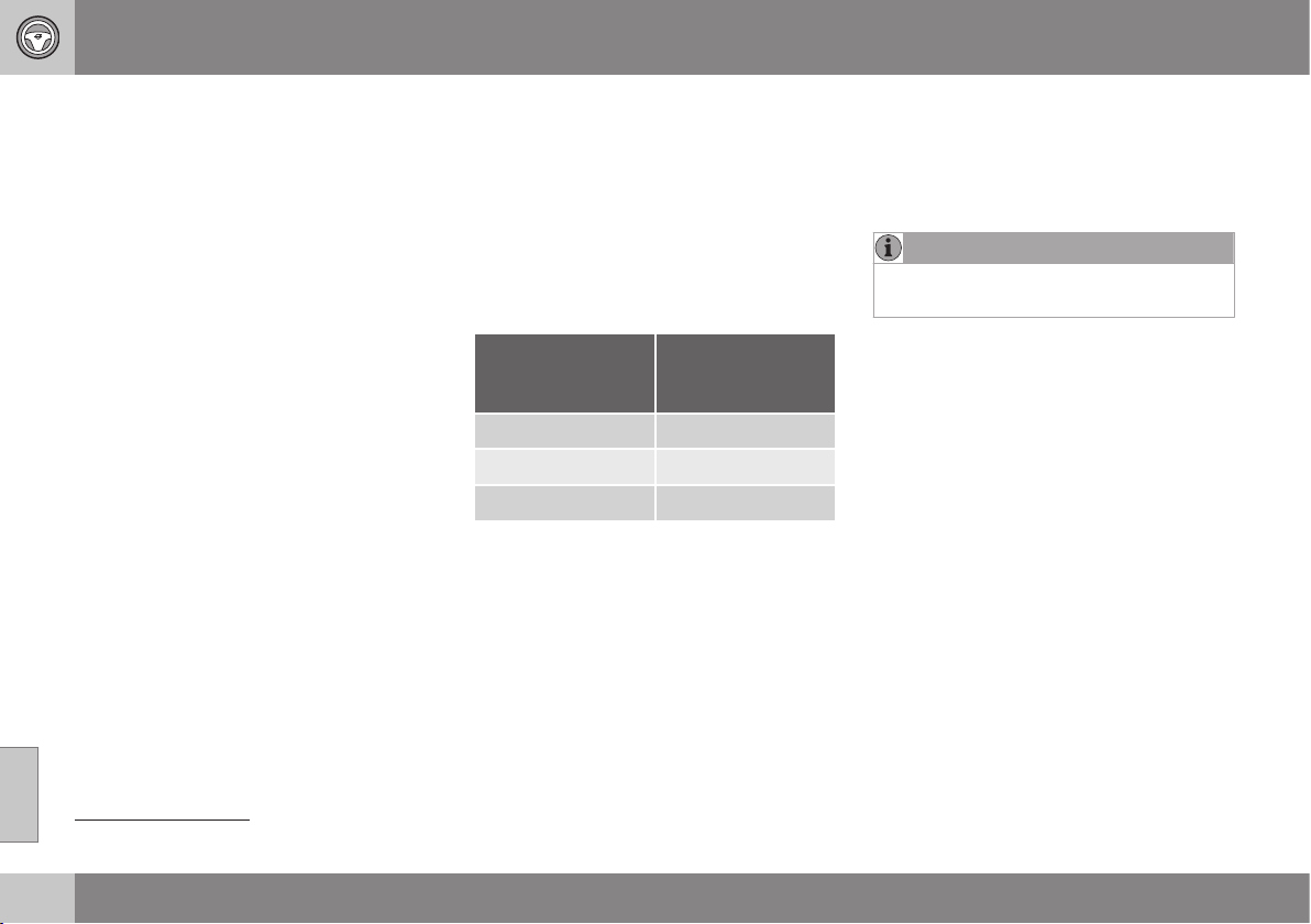
08 Starting and driving
08
266
* Option/accessory, for more information, see Introduction.
Alcohol lock* - to bear in mind
In order to obtain correct function and as
accurate a measurement result as possible:
•
Avoid eating or drinking
approx. 5 minutes before the breath test.
•
Avoid excess windscreen washing - the
alcohol in the washer fluid may result in
an incorrect measurement result.
Change of driver
In order to ensure that a new breath test is
carried out in the event of a change of driver -
depress the switch (2) and the send button (3)
simultaneously for approx. 3 seconds. At
which point the car returns to start inhibition
mode and a new approved breath test is
required before starting the engine.
Calibration and service
The alcohol lock must be checked and cali-
brated at a workshop
1
every 12 months.
30 days before recalibration is necessary the
combined instrument panel shows the mes-
sage
Alcoguard Calibration required See
manual. If calibration is not carried out within
these 30 days then normal engine starting will
be blocked - only starting with the Bypass
function will then be possible, see the follow-
ing heading "Emergency situation".
The message can be cleared by pressing the
send button (3) once. Otherwise it extin-
guishes on its own after approx. 2 minutes
but then reappears each time the engine is
started - only recalibration at a workshop
1
can clear the message permanently.
Cold or hot weather
The colder the weather the longer it takes
before the alcohol lock is ready for use:
Temperature (ºC) Maximum heat-
ing time (sec-
onds)
+10 to +85 10
-5 to +10 60
-40 to -5 180
At temperatures below -20 ºC or above
+60 ºC the alcohol lock requires additional
power supply. The combined instrument
panel shows
Alcoguard Please insert
power cable. In which case, connect the
power supply cable from the glovebox and
wait until indicator lamp (6) is green.
In extremely cold weather the heating time
can be reduced by taking the alcohol lock
indoors.
Emergency situation
In the event of an emergency situation or the
alcohol lock is out of order, it is possible to
bypass the alcohol lock in order to drive the
car.
NOTE
All Bypass activation is logged and saved
in memory, see Recording data (p. 18).
After the Bypass function has been activated
the combined instrument panel shows
Alcoguard Bypass enabled the whole time
while driving and can only be reset by a work-
shop
1
.
The Bypass function can be tested without
the error message being logged - in which
case, carry out all the steps without starting
the car. The error message is cleared when
the car is locked.
When the alcohol lock is installed, either the
Bypass or Emergency function is selected as
the bypassing option. This setting can be
changed afterwards at a workshop
1
.
Activating the Bypass function
•
Depress and hold the left-hand stalk
switch OK button and the button for haz-
ard warning flashers simultaneously for
approx. 5 seconds - the combined instru-
ment panel first shows
Bypass activated
1
An authorised Volvo workshop is recommended.

08 Starting and driving
08
* Option/accessory, for more information, see Introduction.
267
Please wait for 1 minute and then
Alcoguard Bypass enabled - after
which the engine can be started.
This function can be activated more than
once. The error message shown during driv-
ing can only be cleared at a workshop
1
.
Activating the Emergency function
•
Depress and hold the left-hand stalk
switch OK button and the button for haz-
ard warning flashers simultaneously for
approx. 5 seconds - the combined instru-
ment panel shows
Alcoguard Bypass
enabled and the engine can be started.
This function can be used once, after which a
reset must be made at a workshop
1
.
Related information
•
Alcohol lock* - functions and operation
(p. 263)
•
Alcohol lock* - storage (p. 264)
•
Alcohol lock* - before starting the engine
(p. 264)
•
Alcohol lock* (p. 263)
•
Alcohol lock* - symbols and text mes-
sages (p. 267)
Alcohol lock* - symbols and text
messages
In addition to the previously described mes-
sages related to how the alcohol lock works
before starting the engine (p. 264) the com-
bined instrument panel's display can also
show the following:
Display text Meaning/Action
Alcoguard
Restart possi-
ble
The engine has been
switched off for less
than 30 minutes -
engine starting possible
without new test.
Alcoguard
Service
required
Contact a workshop
A
.
Alcoguard No
signal
received
Transmission failed -
send manually with but-
ton (3) or take a new
breath test.
Alcoguard
Please try
again
Test failed - take a new
breath test.
Alcoguard
Please blow
longer
Blowing too short - blow
for longer.
Display text Meaning/Action
Alcoguard
Please blow
softer
Blowing too hard - blow
more gently.
Alcoguard
Please blow
harder
Blowing too weak -
blow harder.
Alcoguard
preheating
Please wait
Heating not finished -
wait for text
Alcoguard
Please blow for 5 sec-
onds.
A
An authorised Volvo workshop is recommended.
Related information
•
Alcohol lock* (p. 263)
•
Alcohol lock* - functions and operation
(p. 263)
•
Alcohol lock* - storage (p. 264)
•
Alcohol lock* - before starting the engine
(p. 264)
•
Alcohol lock* - to bear in mind (p. 266)
1
An authorised Volvo workshop is recommended.
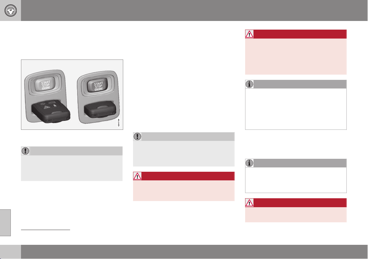
08 Starting and driving
08
268
* Option/accessory, for more information, see Introduction.
Starting the engine
The engine is started and switched off using
the remote control key and the START/STOP
ENGINE button.
Ignition switch with remote control key extrac-
ted/inserted and START/STOP ENGINE button.
IMPORTANT
Do not press in the remote control key
incorrectly turned - hold the end with the
detachable key blade, see Detachable key
blade - detaching/attaching (p. 163).
1. Insert the remote control key in the igni-
tion switch and press it in to its end posi-
tion. Note that if the car is equipped with
alcohol lock* then a breath test must first
be approved before the engine can be
started. For more information on the
Alcohol lock, see Alcohol lock* (p. 263).
2.
Hold the clutch pedal fully depressed
2
.
(For cars with automatic gearbox -
Depress the brake pedal.)
3. Press the START/STOP ENGINE button
and then release it.
When the engine is started the starter motor
works until the engine is started or until its
overheating protection triggers.
IMPORTANT
If the engine fails to start after 3 attempts -
wait for 3 minutes before making a further
attempt. Starting capacity increases if the
battery is allowed to recover.
WARNING
Never remove the remote control key from
the ignition switch after starting the engine
or when the car is being towed.
WARNING
Always remove the remote control key
from the ignition switch when leaving the
car, and make sure that the key position is
0 - in particular if there are children in the
car. For information on how this works -
see Key positions (p. 76).
NOTE
The idling speed can be noticeably higher
than normal for certain engine types during
cold starting. This is done in order that the
emissions system can reach normal oper-
ating temperature as quickly as possible,
which minimises exhaust emissions and
protects the environment.
Keyless drive*
Follow steps 2-3 for keyless (p. 166) starting
of the engine.
NOTE
A prerequisite for the engine to start is that
one of the car's remote control keys with
the Keyless drive function is in the passen-
ger compartment or cargo area.
WARNING
Never remove the remote control key from
the car while driving or during towing.
2
If the car is moving then it is enough to press the START/STOP ENGINE button to start the engine.

08 Starting and driving
08
269
Related information
•
Switching off the engine (p. 269)
Switching off the engine
The engine is switched off using the START/
STOP ENGINE button.
To stop the engine:
•
Press START/STOP ENGINE - the
engine stops.
If the gear selector is not in P position or if
the car is moving:
•
Press twice on START/STOP ENGINE or
hold the button depressed until the
engine stops.
Related information
•
Key positions (p. 76)
Steering lock
The steering lock makes steering difficult if
the car is e.g. taken unlawfully. A mechanical
noise may be noticed when the steering lock
unlocks or locks.
Function
•
The steering lock is activated when the
driver's door is opened after the engine
has been switched off.
•
The steering lock is deactivated when the
remote control key is in the ignition
switch
3
and the START/STOP ENGINE
button is depressed.
Related information
•
Starting the engine (p. 268)
•
Key positions (p. 76)
•
Steering wheel (p. 82)
3
Cars with Keyless drive only need to have a remote control key inside the passenger compartment.
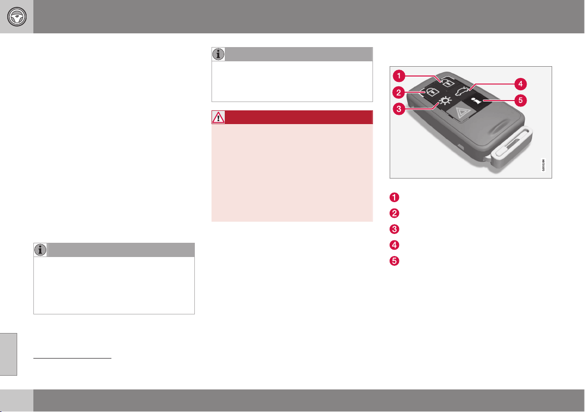
08 Starting and driving
08
270
* Option/accessory, for more information, see Introduction.
Remote start (ERS)*
Remote start (ERS – Engine Remote Start)
means that the car's engine can be started
remotely in order to warm up/cool down the
passenger compartment before departure.
ERS is activated via key and/or via Volvo On
Call*.
The climate control starts with the same set-
tings that were being used when the car was
parked.
An ERS-started engine is activated for a
maximum of 15 minutes, then it is switched
off. After two ERS-activations the engine
must be started in the normal way before
ERS can be re-used.
ERS is only available in cars with automatic
gearbox and cars that have a bonnet switch
4
installed.
NOTE
The service life of the remote control key's
battery is affected by the ERS function. In
the event of frequent use of ERS the bat-
tery should therefore be changed once per
year, see Remote control key - replacing
the battery (p. 165).
NOTE
Follow local/national rules/regulations on
idling. Also take into account the local/
national rules/regulations regarding the
noise level when the engine is running.
WARNING
To remote-start the engine, the following
criteria must be met:
•
The car must be supervised.
•
There must be no people or animals
inside or around the car.
•
The car must not be parked in a
closed, unventilated area - the exhaust
gases may seriously injure humans
and animals.
Related information
•
Remote start (ERS) - operation (p. 270)
•
Remote start (ERS) - symbols and mes-
sages (p. 272)
Remote start (ERS) - operation
The key's buttons for remote start.
Unlocking
Locking
Approach lighting
Unlocking, boot lid
Information
5
Remote starting the engine
To be able to remotely start the engine the
car must be locked and the bonnet closed.
Proceed as follows:
4
Available in the XC60, cars with alarm, most cars with 4-cylinder engines or if ERS is selected for new construction.
5
Only on PCC key, see Remote control key with PCC* - unique functions (p. 161).
08 Starting and driving
08
* Option/accessory, for more information, see Introduction.
271
1. Briefly press on the key's button (2).
2. Follow this immediately afterwards with a
long press - at least 2 seconds - on
button (3).
If the conditions for ERS are fulfilled then the
following takes place:
1. The direction indicators flash quickly sev-
eral times.
2. The engine starts.
3. The direction indicators illuminate with a
constant glow for 3 seconds to verify that
the engine has started.
NOTE
After remote starting, the car continues to
be locked but with deactivated movement
detector*.
With PCC
6
key
The light indication for Approach
lighting
7
flashes several times when
the button is pressed and then goes
to constant glow if all criteria for
ERS have been fulfilled. However, this does
not mean that ERS has started the engine.
To check whether ERS has started the
engine, the user can press the button (5) - if
the engine has started, there is a light indica-
tion by the buttons (2) and (3).
Active functions
The following functions are activated with a
remote started engine:
•
Ventilation system
•
Audio/video system
•
Approach lighting.
Deactivated functions
The following functions are deactivated with a
remote started engine:
•
headlamps
•
Position lamps
•
Number plate lighting
•
Windscreen wiper.
ERS is interrupted
The following steps switch off an ERS-started
engine:
•
The remote control key's button
(1), (2) or (4) is depressed
•
The car is unlocked
•
A door is opened
•
Accelerator pedal or brake pedal is
depressed
•
The gear selector is moved out of P posi-
tion
•
Active ERS time exceeds 15 minutes.
When an ERS-started engine is switched off,
the direction indicators illuminate with a con-
stant glow for 3 seconds.
Related information
•
Remote start (ERS)* (p. 270)
•
Remote start (ERS) - symbols and mes-
sages (p. 272)
6
For more information on the PCC key, see Remote control key with PCC* - unique functions (p. 161).
7
For more information on Approach lighting, see Remote control key - functions (p. 159) and Approach lighting (p. 96).
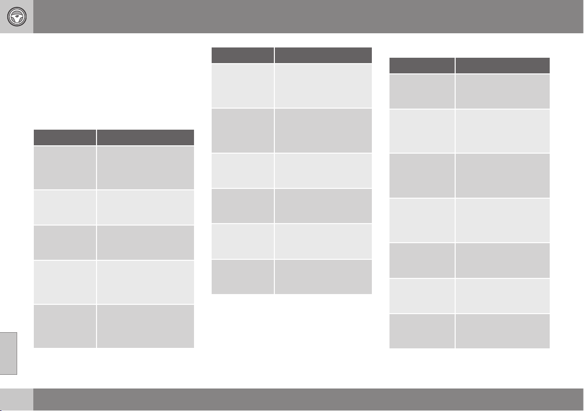
08 Starting and driving
08
272
Remote start (ERS) - symbols and
messages
In situations where the ERS function fails or is
interrupted, a symbol is shown in the com-
bined instrument panel, supplemented by an
explanatory text message.
ERS function unavailable
Message Specification
No remote
start Too
many tries
ERS unavailable
because a maximum of 2
ERS activations in suc-
cession are allowed.
No remote
start Low fuel
level
ERS unavailable
because fuel level too
low.
No remote
start Gear not
in P
ERS unavailable
because gear selector is
not in P position.
No remote
start Driver in
car
ERS unavailable
because someone is in
the passenger compart-
ment.
No remote
start Low
battery
ERS unavailable due to
low battery voltage.
Charge the battery by
starting the engine.
Message Specification
No remote
start Engine
warning
ERS unavailable due to
warning message from
engine. Contact a work-
shop
A
.
No remote
start Engine
coolant level
low
ERS unavailable due to
error message from
cooling system, see
Coolant - level (p. 367).
No remote
start Door
open
ERS unavailable
because a door/boot lid
was not closed.
No remote
start Bonnet
open
ERS did not activate
because the bonnet was
not closed.
No remote
start Car not
locked
ERS unavailable
because the car was not
locked.
No remote
star Key in
car
ERS did not activate
because the key was in
the car.
A
An authorised Volvo workshop is recommended.
Interrupted ERS function
Message Specification
Remote start
off Gear not in
P
ERS interrupted
because gear selector
is not in P position.
Remote start
off Driver in
car
ERS interrupted
because someone is in
the passenger compart-
ment.
Remote start
off Engine
warning
ERS interrupted due to
error message from
engine. Contact a work-
shop
A
.
No remote
start Engine
coolant level
low
ERS interrupted due to
error message from
cooling system.
Remote start
off Bonnet
open
ERS interrupted
because the bonnet is
open.
Remote start
off Low bat-
tery
ERS interrupted since
the battery voltage is
too low.
Remote start
off Low fuel
level
ERS interrupted since
the fuel level is too low.
A
An authorised Volvo workshop is recommended.
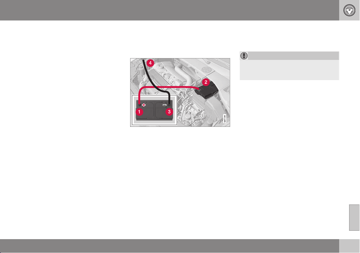
08 Starting and driving
08
}}
* Option/accessory, for more information, see Introduction.
273
Related information
•
Remote start (ERS)* (p. 270)
•
Remote start (ERS) - operation (p. 270)
Jump starting with battery
If the starter battery (p. 379) is discharged
then the car can be started with current from
another battery.
When jump starting the car, the following
steps are recommended to avoid short cir-
cuits or other damage:
1. Set the car's electrical system in key
position 0, see Key positions - functions
at different levels (p. 76).
2. Check that the donor battery has a volt-
age of 12 V.
3. If the donor battery is installed in another
car - switch off the donor car's engine
and make sure that the two cars do not
touch each other.
4. Connect one of the red jump lead's
clamps to the donor battery's positive
terminal (1).
IMPORTANT
Connect the start cable carefully to avoid
short circuits with other components in the
engine compartment.
5. Open the clips on the front cover of the
battery in your car and remove the cover,
see Starter battery - replacement
(p. 381).
6. Connect the red jump lead's other clamp
onto the car's positive terminal (2).
7. Connect one of the black jump lead's
clamps to the donor battery's negative
terminal (3).
8. Connect the other clamp to a grounding
point, e.g. right-hand engine mounting at
the top, the outer screw head (4).
9. Check that the jump lead clamps are
affixed securely so that there are no
sparks during the starting attempt.
10. Start the engine of the "donor car" and
allow it to run a few minutes at a speed
slightly higher than idle
approx. 1500 rpm.
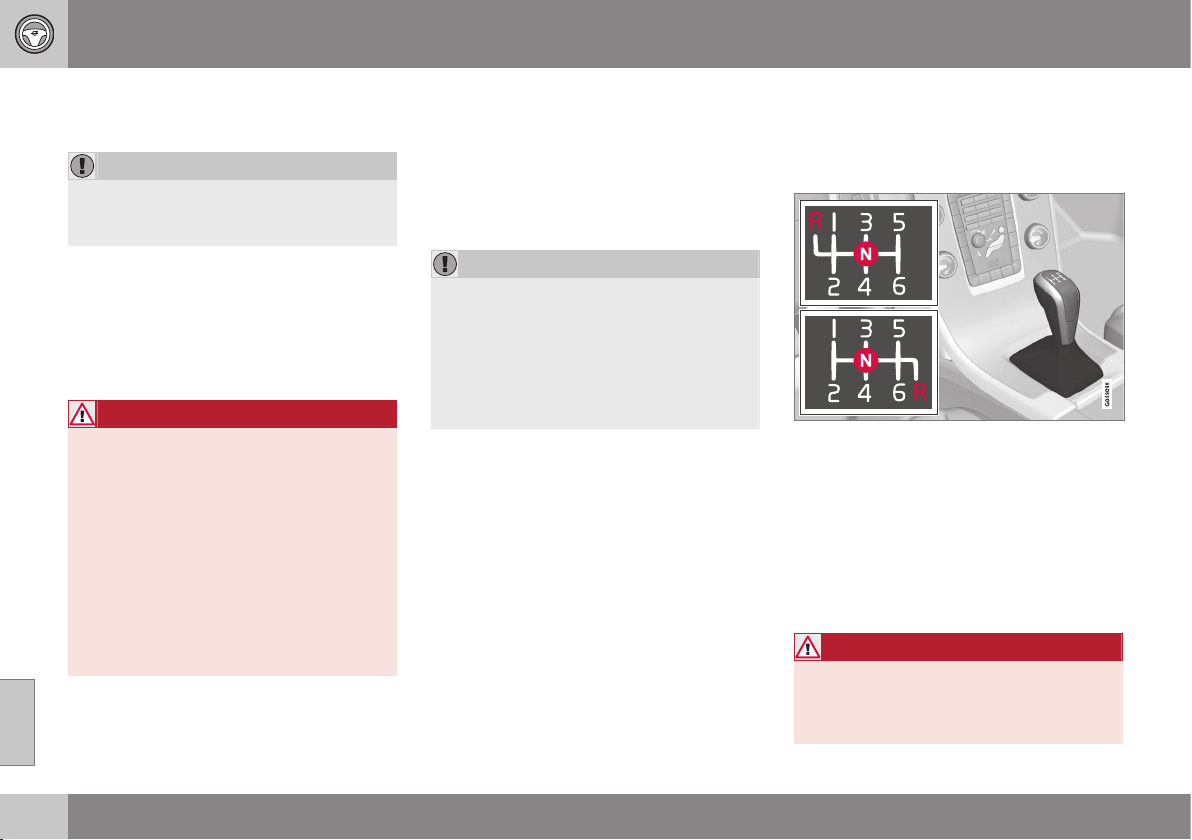
||
08 Starting and driving
08
274
* Option/accessory, for more information, see Introduction.
11. Start the engine in the car with the dis-
charged battery.
IMPORTANT
Do not touch the crocodile clips during the
start procedure. There is a risk of sparks
forming.
12. Remove the jump leads in reverse order -
first the black and then the red.
> Make sure that none of the black jump
lead's clamps comes into contact with
the battery's positive terminal or the
clamp connected to the red jump lead.
WARNING
•
The battery can generate oxyhydrogen
gas, which is highly explosive. A spark
can be formed if a jump lead is con-
nected incorrectly, and this can be
enough for the battery to explode.
•
The battery contains sulphuric acid,
which can cause serious burns.
•
If sulphuric acid comes into contact
with eyes, skin or clothing, flush with
large quantities of water. If acid
splashes into the eyes - seek medical
attention immediately.
Related information
•
Starting the engine (p. 268)
Gearboxes
There are two main types of gearbox. Manual
gearbox and automatic gearbox.
•
Manual gearbox (p. 274)
•
Automatic gearbox - Geartronic (p. 276)
and Powershift (p. 279)
IMPORTANT
To prevent damage to any drive system
components, the working temperature of
the gearbox is checked. If there is a risk of
overheating, a warning symbol is illumi-
nated in the combined instrument panel in
conjunction with a text message being
shown. Follow the recommendation given
in the text message.
Related information
•
Automatic gearbox -- Geartronic*
(p. 276)
Manual gearbox
The function of the gearbox is to change the
gear ratio depending on speed and power
requirements.
Gearshift pattern 6-speed gearbox.
The 6-speed box is available in two versions -
reverse gear position differs between them.
Look at the actual gearshift pattern imprinted
on the gear lever.
•
Depress the clutch pedal fully during
each gear change.
•
Take your foot off the clutch pedal
between gear changes.
WARNING
Always apply the parking brake when
parking on a slope - leaving the car in gear
is not sufficient to hold the car in all situa-
tions.

08 Starting and driving
08
* Option/accessory, for more information, see Introduction.
275
Reverse gear inhibitor
The reverse gear inhibitor hinders the possi-
bility of mistakenly attempting to engage
reverse gear during normal forward travel.
•
Follow the gearing pattern printed on the
gear lever and start from neutral position,
N before moving it to R position.
•
Engage reverse gear only when the car is
stationary.
NOTE
With the upper variant of the shifting pat-
tern for 6-speed gearbox (see previous
illustration) - first press down the gear
lever in the N position in order to engage
reverse gear.
Related information
•
Gearboxes (p. 274)
•
Transmission fluid - grade and volume
(p. 418)
Gear shift indicator*
The gear shift indicator notifies the driver
when it is appropriate to engage the next
higher or lower gear.
An essential detail in connection with environ-
mental driving is to drive in the right gear and
to change gear in good time.
An indicator is available as an aid on certain
variants - GSI (Gear Shift Indicator) - which
notifies the driver when it is appropriate to
engage the next higher or lower gear in order
to obtain the lowest possible fuel consump-
tion.
However, taking into consideration characte-
ristics such as performance and vibration-free
running, it may be advantageous to change
gear at a higher engine speed. The framed
number indicates the current gear.
Manual gearbox
Gear shift indicator for man-
ual gearbox. Only one
marker is illuminated at a
time - during normal driving
it is only illuminated in the
centre.
At the recommended upshift the cursor illumi-
nates "+", and at the recommended down-
shift the cursor illuminates "-" (marked red in
the illustration).
Automatic gearbox
Combined instrument panel "Digital" with
gear shift indicator.
The framed number indicates the current
gear.
With "Analogue" combined
instrument panel, the gear
positions and indicator
arrows are displayed in its
centre.
Related information
•
Manual gearbox (p. 274)
•
Automatic gearbox -- Geartronic*
(p. 276)
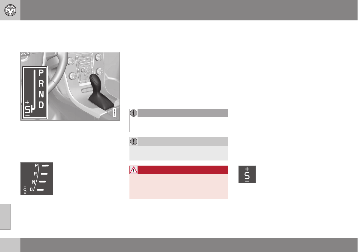
08 Starting and driving
08
276
* Option/accessory, for more information, see Introduction.
Automatic gearbox -- Geartronic*
The Geartronic gearbox has two different gear
modes - Automatic and Manual.
D: Automatic gear positions. +/–: Manual gear
positions. S: Sport mode*.
Combined instrument panel (p. 61) shows the
position of the gear selector using the follow-
ing indications:
P, R, N, D, S*, 1, 2, 3 etc.
Gear positions
Automatic gear positions are
indicated on the right of the
combined instrument panel.
(Only one marker is illumi-
nated at a time - the one
showing the current gear
selector position.)
Symbol "S" for Sport mode is ORANGE when
the mode is active.
Parking position - P
Select P position when starting the engine or
when the car is parked.
In order to be able to move the gear selector
from the P position, the brake pedal must be
depressed and key position must be II, see
Key positions - functions at different levels
(p. 76).
The gearbox is mechanically blocked when
the P position is engaged. Also apply the
parking brake (p. 298) when the car is
parked.
NOTE
The gear selector must be in P position to
allow the car to be locked and alarmed.
IMPORTANT
The car must be stationary when posi-
tion P is selected.
WARNING
Always apply the parking brake when
parking on a slope - the automatic trans-
mission's P position is not sufficient to
hold the car in all situation.
Reverse position - R
The car must be stationary when R position is
selected.
Neutral position - N
No gear is engaged and the engine can be
started. Apply the parking brake if the car is
stationary with the gear selector in N position.
In order to be able to move the gear selector
from N to another gear position, the brake
pedal must be depressed and key position
must be II, see Key positions - functions at
different levels (p. 76).
Drive position - D
D is the normal driving position. Shifting up
and down takes place automatically based on
the level of acceleration and speed. The car
must be stationary when the gear selector is
moved to D position from R position.
Geartronic – Manual gear positions
(+S-)
The driver can also change gear manually
using the Geartronic automatic gearbox. The
car engine-brakes when the accelerator pedal
is released.
The manual gear position is reached
by moving the lever to the side from
position D to the end position at
"+S-". The combined instrument
panel's symbol "+S-" changes colour from
WHITE to ORANGE and the digits
1, 2, 3 etc.
are displayed in a box, corresponding to the
gear that has just been selected.
•
Move the lever forwards towards "+"
(plus) to change up a gear and release the
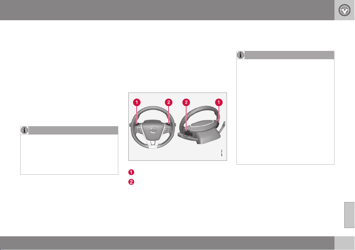
08 Starting and driving
08
}}
* Option/accessory, for more information, see Introduction.
277
lever, which returns to its rest position
between + and –.
or
•
Pull the lever back towards "–" (minus) to
change down a gear and release it.
The manual gearshift mode "+S–" can be
selected at any time while driving.
Geartronic automatically shifts down if the
driver allows the speed to decrease lower
than a level suitable for the selected gear, in
order to avoid jerking and stalling.
To return to automatic driving mode:
•
Move the lever to the side to the end
position at D.
NOTE
If the gearbox has a Sport programme
then the gearbox will only become manual
after the gear selector has been moved
forwards or backwards in its "+S–" posi-
tion. The combined instrument panel then
changes indication from
S to show which
of the gears 1, 2, 3 etc. is engaged.
Paddles*
As a supplement to manual gear changing
with the gear selector there are also controls
located on the steering wheel, so-called
"paddles".
To be able to change gear with the steering
wheel paddles they must first be activated.
This is by means of pulling one of the paddles
toward the steering wheel - the combined
instrument panel then changes indication
from "D" to a figure, which indicates the cur-
rent gear.
To then change gear one step:
•
Pull one of the paddles backwards -
towards the steering wheel - and release.
Both steering wheel "paddles".
"-": Selects the next lower gear.
"+": Selects the next higher gear.
A gear change occurs at each pull of the pad-
dle provided that the engine speed does not
leave the permitted range.
After each gear change the combined instru-
ment panel changes figure to show the cur-
rent gear.
NOTE
Automatic deactivation
If the steering wheel paddles are not used
then they are deactivated after a short time
- this is indicated when the combined
instrument panel switches indication, from
the figure for the current gear back to "D".
The exception is during engine braking -
then the paddles are activated as long as
engine braking is in progress.
Manual deactivation
The steering wheel paddle shifters can
also be deactivated manually:
•
Pull both paddles toward the steering
wheel and hold until the combined
instrument panel changes character
from the figure for the current gear to
"D".
The paddles can also be used with the gear
selector in Sport mode* - then the paddles
are constantly activated without being deacti-
vated.

||
08 Starting and driving
08
278
* Option/accessory, for more information, see Introduction.
Geartronic - Sport mode* (S)
8
The Sport programme provides
sportier characteristics and allows
higher engine speed for the gears.
At the same time it responds more
quickly to acceleration. During active driving,
the use of a lower gear is prioritised, leading
to a delayed upshift.
To activate Sport mode:
•
Move the gear selector to the side from D
position to the end position at "+S–" - the
combined instrument panel changes indi-
cation from
D to S.
Sport mode can be selected at any time while
driving.
Geartronic - Winter mode
It can be easier to pull away on slippery roads
if 3rd gear is engaged manually.
1. Depress the brake pedal and move the
gear selector from D position to the end
position at "+S–" - the combined instru-
ment panel changes indication from
D to
the figure
1
9
.
2. Scroll up to gear 3 by pushing the lever
forward towards "+" (plus) twice - the dis-
play shifts the indication from
1 to 3.
3. Release the brake and accelerate care-
fully.
The gearbox "winter mode" means that the
car moves off with a lower engine speed and
reduced engine power on the drive wheels.
Kick-down
When the accelerator pedal is pressed all the
way to the floor (beyond the position normally
regarded as full acceleration) a lower gear is
immediately engaged. This is known as kick-
down.
If the accelerator is released from the kick-
down position, the gearbox automatically
changes up.
Kick-down is used when maximum accelera-
tion is needed, such as for overtaking.
Safety function
To prevent overrevving the engine, the gear-
box control program has a protective down-
shift inhibitor which prevents the kick-down
function.
Geartronic does not permit downshifting/
kick-down which would result in an engine
speed high enough to damage the engine.
Nothing happens if the driver still tries to shift
down in this way at high engine speed – the
original gear remains engaged.
When kick-down is activated the car can
change one or more gears at a time depend-
ing on engine speed. The car changes up
when the engine reaches its maximum speed
in order to prevent damage to the engine.
Towing
If the car has to be towed - see important
information in the section Towing (p. 318).
Related information
•
Transmission fluid - grade and volume
(p. 418)
•
Automatic gearbox -- Powershift*
(p. 279)
•
Gearboxes (p. 274)
8
With certain engines only.
9
If the car has Sport mode* then "S" is shown first.
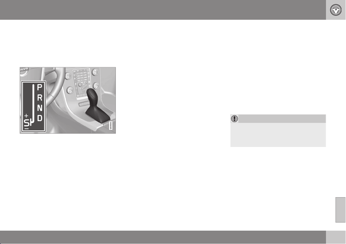
08 Starting and driving
08
}}
* Option/accessory, for more information, see Introduction.
279
Automatic gearbox -- Powershift*
The Powershift automatic gearbox transmits
the motive force from the engine to the drive
wheels with double mechanical clutch discs,
as opposed to Geartronic which instead uses
a hydraulic torque converter.
D: Automatic gear positions. +S–: Manual gear
positions. S: Sport mode*.
Powershift transmission operates in the same
way and has similar controls and functions as
the Geartronic automatic transmission.
One exception is the function "Geartronic -
Winter mode" (p. 276):
•
Powershift enables driving away on a
slippery road surface if 2nd gear is
engaged manually - instead of 3rd gear
with Geartronic.
Towing
The model with Powershift transmission
should not be towed as it is dependent on the
engine running in order to receive sufficient
lubrication. If towing (p. 318) still has to take
place, the route must be as short as possible
and then at very low speed.
In the event of uncertainty as to whether the
car is equipped with Powershift or Geartronic
transmission, this can be verified by checking
the designation on the gearbox label under
the bonnet, Type designations (p. 405). The
designation ”MPS6” means that it is
Powershift transmission - otherwise it is
Geartronic automatic transmission.
See also important information in section
Towing (p. 318).
To bear in mind
The transmission's double clutch has over-
load protection that is activated if it becomes
too hot, e.g. if the car is held stationary with
the accelerator pedal on an uphill gradient for
a long time.
Overheated transmission causes the car to
shake and vibrate, and the warning symbol
illuminates and the combined instrument
panel shows a message. The transmission
can also overheat during slow driving in
queues (10 km/h or slower) on an uphill gradi-
ent, or with a trailer hitched. The gearbox
cools down when the car is stationary, with
foot brake depressed and the engine running
at idling speed.
Overheating during slow driving in queues
can be avoided by driving in stages:
•
Stop the car and wait with your foot on
the brake pedal until there is a moderate
distance to the traffic ahead, drive for-
ward a short distance, and then wait
another moment with your foot on the
brake pedal.
IMPORTANT
Use the foot brake to hold the car station-
ary on an uphill gradient - do not hold the
car with the accelerator pedal. The gear-
box could then overheat.
Text message and action
In some situations the combined instrument
panel may show a text message at the same
time as a symbol is illuminated.
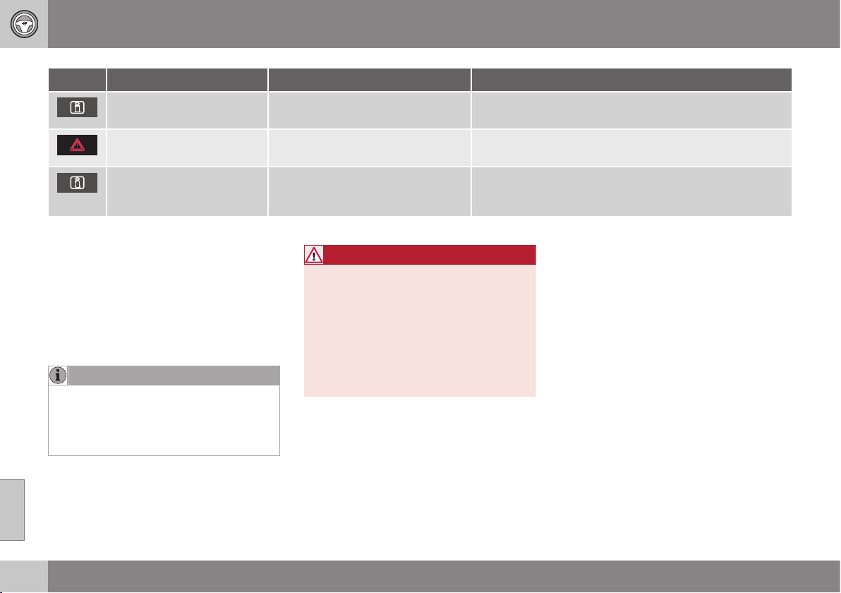
||
08 Starting and driving
08
280
* Option/accessory, for more information, see Introduction.
Symbol Message Driving characteristics Action
Transmission hot Brake to
hold
Difficulty in maintaining even speed
at constant engine speed.
Transmission overheated. Keep the car stationary using the
foot brake
A
.
Transmission hot Park
safely Let engine run
Significant pulling in the car's trac-
tion.
Transmission overheated. Park the car immediately in a safe
manner
A
.
Transmission cooling Let
engine run
No drive due to overheated gearbox. Transmission overheated. For fastest cooling: Run the
engine at idling speed with the gear lever in the N or P posi-
tion until the message clears.
A
For fastest cooling: run the engine at idling speed with the gear lever in the N or P position, until the message clears.
The table shows three steps with an
increased degree of seriousness should the
transmission become too hot. In parallel with
the text message, the driver is also advised
that the car's electronics are temporarily
changing the driving characteristics. Follow
the instructions in the text message where
appropriate.
NOTE
The examples in the table are no indication
of the car being defective, but show that a
safety function has been activated with a
view to preventing damage to any of the
car's components.
WARNING
If a warning symbol combined with the text
Transmission hot Park safely Let
engine run is ignored then the heat in the
gearbox may become so high that the
power transmission between engine and
gearbox is temporarily halted in order to
prevent the clutch from malfunctioning -
the car then loses drive and is stationary
until gearbox temperature has cooled to
an acceptable level.
For more possible text messages with their
respective proposals for solutions concerning
automatic gearbox, see Messages (p. 107).
A text message extinguishes automatically
after the action has been carried out or after
one press on the indicator stalk OK button.
Related information
•
Automatic gearbox -- Geartronic* (p. 276)
•
Transmission fluid - grade and volume
(p. 418)
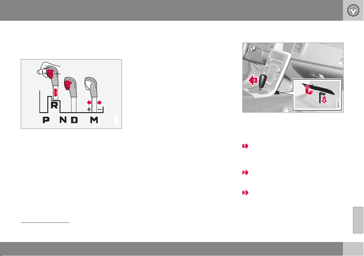
08 Starting and driving
08
}}
281
Gear selector inhibitor
There are two different types of gear selector
inhibitor - mechanical and automatic.
Mechanical gear selector inhibitor
G021351
M: Manual shifting
10
- "+/-"- or "-Sport mode.
The gear selector can be moved forward and
back freely between N and D. Other positions
are locked with a latch that is released with
the inhibitor button on the gear selector.
With the inhibitor button depressed the lever
can be moved forwards or backwards
between P, R, N and D.
Automatic gear selector inhibitor
The automatic gearbox has special safety
systems:
Parking position (P)
Stationary car with engine running:
•
Keep your foot on the brake pedal when
moving the gear selector to another posi-
tion.
Electric gear inhibitor – Shiftlock
Parking position (P)
In order to be able to move the gear selector
from P to other gear positions, the brake
pedal must be depressed and the key posi-
tion (p. 76) must be II.
Shiftlock – Neutral (N)
If the gear selector is in N position and the
car has been stationary for at least 3 seconds
(irrespective of whether the engine is running)
then the gear selector is locked.
In order to be able to move the gear selector
from the N position to another gear position,
the brake pedal must be depressed and the
key position (p. 76) must be II.
Deactivate automatic gear selector
inhibitor
If the car cannot be driven, e.g. due to a flat
starter battery, the gear selector must be
moved from the P position so that the car can
be moved.
Lift the rubber mat in the compartment
behind the centre console and locate a
hole
11
for the key blade (p. 163) in the
bottom of the compartment.
Search for a spring-loaded button down
in the hole with the key blade; depress
the button with the blade and hold.
Move the gear selector from the P posi-
tion and pull up the key blade.
4. Set the rubber mat back in place.
10
The illustration is schematic.
11
There may be 2 holes - one for the key blade and one that fixes the rubber mat.
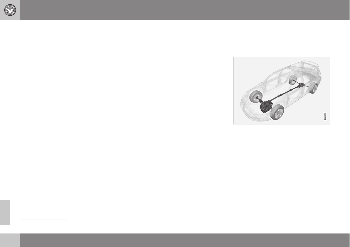
||
08 Starting and driving
08
282
* Option/accessory, for more information, see Introduction.
Related information
•
Automatic gearbox -- Geartronic* (p. 276)
•
Automatic gearbox -- Powershift* (p. 279)
Hill start assist (HSA)*
12
The foot brake can be released before setting
off or reversing uphill - the HSA (Hill Start
Assist) function means that the car does not
roll backwards.
The function means that the pedal pressure in
the brake system remains for several seconds
while the driver's foot is moved from brake
pedal to accelerator pedal.
The temporary braking effect releases after
several seconds or when the driver acceler-
ates.
Related information
•
Starting the engine (p. 268)
All-wheel drive - (AWD)*
Optimal traction is achieved with all-wheel
drive.
All-wheel drive is always available
All-wheel drive (All Wheel Drive) means that
the car is driving all four wheels at the same
time.
The power is automatically distributed
between the front and rear wheels. An elec-
tronically controlled clutch system distributes
the power to the wheels that have the best
grip on the current road surface. This pro-
vides the best traction and prevents wheel
spin. Under normal driving conditions, the
majority of power is transmitted to the front
wheels.
All-wheel drive improves driving safety in rain,
snow and icy conditions.
12
Depends on engine and gearbox combination. HSA not possible with some combinations.
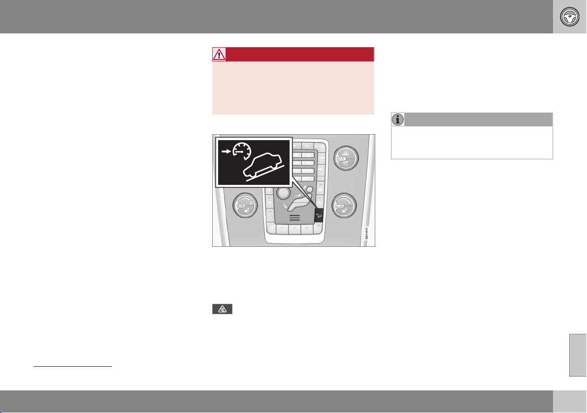
08 Starting and driving
08
}}
* Option/accessory, for more information, see Introduction.
283
Hill Descent Control (HDC)*
13
HDC can be compared to an automatic
engine brake. When you release the accelera-
tor on downhill gradients the car is normally
braked by means of the engine striving for low
engine idling speeds, so-called engine brak-
ing. But the steeper the roadway and the
more load in the car, the faster the car coasts
despite engine braking - the HDC function
compensates for this with automatic brake
intervention.
General information on HDC
HDC makes it possible to increase/reduce
speed on steep downhill gradients, with a
foot only on the accelerator pedal, without
using the foot brake. The sensitivity of the
accelerator pedal decreases and becomes
more precise by means of the full actuation of
the pedal being restricted to adjusting engine
speed within a limited range. The brake sys-
tem brakes itself and provides the car with a
low and even speed, so allowing the driver to
fully focus on steering.
HDC is particularly helpful on steep gradients
with an uneven road surface and slippery
sections. E.g. when launching a boat on a
trailer from a ramp.
WARNING
HDC does not work in all situations but is
designed merely as a supplementary aid.
The driver always bears ultimate responsi-
bility for ensuring that the vehicle is driven
safely.
Function
HDC On/Off.
HDC is activated or deactivated with one of
the centre console's switches. The lamp
within it illuminates when the function is acti-
vated.
When HDC is operating, the combined
instrument panel's symbol illuminates
combined with the text message
Hill
descent control ON.
The function only operates in first gear posi-
tion and in reverse gear. For an automatic
gearbox, gear position 1 must be selected,
which is shown with the figure
1 in the com-
bined instrument panel, see Automatic gear-
box -- Geartronic* (p. 276).
NOTE
HDC cannot be activated on an automatic
gearbox when the gear selector is in posi-
tion D.
Operation
HDC allows the car to roll at a maximum of
10 km/h forwards with engine braking and
7 km/h backwards. However, any speed
within the gear's speed register can be
selected using the accelerator pedal. When
the accelerator pedal is released, the car is
braked quickly to 10 or 7 km/h respectively,
irrespective of the hill's gradient and without
the need for the foot brake.
The brake lights come on automatically when
the function is operating. The driver can brake
or stop the car at any time by using the foot
brake.
HDC is deactivated:
13
Only possible on the S60 Cross Country with AWD.
||
08 Starting and driving
08
284
* Option/accessory, for more information, see Introduction.
•
with the centre console's On/Off button
•
if a gear higher than 1 is selected on a
manual gearbox
•
if a gear higher than 1 is selected on an
automatic gearbox, or if the gear selector
is moved to position D.
The function can be disengaged at any time.
If it takes place on a steep downhill gradient
then the braking effect will not release
directly, but slowly instead.
NOTE
With HDC activated you may experience a
delay between acceleration pedal activa-
tion and engine response.
Related information
•
All-wheel drive - (AWD)* (p. 282)
Start/Stop*
Some engine and gearbox combinations
come fitted with a Start/Stop function which
engages in the event of e.g. stationary traffic
or waiting at traffic lights - the engine is then
switched off temporarily and restarts auto-
matically when the journey is due to continue.
Environmental care is one of Volvo Car Cor-
poration's core values and it influences all of
our operations. This target orientation has
resulted in several separate energy-saving
functions of which Start/Stop is one, all with
the collective task of reducing fuel consump-
tion, which in turn helps to reduce exhaust
emissions.
General information on Start/Stop
The engine is switched off - it becomes quieter
and cleaner.
The Start/Stop function gives the driver the
opportunity for a more active environmentally
conscious way of driving the car by means of
being able to allow the engine to stop auto-
matically, whenever appropriate.
Manual or Automatic
Note that there are differences in the
Start/Stop function depending on whether the
gearbox is manual or automatic.
Related information
•
Start/Stop* - function and operation
(p. 285)
•
Starting the engine (p. 268)
•
Start/Stop* - settings (p. 289)
•
Start/Stop* - the engine does not auto-
start (p. 288)
•
Start/Stop* - the engine auto-starts
(p. 287)
•
Start/Stop* - the engine does not stop
(p. 286)
•
Start/Stop* - involuntary stop manual
gearbox (p. 289)
•
Start/Stop* - symbols and messages
(p. 291)
•
Battery - Start/Stop (p. 383)
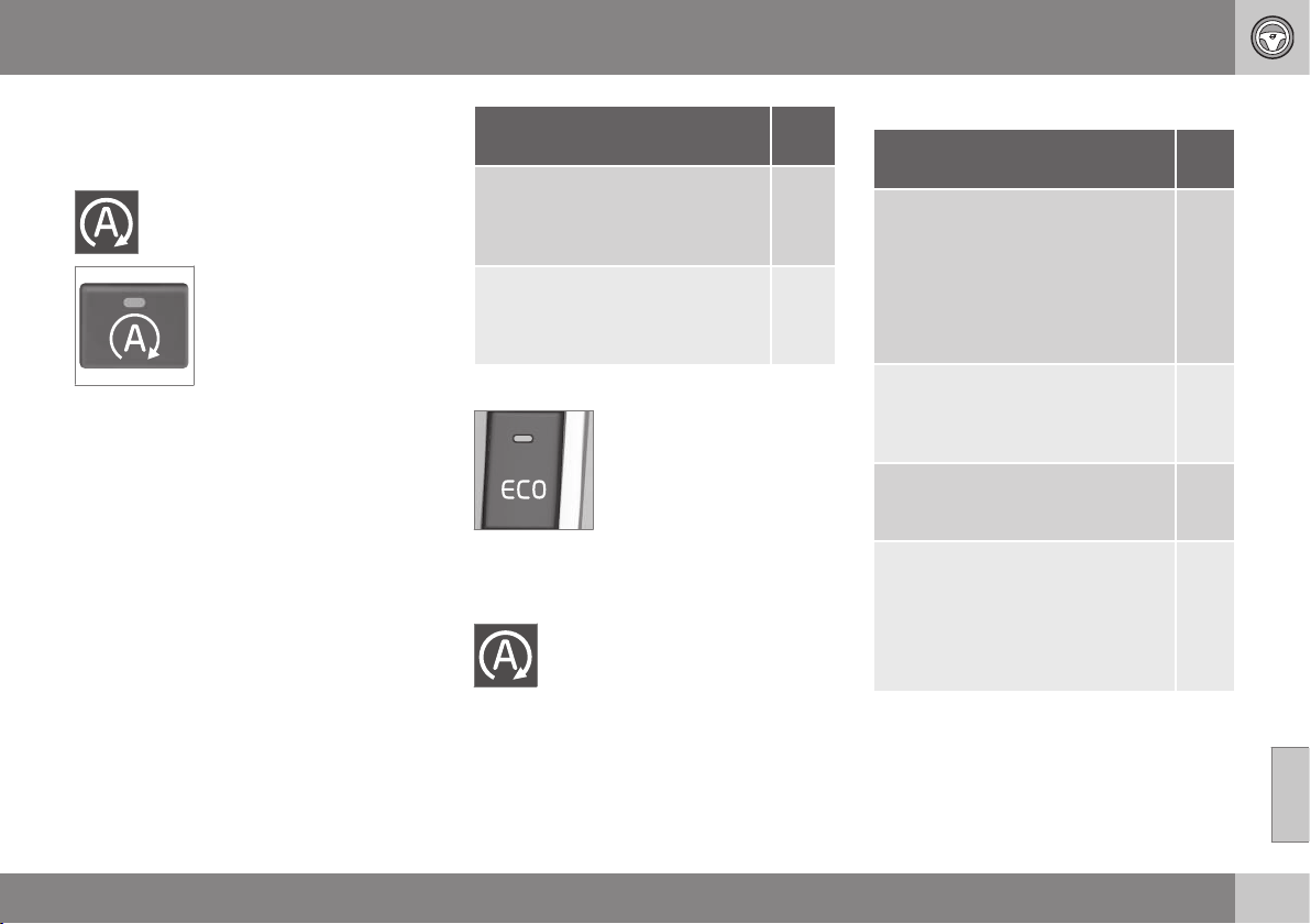
08 Starting and driving
08
}}
* Option/accessory, for more information, see Introduction.
285
Start/Stop* - function and operation
The Start/Stop function is activated automati-
cally when the engine is started with the key.
The Start/Stop function is
activated automatically when
the engine is started with the
key. The driver is made
aware of this by the func-
tion's symbol illuminating in
the combined instrument
panel and the On/Off button
lamp illuminating.
All of the car's normal sys-
tems such as lighting, radio, etc. work as nor-
mal even with an engine that has stopped
automatically, except that some equipment
may have the function temporarily reduced,
e.g. the climate control system's fan speed or
extremely high volume on the audio system.
Auto-stopping the engine
The following is required for the engine to
auto-stop:
Conditions M/A
A
Declutch, set the gear lever in neu-
tral position and release the clutch
pedal - the engine stops automati-
cally.
M
Stop the car with the foot brake
and then keep your foot on the
pedal - the engine stops automati-
cally.
A
A
M = Manual gearbox, A = Automatic gearbox.
If the ECO function is acti-
vated then the engine may
auto-stop before the car is
completely stationary.
For certain engine variants the engine may
auto-stop before the car is stationary regard-
less of whether the ECO function is activated.
When the engine is auto-stopped,
the combined instrument panel's
symbol for the Start/Stop function
illuminates.
Auto-starting the engine
Conditions M/
A
A
With the gear lever in neutral posi-
tion:
1. Depress the clutch pedal or
press the accelerator pedal -
the engine starts.
2. Engage a suitable gear and
drive.
M
Release the foot pressure on the
foot brake - the engine starts auto-
matically and the journey can con-
tinue.
A
Maintain foot pressure on the foot
brake and depress the accelerator
pedal - the engine auto-starts.
A
The following option is also availa-
ble on a downhill gradient:
Release the foot brake and let the
car move off - the engine starts
automatically when the speed
exceeds normal walking pace.
M +
A
A
M = Manual gearbox, A = Automatic gearbox.
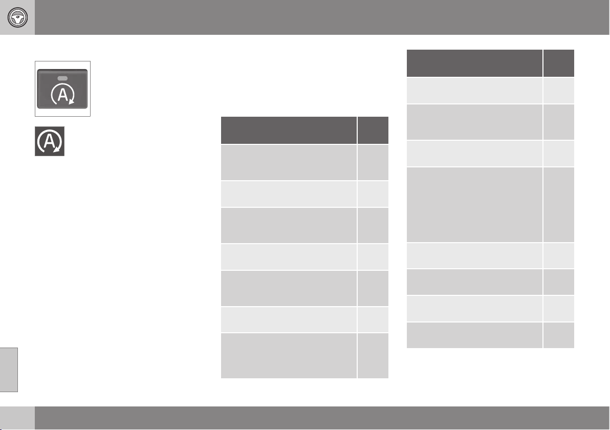
||
08 Starting and driving
08
286
* Option/accessory, for more information, see Introduction.
Deactivating the Start/Stop function
In certain situations, it may
advisable to temporarily
switch off the automatic
Start/Stop function - this is
carried out with a push of
this button.
Disengaged function is indicated by
the combined instrument panel's
Start/Stop symbol and the On/Off
button's lamp extinguishing.
The Start/Stop function is disengaged until it
is reactivated with the button or until the next
time the engine is started with the key.
Related information
•
Start/Stop* (p. 284)
•
Starting the engine (p. 268)
•
Start/Stop* - settings (p. 289)
•
Start/Stop* - the engine does not auto-
start (p. 288)
•
Start/Stop* - the engine auto-starts
(p. 287)
•
Start/Stop* - the engine does not stop
(p. 286)
•
Start/Stop* - involuntary stop manual
gearbox (p. 289)
•
Start/Stop* - symbols and messages
(p. 291)
•
Battery - Start/Stop (p. 383)
Start/Stop* - the engine does not stop
Although the Start/Stop function is activated,
the engine does not always stop automati-
cally.
The engine does not auto-stop if:
Conditions M/A
A
the car has not first achieved
approx. 8 km/h after a key start or
the last auto-stop.
M +
A
the driver has opened the seat-
belt's buckle.
M +
A
the capacity of the starter battery
is below the minimum permissible
level.
M +
A
the engine does not have normal
operating temperature.
M +
A
ambient temperature is around
freezing point or above
approx. 30 °C.
M +
A
the windscreen's electric heating
is activated.
M +
A
the environment in the passenger
compartment differs from the pre-
set values - indicated by the venti-
lation fan running at a high speed.
M +
A
Conditions M/A
A
the car is reversed. M +
A
the starter battery temperature is
below the freezing point or is too
high.
M +
A
the driver makes greater steering
wheel movements.
M +
A
the exhaust system's particulate
filter is full - the temporarily disen-
gaged Start/Stop function is reac-
tivated as soon as an automatic
cleaning cycle has been per-
formed (see Diesel particle filter
(DPF) (p. 309)).
M +
A
the road is very steep. M +
A
a trailer is connected electrically to
the car’s electrical system.
M +
A
the bonnet has been opened
B
.
M +
A
the gearbox does not have normal
operating temperature.
A

08 Starting and driving
08
}}
* Option/accessory, for more information, see Introduction.
287
Conditions M/A
A
the atmospheric air pressure is
less than equivalent to
1500-2500 metres above sea level
- the current air pressure varies
with the prevailing weather condi-
tions.
A
adaptive cruise control Queue
Assist is activated.
A
the gear selector is in S position
C
or "+/-".
A
A
M = Manual gearbox, A = Automatic gearbox.
B
With certain engines only.
C
Sport mode.
Related information
•
Start/Stop* (p. 284)
•
Start/Stop* - function and operation
(p. 285)
•
Starting the engine (p. 268)
•
Start/Stop* - settings (p. 289)
•
Start/Stop* - the engine does not auto-
start (p. 288)
•
Start/Stop* - the engine auto-starts
(p. 287)
•
Start/Stop* - involuntary stop manual
gearbox (p. 289)
•
Start/Stop* - symbols and messages
(p. 291)
•
Battery - Start/Stop (p. 383)
Start/Stop* - the engine auto-starts
An auto-stopped engine may restart in certain
cases without the driver having decided that
the journey should continue.
In the following cases the engine also starts
automatically if the driver has not depressed
the clutch pedal (manual gearbox) or takes
his/her foot off the brake pedal (automatic
gearbox):
Conditions
M/A
A
Misting forms on the windows. M + A
The environment in the passenger
compartment deviates from the
preset values.
M + A
There is a temporarily high current
take-off or starter battery capacity
drops below the lowest permissi-
ble level.
M + A
Repeated pumping of the brake
pedal.
M + A
The bonnet is opened
B
.
M + A
The car starts to roll, or there is a
small increase in speed if the car
auto-stopped without being com-
pletely stationary.
M + A
||
08 Starting and driving
08
288
* Option/accessory, for more information, see Introduction.
Conditions
M/A
A
The driver's seatbelt buckle is
opened with the gear selector in D
or N position.
A
Steering wheel movements
B
.
A
The gear selector is moved out of
the D position to S position
C
, R or
"+/-".
A
The driver's door is opened with
the gear selector in D position - a
"ping" sound and text message
inform that the Start/Stop function
is active.
A
A
M = Manual gearbox, A = Automatic gearbox.
B
With certain engines only.
C
Sport mode.
WARNING
Do not open the bonnet when the engine
has stopped automatically - the engine
may suddenly start automatically. First
switch off the engine as normal using the
START/STOP ENGINE button before
opening the bonnet.
Related information
•
Start/Stop* (p. 284)
•
Start/Stop* - function and operation
(p. 285)
•
Starting the engine (p. 268)
•
Start/Stop* - settings (p. 289)
•
Start/Stop* - the engine does not auto-
start (p. 288)
•
Start/Stop* - the engine does not stop
(p. 286)
•
Start/Stop* - involuntary stop manual
gearbox (p. 289)
•
Start/Stop* - symbols and messages
(p. 291)
•
Battery - Start/Stop (p. 383)
Start/Stop* - the engine does not
auto-start
The engine does not always auto-start after
having auto-stopped.
In the following cases the engine does not
auto-start after having auto-stopped:
Conditions M/A
A
A gear is engaged without
declutching - a display text
prompts the driver to set the gear
lever in neutral position in order to
enable auto-start.
M
The driver is unrestrained. M
The driver is unrestrained, the gear
selector is in P position and the
driver’s door is open - a normal
engine start must take place.
A
A
M = Manual gearbox, A = Automatic gearbox.
Related information
•
Start/Stop* (p. 284)
•
Start/Stop* - function and operation
(p. 285)
•
Starting the engine (p. 268)
•
Start/Stop* - settings (p. 289)
•
Start/Stop* - the engine auto-starts
(p. 287)

08 Starting and driving
08
}}
* Option/accessory, for more information, see Introduction.
289
•
Start/Stop* - the engine does not stop
(p. 286)
•
Start/Stop* - involuntary stop manual
gearbox (p. 289)
•
Start/Stop* - symbols and messages
(p. 291)
•
Battery - Start/Stop (p. 383)
Start/Stop* - involuntary stop manual
gearbox
If a start-up fails and the engine stops, pro-
ceed in accordance with the below:
1. Check that the driver side's seatbelt is
locked in the seatbelt buckle.
2. Depress the clutch pedal again - the
engine starts automatically.
3. In certain cases the gear lever must be
set in neutral position. The combined
instrument panel then shows the text
Put
gear in neutral.
Related information
•
Start/Stop* (p. 284)
•
Start/Stop* - function and operation
(p. 285)
•
Starting the engine (p. 268)
•
Start/Stop* - settings (p. 289)
•
Start/Stop* - the engine does not auto-
start (p. 288)
•
Start/Stop* - the engine auto-starts
(p. 287)
•
Start/Stop* - the engine does not stop
(p. 286)
•
Start/Stop* - symbols and messages
(p. 291)
•
Battery - Start/Stop (p. 383)
Start/Stop* - settings
The car's MY CAR menu system, under the
DRIVe heading, contains information about
Volvo's Start/Stop system, as well as recom-
mendations for energy-saving driving techni-
ques.
Related information
•
Start/Stop* (p. 284)
•
Start/Stop* - function and operation
(p. 285)
•
Starting the engine (p. 268)
•
Start/Stop* - the engine does not auto-
start (p. 288)
•
Start/Stop* - the engine auto-starts
(p. 287)
•
Start/Stop* - the engine does not stop
(p. 286)
•
Start/Stop* - involuntary stop manual
gearbox (p. 289)

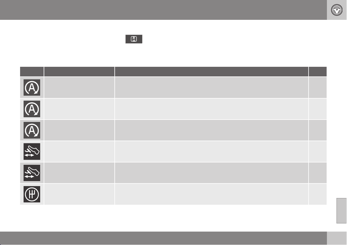
08 Starting and driving
08
}}
* Option/accessory, for more information, see Introduction.
291
Start/Stop* - symbols and messages
The Start/Stop function can show text mes-
sages in the combined instrument panel.
Text message
In combination with this indicator
lamp the Start/Stop function may
show text messages in the com-
bined instrument panel for certain situations.
For some of them there is a recommended
action that should be performed. The follow-
ing table shows some examples.
Symbol Message Info/Action
M/A
A
Auto Start/Stop Service
required
Start/Stop is not operational. Contact a workshop - an authorised Volvo workshop is rec-
ommended.
M + A
Autostart Engine running +
acoustic signal
Activated if the driver's door is opened with auto-stopped engine and the gear selector in
D position.
A
Press start button
The engine will not start automatically - start the engine as normal with the START/STOP
ENGINE button.
M + A
Depress clutch pedal to
start
The engine is ready to auto-start - waiting for the clutch pedal to be depressed. M
Depress brake and clutch
pedals to start
The engine is ready to auto-start - waiting for the brake or clutch pedal to be depressed. M
Put gear in neutral to start
Gear is engaged without declutching - disengage and set the gear lever in neutral posi-
tion.
M

||
08 Starting and driving
08
292
* Option/accessory, for more information, see Introduction.
Symbol Message Info/Action
M/A
A
Select P or N to start
Start/Stop has been deactivated - move the gear selector to N or P position and start the
engine as normal with the START/STOP ENGINE button.
A
Press start button
The engine will not start automatically - start the engine as normal with the START/STOP
ENGINE button and the gear selector in P or N.
A
A
M = Manual gearbox, A = Automatic gearbox.
If a message does not go out following com-
pletion of the action then a workshop should
be contacted - an authorised Volvo workshop
is recommended.
Related information
•
Start/Stop* (p. 284)
•
Start/Stop* - function and operation
(p. 285)
•
Starting the engine (p. 268)
•
Start/Stop* - settings (p. 289)
•
Start/Stop* - the engine does not auto-
start (p. 288)
•
Start/Stop* - the engine auto-starts
(p. 287)
•
Start/Stop* - the engine does not stop
(p. 286)
•
Start/Stop* - involuntary stop manual
gearbox (p. 289)
•
Battery - Start/Stop (p. 383)
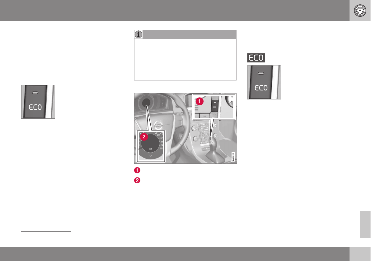
08 Starting and driving
08
}}
* Option/accessory, for more information, see Introduction.
293
ECO*
ECO
14
is an innovative Volvo function for
automatic-gearbox cars, capable of reducing
fuel consumption by up to 5%, depending on
the driver's driving style. The function gives
the driver the option of a more active environ-
mentally conscious way of driving.
General
The following are changed
upon activation of the ECO
function:
•
Gearbox gearshift points.
•
Engine management and response from
the accelerator pedal.
•
Start/Stop function - the engine can also
auto-stop before the car has stopped
down to being completely stationary.
•
The Eco Coast function is activated -
engine braking ceases.
•
Climate control system settings - some
electricity consumers are deactivated or
operate at reduced power.
NOTE
When the ECO function is activated, sev-
eral parameters in the climate control sys-
tem's settings are changed, and several
electricity consumer functions are
reduced. Certain settings can be reset
manually, but full functionality is only
restored by deactivating the ECO function.
ECO - Operation
ECO On/Off
ECO symbol
The ECO function is deactivated when the
engine is switched off, and must therefore be
activated after each time the engine is
started. There are exceptions for certain
engines. However, it is easily verified by
means of both the combined instrument
panel
ECO symbol and the ECO button lamp
illuminating when the function is activated.
ECO function On or Off
Disengaged ECO function is
indicated by the combined
instrument panel
ECO sym-
bol and the ECO button lamp
extinguishing. The function is
then switched off until it is
reactivated with the ECO
button.
Eco Coast - Function
The Eco Coast subfunction means in practice
that engine braking is deactivated, meaning in
turn that the car's kinetic energy is used to
coast for longer distances. When the driver
releases the accelerator pedal the gearbox is
automatically disengaged from the engine
whose speed is reduced to idling speed with
minimum consumption.
This function is intended for use in the event
of an anticipated reduction in speed, e.g. to
coast forward to an intersection or a red light.
Eco Coast enables proactive driving where
the driver can use the so-called "Pulse &
Glide" technique and a minimum of braking.
A combination of Eco Coast and temporarily
deactivated ECO function can also collec-
14
Not possible on the XC60 and XC70 with AWD.
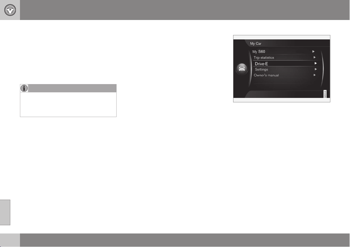
||
08 Starting and driving
08
294
tively contribute to reduced consumption.
Accordingly:
•
Active Eco Coast: Long coasting without
engine braking = Low consumption
and
•
Deactivated ECO function: Short coasting
with engine braking = Minimum con-
sumption.
NOTE
However, to achieve optimal low fuel con-
sumption, Eco Coast in combination with
short coasting distances should generally
be avoided.
Activating Eco Coast
The function is activated when the accelera-
tor pedal is fully released, in combination with
the following parameters:
•
ECO button activated
•
Gear selector in D position
•
Speed within the range of
approx. 65-140 km/h
•
The road's downhill gradient is not
steeper than approx. 6%.
Deactivate Eco Coast
In certain situations it may be desirable to
deactivate the Eco Coast function. Examples
of such situations include:
•
on steep downhill gradients - to be able
to use engine braking.
•
before an imminent overtaking manoeu-
vre - in order to be able to complete it in
the safest possible way.
Deactivating Eco Coast and returning to
engine braking can be performed as follows:
•
Press the ECO button.
•
Move the gear lever to manual "S+/-"
position.
•
Change gear with the steering wheel pad-
dle shifters.
•
Actuate the accelerator or brake pedal.
Eco Coast - Limitations
The function is not available if:
•
cruise control is activated
•
the road's downhill gradient is steeper
than approx. 6%
•
manual gear changing is performed with
the steering wheel paddle shifters*
•
engine and/or gearbox are not at normal
operating temperature.
•
the gear selector is moved from D- to "S
+/-" position
•
speed is outside the range of
approx. 65-140 km/h
More information and settings
The car's menu system MY CAR contains
further information on the ECO concept - see
the section MY CAR (p. 108).
Related information
•
General information on climate control
(p. 122)
08 Starting and driving
08
}}
* Option/accessory, for more information, see Introduction.
295
Foot brake
The foot brake is used to reduce the car's
speed while driving.
The car is equipped with two brake circuits. If
a brake circuit is damaged then the brake
pedal will engage deeper and a higher pres-
sure on the pedal is needed to produce the
normal braking effect.
The driver's brake pedal pressure is assisted
by a brake servo.
WARNING
The brake servo only works when the
engine is running.
If the foot brake is used when the engine is
switched off then the pedal will feel stiff and a
higher pedal pressure must be used to brake
the car.
For cars with the Hill start assist (HSA)*
(p. 282)* function, the pedal returns more
slowly than usual to normal position if the car
is parked on a gradient or on an uneven sur-
face.
In very hilly terrain or when driving with a
heavy load the brakes can be relieved by
using engine braking. Engine braking is most
efficiently used if the same gear is used
downhill as up.
For more general information on heavy loads
on the car, see Engine oil - adverse driving
conditions (p. 414).
Braking on wet roads
When driving for a long time in heavy rain
without braking, the braking effect may be
delayed slightly when next using the brakes.
This may also be the case after a car wash. It
is then necessary to depress the brake
harder. For this reason, maintain a greater
distance to the traffic ahead.
Brake the car firmly after driving on wet roads
and after a car wash. The brake discs are
then warmed up, dry more quickly and are
protected against corrosion. Take the prevail-
ing traffic situation into account when brak-
ing.
Braking on salted roads
When driving on salted roads a layer of salt
may form on the brake discs and brake lin-
ings. This may extend braking distance. For
this reason, keep an extra large safety dis-
tance to the vehicle ahead. Also make sure of
the following:
•
Brake occasionally to remove any layer of
salt. Make sure that other road users are
not put at risk by the braking.
•
Gently depress the brake pedal when
driving is finished and before the next
journey starts.
Maintenance
To keep the car as safe and reliable as possi-
ble, follow the Volvo service intervals as
specified in the Service and Warranty Book-
let.
New and replacement brake linings and brake
discs only provide optimal brake performance
after a few hundred kilometres after "wearing-
in". Compensate for the reduced brake per-
formance by depressing the brake pedal
harder. Volvo recommends only fitting brake
linings that are approved for your Volvo.
IMPORTANT
The wear on the brake system's compo-
nents must be checked regularly.
Contact a workshop for information about
the procedure or engage a workshop to
carry out the inspection - an authorised
Volvo workshop is recommended.
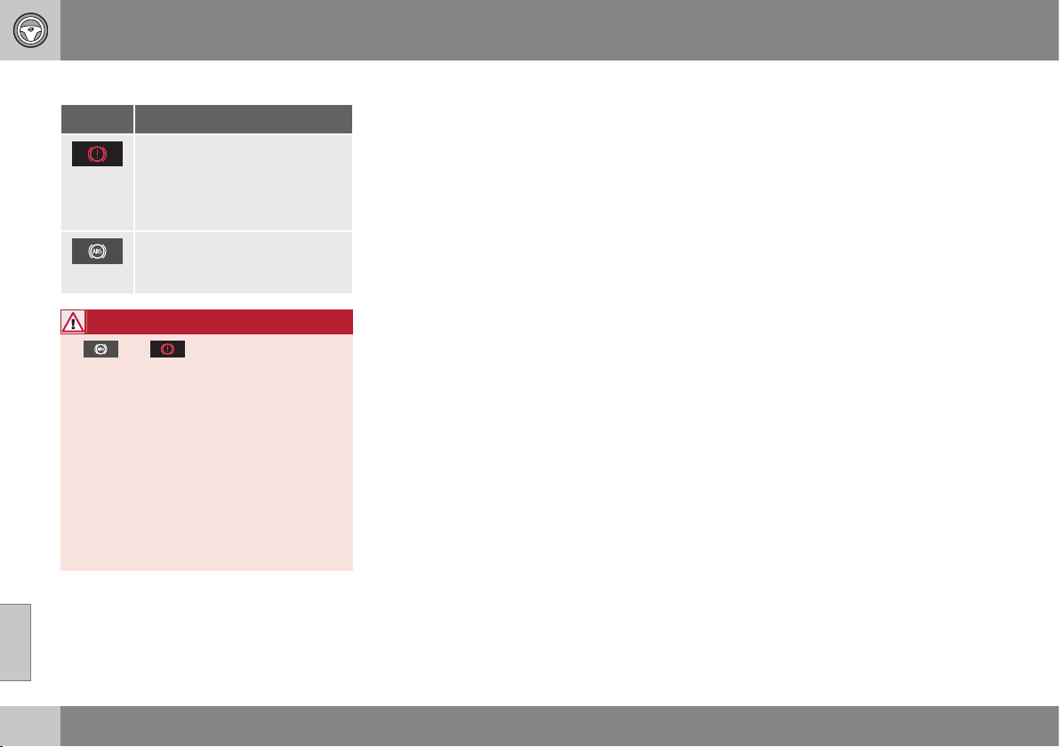
||
08 Starting and driving
08
296
Symbols and messages
Symbol Specification
Constant glow – Check the
brake fluid level. If the level is
low, fill with brake fluid and
check for the cause of the
brake fluid loss.
Constant glow for 2 seconds
when the engine is started -
automatic function check.
WARNING
If and illuminate at the same
time, there may be a fault in the brake sys-
tem.
If the level in the brake fluid reservoir is
normal at this stage, drive carefully to the
nearest workshop and have the brake sys-
tem checked - an authorised Volvo work-
shop is recommended.
If the brake fluid is below the MIN level in
the brake fluid reservoir, do not drive fur-
ther before topping up the brake fluid.
The reason for the loss of brake fluid must
be investigated.
Related information
•
Parking brake (p. 298)
•
Foot brake - emergency brake lights and
automatic hazard warning flashers
(p. 297)
•
Foot brake - emergency brake assistance
(p. 297)
•
Foot brake - anti-lock braking system
(p. 296)
Foot brake - anti-lock braking system
The anti-lock braking system, ABS (Anti-lock
Braking System), prevents the wheels from
locking up during braking.
The function allows the steering ability to be
maintained, and it is easier to swerve to avoid
a hazard for example. Vibration may be felt in
the brake pedal when this is engaged and this
is normal.
A short test of the ABS system is made auto-
matically after the engine has been started
when the driver releases the brake pedal. A
further automatic test of the ABS system may
be made when the car reaches 10 km/h. The
test may be experienced as pulses in the
brake pedal.
Related information
•
Foot brake (p. 295)
•
Parking brake (p. 298)
•
Foot brake - emergency brake lights and
automatic hazard warning flashers
(p. 297)
•
Foot brake - emergency brake assistance
(p. 297)
08 Starting and driving
08
297
Foot brake - emergency brake lights
and automatic hazard warning
flashers
Emergency brake lights are activated in order
to alert vehicles behind about heavy braking.
The function means that the brake light
flashes instead of - as in normal braking -
shining with a constant glow.
Emergency brake lights are activated at
speeds above 50 km/h in the event of heavy
braking. After the car's speed has been
slowed down to below 10 km/h the brake
light returns from flashing to the normal con-
stant glow - while at the same time the car's
hazard warning lights (p. 93) are activated.
These flash until the driver accelerates the car
up to a higher speed again or switches off the
hazard warning lights.
Related information
•
Foot brake (p. 295)
•
Parking brake (p. 298)
•
Foot brake - emergency brake assistance
(p. 297)
•
Foot brake - anti-lock braking system
(p. 296)
Foot brake - emergency brake
assistance
Emergency brake assistance EBA (Emergency
Brake Assist) helps to increase the braking
force and so reduce the braking distance.
EBA detects the driver's braking style and
increases the braking force when necessary.
The brake force can be reinforced up to the
level when the ABS system is engaged. The
EBA function is interrupted when the pressure
on the brake pedal is reduced.
NOTE
When EBA is activated the brake pedal
lowers slightly more than usual, depress
(hold) the brake pedal as long as neces-
sary. If the brake pedal is released then all
braking ceases.
Related information
•
Foot brake (p. 295)
•
Parking brake (p. 298)
•
Foot brake - emergency brake lights and
automatic hazard warning flashers
(p. 297)
•
Foot brake - anti-lock braking system
(p. 296)

08 Starting and driving
08
298
Parking brake
The parking brake holds the car stationary,
when the driver's seat is empty, by mechani-
cally locking/blocking two wheels.
Function
A faint electric motor noise can be heard
when the electrically-controlled parking brake
is being applied. The noise can also be heard
during the automatic function checking of the
parking brake.
If the car is stationary when the parking brake
is applied then it only acts on the rear wheels.
If it is applied when the car is moving then the
normal foot brake is used, i.e. the brake acts
on all four wheels. Brake function changes
over to the rear wheels when the car is almost
stationary.
Low battery voltage
If the battery voltage is too low then the park-
ing brake can neither be released nor applied.
Connect a donor battery if the battery voltage
is too low, see Jump starting with battery
(p. 273).
Applying the parking brake
Parking brake control - apply.
1. Depress the foot brake pedal firmly.
2. Press the parking brake control.
>
The combined instrument pan-
el's symbol starts flashing - once there
is a constant glow the parking brake is
applied.
3. Release the foot brake pedal and make
sure that the car is at a standstill position.
When parking the vehicle, always engage 1st
gear (for manual gearbox) or put the gear
selector in position P (for automatic gearbox).
Emergency brake
In an emergency the parking brake can be
applied when the vehicle is in motion by
pressing and holding the parking brake con-
trol. The braking procedure is stopped when
the control is released.
NOTE
An acoustic signal sounds while emer-
gency braking is active at high speeds.
Parking on a hill
If the car is parked facing uphill:
•
Turn the wheels away from the kerb.
If the car is parked facing downhill:
•
Turn the wheels towards the kerb.
WARNING
Always apply the parking brake when
parking on a slope - leaving the car in
gear, or in P if it has automatic transmis-
sion, is not sufficient to hold the car in all
situation.
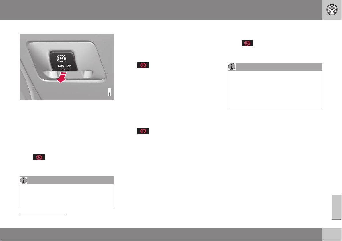
08 Starting and driving
08
}}
299
Disengaging the parking brake
Parking brake control - release.
Cars with manual gearbox
Releasing manually
1. Insert the remote control key in the igni-
tion switch
15
.
2. Depress the foot brake pedal firmly.
3. Apply the parking brake control.
>
The parking brake releases and
the combined instrument panel's sym-
bol extinguishes.
NOTE
The parking brake can also be released
manually by depressing the clutch pedal
instead of the brake pedal. Volvo recom-
mends that the brake pedal is used.
Releasing automatically
1. Start the engine.
2. Engage 1st gear or reverse gear.
3. Ease up the clutch and depress the
accelerator.
>
The parking brake releases and
the combined instrument panel's sym-
bol extinguishes.
Cars with automatic gearbox
Releasing manually
1. Insert the remote control key in the igni-
tion switch
15
.
2. Depress the foot brake pedal firmly.
3. Pull the control.
>
The parking brake releases and
the combined instrument panel's sym-
bol extinguishes.
Releasing automatically
1. Put the seatbelt on.
2. Start the engine.
3. Depress the foot brake pedal firmly.
4. Move the gear selector to position D or R
and depress the accelerator.
>
The parking brake releases and
the combined instrument panel's sym-
bol extinguishes.
NOTE
For safety reasons, the parking brake is
only released automatically if the engine is
running and the driver is wearing a seat-
belt. The parking brake is released imme-
diately on cars with automatic gearbox
when the accelerator pedal is depressed
and the gear selector is in position D or R.
Heavy load uphill
A heavy load, such as a trailer, can cause the
car to roll backward when the parking brake
is released automatically on a steep incline.
Avoid this by depressing the control while
driving off. Release the control when the
engine achieves traction.
Replacing the brake linings
The rear brake linings must be replaced at a
workshop due to the design of the electric
parking brake - an authorised Volvo work-
shop is recommended.
15
For a car with the Keyless system: Press START/STOP ENGINE.

||
08 Starting and driving
08
300
Symbols and messages
For information on how the combined instru-
ment panel's text messages can be shown
and deleted, see Messages - handling
(p. 108).
Symbol Message Meaning/Action
"Message"
•
Read the combined instrument panel's message.
A flashing symbol indicates that the parking brake is applied.
If the symbol flashes in any other situation then this means that a fault has arisen.
•
Read the combined instrument panel's message.
Handbrake not
fully released
A fault is preventing the parking brake from being released:
•
Try to apply and release the brake.
If the fault persists after a few attempts:
•
Visit a workshop - an authorised Volvo workshop is recommended.
Note: A warning signal sounds if the journey is continued with this error message.

08 Starting and driving
08
301
Symbol Message Meaning/Action
Handbrake not
applied
A fault is preventing the parking brake from being applied:
•
Try to release and apply the brake.
If the fault persists after a few attempts:
•
Visit a workshop - an authorised Volvo workshop is recommended.
The message is also illuminated on cars with manual gearbox when the car is driven at low speed with the door
open in order to alert the driver that the parking brake may have been unintentionally disengaged.
Handbrake
Service
required
A fault has arisen:
•
Try to apply and release the brake.
If the fault persists after a few attempts:
•
Visit a workshop - an authorised Volvo workshop is recommended.
If the car has to be parked before a possible
fault has been rectified, then the wheels must
be turned as if parking on a hill and 1st gear
engaged (manual gearbox) or the gear selec-
tor must be in position P (automatic gearbox).
A text message can be acknowledged by
briefly pressing the OK button on the direc-
tion indicator stalk.
Related information
•
Foot brake (p. 295)

08 Starting and driving
08
302
* Option/accessory, for more information, see Introduction.
Driving in water
Driving in water means that the car is driven
through a water-covered roadway. Driving in
water must be carried out with great caution.
The car can be driven through water at a
maximum depth of 25 cm (30 cm with S60
Cross Country) at a maximum speed of walk-
ing pace. Extra caution must be exercised
when passing through flowing water.
During driving in water, maintain a low speed
and do not stop the car. When the water has
been passed, depress the brake pedal lightly
and check that full brake function is achieved.
Water and mud for example can make the
brake linings wet resulting in delayed brake
function.
•
Clean the electric contacts of the electric
engine block heater* and trailer coupling
after driving in water and mud.
•
Do not let the car stand with water over
the sills for any long period of time - this
could cause electrical malfunctions.
IMPORTANT
Engine damage can occur if water enters
the air filter.
In depths greater than 25 cm (30 cm with
S60 Cross Country), water could enter the
transmission. This reduces the lubricating
ability of the oils and shortens the service
life of these systems.
Damage to any component, engine, trans-
mission, turbocharger, differential or its
internal components caused by flooding,
hydrostatic locking or oil shortage, is not
covered by the warranty.
In the event of the engine stalling in water,
do not try restart - tow the car from the
water to a workshop - an authorised Volvo
workshop is recommended. Risk of engine
breakdown.
Related information
•
Recovery (p. 320)
•
Towing (p. 318)
Overheating
Under special conditions, for example hard
driving in hilly terrain and hot climate, there is
a risk that the engine and drive system may
overheat - in particular with a heavy load.
For information about overheating when driv-
ing with a trailer, see Driving with a trailer*
(p. 311).
•
Remove any auxiliary lamps from in front
of the grille when driving in hot climates.
•
If the temperature in the engine's cooling
system is too high then a warning symbol
is illuminated in the combined instrument
panel's information display and a text
message
High engine temperature
Stop safely is shown there - stop the car
in a safe way and allow the engine to run
at idling speed for several minutes in
order to cool down.
•
If the text message
High engine
temperature Turn off engine or Engine
coolant level low Stop safely
is shown
then the engine must be switched off
after stopping the car.
•
In the event of overheating in the gearbox
a built-in protection function is activated
which, amongst other things, illuminates
a warning symbol in the combined instru-
ment panel, and its display shows the
text message
Transmission hot Reduce
speed or Transmission hot Stop safely
Wait for cooling - follow the recommen-
dation given and lower the speed and
08 Starting and driving
08
303
stop the car in a safe way and allow the
engine to run at idling speed for a few
minutes in order to allow the gearbox to
cool down.
•
If the car overheats, the air conditioning
may be switched off temporarily.
•
Do not turn the engine off immediately
you stop after a hard drive.
NOTE
It is normal for the engine's cooling fan to
operate for a time after the engine has
been switched off.
Driving with open tailgate/boot lid
When driving with the boot lid open, toxic
exhaust fumes can be sucked into the car
through the cargo area.
WARNING
Do not drive with the boot lid open. Toxic
exhaust fumes can be drawn into the car
through the cargo area.
Related information
•
Loading (p. 149)
Overload - starter battery
The electrical functions in the car load the
starter battery (p. 379) to varying degrees.
Avoid using the key position II (p. 76) when
the engine is switched off. Instead use posi-
tion I - which uses less power.
Also, be aware of different accessories that
load the electrical system. Do not use func-
tions which use a lot of power when the
engine is switched off. Examples of such
functions are:
•
ventilation fan
•
headlamps
•
windscreen wiper
•
audio system (high volume).
If the starter battery voltage is low then the
combined instrument panel's information dis-
play shows the text
Low battery charge
Power save mode. The energy-saving func-
tion then shuts down certain functions or
reduces certain functions such as the ventila-
tion fan and/or audio system.
– In which case, charge the starter battery
by starting the engine and then running it
for at least 15 minutes - starter battery
charging is more effective during driving
than running the engine at idling speed
while stationary.
08 Starting and driving
08
304
Before a long journey
Before a long journey, it makes good sense to
go through the following points:
•
Check that the engine is working normally
and that fuel consumption (p. 422) is nor-
mal.
•
Make sure that there are no leaks (fuel, oil
or other fluid).
•
Check all bulbs and tyre tread depths.
•
Carrying a warning triangle (p. 333) is a
legal requirement in certain countries.
Related information
•
Engine oil - checking and filling (p. 363)
•
Changing wheels - removing wheels
(p. 329)
•
Lamp replacement - general (p. 369)
Winter driving
For winter driving it is important to perform
certain checks in order to ensure that the car
can be driven safely.
Check the following in particular before the
cold season:
•
The engine coolant (p. 367) must contain
50% glycol. This mixture protects the
engine against frost erosion down to
approximately –35 °C. To avoid health
risks, different types of glycol must not be
mixed.
•
The fuel tank must be kept filled to pre-
vent condensation.
•
Engine oil viscosity is important. Oils with
lower viscosity (thinner oils) facilitate star-
ting in cold weather and also reduce fuel
consumption while the engine is cold. For
more information on suitable oils, see
Engine oil - adverse driving conditions
(p. 414).
IMPORTANT
Low viscosity oil must not be used for hard
driving or in hot weather.
•
The condition of the starter battery and
charge level must be inspected. Cold
weather places great demands on the
starter battery and its capacity is reduced
by the cold.
•
Use washer fluid (p. 378) to avoid ice
forming in the washer fluid reservoir.
To achieve optimum roadholding Volvo rec-
ommends using winter tyres on all wheels if
there is a risk of snow or ice.
NOTE
The use of winter tyres is a legal require-
ment in certain countries. Studded tyres
are not permitted in all countries.
Slippery driving conditions
Practise driving on slippery surfaces under
controlled conditions to learn how the car
reacts.
Related information
•
Winter driving (p. 304)
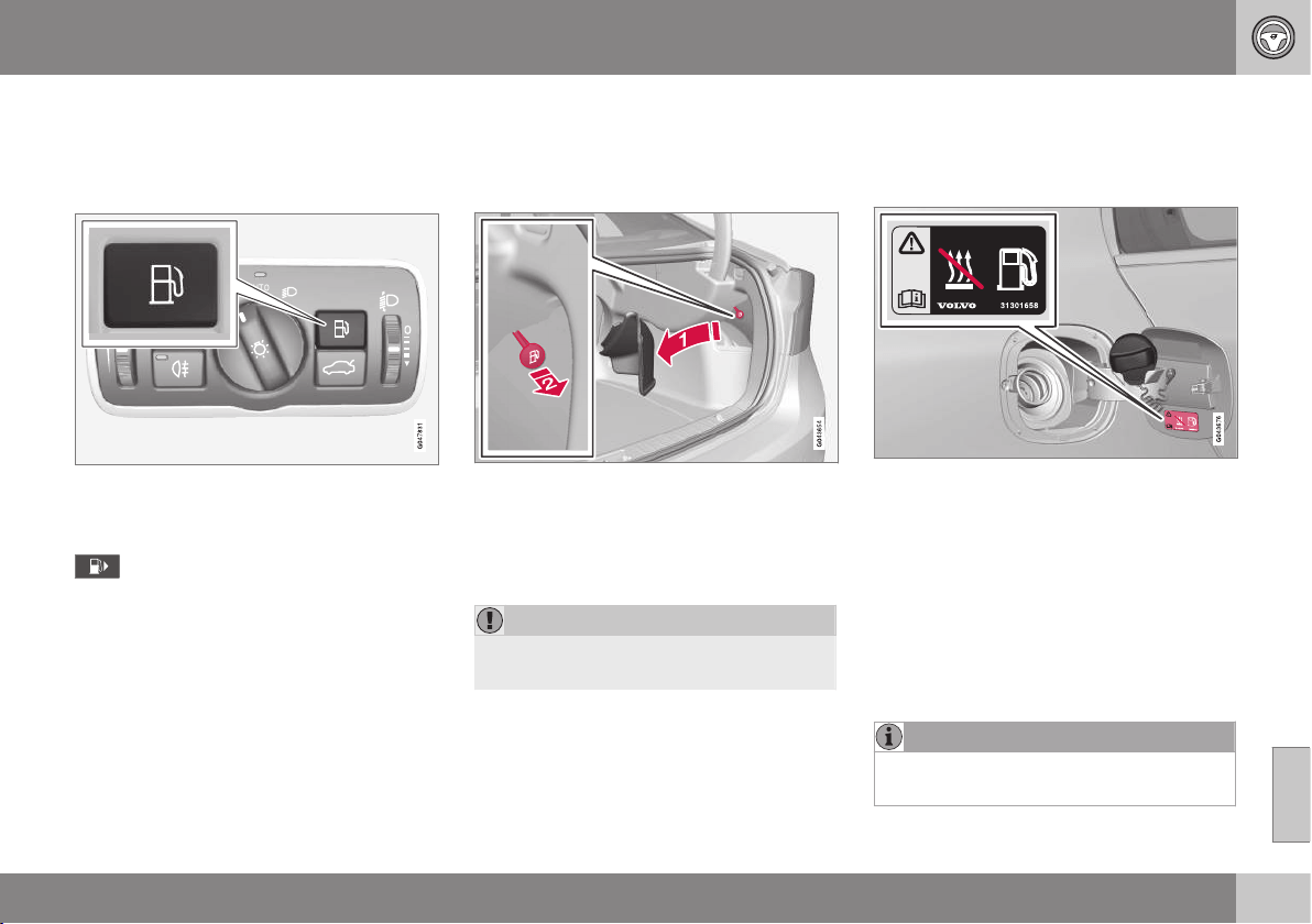
08 Starting and driving
08
}}
305
Fuel filler flap - Opening/closing
The fuel filler flap can be opened/closed as
follows:
Opening/closing the fuel filler flap
Open the fuel filler flap using the button on
the lighting panel - the flap opens when the
button is released.
In the combined instrument panel's
display the arrow on the symbol indi-
cates which side of the car the fuel cap is
located.
•
Close the fuel filler flap by pressing it in
until a click confirms that it is closed.
Related information
•
Filling up with fuel (p. 305)
Fuel filler flap - manual opening
The fuel filler flap can be opened manually
when electric opening from the passenger
compartment is not possible.
1. Open/remove the side hatch in the cargo
area (same side as fuel filler flap) and
locate the green cord with handle.
2. Pull the cord gently straight back until the
fuel filler flap folds out with a "click".
IMPORTANT
Pull the wire gently - minimal force is
required to disengage the hatch lock.
Related information
•
Filling up with fuel (p. 305)
Filling up with fuel
Important things to consider when refuelling.
Opening/closing the fuel cap
The fuel filler cap can be attached onto the flap.
A certain overpressure may arise in the tank
in the event of high outside temperatures.
Open the cap slowly.
•
After refuelling - refit the cap and turn it
until one or more clicking sounds are
heard.
Filling up with fuel
•
Do not overfill the tank but fill until the
pump nozzle cuts out.
NOTE
Excess fuel in the tank can overflow in hot
weather.
||
08 Starting and driving
08
306
Filling with a fuel can
16
When filling with a fuel can, use the funnel
located under the floor hatch in the cargo
area.
Make sure you insert the funnel's pipe firmly
into the filler pipe. The filler pipe has an open-
able cover and the funnel's pipe must be slid
past the cover before filling can begin.
Related information
•
Fuel filler flap - manual opening (p. 305)
•
Fuel - handling (p. 306)
Fuel - handling
Fuel of a lower quality than that recom-
mended by Volvo must not be used as engine
power and fuel consumption is negatively
affected.
WARNING
Always avoid inhaling fuel vapour and get-
ting fuel splashes in the eyes.
In the event of fuel in the eyes, remove any
contact lenses and rinse the eyes in plenty
of water for at least 15 minutes and seek
medical attention.
Never swallow fuel. Fuels such as petrol,
bioethanol and mixtures of them and die-
sel are highly toxic and could cause per-
manent injury or be fatal if swallowed.
Seek medical attention immediately if fuel
has been swallowed.
WARNING
Fuel which spills onto the ground can be
ignited.
Switch off the fuel-driven heater before
starting to refuel.
Never carry an activated mobile phone
when refuelling. The ring signal could
cause spark build-up and ignite petrol
fumes, leading to fire and injury.
IMPORTANT
Mixtures of various fuel types or use of
fuels which are not recommended will
invalidate Volvo's guarantees and any sup-
plementary service agreements; this is
applicable to all engines.
NOTE
Extreme weather conditions, driving with a
trailer or driving at high altitudes in combi-
nation with fuel grade are factors that
could affect the car's performance.
Related information
•
Economical driving (p. 310)
•
Fuel - diesel (p. 307)
•
Diesel particle filter (DPF) (p. 309)
•
Fuel consumption and CO2 emissions
(p. 422)
•
Fuel tank - volume (p. 421)
16
Only applies to cars with diesel engine.

08 Starting and driving
08
}}
307
Fuel - petrol
Petrol is used as fuel.
Only use petrol from well-known producers.
Never use fuel of dubious quality. Petrol must
fulfil the EN 228 standard if this is available.
•
95 RON can be used for normal driving.
•
98 RON is recommended for optimum
performance and minimum fuel consump-
tion.
When driving in temperatures above +38 °C,
fuel with the highest possible octane rating is
recommended for optimum performance and
fuel economy.
IMPORTANT
•
Use only unleaded petrol to avoid
damaging the catalytic converter.
•
Fuel containing metallic additives must
not be used.
•
Do not use any additives which have
not been recommended by Volvo.
Alcohols-ethanol
IMPORTANT
•
Fuel that contains up to
10 percent by volume ethanol is per-
mitted.
•
EN 228 E10 petrol (max
10 percent by volume ethanol) is
approved for use.
•
Ethanol higher than E10 (max
10 percent by volume ethanol) is not
permitted. T.ex. E85 is not permitted.
Related information
•
Fuel - handling (p. 306)
•
Economical driving (p. 310)
•
Fuel consumption and CO2 emissions
(p. 422)
•
Fuel tank - volume (p. 421)
Fuel - diesel
Diesel is used as fuel.
Only use diesel fuel from well-known produc-
ers. Never use fuel of dubious quality. Diesel
engines are sensitive to contaminants in the
fuel such as metals and a high volume of sul-
phur.
At low temperatures (-6 °C to -40 °C), a par-
affin precipitate may form in the diesel fuel,
which may lead to ignition problems. Special
diesel fuel designed for low temperatures
around freezing point is available from the
major oil companies. This fuel is less viscous
at low temperatures and reduces the risk of
paraffin precipitate.
The risk of condensation in the fuel tank is
reduced if the tank is kept well filled. When
refuelling, check that the area around the fuel
filler pipe is clean. Avoid spilling fuel onto the
paintwork. Wash off any spillage with deter-
gent and water.
IMPORTANT
Diesel fuel must:
•
fulfil the EN 590 and/or SS 155435
standards
•
have a sulphur content not exceeding
10 mg/kg
•
have a maximum of 7 vol % FAME
(Fatty Acid Methyl Ester).
||
08 Starting and driving
08
308
IMPORTANT
Diesel type fuels that must not be used:
•
Special additives
•
Marine diesel fuel
•
Heating oil
•
FAME
17
(Fatty Acid Methyl Ester) and
vegetable oil.
These fuels do not fulfil the requirements in
accordance with Volvo recommendations
and generate increased wear and engine
damage that is not covered by the Volvo
warranty.
Empty tank
The design of the fuel system in a diesel
engine means that if the vehicle runs out of
fuel, the tank may need to be vented in the
workshop in order to restart the engine after
fuelling.
Once the engine has stopped due to fuel
starvation, the fuel system needs a few
moments to carry out a check. Do this before
starting the engine, once the fuel tank has
been filled with diesel:
1. Insert the remote control key in the igni-
tion switch and push it in to the end posi-
tion. For more information, see Key posi-
tions (p. 76).
2. Press the START button without
depressing the brake and/or clutch pedal.
3. Wait approx. one minute.
4. To start the engine: Depress the brake
and/or clutch pedal and then press the
START button again.
NOTE
Before filling with fuel in the event of fuel
shortage:
•
Stop the car on as flat/level ground as
possible - if the car is tilting there is a
risk of air pockets in the fuel supply.
Draining condensation from the fuel
filter
The fuel filter separates condensation from
the fuel. Condensation can disrupt engine
operation.
The fuel filter must be drained at the intervals
specified in the Service and Warranty Booklet
or if you suspect that the car has been filled
with contaminated fuel. For more information,
see Volvo service programme (p. 355).
IMPORTANT
Certain special additives remove the water
separation in the fuel filter.
Related information
•
Fuel - handling (p. 306)
•
Diesel particle filter (DPF) (p. 309)
•
Fuel consumption and CO2 emissions
(p. 422)
17
Diesel fuel may contain a certain amount of FAME, but further amounts must not be added.
08 Starting and driving
08
}}
* Option/accessory, for more information, see Introduction.
309
Diesel particle filter (DPF)
Diesel cars are equipped with a particle filter,
which results in more efficient emission con-
trol.
The particles in the exhaust gases are collec-
ted in the filter during normal driving. So-
called "regeneration" is started in order to
burn away the particles and empty the filter.
This requires the engine to have reached nor-
mal operating temperature.
Regeneration of the particle filter is automatic
and normally takes 10-20 minutes. It may
take a little longer at a low average speed.
Fuel consumption may increase slightly dur-
ing regeneration.
Regeneration in cold weather
If the car is frequently driven short distances
in cold weather then the engine does not
reach normal operating temperature. This
means that regeneration of the diesel particle
filter does not take place and the filter is not
emptied.
When the filter has become approx. 80% full
of particles, a yellow warning triangle is
shown in the combined instrument panel, and
the message
Soot filter full See manual is
shown in its information display.
Start regeneration of the filter by driving the
car until the engine reaches normal operating
temperature, preferably on a main road or
motorway. The car should then be driven for
approximately 20 minutes more.
NOTE
The following may arise during regenera-
tion:
•
a smaller reduction of engine power
may be noticed temporarily
•
fuel consumption may increase tem-
porarily
•
a smell of burning may arise.
When regeneration is complete the warning
text is cleared automatically.
Use the parking heater* in cold weather - the
engine then reaches normal operating tem-
perature more quickly.
IMPORTANT
If the filter is completely filled with parti-
cles, it may be difficult to start the engine
and the filter is non-functional. Then there
is a risk that the filter will need to be
replaced.
Related information
•
Fuel - handling (p. 306)
•
Fuel - diesel (p. 307)
•
Fuel consumption and CO2 emissions
(p. 422)
•
Fuel tank - volume (p. 421)
Catalytic converters
The purpose of the catalytic converters is to
purify exhaust gases. They are located close
to the engine so that operating temperature is
reached quickly.
The catalytic converters consist of a monolith
(ceramic or metal) with channels. The channel
walls are lined with a thin layer of platinum/
rhodium/palladium. These metals act as cata-
lysts, i.e. they participate in and accelerate a
chemical reaction without being used up
themselves.
Lambda-sond
TM
oxygen sensor
The Lambda-sond is part of a control system
intended to reduce emissions and improve
fuel economy. For more information, see Fuel
consumption and CO2 emissions (p. 422).
An oxygen sensor monitors the oxygen con-
tent of the exhaust gases leaving the engine.
This value is fed into an electronic system
that continuously controls the injectors. The
ratio of fuel to air directed to the engine is
continuously adjusted. These adjustments
create optimal conditions for efficient com-
bustion, and together with the three-way cat-
alytic converter reduce harmful emissions
(hydrocarbons, carbon monoxide and nitrous
oxides).
||
08 Starting and driving
08
310
* Option/accessory, for more information, see Introduction.
Related information
•
Economical driving (p. 310)
•
Fuel - petrol (p. 307)
•
Fuel - diesel (p. 307)
Economical driving
Driving economically means driving smoothly
while thinking ahead and adjusting your driv-
ing style and speed to the prevailing condi-
tions.
•
For lowest fuel consumption, activate
ECO* (p. 293)
18
.
•
Use the ECO Guide which indicates how
fuel-efficiently the car is being driven, see
Eco guide & Power guide* (p. 65).
•
Drive in the highest gear possible, adap-
ted to the current traffic situation and
road - lower engine speeds result in lower
fuel consumption. Use the gear indicator
(p. 275).
•
Avoid sudden unnecessary acceleration
and heavy braking.
•
High speed results in increased fuel con-
sumption - the wind resistance increases
with speed.
•
Do not run the engine to operating tem-
perature at idling speed, but rather drive
with a light load as soon as possible - a
cold engine consumes more fuel than a
warm one.
•
Drive with the correct air pressure in the
tyres and check this regularly - select
ECO tyre pressure for best results, see
Tyres - approved tyre pressures (p. 423).
•
Choice of tyres can affect fuel consump-
tion - seek advice on suitable tyres from a
dealer.
•
Remove unnecessary items from the car -
the greater the load the higher the con-
sumption.
•
Use engine braking to slow down, when it
can take place without risk to other road
users.
•
A roof load and ski box increase air resis-
tance, leading to higher consumption -
remove the load carriers when not in use.
•
Avoid driving with open windows.
For more information about Volvo Car Corpo-
ration's environmental philosophy, see Envi-
ronmental philosophy (p. 22).
For more information about fuel consumption,
see Fuel consumption and CO2 emissions
(p. 422).
WARNING
Never switch off the engine while moving,
such as downhill, this deactivates impor-
tant systems such as the power steering
and brake servo.
18
Only applies to cars with automatic gearbox.

08 Starting and driving
08
}}
* Option/accessory, for more information, see Introduction.
311
Related information
•
Fuel - handling (p. 306)
•
Fuel consumption and CO2 emissions
(p. 422)
•
Fuel tank - volume (p. 421)
Driving with a trailer*
When driving with a trailer there are a number
of important points to think about regarding
e.g. the towing bracket, the trailer and how
the load is positioned in the trailer.
Payload depends on the car's kerb weight.
The total of the weight of the passengers and
all accessories, e.g. towbar, reduces the car's
payload by a corresponding weight. For more
detailed information, see Weights (p. 409).
If the towing bracket is mounted by Volvo,
then the car is delivered with the necessary
equipment for driving with a trailer.
•
The car's towing bracket must be of an
approved type.
•
If the towbar is retrofitted, check with
your Volvo dealer that the car is fully
equipped for driving with a trailer.
•
Distribute the load on the trailer so that
the weight on the towing bracket com-
plies with the specified maximum towball
load.
•
Increase the tyre pressure to the recom-
mended pressure for a full load. For infor-
mation on the tyre pressure, see Tyres -
approved tyre pressures (p. 423).
•
The engine is loaded more heavily than
usual when driving with a trailer.
•
Do not tow a heavy trailer when the car is
brand new. Wait until it has been driven
at least 1000 km.
•
The brakes are loaded much more than
usual on long and steep downhill slopes.
Downshift to a lower gear and adjust your
speed.
•
For safety reasons, the maximum permit-
ted speed for the car when coupled with
a trailer should not be exceeded. Follow
the regulations in force for the permitted
speeds and weights.
•
Maintain a low speed when driving with a
trailer up long, steep ascents.
•
Avoid driving with a trailer on inclines of
more than 12%.
Trailer cable
An adapter is required if the car's towing
bracket has 13 pin electrics and the trailer
has 7 pin electrics. Use an adapter cable
approved by Volvo. Make sure the cable does
not drag on the ground.
Direction indicators and brake lights on
the trailer
If any of the trailer's lamps for direction indi-
cators are broken, then the combined instru-
ment panel's symbol for direction indicators
flashes faster than normal and the information
display shows the text
Trailer indicator
malfunction
.
If any of the trailer's lamps for the brake light
are broken then the
Trailer brake light
malfunction text is shown.
||
08 Starting and driving
08
312
* Option/accessory, for more information, see Introduction.
Level control*
The rear shock absorbers maintain a constant
height irrespective of the car's load (up to the
maximum permissible weight). When the car
is stationary the rear of the car lowers slightly,
which is normal
Trailer weights
For information on Volvo's permitted trailer
weights, see Towing capacity and towball
load (p. 410).
NOTE
The stated maximum permitted trailer
weights are those permitted by Volvo.
National vehicle regulations can further
limit trailer weights and speeds. Towbars
may be certified for higher or lower towing
weights than the car can actually tow.
WARNING
Follow the stated recommendations for
trailer weights. Otherwise, the car and
trailer may be difficult to control in the
event of sudden movement and braking.
Related information
•
Driving with a trailer* - manual gearbox
(p. 312)
•
Driving with a trailer* - automatic gearbox
(p. 312)
•
Towing bracket/Towbar* (p. 313)
•
Lamp replacement - general (p. 369)
Driving with a trailer* - manual
gearbox
When driving with a trailer in hilly terrain in a
hot climate there may be a risk of overheating.
Overheating
When driving with a trailer in hilly terrain in a
hot climate there may be a risk of overheat-
ing.
•
Do not run the engine at higher revolu-
tions than 4500 rpm (diesel engines:
3500 rpm) - otherwise the oil temperature
may become too high.
Diesel engine 5-cyl
•
In the event of a risk of overheating the
optimal speed for the engine is
2300-3000 rpm for optimal circulation of
the coolant.
Related information
•
Driving with a trailer* (p. 311)
Driving with a trailer* - automatic
gearbox
When driving with a trailer in hilly terrain in a
hot climate there may be a risk of overheating.
•
An automatic gearbox selects the opti-
mum gear related to load and engine
speed.
•
In the event of overheating a warning
symbol is illuminated in the combined
instrument panel with a message that is
shown in the information display - follow
the recommendation given.
Steep inclines
•
Do not lock the automatic transmission in
a higher gear than the engine "can cope
with" - it is not always a good idea to
drive at a high gear with low engine revo-
lutions.
Parking on a hill
1. Depress the foot brake.
2. Activate the parking brake.
3. Move the gear selector to position P.
4. Release the foot brake.
•
Move the gear selector to park position P
when parking an automatic car with a
hitched trailer. Always use the parking
brake.
•
Block the wheels with chocks when park-
ing a car with hitched trailer on a hill.
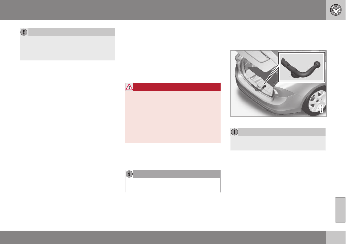
08 Starting and driving
08
* Option/accessory, for more information, see Introduction.
313
IMPORTANT
See also the specific information on slow
driving with a trailer for cars with the
Powershift automatic transmission, see
Automatic gearbox -- Powershift* (p. 279).
Starting on a hill
1. Depress the foot brake.
2. Move the gear selector to driving posi-
tion D.
3. Release the parking brake.
4. Release the foot brake and start driving
off.
Related information
•
Automatic gearbox -- Geartronic* (p. 276)
Towing bracket/Towbar*
A towing bracket means that it is possible to
e.g. tow a trailer behind the car.
If the car is equipped with a detachable/
removable towbar, the installation instruc-
tions for the loose section must be followed
carefully, see Detachable towbar* - attach-
ment/removal (p. 314).
WARNING
If the car is fitted with a Volvo detachable
towbar:
•
Follow the installation instructions
carefully.
•
The detachable section must be
locked with the key before setting off.
•
Check that the indicator window
shows green.
Important checks
•
The towbar's towball must be cleaned
and greased regularly.
NOTE
When a hitch with a vibration damper is
used, the towball must not be lubricated.
Related information
•
Driving with a trailer* (p. 311)
Detachable towbar* - storage
Store the detachable towbar in the cargo
area.
Towbar storage space.
IMPORTANT
Always remove the towbar after use and
store it in the appointed location in the car.
Related information
•
Detachable towbar* - specifications
(p. 314)
•
Detachable towbar* - attachment/removal
(p. 314)
•
Driving with a trailer* (p. 311)
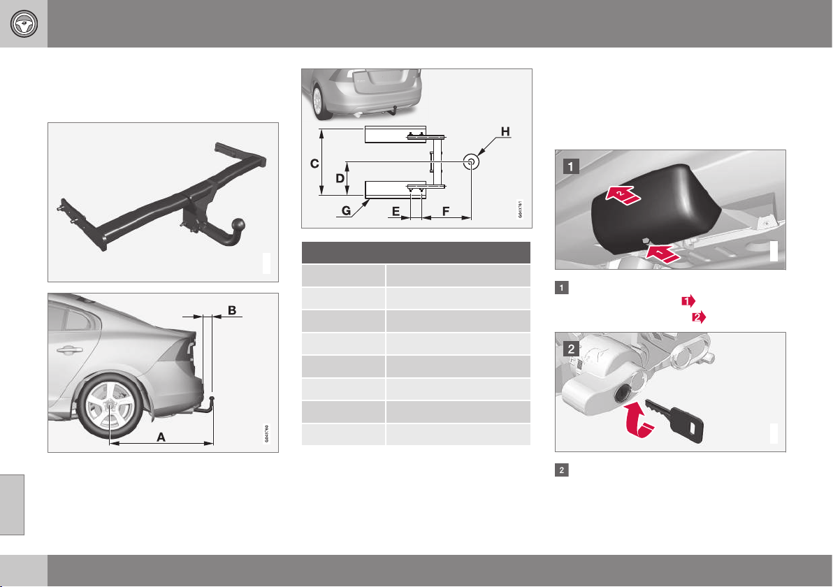
08 Starting and driving
08
314
* Option/accessory, for more information, see Introduction.
Detachable towbar* - specifications
Specifications for detachable towbar.
Specifications
G021485
Dimensions, mounting points (mm)
A 998
B 81
C 854
D 427
E 109
F 282
G Side member
H Ball centre
Related information
•
Detachable towbar* - attachment/removal
(p. 314)
•
Detachable towbar* - storage (p. 313)
•
Driving with a trailer* (p. 311)
Detachable towbar* - attachment/
removal
The attachment/removal of the detachable
towbar is performed in the following way:
Attaching
G018928
Remove the protective cover by first
pressing in the catch
and then pulling
the cover straight back
.
G021487
Ensure that the mechanism is in the
unlocked position by turning the key
clockwise.
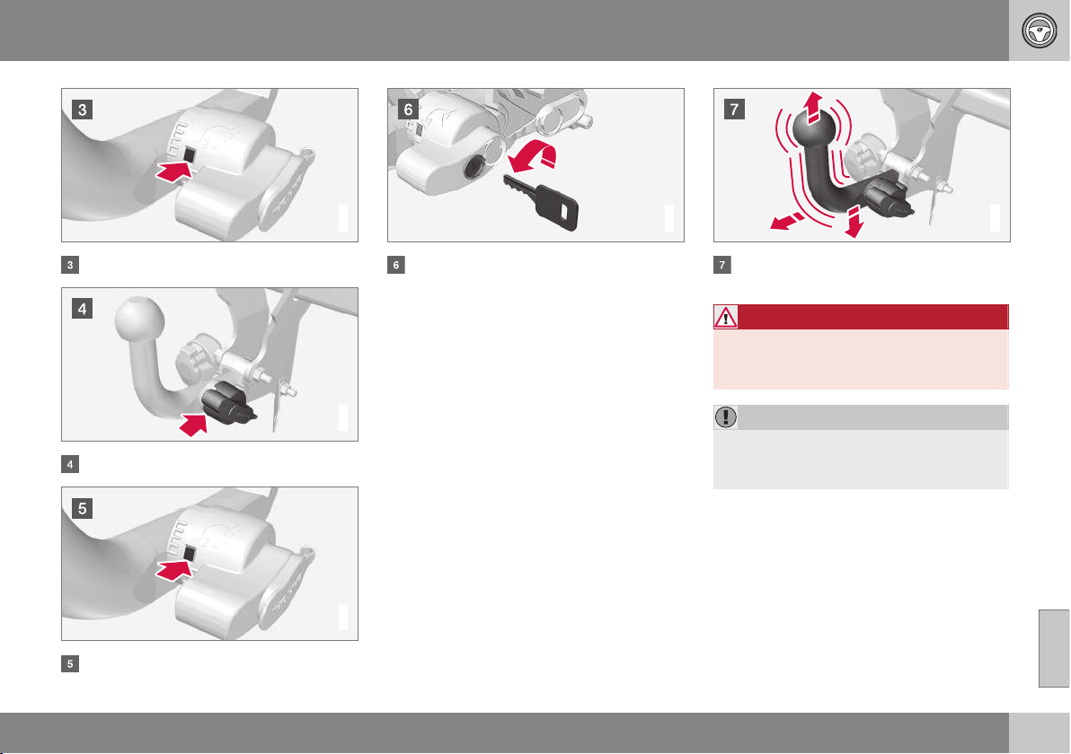
08 Starting and driving
08
}}
315
G021488
The indicator window must show red.
G021489
Insert the towbar until you hear a click.
G021490
The indicator window must show green.
G000000
Turn the key anticlockwise to locked
position. Remove the key from the lock.
G021494
Check that the towbar is secure by pull-
ing it up, down and back.
WARNING
If the towbar is not fitted correctly then it
must be detached and reattached in
accordance with the previous instructions.
IMPORTANT
Only grease in the ball for the towing hitch,
the remainder of the towbar should be
clean and dry.
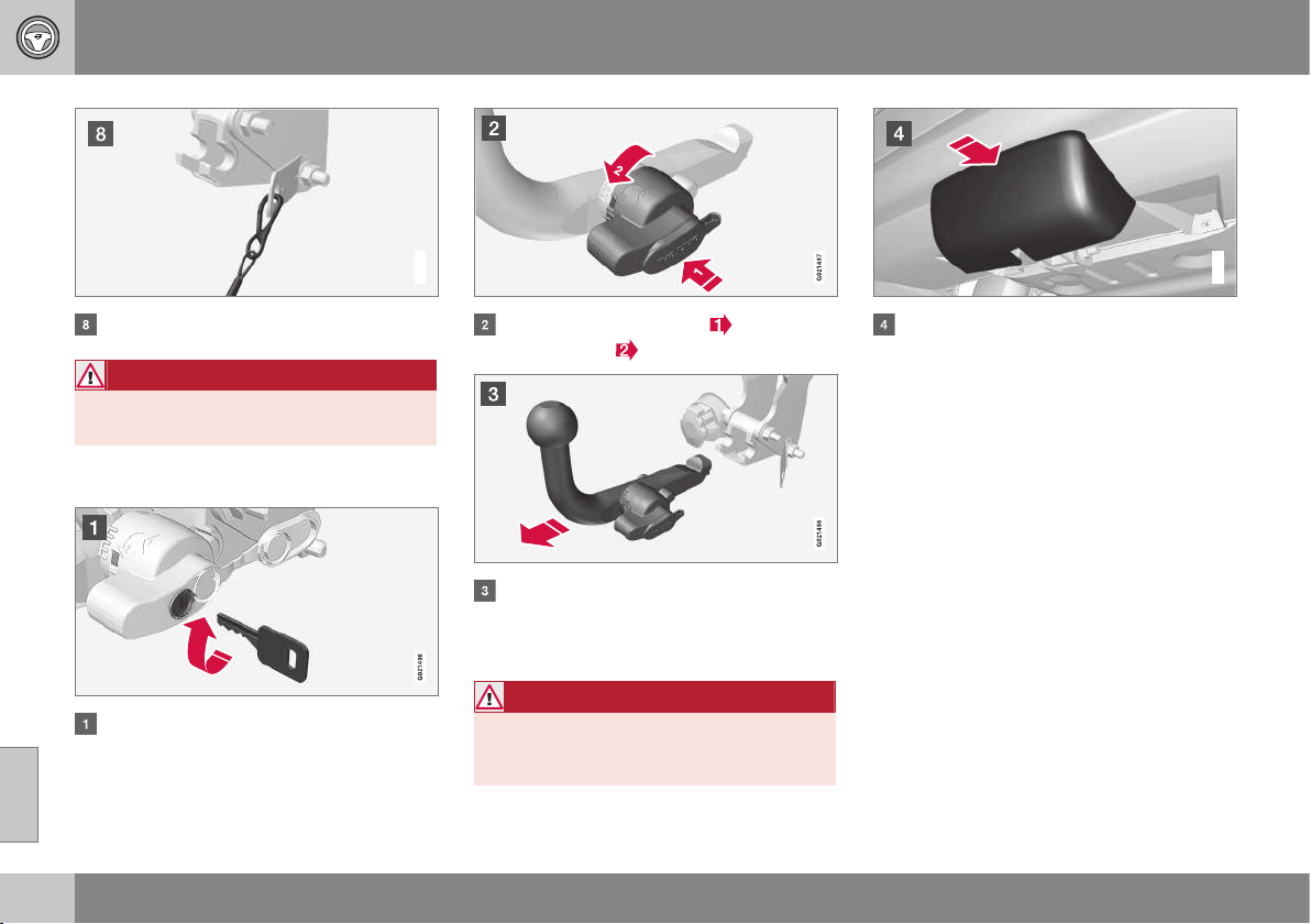
||
08 Starting and driving
08
316
* Option/accessory, for more information, see Introduction.
G021495
Safety cable.
WARNING
Take care to secure the trailer's safety
cable in the intended bracket.
Removing the towbar
Insert the key and turn it clockwise to the
unlocked position.
Push in the locking wheel and turn it
anticlockwise
until you hear a click.
Turn the locking wheel down fully, until it
comes to a stop. Hold it in this position
while pulling the towbar rearward and
upward.
WARNING
Secure the towbar safely if it is stored in
the car, see Detachable towbar* - storage
(p. 313).
G018929
Push the protective cover until it snaps
tight.
Related information
•
Detachable towbar* - storage (p. 313)
•
Detachable towbar* - specifications
(p. 314)
•
Driving with a trailer* (p. 311)
08 Starting and driving
08
317
Trailer Stability Assist - TSA
19
The trailer stability assist TSA (Trailer Stability
Assist) function is designed to stabilise the car
and trailer combination if it begins to snake.
TSA- the function is included in the stability
system (p. 184) ESC
20
.
Function
The snaking phenomenon can occur with any
car/trailer combination. Snaking normally
occurs at high speeds. But, there is a risk of it
occurring at lower speeds (70-90 km/h) if the
trailer is overloaded or the load is improperly
distributed, e.g. too far back.
In order for snaking to occur, there must be a
triggering factor, e.g.:
•
Car with trailer subjected to a sudden and
powerful side wind.
•
Car with trailer drives on an uneven road
surface or in a pothole.
•
Sweeping steering wheel movements.
Operation
If snaking has started, it could be difficult or
even impossible to suppress. This makes the
car/trailer combination difficult to control and
there is a risk that you could, for example,
end up in the wrong lane or leave the car-
riageway.
The trailer stability assist function continually
monitors car movements, particularly lateral
movements. If snaking is detected, the front
wheels are individually braked. This serves to
stabilise the car/trailer combination. This is
often enough to help the driver regain control
of the car.
If snaking is not eliminated the first time the
TSA system comes into action, the car/trailer
combination is braked with all wheels and
engine power is reduced. Once snaking has
been gradually suppressed and the car/trailer
combination is stable once again, the system
stops regulating and the driver once again
has full control of the car. For more informa-
tion, see Electronic stability control (ESC) -
operation (p. 185).
Miscellaneous
TSA can engage within the speed range
60-160 km/h.
NOTE
TSA function is switched off if the driver
selects
Sport mode, see Electronic stabil-
ity control (ESC) - general (p. 184).
TSA may fail to engage if the driver uses sud-
den steering wheel movements to try to rec-
tify the snaking because, in such a situation,
the system cannot determine whether it is the
trailer or the driver that is causing the snak-
ing.
The ESC
20
symbol in the combined
instrument panel flashes when the
TSA system is working.
Related information
•
Electronic stability control (ESC) - general
(p. 184)
19
Included in the installation of Volvo genuine towbar.
20
(Electronic Stability Control) - Electronic stability control.
08 Starting and driving
08
318
Towing
During towing, one vehicle is towed by
another vehicle using a tow rope.
Find out the statutory maximum speed limit
for towing before towing begins.
1. Unlock the steering lock by inserting the
remote control key in the ignition switch
and giving a long press on the START/
STOP ENGINE button - key position II is
activated, see Key positions (p. 76) for
more information about key positions.
2. The remote control key must remain in
the ignition switch while the car is being
towed.
3. Keep the towline taut when the towing
vehicle reduces speed by holding your
foot gently pressed on the brake pedal -
thereby avoiding unnecessary jerking.
4. Be prepared to brake to stop.
WARNING
•
Check that the steering lock is
unlocked before towing.
•
The remote control key must be in key
position II - in position I all airbags are
deactivated.
•
Never remove the remote control key
from the ignition switch when the car
is being towed.
WARNING
The brake servo and power steering do not
work when the engine is switched off - the
brake pedal needs to be depressed
about 5 times more heavily and the steer-
ing is considerably heavier than normal.
Manual gearbox
Prior to towing:
– Move gear lever into neutral and release
the parking brake.
Automatic gearbox Geartronic
Prior to towing:
– Move the gear selector to position N and
release the parking brake.
IMPORTANT
•
Do not tow the vehicle at speeds
higher than 80 km/h or for distances in
excess of 80 km.
•
Note that the car must always be
towed with the wheels rolling forward.
Automatic gearbox Powershift
Models with the Powershift gearbox should
not be towed. If towing still has to take place,
the route must be as short as possible and
then with very low speed.
In the event of uncertainty as to whether or
not the car is equipped with Powershift trans-
mission, this can be verified by checking the
designation on the gearbox label under the
bonnet, see Type designations (p. 405). The
designation ”MPS6” means that it is
Powershift transmission - otherwise it is
Geartronic automatic transmission.
IMPORTANT
Avoid towing.
•
However, the car can be towed for a
short distance at low speed to move it
from a dangerous position - not further
than 10 km and not faster than
10 km/h. Note that the car must
always be towed with the wheels roll-
ing forward.
•
In the event of moving a longer dis-
tance than 10 km, the car must be
transported with the drive wheels
raised from the road - professional
recovery is recommended.
Prior to towing:
– Move the gear selector to position N and
release the parking brake.
Jump starting
Do not tow the car to bump start the engine.
Use a donor battery if the starter battery is
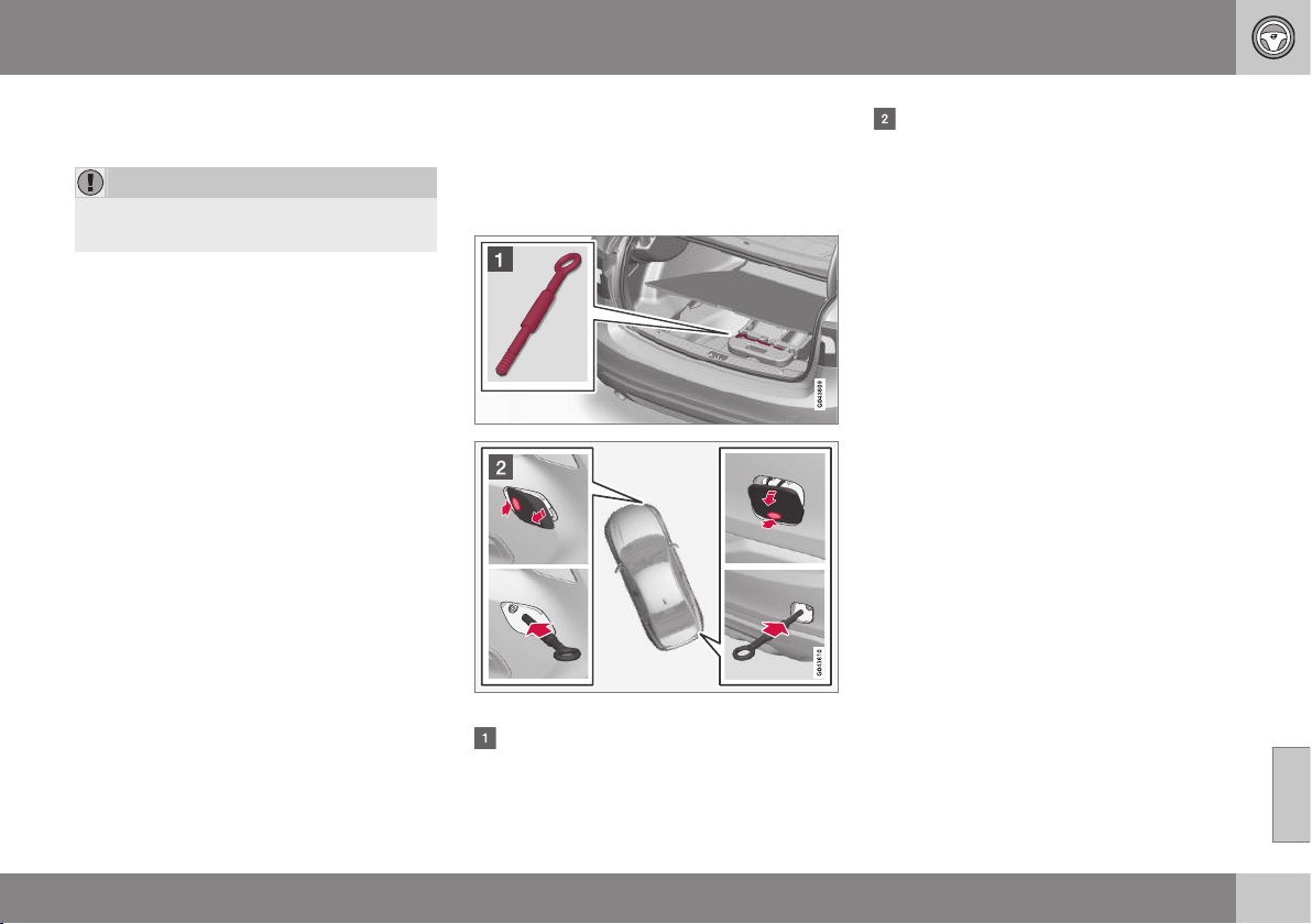
08 Starting and driving
08
}}
319
discharged and the engine does not start, see
Jump starting with battery (p. 273).
IMPORTANT
The catalytic converter may be damaged
during attempts to tow-start the engine.
Related information
•
Towing eye (p. 319)
•
Recovery (p. 320)
Towing eye
The towing eye is screwed into a threaded
socket behind a cover on the right-hand side
of the bumper, front or rear.
Attaching the towing eye
Remove the front and rear covers.
Take out the towing eye that is located
under the floor hatch in the cargo area.
The cover for the towing eye's attach-
ment point is available in two variants
which must be opened in different ways:
•
Open the variant with a recess using a
coin or similar inserted in the recess,
turning it outwards. Then turn out the
cover completely and remove it.
•
The second variant has a marking
along one side or in a corner: Press the
marking with a finger and fold out the
opposite side/corner at the same time
using a coin or similar - the cover turns
around its axis and can then be
removed.
Screw the towing eye right in up to its
flange. Turn in the towing eye firmly e.g.
using the wheel wrench.
After use, unscrew the towing eye and
return it to its place.
Finish by refitting the cover onto the
bumper.
The towing eye may be used to pull the car
up onto a recovery vehicle with a flatbed plat-
form. The car's position and ground clear-
ance determine whether it is possible. If the
slope of the recovery vehicle's ramp is too
steep, or if the ground clearance under the
car is inadequate, then the car may be dam-
aged if you try to pull it up using the towing
eye. Raise the car using the recovery vehi-
cle's lifting device if necessary.
||
08 Starting and driving
08
320
WARNING
No one/nothing is allowed to remain
behind the recovery vehicle while the car
pulled up onto the flatbed platform.
IMPORTANT
The towing eye is only designed for towing
on roads - not for pulling the car unstuck
or out of a ditch. Call a recovery service for
recovery assistance.
Related information
•
Towing (p. 318)
•
Recovery (p. 320)
Recovery
Recovery means that the vehicle is transpor-
ted away by means of another vehicle.
Call a recovery service for recovery assis-
tance.
The towing eye may be used to pull the car
up onto a recovery vehicle with a flatbed plat-
form. The car's position and ground clear-
ance determine whether it is possible. If the
slope of the recovery vehicle's ramp is too
steep, or if the ground clearance under the
car is inadequate, then the car may be dam-
aged if you try to pull it up using the towing
eye. Raise the car using the recovery vehi-
cle's lifting device if necessary.
WARNING
No one/nothing is allowed to remain
behind the recovery vehicle while the car
pulled up onto the flatbed platform.
IMPORTANT
The towing eye is only designed for towing
on roads - not for pulling the car unstuck
or out of a ditch. Call a recovery service for
recovery assistance.
IMPORTANT
Note that the car must always be transpor-
ted with the wheels rolling forward.
•
An All Wheel Drive car (AWD) with
raised front suspension must not be
towed at speeds above 70 km/h. It
should not be towed further than 50
km.
Related information
•
Towing (p. 318)
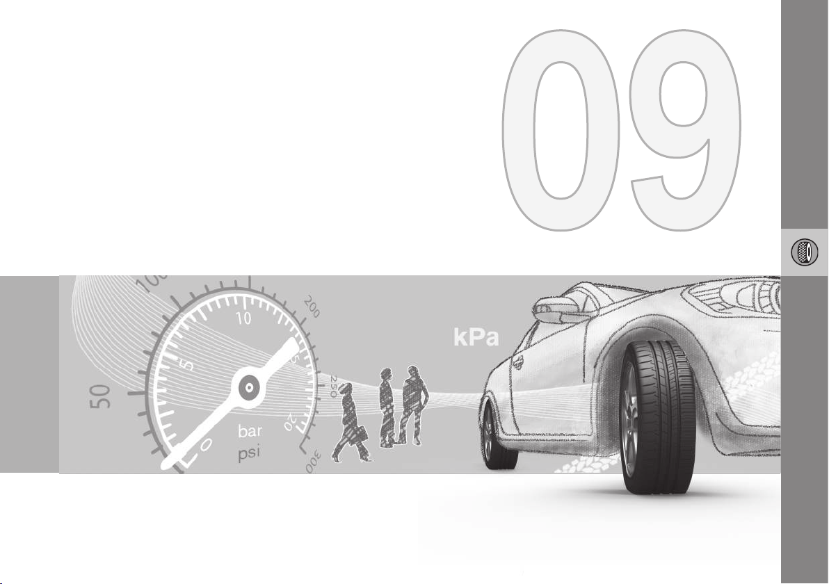
WHEELS AND TYRES
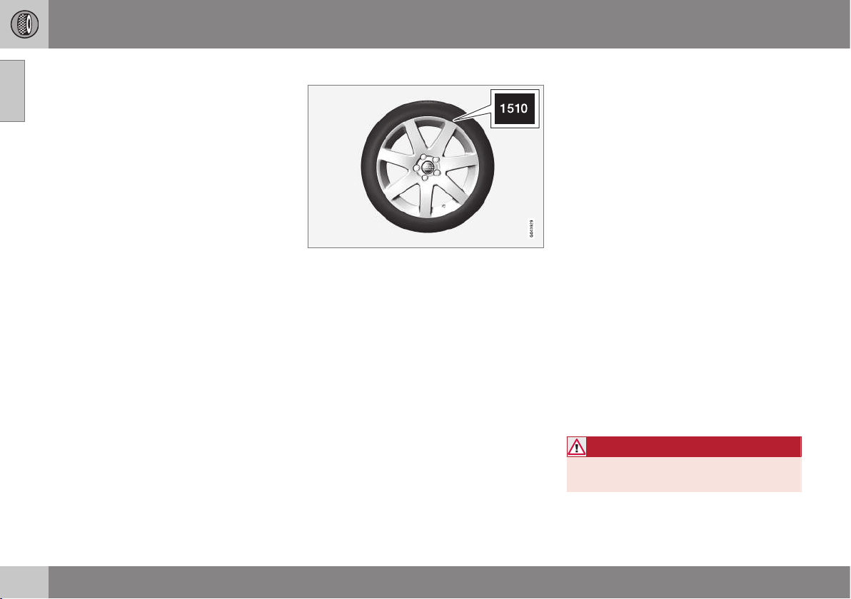
09 Wheels and tyres
09
322
Tyres - maintenance
Amongst other things, the function of the
tyres is to carry load, provide grip on the road
surface, dampen vibration and protect the
wheel from wear.
Driving characteristics
Tyres greatly affect the car's driving characte-
ristics. The type of tyre, dimensions, tyre
pressure and speed rating are important for
how the car performs.
Tyre age
All tyres older than 6 years old should be
checked by an expert even if they seem
undamaged. Tyres age and decompose, even
if they are hardly ever or never used. The
function can therefore be affected. This
applies to all tyres that are stored for future
use. Examples of external signs which indi-
cate that the tyre is unsuitable for use are
cracks or discoloration.
New tyres
Tyres are perishable. After a few years they
begin to harden at the same time as the fric-
tion capacity/characteristics gradually deteri-
orate. For this reason, aim to get as fresh
tyres as possible when you replace them.
This is especially important with regard to
winter tyres. The last four digits in the
sequence mean the week and year of manu-
facture. This is the tyre's DOT marking
(Department of Transportation), and this is
stated with four digits, for example 1510. The
tyre in the figure was manufactured in week
15 of 2010.
Summer and winter wheels
When summer and winter wheels are
changed the wheels should be marked with
which side of the car they were mounted on,
for example L for left and R for right.
Wear and maintenance
Correct tyre pressure (p. 324) results in more
even wear. Driving style, tyre pressure, cli-
mate and road condition affect how quickly
your tyres age and wear.
To avoid differences in tread depth and to
prevent wear patterns arising, the front and
rear wheels can be switched with each other.
A suitable distance for the first change is
approx. 5000 km and then at 10000 km inter-
vals.
Volvo recommends that an authorised Volvo
workshop is contacted for checking if you are
uncertain about tread depth. If significant dif-
ferences in wear (> 1 mm difference in tread
depth) between tyres have already occurred,
then the least worn tyres must always be fit-
ted on the rear. Understeer is normally easier
to correct than oversteer, and leads to the car
continuing forwards in a straight line rather
than having the rear end skidding to one side,
resulting in possible complete loss of control
over the car. This is why it is important for the
rear wheels never to lose grip before the front
wheels.
WARNING
A damaged tyre may lead to loss of control
over the car.
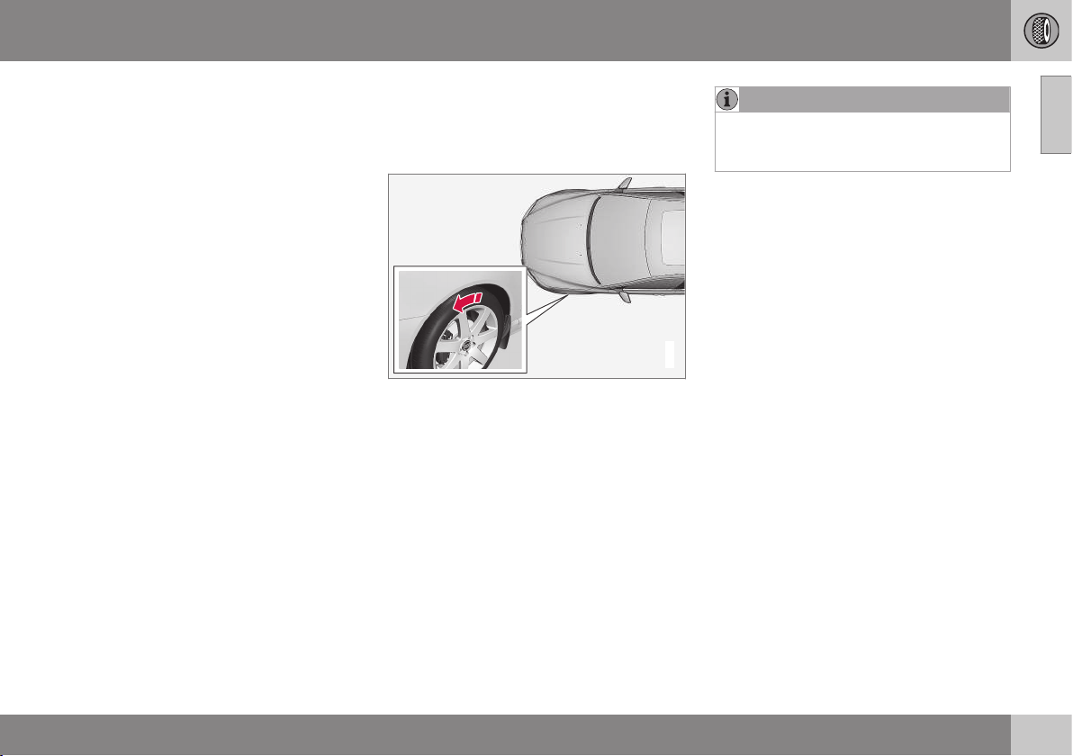
09 Wheels and tyres
09
323
Storage
Wheels with tyres fitted must be stored lying
down or hanging up - never standing up.
Related information
•
Tyres - dimensions (p. 326)
•
Tyres - speed ratings (p. 327)
•
Tyres - load index (p. 327)
•
Tyres - direction of rotation (p. 323)
•
Tyres - tread wear indicators (p. 324)
Tyres - direction of rotation
Tyres with a tread pattern which are designed
to only turn in one direction have the direction
of rotation marked with an arrow.
G021778
The arrow shows the tyre's direction of rotation.
The tyre must always rotate in the same
direction throughout its lifespan. Tyres should
only be switched between front and rear
positions, never between left and right-hand
sides, or vice versa. If the tyres are fitted
incorrectly, the car's braking characteristics
and capacity to force rain and slush out of the
way are adversely affected. Tyres with the
greatest tread depth should always be fitted
to the rear of the car (to decrease the risk of
skidding).
NOTE
Make sure that both pairs of wheels have
the same type and dimension, and also the
same make.
Follow the recommended tyre pressures
specified in the tyre pressure table (p. 423).
Related information
•
Tyres - dimensions (p. 326)
•
Tyres - speed ratings (p. 327)
•
Tyres - load index (p. 327)
•
Tyres - maintenance (p. 322)
•
Tyres - tread wear indicators (p. 324)
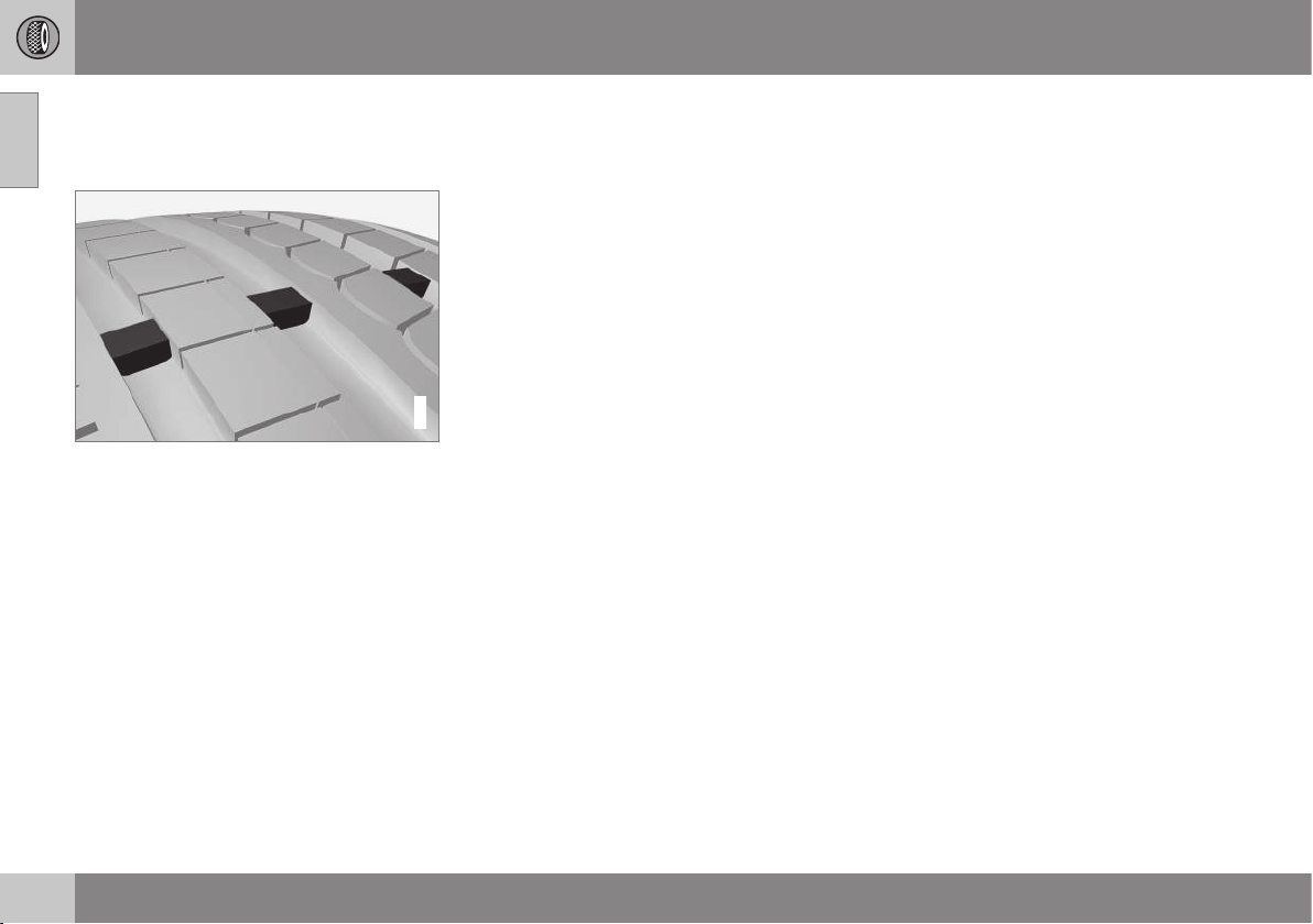
09 Wheels and tyres
09
324
Tyres - tread wear indicators
Tread wear indicators show the status of the
tyre's tread depth.
G021829
Tread wear indicators.
A tread wear indicators is a narrow elevation
across the longitudinal grooves of the tyre's
tread pattern. On the side of the tyre are the
letters TWI (Tread Wear Indicator). When the
tyre's tread depth is down to 1.6 mm, the
tread will be level in height with the tread
wear indicators. Change to new tyres as soon
as possible. Remember that tyres with little
tread depth provide very poor grip in rain and
snow.
Related information
•
Tyres - dimensions (p. 326)
•
Tyres - speed ratings (p. 327)
•
Tyres - load index (p. 327)
•
Tyres - direction of rotation (p. 323)
•
Tyres - maintenance (p. 322)
Tyres - air pressure
Tyres can have different air pressures which
are measured in bar.
Check the air pressure in the tyres
The tyre pressures must be checked every
month.
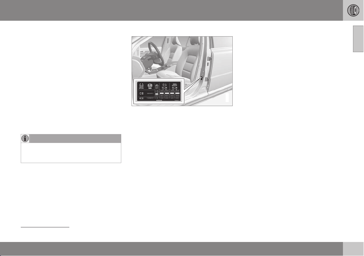
09 Wheels and tyres
09
325
•
Tyre pressure for the car's recommended
tyre dimension.
•
ECO pressure
1
.
Check the tyre pressure on cold tyres. "Cold
tyres" means the tyres are the same tempera-
ture as the ambient temperature. After several
few kilometres of driving, the tyres warm up
and the pressure increases.
Inadequate tyre pressure increases fuel con-
sumption, shortens tyre lifespan and impairs
the car's driving characteristics. Driving on
tyres with tyre pressure that is too low could
result in the tyres overheating and being
damaged. Tyre pressure affects travelling
comfort, road noise and driving characteris-
tics.
NOTE
Tyre pressure decreases over time, this is
a natural phenomenon. Tyre pressure also
varies depending on ambient temperature.
Tyre pressure label
G021830
The tyre pressure label on the driver's side
door pillar (between frame and rear door)
shows which pressures the tyres should have
at different loads and speed conditions. This
is also specified in the tyre pressure table,
see Tyres - approved tyre pressures (p. 423).
Fuel economy, ECO pressure
In order to obtain optimum fuel economy at
speeds below 160 km/h an ECO pressure is
recommended (applies to both full and light
load), see Tyres - approved tyre pressures
(p. 423).
Related information
•
Tyres - dimensions (p. 326)
•
Tyres - speed ratings (p. 327)
•
Tyres - load index (p. 327)
•
Tyres - maintenance (p. 322)
•
Tyres - tread wear indicators (p. 324)
1
ECO pressure results in improved fuel economy.
09 Wheels and tyres
09
326
Wheel and wheel rim dimensions
Wheel and rim dimensions are designated in
accordance with the examples in the table
below.
The car has an approval for the complete
vehicle. This means that certain combinations
of wheel (wheel rim) and tyre are approved.
Wheels (rims) have a designation of dimen-
sions, for example: 7Jx16x50.
7 Rim width in inches
J Rim flange profile
16 Rim diameter in inches
50 Off-set in mm (distance from wheel
centre to wheel contact surface
against the hub)
Related information
•
Tyres - dimensions (p. 326)
•
Tyres - approved tyre pressures (p. 423)
Tyres - dimensions
The car's tyres have a certain dimension, see
the examples in the table below.
The dimensions are stated on all car tyres.
Example of designation: 215/55R16 97W.
215 Tyre width (mm)
55 Ratio between tyre wall height and
tyre width (%)
R Radial ply
16 Rim diameter in inches (")
97 Codes for the maximum permitted
tyre load, tyre load index (LI)
W Speed rating for maximum permitted
speed, speed rating (SS). (In this
case 270 km/h.)
WARNING
19-inch wheels must never be used on
cars that are not equipped with the R-
Design or Sport chassis options. The use
of 19-inch wheels on cars with standard
chassis constitutes a safety risk, with a
risk of vehicle damage, and it impairs the
car's driving characteristics.
The car has an approval for the complete
vehicle with certain combinations of wheel
rims and tyres.
Related information
•
Tyres - speed ratings (p. 327)
•
Tyres - load index (p. 327)
•
Tyres - direction of rotation (p. 323)
•
Tyres - maintenance (p. 322)
•
Tyres - approved tyre pressures (p. 423)
•
Wheel and wheel rim dimensions (p. 326)
09 Wheels and tyres
09
327
Tyres - load index
Load index indicates a tyre's ability to carry a
certain load.
Each tyre has a certain capacity to carry a
load, a load index (LI). The car's weight deter-
mines the load capacity required of the tyres.
Minimum permissible index is indicated in the
load index table.
Related information
•
Tyres - dimensions (p. 326)
•
Tyres - approved tyre pressures (p. 423)
•
Tyres - speed ratings (p. 327)
•
Tyres - maintenance (p. 322)
Tyres - speed ratings
Each tyre can withstand a certain maximum
speed and therefore belongs to a particular
speed rating (SS - Speed Symbol).
Tyre speed class must at least correspond
with the car's top speed. The table below
indicates the maximum permitted speed that
applies for each speed rating (SS). The only
exception to these regulations is the winter
tyre (p. 328)
2
, where a lower speed rating
may be used. If such a tyre is chosen, the car
must not be driven faster than the speed rat-
ing of the tyre (for example, class Q can be
driven at a maximum of 160 km/h). Traffic
regulations determine how fast a car can be
driven, not the speed rating of the tyres.
NOTE
The maximum permitted speed is speci-
fied in the table.
Q 160 km/h (used only on winter tyres)
T 190 km/h
H 210 km/h
V 240 km/h
W 270 km/h
Y 300 km/h
WARNING
The car must be fitted with tyres which
have the same or a higher load index
(p. 327) (LI) and speed rating (SS) than
specified. If a tyre with too low a load
index or speed rating is used, it may over-
heat.
Related information
•
Tyres - dimensions (p. 326)
•
Tyres - load index (p. 327)
•
Tyres - direction of rotation (p. 323)
2
Both those with metal studs and those without.
09 Wheels and tyres
09
328
* Option/accessory, for more information, see Introduction.
Wheel bolts
Wheel bolts are used to fasten the wheels at
the hubs and are available in different ver-
sions.
IMPORTANT
The wheel bolts must be tightened to 140
Nm. Overtightening can damage the nuts
and the bolts.
Only use rims that are tested and approved
by Volvo and which are Volvo genuine acces-
sories. Check the torque with a torque
wrench.
Locking wheel bolts*
Locking wheel bolts* can be used on both
aluminium and steel rims. Under the cargo
area floor there is space for the sleeve for the
lockable wheel bolts.
Related information
•
Wheel and wheel rim dimensions (p. 326)
Winter tyres
Winter tyres are tyres that are adapted for
winter road conditions.
Winter tyres
Volvo recommends winter tyres with particu-
lar dimensions. Tyre dimensions are depend-
ent on engine variant. When driving on winter
tyres, the correct type of tyres must be fitted
to all four wheels.
NOTE
Volvo recommends that you consult a
Volvo dealer about which wheel rim and
tyre types are most suitable.
Studded tyres
Studded winter tyres should be run in gently
for 500-1000 km so the studs settle properly
into the tyres. This gives the tyre, and espe-
cially the studs, a longer service life.
NOTE
The legal provisions for the use of studded
tyres vary from country to country.
Tread depth
Road conditions with ice, slush and low tem-
peratures place considerably higher demands
on tyres than summer conditions. Volvo
therefore recommends not to drive on winter
tyres that have a tread depth of less than
4 mm.
Using snow chains
Snow chains may only be used on the front
wheels (also applies to all-wheel drive cars).
Never drive faster than 50 km/h with snow
chains. Avoid driving on bare ground as this
wears out both the snow chains and tyres.
WARNING
Use Volvo genuine snow chains or equiva-
lent chains designed for the car model,
and tyre and rim dimensions. In the event
of uncertainty Volvo recommends that you
consult an authorised Volvo workshop.
The wrong snow chains may cause serious
damage to your car and lead to an acci-
dent.
Related information
•
Changing wheels - removing wheels
(p. 329)
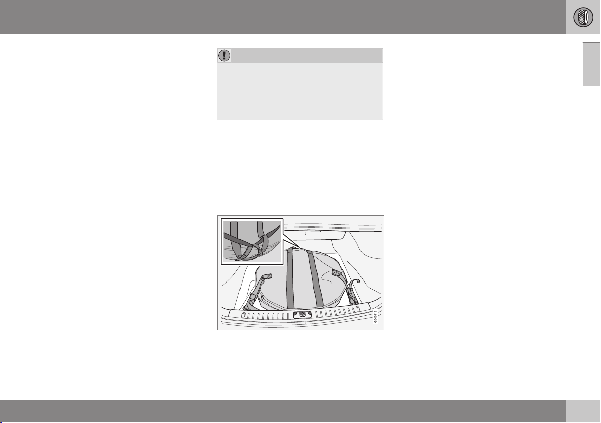
09 Wheels and tyres
09
}}
* Option/accessory, for more information, see Introduction.
329
Changing wheels - removing wheels
The car's wheels can be changed for e.g. win-
ter wheels/winter tyres.
Spare wheel*
The accessory spare wheel can be supplied
in two different versions, in a bag or for stor-
ing under the cargo area floor.
The following instructions only apply if a
spare wheel has been purchased as an
accessory for the car. If the car is not equip-
ped with a spare wheel - see information
about Emergency puncture repair (TMK)
(p. 341).
The spare wheel (Temporary spare) is only
intended for use temporarily and must be
replaced by an ordinary wheel as soon as
possible. The car's handling may be altered
by the use of the spare wheel. The spare
wheel is smaller than the normal wheel. The
car's ground clearance is affected accord-
ingly. Pay attention to high kerbs and do not
machine wash the car. If the spare wheel is
fitted on the front axle, you cannot use snow
chains at the same time. On all-wheel drive
cars the drive on the rear axle can be discon-
nected. The spare wheel must not be
repaired.
The correct tyre pressure for the spare wheel
is stated in the tyre pressure table (p. 423).
IMPORTANT
•
Never drive faster than 80 km/h with a
spare wheel on the car.
•
The car must never be driven fitted
with more than one "Temporary
Spare" wheel.
The spare wheel is located in the spare wheel
well with the outside down. The same bolt
runs through to secure the spare wheel and
the foam block. The foam block contains all
the tools needed to change the wheels.
The spare wheel is supplied in a bag and
must be secured on the cargo area floor
using straps.
Cars with two load retaining eyelets.
Turn the handle on the spare wheel bag in
towards the rear seat. Attach the sewn-in ten-
sioning strap hooks in the load retaining eye-
lets. Attach the long strap into one of the load
retaining eyelets, run the strap around the
spare wheel and through the lower handle.
Tighten the short tensioning strap onto the
long one. Attach the second load retaining
eyelet and tighten.
Taking out the spare wheel under the
cargo area floor
1. Fold up the cargo area floor.
2. Undo the retaining screw.
3. Lift out the foam block with its tools.
4. Lift out the spare wheel.
Taking out the spare wheel in the bag
1. Loosen the straps, lift out the spare wheel
from the cargo area and remove it from
the spare wheel bag.
2. Fold up the cargo area floor.
3. Lift the tools and jack out from the foam
block.
Removing
Set up warning triangle (p. 333) if a wheel is
replaced in trafficked location. The car and
jack* must be on a firm horizontal surface.
1. Apply the parking brake, (p. 298) and
engage reverse gear, or position P if the
car has an automatic gearbox.

||
09 Wheels and tyres
09
330
* Option/accessory, for more information, see Introduction.
WARNING
Check that the jack is not damaged, that
the threads are thoroughly lubricated and
that it is free from dirt.
NOTE
Volvo recommends only using the jack*
that belongs to the car model in question,
which is indicated on the jack's label.
The label also indicates the jack's maxi-
mum lift capacity at a specified minimum
lifting height.
2. Take out the jack*, wheel wrench*,
removal tool for wheel covers* and the
plastic wheel bolt cap removal tool. They
will be found in the foam block. If another
jack is selected, see Raising the car
(p. 358).
Tool for removing the plastic caps on the wheel
bolts.
3. Place chocks in front of and behind the
wheels which will remain on the ground to
prevent them from rolling. Use heavy
wooden blocks or large stones for exam-
ple.
4. Cars with steel rims have removable
wheel covers. Use the removal tool to
hook in and pull off any full-wheel wheel
covers. Alternatively, the wheel covers
can be pulled away by hand.
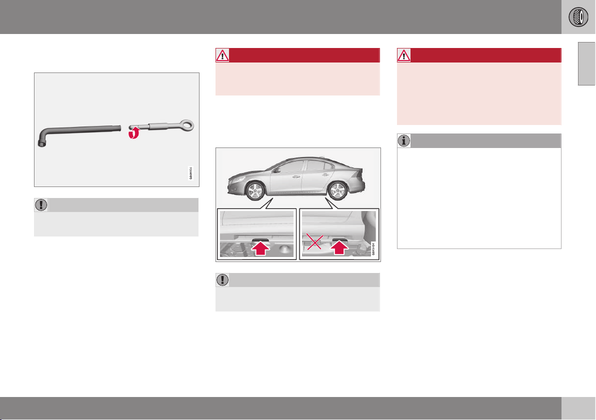
09 Wheels and tyres
09
* Option/accessory, for more information, see Introduction.
331
5. Screw together the towing eye with the
wheel wrench* to the stop position.
IMPORTANT
The towing eye must be screwed all the
way into the wheel bolt wrench.
6. Remove the plastic caps from the wheel
bolts with the intended tool.
7. Loosen the wheel bolts ½-1 turn anti-
clockwise with the wheel wrench.
WARNING
Never position anything between the
ground and the jack, nor between the jack
and the car's jacking point.
8. There are two jacking points on each side
of the car. Wind up the jack so that the
flange in the bodywork ends up in the
notch in the head of the jack.
IMPORTANT
The ground must be firm, smooth and
level.
9. Lift the car so that the wheel is free.
Remove the wheel bolts and lift off the
wheel.
WARNING
Never crawl under the car when it is raised
on the jack.
Passengers must leave the car when it is
raised on the jack. If a wheel must be
changed in a trafficked environment, pas-
sengers must stand in a safe place.
NOTE
The normal car jack is only designed for
occasional, short-term use, such as when
changing a wheel after a puncture, chang-
ing to winter/summer wheels, etc. Only the
jack for the specific car model may be
used to raise the car. If the car is to be
jacked up more often, or for a longer time
than is required just to change a wheel,
use of a garage jack is recommended. In
this instance, follow the instructions for
use that come with the equipment.
Related information
•
Changing wheels - fitting (p. 332)
•
Jack* (p. 334)
•
Warning triangle (p. 333)
•
Wheel bolts (p. 328)
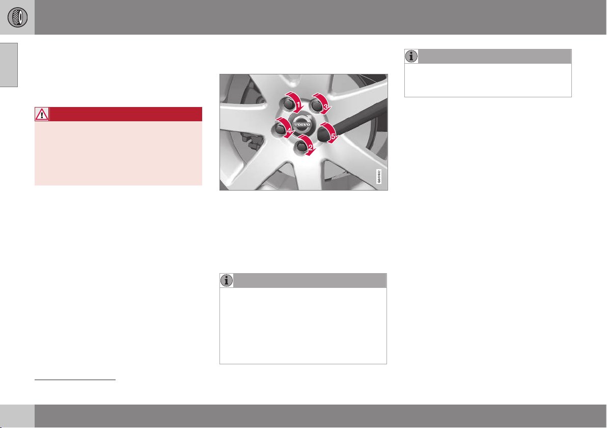
09 Wheels and tyres
09
332
* Option/accessory, for more information, see Introduction.
Changing wheels - fitting
It is important that the procedure for fitting
the wheel is carried out correctly.
Installation
WARNING
Never crawl under the car when it is raised
on the jack.
Passengers must leave the car when it is
raised on the jack. If a wheel must be
changed in a trafficked environment, pas-
sengers must stand in a safe place.
1. Clean the contact surfaces between
wheel and hub.
2. Put on the wheel. Tighten the wheel bolts
thoroughly.
3. Lower the car so that the wheels cannot
rotate.
4. Tighten the wheel bolts crosswise. It is
important that the wheel bolts are tight-
ened properly. Tighten to 140 Nm. Check
the torque with a torque wrench.
5. Refit the plastic caps on the wheel bolts.
6. Refit any full wheel covers.
NOTE
•
After a tyre has been inflated, always
refit the dust cap in order to avoid
damage to the valve from gravel, dirt,
etc.
•
Only use plastic dust caps. Metal dust
caps can rust and become difficult to
unscrew.
NOTE
The wheel cover outlet for the valve must
be positioned over the valve on the wheel
rim during fitting.
When changing to another tyre
dimension
Applies to cars with tyre pressure monitor-
ing
3
: Contact an authorised Volvo workshop
for updating the software at each change of
tyre dimension. A software download may be
necessary both when changing to larger and
smaller dimensions, and also when switching
between summer and winter wheels.
Related information
•
Changing wheels - removing wheels
(p. 329)
•
Jack* (p. 334)
•
Warning triangle (p. 333)
•
Wheel bolts (p. 328)
3
Standard in certain markets.
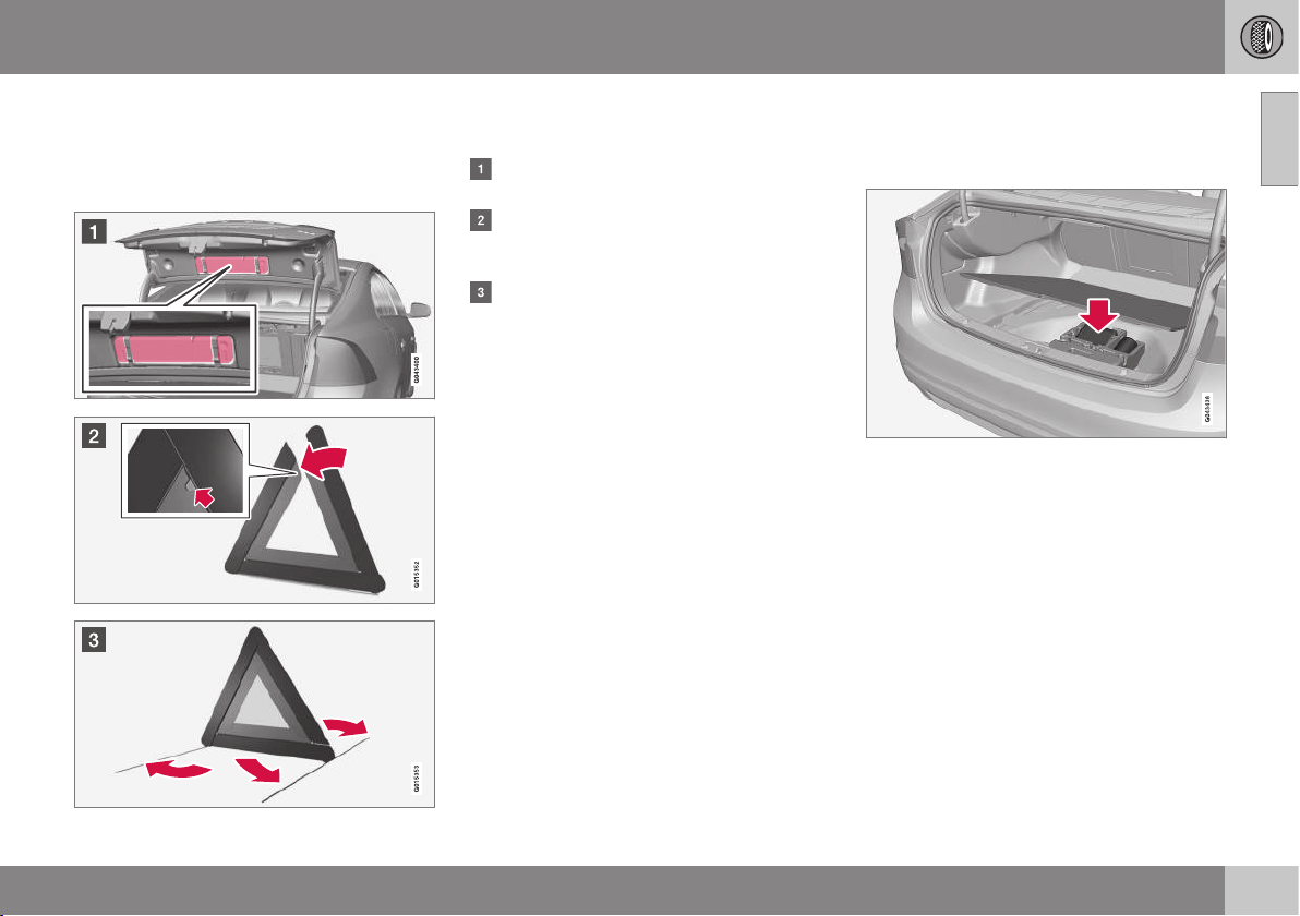
09 Wheels and tyres
09
* Option/accessory, for more information, see Introduction.
333
Warning triangle
The warning triangle is used to warn other
road users of a stationary vehicle.
Storage and folding up
The warning triangle is fitted on the inside of
the boot lid with two clips.
Detach the warning triangle case by pull-
ing both of the snap latches outwards.
Take the warning triangle from the case,
fold out and assemble the two loose
sides.
Fold out the warning triangle's support
legs.
Follow the regulations for the use of a warn-
ing triangle. Position the warning triangle in a
suitable place with regard to traffic.
Ensure the warning triangle and its case are
properly secured in the cargo area after use.
Tools
Amongst other things, the car contains towing
eye, jack* and wheel wrench*.
Located under the cargo area floor are the
car's towing eye, jack* and wheel wrench*.
There is also space here for the sleeve for the
locking wheel bolts and tools for the plastic
wheel bolt caps.
Related information
•
Emergency puncture repair (p. 341)
•
Towing eye (p. 319)
•
Changing wheels - removing wheels
(p. 329)
•
Wheel bolts (p. 328)
•
Jack* (p. 334)
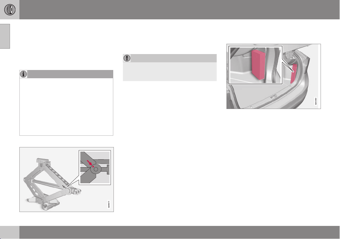
09 Wheels and tyres
09
334
* Option/accessory, for more information, see Introduction.
Jack*
A jack is used to raise the car, e.g. when
changing the tyres.
The original jack should only be used for
changing to the spare wheel. The jack's
thread must always be well greased.
NOTE
The normal car jack is only designed for
occasional, short-term use, such as when
changing a wheel after a puncture, chang-
ing to winter/summer wheels, etc. Only the
jack for the specific car model may be
used to raise the car. If the car is to be
jacked up more often, or for a longer time
than is required just to change a wheel,
use of a garage jack is recommended. In
this instance, follow the instructions for
use that come with the equipment.
Tools - returning into place
The tools and jack* must be returned to their
correct places after use. The jack needs to be
cranked together to the correct position in
order to have space.
IMPORTANT
The tools and jack* must be stored in the
intended location in the car's cargo area
when not in use.
Related information
•
Warning triangle (p. 333)
•
Emergency puncture repair (p. 341)
First aid kit*
The first aid box contains first aid equipment.
A case with first aid equipment is located in
the cargo area.

09 Wheels and tyres
09
}}
* Option/accessory, for more information, see Introduction.
335
Tyre pressure monitoring*
4
Tyre pressure monitoring warns the driver
when the pressure is too low in one or more
of the car's tyres. For certain markets the tyre
pressure monitoring is standard in accord-
ance with legal requirements.
There are two systems for tyre pressure
monitoring, TPMS (Tyre Pressure Monitoring
System) and TM (Tyre Monitor). In the event
of uncertainty about which system the car
has, open the menu system MY CAR and
search for the car's settings:
•
The
Tyre pressure menu is used if it is
TPMS, see Tyre pressure monitoring sys-
tem (TPMS)* - general (p. 335)
•
The
Tyre monitoring menu is used if it is
TM, see Tyre pressure monitoring (TM)*
(p. 339).
The system does not replace normal tyre
maintenance.
Related information
•
Tyre pressure monitoring system (TPMS)*
- general (p. 335)
•
Tyre pressure monitoring (TPMS)* - adjust
(recalibration) (p. 336)
•
Tyre pressure monitoring (TPMS)* - recti-
fying low tyre pressure (p. 339)
•
Tyre pressure monitoring (TPMS)* - acti-
vate/deactivate (p. 338)
•
Tyre pressure monitoring (TPMS)* - rec-
ommendations (p. 338)
Tyre pressure monitoring system
(TPMS)*
11
- general
Tyre pressure monitoring (TPMS) (Tyre
Pressure Monitoring System)* warns the
driver when the pressure is too low in one or
more of the car's tyres.
Tyre pressure monitoring uses sensors
located inside the air valve in each wheel.
When the car is driven at about 30 km/h the
system detects the tyre pressure. If the pres-
sure is too low then a warning lamp
illumi-
nates in the combined instrument panel and
one of the following messages is shown:
•
Tyre pressure low Check front right
tyre
•
Tyre pressure low Check front left
tyre
•
Tyre pressure low Check rear right
tyre
•
Tyre pressure low Check rear left tyre
•
Tyre needs air now Check front right
tyre
•
Tyre needs air now Check front left
tyre
•
Tyre needs air now Check rear right
tyre
4
Standard in certain markets.
||
09 Wheels and tyres
09
336
* Option/accessory, for more information, see Introduction.
•
Tyre needs air now Check rear left
tyre
•
Tyre pressure system Service
required
Both factory-fitted and optional wheels can
be equipped with TPMS sensors in the
valves.
If wheels without TPMS sensors are used or if
a sensor has failed then
Tyre pressure
system Service required will be shown.
Always check the system after changing a
wheel in order to ensure that replacement
wheels work with the system.
For information on the correct tyre pressure,
see Tyres - air pressure (p. 324).
The system does not replace normal tyre
maintenance.
IMPORTANT
If a fault occurs in the TPMS system the
warning lamp
in the combined instru-
ment panel will flash for approx. 1 minute
and then illuminate with a constant glow. A
message is also shown in the combined
instrument panel.
Related information
•
Tyre pressure monitoring (TPMS)* - adjust
(recalibration) (p. 336)
•
Tyre pressure monitoring (TPMS)* - recti-
fying low tyre pressure (p. 339)
•
Tyre pressure monitoring (TPMS)* - acti-
vate/deactivate (p. 338)
•
Tyre pressure monitoring (TPMS)* - rec-
ommendations (p. 338)
Tyre pressure monitoring (TPMS)*
17
-
adjust (recalibration)
Tyre pressure monitoring (TPMS) (Tyre
Pressure Monitoring System)* warns the
driver when the pressure is too low in one or
more of the car's tyres.
TPMS can be adjusted in order to follow Vol-
vo's tyre pressure recommendations (p. 324),
such as when driving with a heavy load, for
example.
NOTE
The car must be stationary when calibra-
tion is started.
Settings are made using the centre console's
controls, see MY CAR (p. 108).
1. Inflate the tyres to the desired pressure in
accordance with the tyre pressure label
on the driver's side door pillar (between
front and rear doors).
2. Start the engine.
3. Select the menu system MY CAR to open
the menus for tyre pressure.
4.
Select
Calibrate tyre pressure and
press OK.
11
Standard in certain markets.
17
Standard in certain markets.

09 Wheels and tyres
09
}}
* Option/accessory, for more information, see Introduction.
337
5. Drive for at least 10 minutes at a speed of
at least 30 km/h.
> Calibration is performed automatically
following initialisation by the driver.
The system provides no confirmation
when the calibration is complete.
The new reference values apply until steps
1-5 are carried out again.
Related information
•
Tyre pressure monitoring* (p. 335)
•
Tyres - air pressure (p. 324)
Tyre pressure monitoring system
(TPMS)*
19
- status
Tyre pressure monitoring (TPMS) (Tyre
Pressure Monitoring System)* warns the
driver when the pressure is too low in one or
more of the car's tyres.
System and tyre status
The current status of the system and the tyres
can be checked, see MY CAR (p. 108).
1. Select the menu system MY CAR to open
the menus for tyre monitoring.
2.
Select
Tyre pressure.
The status is colour-coded for each tyre in
accordance with the following:
•
All-green: the system is operating nor-
mally and the tyre pressure in all tyres is
slightly above the recommended level.
•
Yellow wheel: corresponding tyre's pres-
sure is too low.
•
Red wheel: corresponding tyre's pressure
is very low.
•
All wheels grey: the system is temporarily
unavailable. It may be necessary to drive
the car for a few minutes at a speed
above 30 km/h before the system
becomes active again.
•
All wheels grey and the message
Tyre
pressure system Service required: an
error has occurred in the system. Contact
a Volvo dealer or workshop.
Clearing warning messages
If a tyre pressure message has been shown
and the TPMS warning lamp has been illumi-
nated:
1. Check the tyre pressure on the indicated
tyre/tyres with a tyre pressure gauge.
2. Inflate the tyre/tyres to the correct pres-
sure in accordance with the tyre pressure
label on the driver's side door pillar
(between front and rear doors).
3. In some cases it may be necessary to
drive the car for a few minutes at a speed
above 30 km/h in order to clear the warn-
ing text. At which point, the TPMS warn-
ing lamp is extinguished as well.
19
Standard in certain markets.
09 Wheels and tyres
09
338
* Option/accessory, for more information, see Introduction.
NOTE
•
The TPMS system uses a so-called
compensated pressure value, based
on both tyre temperature and ambient
temperature. This means that the tyre
pressure may differ slightly from the
recommended pressures listed on the
tyre pressure label on the driver's side
door pillar (between front and rear
doors). For this reason, it may be nec-
essary to inflate the tyres to a slightly
higher pressure in order to clear a low
tyre pressure message.
•
To avoid incorrect tyre pressure, the
pressure should be checked on cold
tyres. "Cold tyres" means the tyres are
the same temperature as the ambient
temperature (approx. 3 hours after the
car has been driven). After a few kilo-
metres of driving, the tyres warm up
and the pressure increases.
WARNING
•
Incorrect tyre pressure may lead to
tyre failure, which could result in the
driver losing control of the car.
•
The system cannot indicate sudden
tyre damage in advance.
Tyre pressure monitoring (TPMS)*
20
-
activate/deactivate
21
Tyre pressure monitoring (TPMS) (Tyre
Pressure Monitoring System)* warns the
driver when the pressure is too low in one or
more of the car's tyres.
NOTE
The car must be stationary when the tyre
pressure monitoring is activated/deacti-
vated.
Settings are made using the centre console's
controls, see MY CAR (p. 108).
1. Start the engine.
2. Select the menu system MY CAR to open
the menus for tyre pressure.
3.
Select
Tyre pressure and press OK.
>
An
X is shown in the information dis-
play if the system is activated, the
option disappears if the system is
deactivated.
Related information
•
Tyre pressure monitoring* (p. 335)
Tyre pressure monitoring (TPMS)*
23
-
recommendations
Tyre pressure monitoring (TPMS) (Tyre
Pressure Monitoring System)* warns the
driver when the pressure is too low in one or
more of the car's tyres.
•
Volvo recommends that TPMS sensors
are fitted to all wheels on the car, includ-
ing winter wheels.
•
Volvo recommends that sensors are not
moved between different wheels.
•
The spare wheel is not equipped a with
TPMS sensor.
•
If the spare wheel or a wheel without a
TPMS sensor is used, the error message
Tyre pressure system Service
required will be shown in the combined
instrument panel.
•
If a wheel has been changed, or if the
TPMS sensor has been moved to another
wheel then the seal, nut and valve core
must be replaced.
•
When TPMS sensors are installed, the car
should be switched off for at least 15
minutes otherwise an error message will
be shown in the combined instrument
panel.
20
Standard in certain markets.
21
Only in certain markets.
23
Standard in certain markets.
09 Wheels and tyres
09
}}
* Option/accessory, for more information, see Introduction.
339
WARNING
When inflating a tyre equipped with TPMS,
hold the nozzle of the pump directly
against the valve to avoid damaging the
valve.
NOTE
•
After a tyre has been inflated, always
refit the dust cap in order to avoid
damage to the valve from gravel, dirt,
etc.
•
Only use plastic dust caps. Metal dust
caps can rust and become difficult to
unscrew.
NOTE
If you want to change the tyre dimension
then the TPMS system must be reconfig-
ured. For further information - contact a
Volvo dealer.
Related information
•
Tyre pressure monitoring* (p. 335)
Tyre pressure monitoring (TPMS)*
25
-
rectifying low tyre pressure
The tyre pressure monitoring system TPMS
(Tyre Pressure Monitoring System)
26
warns
the driver when the pressure is too low in one
or more of the car's tyres and indicates the
tyre to which it applies.
Yellow is shown at the first indication of low
tyre pressure, stop and check the tyre pres-
sure as soon as possible.
Red indicates a much lower pressure than
recommended, stop and rectify the tyre pres-
sure immediately.
If a message for low tyre pressure is shown in
the display:
1. Check the tyre pressure on the tyre in
question.
2. Inflate the tyre(s) to the correct pressure.
3. Drive at least at 30 km/h for several
minutes and check that the message dis-
appears.
Related information
•
Tyre pressure monitoring* (p. 335)
Tyre pressure monitoring (TM)*
28
The TM (Tyre Monitor) system senses the
rotation speed of the tyres in order to deter-
mine whether they have the correct tyre pres-
sure. If the pressure is too low, the tyre's
diameter is changed and, as a result, so is the
rotation speed. By comparing the tyres with
each other the system can determine whether
one or more tyres have pressure that is too
low.
Messages
If the tyre pressure is too low then a warning
lamp (
) illuminates in the combined instru-
ment panel and one of the following mes-
sages is shown:
•
Tyre pressure low Check front right
tyre
•
Tyre pressure low Check front left
tyre
•
Tyre pressure low Check rear right
tyre
•
Tyre pressure low Check rear left tyre
•
Tyre pressure low Check tyres
•
Tyre pressure system Service
required
•
The tyre pressure system is currently
not active
25
Standard in certain markets.
26
Option only in certain markets.
28
Standard in certain markets.
||
09 Wheels and tyres
09
340
IMPORTANT
If a fault occurs in the TM system the
warning lamp
in the combined instru-
ment panel will flash for approx. 1 minute
and then illuminate with a constant glow. A
message is also shown in the combined
instrument panel.
The system does not replace normal tyre
maintenance.
TM calibration
In order for TM to work correctly, a reference
value for the tyre pressure must be deter-
mined. This must be performed each time the
tyres are changed or the tyre pressure is
changed.
Recalibration
Settings are made using the centre console's
controls, see MY CAR (p. 108).
1. Switch off the ignition.
2. Inflate all tyres to the desired pressure in
accordance with the tyre pressure label
on the driver's side door pillar (between
front and rear doors) and select key posi-
tion II, see Key positions - functions at
different levels (p. 76).
3. Select the menu system MY CAR to open
the menus for tyre monitoring.
4.
Select
Calibrate tyre pressure and
press OK.
5. Start and drive the car.
> Recalibration is carried out while the
car is being driven and can be inter-
rupted at any time. If the engine is
switched off while recalibration is in
progress then it is resumed when the
car is driven again. The system pro-
vides no confirmation when the cali-
bration is complete.
The new reference value applies until steps
1-5 are repeated.
NOTE
Remember that the TM system must be
recalibrated at each tyre change or if the
tyre pressure is changed. If new reference
values are not stored then the system can-
not function properly.
NOTE
•
After a tyre has been inflated, always
refit the dust cap in order to avoid
damage to the valve from gravel, dirt,
etc.
•
Only use plastic dust caps. Metal dust
caps can rust and become difficult to
unscrew.
System and tyre status
The current status of the system and the tyres
can be checked, see MY CAR (p. 108).
1. Select the menu system MY CAR to open
the menus for tyre monitoring.
2.
Select
Tyre monitoring.
The status is colour-coded for each tyre in
accordance with the following:
•
All-green: the system is operating nor-
mally and the tyre pressure in all tyres is
slightly above the recommended level.
•
Yellow wheel: corresponding tyre's pres-
sure is too low.
•
All wheels yellow: two or more tyres have
pressure that is too low.
•
All wheels grey and the message
The
tyre pressure system is currently not
active: the tyre pressure system is tem-
porarily deactivated. It may be necessary
to drive the car for a short time above 30
km/h before the system becomes active
again.
•
All wheels grey and the message
Tyre
pressure system Service required: an
error has occurred in the system. Contact
a Volvo dealer or workshop.
Clearing warning messages
If a tyre pressure message has been shown
and the TM warning lamp has been illumi-
nated:
09 Wheels and tyres
09
341
1. Check the tyre pressure in all tyres with a
tyre pressure gauge.
2. Inflate the tyre/tyres to the correct pres-
sure in accordance with the tyre pressure
label on the driver's side door pillar
(between front and rear doors).
3. Recalibrate the TM system.
NOTE
To avoid incorrect tyre pressure, the pres-
sure should be checked on cold tyres.
"Cold tyres" means the tyres are the same
temperature as the ambient temperature
(approx. 3 hours after the car has been
driven). After a few kilometres of driving,
the tyres warm up and the pressure
increases.
WARNING
•
Incorrect tyre pressure may lead to
tyre failure, which could result in the
driver losing control of the car.
•
The system cannot indicate sudden
tyre damage in advance.
Emergency puncture repair
The emergency puncture repair kit,
Temporary Mobility Kit (TMK), is used to seal
a puncture and check and adjust the tyre
pressure (p. 423).
The emergency puncture repair kit (p. 342)
consists of a compressor and a bottle of seal-
ant. The sealing works as a temporary repair.
The sealing fluid bottle must be replaced
before its expiration date and after use. The
sealing fluid effectively seals tyres punctured
in the tread.
NOTE
The emergency puncture repair kit is only
intended for sealing tyres with a puncture
in the tread.
The emergency puncture repair kit has limited
capacity to seal tyres which have punctures
in the wall. Do not seal tyres with the emer-
gency puncture repair kit if they have larger
slits, cracks or similar damage. Connect the
compressor to one of the car's 12 V sockets.
Choose the socket that is nearest to the
punctured tyre.
IMPORTANT
If the compressor is connected to one of
the two 12 V sockets, in the tunnel con-
sole, no other current consumer must be
connected to the other one.
NOTE
The compressor for temporary emergency
puncture repair has been tested and
approved by Volvo.
Related information
•
Emergency puncture repair - operation
(p. 343)
•
Emergency puncture repair - rechecking
(p. 345)
•
Emergency puncture repair kit - overview
(p. 342)
•
Tools (p. 333)
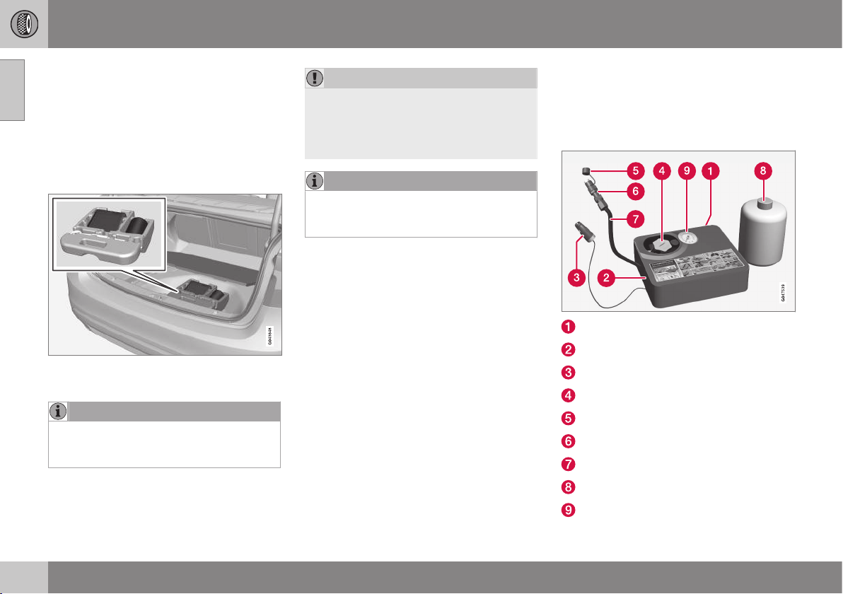
09 Wheels and tyres
09
342
Emergency puncture repair kit -
location
The emergency puncture repair kit,
Temporary Mobility Kit (TMK), is used to seal
a puncture and check and adjust the tyre
pressure.
Location of the emergency puncture
repair kit
The emergency puncture repair kit is located
under the floor in the cargo area.
NOTE
The emergency puncture repair kit is only
intended for sealing tyres with a puncture
in the tread.
IMPORTANT
If the compressor for emergency puncture
repair is connected to one of the two sock-
ets (p. 148) in the tunnel console then no
other current consumer may be connected
to the other one.
NOTE
The compressor for temporary emergency
puncture repair has been tested and
approved by Volvo.
Related information
•
Emergency puncture repair kit - overview
(p. 342)
•
Emergency puncture repair kit - sealant
(p. 347)
•
Emergency puncture repair (p. 341)
Emergency puncture repair kit -
overview
Overview of the component parts of the
emergency puncture repair kit, Temporary
Mobility Kit (TMK).
Label, maximum permitted speed
Switch
Cable
Bottle holder (orange cap)
Protective cap
Pressure reducing valve
Air hose
Sealing fluid bottle
Pressure gauge
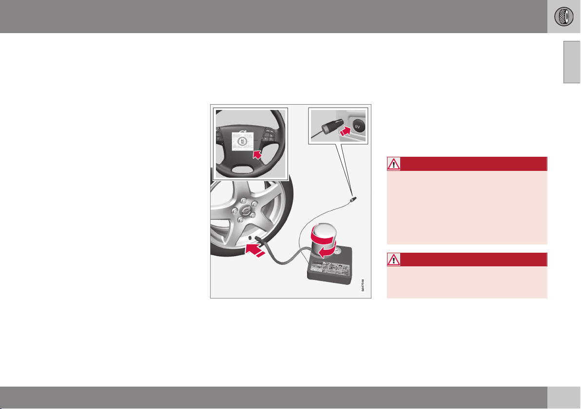
09 Wheels and tyres
09
}}
343
Related information
•
Emergency puncture repair kit - location
(p. 342)
•
Emergency puncture repair kit - sealant
(p. 347)
•
Emergency puncture repair (p. 341)
Emergency puncture repair -
operation
Sealing a puncture with the emergency punc-
ture repair kit, Temporary Mobility Kit (TMK).
Emergency puncture repair
For information on the function of the parts, see
Emergency puncture repair kit - overview
(p. 342).
1. Set up the warning triangle and activate
the hazard warning lights if a tyre is being
sealed in a trafficked location.
If the puncture was caused by a nail or
similar, allow this to remain in the tyre. It
helps to seal the hole.
2. Detach the label for maximum permitted
speed (which is fitted on one side of the
compressor) and affix it to the steering
wheel.
WARNING
You should not drive faster than 80 km/h
after the emergency tyre repair kit has
been used. Volvo recommends that you
visit an authorised Volvo workshop for
inspection of the sealed tyre (maximum
driving distance is 200 km). The staff there
can determine whether or not the tyre can
be repaired or if it needs to be replaced.
WARNING
The sealing fluid can irritate the skin. In the
case of contact with skin, wash away the
fluid with soap and water.
3. Check that the switch is in position 0 and
locate the cable and the air hose.
||
09 Wheels and tyres
09
344
NOTE
Do not break the bottle's seal before use.
The seal is broken automatically when the
bottle is screwed in.
4. Unscrew the orange cap and unscrew the
bottle's stopper.
5. Screw the bottle into its holder.
WARNING
Do not unscrew the bottle, it is equipped
with a reverse catch to prevent leakage.
6. Connect the hose from the compressor to
the valve.
7. Plug the cable into the 12 V socket and
start the car.
NOTE
If the compressor is connected to one of
the two 12 V sockets in the tunnel console
then no other current consumer may be
connected to the other one.
WARNING
Do not leave children in the car without
supervision when the engine is running.
8. Flick the switch to position I.
WARNING
Never stand next to the tyre when the
compressor is running. If cracks or
unevenness arise then the compressor
must be switched off immediately. The
journey should not be continued. Contact-
ing an authorised tyre centre is recom-
mended.
NOTE
When the compressor starts, the pressure
can increase up to 6 bar but the pressure
drops after approximately 30 seconds.
9. Inflate the tyre for 7 minutes.
IMPORTANT
Risk of overheating. The compressor must
not run for more than 10 minutes.
10. Switch off the compressor to check the
pressure on the pressure gauge. Mini-
mum pressure is 1.8 bar and maximum
3.5 bar. (Release air with the pressure
reducing valve if the tyre pressure is too
high.)
WARNING
If the pressure is below 1.8 bar then the
hole in the tyre is too big. The journey
should not be continued. Contacting an
authorised tyre centre is recommended.
11. Switch off the compressor and unplug the
cable from the 12 V socket.
12. Detach the hose from the tyre valve and
fit the valve cap.
09 Wheels and tyres
09
}}
345
13. As soon as possible, drive approximately
3 km at a maximum speed of 80 km/h so
that the sealing fluid can seal the tyre.
NOTE
Sealant will spurt out of the puncture dur-
ing the first few rotations of the tyre.
WARNING
Make sure that nobody is standing near
the car and gets the sealing fluid splashed
onto them when the car is driven away.
The distance should be at least two
metres.
Related information
•
Emergency puncture repair (p. 341)
•
Emergency puncture repair - rechecking
(p. 345)
•
Emergency puncture repair kit - overview
(p. 342)
Emergency puncture repair -
rechecking
When a tyre has been sealed with the emer-
gency puncture repair kit, Temporary Mobility
Kit (TMK), a subsequent check must be made
after approx. 3 kilometres of driving.
Check tyre pressure
1. Reconnect the equipment.
2. Read the tyre pressure on the pressure
gauge.
•
If it is below 1.3 bar
29
then the tyre is
insufficiently sealed. The journey
should not be continued. Contact a
tyre centre.
•
If the tyre pressure is higher than 1.3
bar
29
, the tyre must be inflated to the
pressure specified in accordance with
the tyre pressure table, see Tyres -
approved tyre pressures (p. 423).
Release air using the pressure reduc-
ing valve if the tyre pressure is too
high.
WARNING
Do not unscrew the bottle, it is equipped
with a reverse catch to prevent leakage.
3. Make sure the compressor is switched
off. Detach the air hose and cable.
Fit the valve cap.
NOTE
•
After a tyre has been inflated, always
refit the dust cap in order to avoid
damage to the valve from gravel, dirt,
etc.
•
Only use plastic dust caps. Metal dust
caps can rust and become difficult to
unscrew.
NOTE
The sealing fluid bottle and the hose must
be replaced after use. Volvo recommends
that this replacement is performed by an
authorised Volvo workshop.
WARNING
Check the tyre pressure regularly.
Volvo recommends that the car is driven to
the nearest authorised Volvo workshop for
29
1 bar = 100 kPa.
||
09 Wheels and tyres
09
346
the replacement/repair of the damaged tyre.
Advise the workshop that the tyre contains
sealing fluid.
WARNING
You should not drive faster than 80 km/h
after the emergency tyre repair kit has
been used. Volvo recommends a visit to
an authorised Volvo workshop for inspec-
tion of the sealed tyre (maximum driving
distance is 200 km). The staff there can
determine whether or not the tyre can be
repaired or if it needs to be replaced.
Related information
•
Emergency puncture repair (p. 341)
•
Emergency puncture repair - operation
(p. 343)
•
Emergency puncture repair kit - overview
(p. 342)
Emergency puncture repair kit -
inflating the tyres
The car's original tyres can be inflated using
the compressor in the emergency puncture
repair kit (p. 342).
1. The compressor must be switched off.
Make sure that the switch is in position 0
and locate the cable and air hose.
2. Unscrew the wheel's dust cap and screw
in the air hose valve connection to the
bottom of the thread on the tyre's air
valve.
WARNING
Inhaling car exhaust fumes could result in
danger to life. Never leave the engine run-
ning in sealed areas or areas that lack suf-
ficient ventilation.
WARNING
Do not leave children in the car without
supervision when the engine is running.
3. Connect the cable to one of the car's
12 V sockets and start the car.
4. Start the compressor by flicking the
switch to position I.
IMPORTANT
Risk of overheating. The compressor must
not run for more than 10 minutes.
5. Inflate the tyre to the pressure specified in
accordance with the tyre pressure table,
see Tyres - approved tyre pressures
(p. 423). Release air using the pressure
reducing valve if the tyre pressure is too
high.
6. Switch off the compressor. Detach the air
hose and cable.
7. Refit the dust cap.
Related information
•
Emergency puncture repair (p. 341)
•
Emergency puncture repair kit - overview
(p. 342)
•
Emergency puncture repair - rechecking
(p. 345)

09 Wheels and tyres
09
347
Emergency puncture repair kit -
sealant
The container (bottle) with the emergency
puncture repair kit (p. 342) contains sealant
and it can be replaced.
Replace the bottle when the expiration date
has passed. Treat the old bottle as environ-
mentally hazardous waste.
WARNING
The bottle contains 1.2-Ethanol and natu-
ral rubber-latex.
Harmful if ingested. Could result in allergic
reaction in the event of skin contact.
Avoid contact with the skin and eyes.
Store out of the reach of children.
Related information
•
Emergency puncture repair (p. 341)

09 Wheels and tyres
09
348
* Option/accessory, for more information, see Introduction.
Type approval - tyre pressure
monitoring (TPMS)
Type approval of the sensors in tyre pressure
monitoring - TPMS (Tyre Pressure Monitoring
System)* can be read in the table.
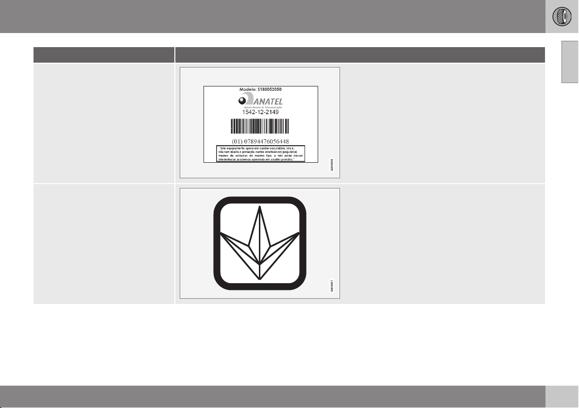
09 Wheels and tyres
09
}}
349
Country/Area
Brazil
Ukraine
||
09 Wheels and tyres
09
350
Country/Area
Israel
09 Wheels and tyres
09
}}
351
Declaration of Conformity (Declaration of Conformity)
Country/
Area
Countries in
the EU:
Exporting country: Germany
Manufacturer: Continental Automotive GmbH
Type of equipment: TPMS unit

||
09 Wheels and tyres
09
352
Country/
Area
Czech Repub-
lic:
Continental tímto prohlašuje, že tento Radio Transmitter je ve shodě se základními požadavky a dalšími příslušnými
ustanoveními směrnice 1999/5/ES.
Denmark: Undertegnede Continental erklærer herved, at følgende udstyr Radio Transmitter overholder de væsentlige krav og øvrige
relevante krav i direktiv 1999/5/EF.
Germany: Hiermit erklärt Continental, dass sich das Gerät Radio Transmitter in Übereinstimmung mit den grundlegenden Anforderungen
und den übrigen einschlägigen Bestimmungen der Richtlinie 1999/5/EG befindet.
Estonia: Käesolevaga kinnitab Continental seadme Radio Transmitter vastavust direktiivi 1999/5/EÜ põhinõuetele ja nimetatud
direktiivist tulenevatele teistele asjakohastele sätetele.
UK Hereby, Continental declares that this Radio Transmitter is in compliance with the essential requirements and other relevant
provisions of Directive 1999/5/EC.
Spain: Por medio de la presente Continental declara que el Radio Transmitter cumple con los requisitos esenciales y cualesquiera
otras disposiciones aplicables o exigibles de la Directiva 1999/5/CE.
Greece: ΜΕ ΗΝ ΠΑΡΟΣΑ Continental ΗΛΩΝΕ Ο Radio Transmitter ΣΜΜΟΡΦΩΝΕΑ ΠΡΟΣ Σ ΟΣΩΕΣ ΑΠΑΗΣΕΣ Α
Σ ΛΟΠΕΣ ΣΧΕΕΣ ΑΑΞΕΣ ΗΣ ΟΗΑΣ 1999/5/Ε.
France: Par la présente Continental déclare que l'appareil Radio Transmitter est conforme aux exigences essentielles et aux autres
dispositions pertinentes de la directive 1999/5/CE.
Italy: Con la presente Continental dichiara che questo Radio Transmitter è conforme ai requisiti essenziali ed alle altre disposizioni
pertinenti stabilite dalla direttiva 1999/5/CE.
Latvia: Ar šo Continental deklarē, ka Radio Transmitter atbilst Direktīvas 1999/5/EK būtiskajām prasībām un citiem ar to saistītajiem
noteikumiem.
Lithuania: Šiuo Continental deklaruoja, kad šis Radio Transmitter atitinka esminius reikalavimus ir kitas 1999/5/EB Direktyvos nuostatas.
Netherlands: Hierbij verklaart Continental dat het toestel Radio Transmitter in overeenstemming is met de essentiële eisen en de andere
relevante bepalingen van richtlijn 1999/5/EG.

09 Wheels and tyres
09
* Option/accessory, for more information, see Introduction.
353
Country/
Area
Malta: Hawnhekk, Continental, jiddikjara li dan Radio Transmitter jikkonforma mal-ħtiġijiet essenzjali u ma provvedimenti oħrajn
relevanti li hemm fid-Dirrettiva 1999/5/EC.
Hungary: Alulírott, Continental nyilatkozom, hogy a Radio Transmitter megfelel a vonatkozó alapvetõ követelményeknek és az
1999/5/EC irányelv egyéb elõírásainak.
Poland: Niniejszym Continental oświadcza, że Radio Transmitter jest zgodny z zasadniczymi wymogami oraz pozostałymi stosownymi
postanowieniami Dyrektywy 1999/5/EC.
Portugal: Continental declara que este Radio Transmitter está conforme com os requisitos essenciais e outras disposições da Directiva
1999/5/CE.
Slovenia: Continental izjavlja, da je ta Radio Transmitter v skladu z bistvenimi zahtevami in ostalimi relevantnimi določili direktive
1999/5/ES.
Slovakia: Continental týmto vyhlasuje, že Radio Transmitter spĺňa základné požiadavky a všetky príslušné ustanovenia Smernice
1999/5/ES.
Finland: Continental vakuuttaa täten että Radio Transmitter tyyppinen laite on direktiivin 1999/5/EY oleellisten vaatimusten ja sitä
koskevien direktiivin muiden ehtojen mukainen.
Sweden: Härmed intygar Continental att denna Radio Transmitter står I överensstämmelse med de väsentliga egenskapskrav och övriga
relevanta bestämmelser som framgår av direktiv 1999/5/EG.
Iceland: Hér með lýsir Continental yfir því að Radio Transmitter er í samræmi við grunnkröfur og aðrar kröfur, sem gerðar eru í tilskipun
1999/5/EC.
Norway: Continental erklærer herved at utstyret Radio Transmitter er i samsvar med de grunnleggende krav og øvrige relevante krav i
direktiv 1999/5/EF.
Related information
•
Tyre pressure monitoring* (p. 335)
MAINTENANCE AND SERVICE

10 Maintenance and service
10
}}
* Option/accessory, for more information, see Introduction.
355
Volvo service programme
To keep the car as safe and reliable as possi-
ble, follow the Volvo service programme as
specified in the Service and Warranty Booklet.
Volvo recommends engaging an authorised
Volvo workshop to perform the service and
maintenance work. Volvo workshops have the
personnel, special tools and service literature
to guarantee the highest quality of service.
IMPORTANT
For the Volvo warranty to apply, check and
follow the instructions in the Service and
Warranty Booklet.
Related information
•
Climate control system - fault tracing and
repair (p. 369)
Book service and repair*
1
Manage service, repair and booking informa-
tion directly in your Internet-connected car.
This service
1
provides a convenient way to
book a service and workshop visit directly in
the car. Car information is sent to your dealer,
who can prepare the workshop visit. The
dealer will contact you to schedule an
appointment time. For certain markets, the
system reminds you of a scheduled appoint-
ment time as it approaches and the naviga-
tion system
2
can also guide you to the work-
shop when the time comes.
Before the service can be used
Volvo ID and my profile
•
Register a Volvo ID. For more information
and how to create a Volvo ID, see Volvo
ID (p. 21).
•
Log in to the owner portal My Volvo, go
to your profile and carry out the following:
1. Check that the car is connected to your
profile.
2. Check that your contact information is
correct.
3. Select the Volvo dealer you want to con-
tact for service and repair.
4. Choose preferred communication chan-
nel (phone). Booking information is
always sent to the car and to you via
email.
Prerequisite for booking from car
•
To send and receive booking information
from and to the car, the car must be con-
nected to the Internet, see the Sensus
Infotainment supplement for information
about how to connect the car to the Inter-
net.
•
Since the booking information is sent
over your private phone subscription, you
will be asked whether you want to send
the information. The question is asked
once and then applies to the selected
connection for a limited time.
•
For the service to work and for the sys-
tem to communicate via the car's screen,
notifications/pop-up messages must be
accepted. In the normal view for the MY
CAR source, press OK/MENU and then
Service & repair Display
notifications
.
Using the service
All menus and settings are accessed from the
normal view in MY CAR by pressing OK/
MENU and then
Service & repair.
When it is time for service, and in some cases
when the car is in need of repair, this is noti-
1
Applies to certain markets.
2
Applies to Sensus Navigation.
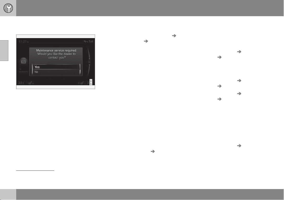
||
10 Maintenance and service
10
356
fied in the combined instrument panel (p. 61)
and via a pop-up menu in the screen.
Service message in the screen.
Meaning of the answer options in the
screen's pop-up menu:
•
Yes - A booking enquiry is sent to your
dealer who then comes back with a
booking proposal. The service lamp and
service message in the combined instru-
ment panel are extinguished.
•
No - No more pop-up messages will be
shown in the screen. The message in the
combined instrument panel remains. After
this option has been selected, it is possi-
ble to start the manual booking in the car,
see below.
•
Postpone - The pop-up menu is shown
the next time the car is started.
Book a service or repair manually
1
1. Press the MY CAR button in the centre
console and select
Service & repair
Dealer information Request service
or repair
.
> Vehicle data is sent automatically to
your dealer.
2. The dealer sends a booking proposal to
the car.
3. Accept or request a new booking pro-
posal.
After the booking has been accepted the
booking information is stored in the car, see
My bookings. The car will automatically com-
municate with you via the screen by means of
reminders about the booking and guide you
to the workshop visit.
You can also book a workshop visit via My
Volvo. Go to "My bookings" and select
"Update" in order to gain access to bookings
from My Volvo.
My bookings
1
Show booking information in the car's screen.
Accept or request a new booking proposal.
–
Select Service & repair My bookings.
Call the dealer
1
With a Bluetooth
®
phone connected to the
car, you can call your dealer. For connecting
the phone, see the Sensus Infotainment sup-
plement.
–
Select Service & repair Dealer
information
Call dealer.
Using the navigation system
1,
2
Enter your workshop as destination or way-
point in the navigation system.
–
Select Service & repair Dealer
information
Set single destination.
–
Select Service & repair Dealer
information
Add as waypoint.
Sending vehicle data
1
Vehicle data are sent to a central Volvo data-
base (not your dealer) from which Volvo deal-
ers can retrieve vehicle information using the
car's identification number (VIN
3
). The num-
ber is printed in the car's service and war-
ranty booklet, alternatively inside the wind-
screen's bottom left-hand corner.
–
Select Service & repair Send car
data
.
1
Applies to certain markets.
2
Applies to Sensus Navigation.
3
Vehicle Identification Number

10 Maintenance and service
10
357
Booking information and vehicle data
When you decide to book a service from your
car, the booking information and vehicle data
will be sent. Vehicle data information consists
of information within the following areas:
•
service requirement
•
function status
•
fluid levels
•
Meter reading
•
the car's vehicle identification number
(VIN
3
)
•
The car's software version.
Related information
•
Volvo ID (p. 21)
3
Vehicle Identification Number

10 Maintenance and service
10
358
Raising the car
When raising the car it is important that the
jack or lifting arms are fitted in the intended
points on the car's underbody.
NOTE
Volvo recommends only using the jack that
belongs to the car model in question. If a
jack is selected other than the one recom-
mended by Volvo, follow the instructions
supplied with the equipment.
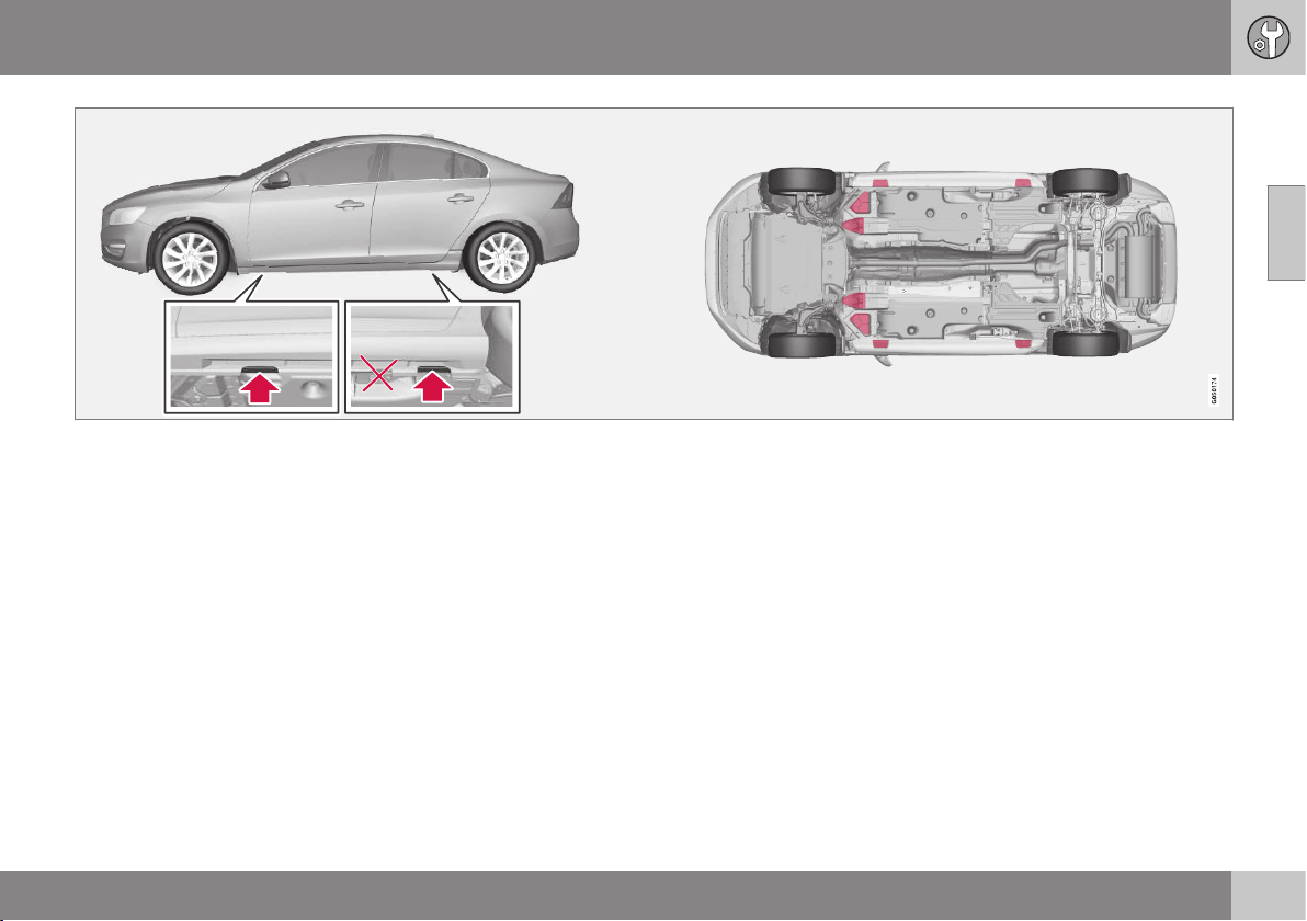
10 Maintenance and service
10
359
Jacking points (arrows) for the jack that belongs to the car and lifting points (marked in red).
If the car is raised with a front workshop jack
then this must be positioned under one of the
four lifting points furthest in under the car. If
the car is raised with a rear workshop jack
then it must be positioned under one of the
lifting points. Ensure that the workshop jack
is positioned so that the car cannot slide off
the jack. Always use axle stands or similar.
If the car is raised with a two-pillar workshop
lift then the front and rear lifting arms can be
positioned under the outer lifting points (jack-
ing points). Alternatively, the inner lifting
points can be used at the front.
Related information
•
Changing wheels - removing wheels
(p. 329)
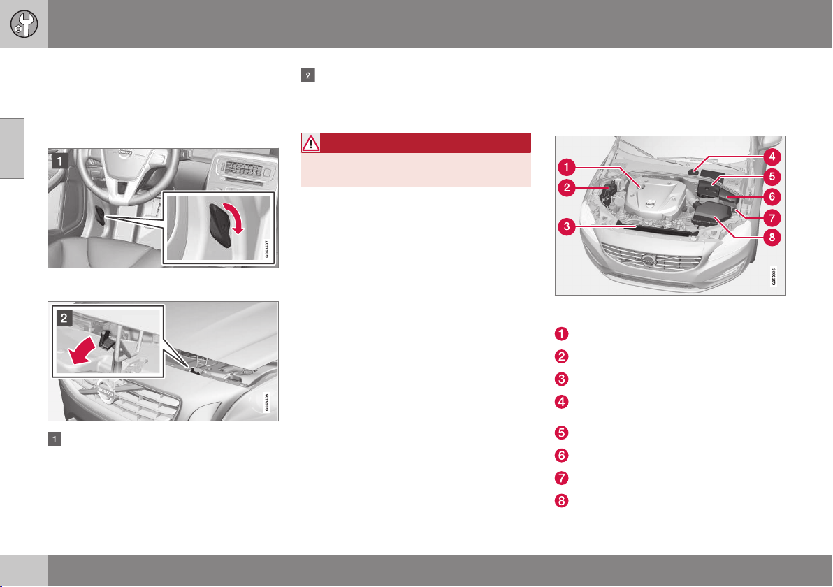
10 Maintenance and service
10
360
Bonnet - opening and closing
The bonnet can be opened when the handle
in the passenger compartment has been
turned clockwise and the lock by the radiator
grille has been moved to the left.
The handle for bonnet opening is always on the
left-hand side.
Turn the handle about 20-25 degrees
clockwise. You will hear when the catch
releases.
Move the catch to the left and open the
bonnet. (The catch hook is located
between the headlamp and radiator grille,
see illustration.)
WARNING
Check that the bonnet locks properly when
closed.
Related information
•
Engine compartment - checking (p. 361)
•
Engine compartment - overview (p. 360)
Engine compartment - overview
The overview shows some service-related
components.
Engine compartment 4-cyl.
The appearance of the engine compartment may
differ depending on engine variant.
Filling engine oil
Coolant expansion tank
Radiator
Reservoir for brake and clutch fluid
(located on the driver's side)
Starter battery
Relay and fuse box
Filling washer fluid
Air filter
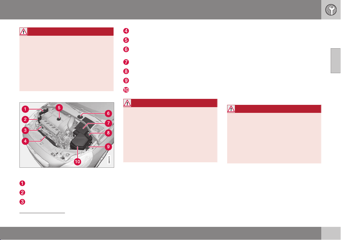
10 Maintenance and service
10
}}
361
WARNING
The ignition system has very high voltage
and output. The voltage in the ignition sys-
tem is highly dangerous. The car's electri-
cal system must always be in key position
0 when work is being performed in the
engine compartment; see Key positions -
functions at different levels (p. 76).
Do not touch the spark plugs or ignition
coil when the car's electrical system is in
key position II or when the engine is hot.
Engine compartment except 4-cyl.
The appearance of the engine compartment may
differ depending on engine variant.
Coolant expansion tank
Power steering fluid reservoir
Engine oil dipstick
4
Radiator
Filling engine oil
Reservoir for brake and clutch fluid
(located on the driver's side)
Starter battery
Relay and fuse box
Filling washer fluid
Air filter
WARNING
The ignition system has very high voltage
and output. The voltage in the ignition sys-
tem is highly dangerous. The car's electri-
cal system must always be in key position
0 when work is being performed in the
engine compartment; see Key positions -
functions at different levels (p. 76).
Do not touch the spark plugs or ignition
coil when the car's electrical system is in
key position II or when the engine is hot.
Related information
•
Bonnet - opening and closing (p. 360)
•
Engine compartment - checking (p. 361)
Engine compartment - checking
Some oils and fluids should be checked at
regular intervals.
Regular checking
Check the following oils and fluids at regular
intervals, e.g. when refuelling:
•
Coolant
•
Engine oil
•
Power steering fluid (not cars with 4-cyl.
engine)
•
Washer fluid
WARNING
Remember that the radiator fan (located at
the front of the engine compartment,
behind the radiator) may start automati-
cally some after the engine has been
switched off.
Always have the engine cleaned by a
workshop - an authorised Volvo workshop
is recommended. There is a risk of fire if
the engine is hot.
Related information
•
Bonnet - opening and closing (p. 360)
•
Engine compartment - overview (p. 360)
•
Coolant - level (p. 367)
•
Engine oil - checking and filling (p. 363)
4
Engines with electronic oil level sensor do not have a dipstick (5-cyl. diesel).
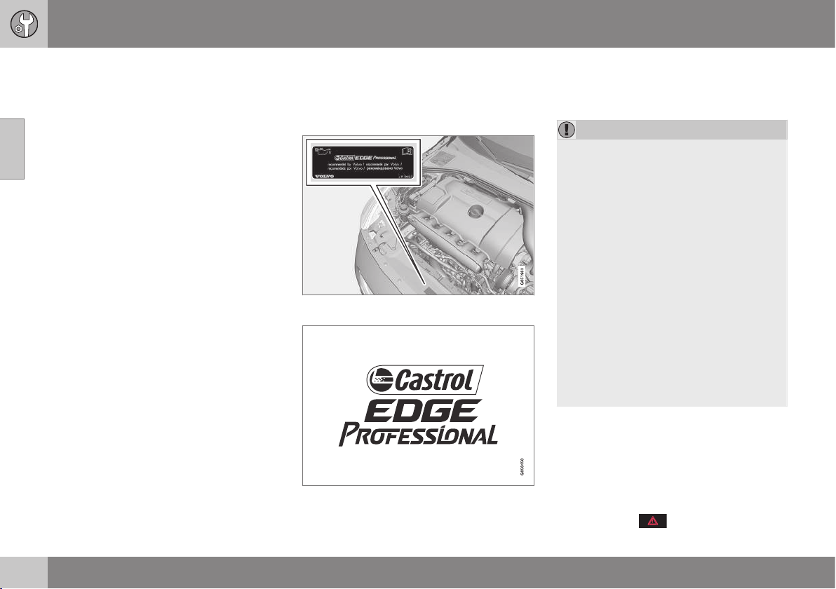
10 Maintenance and service
10
362
•
Power steering fluid - level (p. 368)
•
Washer fluid - filling (p. 378)
Engine oil - general
An approved engine oil must be used in order
that the recommended service intervals can
be applied.
Volvo recommends:
When driving under adverse conditions, see
Engine oil - adverse driving conditions
(p. 414).
IMPORTANT
In order to fulfil the requirements for the
engine's service intervals all engines are
filled with a specially adapted synthetic
engine oil at the factory. The choice of oil
has been made very carefully with regard
to service life, starting characteristics, fuel
consumption and environmental impact.
An approved engine oil must be used in
order that the recommended service inter-
vals can be applied. Only use a prescribed
grade of oil for both filling and oil change,
otherwise you will risk affecting service life,
starting characteristics, fuel consumption
and environmental impact.
Volvo Car Corporation disclaims all war-
ranty liability if engine oil of the prescribed
grade and viscosity is not used.
Volvo recommends that oil changes are
carried out at an authorised Volvo work-
shop.
Volvo uses different systems for warning of
low/high oil level or low oil pressure. Certain
engine variants have an oil pressure sensor,
and then the combined instrument panel's
warning symbol for low oil pressure is used.
Other variants have an oil level sensor, when
the driver is informed via the instrument's
warning symbol and display texts. Cer-
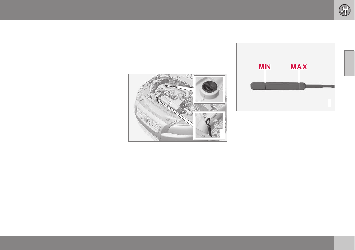
10 Maintenance and service
10
}}
363
tain variants have both systems. Contact a
Volvo dealer for more information.
Change the engine oil and oil filter in accord-
ance with the intervals specified in the Serv-
ice and Warranty Booklet.
Using oil of a higher than specified grade is
permitted. If the car is driven in adverse con-
ditions, Volvo recommends using an oil of a
higher grade; see Engine oil - adverse driving
conditions (p. 414).
For filling capacities, see Engine oil - grade
and volume (p. 415).
Related information
•
Engine oil - checking and filling (p. 363)
Engine oil - checking and filling
The oil level is detected on certain engine
variants with the electronic oil level sensor, on
other engine variants it is checked with the oil
dipstick.
Engine with oil dipstick
5
G021734
Dipstick and filler pipe.
Checking the oil level in a new car is espe-
cially important before the first scheduled oil
change.
Volvo recommends checking the oil level
every 2 500 km. The most accurate measure-
ments are made on a cold engine before star-
ting. The measurement will be inaccurate if
taken immediately after the engine is
switched off. The dipstick will indicate that
the level is too low because the oil has not
had time to flow down into the oil sump.
G021737
The oil level must be between the MIN and MAX
marks.
5
Does not apply to 4-cyl. engine or 5-cyl. diesel engine, which have electronic oil level sensor.
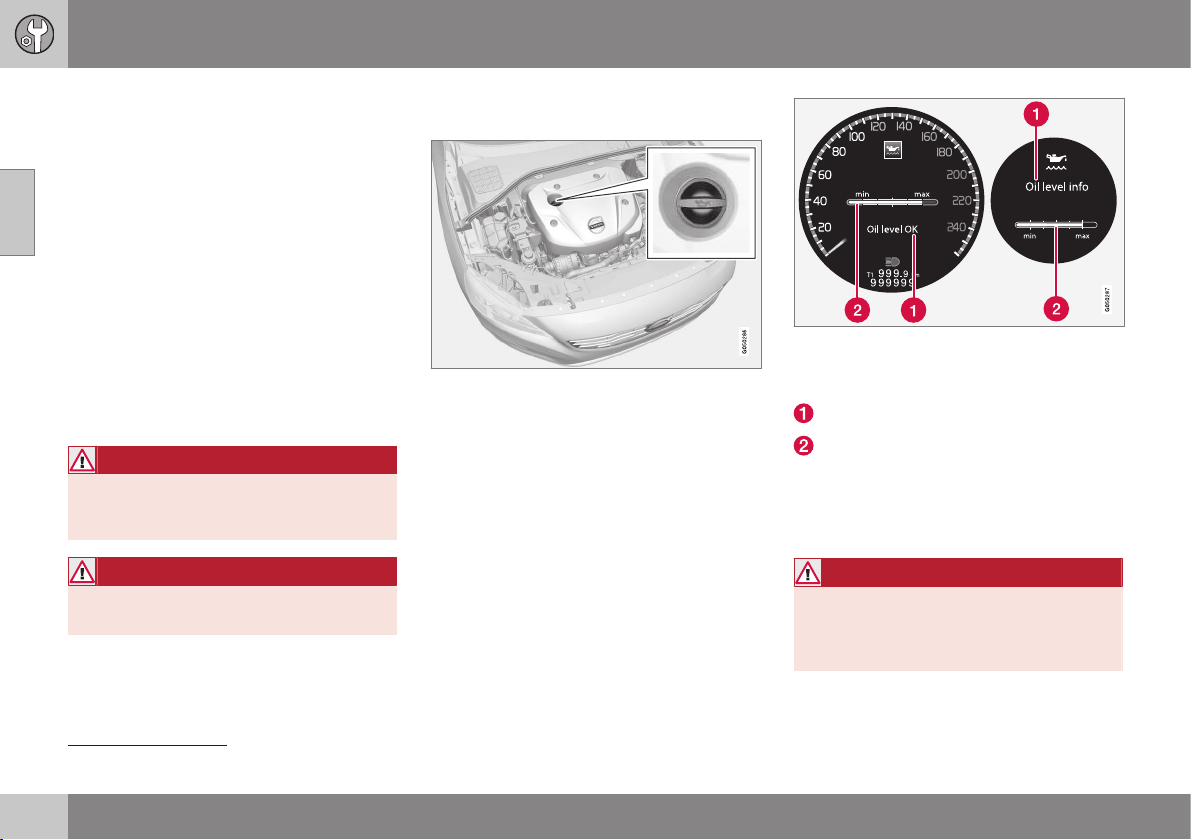
||
10 Maintenance and service
10
364
Measurement and filling if required
1. Ensure that the car is level. After switch-
ing off the engine it is important to wait
5 minutes to allow the oil time to run back
to the sump.
2. Pull up and wipe the dipstick.
3. Re-insert the dipstick.
4. Pull it out and check the level.
5. If the level is close to MIN then 0.5 litres
should be added. If the level is signifi-
cantly below, then an additional amount
is required.
6. If required, check the level again, do it
after driving a short distance. Then repeat
steps 1 - 4.
WARNING
Never fill above the MAX mark. The level
should never be above MAX or below MIN
as this could lead to engine damage.
WARNING
Do not spill oil onto the hot exhaust mani-
fold due to the risk of fire.
Engine with electronic oil level sensor,
4-cyl.
Filler pipe
6
.
In some cases, oil may need to be topped up
between service intervals.
No action needs to be taken on engine oil
level until a message is shown in the com-
bined instrument panel's display, see the fol-
lowing illustration.
Message and graphic in the display. The left-
hand display is shown in the digital combined
instrument panel and the right-hand in the ana-
logue.
Message
Engine oil level
The oil level is checked using the electronic
oil level gauge with the thumbwheel when the
engine is switched off, see Menu navigation -
combined instrument panel (p. 105).
WARNING
If the message Oil service required is
shown, visit a workshop - an authorised
Volvo workshop is recommended. The oil
level may be too high.
6
Engines with electronic oil level sensor do not have a dipstick.
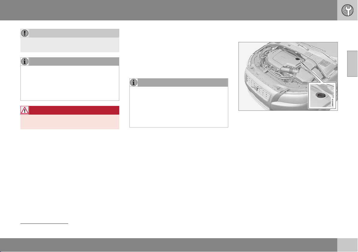
10 Maintenance and service
10
}}
365
IMPORTANT
If notified of low oil level, only fill with the
volume specified, for example, 0.5 litres.
NOTE
The system cannot directly detect changes
when the oil is filled or drained. The car
must have been driven approx. 30 km and
have been stationary for 5 minutes with the
engine switched off and on level ground
before the oil level indication is correct.
WARNING
Do not spill oil onto the hot exhaust mani-
fold due to the risk of fire.
Measuring the oil level, 4-cyl.
If the oil level needs to be checked then it
should be carried out in accordance with the
following sequence.
1. Activate key position II; see Key positions
- functions at different levels (p. 76).
2. Rotate the thumbwheel on the left-hand
stalk switch to position
Oil level.
> You will then see information displayed
about the engine oil level.
For more information on menu naviga-
tion, see Menu navigation - combined
instrument panel (p. 105).
NOTE
If the right conditions for measuring the oil
level are not met (time after engine shut-
down, the car's inclination, outside tem-
perature, etc.) then the message
Not
available will be shown. This does not
mean that there is something wrong in the
car's systems.
Engine with electronic oil level sensor,
5-cyl. diesel
Filler pipe
7
.
No action needs to be taken on engine oil
level until a message is shown in the com-
bined instrument panel's display, see the fol-
lowing illustration.
7
Engines with electronic oil level sensor do not have a dipstick.
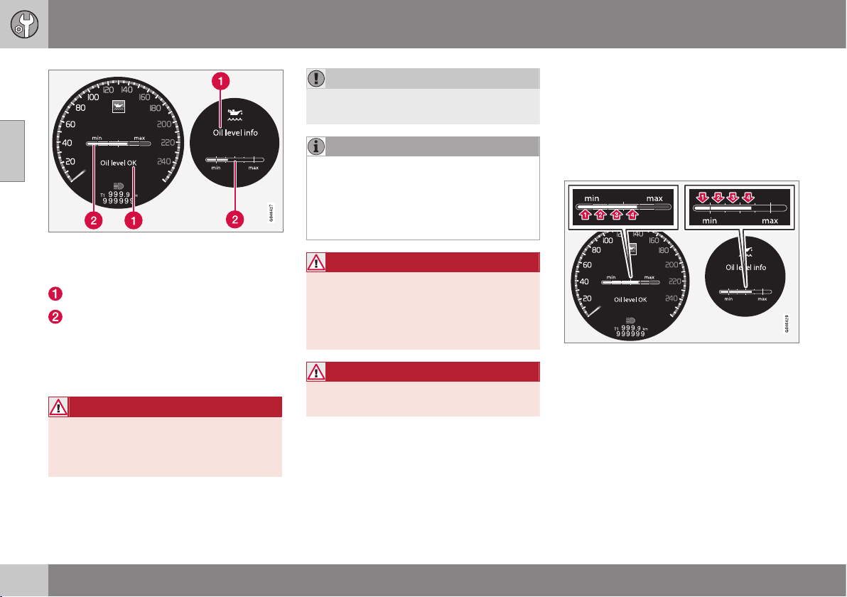
||
10 Maintenance and service
10
366
Message and graphic in the display. The left-
hand display is shown in the digital combined
instrument panel and the right-hand in the ana-
logue.
Message
Engine oil level
The oil level is checked using the electronic
oil level gauge with the thumbwheel when the
engine is switched off, see Menu navigation -
combined instrument panel (p. 105).
WARNING
If the message Oil service required is
shown, visit a workshop - an authorised
Volvo workshop is recommended. The oil
level may be too high.
IMPORTANT
In the event of the message Oil level low
Refill 0.5 litre, only fill with 0.5 litres.
NOTE
The oil level is only detected by the system
during driving. The system cannot directly
detect changes when the oil is filled or
drained. The car must be driven
about 30 km before the oil level display is
correct.
WARNING
Do not fill more oil if filling level (3) or (4)
appears as shown in the illustration below.
The level must never be above MAX or
below MIN, as this could lead to engine
damage.
WARNING
Do not spill oil onto the hot exhaust mani-
fold due to the risk of fire.
Measuring the oil level, 5-cyl. diesel
If the oil level needs to be checked then it
should be carried out in accordance with the
following sequence.
1. Activate key position II; see Key positions
- functions at different levels (p. 76).
2. Rotate the thumbwheel on the left-hand
stalk switch to position
Oil level.
> You will then see information displayed
about the engine oil level.
For more information on menu naviga-
tion, see Menu navigation - combined
instrument panel (p. 105).
The figures 1-4 represent filling level. Do not fill
more oil if filling level (3) or (4) is shown. Recom-
mended filling level is 4. Message and graphic in
the display. The left-hand display is shown in the
digital combined instrument panel and the right-
hand in the analogue.
Related information
•
Engine oil - general (p. 362)
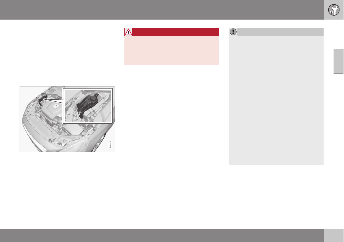
10 Maintenance and service
10
367
Coolant - level
The coolant cools the internal combustion
engine to the correct operating temperature.
The heat that is transferred from the engine to
the coolant can be used to heat the passen-
ger compartment.
The coolant level must lie between the MIN
and MAX marks on the expansion tank.
Checking the level and topping up
When topping up the coolant, follow the
instructions on the packaging. Never top up
with water only. The risk of freezing increases
with both too little and too much coolant con-
centrate.
WARNING
Coolant can be very hot. If the coolant
requires topping up when the engine is at
operating temperature, unscrew the
expansion tank cap slowly to gently
release the overpressure.
For capacities and for standards regarding
water quality; see Coolant - grade and vol-
ume (p. 417).
Check the coolant regularly
The level must be between the MIN and MAX
marks on the expansion tank. If the system is
not filled sufficiently, high temperatures could
occur, causing a risk of damage to the
engine.
IMPORTANT
•
A high content of chlorine, chlorides
and other salts may cause corrosion in
the cooling system.
•
Always use coolant with anti-corrosion
agent as recommended by Volvo.
•
Ensure that the coolant mixture is 50%
water and 50% coolant.
•
Mix the coolant with approved quality
tap water. In the event of any doubt
about water quality, used ready-mixed
coolant in accordance with Volvo rec-
ommendations.
•
When changing coolant/replacing
cooling system components, flush the
cooling system clean with approved
quality tap water or flush with ready-
mixed coolant.
•
The engine must only be run with a
well-filled cooling system. Otherwise,
temperatures that are too high may
occur resulting in the risk of damage
(cracks) in the cylinder head.

10 Maintenance and service
10
368
Brake and clutch fluid - level
Brake and clutch fluid level should be
between the reservoir MIN and MAX marks.
Checking the level
Brake and clutch fluid have a common reser-
voir. The level must be between the MIN and
MAX marks that are visible inside the reser-
voir. Check the level regularly.
Change the brake fluid every other year or at
every other regular service.
The fluid should be changed annually on cars
driven in conditions requiring hard, frequent
braking, such as driving in mountains or tropi-
cal climates with high humidity.
For capacities and recommended brake fluid
grade, see Brake fluid - grade and volume
(p. 420).
WARNING
If the brake fluid is under the MIN level in
the brake fluid reservoir, do not drive fur-
ther before topping up the brake fluid.
Volvo recommends that the reason for the
loss of brake fluid is investigated by an
authorised Volvo workshop.
Filling
The fluid reservoir is located on the driver's side.
The fluid reservoir is protected under the
cover over the cold zone in the engine com-
partment. The round cover must be removed
first before the reservoir cap can be reached.
Turn and open the cover located on the
covering.
Unscrew the reservoir cap and fill the
fluid. The level must be between the MIN
and MAX marks, which are located on
the inside of the reservoir.
IMPORTANT
Do not forget to refit the cap.
Power steering fluid - level
Cars with 4-cyl. engine do not have power
steering fluid. For cars with another engine,
the level of the power steering fluid must be
between the reservoir's MIN and MAX marks.
The fluid does not need to be changed.
IMPORTANT
Keep the area around the power steering
fluid reservoir clean when checking. The
cover must not be opened.
Check the level frequently. The fluid does not
require changing. The level must be between
the MIN and MAX marks.
For recommended fluid grade, see Power
steering fluid - grade (p. 420).
10 Maintenance and service
10
}}
369
NOTE
If a fault should arise in the power steering
system, or if the engine is switched off and
must be towed, then the car can still be
steered.
Climate control system - fault tracing
and repair
The air conditioning system must only be
serviced and repaired by an authorised work-
shop.
Fault tracing and repair
The air conditioning system contains fluores-
cent tracing agents. Use ultraviolet light when
looking for leaks.
Volvo recommends that you contact an
authorised Volvo workshop.
WARNING
The air conditioning system contains pres-
surised refrigerant R134a. This system
must only be serviced and repaired by an
authorised workshop.
Related information
•
Volvo service programme (p. 355)
Lamp replacement - general
Lamp replacement can be carried out for
bulbs. When replacing LED and Xenon lamps,
please refer to a workshop.
The bulbs are specified (p. 376). The follow-
ing list contains locations of bulbs and other
light sources that are specialised, such as
LED
8
lamps, or are unsuitable for changing
for some other reason, except at a work-
shop
9
:
•
Active Xenon headlamps - ABL (Xenon
lamps)
•
Daytime running lights/Position/parking
lamps front
•
Cornering lights
•
Side direction indicators, door mirrors
•
Approach lighting, door mirrors
•
Interior lighting apart from Courtesy light-
ing front
•
Position/parking lamps rear
•
Side marker lamps.
8
LED (Light Emitting Diode)
9
An authorised Volvo workshop is recommended.
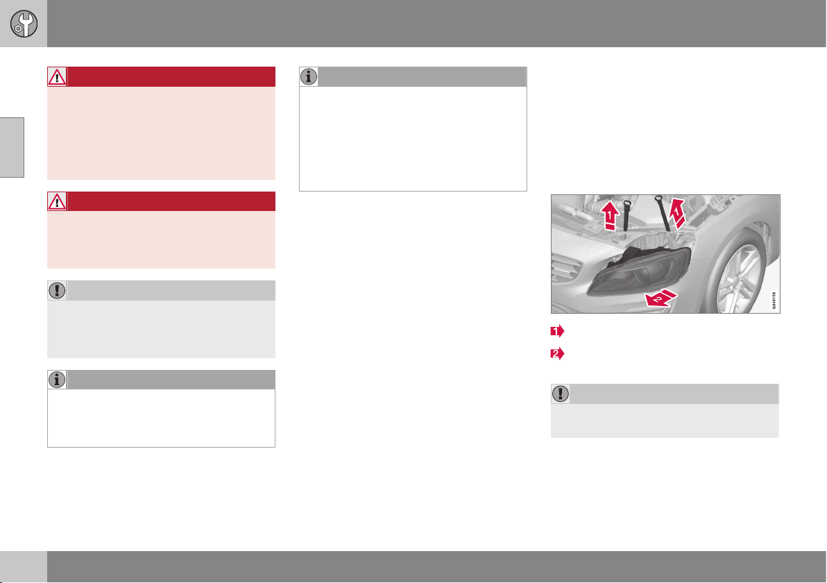
||
10 Maintenance and service
10
370
WARNING
On cars with Xenon headlamps, the
replacement of Xenon lamps must be car-
ried out at a workshop - an authorised
Volvo workshop is recommended. Working
with Xenon lamps demands extreme cau-
tion because the headlamp is equipped
with a high voltage unit.
WARNING
The car's electrical system must be in key
position 0 for bulb replacement; see Key
positions - functions at different levels
(p. 76).
IMPORTANT
Never touch the glass part of the bulbs
with your fingers. Grease from your fingers
is vaporised by the heat, coating the
reflector and then causing damage.
NOTE
If an error message remains after the bro-
ken bulb has been replaced then we rec-
ommend that you visit an authorised Volvo
workshop.
NOTE
Outside lighting such as headlamps, fog
lamps and rear lamps may temporarily
have condensation on the inside of the
lens. This is normal, all exterior lighting is
designed to withstand this. Condensation
is normally vented out of the lamp housing
when the lamp has been switched on for a
time.
Related information
•
Lamp replacement - headlamps (p. 370)
•
Lamp replacement - location of rear
lamps (p. 374)
•
Lamp replacement - vanity mirror lighting
(p. 375)
•
Lamp replacement - lighting in cargo area
(p. 375)
•
Lamp replacement - number plate lighting
(p. 374)
Lamp replacement - headlamps
All of the headlamp bulbs are replaced via the
engine compartment. First loosen and remove
the whole headlamp.
Removing the headlamp
Set the car's electrical system in key position
0, see Key positions - functions at different
levels (p. 76).
Pull out the headlamp's locking pins.
Release the headlamp by alternately tilt-
ing and pulling it out.
IMPORTANT
Do not pull the electrical cable, only the
connector.
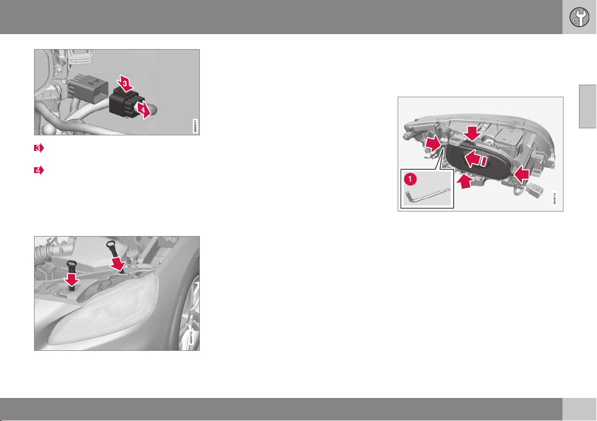
10 Maintenance and service
10
}}
371
Detach the headlamp connector by
pressing down the clip with your thumb.
At the same time, guide out the connec-
tor with your other hand.
5. Lift out the headlamp and place it on a
soft surface to avoid scratching the lens.
6. Replace the bulb in question.
Securing the headlamp
1. Plug in the connector, a clicking sound
should be heard.
2. Reinstall the headlamp and locking pins.
The short pin is fitted closest to the radia-
tor grille. Check that they are firmly
inserted.
3. Check the lighting.
The headlamp must be mounted and the con-
nector firmly connected before the lighting is
switched on or the remote control key is
inserted into the ignition switch.
Related information
•
Lamp replacement - general (p. 369)
•
Lamp replacement - cover for main/
dipped beam bulbs (p. 371)
•
Lamps - specifications (p. 376)
Lamp replacement - cover for main/
dipped beam bulbs
Main/dipped beam bulbs are accessed by
releasing the headlamp's larger cover.
Before starting to replace a bulb, see Lamp
replacement - headlamps (p. 370).
1. Unscrew the cover's four screws using a
Torx tool, size T20 (1). They should not be
loosened completely. (3 - 4 turns are suf-
ficient.)
2. Slide the cover to one side.
3. Remove the cover.
Reinstall the cover in reverse order.
Related information
•
Lamp replacement - headlamps (p. 370)
•
Lamp replacement - dipped beam
(p. 372)
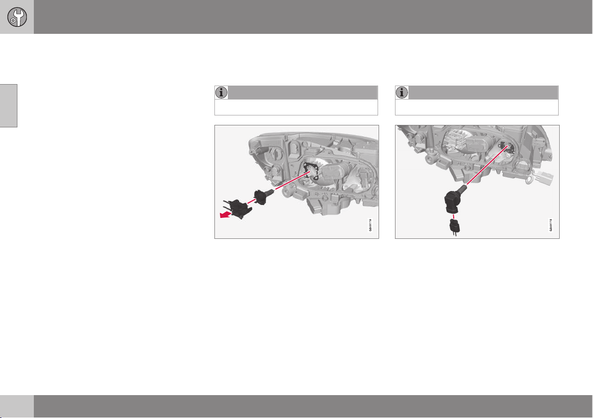
10 Maintenance and service
10
372
•
Lamp replacement - main beam (p. 372)
•
Lamp replacement - extra main beam
(p. 373)
Lamp replacement - dipped beam
The dipped beam bulb is fitted inside the
headlamp's larger cover.
NOTE
Applies to cars with halogen headlamps.
1. Detach the headlamp (p. 370).
2. Remove the cover (p. 371).
3. Unplug the connector from the bulb.
4. Detach the bulb by pulling it straight out.
5. The guide pin on the lamp should be
straight up when it is fitted and a clicking
sound should be heard when it clicks into
place.
Reinstall the parts in reverse order.
Related information
•
Lamps - specifications (p. 376)
Lamp replacement - main beam
The main beam bulb is fitted inside the head-
lamp's larger cover.
NOTE
Applies to cars with halogen headlamps.
1. Detach the headlamp (p. 370).
2. Remove the cover (p. 371).
3. Detach the bulb by turning anticlockwise
and then pulling straight out.
4. Unplug the connector from the bulb.
5. Replace the bulb and align it in the socket
and turn clockwise in order to secure it. It
can only be secured in one position.
Reinstall the parts in reverse order.
Related information
•
Lamps - specifications (p. 376)
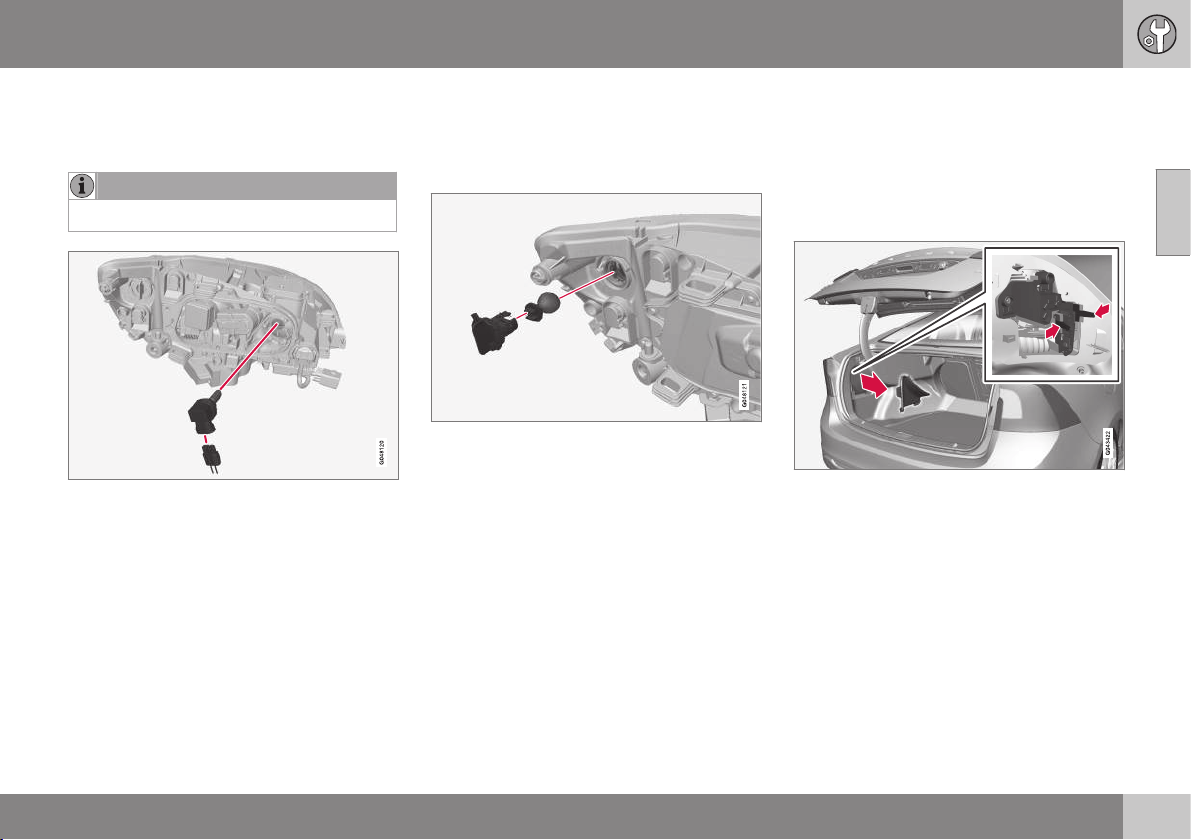
10 Maintenance and service
10
}}
* Option/accessory, for more information, see Introduction.
373
Lamp replacement - extra main beam
The extra main beam bulb is fitted inside the
headlamp's larger cover.
NOTE
Applies to cars with Xenon headlamps*.
1. Detach the headlamp (p. 370).
2. Remove the cover (p. 371).
3. Detach the bulb by turning anticlockwise
and then pulling straight out.
4. Unplug the connector from the bulb.
5. Replace the bulb and align it in the socket
and turn clockwise in order to secure it. It
can only be secured in one position.
Reinstall the parts in reverse order.
Related information
•
Lamps - specifications (p. 376)
Lamp replacement - direction
indicators front
The direction indicator lamp is fitted inside
the headlamp's smaller cover.
1. Detach the headlamp (p. 370).
2. Detach the cover by pulling it straight out.
3. Pull the bulb holder in order to extract the
bulb.
4. Press and simultaneously turn the bulb
anticlockwise in order to detach it.
Reinstall the parts in reverse order.
Related information
•
Lamps - specifications (p. 376)
Lamp replacement - rear lamp
Lamps in the rear lamp cluster are replaced
from inside the cargo area.
Reversing lamps are located behind the panel
in the boot lid.
Lamp housing, rear
The bulbs in the rear light cluster are replaced
from inside the cargo area (not the LED
lamps).
1. Remove the covers in the left/right-hand
panel to access the bulbs. The bulbs are
located in a bulb holder.
2. Press the catches together and pull out
the bulb holder.
3. Remove the blown bulb by pressing it in
and turning anticlockwise.
4. Fit a new bulb, press down and turn
clockwise.
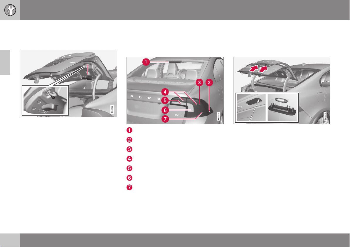
||
10 Maintenance and service
10
374
5. Press the bulb holder into place and refit
the cover.
Reversing lamp
1. Open the panel in the boot lid.
2. Detach the bulb holder by turning it anti-
clockwise.
3. Remove the blown bulb by pressing it in
and turning anticlockwise.
4. Fit a new bulb, press down and turn
clockwise.
5. Attach the bulb holder by turning it clock-
wise.
Related information
•
Lamp replacement - location of rear
lamps (p. 374)
•
Lamps - specifications (p. 376)
Lamp replacement - location of rear
lamps
The overview shows the location of the lamps
at the rear.
Brake light (LED)
Side marker lamps (LED)
Brake light (p. 373)
Position/parking lights (LED)
Reversing lamp (p. 373)
Indicator (p. 373)
Fog lamp (p. 373)
Related information
•
Lamp replacement - general (p. 369)
•
Lamps - specifications (p. 376)
Lamp replacement - number plate
lighting
The number plate lighting is located under the
boot lid handle.
1. Remove the screws with a screwdriver.
2. Carefully detach the whole lamp housing
and withdraw it.
3. Replace the bulb.
4. Refit the whole lamp housing and screw it
into place.
Related information
•
Lamps - specifications (p. 376)
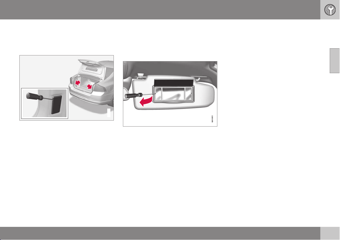
10 Maintenance and service
10
375
Lamp replacement - lighting in cargo
area
The cargo area lighting is positioned on both
sides of the boot lid opening.
G021758
1. Insert a screwdriver and gently prize so
that the lamp housing comes loose.
2. Replace the bulb.
3. Check that the bulb illuminates and press
back the lamp housing.
Related information
•
Lamps - specifications (p. 376)
Lamp replacement - vanity mirror
lighting
The vanity mirror's lamps are fitted inside the
lamp lenses.
Removal of lamp lens
1. Insert a screwdriver under the lamp lens
and gently prize up the lug on the edge.
2. Carefully detach and lift aside the lamp
lens.
3. Use needle-nose pliers to pull the bulb
straight out to the side and replace with a
new one. Note! - Do not pinch hard with
the pliers. Otherwise the lamp lens could
then be crushed.
Attaching the lamp lens
1. Refit the lamp lens.
2. Press it into place.
Related information
•
Lamps - specifications (p. 376)
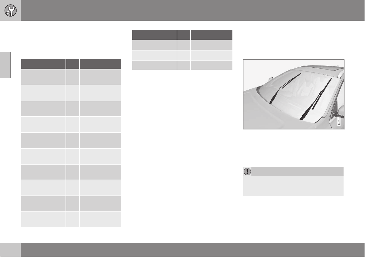
10 Maintenance and service
10
376
Lamps - specifications
The specifications apply to bulbs. When
replacing LED and Xenon lamps, please refer
to a workshop.
Lighting
W
A
Type
Dipped beam,
halogen
55 H7 LL
Main beam, Halo-
gen
65 H9
Extra main beam,
ABL
65 H9
Front direction
indicators
24 PY24W
Courtesy lighting
front
3 T10 Socket
W2.1x9.5d
Glovebox lighting 5 Socket SV8.5
Length 43 mm
Vanity mirror
lighting
1.2 T5 Socket
W2x4.6d
Cargo area light-
ing
10 Socket SV8.5
Length 38 mm
Number plate
lighting
5 C5W LL
Direction indica-
tors, rear
21 PY21W LL
Lighting
W
A
Type
Brake light 21 P21W LL
Reversing lamp 21 H21W LL
Rear fog lamp 21 H21W LL
A
Watt
Related information
•
Lamp replacement - general (p. 369)
Wiper blades
The windscreen wiper blades must be in serv-
ice position when they are to be replaced.
Service position
Wiper blades in service position.
In order to change, clean or lift the wiper
blades (for scraping off ice from the wind-
screen, for example) they must be in service
position.
IMPORTANT
Before placing the wiper blades in the
service position, make sure that they are
not frozen down.
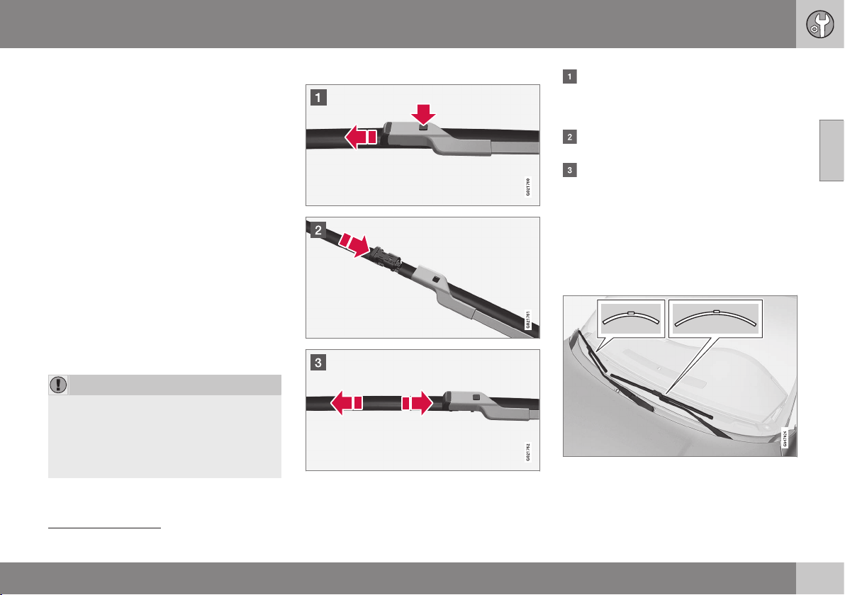
10 Maintenance and service
10
}}
377
1. Insert the remote control key in the igni-
tion switch
10
and briefly press the
START/STOP ENGINE button to set the
car's electrical system to key position I.
For detailed information on key positions,
see Key positions - functions at different
levels (p. 76).
2. Briefly press the START/STOP ENGINE
button again to set the car’s electrical
system in key position 0.
3. Within 3 seconds, move the right stalk
switch up and hold it in position for
approx. 1 second.
> The wipers then move to standing
straight up.
The wipers return to their starting position
when you briefly press the START/STOP
ENGINE button to set the car’s electrical sys-
tem to key position I (or when the car is
started).
IMPORTANT
If the wiper arms in service position have
been folded up from the windscreen, they
must be folded back down onto the wind-
screen before the wipers are allowed to
return to their starting position. This is to
avoid scraping the paint on the bonnet.
Replacing the wiper blades
Fold up the wiper arm when it is in serv-
ice position. Press the button located on
the wiper blade mounting and pull
straight out parallel with the wiper arm.
Slide in the new wiper blade until a "click"
is heard.
Check that the blade is firmly installed.
4. Fold the wiper arm back towards the
windscreen.
The wipers return from service position to
their starting position when you briefly press
the START/STOP ENGINE button to set the
car’s electrical system to key position I (or
when the car is started).
10
Not necessary in cars with the Keyless function.
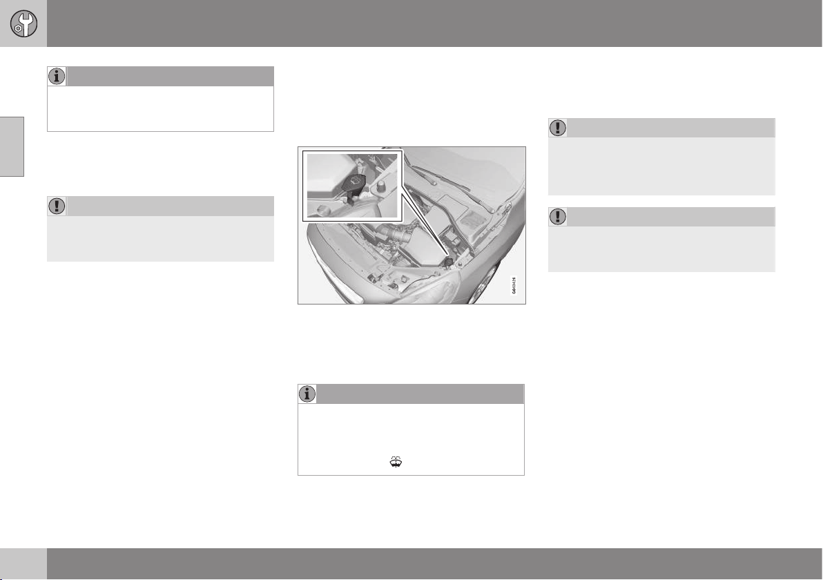
||
10 Maintenance and service
10
378
NOTE
The wiper blades are different lengths. The
blade on the driver's side is longer than on
the passenger side.
Cleaning
For cleaning wiper blades and windscreen,
see Car wash (p. 398).
IMPORTANT
Check the blades regularly. Neglected
maintenance shortens the service life of
the wiper blades.
Related information
•
Washer fluid - filling (p. 378)
Washer fluid - filling
Washer fluid is used for cleaning the head-
lamps and windows. Washer fluid with anti-
freeze must be used when the temperature is
below freezing point.
Topping up the washer fluid takes place by
opening the blue cap.
The windscreen and headlamp washers share
a common reservoir.
NOTE
When there is approx. 1 litre of washer
fluid remaining in the reservoir, a message
to top up the washer fluid will be shown in
the combined instrument panel, together
with the symbol
.
Prescribed grade: Washer fluid recom-
mended by Volvo - with frost protection dur-
ing cold weather and below freezing point.
IMPORTANT
Use Volvo genuine washer fluid or equiva-
lent with a recommended pH of between 6
and 8, in working dilution (e.g. 1:1 with
neutral water).
IMPORTANT
Use washer fluid with antifreeze when the
temperature is below freezing to avoid
freezing in the pump, reservoir and hoses.
Volume:
•
Cars with headlamp washing: 5.4 litres.
•
Cars without headlamp washing: 4.0
litres.
Related information
•
Wiper blades (p. 376)
•
Wipers and washers (p. 96)
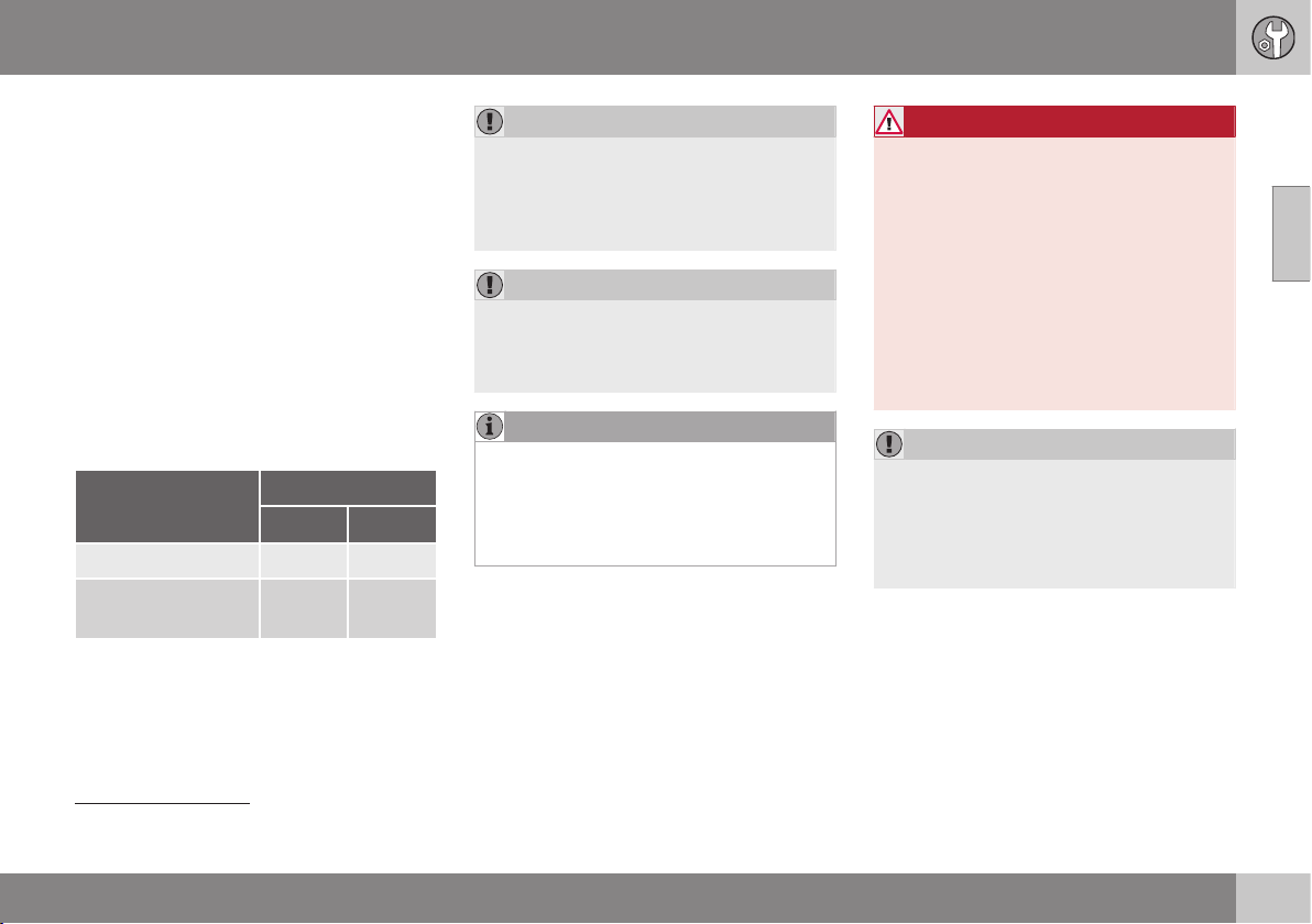
10 Maintenance and service
10
}}
379
Starter battery - general
The starter battery is used to drive the starter
motor and other electrical equipment in the
car.
The starter battery is a traditional 12 V bat-
tery.
The service life and function of the starter
battery is influenced by factors such as the
number of starts, discharging, driving style,
driving conditions, climatic conditions, etc.
•
Never disconnect the starter battery when
the engine is running.
•
Check that the cables to the starter bat-
tery are correctly connected and properly
tightened.
Engine
Petrol Diesel
Voltage (V) 12 12
Cold start capacity
A
- CCA
B
(A)
520–800 700–800
A
In accordance with SAE or EN standard.
B
Cold Cranking Amperes.
IMPORTANT
When replacing the starter battery, in cars
with Start/Stop function, a battery of the
correct type must be fitted, EFB
11
in cars
with manual gearbox and AGM
12
in cars
with automatic gearbox.
IMPORTANT
If the starter battery is replaced, make sure
you replace it with a battery with the same
cold starting capacity and type as the orig-
inal battery (see the label on the battery).
NOTE
•
The starter battery's container size
should be consistent with the original
battery's dimensions.
•
The starter battery's height is different
depending on size.
WARNING
•
The battery can generate oxyhydrogen
gas, which is highly explosive. A spark
can be formed if a jump lead is con-
nected incorrectly, and this can be
enough for the battery to explode.
•
The battery contains sulphuric acid,
which can cause serious burns.
•
If sulphuric acid comes into contact
with eyes, skin or clothing, flush with
large quantities of water. If acid
splashes into the eyes - seek medical
attention immediately.
IMPORTANT
When charging the starter battery or the
support battery (p. 383), only use a mod-
ern battery charger with controlled charg-
ing voltage. Fast charging function must
not be used since it may damage the bat-
tery.
11
Enhanced Flooded Battery.
12
Absorbed Glass Mat.
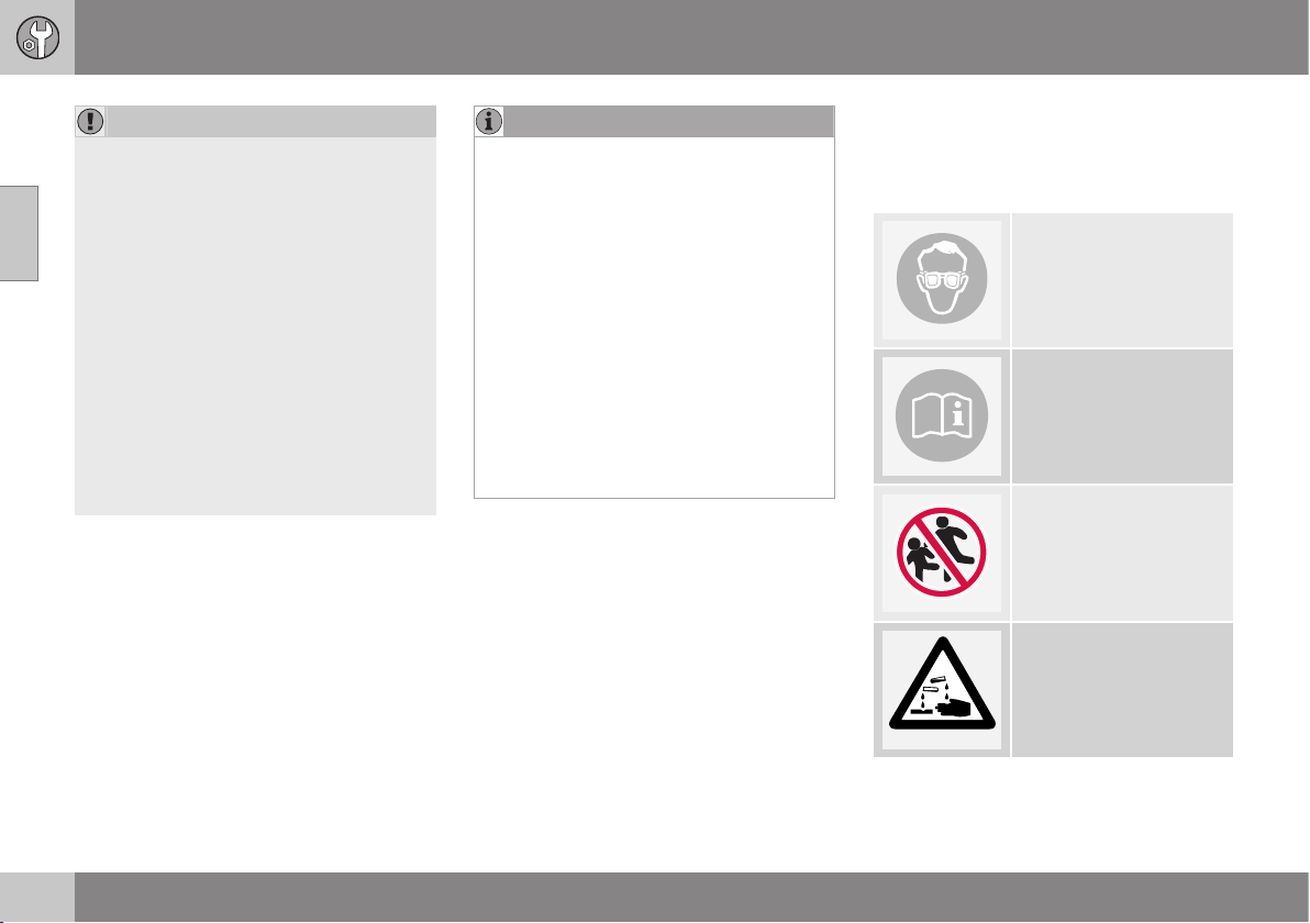
||
10 Maintenance and service
10
380
IMPORTANT
If the following instruction is not observed
then the energy saving function for info-
tainment system may be temporarily dis-
engaged, and/or the message in the com-
bined instrument panel's information dis-
play about the starter battery's state of
charge may be temporarily inapplicable,
following the connection of an external
starter battery or battery charger:
•
The negative battery terminal on the
car's starter battery must never be
used for connecting an external starter
battery or battery charger - only the
car chassis may be used as the
grounding point.
See Jump starting with battery (p. 273) for
a description of how the cable clamps
must be attached.
NOTE
The life of the battery is shortened if it
becomes discharged repeatedly.
The life of the battery is affected by several
factors, including driving conditions and
climate. Battery starting capacity decrea-
ses gradually with time and therefore
needs to be recharged if the car is not
used for a longer time or when it is only
driven short distances. Extreme cold fur-
ther limits starting capacity.
To maintain the battery in good condition,
at least 15 minutes of driving/week is rec-
ommended or that the battery is con-
nected to a battery charger with automatic
trickle charging.
A battery that is kept fully charged has a
maximum service life.
Related information
•
Battery - symbols (p. 380)
•
Starter battery - replacement (p. 381)
•
Battery - Start/Stop (p. 383)
Battery - symbols
There are information and warning symbols
on the batteries.
Symbols on the batteries
Use protective goggles.
Further information in the
owner's manual for the
car.
Store the battery out of
the reach of children.
The battery contains cor-
rosive acid.
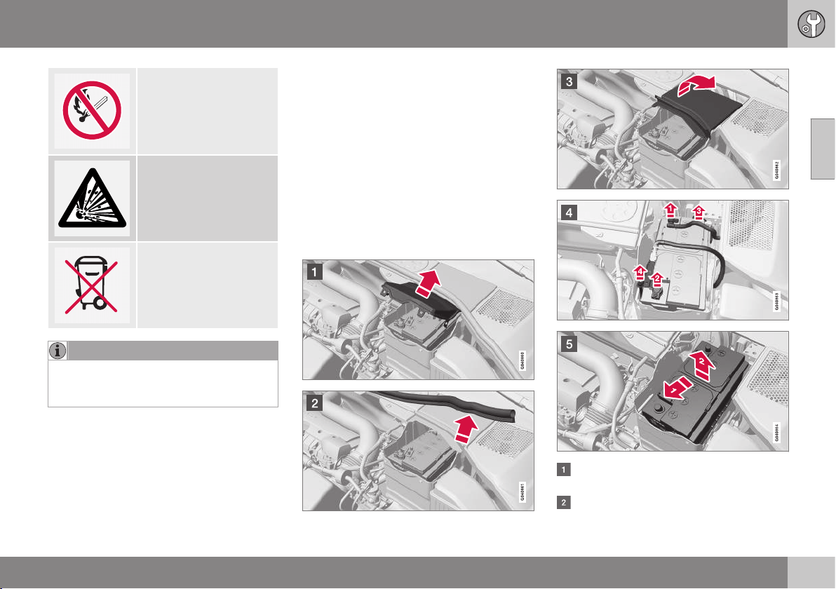
10 Maintenance and service
10
}}
381
Avoid sparks and naked
flames.
Risk of explosion.
Must be taken for recy-
cling.
NOTE
An expended battery must be recycled in
an environmentally safe manner as it con-
tains lead.
Related information
•
Starter battery - general (p. 379)
Starter battery - replacement
The starter battery in the car can be replaced
without the help of a workshop.
The starter battery is a traditional 12 V bat-
tery.
Removal
First of all: Take the remote control key from
the ignition switch and wait at least 5 minutes
before any electrical connections are touched
- this is because the car's electrical system
needs to store the necessary information to
control modules.
Open the clips on the front cover and
remove the cover.
Release the rubber moulding so that the
rear cover is free.
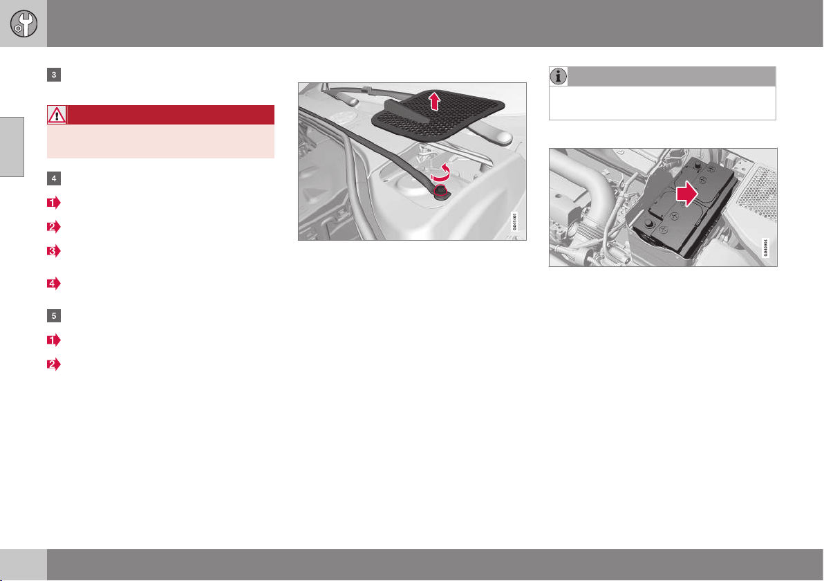
||
10 Maintenance and service
10
382
* Option/accessory, for more information, see Introduction.
Remove the rear cover by screwing one
quarter turn and lifting it away.
WARNING
Connect and remove the positive and neg-
ative cables in the correct order.
Detach the black negative cable.
Detach the red positive cable.
Detach the ventilation hose from the bat-
tery.
Loosen the screw holding the battery
clamp.
Move the battery aside.
Lift it up.
Cross-stay on the R-Design*
Cross-stay and plenum chamber cover.
Cars with R-Design have a cross-stay that
must be removed before the starter battery
can be replaced.
1. Remove the plenum chamber covers on
the right and left-hand sides. Prize care-
fully with a plastic knife or similar.
2. Loosen and remove the screws (one on
the right and one on the left-hand side)
that hold the cross-stay.
3. Remove the cross-stay.
> Now the starter battery can be
removed in accordance with the previ-
ous section.
•
Fitting the cross-stay takes place in the
reverse order.
NOTE
Tighten the screws to 30 Nm. Check the
torque with a torque wrench.
Fitting
1. Lower the battery into the battery box.
2. Move the battery inward and to the side
until it reaches the rear edge of the box.
3. Tighten the clamp that holds the battery.
4. Connect the ventilation hose.
> Check that it is correctly connected to
both battery and outlet in the body.
5. Connect the red positive cable.
6. Connect the black negative cable.
7. Press in the rear cover. (See earlier sec-
tion "Removal".)
8. Fit the rubber moulding. (See "Removal".)
9. Align the front cover and secure it with
the clips. (See "Removal".)

10 Maintenance and service
10
}}
* Option/accessory, for more information, see Introduction.
383
For more information on the car's starter bat-
tery, see Jump starting with battery (p. 273).
Battery - Start/Stop
Cars with the Start/Stop function are equip-
ped with a support battery in addition to the
starter battery.
Cars with the Start/Stop function are equip-
ped with two 12 V batteries - one extra pow-
erful starter battery for starting and one sup-
port battery that helps during the Start/Stop
function's starting sequence.
For more information on the Start/Stop func-
tion, see Start/Stop* (p. 284).
For more information on the car's starter bat-
tery, see Jump starting with battery (p. 273).
The following table shows specifications for
the starter battery and support battery
respectively in cars with Start/Stop function.
Battery
Start, 12 V Support, 12
V
Cold
start
capacity
A
- CCA
B
(A)
720
C
760
D
Left-hand
drive car:
120
E
170
F
Right-hand
drive car:
120
Size,
L×W×H
(mm)
278×175×190
Left-hand
drive car:
150×90×106
E
150×90×130
F
Right-hand
drive car:
150×90×106
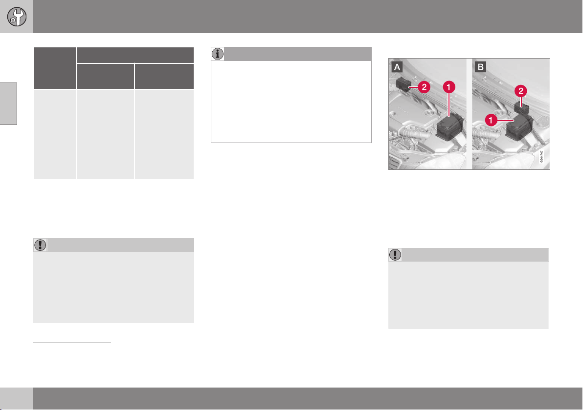
||
10 Maintenance and service
10
384
Battery
Start, 12 V Support, 12
V
Capacity
(Ah)
70
Left-hand
drive car:
8
E
10
F
Right-hand
drive car:
8
A
In accordance with EN standard.
B
Cold Cranking Amperes.
C
Manual gearbox.
D
Automatic gearbox.
E
Manual gearbox in combination with Start/Stop function
that only auto-stops when the car is completely stationary.
F
Others.
IMPORTANT
When replacing the starter battery, in cars
with Start/Stop function, a battery of the
correct type must be fitted, EFB
13
in cars
with manual gearbox and AGM
14
in cars
with automatic gearbox.
When replacing the support battery, a bat-
tery of AGM type must be fitted.
NOTE
•
The higher the current take-off in the
car, the more the alternator must be
working and the batteries charging =
Increased fuel consumption.
•
When the capacity of the starter bat-
tery has fallen below the lowest per-
missible level then the Start/Stop func-
tion is disengaged.
Temporarily reduced Start/Stop function due
to high current take-off means:
•
The engine starts automatically
15
without
the driver depressing the clutch pedal
(manual gearbox).
•
The engine starts automatically without
the driver lifting his/her foot off the foot
brake pedal (automatic gearbox).
Location of the batteries
A: Left-hand drive car. B: Right-hand drive car.
(1) Starter battery
16
(2) Support battery.
The support battery normally requires no
more service than the normal starter battery.
A workshop should be contacted in the event
of questions or problems - an authorised
Volvo workshop is recommended.
IMPORTANT
If the following instruction is not observed
then the Start/Stop function may tempo-
rarily cease to work after the connection of
an external battery or battery charger:
•
The negative battery terminal on the
car's starter battery must never be
used for connecting an external bat-
13
Enhanced Flooded Battery.
14
Absorbed Glass Mat.
15
Automatic starting can only take place if the gear lever is in neutral position.
16
See Starter battery - general (p. 379) for detailed description of the starter battery.
10 Maintenance and service
10
385
tery or battery charger - only the car
chassis may be used as the ground-
ing point.
See Jump starting with battery (p. 273) for
a description of how the cable clamps
must be attached.
NOTE
If the battery has become so discharged
that everything is "black" and in principle
the car does not have all the normal elec-
trical functions and the engine is subse-
quently started using an external battery or
battery charger, then the Start/Stop func-
tion will be activated. It will then be possi-
ble for the engine to be auto-stopped but
in the event of an auto-stop the Start/Stop
function may fail to auto-start the engine
due to inadequate capacity in the battery.
The battery must first be charged in order
to ensure a successful auto-start after an
auto-stop. At an outside temperature of
+15 °C the battery needs to be charged for
at least 1 hour. At a lower outside tem-
perature a charging time of 3-4 hours is
recommended. The recommendation is
that the battery is charged using an exter-
nal battery charger.
If this is not possible then the recommen-
dation is to temporarily deactivate the
Start/Stop function until the battery has
been adequately recharged.
For more information on charging the
starter battery, see Starter battery - gen-
eral (p. 379).
Related information
•
Battery - symbols (p. 380)
Electrical system
The electrical system is single-pole and uses
the chassis and engine casing as a conductor.
The car has a voltage-regulated AC alterna-
tor.
The size, type and performance of the starter
battery depend on the car's equipment and
function.
IMPORTANT
If the starter battery is replaced, make sure
you replace it with a battery with the same
cold starting capacity and type as the orig-
inal battery (see the label on the battery).
Related information
•
Starter battery - replacement (p. 381)
•
Starter battery - general (p. 379)
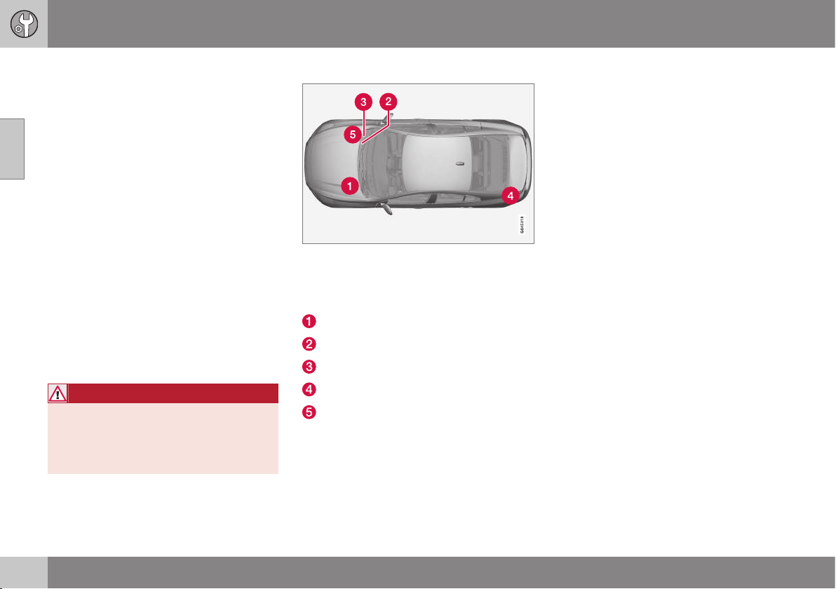
10 Maintenance and service
10
386
Fuses - general
All electrical functions and components are
protected by a number of fuses in order to
protect the car's electrical system from dam-
age by short circuiting or overloading.
If an electrical component or function does
not work, it may be because the component's
fuse was temporarily overloaded and failed. If
the same fuse fails repeatedly then there is a
fault in the circuit. Volvo recommends that
you visit an authorised Volvo workshop for
checking.
Changing
1. Look in the fuse diagram to locate the
fuse.
2. Pull out the fuse and check from the side
to see whether the curved wire has
blown.
3. If this is the case, replace it with a new
fuse of the same colour and amperage.
WARNING
Never use a foreign object or a fuse with
an amperage higher than that specified
when replacing a fuse. This could cause
significant damage to the electrical system
and possibly lead to fire.
Location of central electrical units
Central electrical unit locations in a left-hand
drive car. In a right-hand drive car the central
electrical units under the glovebox change
sides.
Engine compartment
Under the glovebox
Under the glovebox
Cargo area
Engine compartment cold zone (only
Start/Stop)
Related information
•
Fuses - in engine compartment (p. 387)
•
Fuses - under glovebox (p. 391)
•
Fuses - in the control module under the
glovebox (p. 393)
•
Fuses - in cargo area (p. 395)
•
Fuses - in the engine compartment's cold
zone (p. 396)
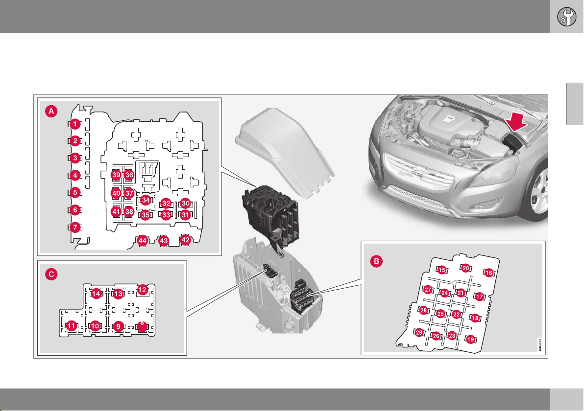
10 Maintenance and service
10
}}
387
Fuses - in engine compartment
Fuses in the engine compartment protect
engine and brake functions, amongst other
things.
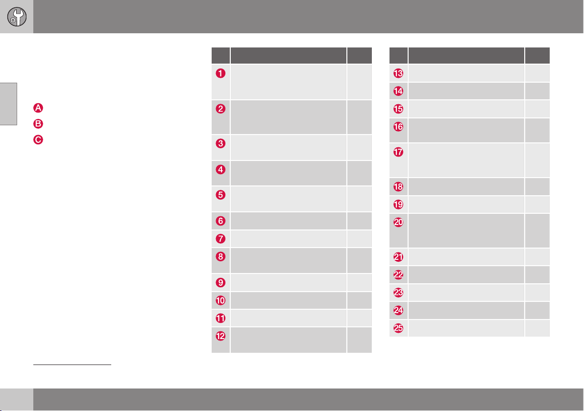
||
10 Maintenance and service
10
388
* Option/accessory, for more information, see Introduction.
General fuses, engine compartment
On the inside of the cover there are tweezers
that facilitate the procedure for the removal
and fitting of fuses.
Positions (see preceding illustration)
Engine compartment, upper
Engine compartment, front
Engine compartment, lower
These fuses are all located in the engine com-
partment box. The fuses in (C) are located
under (A).
On the inside of the cover is a label that
shows the location of the fuses.
•
Fuses 1-7 and 42-44 are of the "Midi
Fuse" type and must only be replaced by
a workshop
17
.
•
Fuses 8-15 and 34 are of the "JCASE"
type and should be replaced by a work-
shop
17
•
Fuses 16-33 and 35-41 are of the "Mini
Fuse" type.
Function
[A]
A
Primary fuse for the central
electronic module (CEM)
under the glovebox
B
50
Primary fuse for the central
electronic module (CEM)
under the glovebox
50
Primary fuse for central elec-
trical unit in cargo area
B
60
Primary fuse for relay/fuse box
under the glovebox
60
Primary fuse for relay/fuse box
under the glovebox
B
60
- -
Electric additional heater*
B
100
Heated windscreen*
B
, left-
hand side
40
Windscreen wipers 30
Parking heater* 25
Ventilation fan
C
40
Heated windscreen*
B
, right-
hand side
40
Function
[A]
A
ABS pump 40
ABS valves 20
Headlamp washers* 20
Headlamp levelling*; Active
Xenon headlamps - ABL*
10
Primary fuse for the central
electronic module (CEM)
under the glovebox
20
ABS 5
Adjustable steering force* 5
Engine control module; Trans-
mission control module; Air-
bags
10
Heated washer nozzles* 10
- -
Headlamp control 5
- -
- -
17
An authorised Volvo workshop is recommended.
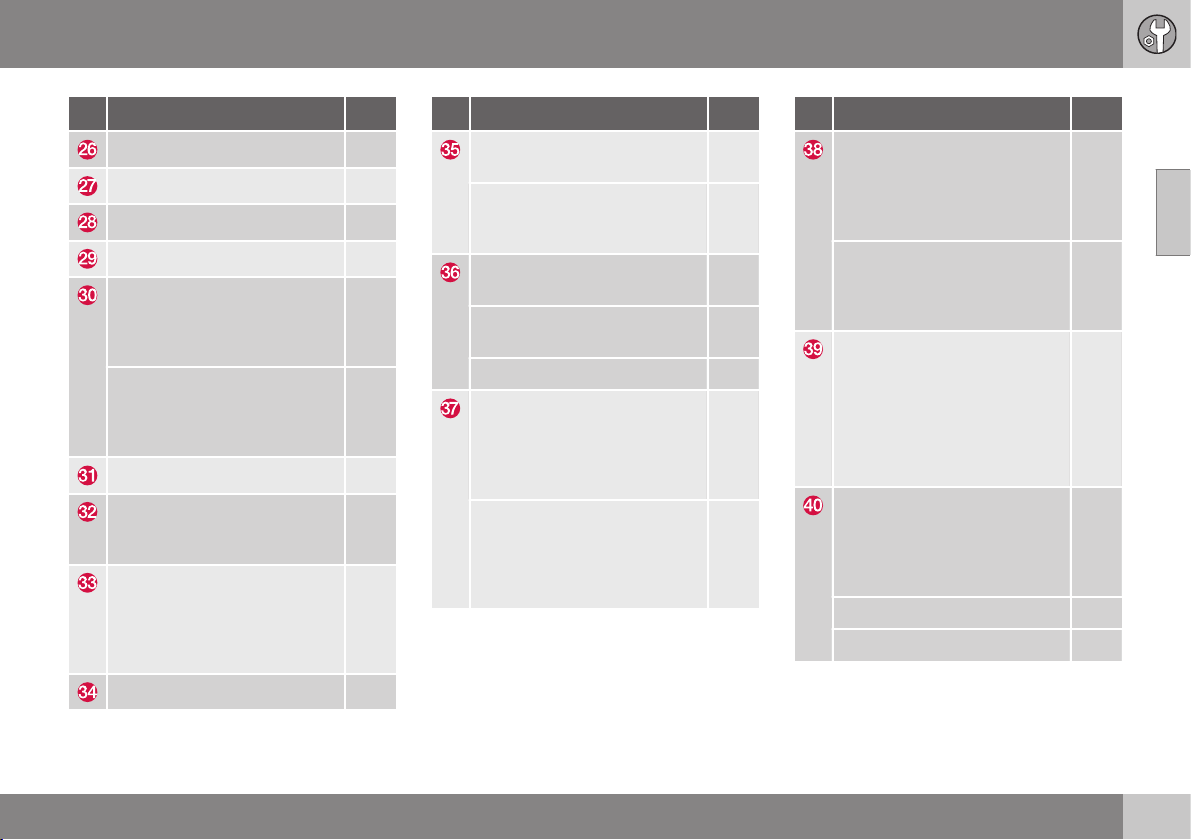
10 Maintenance and service
10
}}
* Option/accessory, for more information, see Introduction.
389
Function
[A]
A
- -
Relay coils 5
Auxiliary lamps* 20
Horn 15
Relay coil in main relay for
engine management system
(4-cyl.); Engine control module
(4-cyl.)
5
Relay coil in main relay for
engine management system
(5, 6-cyl.); Engine control
module (5, 6-cyl.)
10
Transmission control module 15
Solenoid clutch A/C (5, 6-cyl.
petrol); Supporting coolant
pump (4-cyl. diesel)
15
Relay coil in relay for solenoid
clutch A/C (5, 6-cyl. petrol);
Relay coils in central electrical
unit in engine compartment
cold zone (Start/Stop)
5
Start relay (5, 6-cyl. petrol)
C
30
Function
[A]
A
Glow control module (5-cyl.
diesel)
10
Engine control module (4-cyl.);
Ignition coils (5, 6-cyl. petrol);
Capacitor (6-cyl.)
20
Engine control module (5, 6-
cyl. petrol)
10
Engine control module (5-cyl.
diesel)
15
Engine control module (4-cyl.) 20
Mass air flow sensor (4-cyl.);
Thermostat(4-cyl. petrol);
EVAP valve (4-cyl. petrol);
Cooling pump for EGR (4-cyl.
diesel)
10
Mass air flow sensor (5-cyl.
diesel, 6-cyl.); Control valves
(5-cyl. diesel); Injectors (5, 6-
cyl. petrol); Engine control
module (5, 6-cyl. petrol)
15
Function
[A]
A
Solenoid clutch A/C (5, 6-cyl.);
Valves (5, 6-cyl.); Engine con-
trol module (6-cyl.); Mass air
flow sensor (5-cyl. petrol); Oil
level sensor
10
Valves (4-cyl.); Oil pump (4-
cyl. petrol); Lambda-sond,
centre (4-cyl. petrol); Lambda-
sond, rear (4-cyl. diesel)
15
Lambda-sond, front (4-cyl.);
Lambda-sond, rear (4-cyl.
petrol)
EVAP valve (5, 6-cyl. petrol);
Lambda-sonds (5, 6-cyl.);
Control module radiator roller
cover (5-cyl. diesel)
15
Coolant pump (5-cyl. petrol);
Crankcase ventilation heater
(5-cyl. petrol); Oil pump auto-
matic gearbox (5-cyl. petrol
Start/Stop)
10
Ignition coils (4-cyl. petrol) 15
Diesel filter heater (diesel) 20

||
10 Maintenance and service
10
390
Function
[A]
A
Control module, radiator roller
cover (5-cyl. petrol)
5
Solenoid clutch A/C (4-cyl.);
Glow control module (4-cyl.
diesel); Oil pump (4-cyl. diesel)
7.5
Crankcase ventilation heater
(5-cyl. diesel); Oil pump auto-
matic gearbox (5-cyl. diesel
Start/Stop)
10
Coolant pump (4-cyl. petrol) 50
Glow plugs (diesel) 70
Cooling fan (4 - 5-cyl. petrol) 60
Cooling fan (6-cyl., 4, 5-cyl.
diesel)
80
Power steering 100
A
Ampere
B
For cars with the Start/Stop function this fuse location is
empty - see instead Fuses - in the engine compartment's
cold zone (p. 396).
C
For cars with the Start/Stop function this fuse location is
empty - see instead Fuses - in the engine compartment's
cold zone (p. 396).
Related information
•
Fuses - under glovebox (p. 391)
•
Fuses - in the control module under the
glovebox (p. 393)
•
Fuses - in cargo area (p. 395)
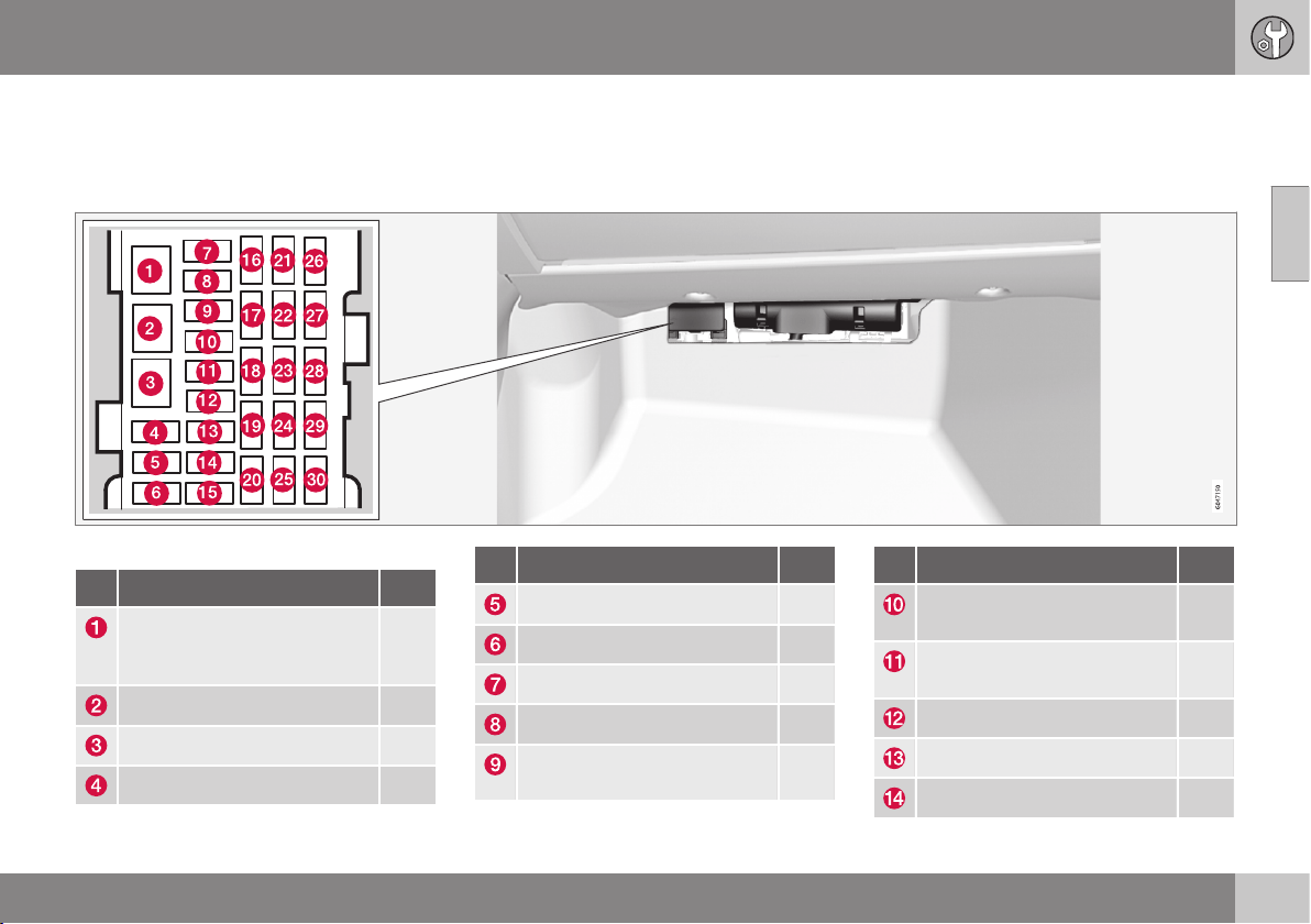
10 Maintenance and service
10
}}
* Option/accessory, for more information, see Introduction.
391
Fuses - under glovebox
Fuses under the glovebox protect the info-
tainment system and seat functions, amongst
other things.
Positions
Function
[A]
A
Primary fuse for audio control
module*; Primary fuse for
fuses 16-20: Infotainment
40
Windscreen washers 25
- -
- -
Function
[A]
A
- -
Door handle (Keyless*) 5
- -
Control panel, driver's door 20
Control panel, front passenger
door
20
Function
[A]
A
Control panel, rear passenger
door, right
20
Control panel, rear passenger
door, left
20
Keyless* 7.5
Power seat, driver's side* 20
Power seat, passenger side* 20

||
10 Maintenance and service
10
392
* Option/accessory, for more information, see Introduction.
Function
[A]
A
- -
Infotainment Control Module
or Screen
B
5
Audio control unit (amplifier)*;
TV*; Digital radio*
10
Audio control module or Con-
trol module Sensus
B
15
Telematics*; Bluetooth* 5
- -
Sunroof*; Interior lighting roof;
Climate sensor*; Damper
motors, air intake
5
12 V socket, tunnel console 15
Seat heating, rear right* 15
Seat heating, rear left* 15
Electric additional heater* 5
Seat heating, front passenger
side
15
Seat heating, front driver's
side
15
Function
[A]
A
Parking assistance*; Parking
camera*; BLIS*
5
AWD control module* 15
Active chassis Four-C* 10
A
Ampere
B
Certain model variants.
Related information
•
Fuses - in engine compartment (p. 387)
•
Fuses - in the control module under the
glovebox (p. 393)
•
Fuses - in cargo area (p. 395)
•
Fuses - in the engine compartment's cold
zone (p. 396)
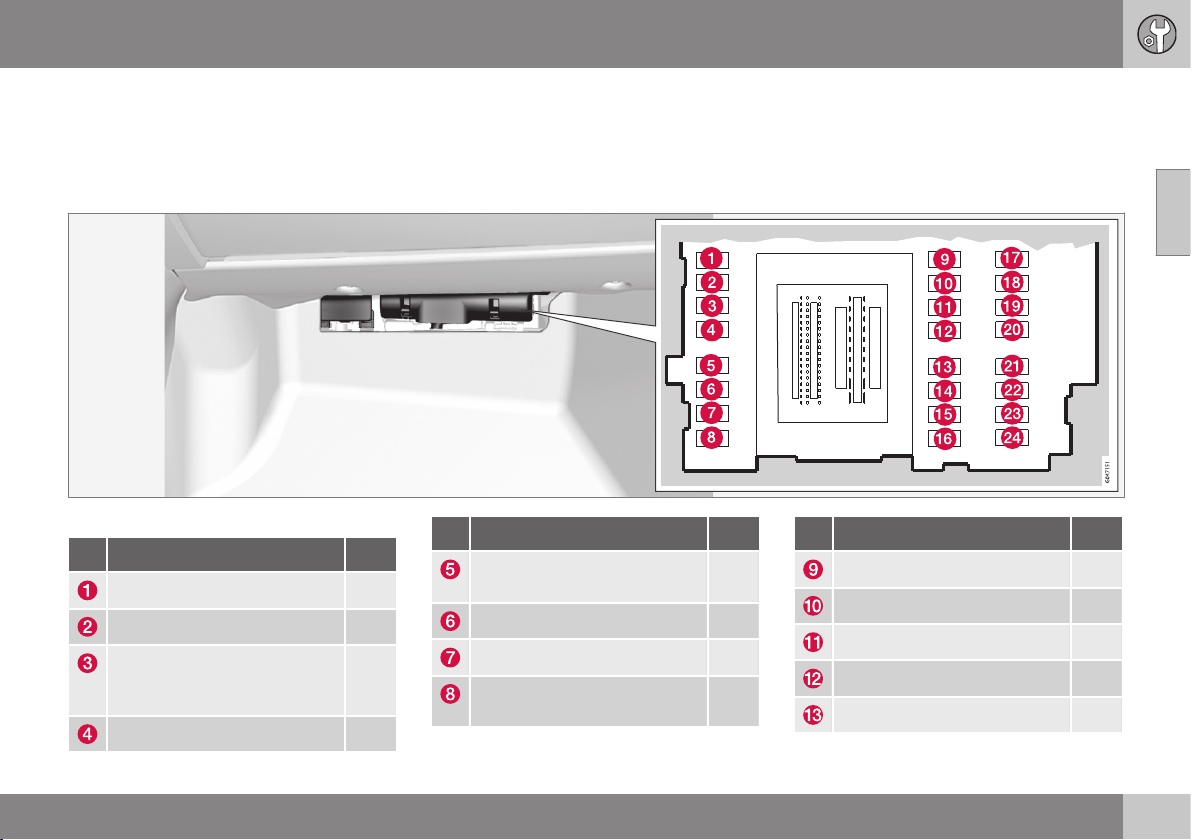
10 Maintenance and service
10
}}
* Option/accessory, for more information, see Introduction.
393
Fuses - in the control module under
the glovebox
Fuses in the control module under the glove-
box protect airbag and collision warning sys-
tem functions, amongst other things.
Positions
Function
[A]
A
- -
- -
Interior lighting; Driver's door
control panel, power win-
dows; Power seats*
7.5
Combined instrument panel 5
Function
[A]
A
Adaptive cruise control, ACC*;
collision warning system*
10
Interior lighting; Rain sensor* 7.5
Steering wheel module 7.5
Central locking system, fuel
filler flap
10
Function
[A]
A
Heated steering wheel* 15
Heated windscreen* 15
Unlocking, boot lid 10
Folding head restraint* 10
Fuel pump 20

||
10 Maintenance and service
10
394
* Option/accessory, for more information, see Introduction.
Function
[A]
A
Movement detector alarm*;
Climate panel
5
Steering lock 15
Siren*; Data link connector
OBDII
5
- -
Airbags 10
Collision warning system* 5
Accelerator pedal sensor;
Dimming interior rearview mir-
ror*; Seat heating, rear*
7.5
Infotainment control module
(Performance); Audio (Per-
formance)
15
Brake light 5
Sunroof* 20
Immobiliser 5
A
Ampere
Related information
•
Fuses - in engine compartment (p. 387)
•
Fuses - under glovebox (p. 391)
•
Fuses - in cargo area (p. 395)
•
Fuses - in the engine compartment's cold
zone (p. 396)
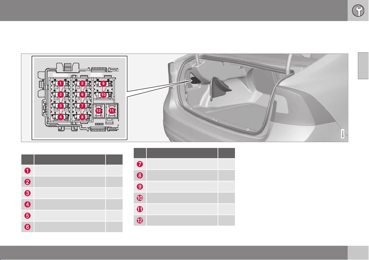
10 Maintenance and service
10
* Option/accessory, for more information, see Introduction.
395
Fuses - in cargo area
Fuses in the cargo area protect the electric
parking brake, amongst other things.
Positions
Function
[A]
A
Electric parking brake, left 30
Electric parking brake, right 30
Rear window defroster 30
Trailer socket 2* 15
- -
12 V socket, cargo area 15
Function
[A]
A
- -
- -
- -
- -
Trailer socket 1* 40
- -
A
Ampere
Related information
•
Fuses - in engine compartment (p. 387)
•
Fuses - under glovebox (p. 391)
•
Fuses - in the control module under the
glovebox (p. 393)
•
Fuses - in the engine compartment's cold
zone (p. 396)
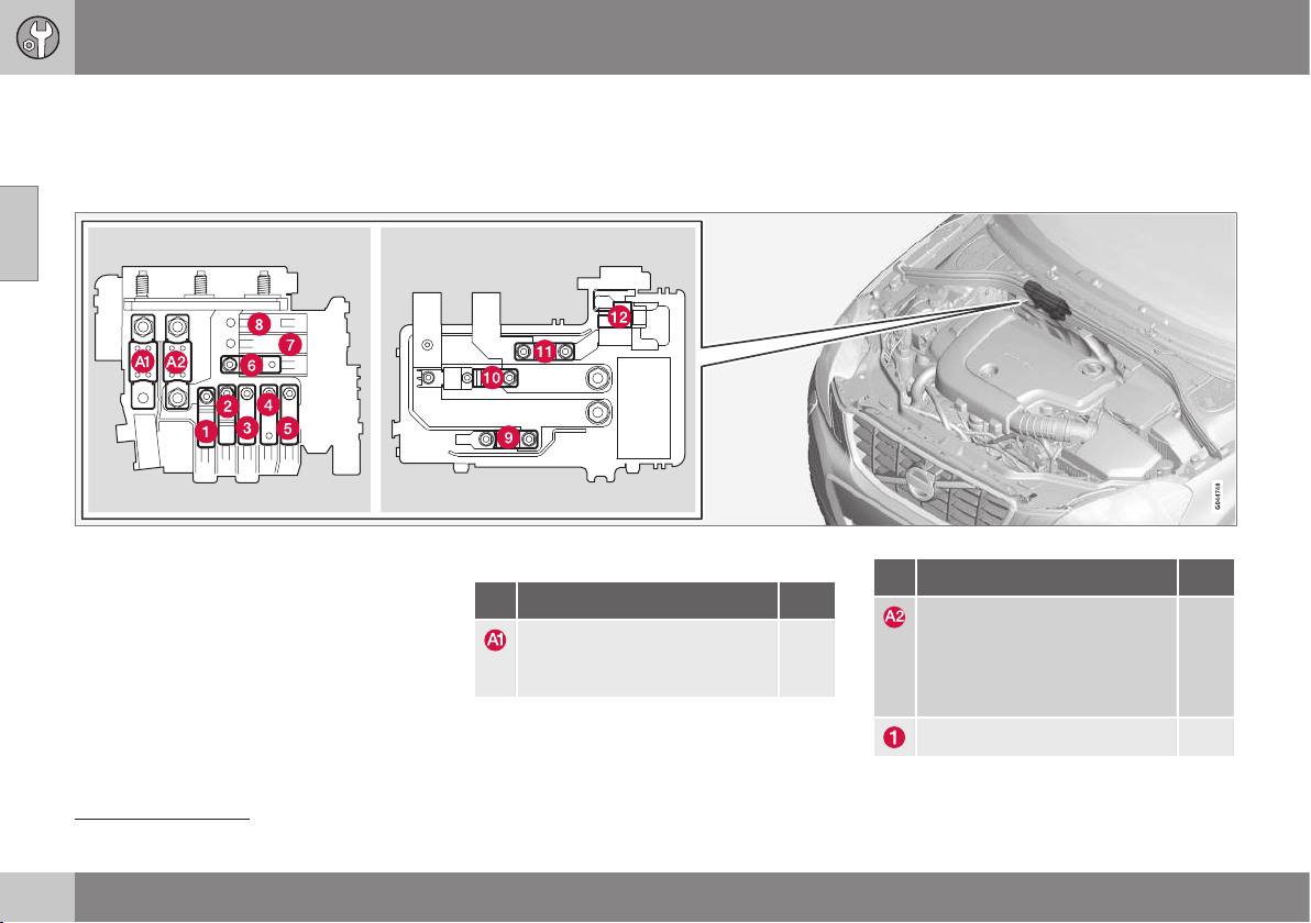
10 Maintenance and service
10
396
* Option/accessory, for more information, see Introduction.
Fuses - in the engine compartment's
cold zone
Fuses in the engine compartment's cold zone
are fitted in cars with the Start/Stop function.
Fuse locations in the engine compartment's cold zone.
•
Fuses A1 and A2 are of the "MEGA Fuse"
type and must only be replaced by a
workshop
18
.
•
Fuses 1-11 are of the "Midi Fuse" type
and must only be replaced by a work-
shop
18
.
•
Fuse 12 is of the "Mini Fuse" type.
For more information on Start/Stop - see
Start/Stop* (p. 284).
Positions
Function
[A]
A
Main fuse for central electrical
unit in the engine compart-
ment
175
Function
[A]
A
Main fuse for central elec-
tronic module (CEM) under
the glovebox, relay/fuse box
under the glovebox, central
electrical unit in cargo area
175
Electric additional heater* 100
18
An authorised Volvo workshop is recommended.

10 Maintenance and service
10
* Option/accessory, for more information, see Introduction.
397
Function
[A]
A
Primary fuse for the central
electronic module (CEM)
under the glovebox
50
Primary fuse for relay/fuse box
under the glovebox
60
Heated windscreen* 60
Primary fuse for central elec-
trical unit in cargo area
60
Ventilation fan 40
- -
- -
Start relay 30
- -
Support battery 70
Central electronic module
(CEM) - reference voltage
support battery
5
A
Ampere
Related information
•
Fuses - in engine compartment (p. 387)
•
Fuses - under glovebox (p. 391)
•
Fuses - in the control module under the
glovebox (p. 393)
•
Fuses - in cargo area (p. 395)
10 Maintenance and service
10
398
Car wash
The car should be washed as soon as it
becomes dirty. Wash the car in a car wash
with oil separator. Use car shampoo.
Handwashing
•
Remove bird droppings from the paint-
work as soon as possible. Bird droppings
contain chemicals that affect and discol-
our paintwork very quickly. An authorised
Volvo workshop is recommended for the
removal of any discoloration.
•
Hose down the underbody.
•
Rinse the whole car until the loose dirt
has been removed in order to reduce the
risk of scratches from washing. Do not
spray directly onto the locks.
•
If necessary, use cold degreasing agent
on very dirty surfaces. Note that the sur-
faces must not then be warmed up by the
sun!
•
Wash using a sponge, car shampoo and
plenty of lukewarm water.
•
Clean the wiper blades with a lukewarm
soap solution or car shampoo.
•
Dry the car using a clean, soft chamois or
a water scraper. If you avoid allowing
water droplets to dry in strong sunlight
then the risk of water stains that may
need to be polished away is reduced.
WARNING
Always have the engine cleaned by a
workshop. There is a risk of fire if the
engine is hot.
IMPORTANT
Dirty headlamps have impaired functional-
ity. Clean them regularly, when refuelling
for example.
Do not use any corrosive cleaning agents
but use water and a non-scratching
sponge instead.
NOTE
Outside lighting such as headlamps, fog
lamps and rear lamps may temporarily
have condensation on the inside of the
lens. This is normal, all exterior lighting is
designed to withstand this. Condensation
is normally vented out of the lamp housing
when the lamp has been switched on for a
time.
Automatic car washes
An automatic car wash is a simple and quick
way of washing the car, but it cannot reach
everywhere. Handwashing the car is recom-
mended for achieving optimum results.
NOTE
The car must only be washed by hand
over the first few months. This is because
the paint is more delicate when it is new.
High-pressure washing
When using high-pressure washing, use
sweeping movements and make sure that the
nozzle does not come closer than 30 cm to
the surface of the car (the distance applies to
all exterior parts). Do not spray directly onto
the locks.
Testing the brakes
WARNING
Always test the brakes after washing the
car, including the parking brake, to ensure
that moisture and corrosion do not attack
the brake linings and reduce braking per-
formance.
Lightly depress the brake pedal now and then
when driving long distances in rain or slush.
The heat from the friction causes the brake
linings to warm up and dry. Do the same
thing after starting in very damp or cold
weather.
Wiper blades
Asphalt, dust and salt residue on wiper
blades, as well as insects, ice etc. on the

10 Maintenance and service
10
}}
399
windscreen, impair the service life of wiper
blades.
For cleaning:
- Set the wiper blades to the service position,
see Wiper blades (p. 376).
NOTE
Wash the wiper blades and windscreen
regularly with lukewarm soap solution or
car shampoo. Do not use any strong sol-
vents.
Exterior plastic, rubber and trim
components
A special cleaning agent available from Volvo
dealers is recommended for the cleaning and
care of coloured plastic parts, rubber and trim
components, such as glossy trim mouldings.
When using such a cleaning agent the
instructions must be followed carefully.
IMPORTANT
Avoid waxing and polishing on plastic and
rubber.
When using degreasant on plastic and
rubber, only rub with light pressure if it is
necessary. Use a soft washing sponge.
Polishing glossy trim mouldings could
wear away or damage the glossy surface
layer.
Polishing agent that contains abrasive
must not be used.
Rims
Only use rim cleaning agent recommended
by Volvo.
Strong rim cleaning agents can damage the
surface and cause stains on chrome-plated
aluminium rims.
Related information
•
Polishing and waxing (p. 399)
•
Cleaning the interior (p. 401)
•
Water and dirt-repellent coating (p. 400)
Polishing and waxing
Polish and wax the car if the paintwork is dull
or to give the paintwork extra protection.
The car does not need to be polished until it
is at least one year old. However, the car can
be waxed during this time. Do not polish or
wax the car in direct sunlight.
Wash and dry the car thoroughly before you
begin polishing or waxing. Clean off asphalt
and tar stains using tar remover or white spi-
rit. More stubborn stains can be removed
using fine rubbing paste designed for car
paintwork.
Polish first with a polish and then wax with
liquid or solid wax. Follow the instructions on
the packaging carefully. Many preparations
contain both polish and wax.
IMPORTANT
Avoid waxing and polishing on plastic and
rubber.
When using degreasant on plastic and
rubber, only rub with light pressure if it is
necessary. Use a soft washing sponge.
Polishing glossy trim mouldings could
wear away or damage the glossy surface
layer.
Polishing agent that contains abrasive
must not be used.
||
10 Maintenance and service
10
400
* Option/accessory, for more information, see Introduction.
IMPORTANT
Only paint treatment recommended by
Volvo should be used. Other treatment
such as preserving, sealing, protection,
lustre sealing or similar could damage the
paintwork. Paintwork damage caused by
such treatments is not covered by Volvo
warranty.
Related information
•
Car wash (p. 398)
Water and dirt-repellent coating
The windows are treated with a surface coa-
ting that improves visibility in difficult weather
conditions.
Water and dirt-repellent coating*
There is natural wear of the water-
repellent coating.
Maintenance:
•
Never use products such as car wax,
degreaser or similar on glass surfaces as
this could ruin their water-repellent prop-
erties.
•
Take care when cleaning so as not to
damage the glass surface.
•
To avoid damaging glass surfaces when
removing ice – only use plastic ice scra-
pers.
•
Treatment with a special finishing agent
available from Volvo dealers is recom-
mended in order to maintain the water-
repellent properties on the side windows.
This should be used first after three years
and then each year.
IMPORTANT
Do not use a metal ice scraper to remove
ice from the windows. Use the heating to
remove ice from the door mirrors, see Win-
dows and rearview and door mirrors -
heating (p. 101).
Related information
•
Car wash (p. 398)

10 Maintenance and service
10
}}
401
Rustproofing
The car received a thorough and complete
rustproofing at the factory. Parts of the body
are made of galvanised sheet metal. The
underbody is protected by a wear-resistant
anti-corrosion compound. A thin, penetrating
rustproofing fluid was sprayed into the
exposed members, cavities, closed sections
and side doors.
Inspection and maintenance
The car's anti-corrosion protection does not
normally need to be maintained, but keeping
the car clean always helps to further reduce
the risk of corrosion. Strong alkaline or acidic
cleaning solutions must always be avoided on
the glossy trim components. Any stone chips
should be rectified as soon as they are dis-
covered.
Related information
•
Paint damage (p. 402)
Cleaning the interior
Only use cleaning agents and car care prod-
ucts recommended by Volvo. Clean regularly
and treat stains at once for best results. Vac-
uuming is important prior to using cleaning
agents.
IMPORTANT
•
Certain items of coloured clothing (e.g.
dark jeans and suede garments) may
stain the upholstery. If this occurs, it is
important to clean and treat these
parts of the upholstery as soon as
possible.
•
Never use strong solvents such as
washer fluid, pure petrol or white spirit
to clean the interior, since this may
damage the upholstery as well as
other interior materials.
•
Never spray the cleaning agent directly
onto components that have electrical
buttons and controls. Wipe them
instead using a moistened cloth con-
taining the cleaning agent.
•
Sharp objects and Velcro may damage
the fabric upholstery.
Fabric upholstery and ceiling upholstery
Volvo offers a comprehensive fabric care
product for fabric upholstery and ceiling
upholstery which, when used in accordance
with the instructions, preserves the properties
of the upholstery. The fabric care product is
available for purchase from a Volvo dealer.
Leather upholstery
Volvo's leather upholstery is treated to pre-
serve its original appearance.
Leather upholstery is a natural product that
changes and acquires a beautiful patina over
time. Regular cleaning and treatment are
required in order that the properties and col-
ours of the leather shall be preserved. Volvo
offers a comprehensive product, Volvo
Leather Care Kit/Wipes, for the cleaning and
treatment of leather upholstery which, when
used in accordance with the instructions, pre-
serves the leather's protective coating.
To achieve best results, Volvo recommends
the cleaning and application of the protective
cream once to four times per year (or more if
required). The Volvo Leather Care Kit/Wipes
is available for purchase from a Volvo dealer.
Leather steering wheel
Leather needs to breathe. Never cover the
leather steering wheel with protective plastic.
Volvo Leather Care Kit/Wipes is recom-
mended for cleaning the leather steering
wheel.
Interior plastic, metal and wood parts
A fibrillated fibre or microfibre cloth, lightly
moistened with water, available from Volvo
dealers, is recommended for cleaning interior
parts and surfaces.

||
10 Maintenance and service
10
402
Do not scrape or rub stains. Never use strong
stain removers. A special cleaning agent
available from Volvo dealers can be used for
more difficult cleaning.
Seatbelts
Use water and a synthetic detergent. A spe-
cial textile cleaning agent is available from a
Volvo dealer. Ensure that the seatbelt is dry
before allowing it to retract.
Inlay mats and floor mat
Remove inlaid carpets for separate cleaning
of the floor carpet and the inlaid carpets. Use
a vacuum cleaner to remove dust and dirt.
Each inlay mat is secured with pins.
Remove the inlay mat by taking hold of the
inlay mat at each pin and lifting the mat
straight up.
Fit the inlay mat in place by pressing it in at
each pin.
WARNING
Only use one inlaid mat at each seat, and
check before setting off that the mat by
the driver's seat is firmly affixed and
secured in the pins so that it does not get
caught adjacent to and under the pedals.
A special textile cleaner is recommended for
stains on the floor mat after vacuuming. Floor
mats must be cleaned with agents recom-
mended by a Volvo dealer.
Related information
•
Car wash (p. 398)
Paint damage
Paint is an important part of the car's rust-
proofing and should therefore be checked
regularly. The most common types of paint-
work damage are stone chips, scratches, and
marks on the edges of wings, doors and
bumpers.
Touching up minor paintwork damage
To avoid the onset of rust, damaged paint-
work should be rectified immediately.
Materials that may be needed
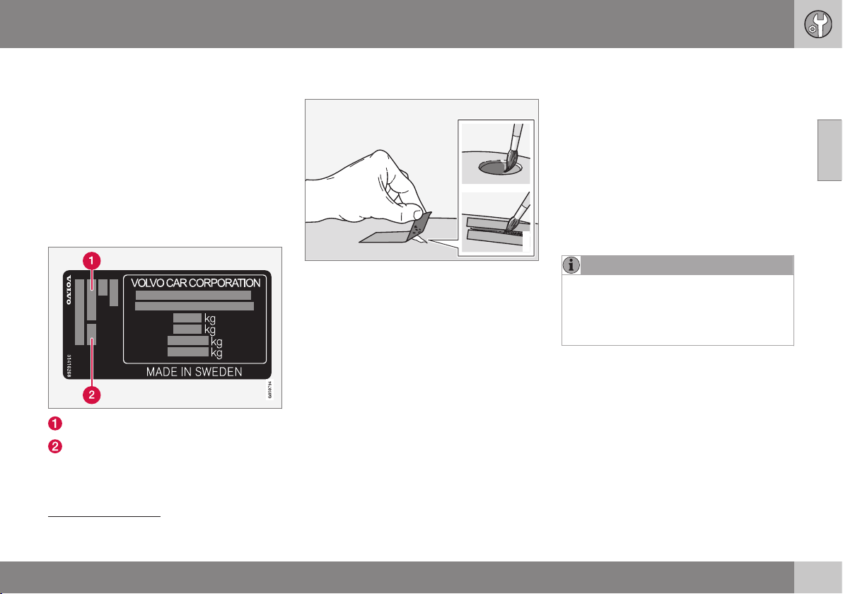
10 Maintenance and service
10
403
•
Primer
19
- a special adhesive primer in a
spray can is available for e.g. plastic-
coated bumpers.
•
base coat and clear coat - are available in
spray cans or as touch-up pens/sticks
20
.
•
Masking tape.
•
fine sand paper
19
.
Colour code
The label for colour code is located on the
car's door pillar and is visible when the right-
hand rear door is opened.
Exterior colour code
Any secondary exterior colour code
It is important that the correct colour is used.
For product label location, see Type designa-
tions (p. 405).
Repairing minor paint damage such as
stone chips and scratches
G021832
Before work is started, the car must be clean
and dry as well as at a temperature above
15 °C.
1. Apply a piece of masking tape over the
damaged surface. Then remove the tape
to remove any loose paint.
If the damage has reached down to a
metal surface (sheet steel), it is preferable
to use a primer. In the event of damage to
a plastic surface, an adhesive primer
should be used for better results - spray
into the spray can's cap and brush thinly.
2. Before painting, gentle polishing using a
very fine polishing agent may be carried
out locally if required (e.g. if there are any
uneven edges). Clean the surface thor-
oughly and allow to dry.
3. Stir the primer well and apply using a fine
brush, matchstick or similar. Finish with
base coat and clear coat once the primer
has dried.
4. For scratches, proceed as above, but
mask around the damaged area to pro-
tect the undamaged paintwork.
NOTE
If the stone chip has not penetrated down
to the meal and an undamaged layer of
paint remains in place, fill in with base coat
and clear coat as soon as the surface has
been cleaned.
Related information
•
Rustproofing (p. 401)
19
If required.
20
Follow the instructions that are included with the package for the touch-up pen/stick.
SPECIFICATIONS

11 Specifications
11
}}
405
Type designations
Type designation, vehicle identification num-
ber, etc., i.e. information unique to the car,
can be read on a label in the car.
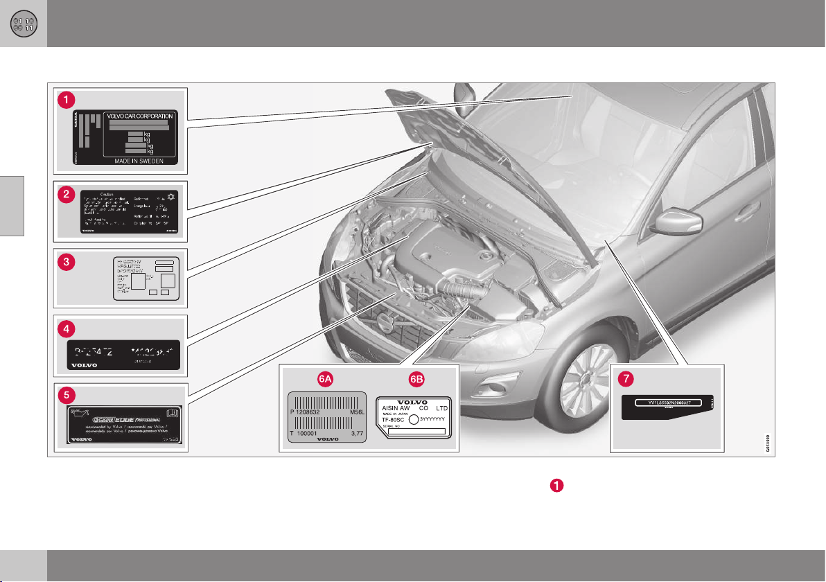
||
11 Specifications
11
406
Label location
The illustration is schematic - details may vary depending on market and model.
Knowing the car's type designation, vehicle
identification and engine numbers can facili-
tate all contact with an authorised Volvo
dealer regarding the car and when ordering
spare parts and accessories.
Type designation, vehicle identification
number, permissible maximum weights
and code designation for exterior colour
11 Specifications
11
407
and date of manufacture. The decal is
positioned on the door pillar, and will be
visible when the right-hand rear door is
opened.
Label for A/C system.
Label for parking heater.
Engine code and engine serial number.
Label for engine oil.
Gearbox type designation and serial num-
ber.
Manual gearbox
Automatic gearbox
Car's identification number (VIN Vehicle
Identification Number).
Further information on the car is presented in
the registration document.
NOTE
It is not intended that the decals illustrated
in the owner's manual should be exact
replicas of those in the car. They are
included to show their approximate
appearance and location in the car. The
information that applies to your particular
car can be found on the decal on the car.
Related information
•
Weights (p. 409)
•
Engine specifications (p. 412)
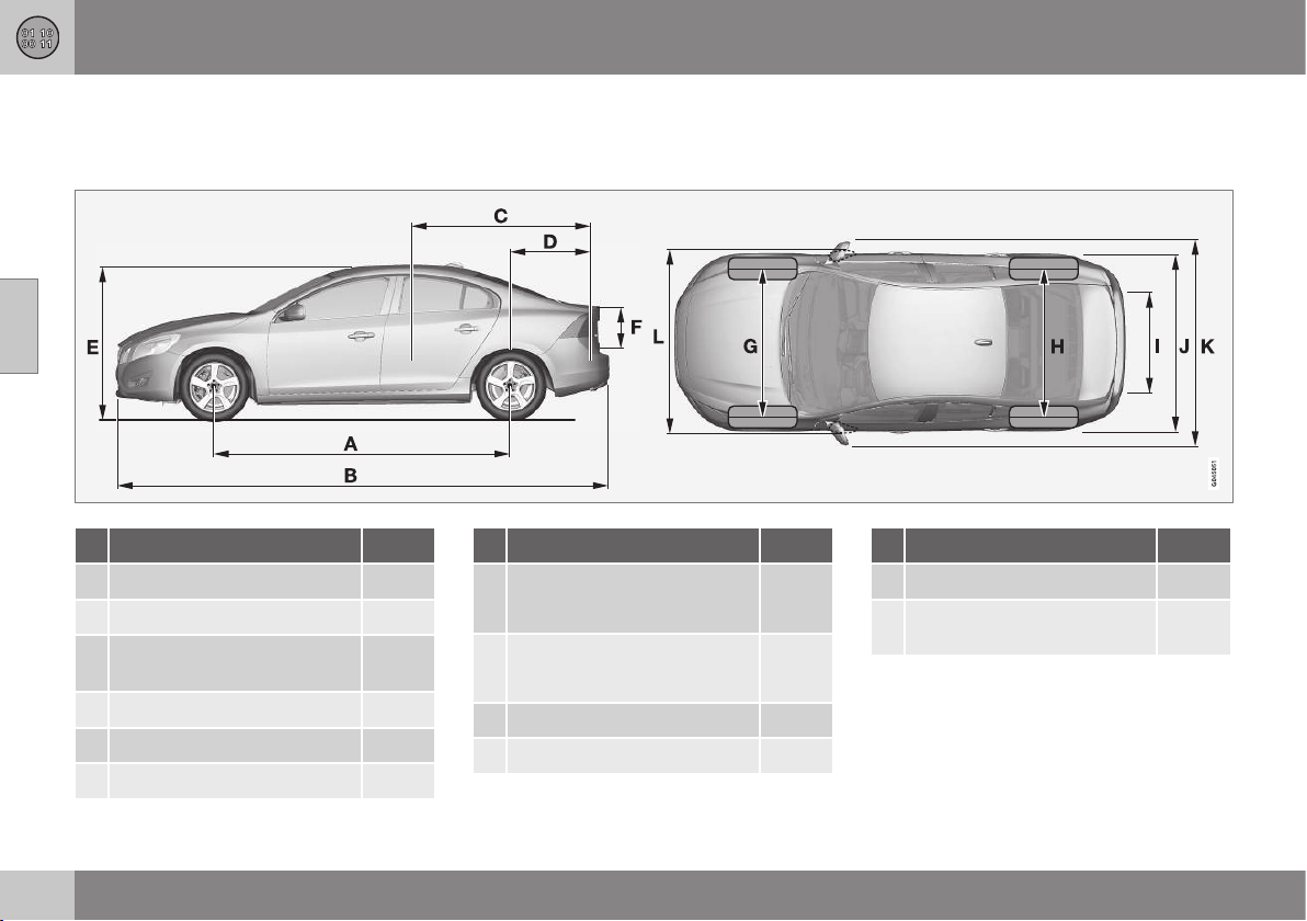
11 Specifications
11
408
Dimensions
Measurement of car length, height, etc. can
be read in the table.
Dimensions mm
A Wheelbase 2776
B Length 4635
C Load length, floor, folded
rear seat 1749
D Load length, floor 965
E Height 1484
F Load height 465
Dimensions mm
G Front track
1588
A
/
1578
B
H Rear track
1585
A
/
1575
B
I Load width, floor 919
J Width 1865
Dimensions mm
K Width including door mirrors 2097
L Width including folded-in
door mirrors 1899
A
with 16" wheel
B
with 17" wheel
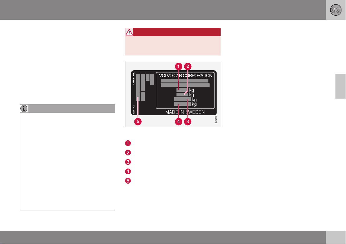
11 Specifications
11
409
Weights
Max. gross vehicle weight, etc. can be read
on a label in the car.
Kerb weight includes the driver, the fuel tank
90% full and all fluids.
The weight of passengers and accessories,
and towball load (p. 410) (when a trailer is
hitched) influence the load capacity and are
not included in the kerb weight.
Permitted max. load = Gross vehicle weight -
Kerb weight.
NOTE
The documented kerb weight applies to
cars in the standard version - i.e. a car
without extra equipment or accessories.
This means that for every accessory added
the loading capacity of the car is reduced
correspondingly by the weight of the
accessory.
Examples of accessories that reduce load-
ing capacity are the Kinetic/Momentum/
Summum equipment levels, as well as
other accessories such as Towbar, Load
carrier, Space box, Audio system, Auxiliary
lamps, GPS, Fuel-driven engine block
heater, Safety grille, Carpets, Cargo cover,
Power seats, etc.
Weighing the car is a certain way of ascer-
taining the kerb weight of your own partic-
ular car.
WARNING
The car's driving characteristics change
depending on how heavily it is loaded and
how the load is distributed.
For information on label location, see Type des-
ignations (p. 405).
Max. gross vehicle weight
Max. train weight (car+trailer)
Max. front axle load
Max. rear axle load
Equipment level
Max. load: See registration document.
Max. roof load: 75 kg.
Related information
•
Towing capacity and towball load
(p. 410)
11 Specifications
11
410
Towing capacity and towball load
Towing capacity and towball load for driving
with a trailer can be read in the tables.
Max. weight braked trailer
NOTE
Not all engines are available in all markets.
Engine
Engine code
A
Gearbox Max. weight braked trailer (kg) Max. towball load (kg)
T3 B4204T37 Manual, M66 1800 90
T3 B4154T4 Automatic, TF-71SC 1500 75
T4 B4204T19 Manual, M66 1800 90
T4 B4204T19 Automatic, TF-71SC 1600 75
T5 B4204T11 Automatic, TG-81SC 1600 75
T5 B4204T15 Automatic, TG-81SC 1600 75
T5 AWD B5254T14 Automatic, TF-80SC 1800 90
T6 B4204T9 Automatic, TG-81SC 1600 75
D2 D4204T8 Manual, M66 1600 75
D2 D4204T20 Automatic, TF-71SC 1600 75
D3 D4204T9 Manual, M66 1600 75
D3 D4204T9 Automatic, TF-71SC 1600 75
D4 D4204T14 Manual, M66 1800 90
D4 D4204T14 Automatic, TG-81SC 1800 90

11 Specifications
11
* Option/accessory, for more information, see Introduction.
411
Engine
Engine code
A
Gearbox Max. weight braked trailer (kg) Max. towball load (kg)
D4 AWD D5244T21 Automatic, TF-80SD 1800 90
D5 D4204T11 Automatic, TG-81SC 1800 90
A
Engine code, component and serial number can be read on the engine; see Type designations (p. 405).
Max. weight unbraked trailer
Max. weight unbraked trailer (kg) Max. towball load (kg)
750 50
Related information
•
Weights (p. 409)
•
Driving with a trailer* (p. 311)
•
Trailer Stability Assist - TSA (p. 317)

11 Specifications
11
412
Engine specifications
Engine specifications (output etc.) for each
respective engine alternative can be read in
the table.
NOTE
Not all engines are available in all markets.
S60
Engine
Engine code
A
Output
(kW/rpm)
Output
(hp/rpm)
Torque
(Nm/rpm)
No. of cylin-
ders
Bore
(mm)
Stroke
(mm)
Swept vol-
ume
(litres)
Compres-
sion ratio
T3 B4154T4 112/5000 152/5000 250/1700-4000 4 82.0 70,9 1,498 10.5:1
T3 B4204T37 112/5000 152/5000 250/1300-4000 4 82.0 93.2 1,969 11.3:1
T4 B4204T19 140/4700 190/4700 300/1300-4000 4 82.0 93.2 1,969 11.3:1
T5 B4204T11 180/5500 245/5500 350/1500–4800 4 82.0 93.2 1,969 10.8:1
T5 B4204T15 162/5500 220/5500 350/1500–4000 4 82.0 93.2 1,969 10.8:1
T5 AWD B5254T14 183/5400 249/5400 360/1800–4200 5 83.0 92,3 2,497 9.5:1
T6 B4204T9 225/5700 306/5700 400/2100-4800 4 82.0 93.2 1,969 10.3:1
D2 D4204T8 88/3750 120/3750 280/1500-2250 4 82.0 93.2 1,969 16.0:1
D2 D4204T20 88/3750 120/3750 280/1500-2250 4 82.0 93.2 1,969 16.0:1
D3 D4204T9 110/3750 150/3750 320/1750-3000 4 82.0 93.2 1,969 16.0:1
D4 D4204T14 140/4250 190/4250 400/1750-2500 4 82.0 93.2 1,969 15.8:1
D4 AWD D5244T21 140/4000 190/4000 420/1500-3000 5 81.0 93.2 2.400 16.5:1
D5 D4204T11 165/4250 225/4250 470/1750-2500 4 82.0 93.2 1,969 15.8:1
A
Engine code, component and serial number can be read on the engine; see Type designations (p. 405).

11 Specifications
11
414
Engine oil - adverse driving conditions
Adverse driving conditions can lead to abnor-
mally high oil temperature or oil consumption.
Below are some examples of adverse driving
conditions.
Check the oil level (p. 363) more frequently for
long journeys:
•
towing a caravan or trailer
•
in mountainous regions
•
at high speeds
•
in temperatures colder than -30 °C or
hotter than +40 °C.
The above also apply to shorter driving dis-
tances at low temperatures.
Choose a fully synthetic engine oil for adverse
driving conditions. It provides extra protection
for the engine.
Volvo recommends:
IMPORTANT
In order to fulfil the requirements for the
engine's service intervals all engines are
filled with a specially adapted synthetic
engine oil at the factory. The choice of oil
has been made very carefully with regard
to service life, starting characteristics, fuel
consumption and environmental impact.
An approved engine oil must be used in
order that the recommended service inter-
vals can be applied. Only use a prescribed
grade of oil for both filling and oil change,
otherwise you will risk affecting service life,
starting characteristics, fuel consumption
and environmental impact.
Volvo Car Corporation disclaims all war-
ranty liability if engine oil of the prescribed
grade and viscosity is not used.
Volvo recommends that oil changes are
carried out at an authorised Volvo work-
shop.
Related information
•
Engine oil - grade and volume (p. 415)
•
Engine oil - general (p. 362)

||
11 Specifications
11
416
S60
Engine
Engine code
A
Oil grade Volume, incl. oil filter
(litres)
T5 AWD B5254T14
Oil grade: ACEA A5/B5
Viscosity: SAE 5W–30
approx 5.5
T3 B4154T4 Castrol Edge Professional V 0W-20 or VCC RBS0-2AE 0w20 approx. 5.6
T3 B4204T37 approx. 5.9
T4 B4204T19 approx. 5.9
T5 B4204T11 approx. 5.9
T5 B4204T15 approx. 5.9
T6 B4204T9 approx. 5.9
D2 D4204T8 Castrol Edge Professional V 0W-20 or VCC RBS0-2AE 0w20 approx 5.2
D2 D4204T20 approx 5.2
D3 D4204T9 approx 5.2
D4 D4204T14 approx 5.2
D5 D4204T11 approx 5.2
D4 AWD D5244T21
Oil grade: ACEA A5/B5
Viscosity: SAE 0W–30
approx. 5.9
A
Engine code, component and serial number can be read on the engine; see Type designations (p. 405).
Related information
•
Engine oil - adverse driving conditions
(p. 414)
•
Engine oil - checking and filling (p. 363)
11 Specifications
11
417
Coolant - grade and volume
Approved coolant volume for each respective
engine alternative can be read in the table.
Prescribed grade: Coolant recommended by
Volvo mixed with 50% water
2
, see the pack-
aging.
NOTE
Not all engines are available in all markets.
Engine
A
Volume
(litres)
T3 B4154T4
8,3 (8,7
B
)
T3 B4204T37
T4 B4204T19
T5 B4204T11
T5 B4204T15
T6 B4204T9
Engine
A
Volume
(litres)
D2 D4204T8
8,9 (9,2
B
)
D2 D4204T20
D3 D4204T9
D4 D4204T14
D5 D4204T11
T5 AWD B5254T14 8.9
D4 AWD D5244T21
A
Engine code, component and serial number can be read
on the engine; see Type designations (p. 405).
B
Applies to cars with fuel-driven heater.
Related information
•
Coolant - level (p. 367)
2
Water quality must fulfil the standard STD 1285.1.
11 Specifications
11
418
Transmission fluid - grade and volume
The prescribed transmission fluid and volume
for each respective gearbox alternative can be
read in the table.
Manual gearbox
Manual gearbox Volume (litres) Prescribed transmission fluid
M66 approx. 1.45 BOT 350M3
NOTE
The gearbox oil does not need to be
changed under normal driving conditions.
However, it may be necessary under
adverse driving conditions.
Automatic gearbox
Automatic gearbox Volume (litres) Prescribed transmission fluid
TF-71SC approx 6.8 AW1
TF-80SC approx 7.0 AW1
TF-80SD approx 7.0 AW1
TG-81SC
approx. 6.6
A
approx. 7.5
B
AW1
A
Petrol engines
B
Diesel engines


11 Specifications
11
420
Brake fluid - grade and volume
The medium in a hydraulic brake system is
called brake fluid, and it is used to transfer
pressure from e.g. a brake pedal via a master
brake cylinder to one or more slave cylinders,
which in turn act on a mechanical brake.
Prescribed grade: DOT 4
Volume: 0.6 litres
Related information
•
Brake and clutch fluid - level (p. 368)
Power steering fluid - grade
Power steering fluid is the denomination of
the medium used in the car's power steering
system.
Prescribed grade: Power steering fluid rec-
ommended by Volvo.
Related information
•
Power steering fluid - level (p. 368)

11 Specifications
11
421
Fuel tank - volume
Fuel tank volume for each respective engine
alternative can be read in the table.
Engine Volume (litres) Prescribed grade
Petrol engine approx 67 Fuel - petrol (p. 307)
Diesel engine approx 67 Fuel - diesel (p. 307)
Related information
•
Filling up with fuel (p. 305)
•
Engine specifications (p. 412)
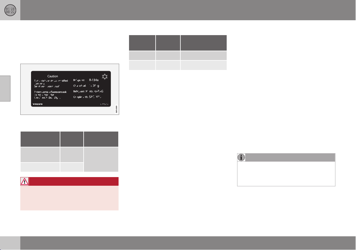
11 Specifications
11
422
Specifications for air conditioning
Prescribed grades and volumes of fluids and
lubricants in the air conditioning system can
be read in the tables below.
A/C decal
The label is fitted on the inside of the bonnet.
Refrigerant
Engine Weight Prescribed
grade
5-cylinder die-
sel
720 g R134a
other 800 g
WARNING
The air conditioning system contains pres-
surised refrigerant R134a. This system
must only be serviced and repaired by an
authorised workshop.
Compressor oil
Engine Volume Prescribed
grade
4-cylinder 60 ml PAG SP-A2
5-cylinder 110 ml PAG SP-10
Related information
•
Climate control system - fault tracing and
repair (p. 369)
•
Type designations (p. 405)
Fuel consumption and CO2 emissions
Fuel consumption and CO2 emissions can be
affected negatively by several causes.
Examples of this are:
•
If the car is equipped with extra equip-
ment that affects the car's weight.
•
The driver's driving style.
•
If the customer has specified wheels
larger than those fitted as standard on the
model's basic version, then resistance
increases.
•
High speed results in increased wind
resistance.
•
Fuel quality, road and traffic conditions,
weather and the condition of the car.
Even a combination of the above-mentioned
examples can result in significantly improved
consumption.
NOTE
Extreme weather conditions, driving with a
trailer or driving at high altitudes in combi-
nation with fuel grade are factors that
could affect the car's performance.
Related information
•
Economical driving (p. 310)
•
Weights (p. 409)
11 Specifications
11
}}
423
Tyres - approved tyre pressures
Approved tyre pressures for each respective
engine alternative can be read in the table.
NOTE
All engines, tyres or combinations of these
are not always available in all markets.
S60
Engine
Tyre size Speed
(km/h)
Load, 1-3 persons Max. load
ECO pressure
A
Front
(kPa)
B
Rear
(kPa)
Front
(kPa)
Rear
(kPa)
Front/rear
(kPa)
T3 (B4154T4)
T3 (B4204T37)
T4 (B4204T19)
D2 (D4204T8)
D2 (D4204T20)
D3 (D4204T9)
205/60 R 16
215/55 R 16
215/50 R 17
235/45 R 17
235/40 R 18
235/40 R 19
0 - 160 230 230 260 260 260
160 + 260 240 280 260 -
T5 (B4204T11)
T5 (B4204T15)
T5 AWD (B5254T14)
D4 (D4204T14)
D4 AWD (D5244T21)
215/55 R 16
235/45 R 17
0 - 160 230 230 260 260 260
160 + 260 240 280 260 -
205/60 R 16
215/50 R 17
235/40 R 18
235/40 R 19
0 - 160 240 240 260 260 260
160 + 280 240 300 260 -
||
11 Specifications
11
424
S60
Engine
Tyre size Speed
(km/h)
Load, 1-3 persons Max. load
ECO pressure
A
Front
(kPa)
B
Rear
(kPa)
Front
(kPa)
Rear
(kPa)
Front/rear
(kPa)
T6 (B4204T9)
D5 (D4204T11)
215/55 R 16
235/45 R 17
0 - 160 230 230 260 260 260
160 + 280 240 300 260 -
205/60 R 16
215/50 R 17
235/40 R 18
235/40 R 19
0 - 160 240 240 260 260 260
160 + 300 240 320 280 -
Temporary Spare Tyre max. 80 420 420 420 420 -
A
Economical driving.
B
In certain countries there is the "bar" unit beside the SI unit "Pascal": 1 bar = 100 kPa.
WARNING
19-inch wheels must never be used on
cars that are not equipped with the R-
Design or Sport chassis options. The use
of 19-inch wheels on cars with standard
chassis constitutes a safety risk, with a
risk of vehicle damage, and it impairs the
car's driving characteristics.
Related information
•
Tyres - dimensions (p. 326)
•
Tyres - air pressure (p. 324)
•
Type designations (p. 405)

11 Specifications
11
425

12 Alphabetical Index
12
426
A
ACC – Adaptive cruise control................. 197
Active Bending Lights (ABL)...................... 91
Active chassis - FOUR-C......................... 183
Active main beam...................................... 88
Active Park Assist.................................... 251
function............................................... 252
Limitations.......................................... 254
operation............................................. 253
Symbols and messages..................... 256
Active Xenon headlamps........................... 91
Active Yaw Control.................................. 184
Adapting driving characteristics.............. 183
Adaptive Cruise Control........................... 197
change cruise control functionality..... 206
deactivate........................................... 204
fault tracing......................................... 209
function............................................... 198
managing speed................................. 201
overtaking........................................... 203
overview.............................................. 200
radar sensor........................................ 206
setting the time interval...................... 202
standby mode..................................... 202
temporary deactivation....................... 202
Additional heater
electric........................................ 142, 143
fuel-driven........................................... 142
Adjusting the steering wheel...................... 82
Airbag
activating/deactivating, PACOS........... 33
driver's side.................................... 32, 39
passenger side......................... 32, 33, 39
AIRBAG ..................................................... 32
Airbag system............................................ 31
warning symbol.................................... 30
Air cleaning
material............................................... 125
passenger compartment.... 123, 124, 125
Air conditioning........................................ 131
Air conditioning, fluid
volume and grade............................... 422
Air conditioning system
repair................................................... 369
Air distribution.......................................... 126
Recirculation....................................... 133
table.................................................... 134
Air quality system IAQS........................... 125
Alarm........................................ 178, 179, 180
alarm indicator.................................... 179
alarm signals....................................... 180
automatic re-arming........................... 179
checking the alarm............................. 161
reduced alarm level............................ 180
remote control key not working.......... 180
Alcohol lock............................................. 263
Allergy and asthma inducing substances. 124
All Wheel Drive, (AWD)............................. 282
All Wheel Drive (AWD).............................. 282
Approach lighting.............................. 96, 159
Automatic car washes............................. 398
Automatic gearbox.......................... 276, 279
manual gear positions (Geartronic)..... 276
towing and recovery........................... 318
trailer................................................... 312
Automatic relocking................................. 171
AWD, All Wheel Drive............................... 282
B
Backrest..................................................... 78
front seat, lowering............................... 78
rear seat, folding................................... 80
Bag holder .............................................. 152
Battery............................................. 303, 379
jump starting....................................... 273
maintenance....................................... 379
overload.............................................. 303

12 Alphabetical Index
12
427
remote control key/PCC..................... 165
symbols on the battery....................... 380
warning symbols................................. 380
BLIS................................................. 256, 257
Bonnet, opening...................................... 360
Book service and repair........................... 355
Boot lid.................................................... 174
Locking/unlocking.............................. 174
Brake and clutch fluid.............................. 368
Brake fluid
grade and volume............................... 420
Brake light.................................................. 92
Brakes.............................................. 295, 297
Anti-lock braking system, ABS........... 296
brake light............................................. 92
brake system...................... 295, 296, 297
Emergency Brake Assistance, EBA ... 297
emergency brake lights........................ 92
filling brake fluid.................................. 368
handbrake........................................... 298
symbols in the combined instrument
panel................................................... 296
Bulbs, see Lighting.................................. 370
C
Camera sensor................................ 217, 228
Car care................................................... 398
Leather upholstery.............................. 401
Cargo area
loading................................................ 149
load retaining eyelets.......................... 152
Car key memory...................................... 156
Car upholstery......................................... 401
Car washing............................................. 398
Catalytic converter................................... 309
Recovery............................................. 318
Chassis settings...................................... 183
Checking the engine oil level................... 362
Children
child safety locks.................................. 42
child seat and airbag............................ 48
child seats and side airbags................. 36
location in car....................................... 48
safety.............................................. 36, 42
Child safety locks.................................... 177
Child seats................................................. 42
ISOFIX fixture system for child seats... 49
recommended...................................... 44
size classes for child seats with ISO-
FIX fixture system................................. 49
types..................................................... 51
upper mounting points for child seats.. 53
City Safety™............................................ 215
Cleaning
automatic car wash............................ 398
car washing........................................ 398
rims..................................................... 399
seatbelts............................................. 402
upholstery........................................... 401
Clean Zone Interior Package (CZIP)........ 124
Climate control
actual temperature............................. 123
auto-regulation................................... 130
general................................................ 122
personal preferences.......................... 125
sensors............................................... 123
temperature control............................ 131
Clock, adjustment...................................... 71
CO
2
emissions......................................... 422
Collision..................................................... 40
Collision warning............................. 222, 223
Collision warning system
function............................................... 223
general limitations............................... 227
operation............................................. 226
Pedestrian detection........................... 225
Radar sensor.............................. 206, 215

12 Alphabetical Index
12
428
Collision Warning System with Auto
Brake....................................................... 222
Colour code, paint................................... 403
Combined instrument panel................ 61, 62
Compass................................................. 102
calibration........................................... 103
Condensation in headlamps.................... 398
Controls, lights........................................... 84
Control symbols................................... 62, 64
Coolant
volume and grade............................... 417
Coolant, checking and filling................... 367
Cooling system........................................ 302
overheating......................................... 302
Cornering lights......................................... 91
Corner Traction Control........................... 184
Crash, see Collision................................... 40
Cruise control.......................................... 194
deactivate........................................... 197
managing speed................................. 195
resume set speed............................... 196
temporary deactivation....................... 195
CTA.......................................................... 259
Cyclist detection...................................... 224
CZIP (Clear Zone Interior Package)......... 124
D
Daytime running lights............................... 86
Deadlock.................................................. 176
deactivation........................................ 176
temporary deactivation....................... 176
Defroster.................................................. 132
Detachable towbar
storage................................................ 313
Diesel....................................................... 307
run out of fuel..................................... 308
Diesel particle filter.................................. 309
Dimensions.............................................. 408
Dipstick, electronic.......................... 364, 365
Direction indicator..................................... 93
Direction indicators.................................... 93
direction of rotation................................. 323
Disengaging the gear selector inhibitor... 281
Display lighting.......................................... 85
Distance Warning.................................... 212
Limitations.......................................... 213
Symbols and messages..................... 214
Door mirrors............................................. 100
automatic dimming............................. 100
Driver Alert Control.................................. 232
operation............................................. 233
Driver Alert System.................................. 232
Driving...................................................... 304
cooling system.................................... 302
with a tailer......................................... 311
with boot lid open............................... 303
Driving in water........................................ 302
Driving with a trailer
towball load........................................ 410
towing capacity.................................. 410
E
ECC, electronic climate control............... 128
Eco Cruise............................................... 293
EcoGuide................................................... 65
Ecolabelling, FSC, owner's manual........... 24
Economical driving.................................. 310
ECO pressure.......................................... 423
Electrical socket...................................... 148
cargo area........................................... 153
Electrical system...................................... 385
Electric parking brake
low battery voltage............................. 298
Electronic climate control - ECC............. 128

12 Alphabetical Index
12
429
Emergency equipment
first aid kit........................................... 334
warning triangle.................................. 333
Emergency puncture repair............. 341, 342
action.................................................. 343
inflating the tyres................................ 346
rechecking.......................................... 345
Emergency puncture repair kit
location............................................... 342
overview.............................................. 342
sealing fluid......................................... 347
Emissions of carbon dioxide................... 422
Engine
deactivate........................................... 269
overheating......................................... 302
start..................................................... 268
Start/Stop........................................... 284
Engine and passenger compartment heater
messages........................................... 140
timer.................................................... 138
Engine block heater................................. 136
Engine block heater and passenger com-
partment heater
direct start.......................................... 137
immediate stop................................... 138
Engine braking, automatic....................... 283
Engine compartment
coolant................................................ 367
oil........................................................ 362
overview.............................................. 360
power steering fluid............................ 368
Engine drag control................................. 184
Engine oil......................................... 362, 414
adverse driving conditions.................. 414
filter..................................................... 362
grade and volume............................... 415
Engine specifications............................... 412
Error messages
Adaptive Cruise Control..................... 210
Driver Alert Control............................. 234
Lane Departure Warning..................... 238
LKA..................................................... 243
see Messages and symbols....... 210, 300
Error messages in BLIS........................... 261
ERS - Remote Start................................. 270
exhaust gases, toxic, sucked in.............. 303
External dimensions................................ 408
F
Fan
ECC.................................................... 130
Fault tracing for the camera sensor......... 218
First aid.................................................... 334
First aid kit............................................... 334
Fluids, capacities...... 378, 417, 418, 420,
421, 422
Fluids and oils.................. 417, 418, 420, 422
Fog lamp
rear........................................................ 92
Foot brake............................... 295, 296, 297
FOUR-C - Active chassis......................... 183
FSC, ecolabelling....................................... 24
Fuel.................................................. 306, 307
fuel consumption................................ 422
fuel economy.............................. 324, 325
fuel filter.............................................. 308
Fuel-driven heater
timer.................................................... 138
Fuelling
filling................................................... 305
fuel cap............................................... 305
fuel filler flap....................................... 305
fuel filler flap, manual opening............ 305
Fuel tank
volume................................................ 421
Fuse box.................................................. 386
Fuses....................................................... 386
cargo area........................................... 395
changing............................................. 386

12 Alphabetical Index
12
430
cold zone............................................ 396
engine compartment.......................... 387
General............................................... 386
Start/Stop........................................... 396
under glovebox........................... 391, 393
G
Gearbox................................................... 274
automatic.................................... 276, 279
manual................................................ 274
Gear indicator.......................................... 275
Gear selector inhibitor............................. 281
Gear selector inhibitor, mechanical disen-
gagement................................................. 281
Geartronic................................................ 276
Glass
laminated/reinforced............................. 24
Glovebox................................................. 147
locking................................................ 173
Gross vehicle weight............................... 409
GSI - Gear selector assistance................ 275
H
Handbrake............................................... 298
Hazard warning flashers............................ 93
HDC......................................................... 283
Headlamp control...................................... 84
Headlamp levelling.................................... 85
Headlamp pattern, adjusting..................... 96
Headlamp pattern adjustment................... 96
Active Bending Lights .......................... 96
Headlamps............................................... 370
head restraint
centre seat, rear.................................... 80
lowering................................................ 81
Heated washer nozzles.............................. 98
Heating
rearview and door mirrors.................. 101
rear window........................................ 101
seats................................................... 129
steering wheel....................................... 83
windscreen......................................... 101
Heat-reflecting windscreen........................ 19
High engine temperature......................... 302
High-pressure headlamp washing............. 98
Hill Descent Control................................. 283
Hill Start Assist........................................ 282
Home safe light duration........................... 95
Horn........................................................... 83
I
IAQS - Interior Air Quality System........... 125
Immobiliser.............................................. 158
Indicator symbols...................................... 66
Inflatable curtain.................................. 36, 39
Information button, PCC.......................... 161
Information display.............................. 61, 62
Inlaid mats............................................... 148
Instrument lighting, see Lighting................ 85
Instrument overview
left-hand drive car................................ 55
right-hand drive car.............................. 58
Instruments and controls..................... 55, 58
Interior Air Quality System (IAQS)
Air cleaning......................................... 125
Interior lighting, see Lighting..................... 94
Interior rearview mirror............................. 102
automatic dimming............................. 102
Intermittent wiping..................................... 97
Internet-connected car
book service and repair...................... 355

12 Alphabetical Index
12
431
J
Jack......................................................... 334
Journey statistics..................................... 120
Jump starting........................................... 273
K
Kerb weight.............................................. 409
Key................................................... 155, 157
Key blade......................................... 162, 163
Keyless drive.... 166, 167, 168, 169, 170, 268
Keyless - locking..................................... 168
Keyless start (keyless drive)..... 166, 167,
168, 169, 170, 268
Keyless - unlocking................................. 169
Keypad in the steering wheel.................... 82
Key positions............................................. 76
L
Labels...................................................... 405
Laminated glass......................................... 24
Lamps, see Lighting................................ 369
Lane assistance
operation..................................... 237, 241
Lane Departure Warning (LDW) 235, 236,
237
Lane Keeping Aid - LKA.................. 239, 240
Lane keeping assistant
operation............................................. 242
Laser sensor............................................ 219
Leather upholstery, washing instructions 401
Light indications, PCC............................. 161
Lighting.................................................... 369
Active Xenon headlamps...................... 91
approach lighting.......................... 96, 159
automatic lighting, passenger com-
partment............................................... 95
bulbs, specifications........................... 376
controls................................................. 94
cornering lights..................................... 91
daytime running lights.......................... 86
display lighting...................................... 85
headlamp levelling................................ 85
home safe lighting................................ 95
instrument lighting................................ 85
in the passenger compartment............. 94
main/dipped beam............................... 87
position/parking lamps......................... 86
rear fog lamp........................................ 92
tunnel detection.................................... 87
Lighting, bulb replacement...................... 370
bulb holder, rear................................. 373
cargo area........................................... 375
dipped beam (cars with halogen head-
lamps)................................................. 372
direction indicators, front.................... 373
main beam (cars with active xenon
headlamps)......................................... 373
main beam (cars with halogen head-
lamps)................................................. 372
number plate lighting.......................... 374
vanity mirror........................................ 375
LKA - Lane Keeping Aid.................. 239, 240
Loading
General............................................... 149
load retaining eyelets.......................... 152
long load............................................. 150
roof load............................................. 151
Lock
locking................................................ 171
manual locking.................................... 171
unlocking.................................... 171, 172
Lockable wheel bolts............................... 328
Lock confirmation ................................... 157
Lock indicator.......................................... 157
Locking/unlocking
glovebox............................................. 173
inside.................................................. 172

12 Alphabetical Index
12
432
M
Main/dipped beam, see Lighting............... 87
Main beam, automatic activation.............. 88
maintenance
Rustproofing....................................... 401
Manual gearbox....................................... 274
GSI - Gear selector assistance........... 275
Towing and recovery.......................... 318
trailer................................................... 312
Manual gear positions (Geartronic).......... 276
Max. roof load.......................................... 409
Memory function in seat............................ 79
Menus
Combined instrument panel............... 105
menu overview.................................... 106
Messages................................................ 108
Messages and symbols
Adaptive Cruise Control..................... 210
Collision Warning with Auto
Brake.......................................... 221, 230
Driver Alert Control............................. 234
Engine block heater and passenger
compartment heater........................... 140
Lane Departure Warning..................... 238
LKA..................................................... 243
Messages in BLIS.................................... 261
Messages in the information display....... 107
Meters
fuel gauge....................................... 61, 63
speedometer................................... 61, 63
tachometer..................................... 61, 63
misting
attending to the windows................... 122
Misting
condensation in headlamps............... 398
Mood lighting............................................. 95
MY CAR................................................... 108
O
Oil, see also Engine oil..................... 414, 415
Oil level low.............................................. 362
Output...................................................... 412
outside temperature gauge....................... 70
Overheating..................................... 302, 311
Owner's manual, ecolabelling.................... 24
P
PACOS....................................................... 33
Paddle on the steering wheel.................... 82
Paintwork
colour code......................................... 403
damage and touch-up........................ 402
Panel lighting............................................. 85
Panic function.......................................... 159
PAP - Active Park Assist.......................... 251
Park Assist....................................... 244, 246
backward............................................ 245
fault indicator...................................... 247
function............................................... 244
parking assistance sensors................ 247
Park assist camera.................................. 248
settings............................................... 250
Parking brake........................................... 298
Passenger compartment filter................. 124
Passenger compartment heater.............. 136
PCC – Personal Car Communicator
functions............................................. 159
range........................................... 162, 167
Pedestrian detection................................ 222
Personal Car Communicator................... 162
Petrol grade............................................. 307
Pinch protection, sunroof........................ 105
Pocket park assist - PAP......................... 251
Polishing.................................................. 399
Position/parking lamps.............................. 86

12 Alphabetical Index
12
433
Power guide............................................... 65
Power seat................................................. 79
Powershift gearbox.......................... 279, 318
Power steering fluid
grade................................................... 420
Power sunroof......................................... 104
Power windows......................................... 98
Privacy locking......................................... 164
Q
Queue Assist............................................ 204
Queue assistance.................................... 204
R
Radar sensor........................................... 198
Limitations.................................. 206, 207
Rain sensor................................................ 97
Rear bulbs
location............................................... 374
Rear seat
Heating............................................... 129
Rearview and door mirrors
compass............................................. 102
door.................................................... 100
electrically retractable......................... 101
heating................................................ 101
interior................................................. 102
Rear window
heating................................................ 101
Recommendations during driving............ 304
Recommended child seats
table...................................................... 44
Recovery.................................................. 320
Refrigerant............................................... 369
Regeneration........................................... 309
Relay/fuse box, see Fuses....................... 386
Remote control immobiliser..................... 158
Remote control key................. 155, 156, 157
battery replacement............................ 165
detachable key blade................. 162, 163
functions............................................. 159
loss..................................................... 155
range........................................... 160, 167
Remote control key system, type appro-
val............................................................ 181
Remote Start - ERS................................. 270
Resetting, trip meter........................ 113, 117
Resetting the door mirrors....................... 100
Resetting the power windows................... 99
Retractable power door mirrors............... 101
Reverse gear inhibitor.............................. 275
Road sign information............................. 188
Limitations.......................................... 190
operation............................................. 188
Roof load, max. weight............................ 409
Rustproofing............................................ 401
S
Safety lock
children................................................. 42
Safety mode.............................................. 40
moving the car...................................... 42
start attempt......................................... 41
Sealing fluid............................................. 347
Seat, see Seats.......................................... 78
Seatbelt...................................................... 26
loosen................................................... 28
pregnancy............................................. 28
putting on............................................. 27
rear seat................................................ 29
seatbelt reminder.................................. 29
seatbelt tensioner................................. 29
Seatbelt reminder...................................... 29

12 Alphabetical Index
12
434
Seatbelt tensioner................................ 29, 39
Seats.......................................................... 78
head restraints, rear.............................. 80
heating................................................ 129
Heating............................................... 129
lowering the front backrest................... 78
lowering the rear backrest.................... 80
power.................................................... 79
Sensus....................................................... 75
Service position....................................... 376
Service programme................................. 355
Set time interval....................................... 212
Side airbag SIPS.................................. 35, 39
SIPS airbag................................................ 35
Skidding................................................... 304
Ski hatch.................................................. 151
slippery driving conditions....................... 304
Soot filter................................................. 309
SOOT FILTER FULL................................. 309
spare wheel............................................. 329
installation........................................... 332
Speed limiter............................................ 191
alarm for speed exceeded.................. 193
deactivation........................................ 193
getting started............................ 191, 192
temporary deactivation....................... 192
Speed ratings, tyres................................. 327
Spin control............................................. 184
Stability and traction control system 184,
186
operation............................................. 185
Stability system....................................... 184
Stains....................................................... 401
Start/Stop................................................ 284
function and operation....................... 285
the engine does not stop.................... 286
Steering force, speed related.................. 183
Steering force level, see Steering force... 183
Steering lock............................................ 269
Steering wheel........................................... 82
heating.................................................. 83
keypad.................................................. 82
paddle................................................... 82
steering wheel adjustment.................... 82
Stone chips and scratches...................... 402
Storage spaces
glovebox............................................. 147
tunnel console.................................... 147
Storage spaces in the passenger com-
partment.................................................. 145
Sun blind.................................................... 99
Sunroof
opening and closing........................... 104
pinch protection.................................. 105
sunscreen........................................... 105
ventilation position.............................. 104
Sunscreen, sunroof.................................. 105
Switching off the engine.......................... 269
Symbols
indicator symbols..................... 62, 64, 66
warning symbols............................. 62, 64
Symbols and messages
Adaptive Cruise Control..................... 210
Collision Warning with Auto
Brake.......................................... 221, 230
Driver Alert Control............................. 234
Lane Departure Warning..................... 238
LKA..................................................... 243
System
tripping.................................................. 39
T
Temperature
actual temperature............................. 123
Temperature control................................ 131
TM - Tyre Monitor.................................... 339
Tools........................................................ 333

12 Alphabetical Index
12
435
Total airing function......................... 122, 173
Towbar
detachable, attachment...................... 314
detachable, removal........................... 316
Towbar, see Towing equipment.............. 313
Towbar - detachable
attachment/removal.................... 314, 316
Towing..................................................... 318
towing eye.......................................... 319
Towing bracket........................................ 313
specifications...................................... 314
Towing capacity and towball load........... 410
Towing eye.............................................. 319
TPMS - Tyre Pressure Monitoring... 335, 337
Traction control........................................ 184
Trailer....................................................... 311
cable................................................... 311
driving with a trailer............................ 311
snaking............................................... 317
Trailer stability assist............................... 184
Trailer Stability Assist.............................. 317
Transmission............................................ 274
Transmission oil
volume and grade............................... 418
Transponder.............................................. 19
Tread depth............................................. 328
Tread wear indicators.............................. 324
Trip computer.......... 109, 111, 115, 119, 120
Trip meter.................................................. 70
Trip meter, resetting........................ 113, 117
Troubleshooting
Adaptive Cruise Control..................... 209
TSA - trailer stability assist ............. 184, 317
Tunnel console........................................ 147
12 V socket......................................... 148
cigarette lighter and ashtray............... 147
Tunnel detection........................................ 87
Type approval
radar system....................................... 261
remote control key system................. 181
tyre pressure monitoring..................... 348
Type designations................................... 405
Tyre dimension........................................ 326
Tyre load index........................................ 327
Tyre pressure label.................................. 324
Tyre pressure monitoring......... 335, 337, 339
Adjust.................................................. 336
arming................................................. 338
deactivate........................................... 338
low tyre pressure................................ 339
recommendations............................... 338
Tyres
direction of rotation............................ 323
maintenance....................................... 322
pressure...................................... 324, 423
puncture repair................................... 341
specifications...................................... 423
tread depth......................................... 328
tread wear indicators.......................... 324
tyre pressure monitoring..... 335, 337, 339
winter tyres......................................... 328
U
Unlocking
from the inside.................................... 172
from the outside................................. 171
Unlocking with the key blade................... 169
V
Vanity mirror...................................... 94, 148
Ventilation................................................ 126
Vibration damper..................................... 313
Volvo ID..................................................... 21
Volvo Sensus............................................. 75

12 Alphabetical Index
12
436
W
Warning lamp
Adaptive Cruise Control..................... 198
collision warning system.................... 226
stability and traction control system.. 184
Warning lamps
Airbags – SRS....................................... 68
alternator not charging......................... 68
Fault in brake system........................... 68
Low oil pressure................................... 68
Parking brake applied........................... 68
seatbelt reminder............................ 29, 68
Warning................................................ 68
Warning sound
collision warning system.................... 226
Warning symbols........................... 62, 64, 68
Warning triangle....................................... 333
Washer fluid............................................. 378
Washer nozzles, heated............................. 98
Washers
washer fluid, filling.............................. 378
windscreen........................................... 97
Water and dirt-repellent coating.............. 400
Water-repellent surface, cleaning............ 400
Waxing..................................................... 399
Weights
kerb weight......................................... 409
Wheel bolts.............................................. 328
lockable.............................................. 328
Wheel rim, dimensions............................ 326
Wheel rims
cleaning.............................................. 399
Wheels
installation........................................... 332
removal............................................... 329
snow chains........................................ 328
Whiplash injury, WHIPS............................. 37
WHIPS
child seat/booster cushion................... 38
seating position.................................... 38
whiplash protection........................ 37, 39
Window
sun blind............................................... 99
Windows, rearview and door mirrors....... 400
Windscreen
heating........................................ 101, 132
Windscreen washing.................................. 97
Windscreen wiper...................................... 96
rain sensor............................................ 97
Winter driving........................................... 304
Winter tyres.............................................. 328
Wiper blades............................................ 376
changing............................................. 377
Cleaning.............................................. 378
Service position.................................. 376
Wipers and washing.................................. 96


TP 18859 (English), AT 1517, MY16, Printed in Sweden, Göteborg 2015, Copyright © 2000-2015 Volvo Car Corporation