User Manual
TAKE MEASUREMENTS
1. Refer to the cooktop installation instructions for dimensions of cooktop, countertop cut-out, and cabinet requirements. However, it is recommended that oversized cabinets be used for easier installation.
2. Cooktop depth can vary greatly from one to another. This may cause the fit of these two appliances to be rather tight.
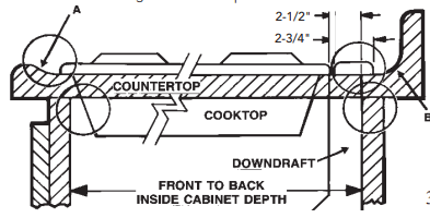
Pay special attention to the areas of potential interference highlighted below. A countertop with (A) a raised lip and/or (B) a backsplash may not allow enough flat countertop for a proper installation. Note that 2-3/4" of flat countertop is required behind cooktop and that 2-1/2" is necessary between the back edge of the cooktop and the inside of cabinet back.
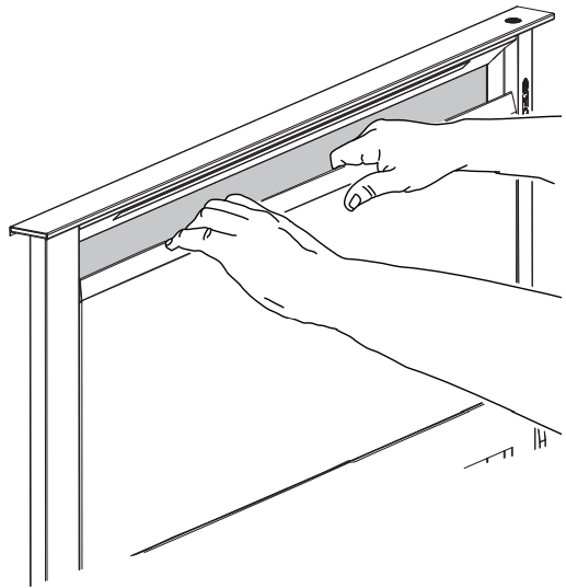
Note: Remove all protective film and packaging before op�eration. In order to remove all protective film and packaging, raise the ventilator housing and remove the front panel to access the filter area
PLAN THE DUCTWORK
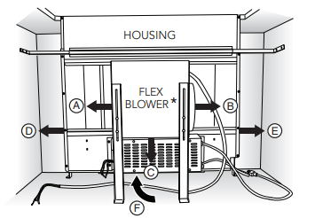
1. The downdraft blower system is designed for use with 8" round ductwork using a flex blower or 10" Round ductwork using a remote blower. (Purchase blowers separately.) Six (6) different discharge connections are available - with side-to-side adjustment for accurate alignment of ductwork:
A = 8" Round, Left Discharge out of Flex Blower
B = 8" Round, Right Discharge out of Flex Blower
C = 8" Round, Down Discharge out of Flex Blower (Electrical Box to be mounted remotely)
D = 2" x 19¼", Left Discharge out of Housing to Remote Blower or Flex Blower in remote location. Use 2" x 19¼" to 8" round transition, 2" x 19¼" to 10" round transition, or 2" x 19¼" ductwork as appropriate.
E = 2" x 19¼", Right Discharge out of Housing to Remote Blower or Flex Blower in remote location. Use 2" x 19¼" to 8" round transition, 2" x 19¼" to 10" round transition, or 2" x 19¼" ductwork as appropriate.
F = 2" x 19¼", Rear Discharge out of Housing to Remote Blower or Flex Blower in remote location. Use 2" x 19¼" to 8" round transition, 2" x 19¼" to 10" round transition, or 2" x 19¼" ductwork as appropriate.
2. For best performance: Choose the ducting option which allows the shortest length of ductwork and a minimum number of elbows and transitions. Check location of floor joists, wall studs, electrical wiring or plumbing for possible interference.
PLAN CABINET CUTOUTS
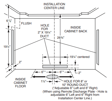
Use the dimensions in the above illustration to help plan how and where to provide duct access through your cabinet. Generally, 1-7/8" x 19" rectangular duct will be used through left, right, and back of cabinet - while 8" round duct will be used through cabinet floor.
For left, right, or rear exhaust: Allow at least 18" for transition and elbow or blower.
For left/right exhaust: A 30" deep cabinet is recommended to align properly with flex blower. Flex blower can be mounted to rear cabinet wall or to a platform/frame (not provided) on the base of the cabinet floor. (See flex blower instructions).
Cabinet depths of 24" to 30" are required - depending on the type of cooking appliance.
PLAN THE WIRING
1. This downdraft blower using the Flex Blower (purchase separately) draws 3.0 Amps and requires a 120 VAC, 60 Hz circuit. If using a remote blower (purchase separately), the system draws 6.0 Amps (max.) and requires a 120 VAC, 60 Hz circuit.
2. The unit has a 18 in. long power cord with a 3-pronged plug. Plan to provide a grounded outlet in a location which will allow the unit’s power cord to reach.
3. Install electrical box according to local codes.
4. The length of cable from the electrical box to the downdraft is 20 in.
5. The length of blower (sold separately) cable to the electrical box is 5 ft.
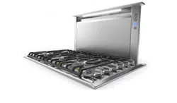
PREPARE THE DOWNDRAFT
Installations ducting through front panel opening only:
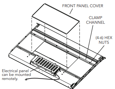
1. Place the downdraft on its back on a table or flat work surface.
2. Loosen the HEX NUTS on the CLAMP CHANNEL and remove the FRONT PANEL COVER.
Installations using FLEX BLOWER only:
(Purchase Model VDVI600 Flex Blower separately.)
Note: Remove adapter plate from Flex Blower per instructions packed with blower.
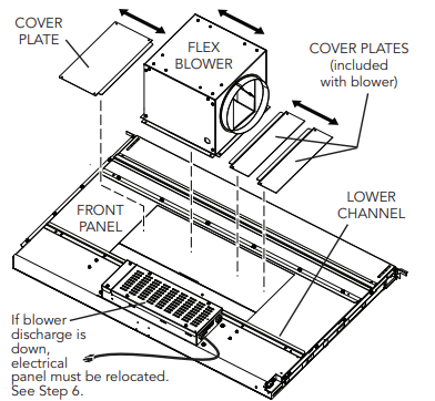
3. Determine its location on FRONT PANEL and whether it will discharge to the left, right, or down. Use a combination of COVER PLATES (3" and/or 6" wide) to close the opening on side(s) of blower. Slide the blower and cover plates between the LOWER CHANNEL and the clamp channel. Tighten the hex nuts to secure blower and panels in place.
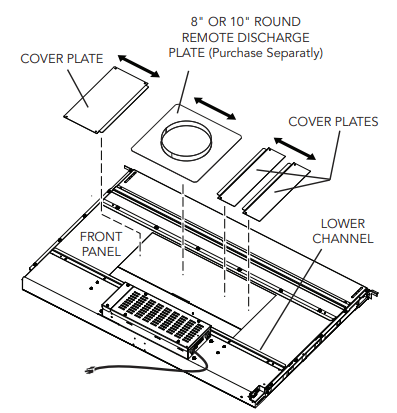
Installations using FLEX BLOWER (in remote location) or REMOTE BLOWER only:
4. Use the REMOTE DISCHARGE PLATE and determine its location on FRONT PANEL.
Use a combination of COVER PLATES (3" and/or 6" wide) to close the opening on side(s) of remote discharge plate.
Slide the remote cover plate and cover plates between the LOWER CHANNEL and the clamp channel. Tighten the hex nuts to secure the plates in place.
All Installations:
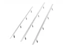
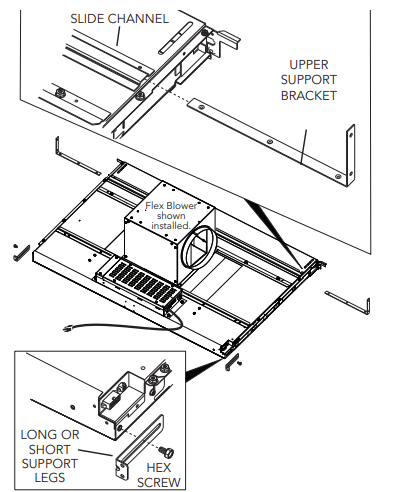
5. Slide UPPER SUPPORT BRACKETS into SLIDE CHANNEL at top left and right of unit.
Attach LONG OR SHORT SUPPORT LEGS (depending upon cabinet height) to bottom sides of unit with HEX SCREWS provided. Do not tighten hex screws completely at this time.
Installations where ELECTRICAL PANEL needs to be mounted in a remote location only:
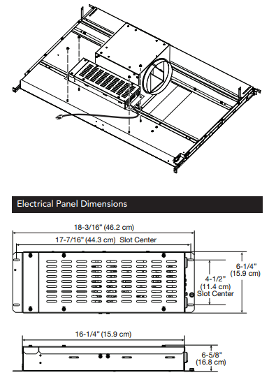
6. Remove (4) HEX NUTS and ELECTRICAL PANEL. 5-ft. extension cables (purchase separately) may be needed to mount electrical panel in a remote location. Do not use more that 2 extension cables. Do not mount electrical panel with vent holes facing down.
Installations using FLEX BLOWER only:
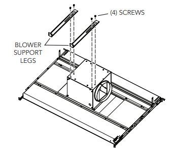
7. Attach BLOWER SUPPORT LEGS with (4) SCREWS provided.
Installations ducting through left, right or rear only:
(Requires purchase of 2" x 19" to 8" or 10" round transition and 2" x 19" rectangular duct cut to appropriate length.)
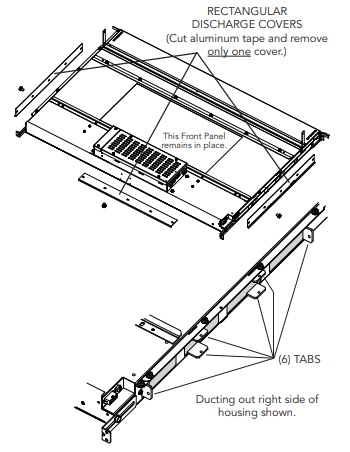
8. Remove only one RECTANGULAR DISCHARGE COVER.
9. Beneath the rectangular discharge cover just removed - Use pliers to bend (6) tabs outward 90 . Use these tabs to connect 2" x 19" rectangular ductwork or 2" x 19" to 8" or 10" round transition to housing when installing ductwork.
CUT COUNTERTOP OPENING
1. Lay out and cut the cooktop cut-out far enough FORWARD so downdraft will fit behind it.
2. Set cooktop in place and slide it as far forward as possible without exposing an gaps. Center and square it with edges of countertop.
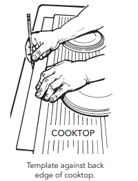
3. Place the plastic template against the back flange of the cooktop or back edge of slide-in range countertop opening. Center the template. Trace around template to mark the downdraft opening.
4. Remove cooktop from countertop.
5. Cut downdraft opening. Be careful not to chip edges of countertop.
INSTALL HOUSING INTO CABINET
1. Remove cooktop.
2. Set housing into cabinet / countertop opening as far back as possible and make sure it is level.
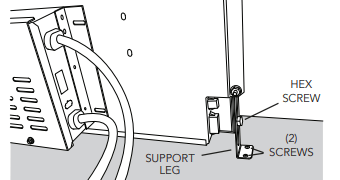
3. Extend SUPPORT LEGS and attach to bottom of cabinet with (2) SCREWS through each leg. Tighten HEX SCREWS.
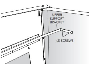
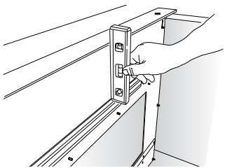
4. Extend UPPER SUPPORT BRACKETS and attached to sides of cabinet with (2) SCREWS through each bracket.
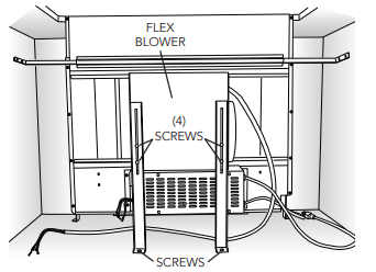
Installations using FLEX BLOWER only:
5. Loosen (4) SCREWS attaching BLOWER SUPPORT LEGS to FLEX BLOWER. Extend legs and secure them to bottom of cabinet with a SCREW through each bracket.
INSTALL ELECTRICAL WIRING
Installations using FLEX BLOWER only:
1. Mount a standard wiring box, with 3-pronged receptacle, within reach of the downdraft's power cord.
2. Run appropriate power cable and connect it to receptacle.
3. Connect blower wires to wires in wiring box. Black to black, white to white, blue to blue, orange to orange, gray to red, and green to ground screw.
4. Replace wiring box cover.
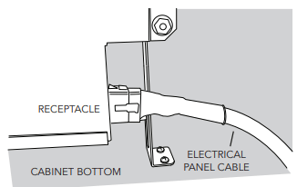
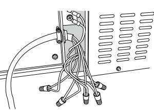
5. Plug ELECTRICAL PANEL CABLE into RECEPTACLE at bottom/right of downdraft housing.
6. Plug the downdraft's power cord into the outlet. Make sure that the power cord is routed away from the heat generated by the cooktop
Installations using REMOTE BLOWER only:
1. Mount a standard wiring box, with 3-pronged receptacle, within reach of the downdraft's power cord.
2. Run appropriate power cable into cabinet and connect it to electrical box and receptacle.
3. These exterior or in-line blower can be used: Models VDVE900, VDVE1200 - Exterior 120 VAC • 60 Hz • 6.0 A (max.)
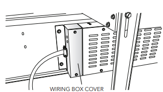
4. Run 2-wire plus ground power cable from the exterior or inline blower to wiring box on adaptor plate. Remove WIRING BOX COVER.
5. Connect blower wires to power cable from exterior or in-line blower. Black to black, white to white, and green to ground screw.
6. Replace wiring box cover.
7. Plug ELECTRICAL PANEL CABLE into RECEPTACLE at bottom/right of downdraft housing.
8. Plug the downdraft's power cord into the outlet. Make sure that the power cord is routed away from the heat generated by the cooktop
INSTALL FINISH TRIM
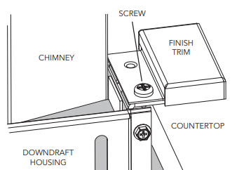
1. Attach FINISH TRIM to top/left and top/right of DOWNDRAFT HOUSING with screw provided.
INSTALL COOKING APPLIANCE
1. Align the cooking appliance with downdraft and fasten appliance in place following appliance instructions.
Note: Accurate alignment of cooking appliance and downdraft is necessary to ensure that there is no interference when air vent is raised and lowered. There should be a gap of 1/32" - 1/16" between the back of the cooktop and the front of the downdraft cover.
MAKE-UP AIR DAMPER (OPTIONAL)
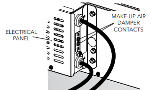
Connects to 2 CONTACTS on ELECTRICAL PANEL. Compatible with G6MD and G8MD damper.
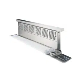
OPERATION
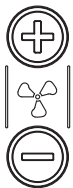
4-Speed Fan Speed Control
Press + button to increase fan speed.
Press - button to decrease fan speed.
After maximum speed is reached, press + button once more to turn off fan.

2-Level Task Light
Press once for LOW setting.
Press 2x for HIGH setting. Icon will illuminate.
Press 3x to turn task light OFF.

30-Hour Filter Clean Reminder
After 30 hours of blower "ON" time, filter clean icon will blink continuously.
To reset, touch and hold icon for 2 or more seconds. Indicator will turn off.

Up / Down Button
To raise / lower chimney, touch up / down button. Any feature that is active will shut off when chimney is retracting. All functions will return to their previous settings when chimney is raised.
USE AND CARE
WARNING: Always disconnect electric power supply before cleaning and/or servicing unit.
Always turn the downdraft blower on before you begin cooking to establish an air flow in the kitchen. Let the blower run for a few minutes to clean the air after you turn the cooktop off. This will keep the whole kitchen cleaner and brighter.
Cleaning
To clean grease filters: Remove front panel and take out the (2) grease filters. Wash filters in a mild detergent solution or a dishwasher. Replace filters before using downdraft.
To clean inside chimney: Remove filters. Pull front panel up and out. Use a mild detergent. DO NOT USE ABRASIVE CLOTH, STEEL WOOL PADS, OR SCOURING POWDERS. Replace front panel and filters before using downdraft.
Servicing
It may be necessary to remove the downdraft blower system from the cabinet in order to service components such as the blower motor or air vent mechanism.
Disconnect power to the cooktop and remove it first. Reverse the steps under “INSTALL HOUSING INTO CABINET” to remove the downdraft from the cabinet.