Loading ...
Loading ...
Loading ...
24
Dryer
Safety
Operation
Requirements
Parts and
Features
Installation
Instructions
Dryer Use
Appendix
Dryer Care
Troubleshooting
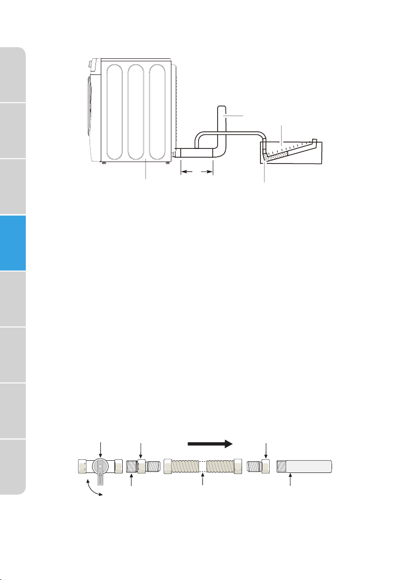
MEASURING AND VERIFYING ACTUAL SYSTEM BACK PRESSURE
a
b
c
d
e
a Dryer - empty and running on Air
Fluff cycle
b 10" (254 mm) min. of straight
pipe - measure back pressure
from the center
c To vent system
d Location on back
pressure measurement
e Inclined manometer
CONNECT THE GAS LINE (FOR GAS MODELS)
Review the “Gas Requirements” section on page 15. Remove the pipe
thread protective cap.
Apply a pipe joint compound or about 1 " wraps of teflon tape over all
threaded connections.
•
The pipe joint compound must be resistant to the actions of any
liquefied petroleum gas.
Connect the gas supply to your dryer. An additional fitting is required
to connect the " (1.9 cm) female thread end of a flexible connector to
the " (1 cm) male threaded end on the dryer. Use only new AGA or CSA
certified gas supply line with SS flexible connectors. within 6 ft (1.8 m) of
the dryer
Securely tighten the gas line fitting over the threads.
Turn on the gas supply.
Manual
Shutoff
Valve
Flare
Union
Flare
Union
Open
Nipple Flexible
Connector
Inlet Pipe on
Back of Dryer
GAS FLOW
All connections must be wrench-tightened
Loading ...
Loading ...
Loading ...