OPEL INSIGNIA
Owner's Manual


Introduction .................................... 2
In brief ............................................ 6
Keys, doors and windows ............ 20
Seats, restraints ........................... 45
Storage ........................................ 67
Instruments and controls ............. 82
Lighting ...................................... 122
Climate control ........................... 134
Driving and operating ................. 148
Vehicle care ............................... 213
Service and maintenance .......... 261
Technical data ........................... 264
Customer information ................ 312
Index .......................................... 314
Contents
2 Introduction
Introduction

Introduction 3
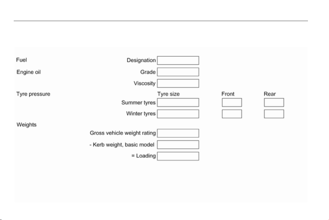
Vehicle specific data
Please enter your vehicle's data on
the previous page to keep it easily
accessible. This information is
available in the sections "Service and
maintenance" and "Technical data"
as well as on the identification plate.
Introduction
Your vehicle is a designed
combination of advanced technology,
safety, environmental friendliness
and economy.
This Owner's Manual provides you
with all the necessary information to
enable you to drive your vehicle
safely and efficiently.
Make sure your passengers are
aware of the possible risk of accident
and injury which may result from
improper use of the vehicle.
You must always comply with the
specific laws and regulations of the
country that you are in. These laws
may differ from the information in this
Owner's Manual.
When this Owner's Manual refers to a
workshop visit, we recommend your
Opel Service Partner. For gas
vehicles we recommend an Opel
Repairer authorised for servicing gas
vehicles.
All Opel Service Partners provide
first-class service at reasonable
prices. Experienced mechanics
trained by Opel work according to
specific Opel instructions.
The customer literature pack should
always be kept ready to hand in the
vehicle.
Using this manual
■ This manual describes all options
and features available for this
model. Certain descriptions,
including those for display and
menu functions, may not apply to
your vehicle due to model variant,
country specifications, special
equipment or accessories.
■ The "In brief" section will give you
an initial overview.
■ The table of contents at the
beginning of this manual and within
each section shows where the
information is located.
■ The index will enable you to search
for specific information.
■ This Owner's Manual depicts left-
hand drive vehicles. Operation is
similar for right-hand drive vehicles.
■ The Owner's Manual uses the
factory engine designations. The
corresponding sales designations
can be found in the section
"Technical data".
■ Directional data, e.g. left or right, or
front or back, always relate to the
direction of travel.
■ The vehicle display screens may
not support your specific language.
■ Display messages and interior
labelling are written in bold letters.

4 Introduction
Danger, Warnings and
Cautions
9 Danger
Text marked 9 Danger provides
information on risk of fatal injury.
Disregarding this information may
endanger life.
9 Warning
Text marked 9 Warning provides
information on risk of accident or
injury. Disregarding this
information may lead to injury.
Caution
Text marked Caution provides
information on possible damage to
the vehicle. Disregarding this
information may lead to vehicle
damage.
Symbols
Page references are indicated with 3.
3 means "see page".
Chronological order to select menu
entries in the vehicle personalization
is indicated with I.
We wish you many hours of
pleasurable driving.
Adam Opel AG

Introduction 5
6 In brief
In brief
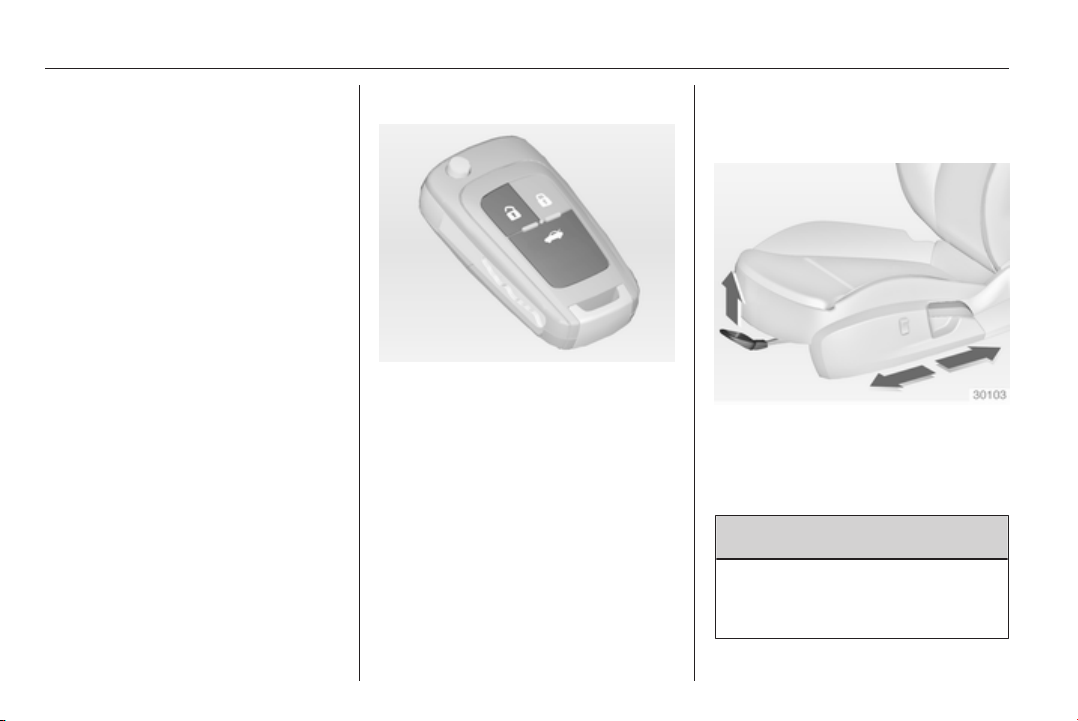
Initial drive information
Vehicle unlocking
Press button c to unlock the doors
and load compartment. Open the
doors by pulling the handles. To open
the tailgate, pull the button under the
tailgate moulding.
Press button x; only the load
compartment is unlocked and opens.
Radio remote control 3 21, Central
locking system 3 23, Electronic key
system 3 22, Load compartment
3 29.
Seat adjustment
Seat positioning
Pull handle, slide seat, release
handle.
Seat position 3 47, Seat adjustment
3 47.
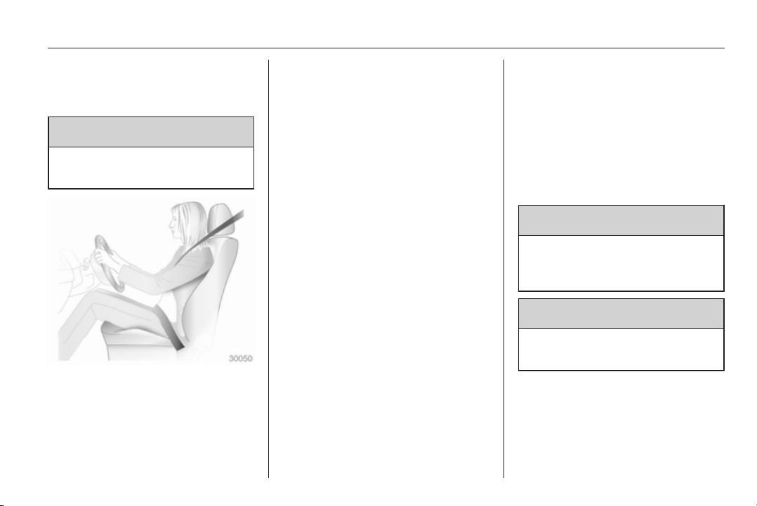
9 Danger
Do not sit nearer than 25 cm from
the steering wheel, to permit safe
airbag deployment.
In brief 7
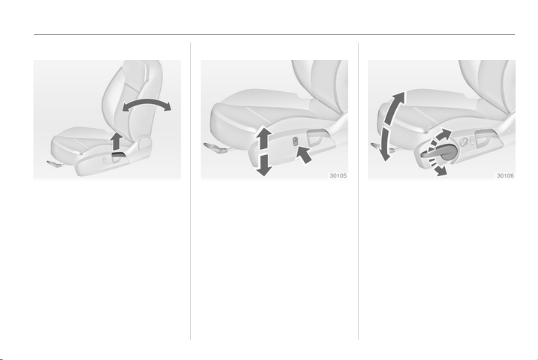
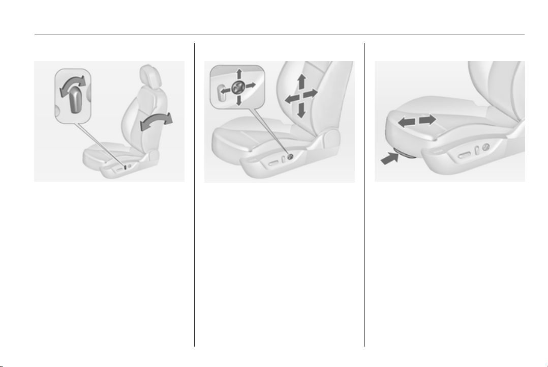
Seat backrests
Pull lever, adjust inclination and
release lever. Allow the seat to
engage audibly.
Seat position 3 47, Seat adjustment
3 47.
Seat height
Press switch
top = seat higher
bottom = seat lower
Seat position 3 47, Seat adjustment
3 47.
Seat inclination
Lever pumping motion
up = front end higher
down = front end lower
Seat position 3 47, Seat adjustment
3 47.

8 In brief
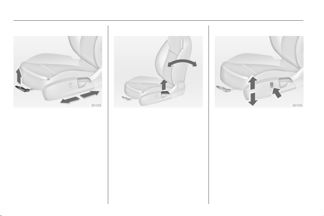
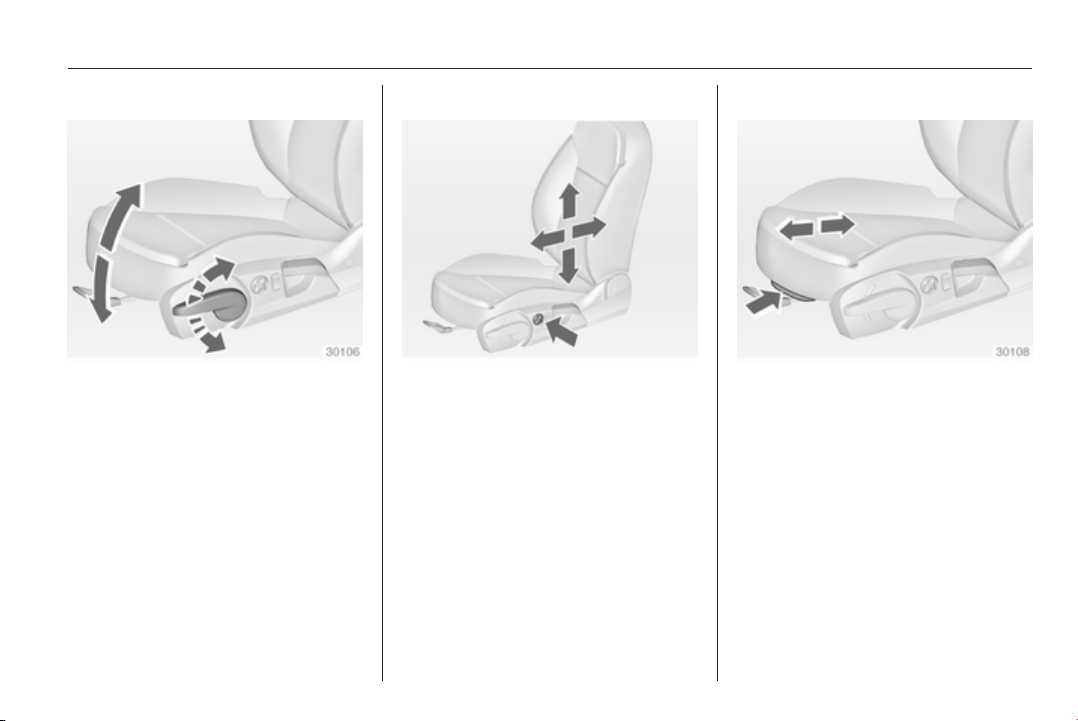
Power seat adjustment
Operate switch 1:
for-/backwards = lengthwise
adjustment
up-/downwards = height
adjustment
up-/downwards at
front
= inclination
adjustment
Operate switch 2:
for-/backwards = backrest
adjustment
Head restraint adjustment
Press release button, adjust height,
engage.
Head restraints 3 45.
Seat belt
Pull out the seat belt and engage in
belt buckle. The seat belt must not be
twisted and must fit close against the
body. The backrest must not be tilted
back too far (maximum approx. 25°).
To release belt, press red button on
belt buckle.
Seat position 3 47, Seat belts
3 54, Airbag system 3 58.

In brief 9
Mirror adjustment
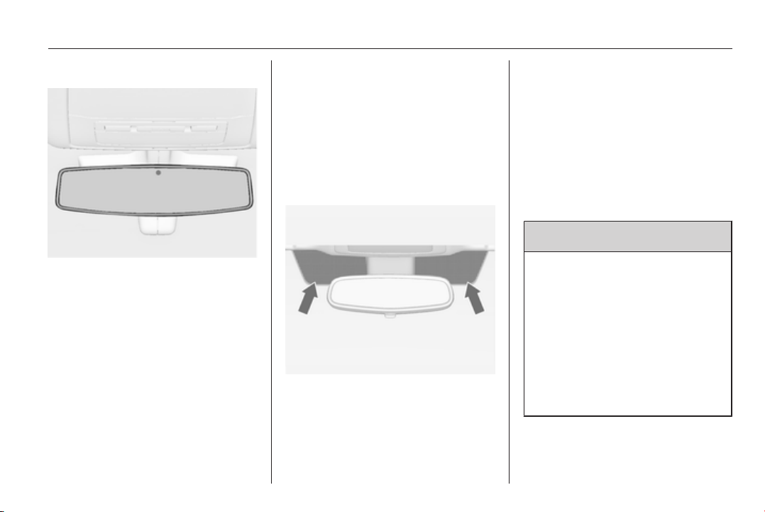
Interior mirror
Adjust the lever on the underside to
reduce dazzle.
Interior mirror 3 38, Automatic anti-
dazzle interior mirror 3 39.
Exterior mirrors
Select the relevant exterior mirror by
switching the control to left mirror (L)
or right mirror (R). Then adjust.
Convex exterior mirrors 3 36,
Electric adjustment 3 36, Folding
exterior mirrors 3 37, Heated
exterior mirrors 3 38.
Steering wheel adjustment
Unlock lever, adjust steering wheel,
then engage lever and ensure it is
fully locked. Do not adjust steering
wheel unless vehicle is stationary and
steering wheel lock has been
released.
Airbag system 3 58, Ignition
positions 3 149.
10 In brief
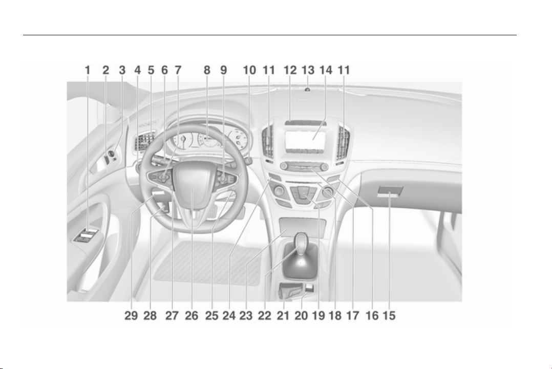
Instrument panel overview

In brief 11
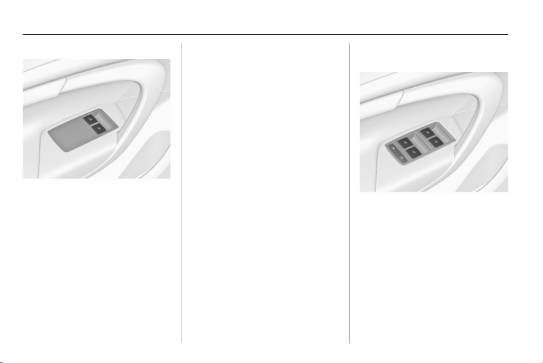
1 Power windows ..................... 39
2 Central locking system .......... 23
3 Exterior mirrors ..................... 36
4 Light switch ........................ 122
Headlight range
adjustment ......................... 124
Front/rear fog lights ............ 128
Instrument illumination ....... 130
5 Side air vents ...................... 145
6 Turn and lane-change
signals, headlight flash,
low/high beam, high beam
assist ................................... 128
Exit lighting ......................... 132
Parking lights ...................... 129
Buttons for Driver
Information Centre .............. 107
7 Cruise control ..................... 171
Speed limiter ....................... 172
Adaptive cruise control ....... 173
Forward collision alert ......... 181
8 Instruments .......................... 96
Driver Information Centre .... 107
9 Buttons for Driver
Information Centre .............. 107
10 Windscreen wiper and
washer, headlight washer,
rear wiper and washer ......... 84
11 Centre air vents .................. 145
12 Sport/Tour mode ................ 168
Traction Control system ..... 166
Electronic Stability Control . 167
Hazard warning flashers .... 128
Parking assist/Advanced
parking aid ......................... 187
Lane departure warning ..... 201
13 Anti-theft alarm system
status LED ........................... 34
14 Colour-Info-Display ............ 114
15 Glovebox .............................. 67
16 Control indicator for airbag
activation/deactivation ....... 101
Control indicator for front
passenger seat belt ........... 100
17 Controls for Colour-Info-
Display operation ................ 114
18 CD-slot
19 Climate control system ........ 134
20 Electric parking brake ......... 164
21 Touchpad ............................ 114
22 Manual transmission .......... 162
Automatic transmission ...... 157
23 Ashtray ................................. 90
24 Eco button for stop-start
system ................................. 153
Fuel selector button .............. 98
25 Ignition/Power switch .......... 149
26 Horn ..................................... 83
27 Steering wheel adjustment ..82
28 Bonnet release lever .......... 215
29 Storage compartment ........... 68
Fuse box ............................ 236

12 In brief
In brief 13
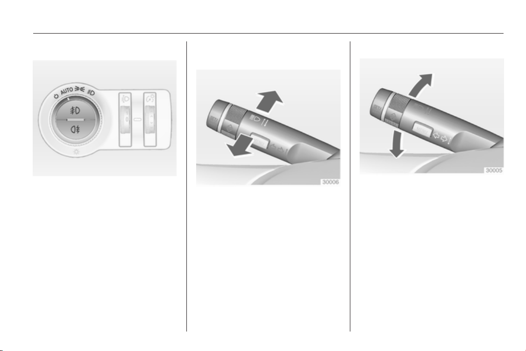
Exterior lighting
Automatic light control
AUTO = automatic light control:
exterior lighting is switched
on and off automatically
m
= activation or deactivation
of the automatic light
control
8
= sidelights
9
= headlights
Fog lights
>
= front fog lights
r
= rear fog light
Lighting 3 122.
Headlight flash, high beam and
low beam
headlight flash = pull lever
high beam = push lever
low beam = push or pull lever
Automatic light control 3 123, High
beam 3 123, High beam assist
3 123, Headlight flash 3 124,
Adaptive forward lighting 3 125.
Turn and lane-change signals
lever up = right turn signal
lever down = left turn signal
Turn and lane-change signals
3 128, Parking lights 3 129.
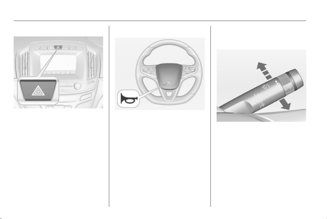
14 In brief
Hazard warning flashers
Operated with the ¨ button.
Hazard warning flashers 3 128.
Horn
Press j.
Washer and wiper systems
Windscreen wiper
2 = fast
1 = slow
P
= interval wiping or automatic
wiping with rain sensor
§
= off
For a single wipe when the
windscreen wiper is off, press the
lever down.
Windscreen wiper 3 84, Wiper
blade replacement 3 221.
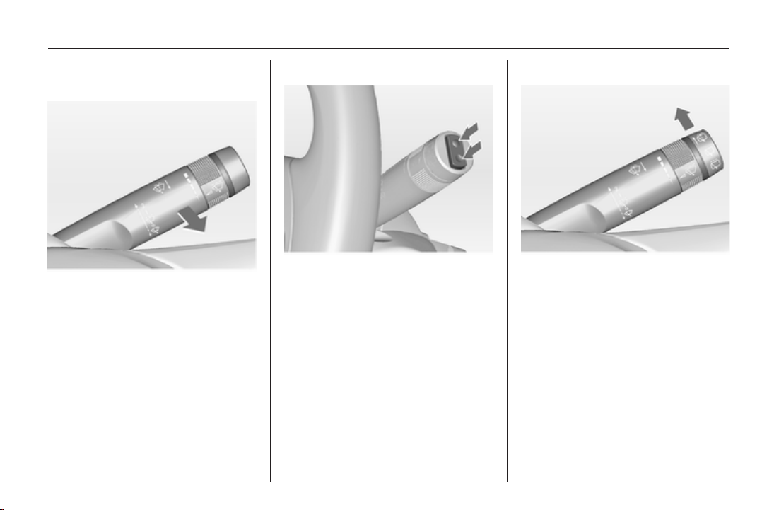
In brief 15
Windscreen and headlight
washer
Pull lever.
Windscreen and headlight washer
system 3 84, Washer fluid 3 218.
Rear window wiper
Press the rocker switch to activate the
rear window wiper:
upper switch = continuous
operation
lower switch = intermittent
operation
middle
position
= off
Rear window washer
Push lever.
Washer fluid is sprayed on the rear
window and the wiper wipes for a few
strokes.
Rear window wiper/washer 3 86.
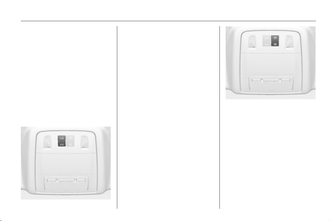
16 In brief
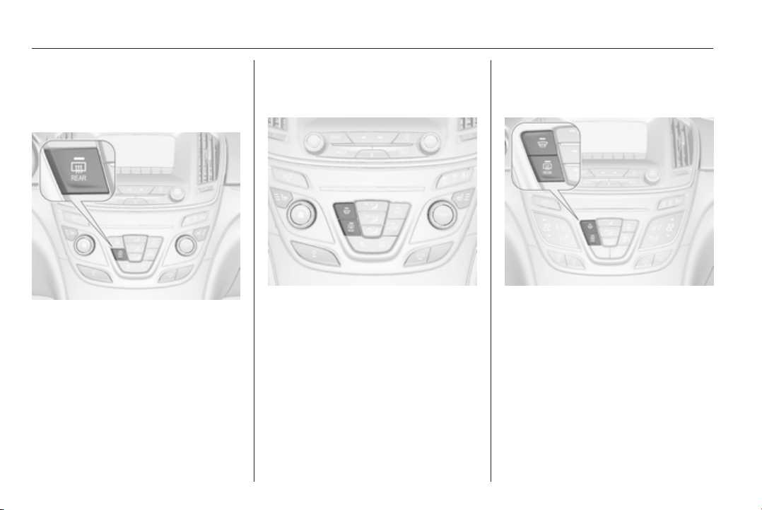
Climate control
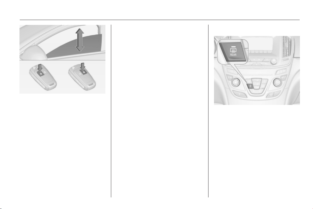
Heated rear window, heated
exterior mirrors
Heating is operated by pressing the
Ü button.
Heated rear window 3 41.
Demisting and defrosting the
windows, air conditioning
system
Press button V.
Set temperature control to warmest
level.
Switch on heated rear window Ü.
Air conditioning system 3 134.
Demisting and defrosting the
windows, automatic climate
control
Press button V.
Temperature and air distribution are
set automatically and the fan runs at
high speed.
Switch on heated rear window Ü.
Dual automatic climate control
3 140
In brief 17
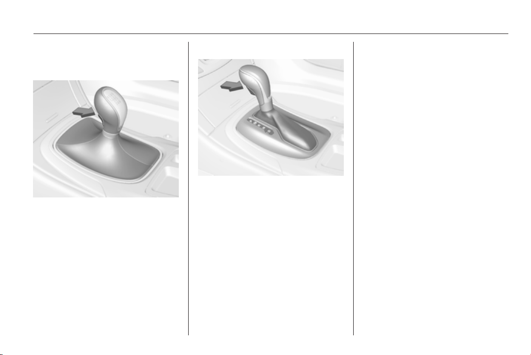
Transmission
Manual transmission
Reverse: with the vehicle stationary,
depress clutch pedal, press the
release button on the selector lever
and engage the gear.
If the gear does not engage, set the
lever to neutral, release the clutch
pedal and depress again; then repeat
gear selection.
Manual transmission 3 162.
Automatic transmission
P = park
R = reverse
N = neutral
D = drive
Manual mode: move selector lever
from D to the left.
<
= higher gear
]
= lower gear
The selector lever can only be moved
out of P when the ignition is on and
the brake pedal is applied. To engage
P or R, press the release button.
Automatic transmission 3 157.
Starting off
Check before starting off
■ Tyre pressure and condition 3 240,
3 289.
■ Engine oil level and fluid levels
3 215.
■ All windows, mirrors, exterior
lighting and number plates are free
from dirt, snow and ice and are
operational.
■ Proper position of mirrors, seats,
and seat belts 3 36, 3 47,
3 55.
■ Brake function at low speed,
particularly if the brakes are wet.
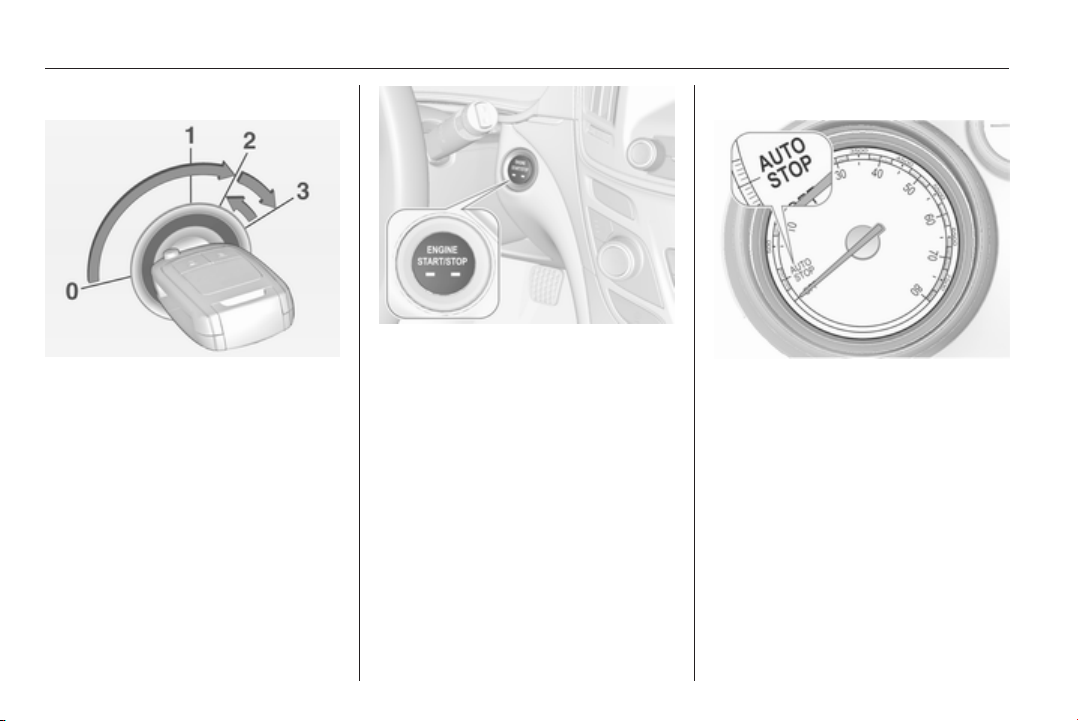
18 In brief
Starting the engine
■ Ignition switch: turn key to position
2
power button: press Engine Start/
Stop button for a few seconds until
green LED lights up
■ move the steering wheel slightly to
release the steering wheel lock
■ operate clutch and brake
■ automatic transmission in P or N
■ do not operate accelerator pedal
■ ignition switch: turn key to position
3 and release
power button: press Engine Start/
Stop button and release
■ engine starts after a short delay.
Starting the engine 3 151.
Stop-start system
If the vehicle is at a low speed or at a
standstill and certain conditions are
fulfilled, activate an Autostop as
follows:
■ Depress the clutch pedal
■ set the lever in neutral
■ release the clutch pedal
An Autostop is indicated by the
needle at the AUTOSTOP position in
the tachometer or by a control
indicator in the instrument cluster.
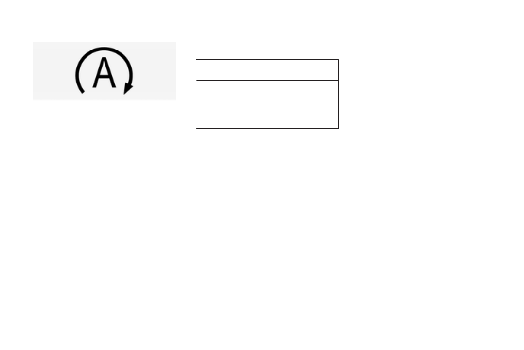
In brief 19
To restart the engine, depress the
clutch pedal again.
Stop-start system 3 153.
Parking
Caution
Do not park the vehicle on an
easily ignitable surface. The high
temperature of the exhaust
system could ignite the surface.
■ Always apply the parking brake.
Apply electric parking brake by
pulling switch m for approx. one
second.
Activate the manual parking brake
without pushing the release button.
Apply as firmly as possible on a
downhill slope or uphill slope.
Depress foot brake at the same
time to reduce operating force.
■ If the vehicle is on a level surface or
uphill slope, engage first gear or set
the selector lever to position P
before switching off the ignition. On
an uphill slope, turn the front
wheels away from the kerb.
If the vehicle is on a downhill slope,
engage reverse gear or set the
selector lever to position P before
switching off the ignition. Turn the
front wheels towards the kerb.
■ After running at high engine speeds
or with high engine loads, operate
the engine briefly at a low load or
run in neutral for approx.
30 seconds before switching off, in
order to protect the turbocharger.
■ Switch off the engine and ignition.
Turn the steering wheel until it
locks.
Automatic transmission: key can
only be removed with selector lever
in P.
■ Close the windows and the sunroof.
■ Lock the vehicle and activate the
anti-theft alarm system 3 23,
3 34.
■ The engine cooling fans may run
after the engine has been switched
off 3 214.
Keys, locks 3 20, Laying the vehicle
up for a long period of time 3 213.
20 Keys, doors and windows
Keys, doors and
windows
Keys, locks ................................... 20
Doors ........................................... 29
Vehicle security ............................ 33
Exterior mirrors ............................ 36
Interior mirrors ............................. 38
Windows ...................................... 39
Roof ............................................. 42
Keys, locks
Keys
Replacement keys
The key number is specified in the
Car Pass or on a detachable tag.
The key number must be quoted
when ordering replacement keys as it
is a component of the immobiliser
system.
Locks 3 257, Radio remote control
3 21, Electronic key 3 22, Central
locking 3 23, Starting the engine
3 151.
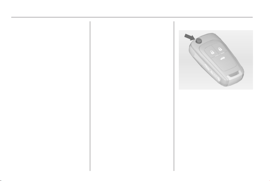
Key with foldaway key section
Press button to extend. To fold the
key, first press the button.
Car Pass
The Car Pass contains security
related vehicle data and should
therefore be kept in a safe place.
When the vehicle is taken to a
workshop, this vehicle data is needed
in order to perform certain operations.
Keys, doors and windows 21
Radio remote control
Enables operation of the following
functions via the use of the remote
control buttons:
■ Central locking system 3 23
■ Anti-theft locking system 3 33
■ Anti-theft alarm system 3 34
■ Tailgate 3 29
■ Power windows 3 39
■ Sunroof 3 42
■ Mirror folding 3 37
The remote control has an
approximate range of up to
50 metres. It can be restricted by
external influences. The hazard
warning flashers confirm operation.
Handle with care, protect from
moisture and high temperatures and
avoid unnecessary operation.
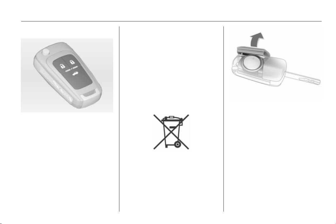
Replacing battery in radio
remote control
Replace the battery as soon as the
range reduces.
Batteries do not belong in household
waste. They must be disposed of at
an appropriate recycling collection
point.
Extend the key and open the unit.
Replace the battery (battery type
CR 2032), paying attention to the
installation position. Close the unit
and synchronise.
Radio remote control
synchronisation
After replacing the battery, unlock the
door with the key in the driver's door
lock. The radio remote control will be
synchronised when you switch on the
ignition.
22 Keys, doors and windows
Fault
If the central locking system cannot
be operated with the radio remote
control, the cause may be one of the
following:
■ Fault in radio remote control
■ Range exceeded
■ Battery voltage too low
■ Frequent, repeated operation of the
radio remote control while not in
range, which will require re-
synchronisation
■ Overload of the central locking
system by operating at frequent
intervals, the power supply is
interrupted for a short time
■ Interference from higher-power
radio waves from other sources
Manual unlocking 3 23.
Electronic key system
Enables a keyless operation of the
following functions:
■ Central locking system 3 23
■ Tailgate 3 29
■ Ignition switching on and starting
the engine 3 151
The electronic key simply needs to be
on the driver's person.
Additionally the electronic key
includes the functionality of the radio
remote control 3 21.
Handle with care, protect from
moisture and high temperatures and
avoid unnecessary operation.
Note
Do not put the electronic key in the
load compartment or in front of the
Info-Display.
Replacing battery in electronic
key
Replace the battery as soon as the
system no longer operates properly
or the range is reduced. The need for
battery replacement is indicated by a
message in the Driver Information
Centre 3 116.
Battery replacement, see radio
remote control 3 21.
Electronic key synchronisation
The electronic key synchronises itself
automatically during every starting
procedure.

Keys, doors and windows 23
Fault
If the central locking cannot be
operated or the engine cannot be
started, the cause may be one of the
following:
■ Fault in electronic key
■ Electronic key out of reception
range
■ Battery voltage too low,
■ Overload of the central locking
system by operating at frequent
intervals, the power supply is
interrupted for a short time
■ Interference from higher-power
radio waves from other sources.
To rectify the cause of the fault,
change the position of the electronic
key.
Manual unlocking 3 23.
Memorised settings
Whenever the ignition is switched off,
the following settings are
automatically memorised by the
remote control unit or the electronic
key:
■ Automatic climate control
■ Lighting
■ Infotainment system
■ Central locking system
■ Sport mode settings
■ Comfort settings
The saved settings are automatically
used the next time the ignition is
switched on with the memorised key
with remote control unit 3 149 or
electronic key 3 22.
A precondition is that Personalisation
by Driver is activated in the personal
settings of the Info-Display. This must
be set for each remote control unit or
electronic key which is used.
Also memorised are the adjustments
of the driver's seat and exterior
mirrors, independent of the memory
positions 3 50.
Power seat automatically moves into
the saved position when unlocking
and opening the driver's door with the
memorised remote control or
electronic key and Auto Memory
Recall in the Info-Display is activated.
Vehicle personalisation 3 118.
Central locking system
Unlocks and locks doors, load
compartment and fuel filler flap.
A pull on an interior door handle
unlocks the respective door. Pulling
the handle once more opens the door.
Note
In the event of an accident in which
airbags or belt pretensioners are
deployed, the vehicle is
automatically unlocked.
Note
A short time after unlocking with the
remote control the doors are locked
automatically if no door has been
opened.

24 Keys, doors and windows
Remote control operation
Unlocking
Press button c.
Unlocking mode can be set in the
vehicle personalisation menu in the
Colour-Info-Display. It can be
configured as follows:
■ all doors, load compartment and
fuel filler flap are unlocked by
pressing button c once,
or
■ only the driver's door, load
compartment and fuel filler flap are
unlocked by pressing button c
once. To unlock all doors, press
button c twice.
Select the relevant setting in Settings,
I Vehicle in the Colour-Info-Display.
Colour-Info-Display 3 114.
Vehicle personalisation 3 118.
The setting can be saved for the
remote control being used.
Memorised settings 3 23.
Locking
Close doors, load compartment and
fuel filler flap.
Press button e.
If the driver's door is not closed
properly, the central locking system
will not work.
Keys, doors and windows 25
Unlocking and opening the tailgate
4-door Saloon, Country Tourer,
Sports Tourer with power tailgate
Press button x when the ignition is
off until tailgate opens automatically.
The doors remain locked.
Power tailgate 3 29.
Confirmation
Operation of central locking system is
confirmed by the hazard warning
flashers.
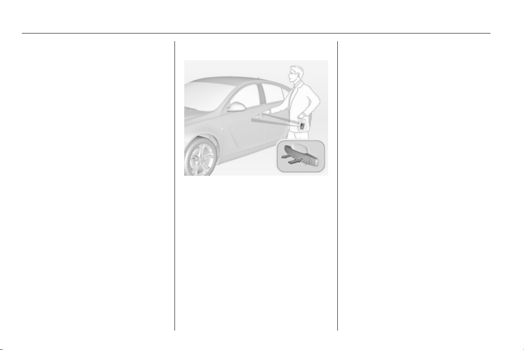
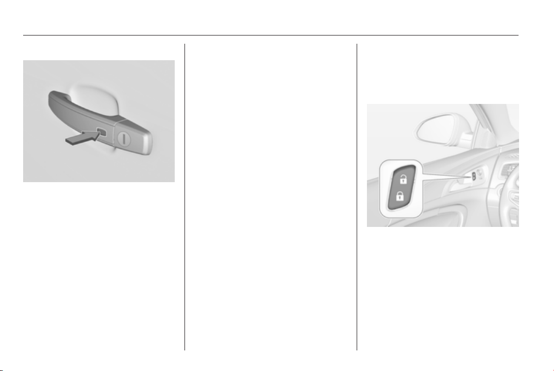
Electronic key system operation
The electronic key must be outside
the vehicle, within a range of approx.
one metre of the relevant door side.
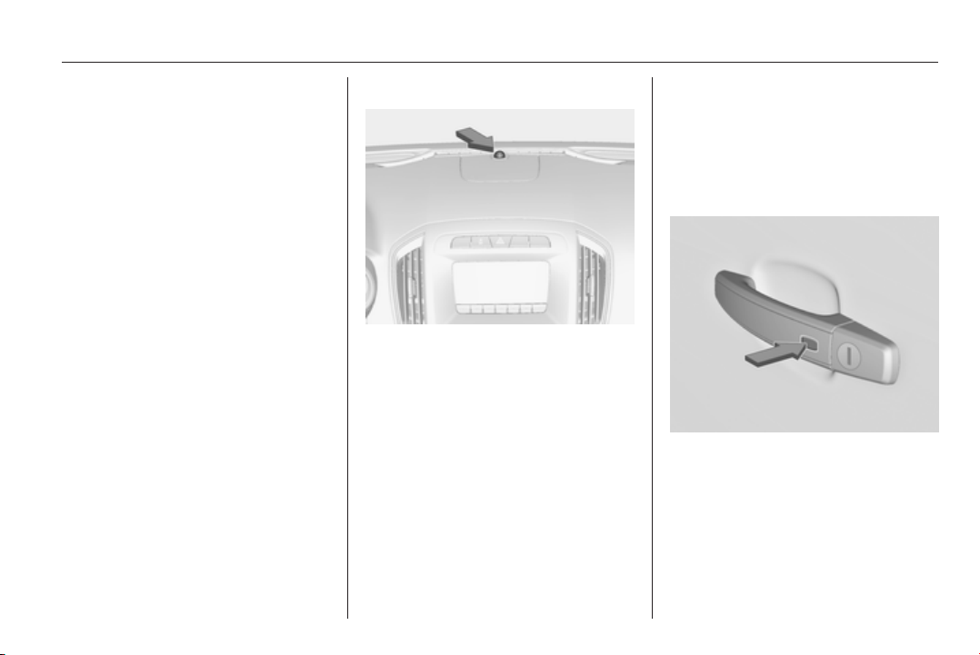
Unlocking
Press the button on any exterior door
handle and pull the handle.
Unlocking mode can be set in the
vehicle personalisation menu in the
Colour-Info-Display. It can be
configured as follows:
■ all doors, load compartment and
fuel filler flap are unlocked by
pressing a button on any exterior
handle once,
or
■ only the driver's door, load
compartment and fuel filler flap are
unlocked by pressing the button on
driver`s door exterior handle once.
To unlock all doors, press button
twice.
Select the relevant setting in Settings,
I Vehicle in the Colour-Info-Display.
Colour-Info-Display 3 114.
Vehicle personalisation 3 118.
The setting can be saved for the
electronic key being used.
Memorised settings 3 23.
26 Keys, doors and windows
Locking
Press the button on any exterior door
handle.
All doors, load compartment and fuel
filler flap are locked.
The system only locks if
■ it has been more than 5 seconds
since unlocking, or
■ twice unlocking presses have been
within 5 seconds, or
■ any door has been opened and
then all doors are closed.
If the driver's door is not closed
properly or the electronic key remains
in the vehicle and the ignition is not
off, locking will not be permitted and a
warning tone sounds three times.
If there have been two or more
electronic keys in the vehicle and the
ignition was on once, the doors will be
locked even if just one electronic key
is taken out of the vehicle.
Unlocking and opening the tailgate
The tailgate and the doors can be
unlocked by pressing the button
under the tailgate moulding when
electronic key is in range.
Passive Locking
See Automatic locking 3 27.
Confirmation
Operation of central locking system is
confirmed by the hazard warning
flashers.
Central locking buttons
Locks or unlocks all doors, the load
compartment and fuel filler flap from
the passenger compartment by a
switch in the driver's door panel.
Press the e button to lock.
Press the c button to unlock.

Keys, doors and windows 27
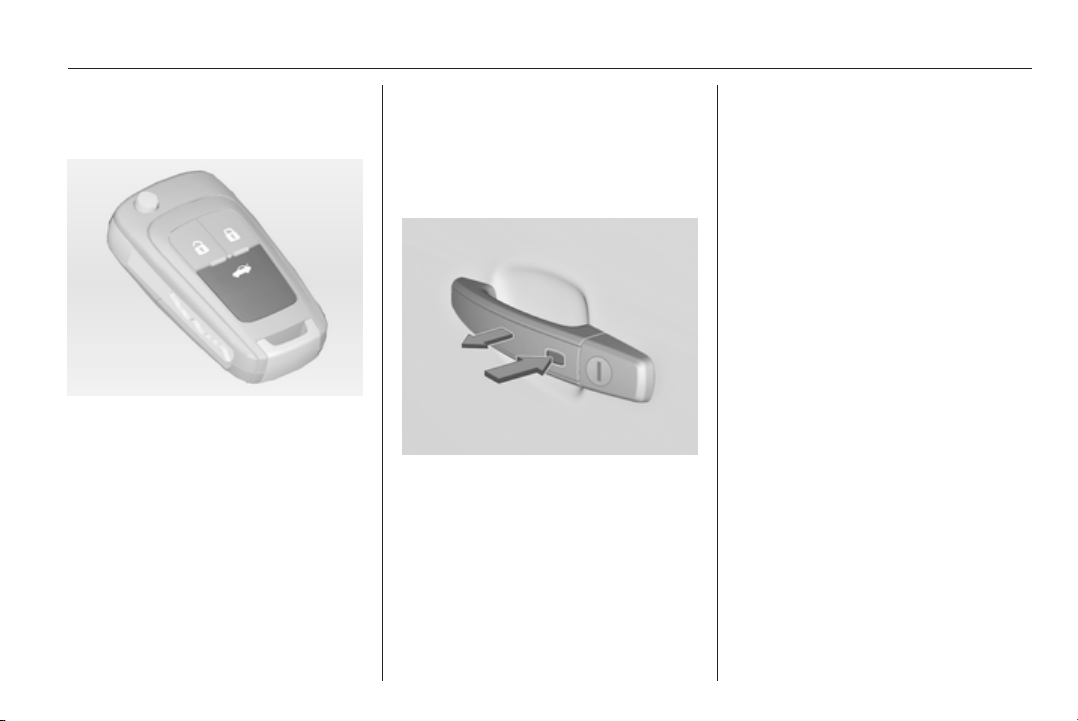
Fault in radio remote control unit
or electronic key system
Manual unlocking
Manually unlock the driver's door by
turning the key in the lock. Switch on
the ignition and press the central
locking button c to unlock all doors,
load compartment and fuel filler flap.
By switching on the ignition, the anti-
theft locking system is deactivated.
Manual locking
Manually lock the driver's door by
turning the key in the lock.
Fault in central locking system
Manual unlocking
Manually unlock the driver's door by
turning the key in the lock. The other
doors can be opened by pulling the
interior handle twice. The load
compartment and fuel filler flap
cannot be opened. To deactivate the
anti-theft locking system, switch on
the ignition 3 34.
Manual locking
Push inside locking knob of all doors
except driver's door. Then close the
driver's door and lock it from the
outside with the key. The fuel filler flap
and tailgate cannot be locked.
Automatic locking
Automatic locking after driving
off
This security feature can be
configured to automatically lock all
doors, load compartment and fuel
filler flap after driving off and
exceeding a certain speed.
When at a standstill after driving, the
vehicle will be unlocked automatically
as soon as the key is removed from
the ignition switch, or with electronic
key system when the ignition is
switched off.
Activation or deactivation of
automatic locking can be set in the
menu Settings, I Vehicle in the
Colour-Info-Display.
Colour-Info-Display 3 114.
Vehicle personalisation 3 118.
The setting can be saved for the
remote control or electronic key being
used 3 23.
Automatic relock after unlocking
This feature can be configured to
automatically lock all doors, load
compartment and fuel filler flap a
short time after unlocking with the
remote control or electronic key,
provided no door has been opened.
Activation or deactivation of
automatic relock can be set in the
menu Settings, I Vehicle in the
Colour-Info-Display.
28 Keys, doors and windows
Colour-Info-Display 3 114.
Vehicle personalisation 3 118.
The setting can be saved for the
remote control or electronic key being
used 3 23.
Passive locking
In vehicles with electronic key
system, this feature locks the vehicle
automatically after several seconds if
a electronic key previously was
recognised inside the vehicle, all
doors have then been closed and the
electronic key does not remain in the
interior.
If the electronic key remains in the
vehicle or the ignition is not off,
passive locking will not be permitted
and a warning tone sounds three
times.
If there have been two or more
electronic keys in the vehicle and the
ignition was on once, the feature
locks the vehicle if just one electronic
key is taken out of the vehicle.
Passive locking can be disabled by
pressing c for a few seconds while
one door is open. It remains disabled
until e is pressed or the ignition is
switched on.
Activation or deactivation of passive
locking can be set in the menu
Settings, I Vehicle in the Colour-Info-
Display.
Colour-Info-Display 3 114.
Vehicle personalisation 3 118.
The setting can be saved for the
remote control or electronic key being
used 3 23.
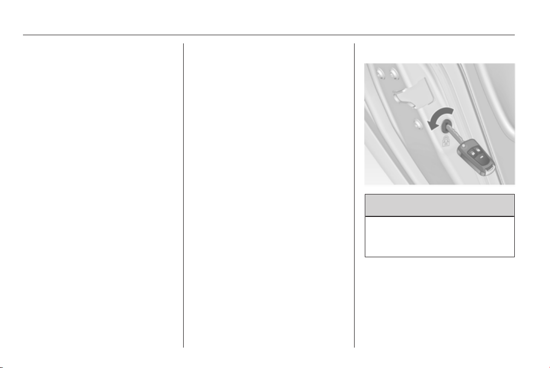
Child locks
9 Warning
Use the child locks whenever
children are occupying the rear
seats.
Using a key or suitable screwdriver,
turn the child lock in the rear door to
the horizontal position. The door
cannot be opened from the inside. For
deactivation turn the child lock to the
vertical position.
Keys, doors and windows 29
Doors
Load compartment
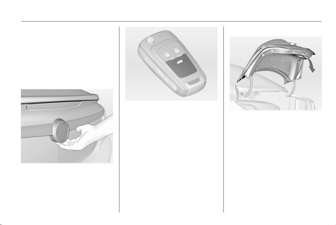
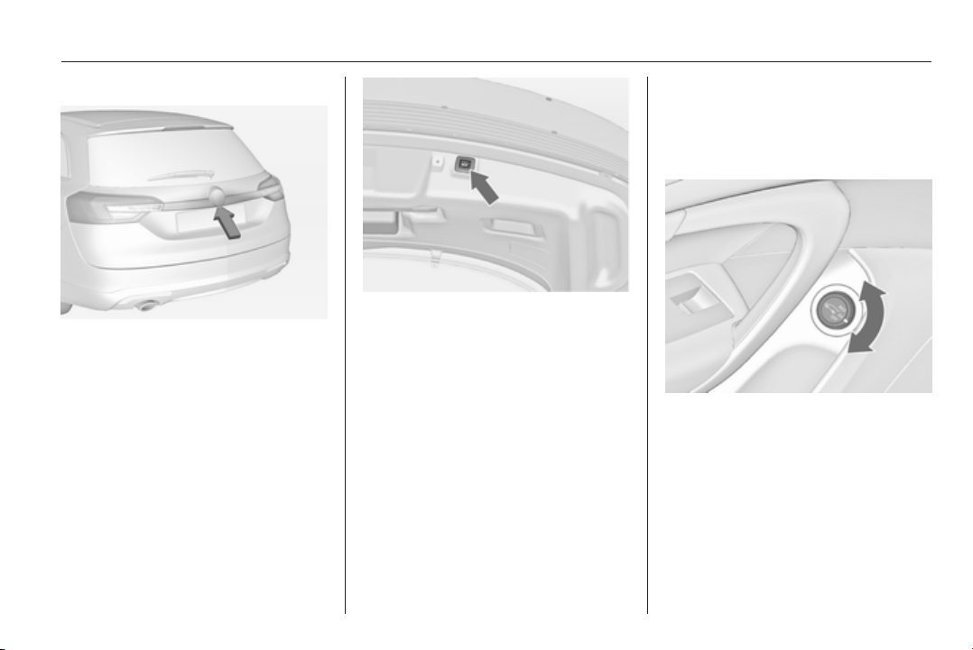
Tailgate
Opening
5-door Hatchback, Sports Tourer,
Country Tourer
After unlocking, press the button
under the tailgate moulding and open
the tailgate manually.
4-door Saloon
Press button x on radio remote
control until the tailgate is opened
automatically, or press the button
under the tailgate moulding after
unlocking.
Central locking system 3 23.
Closing
Use the interior handle.
Do not pull the button under the
moulding whilst closing as this will
unlock the tailgate again.
Central locking system 3 23.
30 Keys, doors and windows
Power tailgate
9 Warning
Take care when operating the
power tailgate. Risk of injury,
particularly to children.
Keep a close watch on the
movable tailgate when operating.
Ensure that nothing becomes
trapped during operating and no
one is standing within the moving
area.
The power tailgate is operated by:
■ Radio remote control button x
■ Switch G in the door panel of the
driver's door
■ Touchpad switch and button G in
the tailgate.
On vehicles with automatic
transmission, the tailgate can only be
operated when the vehicle is
stationary and automatic
transmission in P.
The tail lights flash and a chime
sounds when the power tailgate is
operating.
Note
Operating the power tailgate does
not operate the central locking
system. To open the tailgate with the
remote control, it is not necessary to
unlock the vehicle. Unlock the
vehicle first when operating with the
touchpad switch or the switch in the
driver's door. Lock the vehicle after
closing.
Central locking system 3 23.
Operation with radio remote control
Press and hold button x until the
tailgate starts to open or close.
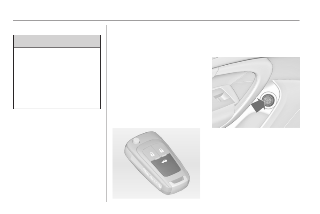
Operation with the switch in the
driver's door
Press and hold button
G until the
tailgate starts to open or close.
Keys, doors and windows 31
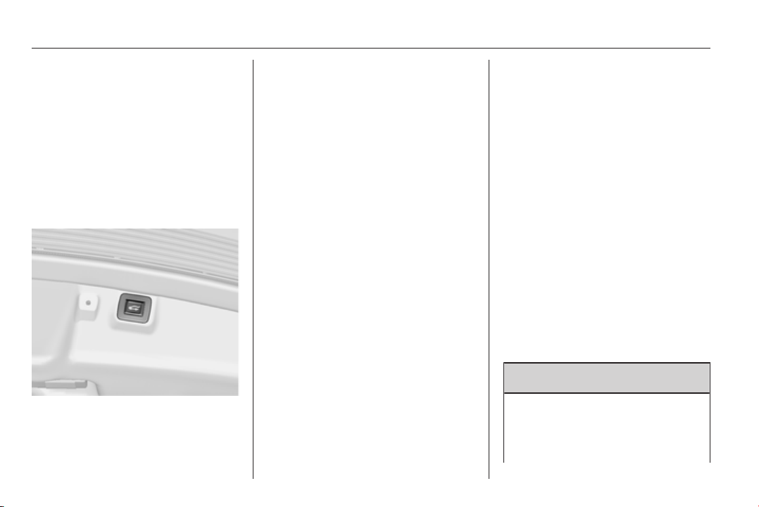
Operation with switches in the tailgate
To open the tailgate, press the
touchpad switch under the tailgate
moulding until the tailgate starts to
move.
To close, press button G in the
open tailgate until the tailgate starts to
move.
Stop or change direction of
movement
Pressing button x on radio remote
control or G on the tailgate or press
on the touchpad switch whilst the
tailgate is moving will stop the tailgate
in the current position. Pressing
button x or G again will reverse
the direction of movement.
Operation modes
The power tailgate has three modes
of operation, which are controlled by
the switch in the driver's door. To
change the mode, turn the switch:
■ Normal mode MAX: power tailgate
opens to full height
■ Intermediate mode 3/4: power
tailgate opens to a reduced height
that can be adjusted
■ Mode Off: tailgate can only be
operated manually.
32 Keys, doors and windows
Adjust reduced opening height in
intermediate mode
1. Turn operation mode switch to
3/4.
2. Open power tailgate with any
operation switch.
3. Stop movement at the desired
height by pressing any operation
switch. If required, manually move
the stopped tailgate to the desired
position.
4. Press and hold the button on the
inside of the open tailgate for
3 seconds.
Note
Adjusting opening height should be
programmed at ground level.
A chime sound indicates the new
setting and the outer rear lights will
flash if the tailgate is below an
opening angel of 30°.
When turning the adjuster wheel in
the driver's door to intermediate mode
3/4, the power tailgate will stop
opening at the newly set position.
The tailgate can only be held open if
a minimum height is exceeded
(minimum opening angle from 30°).
The opening height cannot be
programmed below that height.
Safety function
If the power tailgate encounters an
obstacle during opening or closing,
the direction of movement will
automatically be reversed slightly.
Multiple obstacles in one power cycle
will deactivate the function. In this
case, close or open the tailgate
manually.
The power tailgate has pinch sensors
on the side edges. If the sensors
detect obstacles between tailgate and
chassis, the tailgate will open, until it
is activated again or closed manually.
The safety function is indicated by a
warning chime.
Remove all obstacles before
resuming normal power operation.
If the vehicle is equipped with factory-
fitted towing equipment and a trailer
is electrically connected, the power
tailgate can only be opened with the
touchpad switch or closed with button
G in the open tailgate. Ensure that
there are no obstacles in the moving
area.
General hints for operating
tailgate
9 Warning
Do not drive with the tailgate open
or ajar, e.g. when transporting
bulky objects, since toxic exhaust
gases, which can not be seen or
Keys, doors and windows 33
smelled, could enter the vehicle.
This can cause unconsciousness
and even death.
Caution
Before opening the tailgate, check
overhead obstructions, such as a
garage door, to avoid damage to
the tailgate. Always check the
moving area above and behind the
tailgate.
Note
Power tailgate: If the lifters of the
open tailgate lose pressure, the
tailgate falls a bit and will then be
stopped by the system. Following
the tailgate will be power opened
and closed. During this the tail lights
will flash and a chime will sound.
After closing, the tailgate may not be
operated until it has been serviced
by a workshop.
Note
The operation of the power tailgate
is disabled under low vehicle battery
conditions. In this case, the tailgate
can even not be operated manually.
Note
With the power tailgate disabled and
all doors unlocked, the tailgate can
only be operated manually. In this
event, manually closing the tailgate
requires significantly greater force.
Note
The installation of certain heavy
accessories onto the tailgate may
affect its ability to remain open.
Vehicle security
Anti-theft locking system
9 Warning
Do not use the system if there are
people in the vehicle! The doors
cannot be unlocked from the
inside.
The system deadlocks all the doors.
All doors must be closed and the
electronic key must not remain in the
vehicle. Otherwise the system cannot
be activated.
If the ignition was on, the driver's door
must be opened and closed once so
that the vehicle can be secured.
Unlocking the vehicle disables the
mechanical anti-theft locking system.
This is not possible with the central
locking button in the passenger
compartment.
34 Keys, doors and windows
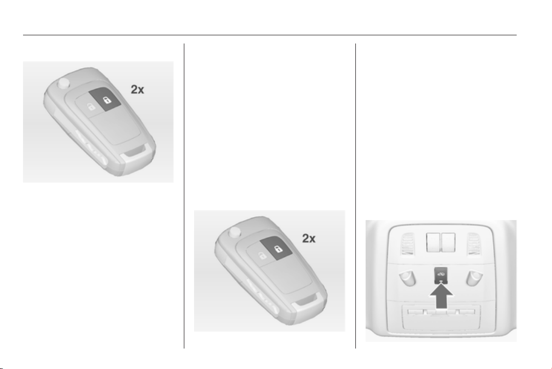
Activating
Radio remote control or electronic
key: press e twice within 5 seconds.
Anti-theft alarm system
The anti-theft alarm system
incorporates and is operated in
conjunction with the anti-theft locking
system.
It monitors:
■ Doors, tailgate, bonnet
■ Passenger compartment including
adjoining load compartment
■ Vehicle inclination, e.g. if it is raised
■ Ignition
Activation
All doors must be closed and the
electronic key must not remain in the
vehicle. Otherwise the system cannot
be activated.
■ Radio remote control: self-
activated 30 seconds after locking
the vehicle by pressing e once.
■ Electronic key system: self-
activated 30 seconds after locking
the vehicle by pressing the button
on any exterior door handle.
■ Radio remote control or electronic
key: directly by pressing e twice
within 5 seconds.
■ Electronic key system with passive
locking enabled: briefly activated
after passive locking occurs.
Note
Changes to the vehicle interior such
as the use of seat covers, and open
windows or sunroof, could impair the
function of passenger compartment
monitoring.
Activation without monitoring of
passenger compartment and
vehicle inclination
Keys, doors and windows 35
Switch off the monitoring of
passenger compartment and vehicle
inclination when animals are being
left in the vehicle, because of high
volume ultrasonic signals or
movements triggering the alarm. Also
switch off when the vehicle is on a
ferry or train.
1. Close tailgate, bonnet, windows
and sunroof.
2. Press button o. LED in the
button o illuminates for a
maximum of 10 minutes.
3. Close doors.
4. Activate the anti-theft alarm
system.
Status message is displayed in the
Driver Information Centre.
Status LED
Status LED is integrated in the sensor
on top of the instrument panel.
Status during the first 30 seconds of
anti-theft alarm system activation:
LED
illuminates
= test, arming delay.
LED flashes
quickly
= doors, tailgate or
bonnet not
completely closed,
or system fault.
Status after system is armed:
LED flashes
slowly
= system is armed.
Seek the assistance of a workshop in
the event of faults.
Deactivation
Radio remote control: Unlocking the
vehicle by pressing button c
deactivates anti-theft alarm system.
Electronic key system: Unlocking the
vehicle by pressing the button on any
exterior door handle deactivates anti-
theft alarm system.
The system is not deactivated when
unlocking the driver's door with the
key or with the central locking button
in the passenger compartment.
36 Keys, doors and windows
Alarm
When triggered, the alarm sounds via
a separate battery-backed power
sounder, and the hazard warning
lights flash simultaneously. The
number and duration of alarm signals
are stipulated by legislation.
The anti-theft alarm system can be
deactivated only by pressing the
button c or by pressing the switch on
the door handle (electronic key
system) or switching on the ignition.
A triggered alarm, which has not been
interrupted by the driver, will be
indicated by the hazard warning
lights. They will flash quickly three
times when the vehicle is unlocked
next time with the radio remote
control. Additionally a warning
message is displayed in the Driver
Information Centre after switching on
the ignition.
Vehicle messages 3 116.
Immobiliser
The system is part of the ignition
switch and checks whether the
vehicle is allowed to be started with
the key being used.
The immobiliser is activated
automatically after the key is removed
from the ignition switch.
If control indicator d flashes when the
ignition is on, there is a fault in the
system; the engine cannot be started.
Switch off the ignition and repeat start
attempt.
If control indicator d continues
flashing, attempt to start the engine
using the spare key and seek the
assistance of a workshop.
Note
The immobiliser does not lock the
doors. You should always lock the
vehicle after leaving it and switch on
the anti-theft alarm system 3 23,
3 34.
Control indicator d 3 105.
Exterior mirrors
Convex shape
The convex exterior mirror contains
an aspherical area and reduces blind
spots. The shape of the mirror makes
objects appear smaller, which will
affect the ability to estimate
distances.
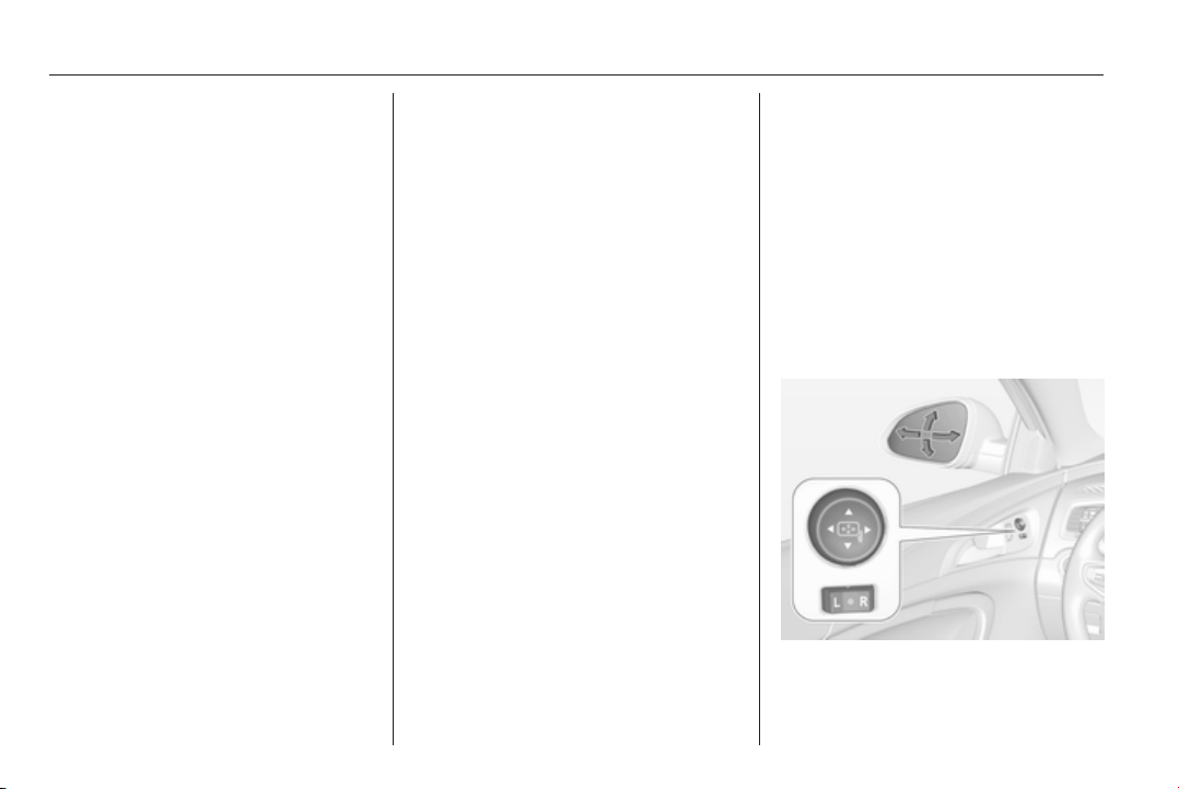
Electric adjustment
Select the relevant exterior mirror by
switching the control to left mirror (L)
or right mirror (R). Then swivel the
control to adjust the mirror.
Keys, doors and windows 37
In position o no mirror is selected.
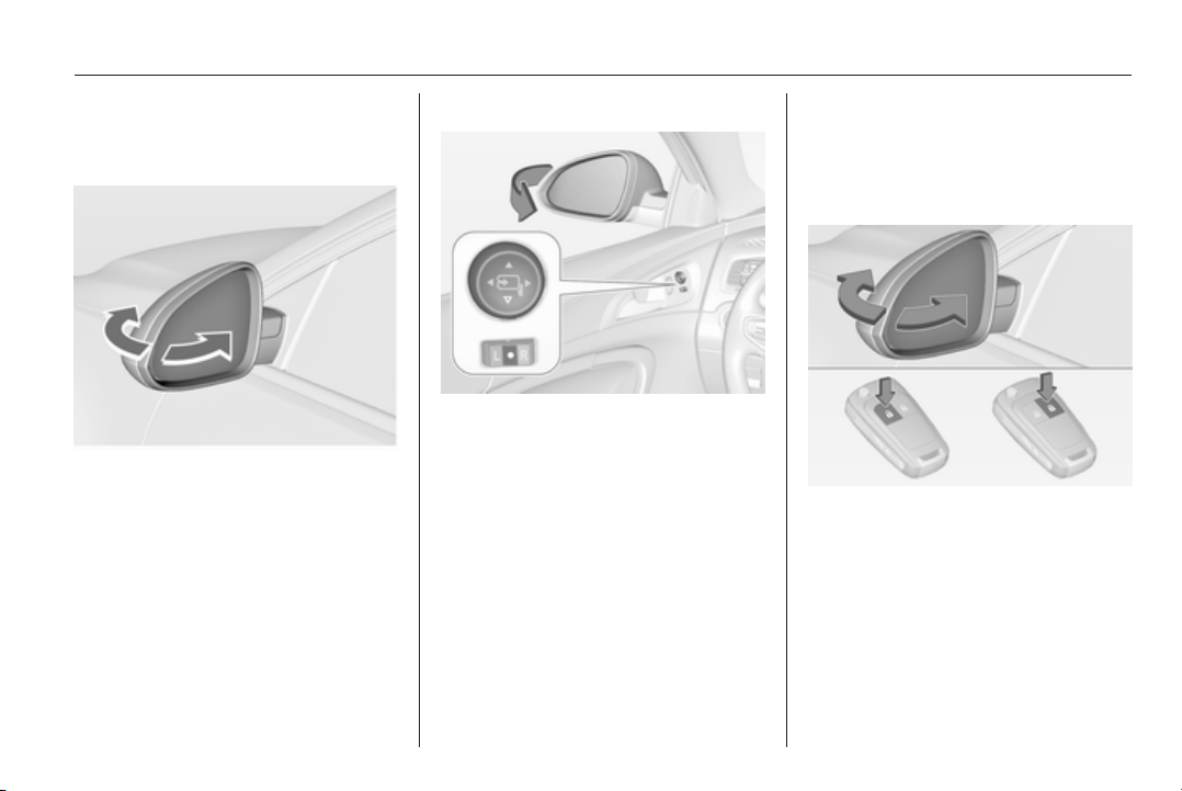
Folding mirrors
For pedestrian safety, the exterior
mirrors will swing out of their normal
mounting position if they are struck
with sufficient force. Reposition the
mirror by applying slight pressure to
the mirror housing.
Electric folding
Switch control to o, then push the
control button c down. Both exterior
mirrors will fold.
Push the control down again - both
exterior mirrors return to their original
position.
If an electrically folded mirror is
manually extended, pressing down
the control will only electrically extend
the other mirror.
Folding mirrors with remote
control
This function is only available if the
vehicle is equipped with electrical
seat memory.
Press button
e again after locking for
one second to fold in mirrors.
Press button c again after unlocking
for one second to fold out mirrors.
Pressing for three seconds activates
window operation. Power windows
3 39. Sunroof 3 42.
If the mirrors were folded in using the
control in the driver's door, they are
not folded out by pressing button c.
38 Keys, doors and windows
This function can be activated or
deactivated in the Vehicle
personalisation.
Select the relevant setting in Settings,
I Vehicle in the Colour-Info-Display.
Colour-Info-Display 3 114.
Vehicle personalisation 3 118.
The settings are automatically stored
for the key being used 3 23.
Heated mirrors
Operated by pressing the Ü button.
The LED in the button indicates
activation.
Heating works with the engine
running and is switched off
automatically after a short time.
Automatic dimming
Dazzling by following vehicles at night
is automatically reduced by dimming
both exterior mirrors.
Parking assist
For mirrors with position memory, the
exterior mirror on the passenger side
is automatically aimed at the rear
tyres as a parking aid when reverse
gear is selected, except during trailer
operation.
Position memory 3 50.
Activation or deactivation of this
function can be changed in the menu
Settings in the Info-Display. Vehicle
personalisation 3 118.
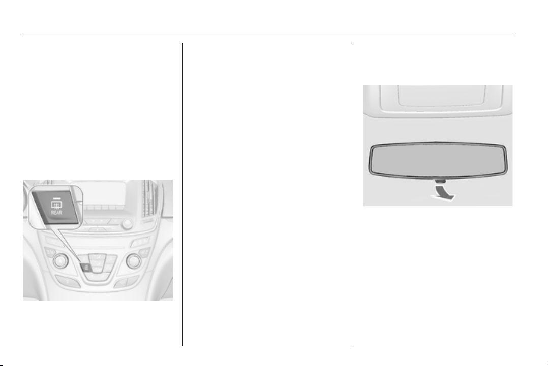
Interior mirrors
Manual anti-dazzle
To reduce dazzle, adjust the lever on
the underside of the mirror housing.
Keys, doors and windows 39
Automatic anti-dazzle
Dazzling by following vehicles at night
is automatically reduced by dimming
the interior mirror.
Windows
Windscreen
Heat-reflecting windscreen
The heat-reflecting windscreen has a
coating which reflects solar radiation.
Also data signals, e.g. from toll
stations, might be reflected.
The marked areas on the windscreen
are not covered with the coating.
Devices for electronic data recording
and fee payment must be attached in
these areas. Otherwise data
recording malfunctions may occur.
Windscreen stickers
Do not attach stickers such as toll
road stickers or similar on the
windscreen in the area of the interior
mirror. Otherwise the detection zone
of the sensor and the view area of the
camera in the mirror housing could be
restricted.
Power windows
9 Warning
Take care when operating the
power windows. Risk of injury,
particularly to children.
If there are children on the rear
seats, switch on the child safety
system for the power windows.
Keep a close watch on the
windows when closing them.
Ensure that nothing becomes
trapped in them as they move.
Operable with ignition in position
Accessory power mode or Ignition on
power mode 3 149, 3 149.
40 Keys, doors and windows
Retained power off 3 151.
Operate the switch for the respective
window by pushing to open or pulling
to close.
Pushing or pulling gently to the first
detent: window moves up or down as
long as the switch is operated.
Pushing or pulling firmly to the second
detent and then releasing: window
moves up or down automatically with
safety function enabled. To stop
movement, operate the switch once
more in the same direction.
Power windows can be operated for
approx. 10 minutes after the ignition
is switched off or until the driver's door
is opened.
Safety function
If the window glass encounters
resistance above the middle of the
window during automatic closing, it is
immediately stopped and opened
again.
Override safety function
In the event of closing difficulties due
to frost or the like, switch on the
ignition, then pull the switch to the first
detent and hold. The window moves
up without safety function enabled.
To stop movement, release the
switch.
Child safety system for rear
windows
Press switch z to deactivate rear
door power windows; the LED
illuminates. To activate, press z
again.
Comfort operating with the
remote control
The windows can be operated
remotely from outside the vehicle.
Keys, doors and windows 41
Press button c again for
three seconds after unlocking: all
windows will be opened.
Press button e again for
three seconds after locking: all
windows will be closed.
Press any button to stop window
movement.
Folding mirrors 3 37.
Closing sunroof 3 42.
Confirmation
Complete opening or closing of the
windows is confirmed by the hazard
warning flashers.
Overload
If the windows are repeatedly
operated within short intervals, the
window operation is disabled for
some time.
Initialising the power windows
If the windows cannot be closed
automatically (e.g. after
disconnecting the vehicle battery), a
warning message is displayed in the
Driver Information Centre.
Vehicle messages 3 116.
Activate the window electronics for
each window as following:
1. Close doors.
2. Switch on ignition.
3. Pull switch to the second detent
until the window starts to close
and hold pulled for additional
4 seconds.
4. Push switch to the second detent
until the window starts to open
automatically.
5. Repeat for each window.
Heated rear window
Operated by pressing the Ü button.
The LED in the button indicates
activation.
Heating works with the engine
running and is switched off
automatically after a short time.
Sun visors
The sun visors can be folded down or
swivelled to the side to prevent
dazzling.
42 Keys, doors and windows
If the sun visors have integral mirrors,
the mirror covers should be closed
when driving.
Roller blinds
To reduce sunlight at the rear seats,
pull the blind upwards using the grip
and engage it at the top of the door
frame.
Roof
Sunroof
9 Warning
Take care when operating the
sunroof. Risk of injury, particularly
to children.
Keep a close watch on the
movable parts when operating
them. Ensure that nothing
becomes trapped in them as they
move.
Operable with ignition in position
Accessory power mode or Ignition on
power mode 3 149, 3 149.
Retained power off 3 151.
Sunroof, 5-door Hatchback/
4-door Saloon
Open or close
Press switch p or r gently to the
first detent: sunroof is opened or
closed with safety function enabled
as long as the switch is operated.
Press switch p or r firmly to the
second detent and then release: the
sunroof is opened or closed
automatically with safety function
enabled. To stop movement, operate
the switch once more.
Keys, doors and windows 43
Raise or close
Press switch q or r: sunroof is
raised or closed automatically with
safety function enabled.
If the sunroof is raised, it can be
opened in one step by pressing p.
Sunblind
The sunblind is manually operated.
Close or open the sunblind by sliding.
When the sunroof is open, the
sunblind is always open.
Panoramaroof, Sports Tourer/
Country Tourer
Open
Press switch p gently to the first
detent: sunroof is opened in the
spoiler position.
Press switch p firmly to the second
detent and then release: the sunroof
is opened automatically with safety
function enabled. To stop movement,
operate the switch once more.
Close
Press switch r gently to the first
detent: sunroof is closed from fully
open or spoiler position with safety
function enabled as long as the switch
is operated.
Press switch r firmly to the second
detent and then release: the sunroof
is completely closed automatically
with safety function enabled. To stop
movement, operate the switch once
more.
Sunblind
The sunblind is power operated.
Close or open the sunblind by
pressing switch H or G.
General hints
Safety function
If the sunroof or sunblind encounters
resistance during automatic closing, it
is immediately stopped and opened
again.
Override safety function
In the event of closing difficulties due
to frost or the like, hold switch r
pressed to the second detent. The
44 Keys, doors and windows
sunroof closes without safety function
enabled. To stop movement, release
the switch.
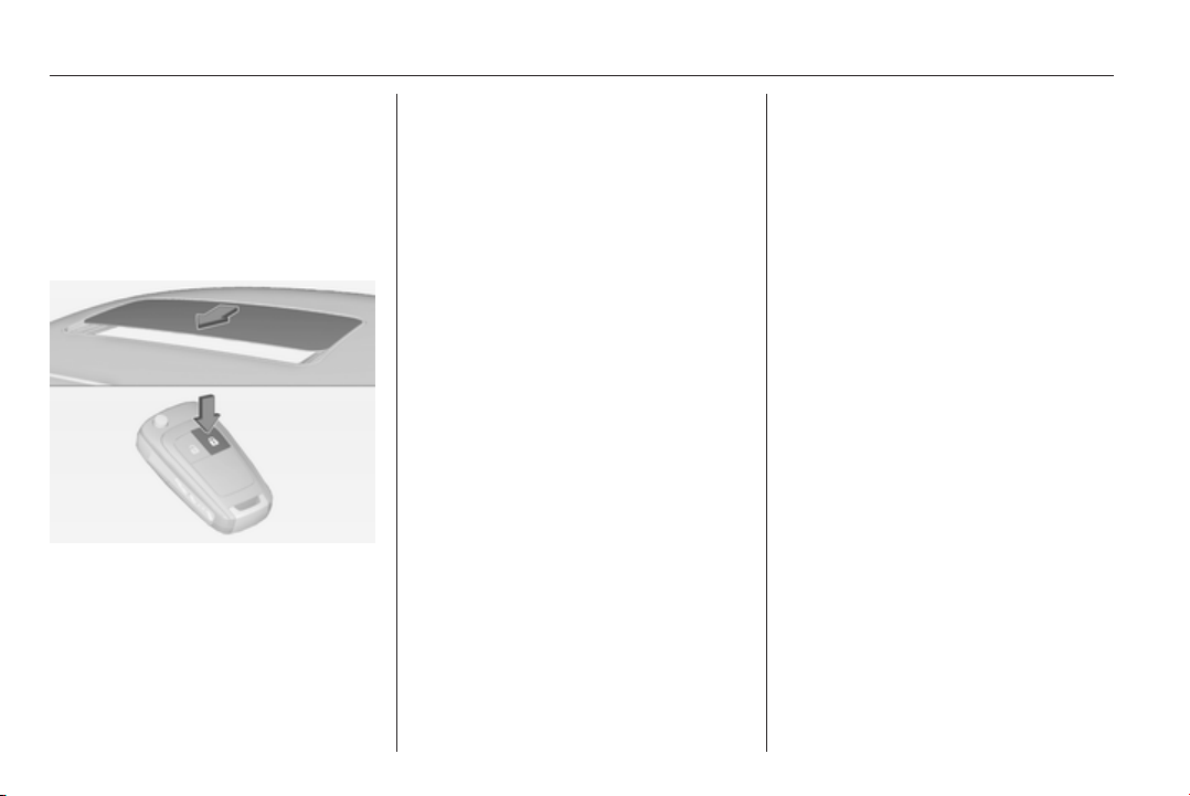
Comfort closing with the remote
control
The sunroof can be closed remotely
from outside the vehicle.
Press and hold button e to close the
sunroof.
Release the button to stop the
movement.
Initialising after a power failure
After a power failure, it may only be
possible to operate the sunroof to a
limited extent. Have the system
initialised by a workshop.
Seats, restraints 45
Seats, restraints
Head restraints ............................ 45
Front seats ................................... 47
Rear seats ................................... 54
Seat belts ..................................... 54
Airbag system .............................. 58
Child restraints ............................. 62
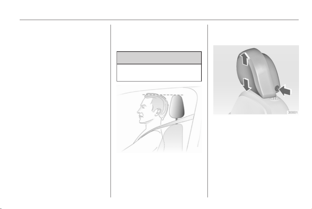
Head restraints
Position
9 Warning
Only drive with the head restraint
set to the proper position.
The upper edge of the head restraint
should be at upper head level. If this
is not possible for extremely tall
people, set to highest position, and
set to lowest position for small people.
Adjustment
Head restraints on front seats
Height adjustment
Press release button, adjust height,
engage.
46 Seats, restraints
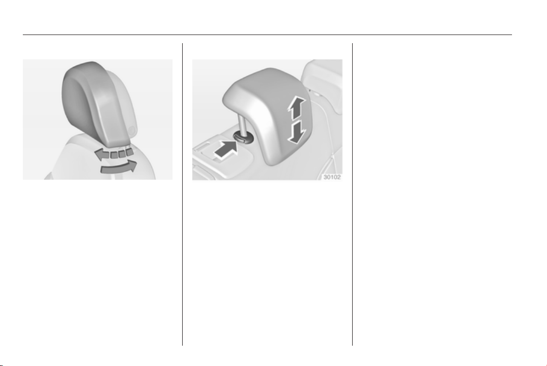
Horizontal adjustment
Pull bolster of head restraint forwards
slowly. It engages in several
positions.
To return to its rearmost position, pull
fully forwards and release.
Head restraints on rear seats
Height adjustment
Pull the head restraint upwards and
let engage. To move downwards,
press the catch to release and push
the head restraint downwards.
Active head restraints
In the event of a rear-end impact, the
front parts of the active head
restraints are moved slightly
forwards. Thus the head is supported
so that the risk of whiplash injury is
reduced.
Note
Approved accessories may only be
attached if the seat is not in use.
Seats, restraints 47
Front seats
Seat position
9 Warning
Only drive with the seat correctly
adjusted.
■
Sit with buttocks as far back against
the backrest as possible. Adjust the
distance between the seat and the
pedals so that legs are slightly
angled when pressing the pedals.
Slide the front passenger seat as
far back as possible.
■ Sit with shoulders as far back
against the backrest as possible.
Set the backrest rake so that it is
possible to easily reach the
steering wheel with arms slightly
bent. Maintain contact between
shoulders and the backrest when
turning the steering wheel. Do not
angle the backrest too far back. We
recommend a maximum rake of
approx. 25°.
■ Adjust the steering wheel 3 82.
■ Set seat height high enough to
have a clear field of vision on all
sides and of all display instruments.
There should be at least one hand
of clearance between head and the
roof frame. Your thighs should rest
lightly on the seat without pressing
into it.
■ Adjust the head restraint 3 45.
■ Adjust the height of the seat belt
3 55.
■ Adjust the thigh support so that
there is a space approx. two fingers
wide between the edge of the seat
and the hollow of the knee.
■ Adjust the lumbar support so that it
supports the natural shape of the
spine.
Seat adjustment
9 Danger
Do not sit nearer than 25 cm from
the steering wheel, to permit safe
airbag deployment.
9 Warning
Never adjust seats while driving as
they could move uncontrollably.
48 Seats, restraints
Seat positioning
Pull handle, slide seat, release
handle.
Seat backrests
Pull lever, adjust inclination and
release lever. Allow the backrest to
engage audibly.
Seat height
Press switch
top = seat higher
bottom = seat lower
Seats, restraints 49
Seat inclination
Lever pumping motion
up = front end higher
down = front end lower
Lumbar support
Adjust lumbar support using the four-
way switch to suit personal
requirements.
Moving support up and down: push
switch up or down.
Increasing and decreasing support:
push switch forwards or backwards.
Adjustable thigh support
Pull the lever and slide the thigh
support.
50 Seats, restraints
Power seat adjustment
9 Warning
Care must be taken when
operating the power seats. There
is a risk of injury, particularly for
children. Objects could become
trapped.
Keep a close watch on the seats
when adjusting them. Vehicle
passengers should be informed
accordingly.
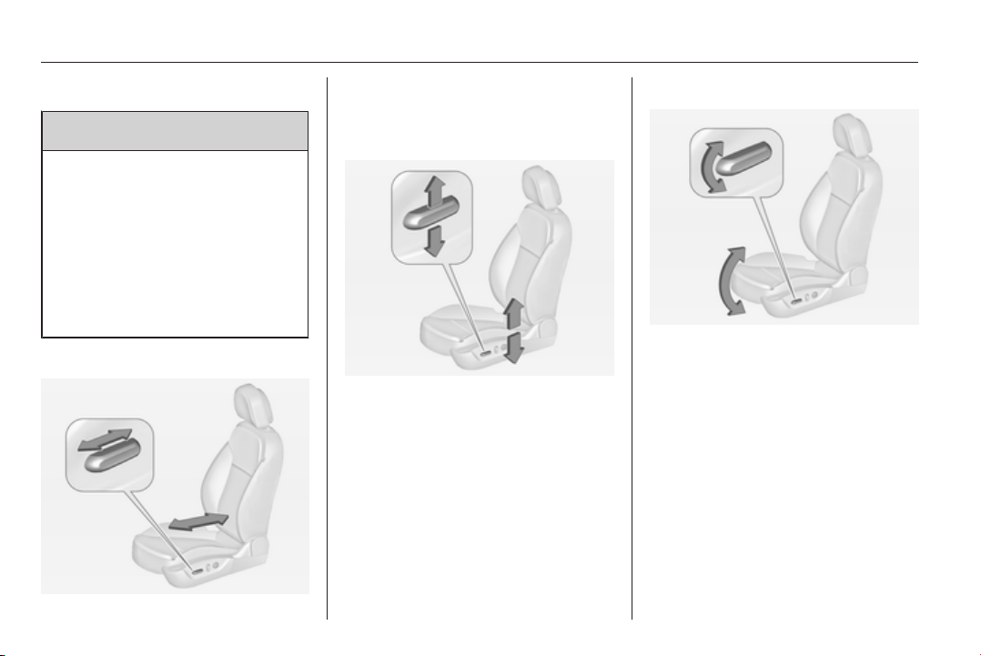
Seat positioning
Move front of switch forwards/
backwards.
Seat height
Move switch upwards/downwards.
Seat inclination
Move front of switch upwards/
downwards.
Seats, restraints 51
Seat backrests
Turn switch forwards/backwards.
Lumbar support
Adjust lumbar support using the four-
way switch to suit personal
requirements.
Moving support up and down: push
switch up or down.
Increasing and decreasing support:
push switch forwards or backwards.
Adjustable thigh support
Pull the lever and slide the thigh
support.
Memory function for power seat
adjustment and exterior mirrors
Two different driver's seat and
exterior mirror settings can be stored.
Memorised settings 3 23, Vehicle
personalisation 3 118.
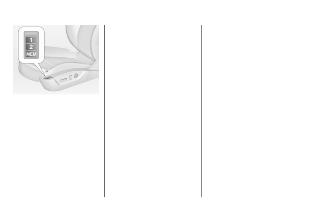
52 Seats, restraints
Storing memory positions by buttons
1 and 2
■ Adjust driver's seat and then adjust
exterior mirrors to desired
positions.
■ Press and hold button MEM and
button 1 at the same time until a
beep sounds.
■ Repeat the steps for a second
driver using button 2.
Recall of memory positions
Press and hold button 1 or 2 until the
stored seat and exterior mirror
positions have been reached.
Releasing the button during seat
movement cancels the recall.
Storing positions by remote control
Actual driver's seat and exterior
mirror positions are automatically
stored by the radio remote control key
each time the ignition is switched off.
These stored positions are
independent of the memory positions
stored by the buttons 1 or 2, see
above.
The stored positions are
automatically recalled by unlocking
and opening the driver's door with the
memorised radio remote control key.
If the door is already open, press
button c on remote control to activate
the recall.
To stop recall movement, press one
of the memory-, power mirror- or
power seat controls.
This function can be activated or
deactivated in the Vehicle
personalisation.
Select the relevant setting in Settings,
I Vehicle in the Colour-Info-Display.
Colour-Info-Display 3 114.
Vehicle personalisation 3 118.
Easy exit function
For a convenient exit out of the
vehicle, the power driver seat moves
rearwards when vehicle is stationary.
To activate, switch off ignition,
remove key from the ignition switch
and open the driver's door. If the door
is already open, switch off ignition to
activate the recall.
To stop recall movement, press one
of the memory- or power seat
controls.
This function can be activated or
deactivated in the Vehicle
personalisation.
Select the relevant setting in Settings,
I Vehicle in the Colour-Info-Display.
Colour-Info-Display 3 114.
Vehicle personalisation 3 118.
Seats, restraints 53
Safety function
If the driver's seat encounters
resistance during movement, the
recall may stop. After removing the
obstruction, press and hold the
appropriate power seat position
button for the memory item for
two seconds. Try recalling the
memory position again. If the recall
does not operate, consult a
workshop.
Overload
If the seat setting is electrically
overloaded, the power supply is
automatically cut-off for a short time.
Note
After an accident in which airbags
have been deployed, the memorised
settings for each position button will
be deactivated.
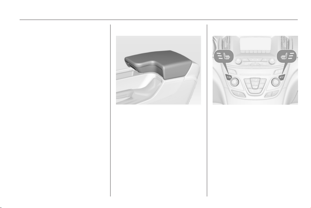
Armrest
Push button and fold armrest
upwards. Under the armrest there is
a storage compartment.
Auxiliary devices, see Infotainment
system manual.
Heating
Adjust heating to the desired setting
by pressing button ß for the
respective seat one or more times.
The control indicator in the button
indicates the setting.
Prolonged use of the highest setting
for people with sensitive skin is not
recommended.
Seat heating is operational when
engine is running and during an
Autostop.
Stop-start system 3 153.
54 Seats, restraints
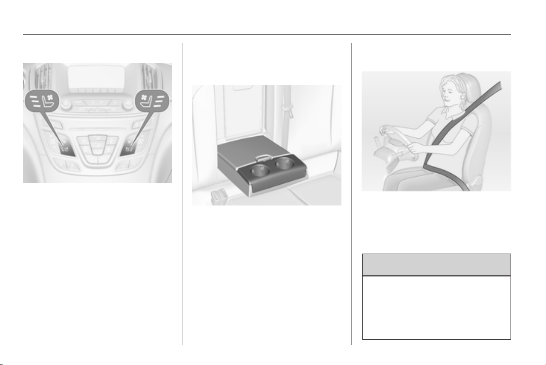
Ventilating
Adjust ventilation to the desired
setting by pressing button A for the
respective seat one or more times.
The control indicator in the button
indicates the setting.
Ventilated seats are operational when
engine is running and during an
Autostop.
Stop-start system 3 153.
Rear seats
Armrest
Fold armrest down. The armrest
contains cupholders and a storage
box.
Seat belts
The seat belts are locked during
heavy acceleration or deceleration of
the vehicle holding the occupants in
the sitting position. Thereby the risk of
injury is considerably reduced.
9 Warning
Fasten seat belt before each trip.
In the event of an accident, people
not wearing seat belts endanger
their fellow occupants and
themselves.

Seats, restraints 55
Seat belts are designed to be used by
only one person at a time. Child
restraint system 3 62.
Periodically check all parts of the belt
system for damage, pollution and
proper functionality.
Have damaged components
replaced. After an accident, have the
belts and triggered belt pretensioners
replaced by a workshop.
Note
Make sure that the belts are not
damaged by shoes or sharp-edged
objects or trapped. Prevent dirt from
getting into the belt retractors.
Seat belt reminder
Each seat is equipped with a seat belt
reminder, indicated for front seats by
control indicators X and k, or for rear
seats by the symbol X in the Driver
Information Centre 3 100.
Belt force limiters
Stress on the body is reduced by the
gradual release of the belt during a
collision.
Belt pretensioners
In the event of a head-on or rear-end
collision of a certain severity, the front
seat belts are tightened.
9 Warning
Incorrect handling (e.g. removal or
fitting of belts) can trigger the belt
pretensioners.
Deployment of the belt pretensioners
is indicated by continuous illumination
of control indicator v 3 101.
Triggered belt pretensioners must be
replaced by a workshop. Belt
pretensioners can only be triggered
once.
Note
Do not affix or install accessories or
other objects that may interfere with
the operation of the belt
pretensioners. Do not make any
modifications to belt pretensioner
components as this will invalidate
the vehicle type approval.
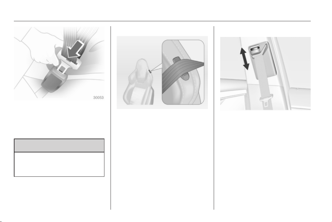
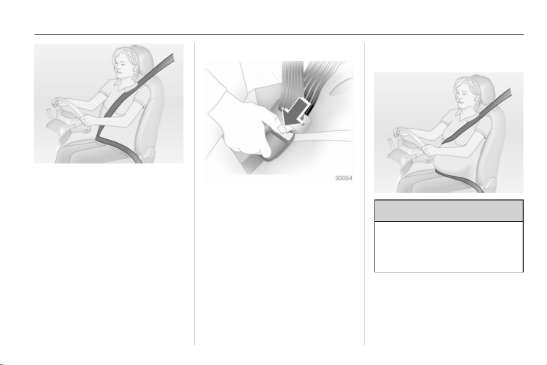
Three-point seat belt
Fastening
Withdraw the belt from the retractor,
guide it untwisted across the body
and insert the latch plate into the
buckle. Tighten the lap belt regularly
whilst driving by pulling the shoulder
belt.
56 Seats, restraints
Loose or bulky clothing prevents the
belt from fitting snugly. Do not place
objects such as handbags or mobile
phones between the belt and your
body.
9 Warning
The belt must not rest against hard
or fragile objects in the pockets of
your clothing.
Seat belt reminder X, k 3 100.
Insignia OPC
Feed seat belt through belt mount on
backrest when fastening seat belt.
Height adjustment
1. Pull belt out slightly.
2. Press button.
3. Adjust height and engage.
Seats, restraints 57
Adjust the height so that the belt lies
across the shoulder. It must not lie
across the throat or upper arm.
Do not adjust while driving.
Removing
To release belt, press red button on
belt buckle.
Insignia OPC
Feed seat belt through belt mount on
backrest after releasing.
Seat belts on the rear seats
The seat belt for the rear centre seat
can only be withdrawn from the
retractor if the backrest is in the rear
position.
Using the seat belt while
pregnant
9 Warning
The lap belt must be positioned as
low as possible across the pelvis
to prevent pressure on the
abdomen.
58 Seats, restraints
Airbag system
The airbag system consists of a
number of individual systems
depending on the scope of
equipment.
When triggered the airbags inflate
within milliseconds. They also deflate
so quickly that it is often unnoticeable
during the collision.
9 Warning
If handled improperly the airbag
systems can be triggered in an
explosive manner.
Note
The airbag systems and belt
pretensioner control electronics are
located in the centre console area.
Do not put any magnetic objects in
this area.
Do not stick anything on the airbag
covers and do not cover them with
other materials.
Each airbag is triggered only once.
Have deployed airbags replaced by
a workshop. Furthermore, it might be
necessary to have the steering
wheel, the instrument panel, parts of
the panelling, the door seals,
handles and the seats replaced.
Do not make any modifications to
the airbag system as this will
invalidate the vehicle type approval.
When the airbags inflate, escaping
hot gases may cause burns.
Control indicator v for airbag systems
3 101.
Front airbag system
The front airbag system consists of
one airbag in the steering wheel and
one in the instrument panel on the
front passenger side. These can be
identified by the word AIRBAG.
Additionally there is a warning label
on the side of the instrument panel,
visible when the front passenger door
is open, or on the front passenger sun
visor.
The front airbag system is triggered in
the event of a front-end impact of a
certain severity. The ignition must be
switched on.
Seats, restraints 59
The inflated airbags cushion the
impact, thereby reducing the risk of
injury to the upper body and head of
the front seat occupants
considerably.
9 Warning
Optimum protection is only
provided when the seat is in the
proper position 3 47.
Keep the area in which the airbag
inflates clear of obstructions.
Fit the seat belt correctly and
engage securely. Only then the
airbag is able to protect.
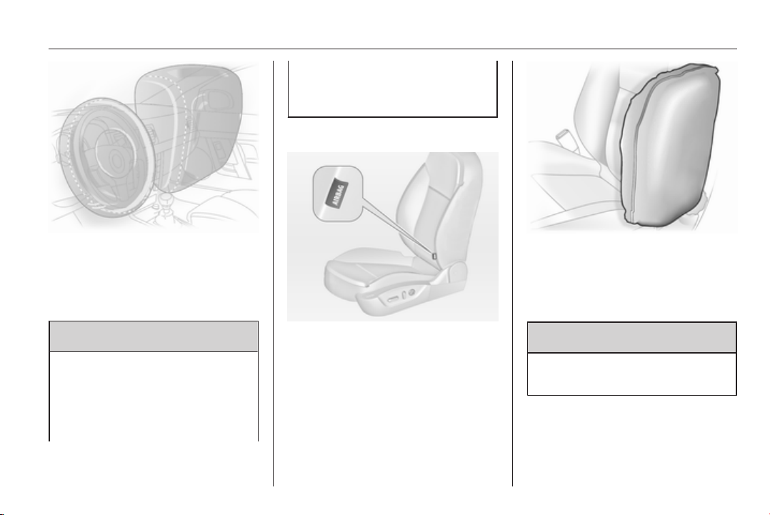
Side airbag system
The side airbag system consists of an
airbag in each front seat backrest and
in the rear outboard seat backrests.
This can be identified by the word
AIRBAG.
The side airbag system is triggered in
the event of a side impact of a certain
severity. The ignition must be
switched on.
The inflated airbags cushion the
impact, thereby reducing the risk of
injury to the upper body and pelvis in
the event of a side-on collision
considerably.
9 Warning
Keep the area in which the airbag
inflates clear of obstructions.
Note
Only use protective seat covers that
have been approved for the vehicle.
Be careful not to cover the airbags.
60 Seats, restraints
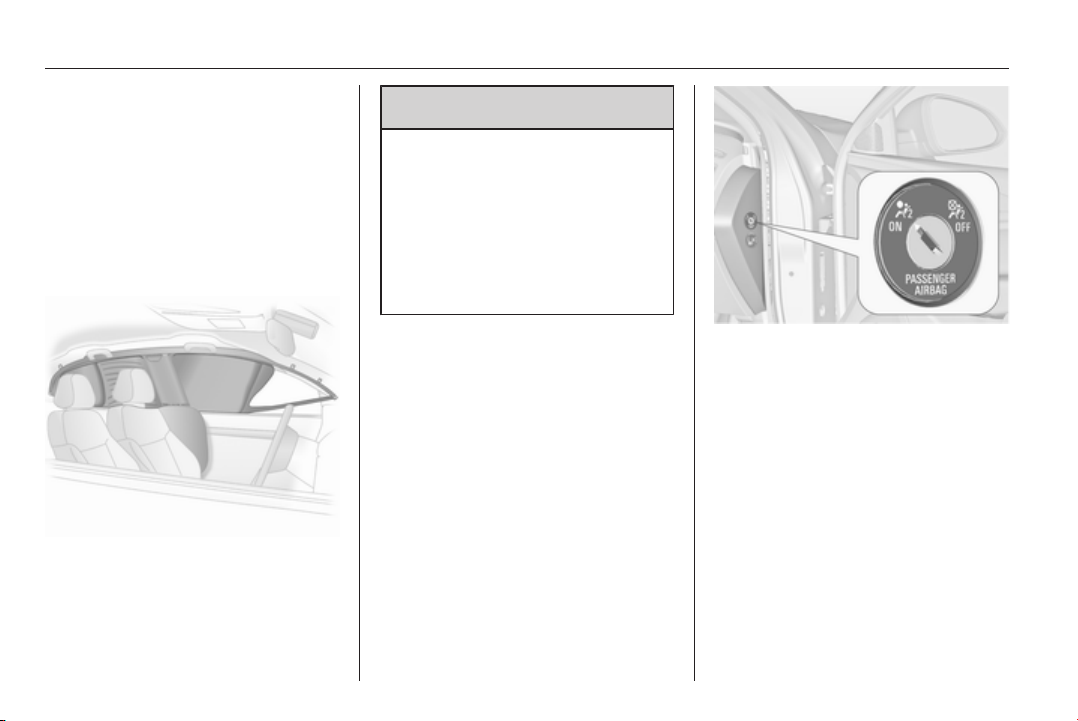
Curtain airbag system
The curtain airbag system consists of
an airbag in the roof frame on each
side. This can be identified by the
word AIRBAG on the roof pillars.
The curtain airbag system is triggered
in the event of a side-on impact of a
certain severity. The ignition must be
switched on.
The inflated airbags cushion the
impact, thereby reducing the risk of
injury to the head in the event of a
side-on impact considerably.
9
Warning
Keep the area in which the airbag
inflates clear of obstructions.
The hooks on the handles in the
roof frame are only suitable for
hanging up light articles of
clothing, without coat hangers. Do
not keep any items in these
clothes.
Airbag deactivation
Front airbag and side airbag systems
for the front passenger seat must be
deactivated if a child restraint system
is to be fitted on this seat. The curtain
airbag system, the belt pretensioners
and all driver airbag systems will
remain active.
The front passenger airbag system
can be deactivated via a key-
operated switch on the right side of
the instrument panel.
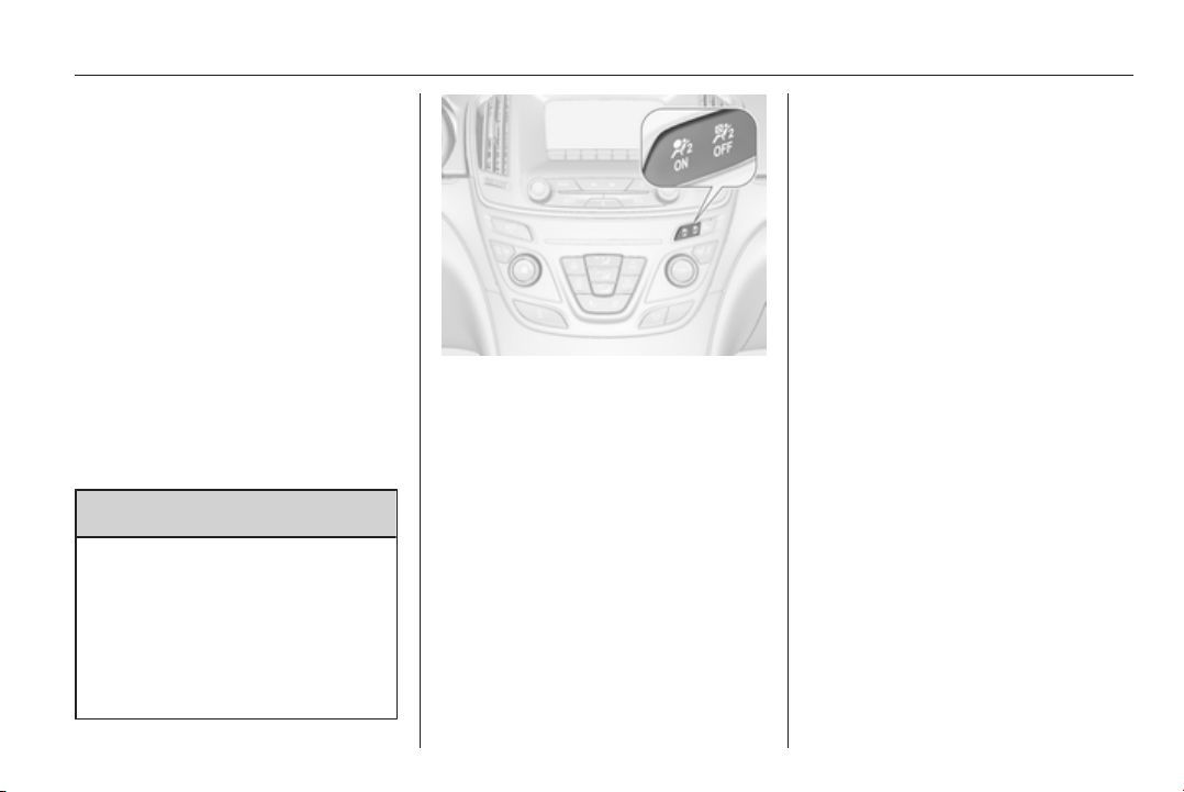
Seats, restraints 61
Use the ignition key to choose the
position:
*
= front passenger airbags are
deactivated and will not inflate
in the event of a collision.
Control indicator * illuminates
continuously. A child restraint
system can be installed in
accordance with the
chart Child restraint
installation locations 3 63.
No adult person is allowed to
occupy the front passenger
seat.
V
= front passenger airbags are
active. A child restraint system
must not be installed.
9 Danger
Risk of fatal injury for a child using
a child restraint system on a seat
with activated front passenger
airbag.
Risk of fatal injury for an adult
person on a seat with deactivated
front passenger airbag.
As long as the control indicator * is
not illuminated, the airbag systems
for the front passenger seat will inflate
in the event of a collision.
If both control indicators are
illuminated simultaneously, there is a
system failure. The status of the
system is not discernible, therefore
no person is allowed to occupy the
front passenger seat. Contact a
workshop immediately.
Consult a workshop immediately if
neither of the two control indicators
are illuminated.
Change status only when the vehicle
is stopped with the ignition off.
Status remains until the next change.
Control indicator for airbag
deactivation 3 101.

62 Seats, restraints
Child restraints
Child restraint systems
We recommend the Opel child
restraint system which is tailored
specifically to the vehicle.
When a child restraint system is being
used, pay attention to the following
usage and installation instructions
and also those supplied with the child
restraint system.
Always comply with local or national
regulations. In some countries, the
use of child restraint systems is
forbidden on certain seats.
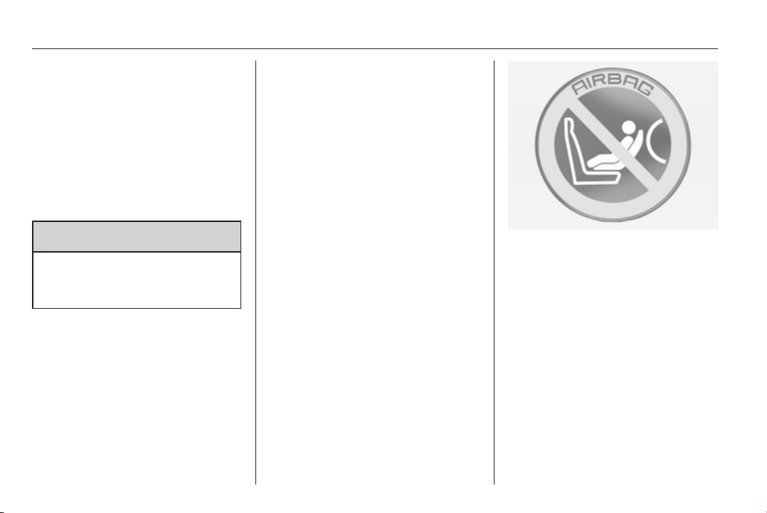
9 Danger
When using a child restraint
system on the front passenger
seat, the airbag systems for the
front passenger seat must be
deactivated; if not, the triggering of
the airbags poses a risk of fatal
injury to the child.
This is especially the case if rear-
facing child restraint systems are
used on the front passenger seat.
Airbag deactivation 3 60.
Selecting the right system
The rear seats are the most
convenient location to fasten a child
restraint system.
Children should travel facing
rearwards in the vehicle as long as
possible. This makes sure that the
child's backbone, which is still very
weak, is under less strain in the event
of an accident.
Suitable are restraint systems that
comply with ECE 44-03 or
ECE 44-04. Check local laws and
regulations for mandatory use of child
restraint systems.
Ensure that the child restraint system
to be installed is compatible with the
vehicle type.
Ensure that the mounting location of
the child restraint system within the
vehicle is correct.
Allow children to enter and exit the
vehicle only on the side facing away
from the traffic.
When the child restraint system is not
in use, secure the seat with a seat belt
or remove it from the vehicle.
Note
Do not stick anything on the child
restraint systems and do not cover
them with any other materials.
A child restraint system which has
been subjected to stress in an
accident must be replaced.

Seats, restraints 63
Child restraint installation locations
Permissible options for fitting a child restraint system
Weight and age class
On front passenger seat
On rear outboard seats On rear centre seatactivated airbag deactivated airbag
Group 0: up to 10 kg
or approx. 10 months
X
U
1
U
2
U
2
Group 0+: up to 13 kg
or approx. 2 years
X
U
1
U
2
U
2
Group I: 9 to 18 kg
or approx. 8 months to 4 years
X
U
1
U
2
U
2
Group II: 15 to 25 kg
or approx. 3 to 7 years
X X U U
Group III: 22 to 36 kg
or approx. 6 to 12 years
X X U U
1
= Only if front passenger seat airbag system is deactivated. If the child restraint system is being secured using a three-
point seat belt, move seat height adjustment to uppermost position and ensure that vehicle safety belt runs forwards
from the upper anchorage point. Adjust seat backrest inclination as far as necessary to a vertical position to ensure
that the belt is tight on the buckle side.
2
= Seat available with ISOFIX and Top-Tether mounting brackets 3 66.
U = Universal suitability in conjunction with three-point seat belt.
X = No child restraint system permitted in this weight class.

64 Seats, restraints
Permissible options for fitting an ISOFIX child restraint system
Weight class Size class Fixture On front passenger seat On rear outboard seats On rear centre seat
Group 0: up to 10 kg E ISO/R1 X IL IL
Group 0+: up to 13 kg E ISO/R1 X IL IL
D ISO/R2 X IL IL
C ISO/R3 X IL IL
Group I: 9 to 18 kg D ISO/R2 X IL IL
C ISO/R3 X IL IL
B ISO/F2 X IL, IUF IL, IUF
B1 ISO/F2X X IL, IUF IL, IUF
A ISO/F3 X IL, IUF IL, IUF
IL = Suitable for particular ISOFIX restraint systems of the 'specific-vehicle', 'restricted' or 'semi-universal' categories.
The ISOFIX restraint system must be approved for the specific vehicle type.
IUF = Suitable for ISOFIX forward-facing child restraint systems of universal category approved for use in this weight class.
X = No ISOFIX child restraint system approved in this weight class.

Seats, restraints 65
ISOFIX size class and seat device
A – ISO/F3 = Forward-facing child restraint system for children of maximum size in the weight class 9 to 18 kg.
B – ISO/F2 = Forward-facing child restraint system for smaller children in the weight class 9 to 18 kg.
B1 – ISO/F2X = Forward-facing child restraint system for smaller children in the weight class 9 to 18 kg.
C – ISO/R3 = Rear-facing child restraint system for children of maximum size in the weight class up to 18 kg.
D – ISO/R2 = Rear-facing child restraint system for smaller children in the weight class up to 18 kg.
E – ISO/R1 = Rear-facing child restraint system for young children in the weight class up to 13 kg.
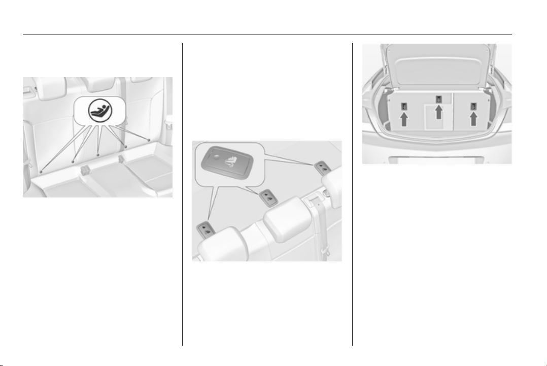
66 Seats, restraints
ISOFIX child restraint
systems
Fasten vehicle-approved ISOFIX
child restraint systems to the ISOFIX
mounting brackets. Specific vehicle
ISOFIX child restraint system
positions are marked in the table by
IL 3 63.
No more than two ISOFIX child
restraint systems can be installed on
the rear seats at the same time,
though not right next to each other.
ISOFIX mounting brackets are
indicated by a logo ISOFIX on the
backrest.
Top-tether fastening eyes
The vehicle has three fastening eyes
on the backside of the rear backrests
or in the area behind the head
restraints.
Top-Tether fastening eyes are
marked with the symbol : for a child
seat.
Open the flap of the required
fastening eye, marked by the child
seat symbol.
In addition to the ISOFIX mounting,
fasten the Top-Tether strap to the
Top-Tether fastening eyes. The strap
must run between the two guide rods
of the head restraint.
ISOFIX child restraint systems of
universal category positions are
marked in the table by IUF 3 63.
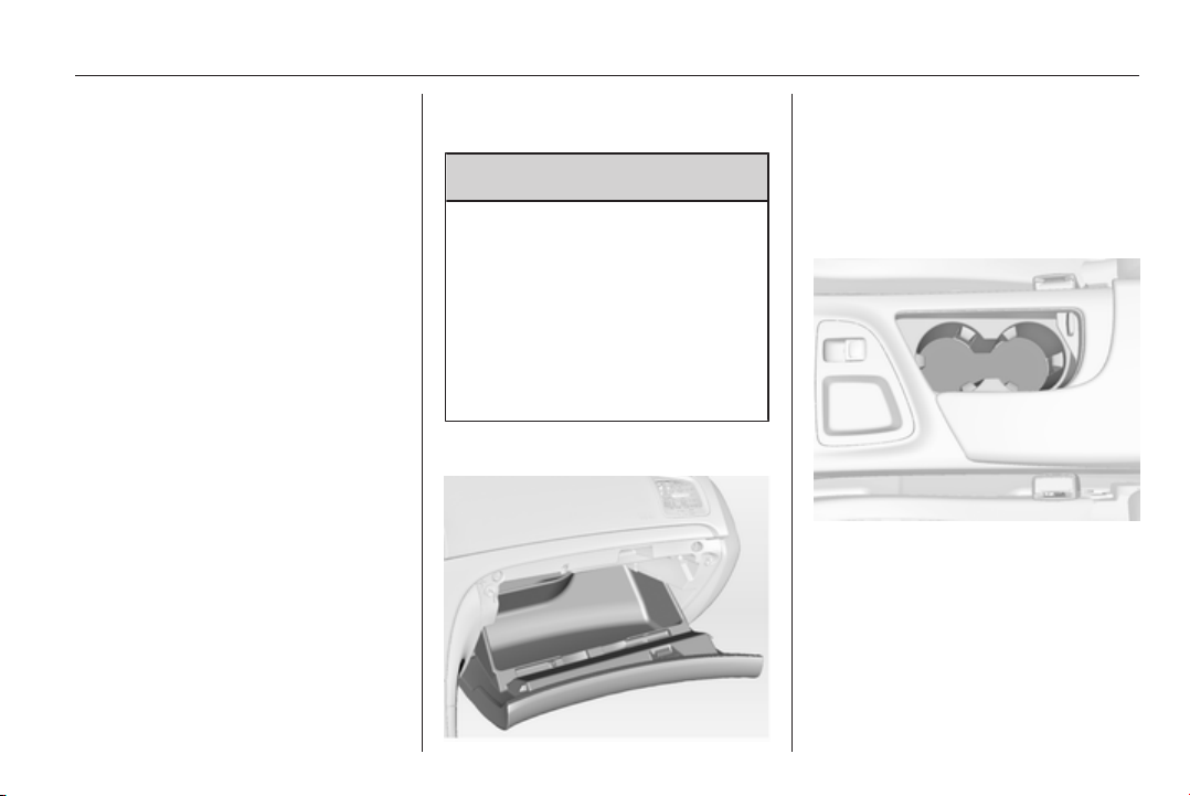
Storage 67
Storage
Storage compartments ................ 67
Load compartment ....................... 69
Roof rack system ......................... 79
Loading information ..................... 80
Storage compartments
9 Warning
Do not store heavy or sharp
objects in the storage
compartments. Otherwise, the
storage compartment lid could
open and vehicle occupants could
be injured by objects being thrown
around in the event of hard
braking, a sudden change in
direction or an accident.
Glovebox
The glovebox features a pen holder
and a coin holder.
The glovebox should be closed whilst
driving.
Cupholders
Cupholders are located in the centre
console.
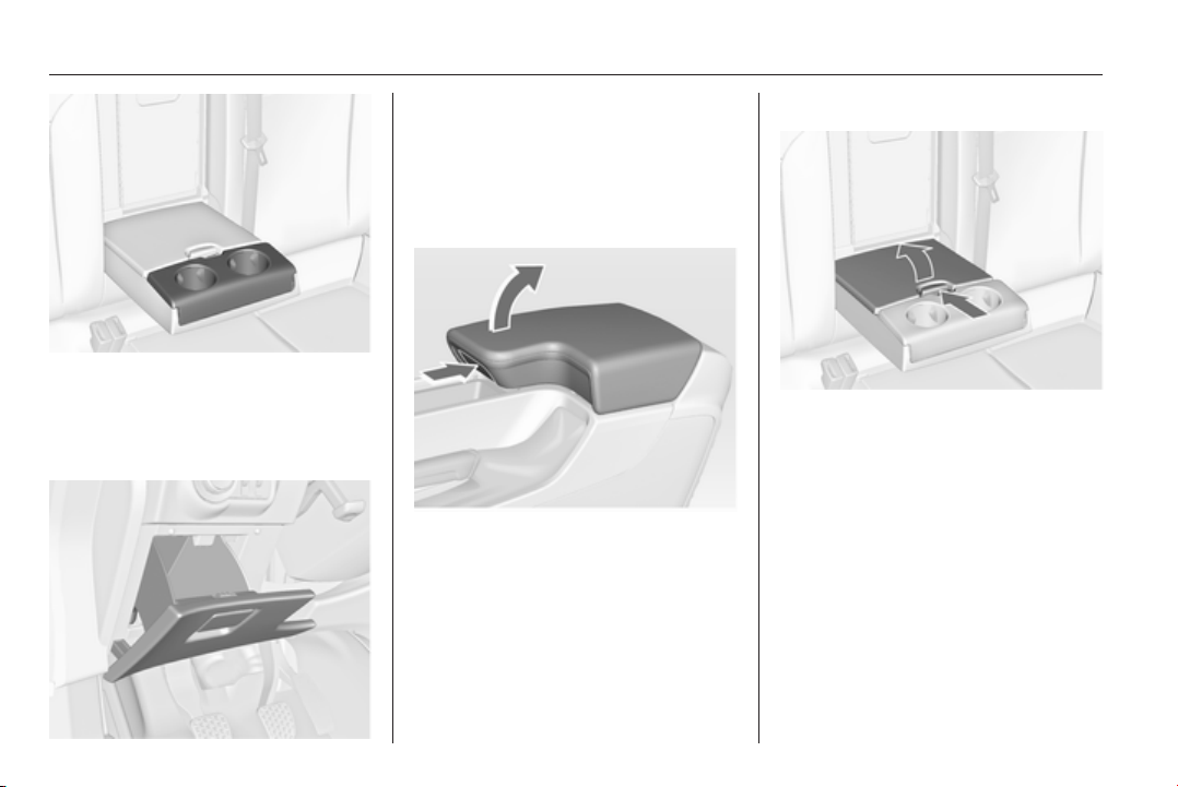
68 Storage
Additional cupholders are located in
the rear armrest. Fold down armrest.
Front storage
A storage compartment is located
next to the steering wheel.
Armrest storage
Storage in the front armrest
Push button to fold up the armrest.
Storage in the rear armrest
Fold down armrest and open cover.
Close cover before folding the
armrest up.
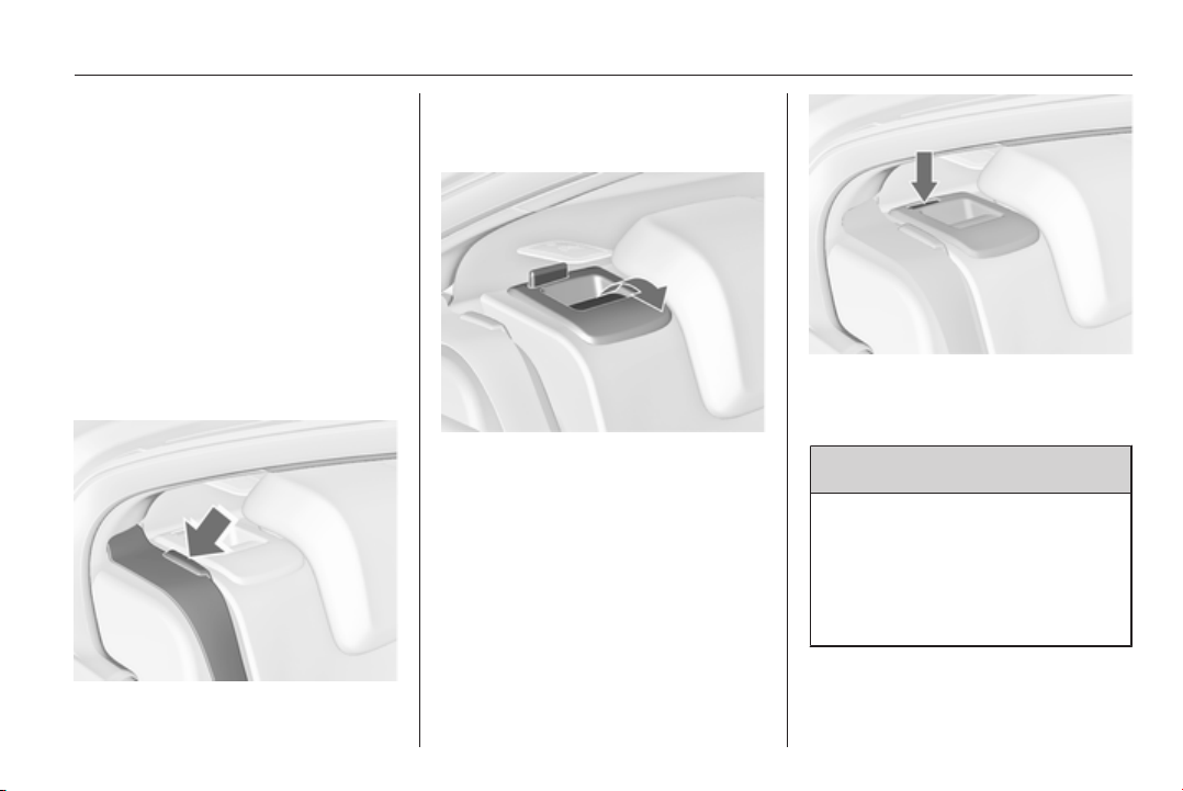
Storage 69
Load compartment
Folding down rear seat
backrests
The rear seat backrest is divided into
two parts. Both parts can be folded
down.
Remove the load compartment cover
if necessary.
Press and hold the catch, then push
the head restraints down.
Fold up the rear armrest.
Put the seat belts of the outboard
seats into the belt guides.
Pull the release lever on one or both
sides and fold down the backrests
onto the seat cushion.
To fold up, raise backrests and guide
them into an upright position until they
engage audibly.
Ensure that the seat belts of the
outboard seats are placed in the
corresponding belt guides.
The backrests are properly engaged
when both red marks on the side near
the release lever are no longer visible.
9 Warning
Only drive the vehicle when the
backrests are securely locked into
position. Otherwise there is a risk
of personal injury or damage to the
load or vehicle in the event of hard
braking or a collision.
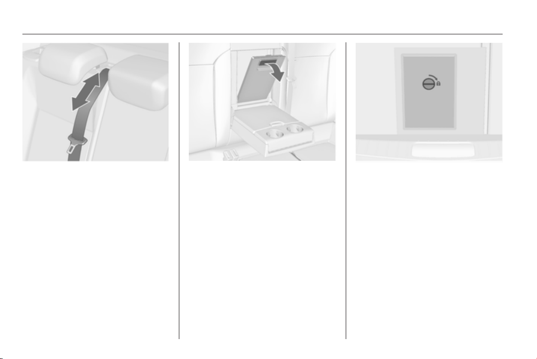
70 Storage
The seat belt of the centre seat could
be blocked when the backrest is
folded up too quickly. To unlock the
retractor, push in the seat belt or pull
it out by approx. 20 mm and then
release.
Opening the pass-through in the
rear centre backrest
Fold down rear armrest.
Pull grip and open the cover.
Suitable for loading long, narrow
objects.
Ensure the cover engages after
folding up.
The closed cover can be secured
from inside the load compartment.
Turn knob by 90°:
knob
horizontal
= cover secured from
the passenger
compartment side
knob
vertical
= cover not secured
Storage in the load
compartment
Depending on the equipment, there
are storage boxes under the load
compartment cover.
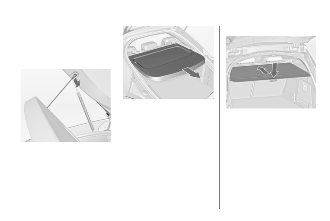
Storage 71
Load compartment cover
Do not place any objects on the cover.
5-door Hatchback
Removing cover
Unhook retaining straps from tailgate.
Pull cover from the side guides.
Fitting cover
Engage cover in side guides and fold
downwards. Attach the retaining
straps to the tailgate.
Sports Tourer, Country Tourer
Closing cover
Pull the cover towards the rear using
the handle until it engages in the
sideward retainers.
Opening cover
Push down the handle at the end of
the cover. It rolls up automatically.
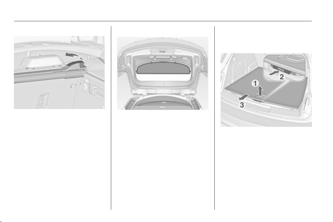
72 Storage
Removing cover
Open the load compartment cover.
Pull the release lever on the right side
up and hold it. Lift the cover first on
the right side and remove from
retainers.
The removed cover can be stored
under the load compartment floor
3 76.
Installing cover
Insert the left side of the load
compartment cover in the recess, pull
the release lever up and hold it, insert
the right side of the load compartment
cover and engage.
Blind at the tailgate
To cover the load compartment
completely, mount the blind at four
fixing points on the inside of the
tailgate.
Rear floor storage cover
Sliding floor cover (FlexFloor)
For a convenient setting of the load
compartment, the floor cover can be
pulled out.
Pulling out the floor cover
■ Raise the floor at the handle slightly
until the spring rolls pop-up on each
side.
■ Press the button under the handle
and pull out the floor cover until it
engages.
Load the floor in this position.
Sliding back into load compartment
■ Press the button under the handle
and slide in the floor cover until it
engages at the end position.
Leave the floor cover in the raised
position as long as it is loaded.
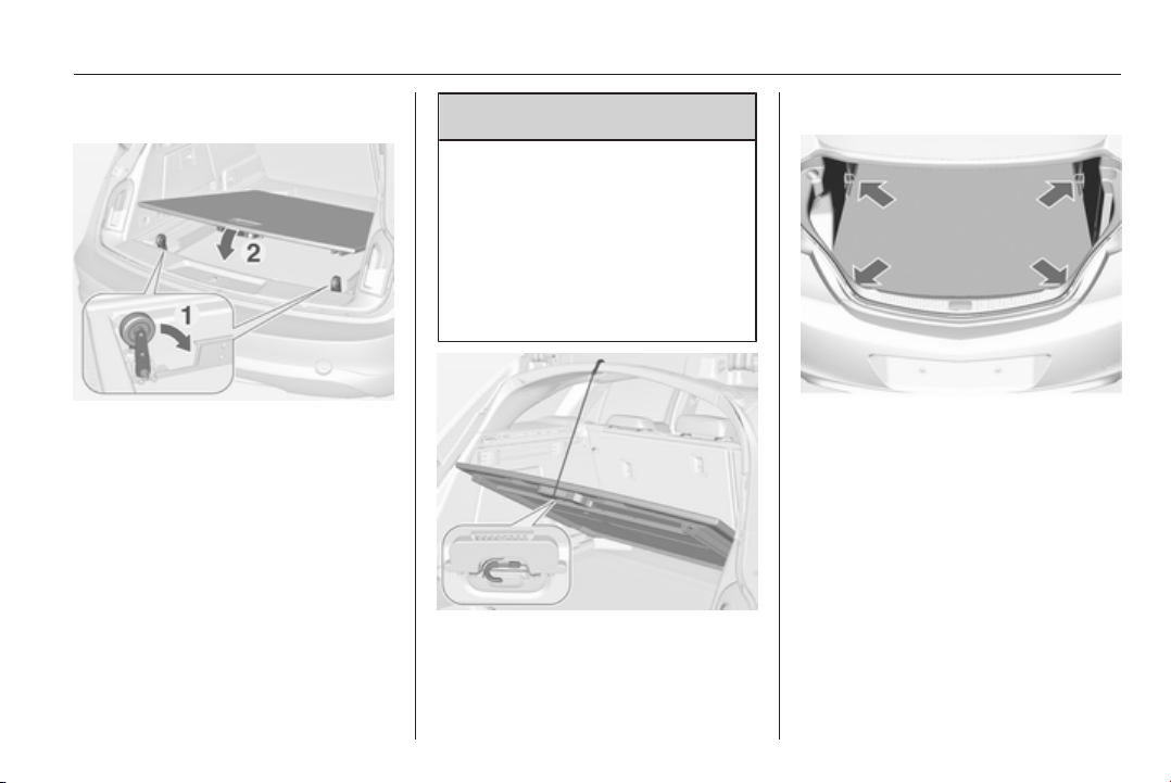
Storage 73
To return the floor cover to its
original position after unloading
■ Raise the floor cover at the handle
slightly and push down the spring
rolls on each side manually. Both
spring rolls must engage in
position.
■ Lower the floor cover.
The pulled out floor cover can be
loaded with max. 120 kg. A warning
label is shown on the floor cover.
Secure objects with lashing straps
attached to lashing eyes 3 73.
Loading information 3 80.
9
Warning
Do not load or unload the
compartment by using the sliding
floor cover when the vehicle is
parked on a slope, as the floor
cover could run uncontrolled into
the end positions.
Lift the floor cover up or down only
when unloaded. Danger of injury.
For access to the spare wheel or tyre
repair kit, lift up the floor cover and
attach the retaining strap at the upper
edge of the tailgate recess. Lift up and
attach the cover only without loading.
Lashing eyes
The lashing eyes are designed to
secure items against slippage, e.g.
using lashing straps or luggage net.
Cargo management
system
The FlexOrganizer is a flexible
system for dividing up the load
compartment.
The system consists of:
■ adapters,
■ mesh pockets,
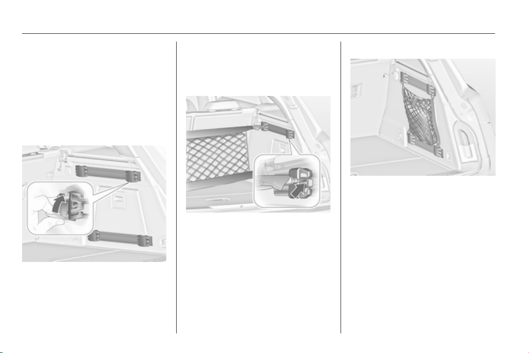
74 Storage
■ hooks,
■ service box,
■ strap set.
The components are fitted in rails on
both side panels using adapters and
hooks.
Installation of adapters in the
rails
Fold open the handle plate, insert the
adapter into the upper and lower
groove of the rail and move to the
required position. Turn the handle
plate upwards to lock the adapter. To
remove, turn the handle plate
downwards and move out of the rail.
Variable partition net
Insert adapters into the required
position in the rails. Stick together the
halves of the net rods.
To install, push rods together a little
and insert into the relevant openings
in the adapters.
To remove, press the net rods
together and remove from the
adapters.
Net pocket
Insert adapters into the required
position in the rails. The net pocket
can be suspended from the adapters.
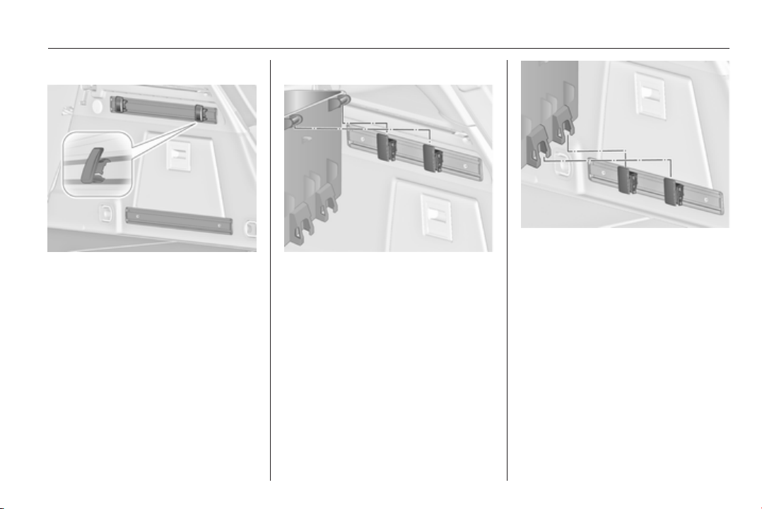
Storage 75
Installation of hooks in the rails
Insert the hook in the desired position
first into the upper groove of the rail
and then press into the lower groove.
To remove, first pull out of the upper
groove.
Service box
Install two hooks in the upper rail.
Insert the upper brackets of the box
from above into the hooks.
Alternatively install both hooks in the
lower rail. Plug in the lower brackets
of the box from above into the lower
hooks.
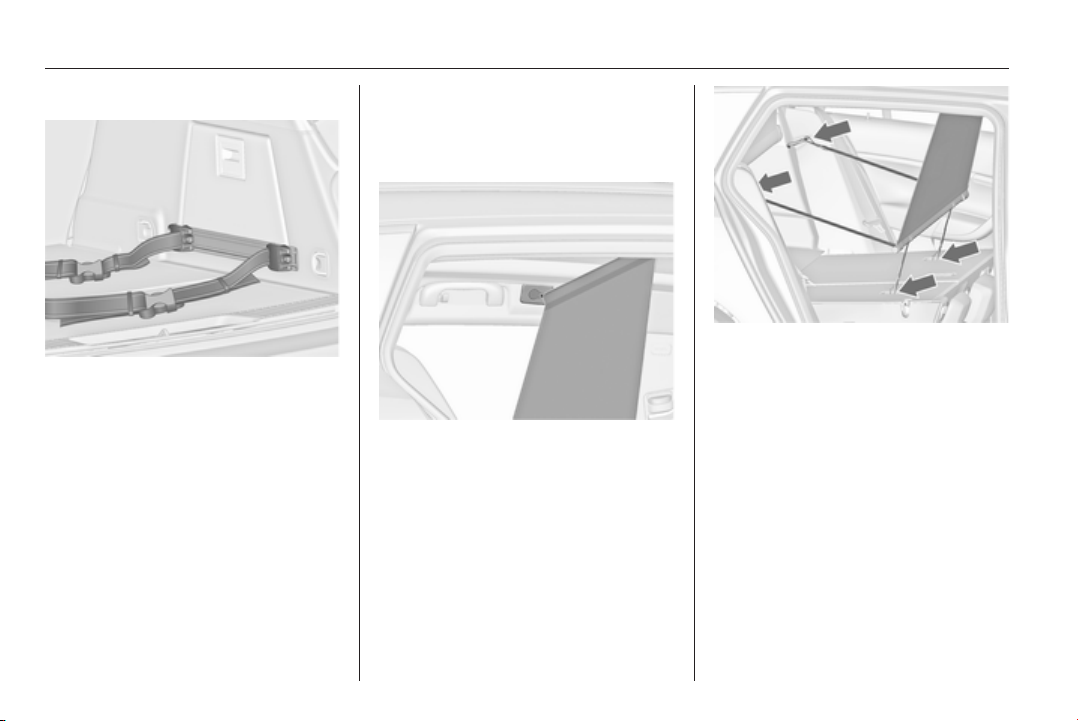
76 Storage
Strap set
Insert the adapters of the strap set
into a rail. Make sure that the belt is
not twisted.
The strap set has two locks to open.
The belt can be tightened.
Safety net
Two different safety nets can be
installed behind the front seats or rear
seats.
Passengers must not be transported
behind the safety net.
Safety net behind the front seats
Push head restraints of the rear seats
down and fold down rear seat
backrests 3 69.
Front installation openings in the roof
frame: latch rod of the net at one side,
compress rod and latch at the other
side.
Fit the hooks of the small belts into the
Top-Tether mounting loops on the
back side of the folded rear seat
backrests.
Fit the hooks of the wider belts into the
locking devices of the rear seat
backrests.
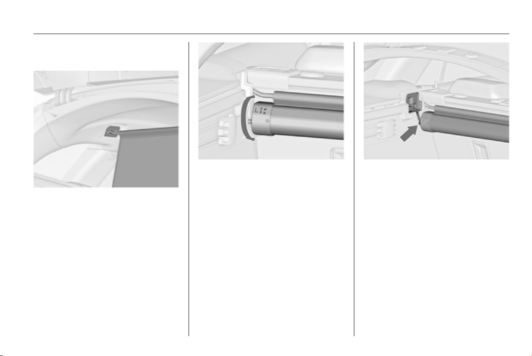
Storage 77
Safety net cassette behind the
rear seats
Pull out the net from the cassette and
latch the rod of the net at one side into
the rear installation opening in the
roof frame. Compress the rod and
latch at the other side.
Removal of the cassette
Roll up safety net.
Remove load compartment cover
3 71.
To unlock, turn cassette slightly
backwards and remove it upwards
from the retainers.
Installation of the cassette
Remove load compartment cover.
Insert the cassette into the retainers
on left and right side. Note the signs
L (left side) and R (right side) on the
cassette as an installation hint.
Turn cassette slightly forwards to
lock.
Stowage of safety nets and load
compartment cover
Rear safety net cassette can be
placed, together with the load
compartment cover and the coiled up
safety net, under the load
compartment floor.
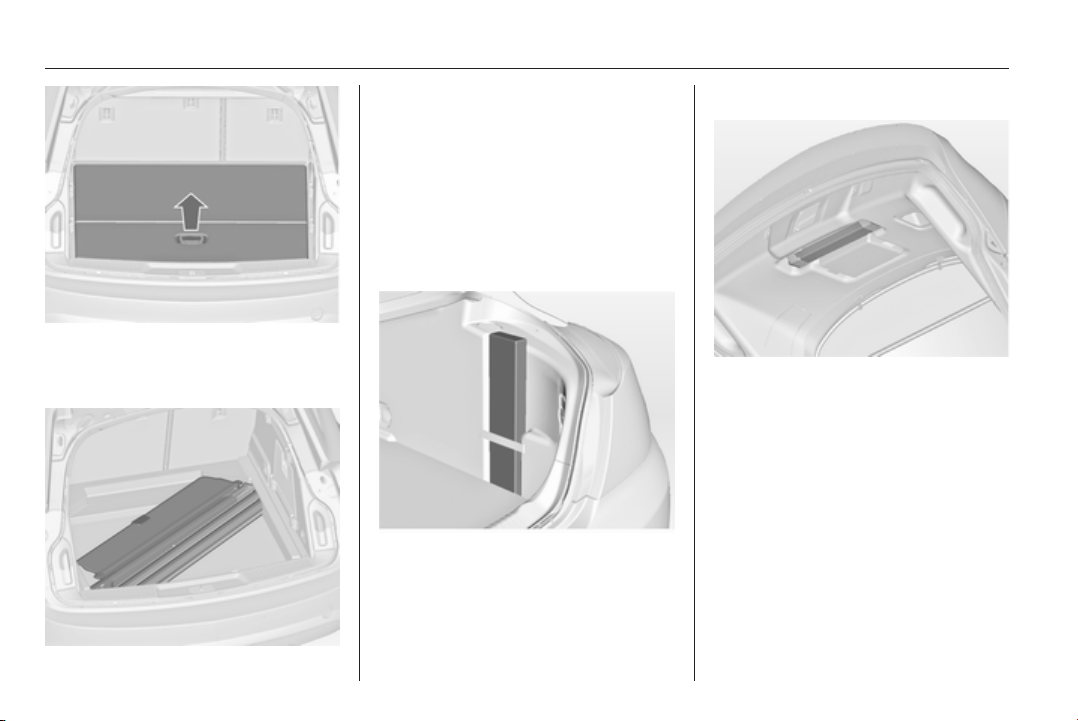
78 Storage
Open the load compartment floor by
pulling the handle. Fold and place the
floor behind the rear seats.
Put the load compartment cover into
the hollow with the upper side
downwards and with the release lever
in the front right edge.
Warning triangle
5-door Hatchback/4-door
Saloon
Stow the warning triangle in the space
behind the strap on the right side of
the load compartment.
Sports Tourer, Country Tourer
Stow the warning triangle in the space
behind the straps on the inside of the
tailgate.
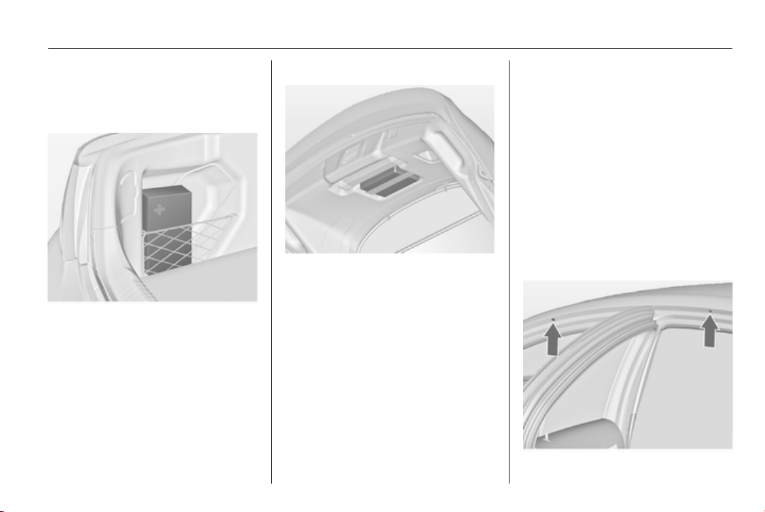
Storage 79
First aid kit
5-door Hatchback/4-door
Saloon
Stow the first aid kit in the space
behind the mesh net on the left side
of the load compartment.
Sports Tourer, Country Tourer
Stow the first aid kit in the space
behind a strap on the inside of the
tailgate.
Roof rack system
Roof rack
For safety reasons and to avoid
damage to the roof, the vehicle
approved roof rack system is
recommended.
Follow the installation instructions
and remove the roof rack when not in
use.
Mounting roof rack
5-door Hatchback/4-door Saloon
Open all doors.
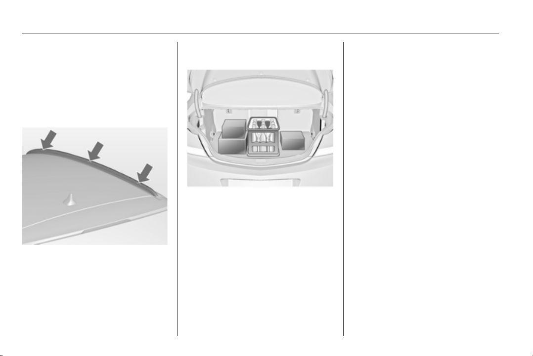
80 Storage
Mounting points are located in each
door frame of the vehicle body.
Detach the cover from each mounting
point and fasten the roof rack with the
attached screws.
Sports Tourer/Country Tourer with
roof railing
To fasten the roof rack, insert the
mounting bolts in the holes indicated
in the figure.
Loading information
■ Heavy objects in the load
compartment should be placed
against the seat backrests. Make
sure that the backrests are securely
engaged, i.e. no longer showing the
red markings on the side near the
release lever. If objects can be
stacked, heavier objects should be
placed at the bottom.
■ Secure objects with lashing straps
attached to lashing eyes 3 73.
■ Secure loose objects in the load
compartment to prevent from
sliding.
■ When transporting objects in the
load compartment, the backrests of
the rear seats must not be angled
forward.
■ Do not allow the load to protrude
above the upper edge of the
backrests.
■ Do not place any objects on the
load compartment cover or the
instrument panel, and do not cover
the sensor on top of the instrument
panel.
■ The load must not obstruct the
operation of the pedals, parking
brake and gear selector, or hinder
the freedom of movement of the
driver. Do not place any unsecured
objects in the interior.
■ Do not drive with an open load
compartment.

Storage 81
9 Warning
Always make sure that the load in
the vehicle is securely stowed.
Otherwise objects can be thrown
around inside the vehicle and
cause personal injury or damage
to the load or car.
■ The payload is the difference
between the permitted gross
vehicle weight (see identification
plate 3 264) and the EC kerb
weight.
To calculate the payload, enter the
data for your vehicle in the Weights
table at the front of this manual.
The EC kerb weight includes
weights for the driver (68 kg),
luggage (7 kg) and all fluids (tank
90 % full).
Optional equipment and
accessories increase the kerb
weight.
■ Driving with a roof load increases
the sensitivity of the vehicle to
cross-winds and has a detrimental
effect on vehicle handling due to
the vehicle's higher centre of
gravity. Distribute the load evenly
and secure it properly with retaining
straps. Adjust the tyre pressure and
vehicle speed according to the load
conditions. Check and retighten the
straps frequently.
Do not drive faster than 120 km/h.
The permissible roof load is
100 kg. The roof load is the
combined weight of the roof rack
and the load.
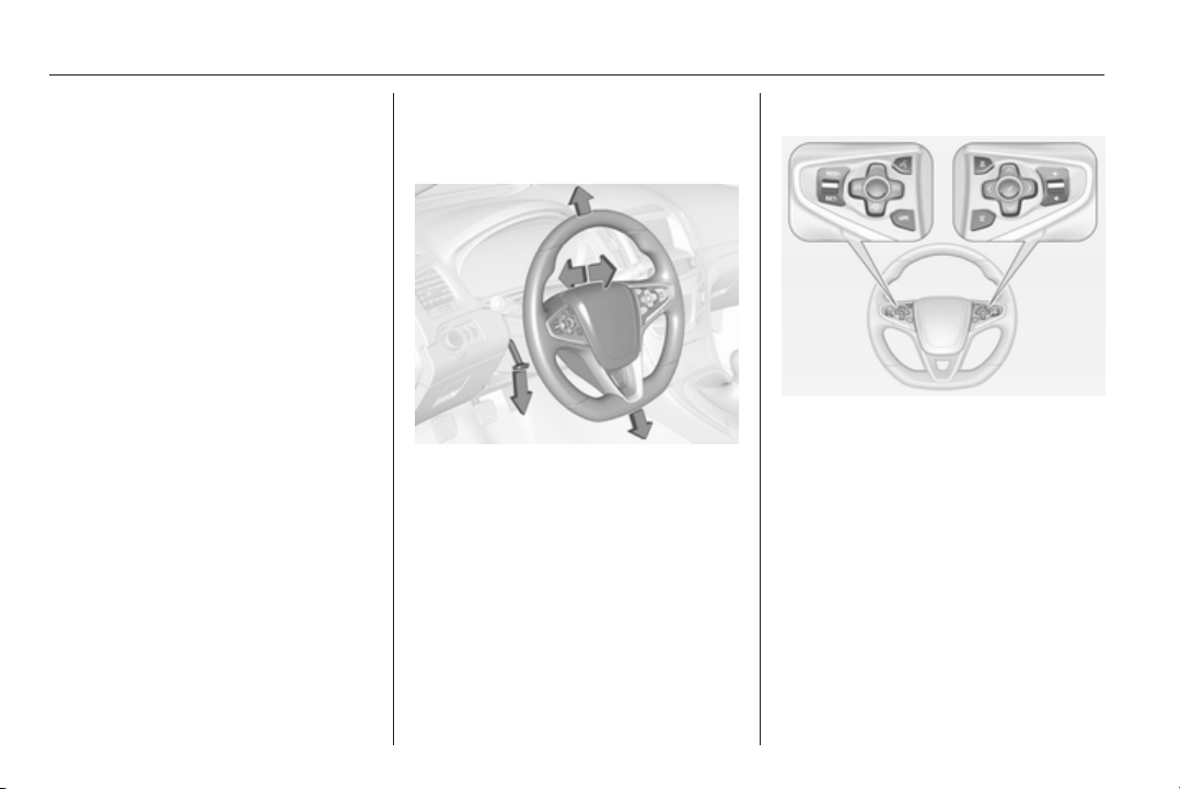
82 Instruments and controls
Instruments and
controls
Controls ....................................... 82
Warning lights, gauges and indi‐
cators ........................................... 91
Information displays ................... 107
Vehicle messages ...................... 116
Vehicle personalisation .............. 118
Controls
Steering wheel adjustment
Unlock lever, adjust steering wheel,
then engage lever and ensure it is
fully locked.
Do not adjust steering wheel unless
vehicle is stationary and steering
wheel lock has been released.
Steering wheel controls
Driver Information Centre, some
driver assistance systems,
Infotainment system and a connected
mobile phone can be operated via the
controls on the steering wheel.
Driver Information Centre 3 107.
Driver assistance systems 3 171.
Further information is available in the
Infotainment system manual.
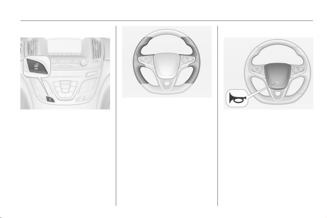
Instruments and controls 83
Heated steering wheel
Activate heating by pressing *
button. Activation is indicated by the
LED in the button.
The recommended grip areas of the
steering wheel are heated quicker
and to a higher temperature than the
other areas.
Heating is operational when the
engine is running and during an
Autostop.
Stop-start system 3 153.
Horn
Press j.
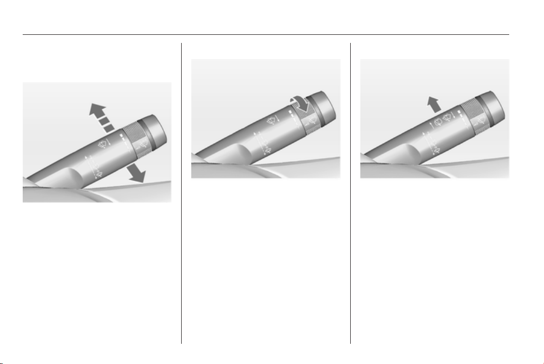
84 Instruments and controls
Windscreen wiper/washer
Windscreen wiper
2 = fast
1 = slow
P
= interval wiping
§
= off
For a single wipe when the
windscreen wiper is off, press the
lever down.
Do not use if the windscreen is frozen.
Switch off in car washes.
Adjustable wiper interval
Wiper lever in position P.
Turn the adjuster wheel to adjust the
desired wipe interval:
short
interval
= turn adjuster wheel
upwards
long
interval
= turn adjuster wheel
downwards
Automatic wiping with rain sensor
P
= automatic wiping with rain
sensor
The rain sensor detects the amount of
water on the windscreen and
automatically regulates the frequency
of the windscreen wiper.
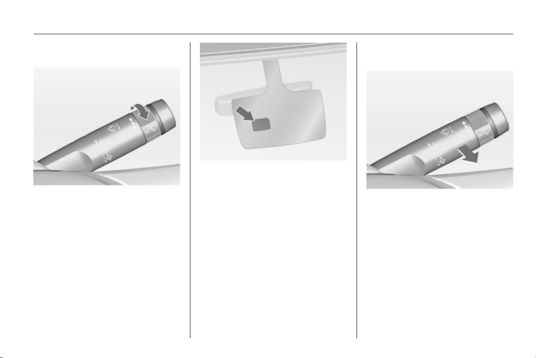
Instruments and controls 85
Adjustable sensitivity of the rain
sensor
Turn the adjuster wheel to adjust the
sensitivity:
low
sensitivity
= turn adjuster wheel
downwards
high
sensitivity
= turn adjuster wheel
upwards
Keep the sensor free from dust, dirt
and ice.
Rain sensor function can be activated
or deactivated in the Vehicle
personalisation.
Select the relevant setting in Settings,
I Vehicle in the Colour-Info-Display.
Colour-Info-Display 3 114.
Vehicle personalisation 3 118.
Windscreen and headlight
washer
Pull lever. Washer fluid is sprayed
onto the windscreen and the wiper
wipes a few times.
If the headlights are on, washer fluid
is also sprayed onto the headlights,
provided that the lever is pulled
sufficiently long. Afterwards the
headlight washer system is
inoperable for 5 wash cycles or until
engine or headlights have been
switched off and on again.
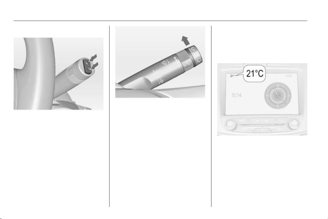
86 Instruments and controls
Rear window wiper/washer
Push the rocker switch to activate the
rear window wiper:
upper
position
= continuous
operation
lower
position
= intermittent
operation
middle
position
= off
Push lever. Washer fluid is sprayed
onto the rear window and the wiper
wipes a few times.
Do not use if the rear window is
frozen.
Switch off in car washes.
The rear window wiper comes on
automatically when the windscreen
wiper is switched on and reverse gear
is engaged.
Activation or deactivation of this
function can be changed in the menu
Settings in the Info-Display.
Vehicle personalisation 3 118.
The rear window washer system is
deactivated when the fluid level is
low.
Outside temperature
A drop in temperature is indicated
immediately and a rise in temperature
after a time delay.
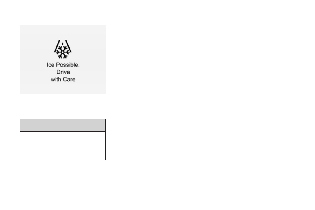
Instruments and controls 87
If outside temperature drops to 3 °C,
a warning message is displayed in the
Driver Information Centre.
9 Warning
The road surface may already be
icy even though the display
indicates a few degrees above
0 °C.
Clock
Date and time are shown in the
Colour-Info-Display. Colour-Info-
Display operation 3 114
4.2'' Display
Operate the display by the buttons
below the display.
Press the ; button and then select
the Settings icon by turning and
pressing MENU button.
Select Time menu page.
Set time
Select the Set Time menu item to
enter the respective submenu.
Select the Auto Set screen button at
the bottom of the screen. Activate
either On - RDS mode or Off - Manual
mode.
If Off - Manual mode is selected,
adjust hours and minutes by turning
and pressing MENU button.
Repeatedly select the 12-24 Hr
screen button at the bottom of the
screen to choose a time mode.
If 12-hour mode is selected, a third
column for AM and PM setting is
displayed. Select the desired option.
In On - RDS Mode the RDS signal of
most VHF transmitters automatically
sets the time. RDS time
synchronisation can take a few
minutes. Some transmitters do not
send a correct time signal. In such
cases, it is recommended to switch off
automatic time synchronisation.
Set date
Date is set automatically.
Return to homepage by pressing ;.
For further information, see
Infotainment system manual
8'' Display
Press the ; button and then select
the Settings icon. Inputs can be done
directly by the finger on the touch
screen icons.
Select Time and Date menu page.
Set time
Select the Set Time menu item to
enter the respective submenu.
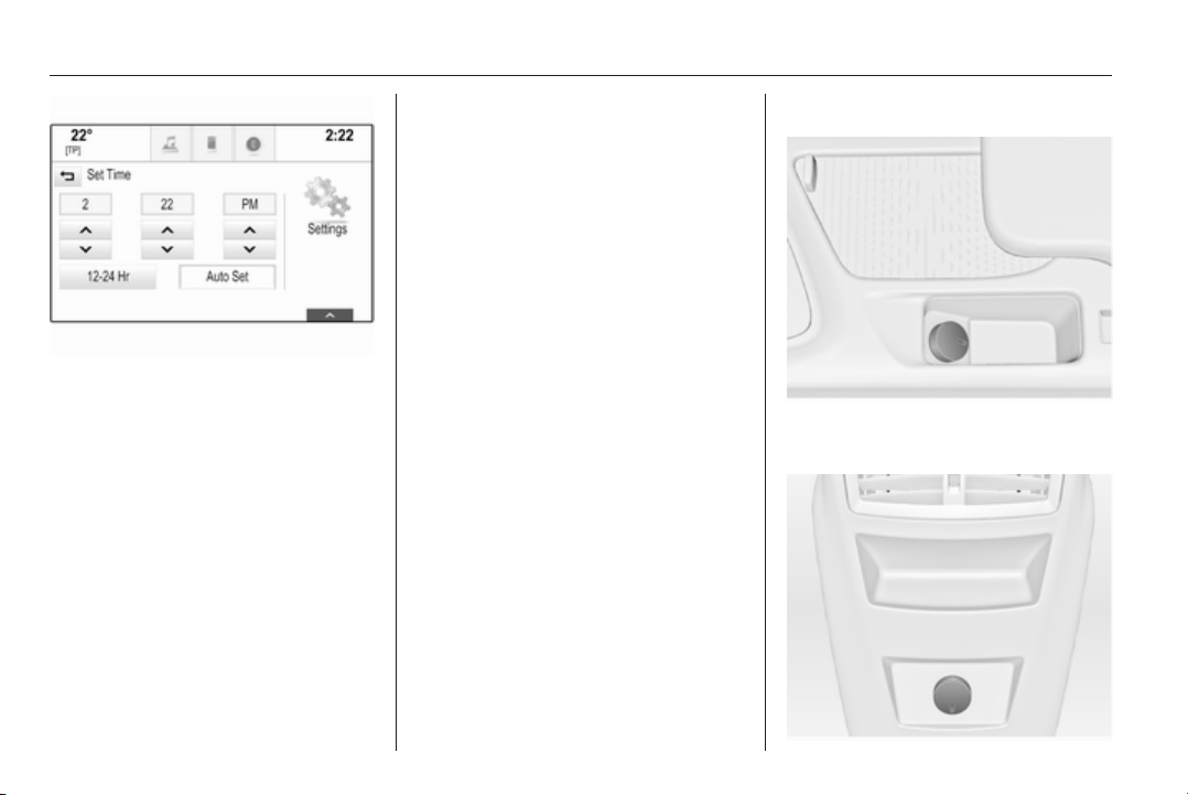
88 Instruments and controls
Select the Auto Set screen button at
the bottom of the screen. Activate
either On - RDS mode or Off - Manual
mode.
If Off - Manual mode is selected,
adjust hours and minutes using hg
screen buttons.
Tap on the 12-24 Hr screen button on
the right side of the screen to select a
time mode.
If 12-hour mode is selected, a third
column for AM and PM setting is
displayed. Select the desired option.
In On - RDS Mode the RDS signal of
most VHF transmitters automatically
sets the time. RDS time
synchronisation can take a few
minutes. Some transmitters do not
send a correct time signal. In such
cases, it is recommended to switch off
automatic time synchronisation.
Set date
Select the Set Date menu item to
enter the respective submenu.
Select the Auto Set screen button at
the bottom of the screen. Activate
either On - RDS mode or Off - Manual
mode.
If Off - Manual mode is selected,
adjust the date using the hor g
screen buttons.
In On - RDS mode date is set
automatically.
Return to homepage by pressing ;.
For further information, see
Infotainment system manual.
Power outlets
12 Volt power outlets are located in
the front and rear centre console.
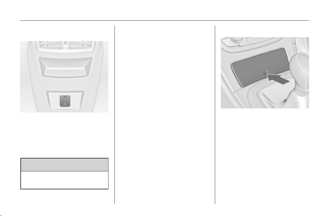
Instruments and controls 89
Do not exceed the maximum power
consumption of 120 watts.
A 230 Volt power outlet is located in
the rear centre console. If ignition is
on and a device is plugged in, an LED
in the outlet illuminates green.
Do not exceed the maximum power
consumption of 150 watts.
9 Danger
Power outlet works under high
electrical voltage!
With ignition off the power outlets are
deactivated. Additionally the power
outlets are deactivated in the event of
low vehicle battery voltage.
Electrical accessories that are
connected must comply with the
electromagnetic compatibility
requirements laid down in
DIN VDE 40 839.
Do not connect any current-delivering
accessories, e.g. electrical charging
devices or batteries.
Do not damage the outlets by using
unsuitable plugs.
Stop-start system 3 153.
Cigarette lighter
The cigarette lighter is located behind
the ashtray cover.
Press ashtray cover to open.
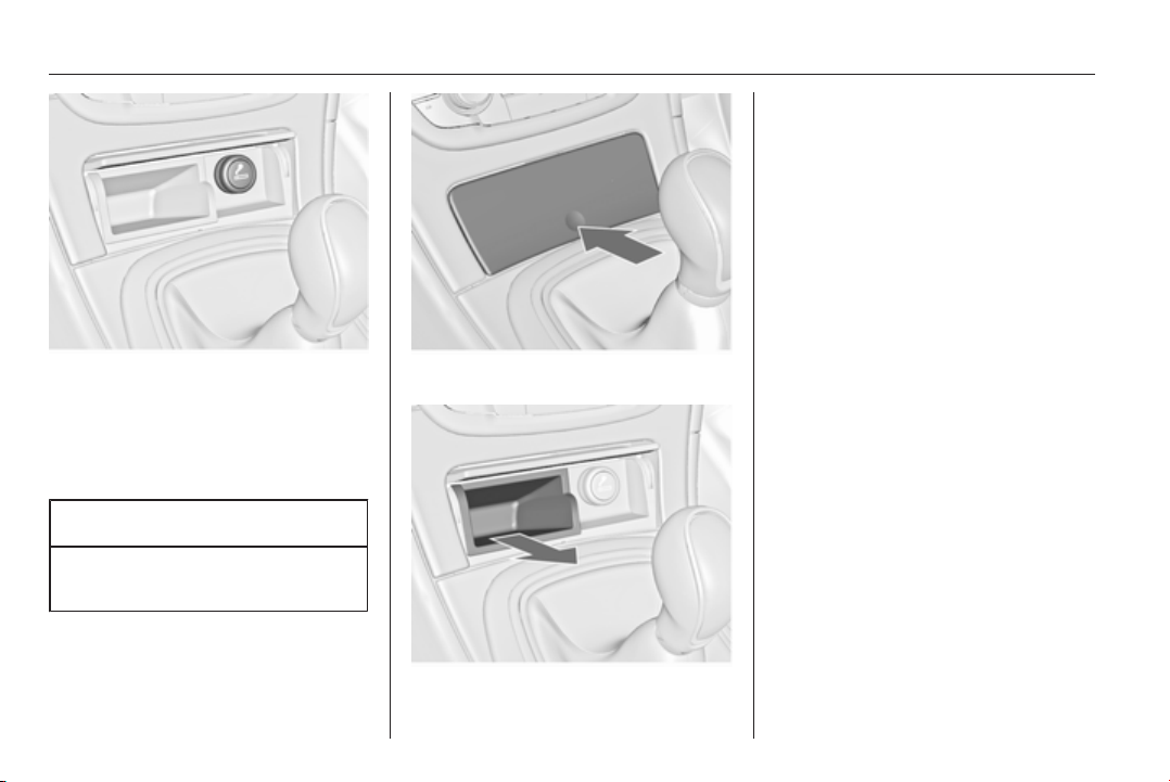
90 Instruments and controls
Press in cigarette lighter. It switches
off automatically once the element is
glowing. Pull out lighter.
Ashtrays
Caution
To be used only for ash and not for
combustible rubbish.
Press ashtray cover to open.
To empty, grip both sides of the
ashtray insert and remove.

Instruments and controls 91
Warning lights, gauges
and indicators
Instrument cluster
Depending on the version, three
instrument clusters are available:
■ Baselevel
■ Midlevel
■ Uplevel
Uplevel instrument cluster can be
displayed as Sport mode or Tour
mode.
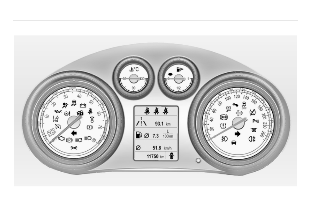
92 Instruments and controls
Baselevel instrument cluster
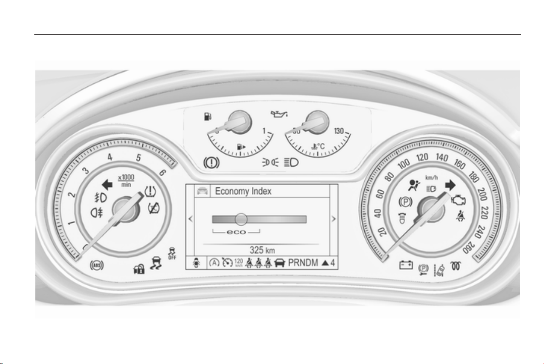
Instruments and controls 93
Midlevel instrument cluster
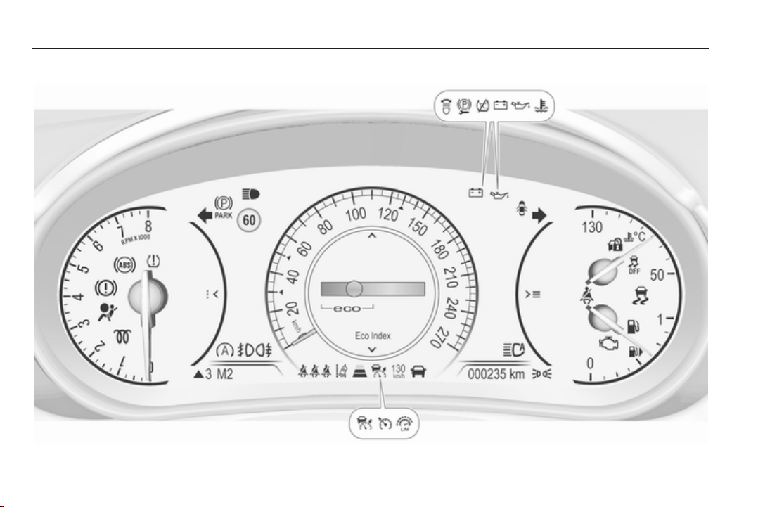
94 Instruments and controls
Uplevel instrument cluster, Sport mode
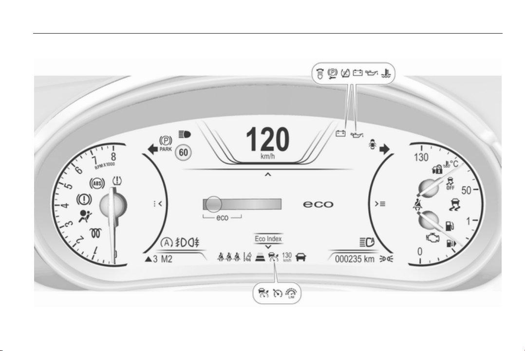
Instruments and controls 95
Uplevel instrument cluster, Tour mode

96 Instruments and controls
Speedometer
Indicates vehicle speed.
Odometer
The total recorded distance is
displayed in km.
Trip odometer
The recorded distance since the last
reset is displayed on the trip computer
page. Two trip odometer are
selectable for different trips.
Baselevel instrument cluster
Select between page W1 and
pageW2 by turning the adjuster
wheel on turn signal lever.
Each trip odometer can be reset
separately when ignition is on: select
respective page, hold the reset knob
depressed for a few seconds or press
the SET/CLR button on the turn signal
lever.
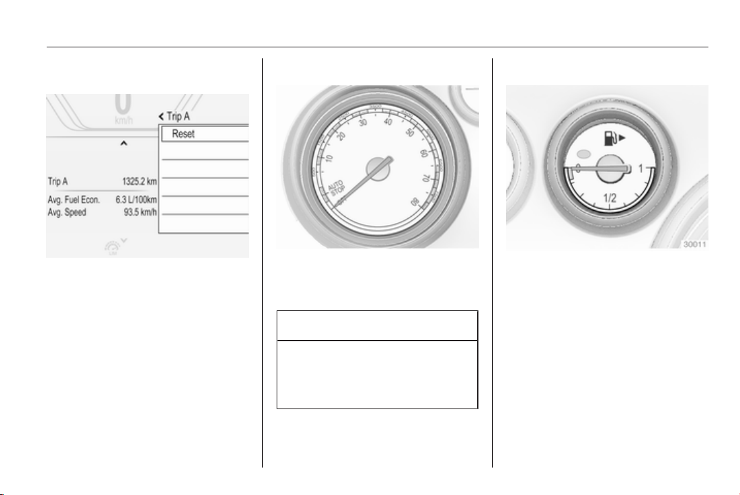
Instruments and controls 97
Midlevel and Uplevel instrument
cluster
Select page Trip A or Trip B in the
Info page by pressing steering wheel
button o.
Each trip odometer can be reset
separately when ignition is on: select
respective page, press >. Confirm by
pressing 9.
General
Trip odometer counts up to a distance
of 2000 km and then restarts at 0.
Driver Information Centre 3 107.
Tachometer
Displays the engine speed.
Drive in a low engine speed range for
each gear as much as possible.
Caution
If the needle is in the red warning
zone, the maximum permitted
engine speed is exceeded. Engine
at risk.
Fuel gauge
Displays the fuel level or gas level in
the tank depending on the operation
mode.
Control indicator i or Y illuminates if
the level in the tank is low. Refuel
immediately if it flashes.
During liquid gas operation, the
system automatically switches over to
petrol operation when gas tanks are
empty 3 98.
Never run the tank dry.
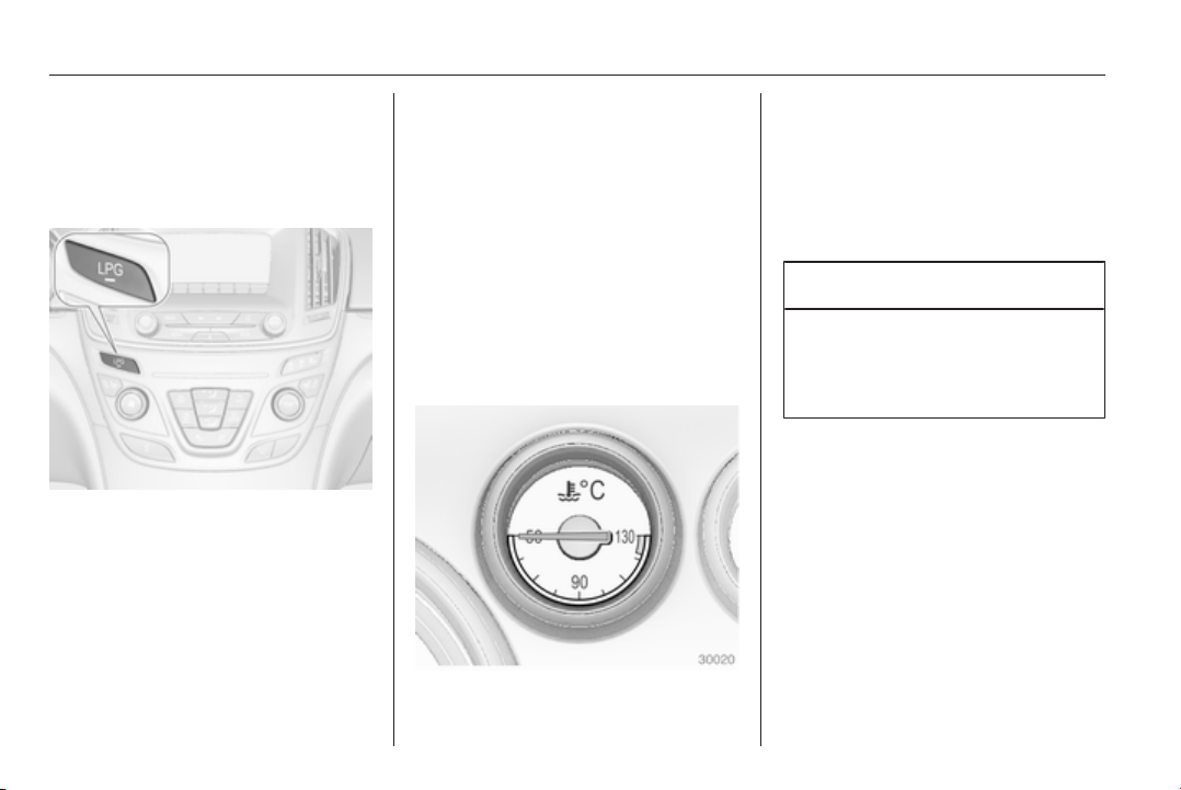
98 Instruments and controls
Because of the fuel remaining in the
tank, the top-up quantity may be less
than the specified tank capacity.
Fuel selector
Pressing button LPG switches
between petrol and liquid gas
operation. The status LED 1 shows
the current operating mode.
1 off = petrol operation
1 illuminates = liquid gas
operation
1 flashes = no switching is
possible, one type
of fuel is empty
As soon as the liquid gas tank is
empty, petrol operation is
automatically engaged until the
ignition is switched off.
After the engine is started, the LED
1 is sometimes off. If the LPG button
is pressed twice in this situation, the
LED 1 starts flashing.
Fuel for liquid gas operation 3 203.
Engine coolant
temperature gauge
Displays the coolant temperature.
50° = engine operating
temperature not yet
reached
90°
(central
area)
= normal operating
temperature
130° = temperature too high
Caution
If engine coolant temperature is
too high, stop vehicle, switch off
engine. Danger to engine. Check
coolant level.
Service display
The engine oil life system lets you
know when to change the engine oil
and filter. Based on driving
conditions, the interval at which an
engine oil and filter change will be
indicated can vary considerably.
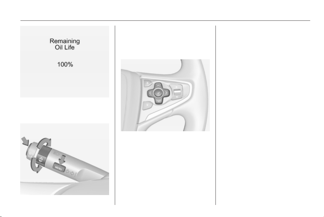
Instruments and controls 99
The remaining oil life duration menu
is displayed in the Driver Information
Centre 3 107.
On Baselevel display select the
Settings Menu by pressing the
MENU button on the turn signal lever.
Turn the adjuster wheel to select the
Remaining Oil Life page.
On Midlevel and Uplevel display
select Info Menu by pressing p on
steering wheel. Press P to select
Remaining Oil Life page.
Remaining oil life duration is indicated
in %.
Reset
On Baselevel display press the SET/
CLR button on turn signal lever for
several seconds to reset. The ignition
must be switched on but engine not
running.
On Midlevel or Uplevel display press
> on steering wheel to open the
subfolder. Select Reset and confirm
by pressing 9 for several seconds.
The ignition must be switched on but
engine not running.
The system must be reset every time
the engine oil is changed to allow
proper functionality. Seek the
assistance of a workshop.
Next service
When the system has calculated that
engine oil life has been diminished,
Change Engine Oil Soon appears in
the Driver Information Centre. Have
engine oil and filter changed by a
workshop within one week or
500 km (whichever occurs first).
Service information 3 261.

100 Instruments and controls
Control indicators
The control indicators described are
not present in all vehicles. The
description applies to all instrument
versions. Depending on the
equipment, the position of the control
indicators may vary. When the
ignition is switched on, most control
indicators will illuminate briefly as a
functionality test.
The control indicator colours mean:
red = danger, important
reminder
yellow = warning, information, fault
green = confirmation of activation
blue = confirmation of activation
white = confirmation of activation
See all control indicators on different
instrument clusters 3 91.
Turn signal
O illuminates or flashes green.
Illuminates briefly
The parking lights are switched on.
Flashes
A turn signal or the hazard warning
flashers are activated.
Rapid flashing: failure of a turn signal
light or associated fuse, failure of turn
signal light on trailer.
Bulb replacement 3 222, Fuses
3 232.
Turn signals 3 128.
Seat belt reminder
Seat belt reminder on front
seats
X for driver's seat illuminates or
flashes red in the instrument cluster.
k for front passenger seat illuminates
or flashes red in the centre console,
when seat is occupied.
Illuminates
After the ignition has been switched
on until the seat belt has been
fastened.
Flashes
After having started the engine for a
maximum of 100 seconds until the
seat belt has been fastened.
Seat belt status on rear seats,
base level instrument cluster
X flashes or illuminates in the Driver
Information Centre.
Illuminates
After the ignition has been switched
on when the seat belt has been
fastened.
Flashes
After starting off when the seat belt is
unfastened.
Fastening the seat belt 3 55.
Seat belt status on rear seats,
midlevel and uplevel instrument
cluster
X illuminates red or green or grey in
the instrument cluster, after the
ignition has been switched on.
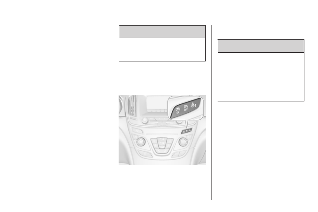
Instruments and controls 101
Illuminates red
Seat occupied and the seat belt is
unfastened.
Illuminates green
Seat occupied and the seat belt has
been fastened.
Illuminates grey
Seat not occupied.
Fastening the seat belt 3 55.
Airbag and belt tensioners
v illuminates red.
When the ignition is switched on, the
control indicator illuminates for
approx. 4 seconds. If it does not
illuminate, does not go out after
4 seconds or illuminates whilst
driving, there is a fault in the airbag
system. Seek the assistance of a
workshop. The airbags and belt
pretensioners may fail to trigger in the
event of an accident.
Deployment of the belt pretensioners
or airbags is indicated by continuous
illumination of v.
9
Warning
Have the cause of the fault
remedied immediately by a
workshop.
Belt pretensioners, airbag system
3 54, 3 58.
Airbag deactivation
V illuminates yellow.
The front passenger airbag is
activated.
* illuminates yellow.
The front passenger airbag is
deactivated 3 60.
9 Danger
Risk of fatal injury for a child using
a child restraint system together
with activated front passenger
airbag.
Risk of fatal injury for an adult
person with deactivated front
passenger airbag.
Charging system
p illuminates red.
Illuminates when the ignition is
switched on and extinguishes shortly
after the engine starts.
Illuminates when the engine is
running
Stop, switch off engine. Vehicle
battery is not charging. Engine
cooling may be interrupted. The
brake servo unit may cease to be
effective. Seek the assistance of a
workshop.
102 Instruments and controls
Malfunction indicator light
Z illuminates or flashes yellow.
Illuminates when the ignition is
switched on and extinguishes shortly
after the engine starts.
Illuminates when the engine is
running
Fault in the emission control system.
The permitted emission limits may be
exceeded. Seek the assistance of a
workshop immediately.
Flashes when the engine is
running
Fault that could lead to catalytic
converter damage. Ease up on the
accelerator until the flashing stops.
Seek the assistance of a workshop
immediately.
Brake and clutch system
Brake and clutch fluid level
R illuminates red.
The brake and clutch fluid level is too
low 3 218.
9
Warning
Stop. Do not continue your
journey. Consult a workshop.
Illuminates after the ignition is
switched on if the manual parking
brake is applied 3 164.
Operate pedal
- illuminates or flashes yellow.
Illuminates
Brake pedal needs to be operated to
release the electric parking brake
3 164.
Clutch pedal needs to be operated to
start the engine. Stop-start system
3 153.
Flashes
Clutch pedal needs to be operated to
start the engine 3 151.
Electric parking brake
m illuminates or flashes red.
Illuminates
Electric parking brake is applied
3 164.
Flashes
Electric parking brake is not fully
applied or released. Depress the
brake pedal and attempt to reset the
system by first releasing and then
applying the electric parking brake. If
m remains flashing, do not drive and
seek the assistance of a workshop.
Electric parking brake fault
j illuminates or flashes yellow.
Illuminates
Electric parking brake is operating
with degraded performance 3 164.
Flashes
Electric parking brake is in service
mode. Stop vehicle, apply and
release the electric parking brake to
reset.

Instruments and controls 103
9 Warning
Have the cause of the fault
remedied immediately by a
workshop.
Antilock brake system
(ABS)
u illuminates yellow.
Illuminates for a few seconds after the
ignition is switched on. The system is
ready for operation when the control
indicator extinguishes.
If the control indicator does not go out
after a few seconds, or if it illuminates
while driving, there is a fault in the
ABS. The brake system remains
operational but without ABS
regulation.
Antilock brake system 3 163.
Upshift
[ is shown as a symbol in the Driver
Information Centre, when upshifting
is recommended for fuel saving
reasons.
On some versions gear shift
indication is popped up as full page in
the Driver Information Centre 3 107.
Gear shifting
R or S with the number of the next
higher or lower gear is indicated,
when up- or down-shifting is
recommended.
Variable effort steering
c illuminates yellow.
Fault in variable effort steering
system. This may lead to a higher or
lower steering effort. Consult a
workshop.
Following distance
E indicates the following distance
setting of adaptive cruise control or
the alert timing sensitivity of forward
collision alert by filled distance bars.
Adaptive cruise control 3 173.
Forward collision alert 3 181.
Lane departure warning
) illuminates green or flashes yellow.
Illuminates green
The system is switched on and ready
to operate.
Flashes yellow
The system recognizes an
unintended lane change.
Ultrasonic parking assist
r illuminates yellow.
Fault in system
or
Fault due to sensors that are dirty or
covered by ice or snow
or
Interference due to external sources
of ultrasound. Once the source of
interference is removed, the system
will operate normally.
Have the cause of the fault in the
system remedied by a workshop.
Ultrasonic parking assist 3 187.

104 Instruments and controls
Electronic Stability Control
off
n illuminates yellow.
The system is deactivated.
Electronic Stability Control
and Traction Control
system
b illuminates or flashes yellow.
Illuminates
A fault in the system is present.
Continued driving is possible. Driving
stability, however, may deteriorate
depending on road surface
conditions.
Have the cause of the fault remedied
by a workshop.
Flashes
The system is actively engaged.
Engine output may be reduced and
the vehicle may be braked
automatically to a small degree.
Electronic Stability Control 3 167,
Traction Control system 3 166.
Traction Control system off
k illuminates yellow.
The system is deactivated.
Preheating
! illuminates yellow.
Preheating is activated. Only
activates when outside temperature
is low.
Diesel particle filter
% illuminates or flashes yellow.
The diesel particle filter requires
cleaning.
Continue driving until %
extinguishes. If possible, do not allow
engine speed to drop below
2000 rpm.
Illuminates
The diesel particle filter is full. Start
cleaning process as soon as
possible.
Flashes
The maximum filling level of the filter
is reached. Start cleaning process
immediately to avoid damage to the
engine.
Diesel particle filter 3 156, Stop-start
system 3 153.
Tyre pressure monitoring
system
w illuminates or flashes yellow.
Illuminates
Tyre pressure loss. Stop immediately
and check tyre pressure.
Flashes
Fault in system or tyre without
pressure sensor mounted (e.g. spare
wheel). After 60-90 seconds the
control indicator illuminates
continuously. Consult a workshop.
Instruments and controls 105
Engine oil pressure
I illuminates red.
Illuminates when the ignition is
switched on and extinguishes shortly
after the engine starts.
Illuminates when the engine is
running
Caution
Engine lubrication may be
interrupted. This may result in
damage to the engine and/or
locking of the drive wheels.
1. Depress clutch.
2. Select neutral gear, set selector
lever to N.
3. Move out of the flow of traffic as
quickly as possible without
impeding other vehicles.
4. Switch off ignition.
9 Warning
When the engine is off,
considerably more force is needed
to brake and steer. During an
Autostop the brake servo unit will
still be operational.
Do not remove key until vehicle is
stationary, otherwise the steering
wheel lock could engage
unexpectedly.
Check oil level before seeking
assistance of a workshop 3 215.
Low fuel
i or Y illuminates or flashes yellow.
Illuminates
Level in fuel tank is too low.
Flashes
Fuel used up. Refuel immediately.
Never run the tank dry.
Catalytic converter 3 157.
Bleeding the diesel fuel system
3 221.
Immobiliser
d flashes yellow.
Fault in the immobiliser system. The
engine cannot be started.
Apply footbrake
- illuminates yellow.
Brake pedal needs to be depressed
to release the electric parking brake
3 164.
Autostop
D illuminates when engine is in an
Autostop.
Stop-start system 3 153.
Exterior light
8 illuminates green.
The exterior lights are on 3 122.
High beam
C illuminates blue.

106 Instruments and controls
Illuminated when high beam is on or
during headlight flash 3 123.
High beam assist
l illuminates green.
The high beam assist is activated,
see adaptive forward lighting 3 125.
Adaptive forward lighting
f illuminates or flashes yellow.
Illuminates
Fault in the system.
Seek the assistance of a workshop.
Flashes
System is switched to symmetrical
low beam.
Control indicator f flashes for approx.
4 seconds after the ignition is
switched on as a reminder for
symmetrical headlight 3 125.
Fog light
> illuminates green.
The front fog lights are on 3 128.
Rear fog light
r illuminates yellow.
The rear fog light is on 3 129.
Cruise control
m illuminates white or green.
Illuminates white
The system is on.
Illuminates green
Cruise control is active. Set speed is
indicated on midlevel or uplevel
display near m symbol.
Cruise control 3 171.
Adaptive cruise control
C or m illuminates white or green.
Illuminates white
The system is on.
Illuminates green
Adaptive cruise control is active. Set
speed is indicated near C or m
symbol.
Adaptive cruise control 3 173.
Vehicle detected ahead
A illuminates green.
A vehicle ahead is detected in the
same lane.
Adaptive cruise control 3 173,
Forward collision alert 3 181.
Speed limiter
L illuminates white or green.
Illuminates white
The system is on.
Illuminates green
Speed limiter is active. Set speed is
indicated near L symbol.
Speed limiter 3 172.
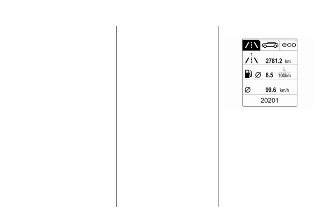
Instruments and controls 107
Traffic sign assistant
L displays detected traffic signs as
control indicator.
Traffic sign assistant 3 198.
Door open
h illuminates red.
A door or the tailgate is open.
Information displays
Driver Information Centre
The Driver Information Centre (DIC)
is located in the instrument cluster.
Depending on the version and the
instrument cluster, the Driver
Information Centre is available as
Baselevel display, Midlevel display or
Uplevel display.
DIC indicates depending on the
equipment:
■ overall and trip odometer
■ vehicle information
■ trip/fuel information
■ economic information
■ performance information
■ vehicle and warning messages
■ audio and infotainment information
■ phone information
■ navigation information
■ vehicle settings
Baselevel display
The menu pages of the Baselevel
display are selected by pressing the
MENU button on the turn signal lever.
Main menu symbols are indicated in
the top line of the display:
■ W Info Menu
■ X Settings Menu
■ s Economic Menu
Some of the displayed functions differ
between vehicle driving and standstill
and some functions are only active
when the vehicle is driving.
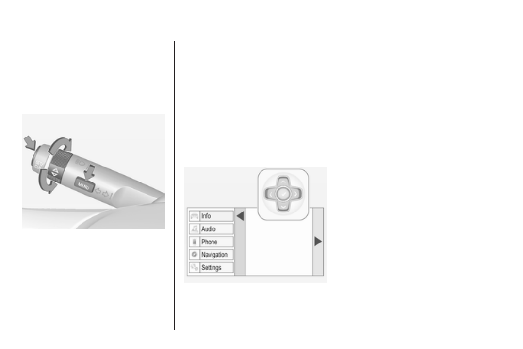
108 Instruments and controls
Vehicle personalisation 3 118.
Memorised settings 3 23.
Selecting menus and functions
The menus and functions can be
selected via the buttons on the turn
signal lever.
Press the MENU button to switch
between the main menus or to return
from a submenu to the next higher
menu level.
Turn the adjuster wheel to select a
subpage of the main menu or to set a
numeric value.
Press the SET/CLR button to select
and confirm a function.
Vehicle and service messages are
popped up in the DIC if required.
Confirm messages by pressing SET/
CLR button. Vehicle messages
3 116.
Midlevel and Uplevel display
Menu pages are indicated by
pressing the steering wheel button p.
Press
Q or P to select a menu, press 9 to
confirm. Selectable menu pages are:
■ Info Menu
■ Performance Menu
■ Audio Menu
■ Phone Menu
■ Navigation Menu
■ Settings Menu
Some of the displayed functions differ
when the vehicle is being driven or at
a standstill. Some functions are only
available when the vehicle is being
driven.
Uplevel instrument cluster can be
displayed as Sport mode or Tour
mode. See below: Settings Menu,
Display Themes.
Vehicle personalisation 3 118.
Memorised settings 3 23.
Selecting menus and functions
The menus and functions can be
selected via the buttons on the right
side in the steering wheel.

Instruments and controls 109
Press p to open main menu page.
Select a main menu page with Q or
P.
Confirm a main menu page with 9.
Once a main menu page is selected,
press Q or P to select subpages.
Press q to open a next folder of the
selected subpage.
Press Q or P to select functions or
to set a numeric value if required.
Press 9 to select and confirm a
function.
If the Driver Information Centre (DIC)
requests the driver to confirm a
function or message by pressing H
(Select), confirm by pressing 9.
Once a main menu page is selected,
this selection remains stored until
another main menu page is selected.
This means once the Info Menu page
is selected, you can change the
subpages just by pressing P or Q.
Vehicle and service messages are
popped up in the DIC if required.
Confirm messages by pressing the
9 button. Vehicle messages 3 116.
Info Menu
Following there is the list of all
possible Info Menu pages. Some may
not be available for your particular
vehicle. Depending on the display
some functions are symbolised.
Turn the adjuster wheel or press Q
or P to select a page:
■ Trip odometer 1/A
Average consumption
Average speed
■ Trip odometer 2/B
Average consumption
Average speed
■ Digital speed
■ Fuel range
■ Fuel range LPG version
■ Instantaneous consumption
■ Remaining oil life
■ Tyre pressure
■ Gasoline fuel level
LPG fuel level
■ Timer
■ Used fuel
■ Traffic sign assistant
■ Following distance
■ Coolant temperature
■ Battery voltage
■ Eco page: Top consumers
■ Economy trend
■ Eco index
■ Blank page

110 Instruments and controls
On Baselevel display, the pages
"Remaining Oil Life ", "Tyre
Pressure", "Traffic Sign Assistant"
and "Following distance indication"
are displayed in the Settings Menu
X. Select by pressing Menu
button.
On Baselevel display, the pages "Top
consumers", "Economy trend" and
"Eco index" are displayed in the Eco
Menu s. Select by pressing
Menu button.
Trip odometer 1/A and 2/B
Trip odometer displays the current
distance since a certain reset.
Trip odometer counts up to a distance
of 2000 km then restarts at 0.
To reset on Baselevel display, press
the SET/CLR button for a few
seconds, on Midlevel and Uplevel
display, press > and confirm with 9.
The information of trip odometer page
1/A and 2/B can be reset separately
for odometer, average consumption
and average speed while the
respective display is active.
Average consumption
Display of average consumption. The
measurement can be reset at any
time and starts with a default value.
To reset on Baselevel display, press
the SET/CLR button for a few
seconds, on Midlevel and Uplevel
display, press > and confirm with 9.
On vehicles with LPG engines,
average consumption is indicated for
the currently selected mode, LPG or
Gasoline.
Average speed
Display of average speed. The
measurement can be reset at any
time.
To reset on Baselevel display, press
the SET/CLR button for a few
seconds, on Midlevel and Uplevel
display, press > and confirm with 9.
Digital speed
Digital display of the instantaneous
speed.
Fuel range
Range is calculated from current fuel
tank content and current
consumption. The display shows
average values.
After refuelling, the range is updated
automatically after a brief delay.
When the fuel level in the tank is low,
a message appears on the display
and the control indicator i or Y in the
fuel gauge illuminates.
When the tank has to be refuelled
immediately, a warning message
appears and remains on the display.
Additionally the control indicator i
or Y in the fuel gauge flashes 3 105.
Fuel range LPG version
Display of approximate fuel range
available with the remaining fuel in
each respective fuel tank of gasoline
and LPG fuel, along with a total range
of both fuel types together. Switch
between the modes by pressing SET/
CLR button or 9 button.

Instruments and controls 111
Instantaneous consumption
Display of the instantaneous
consumption.
On vehicles with LPG engines,
instantaneous consumption is
indicated for the currently selected
mode, LPG or Gasoline.
Remaining oil life
Indicates an estimate of the oil's
useful life. The number in % means
the remaining of current oil life 3 98.
Tire pressure
Checks tyre pressure of all wheels
during driving 3 241.
Gasoline fuel level/LPG fuel level
Displays the fuel level for the fuel not
currently being used (Gasoline or
LPG). A dedicated DIC cluster gauge
shows the fuel level for the fuel
currently being used.
Timer
To start and stop press 9. To reset,
press > and confirm Reset.
Used fuel
Indicates used fuel since a certain
point of time. To reset, press > and
confirm Reset.
Traffic sign assistant
Displays the detected traffic signs for
the current route section 3 198.
Following distance
Displays the distance in seconds to a
preceding moving vehicle 3 184. If
Adaptive cruise control is active this
page shows the following distance
setting instead.
Coolant temperature
Displays the coolant temperature.
Battery voltage
Displays the vehicle battery voltage.
Top consumers
List of top comfort consumers
currently switched on is displayed in
descending order. Fuel saving
potential is indicated. A switched-off
consumer disappears from the list
and the consumption value will be
updated.
During sporadic driving conditions,
the engine will activate the rear
window defog automatically to
increase the engine load. In this
event, the rear window defog is
indicated as one of the top
consumers, without activation by the
driver.
Economy trend
Displays the average consumption
development over a distance of
50 km. Filled segments display the
consumption in 5 km steps and shows
the effect of topography or driving
behaviour on fuel consumption.
Economy index
The current fuel consumption is
indicated on an economic scale. For
economical driving adapt your driving
style to keep the indicator within the
Eco area. Indicator outside the Eco
area means higher fuel consumption.
On Baselevel display, the current
consumption value is indicated.

112 Instruments and controls
Shift indication: On Baselevel display
the current gear is indicated inside an
arrow. The figure above recommends
upshifting for fuel saving reasons.
Blank page
shows a blank page without any
information.
Performance Menu
Performance menu is only viewable
on Uplevel display.
The following is the list of all possible
Performance Menu pages. Some
may not be available for your
particular vehicle.
Turn the adjuster wheel or press Q
or P to select a page:
■ Friction bubble
■ Acceleration and braking
■ Oil temperature
■ Oil pressure
■ Battery voltage
■ Transmission fluid temperature
Friction bubble
A four quadrant visual display,
indicative of the four corners of the
car, with a “bubble” showing where
the most inertia is being exerted on
the vehicle.
Acceleration and braking
Displays the percentage amount of
brake or accelerator pressure applied
by the driver as a bar graph around
the outer perimeter of the DIC area.
The left side is for acceleration and
the right side is for braking.
Oil temperature
Displays the oil temperature in
degrees Celsius.
Oil pressure
Displays the oil pressure in kPa.
Battery voltage
Displays the vehicle battery voltage.
Transmission fluid temperature
Displays the transmission fluid
temperature in degrees Celsius.
Audio Menu
Audio menu enables browsing for
music, selecting from favourites or
changing the audio source.
See Infotainment system manual.
Phone Menu
Phone menu enables managing and
performing of phone calls, scrolling
through contacts or operating
handsfree phoning.
See Infotainment system manual.
Navigation Menu
Navigation menu enables route
guidance.
See Infotainment system manual.
Settings Menu
The following list contains all possible
Settings Menu pages. Some may not
be available for your particular
vehicle. Depending on the display
some functions are symbolised.

Instruments and controls 113
Turn the adjuster wheel or press Q
or P to select a page and follow the
instructions given in the submenus:
■ Units
■ Display themes
■ Info pages
■ Speed warning
■ Tyre loading
■ Software information
Units
Press > while units is displayed.
Select imperial or metric units by
pressing 9.
Display themes
Press > while display themes is
displayed. Select Sport or Touring
mode by pressing 9. Sport mode
includes more vehicle information,
Tour mode includes more media
information.
This setting is only available with
Uplevel display.
Info pages
Press > while Info pages is displayed.
A list of all items in the Info Menu is
displayed. Select the functions to be
displayed in the Info page by pressing
9. Selected pages have a 9 in a
checkbox. Non viewable functions
have a blank checkbox. See Info
Menu above.
Speed warning
The speed warning display allows
you to set a speed that you do not
want to exceed.
To set the speed warning, press >
while the page is displayed. Press
Q or P to adjust the value. Press
9 to set the speed. Once the speed
is set, this feature can be turned off by
pressing 9 while viewing this page. If
the selected speed limit is exceeded,
a pop-up warning is displayed with a
chime.
Tyre loading
The tyre loading display selects tyre
pressure category according to the
actually inflated tyre pressure. Press
> while the page is displayed 3 241.
Select:
■ Light for comfort pressure up to
3 people
■ Eco for Eco pressure up to
3 people
■ Max for full loading
by pressing 9.
Software information
Displays the open source software
information.
Valet mode
Some functions of the Driver
Information Centre and the Colour-
Info-Display can be limited for some
drivers.
Activation or deactivation of valet
mode can be set in the menu
Settings in the vehicle personalisation
menu.
Colour-Info-Display 3 114.
Vehicle personalisation 3 118.
For more information see
Infotainment system manual.
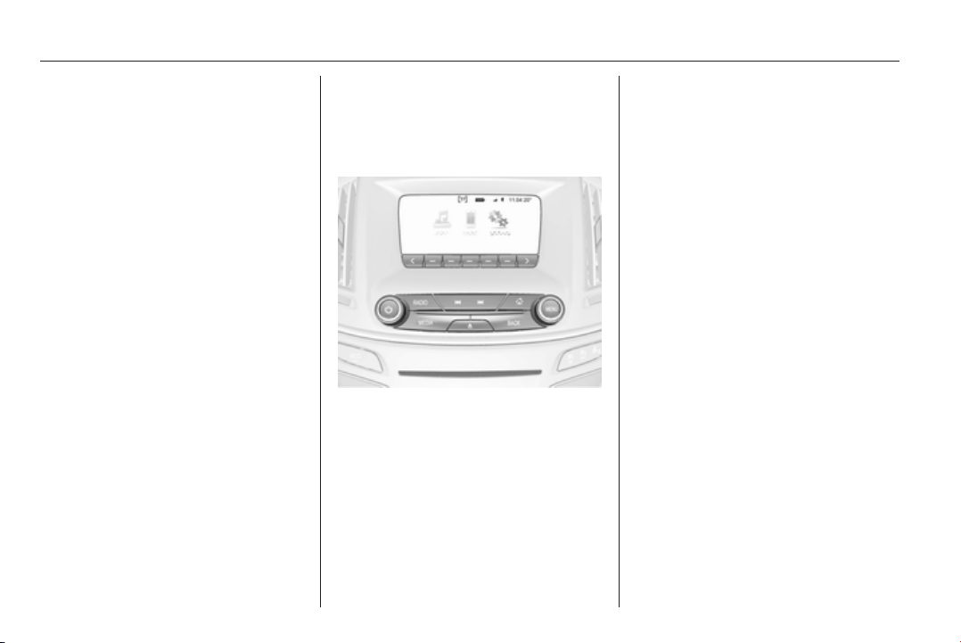
114 Instruments and controls
Colour-Info-Display
The Colour-Info-Display is located in
the instrument panel near the
instrument cluster.
Depending on the vehicle
configuration the vehicle has a
■ 4.2'' colour display
or
■ 8'' colour display with Touch-
Screen and Touch-Pad
functionality
The Info displays indicate:
■ time 3 87
■ outside temperature 3 86
■ date 3 87
■ Infotainment system, see
description in the Infotainment
system manual
■ navigation, see description in the
Infotainment system manual
■ system messages
■ vehicle messages 3 116
■ settings for vehicle personalisation
3 118
4.2'' Colour display
Selecting menus and settings
Menus and settings are accessed via
the display.
Press button X to switch on the
display.
Press button ; to display the
homepage.
Turn button MENU to select a menu
display icon.
Press button MENU to confirm a
selection
Press button BACK to exit a menu
without changing a setting.
Press button ; to return to the
homepage.
For further information, see
Infotainment system manual.
Vehicle personalisation 3 118.
8'' Colour display
Selecting menus and settings
There are three options to operate the
display:
■ via buttons below the display
■ directly with the finger on the
touchscreen
■ via a touchpad in the middle
console between the seats
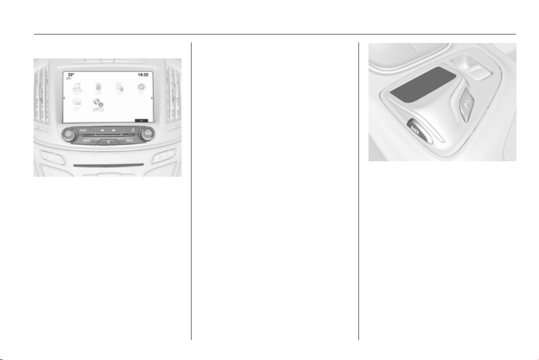
Instruments and controls 115
Button operation
Press button X to switch on the
display.
Press button ; to display the
homepage.
Turn button MENU to select a menu
display icon or a function.
Press button MENU to confirm a
selection.
Turn button MENU to scroll a
submenu list.
Press button MENU to confirm a
selection.
Press button BACK to exit a menu
without changing a setting.
Press button ; to return to the
homepage.
Touchscreen operation
Display must be switched on by
pressing X and homepage must be
selected by pressing ;.
Tap required menu display icon or a
function with the finger.
Scroll a longer submenu list with the
finger up or down.
Confirm a required function or
selection by tapping.
Tap display button q to exit a menu
without changing a setting.
Press button ; to return to the
homepage.
Touchpad operation
Display must be switched on by
pressing X and homepage
selected ;.
Scroll required menu display icon
horizontally with the finger and tap to
confirm.
Scroll a longer submenu list with the
finger vertically.
Confirm a highlighted function or
selection by tapping.
Press button BACK to exit a menu
without changing a setting.
Press button ; to return to the
homepage.
For further information, see
Infotainment system manual.
Vehicle personalisation 3 118.
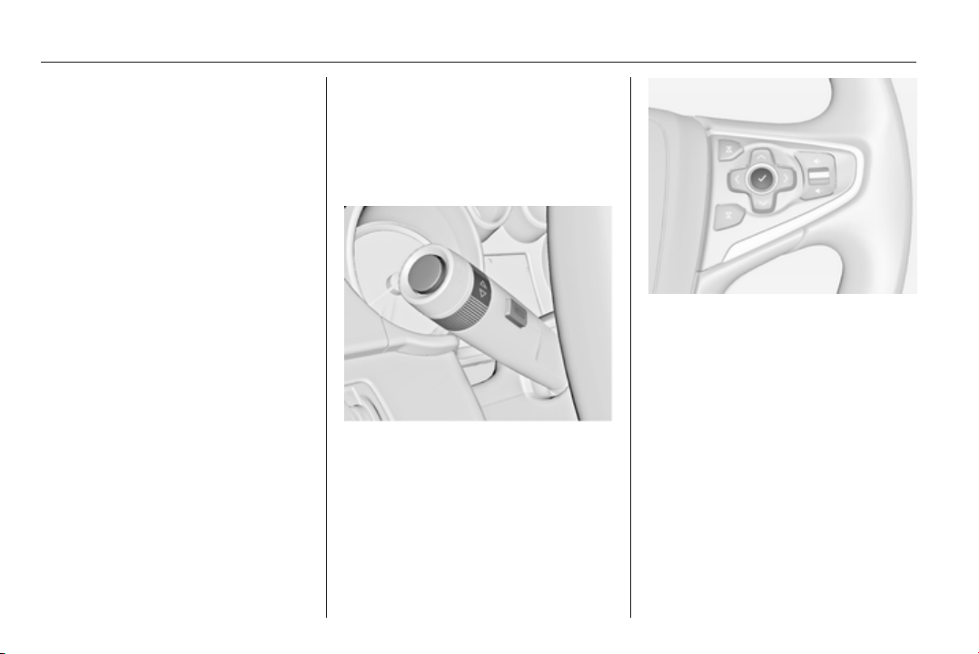
116 Instruments and controls
Valet mode
Some functions of the Driver
Information Centre and the Colour-
Info-Display can be limited for some
drivers.
Activation or deactivation of valet
mode can be set in the menu
Settings in the vehicle personalisation
menu.
Vehicle personalisation 3 118.
For more information see
Infotainment system manual.
Smartphone controller
The smartphone controller allows a
smartphone to access vehicle data
via WLAN or Bluetooth connection.
This data can then be displayed and
analysed on the smartphone.
Vehicle messages
Messages are indicated in the Driver
Information Centre (DIC), in some
cases together with a warning and
signal buzzer.
On Baselevel display press the SET/
CLR button, the MENU button or turn
the adjuster wheel to confirm a
message.
On Midlevel and Uplevel display
press 9 button to confirm a message.
Vehicle and service messages
The vehicle messages are displayed
as text. Follow the instructions given
in the messages.
The system displays messages
regarding the following topics:
■ Service messages
■ Fluid levels
■ Anti-theft alarm system
■ Brakes
■ Drive systems

Instruments and controls 117
■ Ride control systems
■ Driver assistance systems
■ Cruise control
■ Speed limiter
■ Adaptive cruise control
■ Forward collision alert
■ Collision imminent braking system
■ Parking assist systems
■ Lighting, bulb replacement
■ Adaptive forward lighting
■ Wiper/washer system
■ Doors, windows
■ Side blind spot alert
■ Traffic sign assistant
■ Lane departure warning
■ Load compartment, boot lid
■ Radio remote control
■ Electronic key system
■ Keyless starting
■ Seat belts
■ Airbag systems
■ Engine and transmission
■ Tyre pressure
■ Diesel particle filter
■ Vehicle battery status
Messages in the
Colour-Info-Display
Some important messages may
appear additionally in the
Colour-Info-Display. Press the
multifunction knob to confirm a
message. Some messages only pop
up for a few seconds.
Warning chimes
When starting the engine or
whilst driving
Only one warning chime will sound at
a time.
The warning chime regarding not
fastened seat belts has priority over
any other warning chime.
■ If seat belt is not fastened.
■ If a door or the tailgate is not fully
closed when starting off.
■ If a certain speed is exceeded with
parking brake applied.
■ If adaptive cruise control
deactivates automatically.
■ If approaching a vehicle ahead too
closely.
■ If a programmed speed or speed
limit is exceeded.
■ If a warning message appears in
the Driver Information Centre.
■ If the electronic key is not in the
passenger compartment.
■ If the parking assist detects an
object.
■ If an unintended lane change
occurs.
■ If the diesel particle filter has
reached the maximum filling level.
When the vehicle is parked and/
or the driver's door is opened
■ When the key is in the ignition
switch.
■ With exterior lights on.
■ If the trailer hitch is not engaged.
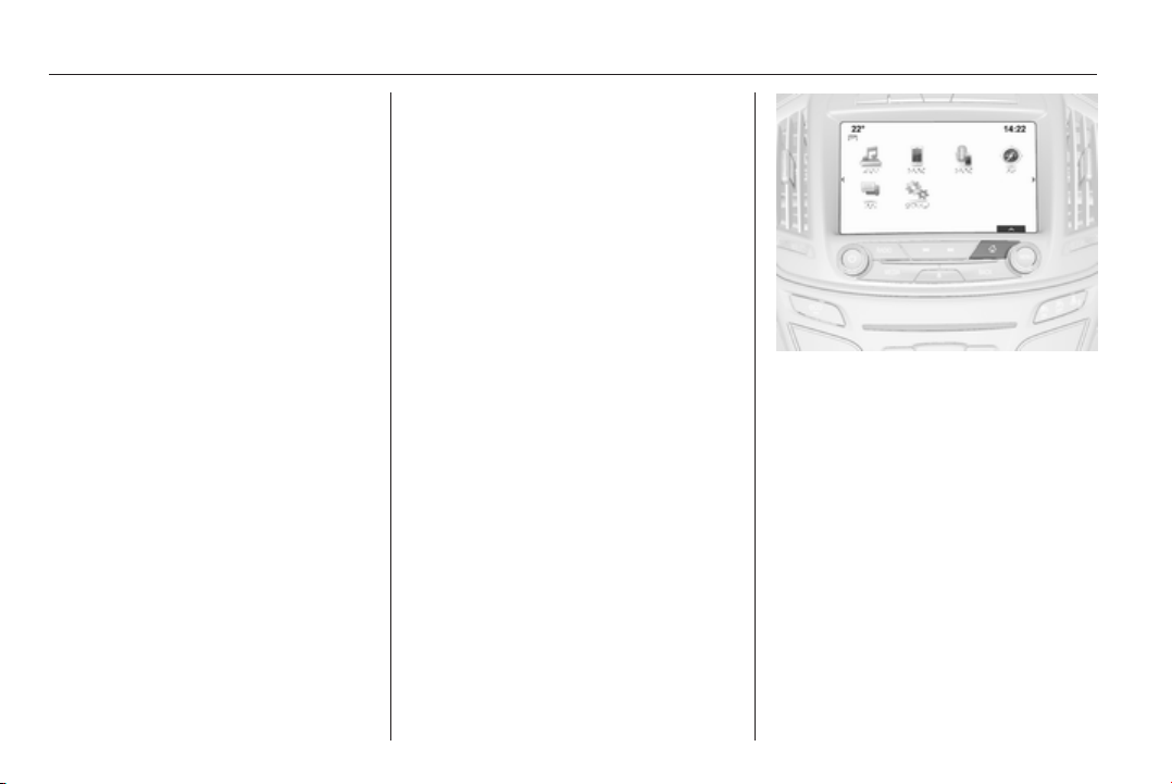
118 Instruments and controls
During an Autostop
■ If the driver's door is opened.
Battery voltage
When the vehicle battery voltage is
running low, a warning message will
appear in the Driver Information
Centre.
1. Switch off any electrical
consumers which are not required
for a safe ride, e.g. seat heating,
heated rear window or other main
consumers.
2. Charge the vehicle battery by
driving continuously for a while or
by using a charging device.
The warning message will disappear
after the engine has been started
twice without a voltage drop.
If the vehicle battery cannot be
recharged, have the cause of the fault
remedied by a workshop.
Vehicle personalisation
The vehicle's behaviour can be
personalised by changing the settings
in the Colour-Info-Display.
Some of the personal settings for
different drivers can be memorised
individually for each vehicle key.
Memorised settings 3 23.
Depending on vehicle equipment and
country-specific regulations some of
the functions described below might
not be available.
Some functions are only displayed or
active when the engine is running.
Personal settings
Following the changing of personal
settings is described via the buttons
below the display. This is valid for
4.2'' as well as 8'' Colour-Info-Display.
Additionally the 8'' display is operable
as a touchscreen and with the
touchpad between the front seats.
See description Colour-Info-Display
3 114 and the Infotainment system
manual.
With active display, press button ;.
Turn button MENU to select Settings
display icon.
Press button MENU to confirm.
The following settings can be
selected by turning and pressing the
multifunction knob:
■ Time and Date
■ Sport Mode
■ Language (Language)
■ Valet Mode
■ Radio
■ Vehicle
■ Bluetooth

Instruments and controls 119
■ Voice
■ Display
■ Rear Camera
■ Return to Factory Settings
■ Software Information
■ TouchPad
In the corresponding submenus the
following settings can be changed:
Time and Date
See Clock 3 87.
Sport Mode
The driver can select the functions
which will be activated in Sport mode
3 168.
■ Sport Mode Backlighting: Change
of instrument illumination colour.
■ Engine Sport Performance:
Accelerator pedal and gear change
characteristics become more
responsive.
■ Sport Steering: Steering support is
reduced.
■ Sport Suspension: Damping
becomes harder.
■ All Wheel Drive: Engine torque is
distributed to a greater extent to the
rear axle.
Language (Language)
Selection of the desired language.
See Infotainment system manual.
Valet Mode
See Infotainment system manual.
Radio
See Infotainment system manual.
Vehicle
■ Climate and Air Quality
Auto Fan Max Speed: Modifies the
level of the cabin airflow of the
climate control in automatic mode.
Air Conditioning Mode: Controls the
state of the cooling compressor
when the vehicle is started. Last
setting (recommended) or at
vehicle start is either always ON or
always OFF.
Auto Demist: Supports windscreen
dehumidification by automatically
selecting the necessary settings
and automatic air conditioning
mode.
Auto Rear Demist: Activates
automatically the heated rear
window.
■ Collision / Detection Systems
Park Assist: Activates or
deactivates the ultrasonic parking
assist.
Auto Collision Preparation:
Activates or deactivates the
automatic brake functionality of the
vehicle in the event of imminent
collision danger. The following is
selectable: the system will take
over brake control, warn by chimes
only or is deactivated completely.
Go Notifier: Activates or
deactivates the reminder function
of the adaptive cruise control.
Side Blind Zone Alert: Activates or
deactivates side blind zone alert.
Rear Cross Traffic Alert: Activates
or deactivates rear cross traffic
alert.

120 Instruments and controls
■ Comfort and Convenience
Chime Volume: Changes the
volume of warning chimes.
Personalisation by Driver:
Activates or deactivates the
personalisation function.
Auto Memory Recall: Activates or
deactivates the recall of memorised
settings for power seat adjustment
and exterior mirrors.
Easy Exit Driver Seat: Activates or
deactivates easy exit function of the
power seat.
Reverse Tilt Mirror: Activates or
deactivates the parking assist
function of the exterior mirror on the
passenger side.
Auto Mirror Folding: Activates or
deactivates folding of the exterior
mirrors with the remote control.
Auto Wipe in Reverse Gear:
Activates or deactivates automatic
switching on of the rear window
wiper when reverse gear is
engaged.
Rainsense Wipers: Activates or
deactivates automatic wiping with
rain sensor.
■ Lighting
Exit Lighting: Activates or
deactivates and changes the
duration of exit lighting.
Vehicle Locator Lights: Activates or
deactivates the welcome lighting.
Adaptive Forward Lighting:
Activates or deactivates the
functions of the adaptive forward
lighting.
Left or Right Hand Traffic: Change
between lighting for left or right
hand traffic.
■ Power Door Locks
Unlocked Door Anti-Lockout:
Activates or deactivates the
automatic driver's door locking
function when the door is open.
Delayed Door Lock: Activates or
deactivates the delayed door
locking function.
Auto Door Lock: Activates or
deactivates the automatic door
unlocking function after switching
off ignition. Activates or deactivates
the automatic door locking function
after driving off.
■ Remote Lock, Unlock, Start
Remote Unlock Light Feedback:
Activates or deactivates the hazard
warning flasher feedback whilst
unlocking.
Remote Lock Feedback: Changes
what kind of feedback is given
when locking the vehicle.
Remote Door Unlock: Changes the
configuration to unlock only the
driver's door or the whole vehicle
whilst unlocking.
Relock Remote Unlocked Doors:
Activates or deactivates the
automatic relock function after
unlocking without opening the
vehicle.
Passive Door Lock: Activates or
deactivates the passive locking
function.
Remote Left in Vehicle Alert:
Activates or deactivates the
warning tone when the electronic
key remains in the vehicle.

Instruments and controls 121
Bluetooth
See Infotainment system manual.
Voice
See Infotainment system manual.
Display
See Infotainment system manual.
Rear Camera
Guidance Lines: Activates or
deactivates the guiding lines.
Rear Park Assist Symbols: Activates
or deactivates the rear park assist
symbols.
Return to Factory Settings
Restore Vehicle Settings: Reset all
settings to the default settings.
Clear All Private Data: Delete all
private information from the vehicle.
Restore Radio Settings: Reset all
radio settings to the default settings.
See Infotainment system manual.
Software Information
See Infotainment system manual.
TouchPad
See Infotainment system manual.
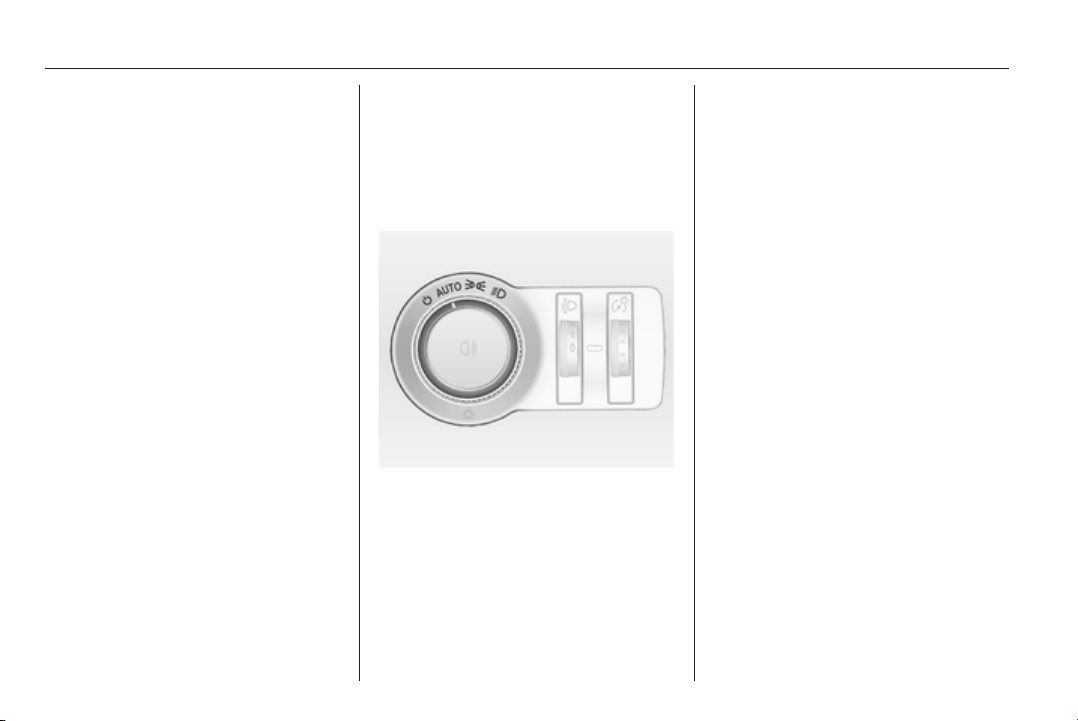
122 Lighting
Lighting
Exterior lighting .......................... 122
Interior lighting ........................... 130
Lighting features ........................ 131
Exterior lighting
Light switch
Light switch with Automatic light
control
Turn light switch:
AUTO = automatic light control:
exterior lighting is switched
on and off automatically
depending on external
lighting conditions.
m
= activation or deactivation
of the automatic light
control. Switch turns back
to AUTO.
8
= sidelights
9
= headlights
The current status of the automatic
light control is displayed in the Driver
Information Centre.
When switching on the ignition,
automatic light control is active.
Control indicator 8 3 105.
Tail lights
Tail lights are illuminated together
with low/high beam and sidelights.
Additional lights in the tailgate frame,
Sports Tourer/Country Tourer
Additional tail light assemblies,
consisting of tail lights and hazard
warning flasher lights, are located in
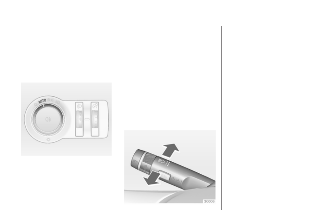
Lighting 123
the tailgate frame. They are
illuminated when the tailgate is open.
Additional tail lights are only intended
as position lights when the tailgate is
open and are not to be used when
driving.
Automatic light control
When the automatic light control
function is switched on and the
engine is running, the system
switches between daytime running
light and low/high beam automatically
depending on the lighting conditions
and information given by the rain
sensor system.
Daytime running light 3 125.
Automatic headlight activation
During poor lighting conditions
headlights are switched on.
Furthermore headlights are switched
on if the windscreen wipers have
been activated for several wipes.
Tunnel detection
When a tunnel is entered headlights
are switched on without delay.
Adaptive forward lighting 3 125.
High beam
To switch from low to high beam,
push lever.
To switch to low beam, push lever
again or pull.
High beam assist
This feature allows the high beam to
function as the main driving light at
night and when vehicle speed is
faster than 40 km/h.
It switches automatically to low beam
when:
■ a sensor detects the lights of
oncoming or preceding vehicles
■ the vehicle speed is slower than
20 km/h
■ it is foggy or snowy
■ driving in urban areas
If there are no restrictions detected,
the system switches back to high
beam.
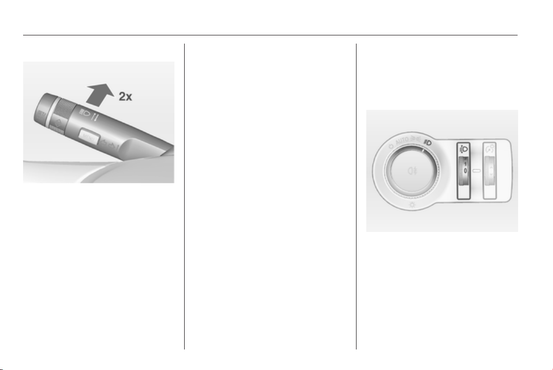
124 Lighting
Activation
The high beam assist is activated by
pushing the indicator lever twice with
a speed above 40 km/h.
The green control indicator l
illuminates continuously when the
assist is activated, the blue one 7
illuminates when high beam is on.
Control indicator l 3 105.
Deactivation
Push indicator lever once. It is also
deactivated when front fog lights are
switched on.
If a headlight flash is activated when
the high beam is on, the high beam
assist will be deactivated.
If a headlight flash is activated when
the high beam is off, the high beam
assist will remain activated.
The latest setting of the high beam
assist will be stored after the ignition
is switched on again.
Headlight flash
To activate the headlight flash, pull
lever.
Headlight range
adjustment
Manual headlight range
adjustment
To adapt headlight range to the
vehicle load to prevent dazzling: turn
thumb wheel ? to required position.
0 = front seats occupied
1 = all seats occupied
2 = all seats occupied and load
compartment laden
3 = driver's seat occupied and load
compartment laden.

Lighting 125
Dynamic automatic headlight
levelling 3 125.
Headlights when driving
abroad
The asymmetrical headlight beam
extends visibility at the edge of the
road at the passenger side.
However, when driving in countries
where traffic drives on the opposite
side of the road, adjust the headlights
to prevent dazzling of oncoming
traffic.
Vehicles with halogen headlight
system
Have the headlights adjusted by a
workshop.
Vehicles with Xenon headlight
system and Adaptive forward
lighting system
Headlights can be set to right hand or
left hand drive traffic mode in the
vehicle personalisation menu in the
Colour-Info-Display.
Select the relevant setting in Settings,
I Vehicle in the Colour-Info-Display.
Colour-Info-Display 3 114.
Vehicle personalisation 3 118.
Every time the ignition is switched on,
control indicator f flashes for approx.
4 seconds as a reminder that right
hand drive traffic mode is selected.
Change back to left hand drive traffic
mode in the vehicle personalisation
menu as described above. f will not
flash when left hand drive traffic mode
is selected.
Control indicator f 3 106.
Daytime running lights
Daytime running light increases
visibility of the vehicle during daylight.
They are switched on automatically
when ignition is on.
If the vehicle is equipped with
automatic light control function, the
system switches between daytime
running light and low/high beam
automatically depending on the
lighting conditions and information
given by the rain sensor system.
Automatic light control 3 123.
Adaptive forward lighting
The Adaptive forward lighting
functions are only available with Bi-
Xenon headlights. Light range, light
distribution and intensity of light are
variably triggered depending on the
light conditions, weather and road
type.
With the light switch in position
AUTO all lighting functions are
available.
The following functions are available
also with light switch in position 9:
■ Dynamic curve lighting
■ Corner lighting
■ Reversing function
■ Dynamic automatic headlight
levelling
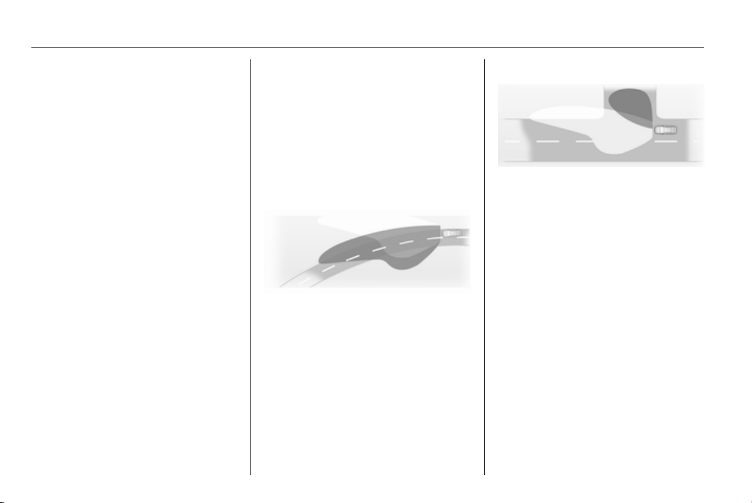
126 Lighting
Playstreet lighting
Activated automatically at low speed
up to approx. 30 km/h. The light beam
is turned at an angle of 8° to the
roadside.
Town lighting
Activated automatically at a speed
range between approx. 40 and
55 km/h and when street lights are
detected by the light sensor. The light
range is reduced by an extended light
distribution.
Country lighting
Activated automatically at a speed
range between approx. 55 and
115 km/h. The beam of light and the
brightness is different between the
left and the right side.
Motorway lighting
Activated automatically at a speed
above approx. 115 km/h and minimal
steering movements. It switches on
after a delay or immediately when the
vehicle is powerfully accelerated. The
light beam is longer and brighter.
Adverse weather lighting
Activated automatically up to a speed
of approx. 70 km/h, when the rain
sensor recognizes condensation or
the wiper operates continuously. The
range, distribution and light intensity
is regulated variably depending on
visibility.
Dynamic curve lighting
The light beam pivots based on
steering wheel angle and speed,
improving lighting in curves.
Control indicator f 3 106.
Corner lighting
On tight bends or when turning off,
depending on the steering angle or
the turn signal light, an additional left
or right reflector is switched on which
illuminates the road at a right angle to
the direction of travel. It is activated
up to a speed of 40 km/h.
Control indicator f 3 106.
Reversing function
If the headlights are on and reverse
gear is engaged, both corner lights
are switched on. They remain
illuminated for 20 seconds after
disengaging reverse gear or until
driving faster than 7 km/h in a forward
gear.
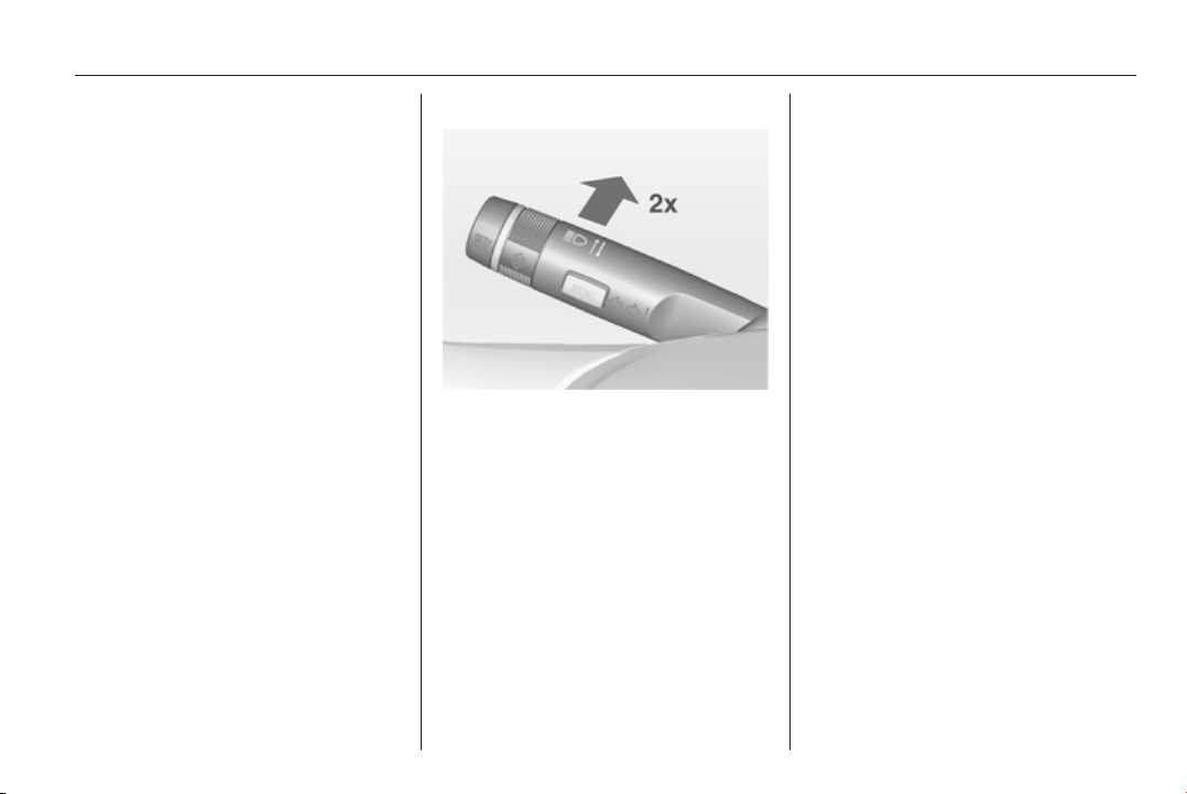
Lighting 127
High Beam Assist
This feature allows the high beam to
function as the main driving light at
night and when vehicle speed is
faster than 40 km/h.
It switches automatically to low beam
when:
■ the camera in the windscreen
detects the lights of oncoming or
preceding vehicles
■ the vehicle speed is slower than
20 km/h
■ it is foggy or snowy
■ driving in urban areas
If there are no restrictions detected,
the system switches back to high
beam.
Activation
The high beam assist is activated by
pushing the indicator lever twice with
a speed above 40 km/h.
The green control indicator l
illuminates continuously when the
assist is activated, the blue one 7
illuminates when high beam is on.
Control indicator l 3 105.
Deactivation
Push indicator lever once. It is also
deactivated when front fog lights are
switched on.
If a headlight flash is activated when
the high beam is on, the high beam
assist will be deactivated.
If a headlight flash is activated when
the high beam is off, the high beam
assist will remain activated.
The latest setting of the high beam
assist will remain after the ignition is
switched on again.
Dynamic automatic headlight
levelling
To prevent oncoming traffic from
dazzle, headlight levelling is
automatically adjusted based on
inclination information measured by
front and rear axle, acceleration or
deceleration and vehicle speed.
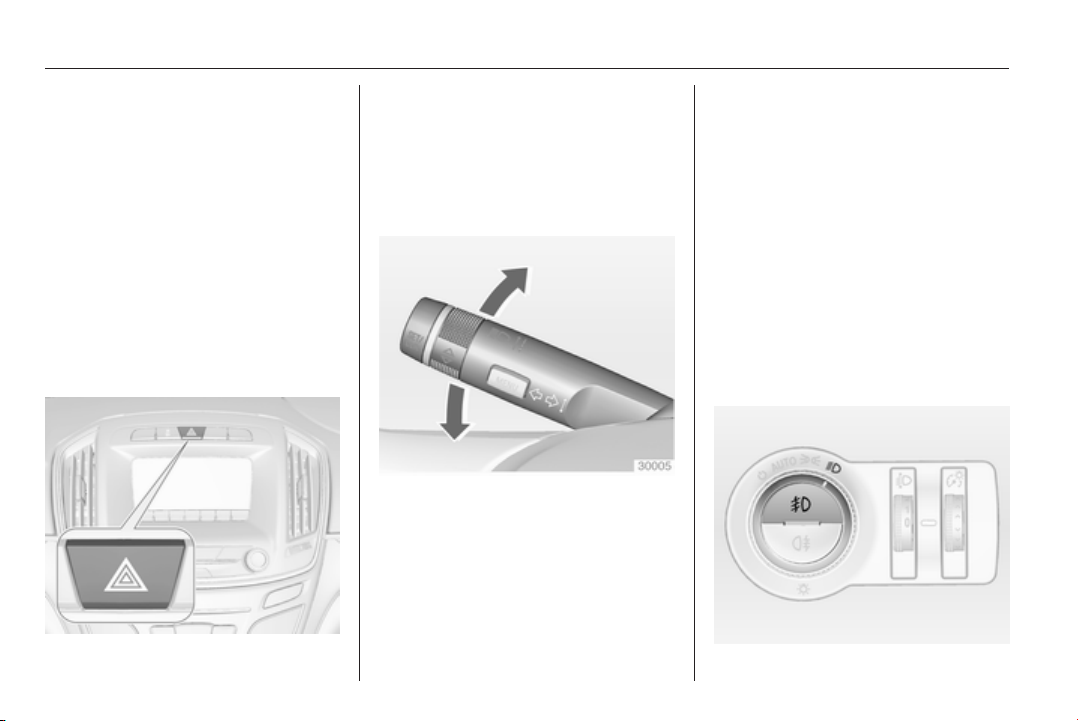
128 Lighting
Fault in Adaptive forward
lighting system
When the system detects a failure in
the Adaptive forward lighting system,
the system moves to a preset position
to avoid dazzling of oncoming traffic.
If this is not possible, the affected
headlight will be automatically
switched off. In any case, one
headlight will stay on. A warning is
displayed in the Driver Information
Centre.
Hazard warning flashers
Operated with the ¨ button.
In the event of an accident with airbag
deployment the hazard warning
flashers are activated automatically.
Turn and lane-change
signals
lever up = right turn signal
lever down = left turn signal
If the lever is moved past the
resistance point, the turn signal is
switched on constantly. When the
steering wheel moves back, the turn
signal is automatically deactivated.
For three flashes, e.g. when changing
lanes, press the lever until resistance
is felt and then release.
With a trailer connected, turn signal
flashes six times when pressing the
lever until resistance is felt and then
releasing.
Move the lever to the resistance point
and hold for longer indication.
Switch the turn signal off manually by
moving the lever to its original
position.
Front fog lights
Operated with the > button.
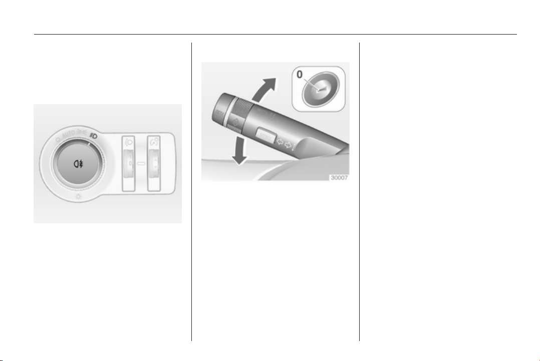
Lighting 129
Light switch in position AUTO:
switching on front fog lights will switch
headlights on automatically.
Rear fog lights
Operated with the r button.
Light switch in position AUTO:
switching on rear fog light will switch
headlights on automatically.
Light switch in position 8: rear fog
light can only be switched on with
front fog lights.
The vehicle rear fog light is
deactivated when towing.
Parking lights
When the vehicle is parked, the
parking lights on one side can be
activated:
1. Switch off ignition.
2. Move turn signal lever all the way
up (right parking lights) or down
(left parking lights).
Confirmed by a signal and the
corresponding turn signal control
indicator.
Reversing lights
The reversing light comes on when
the ignition is on and reverse gear is
selected.
Misted light covers
The inside of the light housing may
mist up briefly in poor, wet and cold
weather conditions, in heavy rain or
after washing. The mist disappears
quickly by itself; to help switch on the
headlights.
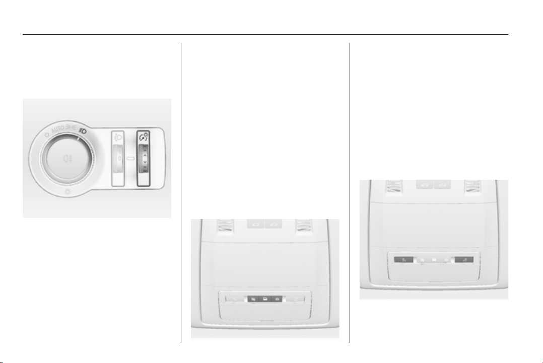
130 Lighting
Interior lighting
Instrument panel
illumination control
Brightness of the following lights can
be adjusted when the exterior lights
are on:
■ Instrument panel illumination
■ Info-Display
■ Dome light
■ Illuminated switches and operation
elements
Turn thumb wheel A and hold until
the desired brightness is obtained.
On vehicles with light sensor, the
brightness can only be adjusted when
the exterior lights are on and the light
sensor detects night conditions.
Interior lights
During entry and exit of the vehicle,
the front and rear courtesy lights
automatically switch on and then off
after a delay.
Note
In the event of an accident with
airbag deployment the courtesy
lights are turned on automatically.
Front courtesy light
Operate rocker switch:
w
= automatic switching on
and off.
press u = on.
press v = off.
Rear courtesy lights
Illuminate in conjunction with the front
courtesy light depending on rocker
switch position.
Reading lights
Operated with s and t buttons in
front and rear courtesy lights.
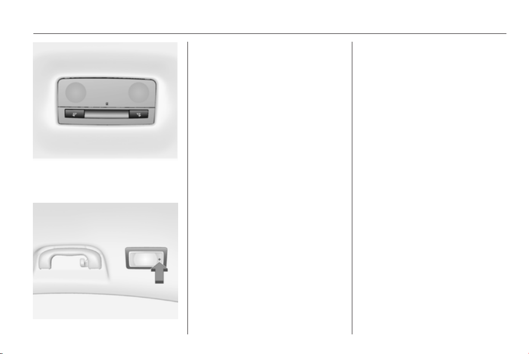
Lighting 131
On vehicles with panoramaroof rear
interior lights are located near the rear
handles.
Switch on reading lights by pressing
< on the cover.
Sunvisor lights
Illuminates when the cover is opened.
Lighting features
Centre console lighting
Spotlight incorporated in the interior
lighting comes on when headlights
are switched on.
Entry lighting
Welcome lighting
Headlights, tail lights, number plate
lights, instrument panel light, interior
lights and puddle lights are switched
on for a short time by unlocking the
vehicle with the radio remote control.
This function works only in the dark
and facilitates locating the vehicle.
The lighting switches off immediately
when the ignition is switched on.
Starting off 3 17.
This function can be activated or
deactivated in the Vehicle
personalisation.
Select the relevant setting in Settings,
I Vehicle in the Colour-Info-Display.
Colour-Info-Display 3 114.
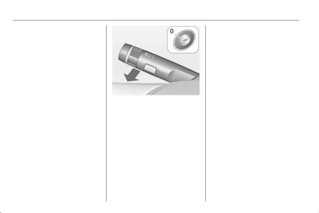
132 Lighting
Vehicle personalisation 3 118.
The settings can be saved for the key
being used 3 23.
The following lights will additionally
switch on when the driver's door is
opened:
■ All switches
■ Driver Information Centre
■ Door pocket lights
Exit lighting
The following lights switch on if the
key is removed from the ignition
switch:
■ Interior lights
■ Instrument panel light
■ Puddle lights
They will switch off automatically after
a delay. This function works only in
the dark. Theatre lighting is activated
if the driver's door is opened during
this time.
Headlights, tail lights and number
plate lights illuminate the surrounding
area for an adjustable time after
leaving the vehicle.
Switching on
1. Switch off ignition.
2. Remove ignition key.
3. Open driver's door.
4. Pull turn signal lever.
5. Close driver's door.
If the driver's door is not closed the
lights switch off after two minutes.
Exit lighting is switched off
immediately if the turn signal lever is
pulled while the driver's door is open.
This function can be activated or
deactivated in the Vehicle
personalisation.
Select the relevant setting in Settings,
I Vehicle in the Colour-Info-Display.
Colour-Info-Display 3 114.
Vehicle personalisation 3 118.
The settings can be saved for the key
being used 3 23.
Battery discharge
protection
Vehicle battery state of charge
function
The function guarantees longest
vehicle battery life via a generator
with controllable power output and
optimised power distribution.
To prevent discharge of the vehicle
battery when driving, the following
systems are reduced automatically in
two stages and finally switched off:

Lighting 133
■ Auxiliary heater
■ Heated rear window and mirrors
■ Heated seats
■ Fan
In the second stage a message which
confirms the activation of the vehicle
battery discharge protection will be
displayed in the Driver Information
Centre.
Switching off electric lights
To prevent discharge of the vehicle
battery when the ignition is switched
off, some interior lights are switched
off automatically after some time.
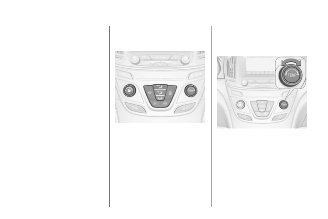
134 Climate control
Climate control
Climate control systems ............. 134
Air vents ..................................... 145
Maintenance .............................. 146
Climate control systems
Air conditioning system
Controller and buttons for the
following functions:
■ Temperature TEMP
■
Air distribution l M K
■ Fan speed Z
■ Cooling A/C
■
Air recirculation 4
■
Demisting and defrosting V
Heated rear window Ü 3 41.
Heated seats ß 3 53.
Ventilated seats
A 3 54.
Heated steering wheel * 3 83.
Temperature TEMP
Turn controller:
red = warm
blue = cold
Heating will not be fully effective until
the engine has reached normal
operating temperature.
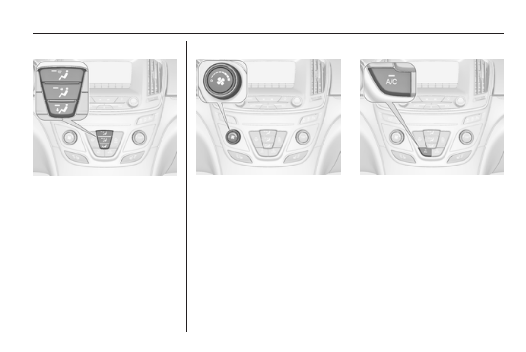
Climate control 135
Air distribution l M K
Press button:
l
= to windscreen and front door
windows
M
= to head area via adjustable air
vents
K
= to foot well
Combinations are possible.
Setting is indicated by the LED in the
button.
Fan speed Z
Adjust the air flow by turning the
controller Z to the desired speed. J
means fan off.
Cooling A/C
Press button A/C to switch on cooling.
Activation is indicated by the LED in
the button. Cooling is only functional
when the engine is running and
climate control fan is switched on.
Press button A/C again to switch off
cooling.
The air conditioning system cools and
dehumidifies (dries) cabin air as
required. Therefore condensation
may form and is drained under the
vehicle.
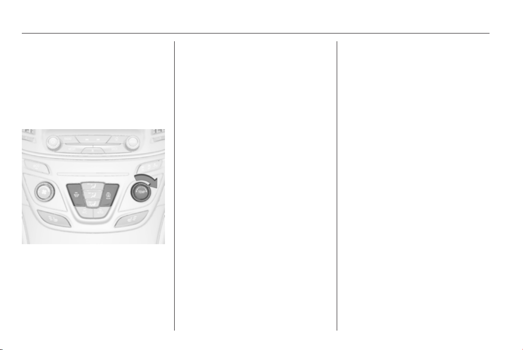
136 Climate control
If no cooling or drying is required,
switch off the cooling system for fuel
saving reasons. Activated cooling
might inhibit Autostops.
Stop-start system 3 153.
Demisting and defrosting the
windows V
■
Press button V: fan automatically
switches to higher speed, the air
distribution is directed towards the
windscreen.
■ Set temperature controller TEMP to
warmest level.
■
Switch on heated rear window Ü.
■ Open side air vents as required and
direct them towards the door
windows.
Note
If the V button is pressed while the
engine is running, an Autostop will
be inhibited until the V button is
pressed again.
If the V button is pressed while the
engine is in an Autostop, the engine
will restart automatically.
Stop-start system 3 153.
Maximum cooling
Briefly open the windows so that hot
air can disperse quickly.
■ Switch on cooling A/C.
■
Press button M for air distribution.
■ Set temperature controller TEMP to
coldest level.
■ Set fan speed controller Z to
highest level.
■ Open all vents.
Air recirculation system 4
Press button 4 to activate air
recirculation mode. Activation is
indicated by the LED in the button.
Select air recirculation to assist in
cooling the interior or in blocking
outside odors or exhaust. When
recirculation is selected, a partial
ventilation to refresh the interior air
will occur every 10 minutes.
Press button 4 again to deactivate
recirculation mode.
In warm and very humid ambient air
conditions, the windscreen might mist
up from outside, when cold air is
directed to it. If windscreen mists up
from outside, activate windscreen
wiper and deactivate l.
Air distribution to l: Air recirculation
is deactivated.
Automatic climate control
system
In Automatic mode temperature, fan
speed and air distribution are
regulated automatically.
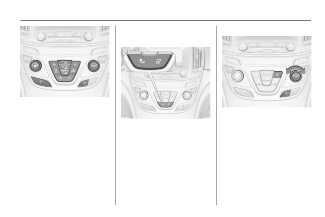
Climate control 137
Controller and buttons for the
following functions:
■ Temperature TEMP
■
Air distribution l M K
■ Fan speed Z
■ Automatic mode AUTO
■ Cooling A/C
■
Air recirculation 4
■
Demisting and defrosting V
■ System ON/OFF X
Heated rear window Ü 3 41.
Heated front seats ß 3 53.
Ventilated front seats A 3 54.
Heated steering wheel * 3 83.
Indication
Settings of temperature and fan
speed are indicated in the climate
display.
Each change of settings is shown in
the Info-Display for a few seconds.
The electronic climate control system
is only fully operational when the
engine is running.
Climate control system settings are
saved in the key used to lock the
vehicle.
Automatic mode AUTO
Basic setting for maximum comfort:
■ Press AUTO, the air distribution
and fan speed are regulated
automatically. Activation is
indicated by the LED in the button.
■ Press A/C to switch on optimal
cooling and demisting. Activation is
indicated by the LED in the button.
■ Set temperature by turning
controller TEMP. Suggested
comfort setting is 22 °C.
■ Open all air vents to allow
optimised air distribution in
automatic mode.
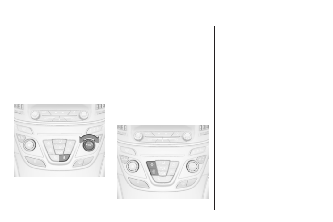
138 Climate control
Setting of fan speed regulation in
automatic mode can be changed in
the vehicle personalisation menu in
the Colour-Info-Display.
Select the relevant setting in Settings,
I Vehicle in the Colour-Info-Display.
Colour-Info-Display 3 114.
Vehicle personalisation 3 118.
Temperature preselection
TEMP
Set temperature by turning controller
TEMP to the desired value.
Selected temperature is indicated in
the climate display.
If the minimum temperature Lo is set,
the climate control system runs at
maximum cooling, if cooling A/C is
switched on.
If the maximum temperature Hi is set,
the climate control system runs at
maximum heating.
Note
If AC is switched on, reducing the set
cabin temperature can cause the
engine to restart from an Autostop or
inhibit an Autostop.
Demisting and defrosting the
windows V
■
Press button V. Activation is
indicated by the LED in the button.
■ Temperature and air distribution
are set automatically and the fan
runs at high speed.
■
Switch on heated rear window Ü.
■ To return to previous mode: press
button V. To return to automatic
mode: press button AUTO.
Setting of automatic rear window
heating can be changed in the vehicle
personalisation menu in the Colour-
Info-Display.
Select the relevant setting in Settings,
I Vehicle in the Colour-Info-Display.
Colour-Info-Display 3 114.
Vehicle personalisation 3 118.
Note
If the V button is pressed while the
engine is running, an Autostop will
be inhibited until the V button is
pressed again.
If the V button is pressed while the
engine is in an Autostop, the engine
will restart automatically.
Stop-start system 3 153.
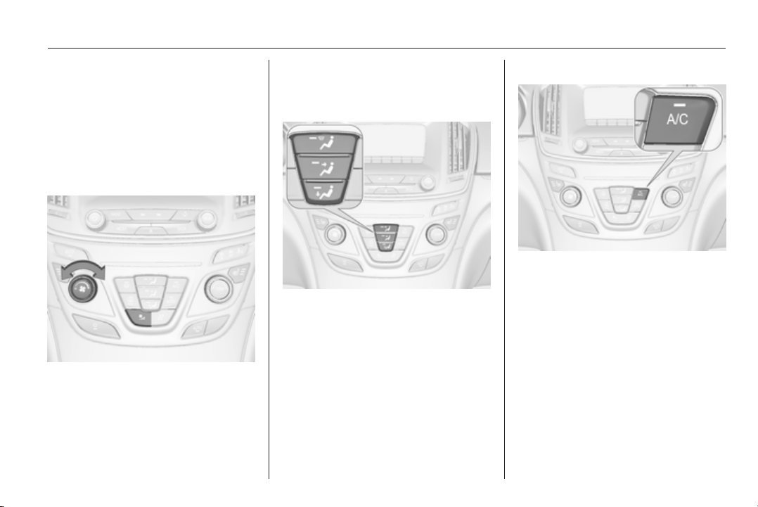
Climate control 139
Manual settings
Climate control system settings can
be manually adapted by using the air
distribution buttons and the fan speed
controller as follows. Manual
changing of settings will deactivate
the automatic mode.
Fan speed Z
Turn controller Z. The selected fan
speed is indicated by the number of
segments in the climate display.
If the fan is switched off, the air
conditioning is also deactivated.
To return to automatic mode: Press
AUTO button.
Air distribution l, M, K
Press appropriate button for desired
adjustment. Activation is indicated by
the LED in the button.
l
= to windscreen and front door
windows.
M
= to head area via adjustable air
vents.
K
= to foot well.
Combinations are possible.
Return to automatic air distribution:
press button AUTO.
Cooling A/C
Press button A/C to switch on cooling.
Activation is indicated by the LED in
the button. Cooling is only functional
when the engine is running and
climate control fan is switched on.
Press button A/C again to switch off
cooling.
The air conditioning system cools and
dehumidifies (dries) cabin air as
required. Therefore condensation
may form and is drained under the
vehicle.
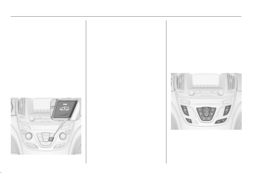
140 Climate control
If no cooling or drying is required,
switch off the cooling system for fuel
saving reasons.
System ON/OFF X
Cooling, fan and automatic mode can
be switched off by pressing button X.
When the system is deactivated, the
LED in the button X is off.
Activation by pressing button X or
cooling button A/C or automatic mode
button AUTO. Activation is indicated
by the LED in the button.
Manual air recirculation 4
Press button 4 to activate air
recirculation mode. Activation is
indicated by the LED in the button.
Select air recirculation to assist in
cooling the interior or in blocking
outside odors or exhaust. When
recirculation is selected, a partial
ventilation to refresh the interior air
will occur every 10 minutes.
Press button 4 again to deactivate
recirculation mode.
In warm and very humid ambient air
conditions, the windscreen might mist
up from outside, when cold air is
directed to it. If windscreen mists up
from outside, activate windscreen
wiper and deactivate l.
Basic settings
Some basic settings can be changed
in the vehicle personalisation menu in
the Colour-Info-Display.
Select the relevant settings in
Settings, I Vehicle in the Colour-Info-
Display.
Colour-Info-Display 3 114.
Vehicle personalisation 3 118.
Dual automatic climate
control system
The dual automatic climate control
allows different climatisation
temperatures for driver and front
passenger side.
In Automatic mode temperature, fan
speed and air distribution are
regulated automatically.
Panels and buttons for the following
functions:
■ Temperature RS
■
Air distribution l M K
■ Fan speed RZS
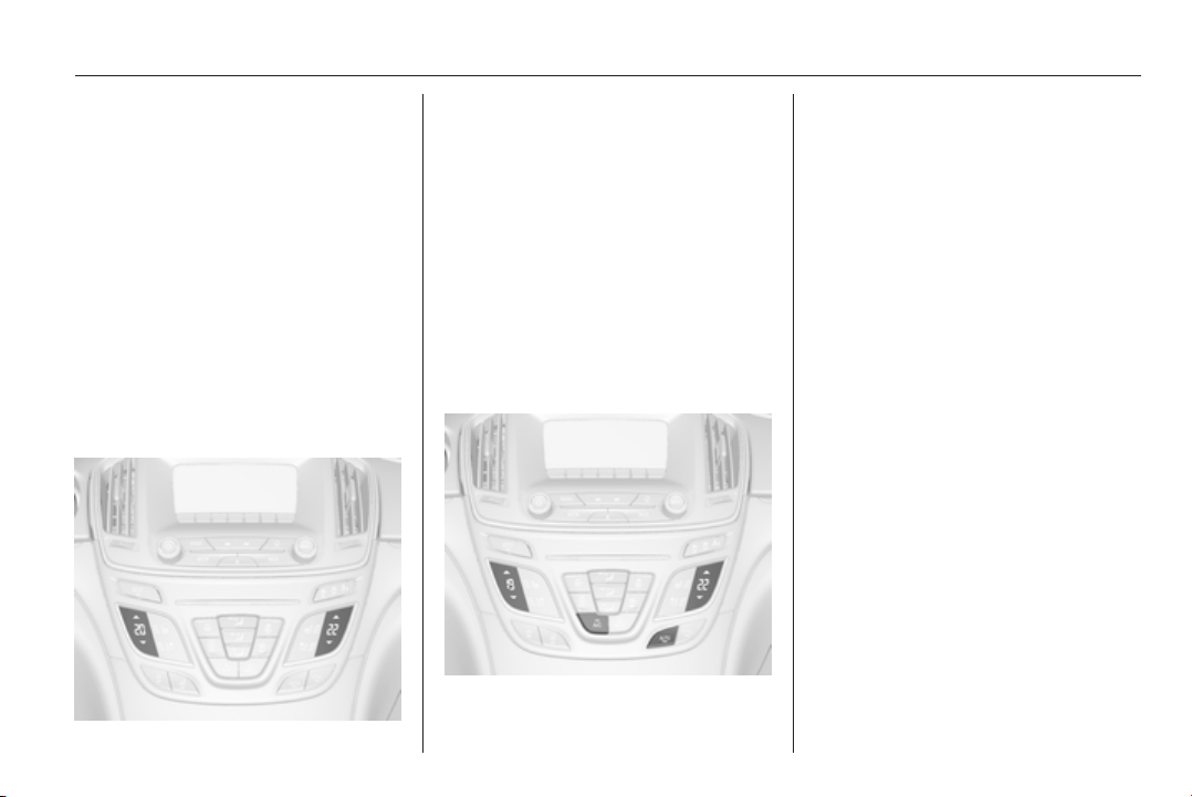
Climate control 141
■ Automatic mode AUTO
■ Cooling A/C
■
Air recirculation 4
■
Demisting and defrosting V
■ System ON/OFF X
■ Dual zone temperature
synchronisation SYNC
Heated rear window Ü 3 41.
Heated front seats ß 3 53.
Ventilated front seats A 3 54.
Heated steering wheel * 3 83.
Indication
Temperature settings are indicated
for driver and passenger side
separately on the panels.
Each change of settings is shown in
the Info-Display for a few seconds.
The dual automatic climate control
system is only fully operational when
the engine is running.
Climate control system settings are
saved in the key used to lock the
vehicle.
Automatic mode AUTO
Basic setting for maximum comfort:
■ Press AUTO, the air distribution
and fan speed are regulated
automatically. Activation is
indicated by the LED in the button.
■ Press A/C to switch on optimal
cooling and demisting. Activation is
indicated by the LED in the button.
■ Set temperature by touching R or
S on the driver side. Suggested
comfort setting is 22 °C.
Temperature can be set differently
for driver and passenger. Touch R
or S on the passenger side to allow
different temperature zones.
■ Open all air vents to allow
optimised air distribution in
automatic mode.
Setting of fan speed regulation in
automatic mode can be changed in
the vehicle personalisation menu in
the Colour-Info-Display.
Select the relevant setting in Settings,
I Vehicle, in the Colour-Info-Display.
Colour-Info-Display 3 114.
Vehicle personalisation 3 118.
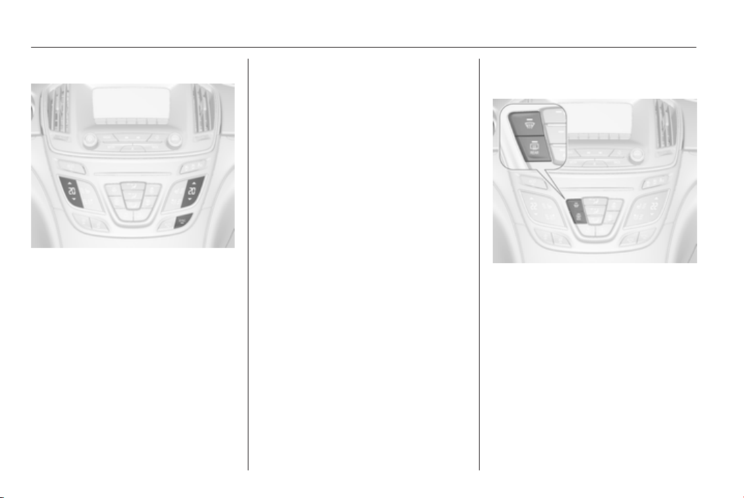
142 Climate control
Temperature preselection SR
Set desired temperature by touching
R for higher temperatures or S for
lower temperatures.
Selected temperature is indicated in
the panels. Using driver's side panel
changes temperatures for both sides
(when SYNC is selected), while using
the passenger side panel changes
only the passenger side temperature
and turns off SYNC, (if selected
before).
If the minimum temperature Lo is set,
the climate control system runs at
maximum cooling, if cooling A/C is
switched on.
If the maximum temperature Hi is set,
the climate control system runs at
maximum heating.
Note
If AC is switched on, reducing the set
cabin temperature can cause the
engine to restart from an Autostop or
inhibit an Autostop.
Dual zone temperature
synchronisation SYNC
Press SYNC to link passenger side
temperature setting to the driver side.
Activation is indicated by the LED in
the button.
When passenger side settings will be
adjusted, the LED extinguishes.
Demisting and defrosting the
windows V
■
Press button V. Activation is
indicated by the LED in the button.
■ Temperature and air distribution
are set automatically and the fan
runs at high speed.
■
Switch on heated rear window Ü.
■ To return to previous mode: press
button V. To return to automatic
mode: press button AUTO.
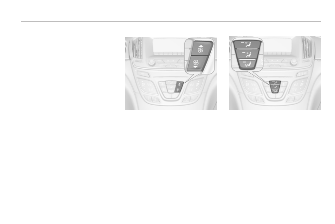
Climate control 143
Setting of automatic rear window
heating based on cool outside
temperatures can be changed in the
vehicle personalisation menu in the
Colour-Info-Display.
Select the relevant setting in Settings,
I Vehicle in the Colour-Info-Display.
Colour-Info-Display 3 114.
Vehicle personalisation 3 118.
Note
If the V button is pressed while the
engine is running, an Autostop will
be inhibited until the V button is
pressed again.
If the V button is pressed while the
engine is in an Autostop, the engine
will restart automatically.
Stop-start system 3 153.
Manual settings
Climate control system settings can
be manually adapted by using the air
distribution buttons and the fan speed
controller as follows. Manual
changing of settings will deactivate
the automatic mode.
Fan speed
SZR
Touch ZS or R. The selected fan
speed is indicated in the Info-Display
for a short time.
If the fan is switched off, the air
conditioning is also deactivated.
To return to automatic mode: Press
AUTO button.
Air distribution l, M, K
Press appropriate button for desired
adjustment. Activation is indicated by
the LED in the button.
l
= to windscreen and front door
windows.
M
= to head area via adjustable air
vents.
K
= to foot well.
Combinations are possible.
Return to automatic air distribution:
press button AUTO.
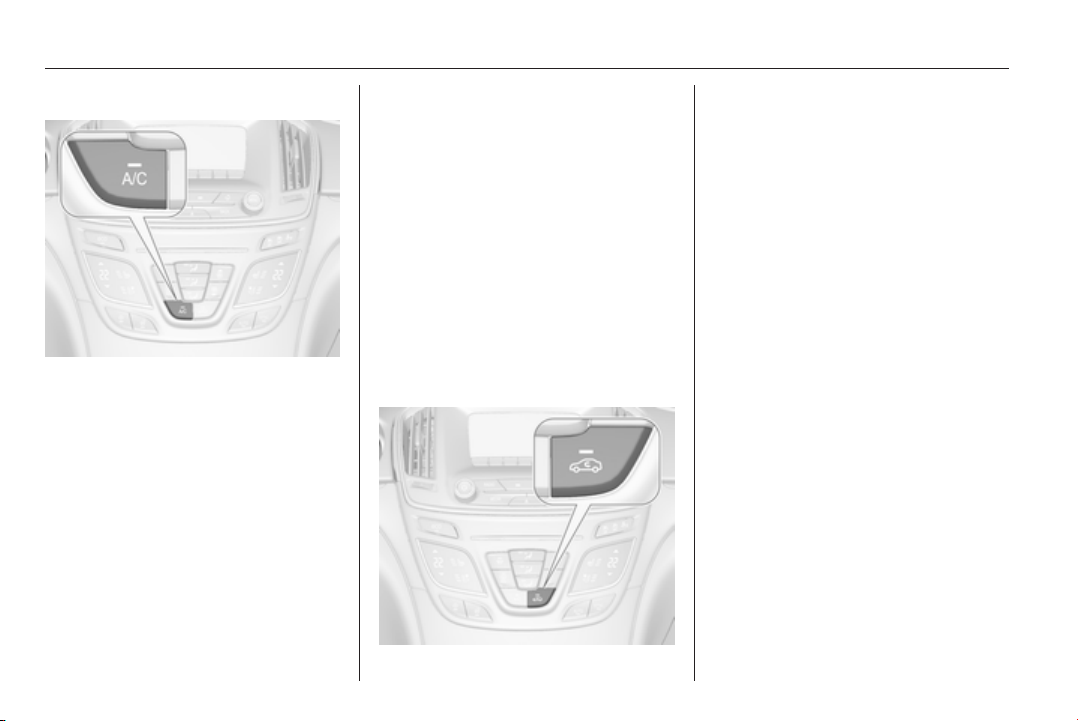
144 Climate control
Cooling A/C
Press button A/C to switch on cooling.
Activation is indicated by the LED in
the button. Cooling is only functional
when the engine is running and
climate control fan is switched on.
Press button A/C again to switch off
cooling.
The air conditioning system cools and
dehumidifies (dries) cabin air as
required. Therefore condensation
may form and is drained under the
vehicle.
If no cooling or drying is required,
switch off the cooling system for fuel
saving reasons.
System ON/OFF X
Cooling, fan and automatic mode can
be switched off by pressing button X.
When the system is deactivated, the
LED in the button X is off.
Activation by pressing button X or
cooling button A/C or automatic mode
button AUTO. Activation is indicated
by the LED in the button.
Manual air recirculation 4
Press button 4 to activate air
recirculation mode. Activation is
indicated by the LED in the button.
Select air recirculation to assist in
cooling the interior or in blocking
outside odors or exhaust. When
recirculation is selected, a partial
ventilation to refresh the interior air
will occur every 10 minutes.
Press button 4 again to deactivate
recirculation mode.
In warm and very humid ambient air
conditions, the windscreen might mist
up from outside, when cold air is
directed to it. If windscreen mists up
from outside, activate windscreen
wiper and deactivate l.
Automatic air recirculation
An air humidity sensor switches
automatically to external air if internal
air humidity is too high.
Basic settings
Some basic settings can be changed
in the vehicle personalisation menu in
the Colour-Info-Display.
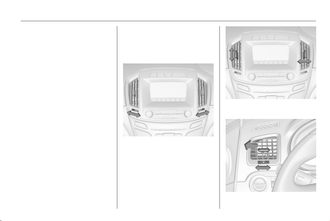
Climate control 145
Select the relevant settings in
Settings, I Vehicle in the Colour-Info-
Display.
Colour-Info-Display 3 114.
Vehicle personalisation 3 118.
Auxiliary heater
Air heater
Quickheat is an electric auxiliary air
heater which automatically warms up
the passenger compartment more
quickly.
Air vents
Adjustable air vents
Front air vents
To open the vent, turn the adjuster
wheel to B. Adjust the air amount at the
vent outlet by turning the adjuster
wheel.
Direct the flow of air by tilting and
swivelling the slats.
To close the vent, turn the adjuster
wheel to 7.
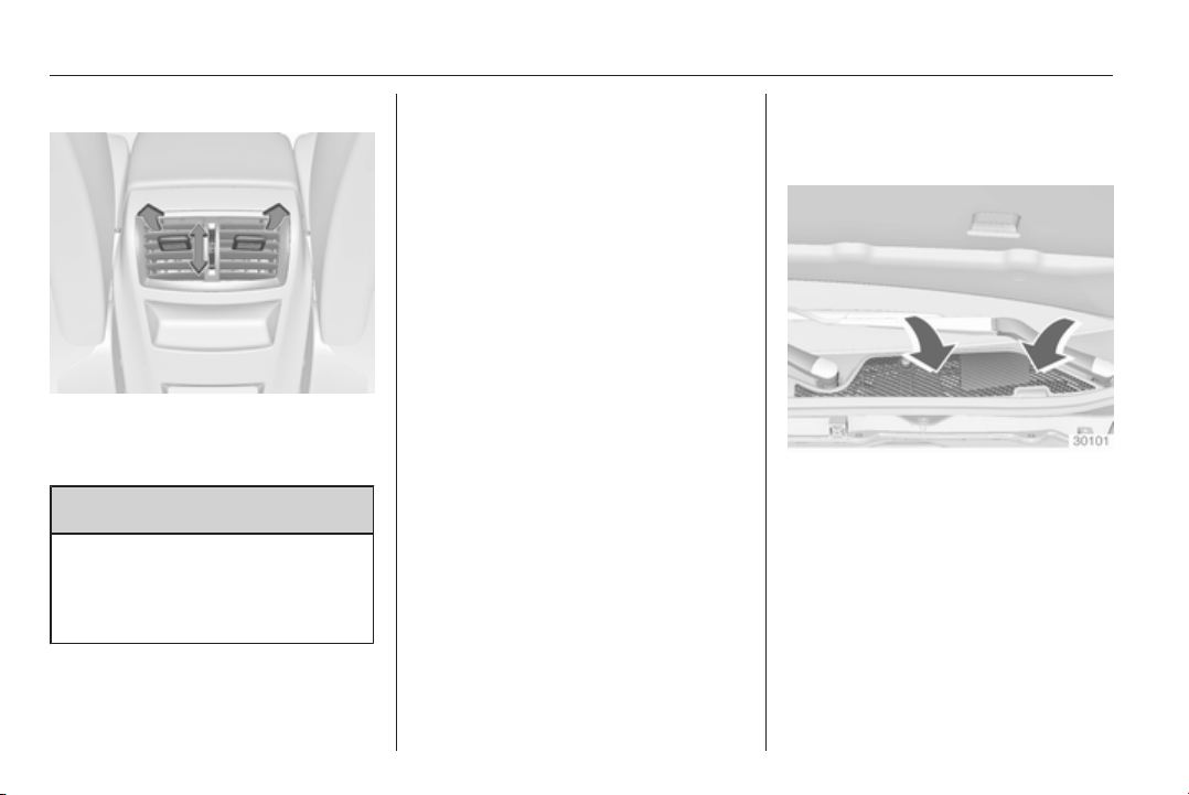
146 Climate control
Rear air vents
Air vents for rear passenger are in the
centre console between the front
seats.
9 Warning
Do not attach any objects to the
slats of the air vents. Risk of
damage and injury in case of an
accident.
Fixed air vents
Additional air vents are located
beneath the windscreen and door
windows and in the foot wells.
Maintenance
Air intake
The air intake in front of the
windscreen in the engine
compartment must be kept clear to
allow air intake. Remove any leaves,
dirt or snow.
Pollen filter
Cabin air filtration
A particle filter cleans the cabin air
from dust, soot, pollen and spores.

Climate control 147
Active carbon filter
In addition to the particle filter, the
active carbon filter reduces odours.
Filter replacement must be carried out
during a regular service.
Air conditioning regular
operation
In order to ensure continuously
efficient performance, it is
recommended that air coditioning
should be operated for a few minutes
once a month, irrespective of the
weather and time of year.
Service
For optimal cooling performance, it is
recommended to annually check the
climate control system, starting
three years after initial vehicle
registration, including:
■ Functionality and pressure test
■ Heating functionality
■ Leakage check
■ Check of drive belts
■ Cleaning of condenser and
evaporator drainage
■ Performance check

148 Driving and operating
Driving and operating
Driving hints ............................... 148
Starting and operating ............... 149
Engine exhaust .......................... 156
Automatic transmission .............. 157
Manual transmission .................. 162
Drive systems ............................ 163
Brakes ........................................ 163
Ride control systems ................. 166
Driver assistance systems ......... 171
Fuel ............................................ 202
Trailer hitch ................................ 209
Driving hints
Control of the vehicle
Never coast with engine not
running (except during
Autostop)
Many systems will not function in this
situation (e.g. brake servo unit, power
steering). Driving in this manner is a
danger to yourself and others. All
systems function during an Autostop,
but there will be a controlled reduction
in power steering assist and vehicle
speed is reduced.
Stop-start system 3 153.
Pedals
To ensure the pedal travel is
uninhibited, there must be no mats in
the area of the pedals.
Steering
If power steering assist is lost
because the engine stops or due to a
system malfunction, the vehicle can
be steered but may require increased
effort.
Control indicator c 3 103.
Caution
Vehicles equipped with hydraulic
power steering:
If the steering wheel is turned until
it reaches the end of its travel, and
is held in that position for more
than 15 seconds, damage may
occur to the power steering
system and there may be loss of
power steering assist.
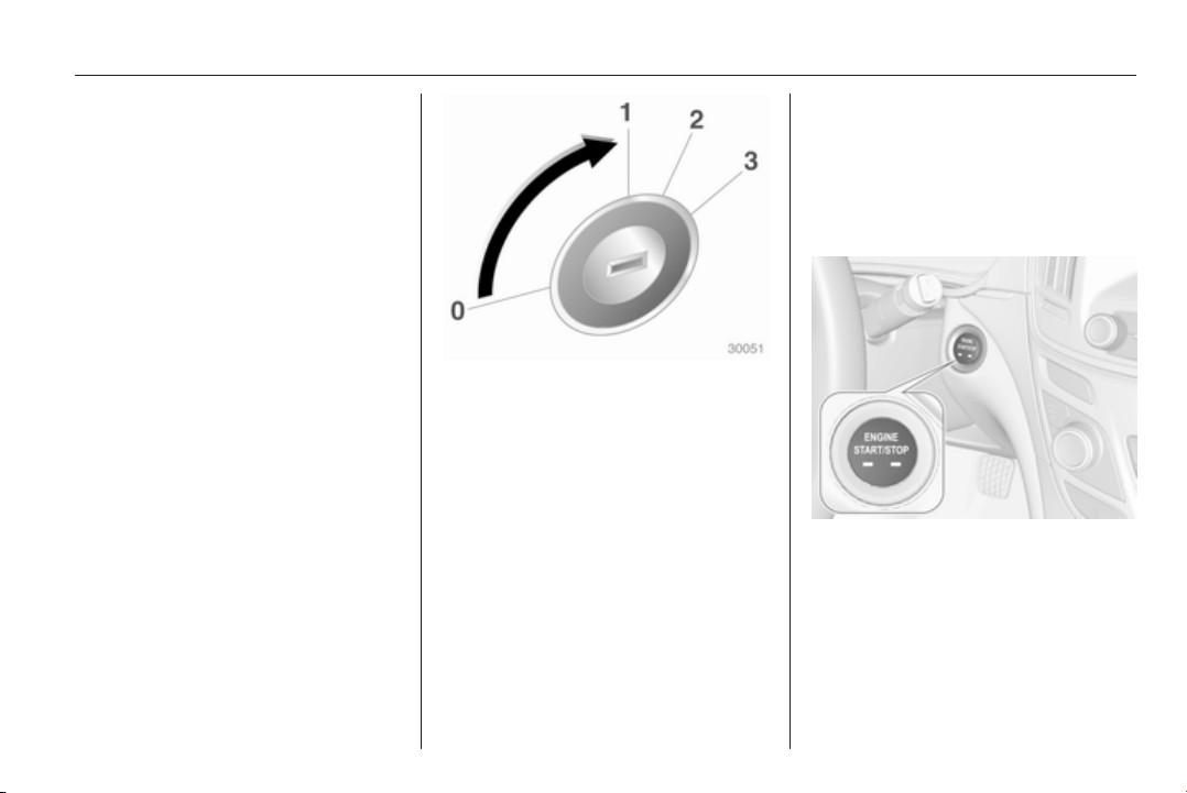
Driving and operating 149
Starting and operating
New vehicle running-in
Do not brake unnecessarily hard for
the first few journeys.
During the first drive, smoke may
occur because of wax and oil
evaporating off the exhaust system.
Park the vehicle in the open for a
while after the first drive and avoid
inhaling the fumes.
During the running-in period fuel and
engine oil consumption may be
higher and the cleaning process of
the diesel particle filter may take
place more often.
Diesel particle filter 3 156.
Ignition switch positions
Turn key:
0 = Ignition off: some functions
remain active until key is
removed or driver's door is
opened, if ignition was on
previously.
1 = Accessory power mode:
Steering wheel lock released,
some electrical functions are
operable, ignition is off.
2 = Ignition on power mode: Ignition
is on, diesel engine is
preheating. Control indicators
light up and the most electrical
functions are operable.
3 = Engine start. Release key after
starting procedure begins.
Steering wheel lock
Remove key from the ignition switch
and turn steering wheel until it
engages.
Power button
Electronic key must be inside the
vehicle.
Accessory power mode: press
Engine Start/Stop button once
without operating clutch or brake
pedal. The yellow LED in the button
illuminates. Steering wheel lock is
released and some electrical
functions are operable, ignition is off.
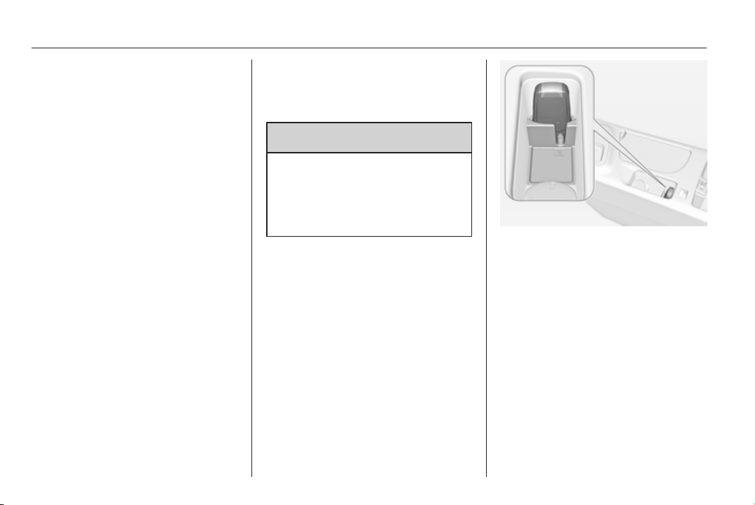
150 Driving and operating
Ignition on power mode: press and
hold Engine Start/Stop button for
6 seconds without operating clutch or
brake pedal. The green LED in the
button illuminates, diesel engine is
preheating. Control indicators light up
and the most electrical functions are
operable.
Engine start: operate clutch pedal
(manual transmission) or brake pedal
(automatic transmission) and press
Engine Start/Stop button once more.
Release button after starting
procedure begins.
Ignition off: press Engine Start/Stop
button briefly in each mode or when
engine is running. Some functions
remain active until driver's door is
opened, if ignition was on before.
Steering wheel lock
The steering wheel lock activates
automatically when:
■ the vehicle is stationary and
■ the ignition has been switched off
and
■ the driver's door is opened.
To release steering wheel lock, open
and close driver's door and switch on
accessory mode or start the engine
directly.
9 Warning
If the vehicle battery is discharged,
the vehicle must not be towed,
tow-started or jump-started as the
steering wheel lock cannot be
disengaged.
Emergency operation on
vehicles with electronic key
system
If either the electronic key fails or the
battery of the electronic key is weak,
the Driver Information Centre may
display No Remote Detected or
Replace Battery in Remote Key when
you try to start the vehicle.
Open the centre console storage area
by lifting up the armrest. Place the
electronic key in the transmitter
pocket. Depress the clutch pedal
(manual transmission) or the brake
pedal (automatic transmission) and
press the Engine Start/Stop button.
To switch off the engine, press the
Engine Start/Stop button again.
Remove the electronic key from the
transmitter pocket.
This option is intended for
emergencies only. Replace the
electronic key battery as soon as
possible 3 22.
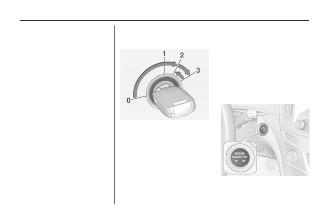
Driving and operating 151
For unlocking or locking the doors see
fault in radio remote control unit or
electronic key system 3 23.
Retained power off
The following electronic systems can
work until the driver's door is opened
or for 10 minutes after the ignition is
switched off:
■ Power windows
■ Sunroof
■ Power outlets
Power to the Infotainment system will
continue to operate for 30 minutes
when ignition is off, regardless of
whether any door will be opened.
Starting the engine
Vehicles with ignition switch
Manual transmission: operate clutch
and brake pedal.
Automatic transmission: operate
brake pedal and move selector lever
to P or N.
Do not operate accelerator pedal.
Diesel engine: turn the key to position
2 for preheating until control
indicator ! extinguishes.
Turn key briefly to position 3 and
release: an automatic procedure
operates the starter with a short delay
until the engine is running, see
Automatic Starter Control.
Before restarting or to switch off the
engine, turn key back to position 0.
During an Autostop, the engine can
be started by depressing the clutch
pedal 3 153.
Vehicles with power button
Manual transmission: operate clutch
and brake pedal.

152 Driving and operating
Automatic transmission: operate
brake pedal and move selector lever
to P or N.
Do not operate accelerator pedal.
Press and release Engine Start/Stop
button: an automatic procedure
operates the starter with a short delay
until the engine is running, see
Automatic Starter Control.
Before restarting or to switch off the
engine, press Engine Start/Stop
button once more.
During an Autostop, the engine can
be started by depressing the clutch
pedal 3 153.
Starting the vehicle at low
temperatures
Starting the engine without additional
heaters is possible down to -25 °С for
diesel engines and -30 °C for petrol
engines. Required is an engine oil
with the correct viscosity, the correct
fuel, performed services and a
sufficiently charged vehicle battery.
With temperatures below -30 °C the
automatic transmission requires a
warming phase of approx. 5 minutes.
The selector lever must be in position
P.
Automatic Starter Control
This function controls the engine
starting procedure. The driver does
not have to hold the key in position 3
or to hold Engine Start/Stop button
pressed. Once applied, the system
will go on starting automatically until
the engine is running. Because of the
checking procedure, the engine starts
running after a short delay.
Possible reasons for a non-starting
engine:
■ Clutch pedal not operated (manual
transmission)
■ Brake pedal not operated or
selector lever not in P or N
(automatic transmission)
■ Timeout occurred
Turbo engine warm-up
Upon start-up, engine available
torque may be limited for a short time,
especially when the engine
temperature is cold. The limitation is
to allow the lubrication system to fully
protect the engine.
Overrun cut-off
The fuel supply is automatically cut off
during overrun, i.e. when the vehicle
is driven with a gear engaged but
accelerator is released.
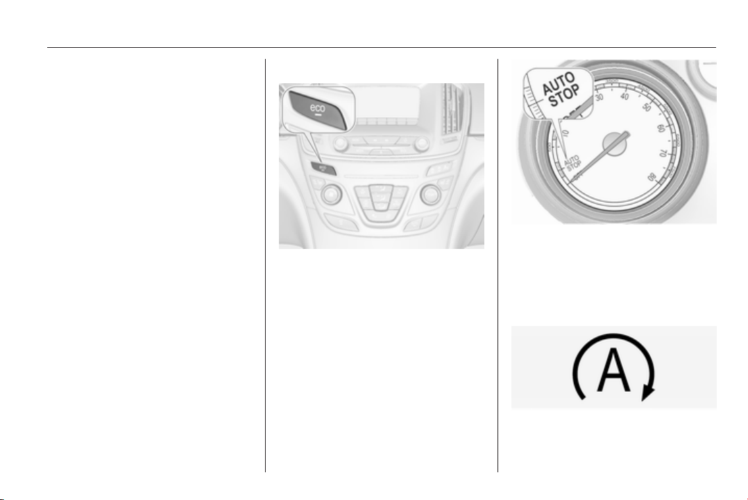
Driving and operating 153
Stop-start system
The stop-start system helps to save
fuel and to reduce the exhaust
emissions. When conditions allow, it
switches off the engine as soon as the
vehicle is at a low speed or at a
standstill, e.g. at a traffic light or in a
traffic jam. It starts the engine
automatically as soon as the clutch is
depressed. A battery sensor ensures
that an Autostop is only performed if
the vehicle battery is sufficiently
charged for a restart.
Activation
The stop-start system is available as
soon as the engine is started, the
vehicle starts-off and the conditions
as stated below in this section are
fulfilled.
Deactivation
Deactivate the stop-start system
manually by pressing the eco button.
The deactivation is indicated when
the LED in the button extinguishes.
Autostop
If the vehicle is at a low speed or at a
standstill, activate an Autostop as
follows:
■ Depress the clutch pedal
■ set the lever to neutral
■ release the clutch pedal
The engine will be switched off while
the ignition stays on.
An Autostop is indicated by the
needle at the AUTOSTOP position in
the tachometer. On some versions a
control indicator in the instrument
cluster lights up when engine is in
Autostop.
During an Autostop, the heating and
brake performance will be
maintained.

154 Driving and operating
Caution
The steering assist can be
reduced during an Autostop.
Conditions for an Autostop
The stop-start system checks if each
of the following conditions is fulfilled.
■ The stop-start system is not
manually deactivated
■ the bonnet is fully closed
■ the driver's door is closed or the
driver's seat belt is fastened
■ the vehicle battery is sufficiently
charged and in good condition
■ the engine is warmed up
■ the engine coolant temperature is
not too high
■ the engine exhaust temperature is
not too high, e.g. after driving with
high engine load
■ the ambient temperature is above
-5° C
■ the climate control system allows
an Autostop
■ the brake vacuum is sufficient
■ the self-cleaning function of the
diesel particle filter is not active
■ the vehicle was driven at least at
walking speed since the last
Autostop
Otherwise an Autostop will be
inhibited.
Certain settings of the climate control
system may inhibit an Autostop. See
Climate control chapter for more
details 3 134.
Immediately after motorway driving
an Autostop may be inhibited.
New vehicle running-in 3 149.
Vehicle battery discharge protection
To ensure reliable engine restarts,
several battery discharge protection
features are implemented as part of
the stop-start system.
Power saving measures
During an Autostop, several electrical
features such as auxiliary electric
heater or rear window heating are
disabled or switched to a power
saving mode. The fan speed of the
climate control system is reduced to
save power.
Restart of the engine by the
driver
Depress the clutch pedal to restart the
engine.
The engine start is indicated by the
needle at the idle speed position in
the tachometer.
If the selector lever is shifted out of
neutral before depressing the clutch
first, control indicator - illuminates
or is shown as a symbol in the Driver
Information Centre.
Control indicator - 3 102.
Restart of the engine by the
stop-start system
The selector lever must be in neutral
to enable an automatic restart.
If one of the following conditions
occurs during an Autostop, the
engine will be restarted automatically
by the stop-start system:

Driving and operating 155
■ The stop-start system is manually
deactivated
■ the bonnet is opened
■ the driver's seat belt is unfastened
and the driver's door is opened
■ the engine temperature is too low
■ the charging level of the vehicle
battery is below a defined level
■ the brake vacuum is not sufficient
■ the vehicle is driven at least at
walking speed
■ the climate control system requests
an engine start
■ the air conditioning is manually
switched on
If the bonnet is not fully closed, a
warning message is displayed in the
Driver Information Centre.
If an electrical accessory, e.g. a
portable CD player, is connected to
the power outlet, a brief power drop
during the restart might be noticeable.
Parking
■ Do not park the vehicle on an easily
ignitable surface. The high
temperature of the exhaust system
could ignite the surface.
■ Always apply parking brake.
Pull electric parking brake switch
m for approx. one second.
Apply manual parking brake
without pressing release button.
Apply as firmly as possible on
downhill or uphill slopes. Depress
the foot brake at the same time to
reduce operating force.
■ Switch off the engine and ignition.
Turn the steering wheel until the
steering wheel lock engages.
■ If the vehicle is on a level surface or
uphill slope, engage first gear or set
the selector lever to P before
switching off the ignition. On an
uphill slope, turn the front wheels
away from the kerb.
If the vehicle is on a downhill slope,
engage reverse gear or set the
selector lever to P before switching
off the ignition. Turn the front
wheels towards the kerb.
■ Lock the vehicle and activate the
anti-theft alarm system.
Note
In the event of an accident with
airbag deployment, the engine is
turned off automatically if the vehicle
comes to a standstill within a certain
time.
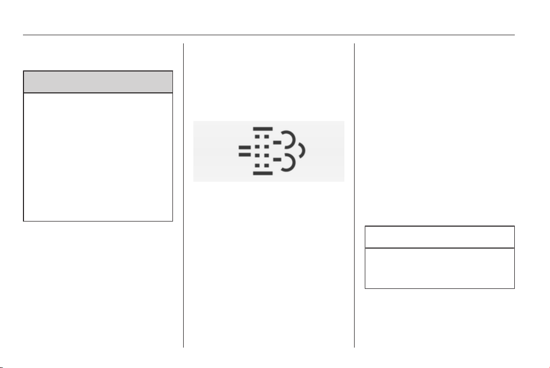
156 Driving and operating
Engine exhaust
9 Danger
Engine exhaust gases contain
poisonous carbon monoxide,
which is colourless and odourless
and could be fatal if inhaled.
If exhaust gases enter the interior
of the vehicle, open the windows.
Have the cause of the fault
rectified by a workshop.
Avoid driving with an open load
compartment, otherwise exhaust
gases could enter the vehicle.
Diesel particle filter
The diesel particle filter system filters
harmful soot particles out of the
exhaust gases. The system includes
a self-cleaning function that runs
automatically during driving without
any notification. The filter is cleaned
by periodically burning off the soot
particles at high temperature. This
process takes place automatically
under set driving conditions and may
take up to 25 minutes. Typically it
needs between 7 and 12 minutes.
Autostop is not available and fuel
consumption may be higher during
this period. The emission of smells
and smoke during this process is
normal.
Under certain driving conditions, e.g.
short distances, the system cannot
clean itself automatically.
If the cleaning of the filter is required
and if previous driving conditions did
not enable automatic cleaning, it will
be indicated by control indicator %.
Simultaneously Diesel partic. filter is
full continue driving appears in the
Driver Information Centre.
% illuminates when diesel particle
filter is full. Start cleaning process as
soon as possible.
% flashes and a warning chime
sounds several times when diesel
particle filter has reached the
maximum filling level. Start cleaning
process immediately to avoid
damage to the engine.
Cleaning process
To activate cleaning process,
continue driving, keep engine speed
above 2000 revolutions per minute.
Shift down if necessary. Diesel
particle filter cleaning is then started.
If additionally a message appears in
the Driver Information Centre that
cleaning is not possible, seek the
assistance of a workshop.
Caution
If the cleaning process is
interrupted, there is a risk of
provoking severe engine damage.
Cleaning takes place quickest at high
engine speeds and loads.
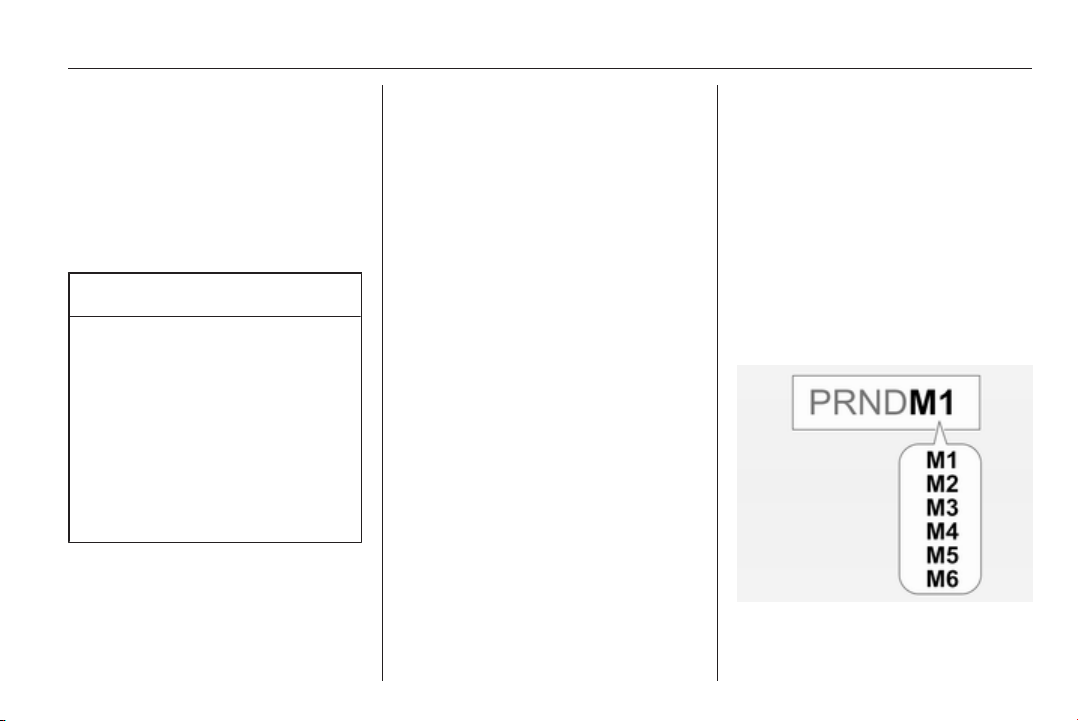
Driving and operating 157
The control indicator % extinguishes
as soon as the self-cleaning
operation is complete.
Catalytic converter
The catalytic converter reduces the
amount of harmful substances in the
exhaust gases.
Caution
Fuel grades other than those listed
on pages 3 202, 3 269 could
damage the catalytic converter or
electronic components.
Unburnt petrol will overheat and
damage the catalytic converter.
Therefore avoid excessive use of
the starter, running the fuel tank
dry and starting the engine by
pushing or towing.
In the event of misfiring, uneven
engine running, a reduction in engine
performance or other unusual
problems, have the cause of the fault
rectified by a workshop as soon as
possible. In an emergency, driving
can be continued for a short period,
keeping vehicle speed and engine
speed low.
Automatic transmission
The automatic transmission permits
automatic gearshifting (automatic
mode) or manual gearshifting
(manual mode).
Manual shifting is possible in manual
mode by tapping the selector lever or
pulling the steering wheel paddles
3 159.
Transmission display
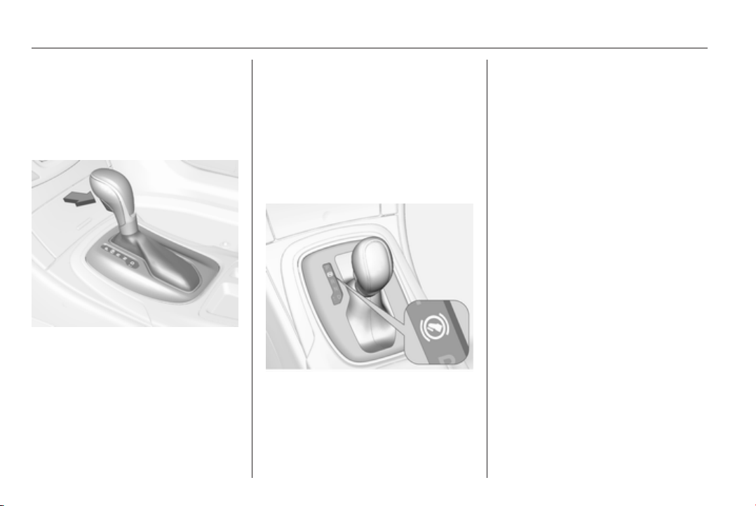
158 Driving and operating
The driving programme in automatic
mode or the selected gear in manual
mode is indicated in the Driver
Information Centre.
Selector lever
P = park position, wheels are
locked, engage only when the
vehicle is stationary and the
parking brake is applied
R = reverse gear, engage only
when vehicle is stationary
N = neutral
D = automatic mode with all gears
<
= manual mode upshifting: move
selector lever to position D to
the left and tap forwards
]
= manual mode downshifting:
move selector lever to position
D to the left and tap backwards
The selector lever is locked in P and
can only be moved when the ignition
is on and the brake pedal is applied.
Without applied brake pedal the
control indicator j illuminates.
If the selector lever is not in P when
the ignition is switched off, control
indicator j and P will flash.
To engage P or R, press the release
button.
The engine can only be started with
lever in position P or N. When position
N is selected, press brake pedal or
apply parking brake before starting.
Do not accelerate while engaging a
gear. Never depress the accelerator
pedal and brake pedal at the same
time.
When a gear is engaged, the vehicle
slowly begins to creep when the
brake is released.
Engine braking
To utilise the engine braking effect,
select a lower gear in good time when
driving downhill, see manual mode.
Rocking the vehicle
Rocking the vehicle is only
permissible if the vehicle is stuck in
sand, mud or snow. Move the selector
lever between D and R in a repeat
pattern. Do not race the engine and
avoid sudden acceleration.
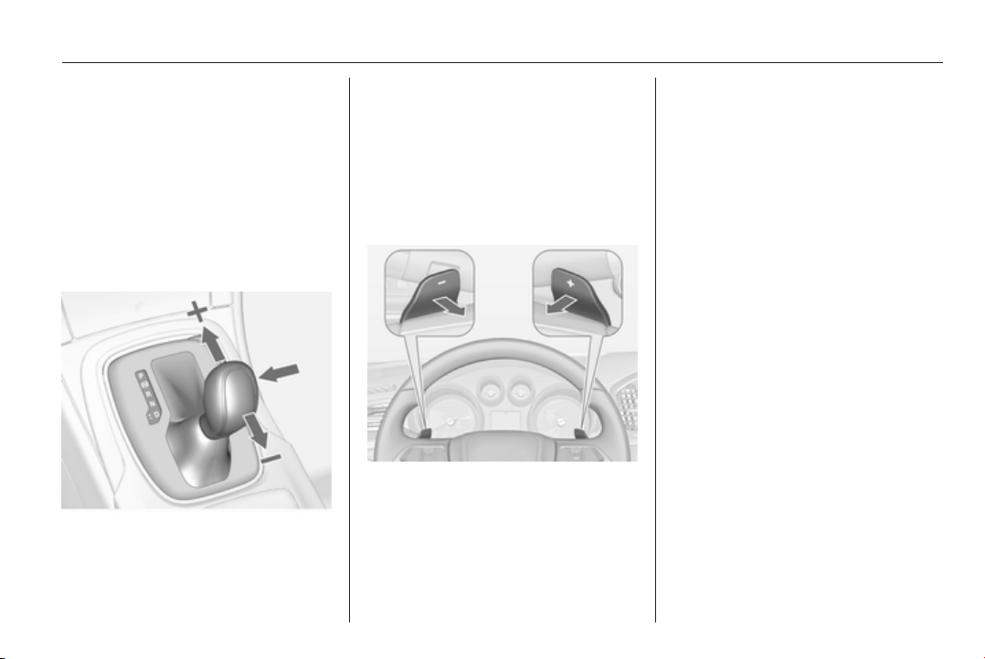
Driving and operating 159
Parking
Apply the parking brake and engage
P.
The ignition key can only be removed
when the selector lever is in position
P.
Manual mode
Selector lever
Move selector lever out of position
D
towards the left to select manual
mode.
Tap selector lever
forwards = shift to a higher gear
backwards = shift to a lower gear.
The selected gear is indicated in the
instrument cluster.
Steering wheel paddles
Move selector lever out of position
D
towards the left to select manual
mode.
Pull steering wheel paddles to select
gears manually
right
paddle <
= pull briefly to shift
one gear up
left
paddle ]
= pull briefly to shift one
gear down, multiple
pulls allows gears to
be skipped.
The selected gear is indicated in the
instrument cluster.
Temporary manual mode in drive
mode D
Manual paddle shifting is also
possible in automatic mode D. Upon
completion of manual shifting
operation, transmission changes to
automatic mode D after a defined
time.
To interrupt manual mode:
■
press < paddle for 1 second, or
■ move selector lever towards the left
to manual mode and back to
position D.
If the vehicle is at a standstill and
engine is idling, the transmission will
remain in temporary manual mode. It
changes to automatic mode when
accelerator pedal is operated for a
defined time and no paddle shifting at
the steering wheel is performed.

160 Driving and operating
General
If a higher gear is selected when
vehicle speed is too low, or a lower
gear when vehicle speed is too high,
the shift is not executed. This can
cause a message in the Driver
Information Centre.
In manual mode no automatic shifting
to a higher gear takes place at high
engine revolutions.
Electronic driving
programmes
■ Following a cold start, the operating
temperature programme increases
engine speed to quickly bring the
catalytic converter to the required
temperature.
■ The automatic neutral shift function
automatically shifts to idling when
the vehicle is stopped with a
forward gear engaged and the
brake pedal is pressed.
■ When SPORT mode is engaged,
the vehicle shifts at higher engine
speeds (unless cruise control is
on). SPORT mode 3 168.
■ Special programmes automatically
adapt the shifting points when
driving up inclines or down hills.
■ When starting off in snowy or icy
conditions or on other slippery
surfaces, the electronic
transmission control selects a
higher gear automatically.
Kickdown
If the accelerator pedal is pressed
down completely in automatic mode,
the transmission shifts to a lower gear
depending on engine speed.
Overheat protection
In the event of transmission-
overheating due to high outside
temperatures or sporty driving style,
the torque and the maximum speed of
the engine can be temporarily
reduced.
Fault
In the event of a fault a vehicle
message is displayed in the Driver
Information Centre. Vehicle
messages 3 116.
The transmission no longer shifts
automatically. Continued travel is
possible with manual shifting.
Only the highest gear is available.
Depending on the fault, 2nd gear may
also be available in manual mode.
Shift only when vehicle is stationary.
Have the cause of the fault remedied
by a workshop.
Interruption of power
supply
In the event of an interruption of
power supply, the selector lever
cannot be moved out of the P
position. The ignition key cannot be
removed from the ignition switch.
If the vehicle battery is discharged,
start the vehicle using jump leads
3 252.
If the vehicle battery is not the cause
of the fault, release the selector lever
and remove the ignition key from the
ignition switch.
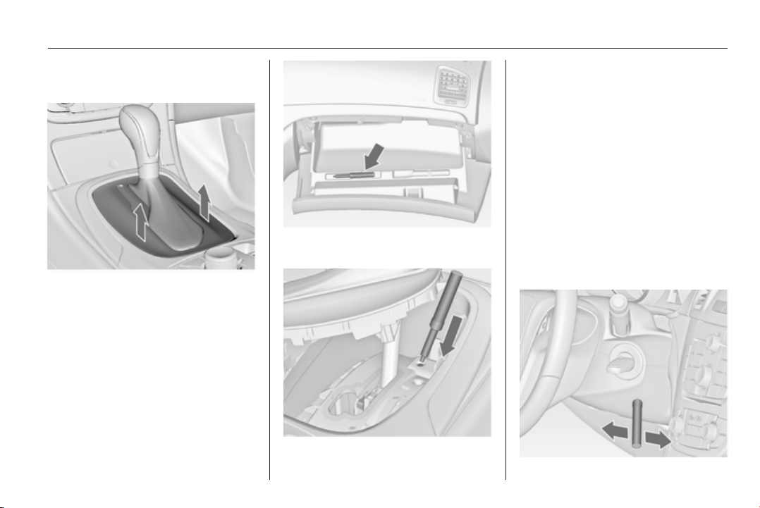
Driving and operating 161
Release selector lever
1. Apply parking brake.
2. Release selector lever trim from
centre console at rear, fold
upwards and rotate to the left.
3. Take the special tool from the
inside of the glovebox cover.
4. Insert it into the opening as far as
it will go and move the selector
lever out of P or N. If P or N is
engaged again, the selector lever
will be locked in position again.
Have the cause of the power
supply interruption remedied by a
workshop.
5. Mount the selector lever trim on
the centre console and refit.
Remove ignition key from
ignition switch
1. Take the special tool from the
inside of the glovebox cover.
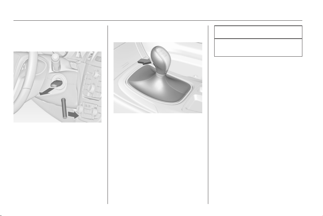
162 Driving and operating
2. Insert the special tool into the
opening below the ignition switch
as far as it will go and swivel it
slightly.
3. Turn special tool to the front and
remove key from the ignition
switch. Several attempts may be
required to successfully remove
the key.
Manual transmission
To engage reverse, with the vehicle
stationary press the release button on
the selector lever and engage the
gear.
If the gear does not engage, set the
lever to neutral, release the clutch
pedal and depress again; then repeat
gear selection.
Do not grind the clutch unnecessarily.
When operating, depress the clutch
pedal completely. Do not use the
pedal as a foot rest.
Caution
It is not advisable to drive with the
hand resting on the selector lever.
Driving and operating 163
Drive systems
All-wheel drive
The All-wheel drive system enhances
driving characteristics and stability,
and helps to achieve the best
possible driveability regardless of
ground surface. The system is always
active and cannot be deactivated.
The torque is distributed steplessly
between the wheels of the front and
rear axle, depending on the driving
conditions. Additionally the torque
between the rear wheels is distributed
depending on the surface.
For optimum system performance,
the vehicle's tyres should not have
varying degrees of wear.
If a service message is displayed in
the Driver Information Centre, the
system may have limited functionality
(or be completely disabled in some
cases, i.e. the vehicle switches to
Front-wheel drive). Seek the
assistance of a workshop.
Towing the vehicle 3 254.
Brakes
The brake system comprises two
independent brake circuits.
If a brake circuit fails, the vehicle can
still be braked using the other brake
circuit. However, braking effect is
achieved only when the brake pedal
is depressed firmly. Considerably
more force is needed for this. The
braking distance is extended. Seek
the assistance of a workshop before
continuing your journey.
When the engine is not running, the
support of the brake servo unit
disappears once the brake pedal has
been depressed once or twice.
Braking effect is not reduced, but
braking requires significantly greater
force. It is especially important to bear
this in mind when being towed.
Control indicator R 3 102.
Antilock brake system
Antilock brake system (ABS)
prevents the wheels from locking.
ABS starts to regulate brake pressure
as soon as a wheel shows a tendency
to lock. The vehicle remains
steerable, even during hard braking.
ABS control is made apparent
through a pulse in the brake pedal
and the noise of the regulation
process.
For optimum braking, keep the brake
pedal fully depressed throughout the
braking process, despite the fact that
the pedal is pulsating. Do not reduce
the pressure on the pedal.
After starting off, the system performs
a self-test which may be audible.
Control indicator u 3 103.
Adaptive brake light
During full braking, all three brake
lights flash for the duration of ABS
control.

164 Driving and operating
Fault
9 Warning
If there is a fault in the ABS, the
wheels may be liable to lock due
to braking that is heavier than
normal. The advantages of ABS
are no longer available. During
hard braking, the vehicle can no
longer be steered and may
swerve.
Have the cause of the fault remedied
by a workshop.
Parking brake
Manual parking brake
Always apply parking brake firmly
without operating the release button,
and apply as firmly as possible on a
downhill or uphill slope.
To release the parking brake, pull the
lever up slightly, press the release
button and fully lower the lever.
To reduce the operating forces of the
parking brake, depress the foot brake
at the same time.
Control indicator R 3 102.
Electric parking brake
Applying when vehicle is stationary
Pull switch m for approx.
one second, the electric parking
brake operates automatically with an
adequate force. For maximum force,
e.g. parking with trailer or on inclines,
pull switch m twice.
The electric parking brake is applied
when control indicator m lights up
3 102.
The electric parking brake can always
be activated, even if the ignition is off.

Driving and operating 165
Do not operate electric parking brake
system too often without engine
running as this will discharge the
vehicle battery.
Before leaving the vehicle, check the
electric parking brake status. Control
indicator m 3 102.
Releasing
Switch on ignition. Keep foot brake
pedal depressed and then push
switch m.
Drive away function
Depressing clutch pedal (manual
transmission) or engaging drive gear
(automatic transmission) and then
depressing the accelerator pedal
releases the electric parking brake
automatically. This is not possible
when the switch is pulled at the same
time.
This function also helps driving away
on inclines.
Aggressive drive away may reduce
life time of wear parts.
Dynamic braking when vehicle is
moving
When the vehicle is moving and the
switch m is kept pulled, the electric
parking brake system will decelerate
the vehicle, but will not apply
statically.
As soon as the switch m is released,
dynamic braking will be stopped.
Automatic applying
If the vehicle is equipped with
Automatic transmission and Adaptive
cruise control is active, electric
parking brake is applied automatically
when vehicle is stopped by the
system for more than 2 minutes.
Parking brake releases automatically
after moving off.
Functionality check
When the vehicle is not moving, the
electric parking brake might be
applied automatically. This is done to
check the system.
Fault
Failure mode of electric parking brake
is indicated by a control indicator j
and by a vehicle message which is
displayed in the Driver Information
Centre. Vehicle messages 3 116.
Apply electric parking brake: pull and
hold the switch m for more than
5 seconds. If control indicator m
illuminates, electric parking brake is
applied.
Release electric parking brake: push
and hold the switch m for more than
2 seconds. If control indicator m
extinguishes, electric parking brake is
released.
Control indicator m flashes: electric
parking brake is not fully applied or
released. When continuously
flashing, release electric parking
brake and retry applying.
Brake assist
If brake pedal is depressed quickly
and forcefully, maximum brake force
is automatically applied.
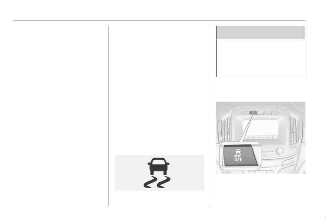
166 Driving and operating
Operation of brake assist might
become apparent by a pulse in the
brake pedal and a greater resistance
when depressing the brake pedal.
Maintain steady pressure on the
brake pedal as long as full braking is
required. Maximum brake force is
automatically reduced when brake
pedal is released.
Hill start assist
The system helps prevent unintended
movement when driving away on
inclines.
When releasing the foot brake after
stopping on an incline, brakes remain
on for further two seconds. Brakes
release automatically as soon as the
vehicle begins to accelerate.
The hill start assist is not active during
an Autostop.
Stop-start system 3 153.
Ride control systems
Traction Control system
The Traction Control system (TC) is a
component of the Electronic Stability
Control.
TC improves driving stability when
necessary, regardless of the type of
road surface or tyre grip, by
preventing the drive wheels from
spinning.
As soon as the drive wheels starts to
spin, engine output is reduced and
the wheel spinning the most is braked
individually. This considerably
improves the driving stability of the
vehicle on slippery road surfaces.
TC is operational as soon as the
control indicator b extinguishes.
When TC operates b flashes.
9
Warning
Do not let this special safety
feature tempt you into taking risks
when driving.
Adapt speed to the road
conditions.
Control indicator b 3 104.
Deactivation
TC can be switched off when spinning
of drive wheels is required:

Driving and operating 167
press button b briefly to deactivate
TC, k illuminates. Deactivation is
displayed as status message in the
Driver Information Centre.
Control indicator k illuminates.
TC is reactivated by pressing the b
button again.
TC is also reactivated the next time
the ignition is switched on.
Electronic Stability Control
Electronic Stability Control (ESC)
improves driving stability when
necessary, regardless of the type of
road surface or tyre grip. It also
prevents the drive wheels from
spinning. ESC operates in
combination with the Traction Control
system (TC) 3 166.
As soon as the vehicle starts to
swerve (understeer/oversteer),
engine output is reduced and the
wheels are braked individually. This
considerably improves the driving
stability of the vehicle on slippery road
surfaces.
ESC is operational as soon as the
control indicator b extinguishes.
When ESC operates, control indicator
b flashes.
9 Warning
Do not let this special safety
feature tempt you into taking risks
when driving.
Adapt speed to the road
conditions.
Control indicator b 3 104.
Deactivation
For a more sporty behaviour ESC and
TC can be deactivated separately:
■ press button b briefly: only Traction
control system is inactive, ESC
remains active, k illuminates
■ hold button b pressed for min.
5 seconds: TC and ESC are
deactivated, k and n illuminate.
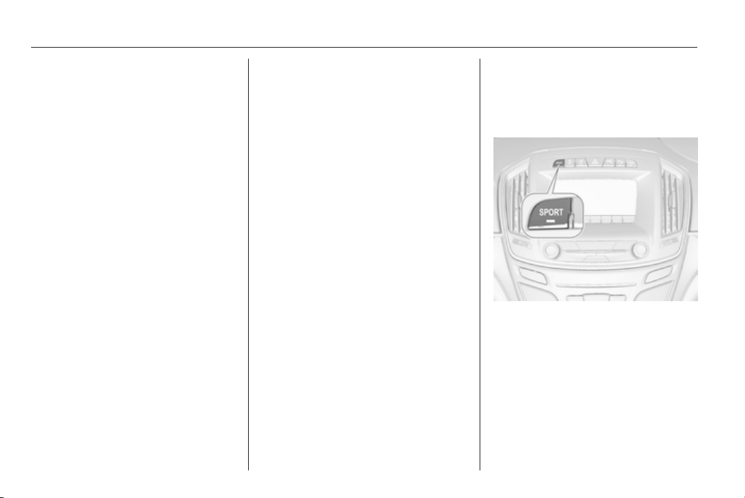
168 Driving and operating
Additionally the selected mode is
displayed as status message in the
Driver Information Centre.
If the vehicle comes into threshold
with deactivated ESP, the system will
reactivate ESP for the time duration
of the threshold, when the brake
pedal is depressed once.
ESC is reactivated by pressing the
b button again. If the TC system was
previously disabled, both TC and
ESC are reactivated.
ESC is also reactivated the next time
the ignition is switched on.
Interactive driving system
Flex Ride
Flex Ride driving system allows the
driver to select between three driving
modes:
■ SPORT mode: press button
SPORT, LED illuminates.
■ TOUR mode: press button TOUR,
LED illuminates.
■ NORMAL mode: neither button
SPORT nor TOUR is pressed, no
LED illuminates.
Deactivate SPORT mode and TOUR
mode by pressing corresponding
button once more.
In each driving mode Flex Ride
networks the following electronic
systems:
■ Continuous Damping Control.
■ Accelerator Pedal Control.
■ Steering Control.
■ All-wheel drive.
■ Electronic Stability Control (ESC).
■ Antilock brake system (ABS) with
cornering brake control (CBC).
■ Automatic transmission.
SPORT mode
The settings of the systems are
adapted to a sportier driving style:
■ Damping of shock absorbers reacts
more stiffly to provide better contact
with the road surface.
■ The engine reacts more quickly to
the accelerator pedal.
■ Steering support is reduced.
■ Engine torque of All-wheel drive is
distributed more to the rear axle.
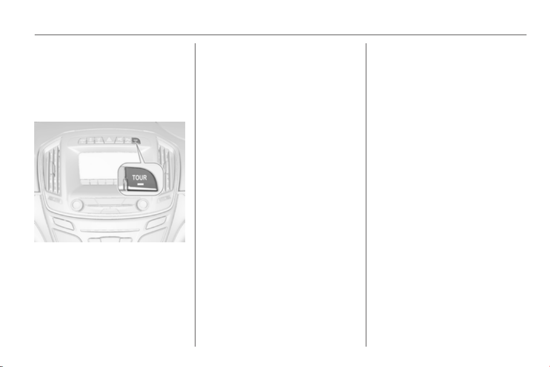
Driving and operating 169
■ Shift points of automatic
transmission occur later.
■ With SPORT mode activated, the
illumination of main instruments
changes from white to red.
TOUR mode
The settings of the systems are
adapted to a comfort driving style:
■ Damping of shock absorbers reacts
more softly.
■ Accelerator pedal reacts with
standard settings.
■ Steering support is in standard
mode.
■ Engine torque of All-wheel drive is
distributed mainly to the front axle.
■ Shift points of automatic
transmission occur in a comfort
mode.
■ Illumination of main instruments is
white.
NORMAL mode
All settings of the systems are
adapted to standard values.
Drive mode control
Within each manually selected driving
mode SPORT, TOUR or NORMAL,
the Drive Mode Control (DMC)
detects and analyses continuously
the real driving characteristic,
responses by the driver, and the
active dynamic state of the vehicle. If
necessary, the control unit of DMC
automatically changes the settings
within the selected driving mode or,
when recognising greater variations,
the driving mode is changed for the
length of variation.
If, for example, NORMAL mode is
selected and DMC detects a sporty
driving behaviour, DMC changes
several settings of the Normal mode
into sporty settings. The DMC
changes to SPORT mode in case of
very sporty driving behaviour.
If, for another example, TOUR mode
is selected and whilst driving on a
winding road a sudden hard brake is
necessary, DMC will detect the
dynamic vehicle condition and
changes the settings for suspension
to SPORT mode to increase vehicle
stability.
When the driving characteristic or the
dynamic vehicle state returns to the
former state, DMC will change the
settings to the preselected driving
mode.
Personalised settings in SPORT
mode
The driver can select the functions of
the SPORT mode when SPORT
button is pressed.
Select the relevant settings in
Settings, I Sport Mode in the Colour-
Info-Display.
Colour-Info-Display 3 114.
Vehicle personalisation 3 118.
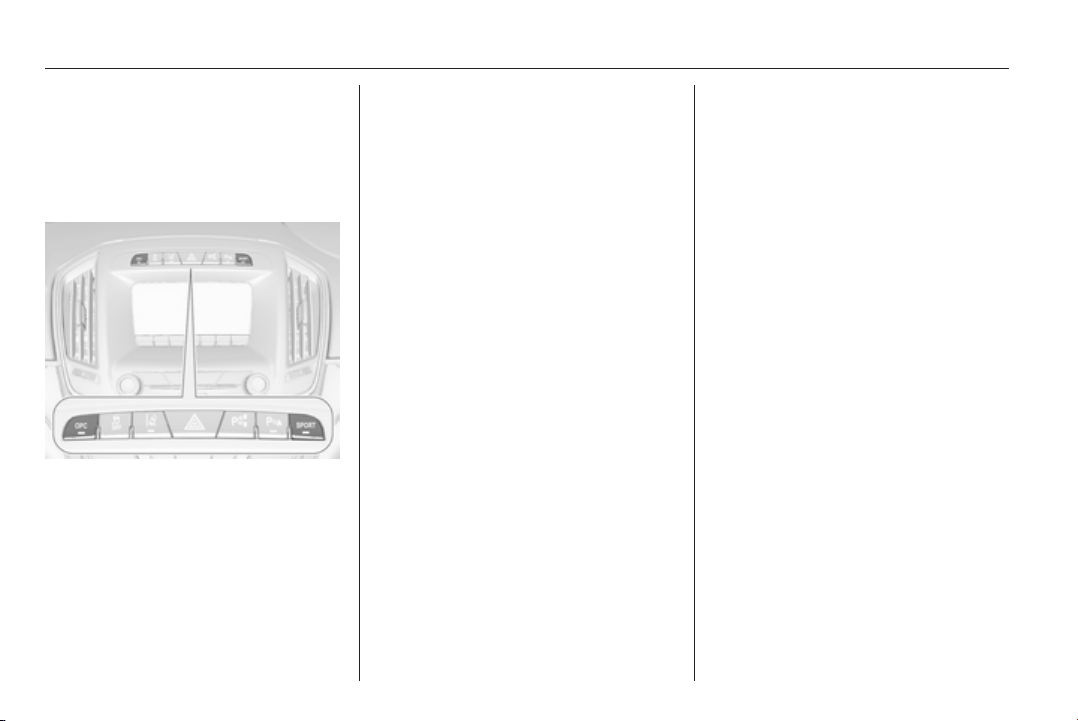
170 Driving and operating
Flex Ride - OPC Version
The OPC Version of Flex Ride system
works in the same way as the
standard Flex Ride system with the
difference that the modes have a
more sporty characteristic.
OPC Flex Ride driving system allows
the driver to select between three
driving modes:
■ OPC mode: press button OPC,
LED illuminates.
■ SPORT mode: press button
SPORT, LED illuminates.
■ NORMAL mode: neither button
SPORT nor OPC is pressed, no
LED illuminates.
Deactivate SPORT mode and OPC
mode by pressing corresponding
button once more.
In each driving mode OPC Flex Ride
networks the following electronic
systems:
■ Continuous Damping Control.
■ Accelerator Pedal Control.
■ Steering Control.
■ All-wheel drive.
■ Electronic Stability Control (ESC).
■ Antilock brake system (ABS) with
cornering brake control (CBC).
■ Automatic transmission.
OPC mode
The drive dynamic characteristics are
adapted to high performance
settings.
In this mode the illumination of main
instruments is switched to red.
SPORT mode
The settings of the systems are
adapted to a sportier driving style.
NORMAL mode
In NORMAL mode, when neither
SPORT nor OPC button is pressed,
all settings of the systems are
adapted to standard values.
Personalised settings in the OPC
mode
The driver can select the functions of
the OPC mode when OPC button is
pressed.
Select the relevant settings in
Settings, I Sport Mode in the Colour-
Info-Display.
Colour-Info-Display 3 114.
Vehicle personalisation 3 118.
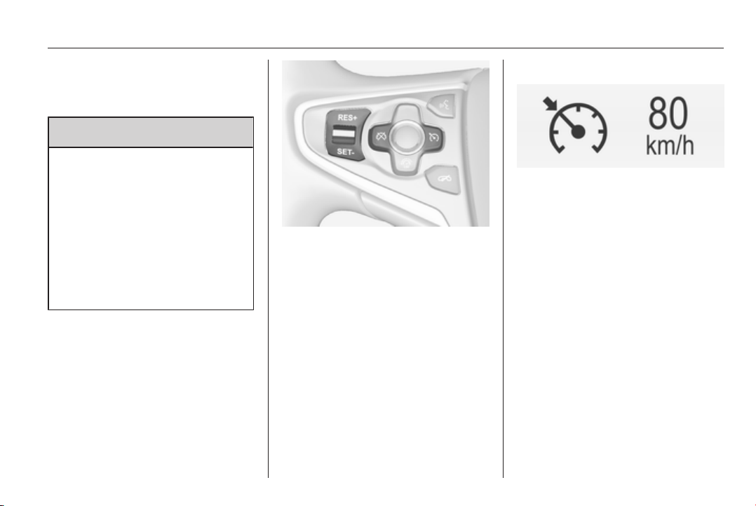
Driving and operating 171
Driver assistance
systems
9 Warning
Driver assistance systems are
developed to support the driver
and not to replace his attention.
The driver accepts full
responsibility when driving the
vehicle.
When using driver assistance
systems, always take care
regarding the current traffic
situation.
Cruise control
The cruise control can store and
maintain speeds of approx. 30 to
200 km/h. Deviations from the stored
speeds may occur when driving uphill
or downhill.
For safety reasons the cruise control
cannot be activated until the foot
brake has been operated once.
Activating in first gear is not possible.
Do not use the cruise control if it is not
advisable to maintain a constant
speed.
With automatic transmission, only
activate cruise control in automatic
mode.
Control indicator m 3 106.
Switching on
Press button m, control indicator m in
instrument cluster illuminates white.
Activation
Accelerate to the desired speed and
turn thumb wheel to SET/-: the
current speed is stored and
maintained. Control indicator m in
instrument cluster illuminates green.
Set speed is indicated on midlevel or
uplevel display near m symbol.
Accelerator pedal can be released.
Vehicle speed can be increased by
depressing the accelerator pedal.
When the accelerator pedal is
released, the previously stored speed
is resumed.
Cruise control remains activated
while gearshifting.
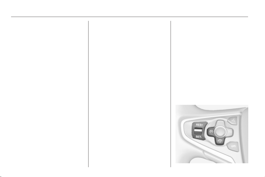
172 Driving and operating
Increase speed
With cruise control active, hold thumb
wheel turned to RES/+ or briefly turn
to RES/+ repeatedly: speed
increases continuously or in small
increments.
Alternatively accelerate to the desired
speed and store by turning to SET/-.
Reduce speed
With cruise control active, hold thumb
wheel turned to SET/- or briefly turn to
SET/- repeatedly: speed decreases
continuously or in small increments.
Deactivation
Press button y, control indicator m in
instrument cluster illuminates white.
Cruise control is deactivated. Last
used set speed is stored in memory
for later speed resume.
Automatic deactivation:
■ vehicle speed below approx.
30 km/h,
■ vehicle speed above approx.
200 km/h,
■ the brake pedal is depressed,
■ the clutch pedal is depressed for a
few seconds,
■ selector lever in N,
■ engine speed in a very low range,
■ the Traction Control system or
Electronic Stability Control is
operating,
■ Forward collision alert has been
triggered.
Resume stored speed
Turn thumb wheel to RES/+ at a
speed above 30 km/h. The stored
speed will be obtained.
Switching off
Press button m, control indicator m in
instrument cluster extinguishes. The
stored speed is deleted.
Pressing button L for activating
speed limiter or switching off the
ignition also switches off cruise
control and deletes the stored speed.
Speed limiter
The speed limiter prevents the
vehicle exceeding a preset maximum
speed.
The maximum speed can be set at a
speed above 25 km/h.
The driver can only accelerate up to
the preset speed. Deviations from the
limited speed may occur when driving
downhill.
The preset speed limit is displayed in
the Driver Information Centre when
the system is active.
Activation
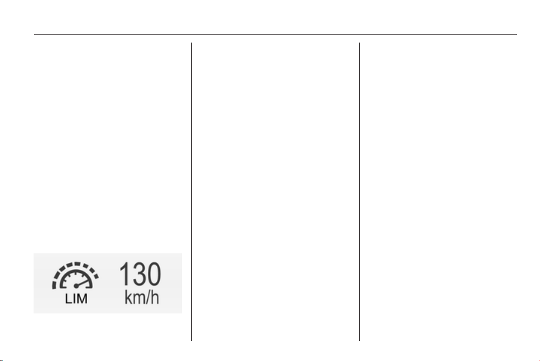
Driving and operating 173
Press button L. The control indicator
L in the instrument cluster illuminates
white. If cruise control or adaptive
cruise control has been activated
before, it is switched off when speed
limiter is activated and the control
indicator m extinguishes.
Set speed limit
With speed limiter active, hold thumb
wheel turned to RES/+ or briefly turn
to RES/+ repeatedly until the desired
maximum speed is displayed in the
Driver Information Centre.
Alternatively accelerate to the desired
speed and briefly turn thumb wheel to
SET/-: the current speed is stored as
maximum speed. Speed limit is
displayed in the Driver Information
Centre.
Control indicator L in the instrument
cluster illuminates green.
Change speed limit
With speed limiter active, turn thumb
wheel to RES/+ to increase or SET/-
to decrease the desired maximum
speed.
Exceeding the speed limit
In the event of an emergency it is
possible to exceed the speed limit by
depressing the accelerator pedal
firmly beyond the point of resistance.
The limited speed will flash in the
Driver Information Centre and a
chime sounds during this period.
Release the accelerator pedal and
the speed limiter function is
reactivated once a speed lower than
the limit speed is obtained.
Deactivation
Press button y: speed limiter is
deactivated and the vehicle can be
driven without speed limit.
The limited speed is stored and a
corresponding message appears in
the Driver Information Centre.
Resume limit speed
Turn thumb wheel to RES/+. The
stored speed limit will be obtained.
Switching off
Press button L, the speed limit
indication in the Driver Information
Centre extinguishes. The stored
speed is deleted.
By pressing button m to activate
cruise control or adaptive cruise
control or by switching off the ignition,
speed limiter is also deactivated and
the stored speed is deleted.
Adaptive cruise control
Adaptive cruise control is an
enhancement to traditional cruise
control with the additional feature of
maintaining a certain distance behind
the vehicle ahead.
Adaptive cruise control automatically
decelerates the vehicle when
approaching a slower moving vehicle.
It then adjusts the vehicle speed to
follow the vehicle ahead at the
selected following distance. The
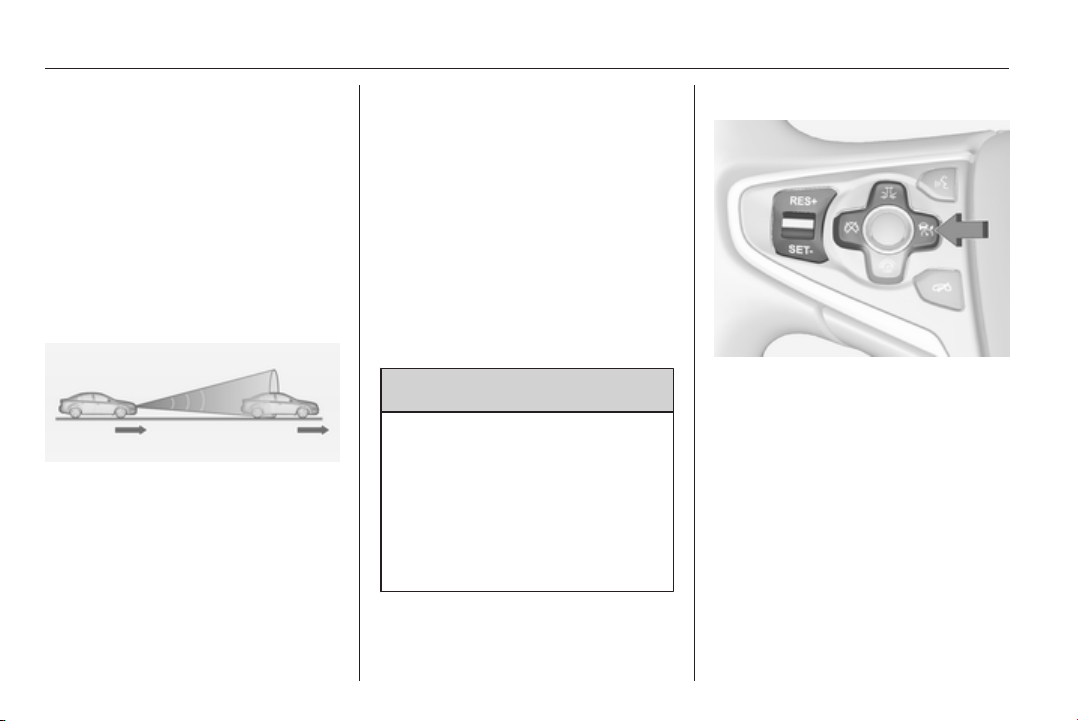
174 Driving and operating
vehicle speed increases or decreases
to follow the vehicle in front, but will
not exceed the set speed. It may
apply limited braking with activated
brake lights.
The adaptive cruise control can store
and maintain speeds over approx.
25 km/h and brakes automatically to
follow a slower vehicle driving ahead
to a minimum speed of 15 km/h. On
vehicles with automatic transmission
the system brakes to a stop.
Adaptive cruise control uses a radar
sensor to detect the vehicles ahead.
If no vehicle is detected in the driving
path, the adaptive cruise control will
behave like a traditional cruise
control.
For safety reasons, the system
cannot be activated before the brake
pedal has been depressed once
since switching on ignition. Activation
in first gear is not possible.
Adaptive cruise control is mainly
advised to be used on long straight
roads like highways or country roads
with steady traffic. Do not use the
system if it is not advisable to
maintain a constant speed.
Control indicator A 3 106, m 3 106,
C 3 106.
9 Warning
The complete driver attention is
always required while driving with
adaptive cruise control. The driver
stays fully in control of the vehicle
because the brake pedal, the
accelerator pedal and the cancel
switch have priority over any
adaptive cruise control operation.
Switching on
Press button C to switch on adaptive
cruise control. The control indicator
m or C in the instrument cluster
illuminates white.
Activation by setting the speed
Adaptive cruise control can be
activated between 25 km/h and
180 km/h.
Accelerate to the desired speed and
turn thumb wheel to SET/-, the
current speed is stored and
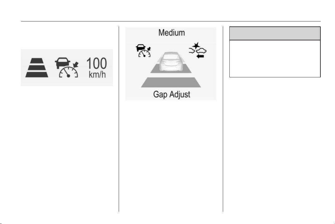
Driving and operating 175
maintained. Control indicator m or
C in the instrument cluster
illuminates green.
The adaptive cruise control symbol,
the following distance setting and set
speed are indicated in the Driver
Information Centre.
The accelerator pedal can be
released. Adaptive cruise control
remains activated while gearshifting.
Overriding set speed
It is always possible to drive faster
than the selected set speed by
depressing the accelerator pedal.
When the accelerator pedal is
released, the vehicle returns to the
desired distance if a slower vehicle is
ahead. Otherwise it returns to the
stored speed.
Once the system is activated,
adaptive cruise control decelerates or
brakes if it detects a vehicle ahead,
which is slower or closer than the
desired following distance.
9
Warning
Accelerating by the driver
deactivates braking by the system.
This is indicated as a popup
warning in the Driver Information
centre.
Increase speed
With adaptive cruise control active,
hold thumb wheel turned to RES/+:
speed increases continuously in large
increments, or activate repeatedly
RES/+: speed increases in small
increments.
If the vehicle is driven with adaptive
cruise control active much faster than
the desired speed, e.g. after
depressing the accelerator pedal,
then the current speed can be stored
and maintained by turning the thumb
wheel to SET/-.
Reduce speed
With adaptive cruise control active,
hold thumb wheel turned to SET/-:
speed decreases continuously in

176 Driving and operating
large increments, or activate
repeatedly SET/-: speed decreases in
small increments.
If the vehicle is driven with adaptive
cruise control active much slower
than the desired speed, e.g. because
of a slower vehicle ahead, then the
current speed can be stored and
maintained by turning the thumb
wheel to SET/-.
Resume stored speed
If the system is switched on but
inactive, then turn thumb wheel to
RES/+ at a speed above 25 km/h to
resume the stored speed.
Full speed range adaptive
cruise control on vehicles with
automatic transmission
Full speed range adaptive cruise
control will maintain a following gap
behind a detected vehicle and slow
your vehicle to a stop behind that
vehicle.
When the vehicle ahead drives away
within two minutes, turn thumb wheel
to RES/+ or operate the accelerator
pedal to resume full speed range
adaptive cruise control.
If the stopped vehicle ahead begins to
move forward and full speed range
adaptive cruise control has not
resumed, the green illuminated
vehicle ahead control indicator A will
flash and a warning chime will sound
as a reminder that the vehicle ahead
is pulling away.
When the vehicle ahead stops for
more than two minutes, the electric
parking brake will apply automatically
and the full speed range adaptive
cruise control is deactivated. In this
event, drive the vehicle normally by
operating the accelerator pedal. Turn
thumb wheel to RES/+ at a speed
above 25 km/h to resume full speed
range adaptive cruise control.
9 Warning
When full speed range adaptive
cruise control is deactivated or
cancelled, the vehicle will no
longer be held at a stop and can
start to move. Always be prepared
to manually apply the brake to hold
the vehicle stationary.
Do not leave the vehicle while it is
being held at a stop by the full
speed range adaptive cruise
control. Always move selector
lever to park position P and switch
off the ignition before leaving the
vehicle.
Setting the following distance
When adaptive cruise control detects
a slower moving vehicle in the driving
path, it will adjust the vehicle speed to
maintain the following distance
selected by the driver.
The following distance can be set to
near, medium or far.
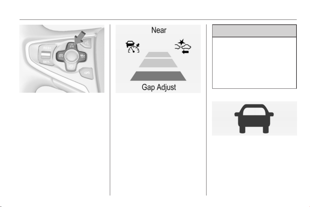
Driving and operating 177
Press button E, the current setting is
shown in the Driver Information
Centre. Press button E again to
change the following distance. The
setting is also displayed in the Driver
Information Centre.
The selected following distance is
indicated by filled distance bars in the
adaptive cruise control page.
Note that the following distance
setting is shared with the sensitivity
setting of forward collision alert
3 181.
Example: If setting 3 (far) is selected,
then the driver is warned sooner
before a possible collision, also if
adaptive cruise control is inactive or
switched off.
9 Warning
The driver accepts full
responsibility for the appropriate
following distance based on traffic,
weather and visibility conditions.
Following distance must be
adjusted or the system switched
off when required by the prevailing
conditions.
Detecting the vehicle ahead
The green illuminated vehicle ahead
control indicator A is displayed when
the system detects a vehicle in the
driving path.
If this symbol does not display, or
displays briefly, adaptive cruise
control will not respond to vehicles
ahead.
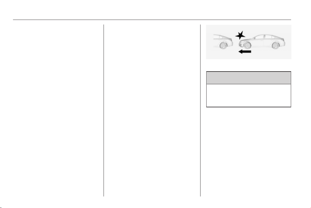
178 Driving and operating
Deactivation
Adaptive cruise control is deactivated
by the driver when:
■ button y is pressed,
■ brake pedal is applied,
■ clutch pedal is depressed for more
than four seconds,
■ gear selector lever of automatic
transmission is moved to N.
The system is also automatically
deactivated when:
■ vehicle speed accelerates above
190 km/h or slows down below
15 km/h (on vehicles with automatic
transmission it slows down to a stop
without deactivating within
two minutes),
■ Traction Control system is
operating for more than
20 seconds,
■ Electronic Stability Control is
operating,
■ there is no traffic and nothing
detected on the road sides for
several minutes. In this case there
are no radar echoes and the sensor
may report that it is blocked,
■ collision imminent braking is
applying the brakes,
■ radar sensor is blocked by an ice or
water film,
■ fault is detected in the radar, engine
or brake system.
Additionally the system is
automatically deactivated on vehicles
with automatic transmission (full
speed range adaptive cruise control)
when:
■ Electric parking brake is applied,
■ vehicle is being held to a stop by the
system for more than two minutes,
■ vehicle stops and a door is opened.
When adaptive cruise control is
deactivated automatically, the control
indicator m or C illuminates white
and a warning symbol is displayed as
a pop-up in the Driver Information
Centre.
The stored speed is maintained.
9 Warning
When adaptive cruise control is
deactivated, the driver must take
over full brake and engine control.
Switching off
Press button C to switch off adaptive
cruise control. The control indicator
m or C extinguishes. The stored
speed is deleted.
Switching off the ignition also
switches off adaptive cruise control
and deletes the stored speed.

Driving and operating 179
Driver's attention
■ Use adaptive cruise control
carefully on bends or mountain
roads, as it can lose the vehicle
ahead and need time to detect it
again.
■ Do not use the system on slippery
roads as it can create rapid
changes in tyre traction (wheel
spinning), so that you could lose
control of the vehicle.
■ Do not use adaptive cruise control
during rain, snow or heavy dirt, as
the radar sensor can be covered by
a water film, dust, ice or snow. This
reduces or suppresses completely
the visibility. In case of sensor
blockage, clean the sensor cover.
System limits
■ The system's automatic brake force
does not permit hard braking and
the braking level may not be
sufficient to avoid a collision.
■ After a sudden lane change, the
system needs a certain time to
detect the next preceding vehicle.
So if a new vehicle is detected, the
system may accelerate instead of
braking.
■ Adaptive cruise control does ignore
the oncoming traffic.
■ Adaptive cruise control does not
brake for pedestrians, animals or
stopped vehicles.
Bends
The adaptive cruise control calculates
a predicted path based on the
centrifugal force. This predicted path
considers the current bend
characteristic, but cannot consider a
future bend change. The system may
lose the current vehicle ahead or
consider a vehicle which is not in the
actual lane. This can happen when
entering or exiting a bend or if the
bend gets stronger or weaker. If it no
longer detects any vehicle ahead,
then control indicator A will
extinguish.
If the centrifugal force is too high in a
bend, the system slows down the
vehicle slightly. This braking level is
not designed to avoid spinning-off the
bend. The driver is responsible for
reducing the selected speed before
entering a bend and in general to
adapt the speed to the road type and
to existing speed limits.
Motorways
On motorways, adapt the set speed
to the situation and the weather.
Always consider that adaptive cruise
control has a limited visibility range, a
limited braking level and a certain
reaction time to verify if a vehicle is on
the driving path or not. Adaptive
cruise control may not be able to
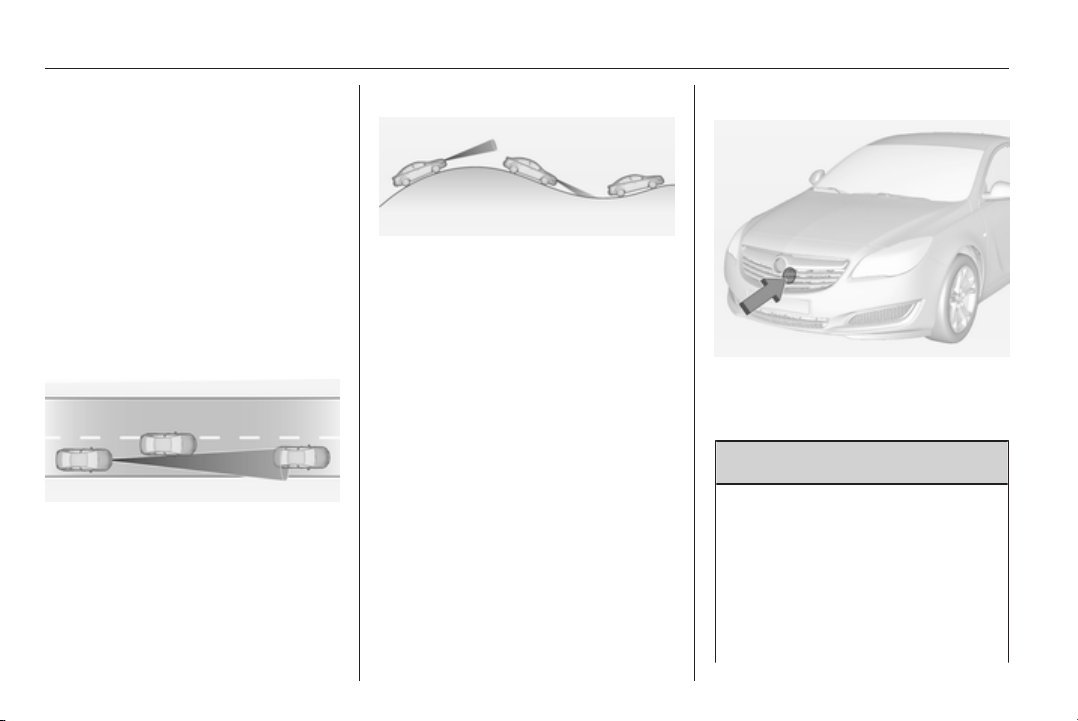
180 Driving and operating
brake the vehicle in time to avoid a
collision with a much slower vehicle or
after a lane change. This is
particularly true if driving fast or if the
visibility is reduced due to weather
conditions.
While entering or exiting a motorway,
adaptive cruise control may lose the
vehicle ahead and accelerate up to
the set speed. For this reason,
decrease the set speed before the
exit or before the entry.
Vehicle path changes
If another vehicle enters your driving
path, adaptive cruise control will first
consider the vehicle when it is
completely in your path. Be ready to
take action and press the brake
pedal, if you need to brake more
quickly.
Hill and trailer considerations
System performance on hills and
when towing a trailer depends on
vehicle speed, vehicle load, traffic
conditions and the road gradient. It
may not detect a vehicle in your path
while driving on hills. On steep hills,
you may have to use the accelerator
pedal to maintain your vehicle speed.
When going downhill, especially
when towing a trailer, you may have
to brake to maintain or reduce your
speed.
Note that applying the brake
deactivates the system. It is not
recommended to use adaptive cruise
control on steep hills especially when
towing a trailer.
Radar unit
The radar unit is mounted behind the
radiator grille below the brand
emblem.
9 Warning
The radar unit was aligned
carefully during manufacture.
Therefore, after a frontal accident,
do not use the system. The front
bumper may appear to be intact,
however the sensor behind can be
out of position and react
incorrectly. After an accident,
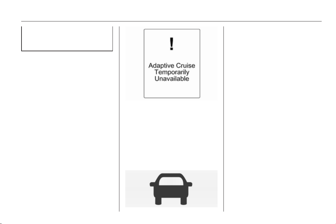
Driving and operating 181
consult a workshop to verify and
correct the adaptive cruise control
sensor position.
Settings
Settings can be changed in the
vehicle personalisation menu in the
Colour-Info-Display.
Select the relevant setting in Settings,
I Vehicle in the Colour-Info-Display.
Colour-Info-Display 3 114.
Vehicle personalisation 3 118.
Fault
If the adaptive cruise control does not
work due to temporary conditions
(e.g. blockage by ice) or if there is a
permanent system error, then a
message is displayed in the Driver
Information Centre.
Vehicle messages 3 116.
Forward collision alert
The forward collision alert can help to
avoid or reduce the harm caused by
front-end crashes. If a vehicle directly
ahead is approached too quickly, a
warning chime and alert in the Driver
Information Centre is provided.
The green illuminated vehicle ahead
symbol A appears in the instrument
cluster when the system has detected
a vehicle in the driving path. A
precondition is that forward collision
alert is activated in the vehicle
personalisation menu 3 118 or that it
is not deactivated by the button V
(depending on the system, see
below).
Depending on the vehicle's
equipment, there are two variants of
the forward collision alert available:
■ Forward collision alert based on
radar system
on vehicles equipped with adaptive
cruise control 3 173.
■ Forward collision alert based on
front camera system
on vehicles with no cruise control or
traditional cruise control only
3 171.
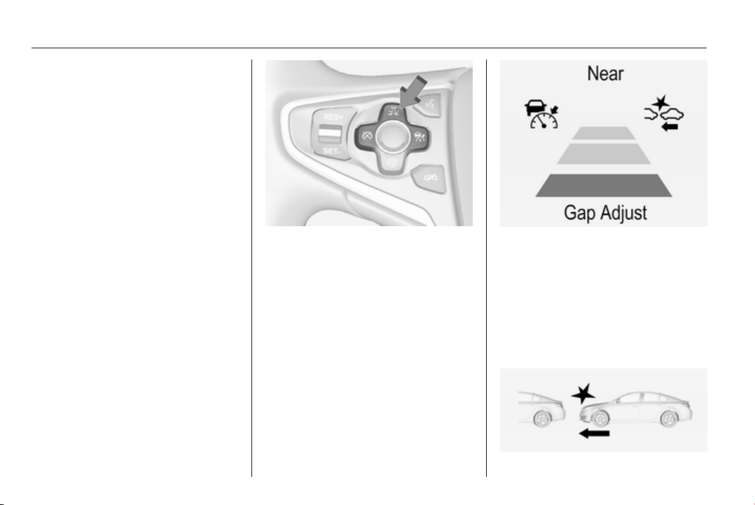
182 Driving and operating
Forward collision alert based on
radar system
The system uses the radar sensor
behind the radiator grille to detect a
vehicle directly ahead, in your path,
within a distance of max. 150 metres.
Activation
Forward collision alert operates
automatically above walking speed,
provided that Auto Collision
Preparation setting is not deactivated
in the vehicle personalisation menu
3 118.
Selecting the alert sensitivity
The alert sensitivity can be set to
near, medium or far.
Press button E, the current setting is
shown in the Driver Information
Centre. Press button E again to
change the alert sensitivity. The
setting is also displayed in the Driver
Information Centre.
Note that the alert timing sensitivity
setting is shared with the following
distance setting of the adaptive cruise
control 3 173. So changing the alert
timing sensitivity changes the
adaptive cruise control following
distance setting.
Alerting the driver
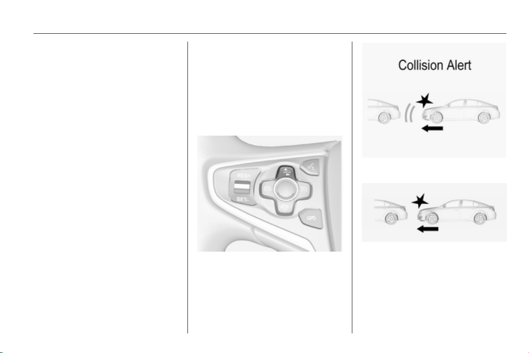
Driving and operating 183
When approaching another vehicle
too rapidly, the collision alert warning
page will be indicated in the Driver
Information Centre. Simultaneously a
warning chime sounds. Depress the
brake pedal, if it is required by the
situation.
Settings
Settings can be changed in the
vehicle personalisation menu in the
Colour-Info-Display.
Select the relevant setting in Settings,
I Vehicle in the Colour-Info-Display.
Colour-Info-Display 3 114.
Vehicle personalisation 3 118.
Forward collision alert based on
front camera system
Forward collision alert uses the front
camera system in the windscreen to
detect a vehicle directly ahead, in
your path, within a distance of approx.
60 metres.
Activation
Forward collision alert operates
automatically above 40 km/h, if it is
not deactivated by button V, see
below.
Selecting the alert sensitivity
The alert sensitivity can be set to
near, medium or far.
Press button V, the current setting is
shown in the Driver Information
Centre. Press button V again to
change the alert sensitivity.
Alerting the driver
When approaching another vehicle
too rapidly, the collision alert warning
page will be indicated in the Driver
Information Centre. Simultaneously a
warning chime sounds. Depress the
brake pedal, if it is required by the
situation.
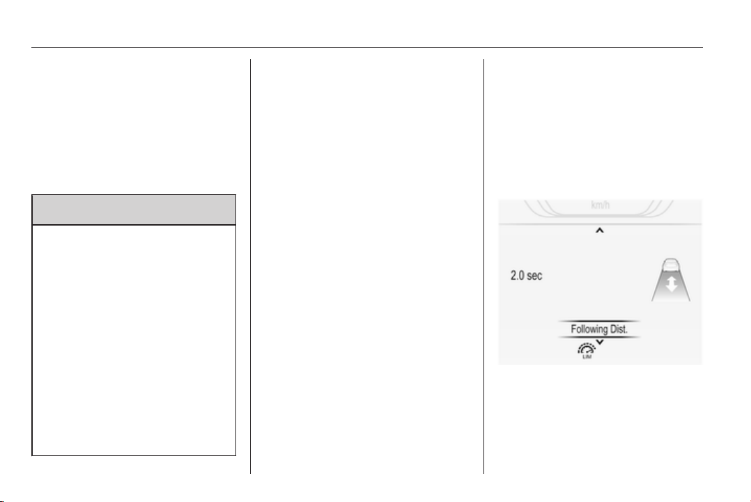
184 Driving and operating
Deactivation
The system can be deactivated.
Press button V repeatedly
untilForward Collision Alert Off
appears in the Driver Information
Centre.
General information for both
variants of forward collision alert
9 Warning
Forward collision alert is just a
warning system and does not
apply the brakes. When
approaching a vehicle ahead too
rapidly, it may not provide you
enough time to avoid a collision.
The driver accepts full
responsibility for the appropriate
following distance based on traffic,
weather and visibility conditions.
The complete attention of the
driver is always required while
driving. The driver must always be
ready to take action and apply the
brakes.
System limitations
The system is designed to warn only
for vehicles, but may react also to
other metallic objects.
In the following cases, forward
collision alert may not detect a vehicle
ahead or sensor performance may be
limited:
■ on winding roads,
■ when weather limits visibility, e.g.
fog, rain, or snow,
■ when the sensor is blocked by
snow, ice, slush, mud, dirt, or
windscreen damage.
Following distance
indication
The following distance indication
displays the distance to a preceding
moving vehicle. The system uses,
depending on the vehicle equipment,
either the radar behind the radiator
grille or the front camera in the
windscreen to detect the distance of
a vehicle directly ahead in your path.
It is active at speeds above 40 km/h.
When a preceding vehicle is detected
ahead, the distance is indicated in
seconds, displayed on a page in the
Driver Information Centre 3 107.
On Baselevel display set Settings
X with the Menu button and
select Following distance indication
via the adjuster wheel on the turn
signal lever 3 107.
On Midlevel or Uplevel display, select
Info menu and press o to
select Following distance indication
3 107.
The minimum indicated distance is
0.5 seconds.
Driving and operating 185
If there is no vehicle ahead or the
vehicle ahead is out of range, two
dashes will be displayed: -.- s.
If Adaptive cruise control is active,
this page shows the following
distance setting instead 3 173.
Active Emergency Braking
Active emergency braking can help to
reduce the damage from crashes with
vehicles and obstacles directly
ahead, when a collision can no longer
be avoided either by manual braking
or by steering. Before the active
emergency braking applies, the driver
is warned by the forward collision
alert 3 181.
The feature uses various inputs (e.g.
radar sensor, brake pressure, vehicle
speed) to calculate the probability of
a frontal collision.
Active emergency braking operates
automatically above walking speed,
provided that Auto Collision
Preparation setting is not deactivated
in the vehicle personalisation menu
3 118.
The system includes:
■ Brake preparation system
■ Emergency automatic braking
■ Forward looking brake assist
9 Warning
This system is not intended to
replace the driver responsibility for
driving the vehicle and looking
ahead. Its function is limited to
supplemental use only. The driver
must continue to apply the brake
pedal as the driving situation
dictates.
Brake preparation system
When approaching a vehicle ahead
so quickly that a collision is likely, the
brake preparation system slightly
pressurises the brakes. This reduces
the response time, when a manual or
automatic braking is requested.
The brake system is prepared so that
braking can occur more rapidly.
Emergency automatic braking
After the brake preparation and just
before the imminent collision, this
function automatically applies limited
braking to reduce the impact speed of
the collision.
Forward looking brake assist
In addition to the brake preparation
system and emergency automatic
braking, the forward looking brake
assist function makes the brake assist
more sensitive. Therefore,
depressing the brake pedal slightly
results in immediate hard braking.
This function helps the driver brake
quicker and harder before the
imminent collision.
9 Warning
Active emergency braking is not
designed to apply hard
autonomous braking or to
automatically avoid a collision. It is
designed to reduce the vehicle
speed before a collision. It may not
react for stopped vehicles,
186 Driving and operating
pedestrians or animals. After a
sudden lane change, the system
needs a certain time to detect the
next preceding vehicle.
The complete attention of the
driver is always required while
driving. The driver shall always be
ready to take action and apply the
brakes and steer to avoid
collisions. The system is designed
to work with all occupants wearing
their seat belts.
System limitations
The active emergency braking has
limited or no function during rain,
snow or heavy dirt, as the radar
sensor can be covered by a water
film, dust, ice or snow. In case of
sensor blockage, clean the sensor
cover.
In some cases, the active emergency
braking system may provide a short
automatic braking in situations that
seem to be unnecessary, for instance
due to traffic signs in a curve or due
to vehicles in another lane. This is
normal operation, the vehicle does
not need service. Firmly apply the
accelerator pedal to override the
automatic braking.
Settings
Settings can be changed in the
vehicle personalisation menu in the
Colour-Info-Display.
Select the relevant setting in Settings,
I Vehicle in the Colour-Info-Display.
Colour-Info-Display 3 114.
Vehicle personalisation 3 118.
Fault
In the event of a system service
requirement, a message is displayed
in the Driver Information Centre.
If the system does not work as it
should do, vehicle messages are
displayed in the Driver Information
Centre.
Vehicle messages 3 116.
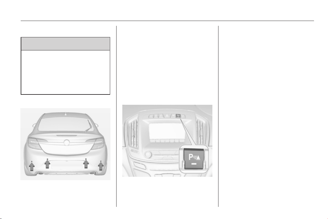
Driving and operating 187
Parking assist
9 Warning
The driver bears full responsibility
for the parking manoeuvre.
Always check the surrounding
area when driving backwards or
forwards while using parking
assist system.
Front-rear parking assist
The front-rear parking assist
measures the distance between the
vehicle and obstacles in front and
behind the vehicle. The system gives
acoustic signals and display
messages.
The system has four ultrasonic
parking sensors each in the rear and
front bumper.
It uses two different acoustic warning
signals for the front and rear
monitoring areas, each with a
different tone frequency.
Activation
When reverse gear is engaged, the
front and rear parking assist is ready
to operate.
An illuminated LED in the parking
assist button r indicates that the
system is ready to operate.
When driving forward at low speeds,
the front parking assist can also be
activated by pressing the parking
assist button r.
Once the button r is pressed within
an ignition cycle, the front parking
assist is always reactivated when the
vehicle underruns a certain value.
Indication
The system warns the driver with
acoustic signals against potentially
hazardous obstacles in front of or
behind the vehicle. An obstacle
detection is indicated by beeps
sounding respective from the front or
rear of the vehicle. The intervall
between the beeps becomes shorter
as the vehicle gets closer to the
obstacle. when the distance is less
than 30 cm, a continuous tone
sounds.
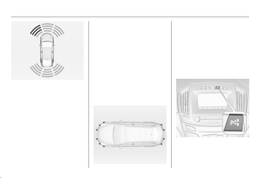
188 Driving and operating
The distance to a front and rear
obstacle is indicated by changing
distance lines around the vehicle.
The parking assist page in the display
can be hidden by vehicle messages
with a higher priority. If the parking
assist page is overwritten by a vehicle
message, distance is no longer
indicated until parking assist is
activated again.
Deactivation
Deactivate the system by pressing
the r button.
The LED in the button will extinguish
and Park Assist Off will be displayed
in the Driver Information Centre.
The system is automatically disabled
above a certain speed.
Fault
In the event of a fault in the system,
or if the system does not work due to
temporary conditions, e.g. snow
covered sensors, r illuminates or a
message is displayed in the Driver
Information Centre.
Vehicle messages 3 116.
Advanced parking assist
The advanced parking assist system
manoeuvres the driver into a parking
slot by giving instructions in the Driver
Information Centre and acoustic
signals.
The system uses the sensors of the
parking assist system in combination
with two additional sensors on both
sides of the front and rear bumper.
Activation
When looking for a parking slot, the
system must be activated by pressing
the ( button.
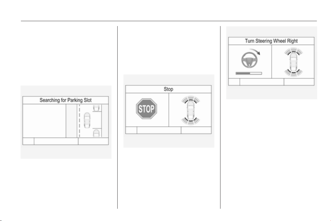
Driving and operating 189
The system can only be activated at
a speed up to 30 km/h and the system
searches for a parking slot at a speed
up to 30 km/h.
The maximum allowed parallel
distance between the vehicle and a
row of parked cars is 1.8 metres.
Functionality
When the vehicle passes a row of
cars and the system is activated, the
advanced parking assist system
begins looking for a suitable parking
slot. When a suitable slot is detected,
a visual feedback and acoustic
signals are given in the Driver
Information Centre.
If the driver does not stop the vehicle
within 10 metres after a parking slot is
proposed, the system starts to search
for another suitable parking slot.
The suggestion of the system is
accepted when the vehicle is stopped
by the driver within 10 metres after the
message is given. The system
calculates the optimal route into the
parking slot. Then it manoeuvres the
driver into the slot by giving detailed
instructions.
The instructions in the display show:
■ a hint when driving faster than
30 km/h,
■ the demand to stop the vehicle,
when a parking slot is detected,
■ the direction of driving during the
parking manoeuvre,
■ the steering wheel position during
parking,
■ for some of the instructions a
progress bar is shown.
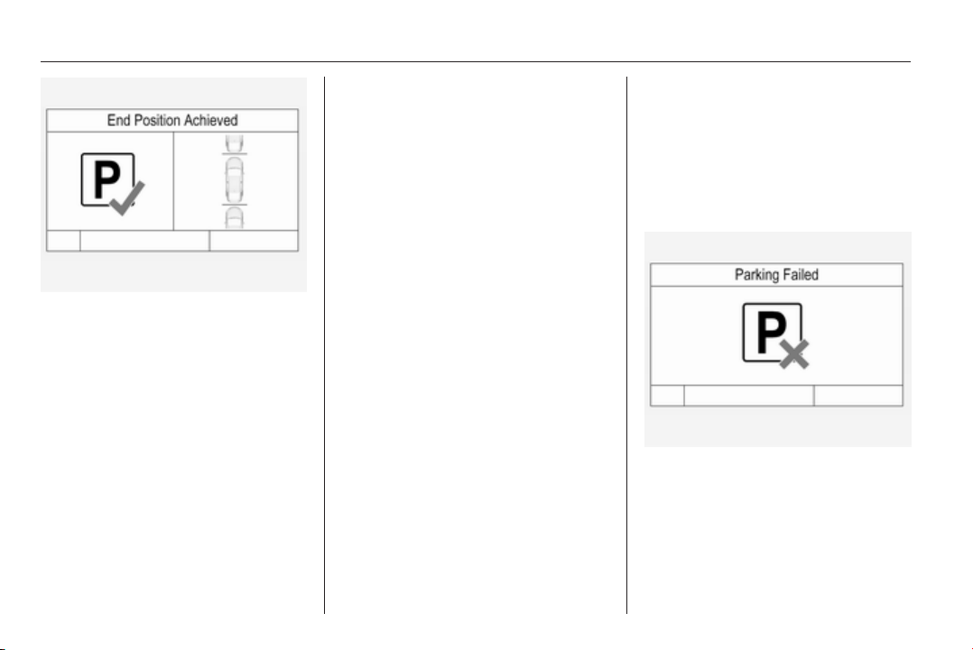
190 Driving and operating
A successful parking manoeuvre is
indicated by a confirmation symbol.
Always pay attention to the sound of
the front-rear parking assist.
Continuous sound means that the
distance to an obstacle is less than
approx. 30 cm.
Changing the parking side
The system is configured to detect
parking slots on the passenger side.
To detect parking slots on the driver
side, press button ( for approx.
2 seconds.
Display priorities
After activating the advanced parking
assist, a message appears in the
Driver Information Centre. Advanced
parking assist indication in the Driver
Information Centre can be inhibited
by vehicle messages with a higher
priority. After approving the message
by pressing the SET/CLR button on
the turn signal lever or the 9 button
in the steering wheel controls,
advanced parking assist instructions
appear again and the parking
manoeuvre can be continued.
Deactivation
The system is deactivated by:
■ pressing the ( button
■ parking manoeuvre successfully
ended
■ driving faster than 30 km/h
■ switching off the ignition
Deactivation by the driver or by the
system during manoeuvring will be
indicated by Parking Deactivated in
the Driver Information Centre.
Fault
A message appears in the Driver
Information Centre when:
■ there is a fault in the system
■ the driver did not successfully
complete the parking manoeuvre
■ the system is not operational
If an object is detected during parking
instructions, Stop is indicated in the
Driver Information Centre. Removing
the object will resume the parking
manoeuvre. If the object is not
removed, the system will be
Driving and operating 191
deactivated. Press button ( to
activate the system and search for a
new parking slot.
Important hints for using the
parking assist systems
9 Warning
Under certain circumstances,
various reflective surfaces on
objects or clothing as well as
external noise sources may cause
the system to fail to detect
obstacles.
Special attention must be paid to
low obstacles which can damage
the lower part of the bumper.
Caution
Performance of the system can be
reduced when sensors are
covered, e.g. by ice or snow.
Performance of the parking assist
system can be reduced due to
heavy loading.
Special conditions apply if there
are taller vehicles in the vicinity
(e.g. off-road vehicles, mini vans,
vans). Object identification and
correct distance indication in the
upper part of these vehicles
cannot be guaranteed.
Objects with a very small reflection
cross-section, e.g. objects of
narrow size or soft materials, may
not be detected by the system.
Parking assist systems do not
detect objects outside the
detection range.
Note
The parking assist system
automatically detects factory-fitted
towing equipment. It is deactivated
when the connector is plugged in.
It is possible that the sensor detects
a non-existing object (echo
disturbance) caused by external
acoustical or mechanic
disturbances.
Advanced parking assist system
may not respond to changes in the
parking space after initiating a
parallel parking manoeuvre.
Note
After use the advanced parking
assist requires a calibration. For
optimal parking guidance, a driving
distance of at least 10 km, including
a number of bends, is required.
Side blind spot alert
The side blind spot alert system
detects and reports objects on either
side of the vehicle, within a specified
"blind spot" zone. The system alerts
visually in each exterior mirror, when
detecting objects that may not be
visible in the interior and exterior
mirrors.
The system's sensors are located in
the bumper on the left and right side
of the vehicle.
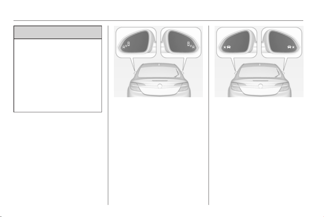
192 Driving and operating
9 Warning
Side blind spot alert does not
replace driver vision.
The system does not detect:
■ Vehicles outside the side blind
zones which may be rapidly
approaching.
■ Pedestrians, cyclists or animals.
Before changing a lane, always
check all mirrors, look over the
shoulder and use the turn signal.
When the system detects a vehicle in
the side blind zone while driving
forward, either while passing a
vehicle or being passed, the amber
warning symbol B will illuminate in
the relevant exterior mirror. If the
driver then activates the turn signal,
the warning symbol B starts flashing
amber as a warning not to change
lanes.
When the vehicle is started, both
exterior mirror displays will briefly
come on to indicate that the system is
operating.
If the vehicle is equipped with lane
change alert 3 193, the symbol F
is displayed in the mirrors.
The system can be activated or
deactivated in the vehicle
personalisation.
Select the relevant setting in Settings,
I Vehiclein the Colour-Info-Display.
Colour-Info-Display 3 114.
Vehicle personalisation 3 118.
Deactivation is indicated by a
message in the Driver Information
Centre (DIC).
Detection zones
The system sensor covers a zone of
approx. 3.5 metres on both sides of
the vehicle. This zone starts at each
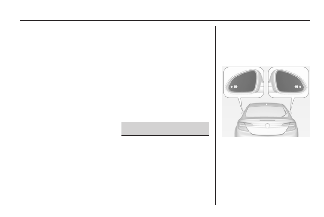
Driving and operating 193
exterior mirror and extends rearwards
by approx. 3 metres. The height of the
zone is approx. between 0.5 metres
and 2 metres off the ground.
The system is deactivated if the
vehicle is towing a trailer.
Side blind spot alert is designed to
ignore stationary objects such as
guardrails, posts, curbs, walls and
beams. Parked vehicles or oncoming
vehicles are not detected.
Fault
Occasional missed alerts can occur
under normal circumstances and will
increase in wet conditions.
Side blind spot alert does not operate
when the left or right corners of the
rear bumper are covered with mud,
dirt, snow, ice, slush, or in heavy
rainstorms. Cleaning instructions
3 257.
In the event of a fault in the system or
if the system does not work due to
temporary conditions, a message is
displayed in the Driver Information
Centre (DIC). Seek the assistance of
a workshop.
Lane change alert
Additional to the side blind spot alert
3 191, lane change alert recognizes
rapidly approaching vehicles from
behind on parallel lanes next to your
vehicle.
If the vehicle is equipped with lane
change alert, side blind spot alert is
always included.
The system alerts visually in each
exterior mirror when detecting rapidly
approaching vehicles from behind.
The radar distance sensors are
located in the rear bumper.
9 Warning
Lane change alert does not
replace driver vision.
Before changing a lane, always
check all mirrors, look over the
shoulder and use the turn signal.
When the system detects an
approaching vehicle from behind
which drives considerably faster, the
amber warning symbol F will
illuminate in the relevant exterior
mirror. If the driver then activates the
turn signal, the warning symbol F
starts flashing amber as a warning not
to change lanes. Additionally a
warning chime sounds.
When the vehicle is started, both
exterior mirror displays will briefly
come on to indicate that the system is
operating.
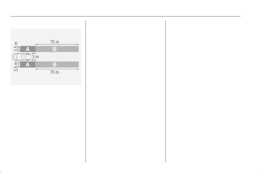
194 Driving and operating
Detection zones
The system sensors cover a zone of
approx. 3.5 metres parallel on both
vehicle sides and approx. 3 metres
rearwards on side blind zone alert
(A) and approx. 70 metres rearwards
on lane change alert (B) on parallel
lanes. The zones start at each
exterior mirror. The height of the zone
is approx. between 0.5 metres and
2 metres off the ground.
Deactivation
Activation or deactivation of the lane
change alert can be set in the vehicle
personalisation menu in the Colour-
Info-Display.
Select the relevant setting in Settings,
I Vehicle in the Colour-Info-Display.
Colour-Info-Display 3 114.
Vehicle personalisation 3 118.
The system is deactivated if the
vehicle is towing a trailer.
Deactivation is indicated by a
message in the Driver Information
Centre (DIC).
Note
After use, the system requires a
calibration. For optimal
performance, drive as soon as
possible on a straight highway road
with roadside objects, e.g. guardrails
and barriers for some distance.
Fault
Occasional missed alerts can occur
under normal circumstances and will
increase in wet conditions or in sharp
curves. Otherwise the system may
light up due to guardrails, signs, trees,
shrubs or other immobile objects.
This is normal operation and the
system does not need to be serviced.
Lane change alert may not operate
when the left or right corners of the
rear bumper are covered with mud,
dirt, snow, ice, slush, or in heavy
rainstorms. Cleaning instructions
3 257.
In the event of a fault in the system or
if the system does not work due to
temporary conditions, a message is
displayed in the Driver Information
Centre (DIC). Seek the assistance of
a workshop.
Rear view camera
The rear view camera assists the
driver when reversing, by displaying a
view of the area behind the vehicle.
The view of the camera is displayed
in the Colour-Info-Display.
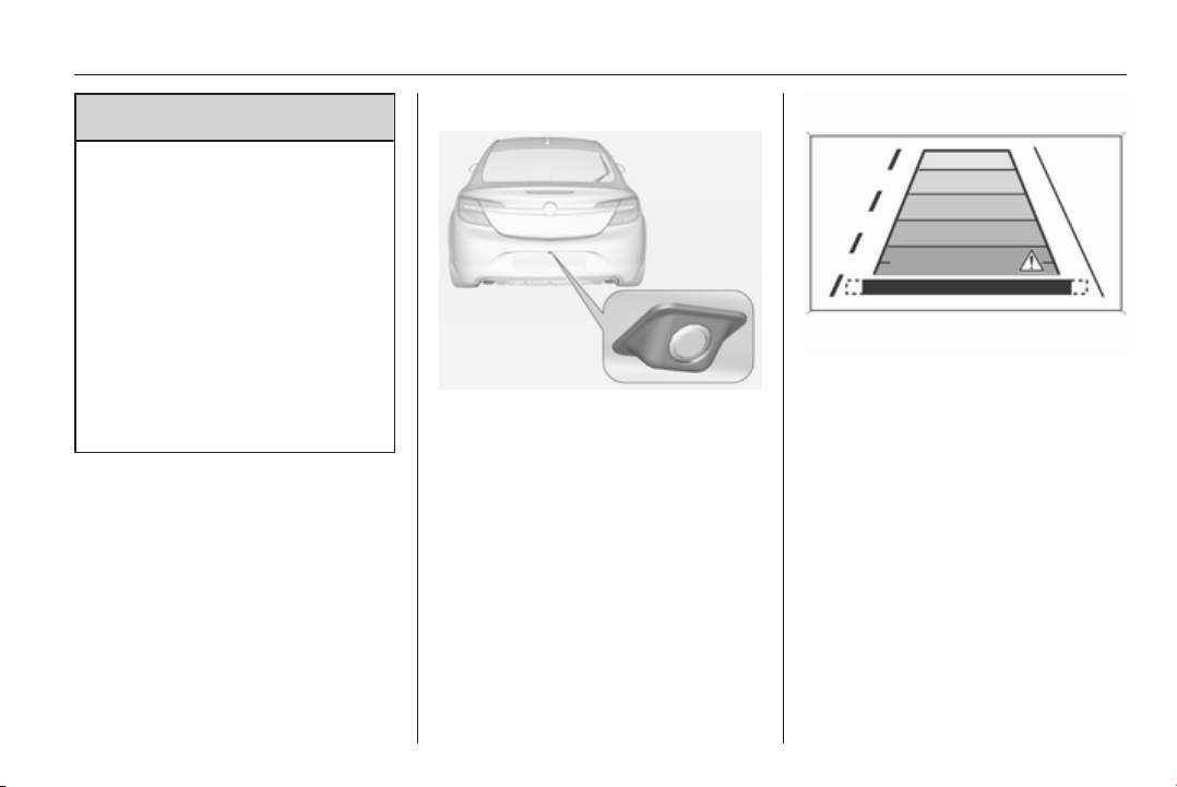
Driving and operating 195
9 Warning
The rear view camera does not
replace driver vision. Note that
objects that are outside the
camera's field of view and the
advanced parking assist sensors,
e.g. below the bumper or
underneath the vehicle, are not
displayed.
Do not reverse the vehicle by only
looking at the Info-Display and
check the surrounding behind and
around the vehicle before
reversing.
Activation
Rear view camera is automatically
activated when reverse gear is
engaged.
Functionality
The camera is mounted between the
number plate lights and has a viewing
angle of 130°.
Due to the high position of the camera
the rear bumper can be seen on the
display as a guide to position.
The area displayed by the camera is
limited. The distance of the image that
appears on the display differs from
the actual distance.
Guiding lines
Dynamic guiding lines are horizontal
lines in 1 metre intervals projected on
the picture to define the distance to
shown objects.
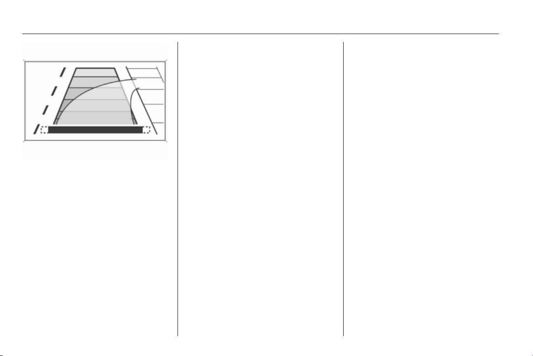
196 Driving and operating
Trajectory lane of the vehicle is
shown in accordance with the
steering angle.
The function can be deactivated in the
vehicle personalisation menu in the
Colour-Info-Display.
Select the relevant setting in Settings,
I Vehicle in the Colour-Info-Display.
Colour-Info-Display 3 114.
Vehicle personalisation 3 118.
Warning symbols
Warning symbols are indicated as
triangles 9 on the picture which show
obstacles detected by the rear
sensors of the advanced parking
assist.
Additionally 9 appears on the top line
of the Info-Display with the warning to
check the vehicle surrounding.
Deactivation
The camera is deactivated when a
certain forward speed is exceeded or
if reverse gear is not engaged for
approx. 10 seconds.
Activation or deactivation of the rear
view camera can be set in the vehicle
personalisation menu in the Colour-
Info-Display.
Select the relevant setting in Settings,
I Vehicle in the Colour-Info-Display.
Colour-Info-Display 3 114.
Vehicle personalisation 3 118.
Fault
Fault messages are displayed with a
9 on the top line of the Info-Display.
The rear view camera may not
operate properly when:
■ the surrounding is dark,
■ the sun or the beam of headlights is
shining directly into the camera
lens,
■ ice, snow, mud, or anything else
covers the camera lens. Clean the
lens, rinse it with water, and wipe it
with a soft cloth,
■ the tailgate is not closed correctly,
■ the vehicle is towing a trailer,
■ the vehicle had a rear end accident,
■ there are extreme temperature
changes.
Rear cross traffic alert
Additional to the rear view camera
3 194, rear cross traffic alert warns of
cross traffic from left or right side
when driving rearwards. When cross
traffic is recognized and the rear view
camera is activated, a warning
triangle with a direction arrow
appears on the Colour-Info-Display,
showing the direction of the traffic.
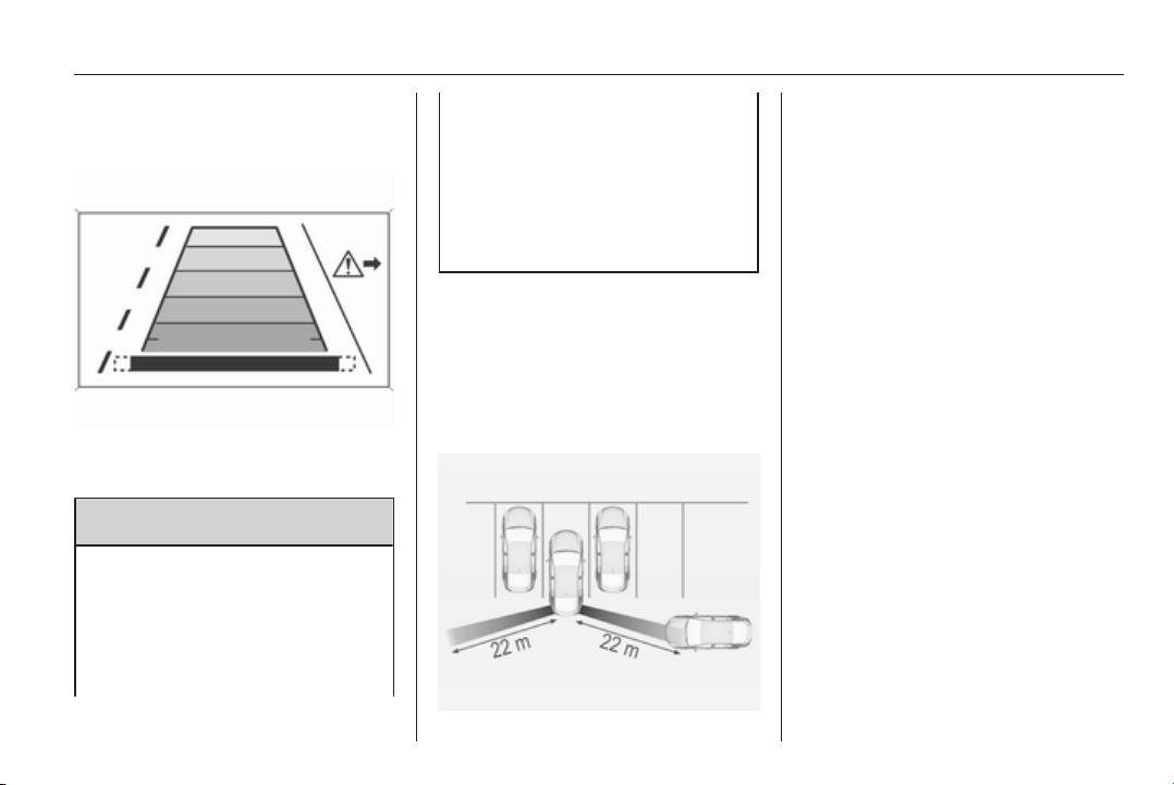
Driving and operating 197
Furthermore three beeps will sound
from the speaker on the respective
side.
The radar distance sensors are
located sideways in the rear bumper.
9 Warning
The rear cross traffic alert does not
replace driver vision. Note that
objects that are outside sensors,
e.g. below the bumper or
underneath the vehicle, are not
displayed.
Pedestrians, children or animals
are not detected.
Do not reverse the vehicle by only
looking at the Info-Display and
check the surrounding behind and
around the vehicle before
reversing.
Activation
Rear cross traffic alert is
automatically activated together with
the rear view camera when reverse
gear is engaged.
Detection zones
The system sensors cover a zone of
approx. 20 metres to the left or right
side behind the vehicle.
Deactivation
Rear cross traffic alert is deactivated
together with the rear view camera
when a certain forward speed is
exceeded or if reverse gear is not
engaged for approx. 10 seconds.
Activation or deactivation of the rear
cross traffic alert can be set in the
vehicle personalisation menu in the
Colour-Info-Display.
Select the relevant setting in Settings,
I Vehicle in the Colour-Info-Display.
Colour-Info-Display 3 114.
Vehicle personalisation 3 118.
Fault
The system may not operate properly
when:
■ ice, snow, mud, or anything else
covers the sensors.
■ the vehicle is towing a trailer,
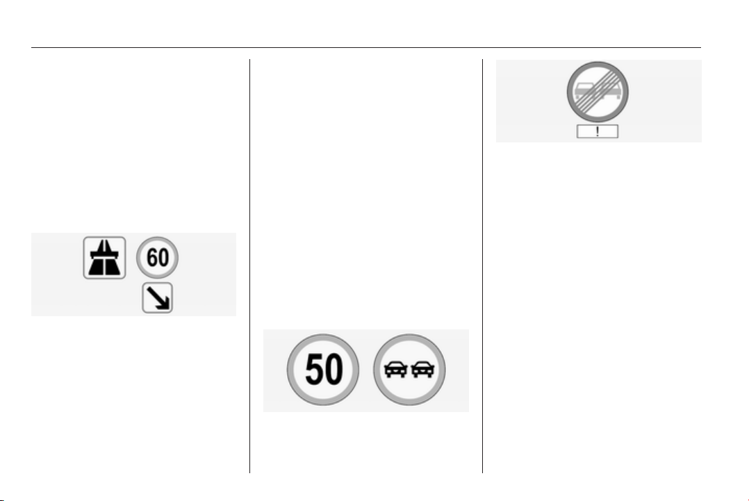
198 Driving and operating
■ the vehicle had a rear end accident,
■ there are extreme temperature
changes.
Traffic sign assistant
Functionality
The traffic sign assistant system
detects designated traffic signs via a
front camera and displays them in the
Driver Information Centre.
Traffic signs, which will be detected,
are:
Limit- and no passing signs
■ speed limit
■ no passing
■ end of speed limit
■ end of no passing
Road signs
beginning and end of:
■ motorways
■ A-roads
■ play streets
Add on signs
■ additional hints to traffic signs
■ restriction of trailer towing
■ wet warning
■ ice warning
■ direction arrows
Speed limit signs are displayed in the
Driver Information Centre until the
next speed limit sign or end of speed
limit is detected or up to a defined sign
timeout.
Combinations of more signs in the
display are possible.
An exclamation mark in a frame
indicates that there are additional
signs detected which cannot be
recognised by the system.
The system is active up to a speed of
200 km/h depending on the lighting
conditions. At night the system is
active up to a speed of 160 km/h.
As soon as the speed becomes
slower than 55 km/h the display will
be reset and the content of the traffic
sign page will be cleared, e. g. when
entering a city zone. The next
recognized speed indication will be
displayed.
Display indication
Traffic signs are displayed on the
Traffic sign detection page in the
Driver Information Centre.
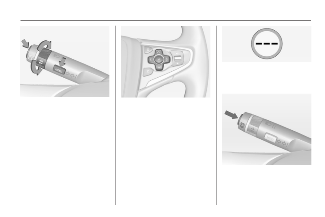
Driving and operating 199
On Baselevel display, select Settings
X with the Menu button and
select Traffic sign detection entry via
the adjuster wheel on the turn signal
lever 3 107.
On Midlevel and Uplevel display
select Info menu and press P to
select Traffic sign detection 3 107.
When another function in the Driver
Information Centre menu was
selected and then Traffic sign
detection page is chosen again, the
last recognized traffic sign will be
displayed.
After the traffic sign page is cleared
by the system, the following symbol is
indicated:
The content of the traffic sign page is
also reset during driving by pressing
the SET/CLR button or 9 button for a
longer time.
Pop-up function
Speed limits and no passing signs are
displayed as pop-ups on each page
of the Driver Information Centre.
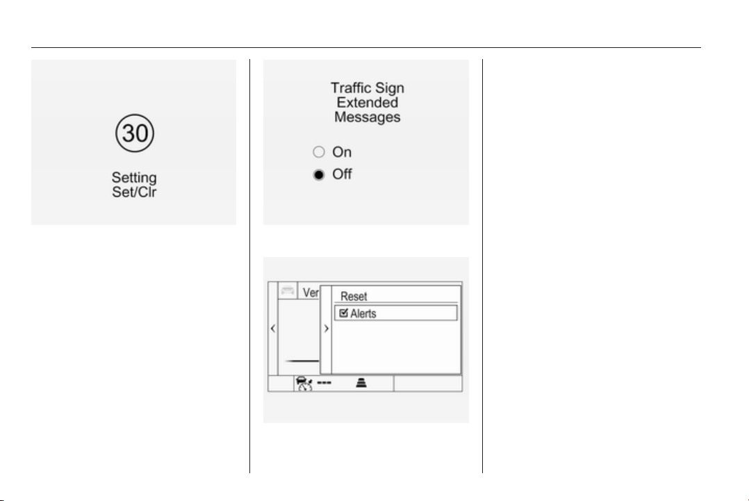
200 Driving and operating
The pop-up function can be
deactivated on the traffic sign page by
pressing the SET/CLR button on the
turn signal lever or 9 button on the
steering wheel.
Illustration shows baselevel DIC.
Illustration shows midlevel or uplevel
DIC.
When the setting page is displayed,
select Off or set alerts I to deactivate
pop-up function. Reactivate by
selecting On or alerts J.
When switching on the ignition, pop-
up function is deactivated.
Pop-up indication is displayed for
approx. 8 seconds in the Driver
Information Centre.
Fault
The traffic sign assistant system may
not operate correctly when:
■ the area of the windscreen, where
the front camera is located, is not
clean
■ traffic signs are completely or
partially covered or difficult to
discern
■ there are adverse environmental
conditions, e.g. heavy rain, snow,
direct sunlight or shadows. In this
event, No Traffic Sign Detection
due to Weather is indicated on the
display
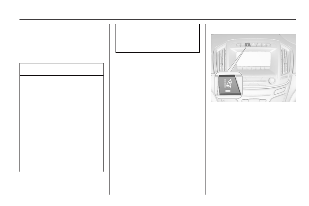
Driving and operating 201
■ traffic signs are incorrectly mounted
or damaged
■ traffic signs do not comply with the
Vienna Convention on traffic signs
(Wiener Übereinkommen über
Straßenverkehrszeichen)
Caution
The system is intended to help the
driver within a defined speed
range to discern certain traffic
signs. Do not ignore traffic signs
which are not displayed by the
system.
The system does not discern any
other than the conventional traffic
signs that might give or end a
speed limit.
Do not let this special feature
tempt you into taking risks when
driving.
Always adapt speed to the road
conditions.
The driver assistance systems do
not relieve the driver from full
responsibility for vehicle
operation.
Lane departure warning
The lane departure warning system
observes the lane markings between
which the vehicle is driving, via a front
camera. The system detects lane
changes and warns the driver in the
event of an unintended lane change
by visual and acoustic signals.
Criteria for the detection of an
unintended lane change are:
■ no operation of turn signals
■ no brake pedal operation
■ no active accelerator operation or
speeding-up
■ no active steering
If the driver is active, no warning will
be issued.
Activation
The lane departure warning system is
activated by pressing the ) button.
The illuminated LED in the button
indicates that the system is switched
on. When the control indicator ) in
the instrument cluster illuminates
green, the system is ready to operate.
The system is only operable at
vehicle speeds above 56 km/h and if
lane markings are available.
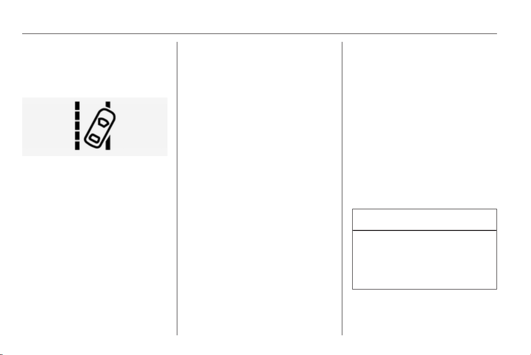
202 Driving and operating
When the system recognises an
unintended lane change, the control
indicator ) changes to yellow and
flashes. Simultaneously a chime
sound is activated.
Deactivation
The system is deactivated by
pressing ) button; the LED in the
button extinguishes.
At speeds below 56 km/h the system
is inoperable.
Fault
The lane departure warning system
may not operate properly when:
■ the windscreen is not clean
■ there are adverse environmental
conditions, e.g. heavy rain, snow,
direct sunlight or shadows
The system cannot operate when no
lane marking is detected.
Fuel
Fuel for petrol engines
Only use unleaded fuel that complies
with European standard EN 228 or
E DIN 51626-1 or equivalent.
Your engine is capable of running
with E10 fuel that fulfills these
standards. E10 fuel contains up to
10 % bioethanol.
Use fuel with the recommended
octane rating 3 269. Use of fuel with
too low an octane rating can reduce
engine power and torque and slightly
increases fuel consumption.
Caution
Do not use fuel or fuel additives
that contain metallic compounds
such as manganese-based
additives. This may cause engine
damage.
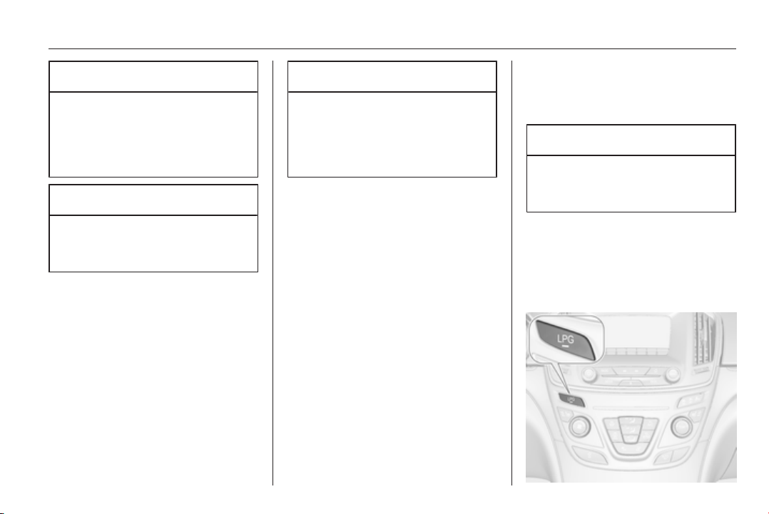
Driving and operating 203
Caution
Use of fuel that does not comply to
EN 228 or E DIN 51626-1 or
equivalent can lead to deposits or
engine damage and may affect
your warranty.
Caution
Use of fuel with too low an octane
rating could lead to uncontrolled
combustion and engine damage.
Fuel for diesel engines
Only use diesel fuel that complies
with EN 590.
In countries outside the European
Union use Euro-Diesel fuel with a
sulfur concentration below 50 ppm.
Caution
Use of fuel that does not comply to
EN 590 or similar can lead to
engine powerloss, increased wear
or engine damage and may affect
your warranty.
Do not use marine diesel oils, heating
oils, Aquazole and similar diesel-
water emulsions. Diesel fuels must
not be diluted with fuels for petrol
engines.
Fuel for liquid gas
operation
Liquid gas is known as LPG
(Liquefied Petroleum Gas) or under
its French name GPL (Gaz de Pétrole
Liquéfié). LPG is also known as
Autogas.
LPG consists mainly of propane and
butane. The octane rating is between
105 and 115, depending on the
butane proportion. LPG is stored
liquid at around 5 - 10 bar pressure.
The boiling point depends on the
pressure and mixing ratio. At ambient
pressure, it is between -42 °C (pure
propane) and -0.5 °C (pure butane).
Caution
The system works at an ambient
temperature of approx. -8 °C to
100 °C.
Full function of the LPG system can
only be guaranteed with liquid gas
which complies with the minimum
requirements of DIN EN 589.
Fuel selector
204 Driving and operating
Press the LPG button to switch
between petrol and liquid gas
operation as soon as the required
parameters (coolant temperature,
gas temperature and minimum
engine speed) have been reached.
The requirements are usually fulfilled
after around 60 seconds (depending
on exterior temperature) and the first
firm press on the accelerator. The
LED status shows the current
operating mode.
1 off = petrol operation
1 illuminates = liquid gas
operation
1 flashes = no switching is
possible, one type
of fuel is empty
As soon as the liquid gas tank is
empty, petrol operation is
automatically engaged until the
ignition is switched off.
Every six months, run the petrol tank
down until control indicator i or Y
illuminates, then refuel. This helps
maintain fuel quality and system
function for petrol operation.
Fill the tank completely at regular
intervals to prevent corrosion in the
tank.
Faults and remedies
If gas mode is not possible, check the
following:
■ Is there enough liquid gas present?
■ Is there enough petrol present for
starting?
Due to extreme temperatures in
combination with the gas
composition, it may take slightly
longer before the system switches
from petrol to gas mode.
In extreme situations, the system may
also switch back to petrol mode if the
minimum requirements are not
fulfilled.
Seek the assistance of a workshop in
the event of all other faults.
Caution
Repairs and adjustments may only
be made by trained specialists in
order to maintain the safety and
warranty on the LPG system.
Liquid gas is given a particular odour
(odorised) so that any leaks can be
detected easily.
9 Warning
If you smell gas in the vehicle or in
the immediate vicinity, switch to
petrol mode immediately. No
smoking. No naked flames or
ignition sources.
If the gas odour persists, do not start
the engine. If possible, close the
manual shut-off valve on the
multivalve. The multivalve is located
on the liquid gas tank in the load
compartment, underneath the rear
floor cover.
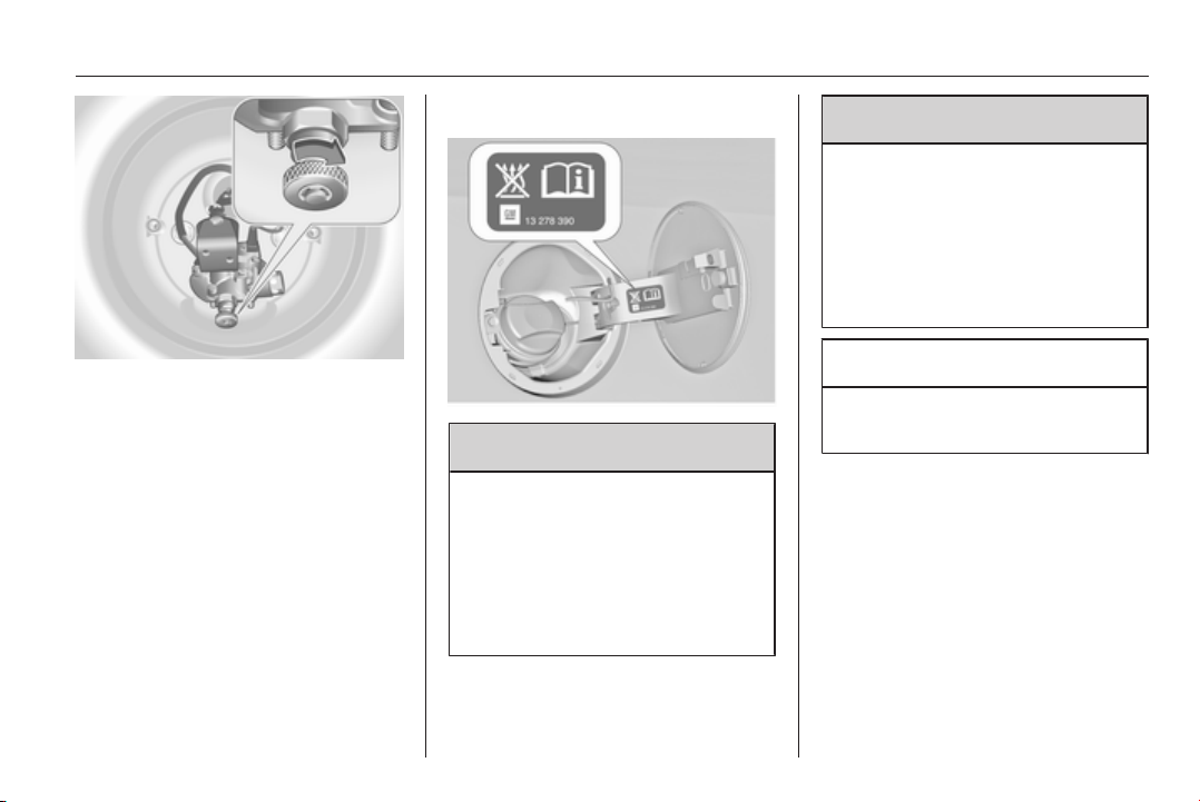
Driving and operating 205
Turn the thumb wheel clockwise.
If no further gas odour is perceptible
when the manual shut-off valve is
closed, the vehicle can be used in
petrol mode. If the gas odour persists,
do not start the engine. Have the
cause of the fault remedied by a
workshop.
When using underground car parks,
follow the instructions of the operator
and local laws.
Note
In the event of an accident, switch off
the ignition and lights. Close the
manual shut-off valve on multivalve.
Refuelling
9 Danger
Before refuelling, switch off engine
and any external heaters with
combustion chambers. Switch off
any mobile phones.
Follow the operating and safety
instructions of the filling station
when refuelling.
9 Danger
Fuel is flammable and explosive.
No smoking. No naked flames or
sparks.
If you can smell fuel in your
vehicle, have the cause of this
remedied immediately by a
workshop.
Caution
In case of misfuelling, do not
switch on ignition.
Fuel filler flap is located at right rear
side of vehicle.
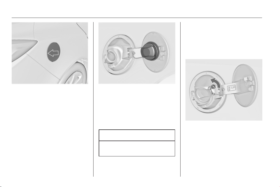
206 Driving and operating
The fuel filler flap can only be opened
if the vehicle is unlocked. Pull flap at
the recess and open.
To open, turn the cap slowly to the
left.
Petrol and Diesel refuelling
To open, turn the cap slowly to the
left.
The fuel filler cap can be retained in
the bracket on the fuel filler flap.
To refuel, fully insert the pump nozzle
and switch it on.
After the automatic cut-off, the tank
can be topped-up with a maximum
two doses of fuel.
Caution
Wipe off any overflowing fuel
immediately.
To close, turn the fuel filler cap to the
right until it clicks.
Close the flap and let engage.
Liquid gas refuelling
Follow the operating and safety
instructions of the filling station when
refuelling.
The filling valve for the liquid gas is
behind the fuel filler cap.
Unscrew protective cap from the filler
neck.
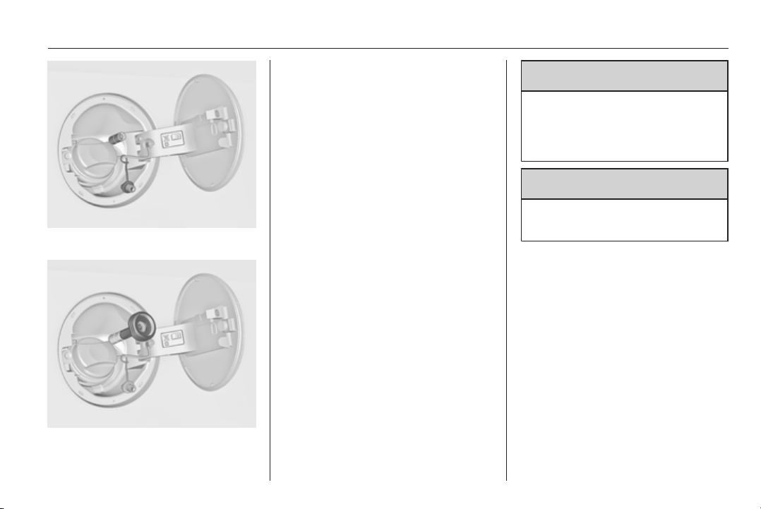
Driving and operating 207
Fit the required adapter.
ACME Adapter: Screw the nut of the
filling nozzle onto the adapter. Press
locking lever on filler nozzle down.
DISH (Italy) filler neck: Place the filler
nozzle into the adapter. Press locking
lever on filler nozzle down.
Bayonet filler neck: Place filler nozzle
on the adapter and turn to the left or
right through one quarter turn. Pull
locking lever of filler nozzle fully.
EURO filler neck: Press the filler
nozzle onto the adapter until it
engages.
Press the button at the liquid gas
supply point. The filling system stops
or begins to run slowly when 80% of
the tank volume is reached
(maximum fill level).
Release button on filling system and
the filling process stops. Release the
locking lever and remove the filler
nozzle. A small quantity of liquid gas
can escape.
Remove adapter and stow in vehicle.
Fit protective cap to prevent the
penetration of foreign bodies into the
filler opening and the system.
9 Warning
Due to the system design, an
escape of liquid gas after
releasing the locking lever is
unavoidable. Avoid inhaling.
9 Warning
The liquid gas tank may only be
filled to 80% for safety reasons.
The multivalve on the liquid gas tank
automatically limits the fill quantity. If
a larger quantity is added, we
recommend not exposing the vehicle
to the sun until the excess amount
has been used up.
Filling adapter
As filling systems are not
standardised, different adapters are
required which are available from
Opel Distributors and from Opel
Authorised Repairers.
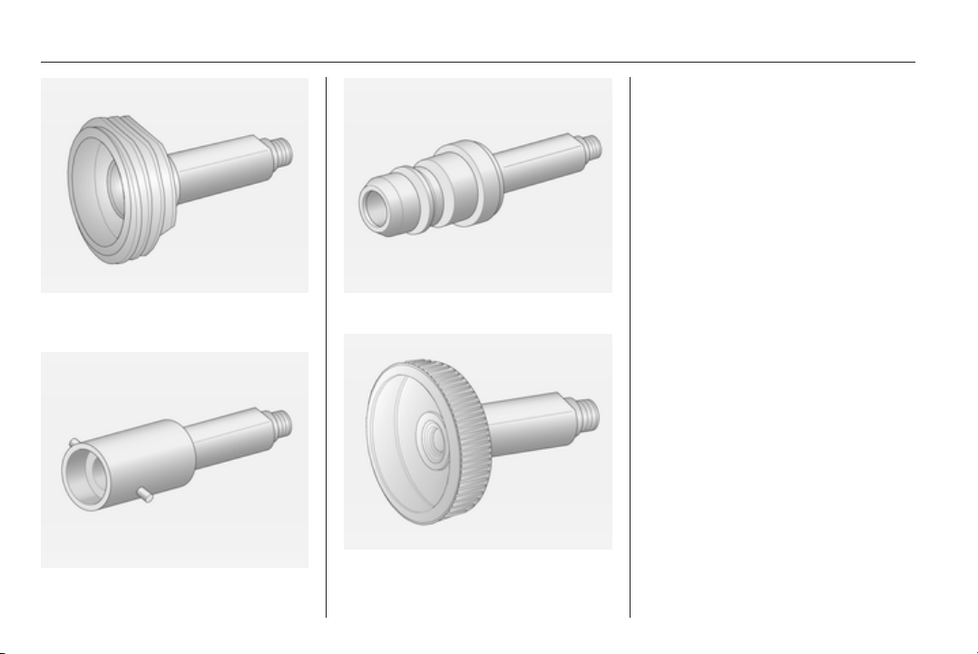
208 Driving and operating
ACME adapter: Belgium, Germany,
Ireland, Luxembourg, Switzerland
Bayonet adapter: Netherlands,
Norway, Spain, United Kingdom
EURO adapter: Spain
DISH (Italy) adapter: Bosnia-
Herzegovina, Bulgaria, Denmark,
Estonia, France, Greece, Italy,
Croatia, Latvia, Lithuania,
Macedonia, Austria, Poland,
Portugal, Romania, Sweden,
Switzerland, Serbia, Slovakia,
Slovenia, Czech Republic, Turkey,
Ukraine, Hungary
Fuel filler cap
Only use genuine fuel filler caps.
Diesel-engined and Ethanol-engined
vehicles have special fuel filler caps.
Fuel consumption - CO
2
-
Emissions
The fuel consumption (combined) of
the model Opel Insignia is within a
range of 11.3 to 4.3 l/100 km.
The CO
2
emission (combined) is
within a range of 265 to 115 g/km.
For the values specific for your
vehicle, refer to the EEC Certificate of
Conformity provided with your vehicle
or other national registration
documents.

Driving and operating 209
General information
The official fuel consumption and
specific CO
2
emission figures quoted
relate to the EU base model with
standard equipment.
Fuel consumption data and CO
2
emission data are determined
according to regulation R (EC) No.
715/2007 (in the version respectively
applicable), taking into consideration
the vehicle weight in running order, as
specified by the regulation.
The figures are provided only for the
purpose of comparison between
different vehicle variants and must
not be taken as a guarantee for the
actual fuel consumption of a
particular vehicle. Additional
equipment may result in slightly
higher results than the stated
consumption and CO
2
figures.
Furthermore, fuel consumption is
dependent on personal driving style
as well as road and traffic conditions.
Trailer hitch
General information
The factory-fitted towing equipment is
folded up under the rear bumper
fascia.
Entrust retrofitting of towing
equipment to a workshop. It may be
necessary to make changes that
affect the cooling system, heat
shields or other equipment. Only use
towing equipment that has been
approved for your vehicle.
To avoid vehicle damage, the power
tailgate cannot be operated with the
radio remote control when a trailer is
electrically connected.
Fitting of towing equipment could
cover the opening of the towing eye.
If this is the case use the coupling ball
bar for towing.
Driving characteristics and
towing tips
Before attaching a trailer, lubricate
the coupling ball. However, do not do
so if a stabiliser, which acts on the
coupling ball, is being used to reduce
snaking movements.
For trailers with low driving stability
and trailers with a permitted gross
vehicle weight of more than 1400 kg
(Front-wheel drive)/1600 kg (All-
wheel drive) the use of a stabiliser is
strongly recommended when driving
above 80 km/h.
If the trailer starts snaking, drive more
slowly, do not attempt to correct the
steering and brake sharply if
necessary.
When driving downhill, drive in the
same gear as if driving uphill and
drive at a similar speed.
Adjust tyre pressure to the value
specified for full load 3 289.

210 Driving and operating
Trailer towing
Trailer loads
The permissible trailer loads are
vehicle and engine-dependent
maximum values which must not be
exceeded. The actual trailer load is
the difference between the actual
gross weight of the trailer and the
actual coupling socket load with the
trailer coupled.
The permissible trailer loads are
specified in the vehicle documents. In
general, they are valid for gradients
up to max. 12 %.
The permitted trailer load applies up
to the specified incline and up to an
altitude of 1000 metres above sea
level. Since engine power decreases
as altitude increases due to the air
becoming thinner, therefore reducing
climbing ability, the permissible gross
train weight also decreases by 10 %
for every 1000 metres of additional
altitude. The gross train weight does
not have to be reduced when driving
on roads with slight inclines (less than
8 %, e.g. motorways).
The permissible gross train weight
must not be exceeded. This weight is
specified on the identification plate
3 264.
Vertical coupling load
The vertical coupling load is the load
exerted by the trailer on the coupling
ball. It can be varied by changing the
weight distribution when loading the
trailer.
The maximum permissible vertical
coupling load (85 kg) is specified on
the towing equipment identification
plate and in the vehicle documents.
Always aim for the maximum load,
especially in the case of heavy
trailers. The vertical coupling load
should never fall below 25 kg.
Rear axle load
When the trailer is coupled and the
towing vehicle fully loaded, the
permissible rear axle load (see
identification plate or vehicle
documents) may be exceeded by
90 kg for the 5-door Hatchback/4-
door Saloon and 85 kg for the Sports
Tourer/Country Tourer, the gross
vehicle weight rating may be
exceeded by 65 kg for the 5-door
Hatchback/4-door Saloon and 60 kg
for the Sports Tourer/Country Tourer.
If the permissible rear axle load is
exceeded, a maximum speed of
100 km/h applies.
Towing equipment
Caution
The folding coupling ball bar
cannot be removed from the
vehicle. When driving without a
trailer, fold in the coupling ball bar.
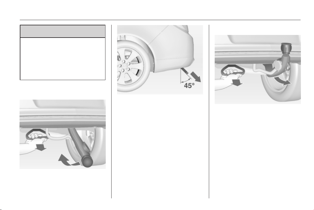
Driving and operating 211
9 Warning
Make sure that no one is in the
pivot zone of the coupling ball bar.
Risk of body injury.
When releasing the stowed
coupling ball bar, make sure to
stand left of the grip.
Release stowed coupling ball
bar
Pull the grip located left to the number
plate under the rear bumper fascia at
an angle of approx. 45° to the ground.
A buzzing tone sounds as a warning
when the release handle is pulled out
and the ball neck is disengaged.
Take the released coupling ball bar
and raise it up until it engages.
Ensure the coupling ball bar is
correctly engaged and the released
handle is guided back to its hidden
initial position, otherwise the buzzing
tone will not stop.
Stow/hide coupling ball bar
Pull the grip located left of the number
plate under the rear bumper fascia at
an angle of approx. 45° to the ground.
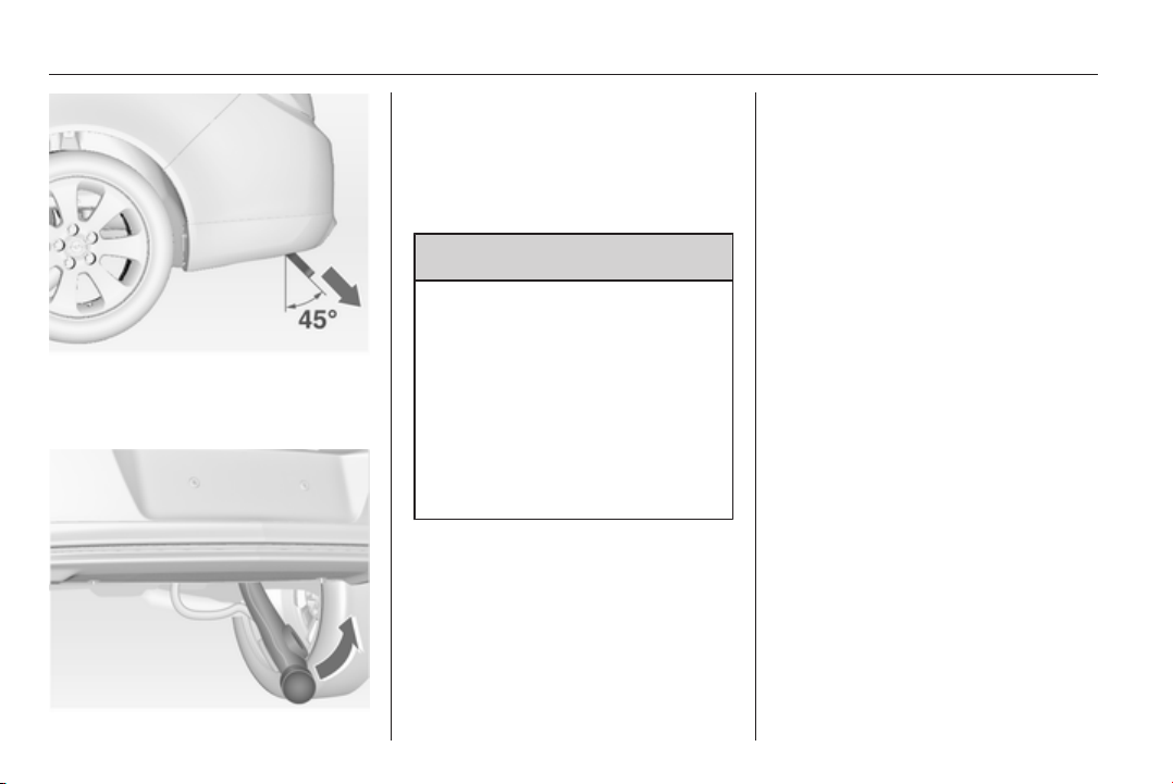
212 Driving and operating
A buzzing tone sounds as a warning
when the release handle is pulled out
and the ball neck is disengaged.
With the flat of the hand, swivel the
released coupling ball bar to the right
until it engages under the floor. Make
sure that the release handle is back in
its hidden initial position, otherwise
the buzzing tone will not stop.
9 Warning
Towing a trailer is permitted only
when the coupling ball bar is fitted
correctly. If the coupling ball bar
does not engage correctly or if the
release handle is impossible to
guide to its hidden initial position in
the housing or if the buzzing tone
sounds after engaging the
coupling ball bar, seek the
assistance of a workshop.
Eye for break-away stopping cable
Attach break-away stopping cable to
eye.
Trailer stability assist
If the system detects snaking
movements, engine power is reduced
and the vehicle/trailer combination is
selectively braked until the snaking
ceases. While system is working keep
steering wheel as still as possible.
Trailer stability assistant (TSA) is a
function of the Electronic Stability
Control 3 167.
Vehicle care 213
Vehicle care
General Information ................... 213
Vehicle checks ........................... 214
Bulb replacement ....................... 222
Electrical system ........................ 232
Vehicle tools .............................. 239
Wheels and tyres ....................... 240
Jump starting ............................. 252
Towing ....................................... 254
Appearance care ....................... 257
General Information
Accessories and vehicle
modifications
We recommend to use genuine parts
and accessories and factory
approved parts specific for your
vehicle type. We cannot assess or
guarantee reliability of other products
- even if they have a regulatory or
otherwise granted approval.
Do not make any modifications to the
electrical system, e.g. changes of
electronic control units (chip tuning).
Caution
When transporting the vehicle on
a train or on a recovery vehicle, the
mud flaps might be damaged.
Vehicle storage
Storage for a long period of time
If the vehicle is to be stored for several
months:
■ Wash and wax the vehicle.
■ Have the wax in the engine
compartment and underbody
checked.
■ Clean and preserve rubber seals.
■ Fill up fuel tank completely.
■ Change engine oil.
■ Drain washer fluid reservoir.
■ Check coolant antifreeze and
corrosion protection.
■ Adjust tyre pressure to the value
specified for full load.
■ Park vehicle in dry, well ventilated
place. Engage first or reverse gear
or set selector lever to P. Prevent
the vehicle from rolling.
■ Do not apply parking brake.
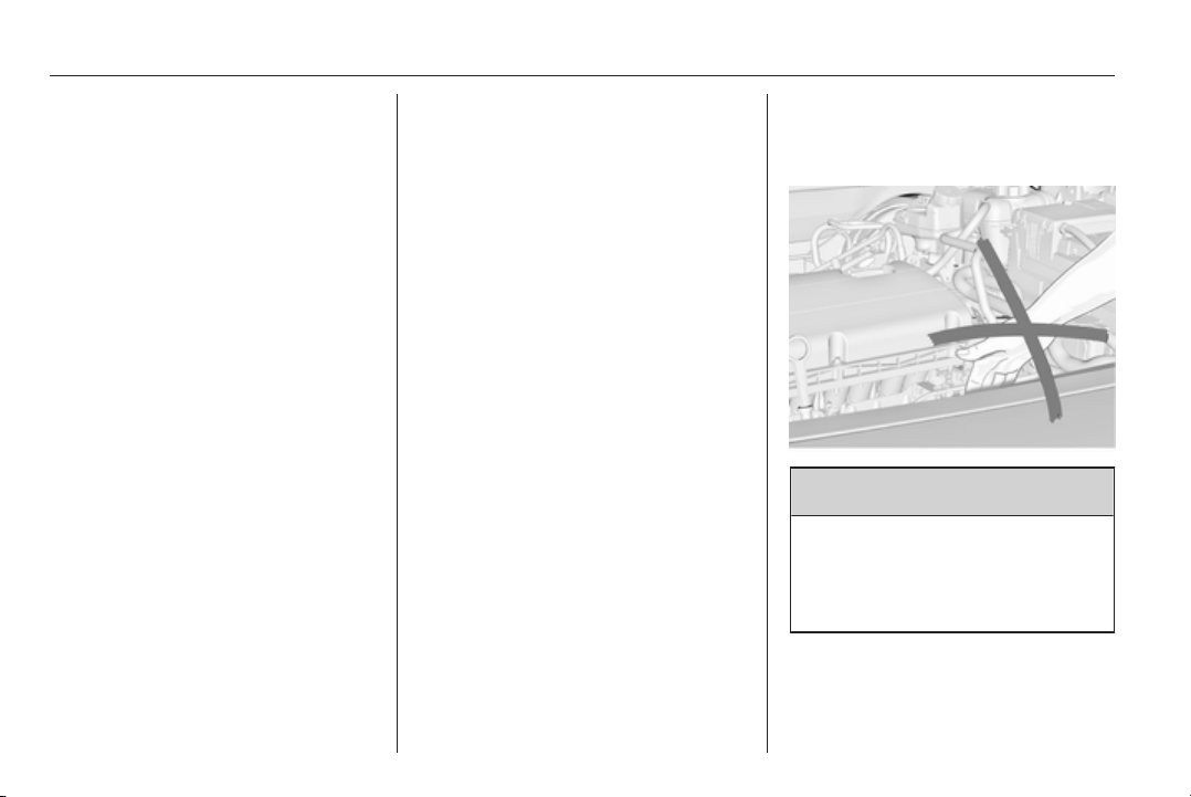
214 Vehicle care
■ Open bonnet, close all doors and
lock the vehicle.
■ Disconnect the clamp from the
negative terminal of the vehicle
battery. Beware that all systems are
not functional, e.g. anti-theft alarm
system.
Putting back into operation
When the vehicle is to be put back into
operation:
■ Connect the clamp to the negative
terminal of the vehicle battery.
Activate the electronics of the
power windows.
■ Check tyre pressure.
■ Fill up the washer fluid reservoir.
■ Check the engine oil level.
■ Check the coolant level.
■ Fit the number plate if necessary.
End-of-life vehicle
recovery
Information on end-of-life vehicle
recovery centres and the recycling of
end-of-life vehicles is available on our
website, where legally required. Only
entrust this work to an authorised
recycling centre.
Gas vehicles must be recycled by a
service centre authorised for gas
vehicles.
Vehicle checks
Performing work
9 Warning
Only perform engine compartment
checks when the ignition is off.
The cooling fan may start
operating even if the ignition is off.
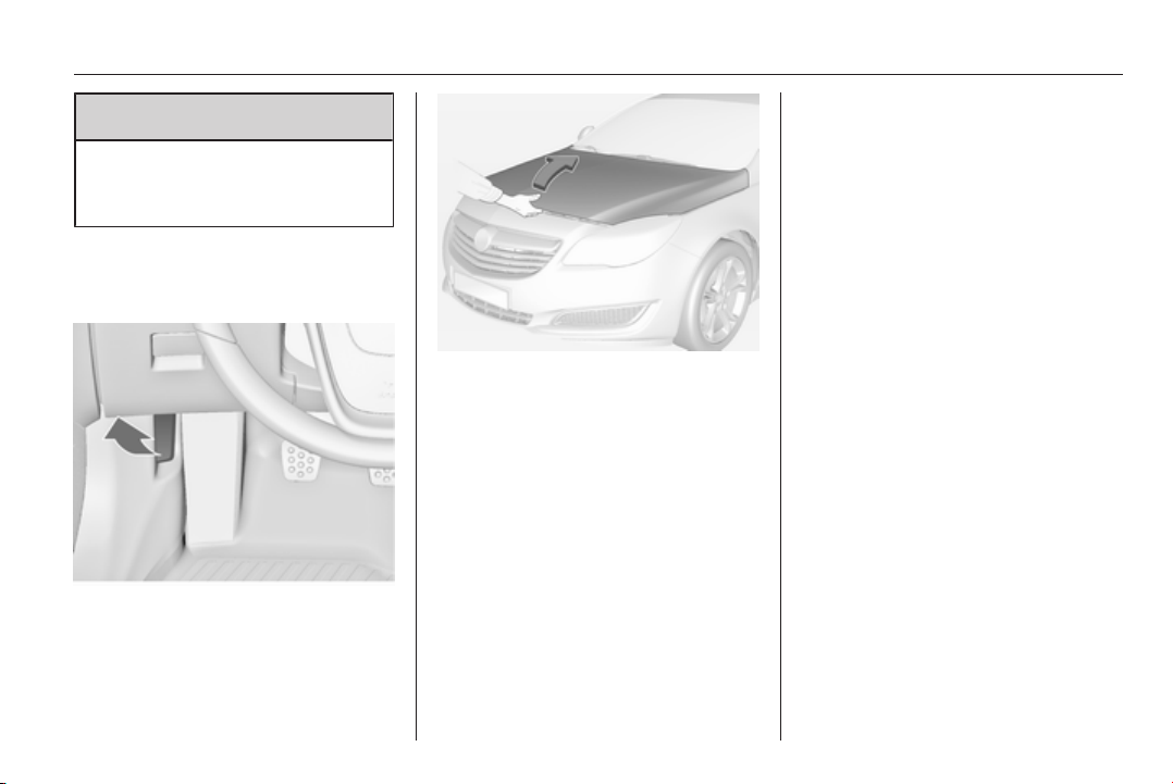
Vehicle care 215
9 Danger
The ignition system and Xenon
headlights use extremely high
voltage. Do not touch.
Bonnet
Opening
Pull the release lever and return it to
its original position.
Move the safety catch sideways to the
left vehicle side and open the bonnet.
The bonnet is held open
automatically.
Air intake 3 146.
If the bonnet is opened during an
Autostop, the engine will be restarted
automatically for safety reasons.
Stop-start system 3 153.
Closing
Lower the bonnet and allow it to drop
into the catch. Check that the bonnet
is engaged.
Engine oil
Check the engine oil manually on a
regular basis to prevent damage to
the engine. Ensure that the correct
specification of oil is used.
Recommended fluids and lubricants
3 262.
Check with the vehicle on a level
surface. The engine must be at
operating temperature and switched
off for at least 5 minutes.
Pull out the dipstick, wipe it clean,
insert it to the stop on the handle, pull
out and read the engine oil level.
Insert dipstick to the stop on the
handle and make half a turn.
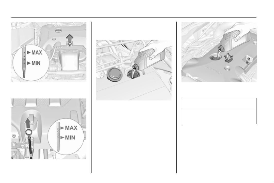
216 Vehicle care
Different dipsticks are used
depending on engine variant.
When the engine oil level has
dropped to the MIN mark, top up
engine oil.
We recommend the use of the same
grade of engine oil that was used at
last change.
The engine oil level must not exceed
the MAX mark on the dipstick.
Caution
Overfilled engine oil must be
drained or suctioned out.
Capacities 3 288, Engine oil quality/
viscosity 3 262.
Fit the cap on straight and tighten it.
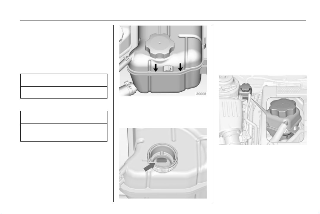
Vehicle care 217
Engine coolant
The coolant provides freeze
protection down to approx. -28 °C. In
northern countries with very low
temperatures the factory filled coolant
provides frost protection down to
approx. -37 °C.
Caution
Only use approved antifreeze.
Coolant level
Caution
Too low a coolant level can cause
engine damage.
If the cooling system is cold, the
coolant level should be above the
filling line mark. Top up if the level is
low.
On another version the filling line
mark is inside the filler opening. To
check open the cap.
Additional cooling circuit for Turbo
engine
Coolant container is fixed at the air
cleaner housing.
If the cooling system is cold, the
coolant level should be above the
filling line mark. Top up if the level is
low.
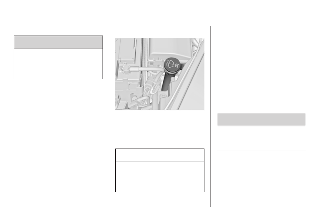
218 Vehicle care
General
9 Warning
Allow the engine to cool before
opening the cap. Carefully open
the cap, relieving the pressure
slowly.
To top up use a 1:1 mixture of
released coolant concentrate mixed
with clean tap water. If no coolant
concentrate is available, use clean
tap water. Install the cap tightly. Have
the coolant concentration checked
and have the cause of the coolant
loss remedied by a workshop.
Washer fluid
Fill with clean water mixed with a
suitable quantity of windscreen
washer fluid which contains
antifreeze. For the correct mixing ratio
refer to the washer fluid container.
Caution
Only washer fluid with a sufficient
antifreeze concentration provides
protection at low temperatures or
a sudden drop in temperature.
Brakes
In the event of minimum thickness of
the brake lining, a squealing noise
sounds during braking.
Continued driving is possible but
have the brake lining replaced as
soon as possible.
Once new brake linings are installed,
do not brake unnecessarily hard for
the first few journeys.
Brake fluid
9 Warning
Brake fluid is poisonous and
corrosive. Avoid contact with eyes,
skin, fabrics and painted surfaces.
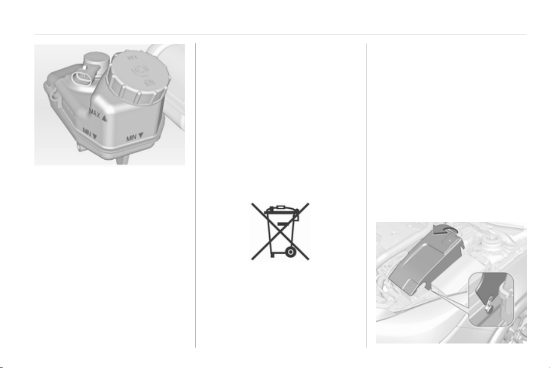
Vehicle care 219
The brake fluid level must be between
the MIN and the MAX marks.
When topping up, ensure maximum
cleanliness as contamination of the
brake fluid can lead to brake system
malfunctions. Have the cause of the
loss of brake fluid remedied by a
workshop.
Only use high-performance brake
fluid approved for the vehicle. Brake
and clutch fluid 3 262.
Vehicle battery
Vehicles without stop-start system
will be equipped with a lead acid
battery. Vehicles with stop-start
system will be equipped with an AGM
battery which is not a lead acid
battery.
The vehicle battery is maintenance-
free provided that the driving profile
allows sufficient charging of the
battery. Short-distance-driving and
frequent engine starts can discharge
the battery. Avoid the use of
unnecessary electrical consumers.
Batteries do not belong in household
waste. They must be disposed of at
an appropriate recycling collection
point.
Laying up the vehicle for more than
4 weeks can lead to vehicle battery
discharge. Disconnect the clamp from
the negative terminal of the vehicle
battery.
Ensure the ignition is switched off
before connecting or disconnecting
the vehicle battery.
Battery discharge protection 3 132.
Replacing the vehicle battery
Note
Any deviation from the instructions
given in this paragraph may lead to
a temporary deactivation of the stop-
start system.
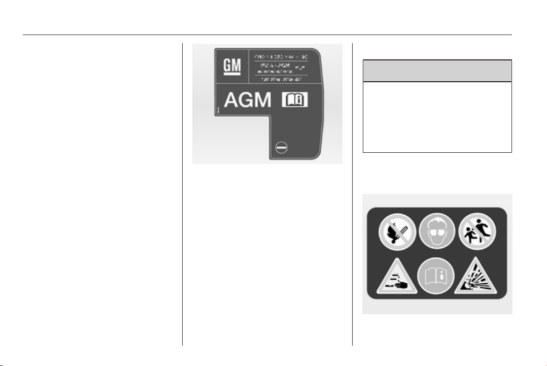
220 Vehicle care
The vehicle battery is covered.
Remove the cover to replace the
battery. Lift up the cover at the rear
and unlatch it at the front.
When the battery is being replaced,
please ensure that there are no open
ventilation holes in the vicinity of the
positive terminal. If a ventilation hole
is open in this area, it must be closed
off with a dummy cap, and the
ventilation in the vicinity of the
negative terminal must be opened.
Only use vehicle batteries that allow
the fuse box to be mounted above the
battery.
In vehicles with stop-start system, be
sure to have the AGM (Absorptive
Glass Mat) battery replaced with an
AGM battery again.
An AGM battery can be identified by
the label on the battery. We
recommend the use of an original
Opel battery.
Note
Using an AGM battery different from
the original Opel battery might result
in a lower performance of the stop-
start system.
We recommend that you have the
vehicle battery replaced by a
workshop.
Stop-start system 3 153.
Charging the vehicle battery
9 Warning
On vehicles with stop-start
system, ensure that the charging
potential does not exceed
14.6 volts when using a battery
charger. Otherwise the battery
might be damaged.
Jump starting 3 252.
Warning label
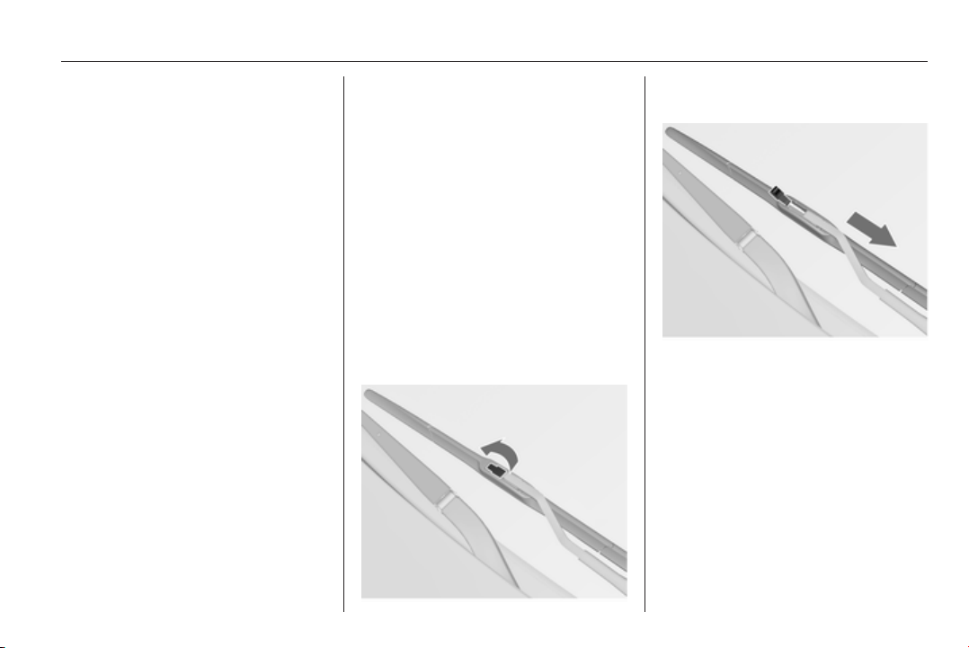
Vehicle care 221
Meaning of symbols:
■ No sparks, naked flames or
smoking.
■ Always shield eyes. Explosive
gases can cause blindness or
injury.
■ Keep the vehicle battery out of
reach of children.
■ The vehicle battery contains
sulphuric acid which could cause
blindness or serious burn injuries.
■ See the Owner’s Manual for further
information.
■ Explosive gas may be present in
the vicinity of the vehicle battery.
Diesel fuel system
bleeding
If the tank has been run dry, the diesel
fuel system must be bled. Switch on
the ignition three times for
15 seconds at a time. Then crank the
engine for a maximum of
40 seconds. Repeat this process after
no less than 5 seconds. If the engine
fails to start, seek the assistance of a
workshop.
Wiper blade replacement
Wiper blades on the windscreen
Lift the wiper arm and open the
retaining clip.
Disengage the wiper blade and
remove.
Attach the wiper blade slightly angled
to the wiper arm and push until it
engages.
Lower wiper arm carefully.
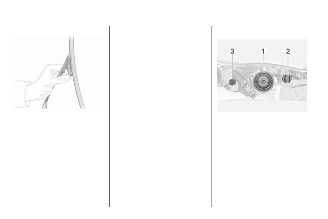
222 Vehicle care
Wiper blade on the rear window
Lift the wiper arm. Press the two
catches on the arm, disengage the
wiper blade and remove.
Attach the wiper blade slightly angled
to the wiper arm and push until it
engages.
Lower wiper arm carefully.
Bulb replacement
Switch off the ignition and switch off
the relevant switch or close the doors.
Only hold a new bulb at the base! Do
not touch the bulb glass with bare
hands.
Use only the same bulb type for
replacement.
Replace headlight bulbs from within
the engine compartment.
Bulb check
After a bulb replacement switch on
the ignition, operate and check the
lights.
Halogen headlights
Bi-Halogen Headlight (1) with one
bulb for low and high beam.
Sidelight/Daytime running light (2).
Front turn signal light (3)
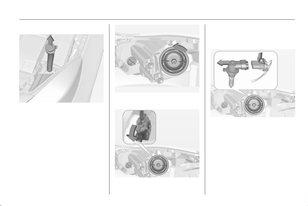
Vehicle care 223
Bi-Halogen Headlight (1)
On left vehicle side pull filling pipe out
of the windscreen washer fluid
container.
1. Rotate the cap anticlockwise and
remove it.
2. Rotate the bulb holder
anticlockwise to disengage.
Withdraw the bulb holder from the
reflector.
3. Disengage the bulb holder from
the plug connector by bending
apart slightly the retaining lug.
4. Replace the bulb and connect
with the plug.
5. Insert the bulb holder, engaging
the two lugs into the reflector and
rotate clockwise to secure.
6. Fit the cap and rotate clockwise.
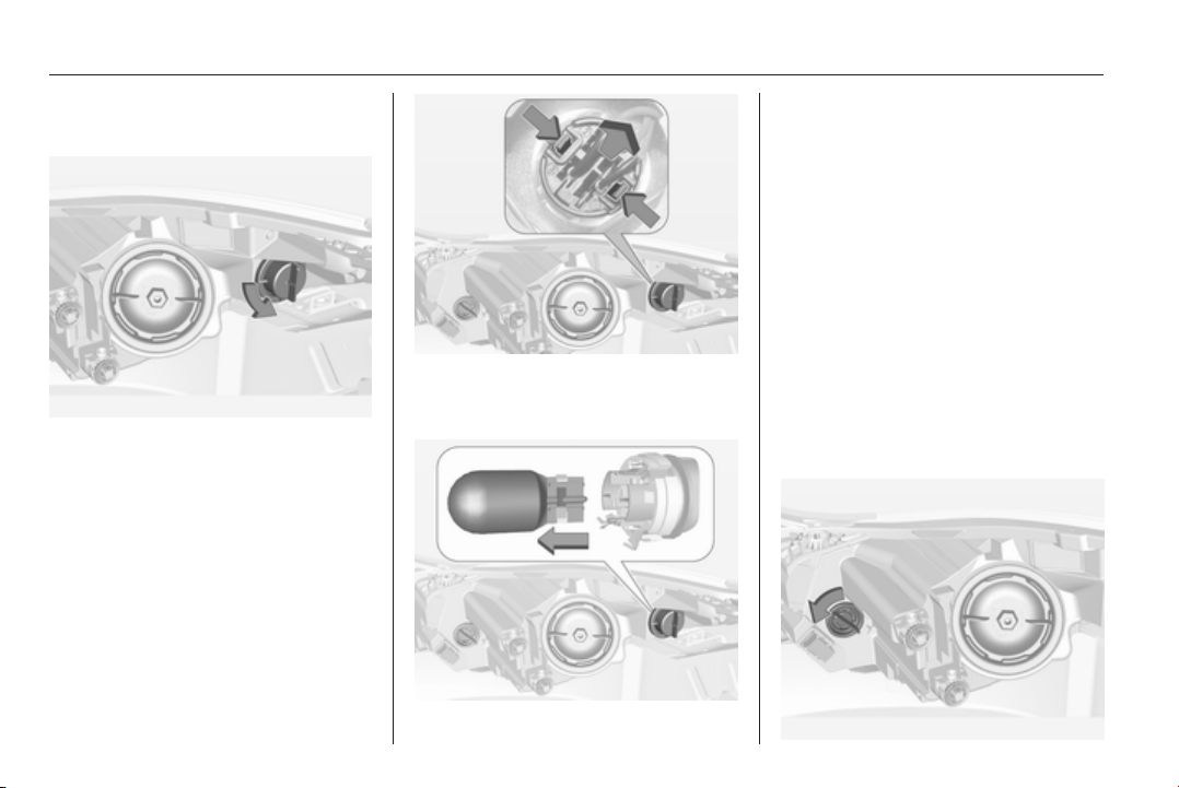
224 Vehicle care
Sidelight/Daytime running light
(2)
1. Rotate cap anticlockwise and
withdraw from the reflector.
2. Press snap-in tongues together
and move socket out of the
housing.
3. Remove the bulb from the socket
by pulling.
4. Replace and insert new bulb into
socket.
5. Insert the bulb socket into the
housing and let engage.
6. Fit the cap and rotate clockwise.
Sidelight/Daytime running light
with LEDs
On another version sidelight and
daytime running lights are designed
as LEDs. In case of defective have
LEDs replaced by a workshop.
Front turn light (3)
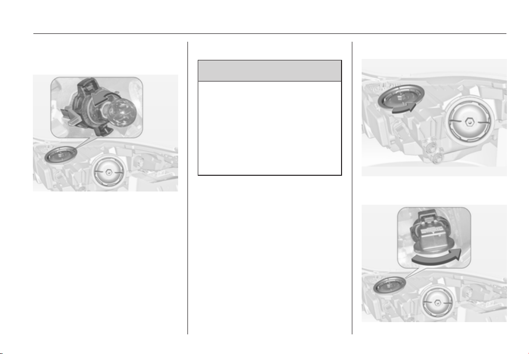
Vehicle care 225
1. Rotate bulb socket anti-clockwise
to disengage. Withdraw the bulb
socket from the housing.
2. Push bulb into socket slightly,
rotate anti-clockwise and remove.
3. Replace and insert new bulb into
socket by rotating clockwise.
4. Insert bulb socket in reflector,
rotate clockwise to engage.
Xenon headlights
9 Danger
Adaptive forward lighting system
uses Xenon headlights.
Xenon headlights work under
extremely high electrical voltage.
Do not touch. Have bulbs replaced
by a workshop.
Bulbs for front turn signal and
corner lighting can be changed.
Sidelight/Daytime running lights are
designed as Light Emitting Diodes
(LEDs) and cannot be changed.
Corner lighting
1. Rotate the cap anticlockwise and
remove it.
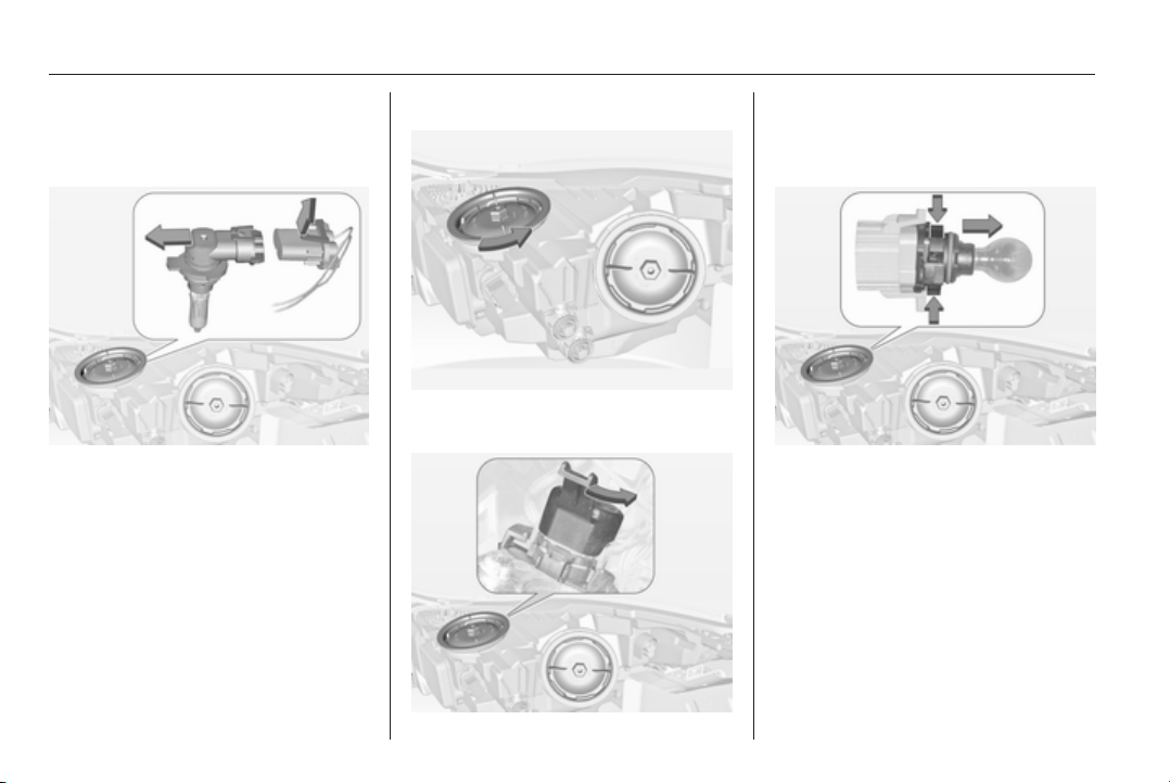
226 Vehicle care
2. Rotate the bulb holder
anticlockwise to disengage.
Withdraw the bulb holder from the
reflector.
3. Disengage the bulb from the plug
connector by unlatching and
pulling.
4. Replace the bulb and connect
bulb holder with the plug
connector.
5. Insert the bulb holder, engaging
the two lugs into the reflector and
rotate clockwise to secure.
6. Fit the cap and rotate clockwise.
Front turn signal
1. Rotate the cap anticlockwise and
remove it.
2. Rotate the bulb holder
anticlockwise to disengage.
Withdraw the bulb holder from the
reflector.
3. Disengage the bulb holder from
the plug connector by unlatching
and pulling.
4. Replace the bulb and connect
bulb holder with the plug.
5. Insert the bulb holder, engaging
the two lugs into the reflector and
rotate clockwise to secure.

Vehicle care 227
Sidelight/Daytime running light
Sidelight and daytime running lights
are designed as LEDs. In case of
failure, have LEDs replaced by a
workshop.
Fog lights
The bulbs are accessible from the
underside of the vehicle.
1. Turn the bulb holder anti-
clockwise and remove it from the
reflector.
2. Disengage the bulb socket from
the plug connector by pressing
the retaining lug.
3. Remove and replace the bulb
socket with bulb and attach the
plug connector.
4. Insert the bulb socket into the
reflector and turn clockwise to
engage.
Tail lights
5-door Hatchback/4-door
Saloon
1. Remove cover from the inside of
the load compartment.
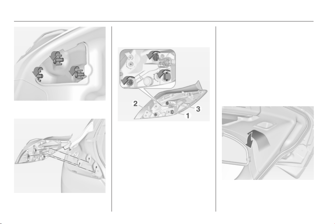
228 Vehicle care
2. Unscrew three plastic securing
nuts from the inside by hand.
3. Carefully withdraw the light
assembly from the recesses and
remove.
4. Turn bulb holder anticlockwise
and remove. Replace bulb by
withdrawing or turning:
Turn signal light 1
Rear fog light 2, only on driver side
Reverse light 3
Tail light and brake light are
designed as LEDs. In case of
failure, have LEDs replaced by a
workshop.
5. Insert bulb holder into the tail light
assembly and turn clockwise. Fit
light assembly with the retaining
pins into the recesses of the
vehicle body and tighten the
securing nuts from the inside of
the load compartment. Close
cover.
Sports Tourer/Country Tourer
1. Release and open the cover in the
tailgate.
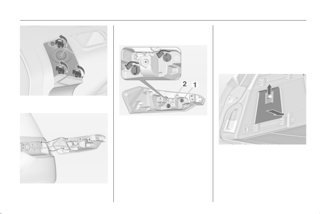
Vehicle care 229
2. Unscrew three plastic securing
nuts by hand.
3. Carefully withdraw the light
assembly from the recesses and
remove.
4. Turn bulb holder anticlockwise
and remove. Replace bulb by
withdrawing:
Reverse light 1
Turn signal light 2
Tail light, brake light and rear fog
light are designed as LEDs. In
case of failure, have LEDs
replaced by a workshop.
5. Insert bulb holder into the tail light
assembly and turn clockwise. Fit
light assembly with the retaining
pins into the recesses of the
tailgate and tighten the securing
nuts from the inside of the tailgate.
Close cover.
Additional tail lights in the tailgate
frame
1. Open tailgate.
2. Release cover in side trim panel
and remove.
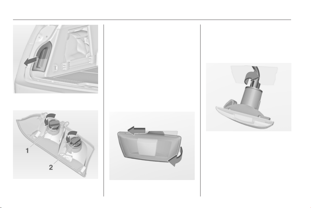
230 Vehicle care
3. Press out lamp housing from the
inside of the side trim panel.
4. Rotate plastic nut anticlockwise
and remove from the bulb holder.
5. Push bulb into socket slightly,
rotate anti-clockwise, remove and
renew bulb. Insert plastic nut into
bulb holder by rotating clockwise.
Tail light (1)
Turn signal light (2)
6. Insert bulb holder into the tailgate
frame. Close cover in the side trim
panel.
Side turn signal lights
To replace bulb, remove lamp
housing:
1. On left vehicle side, slide lamp to
the front and remove it out of the
fender with the rear end.
On right vehicle side, slide lamp to
the rear and remove it out of the
fender with the front end.
2. Turn bulb holder anticlockwise
and remove from housing.
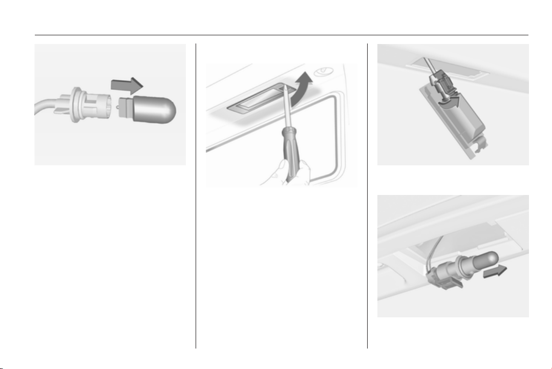
Vehicle care 231
3. Pull bulb from bulb holder and
replace it.
4. Insert bulb holder and turn
clockwise.
5. On left side: insert front end into
fender, slide forward and insert
rear end.
On right side: insert rear end into
fender, slide rearward and insert
front end.
Number plate light
1. Insert screwdriver in bulb
housing, press to the side and
release spring.
2. Remove lamp downwards, taking
care not to pull on the cable.
3. Remove bulb holder from lamp
housing by turning anticlockwise.
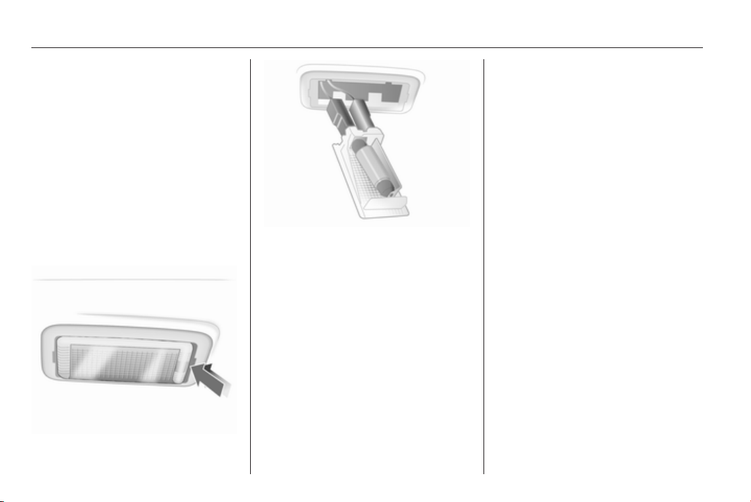
232 Vehicle care
4. Pull bulb from bulb holder and
replace it.
5. Insert bulb holder into lamp
housing and turn clockwise.
6. Insert lamp into bumper and let
engage.
Interior lights
Courtesy light, reading lights
Have bulbs replaced by a workshop.
Load compartment light
1. Prise the lamp out with a
screwdriver.
2. Press bulb slightly towards spring
clip and remove.
3. Insert new bulb.
4. Install lamp.
Instrument panel
illumination
Have bulbs replaced by a workshop.
Electrical system
Fuses
Data on the replacement fuse must
match the data on the defective fuse.
There are three fuse boxes in the
vehicle:
■ in the front left of the engine
compartment,
■ in left-hand drive vehicles, in the
interior behind the storage
compartment, or, in right-hand
drive vehicles, behind the
glovebox,
■ behind a cover on the left side of the
load compartment.
Before replacing a fuse, turn off the
respective switch and the ignition.
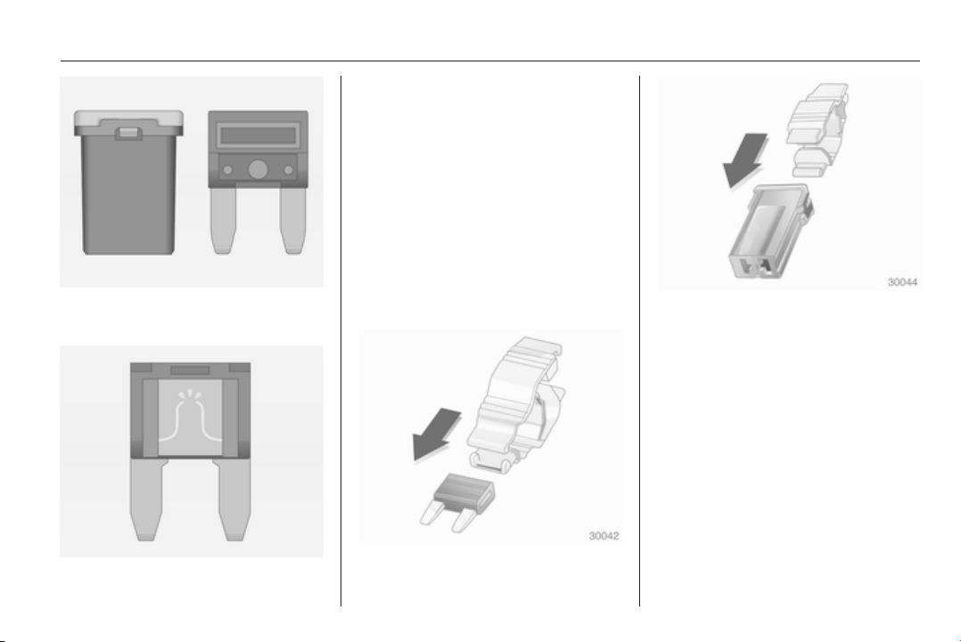
Vehicle care 233
There are different kinds of fuses in
the vehicle.
Depending on the type of fuse, a
blown fuse can be recognized by its
melted wire. Do not replace the fuse
until the cause of the fault has been
remedied.
Some functions are protected by
several fuses.
Fuses may also be inserted without
existence of a function.
Fuse extractor
A fuse extractor may be located in the
fuse box in the engine compartment.
Place the fuse extractor on the
various types of fuse from the top or
side, and withdraw fuse.
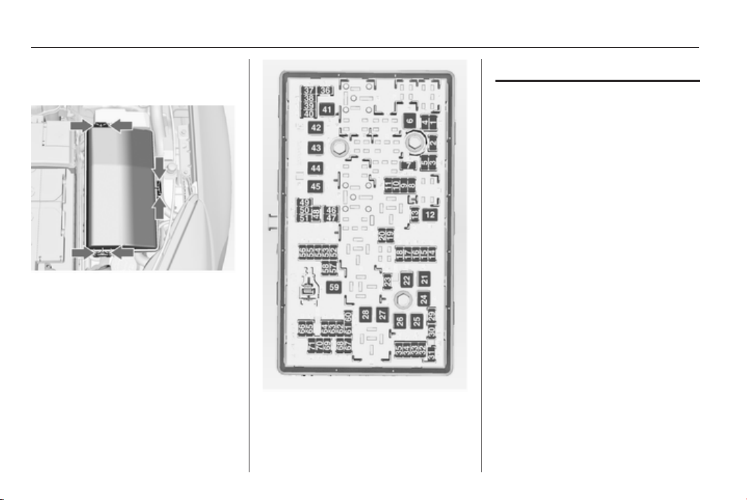
234 Vehicle care
Engine compartment fuse
box
The fuse box is in the front left of the
engine compartment.
Disengage the cover, lift it upwards
and remove.
No. Circuit
1 Transmission control module
2 Engine control module
3 –
4 –
5 Ignition, Transmission control
module, Engine control module
6 Windscreen wiper
7 –
8 Fuel injection, ignition system
9 Fuel injection, ignition system
10 Engine control module
11 Lambda probe
12 Starter
13 Sensor throttle heating
14 Lighting
15 Rear window wiper

Vehicle care 235
No. Circuit
16 Vacuum pump, mass air flow
meter, water in fuel sensor, DC
transformer
17 –
18 Adaptive forward lighting
19 Adaptive forward lighting
20 Fuel pump
21 Rear power windows
22 ABS
23 Variable effort steering
24 Front power windows
25 Power outlets
26 ABS
27 Electric parking brake
28 Heated rear window
29 Left power seat
30 Right power seat
No. Circuit
31 Air conditioning system
32 Body control module
33 Heated front seats
34 Sunroof
35 Infotainment system
36 –
37 Right high beam
38 Left high beam
39 –
40 –
41 Vacuum pump
42 Radiator fan
43 Vehicle battery, DC transformer
(only on vehicles with stop-start
system)
44 Headlamp washer system
45 Radiator fan
No. Circuit
46 Terminal 87, main relay
47 Lambda probe
48 Fog lights
49 Right low beam
50 Left low beam
51 Horn
52 Ignition
53 Ignition, ventilated front seats
54 Ignition
55 Power windows, mirror folding
56 Windscreen washer
57 –
58 –
59 Diesel fuel heating, emission
control system
60 Mirror heating
61 Mirror heating
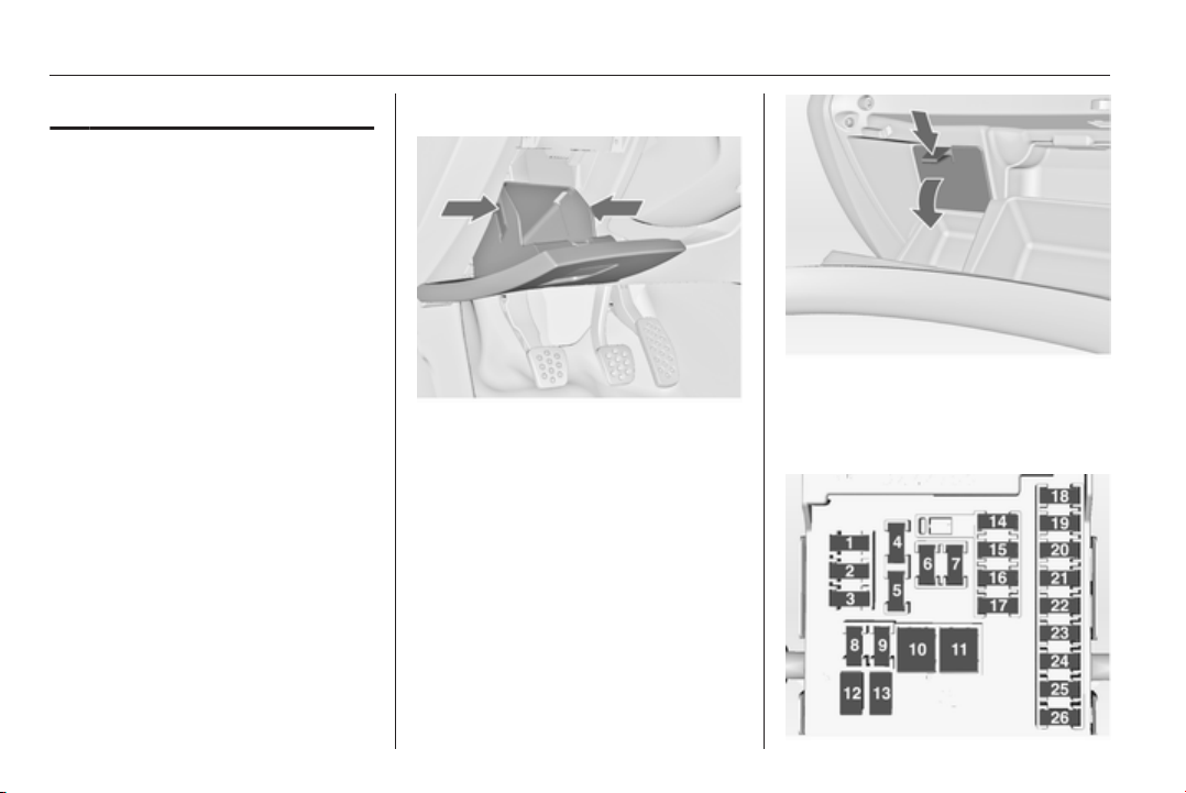
236 Vehicle care
No. Circuit
62 –
63 Rear window sensor
64 Adaptive forward lighting
65 Auxiliary pump (only on vehicles
with stop-start system)
66 Rear window washer system
67 Fuel system control module
68 –
69 Vehicle battery sensor
70 Rain sensor
71 Vehicle battery sensor
After changing of defective fuses
close the fuse box cover and press
until it engages.
If the fuse box cover is not closed
correctly, malfunctions may occur.
Instrument panel fuse box
In left-hand drive vehicles, the fuse
box is behind the storage
compartment in the instrument panel.
Open compartment, compress the
locking tabs, fold compartment down
and remove.
In right-hand drive vehicles, the fuse
box is located behind a cover in the
glovebox. Open the glovebox and
remove the cover.
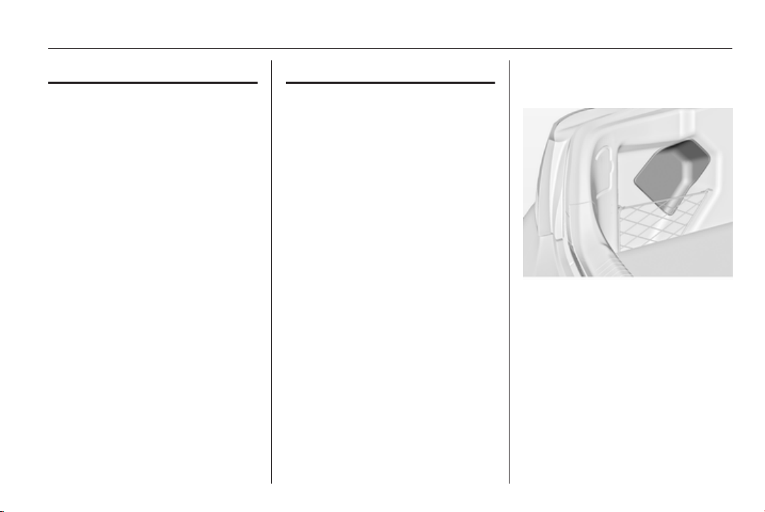
Vehicle care 237
No. Circuit
1 Infotainment system, Info
display
2 Body control unit
3 Body control unit
4 Infotainment system, Info
display
5 Infotainment system, Info
display
6 Cigarette lighter
7 Power outlet
8 Body control unit
9 Body control unit
10 Body control unit
11 Interior fan
12 –
13 –
14 Diagnostic connector
15 Airbag
No. Circuit
16 Central locking system, tailgate
17 Air conditioning system
18 Transportation fuse
19 Memory
20 –
21 Instrument
22 Ignition
23 Body control unit
24 Body control unit
25 –
26 Power outlet load compartment
Power seats, No's. 12 and 13, have
an overload protection. The circuit will
be closed again after cooling down.
Load compartment fuse
box
The fuse box is on the left side of the
load compartment behind a cover.
Remove the cover.
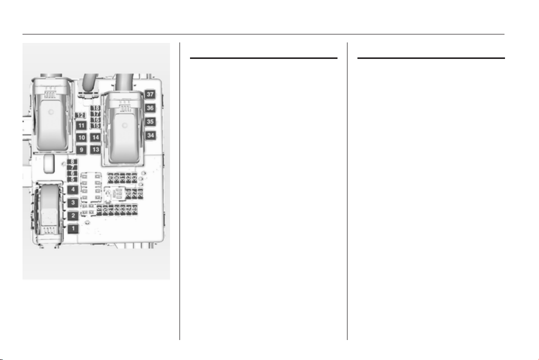
238 Vehicle care
No. Circuit
1 Central locking system, Power
tailgate
2 Trailer module
3 –
4 –
5 Trailer socket
6 Steering wheel heating
7 –
8 Trailer socket
9 Sunroof
10 Central locking system, tailgate
11 –
12 –
13 –
14 –
15 Power tailgate lock
16 Air conditioning system
No. Circuit
17 –
18 –
19 Side obstacle detector
20 Side obstacle detector, venti‐
lated front seats
21 Active damping system, High
beam assist, Cruise control,
Traffic sign assistant, Lane
departure warning, trailer
module
22 Anti-theft alarm system
23 All-wheel drive, anti-theft alarm
system
24 –
25 –
26 –
27 –
28 –
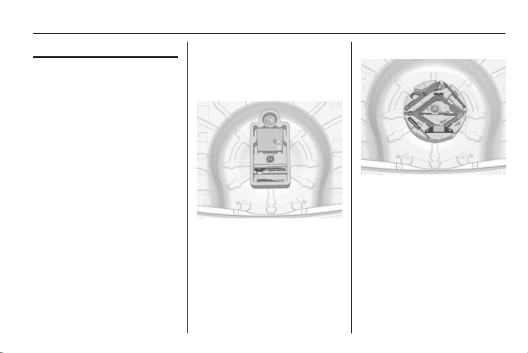
Vehicle care 239
No. Circuit
29 Trailer module, transportation
fuse
30 Side obstacle detector
31 –
32 –
33 –
34 Sunroof
35 –
36 –
37 –
Vehicle tools
Tools
Vehicles with tyre repair kit
The tools and the towing eye are
located together with the tyre repair
kit in a tool box below the floor cover
in the load compartment.
Vehicles with spare wheel
The jack with wheel wrench, the tools,
an extension bolt for securing a
damaged wheel and the towing eye
are placed in the tool box below the
spare wheel in the load compartment.
Spare wheel 3 250.
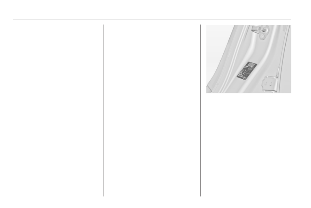
240 Vehicle care
Wheels and tyres
Tyre condition, wheel condition
Drive over edges slowly and at right
angles if possible. Driving over sharp
edges can cause tyre and wheel
damage. Do not trap tyres on the kerb
when parking.
Regularly check the wheels for
damage. Seek the assistance of a
workshop in the event of damage or
unusual wear.
Winter tyres
Winter tyres improve driving safety at
temperatures below 7 °C and should
therefore be fitted on all wheels.
In accordance with country-specific
regulations, affix the speed sticker in
the driver's field of view.
All tyre sizes are permitted as winter
tyres 3 289.
5-door Hatchback, 4-door Saloon,
Sports Tourer
Use tyre size 205/60 R 16 and
235/45 R 18 only as winter tyres.
Tyre designations
E.g. 215/60 R 16 95 H
215 = Tyre width, mm
60 = Cross-section ratio (tyre
height to tyre width), %
R = Belt type: Radial
RF = Type: RunFlat
16 = Wheel diameter, inches
95 = Load index e.g. 95 is
equivalent to 690 kg
H = Speed code letter
Speed code letter:
Q = up to 160 km/h
S = up to 180 km/h
T = up to 190 km/h
H = up to 210 km/h
V = up to 240 km/h
W = up to 270 km/h
Tyre pressure
Check the pressure of cold tyres at
least every 14 days and before any
long journey. Do not forget the spare
wheel. This also applies to vehicles
with tyre pressure monitoring system.
Unscrew the valve cap.
Tyre pressure 3 289.
The tyre and loading information label
on the left door frame indicates the
original equipment tyres and the
correspondent tyre pressures.
The tyre pressure data refers to cold
tyres. It applies to summer and winter
tyres.
Always inflate the spare tyre to the
pressure specified for full load.
The ECO tyre pressure serves to
achieve the smallest amount of fuel
consumption possible.
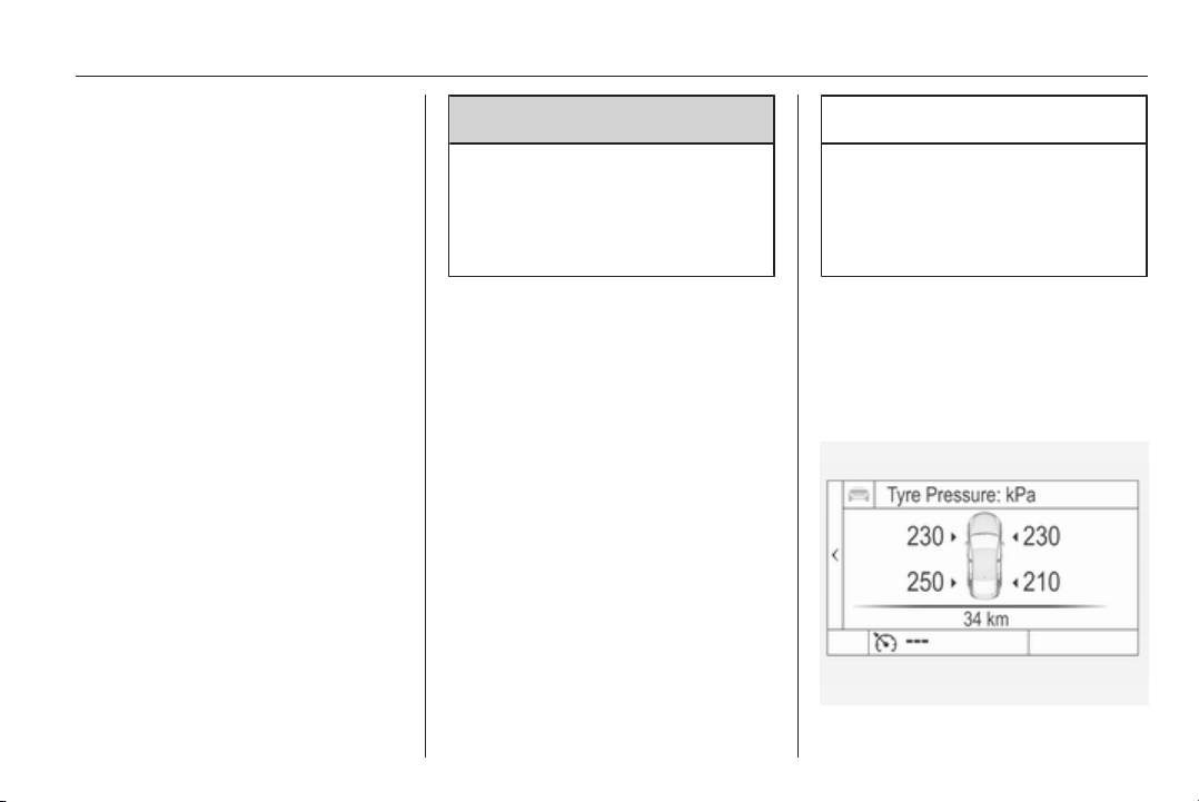
Vehicle care 241
Incorrect tyre pressures will impair
safety, vehicle handling, comfort and
fuel economy and will increase tyre
wear.
Tyre pressures differ depending on
various options. For the correct tyre
pressure value, follow the procedure
below:
1. Identify drive axle and body style.
2. Identify the engine identifier code.
Engine data 3 269.
3. Identify the respective tyre.
The tyre pressure tables show all
possible tyre combinations 3 289.
For the tyres approved for your
vehicle, refer to the EEC Certificate of
Conformity provided with your vehicle
or other national registration
documents.
The driver is responsible for correct
adjustment of tyre pressure.
9 Warning
If the pressure is too low, this can
result in considerable tyre warm-
up and internal damage, leading to
tread separation and even to tyre
blow-out at high speeds.
If the tyre pressure shall be reduced
or increased on a vehicle with tyre
pressure monitoring system, switch
off ignition. After adjusting tyre
pressure switch on ignition and select
the according setting on the page
Tyre load in the Driver Information
Centre, 3 107.
Tyre pressure monitoring
system
The tyre pressure monitoring system
checks the pressure of all four wheels
once a minute when vehicle speed
exceeds a certain limit.
Caution
Tyre pressure monitoring system
warns just about low tyre pressure
condition and does not replace
regular tyre maintenance by the
driver.
All wheels must be equipped with
pressure sensors and the tyres must
have the prescribed pressure.
Select the Tyre pressure monitoring
page under the Info Menu in the
Driver Information Centre 3 107
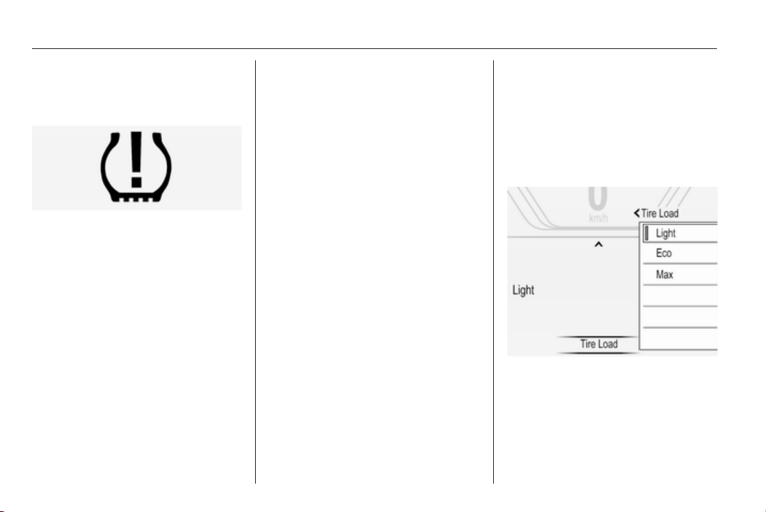
242 Vehicle care
System status and pressure warnings
are displayed by a message with the
corresponding tyre flashing in the
Driver Information Centre.
A detected low tyre pressure
condition is indicated by the control
indicator w 3 104.
If w lights up, stop as soon as
possible and inflate the tyres as
recommended 3 289.
After inflating driving may be required
to update the tyre pressure values in
the Driver Information Centre. During
this time w may light up.
If w lights up at lower temperatures
and extinguishes after some driving,
this could be an indicator for getting
low pressure. Check tyre pressure.
Vehicle messages 3 116.
If the tyre pressure must be reduced
or increased, switch off ignition.
Only mount wheels with pressure
sensors, otherwise the tyre pressure
will not be displayed and w
illuminates continuously.
A spare wheel or temporary spare
wheel is not equipped with pressure
sensors. The tyre pressure
monitoring system is not operational
for these wheels. Control indicator w
illuminates. For the further three
wheels the system remains
operational.
The use of commercially available
liquid tyre repair kits can impair the
function of the system. Factory
approved repair kits can be used.
External high-power radio equipment
could disrupt the tyre pressure
monitoring system.
Each time the tyres are replaced tyre
pressure monitoring system sensors
must be dismounted and serviced.
For the screwed sensor replace valve
core and sealing ring, for clipped
sensor replace complete valve stem.
Vehicle loading status
Adjust tyre pressure to load condition
according tyre information label or
tyre pressure chart 3 289, and select
the according setting in the Tyre
loading page under the Settings
menu in the Driver Information Centre
3 107.
Select:
■ Light for comfort pressure up to
3 people
■ Eco for Eco pressure up to
3 people
■ Max for full loading
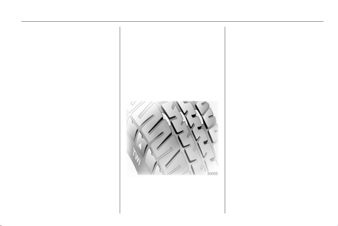
Vehicle care 243
Auto learn function
After changing wheels the vehicle
must be stationary for approx.
20 minutes, before the system
recalculates. The following relearn
process takes up to 10 minutes of
driving with a minimum speed of
20 km/h. In this case $ can be
displayed or pressure values can
swap in the Driver Information Centre.
If problems occur during the relearn
process, a warning message is
displayed in the Driver Information
Centre.
Temperature dependency
Tyre pressure depends on the
temperature of the tyre. During
driving tyre temperature and pressure
increase.
The tyre pressure value displayed in
the Driver Information Centre shows
the actual tyre pressure. Therefore it
is important to check tyre pressure
with cold tyres.
Tread depth
Check tread depth at regular
intervals.
Tyres should be replaced for safety
reasons at a tread depth of 2-3 mm
(4 mm for winter tyres).
For safety reasons, it is
recommended that the tread depth of
the tyres on one axle should not vary
by more than 2 mm.
The legally permissible minimum
tread depth (1.6 mm) has been
reached when the tread has worn
down as far as one of the tread wear
indicators (TWI). Their position is
indicated by markings on the
sidewall.
If there is more wear at the front than
the rear, swap round front wheels and
rear wheels periodically. Ensure that
the direction of rotation of the wheels
remains the same.
Tyres age, even if they are not used.
We recommend tyre replacement
every 6 years.
Changing tyre and wheel
size
If tyres of a different size than those
fitted at the factory are used, it may be
necessary to reprogramme the
speedometer as well as the nominal
tyre pressure and make other vehicle
modifications.
After converting to a different tyre
size, have the label with tyre
pressures replaced.
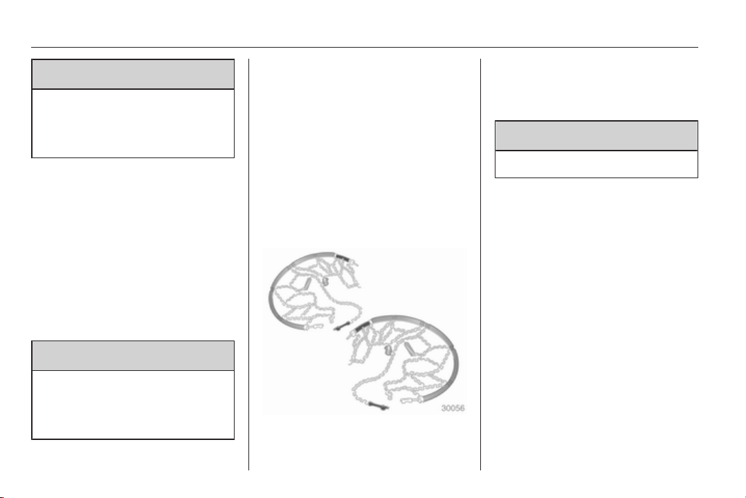
244 Vehicle care
9 Warning
Use of unsuitable tyres or wheels
may lead to accidents and will
invalidate the vehicle type
approval.
Wheel covers
Wheel covers and tyres that are
factory approved for the respective
vehicle and comply with all of the
relevant wheel and tyre combination
requirements must be used.
If the wheel covers and tyres used are
not factory approved, the tyres must
not have a rim protection ridge.
Wheel covers must not impair brake
cooling.
9 Warning
Use of unsuitable tyres or wheel
covers could lead to sudden
pressure loss and thereby
accidents.
Wheel caps
Tyres of size 245/35 R20 have a
specific wheel cap. To remove the
cap from the dismantled wheel first
disengage the arms one by one. Then
press the cap in the middle area from
behind and remove it.
To assemble first adjust the wheel
cap in order that the positioning leg
fits into the recess.
Tyre chains
Tyre chains are only permitted on the
front wheels.
Always use fine mesh chains that add
no more than 10 mm to the tyre tread
and the inboard sides (including chain
lock).
9 Warning
Damage may lead to tyre blowout.
5-door Hatchback, 4-door Saloon,
Sports Tourer
Tyre chains are only permitted on
tyres of size 205/60 R 16,
215/60 R 16, 225/55 R 17,
225/45 R 18, 225/50 R 17 and
235/45 R 18.
Country Tourer
Tyre chains are only permitted on
tyres of size 235/45 R 18.
Temporary spare wheel
The use of tyre chains is not permitted
on the temporary spare wheel.
Tyre repair kit
Minor damage to the tyre tread can be
repaired with the tyre repair kit.
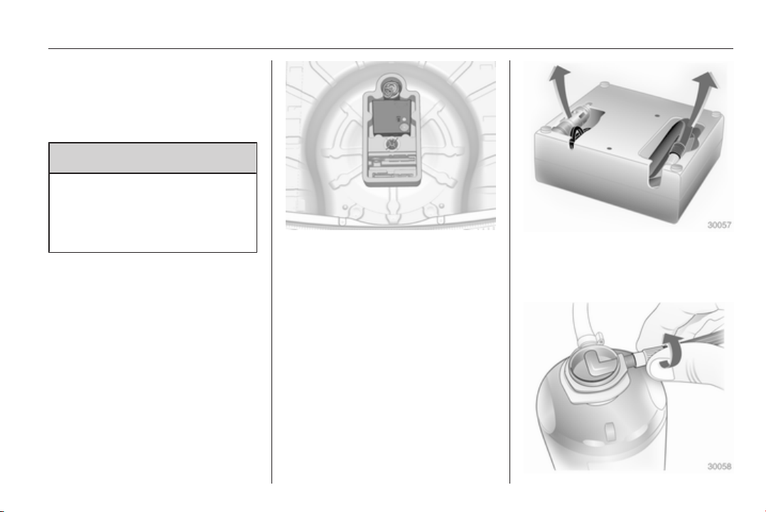
Vehicle care 245
Do not remove foreign bodies from
the tyres.
Tyre damage exceeding 4 mm or that
is at tyre's side wall cannot be
repaired with the tyre repair kit.
9 Warning
Do not drive faster than 80 km/h.
Do not use for a lengthy period.
Steering and handling may be
affected.
If you have a flat tyre:
Apply the parking brake and engage
first gear, reverse gear or P.
The tyre repair kit is in a compartment
under the floor cover in the load
compartment.
1. Take the tyre repair kit from the
compartment.
2. Remove the compressor.
3. Remove the electrical connection
cable and air hose from the
stowage compartments on the
underside of the compressor.
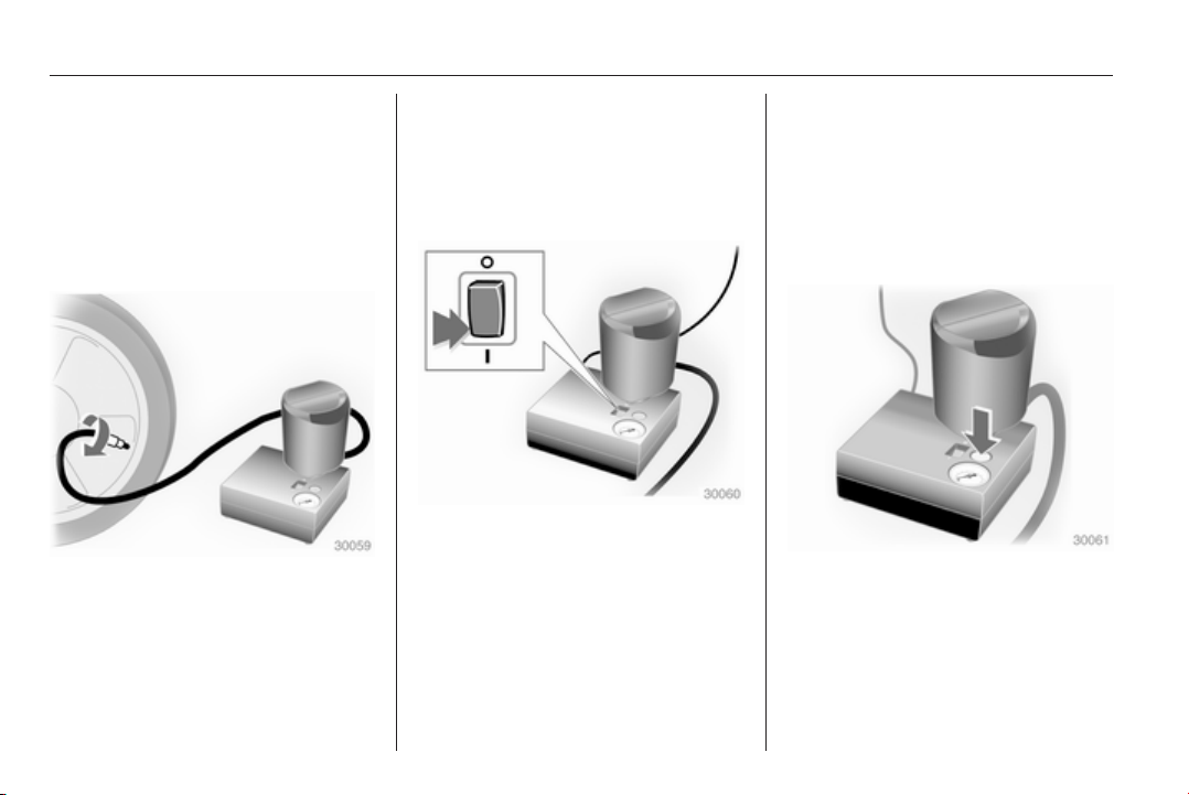
246 Vehicle care
4. Screw the compressor air hose to
the connection on the sealant
bottle.
5. Fit the sealant bottle into the
retainer on the compressor.
Set the compressor near the tyre
in such a way that the sealant
bottle is upright.
6. Unscrew valve cap from defective
tyre.
7. Screw the filler hose to the tyre
valve.
8. The switch on the compressor
must be set to J.
9. Connect the compressor plug to
the power outlet or cigarette
lighter socket.
To avoid discharging the battery,
we recommend running the
engine.
10. Set the rocker switch on the
compressor to I. The tyre is filled
with sealant.
11. The compressor pressure gauge
briefly indicates up to 6 bar whilst
the sealant bottle is emptying
(approx. 30 seconds). Then the
pressure starts to drop.
12. All of the sealant is pumped into
the tyre. Then the tyre is inflated.
13. The prescribed tyre pressure
should be obtained within
10 minutes. Tyre pressure
3 289. When the correct pressure
is obtained, switch off the
compressor.
If the prescribed tyre pressure is
not obtained within 10 minutes,
remove the tyre repair kit. Move
the vehicle one tyre rotation.
Reattach the tyre repair kit and
continue the filling procedure for
10 minutes. If the prescribed tyre
pressure is still not obtained, the
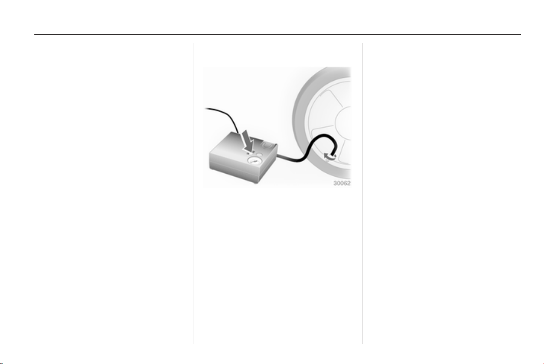
Vehicle care 247
tyre is too badly damaged. Seek
the assistance of a workshop.
Drain excess tyre pressure with
the button over the pressure
indicator.
Do not run the compressor longer
than 10 minutes.
14. Detach the tyre repair kit. Push
catch on bracket to remove
sealant bottle from bracket. Screw
tyre inflation hose to the free
connection of sealant bottle. This
prevents sealant from escaping.
Stow tyre repair kit in load
compartment.
15. Remove any excess sealant
using a cloth.
16. Take the label indicating
maximum permitted speed from
the sealant bottle and affix in the
driver's field of view.
17. Continue driving immediately so
that sealant is evenly distributed
in the tyre. After driving approx.
10 km (but no more than
10 minutes), stop and check tyre
pressure. Screw compressor air
hose directly onto tyre valve and
compressor when doing this.
If tyre pressure is more than
1.3 bar, set it to the correct value.
Repeat the procedure until there
is no more loss of pressure.
If the tyre pressure has fallen
below 1.3 bar, the vehicle must
not be used. Seek the assistance
of a workshop.
18. Stow away tyre repair kit in load
compartment.
Note
The driving characteristics of the
repaired tyre is severely affected,
therefore have this tyre replaced.
If unusual noise is heard or the
compressor becomes hot, turn
compressor off for at least 30
minutes.
The built-in safety valve opens at a
pressure of 7 bar.
Note the expiry date of the kit. After
this date its sealing capability is no
longer guaranteed. Pay attention to
storage information on sealant
bottle.
Replace the used sealant bottle.
Dispose of the bottle as prescribed
by applicable laws.
The compressor and sealant can be
used from approx. -30 °C.
The adapters supplied can be used
to pump up other items e.g.
footballs, air mattresses, inflatable
dinghies etc. They are located on the
underside of the compressor. To
remove, screw on compressor air
hose and withdraw adapter.
Wheel changing
Some vehicles are equipped with a
tyre repair kit instead of a spare wheel
3 244.
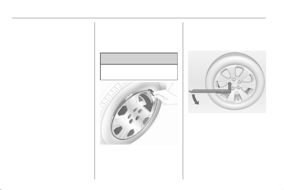
248 Vehicle care
Make the following preparations and
observe the following information:
■ Park the vehicle on a level, firm and
non-skid surface. The front wheels
must be in the straight-ahead
position.
■ Apply the parking brake and
engage first gear, reverse gear or
P.
■ Remove the spare wheel 3 250.
■ Never change more than one wheel
at once.
■ Use the jack only to change wheels
in case of puncture, not for
seasonal winter or summer tyre
change.
■ If the ground on which the vehicle
is standing is soft, a solid board
(max. 1 cm thick) should be placed
under the jack.
■ No people or animals may be in the
vehicle when it is jacked-up.
■ Never crawl under a jacked-up
vehicle.
■ Do not start the vehicle when it is
raised on the jack.
■ Clean wheel nuts and thread with a
clean cloth before mounting the
wheel.
9 Warning
Do not grease wheel bolt, wheel
nut and wheel nut cone.
1. Disengage wheel nut caps with a
screwdriver and remove. Pull off
the wheel cover with the hook.
Vehicle tools 3 239.
Alloy wheels: Disengage wheel
nut caps with a screwdriver and
remove. To protect the wheel,
place a soft cloth between the
screwdriver and the alloy wheel.
2. Fold out the wheel wrench and
install ensuring that it locates
securely and loosen each wheel
nut by half a turn.
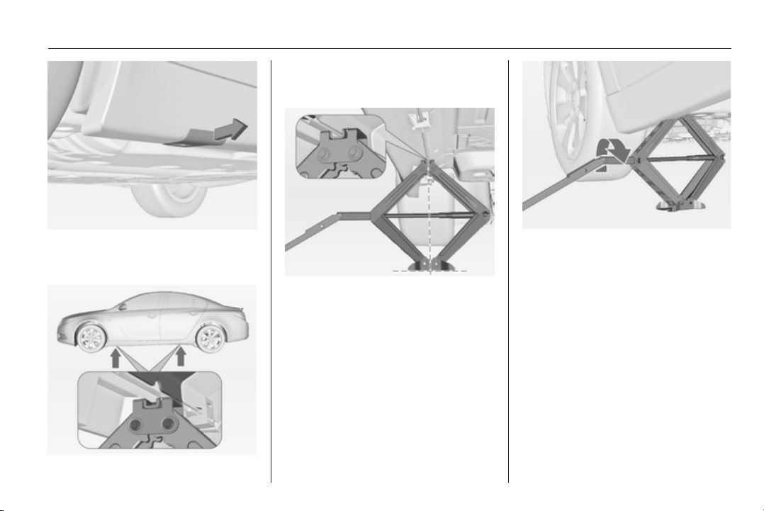
Vehicle care 249
3. Some versions may have covered
the vehicle jacking point. Pull out
the cover sideways.
4. Ensure the jack is correctly
positioned under the relevant
vehicle jacking point.
5. Set the jack to the necessary
height. Position it directly below
the jacking point in a manner that
prevents it from slipping.
Attach wheel wrench and with the
jack correctly aligned rotate wheel
wrench until wheel is clear of the
ground.
6. Unscrew the wheel nuts.
7. Change the wheel. Spare wheel
3 250.
8. Screw on the wheel nuts.
9. Lower vehicle.
10. Install the wheel wrench ensuring
that it locates securely and tighten
each nut in a crosswise
sequence. Tightening torque is
150 Nm.
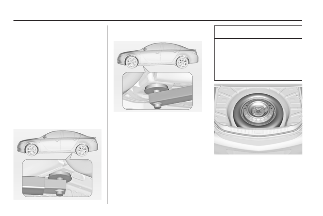
250 Vehicle care
11. Align the valve hole in the wheel
cover with the tyre valve before
installing.
Install wheel nut caps.
12. Install vehicle jacking point cover.
13. Stow the replaced wheel 3 250
and the vehicle tools 3 239.
14. Check the tyre pressure of the
installed tyre and the wheel nut
torque as soon as possible.
Have the defective tyre renewed or
repaired as soon as possible.
Jacking position for lifting
platform
Rear arm position of the lifting
platform at the underbody.
Front arm position of the lifting
platform at the underbody.
Spare wheel
Some vehicles are equipped with a
tyre repair kit instead of a spare
wheel.
The spare wheel can be classified as
a temporary spare wheel depending
on the size compared to the other
mounted wheels and country
regulations.
The spare wheel has a steel rim.
Caution
The use of a spare wheel that is
smaller than the other wheels or in
combination with winter tyres
could affect driveability. Have the
defective tyre replaced as soon as
possible.
The spare wheel is located in the load
compartment beneath the floor
covering.
To remove:
1. Open the floor cover.
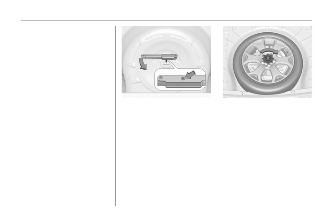
Vehicle care 251
2. The spare wheel is secured with a
wing nut. Turn wing nut
anticlockwise and remove the
spare wheel.
Under the spare wheel there is the
box with vehicle tools.
3. When, after a wheel change, no
wheel is placed in the spare wheel
well, secure the tool box by
turning right back the wing nut and
close the floor cover.
Stowing the replaced full size
wheel in the spare wheel well
The spare wheel well is not designed
for all permitted tyre sizes. If a wheel
wider than the spare must be stowed
in the spare wheel well, the thread
bolt for mounting the wheel must be
replaced by an extension bolt, located
in the tool box 3 239. To replace the
bolt:
■ Remove tool box from the spare
wheel well.
■ Install the hexagon key of the wheel
wrench ensuring that it locates
securely on the bolt.
■ Turn the wheel wrench
anticlockwise to loosen the bolt.
Remove the bolt.
■ Take the extension bolt from the
tool box 3 239 and screw it in hand-
tight using the hexagon key of the
wheel wrench.
■ Store the tool box and the damaged
wheel outside up in the spare wheel
well and secure it by turning the
wing nut clockwise on the bolt.
The floor cover can be placed on the
projecting wheel.
To fit the spare wheel in the well after
renewing the defective wheel use the
short thread bolt again. Exchange the
bolt in the same way.
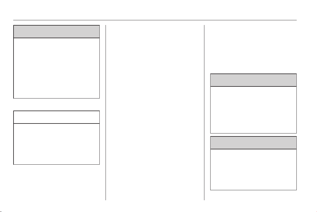
252 Vehicle care
9 Warning
Storing a jack, a wheel or other
equipment in the load
compartment could cause injury if
they are not fixed properly. During
a sudden stop or a collision, loose
equipment could strike someone.
Store wheel, jack and tools always
in the original storage location and
secure them by fixing.
Temporary spare wheel
Caution
The use of a spare wheel that is
smaller than the other wheels or in
combination with winter tyres
could affect driveability. Have the
defective tyre replaced as soon as
possible.
Only mount one temporary spare
wheel. Do not drive faster than
80 km/h. Take curves slowly. Do not
use for a long period of time.
If your vehicle gets a flat tyre on the
rear while towing another vehicle,
mount the temporary spare wheel in
the front and the full tyre in the rear.
Tyre chains 3 244.
Directional tyres
Fit directional tyres such that they roll
in the direction of travel. The rolling
direction is indicated by a symbol
(e.g. an arrow) on the sidewall.
The following applies to tyres fitted
opposing the rolling direction:
■ Driveability may be affected. Have
the defective tyre renewed or
repaired as soon as possible.
■ Drive particularly carefully on wet
and snow-covered road surfaces.
Jump starting
Do not start with quick charger.
A vehicle with a discharged vehicle
battery can be started using jump
leads and the vehicle battery of
another vehicle.
9 Warning
Be extremely careful when starting
with jump leads. Any deviation
from the following instructions can
lead to injuries or damage caused
by battery explosion or damage to
the electrical systems of both
vehicles.
9 Warning
Avoid contact of the battery with
eyes, skin, fabrics and painted
surfaces. The fluid contains
sulphuric acid which can cause
injuries and damage in the event
of direct contact.
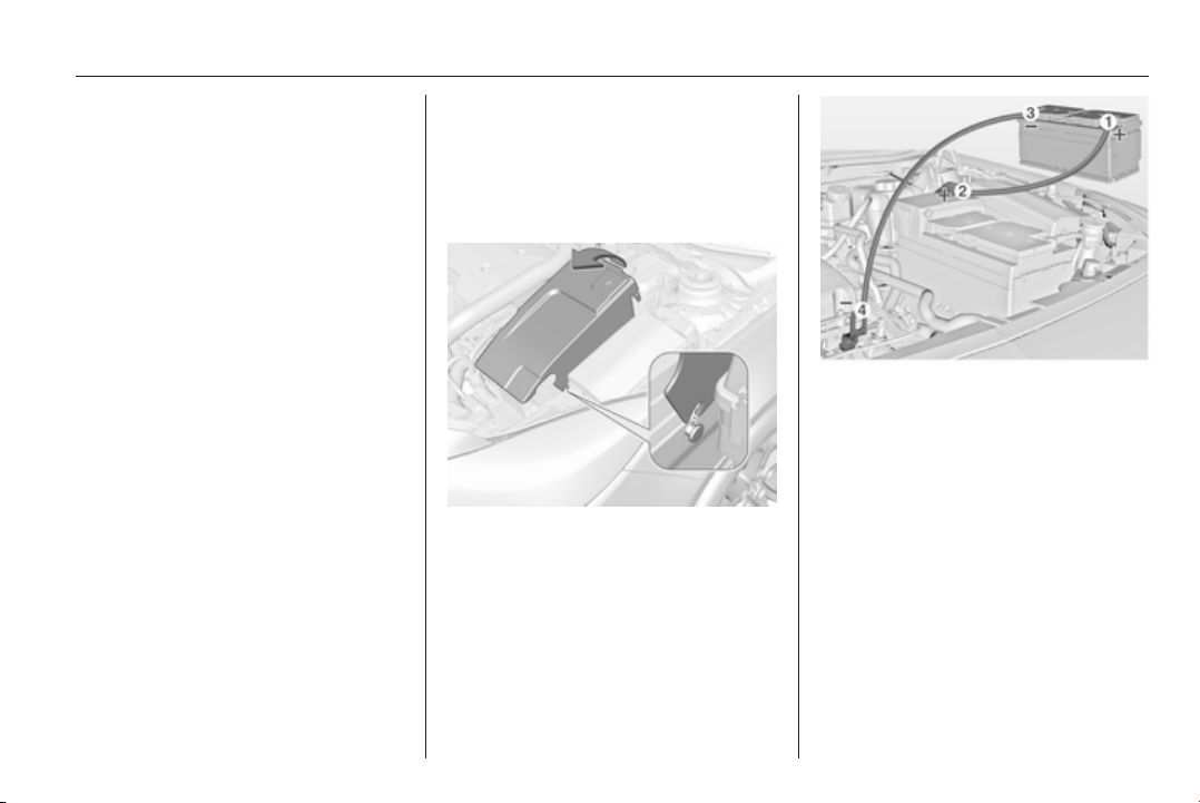
Vehicle care 253
■ Never expose the vehicle battery to
naked flames or sparks.
■ A discharged vehicle battery can
already freeze at a temperature of
0 °C. Defrost the frozen battery
before connecting jump leads.
■ Wear eye protection and protective
clothing when handling a battery.
■ Use a booster battery with the
same voltage (12 Volts). Its
capacity (Ah) must not be much
less than that of the discharged
vehicle battery.
■ Use jump leads with insulated
terminals and a cross section of at
least 16 mm
2
(25 mm
2
for diesel
engines).
■ Do not disconnect the discharged
vehicle battery from the vehicle.
■ Switch off all unnecessary electrical
consumers.
■ Do not lean over the vehicle battery
during jump starting.
■ Do not allow the terminals of one
lead to touch those of the other
lead.
■ The vehicles must not come into
contact with each other during the
jump starting process.
■ Apply the parking brake,
transmission in neutral, automatic
transmission in P.
■ If there is a cover over the vehicle
battery, remove it to charge or jump
start the vehicle battery. Lift up the
cover at the rear and unlatch it at
the front.
■ Open the positive terminal
protection caps of both vehicle
batteries.
Lead connection order:
1. Connect the red lead to the
positive terminal of the booster
battery.
2. Connect the other end of the red
lead to the positive terminal of the
discharged battery.
3. Connect the black lead to the
negative terminal of the booster
battery.
4. Connect the other end of the black
lead to a vehicle grounding point,
such as the engine block or an
engine mounting bolt. Connect as
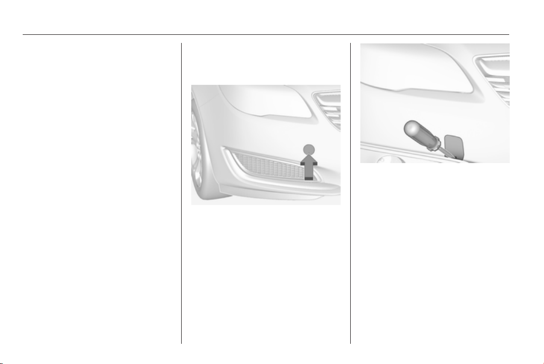
254 Vehicle care
far away from the discharged
battery as possible, however at
least 60 cm.
Route the leads so that they cannot
catch on rotating parts in the engine
compartment.
To start the engine:
1. Start the engine of the vehicle
providing the jump.
2. After 5 minutes, start the other
engine. Start attempts should be
made for no longer than
15 seconds at an interval of
1 minute.
3. Allow both engines to idle for
approx. 3 minutes with the leads
connected.
4. Switch on electrical consumers
(e.g. headlights, heated rear
window) of the vehicle receiving
the jump start.
5. Reverse above sequence exactly
when removing leads.
Towing
Towing the vehicle
5-door Hatchback, 4-door Saloon,
Sports Tourer: disengage cap at
bottom and remove downwards.
Country Tourer: insert a screwdriver
in the slot at the lower edge of the cap.
Release the cap by carefully moving
the screwdriver downwards. To
prevent damage it is recommended to
place a cloth between the screwdriver
and the frame.
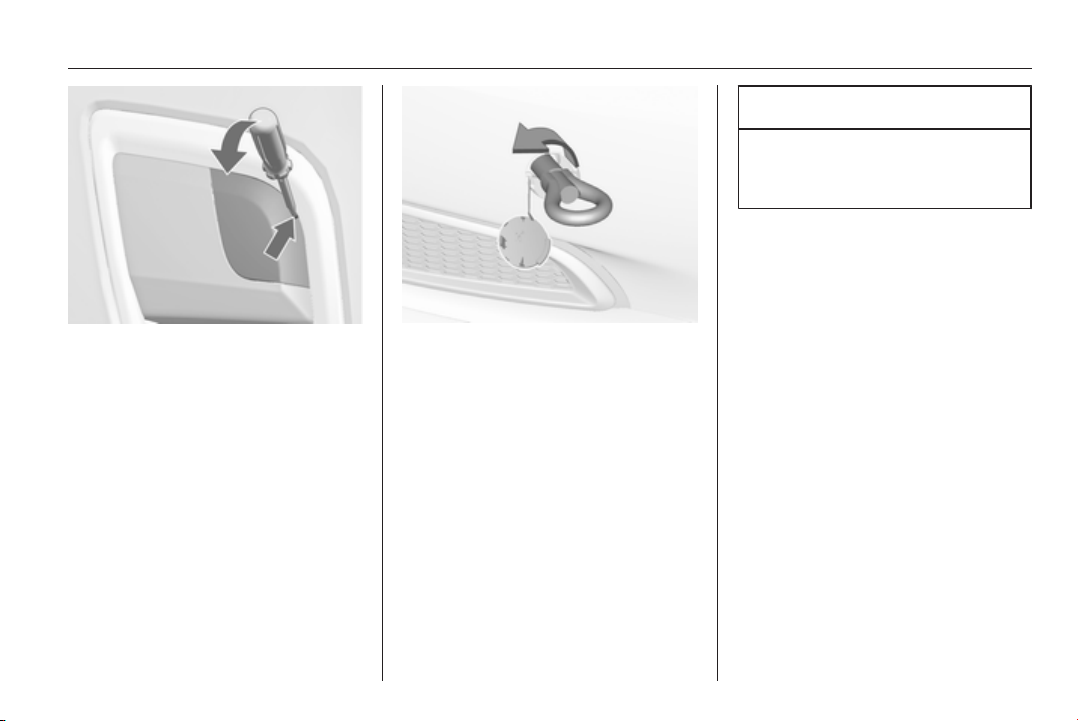
Vehicle care 255
OPC: insert screwdriver in the slot at
the upper bend of the cap. Release
the cap by carefully moving the
screwdriver downwards. To prevent
damage it is recommended to place a
cloth between the screwdriver and
the frame.
The towing eye is stowed with the
vehicle tools 3 239.
Screw in the towing eye as far as it will
go until it stops in a horizontal
position.
Attach a tow rope – or better still a tow
rod – to the towing eye.
The towing eye must only be used for
towing and not for recovering the
vehicle.
Switch on ignition to release steering
wheel lock and to permit operation of
brake lights, horn and windscreen
wiper.
Transmission in neutral.
Caution
Drive slowly. Do not drive jerkily.
Excessive tractive force can
damage the vehicle.
When the engine is not running,
considerably more force is needed to
brake and steer.
To prevent the entry of exhaust gases
from the towing vehicle, switch on the
air recirculation and close the
windows.
Vehicles with manual transmission
and All-wheel drive: If the vehicle is
towed with all four wheels on the
ground then there are no technical
limitations for speed and distance. If
only one axle has been raised, the
maximum speed is 50 km/h. There is
no distance limitation.
Vehicles with automatic transmission
and Front-wheel drive: The vehicle
must be towed facing forwards, not
faster than 80 km/h nor further than
100 km. In all other cases and when
the transmission is defective, the front
axle must be raised off the ground.

256 Vehicle care
Vehicles with automatic transmission
and All-wheel drive: The vehicle must
be towed facing forwards. If the
vehicle is towed with all four wheels
on the ground, the maximum speed is
50 km/h and for a maximum of
50 km. If the front axle has been
raised, the maximum speed is
50 km/h. There is no distance
limitation.
Seek the assistance of a workshop.
After towing, unscrew the towing eye.
5-door Hatchback, 4-door Saloon,
Sports Tourer: insert cap at the
bottom, turn slightly clockwise and
close cap.
Country Tourer: insert cap with the
upper flange into the recess and fix
cap by pushing.
OPC: insert cap with the lower flange
into the recess. Push the cap into the
bumper.
Towing another vehicle
5-door Hatchback, 4-door Saloon,
Sports Tourer, OPC: disengage cap
at bottom and remove downwards.
Country Tourer: insert a screwdriver
in the slot at the lower edge of the cap.
Release the cap by carefully moving
the screwdriver downwards. To
prevent damage it is recommended to
place a cloth between the screwdriver
and the frame.
The towing eye is stowed with the
vehicle tools 3 239.
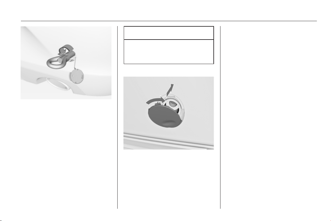
Vehicle care 257
Screw in the towing eye as far as it will
go until it stops in a horizontal
position.
The lashing eye at the rear
underneath the vehicle must never be
used as a towing eye.
Attach a tow rope – or better still a tow
rod – to the towing eye.
The towing eye must only be used for
towing and not for recovering a
vehicle.
Caution
Drive slowly. Do not drive jerkily.
Excessive tractive force can
damage the vehicle.
After towing, unscrew the towing eye.
5-door Hatchback, 4-door Saloon,
Sports Tourer, OPC: insert cap at the
bottom, turn slightly clockwise and
engage cap.
Country Tourer: insert cap with the
upper flange into the recess and fix
cap by pushing.
Appearance care
Exterior care
Locks
The locks are lubricated at the factory
using a high quality lock cylinder
grease. Use de-icing agent only when
absolutely necessary, as this has a
degreasing effect and impairs lock
function. After using de-icing agent,
have the locks regreased by a
workshop.
Washing
The paintwork of your vehicle is
exposed to environmental influences.
Wash and wax your vehicle regularly.
When using automatic vehicle
washes, select a programme that
includes waxing.
Bird droppings, dead insects, resin,
pollen and the like should be cleaned
off immediately, as they contain
aggressive constituents which can
cause paint damage.

258 Vehicle care
If using a vehicle wash, comply with
the vehicle wash manufacturer's
instructions. The windscreen wiper
and rear window wiper must be
switched off. Remove antenna and
external accessories such as roof
racks etc.
If you wash your vehicle by hand,
make sure that the insides of the
wheel housings are also thoroughly
rinsed out.
Wax painted parts of the vehicle
regularly.
Clean edges and folds on opened
doors and the bonnet as well as the
areas they cover.
Caution
Always use a cleaning agent with
a pH value of 4 to 9.
Do not use cleaning agents on hot
surfaces.
Do not clean the engine compartment
with a steam-jet or high-pressure jet
cleaner.
Thoroughly rinse and leather-off the
vehicle. Rinse leather frequently. Use
separate leathers for painted and
glass surfaces: remnants of wax on
the windows will impair vision.
Have the door hinges of all doors
greased by a workshop.
Do not use hard objects to remove
spots of tar. Use tar removal spray on
painted surfaces.
Exterior lights
Headlight and other light covers are
made of plastic. Do not use any
abrasive or caustic agents, do not use
an ice scraper, and do not clean them
dry.
Polishing and waxing
Wax the vehicle regularly (at the
latest when water no longer beads).
Otherwise, the paintwork will dry out.
Polishing is necessary only if the paint
has become dull or if solid deposits
have become attached to it.
Paintwork polish with silicone forms a
protective film, making waxing
unnecessary.
Plastic body parts must not be treated
with wax or polishing agents.
Windows and windscreen wiper
blades
Use a soft lint-free cloth or chamois
leather together with window cleaner
and insect remover.
When cleaning the rear window from
inside, always wipe in parallel to the
heating element to prevent damage.
For mechanical removal of ice, use a
sharp-edged ice scraper. Press the
scraper firmly against the glass so
that no dirt can get under it and
scratch the glass.
Clean smearing wiper blades with a
soft cloth and window cleaner.
Sunroof
Never clean with solvents or abrasive
agents, fuels, aggressive media
(e.g. paint cleaner, acetone-
containing solutions etc.), acidic or
highly alkaline media or abrasive
pads. Do not apply wax or polishing
agents to the sunroof.
Vehicle care 259
Wheels and tyres
Do not use high-pressure jet
cleaners.
Clean rims with a pH-neutral wheel
cleaner.
Rims are painted and can be treated
with the same agents as the body.
Paintwork damage
Rectify minor paintwork damage with
a touch-up pen before rust forms.
Have more extensive damage or rust
areas repaired by a workshop.
Underbody
Some areas of the vehicle underbody
have a PVC undercoating while other
critical areas have a durable
protective wax coating.
After the underbody is washed, check
the underbody and have it waxed if
necessary.
Bitumen/rubber materials could
damage the PVC coating. Have
underbody work carried out by a
workshop.
Before and after winter, wash the
underbody and have the protective
wax coating checked.
Liquid gas system
9 Danger
Liquid gas is heavier than air and
can collect in sink points.
Take care when performing work
at the underbody in a pit.
For painting work and when using a
drying booth at a temperature above
60 °C, the liquid gas tank must be
removed.
Do not make any modifications to the
liquid gas system.
Towing equipment
Do not clean the coupling ball bar with
a steam-jet or high-pressure jet
cleaner.
Interior care
Interior and upholstery
Only clean the vehicle interior,
including the instrument panel fascia
and panelling, with a dry cloth or
interior cleaner.
Clean the leather upholstery with
clear water and a soft cloth. In case of
heavy soiling, use leather care.
The instrument cluster and the
displays should only be cleaned using
a soft damp cloth. If necessary use a
weak soap solution.
Clean fabric upholstery with a
vacuum cleaner and brush. Remove
stains with an upholstery cleaner.
Clothing fabrics may not be
colourfast. This could cause visible
discolourations, especially on light-
coloured upholstery. Removable
stains and discolourations should be
cleaned as soon as possible.
Clean seat belts with lukewarm water
or interior cleaner.

260 Vehicle care
Caution
Close Velcro fasteners as open
Velcro fasteners on clothing could
damage seat upholstery.
The same applies to clothing with
sharp-edged objects, like zips or
belts or studded jeans.
Plastic and rubber parts
Plastic and rubber parts can be
cleaned with the same cleaner as
used to clean the body. Use interior
cleaner if necessary. Do not use any
other agent. Avoid solvents and petrol
in particular. Do not use high-
pressure jet cleaners.

Service and maintenance 261
Service and
maintenance
General information ................... 261
Recommended fluids, lubricants
and parts .................................... 262
General information
Service information
In order to ensure economical and
safe vehicle operation and to
maintain the value of your vehicle, it
is of vital importance that all
maintenance work is carried out at the
proper intervals as specified.
The detailed, up-to-date service
schedule for your vehicle is available
at the workshop.
Service display 3 98.
European service intervals
Maintenance of your vehicle is
required every 30,000 km or after
1 year, whichever occurs first, unless
otherwise indicated in the service
display.
The European service intervals are
valid for the following countries:
Andorra, Austria, Belgium, Bosnia-
Herzegovina, Bulgaria, Croatia,
Cyprus, Czech Republic, Denmark,
Estonia, Finland, France, Germany,
Greece, Greenland, Hungary,
Iceland, Ireland, Italy, Latvia,
Lithuania, Luxembourg, Macedonia,
Malta, Montenegro, Netherlands,
Norway, Poland, Portugal, Romania,
Slovakia, Slovenia, Spain, Sweden,
Switzerland, United Kingdom.
Service display 3 98.
International service intervals
Maintenance of your vehicle is
required every 15,000 km or after
1 year, whichever occurs first, unless
otherwise indicated in the service
display.
The international service intervals are
valid for the countries which are not
listed in the European service
intervals.
Service display 3 98.
Confirmations
Confirmation of service is recorded in
the Service and Warranty Booklet.
The date and mileage is completed
with the stamp and signature of the
servicing workshop.
262 Service and maintenance
Make sure that the Service and
Warranty Booklet is completed
correctly as continuous proof of
service is essential if any warranty or
goodwill claims are to be met, and is
also a benefit when selling the
vehicle.
Service interval with remaining
engine oil life duration
The service interval is based on
several parameters depending on
usage.
The service display lets you know
when to change the engine oil.
Service display 3 98.
Recommended fluids,
lubricants and parts
Recommended fluids and
lubricants
Only use products that meet the
recommended specifications.
Damage resulting from the use of
products not in line with these
specifications will not be covered by
the warranty.
9 Warning
Operating materials are
hazardous and could be
poisonous. Handle with care. Pay
attention to information given on
the containers.
Engine oil
Engine oil is identified by its quality
and its viscosity. Quality is more
important than viscosity when
selecting which engine oil to use. The
oil quality ensures e.g. engine
cleanliness, wear protection and oil
aging control, whereas viscosity
grade gives information on the oil's
thickness over a temperature range.
Dexos is the newest engine oil quality
that provides optimum protection for
gasoline and diesel engines. If it is
unavailable, engine oils of other listed
qualities have to be used.
Recommendations for gasoline
engines are also valid for
Compressed Natural Gas (CNG),
Liquified Petroleum Gas (LPG) and
Ethanol (E85) fuelled engines.
Select the appropriate engine oil
based on its quality and on the
minimum ambient temperature
3 266.
Topping up engine oil
Engine oils of different manufacturers
and brands can be mixed as long as
they comply with the required engine
oil quality and viscosity.
Use of engine oil with only
ACEA A1/B1 or only A5/B5 quality is
prohibited, since it can cause long-
term engine damage under certain
operating conditions.

Service and maintenance 263
Select the appropriate engine oil
based on its quality and on the
minimum ambient temperature
3 266.
Additional engine oil additives
The use of additional engine oil
additives could cause damage and
invalidate the warranty.
Engine oil viscosity grades
The SAE viscosity grade gives
information of the thickness of the oil.
Multigrade oil is indicated by two
figures, e.g. SAE 5W-30. The first
figure, followed by a W, indicates the
low temperature viscosity and the
second figure the high temperature
viscosity.
Select the appropriate viscosity grade
depending on the minimum ambient
temperature 3 266.
All of the recommended viscosity
grades are suitable for high ambient
temperatures.
Coolant and antifreeze
Use only silicate-free long life coolant
(LLC) antifreeze.
The system is factory filled with
coolant designed for excellent
corrosion protection and frost
protection down to approx. -28 °C.
This concentration should be
maintained all year round. The use of
additional coolant additives that
intend to give additional corrosion
protection or seal against minor leaks
can cause function problems. Liability
for consequences resulting from the
use of additional coolant additives will
be rejected.
Brake and clutch fluid
Only use high-performance brake
fluid approved for the vehicle, consult
a workshop.
Over time, brake fluid absorbs
moisture which will reduce braking
effectiveness. The brake fluid should
therefore be replaced at the specified
interval.
Brake fluid should be stored in a
sealed container to avoid water
absorption.
Ensure brake fluid does not become
contaminated.
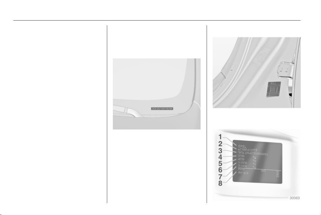
264 Technical data
Technical data
Vehicle identification .................. 264
Vehicle data ............................... 266
Vehicle identification
Vehicle Identification
Number
The Vehicle Identification Number is
visible through the windscreen.
Identification plate
The identification label is located on
the front left door frame.

Technical data 265
Information on identification plate:
1 = Manufacturer
2 = Type approval number
3 = Vehicle Identification Number
4 = Permissible gross vehicle
weight rating in kg
5 = Permissible gross train weight
in kg
6 = Maximum permissible front axle
load in kg
7 = Maximum permissible rear axle
load in kg
8 = Vehicle-specific or country-
specific data, e.g. MY = Model
year
The combined total of front and rear
axle loads must not exceed the
permissible gross vehicle weight. For
example, if the front axle is bearing its
maximum permissible load, the rear
axle can only bear a load that is equal
to the gross vehicle weight minus the
front axle load.
The technical data is determined in
accordance with European
Community standards. We reserve
the right to make modifications.
Specifications in the vehicle
documents always have priority over
those given in this manual.
Engine identification
The technical data tables show the
engine identifier code. Engine data
3 269.
To identify the respective engine,
refer to the engine power in the EEC
Certificate of Conformity provided
with your vehicle or other national
registration documents.

266 Technical data
Vehicle data
Recommended fluids and lubricants
European service schedule
Required engine oil quality
All European countries
(except Belarus, Moldova, Russia, Serbia, Turkey) Only Israel
Engine oil quality Petrol engines
(including CNG, LPG, E85)
Diesel engines Petrol engines
(including CNG, LPG, E85)
Diesel engines
dexos 1 – – ✔ –
dexos 2 ✔ ✔ – ✔
In case dexos quality is unavailable you may use max. 1 litre engine oil quality ACEA C3 once between each oil change.
Engine oil viscosity grades
All European countries and Israel
(except Belarus, Moldova, Russia, Serbia, Turkey)
Ambient temperature Petrol and diesel engines
down to -25 °C SAE 5W-30 or SAE 5W-40
below -25 °C SAE 0W-30 or SAE 0W-40

Technical data 267
International service schedule
Required engine oil quality
All countries outside Europe
except Israel Only Belarus, Moldova, Russia, Serbia, Turkey
Engine oil quality Petrol engines
(including CNG, LPG, E85)
Diesel engines Petrol engines
(including CNG, LPG, E85)
Diesel engines
dexos 1 ✔ – – –
dexos 2 – ✔ ✔ ✔
In case dexos quality is unavailable you may use the oil qualities listed below:
All countries outside Europe
except Israel Only Belarus, Moldova, Russia, Serbia, Turkey
Engine oil quality Petrol engines
(including CNG, LPG, E85)
Diesel engines Petrol engines
(including CNG, LPG, E85)
Diesel engines
GM-LL-A-025 ✔ – ✔ –
GM-LL-B-025 – ✔ – ✔

268 Technical data
All countries outside Europe
except Israel Only Belarus, Moldova, Russia, Serbia, Turkey
Engine oil quality Petrol engines
(including CNG, LPG, E85)
Diesel engines Petrol engines
(including CNG, LPG, E85)
Diesel engines
ACEA A3/B3 ✔ – ✔ –
ACEA A3/B4 ✔ ✔ ✔ ✔
ACEA C3 ✔ ✔ ✔ ✔
API SM ✔ – ✔ –
API SN resource
conserving
✔ – ✔ –
Engine oil viscosity grades
All countries outside Europe (except Israel),
including Belarus, Moldova, Russia, Serbia, Turkey
Ambient temperature Petrol and diesel engines
down to -25 °C SAE 5W-30 or SAE 5W-40
below -25 °C SAE 0W-30 or SAE 0W-40
down to -20 °C
SAE 10W-30
1)
or SAE 10W-40
1)
1)
Permitted, but usage of SAE 5W-30 or SAE 5W-40 with dexos quality is recommended.

Technical data 269
Engine data
Sales designation 1.4 1.4 LPG 1.6 1.8 2.0 OPC
Engine identifier code B14NET B14NET A16XHT A18XER A20NHT A28NER
Piston displacement [cm
3
]
1364 1364 1598 1796 1998 2792
Engine power [kW] 103 103 125 103 184 239
at rpm 4900-6000 4900-6000 4250 6300 5300 5250
Torque [Nm] 200 200 260 175 400 435
at rpm 1850-4900 1850-4900 1650 - 3200 3800 3000-4000 5250
Fuel type Petrol Petrol/Liquid gas Petrol Petrol Petrol Petrol
Octane rating RON
recommended 95 95 98 95 95 98
possible 98 98 95 98 98 95
possible
91 91 91 91 91 91
2)
Additional fuel type – LPG – – – –
Oil consumption [l/1000 km] 0.6 0.6 0.6 0.6 0.6 0.6
2)
Possible only if high engine load, full load or driving in mountainous terrain with a caravan/trailer or high payload is
avoided.

270 Technical data
Sales designation 2.0 CDTI 2.0 CDTI ecoFLEX ecoFLEX 2.0 CDTI 2.0 CDTI
Engine identifier code A20DTL A20DT A20DTE A20DTE A20DTH A20DTR
Piston displacement [cm
3
]
1956 1956 1956 1956 1956 1956
Engine power [kW] 81 96 88 103 120 143
at rpm 4000 4000 4000 4000 4000 4000
Torque [Nm] 260 300 300 350 350 400
at rpm 1750-2500 1750-2500 1750-2500 1750-2500 1750-2500 1750-2500
Fuel type Diesel Diesel Diesel Diesel Diesel Diesel
Oil consumption [l/1000 km] 0.6 0.6 0.6 0.6 0.6 0.6

Technical data 271
Performance
5-door Hatchback/4-door Saloon
Engine
B14NET B14NET LPG A16XHT A18XER A20NHT
A20NHT
AWD
3)
A28NER
Maximum speed
4)
[km/h]
Manual transmission
205 195 220 205 250 250 250
5)
/270
Automatic transmission
– – 210 – 245 245 250
5)
/265
Engine
A20DTL A20DT A20DTE A20DTE
ecoFLEX 88kW ecoFLEX 103kW
Maximum speed
4)
[km/h]
Manual transmission 190 205 195 205
Automatic transmission – 204 – –
3)
All wheel drive
4)
The maximum speed indicated is achievable at kerb weight (without driver) plus 200 kg payload. Optional equipment
could reduce the specified maximum speed of the vehicle.
5)
Limited speed.

272 Technical data
Engine
A20DTH A20DTH A20DTR A20DTR
AWD
3)
AWD
3)
Maximum speed
4)
[km/h]
Manual transmission 220 215 230 –
Automatic transmission 210 210 230 225
Sports Tourer
Engine
B14NET B14NET LPG A16XHT A18XER A20NHT A20NHT A28NER
AWD
3)
Maximum speed
4)
[km/h]
Manual transmission
200 190 215 200 245 240 250
5)
/265
Automatic transmission
– – 205 – 240 235 250
5)
/260
3)
All wheel drive
4)
The maximum speed indicated is achievable at kerb weight (without driver) plus 200 kg payload. Optional equipment
could reduce the specified maximum speed of the vehicle.
5)
Limited speed.

Technical data 273
Engine
A20DTL A20DT A20DTE A20DTE
ecoFLEX 88kW ecoFLEX 103kW
Maximum speed
4)
[km/h]
Manual transmission 185 200 190 200
Automatic transmission – 198 – –
Engine
A20DTH A20DTH A20DTR A20DTR
AWD
3)
AWD
3)
Maximum speed
4)
[km/h]
Manual transmission 215 210 225 –
Automatic transmission 210 208 225 220
4)
The maximum speed indicated is achievable at kerb weight (without driver) plus 200 kg payload. Optional equipment
could reduce the specified maximum speed of the vehicle.
3)
All wheel drive

274 Technical data
Country Tourer
Engine
A20NHT A20DTH A20DTR
AWD
3)
AWD
3)
AWD
3)
Maximum speed
4)
[km/h]
Manual transmission 235 205 –
Automatic transmission 230 200 210
3)
All wheel drive
4)
The maximum speed indicated is achievable at kerb weight (without driver) plus 200 kg payload. Optional equipment
could reduce the specified maximum speed of the vehicle.

Technical data 275
Vehicle weight
Kerb weight, basic model without any optional equipment
4-door Saloon Engine Manual transmission Automatic transmission
[kg]
B14NET
6)
1503 –
B14NET LPG 1571 –
A16XHT – 1613
A16XHT
6)
1571 –
A18XER 1503 –
A20NHT – 1613
A20NHT
6)
1614 –
A20NHT - All-wheel drive – 1788
A20NHT - All-wheel drive
6)
1733 –
A28NER - All-wheel drive 1810 1835
6)
With stop-start function.

276 Technical data
4-door Saloon Engine Manual transmission Automatic transmission
[kg] A20DTL 1613 –
A20DTE ecoFLEX
6)
1613 –
A20DT 1613 1613
A20DTH 1613 1613
A20DTH
6)
1613 –
A20DTH - All-wheel drive – 1788
A20DTH - All-wheel drive
6)
1733 –
A20DTR – 1664
A20DTR
6)
1664 –
A20DTR - All-wheel drive – 1788
6)
With stop-start function.

Technical data 277
Kerb weight, basic model without any optional equipment
5-door Hatchback Engine Manual transmission Automatic transmission
[kg]
B14NET
6)
1503 –
B14NET LPG 1571 –
A16XHT – 1613
A16XHT
6)
1613 –
A18XER 1513 –
A20NHT – 1664
A20NHT
6)
1613 –
A20NHT - All-wheel drive – 1788
A20NHT - All-wheel drive
6)
1788 –
A28NER - All-wheel drive 1825 1843
6)
With stop-start function.

278 Technical data
5-door Hatchback Engine Manual transmission Automatic transmission
[kg] A20DTL 1613 –
A20DTE ecoFLEX
6)
1613 –
A20DT 1613 1613
A20DTH 1613 1613
A20DTH
6)
1613 –
A20DTH - All-wheel drive – 1788
A20DTH - All-wheel drive
6)
1788 –
A20DTR – 1701
A20DTR
6)
1664 –
A20DTR - All-wheel drive – 1816
6)
With stop-start function.

Technical data 279
Kerb weight, basic model without any optional equipment
Sports Tourer/Country Tourer Engine Manual transmission Automatic transmission
[kg]
B14NET
6)
1613 –
B14NET LPG 1664 –
A16XHT – 1701
A16XHT
6)
1664 –
A18XER 1613 –
A20NHT – 1733
A20NHT
6)
1701 –
A20NHT - All-wheel drive – 1843
A20NHT - All-wheel drive
6)
1843 –
A28NER - All-wheel drive 1940 1953
6)
With stop-start function.

280 Technical data
Sports Tourer/Country Tourer Engine Manual transmission Automatic transmission
[kg] A20DTL 1701 –
A20DTE ecoFLEX
6)
1733 –
A20DT 1701 1733
A20DTH 1733 1733
A20DTH
6)
1733 –
A20DTH - All-wheel drive – 1843
A20DTH - All-wheel drive
6)
1843 –
A20DTR – 1733
A20DTR
6)
1733 –
A20DTR - All-wheel drive – 1843
6)
With stop-start function.

Technical data 281
Kerb weight, basic model with all optional equipment
4-door Saloon Engine Manual transmission Automatic transmission
[kg]
B14NET
6)
1701 –
B14NET LPG 1733 –
A16XHT – 1733
A16XHT
6)
1733 –
A18XER 1692 –
A20NHT – 1788
A20NHT
6)
1733 –
A20NHT - All-wheel drive – 1931
A20NHT - All-wheel drive
6)
1931 –
A28NER - All-wheel drive 1968 1992
6)
With stop-start function.

282 Technical data
4-door Saloon Engine Manual transmission Automatic transmission
[kg] A20DTL 1778 –
A20DTE ecoFLEX
6)
1788 –
A20DT 1793 1819
A20DTH 1806 1829
A20DTH
6)
1799 –
A20DTH - All-wheel drive – 1931
A20DTH - All-wheel drive
6)
1901 –
A20DTR – 1816
A20DTR
6)
1816 –
A20DTR - All-wheel drive – 1953
6)
With stop-start function.

Technical data 283
Kerb weight, basic model with all optional equipment
5-door Hatchback Engine Manual transmission Automatic transmission
[kg]
B14NET
6)
1733 –
B14NET LPG 1733 –
A16XHT – 1816
A16XHT
6)
1733 –
A18XER 1707 –
A20NHT – 1816
A20NHT
6)
1788 –
A20NHT - All-wheel drive – 1953
A20NHT - All-wheel drive
6)
1931 –
A28NER - All-wheel drive 1983 2007
6)
With stop-start function.

284 Technical data
5-door Hatchback Engine Manual transmission Automatic transmission
[kg] A20DTL 1793 –
A20DTE ecoFLEX
6)
1787 –
A20DT 1808 1834
A20DTH 1821 1844
A20DTH
6)
1815 –
A20DTH - All-wheel drive – 1931
A20DTH - All-wheel drive
6)
1953 –
A20DTR – 1843
A20DTR
6)
1843 –
A20DTR - All-wheel drive – 1953
6)
With stop-start function.

Technical data 285
Kerb weight, basic model with all optional equipment
Sports Tourer/Country Tourer Engine Manual transmission Automatic transmission
[kg]
B14NET
6)
1815 –
B14NET LPG 1843 –
A16XHT – 1843
A16XHT
6)
1843 –
A18XER 1799 –
A20NHT – 1901
A20NHT
6)
1843 –
A20NHT - All-wheel drive – 2045
A20NHT - All-wheel drive
6)
2015 –
A28NER - All-wheel drive 2074 2098
6)
With stop-start function.

286 Technical data
Sports Tourer/Country Tourer Engine Manual transmission Automatic transmission
[kg] A20DTL 1901 –
A20DTE ecoFLEX
6)
1901 –
A20DT 1901 1941
A20DTH 1918 1931
A20DTH
6)
1918 –
A20DTH - All-wheel drive – 2045
A20DTH - All-wheel drive
6)
2045 –
A20DTR – 1953
A20DTR
6)
1931 –
A20DTR - All-wheel drive – 2073
Vehicle dimensions
4-door Saloon 5-door Hatchback Sports Tourer Country Tourer
Length [mm] 4842 4842 4913 4920
Width without exterior mirrors [mm] 1856 1856 1856 1856
Width with two exterior mirrors [mm] 2084 2084 2084 2084
6)
With stop-start function.

Technical data 287
4-door Saloon 5-door Hatchback Sports Tourer Country Tourer
Height (without antenna) [mm] 1484 1484 1514 1525
Vehicle height - Rear compartment open [mm] 1830 2175 2184 2195
Length of load compartment floor [mm] 1003 1003 1086 1086
Length of load compartment with folded rear seats [mm] 1895 1895 1908 1908
Load compartment width [mm] 1027 1027 1030 1030
Load compartment height [mm] 356 436 677 677
Wheelbase [mm] 2737 2737 2737 2737
Turning circle diameter [m] 11.4 11.4 11.4 11.4

288 Technical data
Capacities
Engine oil
Engine B14NET B14NET LPG A16XHT A18XER A20NHT A28NER
including Filter [l] 4.0 4.0 5.5 4.5 6.0 6.3
between MIN and MAX [l] 1.0 1.0 1.0 1.0 1.0 1.0
Engine A20DTL A20DTE A20DT A20DTH A20DTR
including Filter [l] 4.5 4.5 4.5 4.5 4.5
between MIN and MAX [l] 1.0 1.0 1.0 1.0 1.0
Fuel tank
Petrol/diesel, refilling quantity [l] 70
LPG, refilling quantity [l] 46

Technical data 289
Tyre pressures
Tyre pressures differ depending on the model variant. The order of the listed car models is as follows:
■ Vehicles with Front-wheel drive: 5-door Hatchback/4-door Saloon
■ Vehicles with Front-wheel drive: Sports Tourer
■ Vehicles with All-wheel drive: 5-door Hatchback/4-door Saloon
■ Vehicles with All-wheel drive: Sports Tourer
■ Vehicles with All-wheel drive: Country Tourer
Refer to the table header to find the correct tyre pressure for your model.

290 Technical data
Tyre pressures for vehicles with Front-wheel drive
5-door Hatchback/4-door Saloon
Comfort with up to
3 people
ECO with up to
3 people
With full load
Engine Tyres front rear front rear front rear
[kPa/bar]
([psi])
[kPa/bar]
([psi])
[kPa/bar]
([psi])
[kPa/bar]
([psi])
[kPa/bar]
([psi])
[kPa/bar]
([psi])
B14NET,
B14NET LPG,
A18XER
205/60 R16, 220/2.2
(32)
200/2.0
(29)
270/2.7
(39)
260/2.6
(38)
220/2.2
(32)
270/2.7
(39)
215/60 R16,
225/50 R17,
225/45 R18,
235/45 R18,
245/45 R18,
245/40 R19,
245/35 R20
225/55 R17 220/2.2
(32)
200/2.0
(29)
300/3.0
(43)
300/3.0
(43)
220/2.2
(32)
270/2.7
(39)

Technical data 291
Comfort with up to
3 people
ECO with up to
3 people
With full load
Engine Tyres front rear front rear front rear
[kPa/bar]
([psi])
[kPa/bar]
([psi])
[kPa/bar]
([psi])
[kPa/bar]
([psi])
[kPa/bar]
([psi])
[kPa/bar]
([psi])
A16XHT 225/55 R17, 230/2.3
(33)
210/2.1
(30)
270/2.7
(39)
260/2.6
(38)
230/2.3
(33)
280/2.8
(41)
225/50 R17,
225/45 R18,
235/45 R18,
245/45 R18,
245/40 R19,
245/35 R20

292 Technical data
Comfort with up to
3 people
ECO with up to
3 people
With full load
Engine Tyres front rear front rear front rear
[kPa/bar]
([psi])
[kPa/bar]
([psi])
[kPa/bar]
([psi])
[kPa/bar]
([psi])
[kPa/bar]
([psi])
[kPa/bar]
([psi])
A20NHT 225/50 R17, 240/2.4
(35)
220/2.2
(32)
300/3.0
(43)
300/3.0
(43)
250/2.5
(36)
300/3.0
(43)
225/55 R17,
225/45 R18
235/45 R18, 240/2.4
(35)
220/2.2
(32)
270/2.7
(39)
260/2.6
(38)
250/2.5
(36)
300/3.0
(43)
245/45 R18,
245/40 R19,
245/35 R20
A20NHT with Sport
chassis and Brembo
brake 18''
245/40R19 230/2.3
(33)
220/2.2
(32)
270/2.7
(39)
290/2.9
(42)
260/2.6
(38)
300/3.0
(43)
235/45R18, 250/2.5
(36)
250/2.5
(36)
270/2.7
(39)
290/2.9
(42)
260/2.6
(38)
320/3.2
(46)
245/35R20

Technical data 293
Comfort with up to
3 people
ECO with up to
3 people
With full load
Engine Tyres front rear front rear front rear
[kPa/bar]
([psi])
[kPa/bar]
([psi])
[kPa/bar]
([psi])
[kPa/bar]
([psi])
[kPa/bar]
([psi])
[kPa/bar]
([psi])
A20DTL 225/50 R17, 220/2.2
(32)
200/2.0
(29)
280/2.8
(41)
280/2.8
(41)
220/2.2
(32)
270/2.7
(39)
225/45 R18,
205/60 R16,
215/60 R16,
235/45 R18,
245/45 R18,
245/40 R19,
245/35 R20,
225/55 R17

294 Technical data
Comfort with up to
3 people
ECO with up to
3 people
With full load
Engine Tyres front rear front rear front rear
[kPa/bar]
([psi])
[kPa/bar]
([psi])
[kPa/bar]
([psi])
[kPa/bar]
([psi])
[kPa/bar]
([psi])
[kPa/bar]
([psi])
A20DT,
A20DTE ecoFLEX
215/60 R16, 230/2.3
(33)
210/2.1
(30)
270/2.7
(39)
260/2.6
(38)
230/2.3
(33)
280/2.8
(41)
225/50 R17,
225/45 R18,
205/60 R16,
235/45 R18,
245/45 R18,
245/40 R19,
225/55 R17,
245/35 R20

Technical data 295
Comfort with up to
3 people
ECO with up to
3 people
With full load
Engine Tyres front rear front rear front rear
[kPa/bar]
([psi])
[kPa/bar]
([psi])
[kPa/bar]
([psi])
[kPa/bar]
([psi])
[kPa/bar]
([psi])
[kPa/bar]
([psi])
A20DTH 215/60 R16, 240/2.4
(35)
220/2.2
(32)
270/2.7
(39)
260/2.6
(38)
240/2.4
(35)
290/2.9
(42)
225/50 R17,
225/45 R18,
225/55 R17, 220/2.2
(32)
200/2.0
(29)
270/2.7
(39)
260/2.6
(38)
240/2.4
(35)
290/2.9
(42)
235/45 R18,
245/45 R18,
245/40 R19,
245/35 R20

296 Technical data
Comfort with up to
3 people
ECO with up to
3 people
With full load
Engine Tyres front rear front rear front rear
[kPa/bar]
([psi])
[kPa/bar]
([psi])
[kPa/bar]
([psi])
[kPa/bar]
([psi])
[kPa/bar]
([psi])
[kPa/bar]
([psi])
A20DTH
ecoFLEX
215/60 R16, 240/2.4
(35)
220/2.2
(32)
270/2.7
(39)
260/2.6
(38)
240/2.4
(35)
290/2.9
(42)
225/50 R17,
225/45 R18,
225/55 R17, 220/2.2
(32)
200/2.0
(29)
300/3.0
(43)
300/3.0
(43)
240/2.4
(35)
290/2.9
(42)
235/45 R18, 220/2.2
(32)
200/2.0
(29)
270/2.7
(39)
260/2.6
(38)
240/2.4
(35)
290/2.9
(42)
245/45 R18,
245/40 R19,
245/35 R20

Technical data 297
Comfort with up to
3 people
ECO with up to
3 people
With full load
Engine Tyres front rear front rear front rear
[kPa/bar]
([psi])
[kPa/bar]
([psi])
[kPa/bar]
([psi])
[kPa/bar]
([psi])
[kPa/bar]
([psi])
[kPa/bar]
([psi])
A20DTH with Sport
chassis and Brembo
brake 18''
245/40R19 230/2.3
(33)
220/2.2
(32)
270/2.7
(39)
290/2.9
(42)
260/2.6
(38)
300/3.0
(43)
235/45R18, 250/2.5
(36)
250/2.5
(36)
270/2.7
(39)
290/2.9
(42)
260/2.6
(38)
320/3.2
(46)
245/35R20
A20DTR 225/55 R17 220/2.2
(32)
200/2.0
(29)
270/2.7
(39)
260/2.6
(38)
250/2.5
(36)
300/3.0
(43)
225/50 R17, 240/2.4
(34)
220/2.2
(32)
270/2.7
(39)
260/2.6
(38)
250/2.5
(36)
300/3.0
(43)
225/45 R18,
235/45 R18, 220/2.2
(32)
200/2.0
(29)
270/2.7
(39)
260/2.6
(38)
250/2.5
(36)
300/3.0
(43)
245/45 R18,
245/40 R19,
245/35 R20

298 Technical data
Comfort with up to
3 people
ECO with up to
3 people
With full load
Engine Tyres front rear front rear front rear
[kPa/bar]
([psi])
[kPa/bar]
([psi])
[kPa/bar]
([psi])
[kPa/bar]
([psi])
[kPa/bar]
([psi])
[kPa/bar]
([psi])
A20DTR with Sport
chassis and Brembo
brake 18''
245/40R19 230/2.3
(33)
220/2.2
(32)
270/2.7
(39)
290/2.9
(42)
260/2.6
(38)
300/3.0
(43)
235/45R18, 250/2.5
(36)
250/2.5
(36)
270/2.7
(39)
290/2.9
(42)
260/2.6
(38)
320/3.2
(46)
245/35R20
All Temporary spare
wheel
420/4.2
(61)
420/4.2
(61)
– – 420/4.2
(61)
420/4.2
(61)

Technical data 299
Sports Tourer
Comfort with up to
3 people
ECO with up to
3 people
With full load
Engine Tyres front rear front rear front rear
[kPa/bar]
([psi])
[kPa/bar]
([psi])
[kPa/bar]
([psi])
[kPa/bar]
([psi])
[kPa/bar]
([psi])
[kPa/bar]
([psi])
B14NET,
B14NET LPG,
A18XER
205/60 R16, 220/2.2
(32)
240/2.4
(34)
270/2.7
(39)
290/2.9
(41)
220/2.2
(32)
290/2.9
(42)
215/60 R16,
225/55 R17,
225/50 R17
7)
,
225/45 R18,
235/45 R18,
245/45 R18,
245/40 R19,
245/35 R20
225/50 R17 220/2.2
(32)
240/2.4
(34)
300/3.0
(43)
300/3.0
(43)
220/2.2
(32)
290/2.9
(42)
7)
Winter tyre

300 Technical data
Comfort with up to
3 people
ECO with up to
3 people
With full load
Engine Tyres front rear front rear front rear
[kPa/bar]
([psi])
[kPa/bar]
([psi])
[kPa/bar]
([psi])
[kPa/bar]
([psi])
[kPa/bar]
([psi])
[kPa/bar]
([psi])
A20NHT 225/50 R17, 230/2.3
(33)
250/2.5
(36)
270/2.7
(39)
290/2.9
(42)
230/2.3
(33)
300/3.0
(43)
235/45 R18,
245/35 R20,
225/55 R17,
245/40 R19,
245/45 R18
225/45 R18 270/2.7
(39)
290/2.9
(42)
270/2.7
(39)
290/2.9
(42)
280/2.8
(40)
320/3.2
(46)
A20NHT with Sport
chassis and Brembo brake
18''
245/40R19 230/2.3
(33)
220/2.2
(32)
270/2.7
(39)
290/2.9
(42)
260/2.6
(38)
300/3.0
(43)
235/45R18, 250/2.5
(36)
250/2.5
(36)
270/2.7
(39)
290/2.9
(42)
260/2.6
(38)
320/3.2
(46)
245/35R20

Technical data 301
Comfort with up to
3 people
ECO with up to
3 people
With full load
Engine Tyres front rear front rear front rear
[kPa/bar]
([psi])
[kPa/bar]
([psi])
[kPa/bar]
([psi])
[kPa/bar]
([psi])
[kPa/bar]
([psi])
[kPa/bar]
([psi])
A16XHT,
A20DTL,
A20DT,
A20DTE
ecoFLEX
225/55 R17, 220/2.2
(32)
240/2.4
(34)
270/2.7
(39)
290/2.9
(42)
230/2.3
(33)
300/3.0
(43)
225/50 R17
7)
,
235/45 R18,
245/45 R18,
245/40 R19,
245/35 R20
225/50 R17, 220/2.2
(32)
240/2.4
(34)
300/3.0
(43)
300/3.0
(43)
230/2.3
(33)
300/3.0
(43)
225/45 R18 250/2.5
(36)
270/2.7
(39)
270/2.7
(39)
290/2.9
(42)
250/2.5
(36)
320/3.2
(46)
7)
Winter tyre

302 Technical data
Comfort with up to
3 people
ECO with up to
3 people
With full load
Engine Tyres front rear front rear front rear
[kPa/bar]
([psi])
[kPa/bar]
([psi])
[kPa/bar]
([psi])
[kPa/bar]
([psi])
[kPa/bar]
([psi])
[kPa/bar]
([psi])
A20DTH 225/55 R17 230/2.3
(33)
250/2.5
(36)
270/2.7
(39)
290/2.9
(42)
230/2.3
(33)
300/3.0
(43)
225/50 R17
7)
,
235/45 R18,
245/45 R18,
245/40 R19,
245/35 R20
225/50 R17 230/2.3
(33)
250/2.5
(36)
300/3.0
(43)
300/3.0
(43)
230/2.3
(33)
300/3.0
(43)
225/45 R18 250/2.5
(36)
270/2.7
(39)
270/2.7
(39)
290/2.9
(42)
250/2.5
(36)
320/3.2
(46)
7)
Winter tyre

Technical data 303
Comfort with up to
3 people
ECO with up to
3 people
With full load
Engine Tyres front rear front rear front rear
[kPa/bar]
([psi])
[kPa/bar]
([psi])
[kPa/bar]
([psi])
[kPa/bar]
([psi])
[kPa/bar]
([psi])
[kPa/bar]
([psi])
A20DTH with Sport
chassis and Brembo brake
18''
245/40R19 230/2.3
(33)
220/2.2
(32)
270/2.7
(39)
290/2.9
(42)
260/2.6
(38)
300/3.0
(43)
235/45R18, 250/2.5
(36)
250/2.5
(36)
270/2.7
(39)
290/2.9
(42)
260/2.6
(38)
320/3.2
(46)
245/35R20
A20DTR 225/55 R17, 230/2.3
(33)
250/2.5
(36)
270/2.7
(39)
290/2.9
(42)
240/2.4
(35)
300/3.0
(43)
225/50 R17
7)
,
235/45 R18,
245/45 R18,
245/40 R19,
245/35 R20
225/50 R17 230/2.3
(33)
250/2.5
(36)
300/3.0
(43)
300/3.0
(43)
240/2.4
(35)
300/3.0
(43)
7)
Winter tyre

304 Technical data
Comfort with up to
3 people
ECO with up to
3 people
With full load
Engine Tyres front rear front rear front rear
[kPa/bar]
([psi])
[kPa/bar]
([psi])
[kPa/bar]
([psi])
[kPa/bar]
([psi])
[kPa/bar]
([psi])
[kPa/bar]
([psi])
225/45 R18 260/2.6
(38)
280/2.8
(41)
270/2.7
(39)
290/2.9
(42)
260/2.6
(38)
320/3.2
(46)
A20DTR with Sport
chassis and Brembo brake
18''
245/40R19 230/2.3
(33)
220/2.2
(32)
270/2.7
(39)
290/2.9
(42)
260/2.6
(38)
300/3.0
(43)
235/45R18, 250/2.5
(36)
250/2.5
(36)
270/2.7
(39)
290/2.9
(42)
260/2.6
(38)
320/3.2
(46)
245/35R20
All Temporary spare
wheel
420/4.2
(61)
420/4.2
(61)
– – 420/4.2
(61)
420/4.2
(61)

Technical data 305
Tyre pressures for vehicles with All-wheel drive
5-door Hatchback/4-door Saloon
Comfort with up to 3 people ECO with up to 3 people With full load
Engine Tyres front rear front rear front rear
[kPa/bar] ([psi])
[kPa/bar]
([psi])
[kPa/bar]
([psi])
[kPa/bar]
([psi])
[kPa/bar]
([psi])
[kPa/bar]
([psi])
A20NHT 225/50 R17, 250/2.5 (36) 230/2.3 (33) 290/2.9 (42) 270/2.7 (39) 270/2.7
(39)
300/3.0
(43)
225/45 R18 XL
225/55 R17, 230/2.3 (33) 210/2.1 (30) 270/2.7 (39) 260/2.6 (38) 250/2.5
(36)
290/2.9
(42)
225/45 R18,
235/45 R18,
245/45 R18,
245/40 R19
245/35 R20 250/2.5 (36) 230/2.3 (33) 290/2.9 (42) 270/2.7 (39) 270/2.7
(39)
300/3.0
(43)

306 Technical data
Comfort with up to 3 people ECO with up to 3 people With full load
Engine Tyres front rear front rear front rear
[kPa/bar] ([psi])
[kPa/bar]
([psi])
[kPa/bar]
([psi])
[kPa/bar]
([psi])
[kPa/bar]
([psi])
[kPa/bar]
([psi])
A20NHT with
Sport chassis
and Brembo
brake 18''
245/40R19 230/2.3 (33) 220/2.2 (32) 270/2.7 (39) 290/2.9 (42) 260/2.6
(38)
300/3.0
(43)
235/45R18, 250/2.5 (36) 250/2.5 (36) 270/2.7 (39) 290/2.9 (42) 260/2.6
(38)
320/3.2
(46)
245/35R20
A20DTH 225/55 R17, 240/2.4 (35) 220/2.2 (32) 270/2.7 (39) 260/2.6 (38) 250/2.5
(36)
290/2.9
(42)
225/45 R18,
225/50 R17,
245/45 R18,
245/40 R19
235/45 R18,
245/35 R20

Technical data 307
Comfort with up to 3 people ECO with up to 3 people With full load
Engine Tyres front rear front rear front rear
[kPa/bar] ([psi])
[kPa/bar]
([psi])
[kPa/bar]
([psi])
[kPa/bar]
([psi])
[kPa/bar]
([psi])
[kPa/bar]
([psi])
A20DTH with
Sport chassis
and Brembo
brake 18''
245/40R19 230/2.3 (33) 220/2.2 (32) 270/2.7 (39) 290/2.9 (42) 260/2.6
(38)
300/3.0
(43)
235/45R18, 250/2.5 (36) 250/2.5 (36) 270/2.7 (39) 290/2.9 (42) 260/2.6
(38)
320/3.2
(46)
245/35R20
A20DTR 225/50 R17, 250/2.5(36) 230/2.3 (33) 290/2.9 (42) 270/2.7 (39) 270/2.7
(39)
300/3.0
(43)
225/45 R18
225/55 R17, 230/2.3 (33) 210/2.1 (30) 270/2.7 (39) 260/2.6 (38) 240/2.4
(35)
280/2.8
(41)
245/45 R18,
235/45 R18, 250/2.5(36) 230/2.3 (33) 290/2.9 (42) 270/2.7 (39) 270/2.7
(39)
300/3.0
(43)
245/40 R19,
245/35 R20

308 Technical data
Comfort with up to 3 people ECO with up to 3 people With full load
Engine Tyres front rear front rear front rear
[kPa/bar] ([psi])
[kPa/bar]
([psi])
[kPa/bar]
([psi])
[kPa/bar]
([psi])
[kPa/bar]
([psi])
[kPa/bar]
([psi])
A20DTR with
Sport chassis
and Brembo
brake 18''
245/40R19 230/2.3 (33) 220/2.2 (32) 270/2.7 (39) 290/2.9 (42) 260/2.6
(38)
300/3.0
(43)
235/45R18, 250/2.5 (36) 250/2.5 (36) 270/2.7 (39) 290/2.9 (42) 260/2.6
(38)
320/3.2
(46)
245/35R20
A28 NER 235/45 R18, 270/2.7 (39) 250/2.5 (36) 310/3.1 (45) 300/3.0 (43) 280/2.8
(41)
300/3.0
(43)
245/40 R19
255/35 R20
All Temporary spare
wheel
420/4.2 (61) 420/4.2 (61) – – 420/4.2
(61)
420/4.2
(61)

Technical data 309
Sports Tourer
Comfort with up to
3 people ECO with up to 3 people
With full load
Engine Tyres front rear front rear front rear
[kPa/bar]
([psi])
[kPa/bar]
([psi])
[kPa/bar]
([psi])
[kPa/bar]
([psi])
[kPa/bar]
([psi])
[kPa/bar]
([psi])
A20NHT,
A20DTH,
A20DTR
225/55 R17, 220/2.2 (32) 220/2.2 (32) 270/2.7 (39) 290/2.9 (42) 230/2.3
(33)
300/3.0
(43)
245/45 R18
245/40 R19
225/50 R17, 250/2.5 (36) 250/2.5 (36) 270/2.7 (39) 290/2.9 (42) 260/2.6
(38)
320/3.2
(46)
235/45 R18,
245/35 R20
225/45 R18 270/2.7 (39) 270/2.7 (39) 300/3.0 (43) 320/3.2 (46) 280/2.8
(41)
330/3.3
(48)
A20NHT,
A20DTH,
A20DTR,
with Sport chassis and
Brembo brake 18''
245/40R19 230/2.3 (33) 220/2.2 (32) 270/2.7 (39) 290/2.9 (42) 260/2.6
(38)
300/3.0
(43)
235/45R18, 250/2.5 (36) 250/2.5 (36) 270/2.7 (39) 290/2.9 (42) 260/2.6
(38)
320/3.2
(46)
245/35R20

310 Technical data
Comfort with up to
3 people ECO with up to 3 people
With full load
Engine Tyres front rear front rear front rear
[kPa/bar]
([psi])
[kPa/bar]
([psi])
[kPa/bar]
([psi])
[kPa/bar]
([psi])
[kPa/bar]
([psi])
[kPa/bar]
([psi])
A28 NER 235/45 R18, 260/2.6 (38) 230/2.3 (33) 300/3.0 (43) 320/3.2 (46) 270/2.7
(39)
320/3.2
(46)
245/40 R19,
255/35 R20
All Temporary spare
wheel
420/4.2 (61) 420/4.2 (61) – – 420/4.2
(61)
420/4.2
(61)

Technical data 311
Country Tourer
Comfort with up to
3 people ECO with up to 3 people
With full load
Engine Tyres front rear front rear front rear
[kPa/bar]
([psi])
[kPa/bar]
([psi])
[kPa/bar]
([psi])
[kPa/bar]
([psi])
[kPa/bar]
([psi])
[kPa/bar]
([psi])
A20NHT,
A20DTH,
A20DTR
225/55 R17, 220/2.2 (32) 220/2.2 (32) 270/2.7 (39) 290/2.9 (42) 220/2.2
(32)
290/2.9
(42)
215/60 R17,
235/45 R18,
235/50 R18,
245/45 R19
A20NHT,
A20DTH,
A20DTR,
with Sport chassis and
Brembo brake 18''
245/40R19 230/2.3 (33) 220/2.2 (32) 270/2.7 (39) 290/2.9 (42) 260/2.6
(38)
300/3.0
(43)
235/45R18, 250/2.5 (36) 250/2.5 (36) 270/2.7 (39) 290/2.9 (42) 260/2.6
(38)
320/3.2
(46)
245/35R20
All Temporary
spare wheel
420/4.2 (61) 420/4.2 (61) – – 420/4.2
(61)
420/4.2
(61)

312 Customer information
Customer information
Customer information ................ 312
Vehicle data recording and pri‐
vacy ........................................... 312
Customer information
Declaration of conformity
This vehicle has systems that
transmit and/or receive radio waves
subject to Directive 1999/5/EC.
These systems are in compliance
with the essential requirements and
other relevant provisions of Directive
1999/5/EC. Copies of the original
Declarations of Conformity can be
obtained on our website.
Vehicle data recording
and privacy
Event data recorders
Data storage modules in the
vehicle
A large number of electronic
components of your vehicle contain
data storage modules temporarily or
permanently storing technical data
about the condition of the vehicle,
events and errors. In general, this
technical information documents the
condition of parts, modules, systems
or the environment:
■ Operating conditions of system
components (e.g. filling levels)
■ Status messages of the vehicle and
its single components (e.g. number
of wheel revolutions / rotational
speed, deceleration, lateral
acceleration)
■ Dysfunctions and defects in
important system components

Customer information 313
■ Vehicle reactions in particular
driving situations (e.g. inflation of
an airbag, activation of the stability
regulation system)
■ Environmental conditions (e.g.
temperature)
These data are exclusively technical
and help identifying and correcting
errors as well as optimizing vehicle
functions.
Motion profiles indicating travelled
routes cannot be created with these
data.
If services are used (e.g. repair
works, service processes, warranty
cases, quality assurance),
employees of the service network
(manufacturer included) are able to
read out this technical information
from the event and error data storage
modules applying special diagnostic
devices. If required, you will receive
further information at these
workshops. After an error has been
corrected, the data are deleted from
the error storage module or they are
constantly overwritten.
When using the vehicle, situations
may occur in which these technical
data related to other information
(accident report, damages on the
vehicle, witness statements etc.) may
be associated with a specific person -
possibly, with the assistance of an
expert.
Additional functions contractually
agreed upon with the client (e.g.
vehicle location in emergency cases)
allow the transmission of particular
vehicle data from the vehicle.
Radio Frequency
Identification (RFID)
RFID technology is used in some
vehicles for functions such as tyre
pressure monitoring and ignition
system security. It is also used in
connection with conveniences such
as radio remote controls for door
locking/unlocking and starting, and in-
vehicle transmitters for garage door
openers. RFID technology in Opel
vehicles does not use or record
personal information or link with any
other Opel system containing
personal information.

314
Index
A
Accessories and vehicle
modifications .......................... 213
Active Emergency Braking......... 185
Active head restraints................... 46
Adaptive cruise control....... 106, 173
Adaptive forward lighting ... 106, 125
Adjustable air vents ................... 145
Airbag and belt tensioners ......... 101
Airbag deactivation .............. 60, 101
Airbag system .............................. 58
Air conditioning regular
operation ................................ 147
Air conditioning system .............. 134
Air intake .................................... 146
Air vents...................................... 145
All-wheel drive ........................... 163
Antilock brake system ................ 163
Antilock brake system (ABS) ..... 103
Anti-theft alarm system ................ 34
Anti-theft locking system .............. 33
Appearance care........................ 257
Apply footbrake .......................... 105
Armrest................................... 53, 54
Armrest storage ........................... 68
Ashtrays ....................................... 90
Automatic anti-dazzle .................. 39
Automatic climate control
system .................................... 136
Automatic dimming ...................... 38
Automatic light control ............... 123
Automatic locking ........................ 27
Automatic transmission ............. 157
Autostop..................................... 105
Auxiliary heater........................... 145
B
Battery discharge protection ...... 132
Battery voltage ........................... 118
Belts.............................................. 54
Bonnet ....................................... 215
Brake and clutch fluid................. 262
Brake and clutch system ........... 102
Brake assist ............................... 165
Brake fluid .................................. 218
Brakes ............................... 163, 218
Breakdown.................................. 254
Bulb replacement ....................... 222
C
Capacities .................................. 288
Cargo management system ........ 73
Car Pass ...................................... 20
Catalytic converter ..................... 157
Central locking system ................ 23
Centre console lighting .............. 131
Changing tyre and wheel size ...243
Charging system ........................ 101
Child locks ................................... 28

315
Child restraint installation
locations ................................... 63
Child restraints.............................. 62
Child restraint systems ................ 62
Cigarette lighter ........................... 89
Climate control ............................. 16
Climate control systems............. 134
Clock............................................. 87
Colour-Info-Display..................... 114
Control indicators........................ 100
Control of the vehicle ................. 148
Controls........................................ 82
Convex shape .............................. 36
Coolant and antifreeze............... 262
Cruise control .................... 106, 171
Cupholders .................................. 67
Curtain airbag system .................. 60
Curve lighting.............................. 125
D
Danger, Warnings and Cautions ...4
Daytime running lights ............... 125
Declaration of conformity............ 312
Diesel fuel system bleeding ....... 221
Diesel particle filter............. 104, 156
Door open .................................. 107
Doors............................................ 29
Driver assistance systems.......... 171
Driver Information Centre........... 107
Driving characteristics and
towing tips .............................. 209
Driving hints................................ 148
Dual automatic climate control
system..................................... 140
E
Electric adjustment ...................... 36
Electrical system......................... 232
Electric parking brake................. 102
Electric parking brake fault......... 102
Electronic driving programmes ..160
Electronic key system................... 22
Electronic Stability Control.......... 167
Electronic Stability Control and
Traction Control system.......... 104
Electronic Stability Control off..... 104
End-of-life vehicle recovery ....... 214
Engine compartment fuse box ... 234
Engine coolant ........................... 217
Engine coolant temperature
gauge ....................................... 98
Engine data ............................... 269
Engine exhaust .......................... 156
Engine identification................... 265
Engine oil ................... 215, 262, 266
Engine oil pressure .................... 105
Entry lighting .............................. 131
Event data recorders.................. 312
Exit lighting ................................ 132
Exterior care .............................. 257
Exterior light ............................... 105
Exterior lighting .................... 13, 122
Exterior mirrors............................. 36
F
Fault ........................................... 160
First aid......................................... 79
First aid kit ................................... 79
Fixed air vents ........................... 146
Fog light ..................................... 106
Fog lights ................................... 227
Folding mirrors ............................. 37
Following distance...................... 103
Following distance indication...... 184
Forward collision alert................. 181
Front airbag system ..................... 58
Front fog lights ........................... 128
Front seats.................................... 47
Front storage................................ 68
Front turn signal light.................. 222
Fuel............................................. 202
Fuel consumption - CO
2
-
Emissions ............................... 208
Fuel for diesel engines .............. 203
Fuel for liquid gas operation....... 203
Fuel for petrol engines ............... 202
Fuel gauge ................................... 97
Fuel selector ................................ 98
Fuses ......................................... 232

316
G
Gauges......................................... 96
Gear shifting............................... 103
General information ................... 209
Glovebox ..................................... 67
H
Halogen headlights .................... 222
Hand brake......................... 163, 164
Hazard warning flashers ............ 128
Headlight flash ........................... 124
Headlight range adjustment ...... 124
Headlights................................... 122
Headlights when driving abroad 125
Head restraint adjustment ............. 8
Head restraints ............................ 45
Heated mirrors ............................. 38
Heated rear window ..................... 41
Heated steering wheel ................. 83
Heating ........................................ 53
High beam ......................... 105, 123
High beam assist................ 106, 123
Hill start assist ........................... 166
Horn ....................................... 14, 83
I
Identification plate ..................... 264
Ignition switch positions ............. 149
Immobiliser .......................... 36, 105
Indicators...................................... 96
Information displays.................... 107
Instrument cluster ........................ 91
Instrument panel fuse box ......... 236
Instrument panel illumination ..... 232
Instrument panel illumination
control .................................... 130
Instrument panel overview ........... 10
Interactive driving system........... 168
Interior care ............................... 259
Interior lighting............................ 130
Interior lights ...................... 130, 232
Interior mirrors.............................. 38
Interruption of power supply ...... 160
Introduction .................................... 3
ISOFIX child restraint systems .... 66
J
Jump starting ............................. 252
K
Key, memorised settings.............. 23
Keys ............................................. 20
Keys, locks................................... 20
L
Lane change alert....................... 193
Lane departure warning..... 103, 201
Lashing eyes ............................... 73
Lighting features......................... 131
Light switch ................................ 122
Load compartment ................ 29, 69
Load compartment cover ............. 71
Load compartment fuse box ...... 237
Loading information ..................... 80
Low fuel ..................................... 105
M
Malfunction indicator light .......... 102
Manual anti-dazzle ...................... 38
Manual mode ............................. 159
Manual transmission .................. 162
Memorised settings...................... 23
Mirror adjustment ........................... 9
Misted light covers ..................... 129
N
New vehicle running-in .............. 149
Number plate light ..................... 231
O
Object detection systems........... 187
Odometer ..................................... 96
Oil, engine.......................... 262, 266
Outside temperature .................... 86
Overrun cut-off ........................... 152
P
Parking ................................ 19, 155
Parking assist ...................... 38, 187
Parking brake ............................ 164

317
Parking lights ............................. 129
Performance .............................. 271
Performing work ........................ 214
Pollen filter ................................. 146
Power button.............................. 149
Power outlets ............................... 88
Power seat adjustment................. 50
Power windows ............................ 39
Preheating ................................. 104
Puncture..................................... 247
Q
Quickheat................................... 145
R
Radio Frequency Identification
(RFID)..................................... 313
Radio remote control ................... 21
Reading lights ............................ 130
Rear cross traffic alert................ 196
Rear floor storage cover .............. 72
Rear fog light ............................. 106
Rear fog lights ........................... 129
Rear seats.................................... 54
Rear view camera ...................... 194
Rear window wiper/washer .......... 86
Recommended fluids and
lubricants ........................ 262, 266
Refuelling ................................... 205
Retained power off..................... 151
Reversing lights ......................... 129
Ride control systems.................. 166
Roller blinds ................................. 42
Roof.............................................. 42
Roof load...................................... 80
Roof rack ..................................... 79
S
Safety belts................................... 54
Safety net .................................... 76
Seat adjustment ....................... 6, 47
Seat belt ........................................ 8
Seat belt reminder ..................... 100
Seat belts ..................................... 54
Seat position ................................ 47
Selector lever ............................. 158
Service ............................... 147, 261
Service display ............................ 98
Service information .................... 261
Side airbag system ...................... 59
Side blind spot alert.................... 191
Sidelights.................................... 122
Side turn signal lights ................ 230
Smartphone controller................ 116
Spare wheel ............................... 250
Speed limiter....................... 106, 172
Speedometer ............................... 96
Starting and operating................ 149
Starting off ................................... 17
Starting the engine .................... 151
Steering...................................... 148
Steering wheel adjustment ...... 9, 82
Steering wheel controls ............... 82
Stop-start system........................ 153
Storage......................................... 67
Storage compartments................. 67
Sunroof ........................................ 42
Sunvisor lights ........................... 131
Sun visors .................................... 41
Symbols ......................................... 4
T
Tachometer ................................. 97
Tail lights ................................... 227
Three-point seat belt .................... 55
Tools .......................................... 239
Top-tether fastening eyes ............ 66
Tow bar....................................... 209
Towing................................ 209, 254
Towing another vehicle ............. 256
Towing equipment ..................... 210
Towing the vehicle ..................... 254
Traction Control system ............. 166
Traction Control system off......... 104
Traffic sign assistant........... 107, 198
Trailer coupling........................... 209
Trailer stability assist ................. 212
Trailer towing ............................. 210
Transmission ............................... 17
Transmission display ................. 157

318
Tread depth ............................... 243
Trip odometer .............................. 96
Turn and lane-change signals ... 128
Turn signal ................................. 100
Tyre chains ................................ 244
Tyre designations ...................... 240
Tyre pressure ............................ 240
Tyre pressure monitoring
system............................. 104, 241
Tyre pressures ........................... 289
Tyre repair kit ............................. 244
U
Ultrasonic parking assist ...103, 187
Upholstery.................................. 259
Upshift........................................ 103
Using this manual .......................... 3
V
Valet mode................................. 114
Variable effort steering............... 103
Vehicle battery ........................... 219
Vehicle checks............................ 214
Vehicle data................................ 266
Vehicle data recording and
privacy..................................... 312
Vehicle detected ahead.............. 106
Vehicle dimensions .................... 286
Vehicle Identification Number .... 264
Vehicle jack................................ 239
Vehicle messages ..................... 116
Vehicle personalisation ............. 118
Vehicle security............................ 33
Vehicle specific data ...................... 3
Vehicle storage........................... 213
Vehicle tools............................... 239
Vehicle unlocking ........................... 6
Vehicle weight ........................... 275
Ventilating..................................... 54
Ventilation................................... 134
W
Warning chimes ......................... 117
Warning lights............................... 96
Warning triangle .......................... 78
Washer and wiper systems ......... 14
Washer fluid ............................... 218
Wheel changing ......................... 247
Wheel covers ............................. 244
Wheels and tyres ....................... 240
Windows....................................... 39
Windscreen................................... 39
Windscreen wiper/washer ........... 84
Winter tyres ............................... 240
Wiper blade replacement .......... 221
X
Xenon headlights ....................... 225

Copyright by ADAM OPEL AG, Rüsselsheim, Germany.
The information contained in this publication is effective as of the date indicated below. Adam Opel AG reserves the right to make changes to the technical specifications, features and
design of the vehicles relative to the information in this publication as well as changes to the publication itself.
Edition: August 2013, ADAM OPEL AG, Rüsselsheim.
Printed on chlorine-free bleached paper.
08/2013
*KTA-2675/11-EN*
KTA-2675/11-en