Sanus Systems 2221 Hwy 36 West. St. Paul, MN 55113
800.359.5520 www.sanus.com 8.17.05
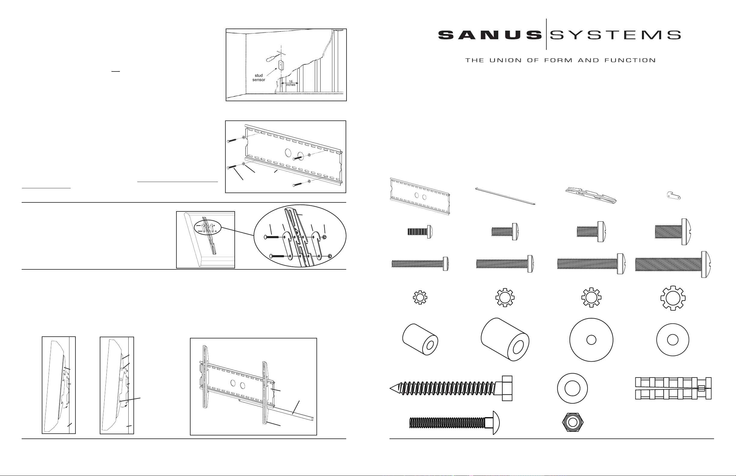
Step 3: Mounting the Wall Plate: Wood Stud, Brick, Solid Concrete, and Concrete Block
mounting options are provided.
Warning: DO NOT OVERTIGHTEN THE LAG BOLTS! Tighten Lag Bolts (u) only
until the Lag Bolt Washer (v) is pulled rmly against the Wall Plate (a)
Wood Stud mounting:
The Wall Plate (a) must be mounted to two wood studs at least 12" apart. Use a high
quality stud sensor to locate two adjacent studs. It is a good idea to verify where the studs
are located with an awl or thin nail shown in Diagram 3a. Pre-drill a 2.5" deep hole at the
desired height in each stud using a 3/16" drill bit. Make sure these holes are in the center
area of the studs and level with each other. Use the Wall Plate as a template to mark the
location of the second hole in each stud. Drill 2.5" deep holes using the 3/16" drill bit in the
marked locations. Attach the Wall Plate to the wall using the four 1/4 x 2.5” Lag Bolts (u)
and four Lag Bolt Washers (v). Make sure the Wall Plate is oriented so the at surface in the
center of the plate is against the wall and that a set of Lag Bolts is on each side of the two
large holes in the center as shown in Diagram 3b.
Brick, Solid Concrete and Concrete Block mounting:
Use the Wall Plate (a) as a template to mark 6 hole locations on the wall. The outer holes
must fall to left and right of the two large holes in the middle of the plate. Three in the top
row of slots and three more in the bottom row. Make sure these holes are level and there is
at least 6" between any two holes. Pre-Drill these holes with a 1/2" masonry bit to at least
2.5" in depth. Insert a Concrete Anchor (w) into each of these holes. Make sure the anchor
is seated completely ush with the concrete surface even if there is a layer of drywall or
other material in front. Attach the Wall Plate to the wall using 6 Lag Bolts (u) and 6 Lag
Bolt Washers (v).
Sanus Systems 2221 Hwy 36 West. St. Paul, MN 55113
800.359.5520 www.sanus.com 8.17.05
Step 4: Choose mounting position:
You can mount your television in either of two positions:
at or at a 5 degree downward tilt. To mount the television
at to the wall use only the Monitor Brackets (c). To mount
the television in the 5 degree tilt position you must rst add
two Gussets (d) to each Monitor Bracket with two Carriage
Bolts (x) and two Gusset Nuts (y) as shown in Diagram 4.
Diagram 4 Detailed View
c
x d d y
Step 5: Hang the TV onto the Wall Plate:
First hook the Monitor Brackets (c) over the top of the Wall Plate (a), then let the bottom of the Monitor Brackets rotate in under the
bottom of the Wall Plate. This process is shown with the at mount option in Diagram 5a, and with the 5 degree tilt option in Diagram
5b. Once the TV is in place, insert the Safety Bar (b) into the slots in the bottom of the Monitor Brackets so that it sits behind the bottom
tab on the Wall Plate as shown in Diagram 5c. The bend at the end of the Safety Bar should face toward the wall. Once the bar passes
out the other side of the Wall Plate a padlock can be added to the hole in the Safety Bar for additional security.
Diagram 5a Diagram 5b Diagram 5c
c
d
c
a a
a
slot for safety bar b
wall wall c
Assembly Instructions for VMPL2 Flat Panel Wall Mount
Thank you for choosing a Sanus Systems Vision Mount Wall Mount. This product is designed to mount at panel televisions weighing up to 175 lb. to
a vertical wall. It allows you to mount your television at against the wall or at a xed 5 degree tilt.
Safety Warning: If you do not understand these directions, or have any doubts about the safety of the installation, please call a qualied contractor or
contact Sanus at 800.359.5520 or www.sanus.com. We can quickly assist you with installation questions and missing or damaged parts. Replacement
parts for Sanus products purchased through authorized dealers will be shipped directly to you. Check carefully to make sure there are no missing or
defective parts. Never use defective parts. Improper installation may cause damage or serious injury. Do not use this product for any purpose that is
not explicitly specied by Sanus Systems. Sanus Systems can not be liable for damage or injury caused by incorrect mounting, incorrect assembly, or
incorrect use.
Note: The supplied wall mounting hardware is not for steel stud walls or old cinder block walls. If you are uncertain about the nature of your wall,
consult an installation contractor. Sanus makes every effort to assure all necessary television mounting hardware is included. If the hardware you need
is not included please consult your local hardware store or call Sanus Systems.
Required Tools: 3/16 drill bit, 1/2” Masonry Bit for brick concrete or concrete block installations, wrench or socket set, Phillips screw driver.
Supplied Parts:
(1) Wall Plate - a (1) Safety Bar - b (2) Monitor Bracket - c (4) Gusset - d
(4) M4 x 12 Bolt - e (4) M5 x 12 Bolt - f (4) M6 x 12 Bolt - g (4) M8 x 16 Bolt - h
(4) M4 x 30 Bolt - i (4) M5 x 30 Bolt - j (4) M6 x 35 Bolt - k (4) M8 x 40 Bolt - l
(4) M4 Lock Washer - m (4) M5 Lock Washer - n (4) M6 Lock Washer - o (4) M8 Lock Washer - p
(4) M4/M5 Spacer - q (4) M6/M8 Spacer - r (8) M4/M5 Washer - s (4) M6/M8 Washer - t
(6) Lag Bolt - u (6) Lag Bolt Washer - v (6) Concrete Anchor - w
(4) Carriage Bolt - x (4) Gusset Nut - y
Diagram 3a
Diagram 3b
v a
u
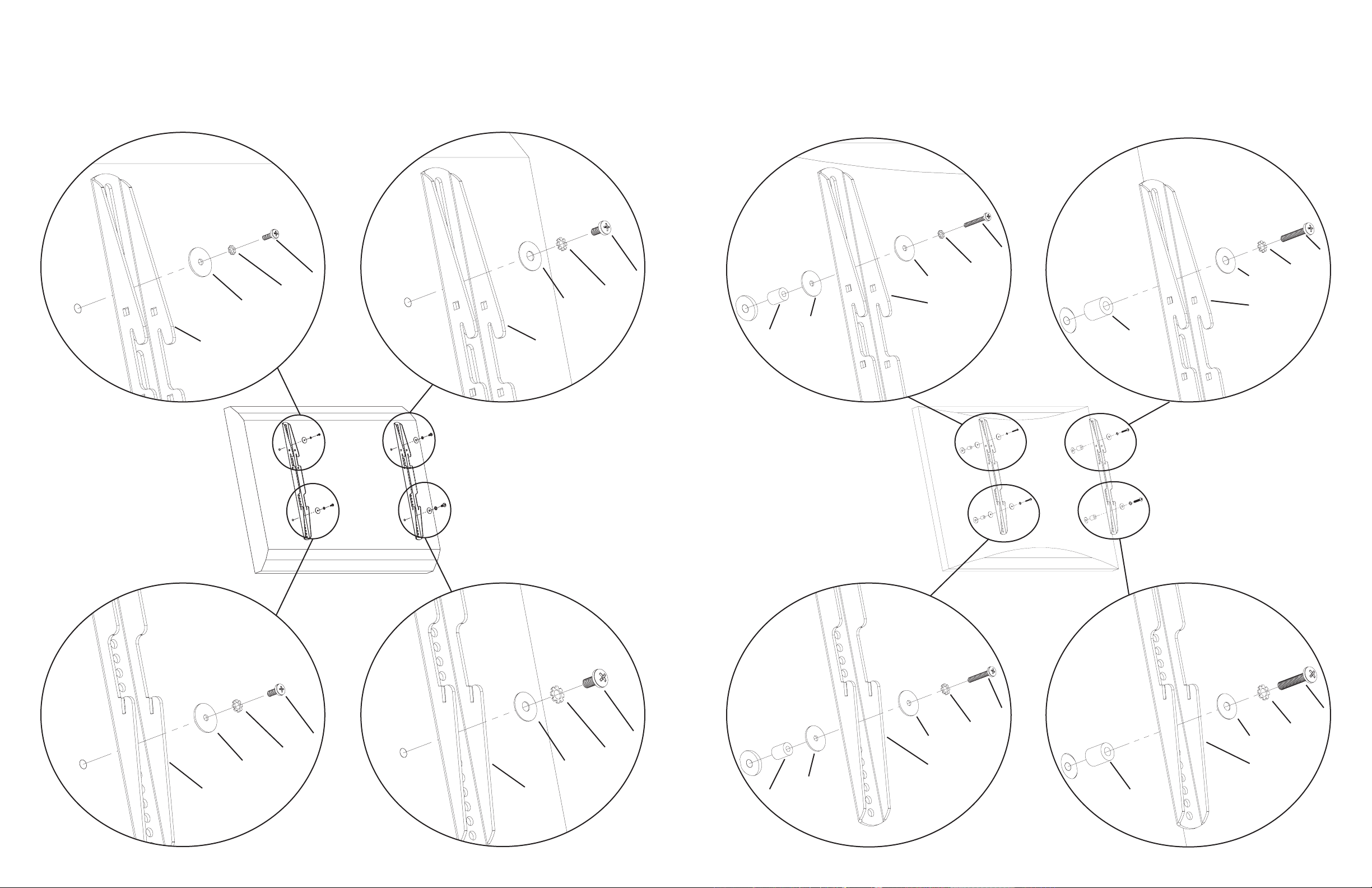
Step 1: Mounting Monitor Brackets to a television with a at back
First, determine the diameter of the Bolt (e,f,g,h) your TV requires by hand threading them into the threaded insert on the back of the TV.
If you encounter any resistance stop immediately! Once you have determined the correct diameter, see the appropriate Diagram below.
You will thread the Bolt through the appropriate Lock Washer (m,n,o,p), a Washer (s,t), the Monitor Bracket (c), and nally into the TV.
Make sure the Monitor Brackets are vertically centered and level with each other.
M4 Diameter Bolt M6 Diameter Bolt
e g
m o
s t
c c
Diagram 1
M5 Diameter Bolt M8 Diameter Bolt
f h
n p
s t
c c
Step 2: Mounting the Monitor Brackets to a television with a curved back, recessed threaded inserts or any other obstruction.
First, determine the diameter of the Bolt (i,j,k,l) your TV requires by hand threading them into the threaded insert on the back of the TV.
If you encounter any resistance, stop immediately! Once you have determined the correct diameter, see the appropriate Diagram below.
You will thread the Bolt through the appropriate Lock Washer (m,n,o,p), a Washer (s,t), the Monitor Bracket (c), a spacer (q,r) and nally
into the TV. For the M4 or M5 diameter bolt, you will need another M4/M5 Washer between the Monitor Bracket and the Spacer. Make
sure the Monitor Brackets are vertically centered on the TV and level with each other.
M4 Diameter Bolt M6 Diameter Bolt
i k
m o
s t
c c
s
q r
Diagram 2
M5 Diameter Bolt M8 Diameter Bolt
j l
n p
s t
c c
s
q r

