Loading ...
Loading ...
Loading ...
1=
2.
3=
Remove the red cap from the gas pipe.
Using a wrench to tighten, connect the gas supply to the
dryer. Use pipe-joint compound on the threads of all non-
flared male fittings. If flexible metal tubing is used, be sure
there are no kinks.
A. Flared male fitting
B. Non-flared male fitting
NOTE: For LP gas connections, you must use pipe-joint
compound resistant to the action of LP gas. Do not use
TEFLON _ttape.
A combination of pipe fittings must be used to connect the
dryer to the existing gas line. Shown is a recommended
connection. Your connection may be different, according to
the supply line type, size and location.
!
A
A. _" flexible gas connector
B. @" dryerpipe
C. _" to _" pipe elbow
D. @"pipe-to-flare adapter fitting
Open the shutoff valve in the supply line. The valve is open
when the handle is parallel to the gas pipe.
4. Once the exhaust vent connection is made, remove the
corner posts and cardboard.
Check the levelness of the dryer. Check levelness first
side to side, then front to back.
If the dryer is not level, prop up the dryer using a wood block.
Use a wrench to adjust the legs up or down and check again for
levelness.
C_OO @W C_
You can change your door swing from a right-side opening to a
left-side opening, if desired.
1. Place a towel or soft cloth on top of the dryer or work space
to protect the surface.
Remove the door assembly
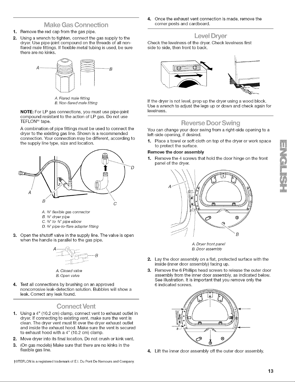
1. Remove the 4 screws that hold the door hinge on the front
panel of the dryer.
A. Dryer front panel
B. Door assembly
4.
A.Closed valve
B.Open valve
Test all connections by brushing on an approved
noncorrosive leak-detection solution. Bubbles will show a
leak. Correct any leak found.
1. Using a 4" (10.2 cm) clamp, connect vent to exhaust outlet in
dryer. If connecting to existing vent, make sure the vent is
clean. The dryer vent must fit over the dryer exhaust outlet
and inside the exhaust hood. Make sure the vent is secured
to exhaust hood with a 4" (10.2 cm) clamp.
2. Move dryer into its final location. Do not crush or kink vent.
3. (On gas models) Make sure that there are no kinks in the
flexible gas line.
2.
3.
4=
Lay the door assembly on a flat, protected surface with the
inside (inner door assembly) facing up.
Remove the 6 Phillips head screws to release the outer door
assembly from the inner door assembly, as indicated below.
See illustration. It is important that you remove only the
6 indicated screws.
o _
Lift the inner door assembly off the outer door assembly.
1-®TEFLON is a registered trademark of E.L Du Pont De Nemours and Company.
13
Loading ...
Loading ...
Loading ...