USER MANUAL
Wines Cellars


1
Index
Important instructions for safety and the environment
For your safety
Respect for the environment
Installation
Installation
Connection to the electrical mains
Before starting
Getting to know the appliance
Main features
Main components
Electronic Control
Main control panel
Turning the appliance on and off
Turning on and off
How to adjust the temperature to suit various needs
Information and malfunction signals on the display
Settings and Special Functions
Customization and Language Settings
Special functions activated through the Menu
Basic settings of the Menu
Internal Layout
Internal Layout (positioning, adjustment, removal)
Lighting
Lighting
Use of the MultiZone compartment
Use of the MultiZone compartment
MultiZone compartment
Conservation of wines
General directions
Wine conservation temperature
Time of conservation
Recommended times for food conservation
Care and Cleaning
Care and Cleaning
Condenser cleaning
Internal cleaning
Troubleshooting guide
Troubleshooting guide
Malfunction indications appearing on the display
Smeg Access Menu Map
Functions
Settings
Page
2
1
1.1
B0900130 1
Product tested in accordante with EN62471
Risk Group 2
PRUDENZA:
NON FISSARE LA LAMPADA IN FUNZIONE.
PUÒ ESSERE DANNOSO PER GLI OCCHI.
CAUTION:
DO NOT STARE AT OPERATING LAMP.
MAY BE HARMFUL TO THE EYES.
Notes
Suggestions for proper use
of the appliance
For your safety
Important
Instruction to prevent damage
to the appliance
Warning
Instructions for preventing
personal injury
Important instructions for safety and the environment
If this appliance is replacing an existing appliance which must be
removed or disposed of, make sure that it does not become a dan-
gerous trap for children by cutting its power supply cable and ren-
dering it impossible to close the door. Use the same caution at the
end of the lifespan of the new appliance.
This appliance is designed to refrigerate beverages and foods and
is destined for domestic use.
The appliance must be installed by following the instructions in the
Installation Guide, particular care should be taken not to obstruct the
vent openings of the appliance and of the built-in units.
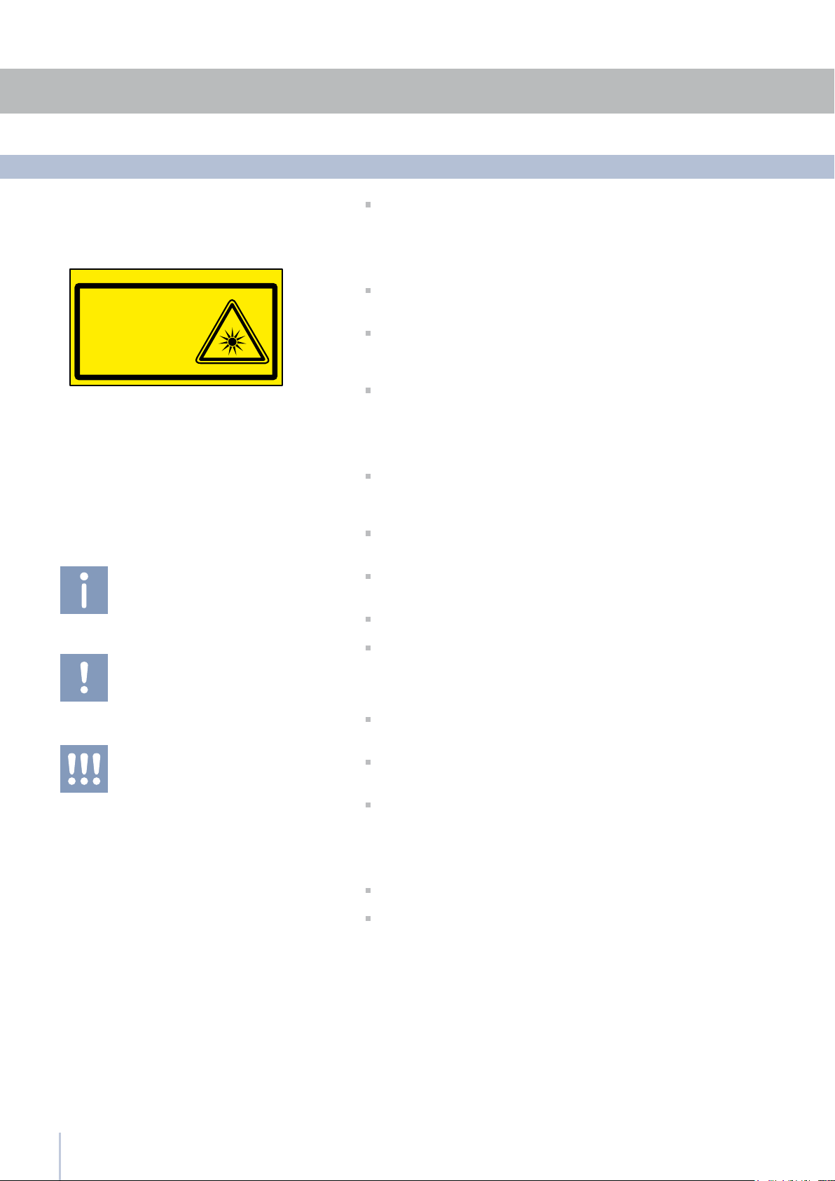
The appliance features a concentrated lighting system with LED
lamps. Do not stare into these lamps when they are on to avoid pos-
sible eyesight damage.
This warning is also contained on the label attached to the inside of
the refrigerator door.
When the freezer is functioning do not touch the inner surfaces in
stainless steel with wet or damp hands, since skin may stick to the
very cold surfaces.
Do not use any type of electrical equipment inside of the food
conservation compartments.
When positioning the shelves, do not place fingers in the shelf
slide guides.
Do not position containers of ammable liquids near the appliance.
Completely switch off the appliance and unplug the power supply
cable during cleaning operations. If the plug is not easily reached, it
is a good idea to disconnect the omnipolar switch that controls the
socket that the appliance is connected to.
The packaging parts can be dangerous for children: do not allow
children to play with the plastic bags, plastic lm or Styrofoam.
Any repairs must be performed by a qualified Smeg Service tech-
nician.
This appliance is not intended for use by persons (including children)
with reduced physical, sensory or lack of experience and knowledge
unless they have been given supervision or instruction concerning use of
the appliance by a person responsible for their safety. Children should
be supervised to ensure that they do not play with the appliance.
Do not damage the appliance refrigerant circuit pipes.
Do not store explosive substances such as aerosol cans with a am-
mable propellant in this appliance.
3
2
2.1
2.2
1.2
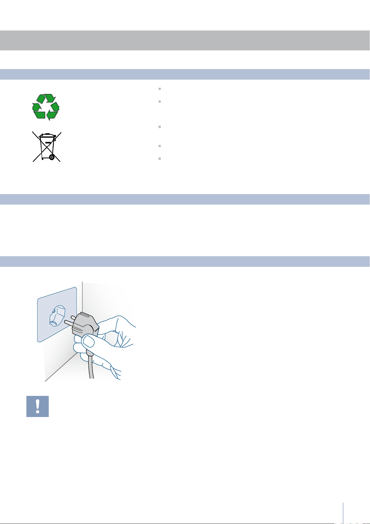
Make sure you dispose properly of all packing materials.
The appliance must not be disposed of with urban waste.
Contact local waste disposal authorities for information on the disposal
of recyclable waste.
For disposal, cut the power supply cord and make it impossible to
close the door.
During disposal, avoid damage to the refrigeration circuit.
Neither the refrigeration circuit nor the insulation contain substances
that are hazardous to the ozone layer
Respect for the environment
Make sure that installation is performed correctly, adhering to all of
the instructions in the specic installation guide provided with the
appliance.
Installation
Connection to the electrical mains
The appliance is equipped with a Schuko type 16A plug.
It must be connected to the electrical mains by means of a corre-
sponding Schuko socket.
Do not use extension cords and/or multiple adapters for connection.
Do not use extension cords and/or multiple
adapters for connection.
Installation

4
3
3.1
3.2
Before starting
Getting to know the appliance
The Smeg triple refrigeration system ensure perfect con-
ditions for conservation of various types of wines
The electronic control guarantees constant temperature
and humidity levels set by the user
The double compressor allows separate management
of the set temperature and humidity for the Cantina, Wine
Cellar and MultiZone compartments
The MultiZone compartment may operate in three dif-
ferent modes: as a freezer, as a refrigerator or as a cooler
compartment
An interactive menu (Menu) permits personalized man-
agement of appliance functions and the display of mes-
sages on operation
Main features
Optimization of consumption during vacation periods
Patented hinge system that permits automatic door closing
MultiZone drawers with Soft self-closing system
Localized lighting system with LEDS
Anti-tipping system with brackets for wall mounting.
Congratulations for having purchased your new Smeg:
from now on you can use our innovative conservation
system, which will allow you to keep all of your food in the
best way possible.
This manual will answer most of your questions about the
product’s features. Should you require further information,
please check our website
www.smeg.com
5
3
3.3
Cantina
MultiZone
1
7
8
9
10
11
12
2
3
4
5
6
Wine Cellar
Before starting
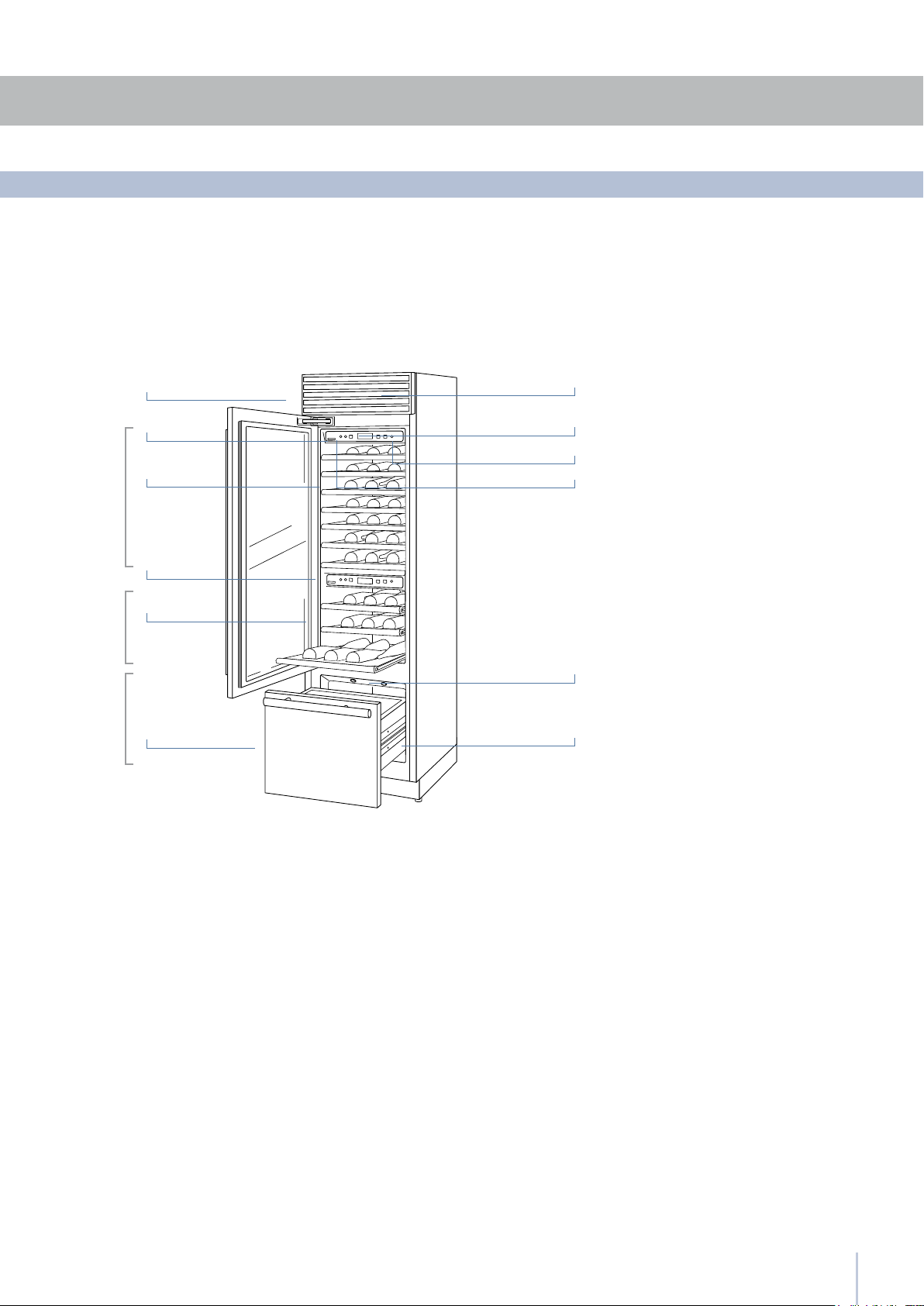
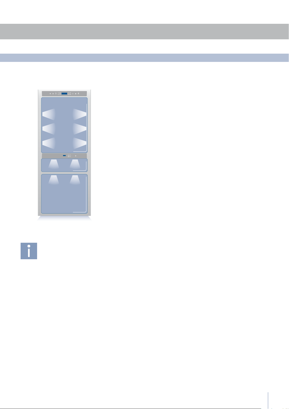
Main components
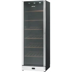
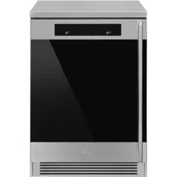
One drawer Wine Cellar
1 Structure in stainless steel
with aluminium trim
2 Wine Cellar and MultiZone
control panels with Menu
3 Sliding bottle shelfs,
mounted on wheels for
easy extraction
4 Cantina area control panel
5 Wine Cellar
6 Frezer compartment that
can be transformed into
a refrigerator or Low Temp
compartment
(MultiZone function)
7 Double refrigeration system
8 Temperature display
9 Acoustic signals
10 Vacation function
(in Menu)
11 Innovative lighting
12 Automatic door and
drawer closure
3
3.3
3.3
Componenti principali
Componenti principali
3.5
3.4
1
Unit
2
Wine cellar
3
Menu
4
Up/down
Wine Cellar
5
Display
6
Up/Down
(MultiZone)
7
Enter
8
Alarm
9
Light
10 11 12 13
10
Display
12
13
Cantina
Humidity
11
Up/Down
Cantina
6
123456798
Before starting
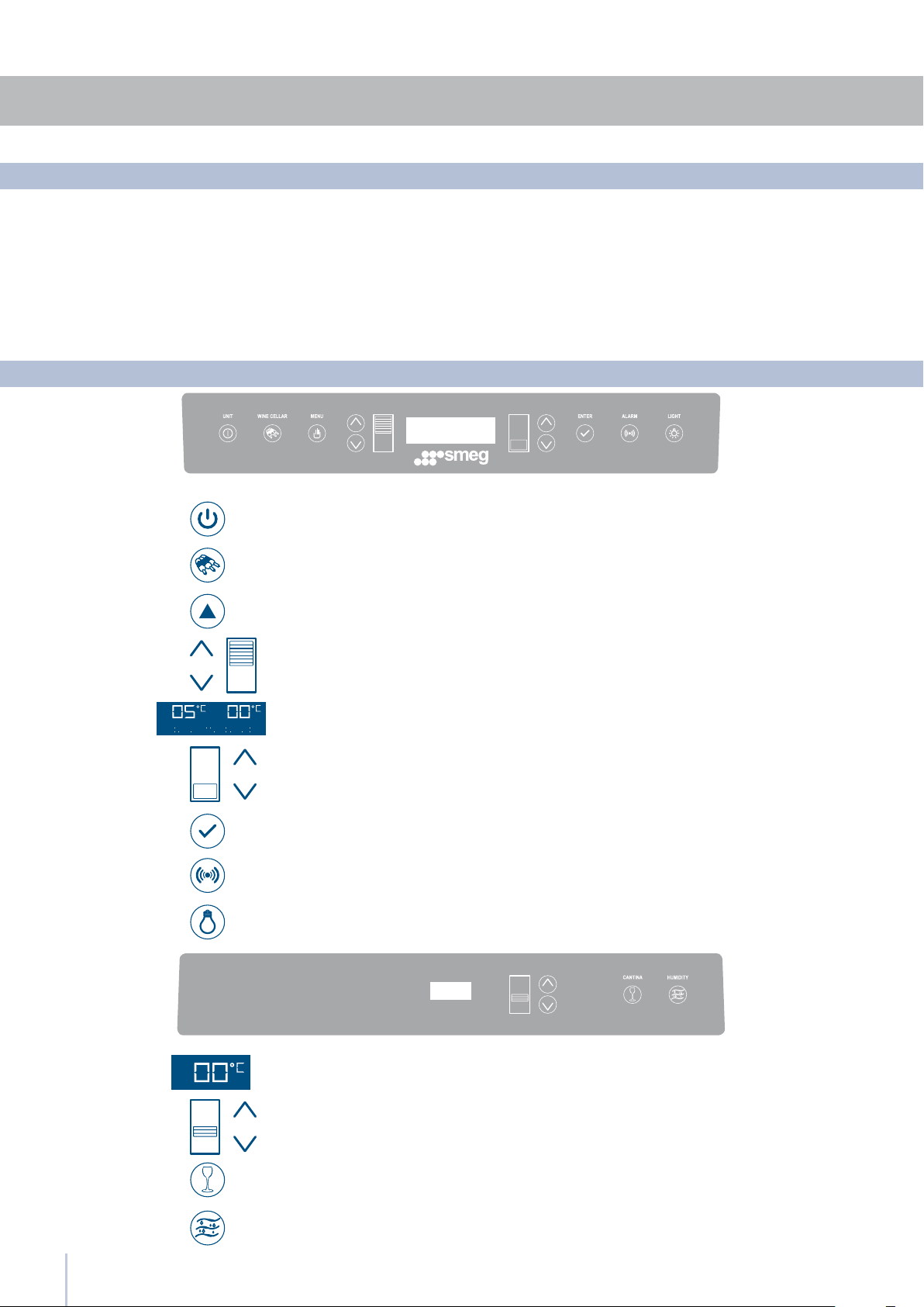
Main control panel
Electronic Control
Allows complete shutdown and start-up of the appliance
(press for three seconds).
Allows access to the appliance functions menu.
Displays the temperature of the Wine Cellar and MultiZone compart-
ments, the date and time, Menu functions and visual messages.
Allows illumination of the Wine Cellar and Cantina compartments also
when the door is closed. Once activated, the light of the top compart-
ment will automatically shut off after 6 hours.
Shows the temperature of the Cantina compartment.
Allows switching on and off only the Cantina compartment on or off
(press for three seconds).
Allows adjustment of humidity in the Wine Cellar and Cantina com-
partments to three levels: High (HI), Medium (A) and Low (LO).
Using the Up and Down keys, it is possible to change the set tempera-
ture for the Cantina compartment.
The innovative electronic control system designed by Smeg maintains constant temperature on the three compartments
and visualizes it on the control panel display. It also allows user interaction making it possible to personalize settings of the
various functions and to receive sound and/or visual messages should any malfunction occur in the appliance.
Allows switching on and off only the Wine Cellar compartment (press
for three seconds).
By selecting Up/Down the preset temperature can be changed ac-
cording to the selected function mode (freezer, refrigerator, Low
Temp).
Conrms activation or deactivation of the selections made in the
Menu.
Allows activating or deactivating the automatic ice production.
Using the Up and Down buttons, it is possible to change the set tem-
perature of the refrigerator and scroll through the interactive menu.

7
4
4.1
Turning the appliance on and off
To prevent accidental modication of settings,
the keypad locks automatically after a certain
period of time and the display shows the mes-
sage “keypad locked”. To re-activate it, simul-
taneously press the keys Menu and Up/Down
(Down) for three seconds.
At the rst start-up, if the message Standby does
not appear, it means that the appliance has al-
ready started the cooling process. If this is the
case, deactivate any possible acoustic signals
by pressing the Alarm key , close the door and
wait until the set temperature is reached.
During the rst start-up, you will not be able to use
the Menu to modify factory settings until the de-
fault temperature has been reached. It is howev-
er possible to set the time and date immediately;
these parameters are required to activate some
of the special functions.
If only the Cantina or Wine Cellar compartment
is turned off, the corresponding fan will continue
to run independently to prevent the formation of
unpleasant odours and mould.
First start-up
Once you have turned on all of the compartments of the appliance,
you can turn off only the wine cellar compartment by pressing the
relevant key for three seconds.
The MultiZone compartment is always on and cannot be turned off
except by completely turning off the appliance.
To shut down the unit completely for cleaning or maintenance, press
the Unit key
for three seconds.
Also take the plug out of the socket and turn off the omnipolar switch
that powers it.
Turning off the Wine Cellar compartment
Turning the Wine Cellar compartment on
again
Complete shutdown
Lengthy shutdown periods
Turning on and off
Press again for three seconds the relevant key.
When the appliance is connected to the electrical power supply but
has not yet been turned on, the display shows the message
This is a safety message to warn that power is supplied to the appli-
ance, while all of the keys on the panel are off.
To switch on all the appliance compartments, press the Unit button
for three seconds.
After you have completely shut down the appliance and unplugged
it, empty it of all its contents, clean it and dry it. Leave the doors and
the drawers ajar to prevent the formation of unpleasant odours.
4
4.4
4.2
8
An integrated control system provides information through luminous
signals or text messages shown on the display.
The information signal is always displayed with a xed text message,
while a malfunction signal is shown with blinking text.
The acoustic signal that accompanies some malfunction signals can be
deactivated by pressing the Alarm key on the main control panel.
The list of malfunction signals is located in the back of this manual.
Turning on the appliance
To adjust the temperature in the various compartments, use the up/
down key for that compartment (see chapter 3.5).
If the “keypad locked” message appear, simultaneously press the keys
Menu and Up/Down (Down) for 3 seconds.
Wines compartment
MultiZone compartment
Each model has been carefully tested before leaving the factory and
is adjusted so as to ensure high performance and low consumption.
The ideal temperature for wine conservation does however depend
on the types of wine you want to conserve, the method of conserva-
tion (Wine Cellar for conservation and consumption, or Cantina for the
conservation and aging of prized bottles).
It also varies according to personal taste.
Please refer to the guide on wine conservation included further ahead
in this manual.
As needed, you can reset the temperatures as follows:
Cantina Compartment:
from +10° C to +18° C (from 50° F to 53.6° F).
The default temperature is +12° C (53.6° F).
Wine Cellar compartment:
from +4° C to +12° C (from 39.2° F to 53.6° F).
The default temperature is +10° C (50° F).
The MultiZone compartment is default set to freezer mode but it can
also be set to run as a refrigerator or cooler compartment.
Instructions for conversion are provided in the paragraph on special
functions and settings.
As needed, you can reset the temperatures as follows:
Freezer compartment: from -15° C to -22° C (from 5° F to -7.6° F).
The default temperature, which is recommended, is -18° (0° F)
Refrigerator compartment: from +2° C to +8° C (from 35.6° F to 46.4° F).
The default temperature, which is recommended, is +5° C (41° F).
Cooler compartment: from -2° C to +2° C (from 28.4° F to 35.6° F),
The default temperature, which is recommended, is 0° C (32° F).
The displayed temperature may vary slightly
with respect to the set temperature if the doors
are continuously opened or insertion of room
temperature food or large quantities of food.
It takes 6 to 12 hours to reach the selected tem-
perature.
Information and malfunction signals on the display
How to adjust the temperature for suit various needs
If the “keypad locked” message appear, simul-
taneously press the keys Menu and Up/Down
(Down)
for 3 seconds.
9
5
5.1
5.2
Functions Shopping Multiz
Shopping Multizone ON/OFF Shopping ON
Functions Shopping Multiz
Shopping Multizone ON/OFF Super Cool OFF
Functions Shopping Multiz
Shopping Time Set Hours: I
Settings and Special Functions
To prevent accidental modication of settings,
the keypad locks automatically after a certain
period of time and the display shows the mes-
sage “keypad locked”.
To re-activate it, simultaneously press the keys
Menu
and Up/Down (Down) for at least
three seconds.
Customization and Language Settings
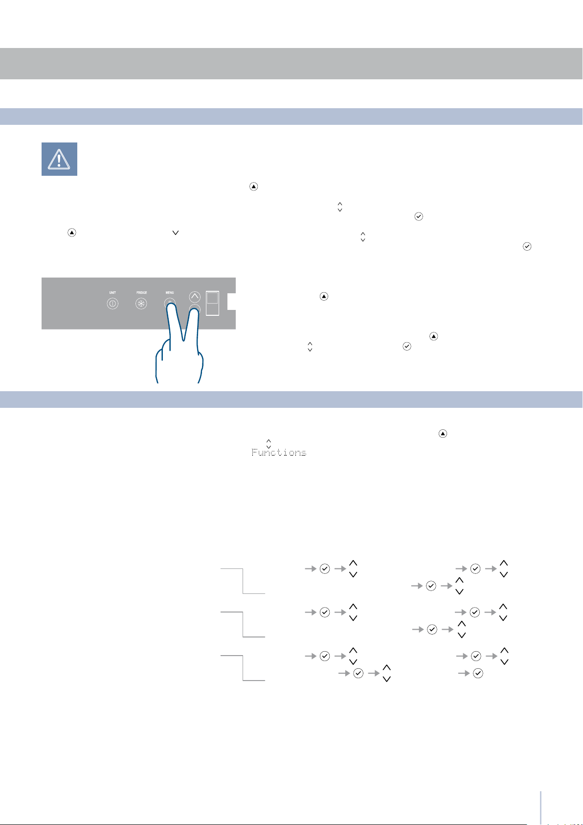
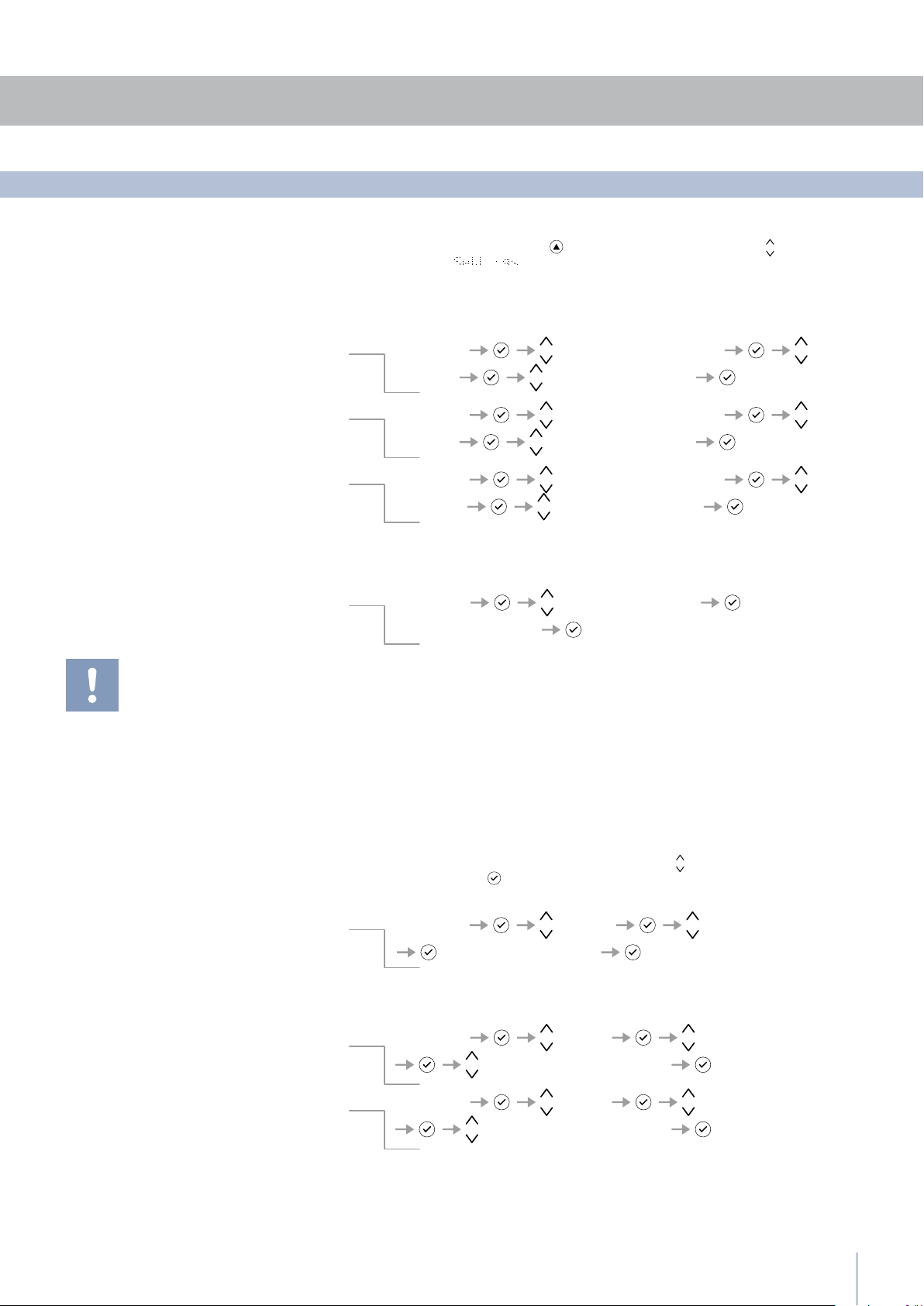
Special functions activated through the Menu
It is possible to customized the functions of your Smeg to adapt it to di-
verse usage needs, resetting the main parameters (Settings) or activating
special functions (Functions).
Functions are visualized on the main display by pressing the Menu button
.
The Up/Down buttons permit scrolling the available functions, which can
be selected by pressing the Enter button . The display visualizes the cur-
rent functioning status.
Using the Up/Down buttons , it is also possible to scroll through the select-
ed function, activating or deactivating by pressing the Enter button .
Once the function is conrmed, the display will automatically visualize the
main menu to select other functions.
At any time it is possible to return to the previous selection through
the Menu button .
The language of the messages appearing on the display can be changed
by operating as follows:
Enter the Menu by pressing the Menu button select Settings via the Up/
Down buttons and conrm via Enter .
Then select the Language function and the desired language.
This function must be activated at least 24 hours before inserting room
temperature items into the freezer, or several hours before placing into
the freezer previously frozen items which have been subject to a slight
temperature rise. This function is automatically deactivated when the
programmed time period expires.
It is possible o program timed activation of the function.
After a prolonged interruption of the electrical power, it is necessary to
reactivate the function.
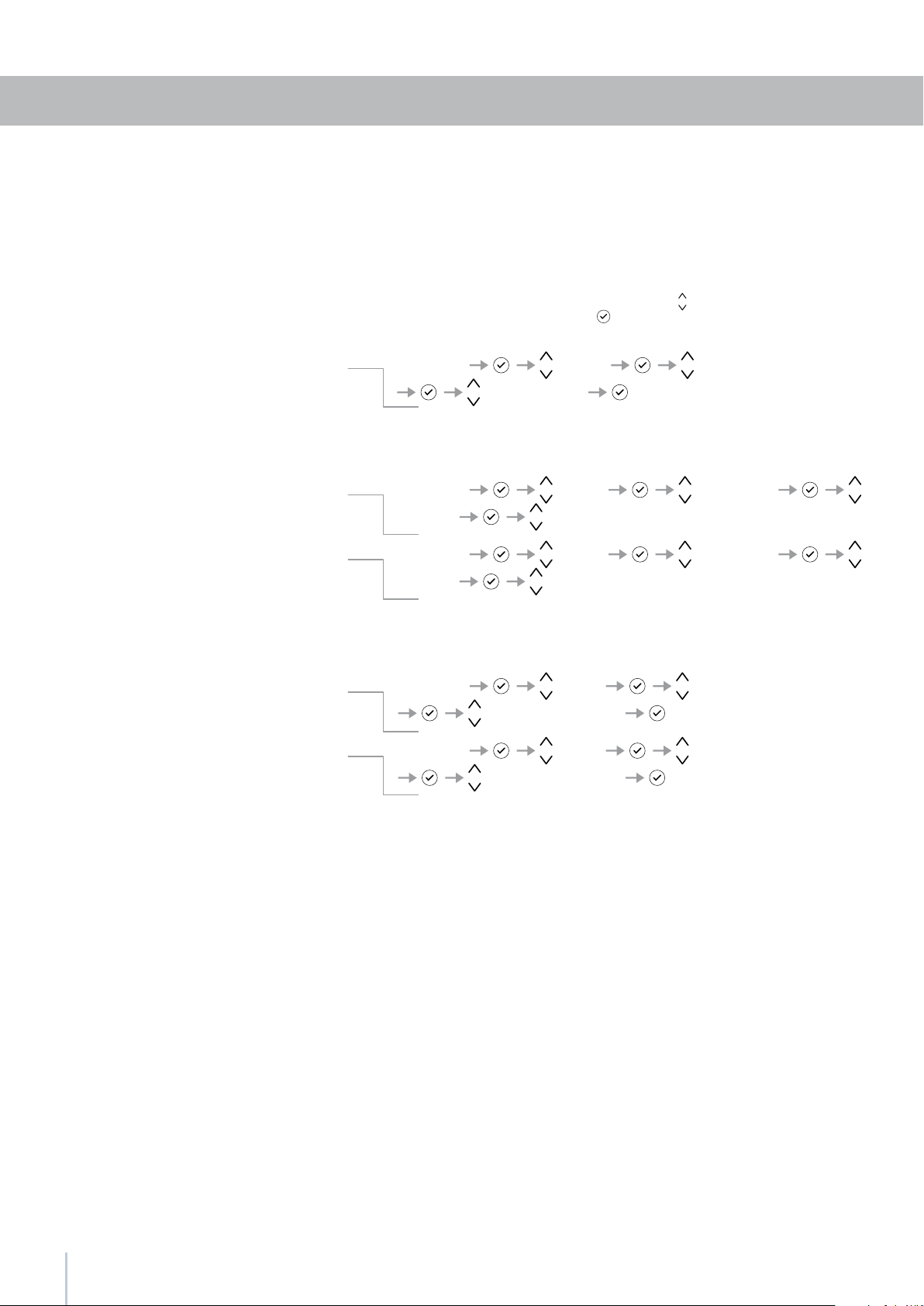
To use special functions, select the Menu key
and use the Up/Down
key to access the menu, conrming the selection
.
How to activate
How to deactivate
How to program timed activation
Shopping MultiZone
5
10
Functions Hodiday Multiz
Holiday Multizone ON/OFF Holiday ON
Functions Hodiday Multiz
Holiday Multizone ON/OFF Holiday OFF
Functions Hodiday Multiz
Holiday Time Set Days: I
Functions Sabbath Mode
Sabbath Mode ON/OFF Sabbath Mode ON
Functions Sabbath Mode
Sabbath Mode ON/OFF Sabbath Mode OFF
Functions Bottle Cooler
Bottle Cooler ON/OFF Bottle Cooler ON
Functions Bottle Cooler
Set Cooling Time Set Time : 20 min
Functions Bottle Cooler
Bottle Cooler ON/OFF Bottle Cooler OFF
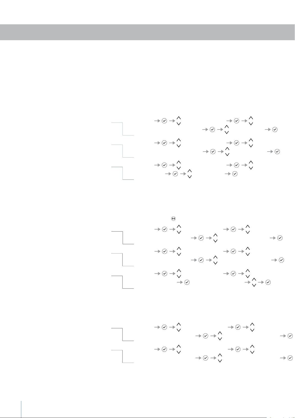
Settings and Special Functions
This function (recommended in case of prolonged absences since it
allows considerable energy savings) brings the Tri-Mode compartment
temperature to - 18°C (46.4°F).
It is possible to program the duration, or it can be manually deacti-
vated upon re-entry after a period of absence.
This function remains active even if during the period of absence there
is a prolonged interruption of electrical power.
It is possible to program a period from 1 to 90 days.
This function can be activated when it is necessary to cool off bever-
ages quickly, by placing them inside the freezer compartment.
It is possible to select a duration of 1 to 45 minutes. A sound signal will
indicated when the optimal temperature has been reached.
After removing the beverages, deactivate the sound signal by press-
ing the Alarm button
.
Bottle Cooler
How to activate
How to deactivate upon re-entry
How to program the duration
How to activate
How to deactivate
How to program the duration
Vacation MultiZone
The function makes it possible to comply to certain religious observ-
ances requiring that the operation of the appliance is not affected by
the opening or closing of the doors (the thermostatic control, the inner
lighting and the ice maker are deactivated).
Sabbath Mode (Optional)
How to activate
How to deactivate
11
5.3
5
Settings Default Setting
Enter to confirm
Settings DateSet Date
DATE: 01-01-2009
Settings DateShow Date
DATE: 01-01-2009 On
Settings DateShow Date
DATE: 01-01-2009 Off
Settings Multizone Options
Fridge Enter to confirm
Settings Multizone Options
Fresco Enter to confirm
Settings Multizone Options
Freezer Enter to confirm
Settings and Special Functions
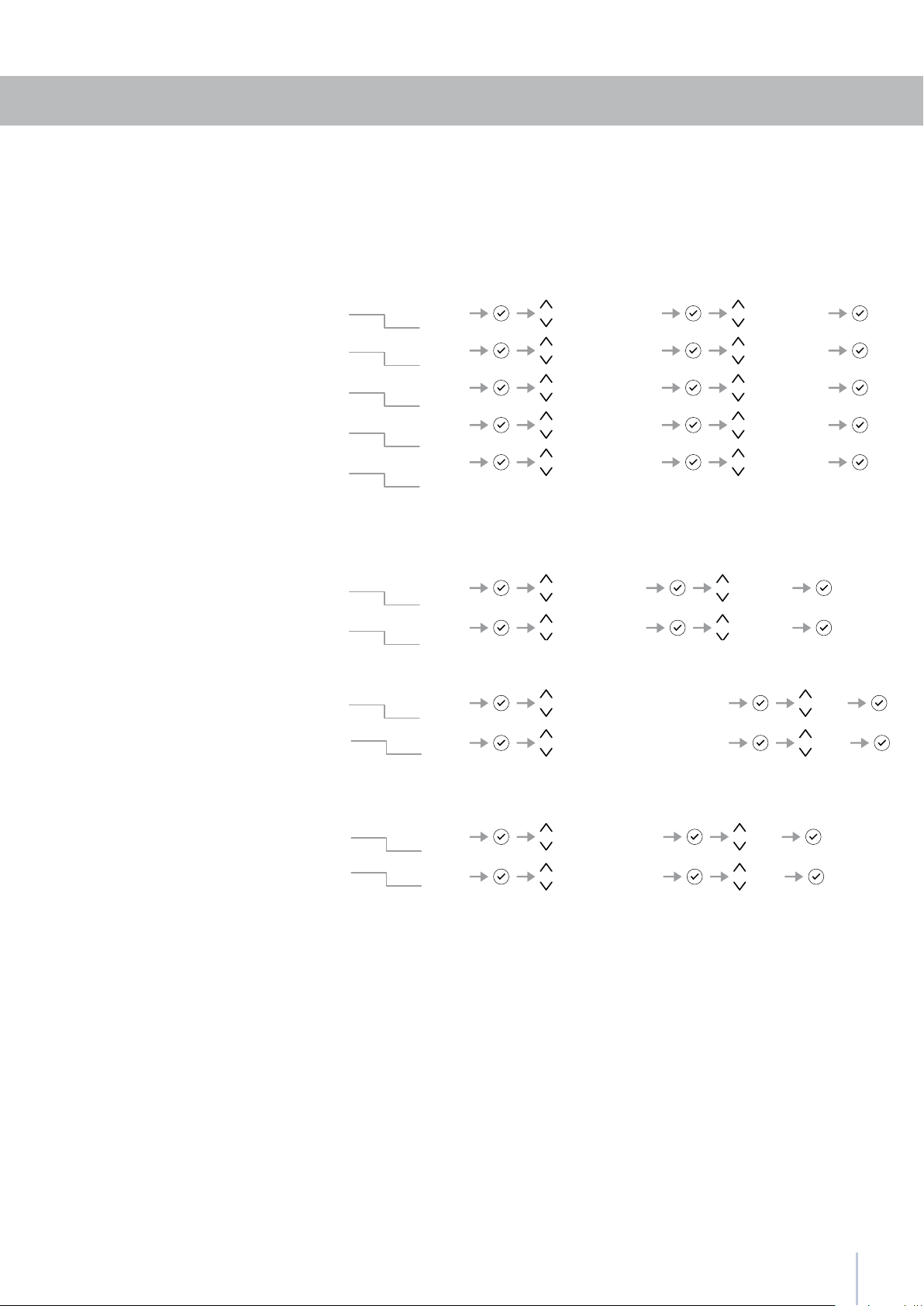
Basic settings of the Menu
This offers the possibility to reset default factory settings and cancels
any previous changes.
Default Setting
How to reset default settings
Using this function it is possible to deactivate/activate the date visuali-
zation on the display.
Show Date
How to activate the date
How to deactivate the date
The display will visualize the date in the format dd:mm:yy (day:month:year),
the day will blink. Use the Up/Down buttons
to modify the setting, con-
rm with Enter to go on to the next setting; once the year is conrmed
the date will be set.
Date
Set Date
How to set the date
Select the Menu button
and used the Up/Down button
to select .
The freezer compartment can, if required, be converted to the refrig-
eration o Low Temp operating mode.
MultiZone Options
How to set the Fridge function
How to set the Low Temp function
How to revert to the Freezer function
ATTENTION: If the default settings are restored, it is
necessary to reactivate the choice of operation of
the MultiZone compartment in case it was previously
set as Fridge or Fresco.
12
5
Settings Time Set Time
TIME: 01:01
Settings Time Set View
Set: 12
Settings Time Set View
Set: 24
Settings Time Show Time
TIME: 01:01 On
Settings Time Show Time
TIME: 01:01 Off
Settings and Special Functions
This function selects the display at 12 or 24 h.Set 12/24
How to set the display to 12 h
How to set the display to 24 h
Through this function it is possible to activate/deactivate the constant
visualization of the time.
Show Time
How to activate the permanent time
How to deactivate
The display visualizes the hours and minutes in the format hh:mm and
with hh: blinking. Use the Up/Down buttons
to modify the setting and
then conrm by pressing Enter
to go on to the next setting.
Once the minutes are conrmed, the time will be set.
Time
Set Time
How to set the time
13
5
Settings Language italiano
Settings Language english
Settings Language français
Settings Language deutsch
Settings Language español
Settings Set ‘C
Settings Set ‘C/’F
Set ‘C/’F
Set ‘F
Settings ShowRoom Mode
ShowRoom Mode
On
Settings Off
Settings Child Lock
Child Lock
On
Settings Off
Showroom Mode
Child Lock
Settings and Special Functions
This function permits visualizing the temperature in Centigrade or Fahr-
enheit degrees. Normally, the appliance is set for visualization in cen-
tigrade degrees.
Set °C/°F
How to set the temperature in Centigrade
How to set the temperature in Fahrenheit
The function allows selection of the language for the display messages.Language
Italian
English
French
German
Spanish
How to activate
How to activate
How to deactivate
How to deactivate
6
6.1
14
Internal Layout
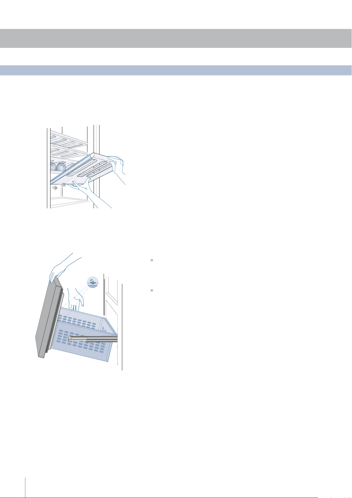
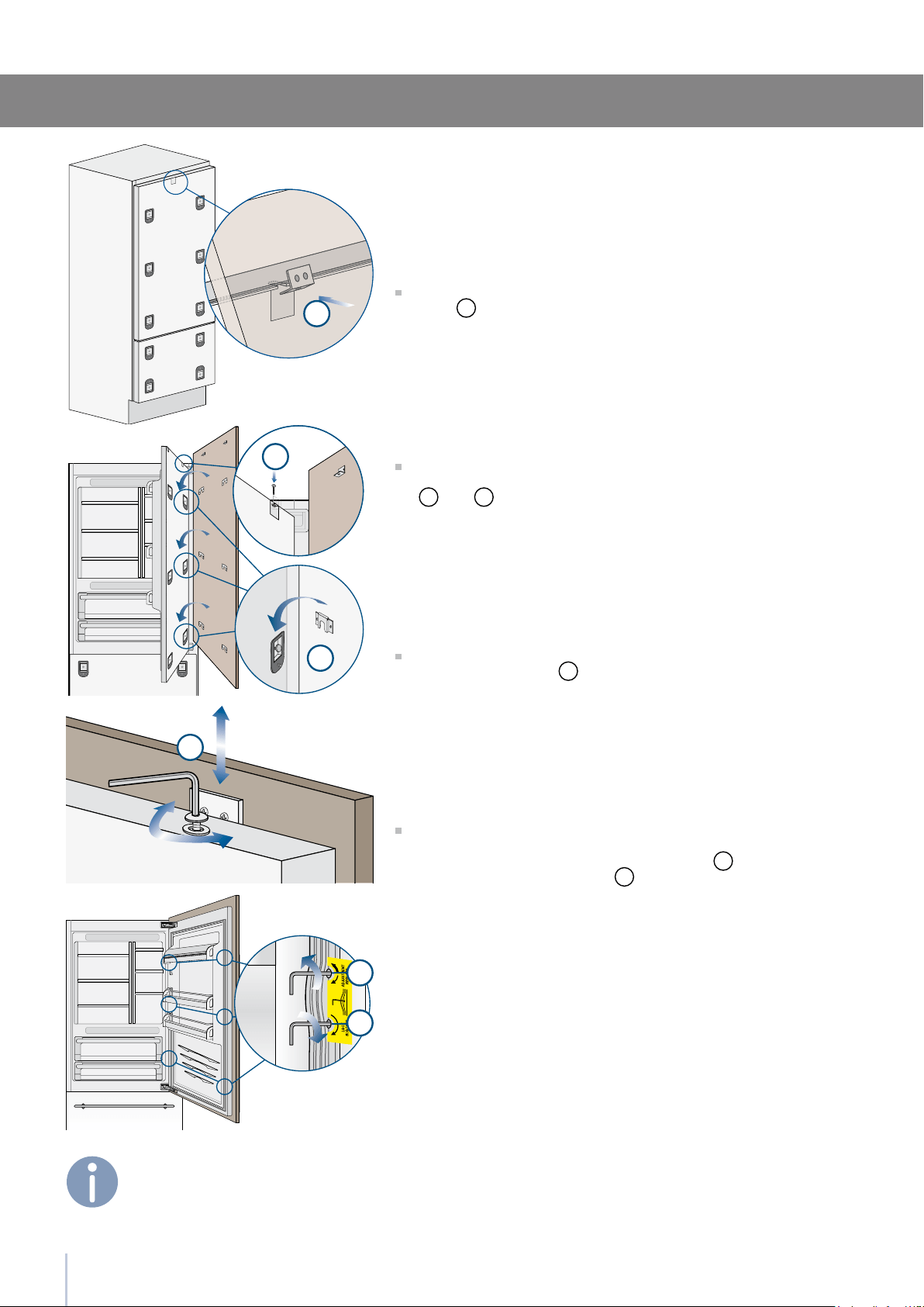
The shelves can be easily removed for cleaning.
Remove the bottles, completely extract the shelf, tilt it upward
until the wheels are free of their seat and extract it.
Wine shelf
MultiZone drawer
Internal Layout (positioning, adjustment, removal)
Fixed to the slide guides with two locking nuts
to remove the drawer, unscrew the locking nuts and remove the
drawer.
to remove the inner MultiZone drawer unscrew the locking nuts.
15
7
7.1
Lighting
Lighting
To provide optimum interior lighting, LED strips illuminate the refrig-
erator compartment from the top and sets of LED lights directly il-
luminate different areas of the refrigerator compartment, of the Low
Temp drawers and the freezer drawer.
In case of malfunction and/or failure of the lighting system, you
should contact an authorized Smeg Service Agent.
Once activated, the light of the top compartment
will automatically shut off after 6 hours.

8
8.1
8.2
16
Use of the MultiZone compartment
Use of the MultiZone compartment
The MultiZone compartment, used in conjunction with the Wine Cellar
and Cantina compartment, allows great exibility in the use of the ap-
pliance.
Some possible uses:
Liquors, such as vodka, gin, tequila, schnapps, limoncello and the
glasses to serve them
Rapid cooling of beverages, by activating the bottle cooler function
Storage of large amounts of ice.
As expansion of the Wine Cellar or of the Cantina
For refrigeration of beer and soft drinks
For storage of cold dishes and snacks.
For conservation of ham, salmon
gourmet preparations.
It comes without saying that, the compartment can be used in a tra-
ditional manner. Suggestions and instructions are provided to offer
you best conservation of your food over time in complete safety.
Freezer mode
Refrigerator mode
Cooler mode
17
9
9.1
9.2
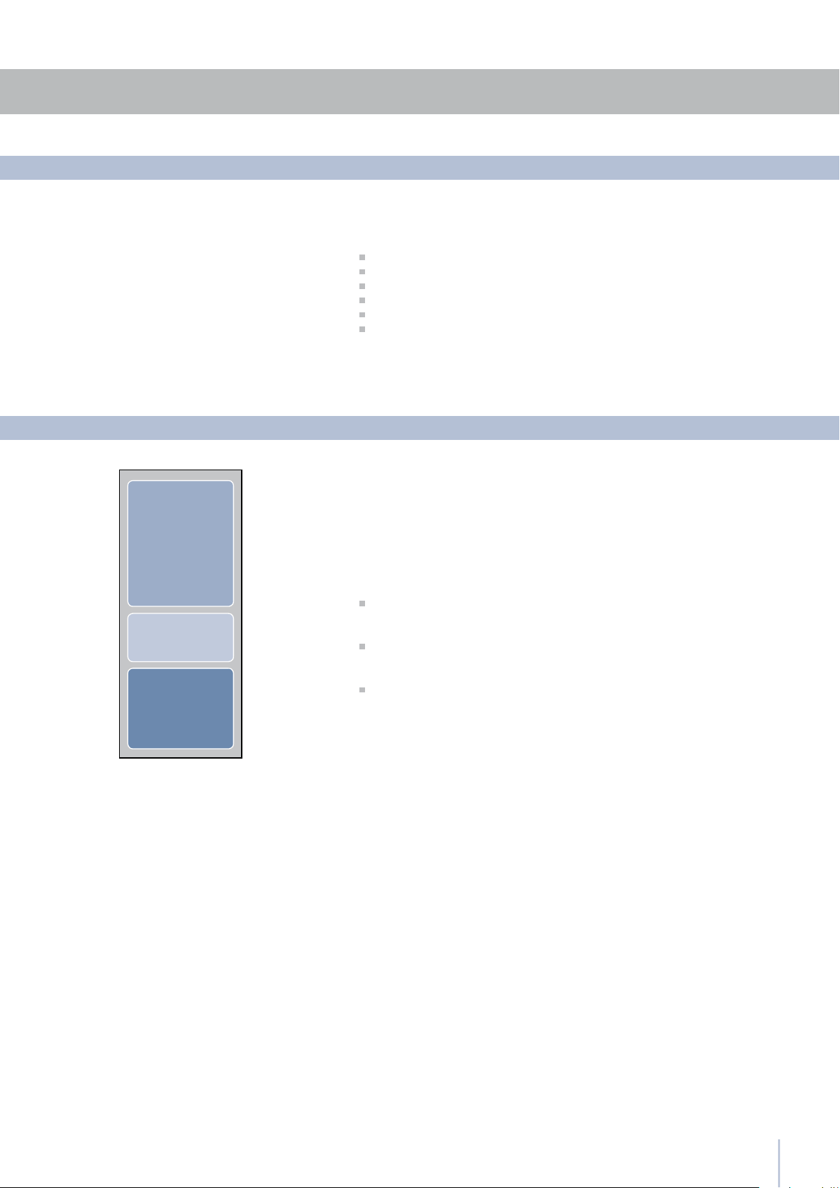
Cantina
Wine Cellar
MultiZone
As is known, wine can be stored for long periods of time if this is done
under the following conditions:
Suitable temperature without appreciable variations over time
Controlled level of humidity
Protection from light
Absence of noise and vibrations
Absence of odours
Bottle kept horizontal.
All of these conditions are fully met in the Smeg Wine Cellar.
The space offered by the Wine Cellar and Cantina compartments,
which can be expanded as necessary by using the MultiZone com-
partment as a wine cellar, allows conservation of your best wines at
three different temperatures.
The three compartments are initially set to the following temperatures:
Cantina compartment
+12° C (53.6° F) - adjustable from +4° C to +18° C (from 39,2° F to 64,4° F)
Wine Cellar compartment
+10° C (50° F) - adjustable from +4° C to +18° C (from 39,2° F to 64,4° F)
MultiZone drawer
-18° (0° F) - adjustable from -15° C to -22° C (from 5° F to -7.6° F)
(freezer mode)
To transform the MultiZone compartment into a wine cellar space, you
must access the Menu, set it as a refrigerator compartment, and ad-
just it to a temperature between +4° C and +8° C (from 39.2° F to 46.4°
F).
All the temperatures can be modied according to the characteristics
of the wines and personal preferences. However, you should attempt
to keep the temperature as constant as possible over time.
Rapid and large-scale temperature variations can in fact cause dila-
tion of the liquid and early aging of the wine.
You should also avoid very low temperatures (below 4° C - 39.2° F )
which may lead to the formation of deposits and damage the aes-
thetic qualities of the wine.
All the compartments offer optimal conditions and take into account
all these needs. It should however be noted that the Cantina com-
partment, in particular, is thermostatically controlled in a very precise
manner and ensures the utmost care and attention over time of your
most prized bottles.
General directions
Conservation temperature
Conservation of wines
Models with Cantina and Wine Cellar
18
9
9.3
18
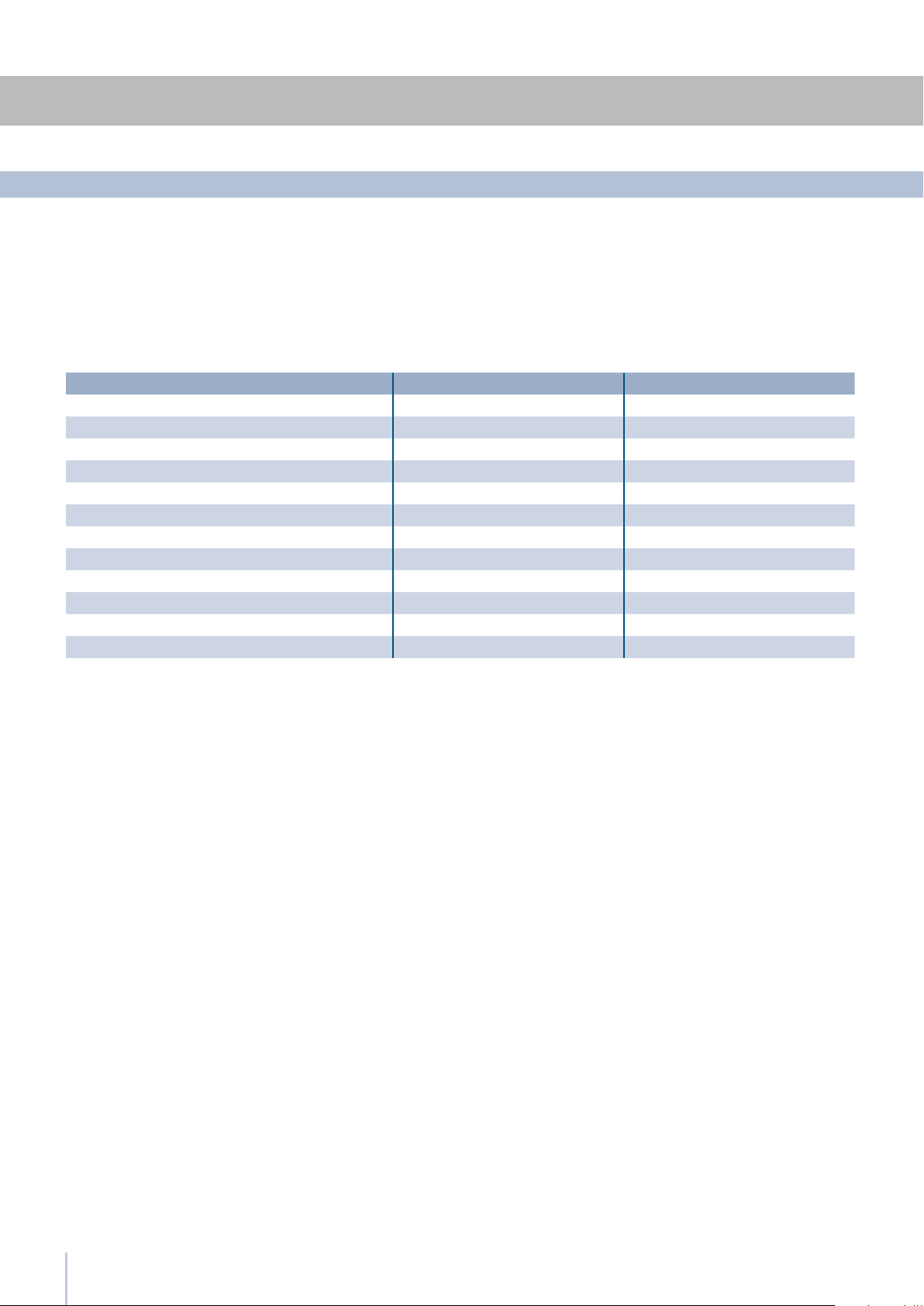
Time of conservation
Improvement of wine over time and its duration usually depends on
the character of the variety and its type.
The following chart shows the best period of conservation and ag-
ing for various types in ideal conservation conditions offered by your
appliance. However, you should always follow the instructions of the
winemaker, especially for ne wines.
TYPE OF WINE CONSERVATION TEMPERATURE TIME OF CONSERVATION
New wines (Vin Nouveau) from 12° to 14° C 6 months
Sweet sparkling wines from 8° to 10° C 1 year
Rosé from 10° to 14° C 1 year
Semi-sparkling wines from 10° to 12° C 1 - 2 years
Normal white wines from 10° to 14° C 1 - 2 years
Light red wines from 12° to 14° C 2 years
Dry sparkling wines from 8° to 10° C 2 years
Classic sparkling wines from 8° to 10° C 3 - 4 years
Barrique and Vigorous white wines from 8° to 12° C 3 - 5 years
Normal red wines from 14° to 16° C 3 - 5 years
Barrique and Vigorous red wines from 14° to 18° C 7 - 10 years
Straw wines or Liquorous wines from 16° to 18° C 10 - 15 years
Conservation of wines

19
10
Fresh foods Conservation area Time
Raw meats
Large cuts Cooler Compartment 4 days
Steaks, poultry and wild game Cooler Compartment 3 days
Ground meat Cooler Compartment 1-2 days
Carpaccio Cooler Compartment Immediately
Cooked meat
Boiled meat and roasted meat Refrigerator Compartment 2 days
Meat sauce Refrigerator Compartment 6 days
Raw and cooked sh Cooler Compartment 2 days
Soups and broths Refrigerator Compartment 2 days
Pasta Refrigerator Compartment 2 days
Opened cold cuts Refrigerator Compartment 3 days
Fresh cheeses Refrigerator Compartment 2-3 days
Well protected aged cheeses Refrigerator Compartment Several months
Eggs (fresh and unwashed) Refrigerator Compartment 15 days
Opened containers Refrigerator Compartment 2-3 days
Raw vegetables (in perforated bags) Refrigerator Compartment 3-6 days
Frozen foods Conservation area Time
Beef, veal, lamb and goat Freezer Compartment (steaks) 6-12 months
Beef, veal, lamb and goat Freezer Compartment (Meat with bone) 4-6 months
Ground beef Freezer Compartment 1-2 months
Pork Freezer Compartment (Without bone) 4-6 months
Pork Freezer Compartment (With bone) 2-3 months
Ground pork Freezer Compartment 1-2 months
Meat leftovers Freezer Compartment 2-3 months
Whole chicken and turkey Freezer Compartment 8-12 months
Goose, duck and pheasant Freezer Compartment 4-8 months
Fish Freezer Compartment 1-2 months
Crustaceans Freezer Compartment 2-3 months
Cooked foods Freezer Compartment 1-2 months
Vegetables Freezer Compartment 8-12 months
Fruit Freezer Compartment 6-12 months
Desserts and cakes Freezer Compartment 2-3 months
Recommended times for food conservation
11
11.1
11.3
11.2
20
Care and Cleaning
Care and Cleaning
Internal cleaning
To clean the parts in steel use a microfiber cloth and the sponge pro-
vided in the kit with the appliance.
Always use the cloth and sponge in the direction of the steel’s satin nish.
Every now and then, to make to steel shiny, wipe with a slightly damp
microfiber cloth.
Do not use the sponge on aluminium parts, such as the handles and
the profiles of the glass shelves.
You should use special care to keep free of obstructions the ventila-
tion openings in the appliance or in the cabinet that houses it.
Scrupulously follow the detailed directions that
can be found in the provided kit and never
use abrasive or metallic products which could
scratch and damage the satin nishing on the
appliance permanently.
Before performing any sort of cleaning, discon-
nect the appliance from the electrical power
supply. Make sure you do not damage the re-
frigerant circuit in any way.
Do not bring cold glass parts into contact with
boiling water.
Do not wash any parts of the refrigerator in a
dishwashing machine since this could damage
or irreparably deform the parts.
Clean the internal and removable parts by washing them with a so-
lution of lukewarm water, a small amount of dishwashing detergent
and a pinch of baking soda.
Rinse and dry right away.
Do not use mechanical devices or other methods to speed up de-
frosting.
Do not use water on the electrical parts, lights
and control panel.
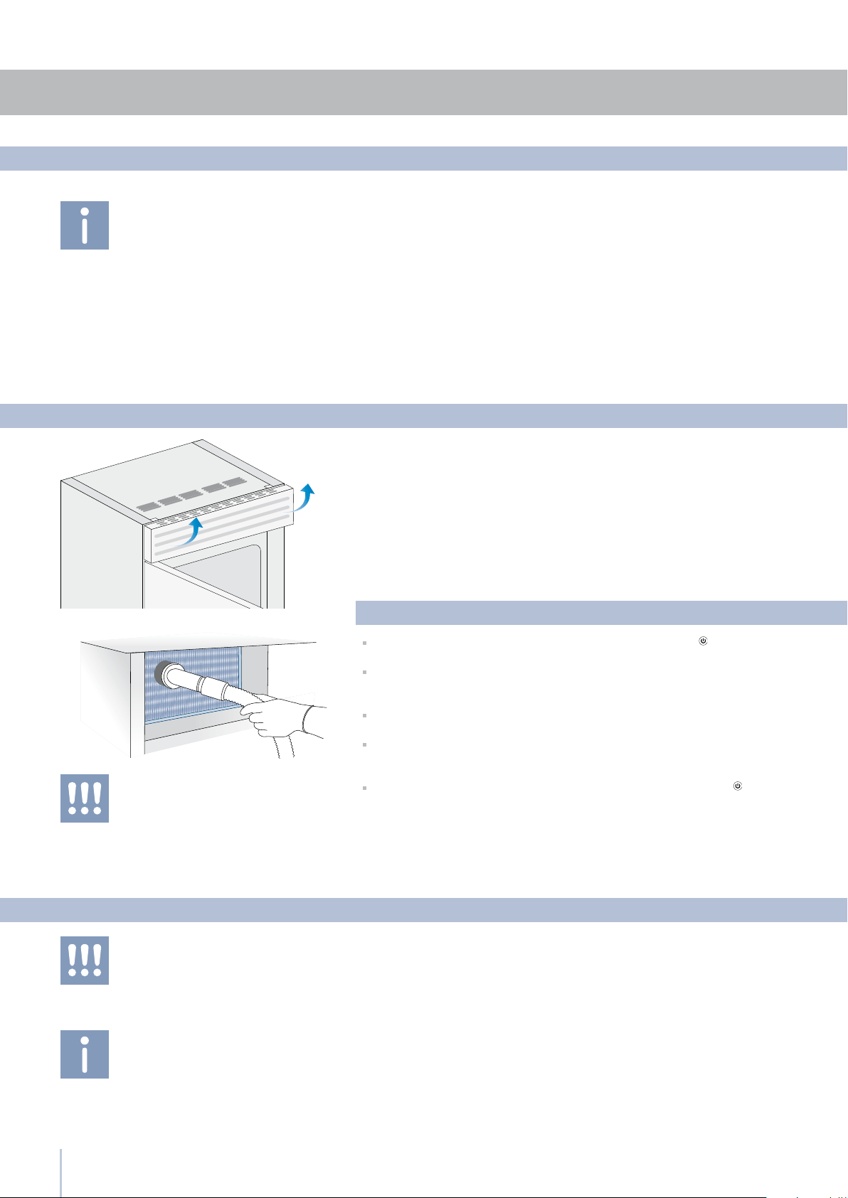
Condenser cleaning
The edges of the condenser are sharp, there-
fore use adequate protection for the hands and
arms when cleaning the condenser.
A ventilation grille is located either at the top of the appliance or at the
bottom according to the model type.
A foam lter is placed behind the grille to protect from dust the ventila-
tion system.
To clean it use a vacuum cleaner with a soft brush attachment at maxi-
mum power, sweeping it along the vent slits. In case of a signicant dust
build up, the ventilation grille can be removed to allow a more accu-
rate cleaning of the lter.
Take care also to check the condition of the nned condenser and
clean it from dust if needed.
Operate as follows:
Switch off the appliance by pressing the Unit button on the main
control panel for approx 3 seconds.
On models with ventilation at the base remove the grille at the bottom
and take it off. On models with ventilation at the top the grille (mag-
netically attached) lift as shown in the picture.
Thoroughly clean the grille and the foam lter, by means of a vacuum
cleaner and the soft brush attachment.
Wait approx 30 minutes, until the nned condenser cools down to
room temperature, then clean it thoroughly from any dust build up as
shown in the picture, taking care not to damage it.
Start up the appliance again, by pressing the Unit button on the
main control panel for approx 3 seconds.

21
12
12.1
Did you leave the doors open for a long period of time?
Do the doors close perfectly?
If the doors do not close perfectly, contact your installer.
Clean the appliance completely as indicated in this manual.
Hermetically cover all the food. Do not conserve food for prolonged
periods of time.
The appliance was designed to permit hermetic closure.
When the door is closed, a vacuum situation can occur: in this case it
is necessary to wait a few seconds until the pressure balances before
opening the door.
The Refrigerator or Freezer has frost or ice
Unpleasant odours inside the refrigerator
The doors are difcult to open
If you notice malfunctions in your appliance, use this guide before calling
Service. This guide may help you resolve the problem yourself or could
provide important information to ensure rapid and effective service.
A malfunction is usually indicated on the display.
Problems that cannot be resolved by the user are signalled through a
malfunction code.
Is the appliance connected to the electrical power supply?
Does electrical power arrive at the electrical socket?
Is the Unit key
activated?
Is the condenser clean?
Does the display show a malfunction code?
Is the temperature adjusted correctly?
Is the condenser clean?
Were the doors or drawers open for a long period of time?
Were large quantities of food recently inserted?
Bear in mind that during a very hot weather and with very high tem-
peratures in the room it is normal that the compressor remains in op-
eration for prolonged periods of time.
Were the doors or drawers open for a long period of time?
Were large quantities of food recently inserted?
Is the condenser clean?
Check that the doors are closed and that the food or containers do
not obstruct the perfect closure of the door.
It is normal to hear noise from the fans or compressors during the
defrost phase.
Noise could be louder depending on the position of the appliance
and the surrounding environment.
If the climate is very humid, the formation of condensation is normal.
Opening the door or drawers for prolonged periods of time can con-
tribute to the formation of condensation.
In any case, make sure that the doors are always perfectly closed.
Malfunction message
The appliance does not work
The internal temperatures are
higher than normal
The appliance remains in function for a long
time period
If you hear strange noises
Condensation forms both inside and out
Troubleshooting guide
Troubleshooting guide

12
12.2
22
Malfunction indications appearing on the display
Troubleshooting guide
Display message Malfunction description
Power Failure Prolonged interruption of electrical power
The appliance starts up again automatically and indicates the highest recorded temperatures
Door open Door open
this message appears few minutes from the door opening
Drawer open Drawer open
this message appears few minutes from the drawer opening
Cellar too warm Cellar (Wine Cellar) compartment too warm
See the troubleshooting guide
Cellar too cold Cellar (Wine Cellar) compartment too cold
Wait 12 hours. If the problem persists, contact Customer Care
Cantina too warm Cantina compartment too warm
See the troubleshooting guide
Cantina too cold Cantina compartment too warm
Wait 12 hours. If the problem persists, contact Customer Care
Fridge too warm MultiZone compartment (refrigerator mode) too warm
See the troubleshooting guide
Fridge too cold MultiZone compartment (refrigerator mode) too cold
Wait 12 hours. If the problem persists, contact Customer Care
Cooler too warm MultiZone compartment (cooler mode) too warm
See the troubleshooting guide
Cooler too cold MultiZone compartment (cooler mode) too cold
Wait 12 hours. If the problem persists, contact Customer Care
Freezer too warm MultiZone compartment (freezer mode) too warm
See the troubleshooting guide
Freezer too cold MultiZone compartment (freezer mode) too cold
Wait 12 hours. If the problem persists, contact Customer Care
Error Code... Functional problems
call Customer Care who may help you to salve the problem or put you in contact with the
nearest Service Agent
FUNCTIONS
23
13
13.1
Menu Map
Functions
Shopping MultiZone
Shopping ON/OFF
Vacation ON/OFF
Shopping MultiZone Off
Vacation MultiZone Off
Bottle Cooler Off
Bottle Cooler On
Set Cooling Time
Sabbath Mode Off
Shopping MultiZone On
Vacation MultiZone On
Shopping Time
Vacation Time
Cooler ON/OFF
Sabbath Mode On
Set Hours: 1
Set Days: 1
Set Time: 20 min
Vacation MultiZone
Bottle Cooler
Set Sabbath Mode
FUNCTIONS
24
13
13.2
Settings
Menu Map
SETTINGS
Multiz Options
Default Setting
Freezer
Fresco
Enter to Conrm
DATE: 01-01-2009 On
TIME: 01:01 On
Set: 24
Set Date
Set Time
italiano
français
english
ON
ON
Set °C
DATE: 01-01-2009 Off
TIME: 01:01 Off
Set: 12
Fridge
Show Date
Set View
Show Time
deutsch
español
OFF
OFF
Set °F
DATE: 01-01-2009
TIME: 01:01
Date
Time
Language
Child Lock
Showroom Mode
Set °C/°F

22-12-2014

SMEG W EN

INSTALLATION GUIDE

IMPORTANT
Dimensions in parentheses are in inches.
Weights in parentheses are in pounds.
Temperatures in parentheses are in Fahrenheit degrees.

1
1
2
4
5
6
7
8
11
12
14
15
16
17
19
20
22
23
26
27
29
30
Installation Guide
Index
Page
Important Instructions
Important safety instructions
Children safety
Technical requirements
Appliance features and installation requirements
Installation niche features: Integrated
Installation niche features: Free-Standing
Preparing to install
Transport to installation site and unpacking
Electrical and Water connection
Levelling
Panels mounting
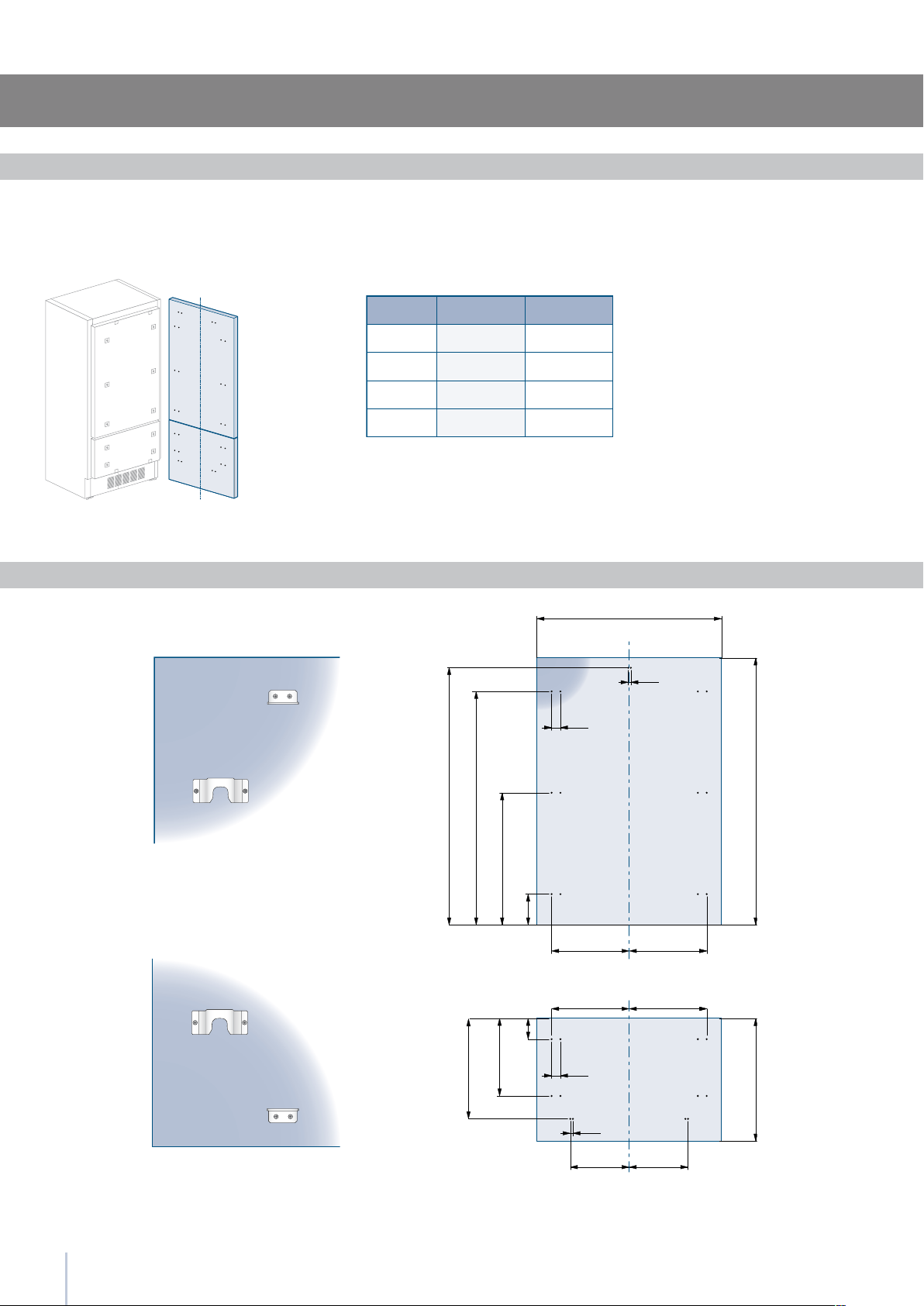
Decorative door and Bottom-Drawer panels layout
Decorative panels layout for Fridge with one Bottom-Drawer
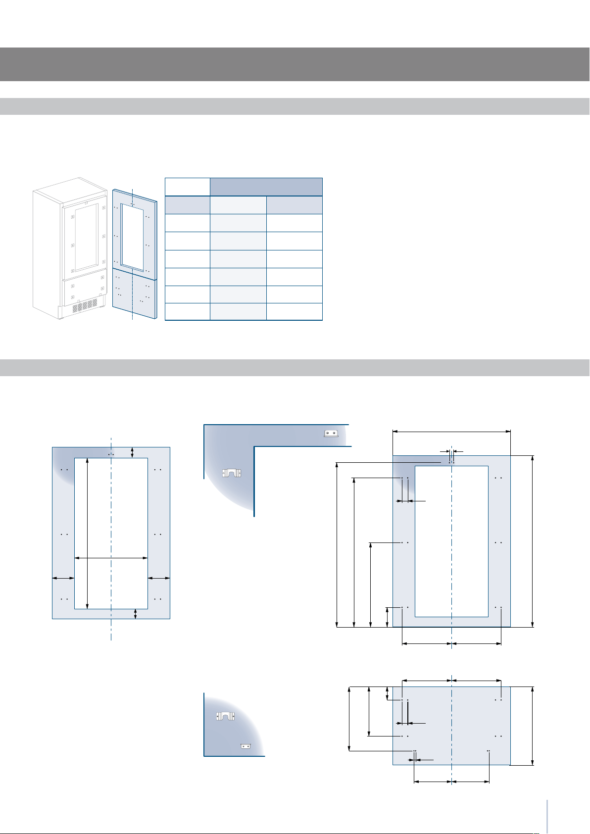
Decorative panels layout for Fridge with Glass door and one Bottom-Drawer
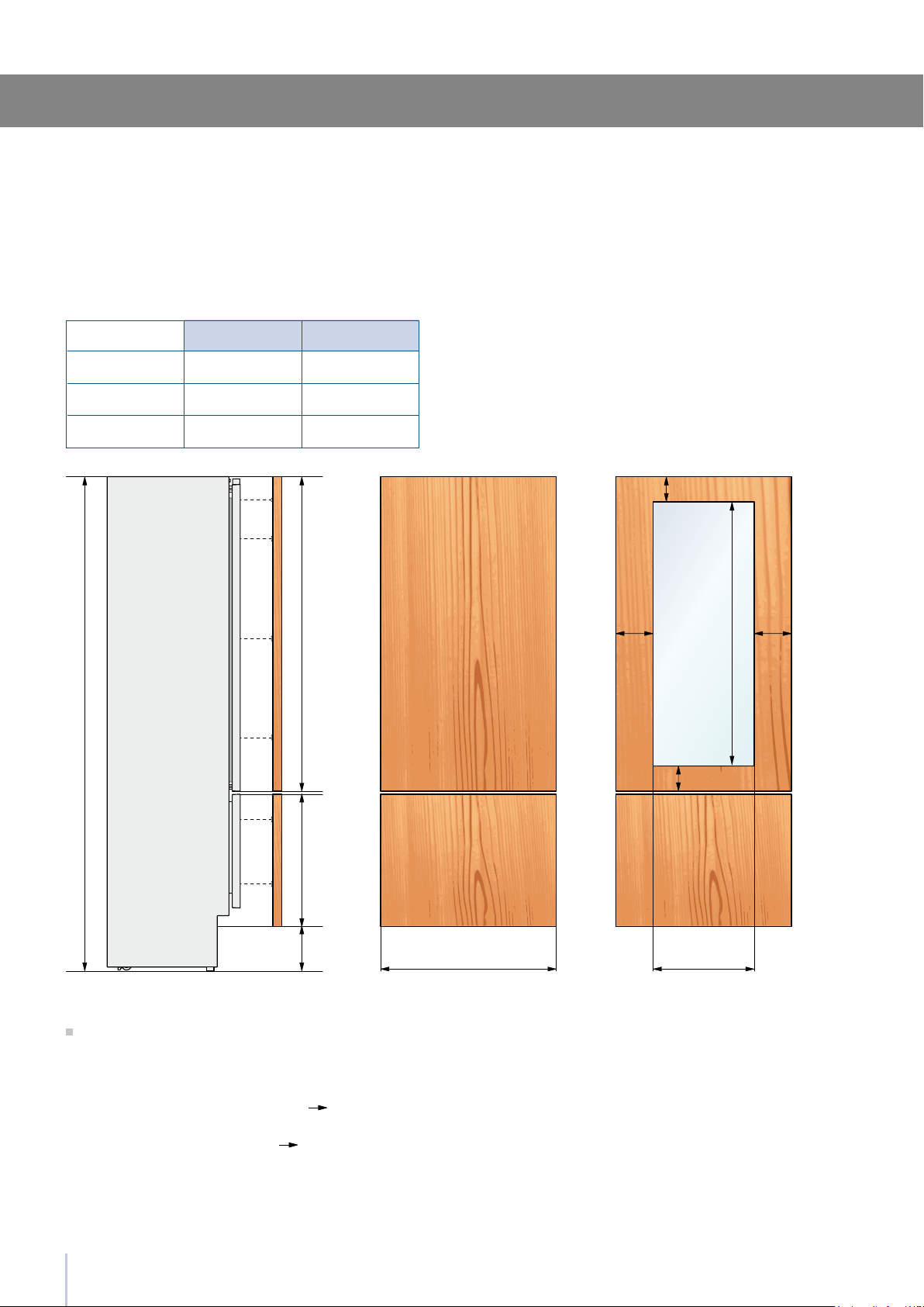
Panels Dimensions One Bottom - Drawer (models)
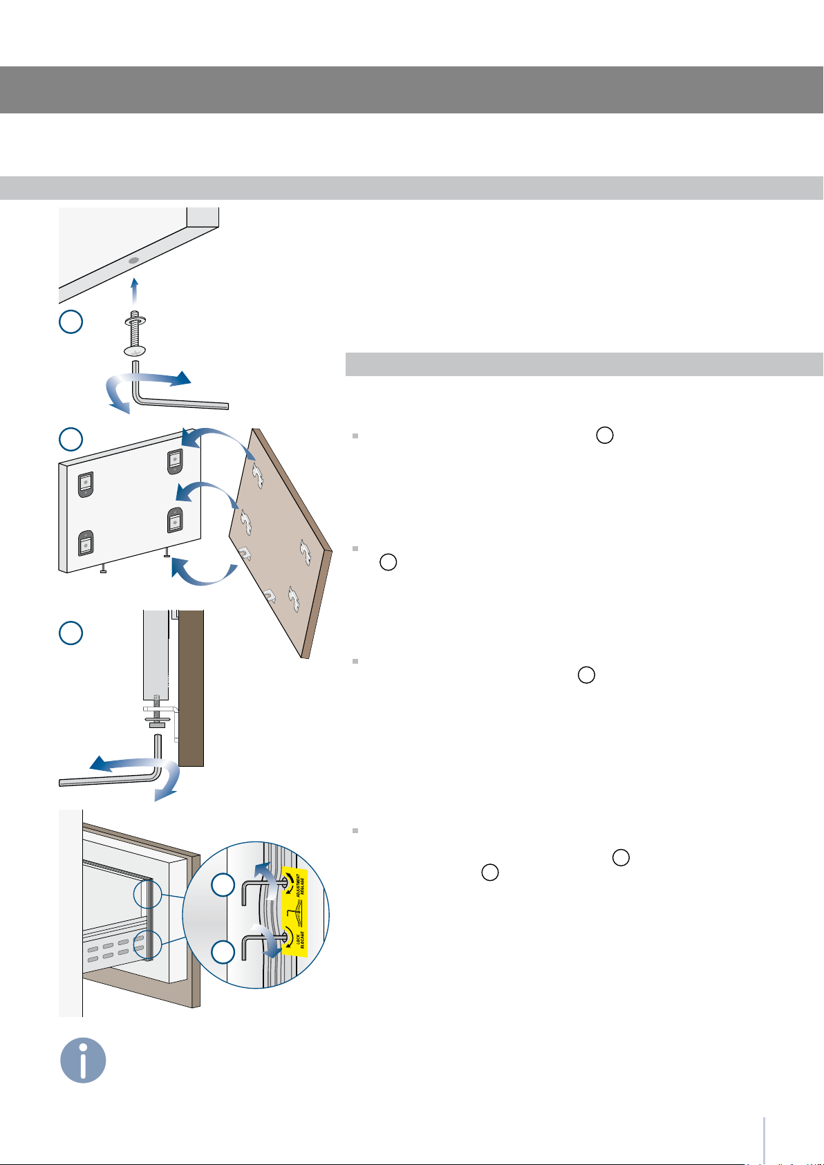
Mounting panels to the door and the drawer
Installation
Built-in installation of single appliance
Built-in installation of two or more appliances
Free-standing installation two or more appliances
Completing the installation
Anti-tipping safety assembly
Mounting the handles on stainless front
Ventilation
Post installation control
Start Up

2
3
Installation Guide
Symbols used in the Guide
Important safely instruction
Children safety
If this appliance is replacing an existing appliance which must be
removed or disposed of, make sure that it does not become a
dangerous trap for children by cutting its power supply cable and
rendering it impossible to close the door.
Use the same caution at the end of the lifespan of the new ap-
pliance.
Note
Tips for the correct use of the
appliance
Warning
directions to prevent injury
Important
Directions to avoid appliance
damage

4
Appliance features and installation requirements
60 Series w: 599 mm (23 5/8”)/ h: 2050 mm (80 3/4”)/ d: 610 mm (24”)
75 Series w: 749 mm (29 1/2”)/ h: 2050 mm (80 3/4”)/ d: 610 mm (24”)
90 Series w: 899 mm (35 3/8”)/ h: 2050 mm (80 3/4”)/ d: 610 mm (24”)
60 Series w: 586 mm (23”)/ h: 2120 mm (84”)/ d: 635 mm (25”)
75 Series w: 736 mm (29”)/ h: 2120 mm (84”)/ d: 635 mm (25”)
90 Series w: 8869 mm (34 7/8”)/ h: 2120 mm (84”)/ d: 635 mm (25”)
60 Series w: 650 mm (25 5/8”) / h: 2210 mm (87”)/ d: 800 mm (31 1/2”)
75 Series w: 800 mm (31 1/2”)/ h: 2210 mm (87”)/ d: 800 mm (31 1/2”)
90 Series w: 950 mm (37 3/8”) / h: 2210 mm (87”)/ d: 800 mm (31 1/2”)
60 Series w: 650 mm (25 5/8”) / h: 2260 mm (89”) / d: 800 mm (31 1/2”)
75 Series w: 800 mm (31 1/2”) / h: 2260 mm (89”) / d: 800 mm (31 1/2”)
90 Series w: 950 mm (37 3/8”) / h: 2260 mm (89”) / d: 800 mm (31 1/2”)
60 Series up to 230 kg (507 lb)
75 Series up to 275 kg (606 lb)
90 Series up to 295 kg (650 lb)
Europe Version: AC 220-240V 50 Hz / North America Version: 110V 60Hz
Europe Version: Schuko 16 A plug / North America Version: 15 A
from 0.1 MPa to 0.5 MPa (1 Bar - 5 Bar)
3/4” female attachment
Customized panels mounting Kit
Anti-tipping Kit (B04000200)
Lateral connecting kit (KCLIT/KCLIH)
4 mm (1/8”) allen wrench
Phillips head screwdriver
wood and percussion drill
2.5 mm (1/8”) bit for wood
8 mm (3/8”) bit for walls
17 mm (3/4”) wrench
Appliance dimensions
Integrated
Appliance dimensions
Free-Standing
Appliance dimensions
Integrated
Appliance dimensions
Free-Standing
Weight with packaging
Voltage
Power supply cable
Potable water supply pressure
Water supply tube
Provided installation accessories
Additional equipment necessary
5
min 2064 (81 )
A A
E W E W
140 (5 ) 140 (5 )
100 (4”)
100 (4”)
RI96: 900 (35 )
WI66: 600 (23 )
RI76: 750 (29 )
A
E
W
2064 mm (81 1/4”)
RI96: 900 mm (35 1/2”)
RI76: 750 mm (29 5/8”)
WI66: 600 mm (23 3/4”)
RI96: 1470 mm (57 7/8”)
RI76: 1320 mm (52”)
WI66: 1170 mm (46”)
105°
RI96: 899 mm (35 3/8”)
RI76: 749 mm (29 1/2”)
WI66: 599 mm (23 5/8”)
2050 mm (80 3/4”)
+ 25 mm (1”)
610 mm (24”)
992 (39”)
RI96: 1470 (57 )
RI76: 1320 (52”)
WI66: 1170 (46”)
RI96: 160 (6 )
RI76: 125 (5”)
WI66: 90 (3 )
560 (22”)
610 (24”)
RI96: 899 (35 ”)
RI76: 749 (29 ”)
WI66: 599 (23 ”)
10 (”)
105°
90°
610 (24”)
560 (22”)
610 (24”)
560 (22”)
1293 (50 )
474 (18 )
231 (9
) +
25 (1”)
500 (19 ) 500 (19 )
248 (9
)
+ 25 (1”)
231 (9
) +
25 (1”)
248 (9
)
+ 25 (1”)
20 ()
15 ()
15 ()
20 ()10 (”)
721 (28 ”) +25 (1”)
2050 (80 ”) +25 (1”)
2050 (80 ”) +25 (1”)
846 (33 ¼”) +25 (1”)
1168(46”)
330 (13”)
259 (10
)
1T/0T 0H
Installation Guide
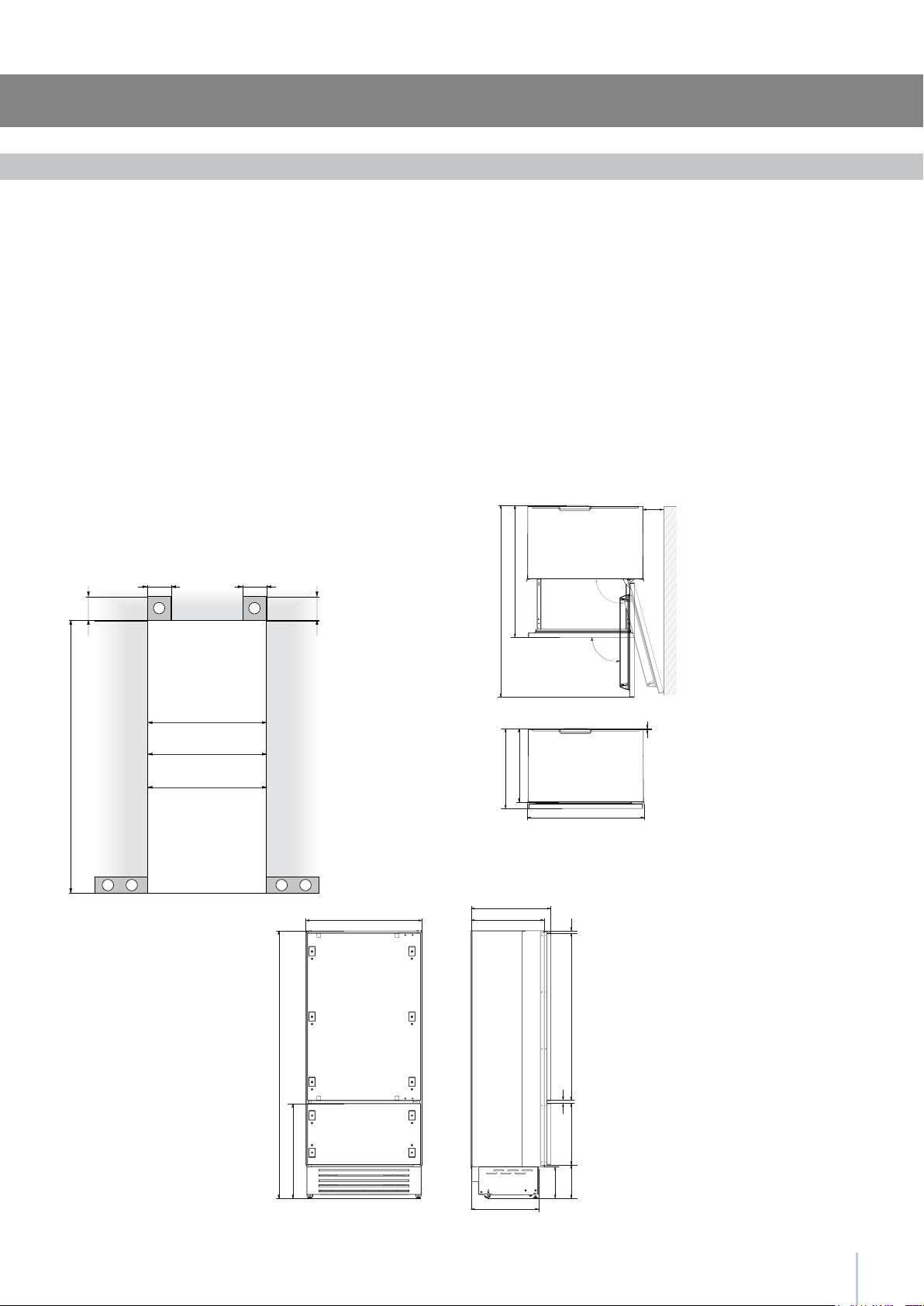
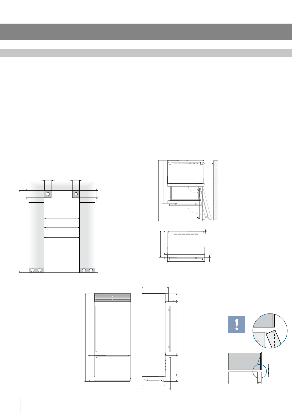
Installation niche features: Integrated Series
area to be left clear for the anti-tipping brackets
area to be left clear for the power supply cable
and water supply hose
Minimum Niche Height
Minimum Niche Width
Door Swing Clearance
Door Opening Angle
Width
Height
Depth with door (without panel)
Important: A 90° door opening
is sufcient to allow opening
and full extraction of the inner
drawers, even if the appliance
is installed directly adjacent to
a wall. Should an opening at
105° be desired, then the ap-
pliance should be positioned
at the distance from the wall
described in gure.
6
min 10 ()
A A
min 2134 (84”)
140 (5 ½”) 140 (5 ½”)
100 (4”)
100 (4”)
E W E W
RF396: 890 (35”)
WF366: 590 (23 ¼”)
RF376: 740 (29 ½”)
A
E
W
2134 mm (84”)
RF396: 890 mm (35”)
RF376: 740 mm (29 1/2”)
WF366: 590 mm (23 1/4”)
RF396: 1470 mm (57 7/8”)
RF376: 1320 mm (52”)
WF366: 1170 mm (46”)
105°
RF396: 886 mm (34 7/8”)
RF376: 736 mm (29”)
WF366: 586 mm (23”)
2120 mm (83 1/2”)
+ 25 mm (1”)
635 mm (25 ”)
1016 (40”)
RF396: 1470 (57 )
RF376: 1320 (52”)
WF366: 1170 (46”)
RF396: 230 (9)
RF376: 195 (7 )
WF366: 160 (6 )
560 (22”)
75 (3”)
RF396: 886 (34 ”)
RF376: 736 (29”)
WF366: 586 (23”)
10 (”)60 (2 ”)
105°
90°
635 (25”)
560 (22”)
2120 (83 ½”) +25 (1”)
613 (24 )+25 (1”)
635 (25)
128 (5) + 25 (1”)
695 (27 )
485 (19 )
1296 (50”)
195 (7 )
8 ()
8 ()
area to be left clear for the anti-tipping brackets
area to be left clear for the power supply cable
and water supply hose
Minimum Niche Height
Minimum Niche Width
Door Swing Clearance
Door Opening Angle
Width
Height
Depth with door
Installation niche features: Free-Standing Series
Important: A 90° door opening
is sufcient to allow opening
and full extraction of the inner
drawers, even if the appliance
is installed directly adjacent to
a wall. Should an opening at
105° be desired, then the ap-
pliance should be positioned
at the distance from the wall
described in gure.
7
1
4
1
2
3
Installation Guide
The appliance is very heavy.
Take maximum care during handling to
avoid injury.
The appliance should always be transport-
ed in an erect position.
Avoid at all costs leaning it on its front side.
Preparing the installation
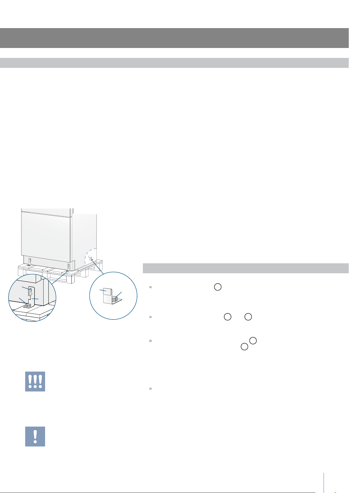
Transport to installation site
and unpacking
Since this is a large and heavy appliance, before transporting the ap-
pliance, check the access to the location where it will be installed
(door size, manoeuvring space in stairwells, etc.).
The appliance is attached to the base of the packaging (pallet) through
four bolts which can be removed using a 17 mm (3/4”) wrench.
It is recommended to use a manual transporting device to move the
appliance to the installation site, and only at this point to remove the
base of the packaging.
The appliance should always be transported in an erect position.
If this is not possible, transport the appliance laying on its rear side.
Once at the installation site, the appliance, which is equipped with four
wheels, can be taken off the pallet and positioned in the installation
area.
Operate as follows:
Take off the four bolts
1
securing the appliance to the pallet by
means of a 17 mm (3/4”) open spanner.
Remove the xing brackets
3
and
4
.
To remove the front xing bracket
3
, unscrew for one or two
turns the rear wheel adjusting bolt
2
by means of a 13 mm (1/2”)
box spanner, avoiding too much strenght while thightening the
nut, which could damage the leveling feet adjusting system.
From the back of the unit and by means of a suitable, high duty hand
trolley, take off the appliance and place it on the oor.
Be very careful to avoid any damage to oors. Delicate oors should be
protected with plywood, hard cardboard or similar material panels.
Series: All
EW
E W
EW
E W
8
E
W
E
W
Electrical and Water connection
A Schuko 16 A socket with an efcient grounding should be made
available for the electrical mains connection, as well as an omnipolar
switch which can easily be reached when the appliance is installed.
To connect to the water supply system (for appliances equipped with
ice makers) a tap with a male 3/4” connection should be provided,
which must also be easily accessible once the appliance is installed.
The appliance is provided with a water supply hose and seal kit which
is suitable for high water pressure and complies the Food Regulations.
The water lter cartridge, which is provided with the appliance, should
be installed according to the accompanying instructions.
Use only the new hose and the new gaskets which are supplied with
the appliance. Discard any hose and gasket which may have already
been installed.
Electrical cord length: 2,0 mt (78 3/4”)
Water connection line length: 2,5 mt (98 3/8”)
Series: All
Do not use extension cords or adapters.
Once the appliance has been connected to
the water system, turn the Ice Maker off (touch
the button
on control panel to switch it off)
before the main water is shut off.
The appliance should be connected only to
a drinkable water supply system.
The Built-in lter cannot make it safe to drink
any water which is not suitable for human
consumption.
Energy: Alternatives and Home Automation
If energy is supplied through an alternative energy power source
(solar, geothermal, etc..) or if home automation systems are installed,
it is necessary to install the Alternative Energy Kit to integrate the unit
into the power grid.
Electrical and water supply behind the unit
Integrated and Classic Series StandPlus and Free-Standing Series
2
1
9
Installation Guide
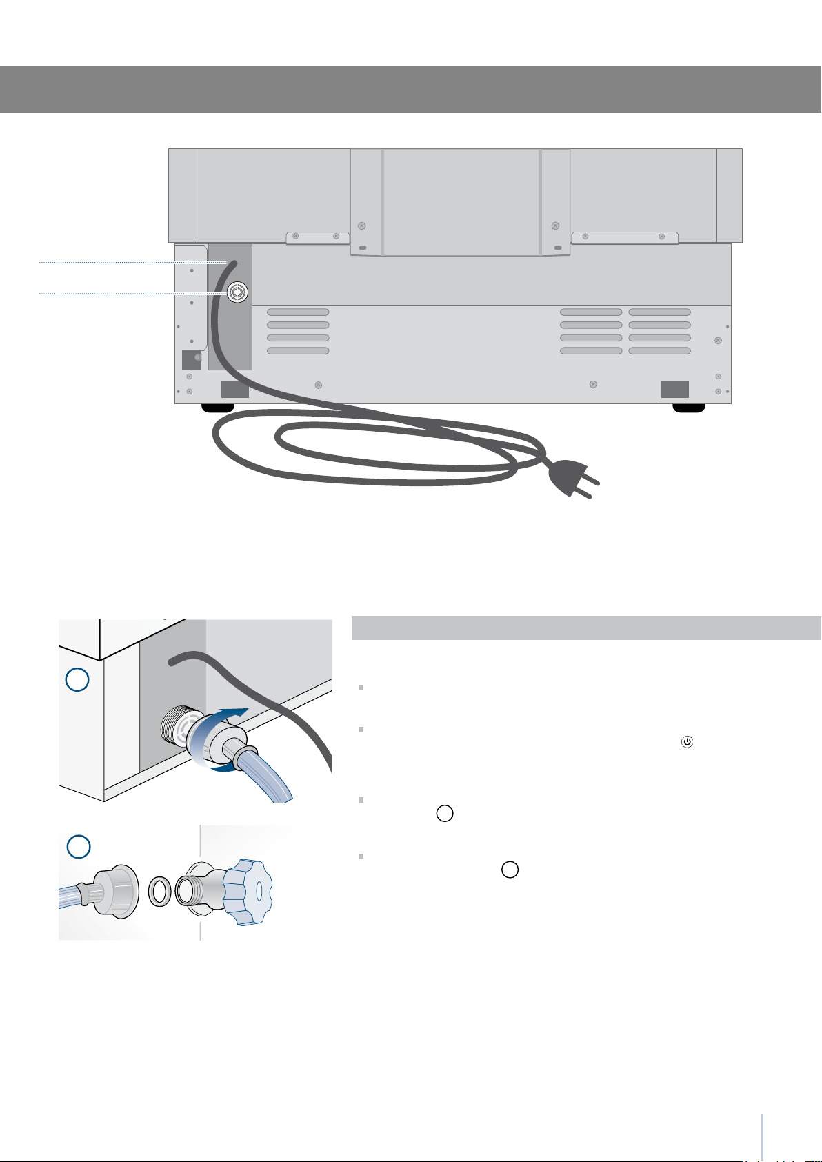
Back of appliance
Water connection
Electrical connection
Series: Integrated
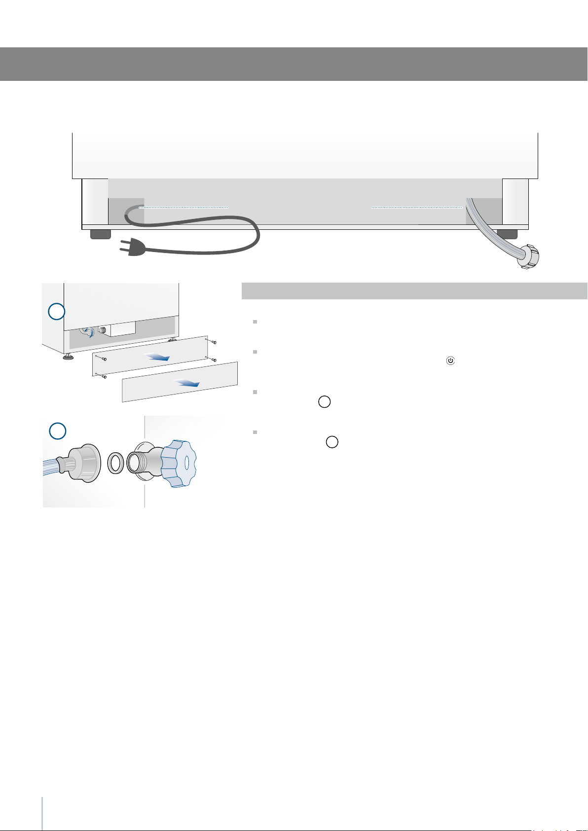
Operate as follows:
Unwind the electric cable and connect it directly to the wall socket.
Make sure the appliance is in the Stand-by condition and that all
lights are off; should it be not so press the Unit button
to switch it
off.
Fit one end of the water hose onto the connector at the appli-
ance’s back
1
.
Fit the other end of the hose to the water tap, use the gaskets pro-
vided in the Owner’s Kit
2
.
StandPlus and Free-Standing Series
2
1
10
Series:Free-Standing
Operate as follows:
Unwind the electric cable and connect it directly to the wall socket.
Make sure the appliance is in the Stand-by condition and that all ights
are off; should it be not so press the Unit button to switch it off.
Connect the water line to the threaded connection at the base of the
unit, as in gure
1
.
Fit the other end of the hose to the water tap, use the gaskets provided
in the Owner’s Kit
2
.
Back of appliance
Front of appliance
Water connectionElectrical connection
11
1
2
1
2
Installation Guide
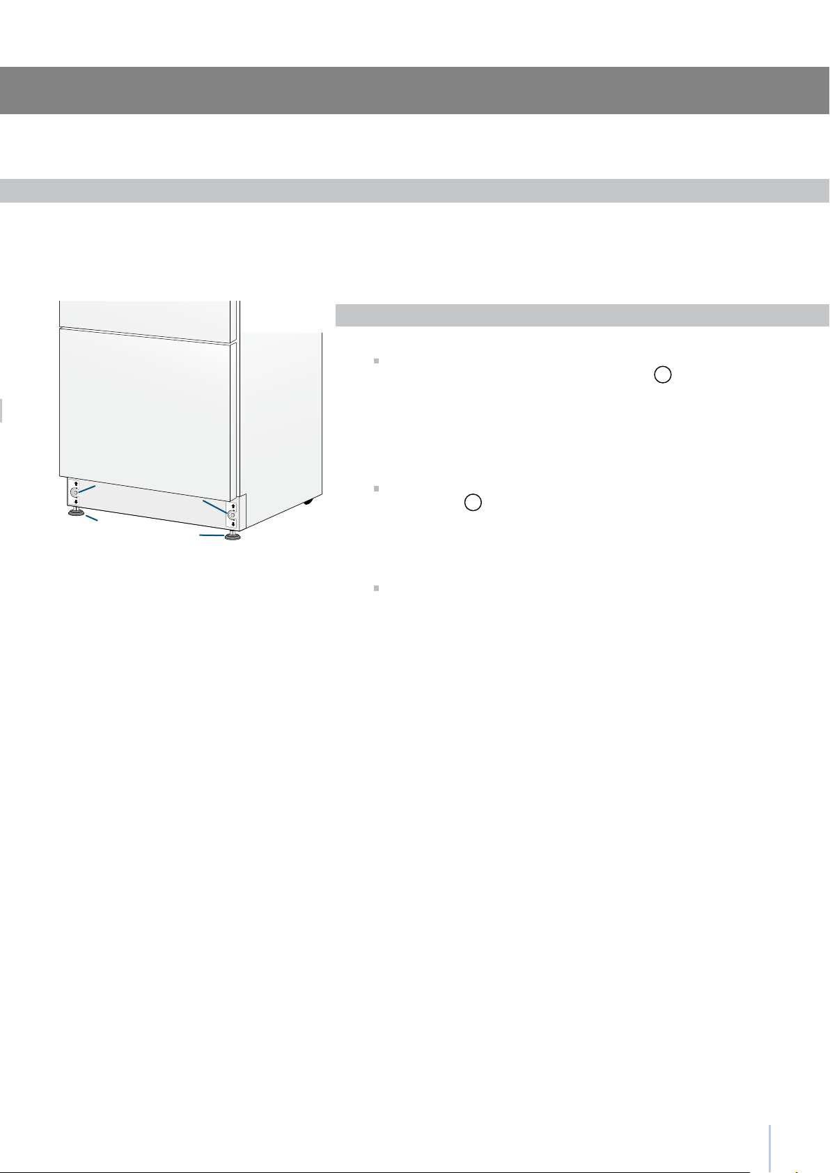
Adjust the appliance level by means of the front levelling feet
and the rear adjustable wheels.
Operate as follows:
After removing the bottom plinth or grille (it is kept in position by
magnets), adjust the height of the levelling feet
1
by means of a 17
mm (3/4”) open spanner.
Then adjust the height of the rear wheels by turning the front
adjusting bolts
2
clockwise or anticlockwise as it may be required.
Remount the bottom plinth or grille.
Levelling
Series: All
12
1
2
3
Decorative door and bottom-drawer panels layout
The dimensions of the panels are indicated in the table and draw-
ings on pages 18-21.
Nevertheless, according to the requirements for aligning with other
kitchen structures, the door panel can be higher than the upper
edge of the refrigerator door, and the drawer panel can be lower
than the edge of the drawer.
The panels must be mounted using special braces which attach
to adjustable devices provided on the door and drawer and with
brackets that anchor and adjust the panel’s vertical direction.
Braces, brackets and fixing screws are provided with the appliance
and must be applied to the panel as indicated.
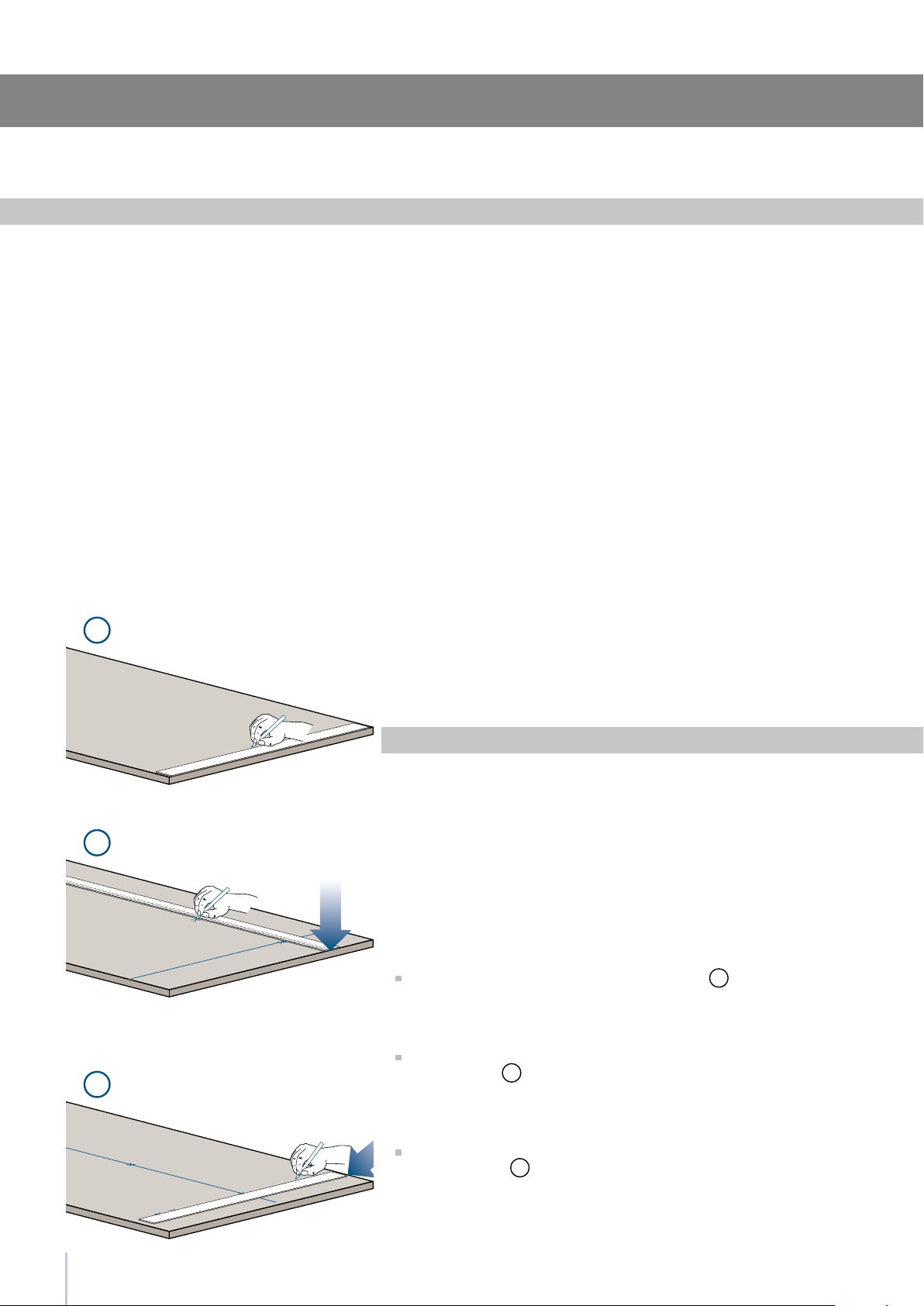
Operate as follows:
To prepare the panels to be mounted on the appliance, follow
these steps, working on the back of the panel.
Door Panel
Trace, a line dividing the panel width in half
1
.
Starting form the Bottom edge of the panel, mark the positioning
of the brackets
2
.
Following the corresponding table, mark the external and then
the internal hole
3
.
Series: Integrated
13
7
8
4
5
Installation Guide
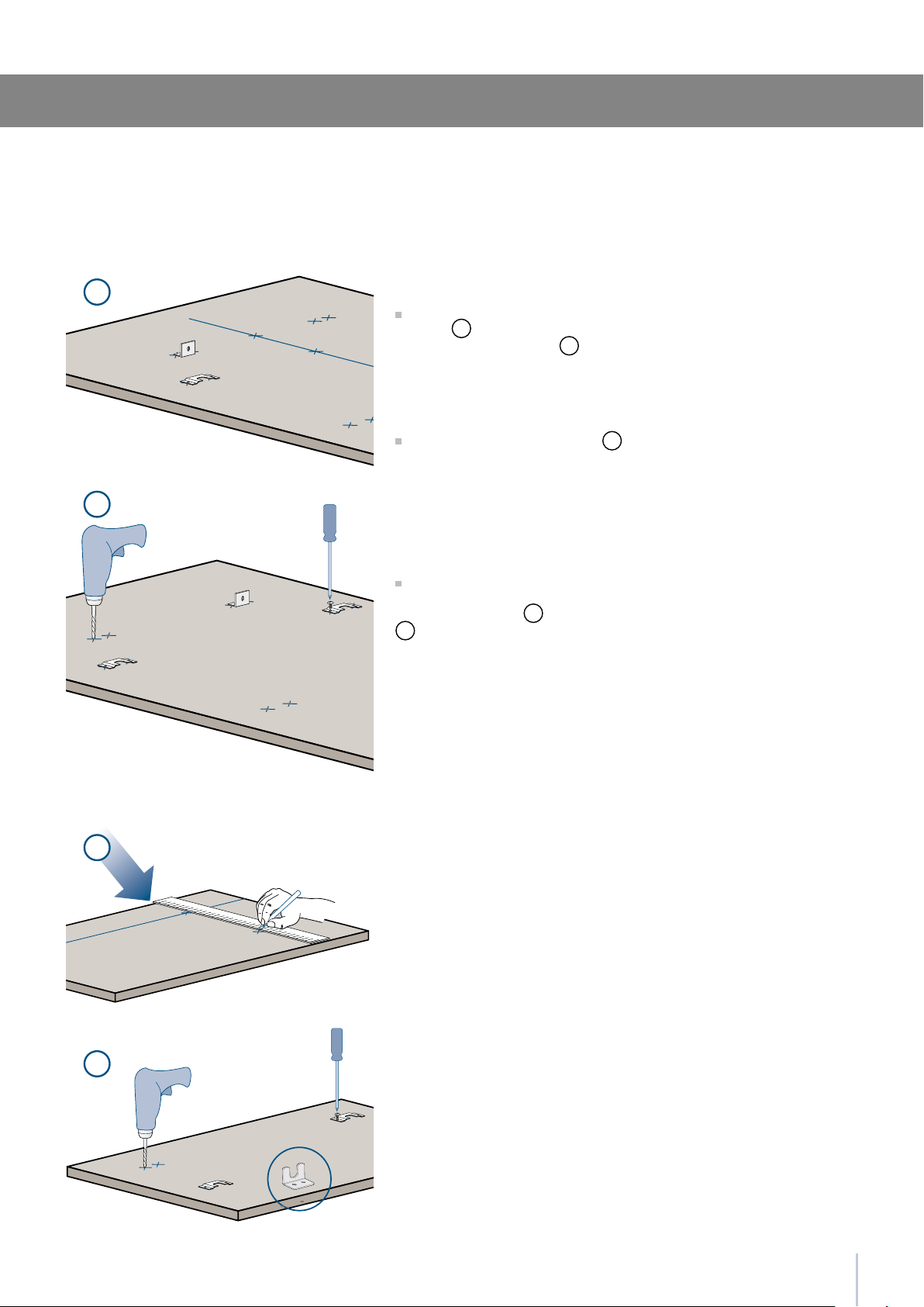
Position the brackets on each set of marks to make sure they are
aligned
4
, then drill holes through the panel (pay close attention
to the panel’s thickness)
5
.
Screw the brackets in place
6
.
Drawer Panel
When preparing the Drawer Panel, follow the same instructions as
per the door panel, but make sure measurements are taken starting
from the top edge
7
. The support bracket faces the opposite way
8
(note imgs 4 and 8).
Series: Integrated
A
897 (35
)
418 (16
)
418 (16
)
B
C
354.5 (14”)
747 (29
)
343 (13
)
343 (13
)
279.5 (11”)F / G
14
B C
B C
A
F G
13 ()
13 (
)
34 (1
)
34 (1
)
1285 (50 )
1163 (45
)
660 (26”)
157 (6
)
min 1320 (52”)max 635 (25”)
507,5 (20”)
382 (15
)
100 (4”)
Decorative panels layout for Fridge with one Bottom-Drawer
Series 90
Series 75
Holes positions
Series: Integrated
15
H I
D E
A
F G
1286 (50 )
6,5 ()
6,5 (
)
1152,5 (45 )
650,5 (13
)
148,5 (5
)
13 ()
34 (1
)
34 (1
)
min 1320 (52”)
max 635 (25”)
507,5 (20”)
382 (15
)
100 (4”)
60: 327 (12 )
1075 (42 )
min 130 (5 )
115 (4
)
135 (5
)
135 (5
)
A
H
I
F / G
597 (23 ) 597 (23 )
203.5(8”) 203.5(8”)
276.5 (10
)
270.5 (10
)230.5 (9
)
236.5 (9
)
276.5 (10
)
276.5 (10
)268 (10
)
268 (10
)
D
E
Installation Guide
Decorative panels layout for Fridge with glass door and one Bottom-Drawer
Holes positionsDoor window dimensions
Series: Integrated
Series 60
Hinge Left
Hinge Right
16
899
749
599
897 (35 1/4”)
-
747 (29 3/8”) -
597 (23 3/4”) 327 (12 7/8”)
B
115 (4 )
min 130 (5 )
135
(5 )
135
(5 )
1075 (42 )
2050 (80 )
min 540 (21 )
max 635 (25”)
187 (7 )
A
3 ()
1320 (52”)
Examples of calculation
Integration in a kitchen column of total height 2160 mm (85”) and 150 mm (6”) kickplate.
(NOTE: In calculating the adjustment foot is considered to 0).
Drawer Calculation:
Kickplate 187 - 150 = 37 mm (1 1/2”)
540 + 37 = 577 mm (22 3/4”)
Upper Panel Calculation:
2160 - 2050 = 110 mm (4 3/8”)
1320 + 110 = 1430 mm (56 1/4”)
Total Height Calculation:
150 + 577 + 3 + 1430 = 2160 mm (85”)
Panels Dimensions One Bottom - Drawer
Door/Drawer Width
A
Series
Door Cutout Width
B
Series: Integrated
Panels with width ranging between 18 mm (3/4 in) and 28 mm (1 1/8 in).
Door panels with weight max of 23 kg (51 lb) and drawer panels with weight max of 11kg (25 lb)
17
1
2
3
4
5
Installation Guide
Mounting panels to the door and the drawer
Once all brackets and small brackets have been applied to the pan-
els, you can begin installing the bottom drawer.
Operate as follows:
Partially tighten the screw to the xing
1
.
Hook the bottom drawer panel starting from the xings on the bot-
tom
2
.
It is now possible to align panels to adjacent cabinets in height
using the lower alignment brackets,
3
tightening or untightening
the screws into position as needed. With the screw slighty tightened,
move the panel sideways to align it to the other panels on the unit or
other adjacent structures.
Depth alignment: working from the inside of the drawer, after lift-
ing up the magnetic seal, adjust the panel position so it is closer to or
further away from the door using the holes
4
and then secure the
panel using the holes
5
.
Series: Integrated
Once the front panel has been adjusted,
check that the gasket has been
repositioned correctly to assure the
door/drawer are closing correctly and
avoid operational errors of the unit.
18
6
8
9
7
10
11
Hook the panel to the fixing devices starting from the top aligning
bracket
6
.
At this point, alignment between the panel and adjacent cabi-
nets can be adjusted using the alignment bracket and small brack-
ets
7
and
8
.
Vertical alignment: tighten or loosen the screw in the brackets to
raise or lower the panel
9
.
Depth alignment: working from the inside of the door, after lift-
ing up the magnetic seal, adjust the panel position so it is closer to
or further away from the door using the holes
10
and then fix the
panel in position using the holes
11
.
Series: Integrated
Once the front panel has been adjusted,
check that the gasket has been
repositioned correctly to assure the
door/drawer are closing correctly and
avoid operational errors of the unit.
19
2
3
1
B
A
6,5 () 6,5 ()
20 ()
20 ()
22 ()
22 ()
22 () 22 ()
Installation Guide
Appliance Wall
or
furniture
Wall
or
furniture
Installation
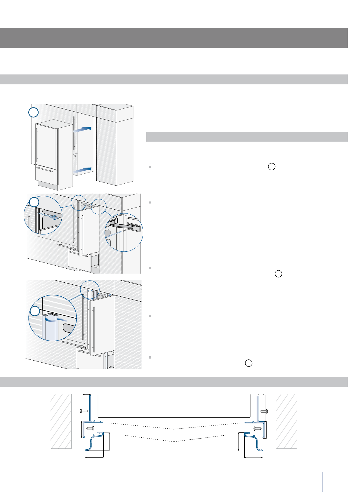
For a built-in installation, to close gaps between the appliance and
the adjacent cabinets, special side proles and aluminum covering
frames are provided.
Operate as follows:
Push the appliance into the installation niche
1
.
If the unit is to be installed inside a niche or within an enclosed
structure, it is necessary to design a ventilation shaft at the back of
the niche to assure proper ventilation at the back of the unit. A 5 mm
gap is sufcient to prevent overheating. Always mount front panels on
door and drawer before pushing the unit into its nal position inside the
niche or structure.
Secure the appliance to the adjacent cabinets by xing to these the
side proles previously mounted on the appliance
2
.
To make this operation easier keep the door and the drawer open.
Check the levelling of the appliance, adjusting its feet and wheels
to correct it.
Mount the proles the covering frames: rst insert them laterally and
then push rmly until a “click” is heard
3
.
A Connecting element B Alluminium frame
Built-in installation single appliance
Side proles mounting
Series: Integrated
20
1
2
3
4
5
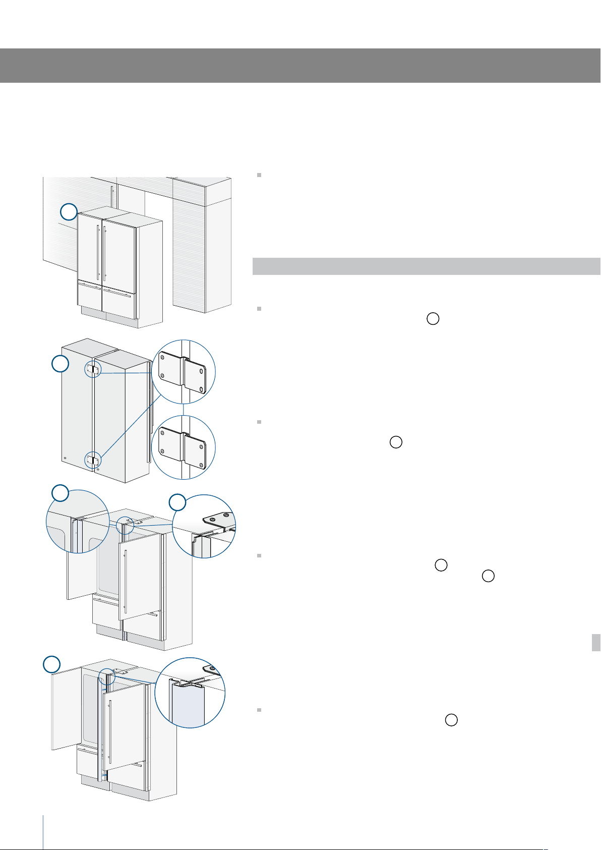
Required accessories to be ordered separately:
Central connection Kit
Special side proles and aluminum covering frames are provided for
closing gaps between the appliance and the adjacent cabinets.
Operate as follows:
Position the appliances in front of the installation area, leaving
enugh space to operate at their back
1
.
Move at the back of the appliances to mount the joining brackets:
x on side of the top and lower brackets to one of the appliances
and subsequently to the other
2
.
Place the two units side by side and join them at the front attaching
the two pro les with the supplied screws
3
.
Attach the bracket on top of the units as per gure
4
.
Finish off by mounting the central cover frame onto the central
profiles, by pushing it until a click is heard
5
.
Built-in installation two or more appliances
Series: Integrated
21
6
8
7
E
D
A
B
A
B
D
6,5 () 6,5 ()
20 ()
20 ()
22 ()
22 ()
22 () 22 ()
6,5 ()6,5 ()
18 ()
44,4 (1 )
18 ()
C
13 ()
Installation Guide
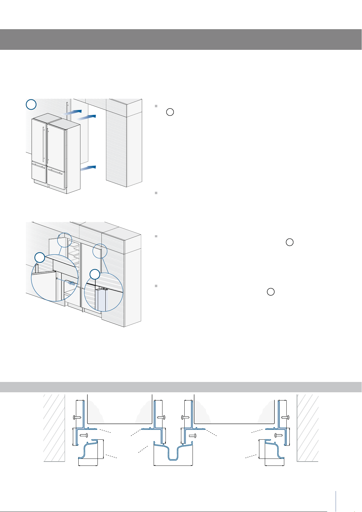
Once completed the previous steps, push the units in their nal posi-
tion
6
.
If the units are to be installed inside a niche or within an enclosed
structure, it is necessary to design a ventilation shaft at the back of
the niche to assure proper ventilation at the back of the unit. A 5 mm
gap is sufcient to prevent overheating. Always mount front panels on
door and drawer before pushing the unit into its nal position inside the
niche or structure.
Check the levelling of the appliance, adjusting its feet and wheels
to correct it.
Secure the appliance to the adjacent cabinets by xing to these the
side proles previously mounted on the appliance
7
.
To make this operation easier keep the door and the drawer open.
Mount the covering frames onto the proles, rst insert them laterally
and then push rmly until a “click” is heard
8
.
Appliance Appliance
Wall
or
furniture
Wall
or
furniture
A Connecting element
B Alluminium frame
D Connecting element
E Aluminium frame
Side and central proles mounting
Series: Integrated
22
1
2
3
Free-standing installation
two or more appliances
Series: Integrated
Operate as follows:
Position the appliances in front of the installation area, leaving
enough space to operate at their back.
Move at the back of the appliances to mount the joining prole
1
Place the two units side by side and join them at the front attach the
bracket on top of the units as per gure
2
and at the bottom
3
.
Check the levelling of the appliance, adjusting its feet and wheels
to correct it.
23
2 x
6 x
152 (6”)
59 (
2
”)
45 (1
”)
1
2
3
4
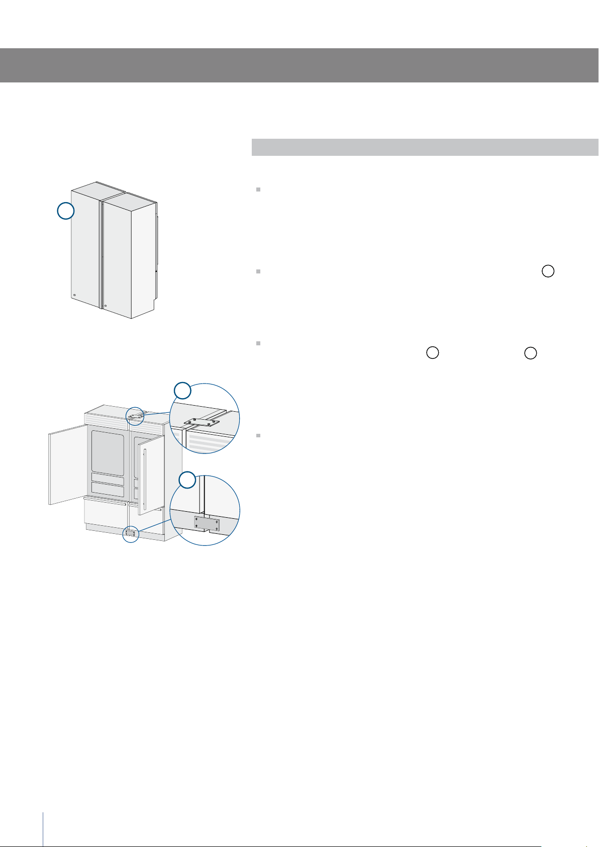
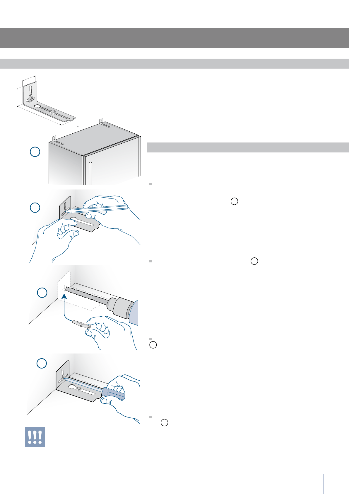
Installation Guide
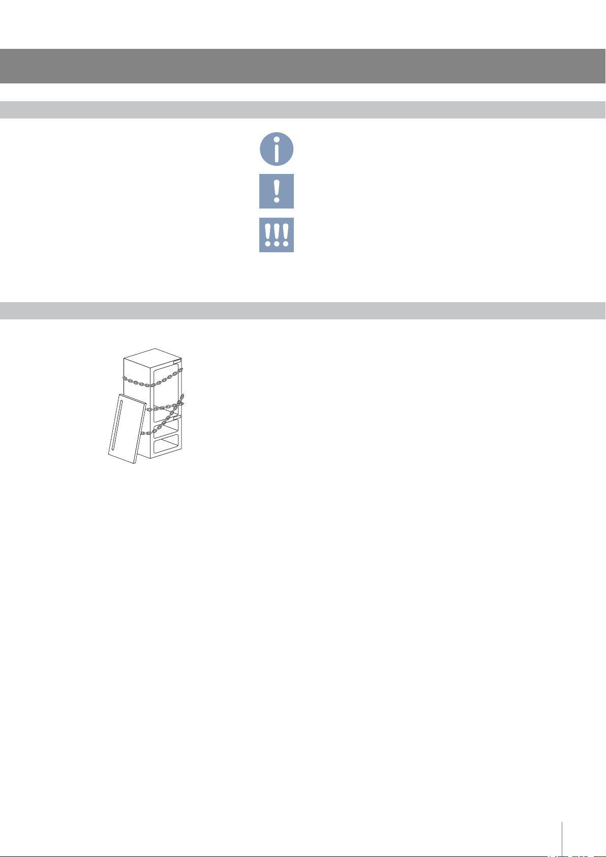
To avoid danger of the appliance tipping over
it is mandatory to secure the appliance to the
wall by means of two special brackets.
To prevent the appliance from tipping over an extra-long kit is vailable
up on request if the appliance needs to remain distanced from the
wall, it is mandatory to install two brackets on the upper part of the
appliance for xing it securely to the wall.
Operate as follows:
The brackets should be applied as illustrated using the provided
screws and expansion plugs.
Place a bracket on the top of the appliance in correspondence to the
xing holes and against the wall
1
.
Mark up the holes position on the wall
2
.
Drill the wall with an 8 mm (3/8”) bit and insert the expansion plug
3
.
Reposition the bracket and x it rst to the cabinet and then to the
wall
4
.
Anti-tipping safety assembly
Series: Integrated
24
1
2
3
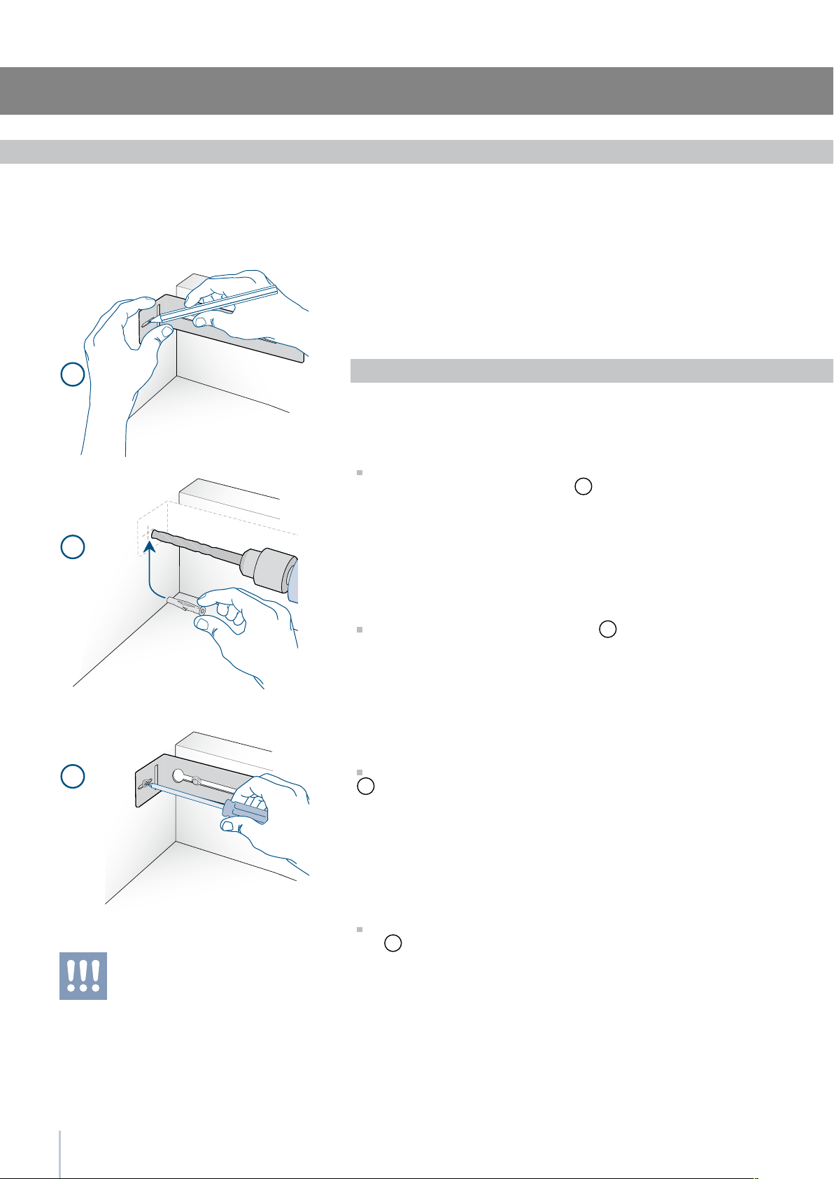
To avoid danger of the appliance tipping over
it is mandatory to secure the appliance to the
wall by means of two special brackets.
Anti-tipping safety assembly: full integration
To avoid danger of the appliance tipping over when opening full doors
and drawers, it is mandatory to install two brackets on the upper part
of the appliance for xing it securely to the wall.
The brackets should be applied as illustrated using the provided screws
and expansion plugs.
Operate as follows:
Place a bracket on the top of the appliance in correspondence to
the xing holes and against the wall
1
.
Mark up the holes position on the wall
2
.
Drill the wall with an 8 mm (3/8”) bit and insert the expansion plug
3
.
Reposition the bracket and x it rst to the cabinet and then to the
wall
4
.
Series:Free-Standing
Anti-tipping safety assembly
25
E
W
7
E
W
1
3
4
5
6
2
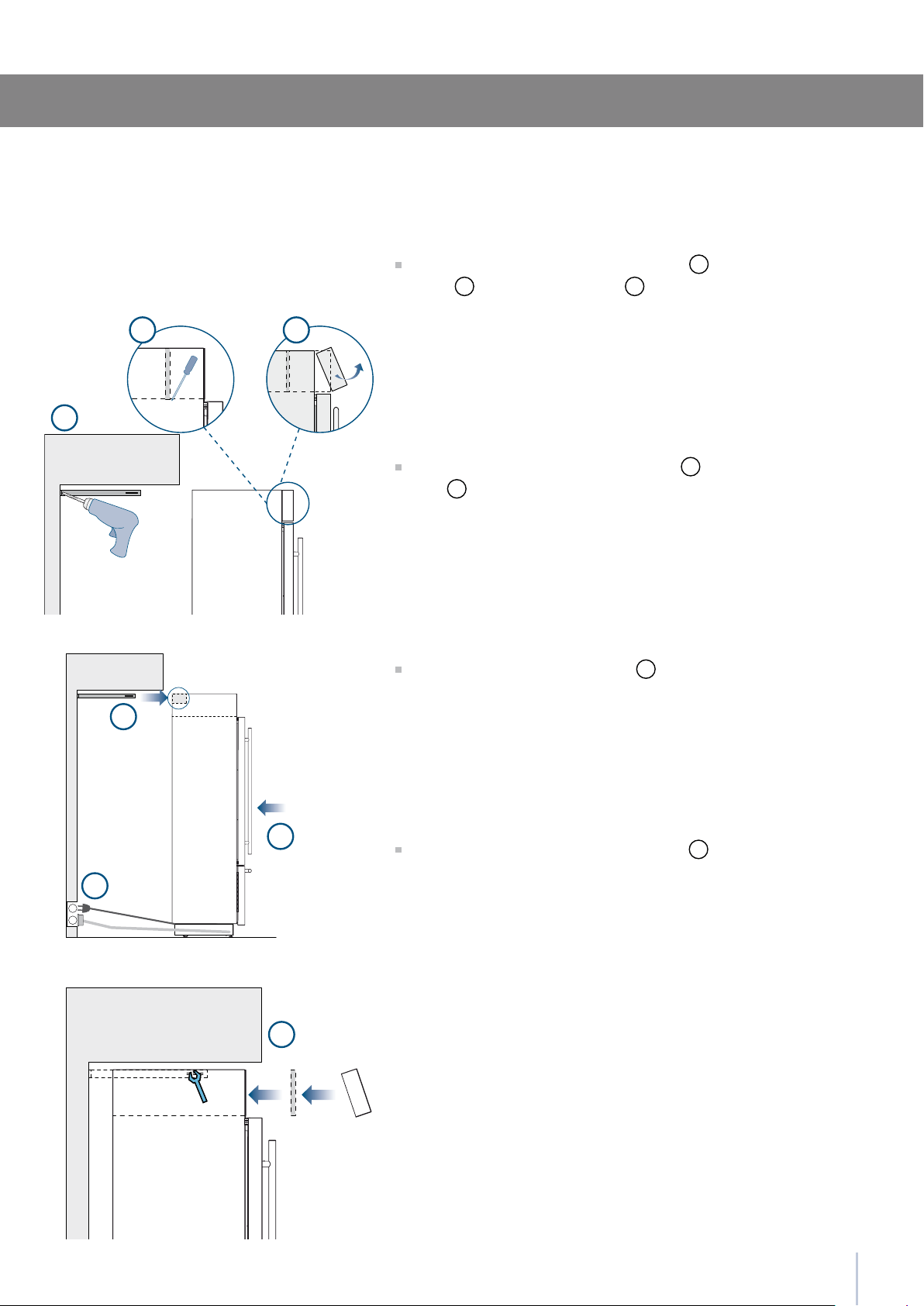
Installation Guide
Anti-tipping safety assembly: full integration
Series:Free-Standing
Fit the brackets and secure them to the wall
1
, remove the ventila-
tion grid
2
and the frontal closing
3
.
Make the electrical and water connection
4
(see page 8) and push
the unit
5
.
Insert the brackets to the rear holes
6
.
Fix brackets and reinstall the removed parts
7
.
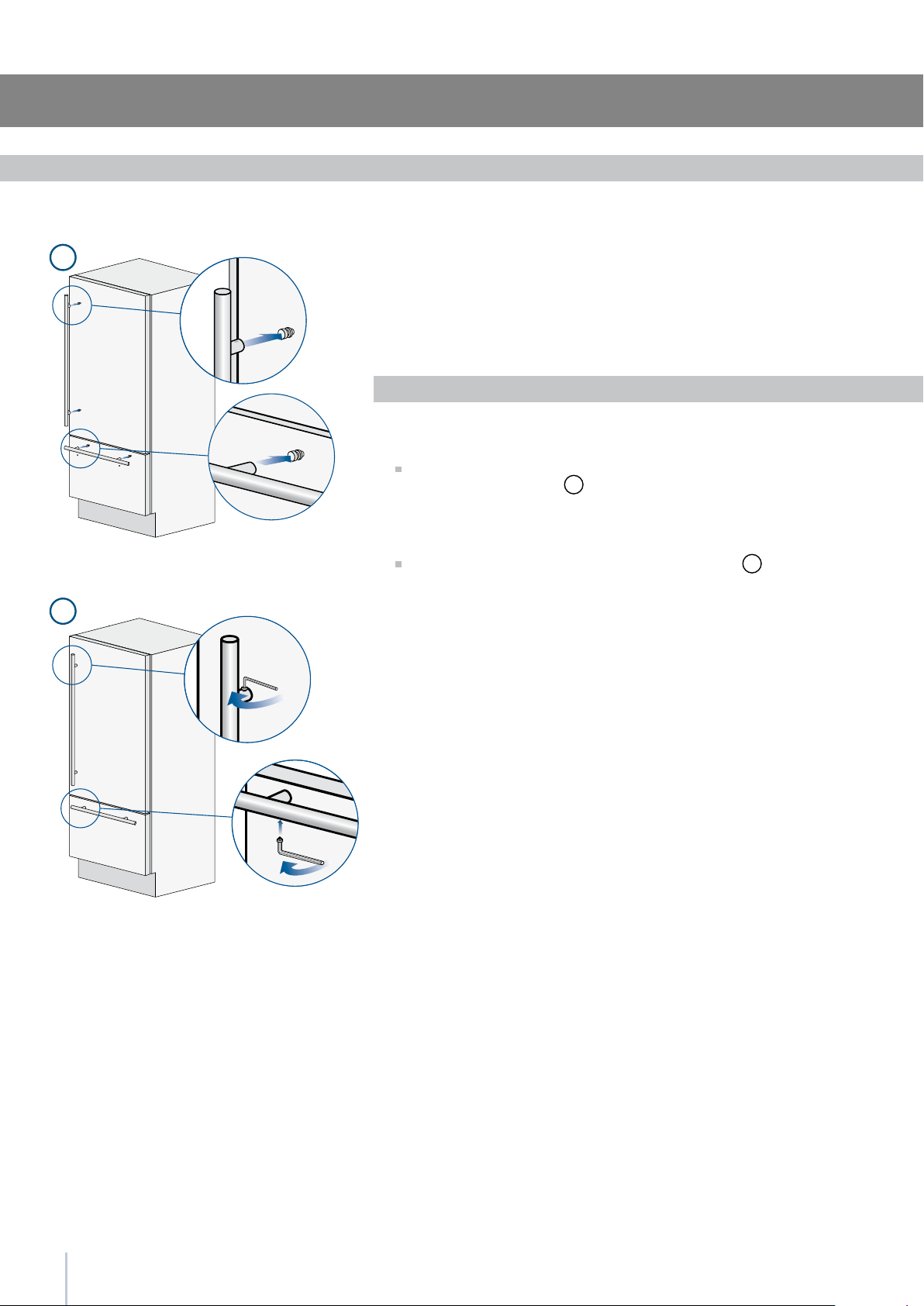
1
2
26
Mounting the handles on stainless front
To mount the handles onto the door and the drawer operate as follows:
Operate as follows:
Insert the two handle spacers onto the supports already available on
the door and the drawer
1
.
Screw in the Allen screws available on the handle
2
.
The screws must be tightened in by means of a 2.5 mm (1/8”) hex
wrench.
Series: Free-Standing
27
A
B
C
C
A 860 (33 ) 740 (29 )560 (22”)
> 100 (4”)
10 ()
50%
B
C
Installation Guide
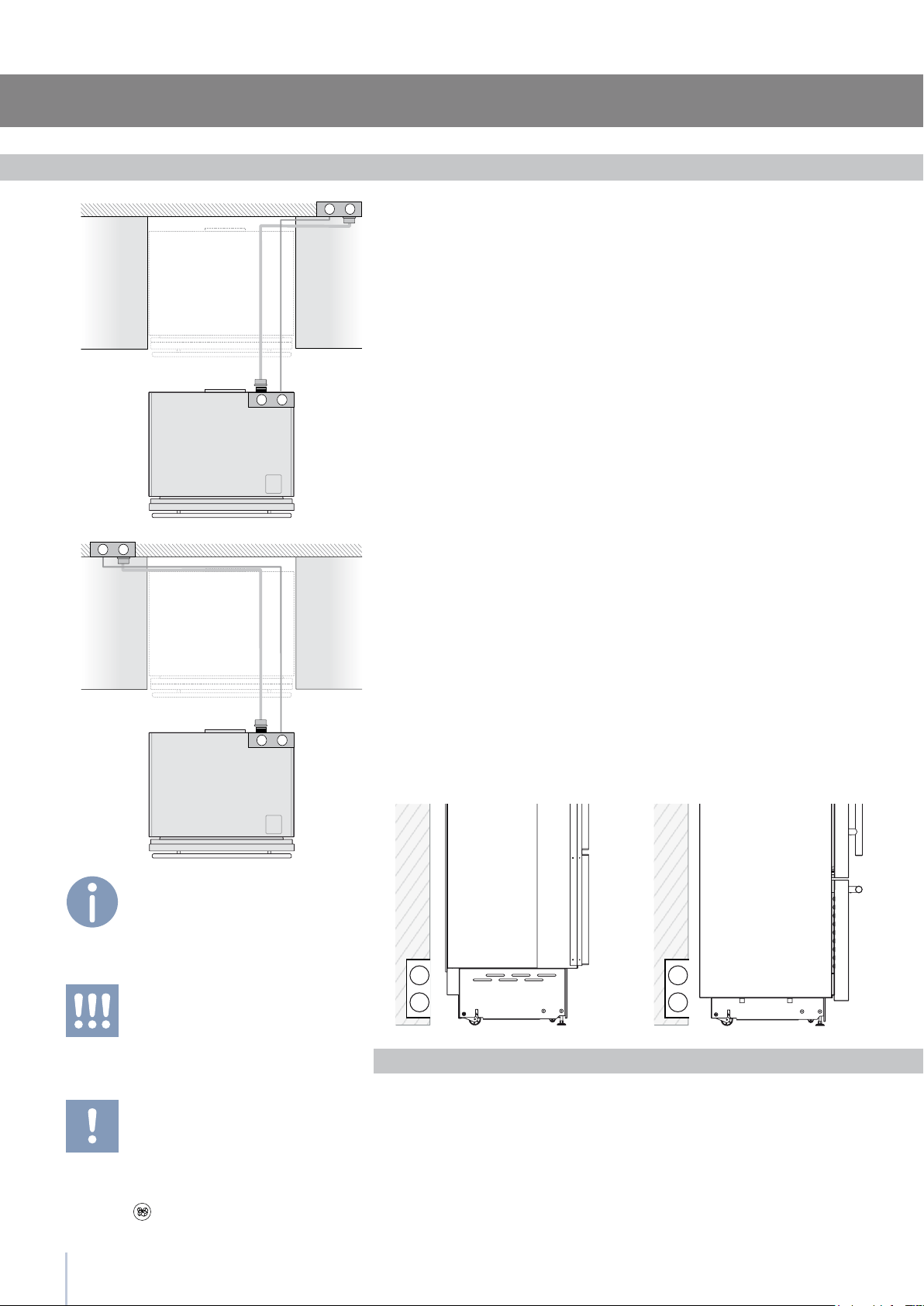
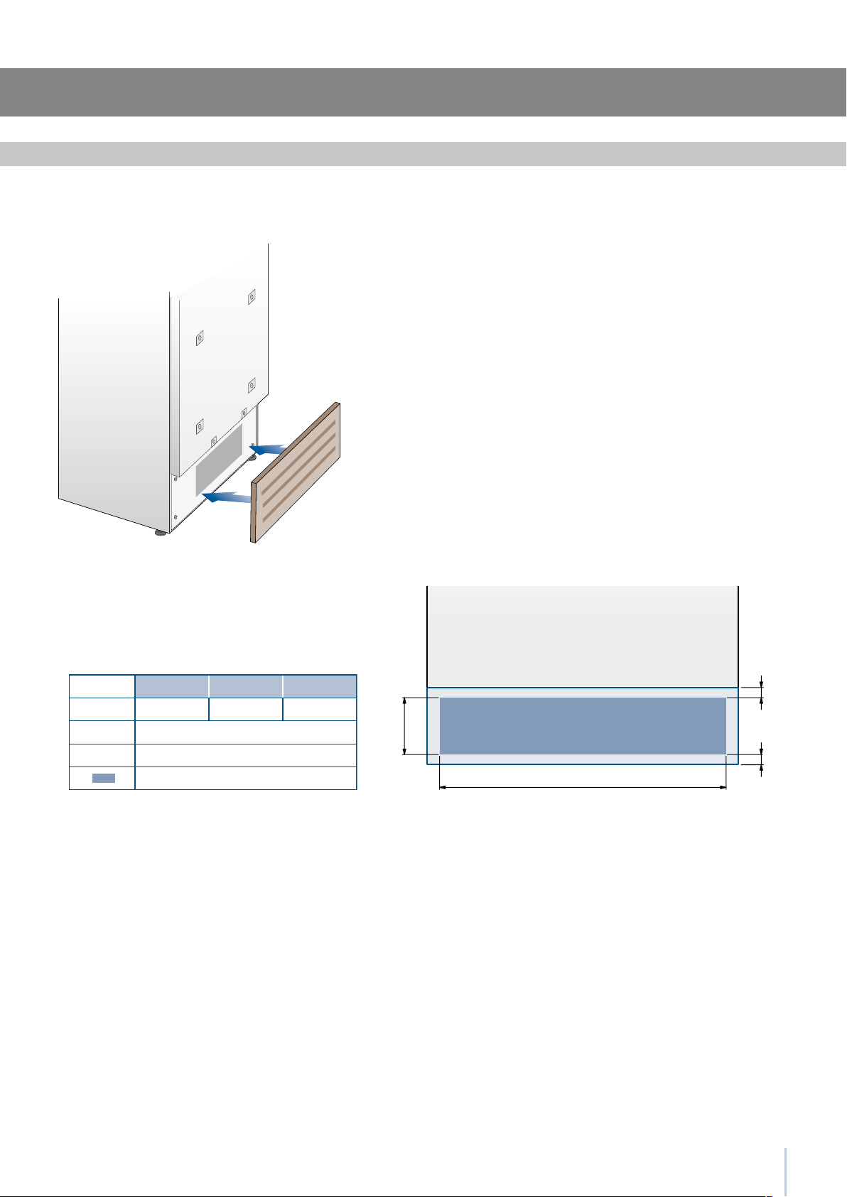
Ventilation
899 Series 749 Series 599 Series
A forced air system assures ventilation through a grille positioned
in the lower front part of the unit. If the kitchen design includes a
kickplate, the latter has to be punched in order to maintain a sati-
sfactory air ow, as described in the drawing. Holes can be in any
shape and size, as long as the total area of the punched part equals
50% of the kickplate are.
In this case, to guarantee a better air ow, it is advisable to remove
the front grille included with the unit. The grille is secured to the unit
with magnetic plates and can be easily removed even by the end
user, to provide for regular cleaning procedures and remove dust.
If the grille is partially covered by the kitchen kickplate, it is advisable
to remove the grille in order to provide for a better airow.
Series: Integrated
28
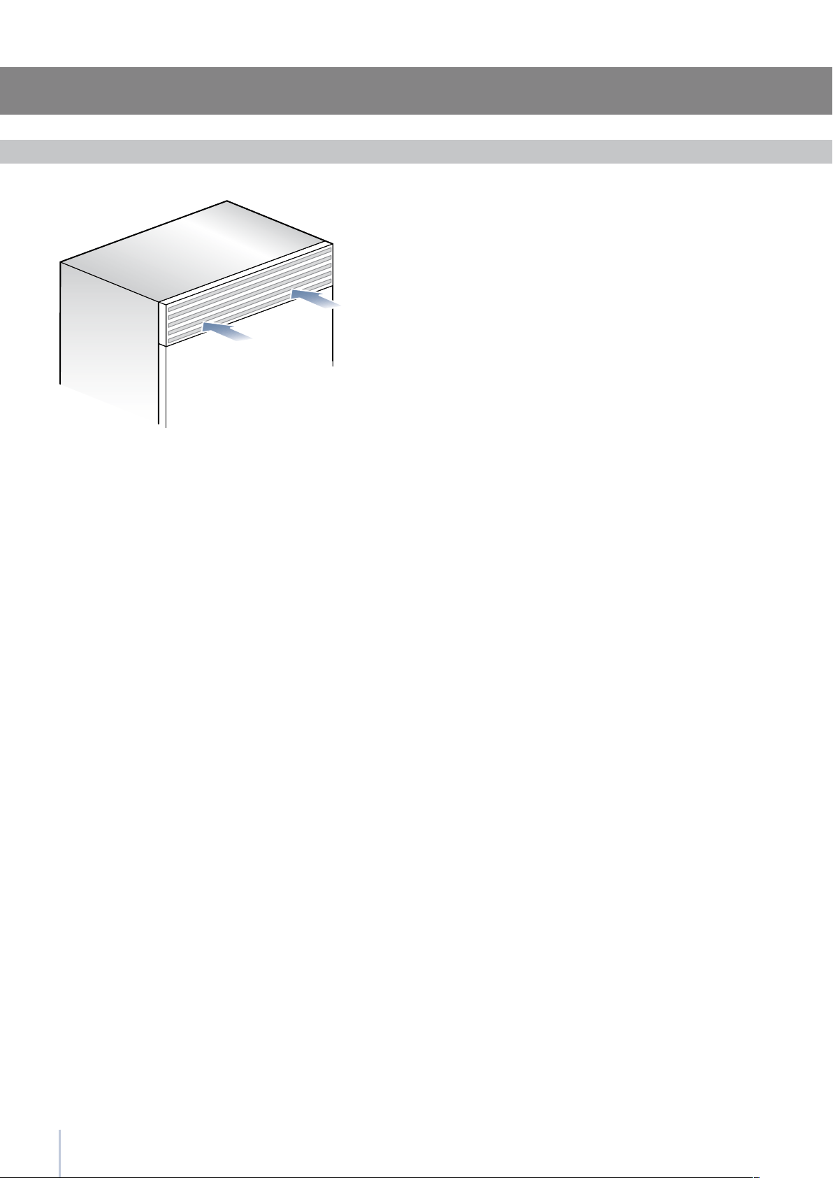
Ventilation
Ventilation is insured by a forced air system through a grille located in
the upper part of the appliance.
This grille should never be covered by panels or any other devices that
could reduce its efciency.
Please refer to page 5-6 to ensure correct air circulation.
Series:Free-Standing

29
Installation Guide
Post installation control
Check that the front levelling feet have been properly installed.
Check that the connection to the water system does not have any
leaks and that the closing tap is easily accessible.
Check that the electrical connection is correctly installed and that
the multipole switch and socket are easily accessible.
Check the perfect alignment of the appliance with adjacent
structures.
Check that all adhesive tape and external or internal temporary
protective devices have been removed.
Check the perfect closing of the doors and the smooth sliding of
the drawers and shelves.
Series: All
30
9
4
4.1
Accensione e spegnimento dell’apparecchiatura
Se alla prima accensione non appare la scritta
Stand-by, ma appaiono altre scritte, significa che
l’apparecchiatura ha già iniziato la procedura di
raffreddamento.
Dura nte l a pri ma ac cens ione n on s arà po ssib ile u ti-
lizz are il men ù Menu pe r u n’ev entu ale mod ifica del le
prei mpost azio ni di fabbr ica fino al raggi ungim ento
dell a tem perat ura p reim post ata. È poss ibile tutt avia re-
gola re da s ubito l’ ora e l a d ata, par amet ri comun que
nece ssari per att ivare alc une f unzi oni speci ali.
Ad ogni accensione l’apparecchiatura esegue una
procedura di autodiagnosi della durata di 3 minuti pri-
ma di avviarsi completamente.
Se si spegne solo il vano Frigorifero, il relativo ven-
tilatore continua a funzionare autonomamente per
prevenire la possibile formazione di odori e muffe.
Prima di spegnere per un periodo lungo l’intera ap-
parecchiatura, rimuovere tutti gli alimenti conservati
e lasciare le porte ed i cassetti aperti per evitare il
formarsi di cattivi odori e muffe.
Quando l’apparecchiatura è collegata alla rete elettrica ma non è
stata ancora accesa viene visualizzato sul display il messaggio
Per accendere tutti i vani dell’apparecchiatura agire per 3 secondi
sul tasto Unit .
Alla prima accensione il vano Multizone è predisposto nella funzio-
nalità Freezer .
Prima accensione
Dopo la prima accensione si raccomanda di attendere almeno 12
ore, senza aprire le porte, prima di introdurre alimenti nell’apparec-
chiatura. Durante tale periodo disattivare eventuali messaggi sonori
sfiorando il tasto Alarm
.
Può essere spento solo attraverso lo spegnimento completo dell’ap-
parecchiatura.
Agire per 3 secondi sul tasto Unit
.
Durante periodi di assenza molto lunghi è consigliabile spegnere il
frigorifero agendo sul tasto Unit
per 3 secondi e staccando la spi-
na o agendo sull’interruttore omnipolare che lo alimenta.
Svuotarlo di tutto il suo contenuto, pulirlo ed asciugarlo e lasciare le
porte ed i cassetti parzialmente aperti per evitare la formazione di
cattivi odori.
Spegnimento vani Frigorifero
Spegnimento vano Multizone
Riaccensione
Spegnimento per lunghi periodi
Accensione e spegnimento
Agire nuovamente sugli stessi tasti per la riaccensione.
Il vano Freezer rimane sempre acceso e non può essere spento se
non attraverso lo spegnimento completo dell’apparecchiatura.
Agire per 3 secondi sul tasto Unit
.
3
3.3
3.3
Componenti principali
Componenti principali
3.5
3.4
123456798
1
Unit
2
Fridge
3
Menu
4
Up/down
Fridge
5
Display
6
Up/Down
Freezer
(Multizone)
7
Enter
8
Ice maker
9
Alarm
8
Il sistema di controllo elettronico mantiene costante la temperatura dei due vani e la visualizza sul display del pannello di con-
trollo; consente inoltre l’interazione dell’utente con il sistema di controllo, tramite l’impostazione personalizzata delle diverse
funzioni e l’invio di messaggi sonori e/o visivi, qualora si verificassero anomalie nel funzionamento dell’apparecchiatura.
Pannello di controllo principale
Controllo elettronico
Permette lo spegnimento completo e l’accensione dell’apparecchia-
tura (agire su di esso per 3 secondi).
Permette lo spegnimento e l’accensione del solo vano frigorifero (agire
su di esso per 3 secondi).
Permette l’accesso al menù delle funzioni dell’apparecchiatura
Visualizza le temperature dei vani frigorifero e freezer, la data e l’ora, le
funzioni Menu ed i messaggi visivi.
Tramite lo sfioramento dei tasti Up/Down è possibile variare la tempe-
ratura preimpostata a seconda delle scelte di utilizzo del vano (free-
zer , frigorifero o 0°C).
Permette di confermare l’attivazione o la disattivazione delle selezioni
operate attraverso Menu.
Permette di attivare o disattivare la produzione automatica di ghiaccio.
Lampeggia per segnalare eventuali anomalie di funzionamento, evi-
denziate anche attraverso un avviso sonoro, disattivabile attraverso lo
sfioramento del tasto.
Tramite lo sfioramento dei tasti Up (su) e Down (giù) è possibile variare
la temperatura già impostata per il frigorifero e muoversi all’interno
del menù interattivo.
Prima di iniziare
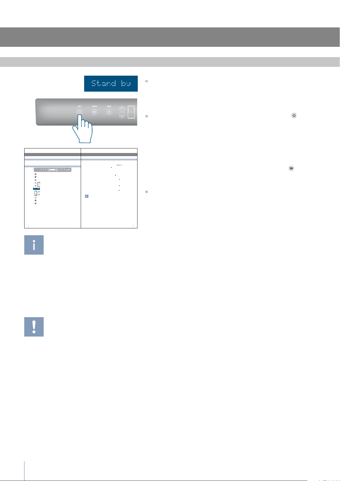
Start up
Series: All
If at the rst start - up the message Stand by does
not appear, but other messages appear, such
as Fridge too warm, Fresco too warm, Freezer
too warm, or sound signals are activated, it
means that the appliance has already started
the cooling process.
If this is the case, deactivate any possible acous-
tic signals by pressing the Alarm button, close
the door and wait until the set temperature is
reached.
To start the appliance, connect the plug to the electrical mains: at
this point, when opening the door, the control panel will usually visual-
ize the message “Stand by”, and all the panel keys be off
To turn on all the appliance compartments, press the Unit button
for three seconds. The display will show the message “Initial test” for
approx. 2 minutes. After this phase the compressors will start up and re-
main on until the default temperature set up in the factory is reached.
Do bear in mind that this condition could last several hours.
If the appliance is provided with an Ice Maker, prior to switching it
on make sure that the water lter cartridge is installed, then ll the
water system. To this purpose switch off the Ice Makerand performe a
manual clean procedure.
At the end switch the Ice Maker on again by touching the
button.
For further information about the appliance operation, refer to the
User Manual.
It is necessary to let the unit reach the correct
temperature before foods are stored inside.

Installation Guide


22-122014

GI-SMEG EN