Loading ...
Loading ...
Loading ...
Instructions for the installer
44
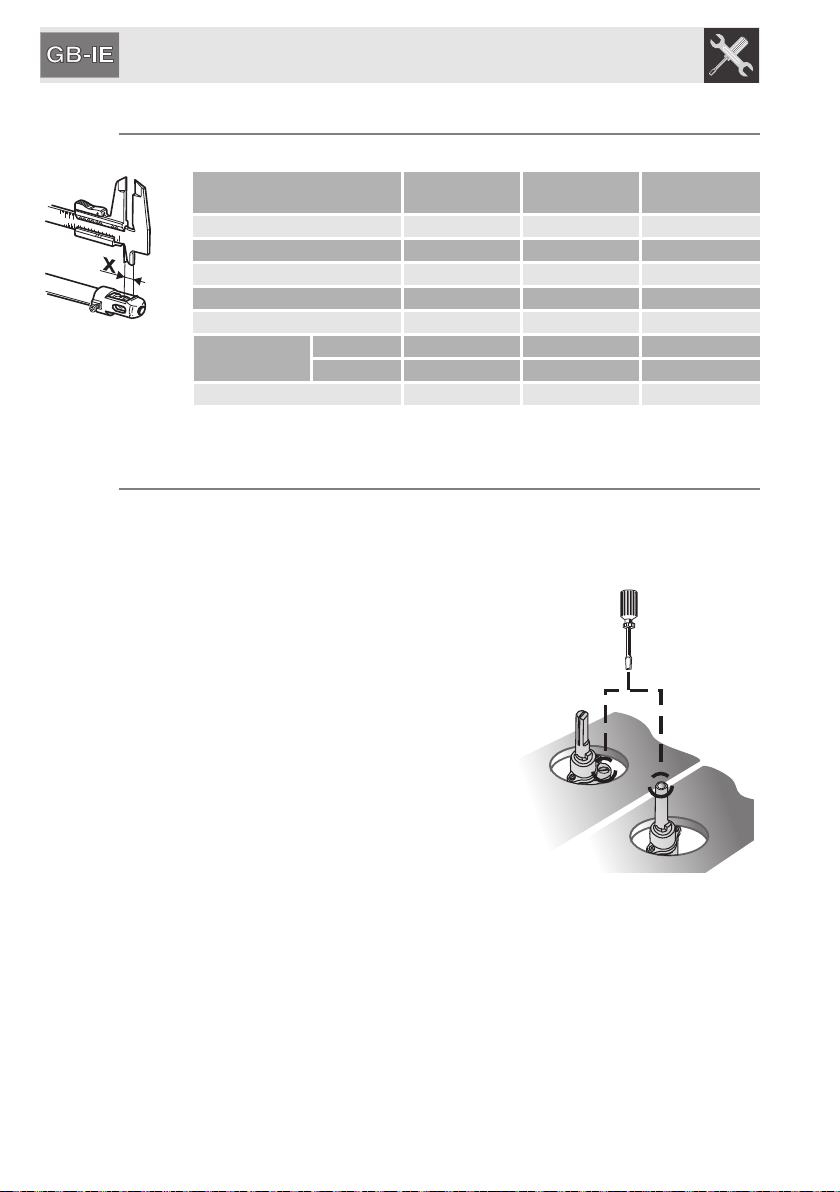
9.5 Primary air adjustment
Refers to distance “X”inmm.
BURNER
G30/G31
28/37 mbar
G20
20 mbar
G110
8 mbar
Auxiliary (1) 1.0 1.5 0.5
Semi-rapid (2) 1.5 1.5 0.5
Medium rapid (3) 1.5 1.0 1.0
Large Rapid (4) 10.0 2.5 1.5
Ultra-rapid (5) 2.5 2.0 1.5
Double crown
Internal (6) 6.0 3.0 1.0
External (6) 10.0 3.0 5.0
Fish burner 2.5 2.0 1.0
To identify the burners on your hob, refer to the drawings in “9.7 Arrangement of the burners on the
cooking hob”.
9.6 Final operations
After making the adjustments described above, reassemble the appliance by
following the instructions in “9.1 Removing the hob top” in reverse order.
9.6.1 Adjusting the minimum for city and natural gas
Reposition the components on the burner and
slide the knobs onto the tap rods.
Light the burner and set it on the minimum
position. Extract the knob again and turn the
adjustment screw inside or next to the tap rod
(depending on the model) until the correct
minimum flame is achieved.
Refit the knob and verify that the burner flame is
stable (when turning the knob rapidly from the
maximum to the minimum position the flame must
not go out).
Loading ...
Loading ...