사용설명서를 읽고 난 후 사용하는 사람이 언제라도 볼 수 있는 장소에
보관하세요.
ACC-W-EH5C
사용설명서
벽걸이 키트
www.lge.co.kr
P/No: MFL69532003 (1605-REV00)
Printed in Korea
*MFL69532003*
2
ENG
한국어
(M4 x L16)
(M4 x L8)
(Φ4 x L10)
3
ENG한국어
주의
• 제품을 설치할 때 또는 제품 설치 후 높이 조정시에는 반드시 두사람 이상이 함께 하세요. 혼자서 하게 되면 제품이
떨어져 부상 또는 제품 파손의 원인이 될 수 있습니다.
1 상자를 열고 위에 있는 포장 및 T-con 박스를 순서대로 제거합니다.
1
2
T-con 박스
2 16/22 pin 케이블의 반대쪽 부분의 connector를 케이블과 일직선이 되도록 꺾어줍니다.
22
16
16
22
22
16
16
22
3 16/22 pin connector를 함께 튜브에 삽입합니다.
16
22
16
22
4
ENG
한국어
4 세트의 중앙 홀에 케이블을 통과시킵니다.
FRONT
FRONT
5
ENG한국어
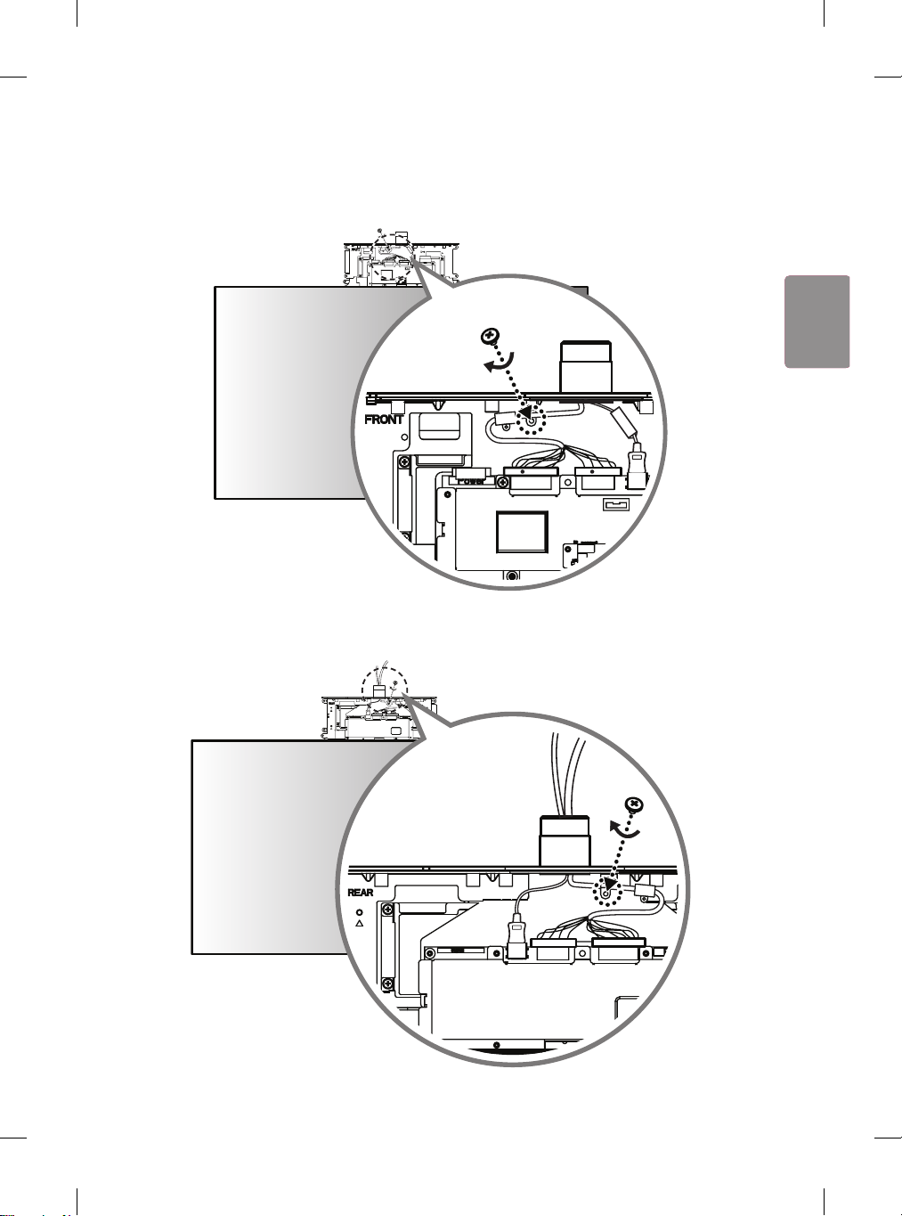
5 FRONT 라벨이 붙은 HDMI 케이블을 FRONT 면에 연결합니다.
붉은색 표시가 있는 16/22 pin 케이블에 케이블 홀더를 끼우고 나사(M3 x L4.5)를 이용해 조립한 후 연결합니다.
22
FRONT
16
RR
22
FRONT
16
RR
6 FRONT 라벨이 없는 HDMI 케이블을 REAR 면에 연결합니다.
붉은색 표시가 없는 16/22 pin 케이블에 케이블 홀더를 끼우고 나사(M3 x L4.5)를 이용해 조립한 후 연결합니다.
16
22
16
22
6
ENG
한국어
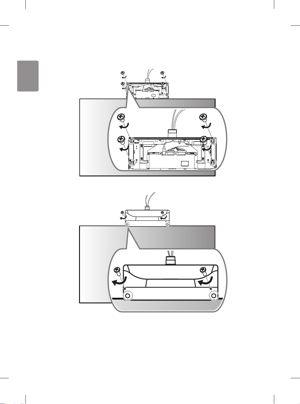
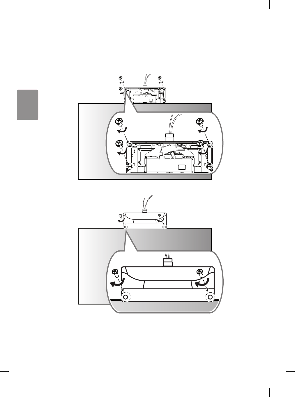
7 T-con 박스의 IR 수신부가 있는 면을 FRONT 면에 덮고, 반대쪽 (REAR 면)에서 나사(Φ3 x L6) 4개로 체결합니다.
16
22
16
22
8 나머지 T-con 커버를 REAR 면에 덮고, 나사(Φ3 x L10) 2개로 체결합니다.
7
ENG한국어
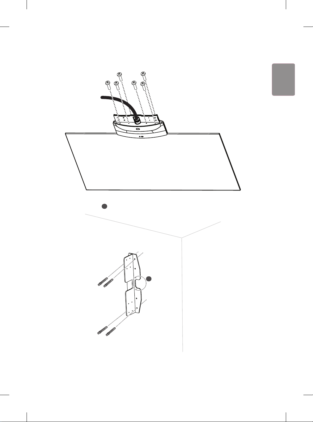
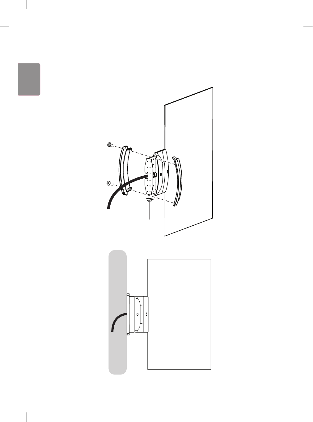
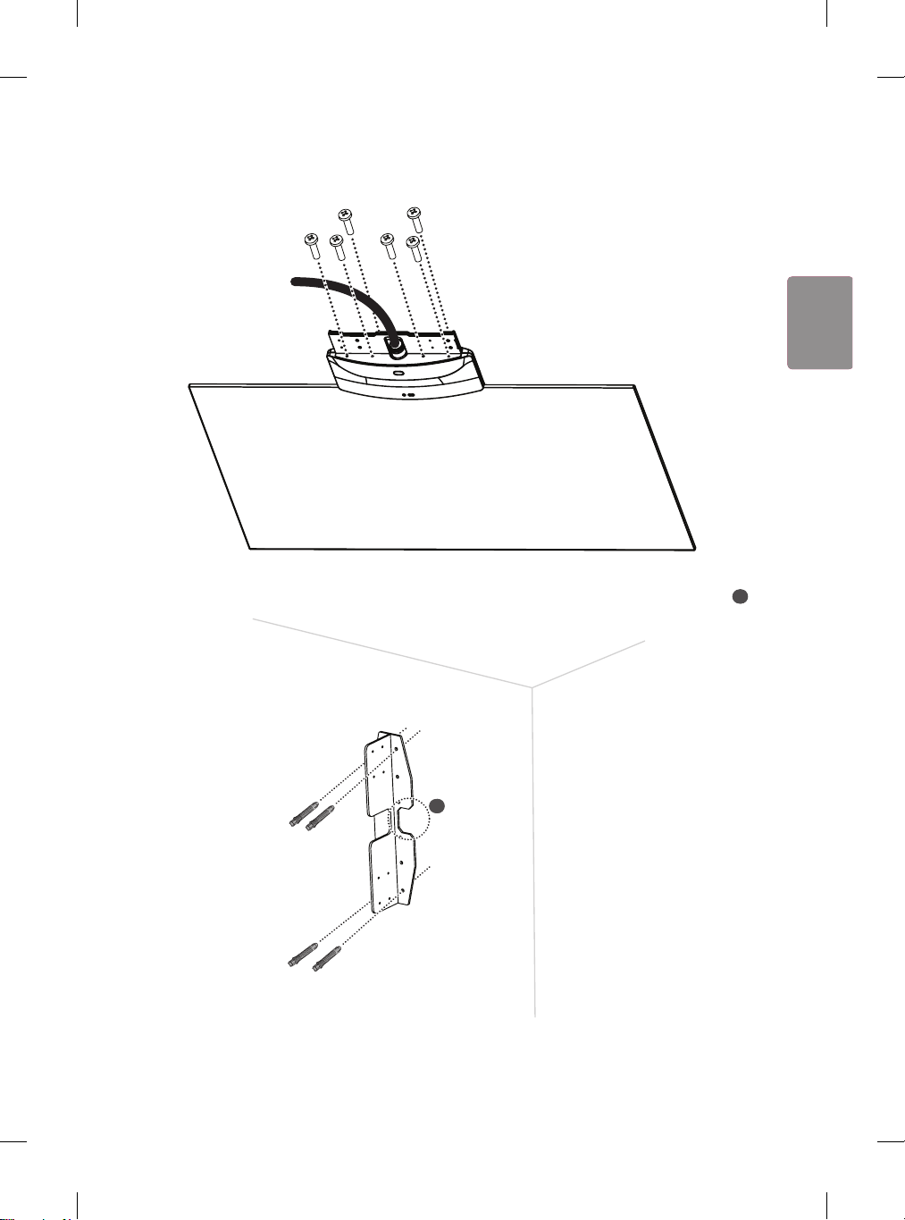
9 나사(M4 x L16) 6개를 이용하여 브래킷 2개를 세트에 조립합니다.
10
앵커 볼트 4개를 이용하여 벽 마운트를 벽면에 설치합니다. (“앵커 및 나사의 고정 방법”을 참조하세요.) 케이블을
벽에 매립할 경우, 표시 부분(
A
)을 따라 벽면에 구멍을 뚫습니다.
A
8
ENG
한국어
앵커 및 나사의 고정 방법
• 벽체의 재질 및 마감재의 두께를 확인하세요.
• 벽체의 재질이 금가지 않는 콘크리트 벽, 경량 콘크리트, 강한 자연석, 연한 자연석, 조적 벽돌, 중공 블록일 때에는
동봉된 앵커 볼트 및 벽걸이 고정 나사를 사용할 수 있습니다.
• 석고보드 또는 종이/나무 가루를 압축한 재질 (MDF) 로 만들어진 벽체에는 절대 설치하지 마세요. 만약 설치할 경우,
마감재 안에 있는 옹벽 (콘크리트) 에 벽걸이 고정 나사를 고정해야 하고 옹벽이 없을 경우 별도의 행거 설치 후 벽걸이
고정 나사를 고정해야 합니다.
• 기타 지정되지 않은 벽체에 설치할 경우에는 고정부 1개소당 인발 하중 70 kgf (686 N), 전단 하중 100 kgf
(980 N) 이상의 힘에 견딜 수 있도록 설치하세요.
1 2 3
앵커 볼트
4 5
벽걸이 고정 나사
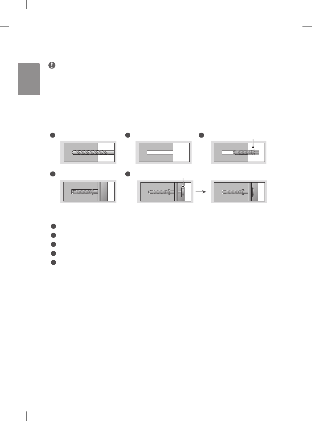
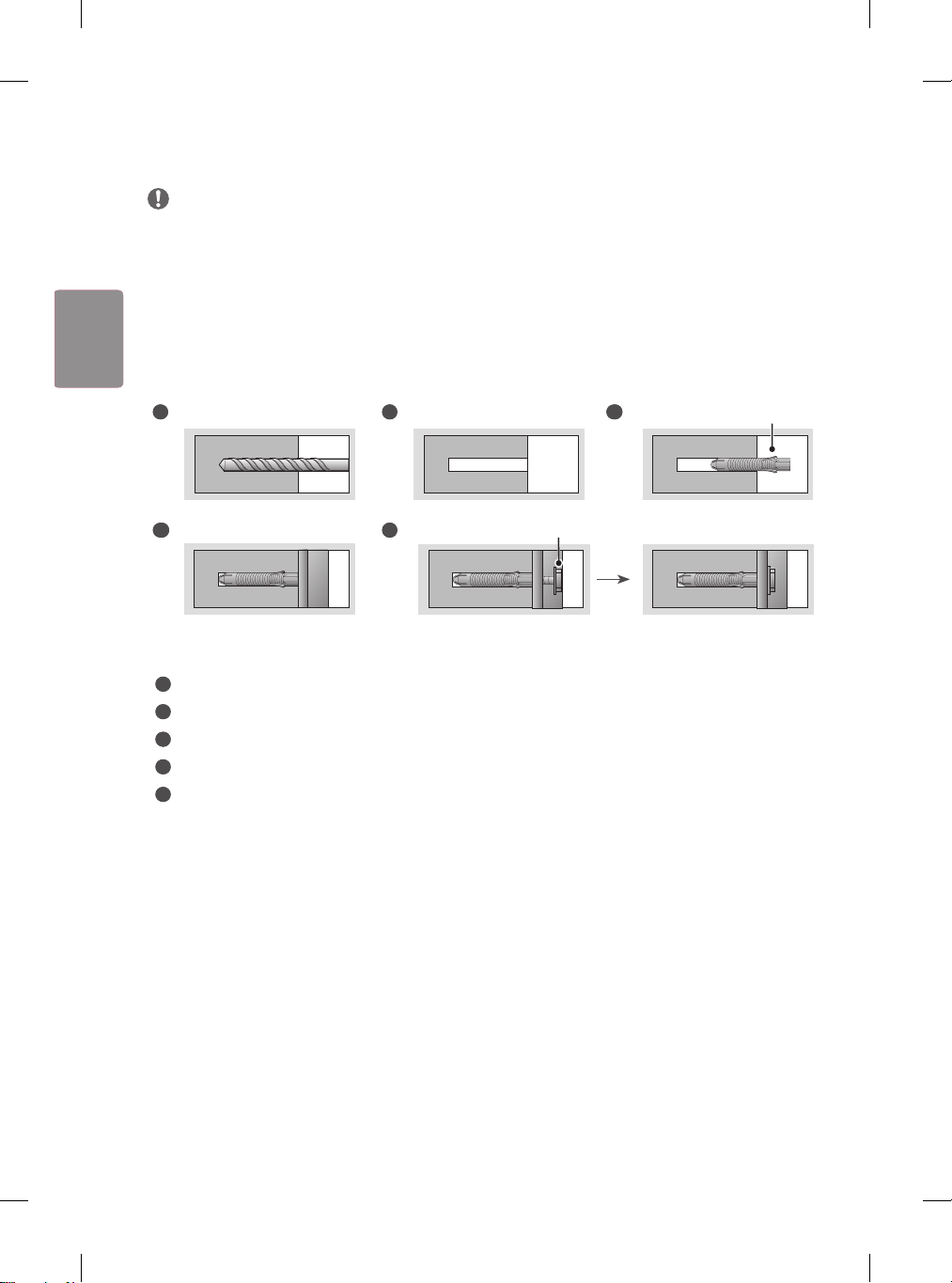
- Ø 8 mm 콘크리트용 드릴 비트와 해머 (임팩트) 드릴을 사용해 주세요.
1
앵커 볼트 위치에 구멍을 드릴 비트 Ø 8 mm를 사용해 깊이 80 mm - 100 mm 이내로 뚫으세요.
2
뚫은 구멍을 청소하세요.
3
구멍에 동봉된 앵커 볼트를 삽입하세요. (앵커 볼트 삽입시 망치를 사용하세요.)
4
구멍 위치에 맞게 벽 마운트를 벽 쪽으로 밀착시키세요. 이때 각도를 조절하는 부분이 상 측으로 향하도록하세요.
5
벽걸이 고정 나사를 구멍에 맞춰 체결하세요. 이때, 나사는 Torque 45 kgf/cm - 60 kgf/cm 이상 조이세요.
9
ENG한국어
11
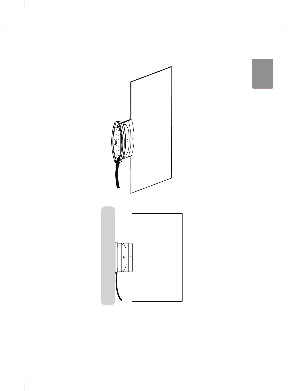
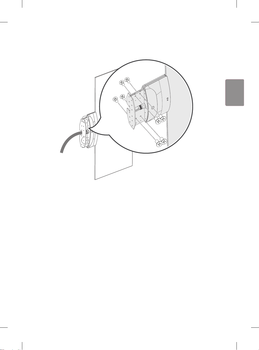
벽 마운트와 브래킷을 조립하고 나사 (M4 x L8) 8개로 고정합니다.
10
ENG
한국어
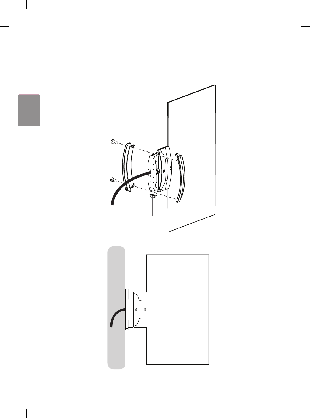
12
세트의 앞뒤 방향에 맞춰 커버 앞면/뒷면/옆면을 조립하고, 나사(Φ4 x L10) 2개로 고정합니다. 케이블이 벽을
관통하지 않을 경우에는 커버 옆면은 조립하지 않고, 그 틈으로 케이블을 뻅니다.
- 케이블을 벽에 매립 할 경우
커버 옆면
<옆면>
11
ENG한국어
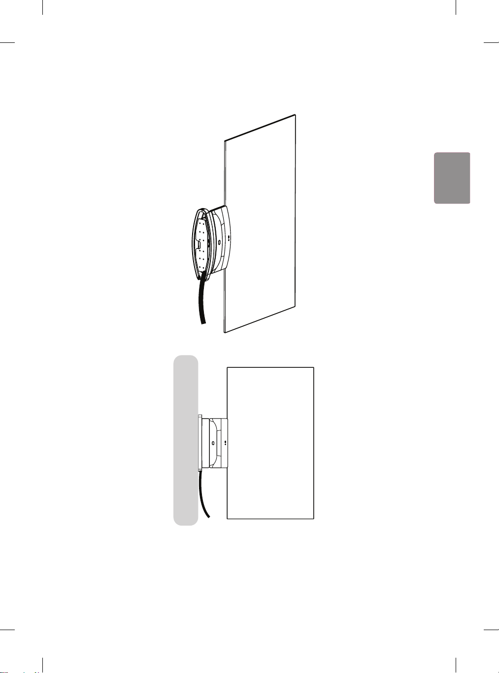
- 케이블을 벽에 매립 하지 않을 경우
<옆면>
12
ENG
한국어
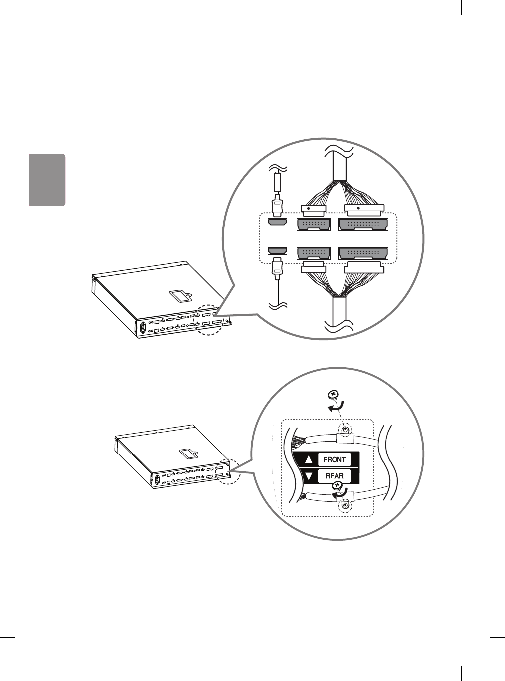
13
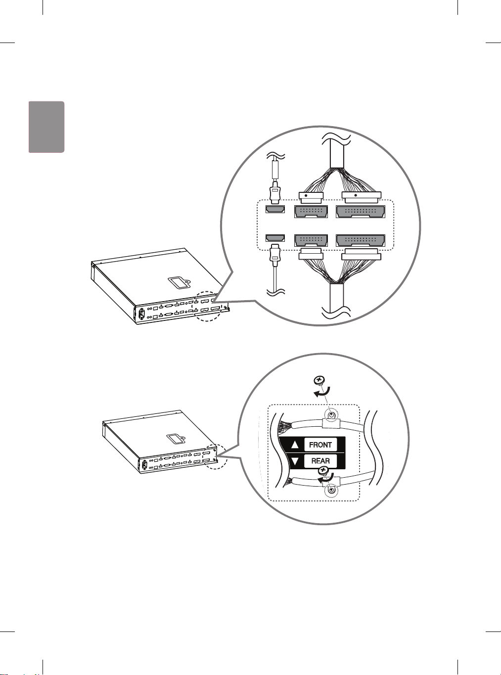
사이니지 박스에 케이블을 연결합니다. 이때, FRONT 라벨이 붙은 HDMI 케이블은 위에, FRONT 라벨이 없는 HDMI
케이블은 아래에 체결합니다. 16/22 pin 케이블의 경우, 붉은색 표시가 있는 케이블을 아래에 체결합니다.
16
16
22
22
FRONT
R
R
14
16/22 pin 케이블을 나사(M3 x L4.5) 2개로 각각 체결합니다.
22
16
22
16
13
ENG한국어
15
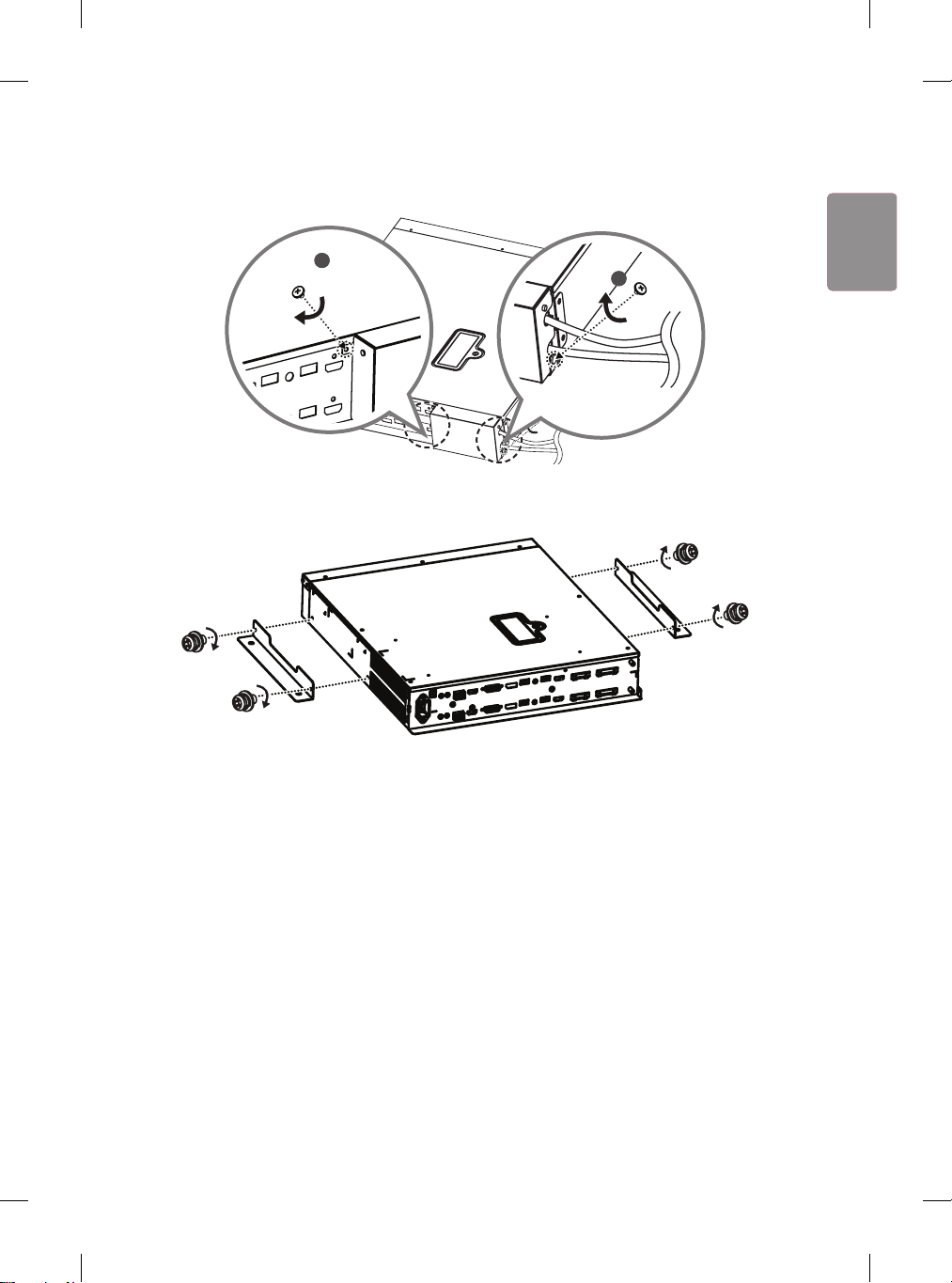
잭커버의 홈을 케이블에 맞춰 덮고 나사(M3 x L4.5) 2개로 체결합니다.
1
2
16
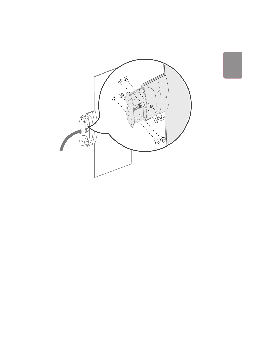
마운팅 브래킷을 나사(M4 x L8) 4개로 사이니지 박스에 조립하여 설치합니다. 필요시 브래킷의 홀을 이용하여
고정하세요.
14
ENG
한국어
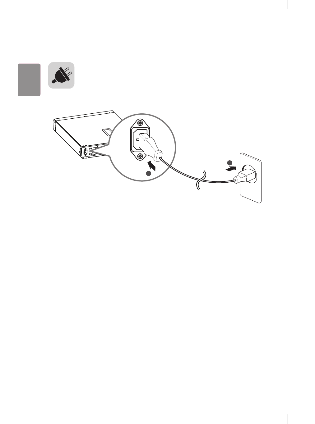
사이니지 박스에 전원코드를 연결합니다.
1
2


www.lg.com
Printed in Korea
Please read this manual carefully before operating your set and
retain it for future reference.
ACC-W-EH5C
OWNER’S MANUAL
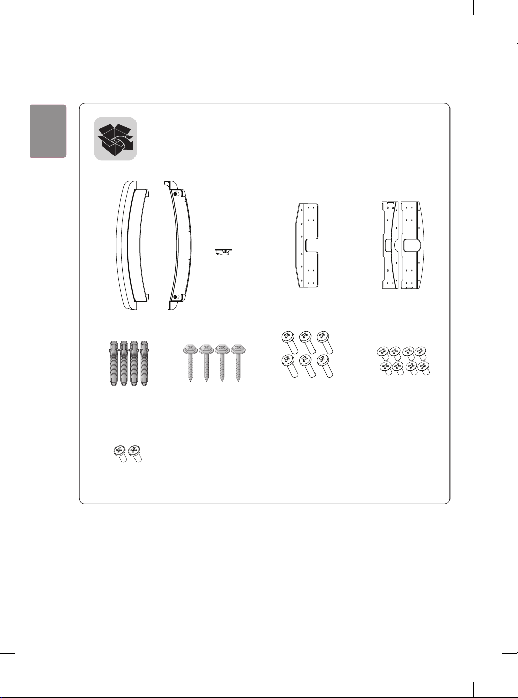
Wall mount kit
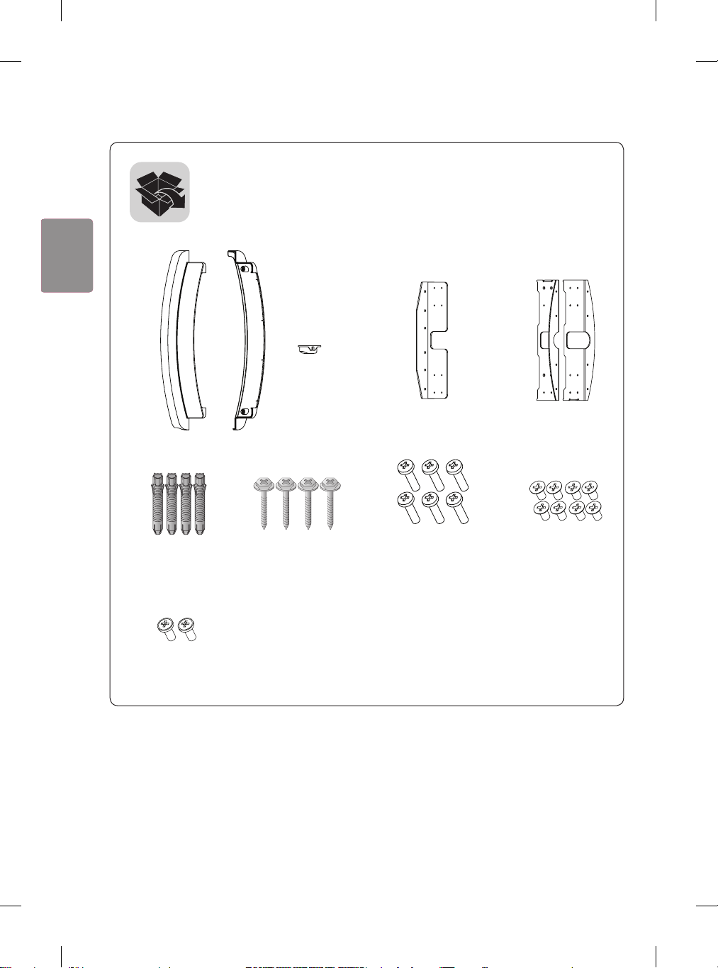
(M4 x L16)
(M4 x L8)
(Φ4 x L10)
2
ENG
ENGLISH
CAUTION
• When installing or adjusting the height of this product, two or more people are required. If you try to
install or adjust the product alone, it may fall, causing personal injury or product damage.
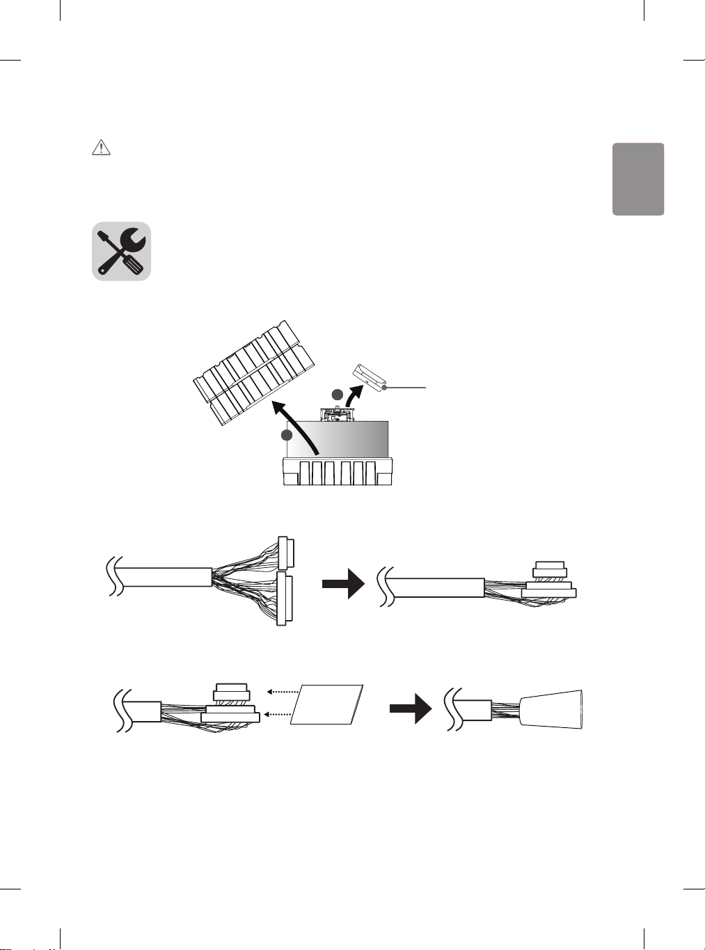
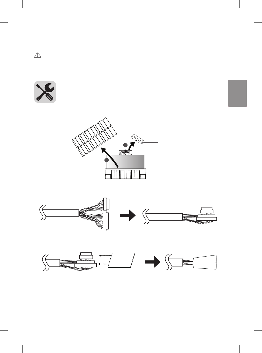
1 Open the product box and remove the packaging materials and T-con box in the order they appear.
1
2
T-con box
2 Fold the connectors on the opposite side of the 16/22 pin cables to make them parallel to the cable.
22
16
16
22
22
16
16
22
3 Insert the connectors of the 16/22 pin cables into the tubes.
16
22
16
22
3
ENGENGLISH
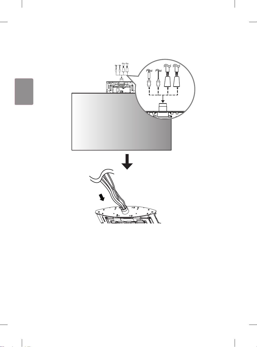
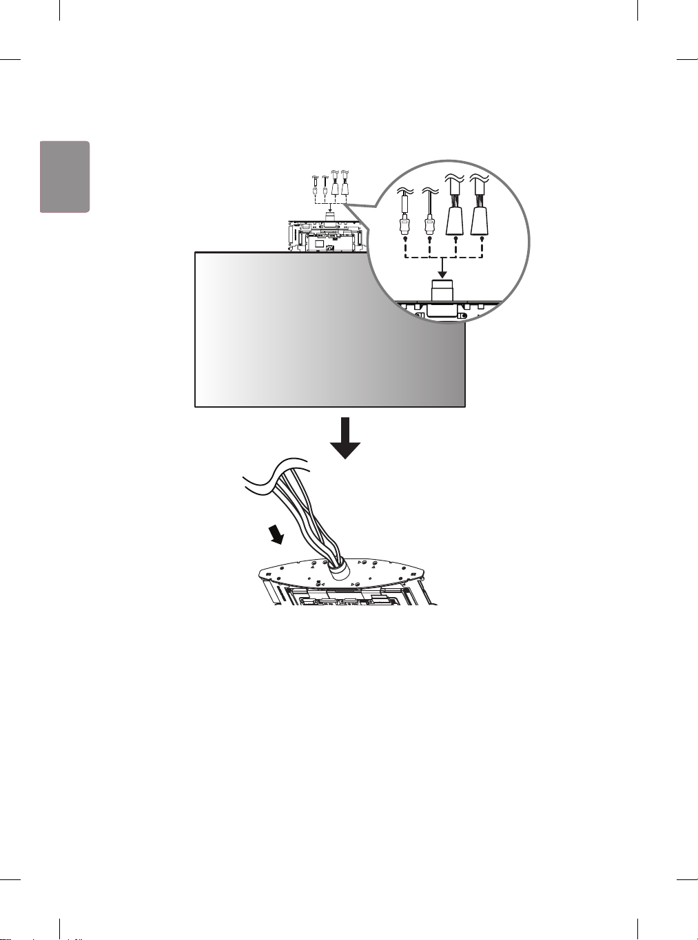
4 Pass the cables through the hole in the middle of the SET.
FRONT
FRONT
4
ENG
ENGLISH
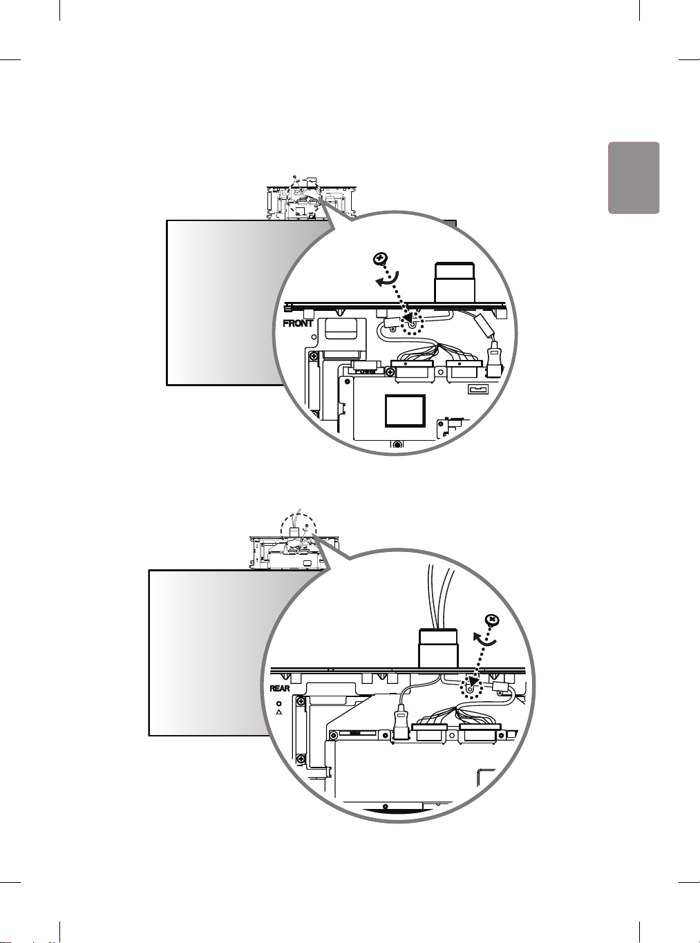
5 Connect the HDMI cable with the label marked ’FRONT’ to the FRONT side.
Insert the 16/22 pin cable with the red mark into the cable holder and attach it using a screw (M3 x L4.5).
22
FRONT
16
RR
22
FRONT
16
RR
6 Connect the HDMI cable without the label marked ‘FRONT’ to the REAR side.
Insert the 16/22 pin cable without the red mark into the cable holder and attach it using a screw (M3 x L4.5).
16
22
16
22
5
ENGENGLISH
7 Cover the FRONT side with the side of the T-con box cover that has the IR receiver and attach it using
4 screws (Φ3 x L6) on the opposite side (REAR side).
16
22
16
22
8 Cover the REAR side with the other T-con box cover and attach it using 2 screws (Φ3 x L10).
6
ENG
ENGLISH
9 Using 6 screws (M4 x L16), assemble 2 brackets to the set.
10
Using 4 anchor bolts, install the wall mount on the wall surface. (Refer to “Fixing the anchors and
screws”.) When embedding cables into the wall, drill holes into the wall according to the markings (
A
).
A
7
ENGENGLISH
FIXING THE ANCHORS AND SCREWS
• Check the wall material and thickness of the finish material.
• You can use the provided Anchor bolts and screws on walls made with concrete, lightweight concrete,
hard fieldstone, soft fieldstone, brick, cellular block, etc., or other materials that do not crack.
• Do not mount the device on walls made with plaster board or medium-density fiberboard (MDF). In this
case, the anchor and screws must be inserted into the concrete behind the finish. If there is no concrete
on the other side, then install first a separate hanger where the anchors and screws can be fixed.
• When installing it on a wall other than that specified in this manual, make sure that each fixing point
withstands uplifting load of 70 kgf (686 N) and shearing load of 100 kgf (980 N) or more.
1 2 3
Anchor bolt
4 5
Wall Mounting Screw
- Use Ф 8 mm concrete drill bit and hammer (impact) drill.
1
Drill a hole with depth of 80 mm – 100 mm where the anchor will be attached using Ø 8 mm drill bit.
2
Clean out the drilled hole.
3
Insert the anchor bolt provided into the hole. (Use a hammer when inserting the anchor bolt.)
4
Place the wall mount up close to the wall. The angle adjusting attachment should be facing upward.
5
Insert the wall mounting screw into the hole and tighten it. Tighten the screw using a torque of at
least 45 kgf/cm – 60 kgf/cm.
8
ENG
ENGLISH
11
Assemble the wall mount and bracket, and then fix in place using 8 screws (M4 x L8).
9
ENGENGLISH
12
Assemble the front/rear/side covers appropriately with the set and fix in place using 2 screws (Φ4 x L10). If
the cables do not pass through the wall, do not assemble the side cover; remove the cables through the gap.
- When cables are embedded in the wall
Side cover
<Side>
10
ENG
ENGLISH
- When cables are not embedded in the wall
<Side>
11
ENGENGLISH
13
Connect the cables to the Signage box. Here, the HDMI cable with the FRONT label is attached to the
top, and the HDMI cable without the FRONT label is attached to the bottom. The 16/22 pin cable with
red mark must be connected to the lower part.
16
16
22
22
FRONT
R
R
14
Attach the 16/22 pin cables using 2 screws (M3 x L4.5).
22
16
22
16
12
ENG
ENGLISH

15
Position the jack cover so that the cables fit into the cut spaces and attach it using 2 screws (M3 x L4.5).
1
2
16
Attach the mounting brackets to the Signage box using 4 screws (M4 x L8). If necessary, fix in place
using the holes on the bracket.
13
ENGENGLISH
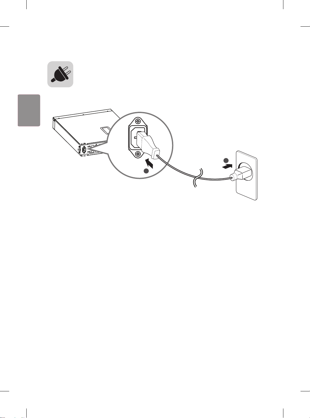
Connect the power cable to the Signage box.
1
2
14
ENG
ENGLISH