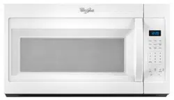
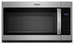
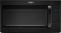
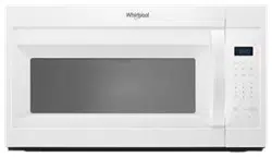
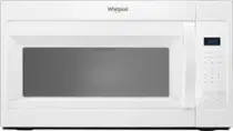
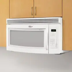
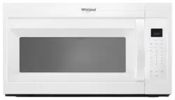
User Manual
INSTALLATION REQUIREMENTS
Tools and Parts
Tools Needed
Gather the required tools and parts before starting installation.
Read and follow the instructions provided with any tools listed here.
- Measuring tape
- Pencil
- Masking tape or thumbtacks
- Scissors
- No. 2 Phillips screwdriver
- No. 3 Phillips screwdriver for 1\4-20 x 3" bolts
- Drill
- 3\16" (5 mm), 3\8," (10 mm), 5\8," (16 mm) drill bits
- 3\4" (19 mm) hole saw
- Diagonal wire cutting pliers
- Stud finder
- 7\16" socket wrench (or box wrench) for 1\4" x 2" lag screws
- 1½" (3.8 cm) diam. hole drill bit for wood or metal cabinet
- Keyhole saw
- Caulking gun and weatherproof caulking compound
- Duct tape
Parts Supplied
For information on reordering, see “Replacement Parts” section.
NOTE: The hardware items listed here are for wood studs. For other types of wall structures, be sure to use appropriate fasteners
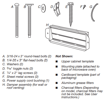
NOTE: Depending on model, aluminum grease filter and charcoal filter may be combined.
Materials Needed
- Standard fittings for wall or roof venting. See “Venting Design Specifications” section.
INSTALLATION INSTRUCTIONS
Remove Cardboard Template
The cardboard piece from the top of the microwave oven packaging is perforated. The piece inside the perforation is for use as a rear wall template.
- Cut along the perforation to separate the template from the rest of the cardboard packaging.
- Set the cardboard template to the side and refer to it during the “Mark Rear Wall” part of installation.
Location Requirements
Check the opening where the microwave oven will be installed. The location must provide:
- Minimum installation dimensions. See “Installation Dimensions” illustration.
- Minimum one 2" x 4" (50.8 x 101.6 mm) wood wall stud and minimum 3\8," (10 mm) thickness drywall or plaster/lath within cabinet opening.
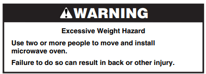
- Support for weight of 150 lbs (68 kg), which includes microwave oven and items placed inside the microwave oven and upper cabinet.
- Grounded electrical outlet inside upper cabinet. See "Electrical Requirements” section.
NOTES:
- If installing the microwave oven near a left sidewall, make sure there is at least 6" (15.2 cm) of clearance between the wall and the microwave oven, so that the door can open fully.
- Some cabinet and building materials are not designed to withstand the heat produced by the microwave oven for cooking. Check with your builder or cabinet supplier to make sure that the materials used will not discolor, delaminate or sustain other damages.
Special Requirements
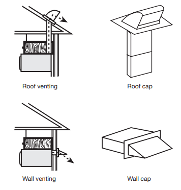
For Wall Venting Installation Only:
- Cutout must be free of any obstructions so that the vent fits properly, and the damper blade opens freely and fully.
For Roof Venting Installation Only:
- If you are using a rectangular to round transition piece, the 3" (7.6 cm) clearance needs to exist above the microwave oven so that the damper blade can open freely and fully. See “Rectangular to Round Transition” illustration in “Venting Design Specifications” section.
Installation Dimensions
NOTE: The grounded 3 prong outlet must be inside the upper cabinet. See “Electrical Requirements” section.
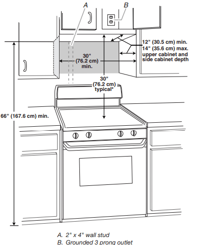
30” (76.2 cm) is typical for 66” (167.6 cm) installation height. Exact dimensions may vary depending on type of range/ cooktop below.
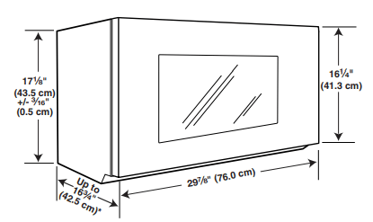
Product Dimensions
Electrical Requirements
Observe all governing codes and ordinances.
Required:
- A 120 volt, 60 Hz, AC only, 15- or 20-amp electrical supply with a fuse or circuit breaker.
Recommended:
- A time-delay fuse or time-delay circuit breaker.
- A separate circuit serving only this microwave oven.
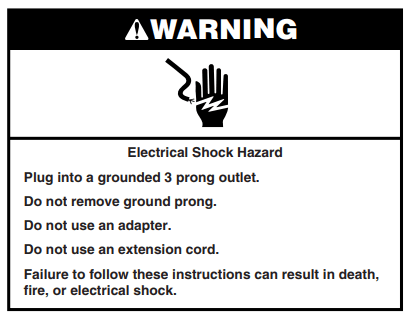
GROUNDING INSTRUCTIONS
For all cord connected appliances:
The microwave oven must be grounded. In the event of an electrical short circuit, grounding reduces the risk of electric shock by providing an escape wire for the electric current. The microwave oven is equipped with a cord having a grounding wire with a grounding plug. The plug must be plugged into an outlet that is properly installed and grounded.
WARNING: Improper use of the grounding plug can result in a risk of electric shock. Consult a qualified electrician or serviceman if the grounding instructions are not completely understood, or if doubt exists as to whether the microwave oven is properly grounded.
Do not use an extension cord. If the power supply cord is too short, have a qualified electrician or serviceman install an outlet near the microwave oven.
SAVE THESE INSTRUCTIONS
Remove Mounting Plate
Depending on your model, the mounting plate may be in the foam packaging, or it may be attached to the back of the microwave oven.
NOTE: To avoid possible damage to the work surface, cover the work surface.
- Remove any remaining contents from the microwave oven cavity.
- If the mounting plate is attached to the back of the microwave oven, remove it and set it aside.
- Tape the microwave oven door closed so that door does not swing open while the microwave oven is being handled.
NOTE: To avoid damage to the microwave oven, do not grip or use the door or door handle while the microwave oven is being handled.
Rotate Blower Motor
The microwave oven is set for recirculation installation. For wall or roof venting, changes must be made to the venting system.
NOTE: Skip this section if you are using recirculation installation. Keep the damper assembly in case the venting method is changed, or the microwave oven is reinstalled in another location where wall or roof venting may be used.
Wall Venting Installation Only
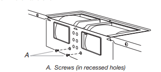
1. Remove screws attaching damper plate to top of microwave oven exterior. Slide damper plate toward the front of the microwave oven and lift up
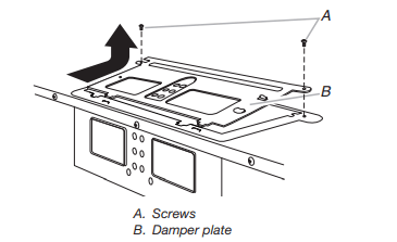
2. Keep damper plate and screws together and set aside.
3. Remove 2 screws attaching blower motor to back of microwave oven.
4. Lift blower motor out of microwave oven.
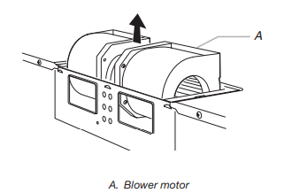
5. Rotate blower motor 180° so that exhaust ports face the back of microwave oven, and lower blower motor back into the microwave oven.
6. Reattach blower motor to back of microwave oven with 2 screws removed in step 3.
7. Reattach damper plate. Make sure damper plate tabs are inserted into the slots in the top of the microwave oven.
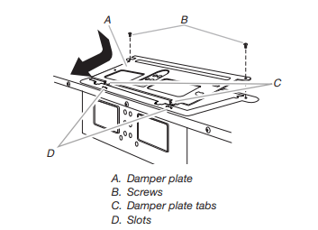
8. Secure damper plate with 2 screws removed in Step 1.
Roof Venting Installation Only
- Repeat Step 1 from “Wall Venting Installation Only.”
- Repeat Step 2 from “Wall Venting Installation Only.”
- Repeat Step 3 from “Wall Venting Installation Only.”
- Repeat Step 4 from “Wall Venting Installation Only.”
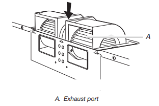
- Rotate blower motor so that exhaust ports face the top of microwave oven, and flat sides of blower motor face back of microwave oven. Lower blower motor back into microwave oven.
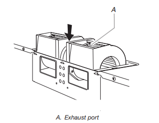
IMPORTANT: If blower motor is not positioned with flat sides facing the back of the microwave oven (as shown), performance will be poor.
6. Reattach blower motor to back of microwave oven with 2 screws removed in Step 3 of “Wall Venting Installation Only.” Securely tighten screws.
NOTE: If blower motor is not correctly oriented, the 2 screws removed in Step 3 cannot be reattached to the microwave oven.
7. Reattach damper plate. Make sure damper plate tabs are inserted into the slots in the top of the microwave oven.
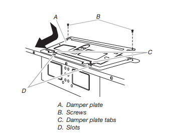
8. Secure damper plate with 2 screws removed in Step 1 of "Wall Venting Installation Only.”
Locate Wall Stud(s)
NOTE: If no wall studs exist within the cabinet opening, do not install the microwave oven.
See illustrations in “Possible Wall Stud Configurations.”
- Using a stud finder, locate the edges of the wall stud(s) within the opening.
- Mark the center of each stud, and draw a plumb line down each stud center. See illustrations in “Possible Wall Stud Configurations.”
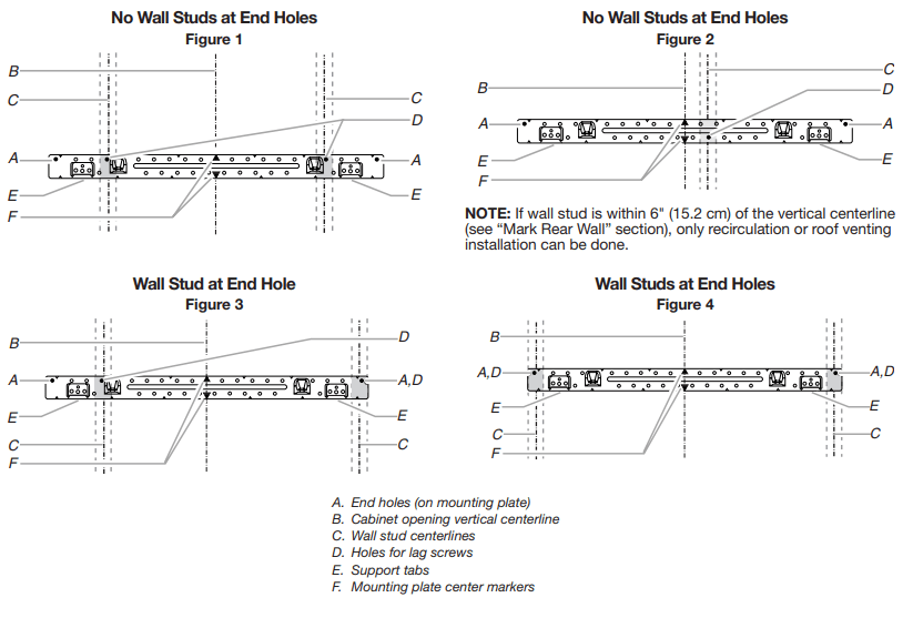
Possible Wall Stud Configurations
These depictions show examples of preferred installation configurations with the mounting plate.
Mark Rear Wall
The microwave oven must be installed on a minimum of 1 wall stud, preferably 2, using a minimum of 1 lag screw, preferably 2.
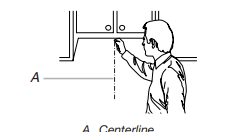
1. Using measuring tape, find and clearly mark the vertical centerline of the opening.
2. Align the center markers on the cardboard template (carton top cap) to the centerline on the wall, making sure it is level, and that the top of the cardboard template is butted up against the bottom edge of the upper cabinet.
NOTES:
- If the front edge of the upper cabinet is lower than the back edge, lower the cardboard template so that its top is level with the front edge of the cabinet.
- If the cardboard template is damaged or unusable, measure and mark the wall with the dimensions described in Step 4
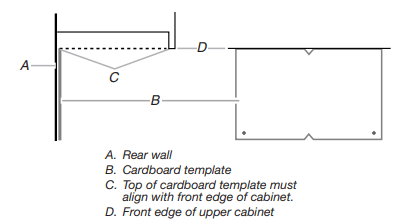
3. Holding the cardboard template in place, mark both holes in the lower corners, and draw a horizontal line across the bottom edge of the cardboard template. These represent the mounting plate’s end holes and bottom edge.
4. Remove the cardboard template and check the markings:
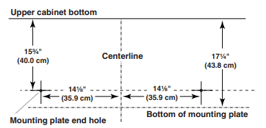
- The bottom edge line must be 17¹⁄₄" (43.8 cm) from the bottom of the upper cabinet and must be level.
- The end holes must be 15³⁄₄" (40.0 cm) from the bottom edge of the upper cabinet and must be on a level line with each other. They must each be 14¹⁄₈" (35.9 cm) from the centerline.
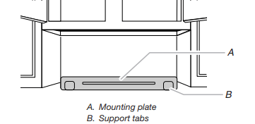
5. With the support tabs facing forward (see illustrations in "Locate Wall Stud(s)” section), align the mounting plate center markers to the centerline on the wall, making sure its bottom edge is aligned to the horizontal line drawn in Step 3, and that the end holes are properly marked. Make sure the mounting plate is level.
6. Holding the mounting plate in place, find the wall stud centerline(s) drawn in Step 2 of “Locate Wall Stud(s),” and mark at least 1, preferably 2 hole(s) through the mounting plate, closest to the wall stud centerline(s). See figures 1, 2 and/or 3 in “Possible Wall Stud Configurations” in “Locate Wall Stud(s)” section. The blackened holes in the shaded areas are ideal hole locations.
7. Set the mounting plate aside.
Wall Venting Installation Only
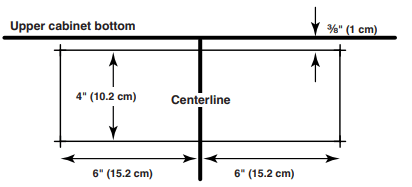
8. Mark the centerline 3\16," (1 cm) down from the bottom edge of the upper cabinet.
9. Using measuring tape, measure out 6" (15.2 cm) on both sides of the centerline, and mark.
10. Measure down 4" (10.2 cm) from the mark made in Step 8, and mark.
11. Using a straightedge, draw the 2 horizontal, level lines through the marks made in steps 8 and 10.
12. Draw the 2 vertical, plumb lines down from the marks made in Step 9 to complete the 12" x 4" (30.5 x 10.2 cm) rectangle. This is the venting cutout area.
13. Cut a 3\4" (19 mm) hole in one corner of the cutout area.
14. Using a keyhole saw, cut out the venting cutout area.
Drill Holes in Rear Wall
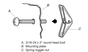
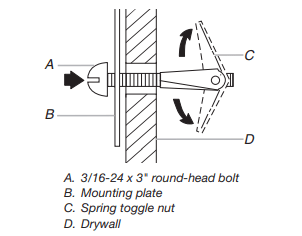
In addition to being installed on at least 1 wall stud, the mounting plate must attach to the wall at both end holes. If the end holes are not over wall studs, use two 3/16-24 x 3" round-head bolts with toggle nuts; if 1 end hole is over a wall stud, use 1 lag screw and one 3/16-24 x 3" round-head bolt with toggle nut; or if both end holes are over wall studs, use 2 lag screws. Following are 3 installation configurations.
Installation for No Wall Studs at End Holes (Figures 1 and 2)
- Drill 5\8" (16 mm) holes through the wall at both end holes marked in Step 3 of “Mark Rear Wall.”
- Drill 3\16" (5 mm) hole(s) into the wall stud(s) at the hole(s) marked in Step 6 of “Mark Rear Wall.” Refer to figures 1 and 2 in “Possible Wall Stud Configurations” in “Locate Wall Stud(s)” section.
Installation for Wall Stud at One End Hole (Figure 3)
- Drill a 3\16" (5 mm) hole into the wall stud at the end hole marked in Step 3 of “Mark Rear Wall.”
- If installing on a second wall stud, drill a 3\16" (5 mm) hole into the wall stud at the other hole marked in Step 6 of “Mark Rear Wall.” Refer to Figure 3 in “Possible Wall Stud Configurations” in “Locate Wall Stud(s)” section.
- Drill a 5\8" (16 mm) hole through the wall at the other end hole.
Installation for Wall Studs at Both End Holes (Figure 4)
1. Drill 3\16" (5 mm) holes into the studs at the end holes marked in Step 3 of “Mark Rear Wall.
Attach Mounting Plate to Wall
NOTE: Secure the mounting plate to the wall at both end holes drilled into the wall studs and/or drywall using either 3/16-24 x 3" round-head bolts and toggle nuts or Z\v x 2" lag screws.
Refer to illustrations in “Possible Wall Stud Configurations” in "Locate Wall Stud(s)” section.
No Wall Studs at End Holes (Figures 1 and 2)
NOTE: The mounting plate must be secured to the wall on at least 1 wall stud as well as at both ends.
1. With the support tabs of the mounting plate facing forward, insert 3/16-24 x 3" round-head bolts through both end holes of mounting plate.
2. Start toggle nuts on bolts from the back of the mounting plate. Leave enough space for the toggle nuts to go through the wall and to open.
3. Position mounting plate on the wall.
4. Push the 2 bolts with toggle nuts through the drywall, and finger tighten the bolts to make sure toggle nuts have opened against drywall.
5. Insert lag screw(s) into the hole(s) drilled into wall stud(s) in Step 2 of “Installation for No Wall Studs at End Holes” in the “Drill Holes in Rear Wall” section.
6. Check alignment of mounting plate, making sure it is level.
7. Securely tighten all lag screws and bolts
Wall Stud at One End Hole (Figure 3)
- With the support tabs of the mounting plate facing forward, insert a 3/16-24 x 3" round-head bolt through the end hole that fits over the 5\8," (16 mm) hole drilled in Step 3 of "Installation for Wall Stud at One End Hole” in the “Drill Holes in Rear Wall” section.
- Start a toggle nut on the bolt from the back of the mounting plate. Leave enough space for the toggle nut to go through the wall and to open.
- Position mounting plate on the wall.
- Push the bolt with toggle nut through the drywall, and finger tighten the bolt to make sure toggle nut has opened against drywall.
- Insert a lag screw into the remaining end hole.
- If installing on a second wall stud, insert a lag screw into the other hole drilled in Step 2 of “Installation for Wall Stud at "One End Hole” in the “Drill Holes in Rear Wall” section.
- Check alignment of mounting plate, making sure it is level.
- Securely tighten the lag screw(s) and bolt.
Wall Studs at Both End Holes (Figure 4)
- Position mounting plate on the wall.
- Insert lag screws into both end holes.
- Check alignment of mounting plate, making sure it is level.
- Securely tighten the lag screws.
Prepare Upper Cabinet
1. Disconnect power to outlet.
2. Remove all contents from upper cabinet.
3. Place Upper Cabinet Template against the bottom of the upper cabinet, and attach with tape or thumbtacks. Make sure the template centerline aligns with the vertical centerline on the rear wall. The “rear wall” arrows must be against the rear wall so that the holes cut into the upper cabinet align with the holes in the top of the microwave oven.
NOTES:
- If the upper cabinet has a frame around it, trim the template edges so that it fits inside the frame, against the upper cabinet bottom. The template has trim lines to use as guides.
- If the wall behind the microwave oven (as installed) has a partial wall covering (for example, tile backsplash), be sure the “Rear Wall” arrows align to the thickest part of the rear wall (for example, the thickness of the tiles rather than the drywall).
4. Make sure the 10" (25.4 cm) dimension from the rear wall to points “D” and “E” on the template is maintained.
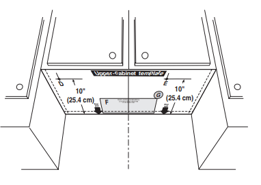
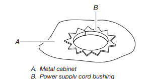
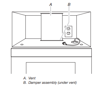
5. Cut the 1¹⁄₂" (3.8 cm) diameter hole at the circular shaded area “G” on the template. This hole is for the power supply cord.
NOTE: If upper cabinet is metal, the supply cord bushing needs to be installed around the supply cord hole as shown.
6. Drill 3\8" (10 mm) holes at points “D” and “E” on the template. These are for two 1/4-20 x 3" bolts and washers used to secure the microwave oven to the upper cabinet.
For Roof Venting Installation Only
7. Cut 3\4" (19 mm) hole at one corner of the shaded rectangular area “F” on Upper Cabinet Template.
8. Using a keyhole saw, cut out the rectangular area.
Install Damper Assembly (for wall venting only)
1. Check that damper blade moves freely and opens fully.
2. Position the damper assembly on the back of the microwave oven so that the damper blade hinge is at the top, and the damper blade opens away from the microwave oven.
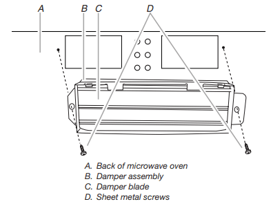
3. Secure damper assembly with 2 sheet metal screws
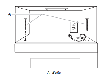
Install the Microwave Oven
IMPORTANT: The control side of the microwave oven is the heavy side. Handle the microwave oven gently.
1. Place a washer on each 1/4-20 x 3" flat-head bolt and place inside upper cabinet near the 3\8," (10 mm) holes.
2. Make sure the microwave oven door is closed and taped shut.
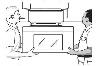
3. Using 2 or more people, lift microwave oven and hang it on support tabs at the bottom of mounting plate.
NOTE: To avoid damage to the microwave oven, do not grip or use the door or door handle while the microwave oven is being handled.
4. With front of microwave oven still tilted, thread power supply cord through the power supply cord hole in the bottom of the upper cabinet.
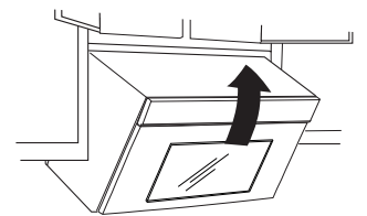
5. Rotate microwave oven up toward upper cabinet.
NOTE: If venting through the wall, make sure the damper assembly fits easily into the vent in the wall cutout.
6. Push microwave oven against mounting plate and hold in place.
NOTE: If microwave oven does not need to be adjusted, skip steps 7-9.
7. If adjustment is required, rotate microwave oven downward. Using 2 or more people, lift microwave oven off of mounting plate, and set aside on a covered surface.
8. Loosen mounting plate screws. Adjust mounting plate and retighten screws.
9. Repeat steps 3-6.
10. With the microwave oven centered, and with at least one person holding it in place, insert bolts through upper cabinet into microwave oven. Tighten bolts until there is no gap between upper cabinet and microwave oven.
NOTES:
- Some upper cabinets may require bolts longer or shorter than 3" (7.6 cm). Longer or shorter bolts are available at most hardware stores.
- Overtightening bolts may warp the top of the microwave oven. To avoid warping, wood filler blocks (installer to provide) may be added. The blocks must be the same thickness as the space between the upper cabinet bottom and the microwave oven
For Roof Venting Installation Only
1. Insert damper assembly through the cabinet cutout so that the long tab of the damper assembly slides under the raised tabs of the damper plate. Then secure with sheet metal screw
NOTE: The screw cannot be installed if the damper assembly is not positioned as shown.
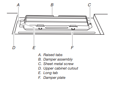
2. Connect vent to damper assembly
Complete Installation
1. Install filters. Refer to the User Instructions for filter placement.
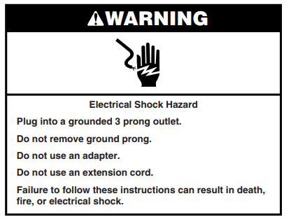
2. Plug microwave oven into grounded 3 prong outlet.
3. Reconnect power.
4. Check the operation of microwave oven by placing 1 cup (250 mL) of water on the turntable and programming a cook time of 1 minute at 100% power. Test vent fan and exhaust by operating the vent fan.
5. If the microwave oven does not operate:
- Check that a household fuse has not blown, or that a circuit breaker has not tripped. Replace the fuse or reset the circuit breaker. If the problem continues, call an electrician.
- Check that the power supply cord is plugged into a grounded 3 prong outlet.
- See the User Instructions for troubleshooting information.
Installation is now complete.
Save Installation Instructions for future use
VENTING DESIGN SPECIFICATIONS
This section is intended for architectural designer and builder/ contractor reference only.
NOTES:
- Vent materials needed for installation are not provided with microwave hood combination.
- We do not recommend using a flexible metal vent.
- To avoid possible product damage, be sure to vent air outside, unless using recirculation installation. Do not vent exhaust air into concealed spaces, such as spaces within walls or ceilings, attics, crawl spaces or garages.
For optimal venting installation, we recommend:
- using roof or wall caps that have back draft dampers
- using a rigid metal vent
- using the most direct route by minimizing the length of the vent and number of elbows to provide efficient performance
- using uniformly sized vents
- using duct tape to seal all joints in the vent system
- using caulking compound to seal exterior wall or roof opening around cap
- not installing 2 elbows together, for optimal hood performance
If venting through the wall, be sure that there is proper clearance within the wall for the damper to open fully.
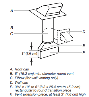
If venting through the roof, and rectangular to round transition is used, be sure there is at least 3" (7.6 cm) of clearance between the top of the microwave oven and the transition piece. See “Rectangular to Round Transition” illustration
Rectangular to Round Transition
NOTE: The minimum 3" (7.6 cm) clearance must exist between the top of the microwave oven and the rectangular to round transition piece so that the damper can open freely and fully.
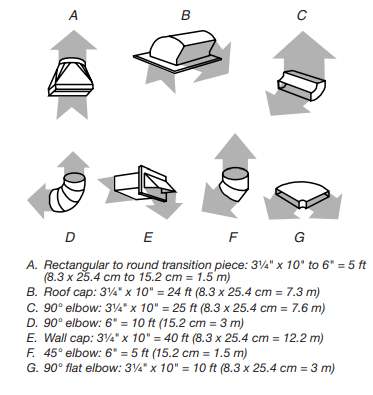
Recommended Standard Fittings
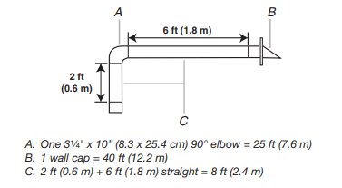
The following length equivalents are for use when figuring vent length. See the examples in “Recommended Vent Length.”
Recommended Vent Length
A 3¹⁄₄" x 10” (8.3 x 25.4 cm) rectangular or 6” (15.2 cm) round vent should be used.
The total length of the vent system including straight vent, elbow(s), transitions and wall or roof caps must not exceed the equivalent of 140 ft (42.7 m) for either type of vent. See "Recommended Standard Fittings” section for equivalent lengths.
For best performance, use no more than three 90° elbows.
To calculate the length of the system you need, add the equivalent lengths of each vent piece used in the system.
See the following examples:
3¹⁄₄" x 10" (8.3 x 25.4 cm) vent system = 73 ft (22.2 m) total
6" (15.2 cm) vent system = 73 ft (22.2 m) total
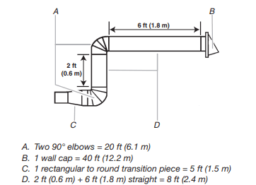
If the existing vent is round, a rectangular to round transition piece must be used. In addition, a rectangular 3" (7.6 cm) extension vent between the damper assembly and rectangular to round transition piece must be installed to keep the damper from sticking
ASSISTANCE
Call your authorized dealer or service center. When you call, you will need the microwave oven model number and serial number. Both numbers can be found on the model and serial number plate, which is located behind the microwave oven door on the front frame of the microwave oven.
If you need additional assistance, call us at our toll free number or visit our website listed in the User Guide.
Replacement Parts
If any of the installation hardware needs to be replaced, call us at our toll free number listed in the User Guide.
Following is a list of available replacement parts. You will need your model number located on the front facing of the microwave oven opening, behind the door.
- Damper Assembly
- Mounting Plate
- Upper Cabinet Template
- Mounting Screw Kit (includes parts A-G in “Parts Supplied” in the “Tools and Parts” section)
Accessories
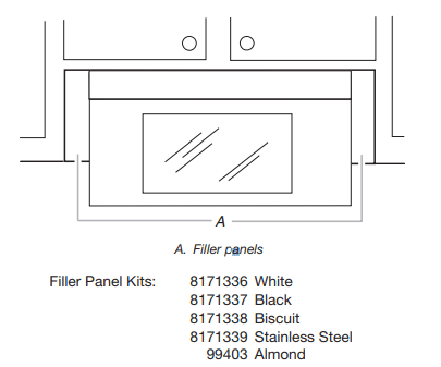
Filler Panel Kits are available from your dealer to use when installing this microwave oven in a 36" (91.4 cm) or 42" (106.7 cm) wide opening. The filler panels come in pairs. Each panel is 3" (7.6 cm) wide.
OPERATING YOUR MICROWAVE OVEN
Settings/Features
Clock
The Clock is a 12-hour (12:00-11:59) clock. Touch CLOCK, enter time, then touch CLOCK or the Start control.
Timer
With the microwave oven in standby mode, touch the Timer control, enter time, then touch the Timer control or the Start control. Cook functions may be entered while the Timer is counting down. To cancel timer, touch Timer control while the Timer countdown is active in the display.
Control Lock
Activate to avoid unintended start. Touch and hold the Cancel control for about 3 seconds until 2 tones sound and padlock icon appears in the display. Repeat to unlock control.
Vent Fan
High (“SPd2”), low (“SPd1”) and off. Comes on automatically as cooling fan during any cook function.
Vent Timer (on some models): Set vent fan to run for exactly 30 minutes, or to run for only 30 minutes more (off after 30 minutes). The vent fan may be turned off at any time using the Vent Fan control. Touch and hold number pad “4” for about 3 seconds until a tone sounds and the vent fan turns on.
Tones
Programming tones and signals. Programming tones may be turned off, or all tones (including end-of-function signals) may be turned off. To turn off programming tones, touch and hold number pad “1” for about 3 seconds, until a confirmation tone sounds. Repeat to turn back on programming tones. To turn off all tones, touch and hold number pad “2” for about 3 seconds until a confirmation tone sounds. Repeat to turn back on all tones.
Demo Mode
Activate to practice using the control without actually turning on the magnetron. Touch and hold number pad “3” for about 3 seconds until a confirmation tone sounds, and “DEMO” icon lights up in the display. Repeat to deactivate.
Standby Mode
When no functions are working, oven will switch to standby power mode and dim the brightness after 5 minutes. Press any button or open/close the door and the display will return to the normal brightness.
Turntable
For best cooking results, do not operate the microwave oven without having the turntable in place.
Cookware and Dinnerware
Microwave-Safe
- Browning dish (Follow manufacturer recommendations.)
- Ceramic glass, glass
- China, earthenware (Follow manufacturer recommendations.)
- Melamine (Follow manufacturer recommendations.)
- Paper towels, paper plates, napkins (Use non-recycled paper.)
- Plastic wraps, bags, covers, dinnerware, containers (Follow manufacturer recommendations.)
- Pottery and clay (Follow manufacturer recommendations.)
- Silicone bakeware (Follow manufacturer recommendations.)
- Wax paper
Do Not Use
- Metal cookware and bakeware
- Straw or wicker
- Gold, silver or pewter
- Non-approved meat thermometers, skewers
- Twist ties
- Foil liners, such as sandwich wrappers
- Staples
- Objects with gold or silver trim or with metallic glaze
To Test Cookware/Dinnerware: Place dish in microwave oven with 1 cup (250 mL) of water beside it. Program 1 minute of cook time at 100%. If dish becomes hot and the water stays cool, do not use the dish in the microwave oven.
Microwave Oven Use
For list of preset programs, see the Cooking Guide label on the front facing of the microwave oven opening, behind the door.
Manual Cooking/Stage Cooking
Touch COOK TIME, touch number pads to enter time, touch COOK POWER (if not 100%), touch number pads to enter power level (10-90), and then touch the Start control.
If programming additional stages, enter the cook time and cook power of each before touching the Start control.
Preset Cooking
Touch COOK, enter number code of food item, enter quantity, and then touch the Start control.
Preset Reheating
Touch REHEAT, enter number code of food item, enter quantity if needed, then touch the Start control.
Preset Defrosting
Unwrap food. Touch DEFROST, enter number code of food item, enter weight, then touch the Start control.
Soften/Melt
Touch SOFTEN/MELT, enter number code of food item, enter quantity, then touch the START control.
Popcorn
Touch POPCORN. Enter bag size in ounces: 3.0 or 3.5 (85 or 99 g), then touch START control
(Baked) Potato
Touch (BAKED) POTATO. Enter number of potatoes: 1, 2, 3 or 4, about 10 to 13 oz (283 to 367 g) each, then touch START control.
NOTE: Place fork-pierced potatoes around turntable edges, at least 1” (2.5 cm) apart. Place a single potato to the side of the turntable (not in the center).
Pizza (reheat)
Touch PIZZA. Enter number of slices: 1, 2 or 3, about 4 oz (113 g) each, then touch START control.
MICROWAVE OVEN CARE
General Cleaning
IMPORTANT: Before cleaning, make sure all controls are off and the microwave oven is cool. Always follow label instructions on cleaning products.
To avoid damage to the microwave oven caused by arcing due to soil buildup, keep cavity, microwave inlet cover and area where the door touches the frame clean.
Clean with mild soap, water and a soft cloth or sponge, or as indicated below.
- Grease filters: mild soap and water or dishwasher.
- Door and exterior: mild soap and water, or glass cleaner applied to paper towel.
- Control panel: sponge or soft cloth and water.
- Stainless steel (on some models): mild soap and water, then rinse with clean water and dry with soft cloth, or use stainless steel cleaner.
- Turntable: mild soap and water or dishwasher.
Installing/Replacing Filters and Light Bulbs
- Grease filters: Grease filters are on the underside of microwave oven. Clean monthly. Slide the filter away from the tab area, and drop out the filter. To reinstall, place end of the filter into the opening opposite the tab area, swing up the other end, and slide it toward the tab area.
- Charcoal filter: The charcoal filter is behind the vent grille at the top front of the microwave oven. The charcoal filter cannot be cleaned, and should be replaced about every months. Remove two screws on the vent grille, tilt the grille forward, lift it out, and remove filter. To reinstall, place the filter into its slotted area – wire mesh side up, replace vent grille, and secure with screws.
- Cooktop light: The cooktop light bulb is located on the underside of the microwave oven, and is replaceable. Remove bulb cover screws, and open the bulb cover. Replace bulb, close bulb cover, and secure with screws.
- Cavity light: The cavity light bulb is located behind the vent grille at the top front of the microwave oven, under the bulb cover, and is replaceable. Remove two screws on the vent grille, tilt the grille forward, and lift it out. Remove bulb cover screw, open bulb cover and replace bulb. Close bulb cover, and secure with screw. Replace vent grille, and secure with screws.
PROBLEM SOLVER
Microwave oven will not operate
Check the following:
- Household fuse or circuit breaker - If a household fuse has blown or a circuit breaker has tripped, replace the fuse or reset the circuit breaker. If the problem continues, call an electrician.
- Magnetron - Try to heat 1 cup (250 mL) of cold water for 2 minutes at 100% cooking power. If water does not heat, try the steps in the bullets below. If microwave oven still does not operate, call for service.
- Door - Firmly close door. On some models, if a packaging spacer is attached to inside of the door, remove it, then firmly close door. If a message about the door appears in the display, the door has been closed for 5 minutes or more without the microwave oven being started. This occurs to avoid unintended starting of the microwave oven. Open and close the door, then start the cycle.
- Control - Make sure control is set properly. Make sure Control Lock is off. Make sure Demo Mode (on some models) is off.
Arcing in the microwave oven
Check the following:
- Soil buildup - Soil buildup on cavity walls, microwave inlet cover, cooking rack supports, and area where the door touches the frame can cause arcing. See “General Cleaning” in “Microwave Oven Care” section.
Turntable alternates rotation directions
- This is normal and depends on motor rotation at the beginning of the cycle.
Display shows messages
- A flashing “:” or “PF” means there has been a power failure. Reset the clock.
- A letter followed by a number is an error indicator. Call for assistance.
Fan running during cooktop usage
- This is normal. The microwave oven’s cooling fan (on some models), which is separate from the vent fan, automatically comes on during microwave oven operation to cool the microwave oven. It may also automatically come on and cycle on and off to cool the microwave oven’s controls while the cooktop below is being used.
Radio, TV or cordless phone interference
Check the following:
- Proximity - Move the receiver away from the microwave oven, or adjust the radio or TV antenna.
- Soil - Make sure the microwave oven door and sealing surfaces are clean.
- Frequency - Some 2.4 GHz-based cordless phones and home wireless networks may experience static or noise while microwave oven is on. Use a corded phone, a different frequency cordless phone or avoid using these items during microwave oven operation.