User Manual Whirlpool WMH31017HZ Microwave Hood Combination
INSTALLATION REQUIREMENTS
Tools and Parts
Parts Supplied
For information on reordering, see the “Replacement Parts” section.
NOTE: The hardware items listed here are for wood studs. For other types of wall structures, be sure to use appropriate fasteners.

NOTE: Depending on model, aluminum grease filter and charcoal filter may be combined.
Materials Needed
- Standard fittings for wall or roof venting. See the “Venting Design Specifications” section
Remove Cardboard Template
The cardboard piece from the top of the microwave oven packaging is perforated. The piece inside the perforation is for use as a rear wall template.
- Cut along the perforation to separate the template from the rest of the cardboard packaging.
- Set the cardboard template to the side and refer to it during the “Mark Rear Wall” part of installation.
Depending on your model, it may use full carton box for packing, then skip remove cardboard template steps, but use the wall template for "Mark Rear Wall" part of installation.
Location Requirements
Check the opening where the microwave oven will be installed. The location must provide:
- Minimum installation dimensions. See the “Installation Dimensions” illustration.
- Minimum one 2" x 4" (50.8 x 101.6 mm) wood wall stud and minimum ³⁄₈" (10 mm) thickness drywall or plaster/lath within cabinet opening.
- Support for weight of 150 lbs (68 kg) which includes microwave oven and items placed inside the microwave oven and upper cabinet.
- Grounded electrical outlet inside upper cabinet. See the "Electrical Requirements” section.
NOTES:
- If installing the microwave oven near a left sidewall, make sure there is at least 6" (15.2 cm) of clearance between the wall and the microwave oven so that the door can open fully.
- Some models have a pocket handle. If installing the microwave near a right side wall, make sure there is at least 3 inches of clearance between wall and microwave oven so you can grab the handle integrated inside the door.
- Some cabinet and building materials are not designed to withstand the heat produced by the microwave oven for cooking. Check with your builder or cabinet supplier to make sure that the materials used will not discolor, delaminate, or sustain other damages.
Special Requirements
For Wall Venting Installation Only:
- Cutout must be free of any obstructions so that the vent fits properly and the damper blade opens freely and fully.
For Roof Venting Installation Only:
- If you are using a rectangular-to-round transition piece, the 3" (7.6 cm) clearance needs to exist above the microwave oven so that the damper blade can open freely and fully. See “Rectangular to Round Transition” illustration in the Venting Design Specifications” section
Installation Dimensions
NOTE: The grounded 3 prong outlet must be inside the upper cabinet. See the “Electrical Requirements” section.

30 "( 76.2 cm) is typical for 66” (167.6 cm) installation height. Exact dimensions may vary depending on type of range/ cooktop below.
NOTE: To ensur e good performance, do not obstruct top vent airflow. If cabinets are deeper than 14” (35.6 cm) but no mor e than 15” (38.1cm), use the bump out mounting kit r e placing the I bar mounting plate from the wall. The bump out mounting kit part # W11185746) is not provided but can be purchased from Whirlpool.

Product Dimensions

Overall depth of product will vary slightly depending on door design.
Electrical Requirements

Observe all governing codes and ordinances.
Required:
- A 120 V, 60 Hz, AC only, 15 or 20 A electrical supply with a fuse or circuit breaker
Recommended:
- A time-delay fuse or time-delay circuit breaker
- A separate circuit serving only this microwave oven
GROUNDING INSTRUCTIONS
- For all cord connected appliances:
The microwave oven must be grounded. In the event of an electrical short circuit, grounding reduces the risk of electric shock by providing an escape wire for the electric current. The microwave oven is equipped with a cord having a grounding wire with a grounding plug. The plug must be plugged into an outlet that is properly installed and grounded.
WARNING: Improper use of the grounding plug can result in a risk of electric shock. Consult a qualified electrician or serviceman if the grounding instructions are not completely understood, or if doubt exists as to whether the microwave oven is properly grounded.
Do not use an extension cord. If the power supply cord is too short, have a qualified electrician or serviceman install an outlet near the microwave oven.
SAVE THESE INSTRUCTIONS
INSTALLATION INSTRUCTIONS
Remove Mounting Plate
Depending on your model, the mounting plate may be in the foam packaging or it may be attached to the back of the microwave oven.
NOTE: To avoid possible damage to the work surface, cover the work surface.
- Remove any remaining contents from the microwave oven cavity.
- If the mounting plate is attached to the back of the microwave oven, remove it and set it aside.
- Tape the microwave oven door closed so that door does not swing open while the microwave oven is being handled.
NOTE: To avoid damage to the microwave oven, do not grip or use the door or door handle while the microwave oven is being handled.
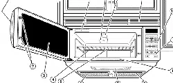
Rotate Blower Motor
The microwave oven is set for recirculation installation. For wall or roof venting, changes must be made to the venting system.
NOTE: Skip this section if you are using recirculation installation. Keep the damper assembly in case the venting method is changed, or the microwave oven is reinstalled in another location where wall or roof venting may be used.
Wall Venting Installation Only
1. Remove screws attaching damper plate to top of microwave oven exterior. Slide damper plate toward the front of the microwave oven and lift up.

2. Keep damper plate and screws together and set aside
3. Remove 2 screws attaching blower motor to back of microwave oven.

4. Lift blower motor out of microwave oven

5. Rotate blower motor 180° so that exhaust ports face the back of microwave oven and lower blower motor back into the microwave oven.

6. Using diagonal wire cutting pliers, gently snip out the rectangular damper vent covers at the perforations.

7. Reattach blower motor to back of microwave oven with 2 screws removed in Step 3.
8. Reattach damper plate. Make sure damper plate tabs are inserted into the slots in the top of the microwave oven.

9. Secure damper plate with 2 screws removed in Step 1
Roof Venting Installation Only
1. Repeat Step 1 from “Wall Venting Installation Only.”
2. Repeat Step 2 from “Wall Venting Installation Only.”
3. Repeat Step 3 from “Wall Venting Installation Only.”
4. Repeat Step 4 from “Wall Venting Installation Only.”
5. Rotate blower motor so that exhaust ports face the top of microwave oven and flat sides of blower motor face back of microwave oven. Lower blower motor back into microwave oven.
IMPORTANT: If blower motor is not positioned with flat sides facing the back of the microwave oven (as shown), performance will be poor
6. Reattach blower motor to back of microwave oven with screws removed in Step 3 of “Wall Venting Installation Only.” Securely tighten screws.
NOTE: If blower motor is not correctly oriented, the 2 screws removed in Step 3 cannot be reattached to the microwave oven.
7. Using diagonal wire cutting pliers, gently snip out the rectangular vent covers on the damper plate removed in Step at the perforations.

8. Reattach damper plate. Make sure damper plate tabs are inserted into the slots in the top of the microwave oven.

9. Secure damper plate with 2 screws removed in Step 1 of "Wall Venting Installation Only.”
Locate Wall Stud(s)
NOTE: If no wall studs exist within the cabinet opening, do not install the microwave oven.
See illustrations in “Possible Wall Stud Configurations.”
- Using a stud finder, locate the edges of the wall stud(s) within the opening.
- Mark the center of each stud and draw a plumb line down each stud center. See illustrations in “Possible Wall Stud Configurations.
Possible Wall Stud Configurations
These depictions show examples of preferred installation configurations with the mounting plate.
No Wall Studs at End Holes Figure 1

No Wall Studs at End Holes Figure 2

Wall Stud at End Hole Figure 3

Wall Studs at End Holes Figure 4

Mark Rear Wall
The microwave oven must be installed on a minimum of 1 wall stud, preferably 2, using a minimum of 1 lag screw, preferably 2.
1. Using measuring tape, find and clearly mark the vertical centerline of the opening.
2. Align the center markers on the cardboard template (carton top cap) or Wall template, to the centerline on the wall, making sure it is level, and that the top of the cardboard template or wall template is butted up against the bottom edge of the upper cabinet.
NOTES:
- If the front edge of the upper cabinet is lower than the back edge, lower the cardboard template or wall template so that its top is level with the front edge of the cabinet.
- If the cardboard template or wall template is damaged or unusable, measure and mark the wall with the dimensions described in Step 4.

3. Holding the cardboard template or wall template in place, mark both holes in the lower corners and draw a horizontal line across the bottom edge of the cardboard template or wall template. These represent the mounting plate’s end holes and bottom edge.
4. Remove the cardboard template or wall template and check the markings:

- The bottom edge line must be 17⁵⁄₁₆" (44.02 cm) from the bottom of the upper cabinet and must be level.
- The end holes must be 15 ⁵⁄₈" (39.71cm) from the bottom edge of the upper cabinet and must be on a level line with each other. They must each be 14¹⁄₈" (35. 96 cm) from the centerline
5. With the support tabs facing forward (see illustrations in the Locate Wall Stud(s)” section), align the mounting plate center markers to the centerline on the wall, making sure its bottom edge is aligned to the horizontal line drawn in Step 3 and that the end holes are properly marked. Make sure the mounting plate is level.
6. Holding the mounting plate in place, find the wall stud centerline(s) drawn in Step 2 of “Locate Wall Stud(s)” and mark at least 1, preferably 2 hole(s) through the mounting plate, closest to the wall stud centerline(s). See figures 1, 2, and/or 3 in “Possible Wall Stud Configurations” in the “Locate Wall Stud(s)” section. The blackened holes in the shaded areas are ideal hole locations.
7. Set the mounting plate aside.
Wall Venting Installation Only

8. Mark the centerline ³⁄₈" (1 cm) down from the bottom edge of the upper cabinet.
9. Using measuring tape, measure out 6" (15.2 cm) on both sides of the centerline, and mark.
10. Measure down 4" (10.2 cm) from the mark made in Step 8 and mark.
11. Using a straightedge, draw the 2 horizontal, level lines through the marks made in steps 8 and 10.
12. Draw the 2 vertical plumb lines down from the marks made in Step 9 to complete the 12" x 4" (30.5 x 10.2 cm) rectangle. This is the venting cutout area.
13. Cut a ³⁄₄" (19 mm) hole in one corner of the cutout area.
14. Using a keyhole saw, cut out the venting cutout area.
Drill Holes in Rear Wall
In addition to being installed on at least 1 wall stud, the mounting plate must attach to the wall at both end holes. If the end holes are not over wall studs, use two ³⁄₁₆-24 x 3" round-head bolts with toggle nuts; if 1 end hole is over a wall stud, use 1 lag screw and one ³⁄₁₆-24 x 3" round-head bolt with toggle nut; or if both end holes are over wall studs, use 2 lag screws. Following are installation configurations.
Installation for No Wall Studs at End Holes (Figures 1 and 2)
- Drill ⁵⁄₈" (16 mm) holes through the wall at both end holes marked in Step 3 of “Mark Rear Wall.”
- Drill ³⁄₁₆" (5 mm) hole(s) into the wall stud(s) at the hole(s) marked in Step 6 of “Mark Rear Wall.” Refer to figures 1 and in “Possible Wall Stud Configurations” in the “Locate Wall Stud(s)” section.
Installation for Wall Stud at One End Hole (Figure 3)
- Drill a ³⁄₁₆" (5 mm) hole into the wall stud at the end hole marked in Step 3 of “Mark Rear Wall.
- If installing on a second wall stud, drill a ³⁄₁₆" (5 mm) hole into the wall stud at the other hole marked in Step 6 of “Mark Rear Wall.” Refer to Figure 3 in “Possible Wall Stud Configurations” in the “Locate Wall Stud(s)” section.
- Drill a ⁵⁄₈" (16 mm) hole through the wall at the other end hole.
Installation for Wall Studs at Both End Holes (Figure 4)
- Drill 3\16" (5 mm) holes into the studs at the end holes marked in Step 3 of “Mark Rear Wall.”
Attach Mounting Plate to Wall
NOTE: Secure the mounting plate to the wall at both end holes drilled into the wall studs and/or drywall using either C\zn-24 x 3" round-head bolts and toggle nuts or Z\v x 2" lag screws.
Refer to illustrations in “Possible Wall Stud Configurations” in the "Locate Wall Stud(s)” section.
No Wall Studs at End Holes (Figures 1 and 2)
NOTE: The mounting plate must be secured to the wall on at least 1 wall stud as well as at both ends.
1. With the support tabs of the mounting plate facing forward, insert C\zn-24 x 3" round-head bolts through both end holes of mounting plate.
2. Start toggle nuts on bolts from the back of the mounting plate. Leave enough space for the toggle nuts to go through the wall and to open.

3. Position mounting plate on the wall.
4. Push the 2 bolts with toggle nuts through the drywall and finger tighten the bolts to make sure toggle nuts have opened against drywall

5. Insert lag screw(s) into the hole(s) drilled into wall stud(s) in Step 2 of “Installation for No Wall Studs at End Holes” in the "Drill Holes in Rear Wall” section.
6. Check alignment of mounting plate, making sure it is level.
7. Securely tighten all lag screws and bolts.
Wall Stud at One End Hole (Figure 3)
- With the support tabs of the mounting plate facing forward, insert a C\zn-24 x 3" round-head bolt through the end hole that fits over the B\," (16 mm) hole drilled in Step 3 of “Installation for Wall Stud at One End Hole” in the “Drill Holes in Rear Wall” section.
- Start a toggle nut on the bolt from the back of the mounting plate. Leave enough space for the toggle nut to go through the wall and to open.
- Position mounting plate on the wall.
- Push the bolt with toggle nut through the drywall and finger tighten the bolt to make sure toggle nut has opened against drywall.
- Insert a lag screw into the remaining end hole.
- If installing on a second wall stud, insert a lag screw into the other hole drilled in Step 2 of “Installation for Wall Stud at One End Hole” in the “Drill Holes in Rear Wall” section.
- Check alignment of mounting plate, making sure it is level.
- Securely tighten the lag screw(s) and bolt.
Wall Studs at Both End Holes (Figure 4)
- Position mounting plate on the wall.
- Insert lag screws into both end holes.
- Check alignment of mounting plate, making sure it is level.
- Securely tighten the lag screws.
Prepare Upper Cabinet
1. Disconnect power to outlet.
2. Remove all contents from upper cabinet.
3. Place Upper Cabinet Template against the bottom of the upper cabinet and attach with tape or thumbtacks. Make sure the template centerline aligns with the vertical centerline on the rear wall.
The “rear wall” arrows must be against the rear wall so that the holes cut into the upper cabinet align with the holes in the top of the microwave oven.
NOTES:
- If the upper cabinet has a frame around it, trim the template edges so that it fits inside the frame, against the upper cabinet bottom. The template has trim lines to use as guides.
- If the wall behind the microwave oven (as installed) has a partial wall covering (for example, tile backsplash), be sure the “Rear Wall” arrows align to the thickest part of the rear wall (for example, the thickness of the tiles rather than the drywall).
4. Make sure the 10" (25.4 cm) dimension from the rear wall to points “D” and “E” on the template is maintained

5. Cut the 1¹⁄₂" (3.8 cm) diameter hole at the circular shaded area “G” on the template. This hole is for the power supply cord.

NOTE: If upper cabinet is metal, the supply cord bushing needs to be installed around the supply cord hole as shown.
6. Drill ³⁄₈" (10 mm) holes at points “D” and “E” on the template. These are for two ¹⁄₄-20 x 3" bolts and washers used to secure the microwave oven to the upper cabinet.
For Roof Venting Installation Only
7. Cut ³⁄₄" (19 mm) hole at one corner of the shaded rectangular area “F” on Upper Cabinet Template.
8. Using a keyhole saw, cut out the rectangular area.
Install Damper (Assembly for wall venting only)
1. Check that damper blade moves freely and opens fully.
2. Position the damper assembly on the back of the microwave oven so that the damper blade hinge is at the top and the damper blade opens away from the microwave oven

3. Secure damper assembly with 2 6 x ³/₈" sheet metal screws.
Install the Microwave Oven

IMPORTANT: The control side of the microwave oven is the heavy side. Handle the microwave oven gently
1. Remove the 2 packing spacers from the top of the vent grille before using the microwave oven.

Note: Depending on your model, it may has no packing spaces. If no packing spaces, install your microwave oven start from Step 2.
2. Place a washer on each ¹⁄₄-20 x 3" flat-head bolt and place inside upper cabinet near the ³⁄₈" (10 mm) holes
3. Make sure the microwave oven door is closed and taped shut.

4. Using 2 or more people, lift microwave oven and hang it on support tabs at the bottom of mounting plate.
NOTE: To avoid damage to the microwave oven, do not grip or use the door or door handle while the microwave oven is being handled.

5. With front of microwave oven still tilted, thread power supply cord through the power supply cord hole in the bottom of the upper cabinet.

6. Rotate microwave oven up toward upper cabinet.
NOTE: If venting through the wall, make sure the damper assembly fits easily into the vent in the wall cutout.
7. Push microwave oven against mounting plate and hold in place.
NOTE: If microwave oven does not need to be adjusted, skip steps 7 through 9.
8. If adjustment is required, rotate microwave oven downward. Using 2 or more people, lift microwave oven off of mounting plate and set aside on a covered surface.
9. Loosen mounting plate screws. Adjust mounting plate and retighten screws.
10. Repeat steps 3 through 6.
11. With the microwave oven centered, and with at least one person holding it in place, insert bolts through upper cabinet into microwave oven. Tighten bolts until there is no gap between upper cabinet and microwave oven.
NOTES:
- Some upper cabinets may require bolts longer or shorter than 3" (7.6 cm). Longer or shorter bolts are available at most hardware stores.
- Overtightening bolts may warp the top of the microwave oven. To avoid warping, wood filler blocks (installer to provide) may be added. The blocks must be the same thickness as the space between the upper cabinet bottom and the microwave oven.

For Roof Venting Installation Only
1. Insert damper assembly through the cabinet cutout so that the long tab of the damper assembly slides under the raised tabs of the damper plate. Then secure with x ³/₈" sheet metal screw.
NOTE: The screw cannot be installed if the damper assembly is not positioned as shown

2. Connect vent to damper assembly

Complete Installation

- Install filters. Refer to the User Instructions for filter placement.
- Plug microwave oven into grounded 3 prong outlet.
- Reconnect power.
- Check the operation of microwave oven by placing 1 cup mL) of water on the turntable and programming a cook time of 1 minute at 100% power. Test vent fan and exhaust by operating the vent fan.
- If the microwave oven does not operate:
- Check that a household fuse has not blown, or that a circuit breaker has not tripped. Replace the fuse or reset the circuit breaker. If the problem continues, call an electrician.
- Check that the power supply cord is plugged into a grounded 3 prong outlet.
- See the User Instructions for troubleshooting information.
Installation is now complete. Save Installation Instructions for future use.
VENTING DESIGN SPECIFICATIONS
This section is intended for architectural designer and builder/ contractor reference only.
NOTES:
- Vent materials needed for installation are not provided with microwave hood combination.
- We do not recommend using a flexible metal vent.
- To avoid possible product damage, be sure to vent air outside, unless using recirculation installation. Do not vent exhaust air into concealed spaces, such as spaces within walls or ceilings, attics, crawl spaces, or garages.
For optimal venting installation, we recommend:
- Using roof or wall caps that have backdraft dampers
- Using a rigid metal vent
- Using the most direct route by minimizing the length of the vent and number of elbows to provide efficient performance
- Using uniformly sized vents
- Using duct tape to seal all joints in the vent system
- Using caulking compound to seal exterior wall or roof opening around cap
- Not installing 2 elbows together for optimal hood performance
If venting through the wall, be sure that there is proper clearance within the wall for the damper to open fully.
If venting through the roof, and rectangular-to-round transition is used, be sure there are at least 3" (7.6 cm) of clearance between the top of the microwave oven and the transition piece. See “Rectangular-to-Round Transition” illustration.

Rectangular-to-Round Transition
NOTE: The minimum 3" (7.6 cm) clearance must exist between the top of the microwave oven and the rectangular to round transition piece so that the damper can open freely and fully.

Recommended Standard Fittings
The following length equivalents are for use when figuring vent length. See the examples in “Recommended Vent Length”.

Recommended Vent Length
A 3¹⁄₄" x 10" (8.3 x 25.4 cm) rectangular or 6" (15.2 cm) round vent should be used.
The total length of the vent system including straight vent, elbow(s), transitions, and wall or roof caps must not exceed the equivalent of 140 ft (42.7 m) for either type of vent. See the "Recommended Standard Fittings” section for equivalent lengths.
For best performance, use no more than three 90° elbows.
To calculate the length of the system you need, add the equivalent lengths of each vent piece used in the system. See the following examples:
3x 1/4" x 10" (8.3 x 25.4 cm) vent system = 73 ft (22.2 m) total

6" (15.2 cm) vent system = 73 ft (22.2 m) total

If the existing vent is round, a rectangular-to-round transition piece must be used. In addition, a rectangular 3" (7.6 cm) extension vent between the damper assembly and rectangularto-round transition piece must be installed to keep the damper from sticking.
ASSISTANCE
Call your authorized dealer or service center. When you call, you will need the microwave oven model number and serial number. Both numbers can be found on the model and serial number plate, which is located behind the microwave oven door on the front frame of the microwave oven.
If you need additional assistance, call us at our toll-free number or visit our website listed in the User Guide.
Replacement Parts
If any of the installation hardware needs to be replaced, call us at our toll-free number listed in the User Guide.
Following is a list of available replacement parts. You will need your model number located on the front facing of the microwave oven opening, behind the door.
- Damper assembly
- Mounting plate
- Upper cabinet template
- Mounting Screw Kit (includes parts A through G in “Parts
- Supplied” in the “Tools and Parts” section)
Accessories
Filler Panel Kits are available from your dealer to use when installing this microwave oven in a 36" (91.4 cm) or 42" cm) wide opening. The filler panels come in pairs. Each panel is 3" (7.6 cm) wide.

TROUBLESHOOTING
First try the solutions suggested here. If you need further assistance or more recommendations that may help you avoid a service call, refer to the warranty page in this manual and scan the code with your mobile device.
Microwave oven will not operate
Check the following:
- Household fuse or circuit breaker: If a household fuse has blown or a circuit breaker has tripped, replace the fuse or reset the circuit breaker. If the problem continues, call an electrician.
- Magnetron: Try to heat 1 cup (250 mL) of cold water for 2 minutes at 100% cooking power. If water does not heat, try the steps in the bullets below. If microwave oven still does not operate, call for service.
- Door: Firmly close door. On some models, if a packaging spacer is attached to inside of the door, remove it, then firmly close door.If a message about the door appears in the display, the door has been closed for 5 minutes or more without the microwave oven being started. This occurs to avoid unintended starting of the microwave oven. Open and close the door, then start the cycle.
- Control: Make sure control is set properly. Make sure Control Lock is OFF. Make sure Demo mode (on some models) is OFF
Arcing in the microwave oven
Check the following:
- Soil buildup: Soil buildup on cavity walls, microwave inlet cover, cooking rack supports, and area where the door touches the frame can cause arcing. See “General Cleaning” in the “Microwave Oven Care” section.
Turntable alternates rotation directions
- This is normal and depends on motor rotation at the beginning of the cycle.
Display shows messages
- A flashing “:” or “PF” means there has been a power failure. Reset the clock.
- A letter followed by a number is an error indicator. Call for assistance
Fan running during cooktop usage
- This is normal. The microwave oven’s cooling fan, which is separate from the vent fan, automatically comes on during microwave oven operation to cool the microwave oven. It may also automatically come on and cycle on and off to cool the microwave oven’s controls while the cooktop below is being used.
Radio, TV, or cordless phone interference
Check the following:
- Proximity: Move the receiver away from the microwave oven, or adjust the radio or TV antenna.
- Soil: Make sure the microwave oven door and sealing surfaces are clean.
- Frequency: Some 2.4 GHz-based cordless phones and home wireless networks may experience static or noise while microwave oven is on. Use a corded phone, a different frequency cordless phone or avoid using these items during microwave oven operation.
WHIRLPOOL®MAJOR APPLIANCE LIMITED WARRANTY
ATTACH YOUR RECEIPT HERE. PROOF OF PURCHASE IS REQUIRED TO OBTAIN WARRANTY SERVICE.
Please have the following information available when you call the Customer eXperience Center:
- Name, address and telephone number
- Model number and serial number
- A clear, detailed description of the problem
- Proof of purchase including dealer or retailer name and address
IF YOU NEED SERVICE:
1. Before contacting us to arrange service, please determine whether your product requires repair. Some questions can be addressed without service. Please take a few minutes to review the Troubleshooting or Problem Solver section of the Use and Care Guide, scan the QR code on the right to access additional resource
2. All warranty service is provided exclusively by our authorized Whirlpool Service Providers. In the U.S. and Canada, direct all requests for warranty service to:
Whirlpool Customer eXperience Center
In the U.S.A., call 1-800-253-1301. In Canada, call 1-800-807-6777.
If outside the 50 United States or Canada, contact your authorized Whirlpool dealer to determine whether another warranty applie
ONE YEAR LIMITED WARRANTY
WHAT IS COVERED
For one year from the date of purchase, when this major appliance is installed, operated and maintained according to instructions attached to or furnished with the product, Whirlpool Corporation or Whirlpool Canada LP (hereafter “Whirlpool”) will pay for Factory Specified Replacement Parts and repair labor to correct defects in materials or workmanship that existed when this major appliance was purchased, or at its sole discretion replace the product. In the event of product replacement, your appliance will be warranted for the remaining term of the original unit’s warranty period.
YOUR SOLE AND EXCLUSIVE REMEDY UNDER THIS LIMITED WARRANTY SHALL BE PRODUCT REPAIR AS PROVIDED HEREIN. Service must be provided by a Whirlpool designated service company. This limited warranty is valid only in the United States or Canada and applies only when the major appliance is used in the country in which it was purchased. This limited warranty is effective from the date of original consumer purchase. Proof of original purchase date is required to obtain service under this limited warranty.
WHAT IS NOT COVERED
1. Commercial, non-residential, multiple-family use, or use inconsistent with published user, operator or installation instructions.
2. In-home instruction on how to use your product.
3. Service to correct improper product maintenance or installation, installation not in accordance with electrical or plumbing codes or correction of household electrical or plumbing (i.e. house wiring, fuses or water inlet hoses).
4. Consumable parts (i.e. light bulbs, batteries, air or water filters, preservation solutions, etc.).
5. Defects or damage caused by the use of non-genuine Whirlpool parts or accessories.
6. Conversion of products from natural gas or L.P. gas.
7. Damage from accident, misuse, abuse, fire, floods, acts of God or use with products not approved by Whirlpool.
8. Repairs to parts or systems to correct product damage or defects caused by unauthorized service, alteration or modification of the appliance.
9. Cosmetic damage including scratches, dents, chips, and other damage to the appliance finishes unless such damage results from defects in materials and workmanship and is reported to Whirlpool within 30 days.
10. Discoloration, rust or oxidation of surfaces resulting from caustic or corrosive environments including but not limited to high salt concentrations, high moisture or humidity or exposure to chemicals.
11. Food or medicine loss due to product failure.
12. Pick-up or delivery. This product is intended for in-home repair.
13. Travel or transportation expenses for service in remote locations where an authorized Whirlpool servicer is not available.
14. Removal or reinstallation of inaccessible appliances or built-in fixtures (i.e. trim, decorative panels, flooring, cabinetry, islands, countertops, drywall, etc.) that interfere with servicing, removal or replacement of the product.
15. Service or parts for appliances with original model/serial numbers removed, altered or not easily determined.The cost of repair or replacement under these excluded circumstances shall be borne by the customer.
DISCLAIMER OF IMPLIED WARRANTIES
IMPLIED WARRANTIES, INCLUDING ANY IMPLIED WARRANTY OF MERCHANTABILITY OR IMPLIED WARRANTY OF FITNESS FOR A PARTICULAR PURPOSE, ARE LIMITED TO ONE YEAR OR THE SHORTEST PERIOD ALLOWED BY LAW. Some states and provinces do not allow limitations on the duration of implied warranties of merchantability or fitness, so this limitation may not apply to you. This warranty gives you specific legal rights, and you also may have other rights that vary from state to state or province to province.
DISCLAIMER OF REPRESENTATIONS OUTSIDE OF WARRANTY
Whirlpool makes no representations about the quality, durability, or need for service or repair of this major appliance other than the representations contained in this warranty. If you want a longer or more comprehensive warranty than the limited warranty that comes with this major appliance, you should ask Whirlpool or your retailer about buying an extended warranty.
LIMITATION OF REMEDIES; EXCLUSION OF INCIDENTAL AND CONSEQUENTIAL DAMAGES
YOUR SOLE AND EXCLUSIVE REMEDY UNDER THIS LIMITED WARRANTY SHALL BE PRODUCT REPAIR AS PROVIDED HEREIN. WHIRLPOOL SHALL NOT BE LIABLE FOR INCIDENTAL OR CONSEQUENTIAL DAMAGES. Some states and provinces do not allow the exclusion or limitation of incidental or consequential damages, so these limitations and exclusions may not apply to you.