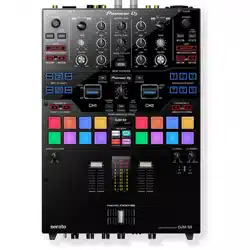
DJ MIXER
DJM-S9
Operating Instructions
http://pioneerdj.com/support/
The Pioneer DJ site shown above offers FAQs, information on software, and various other types of information
and services to allow you to use your product in greater comfort.
http://serato.com/
For the latest version of the
Serato DJ
software, access Serato.com and download the software from there.

En
2
Contents
Before start
Features ....................................................................................................... 3
What’s in the box
........................................................................................ 3
Installing the software ................................................................................ 3
Part names and functions
Browser section .......................................................................................... 6
Deck section ................................................................................................ 6
Mixer section ............................................................................................... 7
Effect section ............................................................................................... 8
Rear panel ................................................................................................... 8
Front panel .................................................................................................. 9
Connections
Connecting input terminals ..................................................................... 11
Connecting output terminals .................................................................. 12
Basic Operation
Starting the system ................................................................................... 13
Quitting the system .................................................................................. 15
Advanced Operation
Using the performance pads ................................................................... 16
Using the user mode ................................................................................ 18
Using FX TRIGGER mode ......................................................................... 19
Using the fader start function.................................................................. 19
Analyzing tracks ........................................................................................ 19
Using effects ............................................................................................. 20
Using recording functions ....................................................................... 20
Using external inputs ............................................................................... 21
Types of effects .......................................................................................... 22
Using the FX BANK function ................................................................... 24
Using the DVS system
Before controlling the Serato DJ software ............................................. 25
Controlling the Serato DJ software ......................................................... 26
Changing the settings
Replacing the bumper in the crossfader section .................................. 30
Changing the settings of this unit in the utilities mode
........................ 32
Changing the settings of this unit using the settings utility ................. 33
Additional information
Troubleshooting ........................................................................................ 35
Block Diagram .......................................................................................... 36
About trademarks and registered trademarks
...................................... 36
Cautions on copyrights ............................................................................ 36
En
3
Before start
Before start
How to read this manual
! Thank you for buying this Pioneer DJ product.
Be sure to read this manual and the “Operating Instructions (Quick
Start Guide)” included with the unit. Both documents include
important information that you should understand before using this
product.
! In this manual, names of screens and menus displayed on the prod-
uct and on the computer screen, as well as names of buttons and
terminals, etc., are indicated within brackets. (e.g.: [CUE] button,
[Files] panel, [MIC] terminal)
! Please note that the screens and specifications of the software
described in this manual as well as the external appearance and
specifications of the hardware are currently under development and
may differ from the final specifications.
! Please note that depending on the operating system version, web
browser settings, etc., operation may differ from the procedures
described in this manual.
Features
This unit is a 2-channel mixer optimally designed for DJ performances
using the “Serato DJ” DJ software by Serato. It is equipped with two
internal sound cards that are compatible with Serato DJ, so perfor-
mances using Serato DJ can be held immediately after connecting
this unit with a computer using a USB cable, with no need to make
any troublesome settings, and also a DJ can smoothly take over from
another. This unit also supports the scratch control of “Serato DJ” using
a control vinyl (record) or control CD.
In addition, this unit carries over the high sound quality, high reliability
design and a panel layout providing high operability of our DJM series,
the standard models in clubs throughout the world, thereby offering
strong support for all types of DJ performances.
MAGVEL FADER PRO
A newly developed “MAGVEL CROSS FADER PRO” is equipped for the
crossfader to support scratch play, which provides high operability and
high durability, and enables to adjusts the operations.
In addition to the “FEELING ADJUST” function that adjusts the operation
load to an appropriate level and the structure that reduces the unneces-
sary rebounds, this unit’s high operability is achieved by replacing the
fader bumper with the desired one.
The detailed operational settings that match each scratch style are also
possible by the adjustment of the curve characteristics and the reverse
function.
MULTI-COLOR PERFORMANCE PADS
Each channel is equipped with eight rubber pads that are used to oper-
ate HOT CUE and SAMPLER of “Serato DJ”.
The use of a short-stroke seat switch for the large pad (20 mm x 20 mm)
achieves the high responsiveness to soft touches.
DJ performances optimizing the use of various functions of “Serato DJ”
are possible by the OLED display that enables you to instantly grasp
the eight pad modes and the multi-color illumination on the pads that
changes in color according to the “Serato DJ” operations.
BEAT EFFECTS
A wide variety of arrangements can be achieved with the 15 types of
“BEAT FX” linked with beats and many effects of “Serato DJ”.
Six effects assigned to the effect buttons can be easily changed to
another, and the frequently used effects and the parameter can be called
quickly with simple operation. In addition, filter effects can be assigned
independently to each channel with the [FILTER] control. The effect
assigned to the [FILTER] control can be changed to effects other than
FILTER.
DUAL SOUNDCARDS
Two USB sound cards are provided to connect the unit to up to
two computers at the same time. They can be switched using the
[INPUT SELECT] switch located at the top side, so that a Serato DJ user
can smoothly take over from another. In addition, this unit supports the
DVS (Digital Vinyl System) function of “Serato DJ”, so that the scratch
function of “Serato DJ” can be controlled using the DJ player or an
analog player.
HIGH SOUND QUALITY
This unit is not only equipped with high-performance Wolfson D/A
converters that are used by the the high-end model of Pioneer DJ player
“CDJ-2000NXS” and the DJ mixer “DJM-2000NXS”, it also uses the high
sound quality design comparable to the designs of those models to
provide powerful sound quality faithful to the original. Furthermore, this
unit achieves stable sound by reducing contact resistance through use
of an AC inlet having a wide contact area with the power cable even in
the DJ booth in a loud environment.
What’s in the box
! Power cord(s)
! USB cable
— Only one USB cable is included with this unit.
To connect two units, use a cable conforming to USB 2.0
standards.
! Fader bumper A x 4
1
! Fader bumper B x 2
1
! Warranty (for some regions only)
2
! Operating Instructions (Quick Start Guide)
! Serato DJ CONTROL CD x 2
1 Fader bumper A and Fader bumper B are included inside of the
panel of this product.
For instructions on removing the panel, see Replacing the bumper in
the crossfader section (p. 30 ).
2 For the North American region, the corresponding information is
provided on the back cover of the “Operating Instructions (Quick
Start Guide)”.
The warranty is included for European region only.
Installing the software
Before installing the software
The Serato DJ software and driver software are not included.
Access the Pioneer DJ support page and download the software.
http://pioneerdj.com/support/
! The user is responsible for preparing the computer, network
devices and other elements of the Internet usage environment
required for a connection to the Internet.
About the driver software
This driver software is an exclusive driver for outputting audio signals
from the computer.
En
4
Obtaining the driver software
1 Launch a web browser on the computer and access
the Pioneer DJ site below.
http://www.pioneerdj.com/
! To switch the screen to Japanese display, scroll the screen to the bot-
tom, click the [EN] indication at the bottom right of the screen and
then select [JA].
2 Click the [Support] icon.
3 After clicking [Software & firmware updates], click
DJM-S9 in the [MIXER] category.
4 After clicking [Drivers], download the latest driver
software from the download page.
About the Serato DJ software
Serato DJ is a DJ software application by Serato. DJ performances are
possible by connecting the computer on which this software is installed
to this unit.
Minimum operating environment
Supported
operating systems
CPU and required memory
Mac OS X: 10.10, 10.9
and 10.8
Intel
®
processor, Core™ i3, i5 and i7 1.07 GHz or better
4 GB or more of RAM
Windows: Windows 8.1
and Windows 7
Intel
®
processor, Core™ i3, i5 and i7 1.07 GHz or better
4 GB or more of RAM
Others
USB port
A USB 2.0 port is required to connect the computer
with this unit.
Display resolution Resolution of 1280 x 720 or greater
Internet connection
An Internet connection is required for registering
the “Serato.com” user account and downloading the
software.
Free HDD Space 5 GB
!
For information on the latest system requirements, compatibility, and supported
operating systems, see “Software Info” of “DJM-S9” on the Pioneer DJ support
page below.
http://pioneerdj.com/support/
!
Operation is not guaranteed on all computers, even if all the required operating
environment conditions indicated here are fulfilled.
! Depending on the computer’s power-saving settings, etc., the CPU and hard
disk may not provide sufficient processing capabilities. For notebook comput-
ers in particular, make sure the computer is in the proper conditions to provide
constant high performance (for example by keeping the AC power connected)
when using Serato DJ.
!
Use of the Internet requires a separate contract with a provider offering Internet
services and payment of provider fees.
! Operating System support assumes you are using the latest point release for
that version.
Obtaining the Serato DJ software
1 Launch a web browser on the computer and access
the Serato DJ site below.
http://serato.com/dj/downloads
2 Log in to your “Serato.com” user account.
! If you have already registered a user account on “Serato.com”, pro-
ceed to step 4.
! If you have not completed registering your user account, do so fol-
lowing the procedure below.
— Following the instructions on the screen, input your e-mail
address and the password you want to set, then select the region
in which you live.
— If you check [E-mail me Serato newsletters], newsletters pro-
viding the latest information on Serato products will be sent from
Serato.
— Once user account registration is completed, you will receive an
e-mail at the e-mail address you have input. Check the contents
of the e-mail sent from “Serato.com”.
! Be careful not to forget the e-mail address and password specified
when you performed user registration. They will be required for
updating the software.
!
The personal information input when registering a new user account
may be collected, processed and used based on the privacy policy on
the Serato website.
3 Click the link in the e-mail message sent from “Serato.
com”.
Proceed to the Serato DJ download page. Proceed to step 5.
4 Log in.
Input the e-mail address and password you have registered to log in to
“Serato.com”.
5 Download the Serato DJ software from the download
page.
About the installation procedure
After installing the driver software in Windows or Mac, install the Serato
DJ software.
Installation Procedure (Windows)
Do not connect this unit and the computer until installation is
completed.
!
Log on as the user which was set as the computer’s administrator
before installing.
! If any other programs are running on the computer, quit them.
1 Double-click the downloaded driver software
(DJM_S9_x.xxx.exe).
2 Proceed with installation according to the instructions
on the screen.
If [Windows Security] appears on the screen while the installation is
in progress, click [Install this driver software anyway] and continue
with the installation.
When the installation program is completed, a completion message
appears.
After installing the driver software, install the Serato DJ software.
3 Unzip the downloaded Serato DJ software file.
4 Double-click the unzipped software file to launch the
installer.
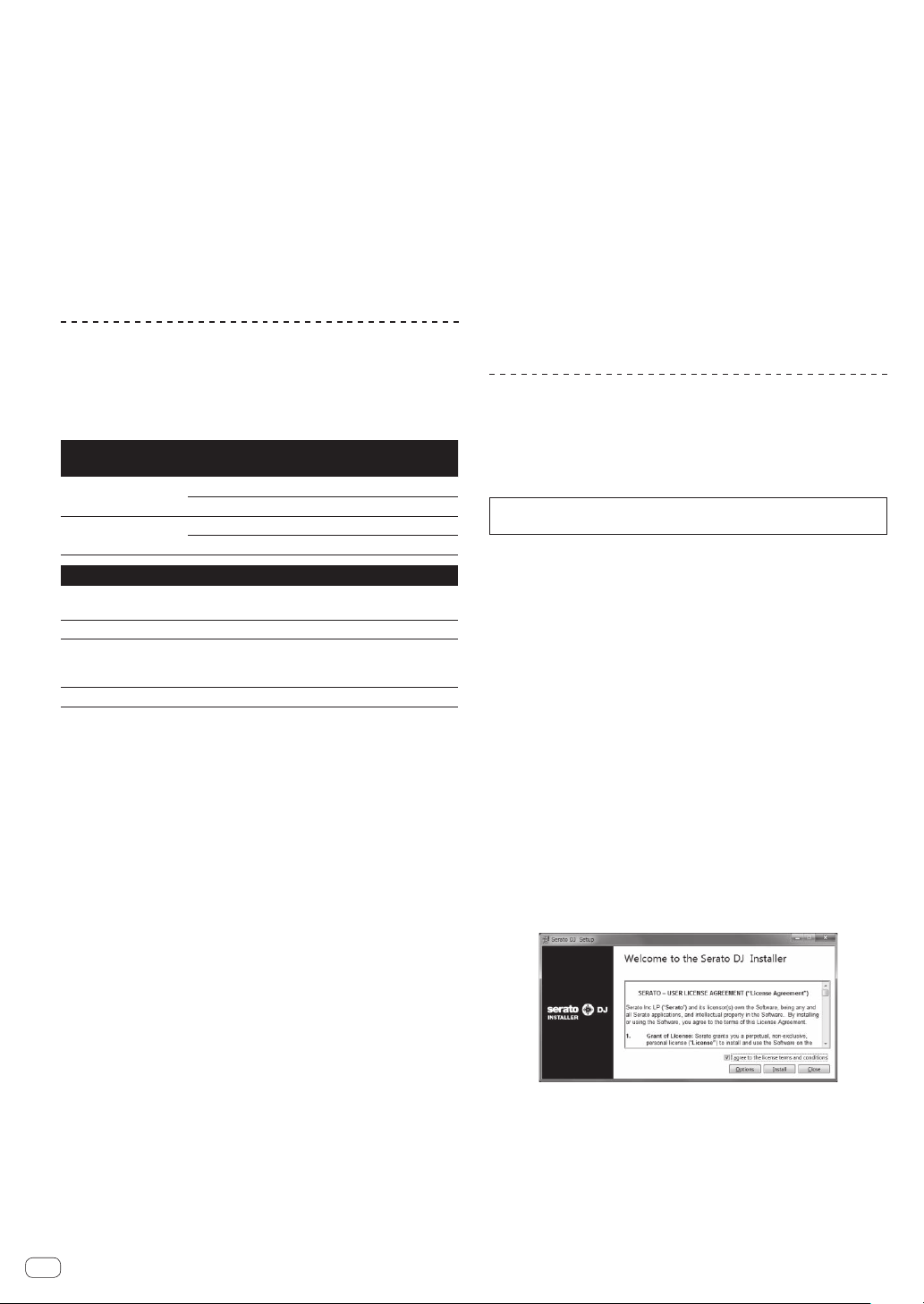
5 Read the terms of the license agreement carefully,
and if you agree, select [I agree to the license terms and
conditions], then click [Install].
! If you do not agree to the contents of the license agreement, click
[Close] to cancel installation.
Installation begins.
En
5
Before start
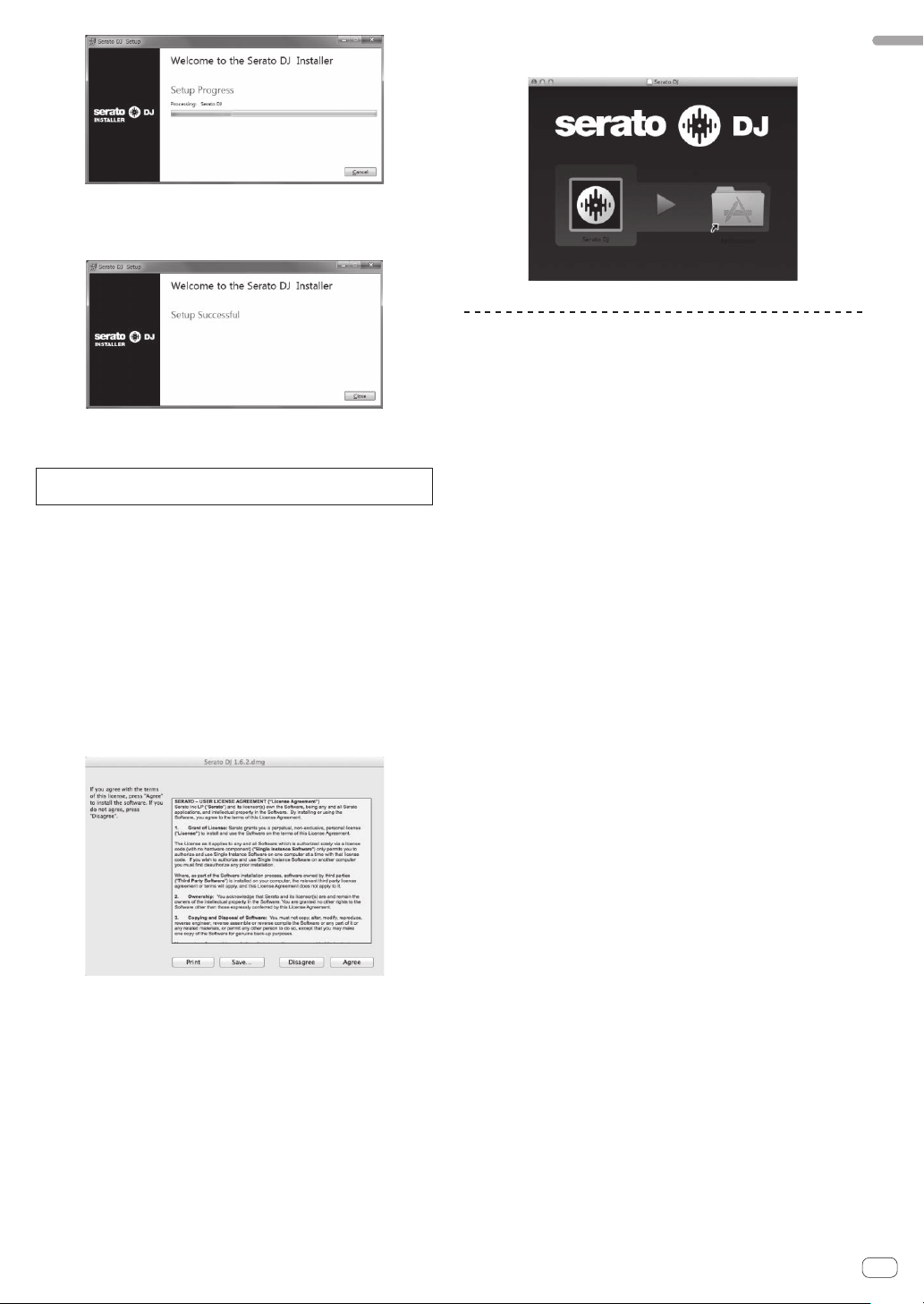
The message of successful installation appears once installation is
completed.
6 Click [Close] to quit the Serato DJ installer.
Installation procedure (Mac OS X)
Do not connect this unit and the computer until installation is
completed.
!
If any other programs are running on the computer, quit them.
1 Double-click the downloaded driver software
(DJM-S9_M_X.X.X.dmg).
2 Proceed with installation according to the instructions
on the screen.
3 Unzip the downloaded Serato DJ software file.
4 Double-click the unzipped software file to launch the
installer.
5 Read the terms of the license agreement carefully,
and if you agree, click [Agree].
! If you do not agree to the contents of the usage agreement, click
[Disagree] to cancel installation.
6 If the following screen appears, drag and drop the
[Serato DJ] icon on the [Applications] folder icon.
Downloading the Serato DJ software
manual
1 Launch a web browser on the computer and access
the Serato DJ site below.
http://serato.com/dj/downloads
2 After clicking “Manuals and Quickstart guides” on the
right-hand side of the download page, click the relevant
manual.
Downloading of the Serato DJ software manual starts.
En
6
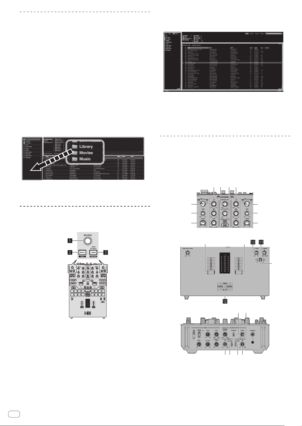
Part names and functions
131
4
2
2
2
3
1 Browser section
2 Deck section
3 Mixer section
4 Effect section
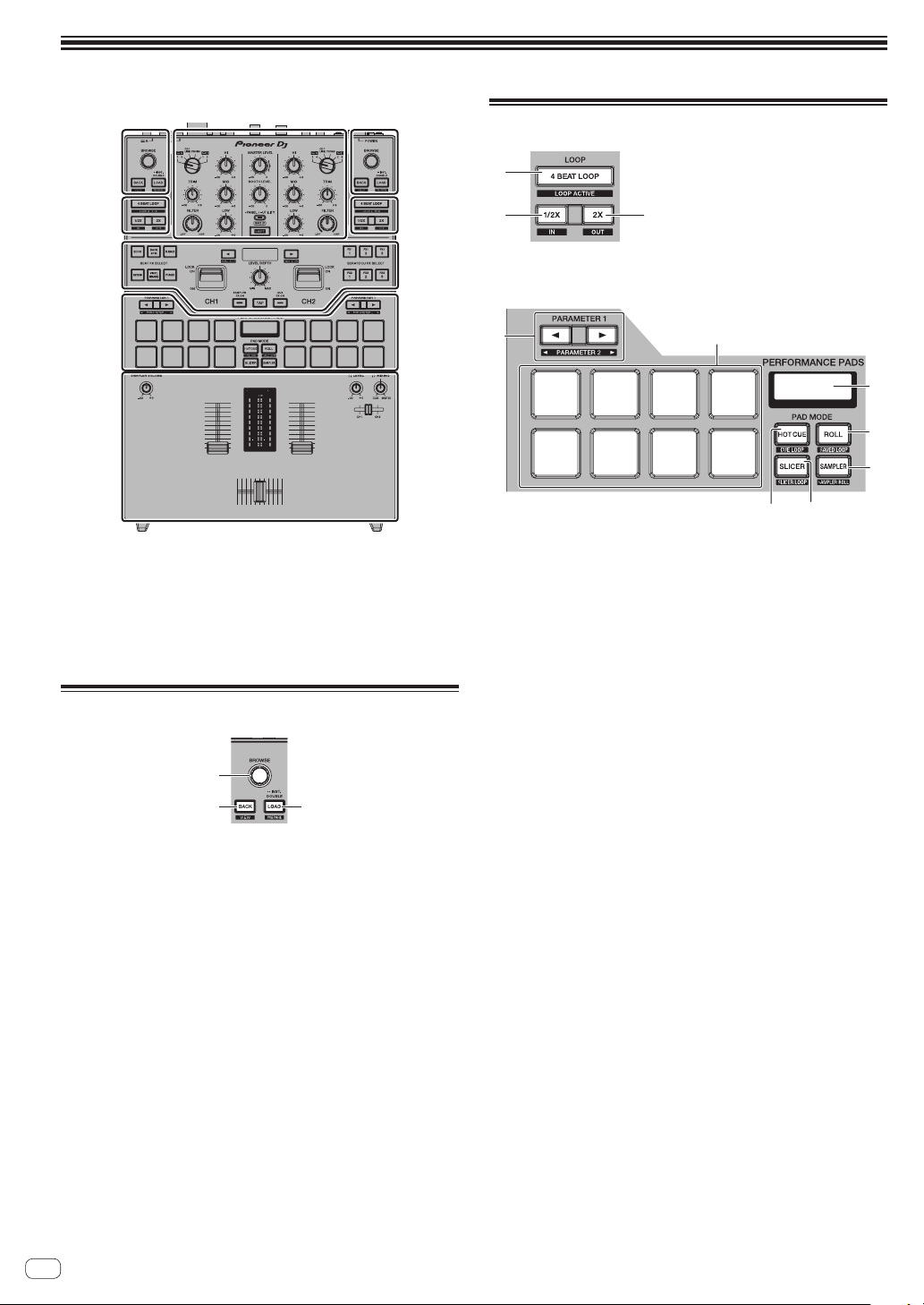
Browser section
2 3
1
1 Rotary selector
Turn:
The cursor moves vertically.
Press:
The next level is displayed.
2 BACK button
The cursor moves to the previous level.
[SHIFT] + press:
Switches the Serato DJ layout.
3 LOAD button
The selected tracks are loaded to the respective decks.
[SHIFT] + press:
Loads tracks to the [Prepare] panel.
Deck section
1
2
3
5
6
4
7
8
9a
1 4BEAT LOOP button
Turns the auto 4-beat loop on.
[SHIFT] + press:
Switches looping between active and non-active. (Loop Active)
2 LOOP 1/2X button
Halves the loop playback length.
[SHIFT] + press:
Sets a loop in point.
3 LOOP 2X button
Doubles the loop playback length.
[SHIFT] + press:
Sets a loop out point and starts loop playback.
4 PARAMETERc button, PARAMETERd button
Sets a parameter for the loop roll, slicer, sampler and other
functions.
[SHIFT] + press:
Sets the second parameters such as slicer, sampler, etc.
5 Performance pads
Control the hot cue, loop roll, slicer, sampler and other functions.
6 PAD section display
Displays the currently set PAD mode and parameters, etc.
7 ROLL mode button
Sets the roll mode.
[SHIFT] + press:
Sets the saved loop mode.
8 SAMPLER mode button
Sets the sampler mode.
[SHIFT] + press:
Sets the sampler roll mode.
9 HOT CUE mode button
Sets the hot cue mode.
En
7
Part names and functions
[SHIFT] + press:
Sets the cue loop mode.
a SLICER mode button
Sets the slicer mode.
[SHIFT] + press:
Sets the slicer loop mode.
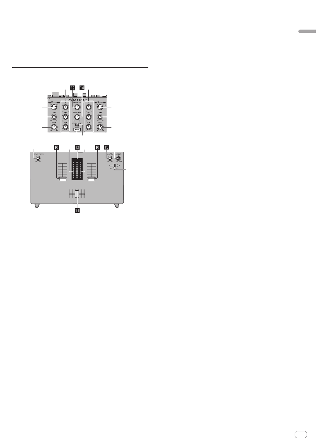
Mixer section
6 6
12
33
78
44
55
9
gh
1 INPUT SELECT switch (CH1 side)
Selects the CH1 input source from the components connected to
this unit.
— [USB-A DECK1]: Select this to use the track loaded in DECK1
of the Serato DJ software on the computer connected to the
[USB-A] terminal.
— [USB-A DECK3]: Select this to use the track loaded in DECK3
of the Serato DJ software on the computer connected to the
[USB-A] terminal.
— [CD/LINE]: Select this to use a line level output device (DJ player,
etc.) connected to the [CD/LINE] terminals.
— [PHONO]: Select this to use a phono level output device (analog
player, etc.) connected to the [PHONO] input terminals.
— [USB-B DECK1]: Select this to use the track loaded in DECK1
of the Serato DJ software on the computer connected to the
[USB-B] terminal.
— [USB-B DECK3]: Select this to use the track loaded in DECK3
of the Serato DJ software on the computer connected to the
[USB-B] terminal.
2 INPUT SELECT switch (CH2 side)
Selects the CH2 input source from the components connected to
this unit.
—
[USB-A DECK2]: Select this to use the track loaded in DECK2
of the Serato DJ software on the computer connected to the
[USB-A] terminal.
— [USB-A DECK4]: Select this to use the track loaded in DECK4
of the Serato DJ software on the computer connected to the
[USB-A] terminal.
—
[CD/LINE]: Select this to use a line level output device (DJ player,
etc.) connected to the [CD/LINE] terminals.
— [PHONO]: Select this to use a phono level output device (analog
player, etc.) connected to the [PHONO] input terminals.
— [USB-B DECK2]: Select this to use the track loaded in DECK2
of the Serato DJ software on the computer connected to the
[USB-B] terminal.
—
[USB-B DECK4]: Select this to use the track loaded in DECK4
of the Serato DJ software on the computer connected to the
[USB-B] terminal.
3 TRIM control
Adjusts the level of the sound input to each channel.
4 ISO control
Boosts or cuts frequencies.
5 Channel Level Indicator
Displays the sound level of the respective channels before passing
through the channel faders.
6 FILTER control
Applies the filter effect.
7 SHIFT button
When another button is pressed while pressing the [SHIFT] button, a
different function is called out.
! For details on the operations using the [SHIFT] button, see the
description regarding the function.
8 PANEL/UTILITY button
The panel display switches in the order below each time the button
is pressed.
Panel display off l [REC] panel l [FX] panel l [SP-6] panel l
Panel display off ...
[SHIFT] + press:
The panel display switches in the order below each time the button
is pressed.
Panel display off l [SP-6] panel l [FX] panel l [REC] panel l
Panel display off ...
Press for over 1 second:
If the button is pressed and held, this unit switches to the mode for
changing the settings of this unit.
9 Headphone CUE fader
Outputs the sound to headphones by changing the ratio of the CH1
and CH2 sounds according to the fader position. To monitor only the
sound of channels, rotate the [HEADPHONES MIX] control all the
way to the CUE side.
a Channel fader
Move:
Outputs the sound of each channel according to the curve charac-
teristics selected by the [CH FADER CURVE] adjustment switch.
[SHIFT] + move:
Use the channel fader start function.
b Crossfader
Move:
Outputs the sound of each channel according to the curve charac-
teristics selected by the [CROSS FADER CURVE] adjustment switch.
[SHIFT] + move:
Uses the crossfader start function.
The crossfader on this unit uses the magnetic position detection
method. Do not place the unit close to a magnet or devices that
generate a strong magnetic field. It may result in malfunction.
c MASTER LEVEL control
Adjusts the master sound level output.
d Master level indicator
Displays the master output’s audio level.
[CLIP] blinks when the output level is too high.
— Blinks slowly: indicates that the sound is about to be distorted.
— Blinks fast: indicates that the sound is distorted.
e Booth monitor level control
Adjusts the level of audio signals output from the [BOOTH] terminal.
En
8
f HEADPHONES LEVEL control
Adjusts the audio level output from the [PHONES] jack.
g HEADPHONES MIX control
Adjusts the balance of the monitor volume between the sound of the
channels selected for headphone CUE fader and the sound of the
master channel.
h SAMPLER VOLUME control
Adjusts the Serato DJ sampler deck’s overall sound level.
Effect section
33
4
4
5
679
8
12
1 BEAT FX SELECT button
Selects BEAT FX to be applied to each channel. (Multiple effects can-
not be selected at the same time.)
This unit provides more effects in addition to the basic effects indi-
cated on the selection buttons on the unit.
For details, see Types of effects (p. 22 ).
2 SERATO DJ FX SELECT button
Select a Serato DJ effect to be applied to each channel. (Multiple
effects cannot be selected at the same time.)
3 EFFECT lever
The selected effect is applied to the corresponding channel while the
lever is tilted toward you. It is locked if the lever is tilted forward, and
the effect continues to be applied if the lever is released.
4 BEAT button
Set the beat fraction for synchronizing the effect sound.
[SHIFT] + press:
These adjust the effects’ parameters.
5 LEVEL/DEPTH control
Adjusts the quantitative parameter of the effect.
6 SAMPLER FX ON button
If this is turned on, the selected effect is applied to the sampler
sound output from Serato DJ.
[SHIFT] + press:
Loads the effect BANK A setting to this unit.
For details on FX BANK, see Using the FX BANK function
(p. 24 ).
7 AUX FX ON button
If this is turned on, the selected effect is applied to the sound of AUX
input.
[SHIFT] + press:
Loads the effect BANK B setting to this unit.
For details on FX BANK, see Using the FX BANK function
(p. 24 ).
8 Effect section display
Displays the name of the currently selected effect and BPM, etc.
9 TAP button
Resets the effect time if the button is pressed and held when an
effect is selected in Serato DJ.
Press:
When the BPM measurement mode is set to [TAP], tap the button
with a finger to input the BPM manually.
Switches the BPM measurement mode to [TAP] when the measure-
ment mode is set to [AUTO].
[SHIFT] + press:
Switches the BPM measurement mode to [AUTO].
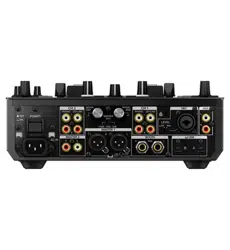
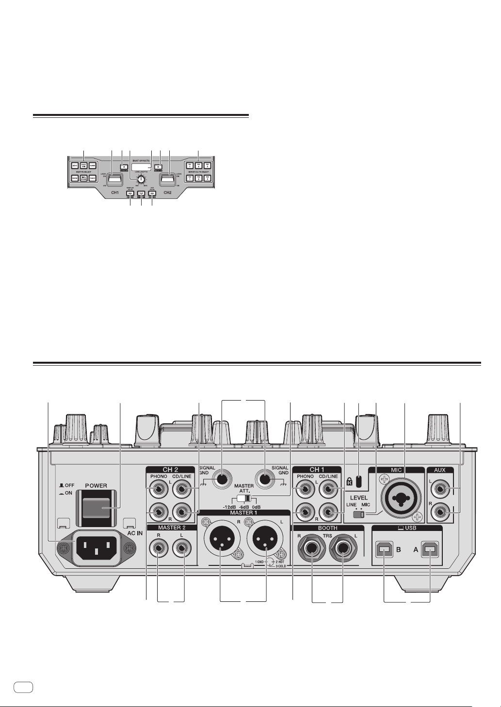
Rear panel
2 4
5
6
5
6
7
a
b
c
1
8
d93e
1 MASTER 1 terminals
Connect powered speakers, etc., here.
Be sure to use these as balanced outputs. Be careful not to acci-
dentally insert the power cord of another unit.
Do not connect the terminal that can supply phantom power.
2 MASTER 2 terminals
Connect to a power amplifier, etc.
3 MASTER ATT level selector switch
Sets the attenuation level of the sound output from the [MASTER 1]
and [MASTER 2] terminals.
En
9
Part names and functions
— [0 dB]: The level of the sound output from [MASTER 1] and
[MASTER 2] terminals is output without change.
— [–6 dB]: The level of the sound output from the [MASTER 1] and
[MASTER 2] terminals is decreased by half.
— [–12 dB]: The level of the sound output from the [MASTER 1] and
[MASTER 2] terminals is decreased by quarter.
The output signal level of DJM-S9 may be too high for some devices
connected to [MASTER 1] or [MASTER 2] terminal. If the sound of
the connected device is distorted, switch MASTER ATT to –6 dB or
–12 dB.
4 BOOTH output terminal
Output terminals for a booth monitor, compatible with balanced or
unbalanced output for a TRS connector.
5 CD/LINE input terminal
Connect to a DJ player or a line level output component.
6 PHONO input terminals
Connect to an analog player or other phono level (MM cartridge) out-
put device. Do not connect to a DJ player or other line level device.
To connect a device to the [PHONO] terminals, remove the short-
circuit pin plug inserted in the terminals.
Insert this short-circuit pin plug into the [PHONO] terminals when
nothing is connected to them to cut external noise.
WARNING
The short-circuit pin plugs out of the reach of children and infants. If
accidentally swallowed, contact a doctor immediately.
7 SIGNAL GND terminal
Connects an analog player’s ground wire here. This helps reduce
noise when the analog player is connected.
8 MIC input terminals
Connects a microphone here.
9 MIC input level selector switch
— [MIC]: Select this when connecting the microphone to the [MIC]
terminal.
— [LINE]: Select this when connecting line level output devices to
the [MIC] terminal.
a Kensington security slot
b USB terminal
Connect to a computer.
c POWER switch
Turns this unit’s power on and off.
d AUX input terminal
Connect to the output terminal of an external device (CD mixer,
sampler, portable audio device, etc.).
e AC IN
Connects to a power outlet using the included power cord. Wait until
all connections between the equipment are completed before con-
necting the power cord.
Be sure to use the included power cord.
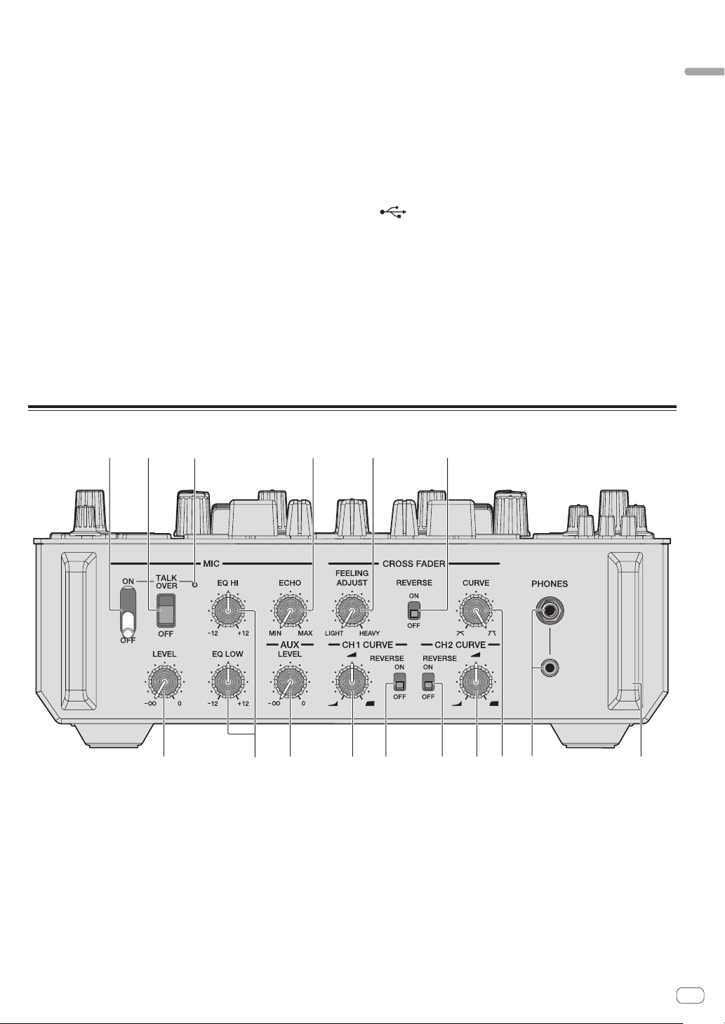
Front panel
2
3 4 5
6
8
9
ab
dd
ecc
7
1
1 PHONES jacks
Connect headphones here.
This product supports 1/4” stereo phone plugs and 3.5 mm stereo
mini plugs.
2 CROSS FADER CURVE adjustment control
Adjusts the crossfader curve characteristics.
3 MIC ON OFF selector switch
Turns the microphone on/off.
4 MIC TALK OVER selector switch
Turns on and off the talk-over function while the microphone is
turned on.
5 MIC indicator
Displays the on/off status of the microphone or the talk-over
function.
—
While the MIC is off: The light is off.
— While the MIC is on: The light is on.
— While talking over: The light blinks.
6 MIC LEVEL control
Adjusts the level of the sound output from the [MIC] channel.
7 MIC EQ (HI, LOW) control
Adjusts the sound quality of the [MIC] channel.
8 MIC ECHO control
Adjusts the parameter of echo effect applied to the [MIC] channel.

En
10
9 AUX LEVEL control
Adjusts the level of the sound input to the AUX channel.
a CROSS FADER FEELING ADJUST control
This can be used to adjust the crossfader’s operating load.
b CROSS FADER REVERSE switch
Turns the crossfader reverse function on and off.
c CH FADER CURVE adjustment control
Adjusts the curve characteristics of the corresponding channel
fader.
d CH FADER REVERSE switch
Turns on and off the reverse function of the corresponding channel
fader.
e Front guard
Protects the terminals and controls on the front panel.
Do not use it as a foot of the product. The unit may tip over.
En
11
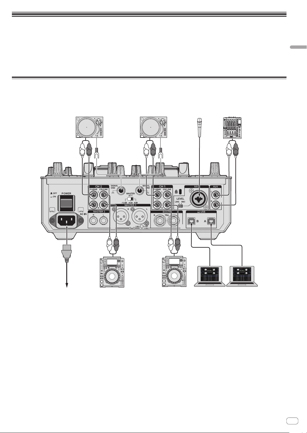
Connections
Connections
! Connect the power cord after all the connections between devices have been completed.
! Be sure to turn off the power and unplug the power cord from the power outlet whenever making or changing connections.
! Refer to the operating instructions for the component to be connected.
! Be sure to use the included power cord.
! Connect this unit and the computer directly using a USB cable.
! Be sure to use the USB cable included with this product or the one that conforms to USB 2.0.
! A USB hub cannot be used.
Connecting input terminals
! When creating a DVS (Digital Vinyl System) combining a computer, audio interface, etc., be careful in connecting the audio interface to this
unit’s input terminals and in the [INPUT SELECT] switch setting.
Also refer to the operating instructions of the DJ software and audio interface.
L
R
L
R
L
R
L
R
L
R
To power outlet
DJ player DJ player Computer
12 12
12 12
0
0
ON
TALK
OVER
OFF
9
6
-
26
/
6
-
26
/
6
-
26
/
9
6
-
26
/
6
-
26
/
6
-
26
/
9
6
-
26
/
6
-
26
/
6
-
26
/
9
6
-
26
/
6
-
26
/
6
-
26
/
0
Analog player Analog player Microphone DJ mixer, etc.

En
12
Connecting output terminals
L
R
Power amplifier
(for booth monitor)
Power amplifier
1 2
Power amplifier
1
Rear panel front panel
HeadphonesTo power outlet
1 Be sure to use the [MASTER 1] terminals only for a balanced output. Connection with an unbalanced input (such as RCA) using an XLR to RCA
converter cable (or converter adapter), etc., may lower the sound quality and/or result in noise.
For connection with an unbalanced input (such as RCA), use the [MASTER 2] terminals.
2 Be careful not to accidentally insert the power cord of another unit to [MASTER 1] terminal.
Do not connect the terminal that can supply phantom power to the [MASTER 1] terminal.
En
13
Basic Operation
Basic Operation
Starting the system
Launching Serato DJ
This manual consists mainly of explanations of functions of this unit as hardware. For detailed instructions on operating the Serato DJ software, see
the Serato DJ software manual.
= Downloading the Serato DJ software manual (p. 5 )
For Windows 7
From the Windows [Start] menu, click the [Serato DJ] icon under [All Programs] > [Serato] > [Serato DJ].
For Windows 8.1
From [Apps view], click the [Serato DJ] icon.
For Mac OS X
In Finder, open the [Applications] folder, then click the [Serato DJ] icon.
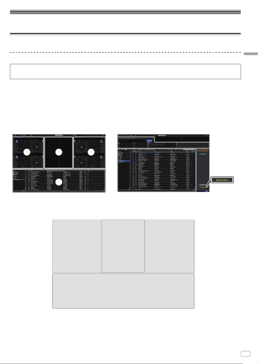
The computer screen immediately after launching the Serato DJ software (the screen on the right shows the status
when the unit is not connected)
A A
C
B
A
C
1
1 There is no need for DJM-S9 users to perform the activation or purchase the license key separately.
Computer screen when a track is loaded in the Serato DJ software
Click [Library] at the upper left of the computer screen, then select [Vertical] or [Horizontal] from the pull-down menu to switch the Serato DJ screen.
AA
C
B
A Deck section
The track information (the name of the loaded track, artist name, BPM, etc.), the overall waveform and other information is displayed here.
B Waveform display
The loaded track’s waveform is displayed here.
C Browser section
Crates in which tracks in the library or sets of multiple tracks are stored are displayed here.
En
14
Importing tracks
The following describes the typical procedure for importing tracks.
! There are various ways to import tracks with the Serato DJ software.
For details, see the Serato DJ software manual.
= Downloading the Serato DJ software manual (p. 5 )
! If you are already using Serato DJ software (Scratch Live, ITCH or
Serato DJ Intro) and have already created track libraries, the track
libraries you have previously created can be used as such.
! If you are using Serato DJ Intro and have already created track librar-
ies, you may have to reanalyze the tracks.
1 Click the [Files] key on the Serato DJ software screen
to open the [Files] panel.
The contents of your computer or the peripheral connected to the com-
puter are displayed in the [Files] panel.
2 Click the folder on the [Files] panel containing the
tracks you want to add to the library to select it.
3 On the Serato DJ software screen, drag and drop the
selected folder to the crates panel.
A crate is created and the tracks are added to the library.
a
b
a [Files] panel
b Crates panel
Loading tracks and playing them
The following describes the procedure for loading tracks into deck [1] as
an example.
1 Rotary selector
2 BACK button
3 LOAD button
1 Press this unit’s [BACK] button, move the cursor to
the crates panel on the computer’s screen, then turn the
rotary selector to select the crate, etc.
2 Press the rotary selector, move the cursor to the
library on the computer’s screen, then turn the rotary
selector and select the track.
a
b
a Library
b Crates panel
3 Press the [LOAD] button to load the selected track
onto the deck.
Playing tracks and outputting the sound
The following describes the procedure for outputting the channel 1
sound as an example.
! Set the volume of the devices (power amplifier, powered speakers,
etc.) connected to the [MASTER 1] and [MASTER 2] terminals to an
appropriate level. Note that loud sound will be output if the volume is
set too high.
6
6
ee
44
55
7
88
9a
fi
hhgg
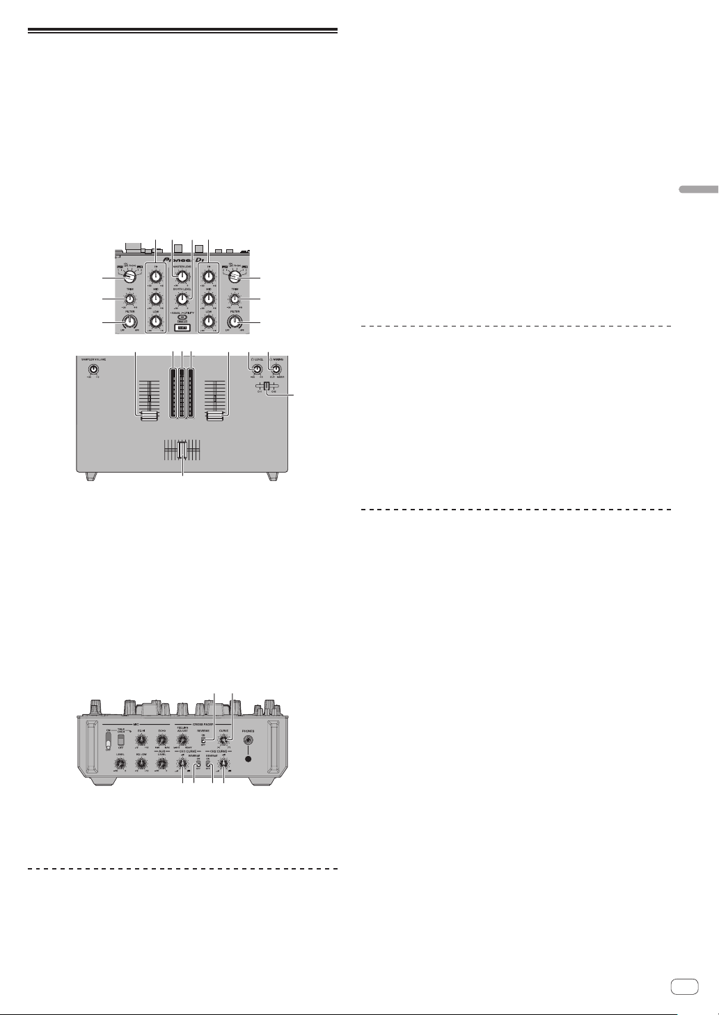
4 TRIM control
5 ISO (HI, MID, LOW) control
6 FILTER control
7 Headphone CUE fader
En
15
Basic Operation
8 Channel fader
9 MASTER LEVEL control
a BOOTH MONITOR LEVEL control
b HEADPHONES MIX control
c Crossfader
d HEADPHONES LEVEL control
e INPUT SELECT switch
f CROSS FADER CURVE adjustment control
g CH FADER CURVE adjustment control
h CH FADER REVERSE switch
i CROSS FADER REVERSE switch
1 Set the positions of the controls, etc., as shown
below.
Names of controls, etc. Position
MASTER LEVEL control Turned fully counterclockwise
TRIM control Turned fully counterclockwise
ISO (HI, MID, LOW) control Center
FILTER control Center
Channel fader Moved forward
Crossfader [CH1] side position
INPUT SELECT switch
The position of the connected
[PC]
2 Press the play button on theSerato DJ screen to play a
track.
3 Move the channel fader away from you.
4 Turn the [TRIM] control.
Adjust [TRIM] so that the orange indicator on the channel level indicator
lights at the peak level.
5 Turn the [MASTER LEVEL] control to adjust the audio
level of the speakers.
Adjust the sound level output from the [MASTER 1] and [MASTER 2]
terminals to an appropriate level.
Monitoring sound with headphones
Set the positions of the controls, etc., as shown below.
Names of controls, etc. Position
HEADPHONES MIX control Turned fully counterclockwise
HEADPHONES LEVEL control Turned fully counterclockwise
1 Move the headphone CUE fader to the CH side to be
monitored.
2 Turn the [HEADPHONES LEVEL] control.
Adjust the sound level output from the headphones to an appropriate
level.
Note
This unit and Serato DJ software include a variety of functions that allow
DJs to create highly individualized performances. For details on the
respective functions, see the Serato DJ software manual.
! The Serato DJ software manual can be downloaded from “Serato.
com”. For details, see Downloading the Serato DJ software manual
(p. 5 ).
Quitting the system
1 Quit Serato DJ.
When the software is closed, a message for confirming that you want to
close it appears on the computer’s screen. Click [Yes] to close.
2 Press the [STANDBY/ON] switch on this unit’s rear
panel to set this unit’s power to standby.
3 Disconnect the USB cable from your computer.
En
16
Advanced Operation
The descriptions from this point on are for functions not described in
the Serato DJ software manual that are specifically for when this unit
and Serato DJ are used in combination.
Using the performance pads
These functions are switched using the respective pad mode buttons
(the [HOT CUE] mode button, [ROLL] mode button, [SLICER] mode but-
ton and [SAMPLER] mode button).
Using hot cues
With this function, playback can be started instantaneously from the
position at which a hot cue is set.
! Up to eight hot cue points can be set and saved per track.
1 Press the [HOT CUE] mode button.
Switches to hot cue mode.
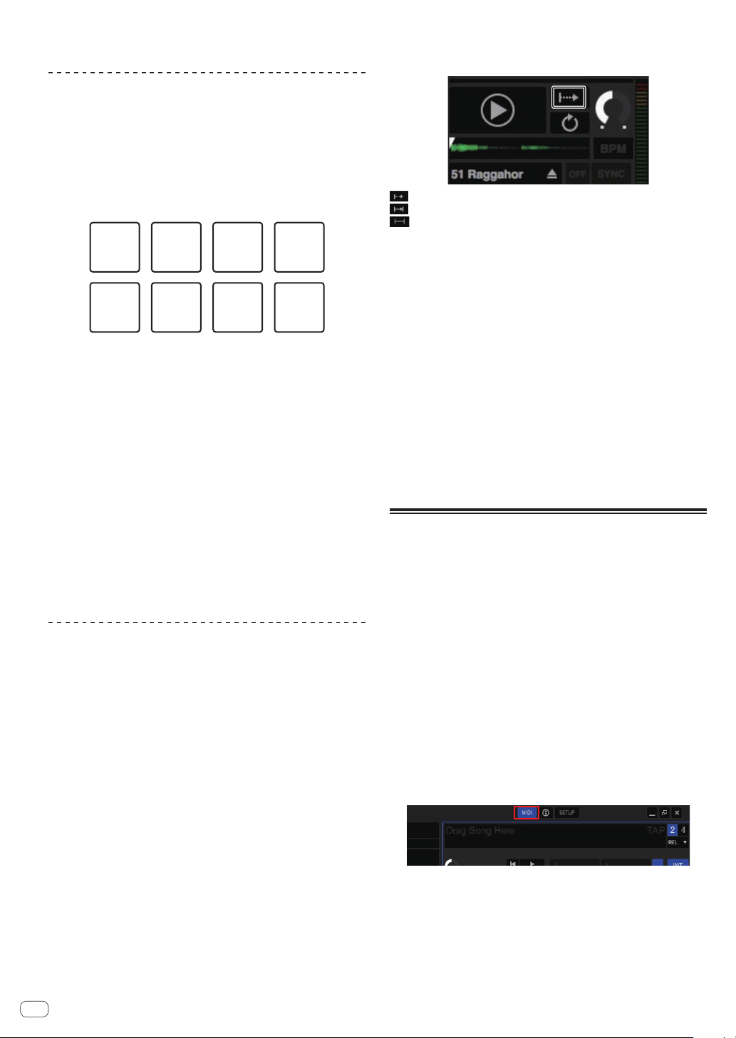
2 In the play or pause mode, press a performance pad
to set the hot cue point.
The hot cue points are assigned to the respective performance pads as
shown below.
Hot cue 1 Hot cue 2 Hot cue 3 Hot cue 4
Hot cue 5 Hot cue 6 Hot cue 7 Hot cue 8
3 Press the performance pad at which the hot cue point
was set.
Playback starts from the hot cue point.
! Set hot cue points can be cleared by pressing a performance pad
while pressing the [SHIFT] button.
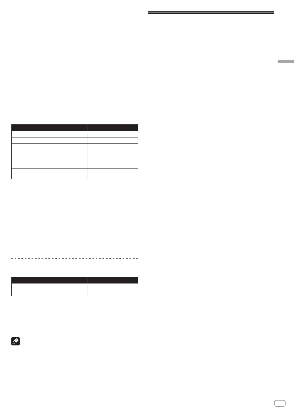
Using the Roll function
When a performance pad is pressed, a loop with the number of beats
assigned to that pad is set and loop playback continues as long as the
pad is being pressed.
During loop roll playback, normal playback with the original rhythm con-
tinues in the background. When loop roll playback is canceled, playback
resumes from the position reached in the background at the point loop
roll playback was canceled.
1 Press the [ROLL] mode button.
Switches to roll mode.
2 Press the [PARAMETERc] or [PARAMETERd] button.
The loop roll beats assigned to the performance pads switch each time
one of the buttons is pressed.
The following four settings can be made:
1 4 beats from 1/32
2 8 beats from 1/16
3 16 beats from 1/8
4 32 beats from 1/4
For example, when set to “8 beats from 1/16”, the pad’s setting is as
shown below.
1/16 beat 1/8 beat 1/4 beat 1/2 beat
1 beat 2 beats 4 beats 8 beats
The range of beats set for the loop roll is displayed on the com-
puter’s screen.
3 Press and hold one of the performance pads.
A loop roll with the number of beats assigned to the pad that was
pressed is played. Playback continues in the background during loop roll
playback.
! The number of beats of the currently playing loop roll can be
changed by pressing the [LOOP 1/2X] or [LOOP 2X] button during
loop roll playback.
4 Release the performance pad.
Loop roll playback is canceled, and playback resumes from the position
reached in the background.
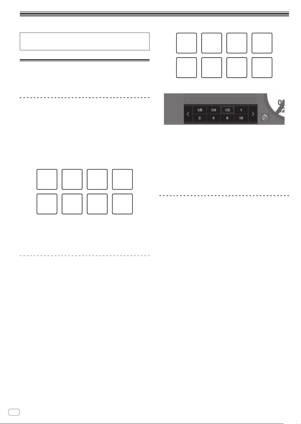
Using the Slicer function
The specified range is divided into eight equal sections, and these eight
sliced sections are assigned to the respective performance pads. While
one of the performance pads is pressed, the sound for the section
assigned to that pad is played in a loop.
During loop playback of the pad’s sound, normal playback with the
original rhythm continues in the background. When the pad is released
and loop playback ends, playback resumes from the position reached at
that point.
! The slicer function cannot be used with tracks for which no beatgrid
is set. For details on setting beatgrids, see the Serato DJ software
manual.
= Downloading the Serato DJ software manual (p. 5 )
1 Press the [SLICER] mode button.
Switches to slicer mode.
! While pressing the [SHIFT] button, pressing the [SLICER] mode but-
ton switches the mode to slicer loop mode.
= About slicer mode and slicer loop mode (p. 17 )
2 Press the [PARAMETERc] or [PARAMETERd] button
while pressing the [SHIFT] button.
Set the domain for the slicer function. The value set for the domain
switches each time one of the buttons is pressed while pressing the
[SHIFT] button.
The domain can be set to one of six settings: 2 beats, 4 beats, 8 beats, 16
beats, 32 beats or 64 beats.
The eight equal sections into which the range specified with the domain
setting have been sliced are assigned to the respective performance
pads as shown below.
En
17
Advanced Operation
Sliced sections 1 to 8
Domain
1234 56
78
Section 1 Section 2 Section 3 Section 4
Section 5 Section 6 Section 7 Section 8
3 Press the [PARAMETERc] or [PARAMETERd] button.
Set the quantization for the slicer function. The value set for the quanti-
zation switches each time one of the buttons is pressed.
The quantization can be set in four ways: 1/8, 1/4, 1/2 and 1.
The length of the loop which is played while the pad is being pressed
can be changed with the “QUANTIZATION” setting. For example, when
“QUANTIZATION” is set to “1”, the entire section assigned to the pad is
played in a loop, and when “QUANTIZATION” is set to “1/2”, only the first
half of the section assigned to the pad is played in a loop.
4 Press and hold one of the performance pads.
When the pad is pressed and held, the sound is played in a loop.
! The length of loop playback differs depending on the quantization
setting.
! When the pad is released, the track returns to the position that is
playing in the background.
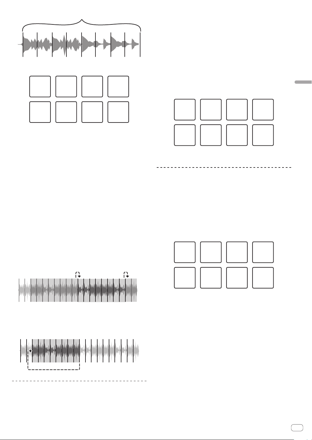
About slicer mode and slicer loop mode
Slicer mode
When the playback position advances to the end of the range that has
been sliced into eight equal sections, the range shown on the display
switches to the next eight sliced sections, and these sliced sections
are assigned to the respective pads, replacing the previously assigned
sections.
12345678
11
2
2
…
345678
Slicer loop mode
When the playback position advances to the end of the range that was
sliced into eight equal parts, the playback position returns to the begin-
ning of the range that was sliced into eight equal parts.
12345678
Using the sampler function
Tracks loaded in the sampler slots of the sampler (SP-6) can be played
with the performance pads.
1 Press the [PANEL SELECT] button to open the [SP-6]
panel on the computer’s screen.
2 Press the [SAMPLER] mode button.
Switches to the sampler mode.
3 Press the [PARAMETERc] or [PARAMETERd] button.
Switch the sampler (SP-6) bank. The sampler has four banks, A, B, C
and D, and each bank has six slots.
4 Operating the mouse on the computer’s screen, drag
and drop tracks to load them into the [SP-6] panel’s slots.
The sampler settings and loaded tracks are saved.
5 Press a performance pad.
The sound for the slot assigned to the pad that was pressed is played.
! Playback method differs depending on the Serato DJ sampler mode.
For details, see the Serato DJ software manual.
= Downloading the Serato DJ software manual (p. 5 )
Slot 1 Slot 2 Slot 3 Slot 4
Slot 5 Slot 6
! When a performance pad is pressed while pressing the [SHIFT] but-
ton, the sound of the slot that is currently playing stops.
Using the cue loop
1 Press the [HOT CUE] mode button while pressing the
[SHIFT] button.
The mode switches to cue loop mode.
2 During playback, press a performance pad.
The loop in point is set at the hot cue slot and loop playback starts.
! The length of the loop at this time is the number of beats set for auto
looping.
The loop in points are assigned to the performance pads as shown
below.
Loop 1 Loop 2 Loop 3 Loop 4
Loop 5 Loop 6 Loop 7 Loop 8
! With the cue loop function, the hot cue point is used as the loop-in
point.
If a performance pad at which a hot cue point is already set is
pressed, loop playback starts from that hot cue point.
3 During loop playback, press the [PARAMETERc]
button.
Halves the loop playback length.
Pressing the [LOOP 1/2X] button obtains the same effect.
4 During loop playback, press the [PARAMETERd]
button.
Doubles the loop playback length.
Pressing the [LOOP 2X] button obtains the same effect.
5 During loop playback, press the [LOOP 1/2X] or
[LOOP 2X] button while pressing the [SHIFT] button.
The loop moves, remaining the same length (loop shift).
6 While pressing the [SHIFT] button, press the same
performance pad.
The track returns to the set loop in point and loop playback continues.
En
18
7 Press the same performance pad again.
Loop playback is canceled.
Using the saved loop
With this function, loop is saved in a loop slot of Serato DJ or a saved
loop is called.
1 Press the [ROLL] mode button while pressing the
[SHIFT] button.
The mode switches to saved loop mode.
2 During loop playback, press a performance pad.
A loop is assigned to the loop slot of Serato DJ.
Slot 1 Slot 2 Slot 3 Slot 4
Slot 7 Slot 8Slot 5 Slot 6
3 Press the performance pad while pressing the [SHIFT]
button.
Playback continues by returning to the beginning of the loop.
4 Press the same performance pad again.
Loop playback is canceled.
5 During loop playback, press the [PARAMETERc]
button.
Halves the loop playback length.
6 During loop playback, press the [PARAMETERd]
button.
Doubles the loop playback length.
7 During loop playback, press the [LOOP 1/2X] or
[LOOP 2X] button while pressing the [SHIFT] button.
The loop moves, remaining the same length (loop shift).
! When the loop shift function is used, if the length of the called
loop is changed, the loop setting is overwritten and saved.
Using the Sampler Roll function
This function plays sampled sounds repeatedly, according to the beat
timing of the BPM of the track that is loaded in the deck.
! The default value is 1/4 beat.
! Select the trigger mode on the [SP-6] panel on the com-
puter’s screen when using the sampler roll function. It will not oper-
ate properly in other play modes.
1 Press the [PANEL SELECT] button to open the [SP-6]
panel on the computer’s screen.
2 Press the [SAMPLER] mode button while pressing the
[SHIFT] button.
The unit switches to the sampler roll mode.
3 Operating the mouse on the computer’s screen, drag
and drop tracks to load them into the [SP-6] panel’s slots.
The sampler settings and loaded tracks are saved.
4 Operate the mouse to set the playing mode of the
sampler slot on the computer’s screen to the trigger
mode.
: Trigger mode
: Hold mode
: On/off mode
! For details on the sampler slots’ playing modes, see the Serato DJ
software manual.
= Downloading the Serato DJ software manual (p. 5 )
5 Press the [PARAMETERc] or [PARAMETERd] button
to select the number of beats to be repeated.
The number of beats changes each time the [PARAMETERc] or
[PARAMETERd] button is pressed.
1/32n1/16n1/8n1/4n1/2n1
6 During playback, press and hold a performance pad.
Playback of the sampler slot starts. Playback continues while the pad
is pressed by returning to the start position repeatedly according to the
selected beat timing.
! With the sampler roll function, multiple sampler slots can simultane-
ously be played repeatedly.
7 Release your finger from the performance pad.
Sampler slot playback returns to normal.
! When the performance pad is pressed while pressing the [SHIFT]
button, the currently playing slot stops.
Using the user mode
The user mode is the function to assign the desired Serato DJ func-
tion to the performance pad of this unit by using the unit with the MIDI
assignment mode of Serato DJ.
! For the MIDI assignment mode of Serato DJ, refer to Serato
DJ’s manual.
= Downloading the Serato DJ software manual (p. 5 )
1 Press the pad mode button twice in succession while
pressing [SHIFT] button.
The unit switches to the user mode.
! The user mode can be set to each pad mode button. The functions
are the same for all user modes.
— [HOT CUE] button: user mode 1
— [ROLL] button: user mode 2
— [SLICER] button: user mode 3
— [SAMPLER] button: user mode 4
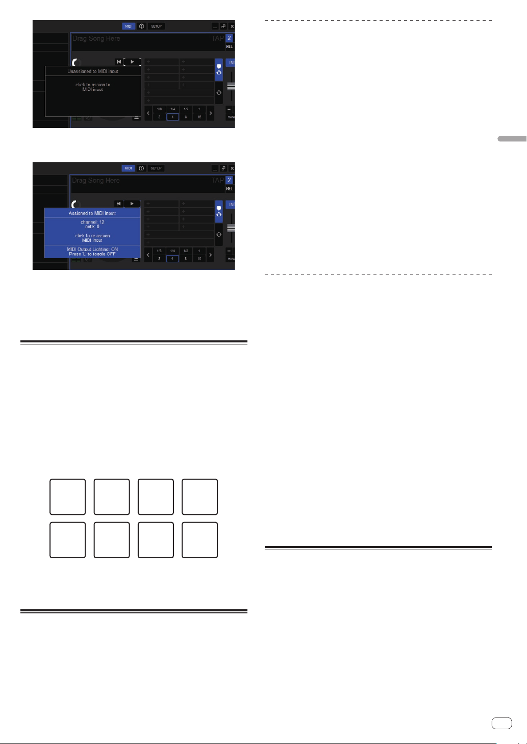
2 Click the [MIDI] button at the upper right of the
Serato DJ screen.
Serato DJ switches to the MIDI assignment mode.
3 Click the function to be assign to a pad on the unit
with a mouse.
The diagram below is a screen example of assigning the [d] (PLAY)
button.
En
19
Advanced Operation
4 Press the pad to assign the function to.
The assignment is completed if the screen shown below is displayed.
5 Click the [MIDI] button at the upper right of the
Serato DJ screen.
MIDI assignment mode of Serato DJ closes.
After the setting is completed, switch the unit to the user mode to use
the Serato DJ function assigned to the pad.
Using FX TRIGGER mode
While in FX TRIGGER mode, BEAT FX can be applied by using the perfor-
mance pad even if a computer is not connected to the unit.
Parameter values are preset to each performance pad so that you can
apply the effect with a simple press of the pad.
! FX TRIGGER mode is enabled only when BEAT FX is selected.
1 Set the [INPUT SELECT] switch to [CD/LINE] or
[PHONO].
2 Press a performance pad.
BEAT FX is applied with the number of beats assigned to the pad while
the pad is pressed.
1/32 beat 1/16 beat 1/8 beat 1/4 beat
1/2 beat 3/4 beat 1 beat 2 beats
PAD1 PAD2 PAD3 PAD4
PAD7 PAD8PAD5 PAD6
! The diagram above is an example of when [ECHO] is selected.
3 Release the performance pad.
The application of the BEAT FX effect stops.
Using the fader start function
Place a check in the check box of [Fader Start options.] on the
[PREFERENCE] tab in the settings utility before using the fader start
function.
For the settings utility, see Changing the settings of this unit using the
settings utility (p. 33 ).
Using the channel fader start function
1 Set the cue.
For instructions on setting a cue point, see “TemporaryCue” in the Serate
DJ software’s manual.
= Downloading the Serato DJ software manual (p. 5 )
! Cues can also be set by moving the channel fader from the back to
the position nearest you while pressing the [SHIFT] button in the
pause mode.
2 While pressing the [SHIFT] button, move the channel
fader from the position nearest you towards the back.
Playback of the track starts from the set cue point.
! When the channel fader is moved back to the position nearest you
while pressing the [SHIFT] button during playback, the track moves
instantaneously back to the set cue point and the pause mode is set.
(Back Cue)
!
If no cue is set, playback starts from the beginning of the track.
! The setting can be changed to set the SYNC mode simultaneously
when the playback is started with the channel fader start function on
the [PREFERENCE] tab in the settings utility.
= Changing the settings (p. 34 )
! When the channel fader is moved from the back to the position near-
est you while pressing the [SHIFT] button when standing by at a cue,
track playback starts from the set cue.
Using the crossfader start function
1 Set the cue.
For instructions on setting a cue point, see “TemporaryCue” in the Serate
DJ software’s manual.
= Downloading the Serato DJ software manual (p. 5 )
! Cues can also be set by moving the crossfader to the left edge or the
right edge while pressing the [SHIFT] button in the pause mode.
2 Move the crossfader to the left edge or right edge
position.
Set to the edge opposite the side on which the channel you want to use
with the fader start function is set.
3 While pressing the [SHIFT] button, move the
crossfader in the opposite direction from the left edge or
right edge.
Playback of the track starts from the set cue point.
! When the crossfader is returned to the original position while press-
ing the [SHIFT] button during playback, the track moves instanta-
neously back to the set cue point and the pause mode is set (Back
Cue).
If no cue is set, playback starts from the beginning of the track.
When the crossfader is moved from the left edge to the right edge (or
from the right edge to the left edge) while pressing the [SHIFT] but-
ton when standing by at a cue, track playback starts from the set cue
point.
Analyzing tracks
When one of this unit’s [LOAD] buttons is pressed and tracks are loaded
onto the decks, the tracks are analyzed, but some time may be required
until analysis is completed and the BPM and waveform are displayed.
When the Serato DJ software is used as an offline player, tracks can be
analyzed ahead of time. For tracks whose analysis has been completed,
the BPM and waveform are displayed immediately when the tracks are
loaded onto the decks.
For details on using the Serato DJ software as an offline player and
instructions on analyzing tracks, see the Serato DJ software manual.
= Downloading the Serato DJ software manual (p. 5 )
! Depending on the number of tracks, some time may be required for
analysis.
En
20
Using effects
Serato DJ has the two effect units FX1 and FX2. The effects can be
applied to CH1, CH2, SAMPLER and AUX. The following describes how
to operate the effect unit by the operations on the unit.
Serato DJ effects unit screen display
Three effects are available per effect unit, and each effect has one
adjustable parameter.
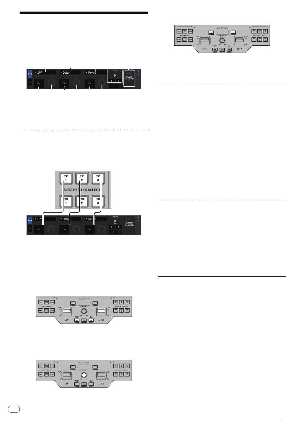
1 11 23
54 54 54
1 This displays the effect type.
2 This displays the effect time.
3 This displays that Insert FX is enabled.
4 This displays the effect parameter status.
5 This displays whether the effect is on or off.
Operating Serate DJ FX
1 Press the [SERATO DJ FX SELECT] button to select an
effect type.
FX1 1, FX1 2 and FX1 3 are for each effect on the FX1 unit. FX2 1, FX2 2
and FX2 3 are for each effect on the FX2 unit.
! The effect applied to each button can be changed by turning the
rotary selector while pressing the [SERATO DJ FX SELECT] button.
! Only one effect can be selected.
2 Tilt the effect lever to turn on the effect.
Tilt the [CH1] effect lever to apply the effect to the sound of CH1.
Tilt the [CH2] effect lever to apply the effect to the sound of CH2.
Press the [SAMPLER FX ON] button to apply the effect to the sampler
sound.
Press the [AUX FX ON] button to apply the effect to the sound input
from AUX.
! The effect lever, [SAMPLER FX ON] button or [AUX FX ON] button
blinks fast when the effect is turned on.
3 Operate the [LEVEL/DEPTH] control to adjust the
effect’s parameters.
Parameters for all effects are adjusted at the same time.
4 Press the [BEATc, d] buttons to adjust the effect
time.
! The effect sound cannot be monitored.
! It is also possible to set the BPM value to be used as the basis for the
effect time from the interval at which the [TAP] button is tapped.
= Switching the effect’s tempo mode (p. 20 )
Switching the effect’s tempo mode
With Serato DJ effects, there are two ways to set the effect’s tempo: with
the “auto tempo mode” and the “manual tempo mode”.
! By default, the auto tempo mode is set.
Auto tempo mode
The track’s BPM value is used as the basis for the effect’s tempo.
Manual tempo mode
The BPM value used as the effect’s basis is calculated from the interval
at which the [TAP] button is tapped.
Switching to the manual tempo mode
Press the [TAP] button while in the auto tempo mode.
! If the [SHIFT] and [TAP] buttons are pressed while in the manual-
tempo mode, the mode switches to the auto tempo mode.
Serato DJ FX function and the restrictions
applied to the operation of the unit
Some operations of the unit are restricted when two computers are con-
nected to the unit.
Restricted operations
! The effect of Serato DJ FX is not applied to AUX when separate com-
puters are selected by the [INPUT SELECT] switches of [CH1] and
[CH2].
! If the input source is switched to [CD/LINE] or [PHONO] by the
[INPUT SELECT] switches, Serato DJ FX selected before the source is
switched will be active.
Using recording functions
Serato DJ has recording functions and can record mixed sound.
For detailed instructions on recording, see the Serato DJ software
manual.
= Downloading the Serato DJ software manual (p. 5 )
1 Open the [REC] panel.
Press the [PANEL SELECT] button to open the [REC] panel.
2 Click [REC] to start recording.
! When you click [REC] again, recording stops.
3 Save the recorded result.
Enter the file name in the text field and click the [SAVE] button.
! You can select the file format and bit depth using the [RECORDING]
screen, which is displayed by selecting the [DJ Preferences] tab in
the [SETUP] menu of Serato DJ.
! Saved recorded files are stored in Crates named “Recorded”.
En
21
Advanced Operation
Using external inputs
This unit is equipped with two external input systems that can be used
for connecting DJ players or analog players. The 2-channel mixer of
this unit can mix the sound of the external input without a computer.
The mixer functions described below operate even if the unit is not con-
nected to a computer.
! For details on the respective items, see Connecting input terminals
(p. 11 ) and Part names and functions (p. 6 ).
! The fader start function (move the channel fader or crossfader while
pressing the [SHIFT] button) cannot be used for the external input.
! The values adjusted with the various controls for the Serato DJ soft-
ware differ from values adjusted for the external input.
Mixer section
3
3
dd
11
22
66 ac8
b
4
55
79
1 TRIM control
2 ISO (HI, MID, LOW) control
3 FILTER control
4 Headphone CUE fader
5 Channel fader
6 Channel Level Indicator
7 MASTER LEVEL control
8 Master level indicator
9 BOOTH MONITOR LEVEL control
a HEADPHONES MIX control
b Crossfader
c HEADPHONES LEVEL control
d INPUT SELECT switch
Front panel
14
3322
1 CROSS FADER CURVE adjustment control
2 CH FADER CURVE adjustment control
3 CH FADER REVERSE switch
4 CROSS FADER REVERSE switch
Mixing the sound of the microphone
1 Connect the microphone to the [MIC] terminal.
2 Set the [ON, OFF] selector switch to [ON].
— [MIC TALK OVER]: The indicator flashes.
— [TALKOVER OFF]: The indicator lights.
! When set to [MIC TALK OVER], the sound of channels other than
the [MIC] channel is attenuated by 18 dB (default) when a sound of
–10 dB or greater is input to the microphone.
! The sound attenuation level of [MIC TALK OVER] can be changed
in the utilities mode. For instructions on changing the setting, see
Changing the settings of this unit in the utilities mode (p. 32 ).
3 Turn the [MIC LEVEL] control.
The level of the sound input from the [MIC] channel is adjusted.
! Pay attention that rotating to the extreme right position outputs a
very loud sound.
4 Input audio signals to the microphone.
Adjusting the sound quality
Turn the [MIC] channels’ [EQ (HI, LOW)] controls.
Applying an echo to the microphone sound
An echo can be applied to the microphone sound by turning the
[MIC ECHO] control.
Mixing the sound of a DJ player, etc.
1 Connect a DJ player or other line level output device
to the [CD/LINE] terminals.
2 Set the [INPUT SELECT] switch to [CD/LINE].
3 Operate the [TRIM] control and the channel faders to
adjust the audio level output from the respective decks.
! The sound can be adjusted with the [ISO (HI, MID, LOW)] controls,
and filter effects can be applied to the respective channels with the
[FILTER] control.
Mixing the sound of analog player, etc
1 Connect the analog player or other phono level (for
MM cartridges) output device to the [PHONO] terminals.
2 Set the [INPUT SELECT] switch to [PHONO].
3 Operate the [TRIM] control and the channel faders to
adjust the audio level output from the respective decks.
! The sound can be adjusted with the [ISO (HI, MID, LOW)] controls,
and filter effects can be applied to the respective channels with the
[FILTER] control.
En
22
Types of effects
FILTER types
The effect type operated with the [FILTER] control can be changed. Start the settings utility on a computer, and select the desired effect from the pull-
down menu for [FILTER] on the [FX BANK] tab.
= Changing the settings of this unit using the settings utility (p. 33 )
Effect Name Descriptions [FILTER] control
DUB ECHO
Applies an echo effect, with the sound delayed slightly after the
original sound output several times and gradually attenuated.
Turn counterclockwise: Applies the echo effect to the mid-range only.
Turn clockwise: Applies the echo effect to the high range only.
FILTER
Outputs sound that has passed through a filter.
Turn counterclockwise: Gradually decreases the low-pass filter’s cutoff frequency.
Turn clockwise: Gradually increases the high-pass filter’s cutoff frequency.
NOISE
White noise generated inside this unit is mixed in to the sound of
the channel via the filter and output.
!
The sound quality can be adjusted by turning the [ISO (HI,
MID, LOW)] control.
Turn counterclockwise: The cut-off frequency of the filter through which the white
noise passes gradually decreases.
Turn clockwise: The cut-off frequency of the filter through which the white noise passes
gradually increases.
PITCH
Changes the sound pitch.
Counterclockwise: Pitch goes down.
Clockwise: Pitch goes up.
WIDE FILTER
Outputs sound that has passed through a filter.
The sound is completely cut if the [FILTER] control is tuned all the
way clockwise or counterclockwise.
Turn counterclockwise: Gradually decreases the low-pass filter’s cutoff frequency.
Turn clockwise: Gradually increases the high-pass filter’s cutoff frequency.
BEAT FX types
The effect type operated with the [BEAT FX] button can be changed. Start the settings utility on a computer, and select the desired effect from the pull-
down menu for [BEAT EFFECTS] on the [FX BANK] tab.
=
Changing the settings of this unit using the settings utility (p. 33 )
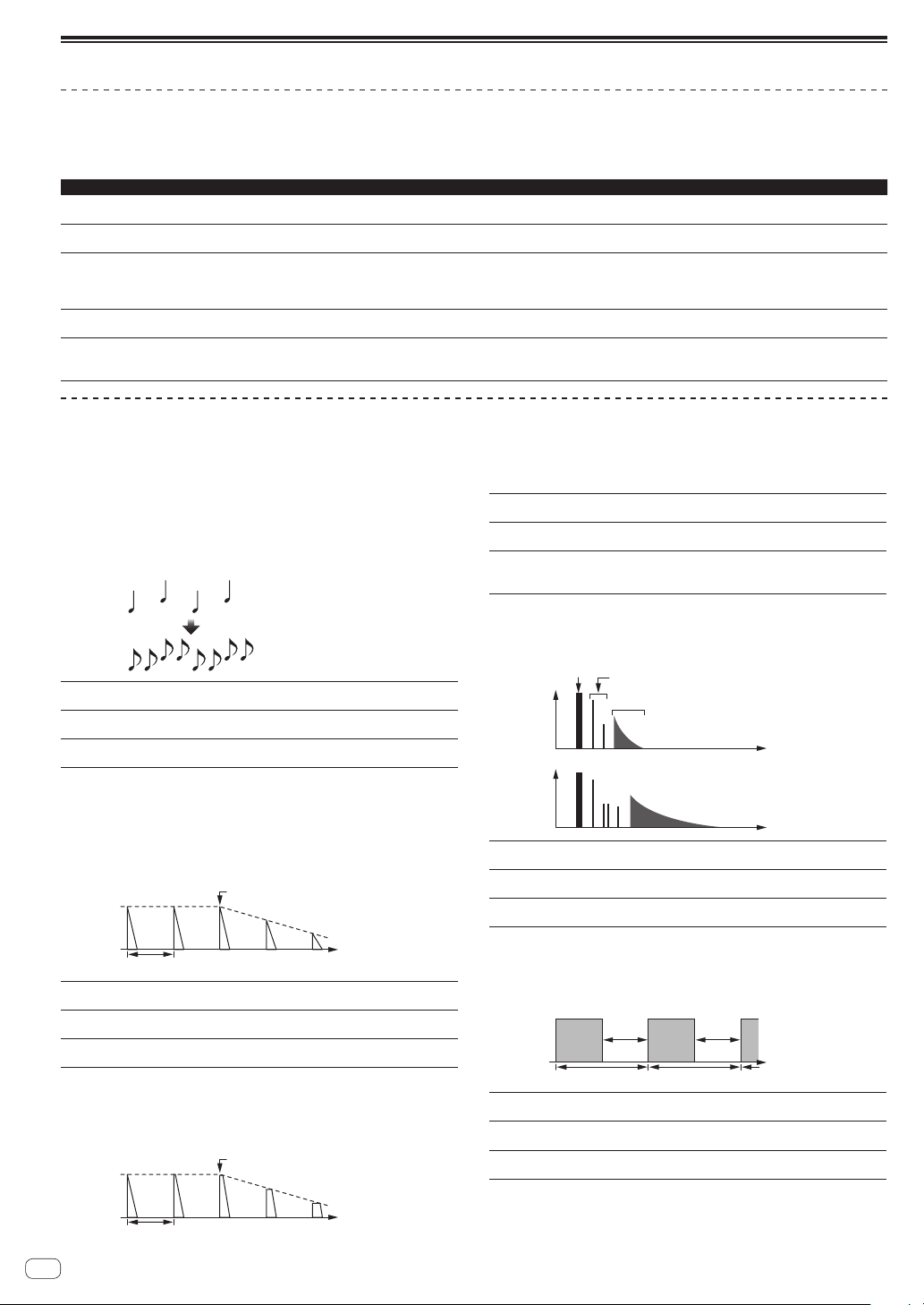
DELAY
1
A delay sound is output once according to the beat fraction set with the
[BEAT c, d] buttons.
When 1/2 beat delay sound is added, 4 beats become 8 beats.
Original
(4 beats)
1/2 delay
(8 beats)
BEAT c, d buttons
(parameter 1)
Sets the delay time between 1/32 and 4/1 with
respect to 1 beat of BPM time.
SHIFT+BEAT c, d button
(parameter 2)
Sets the SWING amount.
LEVEL/DEPTH control
(parameter 3)
Use this to set the balance between the original
sound and the delay sound.
ECHO
1
A delay sound is output several times and gradually attenuated accord-
ing to the beat fraction set with the [BEAT c, d] buttons.
With 1/1 beat echoes, the delay sounds are faded out according to the
track’s tempo even after the input sound has been cut.
Input sound turned off
Time
Fade-out
1 beat
BEAT c, d buttons
(parameter 1)
Sets the delay time between 1/32 and 4/1 with
respect to 1 beat of BPM time.
SHIFT+BEAT c, d button
(parameter 2)
Sets the cut-off frequency for HPF.
LEVEL/DEPTH control
(parameter 3)
Sets the balance between the original sound and the
echo sound, and the feedback amount.
SPIRAL
1
This function adds a reverberation effect to the input sound.
When the delay time is changed, the pitch changes simultaneously.
Input sound turned off
Time
Fade-out
1 beat
BEAT c, d buttons
(parameter 1)
Use these to set a time delay of 1/8 – 16/1 with
respect to the time of one beat of the BPM.
SHIFT+BEAT c, d button
(parameter 2)
Sets the maximum value for the feedback amount.
LEVEL/DEPTH control
(parameter 3)
Use this to set the balance between the original
sound and the effect sound and to set the quantitative
parameter.
REVERB
1
This function adds a reverberation effect to the input sound.
Level
Direct sound
Early reflected sound
Reverberations
1%
100%
Time
BEAT c, d buttons
(parameter 1)
Use these to set the extent of the reverberation effect,
from 1 – 100
%.
SHIFT+BEAT c, d button
(parameter 2)
Sets the filter’s cut-off frequency.
LEVEL/DEPTH control
(parameter 3)
Sets the balance between the original sound and the
effect sound.
TRANS
The sound is cut according to the beat fraction set with the [BEAT c, d]
buttons.
Cut Cut
1/1 beat
Time
BEAT c, d buttons
(parameter 1)
Use these to set a cut time of 1/16 – 16/1 with
respect to the time of one beat of the BPM.
SHIFT+BEAT c, d button
(parameter 2)
Sets the cut ratio.
LEVEL/DEPTH control
(parameter 3)
Sets the balance between the original sound and the
effect sound.
En
23
Advanced Operation
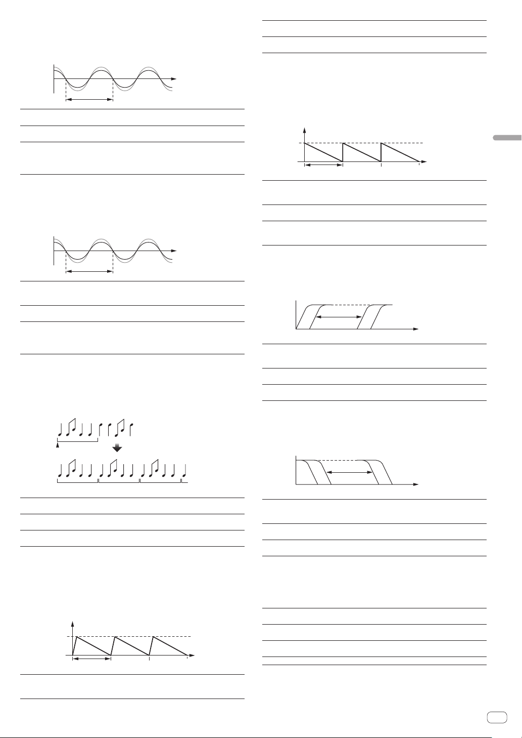
FLANGER
A 1-cycle flanger effect is produced according to the beat fraction set
with the [BEAT c, d] buttons.
Short delay
Cycle
Time
BEAT c, d buttons
(parameter 1)
Use these to set the 1/4 – 64/1 effect time with
respect to the time of one beat of the BPM.
SHIFT+BEAT c, d button
(parameter 2)
Sets the maximum value for the feedback amount.
LEVEL/DEPTH control
(parameter 3)
The further the control is turned clockwise, the more
the effect is stressed.
When turned all the way counterclockwise, only the
original sound is output.
PHASER
The phaser effect changes according to the beat fraction set with the
[BEAT c, d] buttons.
Cycle
Phase shift
Time
BEAT c, d buttons
(parameter 1)
Use these to set the cycle for moving the phaser
effect as of time of 1/4 – 64/1 with respect to the time
of one beat of the BPM.
SHIFT+BEAT c, d button
(parameter 2)
Sets the maximum value for the feedback amount.
LEVEL/DEPTH control
(parameter 3)
The further the control is turned clockwise, the more
the effect is stressed.
When turned all the way counterclockwise, only the
original sound is output.
ROLL
The sound being input at the point when the [ON/OFF] is pressed is
recorded, and the recorded sound is output repeatedly according to the
beat fraction set with the [BEAT c, d] buttons.
Effect turned on
Repeated
Original
1/1 roll
BEAT c, d buttons
(parameter 1)
Use these to set an effect time of 1/16 – 16/1 with
respect to the time of one beat of the BPM.
SHIFT+BEAT c, d button
(parameter 2)
Sets the ratio of the ROLL sound to be cut.
LEVEL/DEPTH control
(parameter 3)
Use this to set the balance between the original
sound and ROLL.
BACK SPIN
The playback speed of the input sound changes according to the beat
fraction set with the [BEATc, d] buttons.
It produces the effect as if the fast reverse playback is performed with
the input sound.
Cycle
Time
Maximum speed for
reverse playback
Maximum speed
Stop
BEAT c, d buttons
(parameter 1)
Sets the cycle for changing the playback speed for the
input sound between 1/4 and 64/1 with respect to 1
beat of BPM time.
SHIFT+BEAT c, d button
(parameter 2)
Sets the BACK SPIN speed.
LEVEL/DEPTH control
(parameter 3)
Sets the balance between the original sound and the
effect sound.
VINYL BRAKE
The playing speed of the input sound changes according to the beat
multiple set with the [BEAT c, d] buttons.
The playback speed for the input sound slows down gradually and stops
eventually.
Cycle
Tim
e
Playing speed
Single speed
Stop
BEAT c, d buttons
(parameter 1)
Sets the cycle at which the playing speed of the input
sound changes to 1/4 – 64/1 with respect to the time
of one beat of the BPM.
SHIFT+BEAT c, d button
(parameter 2)
Sets the VINYL BRAKE speed.
LEVEL/DEPTH control
(parameter 3)
Sets the balance between the original sound and the
effect sound, as well as the amount of change in the
playing speed.
HP FILTER
The high-pass filter’s cut-off frequency changes according to the beat
fraction set with the [BEATc, d] buttons.
Frequency
BEAT c, d buttons
(parameter 1)
Sets the cycle for moving the cut-off frequency
between 1/4 and 64/1 with respect to 1 beat of BPM
time.
SHIFT+BEAT c, d button
(parameter 2)
Sets the maximum value for resonance.
LEVEL/DEPTH control
(parameter 3)
The further the control is turned clockwise, the more
the effect is stressed.
LP FILTER
The low-pass filter’s cut-off frequency changes according to the beat
fraction set with the [BEATc, d] buttons.
Frequency
BEAT c, d buttons
(parameter 1)
Sets the cycle for moving the cut-off frequency
between 1/4 and 64/1 with respect to 1 beat of BPM
time.
SHIFT+BEAT c, d button
(parameter 2)
Sets the maximum value for resonance.
LEVEL/DEPTH control
(parameter 3)
The further the control is turned clockwise, the more
the effect is stressed.
FADER SYNTH (SINE/SAW/SQUARE)
The SYNTH sound is output as the audio source of the base oscillation
frequency set with the [BEATc, d] buttons.
BEAT c, d buttons
(parameter 1)
Sets the base oscillation frequency in seven levels
between –3 and +3.
SHIFT+BEAT c, d button
(parameter 2)
Sets the echo volume applied to the effect sound.
LEVEL/DEPTH control
(parameter 3)
Sets the volume of the effect sound.
Channel fader (parameter 4) Changes the sound in a stepwise manner.
1 The effect sound cannot be monitored.
En
24
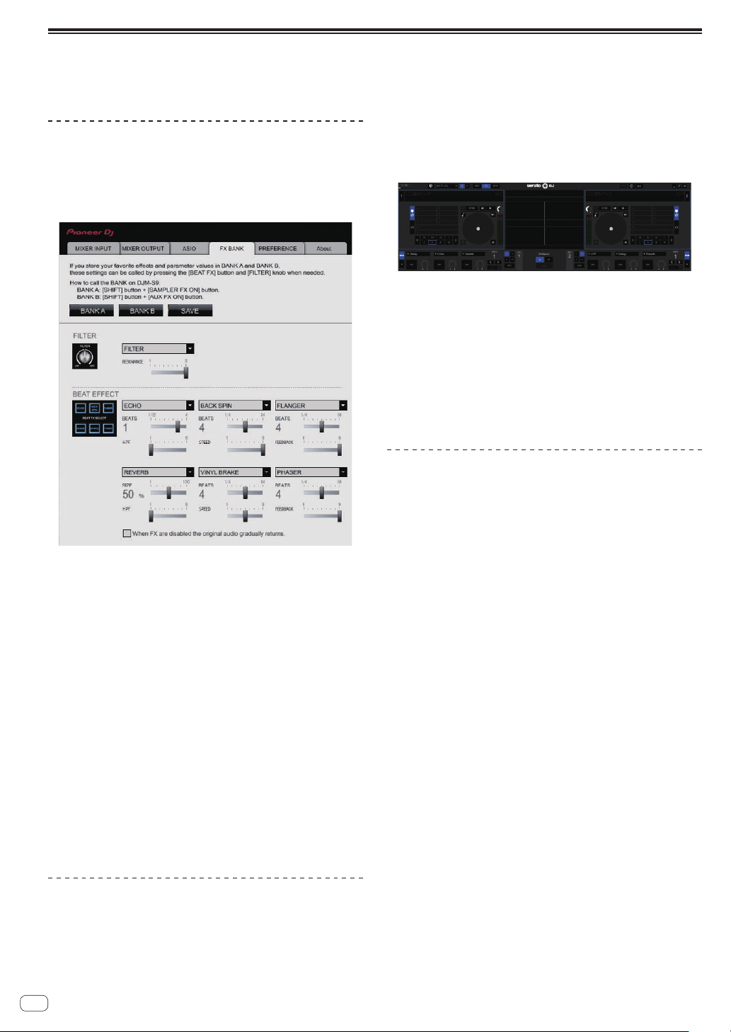
Using the FX BANK function
This unit is equipped with six buttons that can be used for the internal effect selection, and the desired internal effect can be set to each button. Also,
this unit is equipped with six buttons that can be used for the Serato effect selection, and the desired Serato effect can be set to each button. Set
effects can be saved as FX BANK or loaded.
FX BANK function for the internal effects
Setting FX BANK
The effect set to BANK A (or BANK B) can be changed using BANK A (or
BANK B) in the settings utility.
Changing the effect type
The effect type assigned to each [BEAT FX SELECT] button can be
changed by either of the method 1 and 2 below.
1 Using the pull-down menu in the settings utility on the computer
2 Turning the [BROWSE] control while pressing the [BEAT FX SELECT]
button on DJM-S9
Saving FX BANK
Change the effect type and parameters by operating BANK A (or
BANK B) in the settings utility or using the buttons and controls on the
unit. The settings can be registered as a BANK by clicking [SAVE] after
that.
Loading FX BANK
The effect BANKs can be loaded by pressing the buttons on the unit in
the following combinations.
[SHIFT] button + [SAMPLER FX ON] button:
= Loads the effect BANK A.
[SHIFT] button + [AUX FX ON] button:
= Loads the effect BANK B.
FX BANK function of the Serato effect
Setting and saving FX BANK
Change the BANK A and BACK B effects on the FX panel of Serato DJ.
! Effects can be selected from the pull-down menu.
! The setting is saved in the computer if the [Save] button is pressed
after the effect selection and [A] or [B] is selected as the saving
destination.
For details, see the operating instructions for Serato DJ.
Loading FX BANK
Load the Serato DJ effect set that is set on the FX panel of Serato DJ to
each button. The BEAT FX effect set that is set in the settings utility is
also loaded at the same time.
The effect BANKs can be loaded by pressing the buttons on the unit in
the following combinations.
[SHIFT] button + [SAMPLER FX ON] button:
= Loads the effect BANK A.
[SHIFT] button + [AUX FX ON] button:
= Loads the effect BANK B.
FX BANK function and the restrictions
applied to the operation of the unit
Some operations of the unit are restricted when two computers are con-
nected to the unit.
Restricted operations
! FX BANK cannot be loaded.
! The effect type cannot be changed even if the [BROWSE] control is
turned while the [BEAT FX SELECT] button is pressed.
! The BEAT FX effect is reset to the default setting (the effect indicated
on the [BEAT FX SELECT] button).
The restrictions mentioned above are not applied to the following
conditions.
1 When [USB-A] is selected by both [INPUT SELECT] switches of [CH1]
and [CH2].
2 When [USB-B] is selected by both [INPUT SELECT] switches of [CH1]
and [CH2].
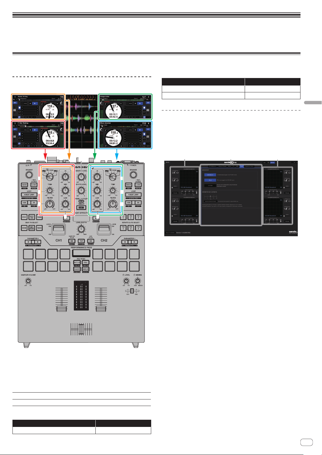
En
25
Using the DVS system
Using the DVS system
This unit allows you to use the Serato DJ software and control disc
1
to operate digital music files using familiar analog players or DJ players.
1 A special CD and record containing the signals necessary for operating digital music files.
Before controlling the Serato DJ software
About input channels
1
2
1
2
4
4
33
5
The signals played on the Serato DJ software’s decks [DECK1] to
[DECK4] are input to this unit’s respective channels.
The combinations of the decks and the respective channels to which the
sound is input are fixed. These combinations are shown below.
Correspondence table of Serato DJ software decks and
DJM-S9 channels
Serato DJ software deck
DECK1 DECK2 DECK3 DECK4
DJM-S9 channel
CH1 CH2 CH1 CH2
Set the positions of the controls, etc., as shown below.
Names of controls, etc. Position
INPUT SELECT switch USB-A or USB-B
Names of controls, etc. Position
TRIM control Turned fully counterclockwise
ISO (HI, MID, LOW) controls Center
Serato DJ setting screen
Computer screen when the Serato DJ software and this
unit are connected (setup screen)
This is the Setup screen displayed when the computer and this unit are
connected after installing the driver software.
1
12
1 CALIBRATION DECK
The Serato DJ software calculates analog signals from the control
disc and processes the signals of digital audio files.
Different signal levels and device statuses can be calculated for each
usage environment to make the optimum settings for reading out the
control signals.
! When CALIBRATION DECK is not displayed, click the
[Expansion Packs] tab. Then, from the list, select [Vinyl/CDJ
Control] and tick the [Enable Vinyl/CDJ control] check box.
2 Utility settings
Utility settings such as settings affecting the entire system and
detailed operation settings can be made here.
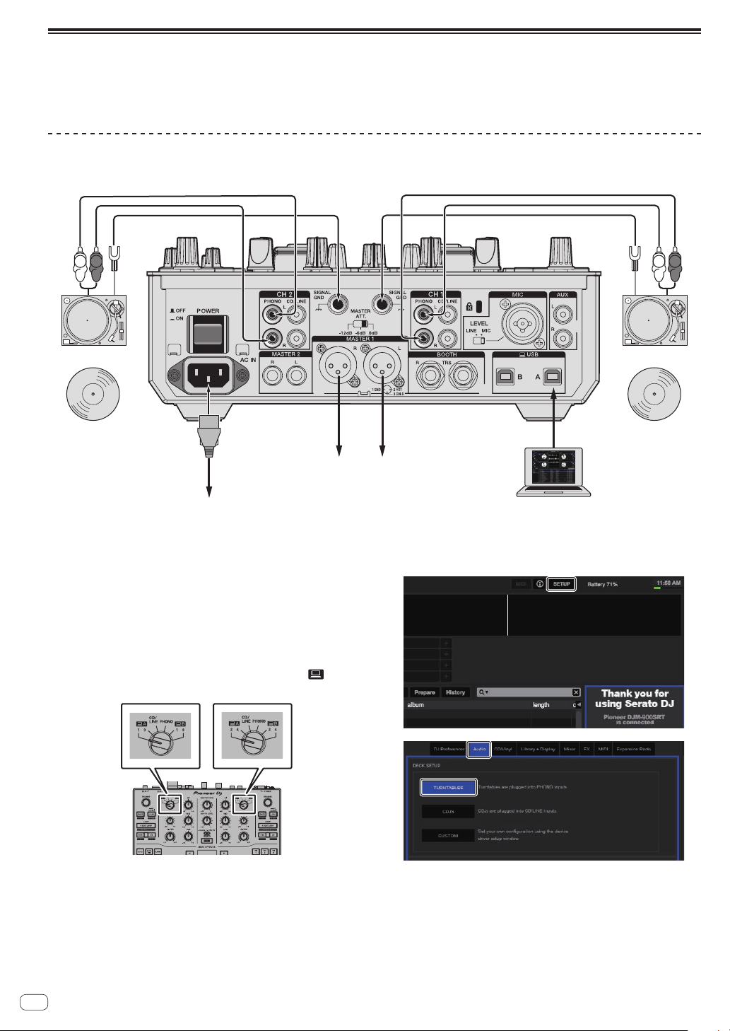
En
26
Controlling the Serato DJ software
Here we explain three types of connections for different usage environments.
! When using analog players, proceed to page 26 .
! When using DJ players, proceed to page 27 .
! When using analog players and DJ players simultaneously, proceed to page 28 .
When using analog players
The following describes how to use the unit by connecting analog players to the Serato DJ software’s decks from [DECK1] to [DECK4].
To amplifier
L
R
L
R
ComputerTo power outlet
Audio cable Audio cable
Ground wire Ground wire
CONTROL VINYLCONTROL VINYL
Analog player Analog player
1 Connect the analog player used to control [DECK1]
and [DECK3] to the [PHONO] terminals of [CH1], and the
analog player used to control [DECK2] and [DECK4] to
the [PHONO] terminals of [CH2].
2 Connect the ground wires for the respective analog
players to this unit’s [SIGNAL GND] terminals.
3 Set the control vinyls on the analog players.
4 Switch the DJM-S9’s input.
Set the [INPUT SELECT] switches of [CH1] and [CH2] to the [ ] side.
[INPUT SELECT]
switch
5 Select [SETUP] on the Serato DJ software’s screen,
then select [TURNTABLES] at the [Audio] tab in the utility
settings.
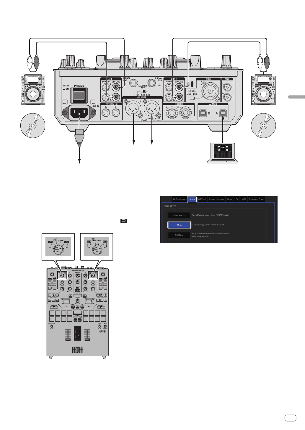
En
27
Using the DVS system
When using DJ players
The following describes how to use the unit by connecting DJ players to the Serato DJ software’s decks from [DECK1] to [DECK4].
To amplifier
L
R
L
R
ComputerTo power outlet
CONTROL CD CONTROL CD
DJ player DJ player
Audio cable Audio cable
1 Connect the DJ player used to control [DECK1] and
[DECK3] to the [CD/LINE] terminals of [CH1], and the DJ
player used to control [DECK2] and [DECK4] to the [CD/
LINE] terminals of [CH2].
2 Load the control CDs in the DJ players.
3 Switch the DJM-S9’s input.
Set the [INPUT SELECT] switches of [CH1] and [CH2] to the [ ] side.
[INPUT SELECT]
switch
4 Select [SETUP] on the Serato DJ software’s screen,
then select [CDJS] at the [Audio] tab in the utility
settings.
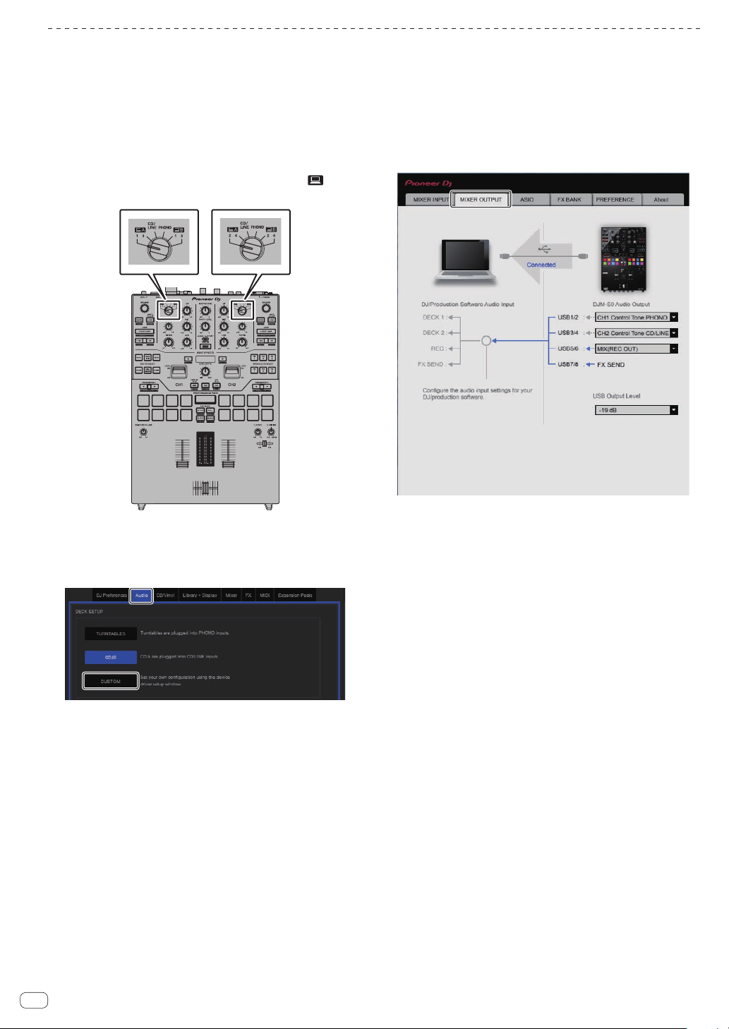
En
28
When using analog players and DJ players simultaneously
The following describes how to use the unit by connecting analog players to the Serato DJ software’s [DECK1] and [DECK3], and DJ players to Serato
DJ software’s [DECK2] and [DECK4].
1 Connect the analog player used to control [DECK1]
and [DECK3] to the [PHONO] terminals of [CH1], and the
DJ player used to control [DECK2] and [DECK4] to the
[CD/LINE] terminals of [CH2].
2 Switch the DJM-S9’s input.
Set the [INPUT SELECT] switches of [CH1] and [CH2] to the [ ] side.
[INPUT SELECT]
switch
3 Select [SETUP] on the Serato DJ software’s screen,
then select [CUSTOM] at the [Audio] tab in the utility
settings.
The settings utility appears.
4 Select the [MIXER OUTPUT] tab in the settings utility,
and then select [CH1 Control Tone PHONO] for CH1 that
is used to operate an analog player and [CH2 Control
Tone CD/LINE] for CH2 that is used to operate a DJ
player.
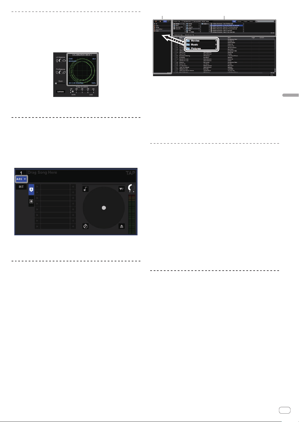
En
29
Using the DVS system
Checking the control signals
Press the play button on the connected player and play
track 1.
Green ring appears at [CALIBRATION DECK].
Check that the innermost ring is close to a true circle.
For details, see the Serato DJ software manual.
= Downloading the Serato DJ software manual (p. 5 )
Selecting the play mode
The Serato DJ software provides three play modes that can be selected
according to your intended purpose.
[ABS], [REL] and [INT] can be selected on the deck unit.
Here we explain the procedure with the play mode set to [ABS] as an
example.
Select [ABS] at the tab on the deck unit.
For a description of the respective play modes, see the Serato DJ soft-
ware manual.
= Downloading the Serato DJ software manual (p. 5 )
Importing or loading tracks
Importing tracks
Here we explain a typical method of operation for importing tracks.
! There are various ways to import tracks with the Serato DJ software.
For details, see the Serato DJ software manual.
=
Downloading the Serato DJ software manual (p. 5 )
! If you are already using Serato DJ software (Scratch Live, ITCH or
Serato DJ Intro) and have already created track libraries, the track
libraries you have previously created can be used as such.
1 Click the [Files] key on the Serato DJ software screen
to open the [Files] panel.
The contents of your computer or the peripheral connected to the com-
puter are displayed in the [Files] panel.
2 Click the folder on the [Files] panel containing the
tracks you want to add to the library to select it.
3 On the Serato DJ software screen, drag and drop the
selected folder to the crates panel.
A crate is created and the tracks are added to the library.
1 2
1 [History] panel
2 [Files] panel
Loading tracks
1 From the [crates] panel, click [crates], etc., to open
[Library].
2 Select a track from [Library], then drag and drop it to
[DECK1] to load it.
Playing tracks
The following describes the procedure for outputting the [DECK1] (CH1)
sound as an example.
! Set the volume of the devices (power amplifier, powered speakers,
etc.) connected to the [MASTER 1] and [MASTER 2] terminals to an
appropriate level. Note that loud sound will be output if the volume is
set too high.
1 Press the play button on the connected player and
play track 1.
Play a track in the Serato DJ software.
2 Turn the [TRIM] control.
Turn the [TRIM] control to adjust so that the channel level indica-
tor’s orange indicator lights at the peak level.
3 Move the channel fader away from you.
4 Turn the [MASTER LEVEL] control to adjust the audio
level of the speakers.
Adjust the sound level output from the [MASTER 1] and [MASTER 2]
terminals to an appropriate level.
Quitting the system
1 Quit [Serato DJ].
When the software is closed, a message for confirming that you want to
close it appears on the computer’s screen. Click [Yes] to close.
2 Press the [POWER] button on this unit’s rear panel to
turn the power off.
3 Disconnect the USB cable from your computer.
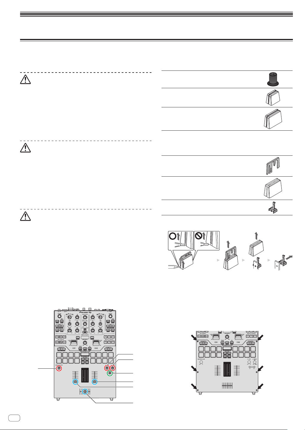
En
30
Changing the settings
Replacing the bumper in the crossfader section
Be sure to follow the directions for safe use of the product.
Note that the part replacement of this unit should be done on your responsibility.
Caution
! Turn off the power of the unit before starting the work.
! Never turn on the power of the unit until the work is completed.
! Never touch areas other than the indicated ones.
! Never use parts other that the supplied ones.
! Take care not to drop the removed parts inside the unit.
! Do not work with wet hands.
! Do not work with liquids placed nearby.
! Do not work in a place where this unit may come into contact with
liquids.
Caution
Perform the replacement with attention to the following.
! Work in a flat and non-slip place.
! Do not work in a dusty place.
! Store the removed parts in a safe place until the installation.
! Keep small parts out of the reach of children and infants. If acciden-
tally swallowed, contact a doctor immediately.
! If parts fell inside the unit and cannot be taken out, never turn on the
power and pull out the power plug, and then contact a service center
to request repairs.
Disclaimer
! The replacement should be done on your own responsibility. Read
the descriptions on this booklet carefully and perform the operation
with caution.
! Note that we will accept no responsibility whatsoever for any loss or
damage resulting from the replacement.
! Replacement parts for the parts lost or damaged during replacement
have to be paid even within the warranty period.
! If malfunctions, damages or any other conditions that require repair
occur with this product resulting from the replacement, the repair
has to be paid even within the warranty period. (The unit may not be
able to be repaired depending on the damaged condition.)
1 Turn off the power of this unit.
2 Remove the controls.
Remove the seven controls shown in the diagram below.
1
2
3
4
5
6
7
1 to 3
Rotary control
4
Fader control (small)
5 to 7
Fader control (large)
! The rotary controls and fader control (small) are attached by inser-
tion. Pull them out upward. If it is hard to pull them out, wrap them
with something that does not slip and pull them out.
! The fader controls (large) consist of the following parts.
Fader control (large) (indicating line part)
Fader control (large) (control part)
Fader control (large) (base part)
! Refer to the diagram below for disassembling the fader control
(large).
1234
1 Lift the bottom edge of the indicating line part with a fine-tipped
tool.
— Lift the side that the bottom edge of the indicating line part
extends to the bottom of the control part.
2 Pull out the indicating line part upward.
3 Pull out the control part upward.
4 Pull out the base part to the side.
3 Remove the screws using a screwdriver.
Remove the six screws shown in the diagram below.
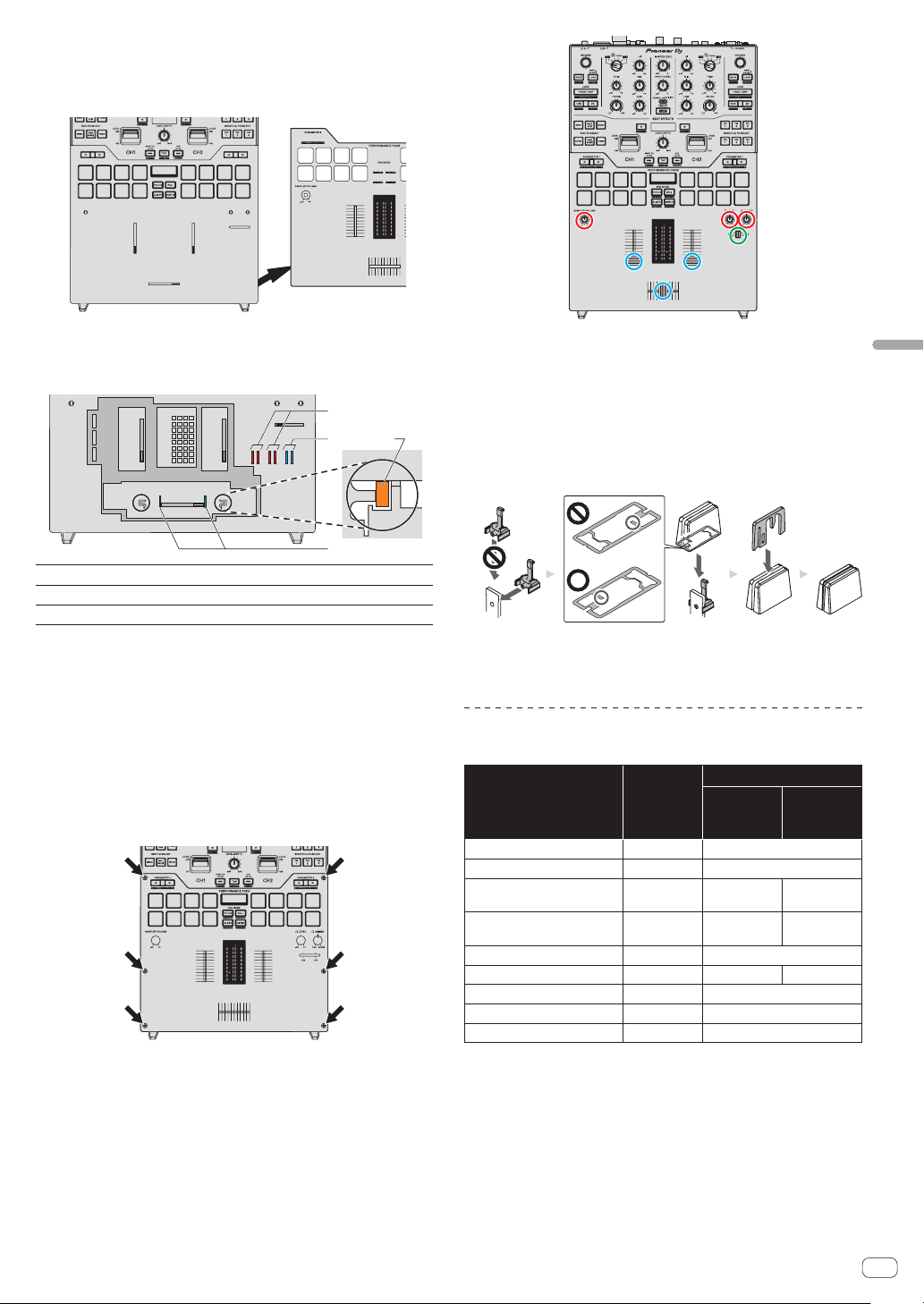
En
31
Changing the settings
! Use a size 1 screwdriver to remove the screws. The use of screw-
drivers other than size 1 screwdrivers may result in damage to the
screws.
4 Remove the aluminum panel.
5 Replace the bumper.
Replace the pre-installed fader bumper C (3 in the diagram below) with
the bumper of the desired hardness.
1
2
3
1
1
Fader bumper A (hardness: hard)
2
Fader bumper B (hardness: soft)
3
Fader bumper C (hardness: rather hard)
! Use tweezers if it is hard to remove the bumper.
! Take care not to drop the bumper inside the unit.
! Do not turn or pull the bumper with excessive force. It may result in
damage to the bumper.
! After the bumper is replaced, adjust the ranges that do not output
sound on both edges of the crossfader by referring to Changing the
settings (p. 34 ).
! The fader unit can be fixed by inserting the fader bumper A vertically
into the grooves (1 in the diagram above) on both edges of the fader
unit. Insert the bumper as necessary.
6 Attach the aluminum panel, and tighten the screws.
Tighten the six screws that removed in the previous step.
! Check if there is no parts or dust fell inside the unit before tightening
the screws.
! Do not tighten the screws too much. It may result in damage to the
screws.
! Be careful not to strip the screw thread when tightening a screw.
! Never install the screws at an angle. It may result in damage to the
parts.
7 Attach the controls.
Attach the seven controls that removed in the previous step.
! The rotary controls and fader control (small) can be attached by
insertion. Attach the controls by pushing them in straight.
! Attach the fader control (small) by inserting the axis through the
center hole on the control.
! Check the orientation of the axises (D cut plane) and attach the
rotary controls by aligning the orientation of the controls parallel to
it.
! Do not attach the controls at an angle or insert them with excessive
force. It may result in damage to the parts.
! Refer to the diagram below for assembling the fader control (large).
1234
1 Insert the base part from the side.
2 Insert the control part in the correct orientation.
3 Insert the indicating line part in the correct orientation.
Purchase of parts
! You can purchase parts in case that parts are lost or damaged.
Part name
Number of
items
Part number
DJM-S9
(Black
Model)
DJM-S9-N
(Gold
Model)
Rotary control 1 DAA1346
Fader control (small) 1 DAC3088
Fader control (large) (indicating
line part)
1 DAC2685 DAC3164
Fader control (large) (control
part)
1 DAC3233 DAC3100
Fader control (large) (base part) 1 DNK6440
Screw 1 DBA1446 DBA1447
Fader bumper A 1 GNK1010
Fader bumper B 1 DEC3596
Fader bumper C 1 DEC3605
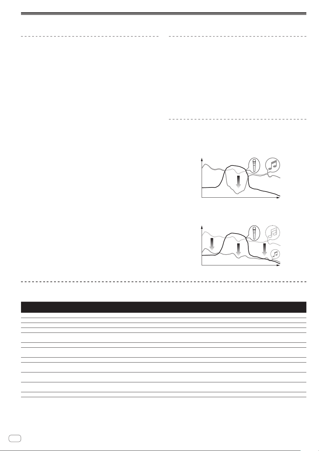
En
32
Changing the settings of this unit in the utilities mode
Launching utilities mode
! The [TAP] button functions as the [SHIFT] button in the utilities
mode. Also, the [SAMPLER FX ON] and [AUX FX ON] buttons func-
tion as the [BEAT c, d] buttons.
1 Press the [PANEL/UTILITY] button for over 1 second.
The [UTILITY] mode setting screen appears.
2 Press the [BEAT c, d] button.
Select the setting item.
3 Press the [SHIFT] button.
The screen switches to the setting item’s setting value change screen.
4 Press the [BEAT c, d] button.
Change the setting value.
5 Press the [SHIFT] button.
Enter the setting value.
The previous screen reappears.
!
To return to the previous screen without changing the settings, press
the [PANEL/UTILITY] button.
6 Press the [PANEL/UTILITY] button.
The [UTILITY] mode setting screen closes.
About the auto standby function
When [AUTO STANDBY] is set to [ON], the unit automatically enters
the standby mode if 10 hours elapses with all of the following conditions
met.
— That none of this unit’s buttons or controls are operated.
— That no audio signals of –10 dB or greater are input to this
unit’s input terminals.
! If the [PANEL/UTILITY] button is pressed, the standby mode is
canceled.
! This unit is shipped with the auto standby function turned on. If you
do not want to use the auto standby function, set [AUTO STANDBY]
to [OFF].
About the talk over function
The talk over function has the two modes described below.
—
[ADV] (advanced talk over): The mid-range of the sound of chan-
nels other than the [MIC] channel is attenuated according to the
[TALKOVER LEVEL] setting value and output.
dB
Frequency
— [NORMAL] (normal talk over): The sound of channels other than the
[MIC] channel is attenuated according to the [TALKOVER LEVEL]
setting value and output.
dB
Frequency
Setting preferences
*: Setting upon purchase
Options
settings
Screen display Setting value Descriptions
AUTO STANDBY
ON/OFF
ON
Turns the auto standby mode on and off.
MIC TALKOVER
ADV/NORMAL
ADVANCED
Sets the microphone talk-over mode.
TALKOVER LEVEL
–6 dB, –12 dB, –18 dB*, –24 dB
–18 dB
Sets the talk-over level applied when the talk-over function is turned on.
MIC LOW CUT
ON/OFF
ON
Turns the low cut filter on and off for microphone.
MIC TO BOOTH
ON/OFF
ON
Sets whether to mix the microphone sound with the sound output from the
[BOOTH] terminal.
MIC LIMITER
ON/OFF
ON
Turns the peak limiter on and off for the sound input to the [MIC] terminal.
MASTER LIMITER
ON/OFF
ON
Turns the peak limiter on and off for the sound output from the [MASTER]
terminal.
BOOTH ATT.
0 dB,
–6 dB, –12 dB
0 dB
Sets the attenuation level of the sound output from the [BOOTH] terminal.
MASTER OUT
mono/stereo
stereo
Switches the sound output from the [MASTER 1] and [MASTER 2] terminals
between monaural and stereo.
BOOTH OUT
mono/stereo
stereo
Switches the sound output from the [BOOTH] terminal between monaural
and stereo.
LED BRIGHTNESS
1-3
1
Sets the brightness of the LED and OLED displays (the larger value is
brighter)
Factory Reset
CANCEL/reset
CANCEL
Restores all the settings to their factory defaults.
1
Note that the output sound may be distorted even if the master level indicator does not light up to the very top.
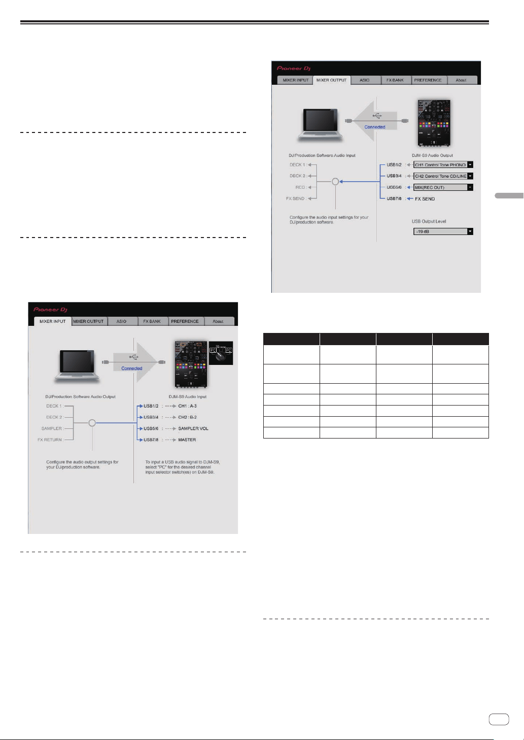
En
33
Changing the settings
Changing the settings of this unit using the settings utility
The setting utility can be used to make the checks and settings
described below.
— Checking the status of this unit’s [INPUT SELECT] switches
— Setting the audio data output from this unit to the computer
— Adjusting the buffer size (when using Windows ASIO)
— Checking the version of the firmware and driver software
— Changing the effect type of BEAT FX
— Changing the function settings for DJM-S9
Displaying the setting utility
For Windows
Click [Start] menu > [All Programs] > [Pioneer] > [DJM-S9] > [DJM-
S9 Settings Utility].
For Mac OS X
Click [Macintosh HD] icon > [Application] > [Pioneer] > [DJM-S9] >
[DJM-S9 Settings Utility].
Checking the status of this
unit’s [INPUT SELECT] switches
Display the setting utility before starting.
Click the [MIXER INPUT] tab.
Setting the audio data output from this
unit to the computer
When Serato DJ is running and using this unit as the default audio
device, set the audio data output in Serato DJ.
Display the setting utility before starting.
1 Click the [MIXER OUTPUT] tab.
2 Click the [Mixer Audio Output] pull-down menu.
Select and set the audio data to be output to the computer from the flow
of audio signals inside this unit.
CH1 CH2 CH3 CH4
CH1 Control Tone
PHONO
1
CH2 Control Tone
PHONO
1
MIX (REC
OUT)
24
FX SEND
CH1 Control Tone
CD/LINE
1
CH2 Control Tone
CD/LINE
1
Cross Fader A
23
—
Post CH1 Fader
2
Post CH2 Fader
2
Cross Fader B
23
—
Cross Fader A
23
Cross Fader A
23
MIC
—
Cross Fader B
23
Cross Fader B
23
AUX
—
MIC MIC Post CH1 Fader
2
—
AUX AUX Post CH2 Fader
2
—
1
The audio data is output with the same volume at which it is input to this unit,
regardless of the [USB Output Level] setting.
2
When using for applications other than recording, pay attention to the DJ
application’s settings so that no audio loops are generated. If audio loops are
generated, sound may be input or output at unintended volumes.
3 The sound which the [ECHO], [DELAY] and [SPIRAL] effects are applied to is
output from [Cross Fader A] or [Cross Fader B].
4
The sound which the [REVERB] effect is applied to is only output from [MIX (REC
OUT)].
3 Click the [USB Output Level] pull-down menu.
Adjust the volume of the audio data output from this unit.
! The [USB Output Level] setting is applied equally to all audio data.
However, when 1 on the table at step 2 is selected, the audio data is
output with the same volume at which it is input to this unit.
! If not enough volume can be achieved with the DJ software’s volume
adjustment alone, change the [USB Output Level] setting to adjust
the volume of the audio data output from this unit. Note that the
sound will be distorted if the volume is raised too high.
Adjusting the buffer size (when using
Windows ASIO)
If an application using this unit as the default audio device (DJ software,
etc.) is running, quit that application before adjusting the buffer size.
Display the setting utility before starting.
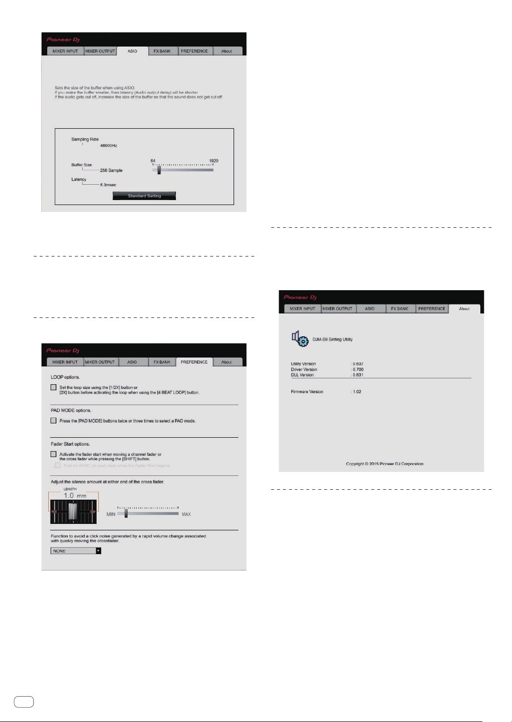
En
34
Click the [ASIO] tab.
! If the buffer size is made large, drops in audio data (breaks in the
sound) occur less easily, but the time lag due to the delay in the
transfer of the audio data (latency) increases.
Changing to the desired effect type
The effects set to the [BEAT FX] and [FILTER] controls on the unit can
be changed to the desired effects on the [FX BANK] tab. For details, see
Using the FX BANK function (p. 24 ).
Changing the settings
The following settings can be changed on the [PREFERENCE] tab.
!
[4BEAT LOOP] button function
If a check mark is placed in the check box, the [4BEAT LOOP] button
on the unit functions as the [AUTO BEAT LOOP] button.
! Pad mode button operation
If a check mark is placed in the check box, the “two presses function”
and “three presses function” for the performance pads are enabled
when the pad mode is switched.
— If two computers are connected to this unit and separate com-
puters are selected by the [INPUT SELECT] switches of [CH1] and
[CH2], the functions are enabled only when the setting on each
computer is on.
!
Fader start function
If a check mark is placed in the check box, the fader start function is
enabled. For details on the fader start function, see Using the fader
start function (p. 19 ).
! Adjustment of the ranges that do not output sound on both edges of
the crossfader.
The ranges that do not output sound on both edges of the crossfader
can be adjusted by moving the slider.
— This setting is disabled and the default setting is applied when
two computers are connected to this unit and [CD/LINE] or
[PHONO] is selected by the [INPUT SELECT] switches of [CH1]
and [CH2].
! Prevention of a drastic change in volume that occurs when the
crossfader is operated
In case that the volume level drastically changes due to the opera-
tions of the crossfader, the volume can be set to the moderate level
by adjusting the time it takes for volume change.
— [NONE] is set when two computers are connected to this unit
and the [INPUT SELECT] switches are set as follows.
! Separate computers are selected by the [INPUT SELECT]
switches of [CH1] and [CH2].
! [CD/LINE] or [PHONO] is selected by the [INPUT SELECT]
switches of [CH1] and [CH2].
Checking the version of the firmware and
driver software
Display the setting utility before starting.
Click the [About] tab.
Checking the latest information on the
driver software
For the latest information on the driver software for exclusive use with
this unit, visit our website shown below.
http://pioneerdj.com/support/
! Operation cannot be guaranteed when multiple units of this mixer
are connected to a single computer.
En
35
Additional information
Troubleshooting
! If you think that there is something wrong with this unit, check the following items, and also access [FAQ & DJ software support information] on
the Pioneer DJ support site and check [FAQ] for [DJM-S9].
http://pioneerdj.com/support/
Sometimes the problem may lie in another component. Inspect the other components and electrical appliances being used. If the problem cannot
be rectified, ask your nearest Pioneer authorized service center or your dealer to carry out repair work.
! This unit may not operate properly due to static electricity or other external influences. In such cases, normal operation may be restored by unplug-
ging the power cord then plugging it back in.
Problem Check Remedy
The power is not turned on. Is the power cord properly connected? Plug in the power cord to an AC outlet.
No sound or small sound. Is the [INPUT SELECT] switch set to the proper
position?
Set the [INPUT SELECT
] switch to the channel’s input source. (page 7 )
Are the connection cables properly connected? Connect the connection cables properly. (page 11 )
Are the terminals and plugs dirty? Clean the terminals and plugs before making connections.
Is [MASTER ATT] set to [
–6 dB] or [–12 dB]? Set the [MASTER ATT] level selector switch to [0 dB]. (page 8 )
Microphone sound is not output or
volume is low.
Is the MIC input level selector switch set properly? Set the MIC input level selector switch to [MIC]. (page 9 )
Distorted sound. Is the sound level output from the [MASTER]
terminal set appropriately?
Adjust the [MASTER LEVEL] control so that the master level indicator lights at
around [0 dB] at the peak level. (page 7 )
Set [MASTER ATT] to [–6 dB] or [–12 dB]. (page 8 )
Is the level of audio input to each channel properly
set?
Adjust the [TRIM] control so that the channel level indicator lights at about
[0 dB] at the peak level. (page 7 )
Distorted sound. Is the MIC input level selector switch set properly? Set the MIC input level selector switch to [LINE]. (page 9 )
Can’t fader start a DJ player. Is a check mark placed in [Fader Start options.]
in the [PREFERENCE] tab of the settings utility?
Place a check mark in [Fader Start options.] in the [PREFERENCE] tab of the
settings utility. (page 34 )
BEAT FX does not work. Is the [BEAT FX SELECT] button and
[LEVEL/DEPTH] control set properly?
Set the [BEAT FX SELECT] button and [LEVEL/DEPTH] control properly.
(page 20 )
The FILTER effect is not applied. Is the [FILTER] control set to an appropriate
position?
Turn the [FILTER] control clockwise or counterclockwise.
Tempo (BPM) cannot be measured or
measurement value of tempo (BPM) is
implausible.
Is the audio input level too high or too low? Adjust the [TRIM] control so that the channel level indicator lights at about
[0 dB
] at the peak level. (page 7 )
For some tracks, it may not be possible to measure the tempo (BPM). Use the
[TAP] button to input the tempo manually. (page 8 )
Measured tempo (BPM) differs from
tempo indicated on CD.
— The values may differ slightly due to the different ways in which the BPM is
measured.
MIDI control does not work. Are the MIDI settings properly set? To operate DJ software other than Serato DJ with this unit, this unit’s MIDI mes-
sages must be assigned to the DJ software you are using. For the assignment
method, see your DJ software’s operating instructions.
This unit is not recognized after it has
been connected to a computer.
Is the driver software properly installed on your
computer?
Install the driver software. If it is already installed, reinstall it. (page 3 )
Sound of a computer cannot be
output from this unit.
Are this unit and computer properly connected? Connect this unit and the computer directly using the included USB cable.
(page 11 )
Are the audio output device settings properly set? Select this unit with the audio output device settings. For instructions on making
settings for your application, see your application’s operating instructions.
Is the [INPUT SELECT] switch set to the proper
position?
Set the [INPUT SELECT] switch to the [
] position. (page 15 )
The BEAT FX effect sound cannot be
monitored with headphones.
— The creation processing of the [ECHO], [REVERB], [DELAY] and [SPIRAL] effect
sounds is performed after the crossfader processing so that the effect sounds
cannot be monitored. It is not a malfunction.
Sound is distorted when an ana-
log player is connected to this
unit’s [PHONO] terminals.
Or, lighting of the channel level
indicator does not change even when
the [TRIM] control is turned.
Have you connected an analog player with a built-
in phono equalizer?
Connect the analog player with built-in phono equalizer to the [CD/LINE] termi-
nals. (page 11 )
If the analog player with built-in phono equalizer has a PHONO/LINE selector
switch, switch it to PHONO.
Is an audio interface for computers connected
between the analog player and this unit?
If the output of the audio interface for computers is line level, connect it to the
[CD/LINE
] terminals. (page 11 )
If the analog player has a PHONO/LINE selector switch, switch it to PHONO.
Additional information
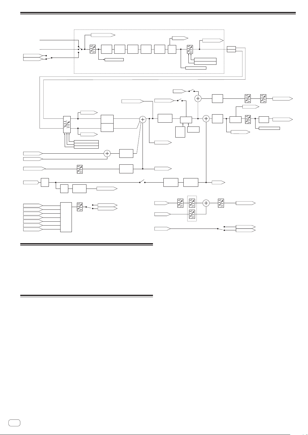
Block Diagram
Peak
Limiter
CH 1/2 Cue
Headphone Mix
Headphone Level
USB Output Level
Master Cue
FX Send
Headphone Out
FILTER
(NOISE)
CH 1/2
3Band
ISOLATOR
CH 1/2
3Band
ISOLATOR
CHx
BEAT FX
PreFILTER
CH 1/2
BEAT FX
PreFader
CH 1/2
Level Meter CH 1/2
CH 1
CH 2
BPM CH 1/2 Detect
CUE
Monitor
CH 1/2
Analog PHONO
Analog CD/LINE
CH Fader
CH 1/2 Control Tone
MIC in
Post CH 1/2 Fader
TalkOver ON/OFF
MIX (Rec Out)
Master Cue
MIC
MIC
Cross Fader B
Cross Fader A
FX Send
AUX
Level meter Master
CH 1/2 Common
Digital Trim
CH 1/2 Cue
Cross Fader
Talk Over
Master
Cue
Talk Over
Level
Talk Over
Mode
Advanced
/Normal
BEAT FX
PostFader
CH 1/2
Master
Level
Booth Level
Booth ATT.
MIC to
Booth Monitor On/Off
Booth Out
Master Out
TalkOver ON/OFF
USB A in
USB B in
MIC
Peak
Limiter
CH1/2 Control Tone
Post CH1/2 Fader
Cross Fader A
Cross Fader B
MIC
AUX
MIX(REC OUT)
USB A SAMPLER
USB B SAMPLER
USB A out
USB B out
USB A out
USB B out
FILTER
(PITCH)
CH 1/2
CH 1/2 Fader Curve
CH 1/2 Fader Reverse
TalkOver ON/OFF
Cross Fader Curve
Cross Fader CutLag
FILTER
(DUB ECHO)
CH 1
FILTER
(DUB ECHO)
CH 2
Cross Fader Reverse
MIC On/Off
Headphone
Cue Fader
AUX in
FX Return
Booth
Mono/
Stereo
Master
Mono/
Stereo
AUX Level
BEAT FX
SAMPLER
BEAT FX
AUX
Output
Select
2Band
MIC EQ
MIC
Filter
MIC In
Level Detect
MIC
ECHO
About trademarks and registered
trademarks
! "Pioneer DJ" is a trademark of PIONEER CORPORATION, and is used
under license.
The names of companies and products mentioned herein are trade-
marks or registered trademarks of their respective owners.
Cautions on copyrights
Recordings you have made are for your personal enjoyment and accord-
ing to copyright laws may not be used without the consent of the copy-
right holder.
! Music recorded from CDs, etc., is protected by the copyright laws of
individual countries and by international treaties. It is the full respon-
sibility of the person who has recorded the music to ensure that it is
used legally.
! When handling music downloaded from the Internet, etc., it is the
full responsibility of the person who has downloaded the music to
ensure that it is used in accordance with the contract concluded
with the download site.
© 2015 Pioneer DJ Corporation. All rights reserved.
<DRI1310-B>
En
36