DJ MIXER
DJM-TOUR1
Operating Instructions
http://pioneerdj.com/support/
The Pioneer DJ site shown above offers FAQs, information on software, and various other types of information
and services to allow you to use your product in greater comfort.
http://rekordbox.com/
For various types of information and services regarding rekordbox™, see the Pioneer DJ website above.
http://kuvo.com/
For various types of information and services regarding KUVO, see the Pioneer DJ website above.

En
2
Contents
How to read this manual
Thank you for buying this Pioneer DJ product.
Be sure to read this manual and the “Operating Instructions (Quick Start
Guide)” included with the unit. Both documents include important infor-
mation that you should understand before using this product.
! In this manual, names of channels and buttons indicated on the
product, names of menus in the software, etc., are indicated within
square brackets ([ ]). (e.g. [MASTER] channel, [ON/OFF], [File]
menu)
! Please note that the screens and specifications of the software
described in this manual as well as the external appearance and
specifications of the hardware are currently under development and
may differ from the final specifications.
! Please note that depending on the operating system version, web
browser settings, etc., operation may differ from the procedures
described in this manual.
Before start
Features ....................................................................................................... 3
Installing the software
Installing the driver software ..................................................................... 4
Part names and functions
Rear panel, front panel ............................................................................... 6
Control Panel .............................................................................................. 8
TILTABLE DISPLAY ................................................................................... 10
Connections
Connecting input terminals ..................................................................... 15
Connecting output terminals .................................................................. 16
Connecting to the control panel .............................................................. 16
Operation
Basic Operation ........................................................................................ 17
How to use the TILTABLE DISPLAY
......................................................... 18
About the display shade ........................................................................... 18
Advanced Operations ............................................................................... 19
Types of effects
Types of SOUND COLOR FX effects ........................................................ 22
Types of BEAT FX ...................................................................................... 22
KUVO
What is KUVO? .......................................................................................... 25
System setup example ............................................................................. 25
Registering the club information ............................................................ 26
Registration procedure ............................................................................ 26
KUVO status details display..................................................................... 27
Changing the settings
Change Procedure ................................................................................... 28
Returning to default settings ................................................................... 28
About the auto standby function ............................................................. 28
About the talk over function..................................................................... 28
About the setting utility software ............................................................ 28
Checking the latest information on the driver software ........................ 29
[Mixer Audio Output] pulldown menu list ......................................... 30
Setting preferences .................................................................................. 30
Additional information
Troubleshooting ........................................................................................ 31
Block Diagram .......................................................................................... 33
About trademarks and registered trademarks ...................................... 34
Cautions on copyrights ............................................................................ 34
Software license notice ............................................................................ 34
En
3
Before start
Before start
Features
This unit is a mixer for professional DJs, offering the variety of functions,
durability, and operability required for working not only in discos and
nightclubs but also at large-scale music festivals and other events. It
not only has an unprecedented overwhelming high sound quality, high
reliability design and support for professional quality connections, it
is also equipped with a wide range of features for DJ performances,
including the SOUND COLOR FX, BEAT FX, PRO DJ LINK, BROWSE,
and WAVE functions, thereby offering strong support for all types of DJ
performances.
HIGH SOUND QUALITY
This unit is designed for thorough improvement of sound quality, for all
digital and analog input/output. Digital audio from the USB and SPD
I/F is compatible with 96 kHz 24-bit high resolution audio. As for analog
audio, this unit is equipped with an ESS 32-bit maximum-performance
D/A converter with low noise and low distortion in wide frequency bands
to enable playback faithful to the original. This unit performs DSP mixing
processing at 96 kHz 64-bit, achieving high-density, vivid sound with high
resolution and a wide range, offering listeners the experience of clear,
warm, powerful club sound.
This unit is equipped with an AES/EBU terminal. This enables use at
large venues as digital audio can be output long distances with little loss
in sound quality.
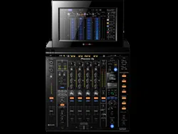
BROWSE & MULTI WAVE VIEW
“BROWSE” and “MULTI WAVE VIEW” are provided to enable quick and
reliable track selection and preparation for performances.
BROWSE
The music files of up to four DJ players connected with PRO DJ LINK can
be displayed in a list. Furthermore, touch operation means that tracks
can be selected and loaded into each DJ player without any stress.
MULTI WAVE VIEW
The waveforms of the tracks currently being played by up to four DJ
players connected with PRO DJ LINK are displayed together. This allows
you to visually grasp the playback conditions of multiple DJ players and
ensures you can create mixes that are a convincing match to the devel-
opment of the track.
DUAL HEADPHONE
This unit is equipped with headphone jacks that allow you to select the
CUE and adjust the volume independently from the conventional head-
phone section. It provides a second headphone section which is optimal
for monitoring during B2B performances by multiple DJ players or when
replacing another DJ.
AUX INPUT
The inclusion of an XLR/TRS combo jack for the AUX input terminal
allows for input from various equipment including a drum machine,
sampler, synthesizer, and external mixer, so you can achieve a greater
variety of performances than ever before.
TILTABLE DISPLAY & DISPLAY SHADE
A display that allows you to adjust the angle and a detachable dis-
play shade ensure excellent visibility under a variety of installation
environments.
BUILT-IN LAN HUB for PRO DJ LINK
This unit employs a NEUTRIK LAN port with a latch lock mechanism.
Use of a compatible LAN cable facilitates a secure connection that will
not disconnect even in environments where conditions such as vibra-
tion, temperature, and humidity are severe. Furthermore, a built-in LAN
HUB function allows you to build a highly reliable system with up to five
PRO DJ LINK connections.
STANDARD LAYOUT & FX
This unit has exactly the same layout, EQ and fader characteristics, and
SOUND COLOR FX, BEAT FX, and SEND/RETURN functions as the DJM-
900NXS2 club standard model to ensure you will achieve impressive
performances without a moment’s hesitation.
KUVO
KUVO is a service that helps people enjoy the club culture both inside
and outside clubs by connecting clubbers, DJs, and clubs using the
concept of “creating the next generation space to enjoy dance music”.
A function to connect to the KUVO service is incorporated into this unit.
This service is based on the idea of delivering information about the
music played at clubs, festivals, and other public venues.
See here for the service details.
http://kuvo.com/about/

En
4
Installing the software
Installing the driver software
This driver software is a proprietary program for inputting and output-
ting audio signals from the computer. To use this unit connected to a
computer on which a Windows or Mac OS is installed, install the driver
software on the computer beforehand.
Software end user license agreement
This Software End User License Agreement (“Agreement”) is between
you (both the individual installing the Program and any single legal
entity for which the individual is acting) (“You” or “Your”) and Pioneer DJ
Corporation (“Pioneer DJ”).
TAKING ANY STEP TO SET UP OR INSTALL THE PROGRAM MEANS
THAT YOU ACCEPT ALL OF THE TERMS OF THIS LICENSE AGREEMENT.
PERMISSION TO DOWNLOAD AND/OR USE THE PROGRAM IS
EXPRESSLY CONDITIONED ON YOUR FOLLOWING THESE TERMS.
WRITTEN OR ELECTRONIC APPROVAL IS NOT REQUIRED TO MAKE
THIS AGREEMENT VALID AND ENFORCEABLE. IF YOU DO NOT
AGREE TO ALL OF THE TERMS OF THIS AGREEMENT, YOU ARE NOT
AUTHORIZED TO USE THE PROGRAM AND MUST STOP INSTALLING IT
OR UNINSTALL IT, AS APPLICABLE.
1 DEFINITIONS
1 “Documentation” means written documentation, specifications
and help content made generally available by Pioneer DJ to aid in
installing and using the Program.
2 “Program” means all or any part of Pioneer DJ’s software
licensed to You by Pioneer DJ under this Agreement.
2 PROGRAM LICENSE
1 Limited License. Subject to this Agreement’s restrictions,
Pioneer DJ grants to You a limited, non-exclusive, non-transfer-
able, license (without the right to sublicense):
a To install a single copy of the Program in Your computer or
mobile device, to use the Program only for Your personal pur-
pose complying with this Agreement and the Documentation
(“Authorized Use”);
b To use the Documentation in support of Your Authorized Use;
and
c To make one copy of the Program solely for backup pur-
poses, provided that all titles and trademark, copyright and
restricted rights notices are reproduced on the copy.
2 Restrictions. You will not copy or use the Program or
Documentation except as expressly permitted by this Agreement.
You will not transfer, sublicense, rent, lease or lend the Program,
or use it for third-party training, commercial time-sharing or
service bureau use. You will not Yourself or through any third
party modify, reverse engineer, disassemble or decompile the
Program, except to the extent expressly permitted by applicable
law, and then only after You have notified Pioneer DJ in writing of
Your intended activities.
3 Ownership. Pioneer DJ or its licensor retains all right, title
and interest in and to all patent, copyright, trademark, trade
secret and other intellectual property rights in the Program and
Documentation, and any derivative works thereof. You do not
acquire any other rights, express or implied, beyond the limited
license set forth in this Agreement.
4 No Support. Pioneer DJ has no obligation to provide support,
maintenance, upgrades, modifications or new releases for the
Program or Documentation under this Agreement.
3 WARRANTY DISCLAIMER
THE PROGRAM AND DOCUMENTATION ARE PROVIDED “AS IS”
WITHOUT ANY REPRESENTATIONS OR WARRANTIES, AND YOU
AGREE TO USE THEM AT YOUR SOLE RISK. TO THE FULLEST EXTENT
PERMISSIBLE BY LAW, PIONEER DJ EXPRESSLY DISCLAIMS ALL
WARRANTIES OF ANY KIND WITH RESPECT TO THE PROGRAM AND
DOCUMENTATION, WHETHER EXPRESS, IMPLIED, STATUTORY,
OR ARISING OUT OF COURSE OF PERFORMANCE, COURSE OF
DEALING OR USAGE OF TRADE, INCLUDING ANY WARRANTIES
OF MERCHANTABILITY, FITNESS FOR A PARTICULAR PURPOSE,
SATISFACTORY QUALITY, ACCURACY, TITLE OR NON-INFRINGEMENT.
4 EXPORT CONTROL AND COMPLIANCE WITH LAWS
AND REGULATIONS
You may not use or otherwise export or re-export the Program except as
authorized by United States law and the laws of the jurisdiction in which
the Program was obtained. In particular, but without limitation, the
Program may not be exported or re-exported (a) into any U.S.-embargoed
countries or (b) to anyone on the U.S. Treasury Department's Specially
Designated Nationals List or the U.S. Department of Commerce Denied
Persons List or Entity List. By using the Program, you represent and war-
rant that you are not located in any such country or on any such list. You
also agree that you will not use the Program for any purposes prohibited
by United States law, including, without limitation, the development,
design, manufacture, or production of nuclear, missile, or chemical or
biological weapons.
5 U.S. GOVERNMENT RESTRICTED RIGHTS
The Program and Documentations are “commercial computer software”
and “commercial computer software documentation” as those terms are
defined in 48 C.F.R. §252.227-7014 (a) (1) (2007) and 252.227-7014 (a) (5)
(2007). The U.S. Government’s rights with respect to the Program and
Documentations are limited by this license pursuant to 48 C.F.R. §12.212
(Computer software) (1995) and 48 C.F.R. §12.211 (Technical data) (1995)
and/or 48 C.F.R. §227.7202-3, as applicable. As such, the Program and
Documentations are being licensed to the U.S. Government end users:
(a) only as “commercial items” as that term is defined in 48 C.F.R. §2.101
generally and as incorporated in DFAR 212.102; and (b) with only those
limited rights as are granted to the public pursuant to this license.
Under no circumstance will the U.S. Government or its end users be
granted any greater rights than we grant to other users, as provided for
in this license. Manufacturer is Pioneer DJ Corporation, 1-1 Shin-Ogura,
Saiwai-ku, Kawasaki-shi, Kanagawa, 212-0031 Japan
6 DAMAGES AND REMEDIES FOR BREACH
You agree that any breach of this Agreement’s restrictions would cause
Pioneer DJ irreparable harm for which money damages alone would be
inadequate. In addition to damages and any other remedies to which
Pioneer DJ may be entitled, You agree that Pioneer DJ may seek injunc-
tive relief to prevent the actual, threatened or continued breach of this
Agreement.
7 TERMINATION
Pioneer DJ may terminate this Agreement at any time upon Your breach
of any provision. If this Agreement is terminated, You will stop using
the Program, permanently delete it from your computer or mobile
device where it resides, and destroy all copies of the Program and
Documentation in Your possession, confirming to Pioneer DJ in writing
that You have done so. Sections 2.2, 2.3, 2.4, 3, 4, 5, 6, 7 and 8 will con-
tinue in effect after this Agreement’s termination.
8 GENERAL TERMS
1 Limitation of Liability. In no event will Pioneer DJ or its subsidiar-
ies be liable in connection with this Agreement or its subject
matter, under any theory of liability, for any indirect, incidental,
special, consequential or punitive damages, or damages for lost
profits, revenue, business, savings, data, use, or cost of substi-
tute procurement, even if advised of the possibility of such dam-
ages or if such damages are foreseeable. In no event will Pioneer
DJ’s liability for all damages exceed the amounts actually paid by
You to Pioneer DJ or its subsidiaries for the Program. The parties
acknowledge that the liability limits and risk allocation in this
Agreement are reflected in the Program price and are essential
elements of the bargain between the parties, without which
Pioneer DJ would not have provided the Program or entered into
this Agreement.
En
5
Installing the software
2 The limitations or exclusions of warranties and liability contained
in this Agreement do not affect or prejudice Your statutory rights
as consumer and shall apply to You only to the extent such limita-
tions or exclusions are permitted under the laws of the jurisdic-
tion where You are located.
3
Severability and Waiver. If any provision of this Agreement is held
to be illegal, invalid or otherwise unenforceable, that provision
will be enforced to the extent possible or, if incapable of enforce-
ment, deemed to be severed and deleted from this Agreement,
and the remainder will continue in full force and effect. The
waiver by either party of any default or breach of this Agreement
will not waive any other or subsequent default or breach.
4 No Assignment. You may not assign, sell, transfer, delegate or
otherwise dispose of this Agreement or any rights or obligations
under it, whether voluntarily or involuntarily, by operation of law
or otherwise, without Pioneer DJ’s prior written consent. Any
purported assignment, transfer or delegation by You will be null
and void. Subject to the foregoing, this Agreement will be binding
upon and will inure to the benefit of the parties and their respec-
tive successors and assigns.
5 Entire Agreement. This Agreement constitutes the entire agree-
ment between the parties and supersedes all prior or contempo-
raneous agreements or representations, whether written or oral,
concerning its subject matter. This Agreement may not be modi-
fied or amended without Pioneer DJ’s prior and express written
consent, and no other act, document, usage or custom will be
deemed to amend or modify this Agreement.
6 You agree that this Agreement shall be governed and construed
by and under the laws of Japan.
Cautions on Installation
! Before installing the driver software, be sure to turn off the power of
this unit and disconnect the USB cable from both this unit and your
computer.
! If you connect this unit to your computer without installing the driver
software first, an error may occur on your computer depending on
the system environment.
! If you have discontinued the installation process in progress, step
through the installation process again from the beginning according
to the following procedure.
! Read Software end user license agreement carefully before installing
this unit’s proprietary driver software.
! Before installing the driver software, terminate all other programs
running on your computer.
! The driver software is compatible with the following OSs.
Supported operating systems
Mac OS X: 10.11, 10.10, 10.9, 10.8 (latest update)
1
Windows
®
10 (latest service pack)
32-bit version
1
64-bit version
1
Windows
®
8/8.1 (latest service pack)
32-bit version
1
64-bit version
1
Windows Pro
®
8/8.1 (latest service pack)
32-bit version
1
64-bit version
1
Windows
®
7 Home Premium/Professional/Ultimate (latest
service pack)
32-bit version
1
64-bit version
1
Checking the latest information on the driver software
For the latest information on this unit’s dedicated driver software, see
the Pioneer DJ site below.
http://www.pioneerdj.com/
Obtaining the driver software
1 Launch a web browser on the computer and access
the Pioneer DJ site below.
http://www.pioneerdj.com/
2 Click the [Support] icon.
3 Click the [FIND SOFTWARE & FIRMWARE UPDATES]
icon.
4 Click the [DJM-TOUR1] icon in the [Mixer] category.
5 After clicking [Drivers], download the latest driver
software from the download page.
! Download the driver for either Windows or Mac from the download
page.
Installation Procedure (Windows)
Read Cautions on Installation carefully before installing the driver
software.
! To install or uninstall the driver software, you need to be authorized
by the administrator of your computer. Log on as the administrator of
your computer before proceeding with the installation.
1 Double-click the file for Windows (DJM-
TOUR1_X.XXX.exe) downloaded in Obtaining the driver
software.
The driver software installation screen appears.
2 Carefully read the Software end user license
agreement and if you consent to the provisions, put a
check mark in [I agree.] and click [OK].
If you do not consent to the provisions of the Software end user license
agreement, click [Cancel] and stop installation.
3 Proceed with installation according to the instructions
on the screen.
If [Windows Security] appears on the screen while the installation is
in progress, click [Install this driver software anyway] and continue
with the installation.
! When the installation program is completed, a completion message
appears.
Installation procedure (Mac OS X)
Read Cautions on Installation carefully before installing the driver
software.
!
To install or uninstall the driver software, you need to be authorized
by the administrator of your computer. Have the name and password
of the administrator of your computer ready in advance.
1 Obtaining the driver software Double-click the file for
Mac (DJM-TOUR1_M_X.X.X.dmg) downloaded in.
2 Double-click [DJM-TOUR1_AudioDriver.pkg].
The driver software installation screen appears.
3 Check the details on the screen and click [Continue
Anyway].
4 When the end user license agreement appears, read
Software end user license agreement carefully, then click
[Continue Anyway].
5 If you consent to the provisions of the Software end
user license agreement, click [Agree].
If you do not consent to the provisions of the Software end user license
agreement, click [I disagree] and stop installation.
6 Proceed with installation according to the instructions
on the screen.
! Click [Cancel] to cancel installation after it has started.
En
6
Part names and functions
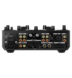
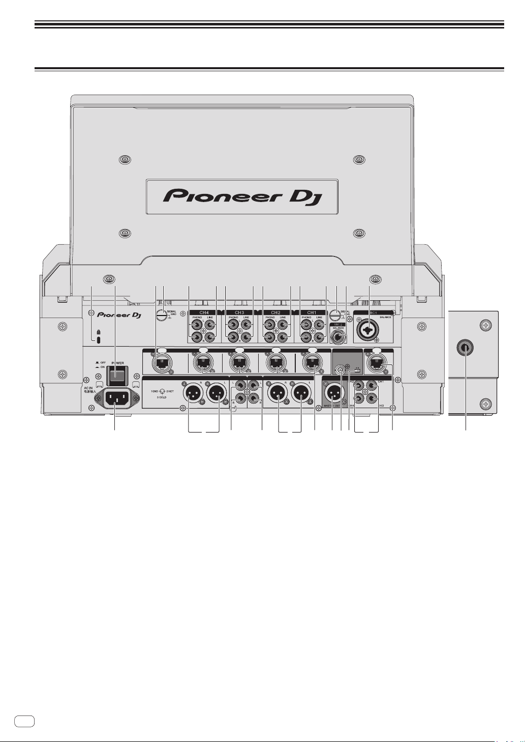
Rear panel, front panel
PHONES
LINK
CH4
EXTENSION
CH3 CH2CH1
IN
OFFON
75
Ω
MASTER2
REC OUT
MASTER1
WORD CLOCK
DIGITAL OUT
INTERNET
DIGITAL IN
BOOTH
AES/EBU
2 4
5 4554 54 6
61
7 8
k
9
gh c bd
j
a
fi e
3
1 Kensington security slot
2 POWER button (page 17 )
Turns this unit’s power on and off.
3 EXTENSION terminal (page 15 )
Used when extending PRO DJ LINK. Connect this to the LAN termi-
nal of a computer with rekordbox installed, etc.
4 PHONO terminals (page 15 )
Connect to a phono level (MM cartridge) output device. Do not input
line level signals.
To connect a device to the [PHONO] terminals, remove the short-
circuit pin plug inserted in the terminals.
Insert this short-circuit pin plug into the [PHONO] terminals when
nothing is connected to them to cut external noise.
5 LINE terminals (page 15 )
Connect to a DJ player or a line level output component.
6 SIGNAL GND terminal (page 15 )
Connects an analog player’s ground wire here. This helps reduce
noise when the analog player is connected.
7 MIC2 terminal (page 15 )
Connects a microphone here.
8 MIC1 terminal (page 15 )
Connects a microphone here.
9 INTERNET terminal
Connect to a router, etc. that is connected to the Internet. Used when
connecting with the KUVO system.
Connect a device to be connected to PRO DJ LINK not to this termi-
nal but to the [EXTENSION] terminal.
a DIGITAL IN terminal (page 15 )
Connect these to the digital coaxial output terminals on DJ players,
etc. The sound may be momentarily interrupted when the output
signal sampling frequency is switched.
b 75 Ω termination ON/OFF switch
c WORD CLOCK input terminal
Set the external clock generator to MASTER and implement digital
master output synchronized with another device.
Use a cable with an impedance of 75 Ω for the connection between
the terminals. Performance is not guaranteed when a cable with an
impedance of other than 75 Ω is used.
Change the 75 Ω termination ON/OFF switch setting according to
the connection method.
— ON
— For connecting with the external clock generator on a one-to-
one basis
— For terminating with this unit when connecting a combina-
tion of multiple devices
— OFF
— For terminating with another device when connecting a
combination of multiple devices

En
7
Part names and functions
d DIGITAL MASTER OUT terminal (page 16 )
Connect to the digital input terminal of a preamplifier, etc. The mas-
ter channel audio is output in AES/EBU format. Be careful not to
accidentally connect this terminal to an analog input terminal.
Be careful not to accidentally insert the power cord of another
unit.
e LINK terminal (page 15 )
Connect to the LINK terminal of a DJ player of Pioneer DJ (PRO DJ
LINK).
f BOOTH terminals (page 16 )
These are output terminals for a booth monitor.
Be careful not to accidentally insert the power cord of another
unit.
g REC OUT terminals (page 16 )
These are output terminals for recording.
h MASTER2 terminals (page 16 )
Connect these to the analog input terminals of a power amplifier, etc.
i MASTER1 terminals (page 16 )
Connect these to the analog input terminals of a power amplifier, etc.
Be sure to use these as balanced outputs.
Be careful not to accidentally insert the power cord of another
unit.
j AC IN
Connects to a power outlet using the included power cord. Wait until
all connections between the equipment are completed before con-
necting the power cord.
Be sure to use the included power cord.
k SECOND HEADPHONES terminal
Connect headphones. Supports a 1/4” stereo phone plug.
WARNING
The short-circuit pin plugs out of the reach of children and infants. If
accidentally swallowed, contact a doctor immediately.
En
8
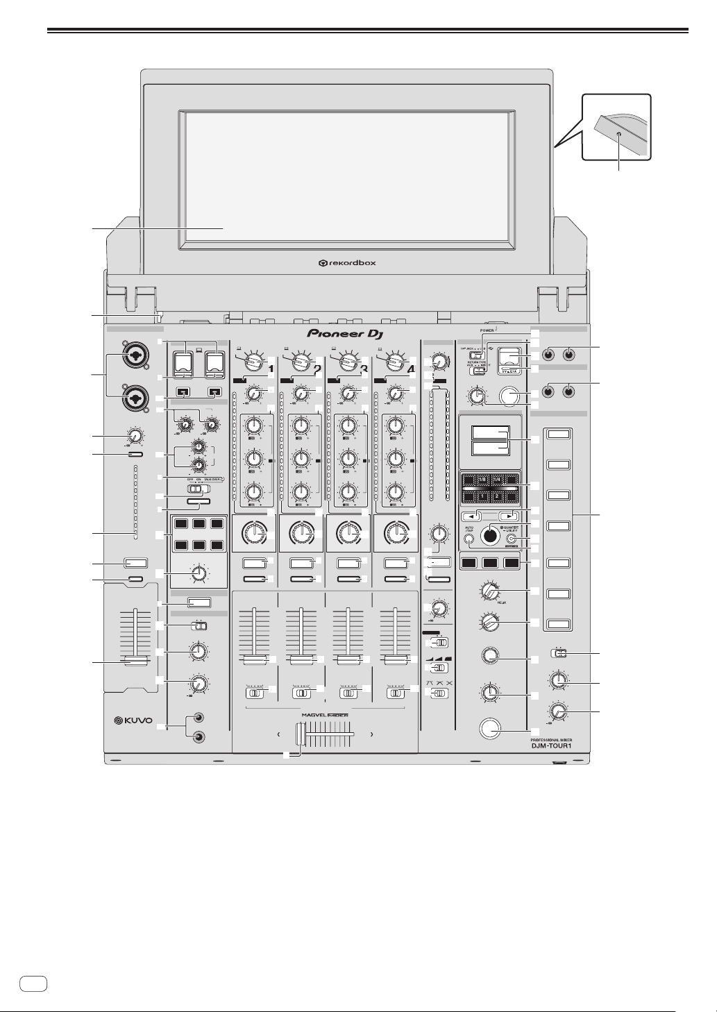
Control Panel
TIME
MAX
LEVEL /DEPTH
ON /OFF
MIN
MAX
LEVELON/OFF
MIN
A
B
CROSS FA DER ASSIGN
MASTER
0
MIXING
LEVEL
PHONES
CUE
CUE
CUE
CUE
10
9
8
7
6
5
4
3
2
1
0
1
10
9
8
7
6
5
4
3
2
1
0
7
1
10
9
8
7
6
5
4
3
2
1
0
7
1
10
9
8
7
6
5
4
3
2
1
0
10
9
8
7
6
5
4
3
2
1
0
EQ
ISOLATOR
BOOTH MONITOR
EQ CURVE
CH FADER
CROSS FA DER
0
dB RL
LEVEL
0
BALANCE
RL
TAP
BEAT FX
BEAT
X
-
PAD
STEREO
MONO SPLIT
HEADPHONES
SPACE
NOISE CRUSH FILTER
DUB
ECHO
SWEEP
LINK
SOUND COLOR FX
LEVEL
HI
LOW
EQ
12 12
12 12
MIC
USB
MIDI
ON/OFF
0 0
CLIP
DECK 3/C
CLIP
DECK 1/A
CLIP
DECK 2/B
TRIM
9
CLIP
CLIP
DECK 4/D
EQ /
LOW
6
-
26
/
MID
6
-
26
/
HI
6
-
26
/
ISO
dB
12
9
6
3
0
-3
-6
-9
-12
-15
-18
-21
-24
-27
-30
BEAT FX
BEAT FX
BEAT FX
CUE
BEAT FX
CUE
BEAT FX
CUE
BEAT FX
BEAT FX
PARAMETER
MAXMIN
AB
DIGITAL
LINE
PHONO
AB
RETURN
AUX
DIGITAL
LINE
PHONO
AB
RETURN
AUX
DIGITAL
LINE
PHONO
AB
RETURN
AUX
DIGITAL
LINE
PHONO
AB
RETURN
AUX
12
15
9
6
3
0
-3
-6
-9
-12
-15
-18
-21
-24
-27
dB
12
9
6
3
0
-3
-6
-18
-24
MASTER
MIC
AUX
CROSS
FADER
FLANGER
PHASER
PITCH
PING PONG
ROLL
SLIP ROLL
DELAY
TRANS
FILTER
SPIRAL
ECHO
REVERB
VINYL BRAKE
FX FREQUENCY
LOW MID HI
SEND
/ RETURN
SEND
/ RETURN
SEND
SEND
/ RETURN
AUX
SEND
/ RETURN
RETURN
SECOND HEADPHONES
MASTER
1/4
14
1/81/2
3/4
1/16
2
1
A
B
23
4
COLOR
HILOW
COLOR
HILOW
COLOR
HILOW
COLOR
HILOW
MIC1
MIC2
BA THRU
BATHRU
BATHRU BATHRU
CUE
CUE
CUE
CUE
CUE
CUE
CUE
CUE
-12
MASTER
0
MIXING
LEVEL
CUE
STEREOMONO SPLIT
TRIM
9
CLIP
L (MONO)
R
BALANCE
L (MONO)
L (MONO)
R
R
UNBALANCE
UNBALANCE
CH 1
CH 2
CH 3
CH 4
MASTER
LINK
AUX
TRIM
9
EQ /
LOW
6
-
26
/
MID
6
-
26
/
HI
6
-
26
/
ISO
dB
12
9
6
3
0
-3
-6
-9
-12
-15
-18
-21
-24
-27
-30
TRIM
9
EQ /
LOW
6
-
26
/
MID
6
-
26
/
HI
6
-
26
/
ISO
dB
12
9
6
3
0
-3
-6
-9
-12
-15
-18
-21
-24
-27
-30
TRIM
9
EQ /
LOW
6
-
26
/
MID
6
-
26
/
HI
6
-
26
/
ISO
dB
12
9
6
3
0
-3
-6
-9
-12
-15
-18
-21
-24
-27
-30
m
k
l
h
g
2
e
d
c
b
2
1
2
3
4
6
5
B
l
C
F
D
L
M
N
O
P
T
U
V
A
G
Q
R
z
3
i
7
E
S
o
r
6
5
4
p
3
1
q
n
t
s
5
u
w
x
y
3
2
o
6
5
4
p
3
1
q
n
2
o
6
5
4
p
3
1
q
n
2
o
6
5
4
p
3
1
q
n
2
2
j
H
I
J
K
8
v
9
a
f
W
1 Channel Fader (page 17 )
Adjusts the level of audio signals output in each channel.
2 Effect channel selector indicator
The indicator of the channel selected with the effect channel selector
switch lights.
3 CUE button (page 17 )
Presses the [CUE] button(s) for the channel(s) you want to monitor.
4 Channel Level Indicator (page 17 )
Displays the sound level of the respective channels before passing
through the channel faders.
5 CLIP indicators
! Each channel: An indicator lights when sound with an exces-
sively high volume is input to a channel.
! Master: Lights when audio with an excessive volume level is
output from the [MASTER1] or [MASTER2] terminals.
6 TRIM control (page 17 )
Adjusts the level of audio signals input in each channel.
7 AUX terminal
Connect to the output terminal of another mixer or a line level output
component. When [L (MONO)] only is connected, the audio input to
[L (MONO)] is also input to [R].

En
9
Part names and functions
8 TILTABLE DISPLAY unlock button
Releases the lock that is engaged when the TILTABLE DISPLAY is
closed.
9 TILTABLE DISPLAY
For how to use the display, see page 10 .
a PHONES terminal (page 17 )
Connect headphones here.
Supports a 1/4” stereo phone plug and a 3.5 mm stereo mini plug,
and two sets of headphones can be used at the same time.
b LEVEL control (page 17 )
Adjusts the sound level output from the headphones.
c MIXING control (page 17 )
This adjusts the monitor volume balance of the sound of channels for
which the [CUE] button is pressed and the sound of the [MASTER]
channel.
d MONO SPLIT, STEREO selector switch (page 17 )
Switches how the monitor sound output from the headphones is
distributed.
e PARAMETER control
Adjusts the SOUND COLOR FX parameter.
f SOUND COLOR FX buttons
These turn the SOUND COLOR FX effects on/off.
g OFF, ON, TALK OVER selector switch (page 17 )
Turns the microphone on/off.
h Microphone indicator (page 17 )
i EQ (HI, LOW) controls (page 17 )
These adjust the tone quality of the [MIC1] and [MIC2] channels.
j MIC LEVEL control (page 17 )
Adjusts the level of the sound input to the [MIC1] and [MIC2]
channels.
k MIDI ON/OFF buttons
Switches the MIDI function on and off.
l USB connection indicator
An indicator lights when a computer is connected. It flashes when
the driver software is not installed on the computer.
m USB terminal (page 16 )
Connect the computer.
n Input selector switches (page 17 )
Selects the input source of each channel from the components con-
nected to this unit.
o EQ/ISO (HI, MID, LOW) controls
These adjust the sound quality of the respective channels.
p COLOR control
This changes the parameters of the SOUND COLOR FX of the differ-
ent channels.
q CROSS FADER ASSIGN (A, THRU, B) selector switch
(page 17 )
Sets the output destination of each channel to [A] or [B].
r Crossfader (page 17 )
Outputs audio signals assigned by the crossfader assign switch cor-
responding to the curve characteristics selected by [CROSS FADER]
(Crossfader Curve Selector Switch).
s MASTER LEVEL control (page 17 )
Adjusts the audio level output from the [MASTER1] and [MASTER2]
terminals.
t Master Level Indicator (page 17 )
Displays the audio level output from the [MASTER1] and [MASTER2]
terminals.
u BALANCE control
Adjusts the left/right balance of the sound output from the
[MASTER1] terminals, etc.
v BOOTH MONITOR control (page 18 )
Adjusts the level of audio signals output from the [BOOTH] terminal.
w EQ CURVE (ISOLATOR, EQ) selector switch
Switches the function of the [EQ/ISO (HI, MID, LOW)] controls.
x CH FADER ( , , ) selector switch
Switches the channel fader’s curve characteristics.
y CROSS FADER ( , , ) curve selector switch
This switches the crossfader curve characteristics.
z SEND/RETURN (1/4” JACK, ) selector switch
Switches the input/output source of the SEND/RETURN channel.
Select either the device connected to the [SEND/RETURN] terminal
on the control panel or the device connected to the mobile device
connection terminal.
A RETURN TYPE (AUX, INSERT) selector switch
Selects the SEND/RETURN method.
B Mobile device connection terminal (USB port)
Connect a mobile device to enable SEND/RETURN to be used for
apps.
C SEND/RETURN ON/OFF button
Turns SEND/RETURN on and off.
D SEND/RETURN LEVEL control
Adjusts the sound level of SEND/RETURN.
E Main unit display
Displays the effect name, BPM, effect parameter, etc.
F X-PAD
BEAT FX is on while this is touched. Also, the parameter can be
adjusted depending on the place touched.
G BEAT c, d buttons
Set the beat fraction for synchronizing the effect sound.
H TAP button
When the BPM measurement mode is set to [TAP], tap the button
with a finger to input the BPM manually.
I QUANTIZE (UTILITY, WAKE UP) button
— QUANTIZE: When the QUANTIZE function is turned on for BEAT
FX, the effect is applied to the sound without getting out of tempo
with the currently playing track.
— UTILITY: Displays the [UTILITY] screen.
— WAKE UP: Cancels the standby state.
J AUTO/TAP button
Switches the BPM measurement mode.
K FX FREQUENCY button
Select the range to apply BEAT FX. BEAT FX is applied to the range of
the button that is lit.
L Beat effect selector switch
Switches the BEAT FX effect type.
M Effect channel selector switch
Switches the channel to which the BEAT FX is to be applied.
N TIME control
Adjusts the BEAT FX’s time parameter.
O LEVEL/DEPTH control
Adjusts the BEAT FX’s quantitative parameter.
P Beat effect ON/OFF button
Turns BEAT FX on and off.
En
10
Q SEND terminals (page 16 )
Connect to the input terminal of an external effector. When
[L (MONO)] only is connected, monaural audio is output.
R RETURN terminals (page 16 )
Connect to the output terminal of an external effector. When the
[L (MONO)] channel only is connected, the [L (MONO)] channel
input is simultaneously input to the [R] channel.
S SECOND HEADPHONES CUE button
Press the [CUE] button for the channel you want to monitor with
SECOND HEADPHONES.
T SECOND HEADPHONES MONO SPLIT / STEREO
selector switch
Switches how the monitor sound output from SECOND
HEADPHONES is distributed.
U SECOND HEADPHONES MIXING control
This adjusts the monitor volume balance of the sound of channels for
which the [CUE] button is pressed and the sound of the [MASTER]
channel.
V SECOND HEADPHONES LEVEL control
Adjusts the level of audio output from SECOND HEADPHONES.
W Display shade attachment screw hole (page 18 )
Do not pull on the channel fader and crossfader knobs with excessive
force. The knobs have a structure by which they cannot be pulled off
easily. Pulling the knobs strongly may result in damaging the unit.
TILTABLE DISPLAY
The display of this unit shows information about the track playing for each channel. Furthermore, it can also display the tracks on media loaded in DJ
players connected with PRO DJ LINK, and you can use this unit to load the tracks into each deck.
! DJ players are compatible with CDJ-TOUR1. However, you need to use rekordbox to export tracks to media.
For the DJ players that can be connected, check the Pioneer DJ SUPPORT page.
http://pioneerdj.com/support/
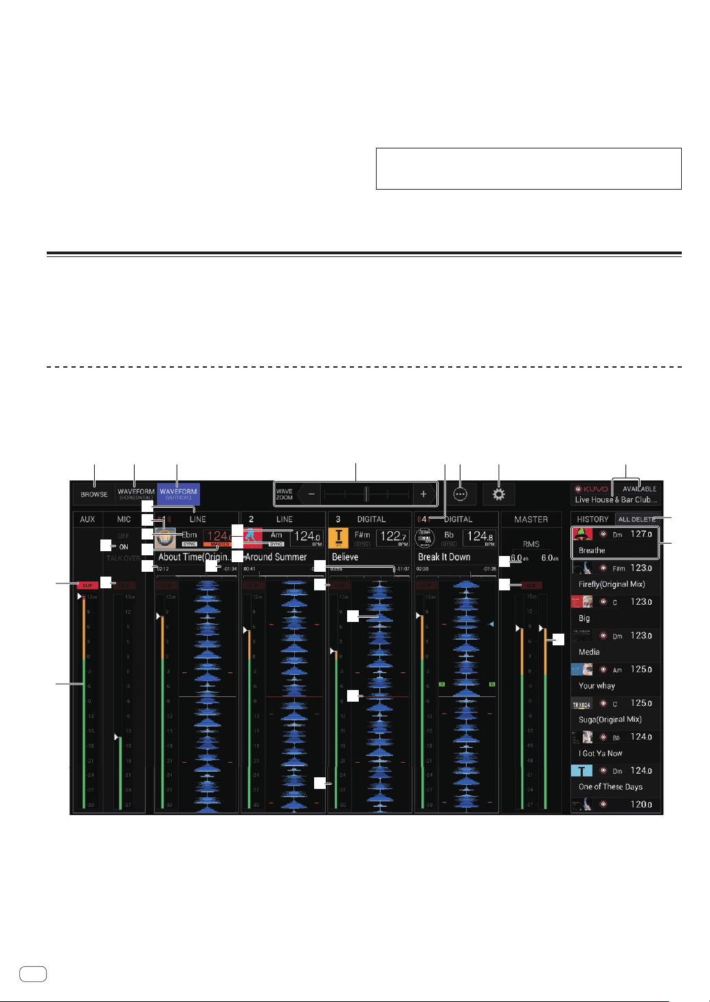
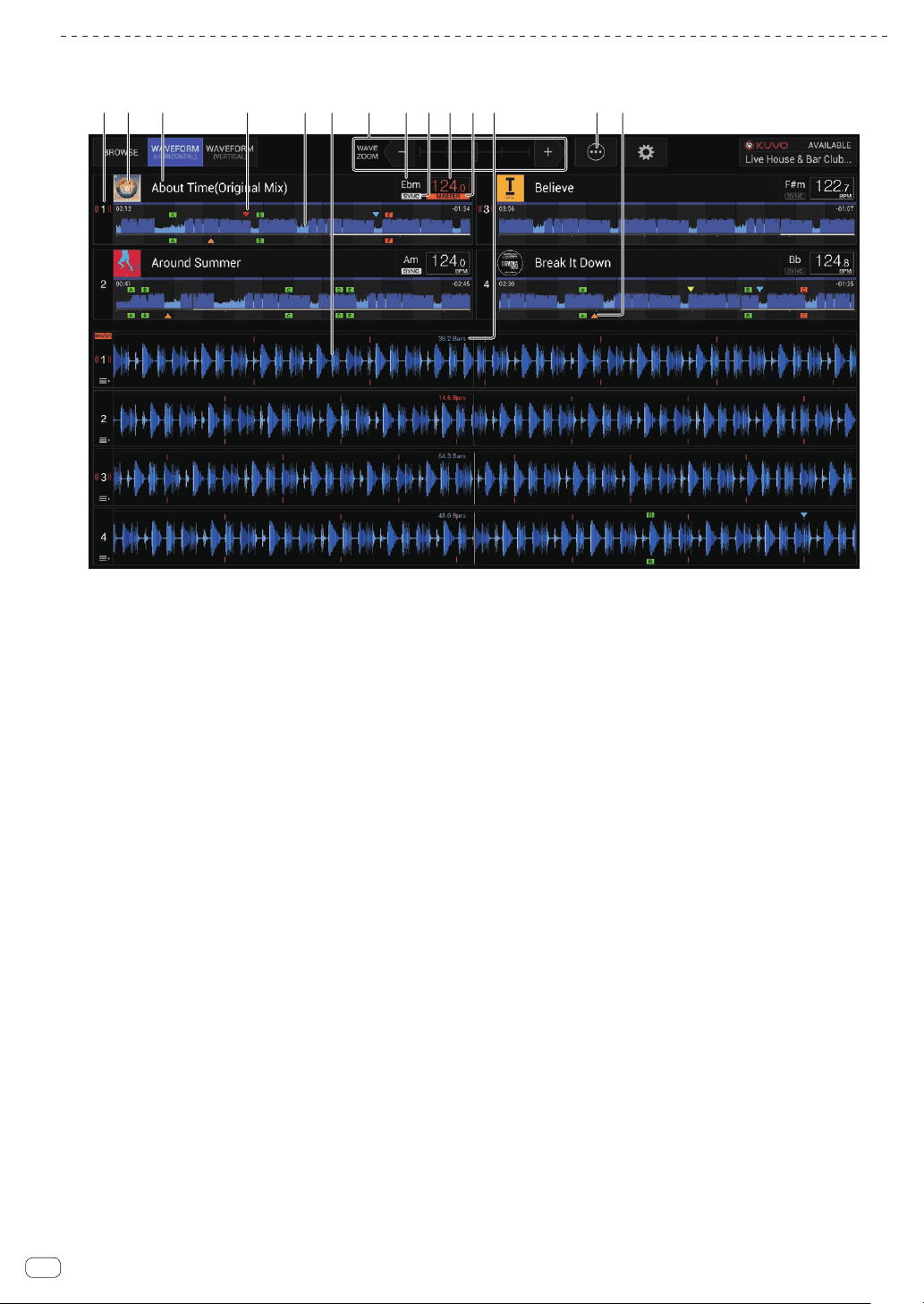
WAVEFORM VERTICAL screen
The information required for quick and reliable mixes can be visually checked as the information and waveforms for the tracks being played by DJ
players connected with PRO DJ LINK are displayed on each channel strip. Sound pressure information (RMS) is displayed to help you to reduce any
incompatibility you may notice when channels are mixed together. Also, the display of the history of tracks played by DJ players allows you to check the
overall flow of your DJ performance.
1 2 3 65 7
9
a
c
b
j k em
n
o
ep
q
f
s
t
r
v
d
e
i
g
h
l
u
8
4
1 BROWSE
Switches to the BROWSE screen.
2 WAVEFORM HORIZONTAL
Switches to the WAVEFORM HORIZONTAL screen.
3 WAVEFORM VERTICAL
Switches to the WAVEFORM VERTICAL screen.
4 Zoom
Changes the scale of the enlarged waveforms that are displayed.
5 Channel number/ON AIR information
Displays the channel number of the mixer. Also displays the ON AIR
status.
6 Menu
Displays a pop-up menu for configuring the following setting.
! Current Position: Select which point on the enlarged waveform
to set the current playback position.
! Waveform Direction: Selects the waveform flow direction. This
is only displayed on the WAVEFORM VERTICAL screen.

En
11
Part names and functions
7 Utilities
Opens a screen for configuring the settings of this unit including this
screen.
For details, see Changing the settings.
8 KUVO status display/club name display
Displays the status of the connection to KUVO.
Also, displays the name of the club currently registered on the KUVO
server. The KUVO status details display screen can be displayed by
touching this area.
9 AUX CLIP indicator
Lights when audio with an excessive volume level is input to the
[AUX] input.
a AUX RMS meter
Displays the RMS value of the [AUX] input calculated from the peak
value.
b MIC OFF/ON/TALK OVER indicators
Displays the status for [MIC] of this unit.
c MIC CLIP indicator
Lights when audio with an excessive volume level is input to the
[MIC] input.
d Input selection display
Displays the source selected with an input selector switch of the
mixer.
e Artwork display
Displays the artwork of loaded tracks that have been analyzed.
f KEY
This indicates the track’s key.
g BPM
Displays the BPM (beats per minute) of the track currently being
played.
h SYNC
Displayed when the DJ player has [SYNC] turned on.
i MASTER
Displayed when the DJ player is in the SYNC MASTER state.
j Elapsed time display
Displays the time elapsed since the start of playback of a loaded
track that has been analyzed.
k Remaining time display
Displays the remaining playback time for a loaded track that has
been analyzed.
l Track names
Displays the track name.
m Play position progress bar display
Displays which position of the overall track is currently playing using
a progress bar.
n Each channel CLIP indicator
An indicator lights when sound with an excessively high volume is
input to a channel.
o Each channel RMS meter
Displays the RMS value calculated from the peak value of the sound
level before sound is passed through the channel fader of each
channel.
p Track waveform display
Displays the waveform of an analyzed track.
The waveform movement direction can be changed from [MENU].
q Current playback position display
Displays the location where the current sound is output on the wave-
form of each channel.
The display position can be changed from [MENU].
r MASTER RMS value display
Displays the RMS value of the [MASTER] output as a numerical
value.
s MASTER CLIP indicator
Lights when audio with an excessive volume level is output from the
[MASTER1] or [MASTER2] terminals.
t MASTER RMS meter
Displays the RMS value calculated from peak value for the level of
sound output from the [MASTER1] and [MASTER2] terminals.
u ALL DELETE button
Deletes the played track information history.
v HISTORY display information
Displays the played track information.
En
12
WAVEFORM HORIZONTAL screen
This screen displays a list of the information and waveforms of the tracks currently being played by DJ players connected with PRO DJ LINK.
1 2 3 56 d4 e7 8 a9 b c
1 Player number/ON AIR information
Displays the player number of the DJ player. The ON AIR state is also
indicated.
2 Artwork display
Displays the artwork of loaded tracks that have been analyzed.
3 Track names
Displays the track name.
4 Cue/loop/hot cue point memory display
This displays the position of cue point, loop point and hot cue point
recorded on the storage device (SD, USB) with the mark.
5 Overall waveform
Displays the overall waveform of the track currently being played.
6 Enlarged waveform
Displays the enlarged waveform of the track currently being played.
The scale of an enlarged waveform can be changed by zooming.
7 Zoom
Changes the scale of the enlarged waveforms that are displayed.
8 KEY
This indicates the track’s key.
9 SYNC
Displayed when the DJ player has [SYNC] turned on.
a BPM
Displays BPM (Beats Per Minute) of the track currently being played.
b MASTER
Displayed when the DJ player is in the SYNC MASTER state.
c BEAT COUNT DOWN
This indicates the number of bars or beats from the currently playing
position to the nearest stored cue point.
d Menu
Displays a pop-up menu for configuring the following setting.
! Current Position: Select which point on the enlarged waveform
to set the current playback position.
e Cue/loop/hot cue point display
This displays the position of cue point, loop point and hot cue point
that have been set using the mark.
En
13
Part names and functions
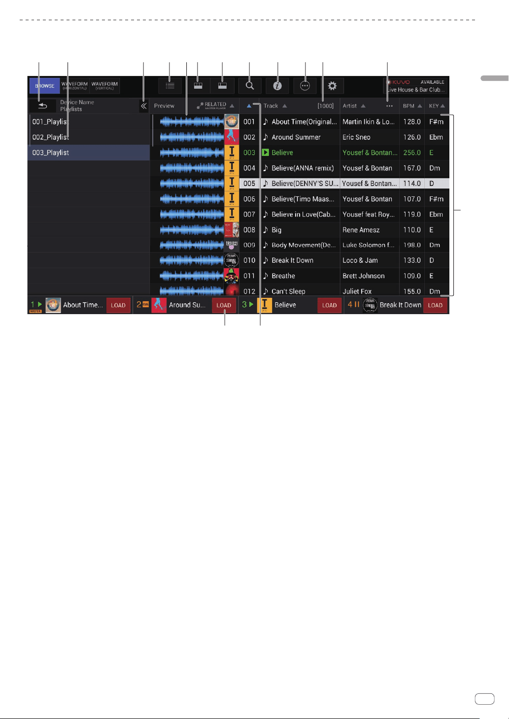
BROWSE screen
The BROWSE screen allows you to browse the media inserted in DJ players connected with PRO DJ LINK and load the tracks into the DJ players.
1 2 3 4 5 6 7 8 9 a b
d
c
ef
1 BACK
Touch this to display the level above.
2 Hierarchy view
Displays the hierarchy of media containing tracks, playlists in media,
etc.
Select media or a folder to display the level below it.
Touch [BACK] to display the level above.
3 Display/hide hierarchy view
Displays or hides the hierarchy view.
4 Artwork display switching
Switch to display the entire artwork or only the upper part.
5 Overall waveform
Displays the waveform of the track.
6 Category filters
Narrow down the tracks by genre, artist, and album.
7 Track filters
Narrow down the tracks by BPM, KEY, tags, etc.
8 Search filters
Enter text to search for a track.
9 INFO
The details of the track selected by the cursor are displayed on the
right side.
a Menu
A pop-up menu is displayed to allow you to perform various opera-
tions such as deleting the list.
b Number of tracks
Displays the number of tracks displayed in the track list.
c User-set category selection
Select any item to display.
d Track list
Displays a list of tracks in the list selected in the hierarchy view.
e SORT
Sorts the tracks by selected category.
f Load track
Touch this to load the selected track into the corresponding DJ
player.
En
14
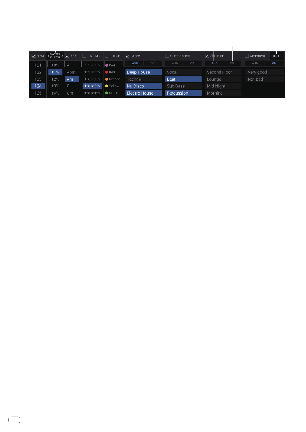
TRACK FILTER
Touch [TRACK FILTER] to display the track filters in the upper part of the screen.
! Tracks can be searched for by the tag information added to tracks using rekordbox or the information such as BPM and KEY.
1 3
2
1 MASTER PLAYER
Set this to [ON] to link the BPM and KEY values to the values of the
track currently being played by [MASTER PLAYER].
2 AND/OR
Specify the narrowing down method for when multiple tags are
selected in the same category.
! AND: Displays the tracks including all the selected tags.
! OR: Displays the tracks including one of the selected tags.
3 RESET
Press this for at least 1 second to clear the filter selection state.
En
15
Connections
Connections
Be sure to turn off the power and unplug the power cord from the power outlet whenever making or changing connections.
Connect the power cord after all the connections between devices have been completed.
Be sure to use the included power cord.
Refer to the operating instructions for the component to be connected.
! When connecting using a LAN cable, use an STP (CAT5e shielded) cable.
! Do not disconnect the LAN cable when music files and/or information are being shared using PRO DJ LINK.
! To connect to the KUVO server, a separate contract with and payment to a provider offering Internet services is required.
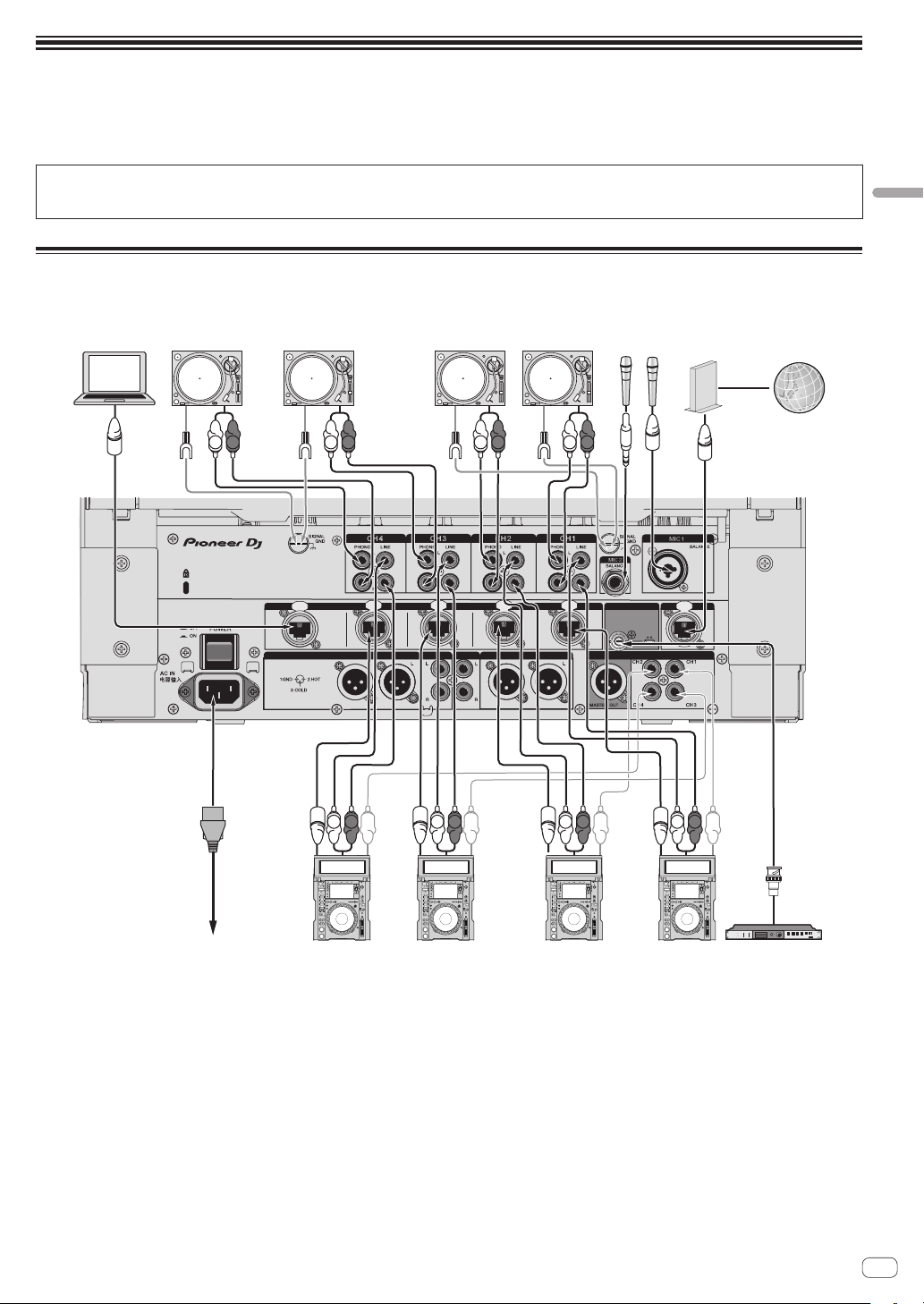
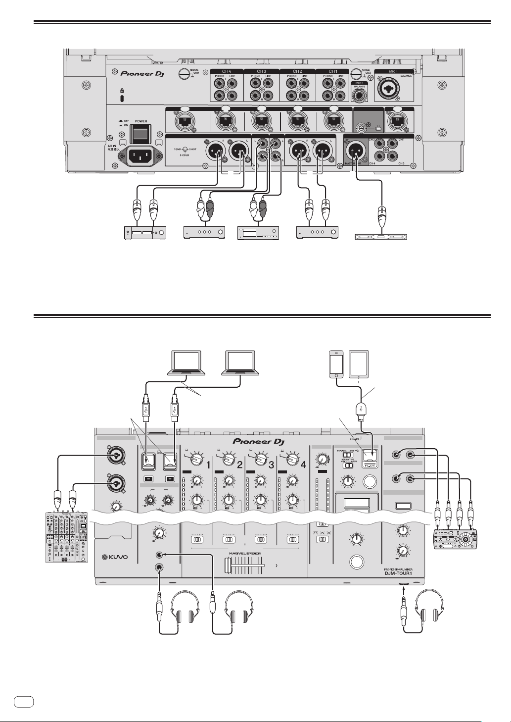
Connecting input terminals
LINK
CH4
EXTENSION
CH3 CH2 CH1
IN
OFFON
75
Ω
MASTER2
REC OUT
MASTER1
WORD CLOCK
DIGITAL OUT
INTERNET
DIGITAL IN
BOOTH
AES/EBU
L
R
L
R
L
R
L
R
L
R
L
R
L
R
L
R
To power outlet
CDJ-TOUR1 or CDJ-2000NXS2 CDJ-TOUR1 or CDJ-2000NXS2 Clock output device
Computer
1
Analog player Analog player
Microphone
Internet
Router for Internet
connection
(commercially
available product)
1 When connecting multiple computers, use a network device (100Base-TX compatible switching hub, wireless router, or access point).
Normal operation may not be possible depending on the connected network device.
En
16
Connecting output terminals
LINK
CH4
EXTENSION
CH3 CH2 CH1
IN
OFFON
75
Ω
MASTER2
REC OUT
MASTER1
WORD CLOCK
DIGITAL OUT
INTERNET
DIGITAL IN
BOOTH
AES/EBU
L
R
L
R
2 2 2
Power amplifier
1
Power amplifier
1
Analog input
recording device
Power amplifier
(for booth monitor)
Digital audio
input device
1 Be sure to use the [MASTER1] terminals only for a balanced output. Connection with an unbalanced input (such as RCA) using an XLR to RCA
converter cable (or converter adapter), etc., may lower the sound quality and/or result in noise.
For connection with an unbalanced input (such as RCA), use the [MASTER2] terminals.
2 Be careful not to accidentally connect the power cord of another product to the [MASTER1], [BOOTH], or [DIGITAL MASTER OUT]
terminal.
Connecting to the control panel
MAX
LEVEL /DEPTH
ON /OFF
MIN
A
B
CROSS FA DER ASSIGN
0
LEVEL
PHONES
CROSS FADER
BATHRU
BATHRU
BATHRU BATHRU
MASTER
0
MIXING
LEVEL
CUE
MAX
LEVELON/ OFF
MIN
LEVEL
0
BEAT FX
LEVEL
HI
MIC
USB
MIDI
ON/OFF
0 0
CLIP
DECK 3/C
TRIM
9
CLIP
DECK 1/A
TRIM
9
CLIP
DECK 2/B
TRIM
9
CLIP
CLIP
DECK 4/D
MID
HI
6
-
26
/
12
9
6
3
0
-3
-6
9
MID
HI
6
-
26
/
12
9
6
3
0
-3
-6
9
MID
HI
6
-
26
/
12
9
6
3
0
-3
-6
9
MID
HI
6
-
26
/
12
9
6
3
0
-3
-6
9
AB
DIGITAL
LINE
PHONO
AB
RETURN
AUX
DIGITAL
LINE
PHONO
AB
RETURN
AUX
DIGITAL
LINE
PHONO
AB
RETURN
AUX
DIGITAL
LINE
PHONO
AB
RETURN
AUX
12
15
9
6
3
0
-3
6
SEND
/ RETURN
SEND
/ RETURN
SEND
SEND
/ RETURN
AUX
SEND
/ RETURN
RETURN
MASTER
MIC1 MIC2
CUE
TRIM
9
L (MONO)
R
L (MONO)
L (MONO)
R
R
UNBALANCE
UNBALANCE
CH 1
TRIM
9
BALANCE
SECOND HEADPHONES
USB hubs cannot be used.
TIME
MAX
LEVEL/DEPTH
ON/OFF
MIN
MAX
LEVEL
ON/OFF
MIN
A
B
CROSSFADERASSIGN
MASTER
0
MIXING
LEVEL
PHONES
CUE
CUE
CUE
BATHRU
BATHRU
BATHRU BATHRU
CUE
10
9
8
7
6
5
4
3
2
1
0
10
9
8
7
6
5
4
3
2
1
0
10
9
8
7
6
5
4
3
2
1
0
10
9
8
7
6
5
4
3
2
1
0
10
9
8
7
6
5
4
3
2
1
0
10
9
8
7
6
5
4
3
2
1
0
TRIM
9
EQISOLATOR
BOOTHMONITOR
EQCURVE
CHFADER
CROSSFADER
0
dB RL
LEVEL
0
BALANCE
RL
TAP
BEATFX
BEAT
X
-
PAD
STEREO
MONOSPLIT
HEADPHONES
SPACE
NOISE CRUSH FILTER
DUB
ECHO
SWEEP
LINK
SOUNDCOLORFX
LEVEL
HI
LOW
EQ
12 12
12 12
MIC
USB
MIDI
ON/OFF
00
0
CLIP
DECK3/C
TRIM
9
CLIP
DECK1/C
TRIM
9
CLIP
DECK2/C
TRIM
9
CLIP CLIP
DECK4/C
EQ/
LOW
6
-
26
/
MID
6
-
26
/
HI
6
-
26
/
ISO
dB
12
9
6
3
0
-3
-6
-9
-12
-15
-18
-21
-24
-27
-30
EQ/
LOW
6
-
26
/
MID
6
-
26
/
HI
6
-
26
/
ISO
dB
12
9
6
3
0
-3
-6
-9
-12
-15
-18
-21
-24
-27
-30
EQ/
LOW
6
-
26
/
MID
6
-
26
/
HI
6
-
26
/
ISO
dB
12
9
6
3
0
-3
-6
-9
-12
-15
-18
-21
-24
-27
-30
EQ/
LOW
6
-
26
/
MID
6
-
26
/
HI
6
-
26
/
ISO
dB
12
9
6
3
0
-3
-6
-9
-12
-15
-18
-21
-24
-27
-30
BEATFX
BEATFX
CUE
COLOR
HILOW
BEATFX
CUE
COLOR
HILOW
BEATFX
CUE
COLOR
HILOW
BEATFX BEATFX
PARAMETER
MAXMIN
AB
DIGITAL
LINE
PHONO
AB
RETURN
AUX
DIGITAL
LINE
PHONO
AB
RETURN
AUX
DIGITAL
LINE
PHONO
AB
RETURN
AUX
DIGITAL
LINE
PHONO
AB
RETURN
AUX
12
15
9
6
3
0
-3
-6
-9
-12
-15
-18
-21
-24
-27
MASTERMIC
CROSS
FADER
FLANGER
PHASHER
PITCH
PINGPONGROLL
SLIPROLL
DELAY
TRANS
FILTER
SPIRAL
ECHO
REVERB
VINYLBRAKE
FXFREQUENCY
LOW MID HI
SEND/RETURN
MASTER
1/4
14
1/81/2
3/4
1/16
2
1
A
B
23
4
COLOR
HILOW
MIC1 MIC2
Headphones Headphones
USB port covers
1
USB port covers
1
Computer
Connect using USB cables.
USB hubs cannot be used.
Mobile device
2
External effector
3
DJ mixer, etc.
1 Do not push or pull hard on a USB port cover. It could be damaged.
2 When connecting a mobile device, use the cable supplied with the device.
For information on compatible mobile devices, see the Pioneer DJ site below.
http://pioneerdj.com/support/
3 Connect the external effector to both the [SEND] terminal and [RETURN] terminal.
En
17
Operation
Basic Operation
Outputting sound
1 Press [POWER] button.
Turn on the power of this unit.
2 Switch the input selector switches.
Selects the input sources for the different channels from among the
devices connected to this unit.
— [ A B]: Selects the audio of the computer connected to the
[USB] port.
— [DIGITAL]: Selects the DJ player connected to the [DIGITAL]
terminals.
— [LINE]: Selects the cassette deck or CD player connected to the
[LINE] terminals.
— [PHONO]: Selects the analog player connected to the [PHONO]
terminals.
— [RETURN AUX]: Selects the [SEND/RETURN] [RETURN] sound.
! When using [RETURN AUX], selects [AUX] using the
[SEND/RETURN] [RETURN TYPE].
! When using [SEND/RETURN], refer to Using the SEND/RETURN
function on page 20 .
3 Turn the [TRIM] control.
Adjusts the level of audio signals input in each channel.
The corresponding channel level indicator lights when audio signals are
being properly input to that channel.
! When the [CLIP] indicator blinks, adjust the [TRIM] control until the
indicator goes out.
— Blinking: Inputting sound at a higher level will cause distortion.
Adjust the [TRIM] control so that the [CLIP] indicator does not
blink.
— Rapid blinking: The input sound is distorted. Adjust the [TRIM]
control so that the [CLIP] indicator does not blink.
4 Move the channel fader away from you.
Adjusts the level of audio signals output in each channel.
5 Switch the [CROSS FADER ASSIGN (A, THRU, B)]
selector switch.
Switches the output destination of each channel.
—
[A]: Assigns to [A] (left) of the crossfader.
—
[B]: Assigns to [B] (right) of the crossfader.
— [THRU]: Selects this when you do not want to use the crossfader.
(The signals do not pass through the crossfader.)
6 Set the crossfader.
This operation is not necessary when the [CROSS FADER ASSIGN (A,
THRU, B)] selector switch is set to [THRU].
7 Turn the [MASTER LEVEL] control.
Audio signals are output from the [MASTER1], [MASTER2], and
[DIGITAL MASTER OUT] terminals.
The master level indicator lights.
Adjusting the sound quality
1 Switch the [EQ CURVE (ISOLATOR, EQ)] selector
switch.
— [ISOLATOR]: Functions as an isolator.
— [EQ]: The equalizer function is set.
2 Turn the [EQ/ISO (HI, MID, LOW)] controls for the
respective channels.
The adjustable ranges for the respective controls are as shown below.
— [HI]: –26 dB to +6 dB (30 kHz)
— [MID]: –26 dB to +6 dB (1 kHz)
— [LOW]: –26 dB to +6 dB (20 Hz)
Monitoring sound with headphones
1 Connect headphones to the [PHONES] terminal.
2 Press the [CUE] button(s) for the channel(s) you want
to monitor.
3 Switch the [MONO SPLIT, STEREO] selector switch.
— [MONO SPLIT]: The sound of the channels for which the [CUE]
button is pressed (other than the [MASTER] channel) is output
from the headphones output’s left channel, the [MASTER] chan-
nel sound is output from the right channel.
— [STEREO]: The sound of the channels for which the [CUE] button
is pressed is output from the headphones in stereo.
4 Turn the [MIXING] control.
This adjusts the monitor volume balance of the sound of channels for
which the [CUE] button is pressed and the sound of the [MASTER]
channel.
5 Turn the [LEVEL] control for [HEADPHONES].
The sound of the channels for which the [CUE] button is pressed is
output from the headphones.
! When the [CUE] button is pressed again, monitoring is canceled.
Switching the fader curve
Select the channel fader curve characteristics
Switch the [CH FADER (
, , )] selector switch.
— [ ]: The curve rises suddenly at the back side.
— [ ]: The curve rises gradually (the sound gradually increases
as the channel fader is moved away from the front side).
— [ ]: Produces a curve that rises steeply in front.
Select the crossfader curve characteristics
Switch the [CROSS FADER (
, , )] selector
switch.
— [ ]: Makes a sharply increasing curve (if the crossfader is
moved away from the [A] side, audio signals are immediately
output from the [B] side).
—
[ ]: Makes a curve shaped between the two curves above and
below.
—
[ ]: Makes a gradually increasing curve (if the crossfader is
moved away from the [A] side, the sound on the [B] side gradu-
ally increases, while the sound on the [A] gradually decreases).
Using a microphone
1 Connect a microphone to the [MIC1] or [MIC2]
terminal.
2 Set the [OFF, ON, TALK OVER] selector switch to [ON]
or [TALK OVER].
— [ON]: The indicator lights.
— [TALK OVER]: The indicator flashes.
Operation
! When set to [TALK OVER], the sound of channels other than the
[MIC] channel is attenuated by 18 dB (default) when a sound of –10
dB or greater is input to the microphone.
! The [TALK OVER] sound attenuation level can be changed at
[UTILITY] screen. For instructions on changing this, see Changing
the settings on page 28 .
! The talk over mode can be switched to the normal mode or the
advanced mode. For instructions on changing it, see Changing the
settings on page
28 .
3 Turn the [MIC LEVEL] or [MIC2 LEVEL] control.
Adjust the level of the sound output from the [MIC] channel.
!
Pay attention that rotating to the extreme right position outputs a
very loud sound.
4 Input audio signals to the microphone.
Adjusting the sound quality
Turn the [MIC] channels’ [EQ (HI, LOW)] controls.
The adjustable ranges for the respective controls are as shown below.
— [HI]: –12 dB to +12 dB (10 kHz)
— [LOW]: –12 dB to +12 dB (100 Hz)
Adjusting the L/R balance of audio
The left/right balance of the sound output from the [MASTER1],
[MASTER2], [BOOTH], [REC OUT], [PHONES], [DIGITAL MASTER OUT]
and [USB] terminals can be adjusted.
! The left/right balance of the audio output from the [USB] terminal
can be adjusted only when [REC OUT] is selected in [Mixer Audio
Output] of the setting utility.
Turn the [BALANCE] control.
The sound’s left/right balance changes according to the direction in
which the [BALANCE] control is turned and its position.
! Rotating to the rightmost position outputs only the right sound of
stereo audio. Rotating to the leftmost position outputs only the left
sound of stereo audio.
Audio is output from the [BOOTH]
terminal
Turn the [BOOTH MONITOR] control.
Adjusts the level of audio signals output from the [BOOTH] terminal.
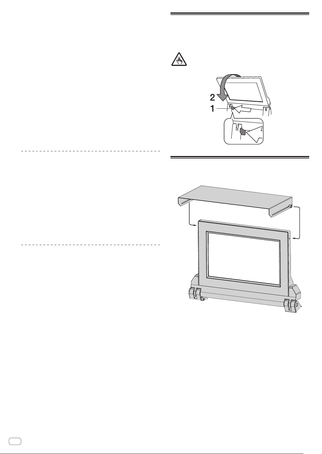
How to use the TILTABLE DISPLAY
When the display is closed, the lock engages when the display is at a
certain angle. When the lock is engaged, move the display back a little
in the open direction once and then press unlock button 1. To fully close
the display, lower the display while pressing the unlock button.
Be careful not to get your fingers caught in the Tiltable display when
opening and closing it.
About the display shade
If outdoor light reflecting on the display bothers you, it can be reduced
by attaching the supplied display shade.
En
18

En
19
Operation
Advanced Operations
About PRO DJ LINK
The following PRO DJ LINK functions can be used when a Pioneer DJ
player supporting PRO DJ LINK (CDJ-TOUR1, CDJ-2000NXS2, etc.), a
computer on which rekordbox is installed and this unit are connected by
LAN cables.
For more details on the PRO DJ LINK function, also refer to the DJ
player’s handling instructions and rekordbox’s operating instructions.
For the DJ players that can be connected, check the Pioneer DJ
SUPPORT page.
http://pioneerdj.com/support/
For instructions on connections, see Connecting input terminals on
page
15 .
! Up to four DJ players can be connected.
! Connect the DJ players to the [LINK] terminal ([CH1] to [CH4]) with
the same number as the channel to which the audio cables are
connected.
! Connect the computer to [EXTENSION] terminal.
QUANTIZE
When tracks analyzed with rekordbox are used, the track is put on beat
even when the [ON/OFF] button of [BEAT FX] is pressed or the [X-PAD]
is touched roughly.
LINK MONITOR
With this function, rekordbox music files stored on the computer can be
quickly monitored over the headphones.
STATUS INFORMATION
This function informs the DJ players of the connected channel status
(on-air status, channel number, etc.).
Browsing the media of a DJ player and
loading the tracks into a DJ player
1 Load the media in a DJ player.
Connect a USB device or insert SD memory to/into a DJ player con-
nected to this unit with PRO DJ LINK.
! DJ players are compatible with CDJ-TOUR1. However, you need to
use rekordbox to export tracks to media.
For the DJ players that can be connected, check the Pioneer DJ
SUPPORT page.
http://pioneerdj.com/support/
! A USB device connected to a USB terminal of this unit cannot be
browsed.
2 Select the media in the BROWSE screen.
Press the [BROWSE] button to display the BROWSE screen.
The media loaded in the DJ player will be displayed. Select the media.
3 Select a track.
The lists in the media are displayed in hierarchy view. Select any list
such as a playlist.
If a folder is selected, the hierarchy list for inside the folder is displayed,
and if the back button is pressed, the hierarchy level above is displayed.
When a list is selected, a list of tracks is displayed in the track list. Select
the tracks you wish to load.
4 Load the track into the DJ player.
While a track you wish to load is selected, press any of the load buttons
of the displayed DJ players at the bottom of the screen to load the track
into the DJ player.
Tracks can also be loaded into a different DJ player than the one in
which the media is loaded.
Using the QUANTIZE function
Based on the GRID information of tracks that have been analyzed with
rekordbox, effects can be added to the sound without getting out of
tempo with the currently playing track.
When using the QUANTIZE function in PRO DJ LINK, connect the DJM-
TOUR1 and a PRO DJ LINK-compatible Pioneer DJ player. For informa-
tion on connecting, see Connecting input terminals on page 15 .
In addition, music files must have been analyzed with rekordbox
beforehand in order to use the QUANTIZE function. For instructions on
analyzing music files with rekordbox, also see rekordbox’s operating
instructions.
!
When using in combination with the CDJ-2000nexus, first update the
firmware to version 1.02 or later.
!
When using in combination with the CDJ-2000 and CDJ-900, first
update the firmware to version 4.0 or later.
1 Press the [QUANTIZE] button.
The QUANTIZE function turns on.
When GRID information is received correctly from the DJ player, with the
QUANTIZE function switched ON, and it is possible to use the QUANTIZE
function, the [QUANTIZE] in the DJM-TOUR1 display area lights.GRID
[QUANTIZE] blinks when information cannot be received correctly.
QUANTIZE [QUANTIZE] turns off regardless of the receiving state of
GRID information when the function is turned off.
! Depending on the playback status of the DJ player (off air, scratch-
ing, reverse playing, etc.), it may not be possible to receive the GRID
information.
2 Press the [ON/OFF] button of [BEAT FX] or touch the
[X-PAD].
The effect is added to the sound in tempo with the track being played.
! When the [QUANTIZE] button is pressed again, the QUANTIZE func-
tion turns off.
Using the LINK MONITOR function
! Check [Use “LINK MONITOR” of Pioneer DJ Mixers.] at [File] >
[Preferences] > [Audio] in rekordbox beforehand. Also refer to the
rekordbox operating instructions.
1 Connect headphones to the [PHONES] terminal.
2 Connect a computer on which rekordbox is installed.
For instructions on connections, see Connecting input terminals on
page 15 .
3 Selecting the track to be monitored with rekordbox.
4 Press the [CUE] button for [LINK].
The track selected with rekordbox is output from the headphones.
!
When the [CUE] button is pressed again, monitoring is canceled.
! The same operation as at Monitoring sound with headphones (steps 3
to 5) can be performed.
Using the SOUND COLOR FX function
These are effects that change in association with the [COLOR] control.
1 Press one of the [SOUND COLOR FX] selection
buttons.
This selects the type of effect.
The button that was pressed flashes.
! Even if one of the [SOUND COLOR FX] selection buttons is already
selected, when a different button is selected and pressed, that but-
ton is selected.
! For the types of effects, see Types of SOUND COLOR FX effects on
page 22 .
! The same effect is set for [CH1] to [CH4].
2 Turn the [COLOR] control.
The effect is applied to the channel(s) for which the control(s) was (were)
turned.
The effect’s quantitative parameter can be adjusted by turning the
[PARAMETER] control.
Canceling the SOUND COLOR FX effect
Press the [SOUND COLOR FX] selection button that is
flashing.
The effect is canceled.
Using the BEAT FX function
This function lets you instantaneously set various effects according to
the tempo (BPM = Beats Per Minute) of the currently playing track.
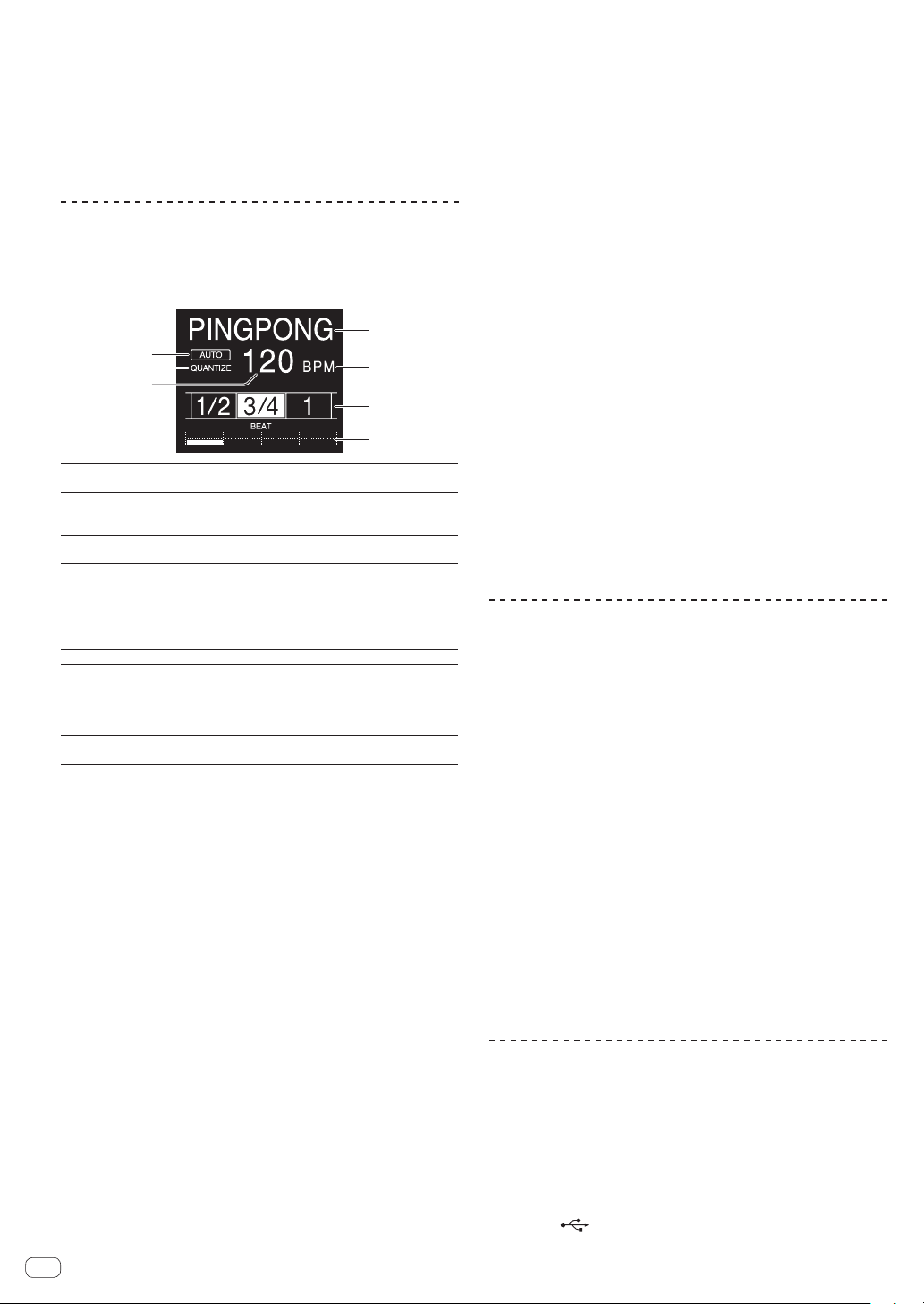
Main unit display
1
6
7
5
2
3
4
1
Effect display
section
The name of the selected effect is displayed.
2
AUTO (TAP)
[AUTO] lights when the BPM measurement mode is set
to the auto mode.
[TAP] lights when in the manual input mode.
3
QUANTIZE
Lights when the QUANTIZE can be used.QUANTIZE Blinks
or turns off when the function cannot be used.
4
BPM value dis-
play (3 digits)
When in the auto mode, this displays the automatically
detected BPM value.
When the BPM cannot be detected, the previously
detected BPM value is displayed and flashes.
When in the manual input mode, this displays the BPM
value that was input manually.
5
BPM
This is always lit.
6
Beat/parameter
display section
This lights according to the selected beat number
position.
Depending on the effect, parameters are displayed when
the [BEAT c, d] buttons are pressed. Blinks when outside
the parameter limits.
7
Touch display
section
Displays the positions shown in [X-PAD].
1 Press [AUTO/TAP] button.
Select the BPM measurement mode.
— [AUTO]: The BPM is measured automatically from the audio
signal that is being input. The [AUTO] mode is set when this
unit’s power is turned on.
— [TAP]: Enter the BPM manually For instructions on input meth-
ods, see Inputting the BPM manually on page 20 .
! The [AUTO] BPM measurement range is BPM = 70 to 180. With
some tracks it may not be possible to measure the BPM correctly. If
the BPM cannot be measured, the BPM value on the display flashes.
In such cases, use the [TAP] button to input the BPM manually.
2 Turn the beat effect selector switch.
This selects the type of effect.
! For the types of effects, see Types of BEAT FX on page 22 .
3 Turn the effect channel selector switch.
This selects the channel to which the effect is applied.
The [BEAT FX] indicator for the channel selected with the effect channel
selector lights.
— [1] – [4]: The effect is applied to the sound of the respective
channel.
— [MIC]: The effect is applied to the sound of [MIC] channel.
— [CROSS FADER A], [CROSS FADER B]: The effect is applied to
sound of the crossfader [A] (left) side or [B] (right) side.
— [MASTER]: The effect is applied to the sound of the [MASTER]
channel.
4 Press the [BEAT c, d] button.
Set the beat fraction for synchronizing the effect sound.
The effect time corresponding to the beat fraction is set automatically.
5 Press the [FX FREQUENCY] [HI][MID][LOW]buttons.
The range an effect is applied can be selected. When an effect is turned
on, the button lights and the effect is applied to the selected range.
When an effect is turned off, the button turns off and the effect is not
applied to the selected range.
6 Press the [ON/OFF] button for [BEAT FX].
The effect is applied to the sound.
The effect’s time parameter can be adjusted by turning the [TIME]
control.
The effect’s quantitative parameter can be adjusted by turning the
[LEVEL/DEPTH] control.
The [ON/OFF] button flashes when the effect is on.
! When the [ON/OFF] button is pressed again, the effect turns off.
Inputting the BPM manually
Tap the [TAP] button at least 2 times in rhythm with the
beat (in quarter notes) of the sound being played.
The average value of the interval at which the [TAP] button was tapped
by finger is set as the BPM.
! When the BPM is set using the [TAP] button, the beat fraction is set
to [1/1] and the time of one beat (quarter note) is set as the effect
time.
! The BPM can be set manually by turning the [TIME] control while
pressing the [TAP] button.
! The BPM can be set in units of 0.1 by pressing the [AUTO/TAP] but-
ton while pressing the [TAP] button and turning the [TIME] control
while pressing the two buttons.
Operating the [X-PAD]
Operating procedure 1
1 Perform steps 1 to 5 of the Using the BEAT FX
function procedure.
2 Touch the [X-PAD].
The two operations of turning the effect on/off and changing the time/
amount parameter of the effect can be performed by touching and slid-
ing a finger on the [X-PAD].
! When you release your finger from the [X-PAD], the effect turns off.
! To keep the effect on when you release your finger from the [X-PAD],
while touching the [X-PAD] press the [ON/OFF] button of [BEAT FX],
then release your finger from the [X-PAD].
Operating procedure 2
1 Using the BEAT FX functionPerform steps 1 to 6.
2 Touch the [X-PAD].
The time/amount parameter of the effect can be changed by sliding a
finger on the [X-PAD].
Using the SEND/RETURN function
External effector and mobile devices can be used.
1 Connect this unit and external effector.
For information on connecting, see Connecting output terminals on
page 16 .
2 Switch the [SEND/RETURN] selector switches.
Select the effector to use.
— [1/4” JACK]: Select when using external effector.
— [USB ]: Select when using a mobile device.
En
20
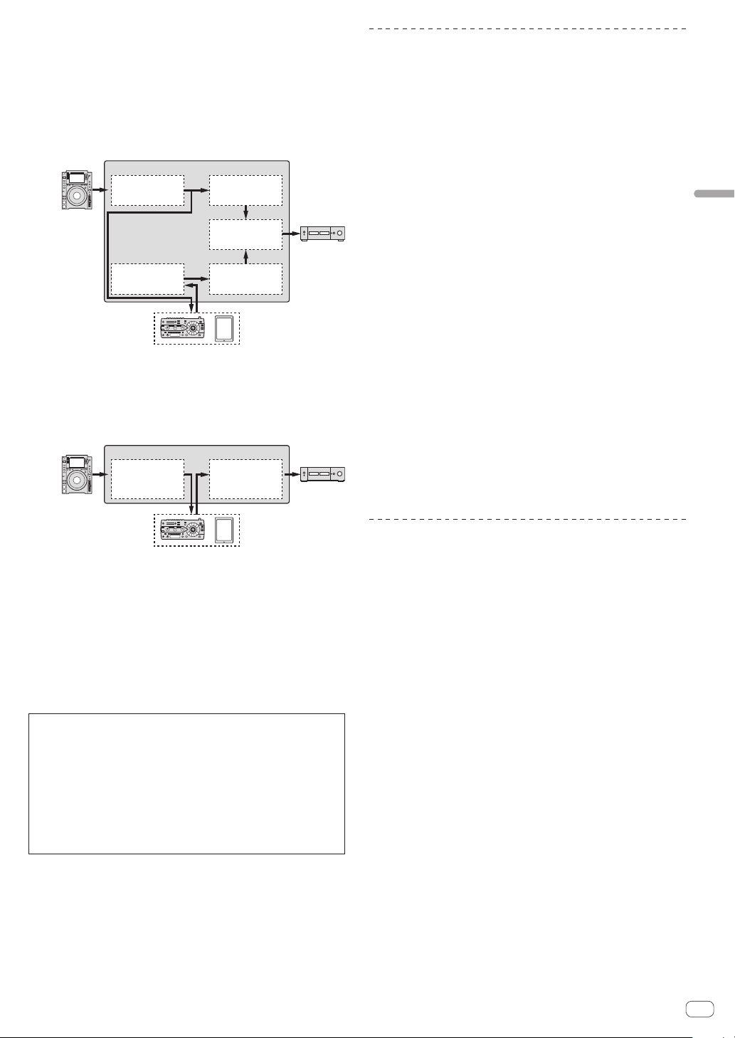
En
21
Operation
3 Switch the [RETURN TYPE] selector switch.
Select the SEND/RETURN method.
— [AUX]: The audio of the channel selected in the effects channel
is input to the external effector (or mobile device), and the output
from the external effector (or mobile device) is input into the
channel selected with [RETURN AUX] using the input selector
switch.
Original sounds and effect sounds can be mixed together as
desired.
External effector /
Mobile device
DJM-TOUR1
CH1
INPUT
OUTPUT
CH1
Trim/EQ/
SOUND COLOR FX
Trim/EQ/
SOUND COLOR FX
CH2
(RETURN AUX) CH2
Ch Fader/
BEAT FX
BUS
MASTER VOL
Ch Fader
— [INSERT]: The audio of the channel selected in the effects chan-
nel is input to the external effector (or mobile device), and the
output from the external effector (or mobile device) is input into
the channel selected in effect channel.
Use as SEND/RETURN of the same system as the previous DJM
series.
DJM-TOUR1
CH1
INPUT
OUTPUT
BUS
Trim/EQ/
SOUND COLOR FX
Ch Fader/
BEAT FX/
MASTER VOL
External effector /
Mobile device
! For details, see Block Diagram on page 33 .
4 Turn the effect channel selector switch.
Select the channel to add the SEND/RETURN function to.
! The channel to add the SEND/RETURN function to is the same as the
channel to which the BEAT FX function is added.
5 Press the [SEND/RETURN] [ON/OFF] button.
! When the [ON/OFF] button is pressed again, the SEND/RETURN
function turns off.
6 Turn the [LEVEL] control for [SEND/RETURN].
Adjusts the SEND/RETURN sound level.
In the following cases, the SEND/RETURN ON/OFF button turns off. When this
function is forced to turn off, it is impossible to turn it on or off.
! When the DJM-TOUR1 is not connected to an effector
! When the [RETURN TYPE] selector switch is set to [AUX], and the effect chan-
nel set to [1], [2], [3], or [4], and the effect channel input selector switch is set
to [RETURN AUX]
! When the [RETURN TYPE] selector switch is set to [AUX], and the effect
channel set to [CROSS FADER A], or [CROSS FADER B], and one or more of
the channels assigned using the [CROSS FADER ASSIGN] switch is set to
[RETURN AUX]
! When the [RETURN TYPE] selector switch is set to [AUX], and the effect chan-
nel is set to [MASTER]
Operating software by MIDI interface
This unit outputs the operation information of buttons and controls in
universal MIDI format.
When connected by USB cable to a computer or mobile device on which
a MIDI-compatible software is installed, the software can be operated
from this unit.
Install the software on your computer or mobile device before use. Also,
set the software’s audio and MIDI related settings.
! For MIDI channel setting instructions, see Changing the settings on
page
28 .
! For details of the MIDI messages on this unit, see the website below.
http://pioneerdj.com/support/
1 Connect this unit to computer or mobile device.
— Computer: Connect the [USB] terminal to your computer.
— Mobile device: Connect the mobile device connection terminal to
the mobile device.
For details about connections, see Connecting to the control panel on
page
16 .
2 Launch the software.
! When connected to a computer, carry out the following procedure.
When a mobile device is connected, the following procedure is not
necessary.
3 Press the [ON/OFF] button.
Turn the MIDI function on.
Transmission of the MIDI messages begin.
! When a fader or control is moved, a message corresponding to the
position is sent.
! When the [ON/OFF] button is pressed again, sending of the MIDI
messages is stopped.
! The MIDI timing clock (BPM information) is sent regardless of the
[ON/OFF] button.
! For mobile devices, MIDI messages and MIDI timing clock is sent
constantly.
Synchronizing digital output with an
external device
This unit can output by synchronizing the sampling frequency of the
digital output with an external device.
1 Connect the external device to the WORD CLOCK
input terminal.
2 Input a master clock.
Operate the external device to input the clock to be synchronized (mas-
ter clock) to this unit.
The supported frequencies for the clock are 44.1 kHz, 48 kHz, 88.2 kHz,
and 96 kHz.
3 Select [WORD CLOCK] of [SAMPLING RATE].
Select [WORD CLOCK] from [SAMPLING RATE] in [DIGITAL MASTER
OUT] of the setting utility.
! [WORD CLOCK] of [SAMPLING RATE] cannot be selected when a
signal is not input to the WORD CLOCK input terminal or a signal of
an unsupported frequency is input.
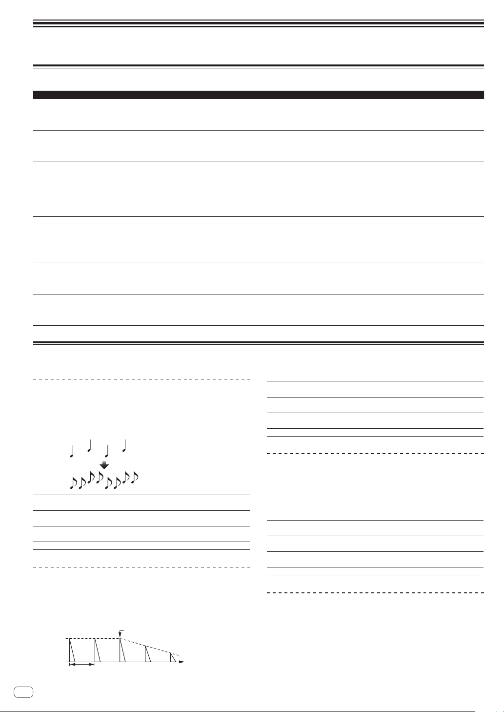
Types of effects
Types of SOUND COLOR FX effects
Effect Name Descriptions [COLOR] control [PARAMETER] control
SPACE
Applies a reverberation effect to the original
sound.
Turn counterclockwise: Applies the reverbera-
tion effect to the mid- and low ranges.
Turn clockwise: Applies the reverberation
effect to the mid- and high ranges.
Turning the control to the right increases
feedback.
DUB ECHO
Applies an echo effect, with the sound delayed
slightly after the original sound output several
times and gradually attenuated.
Turn counterclockwise: Applies the echo
effect to the mid-range only.
Turn clockwise: Applies the echo effect to the
high range only.
Turning the control to the right increases
feedback.
SWEEP
Turning the control to the left produces a gate
effect, and turning it to the right produces a
band pass filter effect.
Turn counterclockwise: A gate effect makes
the sound tighter, with a reduced sense of
volume.
Turn to right: The band pass filter bandwidth
decreases steadily.
Turning the [COLOR] control to the left adjusts
the gate effect.
Turn to the right to tighten the sound.
Turning the [COLOR] to the right adjusts the
center frequency.
Turn to the right to increase the center
frequency.
NOISE
White noise generated inside this unit is
mixed in to the sound of the channel via the
filter and output.
Turn counterclockwise: The cut-off frequency
of the filter through which the white noise
passes gradually descends.
Turn clockwise: The cut-off frequency of the
filter through which the white noise passes
gradually rises.
Turn to the right to increase white noise
volume.
!
The sound quality can be adjusted by
turning the [EQ/ISO (HI, MID, LOW)]
control.
CRUSH
Changes the original sound to a crushed-like
sound for output.
Turn counterclockwise: Increases the
sound’s distortion.
Turn clockwise: The sound is crushed before
passing through the high pass filter.
The further the control is turned clockwise, the
more the effect is stressed.
FILTER
Outputs sound that has passed through a
filter.
Turn counterclockwise: Gradually descends
the low-pass filter’s cutoff frequency.
Turn clockwise: Gradually rises the high-pass
filter’s cutoff frequency.
Turn to the right to increase resonance.
Types of BEAT FX
DELAY
1
A delay sound is output once according to the beat fraction set with the
[BEAT c, d] buttons.
! Lowering the channel faders and cutting the input volume leaves a
delay sound.
Original
(4 beats)
1/2 delay
(8 beats)
BEAT c, d buttons
(parameter 1)
Sets the delay time between 1/16 and 16 beats with
respect to 1 beat of BPM time.
TIME control (parameter 2)
Use this to set the delay time.
1 to 4000 (ms)
LEVEL/DEPTH control
(parameter 3)
Use this to set the balance between the original
sound and the delay sound.
X-PAD (parameter 4) Use this to set the delay time.
ECHO
1
A delay sound is output several times and gradually attenuated accord-
ing to the beat fraction set with the [BEAT c, d] buttons.
!
Lowering the channel faders and cutting the input volume leaves an
echo sound, producing a fade out.
Input sound turned off
Time
Fade-out
1 beat
BEAT c, d buttons
(parameter 1)
Sets the delay time between 1/16 and 16 beats with
respect to 1 beat of BPM time.
TIME control (parameter 2)
Use this to set the delay time.
1 to 4000 (ms)
LEVEL/DEPTH control
(parameter 3)
Use this to set the balance between the original
sound and the echo sound.
X-PAD (parameter 4) Use this to set the delay time.
PING PONG
1
Outputs multiple times while the delay sound is attenuated with different
delay timing to the left and right, in sync with the scaled beat set with the
[BEAT c, d] buttons, producing a stereo effect.
! Lowering the channel faders and cutting the input volume leaves an
echo sound, producing a fade out.
BEAT c, d buttons
(parameter 1)
Sets the delay time between 1/16 and 16 beats with
respect to 1 beat of BPM time.
TIME control (parameter 2)
Use this to set the delay time.
10 to 4000 (ms)
LEVEL/DEPTH control
(parameter 3)
Use this to set the balance between the original
sound and the echo sound.
X-PAD (parameter 4) Use this to set the delay time.
SPIRAL
1
This function adds a reverberation effect to the input sound.
When the delay time is changed, the pitch changes simultaneously.
! Lowering the channel faders and cutting the input volume leaves an
effect sound.
En
22
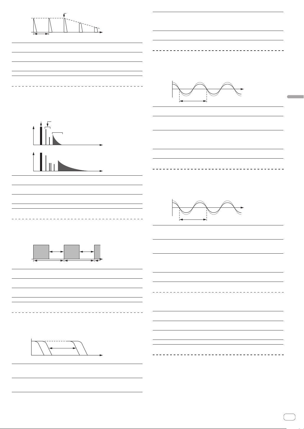
En
23
Types of effects
Input sound turned off
Time
Fade-out
1 beat
BEAT c, d buttons
(parameter 1)
Sets the delay time between 1/16 and 16 beats with
respect to 1 beat of BPM time.
TIME control (parameter 2)
Use this to set the delay time.
10 to 4000 (ms)
LEVEL/DEPTH control
(parameter 3)
Sets feedback, and the balance between the original
sound and the effect sound.
X-PAD (parameter 4) Use this to set the delay time.
REVERB
1
This function adds a reverberation effect to the input sound.
! Lowering the channel faders and cutting the input volume leaves a
delay sound.
Level
Direct sound
Early reflected sound
Reverberations
1%
100%
Time
BEAT c, d buttons
(parameter 1)
Use these to set the extent of the reverberation effect,
from 1 – 100
%.
TIME control (parameter 2)
Use this to set the degree of the reverb effect.
1 – 100 (%)
LEVEL/DEPTH control
(parameter 3)
Sets the balance between the original sound and the
effect sound.
X-PAD (parameter 4) Sets the filter’s cut-off frequency.
TRANS
The sound is cut according to the beat fraction set with the [BEAT c, d]
buttons.
Cut Cut
1/1 beat
Time
BEAT c, d buttons
(parameter 1)
Sets the cut time between 1/16 and 16 beats with
respect to 1 beat of BPM time.
TIME control (parameter 2)
Use this to set the effect time.
10 to 16000 (ms)
LEVEL/DEPTH control
(parameter 3)
Sets the duty and the balance between the original
sound and the effect sound.
X-PAD (parameter 4) This sets the cut time.
FILTER
The filter’s cutoff frequency changes according to the beat fraction set
with the [BEAT c, d] buttons.
Frequency
BEAT c, d buttons
(parameter 1)
Sets the cycle for moving the cut-off frequency with
respect to 1 beat of BPM time in beat time of between
1/16 and 64beats.
TIME control (parameter 2)
Use this to set the cycle at which the cut-off frequency
is moved.
10 to 32000 (ms)
LEVEL/DEPTH control
(parameter 3)
When turned all the way counterclockwise, only the
original sound is output.
The further the control is turned clockwise, the more
the effect is stressed.
X-PAD (parameter 4)
The cycle at which the cut-off frequency is moved
fluctuates finely.
FLANGER
A 1-cycle flanger effect is produced according to the beat fraction set
with the [BEAT c, d] buttons.
Short delay
Cycle
Time
BEAT c, d buttons
(parameter 1)
Sets effect time between 1/16 and 64 beats with
respect to 1 beat of BPM time.
TIME control (parameter 2)
Use this to set the cycle by which the flanger effect
moves.
10 to 32000 (ms)
LEVEL/DEPTH control
(parameter 3)
The further the control is turned clockwise, the more
the effect is stressed.
When turned all the way counterclockwise, only the
original sound is output.
X-PAD (parameter 4)
The cycle at which the flanger effect is moved fluctu-
ates finely.
PHASER
The phaser effect changes according to the beat fraction set with the
[BEAT c, d] buttons.
Cycle
Phase shift
Time
BEAT c, d buttons
(parameter 1)
Sets the cycle for moving the phaser effect with
respect to 1 beat of BPM time in beat time of between
1/16 and 64 beats.
TIME control (parameter 2)
This sets the cycle by which the phaser effect is
moved.
10 to 32000 (ms)
LEVEL/DEPTH control
(parameter 3)
The further the control is turned clockwise, the more
the effect is stressed.
When turned all the way counterclockwise, only the
original sound is output.
X-PAD (parameter 4)
The cycle at which the phaser effect is moved fluctu-
ates finely.
PITCH
Changes the pitch of the source sound.
BEAT c, d buttons
(parameter 1)
Sets the pitch of the effect sound.
-50- 100 (%)
TIME control (parameter 2)
Sets the pitch of the effect sound.
-50- 100 (%)
LEVEL/DEPTH control
(parameter 3)
Sets the pitch of the effect sound. Turn fully left to
return to the original sound.
X-PAD (parameter 4) Sets the pitch of the effect sound.
SLIP ROLL
The sound being input at the point when the [ON/OFF] is pressed is
recorded, and the recorded sound is output repeatedly according to the
beat fraction set with the [BEAT c, d] buttons.
When the effect time changes, the input sound is recorded again.
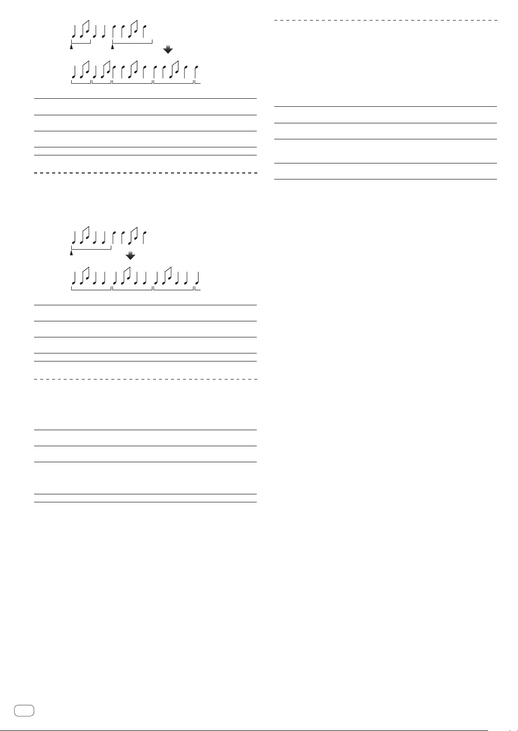
1/1 repeat1/2 repeat
Origina
l
Roll
Changed from 1/2
to 1/1
Effect turned on
BEAT c, d buttons
(parameter 1)
Sets effect time between 1/16 and 16 beats with
respect to 1 beat of BPM time.
TIME control (parameter 2)
Use this to set the effect time.
10 to 4000 (ms)
LEVEL/DEPTH control
(parameter 3)
Use this to set the balance between the original
sound and ROLL.
X-PAD (parameter 4) Use this to set the effect time.
ROLL
The sound being input at the point when the [ON/OFF] is pressed is
recorded, and the recorded sound is output repeatedly according to the
beat fraction set with the [BEAT c, d] buttons.
Effect turned on
Repeated
Original
1/1 roll
BEAT c, d buttons
(parameter 1)
Sets effect time between 1/16 and 16 beats with
respect to 1 beat of BPM time.
TIME control (parameter 2)
Use this to set the effect time.
10 to 4000 (ms)
LEVEL/DEPTH control
(parameter 3)
Use this to set the balance between the original
sound and ROLL.
X-PAD (parameter 4) Use this to set the effect time.
VINYL BRAKE
The playback speed of the input sound changes according to the beat
fraction set with the [BEATc, d] buttons, slowing steadily, until play-
back stops.
BEAT c, d buttons
(parameter 1)
Sets effect time between 1/16 and 16 beats with
respect to 1 beat of BPM time.
TIME control (parameter 2)
Use this to set the effect time.
10 to 4000 (ms)
LEVEL/DEPTH control
(parameter 3)
Sets the playback speed of the input sound. Turn fully
left to return steadily to the original sound. Turn right
from the fully left position to slow playback steadily,
resulting in an effect that stops playback.
X-PAD (parameter 4) Use this to set the effect time.
HELIX
The sound being input at the point when the [ON/OFF] is pressed is
recorded, and the recorded sound is output repeatedly according to the
beat fraction set with the [BEAT c, d] buttons.
Turn the [LEVEL/DEPTH] control right from the fully left position to
record the input sound. Also, turning it fully right fixes the output sound.
Altering the effect time changes the pitch of the sound recorded up to
that point.
BEAT c, d buttons
(parameter 1)
Sets effect time between 1/16 and 16 beats with
respect to 1 beat of BPM time.
TIME control (parameter 2)
Use this to set the effect time.
10 to 4000 (ms)
LEVEL/DEPTH control
(parameter 3)
Set the ratio of sound overlay. Turn fully left to return
to the original sound. Turn right from the fully left
position to records input sound from its default state.
X-PAD (parameter 4)
Set effect time to alter pitch. Remove your finger from
X-PAD to automatically return to the set effect time.
1 When [1] to [4] is selected with the effect channel selector switch,
the effect sound cannot be monitored even if the [CUE] button of the
selected channel is pressed.
En
24

En
25
KUVO
What is KUVO?
KUVO is a community where DJs around the world share the tracks they have played and various other information and clubbers share their reactions
to enable people to discover new favorite DJs, clubs, and music they like.
This unit has a built-in network gateway for installation in a club to enable use of the KUVO service.
When this unit is installed, information on the club, DJs’ playback information, and other information can be distributed to people throughout the world
via the Internet. Playback information and other information sent from Pioneer DJ devices are received via PRO DJ LINK and sent in real time to the
web server.
System setup example
10
9
8
7
6
5
4
3
2
1
0
10
9
8
7
6
5
4
3
2
1
0
10
9
8
7
6
5
4
3
2
1
0
10
9
8
7
6
5
4
3
2
1
0
10
9
8
7
6
5
4
3
2
1
0
10
9
8
7
6
5
4
3
2
1
0
Pioneer DJ
Home
Web server
Smartphone or computer
1
Internet
LAN
Router for Internet connection
(commercially available product)
Management computer
Club
Smartphones
1
PRO DJ LINK compatible DJ devices
DJ
USB device or
SD card
rekordbox
DJM-TOUR1
1 Customers at the club or other people interested in club music can see the information on the club, its DJs’ playback information, etc., on their
smartphones.
For detailed information on the system, see our website below.
http://kuvo.com/
Caution
When a standalone network gateway device (NXS-GW) is connected to the [LINK] terminal of this unit, the built-in network gateway function is dis-
abled. To use the built-in network gateway function, disconnect the standalone network gateway device.
KUVO
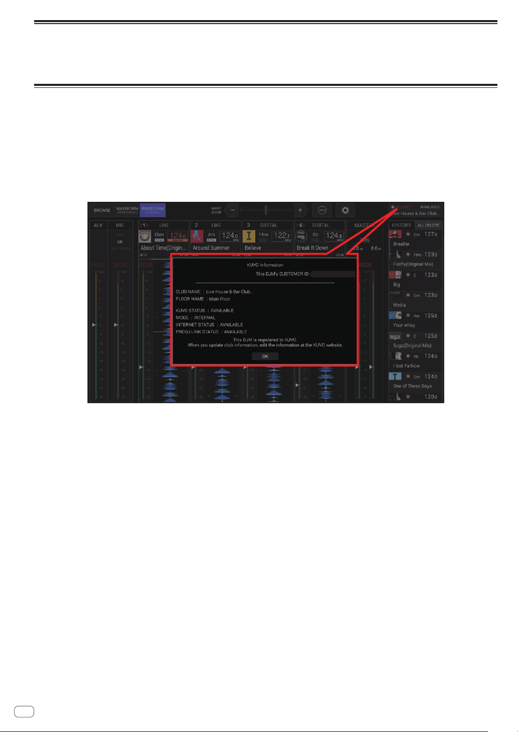
Registering the club information
In order to distribute information to clubbers throughout the world, it is necessary to create a CLUB OWNER account at the KUVO website and register
the club information (club name, location information, etc.).
! A separate contract with and payment to a provider offering Internet services is required.
Registration procedure
Before registering the club information, make the preparations below.
! Prepare a computer that can be connected to the Internet.
! Make a note of the CUSTOMER ID displayed on the KUVO status details screen of this unit. It is required when creating a CLUB OWNER account.
Once preparations are completed, create a CLUB OWNER account and register the club information at the website below.
https://kuvo.com/connect/
! If you already have a CLUB OWNER account, you will be able to use the service if you just log in to the KUVO website and then additionally register
the CUSTOMER ID of this unit.
https://kuvo.com/login/club/
KUVO status details display
CUSTOMER ID : xxxxxxxxxxxxxxx
XXXXXXXXXXXXXXX
En
26
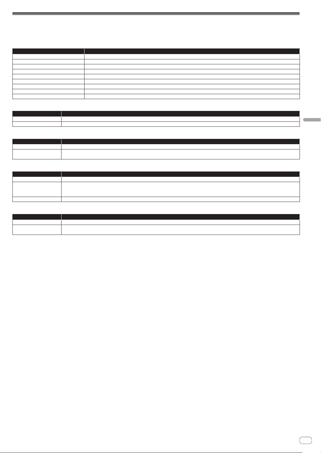
En
27
KUVO
KUVO status details display
Once registration of the club information is complete, connect the [INTERNET] terminal of this unit to a router for Internet connection.
The connection status of this unit and club registration information can be checked on the KUVO status details display screen.
KUVO status details display
Display item Description of item
CUSTOMER ID Displays the CUSTOMER ID required to register the unit with KUVO.
CLUB NAME Displays the name of the club this unit has registered.
FLOOR NAME Displays the name of the floor this unit has registered.
KUVO STATUS Displays whether or not information can be sent to the Web server. (See below.)
MODE Displays which network gateway will be used, internal or external. (See below.)
INTERNET STATUS Displays the connection status of the [INTERNET] terminal. (See below.)
PRO DJ LINK STATUS Displays the connection status of the [LINK] terminal. (See below.)
MESSAGE Displays a message in accordance with the current operating status.
[OK] BUTTON Pressing the [OK] button closes the KUVO status details display screen.
KUVO STATUS
Indication Descriptions
AVAILABLE State in which the performance information can be sent to the Web server.
UNAVAILABLE State in which the performance information cannot be sent to the Web server.
MODE
Indication Descriptions
INTERNAL Connects with the Web server using the built-in network gateway of this unit.
EXTERNAL
Connects with the Web server using an external network gateway (NXS-GW).
This mode is switched to automatically when an external NXS-GW is connected to the [LINK] terminal.
INTERNET STATUS
Indication Descriptions
AVAILABLE State in which an internal or external network gateway is registered with KUVO and the performance information can be sent to the Web server.
NOT REGISTERED
State in which the performance information cannot be sent to the Web server because an internal or external network gateway is not registered
with KUVO.
The CUSTOMER ID and club information need to be registered on the KUVO Web site.
NOT CONNECTED State in which an internal or external network gateway and the Web server cannot communicate for some reason.
PRO DJ LINK STATUS
Indication Descriptions
AVAILABLE State in which a KUVO compatible DJ player is connected correctly to the [LINK] terminal.
NOT CONNECTED
State in which the playback information cannot be sent to the Web server because a KUVO compatible DJ player is not connected correctly to the
[LINK] terminal.
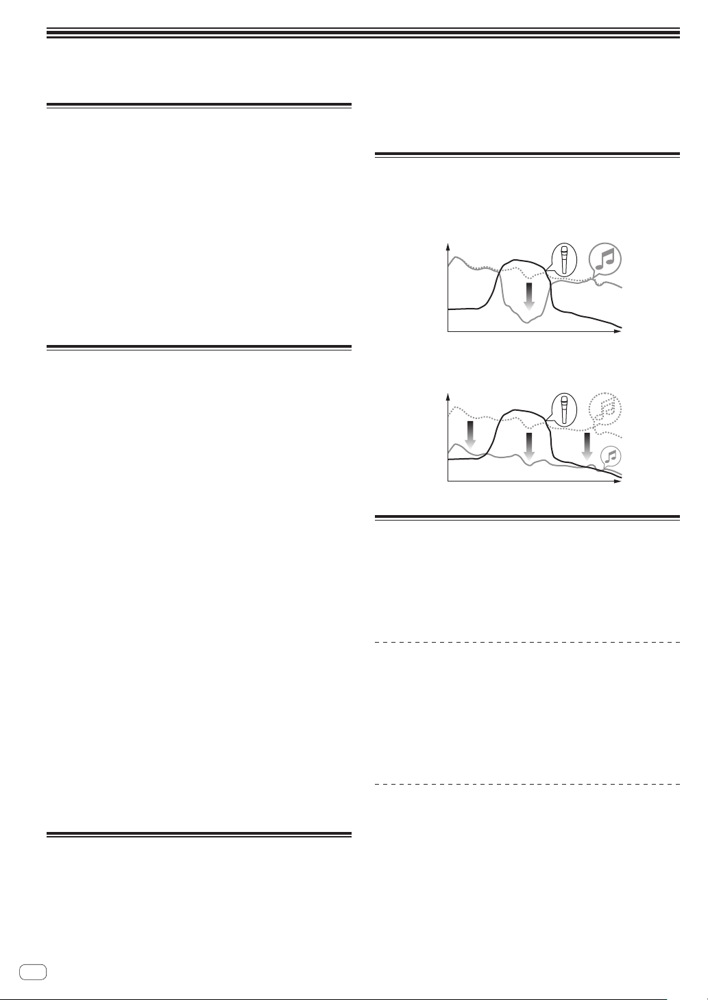
Changing the settings
! For Setting preferences see page 30
Change Procedure
1 Press the [UTILITY] button on the display or press the
[QUANTIZE (UTILITY, WAKE UP)] button for at least 1
second.
The [UTILITY] screen appears on the display.
2 Select a setting item.
Scroll the screen if necessary and select the item you wish to set.
Selecting an item displays the selection options for that item on the right
side of the screen.
3 Select a setting from the selection options.
The setting is changed.
4 Press the [UTILITY] button on the display of this unit.
The previous screen reappears.
Returning to default settings
If a factory reset is performed in an environment in which a router is con-
nected to the [INTERNET] terminal, the information registered to KUVO
will also be cleared. If you do not need to clear the information registered
to KUVO, disconnect the cable from the [INTERNET] terminal.
If the KUVO registration information is not cleared when a factory reset
is performed, a screen appears for confirming whether or not the instal-
lation location is correct when a connection is established to the KUVO
server for the first time after the factory reset.
If it is incorrect, see the KUVO website (http://kuvo.com/).
1 While pressing the [QUANTIZE (UTILITY, WAKE UP)]
buttons, press the [POWER] button.
The factory reset confirmation screen appears on the display.
! It may take between about 30 seconds to 1 minute for the screen to
appear on the display.
2 Select [OK].
If you wish to also clear the setting information registered to KUVO,
check that the router is connected to the [INTERNET] terminal. If you
do not need to clear the setting information registered to KUVO, do not
connect the router to the [INTERNET] terminal.
3 Select [OK].
The factory reset starts.
! If [Cancel] is selected, it returns to the screen of step 2. Turn off the
power to stop the process.
! If a connection could not be established to the KUVO server even
though the router was connected to the [INTERNET] terminal, a mes-
sage appears to notify you that the information registered to KUVO
will not be cleared.
4 Press [POWER] button.
When a message notifying that the factory reset is finished appears on
the screen, press the [POWER] button on this unit to turn off the power
of this unit.
About the auto standby function
When [AUTO STANDBY] is set to [ON], the unit automatically enters
the standby mode if 10 hours elapses with all of the following conditions
met.
— That none of this unit’s buttons or controls are operated.
— That no audio signal is input to each channel of this unit.
— That no PRO DJ LINK connections are made.
! When the [QUANTIZE (UTILITY, WAKE UP)] button is pressed, the
standby mode is canceled.
! This unit is shipped with the auto standby function turned on. If you
do not want to use the auto standby function, set [AUTO STANDBY]
to [OFF].
About the talk over function
The talk over function has the two modes described below.
— [ADVANCED] (advanced talk over): The mid-range only of the sound
of channels other than the [MIC] channel is attenuated according to
the [LEVEL] setting value and output.
dB
Frequency
— [NORMAL] (normal talk over): The sound of channels other than the
[MIC] channel is attenuated according to the [LEVEL] setting value
and output.
dB
Frequency
About the setting utility software
The setting utility can be used to make the checks and settings
described below.
— Checking the status of this unit’s input selector switches
— Setting the audio data output from this unit to the computer
— Adjusting the buffer size (when using Windows ASIO)
— Checking the version of the firmware and driver software
Displaying the setting utility
For Windows
Click [Start] menu > [All Programs] > [Pioneer] > [DJM-TOUR1] >
[DJM-TOUR1 Settings Utility].
For Mac OS X
Click [Macintosh HD] icon > [Application] > [Pioneer] > [DJM-
TOUR1] > [DJM-TOUR1 Settings Utility].
Checking the status of this unit’s input
selector switches
Display the setting utility before starting.
En
28
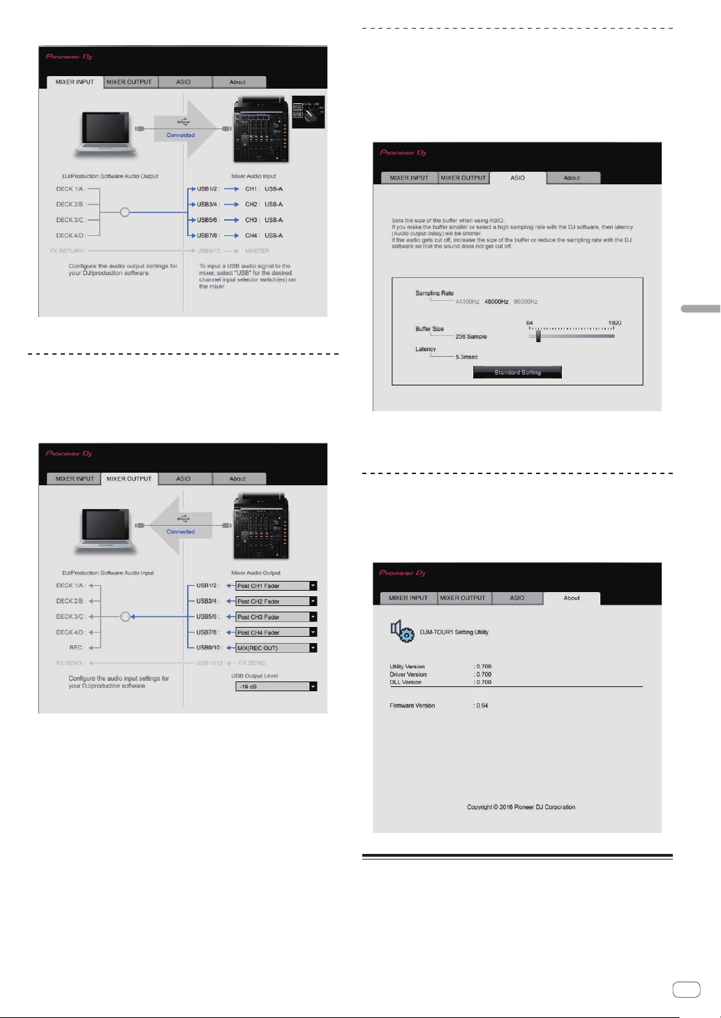
En
29
Changing the settings
Click the [MIXER INPUT] tab.
[FX RETURN] can be used with compatible software.
Setting the audio data output from this
unit to the computer
Display the setting utility before starting.
1 Click the [MIXER OUTPUT] tab.
2 Click the [Mixer Audio Output] pull-down menu.
Select and set the audio data to be output to the computer from the flow
of audio signals inside this unit.
! For [Mixer Audio Output] pulldown menu list see page 30
3 Click the [USB Output Level] pull-down menu.
Adjust the volume of the audio data output from this unit.
! The [USB Output Level] setting is applied equally to all audio data.
However, when 1 on the table at step 2 is selected, the audio data is
output with the same volume at which it is input to this unit.
! If not enough volume can be achieved with the DJ software’s volume
adjustment alone, change the [USB Output Level] setting to adjust
the volume of the audio data output from this unit. Note that the
sound will be distorted if the volume is raised too high.
!
[FX SEND] and [Control Tone] can be used with supported software.
Adjusting the buffer size (when using
Windows ASIO)
If an application using this unit as the default audio device (DJ software,
etc.) is running, quit that application before adjusting the buffer size.
Display the setting utility before starting.
Click the [ASIO] tab.
! If the buffer size is made large, drops in audio data (breaks in the
sound) occur less easily, but the time lag due to the delay in the
transfer of the audio data (latency) increases.
Checking the version of the firmware and
driver software
Display the setting utility before starting.
Click the [About] tab.
Checking the latest information on
the driver software
For the latest information on this unit’s dedicated driver software, see
the Pioneer DJ site below.
http://pioneerdj.com/support/
!
Operation cannot be guaranteed when multiple units of this mixer
are connected to a single computer.
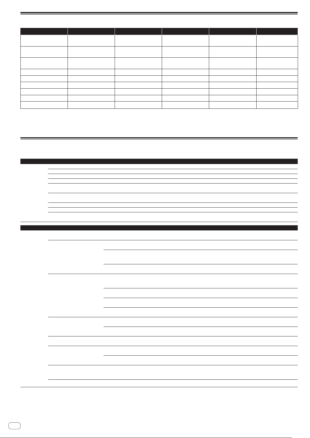
[Mixer Audio Output] pulldown menu list
CH1 (USB1/2) CH2 (USB3/4) CH3 (USB5/6) CH4 (USB7/8) CH5 (USB9/10) CH6 (USB11/12)
CH1 Control Tone
PHONO
1
CH2 Control Tone
PHONO
1
CH3 Control Tone
PHONO
1
CH4 Control Tone
PHONO
1
REC OUT
2
FX SEND
3
CH1 Control Tone CD/
LINE
1
CH2 Control Tone CD/
LINE
1
CH3 Control Tone CD/
LINE
1
CH4 Control Tone CD/
LINE
1
Post AUX Fader
2
—
CH1 Control Tone
DIGITAL
1
CH2 Control Tone
DIGITAL
1
CH3 Control Tone
DIGITAL
1
CH4 Control Tone
DIGITAL
1
Post CH1 Fader
2
—
Post CH1 Fader
2
Post CH2 Fader
2
Post CH3 Fader
2
Post CH4 Fader
2
Post CH2 Fader
2
—
CROSS FADER A
2
CROSS FADER A
2
CROSS FADER A
2
CROSS FADER A
2
Post CH3 Fader
2
—
CROSS FADER B
2
CROSS FADER B
2
CROSS FADER B
2
CROSS FADER B
2
Post CH4 Fader
2
—
MIC MIC MIC MIC CROSS FADER A
2
—
REC OUT
2
REC OUT
2
REC OUT
2
REC OUT
2
CROSS FADER B
2
—
- - - -
MIC
—
1
Can be used with compatible software. The audio data is output with the same volume at which it is input to this unit, regardless of the [USB Output Level] setting.
2
When using for applications other than recording, pay attention to the DJ application’s settings so that no audio loops are generated. If audio loops are generated, sound
may be input or output at unintended volumes.
3 Can be used with compatible software.
Setting preferences
*: Setting upon purchase
Setting type Options settings Setting value Descriptions
DJ SETUP
TOUCH DISPLAY LOCK
OFF*, ON Turns the display touch function on/off.
LANGUAGE
— Sets the display language.
LCD BRIGHTNESS 1, 2, 3*, 4, 5
Adjusts the display brightness.
OLED BRIGHTNESS 1, 2, 3*
Sets the main unit display’s brightness.
MIC LOW CUT
OFF, ON*
Turns on/off the function that cuts the low frequencies of the
microphone audio.
TALK OVER MODE
ADVANCED*, NORMAL
Selects the talk over function’s mode, [ADVANCED] or
[NORMAL].
TALK OVER LEVEL
–6 dB, –12 dB, –18 dB*, –24 dB Sets the talk over function’s sound attenuation level.
MIDI CH
1* to 16 Sets the MIDI channel.
MIDI BUTTON TYPE
TOGGLE*, TRIGGER
Selects the MIDI signal transmission mode, [TOGGLE] or
[TRIGGER].
Setting type Options settings Detail setting items Setting value Descriptions
ENGINEER
SETUP
ENGINEER SETUP LOCK
— OFF, ON*
Turns the change lock setting for
ENGINEER SETUP setting items on/off.
MASTER OUT
1
PEAK LIMITER
OFF, ON*
Lessens sudden, unpleasant digital clip-
ping of the master output.
ATT.
0 dB*,
–3 dB, –6 dB, –9 dB, –12 dB
Sets the attenuation level of the sound out-
put from the [MASTER1] and [MASTER2]
terminals.
MONO/STEREO STEREO*, MONO
Select monaural/stereo master output
audio.
DIGITAL MASTER OUT
1
LEVEL
–5 dB, –10 dB, –15 dB, –19 dB*
Sets the maximum level of the sound
output from the [DIGITAL MASTER OUT]
terminals.
2
SAMPLING RATE
INT 44.1 kHz,INT 48 kHz,INT 88.2
kHz,INT 96 kHz*,WORD CLOCK
Sets the digital signal’s sampling rate.
PEAK LIMITER
OFF, ON*
Alleviates sudden, unpleasant digital clip-
ping of the digital master output.
MONO/STEREO STEREO*, MONO
Select monaural/stereo digital master
output audio.
BOOTH OUT
1
ATT.
0 dB*,
–3 dB, –6 dB, –9 dB, –12 dB
Sets the attenuation level of the sound
output from the [BOOTH] terminal.
MONO/STEREO STEREO*, MONO
Select monaural/stereo booth output
audio.
MIC OUT TO MASTER
1
PEAK LIMITER THRESHOLD
LEVEL
OFF*,15 dB,12 dB,9 dB,6 dB,3 dB,0 dB
Sets the microphone audio limiter added
to the master output.
MIC OUT TO BOOTH
1
LEVEL
0 dB*,
–3 dB, –6 dB, –9 dB, –12 dB,
–15 dB, –18 dB, OFF
Sets the microphone audio level added to
the booth output.
PEAK LIMITER THRESHOLD
LEVEL
OFF*,15 dB,12 dB,9 dB,6 dB,3 dB,0 dB
Sets the microphone audio limiter added
to the booth output.
PC UTILITY
1
— OFF*, ON
Sets whether or not to launch the com-
puter’s setting utility software automati-
cally when a USB cable is connected.
AUTO STANDBY
1
— OFF, ON* Turns the auto standby function on and off.
1
Normally, the [ENGINEER SETUP] setting values cannot be changed. Set [ENGINEER SETUP LOCK] to [OFF] before changing them.
2 Note that the output sound may be distorted even if the master level indicator does not light up to the very top.
En
30
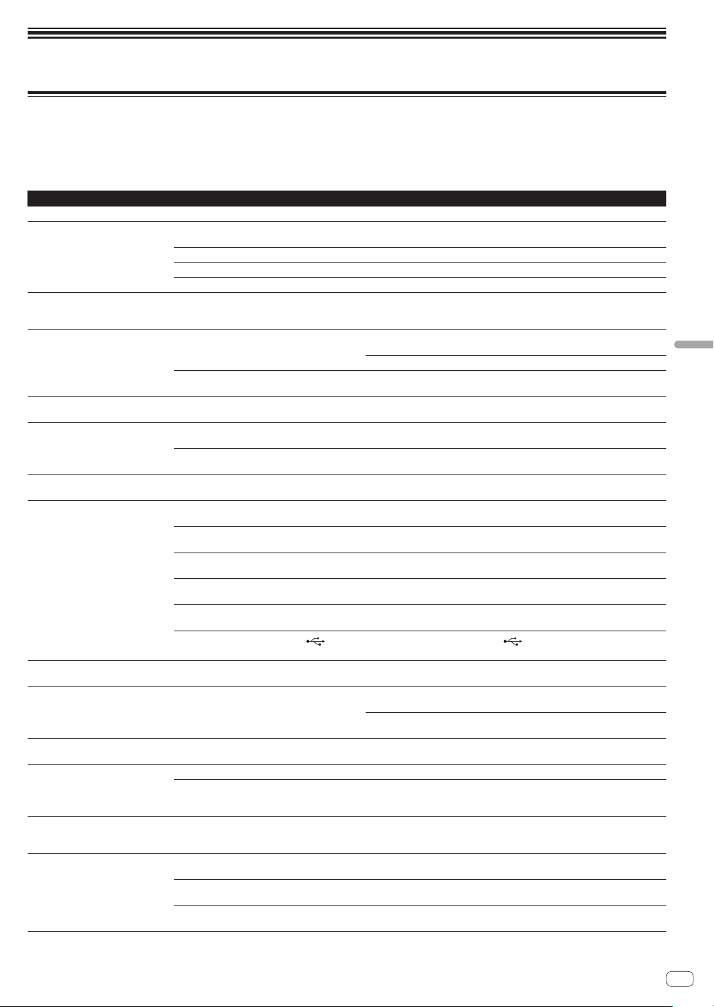
En
31
Additional information
Troubleshooting
! If you think that there is something wrong with this unit, check the following items, and also access [FAQ & DJ software support information] on
the Pioneer DJ support site and check [FAQ] for [DJM-TOUR1].
http://pioneerdj.com/support/
!
This unit may not operate properly due to static electricity or other external influences. In such cases, normal operation may be restored by unplug-
ging the power cord then plugging it back in.
Problem Check Remedy
The power is not turned on. Is the power cord properly connected? Plug in the power cord to an AC outlet.
No sound or small sound. Is the input selector switch set to the proper
position?
Switch the input selector switch to switch the channel’s input source.
(page 17 )
Are the connection cables properly connected? Connect the connection cables properly. (page 15 )
Are the terminals and plugs dirty? Clean the terminals and plugs before making connections.
Is [MASTER OUT] [ATT.] set to [
–6 dB], etc.? Switch the [MASTER OUT] [ATT.] switch on the [UTILITY] screen.
Digital sound cannot be output. Is the digital audio output’s sampling frequency
(fs) suited for the specifications of the connected
device?
On the [UTILITY] screen, set [DIGITAL MASTER OUT] [SAMPLING RATE]
according to the specifications of the connected equipment.
Distorted sound. Is the sound level output from the [MASTER]
channel appropriately set?
Adjust the [MASTER LEVEL] control so that the master channel level indicator
lights at around [0 dB
] at the peak level. (page 17 )
On the [UTILITY] screen, set [MASTER OUT] [ATT.] from [–3 dB] to [–12 dB].
Is the level of audio input to each channel properly
set?
Adjust the [TRIM] control so that the channel level indicator lights at about
[0 dB
] at the peak level. (page 17 )
Can’t crossfade. Are the [CROSS FADER ASSIGN (A, THRU, B)]
selector switches properly set?
Set the [CROSS FADER ASSIGN (A, THRU, B)] selector switches for the different
channels properly. (page 17 )
BEAT FX does not work. Is the effect channel selector switch set to the
proper position?
Turn the effect channel selector switch to select the channel to which you want
to apply the effect.
Is the [FX FREQUENCY] button set correctly? Press the [FX FREQUENCY] button for the band that you want to apply the effect
to, so that it lights.
SOUND COLOR FX does not work. Is the [COLOR] control set to an appropriate
position?
Turn the [COLOR
] control clockwise or counterclockwise. (page 19 )
Can’t use an external effector. Is the effect channel selector switch set to the
proper position?
Turn the effect channel selector switch to select the channel to which you want
to apply the effect.
Is the [SEND/RETURN ON/OFF] button set to
[ON]?
Press the [SEND/RETURN ON/OFF] button and set [SEND/RETURN] to [ON].
(page 20 )
Is the external effector connected to the [SEND] or
[RETURN] terminal correctly?
Connect the external effector to the [SEND] and [RETURN] terminals.
Is the mobile device connected to the mobile
device connection terminal correctly?
Connect the mobile device to the mobile device connection terminal and launch
a compatible application.
Is the [RETURN TYPE (AUX, INSERT)] selector
switch set correctly?
Set the [RETURN TYPE (AUX, INSERT)] switch to the correct position.
Is the [SEND/RETURN (1/4” JACK,
)] selector
switch set correctly?
Set the [SEND/RETURN (1/4” JACK, )] selector switch correctly.
Distorted sound from an external
effector.
Is the external effector’s audio output level set to
an appropriate level?
Adjust the external effector’s audio output level.
Tempo (BPM) cannot be measured or
measurement value of tempo (BPM) is
implausible.
Is the audio input level too high or too low? Adjust the [TRIM] control so that the channel level indicator lights at about
[0 dB
] at the peak level. (page 17 )
For some tracks, it may not be possible to measure the tempo (BPM). Use the
[TAP] button to input the tempo manually.
Measured tempo (BPM) differs from
tempo indicated on CD.
— The values may differ slightly due to the different ways in which the BPM is
measured.
MIDI control does not work. Is the MIDI channel turned on? Press the [ON/OFF] button for [MIDI].
Are the MIDI settings properly set? To operate software with this unit, this unit’s MIDI messages must be assigned
to the software you are using. For the assignment method, see your soft-
ware’s operating instructions.
This unit is not recognized after it has
been connected to a computer.
USB indicator is off or flashing.
Is the driver software properly installed on your
computer?
Install the driver software. If it is already installed, reinstall it.
Sound of a computer cannot be
output from this unit.
Are this unit and computer properly connected? Connect this unit and the computer directly using the included USB cable.
(page 15 )
Are the audio output device settings properly set? Select this unit with the audio output device settings. For instructions on making
settings for your application, see your application’s operating instructions.
Is the input selector switch set to the proper
position?
Set the input selector switch to the [USB
] position. (page 17 )
Additional information
Problem Check Remedy
Sound is distorted when an ana-
log player is connected to this
unit’s [PHONO] terminals.
Or, lighting of the channel level
indicator does not change even when
the [TRIM] control is turned.
Have you connected an analog player with a built-
in phono equalizer?
Connect the analog player with built-in phono equalizer to the [LINE] terminals.
(page 15 )
If the analog player with built-in phono equalizer has a PHONO/LINE selector
switch, switch it to PHONO.
Is an audio interface for computers connected
between the analog player and this unit?
If the output of the audio interface for computers is line level, connect it to the
[LINE
] terminals. (page 15 )
If the analog player has a PHONO/LINE selector switch, switch it to PHONO.
KUVO delivery is not possible
Problem Check Remedy
KUVO STATUS is [UNAVAILABLE]. Is this unit connected to the Internet properly? Check the INTERNET STATUS item below.
Is a KUVO compatible DJ player connected
properly?
Check the PRO DJ LINK STATUS item below.
INTERNET STATUS is [NOT
REGISTERED].
Have you completed registration of the club
information?
Create a CLUB OWNER account and register the club information at the KUVO
website. (Page 26 )
INTERNET STATUS is [NOT
CONNECTED].
Are the [INTERNET] terminal and the router for
Internet connection connected properly?
Connect a router for Internet connection and the [INTERNET] terminal properly.
(Page 15 )
Is a DJ device connected to the [INTERNET]
terminal?
Connect a DJ player to the [LINK] terminal. Connect a router for Internet connec-
tion to the [INTERNET
] terminal. (Page 15 )
Is the power of the switching hub or router for
Internet connection connected to the [INTERNET]
terminal turned on?
Turn on the power of the switching hub or router for Internet connection con-
nected to the [INTERNET] terminal.
Is the firmware of the connected router for Internet
connection the latest version?
Update the firmware of the connected router for Internet connection to the latest
version.
Are you using a LAN cable of Cat 5e or greater for
connection?
Use a LAN cable (STP) of Cat 5e or greater for the connection.
Is the DHCP function of the connected router for
Internet connection enabled?
Enable the DHCP function of the connected router for Internet connection.
PRO DJ LINK STATUS is [NOT
CONNECTED].
Is the connected DJ player CDJ-TOUR1? Connect CDJ-TOUR1. For information on other supported DJ players, see the
Pioneer DJ website.
Is the firmware of the connected DJ device the
latest version?
Update the firmware of the connected DJ device to the latest version.
Are you using a LAN cable of Cat 5e or greater for
connection?
Use a LAN cable (STP) of Cat 5e or greater for the connection.
MODE is [EXTERNAL]. Is a standalone network gateway device (NXS-GW)
connected to the [LINK] terminal?
To use the built-in network gateway function, disconnect the standalone network
gateway device. If you wish information to be delivered from the standalone
network gateway device, check that the standalone network gateway device is
connected to PRO DJ LINK and the Internet properly.
En
32
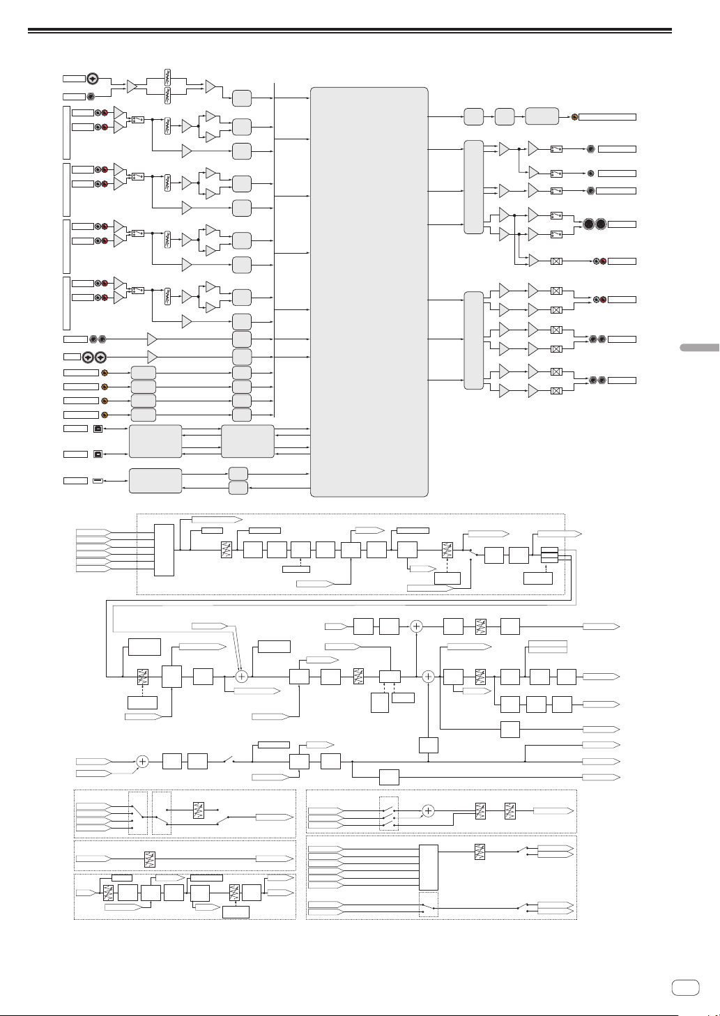
En
33
Additional information
Block Diagram
MIC1
MIC2
DIGITAL_MASTER_OUT
RETURN
AUX
USBA_IN
USBA_OUT
USBB_IN
USBB_OUT
USBC_IN
USBC_OUT
HP
MASTER
BOOTH
REC
SEND
DSP
MICADC
USB_UCOMSRC
MUTE
MUTE
MASTER 2
MUTE
SRC
DIT
Differential
IC
CH1
ADC
LINE
PHONO
ADC
CH1
Differential
CH2
CH3
CH4
DIR
RETURN
ADC
SRC
ADC
LINE
PHONO
ADC
CH2
Differential
Differential
MUTE
MUTE
Differential
ADC
LINE
PHONO
ADC
CH3
Differential
ADC
LINE
PHONO
ADC
CH4
Differential
DIGITAL CH 1
USB A
DIR
SRC
DIGITAL CH 2
DIR
SRC
DIR
SRC
DIGITAL CH 3
DIR
SRC
DIR
SRC
SRC
SRC
DIGITAL CH 4
AUX
ADC
SEND
BOOTH
REC
MASTER 1
HEAD PHONES
DIGITAL MASTER OUT
MINI PLUG
USB B
USBC_UCOM
USB C
HP2
DAC
HEAD PHONES2
MUTE
MUTE
DAC
Differential
Differential
Differential
Differential
Master
PEAK
LIMITER
Master
ATT.
USB OUTPUT LEVEL
HEADPHONE OUT
BEAT FX
CHx
BEAT FX
CHx
CUE
Monitor
CHx
3Band
ISOLATOR
CHx
Sound
Color FX
CHx
Sound
Color FX
CHx
Thru
A
B
SEND/
RETURN
CHx
CH Fader
USB:CHx Control Tone
Mic EQ
CLIP CHx Detect CHx BPM
Detect Mic BPM
USB:FX SEND CHx
TalkOver ON/OFF
USB:Post CHx Fader
Level Meter CHx
Detect
CrossFader A/B
BPM
Detect
Master BPM
Level Meter Master
CLIP Master
Mic
Mic
CHx Common
Trim
SEND CHx
SEND CrossFader A/B
CUE CHx
RETURN INSERT
USB:FX RETURN CHx
Cross Fader
TALK OVER
Talk Over
Level
Talk Over
Mode
Advanced /
Normal
BEAT FX
Master
AUX
INSERT
Master
LEVEL
Booth LEVEL
BOOTH OUT
MASTER OUT
DIGITAL OUT
REC OUT
Mic
Level
Detect
TalkOver on/off
BALANCE
USB A
PHONO
CD/LINE
DIGITAL
RETURN
SEND CHx
SEND CrossFader A/B
SEND Master
CUE CHx
CUE Link
CUE Master
SEND Mic
REUTRN
BEAT FX
Mic
CHx Control Tone
Post CHx Fader
Cross Fader A
Cross Fader B
MIC
FX SEND CHx
FX SEND Master
REC OUT
Output
Select
USB A OUT
USB B OUT
USB A OUT
USB B OUT
EQ/ISO
CHx
EQ/ISO switch
RETURN INSERT
CH FADER
Curve switch
CROSS FADER
ASSIGN switch
CROSS FADER
Curve switch
USB B
MIC1
AUX
MIC2
USB:Cross Fader A/B
CUE Master
MIC On/Off
Booth
MONO/
STEREO
Booth
ATT.
Mic
to Booth
Gain
Mic
PEAK
LIMITER
Master
MONO/
STEREO
CUE
Monitor
Master
Mic
PEAK
LIMITER
LOWCUT
FILTER
CHx
Input
Select
Sound
Color FX
CHx
BEAT FX
CHx
BEAT FX
CrossFader
A/B
SEND/
RETURN
CrossFader
A/B
SEND Master
USB:REC OUT
USB:MIC
RETURN INSERT
SEND/
RETURN
Master
SEND Mic
RETURN INSERT
SEND OUT
REUTRN INSERT
SEND/
RETURN
Mic
Digital
Output
Level
Digital
MONO/
STEREO
Digital
PEAK
LIMITER
Master
MONO/
STEREO
BEAT FX
CH select
CUE
On/Off
Select in
PC
RETURN
TYPE
Send LEVEL
Return LEVEL
SEND/RETURN
HEADPHONE
USB Output
SEND/RETURN (INSERT TYPE)
AUX
AUX
USB:AUX
AUX
Headphone
LEVEL
Headphone
MIXING
MONO SPLIT/STEREO
BEAT FX
AUX
BEAT FX
AUX
BEAT FX
AUX
CUE
Monitor
AUX
SEND/
RETURN
AUX
AUX Fader
CLIP AUX
Level Meter AUX
Trim
SEND AUX
CUE AUX
RETURN INSERT
CH FADER
Curve switch

About trademarks and registered
trademarks
! "Pioneer DJ" is a trademark of PIONEER CORPORATION, and is used
under license.
The names of companies and products mentioned herein are trade-
marks or registered trademarks of their respective owners.
Cautions on copyrights
Recordings you have made are for your personal enjoyment and accord-
ing to copyright laws may not be used without the consent of the copy-
right holder.
! Music recorded from CDs, etc., is protected by the copyright laws of
individual countries and by international treaties. It is the full respon-
sibility of the person who has recorded the music to ensure that it is
used legally.
! When handling music downloaded from the Internet, etc., it is the
full responsibility of the person who has downloaded the music to
ensure that it is used in accordance with the contract concluded
with the download site.
Software license notice
The licenses for the open source software used on this player are shown
below. For accuracy purposes, here we have included the original texts
(in English).
Copyright © 2010 Texas Instruments Incorporated - http://www.ti.com/
Redistribution and use in source and binary forms, with or without modi-
fication, are permitted provided that the following conditions are met:
Redistributions of source code must retain the above copyright notice,
this list of conditions and the following disclaimer.
Redistributions in binary form must reproduce the above copyright
notice, this list of conditions and the following disclaimer in the docu-
mentation and/or other materials provided with the distribution.
Neither the name of Texas Instruments Incorporated nor the names of its
contributors may be used to endorse or promote products derived from
this software without specific prior written permission.
THIS SOFTWARE IS PROVIDED BY THE COPYRIGHT HOLDERS
AND CONTRIBUTORS «AS IS» AND ANY EXPRESS OR IMPLIED
WARRANTIES, INCLUDING, BUT NOT LIMITED TO, THE IMPLIED
WARRANTIES OF MERCHANTABILITY AND FITNESS FOR A
PARTICULAR PURPOSE ARE DISCLAIMED. IN NO EVENT SHALL THE
COPYRIGHT OWNER OR CONTRIBUTORS BE LIABLE FOR ANY DIRECT,
INDIRECT, INCIDENTAL, SPECIAL, EXEMPLARY, OR CONSEQUENTIAL
DAMAGES (INCLUDING, BUT NOT LIMITED TO, PROCUREMENT OF
SUBSTITUTE GOODS OR SERVICES; LOSS OF USE, DATA, OR PROFITS;
OR BUSINESS INTERRUPTION) HOWEVER CAUSED AND ON ANY
THEORY OF LIABILITY, WHETHER IN CONTRACT, STRICT LIABILITY, OR
TORT (INCLUDING NEGLIGENCE OR OTHERWISE) ARISING IN ANY
WAY OUT OF THE USE OF THIS SOFTWARE, EVEN IF ADVISED OF THE
POSSIBILITY OF SUCH DAMAGE.
!
The specifications and design of this product are subject to change
without notice.
© 2016 Pioneer DJ Corporation. All rights reserved.
<DRI1347-B>
En
34