Loading ...
Loading ...
Loading ...
12
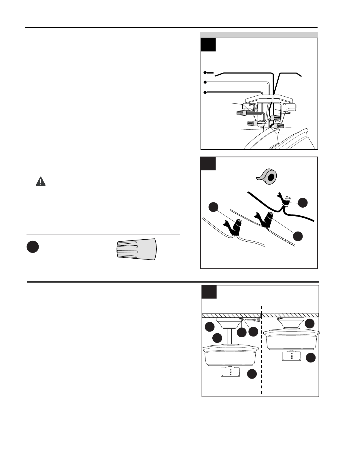
WIRING
Wrap electrical tape (not included) around each
individual wire connector (DD) down to the wire.
WARNING: Make sure no bare wire or wire
strands are visible after making connections. Place
GREEN and WHITE connections on opposite side of
the outlet box from the BLACK and BLUE (if
applicable) connections.
2.
DD
2
DD
DD
Hardware Used
Wire Connector
x 4
DD
NOTE: BLACK wire is hot power for fan. BLUE wire
is hot power for light kit. WHITE wire is common for
fan and light kit. BARE/GREEN wire is ground.
FAN AND LIGHT CONTROLLED BY TWO WALL SWITCHES
FAN AND LIGHT CONTROLLED BY TWO WALL SWITCHES
BLACK
BLUE
1c
WHITE
BLACK (WALL SWITCH)
WHITE (NEUTRAL)
GROUND/GREEN (BARE)
GREEN
120V POWER
FROM CEILING
BLACK
BLACK
(WALL SWITCH
FOR LIGHT)
GREEN
1
1.
Lift canopy (B) to mounting bracket (C) and
align slotted holes in canopy (B) with loosened
canopy mounting screws (Y) in mounting
bracket (C). Twist canopy (B) to lock, then
insert the two canopy mounting screws (Y) and
star washers (X) previously removed (Step 4a,
page 6). Tighten all canopy mounting screws
(Y) securely.
B
B
A
D
D
Y
X
FINAL INSTALLATION
1c. FAN AND LIGHT CONTROLLED BY TWO
WALL SWITCHES: If you intend to control the
fan and light with separate wall switches, connect
BLACK wire from fan to BLACK wire from the
independent wall switch for the fan. Connect
BLUE wire from fan to the BLACK (or RED) wire
from the other independent wall switch for the
light. Connect WHITE wire from fan to WHITE
wire from ceiling. Connect all GROUND (GREEN)
wires together from fan (on downrod (A), if
applicable, and mounting bracket (C)) to
BARE/GREEN wire from ceiling.
Downrod
Option
Closemount
Option
Loading ...
Loading ...
Loading ...