Operation Manual
PERSONAL EMBROIDERY DESIGN SOFTWARE SYSTEM
Please visit us at http://solutions.brother.com where you can get product
support and answers to frequently asked questions (FAQs).
English
Printed in China
XF0606-001
PED_PLUS_BrotherE_OM_cover_1-4
C M Y K
IMPORTANT INFORMATION: REGULATIONS
Federal Communications Commissions (FCC) Declaration of Conformity
(For USA Only)
Responsible Party: Brother International Corporation
100 Somerset Corporate Boulevard
Bridgewater, NJ 08807-0911 USA
declares that the product
Product Name: Brother USB Writer
Model Number: PE-Design
complies with Part 15 of the FCC Rules. Operation is subject to the following two conditions: (1)
this device may not cause harmful interference, and (2) this device must accept any interference
received, including interference that may cause undesired operation.
This equipment has been tested and found to comply with the limits for Class B digital device,
pursuant to Part 15 of the FCC Rules. These limits are designed to provide reasonable
protection against harmful interference in a residential installation. This equipment generates,
uses, and can radiate radio frequency energy and, if not installed and used in accordance with
the instructions, may cause harmful interference to radio communications. However, there is no
guarantee that interference will not occur in a particular installation. If this equipment does cause
harmful interference to radio or television reception, which can be determined by turning the
equipment off and on, the user is encouraged to try to correct the interference by one or more of
the following measures:
– Reorient or relocate the receiving antenna.
– Increase the separation between the equipment and receiver.
– Consult the dealer or an experienced radio/TV technician for help.
– Changes or modifications not expressly approved by the manufacturer or local sales
distributor could void the user’s authority to operate the equipment.
Canadian Department of Communications Compliance Statement
(For Canada Only)
This Class B digital apparatus complies with Canadian ICES-003.
Radio Interference
(Other than USA and Canada)
This machine complies with EN55022 (CISPR Publication 22) /Class B.
XE8656-001.book Page 0 Thursday, June 30, 2011 2:56 PM
1
Read the following before opening the
CD-ROM package
Thank you for purchasing this software. Before opening the CD-ROM package for this software, carefully read
the following Product Agreement, which has been provided for this product. Use this software only if you agree
to the terms of this agreement. By opening the CD-ROM package, you agree to the conditions of its use. This
product cannot be returned after it has been opened.
Product Agreement
Portions of this product were created using technology from Softfoundry International Pte. Ltd.
■ Opening the Operation Manual (PDF format)
This manual is provided in a PDF format on the enclosed CD-ROM. The Operation Manual is also installed
during software installation.
Click All Programs, then PE-DESIGN PLUS, then Operation Manual.
Otherwise, with PE-DESIGN PLUS, click , then Operation Manual. With PES-Writer, click Help, then
Operation Manual.
1) General terms
This is an agreement between you (the end-user) and our company for this product.
2) Use of this product
You may install and use this product on only one computer.
3) Limitations on duplications
You may not duplicate this product, except for backup purposes.
4) Limitations on modifications
You may not modify or disassemble this product in any way.
5) Limitations on transfer
This software may not be transferred to or used in any other way by a third party.
6) Warranty
We accept no responsibility for your choice or use of this product or for any damages that may arise
out of its use.
7) Others
This product is protected by copyright laws.
b Memo:
• Adobe
®
Reader
®
is required for viewing and printing the PDF version of the Operation Manual
• If Adobe
®
Reader
®
is not on your computer, it must be installed. It can be downloaded from the Adobe
Systems Incorporated Web site (http://www.adobe.com/).
• The procedures in this manual are written for use in Windows
®
7. If this software is used on an operating
system other than Windows
®
7, the procedures and appearance of the windows may differ slightly.
Information.fm Page 1 Wednesday, July 6, 2011 3:34 PM

2
Congratulations on choosing our product!
Thank you very much for purchasing our product. To obtain the best performance from this unit and
to ensure safe and correct operation, please read this Operation Manual carefully, and then keep
it in a safe place together with your warranty.
Please read before using this product
For designing beautiful embroidery designs
• This system allows you to create a wide variety of embroidery designs and supports a wider
range of sewing attribute settings (thread density, sewing pitch, etc.). However, the final result
will depend on your particular sewing machine model. We recommend that you make a trial
sewing sample with your sewing data before sewing on the final material.
For safe operation
• Avoid dropping a needle, a piece of wire or other metallic objects into the unit or into the card
slot.
• Do not store anything on the unit.
For a longer service life
• When storing the unit, avoid direct sunlight and high humidity locations. Do not store the unit
close to a heater, iron or other hot objects.
• Do not spill water or other liquids on the unit or cards.
• Do not drop or hit the unit.
For repairs or adjustments
• In the event that a malfunction occurs or adjustment is required, please consult your nearest
service center.
Notice
This Operation Manual does not explain how to use your computer under Windows
®
. Please refer
to the Windows
®
manuals.
Copyright acknowledgment
Windows
®
is a registered trademark of Microsoft Corporation. Other product names mentioned in
the Operation Manual may be trademarks of registered trademarks of their respective companies
and are hereby acknowledged.
Important
Using this unit for unauthorized copying of material from embroidery cards, newspapers and
magazines for commercial purpose is an infringement of copyrights which is punishable by law.
Caution
The software included with this product is protected by copyright laws. This software can be used
or copied only in accordance with the copyright laws.
For additional product information and updates, visit our web site at:
http://www.brother.com/ or http://solutions.brother.com/
SAVE THESE INSTRUCTIONS
This product is intended for household use.
XE8656-001.book Page 2 Thursday, June 30, 2011 2:56 PM
3
Table of Contents
Before Use........................................4
Before Use ............................................... 4
Introduction...................................................4
Installation.....................................................5
Creating Embroidery Patterns......10
Getting Started ...................................... 10
Starting Up Application ...............................10
Creating Embroidery Patterns From Photos
(Photo Stitch 1)...........................................11
Saving.........................................................18
Exiting Application ......................................19
Image To Stitch ..................................... 21
Photo Stitch 2 .............................................21
Auto Punch ................................................. 24
Cross Stitch ................................................27
Common dialog boxes................................30
Entering Text ......................................... 32
Entering Text ..............................................32
Advanced Operations for Entering Text......35
Arranging Embroidery Designs ...37
Arranging Embroidery Designs........... 37
Editing Embroidery Designs .......................37
Checking Embroidery Patterns...................40
Applying Sewing Attributes to Lines and
Regions.......................................................45
Opening/Importing Embroidery Designs..... 48
Transferring Embroidery Designs to
Machines ....................................................52
Printing........................................................54
Specifying the Design Page Size and
Color ...........................................................56
Changing Application Settings....................57
Supplement....................................61
Understanding Windows ...................... 61
PE-DESIGN PLUS Window ........................61
Menus .........................................................65
Tips and Techniques............................. 67
Sewing Direction.........................................67
Sewing Order ..............................................67
Sewing Wide Areas.....................................67
Reference ............................................... 68
Sewing Attributes ........................................68
Font List ......................................................70
PES-Writer.............................................. 72
Writing Multiple Embroidery Files to an
Original Card...............................................72
Troubleshooting .................................... 75
Index ...............................................76
XE8656-001.book Page 3 Thursday, June 30, 2011 2:56 PM
4
Before Use
Before Use
Introduction
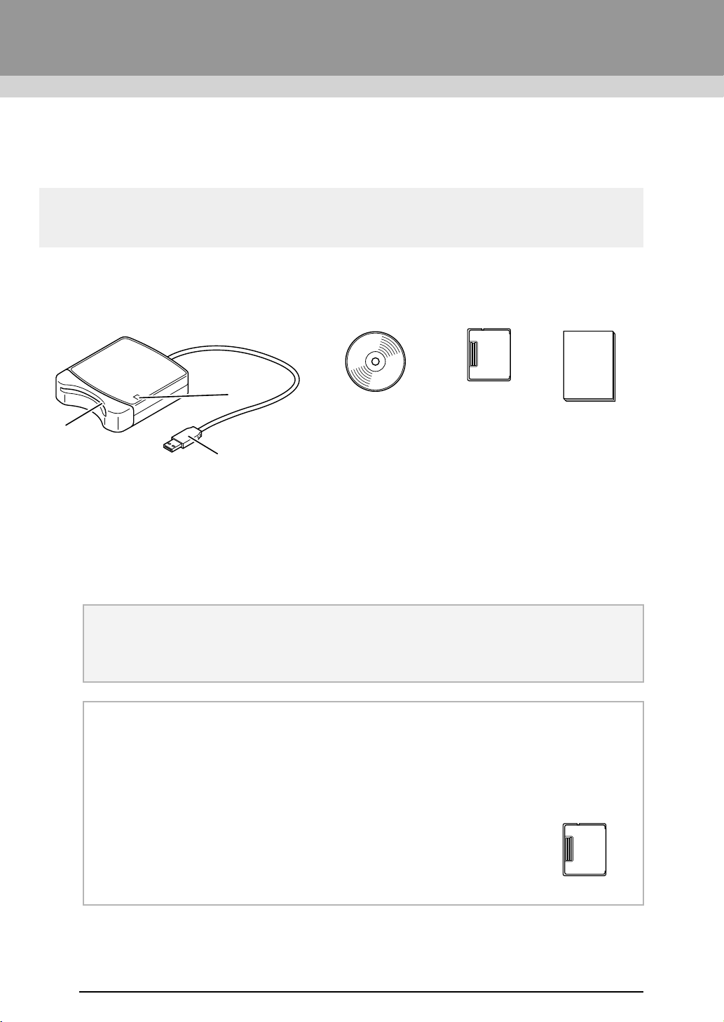
Package Contents
Check that the following items are included. If anything is missing or damaged, contact your authorized dealer
or Brother Customer Service.
a LED indicator
This indicator lights up when the unit is turned on, and flashes when the USB Card Writer Module is
communicating with the computer.
b Card slot
Insert an original card/embroidery card here.
c USB connector
Connect to the computer.
USB Card Writer Module CD-ROM Original card Operation Manual
Contains the software
and Operation Manual
(PDF format).
a Note:
• The only original cards that can be used with this USB Card Writer Module are those like the one
enclosed or optional original cards of the same type.
• Never remove an original card or unplug the USB cable while this indicator is flashing.
b Memo:
• Since power is supplied to the USB Card Writer Module through the USB connection to the
computer, there is no power supply cable or power switch.
• Be sure to keep original cards away from high humidity, direct sunlight, static electricity and strong
shocks. Furthermore, do not bend the cards.
Optional Supply
Additional blank original cards can be purchased through an authorized dealer.
Original card
a
c
b
XE8656-001.book Page 4 Thursday, June 30, 2011 2:56 PM
5
Before Use
Before Use
Installation
Please Read Before Installation
● Before beginning the installation, check that the computer meets the system requirements.
● In order to install the software on Windows
®
Operating System, you must log on to the computer using an
account with administrator privileges. For details on logging on to the computer using an account with
administrator privileges, refer to the Windows
®
manual.
● The installation procedure is described for Windows
®
7. The procedure and dialog boxes for other
operating systems may be slightly different.
● If the installation is canceled before it is completed or if the procedure is not performed as described, the
software will not be installed correctly.
● Do not remove the CD-ROM from the CD-ROM drive of the computer while the installation is being
performed. Remove the CD-ROM after the installation is completed.
● Before turning on the computer, be sure to disconnect the USB Card Writer Module.
System Requirements
Before installing the software on your computer, make sure that the computer meets the following minimum
PC requirements.
Computer IBM-PC or compatible computer
Operating system
Windows
®
XP, Windows Vista
®
, Windows
®
7 (32 or 64 bit)
Processor 1GHz or higher
Memory 512MB (1GB or more is recommended.)
Hard disk free space 200MB
Monitor XGA (1024 x 768), 16-bit color or higher
Port 1 available USB
Printer
A graphic printer that is supported by your system
(if you wish to print your images)
CD-ROM drive Required for installation
Internet access Required for update
a Note:
• Power is supplied to the USB Card Writer Module through the USB connection. Connect the USB
Card Writer Module to a USB connector on the computer or to a self-powered USB hub that can
supply enough power to the Card Writer Module. If the Card Writer Module is not connected in this
way, it may not operate correctly.
• This product may not operate correctly with some computers and USB expansion cards.
XE8656-001.book Page 5 Thursday, June 30, 2011 2:56 PM
6
Before Use
Installing the Software
This section describes how to install the application
software.
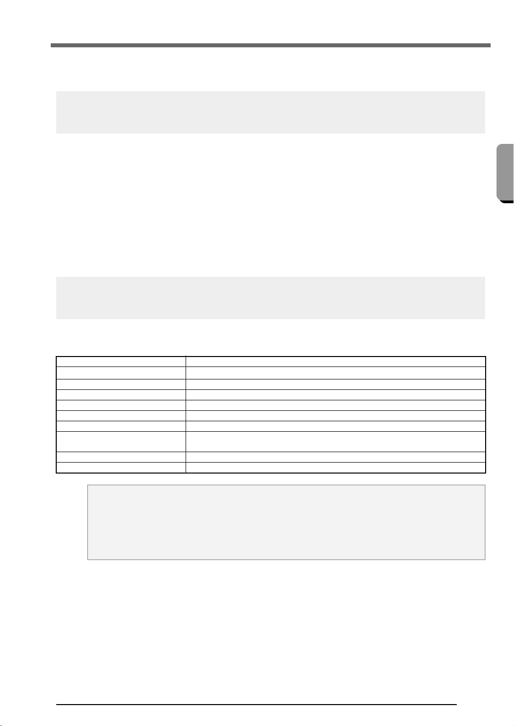
1. Insert the enclosed CD-ROM into the
computer's CD-ROM drive.
■ Windows
®
XP users only
After a short while, the language selection
dialog box for InstallShield Wizard
automatically appears.
Continue with step
4. on page 7.
■ For Windows
®
7 or Windows
Vista
®
users:
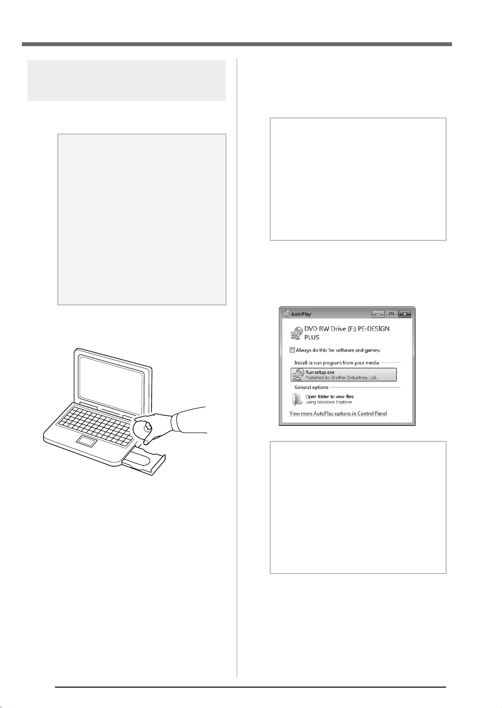
After a short while, the AutoPlay dialog
box automatically appears.
a Note:
• If the installation is interrupted or not
performed as described, the software
will not be installed correctly.
• Before turning on the computer, be sure
that the USB Card Writer Module is
DISCONNECTED.
• In order to install the software, you must
log on to the computer using an account
with administrator privileges. If you are
not logged on with the Administrator
account, the password for the
Administrator account (Administrators)
may be requested with Windows
®
7.
Type in the password to continue the
procedure.
b Memo:
If the installer does not automatically start
up:
1) Click the Start button.
2) Click Run.
The Run dialog box appears.
3) Type in the full path to the installer, and
then click OK to start up the installer.
For example: F:\setup.exe (where "F:" is
the name of the CD-ROM drive)
b Memo:
If the
AutoPlay
Dialog does not automatically
start up:
1) Click the Start button.
2) Click All Programs
Accessories
Run.
The Run dialog box appears.
3) Type in the full path to the installer, and
then click OK to start up the installer.
For example: F:\setup.exe (where “F:” is
the name of the CD-ROM drive)
XE8656-001.book Page 6 Thursday, June 30, 2011 2:56 PM
7
Before Use
Before Use
2. Click Run setup.exe.
The User Account Control dialog box
appears.
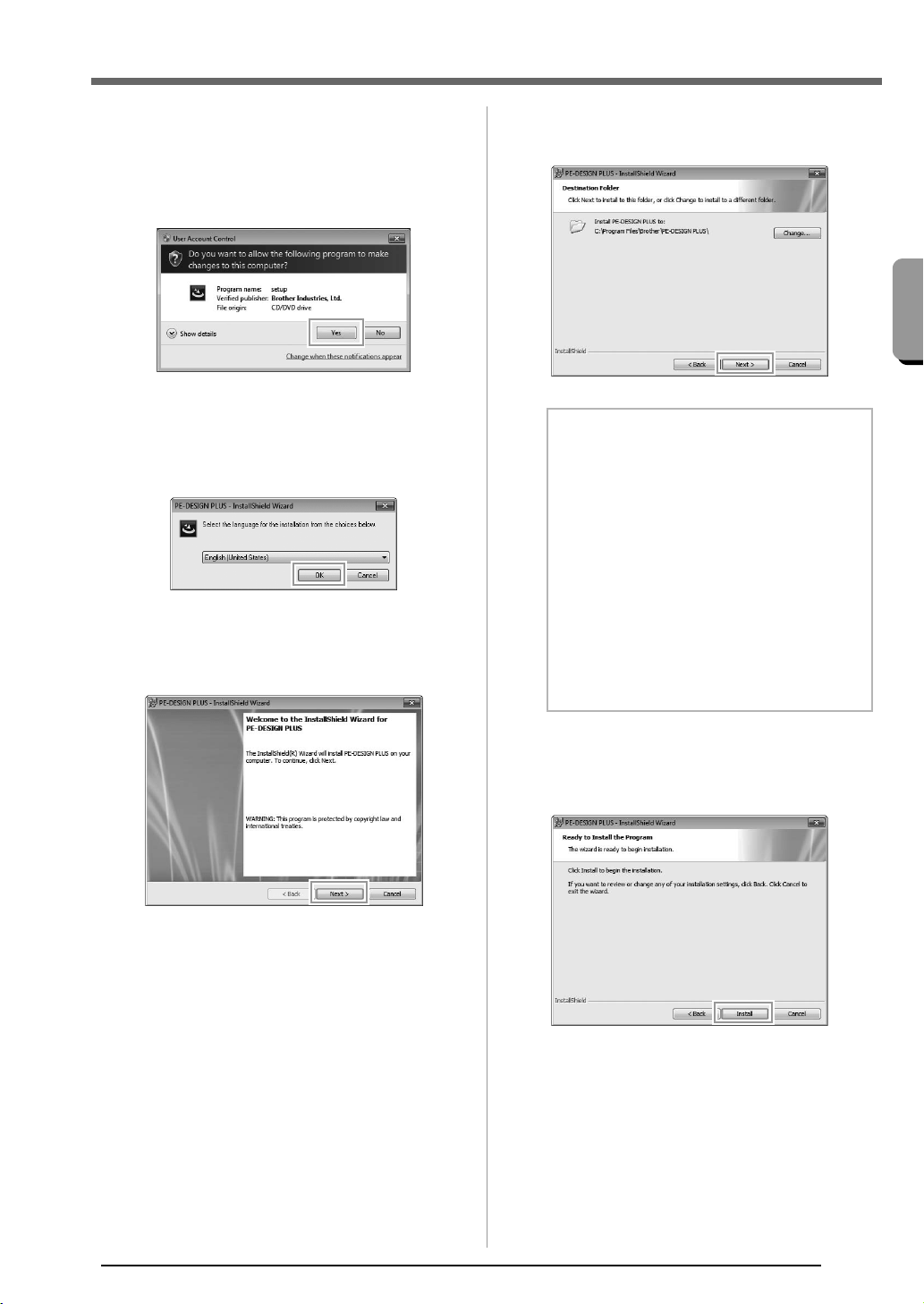
3. Click Yes.
After a short while, the following dialog
box automatically appears.
4. Select the desired language, and then click
OK.
The InstallShield Wizard starts up, and
the first dialog box appears.
5. Click Next to continue with the installation.
A dialog box appears, allowing you to
select the folder where the software will
be installed.
6. Check the installation location, and then click
Next.
A dialog box appears, indicating that
preparations for installation are finished.
7. Click Install to install the application.
When the installation is completed, the
following dialog box appears.
b Memo:
To install the application into a different
folder:
1) Click Change.
2) In the Change Current Destination
Folder dialog box that appeared, select
the drive and folder. (If necessary, type
in the name of a new folder.)
3) Click OK.
The Destination Folder dialog box of
the InstallShield Wizard shows the
selected folder.
4) Click Next to install the application into
the selected folder.
XE8656-001.book Page 7 Thursday, June 30, 2011 2:56 PM
8
Before Use
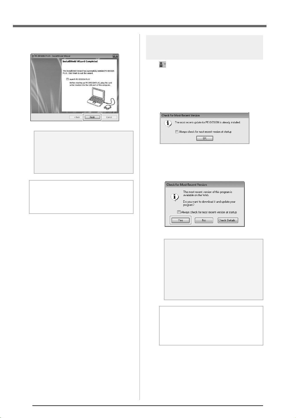
8. Click Finish to complete the installation of the
software.
Checking for the Latest
Version of the Program
Click in PE-DESIGN PLUS, then Check for
Updates.
The software is checked to determine whether or
not it is the latest version.
If the message shown below appears, the latest
version of the software is being used.
If the message shown below appears, the latest
version of the software is not being used. Click Yes,
and then download the latest version of the software
from the Web site.
a Note:
This procedure also automatically installs
the card writer driver. The card writer may
now be connected to your computer.
Make sure that PE-DESIGN PLUS starts
up correctly.
b Memo:
If the dialog box calling for restarting the
computer appears, it is necessary to restart
the computer.
a Note:
• This feature cannot be used if the
computer is not connected to the
Internet.
• It may not be possible to check for the
latest version if a firewall is turned on.
Turn off the firewall, and then try
performing the operation again.
• Administrator privileges are required.
b Memo:
If the
Always check for most recent version
at startup
check box is selected, the software
is checked at startup to determine whether or
not it is the latest version.
PE-DESIGN_Plus.fm Page 8 Wednesday, July 6, 2011 3:35 PM
9
Before Use
Before Use
Technical Support
Contact Technical Support if you have a problem.
Please check the company web site
(http://www.brother.com/) to find the technical
Support in your area. To view the FAQ and
information for software updates, visit the Brother
Solutions Center at (http://solutions.brother.com/).
Online Registration
If you wish to be contacted about upgrades and
provided with important information such as future
product developments and improvements, you can
register your product online by following a simple
registration procedure.
Click Online Registration on the menu of PE-
DESIGN PLUS to start up the installed Web browser
and open the online registration page on our Web
site.
http://www.brother.com/registration/
Uninstallation
1. Click the button in the task bar, and then
click Control Panel.
2. In the Control Panel window, select
Programs and Features.
3. In the Programs and Features window,
select this software, and then click Uninstall.
a Note:
Before contacting web site:
1) Please have your Windows
®
Operating System updated to the most
current version.
2) The make and model number of the
computer that you are using as well as
the Windows
®
Operating System
version.
3) Information about any error messages
that appear.
This information will help expedite your
questions more quickly.
4) Please check and update the software
to the latest version.
b Memo:
Online registration may not be available in
some areas.
b Memo:
• The uninstallation procedure is described
for Windows
®
7 and Windows Vista
®
.
• For Windows
®
XP, click the Start button,
then Control Panel. Double-click Add or
Remove Programs. Select this software,
and then click Remove.
PE-DESIGN_Plus.fm Page 9 Wednesday, July 6, 2011 3:36 PM
10
Creating Embroidery Patterns
Getting Started
Starting Up Application
Starting up PE-DESIGN
PLUS
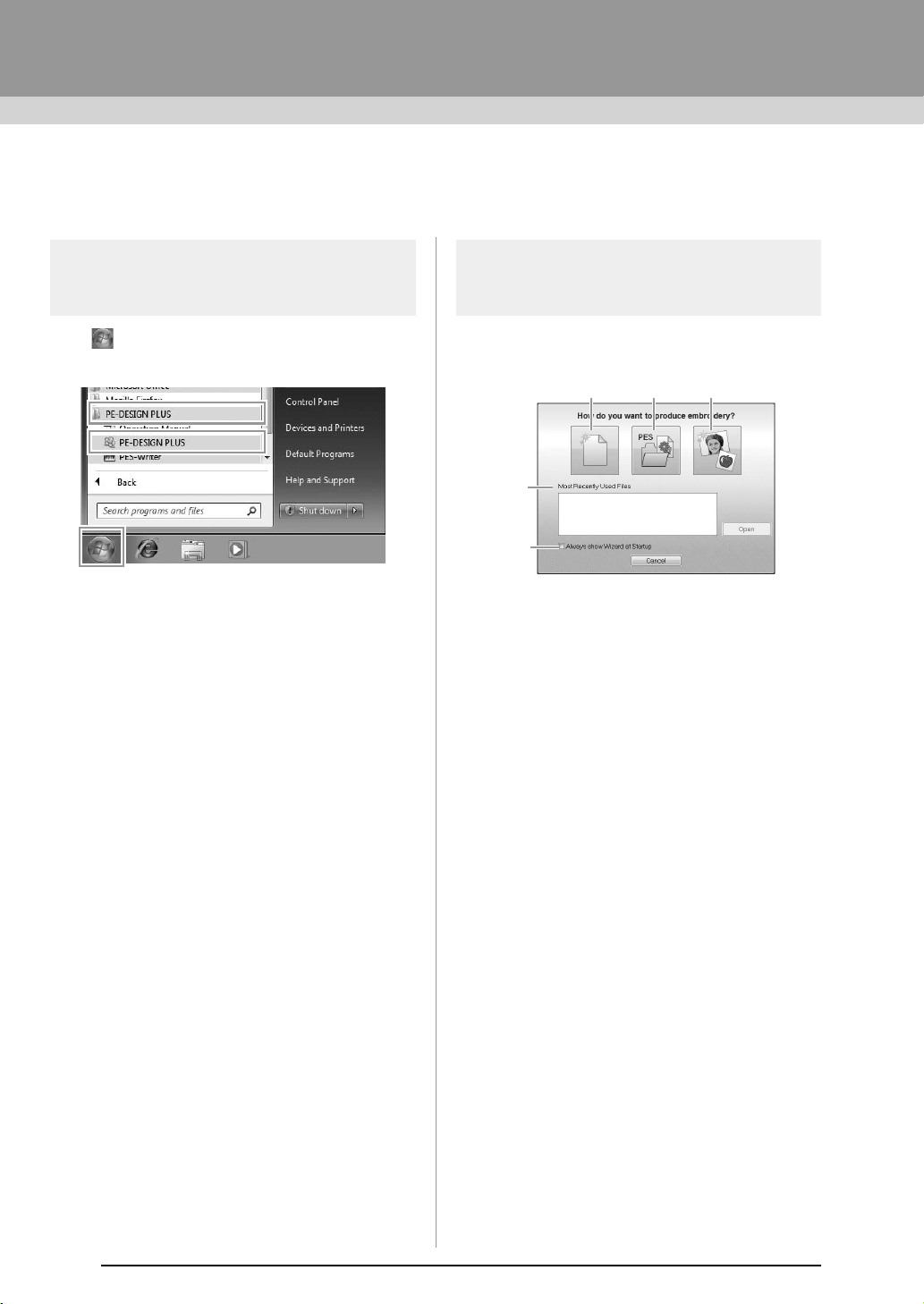
Click , then All Programs, then PE-DESIGN
PLUS, and then click PE-DESIGN PLUS.
About the Top Wizard
When PE-DESIGN PLUS starts up, the following
wizard appears.
(1) New
Click this button to begin creating a new
pattern.
(2) Open PES
Click this button to open embroidery data
(.pes).
c
“Opening a PE-DESIGN PLUS file” on
page 48
(3) Image To Stitch
Click this button to start the wizard for
creating an embroidery pattern from an
image.
c
“Using the Photo Stitch 1 function to
create an embroidery pattern from an
image” on page 11
(4) Most Recently Used Files
Click the name of a file from the list, and
then click Open.
(5) Always show Wizard at Startup
Select this check box to start up the
wizard each time PE-DESIGN PLUS is
started up.
(1) (2) (3)
(4)
(5)
XE8656-001.book Page 10 Thursday, June 30, 2011 2:56 PM
11
Creating Embroidery Patterns
Creating Embroidery Patterns
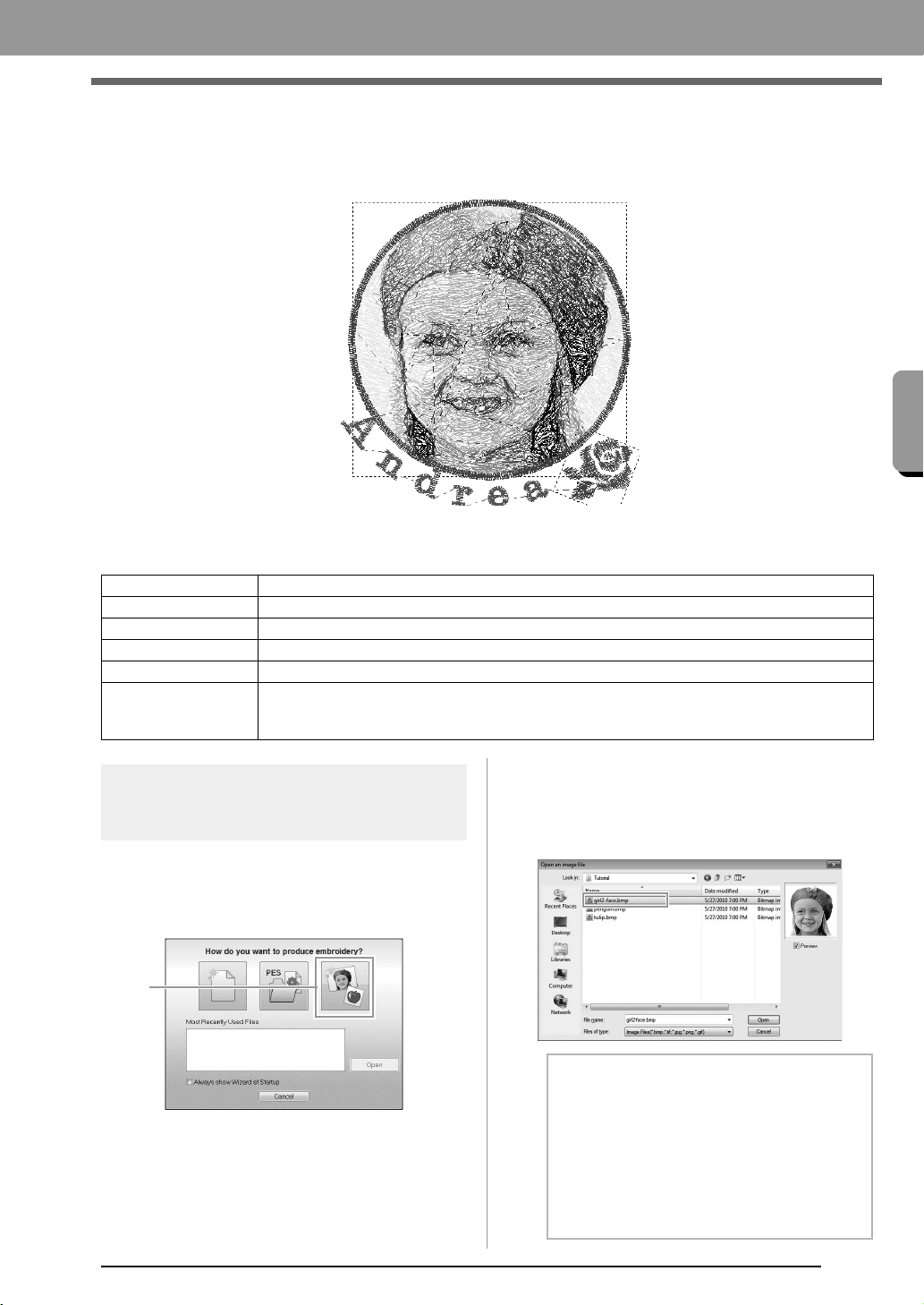
Creating Embroidery Patterns From
Photos (Photo Stitch 1)
The sample file for this tutorial can be found at the following location.
Documents (My Documents)\PE-DESIGN PLUS\Tutorial
Step 1
Using the Photo Stitch 1
function to create an embroidery
pattern from an image
Now, we will open the image of the girl and convert
it to an embroidery pattern.
1. Click 1 in the Top Wizard.
2. Import the file girl2-face.bmp.
Select the file
girl2-face
.bmp
in the folder
Documents (My Documents)\PE-DESIGN
PLUS\Tutorial
Step 1 Using the Photo Stitch 1 function to create an embroidery pattern from an image
Step 2 Changing color of the circle
Step 3 Adding text and setting character spacing
Step 4 Transforming the text
Step 5 Importing and rotating an embroidery pattern
Step 6
Transferring embroidery patterns to embroidery machines
• Transferring the design to an original card
• Transferring data to embroidery machines via a USB media
1
b Memo:
Image file formats
Images in the following formats can be
imported.
• Windows bitmap (.bmp)
• Exif (.tif, .jpg)
• Portable Network Graphics (.png)
• GIF (.gif)
XE8656-001.book Page 11 Thursday, June 30, 2011 2:56 PM
12
Creating Embroidery Patterns
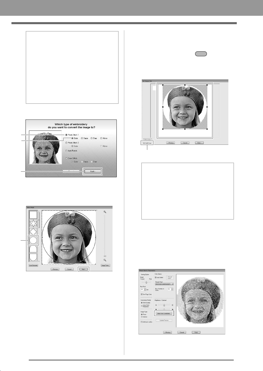
3. Click 1, then 2, then 3.
c
“Image To Stitch Wizard” on page 30
4. Click 1 to select the circle mask, and then click
Next.
c
“Select Mask dialog box” on page 30
5. Adjust the size and position of the image.
1 indicates the Design Page.
• Move the pointer over a handle, and then,
while holding down the key and the
left mouse button, drag the mouse to
reduce the size of the image.
• Drag the image to adjust its output location.
c
“Set Output Size dialog box” on page 31
and “Gray Balance / Set Output Size
dialog box” on page 31
6. Check the preview of the area to be converted
then click Next.
7. Click Select from Candidates.
c
“Photo Stitch 1 Parameters dialog box” on
page 19
b Memo:
Creating beautiful photo embroidery
• The following types of photos are not
appropriate for creating embroidery
patterns.
• Photos where the subject is small, such
as in photos of gatherings
• Photos where the subject appears
dark, such as photos taken in a room or
taken with backlighting
• An image with a width and height between
300 and 500 dots is suitable.
1
2
3
1
b Memo:
• The size of the embroidery pattern appears
in the lower left corner of the dialog box. The
user can change the size freely with this
display.
• For best results, change the size of the
embroidery pattern to the sizes listed below.
• Face only: 100 × 100 mm
• Head and shoulders: 130 × 180 mm
Shift
Embroidery pattern size
1
XE8656-001.book Page 12 Thursday, June 30, 2011 2:56 PM
13
Creating Embroidery Patterns
Creating Embroidery Patterns
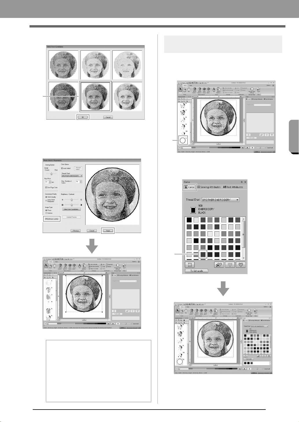
8. Select one of the candidates (1) and click OK.
This preview changes to the selected
image.
9. Select the Add mask outline check box,
check the preview image, and then click
Finish.
Stitches are automatically input.
Step 2 Changing color of the
circle
1. In the Sewing Order pane, move the scroll bar
until circle pattern (1) appears, and then click
it.
2. Click 1 in the Color tab to change the color of
the circle.
b Memo:
If the created embroidery pattern contains
colors that you do not wish to emphasize (for
example, grays in the face), change the
sewing order in the
Sewing Order
pane so
that the undesirable color is sewn before all
other colors.
c
“Checking and Editing the Sewing
Order” on page 43.
1
1
1
XE8656-001.book Page 13 Thursday, June 30, 2011 2:56 PM
14
Creating Embroidery Patterns
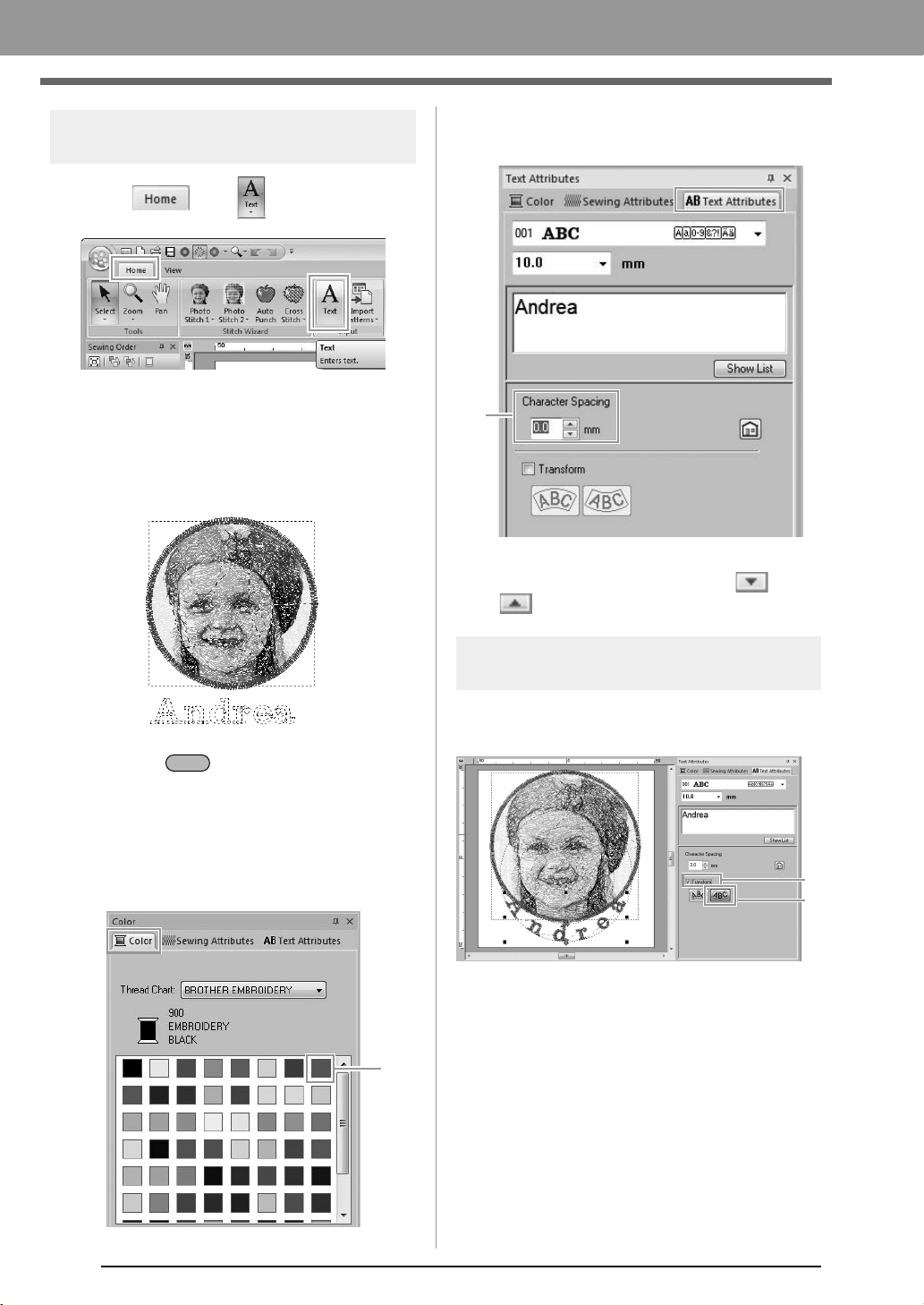
Step 3 Adding text and setting
character spacing
1. Click , then .
2. Click below the girl in the Design Page.
A vertical dashed line will appear on the
Design Page.
3. From the keyboard, type in “Andrea”.
4. Press the key.
The text is entered.
5. Click the text to select it.
6. Click the Color tab, and then click 1 to change
the color of the font.
7. Click the Text Attributes tab, and then set
Character Spacing (1) to 3.0 mm.
Specify the setting by clicking the selector and
typing in the value, or by clicking or
.
Step 4 Transforming the text
1. Click the text to select it, select the Transform
check box (1), and then click 2.
Enter
1
1
1
2
XE8656-001.book Page 14 Thursday, June 30, 2011 2:56 PM
15
Creating Embroidery Patterns
Creating Embroidery Patterns
2. Move the pointer over , or , and
then, while holding down the left mouse
button, drag the mouse to adjust the size,
position or curve of the text.
c
“Transforming text” on page 33
3. To adjust the positions of the embroidery
patterns, click the pattern, and then position
the pointer over the pattern. When the shape
of the pointer changes to , hold down the
left mouse button and drag the pattern to the
desired location.
c
“Editing Embroidery Designs” on page 37
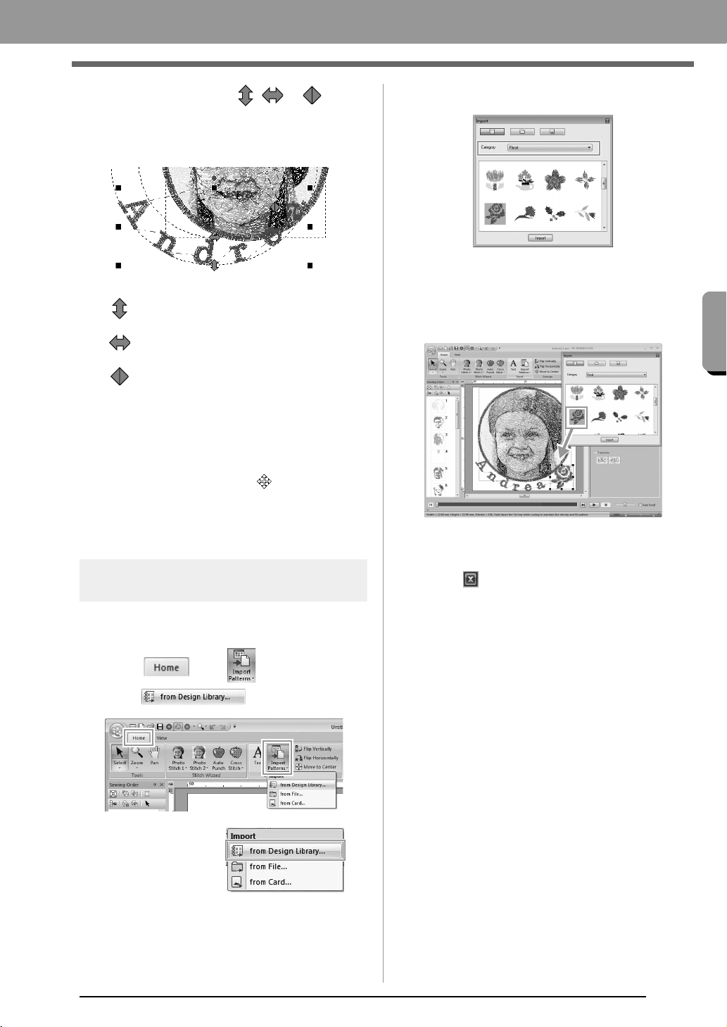
Step 5 Importing and rotating an
embroidery pattern
Now, we will import the embroidery pattern for the
rose.
1. Click , then ,
then .
2. From the Category selector, select Floral.
3. Move the pointer over the rose, and then,
while holding down the left mouse button, drag
the mouse to import the pattern into the
Design Page, as shown in the illustration.
c
“Importing embroidery designs” on
page 49
4. Click in the Import dialog box to close it.
: Adjusts the text size.
: Moves the text along the circle.
: Adjusts the radius of the circle.
PE-DESIGN_Plus.fm Page 15 Wednesday, July 6, 2011 3:36 PM
16
Creating Embroidery Patterns
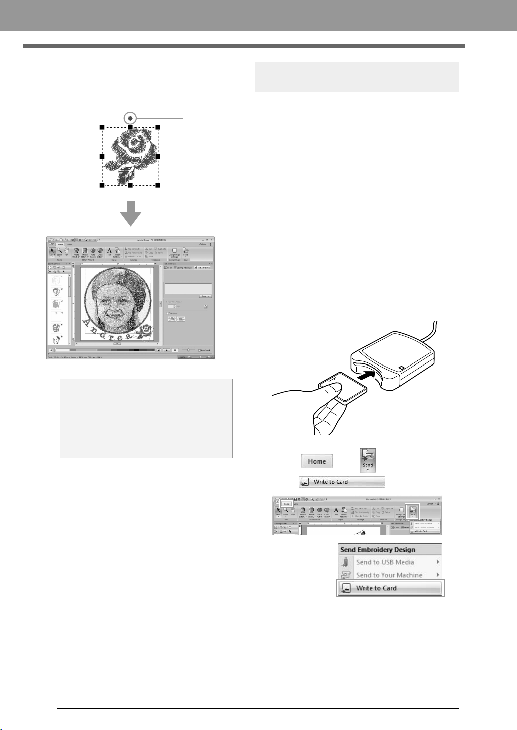
5. Move the pointer over the rotation handle (1),
and then, while holding down the left mouse
button, drag the mouse to adjust the angle of
the pattern.
Step 6
Transferring embroidery patterns
to embroidery machines
You can sew a pattern transferred to your sewing
machine by writing it to media.
There are many methods to transfer data; however,
the procedures for two of these methods are
described below.
• Writing to an original card (☞p. 16)
Data can be transferred to embroidery machines
compatible with original cards.
• Transferring data to embroidery machines via a
USB media (☞p. 17)
Data can be transferred to embroidery machines
equipped with a USB-B connector.
■ Transferring the design to an
original card
1.
Insert an original card into the USB Card
Writer Module.
2. Click , then ,
then .
a Note:
When imported stitch patterns are enlarged
or reduced, the embroidering quality may be
reduced.
c
“Slightly Enlarging/Reducing
Stitch Patterns” on page 38.
1
XE8656-001.book Page 16 Thursday, June 30, 2011 2:56 PM
17
Creating Embroidery Patterns
Creating Embroidery Patterns
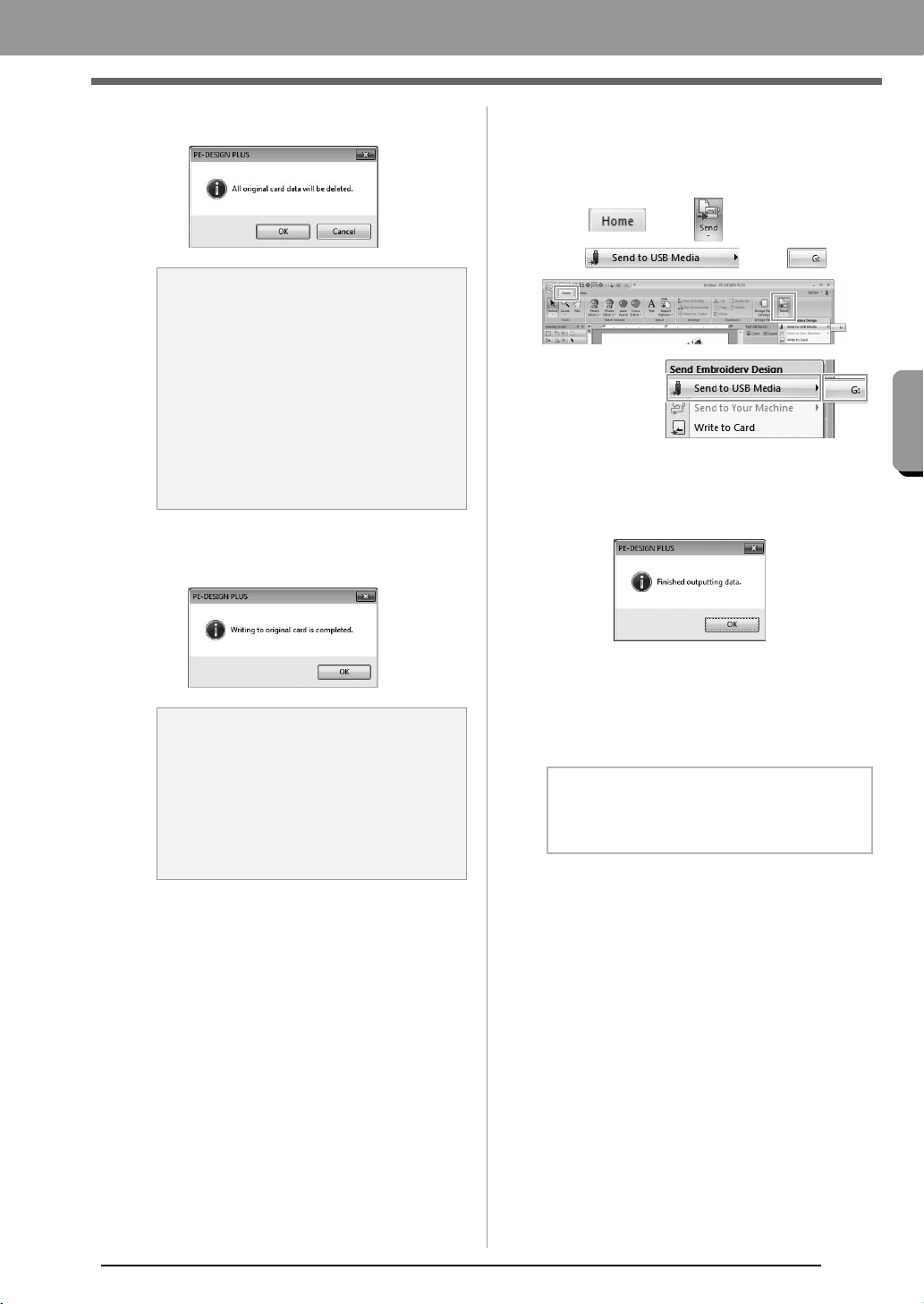
3. Click OK.
4. When the writing is finished, the following
message appears. Click OK.
c
“Transferring to a machine by using an
original card” on page 52.
For details on saving embroidery
patterns, refer to “Saving” on page 18.
5. Insert the original card into the card slot of the
sewing machine.
■ Transferring data to embroidery
machines via a USB media
1. Plug the USB media into the computer.
2. Click , then ,
then , then .
Data transfer begins.
3. When the transferring is finished, the following
message appears. Click OK.
4. After an embroidery pattern is transferred,
remove the USB media from the computer.
5. Insert the USB media into the USB port on the
machine.
a Note:
• When writing to an original card that
already contains data, all data on the card
will be deleted.
• Before using an original card, check that
the designs on the card are no longer
needed.
c
“From an embroidery card” on
page 50
• If you wish to keep the designs, store them
on a hard disk or other storage media.
a Note:
Precautions for using the Card Writer
Module/original cards
• The original card is inserted correctly
when you hear it snap into place.
• Never remove an original card or unplug
the USB cable while the LED indicator is
flashing.
b Memo:
For details on using the embroidery machine,
refer to the Operation Manual included with it.
XE8656-001.book Page 17 Thursday, June 30, 2011 2:56 PM
18
Creating Embroidery Patterns
Saving
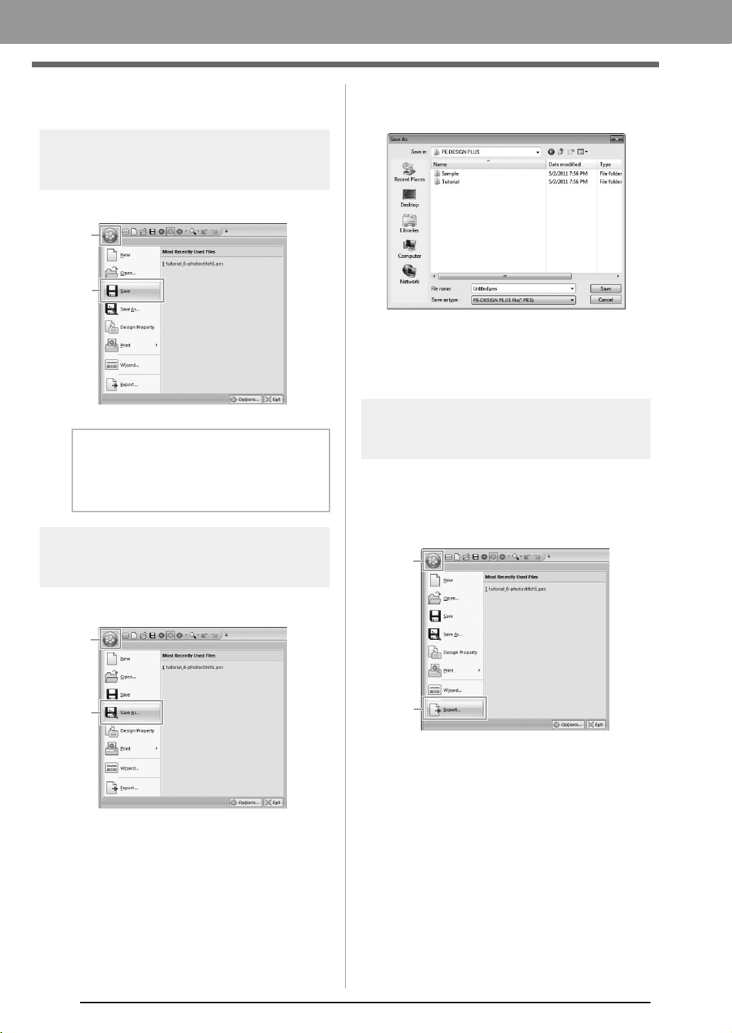
Overwriting
Click 1, then 2.
Saving with a new name
1. Click 1, then 2.
2. Select the drive and the folder, and then type
in the file name.
3. Click Save to save the data.
The new file name appears in the title bar
of the PE-DESIGN PLUS window.
Exporting
The data shown in the Design Page can be exported
as a file of a different format (.dst, .hus, .exp, .pcs,
.vip, .sew, .jef, .csd, .xxx, and .shv).
1. Click 1, then 2
b Memo:
If no file name has been specified or if the file
cannot be found, the
Save As
dialog box
appears.
1
2
1
2
1
2
XE8656-001.book Page 18 Thursday, June 30, 2011 2:56 PM
19
Creating Embroidery Patterns
Creating Embroidery Patterns
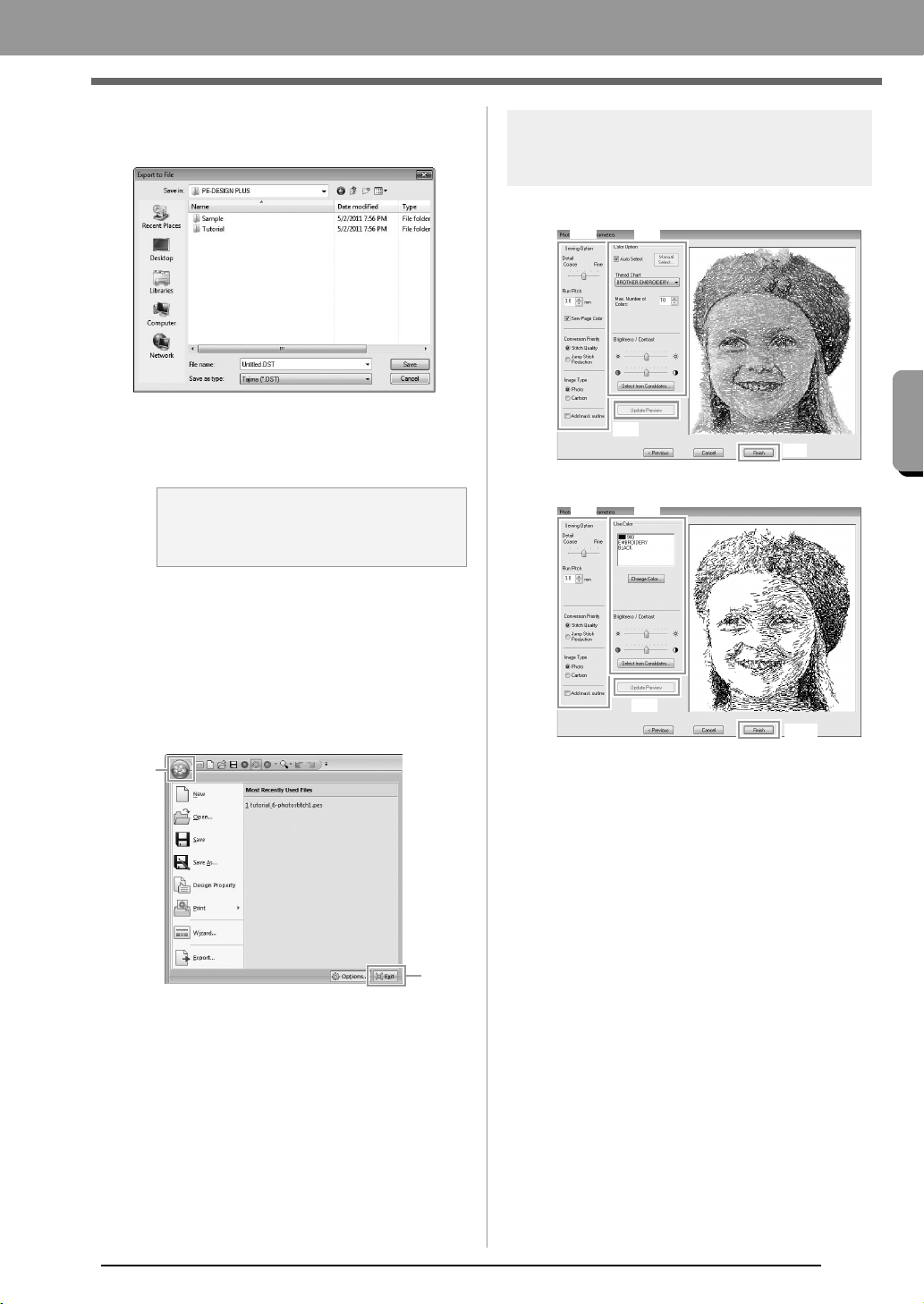
2. Select the drive and the folder, and then type
in the file name.
3. Select a format (.dst, .hus, .exp, .pcs, .vip,
.sew, .jef, .csd, .xxx, or .shv) that the file will be
exported as.
c
“Specifying the number of jumps in
embroidery design of the DST format” on
page 60.
Exiting Application
Click 1, then 2.
More detailed settings can be selected from the
Parameters dialog box of Stitch Wizard.
Photo Stitch 1 Parameters
dialog box
With Color, Sepia or Gray:
With Mono:
Specify the desired settings under Sewing Option
(1) and Color Option (2), and then click Update
Preview (3) to preview the effects of the specified
settings. Click Finish (4) to convert the image to an
embroidery pattern.
a Note:
Some patterns imported from embroidery
cards cannot be exported.
1
2
(3)
(4)
(1) (2)
(3)
(4)
(1)
(2)
XE8656-001.book Page 19 Thursday, June 30, 2011 2:56 PM
20
Creating Embroidery Patterns
(1) Sewing Option
(2) Color Option
Detail
Selecting a setting closer to Fine
creates more details in the pattern and
increases the number of stitches. (The
stitches will be overlapping.)
Run Pitch
When the value is lowered, the sewing
pitch (stitch length) will be shortened,
resulting in finer stitching.
Sew Page
Color
(Available
only with
Color, Sepia
and Gray)
If this check box is cleared, the parts of
the pattern that are the same color as
the Design Page will not be sewn.
If it is selected, those parts will be sewn.
Conversion
Priority
To give priority to creating a pattern as
close to the original photograph, select
Stitch Quality.
To give priority to reducing the number
of jump stitches, select Jump Stitch
Reduction.
Image Type
If Photo is selected, the thread colors
will be mixed together, which will result
in a more natural look.
If Cartoon is selected, the thread colors
will not be mixed together, which will
result in a more simply colored look.
Select Photo for image data from a
photograph, etc. Select Cartoon for
image data from an illustration, etc.
Add mask
outline
If this check box is selected, line data is
created from the mask outline.
Color/Sepia/Gray
Auto Select
Select this check box to automatically
select the thread colors.
Manual
Select
Appears when the Auto Select check
box is cleared.
Click this button to open the Manual
Select dialog box.
c
“Memo:” on page 20
Thread Chart
Selects the thread chart for selecting
the thread color with the Auto Select
function.
Max. Number
of Colors
Sets the number of colors selected by
the Auto Select function.
Mono
Change
Color
Click this button to display the Thread
Color dialog box, where the thread
colors can be changed.
Color/Sepia/Gray/Mono
Brightness /
Contrast
The top slider is used to adjust the
brightness.
The bottom slider is used to adjust the
contrast.
Select from
Candidates
Variations of the image with different
degrees of brightness and contrast are
displayed. Click one of the variations,
and then click OK to apply the settings.
c
7.
on page 12.
Update
Preview
Update the previewed image after
settings have been changed.
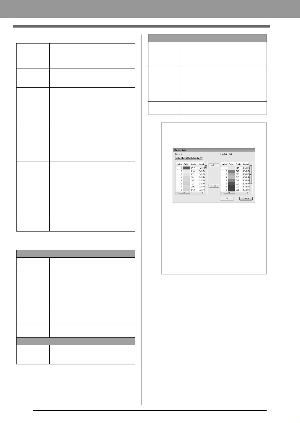
b Memo:
About the
Manual Select
dialog box
• From this dialog box, the thread color to be
used with Photo Stitch 1 can be selected
manually.
• To move the color selected in the
Color List
to the
Use Color List
, click
Add
.
• To delete the color selected in the
Use
Color List
, click
Remove
.
• The thread colors in the
Color List
and
Use
Color List
are listed, in order, starting from
the brightest. This order is the sewing order
and cannot be changed.
XE8656-001.book Page 20 Thursday, June 30, 2011 2:56 PM

21
Creating Embroidery Patterns
Image To Stitch
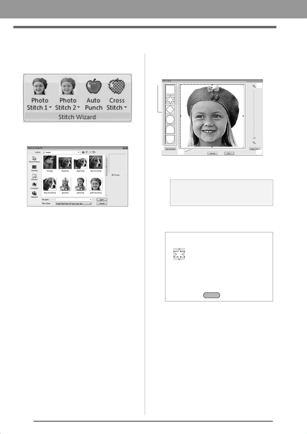
Photo Stitch 2
We will create an embroidery pattern with Photo Stitch 2 in a method different than that used with Photo Stitch 1.
Step 1 Starting the Photo Stitch 2
wizard
Click , then , then .
Step 2
Importing photo data into PE-
DESIGN PLUS
1.
Double-click the
Documents
(
My Documents
)\
PE-DESIGN PLUS\Tutorial folder to open it.
2. Select the file girl2-face.bmp, and then click
Open, or double-click the file's icon.
Step 1 Starting the Photo Stitch 2 wizard
Step 2 Importing photo data into PE-DESIGN PLUS
Step 3 Applying an image mask and adjusting its size and position
Step 4 Changing the sewing angle
b Memo:
When this application is installed, the
PE-DESIGN PLUS
folder is installed in the
Documents (My Documents)
folder.
XE8656-001.book Page 21 Thursday, June 30, 2011 2:56 PM
22
Creating Embroidery Patterns
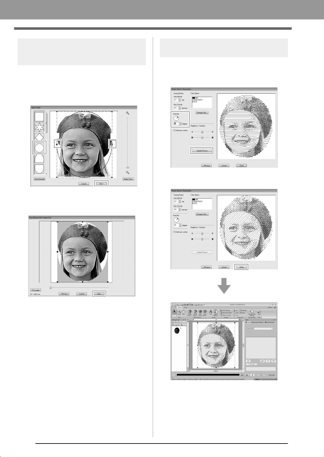
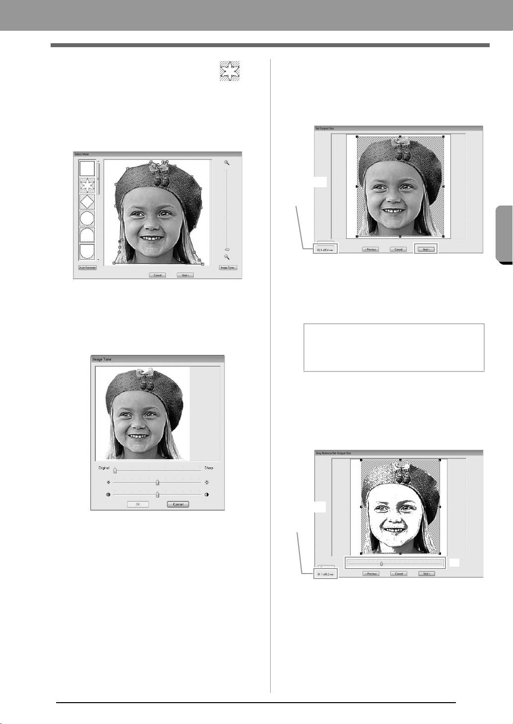
Step 3 Applying an image mask
and adjusting its size and
position
1. Click 1 to select the circle mask.
Drag handle 2 to adjust the size of the mask,
and drag the mask to adjust its position.
Click Next.
c
“Select Mask dialog box” on page 30
2. Click Next.
From this dialog box, the size and position of
the image can be adjusted. For this example,
we will simply continue to the next step.
c
“Gray Balance / Set Output Size dialog
box” on page 31
Step 4
Changing the sewing angle
1. In the Direction box, type “45”.
2. Click Update Preview.
3. Click Finish.
2
2
1
XE8656-001.book Page 22 Thursday, June 30, 2011 2:56 PM
23
Creating Embroidery Patterns
Creating Embroidery Patterns
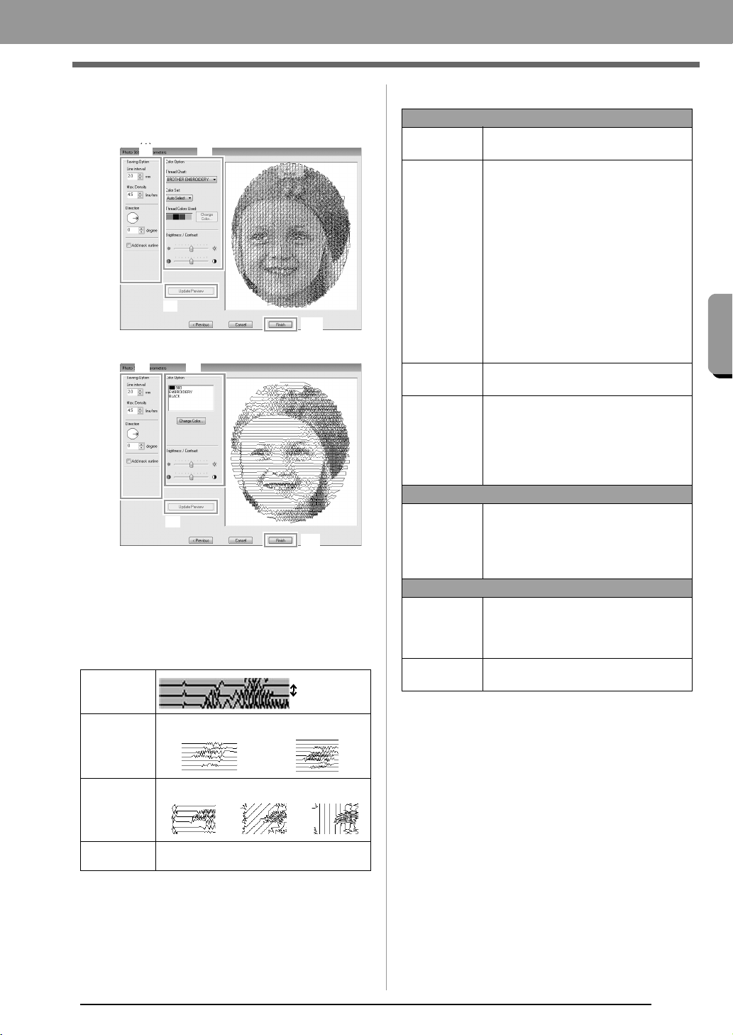
■ Photo Stitch 2 Parameters dialog
box
With Color:
With Mono:
Specify the desired settings under Sewing Option
(1) and Color Option (2), and then click Update
Preview (3) to preview the effects of the specified
settings. Click Finish (4) to convert the image to an
embroidery pattern.
(1) Sewing Option
(2) Color Option
Line interval
Line interval
Max.
Density
Lower value Higher value
Direction
0° 45° 90°
Add mask
outline
If this check box is selected, line data is
created from the mask outline.
(3)
(4)
(1) (2)(1)
(3)
(4)
(1) (2)
Color
Thread Chart
You can select the brand of thread to
use with the Color Set function.
Color Set
If Auto Select is selected, the most
appropriate four colors will automatically
be selected.
Selecting a different option specifies the
four colors used when creating the
embroidery pattern.
The color choices are: cyan (C),
magenta (M), yellow (Y), black (K), red
(R), green (G) and blue (B). Select one
of the following combinations that
contains the colors most used in the
image.
Color combinations: CMYK, RGBK,
CRYK, BMYK
Thread
Colors Used
Displays the four selected thread colors.
Change
Color
Under Thread Colors Used, click a
color. Then, click Change Color to
display the Thread Color dialog box.
Select the new color and click OK. The
selected thread color will be applied to
the image shown in the preview box.
Mono
Change
Color
Click on the Change Color button to
open the Thread Color dialog box if you
wish to change the color of the photo
stitching. Select the color and click
OK
to make the color change.
Color/Mono
Brightness /
Contrast
The top slider is used to adjust the
brightness.
The bottom slider is used to adjust the
contrast.
Update
Preview
Updates the previewed image after
settings have been changed.
XE8656-001.book Page 23 Thursday, June 30, 2011 2:56 PM
24
Creating Embroidery Patterns
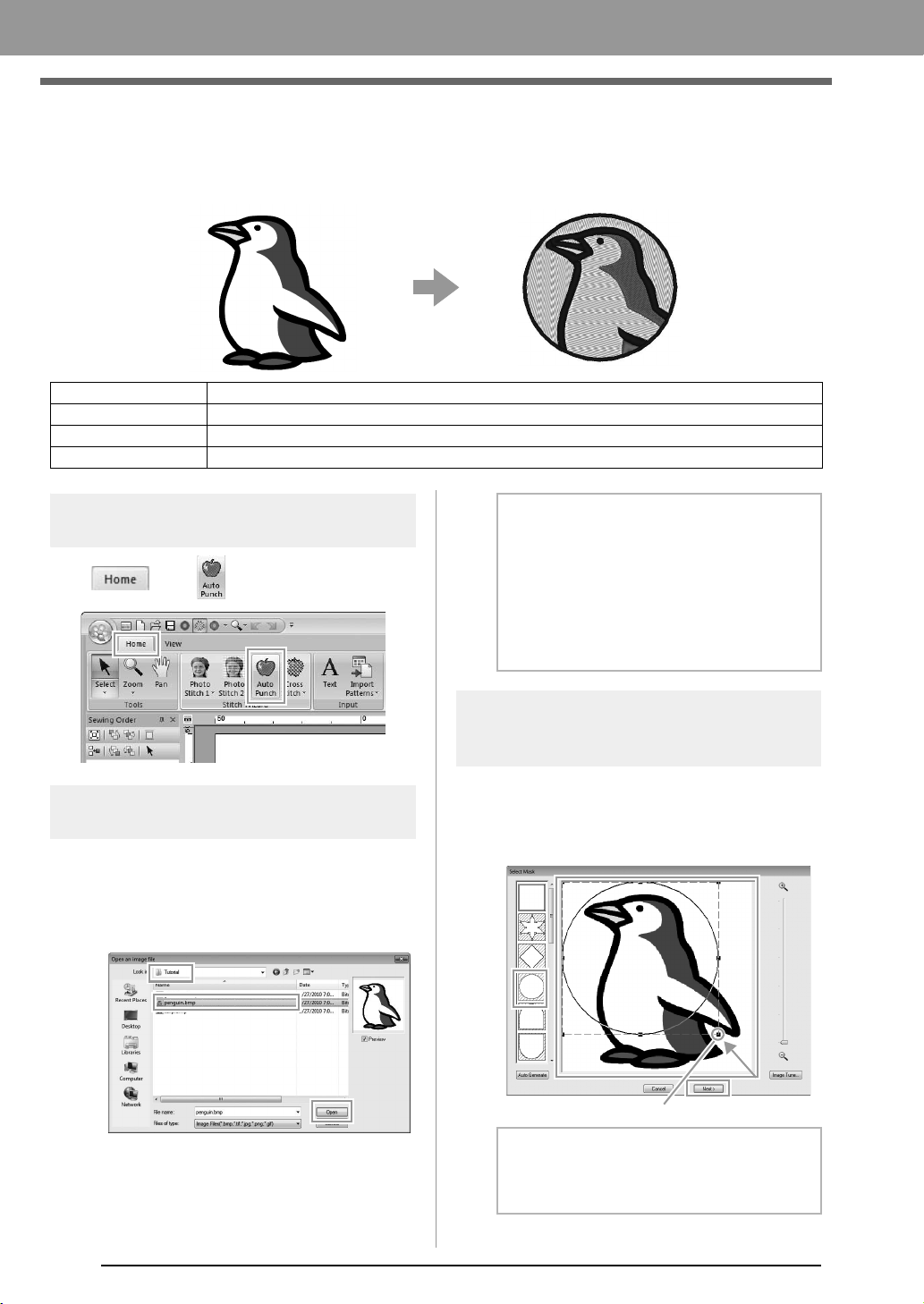
Auto Punch
In this section, we are going to use the Auto Punch function to automatically create an embroidery pattern from
an image.
Step 1 Starting the Auto Punch
wizard
Click , then .
Step 2 Importing image data into
PE-DESIGN PLUS
Select the Tutorial folder, and then select
penguin.bmp as the image.
c
“Importing photo data into PE-DESIGN
PLUS” on page 21
Step 3 Applying an image mask
and adjusting its size and
position
1. Click 1 to select the circle mask.
Drag handle 2 to adjust the size of the mask,
and drag the mask to adjust its position.
Click Next.
c
“Select Mask dialog box” on page 30.
Step 1 Starting the Auto Punch wizard
Step 2 Importing image data into PE-DESIGN PLUS
Step 3 Applying an image mask and adjusting its size and position
Step 4 Creating a border from the mask outline and converting to an embroidery pattern
b Memo:
• Images with few and distinct colors work
best with Auto Punch.
• Various clip art images can be found in
the ClipArt folder (in the folder where
PE-DESIGN was installed) at:
C:\Program Files (Program Files (x86))
\Brother\PE-DESIGN PLUS\ClipArt
b Memo:
The mask outline selected here can be used
as line data (border) in Step 4.
2
1
XE8656-001.book Page 24 Thursday, June 30, 2011 2:56 PM
25
Creating Embroidery Patterns
Creating Embroidery Patterns
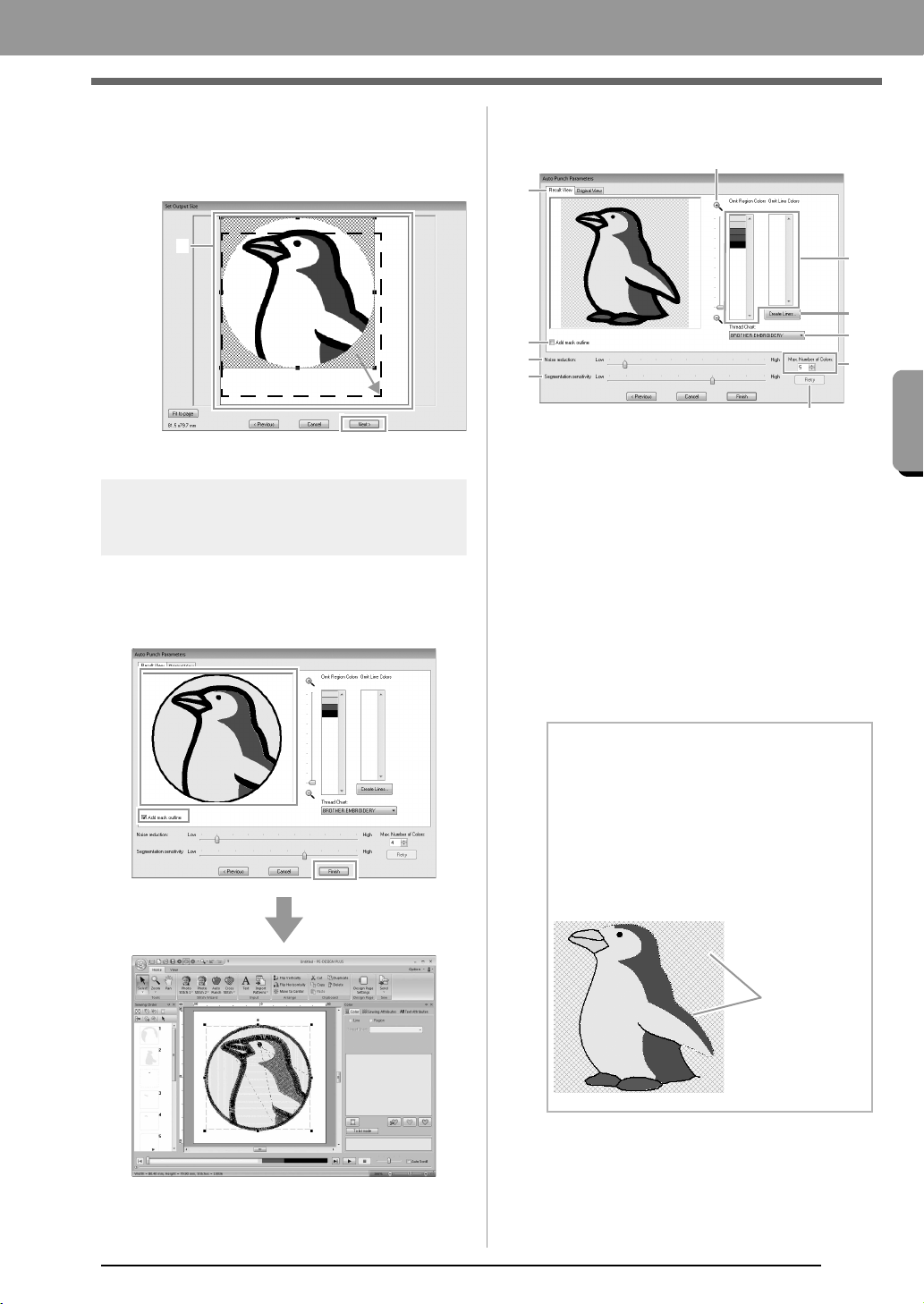
2. 1 indicates the Design Page.
Drag the image to adjust its output location
and size.
Click Next.
c
“Set Output Size dialog box” on page 31
Step 4
Creating a border from the
mask outline and converting
to an embroidery pattern
Select the Add mask outline check box,
check the preview image, and then click
Finish.
■ Auto Punch Parameters dialog
box
(1) Result View
The resulting analyzed image appears in
the image preview box on the Result
View tab.
To display the original image, click the
Original View tab.
(2) Omit Region Colors/Omit Line Colors
In the Omit Region Colors list and Omit
Line Colors list, click the colors to select
whether or not they will be sewn.
You can select whether or not areas will
be sewn by selecting their colors. Colors
that are crossed out are set to not be
sewn.
(3) Zoom
1
b Memo:
• To select whether or not a part of the image
is to be sewn, click in the preview box on the
Result View
tab, or click in the
Omit
Region Colors
and
Omit Line Colors
lists.
• Areas filled with a crosshatch pattern on the
Result View
tab will not be sewn.
In addition, lines that appear as dotted lines
will not be sewn.
(1)
(5)
(4)
(9)
(7)
(8)
(6)
(2)
(3)
(10)
These areas
will not be
sewn.
XE8656-001.book Page 25 Thursday, June 30, 2011 2:56 PM
26
Creating Embroidery Patterns
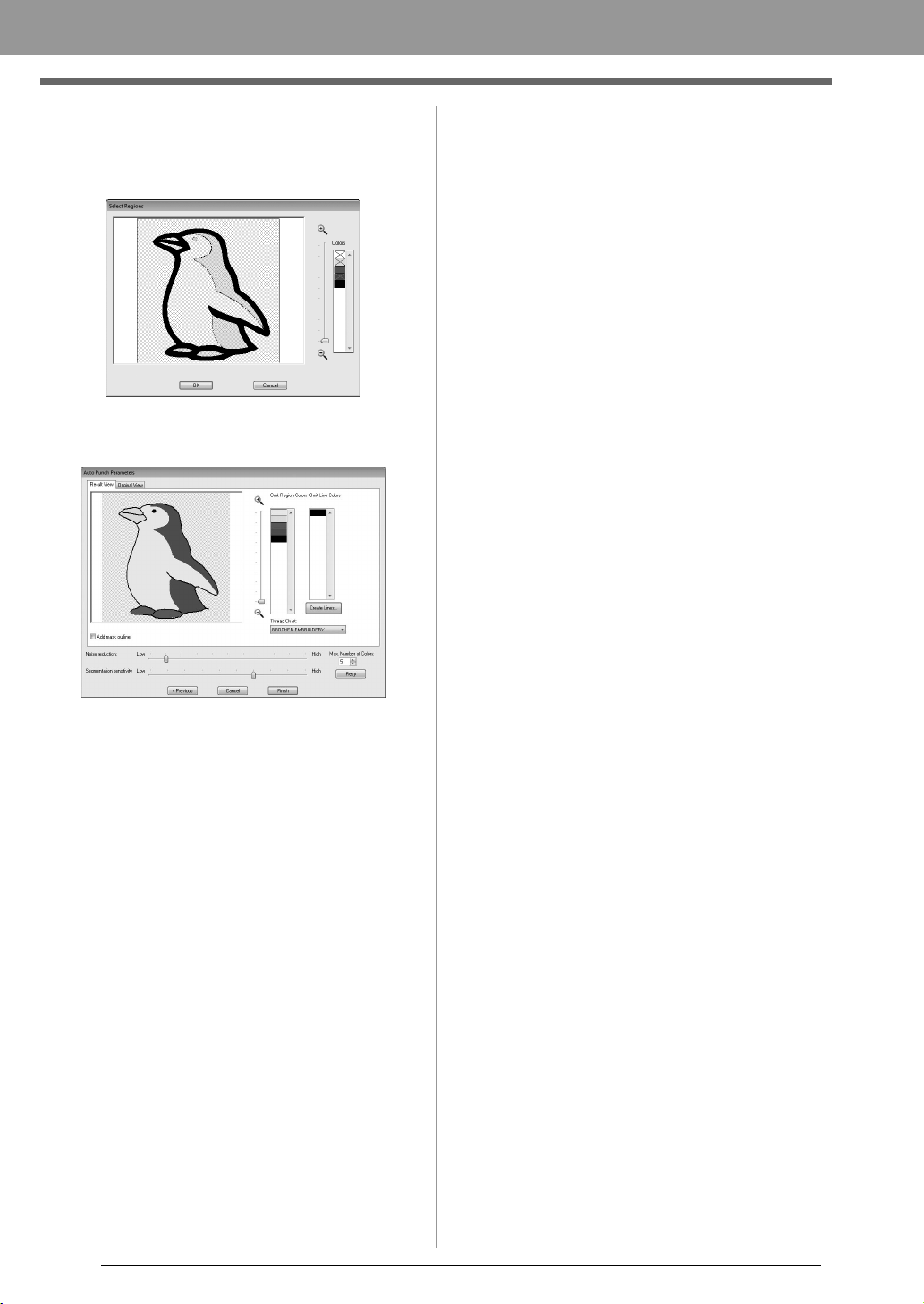
(4) Create Lines
Click this button to display the Select
Regions dialog box, where the areas to
be converted to lines can be selected.
Click the areas to be converted to lines,
and then click OK.
(5) Thread Chart
Select the thread chart to be used.
(6) Add mask outline
If this check box is selected, line data is
created from the mask outline.
(7) Noise reduction
Sets the level of noise (distortions) that is
removed from the imported image.
(8) Segmentation sensitivity
Sets the sensitivity for the image analysis.
(9) Max. Number of Colors
Sets the number of colors used.
(10)Retry
To view the results of the changes, click
this button.
XE8656-001.book Page 26 Thursday, June 30, 2011 2:56 PM
27
Creating Embroidery Patterns
Creating Embroidery Patterns
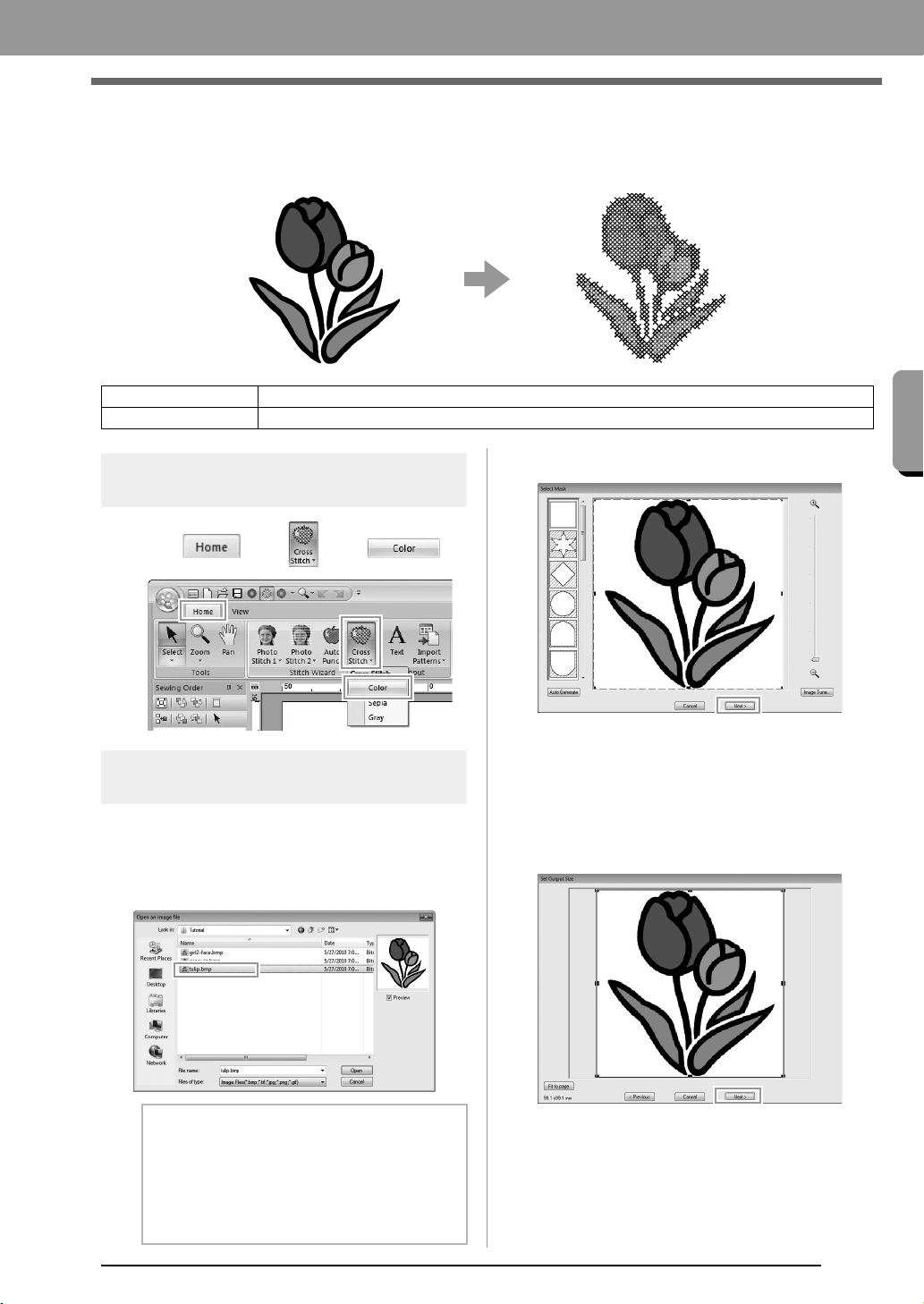
Cross Stitch
Cross Stitch embroidery patterns can be created from images.
Step 1 Starting the Cross Stitch
wizard
1. Click , then , then .
Step 2 Importing image data into
PE-DESIGN PLUS
Select the Tutorial folder, and then select
tulip.bmp as the image.
c
“Importing photo data into PE-DESIGN
PLUS” on page 21
2. Click Next.
From this dialog box, an image mask can be
applied and its size can be adjusted. For this
example, we will simply continue to the next
step.
c
“Select Mask dialog box” on page 30
3. Click Next.
From this dialog box, the size and position of
the image can be adjusted. For this example,
we will simply continue to the next step.
c
“Set Output Size dialog box” on page 31
Step 1 Starting the Cross Stitch wizard
Step 2 Importing image data into PE-DESIGN PLUS
b Memo:
Various clip art images can be found in the
ClipArt folder (in the folder where
PE-DESIGN was installed) at:
C:\Program Files (Program Files (x86))
\Brother\PE-DESIGN PLUS\ClipArt
XE8656-001.book Page 27 Thursday, June 30, 2011 2:56 PM
28
Creating Embroidery Patterns
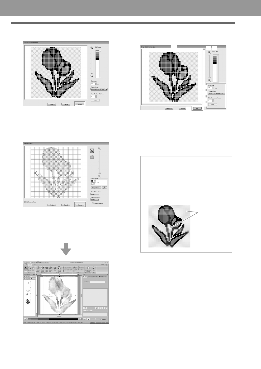
4. Click Next.
In this dialog box, the cross size and the
number of colors can be specified. For this
example, we will use the default settings.
5. Click Finish.
In this dialog box, stitches can be added,
deleted or edited, and colors and the number
of times each stitch is sewn can be specified.
For this example, we will use the default
settings.
■ Cross Stitch Parameters dialog
box
(1) Result View
Areas that will not be converted to cross-
stitching are shown with a crosshatch
pattern.
(2) Omit Colors
In the Omit Colors list, click the colors to
select whether or not they will be sewn.
(3) Zoom
(4) Cross size
Sets the size of the pattern.
(5) Thread Chart
You can select the brand of thread to use
in the created cross stitch pattern.
(6) Max. Number of Colors
Sets the number of colors used in the
created pattern.
(7) Retry
To view the results of the changes, click
this button.
(8) Next
Continues to the next step (Edit Cross
Stitch dialog box).
b Memo:
• To select whether or not a part of the image
is to be sewn, click in the preview box on the
Result View
tab, or click in the
Omit Colors
list.
• Areas filled with a crosshatch pattern on the
Result View
tab will not be sewn.
(1)
(3) (2)
(4)
(5)
(6)
(8)
(7)
These areas
will not be sewn.
XE8656-001.book Page 28 Thursday, June 30, 2011 2:56 PM
29
Creating Embroidery Patterns
Creating Embroidery Patterns
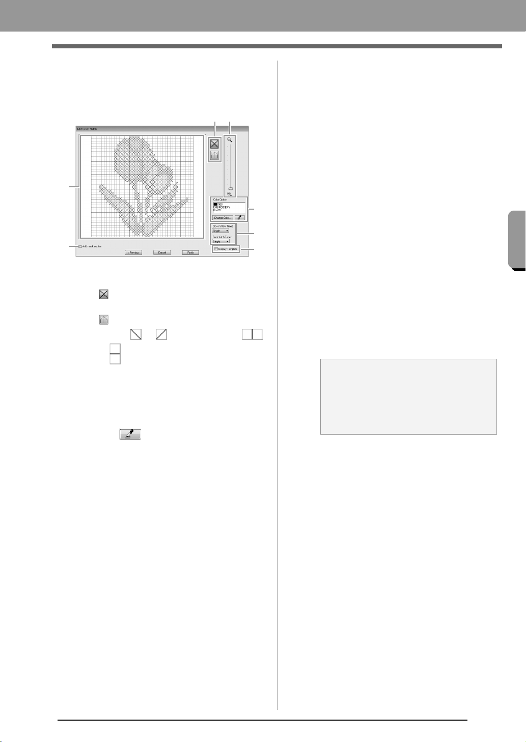
■ Edit Cross Stitch dialog box
Click a button in (1) to select the type of stitch,
select a thread color in (2), and then click or
drag in (3) to edit the stitches.
(1) Selecting stitches
Selecting stitches to be added/deleted
(cross-stitches): Specifies a cross-
stitch inside a box.
(backstitches): Specifies a back stitch
inside ( or ) or on the edge (
or ) of a box.
(2) Color Option
To change the color, click Change Color
to display the Thread Color dialog box,
and then click the desired color.
To select the color to be used for a stitch,
click , and then click the stitch to be
sewn with that color.
(3) Editing area
For cross-stitches
Clicking a box: Adds one stitch.
For backstitches
Clicking an edge of a box: Adds one
stitch at the edge.
Clicking a diagonal line in a box: Adds
one stitch on the diagonal.
For both cross-stitches and backstitches
Dragging the pointer: Adds consecutive
stitches.
Right-clicking/dragging with the right
mouse button held down: Deletes one
stitch/deletes consecutive stitches.
(4) Zoom
(5) Display Template
To display the imported image, click
Display Template.
(6) Add mask outline
If this check box is selected, line data is
created from the mask outline.
(7) Cross Stitch Times/Backstitch Times
For the number of times each stitch is to
be sewn, select Single, Double or Triple.
(6)
(7)
(2)
(3)
(4)(1)
(5)
a Note:
If
Previous
is clicked to return to the
Cross
Stitch Parameters
dialog box after the
stitches have been edited, the edited
stitches are reset to their previous
arrangement.
XE8656-001.book Page 29 Thursday, June 30, 2011 2:56 PM
30
Creating Embroidery Patterns
Common dialog boxes
■ Image To Stitch Wizard
When a conversion method is selected, a dialog box
for selecting an image appears.
■ Select Mask dialog box
The Select Mask dialog box appears no matter
which conversion method was selected.
(1) Drag the handles to adjust the shape of
the mask. Drag the mask to adjust its
position.
(2) Mask shapes
The image will be masked with the
selected shape.
a Note:
With a small original image, it may not be
possible to reduce the size of the mask.
b Memo:
If is
selected, points can be entered,
moved and deleted to create a mask with the
desired shape.
To add points, click the outline of the mask.
To move a point, select the point, and then
drag it. To delete points, select the point, and
the
n press the key
.
(1)
(4)
(5)
(2)
(3)
Delete
XE8656-001.book Page 30 Thursday, June 30, 2011 2:56 PM
31
Creating Embroidery Patterns
Creating Embroidery Patterns
(3) If Auto Generate was clicked, is
selected and an outline of mask was
automatically detected from the image.
The Auto Generate button is available
only with images that have a light-colored
background, like in this photo.
(4) Zoom
(5) Clicking the Image Tune button displays
an Image Tune dialog box.
Settings for Sharpness, Brightness and
Contrast can be selected with the sliders.
(6) To exit the Stitch Wizard, close the Select
Mask dialog box.
To select a different image, click Cancel,
and then repeat the procedure, starting by
selecting a conversion method.
■ Set Output Size dialog box
If Color, Sepia or Gray was selected for Photo
Stitch 1, Photo Stitch 2 or Cross Stitch, or if Auto
Punch was selected:
The following dialog box appears.
Adjust the position and size of the image, and then
click Next to continue to the next step.
• Drag the image to the desired position.
• Drag the handle to adjust the image to the
desired size.
■ Gray Balance / Set Output Size
dialog box
If Mono was selected for Photo Stitch 1 or Photo
Stitch 2:
The following dialog box appears.
Adjust the position and size of the image and the
gray balance, and then click Next to continue to the
next step.
• Drag the image to the desired position.
• Drag the handle to adjust the image to the
desired size.
• Drag the slider (1) to adjust the gray
balance.
b Memo:
Click
Fit to Page
to adjust the image to the
size of the Design Page.
Embroidery
pattern
size
(1)
Embroidery
pattern
size
XE8656-001.book Page 31 Thursday, June 30, 2011 2:56 PM
32
Entering Text
Entering Text
This section describes the procedures for entering text and arranging it in the Transform style with a fan shape.
The sample file for this tutorial can be found at the following location.
Documents (My Documents)\PE-DESIGN PLUS\Tutorial
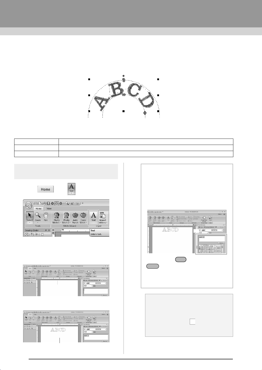
Step 1 Entering Text
1. Click , then .
2. Click in the Design page.
A vertical dashed line will appear on the
Design Page for typing directly on-screen.
3. From the keyboard, type in “ABCD”.
Step 1 Entering Text
Step 2 Transforming text
Step 3 Specifying character spacing
The entered text appears.
b Memo:
• Text can also be entered by clicking
characters in the character table (1) in the
Text Attributes
tab. This is particularly
useful if you have to enter accented
characters that are not available on your
keyboard.
• Hold down the key and press the
key to enter a new line of text.
• Click
Hide List
to hide the character table.
While it is hidden, click
Show List
to display
the character table.
a Note:
If the entered character is not available with
the selected font or if the character cannot
be converted to an embroidery pattern, the
character appears as in the Design
Page. If this occurs, enter a different
character.
(1)
Ctrl
Enter
PE-DESIGN_Plus.fm Page 32 Wednesday, July 6, 2011 3:37 PM
33
Creating Embroidery Patterns
Creating Embroidery Patterns
4. Press the key. The text appears in the
Design Page.
Step 2
Transforming text
1. Click the text to select it.
2. Select the Transform check box (1), and then
click 2.
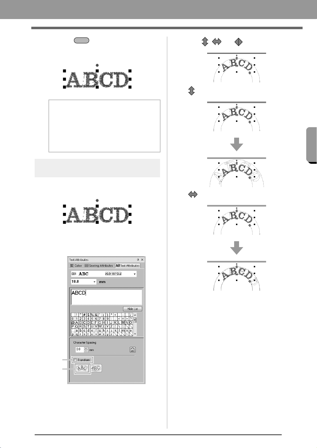
3. Drag , and to transform the text.
:
Adjusts the text size.
:Moves the text along the circle.
b Memo:
The character font, size, color and sew type
can be changed.
c
“Setting text attributes” on
page 35 and “Embroidery
attributes for text” on page 36
Enter
1
2
PE-DESIGN_Plus.fm Page 33 Wednesday, July 6, 2011 3:38 PM
34
Creating Embroidery Patterns
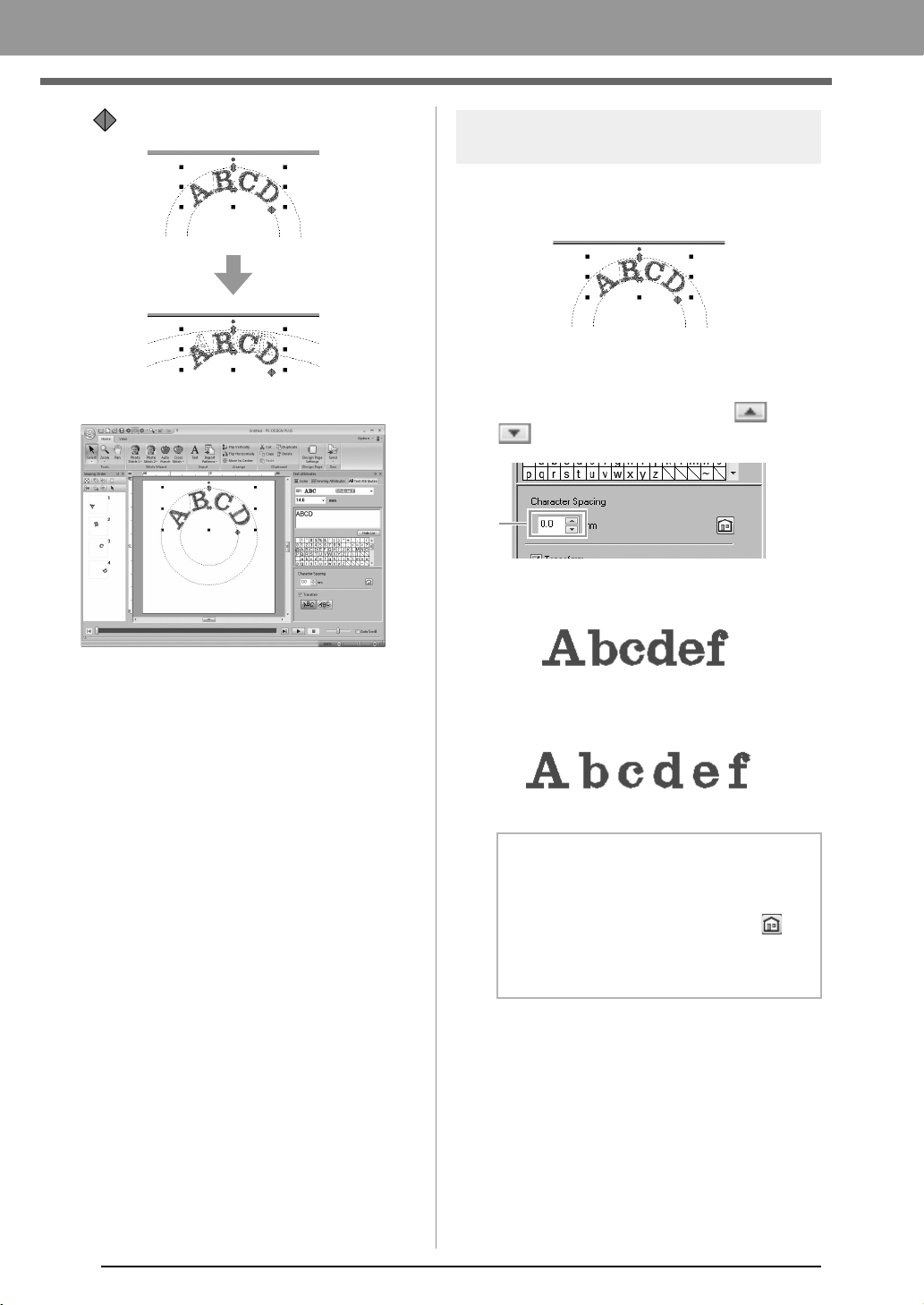
:Adjusts the radius of the circle.
Step 3 Specifying character
spacing
Sets the spacing between all characters.
1. Click the text to select it.
2. Change the Character Spacing (1).
Specify the setting by clicking the selector and
typing in the value, or by clicking or
.
0.0 mm
2.0 mm
b Memo:
• Character Spacing is always applied to the
entire text pattern.
• To return to the default setting, click .
• If the
Text Attributes
tab is not displayed,
click the
View
tab in the Ribbon, and then
click
Text Attributes
.
1
PE-DESIGN_Plus.fm Page 34 Wednesday, July 6, 2011 3:38 PM
35
Creating Embroidery Patterns
Creating Embroidery Patterns
Advanced Operations for Entering Text
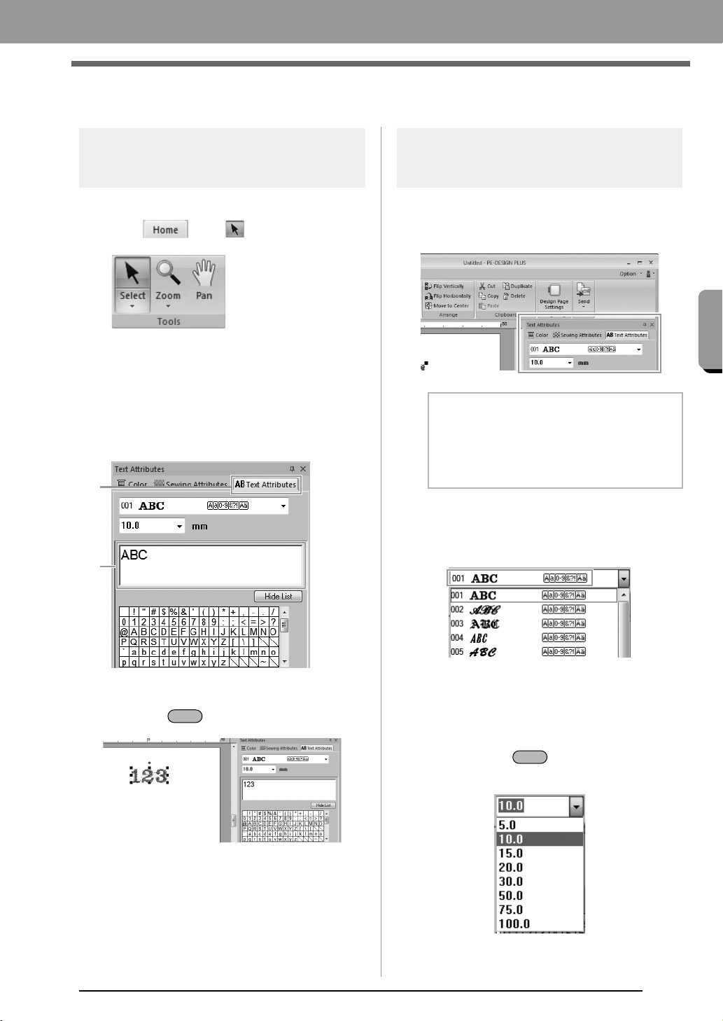
Editing entered text
1. First, select the Select tool.
Click , then .
2. Click a single text pattern to select it.
3. Click the Text Attributes tab (1).
If the Text Attributes tab is not displayed,
click the View tab in the Ribbon, and then click
Text Attributes.
And then click in the text field (2).
4. Edit the text as needed.
Press the key or click the Design Page.
Setting text attributes
Text attributes can be specified with the Font
selector and Text Size selector in the Text
Attributes pane.
■ Font
Click in the Font selector, and then click the desired
font.
c
Memo of “Font List” on page 70
■ Text size
Click in the Text Size selector. Type the desired
height and press the key, or click the desired
value.
1
2
Enter
b Memo:
Click
Text Attributes
tab to display the
Text
Attributes
pane. If the
Text Attributes
tab is
not displayed, click the
View
tab in the Ribbon,
and then click
Text Attributes
.
Enter
PE-DESIGN_Plus.fm Page 35 Wednesday, July 6, 2011 3:39 PM
36
Creating Embroidery Patterns
Embroidery attributes for
text
When text is selected, settings can be specified for
the following.
The Color pane allows you to set the thread color.
c
“Color” on page 47
The Sewing Attributes pane allows you to set the
embroidery attributes.
c
“Sew type” on page 45
XE8656-001.book Page 36 Thursday, June 30, 2011 2:56 PM
37
Arranging Embroidery Designs
Arranging E mbroidery Design s
Arranging Embroidery Designs
Editing Embroidery Designs
Selecting patterns
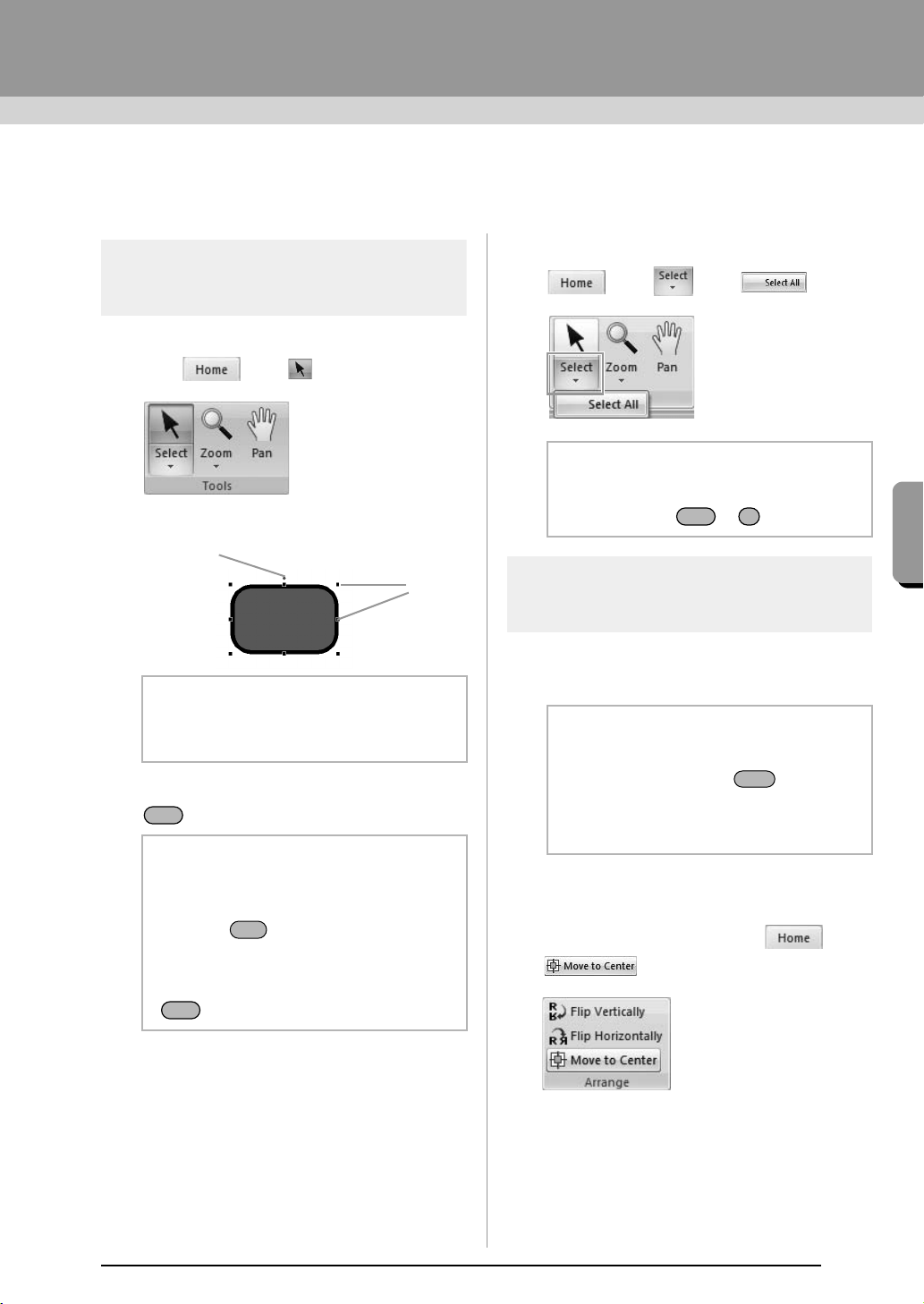
1. First, select the Select tool.
Click , then .
2. Click the pattern.
3. To select an additional pattern, hold down the
key and click the other pattern.
■ Selecting all embroidery patterns
Click , then , then .
Moving patterns
■ Moving manually
Drag the selected pattern(s) to the desired location.
■ Moving embroidery patterns to
the center
Select the pattern(s), and then click ,
then .
b Memo:
The status bar shows the dimensions (width
and height) of the pattern.
b Memo:
• You can also select patterns by dragging
the pointer across the pattern.
• Press the key to select the next
pattern in the order that they were created.
• If multiple patterns are selected, a pattern
can be deselected by holding down the
key while clicking the pattern.
Rotation handle
Handles
Ctrl
Tab
Ctrl
b Memo:
All patterns can also be selected by pressing
the shortcut keys + .
b Memo:
• To move the pattern horizontally or
vertically, hold down the key while
dragging it.
• Pressing the arrow keys moves the
selected pattern.
Ctrl A
Shift
XE8656-001.book Page 37 Thursday, June 30, 2011 2:56 PM
38
Arranging Embroidery Designs
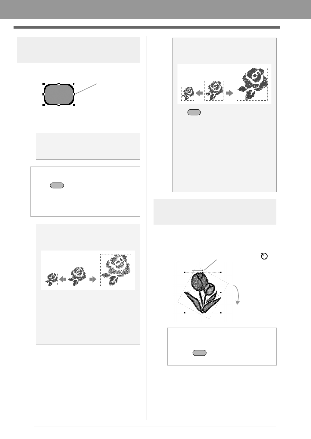
Scaling patterns
1. Select the pattern(s).
2. Drag the handle to adjust the selected
pattern(s) to the desired size.
Rotating patterns
1. Select the pattern(s).
2. Drag the rotation handle.
a Note:
Some patterns imported from embroidery
cards cannot be scaled.
b Memo:
• If the key is held down while a
handle is dragged, the pattern is enlarged
or reduced from the center of the pattern.
• As you drag the handle, the current size is
displayed on the status bar.
a Note:
Slightly Enlarging/Reducing Stitch
Patterns
When stitch patterns are slightly enlarged or
reduced, stitches become thicker or thinner
without the number of stitches changing.
In other words, greatly enlarging or reducing
the pattern changes the quality of the
embroidery since the thread density is
adjusted. Use this method when only slightly
enlarging/reducing the stitch pattern.
Handles
Shift
a Note:
Greatly Enlarging/Reducing Stitch
Patterns
If the key is held down while the stitch
pattern is enlarged or reduced, the thread
density and needle drop point pattern are
maintained.
However, if the original thread density and
needle drop point pattern in the stitch pattern
are not uniform, the thread density and
needle drop point pattern may not be
maintained, even by using this method.
Enlarge/reduce the pattern while checking
the preview. Do not use this method when
only slightly enlarging/reducing the stitch
pattern.
b Memo:
To rotate the pattern in 15° increments, hold
down the key while dragging the
handle.
Ctrl
1. The shape of pointer changes to
2. Rotate
Rotation
handle
Shift
XE8656-001.book Page 38 Thursday, June 30, 2011 2:56 PM
39
Arranging Embroidery Designs
Arranging Embroidery Designs
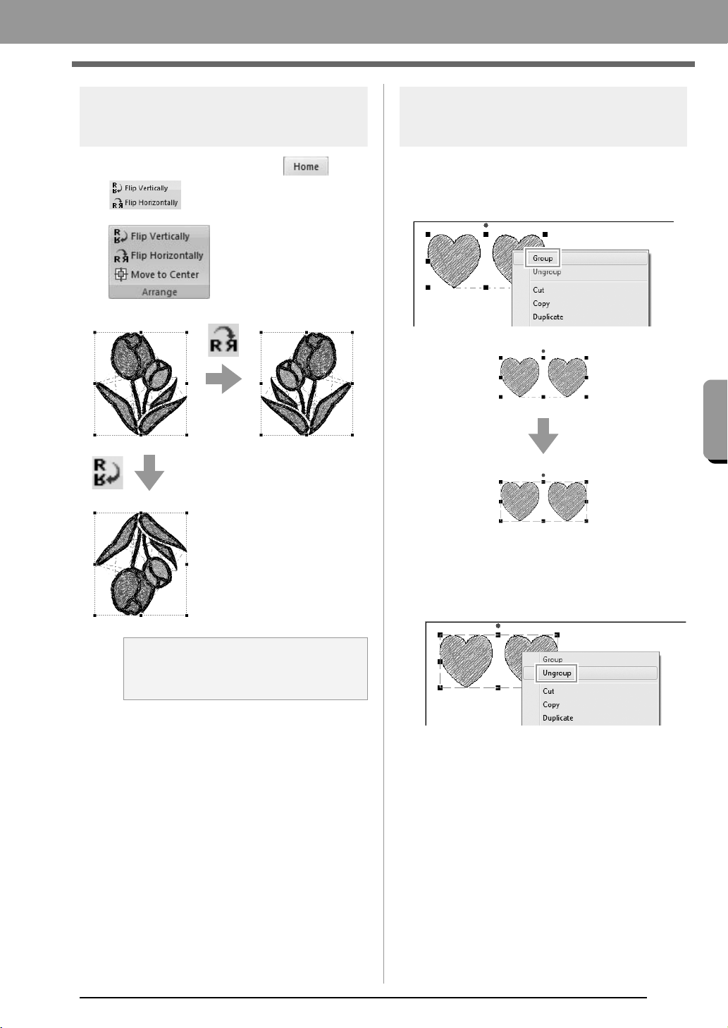
Flipping patterns
horizontally or vertically
Select the pattern(s), and then click ,
then .
Grouping/Ungrouping
embroidery patterns
■ Grouping patterns
Select several patterns, right-click them, and then
select Group in the pop-up menu that appears.
■ Ungrouping patterns
Select a grouped embroidery pattern, right-click it,
and then select Ungroup in the pop-up menu that
appears.
a Note:
Some patterns imported from embroidery
cards cannot be flipped.
XE8656-001.book Page 39 Thursday, June 30, 2011 2:56 PM
40
Arranging Embroidery Designs
Checking Embroidery Patterns
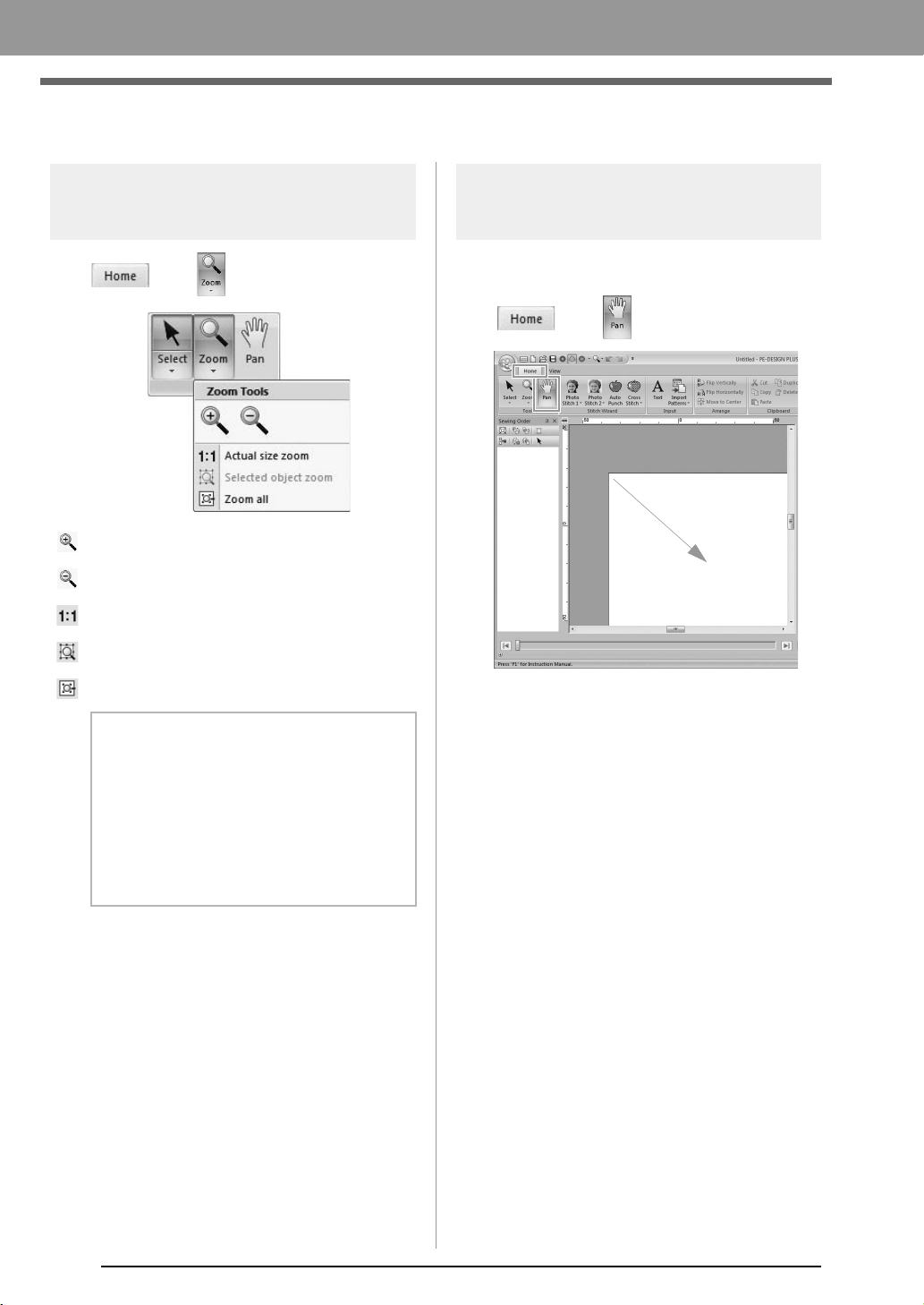
Zooming
Click , then , then 1.
: Zooms In
: Zooms Out
: Zooms to Actual Size
: Fit selected objects to window
: Fit Design Page to window
Using the Pan tool
The part of the work area that is displayed can easily
be changed by using the Pan tool.
Click , then , then drug to 1.
b Memo:
• Zooming is also possible by dragging the
Zoom slider in the status bar or clicking
the Zoom ratio.
c
“PE-DESIGN PLUS Window” on
page 61
• While zooming in or out, right-click to
reverse the zooming operation.
1
1
XE8656-001.book Page 40 Thursday, June 30, 2011 2:56 PM
41
Arranging Embroidery Designs
Arranging Embroidery Designs
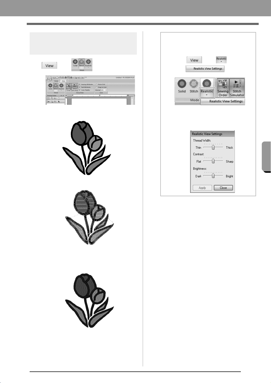
Changing the display of the
embroidery design
Click , then .
■ Solid View
■ Stitch View
You can display a stitch view of it in order to see how
the stitching is connected.
■ Realistic View
You can display a realistic view of it in order to see
how the design will appear once it is sewn.
b Memo:
Changing realistic view settings
1. Click , then ,
then .
2. If necessary, specify settings for
Thread Width (1), Contrast (2) and
Brightness (3), then click Apply (OK).
(1)
(3)
(2)
XE8656-001.book Page 41 Thursday, June 30, 2011 2:56 PM
42
Arranging Embroidery Designs
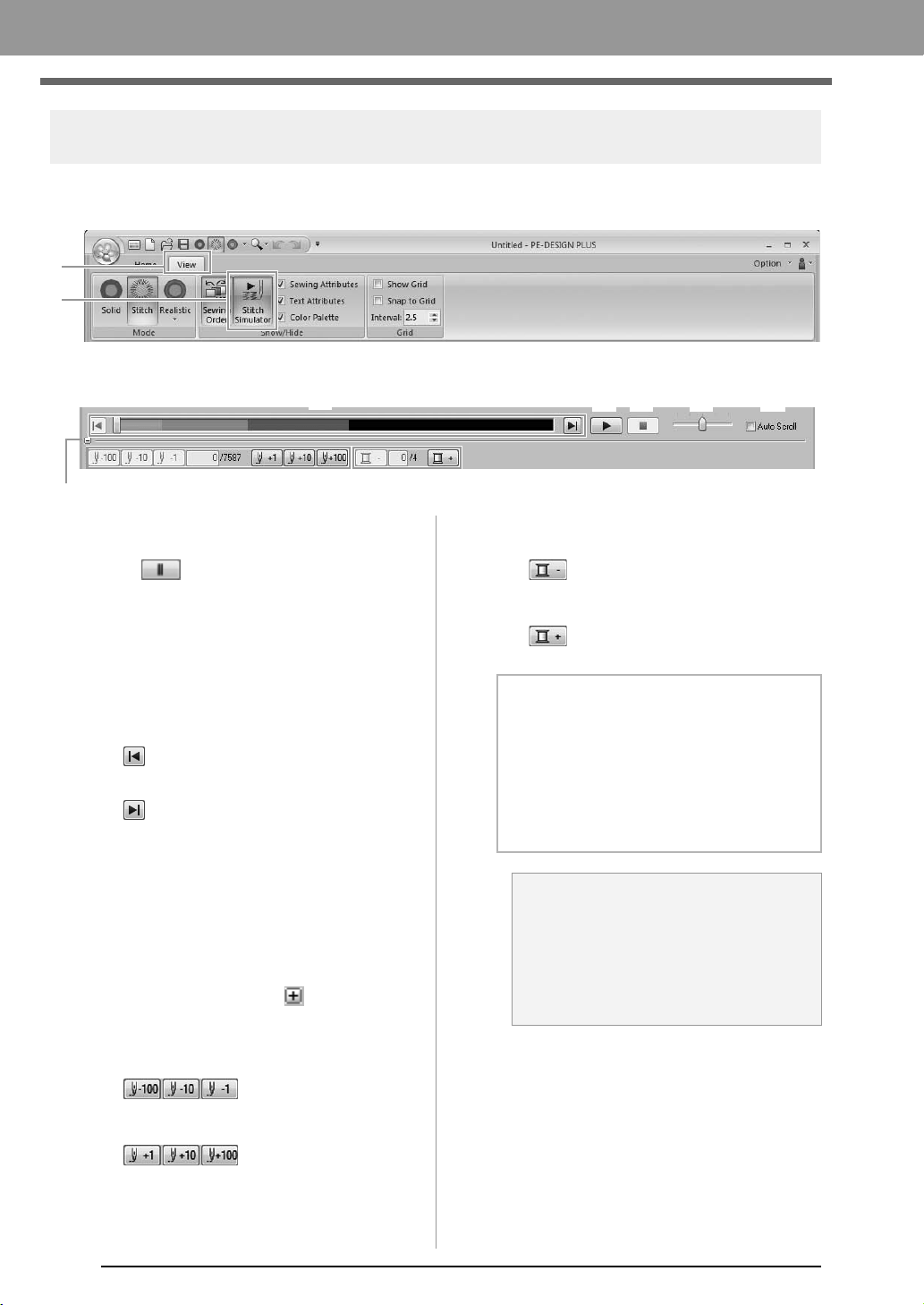
Checking the stitching with the Stitch Simulator
1. Click 1, then 2.
2. Click the buttons to view a simulation of the stitching.
(1) Starts the stitching simulation. During
stitching simulation, this button changes
to , which can be clicked to
temporarily stop the simulation.
(2) Stops the simulation and returns to the
previous display.
(3) The slider shows the current location in
the simulation. In addition, the slider can
be moved to change the position in the
simulation.
: Returns to the beginning of stitching
and stops the simulation.
: Advances to the end of stitching and
stops the simulation.
(4) Drag the slider to adjust the simulation
stitching speed.
(5) Select this check box to automatically
scroll the simulation of the pattern when it
is too large to be fully displayed.
(6) Click to hide the bottom section of the
Stitch Simulator. Click to display it
again.
(7) Shows the number of the current stitch/
total number of stitches.
: Reverses the
simulation by the indicated number of
stitches.
: Advances the
simulation by the indicated number of
stitches.
(8) Shows the number of the color being
drawn/total number of colors used.
: Returns to the beginning of
stitching for the current or previous thread
color.
: Advances to the beginning of
stitching for the next color.
1
2
(1) (4) (5)(2)
(6)
(7)
(3)
(8)
b Memo:
• The Zoom tools and Pan tool can be used
while a simulation is being viewed. If any
other command is selected, the
simulation stops.
• If a value is entered at (7) or (8), the
simulation is reversed/advanced to the
indicated location.
a Note:
• If a pattern was selected when the
stitching simulation was started, only the
selected pattern is drawn in the
simulation.
• The
Auto Scroll
check box is not
available in Realistic View.
XE8656-001.book Page 42 Thursday, June 30, 2011 2:56 PM
43
Arranging Embroidery Designs
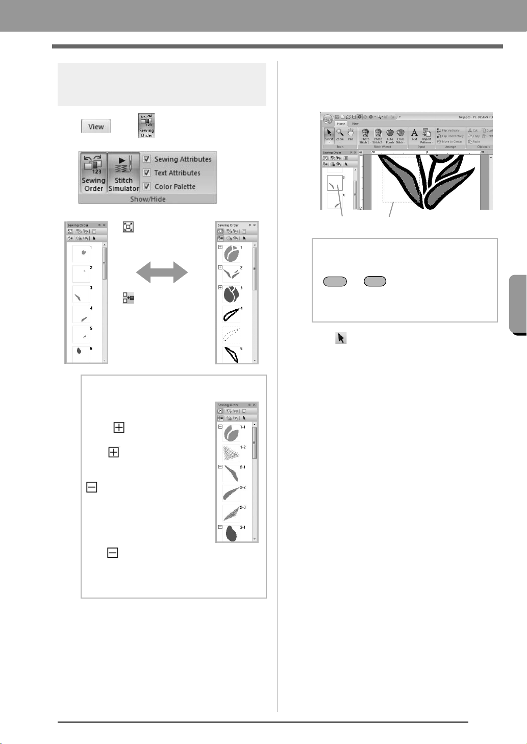
Arranging Embroidery Designs
Checking and Editing the
Sewing Order
Click , then .
■ Selecting a pattern
1. Click a frame containing the pattern in the
Sewing Order pane.
2. Click at the top of the Sewing Order pane
to select the pattern in the Design Page
corresponding to the frame selected in the
Sewing Order pane. The pattern can also be
selected by double-clicking its frame in the
Sewing Order pane.
:Click to enlarge
each pattern to fill
its frame.
:Click to display
in one frame all
patterns of the
same color that will
be sewn together.
b Memo:
When multiple same color
patterns are combined into one
frame, appears to the left of
that frame.
Click to display the
combined same color patterns
in separate frames.
appears under the first
frame, and each frame is
displayed with a subnumber
following the first, to indicate its
sewing order within the patterns
of the same color.
Click to recombine all of the
same color patterns back into
one frame.
b Memo:
• To select multiple patterns, hold down the
or key while clicking the
frames for the desired patterns. In addition,
multiple frames can be selected by
dragging the pointer over them.
Blue line
Marching line
Shift
Ctrl
XE8656-001.book Page 43 Thursday, June 30, 2011 2:56 PM
44
Arranging Embroidery Designs
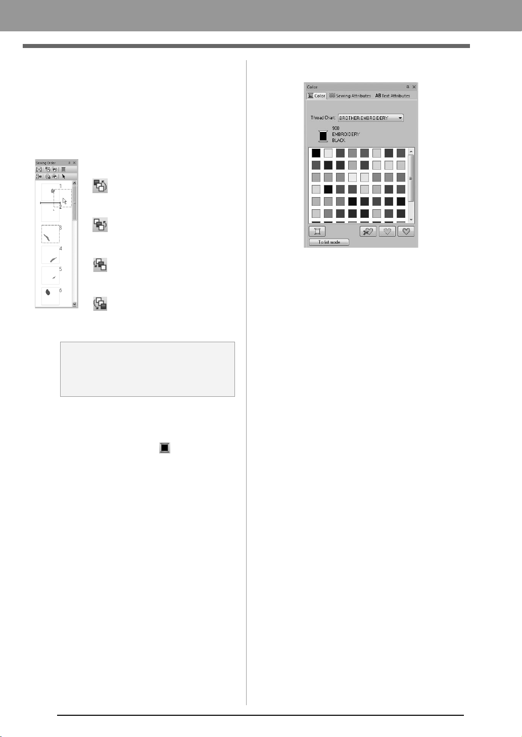
■ Editing the sewing order
The sewing order can be changed by selecting the
frame containing the pattern, then dragging the
frame to the new location. A red line appears,
indicating the position where the frame is being
moved.
■ Changing colors
1. Select one or more frames in the Sewing
Order pane, and then click at the top of the
Sewing Order pane.
The Color pane appears in front of the
other panes.
2. Click the desired color in the Color pane.
c
“Color” on page 47.
■ Changing sewing attributes
1. Select one or more frames in the Sewing
Order pane, and then click the Sewing
Attributes tab. If the Sewing Attributes tab is
not displayed, click View tab in the Ribbon,
then Sewing Attributes.
2. Change the sewing attributes and sew type.
c
“Sew type” on page 45 and “Specifying
sewing attributes” on page 46
An alternative method for moving
the frames is by clicking the
buttons at the top of the Sewing
Order pane.
:Click to move the selected
pattern to the beginning of
the sewing order.
:Click to move the selected
pattern ahead one position
in the sewing order.
:Click to move the selected
pattern back one position in
the sewing order.
:Click to move the selected
pattern to the end of the
sewing order.
a Note:
Check the stitching after changing the
sewing order to be sure that overlapping
patterns will not be sewn in the wrong order.
XE8656-001.book Page 44 Thursday, June 30, 2011 2:56 PM
45
Arranging Embroidery Designs
Arranging Embroidery Designs
Applying Sewing Attributes to Lines and
Regions
Setting the sew type
The Sewing Attributes pane allows you to set the
embroidery attributes.
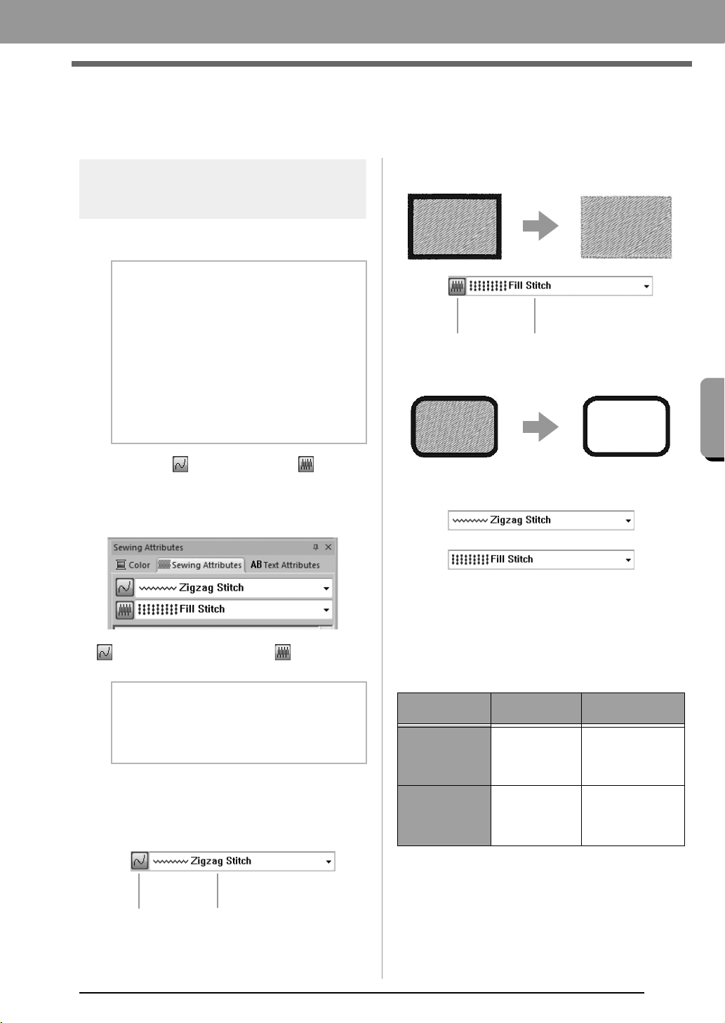
■ Line sew
/
Region sew
Click the Sewing Attributes tab. If the Sewing
Attributes tab is not displayed, click the View tab
in the Ribbon, and then click Sewing Attributes.
switches on/off line sewing, switches on/
off region sewing.
On: The Line sew type/Region sew type
selector are displayed.
Off: The Line sew type/Region sew type
selector are not displayed.
■ Sew type
Use these to set the sew type for outlines, inside
regions, and text patterns.
Click in a sew type selector, and then click the
desired sew type.
The available settings that appear differ
depending on the object that is selected.
c
“Line sew / Region sew” on page 45 and
“Specifying sewing attributes” on page 46
b Memo:
The following embroidery patterns have an
outline and inside region. Sewing for this line
and region can be turned on or off, and their
thread colors and sewing attributes can be
specified.
• Patterns imported from the “Shapes”
category of Design Library
• Individual patterns of an ungrouped
pattern created with the Auto Punch
function
b Memo:
When line sewing or region sewing is
switched off, it is not sewn (and the color or
sew type cannot be selected).
Line sew Line sew type
Line sewing on: Line sewing off:
Region sewing on: Region sewing off:
Object type
Line sew type
settings
Region sew type
settings
Text None
Satin,
Fill,
Prog. Fill
(programmable fill)
Shapes
Zigzag,
Running
Satin,
Fill,
Prog. Fill
(programmable fill)
Region sew
Region sew type
XE8656-001.book Page 45 Thursday, June 30, 2011 2:56 PM
46
Arranging Embroidery Designs
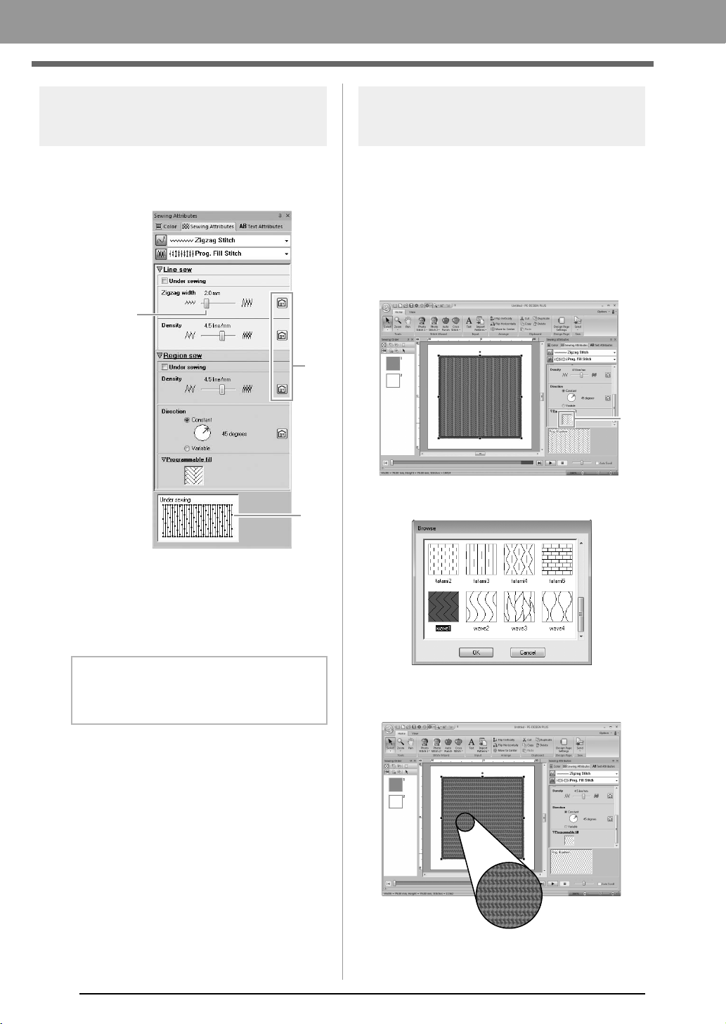
Specifying sewing
attributes
1. Select an embroidery pattern or the Text tool.
2. Click the Sewing Attributes tab.
(1) Click to return to the default setting.
(2) Hint view
With each change in the settings, a
preview of the stitching can be checked
here.
3. Change the sewing attributes displayed under
Line sew or Region sew.
The settings are applied to the
embroidery pattern each time the settings
are changed.
c
For details on the different sewing
attributes and settings, refer to “Line
sewing attributes” on page 68 and
“Region sewing attributes” on page 69.
Changing the pattern of
programmable fill stitch
1. Select an embroidery pattern.
2. Display the Sewing Attributes pane.
3. From the Region sew type selector, select
Prog. Fill Stitch.
4. Click 1 below Programmable fill in the
Region sew section.
5. Click the fill stitch pattern, and then click OK.
The pattern is applied to the inside
regions of the embroidery pattern.
b Memo:
The sewing attributes displayed in the dialog
box depend on the selected sew type.
Adjust
with slider.
(2)
(1)
(1)
XE8656-001.book Page 46 Thursday, June 30, 2011 2:56 PM
47
Arranging Embroidery Designs
Arranging Embroidery Designs
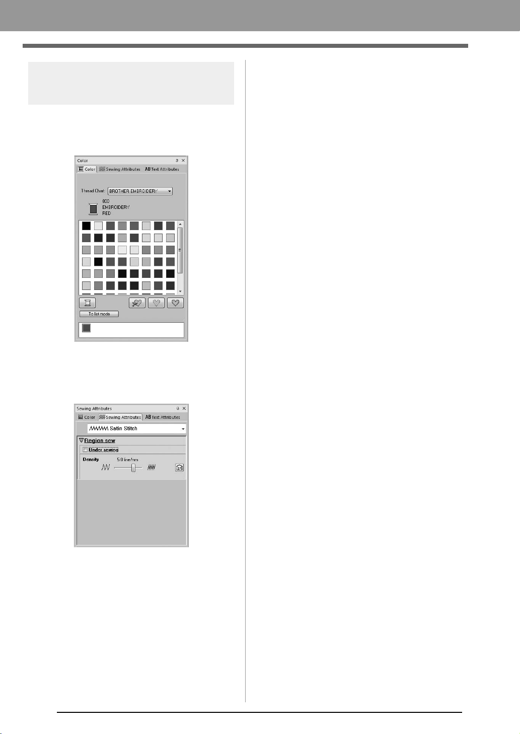
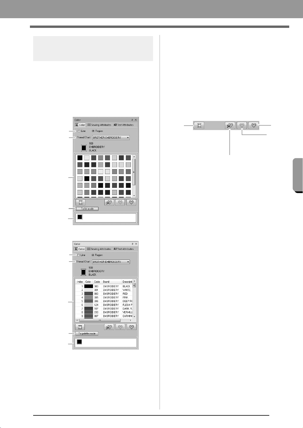
Setting the thread color
The Color pane allows you to set the thread color.
■ Color
Click the Color tab. If the Color tab is not
displayed, click the View tab in the Ribbon, and
then click Color Palette.
• Palette mode
•List mode
(1) Select the type of stitching (Line, Region)
whose color is being selected.
Line: Line color
Region: Region color
(2) From the Thread Chart selector, select a
thread brand or your user thread chart.
(3) From the list of thread colors, select the
desired color.
(4) Click to switch the mode.
(5) Displays all thread colors being used in
the embroidery design. When an
embroidery pattern is selected, a frame
appears around the colors used in that
pattern. The same thread colors can be
specified by selecting them here.
■ Special colors
(6) NOT DEFINED: If you want to be able to
manually select the color for a
monochrome pattern, you can select NOT
DEFINED.
Colors for creating appliqués:
You can create appliqués using the following
three special colors.
(7) APPLIQUE MATERIAL: marks the
outline of the region to cut from the
appliqué material.
(8) APPLIQUE POSITION: marks the
position on the backing material where
the appliqué must be sewn.
(9) APPLIQUE: sews the appliqué on the
backing material.
(4)
(5)
(2)
(3)
(1)
(1)
(4)
(5)
(2)
(3)
(6)
(7)
(8)
(9)
XE8656-001.book Page 47 Thursday, June 30, 2011 2:56 PM
48
Arranging Embroidery Designs
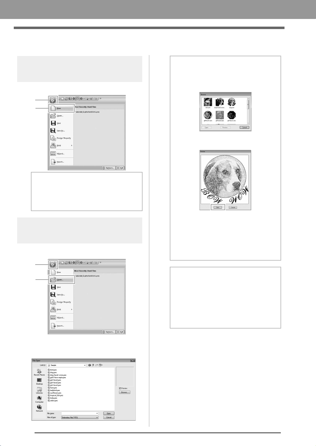
Opening/Importing Embroidery Designs
Creating a new embroidery
design
Click 1, then 2.
Opening a PE-DESIGN
PLUS file
1. Click 1, then 2.
2. Select the drive, the folder and the file, and
then click Open, or double-click the file's icon.
b Memo:
The size of the Design Page can be changed.
c
“Specifying the Design Page Size
and Color” on page 56
1
2
1
2
b Memo:
• To view the data in the selected folder as
thumbnails in the
Browse
dialog box, click
Browse
.
To see a more detailed design, select a file,
and then click
Preview
.
• To open the displayed file, click
Open
.
• If no files are listed, there are no .pes files in
the selected folder. Select a folder
containing a .pes file.
• If the selected file is in a format other than
the .pes format, the message “Unexpected
file format” appears in the
Preview
box.
b Memo:
A file can be opened in any of the following
ways.
• Drag the embroidery design from file
Windows Explorer into the PE-DESIGN
PLUS window.
• Double-click the embroidery design file in
Windows Explorer.
XE8656-001.book Page 48 Thursday, June 30, 2011 2:56 PM
49
Arranging Embroidery Designs
Arranging Embroidery Designs
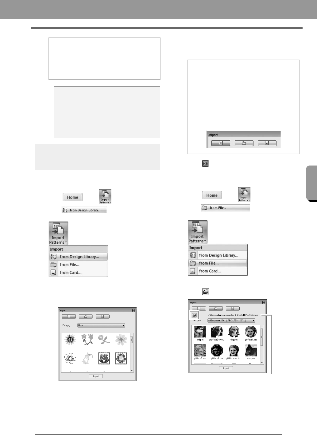
Importing embroidery
designs
■ From Design Library
1. Click , then ,
then .
2. From the Category selector, select a category
to display the corresponding embroidery data.
3. Select the file icon for the design to be
imported, and then click Import, or double
click the file icon.
4. Click to close it.
■ From a folder
1. Click , then ,
then .
2. Click .
b Memo:
Multiple files can be opened in PE-DESIGN
PLUS. In addition, data can be copied and
pasted between files that are open at the
same time.
a Note:
If a .pes file created with PE-DESIGN
NEXT or earlier is opened with this
software, the message “This file will be
imported into a new Design Page.”
appears before the embroidery design is
displayed on the new Design Page.
b Memo:
• The design can be imported by dragging its
file icon from the
Import
dialog box to the
Design Page.
• Multiple files cannot be selected to be
imported at the same time.
• With the buttons at the top of the
Import
dialog box, change the location from where
the file is to be imported.
Indicates the path to the currently selected folder.
XE8656-001.book Page 49 Thursday, June 30, 2011 2:56 PM
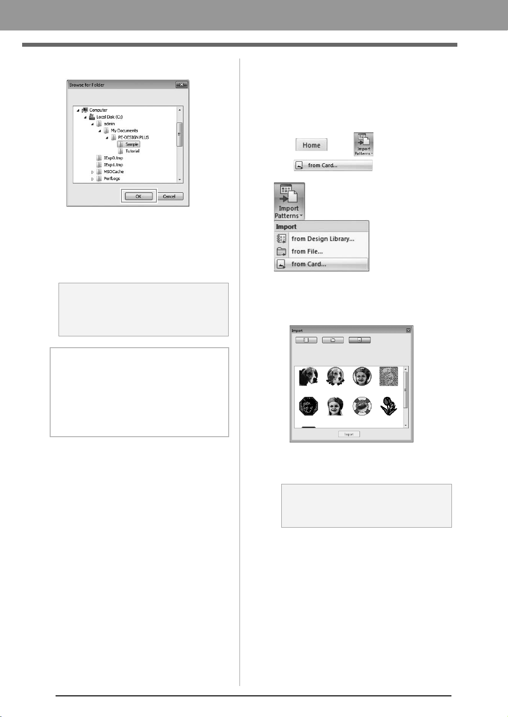
50
Arranging Embroidery Designs
3. Select a folder, and then click OK.
4. From the File Type box, select a file name
extension to display the corresponding
embroidery data.
5. Select the file icon, and then click Import.
The file is imported.
c
“Specifying the number of jumps in
embroidery design of the DST format” on
page 60.
■ From an embroidery card
1. Insert an embroidery card into the USB Card
Writer Module.
c
Refer to “Transferring to a machine by
using an original card” on page 52
2. Click , then ,
then .
After the card has been read, the
embroidery designs on the card are
displayed.
3. Select the file icon, and then click Import.
The file is imported.
a Note:
When importing designs from other vendors,
be sure to choose a design that will fit in the
Design Page.
b Memo:
Since .dst files do not contain thread color
information, the colors of an imported .dst file
may not appear as expected. You can change
the thread colors by using functions in the
Sewing Order
pane.
c
“Changing colors” on page 44
a Note:
Due to copyright issues, some embroidery
cards cannot be used with this function.
XE8656-001.book Page 50 Thursday, June 30, 2011 2:56 PM
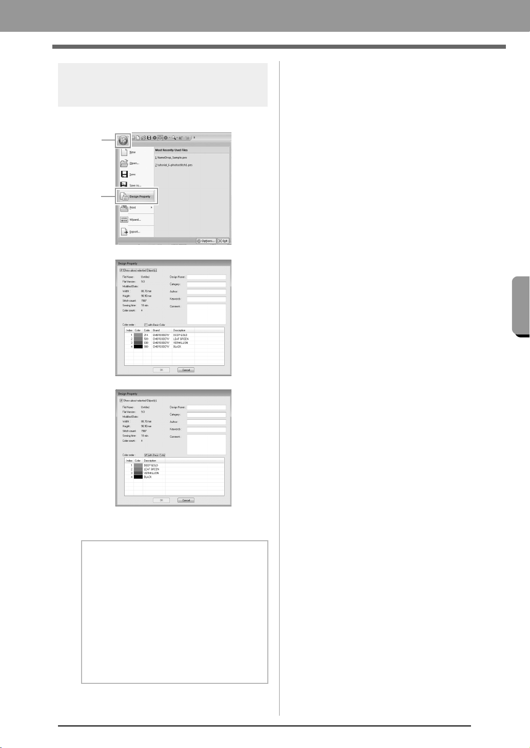
51
Arranging Embroidery Designs
Arranging Embroidery Designs
Checking embroidery
design information
Click 1, then 2.
You can enter comments and information about the
pattern to a saved .pes file.
b Memo:
• You can select and check the properties of
individual patterns within the embroidery
design by selecting the pattern before
opening this dialog box. In this case,
clearing the
Show about selected
Object(s)
check box switches the dialog
box to display properties for all patterns in
the Design Page.
• To display the colors as the machine’s
preset color names, select the
with Basic
Color
check box.
1
2
XE8656-001.book Page 51 Thursday, June 30, 2011 2:56 PM
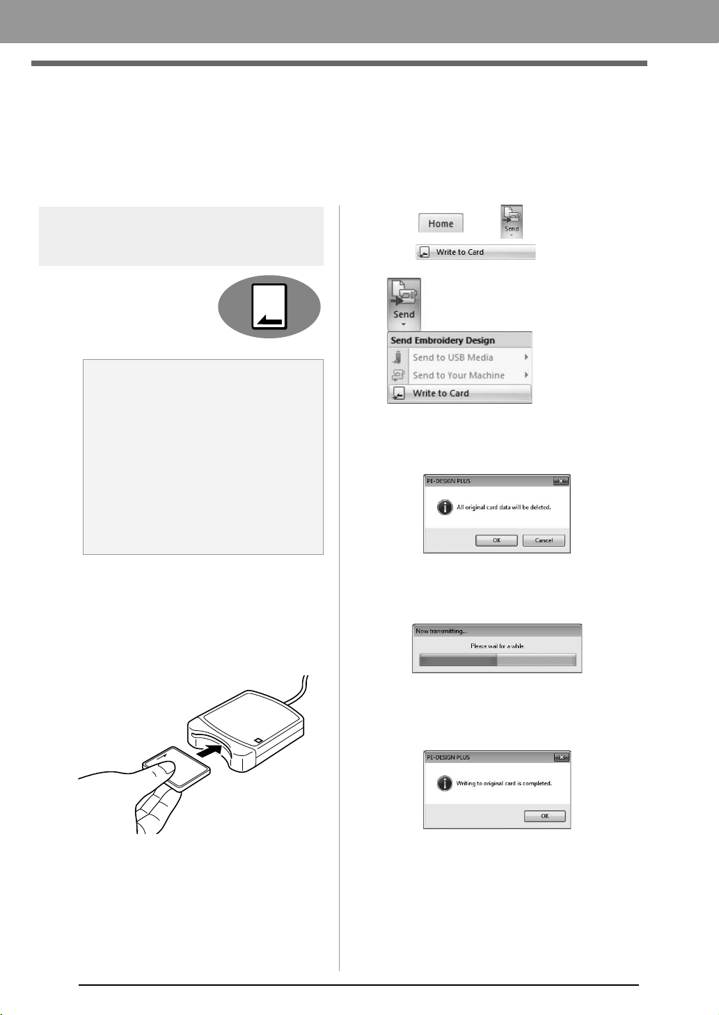
52
Arranging Embroidery Designs
Transferring Embroidery Designs to
Machines
The procedures for transferring the created embroidery pattern to an embroidery machine differ depending on
your embroidery machine model. For details, refer to the Operation Manual provided with your embroidery
machine.
Transferring to a machine
by using an original card
Designs can be transferred to
an embroidery machine
equipped with a card slot.
c
For details on writing multiple embroidery
designs, refer to “Writing Multiple
Embroidery Files to an Original Card” on
page 72.
1. Insert an original card into the USB Card
Writer Module.
2. Click , then ,
then .
3. When the following message appears, click
OK.
Data transfer begins. The following
message appears while the data is being
transferred.
4. After the data has been transferred, the
following message appears, indicating that the
transfer is finished. Click OK.
a Note:
• Be sure that the hoop size of the design
does not exceed the hoop that will be used
on the embroidering machine.
• When writing to an original card that
already contains data, all data on the card
will be deleted. Before writing to a card,
save all necessary data to a hard disk or
other media, and check that no necessary
data remains on the card.
c
“From an embroidery card” on
page 50
XE8656-001.book Page 52 Thursday, June 30, 2011 2:56 PM

53
Arranging Embroidery Designs
Arranging Embroidery Designs
Transferring to a machine
by using USB media
Designs can be transferred to
an embroidery machine
compatible with the USB Host
function.
1. Plug the USB media into the computer.
2. Click , then ,
then , then .
Data transfer begins.
3. After the data has been transferred, the
message “Finished outputting data.” appears,
indicating that the transfer is finished. Click
OK, and then remove the USB media.
Transferring directly to a
machine’s memory
Designs can be transferred to
embroidery machines that can
be connected to a computer
using a USB cable.
1. Connect the embroidery machine to the
computer.
2. Click , then ,
then , then .
Data transfer begins.
3.
After the data has been transferred, the
message “Finished outputting data.” appears,
indicating that the transfer is finished. Click
OK
.
a Note:
If there is already a file with the same name
at the destination, the following dialog box
appears. Select whether to overwrite the
existing file, to stop copying or to copy the
file using a different name.
b Memo:
If multiple USB media are connected, specify
where the data is to be transferred in the area
shown below.
b Memo:
• For details on transferring designs with this
method, refer to the Operation Manual
provided with your embroidery machine.
• If multiple machines are connected, specify
where the data is to be transferred in the
area shown below.
XE8656-001.book Page 53 Thursday, June 30, 2011 2:56 PM
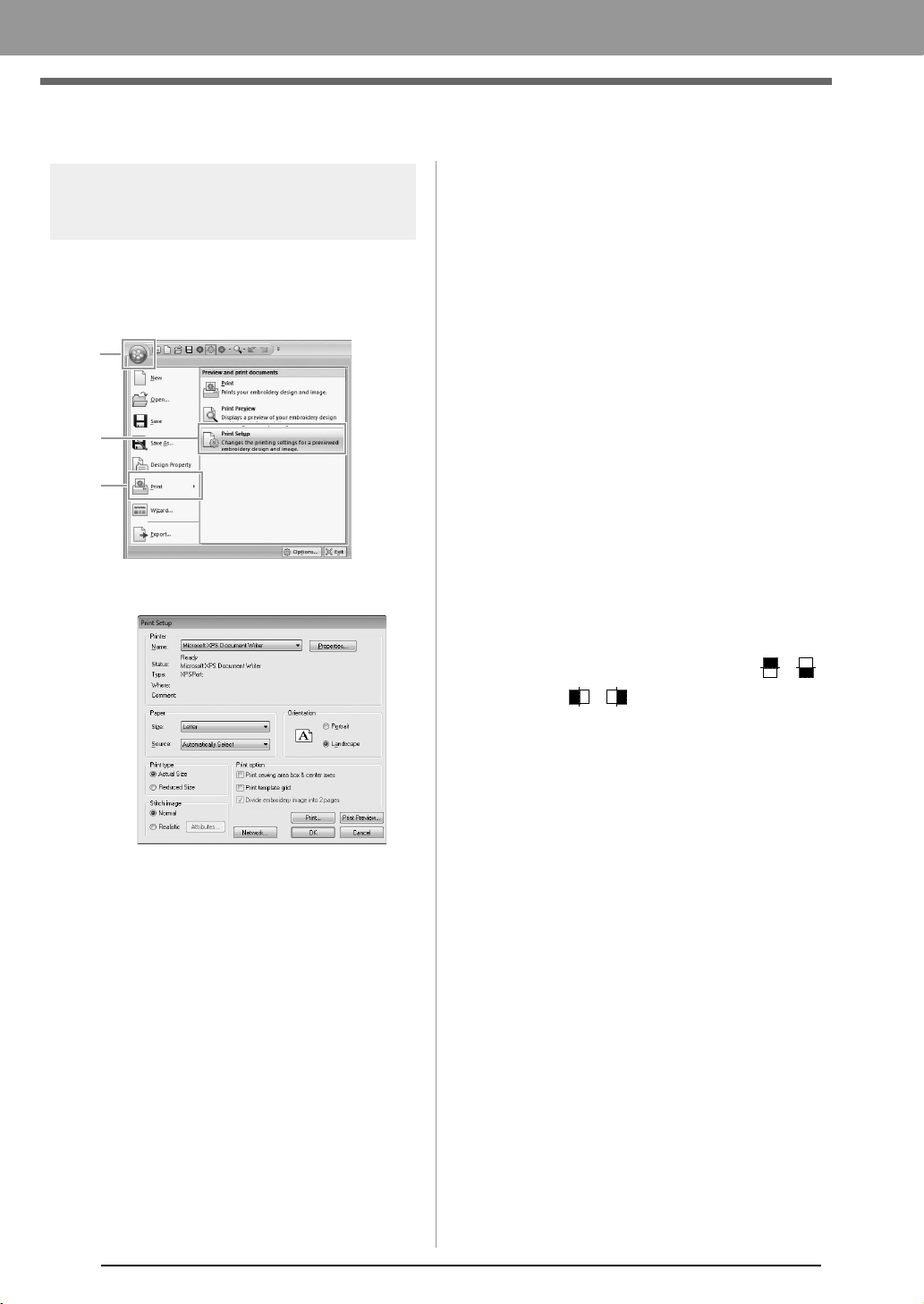
54
Arranging Embroidery Designs
Printing
Specifying print settings
Before printing, you may need to change the print
settings for the embroidery design files.
1. Click 1, then 2, then 3.
2. Specify the print settings.
(1) Specify the paper size.
(2) Specify the paper orientation.
(3) Print type
Actual Size:
Select this option to print the design at
actual size and the sewing information
(dimensions of the embroidery pattern,
sewing color order, stitch count and
hoop position) on separate pages.
Reduced Size:
Select this option to print a reduced
image together with all of the above-
mentioned information on a single
page.
(4) Print option
Print sewing area box & center axes:
Select this option to print black lines to
indicate the sewing area and the
center axes for the data. (This setting is
only available when Actual Size is
selected.)
Print template grid:
Select this check box to print green
lines to represent the grid printed on
the embroidery sheet included with the
hoop.
Divide embroidery image into 2 pages:
Select this check box to print at actual
size and on A4- or Letter-size paper a
design that is larger than the paper size
by dividing it in two and printing each
half on different pages.
(This setting is only available when
Actual size is selected in the Print
Setup dialog box and when the Design
Page is set to the larger hoop sizes.
This setting is not available if a User
Hoop size is selected.)
With this split printing feature, /
or / is printed in the lower-right
corner of the paper to indicate which
half is printed.
(5) Stitch image
Normal:
Select this option to print the design as
lines and dots.
Realistic:
Select this option to print a realistic
image of the design. To change the
settings of the realistic image, click
Attributes.
c
“Changing realistic view settings” on
page 41
3. Click OK.
c
“Changing the display of the embroidery
design” on page 41.
1
2
3
(3)
(4)
(5)
(2)
(1)
XE8656-001.book Page 54 Thursday, June 30, 2011 2:56 PM
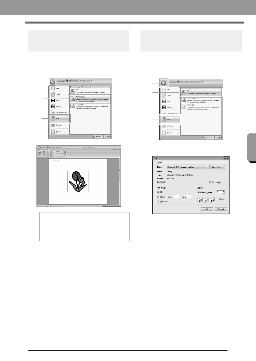
55
Arranging Embroidery Designs
Arranging Embroidery Designs
Checking a print image
You can preview the contents of the Design Page
before printing.
1. Click 1, then 2, then 3.
Printing
You can print the Design Page together with its
sewing information.
1. Click 1, then 2, then 3.
2. Select the necessary settings.
3. Click OK to begin printing.
4. Follow the instructions for the printer to finish
printing.
b Memo:
The print image can also be displayed by
clicking
Print Preview
in the
Print Setup
dialog box.
1
2
3
1
2
3
XE8656-001.book Page 55 Thursday, June 30, 2011 2:56 PM
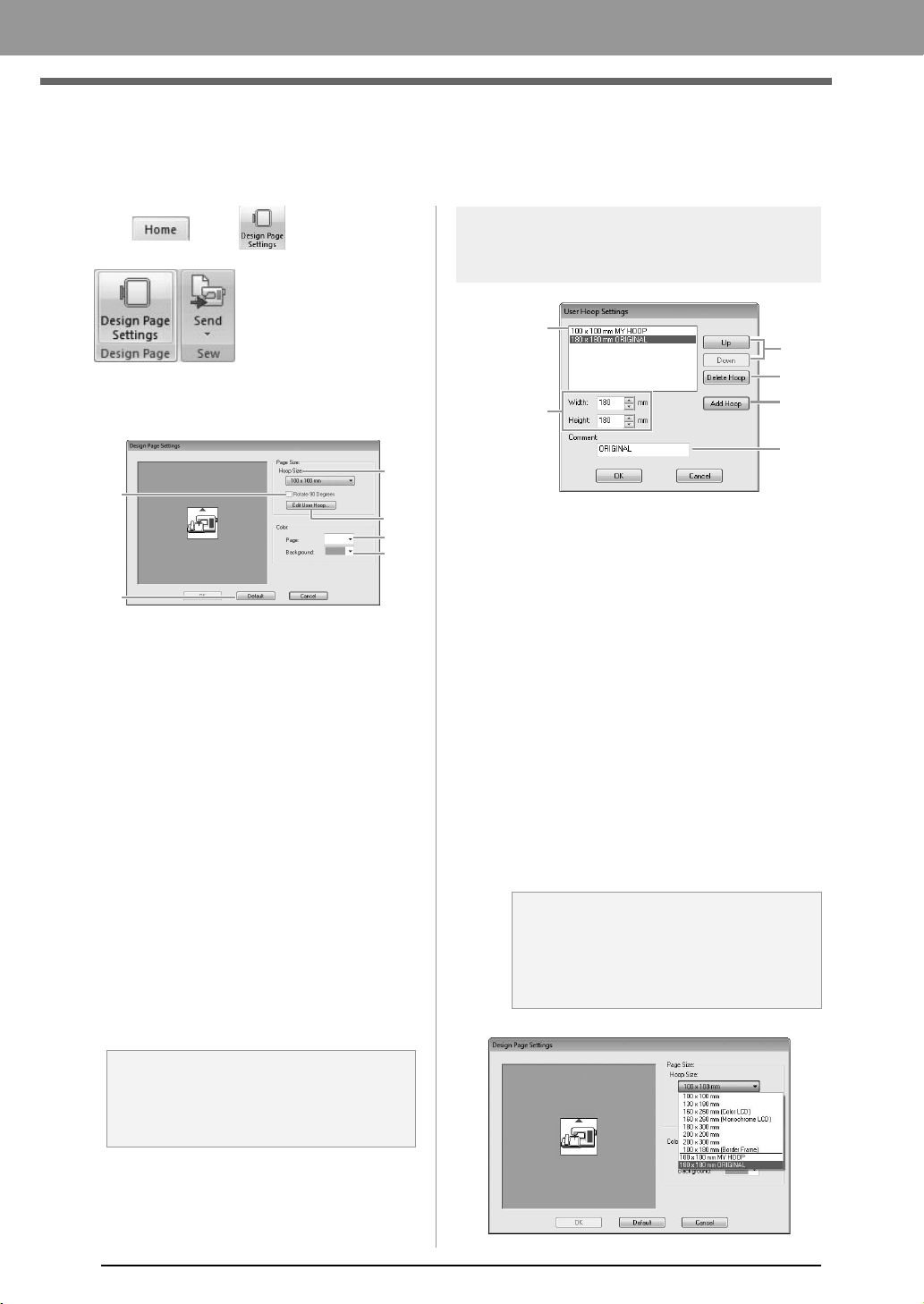
56
Arranging Embroidery Designs
Specifying the Design Page Size and Color
The color and size of the Design Page can be changed. You can select a Design Page size according to the
size of hoop that you will be using with your embroidery machine.
1. Click , then .
2. Specify the settings for the Design Page, and
then click OK.
(1) Hoop Size:
Select the desired hoop size from the
selector.
(2) Rotate 90 Degrees:
Select this check box to arrange the
pattern in a Design Page rotated 90°.
(3) Page:
Select the desired color for the Design
Page.
(4) Background:
Select the desired color for the work area.
(5) Default:
To return to the default settings, click this
button.
(6) Edit User Hoop:
Click this button to display the User Hoop
Settings dialog box, where a user hoop
size can be added. The added user hoop
size appears at the bottom of the list.
User Hoop Setting
(1) Width, Height:
Type in the size of the hoop to be added.
(2) Comment:
If text was entered in this box, that text
appears beside the size.
(3) Add Hoop:
Click this button to add the hoop size.
(4) User Hoop List:
The added hoop size appears in the list.
Select a hoop size in this list to change the
display order or to delete it.
(5) Up, Down:
Click these buttons to move the selected
hoop size up or down in the display order.
(6) Delete Hoop:
Click this button to delete the selected
hoop size.
a Note:
Do not select a hoop size larger than the
embroidery hoop that can be used with your
machine.
(5)
(1)
(4)
(3)
(6)
(2)
a Note:
• A User Hoop cannot rotate 90°.
• Do not create a Custom Hoop larger than
the embroidery hoop that can be used with
your machine.
(1)
(4)
(5)
(6)
(3)
(2)
XE8656-001.book Page 56 Thursday, June 30, 2011 2:56 PM
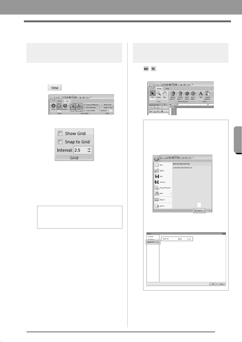
57
Arranging Embroidery Designs
Arranging Embroidery Designs
Changing Application Settings
Changing the grid settings
A grid of dotted lines or solid lines can be displayed
or hidden, and the spacing for the grid can be
adjusted.
1. Click .
2. Specify the grid settings.
Show Grid:
Select this check box to display the grid.
Snap to Grid:
Select this check box to align patterns
with the grid.
Interval:
Specify the grid spacing.
System unit
Click / to switch the measurement units
between millimeters and inches.
b Memo:
The snap feature works whether or not the
grid is displayed.
b Memo:
The system units can also be changed with
the following operation.
Click
1
, then
2
.
Click
System Unit
, and then select the
desired measurement units (
mm
or
inch
).
1
2
XE8656-001.book Page 57 Thursday, June 30, 2011 2:56 PM
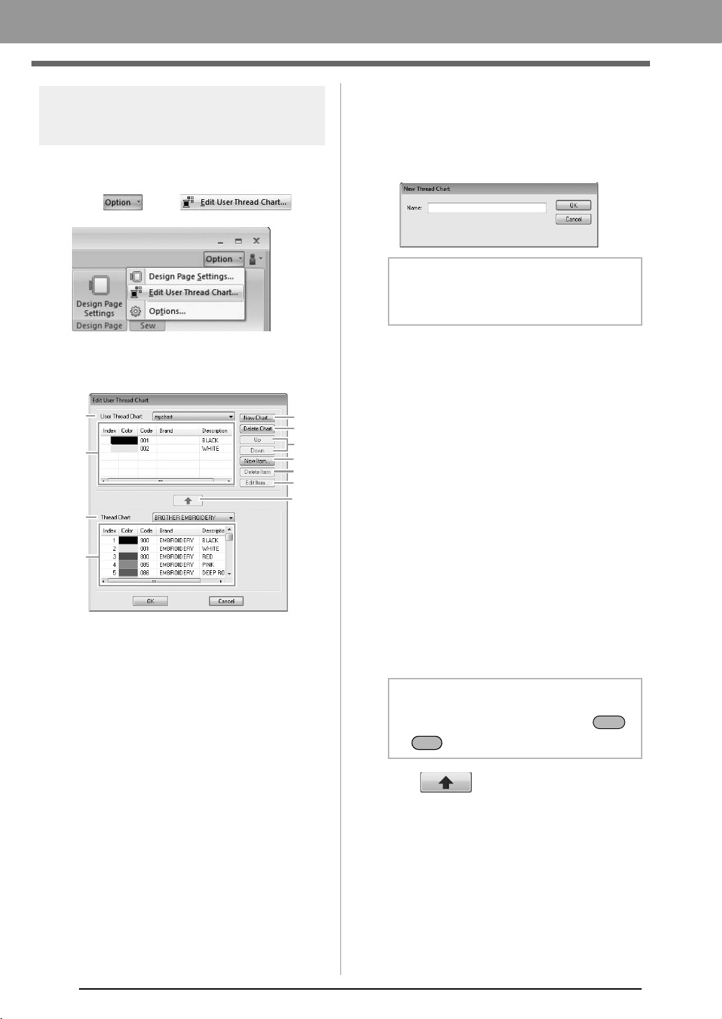
58
Arranging Embroidery Designs
Editing user thread color
lists
If you have a list of thread colors that are frequently
used, they can be saved in a user thread chart.
1. Click , then .
2. A user thread chart can be saved, edited or
deleted.
The operations that can be performed are
described below.
■ Creating a new thread chart
1. Click New Chart (1).
2. Type in the name of the chart, and then click
OK.
■ Deleting a chart
1. From the User Thread Chart selector (7),
select the chart.
2. Click Delete Chart (2).
3. If a message appears, click Yes.
■ Editing a chart
1. From the User Thread Chart selector (7),
select the chart.
2. Continue with the appropriate procedure. To
save the changes, click OK.
■ Adding items from a thread chart
1. From the Thread Chart selector (9), select the
brand of thread.
2. From the list (10), click the thread colors.
3. Click (11).
The selected items are added to the list in
the user thread chart (8).
(11)
(10)
(1)
(7)
(8)
(9)
(2)
(3)
(4)
(5)
(6)
b Memo:
A saved chart can be selected from the
User
Thread Chart
selector.
b Memo:
To add multiple items, hold down the
or keys while selecting thread colors.
Shift
Ctrl
XE8656-001.book Page 58 Thursday, June 30, 2011 2:56 PM
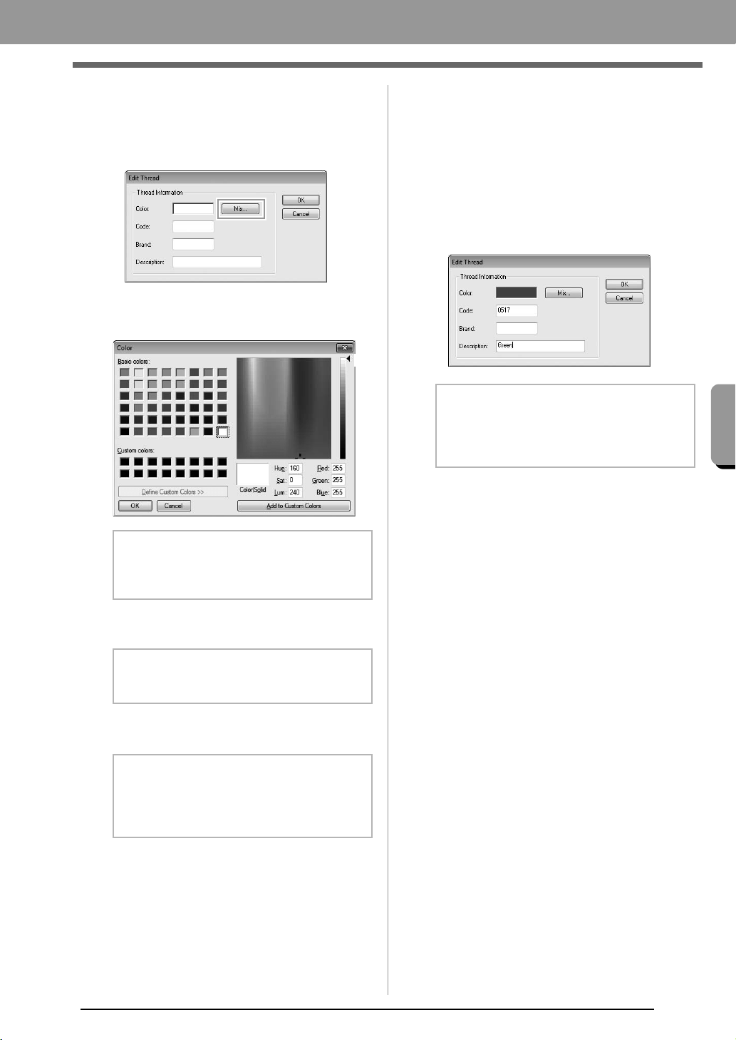
59
Arranging Embroidery Designs
Arranging Embroidery Designs
■ Adding a new item
1. Click New Item (4).
2. To create a new color, click Mix.
3. Specify the color, and then click OK to add the
specified color to the Edit Thread dialog box.
4. If necessary, type in the code, brand and
description into the appropriate boxes.
5. Click OK to add the new item to the user
thread chart (8).
■ Deleting items
1. From the list for the user thread chart (8),
select the item to be deleted.
2. Click Delete Item (5) to delete the item from
the user thread chart.
■ Editing an item
An item registered in the list for a user thread chart
can be edited to change the color or thread number.
1. From the list for the user thread chart (8),
select the item to be edited, and then click Edit
Item (6).
2. Edit the item details in the same way as
adding a new item.
b Memo:
The color cannot be changed if the slider (A)
is moved to the top of the scale.
b Memo:
Only numbers can be entered for the code.
b Memo:
An asterisk (*) appears in front of the index
number for items created or edited by the
user.
(A)
b Memo:
As with newly added items, an asterisk (*)
appears in front of the index number of edited
items.
XE8656-001.book Page 59 Thursday, June 30, 2011 2:56 PM
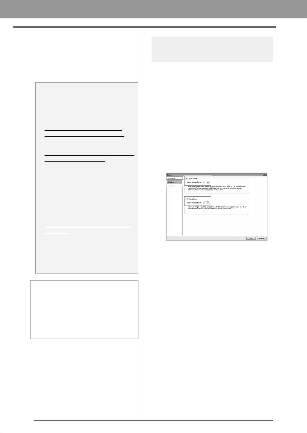
60
Arranging Embroidery Designs
■ Changing the order of items
1. From the list for the user thread chart (8),
select the item to be moved.
2. Click Up or Down (3) to change the order of
the item.
Specifying the number of jumps in
embroidery design of the DST format
With the DST format, you can specify whether or not
the jump stitches are trimmed according to the
number of jump codes. Since the number of codes
differ depending on the embroidery machine being
used.
Display the Options dialog box.
c
“Customizing Quick Access Toolbar/
Shortcut keys” on page 63
Select DST Settings (1), specify the number of
jumps, and then click OK.
To specify a setting for importing, enter a
value beside DST Import Setting (2). To
specify a setting for exporting, enter a value
beside DST Export Setting (3).
DST Import Setting
If the number of consecutive jumps in the DST
file is less than the number of jumps specified
here, those consecutive jumps will be
replaced with a stitch.
If the number of consecutive jumps in the DST
file is greater than or equal to the number of
jumps specified here, those jumps will be
replaced with a jump stitch where the thread is
trimmed.
DST Export Setting
When .pes files are output, jump stitches with
thread trimming are replaced with more
consecutive jump codes than the specified
number of jumps.
a Note:
Thread colors in embroidery patterns
created with this application may appear
differently on the embroidery machine,
depending on the model used.
1. Embroidery machines without a
function for displaying thread colors
The specified thread color information
cannot be displayed at all.
2. Embroidery machines with a function
for displaying thread colors
Of the thread color information specified
in the embroidery pattern, only the thread
color names are displayed on the
machine.
However, the names that are displayed
are limited to the machine's preset thread
color names. Therefore, the machine
displays the names of its preset thread
colors that are closest to the colors
specified in the embroidery pattern.
3. Embroidery machines with a thread
color index
Some machines can display the thread
information specified with this application.
However, for thread colors that have
been edited or added by the user (thread
colors with an asterisk (*) at the left side),
only the thread number is displayed.
b Memo:
The edited user thread chart can also be used
on a different computer. Simply copy
chart2.btc
from
C:\Program Files (Program Files
(x86))\Brother\PE-DESIGN PLUS\Color
on
the original computer to the
Color
folder at the
same path on the destination computer.
1
2
3
XE8656-001.book Page 60 Thursday, June 30, 2011 2:56 PM
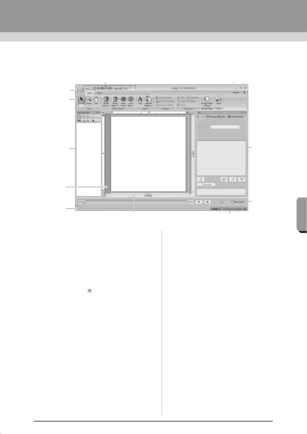
61
Supplement
Supplement
Understanding Windows
PE-DESIGN PLUS Window
1 Application button
Click to display a menu containing commands
for file operations, such as New, Save and Print.
2Ribbon
Click a tab at the top to display the
corresponding commands.
Refer to the name below each group when
selecting the desired command. Clicking a
command with the mark displays a menu
containing a choice of commands.
3 Quick Access Toolbar
This contains the most frequently used
commands. Since this toolbar is always
displayed, regardless of the Ribbon tab that is
selected, adding your most often used
commands makes them easily accessible.
c
“Customizing Quick Access Toolbar/
Shortcut keys” on page 63
4 Option button
Click this button to specify settings for the
Design Page and user thread chart.
5 Help button
Click this button to display the Operation Manual
and view information about the software.
6 Sewing Order pane
This pane shows the sewing order. Click the
buttons at the top of the pane to change the
sewing order or thread color.
7 Color/Sewing Attributes/Text Attributes pane
This pane combines tabs for specifying thread
colors, sewing attributes and text attributes.
Click a tab to display the available parameters.
8 Stitch Simulator pane
The Stitch Simulator shows how the pattern will
be sewn by the machine and how the stitching
will appear.
9 Design Page
The actual part of the work area that can be
saved and sewn.
10 Work area
11 Status bar
This displays the size of the embroidery data,
the number of stitches or a description of the
selected command.
12 Zoom
This displays the current magnification ratio.
Click to specify a value for the magnification
ratio.
Drag the slider to change the magnification ratio.
9
11
3
4
5
12
1
2
7
6
8
10
XE8656-001.book Page 61 Thursday, June 30, 2011 2:56 PM
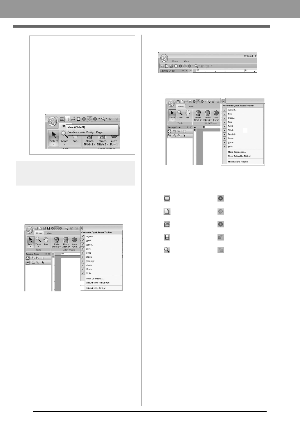
62
Supplement
Customizing the window
■ Quick Access Toolbar/Ribbon
A menu appears when 1 in the Quick Access
Toolbar is clicked.
Click (A) to move the Quick Access Toolbar below
the Ribbon.
To return it to its original position, display the menu
as described above, and then click Show Above
the Ribbon.
If a check mark appears beside (B), the Ribbon is
minimized. When a tab is clicked, the Ribbon
appears. After a command is selected, the Ribbon is
minimized again.
To restore it to its original display, clear the check
mark.
Example: With (A) selected and a check mark
beside (B)
■ Quick Access Toolbar commands
The first time this application is started up, the
following commands appear in the Quick Access
Toolbar (A).
Click 1, then 2 to switch between displaying and
hiding each command.
When the check mark is cleared, the command is
hidden.
Alternatively, changes to the Quick Access
Toolbar can be specified in the Options dialog
box and all applied at the same time.
c
“Customizing Quick Access Toolbar/
Shortcut keys” on page 63
b Memo:
• Panes 6, 7 and 8 can be displayed or
hidden from the
Show/Hide
group in the
View
tab. In addition, these panes can be
displayed as separate dialog boxes
(
Floating
) or attached to the main window
(
Docking
).
• Position the pointer over a command to
display a ScreenTip, which provides a
description of the command and indicates
its shortcut key.
1
(A)
(B)
: Wizard : Solid View
: New
: Stitch View
: Open : Realistic View
: Save : Undo
: Zoom : Redo
1
2
(A)
XE8656-001.book Page 62 Thursday, June 30, 2011 2:56 PM

63
Supplement
Supplement
■ Color/Sewing Attributes/Text
Attributes pane, Sewing Order
pane and Stitch Simulator pane
Floating
Each tab or the entire pane can be undocked to
become a dialog box that can be moved around
the screen.
• Double-click the title bar of the pane, or tab.
• Right-click the pane or tab, and then click
Floating.
• Drag a tab out of the pane.
Docking
Each pane can be docked back to the window.
• Double-click the title bar.
• Right-click the pane, and then click
Docking.
• Drag the title bar to the location where the
pane will be docked.
Hide
When a tab or a pane is no longer needed, it can
be hidden.
• Click in the upper-right corner of the
dialog box.
• Right-click the tab or dialog box, and then
click Hide.
• To hide the tab, click View tab in the
Ribbon, and then click the name in the
View tab. To display the tab again, perform
the same operation.
Auto Hide
When a pane is temporarily not needed,
it can be moved to the side bar, then
displayed by clicking it or positioning the
pointer over it. The pane is automatically
hidden again when it is no longer being
used, for example, when you click
anywhere outside of the pane.
• Right-click the tab or the title bar
of the pane, and then click Auto Hide.
• In the upper-right corner of the pane, click
.
To cancel Auto Hide, right-click the title bar, and then
click
Auto Hide
, or simply click in the title bar.
■ Using access keys
When the key is pressed, a KeyTip (label
showing the letter of the access key) appears on
each command. On the keyboard, press the key
corresponding to the command that you wish to use.
To stop using the access keys and hide the
KeyTips, press the key.
Customizing Quick Access
Toolbar/Shortcut keys
1. Click 1, then 2 to display the Options dialog
box.
b Memo:
The Stitch Simulator pane cannot be
temporarily hidden (Auto Hide).
b Memo:
The
Options
dialog box can also be displayed
using either of the following methods.
• Click at the right end of the Quick
Access Toolbar, and then click
More
Commands
.
• Click
Option
in the upper-right corner of the
window, and then click
Options
.
Alt
Alt
1
2
XE8656-001.book Page 63 Thursday, June 30, 2011 2:56 PM
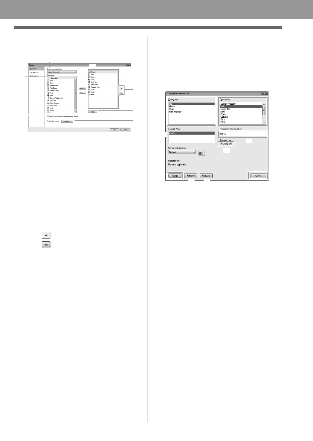
64
Supplement
■ Quick Access Toolbar
1. Click Customize.
2. Repeat the following operations until the
desired commands are displayed.
(1) Choose commands from: selector
Select a command category.
(2) Commands: list
Select the command to be added.
(3) Add button
Selected command is added.
The command appears in (A).
(4) Remove button
Selected command is removed.
The command is removed from (A).
(5)
Select an icon in (A), and then click the
buttons at to move it to the desired
position.
(6) Reset button
Reverting to the default commands.
Settings for the following can also be specified
from this dialog box.
(7) Show Quick Access Toolbar Below the
Ribbon
Select where the Quick Access Toolbar is
displayed. Select the check box to display
the Quick Access Toolbar below the
Ribbon.
(8) Keyboard shortcuts
Click Customize to customize shortcut
keys.
c
“Shortcut keys” on page 64
3. After the settings have been specified, click
OK to apply them.
■ Shortcut keys
1. Click Customize, then Customize (8).
2. In the Categories list, select a command
category. Then, in the Commands list, select
the command whose shortcut keys are to be
specified.
The default shortcut keys appear in the
Current Keys box (1).
3. Use the keyboard to record the new shortcut
keys in the Press new shortcut key (2) box,
and then click Assign (4). The new shortcut
keys appear in the Current Keys box (1).
Usage information about the entered key
combination appears. If the key
combination has already been assigned
to another command, the name of that
command appears at (3).
To remove the default or specified shortcut
keys, select the shortcut keys in (1), and then
click Remove (5).
To revert to the default settings, click Reset
All (6).
4. Repeat steps 2 and 3 until the desired shortcut
keys have been specified for the commands,
and then click Close.
5. Click OK in the Options dialog box.
(1)
(2)
(3)
(4)
(5)
(6)
(7)
(A)
(8)
(1)
(4)
(5)
(6)
(3)
(2)
XE8656-001.book Page 64 Thursday, June 30, 2011 2:56 PM
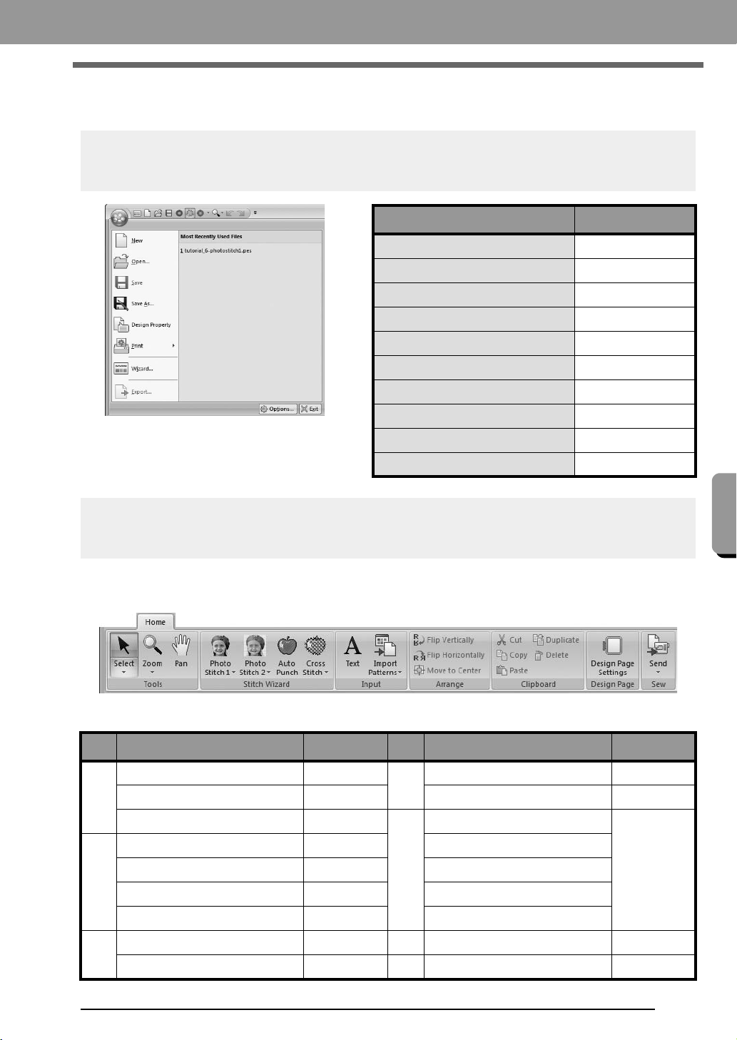
65
Supplement
Supplement
Menus
Application button menu
Ribbon menu tabs
■ Home tab
Menu Reference
New
p. 48
Open
p. 48
Save
p. 18
Save As
p. 18
Design Property
p. 51
Print
p. 54
Wizard
p. 10
Export File
p. 18
Options
p. 57, p. 60, p. 63
Exit
p. 19
No. Menu Reference No. Menu Reference
(1)
Select
p. 37
(4)
Flip Vertically/Horizontally
p. 39
Zoom
p. 40
Move to Center
p. 37
Pan
p. 40
(5)
Cut
—
(2)
Photo Stitch 1
p. 11, p. 19
Copy
—
Photo Stitch 2
p. 21
Paste
—
Auto Punch
p. 24
Duplicate
—
Cross Stitch
p. 27
Delete
—
(3)
Text
p. 32 (6)
Design Page Settings
p. 56
Import Patterns
p. 49 (7)
Send
p. 52
(1) (2) (3) (4) (5) (6) (7)
XE8656-001.book Page 65 Thursday, June 30, 2011 2:56 PM

66
Supplement
■ View tab
No. Menu Reference No. Menu Reference
(1)
Solid View
p. 41
(2)
Text Attributes
p. 32, p. 35
Stitch View
p. 41
Color Palette
p. 47
Realistic View
p. 41
(3)
Show Grid
p. 57
(2)
Sewing Order
p. 43
Snap to Grid
p. 57
Stitch Simulator
p. 42
Grid Interval
p. 57
Sewing Attributes
p. 46
(1)
(2)
(3)
XE8656-001.book Page 66 Thursday, June 30, 2011 2:56 PM
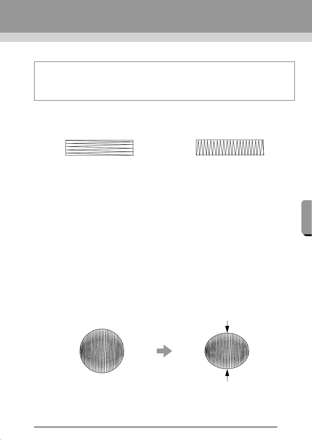
67
Supplement
Tips and Techniques
Sewing Direction
In order to limit pulling or puckering, select a stitch direction perpendicular to the larger edge of the area.
Sewing Order
After creating an embroidery pattern made of several different parts, be sure to check the sewing order and
correct it if necessary.
The default sewing order is the order in which the elements are drawn.
Be careful when changing the sewing order since overlapping areas may be incorrectly positioned.
Sewing Wide Areas
• For best sewing results, set Under sewing to On when sewing wide regions.
c
For more details, refer to “Under sewing” on page 69.
• Changing the Sewing Direction setting prevents pulling-in or puckering of the stitching.
• When embroidering, use stabilizer material specifically for embroidering. Always use stabilizer material
when embroidering lightweight or stretch fabrics, otherwise the needle may bend or break, the stitching may
pull and pucker, or the pattern may become misaligned.
• When satin stitching is sewn in a wide area, the stitched area may shrink after sewing, depending on the
material and the type of thread used. If this happens, switch to this alternate method: Select the fill stitch
and use stabilizer material on the reverse side of the fabric.
This software allows you to create a wide variety of embroidery patterns and supports wider ranges for the
setting of the sewing attributes (thread density, sewing pitch, etc.). However, the final result also depends
on your particular embroidery machine model. We recommend that you make a trial sewing sample with
your sewing data before sewing on the final material. Remember to sew your trial sample on the same
type of fabric as your final material and to use the same needle and the same machine embroidery thread.
Pulling or puckering more likely to occur Pulling or puckering less likely to occur
Pattern After sewing
XE8656-001.book Page 67 Thursday, June 30, 2011 2:56 PM
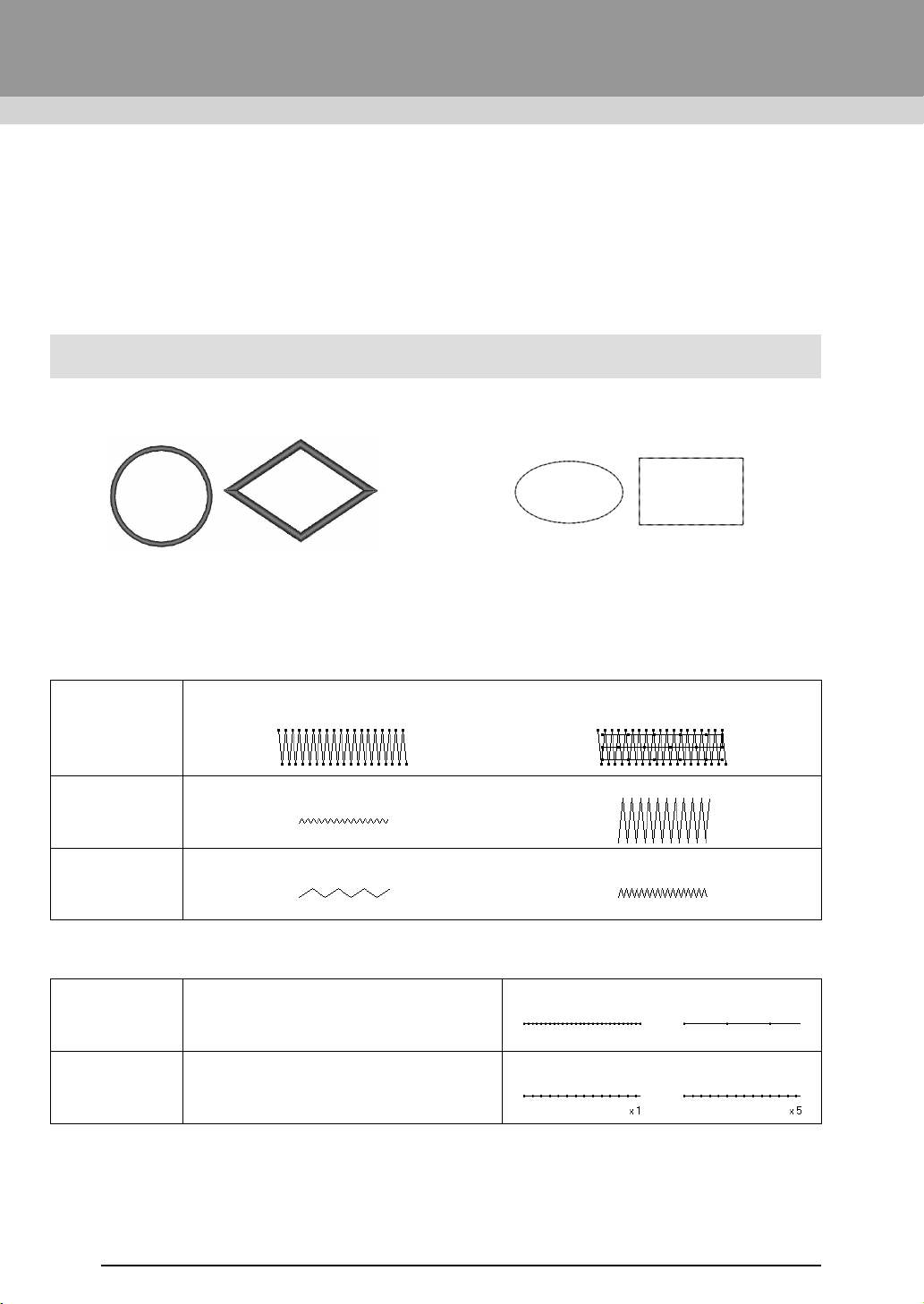
68
Reference
Sewing Attributes
The sewing attributes for each sew type are first set to their default settings; however, by changing the settings
of the sewing attributes, you can create custom stitching.
c
For more details, refer to “Line sewing attributes” on page 68 and “Region sewing attributes” on
page 69.
Line sew types
■ Line sewing attributes
The available attributes differ depending on the selected sew type.
Zigzag stitch
Running stitch
Zigzag Stitch Running Stitch
Under sewing
Sets underlay stitching on or off. To specify underlay stitching, select the check box.
Off On
Zigzag width
Narrow Wide
Density
Coarse Fine
Run pitch Specify the length of one stitch.
Short Long
Run time(s) Specify the number of times the outline is sewn.
1 time 5 times
XE8656-001.book Page 68 Thursday, June 30, 2011 2:56 PM
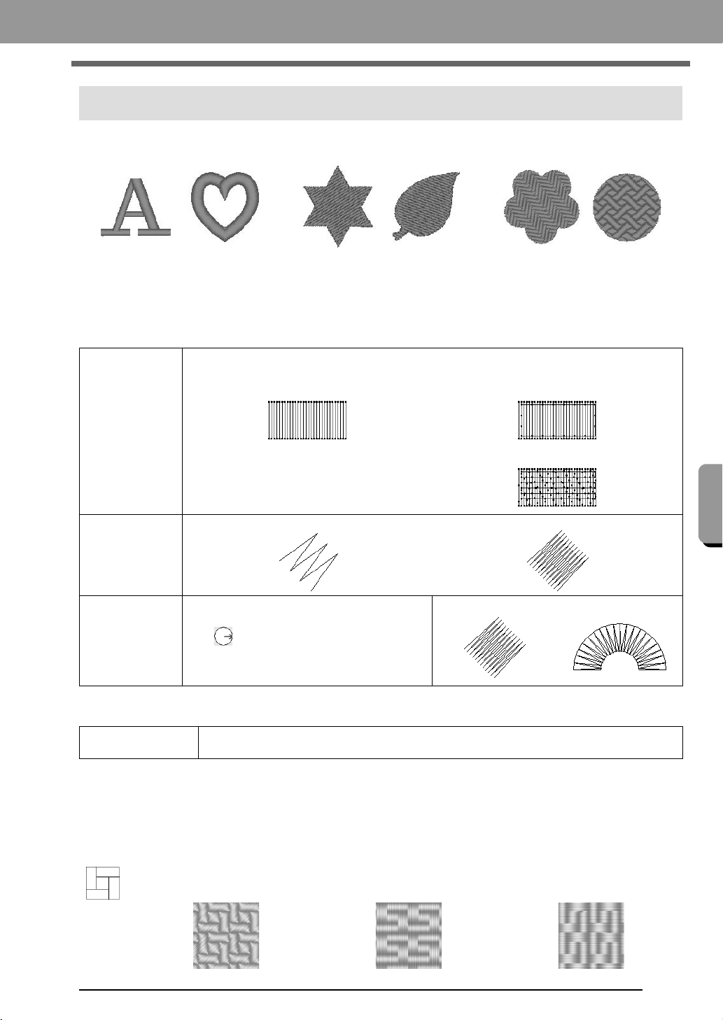
69
Supplement
Supplement
Region sew types
■ Region sewing attributes
The available attributes differ depending on the selected sew type.
Satin stitch/Fill stitch/Programmable fill stitch
Programmable fill stitch
Notes on programmable fill stitches
In some case of the sew type and pattern directions setting of a programmable fill stitch, lines will not be sewn.
Use the Realistic View to view exactly how the stitch pattern will be sewn. To get an even better view, make
test samples of different settings.
Examples of programmable fill stitching:
Satin Stitch Fill Stitch Programmable Fill Stitch
Under sewing
Sets underlay stitching on or off. To specify underlay stitching, select the check box.
Off On
With text patterns
With other patterns (Shapes)
Density
Coarse Fine
Direction
This cannot be specified for text patterns.
Constant: Sews at a fixed angle.
Drag or select a value to specify the angle.
Variable: Automatically varies the sewing
direction according to the shape of the region.
Constant Variable
Programmable fill
Click the pattern display box to display the Browse dialog box. Select the desired pattern from
the list of patterns that appears.
Example 1
Stitch direction: 45° (default)
Example 2
Stitch direction: 90°
Example 3
Stitch direction: 0°
XE8656-001.book Page 69 Thursday, June 30, 2011 2:56 PM
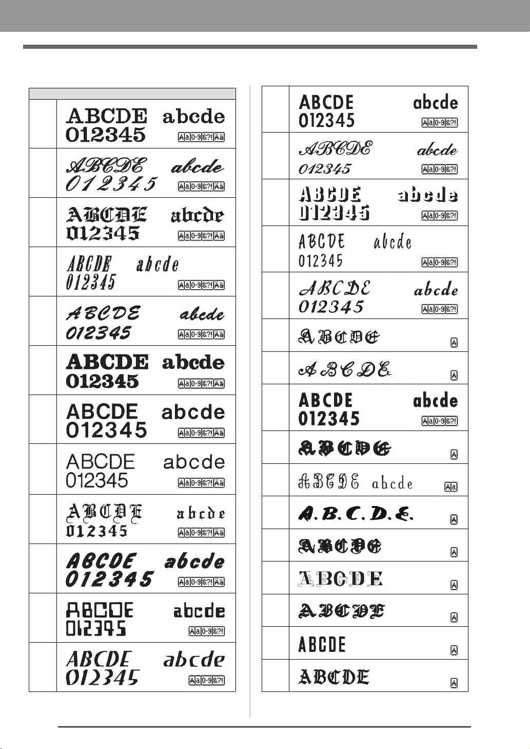
70
Supplement
Font List
Tex t
001
002
003
004
005
006
007
008
009
010
011
012
013
014
015
016
017
018
019
020
021
022
023
024
025
026
027
028
XE8656-001.book Page 70 Thursday, June 30, 2011 2:56 PM
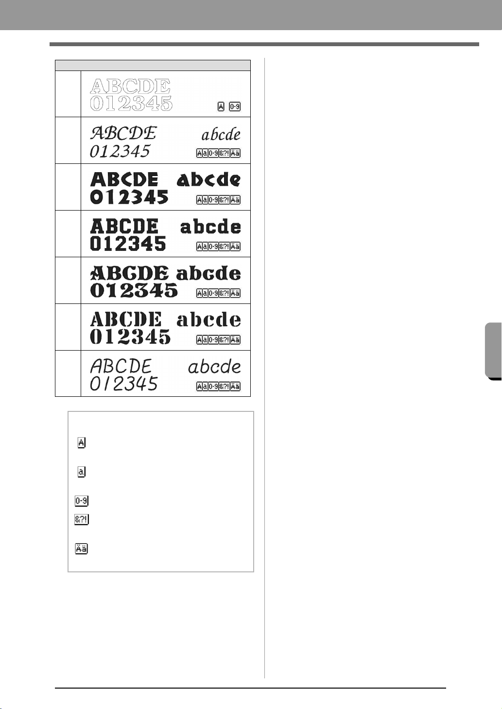
71
Supplement
Supplement
Tex t
029
030
031
032
033
034
035
b Memo:
Uppercase letters of the English
alphabet
Lowercase letters of the English
alphabet
Numerals
Punctuation marks, brackets and other
symbols
Uppercase and lowercase accented
letters
XE8656-001.book Page 71 Thursday, June 30, 2011 2:56 PM
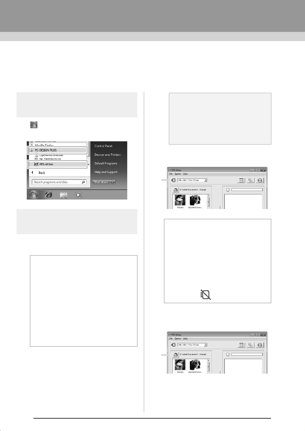
72
PES-Writer
Writing Multiple Embroidery Files to an
Original Card
Starting up PES-Writer
Click , then All Programs, then PE-DESIGN
PLUS, and then click PES-Writer.
Write to card
You can save multiple .pes or .pen files to an original
card at the same time.
1. Insert an original card into the USB Card
Writer Module.
c
“Transferring to a machine by using an
original card” on page 52
2. From the Hoop size selector (1), select the
appropriate size of embroidery hoop.
3. Click 1, and then select the folder where the
desired pattern files (.pes or .pen) are saved,
and then click OK.
The available pattern list displays the
image of the embroidery pattern files.
b Memo:
About .pen files
• .pen files, like .pes files, can be written to
original cards.
• .pen files are copyright-protected
embroidery data and can only be used
with the compatible embroidery machine.
• Some features may not be available, for
example, the embroidery cannot be
previewed.
• These files can be purchased through the
embroidery data sales site "iBroidery.com
Download Center". (US only)
a Note:
• The original card is inserted correctly
when you hear it snap into place.
• It is not necessary to turn off the
computer when original cards are
inserted or removed from the USB Card
Writer Module.
b Memo:
• Do not select a hoop size larger than the
embroidery hoop that can be used with
your embroidery machine. Otherwise, the
created original card will not work
correctly with the embroidery machine.
• Make sure to select a hoop size that is the
same or larger than the largest hoop size
of the files you want to write to the card,
otherwise the pattern cannot be written to
a card and “ ” appears.
1
1
XE8656-001.book Page 72 Thursday, June 30, 2011 2:56 PM
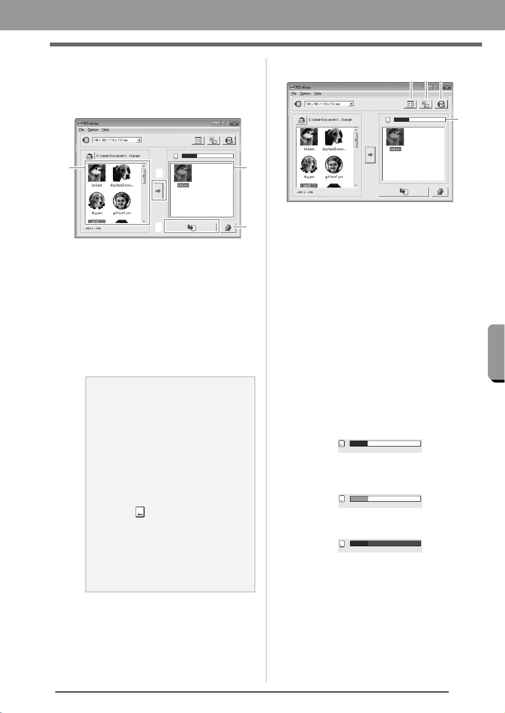
73
Supplement
Supplement
4. Select an embroidery pattern from the
available patterns list (1), and then click 2 to
add the pattern to the selected patterns list (3).
After all embroidery patterns to be written are
added to the selected patterns list, click 4.
• To deselect a file, click the white area
around the pattern.
• To remove the embroidery pattern selected
in the selected patterns list, click
5
.
The patterns are written to an original
card in the order that they are listed after
all data already on the card is erased.
After the patterns are written to the
original card, the card containing the
patterns can be used with the embroidery
machine.
■ Operation screen
(1) Icon size button
Switch between the large and small
display size of the embroidery pattern
images shown in the lists.
(2) Properties button
Display the information (size, number of
stitches, and colors) for the pattern
selected in either list. (This button is
available only if a single pattern is
selected.)
(3) Preview button
Display a realistic image of the pattern
selected in either list. (This button is
available only if a single pattern is
selected.)
(4)
Card capacity indicator
S
hows the capacity of the patterns
selected in the selected patterns list.
The space used by patterns in the
selected patterns list appears in blue.
The space used by the files selected in
the available patterns list appears in light
blue.
If several files exceed the available
space, the progress bar appears in red.
a Note:
• Since original cards are erased
completely before patterns are written to
it, it is useful to keep a copy with the
contents of each card that comes with
the software so that you can easily
recover the files that were on the card.
c
“From an embroidery card” on
page 50
• To check the contents of the original
card, open the Browse dialog box, and
then click , which appears at the top
of the list in the Browse window. The
patterns saved on the inserted card
appear in the available patterns list.
• Do not remove the card or unplug the
USB cable while patterns are being
written to the card (while the LED
indicator is flashing).
3
1
2
4
5
(1) (2)
(3)
(4)
XE8656-001.book Page 73 Thursday, June 30, 2011 2:56 PM
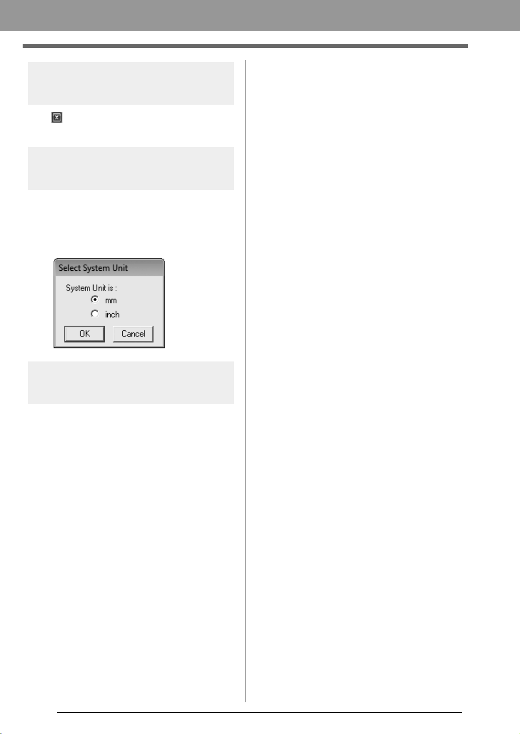
74
Supplement
Exiting application
Click in the upper-right corner of the window, or
click File then Exit from the menu bar.
Selecting system units
1. Click Option, then Select System Unit from
the menu bar.
2. Select the appropriate units (mm or inch) and
then click OK.
Help menu
■ Operation Manual
Displays the Operation Manual.
Click Help, then Operation Manual from the menu
bar.
■ About PES-Writer
Displays version and copyright information.
Click Help, then About PES-Writer from the menu
bar.
XE8656-001.book Page 74 Thursday, June 30, 2011 2:56 PM
75
Supplement
Troubleshooting
If a problem occurs, click Customer Support on the menu of PE-DESIGN PLUS to visit the following Web
site, where you can find causes and solutions to various problems and answers to frequently asked questions.
If you have a problem, check the following solutions. If the solutions suggested do not correct the problem,
contact your authorized dealer or Brother Customer Service.
Problem Estimated Cause Solution Page
The software is not installed
correctly.
An operation not described
in the installation procedure
was performed. (For
example, Cancel was
clicked or the CD-ROM was
removed before the
procedure was completed.)
Follow the instructions as the software
installs to correctly install the software.
The installer does not
automatically start up.
Refer to the memo on page 6 of the
Operation Manual, “If the installer does
not automatically start up”.
The message “No card writer
module is connected. Please
connect card writer module.”
appeared.
The driver for the USB
Card Writer Module is not
installed correctly.
When the USB connector is correctly
plugged into the USB port, the installer
for the driver of the USB Card Writer
Module starts up.
If the operation
described at the
left does not
correct the
problem, go to the
Web site
mentioned under
“Technical
Support”.
(Refer to page 9.)
When trying to upgrade from
an older version, the message
“Cannot connect to the
Internet.” or “The server could
not be connected to. Wait a
while, and then try connecting
again.” appeared and the USB
Card Writer Module could not
be upgraded.
The computer with the
USB Card Writer Module
connected to its USB port
could not establish a
connection to the Internet.
To upgrade the USB Card Writer
Module, the computer with the Card
Writer Module connected to its USB
port must connect to the Internet. If
firewall software is being used, it must
be temporarily disabled during the
upgrade. If a connection to the Internet
cannot be established, contact your
authorized dealer.
The USB Card Writer Module
does not operate correctly.
Not enough power is
being supplied.
Connect the USB Card Writer Module
to a USB port on the computer or to a
self-powered USB hub that can supply
enough power to the Card Writer
Module.
PE-DESIGN_Plus.fm Page 75 Wednesday, July 6, 2011 3:40 PM

76
Index
A
access key .................................................................. 63
Application button ....................................................... 61
Appliqué ...................................................................... 47
Auto Hide .................................................................... 63
Auto Punch ................................................................. 24
Auto Scroll .................................................................. 42
B
Back Stitch .................................................................. 29
Border Line ..................................................... 20, 23, 29
C
Card slot ....................................................................... 4
Card Writer ........................................................... 16, 52
CD-ROM ....................................................................... 5
centering ..................................................................... 37
Change Color ........................................................ 20, 23
checking
stitching .............................................................. 42
Color ........................................................................... 47
Color Option .......................................................... 20, 23
Color pane .................................................................. 61
combining
pattern colors ...................................................... 43
Computer ...................................................................... 5
Cross Stitch function ............................................. 27, 28
D
Design Page Settings ........................................... 56, 57
Design Page size .................................................. 56, 57
Design Property .......................................................... 51
Docking ....................................................................... 63
DST format ................................................................. 60
E
Edit User Thread Chart ............................................... 58
editing
sewing order ....................................................... 44
thread color charts .............................................. 58
thread colors ....................................................... 59
Embroidery attributes for text ...................................... 36
embroidery patterns
adding comments ............................................... 51
centering ............................................................. 37
exporting ............................................................. 18
from images ........................................................ 21
grouping .............................................................. 39
information .......................................................... 51
exporting embroidery patterns .................................... 18
F
fill stitch ....................................................................... 69
Floating ....................................................................... 63
Font List ...................................................................... 70
Font selector ............................................................... 35
G
grid .............................................................................. 57
grouping embroidery patterns ..................................... 39
H
Hard disk free space ..................................................... 5
Help button ................................................................. 61
Hide ............................................................................ 63
Hint View ..................................................................... 46
I
Image to Stitch Wizard ................................................ 30
Image Tune ................................................................. 31
Image Type ................................................................. 20
importing
embroidery patterns ............................................ 49
Installing
Software ............................................................... 6
L
LED ............................................................................... 4
Line Interval ................................................................ 23
Line sew button ........................................................... 45
Line sew type selector ................................................ 45
line sewing attributes .................................................. 68
M
Manual Select ............................................................. 20
Max. Density ............................................................... 23
Max. Number of Colors ................................... 20, 26, 28
measurement units ..................................................... 57
Memory ......................................................................... 5
Monitor .......................................................................... 5
N
New ............................................................................. 48
NOT DEFINED ........................................................... 47
number of jumps ......................................................... 60
O
Online Registration ....................................................... 9
opening
.pes file ............................................................... 48
new Design Page ............................................... 48
PE-DESIGN PLUS file ........................................ 48
Operating system .......................................................... 5
Option button .............................................................. 61
Options ....................................................................... 65
XE8656-001.book Page 76 Thursday, June 30, 2011 2:56 PM

77
Index
P
.pen files ......................................................................72
.pes files ...................................................................... 72
Pan .............................................................................. 40
pattern information ...................................................... 51
adding comments ................................................ 51
Photo Stitch 1 ........................................................ 11, 19
Photo Stitch 2 .............................................................. 21
Port ............................................................................... 5
previewing ...................................................................41
Printer ........................................................................... 5
printing
embroidery patterns ............................................ 55
preview ................................................................55
settings ................................................................ 54
Processor ...................................................................... 5
Programmable fill stitch ...............................................69
Property ...................................................................... 51
Q
Quick Access Toolbar ..................................... 61, 62, 63
R
Realistic View ..............................................................41
settings ................................................................ 41
Redo ........................................................................... 62
Region sew button ...................................................... 45
Registration ...................................................................9
Ribbon ......................................................................... 61
Run Pitch ....................................................................20
running stitch ...............................................................68
S
satin stitch ...................................................................69
saving .......................................................................... 18
Scaling patterns ..........................................................38
Select from Candidates ...............................................20
selecting
all embroidery patterns ....................................... 37
colors ............................................................ 20, 23
patterns ...............................................................37
Sew Page Color ..........................................................20
Sew type selector ........................................................ 45
Sewing Attribute pane ................................................. 61
sewing attributes
setting .................................................................46
sewing direction
programmable fill stitch ....................................... 69
Sewing Option ....................................................... 20, 23
sewing order
editing ................................................................. 44
Sewing Order pane ..................................................... 61
Shortcut keys .............................................................. 64
Solid View ...................................................................41
Special colors ..............................................................47
Status bar ....................................................................61
Stitch Simulator .....................................................42, 61
Stitch View ..................................................................41
System Requirements ................................................... 5
T
Technical Support ......................................................... 9
Text Attribute pane ...................................................... 61
Text Attribute Setting ..................................................35
Text Size selector ....................................................... 35
Thread Chart .........................................................20, 23
Thread Colors Used ....................................................23
Transferring ...........................................................16, 52
U
Under sewing ........................................................68, 69
Undo ...........................................................................62
uninstallating ................................................................. 9
units of measure .........................................................57
USB cable .............................................................17, 53
USB media .................................................................. 53
USB port ....................................................................... 5
user thread color list ....................................................58
W
Window ....................................................................... 61
Write to Card ................................................... 16, 52, 72
Z
zigzag stitch ................................................................ 68
Zoom ...........................................................................40
Zoom ratio ................................................................... 61
XE8656-001.book Page 77 Thursday, June 30, 2011 2:56 PM

Operation Manual
PERSONAL EMBROIDERY DESIGN SOFTWARE SYSTEM
Please visit us at http://solutions.brother.com where you can get product
support and answers to frequently asked questions (FAQs).
English
Printed in China
XF0606-001
PED_PLUS_BrotherE_OM_cover_1-4
C M Y K