Instruction Manual
PERSONAL EMBROIDERY & SEWING DIGITIZING SOFTWARE
Be sure to read this document before using the software.

1
Congratulations on choosing our product!
Thank you very much for purchasing our product. To obtain the best performance from this device
and to ensure safe and correct operation, please read this Instruction Manual carefully, and then
keep it in a safe place together with your warranty.
Please read before using this product
For designing beautiful embroidery designs
• This system allows you to create a wide variety of embroidery designs and supports a wider
range of sewing attribute settings (thread density, sewing pitch, etc.). However, the final result
will depend on your particular sewing machine model. We recommend that you make a trial
sewing sample with your sewing data before sewing on the final material.
For safe operation
• Do not save any files on the "PE-DESIGN Software Key" for transferring or storage.
• Do not plug the "PE-DESIGN Software Key" into your sewing machine.
For a longer service life
• When storing the "PE-DESIGN Software Key", avoid direct sunlight and high humidity
locations. Do not store the "PE-DESIGN Software Key" close to a heater, iron or other hot
objects.
• Do not spill water or other liquids on the "PE-DESIGN Software Key".
• Do not drop or hit the "PE-DESIGN Software Key".
For repairs or adjustments
• In the event that a malfunction occurs or adjustment is required, please consult your nearest
service center.
Notice
• Since this "PE-DESIGN Software Key" device is required to run the software, its replacement
value is the retail price of the software. Please keep in a safe place when not in use.
• Neither this Instruction Manual nor the Reference Guide explains how to use your computer
under Windows. Please refer to the Windows manuals.
Copyright acknowledgment
Any trade names and product names of companies appearing on Brother products, related
documents and any other materials are all trademarks or registered trademarks of those respective
companies.
Caution
The software included with this product is protected by copyright laws. This software can be used
or copied only in accordance with the copyright laws.
For additional product information and updates, visit our website at:
www.brother.com or http://s.brother/cppab/
SAVE THESE INSTRUCTIONS
This product is intended for household use.
2
Table of Contents
Table of Contents
Table of Contents............................................. 2
Introduction.................................... 4
How To Use Manuals....................................... 5
Support/Service ............................................... 7
PE-DESIGN Software Key............................... 9
Comparison of Types of Data Created With
PE-DESIGN 11 .............................................. 10
Starting Up/Exiting Applications..................... 11
Understanding Windows................................ 13
Basic Software Settings................................. 16
Basic Layout & Editing
Operations.................................... 23
Layout & Editing............................................. 24
Tutorial 1: Drawing shapes to create an
embroidery design ......................................... 30
Editing Embroidery Designs........................... 39
Specifying Thread Colors and Sew Types for
Lines and Regions ......................................... 54
Drawing Shapes............................................. 70
Reshaping Embroidery Patterns .................... 76
Editing a Stitch Pattern .................................. 81
Checking Embroidery Patterns ...................... 87
Opening/Importing Embroidery Designs ...... 101
Saving and Printing...................................... 107
Creating Embroidery Patterns
Containing Text.......................... 111
Tutorial 2: Using Templates ......................... 112
Template Feature......................................... 115
Tutorial 3: Entering text................................ 116
Advanced Operations for Entering Text....... 117
Tutorial 4: Monograms................................. 131
Advanced Operations for Entering
Monograms.................................................. 134
User-Mapped Text ....................................... 135
Tutorial 5: Creating Name Drop................... 136
Name Drop Feature (Replacing Text).......... 139
Creating Embroidery Patterns
Using Images ............................. 141
Stitch Wizard: Automatically Converting an
Image to an Embroidery Design .................. 142
Tutorial 6-1: Auto Punch .............................. 143
Auto Punch Features ................................... 145
Tutorial 6-2: Cross Stitch.............................. 146
Cross Stitch Features................................... 148
Tutorial 6-3: Photo Stitch 1........................... 150
Photo Stitch 1 Features................................ 153
Tutorial 6-4: Photo Stitch 2........................... 155
Photo Stitch 2 Features................................ 157
Advanced Stitch Wizard Operations ............ 158
Importing Image Data................................... 163
Changing the Image Settings....................... 165
Tutorial 7: Print and Stitch............................ 167
Operations for Specific
Applications ............................... 172
Tutorial 8: Filling a specified area around a
pattern with embroidery................................ 173
Specify Settings for Background Fill ............ 177
Tutorial 9-1: Creating Appliqués................... 179
Tutorial 9-2: Creating Embroidered
Patches ........................................................ 184
Tutorial 9-3: Creating a Cutwork Pattern
Filled with Net Stitching................................ 187
On Using the Cutwork Functions ................. 191
Tutorial 10-1: Creating Split Embroidery
Designs ........................................................ 195
Specifying Settings for Split Embroidery
Designs ........................................................ 201
Tutorial 10-2: Creating Design for
Multi-Position Hoops .................................... 204
Tutorial 10-3: Embroidering With the Jumbo
Frame........................................................... 209
Specifying/Saving Custom Sewing
Attributes...................................................... 213
Using Manual Punch Tool ............................ 218
Transferring Data....................... 221
Transferring Embroidery Designs to
Machines...................................................... 222
Using the Link Function to Embroider From
the Computer ............................................... 227
Compatibility with ScanNCut
(Brother cutting machine)......... 237
Compatibility with ScanNCut
(Brother cutting machine)............................. 238
Tutorial 11:Sending an FCM File to
CanvasWorkspace....................................... 239
Exporting/Importing an FCM File ................. 243
3
Table of Contents
Design Center ............................ 245
Design Center .............................................. 246
Basic Design Center Operations.................. 249
Design Center Window ................................ 259
Original Image Stage ................................... 260
Line Image Stage......................................... 262
Figure Handle Stage.................................... 264
Sew Setting Stage ....................................... 269
Design Database........................ 277
Design Database ......................................... 278
Design Database Window............................ 279
Starting Up Design Database ...................... 280
Organizing Embroidery Designs .................. 281
Opening Embroidery Designs ...................... 283
Transferring Embroidery Designs to
Machines...................................................... 284
Searching for an Embroidery Design ........... 290
Converting Embroidery Design Files to
Different Formats ......................................... 291
Checking Embroidery Designs..................... 292
Outputting a Catalog of Embroidery
Designs........................................................ 294
Programmable Stitch Creator... 296
Programmable Stitch Creator ...................... 297
Basic Programmable Stitch Creator
Operations ................................................... 299
Creating Fill/Stamp Stitch Pattern................ 301
Editing a Pattern in Fill/Stamp Mode............ 305
Creating Motif Stitch Pattern........................ 307
Editing a Pattern in Motif Mode.................... 310
Creating a Decorative Fill Pattern................ 311
Programmable Stitch Creator Window......... 314
Opening a Template .................................... 315
Preview Window .......................................... 317
Saving Patterns............................................ 317
Changing the Display Settings..................... 319
Font Creator ............................... 320
Font Creator................................................. 321
Creating New Font Characters From
Background Images ..................................... 323
Registering Embroidery Data as a Font....... 330
Font Creator Window ................................... 335
Opening a File.............................................. 337
Selecting a Character and Preparing the
Template ...................................................... 338
Creating a Font Character Pattern............... 340
Editing the Points of a Font Character
Pattern.......................................................... 341
Checking the Created Font Patterns............ 342
Saving Font Character Patterns................... 344
Changing the Settings.................................. 345
Stitch Design Factory................ 347
Stitch Design Factory................................... 348
Basic Stitch Design Factory Operations....... 350
Editing Sewing Stitch Patterns ..................... 353
Changing the Format of Files to be
Exported....................................................... 356
Stitch Design Factory Window ..................... 358
Using a Template ......................................... 359
Other Settings .............................................. 360
Supplement ................................ 362
For Basic Operations ................................... 363
On Settings .................................................. 365
Changing Various Settings........................... 366
For Making an Effective Use of This
Application.................................................... 372
Reference ................................... 374
Sewing Attributes ......................................... 375
Font List ....................................................... 400
Sewing Stitch Patterns for Stitch Design
Factory ......................................................... 404
Troubleshooting ........................................... 407
Index ............................................................ 409

Introduction
This section provides a general understanding of
the basic software applications as well as support
information.
5
Introduction
How To Use Manuals
How To Use Manuals
The following manuals are included with this software.
Read this guide before using the software. This guide contains instructions and precautions necessary to
begin using the software. The second half is filled with tutorials that use key features to create embroidery
patterns as well as project examples.
This manual contains instruction on how to use the PE-DESIGN software.
First, read “PE-DESIGN Software Key”, “Starting Up/Exiting Applications”, “Comparison of Types of Data
Created With PE-DESIGN 11”, “Example of Importing Embroidery Data” and “Understanding Windows” to gain
a general understanding of the basic software applications.
Next, read “Basic Layout & Editing Operations”. This chapter provides procedures for creating embroidery
patterns as examples for performing basic Layout & Editing operations and transferring patterns to the
embroidery machine. Follow the procedures to create actual embroidery patterns.
The chapters dedicated to each application provide descriptions of the useful functions and the various
settings. Each descriptive title allows you to easily find the information that you need. In the chapters
containing tutorials, follow the procedures to practice the various operations. Afterward, read the detailed
descriptions.
Additional information is provided in the following chapters. Read the appropriate chapter when necessary.
Support/Service: Provides warranty information for this product in addition to the procedure for updating the
software.
Supplement: Provides function introductions, details on the settings available in the [Options] dialog box and
troubleshooting procedures in addition to tips and precautions to maximize the use of this software.
Reference: Provides lists of sew types, sewing attributes and fonts.
The procedures in this manual are written for use in Windows 10. If this software is used on an operating
system other than Windows 10, the procedures and appearance of the windows may differ slightly.
■ Opening Online Instruction Manual
An online Instruction Manual is available, which can also be accessed from a mobile device.
http://s.brother/cmpaa/
Viewing from the [Start] screen (for Windows 10 users)
Click . Click [PE-DESIGN 11] and then select [Online Instruction Manual].
Reference Guide
Instruction Manual
b
• For Windows 8.1 users: Position the mouse pointer in the [Start] screen to display the down arrow in the
lower-left corner of the screen (below and left of the tiles), and click it.
From the list of applications that appears in the screen, click [Online Instruction Manual] under the title
[PE-DESIGN 11].
• For Windows 7 users: Click and then [All Programs]. Click [PE-DESIGN 11] and then select [Online
Instruction Manual].
6
Introduction
How To Use Manuals
Viewing from the application
Click [Help] in the window of each application. In [Design Database], [Help] is in the menu bar at the top of
the window.
In other applications, it is located in the upper-right corner of the window.
b
• A PDF version of the Instruction Manual is also available, which can be accessed even when the computer
is offline. Access the PDF version of the Instruction Manual as described below.
Windows 10 users: Click . Click [PE-DESIGN 11] and then select [Instruction Manual].
For Windows 8.1 users: Position the mouse pointer in the [Start] screen to display the down arrow in the
lower-left corner of the screen (below and left of the tiles), and click it.
From the list of applications that appears in the screen, click [Instruction Manual] under the title [PE-
DESIGN 11].
For Windows 7 users: Click
and then [All Programs]. Click [PE-DESIGN 11] and click [PDF] and
then select [Instruction Manual].
• Adobe
®
Reader
®
is required for viewing and printing the PDF version of the Instruction Manual.
• If Adobe
®
Reader
®
is not on your computer, it must be installed. It can be downloaded from the Adobe
Systems Incorporated Web site (https://www.adobe.com/
).

7
Introduction
Support/Service
Support/Service
Contact Technical Support if you have a problem. Please check the company web site
(www.brother.com
) to find the Technical Support in your area. To view the FAQ and information for software
updates, visit the Brother Solutions Center at (http://s.brother/cppab/
).
If you wish to be contacted about upgrades and provided with important information such as future product
developments and improvements, you can register your product online by following a simple registration
procedure.
Click [Help] in Layout & Editing, then [Online Registration] to start up the installed Web browser and open
the online registration page on our Web site.
The online registration page on the Web site appears when the following address is entered in the address bar
of the Web browser.
http://s.brother/pedesignonlinereg/
Technical Support
a
• Have the information ready before contacting Technical Support.
Make sure your computer's operating system is current with all updates.
Have the make and model of your computer and Windows Operating System. (Refer to the Reference
Guide for system requirements.)
Information on error messages that appear. This information will help expedite your questions more
quickly.
Make sure PE-DESIGN 11 is current with any updates.
Online Registration (Except for European region countries)
b
Online registration may not be available in some areas.
8
Introduction
Support/Service
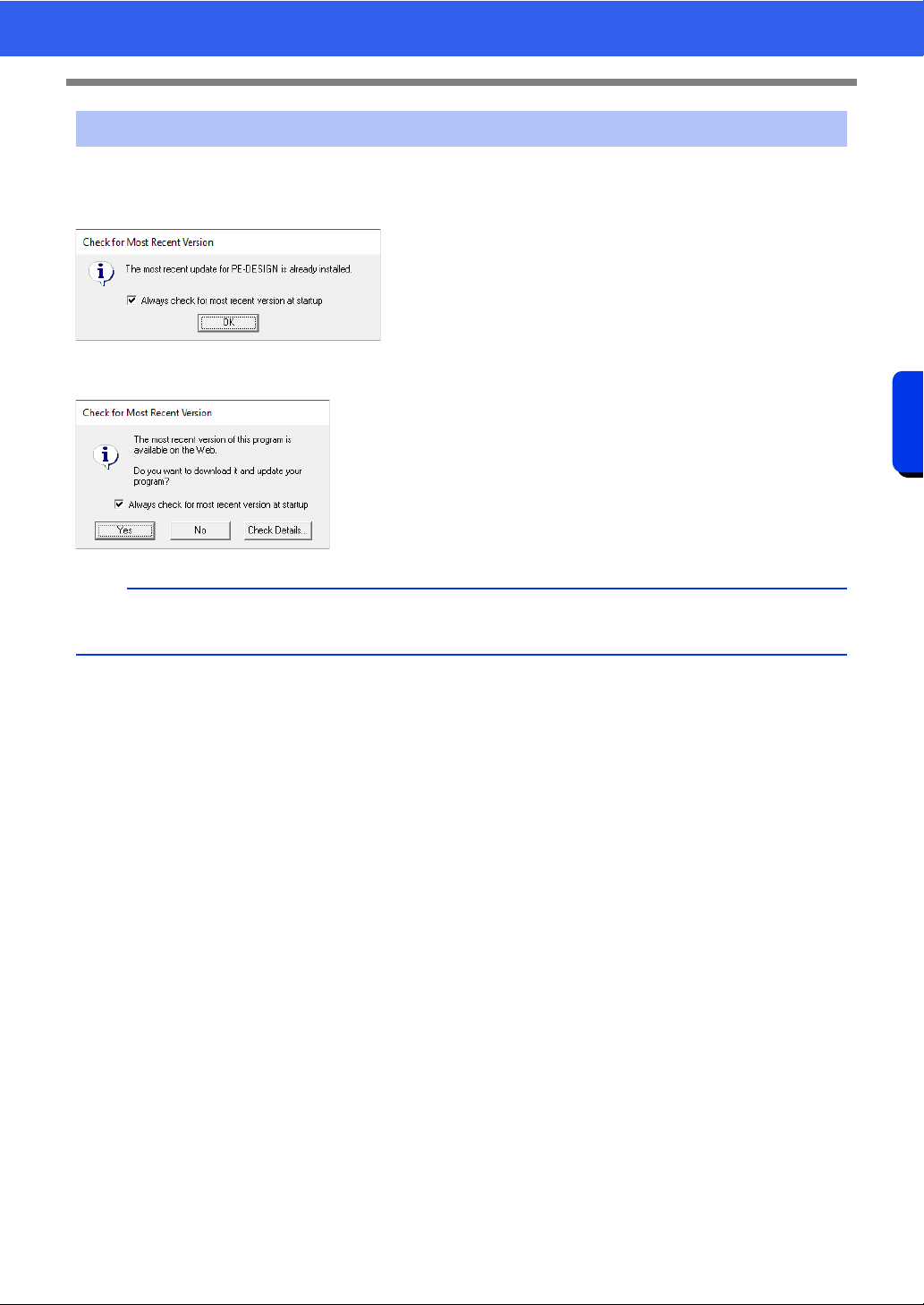
Click [Help] in Layout & Editing, then [Check for Updates].
The software is checked to determine whether or not it is the latest version.
If the message shown below appears, the latest version of the software is being used.
If the message shown below appears, the latest version of the software is not being used. Click [Yes], and
then download the latest version of the software from the Web site.
Checking for the Latest Version of the Program
b
If the [Always check for most recent version at startup] check box is selected, the software is checked
at startup to determine whether or not it is the latest version.
9
PE-DESIGN Software Key
Introduction
PE-DESIGN Software Key
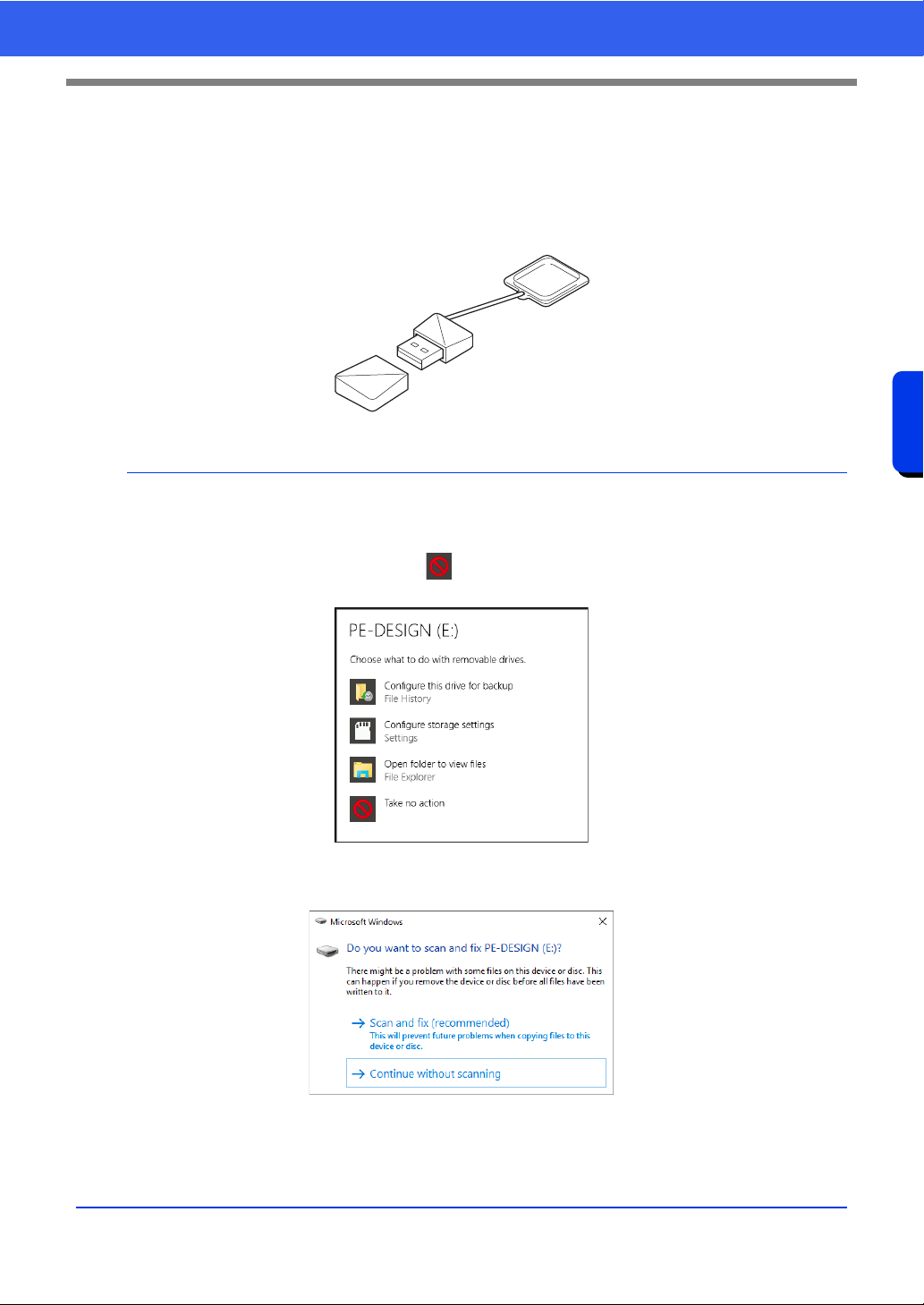
In order to use PE-DESIGN 11, the included "PE-DESIGN Software Key" must be plugged into a USB port of
the computer.
The "PE-DESIGN Software Key" prevents unauthorized use of this software. The software cannot be started
if the "PE-DESIGN Software Key" is not plugged in.
* Design is subject to change.
a
• The "PE-DESIGN Software Key" cannot be used as USB media. Do not save embroidery files on the "PE-
DESIGN Software Key" for transferring or storage.
• When the "PE-DESIGN Software Key" is plugged into a USB port of the computer, the [AutoPlay] dialog
box appears. Do not use this dialog box. Click to close the dialog box, and then start up PE-DESIGN
11.
• When the message "Do you want to scan and fix PE-DESIGN (E:)?" appears, select [Continue without
scanning] and then start up PE-DESIGN 11. The drive name for the PE-DESIGN differs depending on
computers.
• To unplug the "PE-DESIGN Software Key" from the computer, click [Start] - [File Explorer], right-click the
"PE-DESIGN Software Key", and then click [Eject].
• Do not format the "PE-DESIGN Software Key".
• We recommend that you back up this software in order to prepare for unexpected problems.
10
Comparison of Types of Data Created With PE-DESIGN 11
Introduction
Comparison of Types of Data Created
With PE-DESIGN 11
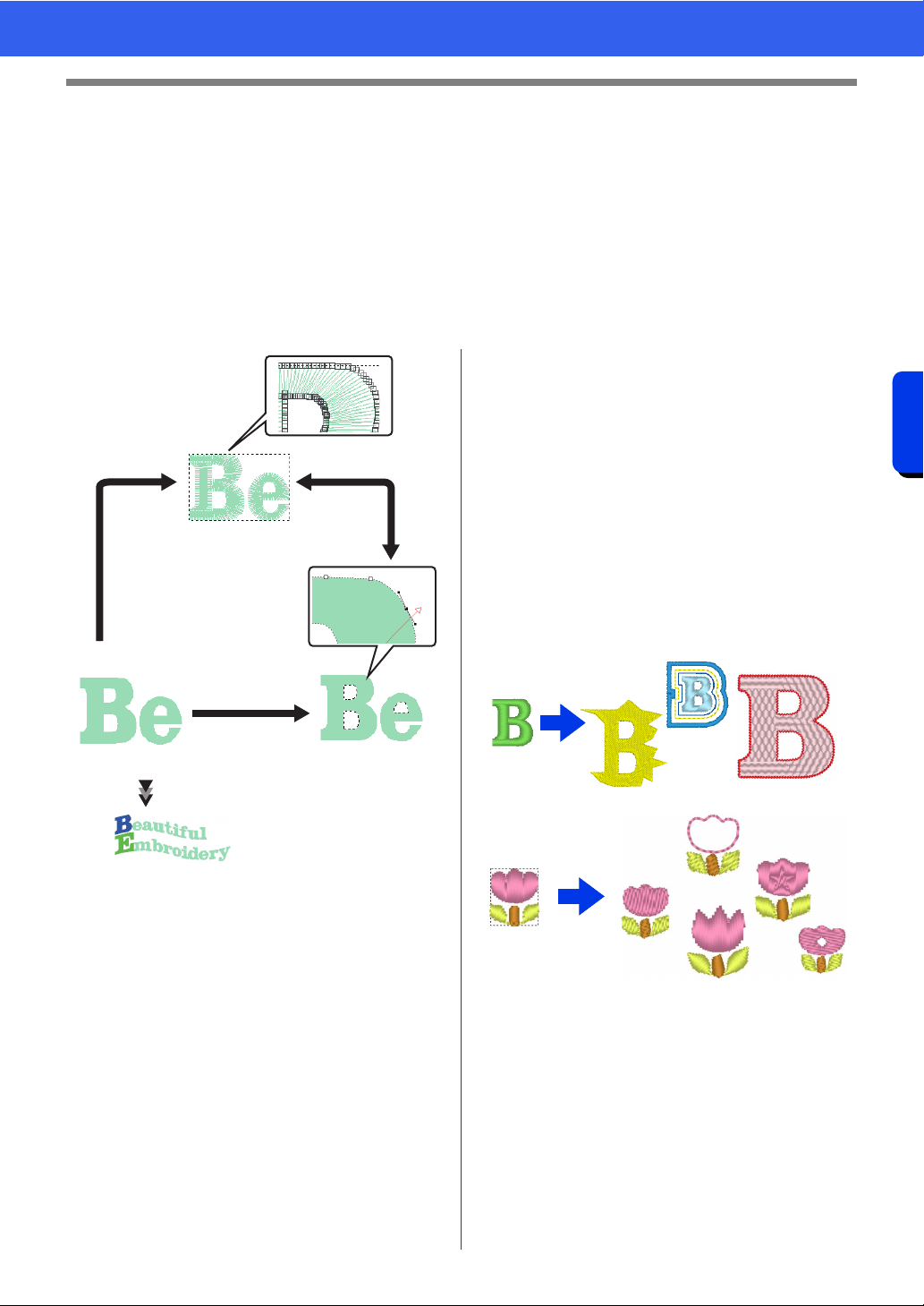
Three types of data are used in PE-DESIGN 11.
Stitch pattern: Built-in embroidery data (created through a conversion in PE-DESIGN 11)
Text pattern: Data created with the [Text] tools
Shape pattern (Outline pattern): Data created with the [Shapes] tools. A uniform/multiple sewing
direction(s) are applied to the entire region.
Each data can be converted to another type as shown below. The arrows indicate the directions in which data
can be converted. The methods of editing the data differ depending on the data type.
1 Text pattern
2 Stitch pattern
3 Shape pattern
4 Change the shape by editing needle drop
points.
5 Change the shape by editing paths.
6 Edit the text or change the font.
Stitch pattern
You can edit (reshaping by moving/deleting points
or splitting/connecting lines at points) points (needle
drop points) and split stitches; however, you cannot
specify region and line sew types or sewing
attributes.
Text pattern
You can edit text by entering/deleting characters,
specify text attributes (such as the font or the
transformation shape) and specify sewing
attributes.
Shape pattern
You can specify region and line sew types as well as
sewing attributes, edit paths (by moving/deleting
points, reshaping through handle movements or by
splitting/connecting lines at points), change the
sewing direction, input/edit stamps, apply
embossing/engraving effects, remove/merge
overlapping regions, set hole sewing, split outlines
and create offset lines and floral patterns.
For example, when a stitch pattern is converted to
shapes, the sew types and sewing attributes can be
changed, and the shapes can easily be edited and
resized. When text pattern is converted to shapes,
the sewing direction and character shapes can be
edited and offset lines can be created.
Functions that are not available with one data type
may be performed if the data is converted to a
different type. Convert data to the type that allows
you to perform the operations necessary for creating
the desired embroidery data.
4
2
31
6
5
11
Starting Up/Exiting Applications
Introduction
Starting Up/Exiting Applications
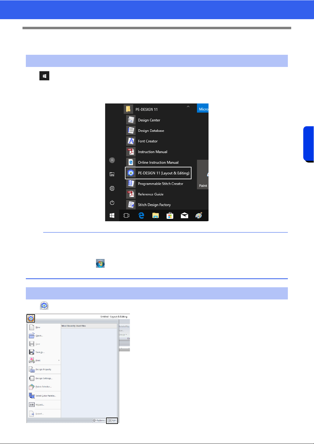
Click , and then Click [PE-DESIGN 11 (Layout & Editing)] under the title [PE-DESIGN 11] in the screen.
When the application starts up, the Startup Wizard appears.
cc "About the Startup Wizard" on page 12
Click , then [Exit].
Starting Up the Application
b
For Windows 8.1 users: Click the down arrow in the bottom-left corner of the [Start] screen to show the
[Apps] view, and then Click [PE-DESIGN 11 (Layout & Editing)] under the title [PE-DESIGN 11] in the
screen.
For Windows 7 users: Click , then [All Programs], then [PE-DESIGN 11], and then click [PE-DESIGN
11 (Layout & Editing)].
Exiting the Application
12
Starting Up/Exiting Applications
Introduction
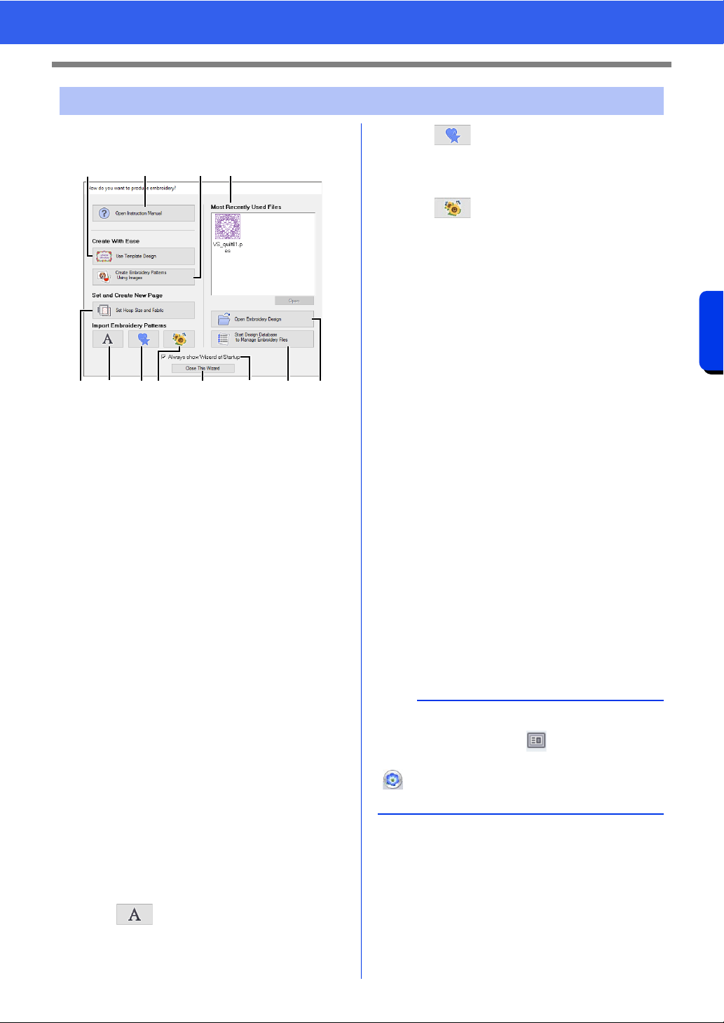
When [Layout & Editing] starts up, the following
wizard appears.
a Open Instruction Manual
Click this button to open the Instruction
Manual (HTML/PDF format).
b Use Template Designs
Click this button to start the [Template
Wizard].
cc "Tutorial 2: Using Templates" on
page 112
c Create Embroidery Patterns Using
Images
Click this button to start the wizard for
creating an embroidery pattern from an
image.
cc "Stitch Wizard: Automatically Converting
an Image to an Embroidery Design" on
page 142 and "Importing Image Data" on
page 163
d Set Hoop Size and Fabric
Click this button to specify the size of the
Design Page (embroidery hoop size).
The fabric to be embroidered can be
selected, and the sewing attributes
appropriate for that fabric can be
specified.
cc "Specifying the Design Page Settings" on
page 16 and "Recalling a group of
settings from the list" on page 213
e
Click this button to import patterns from
[Text] of the [Import] pane.
f
Click this button to import patterns from
[Outline Shapes] of the [Import] pane.
g
Click this button to import patterns from
[Design Library] of the [Import] pane.
h Most Recently Used Files
Select a thumbnail of the most recently
used file from the list, and then click
[Open] to recall the file.
i Open Embroidery Design
Click this button to open embroidery data
(.pes).
cc "Opening a Layout & Editing file" on
page 101
j Start Design Database to Manage
Embroidery Files
Click this button to start up Design
Database.
cc "Design Database" on page 277
k Always show Wizard at Startup
Select this check box to start up the
wizard each time Layout & Editing is
started up.
l Close This Wizard
Click this button to close the Startup
Wizard without performing an operation.
About the Startup Wizard
abch
efg l k ji
d
b
To open the wizard while you are using the
[Layout & Editing], click at the top of the
window (in the [Quick Access Toolbar]), or click
and then select [Wizard] from the command
menu.
13
Understanding Windows
Introduction
Understanding Windows
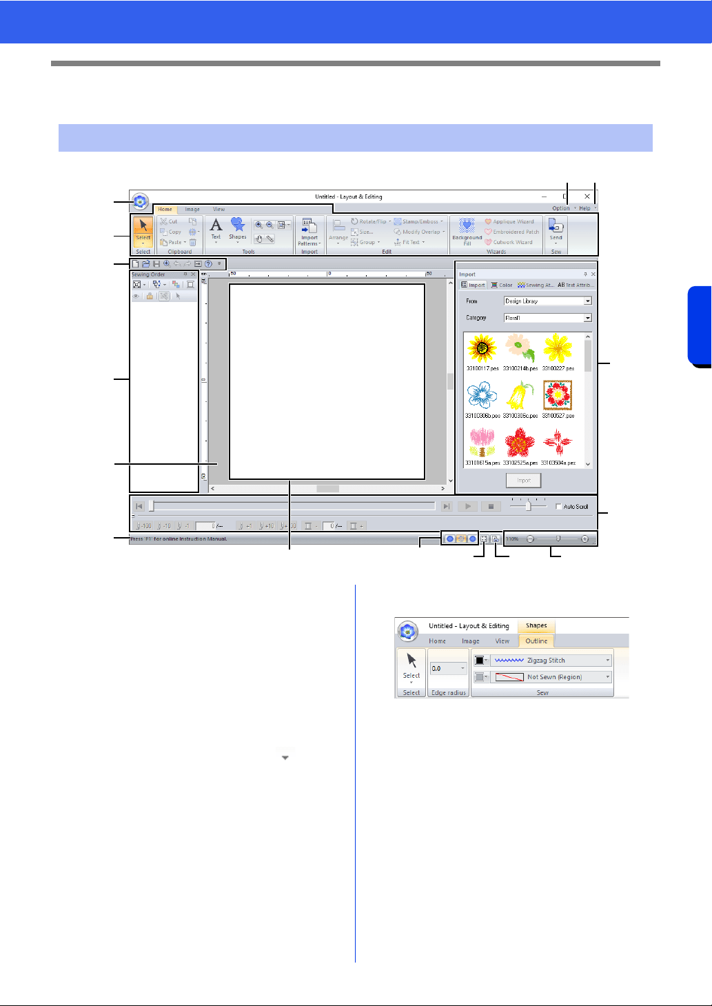
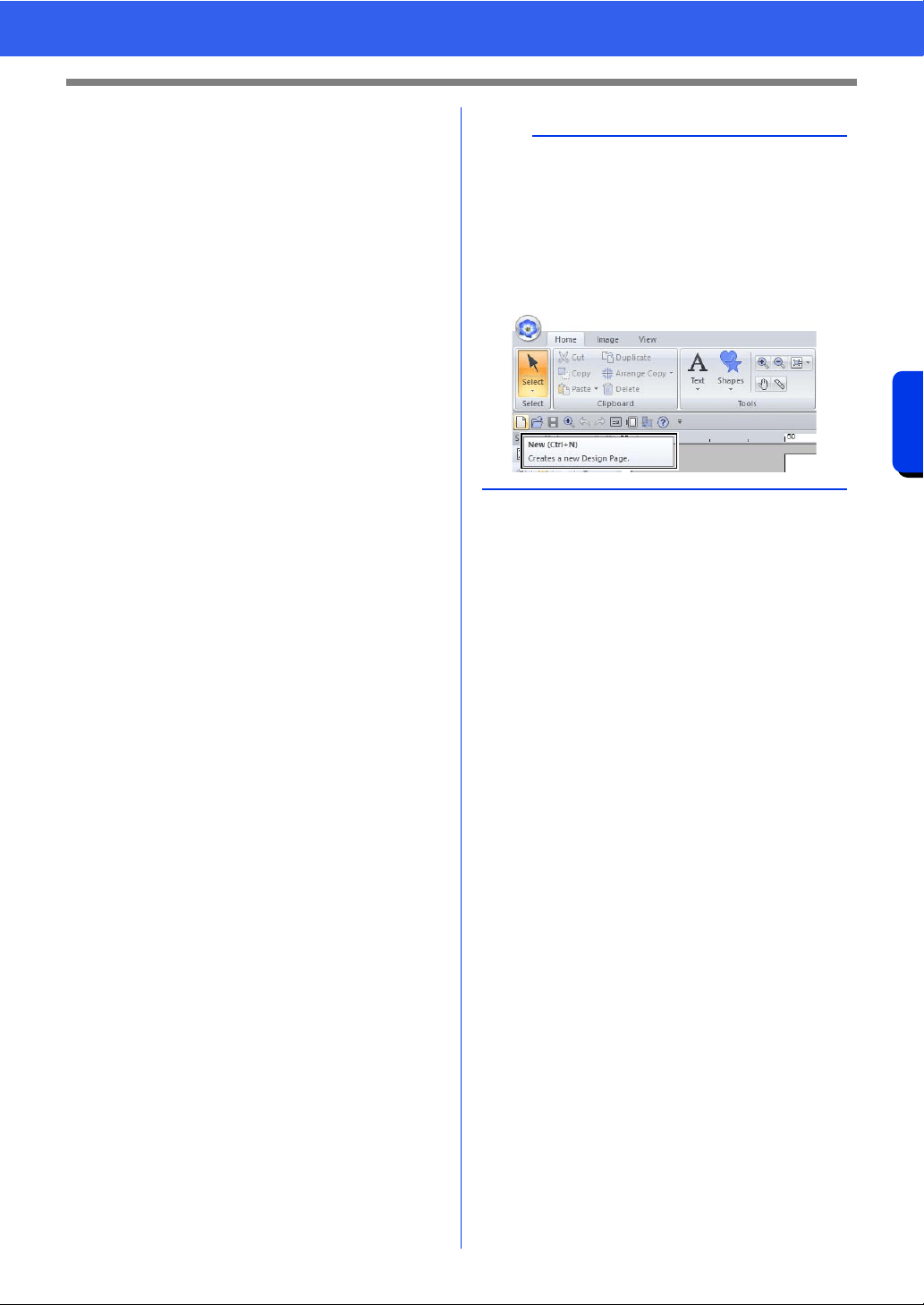
a Application button
Click to display a menu containing
commands for file operations, such as
[New], [Save], [Print] and [Design
Settings].
b Ribbon
Click a tab at the top to display the
corresponding commands.
Refer to the name below each group
when selecting the desired command.
Clicking a command with the mark
displays a menu containing a choice of
commands.
Some other tabs may appear depending
on the tool or embroidery pattern that is
selected. These tabs contain various
commands for performing operations with
the selected tool or embroidery pattern.
Example: When the Shapes (Rectangle)
tool is selected
c Quick Access Toolbar
This contains the most frequently used
commands. Since this toolbar is always
displayed, regardless of the Ribbon tab
that is selected, adding your most often
used commands makes them easily
accessible.
cc "Customizing Quick Access Toolbar" on
page 368
d Option button
Click this button to start up other
applications and specify application
settings, such as user thread charts.
Layout & Editing Window
n
o
l
a
g
h
i
m
b
f
k
de
j
c
14
Understanding Windows
Introduction
e Help button
Click this button to display the Instruction
Manual and view information about the
software.
f Sewing Order pane
This pane shows the sewing order. Click
the buttons at the top of the pane to
change the sewing order or thread color.
g Import/Color/Sewing Attributes/Text
Attributes panes
This pane combines tabs for importing
embroidery patterns as well as for
specifying thread colors, sewing attributes
and text attributes. Click a tab to display
the available parameters.
h Stitch Simulator pane
The Stitch Simulator shows how the
pattern will be sewn by the machine and
how the stitching will appear.
i Design Page
The actual part of the work area that can
be saved and sewn.
j Work area
k Status Bar
This displays the size of the embroidery
data, the number of stitches or a
description of the selected command.
l View mode buttons
Click a button to change the View mode.
m Show grid button
Click to switch between displaying and
hiding the grid.
n Design Property button
Click to display a dialog box containing
sewing information for the embroidery
data.
o Zoom slider
This displays the current magnification
ratio. Click to specify a value for the
magnification ratio.
Drag the slider to change the
magnification ratio.
b
• Panes 6, 7 and 8 can be displayed or hidden
from the [Show/Hide] group in the [View] tab. In
addition, these panes can be displayed as
separate dialog boxes (Floating) or attached to
the main window (Docking).
• Position the pointer over a command to display
a ScreenTip, which provides a description of the
command and indicates its shortcut key.
15
Understanding Windows
Introduction
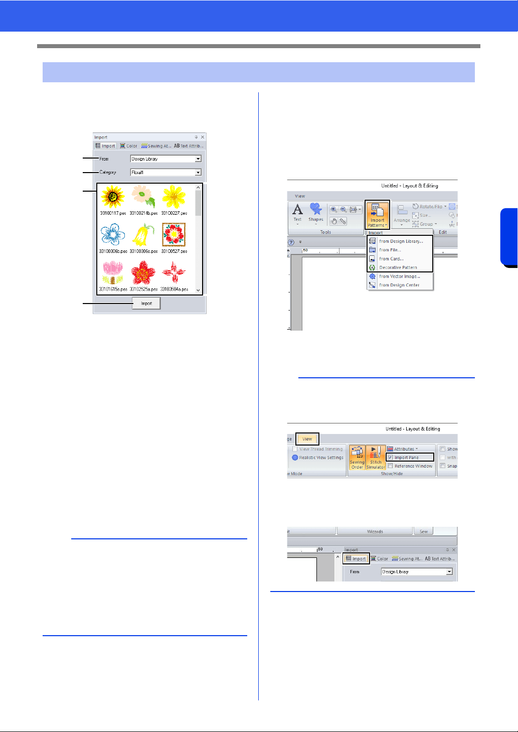
■ Using the Import pane
Embroidery data can be imported by using the
[Import] pane.
a From
Select a pattern location.
b Category
Select a pattern category.
The categories in the pattern location
selected in the [From] selector are listed.
c The patterns in the category selected in
the [Category] selector appear in the list.
Pointing to a pattern and holding down the
left mouse button displays a dotted box in
the Design Page. This allows you to
check the size of the pattern.
d Import
Click this button to import the selected
pattern.
■ Using Import commands
1 Click the [Home] tab.
2 Click [Import Patterns] in the [Import] group,
and then click [from Design Library], [from
File], [from Card] or [Decorative Pattern]
from the [Import] menu.
The [Import] pane appears on the right
side of the screen.
Example of Importing Embroidery Data
b
• The pattern can also be imported by double-
clicking it in the list or by dragging it to the
Design Page.
• Multiple files cannot be selected to be imported
at the same time.
cc "From a folder" on page 102 and "From an
original card" on page 103
a
b
c
d
b
The [Import] pane can also be displayed by
selecting the [Import Pane] check box in the
[View] tab.
When the [Color] pane, [Sewing Attributes]
pane or [Text Attributes] pane is displayed, click
the [Import] tab to display the [Import] pane.
16
Basic Software Settings
Introduction
Basic Software Settings
The color and size of the Design Page can be changed. You can select a Design Page size according to the
size of hoop that you will be using with your embroidery machine. You can also specify a custom size for the
Design Page for embroidery patterns that will be split and embroidered in multiple sections.
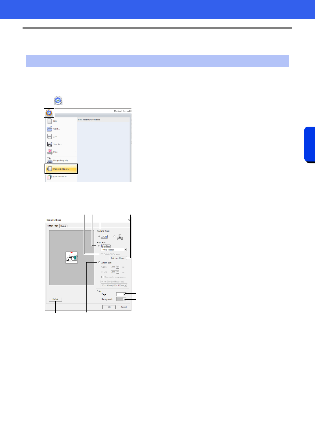
1 Click , then [Design Settings].
2 Specify the settings for the Design Page, and
then click [OK].
a Machine Type
Select your machine type. The settings
available in the [Page Size] selector differ
depending on the selected machine type.
b Hoop Size
Select the desired hoop size from the
selector.
c Rotate 90 Degrees
Select this check box to arrange the
pattern in a Design Page rotated 90°.
d Custom Size
Specify a custom size for split embroidery
patterns.
Select this option, and then type or select
the desired width and height for the
Design Page.
cc "Tutorial 10-1: Creating Split Embroidery
Designs" on page 195
e Page
Select the desired color for the Design
Page.
f Background
Select the desired color for the work area.
g Default
To return to the default settings, click this
button.
h Edit User Hoop
Click this button to display the [User
Hoop Settings] dialog box, where a user
hoop size can be added. The added user
hoop size appears at the bottom of the list.
cc "Specifying a user hoop size" on page 17
Specifying the Design Page Settings
cba h
gd
e
f
17
Basic Software Settings
Introduction
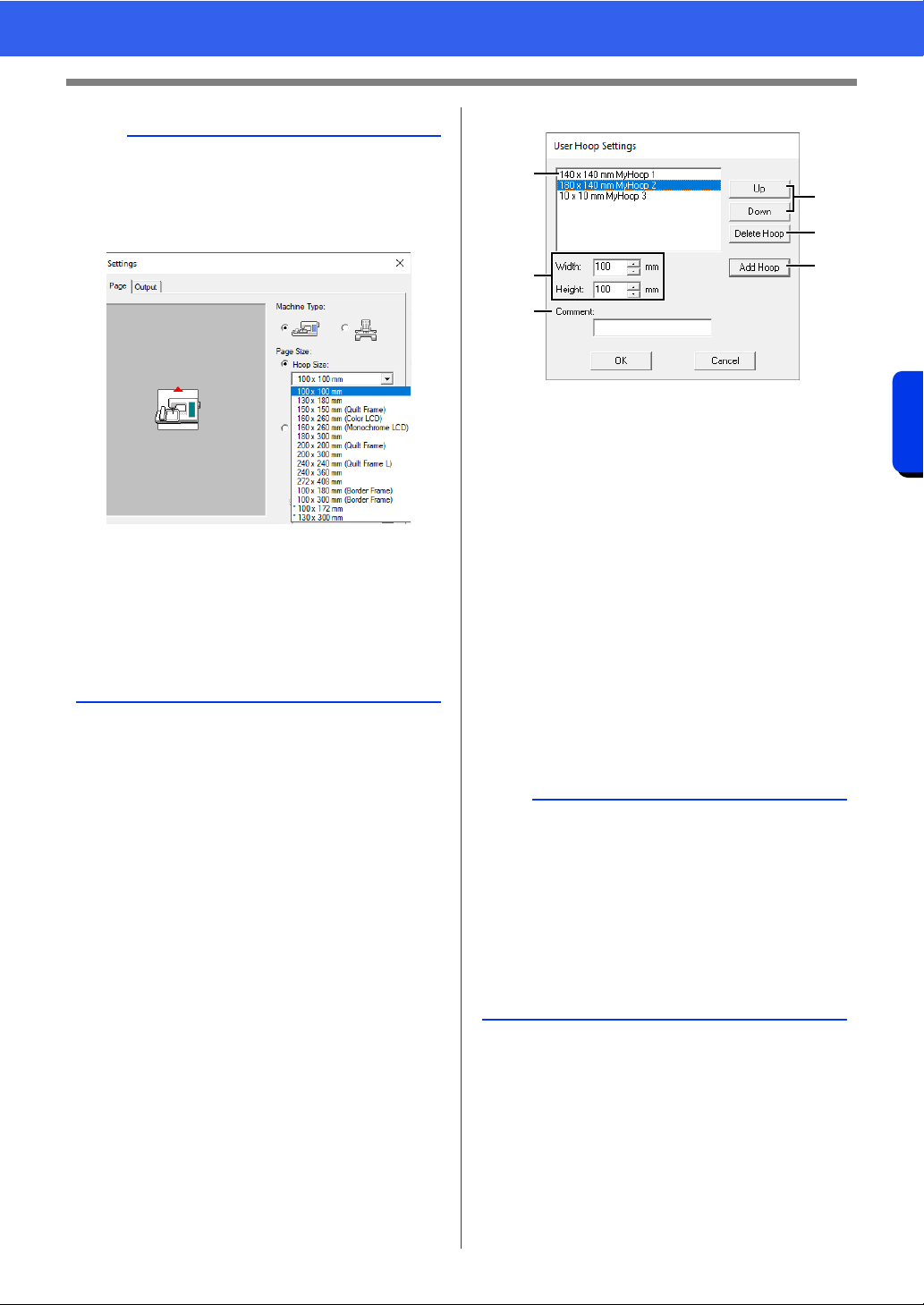
■ Specifying a user hoop size
a User Hoop List
The added hoop size appears in the list.
Select a hoop size in this list to change the
display order or to delete it.
b Width, Height
Type in the size of the hoop to be added.
c Comment
If text was entered in this box, that text
appears beside the size.
d Up, Down
Click these buttons to move the selected
hoop size up or down in the display order.
e Delete Hoop
Click this button to delete the selected
hoop size.
f Add Hoop
Click this button to add the hoop size.
a
• The Design Page sizes 130 × 300 mm, 100 ×
172 mm indicated by the "*", are used to
embroider multi-position designs using a special
embroidery hoop attached to the embroidery
machine at three installation positions.
cc "Tutorial 10-2: Creating Design for Multi-
Position Hoops" on page 204
• Do not select a hoop size larger than the
embroidery hoop that can be used with your
machine.
• When Cap Frame, Cylinder Frame or Round
Frame has been selected, the Design Page
cannot be rotated 90°.
a
• A User Hoop cannot rotate 90°.
• A User Hoop cannot be added to the Section
Size (for Hoop Size) selector under Custom
Size.
• Do not create a Custom Hoop larger than the
embroidery hoop that can be used with your
machine.
• Embroidery data created in a user hoop size
cannot be saved in a format for a previous
version.
a
b
c
d
e
f
18
Basic Software Settings
Introduction
■ Specifying the sewing area
The pattern drawn in the Design Page is sewn
differently depending on the sewing area setting.
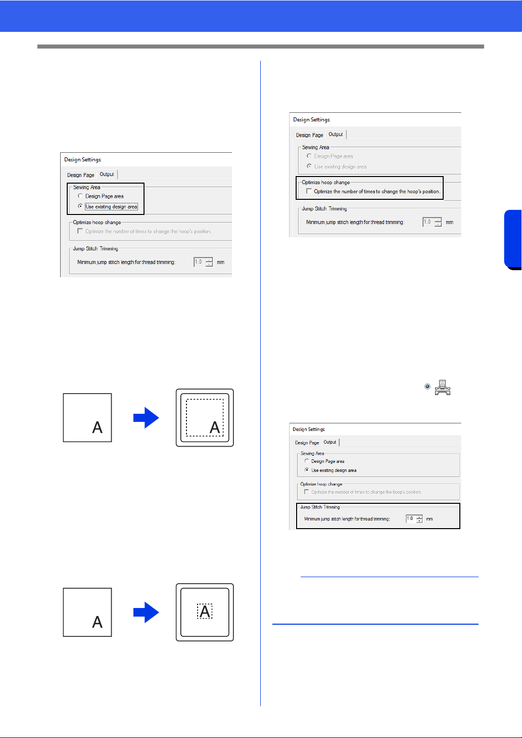
1 Click [Output] tab.
2 Select the desired sewing area ([Design
Page area] or [Use existing design area]).
Design Page area
The patterns will be sewn so that the needle
position when you start sewing is aligned with
the center of your Design Page. The
dimension of the pattern matches the size of
the Design Page, therefore reducing the ability
to move a pattern around the layout screen of
your embroidering machine.
Use existing design area
The patterns will be sewn so that the needle
position when you start sewing is aligned with
the center of the actual patterns. The actual
pattern size is maintained, therefore allowing
greater mobility when using the layout
functions of your embroidering machine.
■ Optimize hoop change
This setting can be selected if a multi-position hoop
(100 × 172 mm or 130 × 300 mm) has been selected
as the Design Page size.
Select the check box to optimize the sewing order/
order of hoop position changes so that the number
of times that the hoop position is changed is
reduced to the minimum.
This reduces the risk of misalignment in the
embroidery pattern or uneven stitching from
changing the hoop position too often.
■ Jump Stitch Trimming
These settings are applied only when embroidering
with our multi-needle embroidery machines. Before
these settings can be specified, select under
[Machine Type] in the [Design Settings] dialog
box.
Specify the minimum jump stitch length for thread
trimming.
cc "Jump Stitch Trimming" on page 98,
"Specifying trimming settings in Layout &
Editing" on page 365 and "Adding jump
stitch trimming to new patterns" on
page 370
Design Page (on
your screen)
Sewing area =
Design Page area
Design Page (on
your screen)
Sewing area = Use
existing design area
a
These settings are not applied with any other
embroidery machine. For details, refer to the
instruction manual provided with your machine.
19
Basic Software Settings
Introduction
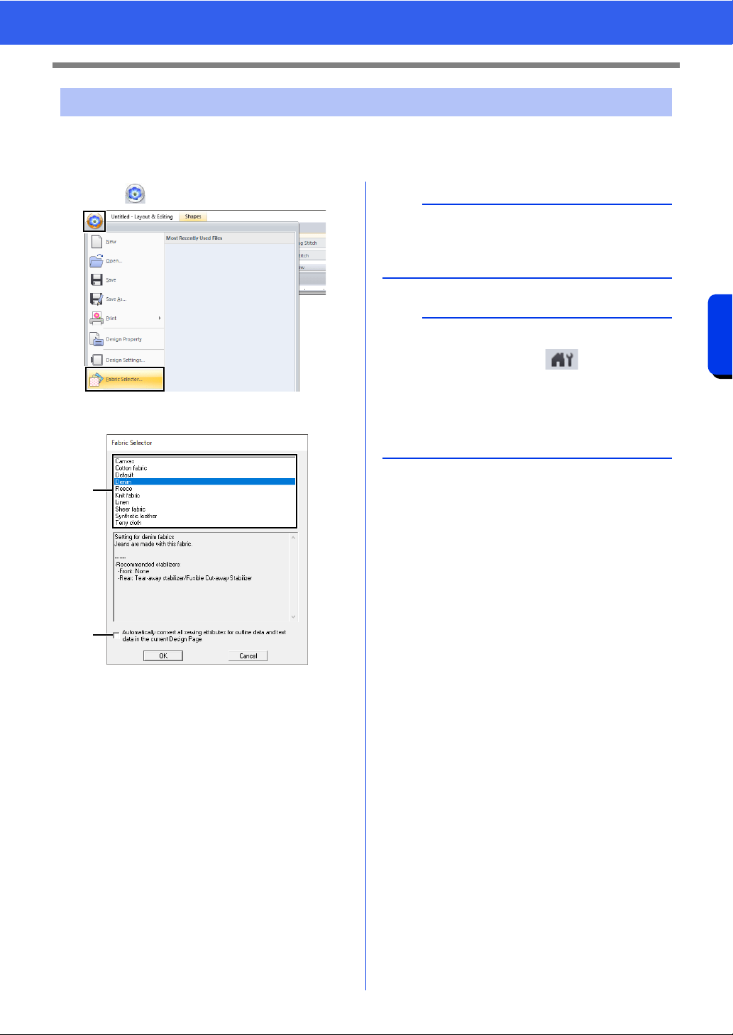
A group of sewing attribute settings appropriate for the major types of fabric can be recalled from the [Fabric
Selector] dialog box. Select the fabric to be embroidered to view a description of the fabric and advice on
embroidering.
1 Click , then [Fabric Selector].
2 Select the group of settings to be recalled.
a Select the type of fabric to be
embroidered to specify the recommended
settings for that fabric.
When a fabric type is selected, a
description appears.
b Select this check box to apply the sewing
attributes to all shape patterns and text
patterns in the current Design Page.
3 Click [OK].
The sewing attributes will be set to those
recommended for the selected fabric.
cc "Specifying sewing attributes" on
page 64
Using Fabric Selector
a
b
a
• Perform a trial sewing before embroidering your
project.
cc "For Basic Operations" on page 363
b
Original settings can be saved to be later used in
the [Fabric Selector]. Click in the [Sewing
Attributes] tab, click [Save As], and then click
[OK] without changing the name for the settings.
The group of settings that you have saved will
appear with “*” beside its name.
cc "Saving the settings in a list" on page 213
20
Basic Software Settings
Introduction
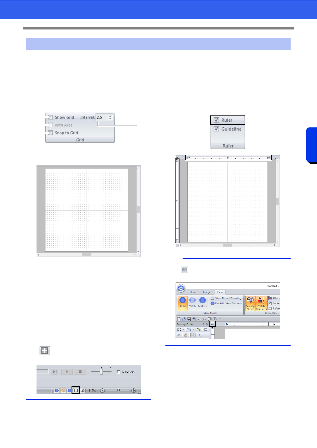
■ Changing the grid settings
A grid of dotted lines or solid lines can be displayed
or hidden, and the spacing for the grid can be
adjusted.
1 Click [View] tab.
2 Specify the grid settings.
a Show Grid
Select this check box to display the grid.
b with Axes
Select this check box to display the grid as
solid lines.
c Interval
Specify the grid spacing.
d Snap to Grid
Select this check box to align patterns
with the grid. The snap feature works
whether or not the grid is displayed.
■ Changing the ruler settings
The ruler can be displayed or hidden.
1 Click the [View] tab.
2 To display the ruler, select the [Ruler] check
box in the [Ruler] group.
To hide the ruler, clear the [Ruler] check box.
Specifying Basic Display Settings
b
The button can also be used to switch the
grid between being displayed or hidden.
a
b
d
c
b
Click to switch the measurement units
between millimeters and inches.
21
Basic Software Settings
Introduction
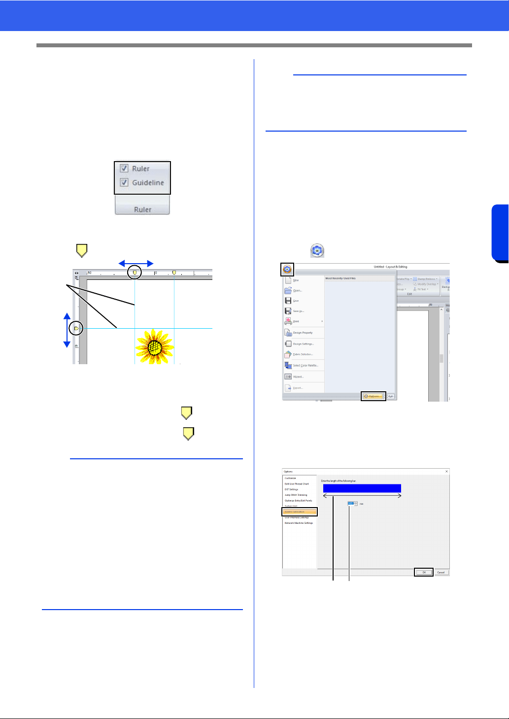
■ Changing the guideline settings
Guidelines can also be used when the ruler is
displayed.
1 Click the [View] tab.
2 Select the [Ruler] check box, and then select
the [Guideline] check box in the [Ruler]
group.
3 Click a ruler in the Design Page.
appears, and a guideline is drawn.
1 Guideline
• To move a guideline, drag .
• To delete a guideline, click .
■ Adjusting on-screen
measurements (Screen
Calibration)
Measurements can be adjusted so that objects will
be displayed at the same size as the actual
embroidery at a zoom ratio of 100%. Once this
adjustment is made, it will not need to be done again
later.
1 Click , then [Options].
2 Click [Screen Calibration]. Hold a ruler
against the screen to measure the length of
a. Next, enter the value at b, and then click
[OK].
Be sure to enter the length in millimeters. A
value in inches is invalid.
b
• A guideline is added each time the ruler is
clicked. In addition, up to 100 guidelines each
can be added to the horizontal and vertical
rulers.
• While a guideline is being dragged, its position is
shown in the status bar.
• When the [Ruler] check box or the [Guideline]
check box is cleared, the guidelines are hidden.
• If both the [Show Grid] and [Snap to Grid]
check boxes are selected, the guidelines will be
added/moved along the lines of the grid.
cc "Changing the grid settings" on page 20
1
b
When a pattern is saved, the guidelines are saved
with it. However, the guidelines are deleted if the
pattern is saved in a format for a version earlier
than version 10.
ab
22
Basic Software Settings
Introduction
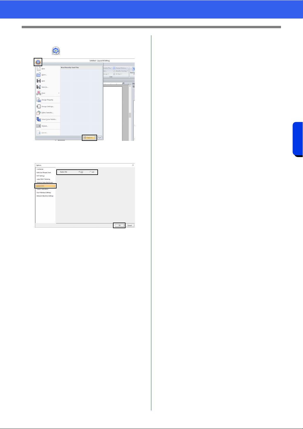
■ System unit
1 Click , then [Options].
2 Click [System Unit], and then select the
desired measurement units ([mm] or [inch]).

Basic Layout & Editing Operations
This section describes the basic operations
performed in Layout & Editing, such as drawing
shapes, editing the embroidery design, specifying
sewing attributes, saving the file and printing it.
24
Layout & Editing
Basic Layout & Editing Operations
Layout & Editing
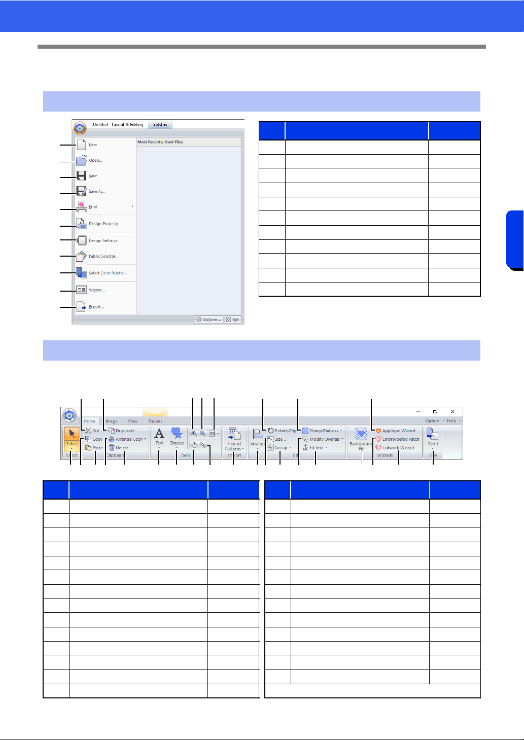
■ Home tab
Application button menu
1
2
3
4
5
6
7
8
9
0
A
No. Menu Reference
1 New p. 101
2 Open p. 101
3 Save p. 107
4 Save As p. 107
5 Print p. 108
6 Design Property p. 99
7 Design Settings p. 16
8 Fabric Selector p. 19
9 Select Color Palette p. 217
10 Wizard p. 12
11 Export p. 107
Ribbon menu tabs
No. Menu Reference No. Menu Reference
1 Select Tools p. 39 15 Import Patterns p. 102
2 Cut — 16 Arrange p. 40
3 Copy — 17 Rotate/Flip p. 42
4 Paste p. 64 18 Size p. 41
5 Duplicate — 19 Group p. 47
6 Arrange Copy Tools p. 43 20 Stamp/Emboss p. 66
7 Delete — 21 Modify Overlap p. 48
8 Text Tools p. 117 22 Fit Text to outline p. 123
9 Shapes Tools p. 70 23 Background fill p. 174
10 Zoom In p. 87 24 Applique Wizard p. 179
11 Zoom Out p. 87 25 Embroidered Patch Wizard p. 185
12 Other Zoom Tools p. 87 26 Cutwork Wizard p. 188
13 Pan p. 87 27 Sew Embroidery p. 222
14 Measure p. 88
1
2
34
5
67 89CD E KL
J
N
O Q
0A B
IFH
G
PM
25
Layout & Editing
Basic Layout & Editing Operations
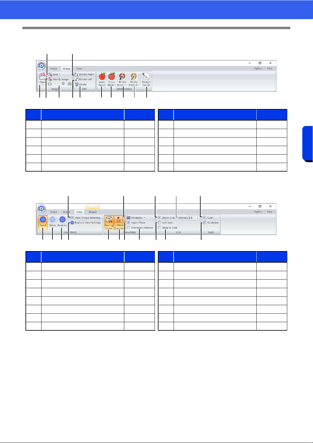
■ Image tab
■ View tab
No. Menu Reference No. Menu Reference
1 Open Image p. 163 7 Delete Image p. 166
2 Save Image p. 166 8 Auto Punch Wizard p. 143
3 Modify Image p. 165 9 Cross Stitch Wizard p. 146
4 Background Image Density p. 165 10 Photo Stitch 1 Wizard p. 150
5 Rotate Right p. 166 11 Photo Stitch 2 Wizard p. 155
6 Rotate Left p. 166 12 Import to Design Center p. 162
No. Menu Reference No. Menu Reference
1 Solid View p. 88 9 Import Pane p. 15
2 Stitch View p. 88 10 Reference Window p. 91
3 Realistic View p. 89 11 Show Grid p. 20
4 View Thread Trimming p. 89 12 Show Grid with Axes p. 20
5 Realistic View Settings p. 89 13 Snap to Grid p. 20
6 Sewing Order p. 92 14 Grid Spacing p. 20
7 Stitch Simulator p. 90 15 Ruler p. 20
8 Attributes Setting p. 36 16 Guideline p. 21
1 34 67
2
5
8 9 0 A B
1 35
4
6 72 9 0
8
B C
A
ED
F
26
Layout & Editing
Basic Layout & Editing Operations
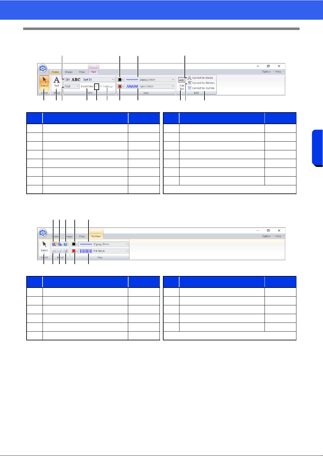
■ Text tab (Text)
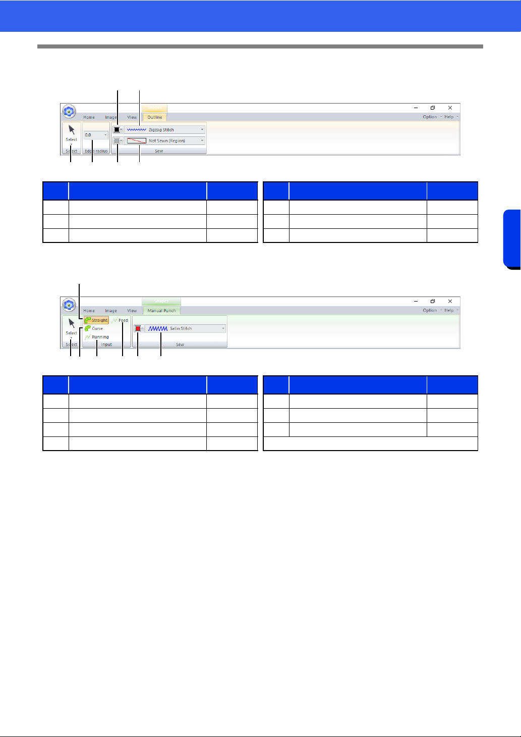
■ Outline tab (Shapes (Outline))
No. Menu Reference No. Menu Reference
1 Select Tools p. 39 9 Text Outline Sew Type p. 128
2 Text Tools p. 117 10 Region color p. 128
3 Font p. 118 11 Text Body Sew Type p. 128
4 Text Size p. 120 12 Edit Text p. 118
5 Font Filter p. 119 13 Convert to Blocks p. 126
6 Font Filter Settings p. 119 14 Convert to Stitches p. 81
7 TrueType Font Attribute Setting p. 121 15 Convert to Outline p. 127
8 Line color p. 128
No. Menu Reference No. Menu Reference
1 Select Tools p. 39 7 Pencil (Open Curve) p. 73
2 Closed Straight Line p. 73 8 Line color p. 75
3 Closed Curve p. 73 9 Line sew type p. 75
4 Pencil (Closed Curve) p. 73 10 Region color p. 75
5 Open Straight Line p. 73 11 Region sew type p. 75
6 Open Curve p. 73
1 54
3
2 7 0 A
8
9
B
C
D E6
1 5 6 7
2
3 4 8 9
0 A
27
Layout & Editing
Basic Layout & Editing Operations
■ Outline tab (Shapes (Rectangle))
■ Manual Punch tab (Shapes (Manual Punch))
No. Menu Reference No. Menu Reference
1 Select Tools p. 39 4 Line sew type p. 75
2 Edge radius p. 71 5 Region color p. 75
3 Line color p. 75 6 Region sew type p. 75
No. Menu Reference No. Menu Reference
1 Select Tools p. 39 5 Feed p. 218
2 Straight Block p. 218 6 Region color p. 75
3 Curved Block p. 218 7 Block sew type p. 75
4 Running p. 218
1 2 5 6
3
4
13 4
2
5 6 7
28
Layout & Editing
Basic Layout & Editing Operations
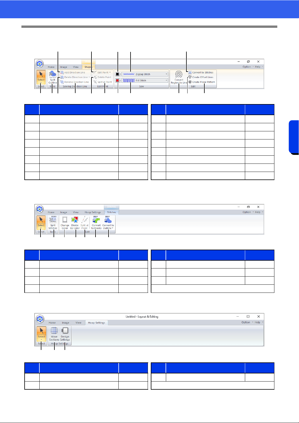
■ Shapes tab (Shapes (Shapes/Circle/Arc))
■ Stitches tab (Stitches)
■ Hoop Settings tab
No. Menu Reference No. Menu Reference
1 Select Tools p. 39 9 Line color p. 75
2 Split Outline p. 50 10 Line sew type p. 75
3 Add Direction Line p. 60 11 Region color p. 75
4 Delete Direction Line p. 61 12 Region sew type p. 75
5 Reverse Direction Line p. 61 13 Convert Region to Line p. 53
6 Edit Point p. 80 14 Convert to Stitches p. 81
7 Delete Point p. 77 15 Create Offset Lines p. 52
8 Split at Point p. 77 16 Create Floral Pattern p. 50
No. Menu Reference No. Menu Reference
1 Select Tools p. 39 5 Split at Point p. 83
2 Split Stitch Data p. 84 6 Convert to Blocks p. 85
3 Change Color p. 81 7 Convert to Outline p. 86
4 Divide by Color p. 85
No. Menu Reference No. Menu Reference
1 Select Tools p. 39 3 Design Settings —
2 Move Sections p. 202
1 4 5
3
A F2
6
7 8
9
0
B
D
EC
21 3 4 5 6 7
21 3
29
Layout & Editing
Basic Layout & Editing Operations
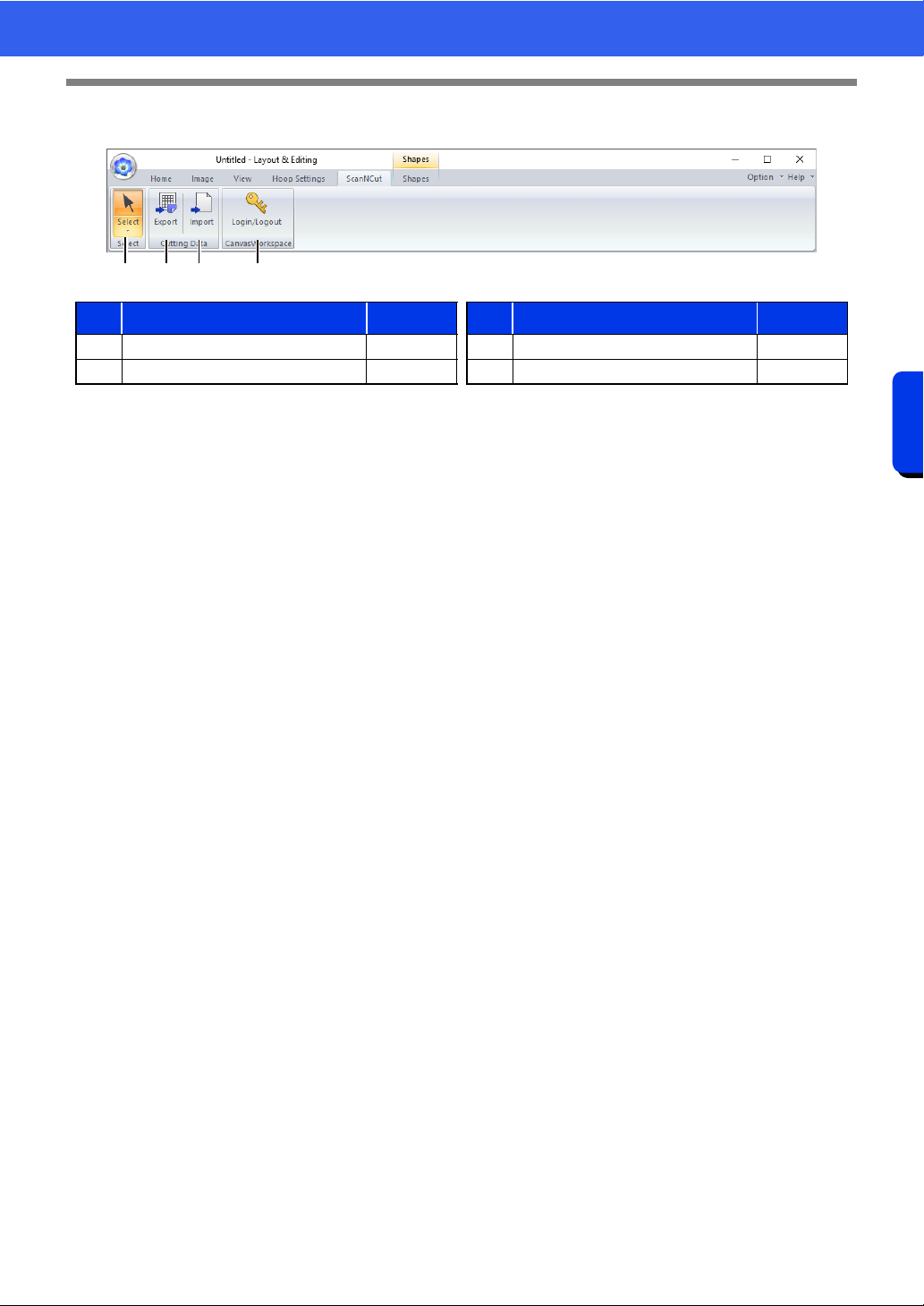
■ ScanNCut tab
No. Menu Reference No. Menu Reference
1 Select Tools p. 39 3 Import p. 243
2 Export p. 243 4 Login/Logout p. 240
21 3 4
30
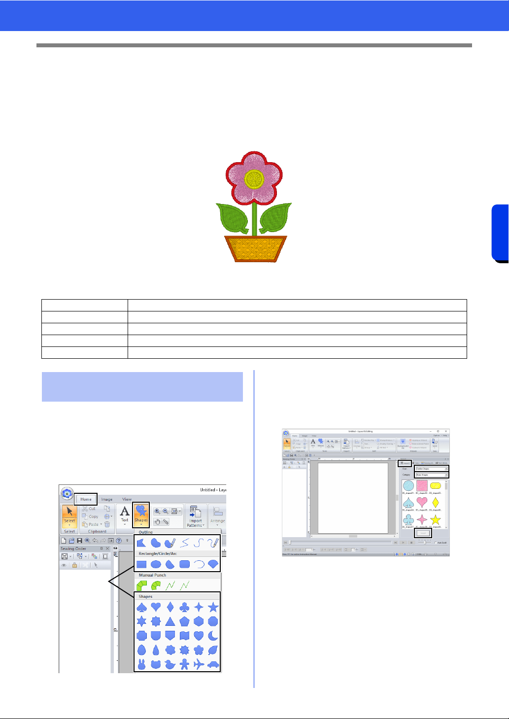
Tutorial 1: Drawing shapes to create an embroidery design
Basic Layout & Editing Operations
Tutorial 1: Drawing shapes to create an
embroidery design
This section will describe how to combine various shapes to create an embroidery design.
We will use an Outline tool to draw the stem. Then, we will create the leaves, flower and flower pot by importing
shape patterns.
The sample file for this tutorial is located at Documents (My documents)\PE-DESIGN 11\Tutorial\Tutorial_1.
Shapes can be created either by drawing them with
the Shapes tools or by importing sample shape
patterns.
1 To draw a shape, select a Shapes tool, and
then drag the pointer in the Design Page to
draw the shape.
1 Shapes tools
2 To import a shape, select [Outline Shapes]
from the [From] selector of the [Import] pane,
then [Basic Shapes] from the [Category]
selector. Select the shape, and then click
[Import].
Specify the sew types for the shape on the
[Shapes] tab, and the thread colors on the
[Shapes] tab or the [Color] pane.
Step 1 Drawing, importing and moving shapes
Step 2 Duplicating, flipping and moving shapes
Step 3 Specifying hole sewing
Step 4 Applying a pattern to stitching
Step 5 Editing points and modifying shapes
Step 1 Drawing, importing and
moving shapes
1
31
Tutorial 1: Drawing shapes to create an embroidery design
Basic Layout & Editing Operations
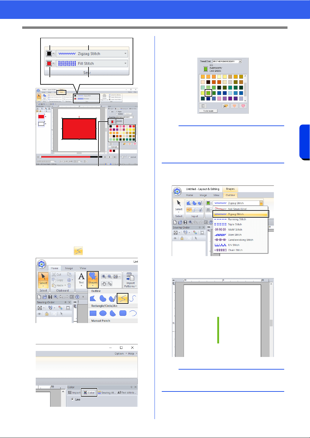
1 Line color button
2 Line sew type selector
3 Region color button
4 Region sew type selector
5 Selected thread color and color name
6 Thread color palette
1 Draw the stem.
(A) Click the [Home] tab.
(B) Click [Shapes] in the [Tools] group, and
then click .
(C) Click the [Color] tab to display the color
palette.
(D) Click [LIME GREEN].
If the desired color is not displayed, move
the scroll bar until it appears.
(E) Click the [Line sew type] selector, and
then select [Zigzag Stitch].
(F) Click the start point 1, and then double-
click the end point 2.
12
34
56
b
To view the thread colors in a list so that the
desired color can more easily be found, click [To
list mode].
cc "Setting the sew type" on page 57
b
The color, sewing attributes and size can also be
changed after the shape is drawn.
1
2
32
Tutorial 1: Drawing shapes to create an embroidery design
Basic Layout & Editing Operations
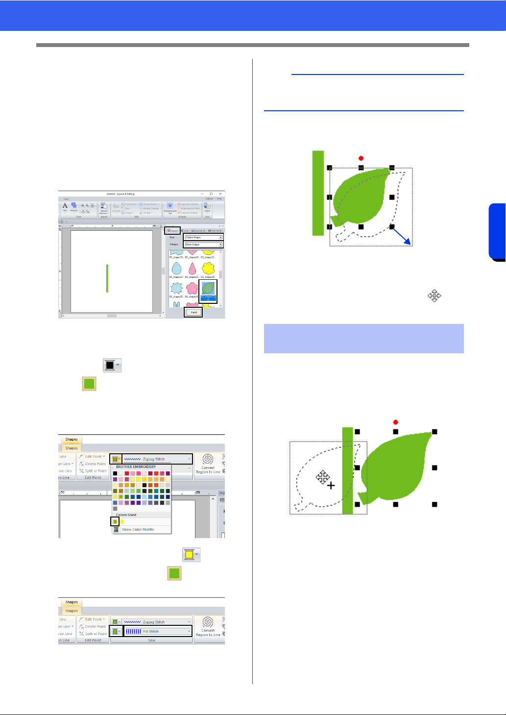
2 Create the leaf on the right.
This time, we will import a shape pattern. We
will also specify the color and sew type for the
region.
(A) Click the [Import] tab.
(B) Select [Outline Shapes] from the [From]
selector and [Basic Shapes] from the
[Category] selector.
(C) Select [BS_shapes27.pes], and then
click [Import].
(D) Click the [Shapes] tab.
(E) Click for line sewing, and then click
under [Colors Used] to select [LIME
GREEN].
(F) Click the [Line sew type] selector, and
then select [Zigzag Stitch].
(G) As with the line color, click for region
sewing, and then click under [Colors
Used] to select [LIME GREEN].
(H) Drag the handle to adjust the leaf to the
desired size.
(I) Place the pointer over the leaf so that the
shape of the pointer changes to , and
then drag the leaf to the desired position.
Now, we will duplicate the leaf on the right side, flip
it horizontally, and then move it to the left side of the
stem.
1 To duplicate the leaf on the right.
(A) Select the leaf.
(B) While holding down the <Ctrl> key, drag
the leaf to move it.
(C) Release the mouse button.
b
The thread colors being used are listed under
[Colors Used].
Step 2 Duplicating, flipping and
moving shapes
33
Tutorial 1: Drawing shapes to create an embroidery design
Basic Layout & Editing Operations
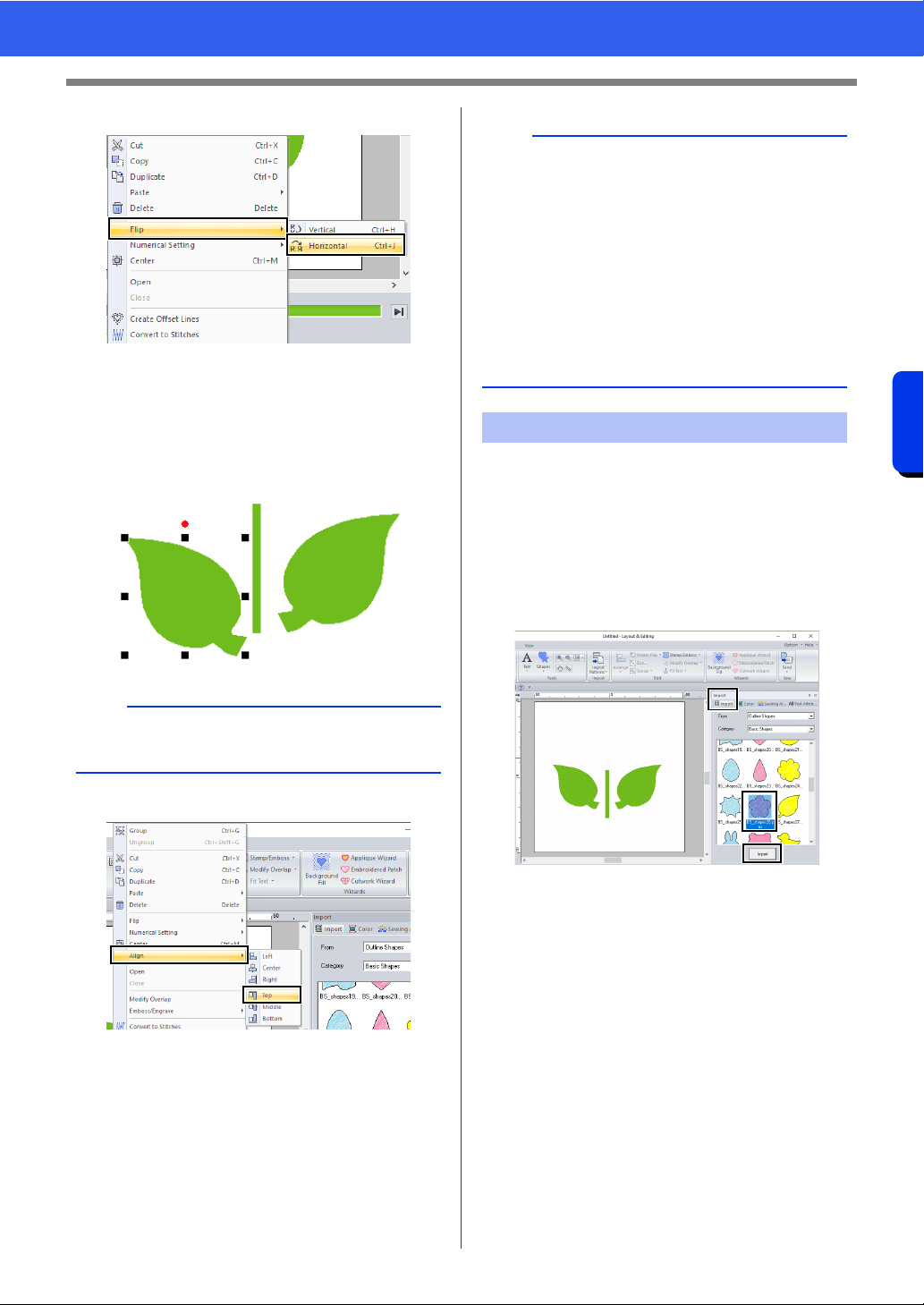
2 To flip the duplicated leaf horizontally.
(A) Right-click on the duplicated leaf.
A drop down menu will appear.
(B) Click [Flip], then [Horizontal].
3 Drag the duplicated leaf to the left side of the
stem.
4 Align the leaves on the left and right sides.
(A) While holding down the <Ctrl> key, click
the leaf on the right side, then the leaf on
the left side to select the two leaves.
Then, right-click the selected leaves.
(B) Right-click the leaves, and then click
[Align], then [Top].
Now, we will create the flower and a circle at the
center. Then, we will apply a setting so that the
overlapping areas are not sewn twice.
1 Create the flower petals.
(A) Click the [Import] tab.
(B) Select [BS_shapes26.pes], and then
click [Import].
(C) Click the [Shapes] tab.
b
To move an object horizontally, hold down the
<Shift> key while dragging the object.
b
• Multiple embroidery patterns can be selected in
any of the following ways.
Click the first pattern, and then, while holding
down the <Ctrl> key, click the next pattern.
Drag the pointer to draw a selection frame
around the patterns to be selected.
• Flipped copies can also be created by clicking
[Arrange Copy] in the [Clipboard] group of the
[Home] tab, then clicking [Vertical Mirror
Copy].
cc "Using the Mirror Copy tool" on page 43.
Step 3 Specifying hole sewing
34
Tutorial 1: Drawing shapes to create an embroidery design
Basic Layout & Editing Operations
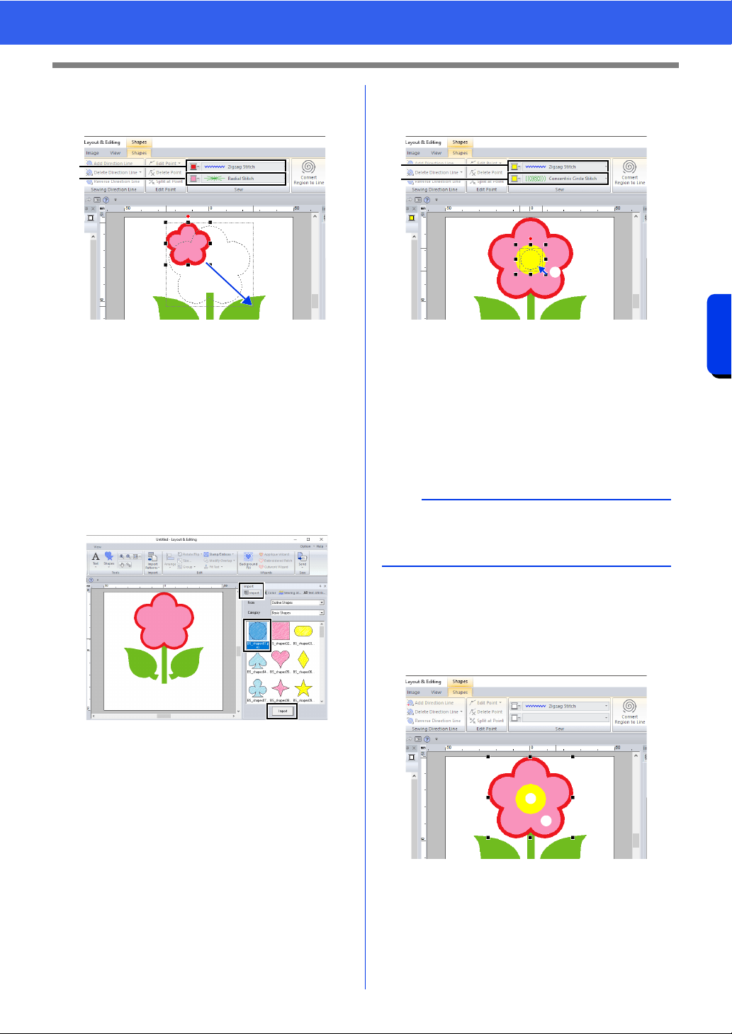
(D) Select [RED] in the color palette as the
line color and [Zigzag Stitch] as the sew
type a.
(E) Select [Radial Stitch] as the sew type
b.
(F) Drag the handle c to adjust the flower
petals to the desired size.
(G) Drag the flower petals to adjust their
position.
2 Create the circle at the center.
(A) Click the [Import] tab.
(B) Select [BS_shapes01.pes], and then
click [Import].
(C) Click the [Shapes] tab.
(D) Select [YELLOW] in the color palette as
the line color and [Zigzag Stitch] as the
sew type
a.
(E) Select [YELLOW] in the color palette as
the region color and [Concentric Circle
Stitch] as the sew type
b.
(F) Drag the circle to the center of the flower
petals.
(G) While holding down the <Shift> key, drag
the handle
c to adjust the circle to the
desired size.
3 Select the patterns where hole sewing is to be
applied.
(A) While holding down the <Ctrl> key, click
the yellow circle a and the flower petals
b.
a
b
c
a
If the <Shift> key is held down while a handle is
dragged, the pattern is enlarged or reduced from
the center of the pattern.
a
b
c
a
b
35
Tutorial 1: Drawing shapes to create an embroidery design
Basic Layout & Editing Operations
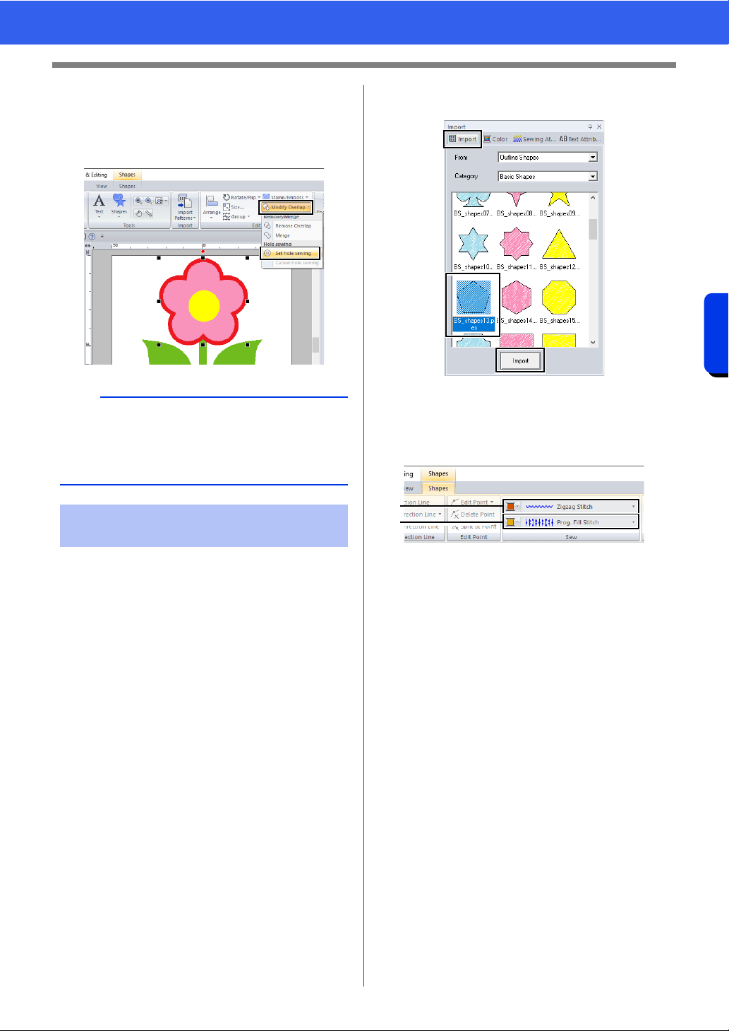
4 Specify hole sewing.
(A) Click the [Home] tab.
(B) Click [Modify Overlap] in the [Edit]
group, and then click [Set hole sewing].
Detailed line and region attribute settings can be
specified from the [Sewing Attributes] pane. Now,
we will specify settings for region sewing for the
flowerpot.
1 Specify the color and sew type for the line and
region of the flowerpot.
(A) Click the [Import] tab.
(B) Select [BS_shapes13.pes], and then
click [Import].
(C) Click the [Shapes] tab.
(D) Select [CLAY BROWN] in the color
palette as the line color and [Zigzag
Stitch] as the sew type
a.
(E) Select [DEEP GOLD] in the color palette
as the region color and [Prog. Fill Stitch]
as the sew type b.
a
Hole sewing cannot be applied if one of the
patterns is not completely enclosed within the
other pattern.
cc "Hole sewing" on page 47.
Step 4 Applying a pattern to
stitching
a
b
36
Tutorial 1: Drawing shapes to create an embroidery design
Basic Layout & Editing Operations
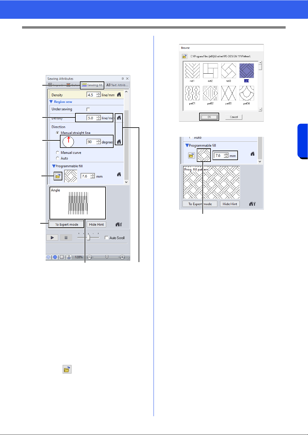
2 Specify the sewing attributes.
(A) Click the [Sewing Attributes] tab.
If the [Sewing Attributes] pane is not
displayed, click the [View] tab, then
[Attributes], then [Sewing Attributes].
1 The effects of the specified settings can be
previewed. This preview can be displayed/
hidden by clicking the Show Hint/Hide Hint
button.
2 Click this button to return the attribute to its
default setting.
(B) There are two display modes for the
[Sewing Attributes] pane. For this
example, we will specify settings in
Beginner mode.
(C) In the [Density] box, type "5.0".
(D) In the [Direction] section, drag the red
arrow to 90°. Otherwise, type "90".
(E) Click in the [Programmable fill]
section.
(F) Select [net4], and then click [OK].
(G) Type "7.6" to specify the pattern size.
1 The selected pattern is displayed.
(C)
(B)
(D)
(A)
(E)
1
2
1
37
Tutorial 1: Drawing shapes to create an embroidery design
Basic Layout & Editing Operations
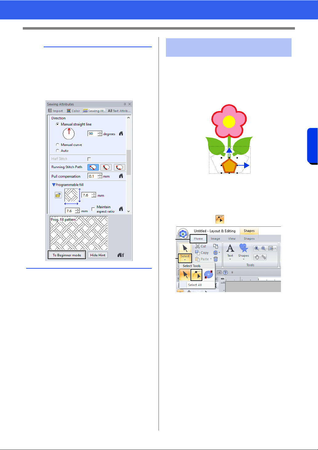
Now, we will delete one corner from the pentagon to
create a flowerpot.
1 Drag the handle to adjust the flowerpot to the
desired size.
Drag the flowerpot to adjust its position.
2 Delete a point.
(A) Click the [Home] tab.
(B) Click [Select] in the [Select] group, and
then click .
(C) Click the shape for the flowerpot.
The points in the shape appear.
b
• If the dialog box is displayed in Expert mode,
click [To Beginner mode] to display the dialog
box in Beginner mode.
• More detailed settings can be specified in Expert
mode.
cc "Specifying sewing attributes" on page 64
Step 5 Editing points and
modifying shapes
(A)
(B)
38
Tutorial 1: Drawing shapes to create an embroidery design
Basic Layout & Editing Operations
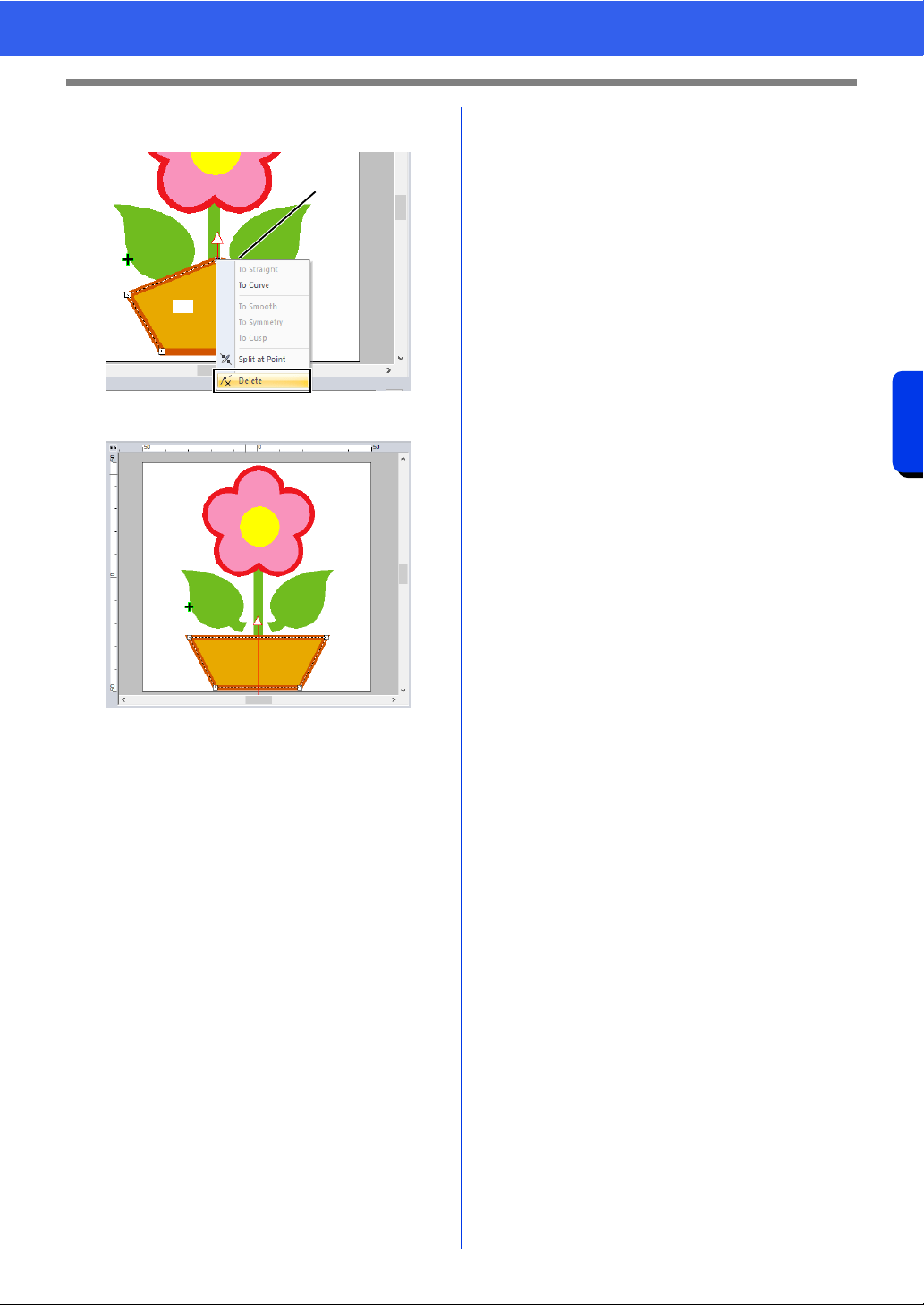
(D) Right-click the top point to be deleted, and
then click [Delete].
The point is deleted to form a trapezoid.
If you want save or export
cc For details on saving embroidery
patterns, refer to "Saving" on page 107.
For details on transferring designs to an
embroidery machine, refer to
"Transferring Embroidery Designs to
Machines" on page 222.
(D)
(C)
39
Editing Embroidery Designs
Basic Layout & Editing Operations
Editing Embroidery Designs
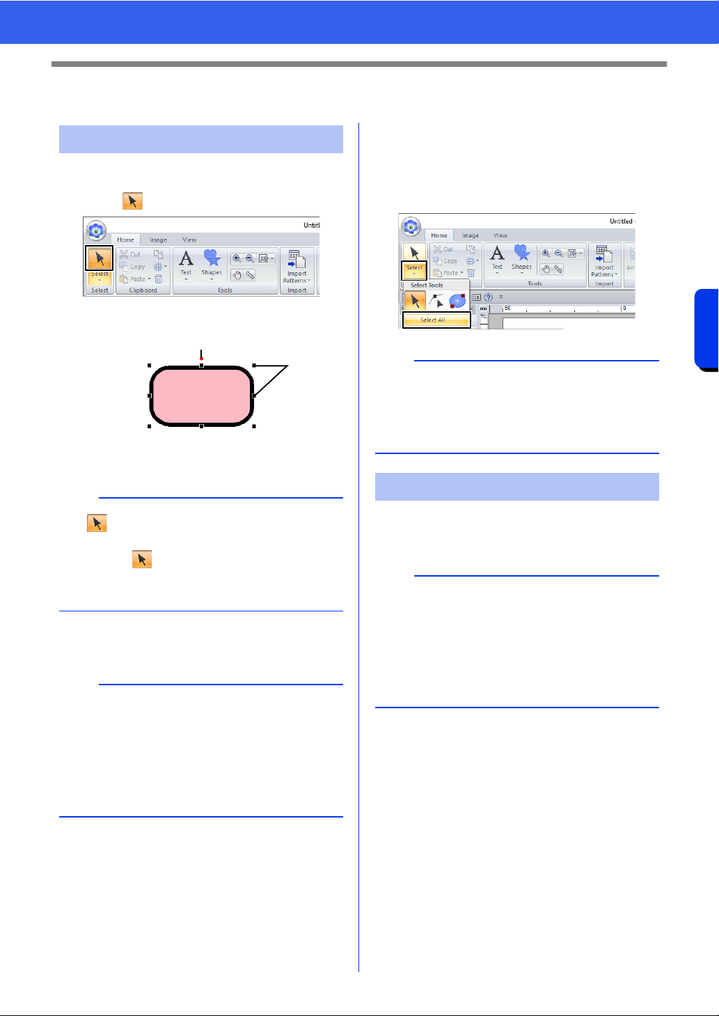
1 Click the [Home] tab.
2 Click in the [Select] group.
3 Click the pattern.
1 Rotation handle
2 Handles
4 To select an additional pattern, hold down the
<Ctrl> key and click the other pattern.
■ Selecting all embroidery patterns
1 Click the [Home] tab.
2 Click [Select] in the [Select] group, and then
click [Select All].
■ Moving manually
Drag the selected pattern(s) to the desired location.
Selecting patterns
b
• If is not displayed in the [Select] group,
click the arrow at the bottom of the button, and
then click .
• The status bar shows the dimensions (width and
height) of the pattern.
b
• You can also select patterns by dragging the
pointer across the pattern.
•Press the <Tab> key to select the next pattern in
the order that they were created.
• If multiple patterns are selected, a pattern can
be deselected by holding down the <Ctrl> key
while clicking the pattern.
1
2
b
• All patterns can also be selected by pressing the
shortcut keys <Ctrl> + <A>.
• Locked embroidery patterns cannot be selected.
cc "Locking embroidery patterns" on page 97
Moving patterns
b
• To move the pattern horizontally or vertically,
hold down the <Shift> key while dragging it.
• Pressing the arrow keys moves the selected
pattern.
• Holding down the <Ctrl> key and dragging the
pattern creates a duplicate of the pattern at the
destination.
40
Editing Embroidery Designs
Basic Layout & Editing Operations
■ Moving embroidery patterns to
the center
1 Select the pattern(s), and then click the
[Home] tab.
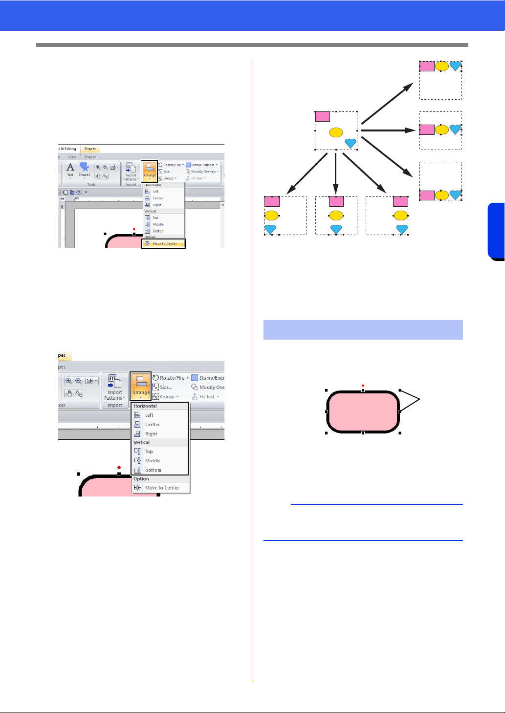
2 Click [Arrange] in the [Edit] group, and then
click [Move to Center].
■ Aligning embroidery patterns
1 Select the patterns, and then click the [Home]
tab.
2 Click [Arrange] in the [Edit] group, and then
click the desired command under [Horizontal]
or [Vertical].
The selected patterns are aligned as
shown below.
1 Top
2 Middle
3 Bottom
4 Left
5 Center
6 Right
■ Scaling manually
1 Select the pattern(s).
1 Handles
2 Drag the handle to adjust the selected
pattern(s) to the desired size.
Scaling patterns
a
We recommend not scaling patterns imported from
original cards.
1
2
3
45 6
1
41
Editing Embroidery Designs
Basic Layout & Editing Operations
■ Scaling numerically
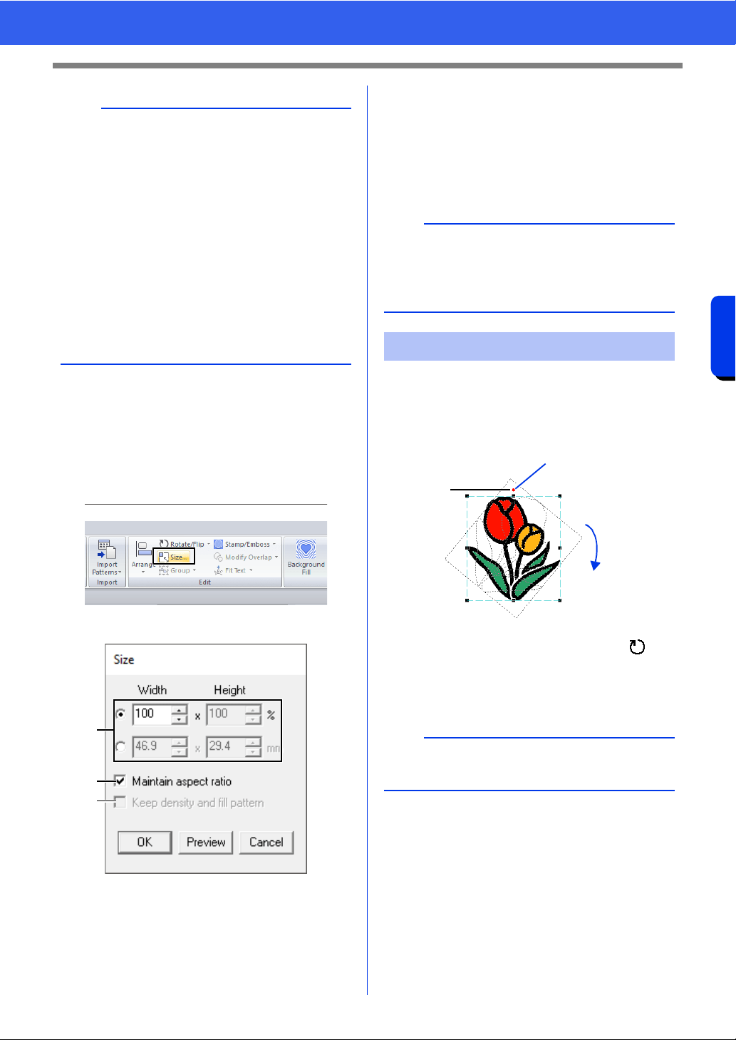
1 Select the pattern(s), and then click the
[Home] tab.
2 Click [Size] in the [Edit] group.
3 Specify the size, and then click [OK].
a Select the whether the width and height
will be set as a percentage (%) or a
dimension (millimeters or inches). Set the
width and height.
b To change the width and height
proportionally, select the [Maintain
aspect ratio] check box.
c To resize the selected pattern while
maintaining the original density and fill
pattern, select the [Keep density and fill
pattern] check box.
■ Rotating manually
1 Select the pattern(s).
2 Drag the rotation handle.
a The shape of pointer changes to
b Rotate
1 Rotation handle
b
• If the <Shift> key is held down while a handle is
dragged, the pattern is enlarged or reduced from
the center of the pattern.
• As you drag the handle, the current size is
displayed on the status bar.
• When scaling stitch patterns, the number of
stitches remains the same, resulting in a loss of
quality. To maintain the density and fill pattern of
the embroidery pattern, hold down the <Ctrl>
key while scaling. Even stitch patterns with a
non-uniform stitch density and needle drop point
pattern can be scaled while maintaining the
density and fill pattern.
cc "Enlarging/Reducing Stitch Patterns" on
page 363.
a
b
c
b
The [Keep density and fill pattern] check box is
available only if stitch pattern is selected.
cc "Enlarging/Reducing Stitch Patterns" on
page 363
Rotating patterns
b
To rotate the pattern in 15° increments, hold down
the <Shift> key while dragging the handle.
a
b
1
42
Editing Embroidery Designs
Basic Layout & Editing Operations
■ Rotating numerically
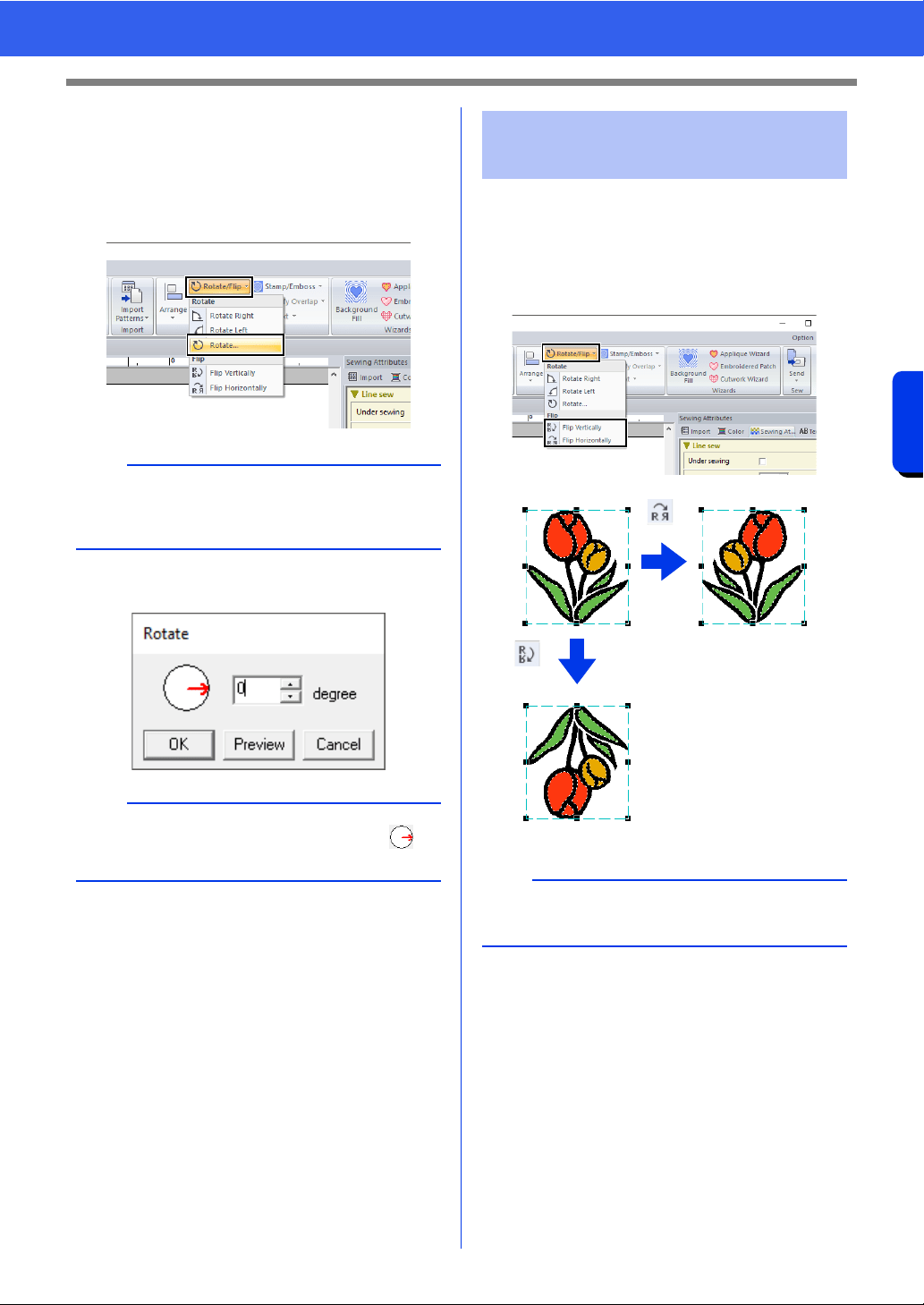
1 Select the pattern(s), and then click the
[Home] tab.
2 Click [Rotate/Flip] in the [Edit] group, and
then click [Rotate].
3 Type or select the rotation angle. Click [OK].
1 Select the pattern(s), and then click the
[Home] tab.
2 Click [Rotate/Flip] in the [Edit] group, and
then click [Flip Vertically] or [Flip
Horizontally].
b
Click [Rotate Right] or [Rotate Left] in the [Edit]
group to rotate the pattern 90° clockwise or
counterclockwise.
b
An angle can also be selected by dragging in
the [Rotate] dialog box.
Flipping patterns
horizontally or vertically
a
Some patterns imported from original cards cannot
be flipped.
43
Editing Embroidery Designs
Basic Layout & Editing Operations
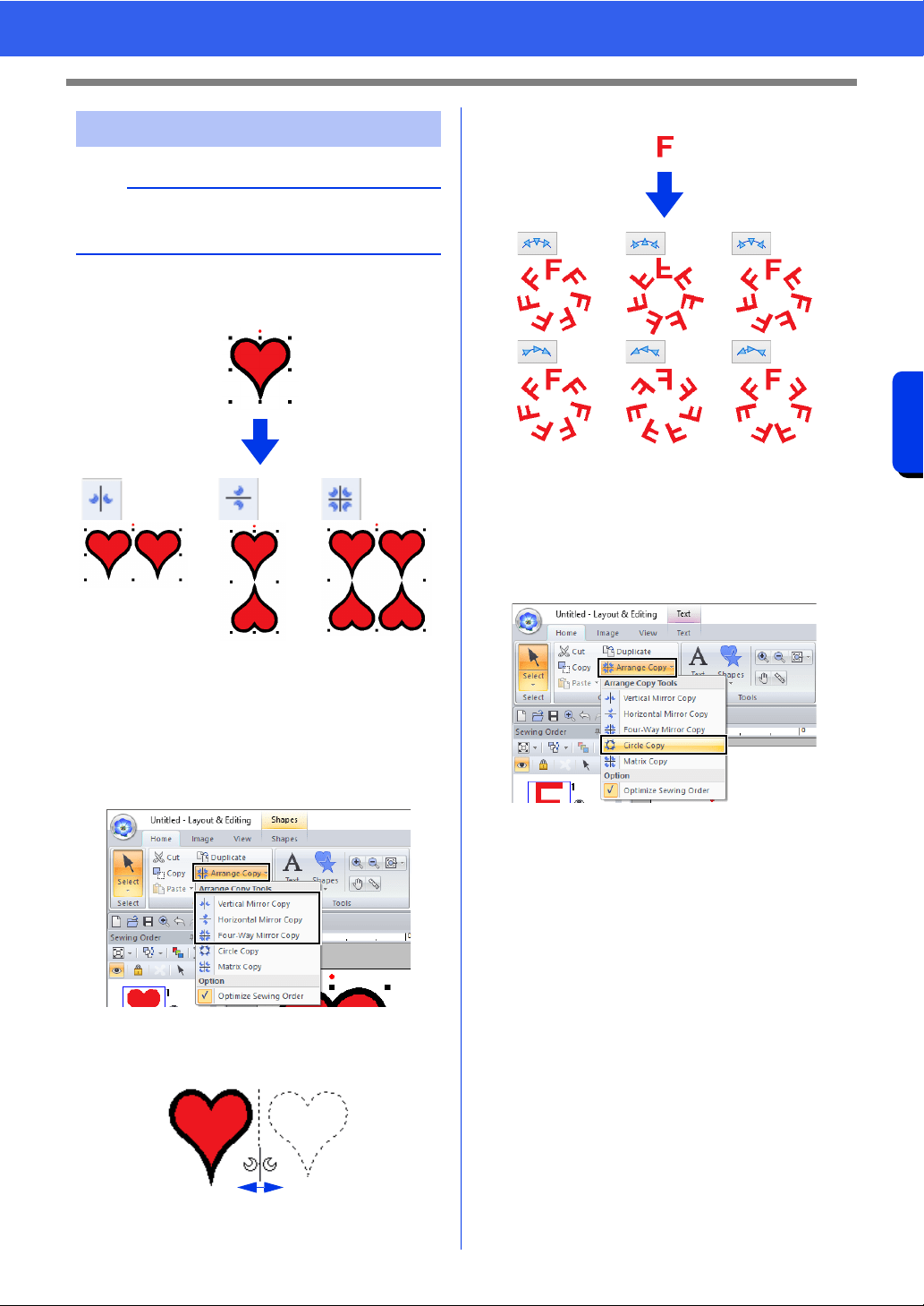
■ Using the Mirror Copy tool
1 Select the pattern(s), and then click the
[Home] tab.
2 Click [Arrange Copy] in the [Clipboard]
group, and then click [Vertical Mirror Copy],
[Horizontal Mirror Copy] or [Four-Way
Mirror Copy].
3 Move the pointer, and then click when the
patterns are arranged as desired.
■ Using the Circle Copy tool
1 Select the pattern(s), and then click the
[Home] tab.
2 Click [Arrange Copy] in the [Clipboard]
group, and then click [Circle Copy].
Arrange Copies
a
It may not be possible to create mirror copies of
some embroidery data read from original cards.
44
Editing Embroidery Designs
Basic Layout & Editing Operations
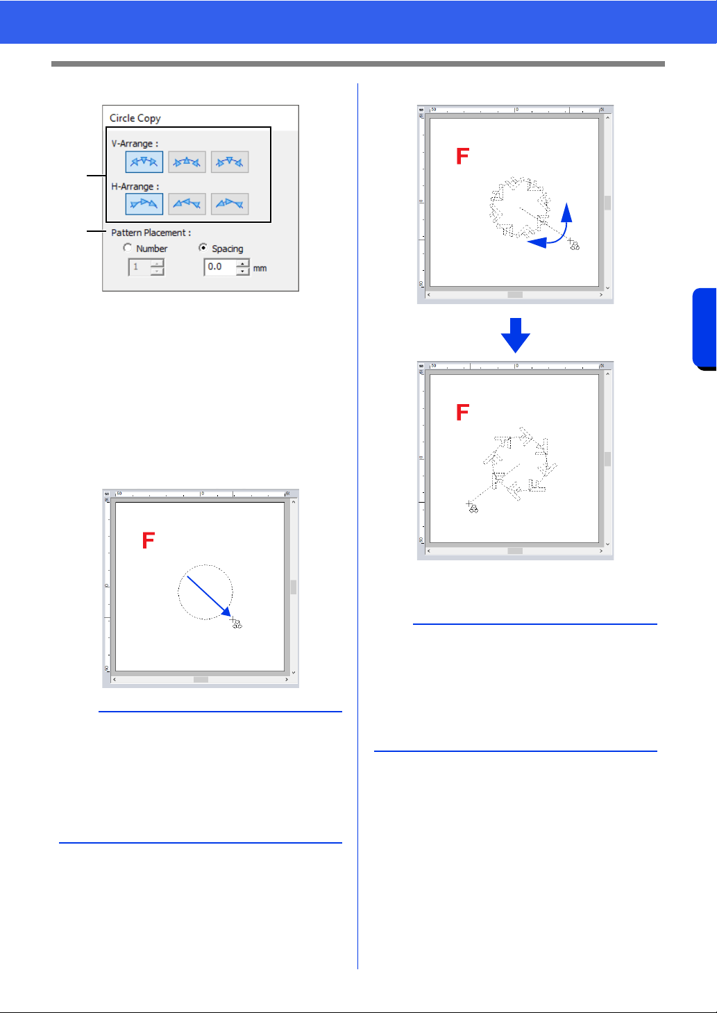
3 Specify the pattern arrangement and spacing.
a Select the desired arrangement.
b Select how the pattern arrangement will
be specified.
Select [Number] to specify the number of
patterns to be arranged.
Select [Spacing] to specify the spacing
between the patterns.
The higher the value, the wider the
patterns are spaced from each other.
4 Drag the pointer to draw a circle or an oval.
5 Move the pointer to select the desired angle.
Rotating the line changes the orientation of
the patterns.
6 Click to finish the copies.
b
• To draw a circle, hold down the <Shift> key
while dragging the pointer.
• To redraw the ellipse, right-click the Design
Page to return to before the ellipse was drawn.
• After drawing a circle or ellipse, hold down the
<Ctrl> key while dragging the pointer to move,
rotate or enlarge/reduce the shape.
a
b
b
• To rotate the line in 15° increments, hold down
the <Shift> key while moving the pointer.
The angle of the line appears in the status bar.
• While changing the orientation by moving the
pointer, the pattern arrangement and spacing
can still be changed in the [Circle Copy] dialog
box.
45
Editing Embroidery Designs
Basic Layout & Editing Operations
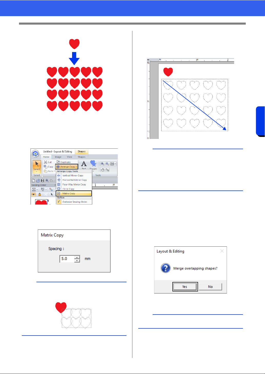
■ Using the Matrix Copy tool
1 Select the pattern(s), and then click the
[Home] tab.
2 Click [Arrange Copy] in the [Clipboard]
group, and then click [Matrix Copy].
3 Specify the spacing between patterns. The
higher the value, the wider the patterns are
spaced from each other.
4 Click in the Design Page, and then move the
pointer.
A rectangle and the patterns that can be
arranged within it appear as dotted lines.
5 Click to finish the copies.
■ Merging patterns
Overlapping shape patterns arranged using
[Vertical Mirror Copy], [Horizontal Mirror Copy],
[Four-Way Mirror Copy], [Circle Copy] or [Matrix
Copy] can be merged. When the following message
appears, click [Yes].
cc The shape patterns are merged.
b
To overlap the patterns, specify a negative value
number.
b
• To redraw the rectangle, right-click the Design
Page to return to before the rectangle was
drawn.
• While resizing the rectangle by moving the
pointer, the pattern spacing can still be changed
in the [Matrix Copy] dialog box.
b
Patterns may not merge under certain conditions.
46
Editing Embroidery Designs
Basic Layout & Editing Operations
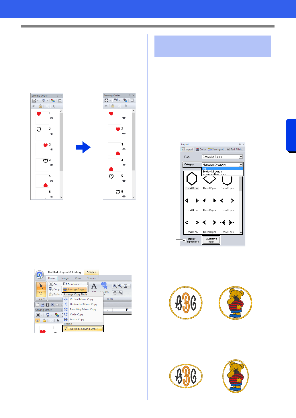
■ Optimizing the sewing order
(color sort)
Before using an [Arrange Copy] tool, optimizing the
sewing order adjusts the sewing order of the
patterns created with the [Arrange Copy] tool in
order to reduce the number of thread color changes.
1 Select the pattern(s), and then click the
[Home] tab.
2 Click [Arrange Copy] in the [Clipboard]
group, and then click [Optimize Sewing
Order] so that the check mark appears.
3 Perform the Arrange Copy operation.
A decorative pattern can be added to selected
embroidery pattern.
1 Select the pattern(s).
2 Display the [Import] pane, and select
[Decorative Pattern] from the [From]
selector.
3 Select a category from the [Category]
selector, select the desired decorative pattern
from the list, and then click [Decorative
Import].
a Maintain aspect ratio
When the check box is selected
The original height-to-width proportion of
the added decorative pattern is
maintained.
When the check box is cleared
The height-to-width proportion of the
decorative pattern changes with the
height-to-width proportion of the selected
embroidery pattern.
[Optimize Sewing
Order] not selected
[Optimize Sewing
Order] selected
The sewing order is the
order in which patterns
are created.
Patterns will be sewn so
that those with the same
thread colors will be
connected.
Adding a decorative
pattern
a
47
Editing Embroidery Designs
Basic Layout & Editing Operations
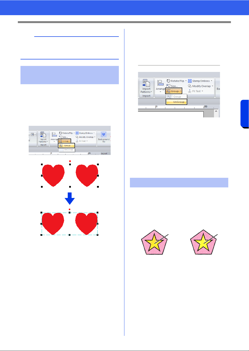
■ Grouping patterns
1 Select several patterns, and then click the
[Home] tab.
2 Click [Group] in the [Edit] group, and then
click [Group].
■ Ungrouping patterns
1 Select grouped patterns, and then click the
[Home] tab.
2 Click [Group] in the [Edit] group, and then
click [UnGroup].
■ Editing grouped patterns
individually
Even after patterns are grouped, they can be edited
individually.
1 To select a single pattern within a group, hold
down the <Alt> key while clicking the pattern.
2 Edit the pattern.
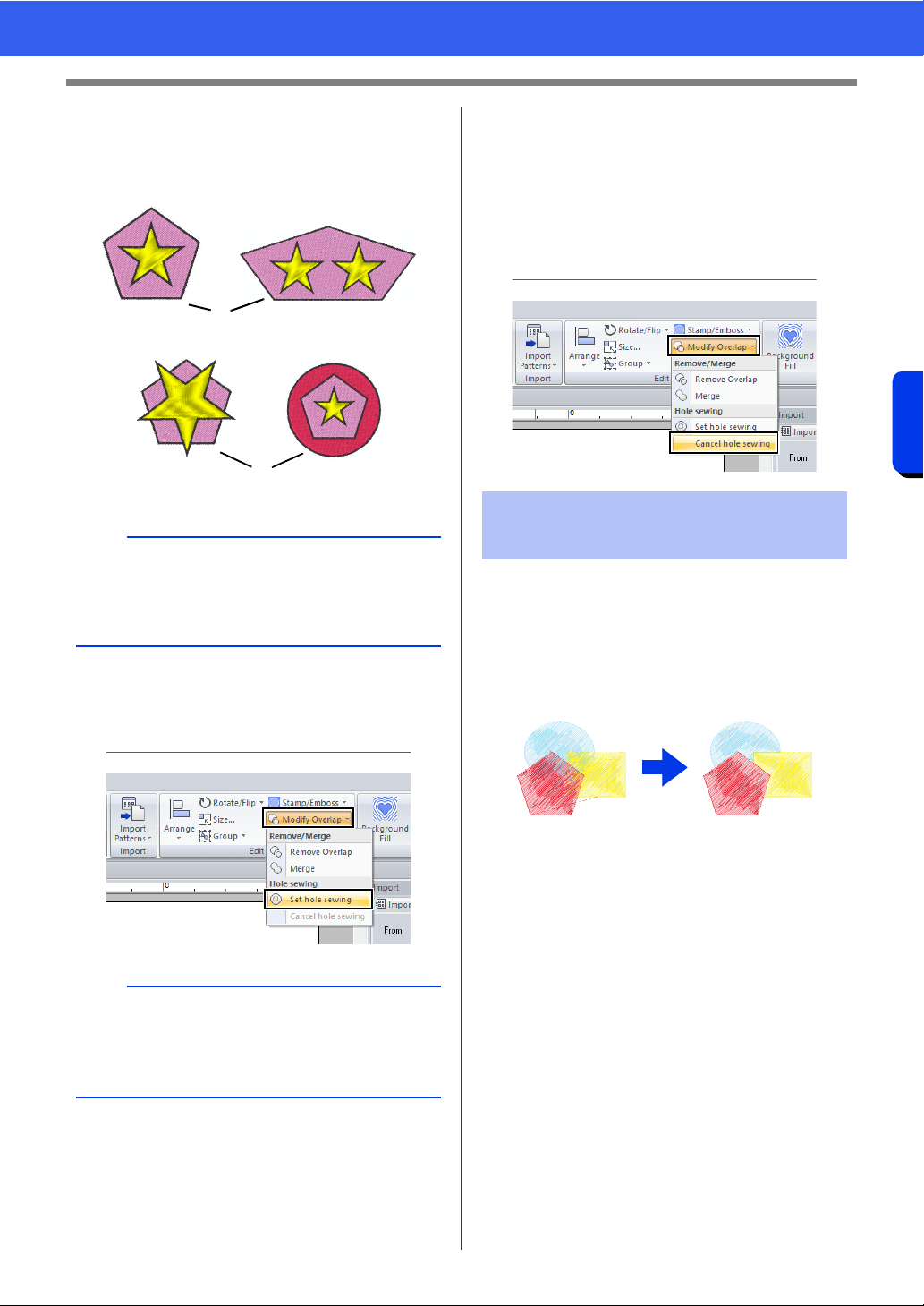
By specifying hole sewing, the stitching in
overlapping regions will not be sewn twice. Hole
sewing can be set only when one region completely
encloses another.
Embroidery patterns created with the Shapes tools
can be selected to set hole sewing.
1 Sewn twice
2 Sewn once
b
If no pattern is selected, the button will appear as
the [Import] button. Clicking this button will import
the decorative pattern at its standard size.
Grouping/Ungrouping
embroidery patterns
Hole sewing
Hole sewing not set Hole sewing set
1
2
48
Editing Embroidery Designs
Basic Layout & Editing Operations
1 Select a pair of patterns, for example, a star
included in a pentagon.
While holding down the <Ctrl> key, click the
star, then the pentagon.
1 Valid
2 Invalid
2 Click the [Home] tab.
3 Click [Modify Overlap] in the [Edit] group,
and then click [Set hole sewing].
■ Canceling hole sewing
1 Select a pattern that has been set for hole
sewing.
2 Click the [Home] tab.
3 Click [Modify Overlap] in the [Edit] group,
and then click [Cancel hole sewing].
Embroidery patterns created with the Shapes tools
can be selected to remove overlapping regions or to
be merged.
■ Removing overlapping
Overlapped patterns can be set so that the
overlapping region is removed.
1 While holding down the <Ctrl> key, click two
or more overlapped patterns to select them.
2 Click the [Home] tab.
a
Hole sewing cannot be specified with the following
shape patterns.
• Patterns with an intersecting outline.
• Patterns with multiple sewing direction lines.
b
To see better what the hole sewing setting does,
preview the patterns before and after setting hole
sewing.
cc "Stitch View" on page 88
1
2
Changing shapes of
overlapped patterns
49
Editing Embroidery Designs
Basic Layout & Editing Operations
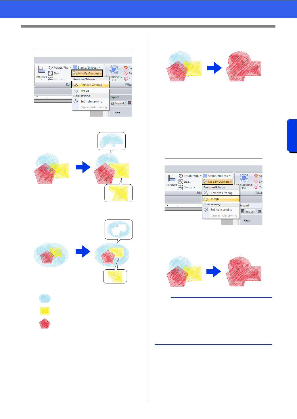
3 Click [Modify Overlap] in the [Edit] group,
and then click [Remove Overlap].
• When partially overlapped
• When enclosed
: First pattern in the sewing order
: Second pattern in the sewing order
: Third pattern in the sewing order
■ Merging
Overlapped pattern can be merged together.
The color and sew type of the last pattern
drawn (topmost pattern) is applied to the
merged pattern.
1 While holding down the <Ctrl> key, click two
or more overlapped patterns to select them.
2 Click the [Home] tab.
3 Click [Modify Overlap] in the [Edit] group,
and then click [Merge].
If this cannot be applied to the selected
patterns, an error message appears.
• When partially overlapped
b
After removing or merging an overlapping region
of patterns with sewing directions specified, the
sewing direction returns to the uniform default
direction.
cc "Specifying the straight sewing direction" on
page 59
50
Editing Embroidery Designs
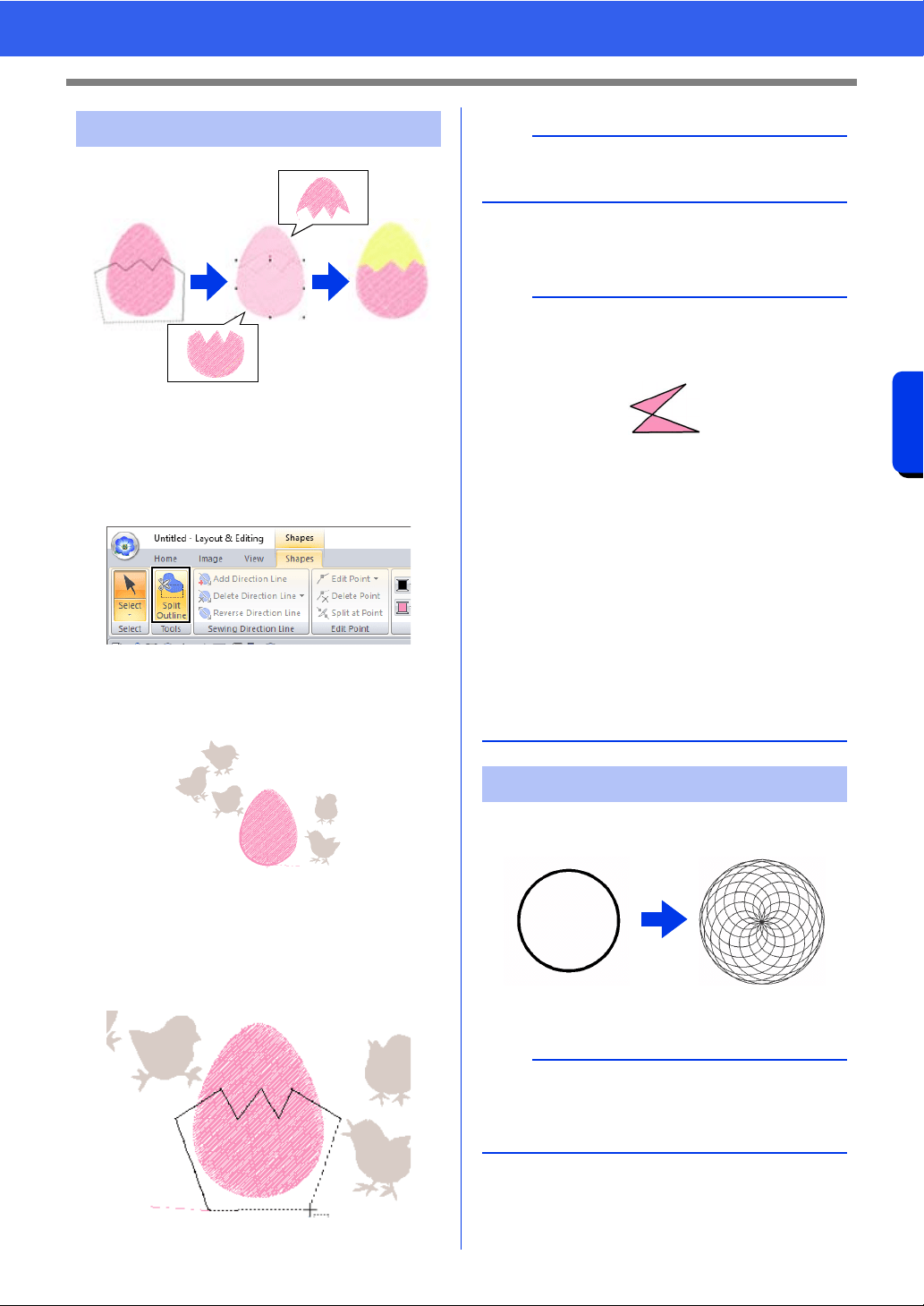
Basic Layout & Editing Operations
1 Select a shape pattern, and then click the
[Shapes] tab.
cc "Shape pattern" on page 10
2 Click [Split Outline] in the [Tools] group to
select the [Split Outline] tool.
If the design contains overlapping patterns,
the selected pattern will appear in front of
the others. All patterns other than the
selected pattern will appear in gray.
3 Click in the Design Page at the point where
you want to start drawing the enclosing lines.
4 Continue clicking in the Design Page to
specify each corner of the enclosure around
the area to be cut off.
5 Double-click in the Design Page to specify the
section to be split off.
Line stitching in a floral pattern can be created
based on the selected shape.
1 Draw a shape, and then select it.
2 Click the [Shapes] tab.
Splitting Shape pattern
b
To remove the last point that was entered, right-
click the mouse button.
a
• Only closed patterns with no intersecting lines
can be split. The pattern shown below cannot be
split.
• The inside pattern with hole sewing applied
cannot be split.
• If the enclosing line that was drawn intersects
itself, the section cannot be split off, and a
message appears.
• After splitting a pattern with fit text to outline
applied, fit text to outline will be canceled.
• If the entered patterns are not in the desired
sewing order, change it in the [Sewing Order]
pane.
cc "Sewing order optimization" on page 94, and
"Changing colors" on page 96
cc "Checking and Editing the Sewing Order" on
page 92
Creating a floral pattern
a
Be sure to select a closed line.
cc "Changing the attributes of line ends" on
page 74
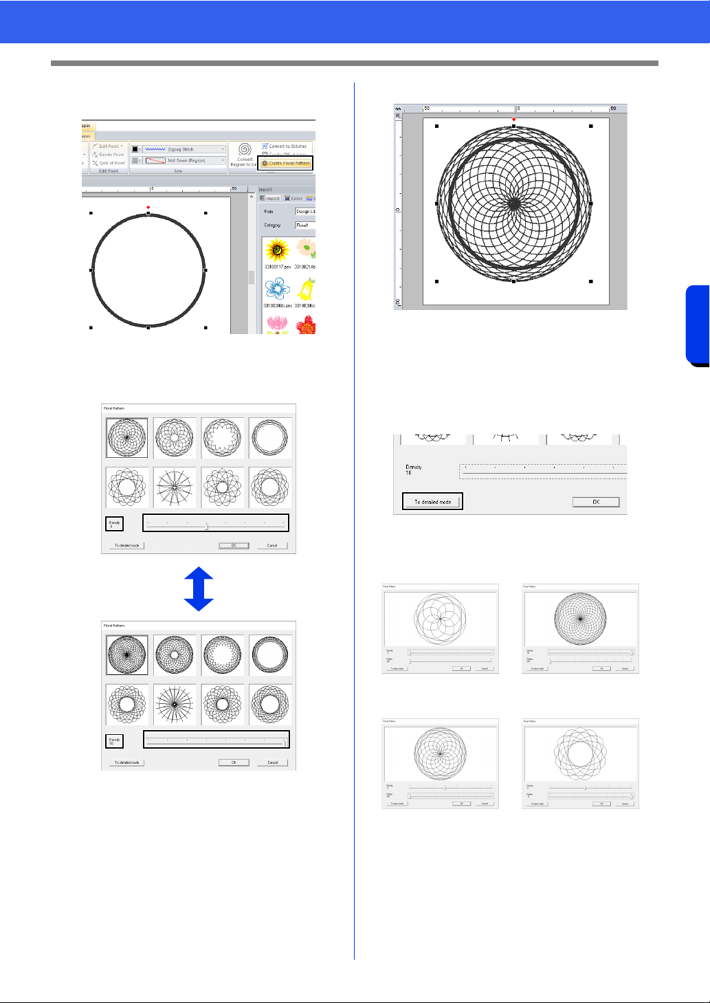
51
Editing Embroidery Designs
Basic Layout & Editing Operations
3 Click [Create Floral Pattern] in the [Edit]
group.
■ Basic mode
1 Drag the [Density] slider to adjust the pattern.
2 Click the desired pattern, and then click [OK].
■ Detailed mode
More detailed settings can be specified in Detail
mode.
1 Click [To detailed mode] in the [Floral
Pattern] dialog box.
2 Drag the [Density] slider and the [Pattern]
slider to adjust the pattern.
Density 3, Pattern 251 Density 10, Pattern 251
Density 6, Pattern 251 Density 6, Pattern 0
52
Editing Embroidery Designs
Basic Layout & Editing Operations
3 After the pattern has been adjusted as
desired, click [OK].
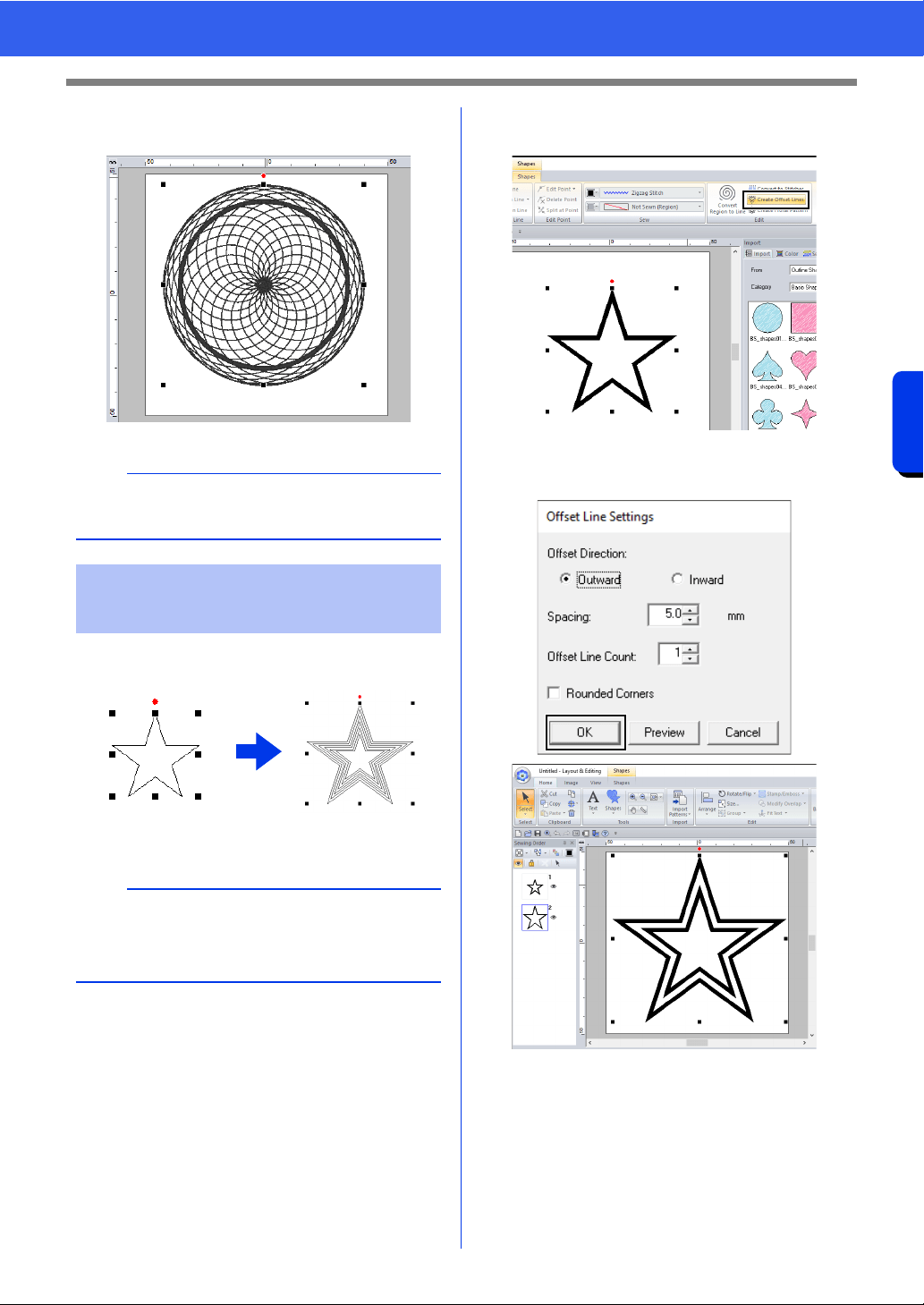
Line stitching in a concentric pattern can be created
based on the selected shape.
1 Draw a shape, and then select it.
2 Click the [Shapes] tab.
3 Click [Create Offset Lines] in the [Edit]
group.
4 Specify the desired settings for the offset line
pattern, and then click [OK].
b
The running stitch is specified for the floral line
pattern.
Creating an offset line
pattern
a
Be sure to select one closed line.
cc "Changing the attributes of line ends" on
page 74
53
Editing Embroidery Designs
Basic Layout & Editing Operations
Offset Direction
Spacing
Offset Line Count
Rounded Corners
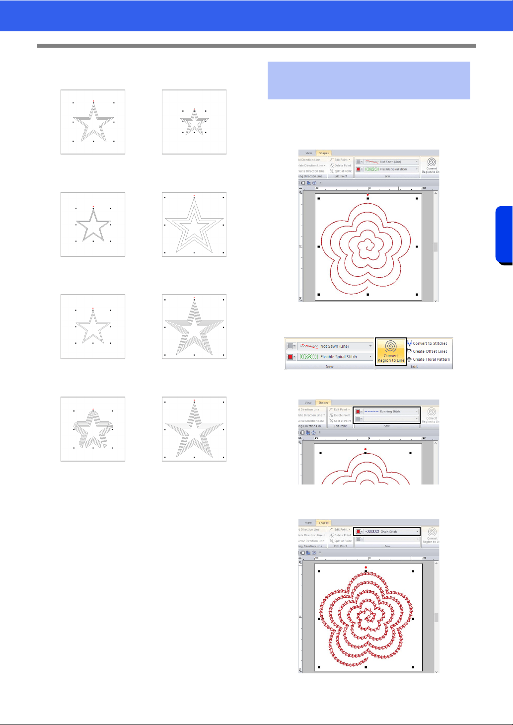
The stitching in regions can be converted to line
stitching.
1 Draw a shape, and then select it.
2 Click [Convert Region to Line] in the [Edit]
group on the [Shapes] tab.
The region sew types change to [Running
Stitch].
3 Select the desired line sew type.
For this example, select [Chain Stitch].
Outward Inward
1 mm 5 mm
1 line 5 lines
Check box selected. Check box cleared.
Converting region
stitching to line stitching
54
Specifying Thread Colors and Sew Types for Lines and Regions
Basic Layout & Editing Operations
Specifying Thread Colors and Sew Types
for Lines and Regions
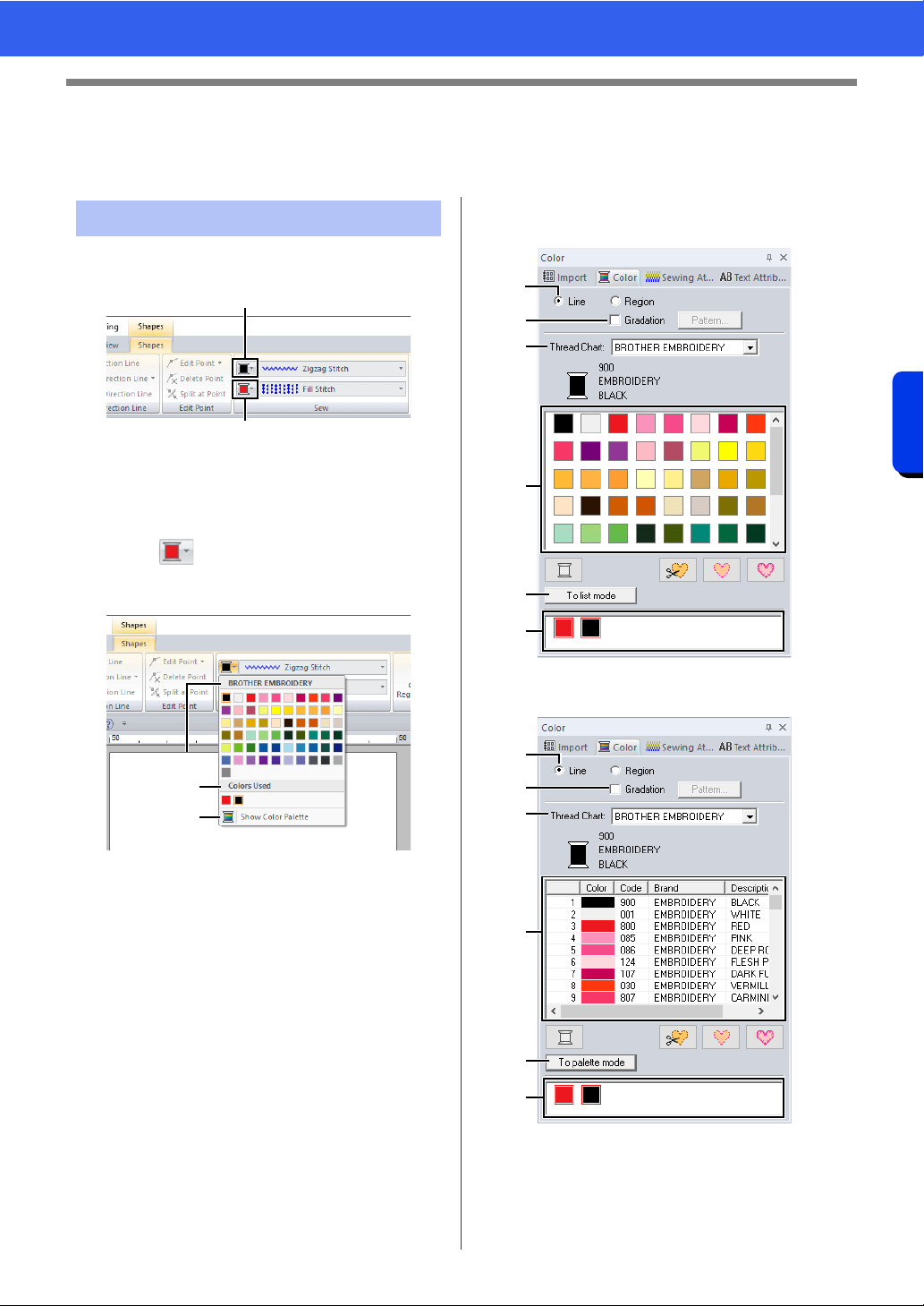
The [Sew] group in the [Shapes] tab allows you to
set the thread color of shapes.
1 Line color
2 Region color
■ Color
Click the [Color] button, and then select the desired
color from the list of thread colors.
a Thread brand name or name of user
thread chart and its thread color list:
Displays the brand name and its thread
color chart for the currently selected
pattern.
b Colors Used
Displays all thread colors being used in
the embroidery design.
c Show Color Palette
Click to display the [Color] pane.
■ Color pane
Palette mode
List mode
Setting the thread color
1
2
a
b
c
a
b
c
d
e
f
a
b
c
d
e
f
55
Specifying Thread Colors and Sew Types for Lines and Regions
Basic Layout & Editing Operations
a Select the type of stitching ([Line] or
[Region]) to display the corresponding
colors being used.
Line
Line color
Region
Region color
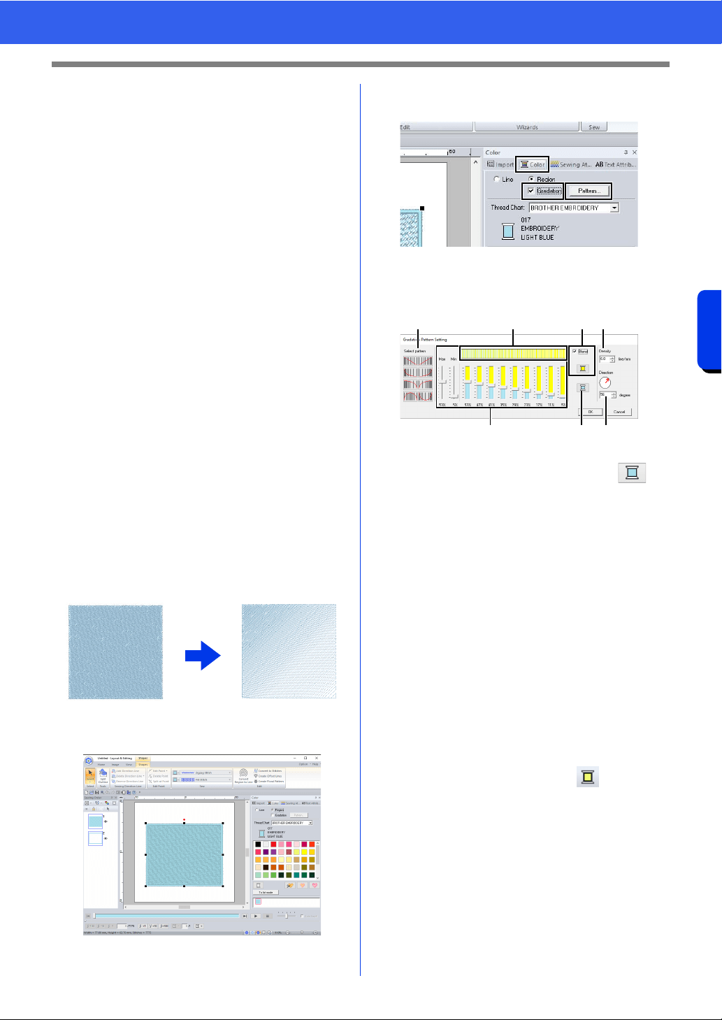
b Select the check box to apply gradation/
blending. Click the [Pattern] button to
specify a gradation/blending pattern.
(Only available when a shape pattern is
selected)
cc "Creating a gradation/blending" on
page 55
c From the [Thread Chart] selector, select
a thread brand or your user thread chart.
d From the list of thread colors, select the
desired color.
e Click to switch the mode.
f Displays all thread colors being used in
the embroidery design. When an
embroidery pattern is selected, a frame
appears around the colors used in that
pattern. The same thread colors can be
specified by selecting them here.
■ Creating a gradation/blending
The density of one or two colors can be adjusted at
various locations to create a custom gradation
pattern.
1 Select an embroidery pattern with region
sewing specified.
2 Click the [Color] tab, select the [Gradation]
check box, and then click [Pattern].
3 Specify the desired settings in the [Gradation
Pattern Setting] dialog box, and then click
[OK].
a To change the thread color, click .
Select a color in the [Thread Color]
dialog box that appeared, and then click
[OK].
b To select a preset gradation pattern, click
the desired pattern under [Select
pattern].
c Move the sliders to adjust the density of
the gradation pattern.
The overall density of the gradation can
be adjusted with the [Max] and [Min]
sliders.
Drag the [Max] slider to adjust the
maximum value and the [Min] slider for
the minimum value. The values between
the maximum and minimum are
automatically adjusted.
d To blend two colors, select the [Blend]
check box, and then click . Select a
color in the [Thread Color] dialog box
that appeared, and then click [OK].
e The preview area shows the setting
changes that you make.
f Specify the density.
g Specify a direction, or drag the red arrow
to adjust it.
bedf
cag
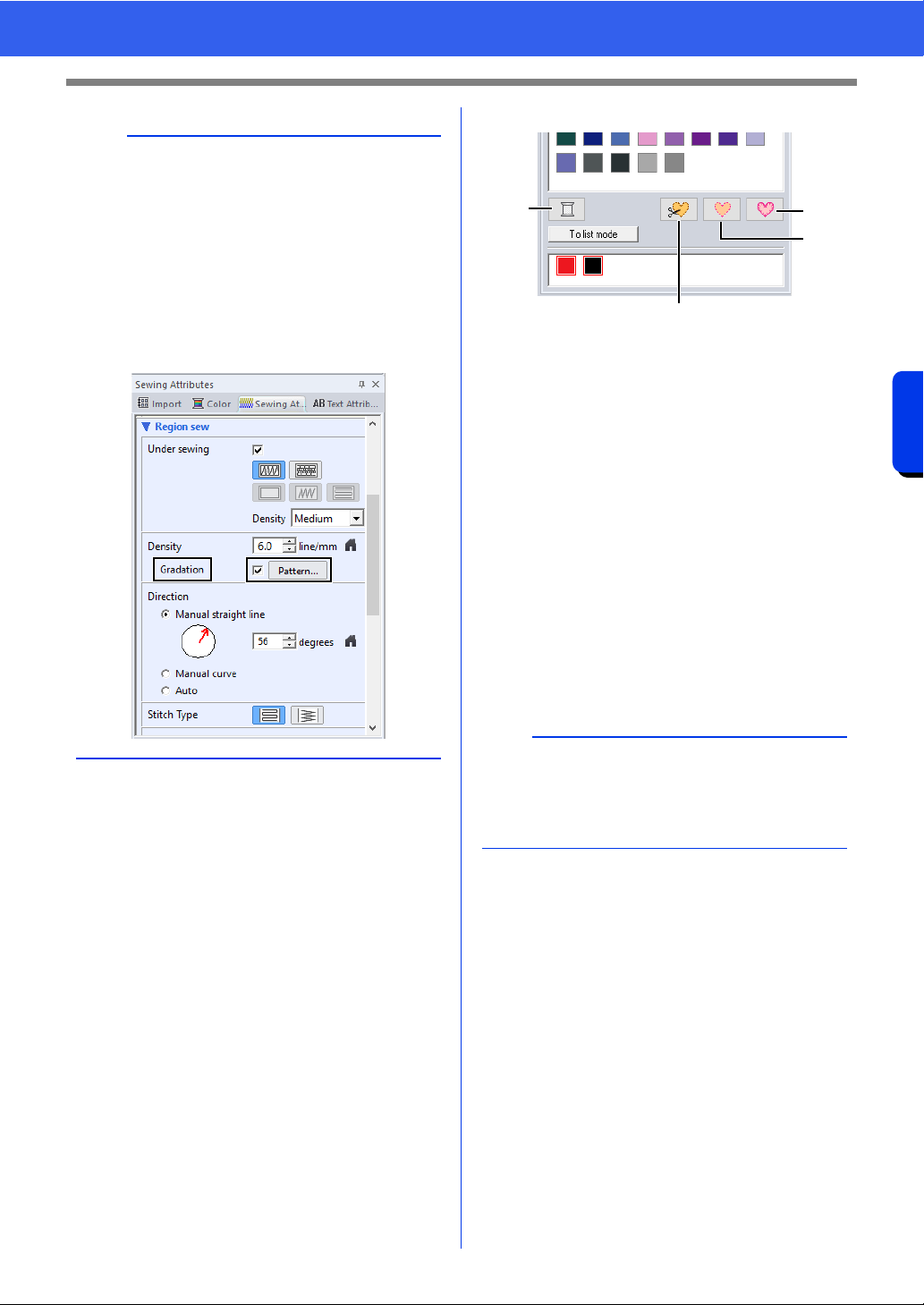
56
Specifying Thread Colors and Sew Types for Lines and Regions
Basic Layout & Editing Operations
■ Special colors
a NOT DEFINED
If you want to be able to manually select
the color for a monochrome pattern, you
can select [NOT DEFINED].
Colors for creating appliqués:
You can create appliqués using the
following three special colors.
b APPLIQUE MATERIAL
marks the outline of the region to cut from
the appliqué material.
c APPLIQUE POSITION
marks the position on the backing
material where the appliqué must be
sewn.
d APPLIQUE
sews the appliqué on the backing
material.
b
• Gradation/blending can be specified if satin
stitches, fill stitches or programmable fill stitches
have been selected for the region sewing and
[Manual straight line] has been selected as the
sewing direction.
• If the [Blend] check box is cleared, the
gradation settings are applied to the remaining
color.
• Gradation/blending can also be specified under
[Density] when the [Sewing Attributes] pane
is displayed in Expert mode.
b
By using the Applique Wizard, appliqués can
easily be created.
cc "Tutorial 9-1: Creating Appliqués" on
page 179
a
b
d
c
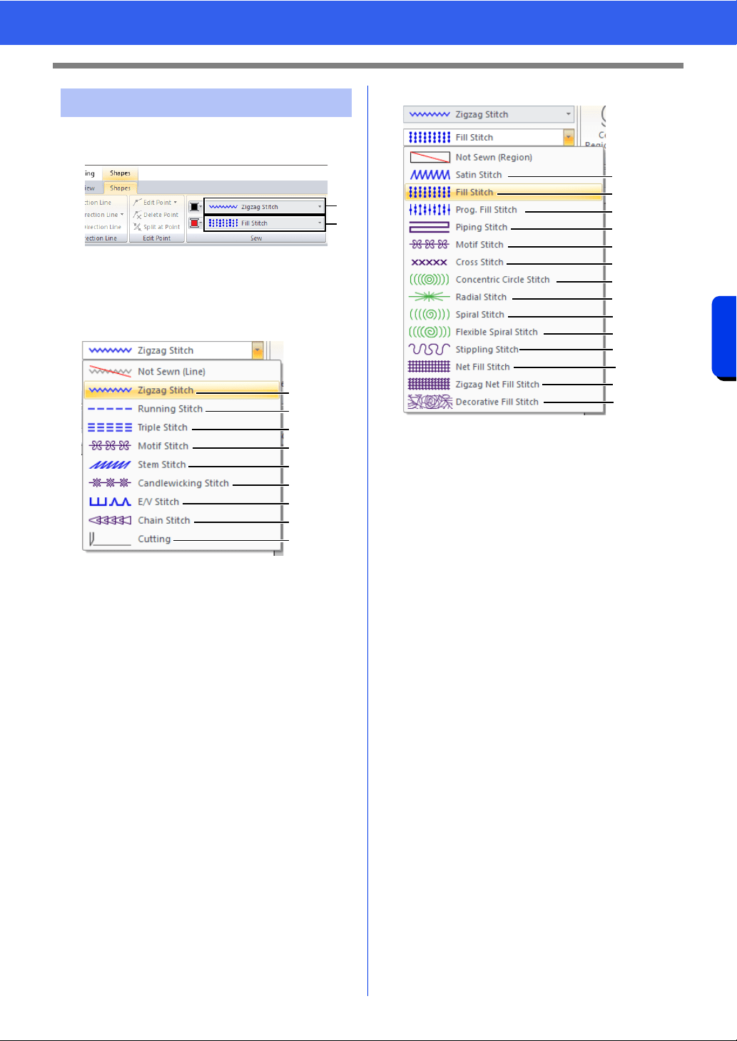
57
Specifying Thread Colors and Sew Types for Lines and Regions
Basic Layout & Editing Operations
The [Sew] group in the [Shapes] tab allows you to
set the sew type.
1 Line sew type selector
2 Region sew type selector
■ Line sew types
1 "Zigzag Stitch" on page 382
2 "Running Stitch" on page 382
3 "Triple Stitch" on page 382
4 "Motif Stitch" on page 383
5 "Stem Stitch" on page 384
6 "Candlewicking Stitch" on page 384
7 "E/V Stitch" on page 385
8 "Chain Stitch" on page 386
9 "Cutting" on page 386
The sew type for lines in shapes and text can be
selected in the [Line sew type] selector.
Click the [Line sew type] selector, and then select
the desired sew type.
a Not Sewn (Line)
Select this setting to turn off line sewing
(line will not be sewn).
b Cutting
Select this setting to specify the line as a
cutting line in a cutwork pattern.
cc "Practical use of Satin Stitch and Cutting
Line" on page 186
cc "Specifying sewing attributes" on page 64
"Line sewing attributes" on page 382
■ Region sew types
1 "Satin Stitch" on page 388
2 "Fill Stitch" on page 390
3 "Programmable Fill Stitch (Prog. Fill Stitch)" on
page 391
4 "Piping Stitch" on page 394
5 "Motif Stitch" on page 395
6 "Cross Stitch" on page 396
7 "Concentric Circle Stitch, Radial Stitch and
Spiral Stitch" on page 396
8 "Flexible Spiral Stitch" on page 396
9 "Stippling Stitch" on page 397
0 "Net Fill Stitch" on page 397
A "Zigzag Net Fill Stitch" on page 398
B "Decorative Fill Stitch" on page 399
The sew type for regions in shapes, and text can be
selected in the [Region sew type] selector.
Click the [Region sew type] selector, and then
select the desired sew type.
The available region sew types differ
depending on whether a shape pattern or
text pattern is selected.
a Not Sewn (Region)
Select this setting to turn off region
sewing (region will not be sewn).
cc "Specifying sewing attributes" on
page 64
"Region sewing attributes" on page 388
Setting the sew type
1
2
1
2
3
4
5
6
7
8
9
a
b
1
2
3
4
5
6
7
7
7
8
9
0
A
B
a
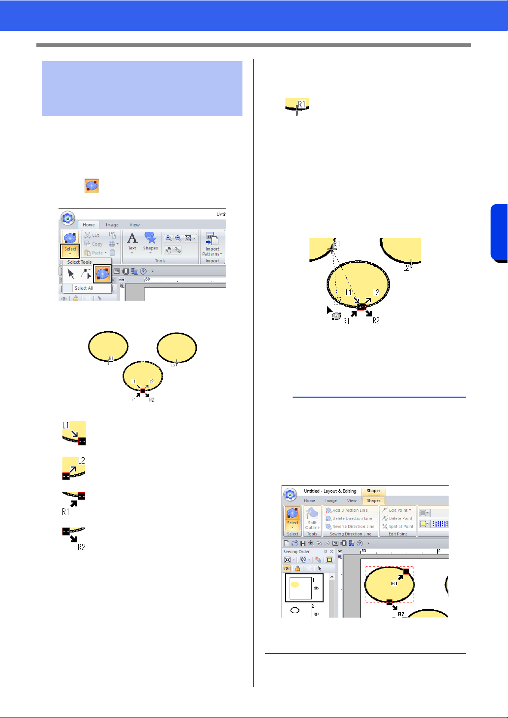
58
Specifying Thread Colors and Sew Types for Lines and Regions
Basic Layout & Editing Operations
■ Moving the entry/exit points
1 Click the [Home] tab.
2 Click [Select] in the [Select] group, and then
click to select the Select Entry/Exit Point
tool.
3 Click the object.
4 Drag the arrow for the point to the desired
location on the outline.
A dotted line appears between the entry (or
exit) point being moved and the cross
indicating the exit (or entry) point of the
previous (or next) pattern.
Moving entry/exit points,
the center point and stitch
pattern reference point
This is the entry point for the outline
stitching. The previous pattern is
connected to this point.
This is the exit point for the outline
stitching. Stitching continues from this
point to the next pattern.
This is the entry point for the inside
region stitching. The previous pattern is
connected to this point.
This is the exit point for the inside
region stitching. Stitching continues
from this point to the next pattern.
The codes that appear indicate the following.
L: Line sewing R: Region sewing
1: Entry point 2: Exit point
This is the entry (or exit) point for the
next (or previous) pattern that is
connected to the exit (or entry) point of
the currently selected pattern.
This point is connected to the entry/exit
point with the same code in the
currently selected pattern. In this
example, R1 in the currently selected
pattern and R1 in the previous pattern
are connected.
b
• If the outline or the inside region are set to not be
sewn, the corresponding point does not appear.
• The entry and exit points can be checked in the
[Sewing Order] pane. Select the Select Entry/
Exit Point tool, and then click a frame in the
[Sewing Order] pane. The entry and exit points
of the selected pattern appear.
• In this case, finish the operation by clicking a
blank area in the [Sewing Order] pane.
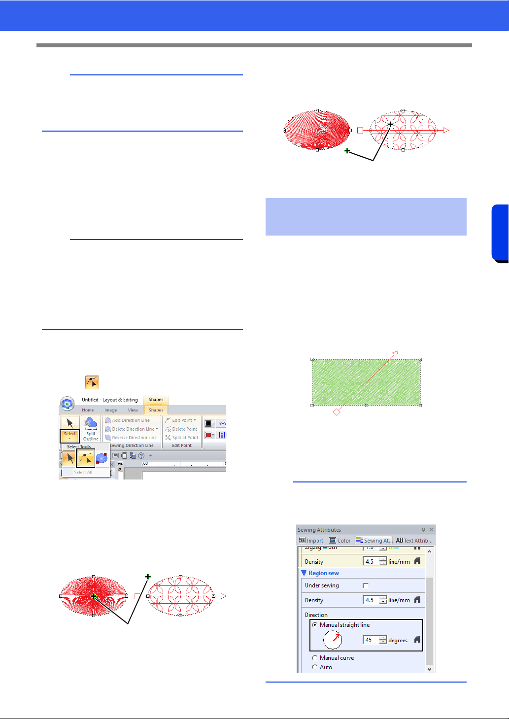
59
Specifying Thread Colors and Sew Types for Lines and Regions
Basic Layout & Editing Operations
■ Moving the center point and stitch
pattern reference point
The center point and reference point for arranging
the stitch pattern can be repositioned for a more
decorative effect.
1 Click the [Home] tab.
2 Click [Select] in the [Select] group, and then
click .
3 Click a region with the concentric circle stitch,
radial stitch, prog. fill stitch, motif stitch, cross
stitch, net fill stitch or zigzag net fill stitch
specified.
1 Handle
4 Drag the handle to the desired location.
1 Handle
When the Outline tools, Rectangle/Circle/Arc tools
or Shapes tools are used, shapes with a single
sewing direction will be created. When the Manual
Punch tools are used, shapes with multiple sewing
directions are created.
The sewing direction is indicated by a sewing
direction line (red arrow). These lines can be edited
by moving the end points, or new sewing direction
lines can be added.
These settings can be adjusted for regions with the
satin stitch, fill stitch, prog. fill stitch, piping stitch or
motif stitch specified.
a
Only entry and exit points for patterns created with
the Shapes tool can be edited. Stitch patterns or
patterns created with the Text tools cannot be
edited.
b
• Regions with the concentric circle stitch, radial
stitch or flexible spiral stitch specified have a
center point.
• Regions with the prog. fill stitch, motif stitch,
cross stitch, net fill stitch, zigzag net fill stitch or
decorative fill stitch specified have a stitch
pattern reference point.
Center Point (Radial
Stitch)
Stitch pattern reference
point (Motif Fill Stitch)
1
Center Point (Radial
Stitch)
Stitch pattern reference
point (Motif Fill Stitch)
Specifying the straight
sewing direction
a
This feature can be used when [Direction] in the
[Sewing Attributes] pane is set to [Manual
straight line] (default setting).
1
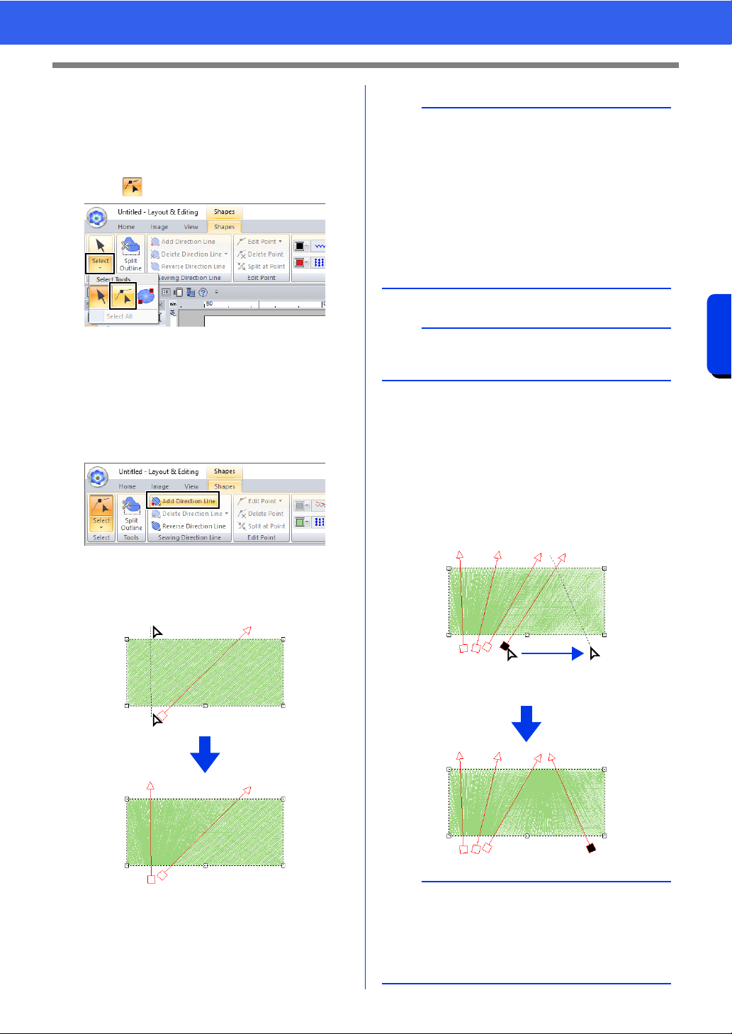
60
Specifying Thread Colors and Sew Types for Lines and Regions
Basic Layout & Editing Operations
■ Specifying multiple sewing
directions
1 Click the [Home] tab.
2 Click [Select] in the [Select] group, and then
click to select the Select Point tool.
3 Click a shape pattern.
The sewing direction lines appear.
4 Click the [Shapes] tab.
5 Click [Add Direction Line] in the [Sewing
Direction Line] group.
6 Click the point for one end of the sewing
direction line being added, and then click the
point for the other end.
■ Changing the sewing angle
1 Select the Select Point tool.
2 Click a shape pattern, and then click an empty
square or empty triangle on the sewing
direction line to select the point.
3 Drag the point to the new location.
1 Selected point
2
1
b
• Specify the sewing direction lines as described
below.
Position both end points outside of the pattern.
Only the lines can be positioned over the
pattern.
When specifying multiple sewing direction
lines, they must not intersect within the
pattern.
• Sewing direction lines specified in any way other
than described above will not be added.
a
If hole sewing has been applied, sewing direction
lines cannot be added.
b
The sewing angle can also be set to a specific
direction (one sewing direction line) with the
settings under [Direction] in the [Sewing
Attributes] pane.
cc "Specifying sewing attributes" on page 64
1
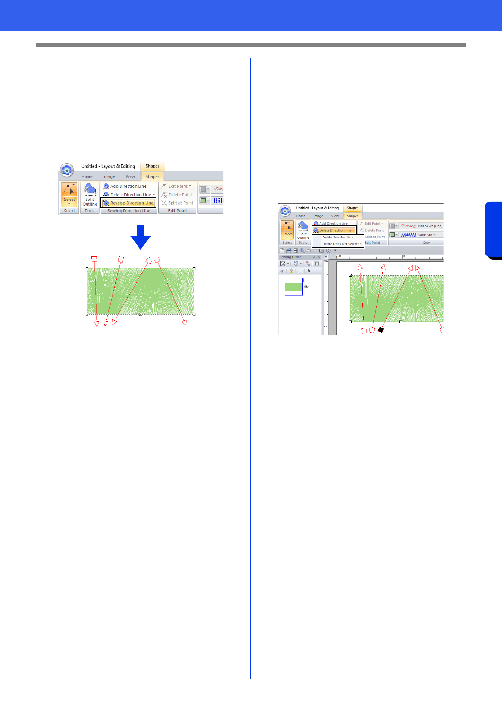
61
Specifying Thread Colors and Sew Types for Lines and Regions
Basic Layout & Editing Operations
■ Reversing the sewing direction
1 Select the Select Point tool.
2 Click a shape pattern.
3 Click the [Shapes] tab.
4 Click [Reverse Direction Line] in the
[Sewing Direction Line] group.
If there are multiple sewing direction lines, all
lines will be reversed.
■ Deleting sewing direction lines
1 Select the Select Point tool.
2 Click a shape pattern, and then click an empty
square or empty triangle on the sewing
direction line to select the point.
3 Click the [Shapes] tab.
4 Click [Delete Direction Line] in the [Sewing
Direction Line] group, and then click [Delete
Selected Line] or [Delete Lines Not
Selected].
Delete Selected Line
Click this command to delete the selected
sewing direction line. Otherwise, press the
<Delete> key to delete the sewing direction.
Delete Lines Not Selected
Click this command to delete all sewing
direction lines except the currently selected
one. The sewing direction will become
uniform.
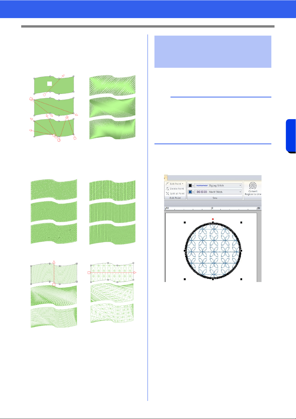
62
Specifying Thread Colors and Sew Types for Lines and Regions
Basic Layout & Editing Operations
■ Sample patterns with sewing
directions changed
When the sewing direction is changed, the pattern
stitching changes as shown below.
1 Default
The sewing direction is also changed when the
pattern size and shape are changed.
■ Specifying curved sewing
direction line
1 Click a shape pattern.
In this example, the motif stitch is selected for
the region sew type.
2 Click the [Sewing Attributes] tab, and then
click [To Expert mode].
cc "Specifying sewing attributes" on
page 64
Sewing direction Satin Stitch
Fill Stitch Programmable Fill Stitch
(Prog. Fill Stitch)
Piping Stitch Motif Stitch
1
Specifying the curved
sewing direction (round
fill)
a
• This feature can be used when [Direction] in
the [Sewing Attributes] pane is set to [Manual
curve].
• A curved sewing direction line can be specified
if fill stitches, programmable fill stitches, piping
stitches or motif stitches have been selected.
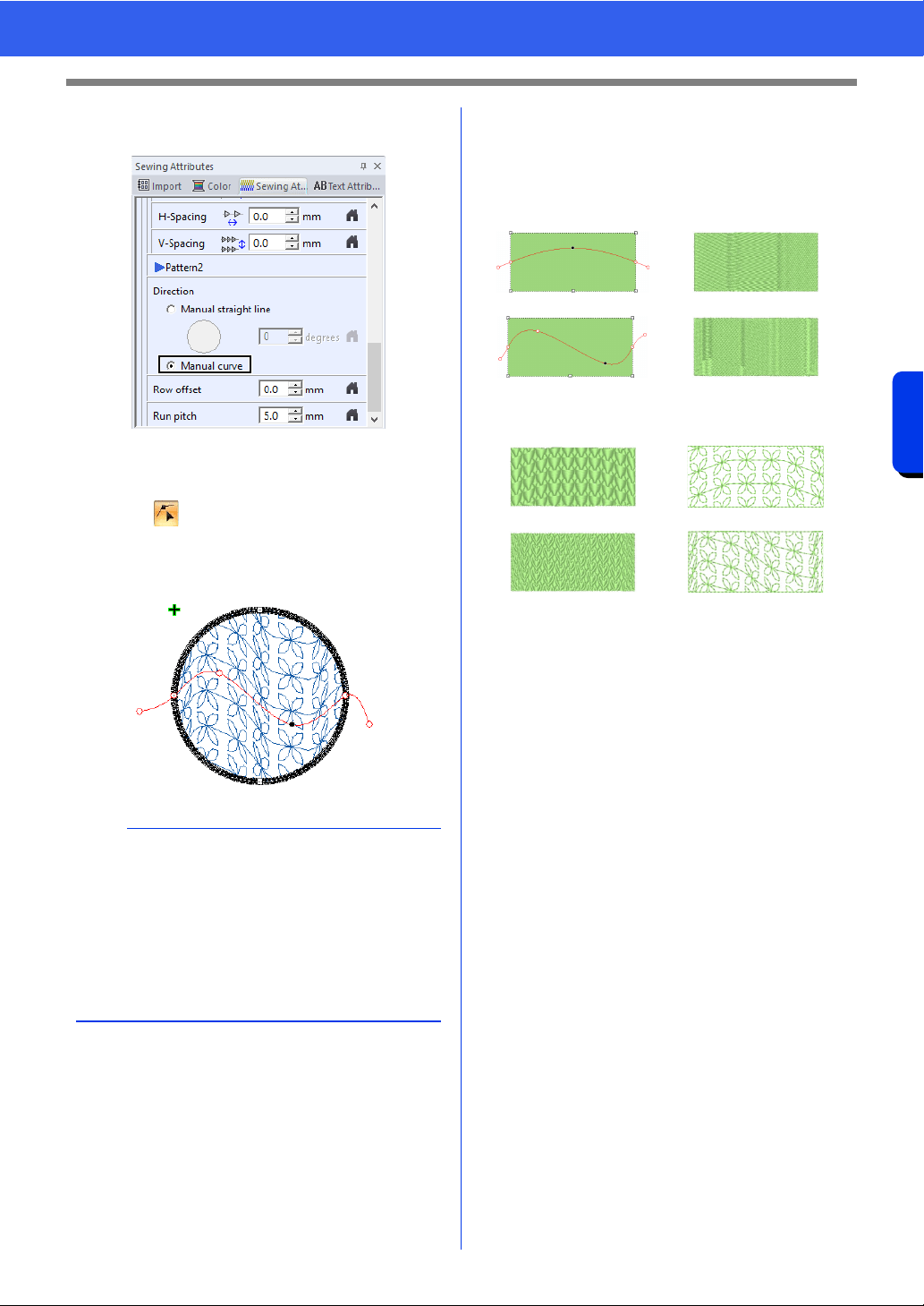
63
Specifying Thread Colors and Sew Types for Lines and Regions
Basic Layout & Editing Operations
3 In the [Region sew] section, select [Manual
curve] under [Direction].
The sewing direction line becomes curved.
4 Click [Select] in the [Select] group, and then
click .
5 Drag a selected point to adjust the curved line.
To add a point, click on the curved line.
■ Sample patterns with sewing
directions changed
When the sewing direction is changed, the pattern
stitching changes as shown below.
The sewing direction is also changed when the
pattern size and shape are changed.
b
• To remove a point at either end or along the
path, select [Delete Point].
• A point at either end of the line or on the outline
of the shape pattern cannot be deleted.
• Only one curved sewing direction line can be
specified.
• Complex curved sewing direction lines that twist
cannot be specified.
Sewing direction Fill Stitch
Programmable Fill Stitch Motif Stitch
(Prog. Fill Stitch)
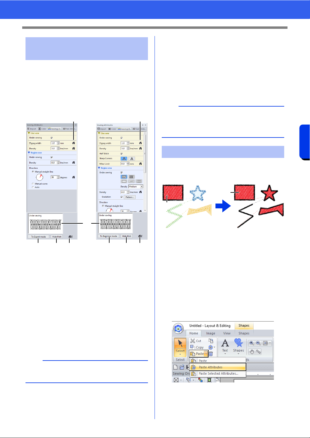
64
Specifying Thread Colors and Sew Types for Lines and Regions
Basic Layout & Editing Operations
1 Select an embroidery pattern, a Shapes tool
or a Text tool.
2 Click the [Sewing Attributes] tab.
a Click to return to the default setting.
b Click to switch the attributes between
those for Beginner mode and those for
Expert mode.
c Click to load/save the sewing settings.
d Click to switch between displaying and
hiding the hint view.
e Hint view
With each change in the settings, a
preview of the stitching can be checked
here. By moving the pointer over each
setting, a preview of the setting can be
displayed.
3 Change the sewing attributes displayed under
[Line sew] or [Region sew].
The settings are applied to the embroidery
pattern each time the settings are changed.
cc For details on the different sewing
attributes and settings, refer to "Line
sewing attributes" on page 382 and
"Region sewing attributes" on page 388.
The thread colors, sew types and sewing attributes
can be copied from one pattern and pasted onto
another to apply the same settings to the pattern.
1 Original
1 Select the shape pattern or text pattern whose
settings are to be copied, and then press the
shortcut keys <Ctrl> + <C> to copy.
2 Select the shape pattern or text pattern where
the settings are to be pasted, and then click
the [Home] tab.
cc "Shape pattern" on page 10
3 Click [Paste] in the [Clipboard] group, and
then click [Paste Attributes].
Specifying sewing
attributes
Beginner mode Expert mode
b
The sewing attributes displayed in the dialog box
depend on the selected sew type.
a a
b dc b dc
e
b
Frequently used sewing attributes can be saved.
cc For details, refer to "Saving the settings in a
list" on page 213
Copying sewing attributes
1
1
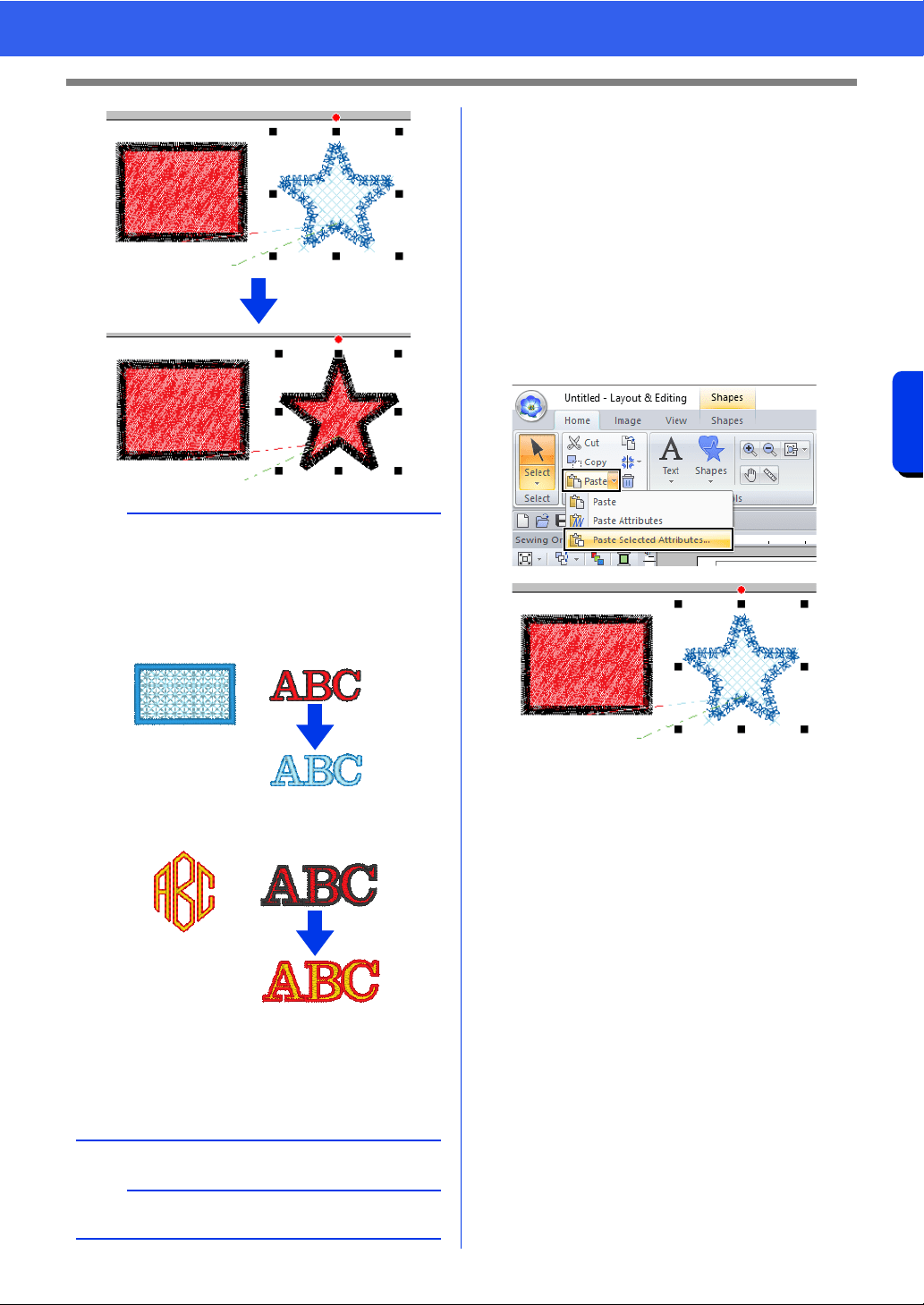
65
Specifying Thread Colors and Sew Types for Lines and Regions
Basic Layout & Editing Operations
■ Copying only specific attributes
Specific attributes, such as the line thread color, can
be copied and pasted onto another pattern.
1 Select the shape pattern or text pattern whose
settings are to be copied, and then press the
shortcut keys <Ctrl> + <C> to copy.
2 Select the shape pattern or text pattern where
the settings are to be pasted, and then click
the [Home] tab.
3 Click [Paste] in the [Clipboard] group, and
then click [Paste Selected Attributes].
b
• When copying attributes from a shape, text,
monogram or small text pattern and pasting
them to a pattern of a different type, only the
colors will be pasted. The sew types and sewing
attributes cannot be pasted.
1 Original
2 Target
• When copying a text pattern with different
sewing attributes applied to each character, the
sewing attributes of the first character will be
copied.
a
This function cannot be used with stitch patterns.
1
1
2
2
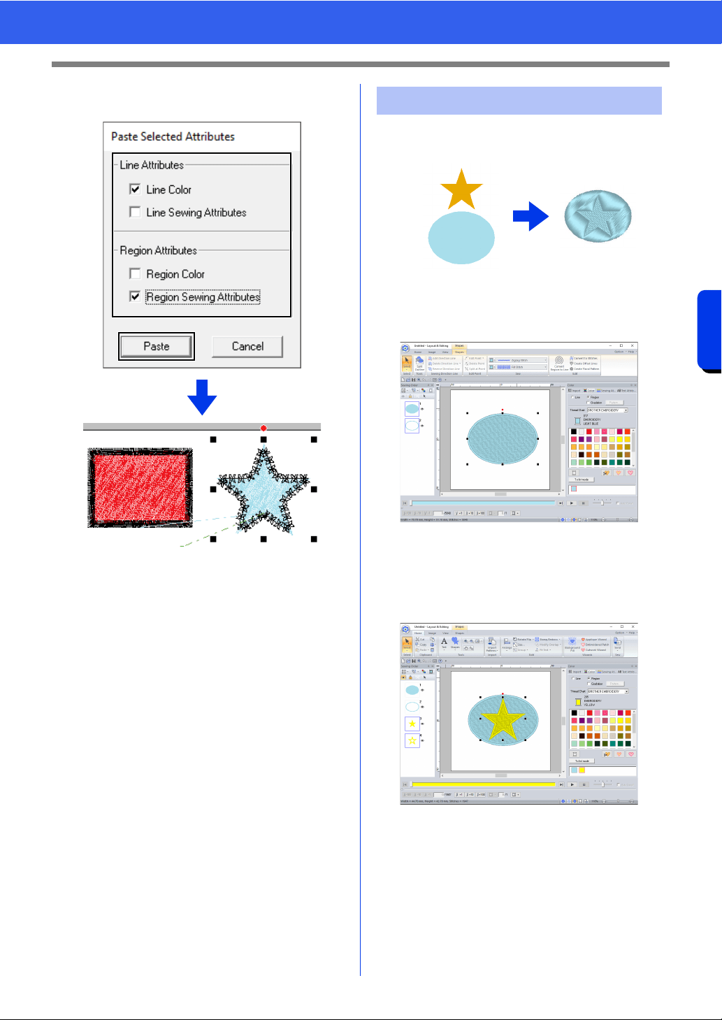
66
Specifying Thread Colors and Sew Types for Lines and Regions
Basic Layout & Editing Operations
4 Select the check boxes of the attributes to be
pasted, and then click [Paste].
Multiple shape patterns can be selected to create an
engraved/embossed effect.
1 Top
2 Bottom
1 Draw a shape.
In this example, the fill stitch is selected for
region sewing.
2 Draw a shape overlapping the shape drawn in
step 1.
3 Select the two shapes, and then click the
[Home] tab.
Embossing/Engraving
1
2
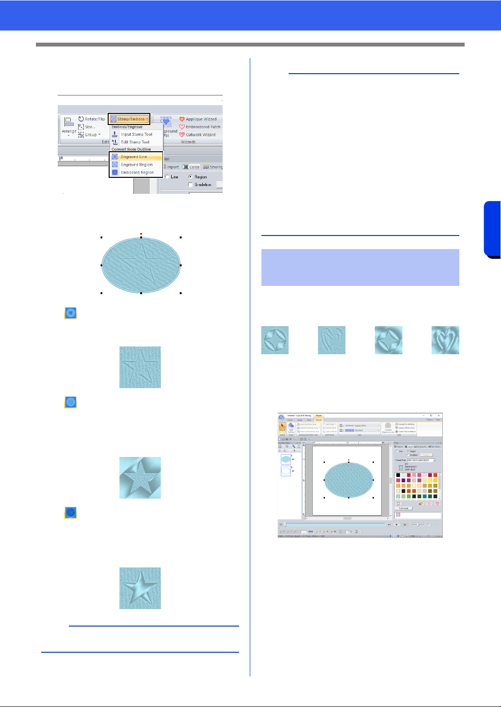
67
Specifying Thread Colors and Sew Types for Lines and Regions
Basic Layout & Editing Operations
4 Click [Stamp/Emboss] in the [Edit] group,
and then click the desired command under
[Convert from Outline].
Engraved Line
The bottom shape is engraved with the
outline of the shape on top.
Engraved Region
An engraving is made in the bottom
shape from the shape on top.
For best result, select [Satin Stitch] for
region sewing of the bottom shape.
Embossed Region
An embossing is made in the bottom
shape from the shape on top.
For best result, select [Fill Stitch] for
region sewing of the bottom shape.
You can create engraved/embossed effects by
stamping stamp patterns into a shape. This appears
as stitching sewn in different directions.
■ Applying a stamp
1 Draw a shape.
2 Click the [Home] tab.
b
This effect can be edited with the Edit Stamp tool.
Example: When the [Engraved Line] command
is selected
a
• These commands can only be used with shape
pattern.
• The bottom shape pattern must have one of the
following sew types specified for region sewing.
Satin Stitch
Fill Stitch
Programmable Fill Stitch (Prog. Fill Stitch)
• In order to use the [Engraved Line] command,
[Line sew type] for the shape pattern must be
set to any setting other than [Not Sewn (Line)].
In order to use the [Engraved Region] or
[Embossed Region] commands, [Region sew
type] for the shape pattern must be set to any
setting other than [Not Sewn (Region)].
Applying and editing
stamps
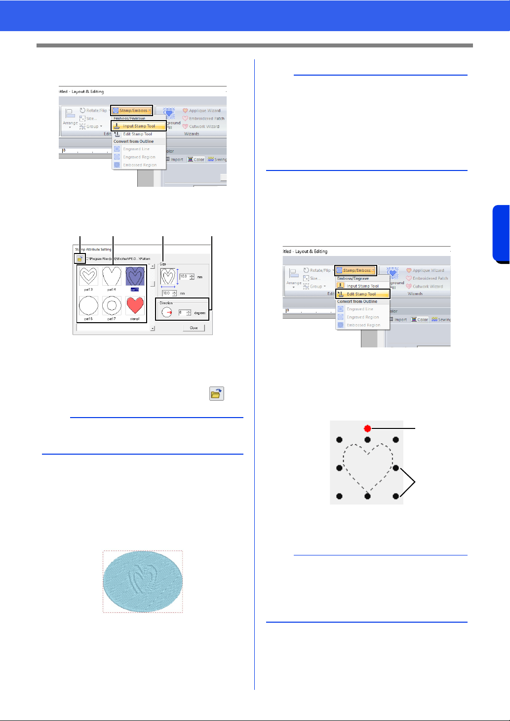
68
Specifying Thread Colors and Sew Types for Lines and Regions
Basic Layout & Editing Operations
3 Click [Stamp/Emboss] in the [Edit] group,
and then click [Input Stamp Tool].
4 Select a stamp pattern (.pas file with stamp
settings applied).
a Select a stamp pattern.
b Specify the size of the stamp pattern.
c Specify the direction of the stamp pattern.
d To select a different folder, click .
5 Click the shape pattern drawn in step 1 to
select it.
"Marching lines" appear around the
selected shape pattern.
6 Click the desired locations within the shape
pattern.
You can preview the effect of the created
stamp in Realistic View.
■ Editing a stamp
1 Click the [Home] tab.
2 Click [Stamp/Emboss] in the [Edit] group,
and then click [Edit Stamp Tool].
3 Click the shape pattern with the stamp.
"Marching lines" appear around the
selected shape pattern.
4 Click the stamp.
1 Rotation handle
2 Scale handles
b
Engraving and embossing stamp settings appear
as red- and blue-filled areas.
abcd
b
• Stamps can be applied to regions of shape
pattern that have the satin stitch, fill stitch and
programmable fill stitch specified.
• Using Programmable Stitch Creator, you can
edit stamp pattern that have been provided or
you can create your own.
cc "Programmable Stitch Creator" on page 296
b
• Only one stamp can be selected at a time.
• To enlarge the stamp, drag a scale handle.
• To rotate the stamp, drag the rotation handle.
• To delete the stamp, press the <Delete> key.
1
2
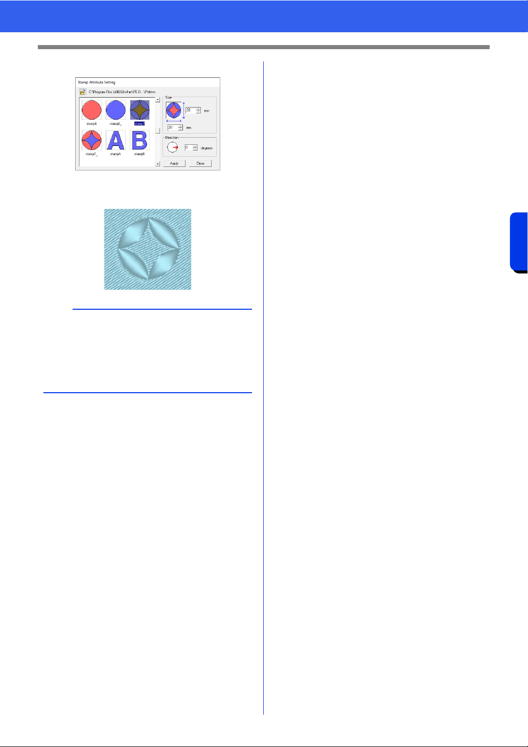
69
Specifying Thread Colors and Sew Types for Lines and Regions
Basic Layout & Editing Operations
5 Edit the stamp.
• To change the stamp pattern, select a
different pattern, and then click [Apply].
b
• If the size of a shape pattern is changed, the size
of the stamp does not change. Be sure to check
the stamp after editing a shape pattern.
• If a shape pattern containing a stamp is edited,
be sure to check the stamp after editing is
finished.
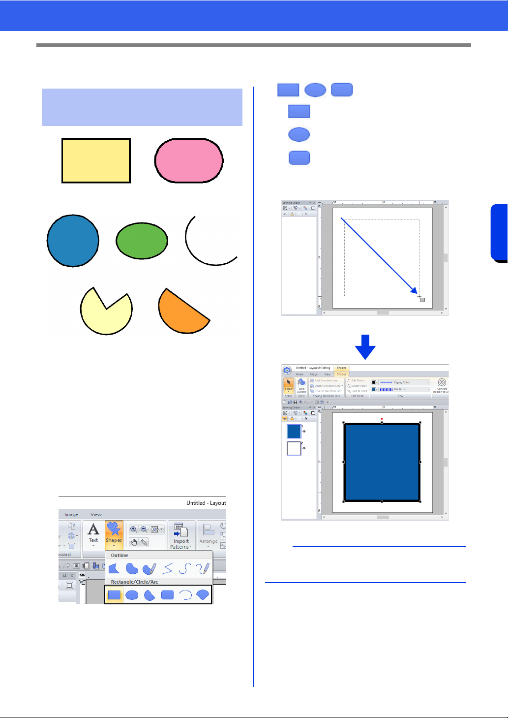
70
Drawing Shapes
Basic Layout & Editing Operations
Drawing Shapes
1 Rectangle
2 Rectangle with rounded corners
3 Circle
4 Oval
5 Arc
6 Fan shape
7 Arc & string
1 Click the [Home] tab.
2 Click [Shapes] in the [Tools] group, and then
click a tool icon under [Rectangle]/[Circle]/
[Arc] to select the desired [Rectangle]/
[Circle]/[Arc] tool.
■ //
: Rectangle
: Circle or Oval
: Rectangle with rounded corners
Drag the pointer in the Design Page.
Drawing rectangle, circle
or arc shape
12
34 5
6
7
b
To draw a circle or square, hold down the <Shift>
key while dragging the pointer.
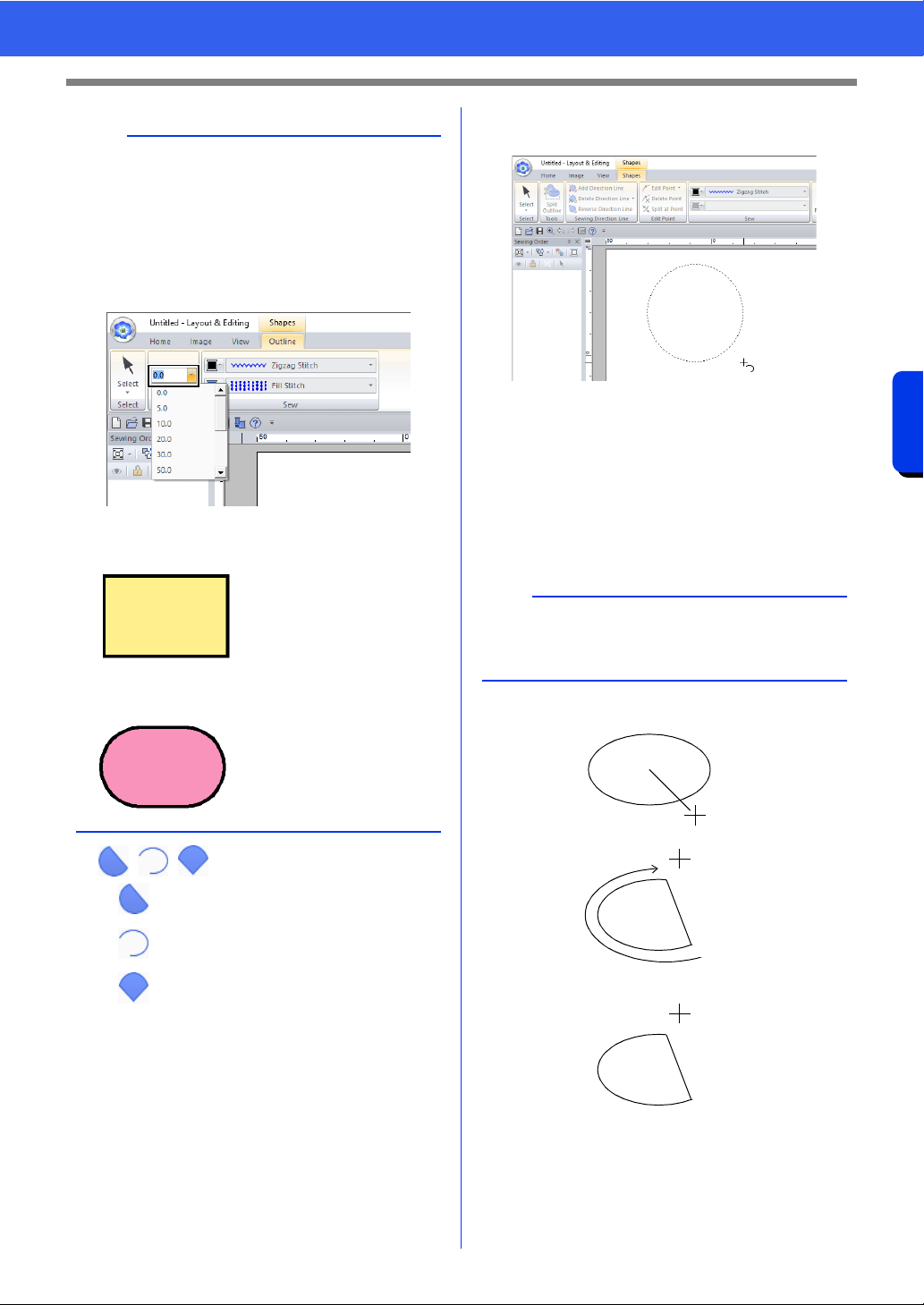
71
Drawing Shapes
Basic Layout & Editing Operations
■ //
: Arc & String
: Arc
: Fan
1 Proceed as you would to draw a circle or an
oval.
A radial line appears on the oval when the
mouse button is released.
2 Move the pointer to the start point of the arc,
and then click.
The radial line disappears.
3 Move the pointer until the arc/arc & string/fan
has the desired shape, and then click.
Arc & String
1 Click at start point.
2 Move to end point.
3 Click at end point.
b
Rectangles with rounded corners
To change the radius of the corners, click the
[Edge radius] selector in the [Outline] tab. Then,
type the desired radius, or select the desired
value.
Specify the radius of the corners before drawing
the rectangle. The setting cannot be changed after
the rectangle has been drawn.
Example 1
Edge radius: 0.0 mm
Example 2
Edge radius: 20.0 mm
b
Dragging the pointer while holding down the
<Shift> key moves it in 15° increments. The
current angle is shown in the status bar.
1
2
3
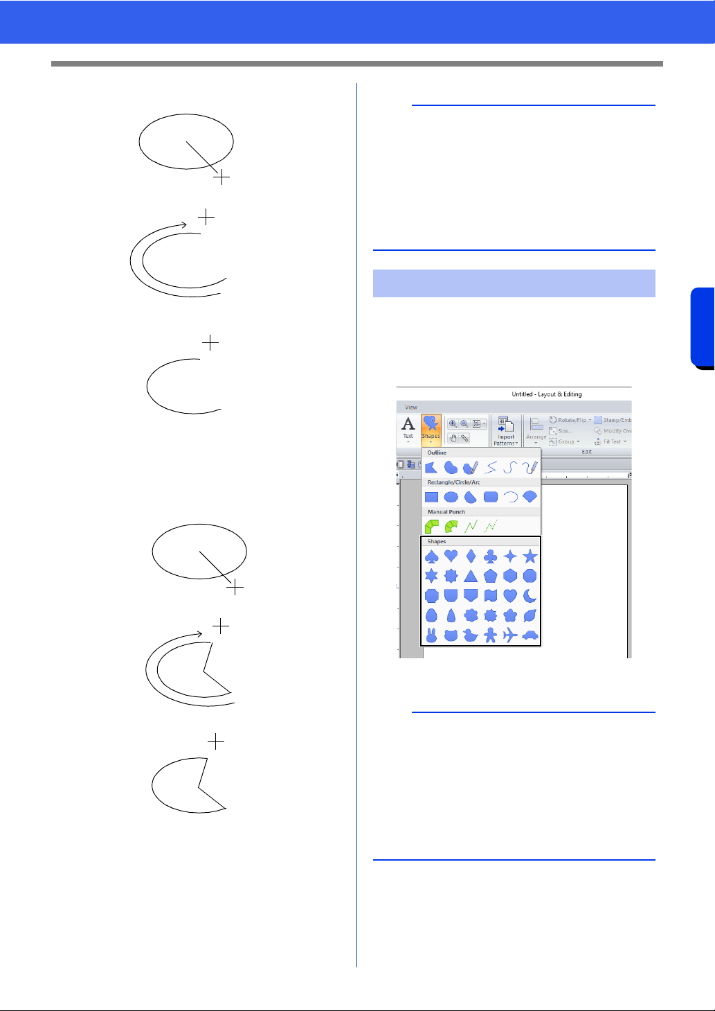
72
Drawing Shapes
Basic Layout & Editing Operations
Arc
1 Click at start point.
2 Move to end point.
3 Click at end point.
Fan
1 Click at start point.
2 Move to end point.
3 Click at end point.
1 Click the [Home] tab.
2 Click [Shapes] in the [Tools] group, and then
click a tool icon under [Shapes] to select the
desired Shapes tool.
3 Drag the pointer in the Design Page.
1
2
3
1
2
3
b
• You can change the color and sew type either
before or after drawing the shape.
cc "Setting the sew type" on page 57
• You can also use the settings in the [Sewing
Attributes] pane to define other attributes of the
shape before or after drawing the shape.
cc "Specifying sewing attributes" on page 64
Drawing various shape
b
• To draw the shape while maintaining the original
height-to-width proportion, hold down the
<Shift> key while dragging the pointer.
• Various sample shape patterns are available in
the [Import] pane when [Outline Shapes] is
selected in the [From] selector and [Basic
Shapes] is selected in the [Category] selector.
cc "Using the Import pane" on page 15
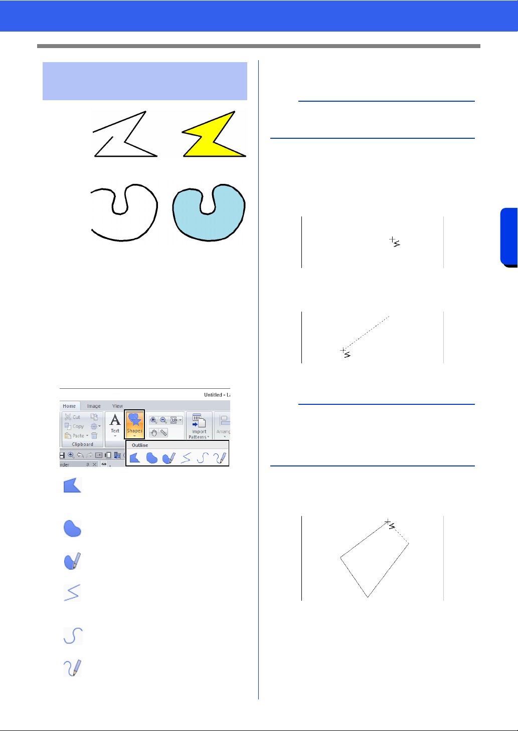
73
Drawing Shapes
Basic Layout & Editing Operations
1 Start point
2 End point
3 Open line
4 Closed line
5 Open curve
6 Closed curve
1 Click the [Home] tab.
2 Click [Shapes] in the [Tools] group, and then
click a tool icon under [Outline] to select the
desired Outline tool.
3 Click in the Design Page or drag the pointer to
draw the line.
■ Straight lines/curves
1 Click in the Design Page to specify the start
point.
2 Click in the Design Page to specify the next
point.
The dotted lines change to solid lines.
3 Continue clicking to specify every point, and
then double-click the last point, or press the
<Enter> key.
Drawing outlines (straight
lines and curves)
: Click points to draw a closed line
constructed of straight lines.
(Shortcut key: <Z>)
: Click points to draw a closed curve.
(Shortcut key: <X>)
: Drag the pointer to draw a closed
freehand curve.
: Click points to draw an open line
constructed of straight lines.
(Shortcut key: <Z>)
: Click points to draw an open curve.
(Shortcut key: <X>)
: Drag the pointer to draw an open
freehand curve.
1
2
34
1
2
56
b
The shortcut keys are available only after an
Outline tool has been selected.
b
• To remove the last point that was entered, right-
click the mouse button, or press the
<BackSpace> key.
• The Curve tool is used in the same way.
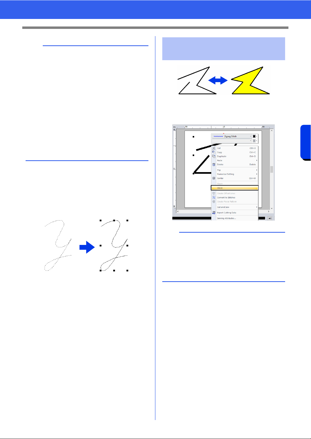
74
Drawing Shapes
Basic Layout & Editing Operations
■ Freehand lines
1 Drag the pointer to draw the line.
2 Release the mouse button to finish drawing.
After selecting a shape pattern, right-click it, and
then click [Open] or [Close] to change the line
ending.
b
• You can freely switch between the different line
types either by clicking a different button or by
pressing the shortcut key.
• When drawing a straight line, hold down the
<Shift> key while moving the pointer to draw
vertically or horizontally.
• Even after the pattern is drawn, you can change
the attributes of line ends.
cc "Changing the attributes of line ends" on
page 74.
• Even after the pattern is drawn, you can
transform straight lines into curves and vice
versa.
cc "Transforming straight lines into curves or
curves into straight lines" on page 80.
Changing the attributes of
line ends
b
In addition, closed shape patterns can be split at
points to create open lines, or the end points of
open shape patterns can be connected to create
closed lines.
cc "Connecting points/splitting outlines (shape
patterns)" on page 77
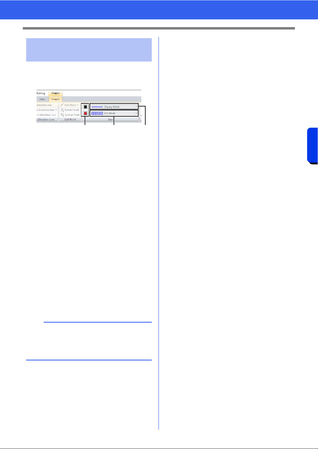
75
Drawing Shapes
Basic Layout & Editing Operations
The [Shapes] tab allows you to set the embroidery
attributes (thread color and sew type).
Example: When a rectangle is selected.
a Line color/Region color
Click this button to set the thread color for
lines and regions.
For special colors:
cc "Special colors" on page 56
b Line sew type selector
All lines in a shape can be set to the same
sew type.
Use these selectors to set the sew type for
lines.
cc "Line sewing attributes" on page 382
c Region sew type selector
All regions in a shape can be set to the
same sew type.
Use these selectors to set the sew type for
regions.
cc "Region sewing attributes" on page 388
cc "Specifying Thread Colors and Sew
Types for Lines and Regions" on page 54
Embroidery attributes of
shapes
b
• To turn off line sewing, select [Not Sewn (Line)]
from the [Line sew type] selector.
• To turn off region sewing, select [Not Sewn
(Region)] from the [Region sew type] selector.
ac b
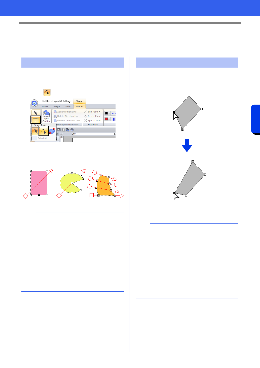
76
Reshaping Embroidery Patterns
Basic Layout & Editing Operations
Reshaping Embroidery Patterns
Patterns can be reshaped by moving, adding or deleting points. While creating shape patterns, a clicked
location becomes a point.
1 Click the [Home] tab.
2 Click [Select] in the [Select] group, and then
click to select the [Select Point] tool.
3 Click the pattern.
4 To select a single point, click an empty square.
1 Select the point.
2 Drag the point to the new location.
1 Selected point
2 Drag
Selecting points
b
Multiple points can be selected in any of the
following ways.
• Drag the pointer.
All points within the box are selected.
• Hold down the <Ctrl> key while clicking the
points.
To deselect a point, click the selected
point.
• Hold down the <Shift> key while pressing an
arrow key to select multiple points.
• Hold down the <Ctrl> key while pressing an
arrow key to change the point that is selected.
Moving points
b
• To move the point of a broken line, a curve, or
stitch data horizontally or vertically, hold down
the <Shift> key while dragging it.
• A selected point can also be moved with the
arrow keys.
• Points in patterns set for hole sewing can also
be moved. However, the point cannot be moved
to cross an outline. In order to move the point in
this way, cancel hole sewing first.
• If you start dragging by clicking elsewhere on the
outline of the pattern, a new point will be inserted
or the selected point(s) will be deselected.
1
2
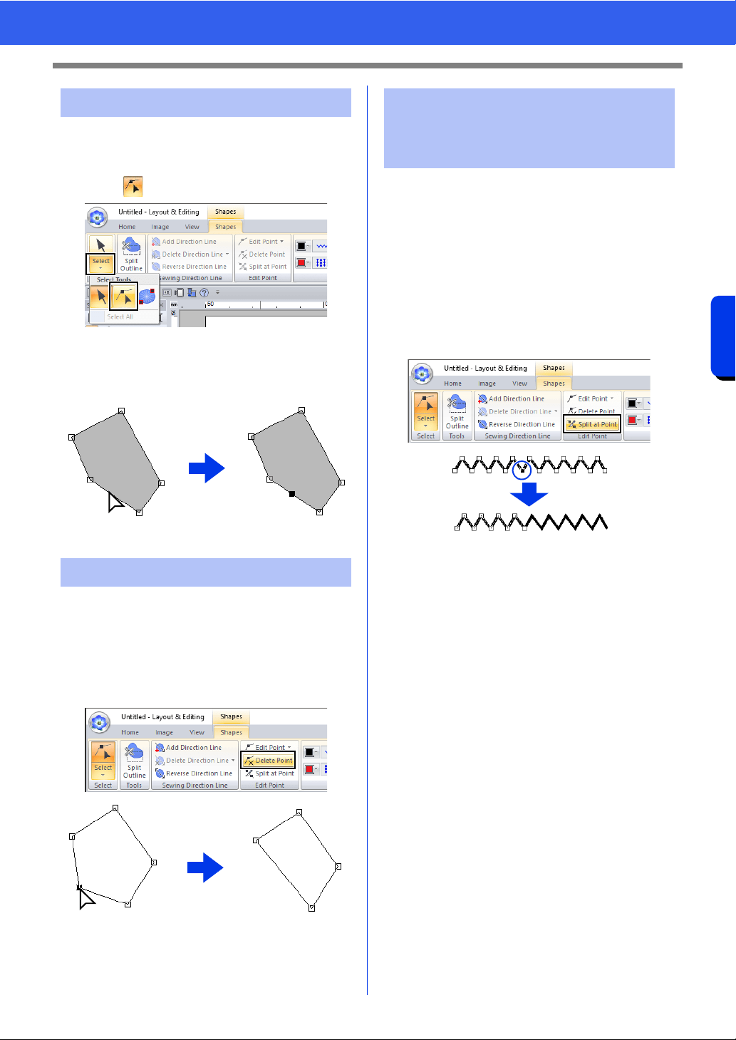
77
Reshaping Embroidery Patterns
Basic Layout & Editing Operations
1 Click the [Home] tab.
2 Click [Select] in the [Select] group, and then
click to select the Select Point tool.
3 Click the pattern.
4 Click the outline to add a point.
1 Click
1 Select the point.
2 Click the [Shapes] tab.
3 Click [Delete Point] in the [Edit Point] group.
Otherwise, press the <Delete> key to remove
the point.
1 Selected point
2 Delete
■ Splitting outlines of open shape
patterns
The outline of an open shape pattern can be split at
a point.
1 Select a point in an open shape pattern.
2 Click the [Shapes] tab.
3 Click [Split at Point] in the [Edit Point] group
to split the line.
Inserting points
Deleting points
1
2
1
Connecting points/
splitting outlines (shape
patterns)
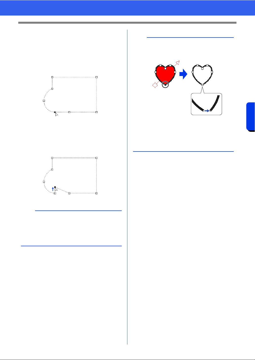
78
Reshaping Embroidery Patterns
Basic Layout & Editing Operations
■ Splitting outlines of closed shape
patterns
The closed path of a shape pattern can be split. The
closed path consists of the points that are
connected to create the shape pattern.
1 Select a point in a closed shape pattern.
2 Click the [Shapes] tab.
3 Click [Split at Point] in the [Edit Point] group
to split the line.
b
• If a shape pattern is split in a shape with hole
sewing applied, hole sewing will be canceled.
• If a shape pattern is split in a shape with fit text
to outline applied, fit text to outline will be
canceled.
b
• When the outline of a closed shape pattern is
split to create an open shape pattern, region
sewing attributes can no longer be specified.
•The [Open] command is also available to
change a closed shape pattern to an open
shape pattern.
cc "Changing the attributes of line ends" on
page 74
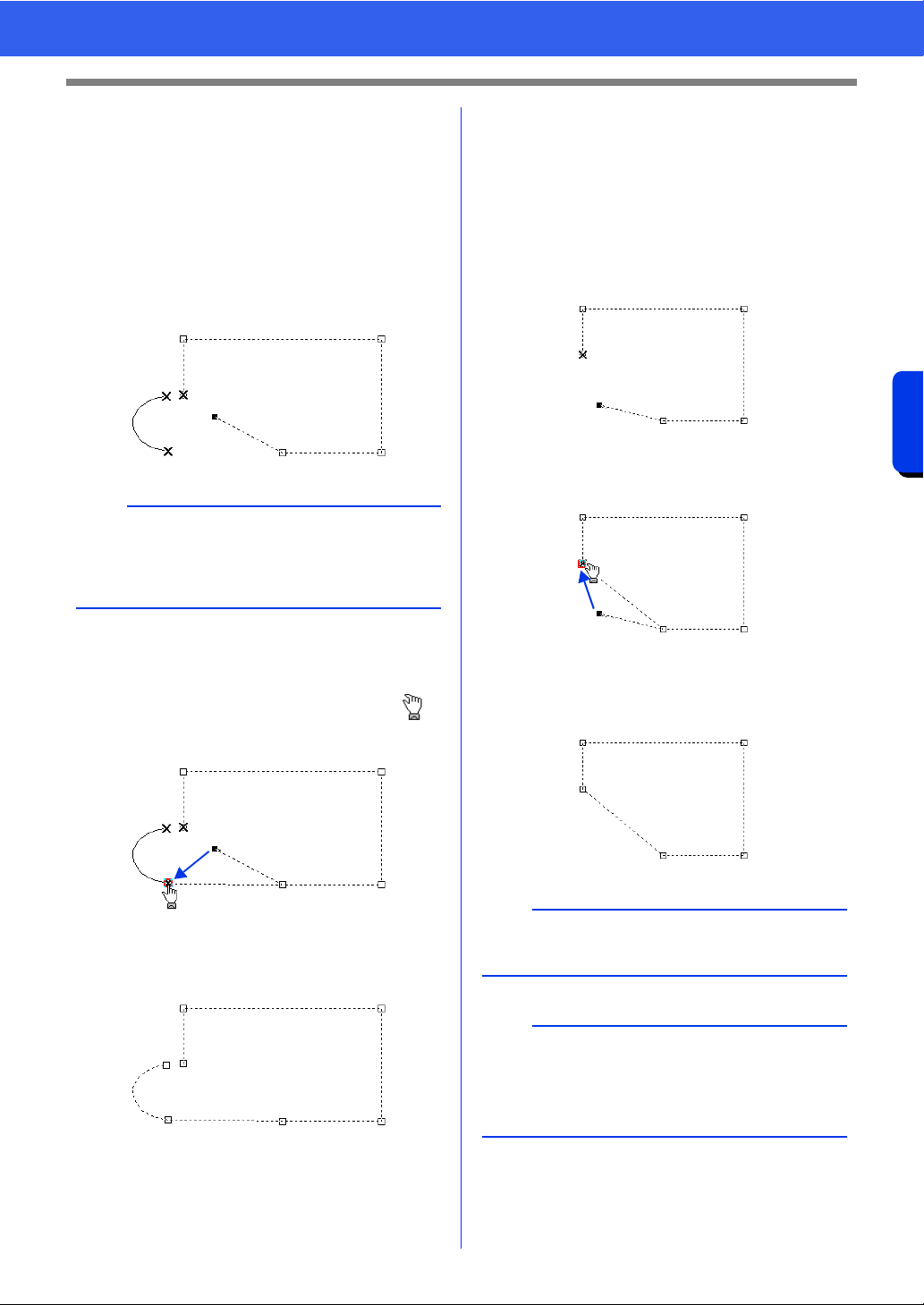
79
Reshaping Embroidery Patterns
Basic Layout & Editing Operations
■ Connecting two open shape
patterns
The end points of two shape patterns can be
connected to create a single shape pattern.
1 Select an end point (entry point or exit point).
2 Press the <Alt> key.
The points that can be connected appear
as ×.
3 While holding down the <Alt> key, drag the
selected point to the other point that you want
to connect to it.
The shape of the pointer changes to ,
and a red square appears when the two
points are overlapping.
4 Release the mouse button to connect the two
points.
■ Connecting the two end points of
a shape pattern
The two end points of an open shape pattern can be
connected to create a closed shape pattern.
1 Select an end point (entry point or exit point).
2 Press the <Alt> key.
The other end point appears as ×.
3 While holding down the <Alt> key, drag the
selected point to the other end point.
4 When the two points are overlapping and the
red square appears, release the mouse
button.
b
The other end point of the shape pattern whose
point is selected as well as the end points (entry
points and exit points) of other shape patterns
appear as ×.
a
When a shape pattern is closed, its region sewing
attributes may appear.
b
The [Close] command is also available to change
an open shape pattern to a closed shape pattern.
cc "Changing the attributes of line ends" on
page 74
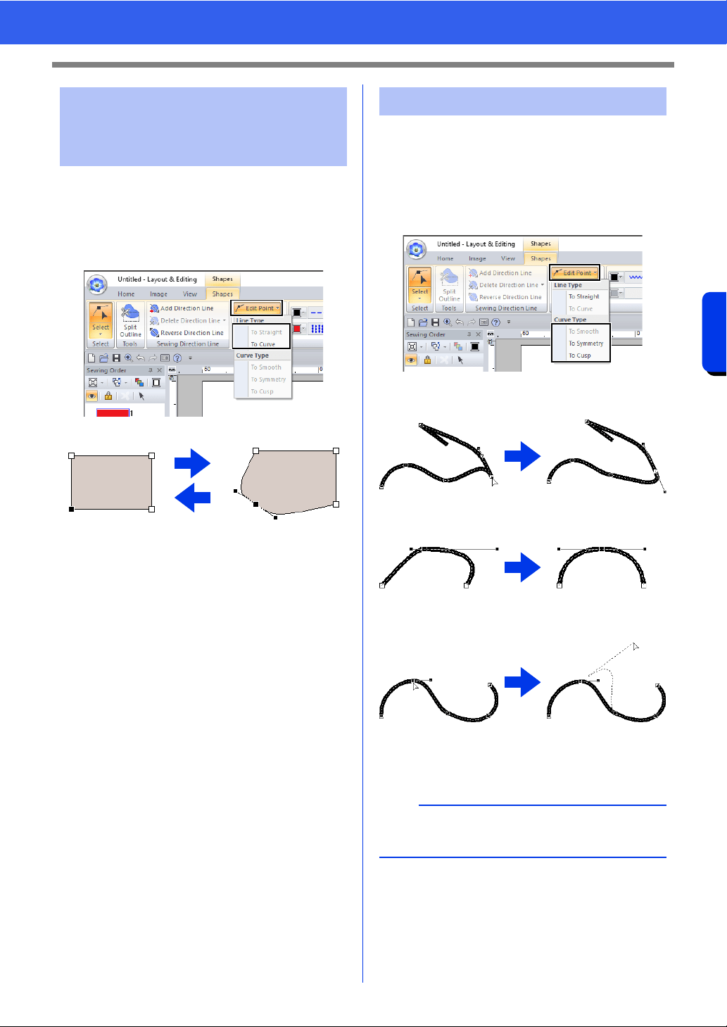
80
Reshaping Embroidery Patterns
Basic Layout & Editing Operations
1 Select the point.
2 Click the [Shapes] tab.
3 Click [Edit Point] in the [Edit Point] group,
and then click [To Straight] or [To Curve].
1 To C urv e
2 To Straight
1 Select a point on a curve.
2 Click the [Shapes] tab.
3 Click [Edit Point] in the [Edit Point] group,
and then click [To Smooth], [To Symmetry]
or [To Cusp].
To Smooth
To Symmetry
To Cusp
4 Drag the solid black handle to adjust the
shape of the line.
Transforming straight
lines into curves or curves
into straight lines
1
2
Changing the curve type
b
The shape can be changed by dragging the solid
black handle on either side of the point.
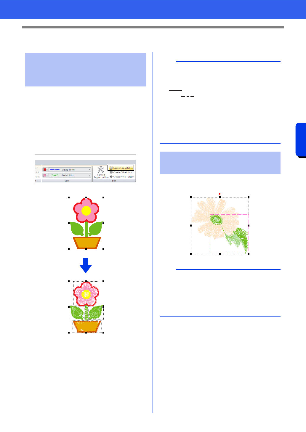
81
Editing a Stitch Pattern
Basic Layout & Editing Operations
Editing a Stitch Pattern
Shape pattern or text pattern can be converted into
a stitch pattern, allowing you to make detailed
changes by modifying the position of individual
stitches.
1 Select the shape pattern, and then click the
[Shapes] tab.
2 Click [Convert to Stitches] in the [Edit]
group.
Hold down the <Alt> key and click the thread color
for the stitch patterns that you wish to select.
Converting shape pattern
or text pattern to a stitch
pattern
b
• [Convert to Stitches] can also be used with text
pattern to convert it to stitch patterns.
• In stitch patterns, stitches appears as solid lines
( ), and jump stitches appear as dotted
lines ( ).
• If any part of grouped patterns, patterns set for
hole sewing, and text arranged on shapes is
selected, all patterns in the entire group are
converted to stitch patterns.
• Patterns that do not have stitches are deleted
when the pattern is converted to a stitch pattern.
Selecting stitch patterns
by thread color
b
• The thread color can be changed when patterns
are selected using this method.
cc "Setting the thread color" on page 54
• If stitch patterns are grouped, patterns cannot be
selected by color using this method.
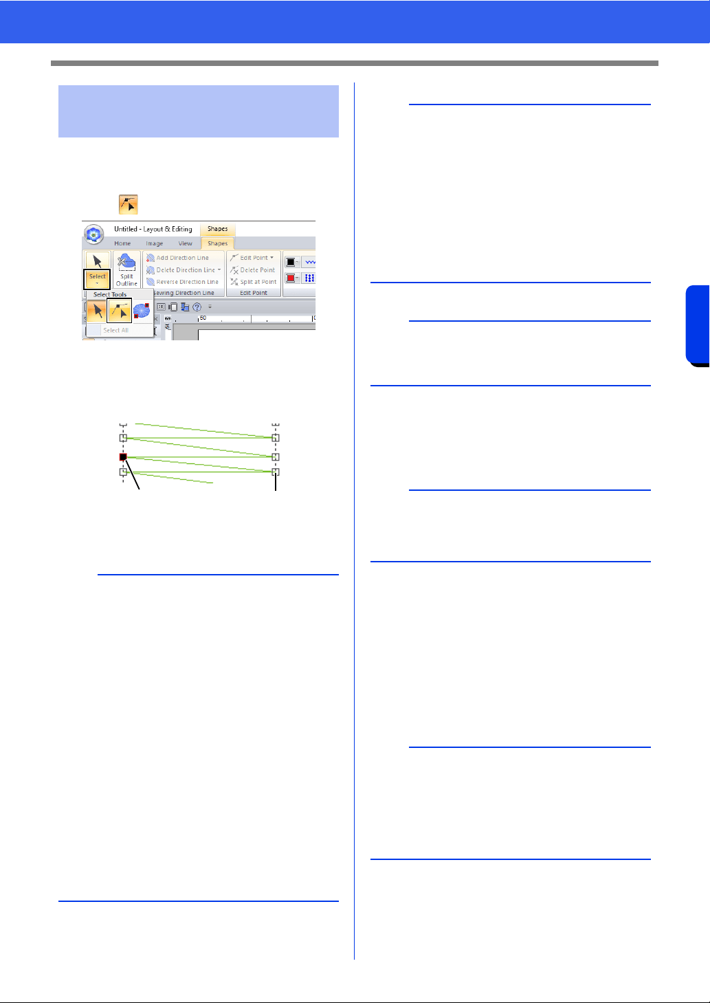
82
Editing a Stitch Pattern
Basic Layout & Editing Operations
1 Click the [Home] tab.
2 Click [Select] in the [Select] group, and then
click to select the Select Point tool.
3 Click the stitch pattern.
4 To select a single stitch point, click an empty
square.
1 Selected point
2 Unselected point
■ Moving stitch points
Drag the selected stitch points to the new location.
■ Inserting stitch points
Click a line between two stitch points to add a new
point at that position.
■ Deleting stitch points
Press the <Delete> key to delete the selected stitch
point.
Selecting stitch points of
stitch pattern
b
• Press the <Tab> key.
All stitch points in the next color are
selected.
• Press the <Shift> and <Tab> keys.
All stitch points in the previous color are
selected.
• Press the <Ctrl> and <Home> keys.
The entry point of the first thread color is
selected.
• Press the <Ctrl> and <End> keys.
The exit point of the last thread color is
selected.
• Select at least one point in a given color, and
then press the <Home> key.
The entry point of the color is selected.
• Select at least one point in a given color, and
then press the <End> key.
The exit point of the color is selected.
12
b
• When selecting stitch points, be sure to click the
stitch point (do not click a blank area of the
Design Page), otherwise all of the selected
points will be deselected.
• If you click on a jump stitch, the points at both
ends are selected.
• Multiple stitch points can be selected in the
same way that embroidery pattern points are
selected.
cc "Selecting points" on page 76
a
Stitch points cannot be edited if the pattern is not a
stitch pattern. The pattern can be viewed in Solid
View.
b
Stitch points are moved in the same way that
embroidery pattern points are moved.
cc "Moving points" on page 76
b
• If the end point of a jump stitch is deleted, that
jump stitch segment is deleted and the stitches
before and after the jump stitch are connected.
• To insert a stitch point and change the previous
line into a jump stitch, hold down the <Ctrl> and
<Shift> keys while clicking on the line.
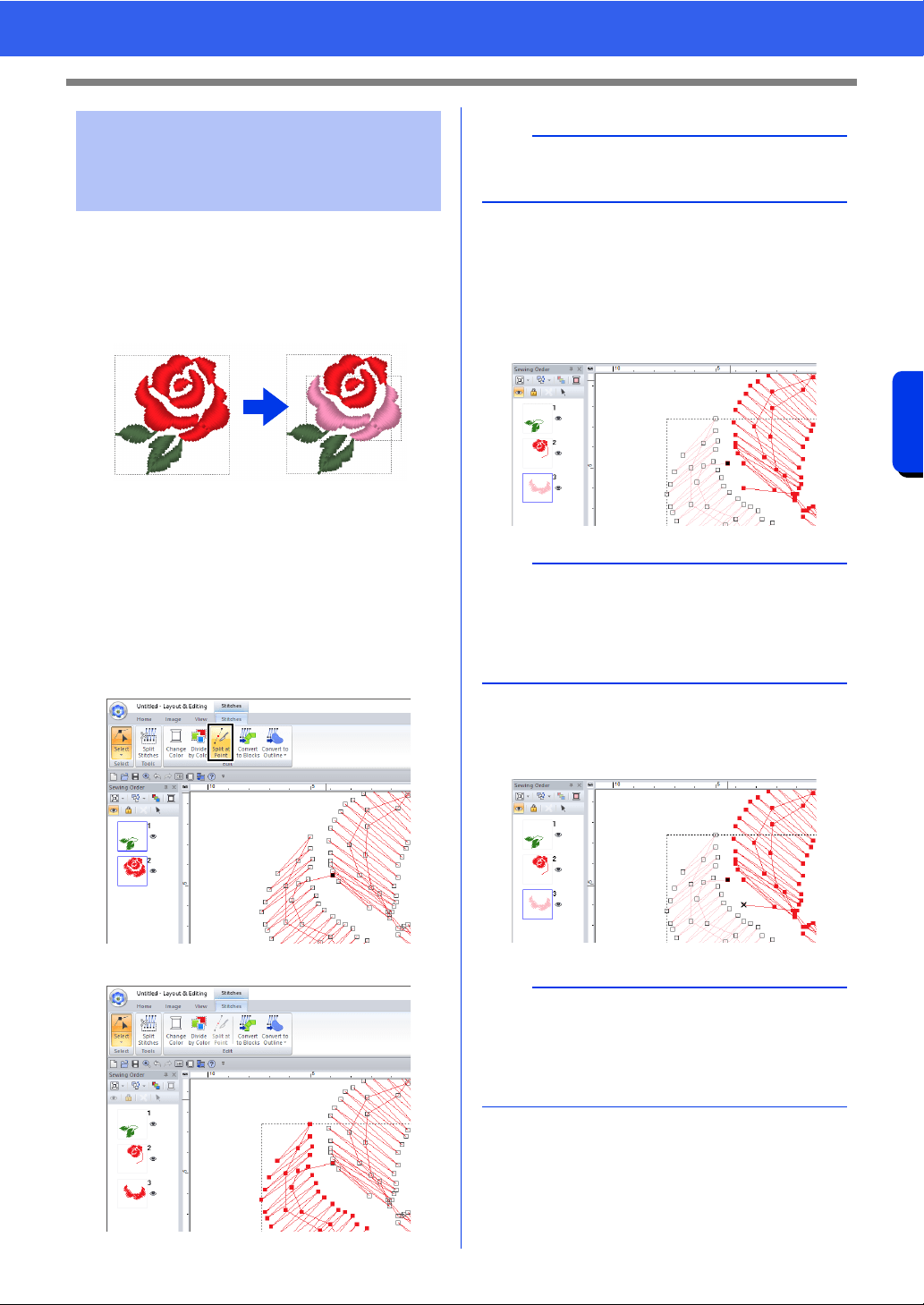
83
Editing a Stitch Pattern
Basic Layout & Editing Operations
A single color pattern can be divided into two by
splitting stitches at a point, and two color patterns
can be combined into one by connecting points. If a
stitch pattern is divided into multiple parts, each part
can be edited separately, such as changed to
different colors.
■ Splitting one stitch pattern into
two at the selected point
1 Select a point in a stitch pattern.
2 Click the [Stitches] tab.
3 Click [Split at Point] in the [Edit] group to split
the stitch pattern.
The stitch pattern is split at the point.
■ Connecting two stitch patterns to
create a single one
1 Select an end point (entry point or exit point) of
a stitch pattern.
2 Press the <Alt> key.
The points that can be connected appear
as ×.
Connecting points/
splitting stitches (stitch
patterns)
a
If an entry point or an exit point is selected, the
[Split at Point] is not available.
b
Select the entry point of the stitch pattern by
pressing keys <Ctrl> + <Home>. Select the exit
point by pressing keys <Ctrl> + <End>. For
details, refer to "Selecting stitch points of stitch
pattern" on page 82.
b
If the entry point of a stitch pattern is selected, the
exit points of the other stitch patterns appear as ×.
If the exit point of a stitch pattern is selected, the
entry points of the other stitch patterns appear as
×.
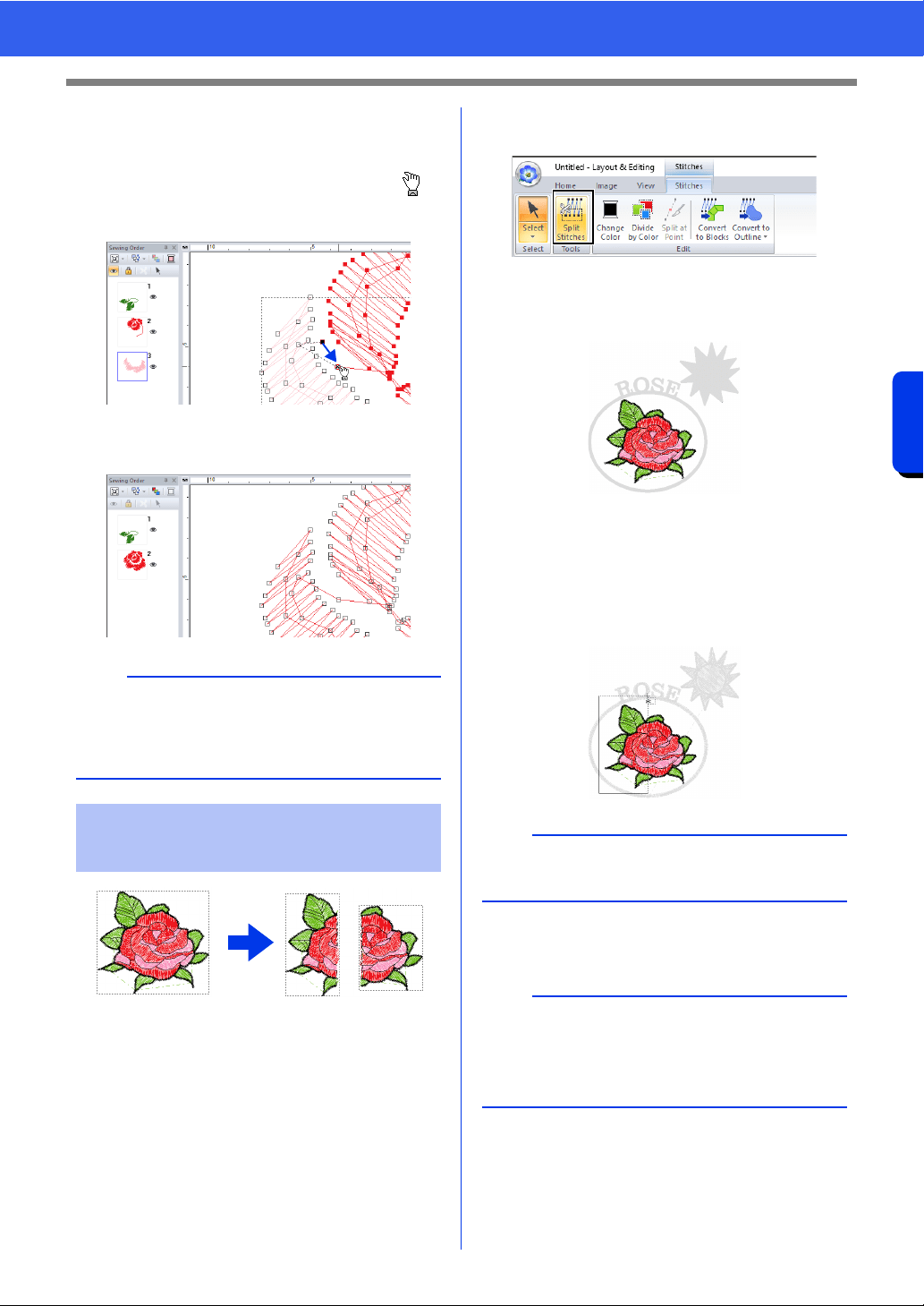
84
Editing a Stitch Pattern
Basic Layout & Editing Operations
3 While holding down the <Alt> key, drag the
selected point to the other point that you want
to connect to it.
The shape of the pointer changes to ,
and a red square appears when the two
points are overlapping.
4 Release the mouse button to connect the two
points.
1 Select a stitch pattern, and then click the
[Stitches] tab.
2 Click [Split Stitches] in the [Tools] group to
select the [Split Stitches] tool.
All other patterns will appear in gray.
Selected pattern will appear in front of other
patterns.
3 Click in the Design Page at the point where
you want to start drawing the enclosing lines.
4 Continue clicking in the Design Page to
specify each corner of the enclosure around
the area to be cut off.
5 Double-click in the Design Page to specify the
section to be split off.
b
After the points are connected, the pattern will
have the thread color of the pattern that was first in
the sewing order before the points were
connected.
Splitting off parts of a
stitch pattern
b
To remove the last point that was entered, right-
click the mouse button.
b
The cutoff piece moves to the end of the sewing
order.
cc "Checking and Editing the Sewing Order" on
page 92
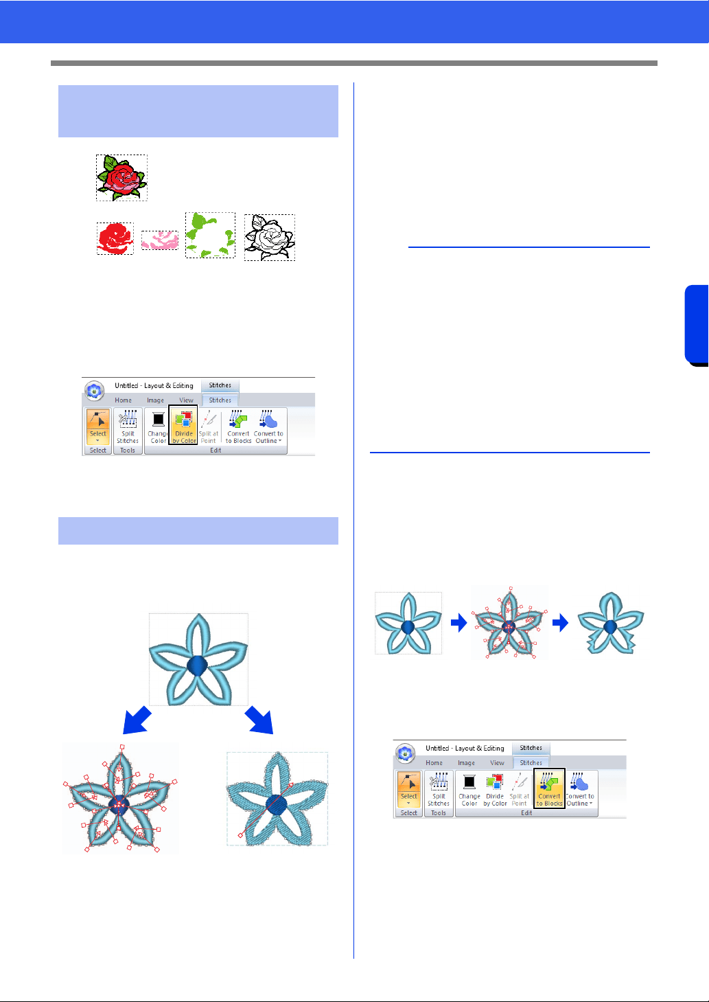
85
Editing a Stitch Pattern
Basic Layout & Editing Operations
1 Before dividing
2 After dividing
1 Select the stitch pattern(s), and then click the
[Stitches] tab.
2 Click [Divide by Color] in the [Edit] group.
Dotted lines appear around each part of the
stitch pattern.
Stitch patterns can be converted into two types of
shape patterns. After being converted, various
editing operations can be performed.
1 Stitch patterns
2 Blocks: A group of shape patterns with multiple
sewing direction lines
3 Shape patterns
4 Convert to Blocks
5 Convert to Outline
Convert to Blocks
The pattern is converted while maintaining the
multiple sewing direction lines.
Use this when you want to enlarge or reduce an
embroidery pattern that uses satin or fill stitches.
Convert to Outline
The pattern is converted following the shape of the
outline.
■ Converting stitch pattern to
blocks
Stitch patterns can be converted into blocks (group
of shape patterns with multiple sewing direction
lines). In blocks (shapes) pattern, the sew types and
sewing attributes can be changed, and the pattern
can easily be edited.
1 Select the stitch pattern(s), and then click the
[Stitches] tab.
2 Click [Convert to Blocks] in the [Edit] group.
Dividing stitch pattern by
color
Converting stitch patterns
1
2
1
23
45
b
• After being converted, the outline patterns can
be edited.
cc "Setting the sew type" on page 57
"Specifying the straight sewing
direction" on page 59
"Specifying sewing attributes" on
page 64
"Reshaping Embroidery Patterns" on
page 76
• For details on the shape pattern and stitch
pattern refer to "Comparison of Types of Data
Created With PE-DESIGN 11" on page 10.
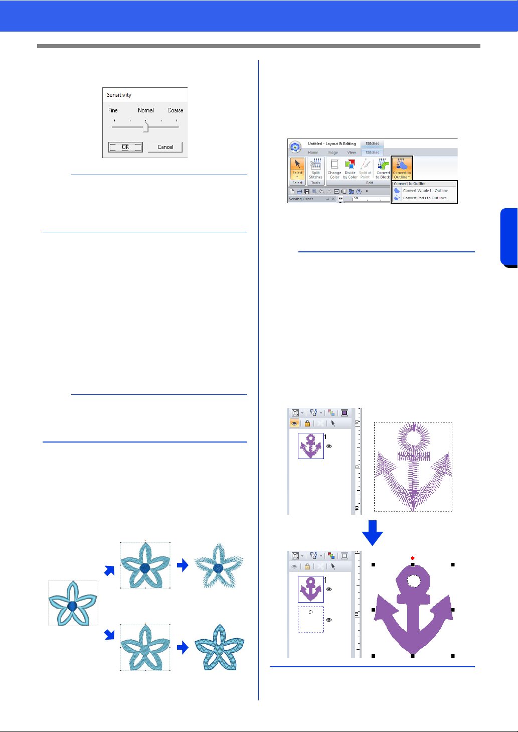
86
Editing a Stitch Pattern
Basic Layout & Editing Operations
3 Move the slider to select the desired
sensitivity. Click [OK].
The stitch pattern is converted to grouped
shape patterns. Being converted to shape
patterns, the outlines of the stitch pattern
can be edited.
cc For details see the following instructions;
"Setting the sew type" on page 57
"Specifying sewing attributes" on
page 64
"Reshaping Embroidery Patterns" on
page 76
"Specifying the straight sewing direction"
on page 59
■ Converting stitch pattern to
outline pattern
Outline patterns can be created from each color in a
stitch pattern or from an outline around the entire
pattern.
1 Convert Whole to Outline
2 Convert Parts to Outlines
1 Select the stitch pattern(s).
2 Click the [Stitches] tab.
3 Click [Convert to Outline] in the [Edit] group,
and then click [Convert Whole to Outline] or
[Convert Parts to Outlines].
The outline patterns are created, and the
original stitch patterns are deleted.
b
The [Normal] setting should provide satisfactory
results in most cases, but depending on the
complexity of the pattern, you may need to select
a setting more towards [Coarse] or [Fine].
a
The [Convert to Blocks] command cannot be
used with some stitch pattern imported from
original cards.
1
2
b
• Line sewing in the created outline patterns is set
to [Not Sewn (Line)], and region sewing is set
to [Fill Stitch].
•If the [Convert Whole to Outline] command is
selected, the thread color will be set to the first
thread color in the sewing order for the original
stitch pattern.
• If multiple outline patterns are created from a
single stitch pattern, the outline patterns are
grouped.
• If there is an opening (area with no stitching, but
surrounded by stitching) in the original stitch
pattern, hole sewing may be applied.
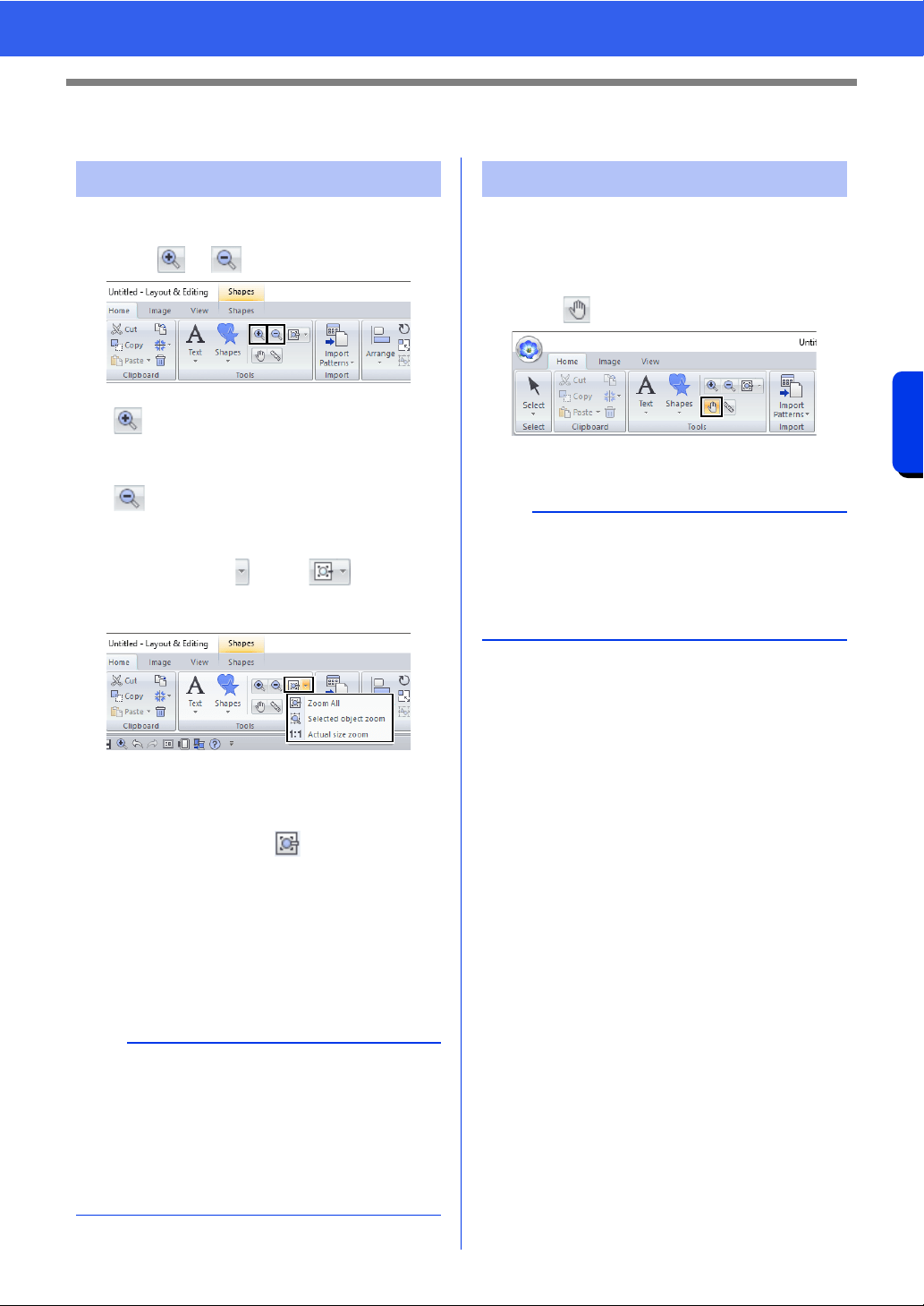
87
Checking Embroidery Patterns
Basic Layout & Editing Operations
Checking Embroidery Patterns
1 Click the [Home] tab.
2 Click or in the [Tools] group.
Otherwise, click beside , and then
click [Zoom All], [Selected object zoom] or
[Actual size zoom].
Zoom All
The entire Design Page is displayed to fit
within the window. The same operation can be
performed by clicking in the [Tools]
group.
Selected object zoom
The Design Page is zoomed to display only
the selected objects.
Actual size zoom
The Design Page is displayed at its actual
size.
The part of the work area that is displayed can easily
be changed by using the Pan tool.
1 Click the [Home] tab.
2 Click in the [Tools] group.
3 Drag the work area to view the desired part.
Zooming
: Click the Design Page to zoom in.
(Right-click the Design Page to zoom
out.)
: Click the Design Page to zoom out.
(Right-click the Design Page to zoom
in.)
b
• Zooming is also possible by dragging the
[Zoom] slider in the status bar or clicking the
Zoom ratio.
• You can also zoom in or out when any other tool
is selected by holding down the <Ctrl> key while
rotating the mouse wheel.
cc "Layout & Editing Window" on page 13
Using the Pan tool
b
• You can also pan the work area when any other
tool is selected by holding down the <Space>
key while dragging the pointer.
• To scroll horizontally, hold down the <Alt> key
while rotating the mouse wheel.
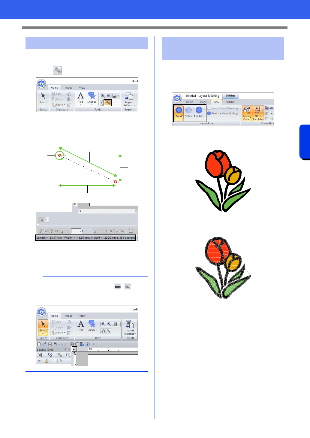
88
Checking Embroidery Patterns
Basic Layout & Editing Operations
1 Click the [Home] tab.
2 Click in the [Tools] group.
3 Click the two points, one on each end of the
distance that you want to measure.
The length appears in the status bar.
1 Length
2 Width
3 Height
4 Angle
1 Click the [View] tab.
2 Click [Solid], [Stitch] or [Realistic] in the
[View Mode] group.
■ Solid View
■ Stitch View
You can display a stitch view of it in order to see how
the stitching is connected.
Using the Measure tool
b
When the rulers are displayed, click / to
switch the measurement units between millimeters
and inches.
1
4
2
3
Changing the display of
the embroidery design
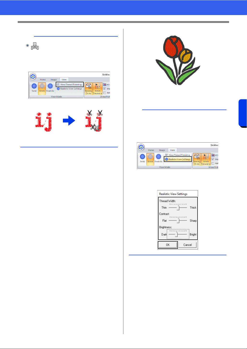
89
Checking Embroidery Patterns
Basic Layout & Editing Operations
■ Realistic View
You can display a realistic view of it in order to see
how the design will appear once it is sewn.
b
If is selected under [Machine Type] in the
[Design Settings] dialog box, click the [View] tab,
and then select the [View Thread Trimming]
check box to view the thread trimming locations in
the Design Page.
1 OFF
2 ON
12
b
Changing realistic view settings
1. Click the [View] tab.
2. Click [Realistic View Settings] in the [View
Mode] group.
3. If necessary, specify settings for [Thread
Width], [Contrast] and [Brightness], and
then click [Apply] ([OK]).
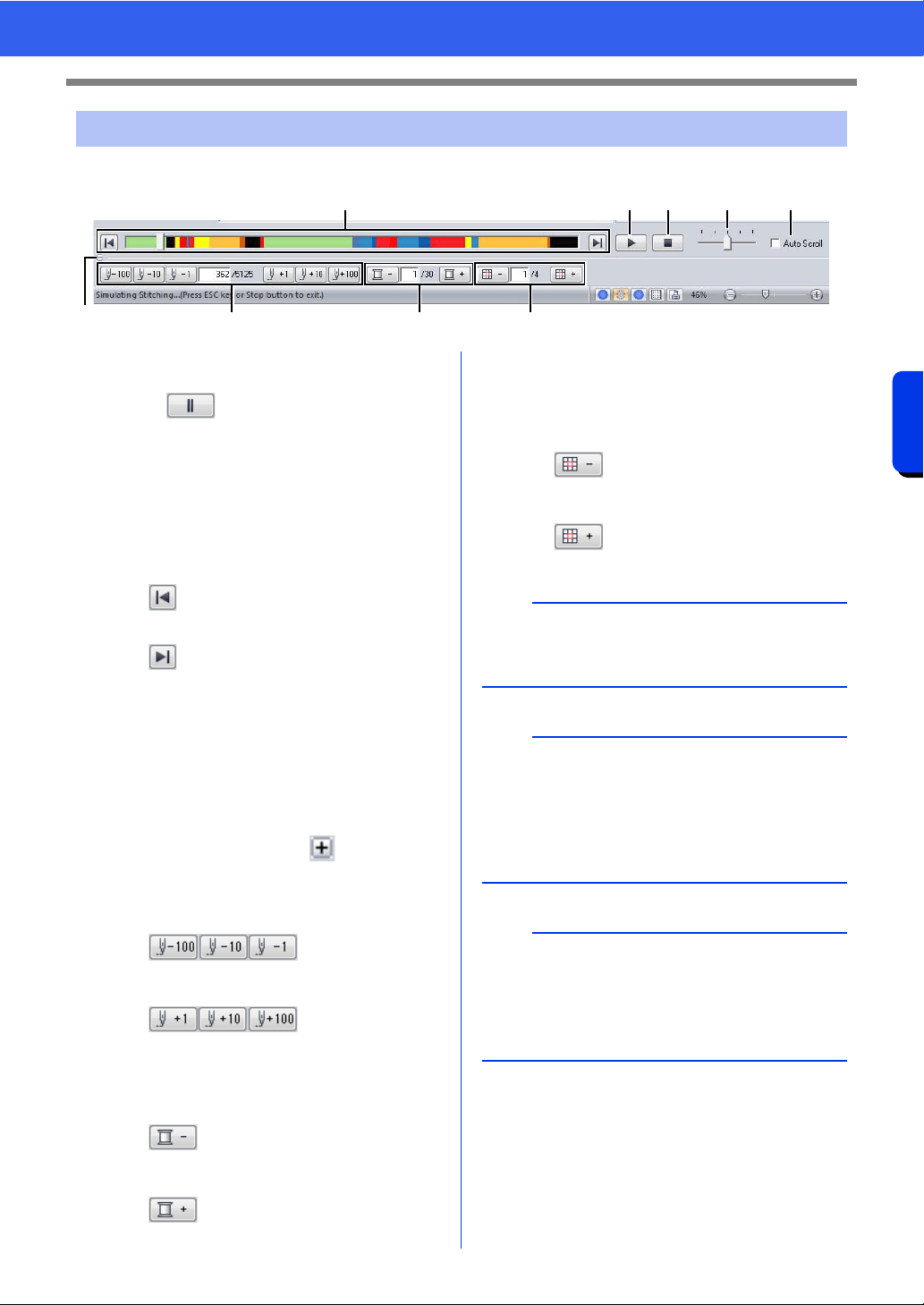
90
Checking Embroidery Patterns
Basic Layout & Editing Operations
1 Click the buttons to view a simulation of the stitching.
a Starts the stitching simulation. During
stitching simulation, this button changes
to , which can be clicked to
temporarily stop the simulation.
b Stops the simulation and returns to the
previous display.
c The slider shows the current location in
the simulation. In addition, the slider can
be moved to change the position in the
simulation.
: Returns to the beginning of stitching
and stops the simulation.
: Advances to the end of stitching and
stops the simulation.
d Drag the slider to adjust the simulation
stitching speed.
e Select this check box to automatically
scroll the simulation of the pattern when it
is too large to be fully displayed.
f Click to hide the bottom section of the
Stitch Simulator. Click to display it
again.
g Shows the number of the current stitch/
total number of stitches.
: Reverses the
simulation by the indicated number of
stitches.
: Advances the
simulation by the indicated number of
stitches.
h Shows the number of the color being
drawn/total number of colors used.
: Returns to the beginning of
stitching for the current or previous thread
color.
: Advances to the beginning of
stitching for the next color.
i Shows the currently displayed pattern
section/total number of hoop sections in
the pattern.
(Appears only for split embroidery
patterns.)
: Returns to the beginning of
stitching in the current or previous hoop
section.
: Advances to the beginning of the
design in the next hoop section.
Checking the stitching with the Stitch Simulator
c
g h i
a b d e
f
a
If the Stitch Simulator is not displayed at the
bottom of the window, click [Stitch Simulator] on
the [View] tab.
b
• The zoom tools and pan tool can be used while
a simulation is being viewed. If any other
command is selected, the simulation stops.
• If a value is entered at
g, h or i, the
simulation is reversed/advanced to the indicated
location.
a
• If a pattern was selected when the stitching
simulation was started, only the selected pattern
is drawn in the simulation.
•The [Auto Scroll] check box is not available in
Realistic View.
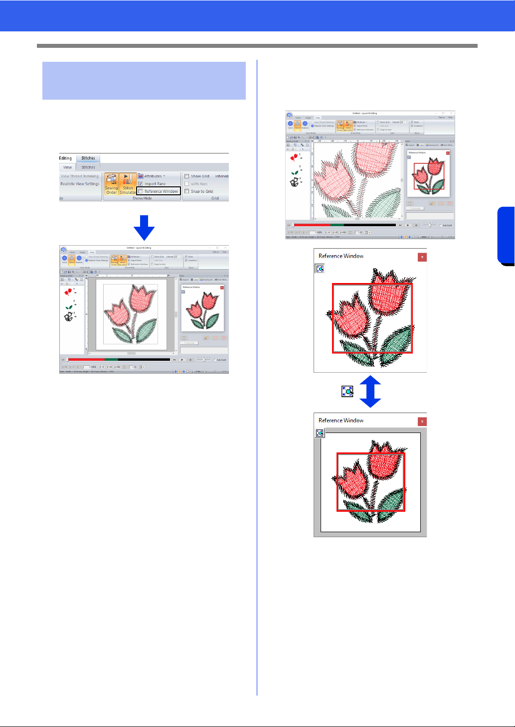
91
Checking Embroidery Patterns
Basic Layout & Editing Operations
1 Click the [View] tab.
2 Select the [Reference Window] check box in
the [Show/Hide] group.
The display are a frame (red rectangle) indicates the
part of the pattern displayed in the Design Page.
■ Zooming
The Reference Window can be switched to display
either the entire Design Page or only the embroidery
pattern.
1 ON
2 OFF
Viewing design in the
Reference Window
1
2
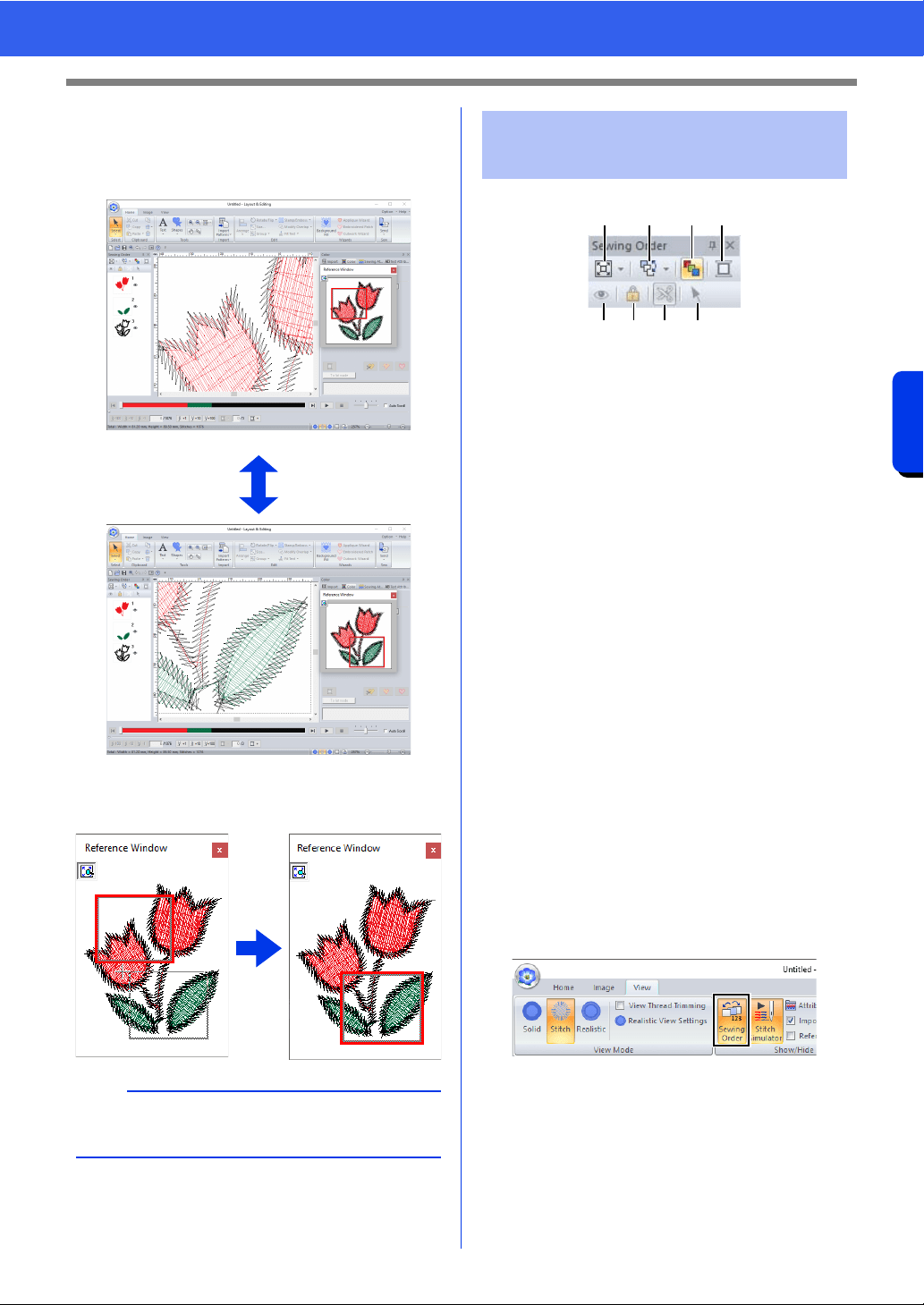
92
Checking Embroidery Patterns
Basic Layout & Editing Operations
■ Moving/Resizing/Redrawing the
display area frame
The part of the design displayed in the Design Page
can be selected from the Reference Window.
Instead of moving the display area frame, the frame
can be redrawn to display the desired part of the
pattern in the Design Page.
a Select how patterns are displayed in the
[Sewing Order] pane.
b Select the desired command to change
the sewing order.
c Optimize Sewing Order
Click to rearrange the sewing order so
that the parts of the entered objects with
the same thread color will be sewn
together.
d Thread Color
Set the color of the selected object.
e Show/hides in the work area the stitched
objects.
f Lock
Click to lock the selected object so it
cannot be edited.
g Jump Stitch Trimming
The Jump Stitch Trimming function can
be turned on or off.
h Select Patterns
Selects the patterns in the Design Page.
1 Click the [View] tab.
2 Click [Sewing Order] in the [Show/Hide]
group.
Clicking the button switches between
displaying and hiding the Sewing Order.
a
With the frame, you can select the area in the
Reference Window to be displayed enlarged.
Checking and Editing the
Sewing Order
abcd
efg h
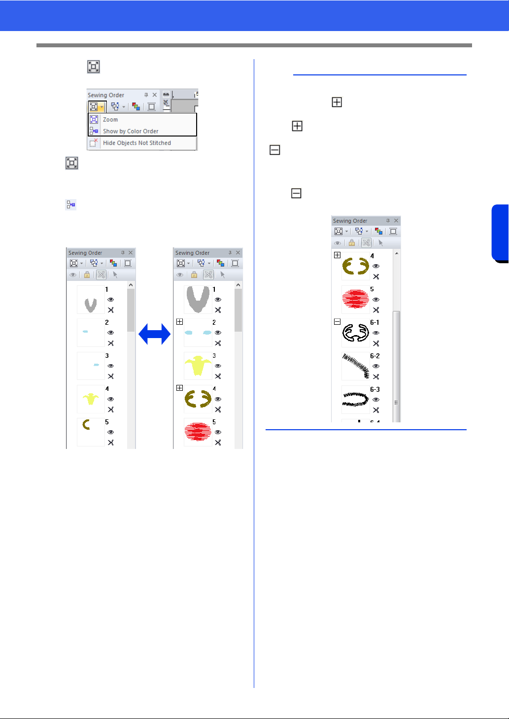
93
Checking Embroidery Patterns
Basic Layout & Editing Operations
3 Click in the [Sewing Order] pane, and
then click [Zoom] and [Show by color order].
Zoom
Click to enlarge each pattern to fill its
frame.
Show by color order
Click to display in one frame all
patterns of the same color that will be
sewn together.
1 OFF
2 ON
12
b
When multiple same color patterns are combined
into one frame, appears to the left of that
frame.
Click to display the combined same color
patterns in separate frames.
appears under the first frame, and each frame
is displayed with a subnumber following the first, to
indicate its sewing order within the patterns of the
same color.
Click to recombine all of the same color
patterns back into one frame.
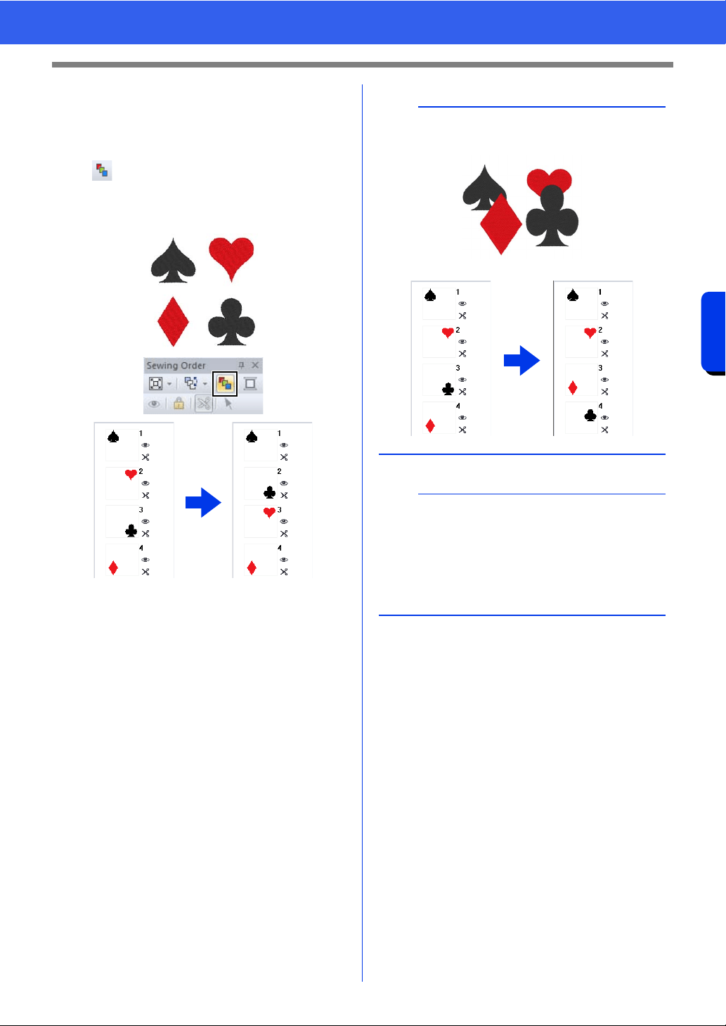
94
Checking Embroidery Patterns
Basic Layout & Editing Operations
■ Sewing order optimization
The sewing order and entry and exit points can be
automatically adjusted to reduce the number of
thread color changes and jump stitches.
Click to optimize the sewing order.
For the pattern at the right (the numbers indicate the
sewing order), the sewing order will be adjusted as
shown below.
The sewing order is adjusted so that patterns of the
same color are grouped in the most optimized
sequence.
In addition, patterns of the same color are optimized
so that the exit point of the previous pattern and the
entry point of the next pattern are the closest points.
1 2
34
a
However, overlapping patterns will be arranged in
the most appropriate sewing order.
b
• The patterns in locked frames and hidden
frames will also be optimized.
• The sewing order of multi-position patterns will
not be optimized.
cc "Optimizing the sewing order (color sort)" on
page 46
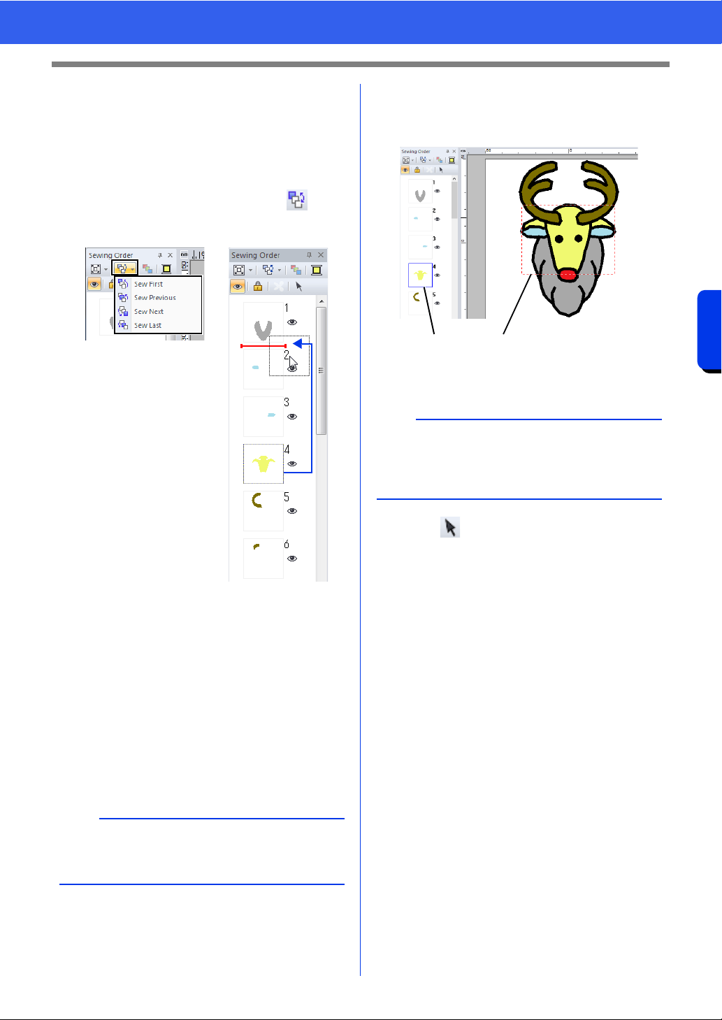
95
Checking Embroidery Patterns
Basic Layout & Editing Operations
■ Editing the sewing order
The sewing order can be changed by selecting the
frame containing the pattern, then dragging the
frame to the new location. A red line appears,
indicating the position where the frame is being
moved.
The frame can also be moved by clicking in the
[Sewing Order] pane, then clicking the desired
command in the menu that appeared.
Sew First
Click to move the selected pattern to the beginning
of the sewing order.
Sew Previous
Click to move the selected pattern ahead one
position in the sewing order.
Sew Next
Click to move the selected pattern back one position
in the sewing order.
Sew Last
Click to move the selected pattern to the end of the
sewing order.
■ Selecting a pattern
1 Click a frame containing the pattern in the
[Sewing Order] pane.
1 Blue line
2 Marching line
2 Click in the [Sewing Order] pane to
select the pattern in the Design Page
corresponding to the frame selected in the
[Sewing Order] pane. The pattern can also
be selected by double-clicking its frame in the
[Sewing Order] pane.
a
Check the stitching after changing the sewing
order to be sure that overlapping patterns will not
be sewn in the wrong order.
b
To select multiple patterns, hold down the <Shift>
or <Ctrl> key while clicking the frames for the
desired patterns. In addition, multiple frames can
be selected by dragging the pointer over them.
12
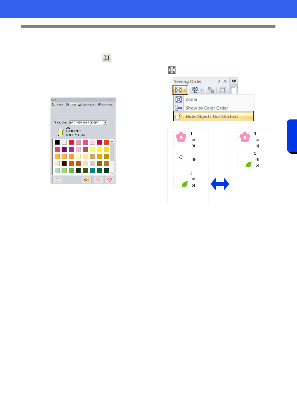
96
Checking Embroidery Patterns
Basic Layout & Editing Operations
■ Changing colors
1 Select one or more frames in the [Sewing
Order] pane, and then click at the top of
the [Sewing Order] pane.
The Color pane appears in front of the other
panes.
2 Click the desired color in the [Color] pane.
cc "Color pane" on page 54
■ Changing sewing attributes
1 In the [Sewing Order] pane, select one or
more frames containing a pattern other than a
stitch pattern.
The sew type selector for the selected
frame appears.
2 Click the [Sewing Attributes] tab.
If the [Sewing Attributes] pane is not
displayed, click the [View] tab, then
[Attributes], and then click [Sewing
Attributes].
3 Change the sewing attributes and sew type.
cc "Line sew types", "Region sew types" on
page 57 and "Specifying sewing
attributes" on page 64
■ Displaying/hiding frames not
sewn
Frames containing patterns that will not be sewn
can be displayed or hidden.
Click , then [Hide Objects Not Stitched].
1 OFF
2 ON
As a default, frames containing patterns that will not
be sewn will be hidden.
When frames containing patterns that will not be
sewn are displayed, that frame can be selected and
its pattern can be edited.
12
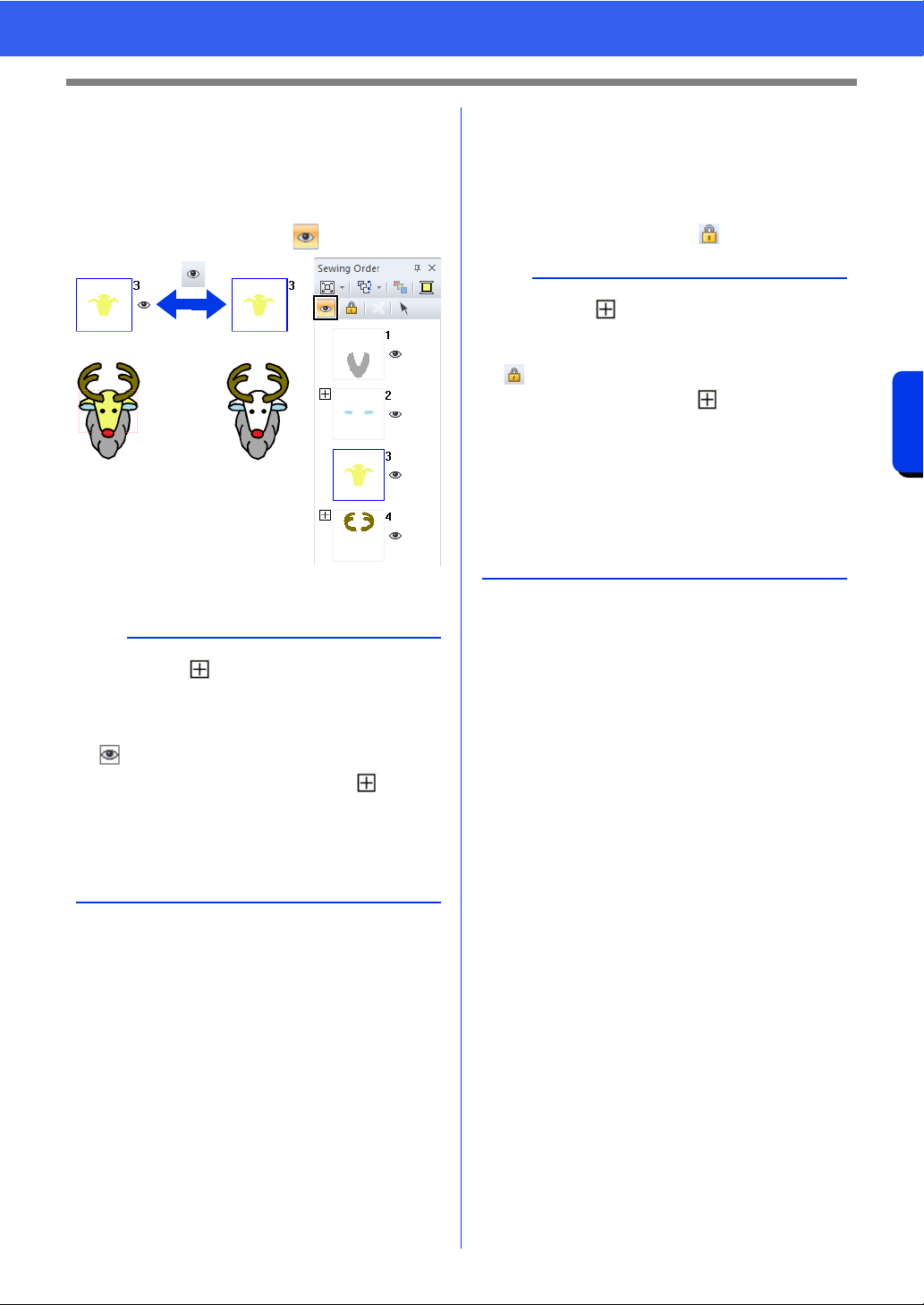
97
Checking Embroidery Patterns
Basic Layout & Editing Operations
■ Hiding embroidery patterns
Each embroidery patterns can be displayed or
hidden in the Design Page. Overlapping embroidery
patterns can easily be edited if the pattern not being
edited is hidden.
Select a frame, and then click .
1 ON
2 OFF
■ Locking embroidery patterns
Embroidery patterns can be locked to prevent them
from being moved or deleted. Locked embroidery
patterns cannot be selected or edited in the Design
Page.
Select a frame, and then click .
b
• Frames with contain multiple patterns of the
same color. If these frames are selected to be
displayed, all patterns in the frame are
displayed.
• appears if the display setting is not the
same for all patterns in a frame with beside
it.
• Displaying either the line or region of an
embroidery pattern made up of an outline and
inside region displays the entire embroidery
pattern.
12
b
• Frames with contain multiple patterns of the
same color. If these frames are selected to be
locked, all patterns in the frame are locked.
• appears if the lock setting is not the same for
all patterns in a frame with beside it.
• Locking either the line or region of an
embroidery pattern made up of an outline and
inside region locks the entire embroidery
pattern.
• Locking any part of a combined pattern, such as
grouped patterns, text arranged on a curve or
patterns with hole sewing specified, locks the
entire embroidery pattern.
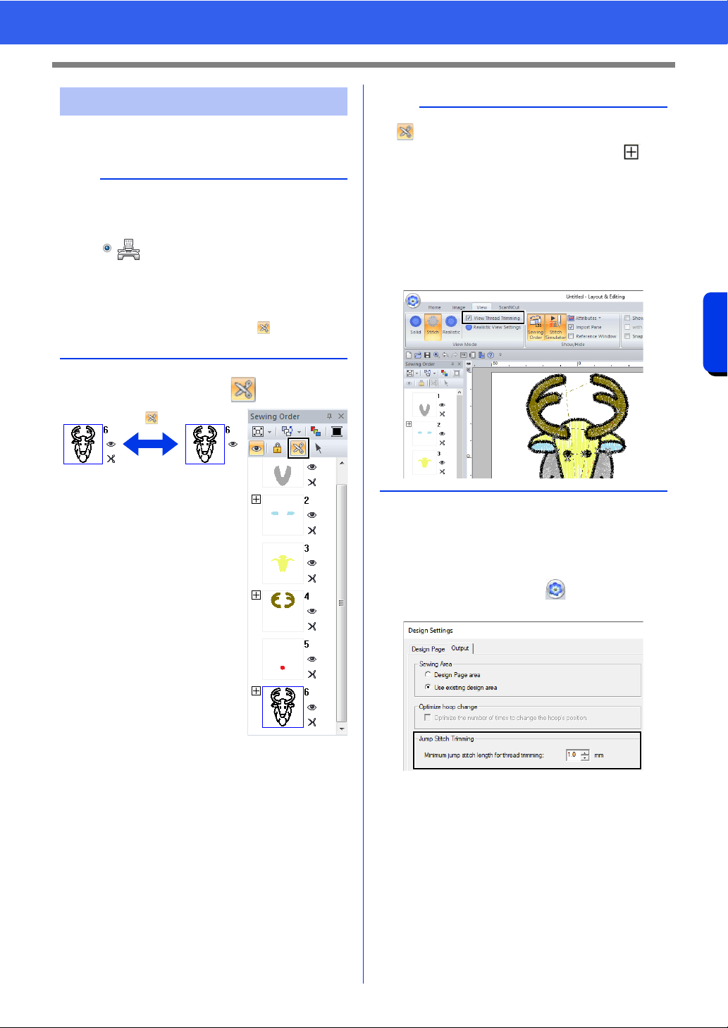
98
Checking Embroidery Patterns
Basic Layout & Editing Operations
The Jump Stitch Trimming function can be turned on
or off.
Select a frame, and then click .
1 ON
2 OFF
About Minimum jump stitch length for thread
trimming
• The jump stitch length can be specified on the
[Output] tab into the [Design Settings] dialog
box. (To displayed it, click , then [Design
Settings]).
• If the jump stitch length is less than the length
specified for [Minimum jump stitch length for
thread trimming], the thread will not be cut,
even if [Jump Stitch Trimming] has been set.
• Whether or not [Minimum jump stitch length
for thread trimming] is available differs
depending on the selected machine model. For
details, refer to the instruction manual for the
machine.
Jump Stitch Trimming
a
These settings are applied only when
embroidering with our multi-needle embroidery
machines. Before these settings can be specified,
select under [Machine Type] in the
[Design Settings] dialog box.
cc "Specifying the Design Page Settings" on
page 16
The Jump Stitch Trimming button ( ) is available
in the [Sewing Order] pane.
12
b
• appears if the thread trimming setting is not
the same for all patterns in a frame with
beside it.
• The thread is cut before the thread color is
changed, even if [Jump Stitch Trimming] has
been turned off for the frame.
• Click the [View] tab, and then select the [View
Thread Trimming] check box in the [View
Mode] group. To view the thread trimming
locations in the Design Page.
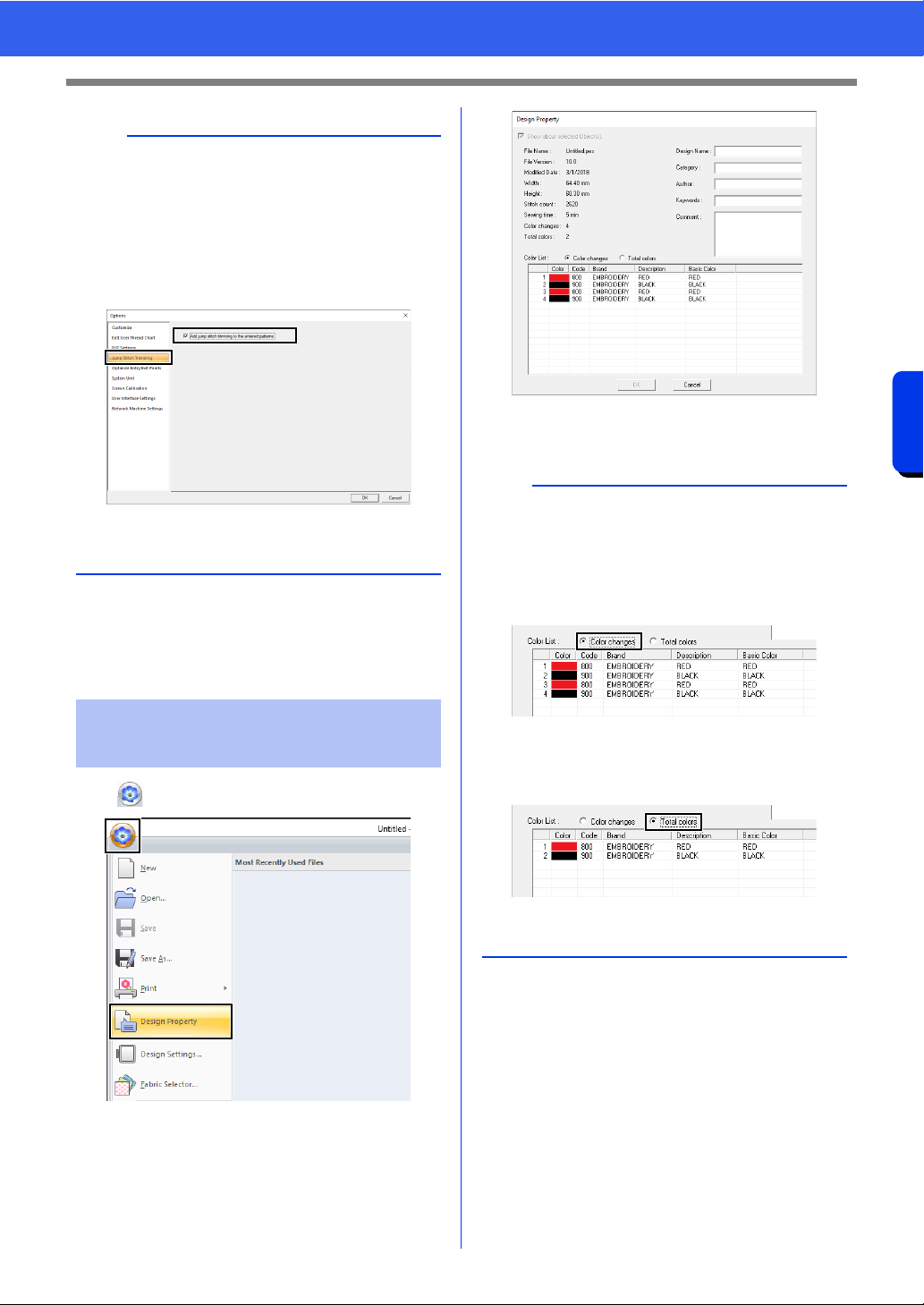
99
Checking Embroidery Patterns
Basic Layout & Editing Operations
cc "Jump Stitch Trimming" on page 18,
"Machine thread trimming according to
settings specified in Layout & Editing" on
page 365 and "Adding jump stitch
trimming to new patterns" on page 370
Click , then [Design Property].
You can enter comments and information about the
pattern to a saved .pes file.
b
The default setting can be specified for whether or
not thread trimming is applied to objects that are
created.
Click [Option] above the Ribbon, and then click
[Options] to display the [Options] dialog box.
Next, click [Jump Stitch Trimming], and then
select or clear the [Add jump stitch trimming to
the entered patterns.] check box.
cc "Adding jump stitch trimming to new patterns"
on page 370
Checking embroidery
design information
b
• The information shown in the color list can be
switched.
Color Changes
The thread color information for each color
change is displayed. This allows you to check
the total number of thread color changes.
Total Colors
The thread color information for the necessary
threads is displayed. This allows you to check
the total number of thread colors.
• The colors corresponding to the 61 basic
Brother colors are listed under [Basic Color].
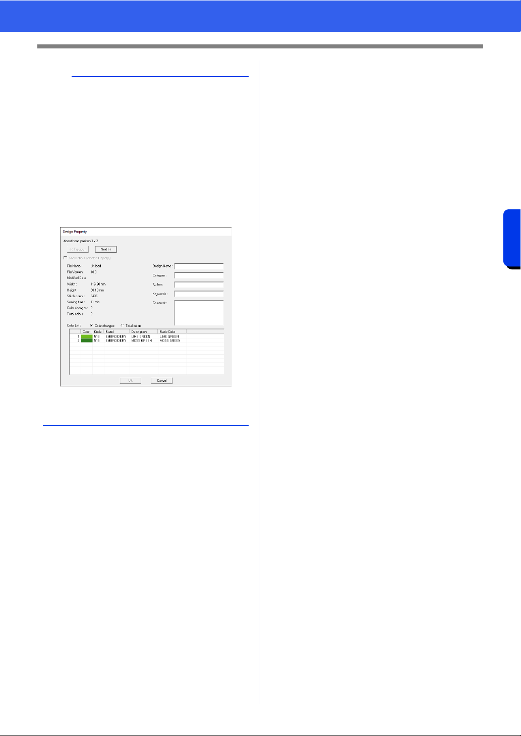
100
Checking Embroidery Patterns
Basic Layout & Editing Operations
b
• You can select and check the properties of
individual patterns within the embroidery design
by selecting the pattern before opening this
dialog box. In this case, clearing the [Show
about selected Object(s)] check box switches
the dialog box to display properties for all
patterns in the Design Page.
• If the Design Page was set to [Custom Size] or
[Hoop Size] was set to a multi-position hoop
(100 × 172 mm or 130 × 300 mm) or the jumbo
frame (360 × 360 mm), a [Design Property]
dialog box appears with the sewing information
for each hoop of the pattern in the Design Page.
• Files can be searched for in Design Database
according to the entered information.
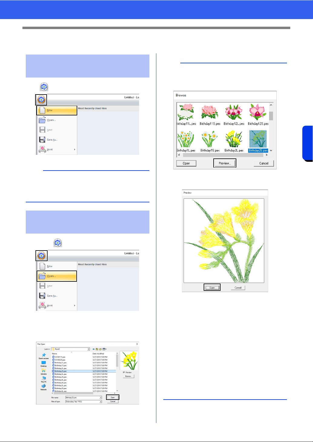
101
Opening/Importing Embroidery Designs
Basic Layout & Editing Operations
Opening/Importing Embroidery Designs
Click , then [New].
1 Click , then [Open].
2 Select the drive, the folder and the file, and
then click [Open], or double-click the file's
icon.
Creating a new embroidery
design
b
The size of the Design Page can be changed.
cc "Specifying the Design Page Settings" on
page 16
Opening a Layout &
Editing file
b
• To view the data in the selected folder as
thumbnails in the [Browse] dialog box, click
[Browse].
To see a more detailed design, select a file, and
then click [Preview].
• To open the displayed file, click [Open].
• If no files are listed, there are no .pes files in the
selected folder. Select a folder containing a .pes
file.
• If the selected file is in a format other than the
.pes format, the message "Unexpected file
format" appears in the [Preview] window.
• A file can be opened in any of the following
ways.
Drag the embroidery design from file Windows
Explorer into the Layout & Editing window.
Double-click the embroidery design file in
Windows Explorer.
Double-click the embroidery design file in
Design Database.
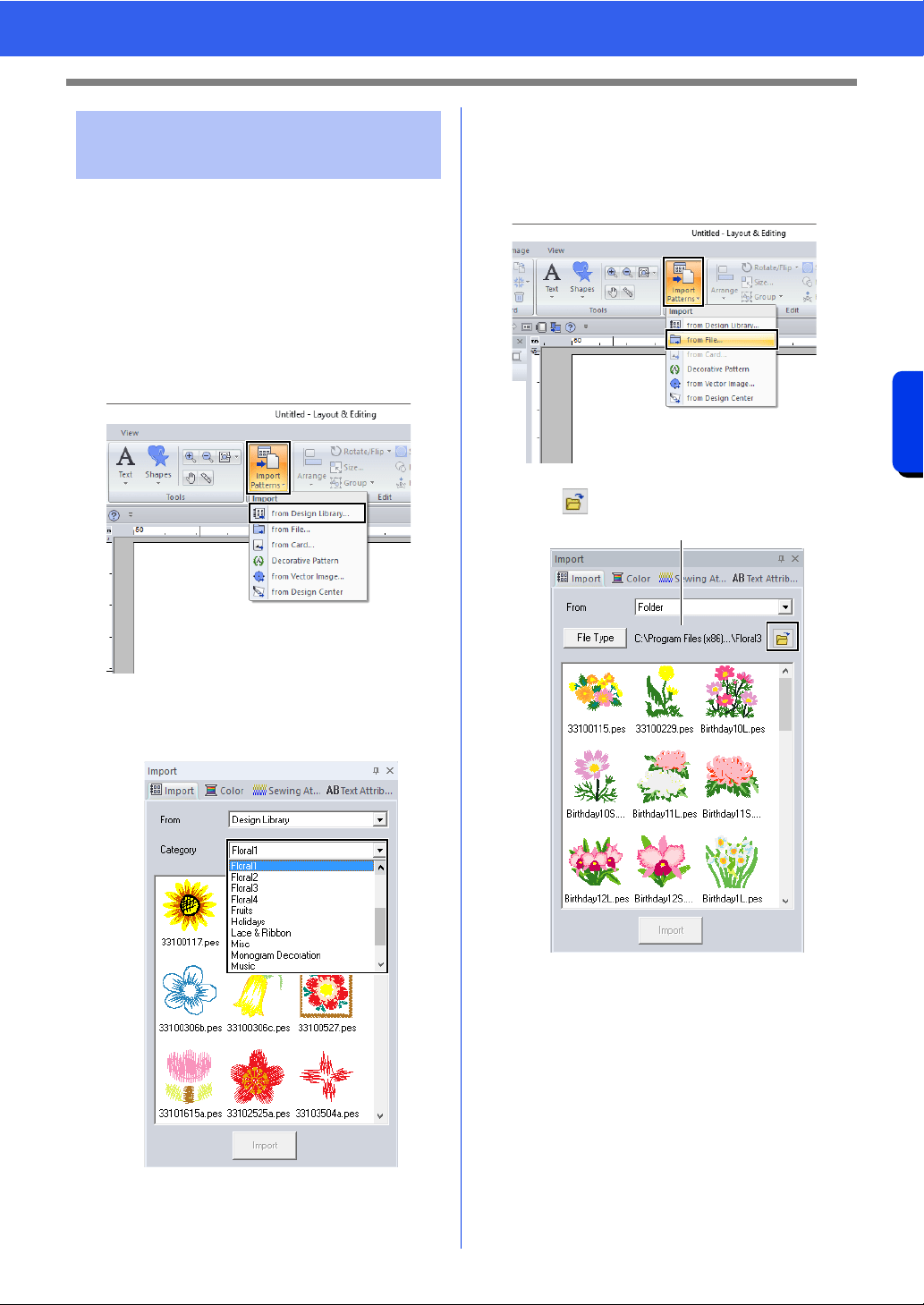
102
Opening/Importing Embroidery Designs
Basic Layout & Editing Operations
Embroidery designs can be imported from the
[Import] pane. For more details on the [Import]
pane, refer to "Example of Importing Embroidery
Data" on page 15.
■ From Design Library
1 Click the [Home] tab.
2 Click [Import Patterns] in the [Import] group,
and then click [from Design Library].
3 From the [Category] selector, select a
category to display the corresponding
embroidery data.
4 Select the file icon for the design to be
imported, and then click [Import].
■ From a folder
1 Click the [Home] tab.
2 Click [Import Patterns] in the [Import] group,
and then click [from File].
3 Click .
1 Indicates the path to the currently selected
folder.
Importing embroidery
designs
1
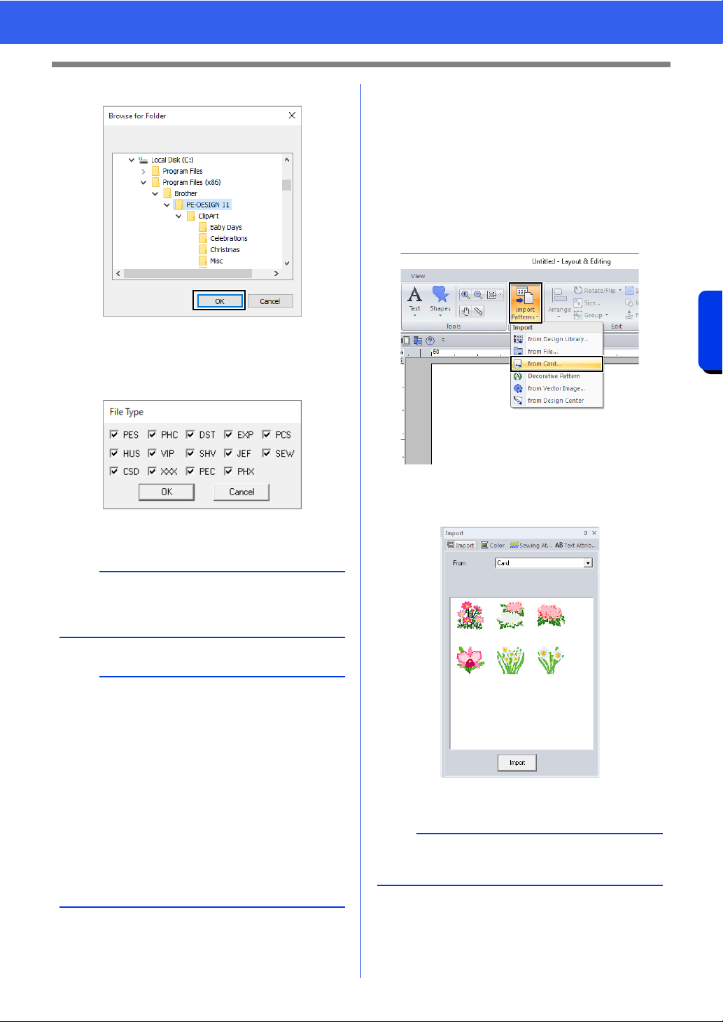
103
Opening/Importing Embroidery Designs
Basic Layout & Editing Operations
4 Select a folder, and then click [OK].
5 Click [File Type] in the [Import] pane. Select
the file name extensions of the corresponding
embroidery data to be displayed, and then
click [OK].
6 Select the file icon, and then click [Import].
■ From an original card
1 Insert an original card into the USB card writer
module.
cc Refer to "Transferring to a machine by
using an original card" on page 225
2 Click the [Home] tab.
3 Click [Import Patterns] in the [Import] group,
and then click [from Card].
After the card has been read, the
embroidery designs on the card are
displayed.
4 Select the file icon, and then click [Import].
a
When importing designs from other vendors, be
sure to choose a design that will fit in the Design
Page.
b
• Since .dst files do not contain thread color
information, the colors of an imported .dst file
may not appear as expected. You can change
the thread colors by using functions in the
[Sewing Order] pane or by holding down the
<Alt> key and selecting a stitch pattern.
cc "Selecting stitch patterns by thread color" on
page 81
• When importing .dst files, the number of jump
stitches for thread trimming can be specified.
cc "Specifying the number of jumps in
embroidery design of the DST format" on
page 369
a
Due to copyright issues, some original cards
cannot be used with this function.
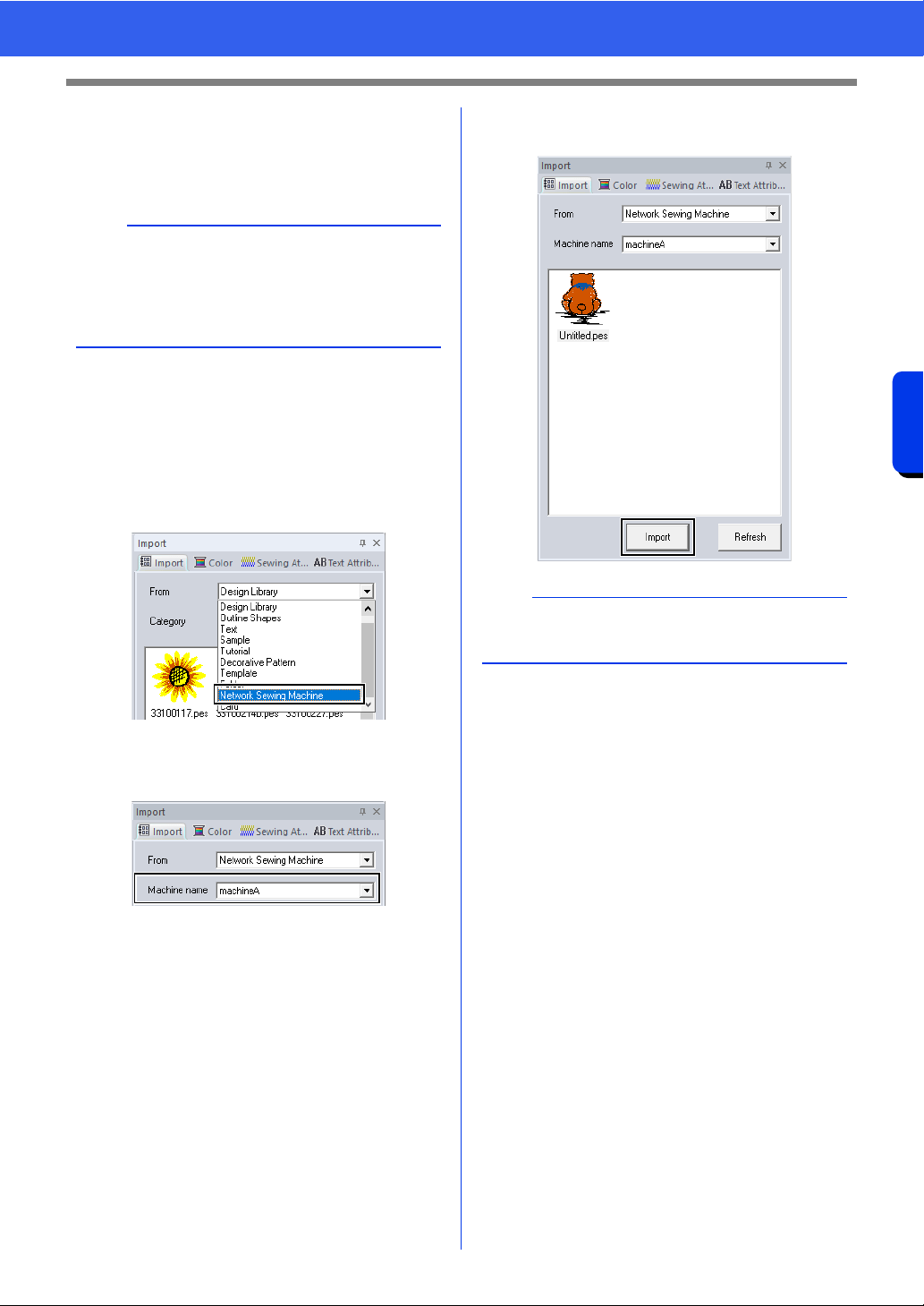
104
Opening/Importing Embroidery Designs
Basic Layout & Editing Operations
■ From a machine via wireless
network
Embroidery designs can be imported from a sewing
machine via the wireless network.
1 Register the machine with the application.
cc "Registering a machine with the
application" on page 224
2 Click the [Home] tab.
3 From the [From] selector of the [Import]
pane, select [Network Sewing Machine].
The name of the machine registered with
the application appears in the [Machine
name] box.
4 Select the icon of the file, and then click
[Import].
a
This function is available only when embroidering
with our wireless LAN-compatible embroidery
machines.
Contact your authorized dealer for details on our
wireless LAN-compatible models.
a
To update the pane with the latest information from
the embroidery machine, click [Refresh].
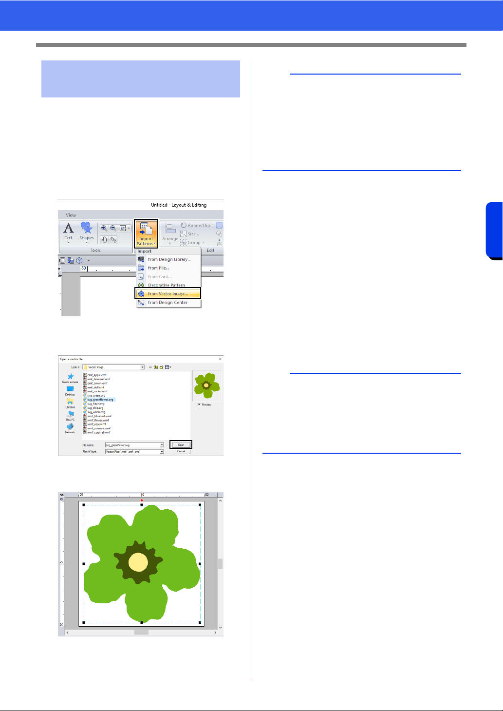
105
Opening/Importing Embroidery Designs
Basic Layout & Editing Operations
Vector image data in the ".wmf" (Windows Metafile),
".emf" (Enhanced Metafile) and ".svg" (Scalable
Vector Graphics) file formats can be converted to
shape patterns.
1 Click the [Home] tab.
2 Click [Import Patterns] in the [Import] group,
and then click [from Vector Image].
3 Select the drive, folder and file, and then click
[Open].
The imported image appears in the Design
Page.
■ Creating an embroidery pattern
using vector images drawn with
other image-editing applications
Being converted to the ".svg" file format, vector
image files created with other commercially
available applications (e.g., ".ai" (Adobe
®
Illustrator
Artwork) and ".cdr" (CorelDRAW
®
file)) can be
imported.
First convert the vector image files into either of
WMF, EMF or SVG file format with your
applications, and then import them to PE-DESIGN
by following the steps described in "Importing vector
images (WMF/EMF/SVG)".
Importing vector images
(WMF/EMF/SVG)
a
• Image, text, width of the line, gradient, opacity,
and any other styles or attributes of graphics will
not be imported. With files in the ".emf" and
".svg" formats, the data is converted while
retaining curves.
• The data on all layers of an SVG file, regardless
of whether it is displayed or hidden, will be
converted into the embroidery pattern.
b
Raster image files (e.g., ".bmp" and ".jpg") can be
used as background images in PE-DESIGN, or
they can be converted to embroidery patterns
using the Image To Stitch Wizard.
cc "Stitch Wizard: Automatically Converting an
Image to an Embroidery Design" on page 142
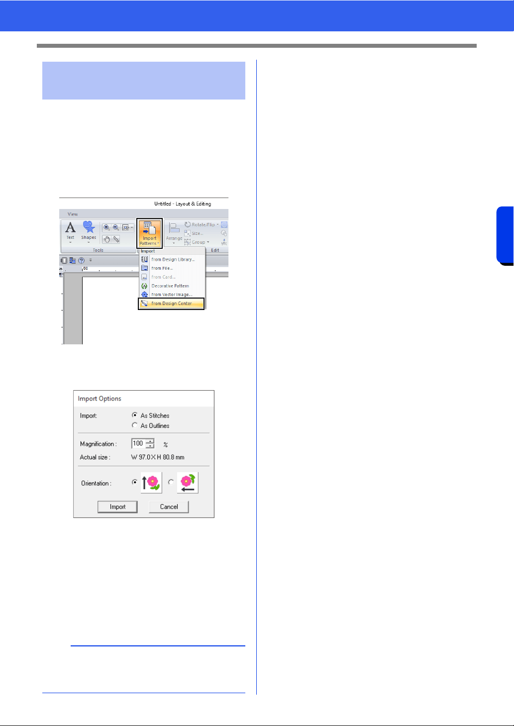
106
Opening/Importing Embroidery Designs
Basic Layout & Editing Operations
1 Start up Design Center and open the file.
cc "Original Image Stage" on page 250 and
"Opening a file" on page 261
2 Click the [Home] tab.
3 Click [Import Patterns] in the [Import] group,
and then click [from Design Center].
4 Specify the desired settings beside [Import],
[Magnification] and [Orientation], and then
click [Import].
Import
As Stitches:
Imports, as stitch patterns, embroidery data
created in Design Center.
As Outlines:
Imports, as outline patterns, embroidery data
created in Design Center. This data can be
edited in the same way as outline patterns
created in Layout & Editing.
Importing embroidery
design from Design Center
a
The maximum magnification ratio that can be
specified is the ratio that enlarges the design to the
size of the Design Page.
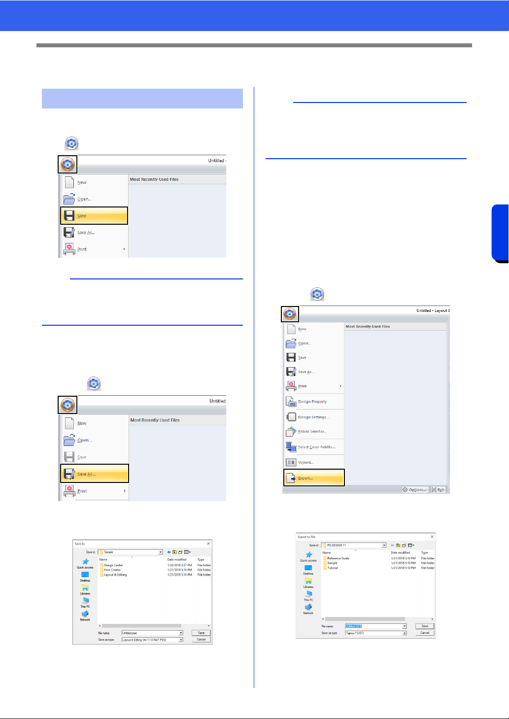
107
Saving and Printing
Basic Layout & Editing Operations
Saving and Printing
■ Overwriting
Click , then [Save].
■ Saving with a new name
1 Click , then [Save As].
2 Select the drive and the folder, and then type
in the file name.
3 Click [Save] to save the data.
The new file name appears in the title bar of
the Layout & Editing window.
■ Outputting design in a different
format
The data shown in the Design Page can be exported
as a file of a different format (.dst, .hus, .exp, .pcs,
.vip, .sew, .jef, .csd, .xxx, and .shv).
1 Click , then [Export].
2 Select the drive and the folder, and then type
in the file name.
Saving
b
If no file name has been specified or if the file
cannot be found, the [Save As] dialog box
appears.
a
If you select a file type of a previous software
version, saved .pes files can be opened with that
version of the software; however, all saved
designs will be converted to stitch pattern.
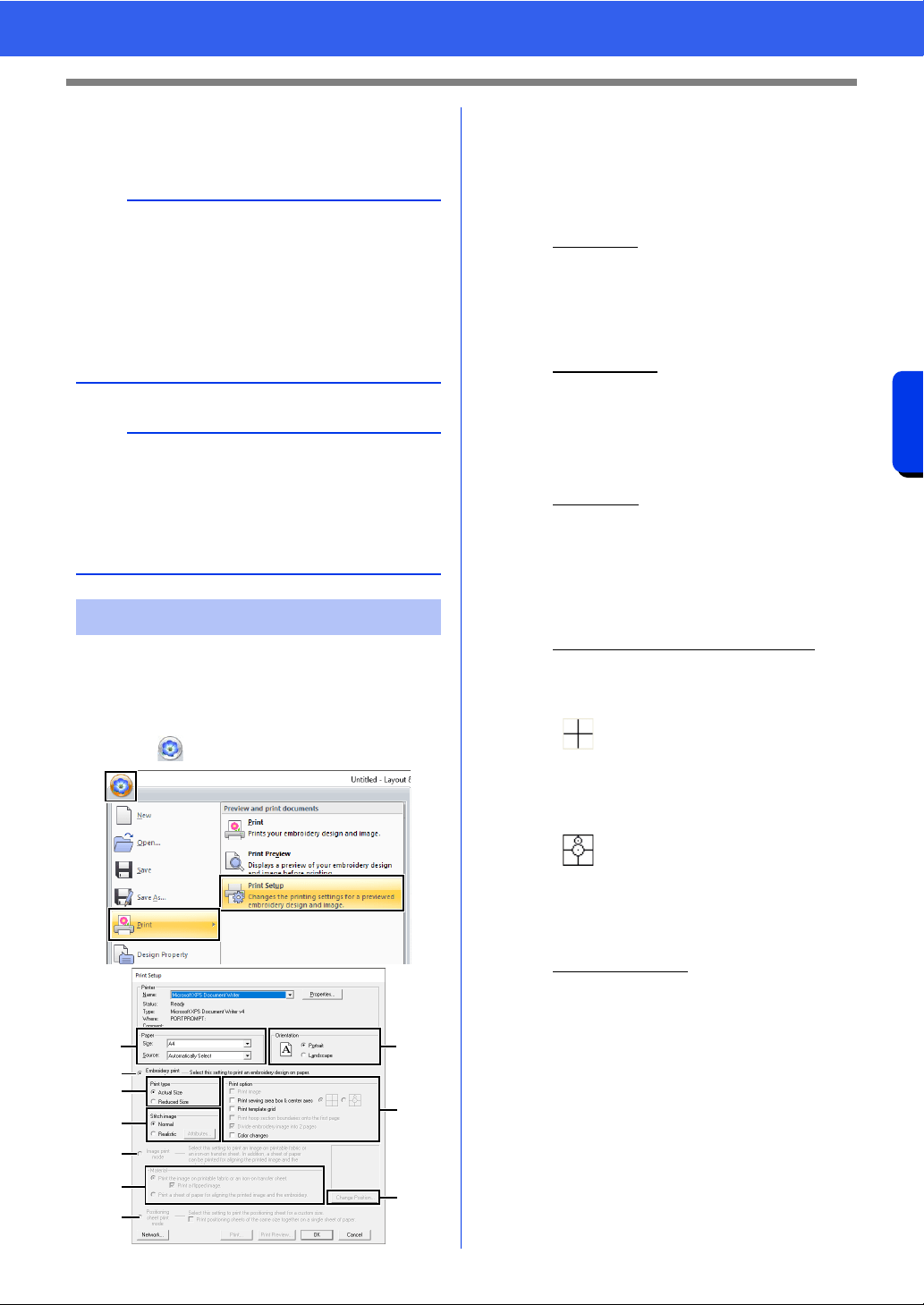
108
Saving and Printing
Basic Layout & Editing Operations
3 Select a format (.dst, .hus, .exp, .pcs, .vip,
.sew, .jef, .csd, .xxx, and .shv) that the file will
be exported as.
■ Specifying print settings
Before printing, you may need to change the print
settings for the embroidery design files.
1 Click , then [Print], then [Print Setup].
a Specify the paper size.
b Specify the paper orientation.
c To print the embroidery pattern, select
[Embroidery print mode].
d Print type
Actual Size:
Select this option to print the design at
actual size and the sewing information
(dimensions of the embroidery pattern,
sewing color order, stitch count and
hoop position) on separate pages.
Reduced Size:
Select this option to print a reduced
image together with all of the above-
mentioned information on a single
page.
e Print option
Print image:
Select this check box to print the image
imported into the Design Page in
addition to the embroidery pattern.
However, any part of the image
extending out of the print area for the
embroidery will not be printed.
Print sewing area box & center axes:
(This setting is only available when
[Actual Size] is selected.)
(This setting cannot be selected if
[Jumbo Frame] has been selected as
the Design Page size.)
Print template grid:
Select this check box to print green
lines to represent the grid printed on
the embroidery sheet included with the
hoop. (This setting cannot be selected
if User Hoop, [Cap Frame], [Cylinder
Frame], [Jumbo Frame], [Clamp
Frame] or [Round Frame] has been
selected as the Design Page size.)
b
The [Number of jumps for trim] setting can be
specified for outputting to the .dst format. Before
outputting, click the [Option] button, then
[Options], then [DST Settings] to specify the
settings.
cc "Specifying the number of jumps in
embroidery design of the DST format" on
page 369
a
• Some patterns imported from original cards
cannot be exported.
• Divided embroidery patterns and embroidery
patterns for the jumbo frame or multi-position
hoop will be exported as a single file, and will not
be split into sections.
Printing
a
c
d
f
b
e
i
g
h
j
: Select this option to print black
lines to indicate the sewing area
(refer to "Specifying the sewing
area" on page 18) and the
center axes for the data.
: Select this option to print an
embroidery positioning mark in
the center of the axes.
109
Saving and Printing
Basic Layout & Editing Operations
Print hoop section boundaries onto the
first page:
Select this check box to print the
sections of a design where the Design
Page has been set to a custom size or
to [Jumbo Frame]. The pattern
sections are printed in red.
Divide embroidery image into 2 pages:
Select this check box to print at actual
size and on A4- or Letter-size paper a
design that is larger than the paper size
by dividing it in two and printing each
half on different pages.
(This setting is only available when
[Actual Size] is selected in the [Print
Setup] dialog box and when the
Design Page is set to the larger hoop
sizes. This setting is not available if a
[User Hoop] size is selected.)
With this split printing feature, /
or / is printed in the lower-right
corner of the paper to indicate which
half is printed.
Color Changes:
Select this check box to print the thread
color change information for the
pattern.
When this check box is cleared, the
information for the necessary threads
is printed. This allows you to check the
total number of thread colors.
f Stitch image
Normal:
Select this option to print the design as
lines and dots.
Realistic:
Select this option to print a realistic
image of the design. To change the
settings of the realistic image, click
[Attributes].
cc "Changing realistic view settings" on
page 89
g When printing an imported image onto
iron-on paper or printable fabric, or when
printing the sheet for positioning the
embroidery in the printed image, select
[Image print mode], and then select an
option under [Material].
h Material
Print the image on printable fabric or an
iron-on transfer sheet:
Select this option to print the
background image on iron-on paper or
fabric that can be printed on. Only the
image is printed.
Print a flipped image:
Select this check box to print the image
flipped on a vertical axis. When printing
on iron-on paper, the image is normally
printed flipped (mirror image). (For
details, refer to the instructions for the
iron-on paper that you are using.)
Select this option if your printer does
not have a function for printing a flipped
(mirror) image. (For details, refer to the
instructions for your printer.)
Print a sheet of paper for aligning the
printed image and the embroidery:
Select this option to print a sheet for
aligning the positions of the image and
embroidery. Positioning marks and
guide lines indicating the embroidering
area are printed on the image.
i Change Position
The position where the image is printed
on the paper can be changed. (Any part of
the image extending out of the print area
of the paper is not printed.) Click [Change
Position] to display the [Image Print
Position Setting] dialog box, and then
drag the image to the desired printing
position in the paper.
j Positioning sheet print mode
Select this option to print positioning
sheets for split embroidery patterns.
cc "Printing the positioning sheets" on
page 203
a
If the [Divide embroidery image into 2 pages]
check box is cleared and you print on paper of a
larger size, the design does not print in two halves.
Likewise, if you print on paper of a smaller size, the
design might be cut off.
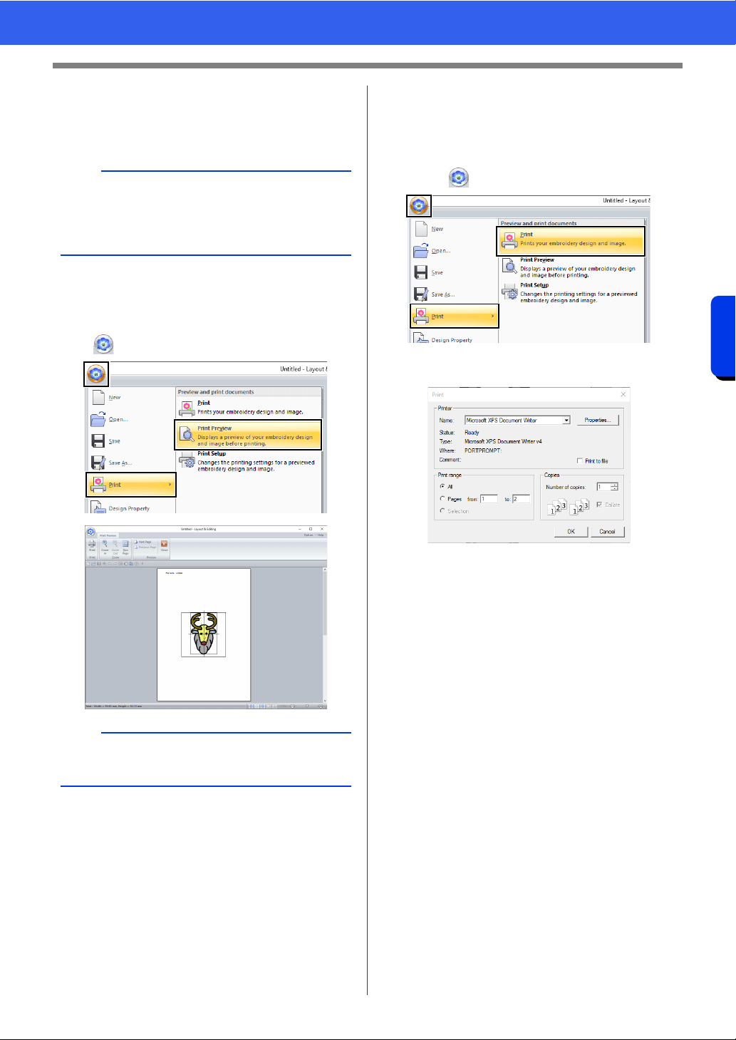
110
Saving and Printing
Basic Layout & Editing Operations
2 Click [OK].
cc "Changing the display of the embroidery
design" on page 88.
■ Checking a print image
You can preview the contents of the Design Page
before printing.
Click , then [Print], then [Print Preview].
■ Printing a Design Page with
sewing information
You can print the Design Page together with its
sewing information.
1 Click , then [Print], then [Print].
2 Select the necessary settings.
3 Click [OK] to begin printing.
4 Follow the instructions for the printer to finish
printing.
b
With embroidery patterns for the jumbo frame
The pattern in Side 2 of an embroidery pattern for
the jumbo frame is printed with the orientation of
the actual embroidery (rotated 180°).
b
The print image can also be displayed by clicking
[Print Preview] in the [Print Setup] dialog box.

Creating Embroidery Patterns
Containing Text
This section provides descriptions for entering text
and the various operations for arranging them. In
addition, details are provided for creating embroidery
patterns whose text can easily be replaced.
From Layout & Editing, various embroidery
patterns can be created for text.
The following types of text can be created.
In addition, text can be arranged in the following
ways.
Built-in fonts:
This software is provided with 130 built-in
fonts. (10 built-in fonts are specifically for
small text)
TrueType fonts:
TrueType fonts installed on your computer
can be used to create embroidery patterns.
Small text:
These small fonts have sizes between 3 and
6 mm (0.12 and 0.24 inch).
Because of their size, these fonts are useful
for beautifully sewing small text.
Monogram:
Design custom monograms by combining
text and decorative patterns.
User-defined
fonts:
User-defined fonts can be created by using
the Font Creator.
User-mapped
fonts:
With Font Creator, embroidery patterns can
be registered to create a user-mapped font.
Registered embroidery patterns can be
edited in the same way as text patterns.
Text
arrangement:
The text can be arranged along an outline or
an arc.
Transforming:
Text can be transformed into any of the 26
Transform styles.
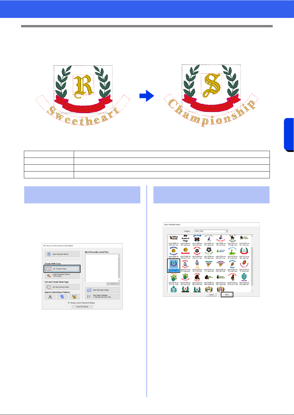
112
Creating Embroidery Patterns Containing Text
Tutorial 2: Using Templates
Tutorial 2: Using Templates
Using the [Template Wizard], you can easily create custom embroidery patterns by simply changing the text
in the patterns that are already available. Follow each step to create a custom embroidery pattern.
The sample file for this tutorial is located at Documents (My documents)\PE-DESIGN 11\Tutorial\Tutorial_2.
When Layout & Editing starts up, the first dialog box
of the wizard appears.
1 Plug your USB media into the computer.
2 Click [Use Template Designs].
1 Select [shirtsCH11B.pes] from the category
[Shirts_Chest], and then click [Next].
Step 1 Starting the Template Wizard
Step 2 Selecting the type of template to be used
Step 3 Editing the text
Step 4 Outputting the edited template
Step 1 Starting the Template
Wizard
Step 2 Selecting the type of
template to be used
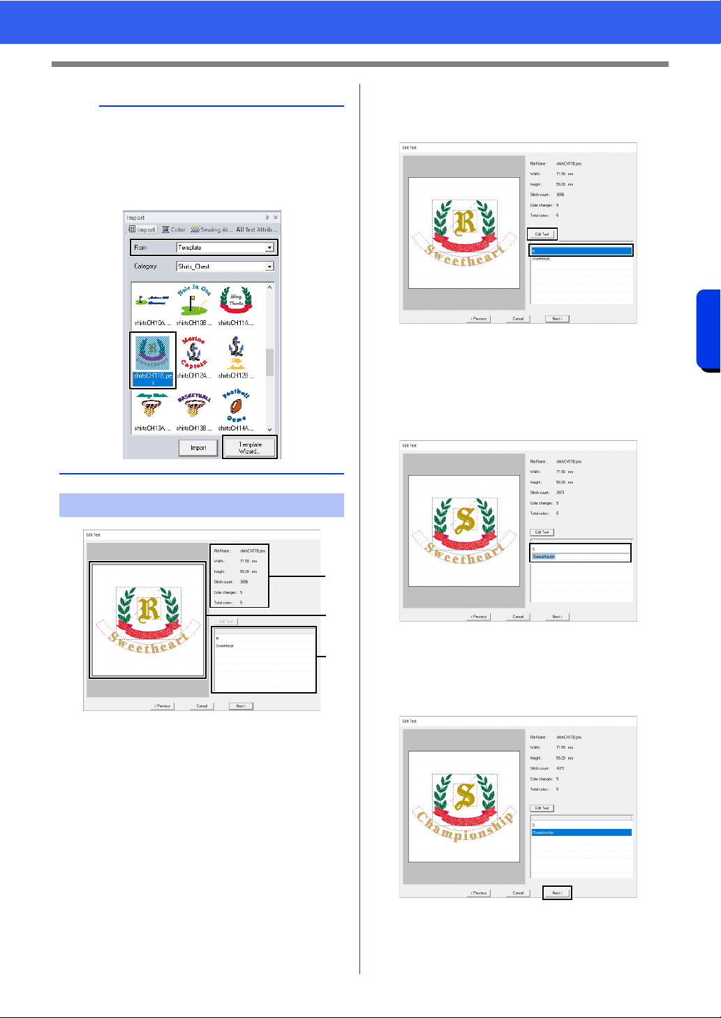
113
Creating Embroidery Patterns Containing Text
Tutorial 2: Using Templates
a Text list: Edit the text here.
b Preview window: Check the results of the
edited text.
c Embroidery information for the template
1 Click "R" in the text edit box, to be changed,
and then click [Edit Text].
The text is highlighted.
2 Type "S", and then press the <Enter> key.
The results of editing appear in the preview
window.
The text "Sweetheart" in the second row is
highlighted.
3 Type "Championship", and then press the
<Enter> key.
4 Click [Next].
b
Various templates are available when [Template]
is selected in the [From] selector of the [Import]
pane.
Select [shirtsCH11B.pes] from the category
[Shirts_Chest], and then click [Template
Wizard] to open the Template Wizard.
Step 3 Editing the text
c
b
a
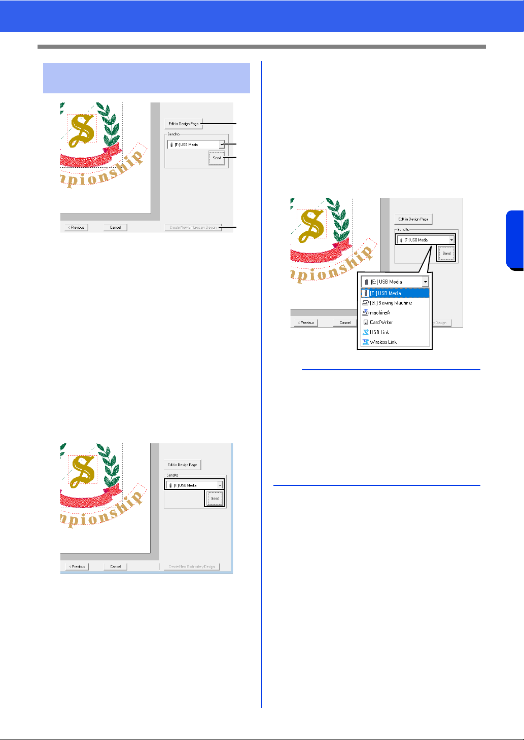
114
Creating Embroidery Patterns Containing Text
Tutorial 2: Using Templates
a Edit in Design page
Click this button to open the template in a
Design Page, where it can be edited or
saved.
b Send to selector
Select the output destination.
c Send
Click this button to output the template.
d Create New Embroidery Design
Click this button to return to the dialog box
for selecting a template. A different
template can be edited.
1 In the [Send to] selector, select your USB
media to be used, and then click [Send].
2 To create another embroidery pattern using a
different template, click [Create New
Embroidery Design]. The dialog box from
Step 2 appears.
To close the Template Wizard, click [Cancel].
■ Outputting the edited template
USB media, a sewing machine, an original card or
the Link function can be selected as output
destinations.
1 Depending on the desired output destination,
prepare the USB media or original card.
Otherwise, connect the embroidery machine
to the computer.
2 Select the output destination from the [Send
to] selector, and then click [Send].
Step 4 Outputting the edited
template
a
b
c
d
a
• Select an output destination according to the
method used to transfer data to your embroidery
machine.
• When no output destination is found, the [Send]
button will be grayed out and unavailable.
cc "Transferring Embroidery Designs to
Machines" on page 222 and "Using the Link
Function to Embroider From the Computer" on
page 227
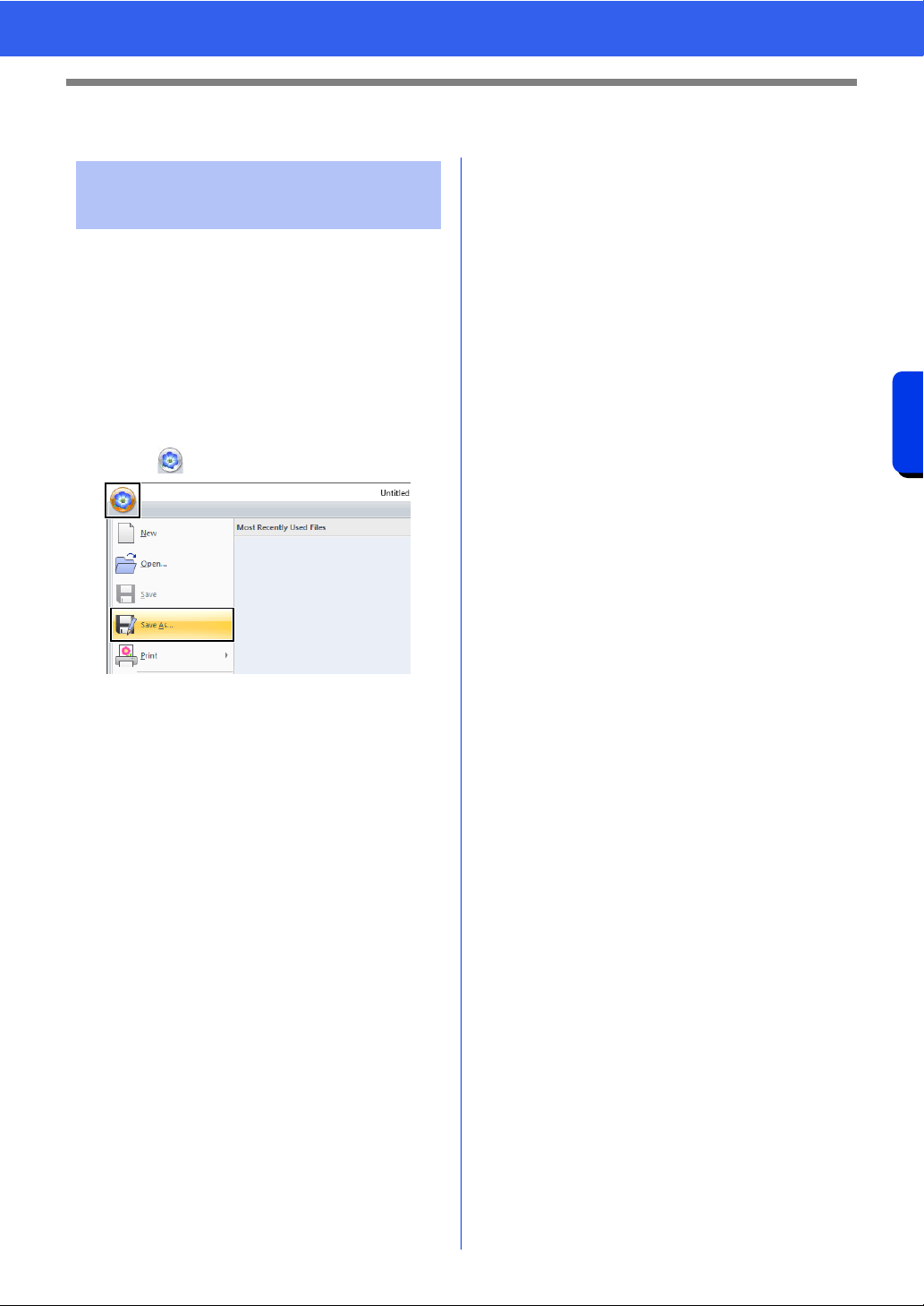
115
Creating Embroidery Patterns Containing Text
Template Feature
Template Feature
A design that you have created can be used as a
template.
1 Create an embroidery pattern that contains
text.
2 Apply the [Name Drop] attribute to the text.
cc "Tutorial 5: Creating Name Drop" on
page 136 and "Name Drop Feature
(Replacing Text)" on page 139
3 Click , then [Save As].
4 Save the created embroidery pattern in a
folder of the [Template Library] folder. Select
the folder (Drive where PE-DESIGN was
installed)\Program Files (x86)\Brother\PE-
DESIGN 11\Template Library\Sample, type
in the file name, and then click [Save].
Saving your design as a
new template
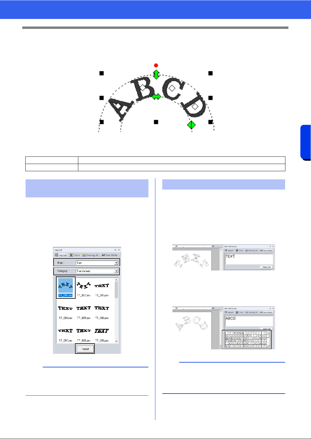
116
Creating Embroidery Patterns Containing Text
Tutorial 3: Entering text
Tutorial 3: Entering text
This section describes the procedures for importing a transformed text pattern and editing the text.
The sample file for this tutorial is located at Documents (My documents)\PE-DESIGN 11\Tutorial\Tutorial_3.
Import a text pattern from the [Import] pane.
1 Display the [Import] pane.
2 Select [Text] from the [From] selector and
[Transformed] from the [Category] selector.
Select [TT_001.pes], and then click [Import].
1 Select the imported text pattern, and then click
the [Text Attributes] tab.
2 Click in the text field.
The text pattern appears as dotted lines,
and the cursor appears at the end of the
text.
3 Press the <BackSpace> key to delete the
text, and then click characters in the character
table to enter text. Finally, press the <Enter>
key to apply them.
Step 1 Importing a transformed text pattern
Step 2 Editing entered text
Step 1 Importing a transformed
text pattern
b
Sample built-in font patterns are available in the
[Import] pane when [Text] is selected in the
[From] selector.
Step 2 Editing entered text
b
For details on other ways to edit text, refer to the
section indicated below.
cc "Editing entered text" on page 118
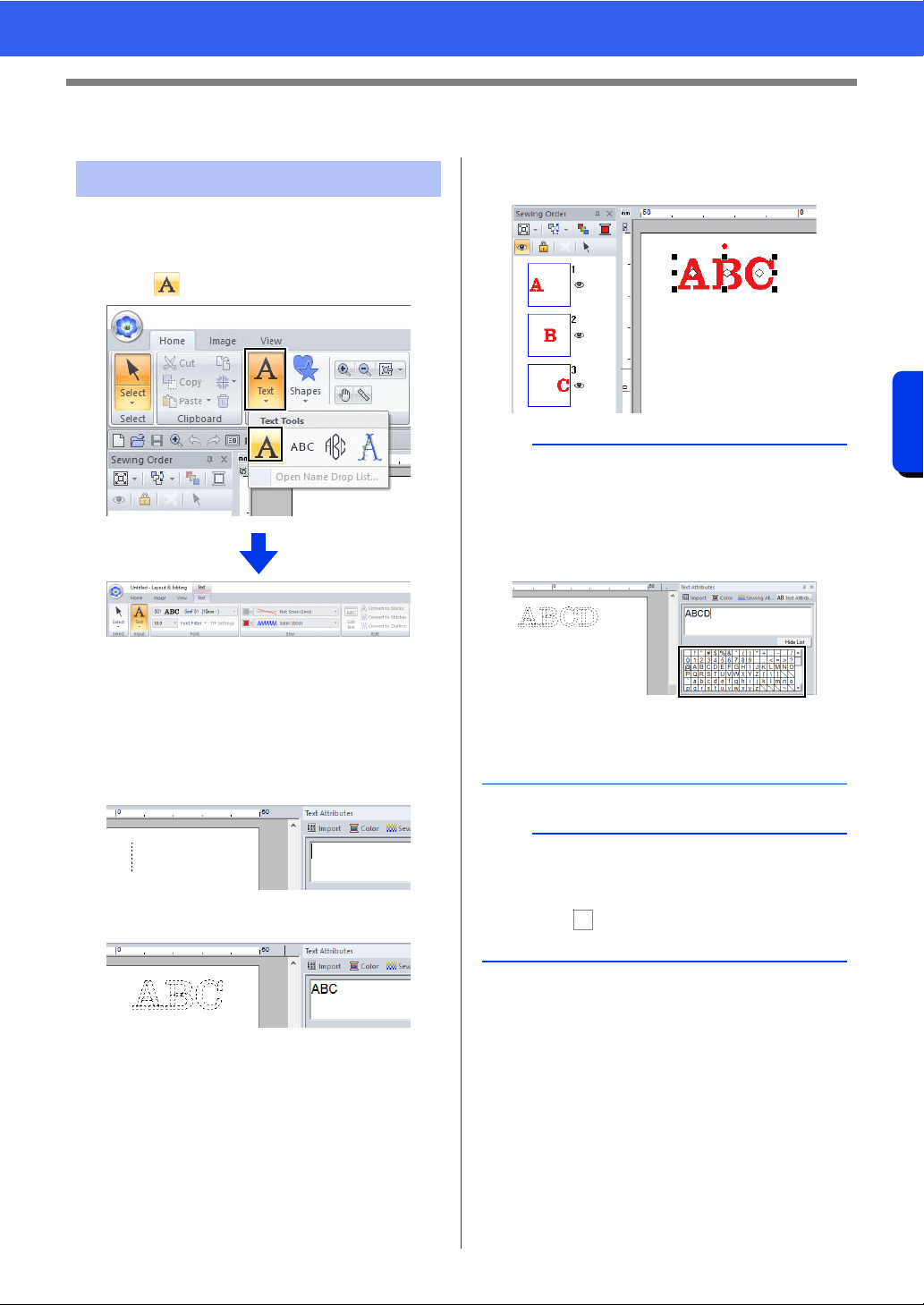
117
Creating Embroidery Patterns Containing Text
Advanced Operations for Entering Text
Advanced Operations for Entering Text
1 Click the [Home] tab.
2 Click [Text] in the [Tools] group, and then
click .
3 If necessary, change the font, text size, color
and sew type.
cc "Setting text attributes" on page 118 and
"Embroidery attributes for text" on
page 128
4 Click in the Design Page.
5 Type the text.
6 Press the <Enter> key or click the Design
Page.
Entering text
b
• Hold down the <Ctrl> key and press the
<Enter> key to enter a new line of text.
• Characters can also be entered by clicking them
in the character table. This is particularly useful
if you have to enter accented characters that are
not available on your keyboard.
•Click [Hide List] to hide the character table.
While it is hidden, click [Show List] to display
the character table.
a
If the entered character is not available with the
selected font or if the character cannot be
converted to an embroidery pattern, the character
appears as in the Design Page. If this occurs,
enter a different character.
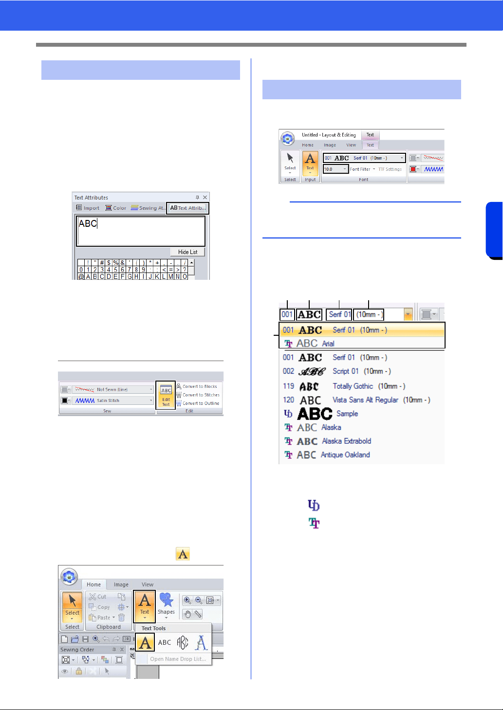
118
Creating Embroidery Patterns Containing Text
Advanced Operations for Entering Text
Switch to one of the following text edit modes, and
then type text as needed using the cursor appearing
at the end of the text.
■ Using Text Attributes tab
1 Select a single text pattern.
2 Click the [Text Attributes] tab, and then click
in the text field.
■ Using Edit text tool
1 Select a single text pattern.
2 Click the [Text] tab, and then click [Edit Text]
in the [Edit] group.
■ Using keyboard
1 Select a single text pattern.
2 Press a character key in the keyboard.
■ Using Text tool
1 Click [Text] in the [Tools] group of the
[Home] tab, and then select .
2 Click a text pattern to edit.
Text attributes can be specified with the [Font]
selector and [Text Size] selector in the [Text] tab.
■ Font
Click the [Font] selector, and then select the
desired font.
a Font Type
• A number identifies built-in fonts.
• identifies user-defined fonts.
• identifies TrueType fonts.
b Font sample
If a single string of text is selected, the
fonts in the list appear with the selected
characters.
c Font name
d Recommended minimum size
e Most recently used fonts
Editing entered text
Setting text attributes
b
The [Text] tab appears when a text pattern or a
Text tool is selected.
ab c d
e
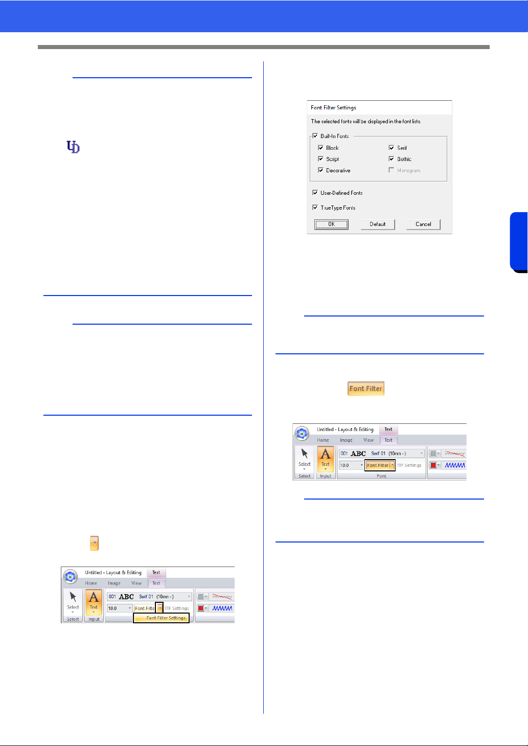
119
Creating Embroidery Patterns Containing Text
Advanced Operations for Entering Text
■ Font Filter
A font listed in the [Font] selector can be selected.
1 Click text or a monogram, or select the [Text]
tool or [Monogram] tool.
2 Click the [Text] tab.
3 Click beside [Font Filter] in the [Font]
group, and then click [Font Filter Settings].
4 Select the check boxes for the fonts to be
displayed, and clear the check boxes for the
fonts to be hidden.
The [Monogram] check box is available when
a pattern with a monogram font or the
[Monogram] tool is selected.
5 Click [OK] to apply the filter settings.
6 To filter the fonts, click [Font Filter] so that it
appears as .
Clicking the button switches between filtering
and unfiltering the fonts.
b
• User-defined fonts
cc "Font Creator" on page 320
• TrueType fonts
The installed TrueType fonts appear after the
user-defined fonts.
• TrueType font settings can be changed in the
[TrueType Font Attribute Setting] dialog box.
cc "Specifying TrueType font attributes" on
page 121
a
• Text created using certain TrueType fonts may
not be converted correctly into an embroidery
pattern due to the shape of the character. These
characters cannot be embroidered correctly.
Test sew before embroidering on your project.
• In addition, text created using some TrueType
fonts cannot be converted at all.
PEF files created with Font Creator
and saved in the [MyFont] folder
where PE-DESIGN was installed
appear as userdefined fonts after
the fonts listed in the table above.
The UD icon appears on user-
defined fonts.
b
To return the fonts to the default (all fonts
displayed), click [Default].
b
The font filter cannot be applied to small text fonts.
cc "Small Text" on page 129
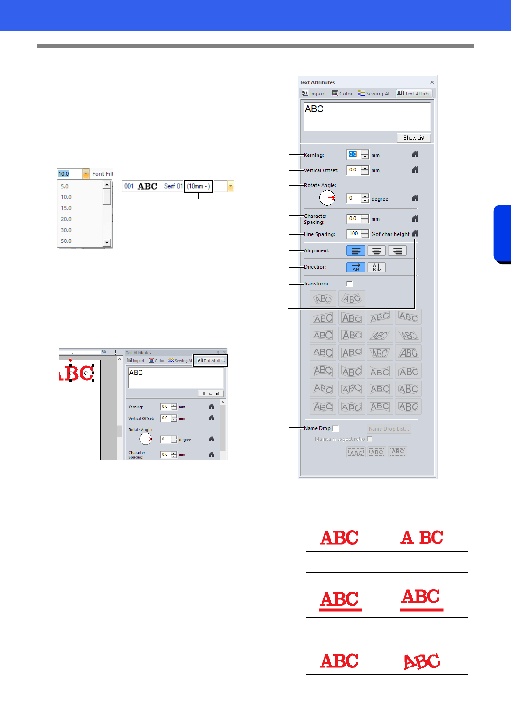
120
Creating Embroidery Patterns Containing Text
Advanced Operations for Entering Text
■ Text size
Click the [Text Size] selector. Type the desired
height and press the <Enter> key, or select the
desired value.
Built-in fonts are listed in the [Font] selector with the
recommended minimum size. We recommend
using these fonts at a size equal or greater than the
size indicated.
1 Recommended minimum size
■ Specifying various text attributes
1 Select the text.
2 Click the [Text Attributes] tab.
If the [Text Attributes] pane is not displayed,
click the [View] tab, then [Attributes], and
then click [Text Attributes].
3 Change the text attributes.
a Kerning
b Vertical Offset
c Rotate Angle
1
0.0 mm 5.0 mm
(between "A" and "B")
0.0 mm 2.0 mm
0° 20°
a
b
c
d
f
g
h
i
j
e
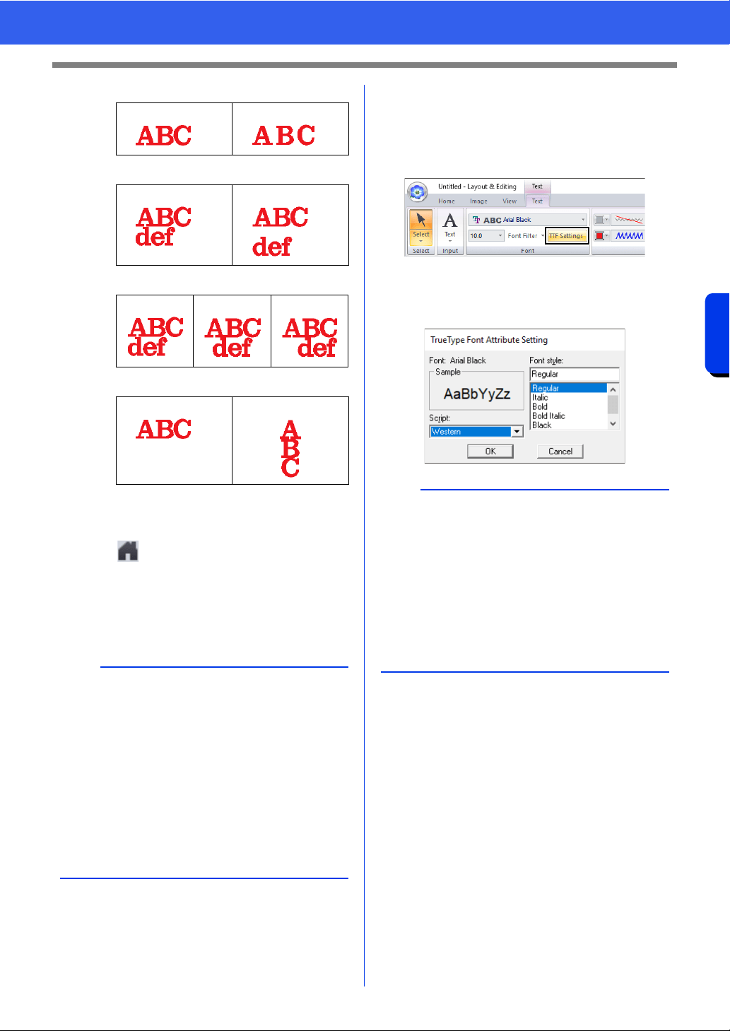
121
Creating Embroidery Patterns Containing Text
Advanced Operations for Entering Text
d Character Spacing
e Line Spacing
f Alignment
g Direction
h Transform
cc "Transforming text" on page 122
i
Click to return to the default setting.
j Name Drop
cc "Name Drop Feature (Replacing Text)"
on page 139
■ Specifying TrueType font
attributes
1 Select text in a TrueType font.
2 Click [TTF Settings] in the [Font] group.
3 Select a font style from the [Font style]
selector, select a character set from the
[Script] selector, and then click [OK].
0.0 mm 2.0 mm
100% 150%
Left Center Right
Horizontal Vertical
b
• Both [Kerning] and [Character Spacing] set
the spacing between characters. [Character
Spacing] is always applied to the entire text
pattern, while [Kerning] can be applied to
individual characters.
cc Refer to "Editing individual characters" on
page 124 for more details about selecting
individual characters in a text pattern.
• Settings specified for [Kerning], [Vertical
Offset] and [Rotate Angle] in the [Text
Attributes] pane are applied to all selected
characters.
a
• The settings for [Font style] and [Script] differ
depending on the TrueType font that is selected.
• If text created from multiple TrueType fonts is
selected, this command is not available. In
addition, if text of the same font but different font
styles or scripts is selected, this dialog box
appears with the attribute settings for the first
letter in the text. In either case mentioned above,
selecting only one character from within text
displays a dialog box containing only that
character's attributes.
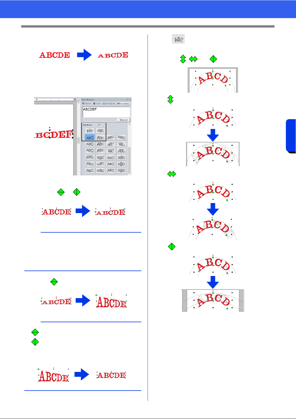
122
Creating Embroidery Patterns Containing Text
Advanced Operations for Entering Text
■ Transforming text
1 Select the text.
2 Select the [Transform] check box, and then
click the transformation shape button.
Depending on the selected shape, a dotted
line and or appear around the text.
3 Drag to transform the text.
If was selected in step
2, the following
operations can also be performed.
Drag , and to transform the text.
:Adjusts the text size.
:Moves the text along the circle.
:Adjusts the radius of the circle.
a
A text pattern contains data for both line and
region sewing. Therefore, if this command is
selected, depending on the form of the font, there
may be a gap between the line and the region in
the text.
b
• can only be dragged vertically.
• can only be dragged horizontally.
• To return the transformed text to its original
shape, clear the [Transform] check box.
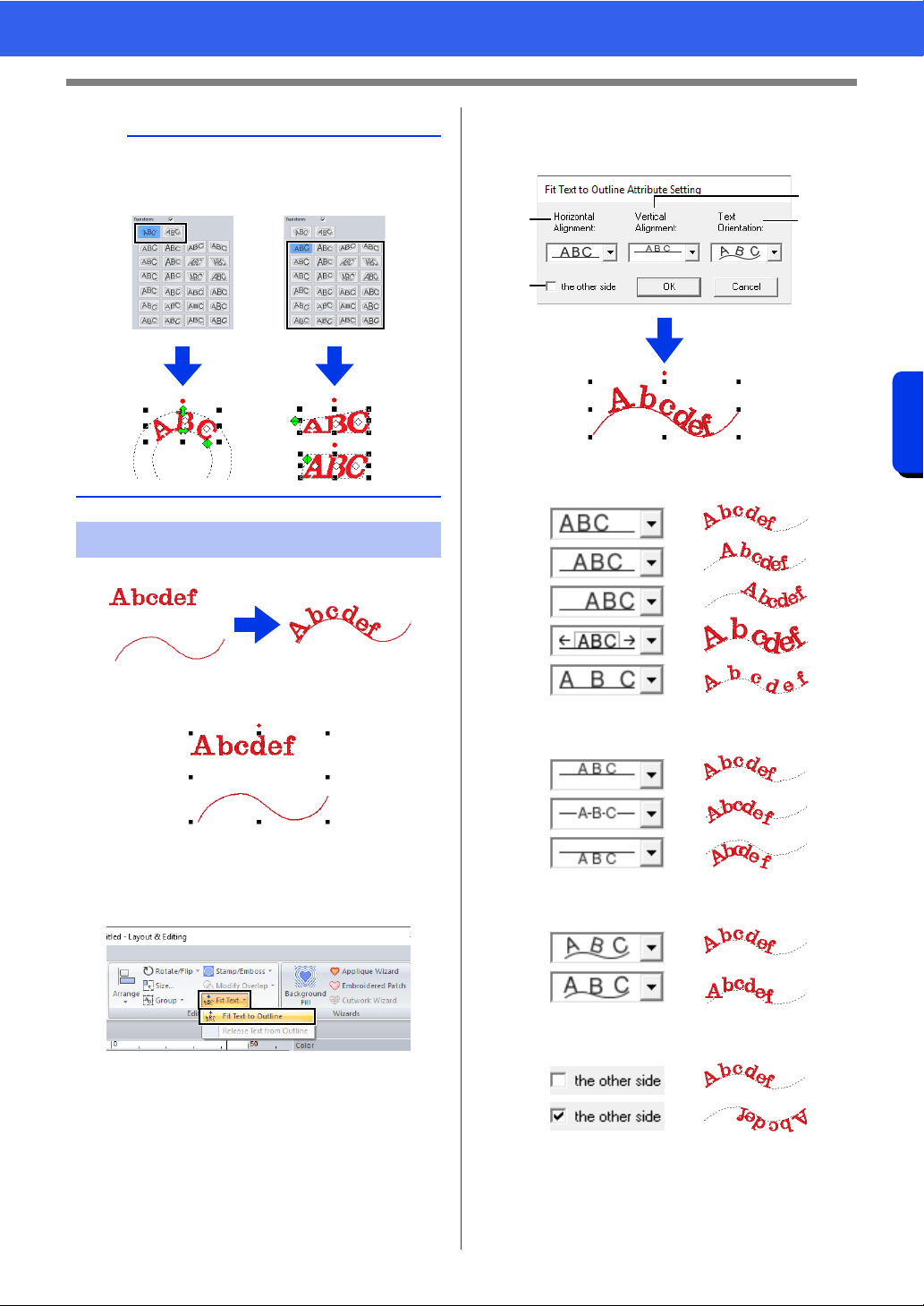
123
Creating Embroidery Patterns Containing Text
Advanced Operations for Entering Text
1 Select the text or small text and an outline.
2 Click the [Home] tab.
3 Click [Fit Text] in the [Edit] group, and then
click [Fit Text to Outline].
4 Specify the desired settings in the [Fit Text to
Outline Attribute Setting] dialog box, and
then click [OK].
a Horizontal Alignment
b Vertical Alignment
c Text Orientation
d the other side
b
Depending on the shape selected under
[Transform], different handles appear for editing
the text.
Fitting text to an outline
a
b
c
d
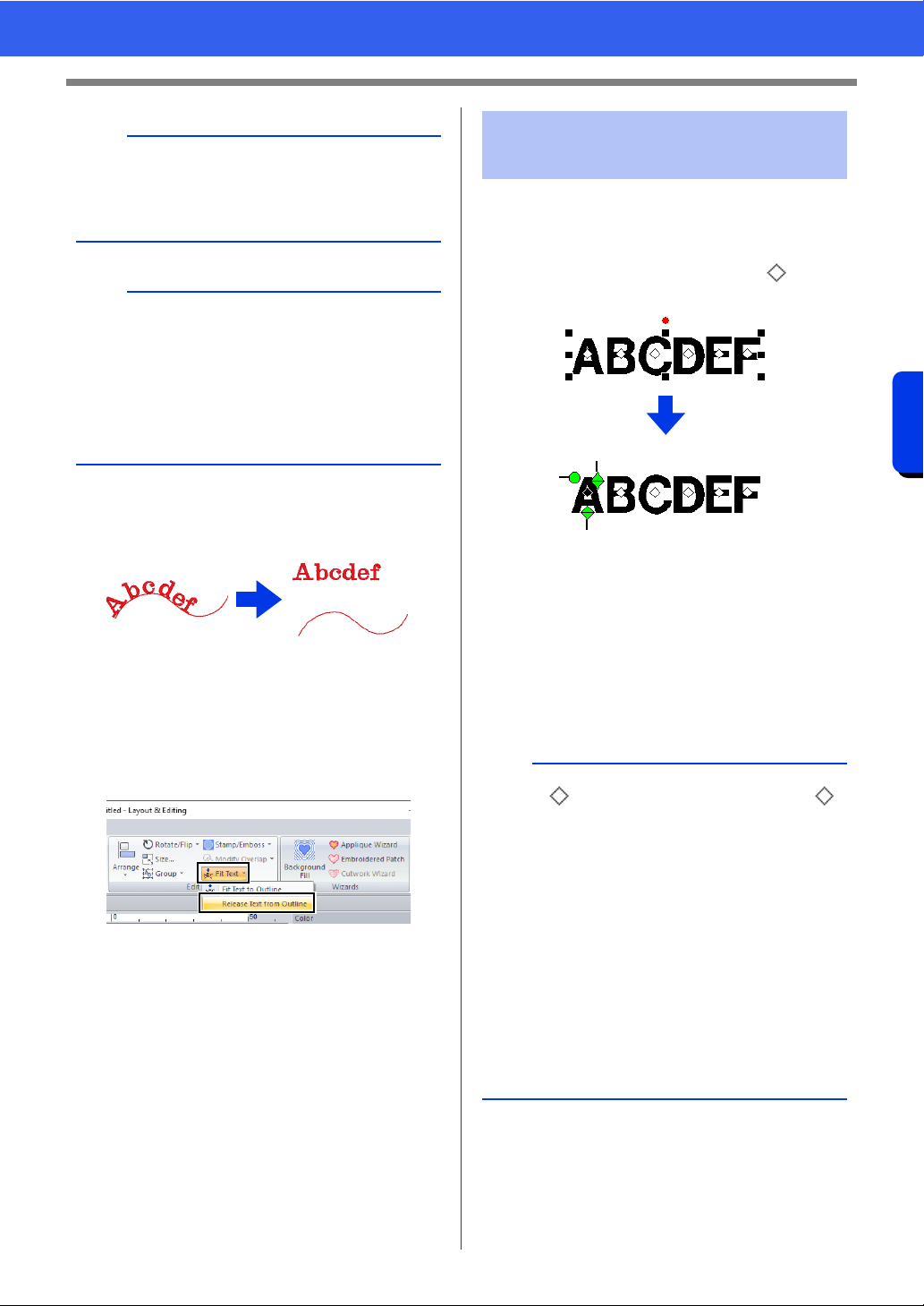
124
Creating Embroidery Patterns Containing Text
Advanced Operations for Entering Text
■ Releasing text from an outline
1 Select text or small text that is arranged on an
outline.
2 Click the [Home] tab.
3 Click [Fit Text] in the [Edit] group, and then
click [Release Text from Outline].
1 Select the text.
2 Select characters in the text.
To select a single character, click for the
character.
a Rotation handle
b Size handle
c Vertical offset handle
Individual characters can be rotated, resized
or repositioned. In addition, when text is
selected, click the [Text] tab to change the
thread color and sewing attributes.
a
• When fit text to outline is specified, the text
transformation is cancelled.
• Only one string of text can be arranged on a
single outline.
b
• To change the position of text on the outline,
select the text, and then drag it.
• The settings for some text attributes ([Size],
[Character Spacing], [Vertical Offset] and
[Rotate Angle]) can be changed for single
characters, even with text fit to an outline.
cc "Editing individual characters" on page 124
Editing individual
characters
b
Multiple can be selected and the selected
can be changed in the same way that embroidery
pattern points are selected.
• Drag the pointer.
All points within the box are selected.
• Hold down the <Ctrl> key while clicking the
points.
To deselect a point, click the selected
point.
• Hold down the <Shift> key while pressing an
arrow key to select multiple points.
• Hold down the <Ctrl> key while pressing an
arrow key to change the point that is selected.
cc "Selecting points" on page 76
a
b
c
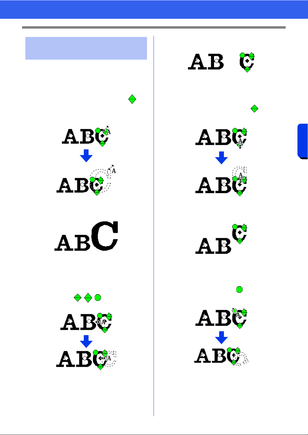
125
Creating Embroidery Patterns Containing Text
Advanced Operations for Entering Text
You can easily use drag operations to change the
size and text attributes.
■ Changing the size
1 Bring the pointer onto the upper right
handle.
2 Drag the handle.
3 When you release the mouse button, the
character size is changed.
■ Changing the kerning
1 Place the pointer onto the character body
other than the handles, and drag
the character horizontally.
2 When you release the mouse button, the
character spacing is changed.
■ Changing the vertical offset
1 Bring the pointer onto the lower handle.
2 Drag the handle vertically.
3 When you release the mouse button, the
character offset is changed.
■ Rotating the characters
1 Bring the pointer onto the handle.
2 Drag the handle.
Changing a character size
and character's attributes
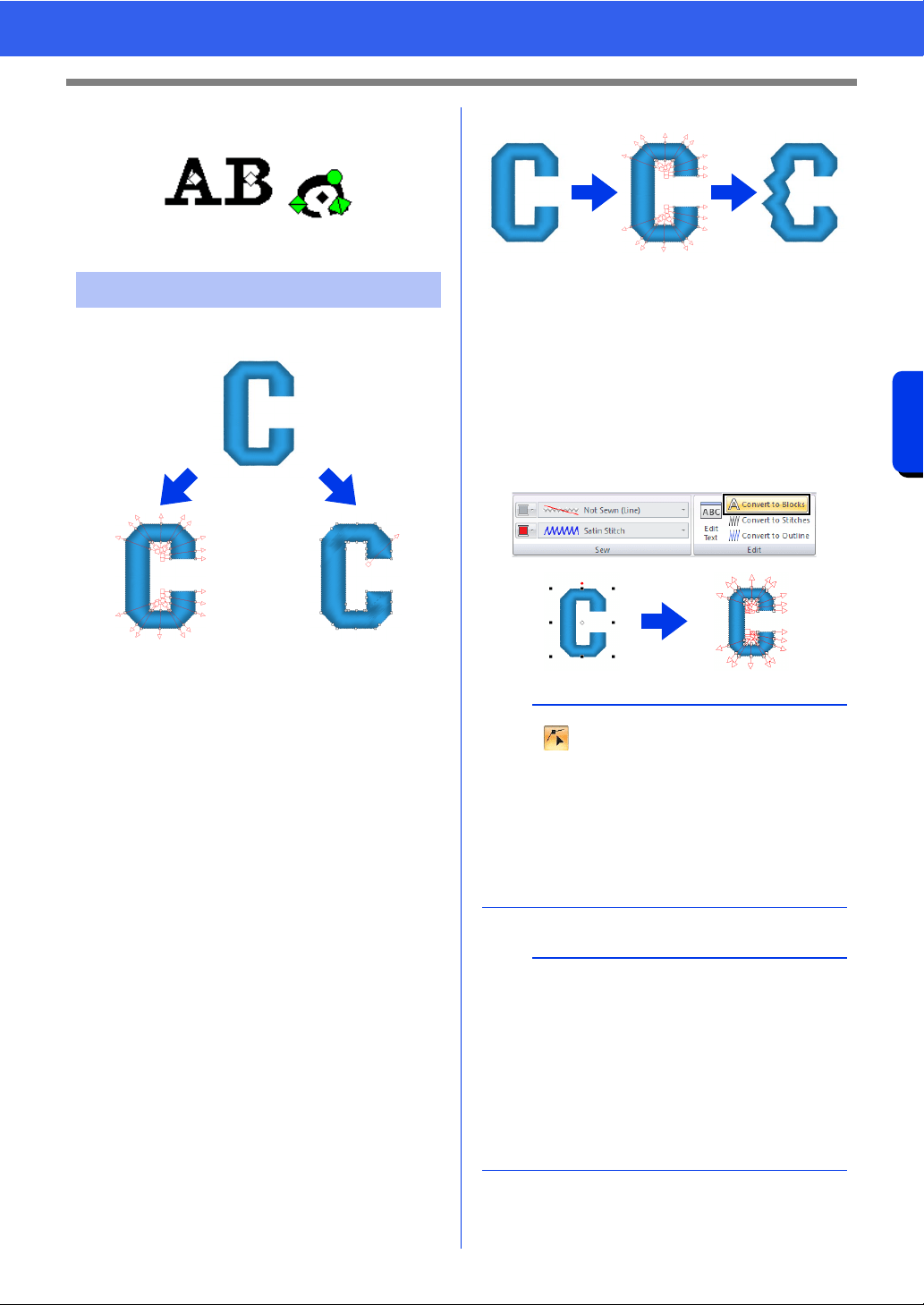
126
Creating Embroidery Patterns Containing Text
Advanced Operations for Entering Text
3 When you release the mouse button, the
character angle is changed.
1 Text pattern
2 Blocks: A group of shape patterns with multiple
sewing direction lines
3 Shape pattern
4 Convert to Blocks
5 Convert to Outline
Convert to Blocks
The pattern is converted while maintaining the
multiple sewing direction lines.
The character shapes can be partially rearranged.
Convert to Outline
The text is converted to shapes, which can be
edited.
Various sew types or embossing/engraving effects
can be applied.
cc "Comparison of Types of Data Created With
PE-DESIGN 11" on page 10
■ Converting text to blocks
Text can be converted into blocks, allowing you
reshape characters. By changing the sewing
direction line in each of these small regions, you can
create text patterns that appear like manual
embroidery.
1 Select the text or monogram text.
2 Click the [Text] tab.
3 Click [Convert to Blocks] in the [Edit] group.
Converting text patterns
1
23
45
a
• Click to select the Select Point tool and
select the converted pattern to see the sewing
direction lines.
cc "Specifying multiple sewing directions" on
page 60
• Small text cannot be converted into blocks
(shape patterns with multiple sewing direction
lines).
b
• The text pattern is converted with the original
sewing quality maintained.
• The shapes of created blocks can be edited in
their finest details.
cc For details on editing blocks or outlines, refer
to "Reshaping Embroidery Patterns" on
page 76
• Since the text data is no longer available, the
text cannot be edited.
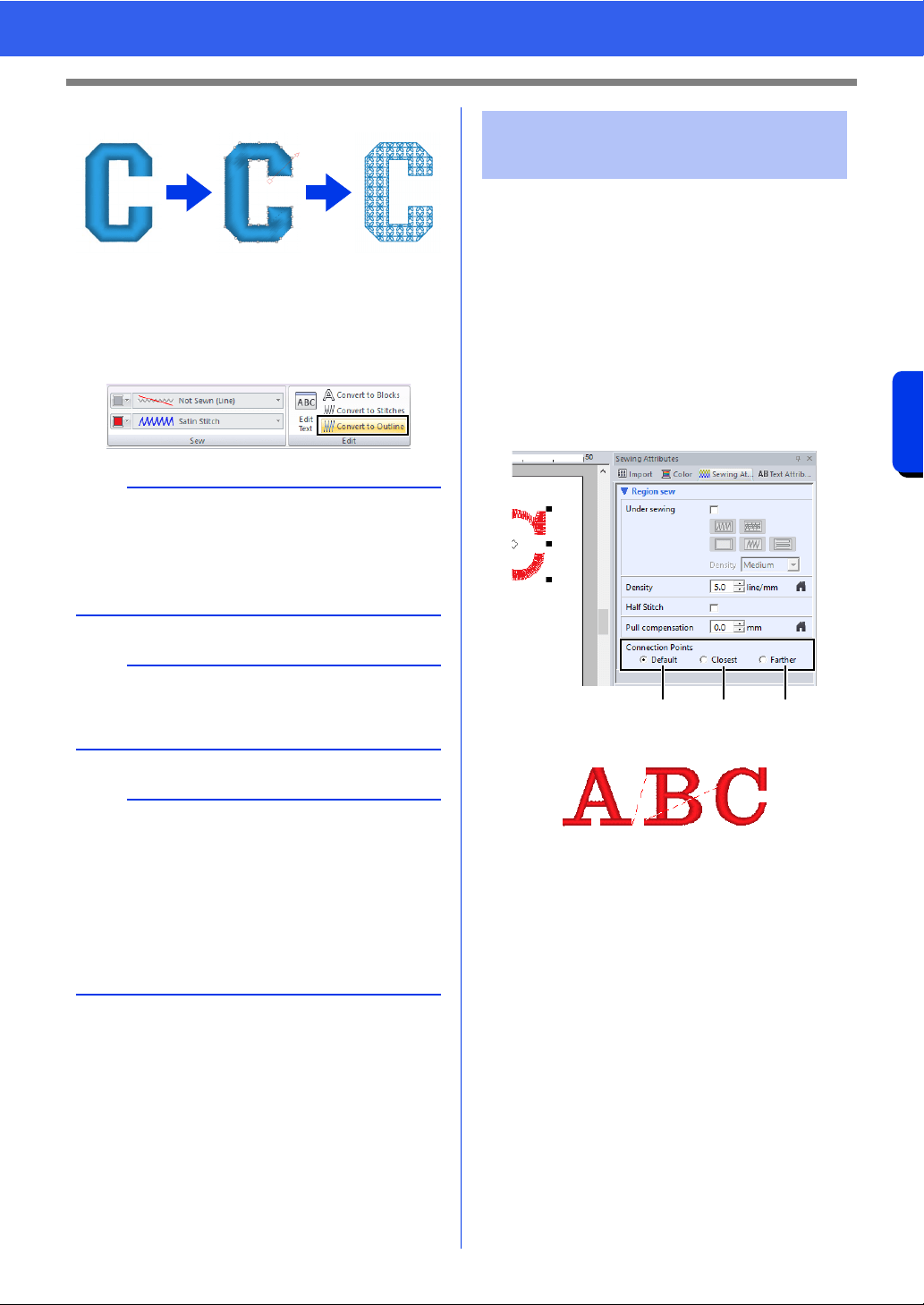
127
Creating Embroidery Patterns Containing Text
Advanced Operations for Entering Text
■ Converting text to outline pattern
1 Select text.
2 Click the [Text] tab.
3 Click [Convert to Outline] in the [Edit] group.
The positions for connection points between
characters within the same text (end point of one
character and the start point of the next character)
can be specified.
The available settings are [Default], [Closest] and
[Farther].
1 Select the text or monogram text.
If the [Sewing Attributes] pane is not
displayed, click the [View] tab in the Ribbon,
and then click [Sewing Attributes].
2 Click a setting under [Connection Points].
a Default
Stitches are created in the default sewing
order for good stitching quality of all
characters.
b
• The outline pattern is now a shape.
• Transformed shapes are grouped. In addition,
hole sewing is automatically specified for
openings (such as the triangle inside the letter
"A").
a
Text patterns created with built-in fonts 025 and
029, user-defined fonts or small text fonts cannot
be converted to outlines.
b
• When a pattern is converted outlines, the sewing
quality will decrease slightly.
• The sewing direction will become uniform, but it
can be edited.
cc "Specifying the straight sewing direction" on
page 59
• Since the text data is no longer available, the
text cannot be edited.
Selecting connection point
positions in a text pattern
abc
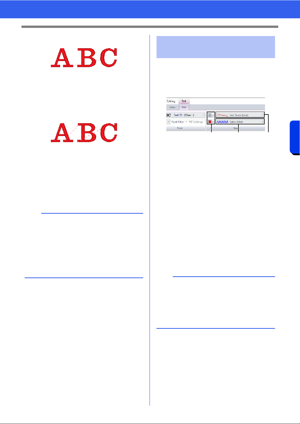
128
Creating Embroidery Patterns Containing Text
Advanced Operations for Entering Text
b Closest
Stitches are created at the shortest distance
between the end point of one character and
the start point of the next character. This
shortens jump stitches and reduces the
number of times that the thread is trimmed.
c Farther
Stitches are created at a farther distance
between the end point of one character and
the start point of the next character. This
lengthens jump stitches so they can easily be
trimmed manually.
A Connection Points setting can be selected
not only for region sewing, but also for line
sewing.
The Sew group in the Attributes tab allows you to set
the embroidery attributes (thread color and sew
type, outline and inside region on/off).
When text is selected, settings can be specified for
the following.
a Line color/Region color
Sets the thread color for outlines and
inside regions.
cc "Color" on page 54
b Line sew type
Sets the sew type for the outlines.
Except with built in fonts 025 and 029, and
a user-defined fonts, all sew types are
available for lines in text.
cc "Line sew types" on page 57
c Region sew type
Sets the sew type for an inside region.
[Satin Stitch], [Fill Stitch] and [Prog.
Fill Stitch] are available for lines in text.
cc "Region sew types" on page 57
a
• These settings are not available with text
created using built-in fonts 025 or 029, a
TrueType font, a user-defined font or a small text
font.
• These settings are not available for text
containing characters of different colors.
• These settings are not available for text where
the sewing order of the characters is not
continuous.
Embroidery attributes for
text
a
• Text patterns created using built-in fonts 025
and 029 or user-defined fonts only have an
inside region. The thread color and sew type for
only the region can be selected.
• Sewing attribute that can be set with Text under
sewing. For details, refer to "Region sewing
attributes" on page 388.
ac b
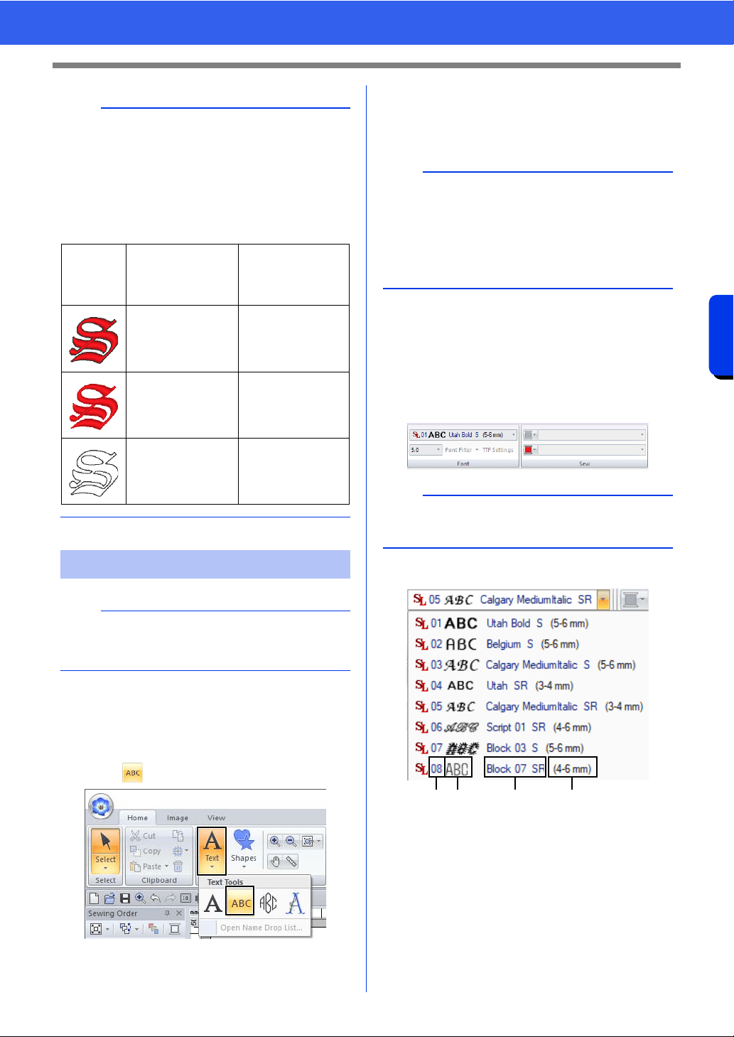
129
Creating Embroidery Patterns Containing Text
Advanced Operations for Entering Text
■ Entering small text
1 Click the [Home] tab.
2 Click [Text] in the [Tools] group, and then
click .
3 Enter text in the same way that regular text is
entered.
cc "Entering text" on page 117
■ Editing small text
Small text attributes can be selected from the [Text]
tab, the [Text Attributes] pane and the [Color]
pane. When the small text tool is selected, the
[Text] tab appears as shown below.
Small text fonts
a Font number
b Font sample
c Font name
d Recommended size
cc "Font List" on page 400
b
• To turn off line sewing, select [Not Sewn (Line)]
from the [Line sew type] selector.
• To turn off region sewing, select [Not Sewn
(Region)] from the [Region sew type] selector.
• The variety of embroidering effects possible
differs depending on the selected combination of
settings for line sewing and region sewing.
Small Text
a
Precautions for embroidering small text patterns.
cc "When sewing small fonts" on page 130
Line sewing
specified
(Text Outline Sew
Type)
Region sewing
specified
(Text Body Sew
Type)
Any other than [Not
Sewn (Line)]
Any other than [Not
Sewn (Region)]
[Not Sewn (Line)]
Any other than [Not
Sewn (Region)]
Any other than [Not
Sewn (Line)]
[Not Sewn
(Region)]
b
Sample small text font patterns are available in the
[Import] pane when [Text] is selected in the
[From] selector and [Small Text] is selected in the
[Category] selector.
cc "Example of Importing Embroidery Data" on
page 15
b
The [Text] tab appears when a small text pattern
or the small text tool is selected.
ab c d
130
Creating Embroidery Patterns Containing Text
Advanced Operations for Entering Text
The settings for all small text attributes except the
font are specified in the same way that they are
specified for regular text patterns.
However, with small text, settings cannot be
specified for the following.
• Sew type
• Sewing Attributes
• Transform
• Name Drop
■ When sewing small fonts
For best results when using your embroidery
machine to embroider patterns containing small font
patterns, follow the recommendations described
below.
1 Reduce the thread tension to less than what is
used when embroidering normal designs.
2 Sew at a speed slower than what is used when
embroidering normal designs.
(For details on adjusting the thread tension
and sewing speed, refer to the instruction
manual provided with your embroidery
machine.)
3 Do not trim the jump stitches between the
characters.
(For details on setting the machine for thread
trimming, refer to the instruction manual for
the embroidery machine.)
a
Only built-in fonts specifically for small text can be
used.
cc For a list of the built-in fonts specifically for
small text, refer to "Small Text" on page 402.
b
To edit an entered small text, select the small text
with the [Select] tool, and then type the new text
into the text field in the [Text Attributes]
pane.There are three other ways to edit text.
cc "Editing entered text" on page 118
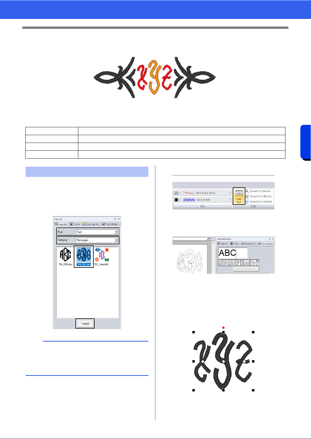
131
Creating Embroidery Patterns Containing Text
Tutorial 4: Monograms
Tutorial 4: Monograms
The sample file for this tutorial is located at Documents (My documents)\PE-DESIGN 11\Tutorial\Tutorial_4.
1 Display the [Import] pane.
2 Select [Text] from the [From] selector and
[Monogram] from the [Category] selector.
Click [TM_002.pes], then [Import].
3 Select the imported monogram pattern, and
then click the [Text] tab.
4 Click [Edit Text] in the [Edit] group.
The text pattern appears as dotted lines,
and the cursor appears at the end of the
text.
5 Press the <BackSpace> key to delete the
text, and then use the keyboard to type in
"XYZ".
6 Press the <Enter> key.
The text appears in the Design Page.
Step 1 Entering monograms
Step 2 Adding a decorative pattern
Step 3 Changing character size of the monogram
Step 4 Changing the thread color and sew type of the monogram
Step 1 Entering monograms
b
Sample monogram patterns are available in the
[Import] pane when [Text] is selected in the
[From] selector and [Monogram] is selected in
the [Category] selector.
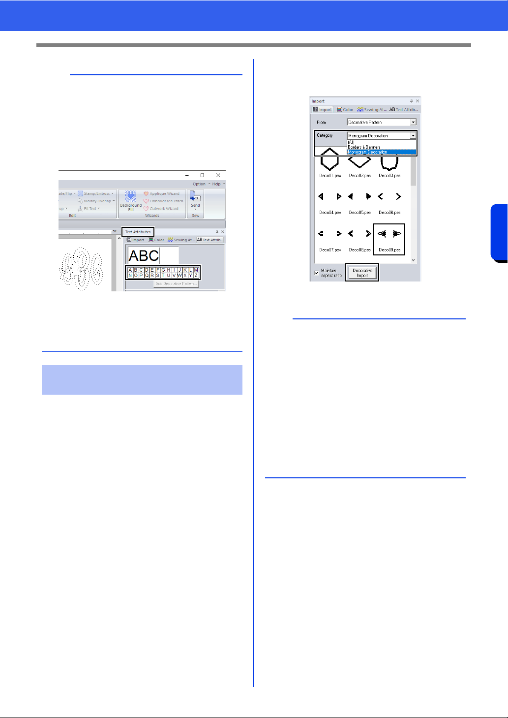
132
Creating Embroidery Patterns Containing Text
Tutorial 4: Monograms
A decorative pattern can be added.
1 Display the [Import] pane, and select
[Decorative Pattern] from the [From]
selector.
2 Select the monogram.
3 Select [Monogram Decoration] from the
[Category] selector. Click [Deco09.pes],
then [Decorative Import].
The decorative pattern is added.
b
• In this example, a monogram pattern was
imported from the [Import] pane; however, a
pattern can also be created by selecting the
Monogram tool, then typing in text.
cc "Entering text" on page 117
• Characters can also be entered from the
character table in the [Text Attributes] tab.
• You cannot insert line feeds.
• A maximum of three characters can be entered.
• Only uppercase letters (the characters
displayed at the character table) can be entered.
Step 2 Adding a decorative
pattern
b
• If a monogram is selected, the [Decorative
Import] button and [Maintain aspect ratio]
check box will appear.
To import the decorative pattern adjusted to the
size of the monogram while maintaining its
original height-to-width proportion, select the
[Maintain aspect ratio] check box. Clear the
check box to import the decorative pattern with
its height-to-width proportion adjusted to the
monogram.
• If no monogram is selected, the button will
appear as the [Import] button. Clicking this
button will import the decorative pattern at its
standard size.
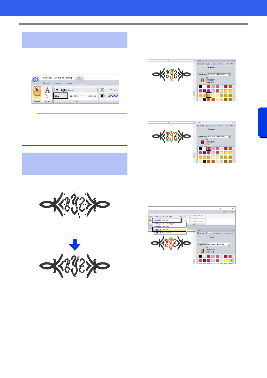
133
Creating Embroidery Patterns Containing Text
Tutorial 4: Monograms
■ Changing the character size of the
monogram
Click the [Text Size] selector, and then type in "22".
Click the point for the monogram character whose
settings are to be changed.
1 Click here.
■ Changing the thread color
1 Click [Color] tab to display the color palette.
2 Click [TANGERINE].
3 Select the characters "YZ", and then click
[RED].
■ Changing sew type
1 Click the [Text] tab.
2 Click the [Text Body Sew Type] selector in
the [Sew] group, and then select [Fill Stitch].
Step 3 Changing character size
of the monogram
b
Diamond and Script are fonts exclusively for
monograms. You can also use the built-in fonts or
TrueType fonts.
cc "Editing monograms" on page 134
Step 4 Changing the thread color
and sew type of the
monogram
1
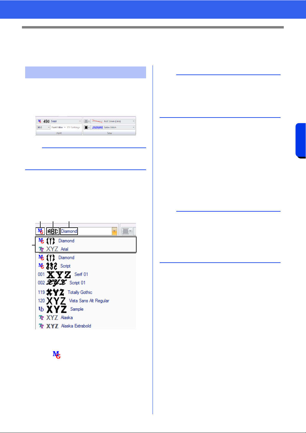
134
Creating Embroidery Patterns Containing Text
Advanced Operations for Entering Monograms
Advanced Operations for Entering
Monograms
Monogram attributes can be selected from the
[Text] tab, the [Text Attributes] pane, the [Sewing
Attributes] pane and the [Color] pane. When the
Monogram tool is selected, the [Text] tab appears
as shown below.
■ Monogram font
Click the [Font] selector, and then select the
desired font.
a Font Type
• A number identifies built-in fonts.
• identifies Monogram fonts.
b Font sample
If a single string of text is selected, the
fonts in the list appear with the selected
characters.
c Font name
d Most recently used fonts
The settings for all monogram attributes except the
font are specified in the same way that they are
specified for regular text patterns.
However, with monograms, settings cannot be
specified for the following.
• Rotate Angle, Character Spacing, Line Spacing,
Alignment, Direction
• Transform
• Name Drop
• Fit Text to Outline
Editing monograms
b
The [Text] tab appears when a monogram or the
Monogram tool is selected.
ab c
d
b
Diamond and Script are fonts exclusively for
monograms. You can also use built-in fonts, user-
defined fonts and TrueType fonts.
cc For a list of the built-in fonts and monogram
fonts, refer to "Font List" on page 400.
b
• To edit an entered monogram, select the text
pattern with the [Select] tool, and then type the
new text into the text field in the [Text
Attributes] pane.
• There are three other ways to edit text.
cc "Editing entered text" on page 118
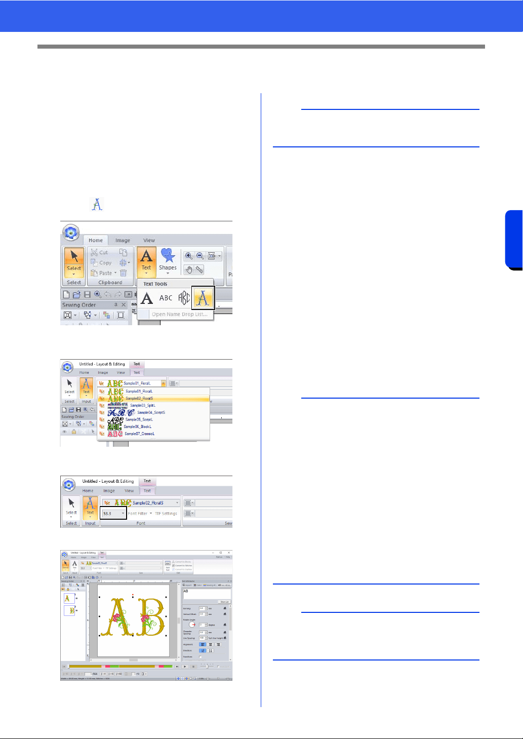
135
Creating Embroidery Patterns Containing Text
User-Mapped Text
User-Mapped Text
■ Entering user-mapped text
1 Register the embroidery data with Font
Creator.
cc "Registering Embroidery Data as a Font"
on page 330
2 Click the [Home] tab.
3 Click [Text] in the [Tools] group, and then
click .
4 Click the [Font] selector, and then select the
desired font.
The standard character height for the
selected font appears.
5 Enter the text.
cc "Entering text" on page 117
The settings for all user-mapped text attributes
except the font are specified in the same way that
they are specified for regular text patterns.
However, with user-mapped text, the following
parameters, commands or operations cannot be
used.
• Sew type
• Sewing Attributes
• Font Filter
• TTF Settings
• Convert to Blocks
• Convert to Outline
• Some editing of individual characters
• Name Drop
• Changing colors
• Some transform functions
b
The [Text] tab appears when a user-mapped text
pattern or the User-mapped text tool is selected.
b
• To edit entered user-mapped text, select the
user-mapped text with the [Select] tool, and
then type the new text into the text field in the
[Text Attributes] pane. There are three other
ways to edit text.
cc "Editing entered text" on page 118
• To change the color of text, perform either of the
following operations.
Click [Convert to Stitches] on the [Text] tab
to convert the text pattern to a stitch pattern
whose thread colors can be changed.
However, the text data will no longer be
available.
Change colors in the embroidery data of the
original .pes file.
a
Enlarging or reducing user-mapped text from the
standard character height may reduce the
embroidery quality.
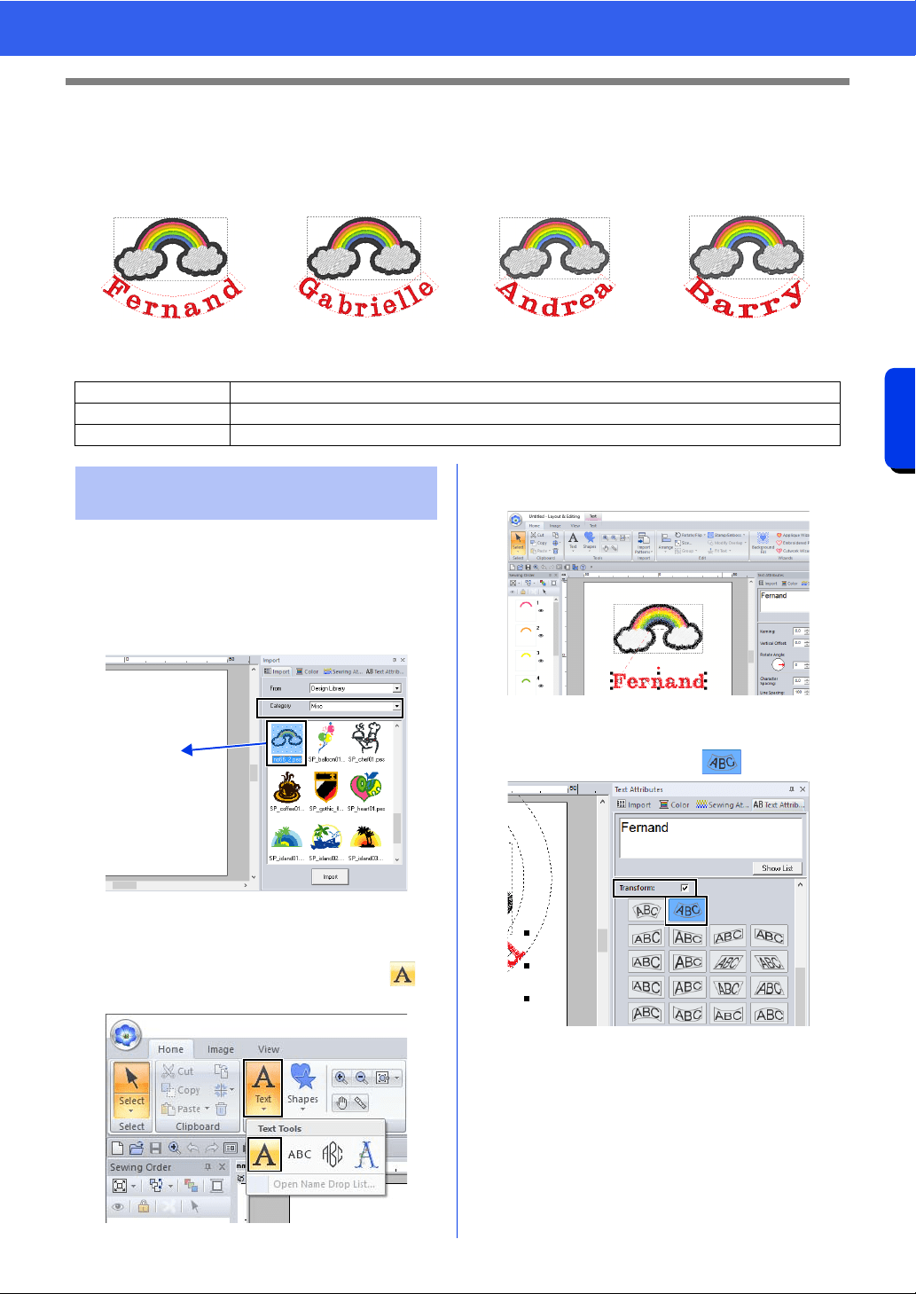
136
Creating Embroidery Patterns Containing Text
Tutorial 5: Creating Name Drop
Tutorial 5: Creating Name Drop
By creating an embroidery pattern containing text and using the Name Drop function, you can easily create a
number of similar embroidery patterns, for example, for uniforms, by replacing only the name in the pattern.
The sample file for this tutorial is located at Documents (My documents)\PE-DESIGN 11\Tutorial\Tutorial_5.
1 Display the [Import] pane, and select [Design
Library] from the [From] selector.
2 Select [Misc] from the [Category] selector,
and then drag the rainbow pattern into the
Design Page.
3 Click the [Home] tab.
4 Click [Text] in the [Tools] group, click ,
and then click the Design Page.
5 Type in "Fernand", and then press the
<Enter> key.
6 Select the text pattern, select the [Transform]
check box, and then click .
Step 1 Designing the embroidery pattern
Step 2 Creating the list
Step 3 Outputting patterns using text from the text list
Step 1 Designing the embroidery
pattern
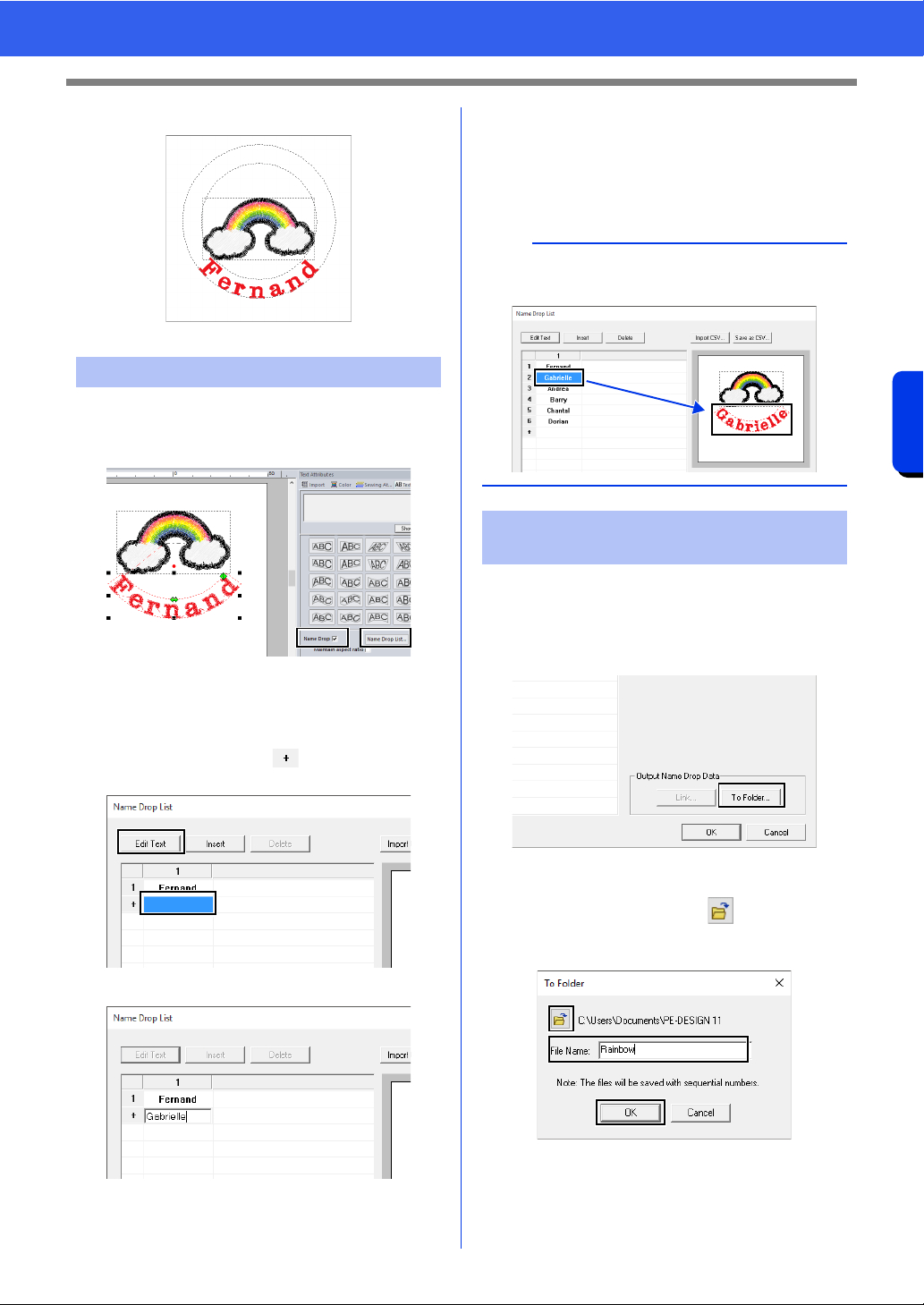
137
Creating Embroidery Patterns Containing Text
Tutorial 5: Creating Name Drop
7 Drag the pattern to adjust its position.
1 Select "Fernand", and then select the [Name
Drop] check box, and click [Name Drop List]
button.
2 Enter text in the list. In this example, we will
add text at the end of the list.
(A) Click a cell in the row and click [Edit
Text], or click the cell to enter input mode.
(B) Use the keyboard to enter the text.
(C) When entering text, press the <Enter>
key so that the cell in the next row enters
input mode.
Repeat steps (A) through (C) to create the text
list.
Let's practice outputting the patterns to files.
Embroidery data with the text replaced by each row
of text in the list can be outputted.
1 Click [To Folder].
2 Select the drive and folder in the dialog box
that appears after clicking , type the name
of the file in the [File Name] box, and then
click [OK].
This application begins checking that there
are no errors in the embroidery data. If no
errors were detected, it begins outputting
the data.
Step 2 Creating the list
b
Selecting a cell containing entered text allows you
to preview that text.
Step 3 Outputting patterns using
text from the text list
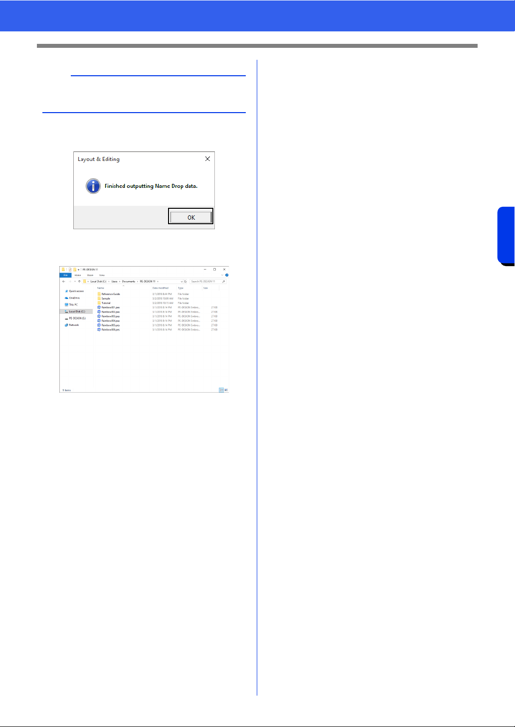
138
Creating Embroidery Patterns Containing Text
Tutorial 5: Creating Name Drop
3 After the data has been outputted, the
following message appears. Click [OK].
An embroidery file is saved in the selected
folder for each line of text in the list.
b
The files are named "<file_name>xxx.pes" (where
"xxx" are consecutive numbers starting with 001).
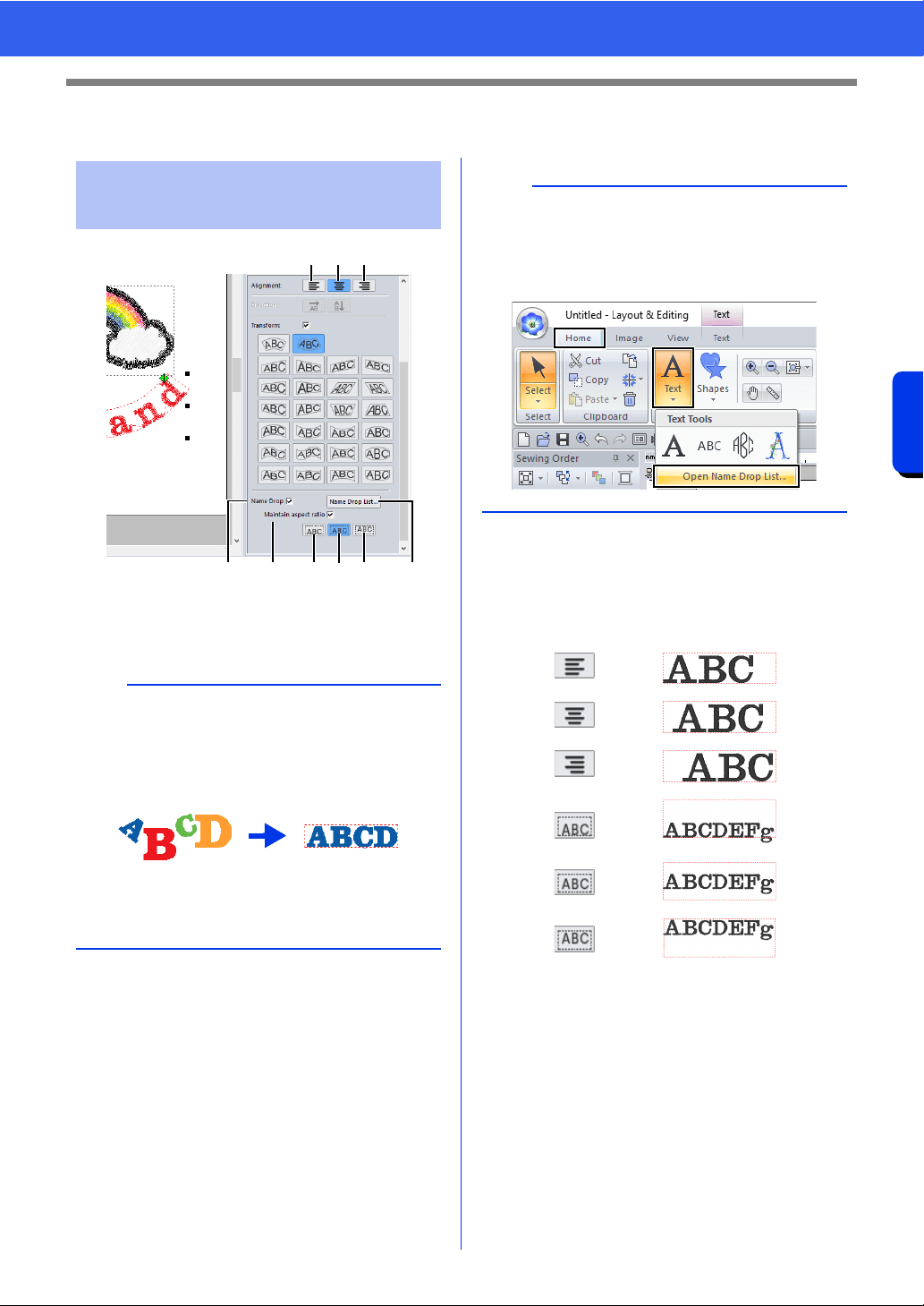
139
Creating Embroidery Patterns Containing Text
Name Drop Feature (Replacing Text)
Name Drop Feature (Replacing Text)
a Name Drop
If this check box is selected, the [Name
Drop] attribute is applied.
b Name Drop List
Click this button to display the [Name
Drop List] dialog box.
c Maintain aspect ratio
If this check box is selected, the height-to-
width proportion of the text is maintained.
d
e
f
g
h
i
Text attributes with Name
Drop attribute applied
a
• When the [Name Drop] attribute is applied, the
settings for [Kerning], [Vertical Offset],
[Rotate Angle], [Character Spacing], [Line
Spacing], the character size and color will be
reset.
•The [Name Drop] attribute is not available with
text where the [Fit Text to Outline] command
has been specified, small text or monogram text.
def
acghi b
b
The [Name Drop List] dialog box for a text pattern
can be displayed by selecting a text pattern with
the [Name Drop] attribute applied, clicking [Text]
in the [Home] tab, then clicking [Text], then [Open
Name Drop List].
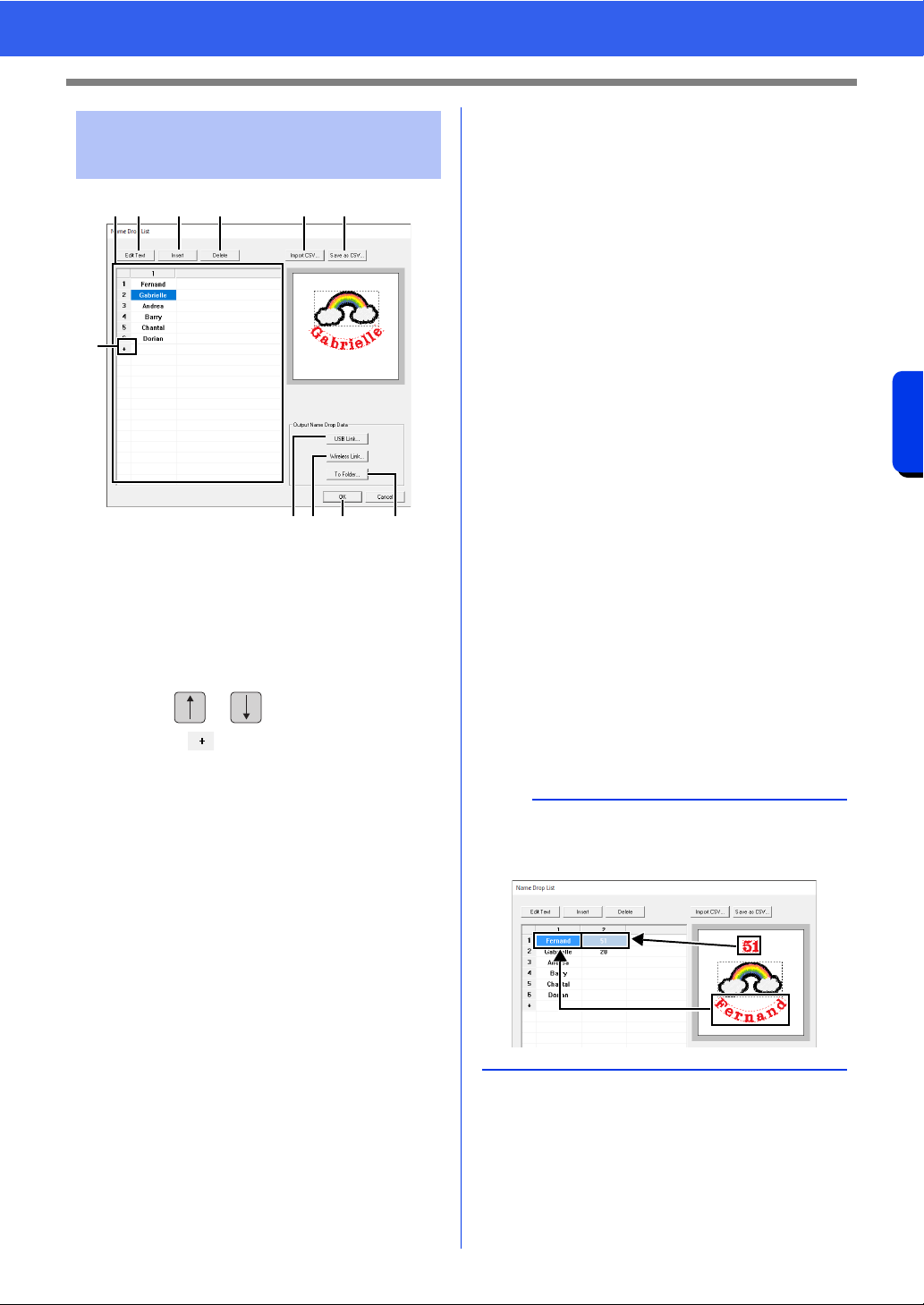
140
Creating Embroidery Patterns Containing Text
Name Drop Feature (Replacing Text)
a Name Drop List
Create the list of text to be used to replace
text in the pattern. Double-click a cell to
enter input mode.
Select a row to display a preview of the
pattern with the text in that row. A row in
the text list can be selected by pressing
the or key.
b Click to add a row at the end of the
list.
(Up to 500 rows can be added.)
c Edit Text
Enters input mode for the text in the
selected cell. (Input mode can also be
entered by double-clicking a cell.)
d Insert
Select a row, and then click [Insert]. A
new row is inserted above the selected
one.
e Delete
Select a row, and then click [Delete]. The
selected row is deleted.
f Import CSV
Imports a Name Drop List as a .csv file.
Click this button, select the drive and
folder, click the name of the file, and then
click [Open], or double-click the file's
icon.
g Save as CSV
Saves the created Name Drop List.
Click this button, select the drive and
folder, type the name of the file in the [File
Name] box, and then click [Save] to save
the list as a .csv file.
h USB Link
Click to send to machines by using the
USB Link function. This button is available
if an embroidery machine compatible with
the USB Link function is connected to the
computer. Connect a compatible
embroidery machine that has been
started in USB Link mode.
cc "USB Link" on page 227
i Wireless Link
Click to send to machines by using the
Wireless Link function. This button is
available if an embroidery machine
compatible with the Wireless Link function
has been connected to the same wireless
network as the computer that is running
PE-DESIGN version 11.2 or later.
cc "Wireless Link" on page 232
j To Folder
cc "Outputting patterns using text from the
text list" on page 137
k Select text in the [Name Drop List] dialog
box and click [OK] to return to the Design
Page and edit the pattern with the text
replaced.
Functions in the Name
Drop List dialog box
ac d e
b
fg
hk ji
b
If the pattern contains two text patterns with the
[Name Drop] attribute applied, the text list
appears as shown below.

Creating Embroidery Patterns Using
Images
Embroidery patterns can easily be created from
images. In addition, this section provides details
on creating an embroidery pattern that is
combined with an image.
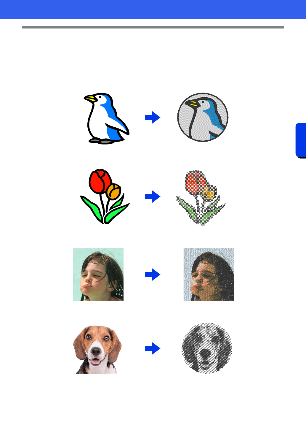
142
Creating Embroidery Patterns Using Images
Stitch Wizard: Automatically Converting an Image to an Embroidery Design
Stitch Wizard: Automatically Converting
an Image to an Embroidery Design
An embroidery pattern can be created from a digital camera photo, a scanned illustration, or a clip art image.
■ Auto Punch cc "Tutorial 6-1: Auto Punch" on page 143
■ Cross Stitch cc "Tutorial 6-2: Cross Stitch" on page 146
■ Photo Stitch 1 cc "Tutorial 6-3: Photo Stitch 1" on page 150
■ Photo Stitch 2 cc "Tutorial 6-4: Photo Stitch 2" on page 155
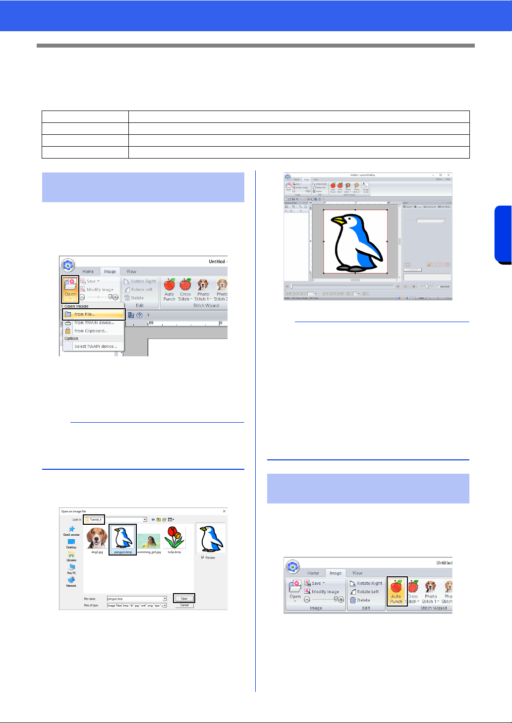
143
Creating Embroidery Patterns Using Images
Tutorial 6-1: Auto Punch
Tutorial 6-1: Auto Punch
In this section, we are going to use the Auto Punch function to automatically create an embroidery pattern from
an image. This creates an embroidery pattern from shapes and colors in the image.
1 Click the [Image] tab.
2 Click [Open] in the [Image] group, and then
click [from File].
3 Double-click the [Documents (My
documents)\PE-DESIGN
11\Tutorial\Tutorial_6] folder to open it.
4 Select the file [penguin.bmp], and then click
[Open], or double-click the file's icon.
The image appears in the work area.
1 Click the [Image] tab.
2 Click [Auto Punch] in the [Stitch Wizard]
group.
Step 1 Importing image data into Layout & Editing
Step 2 Starting the Auto Punch wizard
Step 3 Applying an image mask and adjusting its size and position
Step 4 Creating a border from the mask outline and converting to an embroidery pattern
Step 1 Importing image data into
Layout & Editing
b
When this application is installed, the [PE-
DESIGN 11] folder is installed in the Documents
folder.
b
• Images with few and distinct colors work best
with [Auto Punch].
• Repeat steps
1 to 4 to choose another picture
image.
For details on other procedures, refer to the
following.
cc
f of "Select Mask dialog box" on page 159
• You can import picture images from a scanner,
or clipboard, and import that image.
cc "Importing Image Data" on page 163
Step 2 Starting the Auto Punch
wizard
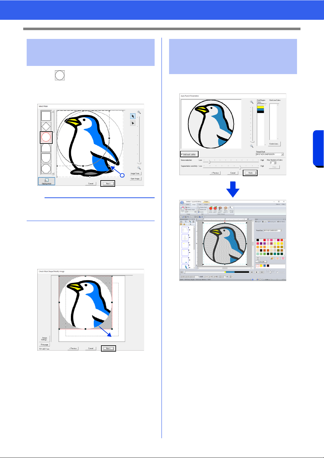
144
Creating Embroidery Patterns Using Images
Tutorial 6-1: Auto Punch
1 Click to select the circle mask.
Drag handle to adjust the size of the mask,
and drag the mask to adjust its position.
Click [Next].
cc "Select Mask dialog box" on page 158.
2 Drag the image to adjust its output location
and size. The white background indicates the
sewing area in the Design Page.
Click [Next].
cc "Check Mask Shape/Modify Image dialog
box" on page 161
Select the [Add mask outline] check box, check
the preview image, and then click [Finish].
The image is automatically hidden and
stitches are automatically input.
Step 3 Applying an image mask
and adjusting its size and
position
b
The mask outline selected here can be used as
line data (border) in Step 4.
Step 4 Creating a border from the
mask outline and
converting to an
embroidery pattern
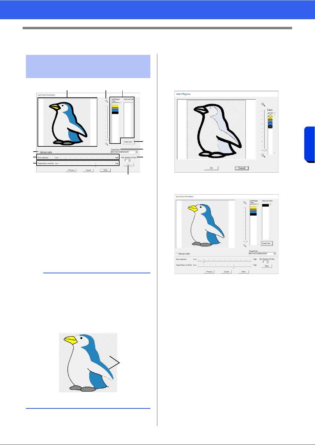
145
Creating Embroidery Patterns Using Images
Auto Punch Features
Auto Punch Features
a Result View
The resulting analyzed image appears in
the Result View box.
b Omit Region Colors/Omit Line Colors
In the [Omit Region Colors] list and
[Omit Line Colors] list, click the colors to
select whether or not they will be sewn.
You can select whether or not areas will
be sewn by selecting their colors. Colors
that are crossed out are set to not be
sewn.
c Zoom
d Create Lines
Click this button to display the [Select
Regions] dialog box, where the areas to
be converted to lines can be selected.
Click the areas to be converted to lines,
and then click [OK].
e Thread Chart
Select the thread chart to be used.
f Add mask outline
If this check box is selected, line data is
created from the mask outline.
g Noise reduction
Sets the level of noise (distortions) that is
removed from the imported image.
h Segmentation sensitivity
Sets the sensitivity for the image analysis.
i Max. Number of Colors
Sets the number of colors used.
j Retry
To view the results of the changes, click
this button.
Auto Punch Parameters
dialog box
b
• To select whether or not a part of the image is to
be sewn, click in the Result View box, or click in
the [Omit Region Colors] and [Omit Line
Colors] lists.
• Areas filled with a crosshatch pattern in the
Result View box will not be sewn.
In addition, lines that appear as dotted lines will
not be sewn.
1 These areas will not be sewn.
acb
d
e
j
i
f
g
h
1
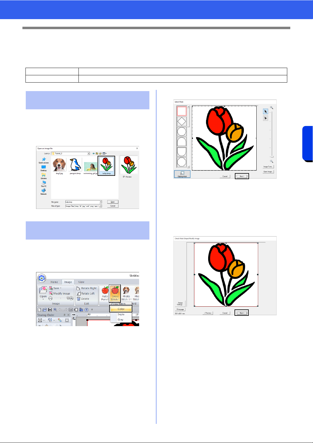
146
Creating Embroidery Patterns Using Images
Tutorial 6-2: Cross Stitch
Tutorial 6-2: Cross Stitch
The Cross Stitch function creates cross-stitch embroidery patterns from images. In this section, we will create
a cross-stitch embroidery pattern from an image.
Select the [Tutorial_6] folder, and then select
[tulip.bmp] as the image.
cc "Importing image data into Layout &
Editing" on page 143
1 Click the [Image] tab.
2 Click [Cross Stitch] in the [Stitch Wizard]
group, and then click [Color].
3 Click [Next].
From this dialog box, an image mask can be
applied, and its size can be adjusted and
shape edited. For this example, we will simply
continue to the next step.
cc "Select Mask dialog box" on page 158
4 Click [Next].
From this dialog box, the size and position of
the image can be adjusted. For this example,
we will simply continue to the next step.
cc "Check Mask Shape/Modify Image dialog
box" on page 161
Step 1 Importing image data into Layout & Editing
Step 2 Starting the Cross Stitch wizard
Step 1 Importing image data into
Layout & Editing
Step 2 Starting the Cross Stitch
wizard
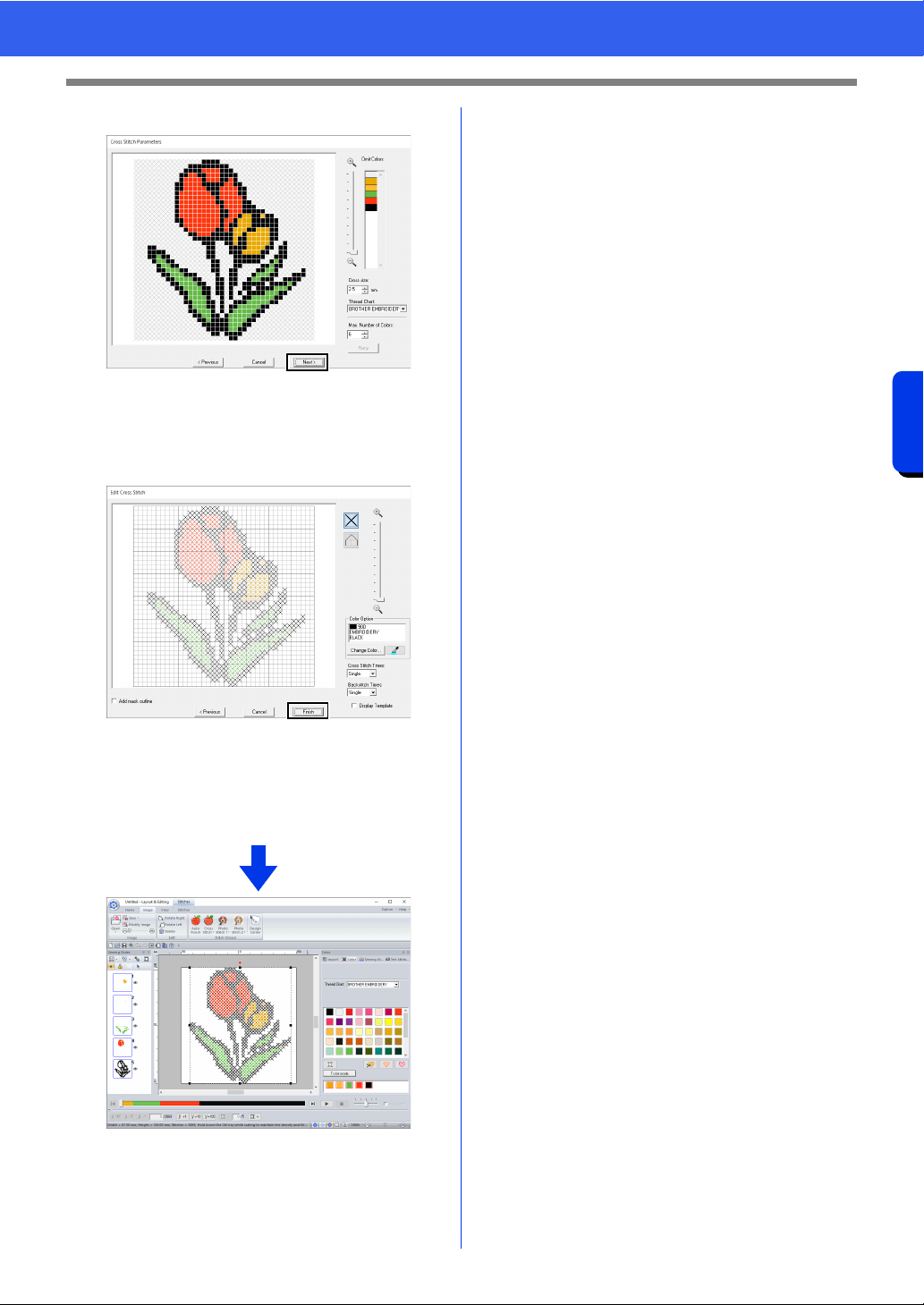
147
Creating Embroidery Patterns Using Images
Tutorial 6-2: Cross Stitch
5 Click [Next].
In this dialog box, the cross size and the
number of colors can be specified. For this
example, we will use the default settings.
6 Click [Finish].
In this dialog box, stitches can be added,
deleted or edited, and colors and the number
of times each stitch is sewn can be specified.
For this example, we will use the default
settings.
The image is automatically hidden and
stitches are automatically input.
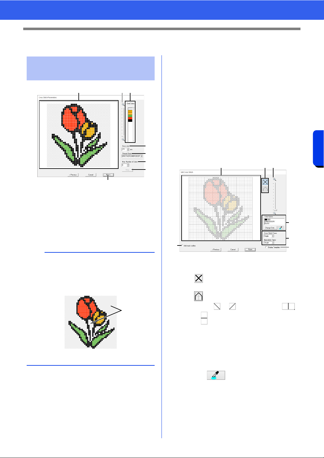
148
Creating Embroidery Patterns Using Images
Cross Stitch Features
Cross Stitch Features
a Result View
Areas that will not be converted to cross-
stitching are shown with a crosshatch
pattern.
b Omit Colors
In the Omit Colors list, click the colors to
select whether or not they will be sewn.
c Zoom
d Cross size
Sets the size of the pattern.
e Thread Chart
You can select the brand of thread to use
in the created cross stitch pattern.
f Max. Number of Colors
Sets the number of colors used in the
created pattern.
g Retry
To view the results of the changes, click
this button.
h Next
Continues to the next step ([Edit Cross
Stitch] dialog box).
■ Edit Cross Stitch dialog box
Click a button in a to select the type of stitch,
select a thread color in
b , and then click or
drag in
c to edit the stitches.
a Selecting stitches
Selecting stitches to be added/deleted
(cross-stitches): Specifies a cross-
stitch inside a box.
(backstitches): Specifies a back stitch
inside ( or ) or on the edge (
or ) of a box.
b Color Option
To change the color, click [Change
Color] to display the [Thread Color]
dialog box, and then click the desired
color.
To select the color to be used for a stitch,
click , and then click the stitch to
be sewn with that color.
Cross Stitch Parameters
dialog box
b
• To select whether or not a part of the image is to
be sewn, click in the Result View box, or click in
the [Omit Colors] list.
• Areas filled with a crosshatch pattern in the
Result View box will not be sewn.
1 These areas will not be sewn.
a c b
d
e
f
g
h
1
cad
b
g
e
f
149
Creating Embroidery Patterns Using Images
Cross Stitch Features
c Editing area
For cross-stitches
Clicking a box: Adds one stitch.
For backstitches
Clicking an edge of a box: Adds one
stitch at the edge.
Clicking a diagonal line in a box: Adds
one stitch on the diagonal.
For both cross-stitches and
backstitches
Dragging the pointer: Adds
consecutive stitches.
Right-clicking/dragging with the right
mouse button held down: Deletes one
stitch/deletes consecutive stitches.
d Zoom
e Display Template
To display the imported image, click
[Display Template].
f Add mask outline
If this check box is selected, line data is
created from the mask outline.
g Cross Stitch Times/Backstitch Times
For the number of times each stitch is to
be sewn, select [Single], [Double] or
[Triple].
a
If [Previous] is clicked to return to the [Cross
Stitch Parameters] dialog box after the stitches
have been edited, the edited stitches are reset to
their previous arrangement.
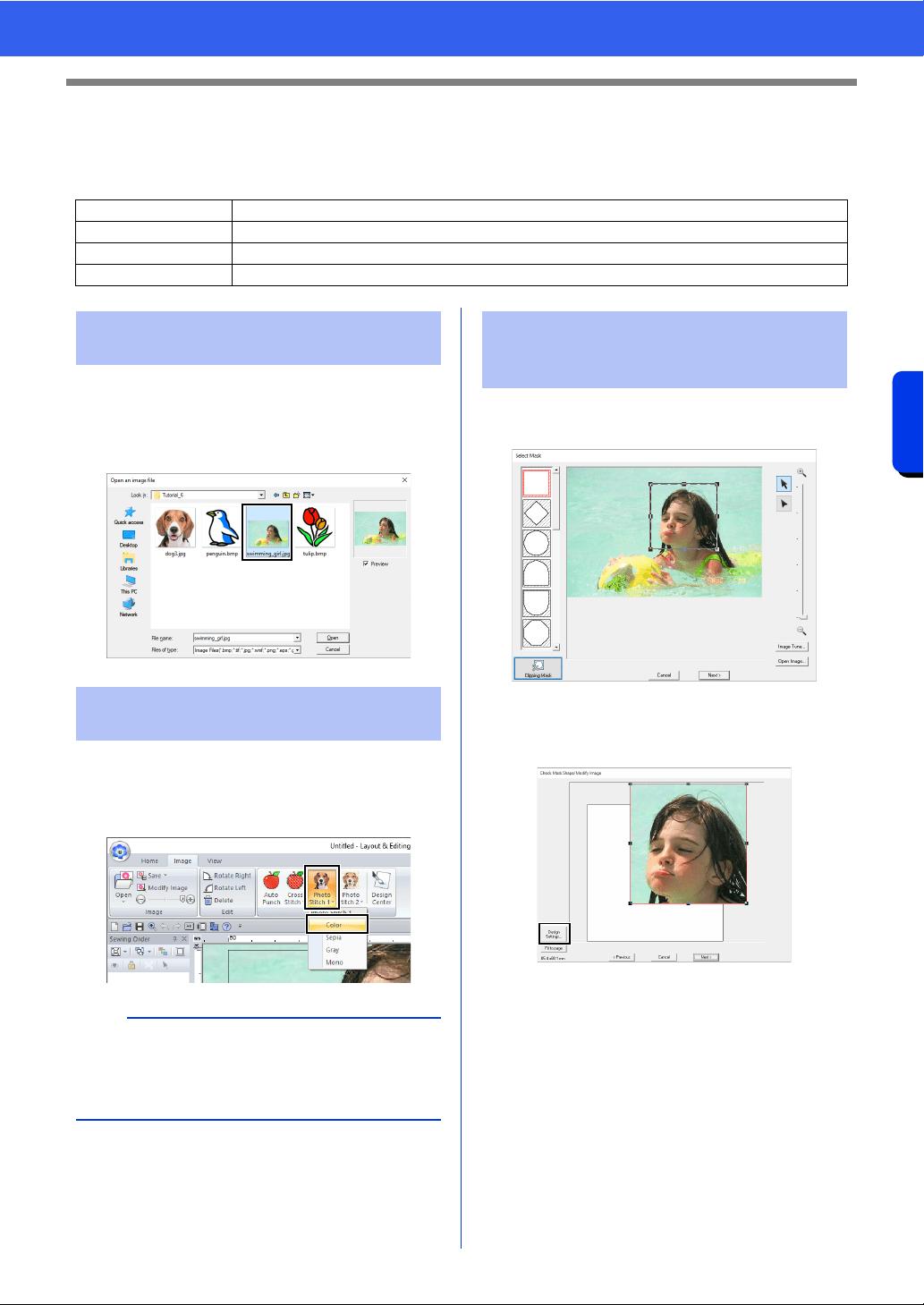
150
Creating Embroidery Patterns Using Images
Tutorial 6-3: Photo Stitch 1
Tutorial 6-3: Photo Stitch 1
By using the Photo Stitch 1 function, embroidery patterns can be created from photos. This type of embroidery
pattern created from a photo has detailed and overlapping stitching.
Select the [Tutorial_6] folder, and then select
[swimming_girl.jpg] as the image.
cc "Importing image data into Layout &
Editing" on page 143
1 Click the [Image] tab.
2 Click [Photo Stitch 1] in the [Stitch Wizard]
group, and then click [Color].
1 Drag the handles to adjust the shape of the
mask. Drag the mask to adjust its position.
2 Then click [Next].
3 Click [Design Settings].
Step 1 Importing photo data into Layout & Editing
Step 2 Starting the Photo Stitch 1 wizard
Step 3 Applying an image mask and adjusting its size and position
Step 4 Selecting appropriate thread colors and creating an embroidery pattern
Step 1 Importing photo data into
Layout & Editing
Step 2 Starting the Photo Stitch 1
wizard
b
With [Photo Stitch 1], an embroidery pattern can
be created in color (Color), sepia (Sepia),
grayscale (Gray) or one color (Mono). For this
example, select [Color].
Step 3 Applying an image mask
and adjusting its size and
position
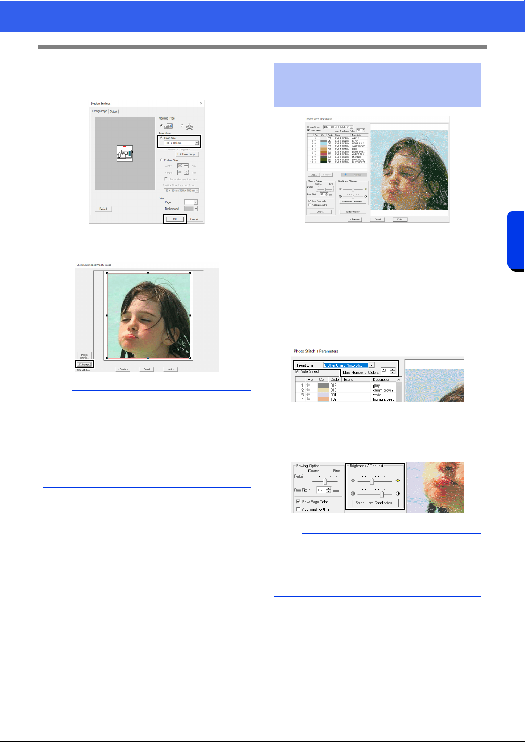
151
Creating Embroidery Patterns Using Images
Tutorial 6-3: Photo Stitch 1
4 Select [Hoop Size] and choose a Design
Page size of 100 × 100 mm from the selector.
Then, click [OK].
5 Click [Fit to page] to change the final finishing
size.
cc "Check Mask Shape/Modify Image dialog
box" on page 161 and "Gray Balance /
Modify Image dialog box" on page 162
6 Check the preview of the area to be converted
then click [Next].
At this point, the embroidery pattern can be
completed by clicking [Finish]. However, this
section will describe how to improve the photo
stitching by changing various settings.
1 From the [Thread Chart] selector, select
[Brother Chart (Photo Stitch)].
In the [Max. Number of Colors] selector,
specify "20".
Click [Update Preview].
2 Slide the [Brightness] slider one position to
the left, and the [Contrast] slider two
positions to the right.
Click [Update Preview].
b
• The size of the embroidery pattern appears in
the lower left corner of the dialog box. The user
can change the size freely with this display.
• The minimum sizes of embroidery patterns that
can be sewn are listed below.
Face only: 100 × 100 mm
Head and face: 130 × 180 mm
Step 4 Selecting appropriate
thread colors and creating
an embroidery pattern
b
Make adjustments as needed, depending on the
image. If it is difficult to adjust the tone, click
[Select from Candidates].
cc "Select from Candidates" on page 154.
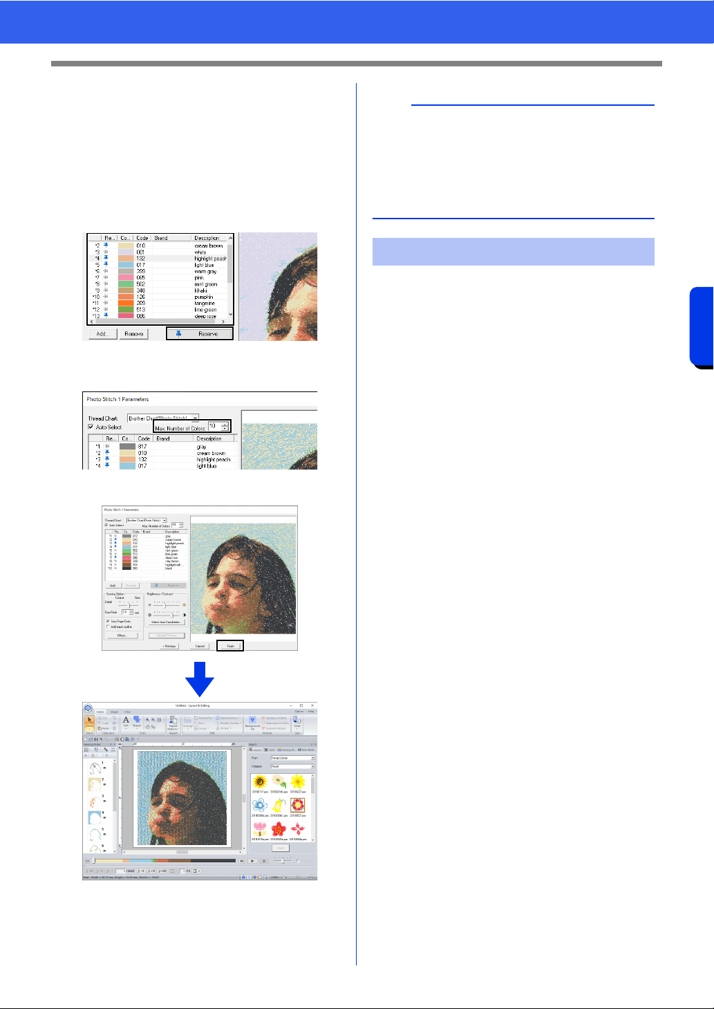
152
Creating Embroidery Patterns Using Images
Tutorial 6-3: Photo Stitch 1
3 While looking at the preview on the right side,
select colors from the list for the most
frequently used colors (light blue for the
background) and for the more characteristic
colors (deep rose for the lips), and then click
[Reserve].
For this example, four colors (cream brown,
light blue, highlight peach and deep rose)
are reserved.
4 In the [Max. Number of Colors] selector,
specify "10", and then click [Update Preview].
5 Click [Finish].
The image is automatically hidden.
If the actual thread colors differ from the thread
colors on the screen, the embroidering results will
be greatly affected.
[Brother Chart (Photo Stitch)] is a thread chart
based on the Brother embroidery thread colors and
flesh tones, and has been adjusted to account for
the difference between thread colors on the screen
and actual thread colors; however, colors may
appear differently depending on your operating
environment.
If the thread colors on the screen are different from
the actual thread colors, use the user thread color
lists and adjust the thread colors to achieve better
results.
cc "Editing user thread color lists" on
page 213
b
If the created embroidery pattern contains colors
that you do not wish to emphasize (for example,
grays in the face), change the sewing order in the
[Sewing Order] pane so that the undesirable color
is sewn before all other colors.
cc "Changing colors" on page 96.
Tips for improved results
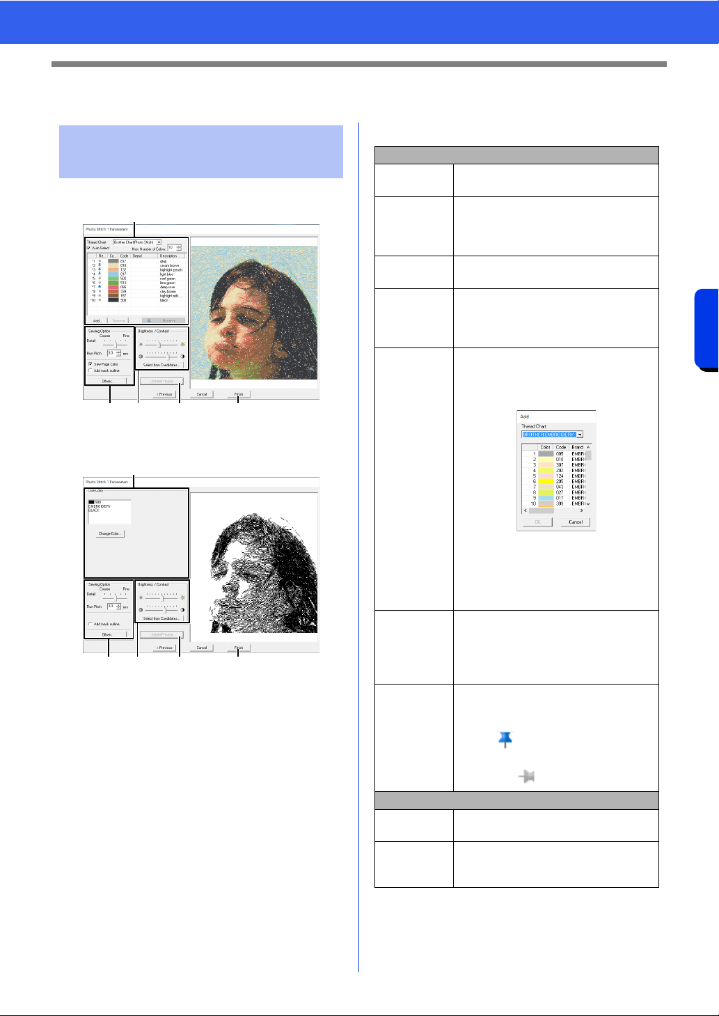
153
Creating Embroidery Patterns Using Images
Photo Stitch 1 Features
Photo Stitch 1 Features
With Color, Sepia or Gray
With Mono
Select the thread colors in the color options
a,
specify the desired settings under [Sewing Option]
b and [Color Option] c, and then, click [Update
Preview]
d to preview the effects of the specified
settings. Click [Finish]
e to convert the image to
an embroidery pattern.
a Color options
Photo Stitch 1 Parameters
dialog box
a
b cd e
a
b cd e
Color/Sepia/Gray
Thread Chart
You can select the brand of thread to
use in the created pattern.
Auto Select
Select whether thread colors will be
selected automatically (on) or manually
(off). Select this check box to turn on
this function.
Max. Number
of Colors
Sets the number of colors selected by
the Auto Select function.
List of colors
used
Displays the thread colors that are
being used. With this list, the thread
colors that are being used can be
checked or changed.
Add
Click this button to add a thread color to
the list of colors used.
When clicked, the [Add] dialog box
appears.
Select a thread chart, then a thread
color, and then click [OK] to add the
color to the list. Added thread colors will
be reserved as thread colors that must
be used.
Remove
Select a thread color in the list of colors
used, and then click this button to delete
the selected color from the list. This is
used to delete unnecessary thread
colors and reduce the number of colors.
Reserve
Specifies thread colors that must be
used. Select a thread color in the list of
colors used, and then click this button to
display in the Reserved column. To
cancel this setting, click to icon so that it
appears as .
Mono
List of colors
used
Displays the thread colors that are
being used.
Change
Color
Click this button to display the [Thread
Color] dialog box, where the thread
colors can be changed.
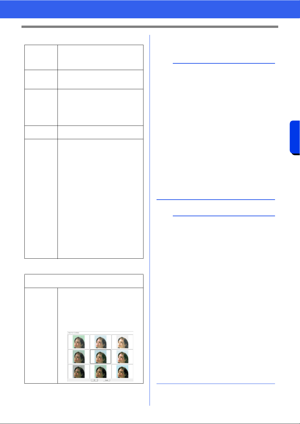
154
Creating Embroidery Patterns Using Images
Photo Stitch 1 Features
b Sewing Option
c Brightness / Contrast
d Update Preview
Update the previewed image after settings have
been changed.
Detail
Selecting a setting closer to [Fine]
creates more details in the pattern and
increases the number of stitches. (The
stitches will be overlapping.)
Run Pitch
When the value is lowered, the sewing
pitch (stitch length) will be shortened,
resulting in finer stitching.
Sew Page
Color
(Available
only with
Color, Sepia
and Gray)
If this check box is cleared, the parts of
the pattern that are the same color as
the Design Page will not be sewn.
If it is selected, those parts will be sewn.
Add mask
outline
If this check box is selected, line data is
created from the mask outline.
Others
Click this button to display the [Others]
dialog box, where the following settings
can be specified.
[Conversion Priority]:
To give priority to creating a pattern as
close to the original photograph, select
[Stitch Quality].
To give priority to reducing the number
of jump stitches, select [Jump Stitch
Reduction].
[Image Type]:
If [Photo] is selected, the thread colors
will be mixed together, which will result
in a more natural look.
If [Cartoon] is selected, the thread
colors will not be mixed together, which
will result in a more simply colored look.
Select [Photo] for image data from a
photograph, etc. Select [Cartoon] for
image data from an illustration, etc.
The top slider is used to adjust the brightness.
The bottom slider is used to adjust the contrast.
Select from
Candidates
The image can be automatically
adjusted.
Click this button to display nine patterns
with different brightness and contrast
levels based on the original image.
Select one of the candidates, and then
click [OK].
b
•If the [Auto Select] check box is selected, the
thread colors will be automatically selected from
the chart selected in the [Thread Chart]
selector. If thread colors are reserved, they will
included in the colors selected according to the
number specified in the [Number of Colors]
box.
If the [Auto Select] check box is cleared, the
settings in the [Thread Chart] selector and
[Number of Colors] box are not applied, and
only the thread colors in the current list of colors
used will be used to assign thread colors.
• When thread colors are added/deleted, the
[Auto Select] check box is cleared. To use
added thread colors and automatically select
other thread colors, select the [Auto Select]
check box, and then update.
• The thread colors in the list of colors used are
listed, in order, starting from the brightest. This
order is the sewing order and cannot be
changed.
b
Creating beautiful photo embroidery
• [Brother Chart (Photo Stitch)] in the [Thread
Chart] selector is a thread chart created to allow
you to preview, in colors nearest to the actual
embroidered thread colors, patterns using
Brother embroidery threads. This chart provides
a color scheme that best corresponds to your
expected result.
However, the colors may appear differently
depending on the computer environment. By
editing the colors to create a user thread chart
corresponding to the threads that you have, you
can create patterns while viewing them in colors
nearest to the actual threads that will be
embroidered.
cc "Editing user thread color lists" on page 213
• The following types of photos are not
appropriate for creating embroidery patterns.
Photos where the subject is small, such as in
photos of gatherings
Photos where the subject appears dark, such
as photos taken in a room or taken with
backlighting
• An image with a width and height between 300
and 500 dots is suitable.
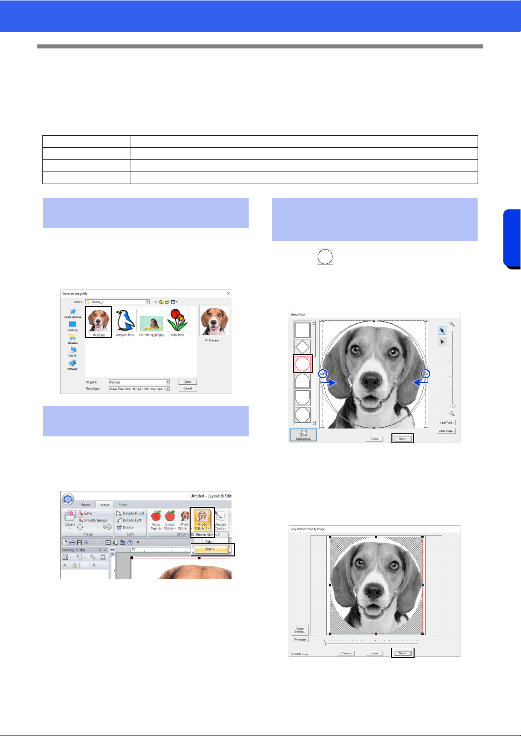
155
Creating Embroidery Patterns Using Images
Tutorial 6-4: Photo Stitch 2
Tutorial 6-4: Photo Stitch 2
We will create an embroidery pattern with [Photo Stitch 2] in a method different than that used with [Photo
Stitch 1]. Although this embroidery pattern will also be created from a photo, this type of embroidery pattern
contains repeating zigzag stitches. This produces a more general rendering than with [Photo Stitch 1];
however, the data is created with well-regulated stitching.
Select the [Tutorial_6] folder, and then select
[dog3.jpg] as the image.
cc "Importing image data into Layout &
Editing" on page 143
1 Click the [Image] tab.
2 Click [Photo Stitch 2] in the [Stitch Wizard]
group, and then click [Mono].
1 Click to select the circle mask.
Drag handle to adjust the size of the mask,
and drag the mask to adjust its position.
Click [Next].
cc "Select Mask dialog box" on page 158
2 From this dialog box, the size and position of
the image can be adjusted. For this example,
we will simply continue to the next step.
Click [Next].
cc "Check Mask Shape/Modify Image dialog
box" on page 161 and "Gray Balance /
Modify Image dialog box" on page 162
Step 1 Importing photo data into Layout & Editing
Step 2 Starting the Photo Stitch 2 wizard
Step 3 Applying an image mask and adjusting its size and position
Step 4 Changing the sewing angle
Step 1 Importing photo data into
Layout & Editing
Step 2 Starting the Photo Stitch 2
wizard
Step 3 Applying an image mask
and adjusting its size and
position
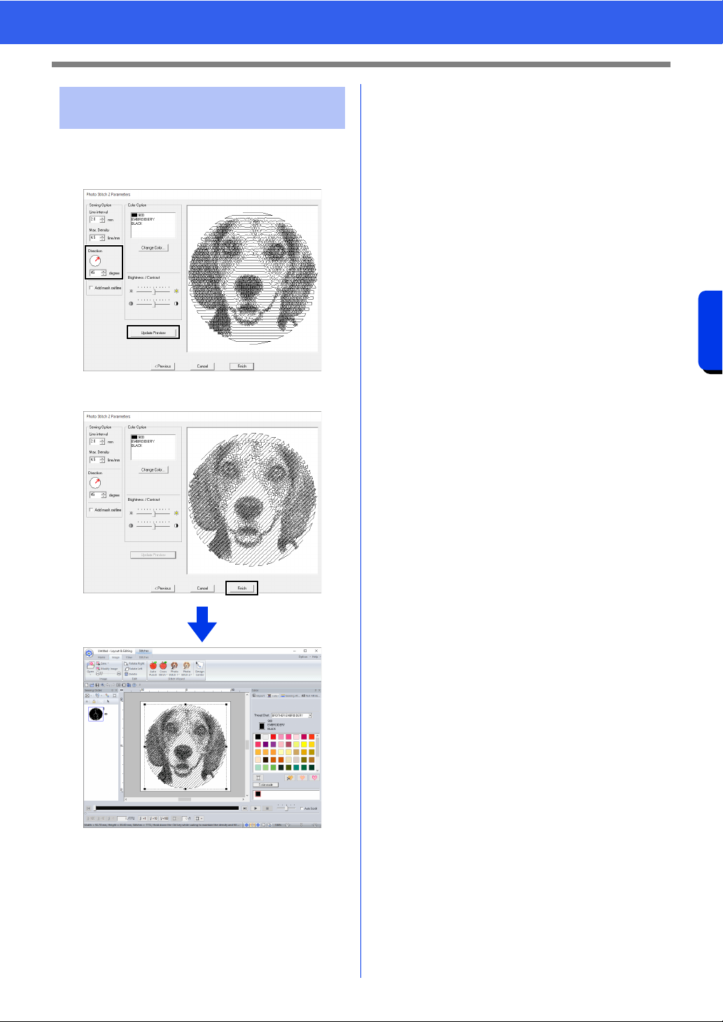
156
Creating Embroidery Patterns Using Images
Tutorial 6-4: Photo Stitch 2
1 In the [Direction] box, type "45".
2 Click [Update Preview].
3 Click [Finish].
Step 4 Changing the sewing
angle
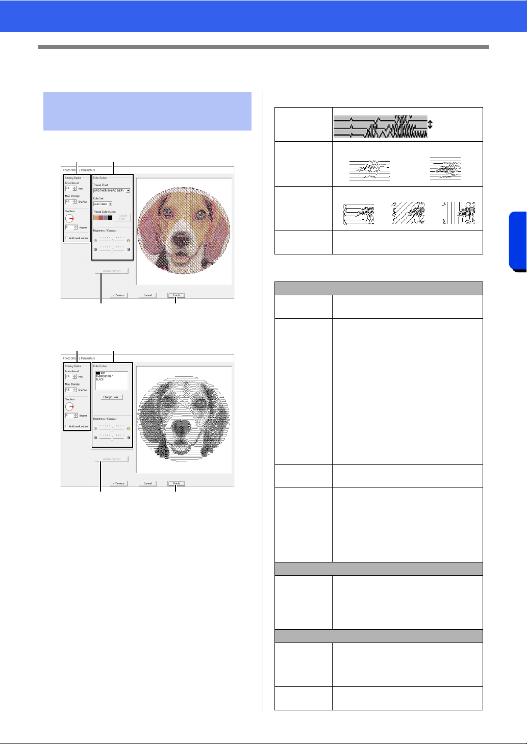
157
Creating Embroidery Patterns Using Images
Photo Stitch 2 Features
Photo Stitch 2 Features
With Color
With Mono
Specify the desired settings under [Sewing Option]
a and [Color Option] b, and then click [Update
Preview]
c to preview the effects of the specified
settings. Click [Finish]
d to convert the image to
an embroidery pattern.
a Sewing Option
b Color Option
Photo Stitch 2 Parameters
dialog box
a
cd
b
a
cd
b
Line interval
Line
interval
Max. Density
Lower value
Higher value
Direction
0°
45° 90°
Add mask
outline
If this check box is selected, line data is
created from the mask outline.
Color
Thread Chart
You can select the brand of thread
available in the [Color Set] selector.
Color Set
If [Auto Select] is selected, the most
appropriate four colors will automatically
be selected.
Selecting a different option specifies the
four colors used when creating the
embroidery pattern.
The color choices are: cyan (C),
magenta (M), yellow (Y), black (K), red
(R), green (G) and blue (B). Select one
of the following combinations that
contains the colors most used in the
image.
Color combinations: CMYK, RGBK,
CRYK, BMYK
Thread
Colors Used
Displays the four selected thread colors.
Change
Color
Under [Thread Colors Used], click a
color. Then, click [Change Color] to
display the [Thread Color] dialog box.
Select the new color and click [OK].
The selected thread color will be applied
to the image shown in the preview
window.
Mono
Change
Color
Click on the [Change Color] button to
open the [Thread Color] dialog box if
you wish to change the color of the
photo stitching. Select the color and
click [OK] to make the color change.
Color/Mono
Brightness /
Contrast
The top slider is used to adjust the
brightness.
The bottom slider is used to adjust the
contrast.
Update
Preview
Updates the previewed image after
settings have been changed.
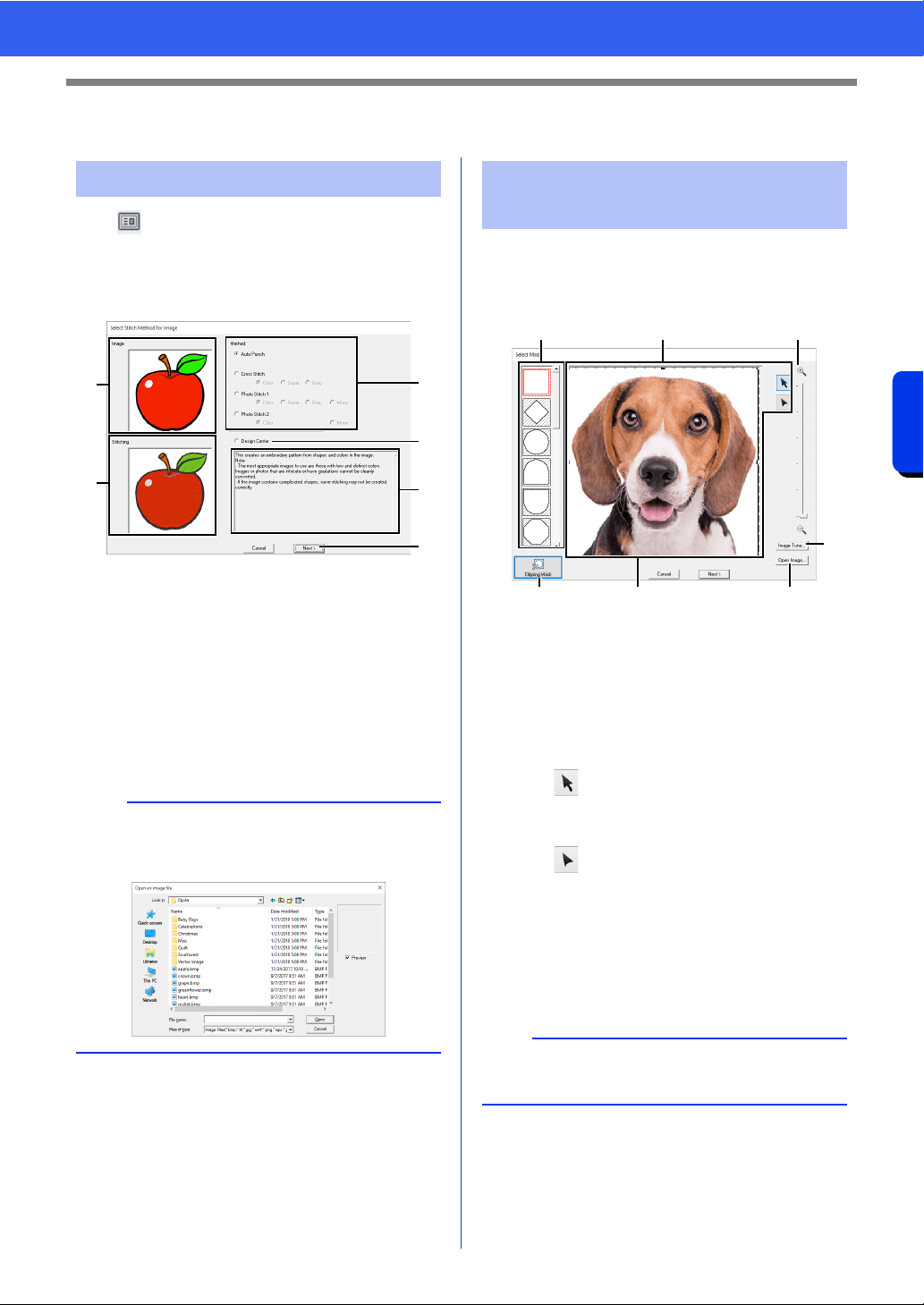
158
Creating Embroidery Patterns Using Images
Advanced Stitch Wizard Operations
Advanced Stitch Wizard Operations
Click at the top of the window (in the [Quick
Access Toolbar]) to display the Startup Wizard,
and then click [Create Embroidery Patterns Using
Images]. If an image has been imported, the next
dialog box appears.
a Sample image before being converted
b Sample image of embroidery pattern
after being converted
c Select the conversion method.
d Select to start up Design Center and
import the image into the Design Page.
e Description of conversion method
f Click to continue to the next step.
■ Select Mask dialog box
The [Select Mask] dialog box appears no matter
which conversion method was selected.
a Mask shapes
The image will be masked with the
selected shape.
b The mask can be reshaped or
repositioned. Select the tool appropriate
for the operation to be performed.
Image To Stitch Wizard
b
If no image has been imported into the Design
Page, the [Open an image file] dialog box
appears.
a
b
c
d
e
f
Adjusting the Mask and
Image
: Drag the handles to enlarge/
reduce the mask. Drag the mask
to adjust its position.
: Points can be entered, moved and
deleted to create a mask with the
desired shape.
To add points, click the outline of
the mask. To move a point, select
the point, and then drag it. To
delete points, select the point, and
then press the <Delete> key.
a
With a small original image, it may not be possible
to reduce the size of the mask.
a b d
e
ffc
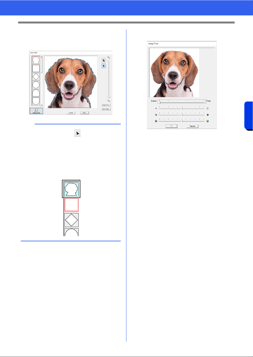
159
Creating Embroidery Patterns Using Images
Advanced Stitch Wizard Operations
c Click to detect the outline of the image.
The detected outline can be edited.
cc "Adjusting the image mask" on page 160
d Zoom
e Clicking the [Image Tune] button displays
an [Image Tune] dialog box.
• Move the [Original] – [Sharp] slider to
adjust the sharpness of the image's
outlines. A setting more towards [Sharp]
makes a more noticeable boundary
between bright and dark areas.
• Move the [Dark] – [Bright] slider to adjust
the brightness of the image.
• Move the [Low] – [High Contrast] slider to
adjust the contrast of the image.
• Move the [Low] – [High Saturation] slider
to adjust the color saturation of the image.
f Clicking [Open Image] allows you
replace the image with a different one.
The [Open an image file] dialog box
appears. Select a file.
The next step differs depending on the color range
selected for the embroidery pattern.
cc "Check Mask Shape/Modify Image dialog box"
on page 161
cc "Gray Balance / Modify Image dialog box" on
page 162
a
A mask shape edited with or created by
clicking [Clipping Mask] will be added at the top
of the list. Then, this mask shape can be selected
the next time a pattern is created using a Stitch
Wizard. A maximum of five shapes will be added,
and they will be arranged in order of the most
recently used.
These mask shapes appear no matter which
Image To Stitch function is selected.
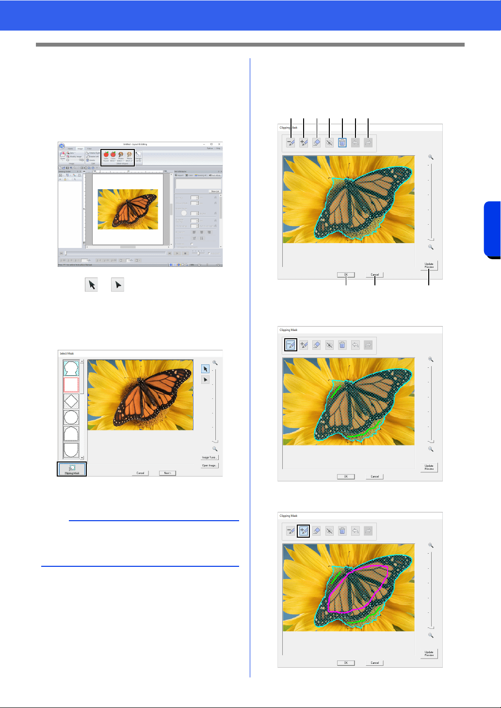
160
Creating Embroidery Patterns Using Images
Advanced Stitch Wizard Operations
■ Adjusting the image mask
The detected outline can be edited.
Your image is accurately traced for a more precise
output. (Enhanced Image Tracing)
1 Select [Auto Punch], [Cross Stitch], [Photo
Stitch 1] or [Photo Stitch 2].
2 Click or , and then specify the image
mask.
cc "Adjusting the Mask and Image" on
page 158
3 Click [Clipping Mask].
The automatically detected image mask
appears.
4 Adjust the image mask.
The outline of the image mask is indicated by
a thick cyan line, and the inside of the image
mask is filled with a cyan crosshatch pattern.
a Fill areas with the yellow-green pen to
remove them from the image mask.
b Fill areas with the pink pen to add them to
the image mask.
a
Enclose the desired part of the image with the
image mask, and then press [Clipping Mask] to
increase the masking precision.
a b c d e f g
i j h
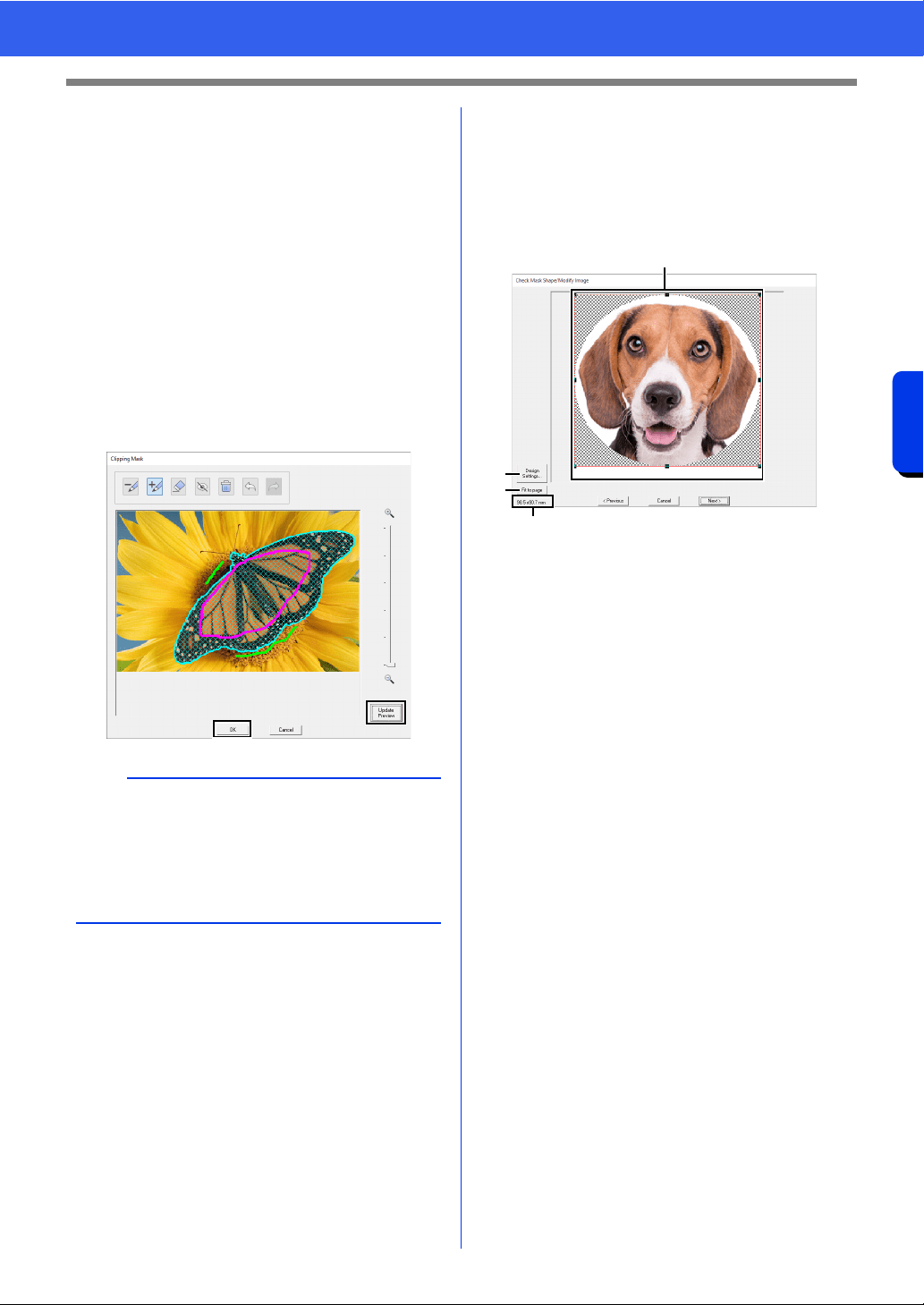
161
Creating Embroidery Patterns Using Images
Advanced Stitch Wizard Operations
c Trace over lines drawn with pen a or b
to erase them.
d Hide all lines drawn with pen a or b.
e Delete all drawn lines.
f Undo the last operation to return the
image mask to its previous condition.
g Redo the last operation that was undone.
h Update the image mask according to the
currently drawn pen lines.
i Click to apply the image mask.
j Click to return to the [Select Mask] dialog
box.
5 Click [Update Preview], check the adjusted
area, and then click [OK].
■ Check Mask Shape/Modify Image
dialog box
If Color, Sepia or Gray was selected for [Photo
Stitch 1], [Photo Stitch 2] or [Cross Stitch], or if
[Auto Punch] was selected:
The following dialog box appears.
a Adjust the position and size of the image.
Drag the image to the desired position.
Drag the handle to adjust the image to the
desired size.
b Click [Design Settings] to change the
size of the Design Page. Specify the
settings in the [Design Settings] dialog
box.
cc "Specifying the Design Page Settings" on
page 16
c Click [Fit to page] to adjust the image to
the size of the Design Page.
d Embroidery pattern size
b
• When selecting areas to be added or removed
from the image mask, the entire area does not
need to be completely filled with the pen marks.
• We recommend repeatedly marking the image
mask with the pens and updating the preview
until the desired image mask is obtained.
a
b
c
d
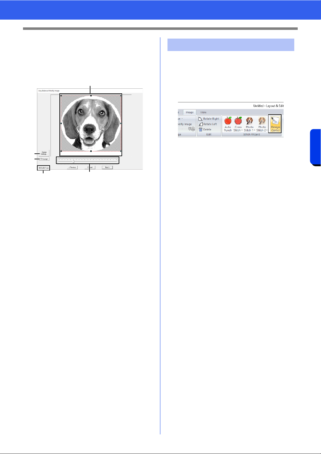
162
Creating Embroidery Patterns Using Images
Advanced Stitch Wizard Operations
■ Gray Balance / Modify Image
dialog box
If [Mono] was selected for [Photo Stitch 1] or
[Photo Stitch 2]:
The following dialog box appears.
a Adjust the position and size of the image.
Drag the image to the desired position.
Drag the handle to adjust the image to the
desired size.
b Click [Design Settings] to change the
size of the Design Page. Specify the
settings in the [Design Settings] dialog
box.
cc "Specifying the Design Page Settings" on
page 16
c Click [Fit to page] to adjust the image to
the size of the Design Page.
d Embroidery pattern size
e Drag the slider to adjust the gray balance.
We will create embroidery data in Design Center by
using an image that was opened in Layout & Editing.
1 Click the [Image] tab.
2 Click [Design Center] in the [Stitch Wizard]
group.
Design Center starts up and the image
appears in the Design Page.
cc "Basic Design Center Operations" on
page 249 and "Line Image Stage" on
page 262
a
b
c
d
e
Importing to Design Center
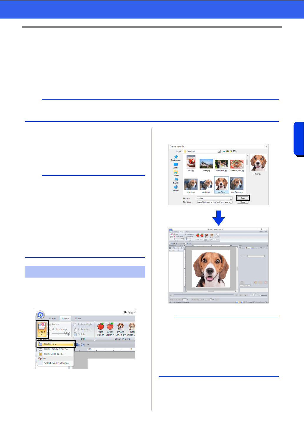
163
Creating Embroidery Patterns Using Images
Importing Image Data
Importing Image Data
An imported image can be used with the Image To Stitch Wizard, as a template for manual punching, or for
printing onto iron-on transfer sheets or printable fabric when using "Print and Stitch".
An image can be imported using any of the following four methods.
• From a file
• From a scanner (TWAIN Device)
• From the Clipboard
■ Image file formats
Images in the following formats can be imported.
Windows bitmap (.bmp), Exif (.tif, .jpg), Windows
Metafile (.wmf), Portable Network Graphics (.png),
Encapsulated PostScript (.eps), GIF (.gif)
1 Click the [Image] tab.
2 Click [Open] in the [Image] group, and then
click [from File].
3 Select the drive, the folder and the file. Click
[Open].
a
Only one image can be added to the work area. If you try to display a different image, it will replace the
previous one.
b
• Vector image data in the ".wmf" (Windows
Metafile), ".emf" (Enhanced Metafile) and ".svg"
(Scalable Vector Graphics) file formats can be
converted to shape patterns as it is without
some information not supported.
cc "Importing vector images (WMF/EMF/SVG)"
on page 105
• If an EPS file doesn't contain a "Preview" image,
it can not be displayed correctly. When you
create a file in EPS format, be sure to save it with
preview image.
Importing image from a file
b
•If the [Preview] check box is selected, the
contents of the selected file will appear in the
[Preview] window.
• Various clip art images can be found in the
[ClipArt] folder (in the folder where PE-DESIGN
was installed) at:
C:\Program Files (x86)\Brother\PE-DESIGN
11\ClipArt
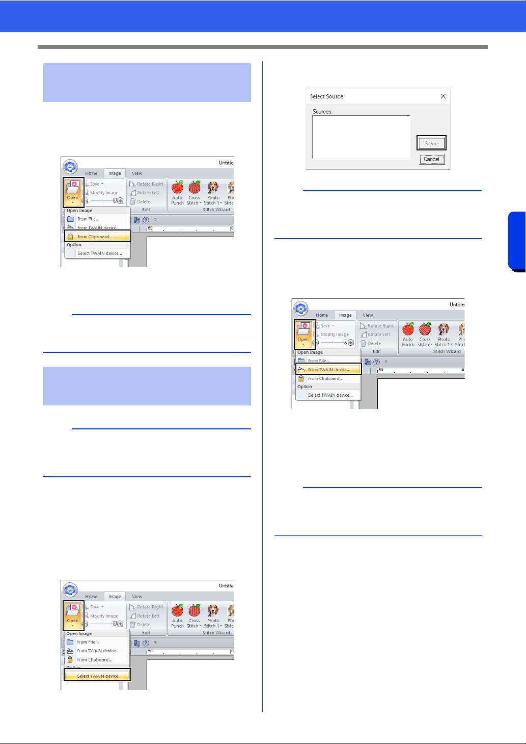
164
Creating Embroidery Patterns Using Images
Importing Image Data
1 Click the [Image] tab.
2 Click [Open] in the [Image] group, and then
click [from Clipboard].
The image on the clipboard is imported into
the Design Page.
1 Check that the scanner or other TWAIN
device is correctly connected to your
computer.
2 Click the [Image] tab.
3 Click [Open] in the [Image] group, and then
click [Select TWAIN device].
4 From the [Sources] list, click the desired
device to select it. Click [Select].
5 Click the [Image] tab.
6 Click [Open] in the [Image] group, and then
click [from TWAIN device].
The driver interface for the device selected
in the Select Source dialog box appears.
7 Specify the necessary settings for importing
an image, and then import the image.
The imported image will be pasted into the
Design Page at its original size.
Importing image from the
clipboard
a
This can only be done when there is image data on
the Clipboard.
Importing image from a
scanner (TWAIN Device)
b
TWAIN is an application interface (API)
standardization for software that controls scanners
and other devices.
a
If no TWAIN device is installed, there will be no
names displayed in the [Sources] list. First, install
the driver software for the TWAIN device.
a
For information on using the driver interface, refer
to the help manual for that interface, or contact the
manufacturer of the interface.
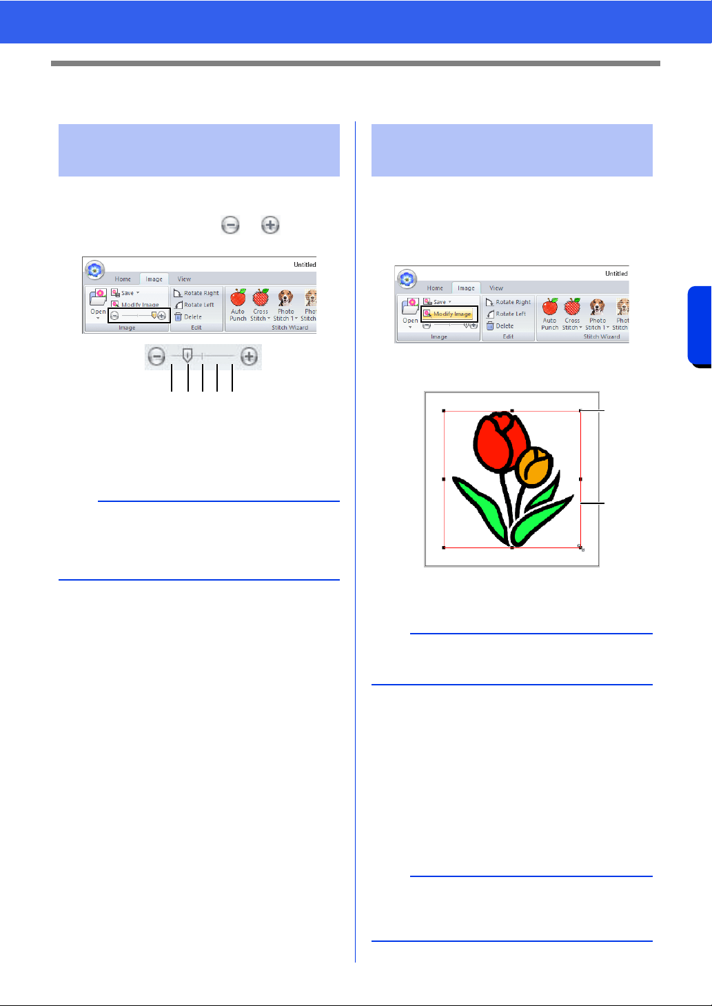
165
Creating Embroidery Patterns Using Images
Changing the Image Settings
Changing the Image Settings
1 Click the [Image] tab.
2 Drag the slider, or click or in the
[Image] group.
1 Hide (off)
2 25%
3 50%
4 75%
5 100%
■ Selecting an image
1 Click the [Image] tab.
2 Click [Modify Image] in the [Image] group.
The image is selected and appears as
shown below.
1 Handle
2 Red line
■ Moving an image
Drag the selected image to the desired location.
■ Scaling an image
Drag the handle to adjust the image to the desired
size.
Adjusting the density of
the background image
b
Press the shortcut key <F6> to switch between
displaying the image (On (100%)) to displaying it
faded at each density (75%, 50% and 25%) to
hiding the image (Off).
123 54
Changing the size, angle
and position of the image
b
The status bar shows the dimensions (width and
height) of the image.
b
If the <Shift> key is held down while a handle is
dragged, the image is enlarged or reduced from
the center of the image.
1
2
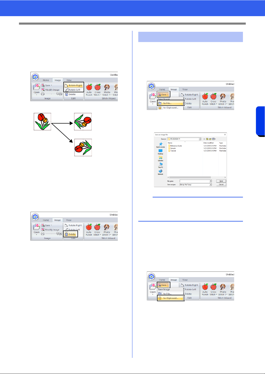
166
Creating Embroidery Patterns Using Images
Changing the Image Settings
■ Rotating an image
An image can be rotated in 90° increments.
1 Click the [Image] tab.
2 Click [Rotate Right] or [Rotate Left] in the
[Edit] group.
1 Rotate Right
2 Rotate Left
■ Deleting an image
1 Click the [Image] tab.
2 Click [Delete] in the [Edit] group.
An image can also be deleted by selecting it, then
pressing the <Delete> key.
cc "Changing the size, angle and position of
the image" on page 165
■ Saving as a file
1 Click the [Image] tab.
2 Click [Save] in the [Image] group, and then
click [to File].
3 Select the drive, the folder and the format.
Type in file name. Click [Save].
■ Outputting to the Clipboard
1 Click the [Image] tab.
2 Click [Save] in the [Image] group, and then
click [to Clipboard].
1
2
Saving the image data
b
The image data can be saved in either of the
following formats: Windows bitmap (.bmp), Exif
(.jpg).
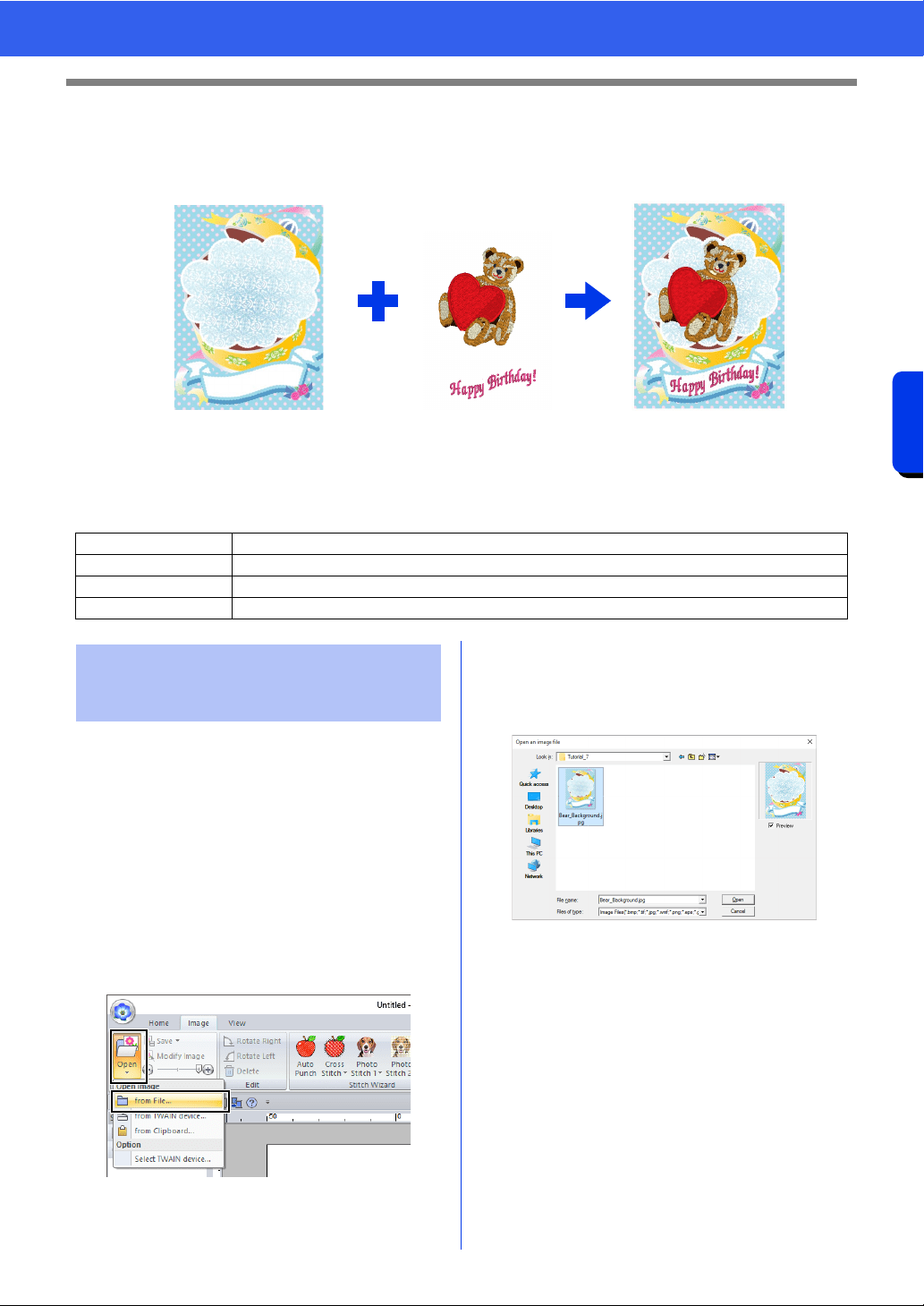
167
Creating Embroidery Patterns Using Images
Tutorial 7: Print and Stitch
Tutorial 7: Print and Stitch
In this example, we will create a design that combines embroidery and an image.
1 Print the background image on fabric.
2 Embroider
The sample file for this tutorial is located at Documents (My documents)\PE-DESIGN 11\Tutorial\Tutorial_7.
For this example, we will use the gift box image
(Bear_Background.jpg) and the embroidery pattern
of the bear (tutorial_7_Bear.pes).
1 Start up Layout & Editing.
Specify a Design Page size of 130 × 180 mm.
cc "Specifying the Design Page Settings" on
page 16
2 Click the [Image] tab.
3 Click [Open] in the [Image] group, and then
click [from File].
4 Import the file [Bear_Background.jpg].
Select the file Bear_Background.jpg in the
folder [Documents (My documents)\PE-
DESIGN 11\Tutorial\Tutorial_7].
cc "Importing Image Data" on page 163.
5 Display the [Import] pane.
Step 1 Creating a design combined with a background image
Step 2 Printing the background image
Step 3 Printing the positioning sheet
Step 4 Embroidering
1
2
Step 1 Creating a design
combined with a
background image
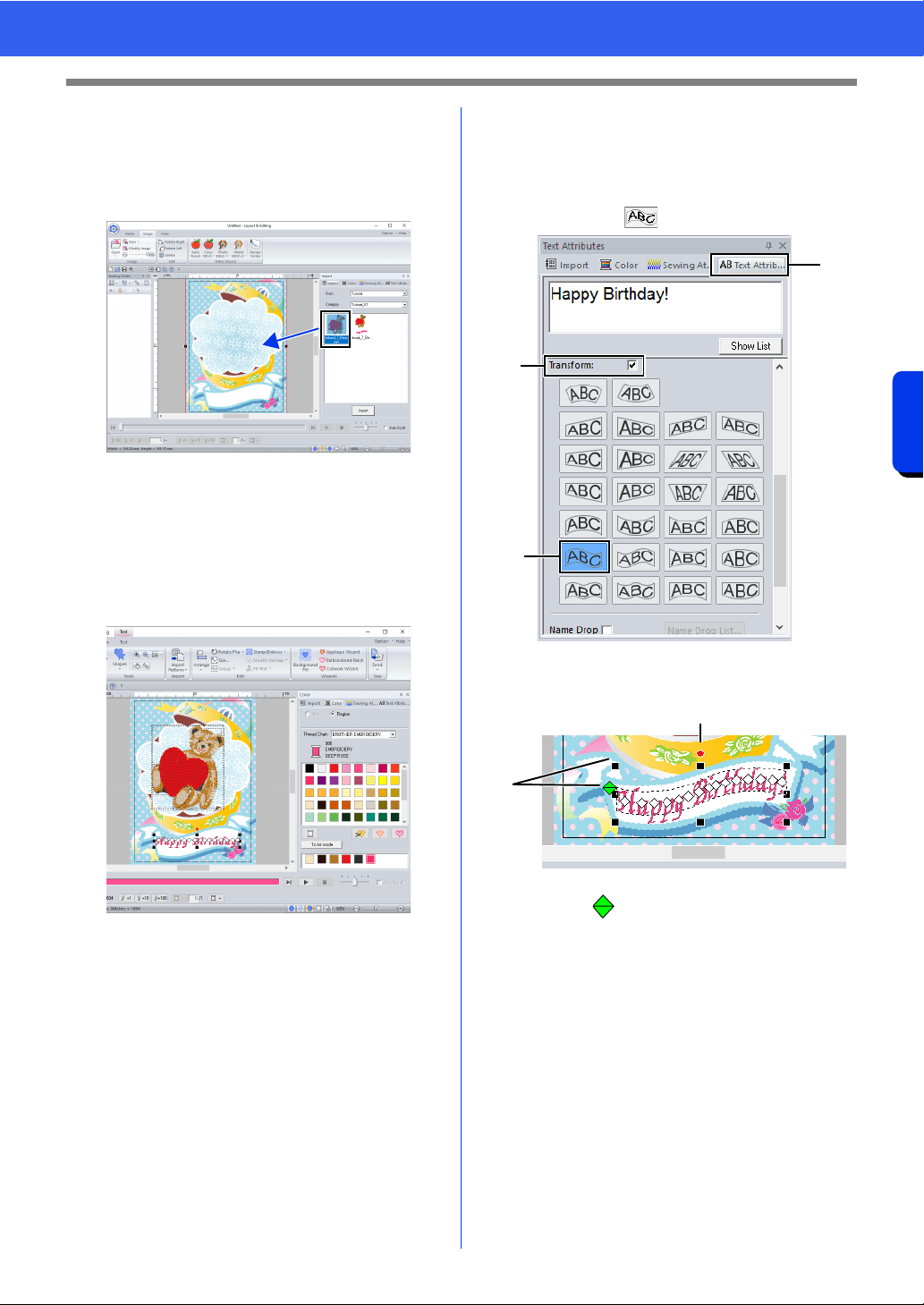
168
Creating Embroidery Patterns Using Images
Tutorial 7: Print and Stitch
6 Import the file [tutorial_7_Bear.pes].
Select [Tutorial] from the [From] selector and
[Tutorial_07] from the [Category] selector.
Drag [tutorial_7_Bear.pes] to the Design
Page.
cc "Importing embroidery designs" on
page 102
7 Enter the text.
Select built-in font [No. 30], and thread color
[DEEP ROSE].
Type in "Happy Birthday!".
cc "Entering text" on page 117
8 Transform the text to fit with the design of the
image.
a Click [Text Attributes] tab.
b Select the [Transform] check box, and
then click .
c Drag the rotation handle to adjust the
angle of the pattern.
d Drag or a handle to adjust the size of
the pattern.
cc "Transforming text" on page 122 and
"Rotating patterns" on page 41
9 After the design is finished, save the
embroidery data onto media so it can be
transferred to the embroidery machine.
cc For details on saving embroidery
patterns, refer to "Saving" on page 107.
For details on transferring designs to an
embroidery machine, refer to
"Transferring Embroidery Designs to
Machines" on page 222.
a
b
b
c
d
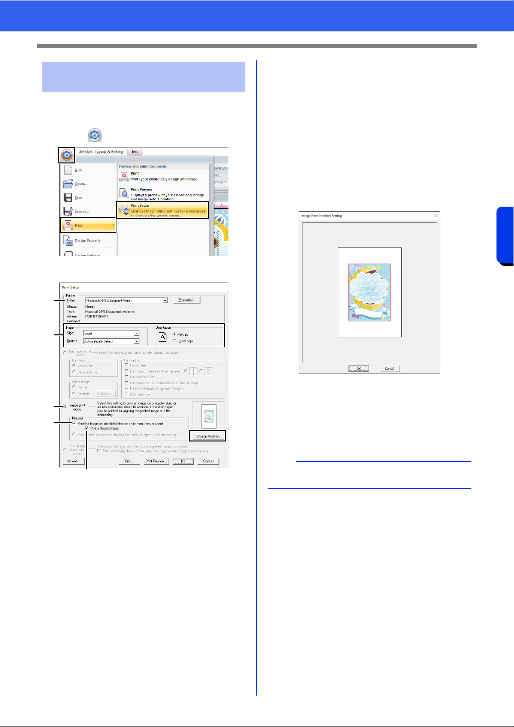
169
Creating Embroidery Patterns Using Images
Tutorial 7: Print and Stitch
Print the background image on an iron-on transfer
sheet or printable fabric.
1 Click , then [Print], then [Print Setup].
2 Specify the print settings.
a Select the printer to be used.
b Under [Paper] and [Orientation], select
the appropriate settings for the iron-on
transfer sheet or printable fabric to be
printed on.
c Select [Image print mode].
d Select [Print the image on printable
fabric or an iron-on transfer sheet].
e To print a flipped image on an iron-on
transfer sheet, select the [Print a flipped
image] check box.
Some printers will automatically print an
image flipped if an iron-on transfer sheet
is selected as the paper. If this type of
printer is being used, clear the [Print a
flipped image] check box.
For details, refer to the instructions for the
printer being used.
3 Click [Change Position].
4 Check the image position.
If any part of the image extends out of the print
area, drag the image to adjust its position.
5 Click [OK].
6 Click [Print].
Step 2 Printing the background
image
a
b
c
d
e
b
To check the print image, click [Print Preview].
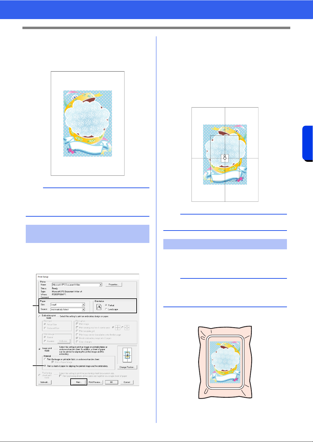
170
Creating Embroidery Patterns Using Images
Tutorial 7: Print and Stitch
7 Specify the appropriate settings in the [Print
Setup] dialog box, and then click [OK].
cc "Printing" on page 108.
Printing begins.
Print a sheet for aligning the image and the
embroidery.
1 Specify the print settings.
a Under [Paper] and [Orientation], select
the appropriate settings for the paper to
be printed on.
b Select [Print a sheet of paper for
aligning the printed image and the
embroidery].
2 Click [Print].
3 Specify the appropriate settings in the [Print
Setup] dialog box, and then click [OK].
cc "Printing" on page 108.
Printing begins.
1 If an iron-on transfer sheet is used, transfer
the image onto fabric.
2 Hoop the fabric in the embroidery frame.
b
For details on printing on iron-on transfer sheets or
printable fabric, refer to the instructions for the
iron-on transfer sheets and printable fabric.
Step 3 Printing the positioning
sheet
a
b
b
To check the print image, click [Print Preview].
Step 4 Embroidering
b
For details on transferring from iron-on transfer
sheets, refer to the instructions for the iron-on
transfer sheets.
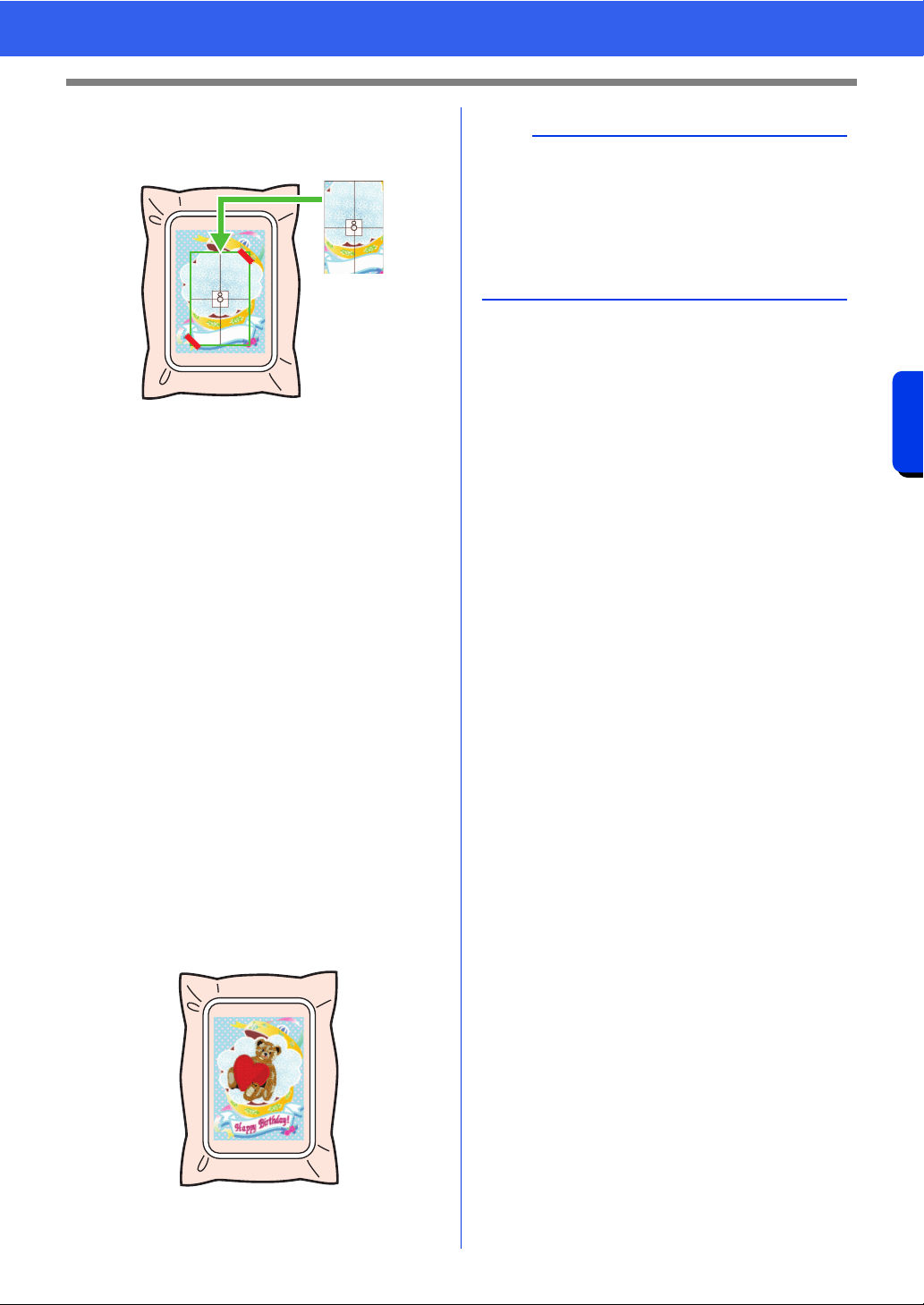
171
Creating Embroidery Patterns Using Images
Tutorial 7: Print and Stitch
3 Place the positioning sheet on the fabric to be
embroidered so that it is aligned with the
printed image.
• If the positioning sheet is too large, cut it to
an appropriate size so it can easily be used
for aligning the positions.
• Tape the positioning sheet to the fabric to
secure it in place.
4 Attach the embroidery frame to the
embroidery machine.
Be sure that the positioning sheet does not
move out of place.
5 Align the needle with the mark at the center of
the positioning sheet.
• If the embroidery machine has a built-in
camera, press the start positioning button
to detect the positioning mark and
automatically align the embroidering
position.
• With other embroidery machines, manually
align the positions.
6 After positioning is finished, remove the
positioning sheet from the fabric.
7 Start the embroidery machine to embroider
the pattern.
b
• For details on using the embroidery machine,
refer to the instruction manual included with the
machine.
• Some patterns of completed samples for "Print
and Stitch" are provided in the following folder.
Documents (My documents)\PE-DESIGN
11\Sample\Layout & Editing\Print and Stitch

Operations for Specific Applications
This section describes operations for creating
embroidery patterns using manual punching and
for specific applications such as appliqués,
embroidered patches and large-sized embroidery
patterns.
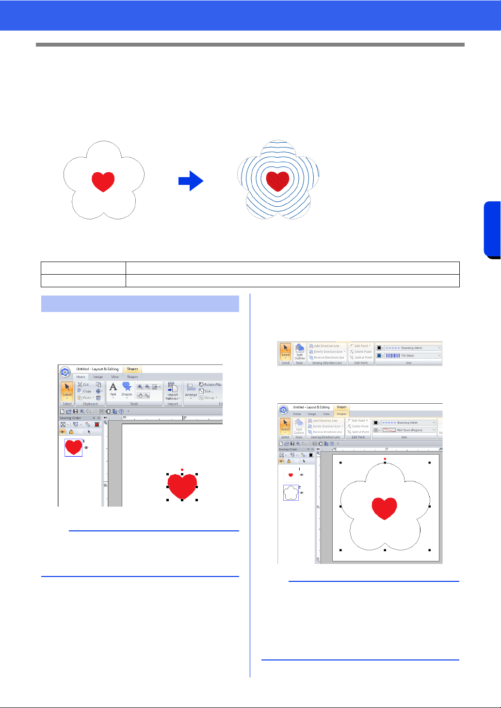
173
Operations for Specific Applications
Tutorial 8: Filling a specified area around a pattern with embroidery
Tutorial 8: Filling a specified area around
a pattern with embroidery
Use the Background Fill function to specify an area around a pattern and fill the area with embroidery.
For this example, we will create an echo quilting pattern.
The sample file for this tutorial is located at Documents (My documents)\PE-DESIGN 11\Tutorial\Tutorial_8.
1 Click the [Home] tab.
2 Draw the pattern that will be arranged at the
center.
3 Add a pattern around the first one to specify
the area to be filled.
For this example, select [BLACK] as the line
color and [BLUE] as the region color.
4 Select [Not Sewn (Region)] from the [Region
sew type] selector.
Step 1 Creating a pattern
Step 2 Adding a pattern to the background fill
Step 1 Creating a pattern
b
This feature can not be used if the pattern runs off
the Design Page. Be mindful of the placement of
the pattern.
b
• The thread color used to fill an area is the region
color that was specified last.
• Any region with no stitching can be specified in
the Design Page. Set the sew type for the
pattern that was added to specify the area to any
setting other than [Not Sewn].
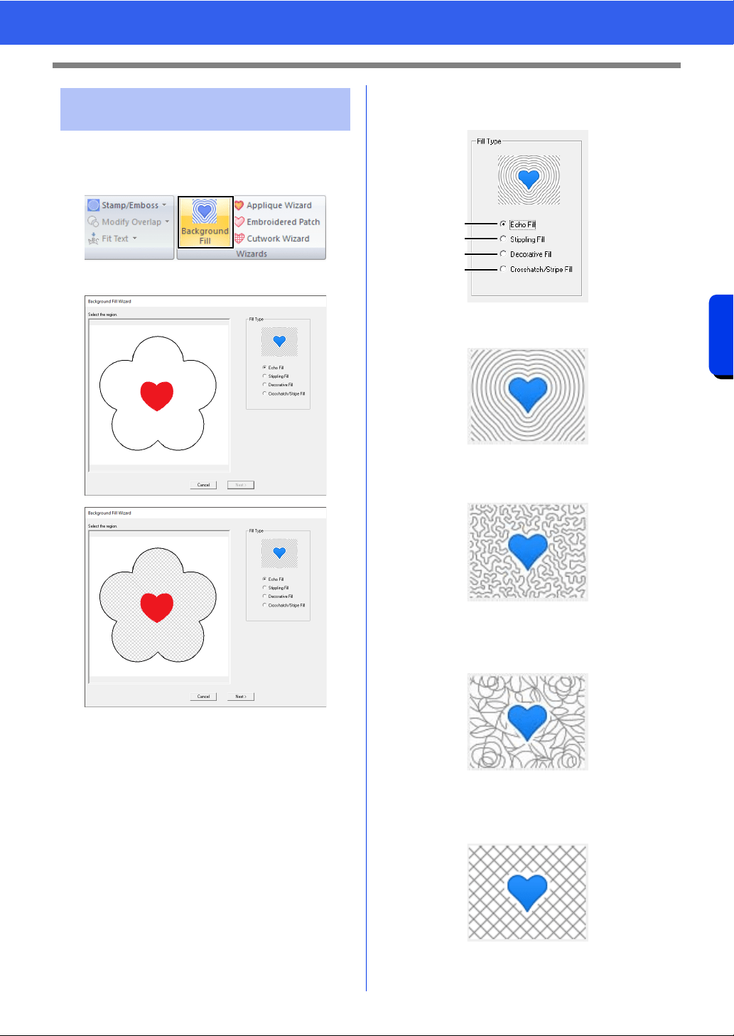
174
Operations for Specific Applications
Tutorial 8: Filling a specified area around a pattern with embroidery
1 Select all patterns.
2 Click [Background Fill] on the [Wizards] tab.
3 Click an area to select it.
4 Select [Echo Fill] under [Fill Type], and then
click [Next].
a Creates an echo quilting pattern to fill the
area.
b Creates a stippling pattern to fill the area.
cc "Stippling Fill" on page 177
c Creates a decorative fill pattern to fill the
area.
cc "Decorative Fill" on page 177
d Creates a crosshatch/stripe pattern to fill
the area.
cc "Crosshatch/Stripe Fill" on page 178
Step 2 Adding a pattern to the
background fill
a
b
c
d
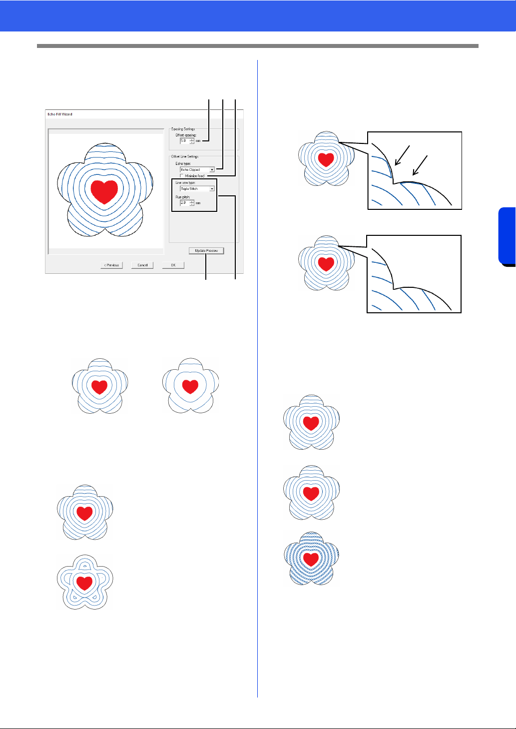
175
Operations for Specific Applications
Tutorial 8: Filling a specified area around a pattern with embroidery
5 Specify the settings for the background fill
pattern, and then click [OK].
a Specify the distance from the inner
pattern and the spacing between the echo
patterns.
For this example, set it to 5.0 mm.
b Select the type of echo quilting pattern.
For this example, select [Echo Clipped].
c Select this check box to link the ends of
the echo patterns.
This setting is available only when [Echo
Clipped] is selected for [Echo Type].
For this example, clear this check box.
d Specify the sew type and other sewing
attributes for the pattern.
For this example, select [Triple Stitch].
e Click to update the previewed image.
6 Click [OK].
7.0 mm 12.0 mm
Echo Clipped
The inner pattern is
enclosed by concentric
copies of its outline.
Echo
The area between the inner
and outer patterns is
enclosed with concentric
shapes formed from the
outlines of the two patterns.
e
d
b ca
Check box selected.
Check box cleared.
Running Stitch
Settings can be specified for
[Run pitch] and [Run
time(s)].
cc "Running Stitch" on
page 382
Triple Stitch
Settings can be specified for
[Run pitch].
cc "Triple Stitch" on
page 382
Chain Stitch
Settings can be specified for
[Stitch Type] and [Size].
cc "Chain Stitch" on
page 386
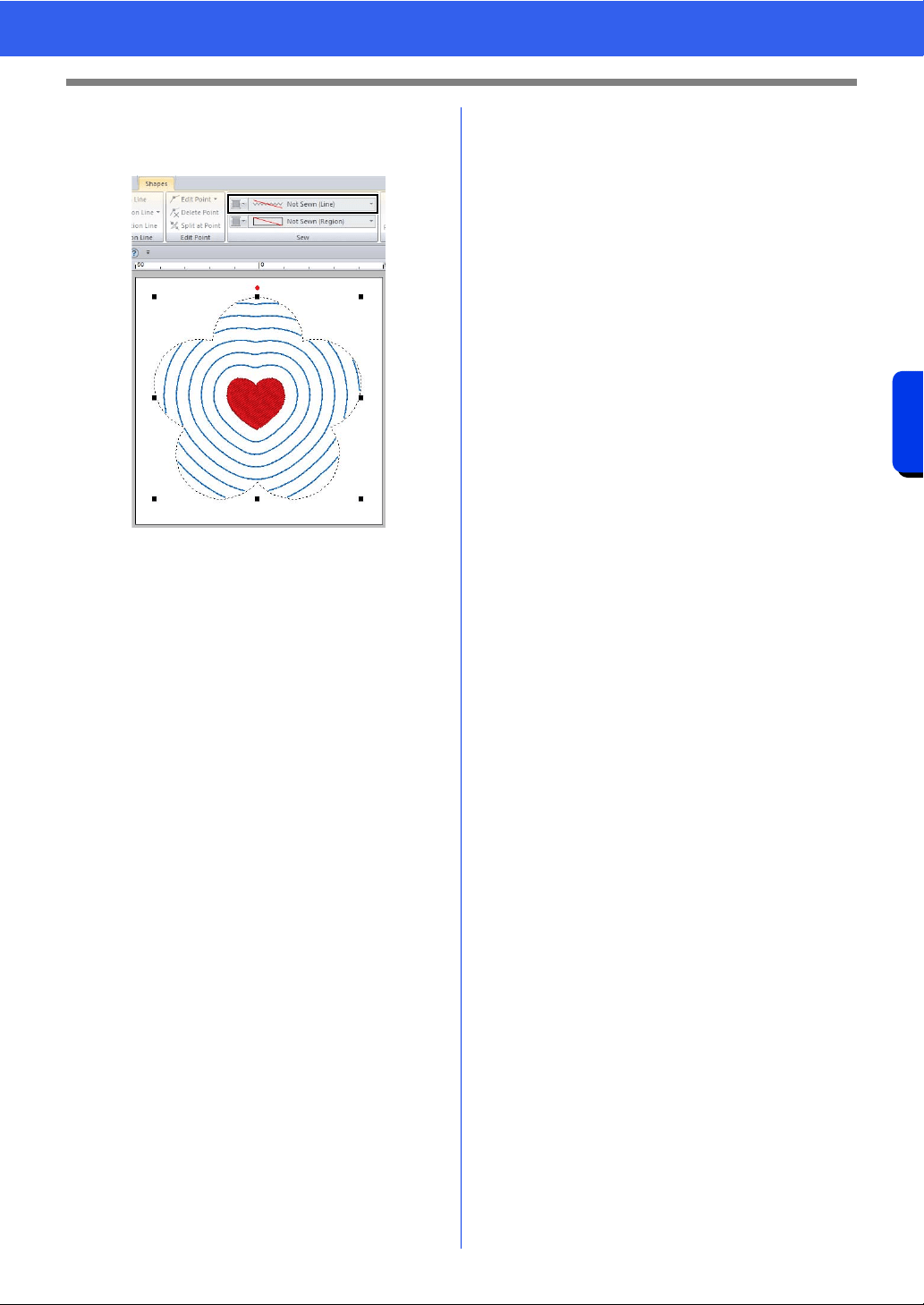
176
Operations for Specific Applications
Tutorial 8: Filling a specified area around a pattern with embroidery
7 Select the shape added in step 3 of “Creating
a pattern”, and then select [Not Sewn (Line)]
from the [Line sew type] selector.
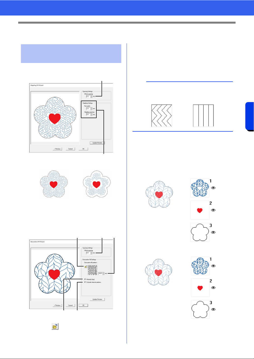
177
Operations for Specific Applications
Specify Settings for Background Fill
Specify Settings for Background Fill
■ Stippling Fill
a Specify the spacing between the patterns.
b Specify sewing attributes for the stippling.
cc "Stippling Stitch" on page 397
■ Decorative Fill
a Specify the spacing between the patterns.
b Click to select a decorative fill
pattern.
c Specify the size of the decorative fill
pattern.
d Select this check box to connect the
edges of objects with running stitches.
cc "Decorative Fill Stitch" on page 399
e Select this check box to not embroider the
part of the background overlapped by the
inner pattern.
Clear this check box to sew the created
stitching first, then sew the overlapping
pattern.
Specify settings for
background fill pattern
1.0 mm 7.0 mm
b
a
a cb
e
d
b
With patterns that are not connected at the top and
bottom or at the left and right as shown below,
select this check box to reduce the feed.
Check box selected.
Check box cleared.
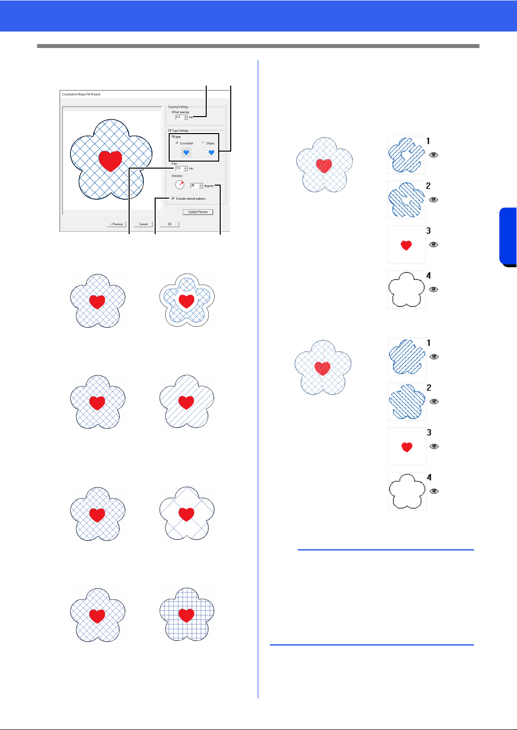
178
Operations for Specific Applications
Specify Settings for Background Fill
■ Crosshatch/Stripe Fill
a Specify the spacing between the patterns.
b Select the fill type.
c Specify the size of the pattern (or line
spacing).
d Specify the pattern angle.
e Select this check box to not embroider the
part of the background overlapped by the
inner pattern.
Clear this check box to sew the created
stitching first, then sew the overlapping
pattern.
0.0 mm 6.0 mm
Crosshatch Stripes
7.0 mm 30.0 mm
45° 90°
ab
c
e
d
Check box selected.
Check box cleared.
b
• This function is not available when the selected
embroidery frame has a width or height of less
than 100 mm.
• This function is not available when the selected
embroidery frame is a multi-position hoop.
• This function is not available if the [Name Drop]
attribute is applied to a part of the pattern.
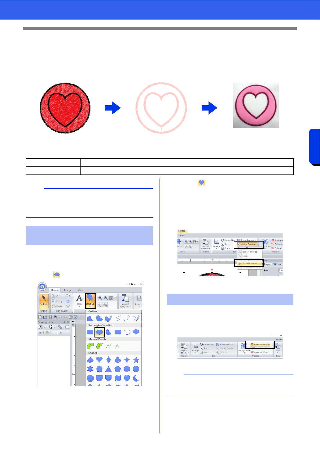
179
Operations for Specific Applications
Tutorial 9-1: Creating Appliqués
Tutorial 9-1: Creating Appliqués
The Applique Wizard provides instructions for easily creating appliqués. For this example, we will create an
appliqué that has holes (empty regions).
The sample file for this tutorial is located at Documents (My documents)\PE-DESIGN 11\Tutorial\Tutorial_9.
1 Click the [Home] tab.
2 Click [Shapes] in the [Tools] group, and then
click .
3 Drag the pointer in the Design Page to draw a
circle.
4 Select as described in steps 1 and 2, and
then drag the pointer in the Design Page to
draw a heart on top of the circle.
5 Select the two patterns, click [Modify
Overlap] in the [Edit] group, and then select
[Set hole sewing] to apply hole sewing.
cc "Hole sewing" on page 47
1 Select the outer pattern, and then click
[Applique Wizard] in [Home] tab to start the
[Applique Wizard] dialog box.
Step 1 Creating an appliqué pattern
Step 2 Using the Applique Wizard
b
The Applique Wizard cannot be used if a pattern
containing text with the [Name Drop] attribute
applied is selected.
Step 1 Creating an appliqué
pattern
Step 2 Using the Applique Wizard
b
Be sure to select the outer pattern before starting
the [Applique Wizard].
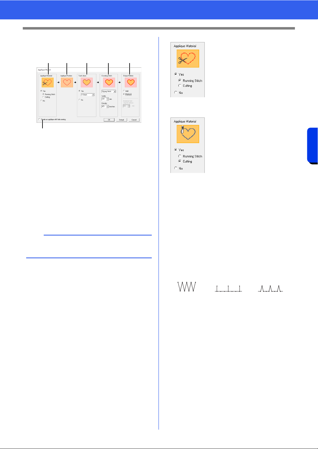
180
Operations for Specific Applications
Tutorial 9-1: Creating Appliqués
2 Specify settings in the [Applique Wizard]
dialog box in the following order
a - f.
a Applique Material
b Applique Position
c Tack down
d Covering Stitch
e Output Pattern
f Create an applique with hole sewing
This check box appears when using a
pattern with hole sewing applied and
[Replace] is selected under [Output
Pattern].
3 Specify cutting lines for the appliqué in
[Applique Material].
The outline of the appliqué can be sewn as
running stitches or the appliqué can be cut out,
or it can be neither sewn nor cut out.
For this example, select [Yes] then
[Cutting].
4 [Applique Position] is specified
automatically.
The guideline for attaching the appliqué
piece is set to be sewn automatically.
5 Specify basting of the appliqué in [Tack
down].
The appliqué piece can be basted onto the
base fabric. Select one of three stitches.
For this example, select [Yes] then [V
Stitch].
b
To return all parameters to their default settings,
click [Default].
ab c d e
f
Running Stitch
Select this setting to sew the
cutting line, then cut along
the cutting line with scissors.
Cutting
In order for this setting to be
available
cc "Basic requirements for
Cutwork functions" on
page 191
Select this setting to cut the
fabric with a machine
installed with cutwork
needles.
Zigzag Stitch E Stitch V Stitch
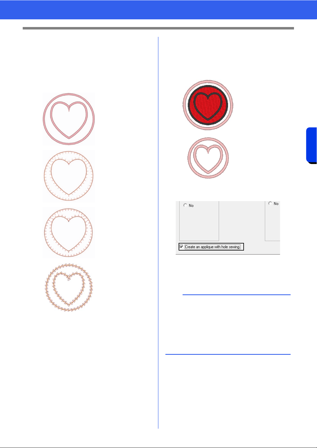
181
Operations for Specific Applications
Tutorial 9-1: Creating Appliqués
6 Specify the stitching for securing the appliqué
in [Covering Stitch]. Select the sew type and
other attributes ([Width] and [Density]) for
finishing the appliqué.
For this example, select "Zigzag Stitch",
and then set [Width] to "3.0 mm" and
[Density] to "5.0 line/mm".
cc For details on setting [Stroke], [Interval]
and [Pitch], refer to"E/V Stitch" on
page 385
cc For details on setting [Stitch Type],
[Size] and [Time], refer to "Chain Stitch"
on page 386.
7 Under [Output Pattern], select whether
covering stitches will be added around the
entire pattern ([Add]) or covering stitches will
be sewn for shape lines ([Replace]).
For this example, select [Replace].
8 Specify hole sewing in [Create an applique
with hole sewing].
Select this check box when creating an
appliqué with holes (empty regions).
For this example, select this check box.
Zigzag Stitch
Settings can be
specified for [Width]
and [Density].
E Stitch
Settings can be
specified for
[Stroke], [Interval]
and [Pitch].
V Stitch
Settings can be
specified for
[Stroke], [Interval]
and [Pitch].
Chain Stitch
Settings can be
specified for [Stitch
Type], [Size] and
[Time].
Add
Settings can be
specified for
[Distance from
original Pattern].
Replace
b
This check box appears when only the outer
pattern with hole sewing applied or only a text
pattern (with fonts other than built-in fonts 025 and
029, a user-defined font or a Small Text font) is
selected, or when [Replace] is selected under
[Output Pattern].
* Multiple text patterns can be selected if certain
conditions are met.
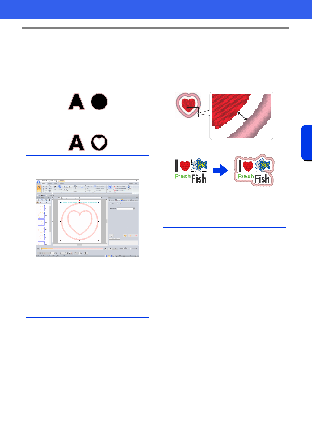
182
Operations for Specific Applications
Tutorial 9-1: Creating Appliqués
9 Click [OK] to exit the Applique Wizard dialog
box.
■ About the Output Pattern settings
Add
• Covering stitches will be created around the
original pattern.
• Under [Distance from original Pattern], specify
the distance of the covering stitches from the
original pattern.
• This can be used to combine various patterns.
Replace
• Covering stitches will be sewn for outlines in the
original pattern.
• The original pattern will be deleted.
• Shape and text patterns can be used as the
original pattern. However, the following patterns
cannot be used.
- Open lines
- Closed lines that are intersecting
- Text created with built-in fonts 025 and 029,
an user-defined font or a Small Text font
- Original patterns containing both a shape
pattern and a text pattern
b
The shape of the appliqué material appears as
shown below, depending on whether the [Create
an applique with hole sewing] check box is
selected or not.
When the [Create an applique with hole sewing]
check box is cleared
When the [Create an applique with hole sewing]
check box is selected
b
When [Cutting] is selected under [Applique
Material]:
• Uncut sections will remain in cutting lines
specified with the Applique Wizard. Be sure to
cut them with scissors after embroidering is
finished.
a
The [Add] setting is not available if the stitch
pattern does not exist, for example, when both the
line and region sew types are set to [Not Sewn].
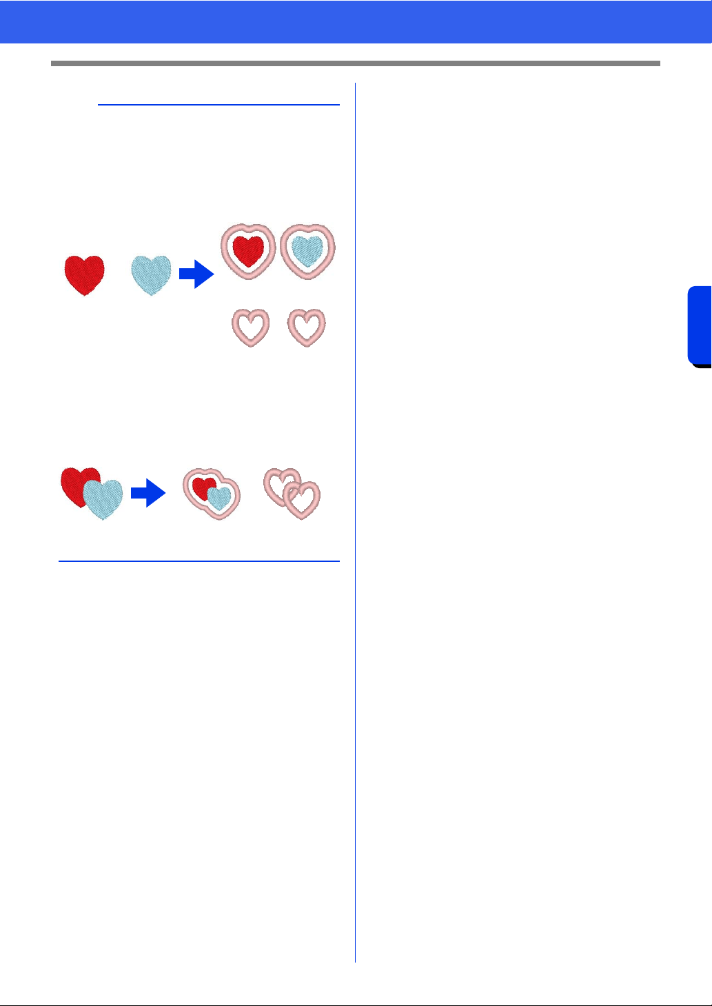
183
Operations for Specific Applications
Tutorial 9-1: Creating Appliqués
b
When multiple patterns are selected, covering
stitches will be created as shown below.
• If the patterns do not overlap
Covering stitches will be created for each
pattern.
1 Add
2 Replace
• If the patterns overlap
With the [Add] setting, covering stitches will be
created for an outline around all patterns.
1 Add
2 Replace
1
2
1
2
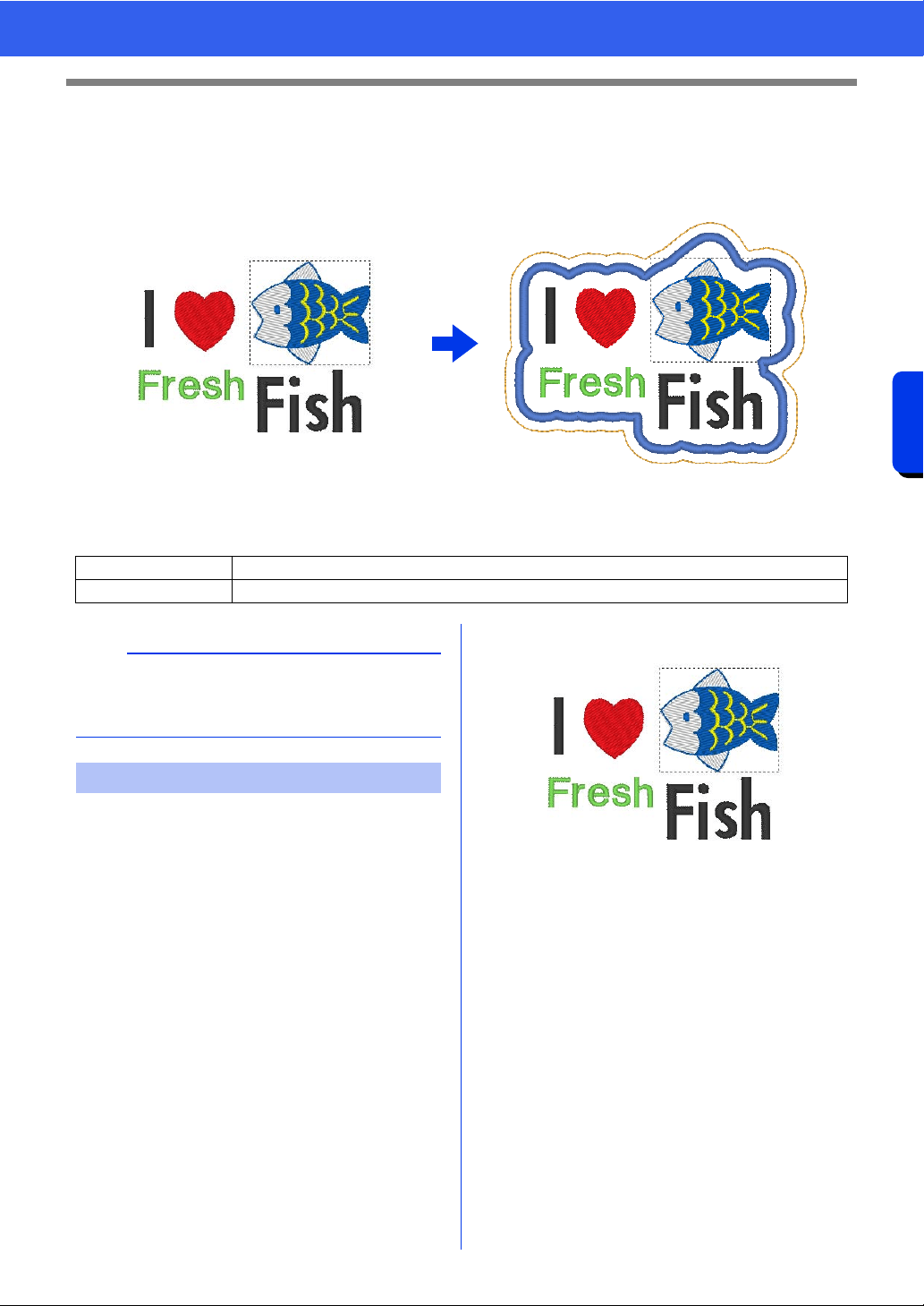
184
Operations for Specific Applications
Tutorial 9-2: Creating Embroidered Patches
Tutorial 9-2: Creating Embroidered
Patches
The Embroidered Patch Wizard provides instructions for easily creating embroidered patches.
The sample file for this tutorial is located at Documents (My documents)\PE-DESIGN 11\Tutorial\Tutorial_9.
1 Select the appropriate [Shapes] tool, and
then draw a heart.
cc "Drawing various shape" on page 72.
2 Import the fish pattern from the [Aquatic]
category of the Design Library.
cc "From Design Library" on page 102.
3 Select the [Text] tool, and then type in "I",
"Fresh" and "Fish".
cc "Entering text" on page 117.
4 Drag each pattern to arrange them so that
they are well balanced.
Step 1 Creating the patch pattern
Step 2 Using the Embroidered Patch Wizard
b
The Embroidered Patch Wizard cannot be used if
a pattern containing text with the [Name Drop]
attribute applied is selected.
Step 1 Creating the patch pattern
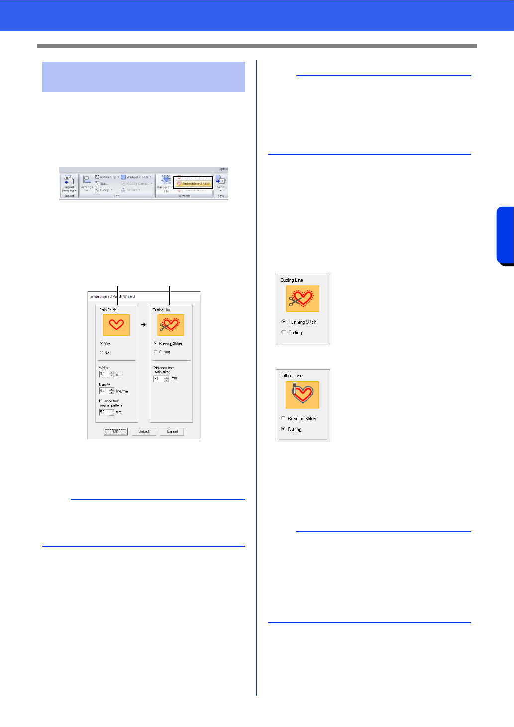
185
Operations for Specific Applications
Tutorial 9-2: Creating Embroidered Patches
1 Select all patterns, and then click the [Home]
tab.
2 Click [Embroidered Patch] in the [Wizards]
group to start the [Embroidered Patch
Wizard].
3 Specify settings in the [Embroidered Patch
Wizard] dialog box in the following order
a -
b .
a Satin Stitch
b Cutting Line
4 Under [Satin Stitch], specify a border for the
embroidered patch.
For this example, select [Yes], and then set
[Width] to "3.0 mm", [Density] to "4.5 line/
mm" and [Distance from original Pattern]
to "5.0 mm".
5 Under [Cutting Line], specify the cutting lines
for the embroidered patch.
The cutting line of the embroidered patch can
be sewn as running stitches or the
embroidered patch can be cut out.
For this example, select [Running Stitch],
and then set [Distance from satin stitch]
to "3.0 mm".
6 Click [OK] to exit the [Embroidered Patch
Wizard] dialog box.
Step 2 Using the Embroidered
Patch Wizard
b
To return all parameters in the [Embroidered
Patch Wizard] to their default settings, click
[Default].
ab
a
• [Width], [Density] and [Distance from original
Pattern] will be available if [Yes] has been
selected.
•Use [Distance from original Pattern] to specify
the distance between the original pattern and
the border.
Running Stitch
Select this setting to sew the
cutting line, then cut along
the cutting line with scissors.
Cutting
In order for this setting to be
available
cc "Basic requirements for
Cutwork functions" on
page 191
Select this setting to cut the
fabric with a machine
installed with cutwork
needles.
b
• When [Cutting] is selected under [Cutting
Line], uncut sections will remain in the cutting
lines created with the Embroidered Patch
Wizard. Be sure to cut them with scissors after
embroidering is finished.
• The thread color of the satin stitching is the color
currently specified in the Design Page.
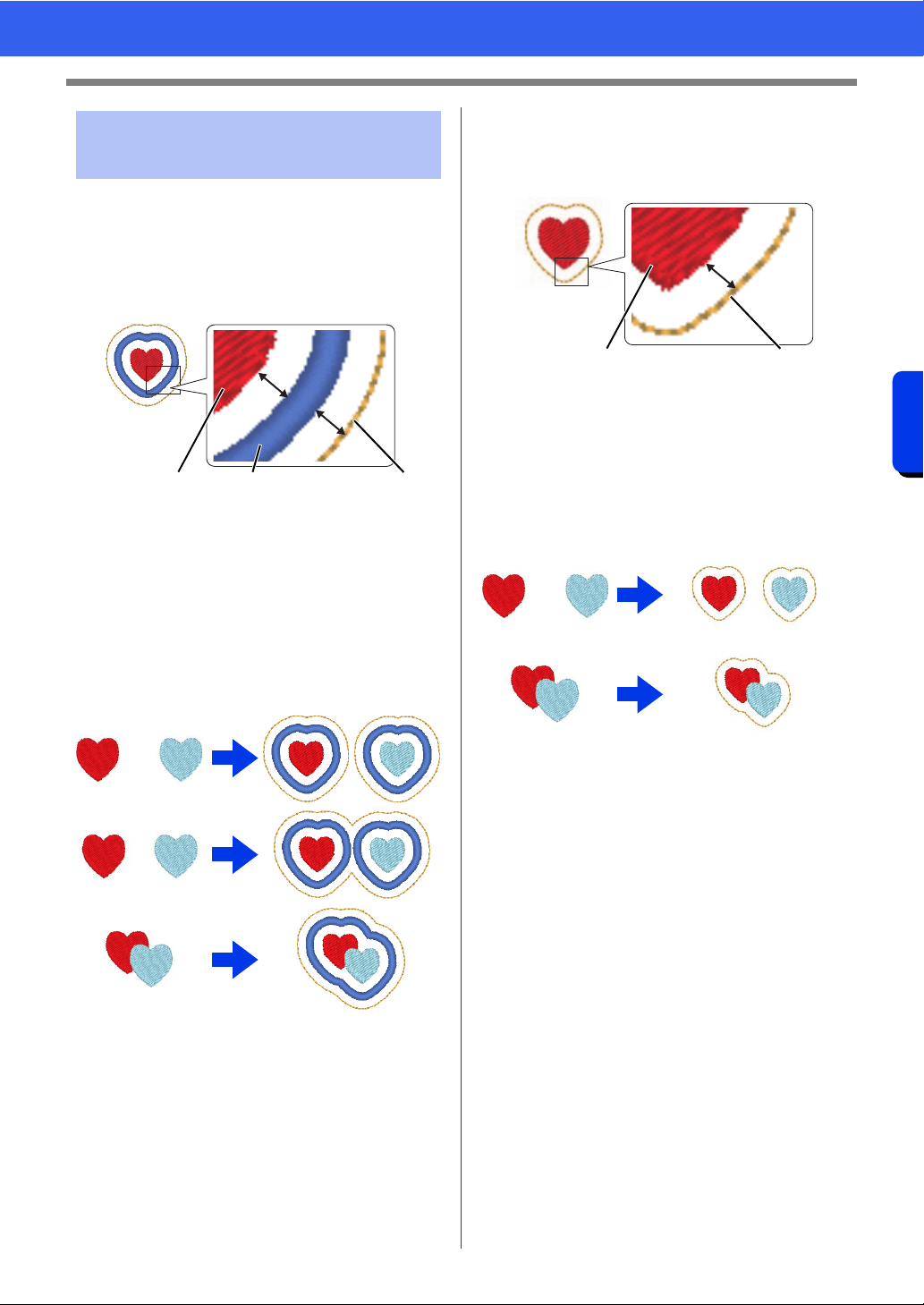
186
Operations for Specific Applications
Tutorial 9-2: Creating Embroidered Patches
When [Satin Stitch] is set to [Yes]
The distance between the patch pattern and the
satin stitches is specified under [Distance from
original Pattern], and the distance between the
satin stitches and the cutting line is specified under
[Distance from satin stitch].
1 Patch pattern
2 Satin Stitch
3 Cutting Line
If multiple patterns are selected for the patch
pattern, the finished result differs depending on the
distances between the patterns as well as between
the patterns, satin stitches and cutting line in
addition to the width of the satin stitches.
When [Satin Stitch] is set to [No]
The distance between the patch pattern and the
cutting line is specified under [Distance from
original Pattern].
1 Patch pattern
2 Cutting Line
If multiple patterns are selected for the patch
pattern, the finished result differs depending on the
distances between the patterns and between the
patterns and cutting line.
Practical use of Satin
Stitch and Cutting Line
12 3
1
2
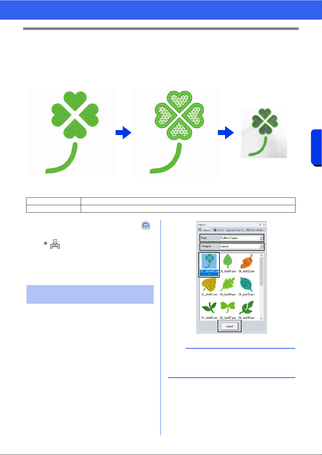
187
Operations for Specific Applications
Tutorial 9-3: Creating a Cutwork Pattern Filled with Net Stitching
Tutorial 9-3: Creating a Cutwork Pattern
Filled with Net Stitching
Cutwork patterns, combining embroidery and cutting with cutwork needles, can be created using the extended
functions. By using the [Cutwork Wizard], a cutwork pattern can easily be created.
The sample file for this tutorial is located at Documents (My documents)\PE-DESIGN 11\Tutorial\Tutorial_9.
For the cutwork functions to be available, click ,
then [Design Settings]. Under [Machine Type],
select .
When the cutwork functions are not being used, it is
not necessary to select this setting.
cc "Specifying the Design Page Settings" on
page 16
1 Display the [Import] pane.
2 Select [Outline Shapes] from the [From]
selector, select [Leaves] from the [Category]
selector, select [OL_clover01.pes], and then
click [Import].
Step 1 Creating an outline shape for cutwork
Step 2 Using the Cutwork Wizard
Step 1 Creating an outline shape
for cutwork
b
Patterns in [Outline Shapes] from the [From]
selector are appropriate for creating the cutwork
patterns.
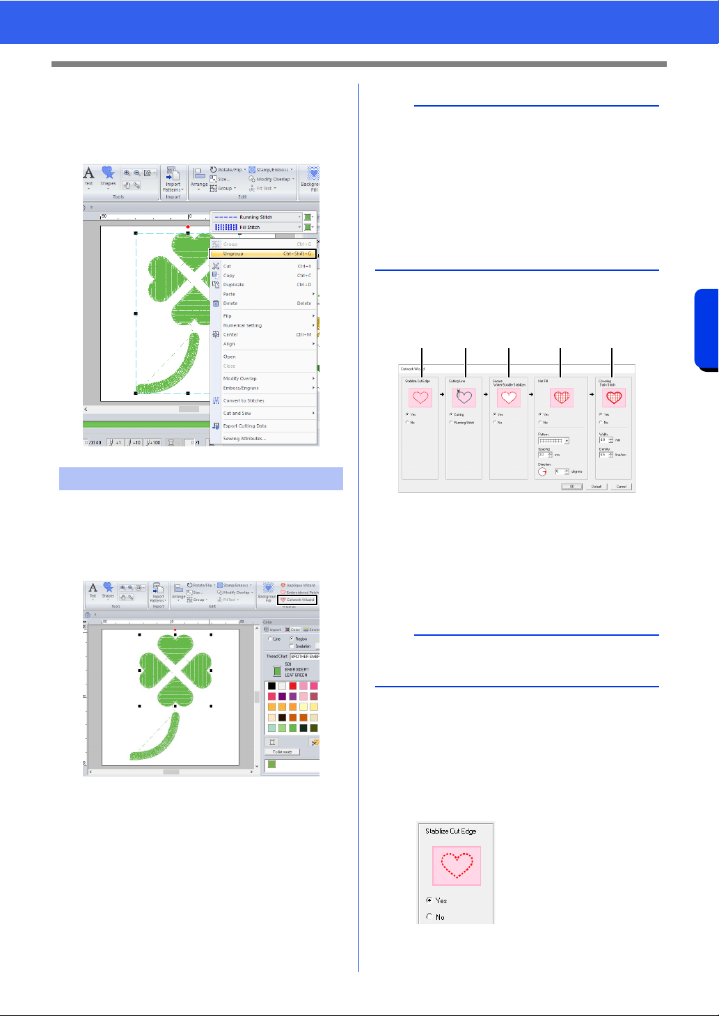
188
Operations for Specific Applications
Tutorial 9-3: Creating a Cutwork Pattern Filled with Net Stitching
3 Enlarge the pattern imported into the Design
Page.
4 Ungroup the pattern. Select the pattern,
right-click it, and then click [Ungroup].
1 Select the four leaves, and then click the
[Home] tab.
2 Click [Cutwork Wizard] in the [Wizards]
group to start the [Cutwork Wizard].
3 Specify settings in the [Cutwork Wizard] in
the following order
a - e.
a Stabilize Cut Edge
b Cutting Line
c Secure Water-Soluble Stabilizer
d Net Fill
e Covering Satin Stitch
4 Specify running stitching along the edge
before cutting in [Stabilize Cut Edge].
By specifying that running stitches be sewn
before the fabric is cut, the cut edges are
reinforced, preventing them from unraveling.
For this example, select [Yes].
Step 2 Using the Cutwork Wizard
b
•The [Cutwork Wizard] can also be used if
closed shape patterns or text patterns are
selected.
• If a line of the pattern crosses itself, the
[Cutwork Wizard] will not be available.
• Text with built-in font 025 or 029 or a user-
defined font cannot be used.
• Shape patterns and text patterns cannot be
combined.
b
To return all parameters to their default settings,
click [Default].
a b c d e
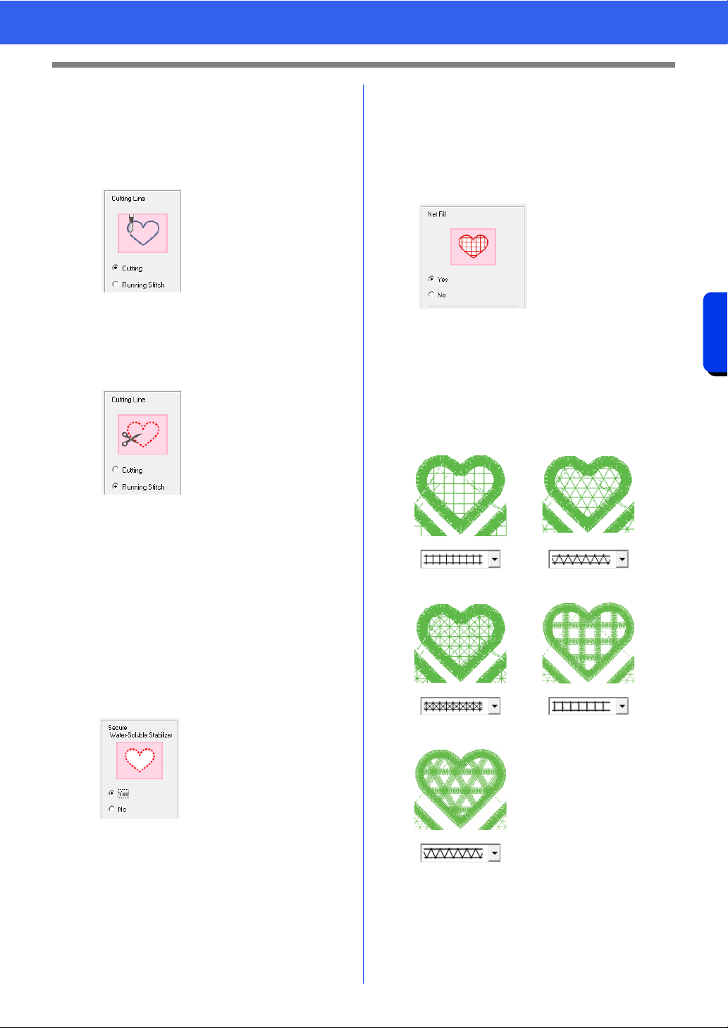
189
Operations for Specific Applications
Tutorial 9-3: Creating a Cutwork Pattern Filled with Net Stitching
5 Specify cutting line type in [Cutting Line].
Select whether the fabric will be cut along the
cutting line or whether the cutting line will
remain as running stitches.
For this example, select [Cutting].
6 Specify securing of the water-soluble
stabilizer in [Secure Water-Soluble
Stabilizer].
Running stitches will be sewn to secure the
water-soluble stabilizer after the fabric has
been cut. In order to prevent embroidery from
losing its shape after it has been cut, place
water-soluble stabilizer in the cutout areas
and sew it in place.
For this example, select [Yes].
7 Specify net fill stitching inside the cutout areas
in [Net Fill].
By sewing net fill stitching in cutouts, inner
cutouts can be reinforced while allowing for a
greater design variety.
For this example, select [Yes].
Select the parameters according to the
procedure from step 8 to 10, when [Net Fill]
is set to [Yes].
8 Specify the net fill stitch pattern in [Pattern].
Five net fill stitch patterns are available.
For this example, select [Pattern 2].
Cutting
In order for this setting
to be available
cc "Basic
requirements for
Cutwork
functions" on
page 191
Select this setting to
cut the fabric with a
machine installed with
cutwork needles.
Running Stitch
Select this setting to
sew the cutting line,
then cut along the
cutting line with
scissors.
Pattern 1 Pattern 2
Pattern 3 Pattern 4
Pattern 5
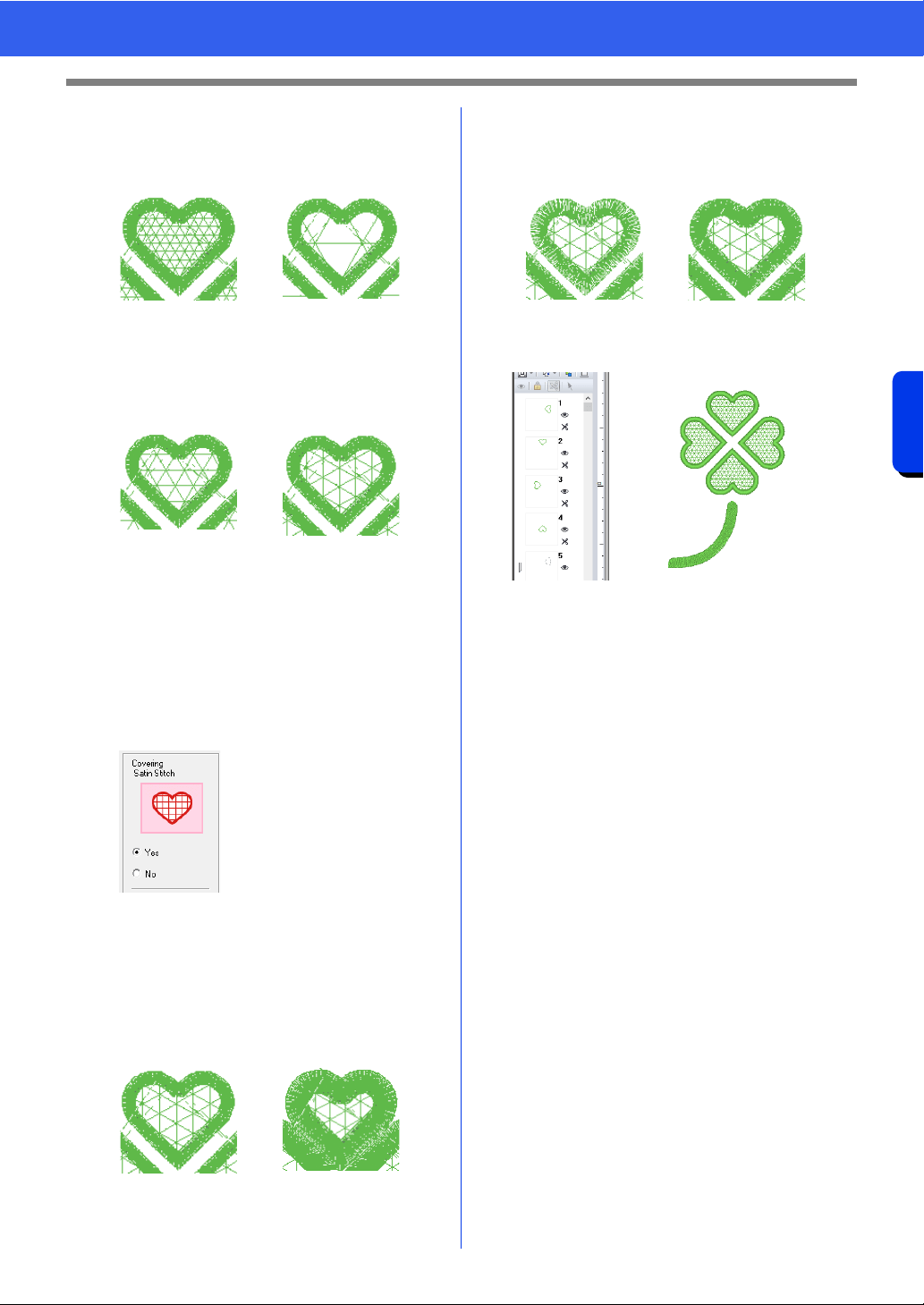
190
Operations for Specific Applications
Tutorial 9-3: Creating a Cutwork Pattern Filled with Net Stitching
9 Specify the pattern spacing for the net fill stitch
in [Spacing].
For this example, set it to [3.0 mm].
10 Specify the pattern direction of the net fill stitch
in [Direction].
For this example, set it to [0°].
11 Specify satin stitching after cutting in
[Covering Satin Stitch].
Satin stitching is sewn along the edges of
inner cutouts.
The zigzag stitch or the stem stitch is used as
an underlay for the satin stitching.
For this example, select [Yes].
Select the parameters according to the
procedure from step
12 to 13, when
[Covering Satin Stitch] is set to [Yes].
12 Specify the width of the satin stitching in
[Width].
For this example, set it to [4.0 mm].
13 Specify the density of the satin stitching in
[Density].
For this example, set it to [6.5 line/mm].
14 Click [OK] to exit the [Cutwork Wizard].
2.0 mm 10.0 mm
0° 90°
3.0 mm 6.0 mm
5.0 line/mm 7.0 line/mm
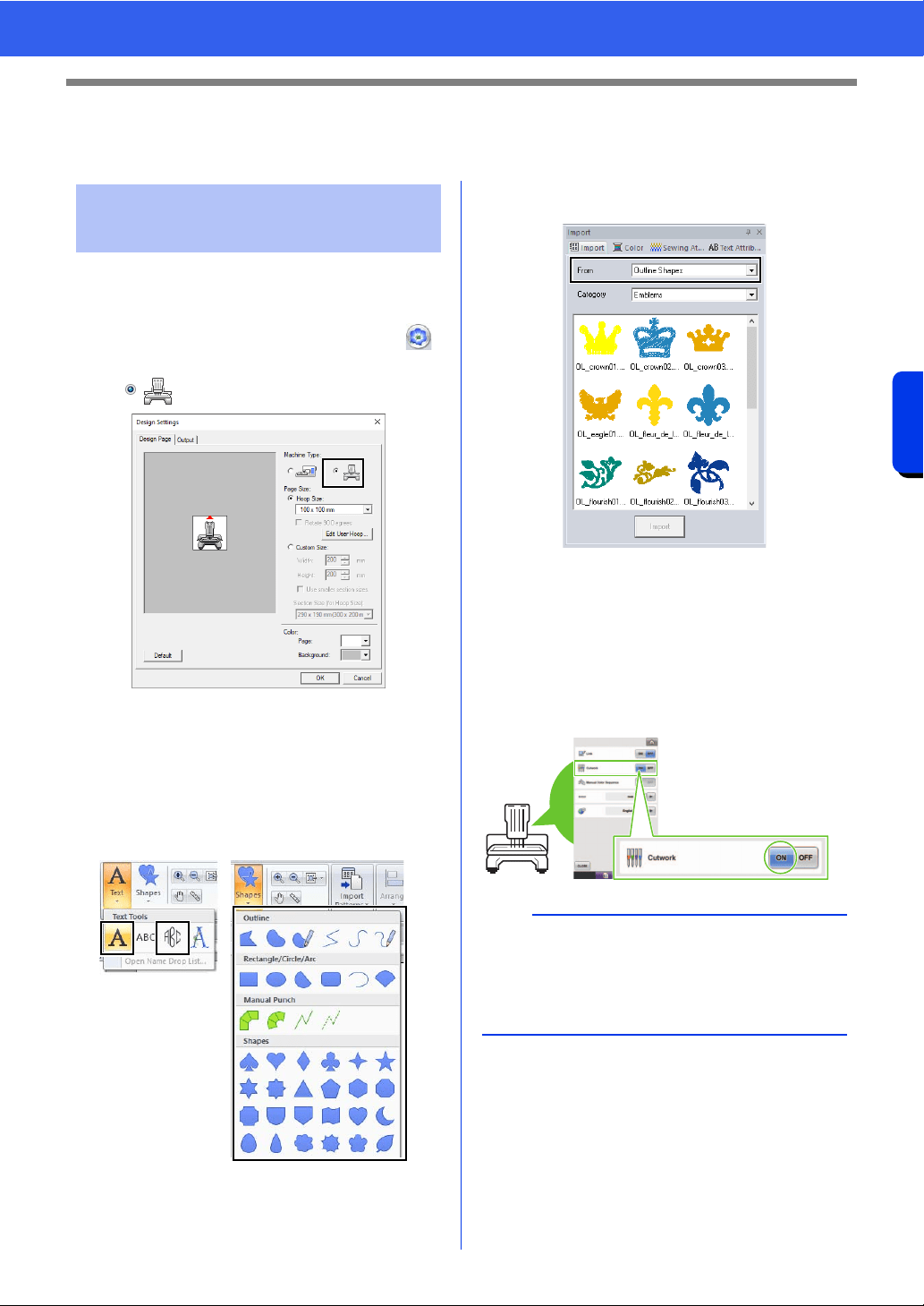
191
Operations for Specific Applications
On Using the Cutwork Functions
On Using the Cutwork Functions
Before using Cutwork functions, check the following.
■ Set the "Machine Type" to multi-
needle embroidery machine
For the Cutwork functions to be available, click ,
then [Design Settings]. Under [Machine Type],
select .
■ Outline shapes and text can be
used to create a cutwork pattern
• Outline shapes that have been drawn with the
tools indicated below.
• Text created in fonts other than built-in fonts 025
and 029, a user-defined font or a small text font.
• Patterns when [Outline Shapes] is selected in
the [From] selector of the [Import] pane.
■ Use a multi-needle machine that
has been upgraded to work with
Cutwork functions
The embroidery machine should be set to cutwork
mode in the settings screen before starting to
embroider. Refer to the included instruction manual
for the details of embroidery machine operation.
Basic requirements for
Cutwork functions
a
Cutwork functions cannot be used with single-
needle embroidery machines. In addition, some
multi-needle machines may not support the
functions. Be sure to check that your machine is
compatible with the cutwork functions.
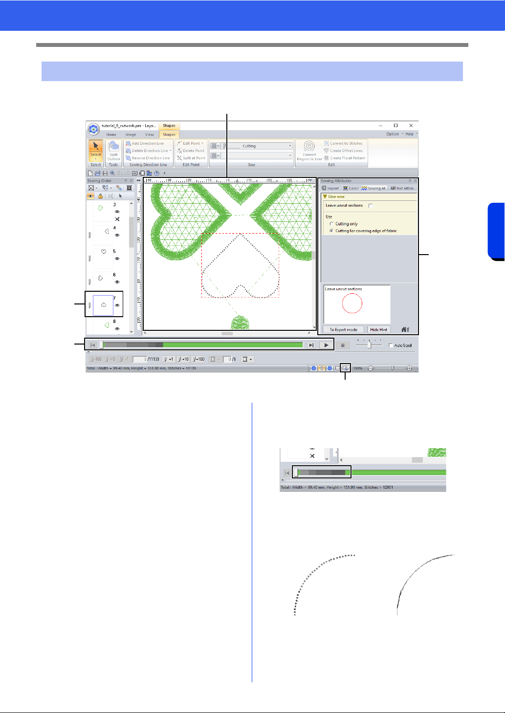
192
Operations for Specific Applications
On Using the Cutwork Functions
The settings and window areas specifically for cutwork functions are described below.
a Sewing Order
The cutting lines appear in one frame in
the [Sewing Order] pane, and the icon
for the cutwork needle appears beside the
frame.
b Design Page
The cutting lines appear as gray dotted
lines in the Design Page, regardless of
whether the [Solid View], [Stitch View]
or [Realistic View] is selected.
c Sewing Attributes
In the [Sewing Attributes] pane, detailed
cutting settings can be specified for the
cutwork functions.
cc "Cutting" in the "Line sewing attributes"
on page 386
d Previewing cutting lines
In the [Stitch Simulator] pane, the
cutwork needles are displayed in four
different shades of gray.
In a stitch simulation, the cutting lines appear as
short gray lines, indicating the needle drop
points for making the cuts.
Layout & Editing window for cutwork patterns
c
a
d
b
e
While being edited In a stitch simulation
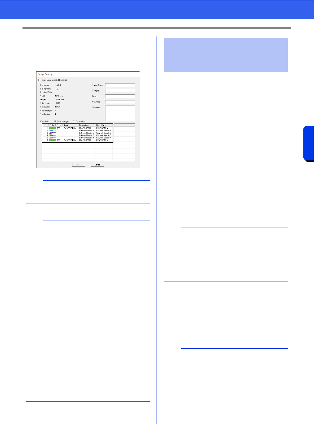
193
Operations for Specific Applications
On Using the Cutwork Functions
e Checking Design Property
When [Cutting] has been assigned to a
line from the [Line sew type] selector,
[Design Property] screen appears as
shown below.
In addition to transferring cutwork patterns to a
machine, they can be saved or printed.
■ Transferring
Transferring using USB media
By using commercially available USB media,
cutwork patterns can be transferred to embroidery
machines compatible with the USB media.
cc "Transferring to a machine by using USB
media" on page 222
Transferring directly to a machine's
memory
Cutwork patterns can be transferred to embroidery
machines that can be connected to a computer
using a USB cable.
cc "Transferring directly to a machine's
memory" on page 223
■ Saving
Saving cutwork patterns in the PES format
For details, refer to "Saving and Printing" on
page 107.
b
[Color order] can be also viewed in the [Design
Property] screen in the Design Database.
a
• In patterns with [Cutting] selected in the [Line
sew type] selector, the line color and region
sewing settings are not available.
• Designs containing the line sew type [Cutting]
are saved as cutwork patterns.
cc "Transferring/saving/exporting the cutwork
patterns" on page 193
• Created cutwork patterns can be used only with
embroidery machines upgraded for cutwork.
• With PE-DESIGN 11, the line sew type
[Cutting] changes to [Running Stitch] in the
following situations.
When the [Machine Type] setting (on the
[Design Page] tab of the [Design Settings]
dialog box) is changed from a multi-needle
embroidery machine to a single-needle
embroidery machine
When a cutwork pattern is imported while
[Machine Type] (on the [Design Page] tab) is
set to a single-needle embroidery machine
• Cutwork pattern cannot be transferred to a
machine by using an original card or the Link
function.
• Cutwork pattern cannot be created in Design
Center. To set the line sew type to [Cutting],
use Layout & Editing.
Transferring/saving/
exporting the cutwork
patterns
a
• Cutwork patterns cannot be transferred to a
machine by using an original card or the Link
function.
• The cutwork patterns can be transferred to
embroidery machine only after the upgrade for
cutwork has been installed and certified to the
machine.
a
Designs containing the line sew type [Cutting] are
saved as cutwork patterns.

194
Operations for Specific Applications
On Using the Cutwork Functions
■ Exporting
Exporting cutwork patterns in other
formats
Created cutwork patterns can be converted to other
formats (.dst, .hus, .exp, .pcs, .vip, .sew, .jef, .csd,
.xxx, and .shv) and outputted.
When exported as another format, the cutting lines
will be changed to a running stitch.
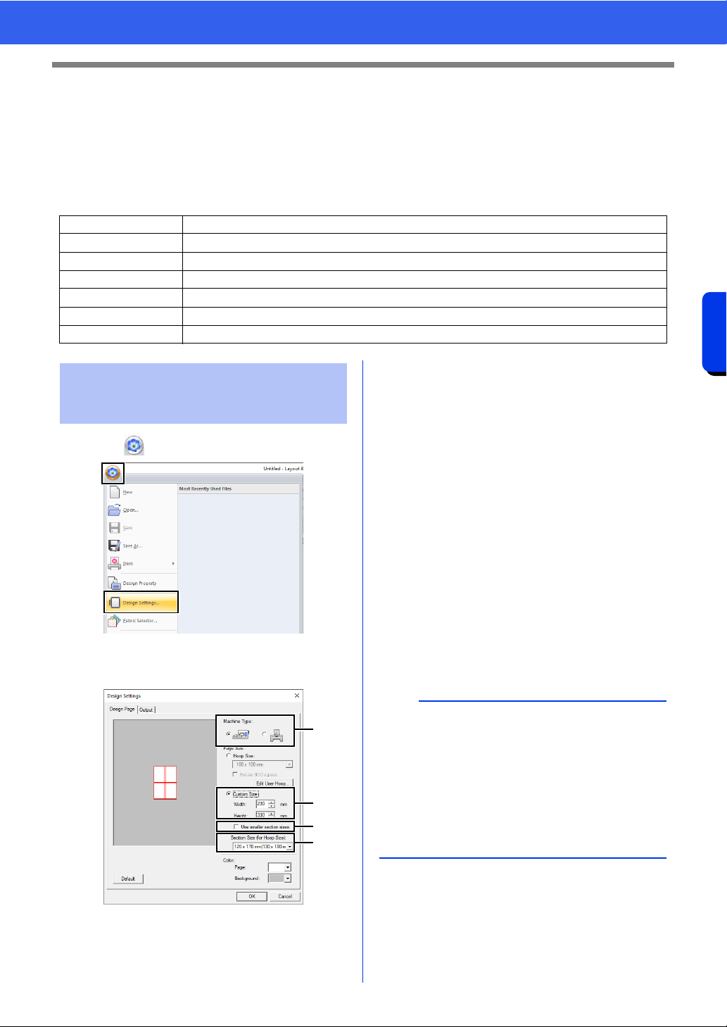
195
Operations for Specific Applications
Tutorial 10-1: Creating Split Embroidery Designs
Tutorial 10-1: Creating Split Embroidery
Designs
Layout & Editing has a function for creating split embroidery designs when the embroidery pattern being
created is larger than the embroidery hoop.
The sample file for this tutorial is located at Documents (My documents)\PE-DESIGN 11\Tutorial\Tutorial_10.
1 Click , then [Design Settings].
2 Specify the Design Page size and the size of
the design sections.
a Select the type of embroidery machine to
be used.
b Select [Custom Size], and then type or
select the desired width and height for the
Design Page. This setting is to specify the
exact width and height of a design.
For this example, set width to 230 mm and
height to 330 mm.
c Select the [Use smaller section sizes.]
check box to create sections that are
smaller than normal. This makes it easier
to connect large-size split embroidery
patterns.
For this example, clear this check box.
d Click the [Section Size (for Hoop Size)]
selector, and then select the size of the
sections (your embroidery hoop).
For this example, select 120 × 170 mm
(130 × 180 mm).
cc "Changing the size of sections" on
page 201
3 Click [OK].
Step 1 Specifying the Design Page size in Layout & Editing
Step 2 Creating the embroidery design
Step 3 Checking the embroidering order
Step 4 Attaching stabilizer to the fabric
Step 5 Using the Positioning Sheet to mark the embroidering position on the fabric
Step 6 Hooping the fabric
Step 7 Embroidering
Step 1 Specifying the Design
Page size in Layout &
Editing
a
b
c
d
b
•With the [Section Size (for Hoop Size)] setting,
the width and height of the sections are 10mm
smaller than the actual hoop size in order to
provide space for fine positioning adjustments
with adjustment sections. The 10mm is for
overlapping.
• It is not necessary for the [Section Size (for
Hoop Size)] to match the Design Page size.
Select the hoop size to be used for sewing.
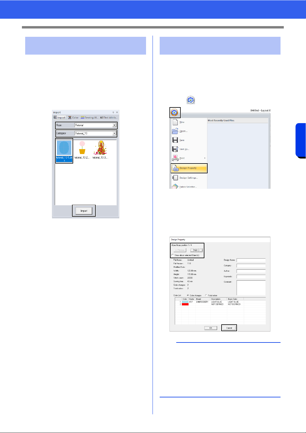
196
Operations for Specific Applications
Tutorial 10-1: Creating Split Embroidery Designs
For this example, we will use one of the lace
embroidery patterns provided with the software.
1 Display the [Import] pane.
2 Select [Tutorial] from the [From] selector and
[Tutorial_10] from the [Category] selector.
Click [tutorial_10-1.pes], then [Import].
cc "Importing embroidery designs" on
page 102.
Check the sewing order to see the order that the
design sections will be sewn and determine which
parts of the fabric should be hooped.
The design sections are sewn in order from left to
right, top to bottom.
1 Click , then [Design Property].
2 Uncheck the [Show about selected
Object(s)] to view the separate design
sections. Click on [Next] and [Previous] to
move back and forth through each section.
Check the design, and then click [Cancel].
Step 2 Creating the embroidery
design
Step 3 Checking the
embroidering order
a
Before an embroidery pattern created in a custom
Design Page is saved, running stitches are added
at the edges of the design sections so that the
design sections can easily be aligned during
sewing. This alignment stitching appears in the
[NOT DEFINED] color and cannot be edited.
cc Memo of "Step 7 Embroidering" on page199
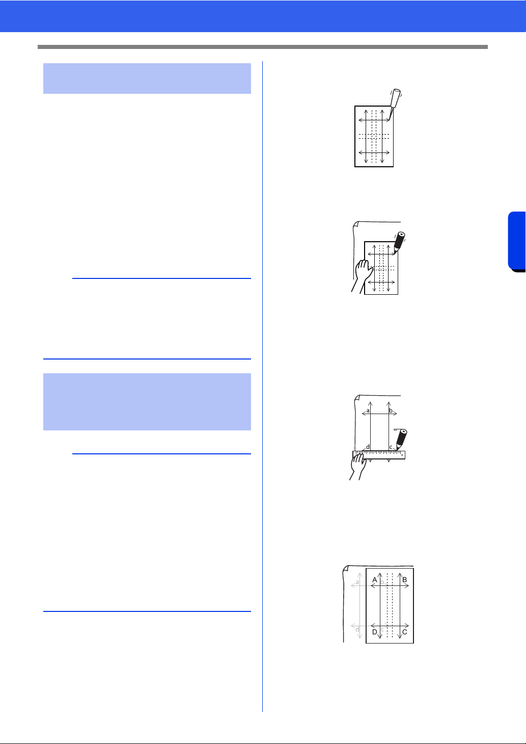
197
Operations for Specific Applications
Tutorial 10-1: Creating Split Embroidery Designs
Stabilizer must always be used when embroidering
to stabilize the fabric. There are many types of
stabilizer; the type that you will use depends on the
type of fabric that you are embroidering on. For
large-size designs that are split into sections, the
stabilizer must be adhered to the fabric, for
example, iron-on stabilizer. In some cases, you may
need to use two pieces of stabilizer for your
embroidery.
When using spray adhesive, spray the adhesive
onto a hooped piece of stabilizer that is strong
enough for the entire large-size embroidery. In
some cases, you may need to use two pieces of
stabilizer for your embroidery.
1 Punch a hole at the end of each arrow on the
positioning sheet.
2 Place the positioning sheet on the fabric, and
then insert the tip of a marking pen into each
hole to mark the fabric.
3 Connect the points marked on the fabric to
draw reference lines.
The intersections of the lines drawn on the
fabric are marked as a, b, c and d.
In addition, the intersections of the lines on the
positioning sheet are marked as A, B, C and
D.
4 Place the positioning sheet on the fabric.
Align points A and D on the positioning sheet
with marks b and c on the fabric, and then
repeat steps 2 and 3 to draw reference lines
on the fabric for an embroidering position on
the right side.
Step 4 Attaching stabilizer to the
fabric
a
• For best results, attach the stabilizer to the fabric
(as described on this page). Without the correct
stabilizer, the design may become misaligned
due to puckering in the fabric.
• Be sure to check the recommendations on the
stabilizer package.
Step 5
Using the Positioning
Sheet to mark the
embroidering position on
the fabric
b
• The positioning sheets are included in the
package.
• The Positioning Sheets are also in the
[Positioning Sheet] folder and can be printed
out with a printer.
Location of the Positioning Sheets: C:\Program
Files (x86)\Brother\PE-DESIGN 11\Positioning
Sheet.
• The positioning sheets in the PDF files are at
actual size. When printing the positioning sheet
from the PDF file, be sure to print it at actual
size. Do not print while reducing or enlarging to
fit the paper size.
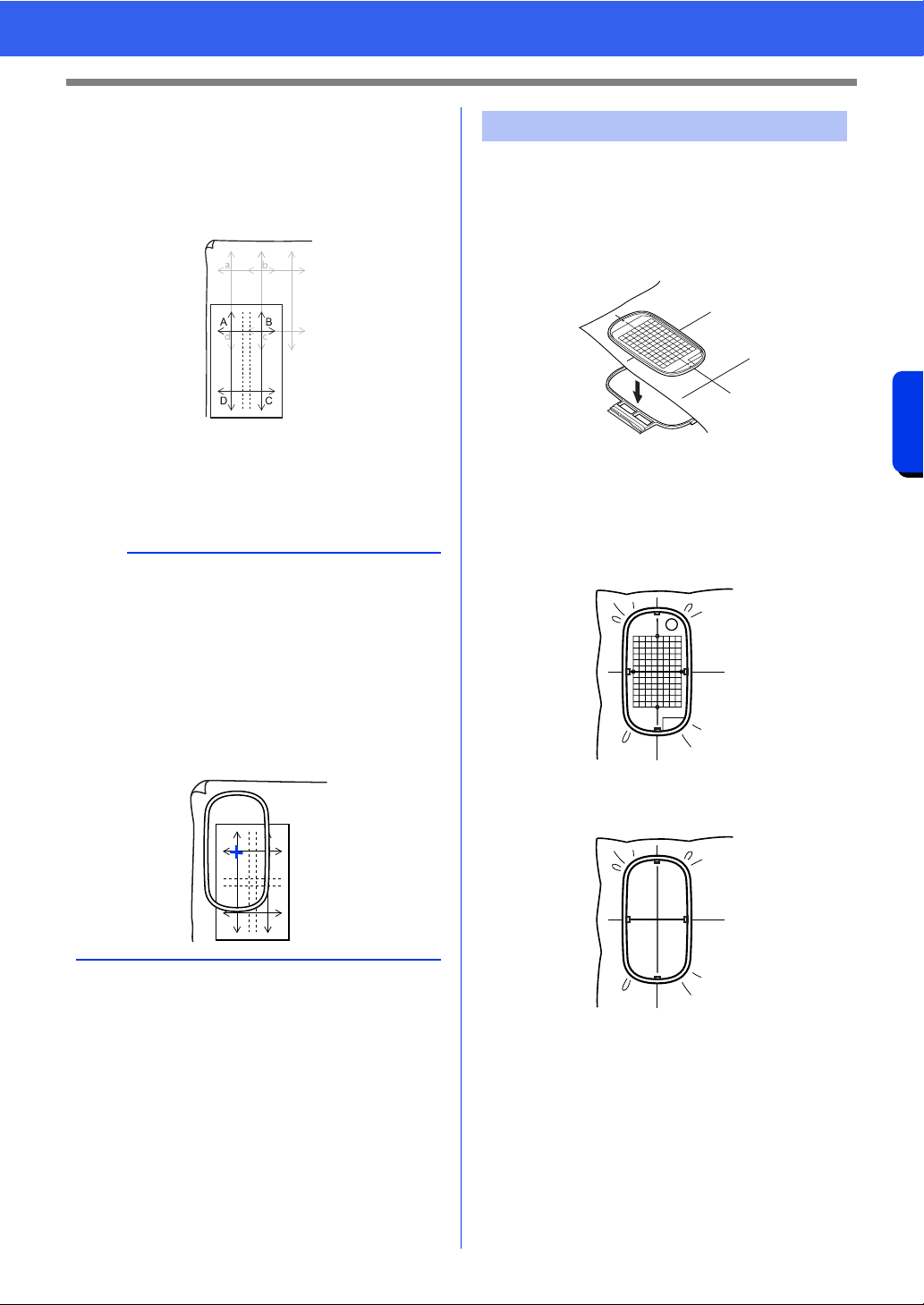
198
Operations for Specific Applications
Tutorial 10-1: Creating Split Embroidery Designs
5 Place the positioning sheet on the fabric.
Align points A and B on the positioning sheet
with marks d and c on the fabric, and then
repeat steps
2 and 3 to draw reference lines
on the fabric for an embroidering position
below the first one.
6 Repeat steps 4 through 5 to reposition the
positioning sheet and draw the embroidering
position for each section of the embroidery
pattern.
1 Insert the embroidery sheet into the inner ring
of the embroidery hoop, and then place them
on top of the fabric with the centerline on the
embroidery sheet aligned with the reference
lines (drawn on the fabric) for the first pattern
section to be sewn.
2 Keeping the reference lines on the embroidery
sheet aligned with the reference lines for the
first pattern section, place the fabric and inner
ring of the embroidery hoop into the outer ring
of the hoop, and then pull the fabric so that it
is tight.
3 Finish hooping the fabric, and then remove the
embroidery sheet.
a
• The intersection of the horizontal and vertical
line indicates the center of the embroidery hoop.
• While carefully considering how the fabric will be
hooped, place the positioning sheet on the
fabric, and then draw lines to indicate the
embroidering position. In addition, because all
embroidery areas are not drawn on the
positioning sheet for large embroidery hoops, be
careful that the embroidery area does not extend
from the marked area on the fabric as shown
below.
Step 6 Hooping the fabric
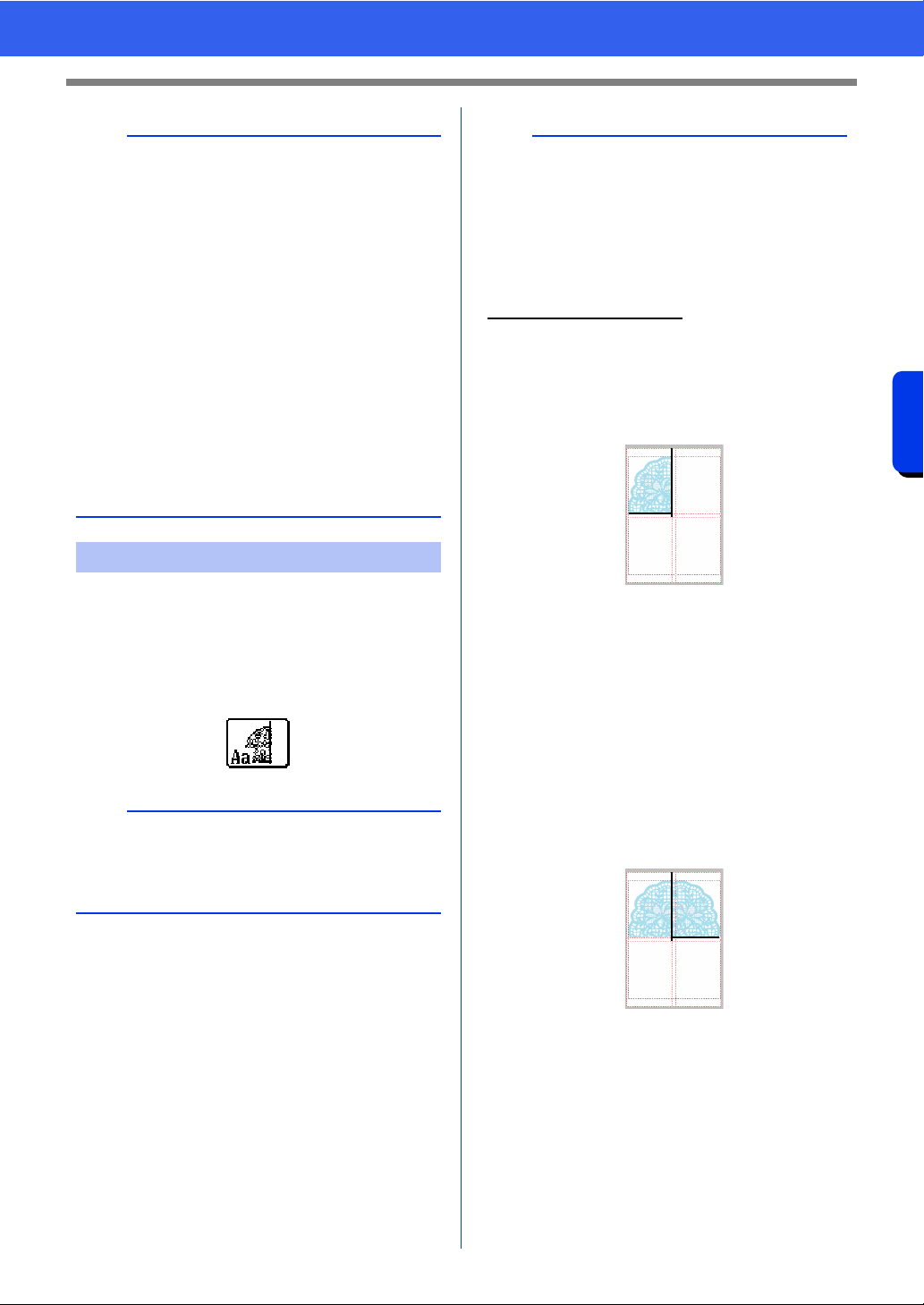
199
Operations for Specific Applications
Tutorial 10-1: Creating Split Embroidery Designs
1 When large-size embroidery designs are
transferred to the embroidery machine, the
patterns appear on the embroidery machine
display as shown below. For this example,
select the first embroidery pattern section
(Aa).
2 Attach the embroidery hoop to the embroidery
machine, and then using the machine's layout
adjusting functions, align the needle position
with the intersection of the lines drawn on the
fabric.
3 Embroider the selected pattern.
4 Remove the embroidery hoop from the
embroidery machine, and then remove the
fabric from the hoop.
5 Hoop the fabric for the next design section.
cc "Hooping the fabric" on page 198
a
• Place the fabric and hoop on a level surface, and
then make sure that the inner ring is pressed in
well enough that the top edge of the inner ring
aligns with the top edge of the outer ring.
• If the embroidery sheet is not used, the marks on
the embroidery hoop can be used to hoop the
fabric vertically and horizontally.
However, since the center point on some
embroidery machines is off center, the
embroidery sheet should be used for best
results.
• Tip: The sticky stabilizer should be removed
right away after the embroidery design is
finished.
• Tip: The fabric can be hooped more easily if
double-sided tape is affixed to the back of the
inner ring, which is placed on top of the fabric,
and then the fabric is clamped between the inner
ring and the outer ring.
Step 7 Embroidering
b
If there is no stitching in section Aa, select the first
section that contains stitching. Click on
[Application] button, and then click [Design
Property] to check the embroidering order.
b
When an embroidery design created in a custom
Design Page is saved or transferred to an original
card, alignment stitching (single lines of running
stitches with the color [NOT DEFINED], with a
pitch of 7.0 mm, and starting with fixed stitches
with a pitch of 0.3 mm) is added at the edges of the
design sections. (The alignment stitching appears
in the print preview and is printed in red.)
Sample data for this tutorial
(1) Embroider the upper-left design section.
Alignment stitching is sewn below and on
the right side of the embroidered design
section.
(2) Hoop the fabric for the upper-right design
section with the left side of the hoop aligned on
the alignment stitching on the right side of the
design section sewn in step (1), and then
embroider the design.
Before the design section is embroidered,
alignment stitching is sewn on the left
side. Make sure that this alignment
stitching aligns with the alignment
stitching sewn in step (1). After the design
section is embroidered, alignment
stitching is sewn below the design
section.
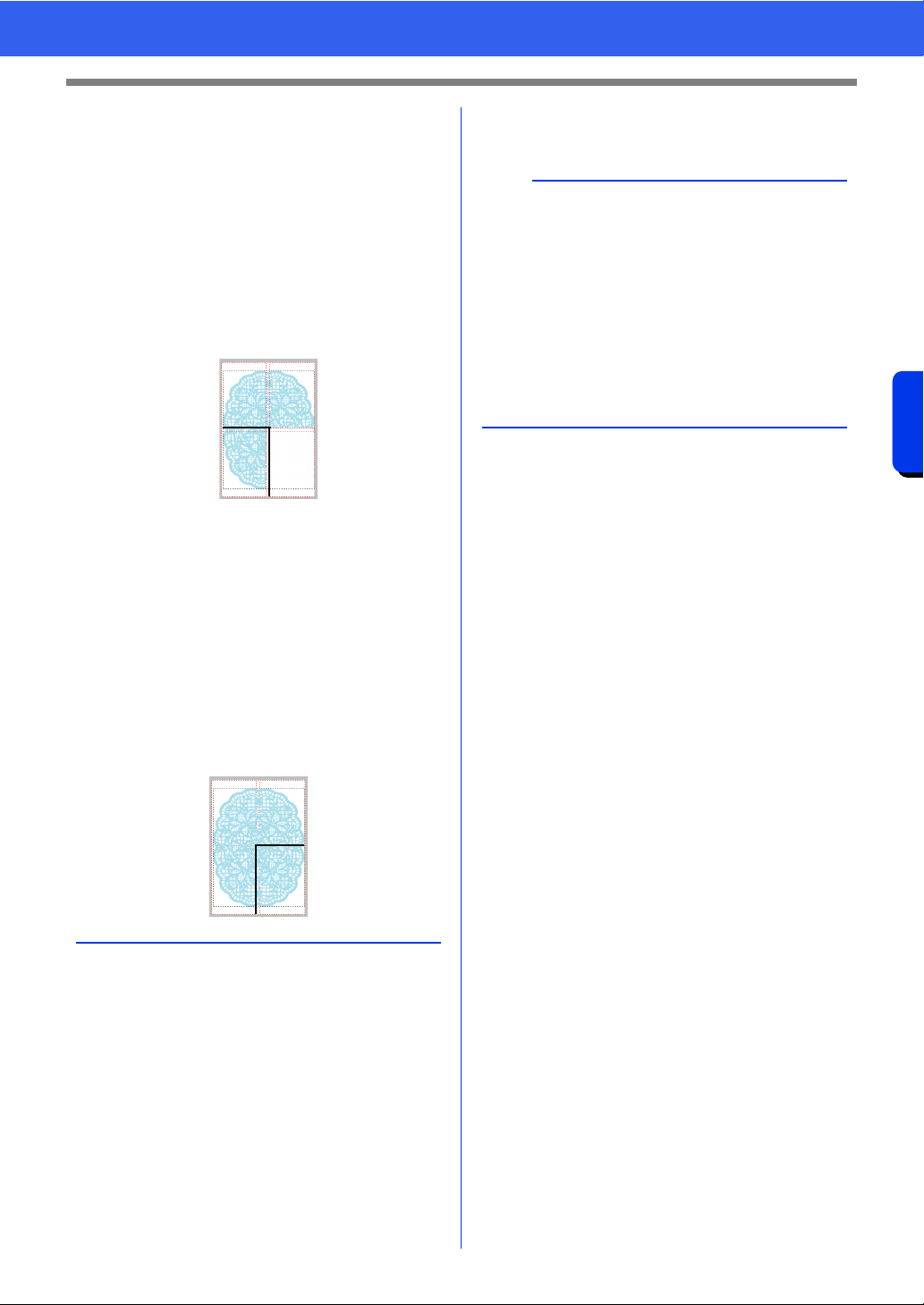
200
Operations for Specific Applications
Tutorial 10-1: Creating Split Embroidery Designs
6 Continue hooping the fabric and embroidering
until the entire embroidery design is sewn.
(3) Hoop the fabric for the lower-left design section
with the top of the hoop aligned on the
alignment stitching at the bottom of the design
section sewn in step (1), and then embroider
the design.
Before the design section is embroidered,
alignment stitching is sewn at the top.
Make sure that this alignment stitching
aligns with the alignment stitching sewn in
step (1). After the design section is
embroidered, alignment stitching is sewn
on the right side of the design section.
(4) Hoop the fabric for the lower-right design
section with the left side of the hoop aligned on
the alignment stitching on the right side of the
design section sewn in step (3) and with the top
of the hoop aligned on the alignment stitching
at the bottom of the design section sewn in
step (2), and then embroider the design.
Before the design section is embroidered,
alignment stitching is sewn on the left side
and at the top. Make sure that this
alignment stitching aligns with the
alignment stitching sewn in step (3) and in
step (2).
b
• The procedure is different for models that use a
built-in camera to connect large-size split
embroidery patterns.
• For models that use a built-in camera,
embroidery positioning stickers (Snowman
positioning stickers) can be used.
• For details, refer to the instruction manual
provided with the embroidery machine.
• By adjusting the size of the sections, patterns
can easily be connected.
cc "Changing the size of sections" on page 201
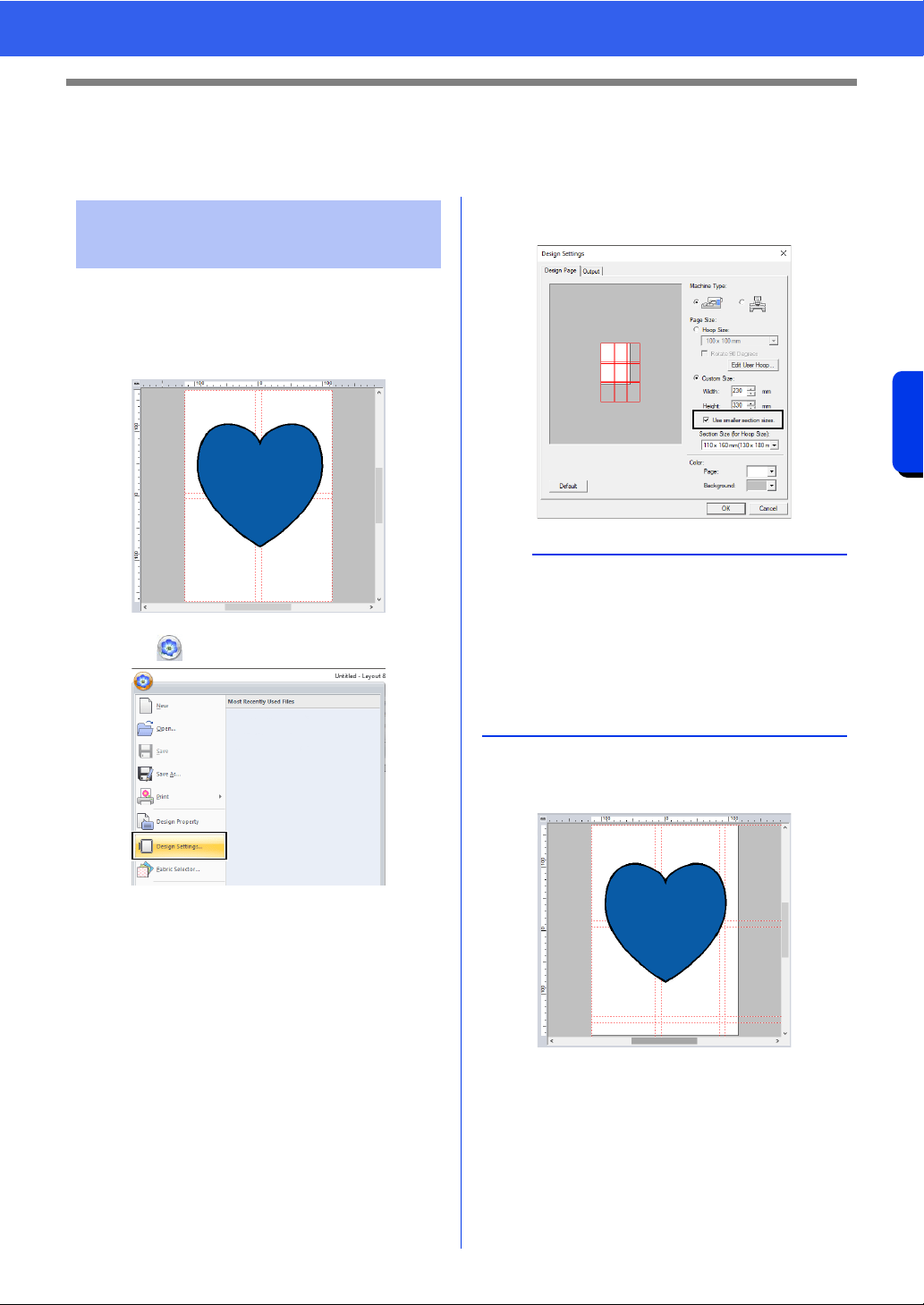
201
Operations for Specific Applications
Specifying Settings for Split Embroidery Designs
Specifying Settings for Split Embroidery
Designs
By reducing the size of the sections, patterns can
easily be connected when split embroidery designs
are embroidered.
1 Create a split embroidery pattern.
2 Click , then [Design Settings].
3 Select [Custom Size], and then type or select
the desired width and height for the Design
Page.
cc For details on creating split embroidery
designs, refer to "Tutorial 10-1: Creating
Split Embroidery Designs" on page 195.
4 Select the [Use smaller section sizes.]
check box.
5 Click [OK].
The section size is changed.
Changing the size of
sections
b
• Select the [Use smaller section sizes.] check
box to create sections with a size of 10 mm less
than normal on all sides.
• For a better result, embroidery positioning
stickers (Snowman positioning stickers) can be
used for models with built-in camera.
For details, refer to the instruction manual
provided with the embroidery machine.
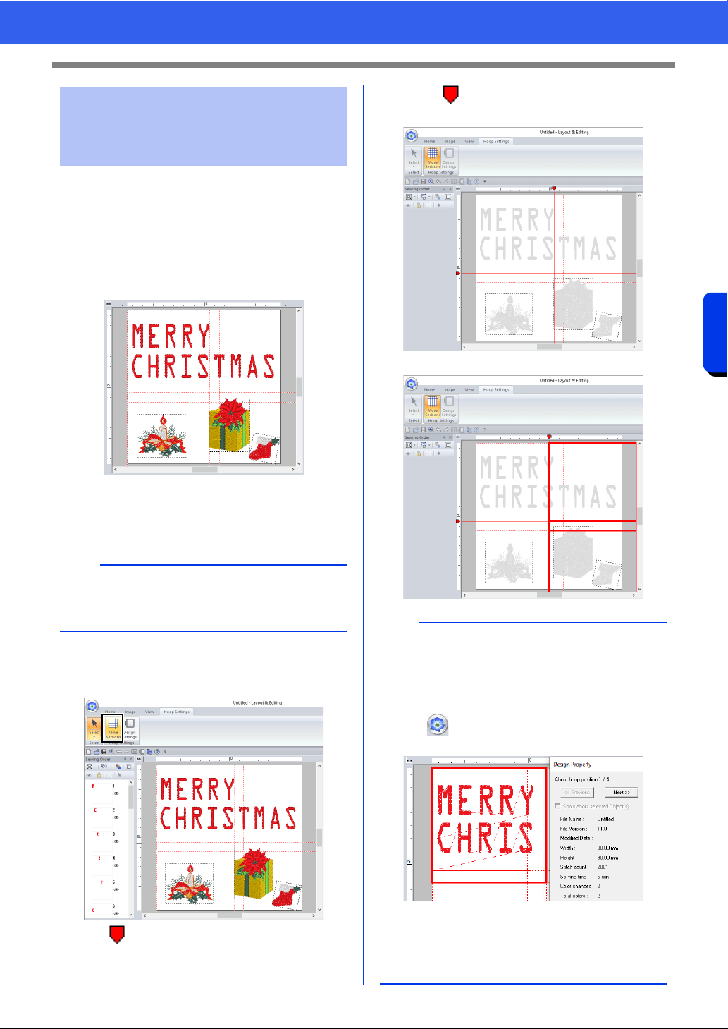
202
Operations for Specific Applications
Specifying Settings for Split Embroidery Designs
By specifying the split positions for each hoop
section, you can sew embroidery patterns without
the need to split patterns smaller than the
embroidering area.
■ Adjusting the split positions
1 Create a split embroidery pattern.
cc "Tutorial 10-1: Creating Split Embroidery
Designs" on page 195
2 Click the [Hoop Settings] tab.
3 Click [Move Sections] in the [Hoop Settings]
group.
appears in the ruler.
4 Drag to adjust the split position. The frame
being moved appears as a solid red line.
The split positions are changed.
Adjusting the split
positions in split
embroidery designs
b
The [Hoop Settings] tab appears only if [Custom
Size] was selected in the [Design Settings]
dialog box.
b
• This is useful in preventing patterns smaller than
the embroidering area from being split, reducing
the number of thread color changes and
allowing you to change the split positions of the
pattern.
•Click , then [Design Property] to check the
split pattern.
cc "Checking the embroidering order" on
page 196
• The settings are reset when the embroidery
frame is changed.
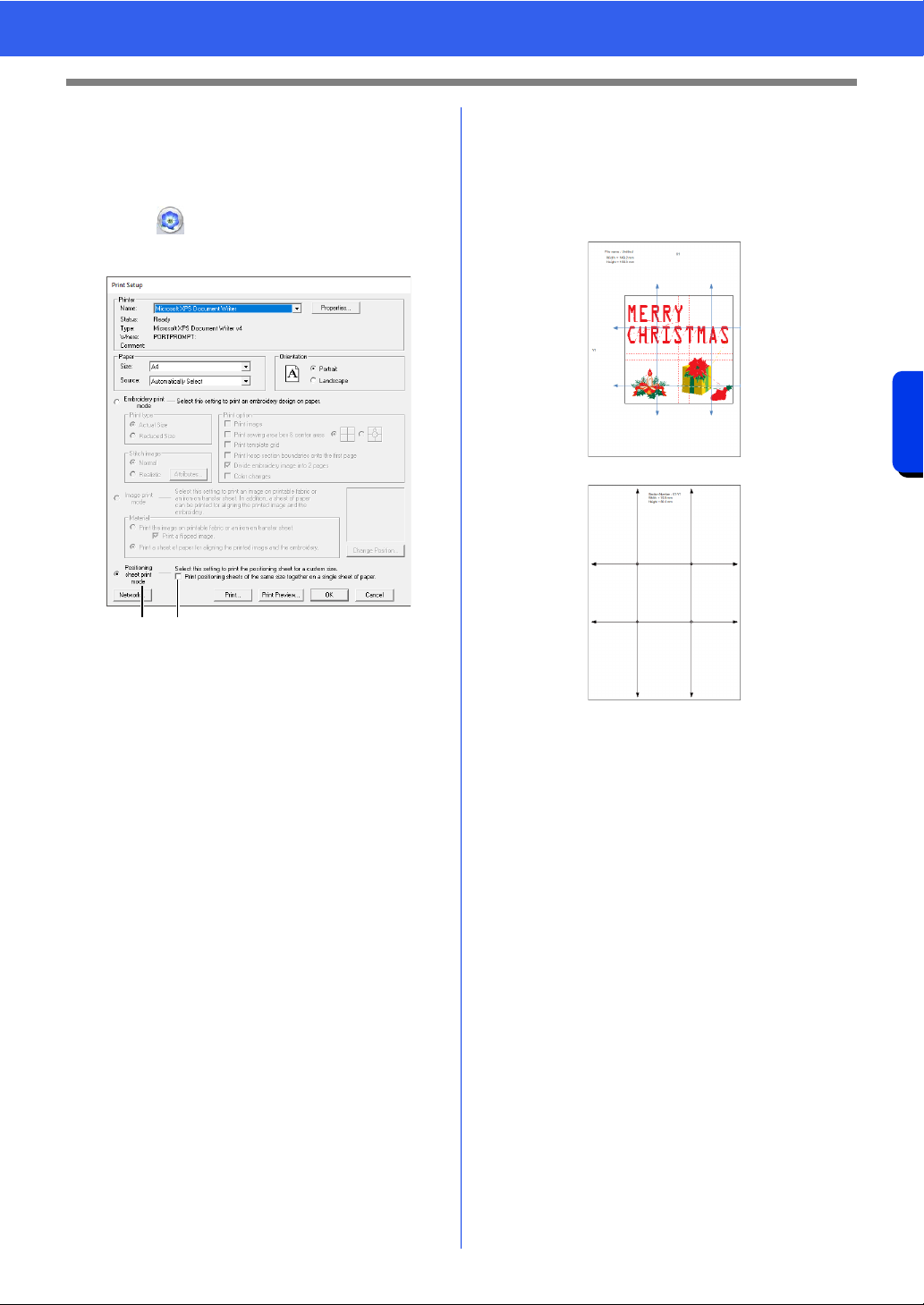
203
Operations for Specific Applications
Specifying Settings for Split Embroidery Designs
■ Printing the positioning sheets
After specifying split positions for the hoop sections,
new positioning sheets are necessary in order to
correctly position the pattern.
1 Click , then [Print], then [Print Setup].
2 Change the print settings.
a Select this option to print a positioning
sheet for each section.
b Select this check box to print only one
positioning sheet (one size).
Clear this check box to print a positioning
sheet for each section.
3 Click [Print] to print the positioning sheets.
A page (
1) showing the entire pattern, the
pattern size and file name as well as a
positioning sheet (2) for each section are
printed.
cc For details on using positioning sheets to
connect large-size split embroidery
patterns, refer to "Using the Positioning
Sheet to mark the embroidering position
on the fabric" on page 197.
a b
1
2
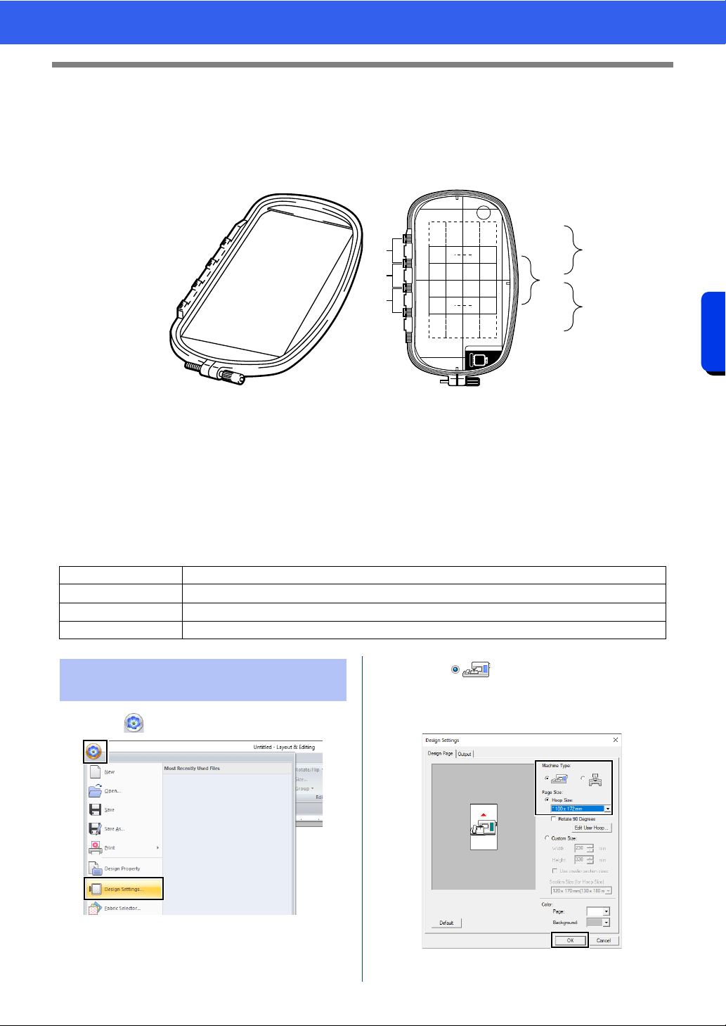
204
Operations for Specific Applications
Tutorial 10-2: Creating Design for Multi-Position Hoops
Tutorial 10-2: Creating Design for Multi-
Position Hoops
This program enables you to create multi-position designs that you can stitch in any multi-position hoop
attached to your embroidery machine.
Example of multi-position hoop: 100 × 172 mm hoop
Although the size of the design that can be embroidered using an multi-position hoop is 130 × 180 mm (or 100
× 100 mm, depending on the sewing area of the embroidery machine), first determine which of the three
installation positions (indicated as a, b, and c in the illustration above) the multi-position hoop will be installed
at and determine the orientation of the design.
When creating the design, each design section can only be as large as the sewing area of the embroidery
machine.
The sample file for this tutorial is located at Documents (My documents)\PE-DESIGN 11\Tutorial\Tutorial_10.
1 Click , then [Design Settings].
2 Select under [Machine Type], and
then select [Hoop Size] and choose a Design
Page size of 130 × 300 mm or 100 × 172 mm
from the selector. Then, click [OK].
Step 1 Selecting the Design Page size
Step 2 Creating the design
Step 3 Optimizing hoop changes
Step 4 Checking the pattern
a
b
c
a
b
c
ABC
Step 1 Selecting the Design Page
size
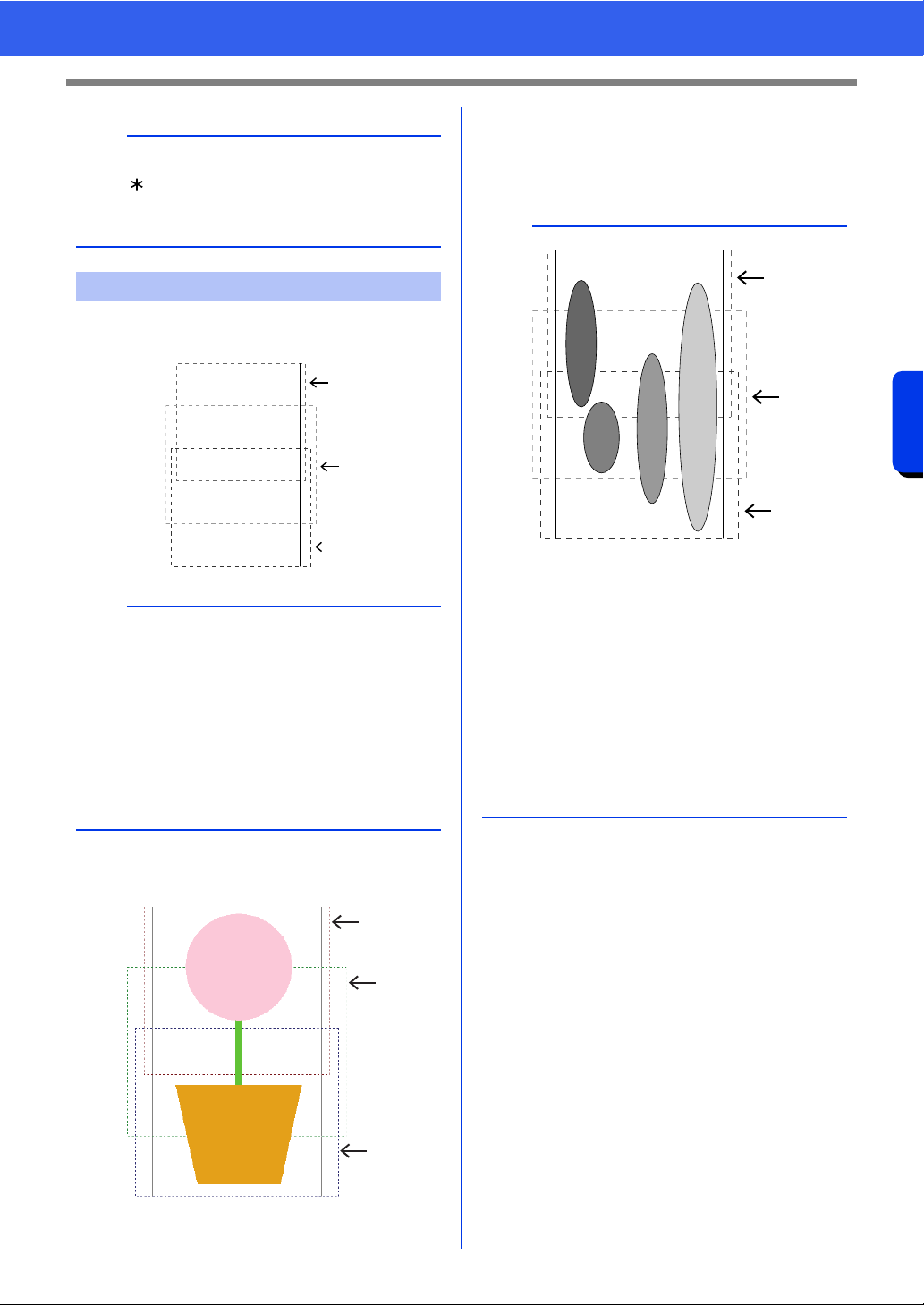
205
Operations for Specific Applications
Tutorial 10-2: Creating Design for Multi-Position Hoops
1 The Design Page appears on the screen as
shown below.
2 Create the design, making sure that it meets
the following conditions.
• The size of one pattern must be no larger
than 100 × 100 mm (or 130 × 180 mm).
• Each pattern must completely fit within a
single area (a, b, or c).
b
• Settings for multi-position hoops are indicated
by " ".
• Choose the appropriate setting after checking
the size of the hoop available for your machine.
Step 2 Creating the design
b
• Area a
Embroidering area when the multi-position hoop
is installed at the top installation position.
• Area b
Embroidering area when the multi-position hoop
is installed at the middle installation position.
• Area c
Embroidering area when the multi-position hoop
is installed at the bottom installation position.
The dotted lines separate each area.
a
b
c
a
b
c
b
1: The position of this pattern is correct since it fits
completely within area a.
2: The position of this pattern is correct since it fits
completely within either area b or area c.
3: The size of this pattern is acceptable, but its
position must be corrected since it does not fit
completely within any of the areas.
(It will be necessary to correct the position in
order to fit in either b or c.)
4: This pattern must be corrected since it is too
large.
(It will be necessary to correct the position and
size in order to fit in either a, b, or c.)
a
b
c
4
3
2
1
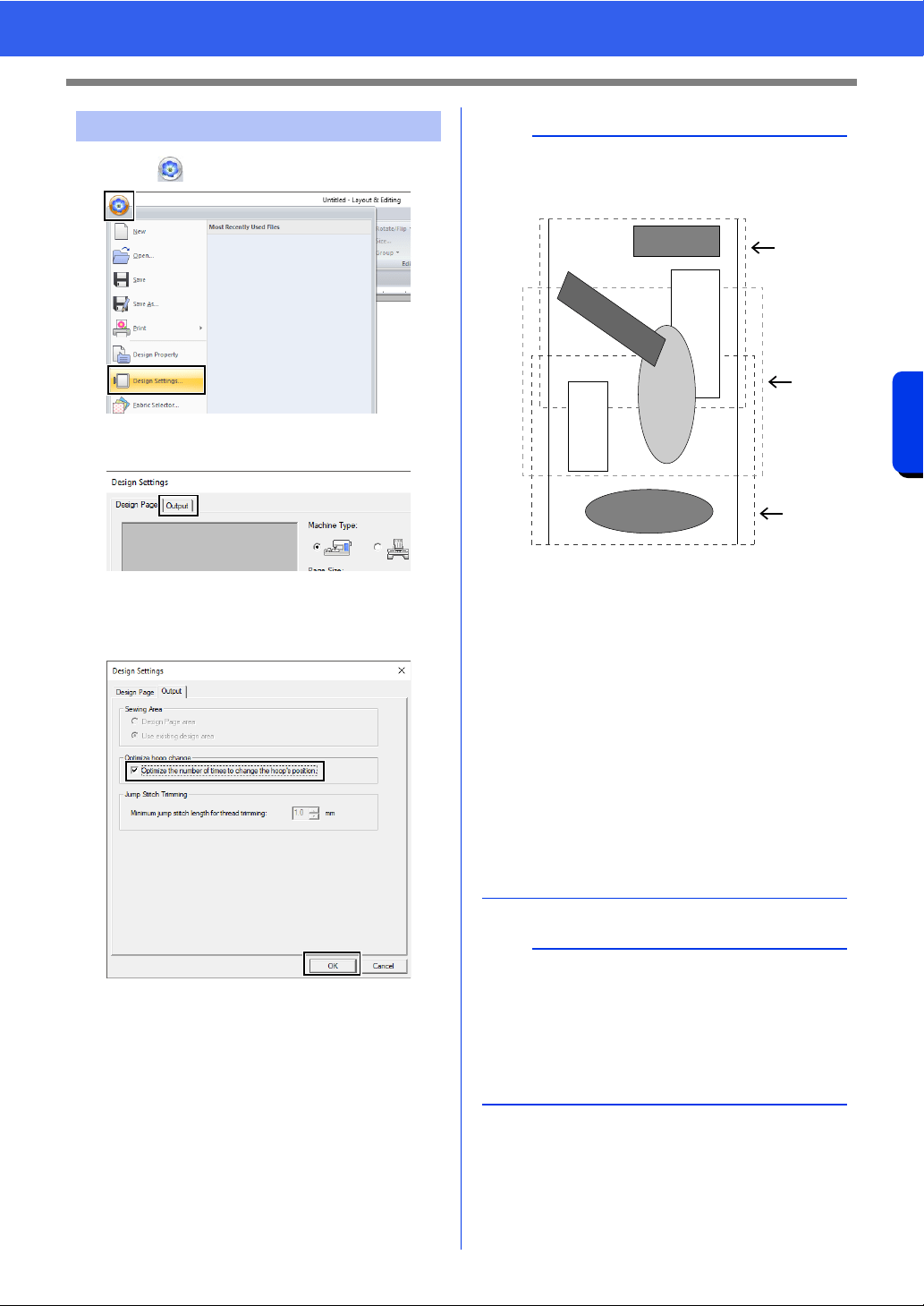
206
Operations for Specific Applications
Tutorial 10-2: Creating Design for Multi-Position Hoops
1 Click , then [Design Settings].
2 Click [Output] tab.
3 Select the [Optimize the number of times to
change the hoop’s position] check box, and
then click [OK].
Step 3 Optimizing hoop changes
b
• A check mark appears when this function is
turned on; no check mark is displayed when this
function is turned off.
• When the Optimize hoop change function is
turned on, the sewing order that you have set is
optimized to reduce the number of times that the
hoop installation position is changed.
For the example shown on this page, the sewing
order is: a (pattern 1) b (pattern 2) a
(patterns 3 & 5) c (patterns 4 & 6)
If the Optimize hoop change function is turned
off, each pattern is sewn according to the sewing
order that you have set.
For the example shown on this page, the sewing
order is: a (pattern 1) b (pattern 2) a
(pattern 3) c (pattern 4) a (pattern 5) c
(pattern 6)
Therefore, since the number of times for
changing the hoop installation position is not
optimized, it may be changed more often than if
it was optimized.
a
Since the pattern may not be sewn correctly or the
fabric may not feed evenly if the hoop installation
position is changed too often, we recommend
turning on the [Optimize hoop change] function.
Turning on this function will change the sewing
order that you have set, therefore, check the
sewing order before you begin embroidering.
a
b
c
4
2
1
3
5
6
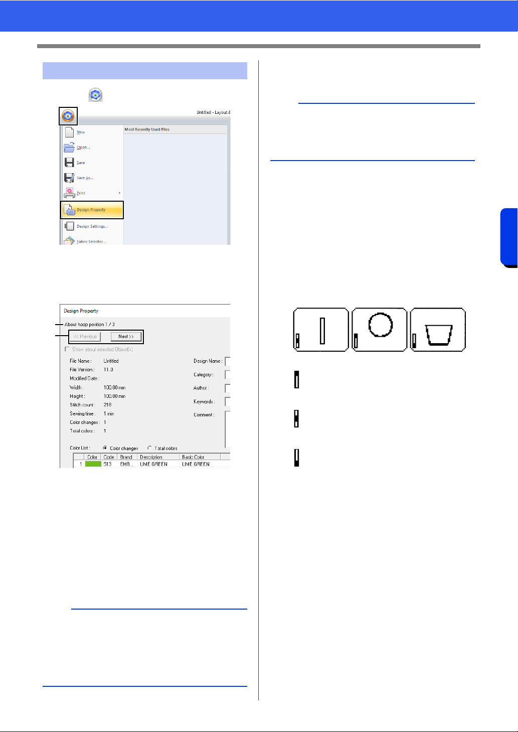
207
Operations for Specific Applications
Tutorial 10-2: Creating Design for Multi-Position Hoops
1 Click , then [Design Property].
2 Check the sewing order of each pattern and
the number of times the hoop position will be
changed.
Only the patterns that would be sewn at the
current position in the hoop installation order
appear in the Design Page, and the
embroidering area for the current hoop
position is outlined in red.
a The position in the hoop installation order
for the currently displayed pattern.
b To display information for patterns at
other positions in the hoop installation
order, click [Previous] or [Next].
■ Saving the design
The entire design is saved as a single file (.pes).
■ Writing the design to an original
card
A design for a multi-position hoop is created by
considering the pattern in each hoop installation
position as one pattern, then combining them.
Therefore, when this type of design is written to an
original card, one multi-position hoop design is
saved as a combination of multiple patterns.
Therefore, the frame installation position sewing
order for the pattern shown above is b, a, then c.
Step 4 Checking the pattern
a
If a pattern is larger than the embroidery area or if
a pattern is positioned so that it does not
completely fit within an embroidery area, the error
message appears. After the pattern causing the
error is displayed, select the pattern and change
its size or position.
a
b
b
If the file size or the number of color changes is
larger than the specified number, or if one of the
patterns does not completely fit within an
embroidery area, the error message appears.
: This pattern is sewn when the hoop is
installed at the top installation position
(position a).
: This pattern is sewn when the hoop is
installed at the middle installation
position (position b).
: This pattern is sewn when the hoop is
installed at the bottom installation
position (position c).
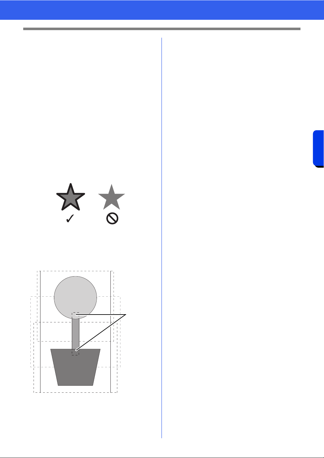
208
Operations for Specific Applications
Tutorial 10-2: Creating Design for Multi-Position Hoops
Notes on embroidering using the multi-
position hoop
• Before embroidering your design, sew a trial
sample of the design on a scrap piece of fabric
from your design, making sure to use the same
needle and thread.
• Be sure to affix stabilizer material to the back of
the fabric and tightly stretch the fabric within the
hoop. When embroidering on thin or stretch
fabrics, use two layers of stabilizer material. If no
stabilizer material is used, the fabric may become
over-stretched or wrinkled or the embroidery may
not be sewn correctly.
cc For more ways to stabilize large designs,
refer to "Attaching stabilizer to the fabric"
on page 197
• Use the zigzag stitch for sewing the outlines in
order to prevent embroidering outside the
outlines.
• For patterns that require the hoop to be installed
at different installation positions, design the
embroidery pattern so that the various parts of
the pattern overlap in order to prevent
misalignment while embroidering.
1 Overlap
■ Printing a Design Page for a multi-
position hoop
On the first page, a complete image of the Design
Page is printed at actual size. (However, for a 130 ×
300 mm Design Page, a reduced image of the
Design Page is printed.) On the following pages, an
image of each design section and its sewing
information are printed in the sewing order.
When [Actual Size] is selected:
An image of the pattern in each design section is
printed on a separate page as the corresponding
sewing information.
When [Reduced Size] is selected:
An image of the pattern in each design section is
printed on the same page as the corresponding
sewing information.
cc "Printing" on page 108
1
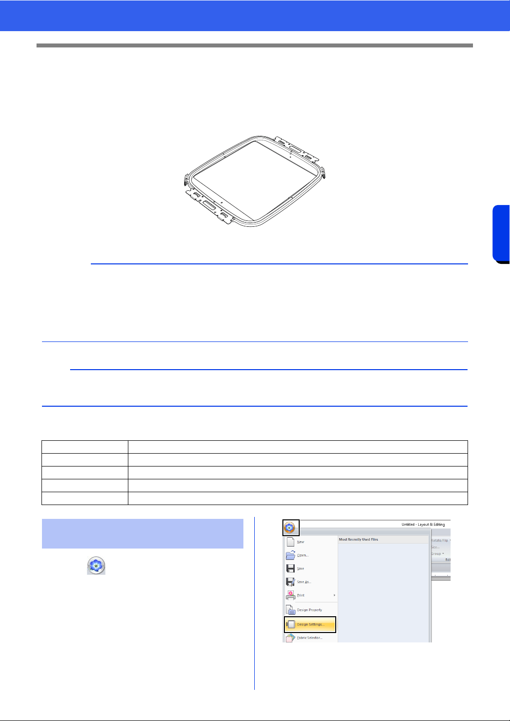
209
Operations for Specific Applications
Tutorial 10-3: Embroidering With the Jumbo Frame
Tutorial 10-3: Embroidering With the
Jumbo Frame
This section describes the procedures for creating embroidery data and for embroidering using the jumbo
frame (frame size: 360 × 360 mm; with mounts on both sides of the embroidery frame).
Jumbo frame: 360 × 360 mm embroidery frame
The sample file for this tutorial is located at Documents (My documents)\PE-DESIGN 11\Tutorial\Tutorial_10.
1 Click , then [Design Settings].
a
• If the jumbo frame was selected, the size of the Design Page becomes 350 × 350 mm in order to create
margins that allow automatic positioning using the built-in camera.
• The jumbo frame described here was designed specifically for our multi-needle embroidery machines
equipped with a built-in camera. It cannot be used with any other machine, such as single-needle
embroidery machines. Check the instruction manual provided with your multi-needle embroidery machine
to determine if it is compatible with the jumbo frame.
b
For details on embroidering using the camera and on affixing the embroidery positioning stickers, refer to the
instruction manual provided with the embroidery machine.
Step 1 Selecting the Design Page size
Step 2 Creating the embroidery design
Step 3 Checking a divided pattern
Step 4 Attaching stabilizer to the fabric
Step 5 Embroidering
Step 1 Selecting the Design Page
size
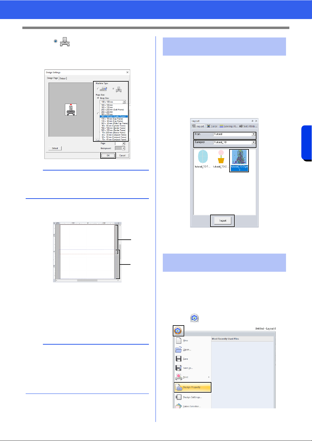
210
Operations for Specific Applications
Tutorial 10-3: Embroidering With the Jumbo Frame
2 Click under [Machine Type], select
360 × 360 mm (Jumbo Frame) from the
[Hoop Size] selector under [Page Size], and
then click [OK].
3 The Design Page appears on the screen as
shown below.
a Side 1 embroidering area
Area embroidered first
b Side 2 embroidering area
Area embroidered second
The embroidery pattern is automatically
divided into the different areas.
For this example, an embroidery pattern provided
with this software will be used in the procedure
described below.
1 Display the [Import] pane.
2 Select [Tutorial] from the [From] selector and
[Tutorial_10] from the [Category] selector.
Click [tutorial_10-3.pes], then [Import].
cc "Importing embroidery designs" on
page 102.
Before starting to embroider, the divided embroidery
pattern can be checked. If a pattern that you do not
wish to be divided has been split onto Side 1 and
Side 2, you can check the embroidery pattern, then
adjust it so it is not split.
1 Click , then [Design Property].
a
Check the size of embroidery frames that can be
used with your machine before changing the
setting.
a
The embroidery pattern is split with a section
overlapping
a and b.
If the pattern arranged in this section uses satin
stitches, the stitch may change when the pattern is
split. Therefore, we recommend shifting the
pattern or changing the sew type to fill stitches.
a
b
Step 2 Creating the embroidery
design
Step 3 Checking a divided
pattern
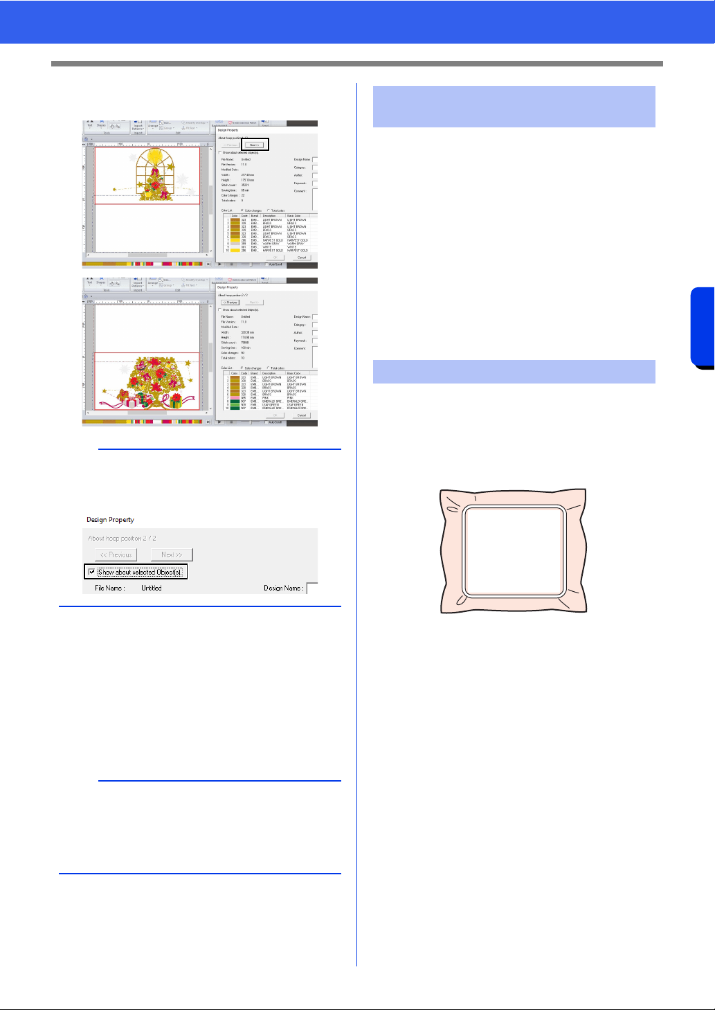
211
Operations for Specific Applications
Tutorial 10-3: Embroidering With the Jumbo Frame
2 Click [Next] to view the next side of the
embroidery design.
■ Saving the design
The entire design is saved as a single file (.pes).
cc "Transferring to a machine by using USB
media" on page 222, and "Transferring
directly to a machine's memory" on
page 223
Always use stabilizer when embroidering.
For large designs split into sections, the stabilizer
must be attached to the fabric, for example, by using
iron-on stabilizer, self-adhesive stabilizer or spray
adhesive. Use stabilizer appropriate for the fabric.
In addition, be sure to use stabilizer that is strong
enough and large enough for the entire
embroidering area. You may need to attach two
layers if thin stabilizer is used.
cc See more information about stabilizer,
"Step 4 Attaching stabilizer to the fabric"
on page197.
Embroider using the embroidery positioning stickers
included with the embroidery machine. These
stickers are detected by the embroidery machine's
built-in camera to automatically position the fabric.
1 Hoop the fabric in the embroidery frame.
2 Attach the embroidery frame to the
embroidery machine.
3 Select the pattern for side 1, and then start the
embroidery machine to embroider the side 1
embroidering area.
b
To view the embroidery pattern of the separate
sides, uncheck the [Show about selected
Object(s)].
a
An embroidery design for the jumbo frame cannot
be transferred to the machine by using an original
card. Transfer these designs directly to the
machine's memory or to the machine by using
USB media.
Step 4 Attaching stabilizer to the
fabric
Step 5 Embroidering
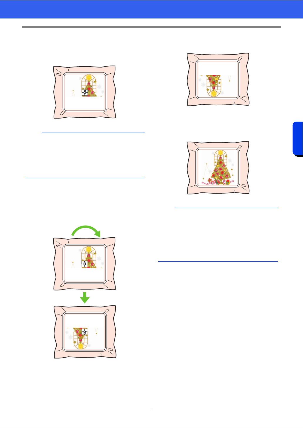
212
Operations for Specific Applications
Tutorial 10-3: Embroidering With the Jumbo Frame
4 When embroidering is finished, follow the
instructions on the embroidery machine to
affix embroidery positioning sticker (Snowman
positioning sticker) on the embroidering area.
The embroidery machine's built-in camera
detects the embroidery positioning sticker.
5 After the sticker have been detected, remove
the embroidery frame, rotate it 180°, and then
re-attach it to the embroidery machine.
The embroidery machine's built-in camera
detects the embroidery positioning sticker
again.
6 Follow the embroidery machine instructions to
remove the embroidery positioning stickers.
7 Select the pattern for side 2, and then start the
embroidery machine to embroider the side 2
embroidering area.
■ Embroidery data for the jumbo
frame
• When the embroidery design is being saved in
[Layout & Editing], older file format versions are
not available.
In addition, the embroidery design is saved as
data specifically for our multi-needle embroidery
machines equipped with a built-in camera. It
cannot be sewn with any other machine.
• An embroidery pattern created in a Design Page
set to the jumbo frame size in [Design Center]
cannot be transferred directly to the machine.
Import the embroidery pattern into [Layout &
Editing], and then transfer it to the embroidery
machine.
b
An image of the needle location appears in the
screen with the positioning detection area framed
by a line.
Affix an embroidery positioning sticker so that it fits
within the line. For details, refer to the instruction
manual for the machine.
b
• For details on using the embroidery machine,
refer to the instruction manual included with it.
• Carefully remove the embroidery frame and
reattach it correctly. If the embroidery frame is
not correctly attached or if there is slack in the
fabric, the embroidery pattern may become
misaligned.
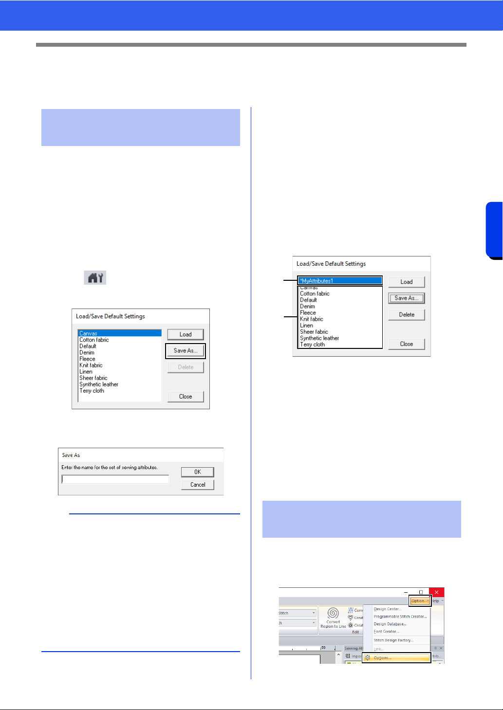
213
Operations for Specific Applications
Specifying/Saving Custom Sewing Attributes
Specifying/Saving Custom Sewing
Attributes
Frequently used sewing attributes can be saved
together, and recalled when specifying sewing
attributes.
■ Saving the settings in a list
1 Click the [Sewing Attributes] tab.
cc "Specifying sewing attributes" on
page 64
2 If necessary, change the settings, and then
click .
3 Click [Save As].
4 Type in a name for the group of settings, and
then click [OK] to register the group in a list.
■ Deleting a group of settings from
the list
1 In the [Load/Save Default Settings] dialog
box, select the group of settings to be deleted.
2 Click [Delete] to delete the selected group of
settings from the list.
■ Recalling a group of settings from
the list
1 In the [Load/Save Default Settings] dialog
box, select the group of settings to be recalled.
a A group of settings that you have saved
will appear with "*" beside its name.
b Sewing attributes appropriate for various
fabrics are already available. Select the
type of fabric to be embroidered to specify
the recommended settings for that fabric.
2 Click [Load].
The settings in the [Sewing Attribute
Setting] dialog box change to the saved
settings.
If you have a list of thread colors that are frequently
used, they can be saved in a user thread chart.
1 Click [Option], then [Options].
Saving frequently used
sewing attributes
b
• The saved setting can also be used on a
different computer. Simply copy [sastu.txt] from
[C:\Program Files (x86)\Brother\PE-DESIGN
11\Settings] on the original computer to the
[Settings] folder at the same path on the
destination computer.
• In Explorer click on C:\Program Files
(x86)\Brother\PE-DESIGN 11\Settings. Single
left click on the [Settings] folder to view the
contents. Single right click on sastu.txt and
select copy from the menu. Paste to a USB
device and transfer to a different computer.
Editing user thread color
lists
a
b

214
Operations for Specific Applications
Specifying/Saving Custom Sewing Attributes
2 Click [Edit User Thread Chart].
3 A user thread chart can be saved, edited or
deleted.
a Select an existing thread chart.
b Adds thread colors from a existing thread
chart.
c When editing or deleting a thread chart,
select the thread chart here before
performing the operation.
d Select a user thread chart.
e Creates a new thread chart.
f Changes the thread chart name.
g Deletes a thread chart.
h Imports the thread chart.
i Changes the order of the thread colors.
j Displays thread colors in existing thread
chart.
k Deletes a thread color.
l Displays thread colors in the user thread
chart.
m Adds a new thread color.
n Edits a thread color.
■ Creating a new thread chart
1 Click [New Chart] e.
2 Type in the name of the chart, and then click
[OK].
■ Renaming a thread chart
1 From the [User Thread Chart] selector d,
select the chart.
2 Click [Rename Chart] f.
3 Type in the name of the chart, and then click
[OK].
■ Deleting a chart
1 From the [User Thread Chart] selector d,
select the chart.
2 Click [Delete Chart] g.
3 If a message appears, click [Yes].
efcba
jkl
m
d
g
hh
n
i
b
A saved thread chart can be selected from the
[User Thread Chart] selector.
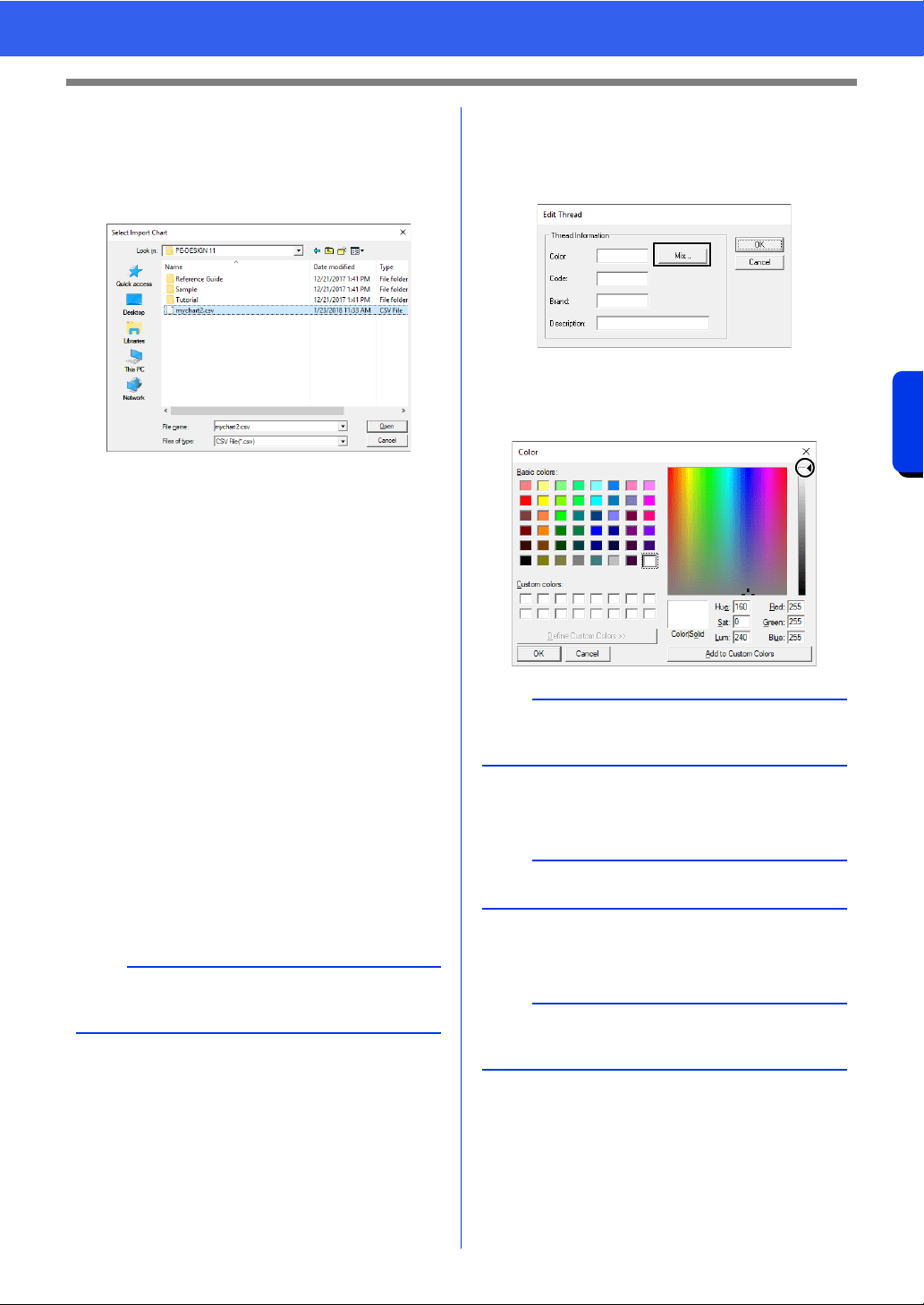
215
Operations for Specific Applications
Specifying/Saving Custom Sewing Attributes
■ Importing a thread chart
1 Click [Import Chart] h.
2 Select the drive, the folder, and the btc, btc2 or
csv file, and then click [Open].
Files in the .btc, .btc2 or .csv format can be
imported.
cc "Changing the order of items" on
page 216
3 If a message appears, click [Yes].
■ Editing a chart
1 From the [User Thread Chart] selector d,
select the chart.
2 Continue with the appropriate procedure. To
save the changes, click [OK].
■ Adding items from a thread chart
1 From the [Thread Chart] selector a, select
the thread brand or a user thread chart.
If multiple user thread charts have been
created, thread colors can be selected from
different user thread charts.
2 From the list j, click the thread colors.
3 Click [Add] b.
The selected items are added to the list in
the user thread chart l.
■ Adding a new item
1 Click [New Item] m.
2 To create a new color, click [Mix].
3 Specify the color, and then click [OK] to add
the specified color to the [Edit Thread] dialog
box.
4 If necessary, type in the code, brand and
description into the appropriate boxes.
5 Click [OK] to add the new item to the user
thread chart
l.
b
To add multiple items, hold down the <Shift> or
<Ctrl> keys while selecting thread colors.
b
The color cannot be changed if the slider (a) is
moved to the top of the scale.
b
Only numbers can be entered for the code.
b
An asterisk (*) appears in front of the index number
for items created or edited by the user.
(a)
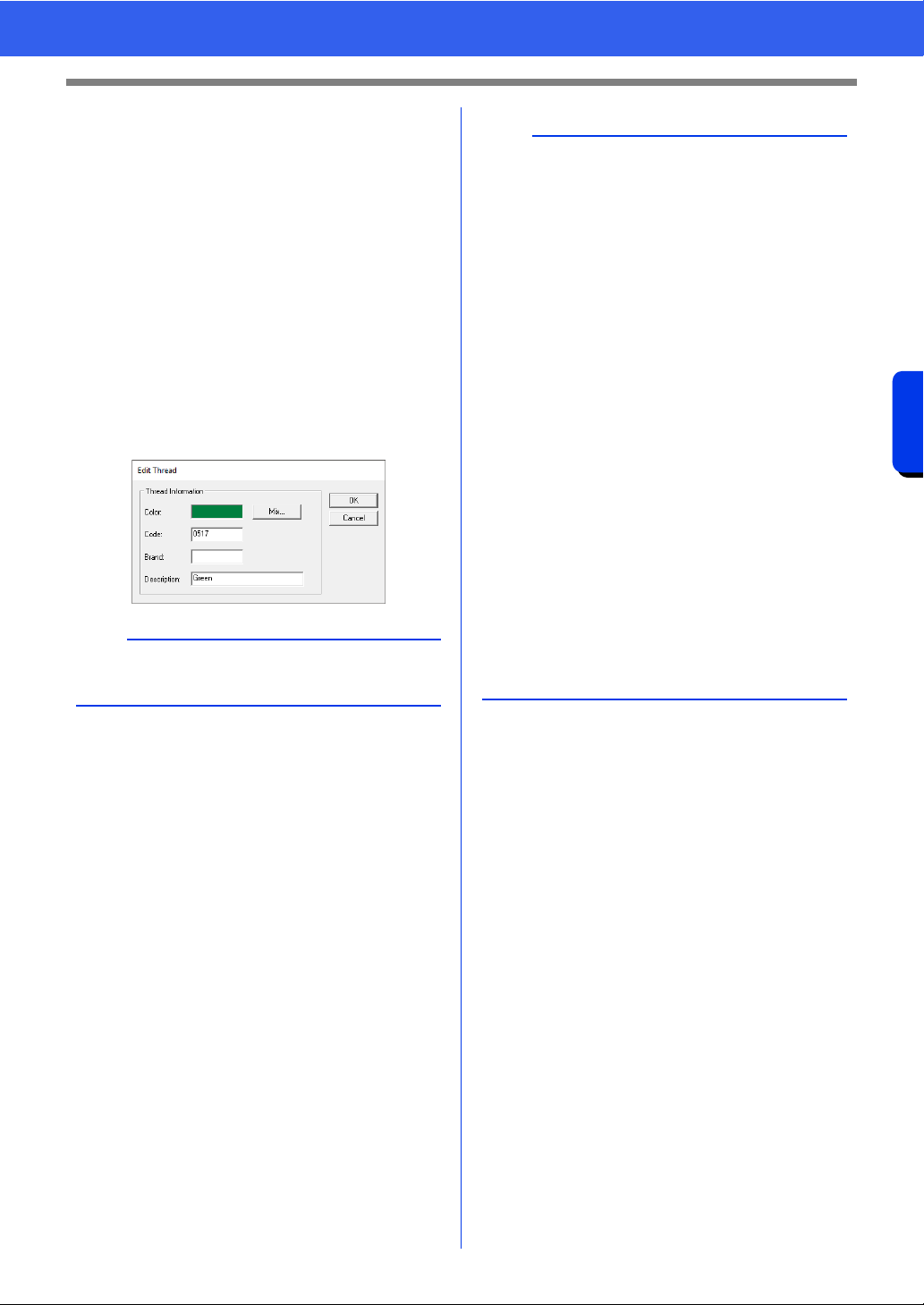
216
Operations for Specific Applications
Specifying/Saving Custom Sewing Attributes
■ Deleting items
1 From the list for the user thread chart l,
select the item to be deleted.
2 Click [Remove] k to delete the item from the
user thread chart.
■ Editing an item
An item registered in the list for a user thread chart
can be edited to change the color or thread number.
1 From the list for the user thread chart l,
select the item to be edited, and then click
[Edit Item] n.
2 Edit the item details in the same way as
adding a new item.
■ Changing the order of items
1 From the list for the user thread chart l,
select the item to be moved.
2 Click [Up] or [Down] i to change the order
of the item.
b
As with newly added items, an asterisk (*) appears
in front of the index number of edited items.
b
User thread chart files
Existing user thread charts can be imported, or
edited user thread charts can be used on a
different computer.
• A newly created user thread chart is saved, in
the .btc2 format with the same name as the
thread chart, at [C:\Program Files
(x86)\Brother\PE-DESIGN 11\MyChart].
• Existing user thread charts, created with the
previous versions of the application such as PE-
DESIGN 10, can be used in PE-DESIGN 11.
Import the file "chart2.btc" from the following
location;
[C:\Program Files (x86)\Brother\PE-DESIGN
10\Color].
• The file "chart1.btc" in the [Color] folder cannot
be imported.
• A user thread chart file in the .csv format can be
imported.
The .csv file should contain information for
Code, Brand, Description, R, G and B,
separated by commas with one color on each
line. The RGB values must be within 0-255.
Example: For a .csv file
100,MyBrand,Black,10,10,10
101,MyBrand,White,245,245,245
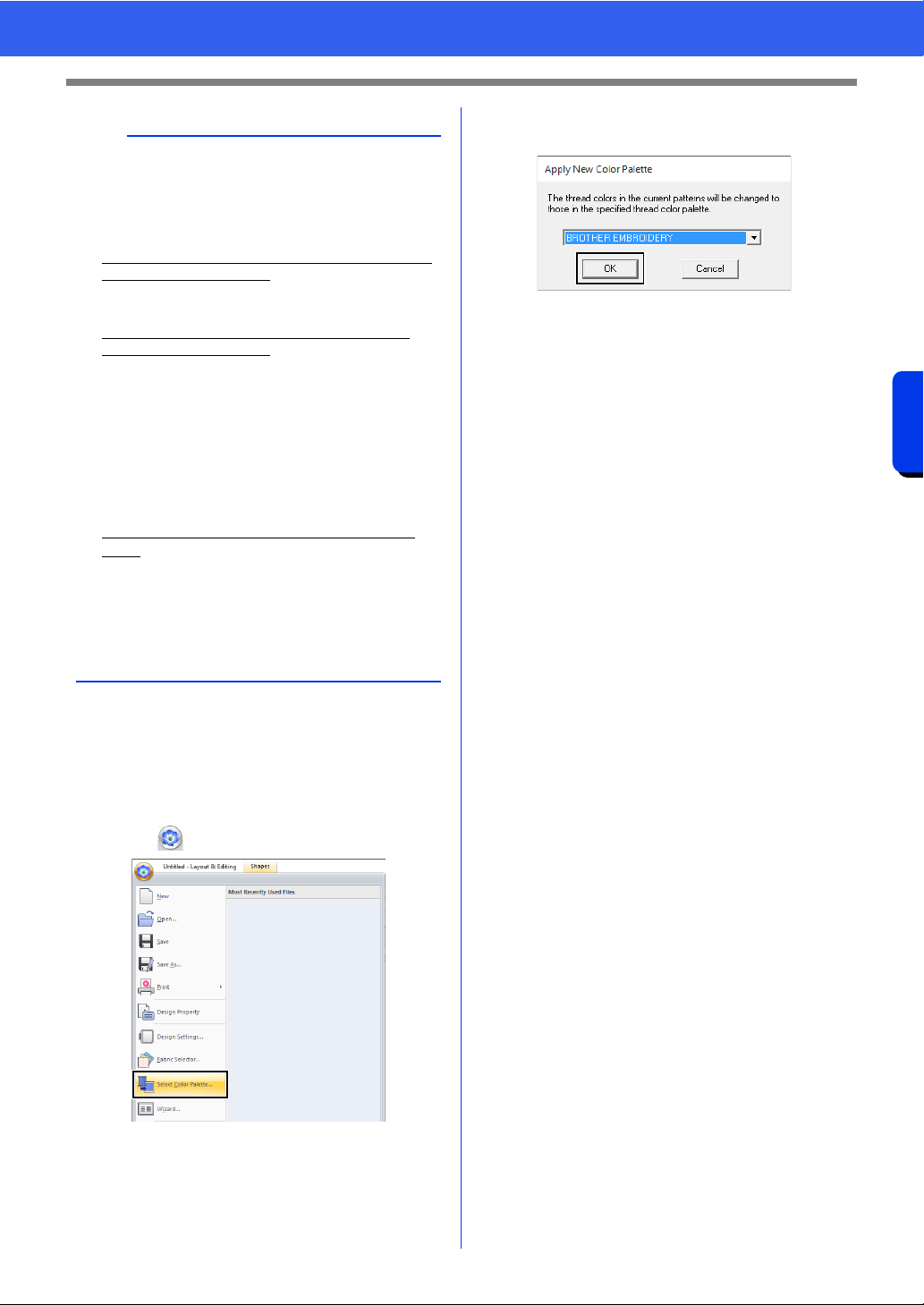
217
Operations for Specific Applications
Specifying/Saving Custom Sewing Attributes
■ Applying a different thread color
chart
The thread colors in the pattern currently displayed
in the Design Page can be converted to the colors in
a specified thread color chart.
1 Click , then [Select Color Palette].
2 In the dialog box, select a thread color chart,
and then click [OK].
The thread colors in all patterns in the
Design Page are converted to similar colors
in the specified thread color chart.
a
Thread colors in embroidery patterns created with
this application may appear differently on the
embroidery machine, depending on the model
used.
1. Embroidery machines without a function for
displaying thread colors
The specified thread color information cannot
be displayed at all.
2. Embroidery machines with a function for
displaying thread colors
Of the thread color information specified in the
embroidery pattern, only the thread color
names are displayed on the machine.
However, the names that are displayed are
limited to the machine's preset thread color
names. Therefore, the machine displays the
names of its preset thread colors that are
closest to the colors specified in the embroidery
pattern.
3. Embroidery machines with a thread color
index
Some machines can display the thread
information specified with this application.
However, for thread colors that have been
edited or added by the user (thread colors with
an asterisk (*) at the left side), only the thread
number is displayed.
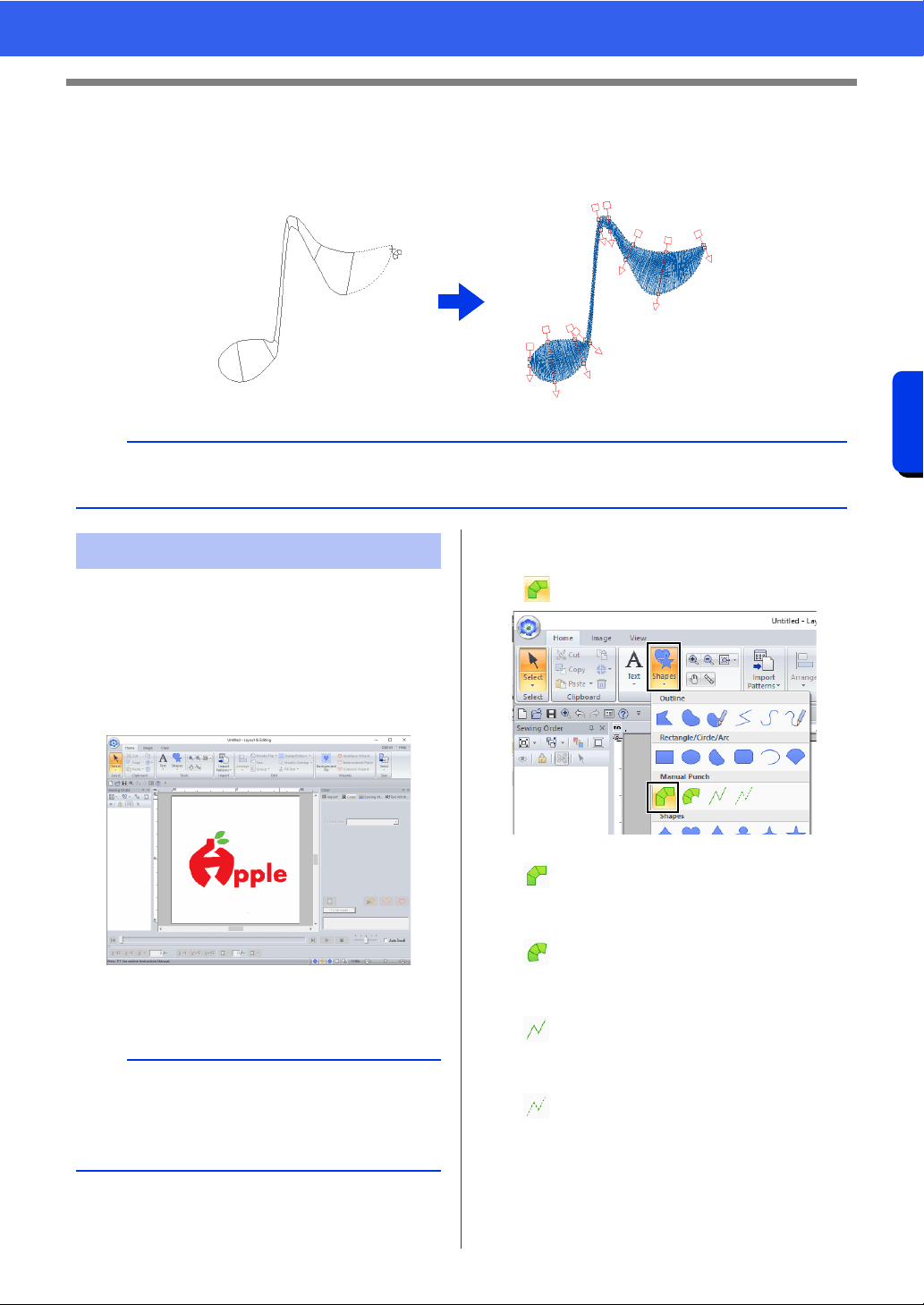
218
Operations for Specific Applications
Using Manual Punch Tool
Using Manual Punch Tool
By using the [Manual Punch] tools, you can create embroidery patterns whose sewing direction lines can be
manually adjusted.
Using the [Manual Punch] tools, an embroidery
pattern can be created using an image of your logo
in the background.
1 Open an image of the logo to be used to
create the embroidery pattern.
cc "Importing Image Data" on page 163
For this example, we will create a pattern of the red
design at the far left.
2 First, select the [Manual Punch] tool. Click
the [Home] tab, click [Shapes], and then click
.
cc "Jump Stitch and Jump Stitch Trimming"
on page 365
b
Shapes drawn using the [Manual Punch] tools can be edited in the same way as shapes drawn using the
[Shapes] tools.
Creating an original logo
b
A faded copy of the background image can be
displayed in the [Design Page].
cc "Adjusting the density of the background
image" on page 165
: Select this tool to create straight block
patterns (region sewing).
(Shortcut key: <Z>)
: Select this tool to create curved block
patterns (region sewing).
(Shortcut key: <X>)
: Select this tool to create running
patterns (line sewing).
(Shortcut key: <V>)
: Select this tool to create feed patterns
(jump stitches).
(Shortcut key: <B>)
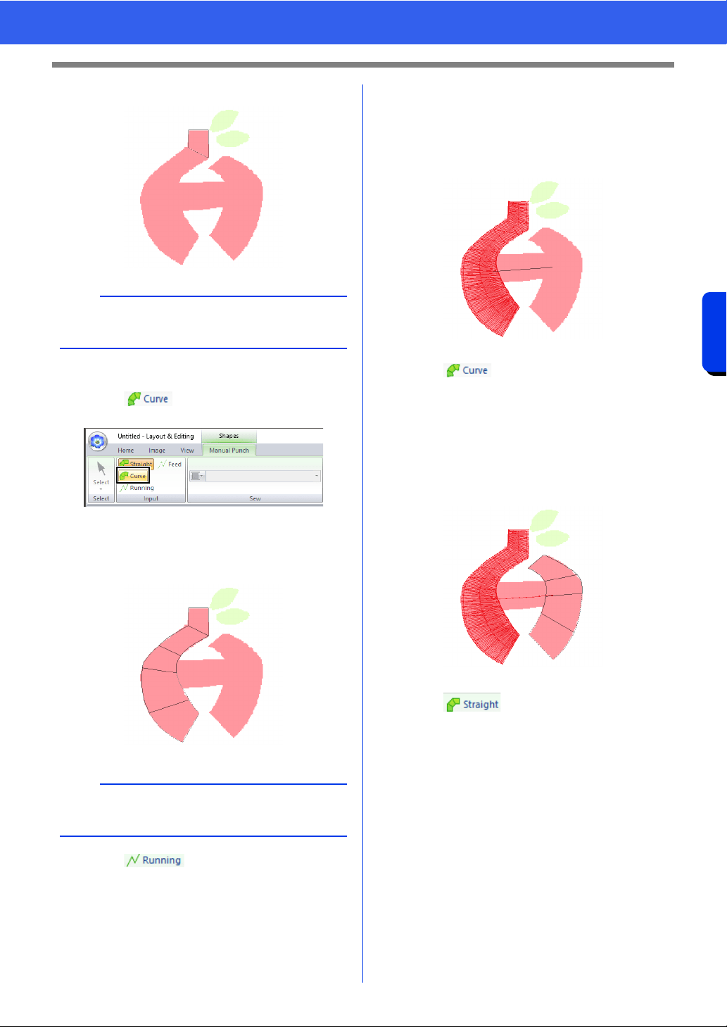
219
Operations for Specific Applications
Using Manual Punch Tool
3 Click points 1 through 4, in order.
4 Select the Curve tool.
Click in the [Input] group of the
[Manual Punch] tab.
5 Click points 5 through 11, in order.
Click point 12 (last point of the pattern part),
and then press the <Enter> key.
6 Click in the [Input] group of the
[Manual Punch] tab.
7 Click point 13, then point 14 (last point of
running stitching connecting the parts), and
then press the <Enter> key.
Specify the point so that it overlaps/connects
the part created in step
5.
8 Click in the [Input] group of the
[Manual Punch] tab.
9 Click points 15 through 23, in order.
Click point 24 (last point of the pattern part),
and then press the <Enter> key.
Specify the point so that it overlaps/connects
the part created in step
7.
10 Click in the [Input] group of the
[Manual Punch] tab.
b
To remove an entered point, right-click it or press
the <BackSpace> key.
b
Instead of pressing the <Enter> key, the pattern
part can be completed by double-clicking.
1
2
3
4
6
5
10
7
8
9
11
12
13
14
16
15
19
17
18
23
21
22
24
20
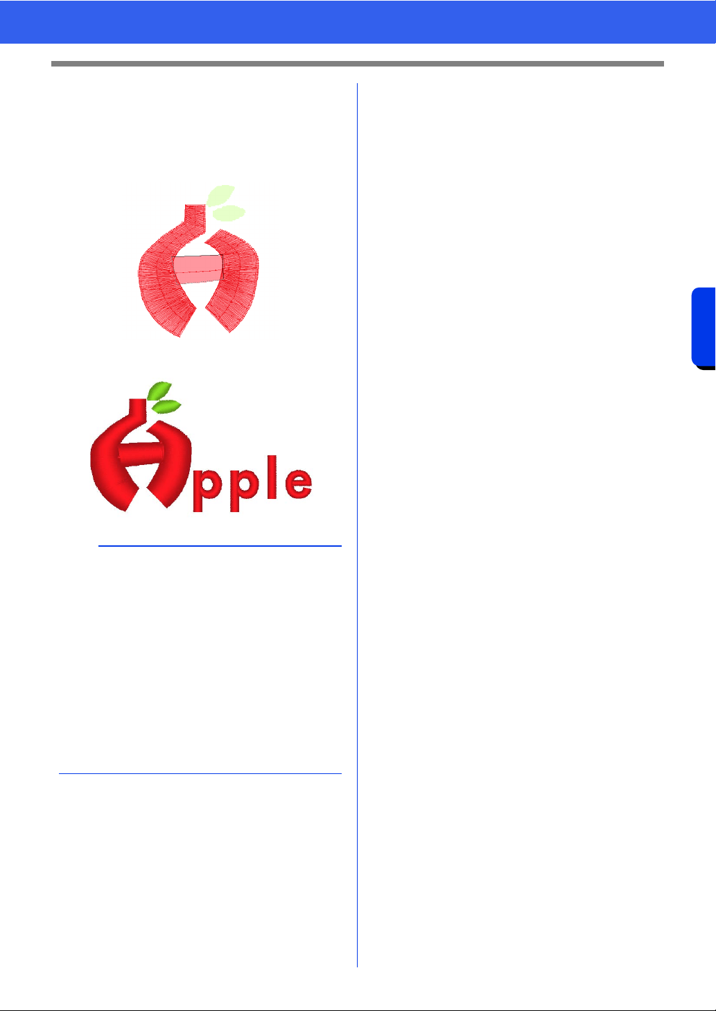
220
Operations for Specific Applications
Using Manual Punch Tool
11 Click points 25 through 27, in order.
Click point 28 (last point of the pattern part),
and then press the <Enter> key.
Specify the point so that it overlaps/connects
the part created in step
9.
Image of finished logo
b
• If parts are connected to previous and following
ones, jump stitches will not be created in order
to automatically optimize entry and exit points.
We recommend checking stitching with the
Stitch Simulator before sewing.
cc "Checking the stitching with the Stitch
Simulator" on page 90
• Manually adding or adjusting sewing direction
lines in shape patterns afterward allows you to
continue creating patterns using the same
Manual Punch tools.
cc "Specifying the straight sewing direction" on
page 59
26
25
27
28

Transferring Data
This section describes operations for transferring
embroidery designs to embroidery machines.
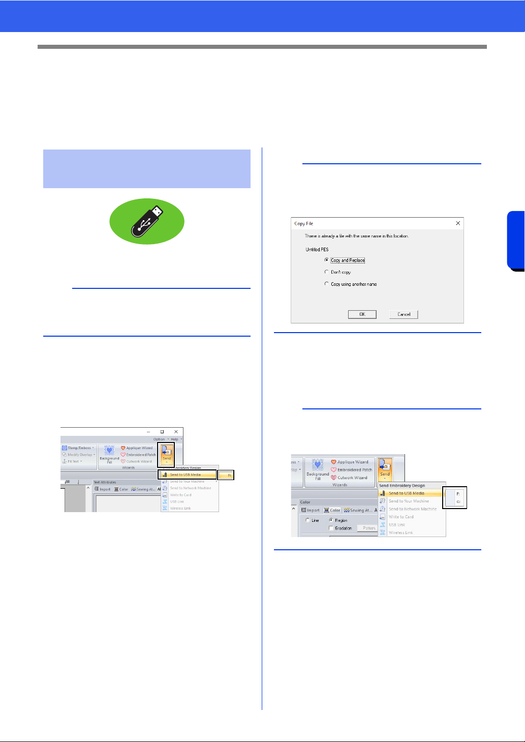
222
Transferring Data
Transferring Embroidery Designs to Machines
Transferring Embroidery Designs to
Machines
The procedures for transferring the created embroidery pattern to an embroidery machine differ depending on
your embroidery machine model. For details, refer to the instruction manual provided with your embroidery
machine.
Designs can be transferred to an embroidery
machine compatible with the USB Host function.
1 Plug the USB media into the computer.
2 Click the [Home] tab.
3 Click [Send] in the [Sew] group, click [Send
to USB Media], and then select the desired
drive.
Data transfer begins.
4 After the data has been transferred, the
message "Finished outputting data." appears,
indicating that the transfer is finished. Click
[OK], and then remove the USB media.
Transferring to a machine
by using USB media
a
The "PE-DESIGN Software Key" cannot be used
as USB media. Do not save embroidery files on
the "PE-DESIGN Software Key" for transferring.
a
If there is already a file with the same name at the
destination, the following dialog box appears.
Select whether to overwrite the existing file, to stop
copying or to copy the file using a different name.
b
If multiple USB media are connected, specify
where the data is to be transferred in the area
shown below.
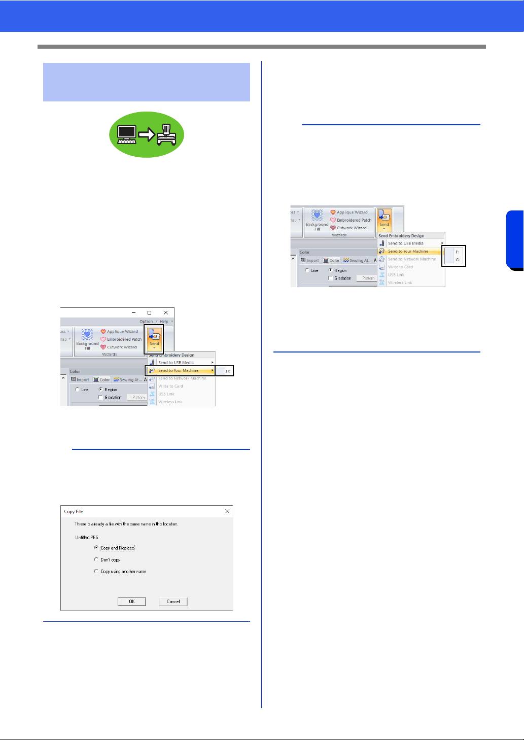
223
Transferring Data
Transferring Embroidery Designs to Machines
Designs can be transferred to embroidery machines
that can be connected to a computer using a USB
cable.
1 Connect the embroidery machine to the
computer.
2 Click the [Home] tab.
3 Click [Send] in the [Sew] group, click [Send
to Your Machine], and then select the
desired drive.
Data transfer begins.
4 After the data has been transferred, the
message "Finished outputting data." appears,
indicating that the transfer is finished. Click
[OK].
Transferring directly to a
machine's memory
a
If there is already a file with the same name at the
destination, the following dialog box appears.
Select whether to overwrite the existing file, to stop
copying or to copy the file using a different name.
b
• For details on transferring designs with this
method, refer to the instruction manual provided
with your embroidery machine.
• If multiple machines are connected, specify
where the data is to be transferred in the area
shown below.
• If the connected embroidery machine has been
set to Link mode, the command [Send to Your
Machine], mentioned in this procedure, cannot
be selected. To select this command, return the
machine to normal mode.
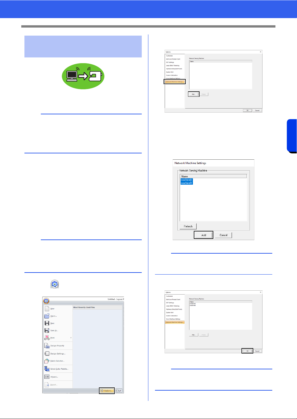
224
Transferring Data
Transferring Embroidery Designs to Machines
Embroidery designs can be transferred to a sewing
machine via the wireless network.
■ Registering a machine with the
application
1 Connect the computer running the application
to your home network (wireless LAN access
point).
2 Connect the sewing machine to the same
home network.
For details on making connections, refer to the
manual provided with your machine.
3 Click , and then click [Options] at the
bottom of the command list.
4 Click [Network Machine Settings], and then
click [Add].
The names of sewing machines connected
to your home network (wireless LAN
access point) appear.
5 Select the sewing machine, and then click
[Add].
6 Click [OK] to register the machine.
Transferring to a machine
via wireless network
a
This function is available only when embroidering
with our wireless LAN-compatible embroidery
machines.
Contact your authorized dealer for details on our
wireless LAN-compatible models.
b
Embroidery patterns cannot be transferred if the
computer and sewing machine are connected to
different home network. Be sure to connect to the
same home network.
b
If the desired sewing machine does not appear in
the list, click [Refresh].
b
To unregister a machine, select the machine, click
[Delete], and then click [OK].
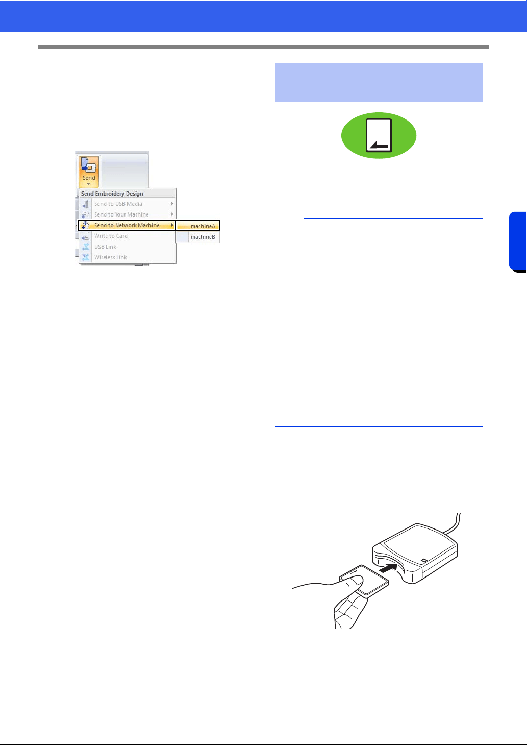
225
Transferring Data
Transferring Embroidery Designs to Machines
■ Transferring embroidery patterns
to a sewing machine
1 Click the [Home] tab.
2 Click [Send] in the [Sew] group, click [Send
to Network Machine], and then select the
desired machine.
Data transfer begins.
3 After the data has been transferred, the
message “Finished outputting data.” appears,
indicating that the transfer is finished. Click
[OK].
Designs can be transferred to an embroidery
machine equipped with a card slot.
cc For details on writing multiple embroidery
designs, refer to "Transferring
Embroidery Designs to Machines" on
page 284.
1 Plug the USB card writer module. Insert an
original card into the USB card writer module.
2 Click the [Home] tab.
Transferring to a machine
by using an original card
a
• Be sure that the hoop size of the design does not
exceed the hoop that will be used on the
embroidering machine.
• When writing to an original card that already
contains data, all data on the card will be
deleted. Before writing to a card, save all
necessary data to a hard disk or other media,
and check that no necessary data remains on
the card.
cc "From an original card" on page 103
• An embroidery design for the jumbo frame
cannot be transferred to the machine by using
an original card. This size is designed
specifically for our multi-needle embroidery
machines equipped with a built-in camera.
cc "Tutorial 10-3: Embroidering With the Jumbo
Frame" on page 209
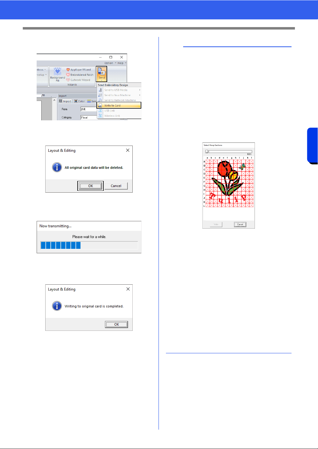
226
Transferring Data
Transferring Embroidery Designs to Machines
3 Click [Send] in the [Sew] group, and then click
[Write to Card].
4 When the following message appears, click
[OK].
Data transfer begins. The following
message appears while the data is being
transferred.
5 After the data has been transferred, the
following message appears, indicating that the
transfer is finished. Click [OK].
a
Transferring split embroidery designs
Embroidery patterns for the split patterns created
on the custom-sized Design Page are written to
cards split into their separate sections.
If the total size of the pattern exceeds the capacity
of the media or the machine's memory or if the
pattern is split into over 80 sections with a Design
Page size of 90 × 90 cm (35.4" × 35.4"), you will
need to split the pattern and write the separate
sections onto several media.
If all pattern sections cannot be saved with a single
operation, the [Select Hoop Sections] dialog box
appears. Select pattern sections until the media
becomes full.
The card capacity indicator at the top of the dialog
box shows the amount of space available on the
card (white) and the amount of space used by the
pattern sections (blue).
When a pattern section is selected, the total
amount of space used by the selected pattern
sections appears in blue. If the capacity is
exceeded, the entire card capacity indicator
appears in red. To deselect a pattern section, click
it again.
Click [Write] to write the selected pattern sections
to the media. (The [Write] button is available only
when a pattern section is selected and there is
sufficient space on the media for the selected
pattern sections.)
cc For details on creating split embroidery
designs, refer to "Tutorial 10-1: Creating Split
Embroidery Designs" on page 195.
227
Transferring Data
Using the Link Function to Embroider From the Computer
Using the Link Function to Embroider
From the Computer
There are two types of Link functions: [USB Link]
and [Wireless Link]. If [Link] is listed in the settings
screen of your embroidery machine, your machine
supports the USB Link function.
Embroidery designs can be embroidered by
transferring the embroidery data from the computer
to one or more embroidery machines compatible
with the USB Link function. Connect the embroidery
machine and computer with a USB cable. These
embroidery designs are embroidered after the data
is sent from the computer to the embroidery
machine in the same way that a document is printed
after the data is sent from a computer to a printer.
1 Create an embroidery design in [Layout &
Editing].
2 Set the embroidery machine in USB Link
mode.
• Turn on the USB Link function of the
embroidery machine, and then turn off the
machine.
3 Use the USB cable included with the
embroidery machine to connect the machine
to the computer.
• Turn on the embroidery machine.
4 Click the [Home] tab.
USB Link
a
• The USB Link function can be used only with
embroidery machines compatible with the
function; it cannot be used with other machines.
For details, refer to the instruction manual
provided with your embroidery machine.
• The USB Link function cannot be used with the
following embroidery designs.
Size exceeds the area that can be
embroidered with the machine
Embroidery designs in a Design Page of a
custom size or for the jumbo frame
Size selected in the [Hoop Size] selector of
the [Design Settings] dialog box is for an
embroidery hoop that does not completely fit
within the maximum embroidering area of the
embroidery machine to which the data is
transferred
• Up to four embroidery machines can be
connected using the USB Link function.
a
For details on setting the machine in USB Link
mode, refer to the instruction manual provided with
your embroidery machine.
a
• For details on connecting the machines to the
computer, refer to the instruction manual
provided with your embroidery machine.
• If the machine is positioned far from the
computer, we recommend you to use a self-
powered USB hub. Do not use USB extension
cables or repeater cables.
• Do not connect or disconnect the USB cable
while the machine is turned on.
•Select [Power Options] in [Control Panel], and
then set both [System standby] and [System
hibernates] to [Never].
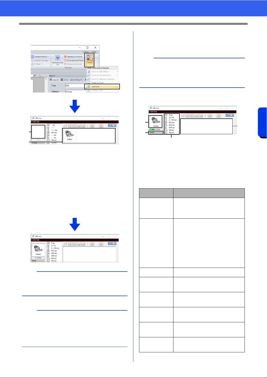
228
Transferring Data
Using the Link Function to Embroider From the Computer
5 Click [Send] in the [Sew] group, and then click
[USB Link].
a Transferred design
b Queue
Displays the data before it is transferred
to the embroidery machine.
When the machine is ready to start loading
the data, data transfer begins. While the
data is being transferred, a message
appears in the screen of the embroidery
machine, and the design moves to the
transferred design area.
6 After the design has been transferred, press
the start/stop button on the embroidery
machine to begin embroidering.
When embroidering is started, the following appears
in the [USB Link] dialog box.
a Transferred design
b Queue
c Shows the status of the embroidery
machine.
d Status indication
Each status indication is described below
a
If the data sent from [Layout & Editing] does not
appear in the transferred design box, continue the
operation by using the machine's operation panel.
b
If you want to send more than one design to the
[USB Link] dialog box, repeat steps
4 and 5 for
each design. The [USB Link] dialog will remain
open while the selected design from [Layout &
Editing] will be sent to the Link.
a
b
b
The transferred data cannot be edited from the
embroidery machine. The received data can only
be embroidered. However, embroidering settings
can be specified.
Status Description
Ready Press the button on the
embroidery machine (Start/Stop
button) to start sewing.
Waiting If there is no data in the queue
b, select [USB Link] as the
destination in the application,
and send data.
If this is the status even though
there is data in the queue b,
continue the operation by using
the machine's operation panel.
Sewing The machine is sewing.
Paused The machine has temporarily
been stopped.
Color
change
Change the thread spool on the
machine.
Check
thread
Check the bobbin thread or the
upper thread on the machine.
Check frame Install a different embroidery
frame on the machine.
Error Check the details of the error
that occurred on the machine.
c
a
b
d
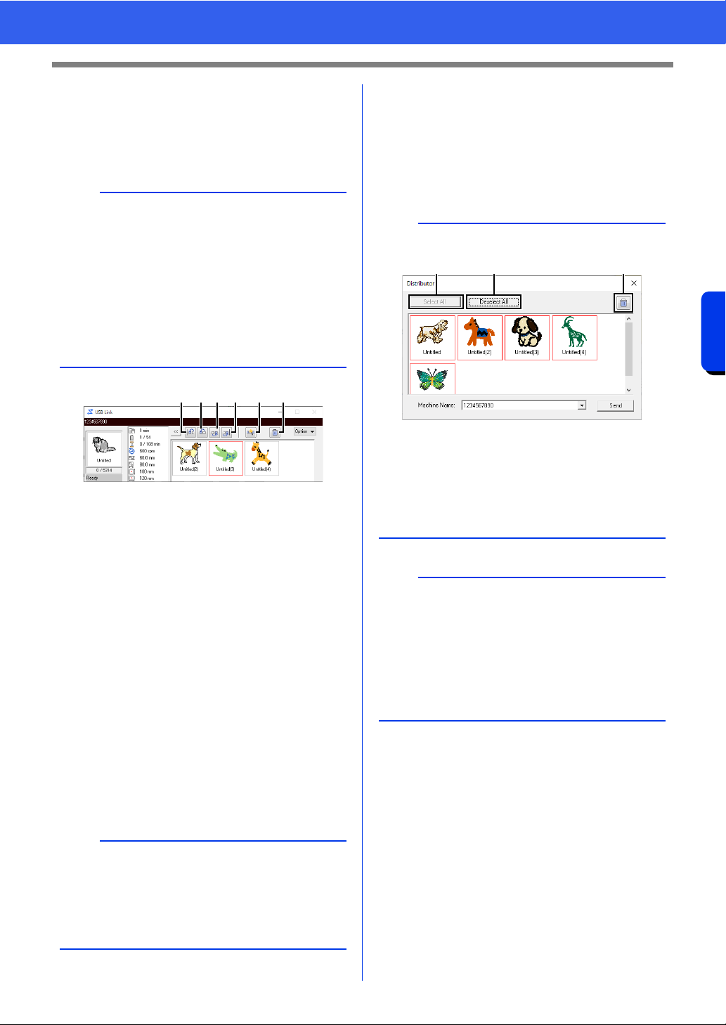
229
Transferring Data
Using the Link Function to Embroider From the Computer
■ If multiple designs were sent to a
single machine
Multiple embroidery designs can be embroidered
after being sent to the [USB Link] dialog box. In this
case, the dialog box appears as shown below.
The following operations can be performed from this
dialog box.
a Moves the selected design(s) to the
beginning of the embroidering order.
b Moves the selected design(s) one
position forward in the embroidering
order.
c Moves the selected design(s) one
position backward in the embroidering
order.
d Moves the selected design(s) to the end
of the embroidering order.
e Automatically adjusts the embroidering
order of the designs to reduce as much as
possible the number of thread color
changes.
f Deletes the selected design(s) from the
[USB Link] dialog box.
■ If multiple embroidery machines
are connected
The [Distributor] dialog box appears, in addition
with the [USB Link] dialog box for each embroidery
machine. The designs in the [Distributor] dialog will
all be selected. Specify which file is to be transferred
to which machine.
b
• Design Database is available to send multiple
designs at a time.
cc "Sending embroidery designs to machines by
using the Link function" on page 289
• With the [Name Drop] function, you can also
send multiple designs where only the text is
replaced.
cc "Outputting patterns using text from the text
list" on page 137
b
Before the message "The machine will move.
Keep your hands etc. away from the machine."
appears on the machine and [OK] is pressed, the
embroidering order of the designs, including the
first one, can be changed since the first design has
not yet been sent to the machine.
abcd e f
b
Distributor dialog box
a Selects all embroidery designs.
b Deselects the embroidery designs.
c Deletes the selected embroidery design.
(The design is deleted without being
moved to the <Recycle Bin>.)
a
• For multiple designs to be sent in Layout &
Editing, repeat step 5 for each design.
cc "USB Link" on page 227
• When using Design Database, multiple patterns
can be sent once in the [Distributor] dialog box.
cc "Sending embroidery designs to machines by
using the Link function" on page 289
a b c
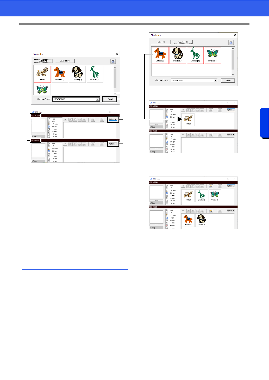
230
Transferring Data
Using the Link Function to Embroider From the Computer
1 Select a machine in the [Machine Name] a
selector, select an embroidery file, and then
click [Send]
b .
a Machine Name
b Sends the selected embroidery file to the
[USB Link] dialog box.
c The [Distributor] dialog box can also be
displayed by clicking [Distributor] on the
[Option] menu of the [USB Link] dialog
box.
The embroidery designs are moved to the
[USB Link] dialog box.
2 Repeat step 1 to move each design to the
[USB Link] dialog box.
b
• The initial machine name is the machine's ID.
For details, refer to the instruction manual
provided with your embroidery machine.
• The name of the machine can be changed.
For details, refer to "Changing the embroidery
machine name appearing with the USB Link
function" on page 231
b
a
c
c
a
a
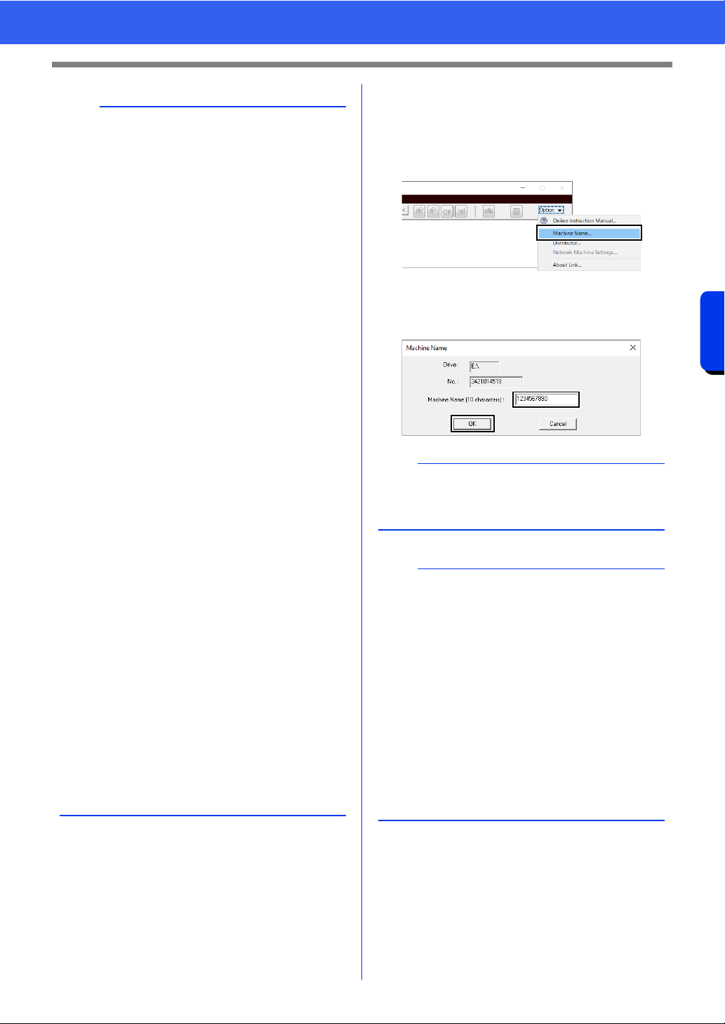
231
Transferring Data
Using the Link Function to Embroider From the Computer
■ Changing the embroidery
machine name appearing with the
USB Link function
1 Click [Machine Name] in the [Option] menu
of the queue whose name is to be changed.
2 Type the name in the [Machine Name] box,
and then click [OK].
b
• The embroidering order of designs in the queue
can be changed.
cc For details, refer to "If multiple designs were
sent to a single machine" on page 229.
• If additional machines are connected while the
[USB Link] dialog box is displayed,
corresponding queues will appear. If a machine
is disconnected, the corresponding queue will
disappear.
• To display the [Property] dialog box for a file,
double-click the file's icon, or click a file to select
it, right-click it, and then click [Property] from
the menu that appears.
• To reduce this dialog box to a button on the
taskbar, click the [Minimize] button.
To disconnect the USB cable, or shut down the
computer
• After data transferring to embroidery machine
and the transferring message on the screen of
the machine is closed, you can disconnect the
USB cable, or shut down the computer.
When connected to the embroidery machine
again, you can continue the USB Link operation.
• The embroidery machine can finish sewing the
design currently being embroidered even if the
computer is turned off.
• If the embroidery machine is turned off while it is
embroidering, the resume operation can be
used the next time it is turned on. At that time,
transmission can be resumed using the USB
Link function by clicking [USB Link] in [Design
Database] or in the [Option] menu of [Layout
& Editing] to display the [USB Link] dialog box.
• If the embroidery machine connection cannot be
detected, the [USB Link] dialog box will close
automatically.
• To display the [USB Link] dialog box again after
the computer has been restarted, click [USB
Link] in [Design Database] or in the [Option]
menu (in the upper-right corner) of [Layout &
Editing].
• To display the [Distributor] dialog box, click
[Distributor] in the [Option] menu of the [USB
Link] dialog box.
b
A name (up to 10 alphanumeric characters/
symbols) can be specified for the embroidery
machine.
a
• When an embroidery machine is connected to
the computer, the embroidery machine is
recognized by the computer as a removable disk
and is assigned a drive letter. If this drive letter
is the same as one that has already been
assigned by the computer, designs cannot be
sent from the computer to that embroidery
machine. This problem occurs, for example, if a
network drive has been assigned a computer
drive letter. If this occurs, cancel the assignment
for the drive with the conflicting drive letter.
• When the number of embroidery machines
connected to the computer via USB is
increased, the operating system may require
that the computer be restarted. At that time,
restart the computer.
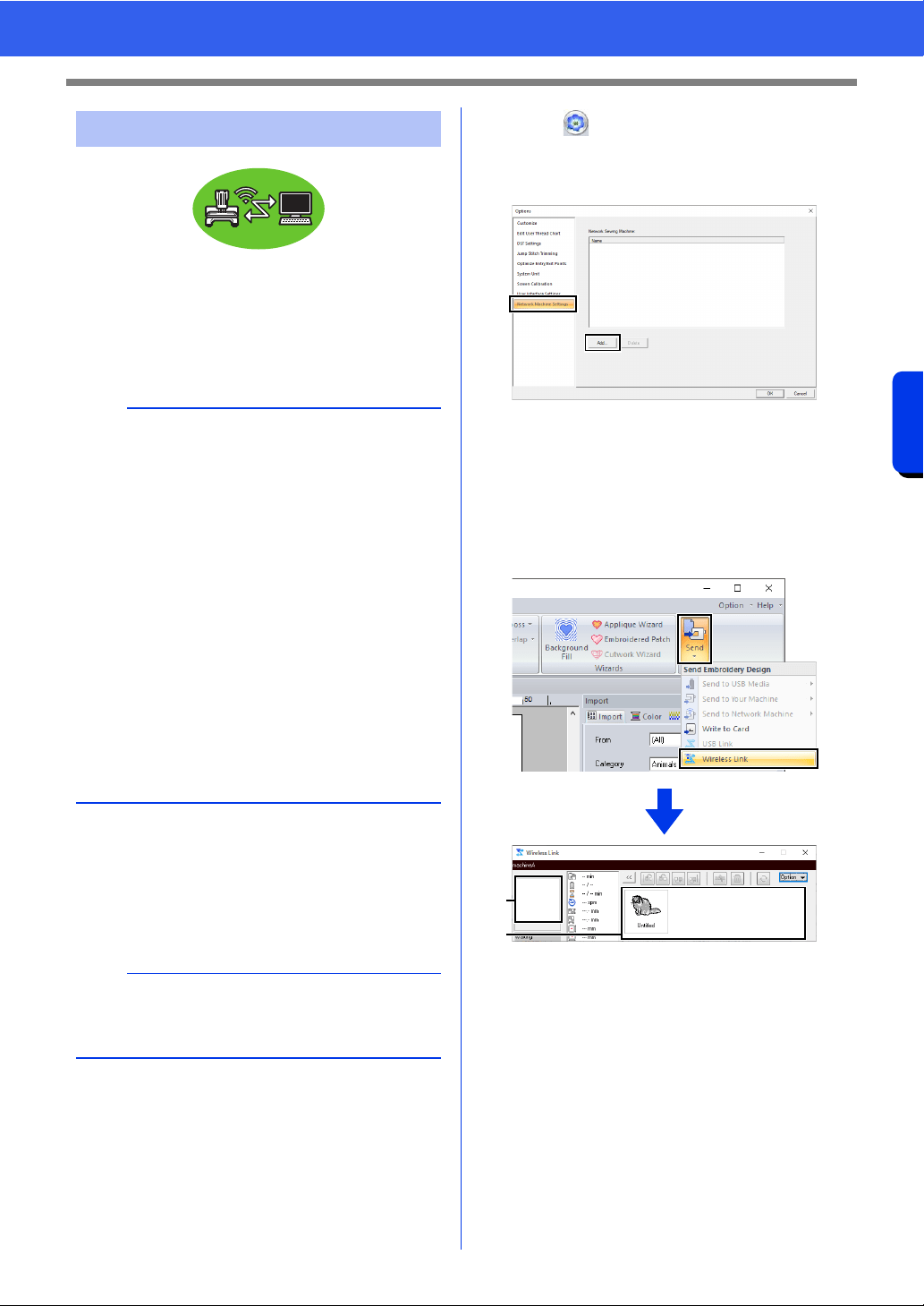
232
Transferring Data
Using the Link Function to Embroider From the Computer
Embroidery designs can be embroidered by
transferring the embroidery data from the computer
to one or more embroidery machines that support
the Wireless Link function. This is useful when the
embroidery machine and computer are set up where
they cannot be connected with a USB cable.
1 Create an embroidery design in [Layout &
Editing].
2 Connect to the embroidery machine
wirelessly, and then set to the Link mode that
uses a wireless network connection.
3 Click , and then click [Options]. Display
the [Network Machine Settings] dialog box,
and then register an embroidery machine on
the network.
cc For detailed instructions, see
"Transferring to a machine via wireless
network" on page 224.
4 Click the [Home] tab.
5 Click [Send] in the [Sew] group, and then click
[Wireless Link].
a Transferred design
Displays transferred data. If [Connection
Error] occurred, the error information
appears.
b Queue
Displays the data before it is transferred
to the embroidery machine.
When the machine is ready to start loading
the data, data transfer begins. While the
data is being transferred, a message
appears in the screen of the embroidery
machine, and the design moves to the
transferred design area.
Wireless Link
a
• The Wireless Link function can be used only with
embroidery machines compatible with the
function; it cannot be used with other machines.
For details, refer to the instruction manual
provided with your embroidery machine.
• The Wireless Link function cannot be used with
the following embroidery designs.
Size exceeds the area that can be
embroidered with the machine
Embroidery designs in a Design Page of a
custom size or for the jumbo frame
Size selected in the [Hoop Size] selector of
the [Design Settings] dialog box is for an
embroidery hoop that does not fit within the
maximum embroidering area of the
embroidery machine to which the data is
transferred
• Up to ten embroidery machines can be
connected using the Wireless Link function.
a
For details on setting the machine, refer to the
instruction manual provided with your embroidery
machine.
a
b
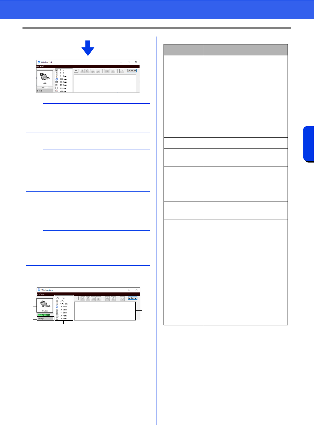
233
Transferring Data
Using the Link Function to Embroider From the Computer
6 After the design has been transferred, press
the start/stop button on the embroidery
machine to begin embroidering.
When embroidering is started, the following appears
in the [Wireless Link] dialog box.
a Transferred design
b Queue
c Shows the status of the embroidery
machine.
d Status indication
Each status indication is described below
a
If the data sent from [Layout & Editing] does not
appear in the transferred design box, continue the
operation by using the machine's operation panel.
b
If you want to send more than one design to the
[Wireless Link] dialog box, repeat steps
4 and 5
for each design. The [Wireless Link] dialog will
remain open while the selected design from
[Layout & Editing] will be sent to the Link.
b
The transferred data cannot be edited from the
embroidery machine. The received data can only
be embroidered. However, embroidering settings
can be specified.
c
a
b
d
Status Description
Ready Press the button on the
embroidery machine (Start/Stop
button) to start sewing.
Waiting If there is no data in the queue
b, select [Wireless Link] as
the destination in the
application, and send data.
If this is the status even though
there is data in the queue
b,
continue the operation by using
the machine's operation panel.
Sewing The machine is sewing.
Paused The machine has temporarily
been stopped.
Color
change
Change the thread spool on the
machine.
Check
thread
Check the bobbin thread or the
upper thread on the machine.
Check frame Install a different embroidery
frame on the machine.
Error Check the details of the error
that occurred on the machine.
Connection
Error
The error information appears
in the box (
a) where the
transferred design is displayed.
If the embroidery machine is
not in Wireless Link mode, start
it up in Wireless Link mode.
If a network error has occurred,
check the network connection
between the computer and
embroidery machine.
Connecting…
Searching for an embroidery
machine on the same network.
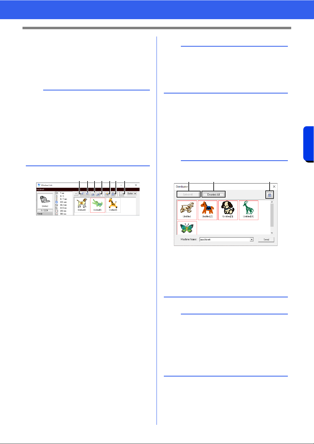
234
Transferring Data
Using the Link Function to Embroider From the Computer
■ If multiple designs were sent to a
single machine
Multiple embroidery designs can be embroidered
after being sent to the [Wireless Link] dialog box.
In this case, the dialog box appears as shown
below.
The following operations can be performed from this
dialog box.
a Moves the selected design(s) to the
beginning of the embroidering order.
b Moves the selected design(s) one
position forward in the embroidering
order.
c Moves the selected design(s) one
position backward in the embroidering
order.
d Moves the selected design(s) to the end
of the embroidering order.
e Automatically adjusts the embroidering
order of the designs to reduce as much as
possible the number of thread color
changes.
f Deletes the selected design(s) from the
[Wireless Link] dialog box.
g Reconnects to the machine if
communication was interrupted. Available
only if a network error has occurred.
■ If multiple embroidery machines
are connected
The [Distributor] dialog box appears, in addition
with the [Wireless Link] dialog box for each
embroidery machine. The designs in the
[Distributor] dialog will all be selected. Specify
which file is to be transferred to which machine.
b
• Design Database is available to send multiple
designs at a time.
cc "Sending embroidery designs to machines by
using the Link function" on page 289
• With the [Name Drop] function, you can also
send multiple designs where only the text is
replaced.
cc "Outputting patterns using text from the text
list" on page 137
abcdefg
b
Before the message "The machine will move.
Keep your hands etc. away from the machine."
appears on the machine and [OK] is pressed, the
embroidering order of the designs, including the
first one, can be changed since the first design has
not yet been sent to the machine.
b
Distributor dialog box
a Selects all embroidery designs.
b Deselects the embroidery designs.
c Deletes the selected embroidery design.
(The design is deleted without being
moved to the <Recycle Bin>.)
a
• For multiple designs to be sent in Layout &
Editing, repeat step 5 for each design.
cc "Wireless Link" on page 232
• When using Design Database, multiple patterns
can be sent once in the [Distributor] dialog box.
cc "Sending embroidery designs to machines by
using the Link function" on page 289
a b c
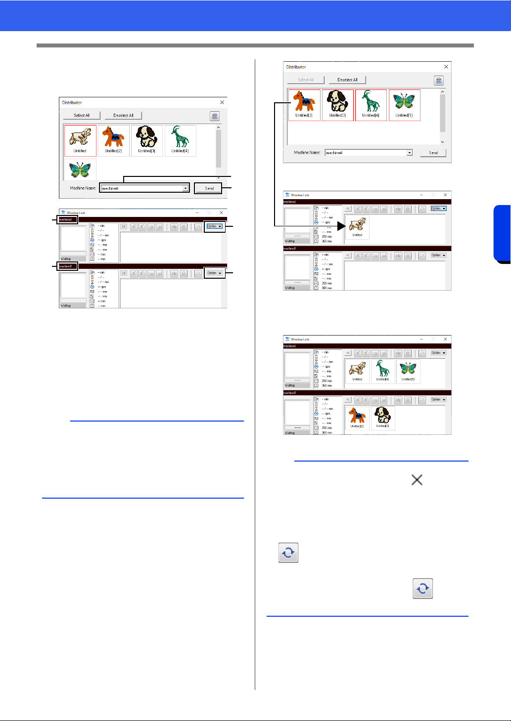
235
Transferring Data
Using the Link Function to Embroider From the Computer
1 Select a machine in the [Machine Name] a
selector, select an embroidery file, and then
click [Send]
b .
a Machine Name
b Sends the selected embroidery file to the
[Wireless Link] dialog box.
c The [Distributor] dialog box can also be
displayed by clicking [Distributor] on the
[Option] menu of the [Wireless Link]
dialog box.
The embroidery designs are moved to the
[Wireless Link] dialog box.
2 Repeat step 1 to move each design to the
[Wireless Link] dialog box.
b
• With embroidery machines that support
Wireless Link mode, the name registered with
the embroidery machine appears as the
machine name.
For details, refer to the instruction manual
provided with your embroidery machine.
b
a
c
c
a
a
b
• To exit Wireless Link mode, click in the
upper-right corner of the [Wireless Link] dialog
box.
• If the embroidery machine is turned off while
embroidering, a network error will occur. Turn
the machine off, then on again, and then press
to re-establish the connection.
* It may not be possible to re-establish the
connection, even after pressing , until
the embroidery machine has restarted.
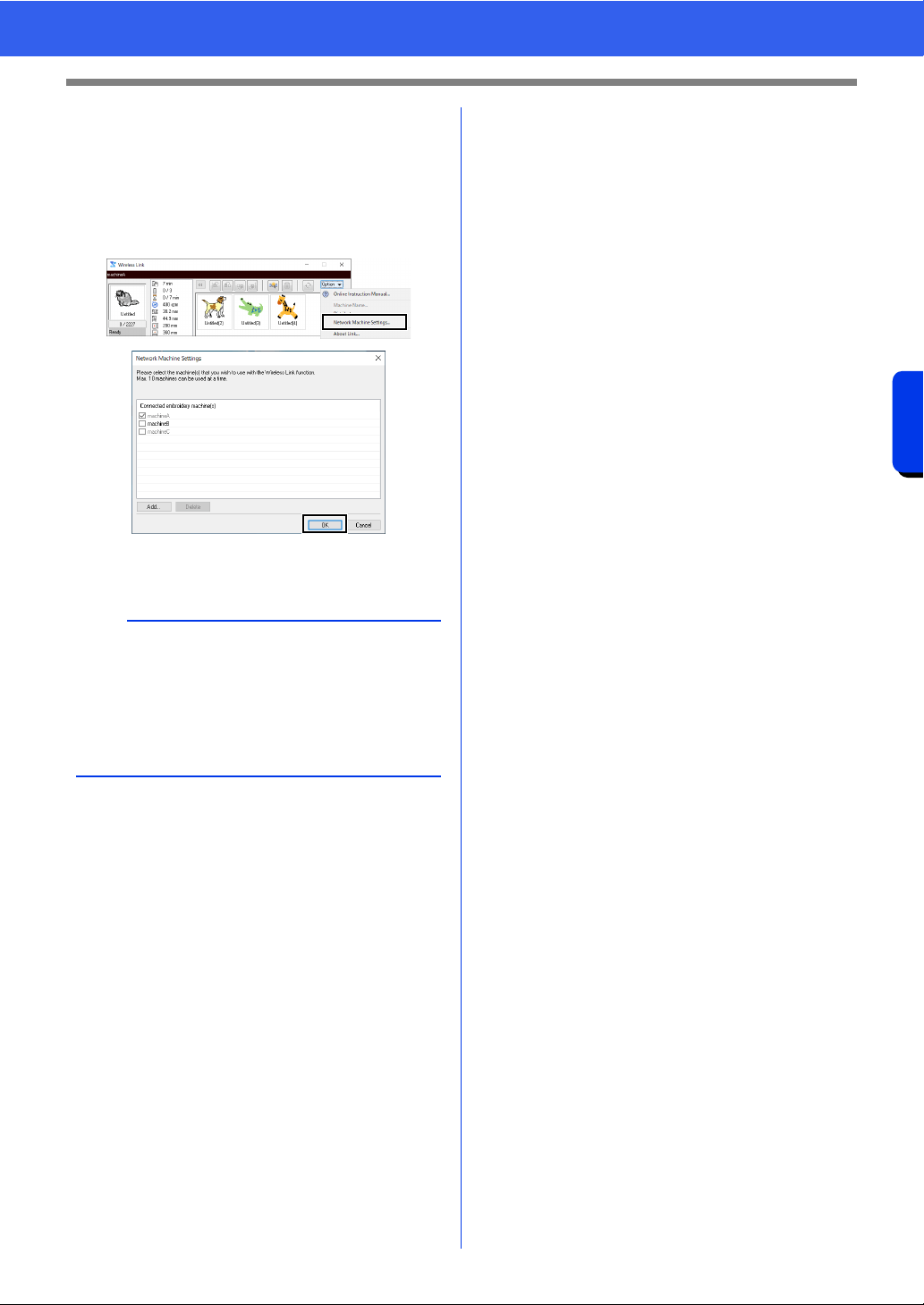
236
Transferring Data
Using the Link Function to Embroider From the Computer
■ Changing the number of
connected embroidery machines
Click [Options] in the [Wireless Link] dialog box to
display the [Network Machine Settings] dialog
box. In the list of registered embroidery machines,
select the check box of the embroidery machine to
connect to, and then click [OK].
The [Wireless Link] dialog box for the
embroidery machine appears.
a
• To switch between Wireless Link and USB Link,
close the dialog box, click [Send] in the [Sew]
group, and then click either [Wireless Link] or
[USB Link].
Set the appropriate Link function on the
embroidery machine (Wireless LAN or USB
cable).

Compatibility with ScanNCut
(Brother cutting machine)
This section describes basic operations in
ScanNCut (Brother cutting machine) as well as
the functions for linking it to this software. The
operations are performed in Layout & Editing.
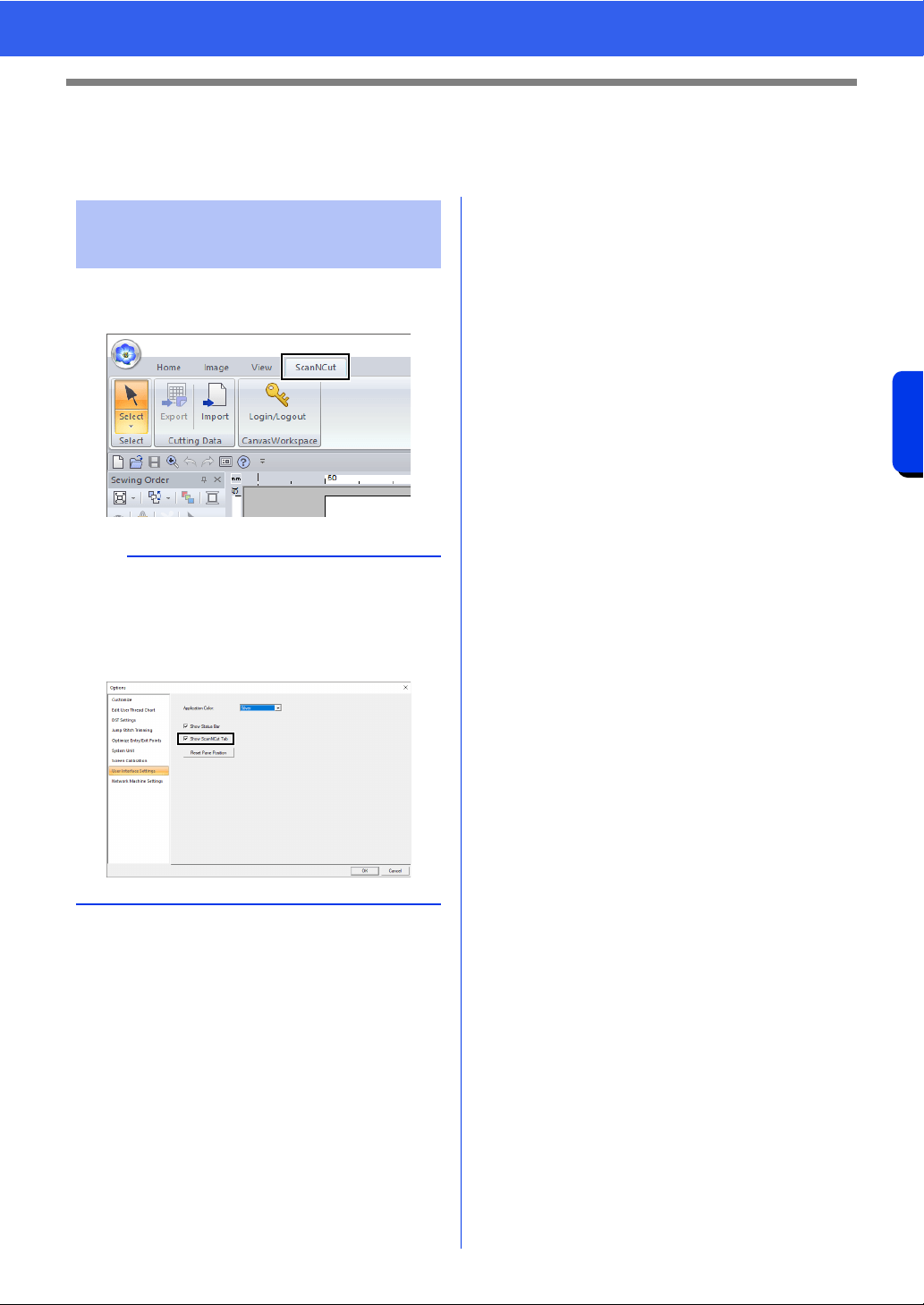
238
Compatibility with ScanNCut (Brother cutting machine)
Compatibility with ScanNCut (Brother cutting machine)
Compatibility with ScanNCut (Brother
cutting machine)
ScanNCut (Brother cutting machine) can be
compatible with PE-DESIGN by this tab.
About the [ScanNCut] tab
(Layout & Editing)
b
If the [ScanNCut] tab is no longer needed, click
[Options] in the [Option] menu in the upper-right
corner of the window, click [User Interface
Settings], and then clear the [Show ScanNCut
tab] check box.
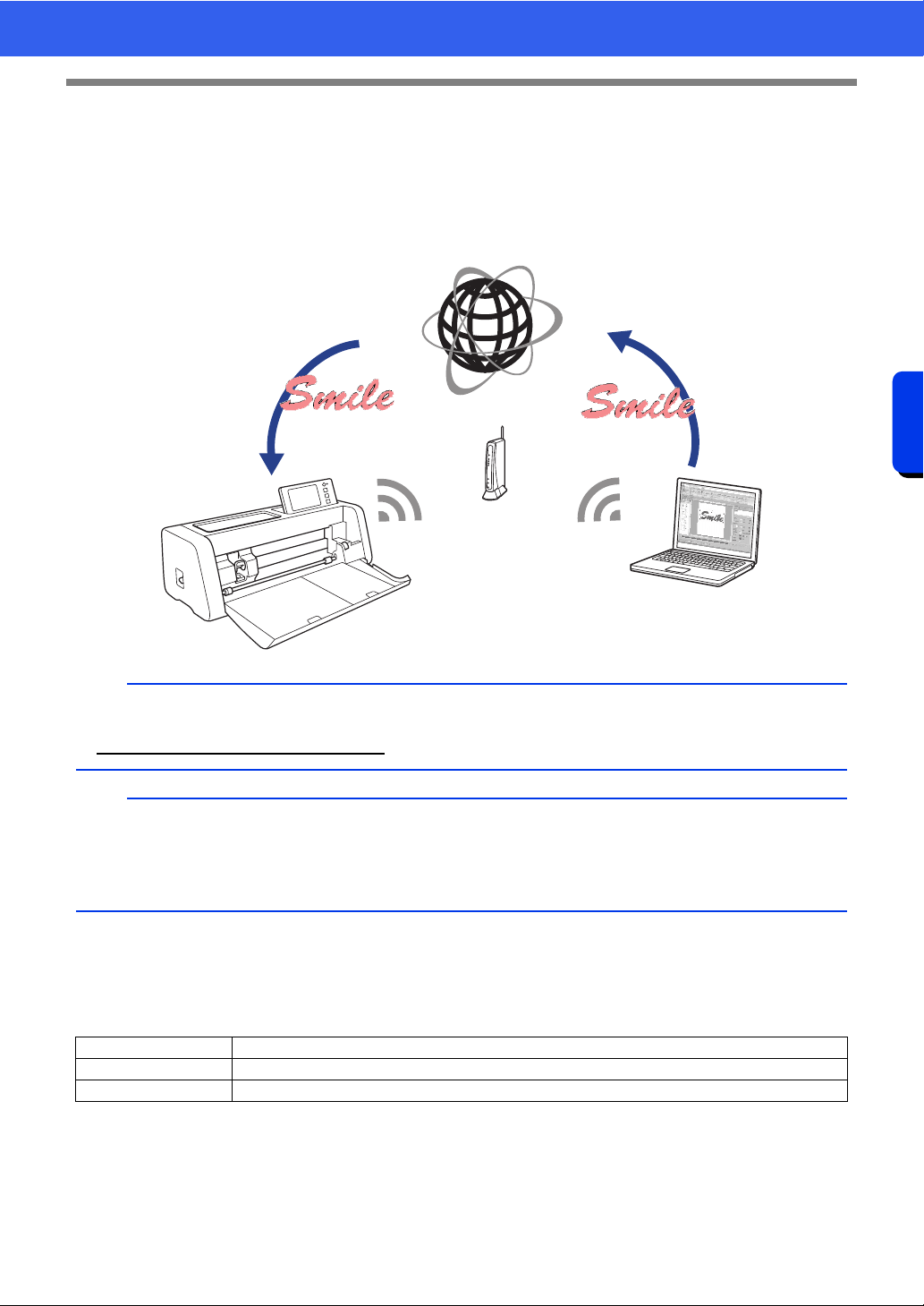
239
Compatibility with ScanNCut (Brother cutting machine)
Tutorial 11:Sending an FCM File to CanvasWorkspace
Tutorial 11:Sending an FCM File to
CanvasWorkspace
From this software, patterns can be sent to CanvasWorkspace (online service for Brother cutting machines).
In addition, patterns can be sent from CanvasWorkspace to your ScanNCut machine (wireless network models
only).
The sample file for this tutorial is located at
Documents (My documents)\PE-DESIGN 11\Tutorial\Tutorial_11.
b
• CanvasWorkspace is a pattern-editing application for Brother cutting machines. In order to use this
function, create your free account from the following link.
http://CanvasWorkspace.Brother.com
a
• Embroidered fabric cannot be cut with the ScanNCut machine.
• There are limitations on the thickness of fabric that can be cut by the ScanNCut machine.
• For details, refer to the Operation Manual for ScanNCut (Brother cutting machine).
• This function cannot be used if a pattern containing text with the [Name Drop] attribute applied is selected.
Step 1 Logging in to CanvasWorkspace
Step 2 Selecting a pattern
Step 3 Sending a pattern to CanvasWorkspace
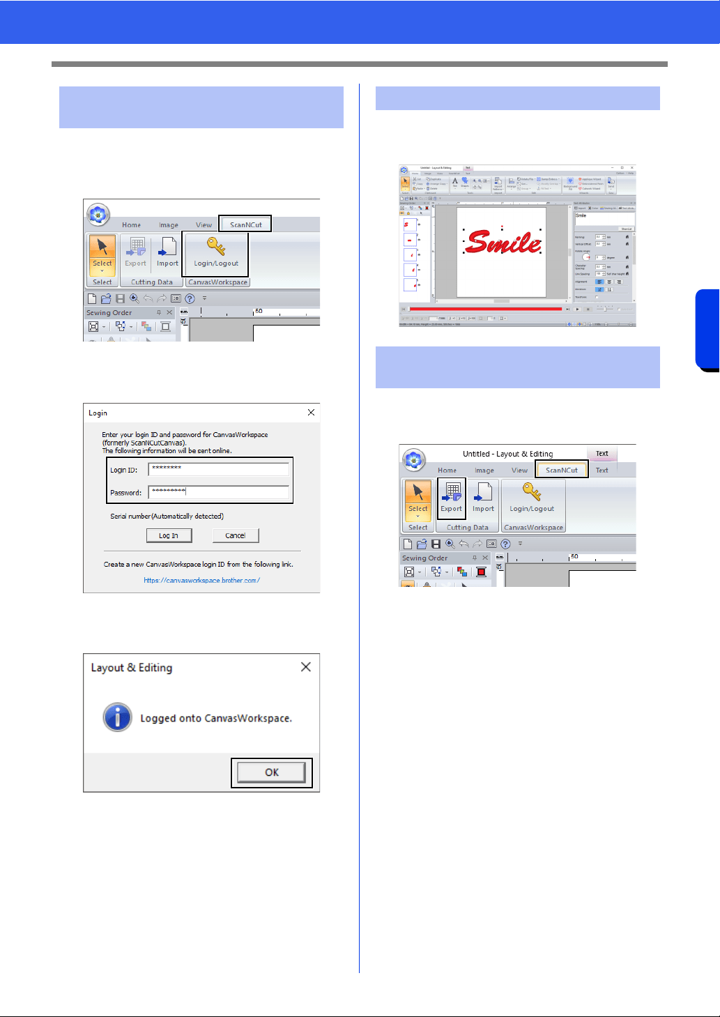
240
Compatibility with ScanNCut (Brother cutting machine)
Tutorial 11:Sending an FCM File to CanvasWorkspace
1 Click the [ScanNCut] tab, and then click
[Login/Logout] in the [CanvasWorkspace]
group.
2 In the [Login] dialog box, type the login ID and
password for CanvasWorkspace.
3 When login is finished, the following message
appears. Click [OK].
1 Select the [Text] tool, and then type in
“Smile”.
1 Click the [ScanNCut] tab, and then click
[Export] in the [Cutting Data] group.
Step 1 Logging in to
CanvasWorkspace
Step 2 Selecting a pattern
Step 3 Sending a pattern to
CanvasWorkspace
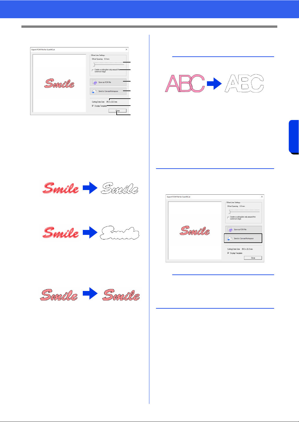
241
Compatibility with ScanNCut (Brother cutting machine)
Tutorial 11:Sending an FCM File to CanvasWorkspace
2 Specify the settings for the cutting line.
a Offset Spacing
Set the [Offset Spacing] to specify the
distance from the outline of the pattern to
the cutting line.
For this example, set it to [0.0] mm.
• If [Offset Spacing] is set to 0.0 mm,
the outline of the pattern will become
the cutting line.
• If [Offset Spacing] is set to any setting
other than 0.0 mm and the cutting lines
overlap, they will be merged.
b Select this check box to draw the cutting
line only around the outer edge of the
pattern. Clear this check box to also draw
cutting lines inside the pattern.
For this example, clear this check box.
c Save as FCM File
Click this button to display the [Save as
FCM File] dialog box, where the
destination for saving the file can be
specified.
d Send to CanvasWorkspace
Click this button to send the FCM file to
CanvasWorkspace.
e Cutting Data Size
Displays the size of the cutting data.
f Display Template
Select this check box to display a faint
image of the original pattern.
g Close
Click this button to close the dialog box.
3 Click the [Send to CanvasWorkspace]
button.
ON OFF
a
b
c
d
f
e
g
b
• If patterns overlap, they will be merged.
• However, if [Offset Spacing] is set to 0.0 mm,
the overlapped pattern may not be merged.
• Extremely small data will not be exported.
• The maximum size for cutting data fits within a
12 × 12 inch (305 × 305 mm) mat. If this
maximum is exceeded, an error message
appears.
• If more than 300 cutting data are contained in a
embroidery design, the FCM file cannot be
saved. If this maximum is exceeded, an error
message appears.
b
• The password input dialog box will appear if
you have not logged into CanvasWorkspace in
Step 1. Type in the login ID and password to log
in.
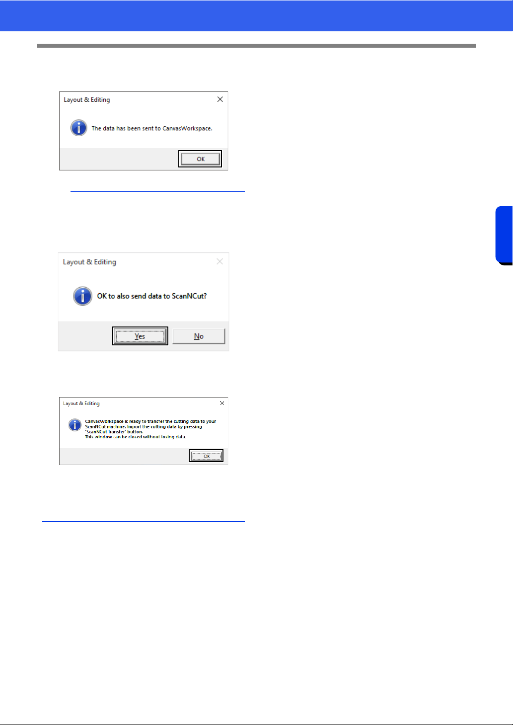
242
Compatibility with ScanNCut (Brother cutting machine)
Tutorial 11:Sending an FCM File to CanvasWorkspace
4 When the transfer is finished, the following
message appears. Click [OK].
5 The transferred pattern appears in
CanvasWorkspace.
*For details on opening a transferred pattern
in CanvasWorkspace, refer to the Help for
CanvasWorkspace.
• The pattern is named as
“fromPED_yyyymmddhhmm”
automatically.
b
• If you have registered your ScanNCut machine
(wireless network models only) with your
CanvasWorkspace account, the following
message appears.
• To also send the pattern to your ScanNCut
machine, click [Yes], and then click [OK] again
when the following message appears.
• Then, touch the Transfer button on ScanNCut to
import the sent pattern.
• To not send the pattern to your ScanNCut
machine, click [No].
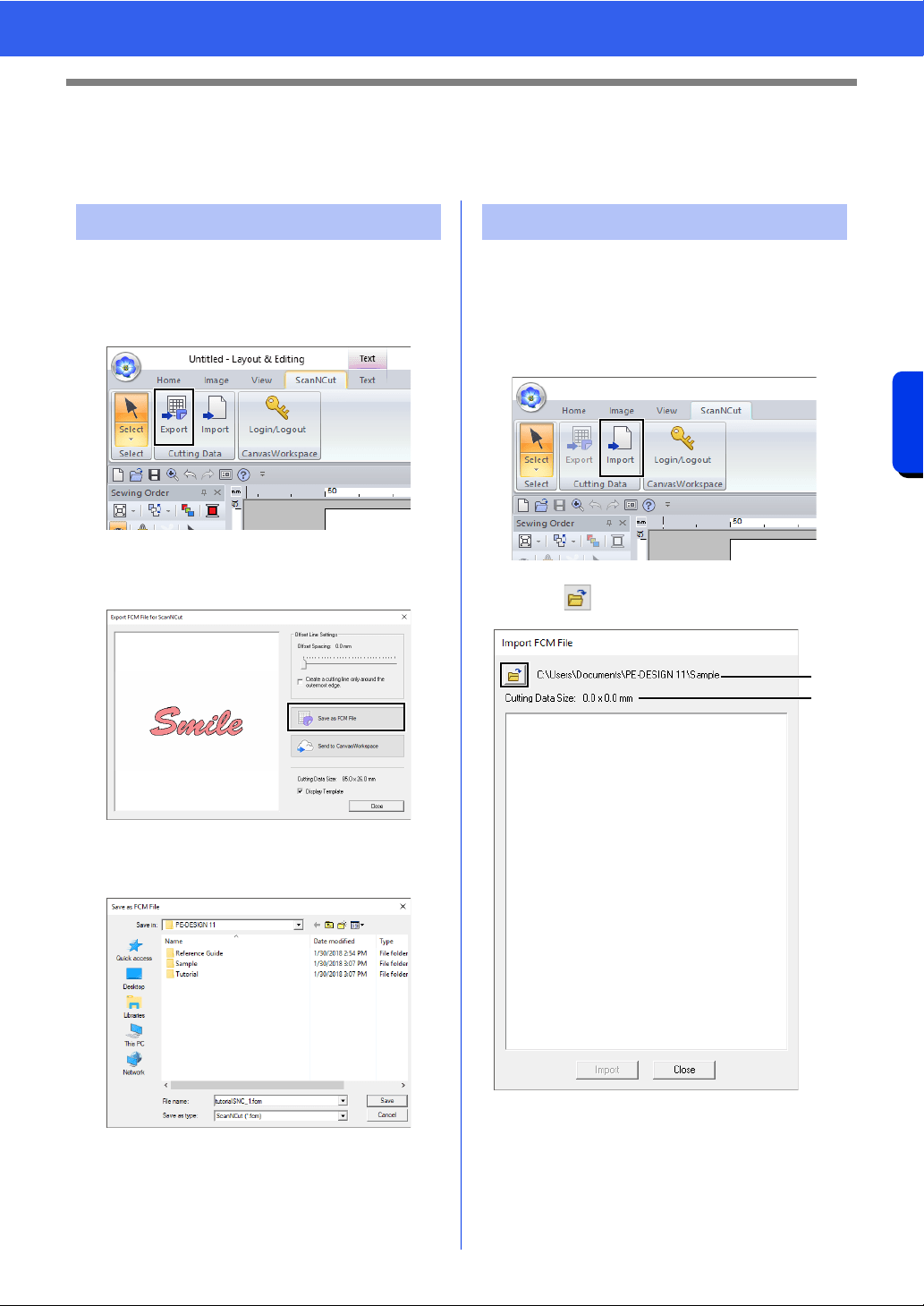
243
Compatibility with ScanNCut (Brother cutting machine)
Exporting/Importing an FCM File
Exporting/Importing an FCM File
A created embroidery pattern can be exported/ imported as data in the .fcm format so that it can be cut out
using ScanNCut (Brother cutting machine), or edit using PE-DESIGN.
1 Select the pattern(s), and then click the
[ScanNCut] tab.
2 Click [Export] in the [Cutting Data] group.
3 After the cutting line settings have been
specified, click the [Save as FCM File] button.
4 Select the drive and the folder, and then type
in the file name.
5 Click [Save] to save the data.
An FCM file can be imported into PE-DESIGN as an
embroidery pattern.
1 Click the [ScanNCut] tab.
2 Click [Import] in the [Cutting Data] group
3 Click .
a Indicates the path to the currently
selected folder.
b Displays the size of the cutting data.
Exporting an FCM File Importing an FCM File
a
b
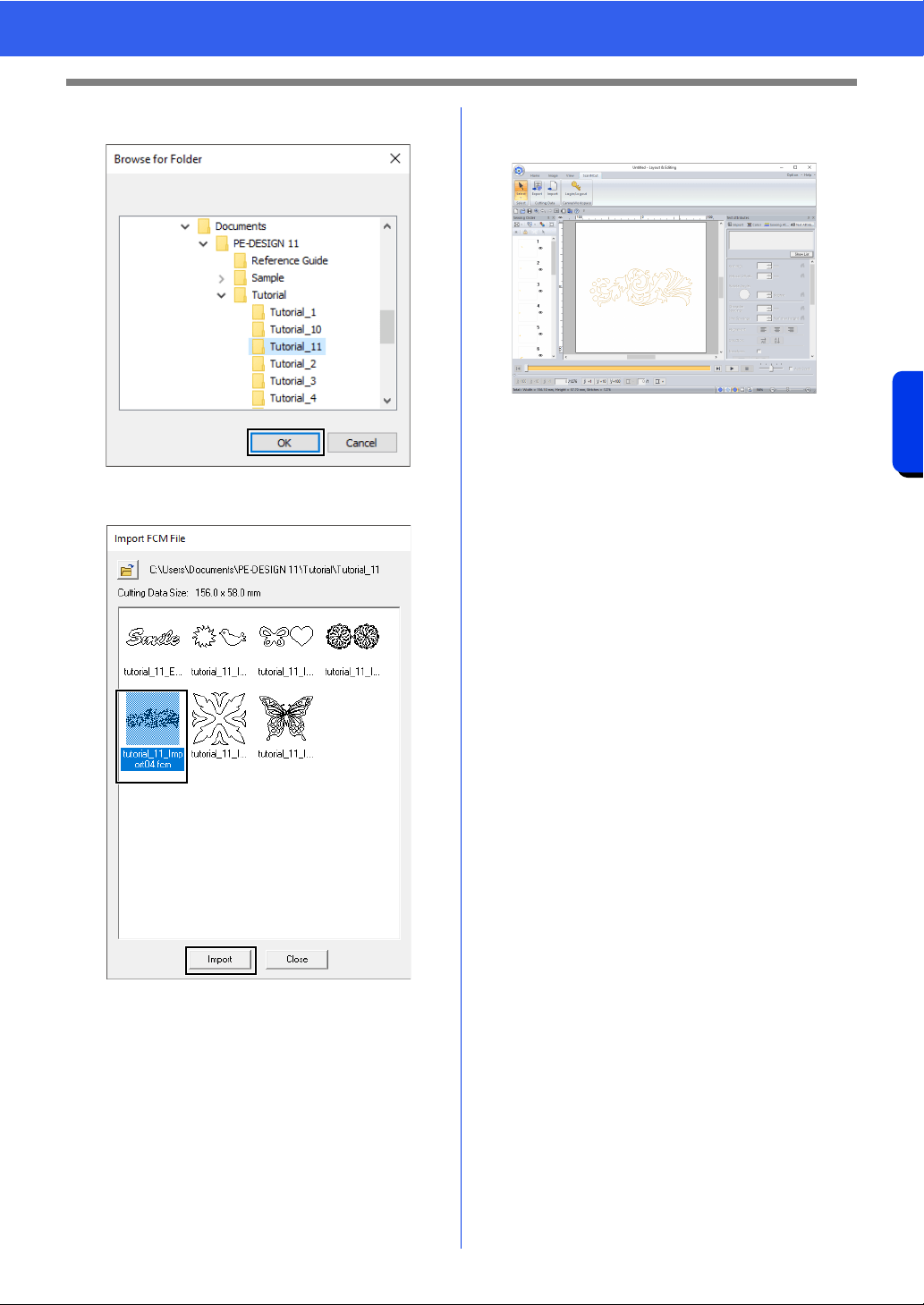
244
Compatibility with ScanNCut (Brother cutting machine)
Exporting/Importing an FCM File
4 Select a folder, and then click [OK].
5 Select a thumbnail, and then click [Import].
6 The imported embroidery pattern appears in
the Design Page.

Design Center
This section describes the basic operations
performed in Design Center. A simple step-by-
step procedure is provided to create an
embroidery pattern from a template image, such
as an illustration.
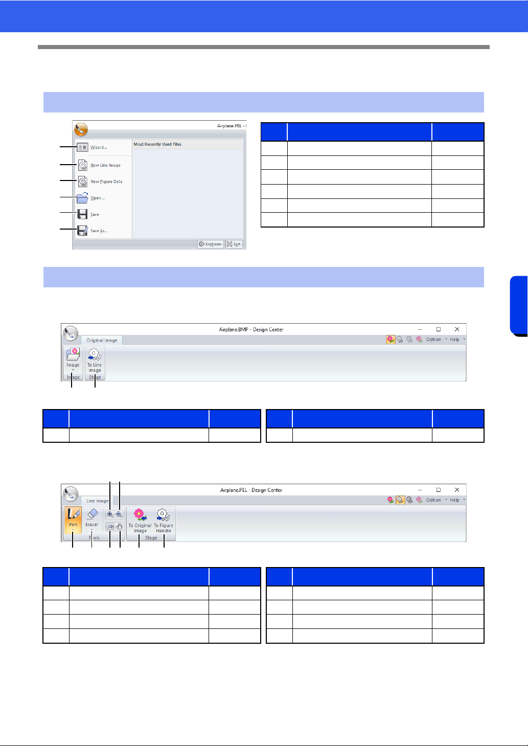
246
Design Center
Design Center
Design Center
■ Original Image tab
■ Line Image tab
Application button menu
1
2
3
4
5
6
No. Menu Reference
1 Wizard p. 260
2 New Line Image p. 263
3 New Figure Data p. 265
4 Open p. 261
5 Save p. 275
6 Save As p. 275
Ribbon menu tabs
No. Menu Reference No. Menu Reference
1 Open Image — 2 To Line image p. 262
No. Menu Reference No. Menu Reference
1 Pen Tools p. 251 5 Fit window —
2 Eraser Tools p. 251 6 Pan p. 251
3 Zoom In p. 251 7 To Original image p. 260
4 Zoom Out p. 251 8 To Figure handle p. 264
21
2156 7 8
3 4
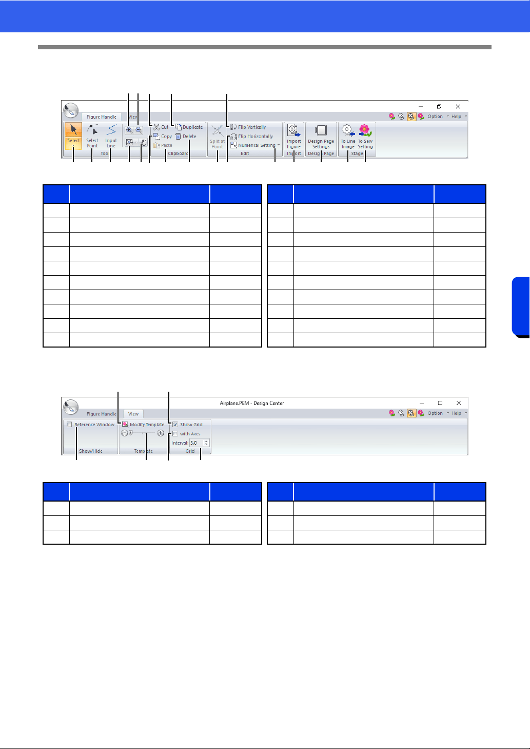
247
Design Center
Design Center
■ Figure Handle tab
■ View tab
No. Menu Reference No. Menu Reference
1 Select Tools p. 252 11 Duplicate —
2 Edit Point Tool p. 253 12 Delete p. 253
3 Line Tool p. 252 13 Split at Point p. 254
4 Zoom In — 14 Flip vertically p. 266
5 Zoom Out — 15 Flip horizontally p. 266
6 Other Zoom Tools — 16 Numerical Setting p. 266
7 Pan — 17 Import Figure p. 265
8 Cut — 18 Design Page Settings p. 265
9 Copy — 19 To Line image p. 262
10 Paste — 20 To Sew setting p. 255
No. Menu Reference No. Menu Reference
1 Reference Window p. 266 4 Show Grid p. 268
2 Modify Template p. 268 5 Show Grid with Axes p. 268
3 Background Image Density p. 268 6 Grid Interval p. 268
1
8
92
A
30BC FE G
D
J6 7 H I
4
5
1
2
5
4
63
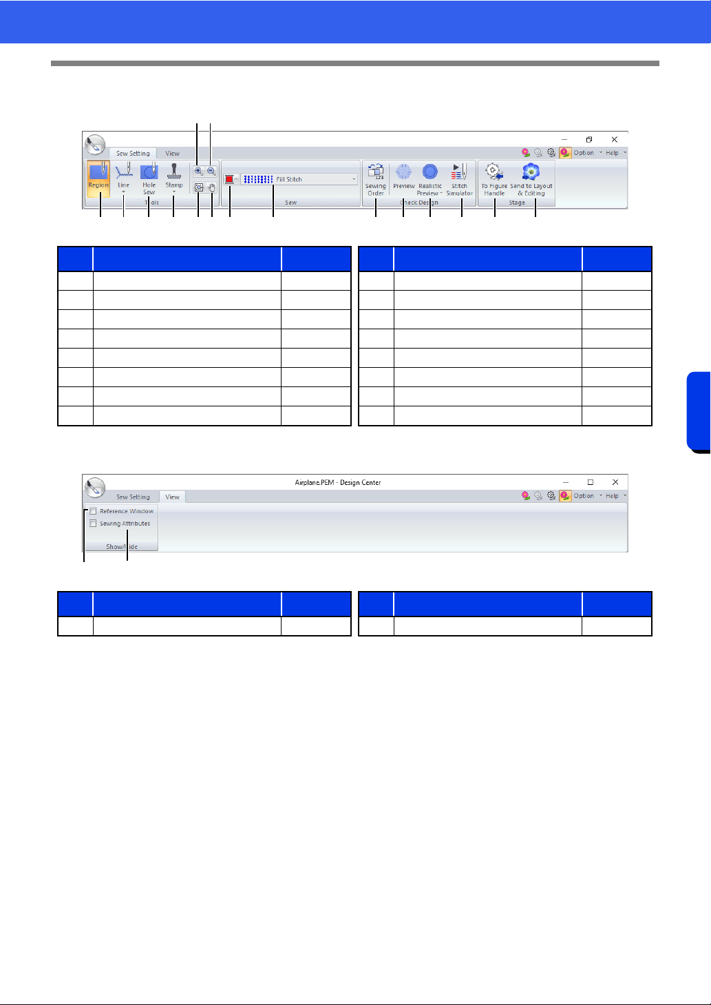
248
Design Center
Design Center
■ Sew Setting tab
■ View tab
No. Menu Reference No. Menu Reference
1 Region Tool p. 269 9 Color p. 270
2 Line Tools p. 270 10 Sew Type p. 270
3 Hole Sew Tool p. 273 11 Sewing Order p. 274
4 Stamp Tools p. 274 12 Preview —
5 Zoom In — 13 Realistic Preview —
6 Zoom Out — 14 Stitch Simulator p. 275
7 Fit window — 15 To Figure handle p. 264
8 Pan — 16 To Layout & Editing p. 258
No. Menu Reference No. Menu Reference
1 Reference Window p. 266 2 Sewing Attributes p. 271
21 3 4 7 8 9 0 A B C D E F
5
6
12
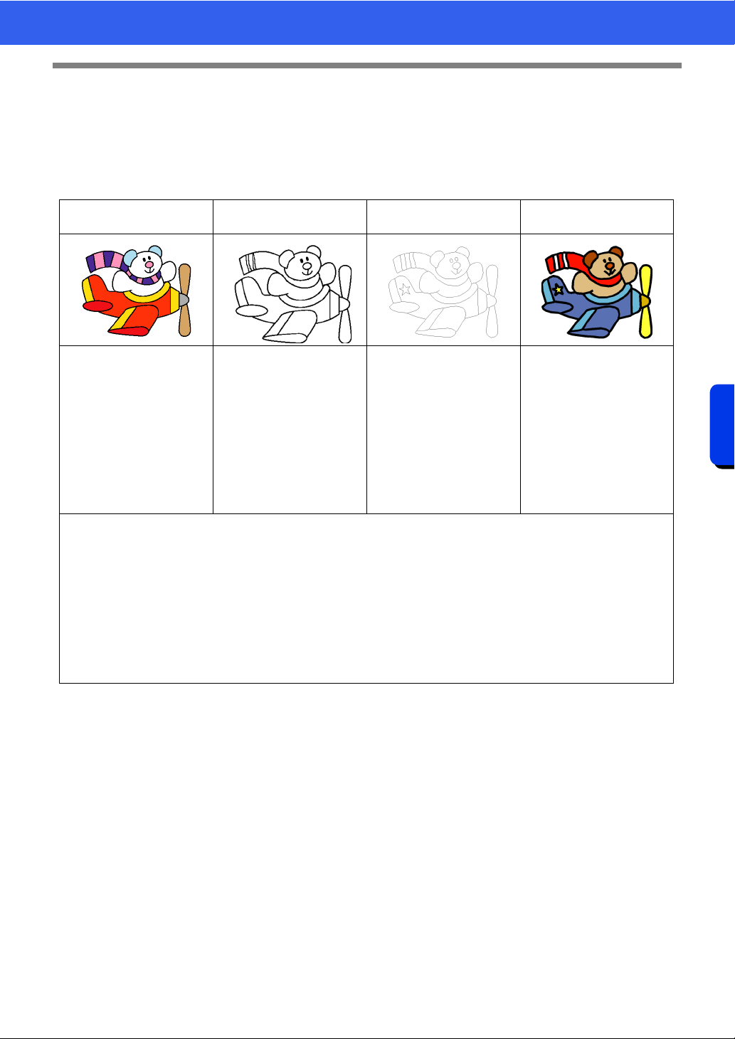
249
Design Center
Basic Design Center Operations
Basic Design Center Operations
In Design Center, embroidery patterns can be created from an original image. In addition, you can specify
colors and sewing attributes for the lines and regions that are more detailed than those specified with the [Auto
Punch] function in Layout & Editing.
An embroidery design is created in the following four stages.
This section describes the basic operations performed in Design Center. For details on the procedures or
settings, refer to "Design Center Window" on page 259.
Step 1
Original Image Stage
Step 2
Line Image Stage
Step 3
Figure Handle Stage
Step 4
Sew Setting Stage
Open an image file, and
select the colors to be used
for creating the outlines.
The original image is
converted to a black-and-
white line image.
Outlines can be drawn or
erased.
The line image is converted
to a figure handle image.
Points in the figure handle
image can be edited to
change the design.
The sew type and thread
colors are specified in the
outline to complete the
embroidery design.
Example:
The stripes in the scarf are
erased.
Stripes are added to the
scarf.
Example:
The eyes are moved, and
the facial expression is
changed.
A star is added to the tail of
the plane.
Example:
By applying colors different
than in the original image,
the design is given a
different appearance.
• If the data is saved, work can be stopped at each stage, then started again.
• The most appropriate images to use are those with few and distinct colors. Images or photos that are
intricate or have gradations are not suitable since it is difficult to extract their outlines.
• Line image data is saved in the .pel format, and figure handle data is saved in the .pem format.
• The embroidery data is saved in the .pem format. To transfer .pem data created in Design Center to an
embroidery machine, import the pattern into Layout & Editing, and then transfer the data to an embroidery
machine.
cc "Importing into Layout & Editing" on page 258 and "Transferring Embroidery Designs to
Machines" on page 222
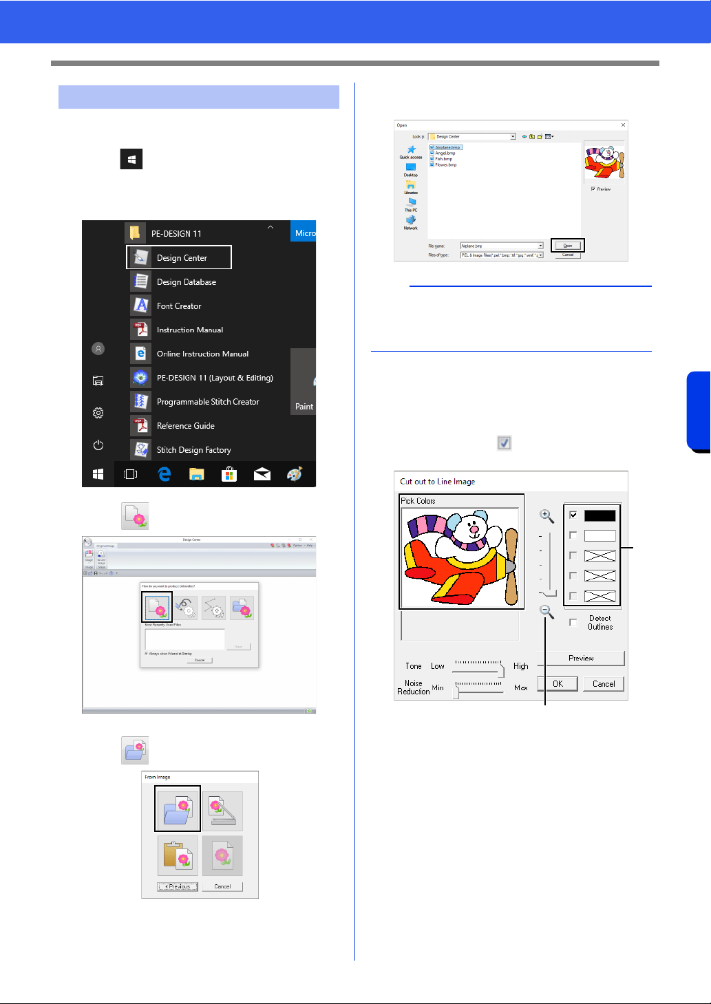
250
Design Center
Basic Design Center Operations
■ Extract outlines from an image
1 Click .
2 Click [Design Center] under the title [PE-
DESIGN 11] in the screen.
3 Click .
4 Click .
5 Select the desired image file, and then click
[Open].
6 In the image displayed in the [Pick Colors]
window, select the colors to be used for the
outlines (embroidery lines).
The selected color appears in a box on the
right side, and appears in the check box
to show that the color is selected.
a The desired color can be selected more
easily if the [Zoom] slider is used to
enlarge the image.
b If a color other than that for the outline
was selected, clear the check box beside
the color to deselect it.
Step 1 Original Image Stage
a
Airplane image is located at:
Documents (My documents)\PE-DESIGN
11\Sample\Design Center.
a
b
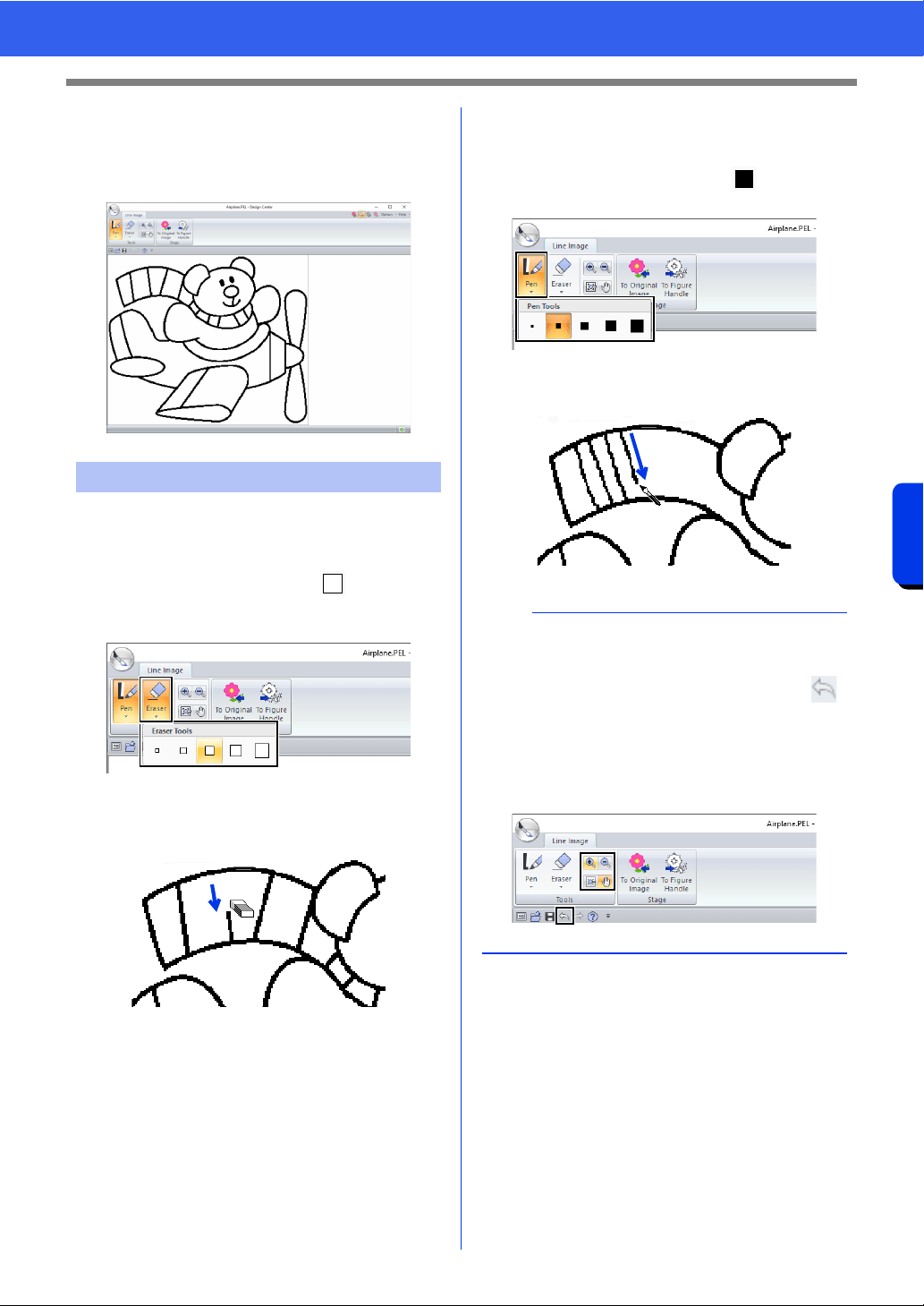
251
Design Center
Basic Design Center Operations
7 After selecting the colors to be used for the
outlines, click [OK].
The line image appears in the Design
Page.
■ Using the Eraser
1 To erase a line, click [Eraser] in the [Tools]
group, and then select a tool
according to
the size of the area or thickness of the line to
be erased.
2 Move the pointer over the line to be erased,
and then click the line or drag the pointer to
erase the line.
■ Using the Pen
1 To draw lines, select the [Pen] in the [Tools]
group, and then select a tool with the
desired thickness of the line to be drawn.
2 Drag the pointer to draw a line. To add a point,
click in the Design Page.
Step 2 Line Image Stage
b
• To draw vertical or horizontal lines, hold down
the <Shift> key while moving the pointer.
• If lines are drawn or erased incorrectly, click
(Undo button) to undo the last operation.
• To change the display size, use [Zoom]
command.
• The part of the work area that is displayed can
easily be changed by using the [Pan] tool.
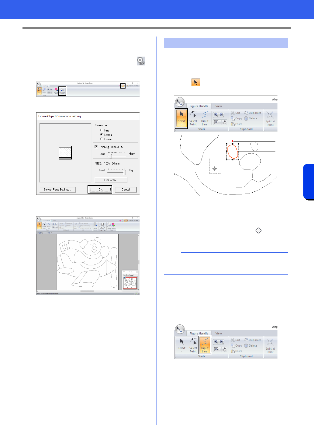
252
Design Center
Basic Design Center Operations
■ Editing the extracted outline
1 When the line image is finished, click [To
Figure Handle] in the [Stage] group or
(the second icon from the left) in the upper-
right corner of the screen.
2 Click [OK].
The line image is converted to a figure
handle image.
■ Moving outlines
1 Click the [Figure Handle] tab.
2 Click in the [Tools] group, and then click
the outline to be moved.
1 Rotation handle
2 Scale handles
3 Move the pointer over the outline so that the
shape of the pointer changes to , and then
drag the outline.
■ Adding lines to the figure handle
image
1 Click [Input Line] in the [Tools] group.
Step 3 Figure Handle Stage
b
Drag a handle to change the size or angle. To
delete the outline, press the <Delete> key.
1
2
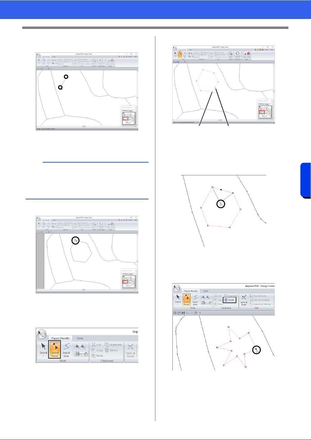
253
Design Center
Basic Design Center Operations
2 Click the start point (1), and then click the next
point (2).
A line is drawn connecting the two points.
Continue clicking to draw additional lines.
3 Double-click the end point.
■ Reshaping outlines
1 Click [Select Point] in the [Tools] group.
2 Click an outline.
1 Point
2 Pink Line
3 To add a point, click the outline (1).
To create a corner, drag the point (2).
4 If the point is deleted, the corner is removed.
Click the point to be deleted, and then press
the <Delete> key, or click [Delete] in the
[Clipboard] group.
b
• To remove the last point that was entered, right-
click.
• To draw vertical or horizontal lines, hold down
the <Shift> key while moving the pointer.
2
1
12
1
2
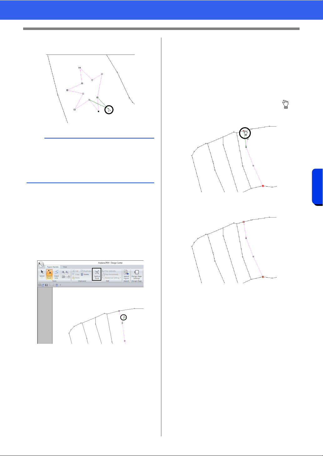
254
Design Center
Basic Design Center Operations
5 To change the shape of the line, drag the
point.
■ Splitting lines
Lines can be split at a point.
1 Perform steps 1 and 2 in “Reshaping
outlines” to select a line.
2 Select a point, and then click [Split at Point]
in the [Edit] group to split the line.
■ Connecting lines
Two points can be connected to form a line.
1 Perform steps 1 and 2 in “Reshaping
outlines” to select a line.
2 While holding down the <Alt> key, drag the
selected point to the other point that you want
to connect to it.
The shape of the pointer changes to ,
and a red square appears when the two
points are overlapping.
3 Release the mouse button to connect the two
points.
b
• If multiple points are selected, all of the points
will be moved or deleted.
• To select additional points, hold down the <Ctrl>
key and click each point, or drag the pointer over
the points.
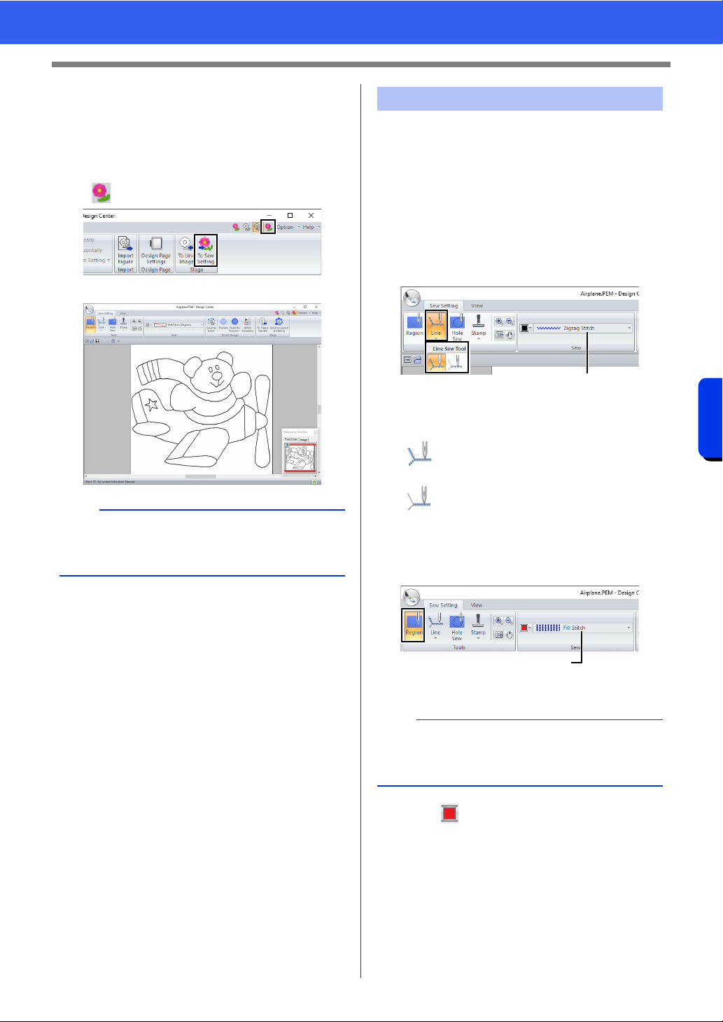
255
Design Center
Basic Design Center Operations
■ Continuing to the Sew Setting
Stage
When the figure handle image is finished, continue
to the Sew Setting Stage.
1 Click [To Sew Setting] in the [Stage] group or
in the upper-right corner of the screen.
We are now going to apply sewing attributes to the
different parts of the outline to create the embroidery
pattern.
■ Specifying sewing attributes
1 Click the [Sew Setting] tab.
2 To specify the sew type for the line, click
[Line] in the [Tools] group, and then select
the desired tool from [Line Sew Tool].
1 [Line sew type] selector
To specify the sew type for the region, click
[Region] in the [Tools] group.
1 [Region sew type] selector
3 Click .
b
Even after continuing to the Sew Setting Stage,
you can return to the Figure Handle Stage to edit
the figure handle image.
Step 4 Sew Setting Stage
: Click this button to apply sewing
attributes to the entire outline.
: Click this button to apply sewing
attributes to a portion of the outline.
b
Sewing attributes cannot be applied to regions if
the region is not completely enclosed in an outline
in the Figure Handle Stage.
1
1
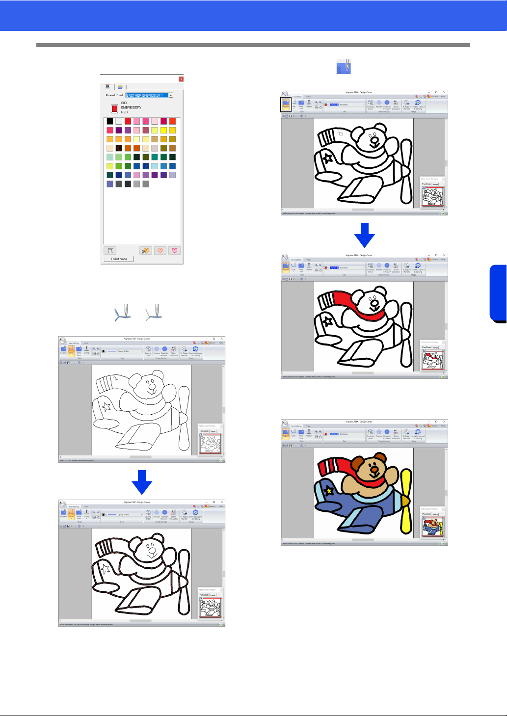
256
Design Center
Basic Design Center Operations
4 Click the desired color.
5 Click the down arrow in the sew type selector
and choose the desired sew type.
6 When using or , click the outline
where the sewing attributes are to be applied.
7 When using , click the region where the
sewing attributes are to be applied.
To change the sewing attributes, repeat steps
2 through 7.
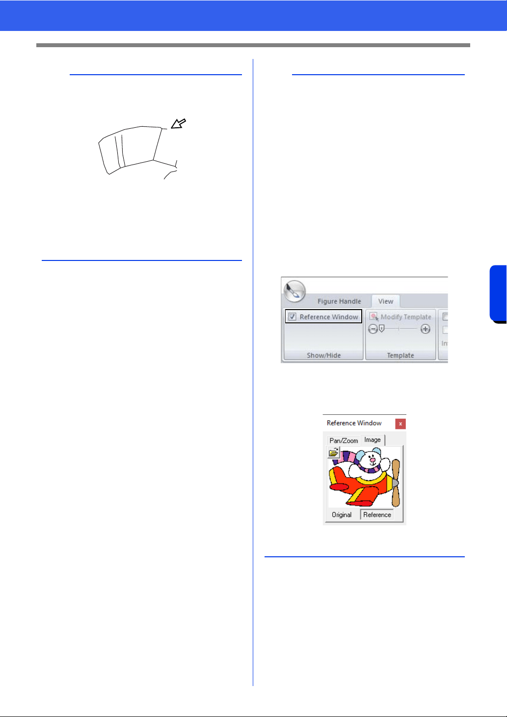
257
Design Center
Basic Design Center Operations
a
Sewing attributes for region cannot be applied to
open regions (regions not fully enclosed in an
outline), as shown in the illustration below.
If attributes cannot be applied to a region, return to
the Figure Handle Stage and make sure that
region is closed. Edit any broken lines with the Edit
Point tool.
cc "Adding lines to the figure handle image" on
page 252
b
•From the [Sewing Attribute Setting] dialog
box, detailed settings for attributes, such as the
width of satin stitches and the run pitch, can be
specified.
cc "Specifying sewing attributes" on page 271.
• The Reference Window is useful for specifying
colors while checking the colors of the original
image.
Using the Reference Window
This allows you to select colors while checking the
colors in the original image.
1. Click the [View] tab.
2. Select the [Reference Window] check box
in the [Show/Hide] group.
3. Click the [Image] tab.
The image opened in Original Image
stage appears.
If [Reference] has been clicked, click
[Original].
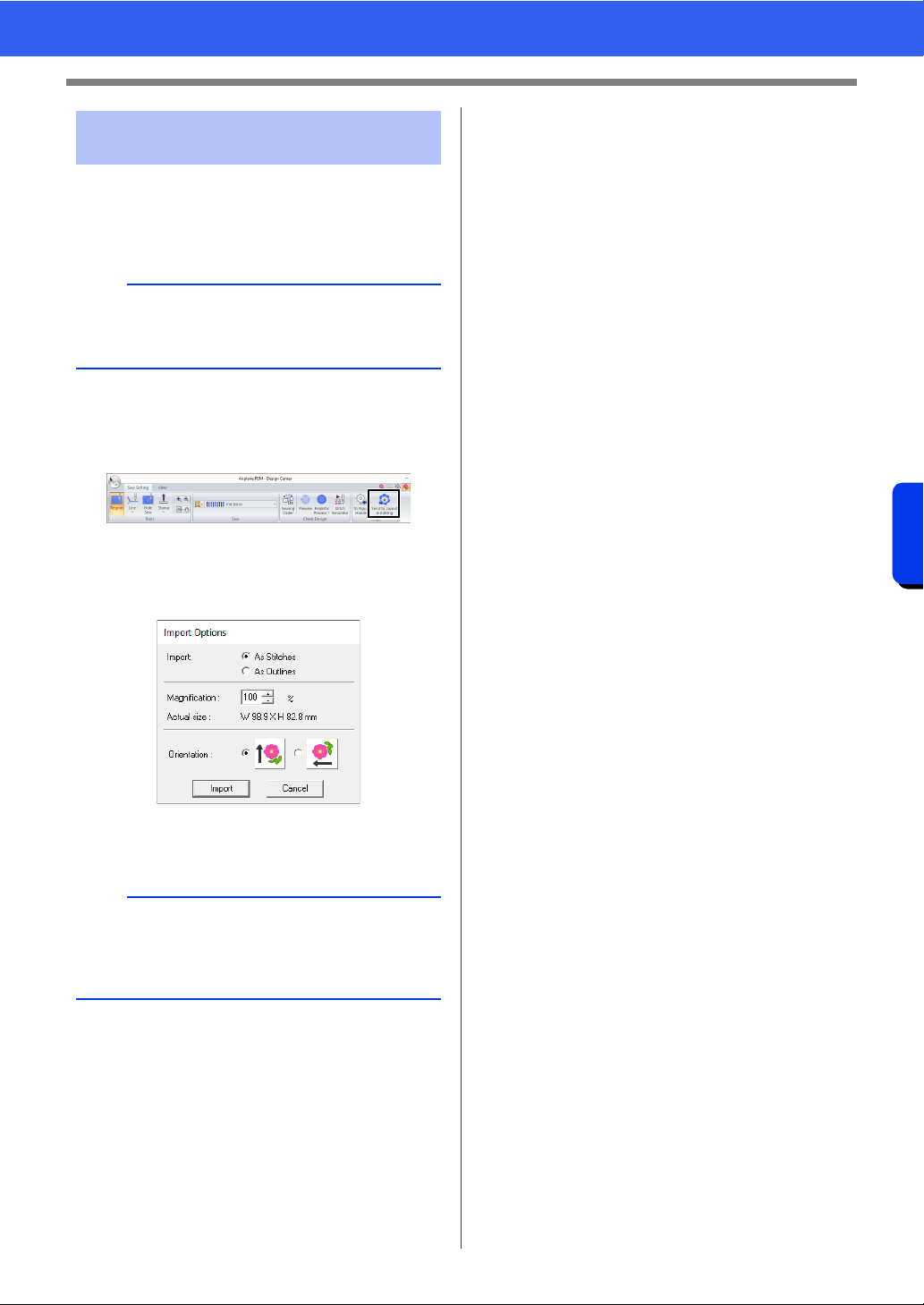
258
Design Center
Basic Design Center Operations
The embroidery pattern created in Design Center
can be imported into Layout & Editing. In addition,
the created data can be transferred to the machine
using functions in Layout & Editing.
1 Click the [Sew Setting] tab.
2 Click [Send to Layout & Editing] in the
[Stage] group.
Layout & Editing starts up.
3 Select either to import a pattern as stitch
pattern or as outline pattern.
4 Specify settings for [Import], [Magnification]
and [Orientation], and then click [Import].
Step 5 Importing into Layout &
Editing
a
If the sewing attributes of an outline or region are
not set, the embroidery pattern cannot be
imported.
b
For details on the settings [As Stitches] and [As
Outlines] beside [Import], refer to "Importing
embroidery design from Design Center" on
page 106.
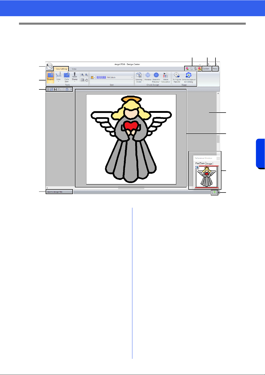
259
Design Center
Design Center Window
Design Center Window
a Application button
b Ribbon
c Quick Access Toolbar
d Stage button
Indicates the current stage. Click to move
to a different stage.
e Option button
f Help button
g Reference Window
Displays all outlines and patterns in the
work area, giving you an overview while
you work on a detailed area.
cc "Viewing outlines in the Reference
Window" on page 266
h Design Page
i Work area
j Status Bar
k Refresh Window button
cc "Understanding Windows" on page 13
d ef
a
j
g
k
h
i
b
c
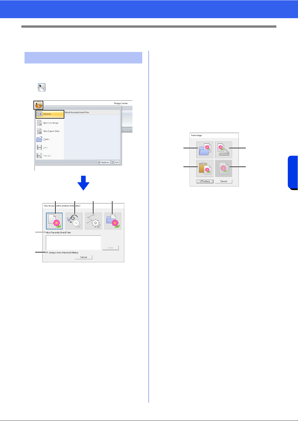
260
Design Center
Original Image Stage
Original Image Stage
This wizard provides a step-by-step guide for
creating embroidery patterns.
Click , and then select [Wizard] from the
command list.
a From Image
Clicking this button displays the [From
Image] dialog box.
b New Line Image
Clicking this button opens a new Design
Page in the Line Image Stage.
cc "Drawing a new line image freehand" on
page 263.
c New Figure
Clicking this button opens a new Design
Page in the Figure Handle Stage.
cc "Drawing a new figure handle image
freehand" on page 265.
d Open PEM
Clicking this button displays the [Open]
dialog box so that a .pem file can be
selected.
e Most Recently Used Files
From the list, click the name of the file,
and then click [Open].
f Always show Wizard at Startup
Select this check box to start up the
wizard each time Design Center is started
up.
■ Opening an image
When you click the [From Image] button in the
[How do you want to produce embroidery?]
dialog box, the [From Image] dialog box appears.
a Open Image File
Clicking this button that displays the
[Open] dialog box to select an image file.
cc "Image file formats" on page 163
b From Clipboard
Clicking this button to paste the image on
the Clipboard into the Design Page. This
function can only be used when there is
an image on the Clipboard.
c From TWAIN Device
Clicking this button to import an image
from a TWAIN device (such as a scanner)
connected to your computer, then paste it
in the Design Page.
d Use Current Image
Clicking this button to use an image
opened in the Original Image Stage. This
function can only be used when an image
is opened in the Original Image Stage.
Using the wizard
abcd
e
f
a
b
c
d
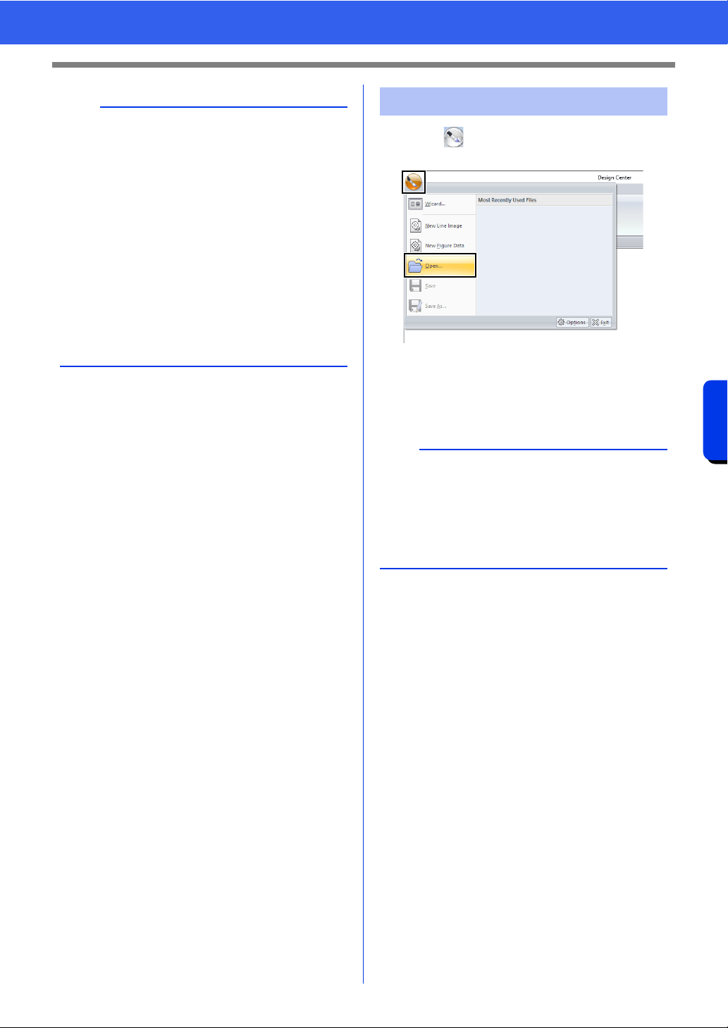
261
Design Center
Original Image Stage
1 Click , and then select [Open] from the
command list.
2 Select the drive and the folder.
3 To open a file, select it, and then click [Open],
or double-click the file's icon.
b
• To import an image from a file TWAIN device
• Connect the TWAIN device to the computer,
and then click [Image], then [Open from
TWAIN Device], or click [From TWAIN
Device] in the [From Image] dialog box.
When the [Select Source] dialog box
appears, select a device. Next, click [Select].
• For information on using the driver interface,
refer to the help manual for that interface, or
contact the manufacturer of the interface.
• Tips for scanning illustrations for Design Center
• If the outline is not clear, trace the outline on
tracing paper.
• Better scanning results may be produced by
reducing the tone of the image.
Opening a file
b
• If an image file is selected, the file is opened in
the Original Image Stage.
• If a .pel file is selected, the file is opened in the
Line Image Stage.
• If a .pem file is selected, the file is opened in the
Figure Handle Stage or the Sew Setting Stage.
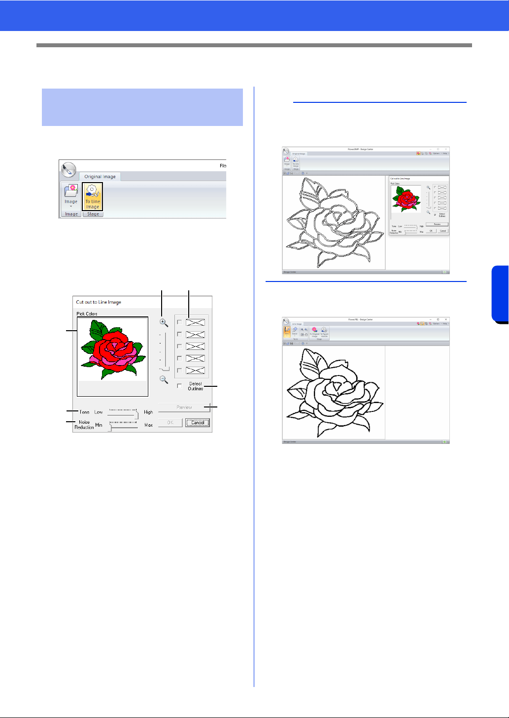
262
Design Center
Line Image Stage
Line Image Stage
1 In the Original Image Stage, click [To Line
image].
cc "Original Image Stage" on page 250.
2 Selecting the colors to be used for the
outlines, and then click [OK].
a Zoom slider
Use this slider to adjust the zoom ratio for
displaying the image.
b Tone slider
Use this slider to reduce color tones in
images where it is difficult to select the
outline color.
c Noise reduction slider
Use this slider to reduce image noise
(distortions) in images where the outline is
not clear.
d Click the outline color(s) to convert into
black outlines.
e Displays the colors selected in d. To
deselect a color, clear the corresponding
check box.
f To extract the color boundaries, click
[Detect Outlines] check box.
g Click [Preview] to preview the line image
in the Design Page.
Extracting the outlines of
an image
ae
d
b
c
f
g
b
When the extracting color boundaries using
[Detect Outlines], the colors are converted to line
image as shown below.
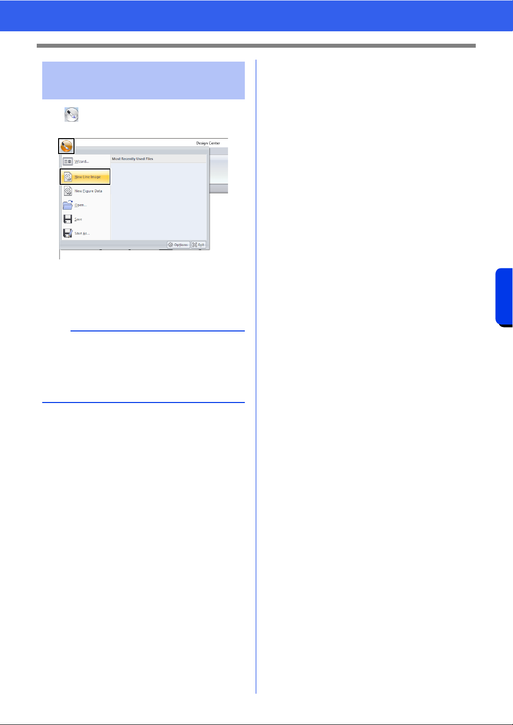
263
Design Center
Line Image Stage
Click , and then select [New Line Images] from
the command list.
Using the Pen and Eraser tools, the line image can
be drawn freehand in the Design Page.
cc "Line Image Stage" on page 251.
Drawing a new line image
freehand
b
In the Line Image Stage, the file will be saved as a
.pel file.
cc "Saving embroidery patterns" on page 275,
and "Drawing a new figure handle image
freehand" on page 265.
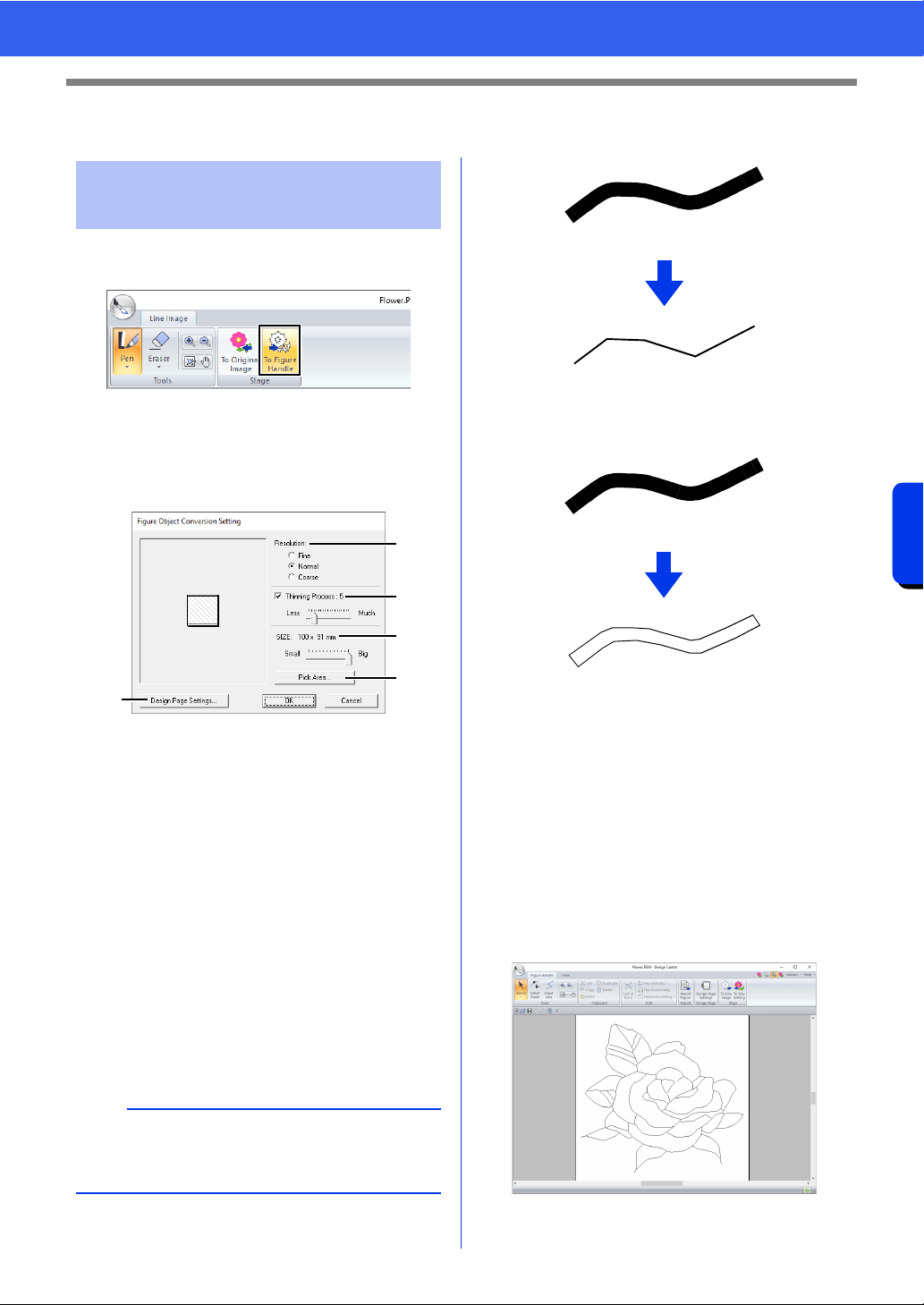
264
Design Center
Figure Handle Stage
Figure Handle Stage
1 In the Line Image Stage, click [To Figure
Handle].
cc "Line Image Stage" on page 251.
2 Specify the desired settings in the [Figure
Object Conversion Setting] dialog box, and
then click [OK].
a Select a setting under [Resolution].
Fine
Select this setting only if the image
contains many small details.
Normal
Select this setting to provide a sufficient
resolution without making the file too
large.
Coarse
Select this setting to keep the file as small
as possible.
b To replace the black outlines with figure
handle lines along the center of the
outlines, select the [Thinning Process]
check box, and then use the slider to
select the degree of detail.
1 ON
To replace the black lines with figure handle
lines following the border of the outlines, clear
the [Thinning Process] check box.
2 OFF
c Use the [SIZE] slider to set the size.
d You will not be able to enlarge the image
beyond the limits of the Design Page
area. If necessary, click [Design Page
Property], and then change the Design
Page size.
e To create outline data from a part of the
image, select the specific area by clicking
[Pick Area], then dragging the pointer (+)
to draw a selection frame around the area
to be selected.
Changing settings for
converting to outlines
b
When the slider is set to [Much], even very thick
black lines will be replaced with a line along the
center.
a
b
c
e
d
1
2
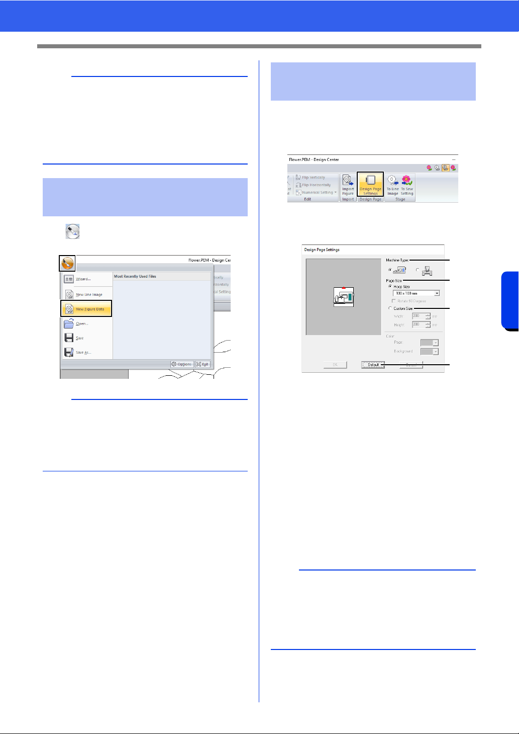
265
Design Center
Figure Handle Stage
Click , and then select [New Figure Data] from
the command list.
1 Click the [Figure Handle] tab.
2 Click [Design Page Settings] in the [Design
Page] group.
3 Select the Design Page size, and then click
[OK].
a Select a machine type.
The settings available in the [Page Size]
selector differ depending on the machine
type selected here.
b To adjust the Design Page size according
to the hoop size, select [Hoop Size], and
then select the desired hoop size from the
selector.
c To specify a custom Design Page size,
select [Custom Size], and then type or
select the desired width and height for the
Design Page.
d To return to the default settings, click
[Default].
a
It may not be possible for outline data to be created
from an image when moving from the Line Image
Stage to the Figure Handle Stage, even after
various outline conversion settings have been
specified. If this occurs, return to the Line Image
Stage, and correct the outlines in the line image or
apply corrections to the image.
Drawing a new figure
handle image freehand
b
• In the Figure Handle Stage, the file will be saved
as a .pem file.
• To retrieve data from a saved .pem file, use the
command [Import Figure] in the [Figure
Handle] tab.
Specifying the Design
Page size
a
• Do not select a hoop size larger than the
embroidery hoop that can be used with your
machine.
• Do not create a Custom Hoop larger than the
embroidery hoop that can be used with your
machine.
a
b
c
d
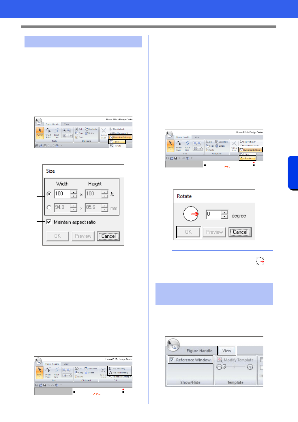
266
Design Center
Figure Handle Stage
■ Scaling outlines
Scaling numerically:
1 Select the outline.
2 Click the [Figure Handle] tab.
3 Click [Numerical Setting] in the [Edit] group,
and then select [Size].
4 Select a size, and then click [OK].
a To change the width and height
proportionally, select the [Maintain
aspect ratio] check box.
b Select whether the width and height will
be set as a percentage (%) or a dimension
(millimeters or inches).
Type or select the desired width and
height.
■ Flipping outlines horizontally or
vertically
1 Select the outline.
2 Click [Flip Vertically] or [Flip Horizontally] in
the [Edit] group.
■ Rotating outlines
Rotating manually
1 Select the outline.
2 Move the pointer over the rotation handle. And
then drag.
Rotating numerically
1 Select the outline.
2 Click [Numerical Setting] in the [Edit] group,
and then select [Rotate].
3 Type or select the desired rotation angle, and
then click [OK].
1 Click the [View] tab.
2 Select the [Reference Window] check box in
the [Show/Hide] group.
Editing outlines
a
b
b
An angle can also be selected by dragging in
the [Rotate] dialog box.
Viewing outlines in the
Reference Window
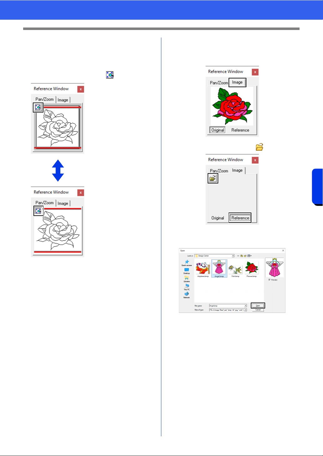
267
Design Center
Figure Handle Stage
■ Zooming
The [Reference Window] can be switched to
display either the entire Design Page or only the
embroidery pattern.
Click the [Pan/Zoom] tab, click .
■ Moving the display area frame
The part of the outline displayed in the Design Page
can be selected from the [Reference Window].
1 Move the pointer over the display area frame.
2 Drag the display area frame so that it
surrounds the desired part of the outline.
The selected part of the outline is displayed
in the Design Page.
■ Redrawing the display area frame
Instead of moving the display area frame, the frame
can be redrawn to display the desired part of the
outline in the Design Page.
Click the area to be displayed, or drag the pointer
over the desired part of the outline in the
[Reference Window].
■ Displaying a different reference
image
1 Click the [Image] tab.
2 Click [Reference], then click .
3 Select the reference image, and then click
[Open].
Displays the entire Design
Page.
Displays the entire
pattern.
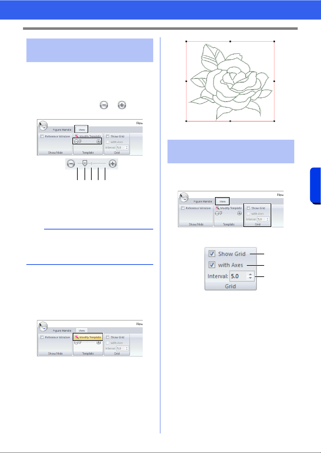
268
Design Center
Figure Handle Stage
■ Changing the display of the
background image
1 Click the [View] tab.
2 Drag the slider, or click or in the
[Template] group.
1 Hide (off)
2 25%
3 50%
4 75%
5 100%
■ Changing the size and position of
the background image
1 Select the template. Click [Modify Template]
in the [Template] group.
2 Drag the template image to move it to the
desired location.
Drag a handle to enlarge or reduce the size of
the template image.
■
Changing the grid settings
1 Click the [View] tab.
2 Specify the grid settings in the [Grid] group.
a To display the grid, select the [Show
Grid] check box.
To hide the grid, clear the [Show Grid]
check box.
b To display the grid as solid lines, select
the [with Axes] check box.
To display the grid as dots (intersecting
points of the grid) , clear the [with Axes]
check box.
c To set the grid spacing, type or select a
value in the [Interval] box.
■ Changing the measurement units
Click [Option], then [Options], then [System Unit],
and then select the desired measurement units
([mm] or [inch]).
cc "System unit" on page 22
Changing the background
image
b
Press the shortcut key <F6> to switch between
displaying the image (On (100%)) to displaying it
faded at each density (75%, 50% and 25%) to
hiding the image (Off).
123 54
Changing application
settings
a
b
c
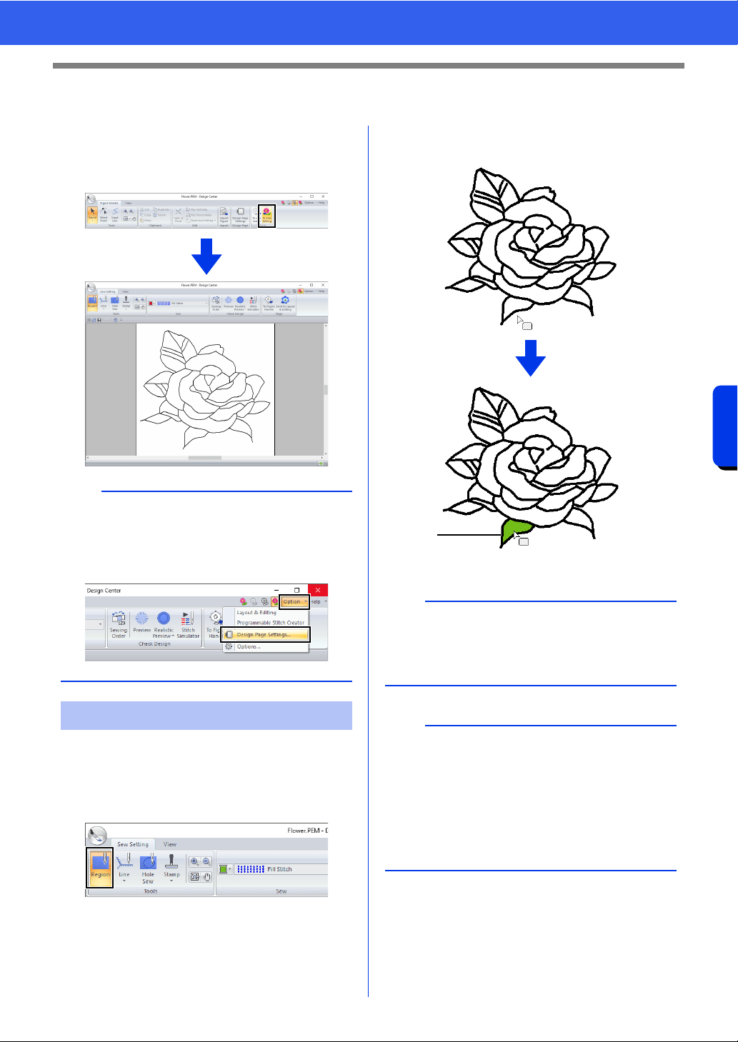
269
Design Center
Sew Setting Stage
Sew Setting Stage
1 In the Figure Handle Stage, click [Figure
Handle] tab to display the [Stage] group.
2 Click [To Sew Setting] in the [Stage] group.
■ Region sewing
1 Click the [Sew Setting] tab.
2 Click [Region] in the [Tools] group.
3 If necessary, change the color and sew type.
cc "Sewing attributes" on page 270
4 Click the enclosed region to apply the sewing
attributes.
1 Marching lines
b
In the Sew Setting Stage, the colors of the Design
Page and background can be changed from the
[Design Settings] dialog box (displayed by
clicking the [Option] menu, and then selecting
[Design Page Settings].)
Setting region/line sewing
a
• If the attributes cannot be applied to a region, go
back to the Figure Handle Stage and make sure
that region is closed.
• Edit any broken lines with the Edit Point tool.
b
• Although a region may seem closed, if the
sewing attributes cannot be specified for the
region, the region may not actually be closed.
• To find the opening in the region, use the line
drawing mode in the Figure Handle Stage to
divide the region into smaller regions, and then
check which region sewing attributes cannot be
applied to in the Sew Setting Stage.
1
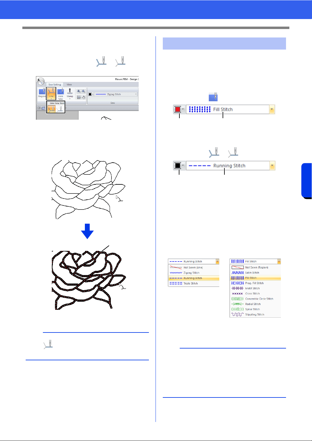
270
Design Center
Sew Setting Stage
■ Line sewing
1 Click [Line] in the [Tools] group, and then
select the desired tool ( or ) from
[Line Sew Tool].
2 If necessary, change the color and sew type.
cc "Sewing attributes" on page 270.
3 Click the outline to apply the sewing attributes.
1 Marching lines
The Sew pane on the [Sew setting] tab, available in
the Sew Setting Stage, allows you to set the color
and sew type of region and outlines.
The sewing attributes that are available depend on
the tool selected.
Example 1: When is selected
1 Region color button
2 Region sew type selector
Example 2: When or is selected
1 Line color button
2 Line sew type selector
■ Sew type
1 Click in a sew type selector.
2 Click the desired sew type.
3 Click the region or line to apply the sew type
setting.
b
When is selected, settings are applied only to
a portion of the clicked outline.
1
Sewing attributes
Line sew type Region sew type
b
• To turn off sewing, select [Not Sewn (Line)]
from the [Line sew type] selector or [Not Sewn
(Region)] from the [Region sew type] selector.
• If the sewing has been turned off, the regions
appear in white or the lines appear as dotted
lines.
12
12
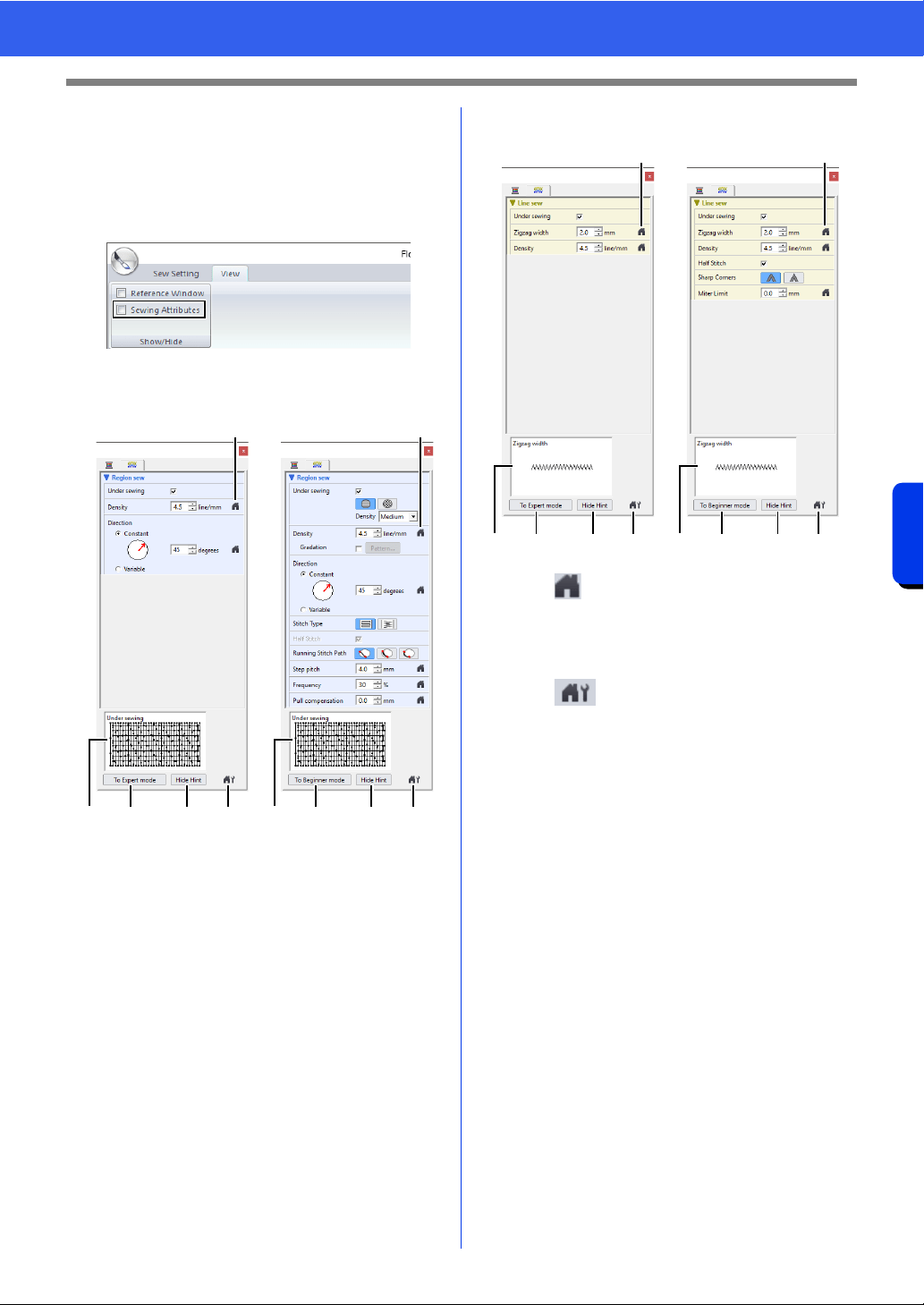
271
Design Center
Sew Setting Stage
■ Specifying sewing attributes
1 Click the [View] tab.
2 Select the [Sewing Attributes] check box in
the [Show/Hide] group to display the [Sewing
Attributes] dialog box.
For region sewing
For line sewing
a
Click to return to the default setting.
b To Expert mode/To Beginner mode
Click to switch the mode.
c
Click to load/save the sewing settings.
cc "Saving frequently used sewing
attributes" on page 213
d Hide Hint/Show Hint
Click to switch between displaying and
hiding the hint view
e With each change in the sewing
attributes, a preview of the stitching can
be checked here.
1 Change the sewing attributes displayed under
[Line sew] or [Region sew].
cc For details on the different sewing
attributes and settings, refer to "Line
sewing attributes" on page 382 and
"Region sewing attributes" on page 388
2 When the line sewing attributes are displayed,
click an outline to apply the line sewing
attributes to the outline.
When the region sewing attributes are
displayed, click a region to apply the region
sewing attributes to the region.
Beginner mode Expert mode
aa
eb dc eb d c
Expert modeBeginner mode
a
eb dc
a
eb dc

272
Design Center
Sew Setting Stage
■ Color
1 Click the [View] tab.
2 Select the [Sewing Attributes] check box in
the [Show/Hide] group to display the [Sewing
Attributes] dialog box.
3 Click the [Color] tab.
4 From the [Thread Chart] selector, select a
thread color chart or a user thread chart.
5 From the list of thread colors, click the desired
color.
cc For details on the four buttons under the
list, refer to "Special colors" on page 56
6 Click the region or outline to apply the color
setting.
■ Creating a gradation
The density of the color can be adjusted at various
locations to create a custom gradation pattern.
1 In Expert mode of the [Sewing Attribute
Setting] dialog box, select the [Gradation]
check box, and then click [Pattern].
2 Specify the desired settings in the [Gradation
Pattern Setting] dialog box, and then click
[OK].
a To select a preset gradation pattern, click
the desired pattern under [Select
pattern].
b Move the sliders to adjust the density of
the gradation pattern.
c The preview area shows the setting
changes that you make.
In order to increase the decorative effect, you can
move the center point of regions set to the
concentric circle stitch or radial stitch.
1 Click the [Sew Setting] tab.
b
Saving frequently used sewing attributes
• Frequently used sewing attributes can be saved
together, and recalled when specifying sewing
attributes.
• Perform this operation in the same way that it is
performed in Layout & Editing.
cc For details, refer to "Saving frequently used
sewing attributes" on page 213
b
Gradation can be specified if satin stitches, fill
stitches or programmable fill stitches have been
selected for the region sewing and [Manual
straight line] has been selected as the sewing
direction.
a
An additional color (used for blending in Layout &
Editing) cannot be specified with the gradation
setting in Design Center.
Applying effects to
concentric circle and radial
stitches
a
c
b
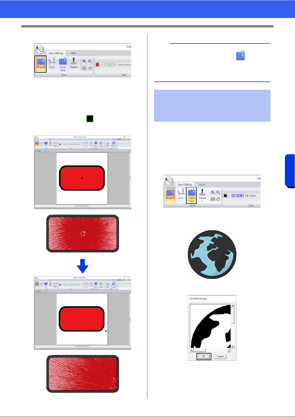
273
Design Center
Sew Setting Stage
2 Click [Region] in the [Tools] group.
3 Select the desired color and sew type
([Concentric Circle Stitch] or [Radial
Stitch]).
4 Click the region.
The center point ( ) appears.
5 Drag the center point to the desired location.
By specifying hole sewing, the stitching in
overlapping regions will not be sewn twice. Hole
sewing can be set only when one region completely
encloses another.
1 Click the [Sew Setting] tab.
2 Click [Hole Sew] in the [Tools] group.
3 Click the region that completely encloses
another region.
4 Click [OK] to set hole sewing.
b
To move the center point later, click , and then
right click the region with the concentric circle
stitch or radial stitch applied. The center point
appears and can be moved.
Preventing overlapping
stitching of regions (hole
sewing)
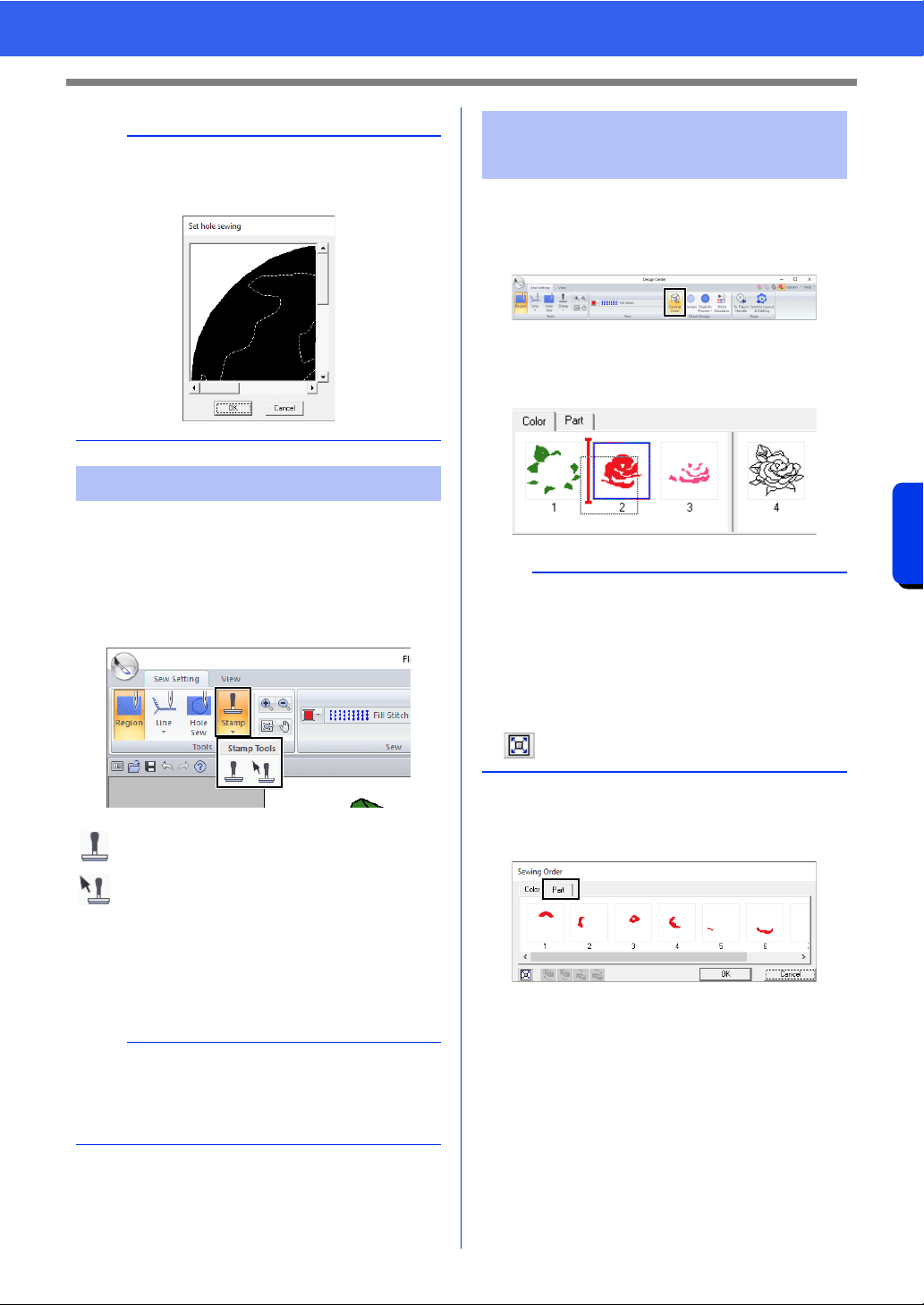
274
Design Center
Sew Setting Stage
Stamps can be applied to regions in the Sew Setting
Stage of Design Center.
1 Click the [Sew Setting] tab.
2 Click [Stamp] in the [Tools] group, and then
select the desired tool from [Stamp Tools].
Settings for stamps are specified in the same way
that they are in Layout & Editing.
cc "Applying and editing stamps" on
page 67
1 Click the [Sew Setting] tab.
2 Click [Sewing Order] in the [Check Design]
group.
3 To change the sewing order of a color, select
the frame for the color, and then drag the
frame to the desired position.
4 To view the sewing order of multiple patterns
of the same color, select the frame, and then
click the [Part] tab.
5 To change the sewing order of a pattern,
select the frame for the pattern, and then drag
the frame to the desired position.
6 Click [OK].
b
To cancel hole sewing, click the white inner region.
The inner region will be sewn twice when it
appears in the same color as the outer region.
Applying stamps
: Click this button to apply a stamp.
: Click this button to edit the applied stamp.
b
Some stamp patterns are provided with this
application; however, by using Programmable
Stitch Creator, you can edit the patterns that are
provided or you can create your own.
Checking and editing the
sewing order
b
• To select additional frames, hold down the
<Shift> or <Ctrl> key and select each frame.
• The frames containing regions are separated
from the frames containing outlines with a thick
vertical line. Frames from one side of the line
cannot be moved to the other side.
• To enlarge the pattern for better viewing, click
.
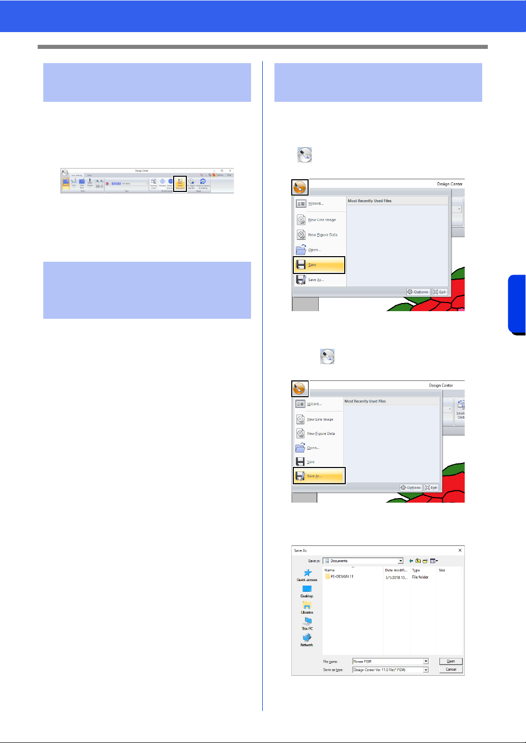
275
Design Center
Sew Setting Stage
1 Click the [Sew Setting] tab.
2 Click [Stitch Simulator] in the [Check
Design] group to view stitching using the
stitch simulator.
The basic operations are the same as those
described for Layout & Editing.
cc "Checking the stitching with the Stitch
Simulator" on page 90
Embroidery patterns can be viewed in the
Reference Window in the Sew Setting Stage in the
same way that they are in the Figure Handle Stage.
cc "Viewing outlines in the Reference
Window" on page 266.
The file can be saved at each stage.
■ Overwriting
Click , and then select [Save] from the
command list.
■ Saving with a new name
1 Click , and then select [Save As] from the
command list.
2 Select the drive and the folder, and then type
in the file name.
Checking the stitching in
the Stitch Simulator
Viewing embroidery
patterns in the Reference
Window
Saving embroidery
patterns
276
Design Center
Sew Setting Stage
3 Click [Save].
b
• Image data from the Original Image Stage can
be saved as a bitmap file (.bmp).
• In the Line Image Stage, image data is saved as
a .pel file.
• In the Figure Handle Stage and the Sew Setting
Stage, pattern data is saved as a .pem file.
a
If you select a file type of a previous software
version, saved .pem files can be opened with that
version of the software; however, some
information may be lost.

Design Database
Using Design Database, the created embroidery
data can be managed. In addition, while viewing
images of the file contents, the files can be
organized, or multiple embroidery designs can be
transferred to embroidery machines.
278
Design Database
Design Database
Design Database
■ File menu
■ Edit menu
■ Display menu
■ Option menu
■ Help menu
List of menus
Menu Toolbar Reference Menu Toolbar Reference
Open in Layout & Editing — p. 283 Print Setup — p. 294
Import Into Layout &
Editing
— p. 283
Print Preview — —
Create New Folder — p. 281 Print — p. 294
Convert Format — p. 291
Create Image File and
HTML
—
p. 295
Delete — p. 282 Create CSV — p. 295
Search — p. 290 Exit — —
Menu Toolbar Reference Menu Toolbar Reference
Cut
p. 281
Paste p. 281
Copy Select All — —
Menu Toolbar Reference Menu Toolbar Reference
Large Thumbnails
p. 282
Property p. 292
Small Thumbnails Refresh — —
Details Toolbar — p. 279
Preview p. 292 Status Bar — —
Menu Toolbar Reference Menu Toolbar Reference
Select
System Unit
mm
—p.22
Application
Color
Blue
— p. 371
inch Black
USB Link — p. 289 Silver
Wireless Link — p. 289 Aqua
DST Settings — p. 369 Network Machine Settings — p. 286
Menu Toolbar Reference Menu Toolbar Reference
Online Instruction Manual —p.5About Design Database — —
Customer Support —p.7
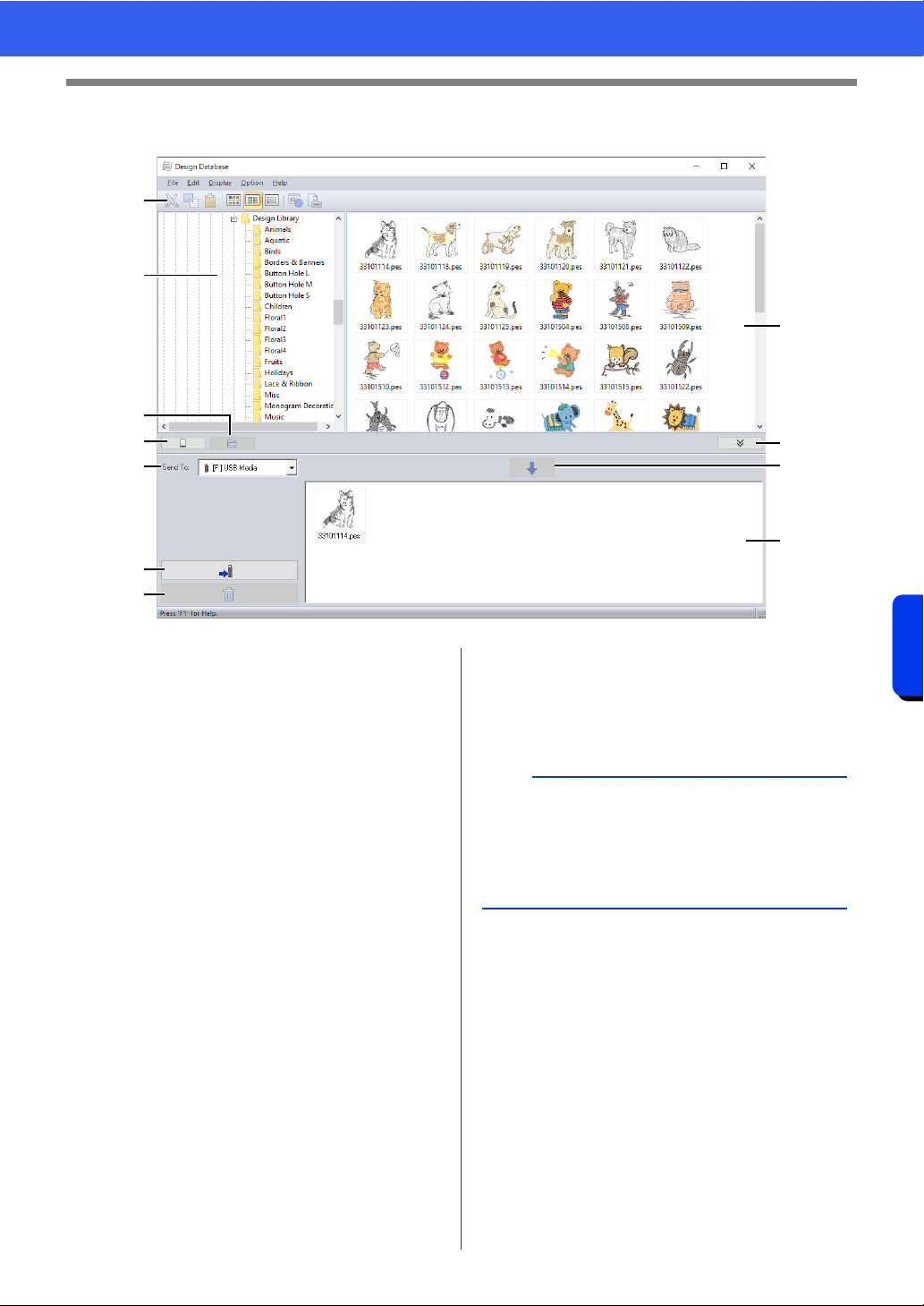
279
Design Database
Design Database Window
Design Database Window
a Toolbar
b Folder pane
c Contents pane
Displays thumbnails of all embroidery
design in the selected folder.
d Card reading button
Reads an original card.
e Folder content display button
Displays the folder contents.
f Send to selector
Select where the embroidery files will be
written or sent.
g Write button
Begins writing the selected designs
(displayed in the writing list).
h Remove button
Returns the selected design (displayed in
the writing list) to the unselected state.
i Writing list
Displays the list of designs to be written to
the original card, USB media or
embroidery machine.
j Add button
Adds the design selected in the contents
pane to the writing/transfer list.
k Writing box display/non-display
button
Click when writing/transferring designs.
Click this button to hide or display the
Writing list.
a
b
d
f
g
h
c
e
k
j
i
b
Settings for the following can be selected from the
Option menu.
•Select mm or inch as the system units.
•Select Blue, Black, Silver or Aqua as the
application color.
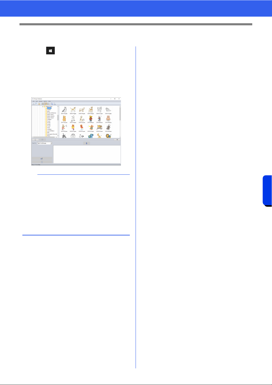
280
Design Database
Starting Up Design Database
Starting Up Design Database
1 Click .
2 Click [Design Database] under the title [PE-
DESIGN 11] in the screen.
3 Click a folder in the folder pane.
All embroidery files in the folder are
displayed in the contents pane on the right.
b
• The displayed files have the following
extensions.
.pes, .phc, .phx, .dst, .exp, .pcs, .hus, .vip, .shv,
.jef, .sew, .csd, .xxx, .pen
• .pem files are not displayed since they cannot be
read by the machine. Import the embroidery
design into Layout & Editing from Design
Center, and then save it as a .pes file.
• Zipped file can not be read in this application.
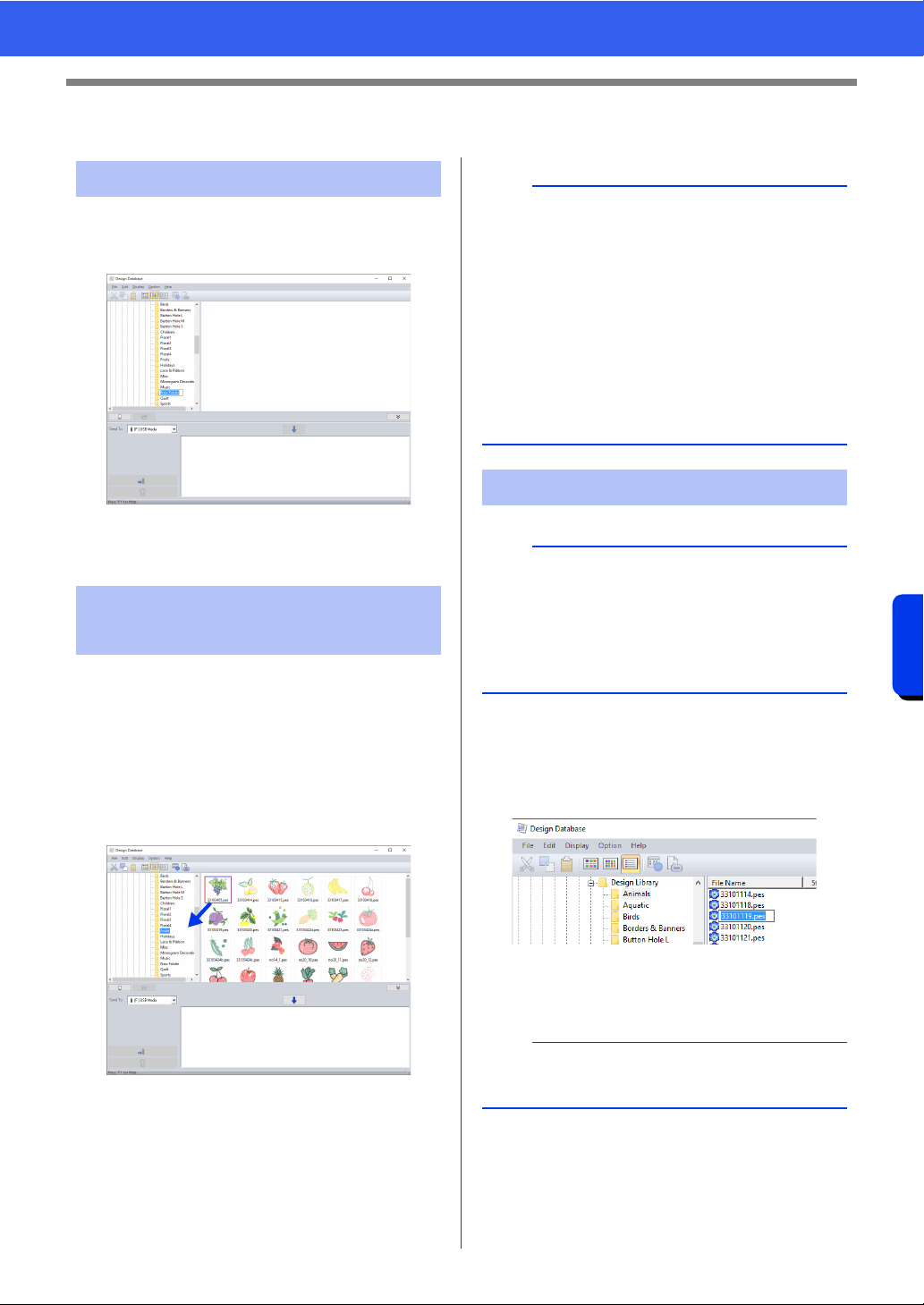
281
Design Database
Organizing Embroidery Designs
Organizing Embroidery Designs
1 In the folder pane, on the left, select the folder.
2 Click [File], then [Create New Folder].
3 Type in the name of the new folder, and then
press the <Enter> key.
1 In the folder pane, locate the folder where you
want to move the embroidery design.
2 In the folder pane, click the folder that contains
the embroidery design.
3 Drag the embroidery design in the contents
pane to the folder you previously located in the
folder pane.
If the two folders are on the same drive, the
selected embroidery design is moved to
the other folder.
If the two folders are on separate drives,
the selected embroidery design is copied
into the other folder.
1 In the folder pane, select the folder containing
the embroidery design.
2 Select the embroidery design. Then click
again.
3 Type in the new name of the embroidery
design, and then press the <Enter> key.
Creating new folders
Moving/copying files to a
different folder
b
• To copy the file from one folder to another on the
same drive, hold down the <Ctrl> key while
dragging the embroidery design.
• To move the file from one folder to another on
different drives, hold down the <Shift> key while
dragging the embroidery design.
• The file can also be removed from the current
folder (or copied) by selecting the menu
command [Edit] - [Cut] (or [Edit] - [Copy]).
Then, the file can be added to the new folder by
selecting it in the folder pane, then selecting the
menu command [Edit] - [Paste].
Changing file names
a
The names of embroidery designs can be changed
from Design Database only when the sewing
information (menu command [Display] –
[Details]) is displayed.
cc "Changing how files are displayed" on
page 282
b
When renaming a file, the file extension cannot be
changed.
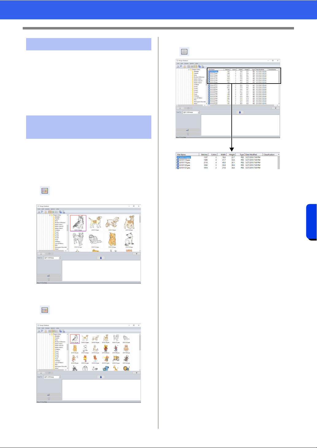
282
Design Database
Organizing Embroidery Designs
1 In the folder pane, select the folder containing
the embroidery design that you want to delete.
2 In the contents pane, select the name of the
embroidery design.
3 Press the <Delete> key.
The file is moved to the Recycle Bin.
The embroidery designs in the contents pane can
be displayed as large thumbnails or small
thumbnails, or they can be listed by their sewing
information.
■ Large Thumbnails
Click or click [Display], then [Large
Thumbnails].
■ Small Thumbnails
Click or click [Display], then [Small
Thumbnails].
■ Sewing information
Click or click [Display], then [Details].
Deleting files
Changing how files are
displayed

283
Design Database
Opening Embroidery Designs
Opening Embroidery Designs
1 In the folder pane, select the folder containing
the embroidery design that you want to open
in Layout & Editing.
2 In the contents pane, select the .pes file.
3 Click [File], then [Open in Layout & Editing].
Files in the following formats can be imported.
.pes, .phc, .phx, .dst, .exp, .pcs, .hus, .vip, .shv, .jef,
.sew, .csd, or .xxx
1 In the folder pane, select the folder containing
the embroidery design that you want to import
into Layout & Editing.
2 In the contents pane, select the embroidery
design.
3 Click [File], then [Import Into Layout &
Editing].
The selected embroidery design appears in
the Layout & Editing window.
Opening files with Layout
& Editing
a
Be sure to select a folder that contains .pes files.
Importing files into Layout
& Editing
a
Files in the .pen format cannot be imported into
Layout & Editing.
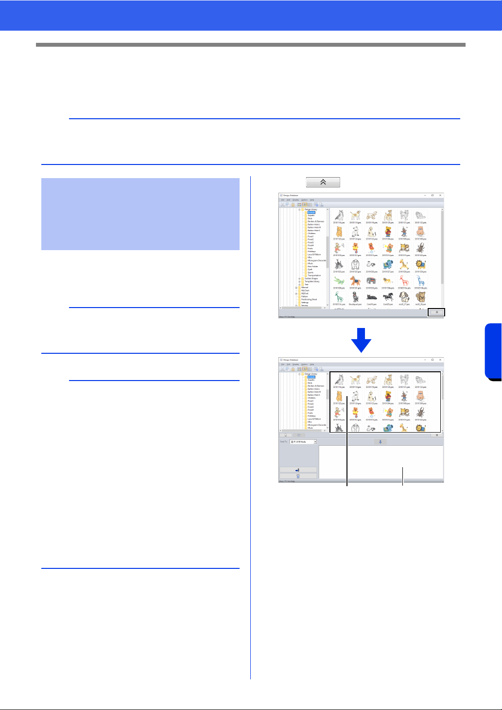
284
Design Database
Transferring Embroidery Designs to Machines
Transferring Embroidery Designs to
Machines
1 Prepare the media to be used to make the
transfer, or connect an embroidery machine to
the computer.
2 Click .
1 Contents pane (Available designs)
2 Writing list (Selected designs)
a
The procedures for transferring the created embroidery design to an embroidery machine differ depending
on your embroidery machine model. For detail, refer to the instruction manual provided with your embroidery
machine.
Transferring to a machine
by using USB media/
wireless network/USB
cable/original card
a
Be sure that the hoop size of the design does not
exceed the hoop that will be used on the
embroidering machine.
b
• If the design is to be written to an original card,
insert the original card into the USB card writer
module.
• If the design is to be written to USB media, plug
the USB media into the computer.
• If the design is to be transferred directly to an
embroidery machine, connect the embroidery
machine to the computer. For details on
transferring design, refer to the instruction
manual provided with your embroidery machine.
• In order to use the Link function to transfer
embroidery designs, an embroidery machine
compatible with the Link function must be
running in Link mode.
cc "Using the Link Function to Embroider From
the Computer" on page 227
12
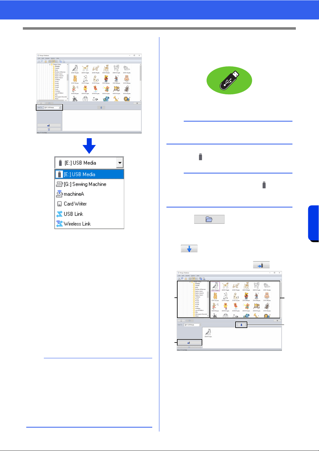
285
Design Database
Transferring Embroidery Designs to Machines
3 Click the [Send To] selector, and then click
the destination.
a Sends designs to the USB media.
b Sends designs directly to an embroidery
machine.
c Sends designs to embroidery machine(s)
via a wireless network connection.
cc "Wirelessly transferring data" on
page 286
d Sends designs to the USB card writer.
e Sends designs to embroidery machine(s)
by using the USB Link function.
cc "USB Link" on page 227
f Sends designs to embroidery machine(s)
by using the Wireless Link function.
cc "Wireless Link" on page 232
The remaining steps differ depending on the
destination where the data is to be sent.
■ Using USB media
Designs can be transferred to an embroidery
machine compatible with the USB Host function.
1 Select from the [Send To] selector.
2 Click .
3 Select a folder in a, select an embroidery file
from the contents pane
b, and then click
c to add the file to the writing list.
After all embroidery files to be written are
added to the writing list, click d.
The designs in the writing list are written to
the USB media.
When the designs have been written, the
message "Finished outputting data."
appears.
b
If Link is not available in the [Send To] selector,
check that the embroidery machine is running in
Link mode. With the USB Link function, make sure
the USB cable is correctly connected to the
machine and computer. With the Wireless Link
function, register a machine that supports the
Wireless Link function and is on the network.
cc "Registering a machine with the application"
on page 224
a
b
c
d
e
f
a
The "PE-DESIGN Software Key" cannot be used
as USB media.
b
If multiple USB media are connected, for each
connected device appears. Select the USB media
where the design is to be written.
a
d
b
c
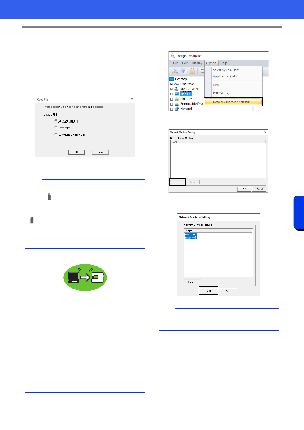
286
Design Database
Transferring Embroidery Designs to Machines
■ Wirelessly transferring data
1 Connect the computer running the application
to your home network (wireless LAN access
point).
2 Connect the sewing machine to the same
home network.
For details on making connections, refer to the
manual provided with your machine.
3 Click [Network Machine Settings] in the
[Option] menu.
4 Click [Add].
5 Select the sewing machine, and then click
[Add].
a
• Do not remove the USB media while designs are
being written.
• If there is already a file with the same name at
the destination, the following dialog box
appears. Select whether to overwrite the
existing file, to stop copying or to copy the file
using a different name.
b
If a volume label has been specified for the USB
media, " [(Drive Letter):] (Volume Label)"
appears in the [Send To] selector.
If a volume label has not been specified,
" [(Drive Letter):] USB Media" appears.
For details on changing the name (volume label)
for the USB media, refer to the manual provided
with the USB media.
b
Embroidery patterns cannot be transferred if the
computer and sewing machine are connected to
different home networks. Be sure to connect to the
same home network.
b
If the desired sewing machine does not appear in
the list, click [Refresh].
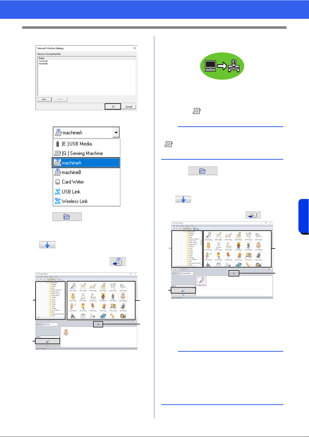
287
Design Database
Transferring Embroidery Designs to Machines
6 Click [OK] to register the machine.
7 Select the machine in the [Send To] selector.
8 Click .
9 Select a folder in a, select an embroidery file
from the contents pane
b, and then click
c to add the file to the writing list.
After all embroidery files to be written are
added to the writing list, click
d.
The designs in the writing list are
transferred to the machine.
When the transfer is finished, the message
"Finished outputting data." appears.
■ Transferring directly to a
machine's memory
Designs can be transferred to embroidery machines
that can be connected to a computer using a USB
cable.
1 Select from the [Send To] selector.
2 Click .
3 Select a folder in a, select an embroidery file
from the contents pane
b, and then click
c to add the file to the writing list.
After all embroidery files to be written are
added to the writing list, click d.
The designs in the writing list are written to
the embroidery machine's memory.
When the designs have been written, the
message "Finished outputting data."
appears.
a
d
b
c
b
If multiple embroidery machines are connected,
for each machine appears. Select the
machine to be used to embroider.
a
• Do not remove the USB cable while designs are
being written.
• If there is already a file with the same name at
the destination, a dialog box appears. Select
whether to overwrite the existing file, to stop
copying or to copy the file using a different
name.
a
d
b
c
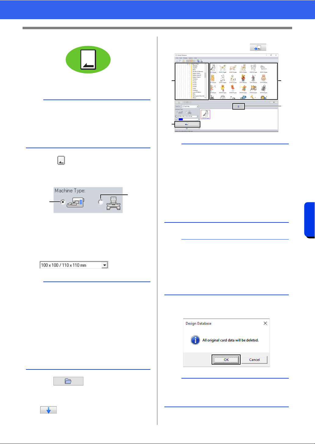
288
Design Database
Transferring Embroidery Designs to Machines
■ Using an original card
Designs can be transferred to an embroidery
machine equipped with a card slot.
1 Select from the [Send To] selector.
2 Under [Machine Type], select the type of
embroidery machine to be used.
a Single-needle machine
b Multi-needle machine
3 From the [Hoop Size] selector, select the
appropriate size of embroidery hoop.
4 Click .
5 Select a folder in a, select an embroidery file
from the contents pane
b, and then click
c to add the file to the writing list.
After all embroidery files to be written are
added to the writing list, click
d.
6 If the files are to be written to an original card,
the following message appears. Click [OK].
a
• Files other than .phc, .phx files can be written.
• If no USB card writer module is connected to the
computer, an original card cannot be selected as
the output destination. Before transferring, make
sure that a USB card writer module is connected
to the computer.
a
• Do not select a hoop size larger than the
embroidery hoop that can be used with your
embroidery machine. Otherwise, the created
original card will not work correctly with the
embroidery machine.
• When writing to an original card that already
contains data, all data on the card will be
deleted. Before writing to a card, save all
necessary data to a hard disk or other media,
and check that no necessary data remains on
the card.
cc "From an original card" on page 103
b
a
a
• An embroidery design for the jumbo frame
cannot be transferred to the machine by using
an original card.
• If the pattern in the selected embroidery file is
larger than the hoop size selected in step
3, or
the number of stitches or number of colors for
the pattern exceeds the maximum for the hoop
selected in step
3, that file cannot be added to
the writing list. Only the embroidery designs
displayed in the writing list will be written to the
original card.
b
• Embroidery files can also be added to the writing
list by right-clicking the file, then clicking [Add to
Writing List], or by selecting a file in the
contents pane and dragging it to the writing list.
• A file can also be removed from the writing list by
right-clicking it in the writing list, then clicking
[Remove from Writing List].
a
Do not remove the card or unplug the USB cable
while designs are being written to the card (while
the LED indicator is flashing).
a
d
b
c
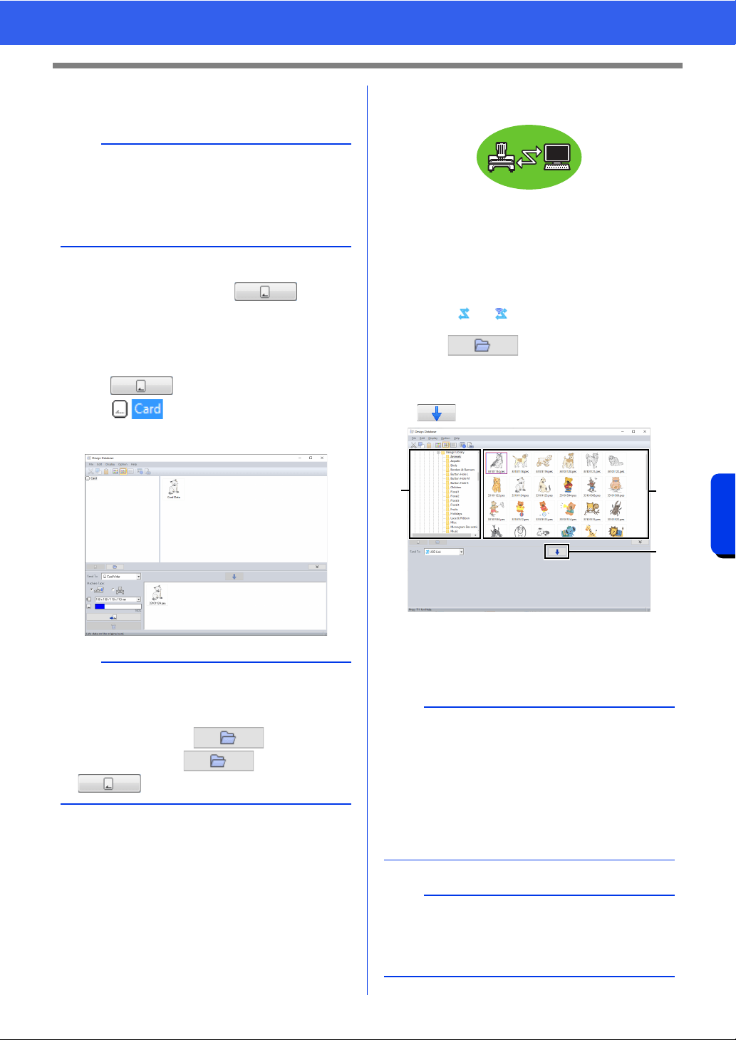
289
Design Database
Transferring Embroidery Designs to Machines
7 When a message appears, indicating that
writing is finished, click [OK].
• To rewrite the embroidery files written on
the original card, click to select
those files, and move files to the writing list
in the same manner.
• To check the embroidery design file being
written to the original card, click
.
appears in the folder pane, and
all embroidery designs written to the
original card appear in the contents pane.
■
Sending embroidery designs to
machines by using the Link function
An embroidery machine compatible with the Link
function must be running in Link mode. [USB Link]
and [Wireless Link] are available with the Link
function.
cc "Using the Link Function to Embroider
From the Computer" on page 227
1 Select or from the [Send To] selector.
2 Click .
3 Select a folder in a, select an embroidery file
from the contents pane
b, and then click
c.
4 Continue the procedure as described in
Step 5 of "USB Link" on page 227 or Step 5
of "Wireless Link" on page 232.
b
Patterns created on a custom-sized Design Page
are written to cards split into their various hoop
sections.
cc Note of "Transferring to a machine by using an
original card" on page 225
b
• Embroidery designs written to the original card
appear as [Card Data] in the contents pane.
• To display the contents of the folder in the
contents pane, click . Switch the
display by clicking and
.
a
Files in the .dst, .exp, .phc, and .phx formats
cannot be transferred with the Link function. When
[USB Link] or [Wireless Link] is selected in the
[Send To] box, .dst, .exp, .phc, and .phx files do
not appear in the contents pane.
In addition, embroidery files with the Design Page
size set to [Custom Size] or with [Hoop Size] set
to 360 × 360 mm (Jumbo Frame) do not appear
in the contents pane.
b
To display the [USB Link] or [Wireless Link]
dialog box again after the computer has been
restarted, click [USB Link] or [Wireless Link] in
the [Option] menu.
a
b
c
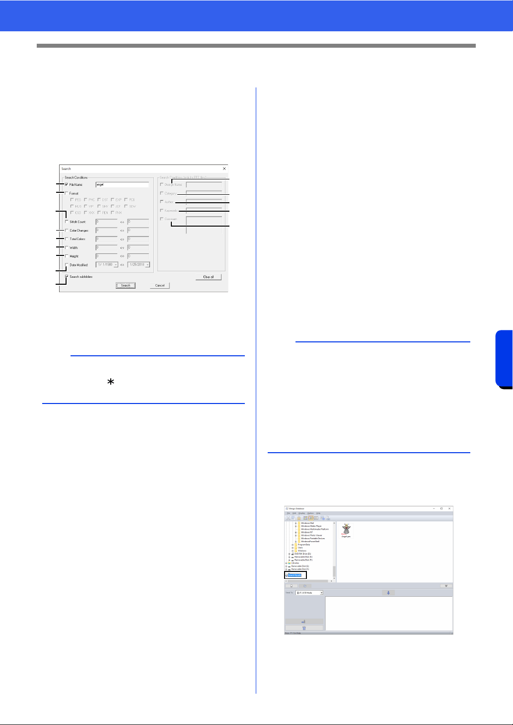
290
Design Database
Searching for an Embroidery Design
Searching for an Embroidery Design
1 In the folder pane, select the folder.
2 Click [File], then [Search].
3 Specify the search conditions. Select the
check box of the search conditions to be
specified.
a File Name
Select to search for files with a specific file
name. Type the file name in the box.
b Format
Select the check box beside the desired
file format.
c Stitch Count
In the boxes, type the lower and upper
limits of the range for the number of
stitches.
d Color Changes
In the boxes, type the lower and upper
limits of the range for the number of color
changes.
e Total Colors
In the boxes, type the lower and upper
limits of the range for the total number of
thread colors.
f Width
In the boxes, type the lower and upper
limits of the width range.
g Height
In the boxes, type the lower and upper
limits of the height range.
h Date Modified
In the boxes, type the modification date
range (from when to when).
When searching for .pes files, the
following conditions can also be specified.
i Design Name
Type the design name in the box.
j Category
In the box, type specific characters or the
embroidery category.
k Author
In the box, type the author's name to be
searched for.
l Keywords
In the box, type the keyword to be
searched for.
m Comment
In the box, type the comment to be
searched for.
4 Click [Search].
A list of files matching the specified search
conditions appears.
b
Wildcard characters ("?" to represent a single
character and " " to represent multiple
characters) can also be used.
a
b
c
d
e
f
g
h
n
i
j
k
l
m
b
• To also search through the subfolders (folders
within the selected folder), select the [Search
subfolders]
n check box.
• All characters entered in the box beside [File
Name] will be considered as a single set of
characters. However, you can search for files
matching multiple words in the boxes below
[Search Conditions (only for PES files)] by
separating the words with a space.
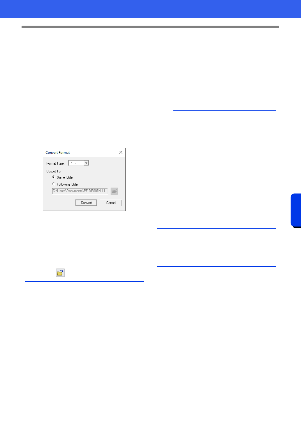
291
Design Database
Converting Embroidery Design Files to Different Formats
Converting Embroidery Design Files to
Different Formats
Embroidery design files can easily be converted to a file of one of the other formats (.pes, .dst, .exp, .pcs, .hus,
.vip, .shv, .jef, .sew, .csd, or .xxx).
1 In the folder pane, select the folder containing
the embroidery design that you want to
convert.
2 In the contents pane, select the embroidery
desired format.
3 Click [File], then [Convert Format].
4 From the [Format Type] selector, select the
desired format.
5 Under [Output To], select whether the new
file is added to the same folder as the original
file (Same folder) or to a specified folder
(Following folder).
6 Click [Convert].
The file is converted, and the new file is
added to the specified folder.
b
To change the folder where the new file will be
added, click .
b
•With [DST Settings] on the [Option] menu, the
number of jumps for thread trimming can be
specified for .dst files.
cc "Specifying the number of jumps in
embroidery design of the DST format" on
page 369
• If multiple files with different formats are
selected to be converted while [Same folder] is
selected, any file with the same format as the
new one will not be converted. However, if the
files are being added to a different folder than
the original one, any file with the same format as
the new one will be copied to the different folder,
instead of being converted.
• If the file is converted to a .pes file, the thread
colors are converted as if the file was imported
into Layout & Editing.
a
Files cannot be converted to the .phc, .phx, or .pen
formats.
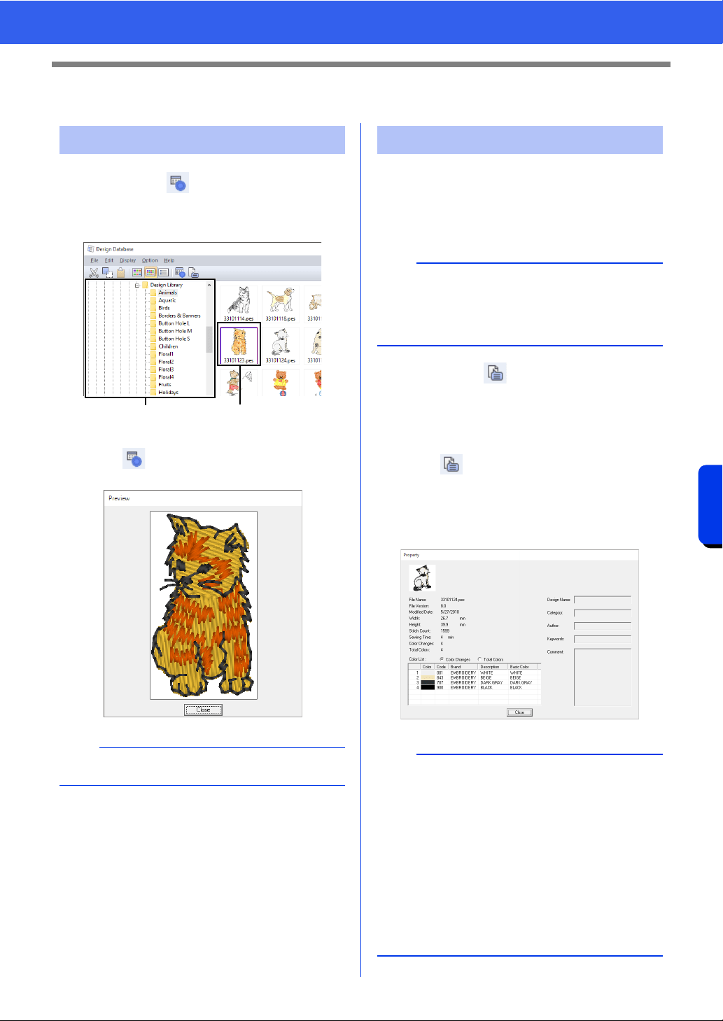
292
Design Database
Checking Embroidery Designs
Checking Embroidery Designs
Toolbar button:
1 Select a folder in a, select an embroidery file
from the contents pane
b.
2 Click , or click [Display] menu, then
[Preview].
Sewing information such as the file name, size,
stitch count, sewing time, color count and
modification date can be checked in the Property
dialog box. With .pes file, additional information
about the embroidery design can be viewed.
Toolbar button:
1 In the contents pane, select the embroidery
design corresponding to the information that
you want to view.
2 Click , or click [Display] menu, then
[Property].
• When opening PES files (version 4.0 or
later), the following [Property] dialog box
will be displayed.
Previewing files
b
Files in the .pen format cannot be previewed.
ab
Checking file information
a
• The displayed sewing time is an estimate. The
actual sewing time depends on the machine
model used and the specified settings.
The sewing time is not displayed with .pen files.
b
•Select [Color changes] beside [Color List] to
display the thread color change information in
the color list. Select [Total colors] to display the
information for all thread colors in the color list.
cc "Checking embroidery design information" on
page 99
• When a .pes file that contains user-defined
colors is registered, those colors appear as
[Basic Color].
cc "Checking embroidery design information" on
page 99
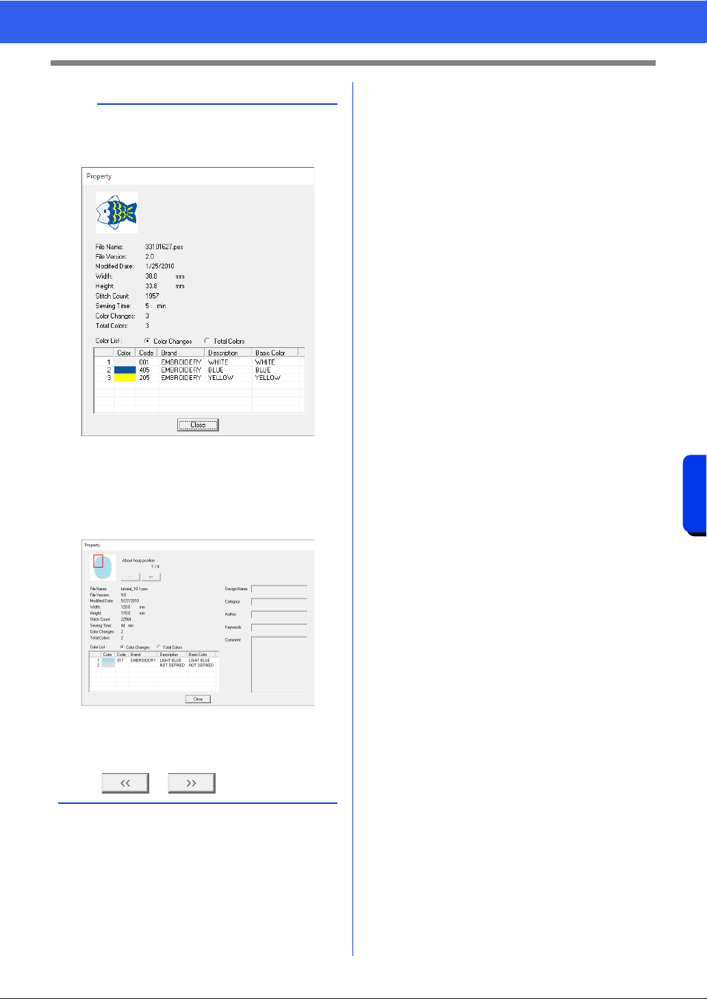
293
Design Database
Checking Embroidery Designs
b
• When opening Non-PES files or PES files
(version 3.0 or earlier), the following [Property]
dialog box will be displayed.
• If the Design Page size was set to [Custom
Size] or if [Hoop Size] was set to a multi-
position hoop (100 × 172 mm or 130 × 300 mm)
or a jumbo frame (360 × 360 mm), a [Property]
dialog box similar to the one shown below
appears.
• The red box in the dialog box shows the position
of the displayed pattern section.
• To display information for other hoop positions,
click or .
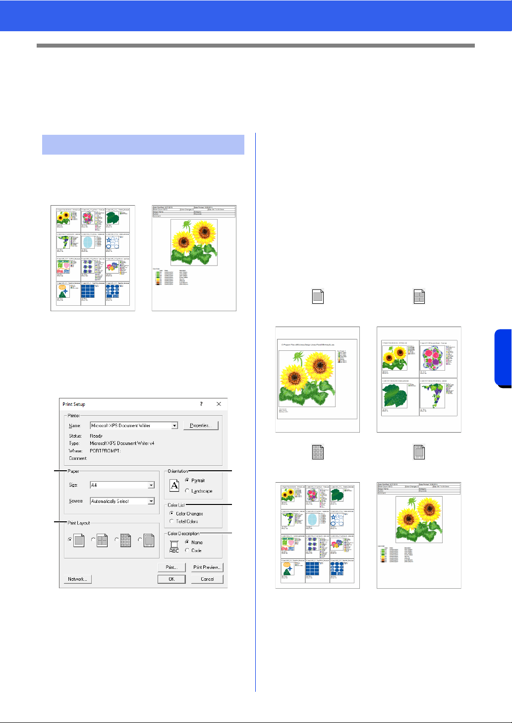
294
Design Database
Outputting a Catalog of Embroidery Designs
Outputting a Catalog of Embroidery
Designs
Images and sewing information for all embroidery designs can be outputted in a number of formats. Select
among the following modes according to your preferences.
Images of all embroidery designs in the selected
folder can be printed as a catalog or as an
instruction guide.
1 In the folder pane, select the folder containing
the embroidery designs.
2 Click [File], then [Print Setup].
3 Under [Paper] a and [Orientation] b,
select the appropriate settings.
4 Select [Color List] c.
Color changes
The thread color information for each color
change is displayed.
Total colors
The thread color information for the necessary
threads is displayed. This allows you to check
the total number of thread colors.
cc "Checking embroidery design
information" on page 99
5 Select [Print Layout] d.
6 Under [Color Description] e, select
whether the thread colors appear as the name
of the color or as the brand and thread
number.
7 Click [Print].
Printing
a
d
b
e
c
Catalog style 1 Catalog style 4
Catalog style 12 Instruction Guide style
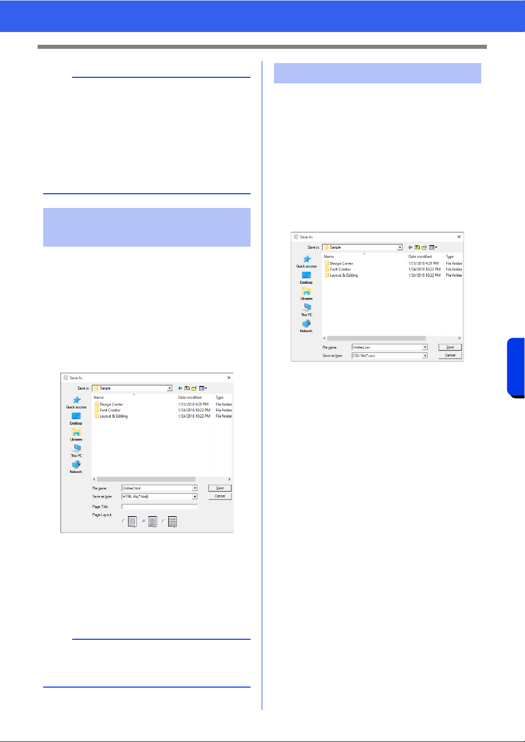
295
Design Database
Outputting a Catalog of Embroidery Designs
Instead of being printed, the catalog of embroidery
designs can be outputted as image and HTML files.
1 In the folder pane, select the folder containing
the embroidery designs.
2 Click [File], then [Create Image File and
HTML].
3 Select the drive and the folder, and then type
in the name of the HTML file.
4 To add a title at the top of the file and in the title
bar, type the title in the [Page Title] box.
5 Under [Page Layout], select how the designs
appear on the page.
6 Click [Save].
A .csv file containing the sewing information (file
name, dimensions, number of stitches, number of
colors, file path, file properties (.pes files only) and
the names of thread colors and thread numbers) for
selected embroidery designs can be outputted.
1 In the folder pane, select the folder containing
the embroidery designs.
2 Click [File], then [Create CSV].
3 Select the drive and the folder, and then type
in the name of the .csv file.
4 Click [Save].
b
• If one or more embroidery designs were
selected in the contents pane, only the selected
designs are printed.
• If the brand name, thread number or file
properties is too long, some of the text may not
be printed.
• If [File], then [Print] is clicked, the embroidery
designs are printed according to the settings
already selected in the [Print Setup] dialog box.
Outputting as Image and
HTML Files
b
A folder with the HTML file name is added to the
folder where the HTML file is saved, and the image
files are saved inside that added folder.
Outputting as a CSV file

Programmable Stitch Creator
Programmable Stitch Creator allows you to create
and edit stitch patterns, which can then be used
as programmable fill stitches or motif stitches in
both Layout & Editing and Design Center.
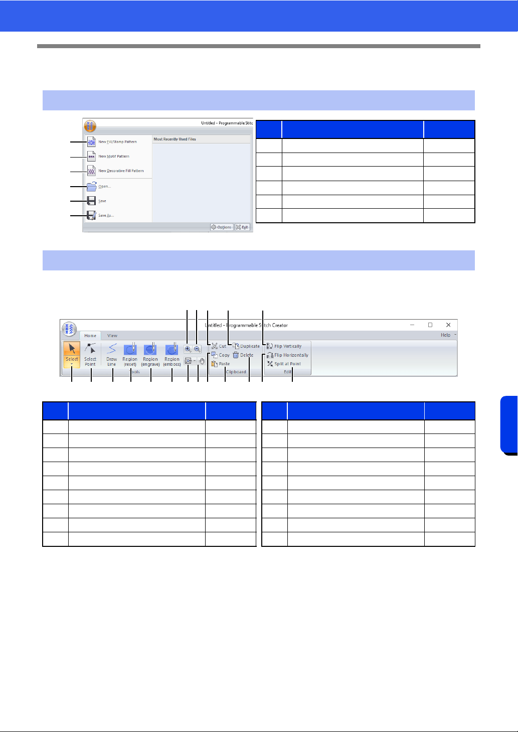
297
Programmable Stitch Creator
Programmable Stitch Creator
Programmable Stitch Creator
■ Home tab
Application button menu
1
2
3
4
5
6
No. Menu Reference
1 New Fill/Stamp Pattern —
2 New Motif Pattern p. 307
3 New Decorative Fill Pattern p. 311
4 Open p. 301
5 Save p. 317
6 Save As p. 317
Ribbon menu tabs
No. Menu Reference No. Menu Reference
1 Select Tool p. 305 10 Pan —
2 Edit Point Tool p. 305 11 Cut —
3 Draw Line Tool p. 302 12 Copy —
4 Region (Reset) Tool p. 303 13 Paste —
5 Region (Engrave) Tool p. 303 14 Duplicate —
6 Region (Emboss) Tool p. 303 15 Delete p. 310
7 Zoom In — 16 Flip vertically p. 305
8 Zoom Out — 17 Flip horizontally p. 305
9 Other Zoom Tools — 18 Split at Point p. 306
1 B
A
E2
D
C3 4 5 6
F
H
9 0
7
8
G
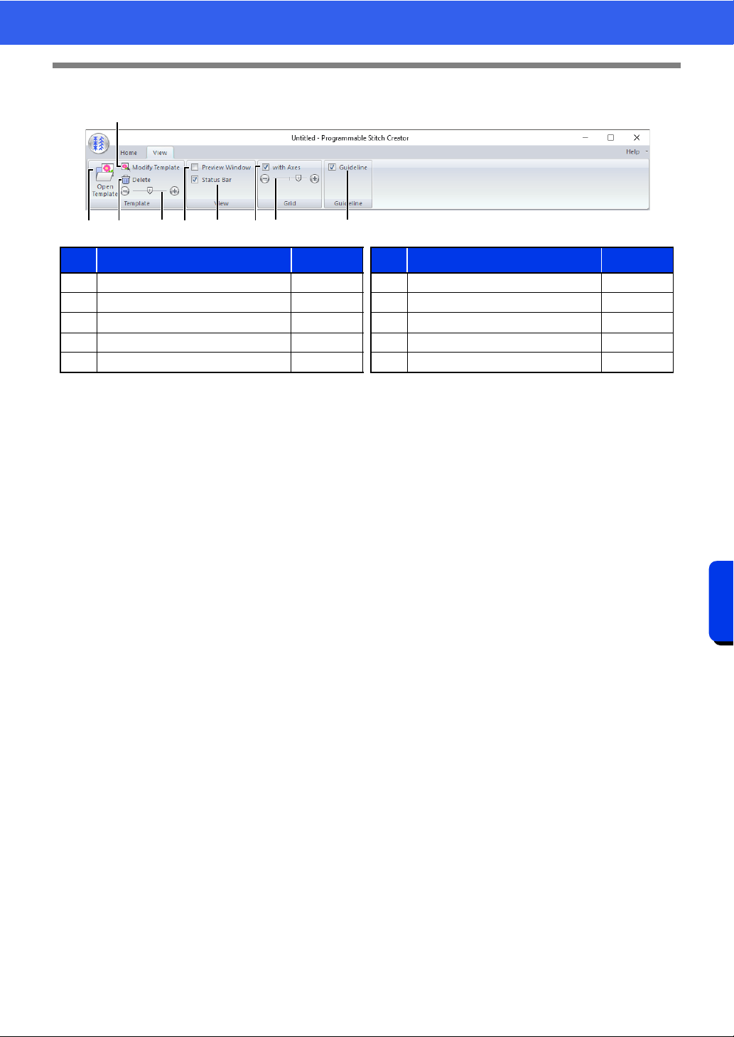
298
Programmable Stitch Creator
Programmable Stitch Creator
■ View tab
No. Menu Reference No. Menu Reference
1 Open Template p. 315 6 Show/Hide Status Bar p. 314
2 Modify Template p. 315 7 Show Grid with Axes p. 319
3 Delete Image p. 315 8 Grid interval p. 319
4 Background Image Density p. 316 9 Guideline p. 319
5 Show/Hide Preview window p. 317
145 6 8
2
3 97
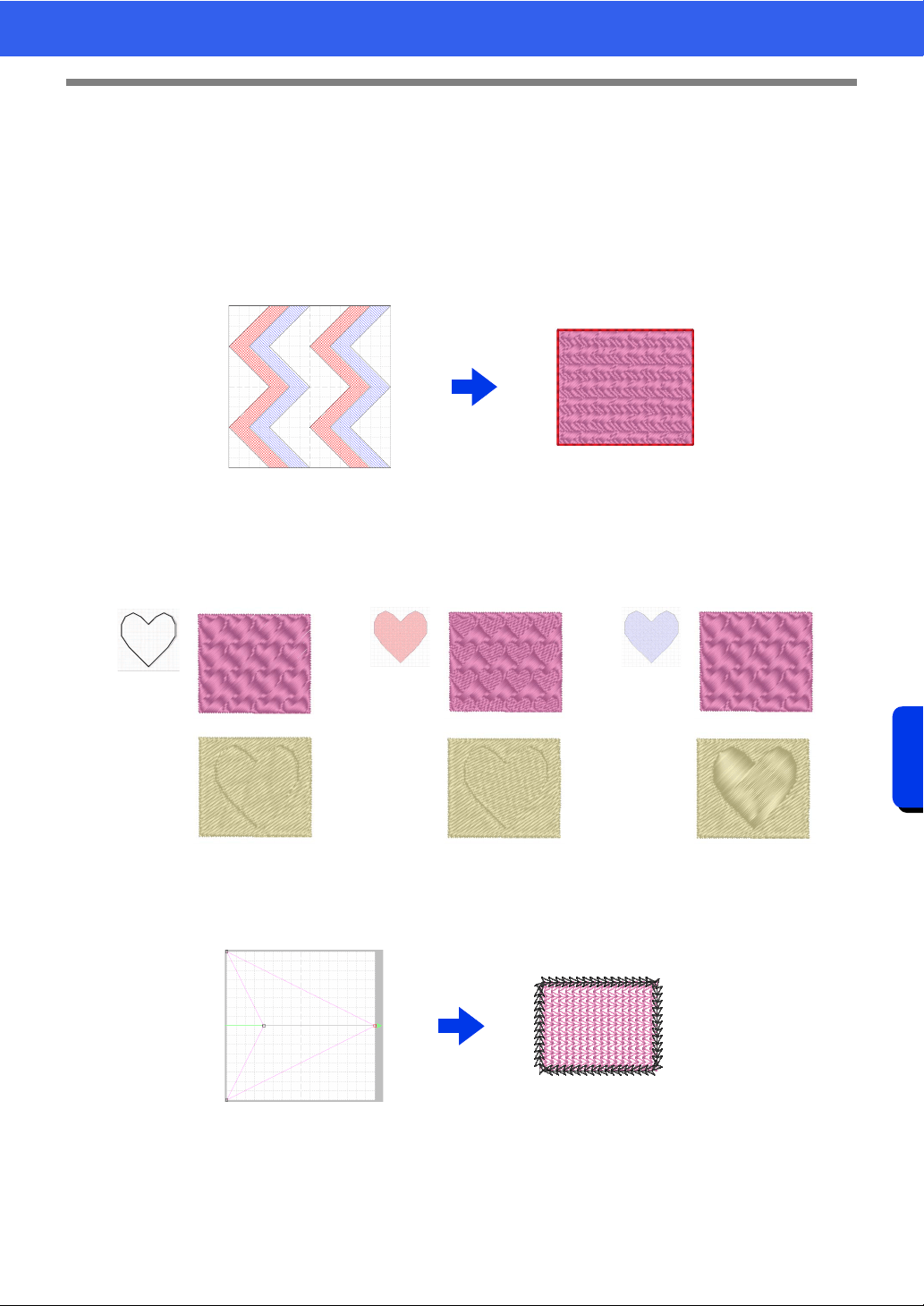
299
Programmable Stitch Creator
Basic Programmable Stitch Creator Operations
Basic Programmable Stitch Creator
Operations
Programmable Stitch Creator is an application for creating, editing and saving stitch patterns that can be used
for programmable fill stitch, motif stitch or decorative fill stitch sewing. The following three types of patterns
can be created in their corresponding mode.
Fill/stamp stitch patterns
• These patterns can be used as stamp patterns and for sewing with the programmable fill stitch in
Layout & Editing or Design Center.
• These patterns can be created with a single line or with multiple lines. In addition, these patterns can
be used to create an embossing/engraving effect in sewn regions.
• These patterns are created in Fill/Stamp mode.
1 engrave
2 emboss
Motif stitch patterns
• These patterns can be used for sewing lines with the motif stitch and for sewing regions with the motif
stitch, piping stitch and stippling stitch in Layout & Editing or Design Center.
• These patterns are created with a single line, which gives the look of a single-stroke drawing, and they
are used for decorative machine sewing.
• These patterns are created in Motif mode.
12
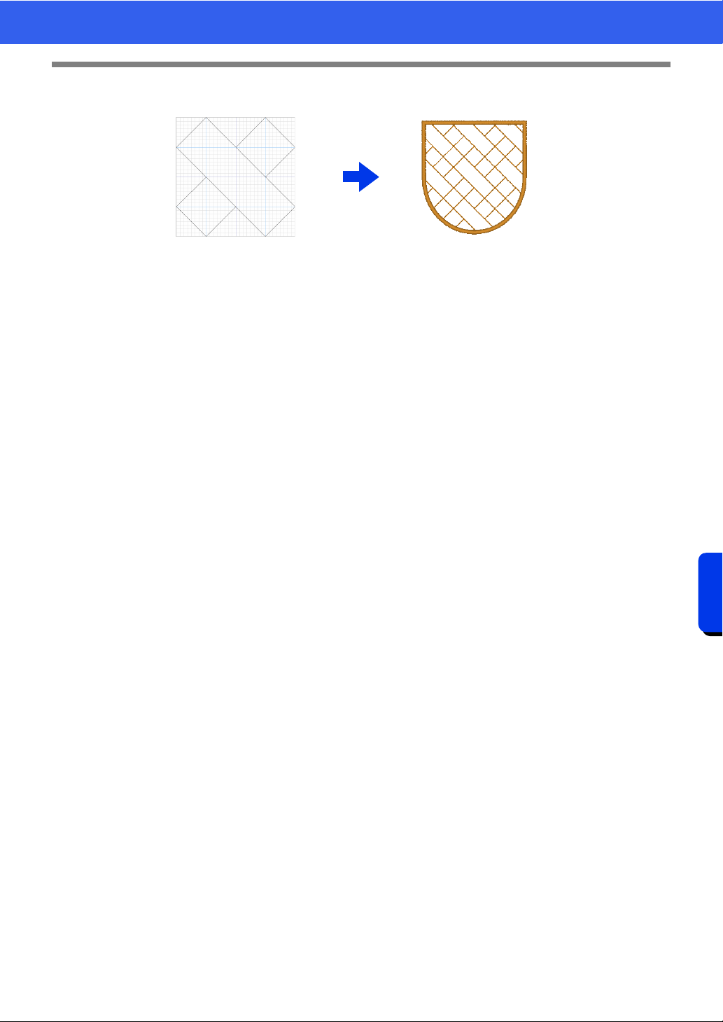
300
Programmable Stitch Creator
Basic Programmable Stitch Creator Operations
Decorative fill patterns
• These patterns can be selected as the sew type for a region.
• These patterns can be used to sew shapes arranged without spacing, like tiling, or to fill a region with
a beautiful pattern.
• These patterns are created in Decorative Fill mode.
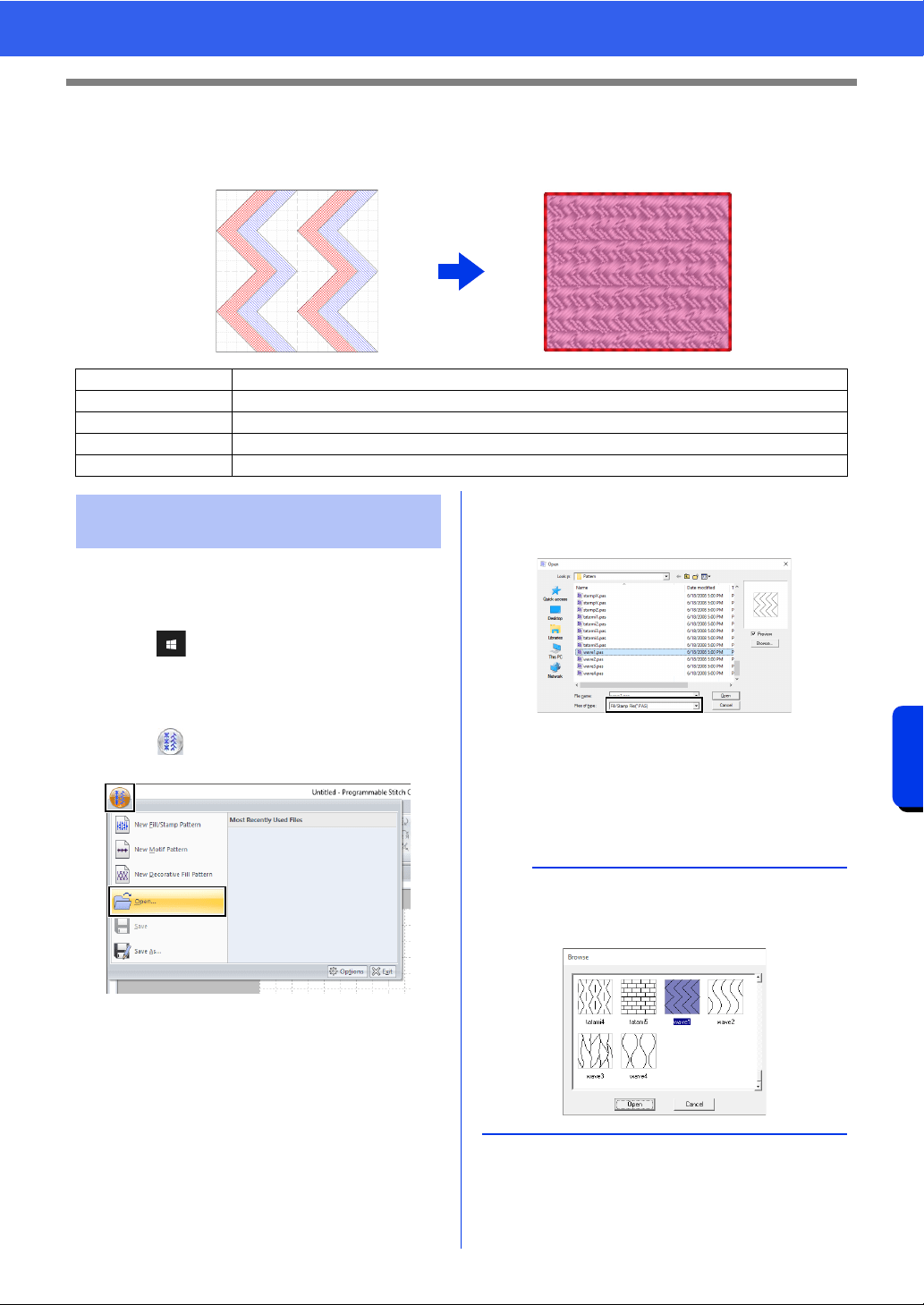
301
Programmable Stitch Creator
Creating Fill/Stamp Stitch Pattern
Creating Fill/Stamp Stitch Pattern
Existing programmable stitch patterns can be edited to create new patterns.
First, we will open a fill/stamp stitch pattern to be
edited. In this example, we will use pattern
wave1.pas.
1 Click .
2 Click [Programmable stitch Creator] under
the title [PE-DESIGN 11] in the screen.
3 Click , and then select [Open] from the
command list.
4 Select Fill/Stamp File(*.PAS) in the Files of
type selector.
Select the pattern file wave1.pas.
The pattern file can be found at the following
location.
For example, (Drive where PE-DESIGN was
installed)\Program Files (x86)\Brother\PE-
DESIGN 11\Pattern.
Step 1 Opening a fill/stamp stitch pattern
Step 2 Drawing lines to edit the fill/stamp stitch pattern
Step 3 Applying embossing/engraving effects to the fill/stamp stitch pattern
Step 4 Saving the edited fill/stamp stitch pattern
Step 5 Using the edited fill/stamp stitch patterns in Layout & Editing
Step 1 Opening a fill/stamp stitch
pattern
b
To view the data in the selected folder as
thumbnails in the [Browse] dialog box, click
[Browse].
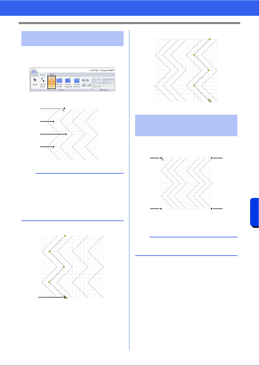
302
Programmable Stitch Creator
Creating Fill/Stamp Stitch Pattern
1 Click the [Home] tab.
2 Click [Draw Line] in the [Tools] group.
3 Click points (1) through (4).
4 Double-click (5) (end point).
5 Repeat the previous operations.
1 Click (1), and then double-click (2).
Next, click (3), and then double-click (4).
Lines are drawn along the top and bottom
edges of the Design Page.
Step 2 Drawing lines to edit the
fill/stamp stitch pattern
b
• To remove the last point that was entered, right-
click the mouse button.
cc "Reshaping a fill/stamp stitch patterns" on
page 305
• The grid width can be changed.
cc "Changing the grid settings" on page 319
1
2
3
4
5
Step 3 Applying embossing/
engraving effects to the
fill/stamp stitch pattern
b
In order to create an effect, the lines must form a
closed region.
12
43
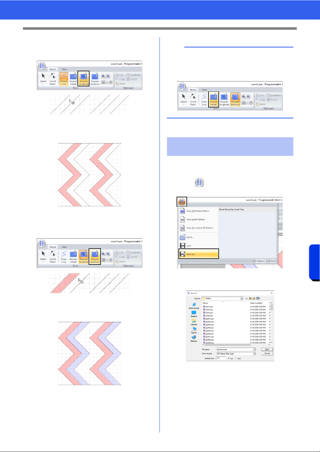
303
Programmable Stitch Creator
Creating Fill/Stamp Stitch Pattern
2 Click [Region (engrave)] in the [Tools]
group, and then click the first and fourth wave
regions.
These regions appear in red and will be
sewn with short stitches to give the effect of
engraving.
3 Click [Region (emboss)] in the [Tools]
group, and then click the second and fifth
wave regions.
This region appears in blue and will be
sewn with no dropped stitches to give the
effect of embossing.
Fill/stamp stitch patterns are saved in the .pas
format.
1 Click , and then select [Save As] from the
command list.
2 Select the drive and the folder, and then type
in the file name.
When saving a fill/stamp pattern, specify the
size beside [Default Size]. Click [mm] or
[inch] to select the measurement units.
3 Click [Save].
b
To remove the embossing/engraving effect, use
the [Region (reset)] tool. Click [Region (reset)] in
the [Tools] group, and then click a region with an
effect applied.
Step 4 Saving the edited fill/
stamp stitch pattern
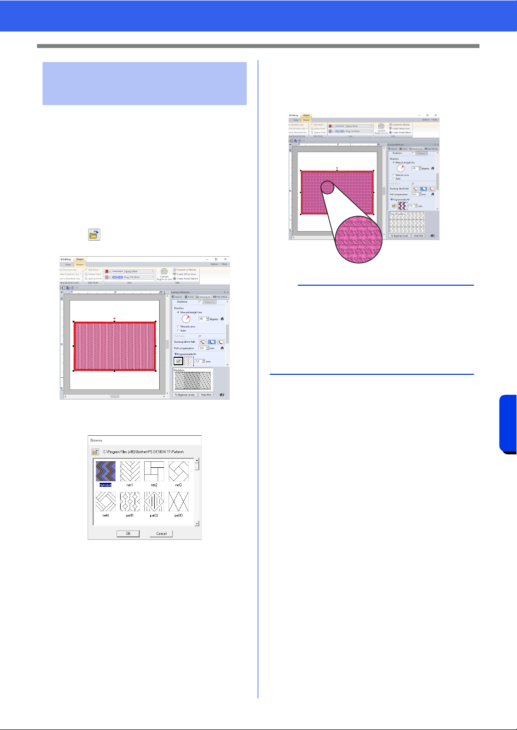
304
Programmable Stitch Creator
Creating Fill/Stamp Stitch Pattern
1 Start up Layout & Editing.
2 Select a shape.
3 From the [Region sew type] selector (in the
[Shapes] tab), select [Prog. Fill Stitch].
4 Display the [Sewing Attributes] pane.
cc "Specifying sewing attributes" on
page 64
5 Click below [Programmable fill] in the
[Region sew] section.
6 Select the drive and folder where the pattern
was saved in Step 4.
7 Click the edited fill/stamp stitch pattern, and
then click [OK].
The pattern is applied to the inside regions
of the embroidery pattern.
Step 5 Using the edited fill/stamp
stitch patterns in Layout &
Editing
b
• A fill/stamp stitch pattern can also be applied as
a stamp by using the Stamp Tools.
cc "Applying and editing stamps" on page 67
• For best results, refer to "Notes on
programmable fill stitches and stamps" on
page 393.
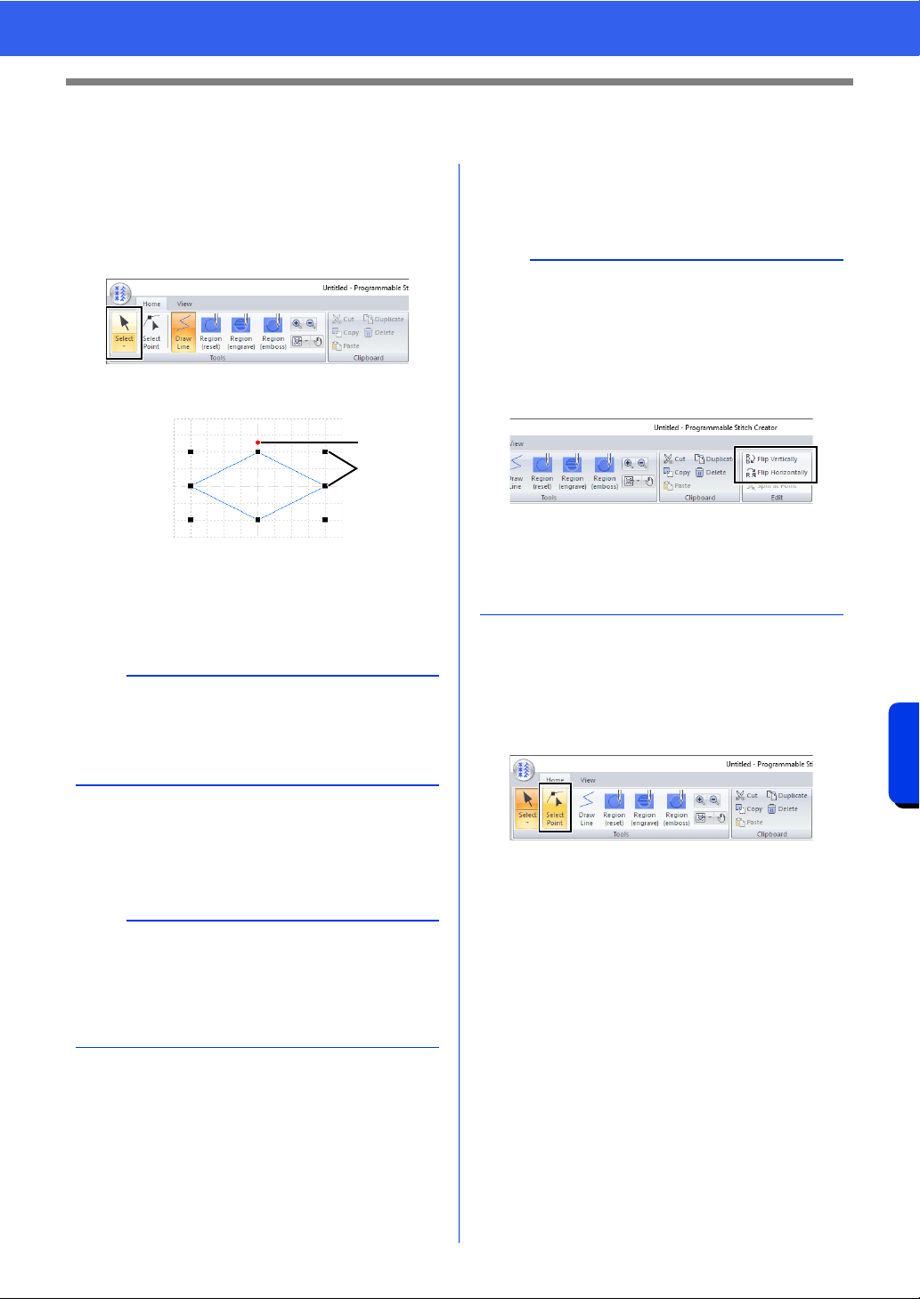
305
Programmable Stitch Creator
Editing a Pattern in Fill/Stamp Mode
Editing a Pattern in Fill/Stamp Mode
■ Selecting patterns
1 Click the [Home] tab.
2 Click [Select] in the [Tools] group to use the
[Select] tool.
3 Click the pattern.
1 Rotation handle
2 Handles
4 To select an additional pattern, hold down the
<Ctrl> key and click the other pattern.
■ Moving patterns
Selected patterns can be dragged to move them.
■ Scaling patterns
Drag a handle of the selected pattern to adjust its
size. Drag the rotation handle to rotate the pattern.
■ Reshaping a fill/stamp stitch
patterns
1 Click [Select Point] in the [Tools] group.
2 Click the broken line.
b
• You can also select patterns by dragging the
pointer across the pattern.
• Hold down the <Ctrl> key and click a selected
pattern to deselect it.
b
• To move the pattern horizontally or vertically,
hold down the <Shift> key while dragging it.
• Pressing the arrow keys moves the selected
pattern one grid mark in the direction of the
arrow on the key.
1
2
b
• If the <Shift> key is held down while a handle is
dragged, the pattern is enlarged or reduced from
the center of the pattern.
•Click [Flip Vertically] in the [Flip] group to flip
the selected pattern(s) up/down. Click [Flip
Horizontally] in the [Flip] group to flip the
selected pattern(s) left/right.
• Using commands other than those mentioned
above, selected patterns can be edited in other
ways, for example, duplicated or deleted.
cc "Programmable Stitch Creator" on page 297.
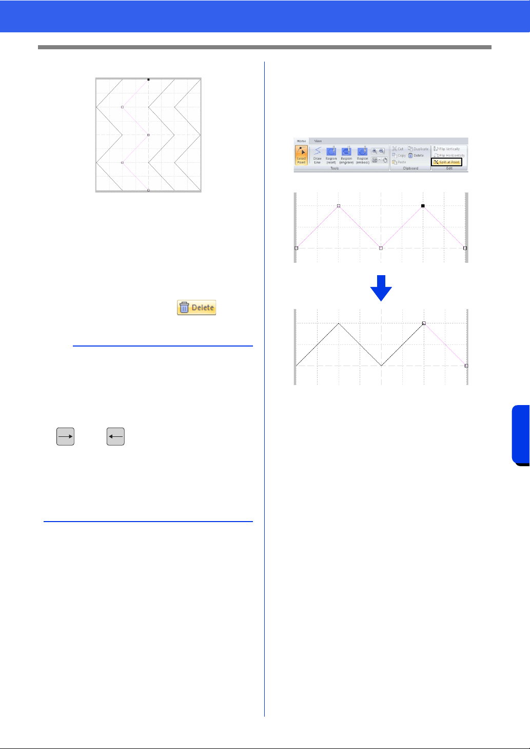
306
Programmable Stitch Creator
Editing a Pattern in Fill/Stamp Mode
3 To edit a point, click the point to select it.
• To move the point, drag it to the new
location.
• To insert a point, click the line to add a new
point.
A new point appears selected.
• To delete the point, click or press
the <Delete> key.
■ Splitting patterns
1 Click [Select Point] in the [Tools] group.
2 Select the point that you want to split.
3 Click [Split at Point] in the [Edit] group.
b
• If a line is composed of two points and you
delete one of them, the entire line is deleted.
• To select multiple points, hold down the <Ctrl>
key while clicking the points, or dragging the
pointer over the points.
• Hold down the <Ctrl> key while pressing the
key or key. The selection direction
changes to the end or start point.
• Hold down the <Shift> key while dragging the
points. The points are moved horizontally or
vertically.
• Press an arrow key. The points move in the
direction of the arrow on the key.
: Selected point
: Unselected point
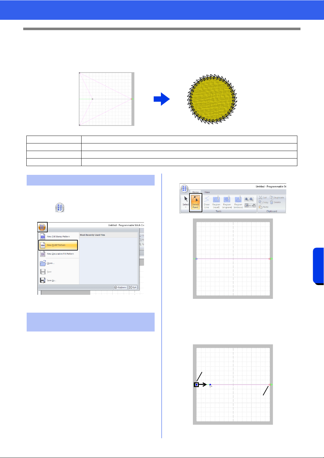
307
Programmable Stitch Creator
Creating Motif Stitch Pattern
Creating Motif Stitch Pattern
Now, we will create a new motif stitch pattern. Motif stitch patterns are created in Motif mode.
1 Start up Programmable Stitch Creator.
2 Click , and then select [New Motif
Pattern] from the command list.
In Motif mode, you can create original patterns by
changing the shape of a single line.
1 Click the [Home] tab.
2 Click [Select Point] in the [Tools] group.
Blue square: Start point
Red square: End point
3 Select (1), then drag the point.
The line that moves turns green when moving
a point.
Step 1 Enter motif mode
Step 2 Shaping a single line to create motif stitch pattern
Step 3 Saving the created motif stitch pattern
Step 4 Using the edited motif stitch pattern in Layout & Editing
Step 1 Enter motif mode
Step 2 Shaping a single line to
create motif stitch pattern
1
2
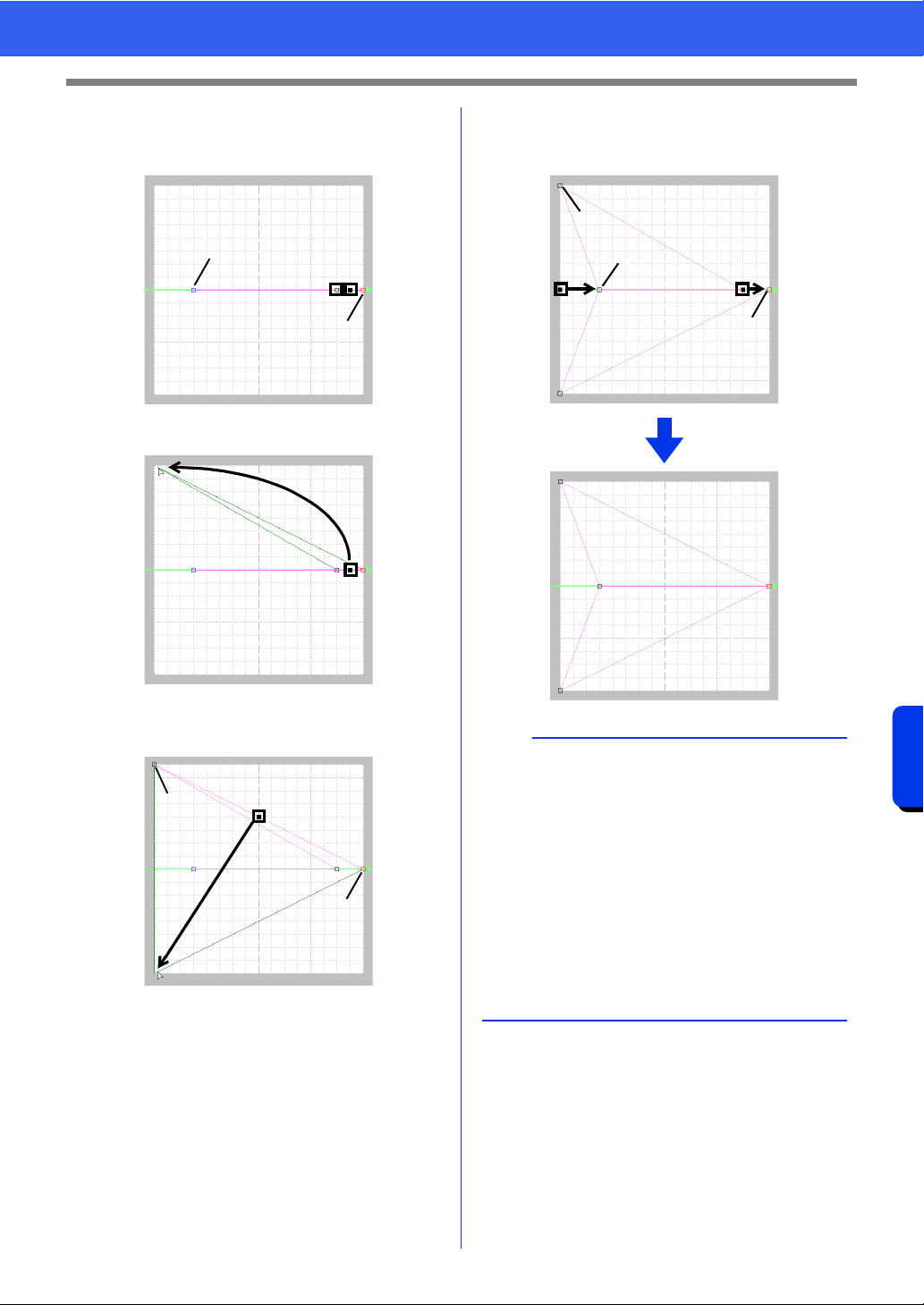
308
Programmable Stitch Creator
Creating Motif Stitch Pattern
4 Click the line to insert points.
Click (3) located between (1) and (2).
Click (4) located between (3) and (2).
5 Select (4), then drag the point.
6 Click between (2) and (4) to insert point (5),
and then drag point (5).
7 Click (6) located between (4) and (5), then
drag the point to (1).
Select (3), then drag the point to (2).
1
34
2
4
4
5
2
b
• To move the point horizontally or vertically, hold
down the <Shift> key while dragging it.
• Pressing the arrow keys moves the selected
point one grid mark in the direction of the arrow
on the key. If the grid is not displayed, the
pattern moves a distance smaller than the
smallest grid interval in the direction of the arrow
on the key.
• To delete a selected point, press the <Delete>
key.
• These patterns can be applied in line sewing
and region sewing in Layout & Editing, and
region sewing in Design Center.
1
4
6
5
3
2
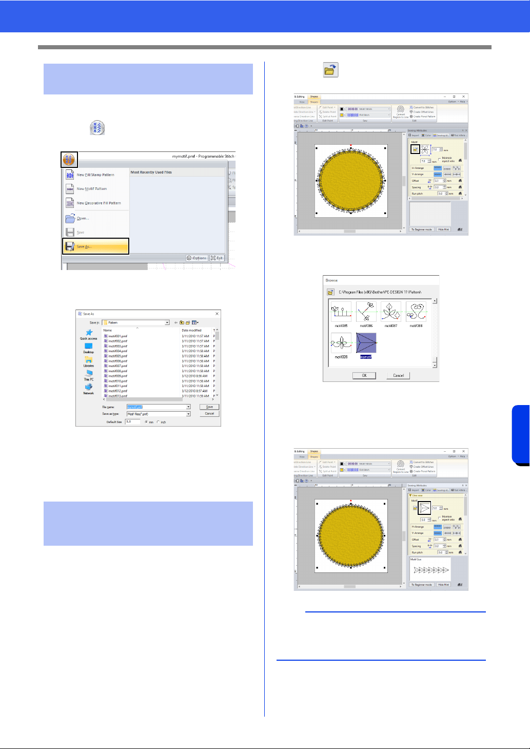
309
Programmable Stitch Creator
Creating Motif Stitch Pattern
Motif stitch patterns are saved in the .pmf format.
1 Click , and then select [Save As] from the
command list.
2 Select the drive and the folder, and then type
in the file name.
When saving a motif pattern, specify the
size beside [Default Size]. Click [mm] or
[inch] to select the measurement units.
3 Click [Save].
1 Start up Layout & Editing.
2 Select a shape.
3 From the [Line sew type] selector (in the
[Shapes] tab), select [Motif Stitch].
4 Display the [Sewing Attributes] pane.
cc "Specifying sewing attributes" on
page 64
5 Click below [Motif] in the [Line sew]
section.
6 Select the drive and folder where the pattern
was saved in Step 3.
7 Click the created motif stitch pattern, and then
click [OK].
The pattern is applied to the outlines of the
embroidery pattern.
Step 3 Saving the created motif
stitch pattern
Step 4 Using the edited motif
stitch pattern in Layout &
Editing
b
A motif stitch pattern can be used when the motif
stitch, piping stitch or stippling stitch has been
selected as the sew type of a region.
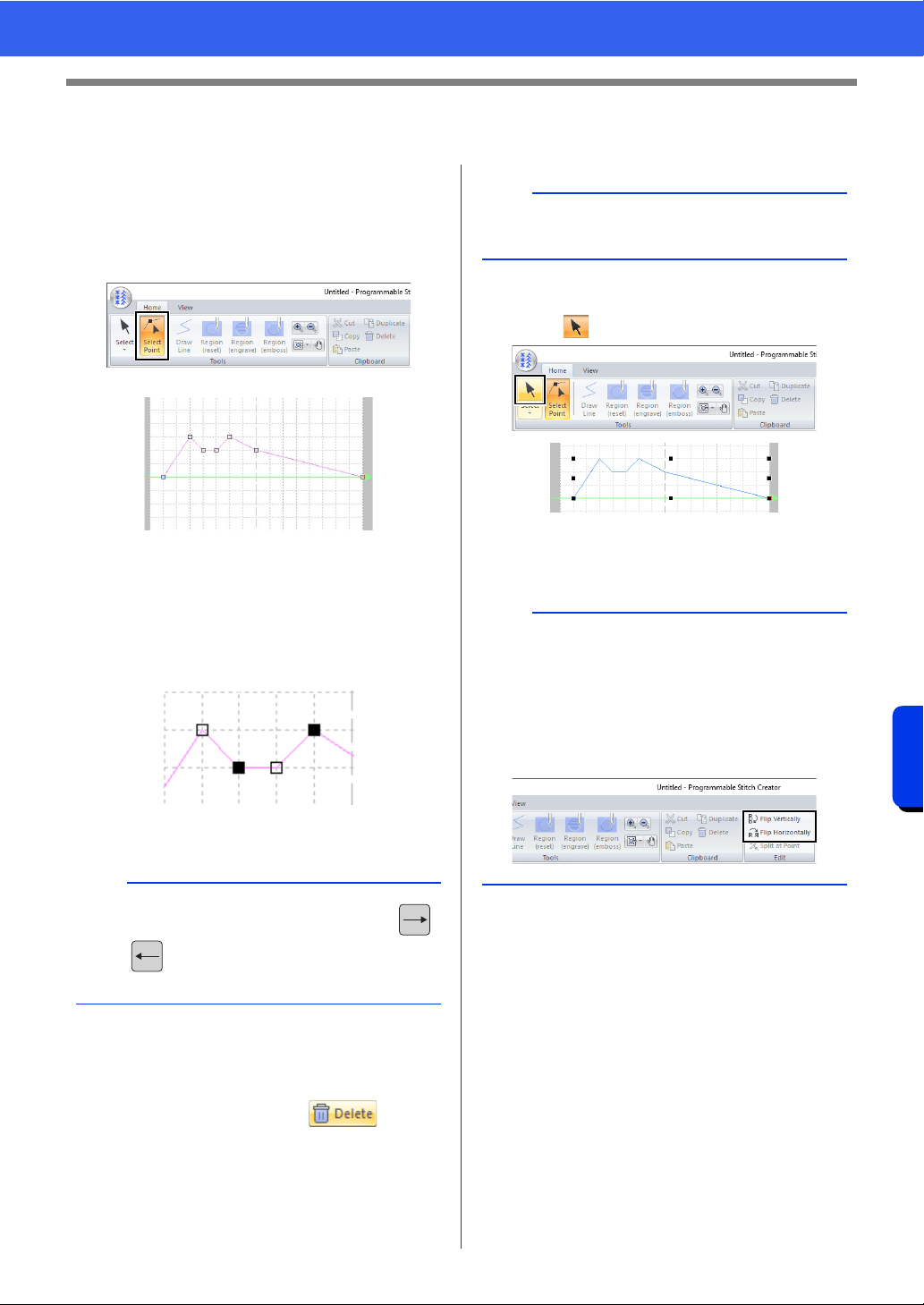
310
Programmable Stitch Creator
Editing a Pattern in Motif Mode
Editing a Pattern in Motif Mode
■ Moving and deleting several
points at a time
1 Click the [Home] tab.
2 Click [Select Point] in the [Tools] group.
Blue square: Start point
Red square: End point
3 To select a single point, click an empty square.
To select multiple points, hold down the
<Ctrl> key while clicking the points, or
dragging the pointer over the points.
4 Edit the points.
• To move the points, drag them to the
desired location.
• To delete the point, click or press
the <Delete> key.
■ Scaling patterns
1 Click in the [Tools] group.
2 Drag the handle to adjust the selected
pattern(s) to the desired size.
b
Hold down the <Ctrl> key while pressing the
key or key. The selection direction changes
to the end or start point.
: Selected point
: Unselected point
a
The start point (blue square) and end point (red
square) can not be deleted.
b
• If the <Shift> key is held down while a handle is
dragged, the pattern is enlarged or reduced from
the center of the pattern.
• To flip the pattern along a vertical axis, click
[Flip Vertically] in the [Edit] group.
• To flip the pattern along a horizontal axis, click
[Flip Horizontally] in the [Edit] group.
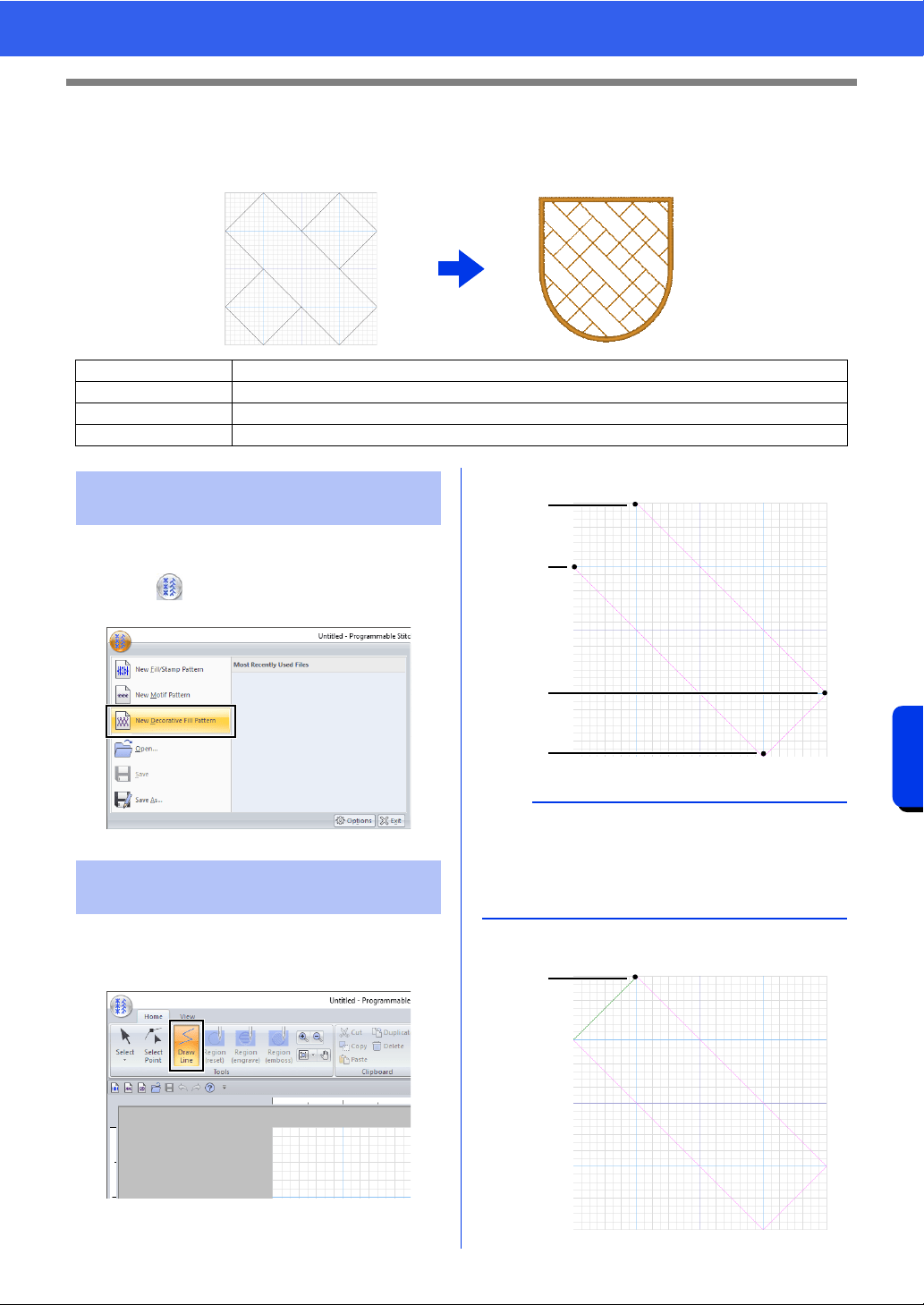
311
Programmable Stitch Creator
Creating a Decorative Fill Pattern
Creating a Decorative Fill Pattern
Here, we will create a new decorative fill pattern. Decorative fill patterns are created in Decorative Fill mode.
1 Start up Programmable Stitch Creator.
2 Click , and then select [New Decorative
Fill Pattern] from the command list.
1 Click the [Home] tab.
2 Click [Draw Line] in the [Tools] group.
3 Click points (1) through (4), in order.
4 Double-click point (5) (end point).
Step 1 Entering Decorative fill mode
Step 2 Creating a decorative fill pattern
Step 3 Saving an edited decorative fill pattern
Step 4 Using an edited decorative fill pattern in Layout & Editing
Step 1 Entering Decorative fill
mode
Step 2 Creating a decorative fill
pattern
a
• To remove the last point that was entered, click
the right mouse button.
• The grid spacing can be changed.
cc "Changing the grid settings" on page 319
1
4
2
3
5
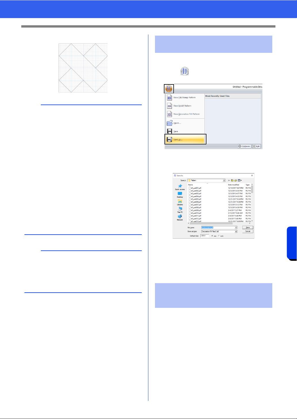
312
Programmable Stitch Creator
Creating a Decorative Fill Pattern
5 Enter all necessary points.
Decorative fill patterns are saved in the .plf format.
1 Click , and then select [Save As] from the
command list.
2 Select the destination, and then type in the file
name.
Specify the size beside [Default Size].
Click [mm] or [inch] to select the
measurement units.
3 Click [Save].
1 Start up Layout & Editing.
2 Select a shape.
3 From the [Region sew type] selector on the
[Shapes] tab of the Ribbon, select
[Decorative Fill Stitch].
4 Display the [Sewing Attributes] pane.
cc "Specifying sewing attributes" on
page 64
a
• In order to create patterns that will be cleanly
sewn without feeds between them, keep the
following in mind.
• Make sure that all lines in the pattern connect.
• Make sure that patterns can connect at the top
and bottom as well as at the left and right.
• Make sure that there are points at the top,
bottom, left and right where patterns can
connect.
•Use the [Preview] pane to check that patterns
are connecting at the top, bottom, left and
right.
cc "Preview Window" on page 317
• Use the guidelines to easily align the locations
of points on the top, bottom, left and right
edges.
cc "Changing the guideline settings" on
page 319
b
• The editing procedures for Decorative fill mode
are the same as in Fill/Stamp mode. However,
region settings cannot be specified.
cc "Editing a Pattern in Fill/Stamp Mode" on
page 305
Step 3 Saving an edited
decorative fill pattern
Step 4 Using an edited
decorative fill pattern in
Layout & Editing
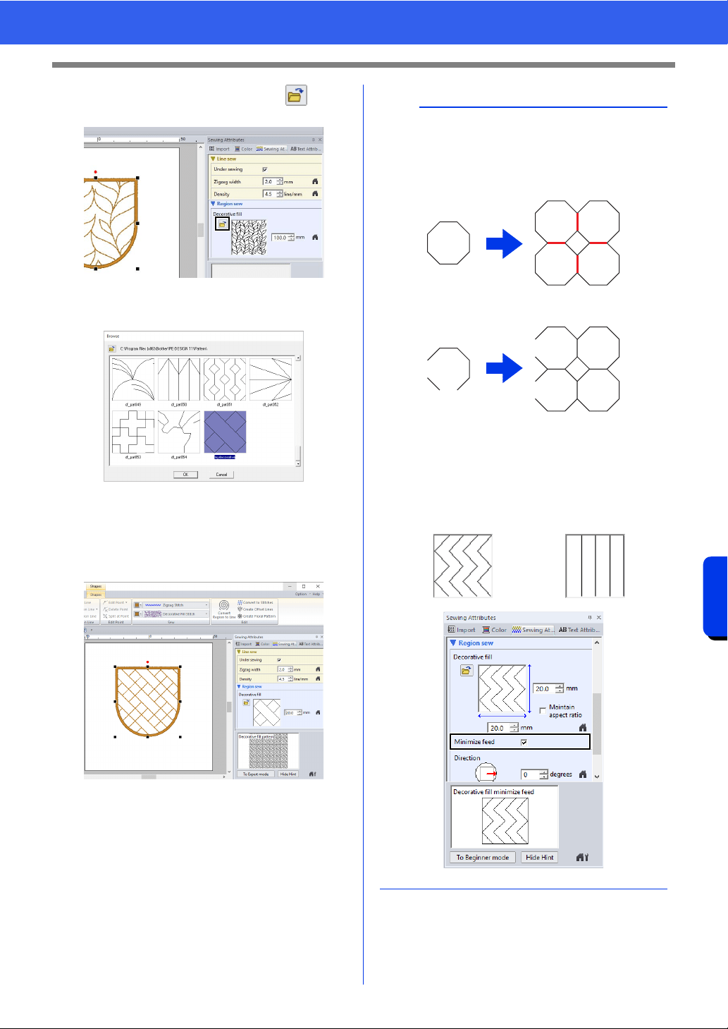
313
Programmable Stitch Creator
Creating a Decorative Fill Pattern
5 In the [Region sew] section, click under
[Decorative fill].
6 Select the drive and folder where the pattern
was saved in Step 3.
7 Click the created decorative fill pattern, and
then click [OK].
cc The stitch pattern is applied to the region
of the embroidery pattern.
b
• In order to create a decorative fill pattern that will
be cleanly sewn, make sure that lines in
connecting patterns do not overlap. Create
patterns that will not overlap when sewn, as
shown below.
1 Patterns overlapping when sewn
2 Clean finish as a result of patterns not
overlapping when sewn
• With patterns that are not connected at the top
and bottom or at the left and right as shown
below, select the [Minimize feed] check box to
reduce the feed.
1
2
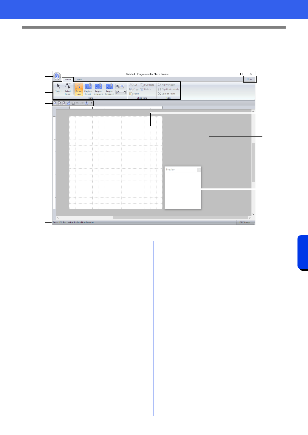
314
Programmable Stitch Creator
Programmable Stitch Creator Window
Programmable Stitch Creator Window
a Application button
b Ribbon
c Quick Access Toolbar
d Help button
e Preview window
Shows how the pattern will be sewn.
cc "Preview Window" on page 317
f Design Page
g Work area
h Status Bar
cc "Understanding Windows" on page 13
b
a
h
d
g
e
f
c
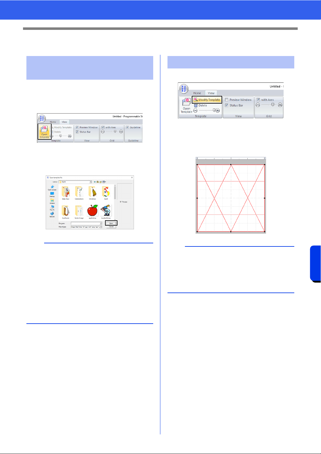
315
Programmable Stitch Creator
Opening a Template
Opening a Template
1 Click the [View] tab.
2 Click [Open Template] in the [Template]
group.
3 Select the drive, the folder and the file, and
then click [Open] or double-click the file's
icon.
1 Click [Modify Template].
The application enters template-editing
mode, and a red frame appears around the
template.
2 Edit the template.
Opening an image in the
background
b
• The tutorial file for this application is located in
Documents (My documents)\PE-DESIGN
11\Sample\Programmable Stitch
Creator\Template.
• Only one image can be added to the work area.
If you try to display a different image, it will
replace the previous one.
• There are many different types of files that can
be opened.
cc "Image file formats" on page 163
Editing the Template
b
• Drag the inside of the red frame to move the
template image.
• Click outside of the red frame to exit template-
editing mode.
•Click [Delete] to delete the template.
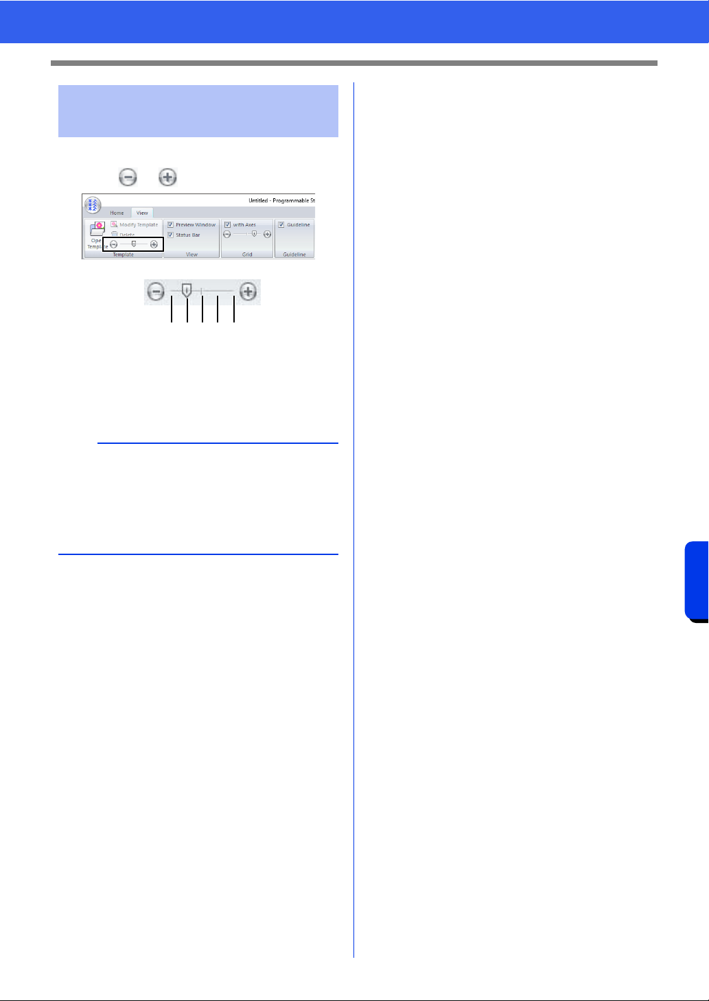
316
Programmable Stitch Creator
Opening a Template
1 Drag the slider in the [Template] group, or
click or .
1 Hide (off)
2 25%
3 50%
4 75%
5 100%
Changing the density
background image
b
• This function is not available if no template
image has been imported into the work area.
• Press the shortcut key <F6> to switch between
displaying the image (On (100%)) to displaying
it faded at each density (75%, 50% and 25%) to
hiding the image (Off).
1352 4
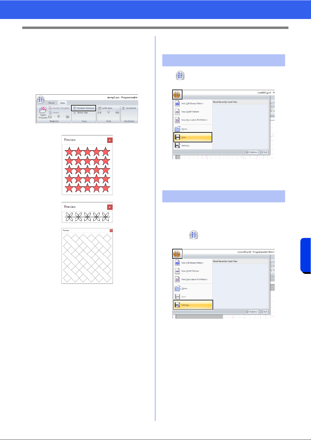
317
Programmable Stitch Creator
Preview Window
Preview Window
1 Click the [View] tab.
2 To switch between displaying and hiding the
[Preview] window, select or unselect the
[Preview Window] check box in the [View]
group.
1 In Fill/Stamp mode
2 In Motif mode
3 In Decorative Fill mode
Saving Patterns
Click , and then select [Save] from the
command list.
If no file name has been specified or if the
file cannot be found, the [Save As] dialog
box appears.
The files are saved as.pas files in Fill/Stamp mode,
as .pmf files in Motif mode, and as .plf files in
Decorative fill mode.
1 Click , and then select [Save As] from the
command list.
1
2
3
Overwriting
Saving with a new name
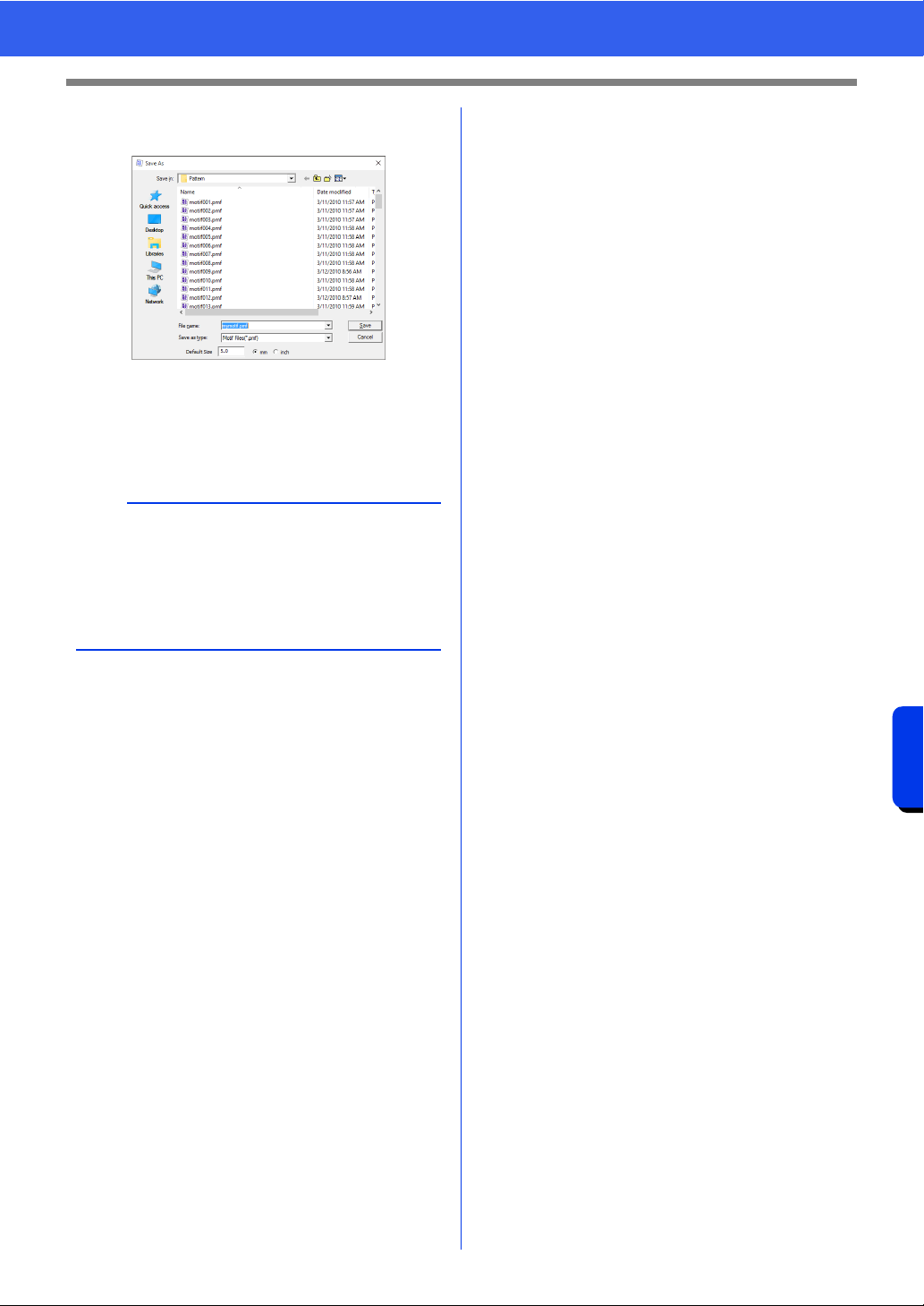
318
Programmable Stitch Creator
Saving Patterns
2 Select the drive and the folder, and then type
in the file name.
When saving a motif pattern, specify the
size beside [Default Size]. Click [mm] or
[inch] to select the measurement units.
3 Click [Save].
b
Saved files can be used in Layout & Editing or
Design Center.
cc "Using the edited fill/stamp stitch patterns in
Layout & Editing" on page 304 and "Using the
edited motif stitch pattern in Layout & Editing"
on page 309
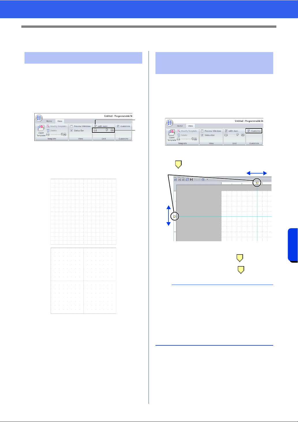
319
Programmable Stitch Creator
Changing the Display Settings
Changing the Display Settings
The grid can be displayed or hidden, and how the
grid is displayed as well as its spacing can be
specified.
1 Click the [View] tab.
2 Specify the grid settings.
a with Axes
Select this check box to display the grid
lines.
The grid display differs depending on the
mode.
1 Check box selected.
2 Check box cleared.
b Grid interval
Drag the slider to specify the grid spacing.
• In Fill/Stamp mode or Motif mode, the
available settings are no grid and 1/64,
1/32, 1/16 and 1/8 of the Design Page
width.
• In Decorative fill mode, the available
settings are no grid and 1/128, 1/64, 1/
32 and 1/16 of the Design Page width.
1 Click the [View] tab.
2 To display the guidelines, select the
[Guideline] check box in the [Guideline]
group. To hide the guidelines, clear the check
box.
3 Click a ruler in the Design Page.
appears, and a guideline is drawn.
1 Guideline
• To move a guideline, drag .
• To delete a guideline, click .
Changing the grid settings
b
a
1
2
Changing the guideline
settings
b
• A guideline is added each time the ruler is
clicked. In addition, up to 100 guidelines each
can be added to the horizontal and vertical
rulers.
• When the [Guideline] check box is cleared, the
guidelines are hidden.
• If the grid is displayed, the guidelines will be
added/moved along the lines of the grid.
1

Font Creator
User-defined fonts can be created using Font
Creator. In addition, your embroidery data can be
registered as a font. These fonts can be recalled
to be used in Layout & Editing.
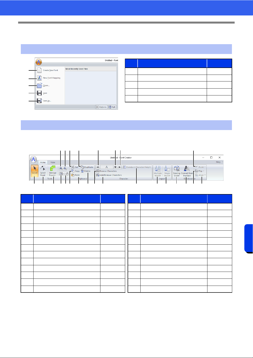
321
Font Creator
Font Creator
Font Creator
■ Home tab
Application button menu
1
2
3
4
5
No. Menu Reference
1 Create New Font p. 337
2 New Font Mapping p. 330
3 Open p. 337
4 Save p. 344
5 Save As p. 344
Ribbon menu tabs
No. Menu Reference No. Menu Reference
1 Select Object Tool p. 340 14 Select Character p. 338
2 Edit Point Tool p. 341 15 Next Character p. 338
3 Manual Punch Tool p. 325 16 Browse Characters p. 343
4 Zoom In — 17 Add/Remove Character p. 338
5 Zoom Out — 18 Standard Character Height p. 332
6 Other Zoom Tools — 19 Multiple Import p. 334
7 Pan — 20 Single Import p. 331
8 Cut — 21 Sewing Order p. 342
9 Copy — 22 Convert TrueType Font to Data p. 340
10 Paste — 23 Point Edit p. 341
11 Duplicate — 24 Flip p. 340
12 Delete p. 341 25 Align —
13 Previous Character p. 338
1
8
92
A
0BFG L
MCDE
3 6 7 N O
4
5
KH JI
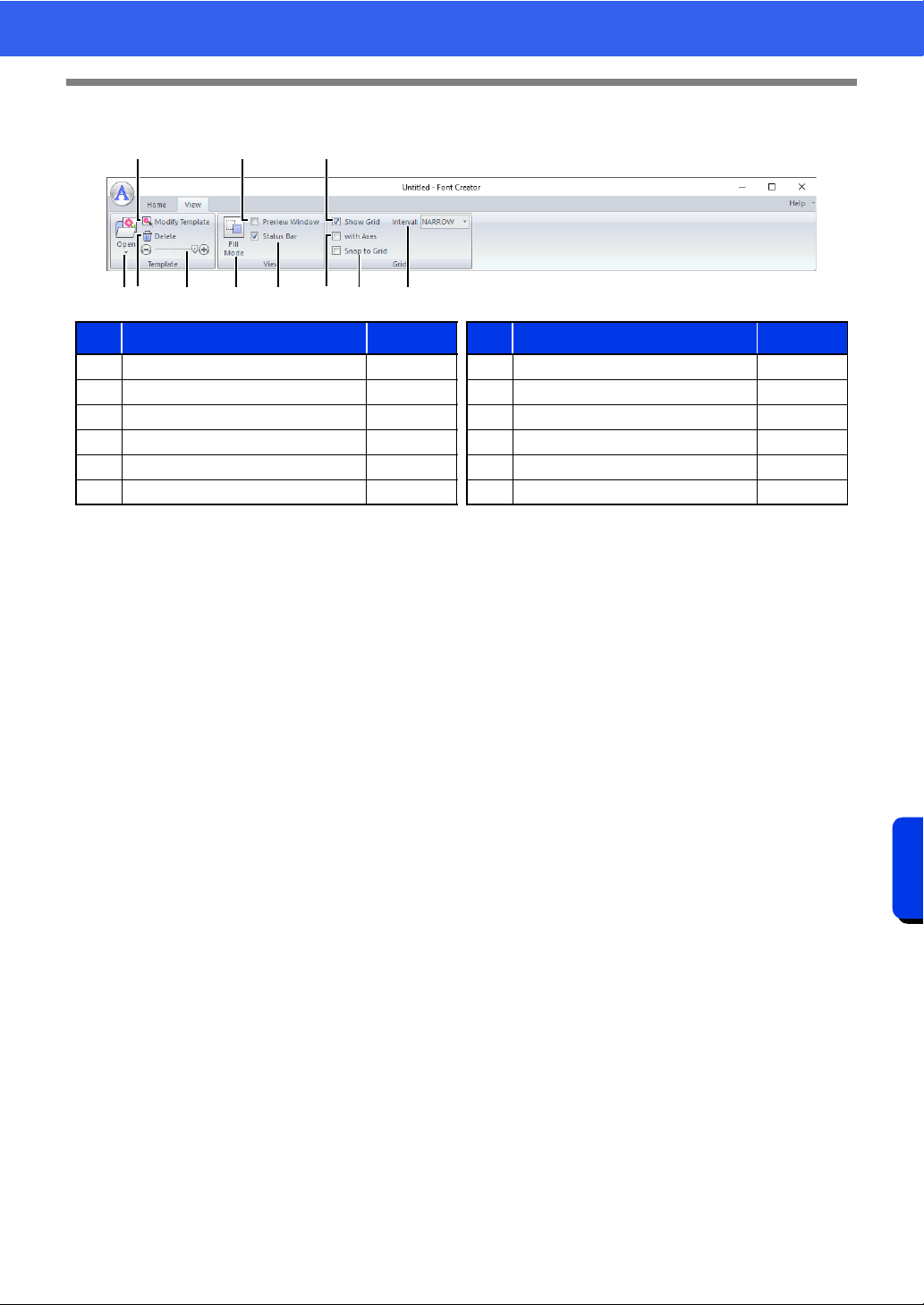
322
Font Creator
Font Creator
■ View tab
No. Menu Reference No. Menu Reference
1 Open Template p. 323 7 Show/Hide Status Bar p. 335
2 Modify Template p. 345 8 Show Grid p. 346
3 Delete Image — 9 Show Grid with Axes p. 346
4 Background Image Density p. 345 10 Snap to Grid p. 346
5 Fill Mode p. 345 11 Grid Spacing p. 346
6 Preview Window p. 342
1 9
2
A
6
04 5 7
8
3
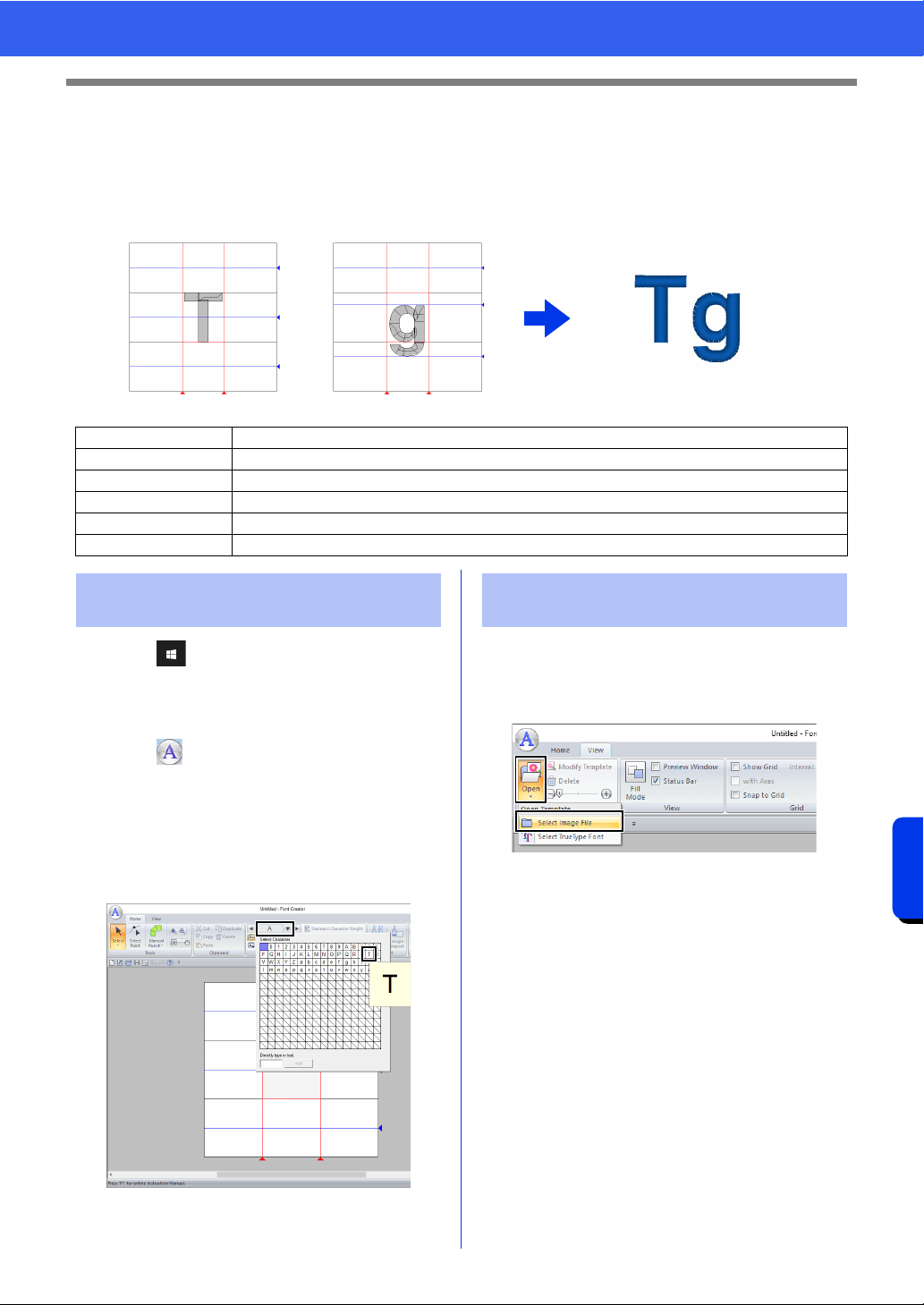
323
Font Creator
Creating New Font Characters From Background Images
Creating New Font Characters From
Background Images
With Font Creator, user-defined font characters that can be used in Layout & Editing can be created and
edited. Using these custom characters, original embroidery patterns can be created.
1 Click .
2 Click [Font Creator] under the title [PE-
DESIGN 11] in the screen.
3 Click , and then select [Create New Font]
from the command list.
4 Click the [Home] tab.
5 Click the [Select Character] box in the
[Character] group, and then select "T" from
the list.
1 Click the [View] tab.
2 Click [Open] in the [Template] group, and
then select [Select Image File] from the list.
Step 1 Selecting a character to be created
Step 2 Opening a background image
Step 3 Creating a font character pattern
Step 4 Creating other font character patterns
Step 5 Save the font character pattern
Step 6 Creating an embroidery pattern using the created font characters
Step 1 Selecting a character to be
created
Step 2 Opening a background
image
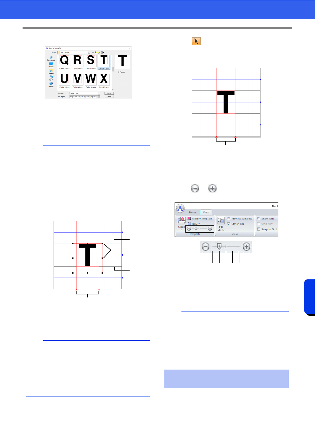
324
Font Creator
Creating New Font Characters From Background Images
3 Import the Capital_T.bmp.
The image file can be found at the following
location.
Documents (My documents)\PE-DESIGN
11\Sample\Font Creator\Font Template
4 Move the character so that the top aligns with
the [Capital Line]. To adjust the height of the
character, drag a handle to adjust the height
between the [Capital Line] and the [Base
Line].
1 Capital Line
2 Handles
3 Base Line
4 Set Line
5 Click the [Home] tab.
6 Click in the [Tools] group, and then drag
the red triangle icons to move the set lines so
that they are aligned with the left and right of
the character.
1 Set Line
7 Click the [View] tab.
8 In the [Template] group, drag the slider (or
click or ) to change the density of the
template image to "25%".
1 Hide (off)
2 25%
3 50%
4 75%
5 100%
1 Click the [Home] tab.
b
There are many different types of files that can be
opened.
cc "Image file formats" on page 163
b
• Red lines are added above, below and to the left
and right of the sample image. Use these lines
as guides for adjusting the [Base Line], [Capital
Line] and [Set Lines].
• If the handles have disappeared, right-click the
image, and then click [Modify Template] in the
menu that appeared.
1
3
2
4
b
• This function is not available if no template
image has been imported into the work area.
• Press the shortcut key <F6> to switch between
displaying the image (On (100%)) to displaying
it faded at each density (75%, 50% and 25%) to
hiding the image (Off).
Step 3 Creating a font character
pattern
1
123 54
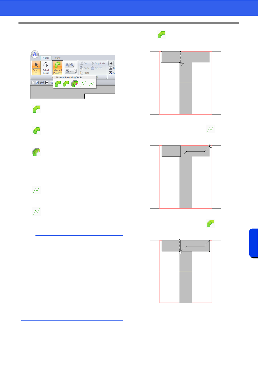
325
Font Creator
Creating New Font Characters From Background Images
2 Click the [Manual Punch] in the [Tools]
group, and then select the desired tool from
[Manual Punching Tools].
3 Click , and then click in the Design Page
to specify points (1) (start point) through (4).
4 Click [Manual Punch], select , and then
click point (5) through (7).
5 Click [Manual Punch], select , and then
click points (8) through (10).
: Straight block-type punching patterns
(region sewing).
(Shortcut key: <Z>)
: Curved block-type punching patterns
(region sewing)
(Shortcut key: <X>)
: Semi-automatically created straight
block-type punching pattern
By semi-automatically tracing, points
can be specified along the lines of a
template.
(Shortcut key: <C>)
: Running-type punching pattern (line
sewing)
(Shortcut key: <V>)
: Feed-type punching pattern (jump
stitches)
(Shortcut key: <B>)
b
• When entering points, you can switch between
the various tools. This is very easy if the shortcut
keys are used.
• A template image is needed in order to use the
semi-automatic block-type punch tool. If there is
no image, this tool will create a punching pattern
like the straight block-type punch tool. In
addition, this tool cannot be used if a TrueType
font is used as the template.
• Once the pattern is drawn, you can still
transform straight block-type patterns into
curved block-type patterns and vice versa.
cc For details, refer to "To Straight/To Curve" on
page 341
13
2
4
5
6
7
9
8
10
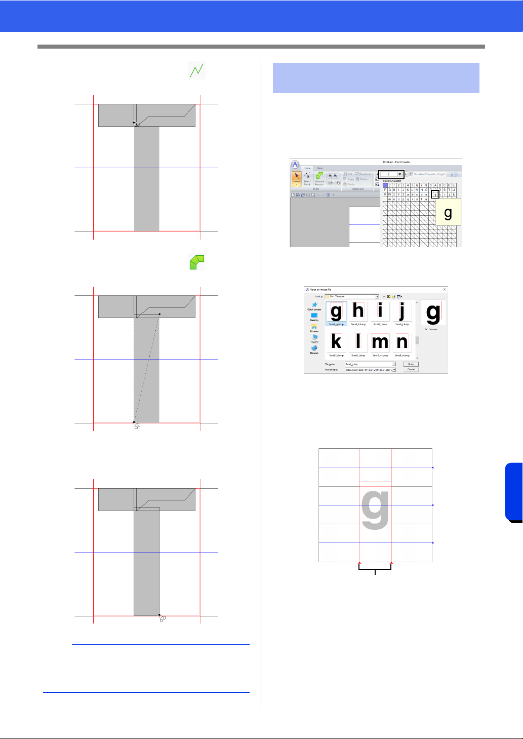
326
Font Creator
Creating New Font Characters From Background Images
6 Click [Manual Punch], select , and then
click point (11).
7 Click [Manual Punch], select , and then
click points (12) through (13).
8 Double-click point (14) (the last point of the
entire pattern), or click point (14) and press the
<Enter> key.
1 Click the [Home] tab.
2 Click the [Select Character] box in the
[Character] group, and then select "g" from
the list.
3 Import file Small_g.bmp in the same way that
"T" was imported.
4 In the same way that "T" was adjusted,
change the character size and position, and
then drag the red triangle icons to move the
set line so that they are aligned with the left
and right of the character.
1 Set Line
If the red lines are not shown, change the
density of the template image.
b
To remove the last point that was entered, right-
click the mouse button, or press the
<BackSpace> key.
11
12
13
14
Step 4 Creating other font
character patterns
1
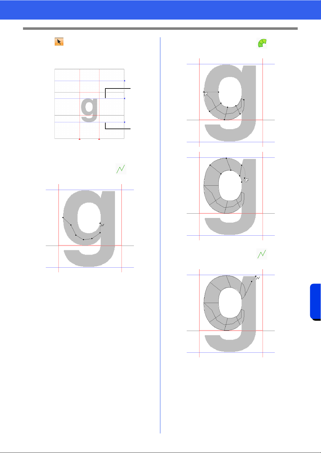
327
Font Creator
Creating New Font Characters From Background Images
5
Click in the [Tools] group, and then drag
the blue triangle icons to move the mean line
and descender line so that they are aligned
with the top and bottom of the character.
1 Mean Line
2 Descender Line
6 Click [Manual Punch], select , and then
click points (1) through (7).
7 Click [Manual Punch], select , and then
click points (8) through (24).
8 Click [Manual Punch], select , and then
click points (25) through (26).
1
2
1
2
3
4
5
6
7
8
9
10
11
12
13
14
15
16
18
17
20
19
22
21
23
24
25
26
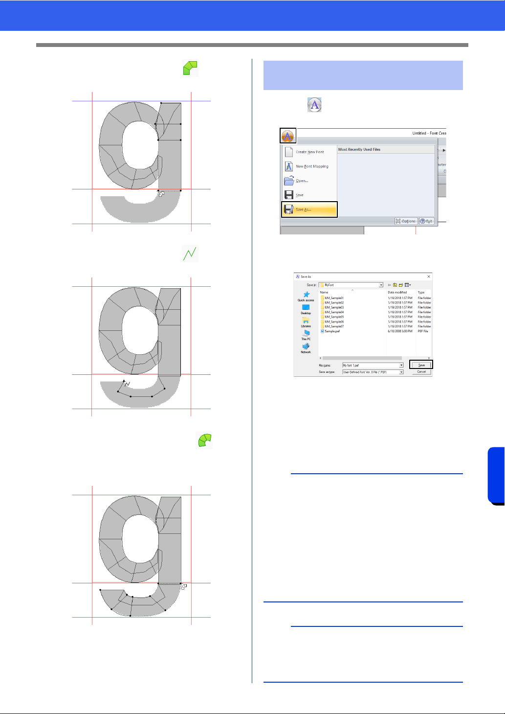
328
Font Creator
Creating New Font Characters From Background Images
9 Click [Manual Punch], select , and then
click points (27) through (33).
10 Click [Manual Punch], select , and then
click points (34) through (38).
11 Click [Manual Punch] and select . Next,
click points (39) through (46), and then
double-click point (47) (end point), or click
point (47) and press the <Enter> key.
1 Click , and then select [Save As] from the
command list.
2 Select the [MyFont] folder at the following
location.
For example, (Drive where PE-DESIGN was
installed)\Program Files (x86)\Brother\PE-
DESIGN 11\MyFont.
And then type in the file name. For this
example, type in the name "My font 1".
Click [Save].
27
28
29
3031
3233
38
37
36
35
34
39
41
40
42
43
44
47
46
45
Step 5 Save the font character
pattern
a
• The created font is saved in the [MyFont] folder
at the following location.
For example, (Drive where PE-DESIGN was
installed)\Program Files (x86)\Brother\PE-
DESIGN 11\MyFont.
• The font will not be usable in the Layout &
Editing if it's stored in a different folder.
• If any part of the character pattern extends off
the Design Page, a message appears. Edit the
character pattern so that no part extends off the
Design Page, and then save it again.
b
If the background image is displayed, the
information for the background image will be
saved with the font file. The next time that the font
file is opened, the background image is displayed.
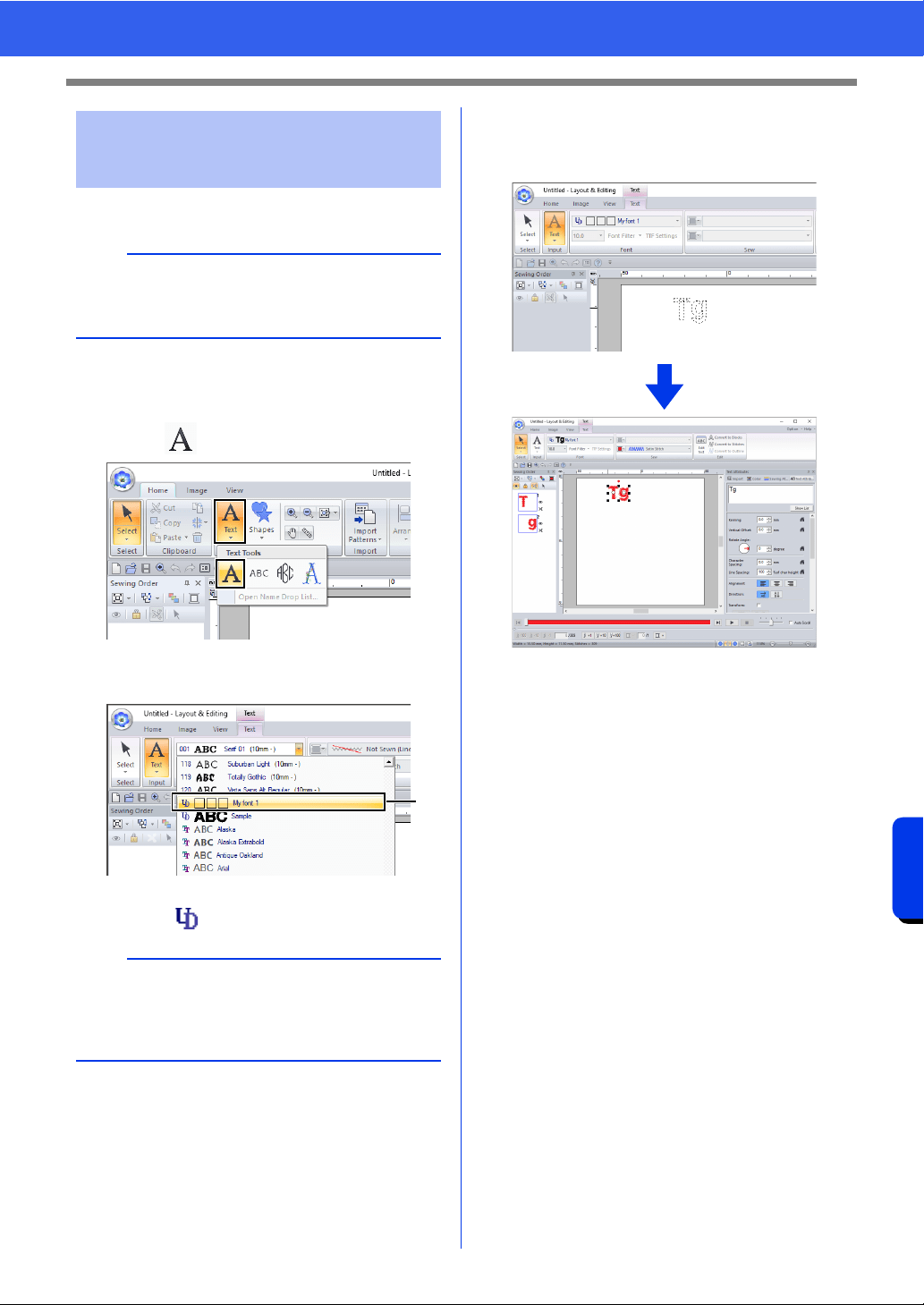
329
Font Creator
Creating New Font Characters From Background Images
1 Start up Layout & Editing.
2 Click the [Home] tab.
3 Click [Text] in the [Tools] group, and then
select from [Text Tools].
4 Click in the Font selector, and then select
"My font 1".
a Fonts created in Font Creator appear with
the icon in front of the font name.
5 Click in the Design Page.
Input the text, and then press <Enter> the key
or click the Design Page.
cc "Creating Embroidery Patterns
Containing Text" on page 111
Step 6 Creating an embroidery
pattern using the created
font characters
a
If Layout & Editing is already started, exit it, and
then start it again. The new font is detected when
the application starts up.
b
Since fonts for only "T" and "g" were created in the
previous examples ("A", "B", "C", etc. were not
created), only these characters appear in the
sample when [Font] selector is clicked.
a
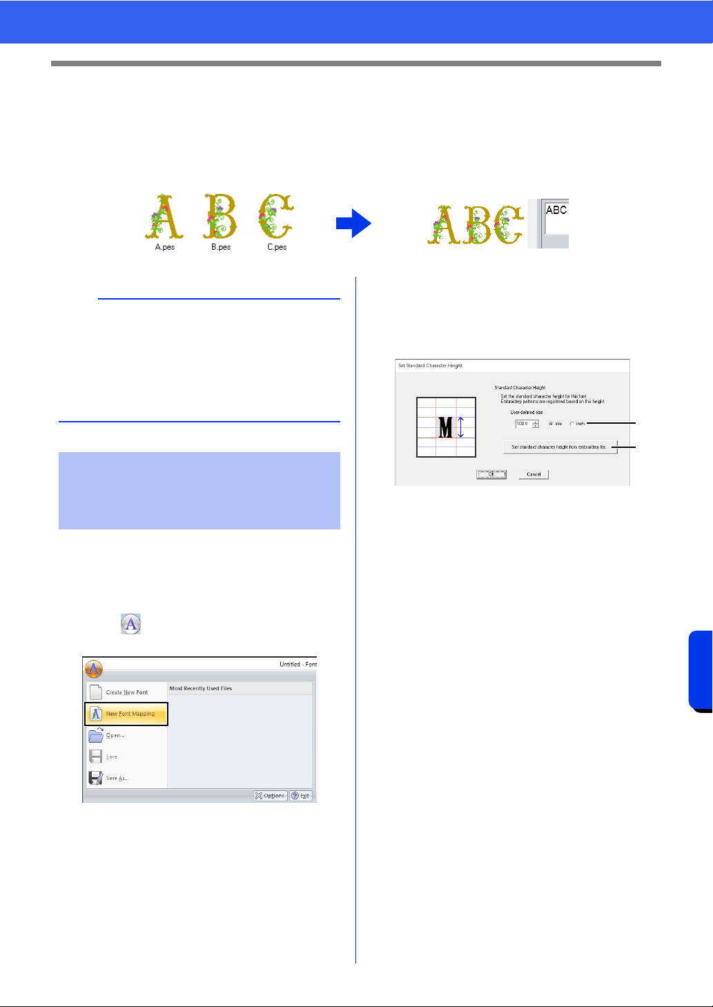
330
Font Creator
Registering Embroidery Data as a Font
Registering Embroidery Data as a Font
You can register your embroidery data as a font. Once registered, the character patterns can be arranged by
simply entering text. Font character patterns can be created either from individual embroidery patterns or as
a batch from multiple embroidery patterns.
■ Specifying the standard character
height
1 Start up Font Creator.
2 Click , and then select [New Font
Mapping] from the command list.
The [Set Standard Character Height]
dialog box appears.
3 Specify the standard character height. For this
example, click [Set standard character
height from embroidery file] to specify the
height of the embroidery pattern as the
standard.
a User-defined size
The entered value will be the standard
character height. Select "mm" or "inch" as
the measurement units.
b Set standard character height from
embroidery file
The height of the selected embroidery
pattern will be standard character height.
a
• Prepare the embroidery data and the folder to be
registered.
• Create your folder in the following location, and
save your embroidery data in the folder.
(Drive where PE-DESIGN was
installed)\Program Files (x86)\Brother\PE-
DESIGN 11\MyFont.
Registering embroidery
data (individual
registration)
a
b
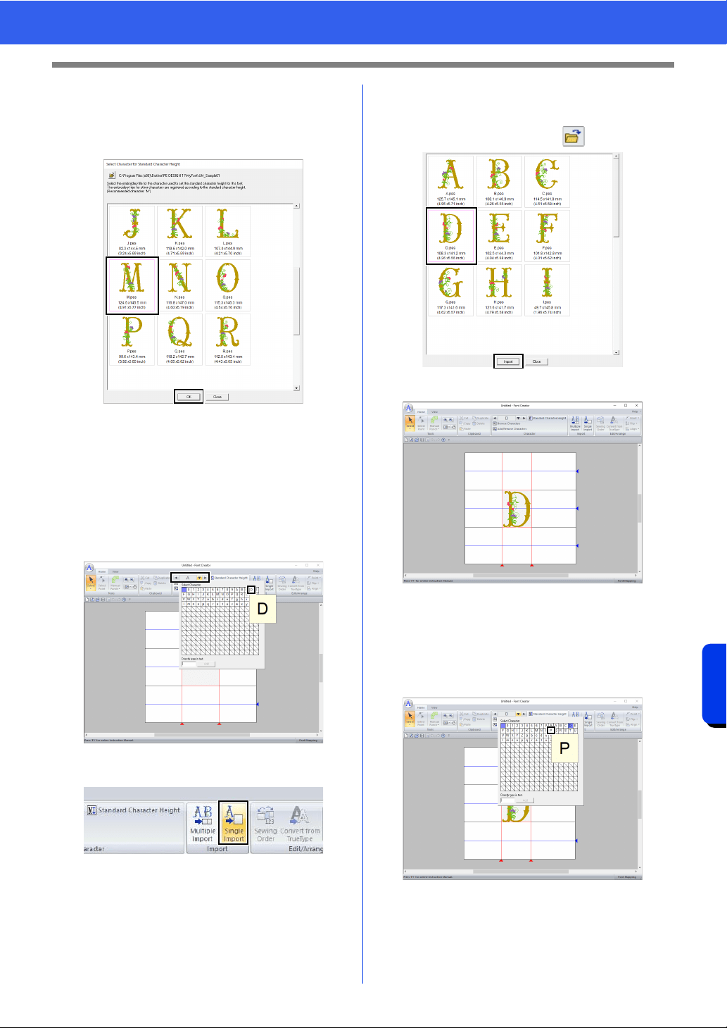
331
Font Creator
Registering Embroidery Data as a Font
4 Select the pattern that will specify the
standard character height, and then click
[OK].
For this example, select the "M" character.
The height of the selected pattern will be
standard character height.
■ Selecting the embroidery data to
register
1 From the [Select Character] box, select the
character to be registered. For this example,
select "D".
2 Click [Single Import] on the [Home] tab.
3 Select the embroidery file to be registered,
and then click [Import] then click [Close].
To change the folder, click .
The registered character appears.
■ Selecting additional embroidery
data
1 From the [Select Character] box, select the
character to be registered. For this example,
select "P".
2 Click [Single Import] on the [Home] tab.
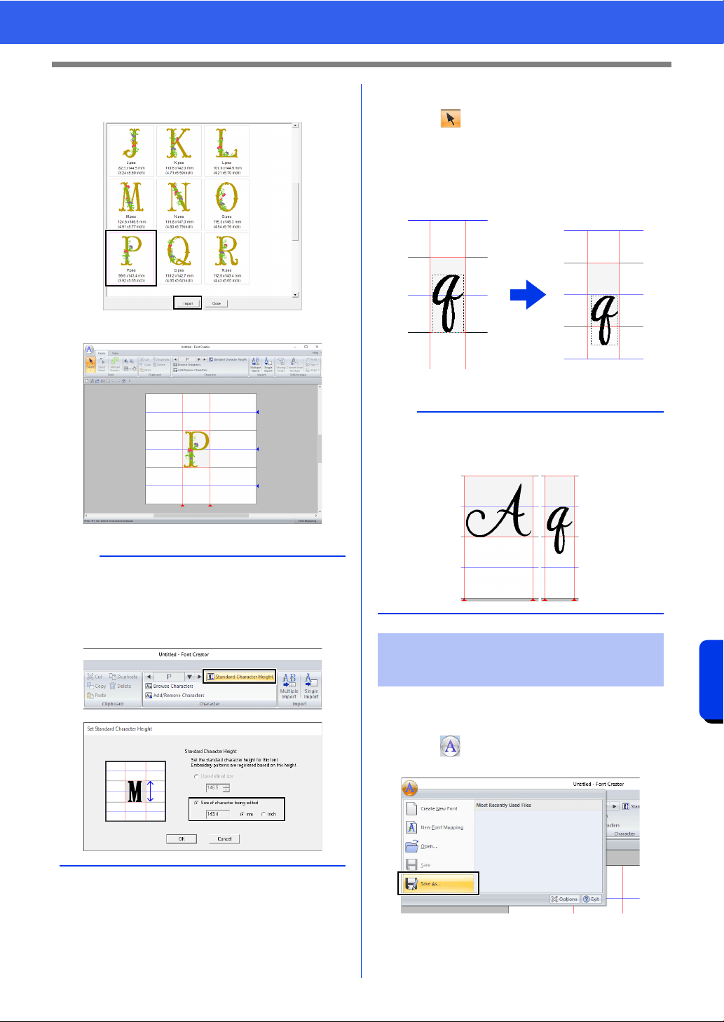
332
Font Creator
Registering Embroidery Data as a Font
3 Select the embroidery file to be registered,
and then click [Import].
The registered character appears.
■ Adjusting the character position
1
Click in the [Tools] group, and then click
the character.
Dotted lines appear around the character.
2 Drag the character to move it.
Registered characters will be saved as font
character patterns in the PFK format.
1 Click , and then select [Save As] from the
command list.
b
• To change the standard character height to the
height of the character embroidery pattern
currently being edited, click [Standard
Character Height], and then select [Size of
character being edited].
b
When text is entered with the registered font, the
text will have the height specified in the [Set
Standard Character Height] dialog box.
Saving registered
characters
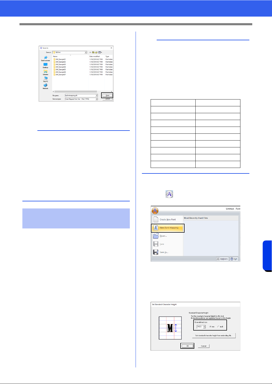
333
Font Creator
Registering Embroidery Data as a Font
2 Save the pattern to the [MyFont] folder at the
following location.
For example, (Drive where PE-DESIGN was
installed)\Program Files (x86)\Brother\PE-
DESIGN 11\MyFont
1 Prepare the embroidery data to be registered,
and rename them so that the character in each
file can be identified by the file name.
2 Start up Font Creator.
3 Click , and then select [New Font
Mapping] from the command list.
The [Set Standard Character Height]
dialog box appears.
4 Specify the standard character height.
For this example, specify a character height of
146.5 mm, and then click [OK].
cc "Specifying the standard character
height" on page 330
a
• When the font character pattern is saved, text
can be entered with it in Layout & Editing.
cc "User-Mapped Text" on page 135
• If the pattern is saved in a different folder, it
cannot be edited in Layout & Editing.
• When a .pes file that contains user-defined
colors is registered, those colors appear as
[Basic Color] in Layout & Editing.
cc "Checking embroidery design information" on
page 99
Registering embroidery
data (batch registration)
b
Characters are registered according to the file
name of the embroidery data.
In order to differentiate uppercase and lowercase
letters, add "u_" at the beginning of file names for
uppercase letters, and "l_" at the beginning of file
names for lowercase letters (for example, u_A.pes
or l_a.pes).
For characters that cannot be used in file names,
specify their file names as shown below.
Character File name
\ s_bs
/s_sl
:s_cn
* s_as
? s_qm
" s_dq
<s_lt
> s_gt
|s_vb
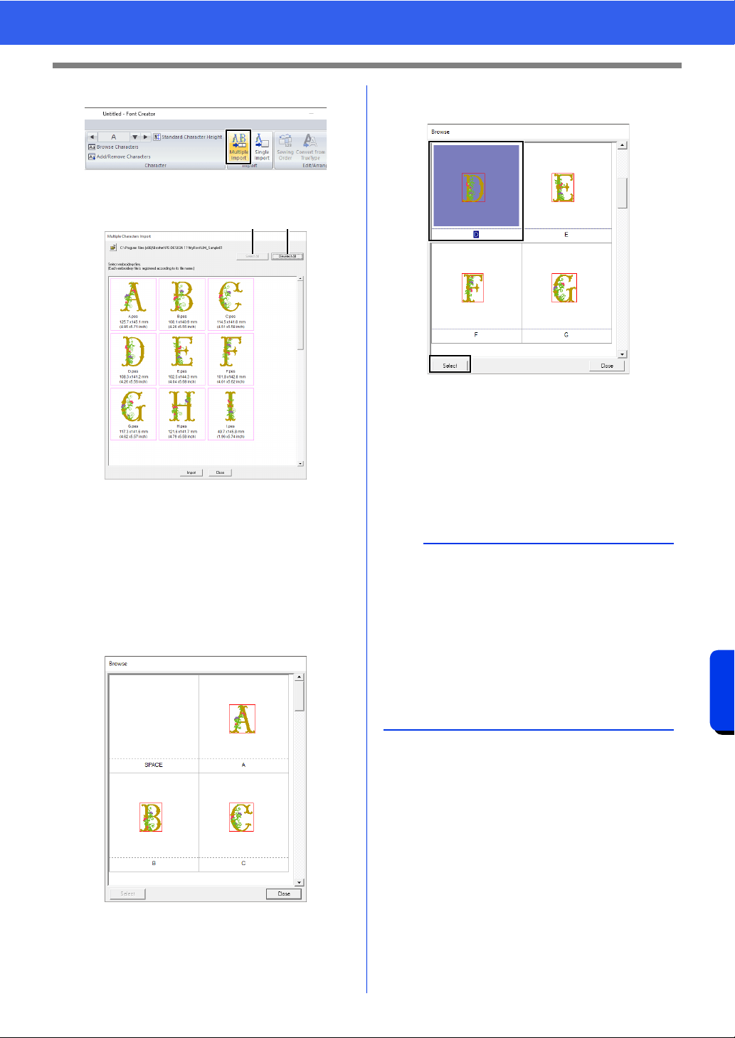
334
Font Creator
Registering Embroidery Data as a Font
5 Click [Multiple Import] on the [Home] tab.
6 Select the files to be registered.
a Select All
Click to select all files.
b Deselect All
Click to deselect all files.
7 Click [Import].
When registration is finished, one of the
registered characters appears in the
Design Page, and the [Browse] dialog box
appears.
8 Select the character whose position is to be
adjusted, and then click [Select].
9 Adjust the position of the character.
cc "Adjusting the character position" on
page 332
10 Save the registered characters.
cc "Saving registered characters" on
page 332
a b
b
• Embroidery files of the following types will not
appear in the file list of the dialog box.
• Files where the embroidery pattern size
exceeds 500 mm
• Files where the embroidery pattern size is less
than 5 mm
• Files where the hoop size has been set to a
large-size split embroidery frame, jumbo
frame or a multi-position hoop
• Files that contain a cutwork pattern
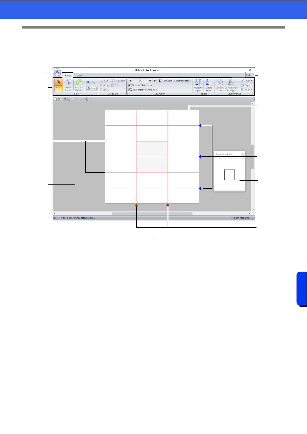
335
Font Creator
Font Creator Window
Font Creator Window
a Application button
b Ribbon
c Quick Access Toolbar
d Help button
e Preview Window
Shows how the stitch pattern will be sewn.
cc "Previewing the embroidery pattern" on
page 342
f Design Page
g Guidelines (fixed)
cc "About the Design Page guidelines" on
page 336
h Guidelines (movable)
cc "About the Design Page guidelines" on
page 336
i Work area
j Status Bar
cc "Understanding Windows" on page 13
b
a
d
f
h
e
h
g
i
j
c
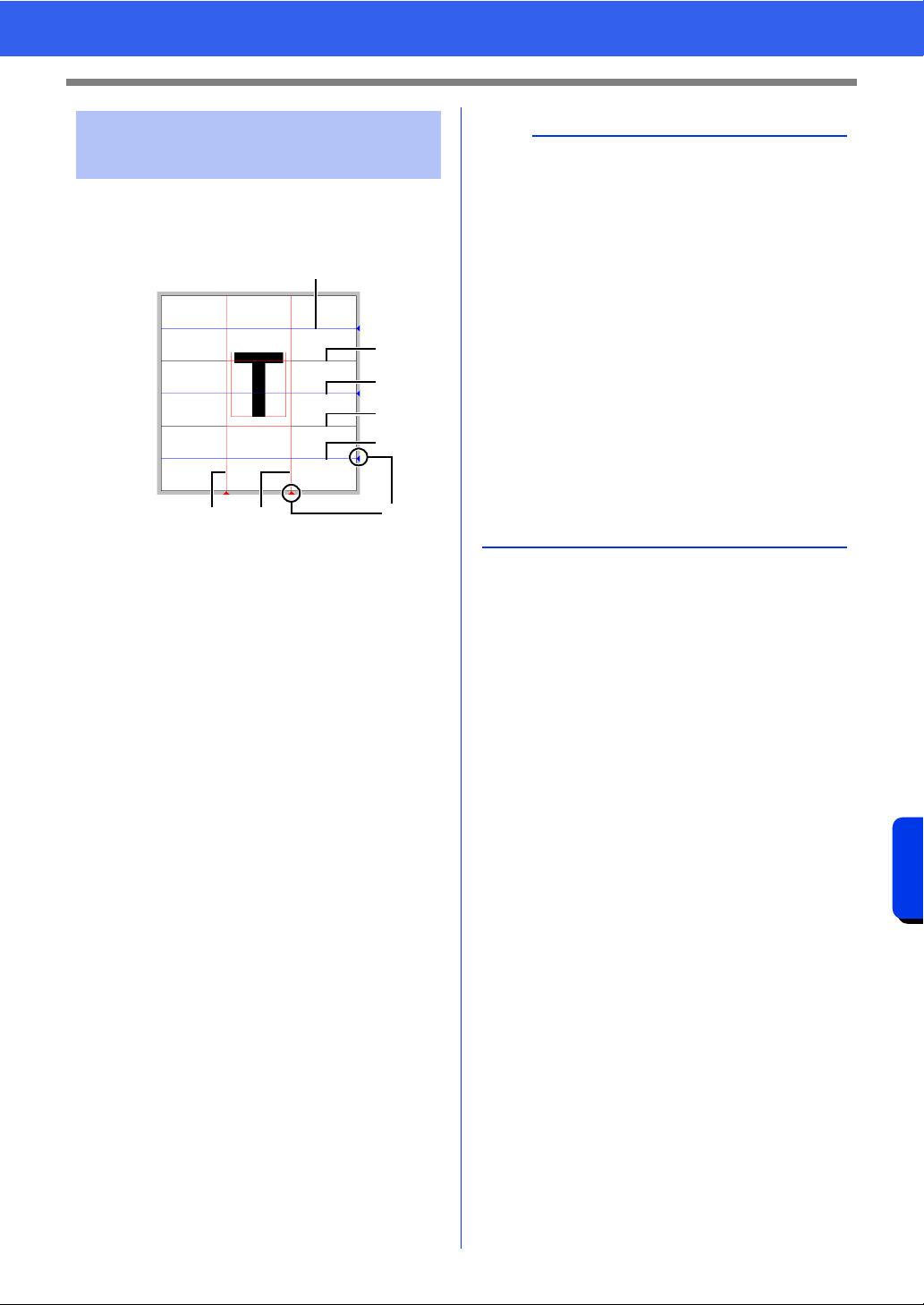
336
Font Creator
Font Creator Window
The standard guidelines for creating fonts are
shown in the Design Pages. The contents of each of
the guidelines are as shown below.
1 Triangle icon
a Base Line
b Capital Line
The font's standard height will be from the
Base Line to the Capital Line line. These
line cannot be moved.
c Mean Line
When in lower case, the standard height
of the font will be from the Base Line to
this line. It can be moved by dragging the
triangle icon on the right edge.
d Descender Line
This line is the standard for characters
with parts that hang down (descenders)
such as "g" and "y". It can be moved by
dragging the triangle icon on the right
edge.
e Ascender Line
This line is the standard for characters
with parts that extended above
(ascenders) such as the accent mark. It
can be moved by dragging the triangle
icon on the right edge.
f Set Line (Left)
g Set Line (Right)
This line will be the font width. The font
width can be adjusted by dragging the
triangle icon on the bottom edge.
About the Design Page
guidelines
e
b
c
a
d
fg
1
b
• The heights and widths specified for the [Base
Line], [Capital Line] and [Set Lines] are the
reference mask for creating the font character.
• When characters created with Font Creator are
imported into Layout & Editing, the width and
height of the characters will be in the following
area.
Character height: from Base Line
a to
Capital Line
b
Character width: from Set Line (Left) f to Set
Line (Right)
g
• In order to align the height of the characters, the
[Ascender Line], [Mean Line] and [Descender
Line] appear the same with all characters.
Therefore, if the height of any of these lines is
changed, the setting is maintained, even when a
different character is selected to be edited.
• The widths of the [Set Lines] can be set
separately for each character.
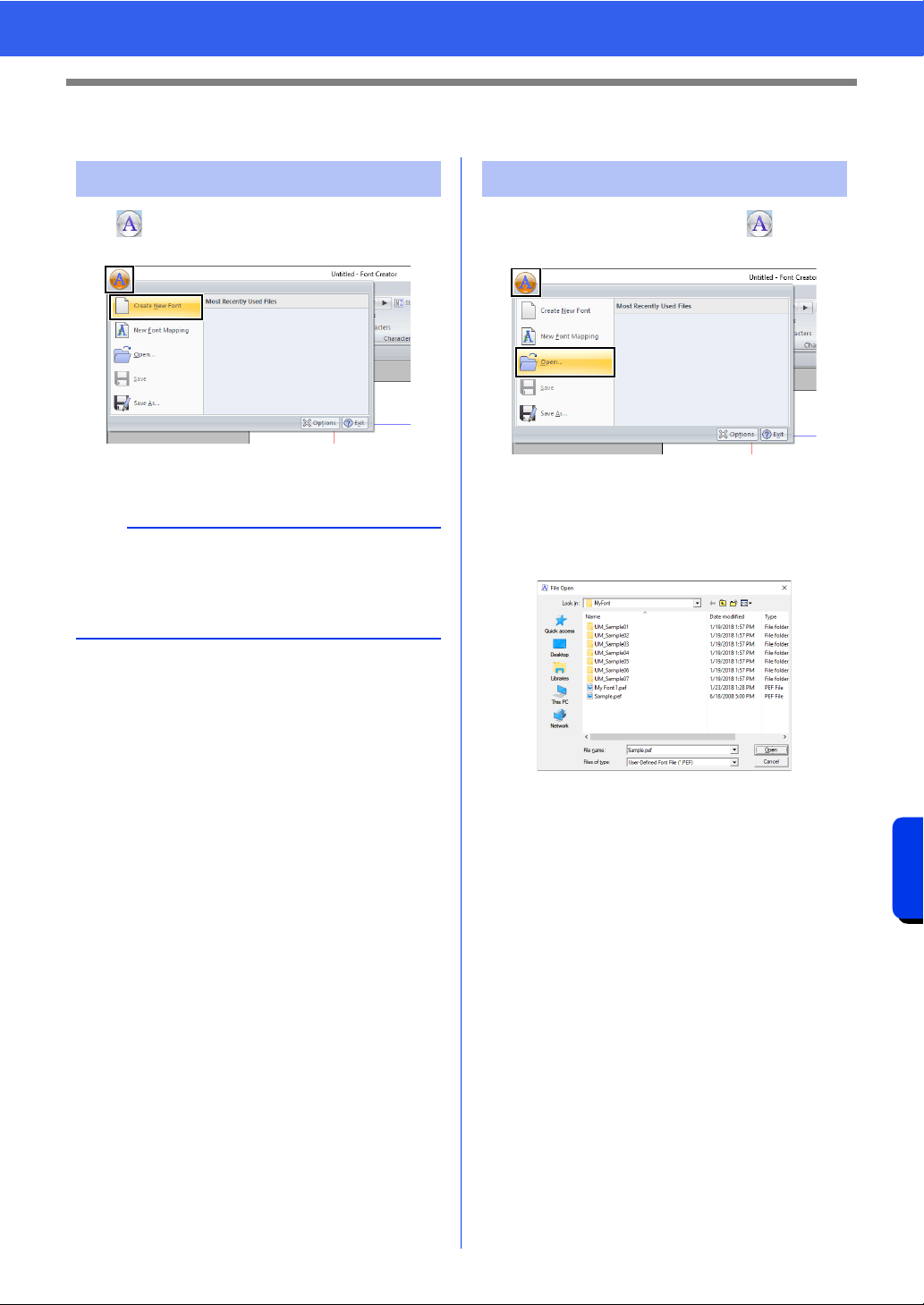
337
Font Creator
Opening a File
Opening a File
Click , and then select [Create New Font] from
the command list.
The application enters Create New Font
mode.
1 In Create New Font mode, click , and then
select [Open] from the command list.
2 The created font is saved in the [MyFont]
folder at the following location.
(Drive where PE-DESIGN was
installed)\Program Files (x86)\Brother\PE-
DESIGN 11\MyFont
3 To open a file, select it, and then click [Open],
or double-click the file's icon.
Creating a new font
b
To create font character patterns from embroidery
data, select [New Font Mapping].
cc "Registering Embroidery Data as a Font" on
page 330
Opening a font file
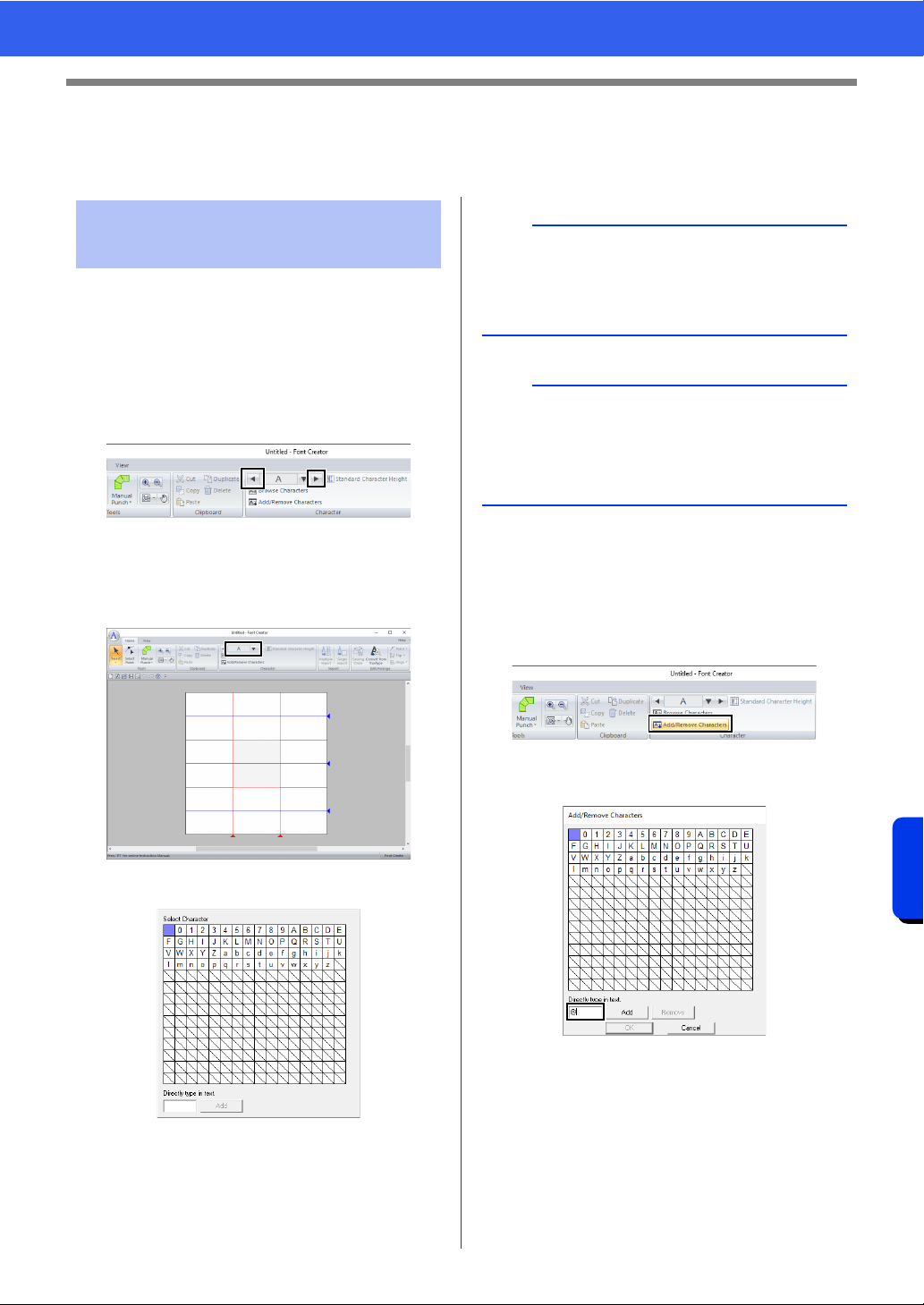
338
Font Creator
Selecting a Character and Preparing the Template
Selecting a Character and Preparing the
Template
■ Selecting from the selector
1 Click the [Home] tab.
2 Click the left or right arrow buttons of the
[Select Character] box in the [Character]
group to select a character before or after the
one that is currently displayed.
■ Selecting from a character list
1 Click the [Select Character] box in the
[Character] group.
2 Click the character to be created.
■ Adding/deleting registered
characters
1 Click [Add/Remove Characters] in the
[Character] group.
2 From the keyboard, enter the character to be
registered.
Selecting the character to
be created
b
• Characters where pattern has already been
created appear with a blue background.
• The blank box in the upper-left corner is a space.
Click this box to select a space.
a
If any part of the character pattern extends off the
Design Page when a different character is
selected, a message appears. Before selecting a
different character, edit the character pattern so
that no part extends off the Design Page.
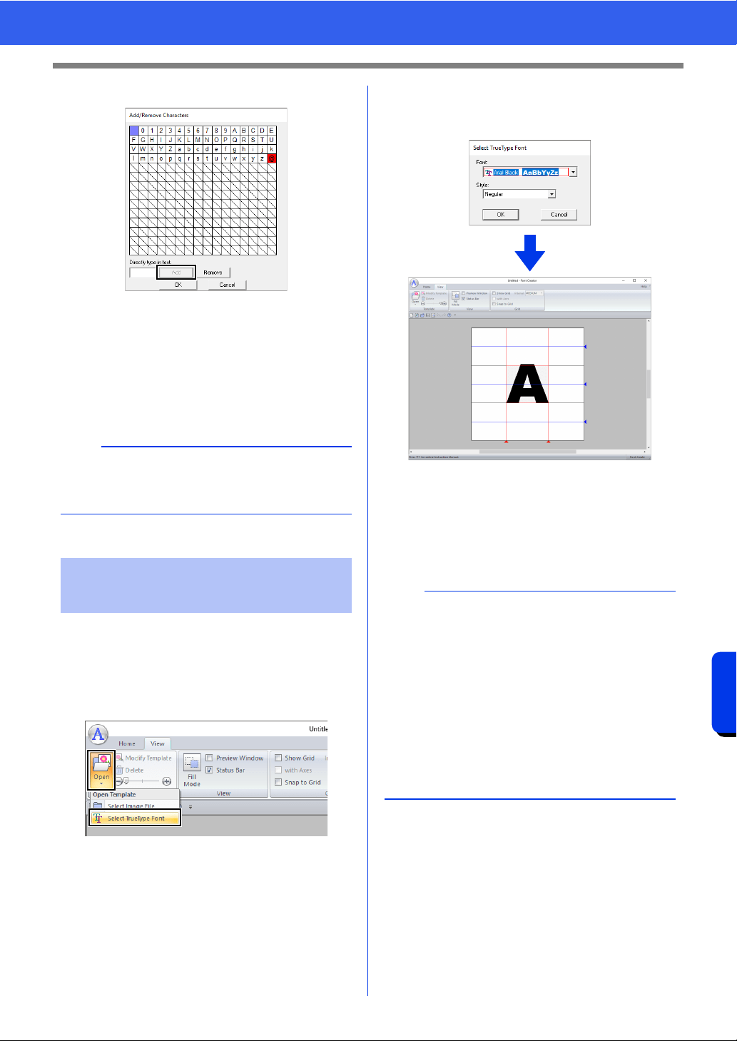
339
Font Creator
Selecting a Character and Preparing the Template
3 Click [Add].
4 To delete a registered character, select the
character, and then click [Remove].
The box is selected in red. Each click of the
character switches between selecting and
deselecting it.
5 When the settings can be applied, click [OK].
1 In Create New Font mode, click the [View]
tab.
2 Click [Open] in the [Template] group, and
then select [Select TrueType Font] from the
list.
3 From the [Font] selector, select the font. From
the [Style] selector, select the character style.
And then click [OK].
While working on a character in a font, the
same TrueType font appears until a different
template is selected for the background. Each
time a different character is selected in the
[Select Character] box, the template of the
character in the same TrueType font appears.
b
If a character is registered even though a font has
not been created, the information for the registered
character is saved in a font file.
Opening a template
(TrueType font)
b
• If the character selected in the [Select
Character] box is not available in the TrueType
font, "?" appears as the template.
• If a TrueType font was selected as the template,
it cannot be moved or resized.
• In this case, it can automatically be converted to
a font character pattern.
cc "Automatically converting TrueType fonts" on
page 340.
• In addition, the character cannot be drawn with
the semi-automatic block-type punch tool.
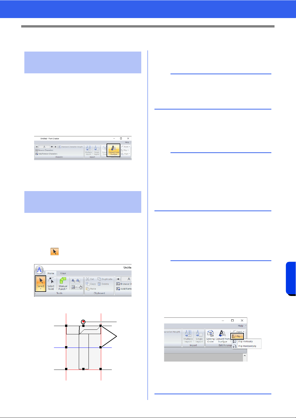
340
Font Creator
Creating a Font Character Pattern
Creating a Font Character Pattern
1 In Create New Font mode, open the TrueType
font to be used as a template.
cc "Opening a template (TrueType font)" on
page 339.
2 Click the [Home] tab.
3 Click [Convert from TrueType] in the [Edit/
Arrange] group.
4 If a TrueType font has not been selected for
the template, the [Select TrueType Font]
dialog box appears.
■ Selecting patterns
1 In Create New Font mode, click the [Home]
tab.
2 Click in the [Tools] group to use the
[Select] tool.
3 Click the pattern.
1 Rotation handle
2 Handles
4 To select an additional pattern, hold down the
<Ctrl> key and click the other pattern.
■ Moving patterns
Selected patterns can be dragged to move them.
■ Scaling patterns
Drag a handle of the selected pattern to adjust its
size. Drag the rotation handle to rotate the pattern.
Automatically converting
TrueType fonts
Editing Font Character
Patterns
1
2
b
• You can also select patterns by dragging the
pointer across the pattern.
• Hold down the <Ctrl> key and click a selected
pattern to deselect it.
b
• To move the pattern horizontally or vertically,
hold down the <Shift> key while dragging it.
• Pressing the arrow keys moves the selected
pattern one grid mark in the direction of the
arrow on the key. If the grid is not displayed, the
pattern moves a distance smaller than the
smallest grid interval in the direction of the arrow
on the key.
b
• If the <Shift> key is held down while a handle is
dragged, the pattern is enlarged or reduced from
the center of the pattern.
•Click [Flip] in the [Edit/Arrange] group, and
then select [Flip Vertically] to flip the selected
pattern(s) up/down.
Select [Flip Horizontally] to flip the selected
pattern(s) left/right.
• Using commands other than those mentioned
above, selected patterns can be edited in other
ways, for example, duplicated or deleted.
cc "Font Creator" on page 321.
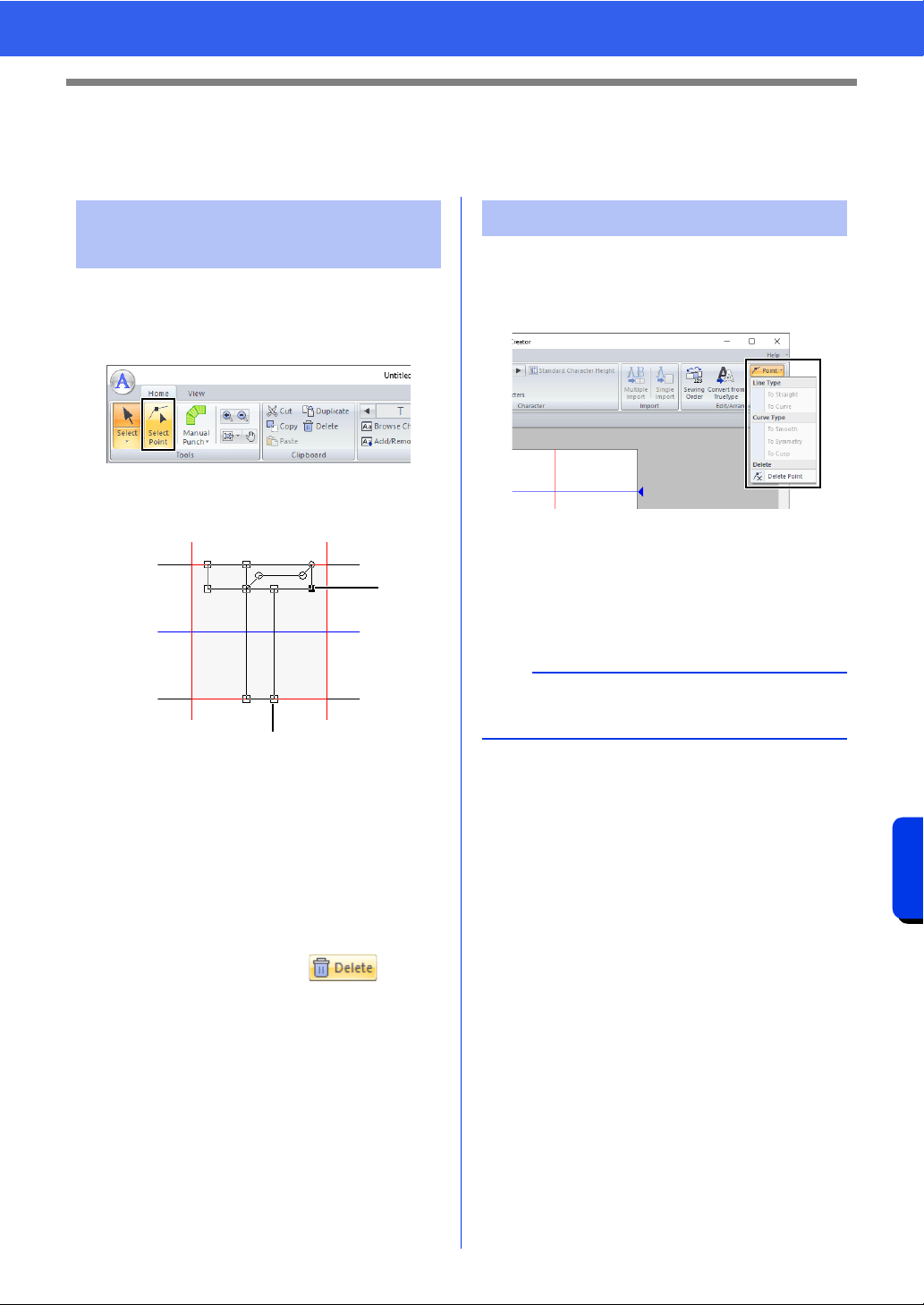
341
Font Creator
Editing the Points of a Font Character Pattern
Editing the Points of a Font Character
Pattern
1 In Create New Font mode, click the [Home]
tab.
2 Click [Select Point] in the [Tools] group.
3 Click the pattern.
4 To edit a point, click the point to select it.
1 Unselected point
2 Selected point
• To move the point, drag it to the new
location.
• To insert a point, click the line to add a new
point.
A new point appears selected (as a small
black square or circle).
• To delete the point, click or press
the <Delete> key.
1 Select the point(s).
2 Click [Point] in the [Edit/Arrange] group, and
then select the desired command from the list.
cc For details on the commands To Straight,
To Curve, To Smooth, To Symmetry and
To Cusp, "Transforming straight lines
into curves or curves into straight lines"
on page 80 and "Changing the curve
type" on page 80.
Editing points and
reshaping patterns
1
2
To Straight/To Curve
a
These commands are not available with patterns
entered using the [Running] or [Feed] tools.
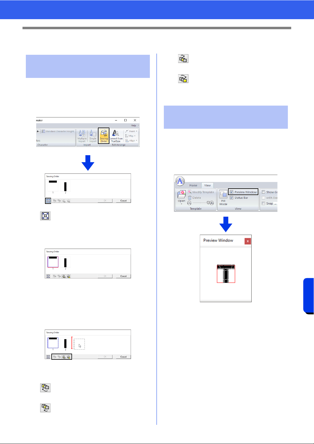
342
Font Creator
Checking the Created Font Patterns
Checking the Created Font Patterns
1 In Create New Font mode, click the [Home]
tab.
2 Click [Sewing Order] in the [Edit/Arrange]
group.
: Click to enlarge each pattern to fill its
frame.
3 Select a pattern in the [Sewing Order] dialog
box.
4 The sewing order can be changed by
selecting the frame containing the pattern that
you want to move, then dragging the frame to
the new location. A vertical red line appears,
indicating the position where the frame is
being moved.
An alternative method for moving the frames is by
clicking the buttons at the bottom of the dialog box.
: To move to the beginning of the
sewing order.
: To move ahead one position in the
sewing order.
: To move back one position in the
sewing order.
: To move to the end of the sewing
order.
To change the sewing order, click [OK].
1 Click the [View] tab.
2 To switch between displaying and hiding the
[Preview Window], select or unselect the
[Preview Window] check box in the [View]
group.
Checking and editing the
sewing order
Previewing the embroidery
pattern
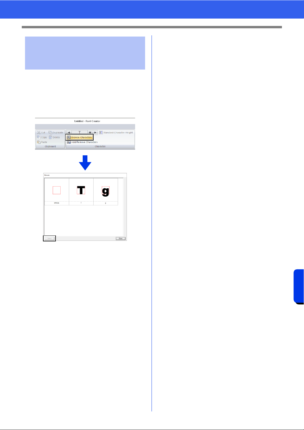
343
Font Creator
Checking the Created Font Patterns
A list of characters included in the font file currently
being edited can be viewed.
1 Click the [Home] tab.
2 Click [Browse Characters] in the
[Character] group.
To select a character, click the character, and then
click [Select].
Checking and selecting
from the list of created
characters
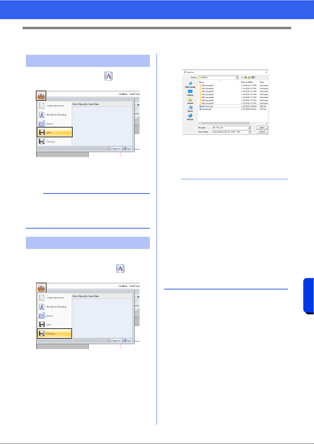
344
Font Creator
Saving Font Character Patterns
Saving Font Character Patterns
In Create New Font mode, click , and then
select [Save] from the command list.
If no file name has been specified or if the
file cannot be found, the [Save As] dialog
box appears.
The font character patterns are saved as .pef files.
1 In Create New Font mode, click , and then
select [Save As] from the command list.
2 Select the [MyFont] folder at the following
location.
For example, (Drive where PE-DESIGN was
installed)\Program Files (x86)\Brother\PE-
DESIGN 11\MyFont
And then type in the file name, then click [Save].
Overwriting
a
If any part of the character pattern extends off the
Design Page, a message appears. Edit the
character pattern so that no part extends off the
Design Page, and then save it again.
Saving with a new name
a
• The font will not be usable in the Layout &
Editing if it's stored in a different folder.
• The created font is saved in the [MyFont] folder
at the following location.
For example, (Drive where PE-DESIGN was
installed)\Program Files (x86)\Brother\PE-
DESIGN 11\MyFont
• Saved files can be used in Layout & Editing.
cc "Creating an embroidery pattern using the
created font characters" on page 329
• If Layout & Editing has already started up when
a new character is saved in Font Creator, that
character will not appear in the [Font] selector
list in Layout & Editing. In this case, exit Layout
& Editing, and then start it up again.
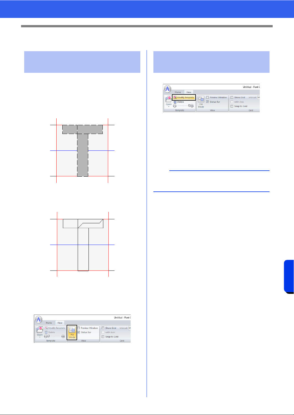
345
Font Creator
Changing the Settings
Changing the Settings
There are two drawing modes in Create New Font
mode of Font Creator.
• Fill mode
Blocks appear filled in. In this mode, the
overlapping positions of patterns can be
viewed better.
• Outline mode (Fill mode Off)
Blocks do not appear filled in. In this mode,
points can be edited more easily.
Perform the operation described below to switch
between these modes.
Click the [View] tab.
Click [Fill Mode] in the [View] group.
Click [Modify Template] in the [Template] group.
The background image is selected.
The background image can be moved or
resized in the same way that font character
patterns are edited.
cc "Editing Font Character Patterns" on
page 340.
Changing the drawing
mode
Scaling/Moving the
background image
b
The background image cannot be scaled or moved
if a TrueType font is used as the template.
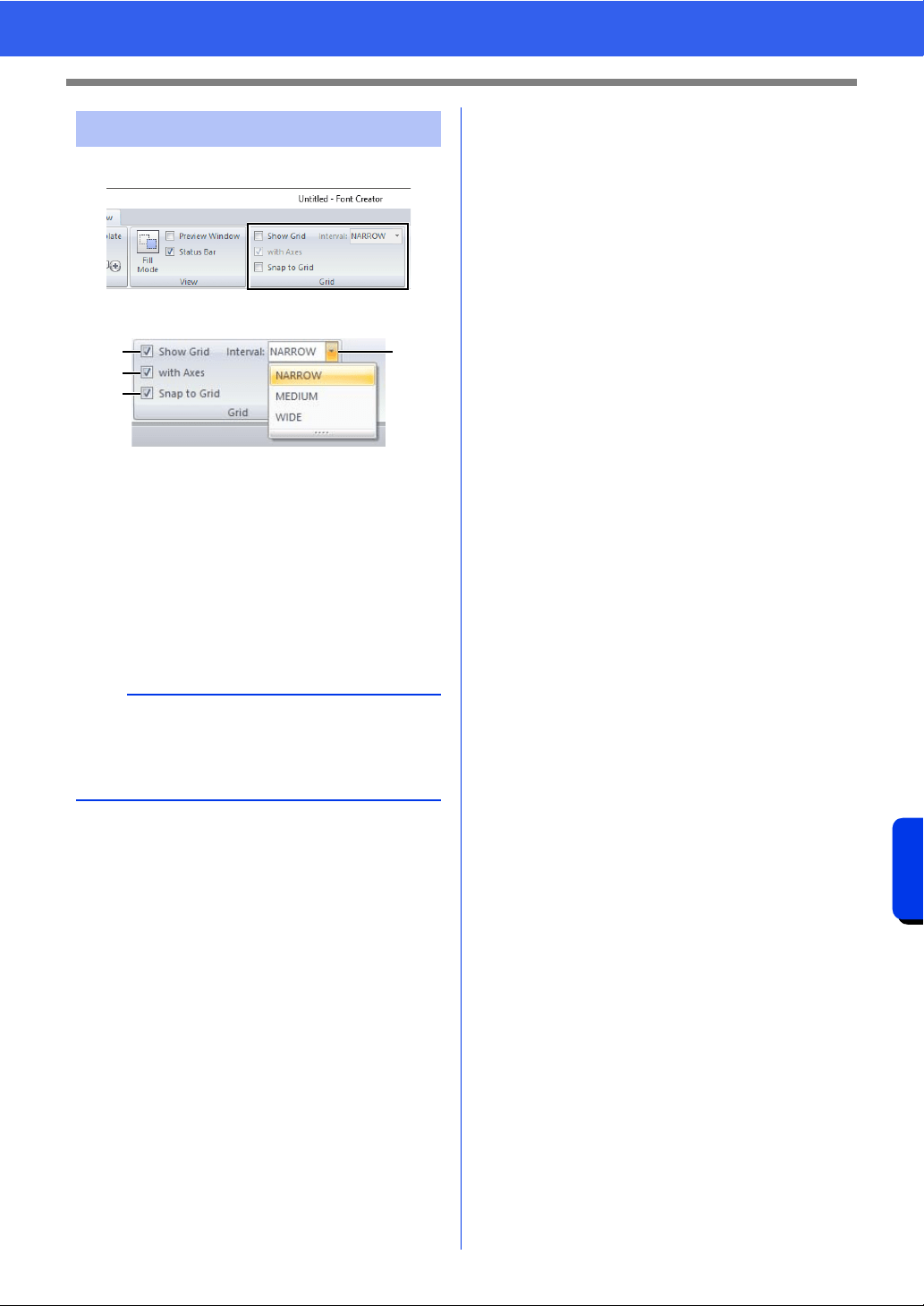
346
Font Creator
Changing the Settings
1 Click the [View] tab.
2 Specify the grid settings in the [Grid] group.
a To display the grid, select the [Show
Grid] check box.
b To display the grid as solid lines, select
the [with Axes] check box.
c In the [Interval] box, select the grid
spacing.
d To input the font in a uniform thickness or
match vertical and horizontal positions,
select the [Snap to Grid] check box.
Changing the grid settings
b
The pointer will move by the amount set in
[Interval] box.
The snap feature works whether or not the grid is
displayed.
a
b
d
c

Stitch Design Factory
Stitch Design Factory can be used to create and
edit sewing stitch patterns for sewing machines.
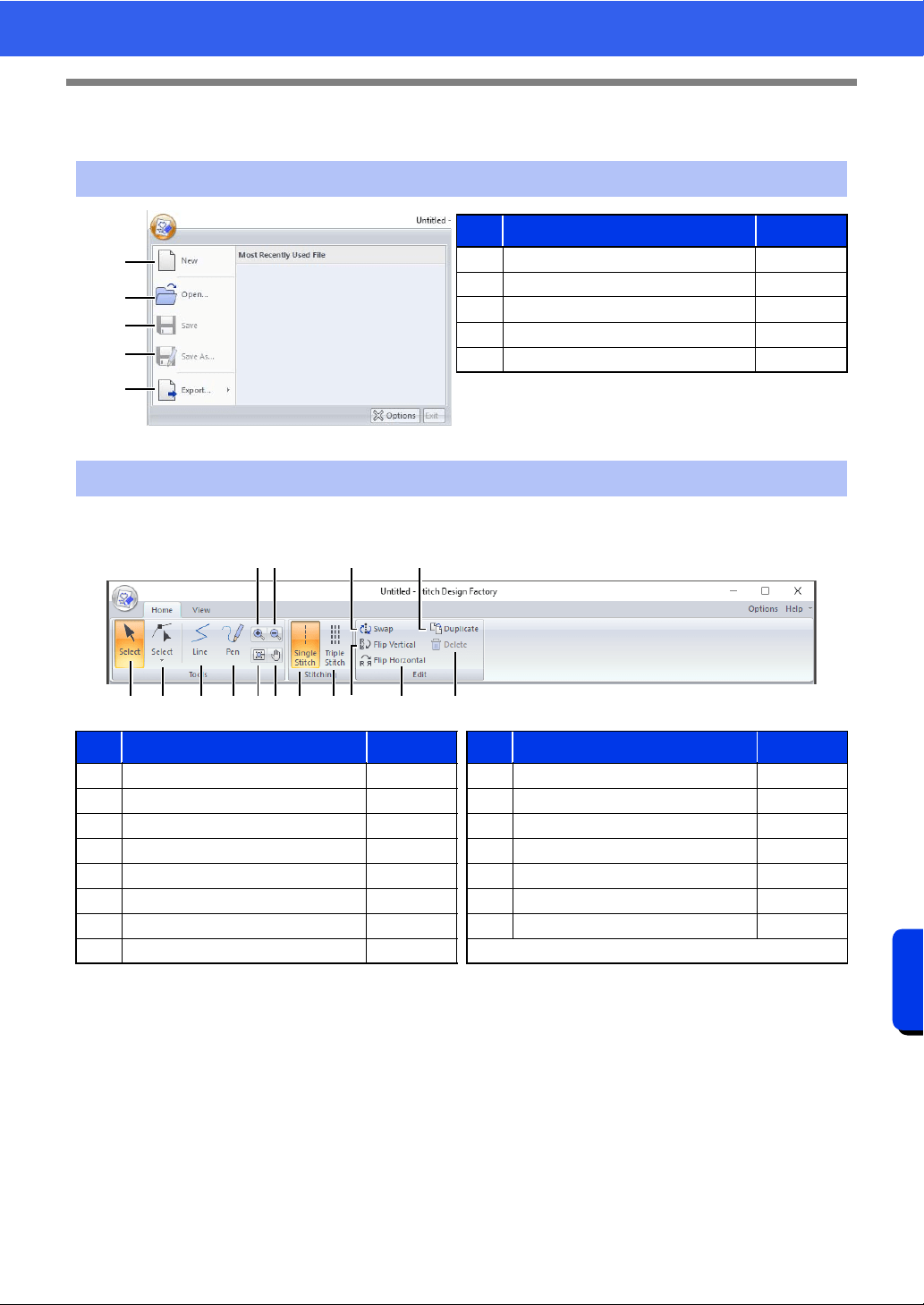
348
Stitch Design Factory
Stitch Design Factory
Stitch Design Factory
■ Home tab
Application button menu
1
2
3
4
5
No. Menu Reference
1New —
2 Open —
3Save —
4 Save As p. 351
5 Export p. 352
Ribbon menu tabs
No. Menu Reference No. Menu Reference
1 Select Object p. 353 9 Single Stitch p. 350
2 Select Point p. 353 10 Triple Stitch p. 350
3 Line Tool p. 350 11 Swap p. 354
4 Pen Tool p. 350 12 Flip Vertical p. 353
5 Zoom in — 13 Flip Horizontal p. 353
6 Zoom Out — 14 Duplicate p. 354
7 Selected object zoom — 15 Delete p. 353
8Pan —
1 B
A
C2 3 4 8 9
D
E07
5 6
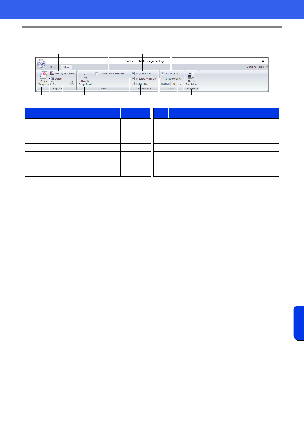
349
Stitch Design Factory
Stitch Design Factory
■ View tab
No. Menu Reference No. Menu Reference
1 Open Template p. 359 8 Preview Window p. 360
2 Modify Template p. 359 9 Status Bar p. 360
3 Delete Image p. 359 10 Show Grid p. 361
4 Template Density p. 359 11 Snap to Grid p. 361
5 Needle Drop Point p. 360 12 Grid Spacing p. 361
6 Horizontal Orientation p. 360 13 Stitch Simulator p. 361
7 Import Pane p. 360
34 A5 CB91 8
7 062
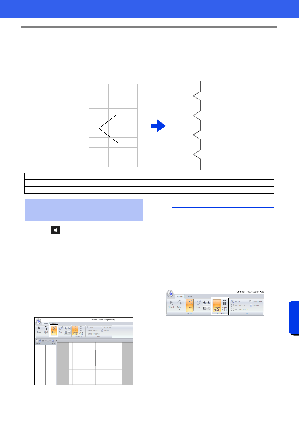
350
Stitch Design Factory
Basic Stitch Design Factory Operations
Basic Stitch Design Factory Operations
With this application, you can combine and edit built-in patterns as well as create original decorative sewing
stitch patterns. This application cannot be used to create embroidery patterns.
Contact your authorized dealer for details on the sewing machines that can import the created sewing stitch
patterns.
1 Click .
2 Click [Stitch Design Factory] under the title
[PE-DESIGN 11] in the screen.
3 Some sewing machines can use sewing stitch
patterns larger than this application's standard
Design Page.
In that case, change the format of the file to be
exported.
cc "Changing the Format of Files to be
Exported" on page 356
4 Make sure that [Line] is selected.
5 Select [Single Stitch] or [Triple Stitch] in the
[Stitching] group.
Step 1 Creating sewing stitch patterns
Step 2 Saving sewing stitch patterns
Step 3 Exporting sewing stitch patterns
Creating sewing stitch
patterns
b
• When Stitch Design Factory is started up, a
single vertical stitch appears at the center.
Create the sewing stitch pattern by moving
points in this line or adding points to it.
• The vertical direction in the Design Page
represents vertical feeding by the sewing
machine, and the horizontal direction represents
horizontal feeding.
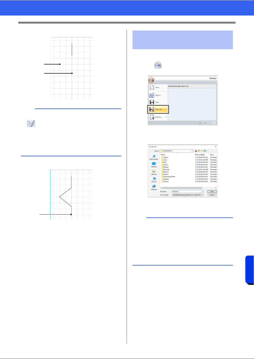
351
Stitch Design Factory
Basic Stitch Design Factory Operations
6 Click points (1) and (2), in order.
7 Double-click point (3) (end point).
Sewing stitch patterns are saved in the PSF format.
1 Click , and then select [Save As] from the
command list.
2 Select the destination, and then type in the file
name.
3 Click [Save].
b
• To draw lines by dragging the pointer, select
on the [Home] tab.
• To remove the last point that was entered, click
the right mouse button.
• The grid spacing can be changed.
cc "Changing the grid settings" on page 361
1
2
3
Saving sewing stitch
patterns
b
• .psf files can be edited with this application;
however, they cannot be imported by sewing
machines.
• When importing the pattern to a sewing
machine, export it in the PMV or PMP format.
cc "Exporting sewing stitch patterns" on
page 352
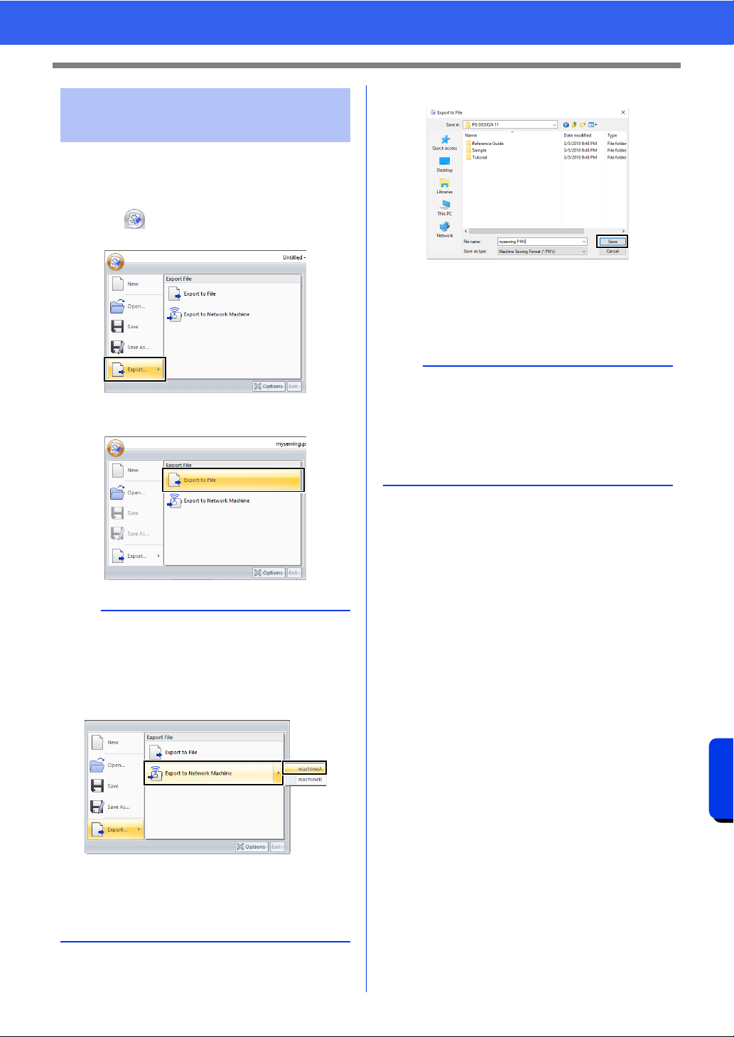
352
Stitch Design Factory
Basic Stitch Design Factory Operations
In order for the created sewing stitch pattern to be
imported by the sewing machine, it must be
exported into a different file format.
1 Click , and then select [Export] from the
command list.
2 Click [Export to File].
3 Select the destination, and then type in the file
name.
4 Click [Save].
The file is exported in the PMV or PMP
format.
cc "Changing the Format of Files to be
Exported" on page 356
Exporting sewing stitch
patterns
b
The sewing stitch pattern can be transferred to a
sewing machine via a wireless network connection
(only with compatible models).
After registering the machine with the application,
click [Export to Network Machine], and then
select the desired machine.
The sewing stitch pattern is transferred to
the sewing machine.
cc "Registering a machine with the application"
on page 224
b
Files in the PMV and PMP formats can be
imported only into sewing machines; they cannot
be edited in PE-DESIGN 11.
If the pattern may need to be edited again, save it
in the PSF format.
cc "Saving sewing stitch patterns" on page 351
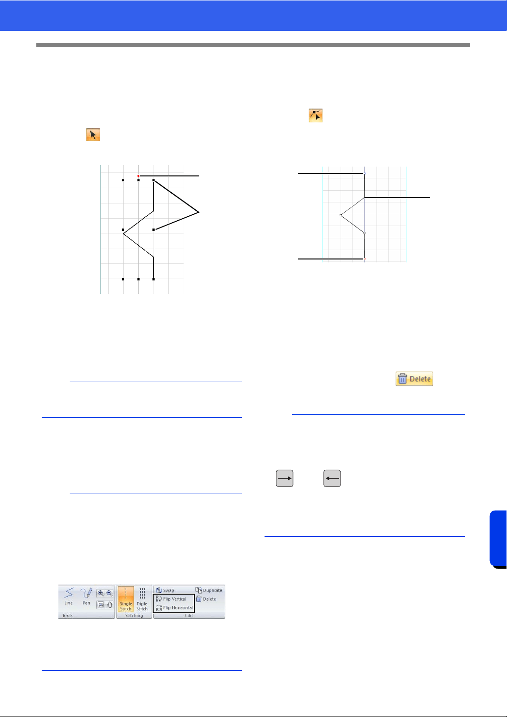
353
Stitch Design Factory
Editing Sewing Stitch Patterns
Editing Sewing Stitch Patterns
■ Selecting sewing stitch patterns
1 Click the [Home] tab.
2 Click in the [Tools] group.
3 Click the sewing stitch pattern.
1 Rotation handle
2 Handle
■ Moving sewing stitch patterns
Selected sewing stitch patterns can be dragged to
move them.
■ Editing sewing stitch patterns
Drag a handle of the selected sewing stitch pattern
to adjust its size. Drag the rotation handle to rotate
the pattern.
■ Reshaping sewing stitch patterns
1 Click in the [Tools] group.
2 Click a line in the sewing stitch pattern.
3 Click a point to select it, and then edit it.
1 Blue square: Start point
2 Red square: End point
3 Selected point
• To move the point, drag it to the new
location.
• To insert a point, click the line to add a new
point.
A new point appears.
• To delete the point, click , or
press the <Delete> key.
b
To move the pattern horizontally or vertically, hold
down the <Shift> key while dragging the pattern.
b
• If the <Shift> key is held down while a handle is
dragged, the pattern is enlarged or reduced from
its center.
•Click [Flip Vertical] in the [Edit] group to flip the
selected pattern vertically (up/down).
•Click [Flip Horizontal] in the [Edit] group to flip
the selected pattern horizontally (left/right).
• Using commands other than those mentioned
above, selected patterns can be edited in other
ways, for example, duplicated or their start point
and end point swapped.
1
2
b
• To select multiple points, hold down the <Ctrl>
key while clicking the points, or drag the pointer
over the points.
• Hold down the <Ctrl> key while pressing the
key or key to change the selection
direction toward the end point or start point.
• Hold down the <Shift> while clicking a point to
select all points between it and the last point
previously selected.
3
2
1
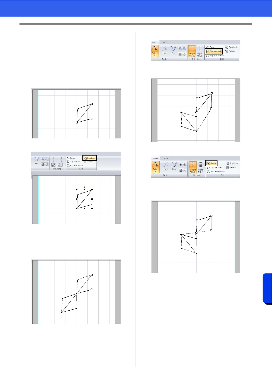
354
Stitch Design Factory
Editing Sewing Stitch Patterns
■ Changing the sewing order
The beginning of stitching (start point) and the end
of stitching (end point) can be switched. This allows
the sewing stitch pattern to be edited so that the end
of stitching for one pattern is closer to the beginning
of stitching for the next pattern.
1 Create a sewing stitch pattern.
The sewing order is as shown below.
2 Select all points and then click [Duplicate].
The selected sewing stitch pattern is
duplicated, and the duplicated point is
selected.
The sewing order of the duplicated sewing
stitch pattern is as shown below.
3 Click [Flip Vertical].
The sewing order of the sewing stitch
pattern is as shown below.
4 Click [Swap] in the [Edit] group.
The start point and end point of the
selected sewing stitch pattern is switched.
The sewing order is as shown below.
5
4
1
3
2
6
4
1
3
2
6
5
1
4
3
5
2
6
6
3
4
2
5
1
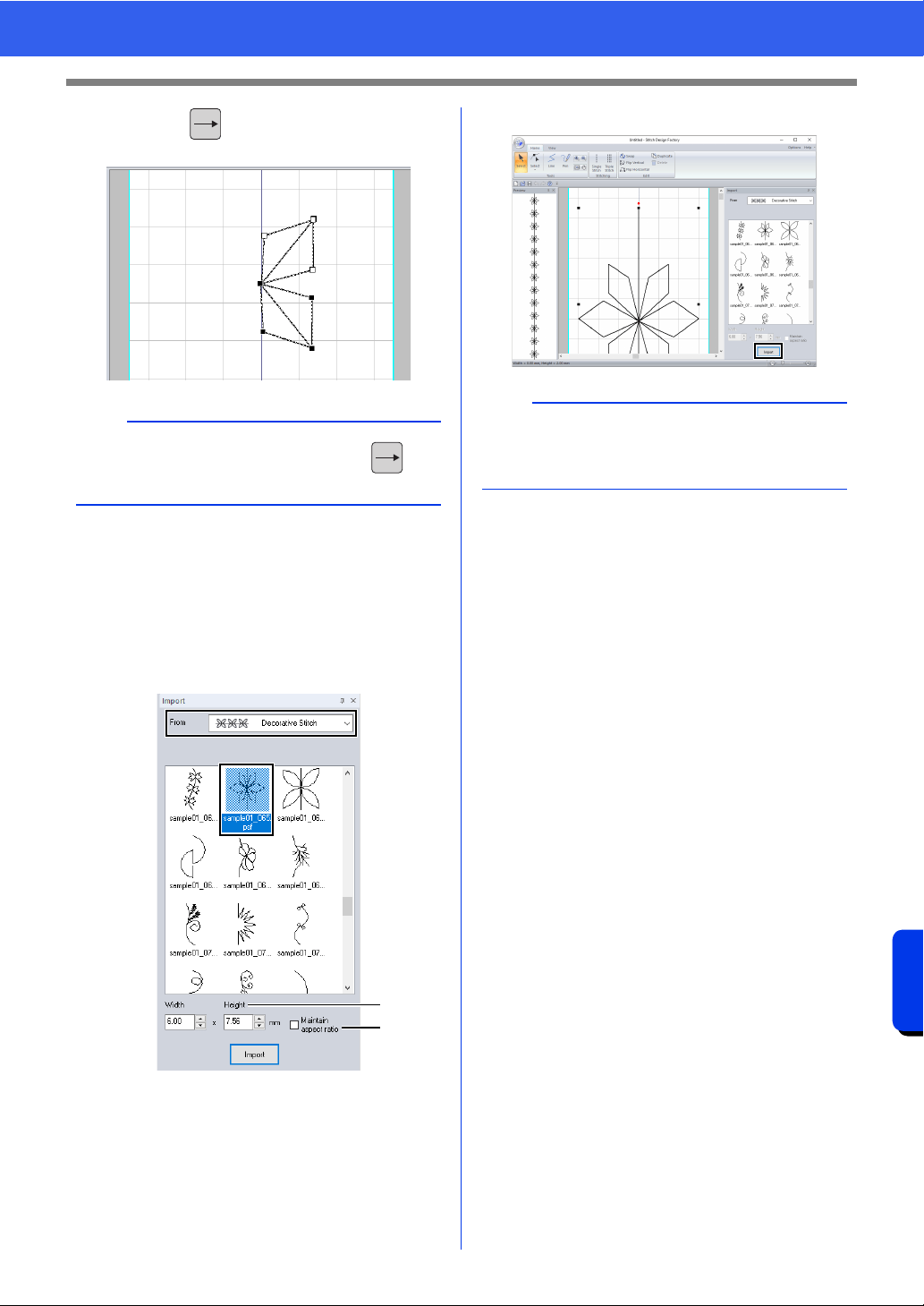
355
Stitch Design Factory
Editing Sewing Stitch Patterns
5 Press the key to move the selected
sewing stitch pattern.
■ Importing sewing stitch patterns
Sewing stitch patterns provided with the application
as .psf files can be imported and edited.
1 Select a category from the [From] selector of
the [Import] pane, and then click the sewing
stitch pattern to be imported.
a The size of the pattern to be imported can
be specified.
b Select this check box to maintain the
original height-to-width proportion of the
pattern.
2 Click [Import].
b
• Points can be selected by pressing the key
while holding down <Shift>.
a
b
b
• If there is a pattern already in the Design Page,
the new pattern will be added so that its start
point is the end point of the previous pattern.
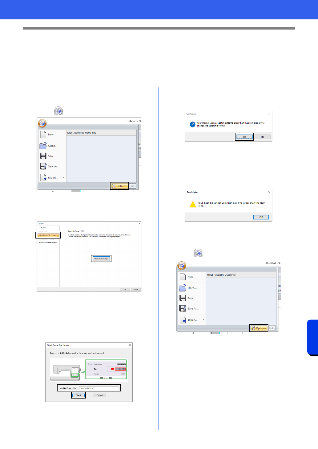
356
Stitch Design Factory
Changing the Format of Files to be Exported
Changing the Format of Files to be
Exported
Some sewing machines can use sewing stitch patterns larger than this application's standard Design Page.
The PMV file format is for patterns at the standard size, and the PMP file format is for large-size patterns.
■ Changing the format of files to be
exported from PMV to PMP
1 Click , then [Options].
2 Click [Select Export File Format], then
[Check Machine Type].
3 Type the sewing machine number beside
[Machine Number(No.)], and then click
[Check].
For details on the location of the machine
number, refer to the manual provided with
your sewing machine.
4 If your sewing machine can use large-size
sewing stitch patterns, the following message
appears. Click [Yes].
After a message appears, click [OK].
The export file format changes to the PMP
format.
If your sewing machine cannot use large-size
sewing stitch patterns, the following message
appears. Click [OK].
■ Changing the format of files to be
exported from PMP to PMV
1 Click , then [Options].
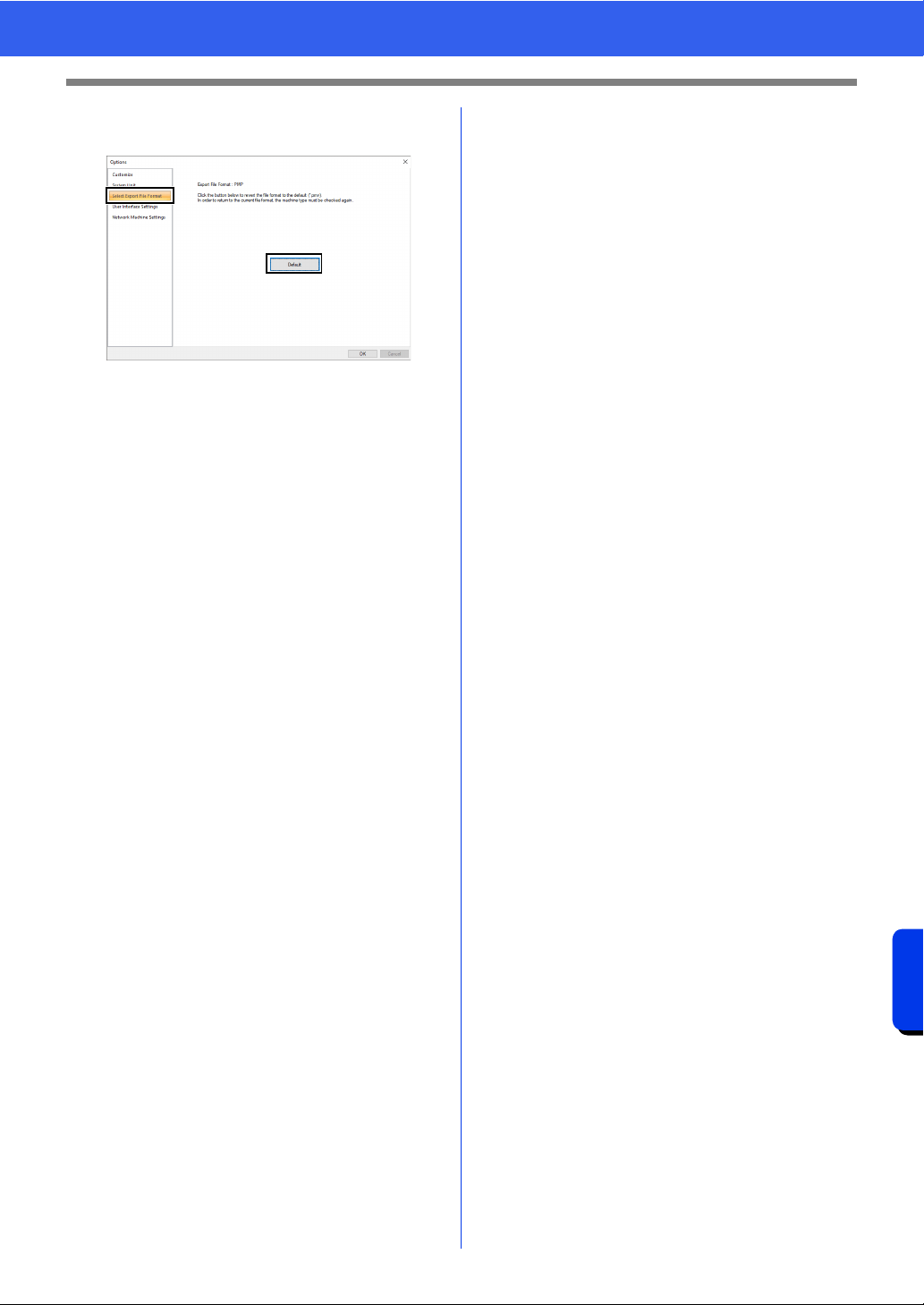
357
Stitch Design Factory
Changing the Format of Files to be Exported
2 Click [Select Export File Format], then
[Default].
3 After a message appears, click [OK].
The export file format changes to the PMV
format.
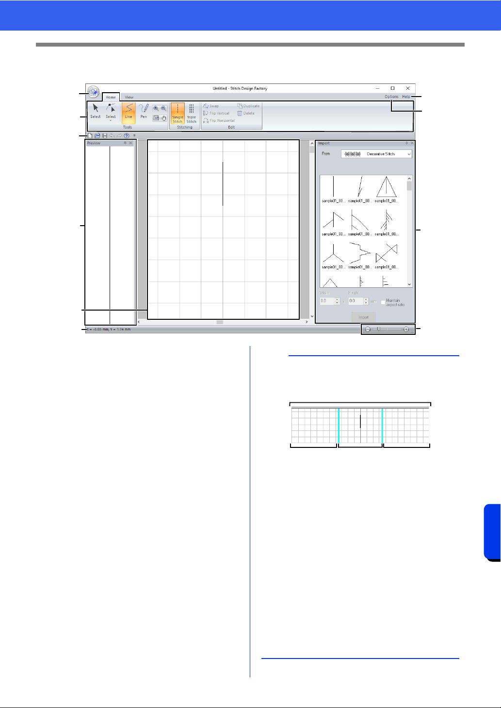
358
Stitch Design Factory
Stitch Design Factory Window
Stitch Design Factory Window
a Application button
b Ribbon
c Quick Access Toolbar
d Options button
e Help button
f Import pane
g Preview pane
h Design area
i Status Bar
cc "Understanding Windows" on page 13
j Zoom
b
a
f
g
h
i
c
j
e
d
b
When the PMP format is selected for exported
files, the data will have the following three areas.
a Design area
This is the area where the sewing stitch
pattern can be created. The design area
consists of the main area and the
extension area.
b Main area
This is the area where the sewing
machine needle can move. Specify the
start point and end point of the sewing
stitch pattern within this area.
c Extension area
This is the area outside of that where the
sewing machine needle can move. This
can be used when creating the sewing
stitch pattern, but be sure to specify the
start point and end point within the main
area.
a
cb c
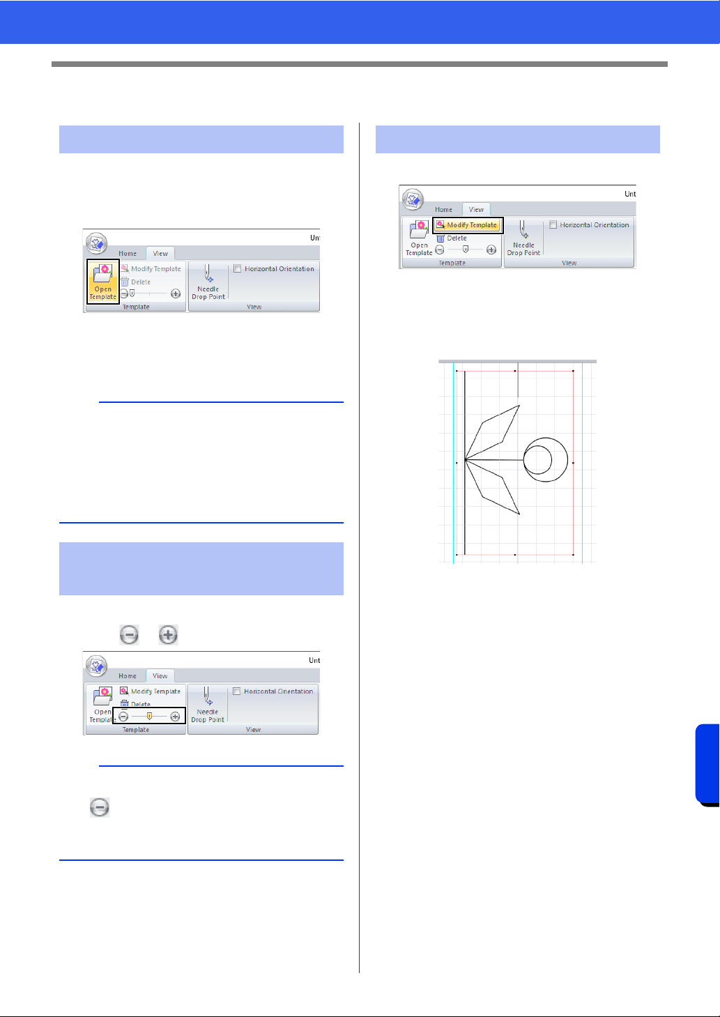
359
Stitch Design Factory
Using a Template
Using a Template
1 Click the [View] tab.
2 Click [Open Template] in the [Template]
group.
3 Select the folder where the template is saved,
select the file, and then click [Open] or
double-click the file's icon.
1 Drag the slider in the [Template] group, or
click or .
1 Click [Modify Template].
The application enters template-editing
mode, and a red frame appears around the
template.
2 Edit the template.
• Drag the inside of the red frame to move
the template image.
• Click outside of the red frame to exit
template-editing mode.
• Click [Delete] to delete the template.
Opening a template
b
• Only one template can be opened in the Design
Page. If you try to open a different template, it
will replace the previous one.
• There are many different types of files that can
be opened.
cc "Image file formats" on page 163
Changing the template
display density
b
• To hide the template, drag the slider all the way
to .
• Press function key <F6> to switch between the
settings for the template display density.
Editing the template
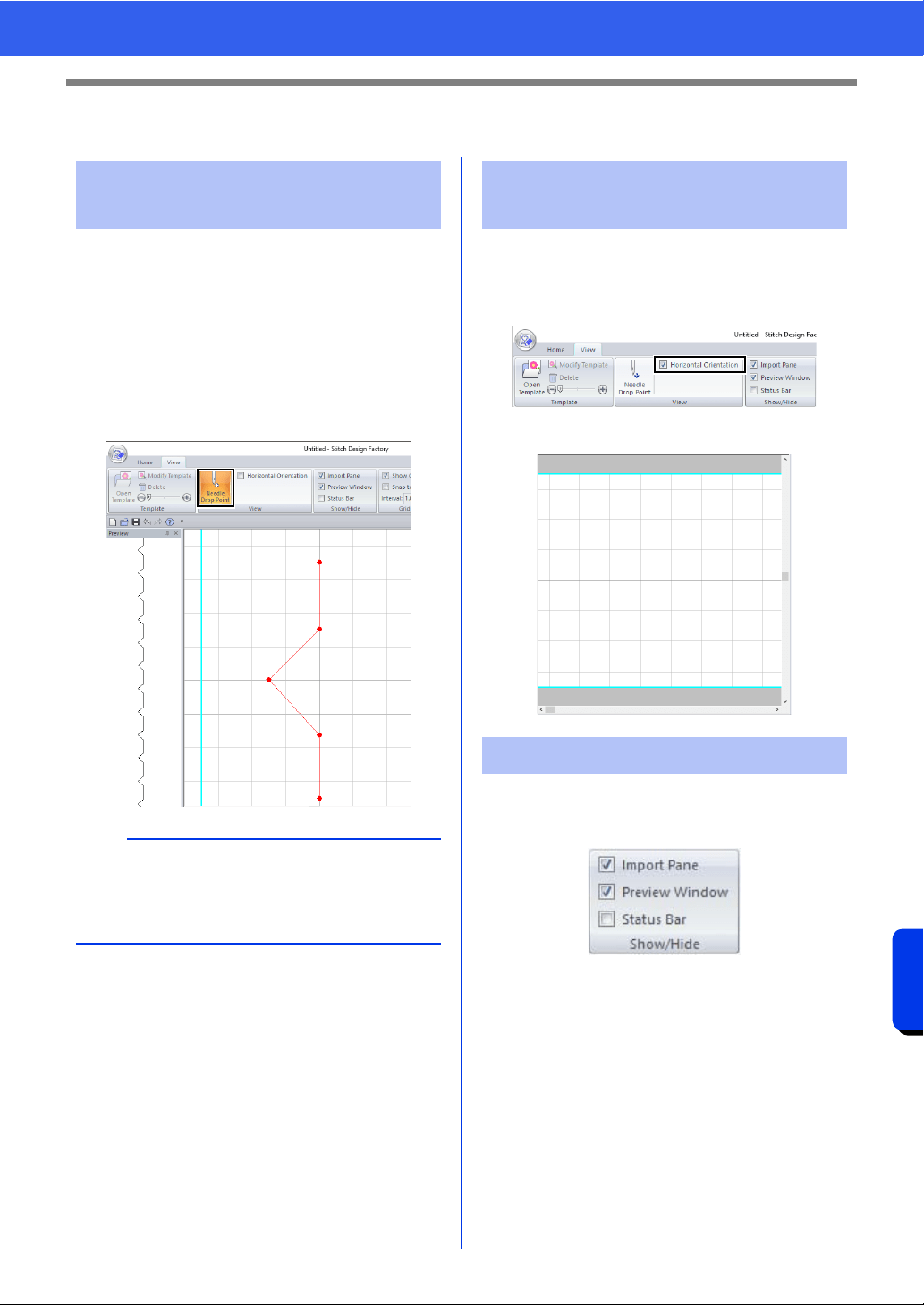
360
Stitch Design Factory
Other Settings
Other Settings
The points displayed in the Design Page are
different from the needle drop points. Follow the
procedure described below to display the needle
drop points in order to check them.
1 Click the [View] tab.
2 Click [Needle Drop Point] in the [View]
group.
The needle drop points appear.
1 Click the [View] tab.
2 Select the [Horizontal Orientation] check
box in the [View] group.
The Design Page is oriented horizontally.
To display or hide the [Import] pane, [Preview]
pane and status bar, select or clear the
corresponding check box in the [Show/Hide] group.
Displaying needle drop
points
b
• The final result also depends on your sewing
machine. We recommend that you make a trial
sewing sample with your sewing data before
sewing on the final material.
Orienting the Design Page
Horizontally
Display/hiding
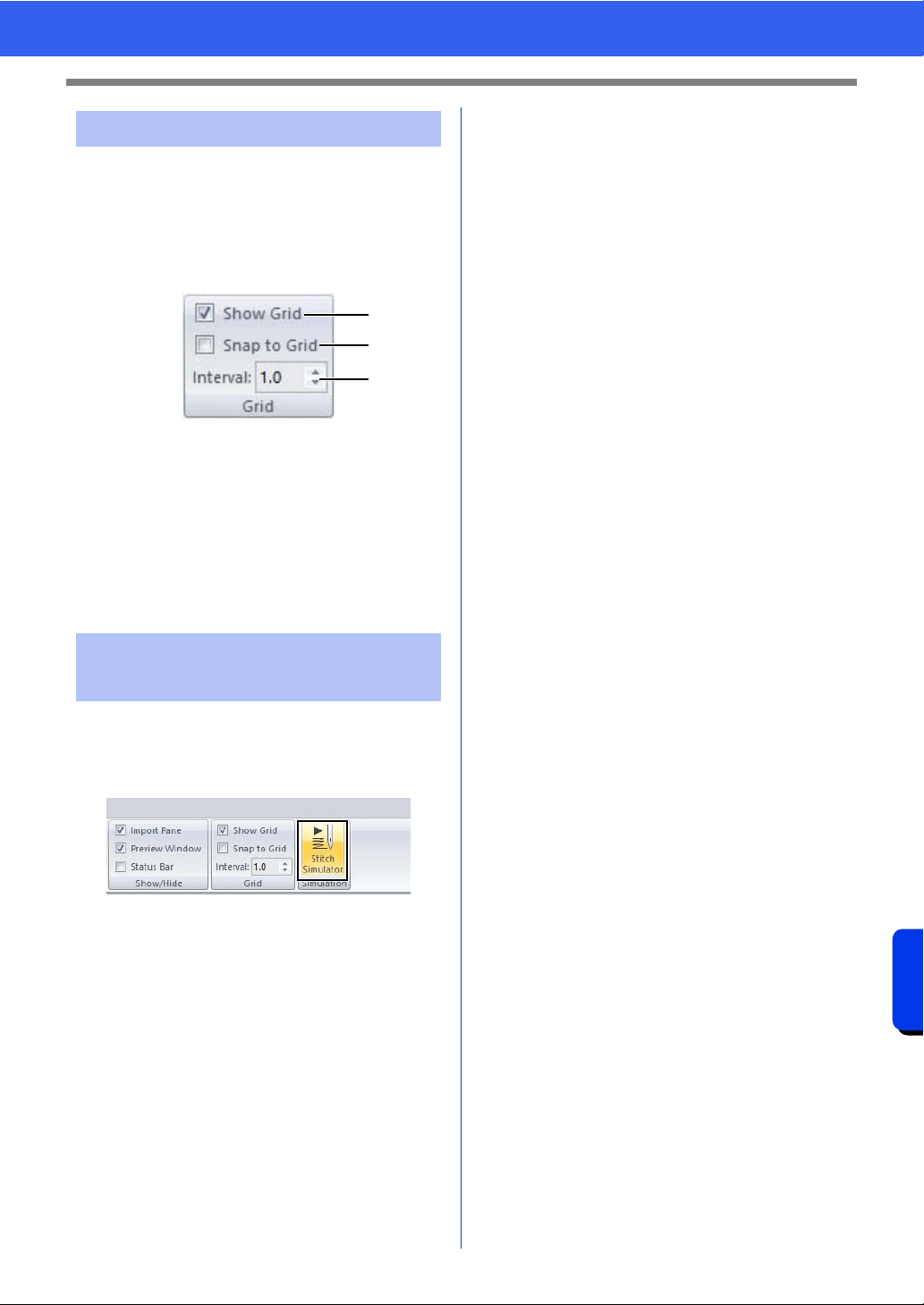
361
Stitch Design Factory
Other Settings
The grid can be displayed or hidden, and how the
grid is displayed as well as its spacing can be
specified.
1 Click the [View] tab.
2 Specify the grid settings.
a Show Grid
Select this check box to display the grid.
b Snap to Grid
Select this check box to align sewing
stitch patterns with the grid. The snap
feature works whether or not the grid is
displayed.
c Interval
Specify the grid spacing.
1 Click the [View] tab.
2 Click [Stitch Simulator] in the [Simulation]
group.
The Stitch Simulator operations are the same
as for Layout & Editing.
cc "Checking the stitching with the Stitch
Simulator" on page 90
Changing the grid settings
Checking stitching with the
Stitch Simulator
a
b
c

Supplement
This section provides hints and detailed
techniques for creating even more attractive
embroidery and sewing stitch patterns.
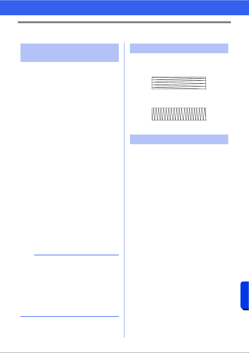
363
Supplement
For Basic Operations
For Basic Operations
Imported stitch patterns can be enlarged or reduced
in Layout & Editing in the following three ways.
1 Stitch patterns can be simply enlarged/reduced.
2 Stitch patterns can be enlarged/reduced while
the <Ctrl> key is held down.
3 Using the [Convert to Blocks] tools, stitch
patterns can be enlarged/reduced after being
converted to a group of shape patterns with
multiple sewing direction lines.
With method 1, the stitching will become more
dense or light without the number of stitches sewn
changing. In other words, greatly enlarging or
reducing the pattern changes the quality of the
embroidery since the thread density is not adjusted.
Use this method when only slightly enlarging/
reducing the stitch pattern.
With method 2, the size of the pattern is changed
while maintaining the thread density and needle
drop point pattern. However, if the original thread
density and needle drop point pattern in the stitch
pattern are not uniform, the thread density and
needle drop point pattern may not be maintained,
even by using this method. Enlarge/reduce the
pattern while checking the preview. Do not use this
method when only slightly enlarging/reducing the
stitch pattern.
With method 3, the thread density is maintained
while the pattern is enlarged/reduced. However, the
needle drop point pattern is not entirely maintained.
Use this method when you wish to change the
stitching or shape. Do not use this method when
only slightly enlarging/reducing the stitch pattern.
In order to limit pulling or puckering, select a stitch
direction perpendicular to the larger edge of the
area.
After creating an embroidery pattern made of
several different parts (in Layout & Editing or Design
Center), be sure to check the sewing order and
correct it if necessary.
With Layout & Editing, the default sewing order is
the order in which the elements are drawn.
With Design Center, the default sewing order is the
order in which the sewing attributes are applied.
Be careful when changing the sewing order since
overlapping areas may be incorrectly positioned.
Enlarging/Reducing Stitch
Patterns
a
This software allows you to create a wide variety of
embroidery patterns and supports wider ranges for
the setting of the sewing attributes (thread density,
sewing pitch, etc.). However, the final result also
depends on your particular embroidery machine
model. We recommend that you make a trial
sewing sample with your sewing data before
sewing on the final material. Remember to sew
your trial sample on the same type of fabric as your
final material and to use the same needle and the
same machine embroidery thread.
Sewing Direction
Pulling or puckering more likely to occur
Pulling or puckering less likely to occur
Sewing Order
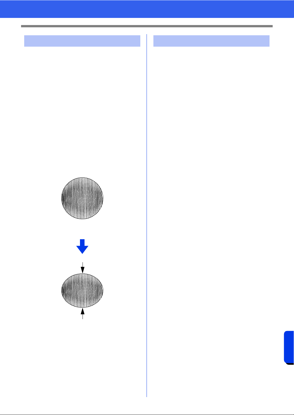
364
Supplement
For Basic Operations
• For best sewing results, set [Under sewing] to
[On] when sewing wide regions.
cc For more details, refer to "Under sewing"
on page 388.
• Changing the [Sewing Direction] setting
prevents pulling-in or puckering of the stitching.
• When embroidering, use stabilizer material
specifically for embroidering. Always use
stabilizer material when embroidering lightweight
or stretch fabrics, otherwise the needle may bend
or break, the stitching may pull and pucker, or the
pattern may become misaligned.
• When satin stitching is sewn in a wide area, the
stitched area may shrink after sewing, depending
on the material and the type of thread used. If this
happens, switch to this alternate method: Select
the fill stitch and use stabilizer material on the
reverse side of the fabric.
• For better results, check the following points.
Keep the distance of each point in sewing stitch
patterns to within around 2.0 mm.
cc "Displaying needle drop points" on
page 360
Avoid having the needle drop points too far
away from main area.
cc "Main area" on page 358
• However, the final result also depends on your
sewing machine. We recommend that you make a
trial sewing sample with your sewing data before
sewing on the final material.
Sewing Wide Areas
Pattern
After sewing
Sewing Stitch Patterns
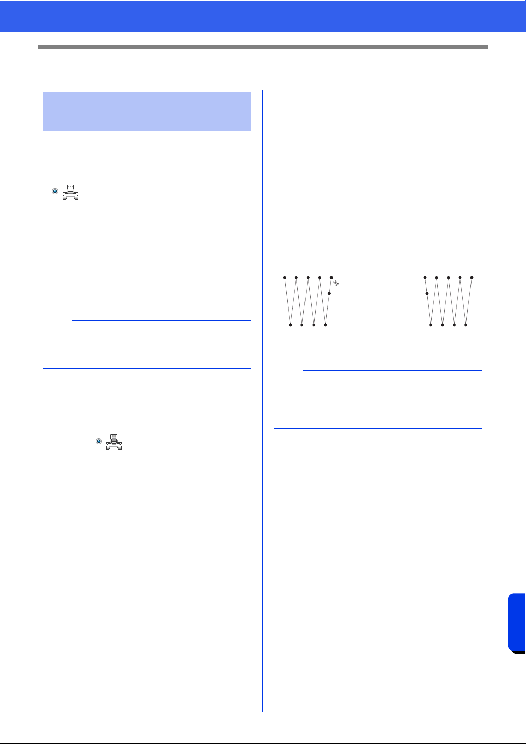
365
Supplement
On Settings
On Settings
■ Machine thread trimming
according to settings specified in
Layout & Editing
If is selected in the [Design Settings] dialog
box of Layout & Editing, trimming can be turned on
or off at each jump stitch location.
These settings are saved in embroidery data files
(.pes).
If you are using our multi-needle embroidery
machine with the Jump Stitch Trimming function
turned on to embroider this imported .pes file, the
machine will trim the thread according to the PES
data settings.
■ Specifying trimming settings in
Layout & Editing
1 Select in the [Design Settings] dialog
box.
cc "Specifying the Design Page Settings" on
page 16
2 Display the trimming locations in Layout &
Editing.
cc Memo of "Changing the display of the
embroidery design" on page 88
3 Turn on/off jump stitch trimming for each
embroidery pattern.
cc "Jump Stitch Trimming" on page 98
If necessary, change settings for the
following.
• Automatically turning off trimming when the
jump stitch length is less than that
specified.
cc "Jump Stitch Trimming" on page 98 and
"About Minimum jump stitch length for
thread trimming" on page 98
• Default setting for turning on/off jump stitch
trimming when a new embroidery pattern is
created.
cc "Adding jump stitch trimming to new
patterns" on page 370
1 Stitching
2 Jump stitch
Jump Stitch and Jump
Stitch Trimming
a
For details on the jump stitch trimming function of
the machine, refer to the instruction manual
provided with your embroidery machine.
a
These settings are applied only when
embroidering with our multi-needle embroidery
machines. These settings are not applied with any
other embroidery machine.
1 2 1
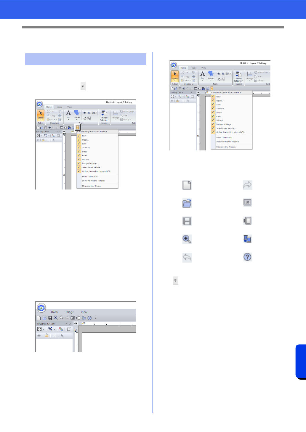
366
Supplement
Changing Various Settings
Changing Various Settings
■ Quick Access Toolbar/Ribbon
A menu appears when in the [Quick Access
Toolbar] is clicked.
Click [More commands] to add or remove the
commands appearing in the list of the [Quick
Access Toolbar].
Click [Show Above the Ribbon] to move the
[Quick Access Toolbar] above the Ribbon. To
return it to its original position, display the menu as
described above, and then click [Show Below the
Ribbon].
If a check mark appears beside [Minimize the
Ribbon], the Ribbon is minimized. When a tab is
clicked, the Ribbon appears. After a command is
selected, the Ribbon is minimized again. To restore
it to its original display, clear the check mark.
Example: With [Show Below the Ribbon] selected
and a check mark beside [Minimize the Ribbon]
■ Quick Access Toolbar commands
The first time this application is started up, the
following commands appear in the Quick Access
Toolbar.
Click , then select or unselect the check boxes
beside the commands to switch between displaying
and hiding them. When the check mark is cleared,
the command is hidden. Alternatively, changes to
the commands listed in the [Quick Access
Toolbar] can be specified in the [Options] dialog
box and all applied at the same time.
cc "Customizing Quick Access Toolbar" on
page 368
Customizing the window
: New : Redo
: Open
: Wizard
: Save
: Design Settings
: Zoom In
: Select Color Palette
: Undo
: Online Instruction Manual
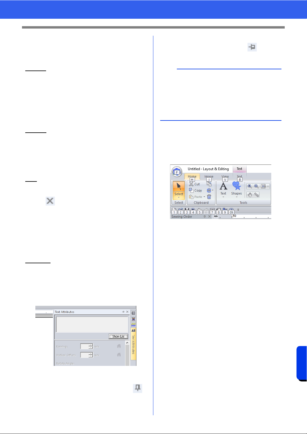
367
Supplement
Changing Various Settings
■ Import/Color/Sewing Attributes/
Text Attributes pane, Sewing
Order pane and Stitch Simulator
pane
Floating
Each tab or the entire pane can be undocked to
become a dialog box that can be moved around the
screen.
• Double-click the title bar of the pane, or tab.
• Right-click the pane or tab, and then click
[Floating].
• Drag a tab out of the pane.
Docking
Each pane can be docked back to the window.
• Double-click the title bar.
• Right-click the pane, and then click [Docking].
• Drag the title bar to the location where the pane
will be docked.
Hide
When a tab or a pane is no longer needed, it can be
hidden.
• Click in the upper-right corner of the dialog
box.
• Right-click the tab or dialog box, and then click
[Hide].
• To hide the tab, click [View] tab in the Ribbon,
and then click the name in the [View] tab. To
display the tab again, perform the same
operation.
Auto Hide
When a pane is temporarily not needed, it can be
moved to the side bar, then displayed by clicking it
or positioning the pointer over it. The pane is
automatically hidden again when it is no longer
being used, for example, when you click anywhere
outside of the pane.
• Right-click the tab or the title bar of the pane, and
then click [Auto Hide].
• In the upper-right corner of the pane, click .
To cancel Auto Hide, right-click the title bar, and
then click [Auto Hide], or simply click in the title
bar.
■ Using access keys
When the <Alt> key is pressed, a KeyTip (label
showing the letter of the access key) appears on
each command. On the keyboard, press the key
corresponding to the command that you wish to use.
To stop using the access keys and hide the
KeyTips, press the <Alt> key.
b
• The Stitch Simulator pane cannot be temporarily
hidden (Auto Hide).
• These panes can be returned to their default
displays.
cc "Customizing User Interface Settings" on
page 371
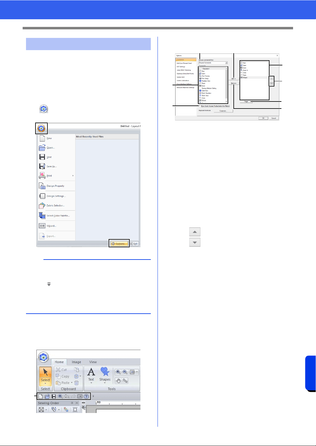
368
Supplement
Changing Various Settings
From the [Options] dialog box, the commands
appearing in the [Quick Access Toolbar] and
settings for the application's appearance can be
selected, and also the settings on shortcut keys,
jump stitches, thread charts can be specified or
changed. Follow the procedure described below to
display the [Options] dialog box.
Click , and then click [Options] on the bottom of
the window.
■ Customizing Quick Access
Toolbar
1 Quick Access Toolbar
1 Click [Customize].
2 Repeat the following operations until the
desired commands are displayed.
a Choose commands from selector
Select a command category.
b Commands list
Select the command to be added.
c Add button
Selected command is added.
The command appears in A.
d Remove button
Selected command is removed.
The command is removed from A.
e
Select an icon in A, and then click the
buttons to move it to the desired position.
f Reset button
Reverting to the default commands.
Settings for the following can also be specified
from this dialog box.
g Show Quick Access Toolbar Below the
Ribbon
Select where the Quick Access Toolbar is
displayed. Select the check box to display
the Quick Access Toolbar below the
Ribbon.
3 After the settings have been specified, click
[OK] to apply them.
Changing options settings
b
The [Options] dialog box can also be displayed
using either of the following methods.
• Click at the right end of the Quick Access
Toolbar, and then click [More Commands].
•Click [Option] in the upper-right corner of the
window, and then click [Options].
1
A
a
b
g
e
f
c
d
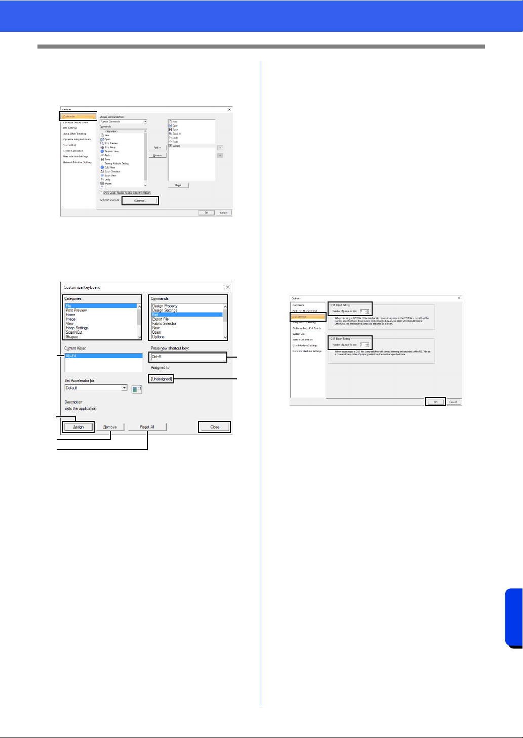
369
Supplement
Changing Various Settings
■ Customizing Shortcut keys
1 Click [Customize] in the command list, then
[Customize] beside [Keyboard shortcuts].
2 In the [Categories] list, select a command
category. Then, in the [Commands] list,
select the command whose shortcut keys are
to be specified.
The default shortcut keys appear in the
[Current Keys] box a.
3 Use the keyboard to record the new shortcut
keys in the [Press new shortcut key]
b box,
and then click [Assign]
d. The new shortcut
keys appear in the [Current Keys] box
a.
Usage information about the entered key
combination appears. If the key
combination has already been assigned to
another command, the name of that
command appears at
c.
To remove the default or specified shortcut
keys, select the shortcut keys in
a, and then
click [Remove]
e.
To revert to the default settings, click [Reset
All]
f.
4 Repeat steps 2 and 3 until the desired
shortcut keys have been specified for the
commands, and then click [Close].
5 Click [OK] in the [Options] dialog box.
■ Editing user thread charts
For detailed instructions, see "Editing user thread
color lists" on page 213.
■ Specifying the number of jumps in
embroidery design of the DST
format
With the DST format, you can specify whether or not
the jump stitches are trimmed according to the
number of jump codes. The number of codes differs
depending on the embroidery machine being used.
Click [DST Settings] in the command list, specify
the number of jumps, and then click [OK].
To specify a setting for importing, enter a value
beside [DST Import Setting]. To specify a setting
for exporting, enter a value beside [DST Export
Setting].
DST Import Setting
If the number of consecutive jumps in the DST
file is less than the number of jumps specified
here, those consecutive jumps will be
replaced with a stitch.
If the number of consecutive jumps in the DST
file is greater than or equal to the number of
jumps specified here, those jumps will be
replaced with a jump stitch where the thread is
trimmed.
DST Export Setting
When .pes files are output, jump stitches with
thread trimming are replaced with more
consecutive jump codes than the specified
number of jumps.
a
e
d
f
b
c
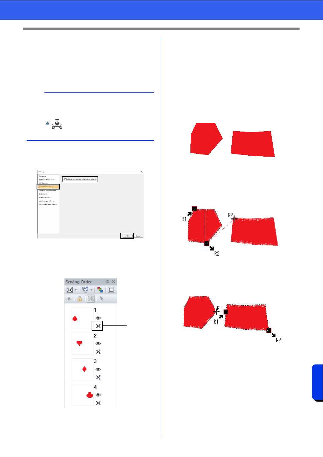
370
Supplement
Changing Various Settings
■ Adding jump stitch trimming to
new patterns
When creating a new embroidery pattern for our
multi-needle embroidery machines, you can specify
whether or not to add jump stitch trimming to the
pattern.
Click [Jump Stitch Trimming] in the command list,
select the [Add jump stitch trimming to the
entered patterns.] check box, and then click [OK].
When the check box is selected, scissors
icon appear beside the frames to indicate
jump stitch trimmings are applied.
1 Scissors icon
■ Optimize Entry/Exit Points
When data for multiple regions is created with a
[Shapes] tool, the exit and entry points between
regions of the same color can be automatically
optimized.
Click [Optimize Entry/Exit Points] in the command
list, select the [Optimize Entry/Exit Points.] check
box, and then click [OK].
If data is created by clicking in the order shown
below:
When the check box is cleared
The entry and exit points are set based on the order
that the data was entered.
When the check box is selected
The entry and exit points are set where a straight
line connecting the regions will be the shortest.
■ Changing the system unit
For detailed instructions, see "System unit" on
page 22.
■ Adjusting the screen calibration
For detailed instructions, see "Adjusting on-screen
measurements (Screen Calibration)" on page 21
a
These settings are applied only when
embroidering with our multi-needle embroidery
machines. Before these settings can be specified,
select under [Machine Type] in the
[Design Settings] dialog box.
1
1
2
3
4
5
6
7
8
9
0
A
B
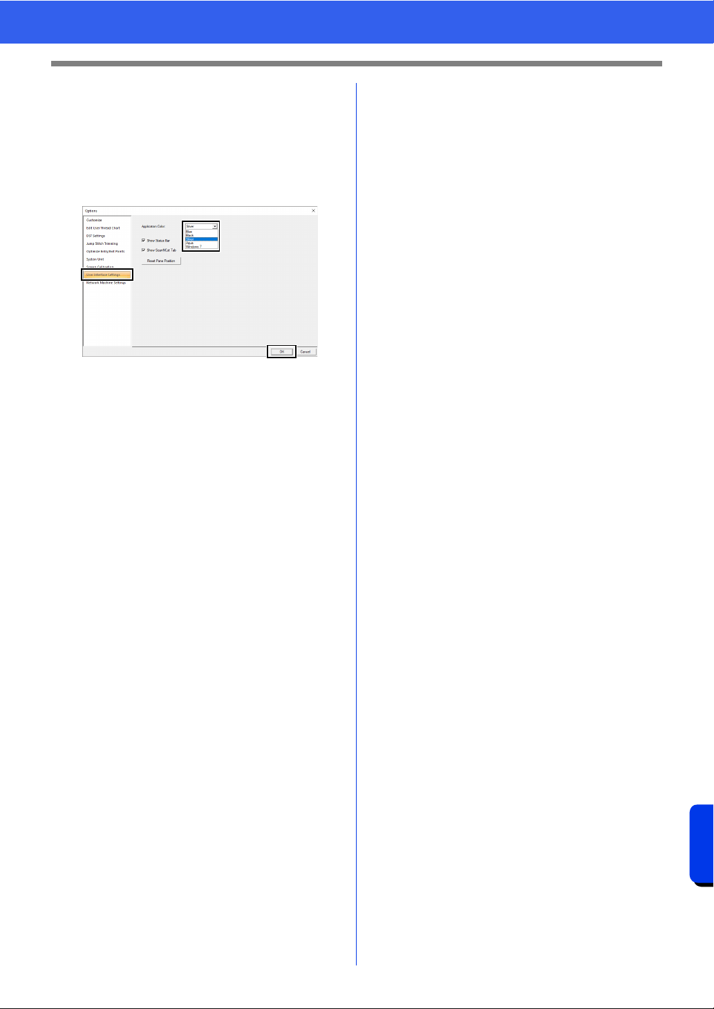
371
Supplement
Changing Various Settings
■ Customizing User Interface
Settings
The color scheme of the applications can be
selected.
Click [User Interface Settings] in the command list,
select the desired color scheme from [Application
Color], and then click [OK].
With the [Show Status Bar] check box, select
whether to display or hide the status bar. To display
the status bar, select the check box.
With the [Show ScanNCut Tab] check box, select
whether to display or hide the [ScanNCut] tab. To
display the [ScanNCut] tab, select the check box.
If the [Reset Pane Position] button is clicked, the
docked panes ([Import]/[Color]/[Sewing
Attributes]/[Text Attributes] panes, [Sewing
Order] pane and [Stitch Simulator] pane) return to
their default displays after the application is
restarted.
■ Network Machine Settings
For detailed instructions, see "Transferring to a
machine via wireless network" on page 224.
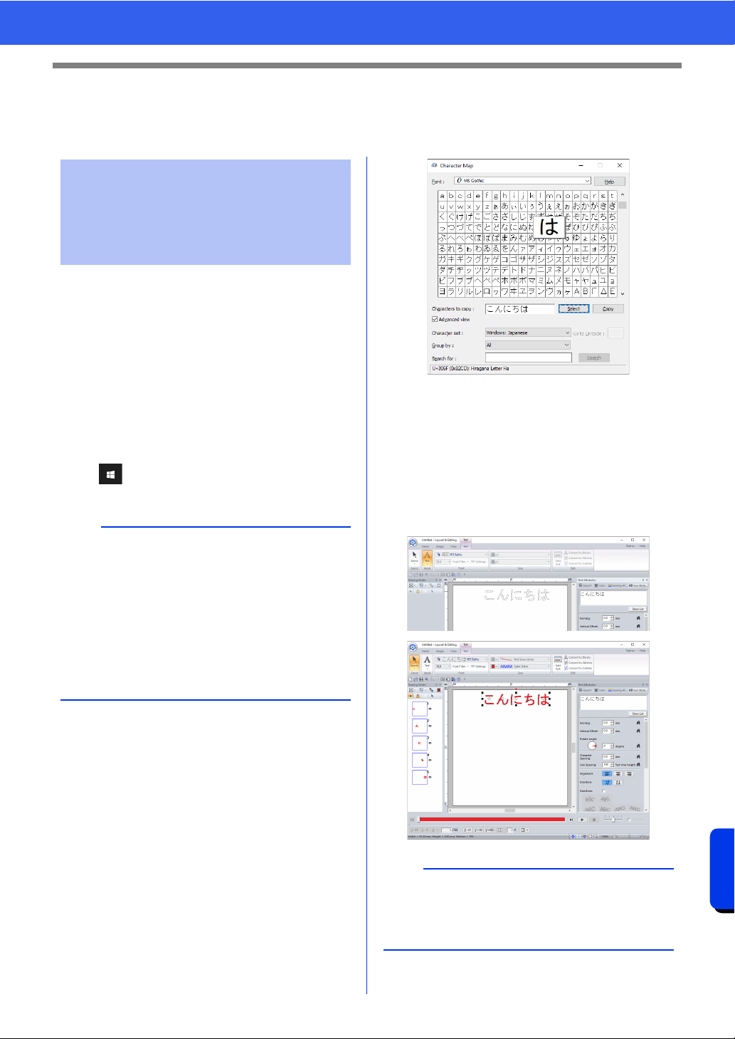
372
Supplement
For Making an Effective Use of This Application
For Making an Effective Use of This
Application
Embroidery patterns can be created from various
characters, such as Japanese, Chinese, Korean
etc, using TrueType fonts.
For this example, we will create an embroidery
pattern from Japanese characters.
1 Start up Layout & Editing.
2 Select a Text tool, and then select a Japanese
TrueType font (for example, "MS Gothic").
3 Display the character map on the computer.
( – [Windows Accessories] –
[Character Map])
4 Select [MS Gothic] from the [Font] list in
[Character Map], and then select the
[Advanced view] check box. Next, select
[Windows: Japanese] from the [Character
set] list, select the desired character, and then
click [Select].
(This example shows the Japanese hiragana
for the word meaning "Good Afternoon".)
5 After selecting all of the desired characters,
click [Copy] to copy the characters.
6 Click in the Design Page where you want to
enter the text.
7 Paste the characters into the text field in the
[Text Attributes] pane, and then press the
<Enter> key.
Converting Characters
(Japanese, Chinese,
Korean, etc) to Embroidery
Patterns
b
• For Windows 8.1 users: Position the mouse
pointer in the [Start] screen to display the down
arrow in the lower-left corner of the screen
(below and left of the tiles), and click it.
From the list of applications that appears in the
screen, click [Character Map] under the title
[Windows Accessories].
• For Windows 7 users: [Start] – [All Programs]
– [Accessories] – [System Tools] –
[Character Map]
b
If Japanese or Korean can be entered directly from
the computer keyboard, those characters can be
entered directly into the [Edit Text Letters] dialog
box.
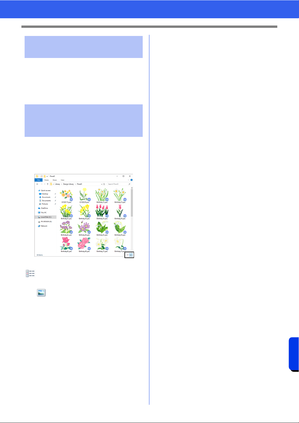
373
Supplement
For Making an Effective Use of This Application
■ When converting TrueType fonts
to embroidery patterns
For best results when converting TrueType fonts to
embroidery patterns, select a font where all lines are
as thick as possible, such as with a Block font.
Embroidery files in PES format can be viewed as
thumbnails with Explorer (Windows Explorer in
Windows 7 and File Explorer in Windows 8.1/10). It
helps you to manage embroidery designs more
easily.
To display information on embroidery files, click
.
To display embroidery files by using thumbnails,
click .
Fonts Suitable for
Embroidering
Displaying the embroidery
designs in PES format as
thumbnails

Reference
This section contains font samples and
information on the various sewing attributes.
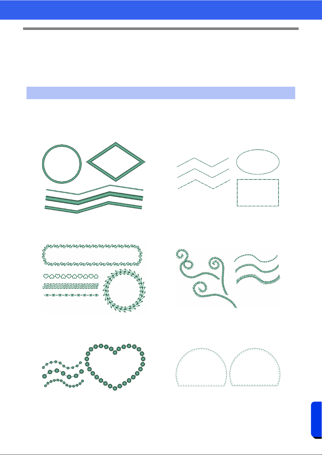
375
Reference
Sewing Attributes
Sewing Attributes
The sewing attributes for each sew type are first set to their default settings; however, by changing the settings
of the sewing attributes, you can create custom stitching.
cc For more details, refer to "Line sewing attributes" on page 382 and "Region sewing attributes" on
page 388.
Line sew types
Zigzag Stitch
cc "Zigzag Stitch" on page 382
Running Stitch/Triple Stitch
cc "Running Stitch" on page 382
cc "Triple Stitch" on page 382
Motif Stitch
cc "Motif Stitch" on page 383
Stem Stitch
cc "Stem Stitch" on page 384
Candlewicking Stitch
cc "Candlewicking Stitch" on page 384
E/V Stitch
cc "E/V Stitch" on page 385
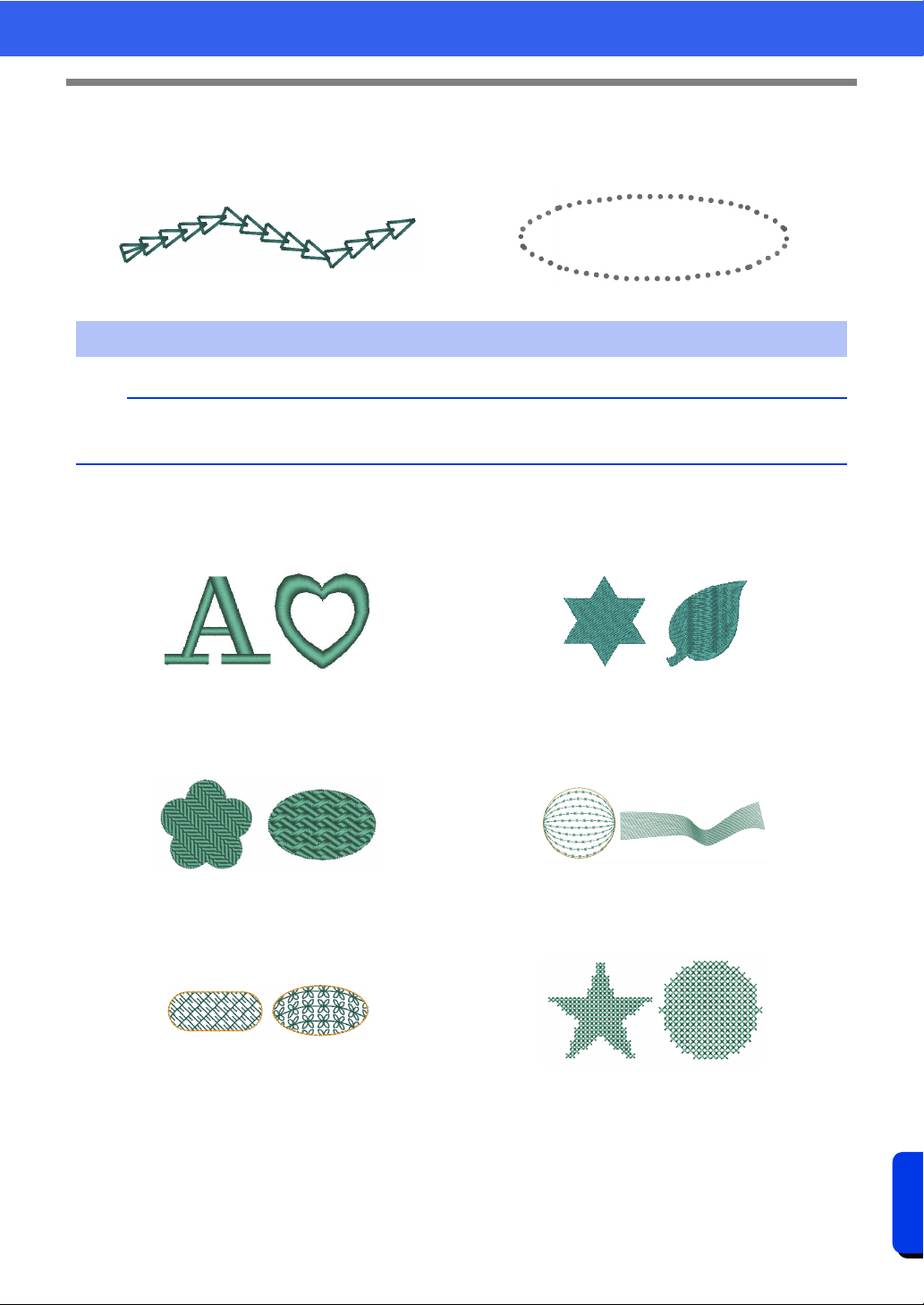
376
Reference
Sewing Attributes
Chain Stitch
cc "Chain Stitch" on page 386
Cutting
cc "Cutting" on page 386
Region sew types
b
The patterns of the programmable fill stitches, motif stitches and decorative fill stitches differ depending on
the selected stitch pattern.
Satin Stitch
cc "Satin Stitch" on page 388
Fill Stitch
cc "Fill Stitch" on page 390
Programmable Fill Stitch (Prog. Fill Stitch)
cc "Programmable Fill Stitch (Prog. Fill Stitch)" on
page 391
Piping Stitch
cc "Piping Stitch" on page 394
Motif Stitch
cc "Motif Stitch" on page 395
Cross Stitch
cc "Cross Stitch" on page 396
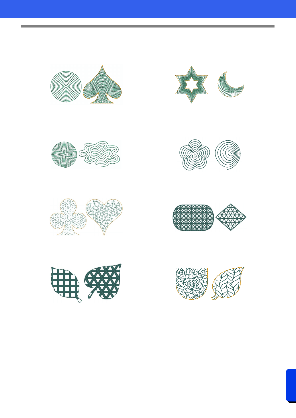
377
Reference
Sewing Attributes
Concentric Circle Stitch
cc "Concentric Circle Stitch, Radial Stitch and
Spiral Stitch" on page 396
Radial Stitch
cc "Concentric Circle Stitch, Radial Stitch and
Spiral Stitch" on page 396
Spiral Stitch
cc "Concentric Circle Stitch, Radial Stitch and
Spiral Stitch" on page 396
Flexible Spiral Stitch
cc "Flexible Spiral Stitch" on page 396
Stippling Stitch
cc "Stippling Stitch" on page 397
Net Fill Stitch
cc "Net Fill Stitch" on page 397
Zigzag Net Fill Stitch
cc "Zigzag Net Fill Stitch" on page 398
Decorative Fill Stitch
cc "Decorative Fill Stitch" on page 399
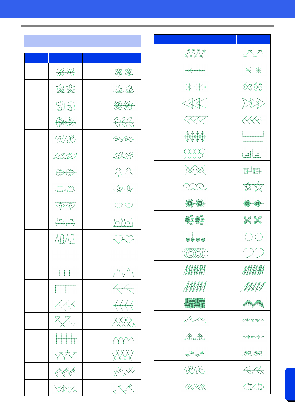
378
Reference
Sewing Attributes
Motif Stitch Pattern
Name Pattern Name Pattern
motif001 motif002
motif003 motif004
motif005 motif006
motif007 motif008
motif009 motif010
motif011 motif012
motif013 motif014
motif015 motif016
motif017 motif018
motif019 motif020
motif021 motif022
motif023 motif024
motif025 motif026
motif027 motif028
motif029 motif030
motif031 motif032
motif033 motif034
motif035 motif036
motif037 motif038
motif039 motif040
motif041 motif042
motif043 motif044
motif045 motif046
motif047 motif048
motif049 motif050
motif051 motif052
motif053 motif054
motif055 motif056
motif057 motif058
motif059 motif060
motif061 motif062
motif063 motif064
motif065 motif066
motif067 motif068
motif069 motif070
motif071 motif072
motif073 motif074
motif075 motif076
motif077 motif078
motif079 motif080
motif081 motif082
Name Pattern Name Pattern
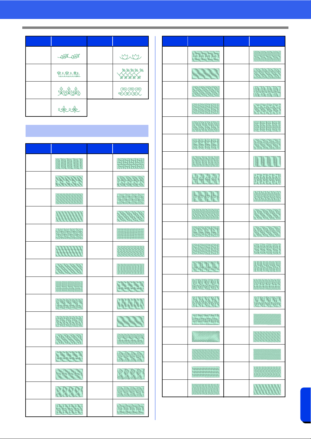
379
Reference
Sewing Attributes
motif083 motif084
motif085 motif086
motif087 motif088
motif089
Prog. Fill Stitch Pattern
Name Pattern Name Pattern
net1 net2
net3 net4
pat1 pat2
pat3 pat4
pat5 pat6
pat7 pat8
pat9 pat10
pat11 pat12
pat13 pat14
pat15 pat16
pat17 stamp1
stamp1_ stamp2
stamp2_ stamp3
stamp3_ stamp4
stamp4_ stamp5
Name Pattern Name Pattern
stamp5_ stamp6
stamp6_ stamp7
stamp7_ stampA
stampB stampC
stampD stampE
stampF stampG
stampH stampI
stampJ stampK
stampL stampM
stampN stampO
stampP stampQ
stampR stampS
stampT stampU
stampV stampW
stampX stampY
stampZ tatami1
tatami2 tatami3
tatami4 tatami5
wave1 wave2
wave3 wave4
Name Pattern Name Pattern
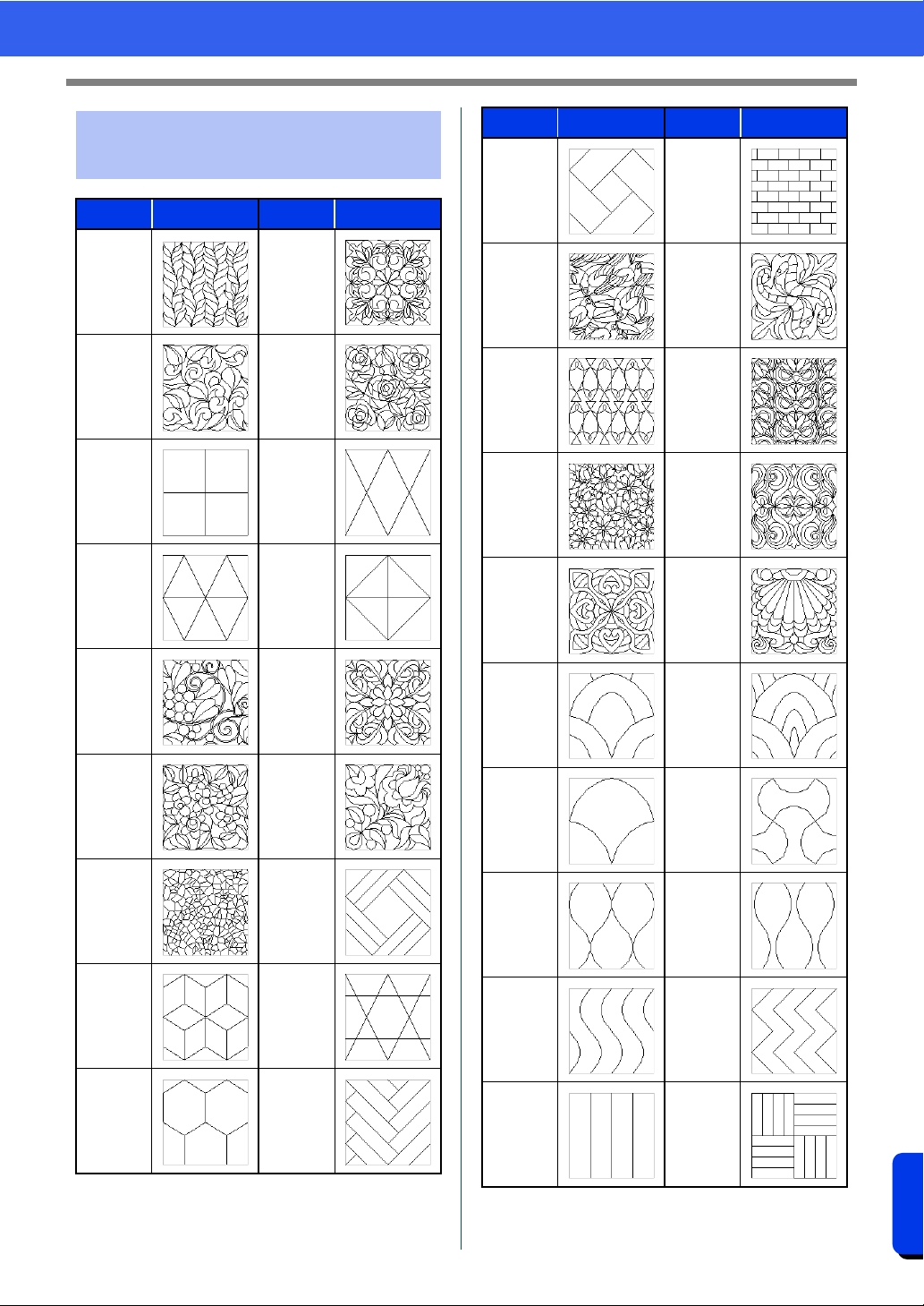
380
Reference
Sewing Attributes
Decorative Fill Stitch
Pattern
Name Pattern Name Pattern
df_pat001 df_pat002
df_pat003 df_pat004
df_pat005 df_pat006
df_pat007 df_pat008
df_pat009 df_pat010
df_pat011 df_pat012
df_pat013 df_pat014
df_pat015 df_pat016
df_pat017 df_pat018
df_pat019 df_pat020
df_pat021 df_pat022
df_pat023 df_pat024
df_pat025 df_pat026
df_pat027 df_pat028
df_pat029 df_pat030
df_pat031 df_pat032
df_pat033 df_pat034
df_pat035 df_pat036
df_pat037 df_pat038
Name Pattern Name Pattern
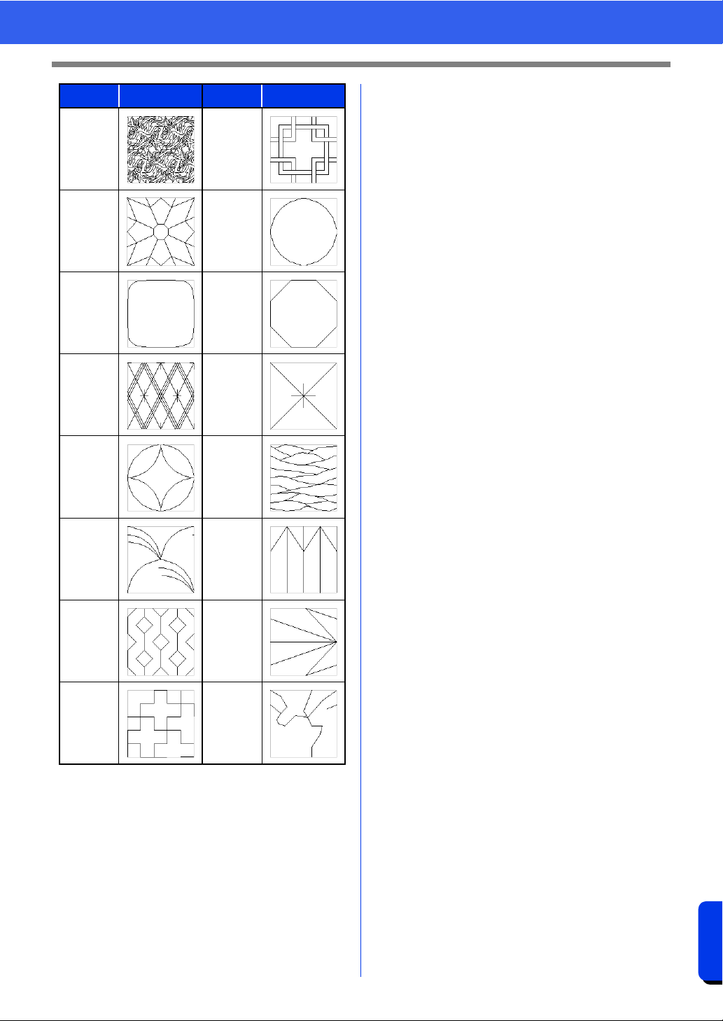
381
Reference
Sewing Attributes
df_pat039 df_pat040
df_pat041 df_pat042
df_pat043 df_pat044
df_pat045 df_pat046
df_pat047 df_pat048
df_pat049 df_pat050
df_pat051 df_pat052
df_pat053 df_pat054
Name Pattern Name Pattern
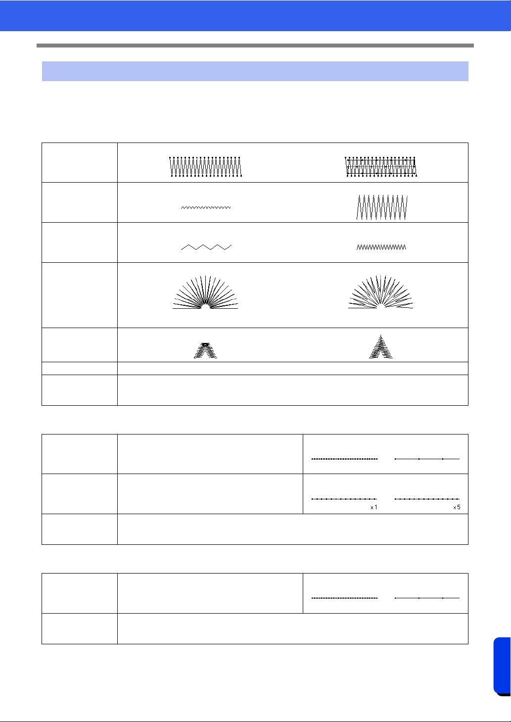
382
Reference
Sewing Attributes
The available attributes differ depending on the selected sew type.
cc "Specifying sewing attributes" on page 64
Zigzag Stitch
Running Stitch
Triple Stitch
Line sewing attributes
Under sewing
Off On
Zigzag width
Narrow Wide
Density
Coarse Fine
Half Stitch
Off
The inside stitching is dense.
On
The stitching is adjusted to a more even density.
Sharp Corners
Miter limit Specify the sharpness of corners in zigzag stitching.
Connection
Points
This sewing attribute is available only when a text pattern is selected.
cc "Selecting connection point positions in a text pattern" on page 127
Run pitch Specify the length of one stitch.
Short Long
Run time(s) Specify the number of times the outline is sewn.
1 time 5 times
Connection
Points
This sewing attribute is available only when a text pattern is selected.
cc "Selecting connection point positions in a text pattern" on page 127
Run pitch Specify the length of one stitch.
Short Long
Connection
Points
This sewing attribute is available only when a text pattern is selected.
cc "Selecting connection point positions in a text pattern" on page 127
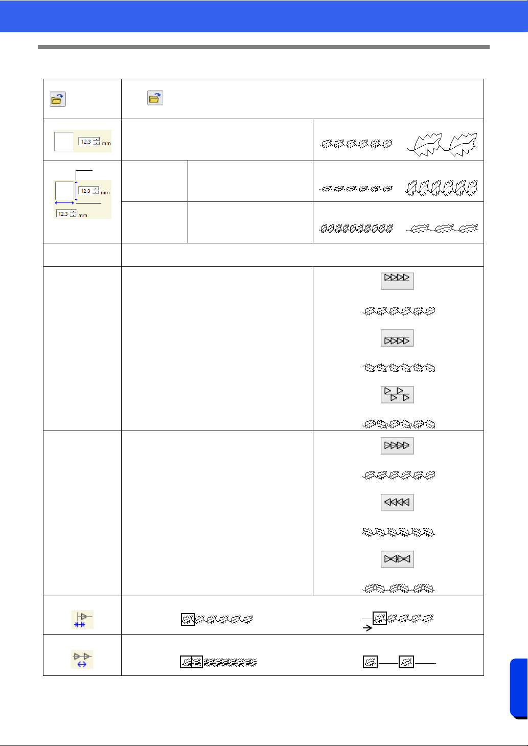
383
Reference
Sewing Attributes
Motif Stitch
Select a pattern for the motif stitch.
Click to display the [Browse] dialog box. Select a folder, and then select the desired pattern
(.pmf file) from the list of patterns that appears.
Specify the pattern size. The pattern can be
enlarged or reduced while maintaining the width-to-
height proportion.
Smaller Larger
1 Height
(vertical length)
Specify the pattern height.
Short Tall
2 Width
(horizontal
length)
Specify the pattern width.
Short Long
Maintain aspect
ratio
When selected, the height-to-width proportions of the pattern are maintained.
H-Arrange
(horizontal
arrangement)
Specify the arrangement of the patterns along a
horizontal axis.
All patterns or each pattern can be flipped along the
horizontal axis.
Normal
Mirror
Alternate
V-Arrange
(vertical
arrangement)
Specify the arrangement of the patterns along a
vertical axis.
All patterns or each pattern can be flipped along the
vertical axis.
Normal
Mirror
Alternate
Offset
0.0 mm
Offset: 4.5mm
Spacing
Narrow Wide
1
2
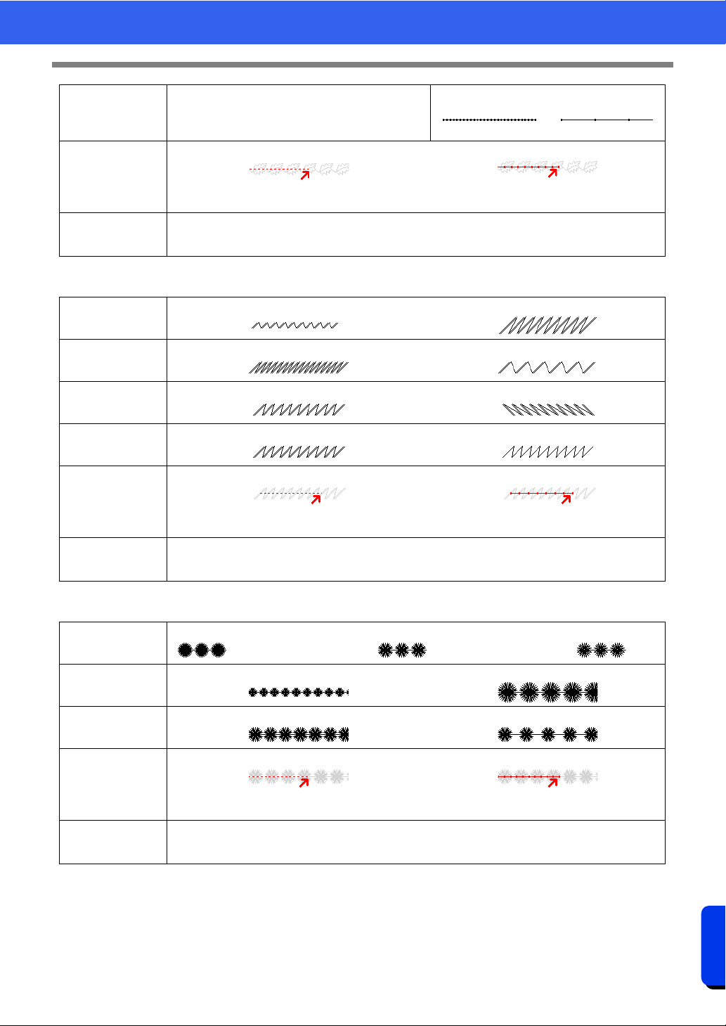
384
Reference
Sewing Attributes
Stem Stitch
Candlewicking Stitch
Run pitch Specify the length of one stitch.
Short Long
Start/End Type
Feed Run
cc "If the entry/exit points of sewing have been changed" on page 387
Connection
Points
This sewing attribute is available only when a text pattern is selected.
cc "Selecting connection point positions in a text pattern" on page 127
Width
Narrow Wide
Spacing
Narrow Wide
Angle
45° 135°
Stitch Type
Triple Single
Start/End Type
Feed Run
cc "If the entry/exit points of sewing have been changed" on page 387
Connection
Points
This sewing attribute is available only when a text pattern is selected.
cc "Selecting connection point positions in a text pattern" on page 127
Density
Dense Medium Light
Size
Smaller Larger
Spacing
Narrow Wide
Start/End Type
Feed Run
cc "If the entry/exit points of sewing have been changed" on page 387
Connection
Points
This sewing attribute is available only when a text pattern is selected.
cc "Selecting connection point positions in a text pattern" on page 127
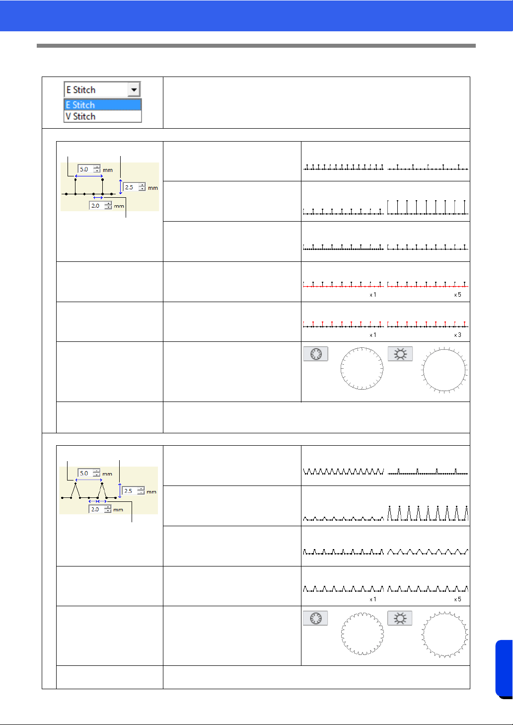
385
Reference
Sewing Attributes
E/V Stitch
Select the E Stitch or the V Stitch.
E Stitch
1 Interval
Narrow Wide
2 Stroke width
Short Long
3 Run pitch
Narrow Wide
Run time(s)
Specify the number of times the line
is sewn.
1 time 5 times
Stroke time(s)
Specify the number of times each
stroke is sewn.
1 time 3 times
Arrange
Connection Points
This sewing attribute is available only when a text pattern is selected.
cc "Selecting connection point positions in a text pattern" on page 127
V Stitch
1 Interval
Narrow Wide
2 Stroke width
Short Long
3 Run pitch
Narrow Wide
Run time(s)
With the V stitch, the line and the
strokes are sewn the same number
of times.
1 time 5 times
Arrange
Connection Points
This sewing attribute is available only when a text pattern is selected.
cc "Selecting connection point positions in a text pattern" on page 127
1
2
3
12
3
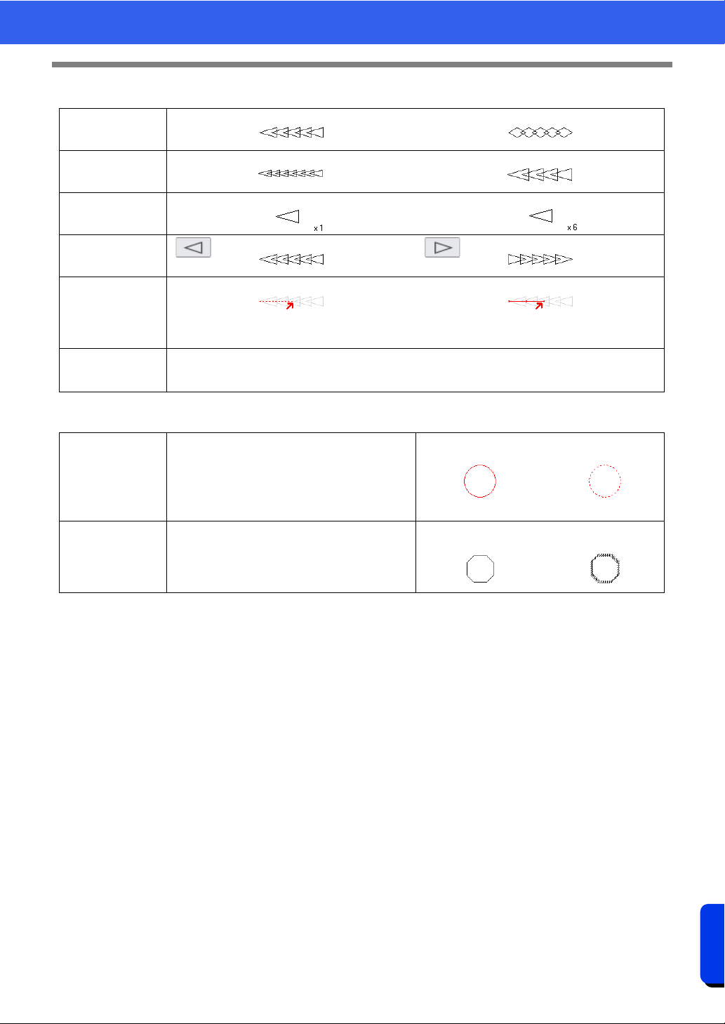
386
Reference
Sewing Attributes
Chain Stitch
Cutting
Stitch Type
Triangular Diamond-shaped
Size
Smaller Larger
Time
1 time 6 time
Arrange
Start/End Type
Feed Run
cc "If the entry/exit points of sewing have been changed" on page 387
Connection
Points
This sewing attribute is available only when a text pattern is selected.
cc "Selecting connection point positions in a text pattern" on page 127
Leave uncut
sections
Specify whether or not sections of the cutting
line are to be left uncut.
This prevents the fabric from moving out of
place during cutting.
If it is set to [On], cut them with scissors after
the cutting step is finished.
Off On
Use
For more cleanly cut edges, for example, on
patches, select [Cutting only]. If the cut edge
will be embroidered, for example, on appliqués,
select [Cutting for covering edge of fabric].
Cutting only
Cutting for covering
edge of fabric
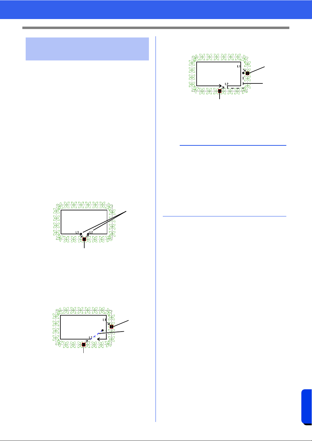
387
Reference
Sewing Attributes
If the entry/exit points of line sewing with the motif
stitch, stem stitch, candlewicking stitch or chain
stitch have been changed or optimized, select a
setting for [Start/End Type] in the line sewing
attributes.
cc "Start/End Type" on page 384 and
"Moving entry/exit points, the center point
and stitch pattern reference point" on
page 58
If [Feed] was selected under [Start/End Type],
jump stitches are entered at the beginning or end of
pattern stitching (with a motif stitch, stem stitch,
candlewicking stitch or chain stitch). If [Run] was
selected under [Start/End Type], running stitches
following the path are entered at the beginning of
and between pattern stitching.
Before the entry/exit points are changed
1 Path of actual stitching
2 Entry point/Exit point
When the entry point is moved
Feed
1 Entry point
2 Jump stitch
3 Exit point
Run
1 Entry point
2 Running stitch
3 Exit point
If the entry/exit points of
sewing have been changed
1
2
2
1
3
a
• After changing the Start/End Type, check the
stitching with the stitch simulator.
cc "Checking the stitching with the Stitch
Simulator" on page 90
• Embroidery patterns where the Start/End Type
of line sewing with the motif stitch, have been
changed or optimized in an application earlier
than version 8 are opened or imported with this
stitching specified as jump stitches.
2
3
1
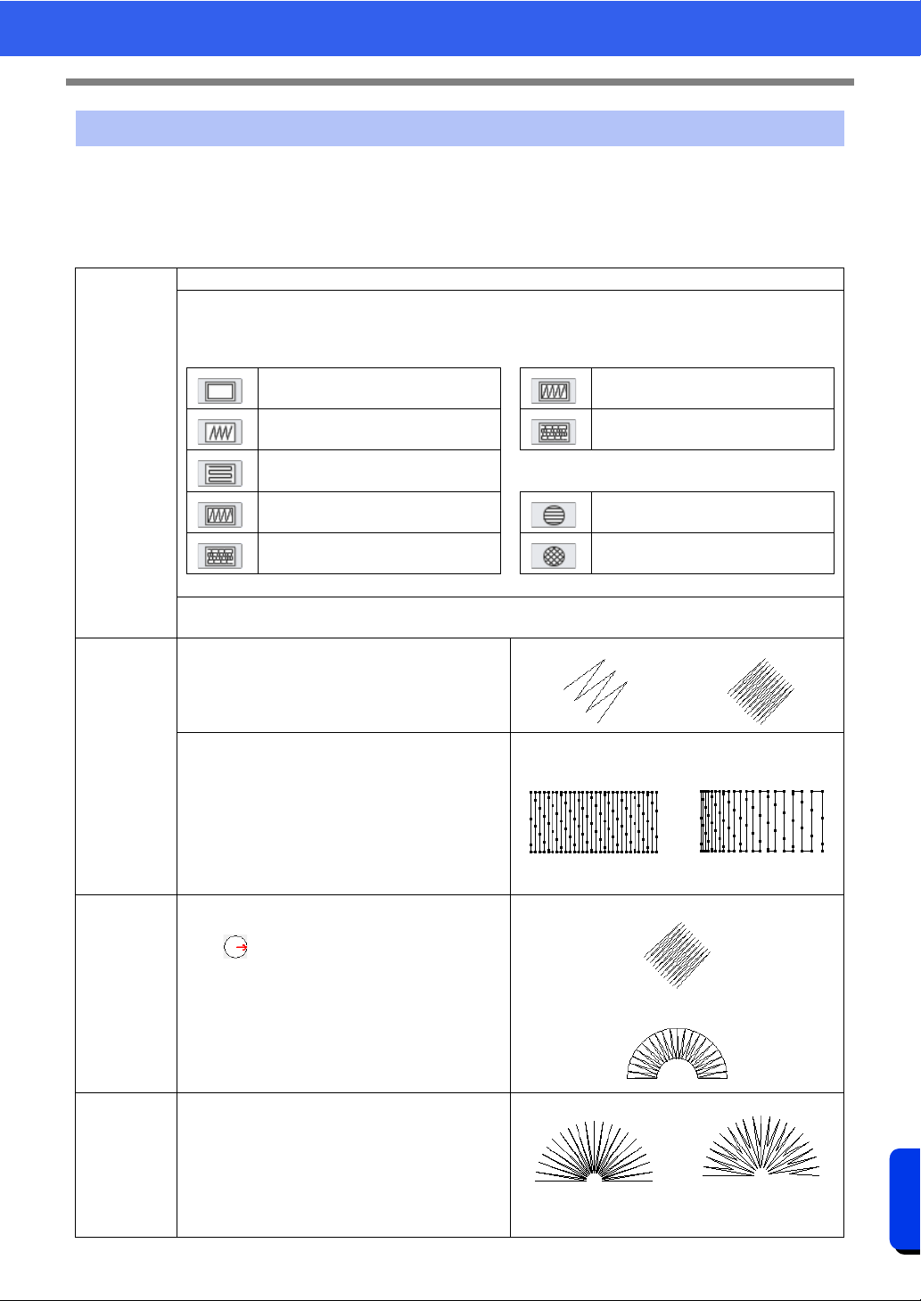
388
Reference
Sewing Attributes
The available attributes differ depending on the selected sew type.
cc "Specifying sewing attributes" on page 64
Satin Stitch
Region sewing attributes
Under
sewing
To specify underlay stitching, select the check box, and then specify settings for the following attributes.
Specify the type of underlay stitching to be sewn.
• For text patterns or for shape patterns with
multiple sewing direction lines
• For shape patterns with a single sewing direction
line
Edge only Single
Region only (single layer of zigzag
shaped stitches)
Double
Region only (single layer of piping
stitches)
• For regions in Design Center
Edge and region (single layer of
zigzag shaped stitches)
Single
Region only (double layer of zigzag
shaped and piping stitches)
Double
[Density]
Select [Dense], [Medium] or [Light] as the density for the underlay stitching.
Density
Coarse Fine
[Gradation]
This cannot be specified under the following
conditions.
• The sewing direction is set to [Variable]
• Text pattern
• When a feathered edge is specified
Click [Pattern] to set the gradation pattern.
cc "Creating a gradation/blending" on page 55
Off On
Direction
This cannot be specified for text pattern.
[Manual straight line]: Sews at a fixed angle.
Drag or select a value to specify the angle. If
there are multiple sewing direction lines, a value
cannot be specified for the angle.
[Manual straight line]
[Auto]: Automatically varies the sewing direction
according to the shape of the region.
[Auto]
Half Stitch
To specify half stitching, select the check box.
This cannot be specified if the sewing direction is
set to [Manual straight line] and there is only one
sewing direction line.
Off
The inside stitching is
dense.
On
The stitching is
adjusted to a more
even density.
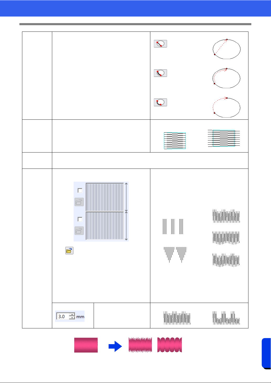
389
Reference
Sewing Attributes
1 Feathered edge settings not specified
2 Feathered edge settings specified
Running
Stitch Path
The inside of region setting is not available if the
[Gradation] check box is selected.
This cannot be specified under the following
conditions.
• The sewing direction is set to [Auto].
• Text patterns
• When a feathered edge is specified
Inside of region
Along outline
On outline
Pull com-
pensation
Lengthen the sewing region in the sewing direction
to adjust for pattern shrinkage during sewing.
No compensation
Longest compensation
Connection
Points
This sewing attribute is available only when a text pattern is selected.
cc "Selecting connection point positions in a text pattern" on page 127
Feathered
edge
Specify the edge of the stitching where the
feathered edge is to be applied.
Click to display the [Browse] dialog box.
Select the desired pattern from the list of patterns
that appears.
This sewing attribute is available only when a
shape pattern is selected. In addition, this attri-
bute cannot be selected under the following con-
ditions.
• When a gradation is specified
• When the sewing direction is set to [Auto]
• When hole sewing is specified
Top side of pattern
For <pattern11>
Bottom side of pattern
For <pattern18>
Top edge only
Bottom edge only
Top and bottom edges
Specify the width of the
feathered edge
Short Long
12
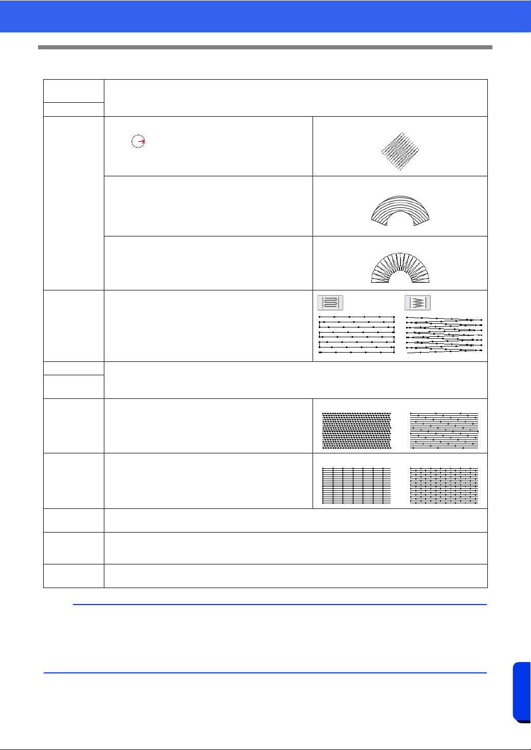
390
Reference
Sewing Attributes
Fill Stitch
Under
sewing
cc "Satin Stitch" on page 388
Density
Direction
[Manual straight line]: Sews at a fixed angle.
Drag or select a value to specify the angle. If
there are multiple sewing direction lines, a value
cannot be specified for the angle.
[Manual straight line]
[Manual curve]: Specify curved sewing direction line.
cc "Specifying curved sewing direction line" on
page 62
[Manual curve]
[Auto]: Automatically varies the sewing direction
according to the shape of the region.
[Auto]
Stitch Type
Specify the shape of the returning ends of the stitching.
This cannot be specified if the sewing direction is set to
[Auto].
Half Stitch
cc "Half Stitch" on page 388 and "Running Stitch Path" on page 389
Running
Stitch Path
Step pitch Specify the length of one stitch.
Short Long
Frequency
0% 50%
Pull com-
pensation
cc "Pull compensation" on page 389
Connection
Points
This sewing attribute is available only when a text pattern is selected.
cc "Selecting connection point positions in a text pattern" on page 127
Feathered
edge
cc "Feathered edge" on page 389
b
In [Design Center], the settings under [Direction] are as described below.
• [Manual straight line] appears as [Constant].
• [Auto] appears as [Variable].
• [Manual curve] does not exist.
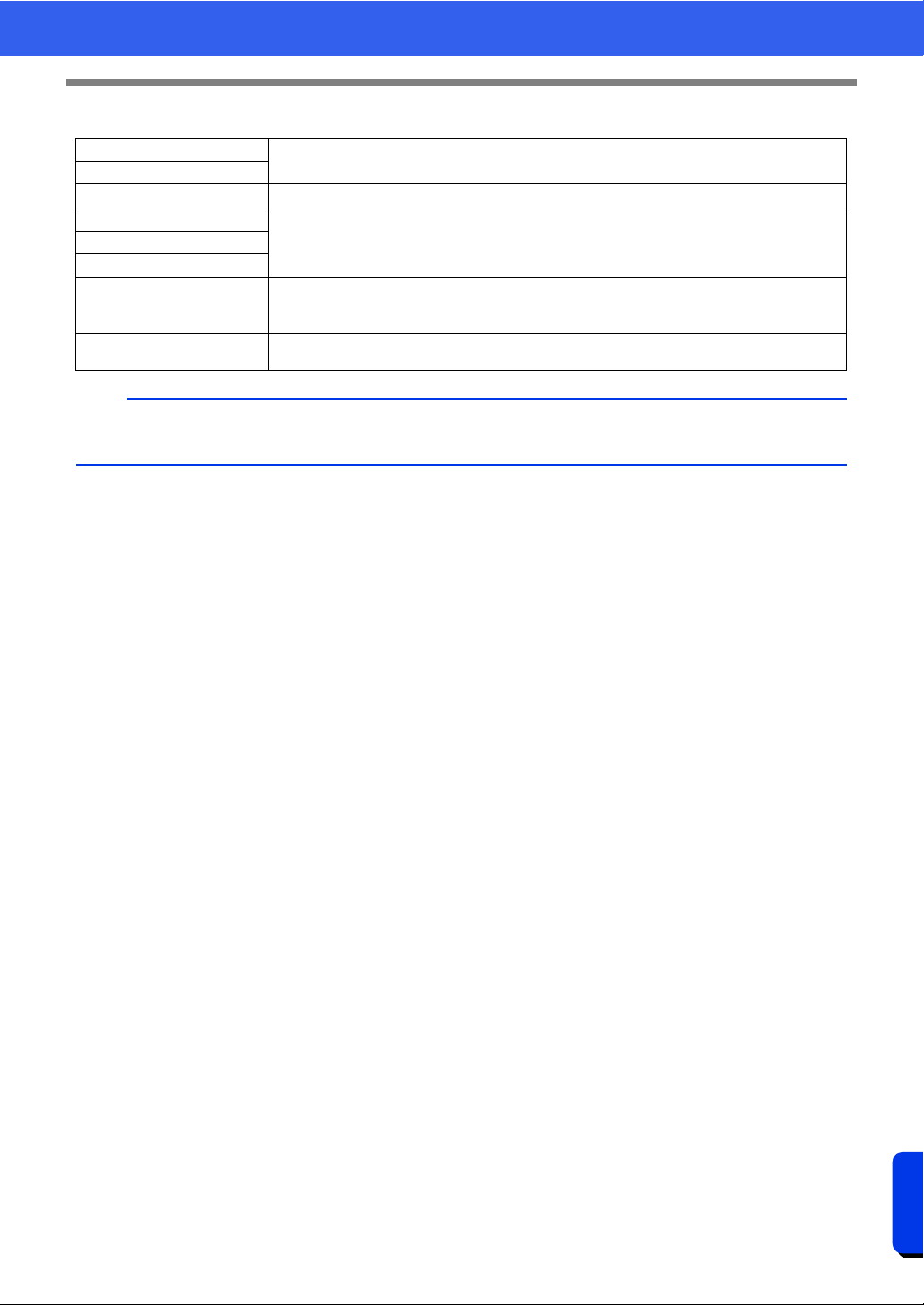
391
Reference
Sewing Attributes
Programmable Fill Stitch (Prog. Fill Stitch)
Under sewing
cc "Satin Stitch" on page 388
Density
Direction cc "Fill Stitch" on page 390
Half Stitch
cc "Satin Stitch" on page 388Running Stitch Path
Pull compensation
Connection Points
This sewing attribute is available only when a text pattern is selected.
cc "Selecting connection point positions in a text pattern" on page 127
Feathered edge
cc "Feathered edge" on page 389
b
We recommend specifying base stitching (selecting the [Base Sewing] check box) for a programmable fill
stitch when [Direction] is set to [Manual curve].
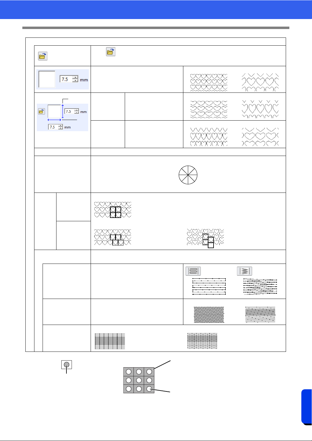
392
Reference
Sewing Attributes
1 Pattern
2 Area where the embossing or engraving effects are applied
3 This area is sewn with the stitching settings specified for the base sewing of the programmable fill stitch.
4 This area is sewn with the stitching settings specified by the pattern file.
Programmable fill
Click to display the [Browse] dialog box. Select a folder, and then select the desired
pattern (.pas file) from the list of patterns that appears.
Specify the pattern size. The pattern can
be enlarged or reduced while maintaining
the width-to-height proportion.
Smaller Larger
1 Height
(vertical
length)
Specify the pattern
height.
Short
Tall
2 Width
(horizontal
length)
Specify the pattern
width.
Short
Long
Maintain aspect ratio When selected, the height-to-width proportions of the pattern are maintained.
Direction
Offset
row
0%
column
Row 50% Column 50%
Base Sewing
To specify base stitching, select the check box, and then specify settings for the following
attributes.
Stitch Type
Specify the shape of the returning ends
of the stitching.
This cannot be specified if the sewing
direction is set to [Auto].
Step pitch Specify the length of one stitch.
Short
Long
Frequency
0% 50%
1
2
45°
0°
315°
90°
135°
180°
225°
270°
2
3
4
1
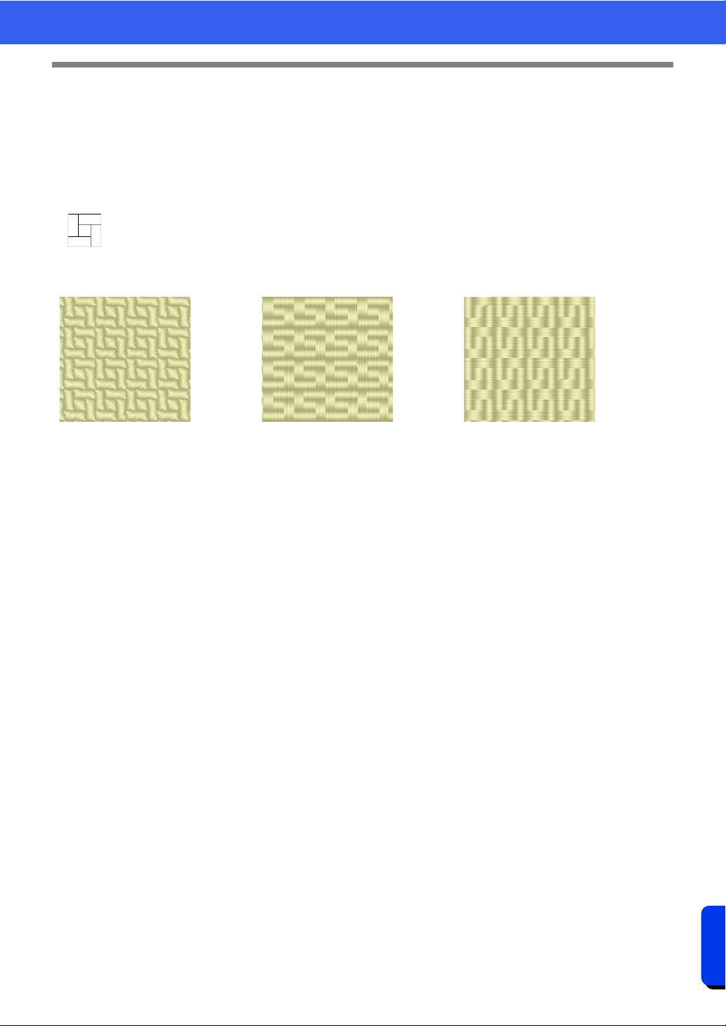
393
Reference
Sewing Attributes
Notes on programmable fill stitches and stamps
In some case of the sew type and pattern directions setting of a programmable fill stitch or a stamp, lines will
not be sewn.
Use the Realistic View to view exactly how the stitch pattern will be sewn. To get an even better view, make
test samples of different settings.
Examples of programmable fill stitching:
cc "Changing the display of the embroidery design" on page 88, and "Programmable Stitch Creator"
on page 296
Example 1
Stitch direction: 45° (default)
Example 2
Stitch direction: 90°
Example 3
Stitch direction: 0°
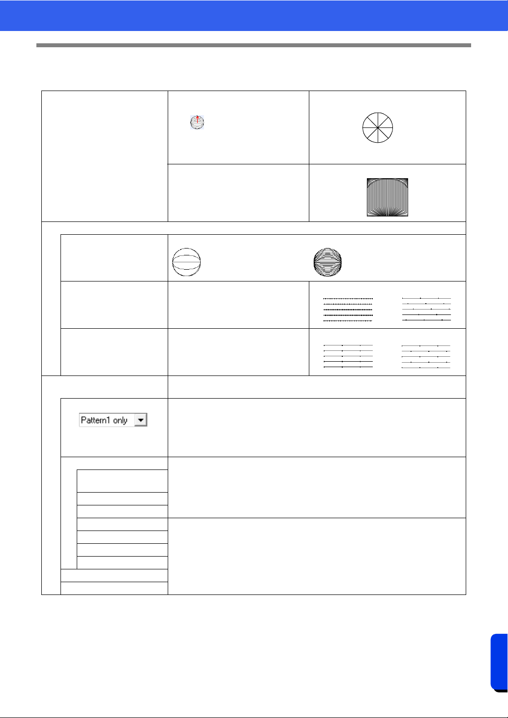
394
Reference
Sewing Attributes
Piping Stitch
Stitching is created to run through the length of blocks.
Direction
[Manual straight line]: Sews at a fixed
angle.
Drag or select a value to specify
the angle. If there are multiple sewing
direction lines, a value cannot be
specified for the angle.
[Manual straight line]
[Manual curve]: Specify curved sewing
direction line.
cc "Specifying curved sewing
direction line" on page 62
[Manual curve]
Specify settings for the following if the motif stitch pattern is not used.
Density
Coarse Fine
Run pitch
Specify the length of one stitch.
Short Long
Frequency Specify the shift in the stitches.
0% 50%
Use Motif
To use a motif stitch in the pattern, select the check box, and then specify settings for
the following attributes.
Motif
cc "Motif Stitch" in the "Region sewing attributes" on page 395
Pattern1/Pattern2
cc "Motif Stitch" in the "Line sewing attributes" on page 383
Pattern and size of the
motif stitch patterns
H-Arrange
V-Arrange
H-Offset
cc "Motif Stitch" in the "Region sewing attributes" on page 395
V-Offset
H-Spacing
V-Spacing
Row offset
Run pitch
45°
0°
315°
90°
135°
180°
225°
270°
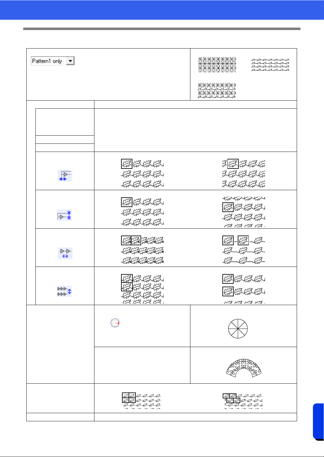
395
Reference
Sewing Attributes
Motif Stitch
Motif
Select the pattern to be used for the motif stitch.
[Pattern1 only]
[Pattern2 only]
[Pattern1 and 2]
Pattern1/Pattern2 Specify settings for each pattern.
Pattern and size of
the motif stitch
patterns Maintain
aspect ratio
cc "Motif Stitch" in the "Line sewing attributes" on page 383
H-Arrange
V-Arrange
H-Offset
(
horizontal
spacing)
0.0 mm 2.5 mm
V-Offset
(vertical spacing)
0.0 mm 2.5 mm
H-Spacing
(
horizontal
spacing)
Narrow Wide
V-Spacing
(vertical spacing)
Narrow Wide
Direction
[Manual straight line]: Sews at a fixed
angle.
Drag or select a value to specify
the angle. If there are multiple sewing
direction lines, a value cannot be
specified for the angle.
[Manual straight line]
[Manual curve]: Specify curved sewing
direction line.
cc "Specifying curved sewing direction
line" on page 62
[Manual curve]
Row offset
Smaller Larger
Run pitch cc "Motif Stitch" in the "Line sewing attributes" on page 383
45°
0°
315°
90°
135°
180°
225°
270°
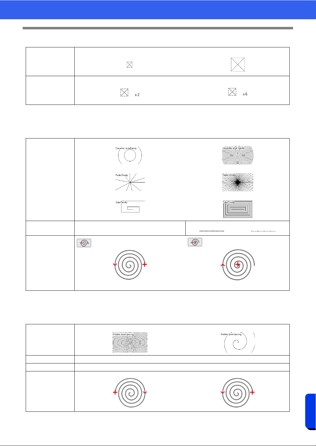
396
Reference
Sewing Attributes
Cross Stitch
Concentric Circle Stitch, Radial Stitch and Spiral Stitch
For details on moving the center point of the concentric circle stitch and the radial stitch, refer to "Moving the
center point and stitch pattern reference point" on page 59.
Flexible Spiral Stitch
For details on moving the center point , refer to "Moving the center point and stitch pattern reference point" on
page 59.
Size
Smaller Larger
Times
Single Triple
Density
Concentric Circle Stitch Coarse
Radial Stitch Coarse
Spiral Stitch Coarse
Concentric Circle Stitch Fine
Radial Stitch Fine
Spiral Stitch Fine
Run pitch Specify the length of one stitch.
Short Long
Start Point (only
with Concentric
Circle Stitch and
Spiral Stitch)
Starts from the outside of the spiral.
Starts from the inside of the spiral.
Spacing
Narrow
Wide
Run pitch "Concentric Circle Stitch, Radial Stitch and Spiral Stitch" on page 396
Start Point "Concentric Circle Stitch, Radial Stitch and Spiral Stitch" on page 396
Direction
Clockwise
Counterclockwise
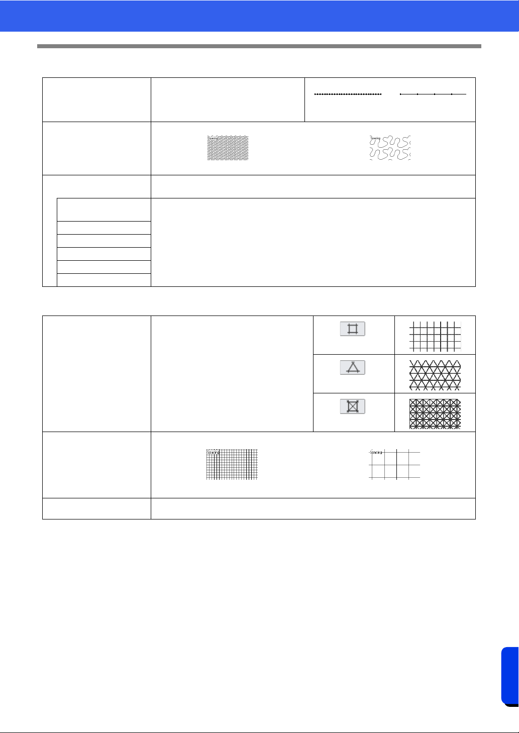
397
Reference
Sewing Attributes
Stippling Stitch
Net Fill Stitch
Run pitch
Specify the length of one stitch.
This cannot be specified if the motif stitch is
used.
Short
The turns are
smoother.
Long
The turns are more
angled.
Spacing
Narrow
The pattern is finer.
Wide
The pattern is coarser.
Use Motif
To use a motif stitch in the pattern, select the check box, and then specify settings for the
following attributes.
Pattern and size of the
motif stitch patterns
cc "Motif Stitch" in the "Line sewing attributes" on page 383
H-Arrange
V-Arrange
Offset
Spacing
Run pitch
Pattern
Specify the pattern to be used for the net fill
stitch.
Spacing
Fine
The pattern is finer.
Coarse
The pattern is coarser.
Direction
cc "Motif Stitch" in the "Region sewing attributes" on page 395
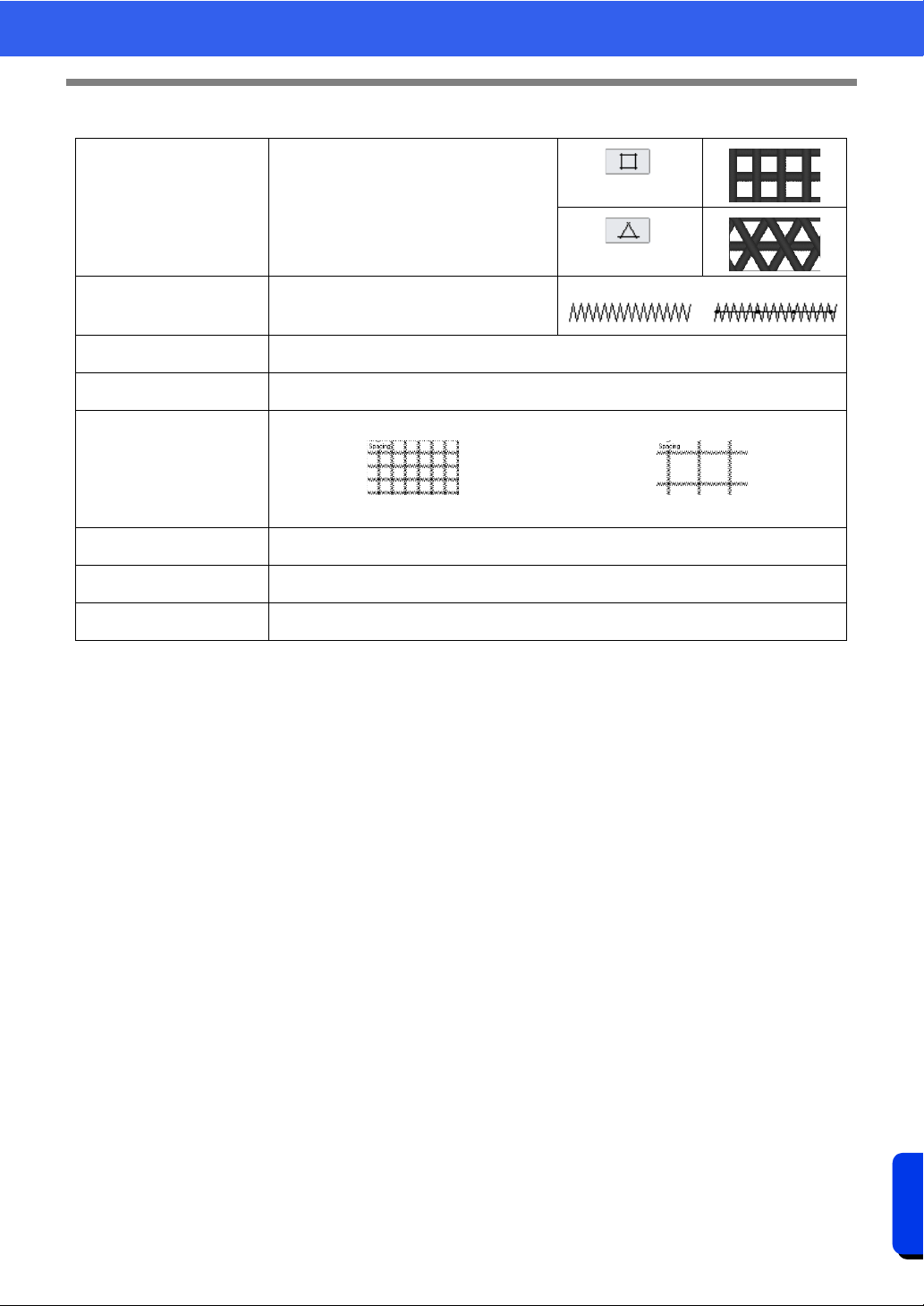
398
Reference
Sewing Attributes
Zigzag Net Fill Stitch
Pattern
Specify the pattern to be used for the
zigzag net fill stitch.
Under sewing
To specify underlay stitching, select the
check box.
Off On
Zigzag width
cc "Zigzag Stitch" in the "Line sewing attributes" on page 382
Density
cc "Zigzag Stitch" in the "Line sewing attributes" on page 382
Spacing
Fine
The pattern is finer.
Coarse
The pattern is coarser.
H-Offset
cc "Motif Stitch" in the "Region sewing attributes" on page 395
V-Offset
cc "Motif Stitch" in the "Region sewing attributes" on page 395
Direction
cc "Motif Stitch" in the "Region sewing attributes" on page 395
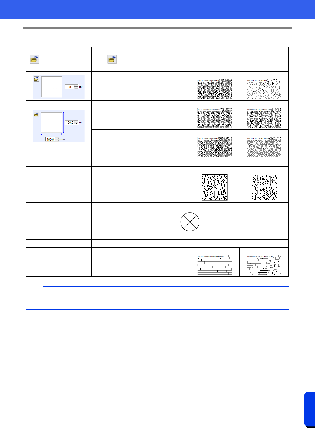
399
Reference
Sewing Attributes
Decorative Fill Stitch
Select a pattern for the decorative fill stitch.
Click
to display the [Browse] dialog box. Select the desired pattern from the list of
patterns (.plf file) that appears.
Specify the pattern size. The pattern can be
enlarged or reduced while maintaining the
width-to-height proportion.
Smaller larger
1 Height (vertical
length)
Specify the pattern
height.
Short Tall
2 Width (horizontal
length)
Specify the pattern
width.
Short Long
Maintain aspect ratio When selected, the height-to-width proportions of the pattern are maintained.
Minimize feed
Specify running stitches around the edges
of objects.
On
Off
Direction
Run pitch cc "Motif Stitch" in the "Line sewing attributes" on page 383
Random Shift Specify the level of breakdown in patterns.
0% 50%
b
• If [Minimize feed] has been turned off, parts of the pattern may be lost since extremely short stitches will
not be created.
1
2
45°
0°
315°
90°
135°
180°
225°
270°
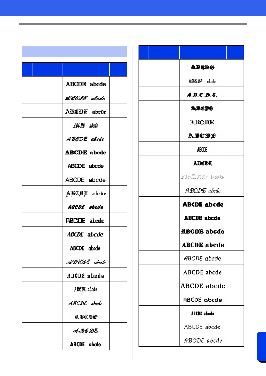
400
Reference
Font List
Font List
Text
No. Font Name Text Outlines
Min.
size
001 Serif 01
10 mm
(0.39")
002 Script 01
10 mm
(0.39")
003 Gothic 01
10 mm
(0.39")
004 Serif 02
10 mm
(0.39")
005 Script 02
10 mm
(0.39")
006 Serif 03
8 mm
(0.31")
007 Block 01
9 mm
(0.35")
008 Block 02
10 mm
(0.39")
009 Gothic 02
10 mm
(0.39")
010 Block 03
10 mm
(0.39")
011 Decorative 01
10 mm
(0.39")
012 Block 04
10 mm
(0.39")
013 Block 05
9 mm
(0.35")
014 Script 03
10 mm
(0.39")
015 Decorative 02
20 mm
(0.79")
016 Decorative 03
10 mm
(0.39")
017 Script 04
10 mm
(0.39")
018 Gothic 03
10 mm
(0.39")
019 Script 05
10 mm
(0.39")
020 Block 06
9 mm
(0.35")
021 Gothic 04
10 mm
(0.39")
022 Decorative 04
10 mm
(0.39")
023 Decorative 05
8 mm
(0.31")
024 Gothic 05
10 mm
(0.39")
025 Decorative 06
10 mm
(0.39")
026 Gothic 06
10 mm
(0.39")
027 Block 07
10 mm
(0.39")
028 Gothic 07
10 mm
(0.39")
029
Brussels Demi
Outline
10 mm
(0.39")
030
Calgary
MediumItalic
10 mm
(0.39")
031 Istanbul
10 mm
(0.39")
032 Los Angeles
10 mm
(0.39")
033 Saipan
10 mm
(0.39")
034 San Diego
10 mm
(0.39")
035
Sicilia Light
Italic
10 mm
(0.39")
036 Alaska
10 mm
(0.39")
037 Bayern Book
10 mm
(0.39")
038 Belgium
10 mm
(0.39")
039 Bengal
10 mm
(0.39")
040 Bergen
10 mm
(0.39")
041 Berlin Regular
10 mm
(0.39")
No. Font Name Text Outlines
Min.
size
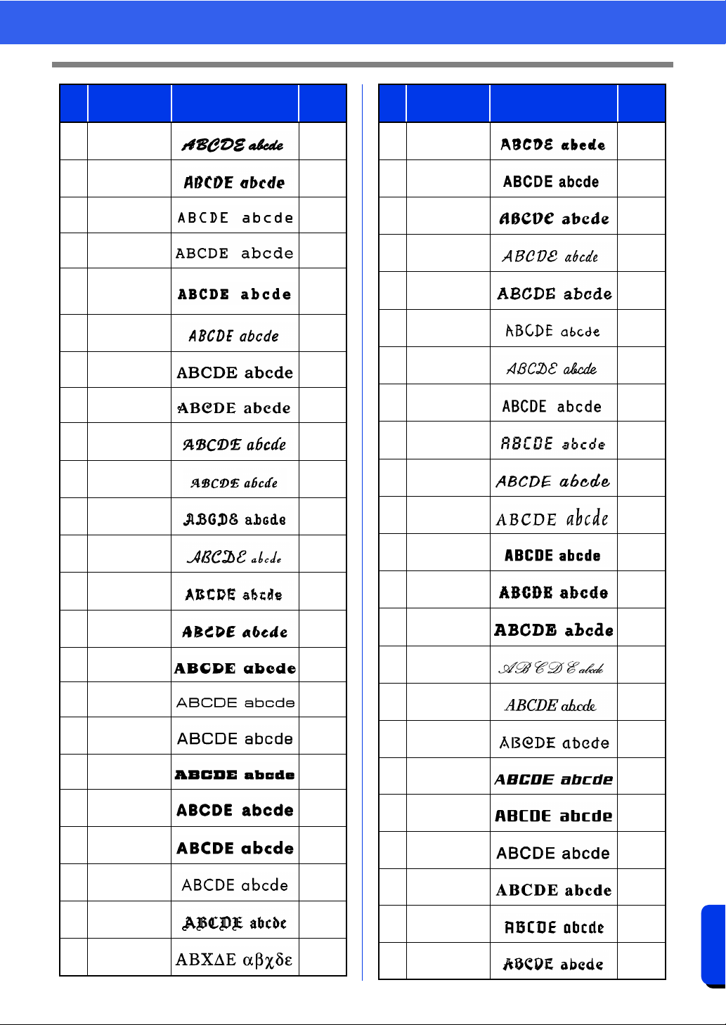
401
Reference
Font List
042
Bermuda
Script
10 mm
(0.39")
043 Blackstone
10 mm
(0.39")
044 BR-OCRA
10 mm
(0.39")
045
Brougham
Bold
9 mm
(0.35")
046
Brougham
Condensed
ExtraBold
9 mm
(0.35")
047 Brunei
10 mm
(0.39")
048 Brussels Light
10 mm
(0.39")
049 Cairo
10 mm
(0.39")
050
Calgary
BoldItalic
10 mm
(0.39")
051
Calgary
BoldItalic LS
10 mm
(0.39")
052 Canberra
10 mm
(0.39")
053 Connecticut
10 mm
(0.39")
054 Cordoba
10 mm
(0.39")
055 Cyprus
10 mm
(0.39")
056 Equador
9 mm
(0.35")
057
Epsom
Expanded
9 mm
(0.35")
058 Epsom
10 mm
(0.39")
059
Firenze Bold
Expanded
10 mm
(0.39")
060
Florida
Medium
8 mm
(0.31")
061 Frankfurt Bold
9 mm
(0.35")
062
Frankfurt
Medium
10 mm
(0.39")
063 Germany
10 mm
(0.39")
064 BR Symbol
10 mm
(0.39")
No. Font Name Text Outlines
Min.
size
065 Haiti
9 mm
(0.35")
066
Helsinki
Narrow Bold
10 mm
(0.39")
067 Hungary
10 mm
(0.39")
068 Jakarta
10 mm
(0.39")
069 Jawa
10 mm
(0.39")
070 Kentucky
10 mm
(0.39")
071
Kingston
Regular
10 mm
(0.39")
072
Letter Gothic
Bold
10 mm
(0.39")
073 Lillehammer
10 mm
(0.39")
074 Liverpool Italic
10 mm
(0.39")
075 Maryland
10 mm
(0.39")
076 Miami Roman
9 mm
(0.35")
077 Montreal
10 mm
(0.39")
078 Panama Bold
8 mm
(0.31")
079 Princeton Italic
10 mm
(0.39")
080 Riesa
10 mm
(0.39")
081 Salamanca
10 mm
(0.39")
082
Seattle
BoldItalic
10 mm
(0.39")
083 Sofia Bold
9 mm
(0.35")
084 Helsinki
10 mm
(0.39")
085
Tennessee
ExtraBold
10 mm
(0.39")
086 Themes
10 mm
(0.39")
087 Tianjin
10 mm
(0.39")
No. Font Name Text Outlines
Min.
size
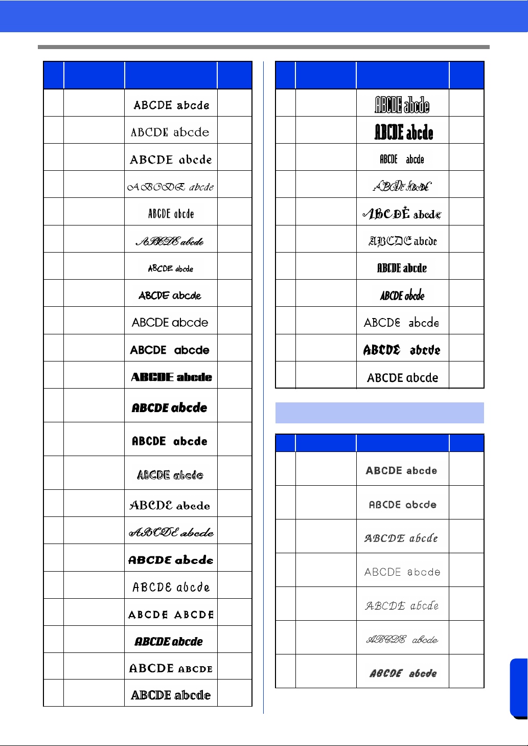
402
Reference
Font List
088 Tirol
10 mm
(0.39")
089 US Roman
10 mm
(0.39")
090 Venezia
10 mm
(0.39")
091 Vermont
10 mm
(0.39")
092 Wellington
10 mm
(0.39")
093
Künstlersch-
reibschrift
10 mm
(0.39")
094
Tom s
Handwritten
10 mm
(0.39")
095 Luedickital
10 mm
(0.39")
096 Atranta Book
10 mm
(0.39")
097 Atranta Demi
10 mm
(0.39")
098 Montana
10 mm
(0.39")
099
Base 900
Sans Heavy
Italic
10 mm
(0.39")
100
Base
Monospace
Wide Bold
10 mm
(0.39")
101
Blockhead
Alphabet
Darkside
15 mm
(0.59")
102
Dalliance
Roman
10 mm
(0.39")
103
Dalliance
Script
10 mm
(0.39")
104
Dogma Script
Bold
10 mm
(0.39")
105
Elliotts Apollo
Venus Dioxide
10 mm
(0.39")
106
Exocet
Medium
13 mm
(0.51")
107
Los Feliz Bold
Italic
9 mm
(0.35")
108
Mason Serif
Bold
12 mm
(0.47")
109
Matrix Inline
Extra Bold
17 mm
(0.67")
No. Font Name Text Outlines
Min.
size
110
Modula
Outlined
19 mm
(0.75")
111
Modula Round
Serif Ultra
17 mm
(0.67")
112
Modula Sans
Bold
10 mm
(0.39")
113
Not Caslon
Two
30 mm
(1.18")
114
Remedy
Double
25 mm
(0.98")
115
Sabbath Black
Regular
13 mm
(0.51")
116 Senator Ultra
13 mm
(0.51")
117
Soda Script
Bold
10 mm
(0.39")
118
Suburban
Light
10 mm
(0.39")
119 Totally Gothic
10 mm
(0.39")
120
Vista Sans Alt
Regular
10 mm
(0.39")
Small Text
No. Font Name Text Outlines Size
01 Utah Bold S
5-6 mm
(0.20-
0.24")
02 Belgium S
5-6 mm
(0.20-
0.24")
03
Calgary
MediumItalic S
5-6 mm
(0.20-
0.24")
04 Utah SR
3-4 mm
(0.12-
0.16")
05
Calgary
MediumItalic
SR
3-4 mm
(0.12-
0.16")
06 Script 01 SR
4-6 mm
(0.16-
0.24")
07 Block 03 S
5-6 mm
(0.20-
0.24")
No. Font Name Text Outlines
Min.
size
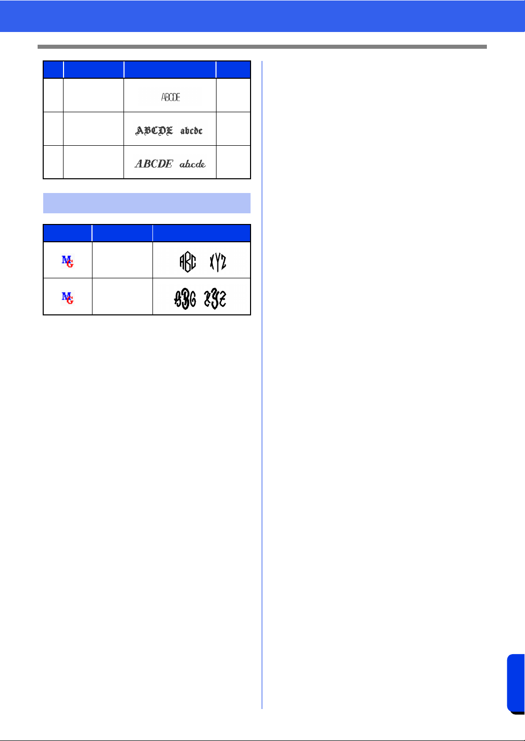
403
Reference
Font List
08 Block 07 SR
4-6 mm
(0.16-
0.24")
09 Germany S
5-6 mm
(0.20-
0.24")
10 Riesa S
5-6 mm
(0.20-
0.24")
Monogram
Symbol Font Name Text Outlines
Diamond
Script
No. Font Name Text Outlines Size
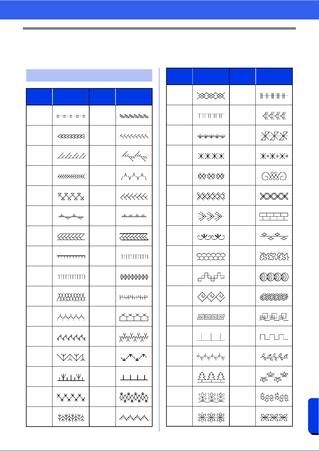
404
Reference
Sewing Stitch Patterns for Stitch Design Factory
Sewing Stitch Patterns for Stitch Design
Factory
Decorative Stitch
Name
Sewing Stitch
Pattern
Name
Sewing Stitch
Pattern
sample01
_001
sample01
_002
sample01
_003
sample01
_004
sample01
_005
sample01
_006
sample01
_007
sample01
_008
sample01
_009
sample01
_010
sample01
_011
sample01
_012
sample01
_013
sample01
_014
sample01
_015
sample01
_016
sample01
_017
sample01
_018
sample01
_019
sample01
_020
sample01
_021
sample01
_022
sample01
_023
sample01
_024
sample01
_025
sample01
_026
sample01
_027
sample01
_028
sample01
_029
sample01
_030
sample01
_031
sample01
_032
sample01
_033
sample01
_034
sample01
_035
sample01
_036
sample01
_037
sample01
_038
sample01
_039
sample01
_040
sample01
_041
sample01
_042
sample01
_043
sample01
_044
sample01
_045
sample01
_046
sample01
_047
sample01
_048
sample01
_049
sample01
_050
sample01
_051
sample01
_052
sample01
_053
sample01
_054
sample01
_055
sample01
_056
sample01
_057
sample01
_058
sample01
_059
sample01
_060
sample01
_061
sample01
_062
sample01
_063
sample01
_064
sample01
_065
sample01
_066
Name
Sewing Stitch
Pattern
Name
Sewing Stitch
Pattern
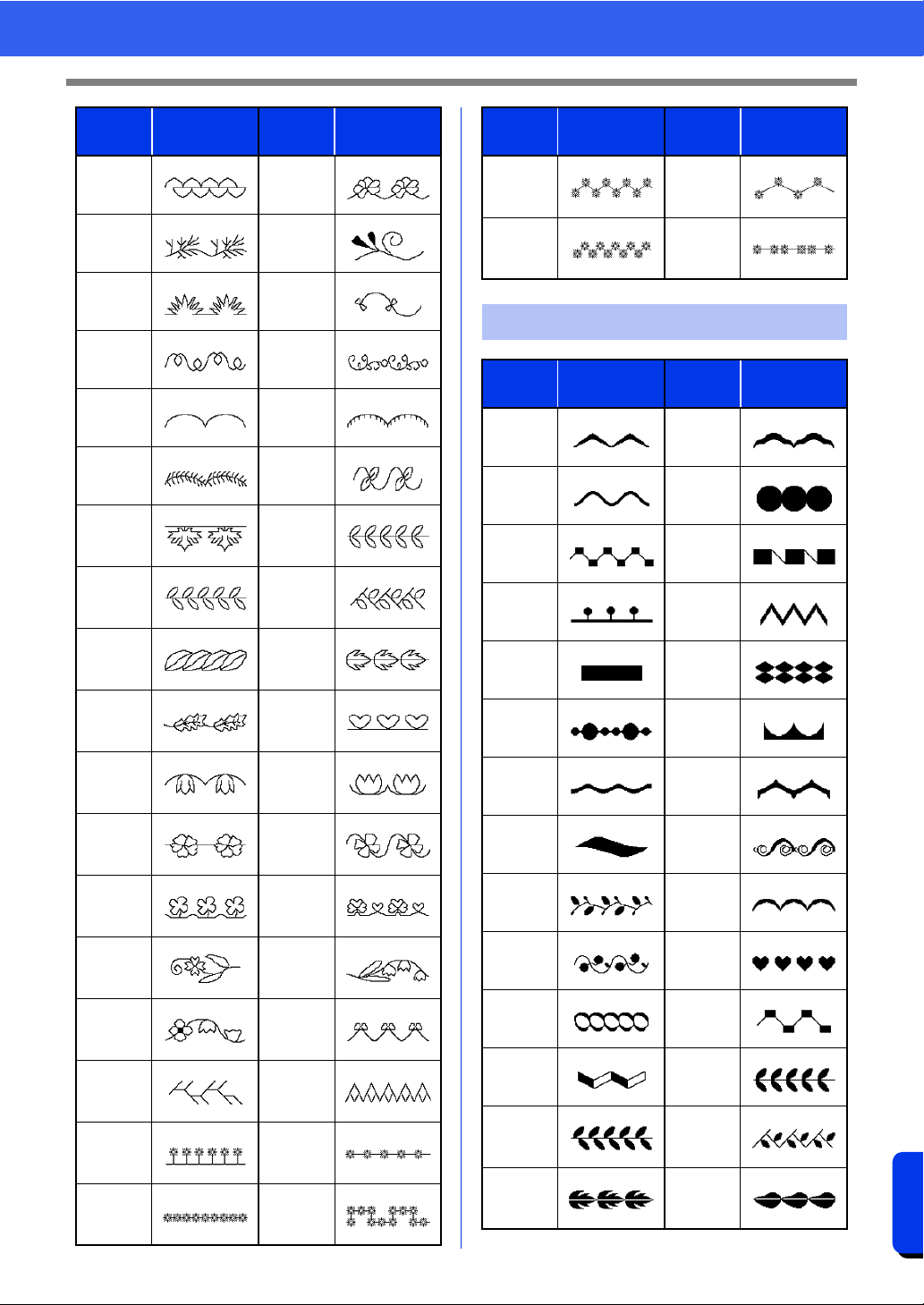
405
Reference
Sewing Stitch Patterns for Stitch Design Factory
sample01
_067
sample01
_068
sample01
_069
sample01
_070
sample01
_071
sample01
_072
sample01
_073
sample01
_074
sample01
_075
sample01
_076
sample01
_077
sample01
_078
sample01
_079
sample01
_080
sample01
_081
sample01
_082
sample01
_083
sample01
_084
sample01
_085
sample01
_086
sample01
_087
sample01
_088
sample01
_089
sample01
_090
sample01
_091
sample01
_092
sample01
_093
sample01
_094
sample01
_095
sample01
_096
sample01
_097
sample01
_098
sample01
_099
sample01
_100
sample01
_101
sample01
_102
Name
Sewing Stitch
Pattern
Name
Sewing Stitch
Pattern
sample01
_103
sample01
_104
sample01
_105
sample01
_106
Decorative Satin Stitch
Name
Sewing Stitch
Pattern
Name
Sewing Stitch
Pattern
sample02
_001
sample02
_002
sample02
_003
sample02
_004
sample02
_005
sample02
_006
sample02
_007
sample02
_008
sample02
_009
sample02
_010
sample02
_011
sample02
_012
sample02
_013
sample02
_014
sample02
_015
sample02
_016
sample02
_017
sample02
_018
sample02
_019
sample02
_020
sample02
_021
sample02
_022
sample02
_023
sample02
_024
sample02
_025
sample02
_026
sample02
_027
sample02
_028
Name
Sewing Stitch
Pattern
Name
Sewing Stitch
Pattern
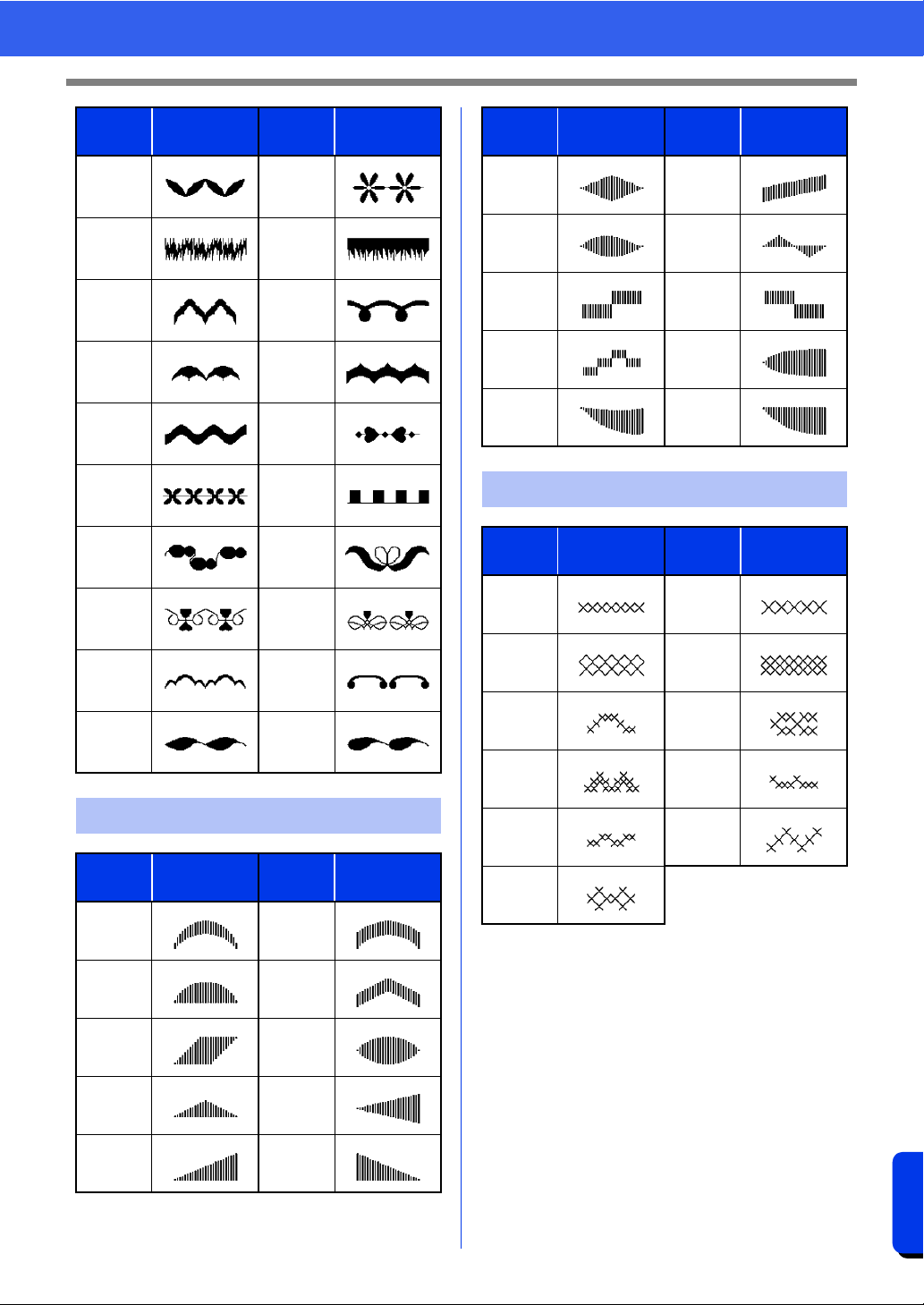
406
Reference
Sewing Stitch Patterns for Stitch Design Factory
sample02
_029
sample02
_030
sample02
_031
sample02
_032
sample02
_033
sample02
_034
sample02
_035
sample02
_036
sample02
_037
sample02
_038
sample02
_039
sample02
_040
sample02
_041
sample02
_042
sample02
_043
sample02
_044
sample02
_045
sample02
_046
sample02
_047
sample02
_048
Satin Stitch
Name
Sewing Stitch
Pattern
Name
Sewing Stitch
Pattern
sample03
_001
sample03
_002
sample03
_003
sample03
_004
sample03
_005
sample03
_006
sample03
_007
sample03
_008
sample03
_009
sample03
_010
Name
Sewing Stitch
Pattern
Name
Sewing Stitch
Pattern
sample03
_011
sample03
_012
sample03
_013
sample03
_014
sample03
_015
sample03
_016
sample03
_017
sample03
_018
sample03
_019
sample03
_020
Cross Stitch
Name
Sewing Stitch
Pattern
Name
Sewing Stitch
Pattern
sample04
_001
sample04
_002
sample04
_003
sample04
_004
sample04
_005
sample04
_006
sample04
_007
sample04
_008
sample04
_009
sample04
_010
sample04
_011
Name
Sewing Stitch
Pattern
Name
Sewing Stitch
Pattern
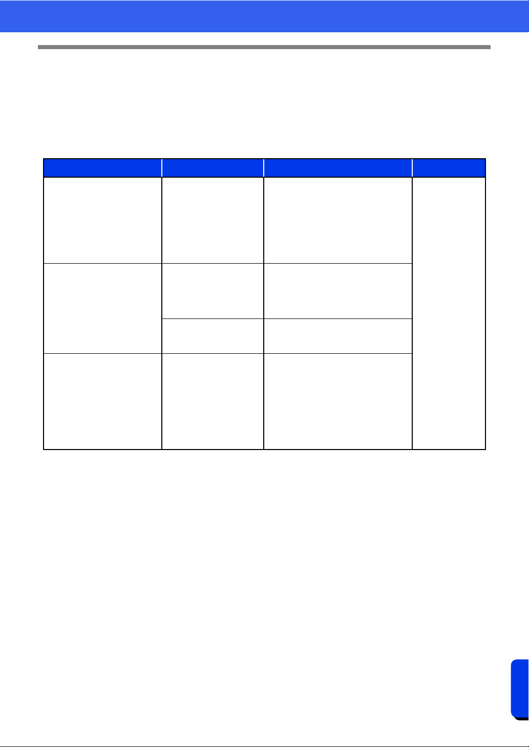
407
Reference
Troubleshooting
Troubleshooting
If a problem occurs, click [Help], then [Customer Support] in the menu to visit the following Web site, where
you can find causes and solutions to various problems and answers to frequently asked questions.
If you have a problem, check the following solutions. If the solutions suggested do not correct the problem,
contact your authorized dealer or Brother Customer Service.
Problem Estimated Cause Solution Page
The software is not installed
correctly.
An operation not described
in the installation procedure
was performed. (For
example, Cancel was
clicked or the "PE-DESIGN
Software Key" was
removed before the
procedure was completed.)
Follow the instructions as the software
installs to correctly install the software.
See "Reference
Guide".
The message "No PE-DESIGN
Software Key is connected.
Please connect a PE-DESIGN
Software Key." appeared.
The
"PE-DESIGN Software
Key"
is not connected.
Check that the
"PE-DESIGN Software
Key"
appears in the computer's list of
removable storage devices. If it does
not appear, unplug the
"PE-DESIGN
Software Key"
, and then plug it in again.
The information on the
"PE-DESIGN Software
Key"
is corrupted.
Leave it plugged in, and uninstall, then
re-install PE-DESIGN 11.
When trying to upgrade from
an older version, the message
"Cannot connect to the
Internet." or "The server could
not be connected to. Wait a
while, and then try connecting
again." appeared and
"PE-
DESIGN Software Key"
could
not be upgraded.
The computer with
"PE-
DESIGN Software Key"
connected to its USB port
could not establish a
connection to the Internet.
To upgrade
"PE-DESIGN Software Key"
,
the computer with
"PE-DESIGN
Software Key"
connected to its USB
port must connect to the Internet. If
firewall software is being used, it must
be temporarily disabled during the
upgrade. If a connection to the Internet
cannot be established, contact your
authorized dealer.
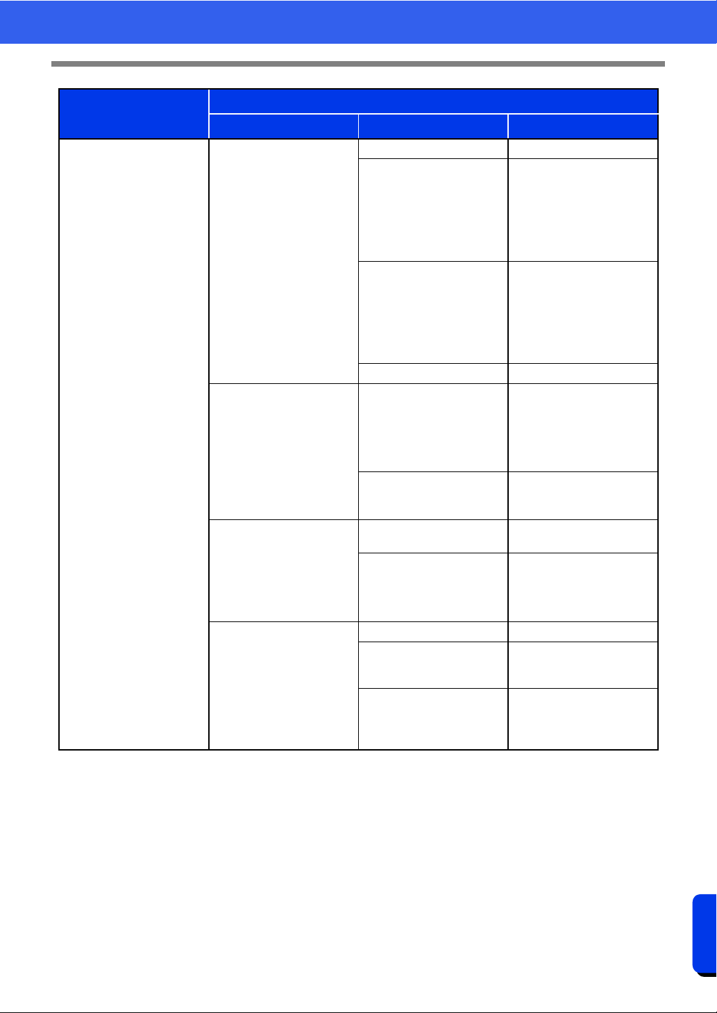
408
Reference
Troubleshooting
Problem
Possible Cause
Cause File Format Solution
The error message
"Unexpected file format"
appears.
or
Your embroidery pattern or
image cannot be opened.
When opening an embroidery
pattern
(Application button >
[Open]
)
.pes The data may be corrupted.
.phc, .phx (machine
embroidery format)
The file cannot be opened,
but it can be imported.
→ ([Home] tab > [Import
Patterns] > [from File])
Otherwise, convert the file to
the PES format, and then
open it.
Other manufacturers'
compatible formats
(.dst, .hus, .exp, .pcs, .vip,
.sew, .jef, .csd,
.xxx, and .shv)
The file cannot be opened,
but it can be imported.
→ ([Home] tab > [Import
Patterns] > [from File])
Otherwise, convert the file to
the PES format, and then
open it.
Incompatible formats The file cannot be used.
When importing embroidery
patterns
([Home] tab > [Import
Patterns] > [from File])
.pes, .phc, .phx
Other manufacturers'
compatible formats
(.dst, .hus, .exp, .pcs, .vip,
.sew, .jef, .csd,
.xxx, and .shv)
The data may be corrupted.
Incompatible formats
Convert the file to a
compatible format, such as
PES, and then use it.
When opening a background
image
([Image] tab > [Open])
or When opening an image
for Stitch Wizard
(Auto Punch, Photo Stitch 1
and 2, and Cross Stitch)
.bmp, .tif, .jpg, .wmf, .png,
.eps, and .gif
The data may be corrupted.
Images in formats other than
those listed above
The file cannot be opened.
→ Use an image in one of
the formats listed above.
When importing an image as
an embroidery pattern
([Home] tab > [Import
Patterns] > [from Vector
Image])
.wmf, .emf, and .svg The data may be corrupted.
Vector images in a format
other than .wmf, .emf, or
.svg
Convert the file to the .wmf,
.emf, or .svg format, and
then import it.
Raster images (.bmp, .jpg,
etc.)
Currently, these files cannot
be imported. Open them in
the background and use
them for tracing.
409
Index
Index
A
Access key ................................................................367
Advanced stitch wizard ..............................................158
Aligning
Embroidery patterns ............................................40
Application appearance .............................................368
Application button ........................................................13
Appliqué ..............................................................56, 179
Applique Wizard ........................................................179
Arc ...............................................................................71
Arcs .............................................................................71
Attaching stabilizer ....................................................197
Attributes
Line sewing attributes .......................................382
Name Drop Text ................................................139
Region sewing attributes ...................................388
Sewing attributes .................................................64
Text attributes ...................................................118
Auto Hide ...................................................................367
Auto Punch function ..................................................143
Auto Punch Parameters ....................................145
Auto Scroll ...................................................................90
B
Back Stitch ................................................................148
Background Fill ..........................................................174
Basic color ...................................................................99
Beginner mode ....................................................64, 271
Blending ......................................................................55
Block data ..................................................................126
Block pattern .....................................................218, 325
Blocks
Convert to Blocks ................................................85
Converted from text ...........................................126
C
Candlewicking Stitch .........................................375, 384
Card writer .........................................................225, 284
Center point .................................................................59
Centering .....................................................................40
Chain Stitch .......................................................376, 386
Change Color ....................................................153, 157
Changing
Thread color order .............................................216
Changing the character spacing ................................125
Character spacing .....................................................121
Check for Updates .........................................................8
Checking
Sewing order .......................................................92
Stitching ..............................................................90
Circle ...........................................................................71
Circle copy ...................................................................43
Circles .........................................................................71
Clipping Mask ............................................................160
Closed paths ...............................................................74
Color button .........................................................54, 270
Color changes .............................................................99
Color Option ......................................................153, 157
Color pane ...................................................................14
Color Sort ....................................................................46
Combining
Pattern colors ......................................................93
Concentric circle stitch ......................................377, 396
Center point .........................................................59
Connection Points .........................................79, 83, 127
Convert Region to Line ................................................53
Converting
Embroidery pattern formats ...............................291
Region to line ......................................................53
Shape pattern to stitch ........................................81
Stitch to blocks ....................................................85
Stitch to shapes ...................................................85
Text pattern to stitch ............................................81
Text to blocks ....................................................126
Text to outline pattern .......................................126
Text to stitches ..................................................126
Copy
Arrange Copies ...................................................43
Sewing attributes .................................................64
Create new font mode ...............................................337
Creating
New folders .......................................................281
New thread color chart ......................................214
Cross stitch ........................................................376, 396
Cross Stitch function .................................................146
Cross Stitch parameters ....................................148
Crosshatch/stripe fill ..................................................178
CSV ...........................................................................215
Customer Support .........................................................7
Customize .........................................................368, 369
Cutting line ..................................................................57
Cutting machine ........................................................238
Cutwork
Cutting .................................................................57
Function ............................................................191
Net Stitching ......................................................187
Cutwork wizard ..........................................................187
D
Decorative fill .....................................177, 311, 377, 399
Decorative fill mode ...................................................311
Decorative fill stitch ...........................................377, 399
Decorative pattern .......................................................46
Deleting
Point ....................................................................77
Sewing direction lines .........................................61
Thread color charts ...........................................214
Thread colors from charts .................................216
Design Center ...................................................246, 249
Design Database ...............................................277, 278
Design Page Property ...........................16, 20, 204, 265
Design Page size ..........................................16, 20, 265
Multi-position hoops ..........................................204
Design Property .....................................................14, 99
Design Settings ...................................................16, 265
Displaying
Background images ..........................................316
Color pane ...........................................................54
Details ...............................................................282
Embroidery patterns ..........................................282
Images ......................................................165, 268
Import pane .........................................................15
Large Thumbnails .............................................282
Small Thumbnails ..............................................282
Distributor dialog box .........................................229, 234

410
Index
Divide Stitches by Color ..............................................85
Docking .....................................................................367
Drawing .......................................................................70
DST ...................................................................291, 369
DST Settings .............................................................369
Duplicate .....................................................................32
E
E/V stitch ...........................................................375, 385
Echo fill ......................................................................175
Edit User Thread Chart .............................................213
Editing
Grouped objects ..................................................47
Name Drop ........................................................139
Points ..........................................................76, 305
Sewing order .......................................................95
Template ...........................................................113
Thread color charts ...........................................215
Thread colors ....................................................216
Emboss ...............................................................66, 299
Embroidered patch wizard .........................................184
Embroidering .....................................................199, 211
Patch .................................................................184
Embroidering area .............................................205, 210
Embroidery attributes for text ............................128, 129
Embroidery patterns
Adding comments ...............................................99
Aligning ...............................................................40
Centering .............................................................40
Converting formats ............................................291
Displaying ..........................................................282
Exporting ...........................................................107
From images .............................................143, 158
Grouping .............................................................47
Importing ...........................................................283
Information ........................................................292
Multi-position hoops ..........................................205
Printing ......................................................208
Opening .............................................................283
Organizing .........................................................281
EMF ...........................................................................105
Engrave ...............................................................66, 299
Enhanced Image Tracing ..........................................160
Entry/exit points
Moving .................................................................58
Eraser ........................................................................251
Exclude internal patterns ...................................177, 178
Expert mode ........................................................64, 271
Exporting
Embroidery patterns ..........................................107
FCM files ...........................................................243
F
Fan ..............................................................................71
FCM ...........................................................................239
Figure Handle stage ..................................................247
File
New line image ..................................................263
Open in Layout & Editing ..................................283
Search ...............................................................290
File property ..............................................................292
Fill stitch ............................................................376, 390
Fill/Stamp mode ........................................................301
Flexible spiral stitch ...........................................377, 396
Flip .........................................................33, 42, 169, 266
Floating ......................................................................367
Floral pattern ...............................................................50
Folders ......................................................................281
Font Creator ......................................................320, 321
Font filter ...................................................................119
Font List .....................................................................400
Font selector ..............................................................118
G
Gradation .............................................................55, 272
Grid ..............................................20, 268, 319, 346, 361
Grouping embroidery patterns .....................................47
Guideline .............................................................21, 319
H
H-Arrange ..................................................................383
Help button ..................................................................14
Hide ...........................................................................367
Hint View .............................................................64, 271
H-Offset .....................................................................395
Hole sewing .........................................................47, 273
Appliqué ............................................................180
Cancel .................................................................48
Hoop changes ...........................................................206
Hooping .....................................................................198
Horizontal Alignment .................................................123
H-Spacing ..................................................................395
I
Image to Stitch Wizard ......................................142, 158
Image Tune ...............................................................159
Image Type ...............................................................154
Images
Clipping Mask ....................................................160
Converting to embroidery patterns ....142, 143, 158
Moving ...............................................................165
Outputting ..........................................................166
Resizing ............................................................165
Saving ...............................................................166
Scaling ..............................................................165
Importing
.fcm files ............................................................243
.pem files ...........................................................260
Background images ..........................................315
Clipboard images ......................................164, 260
Embroidery patterns ............................15, 102, 283
From Design Center ..........................................106
From original cards ...................................103, 289
Images ......................................................163, 260
Import pane .........................................................15
TWAIN images ..................................................164
Input
From Clipboard .................................................164
From file ............................................................163
From TWAIN device ..........................................164
Inserting
Stitch points .........................................................82
J
Jumbo frame .............................................................209
Jump Stitch ................................................................365
Jump Stitch Trimming ............................18, 98, 365, 370

411
Index
K
Kerning ..............................................................120, 125
L
Large Thumbnails ......................................................282
Layout & Editing ............................................11, 24, 101
Layout copy .................................................................43
Line color button ..........................................................55
Line Image stage .......................................................246
Line Interval ...............................................................157
Line sewing .........................................................57, 270
Line sewing attributes ................................................382
Line spacing ..............................................................121
Link Function .....................................................227, 289
Lock .............................................................................97
M
Machine Type ......................................................16, 265
Manual curve .......................................62, 390, 394, 395
Manual punch ..............................................27, 218, 325
Manual straight line .....................59, 388, 390, 394, 395
Matrix copy ..................................................................45
Max. Density ..............................................................157
Max. Number of Colors .....................................145, 148
Measure ................................................................22, 88
Measurement units ..............................................22, 268
Merge ....................................................................45, 49
Minimize feed ............................................175, 177, 399
Mirror copy ..................................................................43
Modify ................................................................165, 268
Monograms .......................................................131, 134
Motif mode .................................................................307
Motif stitch .................................................376, 383, 395
Move Sections ...........................................................202
Moving
Center points .......................................................59
Embroidery patterns to center .............................40
Entry/exit points ...................................................58
Images ..............................................................165
Stitch points .........................................................82
Multiple Import ...........................................................334
Multi-position hoops ..................................................204
N
Name Drop Feature ...........................................136, 139
Name Drop List .................................................137, 140
Net fill stitch ...............................................189, 377, 397
Network Machine Settings .................................224, 286
New ...........................................................................101
New font mapping mode ...........................................330
New Line Image ........................................................263
NOT DEFINED ............................................................56
Not sewn
Line .....................................................................57
Region .................................................................57
Number of jumps .......................................................369
O
Offset .................................................120, 125, 383, 392
Offset line ....................................................................52
Online Registration ........................................................7
Open paths ..................................................................74
Opening
.pem files ...........................................................260
.pes file ..............................................................101
Background images ..........................................315
Clipboard images ......................................164, 260
Embroidery patterns ..................................106, 283
Images ......................................................163, 260
Layout & Editing file ..........................................101
New Design Page .............................................101
New figure handle images .................................260
New line images ................................................260
New stitch pattern .............................................307
Stitch patterns ...................................................301
TWAIN images ..................................................164
Optimizing
Hoop changes ...........................................206, 209
Option
Design Property ................................................207
Edit User Thread Chart .....................................213
Option button ...............................................................13
Options ......................................................................368
Organizing embroidery patterns ................................281
Outline .................................................................10, 127
Convert to Outline ...............................................86
Converted from text ...........................................127
Text ...................................................................129
Output
Template ...........................................................114
To Clipboard ......................................................166
To File ...............................................................166
Oval .............................................................................70
Overlap ........................................................................45
P
Pan ......................................................................87, 251
Pattern .........................................................................10
Pattern information ..............................................99, 292
Adding comments ...............................................99
Multi-position hoops ..........................................207
Pattern Placement .......................................................45
PE-DESIGN Software Key ............................................9
Pencil ...........................................................................74
Photo Stitch 1 ............................................................150
Candidates ........................................................154
Color ..................................................................150
Parameters ........................................................153
Photo Stitch 2 ............................................................155
Color ..................................................................157
Parameters ........................................................157
Piping stitch .......................................................376, 394
PMP ...........................................................................356
PMV ...........................................................................356
Points
Editing .........................................................76, 305
Positioning Sheet ......................................................197
Positioning sticker .....................................200, 201, 212
Preview window .........................................317, 342, 360
Previewing ...........................................................88, 292
Stitch patterns ...................................................317
Print and Stitch ..........................................................167
Printing
Catalogs ............................................................294
Embroidery patterns ..........................................110
Instruction guide ................................................294
Multi-position hoops ..........................................208
Preview .............................................................110
Settings .............................................................108
Programmable fill stitch .....................................376, 391
412
Index
Programmable Stitch Creator ............................296, 297
PSF ...........................................................................351
Pull Compensation ....................................................389
Q
Quick Access Toolbar .................................13, 366, 368
R
Radial stitch .......................................................377, 396
Center point .........................................................59
Random shift .............................................................399
Realistic View ..............................................................89
Settings ...............................................................89
Rectangle ....................................................................70
Redo ..........................................................................366
Reference Window ..............................................91, 266
Region color button ...................................................270
Region sewing .....................................................57, 270
Remove Overlaps ........................................................48
Resizing
Images ..............................................................165
Ribbon .........................................................................13
Rotate ............................................................41, 42, 266
Rotate angle ..............................................................120
Rotating .......................................................................42
Round fill .....................................................................62
Ruler ............................................................................20
Run Pitch ...................................................................154
Running stitch ....................................................375, 382
S
Satin stitch .........................................................376, 388
Saving
Different formats ................................................107
Embroidery patterns ..................................107, 275
Images ..............................................................166
Stitch patterns ...................................................317
Template ...........................................................115
Scaling
Images ..............................................................165
Scaling patterns ...................................40, 305, 310, 340
ScanNCut ............................................................29, 239
Screen Calibration .......................................................21
Searching ..................................................................290
Select Color Palette ...................................................217
Select from Candidates .............................................154
Selecting
All embroidery patterns .......................................39
Colors ..................................................81, 153, 157
Patterns .........................................................39, 95
Sewing area ........................................................18
Send
Link ............................................................228, 232
Send to Network Machine .................................225
Send to USB Media ...........................................222
Send to Your Machine .......................................223
Write to Card .....................................................226
Sew Page Color ........................................................154
Sew Setting stage .....................................................248
Sew type selector ................................................57, 270
Sewing Attribute pane .................................................14
Sewing attributes .........................................................75
Copy ....................................................................64
Setting .........................................................64, 255
Sewing Attributes bar ................................................270
Sewing direction
Programmable fill stitch .....................................393
Specifying ......................................................59, 62
Sewing Option ...................................................154, 157
Sewing order .......................................................92, 274
Editing .................................................................95
Optimize ..............................................................46
Sewing Order pane .....................................................14
Sewing stitch pattern .................................................350
Shape patterns ............................................................10
Shortcut keys .............................................................369
Show grid ..............................................................14, 20
Single Import .............................................................331
Single Stitching ..........................................................350
Small Text .................................................................129
Snap to grid .................................................................20
Snowman positioning sticker .....................200, 201, 212
Solid View ....................................................................88
Special colors ..............................................................56
Spiral stitch ........................................................377, 396
Split at point ...........................................77, 83, 254, 306
Split embroidery designs ...........................................195
Split Stitch data .......................................50, 83, 84, 254
Stabilizer ....................................................................197
Stage
To figure handle ................................................264
To line image .....................................................262
To Sew Setting ..................................................269
Stamp ..................................................................68, 274
Standard Character Height ........................................332
Start/end point ...........................................................387
Startup wizard .............................................................12
Status bar ....................................................................14
Stem Stitch ........................................................375, 384
Step Pitch ..........................................................390, 392
Stippling fill ................................................................177
Stippling stitch ...................................................377, 397
Stitch Design Factory ........................................347, 348
Stitch patterns .............................................................10
Previewing .........................................................317
Saving ...............................................................317
Stitch points
Deleting ...............................................................82
Inserting ..............................................................82
Moving .................................................................82
Stitch Simulator .....................................................14, 90
Stitch to Block ..............................................................85
Stitch View ...................................................................88
String ...........................................................................71
SVG ...........................................................................105
Swap .........................................................................354
System Unit .................................................................22
T
Template (background) .....................................315, 338
Template Wizard .......................................................112
Text
Convert to blocks ..............................................126
Convert to Outline Object ..................................127
Edit Letters ........................................................117
Entering text ......................................................116
Fit Text to Outline Setting ..................................123
Release Text from Outline ................................124
Text Attribute Setting .........................................118
TrueType Font Attribute Setting ........................121
Text Attribute pane ......................................................14

413
Index
Text menu ...................................................................26
Text Orientation .........................................................123
Text patterns ...............................................................10
Text Size selector ......................................................120
Thread Chart .....................................................153, 157
Thread colors
Adding to charts ................................................215
Apply new color palette .....................................217
Basic color ...........................................................99
Creating new colors ..........................................215
Deleting charts ..................................................214
Deleting from charts ..........................................216
Editing ...............................................................216
Editing charts ....................................................215
New charts ........................................................213
Order .................................................................216
Total colors ..........................................................99
User list .............................................................216
Thread Colors Used ..................................................157
Thumbnail ..........................................................282, 373
Transferring ...............................................222, 227, 284
Triple stitch ................................................................382
Triple Stitching ...........................................................350
TrueType Font ...........................................................119
U
Under sewing ....................................................382, 388
Undo ..................................................................251, 366
Unit ......................................................................22, 268
USB cable .........................................................223, 287
USB media ........................................................222, 285
Use smaller section sizes ..........................................201
User Interface Settings ..............................................371
User thread color list .................................................213
User-mapped text ......................................................135
V
V-Arrange ..................................................................383
Vector images ...........................................................105
Vertical Alignment .....................................................123
Vertical Offset ............................................................120
View mode buttons ......................................................14
V-Offset .....................................................................395
V-Spacing ..................................................................395
W
Window ........................................................................13
Wireless network .......................................104, 224, 286
WMF ..........................................................................105
Z
Zigzag net fill stitch ............................................377, 398
Zigzag stitch ......................................................375, 382
Zoom ...........................................................................87
Zoom ratio ...................................................................14

Please visit us at http://s.brother/cppab/ where you can get product support and
answers to frequently asked questions (FAQs).
English
Version B