
Kia, THE COMPANY
Enjoy your vehicle and Kia’s “Family-like Care” experience!
Thank you for becoming the owner of a new Kia vehicle.
As a global car manufacturer focused on building high-quality, value for
money prices, Kia Motors is dedicated to providing you with a customer
service experience that exceeds your expectations.
At all of our Kia dealerships you will be treated with warmth, hospitality
and professionalism by people who care based on our “Family-like Care”
promise.
All information contained in this Owner’s Manual is accurate at the
time of publication. However, Kia reserves the right to make changes
at any time so that our policy of continual product improvement can be
carried out.
This manual applies to all models of this vehicle and includes descrip-
tions and explanations of optional as well as standard equipment. As a
result, you may encounter material in this manual that is not applicable
to your specific Kia vehicle.

i
Thank you for choosing a Kia vehicle.
This manual will familiarize you with operational, maintenance and safety information about your new vehicle. It is
supplemented by a Warranty and Maintenance book that provides important information on all warranties regarding
your vehicle. Kia urges you to read these publications carefully and follow the recommendations to help assure
enjoyable and safe operation of your new vehicle.
Kia offers a great variety of options, components and features for its various models. Therefore, some of the equip-
ment described in this manual, along with the various illustrations, may not be applicable to your particular vehicle.
The information and specifications provided in this manual were accurate at the time of printing. Kia reserves the
right to discontinue or change specifications or design at any time without notice and without incurring any obliga-
tion. If you have questions, always check with your authorized Kia dealer.
Kia assures you of our continuing interest in your motoring pleasure and satisfaction in your Kia vehicle.
© 2016 Kia MOTORS Corp.
All rights reserved. Reproduction by any means, electronic or mechanical, including photocopying, recording, or by
any information storage and retrieval system or translation in whole or part is not permitted without written author-
ization from Kia MOTORS Corporation.
FFoorreewwoorrdd

ii
1
Introduction
2
Your vehicle at a glance
3
Safety features of your vehicle
4
Features of your vehicle
5
Audio system
6
Driving your vehicle
7
What to do in an emergency
8
Maintenance
9
Specifications & Consumer information
10
Appendix
I
Index
table of contents

HEV (HYBRID ELECTRIC VEHICLE) SYSTEM / H2
NIRO HYBRID ENERGY FLOW / H3
STARTING THE HYBRID VEHICLE (SMART KEY) / H5
THE COMPONENTS OF HYBRID VEHICLE / H6
Hybrid System Overview
H2
HEV (HYBRID ELECTRIC VEHICLE) SYSTEM
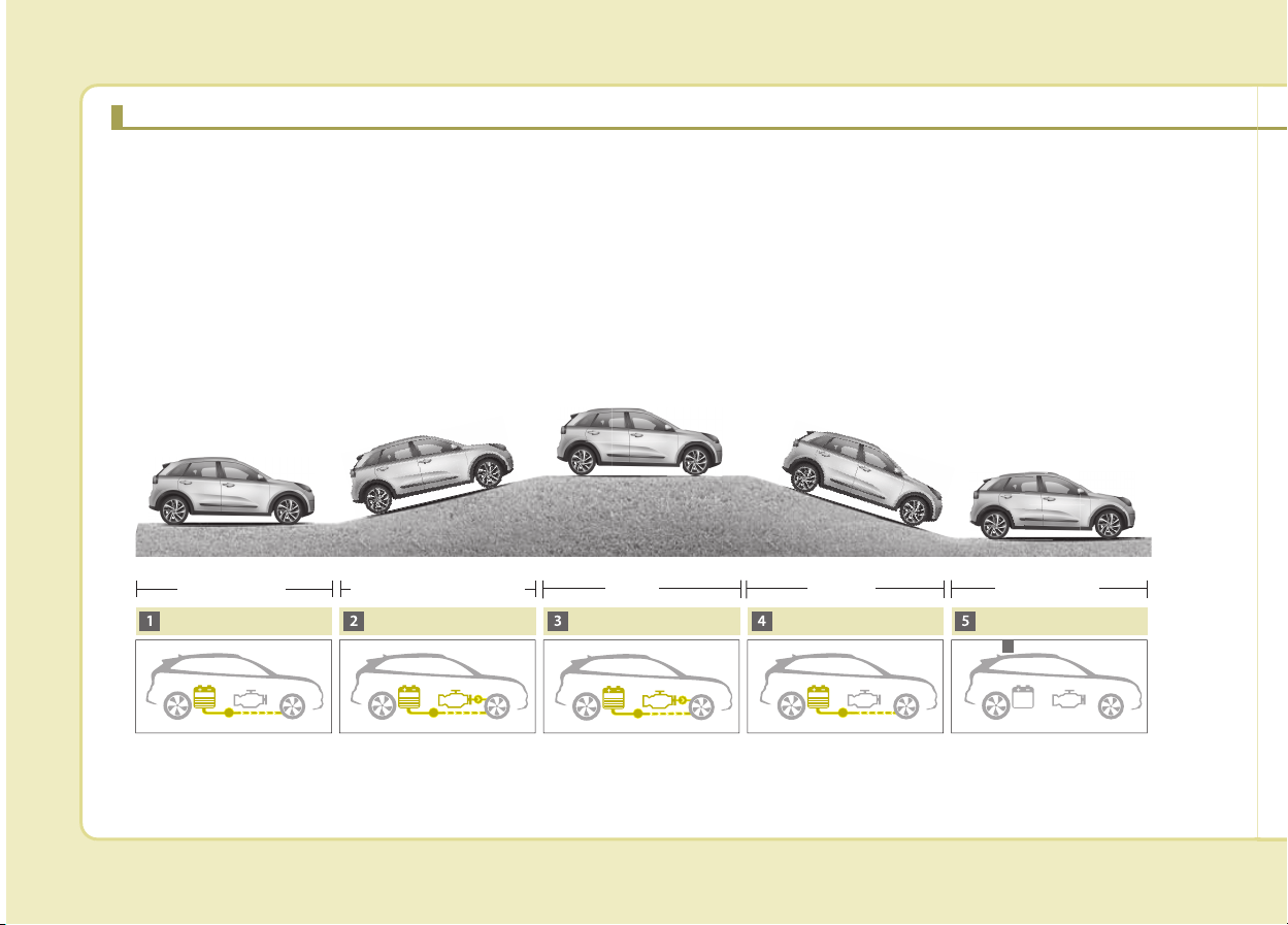
The Kia Hybrid Electric Vehicle (HEV) uses both the gasoline engine and the electric motor for power. The electric
motor is run by a 270V high-voltage HEV battery.
Depending on the driving conditions, the HEV computer selectively operates between the engine and the electric
motor or even both at the same time.
Fuel efficiency increases when the engine is at idle, or when the vehicle is driven by the electric motor with the HEV
battery.
The HEV battery charge must be maintained for the times when the engine acts as a generator, such as when
stopped at idle. Charging also occurs when decelerating or by regenerative braking.
ODE056001
Start up / Low speed cruise
Acceleration
High speed cruise
Deceleration
Stop
Electric motor Electric motor + Engine
6
Engine
Charging
Engine OFF
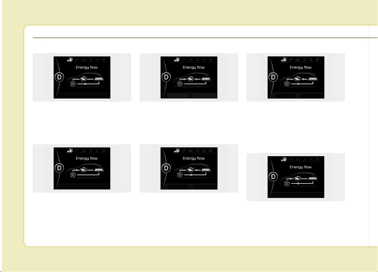
H3
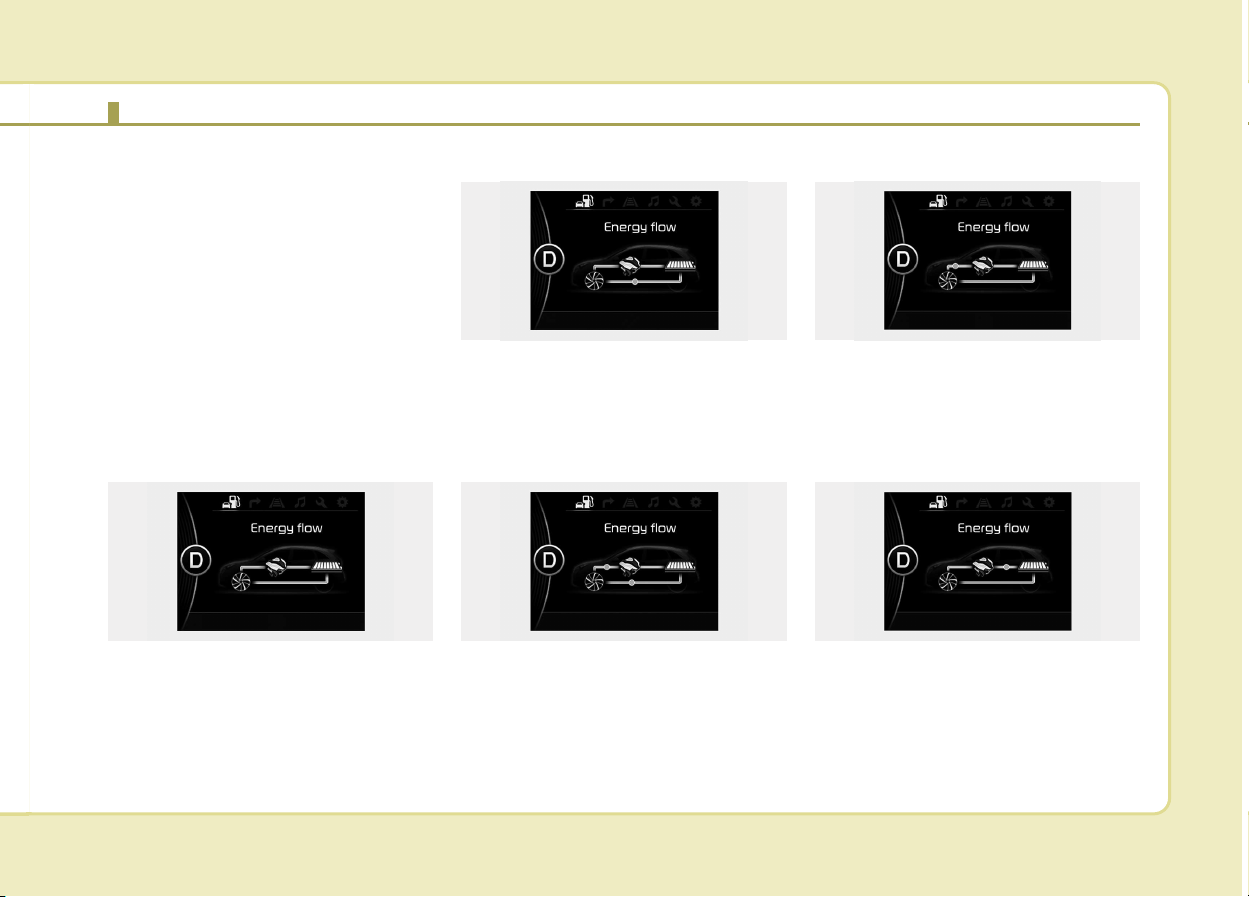
Kia hybrid system notifies the drivers
of energy flow in various operating
modes. Eleven Modes show drivers
the current operating condition.
Vehicle Stop
The mode means the vehicle at stop.
(There is no energy flow.)
EV Propulsion
Electric power is used to move the
vehicle.
(Battery ➞ Wheel)
Power Assist
Electric and Engine power are used
to move the vehicle.
(Battery & Engine ➞ Wheel)
Engine Only Propulsion
Engine power is used to move the
vehicle.
(Engine ➞ Wheel)
Engine Generation
Vehicle is stopped with the Engine
charging the hybrid battery.
(Engine ➞ Battery)
NIRO HYBRID ENERGY FLOW
ODE046121L ODE046123L
ODE046122LODE046120L ODE046124L
H4
Regeneration
Hybrid battery is being charged by
regenerative braking.
(Wheel ➞ Battery)
Engine Brake
The vehicle is being slowed by
engine compression.
(Wheel ➞ Engine)
Power Reserve
Engine is both driving the vehicle
and charging the hybrid battery.
(Engine ➞ Wheel & Battery)
Engine Generation/Motor Drive
The vehicle is being slowed by engine
compression and regenerative brak-
ing. The hybrid battery is being
charged by regenerative braking.
(Engine ➞ Battery ➞ Wheel)
Engine Generation/Regeneration
The engine and regenerative braking
system charge the hybrid battery
driving deceleration.
(Engine & Wheel ➞ Battery)
Engine Brake/Regeneration
The engine compression can be
used to slow the vehicle. The regen-
erative braking system can be used
to charge the hybrid system.
(Wheel ➞ Engine & Battery)
ODE046127L
ODE046121L
ODE046128L
ODE046122L
ODE046128L
ODE046126L

H5
Starting the Hybrid System
1.Carry the smart key into the vehicle.
2.Make sure the parking brake is
firmly applied.
3.Place the shift lever in the P(Park)
position.
In N (neutral) position, you can not
start the vehicle.
4.Depress the brake pedal.
5.Press the engine start/stop button
or turn the ignition switch to the ON
position.
6.The engine should be started with-
out pressing the accelerator. In
extremely cold weather or after the
vehicle has not been operated for
several days, let the engine warm up
without depressing the accelerator.
• Even if the smart key is in the
vehicle, if it is far away from you,
the engine may not start.
• When the engine start/stop but-
ton is in the ACC or ON position
or turn the ignition switch to the
ACC or ON position. If any door is
open, the system checks for the
smart key. If the smart key is not
in the vehicle, the warning, "Key
is not in vehicle" will come on,
and if all doors are closed, the
chime will also sound for about 5
seconds. The indicator will turn
off while the vehicle is moving.
Keep the smart key in the vehicle
when using the ACC position or if
the vehicle engine is on.
If the starting procedure is fol-
lowed, the "READY" symbol on
the instrument cluster will turn on.
For more details, Please check
chapter 6.
ECONOMICAL and SAFE
OPERATION of Hybrid system
• Drive smoothly. Accelerate at a mod-
erate rate and maintain a steady
cruising speed. Don't make "jack-
rabbit" starts. Don't race between
stoplights. Avoid heavy traffic when-
ever possible. Always maintain a
safe distance from other vehicles so
you can avoid unnecessary braking.
This also reduces brake wear.
• The regenerative brake generates
energy when the vehicle decelerates.
• When the hybrid battery power is
low, the hybrid system automatical-
ly recharges the hybrid battery.
• When the engine runs in "N" posi-
tion, the hybrid system cannot gen-
erate electricity. The hybrid battery
cannot recharge in "N" position.
Please refer to chapter 6.
✽✽
NOTICE
When the hybrid system is in
READY mode, the engine will auto-
matically start and stop as needed.
The "READY" symbol will illumi-
nate in the cluster when the system
is operational.
STARTING THE HYBRID VEHICLE (SMART KEY)
H6
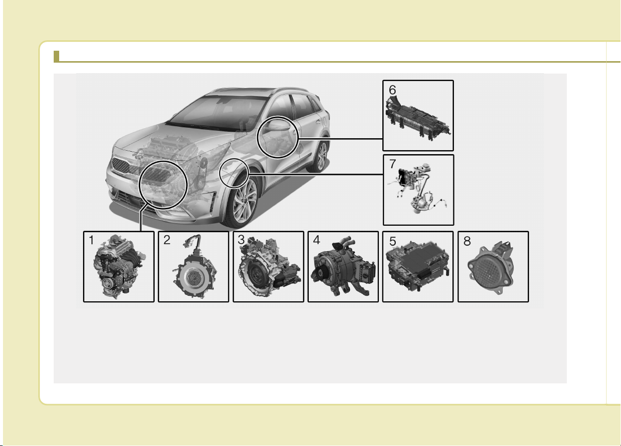
THE COMPONENTS OF HYBRID VEHICLE
1. Engine : 1.6L
2. Motor : 32kW
3. Transmission : 6DCT
4. Hybrid starter generator (HSG)
5. HPCU (Hybrid Power Control Unit)
6. High voltage battery system
7. Generative brake system
8. Virtual Engine Sound System (VESS)
ODEQ016001L
❈ The actual shape may differ from the illustration.
H7
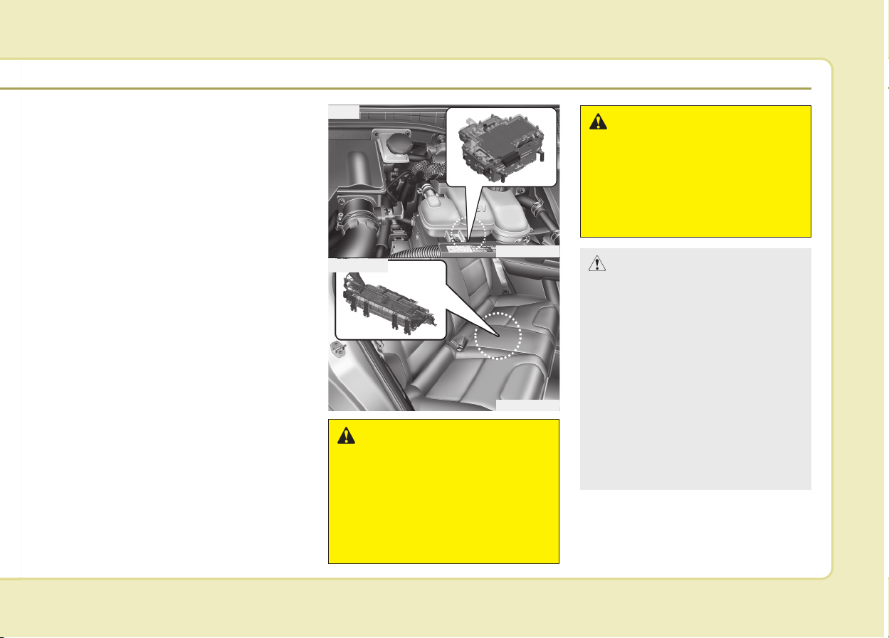
The Hybrid battery uses high voltage
top operate the electric motor and
other components and other compo-
nents. High voltage is dangerous if
touched.
Your vehicle is equipped with orange
colored insulation and covers over
the high voltage components to pro-
tect people from electric shock. High
voltage warning labels are attached
to some system components as
additional warnings. Your vehicle is
recommended to be serviced by an
authorized Kia dealer.
WARNING
Never touch orange or high volt-
age labeled components includ-
ing wires, cables, and connec-
tions. If the insulators or covers
are damaged or removed, severe
injury or death from electrocu-
tion may occur.
WARNING
When replacing the fuses in the
engine compartment, never
touch the HPCU. The HPCU car-
ries high voltage. Touching the
HPCU could result in electrocu-
tion, serious injury, or death.
ODEQ016002
ODEQ016003
HPCU
HEV Battery
CAUTION
• Do not apply strong force nor
pile up any items above the
rear seat. Such an attempt may
distort the high voltage battery
case, causing a safety problem
or degrading the performance.
• Be careful when loading
inflammable liquid in rear seat.
It could cause operational and
safety degradation if the liquid
leaks and flows in high voltage
battery.
(Continued)
H8
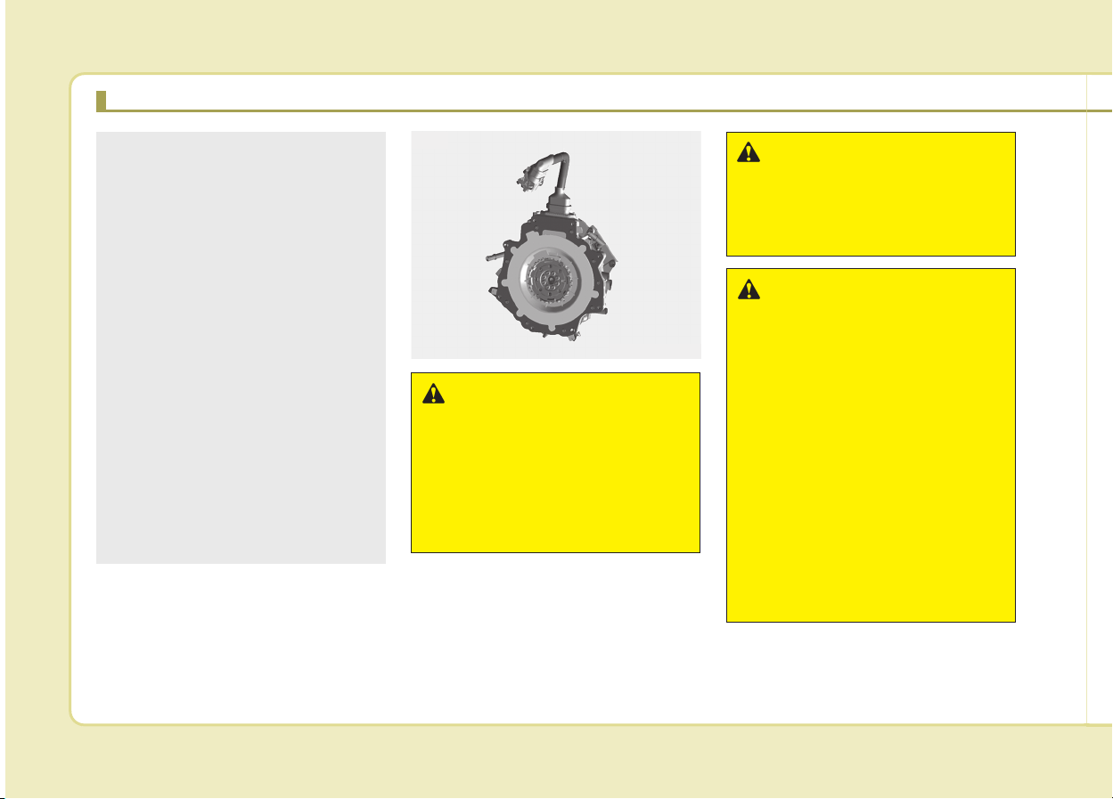
THE COMPONENTS OF HYBRID VEHICLE (CONT.)
WARNING
As with all batteries, avoid fluid
contact with the Hybrid battery.
If the battery is damaged and if
electrolyte comes in contact
with your body, clothes or eyes,
immediately flush with a large
quantity of fresh water.
WARNING
Do not use an after-market bat-
tery charger to charge the
Hybrid battery. Doing so may
result in death or serious injury.
WARNING - High Waters
• Avoid high waters as this may
result in your vehicle becom-
ing saturated with water and
could compromise the high
voltage components.
• Do not touch the any of the
high voltage components
within your vehicle if your
vehicle has been submerged
in water equal to half of the
vehicle height. Touching high
voltage components once
submerged in water could
result in severe burns or elec-
tric shock that could result in
death or serious injury.
ODEQ016004
Motor
(Continued)
• Prolonged exposure of high
voltage battery to high temper-
ature may lead to decrease in
battery performance.
Therefore, the heat treatment
duration for vehicle paint work
should not exceed 30 minutes
in 70°C and 20 minutes in 80°C.
• When cleaning the inside of the
engine room, high pressure
washing and applying water
directly can both cause short
circuit of the high voltage. This
may lead to electric shock.
Also, the vehicle parts, espe-
cially electronic, can be dam-
aged and result in vehicle mal-
function. Always use caution
when cleaning the inside of
the engine room.
H9
WARNING -
Exposure to High Voltage
• High voltage in the hybrid bat-
tery system is very dangerous
and can cause severe burns
and electric shock. This may
result in serious injury or death.
• For your safety, never touch,
replace, dismantle or remove
any portion of the hybrid bat-
tery system including compo-
nents, cables and connectors.
WARNING - Use of Water
or Liquids
If water or liquids come into
contact with the hybrid system
components, and you are also
in contact with the water, severe
injury or death due to electrocu-
tion may occur.
WARNING -
Hot Components
When the hybrid battery system
operates, the HEV battery sys-
tem can be hot. Heat burns may
result from touching even insu-
lated components of the HEV
system.
CAUTION - Cleaning
Engine
When you clean the engine
compartment, do not wash
using water. Water may cause
electric arcing to occur and
damage electronic parts and
components.
WARNING -
Carrying Liquids in rear seat
Do not load large amounts of
water in open containers into the
vehicle. If the water spills onto
the HEV battery, it may cause a
short and damage the battery.

H10
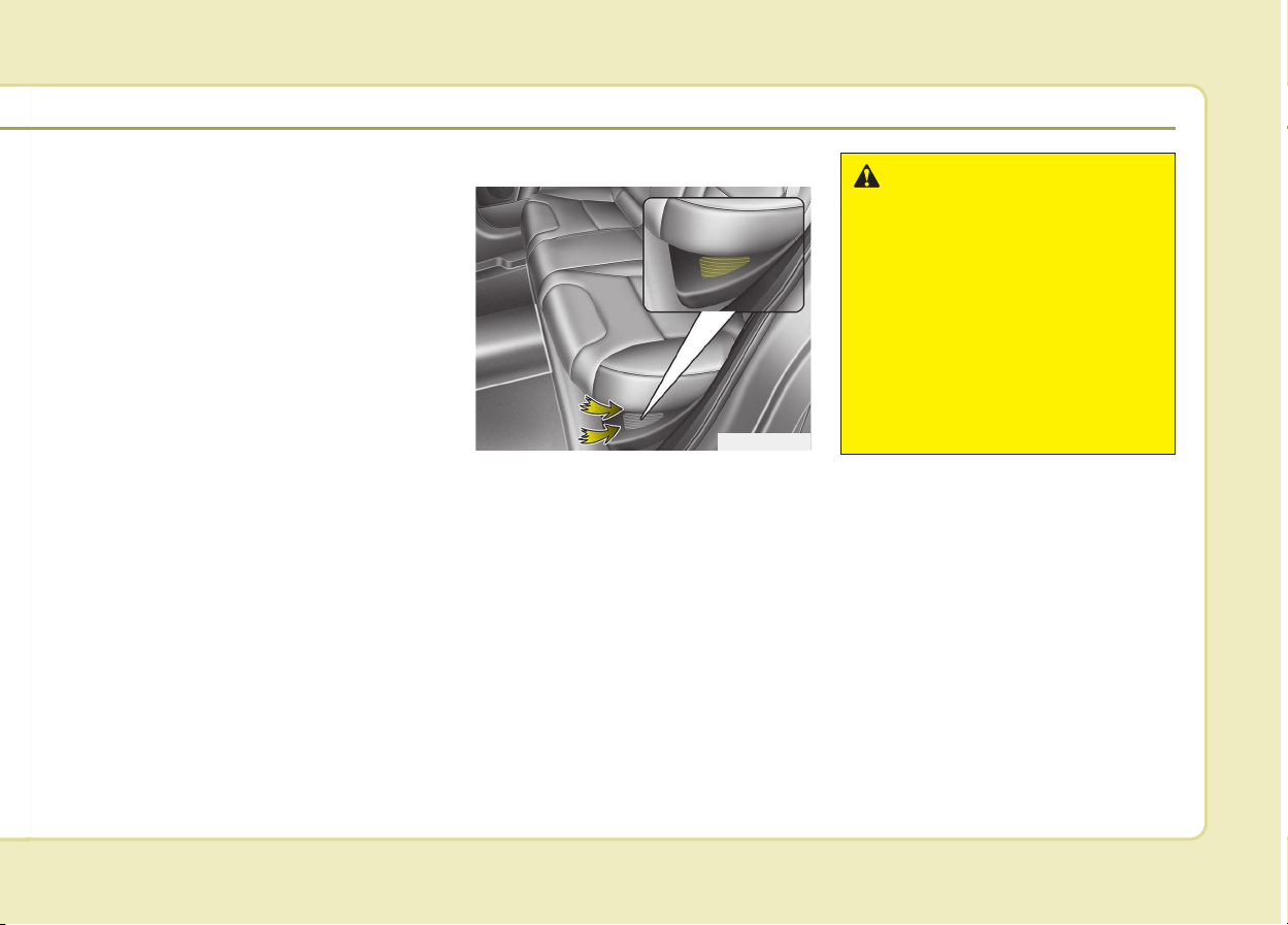
Safety plug
The safety plug is located under-
neath the rear seat.
Some Special Features of the
Hybrid Vehicle.
Hybrid vehicles sound different than
gasoline engine vehicles. When the
hybrid system operates, you may
hear a sound from the hybrid battery
system behind the rear seat. If you
apply the accelerator pedal rapidly,
you may hear a sound. When you
apply the brake pedal, you may hear
a sound from the regenerative brake
system. When the hybrid system is
turned off or on, you may hear a
sound in the engine compartment. If
you depress the brake pedal repeat-
edly when the hybrid system is
turned on, you may hear a sound in
the engine compartment. None of
these sounds indicate a problem.
They are characteristics of hybrid
vehicles.
When the hybrid system is turned on,
the engine may run. This does not
indicate a malfunction. If the "READY"
symbol is on, the hybrid system is
operating. Even if the gasoline engine
is off, you can operate the vehicle.
The HEV system may emit electro-
magnetic waves which can affect the
performance of electronic devices
appliances, such as laptop comput-
ers, which are not part of the vehicle
design.
If you park the vehicle for a long time,
the hybrid system will discharge. You
need to drive the vehicle several times
per month to maintain a charge.
When you start the hybrid system in
the "P" transmission position, the
"READY" symbol is illuminated in the
cluster. The driver can drive the vehi-
cle even if the engine is stopped.
THE COMPONENTS OF HYBRID VEHICLE (CONT.)
ODEQ016006
DANGER
Never touch the safety plug
under the rear seat. Safety plug
is attached to high voltage
hybrid battery system. Touching
safety plug will result in death or
serious injury. Service person-
nel should follow procedure in
service manual.
WARNING
When you leave the vehicle, you
should turn off the hybrid sys-
tem. If you depress the acceler-
ator pedal by mistake and the
vehicle is not in the "P" posi-
tion, the vehicle will accelerate.
This may result in serious injury
or death.
H11
Virtual Engine Sound System
(VESS)
The Virtual Engine Sound System
generates an engine sound for
pedestrians to hear vehicle while at
low speeds in EV mode.
Hybrid battery air intake
The hybrid battery air intake is locat-
ed on bottom the rear seats. The air
intake cools down the hybrid battery.
When the hybrid battery air intake is
blocked, the hybrid battery may be
overheated. Do not obstruct the air
intake with any other objects.
WARNING - Air Intake
• Blocking the air intake behind
the rear seats may damage
the HEV battery.
• Do not allow any water into
the air intake even when
cleaning. If any water enters
the air intake, the Hybrid bat-
tery may cause an electric
shock which can cause seri-
ous injury or death due to
electrocution.
ODEQ016007
H12
If An Accident Occurs
• Avoid the engine compartment.
• Avoid any orange or high voltage
wires, cables, or components.
• Assume that a high voltage com-
ponent is exposed and move away
from the vehicle as promptly as
possible.
• Refer to Chapter 7 for towing infor-
mation.
THE COMPONENTS OF HYBRID VEHICLE (CONT.)
WARNING
• After parking the vehicle, shift
the transmission into "P"
position. Turn off the hybrid
system by pushing the Engine
Start/Stop button.
• For your safety, do not touch
high voltage cables, connec-
tors and package modules.
High Voltage components are
orange in color.
• Exposed cables or wires may
be visible inside or outside of
the vehicle. Never touch the
wires or cables, because an
electrical shock may occur
causing injury or death.
(Continued)
(Continued)
• If a fire occurs,
to extinguish a small high-
voltage battery fire, the follow-
ing techniques can be used:
- Dry chemical
- CO2
- Large amounts of water
- Regular foam
For a large high-voltage bat-
tery fire, use these types of
extinguishing methods:
- Large amounts of water
- Fog
- Regular foam
• If you need towing, refer to
chapter 7.
H13
WARNING
If a vehicle accident occurs:
1.Stop the vehicle and shift the
transmission into "P" position.
And then depress the parking
brake.
2.Turn off the Hybrid system by
pushing the Engine Start/Stop
Button.
3.Evacuate to the safety place.
4.Call emergency services for
help and let them know the
vehicle is a Hybrid vehicle.
Do not touch high voltage
cables, connectors and pack-
age modules. High voltage com-
ponents are orange in color.
Exposed cables or wires may
be visible inside or outside of
the vehicle. Never touch the
wires or cables, because an
electrical shock may occur
causing injury or death.
WARNING
If a fire occurs:
1.Stop the vehicle and shift the
transmission in to "P" posi-
tion, and then depress the
parking brake. To ventilate
smoke from a fire, open the
windows if possible.
2.Turn off the Hybrid system by
pushing the Engine Start/Stop
Button.
3.Leave the vehicle and evacu-
ate to the safety place.
4.Call emergency services for
help and let them know the
vehicle is a Hybrid vehicle.
If you have an extinguisher,
extinguish a fire carefully.
Do not touch high voltage
cables, connectors and pack-
age modules. High voltage com-
ponents are orange in color.
Exposed cables or wires may
be visible inside or outside of
the vehicle. Never touch the
wires or cables, because an
electrical shock may occur
causing injury or death.
WARNING
If a submersion in water occurs:
If your vehicle was flooded and
has soaked carpeting or water
on the flooring, you should not
try to start the Hybrid system.
Never touch the high voltage
cables, connectors and pack-
age modules, because an elec-
trical shock may occur causing
injury or death. High Voltage
cables are orange in color.
We recommend that the car
towed to an authorized Kia dealer.
H14
When the hybrid vehicle shuts
off
When the high voltage battery or 12-
volt battery discharges, or fuel tank is
empty, the hybrid system may not
operate.
If the Hybrid system stops operating
while the vehicle is moving, reduce
the vehicle speed gradually. Pull
your vehicle off the road in a safe
area, and shift the transmission in to
Park (P) position and;
1.Turn on the hazard warning flashers.
2.Set the start button at OFF, and try
to start the Hybrid system by
applying the brake pedal and push-
ing the start button.
3.If the Hybrid system will not oper-
ate, refer to "EMERGENCY
STARTING" in chapter 7.
Before you try to jump start the vehi-
cle, confirm the fuel level. If the fuel
level is low add more fuel before
attempting as emergency start.
THE COMPONENTS OF HYBRID VEHICLE
WARNING - Accident
Vehicle
Never touch electric wires or
cable. If exposed electric wires
or cables are visible inside or
outside of your vehicle, an elec-
tric shock may occur.
WARNING - Putting out
fire
Never use a small quantity of
water to put out a fire in your
vehicle. If a fire occurs, evacu-
ate the car immediately and
contact the fire department.

Introduction
How to use this manual . . . . . . . . . . . . . . . . . . . . . . 1-2
Fuel requirements . . . . . . . . . . . . . . . . . . . . . . . . . . 1-3
• Gasoline engine . . . . . . . . . . . . . . . . . . . . . . . . . . . . . . . 1-3
Vehicle handling instructions . . . . . . . . . . . . . . . . . 1-6
Vehicle break-in process . . . . . . . . . . . . . . . . . . . . . 1-6
HEV powertrain . . . . . . . . . . . . . . . . . . . . . . . . . . . . 1-6
1
Introduction
21
We want to help you get the greatest
possible driving pleasure from your
vehicle. Your Owner’s Manual can
assist you in many ways. We strong-
ly recommend that you read the
entire manual. In order to minimize
the chance of death or injury, you
must read the WARNING and CAU-
TION sections in the manual.
Illustrations complement the words in
this manual to best explain how to
enjoy your vehicle. By reading your
manual, you learn about features,
important safety information, and driv-
ing tips under various road conditions.
The general layout of the manual is
provided in the Table of Contents.
Use the index when looking for a
specific area or subject, it has an
alphabetical listing of all information
in your manual.
Chapters: This manual has nine
chapters plus an index. Each chapter
begins with a brief list of contents so
you can tell at a glance if that chap-
ter has the information you want.
You will find various WARNINGs,
CAUTIONs, and NOTICEs in this
manual. These WARNINGs were pre-
pared to enhance your personal safe-
ty.You should carefully read and follow
ALL procedures and recommenda-
tions provided in these WARNINGs,
CAUTIONs and NOTICEs.
✽✽
NOTICE
A NOTICE indicates interesting or
helpful information is being provided.
HOW TO USE THIS MANUAL
WARNING
A WARNING indicates a situation
in which harm, serious bodily
injury or death could result if the
warning is ignored.
CAUTION
A CAUTION indicates a situation
in which damage to your vehicle
could result if the caution is
ignored.
13
Introduction
Gasoline engine
Unleaded
For Europe
For the optimal vehicle performance,
we recommend you to use unleaded
gasoline with an octane rating of
RON (Research Octane Number) 95
/ AKI (Anti Knock Index) 91 or higher.
You may use unleaded gasoline with
an octane rating of RON 91~94 / AKI
87~90 but it may result in slight per-
formance reduction of the vehicle.
(Do not use methanol blended fuels.)
Except Europe
Your new Kia vehicle is designed to
use only unleaded fuel having an
Octane Rating of RON (Research
Octane Number) 91 / AKI (Anti-
Knock Index) 87 or higher. (Do not
use methanol blended fuels.)
Your new vehicle is designed to
obtain maximum performance with
UNLEADED FUEL, as well as mini-
mize exhaust emissions and spark
plug fouling.
Leaded (if equipped)
For some countries, your vehicle is
designed to use leaded gasoline.
When you are going to use leaded
gasoline, we recommend that you
ask an authorized Kia dealer
whether leaded gasoline in your
vehicle is available or not.
Octane Rating of leaded gasoline is
same with unleaded one.
FUEL REQUIREMENTS
WARNING
• Do not "top off" after the noz-
zle automatically shuts off
when refueling.
• Always check that the fuel cap
is installed securely to pre-
vent fuel spillage in the event
of an accident.
CAUTION
NEVER USE LEADED FUEL. The
use of leaded fuel is detrimental
to the catalytic converter and
will damage the engine control
system’s oxygen sensor and
affect emission control.
Never add any fuel system
cleaning agents to the fuel tank
other than what has been speci-
fied. (We recommend that you
consult an authorized Kia dealer
for details.)

Introduction
41
Gasoline containing alcohol and
methanol
Gasohol, a mixture of gasoline and
ethanol (also known as grain alco-
hol), and gasoline or gasohol con-
taining methanol (also known as
wood alcohol) are being marketed
along with or instead of leaded or
unleaded gasoline.
Do not use gasohol containing more
than 10% ethanol, and do not use
gasoline or gasohol containing any
methanol. Either of these fuels may
cause drivability problems and dam-
age to the fuel system, engine control
system and emission control system.
Discontinue using gasohol of any
kind if drivability problems occur.
Vehicle damage or drivability prob-
lems may not be covered by the
manufacturer’s warranty if they result
from the use of:
1. Gasohol containing more than
10% ethanol.
2. Gasoline or gasohol containing
methanol.
3. Leaded fuel or leaded gasohol.
Other fuels
Using fuels such as
- Silicone (Si) contained fuel,
- MMT (Manganese, Mn) contained
fuel,
- Ferrocene (Fe) contained fuel, and
- Other metalic additives contained
fuels, may cause vehicle and engine
damage or cause plugging, misfir-
ing, poor acceleration, engine
stalling, catalyst melting, abnormal
corrosion, life cycle reduction, etc.
Also, the Malfunction Indicator
Lamp (MIL) may illuminate.
✽✽
NOTICE
Damage to the fuel system or per-
formance problem caused by the use
of these fuels may not be covered by
your New Vehicle Limited Warranty.
CAUTION
Never use gasohol which con-
tains methanol. Discontinue use
of any gasohol product which
impairs drivability.

15
Introduction
Use of MTBE
Kia recommends avoiding fuels con-
taining MTBE (Methyl Tertiary Butyl
Ether) over 15.0% vol. (Oxygen
Content 2.7% weight) in your vehicle.
Fuel containing MTBE over 15.0%
vol. (Oxygen Content 2.7% weight)
may reduce vehicle performance and
produce vapor lock or hard starting.
Do not use methanol
Fuels containing methanol (wood
alcohol) should not be used in your
vehicle. This type of fuel can reduce
vehicle performance and damage
components of the fuel system,
engine control system and emission
control system.
Fuel Additives
Kia recommends that you use
unleaded gasoline which has an
octane rating of RON (Research
Octane Number) 95 / AKI (Anti Knock
Index) 91 or higher (for Europe) or
Octane Rating of RON (Reasearch
Octane Number) 91 / AKI (Anti-Knock
Index) 87 or higher (except Europe).
For customers who do not use good
quality gasolines including fuel addi-
tives regularly, and have problems
starting or the engine does not run
smoothly, one bottle of additives
added to the fuel tank at every
15,000km (For Europe)/ 10,000km
(Except Europe). Additives are avail-
able from your authorized Kia dealer
along with information on how to use
them. Do not mix other additives.
Operation in foreign countries
If you are going to drive your vehicle
in another country, be sure to:
• Observe all regulations regarding
registration and insurance.
• Determine that acceptable fuel is
available.
CAUTION
Your New Vehicle Limited
Warranty may not cover damage
to the fuel system and any per-
formance problems that are
caused by the use of fuels con-
taining methanol or fuels con-
taining MTBE (Methyl Tertiary
Butyl Ether) over 15.0% vol.
(Oxygen Content 2.7% weight.)

Introduction
61
As with other vehicles of this type,
failure to operate this vehicle correct-
ly may result in loss of control, an
accident or vehicle rollover.
Specific design characteristics (high-
er ground clearance, track, etc.) give
this vehicle a higher center of gravity
than other types of vehicles. In other
words they are not designed for cor-
nering at the same speeds as con-
ventional 2-wheel drive vehicles.
Avoid sharp turns or abrupt maneu-
vers. Again, failure to operate this
vehicle correctly may result in loss of
control, an accident or vehicle
rollover. Be sure to read the
“Reducing the risk of a rollover”
driving guidelines, in chapter 6 of
this manual.
No special break-in period is needed.
By following a few simple precautions
for the first 1,000 km (600 miles) you
may add to the performance, econo-
my and life of your vehicle.
• Do not race the engine.
• While driving, keep your engine
speed (rpm, or revolutions per
minute) within 3,000 rpm.
• Do not maintain a single speed for
long periods of time, either fast or
slow. Varying engine speed is need-
ed to properly break-in the engine.
• Avoid hard stops, except in emer-
gencies, to allow the brakes to seat
properly.
• Don't tow a trailer during the first
2,000 km (1,200 miles) of operation.
By following a few simple precautions
for the first 1,000 km (600 miles) you
may add to the performance, econo-
my and life of your vehicle.
• Do not race the engine.
• Avoid hard stops, except in emer-
gencies, to allow the brakes to seat
properly.
VEHICLE BREAK-IN
PROCESS
HEV POWERTRAINVEHICLE HANDLING
INSTRUCTIONS

Your vehicle at a glance
Exterior overview . . . . . . . . . . . . . . . . . . . . . . . . . . . 2-2
Interior overview . . . . . . . . . . . . . . . . . . . . . . . . . . . 2-4
Instrument panel overview . . . . . . . . . . . . . . . . . . . 2-5
Engine compartment . . . . . . . . . . . . . . . . . . . . . . . . 2-6
2
Your vehicle at a glance
22
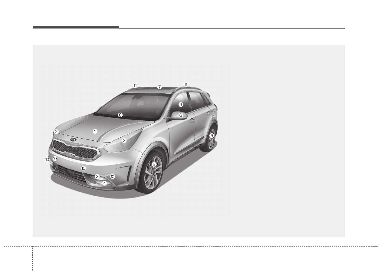
EXTERIOR OVERVIEW
1. Hood......................................................4-26
2. Head lamp (Features of your vehicle) .....4-96
Head lamp (Maintenance).....................8-85
3. Day time running light (D.R.L) ...............4-96
4. Fog lamp ....................................4-100, 8-87
5. Wheel and tire.........................8-50, 9-5, 9-6
6. Outside rearview mirror.........................4-40
7. Sunroof..................................................4-31
8. Front windshield wiper blades
(Features of your vehicle)....................4-102
Front windshield wiper blades
(Maintenance) .......................................8-42
9. Windows................................................4-21
10. Parking assist system .........................4-89
11. Roof rack...........................................4-147
ODE016001
■ Front view
❈ The actual shape may differ from the illustration.
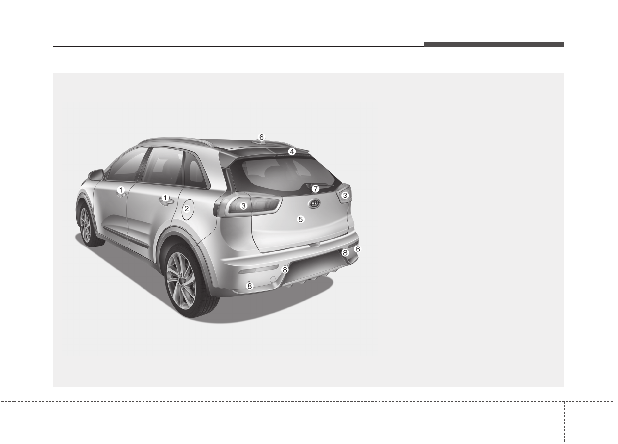
23
Your vehicle at a glance
1. Door locks .............................................4-15
2. Fuel filler lid ...........................................4-28
3. Rear combination lamp
(Maintenance) .......................................8-83
4. High mounted stop lamp
(Maintenance) .......................................8-90
5. Tailgate ..................................................4-19
6. Antenna ...................................................5-2
7. Rear wiper and Rearview camera
...................................................4-106, 4-94
8. Parking assist system (Rear) .......4-85, 4-89
ODE016002
■ Rear view
❈ The actual shape may differ from the illustration.
Your vehicle at a glance
42
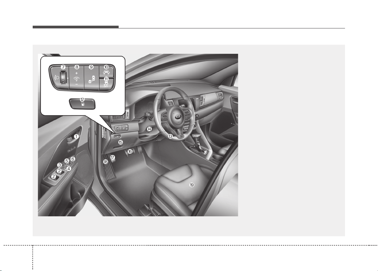
INTERIOR OVERVIEW
1. Inside door handle.................................4-15
2. Power window switch ............................4-21
3. Central door lock switch ........................4-16
4. Power window lock button.....................4-24
5. Outside rearview mirror control.............4-41
6. Outside rearview mirror folding .............4-42
7. Headlight leveling device.....................4-101
8. Instrument panel illumination control ....4-45
9. BSD On/Off button ................................6-82
10. LKAS On/Off button ............................6-73
11. ESC Off button ....................................6-30
12. Fuel filler lid open button.....................4-28
13. Steering wheel ....................................4-36
14. Tilt and telescopic steering control lever
............................................................4-37
15. Inner fuse panel ..................................8-68
16. Brake pedal .........................................6-24
17. Parking brake pedal ...................6-25, 8-37
18. Hood release lever ..............................4-26
19. Seat .......................................................3-2
ODE016003L
❈ The actual shape may differ from the illustration.
25
Your vehicle at a glance
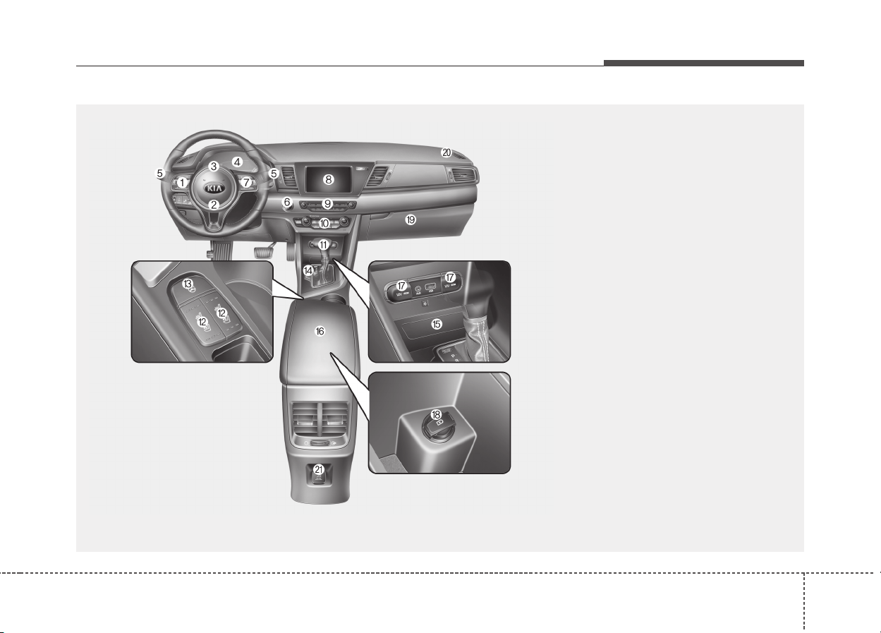
INSTRUMENT PANEL OVERVIEW
1. Steering wheel audio controls ...............5-3
2. Driver`s front air bag ...........................3-56
3. Horn.....................................................4-38
4. Instrument cluster................................4-44
5. Wiper and washer control lever
(Right)................................................4-102
Turn signal / headlamp control lever
(Left) ....................................................4-95
6. Engine start/stop button ........................6-9
7. Cruise control ......................................6-49
Smart cruise control ............................6-54
8. AVN (Audio/Video/Navigation)...............5-8
9. Hazard warning flasher .........................7-2
10. Climate control system....................4-117
11. Shift lever DCT ..................................6-15
12. Front seat warmer ...........................4-136
Front air ventilation seat ..................4-138
13. Heated steering wheel button ...........4-37
14. Parking assist system On/Off button...4-89
15. Smart phone wireless charger ........4-141
16. Center console storage box ............4-131
17. Power outlet.....................................4-138
18. USB charger....................................4-139
19. Glove box ........................................4-131
20. Passenger`s front air bag.................3-56
21. AC 220V inverter .............................4-140
ODE016004
❈ The actual shape may differ from the illustration.
Your vehicle at a glance
62
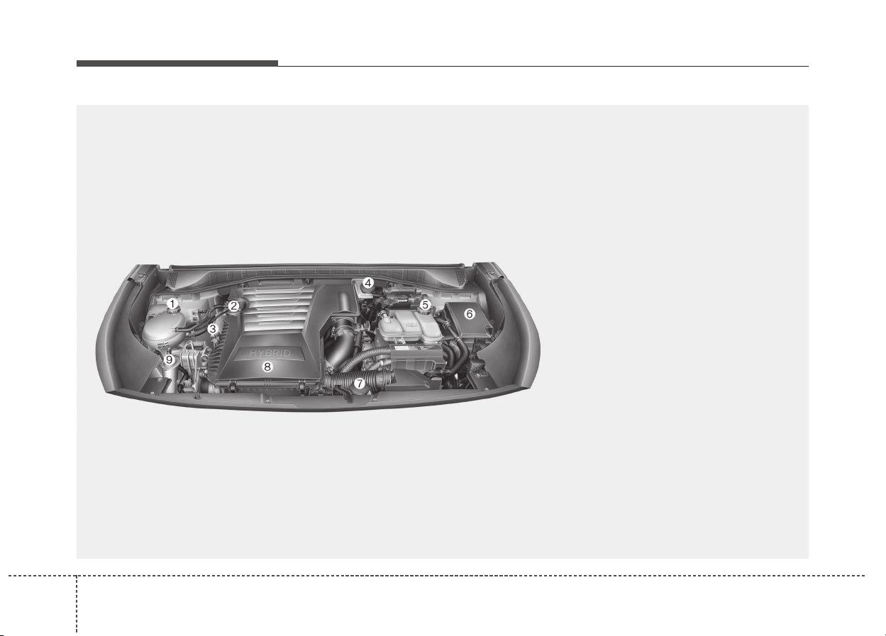
ENGINE COMPARTMENT
ODE076001
■■
Gasoline Kappa 1.6GDI
❈ The actual engine room in the vehicle may differ from the illustration.
1. Engine coolant reservoir...................8-28
2. Engine oil filler cap ...........................8-26
3. Engine oil dipstick.............................8-26
4. Brake fluid reservoir..........................8-33
5. Inverter coolant reservoir..................8-30
6. Fuse box ...........................................8-65
7. Engine clutch actuator reservoir
tank ...................................................8-34
8. Air cleaner.........................................8-38
9. Windshield washer fluid reservoir .....8-36

Safety features of your vehicle
Seats . . . . . . . . . . . . . . . . . . . . . . . . . . . . . . . . . . . . . . 3-2
• Front seat adjustment - manual. . . . . . . . . . . . . . . . . . 3-6
• Front seat adjustment - power. . . . . . . . . . . . . . . . . . . 3-7
• Headrest (for front seat) . . . . . . . . . . . . . . . . . . . . . . . . 3-8
• Seatback pocket . . . . . . . . . . . . . . . . . . . . . . . . . . . . . . 3-11
• Driver position memory system (for power seat). . . 3-12
• Rear seat. . . . . . . . . . . . . . . . . . . . . . . . . . . . . . . . . . . . 3-13
• Headrest . . . . . . . . . . . . . . . . . . . . . . . . . . . . . . . . . . . . 3-16
Seat belts . . . . . . . . . . . . . . . . . . . . . . . . . . . . . . . . . 3-18
• Seat belt restraint system . . . . . . . . . . . . . . . . . . . . . . 3-18
• Pre-tensioner seat belt. . . . . . . . . . . . . . . . . . . . . . . . . 3-26
• Seat belt precautions . . . . . . . . . . . . . . . . . . . . . . . . . . 3-29
• Care of seat belts . . . . . . . . . . . . . . . . . . . . . . . . . . . . . 3-32
Child restraint system (CRS) . . . . . . . . . . . . . . . . 3-33
• Selecting a Child Restraint System (CRS) . . . . . . . . 3-34
• Installing a Child Restraint System (CRS). . . . . . . . 3-36
• ISOFIX anchorage and top-tether anchorage
(ISOFIX anchorage system) for children . . . . . . . 3-37
Air bag - supplemental restraint system . . . . . . . 3-47
• How does the air bag system operate . . . . . . . . . . . . 3-48
• Air bag warning light . . . . . . . . . . . . . . . . . . . . . . . . . 3-51
• SRS components and functions . . . . . . . . . . . . . . . . . 3-53
• Driver's and passenger's front air bag . . . . . . . . . . . 3-56
• Side air bag . . . . . . . . . . . . . . . . . . . . . . . . . . . . . . . . . 3-62
• Curtain air bag . . . . . . . . . . . . . . . . . . . . . . . . . . . . . . 3-63
• SRS Care . . . . . . . . . . . . . . . . . . . . . . . . . . . . . . . . . . . 3-68
• Additional safety precautions. . . . . . . . . . . . . . . . . . . 3-69
• Air bag warning label . . . . . . . . . . . . . . . . . . . . . . . . . 3-70
3
Safety features of your vehicle
23
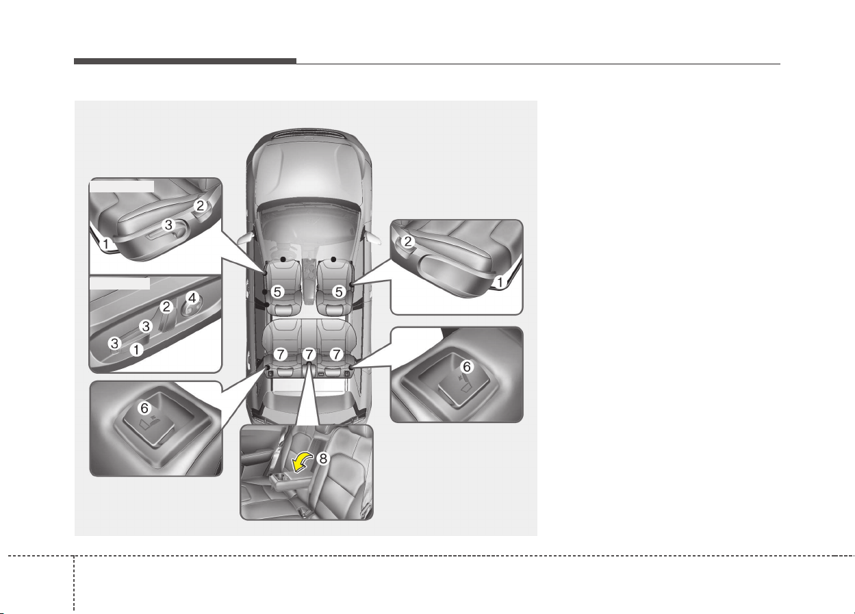
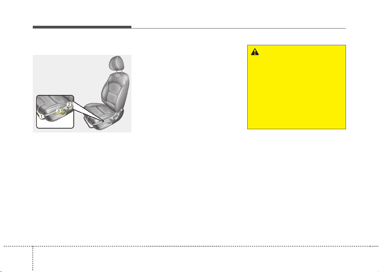
Front seat
(1) Forward and backward
(2) Seatback angle
(3) Seat cushion height (Driver`s seat)
(4) Lumbar support (Driver’s seat)*
(5) Head rest
Rear seat
(6) Seatback folding
(7) Headrest
(8) Armrest*
* : if equipped
SEATS
ODE036001L
■ Manual seat
■ Power seat
33
Safety features of your vehicle
WARNING - Uprighting
seat
When you return the seatback
to its upright position, hold the
seatback and return it slowly
and be sure there are no other
occupants around the seat. If
the seatback is returned with-
out being held and controlled,
the back of the seat could
spring forward resulting in acci-
dental injury to a person struck
by the seatback.
WARNING - Loose
objects
Loose objects in the driver’s
foot area could interfere with
the operation of the foot pedals,
possibly causing an accident.
Do not place anything under the
front seats.
WARNING - Driver
responsibility for passengers
Riding in a vehicle with the
seatback reclined could lead to
serious or fatal injury in an acci-
dent. If a seat is reclined during
an accident, the occupant’s
hips may slide under the lap
portion of the seat belt applying
great force to the unprotected
abdomen. Serious or fatal inter-
nal injuries could result. The
driver must advise the passen-
ger to keep the seatback in an
upright position whenever the
vehicle is in motion.
WARNING
Do not use a sitting cushion
that reduces friction between
the seat and passenger. The
passenger’s hips may slide
under the lap portion of the seat
belt during an accident or a
sudden stop. Serious or fatal
internal injuries could result
because the seat belt cannot
operate normally.
Safety features of your vehicle
43
WARNING - Rear
seatbacks
• The rear seatback must be
securely latched. If not, passen-
gers and objects could be
thrown forward resulting in seri-
ous injury or death in the event
of a sudden stop or collision.
• Luggage and other cargo
should be laid flat in the cargo
area. If objects are large,
heavy, or must be piled, they
must be secured.
Under no circumstances
should cargo be piled higher
than the seatbacks. Failure to
follow these warnings could
result in serious injury or
death in the event of a sudden
stop, collision or rollover.
(Continued)
(Continued)
• In order to avoid unnecessary
and perhaps severe air bag
injuries, always sit as far back
as possible from the steering
wheel while maintaining com-
fortable control of the vehicle.
We recommend that your chest
be at least 25 cm (10 inches)
away from the steering wheel.
WARNING - Driver’s seat
• Never attempt to adjust the
seat while the vehicle is mov-
ing. This could result in loss
of control, and an accident
causing death, serious injury,
or property damage.
• Do not allow anything to inter-
fere with the normal position of
the seatback. Storing items
against a seatback or in any
other way interfering with prop-
er locking of a seatback could
result in serious or fatal injury
in a sudden stop or collision.
• Always drive and ride with your
seatback upright and the lap
portion of the seat belt snug
and low across the hips.This is
the best position to protect you
in case of an accident.
(Continued)
35
Safety features of your vehicle
WARNING
• Do not adjust the seat while
wearing seat belts. Moving
the seat cushion forward may
cause strong pressure on the
abdomen.
• Use extreme caution so that
hands or other objects are not
caught in the seat mechanisms
while the seat is moving.
• Do not put a cigarette lighter
on the floor or seat. When you
operate the seat, gas may
gush out of the lighter and
cause fire.
• If there are occupants in the
rear seats, be careful while
adjusting the front seat posi-
tion.
• Use extreme caution when
picking small objects trapped
under the seats or between
the seat and the center con-
sole. Your hands might be cut
or injured by the sharp edges
of the seat mechanism.
(Continued)
• No passenger should ride in
the cargo area or sit or lie on
folded seatbacks while the
vehicle is moving. All passen-
gers must be properly seated
in seats and restrained prop-
erly while riding.
• When resetting the seatback
to the upright position, make
sure it is securely latched by
pushing it forward and back-
wards.
• To avoid the possibility of
burns, do not remove the car-
pet in the cargo area.
Emission control devices
beneath this floor generate
high temperatures.
WARNING
After adjusting the seat, always
check that it is securely locked
into place by attempting to
move the seat forward or back-
ward without using the lock
release lever. Sudden or unex-
pected movement of the dri-
ver's seat could cause you to
lose control of the vehicle
resulting in an accident.
Safety features of your vehicle
63
Front seat adjustment - manual
Forward and backward (1)
To move the seat forward or backward:
1. Pull the seat slide adjustment
lever up and hold it.
2. Slide the seat to the position you
desire.
3. Release the lever and make sure
the seat is locked in place.
Adjust the seat before driving, and
make sure the seat is locked securely
by trying to move forward and back-
ward without using the lever. If the
seat moves, it is not locked properly.
Seatback angle (2)
To recline the seatback:
1. Lean forward slightly and lift up the
seatback recline lever.
2. Carefully lean back on the seat
and adjust the seatback of the
seat to the position you desire.
3. Release the lever and make sure
the seatback is locked in place. (The
lever MUST return to its original
position for the seatback to lock.)
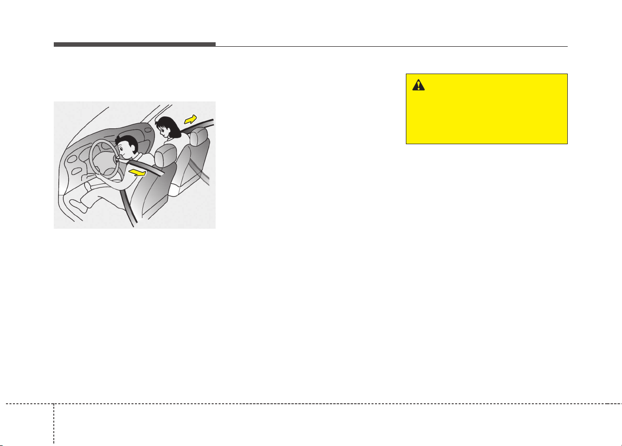
Reclining seatback
Sitting in a reclined position when
the vehicle is in motion can be dan-
gerous. Even when buckled up, the
protections of your restraint system
(seat belts and/or air bags) is greatly
reduced by reclining your seatback.
Seat belts must be snug against your
hips and chest to work properly.
When the seatback is reclined, the
shoulder belt cannot do its job
because it will not be snug against
your chest. Instead, it will be in front
of you. During an accident, you could
be thrown into the seat belt, causing
neck or other injuries.
The more the seatback is reclined,
the greater chance the passenger’s
hips will slide under the lap belt or
the passenger’s neck will strike the
shoulder belt.
WARNING
NEVER ride with a reclined seat-
back when the vehicle is moving.
Riding with a reclined seatback
increases your chance of seri-
ous or fatal injuries in the event
of a collision or sudden stop.
Drivers and passengers should
ALWAYS sit well back in their
seats, properly belted, and with
the seatbacks upright.
ODE036062
37
Safety features of your vehicle
Seat height (for driver`s seat,
if equipped) (3)
To change the height of the seat, push
the lever upwards or downwards.
• To lower the seat cushion, push the
lever down several times.
• To raise the seat cushion, pull the
lever up several times.
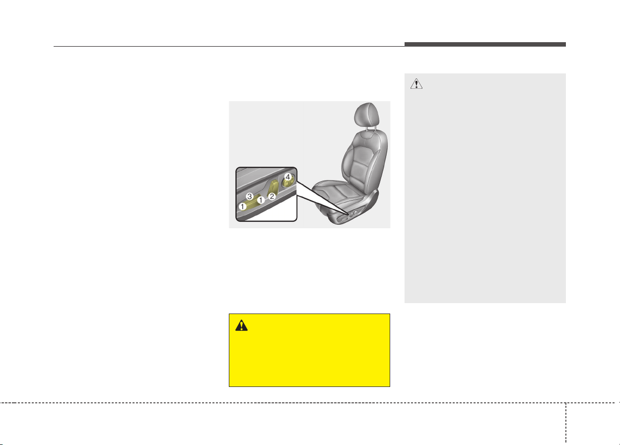
Front seat adjustment - power
(if equipped)
The front seat can be adjusted by
using the control switches located on
the outside of the seat cushion.
Before driving, adjust the seat to the
proper position so you can easily con-
trol the steering wheel, pedals and
switches on the instrument panel.
WARNING
The power seat is operable with
the ignition OFF.
Therefore, children should never
be left unattended in the vehicle.
ODE036061
CAUTION
• The power seat is driven by an
electric motor. Stop operating
once the adjustment is com-
pleted. Excessive operation
may damage the electrical
equipment.
• When in operation, the power
seat consumes a large amount
of electrical power. To prevent
unnecessary charging system
drain, don’t adjust the power
seat longer than necessary
while the engine is not running.
• Do not operate two or more
power seat control switches at
the same time. Doing so may
result in power seat motor or
electrical component malfunc-
tion.
Safety features of your vehicle
83
Forward and backward (1)
Push the control switch forward or
backward to move the seat to the
desired position. Release the switch
once the seat reaches the desired
position.
Seatback angle (2)
Push the control switch forward or
backward to move the seatback to
the desired angle. Release the
switch once the seat reaches the
desired position.
Seat height (if equipped) (3)
Pull the front portion of the control
switch up to raise or press down to
lower the front part of the seat cush-
ion. Pull the rear portion of the con-
trol switch up to raise or press down
to lower the rear part of the seat
cushion. Release the switch once the
seat reaches the desired position.
Lumbar support (for driver’s seat,
if equipped) (4)
The lumbar support can be adjusted
by pressing the lumbar support
switch on the side of the seat.
1. Press the front portion of the
switch to increase support, or the
rear portion of the switch, to
decrease support.
2. Release the switch once it reach-
es the desired position.
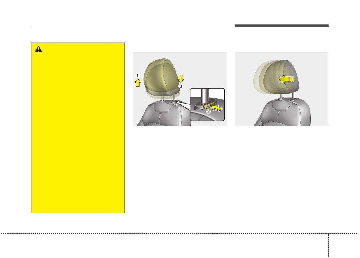
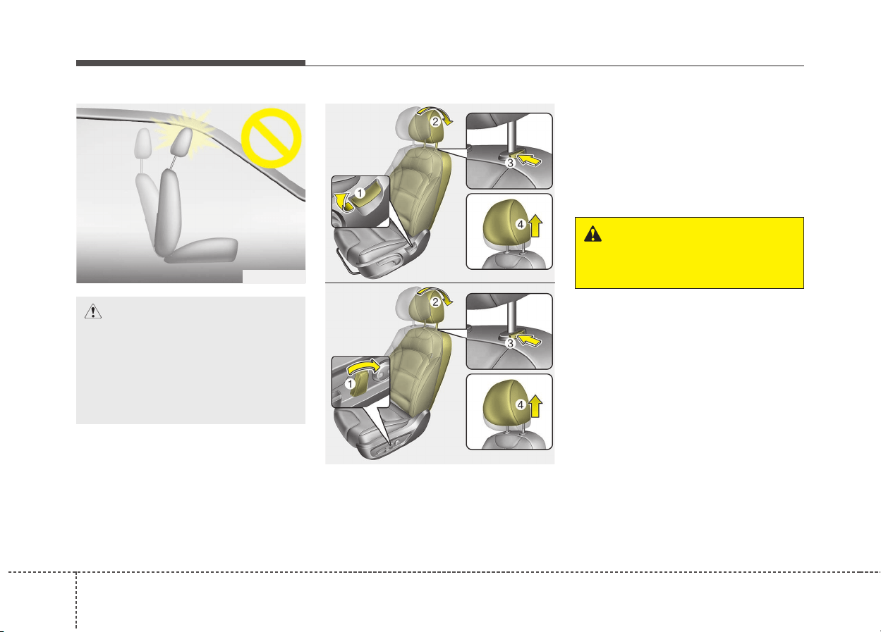
Headrest (for front seat)
The driver's and front passenger's
seats are equipped with a headrest
for the occupant's safety and comfort.
The headrest not only provides com-
fort for the driver and front passen-
ger, but also helps protect the head
and neck in the event of a collision.
ODE036074L
39
Safety features of your vehicle
Adjusting the height up and down
To raise the headrest, pull it up to the
desired position (1). To lower the
headrest, push and hold the release
button (2) and lower the headrest to
the desired position (3).
Forward and backward adjustment
The headrest may be adjusted for-
ward to 3 different positions by
pulling the headrest forward to the
desired detent.
To adjust the headrest to it’s furthest
backwards position,
Pull the headrest fully forward to the
farthest position and release it.
Adjust the headrest so that it properly
supports the head and neck.
ODE036009
WARNING
• For maximum effectiveness in
case of an accident, the head-
rest should be adjusted so the
middle of the headrest is at the
same height of the center of
gravity of an occupant's head.
Generally, the center of gravity
of most people's head is simi-
lar with the height of the top of
their eyes. Also, adjust the
headrest as close to your head
as possible. For this reason,
the use of a cushion that holds
the body away from the seat-
back is not recommended.
• Do not operate the vehicle with
the headrests removed. Severe
injury to the occupants may
occur in the event of an acci-
dent. Headrests may provide
protection against neck injuries
when properly adjusted.
• Do not adjust the headrest
position of the driver’s seat
while the vehicle is in motion.
ODE036010L
Safety features of your vehicle
103
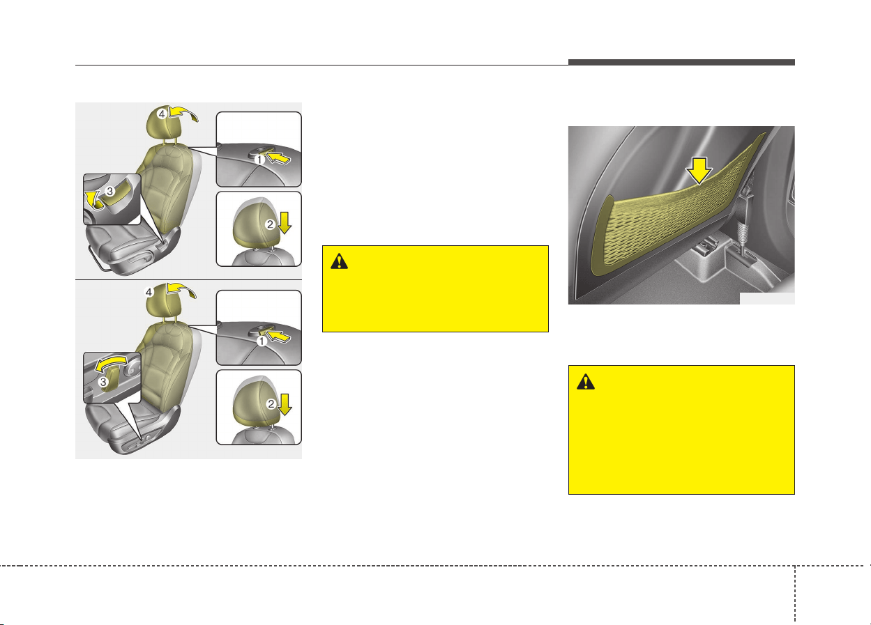
Removal/Reinstall
To remove the headrest:
1. Recline the seatback (2) with the
recline dial or switch (1).
2. Raise headrest as far as it can go.
3. Press the headrest release button
(3) while pulling the headrest up (4).
CAUTION
If you recline the seatback
towards the front with the head-
rest and seat cushion raised,
the headrest may come in con-
tact with the sunvisor or other
parts of the vehicle.
OYFH034205
ODE036011
ODE036012
■ Type B
■ Type A
WARNING
NEVER allow anyone to ride in a
seat with the headrest removed.
311
Safety features of your vehicle
To reinstall the headrest:
1. Put the headrest poles (2) into the
holes while pressing the release
button or switch (1).
2. Recline the seatback(4) with the
recline dial or switch (3).
3. Adjust the headrest to the appro-
priate height.
Seatback pocket
The seatback pocket is provided on
the back of the front passenger’s and
driver’s seatbacks.
WARNING
Always make sure the headrest
locks into position after rein-
stalling and adjusting it properly.
ODE036013
ODE036014
■ Type B
■ Type A
ODE036015
WARNING - Seatback
pockets
Do not put heavy or sharp
objects in the seatback pockets.
In an accident they could come
loose from the pocket and
injure vehicle occupants.
Safety features of your vehicle
123
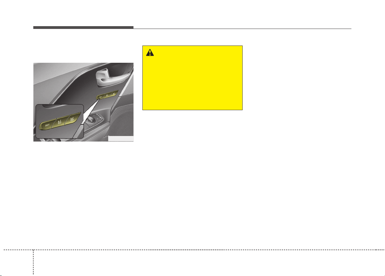
Driver position memory system
(if equipped, for power seat)
A driver position memory system is
provided to store and recall the driv-
er seat and outside rearview mirror
position with a simple button opera-
tion. By saving the desired position
into the system memory, different
drivers can reposition the driver seat
based upon their driving preference.
If the battery is disconnected, the
position memory will be erased and
the driving position should be
restored in the system.
Storing positions into memory
using the buttons on the door
Storing driver’s seat positions
1. Shift the shift lever into P while the
engine start/stop button is ON or
ignition switch ON.
2. Adjust the driver’s seat and out-
side rearview mirror comfortable
for the driver.
3. Press SET button on the control
panel. The system will beep once.
4. Press one of the memory buttons
(1 or 2) within 4 seconds after
pressing the SET button. The sys-
tem will beep twice when memory
has been successfully stored.
ODE036023
WARNING
Never attempt to operate the
driver position memory system
while the vehicle is moving.
This could result in loss of con-
trol, and an accident causing
death, serious injury, or property
damage.
313
Safety features of your vehicle
Recalling positions from memory
1. Shift the shift lever into P while the
engine start/stop button is ON or
ignition switch ON.
2. To recall the position in the memory,
press the desired memory button (1
or 2). The system will beep once,
then the driver’s seat will automati-
cally adjust to the stored position.
Adjusting the control switch for the
driver’s seat while the system is
recalling the stored position will
cause the movement to stop and
move in the direction that the control
switch is moved.
Easy access function (if equipped)
The system will move the driver's
seat automatically as follows:
• Without smart key system
- It will move the driver’s seat rear-
ward when the ignition key is
removed and front driver’s door is
opened.
- It will move the driver’s seat for-
ward when the ignition key is
inserted.
• With smart key system
- It will move the driver’s seat rear-
ward when the engine start/stop
button is changed to the OFF
position and front driver’s door is
opened.
- It will move the driver’s seat for-
ward when the engine start/stop
button is changed to the ACC or
START position.
- It will move the driver's seat for-
ward when you get in your vehicle
with the smart key after closing
the driver's door.
You can activate or deactivate this
feature. Refer to "User settings" in
chapter 4.
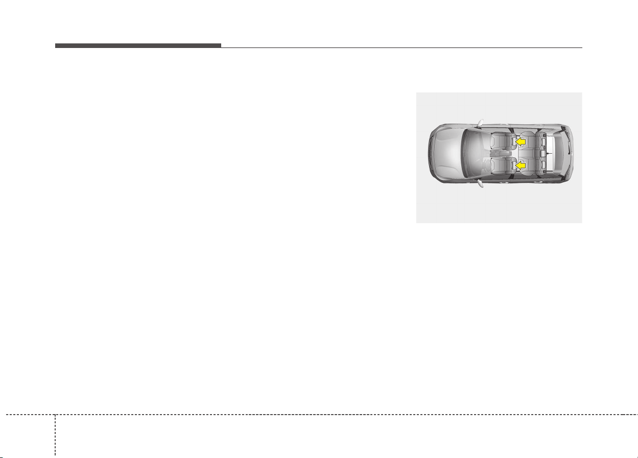
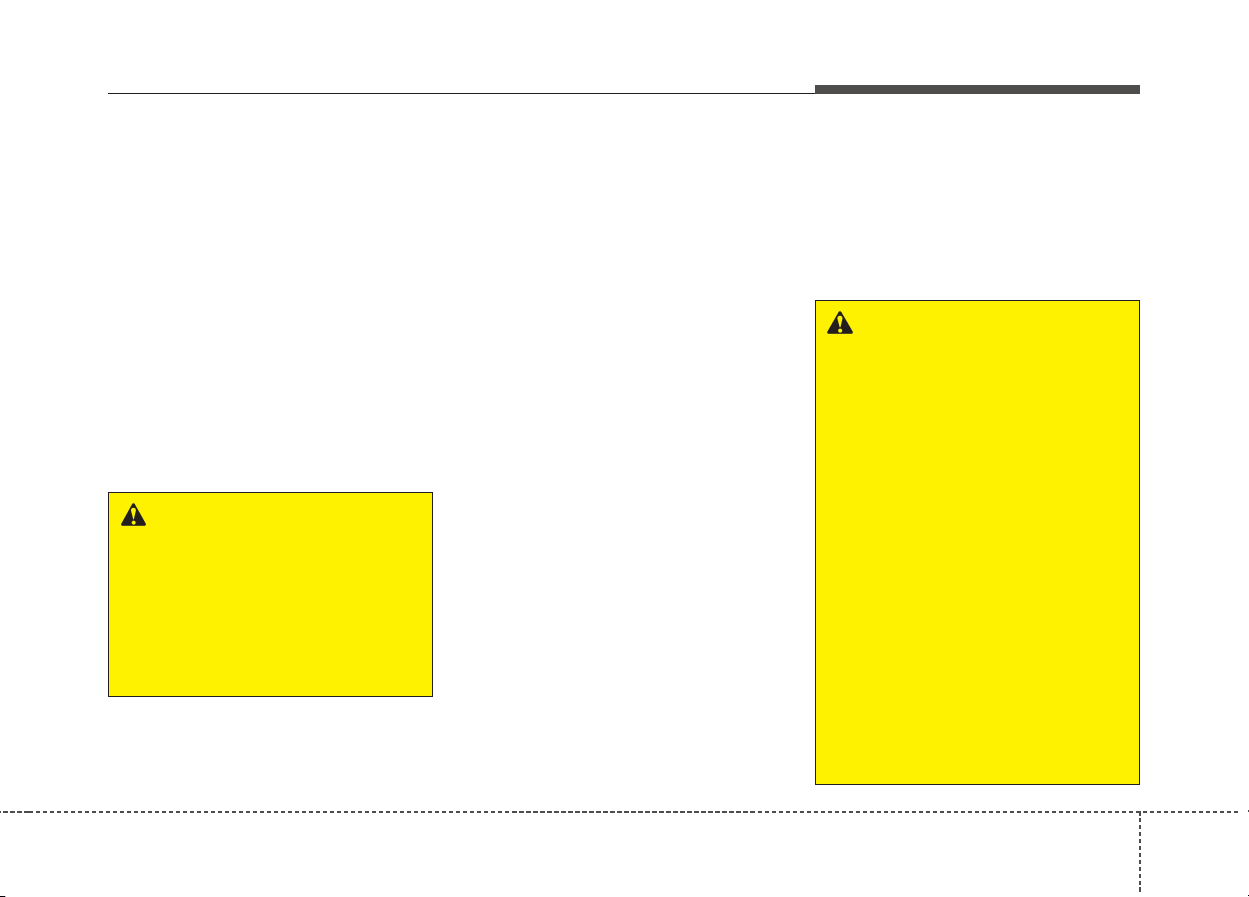
Rear seat
Folding the rear seat
The rear seatbacks can be folded to
facilitate carrying long items or to
increase the luggage capacity of the
vehicle.
WARNING
Use caution when recalling the
adjustment memory while sit-
ting in the vehicle. Push the
seat position control switch to
the desired position immediate-
ly if the seat moves too far in
any direction.
WARNING
The purpose of the fold-down
rear seatbacks is to allow you to
carry longer objects that could
not be accommodated in the
cargo area.
Never allow passengers to sit
on top of the folded down seat-
back while the vehicle is mov-
ing. This is not a proper seating
position and no seat belts are
available for use. This could
result in serious injury or death
in case of an accident or sud-
den stop. Objects carried on the
folded down seatback should
not extend higher than the top
of the front seatbacks. This
could allow cargo to slide for-
ward and cause injury or dam-
age during sudden stops.
Safety features of your vehicle
143
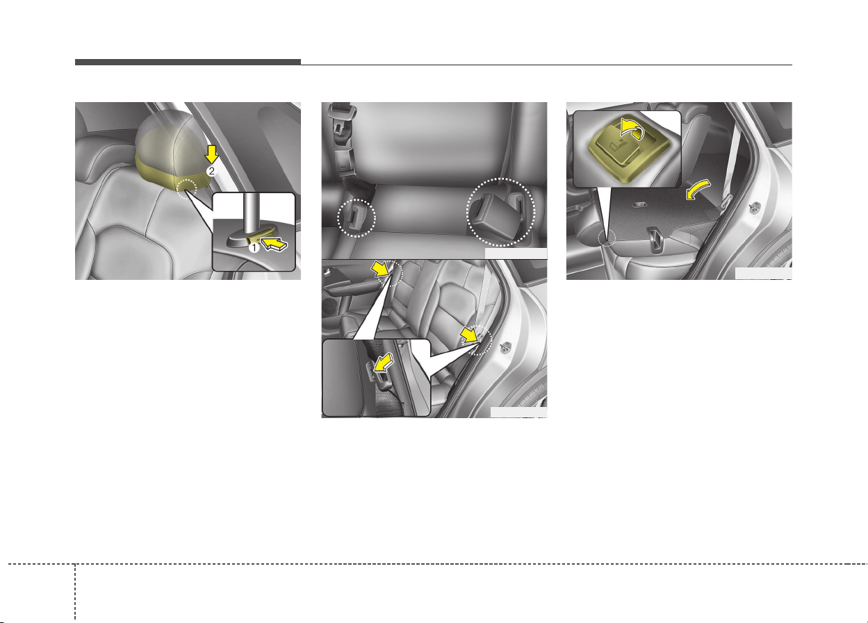
To fold down the rear seatback:
1. Set the front seatback to the
upright position and if necessary,
slide the front seat forward.
2. Lower the rear head restraints to
the lowest position.
3. When folding the seat back, insert
the rear seat belt buckle in the
pocket between the rear seatback
and cushion then make sure both
seatbelts do not interfere with
stowed luggage and cargo. Then,
insert the seat belt into the two
holes located on both sides.
4. Pull on the seatback folding lever,
then fold the seat toward the front
of the vehicle. When you return the
seatback to its upright position,
always be sure it has locked into
position by pushing on the top of
the seatback.
ODE036019
ODE036029L
ODE036020
ODE036021
315
Safety features of your vehicle
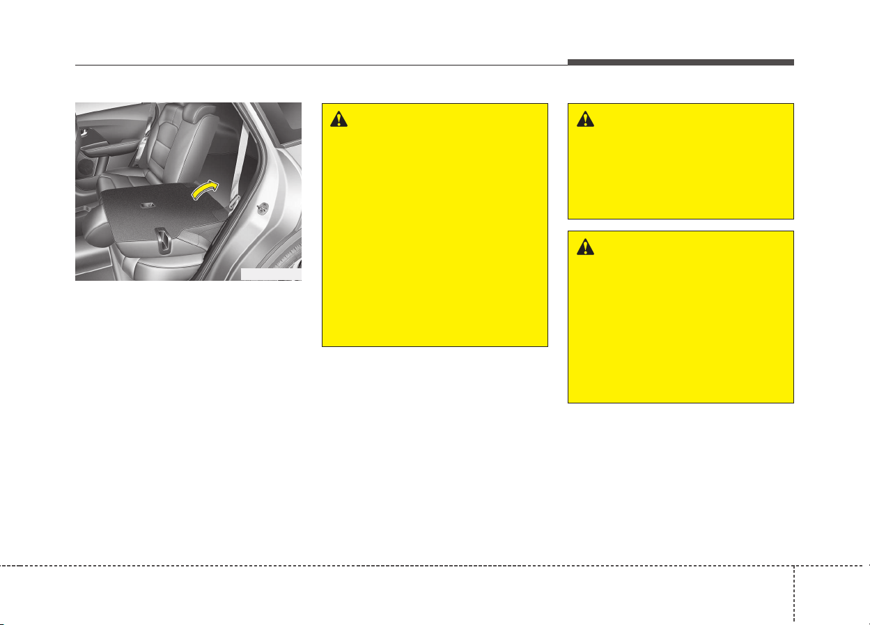
5. To use the rear seat, lift and pull the
seatback backward by lifting up
seat back. Pull the seatback firmly
until it clicks into place. Make sure
the seatback is locked in place.
6. Return the rear seat belt to the
proper position.
ODE036022L
WARNING
When returning the rear seat-
back from a folded to an upright
position, hold the seatback and
return it slowly. Ensure that the
seatback is completely locked
into its upright position by
pushing on the top of the seat-
back. In an accident or sudden
stop, the unlocked seatback
could allow cargo to move for-
ward with great force and enter
the passenger compartment,
which could result in serious
injury or death.
WARNING
Do not place objects in the rear
seats, since they cannot be
properly secured and may hit
vehicle occupants in a collision
causing serious injury or death.
WARNING
Make sure the engine is off, the
shift lever is in P (Park), and the
parking brake is securely
applied whenever loading or
unloading cargo. Failure to take
these steps may allow the vehi-
cle to move if the shift lever is
inadvertently moved to another
position.
Safety features of your vehicle
163
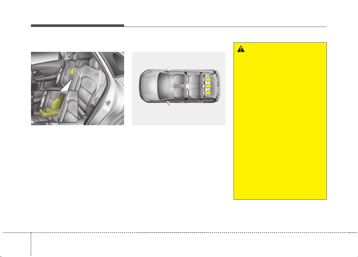
Armrest (if equipped)
To use the armrest, pull it forward
from the seatback.
Headrest
The rear seat(s) is equipped with
headrests in all the seating positions
for the occupant's safety and comfort.
The headrest not only provides com-
fort for passengers, but also helps
protect the head and neck in the
event of a collision.
ODE036018 ODE036075L
WARNING
• For maximum effectiveness in
case of an accident, the head-
rest should be adjusted so the
middle of the headrest is at the
same height of the center of
gravity of an occupant's head.
Generally, the center of gravity
of most people's head is simi-
lar with the height of the top of
their eyes. Also adjust the
headrest as close to your head
as possible. For this reason,
the use of a cushion that holds
the body away from the seat-
back is not recommended.
• Do not operate the vehicle
with the headrests removed.
Severe injury to an occupant
may occur in the event of an
accident. Headrests may pro-
vide protection against severe
neck injuries when properly
adjusted.
317
Safety features of your vehicle
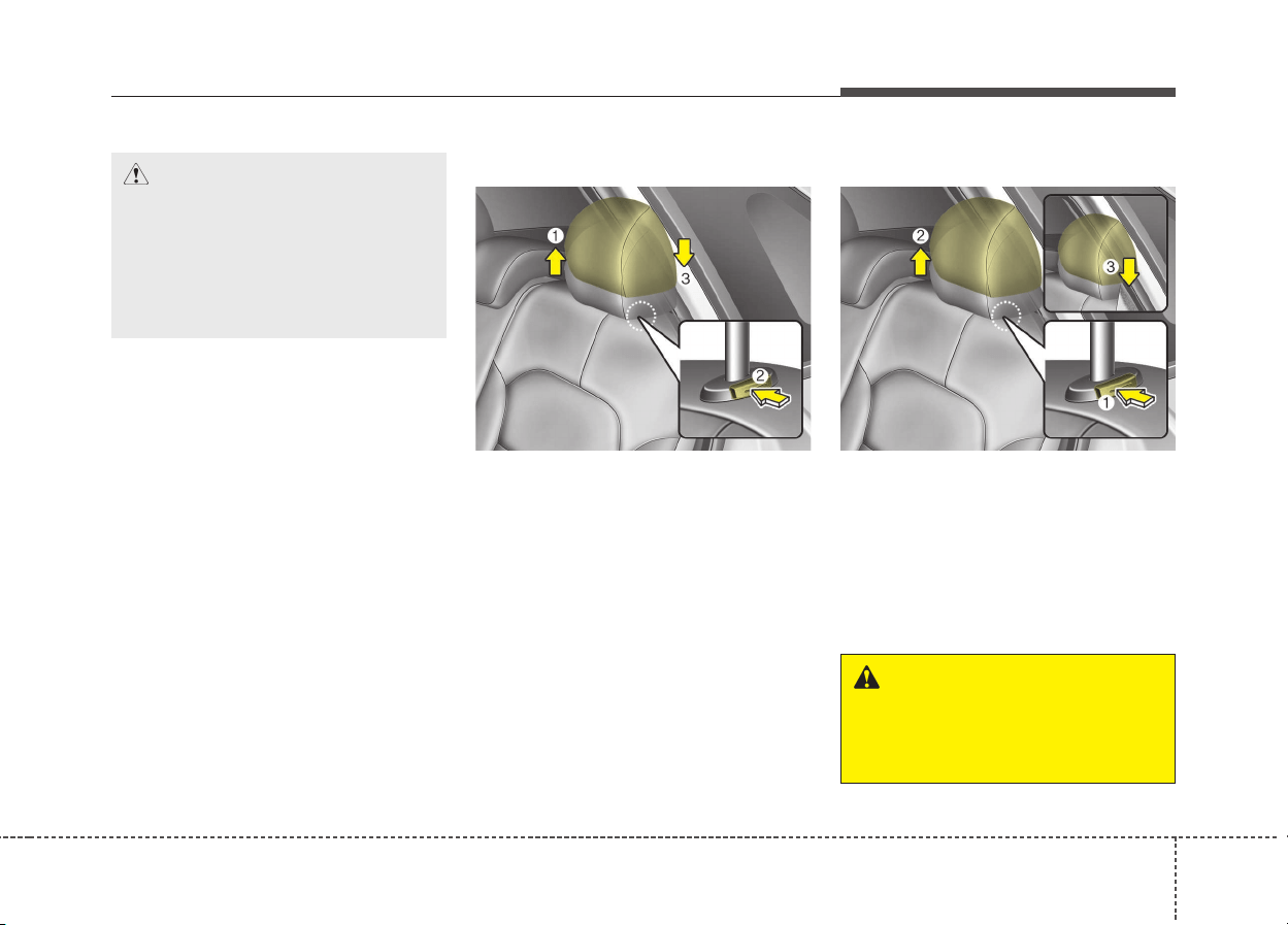
Adjusting the height up and down
To raise the headrest, pull it up to the
desired position (1). To lower the
headrest, push and hold the release
button (2) on the headrest support
and lower the headrest to the desired
position (3).
Removal and installation
To remove the headrest, raise it as
far as it can go then press the
release button (1) while pulling the
headrest up (2).
To reinstall the headrest, put the
headrest poles (3) into the holes while
pressing the release button (1). Then
adjust it to the appropriate height.
ODE036016 ODE036017
CAUTION
When there is no occupant in
the rear seats, adjust the height
of the headrest to the lowest
position. The rear seat headrest
can reduce the visibility of the
rear area.
WARNING
Make sure the headrest locks in
position after adjusting it to
properly protect the occupants.
Safety features of your vehicle
183
Seat belt restraint system
SEAT BELTS
WARNING
• For maximum restraint sys-
tem protection, the seat belts
must always be used whenev-
er the vehicle is moving.
• Seat belts are most effective
when seatbacks are in the
upright position.
• Children age 12 and under
must always be properly
restrained. If a child over 12
must be seated in the front
seat, he/she must be properly
belted and the seat should be
moved as far back as possi-
ble.
• Never wear the shoulder belt
under your arm or behind
your back. An improperly
positioned shoulder belt can
cause serious injuries in a
crash.
(Continued)
(Continued)
The shoulder belt should be
positioned midway over your
shoulder across your collar-
bone.
• Never wear a seat belt over
fragile objects. If there is a
sudden stop or impact, the
seat belt can damage it.
• Avoid wearing twisted seat
belts. A twisted belt can't do
its job well. In a collision, it
could even cut into you. Be
sure the belt webbing is
straight and not twisted.
• Be careful not to damage the
belt webbing or hardware. If
the belt webbing or hardware
is damaged, replace it.
WARNING
Seat belts are designed to bear
upon the bony structure of the
body, and should be worn low
across the front of the pelvis or
the pelvis, chest and shoulders,
as applicable; wearing the lap
section of the belt across the
abdominal area must be avoided.
Seat belts should be adjusted as
firmly as possible, consistent
with comfort, to provide the pro-
tection for which they have been
designed.
A slack belt will greatly reduce
the protection afforded to the
wearer.
(Continued)
319
Safety features of your vehicle
(Continued)
Care should be taken to avoid
contamination of the webbing
with polishes, oils and chemi-
cals, and particularly battery
acid. Cleaning may safely be
carried out using mild soap and
water. The belt should be
replaced if webbing becomes
frayed, contaminated or dam-
aged. It is essential to replace
the entire assembly after it has
been worn in a severe impact
even if damage to the assembly
is not obvious. Belts should not
be worn with straps twisted.
Each belt assembly must only
be used by one occupant; it is
dangerous to put a belt around
a child being carried on the
occupant's lap.
WARNING
• No modifications or additions
should be made by the user
which will either prevent the
seat belt adjusting devices
from operating to remove
slack, or prevent the seat belt
assembly from being adjusted
to remove slack.
• When you fasten the seat belt,
be careful not to latch the seat
belt in buckles of other seat.
It's very dangerous and you
may not be protected by the
seat belt properly.
• Do not unfasten the seat belt
and do not fasten and unfas-
ten the seat belt repeatedly
while driving.This could result
in loss of control, and an acci-
dent causing death, serious
injury, or property damage.
(Continued)
(Continued)
• When fastening the seat belt,
make sure that the seat belt
does not pass over objects that
are hard or can break easily.
• Make sure there is nothing in
the buckle. The seat belt may
not be fastened securely.
Safety features of your vehicle
203
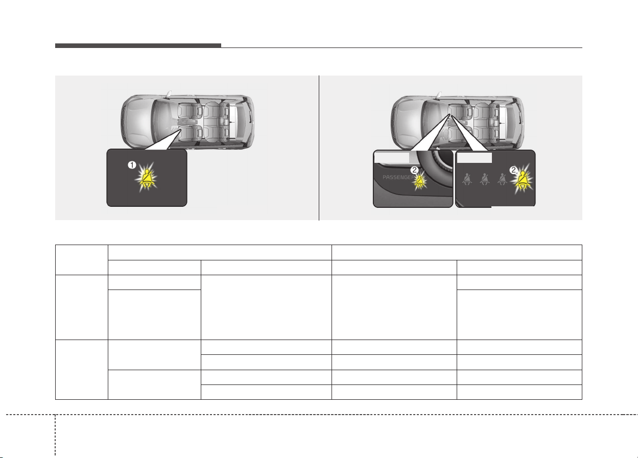
Front seat belt warning
Driving
conditions
Conditions Warning pattern
Seat belt Vehicle speed Light Sound
While
parked
(Ignition
switch
ON)
Buckled
0km/h
Illuminates
(for 6 seconds)
No sound
Unbuckled
- Sounds
(for 6 seconds, driver`s seat)
- No sound
(for passenger’s seat)
While
driven
Unbuckled
Less than 20km/h Continuously Illuminates No sound
Including and more than 20km/h Blinks continuously Alarm sounds for 100 seconds
When the seatbelt is
unbuckled after use
Less than 20km/h Continuously Illuminates No sound
Including and more than 20km/h Blinks continuously Alarm sounds for 100 seconds
ODE036083L
■ Type B■ Type A
ODE036084L
321
Safety features of your vehicle
✽✽
NOTICE
• You can find the front passenger’s
seat belt warning light on the cen-
ter fascia panel.
• Although the front passenger seat
is not occupied, the seat belt warn-
ing light will blink or illuminate
for 6 seconds.
• The front passenger's seat belt
warning may operate when lug-
gage is placed on the front passen-
ger seat.
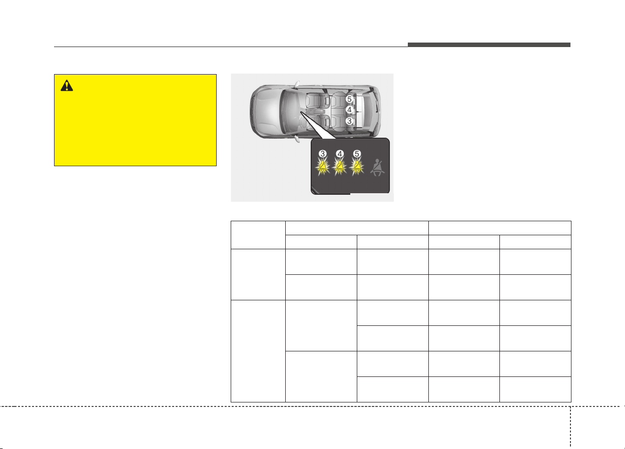
Rear passenger’s seat belt warning
If the rear passenger's lap/shoulder
belt is/are connected and disconnect-
ed twice within 9 seconds after the
belt is fastened, the corresponding
seat belt warning light will not operate.
ODE036076L
WARNING
Riding in an improper position
adversely affects the front seat
belt warning system. It is impor-
tant for the driver to instruct the
passenger to properly be seat-
ed as instructed in this manual.
Driving
conditions
Conditions Warning pattern
Seat belt Vehicle speed Light Sound
While
parked
(ignition
switch on)
Buckled 0km/h
Illuminates
(for 6 seconds)
No sound
Unbuckled 0km/h
Illuminates
(for 6 seconds)
No sound
While
driven
Unbuckled
Equal to or less
than 9km/h
No illuminates No sound
Over 9km/h
Illuminates
(for 35 seconds)
No sound
When the seat-
belt is unbuckled
after use
Under 20km/h
Illuminates
(for 35 seconds)
No sound
Over 20km/h
Blinks continuously
(for 35 seconds)
Sound
(for 35 seconds)
Safety features of your vehicle
223
Lap/Shoulder belt
Height adjustment (For Front seat)
You can adjust the height of the shoul-
der belt anchor to one of 4 positions
for maximum comfort and safety.
The height of the adjusting seat belt
should not be too close to your neck.
You will not be getting the most effec-
tive protection. The shoulder portion
should be adjusted so that it lies
across your chest and midway over
your shoulder near the door and not
your neck.
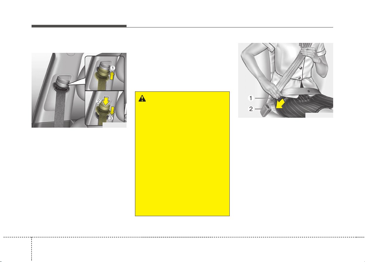
To adjust the height of the seat belt
anchor, lower or raise the height
adjuster into an appropriate position.
To raise the height adjuster, pull it up
(1). To lower it, push it down (3) while
pressing the height adjuster button (2).
Release the button to lock the
anchor into position. Try sliding the
height adjuster to make sure that it
has locked into position.
To fasten your seat belt:
To fasten your seat belt, pull it out of
the retractor and insert the metal tab
(1) into the buckle (2). There will be
an audible "click" when the tab locks
into the buckle.
The seat belt automatically adjusts to
the proper length only after the lap
belt portion is adjusted manually so
that it fits snugly around your hips. If
you lean forward in a slow, easy
motion, the belt will extend and let
you move around. If there is a sud-
den stop or impact, however, the belt
will lock into position. It will also lock
if you try to lean forward too quickly.
WARNING
• Verify the shoulder belt
anchor is locked into position
at the appropriate height.
Never position the shoulder
belt across your neck or face.
Improperly positioned seat
belts can cause serious
injuries in an accident.
• Failure to replace seat belts
after an accident could leave
you with damaged seat belts
that will not provide protec-
tion in the event of another
collision leading to personal
injury or death. Replace your
seat belts after being in an
accident as soon as possible.
ODE036030
B180A01NF-1
323
Safety features of your vehicle
✽✽
NOTICE
If you are not able to pull out the
seat belt from the retractor, firmly
pull the belt out and release it. Then
you will be able to pull the belt out
smoothly.
To release the seat belt:
The seat belt is released by pressing
the release button (A) in the locking
buckle. When it is released, the belt
should automatically draw back into
the retractor.
If this does not happen, check the
belt to be sure it is not twisted, then
try again.
B200A01NF
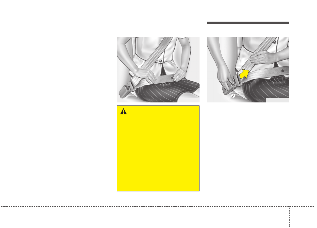
WARNING
You should place the lap belt
portion as low as possible and
snugly across your hips, not on
your waist. If the lap belt is locat-
ed too high on your waist, it may
increase the chance of injury in
the event of a collision. Both
arms should not be under or
over the belt. Rather, one should
be over and the other under, as
shown in the illustration.
Never wear the seat belt under
the arm near the door.
OUM036100L
Safety features of your vehicle
243
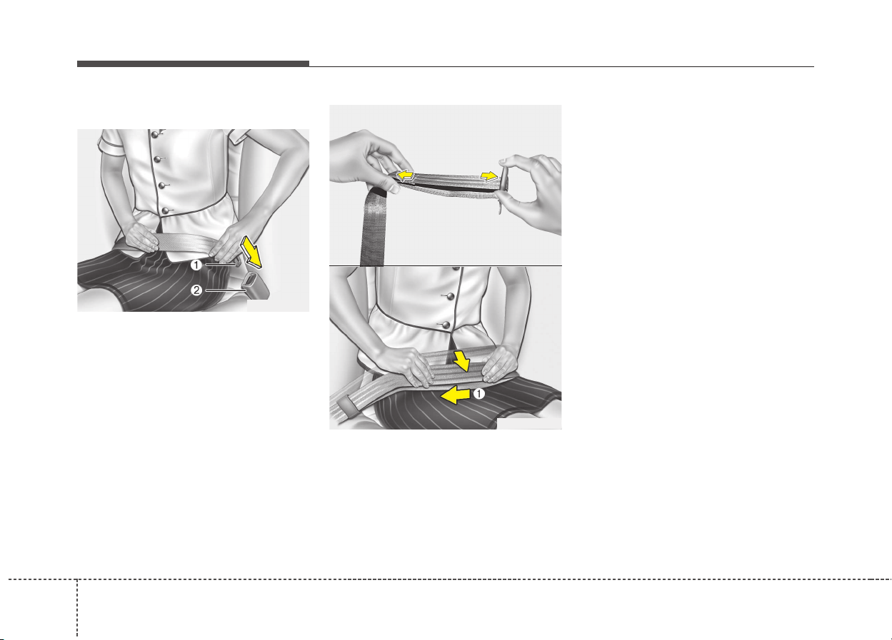
Lap belt (if equipped)
To fasten your seat belt:
To fasten a 2-point static type belt,
insert the metal tab (1) into the lock-
ing buckle (2). There will be an audi-
ble "click" when the tab locks into the
buckle. Check to make sure the belt
is properly locked and that the belt is
not twisted.
With a 2-point static type seat belt, the
length must be adjusted manually so
it fits snugly around your body. Fasten
the belt and pull on the loose end to
tighten. The belt should be placed as
low as possible on your hips (1), not
on your waist. If the belt is too high, it
could increase the possibility of your
being injured in an accident.
When using the rear center seat belt,
the buckle with the “CENTER” mark
must be used.
ODE036080L
OHM039105N
ODE036081L
325
Safety features of your vehicle
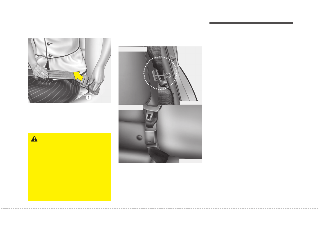
To release the seat belt:
When you want to release the seat
belt, press the button (1) in the lock-
ing buckle.
Stowing the rear seat belt
• If the center seat belt is not in use,
always lock the latch plate into the
buckle as above illustration.
• The rear seat belt buckles can be
stowed in the pocket between the
rear seatback and cushion when
not in use.
• Insert the seat belt into the two
holes located on both sides. It will
help keep the belts from being
trapped behind or under the seats.
After inserting the seat belt, tighten
the belt webbing by pulling it up.
ODE036082L
WARNING
The center lap belt latching
mechanism is different from
those for the rear seat shoulder
belts. When fastening the rear
seat shoulder belts or the cen-
ter lap belt, make sure they are
inserted into the correct buck-
les to obtain maximum protec-
tion from the seat belt system
and assure proper operation.
ODE036028
■ Outboard belt
ODE036027L
■ Center belt
Safety features of your vehicle
263
Pre-tensioner seat belt
(if equipped)
Your vehicle is equipped with driver's
and front passenger's and rear side
passenger’s (if equipped) pre-ten-
sioner seat belts (retractor pre-ten-
sioner). The pre-tensioner seat belts
can be activated, where the frontal
collision is severe enough, together
with the air bags.
When the vehicle stops suddenly, or
if the occupant tries to lean forward
too quickly, the seat belt retractor will
lock into position. In certain frontal
collisions, the pre-tensioner will acti-
vate and pull the seat belt into tighter
contact against the occupant's body.
- Retractor Pretensioner
The purpose of the retractor pre-
tensioner is to make sure that the
shoulder belts fit in tightly against
the occupant's upper body in cer-
tain frontal collisions.
If the system senses excessive ten-
sion on the driver or passenger's
seat belt when the pre-tensioner sys-
tem activates, the load limiter inside
the retractor pre-tensioner will
release some of the pressure on the
affected seat belt. (if equipped)
OQLE035094
WARNING
For your safety, be sure that the
belt webbing is not loose or
twisted and always sit properly
on your seat.
327
Safety features of your vehicle
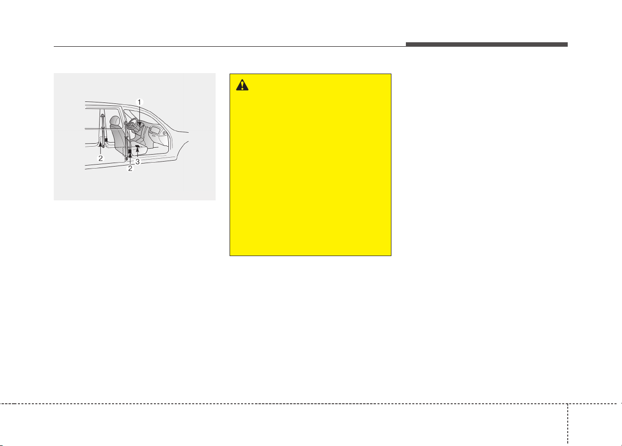
The seat belt pre-tensioner system
consists mainly of the following com-
ponents. Their locations are shown in
the illustration:
(1) SRS air bag warning light
(2) Retractor pre-tensioner assembly
(3) SRS control module
✽✽
NOTICE
• When the pre-tensioner seat belts
are activated, a loud noise may be
heard and fine dust, which may
appear to be smoke, may be visible
in the passenger compartment.
These are normal operating condi-
tions and are not hazardous.
• Although it is harmless, the fine
dust may cause skin irritation and
should not be breathed for pro-
longed periods. Wash all exposed
skin areas thoroughly after an
accident in which the pre-tension-
er seat belts were activated.
• Because the sensor that activates
the SRS air bag is connected with
the pre-tensioner seat belt, the
SRS air bag warning light on the
instrument panel will illuminate
for approximately 6 seconds after
the ignition switch has been
turned to the "ON" position, and
then it should turn off.
OQLE045486
WARNING
To obtain maximum benefit
from a pre-tensioner seat belt:
1. The seatbelt must be worn
correctly and adjusted to the
proper position. Please read
and follow all of the important
information and precautions
about your vehicle’s occupant
safety features – including
seat belts and air bags – that
are provided in this manual.
2. Be sure you and your passen-
gers always wear seat belts
properly.
Safety features of your vehicle
283
CAUTION
If the pre-tensioner seat belt is
not working properly, the SRS
air bag warning light will illumi-
nate even if there is no malfunc-
tion of the SRS air bag. If the
SRS air bag warning light does
not illuminate when the ignition
key is turned to ON, or if it
remains illuminated after illumi-
nating for approximately 6 sec-
onds, or if it illuminates while
the vehicle is being driven, we
recommend that the system be
inspected by an authorized Kia
dealer.
WARNING
• Pre-tensioners are designed
to operate only one time. After
activation, pre-tensioner seat
belts must be replaced. All
seat belts, of any type, should
always be replaced after they
have been worn during a colli-
sion.
• The pre-tensioner seat belt
assembly mechanisms become
hot during activation. Do not
touch the pre-tensioner seat
belt assemblies for several min-
utes after they have been acti-
vated.
• Do not attempt to inspect or
replace the pre-tensioner seat
belts yourself. We recommend
that the system be inspected
by an authorized Kia dealer.
• Do not attempt to service or
repair the pre-tensioner seat
belt system in any manner.
(Continued)
(Continued)
• Improper handling of the pre-
tensioner seat belt assem-
blies, and failure to heed the
warnings not to strike, modify,
inspect, replace, service or
repair the pre-tensioner seat
belt assemblies may lead to
improper operation or inadver-
tent activation and serious
injury.
• Always wear the seat belts
when driving or riding in a
motor vehicle.
• If the vehicle or pre-tensioner
seat belt must be discarded,
we recommend that you con-
tact an authorized Kia dealer.
329
Safety features of your vehicle
Seat belt precautions
Infant or small child
You should be aware of the specific
requirements in your country. Child
and/or infant seats must be properly
placed and installed in the vehicle
seat. For more information about the
use of these restraints, refer to “Child
restraint system” in this section.
CAUTION
Body work on the front area of
the vehicle may damage the pre-
tensioner seat belt system.
Therefore, we recommend that
the system be serviced by an
authorized Kia dealer.
WARNING
All occupants of the vehicle
must wear their seat belts at all
times. Seat belts and child
restraints reduce the risk of
serious or fatal injuries for all
occupants in the event of a col-
lision or sudden stop. Without a
seat belt, occupants could be
shifted too close to a deploying
air bag, strike the interior struc-
ture or be thrown from the vehi-
cle. Properly worn seat belts
greatly reduce these hazards.
Always follow the precautions
about seat belts, air bags and
occupant seating contained in
this manual.
WARNING
Every person in your vehicle
needs to be properly restrained
at all times, including infants
and children. Never hold a child
in your arms or lap when riding
in a vehicle. The violent forces
created during a crash will tear
the child from your arms and
throw the child against the inte-
rior. Always use a child restraint
appropriate for your child's
height and weight.
Safety features of your vehicle
303
✽✽
NOTICE
Small children are best protected
from injury in an accident when
properly restrained in the rear seat
by a child restraint system that
meets the requirements of the Safety
Standards of your country. Before
buying any child restraint system,
make sure that it has a label certify-
ing that it meets Safety Standards of
your country. The restraint must be
appropriate for your child's height
and weight. Check the label on the
child restraint for this information.
Refer to “Child restraint system” in
this section.
Larger children
Children who are too large for child
restraint systems should always
occupy the rear seat and use the
available lap/shoulder belts. The lap
portion should be fastened and
snugged on the hips and as low as
possible. Check if the belt fits period-
ically. A child's squirming could put
the belt out of position. Children are
given the most safety in the event of
an accident when they are restrained
by a proper restraint system in the
rear seat. If a larger child (over age
12) must be seated in the front seat,
the child should be securely
restrained by the available lap/shoul-
der belt and the seat should be
placed in the rearmost position.
Children age 12 and under should be
restrained securely in the rear seat.
NEVER place a rear facing child seat
in the front seat of a vehicle, unless
the air bag is deactivated.
If the shoulder belt portion slightly
touches the child’s neck or face, try
placing the child closer to the center of
the vehicle. If the shoulder belt still
touches their face or neck they need to
be returned to a child restraint system.
WARNING - Shoulder
belts on small children
• Never allow a shoulder belt to
be in contact with a child’s
neck or face while the vehicle
is in motion.
• If seat belts are not properly
worn and adjusted on chil-
dren, there is a risk of death or
serious injury.
331
Safety features of your vehicle
Pregnant women
The use of a seat belt is recom-
mended for pregnant women to
lessen the chance of injury in an
accident. When a seat belt is used,
the lap belt portion should be placed
as low and securely as possible on
the hips, not across the abdomen.
For specific recommendations, con-
sult a physician.
Injured person
A seat belt should be used when an
injured person is being transported.
When this is necessary, you should
consult a physician for recommenda-
tions.
One person per belt
Two people (including children) should
never attempt to use a single seat belt.
This could increase the severity of
injuries in case of an accident.
Do not lie down
To reduce the chance of injuries in
the event of an accident and to
achieve maximum effectiveness of
the restraint system, all passengers
should be sitting up and the front and
rear seats should be in an upright
position when the vehicle is moving.
A seat belt cannot provide proper
protection if the person is lying down
in the rear seat or if the front and rear
seats are in a reclined position.
WARNING - Pregnant
women
Pregnant women must never
place the lap portion of the
safety belt over the area of the
abdomen where the fetus is
located or above the abdomen
where the belt could crush the
fetus during an impact.
WARNING
Riding with a reclined seatback
increases your chance of seri-
ous or fatal injuries in the event
of a collision or sudden stop.
The protection of your restraint
system (seat belts and air bags)
is greatly reduced by reclining
your seat. Seat belts must be
secured against your hips and
chest to work properly. The
more the seatback is reclined,
the greater the chance an occu-
pant's hips will slide under the
lap belt causing serious internal
injuries. Also, the shoulder belt
may strike the occupant's neck.
Drivers and passengers should
always sit well back in their
seats, properly belted, and with
the seatbacks upright.

Safety features of your vehicle
323
Care of seat belts
Seat belt systems should never be
disassembled or modified. In addi-
tion, care should be taken to assure
that seat belts and belt hardware are
not damaged by seat hinges, doors
or other abuse.
Periodic inspection
All seat belts should be inspected
periodically for wear or damage of
any kind. Any damaged parts should
be replaced as soon as possible.
Keep belts clean and dry
Seat belts should be kept clean and
dry. If belts become dirty, they can be
cleaned by using a mild soap solu-
tion and warm water. Bleach, dye,
strong detergents or abrasives
should not be used because they
may damage and weaken the fabric.
When to replace seat belts
Entire in-use seat belt assembly or
assemblies should be replaced if the
vehicle has been involved in an acci-
dent. This should be done even if no
damage is visible. We recommend
that you consult an authorized Kia
dealer.
WARNING
When you return the rear seat-
back to its upright position after
the rear seatback has been fold-
ed down, be careful not to dam-
age the seat belt webbing or
buckle. Be sure that the web-
bing or buckle does not get
caught or pinched in the rear
seat. A seat belt with damaged
webbing or buckle could possi-
bly fail during a collision or sud-
den stop, resulting in serious
injury. If the webbing or buckles
are damaged, get them replaced
immediately.
333
Safety features of your vehicle
Our recommendation:
Children always in the rear
Children under age 13 should always
ride in the rear seats and must
always be properly restrained to min-
imize the risk of injury in an accident,
sudden stop or sudden maneuver.
According to accident statistics, chil-
dren are safer when properly
restrained in the rear seats than in
the front seat. Children too large for a
Child Restraint System must use the
seat belts provided.
Most countries have regulations
which require children to travel in
approved Child Restraint Systems.
The laws governing the age or
height/weight restrictions at which
seat belts can be used instead of
Child Restraint System differs
among countries, so you should be
aware of the specific requirements in
your country, and where you are trav-
elling.
Child Restraint Systems must be
properly installed in the vehicle seat.
Always use a commercially available
Child Restraint System that meets
the requirements of your country.
Child Restraint System (CRS)
Infants and younger children must be
restrained in an appropriate rearward-
facing or forward-facing CRS that has
first been properly secured to the seat
of the vehicle. Read and comply with
the instructions for installation and
use provided by the manufacturer of
the Child Restraint System.
CHILD RESTRAINT SYSTEM (CRS)
WARNING
Always properly restrain chil-
dren in the vehicle. Children of
all ages are safer when riding in
the rear seats. Never place a
rearward-facing Child Restraint
System on the front passenger
seat, unless the air bag is deac-
tivated.
WARNING
• Always follow the Child
Restraint System manufactur-
er’s instructions for installa-
tion and use.
• Always properly restrain your
child in the Child Restraint
System.
• Do not use an infant carrier or
a child safety seat that
“hooks” over a seatback, it
may not provide adequate
protection in an accident.
• After an accident, we recom-
mend a Kia dealer to check
the Child Restraint System,
seat belts, ISOFIX anchorages
and top-tether anchorages.
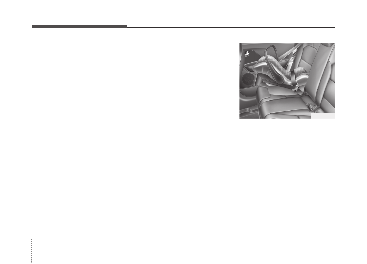
Safety features of your vehicle
343
Selecting a Child Restraint
System (CRS)
When selecting a Child Restraint
System for your child, always:
• Make sure the Child Restraint
System has a label certifying that it
meets applicable Safety Standards
of your country.
A Child Restraint System may only
be installed if it was approved in
accordance with the requirements
of ECE-R44 or ECE-R129.
• Select a Child Restraint System
based on your child’s height and
weight. The required label or the
instructions for use typically pro-
vide this information.
• Select a Child Restraint System
that fits the vehicle seating position
where it will be used.
For the suitability of Child Restraint
Systems on the vehicle's seating
positions, please refer to the instal-
lation tables on pages 3-41 and 3-
44 to 3-46.
• Read and comply with the warn-
ings and instructions for installation
and use provided with the Child
Restraint System.
Child Restraint System types
There are three main types of Child
Restraint Systems: rearward-facing,
forward-facing and booster Child
Restraint Systems.
They are classified according to the
child’s age, height and weight.
Rearward-facing Child Restraint
System
A rearward-facing Child Restraint
System provides restraint with the
seating surface against the back of
the child. The harness system holds
the child in place, and in an accident,
acts to keep the child positioned in
the Child Restraint Systems and
reduce the stress to the fragile neck
and spinal cord.
ODE036031

335
Safety features of your vehicle
All children under the age of one
year must always ride in a rearward-
facing Child Restraint System. There
are different types of rearward-facing
Child Restraint Systems: infant-only
Child Restraint Systems can only be
used rearward-facing. Convertible
and 3-in-1 Child Restraint Systems
typically have higher height and
weight limits for the rearward-facing
position, allowing you to keep your
child rearward-facing for a longer
period of time.
Keep using Child Restraint Systems
in the rearward-facing position as
long as children fit within the height
and weight limits allowed by the
Child Restraint System's manufac-
turer.
Forward-facing Child Restraint System
A forward-facing Child Restraint
System provides restraint for the
child’s body with a harness. Keep
children in a forward-facing Child
Restraint System with a harness
until they reach the top height or
weight limit allowed by your Child
Restraint System’s manufacturer.
Once your child outgrows the for-
ward-facing Child Restraint System,
your child is ready for a booster seat.
Booster seats
A booster seat is a Child Restraint
System designed to improve the fit of
the vehicle’s seat belt system. A
booster seat positions the seat belt
so that it fits properly over the
stronger parts of your child’s body.
Keep your children in booster seats
until they are big enough to fit in a
seat belt properly.
For a seat belt to fit properly, the lap
belt must lie comfortable across the
upper thighs, not the stomach. The
shoulder belt should lie comfortable
across the shoulder and chest and
not across the neck or face. Children
under age 13 must always be prop-
erly restrained to minimize the risk of
injury in an accident, sudden stop or
sudden maneuver.
ODE026007
Safety features of your vehicle
363
Installing a Child Restraint
System (CRS)
After selecting a proper Child
Restraint System for your child and
checking that the Child Restraint
System fits properly on the seating
position, there are three general
steps for a proper installation:
• Properly secure the Child
Restraint System to the vehicle.
All Child Restraint Systems must
be secured to the vehicle with the
lap belt or lap part of a lap/shoul-
der belt or with the ISOFIX top-
tether and/or ISOFIX anchorage
and/or with the support leg.
• Make sure the Child Restraint
System is firmly secured. After
installing a Child Restraint System
to the vehicle, push and pull the
seat forward and from side-to-side
to verify that it is securely attached
to the seat. A Child Restraint
System secured with a seat belt
should be installed as firmly as
possible. However, some side-to-
side movement can be expected.
When installing a Child Restraint
System, adjust the vehicle seat
and seatback (up and down, for-
ward and rearward) so that your
child fits in the Child Restraint
System in a confortable manner.
• Secure the child in the Child
Restraint System. Make sure the
child is properly strapped in the
Child Restraint System according
to the Child Restraint System man-
ufacturer’s instructions.
WARNING
Before installing your Child
Restraint System always:
Read and follow the instructions
provided by the manufacturer of
the Child Restraint System.
Failure to follow all warnings
and instructions could increase
the risk of the SERIOUS INJURY
or DEATH if an accident occurs.
WARNING
If the vehicle headrest prevents
proper installation of a Child
Restraint System, the headrest
of the respective seating posi-
tion shall be readjusted or
entirely removed.
CAUTION
A Child Restraint System in a
closed vehicle can become very
hot. To prevent burns, check the
seating surface and buckles
before placing your child in the
Child Restraint System.
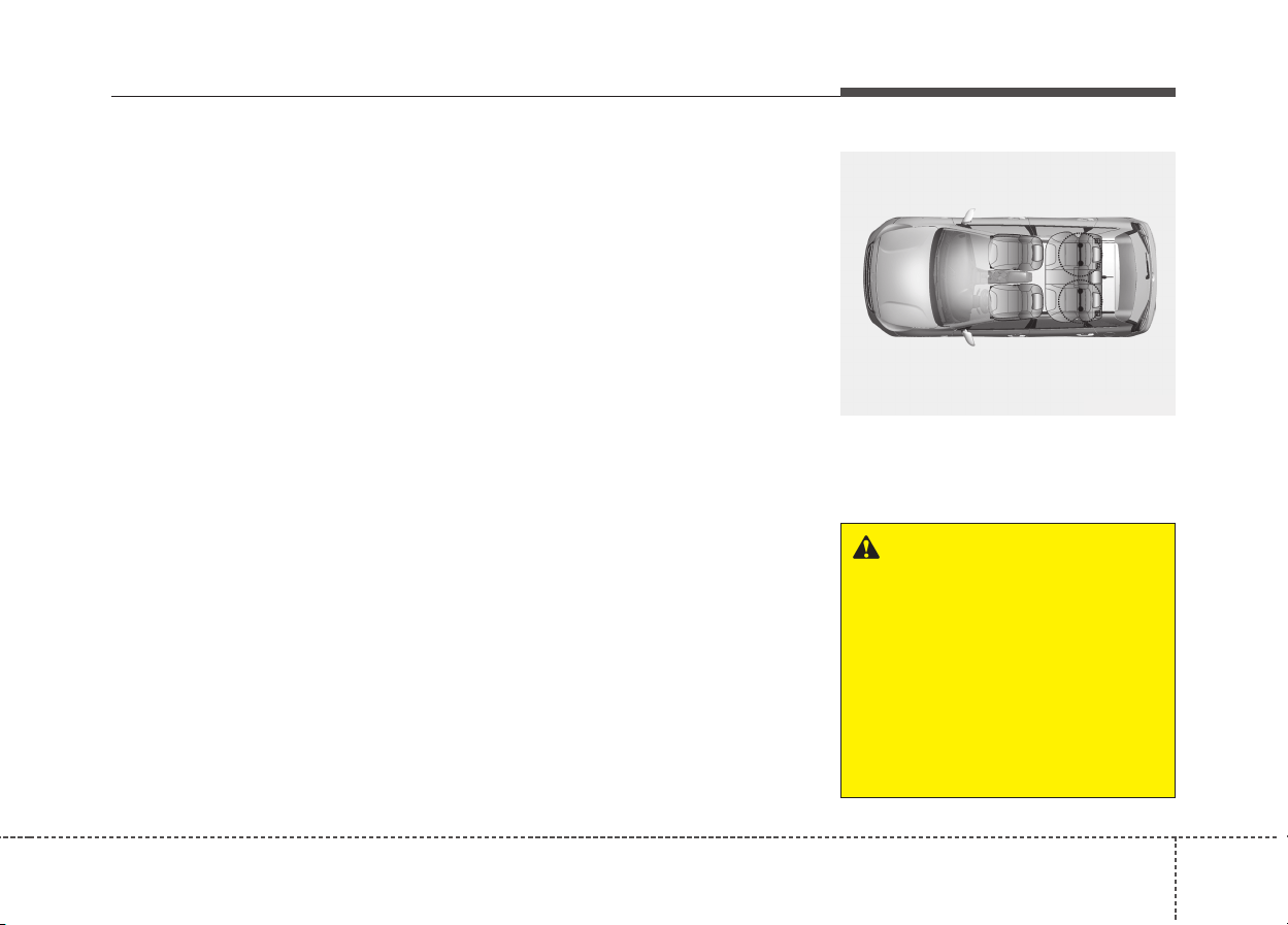
337
Safety features of your vehicle
ISOFIX anchorage and top-
tether anchorage (ISOFIX
anchorage system) for children
The ISOFIX system holds a Child
Restraint System during driving and
in an accident. This system is
designed to make installation of the
Child Restraint System easier and
reduce the possibility of improperly
installing your Child Restraint System.
The ISOFIX system uses anchors in
the vehicle and attachments on the
Child Restraint System. The ISOFIX
system eliminates the need to use
seat belts to secure the Child
Restraint System to the rear seats.
ISOFIX anchorages are metal bars
built into the vehicle. There are two
lower anchors for each ISOFIX seat-
ing position that will accommodate a
Child Restraint System with lower
attachments.
To use the ISOFIX system in your
vehicle, you must have a Child
Restraint System with ISOFIX
attachments.
The Child Restraint System manu-
facturer will provide you with instruc-
tions on how to use the Child
Restraint System with its attach-
ments for the ISOFIX anchorages.
ISOFIX anchorages have been pro-
vided in the left and right outboard
rear seating positions. Their loca-
tions are shown in the illustration.
WARNING
Do not attempt to install a Child
Restraint System using ISOFIX
anchorages in the rear center
seating position. There are no
ISOFIX anchorages provided for
this seat. Using the outboard
seat anchorages, for the CRS
installation on the rear center
seating position, can damage
the anchorages.
ODE036077L
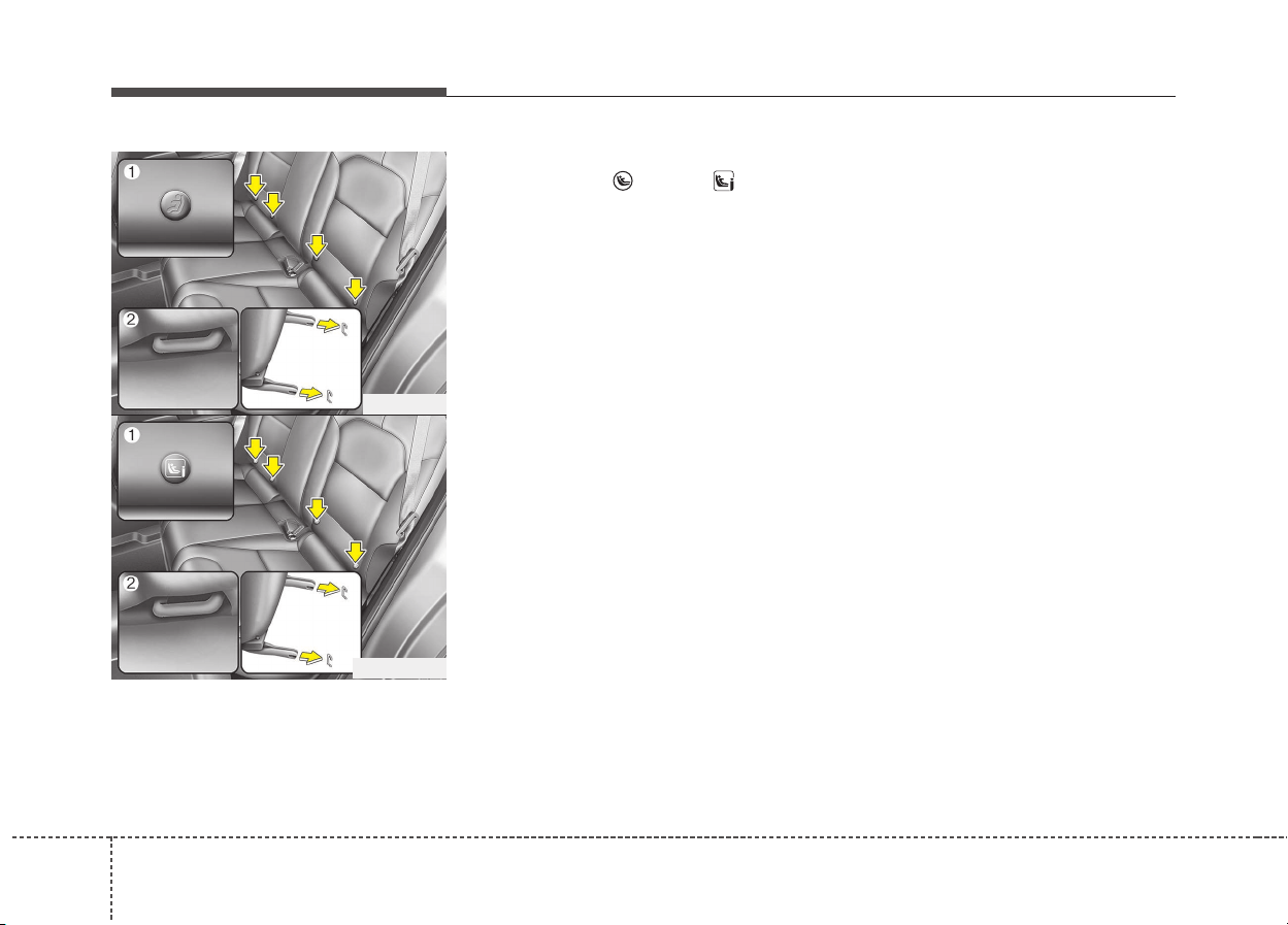
Safety features of your vehicle
383
ISOFIX anchorages are located
between the seatback and the seat
cushion of the rear seat left and right
outboard seating positions, indicated
by the symbols.
❈ (1) : ISOFIX Anchor Position Indicator
(Type A- ,Type B- )
(2) : ISOFIX Anchor
Securing a Child Restraint System
with the “ISOFIX Anchorage
System”
To install an i-Size or ISOFIX-com-
patible Child Restraint System in
either of the rear outboard seating
positions:
1. Move the seat belt buckle away
from the ISOFIX anchorages.
2. Move any other objects away from
the anchorages that could prevent
a secure connection between the
Child Restraint System and the
ISOFIX anchorages.
3. Place the Child Restraint System
on the vehicle seat, then attach
the seat to the ISOFIX anchorages
according to the instructions pro-
vided by the Child Restraint
System manufacturer.
4. Follow the instructions of the Child
Restraint System's manufacturer
for proper installation and connec-
tion of the ISOFIX attachments on
the Child Restraint System to the
ISOFIX anchorages.
ODE036035
ODE036079L
■ Type A
■ Type B

339
Safety features of your vehicle
Securing a Child Restraint
System seat with “Top-tether
Anchorage” system (if equipped)
Child restraint system top tether
anchorages are located on the back
of the rear seatbacks.
WARNING
Take the following precautions
when using the ISOFIX system:
• Read and follow all installation
instructions provided with
your Child Restraint System.
• To prevent the child from
reaching and taking hold of
unretracted seat belts, buckle
all unused rear seat belts and
retract the seat belt webbing
behind the child. Children can
be strangled if a shoulder belt
becomes wrapped around
their neck and the seat belt
tightens.
• NEVER attach more than one
Child Restraint System to a
single anchorage. This could
cause the anchor or attach-
ment to come loose or break.
(Continued)
(Continued)
• Always have the ISOFIX sys-
tem inspected by your dealer
after an accident. An accident
can damage the ISOFIX sys-
tem and may not properly
secure the Child Restraint
System.
ODE036032L
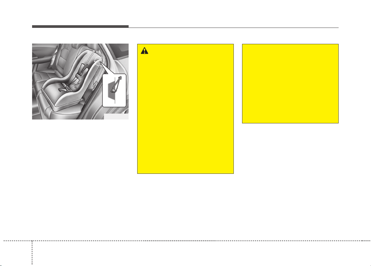
Safety features of your vehicle
403
1. Route the Child Restraint System
top-tether strap over the seatback.
Placing the top tether strap,
please follow the instructions of
the Child Restraint System manu-
facturer.
2. Connect the top-tether strap to the
top-tether anchorage, then tighten
the top-tether strap according to
the instructions of your Child
Restraint System's manufacturer
to firmly attach the Child Restraint
System to the seat.
ODE036033
WARNING
Take the following precautions
when installing the top-tether:
• Read and follow all installation
instructions provided with
your Child Restraint System.
• NEVER attach more than one
Child Restraint System to a
single ISOFIX top-tether
anchorage. This could cause
the anchorage or attachment
to come loose or break.
• Do not attach the top-tether to
anything other than the cor-
rect top-tether anchorage. It
may not work properly if
attached to something else.
(Continued)
(Continued)
• Child Restraint System
anchorages are designed to
withstand only those loads
imposed by correctly fitted
Child Restraint System.
Under no circumstances are
they to be used for adult seat
belts or harnesses or for
attaching other items or
equipment to the vehicle.

341
Safety features of your vehicle
Suitability of each seating position for ISOFIX Child Restraint Systems according to ECE regulations
IUF = Sutiable for ISOFIX Forward-Facing Child Restraint Systems of
universal category approved for use in the mass group.
IL = Suitable for particular ISOFIX Child Restraint Systems given in the
attached list. These ISOFIX CRS are those of the "specific vehi-
cle", "restricted" or "semi-universal" categories.
X = ISOFIX position not suitable for ISOFIX Child Restraint System in
this mass group and/or this size class.
A - ISO/F3 : Full-Height forward-facing toddler Child Restraint System
(height 720mm)
B - ISO/F2 : Reduced-height forward-facing toddler Child Restraint
System (height 650mm)
B1 - ISO/F2X : Reduced-height second version back surface shape for-
ward-facing toddler Child Restraint System (height 650mm)
C - ISO/R3 : Full-size rearward-facing toddler Child Restraint System
D - ISO/R2 : Reduced-size rearward-facing toddler Child Restraint System
E - ISO/R1 : Infant-size rearward-facing Child Restraint System
F - ISO/L1 : Left lateral facing position Child Restraint System (carry-cot)
G - ISO/L2 : Right lateral facing position Child Restraint System (carry-cot)
Mass Group Size Class Fixture
Vehicle ISOFIX positions
1st 2nd row
Passenger Left Hand Center Right Hand
Carrycot
F ISO/L1 N/A X N/A X
G ISO/L2 N/A X N/A X
0- : UP TO 10KG E ISO/R1 N/A IL N/A IL
0+ : UP TO 13KG
E ISO/R1 N/A IL N/A IL
D ISO/R2 N/A IL N/A IL
C ISO/R3 N/A IL N/A IL
1 : 9 TO 18KG
D ISO/R2 N/A IL N/A IL
C ISO/R3 N/A IL N/A IL
B ISO/F2 N/A IUF,IL N/A IUF,IL
B1 ISO/F2X N/A IUF,IL N/A IUF,IL
A ISO/F3 N/A IUF,IL N/A IUF,IL
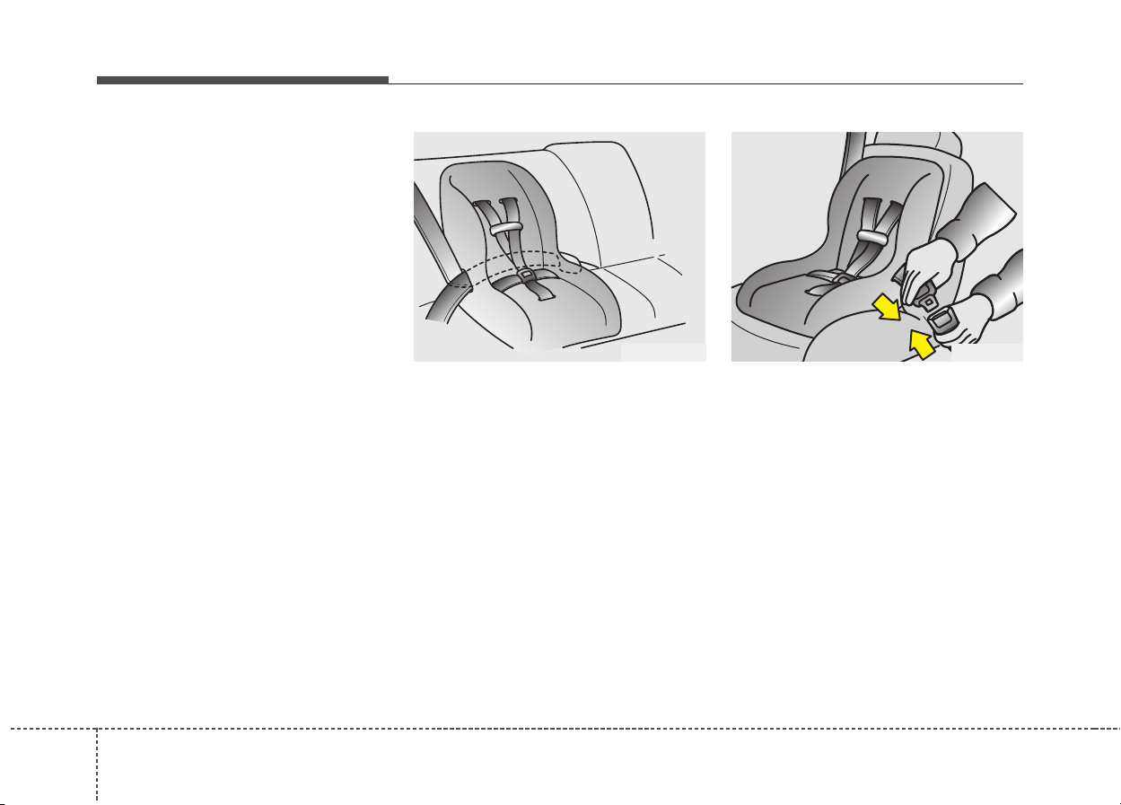
Safety features of your vehicle
423
Securing a Child Restraint
System with a lap/shoulder belt
When not using the ISOFIX system,
all Child Restraint Systems must be
secured to a rear seat with the lap
part of a lap/shoulder belt.
Installing a Child Restraint System
with a lap/shoulder belt
To install a Child Restraint System
on the rear seats, do the following:
1. Place the Child Restraint System
on a rear seat and route the lap/
shoulder belt around or through
the Child Restraint System, follow-
ing the Child Restraint System
manufacturer’s instructions.
Make sure the seat belt webbing
is not twisted.
2. Fasten the lap/shoulder belt latch
into the buckle. Listen for the dis-
tinct “click” sound. Position the
release button so that it is easy to
access in case of an emergency.
E2MS103005 OEN036101
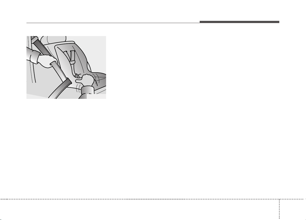
343
Safety features of your vehicle
3. Remove as much slack from the
belt as possible by pushing down
on the Child Restraint System
while feeding the shoulder belt
back into the retractor.
4. Push and pull on the Child
Restraint System to confirm that
the seat belt is holding it firmly in
place.
If your Child Restraint System manu-
facturer recommends the use of a
top-tether with the lap/shoulder belt,
see page 3-39
To remove the Child Restraint
System, press the release button on
the buckle and then pull the
lap/shoulder belt out of the Child
Restraint System and allow the seat
belt to retract fully.
OEN036104

Safety features of your vehicle
443
Suitability of each seating position for "universal" category belted Child Restraint Systems according to
ECE regulations (For Europe)
Use Child Restraint System that have been officially approved and are appropriate for your children. When using the
Child Restraint System, refer to the following table.
U = Suitable for "universal" category Child Restraint Systems approved for use in this mass group
U* = Suitable for "universal" category Child Restraint Systems with seat height adjusted to the highest and rearmost position
UF = Suitable for forward facing "universal" category restraints approved for use in this mass group
L = Suitable for particular child restraints given on attached list. These restraints may be of the "specific vehicle", "restricted" or "semi-universal"
categories.
B = Built-in restraint approved for this mass group.
X = Seat position not suitable for children in this mass group.
❈ Never install a Child Restraint System with a support leg on the front passenger seat and the second row center seat.
Mass Group
Seating Position
Front Passenger Second Row
Airbag
activated
Airbag
deactivated
Outboard
Left
Center
(3 POINT BELT)
Outboard
Right
Group 0 (0-9months) up to 10kg
X U* U UU
Group 0 + (0-2years) up to 13kg
X U* U UU
Group I (9months-4years) 9 to 18kg
X U* U UU
Group II (15 to 25kg) 15 to 25kg
UF U* U UU
Group III (22 to 36kg) 22 to 36kg
UF U* U UU

345
Safety features of your vehicle
Suitability of each seating position for "universal" category belted Child Restraint Systems according to
ECE regulations (Except Europe)
Use Child Restraint System that have been officially approved and are appropriate for your children. When using the
Child Restraint System, refer to the following table.
U = Suitable for "universal" category Child Restraint Systems approved for use in this mass group
U* = Suitable for "universal" category Child Restraint Systems with seat height adjusted to the highest position
UF = Suitable for forward facing "universal" category restraints approved for use in this mass group
L = Suitable for particular child restraints given on attached list. These restraints may be of the "specific vehicle", "restricted" or "semi-universal"
categories.
B = Built-in restraint approved for this mass group.
X = Seat position not suitable for children in this mass group.
Mass Group
Seating Position
Front Passenger Second Row
Airbag
activated
Airbag
deactivated
Outboard Left
Center
(3 POINT BELT)
Center
(2 POINT BELT)
Outboard
Right
Group 0 (0-9months) up to 10kg X U* U U UF U
Group 0 + (0-2years) up to 13kg X U* U U UF U
Group I (9months-4years) 9 to 18kg X U* U U UF U
Group II (15 to 25kg) 15 to 25kg UF U* U U UF U
Group III (22 to 36kg) 22 to 36kg UF U* U U UF U

Safety features of your vehicle
463
i-Size Child Restraint Systems according to ECE regulations
i-U = Suitable for i-Size "universal" Child Restraints Systems forward and rearward facing
i-UF = Suitable for forward-facing i-Size "universal" Child Restraints Systems only.
X = Seat position not suitable for i-size CRS.
Mass Group
Seating Position
Front Passenger
Second Row
Outboard Left Center Outboard Right
i-size Child Restraints Systems X i-U X i-U
Recommended child restraint systems – For Europe
❈❈
The Graco Junior III will be used without the backrest
CRS Manufacturer information
Maxi Cosi Cabriofix & Familyfix http://www.maxi-cosi.com
Britax Römmer http://www.britax.com
Graco http://www.gracobaby.com
Mass Group Name Manufacturer Type of Fixation
ECE-R44
Approval No.
Group 0+ Cabriofix & Familyfix Maxi Cosi Rearward-facing with ISOFIX E4 04443907
Group I Duo Plus Britax Römer Forward-facing with ISOFIX and top-tether E1 04301133
Group II KidFix II XP Britax Römer Forward-facing with ISOFIX and vehicle belt E1 04301323
Group III Junior III Graco Forward-facing with vehicle Belt
E11 03.44.164
E11 03.44.165
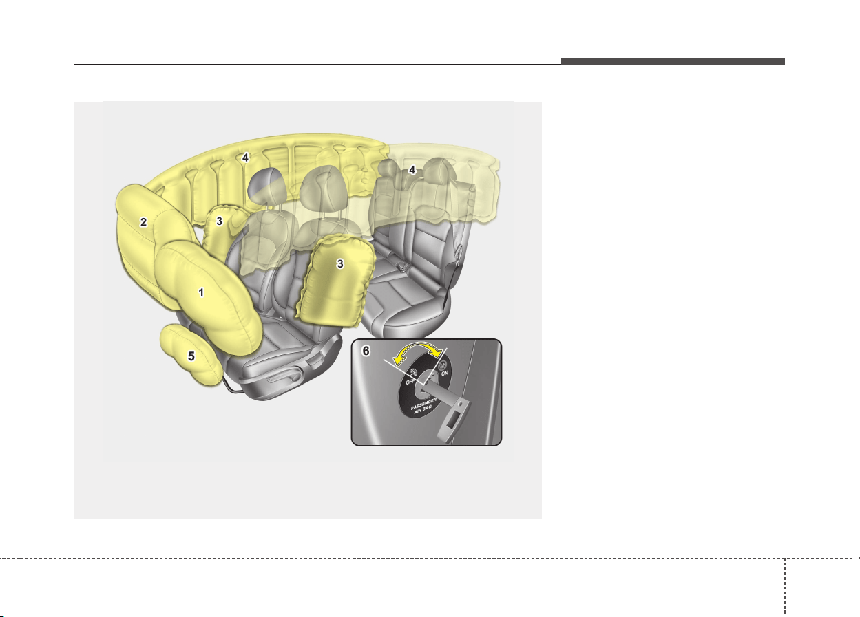
347
Safety features of your vehicle
(1) Driver’s front air bag
(2) Passenger’s front air bag*
(3) Side air bag*
(4) Curtain air bag*
(5) Driver’s knee air bag*
(6) Passenger’s front air bag
ON/OFF switch*
* : if equipped
AIR BAG - SUPPLEMENTAL RESTRAINT SYSTEM (IF EQUIPPED)
❈ The actual air bags in the vehicle may differ from the illustration.
ODE036036L

Safety features of your vehicle
483
How does the air bag system
operate
• Air bags are activated (able to
inflate if necessary) only when the
ignition switch is turned to the ON
or START position.
• Air bags inflate instantly in the
event of a serious frontal collision
or side collision (if equipped with a
side air bag or curtain air bag) in
order to help protect the occupants
from serious physical injury.
• In normal conditions, the airbag is
designed to deploy based on cer-
tain angle and intensity of the col-
lision. These two factors are cru-
cial elements for deciding whether
to transmit airbag deployment sig-
nal or start the electrical operation
or not.
• The airbag will deploy based on
angle and intensity of the collision.
It will not deploy in every crash or
collision situations
• The front air bags will completely
inflate and deflate in an instant.
It is virtually impossible for you to
see the air bags inflate during an
accident.
It is much more likely that you will
simply see the deflated air bags
hanging out of their storage com-
partments after the collision.
WARNING
• Even in vehicles with air bags,
you and your passengers
must always wear the safety
belts provided in order to min-
imize the risk and severity of
injury in the event of a colli-
sion or rollover.
• SRS and pretensioners con-
tain explosive chemicals.
If scraping a vehicle without
removing SRS and preten-
sioners from a vehicle, it may
cause fire. Before scraping a
vehicle, we recommend that
you contact an authorized Kia
dealer.
• Keep the SRS parts and
wirings away from water or any
liquid. If the SRS components
are inoperative due to expo-
sure to water or liquids, it may
cause fire or severe injury.
349
Safety features of your vehicle
• In order to help provide protection
in a severe collision, the air bags
must inflate rapidly. The speed of
the air bag inflation is a conse-
quence of extremely short time in
which a collision occurs and the
need to inflate the air bag between
the occupant and the vehicle struc-
tures before the occupant impacts
those structures.
This speed of inflation reduces the
risk of serious or life-threatening
injuries in a severe collision and is
thus a necessary part of the air
bag design.
However, air bag inflation can also
cause injuries which can include
facial abrasions, bruises and bro-
ken bones because the inflation
speed also causes the air bags to
expand with a great deal of force.
• There are even circumstances
under which contact with the
steering wheel air bag can cause
fatal injuries, especially if the
occupant is positioned exces-
sively close to the steering
wheel.
Noise and smoke
When the air bags inflate, they make
a loud noise and they leave smoke
and powder in the air inside of the
vehicle. This is normal and is a result
of the ignition of the air bag inflator.
After the air bag inflates, you may
feel substantial discomfort in breath-
ing due to the contact of your chest
with both the seat belt and the air
bag, as well as from breathing the
smoke and powder. Open your
doors and/or windows as soon as
possible after the impact in order
to reduce discomfort and prevent
prolonged exposure to smoke and
powder.
Though the smoke and powder are
non-toxic, they may cause irritation
to the skin (eyes, nose and throat,
etc). If this is the case, wash and
rinse with cold water immediately
and consult a doctor if the symptom
persists.
WARNING
• To avoid severe personal
injury or death caused by
deploying air bags in a colli-
sion, the driver should sit as
far back from the steering
wheel air bag as possible (at
least 250 mm (10 inches)
away). The front passengers
should always move their
seats as far back as possible
and sit back in their seat.
• Air bags inflate instantly in the
event of a collision, and pas-
sengers may be injured by the
air bag expansion force if they
are not in a proper position.
• Air bag inflation may cause
injuries including facial or
bodily abrasions, injuries
from broken glasses or burns.
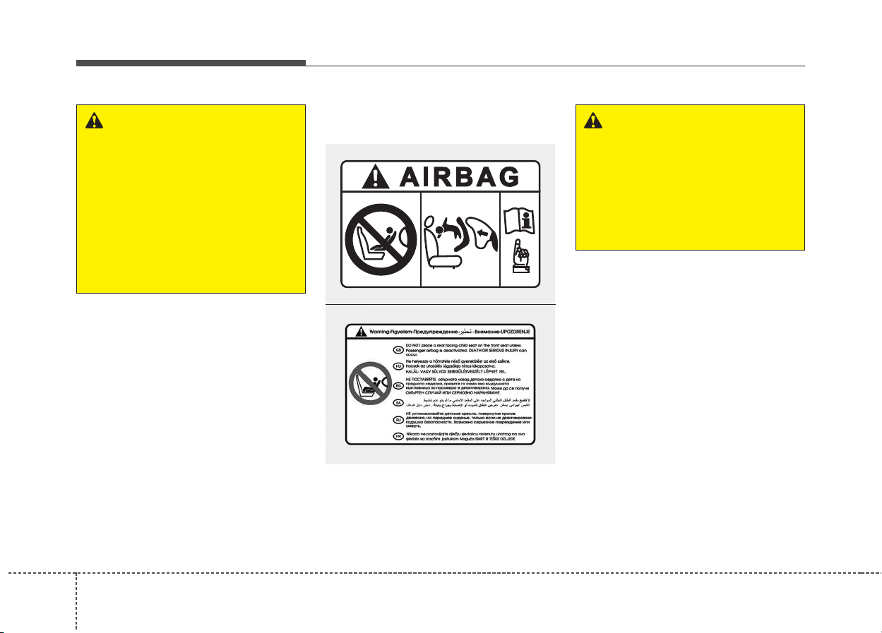
Safety features of your vehicle
503
Front passenger's air bag warning
label for child restraint system
In addition, we recommend that you
do not place front-facing child
restraints in the front passenger’s
seat either. If the front passenger air
bag inflates, it could cause serious or
fatal injuries to the child.
If your vehicle is equipped with the
passenger’s front air bag ON/OFF
switch, you can activate or deactivate
the front passenger’s air bag when
necessary.
For more details, please refer to
"Passenger’s front air bag ON/OFF
switch" in this chapter. (if equipped)
WARNING
When the air bags deploy, the air
bag related parts in the steering
wheel, instrument panel, front
seats and/or in both sides of the
roof rails above the front and
rear doors are very hot. To pre-
vent injury, do not touch the air
bag storage area’s internal com-
ponents immediately after an air
bag has inflated.
WARNING
Never place a rear facing child
restraint in the front passenger
seat, unless the passenger-side
air bag is deactivated. An inflat-
ing passenger-side air bag
could impact the rear-facing
child restraint and kill the child.
OYDESA2042
OHM036053L
■ Type A
■ Type B
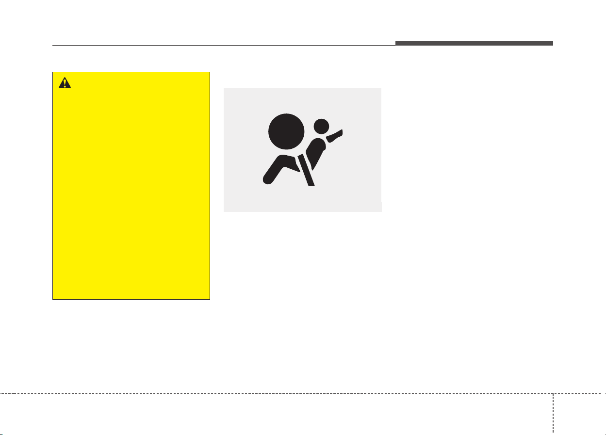
351
Safety features of your vehicle
Air bag warning light
The purpose of the air bag warning
light in your instrument panel is to
alert you of a potential problem with
your air bag - Supplemental
Restraint System (SRS).
When the ignition switch is turned ON,
the warning light should illuminate for
approximately 6 seconds, then go off.
Have the system checked if:
• The light does not turn on briefly
when you turn the ignition ON.
• The light stays on after illuminating
for approximately 6 seconds.
• The light comes on while the vehi-
cle is in motion.
• The light blinks when the ignition
switch is in ON position.
WARNING
• NEVER use a rearward facing
child restraint on a seat pro-
tected by an ACTIVE AIR BAG
in front of it, DEATH or SERI-
OUS INJURY to the CHILD can
occur.
• When children are seated in
the rear outboard seats of a
vehicle equipped with side
and/or curtain air bags, be
sure to install the child
restraint system as far away
from the door side as possible,
and securely lock the child
restraint system in position.
Inflation of side and/or curtain
air bags could cause serious
injury or death to an infant or
child.
W7-147
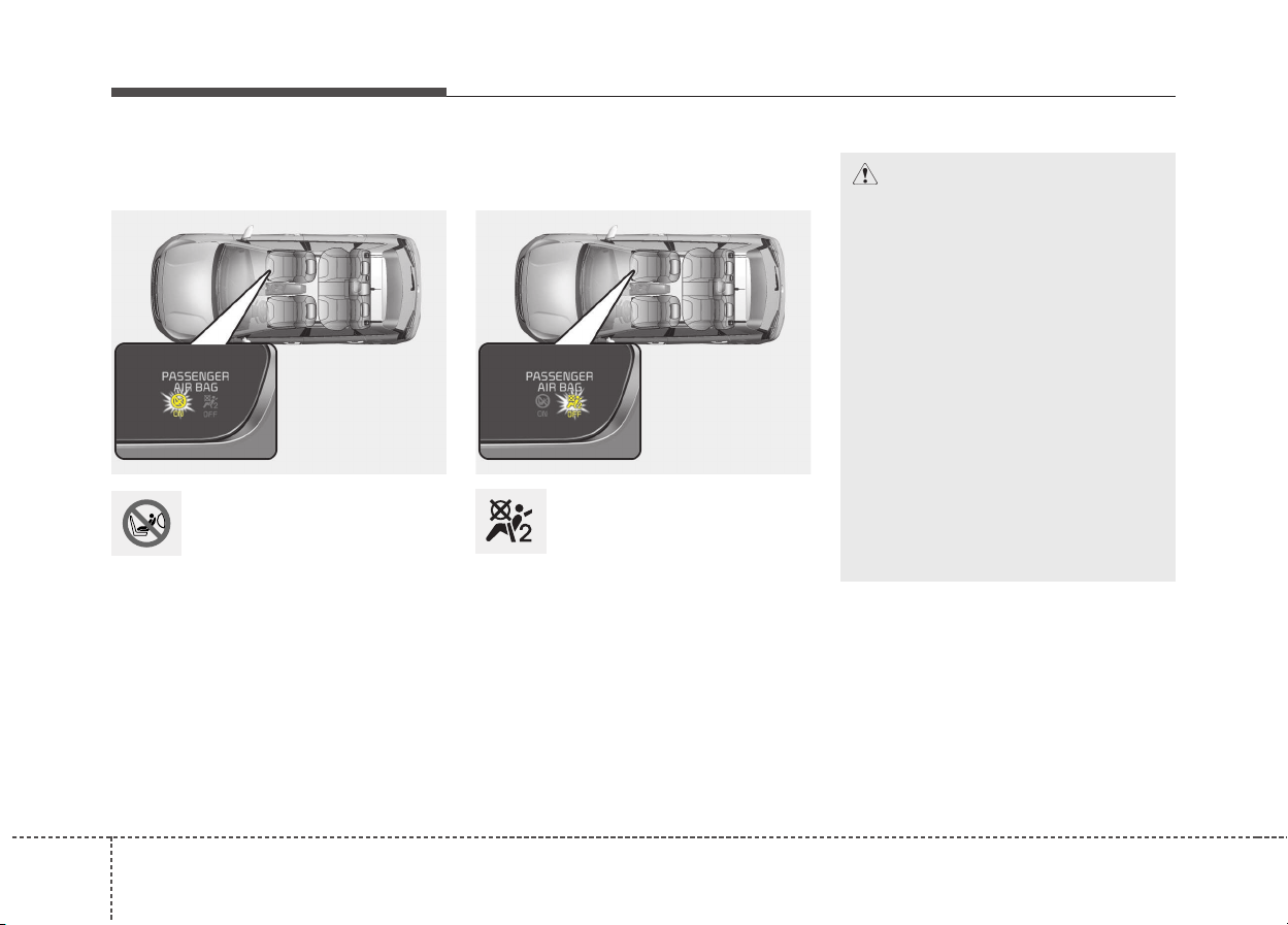
Safety features of your vehicle
523
Passenger’s front air bag
ON indicator (if equipped)
The passenger's front air
bag ON indicator illumi-
nates for approximately 4
seconds after the ignition
switch is turned to the ON position.
The passenger's front air bag ON indi-
cator also comes on when the pas-
senger's front air bag ON/OFF switch
is set to the ON position and goes off
after approximately 60 seconds.
Passenger’s front air bag
OFF indicator (if equipped)
The passenger’s front air
bag OFF indicator illumi-
nates for about 4 seconds
after the ignition switch is
turned to the ON position.
The passenger’s front air bag OFF
indicator also comes on when the
passenger’s front air bag ON/OFF
switch is set to the OFF position and
goes off when the passenger’s front
air bag ON/OFF switch is set to the
ON position.
CAUTION
If the passenger’s front air bag
ON/OFF switch malfunctions,
the passenger’s front air bag
OFF indicator will not illuminate
(The passenger's front air bag
ON indicator comes on and goes
off after approximately 60 sec-
onds) and the passenger’s front
air bag will inflate in a frontal
impact even if the passenger’s
front air bag ON/OFF switch is
set to the OFF position.
If this occurs, we recommend
that the passenger’s front air
bag ON/OFF switch and the SRS
air bag system be inspected by
an authorized Kia dealer.
ODE036085L ODE036086L
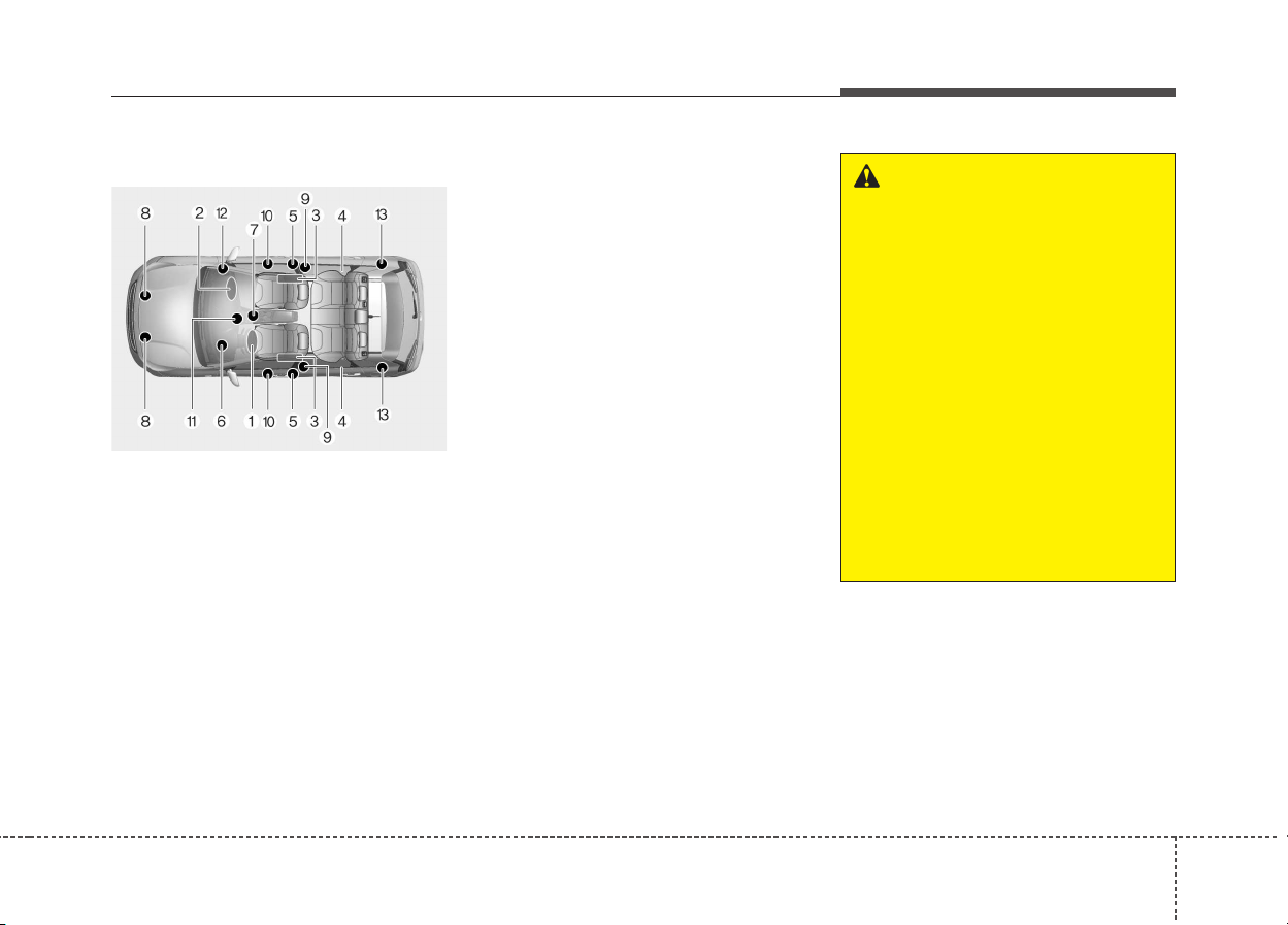
353
Safety features of your vehicle
SRS components and functions
The SRS consists of the following
components:
1. Driver's front air bag module
2. Passenger's front air bag module*
3. Side air bag modules*
4. Curtain air bag modules*
5. Retractor pre-tensioner assemblies*
6. Air bag warning light
7. SRS control module (SRSCM)
8. Front impact sensors
9. Side impact sensors*
10. Side pressure sensors*
11. Passenger’s front air bag
ON/OFF indicator
(front passenger's seat only)*
12. Passenger’s front air bag
ON/OFF switch*
13. Retractor pre-tensioner
assemblies*
* : if equipped
The SRSCM continually monitors all
SRS components while the ignition
switch is ON to determine if a crash
impact is severe enough to require
air bag deployment or pre-tensioner
seat belt deployment.
The SRS air bag warning light on the
instrument panel will illuminate for
about 6 seconds after the ignition
switch is turned to the ON position,
after which the SRS air bag warning
light should go out.
WARNING
If any of the following condi-
tions occurs, this indicates a
malfunction of the SRS. We rec-
ommend that the system be
inspected by an authorized Kia
dealer.
• The light does not turn on
briefly when you turn the igni-
tion ON.
• The light stays on after illumi-
nating for approximately 6
seconds.
• The light comes on while the
vehicle is in motion.
• The light blinks when the igni-
tion switch is in ON position.
ODE036078L
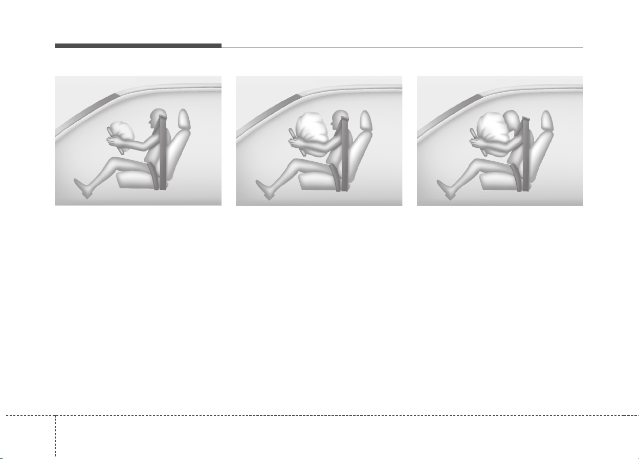
Safety features of your vehicle
543
The front air bag modules are locat-
ed both in the center of the steering
wheel and in the front passenger's
panel above the glove box. When the
SRSCM detects a sufficiently severe
impact to the front of the vehicle, it
will automatically deploy the front air
bags.
Upon deployment, tear seams mold-
ed directly into the pad covers will
separate under pressure from the
expansion of the air bags. Further
opening of the covers then allows full
inflation of the air bags.
A fully inflated air bag, in combina-
tion with a properly worn seat belt,
slows the driver's or the passenger's
forward motion, reducing the risk of
head and chest injury.
After complete inflation, the air bag
immediately starts deflating,
enabling the driver to maintain for-
ward visibility and the ability to steer
or operate other controls.
B240B01L
Driver’s front air bag (1)
B240B02L
Driver’s front air bag (2)
B240B03L
Driver’s front air bag (3)
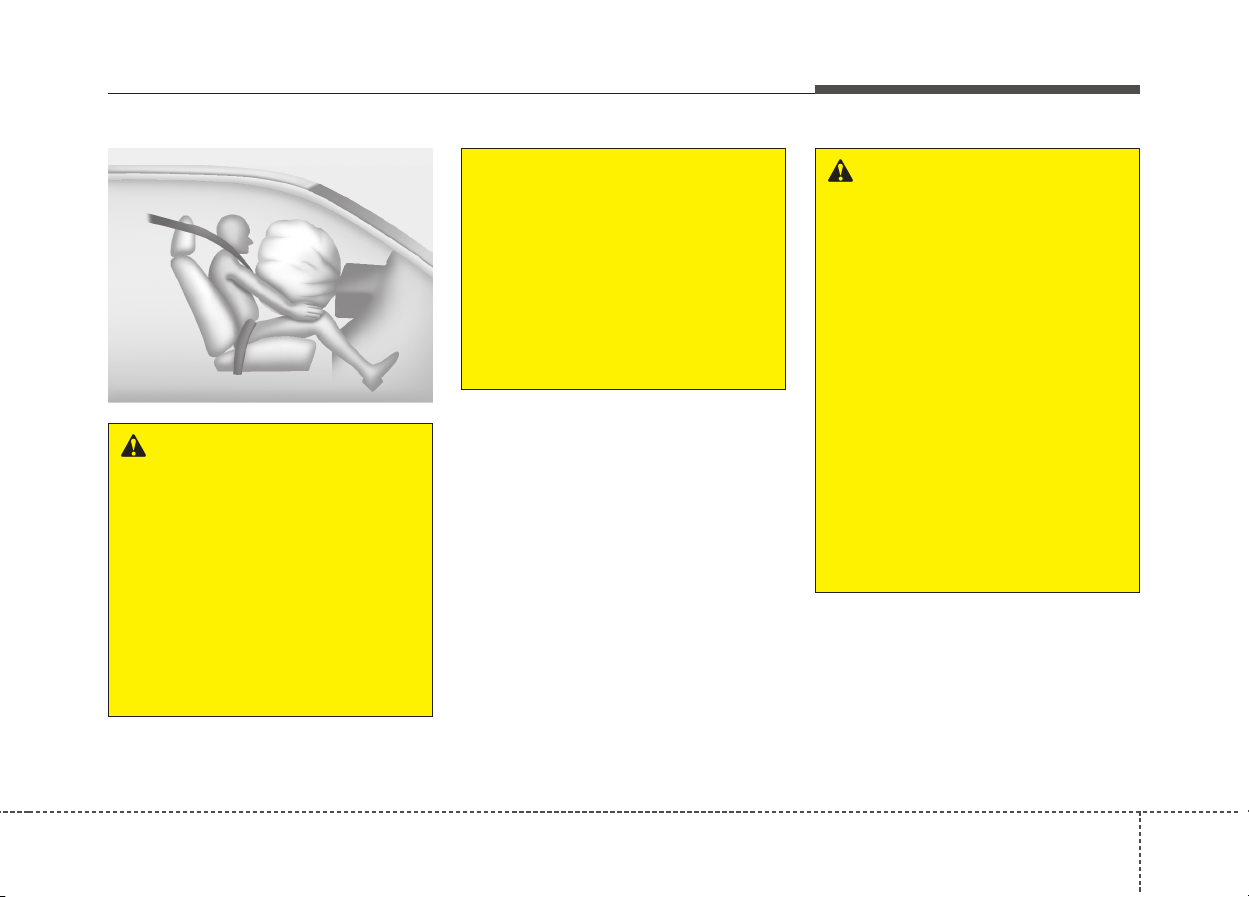
355
Safety features of your vehicle
WARNING
• Do not install or place any
accessories (drink holder,
cassette holder, sticker, etc.)
on the front passenger's
panel above the glove box in a
vehicle with a passenger's air
bag. Such objects may
become dangerous projec-
tiles and cause injury if the
passenger's air bag inflates.]
(Continued)
B240B05L
Passenger’s front air bag (if equipped)
(Continued)
• When installing a container of
liquid air freshener inside the
vehicle, do not place it near
the instrument cluster nor on
the instrument panel surface.
It may become a dangerous
projectile and cause injury if
the passenger's air bag
inflates.
WARNING
• If an air bag deploys, there
may be a loud noise followed
by a fine dust released in the
vehicle. These conditions are
normal and are not hazardous
- the air bags are packed in
this fine powder. The dust
generated during air bag
deployment may cause skin
or eye irritation as well as
aggravate asthma for some
persons. Always wash all
exposed skin areas thorough-
ly with cold water and mild
soap after an accident in
which the air bags were
deployed.
(Continued)
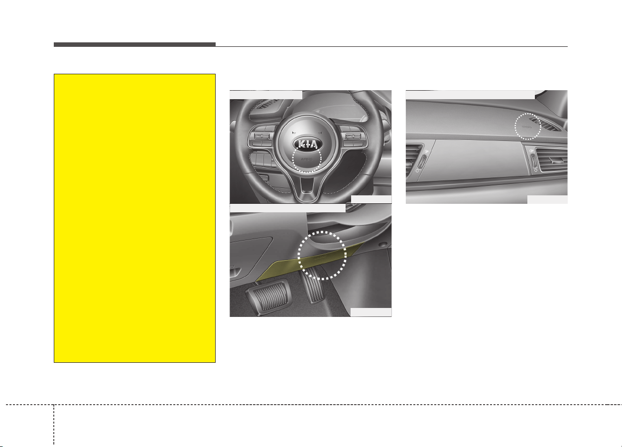
Safety features of your vehicle
563
Your vehicle is equipped with a
Supplemental Restraint (Air Bag)
System and lap/shoulder belts at
both the driver and passenger seat-
ing positions.
The indicators of the system's pres-
ence are the letters "AIR BAG" locat-
ed on the air bag pad cover on the
steering wheel and the passenger's
side front panel pad above the glove
box.
(Continued)
• The SRS can function only
when the ignition key is in the
ON position. If the SRS air bag
warning light does not illumi-
nate, or continuously remains
on after illuminating for about 6
seconds when the ignition key
is turned to the ON position, or
after the engine is started,
comes on while driving, the
SRS is not working properly. If
this occurs, we recommend
that the system be inspected
by an authorized Kia dealer.
• Before you replace a fuse or
disconnect a battery terminal,
turn the ignition switch to the
LOCK position and remove
the ignition key. Never remove
or replace the air bag related
fuse(s) when the ignition
switch is in the ON position.
Failure to heed this warning
will cause the SRS air bag
warning light to illuminate.
ODE036037
ODE036063
■ Driver’s front air bag
■ Driver’s knee air bag (if equipped)
ODE036038
■ Passenger’s front air bag (if equipped)
Driver's and passenger's front air bag
357
Safety features of your vehicle
The SRS consists of air bags
installed under the pad covers in the
center of the steering wheel and the
passenger's side in the front panel
above the glove box.
The purpose of the SRS is to provide
the vehicle's driver and/or the front
passenger with additional protection
than that offered by the seat belt sys-
tem alone in case of a frontal impact
of sufficient severity.
WARNING
Always use seat belts and child
restraints – every trip, every
time, everyone! Air bags inflate
with considerable force and in
the blink of an eye. Seat belts
help keep occupants in proper
position to obtain maximum
benefit from the air bag. Even
with air bags, improperly and
unbelted occupants can be
severely injured when the air
bag inflates. Always follow the
precautions about seat belts, air
bags and occupant safety con-
tained in this manual.
To reduce the chance of serious
or fatal injuries and receive the
maximum safety benefit from
your restraint system:
(Continued)
(Continued)
• ABC – We recommend to
always Buckle Children in the
2nd row seat. It is the safest
place for children of any age
to ride.
• Front and side air bags can
injure occupants improperly
positioned in the front seats.
• Move your seat as far back as
practical from the front air
bags, while still maintaining
control of the vehicle.
• You and your passengers
should never sit or lean unnec-
essarily close to the air bags.
Improperly positioned drivers
and passengers can be severe-
ly injured by inflating air bags.
• Never lean against the door or
center console – always sit in
an upright position.
(Continued)

Safety features of your vehicle
583
(Continued)
• If the SRS air bag warning
light remains illuminated
while the vehicle is being driv-
en, we recommend that the
system be inspected by an
authorized Kia dealer.
• Air bags can only be used
once – we recommend that
the system be replaced by an
authorized Kia dealer.
• The SRS is designed to deploy
the front air bags when an
impact is sufficiently severe.
Additionally, the air bags will
only deploy once. Seat belts
must be worn at all times.
• Front air bags are not intend-
ed to deploy in side-impact,
rear-impact or rollover crash-
es. However, when frontal
deployment threshold is sat-
isfied at side-impact, front air
bags may deploy.
(Continued)
(Continued)
• Do not allow a passenger to
ride in the front seat when the
passenger’s front air bag OFF
indicator is illuminated,
because the air bag will not
deploy in the event of a mod-
erate or severe frontal crash.
• No objects should be placed
over or near the air bag mod-
ules on the steering wheel,
instrument panel or the front
passenger's panel above the
glove box, because any such
object could cause harm if the
vehicle is in a crash severe
enough to cause the air bags
to deploy.
• Do not tamper with or discon-
nect SRS wiring or other com-
ponents of the SRS system.
Doing so could result in injury,
due to accidental deployment
of the air bags or by rendering
the SRS inoperative.
(Continued)
(Continued)
In addition, front air bags will
not deploy in frontal crashes
below the deployment thresh-
old.
• A child restraint system
should never be placed in the
front seat. The infant or child
could be severely injured or
killed by an air bag deploy-
ment in case of an accident.
• Children age 12 and under
must always be properly
restrained in the rear seat. If a
child over 12 must be seated
in the front seat, he or she
must be properly belted and
the seat should be moved as
far back as possible.
(Continued)
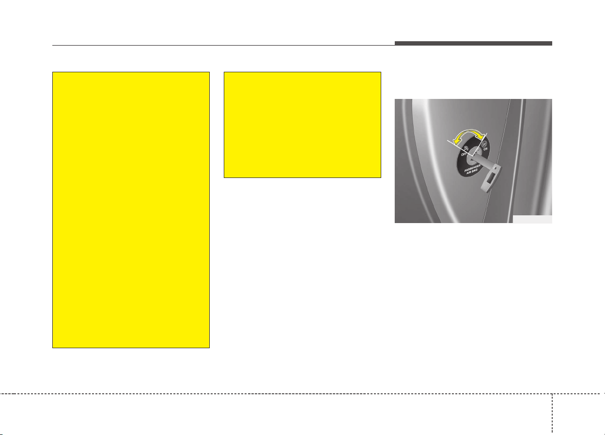
359
Safety features of your vehicle
Passenger’s front air bag ON/OFF
switch (if equipped)
The passenger’s front air bag can be
deactivated by the passenger’s front
air bag ON/OFF switch if a child
restraint is installed on the front pas-
senger's seat or if the front passen-
ger's seat is unoccupied by a person.
To ensure the safety of your child,
the passenger’s front air bag must be
deactivated when it should be neces-
sary to install a rearward facing child
seat on the front passenger seat in
exceptional circumstances.
OQL035086
(Continued)
• For maximum safety protec-
tion in all types of crashes, all
occupants including the driver
should always wear their seat
belts whether or not an air bag
is also provided at their seat-
ing position to minimize the
risk of severe injury or death
in the event of a crash.
Do not sit or lean unnecessar-
ily close to the air bag while
the vehicle is in motion.
• Sitting improperly or out of
position can result in serious
or fatal injury in a crash. All
occupants should sit upright
with the seat back in an upright
position, centered on the seat
cushion with their seat belt on,
legs comfortably extended and
their feet on the floor until the
vehicle is parked and the igni-
tion key is removed.
(Continued)
(Continued)
• The SRS air bag system must
deploy very rapidly to provide
protection in a crash. If an
occupant is out of position
because of not wearing a seat
belt, the air bag may forcefully
contact the occupant causing
serious or fatal injuries.
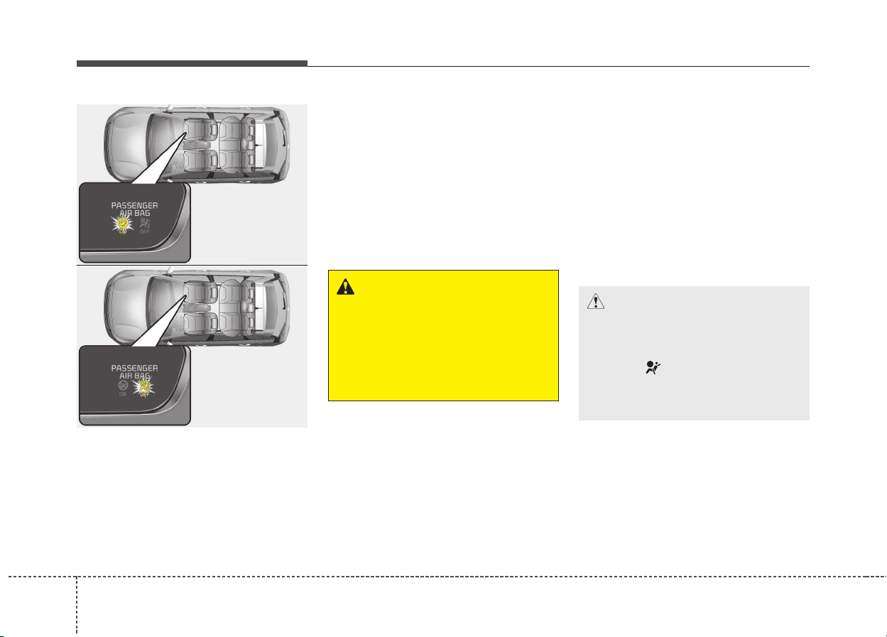
Safety features of your vehicle
603
To deactivate or reactivate the passen-
ger’s front air bag:
To deactivate the passenger’s front
air bag, insert the master key into the
passenger’s front air bag ON/OFF
switch and turn it to the OFF position.
The passenger’s front air bag OFF
indicator will illuminate and stay on
until the passenger’s front air bag is
reactivated.
To reactivate the passenger’s front
air bag, insert the master key into the
passenger’s front air bag ON/OFF
switch and turn it to the ON position.
The passenger’s front air bag OFF
indicator will go out.
✽✽
NOTICE
• When the passenger’s front air
bag ON/OFF switch is set to the
ON position, the passenger’s front
air bag is activated and child or
infant seat should not be installed
on the front passenger seat.
• When the passenger’s front air
bag ON/OFF switch is set to the
OFF position, the passenger’s
front air bag is deactivated.
CAUTION
• If the passenger’s front air bag
ON/OFF switch is not working
properly, the air bag warning
light ( )on the instrument
panel will illuminate.
(Continued)
ODE036085L
ODE036086L
WARNING
The front air bag ON/OFF switch
could turn by using a similar
small rigid device. Always check
the status of the front air bag
ON/OFF switch and passenger's
front air bag OFF indicator.
361
Safety features of your vehicle
(Continued)
• Children who are too large for
child restraint systems
should always occupy the
rear seat and use the available
lap/shoulder belts. Children
are afforded the most safety
in the event of an accident
when they are restrained by a
proper restraint system in the
rear seat.
• As soon as the child seat is
no longer needed on the front
passenger's seat, reactivate
the front passenger's air bag.
(Continued)
And, the passenger's front air
bag OFF indicator ( ) will not
illuminate (The passenger's
front air bag ON indicator
comes on and goes off after
approximately 60 seconds),
the SRS Control Module reac-
tivates the passenger’s front
air bag and the passenger’s
front air bag will inflate in
frontal impact crashes even if
the passenger’s front air bag
ON/OFF switch is set to the
OFF position.
If this occurs, we recommend
that the system be inspected
by an authorized Kia dealer.
• If the SRS air bag warning
light blinks or does not illumi-
nate when the ignition switch
is turned to the ON position,
or if it illuminates while the
vehicle is being driven, we
recommend that the system
be inspected by an authorized
Kia dealer.
WARNING
• The driver is responsible for
the proper position of the pas-
senger’s front air bag ON/OFF
switch.
• Deactivate the passenger's
front air bag only when the
ignition switch is switched off,
or the malfunction may occur
in the SRS Control Module.
And there may be a danger
that the driver's and/or front
passenger’s and/or side and
curtain air bag may fail to trig-
ger, or not trigger correctly
during a collision.
• Never install a rearward fac-
ing child seat on the front pas-
senger's seat unless the pas-
senger's front air bag has
been deactivated. The infant
or child could be severely
injured or killed by an air bag
deployment in case of an acci-
dent.
(Continued)
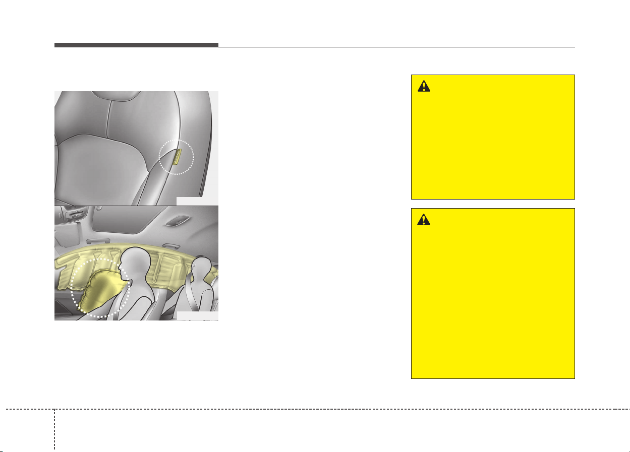
Safety features of your vehicle
623
Side air bag (if equipped)
❈ The actual air bags in the vehicle may differ
from the illustration.
Your vehicle is equipped with a side
air bag in each front seat.
The purpose of the air bag is to pro-
vide the vehicle's driver and/or the
front passenger with additional pro-
tection than that offered by the seat
belt alone.
The side air bags are designed to
deploy during certain side-impact
collisions, depending on the crash
severity of impact. However, when
side deployment threshold is satis-
fied at front-impact, side air bags
may deploy. The side air bags are not
designed to deploy in all side impact
situations.
The side air bags may deploy on the
side of the impact.
WARNING
Do not allow the passengers to
lean their heads or bodies onto
doors, put their arms on the
doors, stretch their arms out of
the window, or place objects
between the doors and passen-
gers when they are seated on
seats equipped with side and/or
curtain air bags.
WARNING
• The side air bag is supple-
mental to the driver's and the
passenger's seat belt systems
and is not a substitute for
them. Therefore your seat
belts must be worn at all times
while the vehicle is in motion.
The air bags deploy only in
certain side impact conditions
severe enough to cause sig-
nificant injury to the vehicle
occupants.
(Continued)
ODE036040
ODE036041
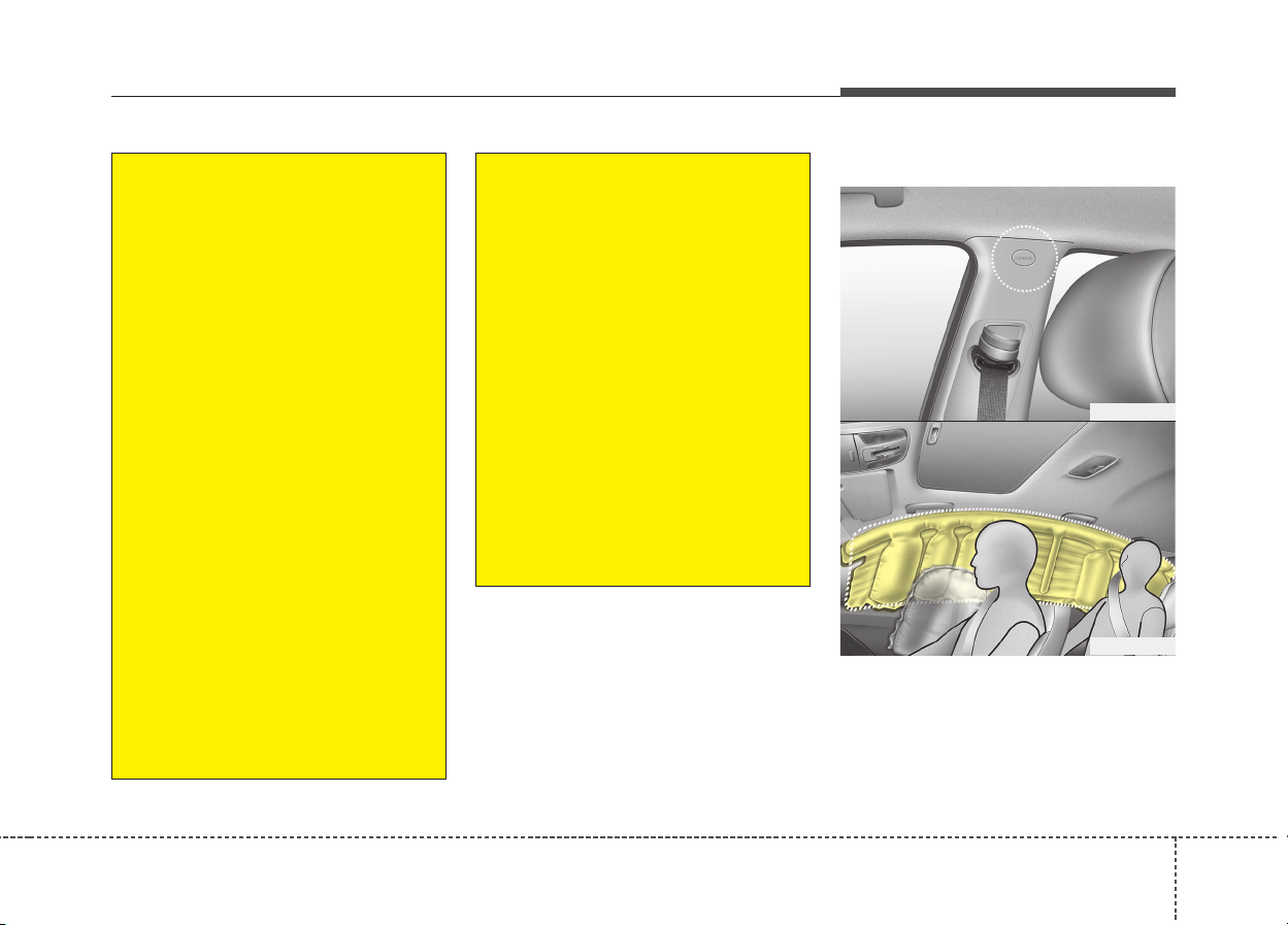
363
Safety features of your vehicle
Curtain air bag (if equipped)
Curtain air bags are located along
both sides of the roof rails above the
front and rear doors.
❈ The actual air bags in the vehicle may differ
from the illustration.
ODE036042
ODE036043
(Continued)
• Do not place any objects (an
umbrella, bag, etc.) between the
front door and the front seat.
Such objects may become dan-
gerous projectiles and cause
injury if the supplemental side
air bag inflates.
• To prevent unexpected
deployment of the side air bag
that may result in personal
injury, avoid impact to the
side impact sensor when the
ignition switch is on.
• If the seat or seat cover is
damaged, we recommend that
the system be serviced by an
authorized Kia dealer.
(Continued)
• For best protection from the
side air bag system and to
avoid being injured by the
deploying side air bag, both
front seat occupants should
sit in an upright position with
the seat belt properly fastened.
The driver's hands should be
placed on the steering wheel at
the 9:00 and 3:00 positions.
The passenger's arms and
hands should be placed on
their laps.
• Do not use any accessory
seat covers.
• Use of seat covers could
reduce or prevent the effec-
tiveness of the system.
• Do not install any accessories
on the side or near the side air
bag.
• Do not place any objects over
the air bag or between the air
bag and yourself.
(Continued)
Safety features of your vehicle
643
They are designed to help protect the
heads of the front seat occupants
and the rear outboard seat occupants
in certain side impact collisions.
The curtain air bags are designed to
deploy during certain side impact
collisions, depending on the crash
severity of impact. However, when
side deployment threshold is satis-
fied at front-impact, curtain air bags
may deploy.
The curtain air bags may deploy on
the side of the impact.
The curtain air bags are not designed
to deploy in all side impacts situations.
WARNING
• In order for side and curtain
air bags to provide the best
protection, front seat occu-
pants and outboard rear occu-
pants should sit in an upright
position with the seat belts
properly fastened. Importantly,
children should sit in a proper
child restraint system in the
rear seat.
• When children are seated in
the rear outboard seats, they
must be seated in the proper
child restraint system. Make
sure to position the child
restraint system as far away
from the door side as possible,
and secure the child restraint
system in a locked position.
(Continued)
(Continued)
• Do not allow the passengers to
lean their heads or bodies
against doors, put their arms
on the doors, stretch their arms
out of the window or place
objects between the doors and
passengers when they are
seated on seats equipped with
side and curtain air bags.
• Never try to open or repair any
components of the side curtain
air bag system.We recommend
that the system be serviced by
an authorized Kia dealer.
Failure to follow the above
instructions can result in injury
or death to the vehicle occu-
pants in an accident.
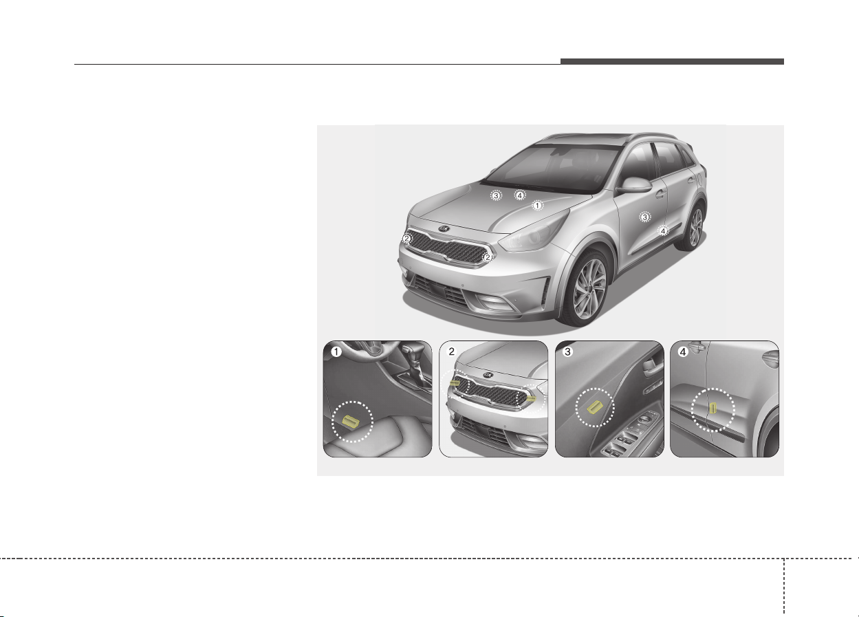
365
Safety features of your vehicle
Why didn’t my air bag go off in a
collision? (Inflation and non-infla-
tion conditions of the air bag)
There are many types of accidents
in which the air bag would not be
expected to provide additional
protection.
These include rear impacts, sec-
ond or third collisions in multiple
impact accidents, as well as low
speed impacts.
Air bag collision sensors
(1) SRS control module
(2) Front impact sensor
(3) Side pressure sensor (if equipped)
(4) Side impact sensor (if equipped)
❈ The actual air bag collision sensors in the vehicle may differ from the illustration.
ODE036044/ODE036045/ODE036046/ODE036047/ODE036048

Safety features of your vehicle
663
Air bag inflation conditions
Front air bags
Front air bags are designed to inflate
in a frontal collision depending on the
severity of impact of the front collision.
Side and curtain air bags (if equipped)
Side and curtain air bags are
designed to inflate when an impact is
detected by side collision sensors
depending on the severity of impact
resulting from a side impact collision.
Although the front air bags (driver’s
and front passenger’s air bags) are
designed to inflate only in frontal colli-
sions, they also may inflate in other
types of collisions if the front impact
sensors detect a sufficient impact. Side
air bags (side and/or curtain air bags)
are designed to inflate only in side
impact collisions, but they may inflate
in other collisions if the side impact
sensors detect a sufficient impact.
WARNING
• Do not hit or allow any objects
to impact the locations where
air bag or sensors are installed.
This may cause unexpected
air bag deployment, which
could result in serious per-
sonal injury or death.
• If the installation location or
angle of the sensors is altered
in any way, the air bags may
deploy when they should not
or they may not deploy when
they should, causing severe
injury or death.
Therefore, do not try to per-
form maintenance on or
around the air bag sensors.
We recommend that the sys-
tem be serviced by an author-
ized Kia dealer.
(Continued)
(Continued)
• Problems may arise if the sen-
sor installation angles are
changed due to the deforma-
tion of the front bumper, body
or front door and B/C pillars
where side collision sensors
are installed. We recommend
that the system be serviced
by an authorized Kia dealer.
• Your vehicle has been
designed to absorb impact
and deploy the air bag(s) in
certain collisions. Installing
bumper guards or replacing a
bumper with non-genuine
parts may adversely affect
your vehicles collision and air
bag deployment performance.

367
Safety features of your vehicle
If the vehicle chassis is impacted by
bumps or objects on unimproved
roads or sidewalks, air bags may
deploy. Drive carefully on unim-
proved roads or on surfaces not
designed for vehicle traffic to prevent
unintended air bag deployment.
Air bag non-inflation conditions
• In certain low-speed collisions the
air bags may not deploy. The air
bags are designed not to deploy in
such cases because they may not
provide benefits beyond the pro-
tection of the seat belts in such col-
lisions.
• Air bags are not designed to inflate
in rear collisions, because occu-
pants are moved backward by the
force of the impact. In this case,
inflated air bags would not be able
to provide any additional benefit.
• Front air bags may not inflate in
side impact collisions, because
occupants move to the direction of
the collision, and thus in side
impacts, front air bag deployment
would not provide additional occu-
pant protection.
• However, if equipped with side and
curtain air bags, the air bags may
inflate depending on the severity of
impact.
• In an angled collision, the force of
impact may direct the occupants in
a direction where the air bags would
not be able to provide any addition-
al benefit, and thus the sensors may
not deploy any air bags.
• Just before impact, drivers often
brake heavily. Such heavy braking
lowers the front portion of the vehi-
cle causing it to “ride” under a vehi-
cle with a higher ground clearance.
Air bags may not inflate in this
"under-ride" situation because
deceleration forces that are detect-
ed by sensors may be significantly
reduced by such “under-ride” colli-
sions.
• Front air bags may not inflate in
rollover accidents because front air
bag deployment would not provide
additional occupant protection.
• Air bags may not inflate if the vehi-
cle collides with objects such as util-
ity poles or trees, where the point of
impact is concentrated to one area
and the full force of the impact is not
delivered to the sensors.

Safety features of your vehicle
683
SRS Care
The SRS is virtually maintenance-free
and so there are no parts you can
safely service by yourself. If the SRS
air bag warning light does not illumi-
nate, or continuously remains on, we
recommend that the system be
inspected by an authorized Kia dealer.
WARNING
• Modification to SRS compo-
nents or wiring, including the
addition of any kind of badges
to the pad covers or modifica-
tions to the body structure,
can adversely affect SRS per-
formance and lead to possible
injury.
• For cleaning the air bag pad
covers, use only a soft, dry
cloth or one which has been
moistened with plain water.
Solvents or cleaners could
adversely affect the air bag
covers and proper deploy-
ment of the system.
(Continued)
(Continued)
• No objects should be placed
over or near the air bag mod-
ules on the steering wheel,
instrument panel, and the
front passenger's panel above
the glove box, because any
such object could cause harm
if the vehicle is in a crash
severe enough to cause the
air bags to inflate.
• If the air bags inflate, we rec-
ommend that the system be
replaced by an authorized Kia
dealer.
• Do not tamper with or discon-
nect SRS wiring, or other
components of the SRS sys-
tem. Doing so could result in
injury, due to accidental infla-
tion of the air bags or by ren-
dering the SRS inoperative.
(Continued)
(Continued)
• If components of the air bag
system must be discarded, or
if the vehicle must be
scrapped, certain safety pre-
cautions must be observed.
An authorized Kia dealer
knows these precautions and
can give you the necessary
information. Failure to follow
these precautions and proce-
dures could increase the risk
of personal injury.
• If your car was flooded and
has soaked carpeting or water
on flooring, you shouldn't try
to start the engine; we recom-
mend that you contact an
authorized Kia dealer.
369
Safety features of your vehicle
Additional safety precautions
• Never let passengers ride in the
cargo area or on top of a folded-
down back seat. All occupants
should sit upright, fully back in their
seats with their seat belts on and
their feet on the floor.
• Passengers should not move
out of or change seats while the
vehicle is moving. A passenger
who is not wearing a seat belt dur-
ing a crash or emergency stop can
be thrown against the inside of the
vehicle, against other occupants,
or out of the vehicle.
• Each seat belt is designed to
restrain one occupant. If more
than one person uses the same
seat belt, they could be seriously
injured or killed in a collision.
• Do not use any accessories on
seat belts. Devices claiming to
improve occupant comfort or repo-
sition the seat belt can reduce the
protection provided by the seat belt
and increase the chance of serious
injury in a crash.
• Passengers should not place
hard or sharp objects between
themselves and the air bags.
Carrying hard or sharp objects on
your lap or in your mouth can result
in injuries if an air bag inflates.
• Keep occupants away from the
air bag covers. All occupants
should sit upright, fully back in their
seats with their seat belts on and
their feet on the floor. If occupants
are too close to the air bag covers,
they could be injured if the air bags
inflate.
• Do not attach or place objects
on or near the air bag covers.
Any object attached to or placed
on the front or side air bag covers
could interfere with the proper
operation of the air bags.
• Do not modify the front seats.
Modification of the front seats
could interfere with the operation of
the supplemental restraint system
sensing components or side air
bags.
• Do not place items under the
front seats. Placing items under
the front seats could interfere with
the operation of the supplemental
restraint system sensing compo-
nents and wiring harnesses.
• Never hold an infant or child on
your lap. The infant or child could
be seriously injured or killed in the
event of a crash. All infants and chil-
dren should be properly restrained
in appropriate child safety seats or
seat belts in the rear seat.
WARNING
• Sitting improperly or out of
position can cause occupants
to be shifted too close to a
deploying air bag, strike the
interior structure or be thrown
from the vehicle resulting in
serious injury or death.
• Always sit upright with the
seatback in an upright posi-
tion, centered on the seat
cushion with your seat belt
on, legs comfortably extended
and your feet on the floor.
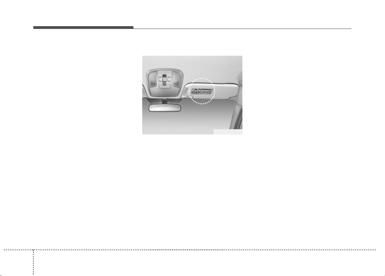
Safety features of your vehicle
703
Adding equipment to or modifying
your air bag-equipped vehicle
If you modify your vehicle by chang-
ing your vehicle's frame, bumper sys-
tem, front end or side sheet metal or
ride height, this may affect the opera-
tion of your vehicle's air bag system.
Air bag warning label
Air bag warning labels are attached
to alert the passengers of the poten-
tial risk of the air bag system.
Note that these government warnings
focus on the risk of children. We also
want you to be aware of the risks
which adults are exposed to that have
been described in previous pages.
ODE036069L

Features of your vehicle
Keys . . . . . . . . . . . . . . . . . . . . . . . . . . . . . . . . . . . . . . 4-4
• Record your key number . . . . . . . . . . . . . . . . . . . . . . . 4-4
• Key operations. . . . . . . . . . . . . . . . . . . . . . . . . . . . . . . . 4-4
• Immobilizer system . . . . . . . . . . . . . . . . . . . . . . . . . . . . 4-5
Remote keyless entry . . . . . . . . . . . . . . . . . . . . . . . . 4-7
• Remote keyless entry system operations. . . . . . . . . . . 4-7
• Smart key system operation . . . . . . . . . . . . . . . . . . . . . 4-8
• Transmitter precautions . . . . . . . . . . . . . . . . . . . . . . . . 4-9
• Battery replacement . . . . . . . . . . . . . . . . . . . . . . . . . . 4-10
Theft-alarm system . . . . . . . . . . . . . . . . . . . . . . . . 4-12
• Armed stage . . . . . . . . . . . . . . . . . . . . . . . . . . . . . . . . . 4-12
• Theft-alarm stage . . . . . . . . . . . . . . . . . . . . . . . . . . . . 4-13
• Disarmed stage. . . . . . . . . . . . . . . . . . . . . . . . . . . . . . . 4-14
Door locks . . . . . . . . . . . . . . . . . . . . . . . . . . . . . . . . 4-15
• Operating door locks from outside the vehicle . . . . 4-15
• Operating door locks from inside the vehicle. . . . . . 4-15
• Door lock/unlock features. . . . . . . . . . . . . . . . . . . . . . 4-17
• Child-protector rear door locks . . . . . . . . . . . . . . . . . 4-18
Tailgate . . . . . . . . . . . . . . . . . . . . . . . . . . . . . . . . . . 4-19
• Opening the tailgate . . . . . . . . . . . . . . . . . . . . . . . . . . 4-19
• Closing the tailgate . . . . . . . . . . . . . . . . . . . . . . . . . . . 4-20
• Emergency tailgate safety release . . . . . . . . . . . . . . . 4-20
Windows . . . . . . . . . . . . . . . . . . . . . . . . . . . . . . . . . 4-21
• Power windows . . . . . . . . . . . . . . . . . . . . . . . . . . . . . . 4-22
Hood. . . . . . . . . . . . . . . . . . . . . . . . . . . . . . . . . . . . . 4-26
• Opening the hood . . . . . . . . . . . . . . . . . . . . . . . . . . . . 4-26
• Closing the hood . . . . . . . . . . . . . . . . . . . . . . . . . . . . . 4-27
Fuel filler lid . . . . . . . . . . . . . . . . . . . . . . . . . . . . . . 4-28
• Opening the fuel filler lid . . . . . . . . . . . . . . . . . . . . . . 4-28
Sunroof . . . . . . . . . . . . . . . . . . . . . . . . . . . . . . . . . . 4-31
• Sliding the sunroof . . . . . . . . . . . . . . . . . . . . . . . . . . . 4-32
• Tilting the sunroof. . . . . . . . . . . . . . . . . . . . . . . . . . . . 4-33
• Sunshade . . . . . . . . . . . . . . . . . . . . . . . . . . . . . . . . . . . 4-34
• Resetting the sunroof . . . . . . . . . . . . . . . . . . . . . . . . . 4-34
• Sunroof open warning. . . . . . . . . . . . . . . . . . . . . . . . . 4-35
Steering wheel . . . . . . . . . . . . . . . . . . . . . . . . . . . . . 4-36
• Tilt & telescopic steering . . . . . . . . . . . . . . . . . . . . . . 4-37
• Heated steering wheel . . . . . . . . . . . . . . . . . . . . . . . . . 4-37
• Horn . . . . . . . . . . . . . . . . . . . . . . . . . . . . . . . . . . . . . . . 4-38
Mirrors . . . . . . . . . . . . . . . . . . . . . . . . . . . . . . . . . . 4-39
• Inside rearview mirror . . . . . . . . . . . . . . . . . . . . . . . . 4-39
• Outside rearview mirror. . . . . . . . . . . . . . . . . . . . . . . 4-40
Instrument cluster . . . . . . . . . . . . . . . . . . . . . . . . . 4-44
• Instrument cluster control . . . . . . . . . . . . . . . . . . . . . 4-45
• LCD window control. . . . . . . . . . . . . . . . . . . . . . . . . . 4-46
• Gauges . . . . . . . . . . . . . . . . . . . . . . . . . . . . . . . . . . . . . 4-46
• Dual clutch transmission shift indicator . . . . . . . . . . 4-50
• Dual clutch transmission shift indicator in
sports mode (for Europe) . . . . . . . . . . . . . . . . . . . . . 4-51
4

LCD windows . . . . . . . . . . . . . . . . . . . . . . . . . . . . . 4-52
• Over view . . . . . . . . . . . . . . . . . . . . . . . . . . . . . . . . . . . 4-52
• Energy flow . . . . . . . . . . . . . . . . . . . . . . . . . . . . . . . . . 4-56
• LCD modes. . . . . . . . . . . . . . . . . . . . . . . . . . . . . . . . . . 4-58
Warning and indicator lights . . . . . . . . . . . . . . . . 4-72
• Warning lights . . . . . . . . . . . . . . . . . . . . . . . . . . . . . . . 4-72
• Indicator lights. . . . . . . . . . . . . . . . . . . . . . . . . . . . . . . 4-80
Rear parking assist system . . . . . . . . . . . . . . . . . . 4-85
• Operation of the rear parking assist system. . . . . . . 4-85
• Non-operational conditions of rear parking
assist system . . . . . . . . . . . . . . . . . . . . . . . . . . . . . . . . 4-86
• Rear parking assist system precautions . . . . . . . . . . 4-87
• Self-diagnosis . . . . . . . . . . . . . . . . . . . . . . . . . . . . . . . . 4-88
Parking assist system . . . . . . . . . . . . . . . . . . . . . . . 4-89
• Operation of the parking assist system . . . . . . . . . . . 4-89
• Non-operational conditions of parking assist system. 4-91
• Self-diagnosis . . . . . . . . . . . . . . . . . . . . . . . . . . . . . . . . 4-93
Rearview camera . . . . . . . . . . . . . . . . . . . . . . . . . . 4-94
Lighting . . . . . . . . . . . . . . . . . . . . . . . . . . . . . . . . . . 4-95
• Battery saver function. . . . . . . . . . . . . . . . . . . . . . . . . 4-95
• Headlight escort function . . . . . . . . . . . . . . . . . . . . . . 4-95
• Daytime running light. . . . . . . . . . . . . . . . . . . . . . . . . 4-96
• Lighting control. . . . . . . . . . . . . . . . . . . . . . . . . . . . . . 4-96
• High beam operation. . . . . . . . . . . . . . . . . . . . . . . . . . 4-98
• Turn signals and lane change signals . . . . . . . . . . . . 4-99
• Front fog light . . . . . . . . . . . . . . . . . . . . . . . . . . . . . . 4-100
• Rear fog light . . . . . . . . . . . . . . . . . . . . . . . . . . . . . . . 4-100
• Headlight leveling device . . . . . . . . . . . . . . . . . . . . . 4-101
Wipers and washers . . . . . . . . . . . . . . . . . . . . . . . 4-102
• Windshield wiper/washer . . . . . . . . . . . . . . . . . . . . . 4-102
• Rear window wiper/washer . . . . . . . . . . . . . . . . . . . 4-102
• Windshield wipers. . . . . . . . . . . . . . . . . . . . . . . . . . . 4-103
• Windshield washers. . . . . . . . . . . . . . . . . . . . . . . . . . 4-105
• Rear window wiper and washer switch. . . . . . . . . . 4-106
Interior light . . . . . . . . . . . . . . . . . . . . . . . . . . . . . 4-107
• Automatic turn off function . . . . . . . . . . . . . . . . . . . 4-107
• Map lamp . . . . . . . . . . . . . . . . . . . . . . . . . . . . . . . . . . 4-107
• Room lamp. . . . . . . . . . . . . . . . . . . . . . . . . . . . . . . . . 4-108
• Tailgate room lamp . . . . . . . . . . . . . . . . . . . . . . . . . . 4-109
• Vanity mirror lamp . . . . . . . . . . . . . . . . . . . . . . . . . . 4-109
Welcome system . . . . . . . . . . . . . . . . . . . . . . . . . . 4-110
• Welcome light. . . . . . . . . . . . . . . . . . . . . . . . . . . . . . . 4-110
• Escort welcome . . . . . . . . . . . . . . . . . . . . . . . . . . . . . 4-110
• Interior light. . . . . . . . . . . . . . . . . . . . . . . . . . . . . . . . 4-110
Defroster . . . . . . . . . . . . . . . . . . . . . . . . . . . . . . . . 4-111
• Rear window defroster . . . . . . . . . . . . . . . . . . . . . . . 4-111
Climate control system. . . . . . . . . . . . . . . . . . . . . 4-112
• System operation . . . . . . . . . . . . . . . . . . . . . . . . . . . . 4-112
• Air conditioning . . . . . . . . . . . . . . . . . . . . . . . . . . . . . 4-113
• Climate control air filter . . . . . . . . . . . . . . . . . . . . . . 4-114
4

• Air conditioning refrigerant label . . . . . . . . . . . . . . 4-115
• Checking the amount of air conditioner refrigerant
and compressor lubricant . . . . . . . . . . . . . . . . . . . . 4-116
• Automatic climate control system . . . . . . . . . . . . . . 4-117
• Automatic heating and air conditioning . . . . . . . . . 4-118
• Automatic ventilation . . . . . . . . . . . . . . . . . . . . . . . . 4-126
• Sunroof inside air recirculation . . . . . . . . . . . . . . . . 4-126
Windshield defrosting and defogging. . . . . . . . . 4-127
• Automatic climate control system . . . . . . . . . . . . . . 4-127
• Operation tips . . . . . . . . . . . . . . . . . . . . . . . . . . . . . . 4-128
• Defogging logic. . . . . . . . . . . . . . . . . . . . . . . . . . . . . . 4-128
• Auto defogging system . . . . . . . . . . . . . . . . . . . . . . . 4-129
Clean air . . . . . . . . . . . . . . . . . . . . . . . . . . . . . . . . 4-130
Storage compartment. . . . . . . . . . . . . . . . . . . . . . 4-131
• Center console storage . . . . . . . . . . . . . . . . . . . . . . . 4-131
• Glove box . . . . . . . . . . . . . . . . . . . . . . . . . . . . . . . . . . 4-131
• Sunglass holder . . . . . . . . . . . . . . . . . . . . . . . . . . . . . 4-132
• Luggage box. . . . . . . . . . . . . . . . . . . . . . . . . . . . . . . . 4-133
Interior features . . . . . . . . . . . . . . . . . . . . . . . . . . 4-134
• Ashtray . . . . . . . . . . . . . . . . . . . . . . . . . . . . . . . . . . . . 4-134
• Cup holder . . . . . . . . . . . . . . . . . . . . . . . . . . . . . . . . . 4-134
• Sunvisor . . . . . . . . . . . . . . . . . . . . . . . . . . . . . . . . . . . 4-135
• Seat warmer . . . . . . . . . . . . . . . . . . . . . . . . . . . . . . . . 4-136
• Air ventilation seat . . . . . . . . . . . . . . . . . . . . . . . . . . 4-138
• Power outlet . . . . . . . . . . . . . . . . . . . . . . . . . . . . . . . . 4-138
• USB charger. . . . . . . . . . . . . . . . . . . . . . . . . . . . . . . . 4-139
• AC inverter . . . . . . . . . . . . . . . . . . . . . . . . . . . . . . . . 4-140
• Wireless smart phone charging system. . . . . . . . . . 4-141
• Coat hook . . . . . . . . . . . . . . . . . . . . . . . . . . . . . . . . . . 4-144
• Floor mat anchor(s). . . . . . . . . . . . . . . . . . . . . . . . . . 4-144
• Luggage net holder . . . . . . . . . . . . . . . . . . . . . . . . . . 4-145
• Cargo security screen . . . . . . . . . . . . . . . . . . . . . . . . 4-146
Exterior features. . . . . . . . . . . . . . . . . . . . . . . . . . 4-147
• Roof rack . . . . . . . . . . . . . . . . . . . . . . . . . . . . . . . . . . 4-147
4
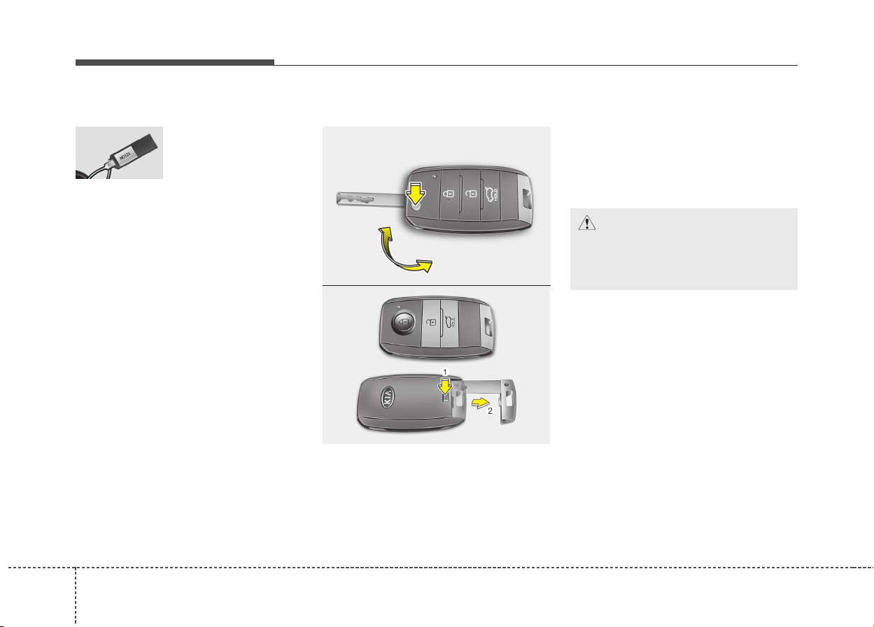
Features of your vehicle
44
Record your key number
The key code number
is stamped on the
key code tag
attached to the key
set. Should you lose
your keys, we recommend that you
contact an authorized Kia dealer.
Remove the key code tag and store it
in a safe place. Also, record the key
code number and keep it in a safe
place (not in the vehicle).
Key operations
• Used to start the engine.
• Used to lock and unlock the doors.
Folding key
To unfold the key, press the release
button then the key will unfold auto-
matically.
To fold the key, fold the key manually
while pressing the release button.
Smart key
To remove the mechanical key, press
and hold the release button (1) and
remove the mechanical key (2).
To reinstall the mechanical key, put
the key into the hole and push it until
a click sound is heard.
KEYS
CAUTION
Do not fold the key without
pressing the release button.
This may damage the key.
ODE046038L
ODE046037L
■ Folding key
■ Smart Key
45
Features of your vehicle
Immobilizer system
Your vehicle is equipped with an
electronic engine immobilizer system
to reduce the risk of unauthorized
vehicle use.
Your immobilizer system is com-
prised of a small transponder in the
ignition key and electronic devices
inside the vehicle.
With the immobilizer system, when-
ever you insert your ignition key into
the ignition switch and turn it to ON
or Whenever the engine start/stop
button is changed to the ON position,
it checks and determines and verifies
if the ignition key is valid or not.
If the key is determined to be valid,
the engine will start.
If the key is determined to be invalid,
the engine will not start.
WARNING - Ignition key
(smart key)
Leaving children unattended in
a vehicle with the ignition key
(smart key) is dangerous even if
the key is not in the ignition or
start button is ACC or ON posi-
tion. Children copy adults and
they could place the key in the
ignition or press the start but-
ton. The ignition key (smart key)
would enable children to oper-
ate power windows or other
controls, or even make the vehi-
cle move, which could result in
serious bodily injury or even
death. Never leave the keys in
your vehicle with unsupervised
children, when the engine is
running.
WARNING
We recommend that you use
parts for replacement from an
authorized Kia dealer. If an
aftermarket key is used, the
ignition switch may not return
to ON after START. If this hap-
pens, the starter will continue to
operate causing damage to the
starter motor and possible fire
due to excessive current in the
wiring.

Features of your vehicle
64
To activate the immobilizer
system:
Turn the ignition key to the OFF posi-
tion or change the engine start/stop
button to the OFF position. The
immobilizer system activates auto-
matically. Without a valid ignition key
for your vehicle, the engine will not
start.
To deactivate the immobilizer
system:
Insert the ignition key into the key
cylinder and turn it to the ON position
or change the engine start/stop but-
ton to the ON position.
✽✽
NOTICE
When starting the engine, do not use
the key with other immobilizer keys
around. Otherwise the engine may
not start or may stop soon after it
starts. Keep each key separately in
order to avoid a starting malfunc-
tion.
✽
✽
NOTICE
If you need additional keys or lose
your keys, we recommend that you
consult an authorized Kia dealer.
CAUTION
The transponder in your ignition
key is an important part of the
immobilizer system. It is
designed to give years of trou-
ble-free service, however you
should avoid exposure to mois-
ture, static electricity and rough
handling. Immobilizer system
malfunction could occur.
CAUTION
Do not put metal accessories
near the ignition switch. Metal
accessories may interrupt the
transponder signal and may
prevent the engine from being
started.
CAUTION
Do not change, alter or adjust
the immobilizer system because
it could cause the immobilizer
system to malfunction. We rec-
ommend that the system be
serviced by an authorized Kia
dealer.
Malfunctions caused by improp-
er alterations, adjustments or
modifications to the immobilizer
system are not covered by your
vehicle manufacturer warranty.
WARNING
In order to prevent theft of your
vehicle, do not leave spare keys
anywhere in your vehicle. Your
immobilizer password is a cus-
tomer unique password and
should be kept confidential. Do
not leave this number anywhere
in your vehicle.
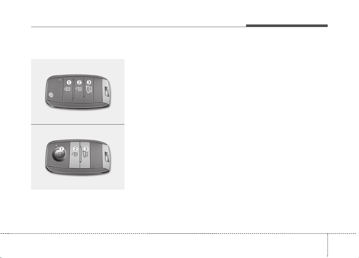
47
Features of your vehicle
Remote keyless entry system
operations
Lock (1)
All doors (and tailgate) are locked if
the lock button is pressed.
If all doors (and tailgate) are closed,
the hazard warning lights will blink
once to indicate that all doors (and
tailgate) are locked.
Unlock (2)
All doors (and tailgate) are unlocked
if the unlock button is pressed.
The hazard warning lights will blink
twice to indicate that all doors (and
tailgate) are unlocked.
However, after pressing this button,
the doors (and tailgate) will lock
automatically unless you open any
door within 30 seconds.
Tailgate unlock (3)
The tailgate is unlocked if the button
is pressed for more than 1 second.
The hazard warning lights will blink
twice to indicate that the tailgate is
unlocked.
However, after pressing this button,
the tailgate will lock automatically
unless you open the tailgate within
30 seconds.
Also, once the tailgate is opened and
then closed, the tailgate will lock
automatically.
REMOTE KEYLESS ENTRY
OUM046433L
OUM046432L
■ Folding key
■ Smart Key
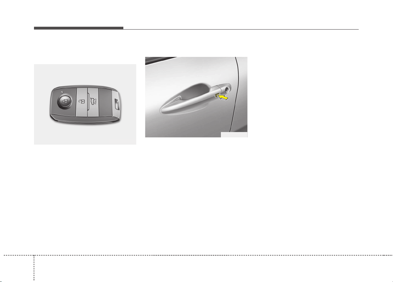
Features of your vehicle
84
Smart key system operation
(if equipped)
With a smart key, you can lock or
unlock a door (and tailgate) and even
start the engine without inserting the
key.
The functions of the buttons on a
smart key are similar to the remote
keyless entry. (Refer to the “Remote
keyless entry” in this chapter.)
Carrying the smart key, you may lock
and unlock the vehicle doors (and
tailgate). Also, you may start the
engine. Refer to the following, for
more details.
Locking
Pressing the button of the front out-
side door handles with all doors (and
tailgate) closed and any door
unlocked, locks all the doors (and
tailgate). The hazard warning lights
will blink once to indicate that all
doors (and tailgate) are locked. The
button will only operate when the
smart key is within 0.7 ~ 1m (28 ~
39.3 in) from the outside door han-
dle. If you want to make sure that a
door has locked or not, you should
check the door lock button inside the
vehicle or pull the outside door han-
dle.
Even though you press the button,
the doors will not lock and the chime
sounds if any of the following occurs:
• The smart key is in the vehicle.
• The ENGINE START/STOP button
is in the ACC or ON position.
• Any door except the tailgate is
opened.
OXM043002
ODE046001

49
Features of your vehicle
Unlocking
Pressing the button of the front out-
side door handles with all doors (and
tailgate) closed and locked, unlocks
all the doors (and tailgate). The haz-
ard warning lights will blink twice to
indicate that all doors (and tailgate)
are unlocked. The button will only
operate when the smart key is within
0.7 ~ 1m (28 ~ 39.3 in) from the out-
side door handle.
When the smart key is recognized in
the area of 0.7 ~ 1m (28 ~ 39.3 in)
from the front outside door handle,
other people can also open a door
without possession of the smart key.
Tailgate unlocking
If you are within 0.7 ~ 1m (28 ~ 39.3
in) from the outside tailgate handle,
with your smart key in possession,
the tailgate will unlock and open
when you press the tailgate handle
switch.
The hazard warning lights will blink
twice to indicate that the tailgate is
unlocked.
Also, once the tailgate is opened and
then closed, the tailgate will lock
automatically.
Start-up
You can start the engine without
inserting the key. For detailed infor-
mation refer to “Starting the engine
with a smart key” in chapter 6.
Transmitter precautions
The transmitter will not work if any of
the following occurs:
• The ignition key is in the ignition
switch. (for folding key)
• Another vehicle’s smart key is being
operated close to your vehicle.
• You exceed the operating distance
limit (about 10 m [30 feet]).
• The battery in the transmitter is
weak.
• Other vehicles or objects may be
blocking the signal.
• The weather is extremely cold.
• The transmitter is close to a radio
transmitter such as a radio station or
an airport which can interfere with
normal operation of the transmitter.
• If the transmitter is in close proximi-
ty to your cell phone or smart phone,
the signal from the transmitter could
be blocked by normal operation of
your cell phone or smart phone. This
is especially important when the
phone is active such as making call,
receiving calls, text messaging,
and/or sending/ receiving emails.
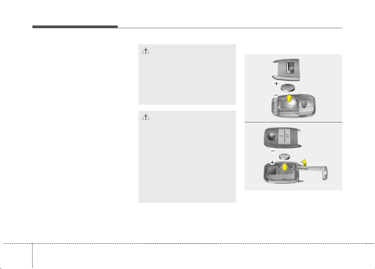
Features of your vehicle
104
Avoid placing the transmitter and
your cell phone or smart phone in
the same pants or jacket pocket
and maintain adequate distance
between the two devices.
When the transmitter does not work
correctly, open and close the door
with the mechanical key. If you have
a problem with the transmitter, we
recommend that you contact an
authorized Kia dealer.
Battery replacement
A transmitter uses a 3 volt lithium
battery which will normally last for
several years. When replacement is
necessary, use the following proce-
dure.
CAUTION
Changes or modifications not
expressly approved by the party
responsible for compliance
could void the user’s authority
to operate the equipment. If the
keyless entry system is inopera-
tive due to changes or modifica-
tions not expressly approved by
the party responsible for com-
pliance, it will not be covered by
your manufacturer’s vehicle
warranty.
CAUTION
Keep the transmitter away from
water or any liquid. If the key-
less entry system is inoperative
due to exposure to water or
other liquids, it will not be cov-
ered by your manufacturer’s
vehicle warranty.
OYDDCO2005
■ Folding key
ODE046039L
■ Smart Key

411
Features of your vehicle
1. Insert a slim tool into the slot and
gently pry open the folding key
center cover or Pry open the rear
cover of the smart key.
2. Replace the battery with a new
battery (CR2032). When replacing
the battery, make sure the battery
position.
3. Install the battery in the reverse
order of removal.
For transmitter replacement, we rec-
ommend that you contact an author-
ized Kia dealer.
✽✽
NOTICE
An inappropriately disposed battery
can be harmful to the environment
and human health.
Dispose the battery according to
your local law(s) or regulation.
CAUTION
• The keyless entry system
transmitter is designed to give
you years of trouble-free use,
however it can malfunction if
exposed to moisture or static
electricity. If you are unsure
how to use or replace the bat-
tery, we recommend that you
contact an authorized Kia
dealer.
• Using the wrong battery can
cause the transmitter to mal-
function. Be sure to use the
correct battery.
• To avoid damaging the trans-
mitter, don't drop it, get it wet,
or expose it to heat or sun-
light.
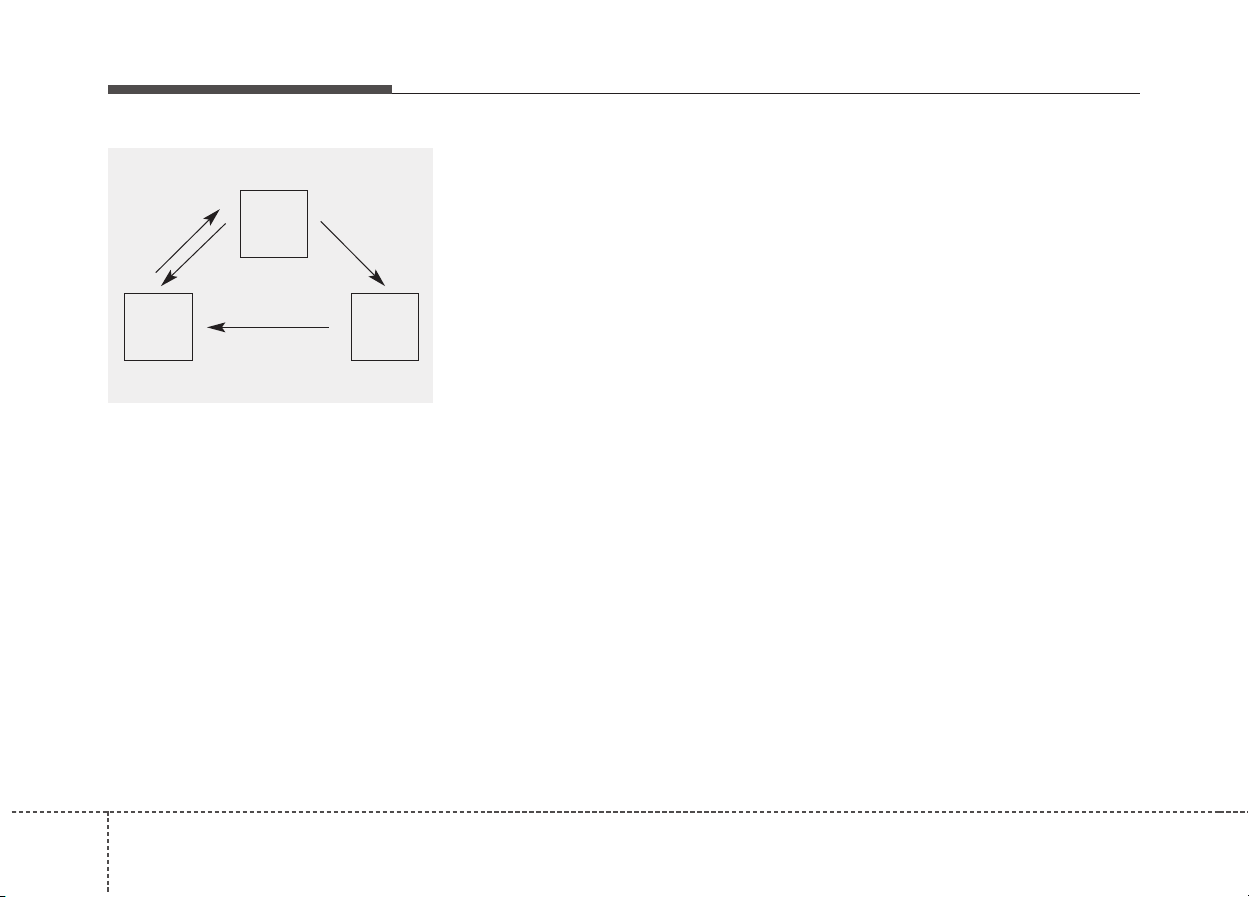
Features of your vehicle
124
THEFT-ALARM SYSTEM (IF EQUIPPED)
This system is designed to provide
protection from unauthorized entry
into the vehicle. This system is oper-
ated in three stages: the first is the
“Armed” stage, the second is the
“Theft-alarm” stage, and the third is
the “Disarmed” stage. If triggered,
the system provides an audible
alarm with blinking of the hazard
warning lights.
Armed stage
Park the vehicle and stop the engine.
Arm the system as described below.
Using the folding key
1. Turn off the engine and remove the
ignition key from the ignition
switch.
2. Make sure that all doors, the
engine hood and tailgate are
closed and latched.
3. Lock the doors by pressing the
lock button on the transmitter.
After completion of the steps
above, the hazard warning lights
will blink once to indicate that the
system is armed.
If the tailgate or engine hood
remains opened, the hazard warn-
ing lights will not operate and
theft-alarm will not arm. After this,
if the tailgate and engine hood are
closed, the hazard warning lights
will blink once and the theft-alarm
will arm.
Using the smart key
1. Turn off the engine.
2. Make sure that all doors, the
engine hood and tailgate are
closed and latched.
3.• Lock the doors by pressing the
button of the front outside door
handle with the smart key in your
possession.
After completion of the steps
above, the hazard warning lights
will operate once to indicate that
the system is armed.
If the tailgate or engine hood
remains opened, the hazard
warning lights will not operate
and theft-alarm will not arm. After
this, if the tailgate and engine
hood are closed, the hazard
warning lights will blink once and
the theft-alarm will arm.
Armed
stage
Theft-alarm
stage
Disarmed
stage

413
Features of your vehicle
• Lock the doors by pressing the
lock button on the smart key.
After completion of the steps
above, the hazard warning lights
will operate once to indicate that
the system is armed.
If the tailgate or engine hood
remains opened, the hazard
warning lights will not operate
and theft-alarm will not arm. After
this, if the tailgate and engine
hood are closed, the hazard
warning lights will blink once and
the theft-alarm will arm.
Do not arm the system until all
passengers have left the vehicle. If
the system is armed while a pas-
senger(s) remains in the vehicle,
the alarm may be activated when
the remaining passenger(s)
leaves the vehicle. If any door (or
tailgate) or engine hood is opened
within 30 seconds after the sys-
tem enters the armed stage, the
system will be disarmed to pre-
vent unnecessary alarm.
Theft-alarm stage
The alarm will be activated if any of
the following occurs while the system
is armed.
• A front or rear door is opened with-
out using the transmitter.
• The tailgate is opened without
using the transmitter.
• The engine hood is opened.
The horn will sound and the hazard
warning lights will blink continuously
for approximately 27 seconds. To
turn off the system, unlock the doors
with the transmitter.

Features of your vehicle
144
Disarmed stage
The system will be disarmed when:
Folding key
- The door unlock button is pressed.
- The engine is started. (within 3
seconds)
- The ignition switch is in the “ON”
position for 30 seconds or more.
Smart key
- The door unlock button is pressed.
- The button of the front outside door
is pressed while carrying the smart
key.
- The engine is started. (within 3
seconds)
After the doors are unlocked, the
hazard warning lights will blink twice
to indicate that the system is dis-
armed.
After pressing the unlock button, if
any door (or tailgate) is not opened
within 30 seconds, the system will be
rearmed.
✽✽
NOTICE
• Without smart key system
If the system is not disarmed with
the transmitter, insert the key into
the ignition switch and start the
engine. Then the system will be
disarmed.
• With smart key system
If the system is not disarmed with
the smart key, open the door with
the mechanical key and start the
engine. Then the system will be
disarmed.
• If you lose your keys, we recom-
mend that you consult an author-
ized Kia dealer.
CAUTION
Do not change, alter or adjust
the theft-alarm system because
it could cause the theft-alarm
system to malfunction and we
recommend that the system be
serviced by an authorized Kia
dealer.
Malfunctions caused by improp-
er alterations, adjustments or
modifications to the theft-alarm
system are not covered by your
vehicle manufacturer warranty.
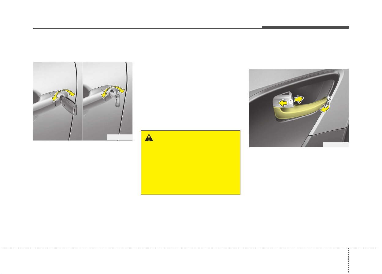
415
Features of your vehicle
Operating door locks from
outside the vehicle
• Turn the key toward the rear of the
vehicle to lock and toward the front
of the vehicle to unlock.
• If you lock/unlock the driver’s door
with a key, all vehicle doors will
lock/unlock automatically.
• Doors can also be locked and
unlocked with the transmitter.
• Once the doors are unlocked, they
may be opened by pulling the door
handle.
• When closing the door, push the
door by hand. Make sure the doors
are closed securely.
✽✽
NOTICE
• In cold and wet climates, door lock
and door mechanisms may not
work properly due to freezing con-
ditions.
• If the door is locked/unlocked
multiple times in rapid succession
with either the vehicle key or door
lock switch, the system may stop
operating temporarily in order to
protect the circuit and prevent
damage to system components.
Operating door locks from
inside the vehicle
With the door lock button
• To unlock a door, pull the door lock
button (1) to the “Unlock” position.
The red mark on the door lock but-
ton will be visible.
• To lock a door, push the door lock
button (1) to the “Lock” position. If
the door is locked properly, the red
mark on the door lock button will
not be visible.
• To open a door, pull the door han-
dle (2) outward.
DOOR LOCKS
WARNING
• If you don’t close the door
securely, the door may open
again.
• Be careful that someone’s
body and hands are not
trapped when closing the
door.
ODE046002
ODE046004
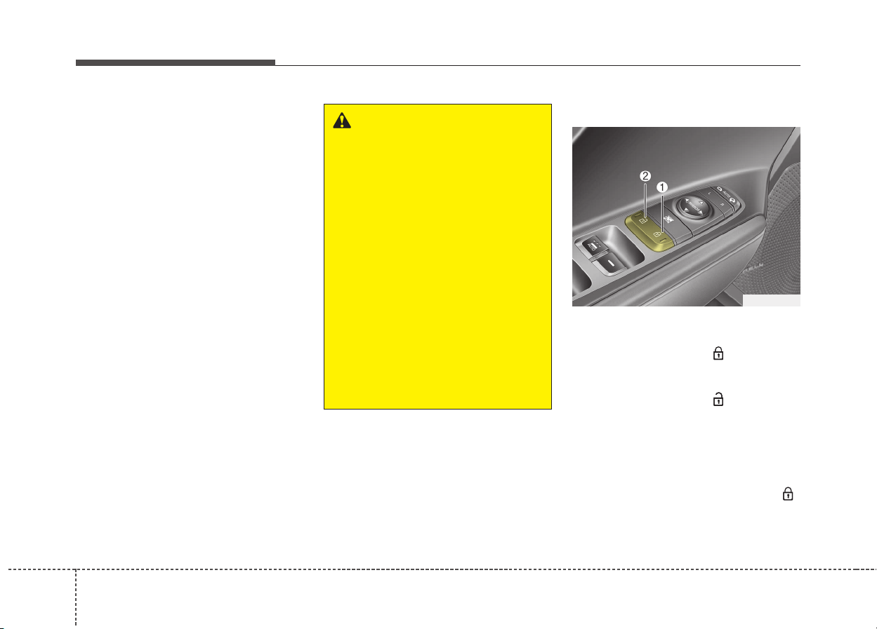
Features of your vehicle
164
• If the inner door handle of the dri-
ver’s (or front passenger’s) door is
pulled when the door lock button is
in the lock position, the button will
unlock and the door will open. (if
equipped)
• Front door cannot be locked if the
ignition key is in the ignition switch
(or if the smart key is in the vehicle)
and the front door is opened.
With central door lock switch
Operate by pressing the central door
lock switch.
• When pressing the ( ) portion (1)
of the switch, all vehicle doors will
lock.
• When pressing the ( ) portion (2)
of the switch, all vehicle doors will
unlock.
• If the key is in the ignition switch (or
if the smart key is in the vehicle)
and any door is opened, the doors
will not lock even though the ( )
portion (1) of the central door lock
switch is pressed.
ODE046005
WARNING - Door lock
malfunction
If a power door lock ever fails to
function while you are in the
vehicle, try one or more of the
following techniques to exit:
• Operate the door unlock fea-
ture repeatedly (both electron-
ic and manual) while simulta-
neously pulling on the door
handle.
• Operate the other door locks
and handles, front and rear.
• Lower a front window and use
the key to unlock the door
from outside.
• Move to the cargo area and
open the tailgate.
417
Features of your vehicle
Door lock/unlock features
Impact sensing door unlock sys-
tem (if equipped)
All doors will automatically unlock
when an impact causes the air bags
to deploy.
Speed sensing door lock system
(if equipped)
All doors will automatically lock after
the vehicle speed exceeds 15 km/h.
You can activate or deactivate the
auto door lock/unlock features in the
vehicle. Refer to “User setting” in this
chapter.
WARNING - Unlocked
vehicles
Leaving your vehicle unlocked
can invite theft or possible harm
to you or others from someone
hiding in your vehicle while you
are gone. Always remove the
ignition key, engage the parking
brake, close all windows and
lock all doors when leaving
your vehicle unattended.
WARNING - Unattended
children
An enclosed vehicle can
become extremely hot, causing
death or severe injury to unat-
tended children or animals who
cannot escape the vehicle.
Furthermore, children might
operate features of the vehicle
that could injure them, or they
could encounter other harm,
possibly from someone gaining
entry to the vehicle. Never leave
children or animals unattended
in your vehicle.
WARNING - Doors
• The doors should always be
fully closed and locked while
the vehicle is in motion to pre-
vent accidental opening of the
door. Locked doors will also
discourage potential intruders
when the vehicle stops or
slows down.
• Be careful when opening
doors and watch for vehicles,
motorcycles, bicycles or
pedestrians approaching the
vehicle in the path of the door.
Opening a door when some-
thing is approaching can
cause damage or injury.
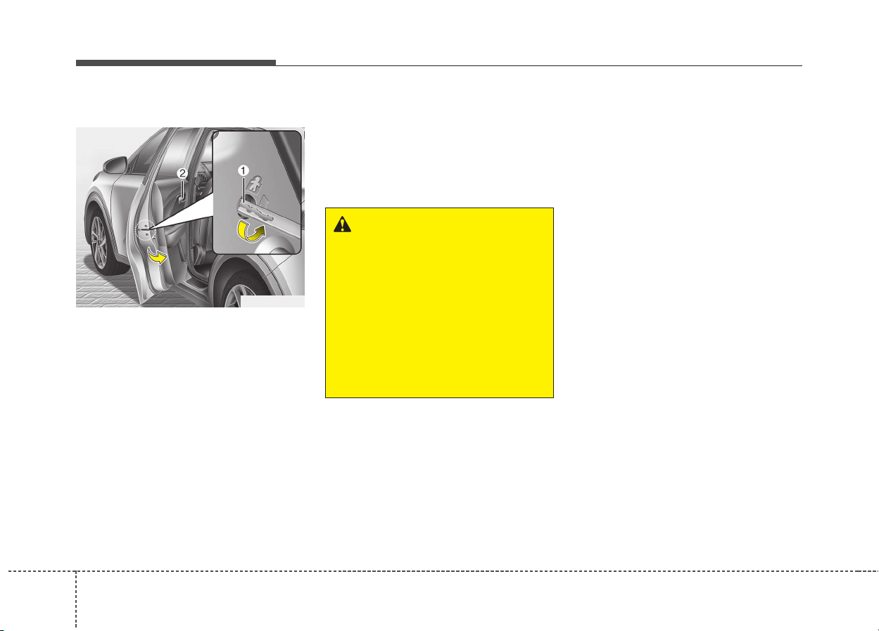
Features of your vehicle
184
Child-protector rear door locks
The child safety lock is provided to
help prevent children from acciden-
tally opening the rear doors from
inside the vehicle. The rear door
safety locks should be used whenev-
er children are in the vehicle.
The child safety lock is located on
the edge of each rear door. When the
child safety lock is in the lock position
(1), the rear door will not open if the
inner door handle (2) is pulled.
To lock the child safety lock, insert a
key (or screwdriver) into the hole and
turn it to the lock position.
To allow a rear door to be opened
from inside the vehicle, unlock the
child safety lock.
WARNING - Rear door
locks
If children accidentally open the
rear doors while the vehicle is
in motion, they could fall out
and be severely injured or
killed. To prevent children from
opening the rear doors from the
inside, the rear door safety
locks should be used whenever
children are in the vehicle.
ODE046006L
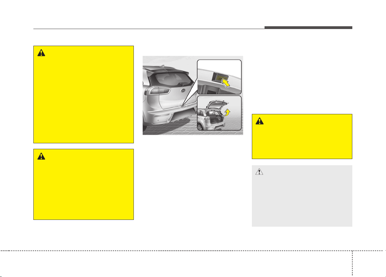
419
Features of your vehicle
Opening the tailgate
• The tailgate is locked or unlocked
when all doors are locked or
unlocked with the key, transmitter,
smart key or central door
lock/unlock switch.
• Only the tailgate is unlocked if the
tailgate unlock button on the trans-
mitter or smart key is pressed for
approximately 1 second.
• If unlocked, the tailgate can be
opened by pressing the handle and
pulling it up.
• Once the tailgate is opened and
then closed, the tailgate locks
automatically. (All doors must be
locked.)
✽✽
NOTICE
In cold and wet climates, door lock
and door mechanisms may not work
properly due to freezing conditions.
TAILGATE
ODE046007
WARNING
The tailgate swings upward.
Make sure no objects or people
are near the rear of the vehicle
when opening the tailgate.
CAUTION
Make certain that you close the
tailgate before driving your
vehicle. Possible damage may
occur to the tailgate lift cylin-
ders and attaching hardware if
the tailgate is not closed prior to
driving.
WARNING - Rear cargo
area
Occupants should never ride in
the rear cargo area where no
restraints are available. To avoid
injury in the event of an acci-
dent or sudden stops, occu-
pants should always be proper-
ly restrained.
WARNING - Exhaust
fumes
If you drive with the tailgate
opened, you will draw danger-
ous exhaust fumes into your
vehicle which can cause seri-
ous injury or death to vehicle
occupants.
If you must drive with the tail-
gate opened, keep the air vents
and all windows open so that
additional outside air comes
into the vehicle.
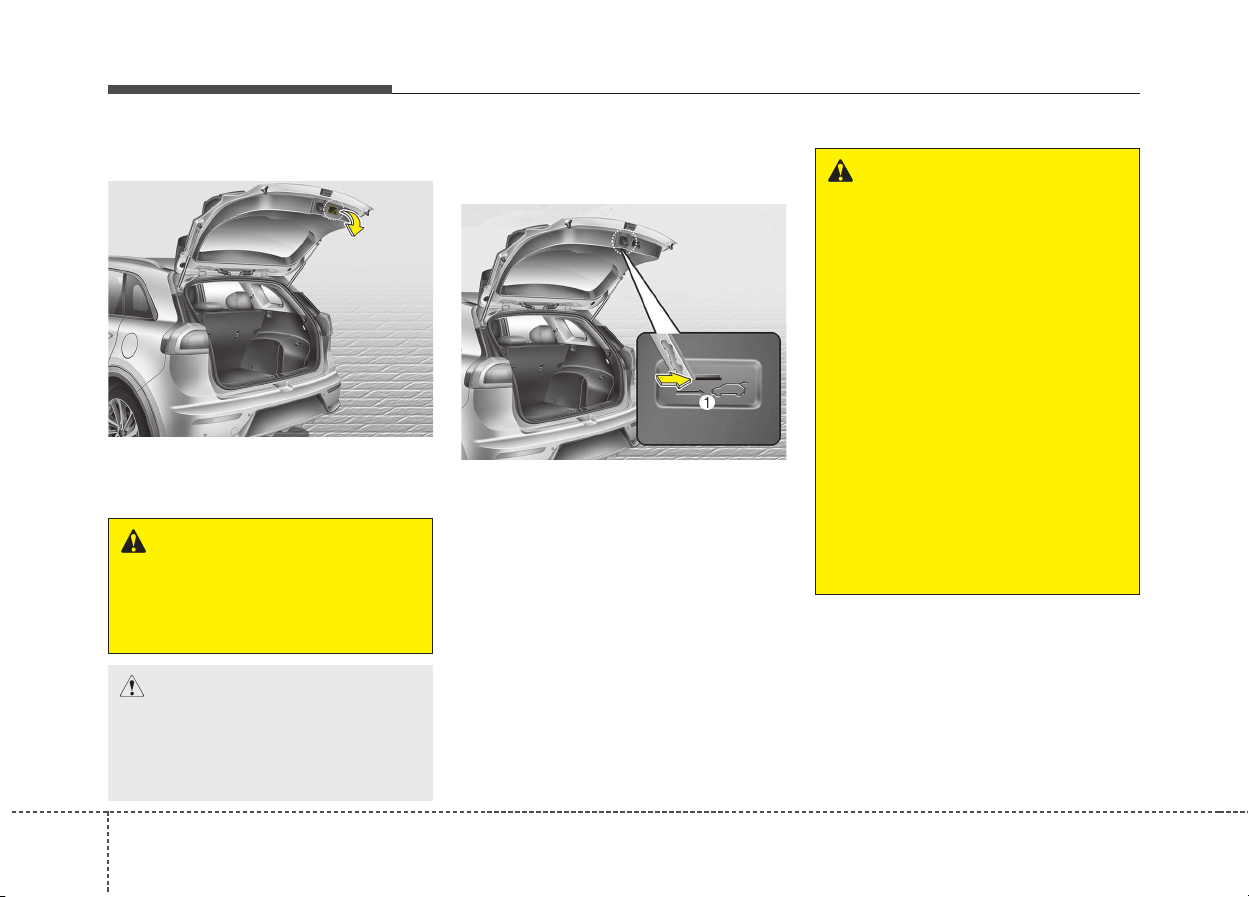
Features of your vehicle
204
Closing the tailgate
Lower and push down the tailgate
firmly. Make sure that the tailgate is
securely latched.
Emergency tailgate safety
release
Your vehicle is equipped with the
emergency tailgate safety release
lever located on the bottom of the
tailgate. When someone is inadver-
tently locked in the luggage compart-
ment. The tailgate can be opened by
doing as follows:
1. Input the mechanical key into the
hole.
2. Push the mechanical key to the
right.
3. Push up the tailgate.
ODE046008
WARNING
Make sure your hands, feet and
other parts of your body are
safely out of the way before
closing the tailgate.
CAUTION
Make sure nothing is near the
tailgate latch and striker while
closing the tailgate. It may dam-
age the tailgate's latch.
WARNING
• For emergencies, be fully
aware of the location of the
emergency tailgate safety
release lever in the vehicle
and how to open the tailgate if
you are accidentally locked in
the luggage compartment.
• No one should be allowed to
occupy the luggage compart-
ment of the vehicle at any
time. The luggage compart-
ment is a very dangerous
location in the event of a
crash.
• Use the release lever for
emergencies only. Use with
extreme caution, especially
while the vehicle is in motion.
ODE046009
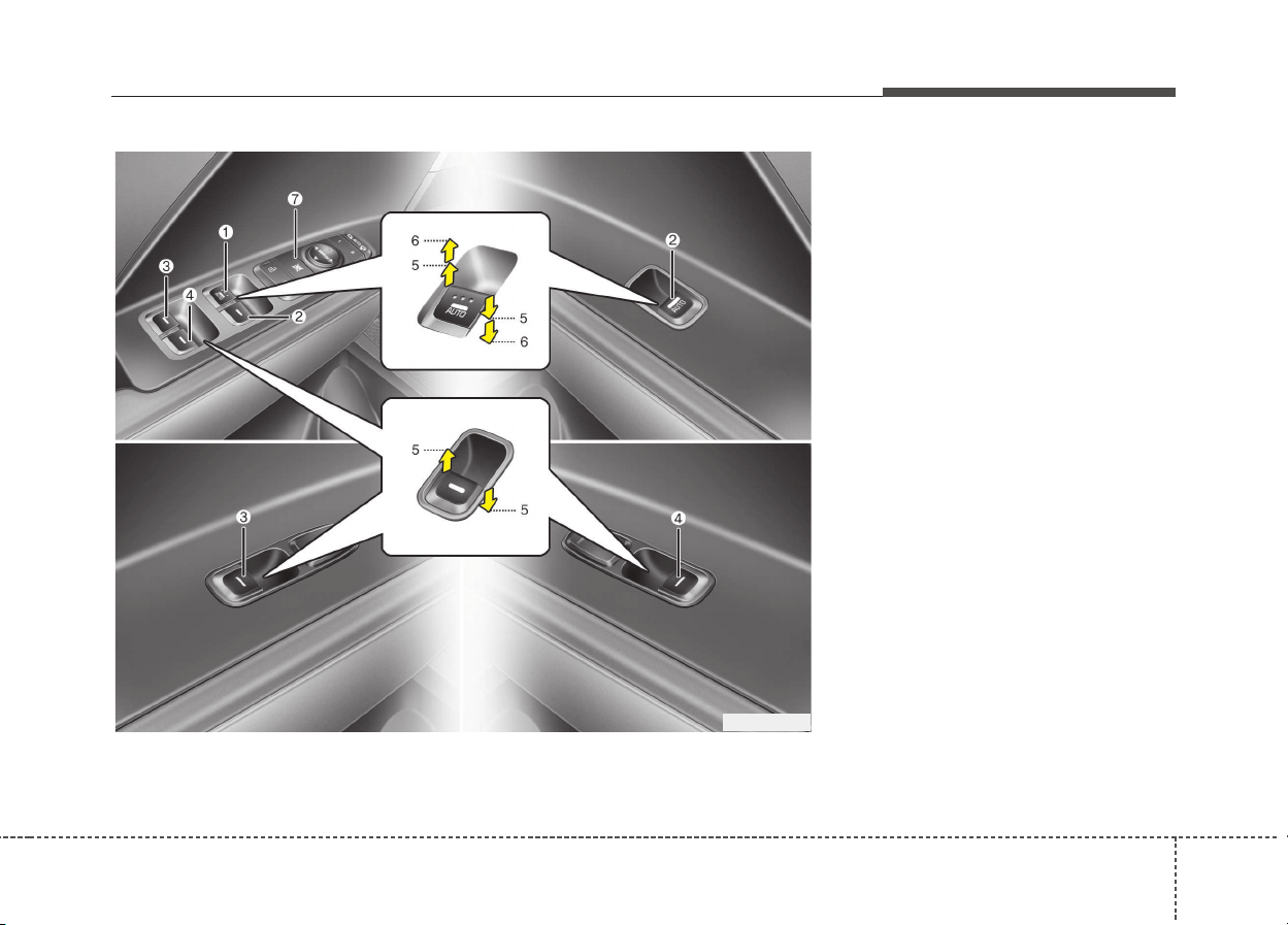
421
Features of your vehicle
(1) Driver’s door power window
switch
(2) Front passenger’s door power
window switch
(3) Rear door (left) power window
switch
(4) Rear door (right) power window
switch
(5) Window opening and closing
(6) Automatic power window up*/
down*
(7) Power window lock switch
* if equipped
✽✽
NOTICE
In cold and wet climates, power win-
dows may not work properly due to
freezing conditions.
WINDOWS
ODE046010
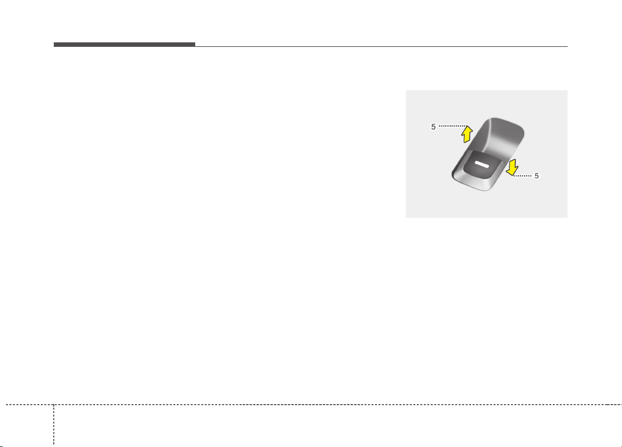
Features of your vehicle
224
Power windows
The ignition switch must be in the ON
position for power windows to oper-
ate.
Each door has a power window
switch that controls the door's win-
dow. The driver has a power window
lock button which can block the oper-
ation of passenger windows. The
power windows can be operated for
approximately 30 seconds after the
ignition key is removed or turned to
the ACC or LOCK position. However,
if the front doors are opened, the
power windows cannot be operated
even within the 30 second period.
The driver’s door has a master power
window switch that controls all the
windows in the vehicle.
✽✽
NOTICE
While driving with the rear windows
down or with the sunroof (if
equipped) in an open (or partially
open position), your vehicle may
demonstrate a wind buffeting or
pulsation noise. This noise is a nor-
mal occurrence and can be reduced
or eliminated by taking the follow-
ing actions. If the noise occurs with
one or both of the rear windows
down, partially lower both front
windows approximately one inch.
If you experience the noise with the
sunroof open, slightly reduce the
size of the sunroof opening.
Window opening and closing
Type A
To open or close a window, press
down or pull up the front portion of
the corresponding switch to the first
detent position (5).
OQL045022
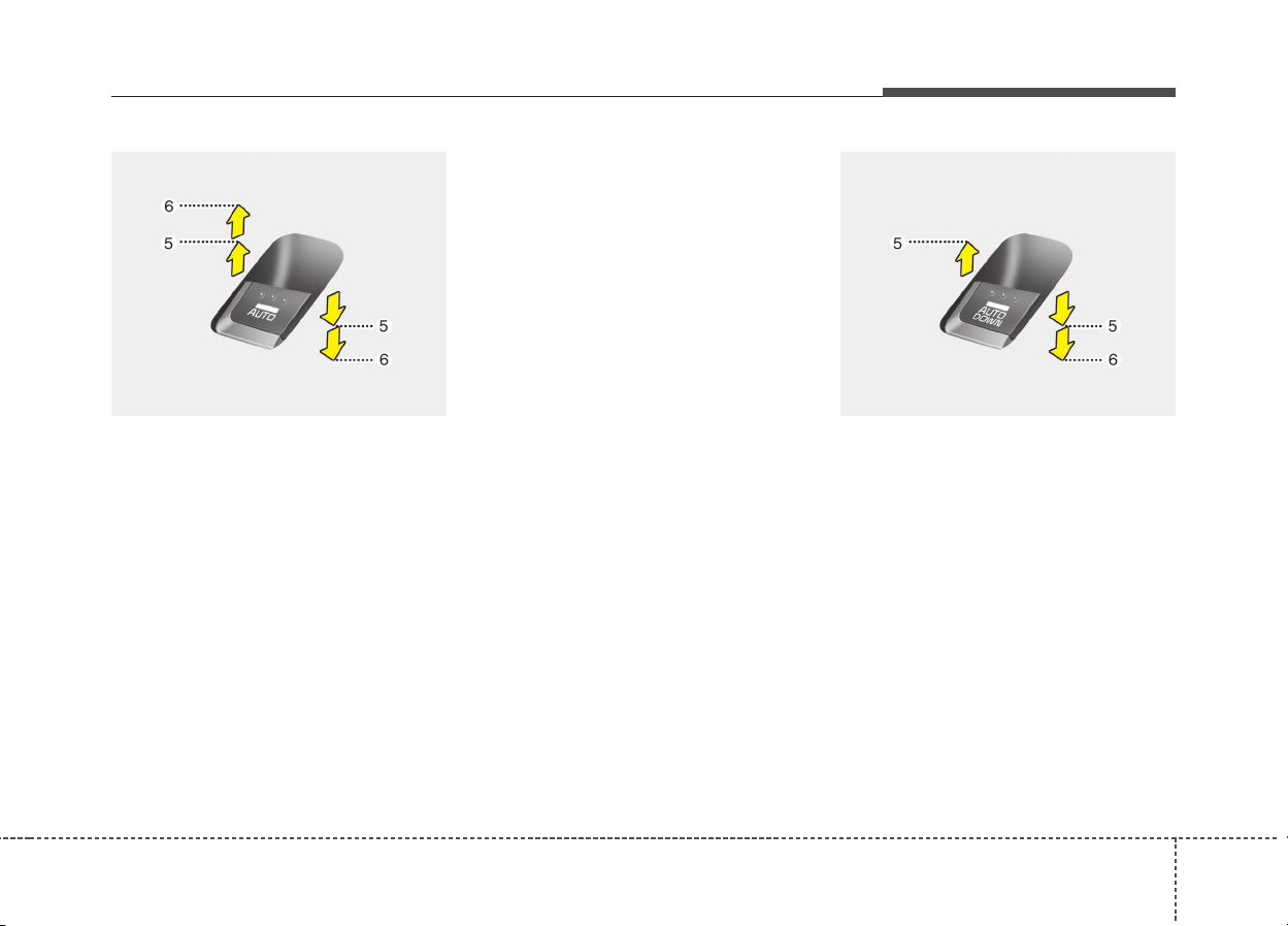
423
Features of your vehicle
Type B - Auto up/down window
(if equipped)
Pressing or pulling up the power win-
dow switch momentarily to the sec-
ond detent position (6) completely
lowers or raises the window even
when the switch is released. To stop
the window at the desired position
while the window is in operation, pull
up or press down and release the
switch.
If the power window does not oper-
ate normally, the automatic power
window system must be reset as fol-
lows:
1. Turn the ignition switch to the ON
position.
2. Close the window and continue
pulling up the power window
switch for at least 1 second after
the window is completely closed.
Type C - Auto down window
(if equipped)
(Driver’s window)
Pressing the power window switch
momentarily to the second detent
position (6) completely lowers the
driver’s window even when the
switch is released. To stop the win-
dow at the desired position while the
window is in operation, pull up the
switch momentarily to the opposite
direction of the window movement.
OQL045021 OQLE045021
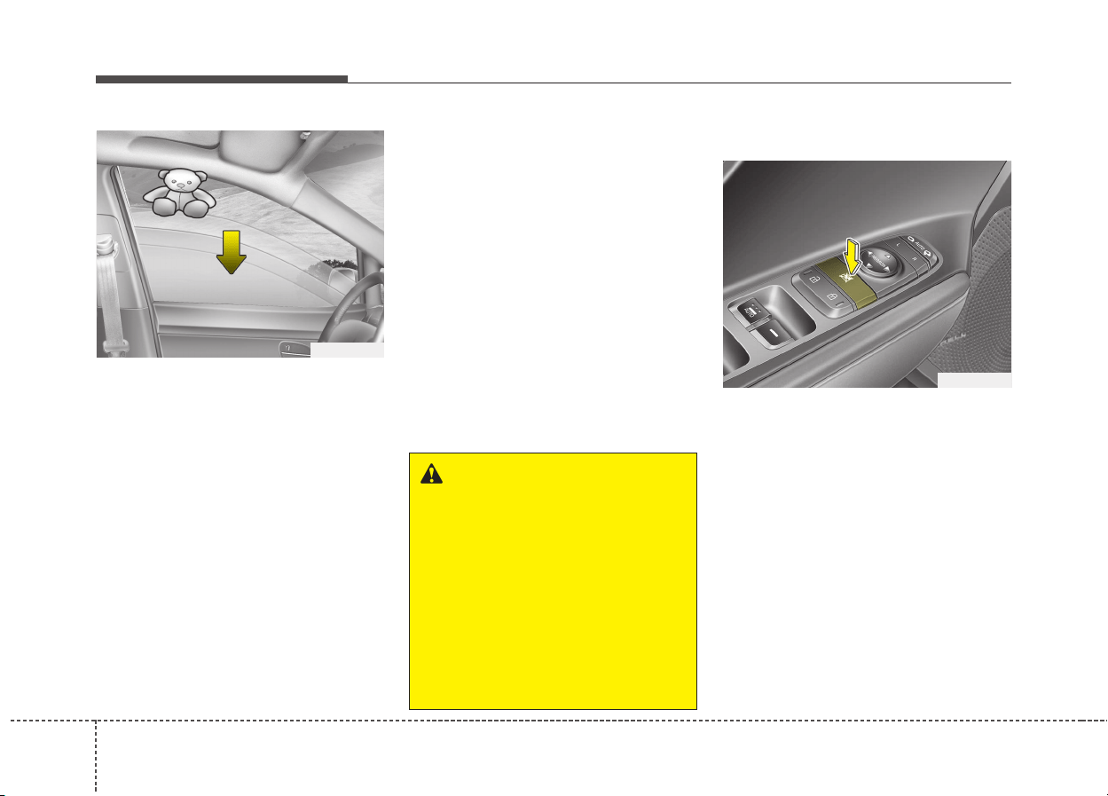
Features of your vehicle
244
Automatic reversal (For Type B)
If the upward movement of the win-
dow is blocked by an object or part of
the body, the window will detect the
resistance and will stop upward
movement. The window will then
lower approximately 30 cm (11.8 in.)
to allow the object to be cleared.
If the window detects the resistance
while the power window switch is
pulled up continuously, the window
will stop upward movement then
lower approximately 2.5 cm (1 in.).
And if the power window switch is
pulled up continuously again within 5
seconds after the window is lowered
by the automatic window reversal
feature, the automatic window rever-
sal will not operate.
✽✽
NOTICE
The automatic reverse feature for
the window is only active when the
“auto up” feature is used by fully
pulling up the switch. The automat-
ic reverse feature will not operate if
the window is raised using the
halfway position on the power win-
dow switch.
Power window lock button
The driver can disable the power
window switches on the rear passen-
gers’ doors by pressing the power
window lock switch to the lock posi-
tion (pressed).
When the power window lock switch
is pressed :
• The driver’s master control can
operate the front passenger’s
power window and the rear pas-
sengers’ power windows.
WARNING
Always check for obstructions
before raising any window to
avoid injuries or vehicle dam-
age. If an object less than 4 mm
(0.16 in.) in diameter is caught
between the window glass and
the upper window channel, the
automatic reverse window may
not detect the resistance and
will not stop and reverse direc-
tion.
ODE046013
OUN026013
425
Features of your vehicle
• The front passenger’s control can
operate the front passenger’s
power window.
• The rear passengers’ control can-
not operate the rear passengers’
power window.
WARNING - Windows
• NEVER leave the keys in your
vehicle with unsupervised
children, when the engine is
running.
• NEVER leave any child unat-
tended in the vehicle. Even
very young children may inad-
vertently cause the vehicle to
move, entangle themselves in
the windows, or otherwise
injure themselves or others.
• Always double check to make
sure all arms, hands, head
and other obstructions are
safely out of the way before
closing a window.
• Do not allow children play
with the power windows. Keep
the driver’s door power win-
dow lock button in the LOCK
position (pressed). Serious
injury can result from uninten-
tional window operation by
the child.
• Do not extend heads or any
limbs outside the window
while the vehicle is in motion.
CAUTION
• To prevent possible damage
to the power window system,
do not open or close two win-
dows or more at the same
time. This will also ensure the
longevity of the fuse.
• Never try to operate the main
switch on the driver's door
and the individual door win-
dow switch in opposite direc-
tions at the same time. If this
is done, the window will stop
and cannot be opened or
closed.
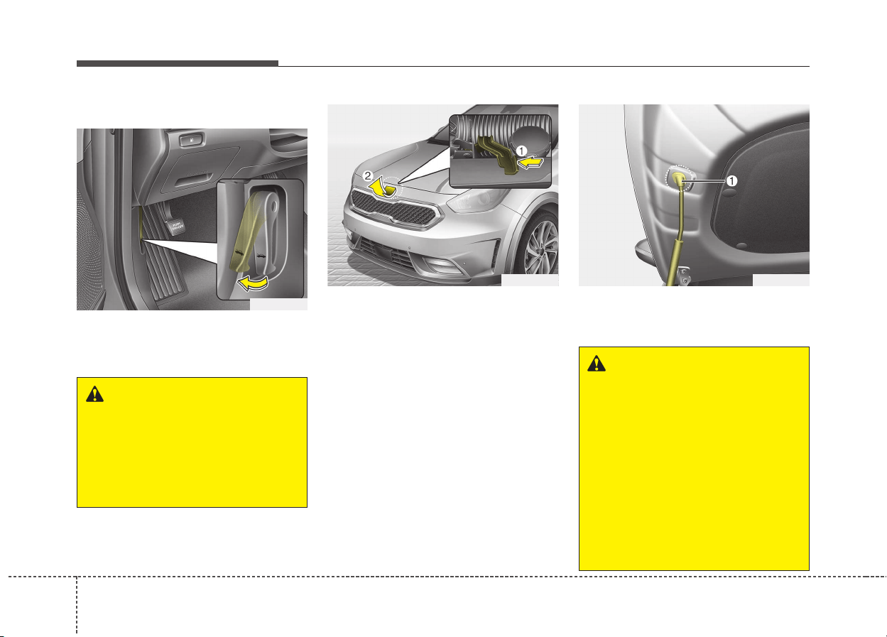
Features of your vehicle
264
Opening the hood
1. Pull the release lever to unlatch
the hood. The hood should pop
open slightly.
2. Go to the front of the vehicle, raise
the hood slightly, push the second-
ary latch (1) up side and lift the
hood (2).
3. Raise the hood. It will completely
rise by itself after it has been
raised about halfway.
4. Pull out the stay rod.
5. Hold the hood opened with the
stay rod (1).
HOOD
ODE046014
ODE046015
WARNING
Open the hood after turning off
the engine on a flat surface,
shifting the shift lever to the
P(Park) position for dual clutch
transmission and setting the
parking brake.
ODE046016
WARNING
• Grasp the stay rod in the area
wrapped in rubber. The rubber
will help prevent you from
being burned by hot metal
when the engine is hot.
• The stay rod must be inserted
completely into the hole pro-
vided whenever you inspect
the engine compartment. This
will prevent the hood from
falling and possibly injuring
you.
427
Features of your vehicle
Closing the hood
1. Before closing the hood, check the
following:
• All filler caps in the engine com-
partment must be correctly
installed.
• Gloves, rags or any other com-
bustible material must be
removed from the engine com-
partment.
2. Lower the hood halfway and push
down to securely lock in place.
WARNING
• Always double check to be
sure that the hood is firmly
latched before driving away. If
it is not latched, the hood
could open while the vehicle
is being driven, causing total
loss of visibility, which might
result in an accident.
• Do not move the vehicle with
the hood raised. The view will
be blocked and the hood
could fall or be damaged.
WARNING
• Before closing the hood,
ensure that all obstructions
are removed from the hood
opening. Closing the hood
with an obstruction present in
the hood opening may result
in property damage or severe
personal injury.
• Do not leave gloves, rags or
any other combustible materi-
al in the engine compartment.
Doing so may cause a heat-
induced fire.
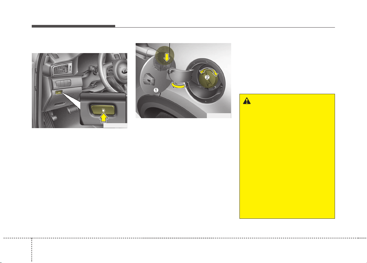
Features of your vehicle
284
Opening the fuel filler lid
1. The fuel filler lid must be opened
from inside the vehicle by pushing
the fuel filler lid opener.
✽✽
NOTICE
If the fuel filler lid does not open
because ice has formed around it,
tap lightly or push on the lid to
break the ice and release the lid. Do
not pry on the lid. If necessary,
spray around the lid with an
approved de-icer fluid (do not use
radiator anti-freeze) or move the
vehicle to a warm place and allow
the ice to melt.
2. Pull the fuel filler lid (1) out to fully
open.
3. To remove the fuel tank cap (2),
turn it counterclockwise. You may
hear a hissing noise as the pres-
sure inside the tank equalizes.
4. Place the cap on the fuel filler lid.
Closing the fuel filler lid
1. To install the cap, turn it clockwise
until it “clicks”. This indicates that
the cap is securely tightened.
2. To close the fuel filler lid, press the
edge of the fuel filler lid.
Make sure it is securely closed.
FUEL FILLER LID
ODE046017
ODE046018
WARNING - Refueling
• If pressurized fuel sprays out,
it can cover your clothes or
skin and subject you to the
risk of fire and burns. Always
remove the fuel cap carefully
and slowly. If the cap is vent-
ing fuel or if you hear a hiss-
ing sound, wait until the con-
dition stops before complete-
ly removing the cap.
• Do not "top off" after the noz-
zle automatically shuts off
when refueling.
• Always check that the fuel cap
is installed securely to pre-
vent fuel spillage in the event
of an accident.

429
Features of your vehicle
WARNING - Refueling
dangers
Automotive fuels are flammable
materials. When refueling,
please note the following guide-
lines carefully. Failure to follow
these guidelines may result in
severe personal injury, severe
burns or death by fire or explo-
sion.
• Read and follow all warning
posted at the gas station facility.
• Before refueling note the loca-
tion of the Emergency
Gasoline Shut-Off, if available,
at the gas station facility.
• Before touching the fuel noz-
zle, you should eliminate
potentially dangerous static
electricity discharge by touch-
ing another metal part of the
vehicle, a safe distance away
from the fuel filler neck, noz-
zle, or other gas source.
(Continued)
(Continued)
• Do not get back into a vehicle
once you have begun refuel-
ing since you can generate
static electricity by touching,
rubbing or sliding against any
item or fabric (polyester, satin,
nylon, etc.) capable of produc-
ing static electricity. Static
electricity discharge can
ignite fuel vapors resulting in
rapid burning. If you must re-
enter the vehicle, you should
once again eliminate poten-
tially dangerous static elec-
tricity discharge by touching a
metal part of the vehicle, away
from the fuel filler neck, noz-
zle or other gasoline source.
• When using an approved
portable fuel container, be
sure to place the container on
the ground prior to refueling.
Static electricity discharge
from the container can ignite
fuel vapors causing a fire.
(Continued)
(Continued)
Once refueling has begun,
contact with the vehicle
should be maintained until the
filling is complete.
Use only approved portable
plastic fuel containers
designed to carry and store
gasoline.
• Do not use cellular phones
while refueling. Electric cur-
rent and/or electronic interfer-
ence from cellular phones can
potentially ignite fuel vapors
causing a fire.
• When refueling, always shut
the engine off. Sparks pro-
duced by electrical compo-
nents related to the engine
can ignite fuel vapors causing
a fire. Once refueling is com-
plete, check to make sure the
filler cap and filler lid are
securely closed, before start-
ing the engine.
(Continued)
Features of your vehicle
304
(Continued)
• DO NOT use matches or a
lighter and DO NOT SMOKE or
leave a lit cigarette in your
vehicle while at a gas station
especially during refueling.
Automotive fuel is highly
flammable and can, when
ignited, result in fire.
• If a fire breaks out during refu-
eling, leave the vicinity of the
vehicle, and immediately con-
tact the manager of the gas
station and then contact the
local fire department. Follow
any safety instructions they
provide.
CAUTION
• Make sure to refuel your vehi-
cle according to the “Fuel
requirements” suggested in
chapter 1.
• If the fuel filler cap requires
replacement, please make
sure that you use parts
designed for replacement in
your vehicle. An incorrect fuel
filler cap can result in a seri-
ous malfunction of the fuel
system or emission control
system. For more detailed
information, we recommend
that you contact an authorized
Kia dealer.
• Do not spill fuel on the exteri-
or surfaces of the vehicle. Any
type of fuel spilled on painted
surfaces may damage the
paint.
• After refueling, make sure the
fuel cap is installed securely
to prevent fuel spillage in the
event of an accident.
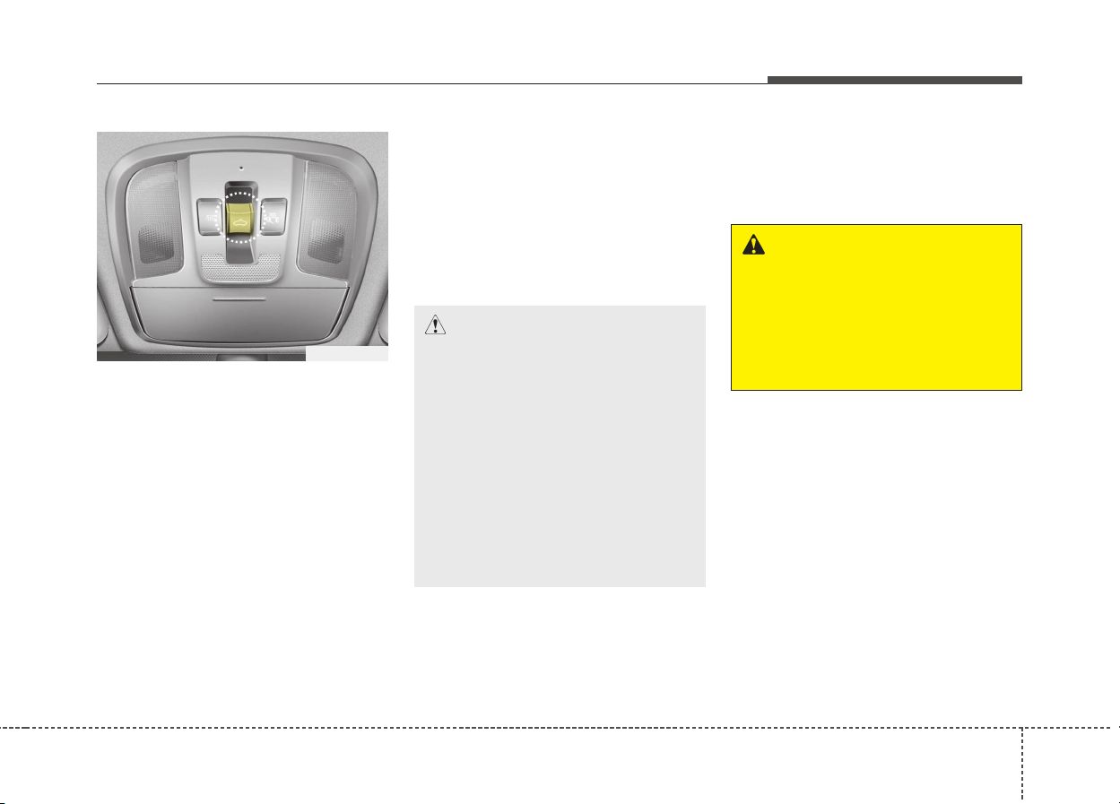
431
Features of your vehicle
If your vehicle is equipped with a
sunroof, you can slide or tilt your
sunroof with the sunroof control
switch located on the overhead con-
sole.
The sunroof can only be opened,
closed, or tilted when the ignition
switch is in the ON position.
✽✽
NOTICE
• In cold and wet climates, the sun-
roof may not work properly due to
freezing conditions.
• After washing the car or after
there is rain, be sure to wipe off
any water that is on the sunroof
before operating it.
✽
✽
NOTICE
The sunroof cannot slide when it is
in the tilt position nor can it be tilted
while in an open or slide position.
SUNROOF (IF EQUIPPED)
ODE046035L
CAUTION
• Do not continue to move the
sunroof control lever after the
sunroof is in the fully open,
closed, or tilt position.
Damage to the motor or sys-
tem components could occur.
• Make sure the sunroof is
closed fully when leaving your
vehicle. If the sunroof is open,
rain or snow may leak through
the sunroof and wet the interi-
or as well as cause theft.
WARNING
Never adjust the sunroof or
sunshade while driving. This
could result in loss of control
and an accident that may cause
death, serious injury, or proper-
ty damage.
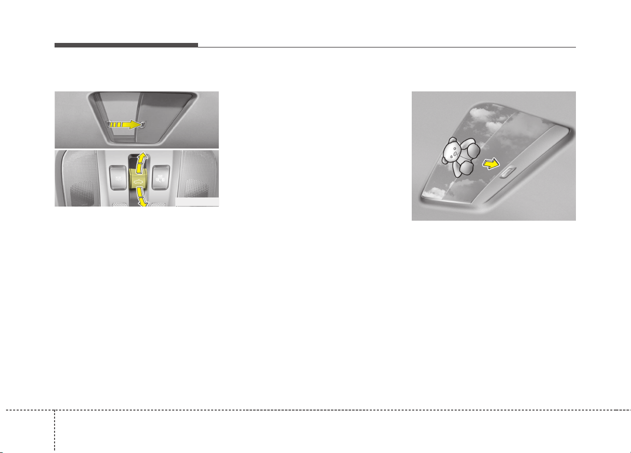
Features of your vehicle
324
Sliding the sunroof
To open or close the sunroof (manu-
al slide feature), push the sunroof
control lever backward or forward to
the first detent position.
To open the sunroof (autoslide fea-
ture), push the sunroof control switch
backward to the second detent posi-
tion.
The sunroof will slide to the recom-
mended open position (about 7 cm
before the maximum slide open posi-
tion).
To stop the sunroof sliding at any
point, push the sunroof control
switch momentarily.
To open the sunroof to the maximum
slide open position, press the switch
towards the rear of the vehicle once
again and hold it until the sunroof
slide all the way open.
✽✽
NOTICE
To reduce wind noise while driving,
we recommend you to drive at the
recommended position (about 7 cm
before the maximum slide open
position).
To close the sunroof (autoslide fea-
ture), move the sunroof control
switch forward to the second detent
position.
The sunroof will close all the way. To
stop the sunroof sliding at any point,
pull or push the sunroof control
switch momentarily.
Automatic reversal
If an object or part of the body is
detected while the sunroof is closing
automatically, it will reverse direction,
and then stop.
The auto reverse function does not
work if a small obstacle is between
the sliding glass and the sunroof
sash. You should always check that
all passengers and objects are away
from the sunroof before closing it.
ODE046020
OBK049018
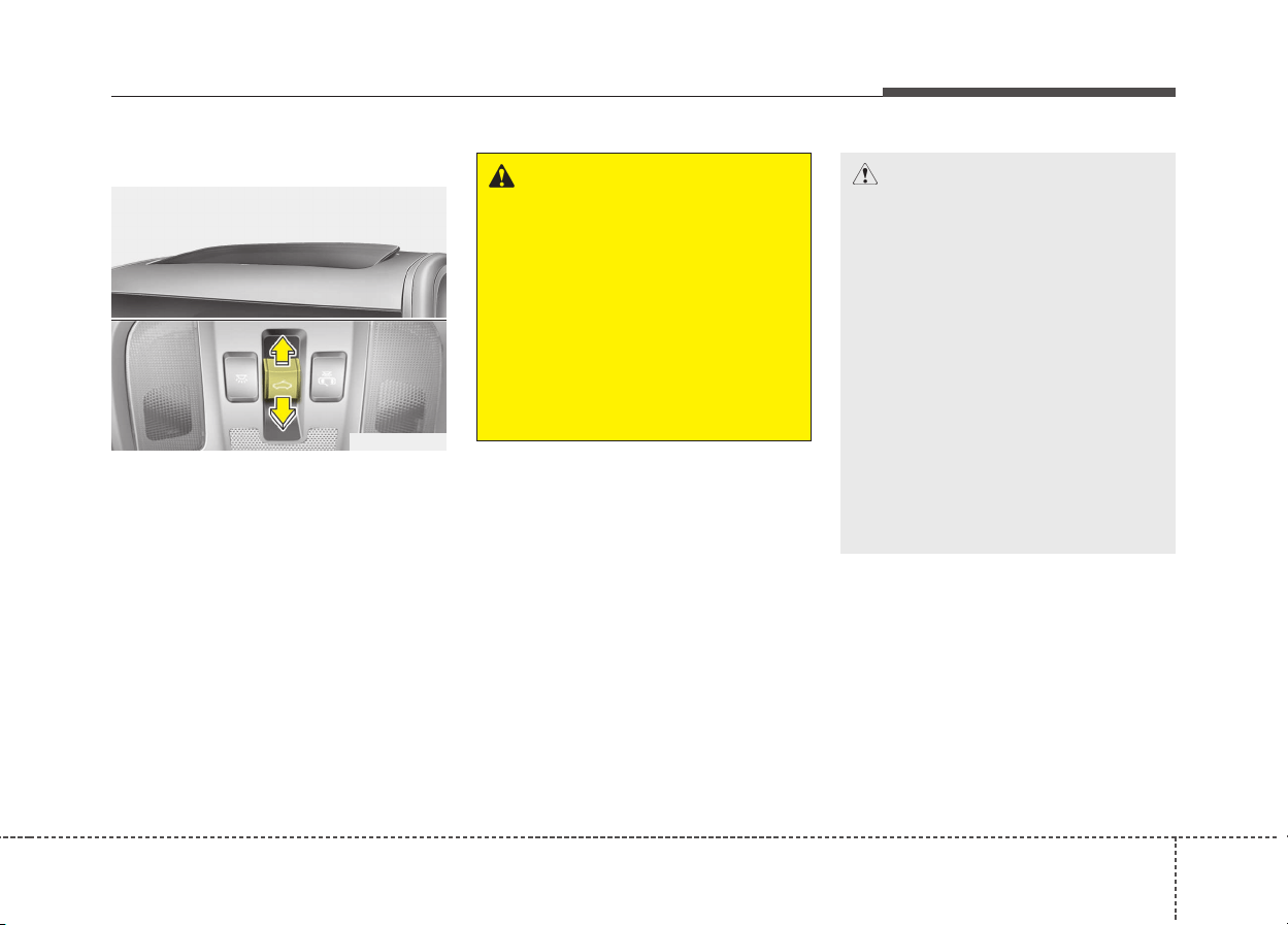
433
Features of your vehicle
Tilting the sunroof
To open the sunroof
Push the sunroof control lever
upward until the sunroof moves to
the desired position.
To close the sunroof
Move the sunroof lever forward until
the sunroof moves to the desired
position.
ODE046021L
CAUTION
• Periodically remove any dirt
that may accumulate on the
guide rail.
• If you try to open the sunroof
when the temperature is
below freezing or when the
sunroof is covered with snow
or ice, the glass or the motor
could be damaged.
• While using sunroof for a long
time, a dust between sunroof
and roof panel can make a
noise. Open the sunroof and
regularly remove the dust
using clean cloth.
WARNING - Sunroof
• Be careful that someone’s
head, hands and body are not
trapped by a closing sunroof.
• Do not extend face, neck,
arms or body outside through
the sunroof opening while
driving.
• Make sure hand and face are
safely out of the way before
closing a sunroof.

Features of your vehicle
344
Sunshade
The sunshade will be opened with
the glass panel automatically when
the glass panel is opened. You will
have to close it manually if you want
it closed.
Resetting the sunroof
Reset the sunroof when:
- The vehicle battery has dis-
charged or replaced, or the fuse
has been replaced.
- The sunroof does not operate
normally.
- The glass opens during operation
even though there are no
obstructions.
- The glass is not of uniform height.
1.Turn the ignition switch to the ON
position or start the engine. We
recommend resetting the sunroof
while the engine is running.
2.Close the sunroof completely if
opened.
3.Release the sunroof control lever.
4.Move the sunroof control lever for-
ward in the direction of close until
the sunroof moves tilt up. Then,
release the lever.
5.Move the sunroof control lever for-
ward in the direction of close, until
the sunroof operates as follows
again:
Tilt down → Slide Open → Slide
Close.
✽✽
NOTICE
Do not release the lever until the
operation is completed.
If you release the lever during oper-
ation, try again from step 2.
6.Release the sunroof control lever
after all operation has completed.
(The sunroof system has been
reset.)
❈For more detailed information, we
recommend that you contact an
authorized Kia dealer.
CAUTION
The sunroof is made to slide
together with the sunshade. Do
not leave the sunshade closed
while the sunroof is open.
OBK049019
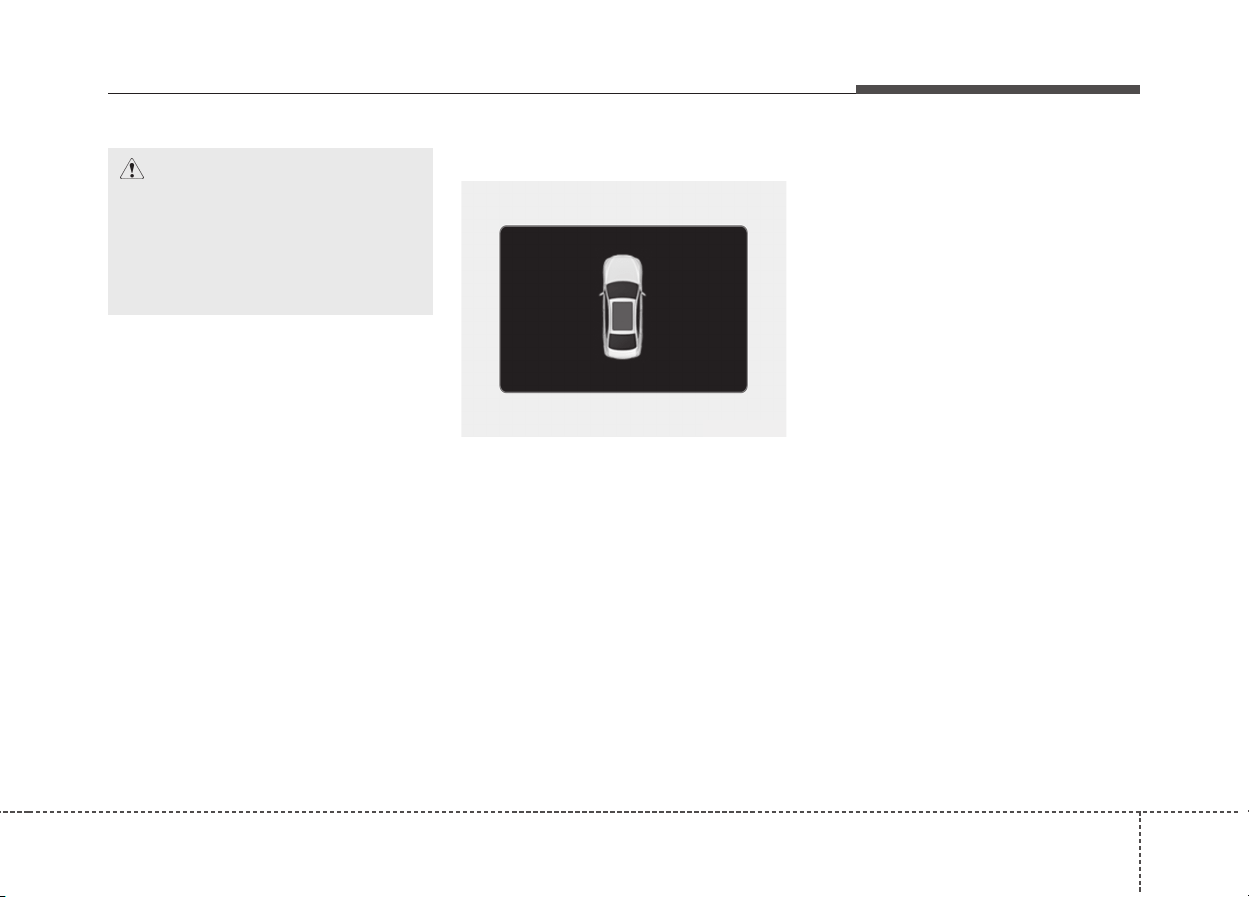
435
Features of your vehicle
Sunroof open warning
If the driver removes the ignition key
(smart key: turns off the engine)
when the sunroof is not fully closed,
the warning chime will sound for
approximately 6 seconds and a mes-
sage will appear on the LCD window.
Close the sunroof securely when
leaving your vehicle.
CAUTION
If the sunroof is not reset when
the vehicle battery is discon-
nected or discharged, or related
fuse is blown, the sunroof may
operate improperly.
ODE046119

Features of your vehicle
364
Electronic power steering
Power steering uses the motor to
assist you in steering the vehicle. If
the engine is off or if the power steer-
ing system becomes inoperative, the
vehicle may still be steered, but it will
require increased steering effort.
Electronic power steering is con-
trolled by the power steering control
unit which senses the steering wheel
torque and vehicle speed to com-
mand the motor.
The steering effort becomes heavier
as the vehicle’s speed increases and
becomes lighter as the vehicle’s
speed decreases for better control of
the steering wheel.
Should you notice any change in the
effort required to steer during normal
vehicle operation, we recommend
that the system be checked by an
authorized Kia dealer.
✽✽
NOTICE
The following symptoms may occur
during normal vehicle operation:
• The EPS warning light does not
illuminate.
• The steering effort is high immedi-
ately after turning the ignition
switch on. This happens as the
EPS system performs the diagnos-
tics. When the diagnostics is com-
pleted, the steering effort will
return to its normal condition.
• A click noise may be heard from
the EPS relay after the ignition
switch is turned to the ON or
LOCK position.
• Motor noise may be heard when
the vehicle is at a stop or at a low
driving speed.
• The steering effort can suddenly
increase, if the operation of the
EPS system is stopped to prevent
serious accidents when EPS con-
trol unit detects malfunction of the
EPS system by self-diagnosis.
• The steering effort increases if the
steering wheel is rotated continu-
ously when the vehicle is not in
motion.
(Continued)
(Continued)
However, after a few minutes, it
will return to its normal condi-
tions.
• If the Electronic Power Steering
System does not operate normally,
the warning light will illuminate
on the instrument cluster. The
steering wheel may become diffi-
cult to control or operate abnor-
mally. We recommend that you
contact an authorized Kia dealer.
• When you operate the steering
wheel in low temperature, the
steering effort may be high and
abnormal noise could occur. If
temperature rises, the noise will
disappear. This is a normal condi-
tion.
• If the vehicle needs to be jump
started due to battery discharge,
the steering wheel may not func-
tion normally. This is a temporary
situation caused by low battery
voltage. It will be solved once the
battery is charged. Check for nor-
mal steering function by turning
the steering wheel slowly before
driving the vehicle.
STEERING WHEEL

437
Features of your vehicle
Tilt & telescopic steering
A tilt and telescopic steering wheel
allows you to adjust the steering
wheel before you drive. You can also
raise it to give your legs more room
when you exit and enter the vehicle.
The steering wheel should be posi-
tioned so that it is comfortable for
you to drive, while permitting you to
see the instrument panel warning
lights and gauges.
To change the steering wheel angle,
pull down the lock release lever (1),
adjust the steering wheel to the
desired angle (2) and height (3), then
pull up the lock-release lever (4) to
lock the steering wheel in place. Be
sure to adjust the steering wheel to
the desired position before driving.
✽✽
NOTICE
After adjustment, sometimes the
lock-release lever may not lock the
steering wheel.
It is not a malfunction. This occurs
when two gears engage. In this case,
adjust the steering wheel again and
then lock the steering wheel.
Heated steering wheel
(if equipped)
With the ignition switch in the ON
position or engine start/stop button in
the ON position, pressing the heated
steering wheel button warms the
steering wheel. The indicator on the
button will illuminate.
To turn the heated steering wheel off,
press the button once again. The
indicator on the button will turn off.
WARNING
• Never adjust the angle of the
steering wheel while driving.
You may lose steering control
and cause severe personal
injury, death or accidents.
• After adjusting, push the
steering wheel both up and
down to be certain it is locked
in position.
ODE046022
ODE046023

Features of your vehicle
384
✽✽
NOTICE
The heated steering wheel will turn
off automatically approximately 30
minutes after the heated steering
wheel is turned on.
Horn
To sound the horn, press the area
indicated by the horn symbol on your
steering wheel (see illustration). The
horn will operate only when this area
is pressed. Check the horn regularly
to be sure it operates properly.
CAUTION
Do not install any grip to oper-
ate the steering wheel. This
causes damage to the heated
steering wheel system.
ODE046024
CAUTION
• Do not strike the horn severe-
ly to operate it, or hit it with
your fist. Do not press on the
horn with a sharp-pointed
object.
• When cleaning the steering
wheel, do not use an organic
solvent such as thinner, ben-
zene, alcohole and gasoline.
Doing so may damage the
steering wheel.
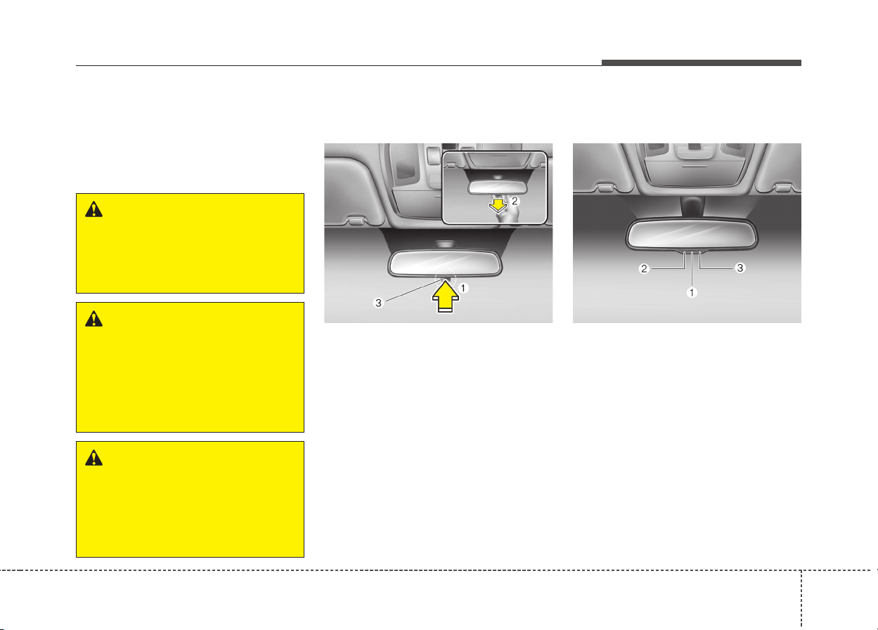
439
Features of your vehicle
Inside rearview mirror
Adjust the rearview mirror so that the
center view through the rear window
is seen. Make this adjustment before
you start driving.
Day/night rearview mirror
(if equipped)
Make this adjustment before you
start driving and while the day/night
lever(3) is in the day position (1).
Pull the day/night lever(3) toward you
(2) to reduce the glare from the
headlights of the vehicles behind you
during night driving.
Remember that you lose some
rearview clarity in the night position.
❈ (1) : Day, (2) : Night
Electrochromic mirror (ECM)
(if equipped)
The electric rearview mirror automat-
ically controls the glare from the
headlights of the vehicles behind you
in nighttime or low light driving condi-
tions. The sensor (3) mounted in the
mirror senses the light level around
the vehicle, and automatically con-
trols the headlight glare from the
vehicles behind you.
When the engine is running, the
glare is automatically controlled by
the sensor mounted in the rearview
mirror.
MIRRORS
WARNING - Rear visibility
Do not place objects in the rear
seat or cargo area which would
interfere with your vision
through the rear window.
ODE046025L
WARNING
Do not adjust the rearview mir-
ror while the vehicle is moving.
This could result in loss of con-
trol, and an accident which
could cause death, serious
injury or property damage.
WARNING
Do not modify the inside mirror
and don’t install a wide mirror. It
could result in injury, during an
accident or deployment of the
air bag.
ODE046036L
Features of your vehicle
404
Whenever the shift lever is shifted
into reverse (R), the mirror will auto-
matically go to the brightest setting in
order to improve the drivers view
behind the vehicle.
To operate the electric rearview mirror:
• The mirror defaults to the ON posi-
tion whenever the ignition switch is
turned on.
• Press the ON/OFF button (1) to
turn the automatic dimming func-
tion off. The mirror indicator light
(2) will turn off.
Press the ON/OFF button (1) to
turn the automatic dimming func-
tion on. The mirror indicator light
(2) will illuminate.
Outside rearview mirror
Be sure to adjust the mirror angles
before driving.
Your vehicle is equipped with both
left-hand and right-hand outside
rearview mirrors. The mirrors can be
adjusted remotely with the remote
switch. The mirror heads can be fold-
ed back to prevent damage during an
automatic car wash or when passing
through a narrow street.
WARNING - Rearview
mirrors
• The outside rearview mirror is
convex. Objects seen in the
mirror are closer than they
appear.
• Use your interior rearview
mirror or direct observation to
determine the actual distance
of following vehicles when
changing lanes.
CAUTION
When cleaning the mirror, use a
paper towel or similar material
dampened with glass cleaner.
Do not spray glass cleaner
directly on the mirror. It may
cause the liquid cleaner to enter
the mirror housing.
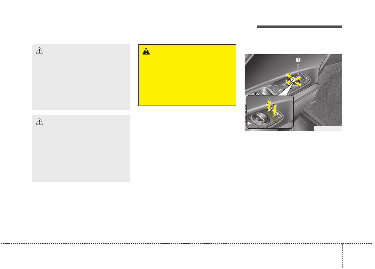
441
Features of your vehicle
Remote control
Adjusting the rearview mirrors :
1. Press either the L (Front left side)
or R (Front right side) button (1) to
select the rearview mirror you
would like to adjust.
2. Use the mirror adjustment control
(2) to position the selected mirror
up, down, left or right.
3. After adjustment, put the button
into neutral (center) position to
prevent inadvertent adjustment.
CAUTION
Do not scrape ice off the mirror
face; this may damage the sur-
face of the glass. If ice should
restrict the movement of the
mirror, do not force the mirror
for adjustment. To remove ice,
use a deicer spray, or a sponge
or soft cloth with warm water.
CAUTION
If the mirror is jammed with ice,
do not adjust the mirror by
force. Use an approved spray
de-icer (not radiator antifreeze)
to release the frozen mecha-
nism or move the vehicle to a
warm place and allow the ice to
melt.
WARNING
Do not adjust or fold the outside
rearview mirrors while the vehi-
cle is moving. This could result
in loss of control, and an acci-
dent which could cause death,
serious injury or property dam-
age.
ODE046028L
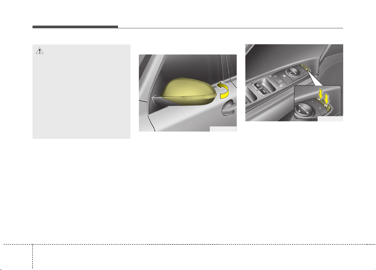
Features of your vehicle
424
Folding the outside rearview mirror
Manual type
To fold the outside rearview mirror,
grasp the housing of the mirror and
then fold it toward the rear of the
vehicle.
Electric type
The outside rearview mirror can be
folded or unfolded by pressing the
switch as below.
Left : The mirror will unfold.
Right : The mirror will fold.
Center (AUTO) :
The mirror will fold or unfold auto-
matically as follows:
• Without smart key system
- The mirror will fold or unfold when
the door is locked or unlocked by
the transmitter. (if equipped)
CAUTION
• The mirrors stop moving when
they reach the maximum
adjusting angles, but the
motor continues to operate
while the switch is pressed.
Do not press the switch longer
than necessary, the motor
may be damaged.
• Do not attempt to adjust the
outside rearview mirror by
hand. Doing so may damage
the parts.
ODE046030
ODE046029

443
Features of your vehicle
• With smart key system
- The mirror will fold or unfold when
the door is locked or unlocked by
the smart key.
- The mirror will fold or unfold when
the door is locked or unlocked by
the button on the outside door
handle.
- The mirror will unfold when you
approach the vehicle (all doors
closed and locked) with a smart
key in possession. (if equipped)
CAUTION
In case it is an electric type out-
side rearview mirror, don’t fold it
by hand. It could cause motor
failure.
CAUTION
The electric type outside
rearview mirror operates even
though the ignition switch is in
the LOCK position or the engine
Start/Stop button is in the OFF
position. However, to prevent
unnecessary battery discharge,
do not adjust the mirrors longer
than necessary while the engine
is not running.
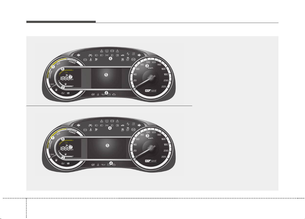
Features of your vehicle
444
INSTRUMENT CLUSTER
1. Hybrid system gauge
2. Fuel gauge
3. Speedometer
4. Warning and indicator lights
5. LCD window
6. Battery SOC (State of Charge) gauge
7. Distance To Empty
ODE046100L/ODE046101L
■■
Type A
❈ For more details, refer to the "Gauges" in
this chapter.
■■
Type B
❈ The above illustration is a sample for explanation only. Actual instrument panel may be different.
For specifics, please refer to the actual instrument panel in your car and relevant in this section.
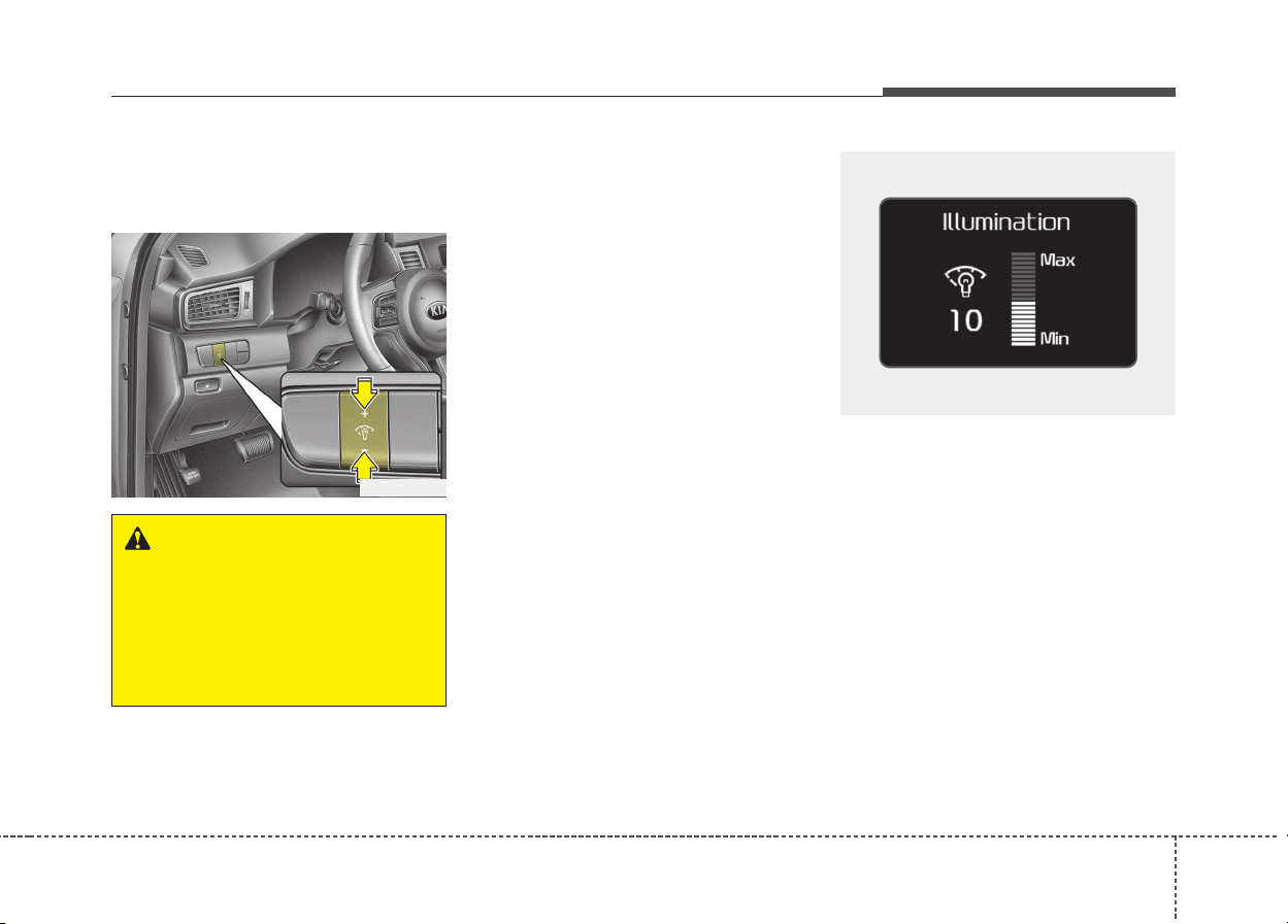
445
Features of your vehicle
Instrument Cluster Control
Adjusting Instrument Cluster
Illumination (if equipped)
The brightness of the instrument
panel illumination is changed by
pressing the illumination control but-
ton (“+” or “-”) when the ignition
switch or Engine Start/Stop button is
ON, or the tail lights are turned on.
• If you hold the illumination control
button (“+” or “-”), the brightness
will be changed continuously.
• If the brightness reaches to the
maximum or minimum level, an
alarm will sound.
ODE046102
OQLE045233
WARNING
Never adjust the instrument
cluster while driving. This could
result in loss of control and lead
to an accident that may cause
death, serious injury, or proper-
ty damage.
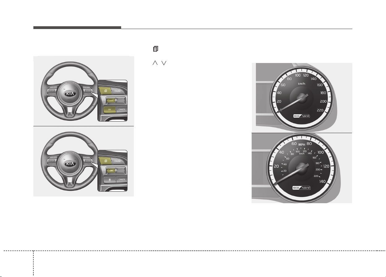
Features of your vehicle
464
LCD window control
The LCD window modes can be
changed by using the control buttons
on the steering wheel.
(1) : MODE button for change the
LCD MODES
(2) / : MOVE scroll switch for
select the items
(3) OK : SET/RESET button for set
the items or reset the items
❈ For the LCD modes, refer to “LCD
window” in this chapter.
Gauges
Speedometer
The speedometer indicates the
speed of the vehicle and is calibrated
in miles per hour (mph) and/or kilo-
meters per hour (km/h).
ODE046105
ODE046105L
■ Type A (km/h)
■ Type B (MPH, km/h)
ODE046103
ODE046104
■ Type A
■ Type B
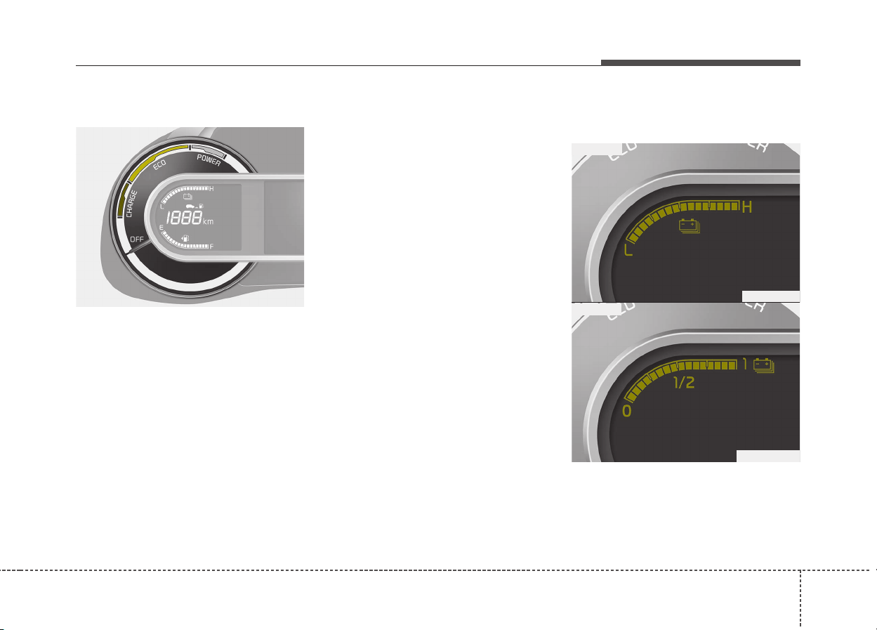
447
Features of your vehicle
Hybrid System Gauge
The hybrid system gauge indicates
whether the current driving condition
is fuel efficient or not.
• CHARGE : Shows that the energy
made by the vehicle is
being converted to
electrical energy.
(Regenerated energy)
• ECO : Shows that the vehicle is
being driven in an Eco-
friendly manner.
• POWER : Shows that the vehicle is
exceeding the Eco-
friendly range.
✽✽
NOTICE
Accordance to the hybrid system
gauge area the “EV” indicator
comes on or off.
- “EV” indicator ON : Vehicle is
driven using the electric motor or
the gasoline engine is stopped.
- “EV” indicator OFF : Vehicle is
driven using the gasoline engine.
Hybrid Battery SOC
(State of Charge) Gauge
This gauge indicates the remaining
hybrid battery power. If the SOC is
near the “L (Low) or 0” level, the vehi-
cle automatically operates the
engine to charge the battery.
ODE046107
ODE046107L
■ Type A
■ Type B
ODE046106
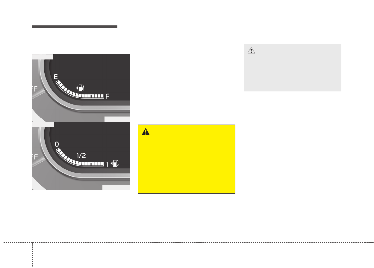
Features of your vehicle
484
Fuel Gauge
This gauge indicates the approxi-
mate amount of fuel remaining in the
fuel tank.
✽✽
NOTICE
• The fuel tank capacity is given in
chapter 9.
• The fuel gauge is supplemented by
a low fuel warning light, which
will illuminate when the fuel tank
is nearly empty.
• On inclines or curves, the fuel
gauge pointer may fluctuate or the
low fuel warning light may come
on earlier than usual due to the
movement of fuel in the tank.
WARNING - Fuel Gauge
Running out of fuel can expose
vehicle occupants to danger.
You must stop and obtain addi-
tional fuel as soon as possible
after the warning light comes
on or when the gauge indicator
comes close to the “0 or E
(Empty)” level.
CAUTION
Avoid driving with a extremely
low fuel level. Running out of
fuel could cause the engine to
misfire damaging the catalytic
converter.
ODE046108
ODE046108L
■ Type A
■ Type B
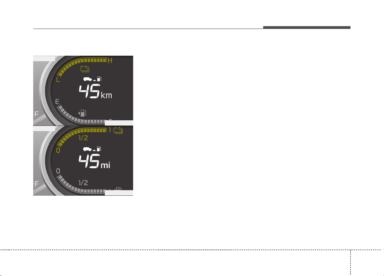
449
Features of your vehicle
Distance to empty
Distance To Empty
• The distance to empty is the esti-
mated distance the vehicle can be
driven with the remaining fuel.
- Distance range: 1~9,999 km or
1~9,999 mi.
• If the estimated distance is below 1
km (1 mi.), the trip computer will
display “---” as distance to empty.
• If the level of the remaining fuel is
more than three-quarters, more
than 3 liters of fuel must be refilled
for the fuel gauge to change. In
other cases, more than 6 liters of
fuel must be refilled for the vehicle
to change the fuel gauge.
✽✽
NOTICE
• If the vehicle is not on level ground
or the battery power has been
interrupted, the distance to empty
function may not operate correct-
ly.
• The distance to empty may differ
from the actual driving distance as
it is an estimate of the available
driving distance.
• The fuel economy and distance to
empty may vary significantly
based on driving conditions, driv-
ing habits, and condition of the
vehicle.
ODE046142L
ODE046109L
■ Type A
■ Type B
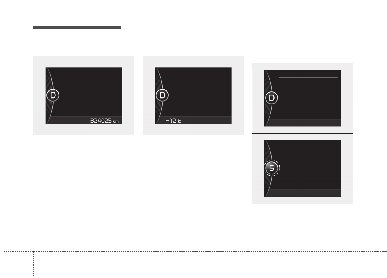
Features of your vehicle
504
Odometer
The odometer Indicates the total dis-
tance that the vehicle has been driv-
en and should be used to determine
when periodic maintenance should
be performed.
- Odometer range : 0 ~ 1,599,999 km
or 999,999 miles.
Outside Temperature Gauge
This gauge indicates the current out-
side air temperatures by 1°C (1°F).
- Temperature range : -40°C~ 60°C (-
40°F ~ 140°F)
The outside temperature on the dis-
play may not change immediately
like a general thermometer to pre-
vent the driver from being inattentive.
The temperature unit can be
changed by using the “User Settings”
mode of the LCD window.
❈ For more details, refer to “LCD
window” in this chapter.
Dual clutch transmission shift
indicator
This indicator displays which shift
lever is selected.
OQL045109OQL045108
ODE046141L
ODE046140L
■ Drive mode
■ Sports mode
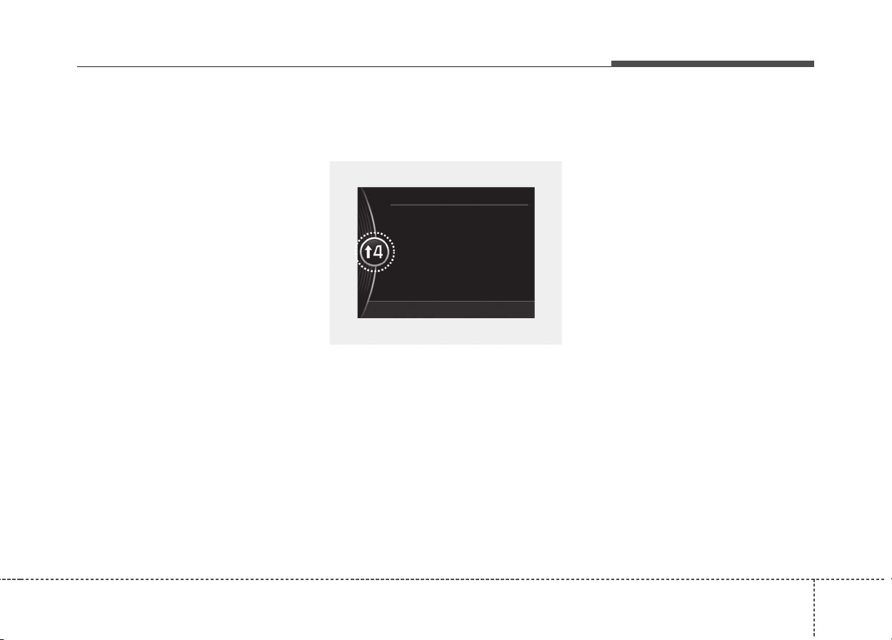
451
Features of your vehicle
•Park :P
• Reverse : R
• Neutral : N
•Drive :D
• Sports mode (if equipped) : S
Dual clutch transmission shift
indicator in sports mode
(for Europe, if equipped)
If the driver selects “Sports mode”
and changes gear, both higher and
lower, the gear will automatically
change to manual “Sports mode”.
Depending on the selected gear, the
gear display range will be from 1 to 6.
• Shifting up :
↑
↑
2,
↑↑
3,
↑↑
4,
↑↑
5,
↑↑
6
• Shifting down :
↓
↓
1,
↓↓
2,
↓↓
3,
↓↓
4,
↓↓
5
For example
↑
↑
4 : Display means the optimal gear
is 4 and driver may shift up to 4.
↓
↓
2 : Display means the optimal gear
is 2 and driver may shift down to
2.
When the operation conditions are
not satisfied properly, the indicator is
not displayed.
OQLE045190
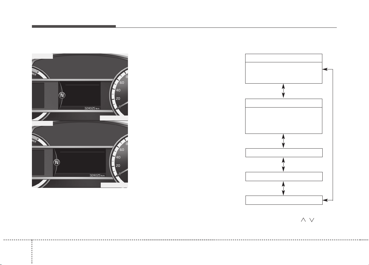
Features of your vehicle
524
Over view
LCD windows show the following var-
ious information to drivers.
- Trip information
- LCD modes
- Warning messages
Trip information (Trip computer)
The trip computer is a microcomput-
er-controlled driver information sys-
tem that displays information related
to driving.
✽✽
NOTICE
Some driving information stored in
the trip computer (for example
Average Vehicle Speed) resets if the
battery is disconnected.
Trip Modes
LCD WINDOWS (IF EQUIPPED)
ODE046098L
ODE046099L
■ Type A
■ Type B
To change the trip mode, scroll the
MOVE scroll switch ( / ) in the
trip computer mode.
• Tripmeter [A/B]
• Average Vehicle Speed [A/B]
• Elapsed Time [A/B]
TRIP A/B
• Average Fuel Economy
• Instant Fuel Economy
Digital Speedometer
Driving style
Energy flow
FUEL ECONOMY
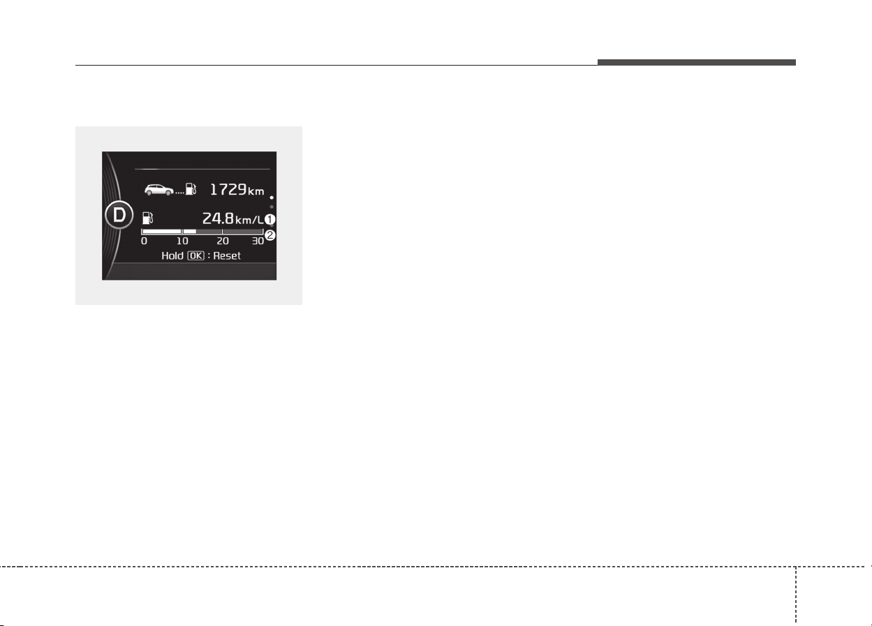
453
Features of your vehicle
Fuel Economy
Average Fuel Economy (1)
• The average fuel economy is calcu-
lated by the total driving distance
and fuel consumption since the last
average fuel economy reset.
- Fuel economy range : 0.0 ~ 99.9
km/L, L/100Km or MPG
• The average fuel economy can be
reset both manually and automati-
cally.
Manual reset
To clear the average fuel economy
manually, press the OK button
(reset) on the steering wheel for
more than 1 second when the aver-
age fuel economy is displayed.
Automatic reset
To make the average fuel economy
be reset automatically whenever
refueling, select the “Fuel economy
auto reset” mode in User Setting
menu of the LCD display (Refer to
“LCD window”).
• OFF - You may set to default man-
ually by using the trip switch reset
button.
• After ignition - The vehicle will
automatically set to default once 4
hours pass after the Engine
start/stop button is turned to the
OFF position.
• After refueling - After refueling
more than 6 liters and driving over
1km/h, the vehicle will reset to
default automatically.
✽✽
NOTICE
The average vehicle speed is not dis-
played, when the vehicle drives
shorter than 300 meters (0.19 miles)
or less than 10 seconds after turning
ON the Engine Start/Stop button.
ODE046138L
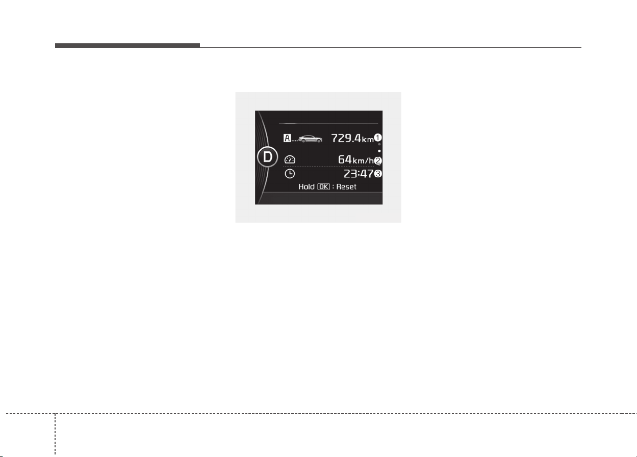
Features of your vehicle
544
Instant Fuel Economy (2)
• This mode displays the instant fuel
economy during the last few sec-
onds when the vehicle speed is
more than 10 km/h (6.2 MPH).
- Fuel economy range : 0.0 ~ 30
L/100km or 0.0 ~ 50.0 MPG
Trip A/B
Tripmeter (1)
• The tripmeter is the total driving
distance since the last tripmeter
reset.
- Distance range: 0.0 ~ 9999.9 km
or mi.
• To reset the tripmeter, press the
OK button (reset) on the steering
wheel for more than 1 second
when the tripmeter is displayed.
Average Vehicle Speed (2)
• The average vehicle speed is cal-
culated by the total driving dis-
tance and driving time since the
last average vehicle speed reset.
- Speed range: 0 ~ 999 km/h or
MPH
• To reset the average vehicle
speed, press the OK button (reset)
on the steering wheel for more
than 1 second when the average
vehicle speed is displayed.
✽✽
NOTICE
• The average vehicle speed is not
displayed if the driving distance
has been less than 50 meters (0.03
miles) or the driving time has been
less than 10 seconds since the igni-
tion switch or Engine Start/Stop
button was turned to ON.
• Even if the vehicle is not in
motion, the average vehicle speed
keeps going while the engine is
running.
ODE046134L
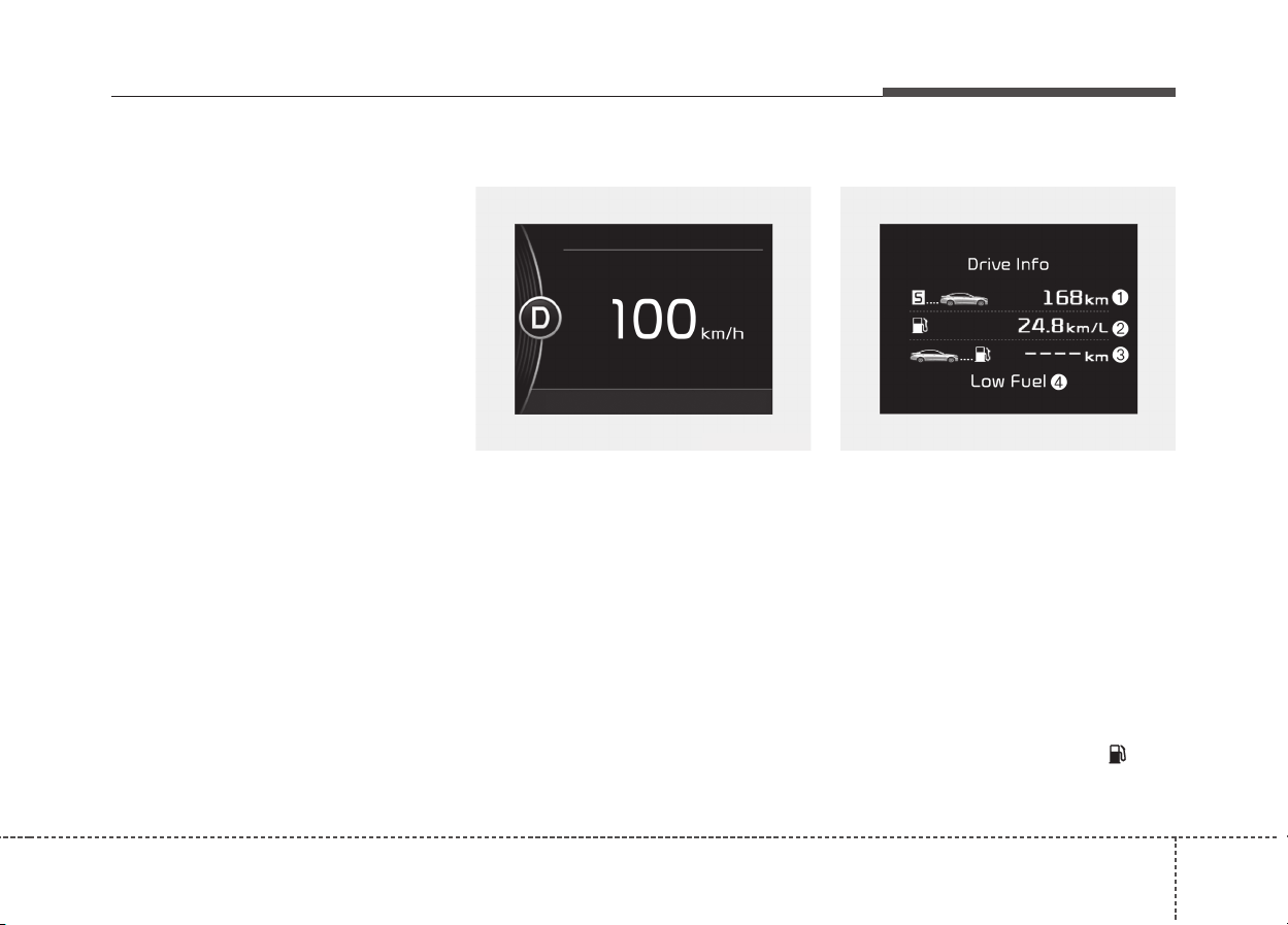
455
Features of your vehicle
Elapsed Time (3)
• The elapsed time is the total driv-
ing time since the last elapsed time
reset.
- Time range (hh:mm): 00:00 ~
99:59
• To reset the elapsed time, press
the OK button (reset) on the steer-
ing wheel for more than 1 second
when the elapsed time is dis-
played.
✽✽
NOTICE
Even if the vehicle is not in motion,
the elapsed time keeps going while
the engine is running.
Digital speedometer
This mode displays the current
speed of the vehicle.
One time driving information mode
This display shows trip distance (1),
average fuel economy (2) and the
vehicle can be driven with the
remaining fuel (3).
This information is displayed for a
few seconds when you turn off the
engine and then goes off automati-
cally. The information provided is cal-
culated according to each trip.
If the estimated distance is below
1km (1mi.), the distance to empty (3)
will display as “---”.
When low fuel warning light ( ) illu-
minates in the cluster, the refuel
message will appear(4).
ODE046135L ODE046143L
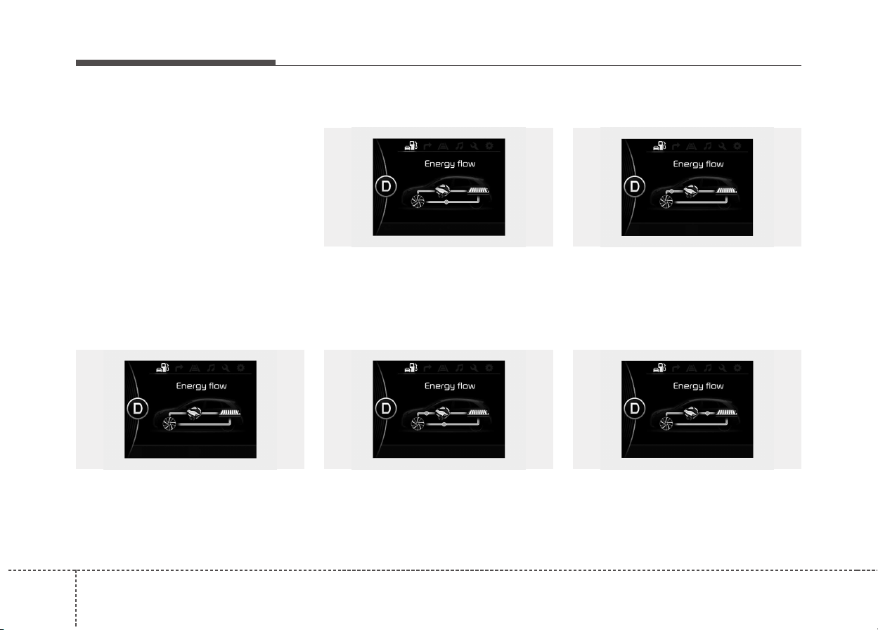
Features of your vehicle
564
Energy flow
Kia hybrid system notifies the drivers
of energy flow in various operating
modes. Eleven Modes show drivers
the current operating condition.
Vehicle Stop
The mode means the vehicle at stop.
(There is no energy flow.)
EV Propulsion
Electric power is used to move the
vehicle. (Battery ➞ Wheel)
Power Assist
Electric and Engine power are used
to move the vehicle.
(Battery & Engine ➞ Wheel)
Engine Only Propulsion
Engine power is used to move the
vehicle. (Engine ➞ Wheel)
Engine Generation
Vehicle is stopped with the Engine
charging the hybrid battery.
(Engine ➞ Battery)
ODE046123L
ODE046124L
ODE046121L
ODE046122LODE046120L
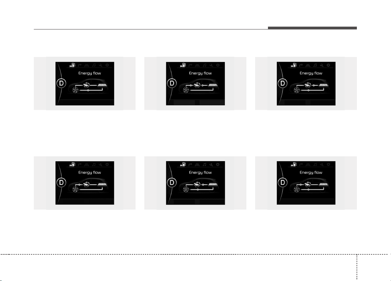
457
Features of your vehicle
Regeneration
Hybrid battery is being charged by
regenerative braking.
(Wheel ➞ Battery)
Engine Brake
The vehicle is being slowed by
engine compression.
(Wheel ➞ Engine)
Power Reserve
Engine is both driving the vehicle
and charging the hybrid battery.
(Engine ➞ Wheel & Battery)
Engine Generation/Motor Drive
The vehicle is being slowed by engine
compression and regenerative brak-
ing. The hybrid battery is being
charged by regenerative braking.
(Engine ➞ Battery ➞ Wheel)
Engine Generation/Regeneration
The engine and regenerative braking
system charge the hybrid battery
driving deceleration.
(Engine & Wheel ➞ Battery)
Engine Brake/Regeneration
The engine compression can be
used to slow the vehicle. The regen-
erative braking system can be used
to charge the hybrid system.
(Wheel ➞ Engine & Battery)
ODE046128L
ODE046122L
ODE046127L
ODE046128L
ODE046121L
ODE046126L
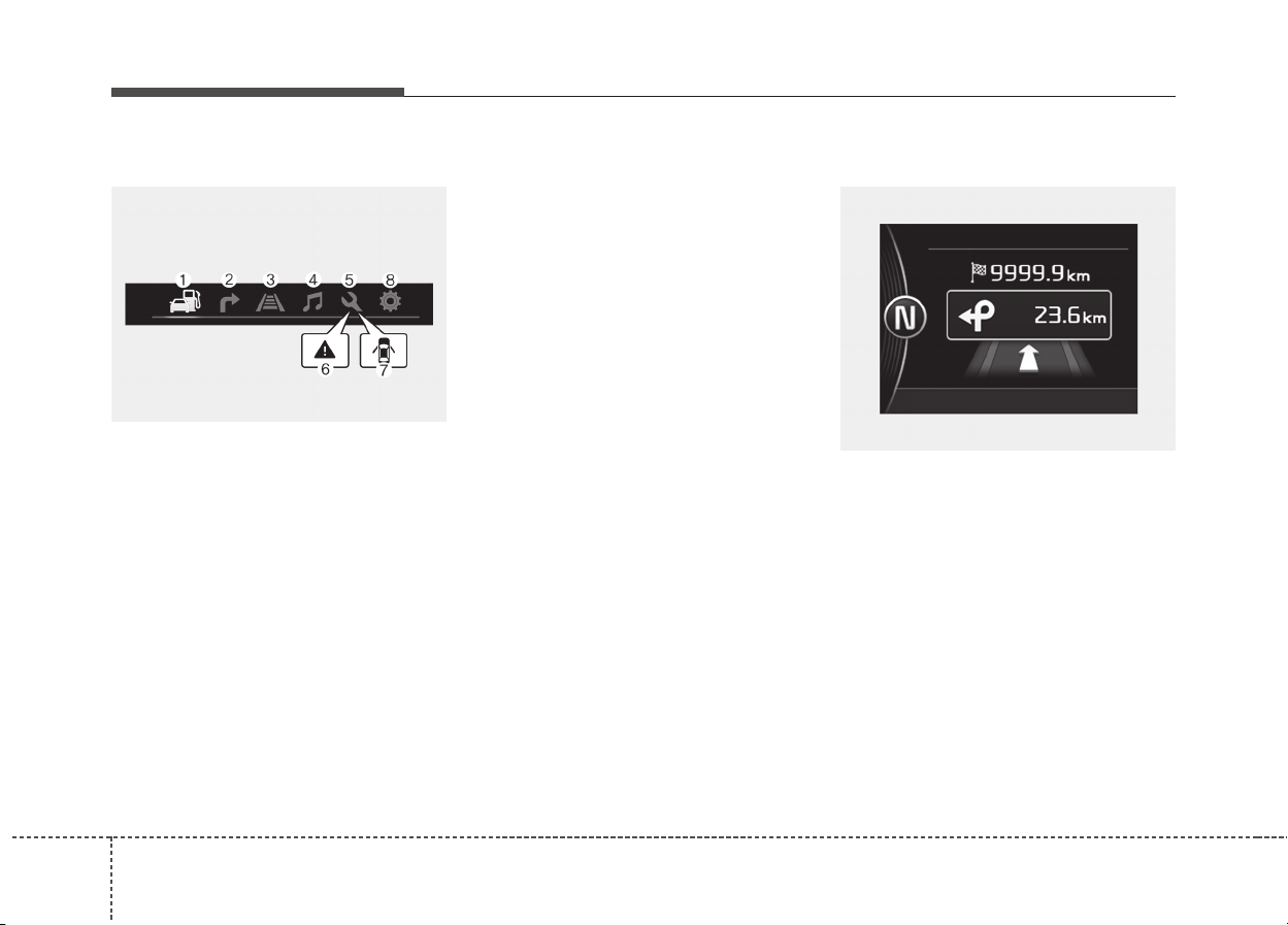
Features of your vehicle
584
LCD Modes
(1) Trip Computer mode
This mode displays driving informa-
tion like the tripmeter, fuel economy,
and so on.
❈ For more details, refer to “Trip
Computer” in this chapter.
(2) Turn By Turn mode (if equipped)
This mode displays the state of the
navigation.
(3) LKAS/SCC mode (if equipped)
This mode displays the state of the
Lane Keeping Assist System (LKAS)
and Smart Cruise Control (SCC).
(4) Audio mode (if equipped)
This mode displays the state of the
A/V system.
(5) Service mode
This mode informs of service interval
(mileage or days) and pressure sta-
tus of each tire.
(6) Master warning mode
This mode informs of warning mes-
sages related to washer fluid or mal-
function of Blind Spot Detection sys-
tem (BSD) and so on.
(7) Door open mode
When the any door is not closed
securely, this symbol illuminated.
(8) User settings mode
On this mode, you can change set-
ting of the doors, lamps, and so on.
❈ For controlling the LCD modes,
refer to “LCD window Control” in
this chapter.
Turn By Turn Mode (if equipped)
This mode displays the state of the
navigation.
ODE046136L
OJF045223L
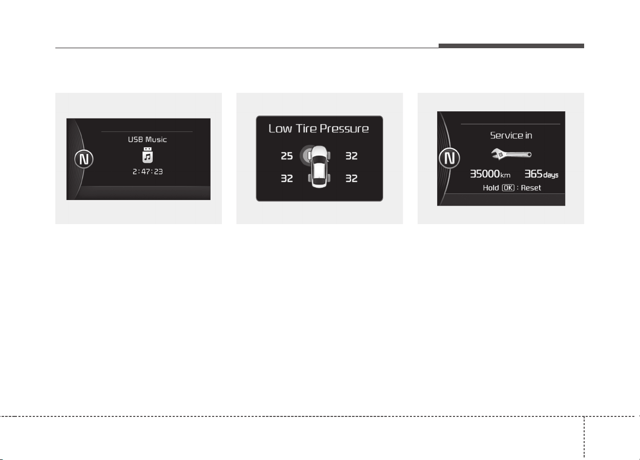
459
Features of your vehicle
A/V Mode (if equipped)
This mode displays the state of the
A/V system.
Tire Pressure (if equipped)
This mode displays the pressure sta-
tus of each tire.
You can change the tire pressure unit
in “User settings” mode.
❈ For more details, refer to “User
Settings mode” in this chapter.
Service Mode
Service in
It calculates and displays when you
need a scheduled maintenance
service (mileage or days).
If the remaining mileage or time
reaches 1,500 km (900 mi.) or 30
days, “Service in” message is dis-
played for several seconds each time
you set the ignition switch or Engine
Start/Stop Button to the ON position.
OJF045142L OJF045144LOJF045292L

Features of your vehicle
604
Service required
If you do not have your vehicle serv-
iced according to the already
inputted service interval, “Service
required” message is displayed for
several seconds each time you set
the ignition switch or Engine
Start/Stop Button to the ON position.
To reset the service interval to the
mileage and days you inputted
before:
- Activate the reset mode by press-
ing the OK button (reset) for more
than 5 second, then press the OK
button (reset) again for more than 1
second (Europe).
- Press the OK button (reset) for
more than 1 second (Except
Europe).
Service in OFF
If the service interval is not set,
“Service in OFF” message is dis-
played on the LCD window.
✽✽
NOTICE
If any of the following conditions
occurs, the mileage and days may be
incorrect.
- The battery cable is disconnected.
- The fuse switch is turned off.
- The battery is discharged.
OJF45294L OJF045295L
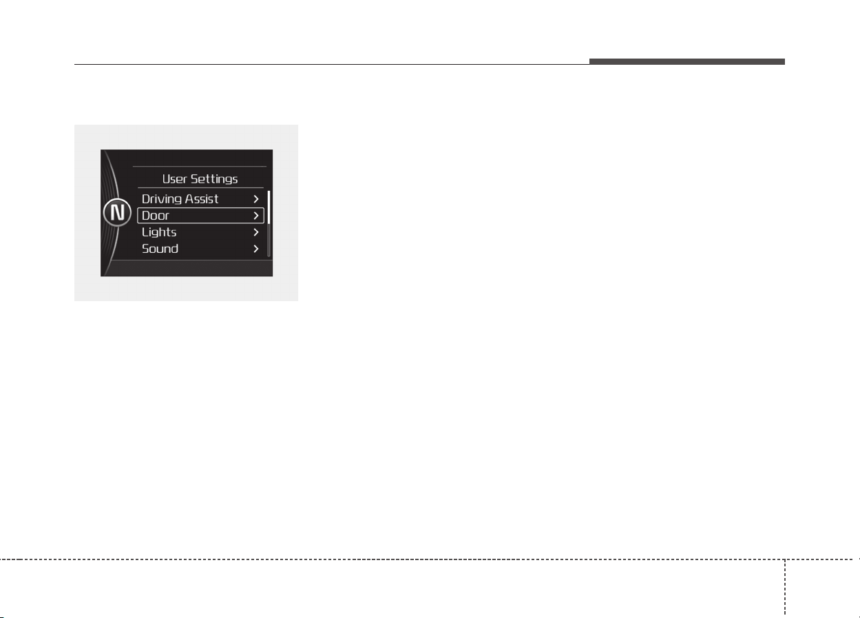
461
Features of your vehicle
User Settings Mode
On this mode, you can change set-
ting of the doors, lamps, and so on.
Driving Assist (if equipped)
• Lane Keeping Assist System
(LKAS, if equipped) :
To adjust the sensitivity of the Lane
Keeping Assist System.
- Lane Departure/Standard
LKA/Activ LKA
❈ For more information, refer to the
“Lane Keep Assist System” in
chapter 6.
• Smart cruise control (if equipped) :
To adjust the sensitivity of the
Smart Cruise Control system.
- Slow/Normal/Fast
❈ For more information, refer to the
“Smart Cruise Control” in chapter 6.
• Assist Emergency Braking system
(AEB,if equipped) :
To activate or deactivate the Assist
Emergency Braking (AEB).
❈ For more information, refer to
“Assist Emergency Braking (AEB)”
in chapter 6.
• Forward Collision Warning (FCW, if
equipped) :
To adjust the initial warning alert
time for Assist Emergency Braking
system.
- Late/Normal/Early
❈ For more information, refer to
“Assist Emergency Braking (AEB)”
in chapter 6.
• Rear Collision Warning (RCW,if
equipped)
- Rear Cross Traffic Alert :
To activate or deactivate the Rear
Cross Traffic Alert system.
❈ For more information, refer to
“Blind Spot Detection” in chapter 6.
- Blind Spot Detection sound :
To activate or deactivate the Blind
Spot Detection sound.
❈ For more information, refer to
“Blind Spot Detection” in chapter 6.
OJF045148L

Features of your vehicle
624
• Coasting guide (if equipped)
- Coasting guide : To activate or
deactivate the Coasting guide.
- Sound : To activate or deactivate
the Coasting guide sound.
- Start coasting : To adjust the ini-
tial guiding time for Coasting
guide.
Door
• Automatically Lock
- Disable : The auto door lock oper-
ation will be canceled.
- Enable on Speed : All doors will
be automatically locked when the
vehicle speed exceeds 15km/h
(9.3 mph).
- Enable on Shift: All doors will be
automatically locked if the trans-
mission shift lever is shifted from
the P (Park) position to the R
(Reverse), N (Neutral), or D
(Drive) position.
• Automatically Unlock
- Disable : The auto door unlock
operation will be canceled.
- Vehicle Off : All doors will be
automatically unlocked when the
Engine Star/Stop button is set to
the OFF position.
- Driver Door Unlock : All doors will
be automatically unlocked when
the driver's door is unlocked.
- On Shift to P : All doors will be
automatically unlocked if the shift
lever is shifted to the P (Park)
position.
Lights
• One Touch Turn Signal
- Off : The one touch turn signal
function will be deactivated.
- 3, 5, 7 Flashes : The lane change
signals will blink 3, 5, or 7 times
when the turn signal lever is
moved slightly.
❈ For more details, refer to “Light” in
this chapter.
• Head Lamp Delay (if equipped)
If this item checked, the head lamp
delay function will be activated.
• Welcome Light (if equipped)
If this item checked, the welcome
light function will be activated.
Sound
• Park Assist System Vol. (if
equipped) : Adjust the Park Assist
System volume. (Level 1 ~ 3)

463
Features of your vehicle
Convenience
• Seat Easy Access (if equipped)
- None : The seat easy access
function will be deactivated.
- Normal/Enhanced : When you
turn off the engine, the driver’s
seat will automatically move rear
7.6 cm (Enhanced) for you to
enter or exit the vehicle more
comfortably. If you change the
Engine Start/Stop Button from
OFF position to the AC function,
the driver’s seat will return to the
original position.
❈ For more details, refer to “Driver
Position Memory System” in chap-
ter 3.
• Wireless smart phone charging
system (if equipped) : If this item
checked, the Wireless smart
phone charging system will be acti-
vated.
• Wiper/Light Display (if equipped) :
If this item checked, the Wiper/
Light Display will be activated.
Service interval
• Service Interval : On this mode, you
can activate the service interval
function with mileage (km or mi.)
and period (months).
- Off : The service interval function
will be deactivated.
- On :You can set the service inter-
val (mileage and months).
Other Features
• Fuel Economy Auto Reset
- Off : The average fuel economy will
not reset automatically whenever
refueling.
- On (Auto Reset) : The average
fuel economy will reset automati-
cally when refueling.
❈ For more details, refer to “Trip
Computer” in this chapter.
• Fuel Economy Unit : Choose the
fuel economy unit. (Km/L, L/100)
• Temperature Unit : Choose the
temperature unit. (°C, °F)
• Tire Pressure Unit (if equipped) :
Choose the tire pressure unit. (psi,
kPa, Bar)
• Language : Choose the language.

Features of your vehicle
644
Coasting guide (if equipped)
A chime will sound and the coasting
guide indicator will blink four times to
inform the driver when to take the
foot off from the accelerator by antic-
ipating a decelerating event* based
on the analysis of driving routes and
road conditions of the navigation. It
encourages the driver to remove foot
from the pedal and allow coasting
down the road with EV motor only.
This helps prevent unnecessary fuel
consumption and increases fuel effi-
ciency.
❈ Example of a deceleration event is
going down an extended hill, slow-
ing down approaching a toll booth,
and approaching reduced speed
zones.
• User settings
Press the Engine Start/Stop button
and put the shift lever in P(Park). In
the User Settings Mode, select
Driving Assist, Coasting Guide, and
then On to turn on the system.
Cancel the selection of coasting
guide to turn off the system. For the
explanation of the system, press and
hold the [OK] button.
• Operation conditions
To activate the system, take the fol-
lowing procedures. Enter your desti-
nation information on the navigation
and select the driving route. Select
the ECO mode in the Integrated
Driving Control System. Then, satisfy
the following.
- The driving speed should be
between 60 km/h(37 mph) and 160
km/h(99 mph).
❈ The operating speed may vary
due to difference between instru-
ment cluster and navigation effect-
ed by tire inflation level.
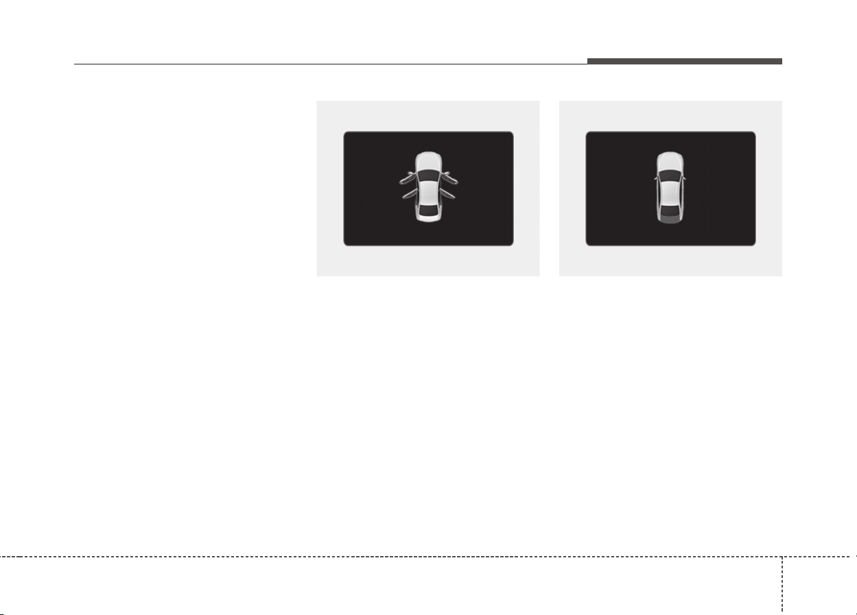
465
Features of your vehicle
Warning messages
Warning messages appear on the
LCD to warn the driver. It is located in
the center of the instrument cluster.
The warning message may appear
differently depending on the type of
instrument cluster and some may not
show the warning message at all.
The warning message is shown in
either symbol, symbol and text, or
text type only. You can choose the
preferred language by selecting the
User setting menu in LCD mode.
Door Open
• It means that any door is open.
Tailgate Open
• It means that the tailgate is open.
ODE046116 ODE046117
Features of your vehicle
664
Hood Open
• It means that hood is open.
Sunroof Open (if equipped)
• This warning is displayed if you
turn off the engine when the sun-
roof is open.
Turn on FUSE SWITCH (if equipped)
• This warning message illuminates
if the fuse switch under the steer-
ing wheel is OFF.
• It means that you should turn the
fuse switch on.
❈ For more details, refer to “Fuses”
in chapter 8.
ODE046118 OJF045166LODE046119

467
Features of your vehicle
Engine has overheated
This warning message illuminates
when the engine coolant tempera-
ture is above 120°C (248°F). This
means that the engine is overheated
and may be damaged.
If your vehicle is overheated, refer to
“Overheating” in chapter 7.
Shift to P (for smart key system)
• This warning message illuminates
if you try to turn off the engine with-
out the shift lever in P (Park) posi-
tion.
• At this time, the Engine Start/Stop
Button turns to the ACC position (If
you press the Engine Start/Stop
Button once more, it will turn to the
ON position).
Low Key Battery
(for smart key system)
• This warning message illuminates
if the battery of the smart key is
discharged when the Engine
Start/Stop Button changes to the
OFF position.
Press START button while turn steer-
ing (for smart key system)
• This warning message illuminates
if the steering wheel does not
unlock normally when the Engine
Start/Stop Button is pressed.
• It means that you should press the
Engine Start/Stop Button while
turning the steering wheel right
and left.
Steering wheel unlocked
(for smart key system)
• This warning message illuminates
if the steering wheel does not lock
when the Engine Start/Stop Button
changes to the OFF position.
ODE046137L

Features of your vehicle
684
Check Steering Wheel Lock System
(for smart key system)
• This warning message illuminates
if the steering wheel does not lock
normally when the Engine
Start/Stop Button changes to the
OFF position.
Press brake pedal to start engine
(for smart key system)
• This warning message illuminates
if the Engine Start/Stop Button
changes to the ACC position twice
by pressing the button repeatedly
without depressing the brake pedal.
• It means that you should depress
the brake pedal to start the engine.
Key not in vehicle (for smart key system)
• This warning message illuminates
if the smart key is not in the vehicle
when you press the Engine
Start/Stop Button.
• It means that you should always
have the smart key with you.
Key not detected (for smart key system)
• This warning message illuminates
if the smart key is not detected
when you press the Engine
Start/Stop Button.
Press START button again
(for smart key system)
• This warning message illuminates
if you can not operate the Engine
Start/Stop Button when there is a
problem with the Engine Start/Stop
Button system.
• It means that you could start the
engine by pressing the Engine
Start/ Stop Button once more.
• If the warning illuminates each
time you press the Engine
Start/Stop Button, we recommend
that you have the vehicle inspected
by an authorized Kia dealer.
Press START button with smart key
(for smart key system)
• This warning message illuminates
if you press the Engine Start/Stop
Button while the warning message
“Key not detected” is illuminating.
• At this time, the immobilizer indica-
tor light blinks.

469
Features of your vehicle
Check fuse “BRAKE SWITCH”
(for smart key system)
• This warning message illuminates
if the brake switch fuse is discon-
nected.
• It means that you should replace
the fuse with a new one. If that is
not possible, you can start the
engine by pressing the Engine
Start/Stop Button for 10 seconds in
the ACC position.
Shift to P or N to start engine
(for smart key system)
• This warning message illuminates
if you try to start the engine with
the shift lever not in the P (Park) or
N (Neutral) position.
✽✽
NOTICE
You can start the engine with the
shift lever in the N (Neutral) posi-
tion. But, for your safety, we recom-
mend that you start the engine with
the shift lever in the P (Park) posi-
tion.
Low Washer Fluid
• This warning message illuminates
on the service reminder mode if
the washer fluid level in the reser-
voir is nearly empty.
• It means that you should refill the
washer fluid.
Low Fuel
• This warning message illuminates
if the fuel tank is nearly empty.
- When the low fuel level warning
light is illuminates.
Add fuel as soon as possible.
Device in wireless charger
(if equipped)
If a smart phone is still left on the
wireless charging pad unattended,
even when the Engine start/stop but-
ton is turned to the ACC or OFF posi-
tion. And the instrument panel's one
time driving information mode has
finished, a warning message will lit
up on the instrument panel.
❈ For more details, refer to “Smart
Phone Wireless Charger” in this
chapter.

Features of your vehicle
704
Check Hybrid system
This warning message illuminates
when there is a problem with the
hybrid control system.
Refrain from driving when the warn-
ing message is displayed.
In this case, we recommend that you
have your vehicle inspected by an
authorized Kia dealer.
Check Hybrid system. Turn off engine.
This warning message illuminates
when there is a problem with the
hybrid system. The “ ” indicator
will blink and a warning chime will
sound until the problem is solved.
In this case, we recommend that you
have your vehicle inspected by an
authorized Kia dealer.
Check Hybrid system. Do not start engine.
This warning message illuminates
when the hybrid battery power
(SOC) level is low. A warning chime
will sound until the problem is solved.
In this case, we recommend that you
have your vehicle inspected by an
authorized Kia dealer.
Stop vehicle and check power supply
This warning message illuminates
when a failure occurs in the power
supply system.
In this case, park the vehicle in a
safe location and recommend that
you tow your vehicle to the nearest
authorized Kia dealer and have the
vehicle inspected.
Stop vehicle to charge battery
This warning message illuminates
when the hybrid battery power
(SOC) level is low.
In this case, park the vehicle in a
safe location and wait until the hybrid
battery is charged.
Refuel to prevent Hybrid battery dam-
age
This warning message illuminates
when the fuel tank is nearly empty.
You should refill the fuel tank to pre-
vent hybrid battery damage.

471
Features of your vehicle
Refill inverter coolant
This warning message illuminates
when the inverter coolant is nearly
empty.
You should refill the inverter coolant.
Check brakes
This warning message illuminates
when the brake performance is low
or the regenerative brake does not
work properly due to a failure in the
brake system.
In this case, it may take longer for the
brake pedal to operate and the brak-
ing distance may become longer.
Stop vehicle and check brakes
This warning message is displayed
when a failure occurs in the brake
system.
In this case, park the vehicle in a
safe location and tow your vehicle to
the nearest authorized Kia dealer
and have the vehicle inspected.

Features of your vehicle
724
WARNING AND INDICATOR LIGHTS
Warning lights
✽✽
NOTICE - Warning lights
Make sure that all warning lights
are OFF after starting the engine. If
any light is still ON, this indicates a
situation that needs attention.
Hybrid system warning
light
This warning light illuminates:
When there is a malfunction with the
hybrid system.
In this case, we recommend that you
have the vehicle inspected by an
authorized Kia dealer.
Air bag Warning Light
This warning light illuminates:
• Once you set the ignition switch or
Engine Start/Stop Button to the ON
position.
- It illuminates for approximately 6
seconds and then goes off.
• When there is a malfunction with
the SRS.
In this case, we recommend that
you have the vehicle inspected by
an authorized Kia dealer.
Seat Belt Warning Light
This warning light informs the driver
that the seat belt is not fastened.
❈ For more details, refer to the “Seat
Belts” in chapter 3.
473
Features of your vehicle
Parking Brake & Brake
Fluid Warning Light
This warning light illuminates:
• Once you set the ignition switch or
Engine Start/Stop Button to the ON
position.
- It illuminates for approximately 3
seconds
- It remains on if the parking brake
is applied.
• When the parking brake is applied.
• When the brake fluid level in the
reservoir is low.
- If the warning light illuminates
with the parking brake released, it
indicates the brake fluid level in
reservoir is low.
If the brake fluid level in the reservoir
is low:
1. Drive carefully to the nearest safe
location and stop your vehicle.
2. With the engine stopped, check
the brake fluid level immediately
and add fluid as required (For
more details, refer to “Brake Fluid”
in chapter 8). Then check all brake
components for fluid leaks. If any
leak on the brake system is still
found, the warning light remains
on, or the brakes do not operate
properly, do not drive the vehicle.
In this case, we recommend that you
have the vehicle towed to an author-
ized Kia dealer and inspected.
Dual-diagonal braking system
Your vehicle is equipped with dual-
diagonal braking systems. This
means you still have braking on two
wheels even if one of the dual sys-
tems should fail.
With only one of the dual systems
working, more than normal pedal
travel and greater pedal pressure are
required to stop the vehicle.
Also, the vehicle will not stop in as
short a distance with only a portion
of the brake system working.
If the brakes fail while you are driv-
ing, shift to a lower gear for addition-
al engine braking and stop the vehi-
cle as soon as it is safe to do so.
WARNING
- Parking Brake & Brake
Fluid Warning Light
Driving the vehicle with a warn-
ing light ON is dangerous. If the
Parking Brake & Brake Fluid
Warning Light illuminates with
the parking brake released, it
indicates that the brake fluid
level is low.
In this case, we recommend that
you have the vehicle inspected
by an authorized Kia dealer.
Features of your vehicle
744
Anti-lock Brake System
(ABS) Warning Light
This warning light illuminates:
• Once you set the ignition switch or
Engine Start/Stop Button to the ON
position.
- It illuminates for approximately 3
seconds and then goes off.
• When there is a malfunction with
the ABS (The normal braking sys-
tem will still be operational without
the assistance of the anti-lock
brake system).
In this case, we recommend that
you have the vehicle inspected by
an authorized Kia dealer.
Electronic
Brake force
Distribution
(EBD) System
Warning Light
These two warning lights illuminate at
the same time while driving:
• When the ABS and regular brake
system may not work normally.
In this case, we recommend that
you have the vehicle inspected by
an authorized Kia dealer.
WARNING - Electronic
Brake force Distribution
(EBD) System Warning Light
When both ABS and Parking
Brake & Brake Fluid Warning
Lights are on, the brake system
will not work normally and you
may experience an unexpected
and dangerous situation during
sudden braking.
In this case, avoid high speed
driving and abrupt braking.
We recommend you have the
vehicle inspected by an author-
ized Kia dealer as soon as pos-
sible.
475
Features of your vehicle
Regenerative Brake
Warning Light
This warning light illuminates :
When the regenerative brake does
not operate and the brake does not
perform well. This causes the Brake
Warning light (red) and Regenerative
Brake Warning Light (yellow) to illu-
minate simultaneously.
In this case, drive safely and we rec-
ommend that you have your vehicle
inspected by an authorized Kia deal-
er.
The operation of the brake pedal
may be more difficult than normal
and the braking distance can
increase.
✽✽
NOTICE
- Electronic Brake
force Distribution (EBD)
System Warning Light
When the ABS Warning Light is on
or both ABS and Parking Brake &
Brake Fluid Warning Lights are on,
the speedometer, odometer, or trip-
meter may not work. Also, the EPS
Warning Light may illuminate and
the steering effort may increase or
decrease.
In this case, we recommend you
have the vehicle inspected by an
authorized Kia dealer as soon as
possible.
Electronic Power
Steering (EPS) Warning
Light
This warning light illuminates:
• Once you set the ignition switch or
Engine Start/Stop Button to the ON
position.
- It remains on until the engine is
started.
• When there is a malfunction with
the EPS.
In this case, we recommend that
you have the vehicle inspected by
an authorized Kia dealer.
(yellow color)
(red color)
Features of your vehicle
764
Malfunction Indicator
Lamp (MIL)
This warning light illuminates:
• Once you set the ignition switch or
Engine Start/Stop Button to the ON
position.
- It remains on until the engine is
started.
• When there is a malfunction with
the emission control system.
In this case, we recommend that
you have the vehicle inspected by
an authorized Kia dealer.
Charging System
Warning Light
This warning light illuminates:
• Once you set the ignition switch or
Engine Start/Stop Button to the ON
position.
- It remains on until the engine is
started.
• When there is a malfunction with
either the alternator or electrical
charging system.
If there is a malfunction with either the
alternator or electrical charging system:
1.Drive carefully to the nearest safe
location and stop your vehicle.
2.Turn the engine off and check the
alternator drive belt for looseness
or breakage.
If the belt is adjusted properly,
there may be a problem in the elec-
trical charging system.
In this case, we recommend that
you have the vehicle inspected by
an authorized Kia dealer as soon
as possible.
CAUTION - Malfunction
Indicator Lamp (MIL)
Driving with the Malfunction
Indicator Lamp (MIL) on may
cause damage to the emission
control systems which could
affect drivability and/or fuel
economy.
CAUTION - Gasoline
Engine
If the Malfunction Indicator
Lamp (MIL) illuminates, poten-
tial catalytic converter damage
is possible which could result in
loss of engine power.
In this case, we recommend that
you have the vehicle inspected
by an authorized Kia dealer as
soon as possible.
477
Features of your vehicle
Engine Oil Pressure
Warning Light
This warning light illuminates:
• Once you set the ignition switch or
Engine Start/Stop Button to the ON
position.
- It remains on until the engine is
started.
• When the engine oil pressure is
low.
If the engine oil pressure is low:
1.Drive carefully to the nearest safe
location and stop your vehicle.
2.Turn the engine off and check the
engine oil level (For more details,
refer to “Engine Oil” in chapter 8). If
the level is low, add oil as required.
If the warning light remains on after
adding oil or if oil is not available,
we recommend that you have the
vehicle inspected by an authorized
Kia dealer as soon as possible.
Low Fuel Level Warning
Light
This warning light illuminates:
When the fuel tank is nearly empty.
If the fuel tank is nearly empty:
Add fuel as soon as possible.
CAUTION - Engine Oil
Pressure Warning Light
•
If the engine does not stop
immediately after the Engine
Oil Pressure Warning Light is
illuminated, severe damage
could result.
•
If the warning light stays on
while the engine is running, it
indicates that there may be
serious engine damage or
malfunction. In this case,
1. Stop the vehicle as soon as
it is safe to do so.
2.Turn off the engine and
check the oil level. If the oil
level is low, fill the engine
oil to the proper level.
3. Start the engine again. If the
warning light stays on after
the engine is started, turn
the engine off immediately.
In this case, we recommend
that you have the vehicle
inspected by an authorized
Kia dealer.
CAUTION - Low Fuel
Level
Driving with the Low Fuel Level
warning light on or with the fuel
level below “0 or E” can cause
the engine to misfire and dam-
age the catalytic converter (if
equipped).

Features of your vehicle
784
Low Tire Pressure
Warning Light
(if equipped)
This warning light illuminates:
• Once you set the ignition switch or
Engine Start/Stop Button to the ON
position.
- It illuminates for approximately 3
seconds and then goes off.
• When one or more of your tires are
significantly underinflated.
❈ For more details, refer to “Tire
Pressure Monitoring System
(TPMS)” in chapter 7.
This warning light remains on after
blinking for approximately 60 seconds
or repeats blinking and off at the
intervals of approximately 3 seconds:
• When there is a malfunction with
the TPMS.
In this case, have your vehicle
inspected by an authorized Kia
dealer as soon as possible.
❈ For more details, refer to “Tire
Pressure Monitoring System
(TPMS)” in chapter 7.
WARNING - Safe Stopping
• The TPMS cannot alert you to
severe and sudden tire damage
caused by external factors.
• If you notice any vehicle insta-
bility, immediately take your
foot off the accelerator pedal,
apply the brakes gradually
with light force, and slowly
move to a safe position off the
road.
WARNING - Low tire
pressure
• Significantly low tire pressure
makes the vehicle unstable
and can contribute to loss of
vehicle control and increased
braking distances.
• Continued driving or low
pressure tires will cause the
tires to overheat and fail.

479
Features of your vehicle
Master Warning Light
• This warning light informs the driv-
er the following situations
- Blind Spot Detection fail
- Smart Cruise Control fail
- Blind Spot Detection automatic
cancelation
- Smart Cruise Control radar fail
- Engine oil shortage and so on
The Master Warning Light illumi-
nates when more than one of the
above warning situations occur. If the
warning situation is solved, the mas
ter warning light will turn off.
Engine Coolant
Temperature Warning
Light
This warning light illuminates:
• When the engine coolant tempera-
ture is above 120°C (248°F). This
means that the engine is overheat-
ed and may be damaged.
If your vehicle is overheated, refer
to “Overheating” in chapter 7.
Overspeed Warning
Light (if equipped)
This warning light blinks:
• When you drive the vehicle more
than 120 km/h.
- This is to prevent you from driving
your vehicle with overspeed.
- The overspeed warning chime
also sound for approximately 5
seconds.
CAUTION - Engine
Overheating
Do not continue driving with the
engine overheated. Otherwise
engine may be damaged.
120
km/h
Features of your vehicle
804
Assist Emergency
Braking (AEB) Warning
light (if equipped)
This indicator light illuminates:
• When there is a malfunction with
the AEB.
In this case, we recommend that
you have the vehicle inspected by
an authorized Kia dealer.
Indicator Lights
Electronic Stability
Control (ESC) Indicator
Light (if equipped)
This indicator light illuminates:
• Once you set the ignition switch or
Engine Start/Stop Button to the ON
position.
- It illuminates for approximately 3
seconds and then goes off.
• When there is a malfunction with
the ESC system.
In this case, we recommend that
you have the vehicle inspected by
an authorized Kia dealer.
This indicator light blinks:
While the ESC is operating.
❈ For more details, refer to
“Electronic Stability Control
(ESC)” in chapter 6.
Electronic Stability
Control (ESC) OFF
Indicator Light
(if equipped)
This indicator light illuminates:
• Once you set the ignition switch or
Engine Start/Stop Button to the ON
position.
- It illuminates for approximately 3
seconds and then goes off.
• When you deactivate the ESC sys-
tem by pressing the ESC OFF but-
ton.
❈ For more details, refer to
“Electronic Stability Control
(ESC)” in chapter 6.
481
Features of your vehicle
Immobilizer Indicator
Light (Without Smart
Key) (if equipped)
This indicator light illuminates:
• When the vehicle detects the
immobilizer in your key properly
while the ignition switch is ON.
- At this time, you can start the
engine.
- The indicator light goes off after
starting the engine.
This indicator light blinks:
• When there is a malfunction with
the immobilizer system.
In this case, we recommend that
you have the vehicle inspected by
an authorized Kia dealer.
Immobilizer Indicator
Light (With Smart Key)
(if equipped)
This indicator light illuminates for up
to 30 seconds:
• When the vehicle detects the
smart key in the vehicle properly
while the Engine Start/Stop Button
is ACC or ON.
- At this time, you can start the
engine.
- The indicator light goes off after
starting the engine.
This indicator light blinks for a few
seconds:
• When the smart key is not in the
vehicle.
- At this time, you can not start the
engine.
This indicator light illuminates for 2
seconds and goes off:
• When the vehicle can not detect
the smart key which is in the vehi-
cle while the Engine Start/Stop
Button is ON.
In this case, we recommend that
you have the vehicle inspected by
an authorized Kia dealer.
This indicator light blinks:
• When the battery of the smart key
is weak.
- At this time, you can not start the
engine. However, you can start the
engine if you press the Engine
Start/Stop Button with the smart
key. (For more details, refer to
“Starting the Engine” in chapter 6).
• When there is a malfunction with
the immobilizer system.
In this case, we recommend that
you have the vehicle inspected by
an authorized Kia dealer.
Features of your vehicle
824
Turn Signal Indicator
Light
This indicator light blinks:
• When you turn the turn signal light
on.
If any of the following occurs, there
may a malfunction with the turn signal
system. In this case, we recommend
that you have the vehicle inspected by
an authorized Kia dealer.
- The indicator light does not blink
but illuminates.
- The indicator light blinks more
rapidly.
- The indicator light does not illumi-
nate at all.
Low Beam Indicator
Light (if equipped)
This indicator light illuminates:
• When the headlights are on.
High Beam Indicator
Light
This indicator light illuminates:
• When the headlights are on and in
the high beam position
• When the turn signal lever is pulled
into the Flash-to-Pass position.
Light ON Indicator Light
This indicator light illuminates:
• When the tail lights or headlights
are on.
Front Fog Indicator
Light (if equipped)
This indicator light illuminates:
• When the front fog lights are on.
Rear Fog Indicator Light
(if equipped)
This indicator light illuminates:
• When the rear fog lights are on.
483
Features of your vehicle
EV Mode Indicator
This indicator illuminates when the
vehicle is driven by the electric
motor.
Ready Indicator
This indicator illuminates :
When the vehicle is ready to be driv-
en.
- ON : Normal driving is possible.
- OFF : Normal driving is not possi-
ble, or a problem has occurred.
- Blinking : Emergency driving.
When the ready indicator goes OFF
or blinks, there is a problem with the
system. In this case, we recommend
that you have your vehicle inspected
by an authorized Kia dealer.
LKAS (Lane Keeping
Assistant System)
Indicator (if equipped)
The LKAS indicator will illuminate
when you turn the lane keeping
assistant system on by pressing the
LKAS button.
If there is a problem with the system,
the yellow LKAS indicator will illumi-
nate.
❈ For more details, refer to “LKAS” in
chapter 6.
EV
Features of your vehicle
844
Cruise Indicator Light
(if equipped)
This indicator light illuminates:
• When the cruise control system is
enabled.
❈ For more details, refer to “Cruise
Control System” in chapter 6.
Cruise SET Indicator
Light (if equipped)
This indicator light illuminates:
• When the cruise control speed is
set.
❈ For more details, refer to “Cruise
Control System” in chapter 6.
SPORT Mode Indicator
Light (if equipped)
This indicator light illuminates:
• When you select “SPORT” mode
as drive mode.
❈ For more details, refer to “Drive
Mode Integrated Control System”
in chapter 6.
ECO Mode Indicator
Light (if equipped)
This indicator light illuminates:
• When you select “ECO” mode as
drive mode.
❈ For more details, refer to “Drive
Mode Integrated Control System”
in chapter 6.
SET
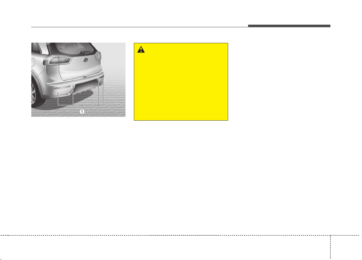
485
Features of your vehicle
The rear parking assist system
assists the driver during backward
movement of the vehicle by chiming
if any object is sensed within a dis-
tance of 120 cm (47 in.) behind the
vehicle.
This system is a supplemental sys-
tem and it is not intended to nor does
it replace the need for extreme care
and attention of the driver. The sens-
ing range and objects detectable by
the back sensors (➀) are limited.
Whenever backing-up, pay as much
attention to what is behind you as
you would in a vehicle without a rear
parking assist system.
Operation of the rear parking
assist system
Operating condition
• This system will activate when the
indicator on the rear parking assist
OFF button is not illuminated. If
you desire to deactivate the rear
parking assist system, press the
rear parking assist OFF button
again. (The indicator on the button
will illuminate.) To turn the system
on, press the button again. (The
indicator on the button will go off.)
• This system will activate when
backing up with the ignition switch
ON.
If the vehicle is moving at a speed
over 5 km/h (3 mph), the system
may not be activated correctly.
• The sensing distance while the
rear parking assist system is in
operation is approximately 120 cm
(47 in.).
• When more than two objects are
sensed at the same time, the clos-
est one will be recognized first.
REAR PARKING ASSIST SYSTEM (IF EQUIPPED)
WARNING
The rear parking assist system
is a supplementary function
only. The operation of the rear
parking assist system can be
affected by several factors
(including environmental condi-
tions). It is the responsibility of
the driver to always check the
area behind the vehicle before
and while backing up.
ODE046400L
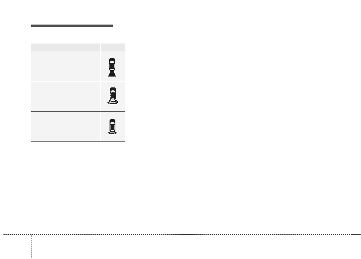
864
Features of your vehicle
Non-operational conditions of
rear parking assist system
The rear parking assist system
may not operate properly when:
1. Moisture is frozen to the sensor. (It
will operate normally when the
moisture has been cleared.)
2. The sensor is covered with foreign
matter, such as snow or water, or
the sensor cover is blocked. (It will
operate normally when the materi-
al is removed or the sensor is no
longer blocked.)
3. Driving on uneven road surfaces
(unpaved roads, gravel, bumps,
gradient).
4. Objects generating excessive
noise (vehicle horns, loud motor-
cycle engines, or truck air brakes)
are within range of the sensor.
5. Heavy rain or water spray exists.
6. Wireless transmitters or mobile
phones are within range of the
sensor.
7. The sensor is covered with snow.
8. Trailer towing
The detecting range may decrease
when:
1. The sensor is stained with foreign
matter such as snow or water.
(The sensing range will return to
normal when removed.)
2. Outside air temperature is
extremely hot or cold.
The following objects may not be
recognized by the sensor:
1. Sharp or slim objects such as
ropes, chains or small poles.
2. Objects which tend to absorb the
sensor frequency such as clothes,
spongy material or snow.
3. Undetectable objects smaller than
1 m (40 in.) in height and narrower
than 14 cm (6 in.) in diameter.
✽✽
NOTICE
The indicator may differ from the
illustration as objects or sensors sta-
tus.
If the indicator blinks, we recom-
mend that the system be checked by
an authorized Kia dealer.
When an object is 120 cm
to 61 cm (47 in. to 24 in.)
from the rear bumper:
Buzzer beeps intermittently.
When an object is 60 cm to
31 cm (23 in. to 12 in.) from
the rear bumper:
Buzzer beeps more frequently.
When an object is within
30 cm (11 in.) of the rear
bumper:
Buzzer sounds continuously.
Types of warning sound
Indicator*
* if equipped
487
Features of your vehicle
Rear parking assist system
precautions
• The rear parking assist system
may not sound consistently
depending on the speed and
shapes of the objects detected.
• The rear parking assist system
may malfunction if the vehicle
bumper height or sensor installa-
tion has been modified or dam-
aged. Any non-factory installed
equipment or accessories may
also interfere with the sensor per-
formance.
• The sensor may not recognize
objects less than 30 cm (12 in.)
from the sensor, or it may sense an
incorrect distance. Use caution.
• When the sensor is frozen or
stained with snow, dirt, or water,
the sensor may be inoperative until
the stains are removed using a soft
cloth.
• Do not push, scratch or strike the
sensor. Sensor damage could
occur.
✽✽
NOTICE
This system can only sense objects
within the range and location of the
sensors; It can not detect objects in
other areas where sensors are not
installed. Also, small or slim objects,
such as poles or objects located
between sensors may not be detected
by the sensors.
Always visually check behind the
vehicle when backing up.
Be sure to inform any drivers of the
vehicle that may be unfamiliar with
the system regarding the systems
capabilities and limitations.
WARNING
Pay close attention when the
vehicle is driven close to
objects on the road, particularly
pedestrians, and especially
children. Be aware that some
objects may not be detected by
the sensors, due to the object’s
distance, size or material, all of
which can limit the effective-
ness of the sensor. Always per-
form a visual inspection to
make sure the vehicle is clear of
all obstructions before moving
the vehicle in any direction.

884
Features of your vehicle
Self-diagnosis
If you don’t hear an audible warning
sound or if the buzzer sounds inter-
mittently when shifting the gear to
the R (Reverse) position, this may
indicate a malfunction in the rear
parking assist system. If this occurs,
we recommend that the system be
checked by an authorized Kia dealer.
WARNING
Your new vehicle warranty does
not cover any accidents or dam-
age to the vehicle or injuries to
its occupants due to a rear
parking assist system malfunc-
tion. Always drive safely and
cautiously.

489
Features of your vehicle
The parking assist system assists
the driver during movement of the
vehicle by chiming if any object is
sensed within the distance of 100 cm
(39 in.) in front and 120 cm (47 in.)
behind the vehicle.
This system is a supplemental sys-
tem and it is not intended to nor does
it replace the need for extreme care
and attention of the driver.
The sensing range and objects
detectable by the sensors (➀) are
limited. Whenever moving pay as
much attention to what is in front and
behind of you as you would in a vehi-
cle without a parking assist system.
Operation of the parking
assist system
Operating condition
• This system activates when the
parking assist system button is
pressed with the ignition switch
ON.
• The indicator of the parking assist
system button turns on automati-
cally and activates the parking
assist system when you shift the
gear to the R (Reverse) position.
• The sensing distance while back-
ing up is approximately 120 cm (47
in.) when you are driving less than
10 km/h (6.2 mph).
PARKING ASSIST SYSTEM (IF EQUIPPED)
WARNING
The parking assist system
should only be considered as a
supplementary function. The
driver must check the front and
rear view. The operational func-
tion of the parking assist sys-
tem can be affected by many
factors and conditions of the
surroundings, so the responsi-
bility rests always with the driv-
er.
ODE046400L
ODE046401L
■ Rear
■ Front
ODE046402
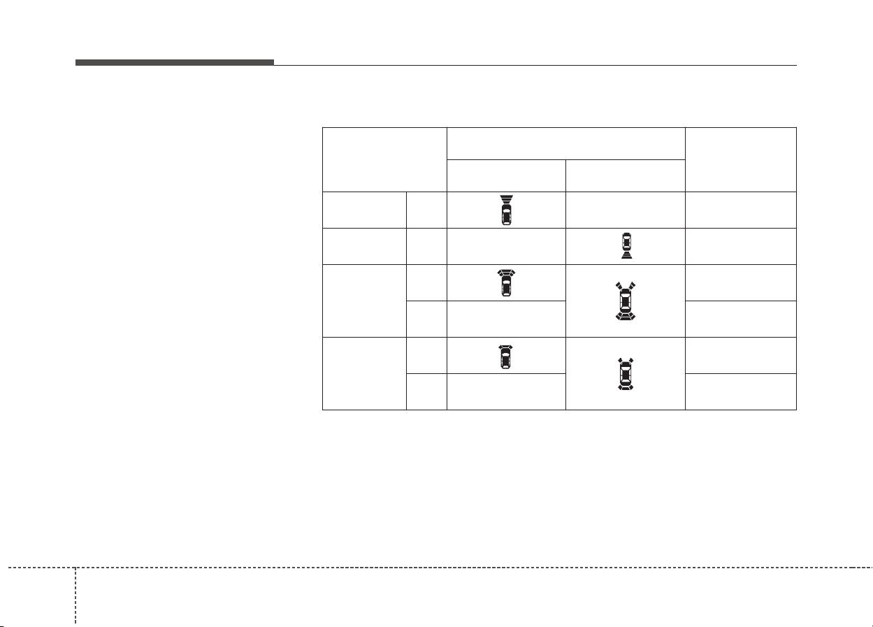
904
Features of your vehicle
• The sensing distance while moving
forward is approximately 100 cm
(39 in.) when you are driving less
than 10 km/h (6.2 mph).
• When more than two objects are
sensed at the same time, the clos-
est one will be recognized first.
• The side sensors are activated
when you shift the gear to the R
(Reverse) position.
• If the vehicle speed is above
20km/h, the system automatically
turns off. To activate again, push
the button.
✽✽
NOTICE
It may not operate if it’s distance
from the object is already less than
approximately 25 cm when the sys-
tem is ON.
Distance
from object
Warning indicator
Warning sound
When driving
forward
When driving
rearward
100cm~61cm Front -
Buzzer beeps
intermittently
120cm~61cm Rear -
Buzzer beeps
intermittently
60cm~31cm
Front
Buzzer beeps
frequently
Rear -
Buzzer beeps
frequently
30cm
Front
Buzzer sounds
continuously
Rear -
Buzzer sounds
continuously
Type of warning indicator and sound
✽✽
NOTICE
• The actual warning sound and indicator may differ from the illustration
according to objects or sensor status.
• Do not wash the vehicle's sensor with high pressure water.

491
Features of your vehicle
Non-operational conditions of
parking assist system
Parking assist system may not
operate normally when:
1. Moisture is frozen to the sensor. (It
will operate normally when mois-
ture melts.)
2. Sensor is covered with foreign
matter, such as snow or water, or
the sensor cover is blocked. (It will
operate normally when the materi-
al is removed or the sensor is no
longer blocked.)
3. Sensor is stained with foreign mat-
ter such as snow or water.
(Sensing range will return to nor-
mal when removed.)
4.The parking assist button is off.
There is a possibility of parking
assist system malfunction when:
1. Driving on uneven road surfaces
such as unpaved roads, gravel,
bumps, or gradient.
2. Objects generating excessive
noise such as vehicle horns, loud
motorcycle engines, or truck air
brakes can interfere with the sen-
sor.
3. Heavy rain or water spray.
4. Wireless transmitters or mobile
phones present near the sensor.
5. Sensor is covered with snow.
CAUTION
• This system can only sense
objects within the range and
location of the sensors;
It can not detect objects in
other areas where sensors are
not installed. Also, small or
slim objects, such as poles or
objects located between sen-
sors may not be detected by
the sensors.
Always visually check behind
the vehicle when backing up.
• Be sure to inform any drivers
of the vehicle that may be
unfamiliar with the system
regarding the systems capa-
bilities and limitations.

924
Features of your vehicle
Detecting range may decrease
when:
1. Outside air temperature is
extremely hot or cold.
2. Undetectable objects smaller than
1 m and narrower than 14 cm in
diameter.
The following objects may not be
recognized by the sensor:
1. Sharp or slim objects such as
ropes, chains or small poles.
2. Objects, which tend to absorb sen-
sor frequency such as clothes,
spongy material or snow.
✽✽
NOTICE
1. The warning may not sound
sequentially depending on the
speed and shapes of the objects
detected.
2. The parking assist system may
malfunction if the vehicle bumper
height or sensor installation has
been modified. Any non-factory
installed equipment or accessories
may also interfere with the sensor
performance.
3. Sensor may not recognize objects
less than 30 cm from the sensor,
or it may sense an incorrect dis-
tance. Use with caution.
4. When the sensor is frozen or
stained with snow or water, the
sensor may be inoperative until
the stains are removed using a
soft cloth.
5. Do not push, scratch or strike the
sensor with any hard objects that
could damage the surface of the
sensor. Sensor damage could
occur.
✽
✽
NOTICE
This system can only sense objects
within the range and location of the
sensors, it can not detect objects in
other areas where sensors are not
installed. Also, small or slim objects,
or objects located between sensors
may not be detected.
Always visually check in front and
behind the vehicle when driving.
Be sure to inform any drivers in the
vehicle that may be unfamiliar with
the system regarding the systems
capabilities and limitations.
493
Features of your vehicle
Self-diagnosis
When you shift the gear to the R
(Reverse) position and if one or more
of the below occurs you may have a
malfunction in the rear parking assist
system.
• You don't hear an audible warning
sound or if the buzzer sounds inter-
mittently.
If this occurs, we recommend that
the system be checked by an author-
ized Kia dealer.
WARNING
Pay close attention when the
vehicle is driven close to
objects on the road, particularly
pedestrians, and especially
children. Be aware that some
objects may not be detected by
the sensors, due to the objects
distance, size or material, all of
which can limit the effective-
ness of the sensor. Always per-
form a visual inspection to
make sure the vehicle is clear of
all obstructions before moving
the vehicle in any direction.
WARNING
Your new vehicle warranty does
not cover any accidents or dam-
age to the vehicle or injuries to
its occupants related to a park-
ing assist system. Always drive
safely and cautiously.
• is displayed. (if equipped)
(blinks)
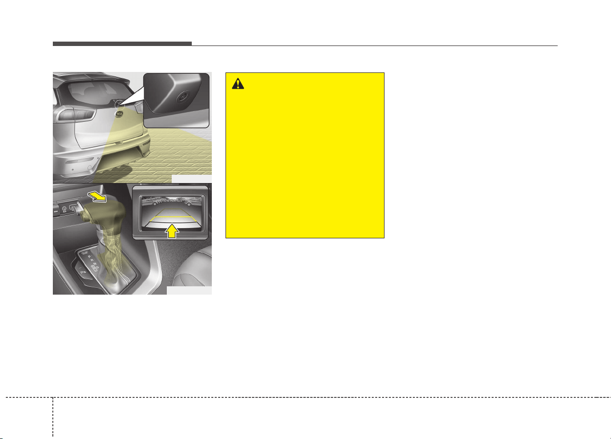
944
Features of your vehicle
The rearview camera will activate
when the back-up light is ON with the
ignition switch ON and the shift lever
in the R (Reverse) position.
This system is a supplemental sys-
tem that shows behind the vehicle
through the rearview display mirror
while backing-up.
❈ If your vehicle is equipped with
AVN(Audio, Video and Navigation)
system, rearview display will show
behind the vehicle through the
AVN monitor while backing-up.
Refer to a separately supplied
manual for detailed information.
WARNING
• This system is a supplemen-
tary function only. It is the
responsibility of the driver to
always check the inside/out-
side rearview mirror and the
area behind the vehicle before
and while backing up because
there is a dead zone that can't
be seen by the camera.
• Always keep the camera lens
clean. If lens is covered with
foreign matter, the camera
may not operate normally.
ODE046403
ODE046404L
REARVIEW CAMERA (IF EQUIPPED)

495
Features of your vehicle
Battery saver function
• The purpose of this feature is to
prevent the battery from being dis-
charged. The system automatically
turns off the parking lights when
the driver removes the ignition key
and opens the driver-side door.
• With this feature, the parking lights
will turn off automatically if the driv-
er parks on the side of the road at
night.
If necessary, to keep the lights on
when the ignition key is removed,
perform the following:
1) Open the driver-side door.
2) Turn the parking lights OFF and
ON again using the light switch
on the steering column.
Headlight escort function
(if equipped)
If you turn the ignition switch to the
ACC or OFF position with the head-
lights ON, the headlights remain on
for about 5 minutes. However, if the
driver's door is opened and closed,
the headlights are turned off after 15
seconds.
The headlights can be turned off by
pressing the lock button on the trans-
mitter (or smart key) twice or turning
the light switch to the OFF position.
LIGHTING
CAUTION
If the driver gets out of the vehi-
cle through other doors (except
driver's door), the battery saver
function does not operate.
Therefore, It causes the battery
to be discharged. In this case,
make sure to turn off the lamp
before getting out of the vehicle.
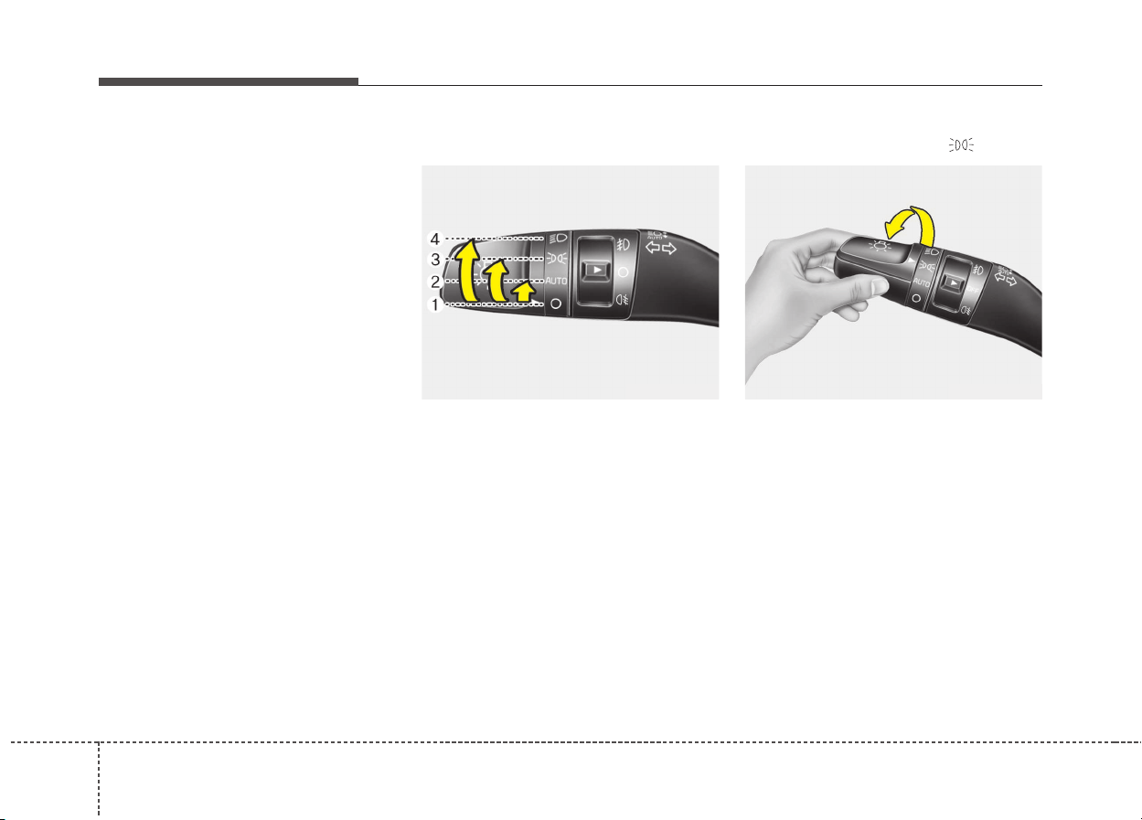
964
Features of your vehicle
Daytime running light
(if equipped)
The Daytime Running Lights (DRL)
can make it easier for others to see the
front of your vehicle during the day.
DRL can be helpful in many different
driving conditions, and it is especially
helpful after dawn and before sunset.
The DRL system will turn the dedi-
cated lamp OFF when:
1. The headlight or fog lamp switch is
ON.
2. The engine is OFF.
❈
❈
Traffic Change (For Europe)
The low beam light distribution is
asymmetric. If you go abroad to a
country with opposite traffic direc-
tion, this asymmetric part will dazzle
oncoming car driver. To prevent daz-
zle, ECE regulation demand several
technical solutions (ex. automatic
change system, adhesive sheet,
down aiming). This headlamps are
designed to adjust in user setting
mode in cluster.
Lighting control
The light switch has a Headlight and
a Parking light position.
To operate the lights, turn the knob at
the end of the control lever to one of
the following positions:
(1) OFF position
(2) Auto light position
(3) Parking light position
(4) Headlight position
Parking light position ( )
When the light switch is in the park-
ing light position (3rd position), the
tail, license and instrument panel
lights will turn ON.
OUM044053L OUM044054L
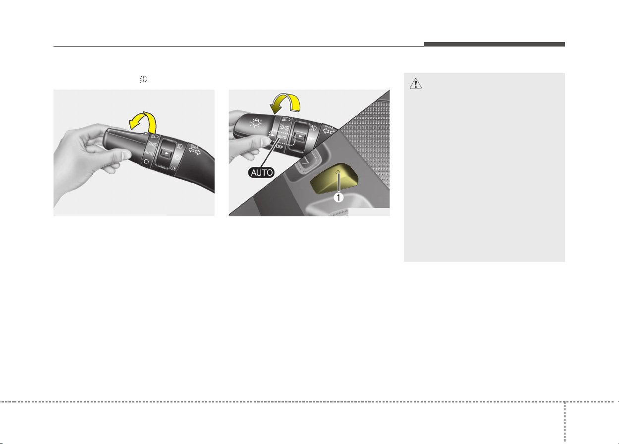
497
Features of your vehicle
Headlight position ( )
When the light switch is in the head-
light position (4th position), the head,
tail, license and instrument panel
lights will turn ON.
✽✽
NOTICE
The ignition switch must be in the
ON position to turn on the head-
lights.
Auto light (if equipped)
When the light switch is in the AUTO
light position, the taillights and head-
lights will be turned ON or OFF auto-
matically depending on the amount
of light outside the vehicle.
OUM044217L ODE046408
CAUTION
• Never place anything over the
sensor (1) located on the
instrument panel. This will
ensure better auto-light sys-
tem control.
• Don’t clean the sensor using a
window cleaner. The cleaner
may leave a light film which
could interfere with sensor
operation.
• If your vehicle has window tint
or other types of metallic coat-
ing on the front windshield,
the Auto light system may not
work properly.
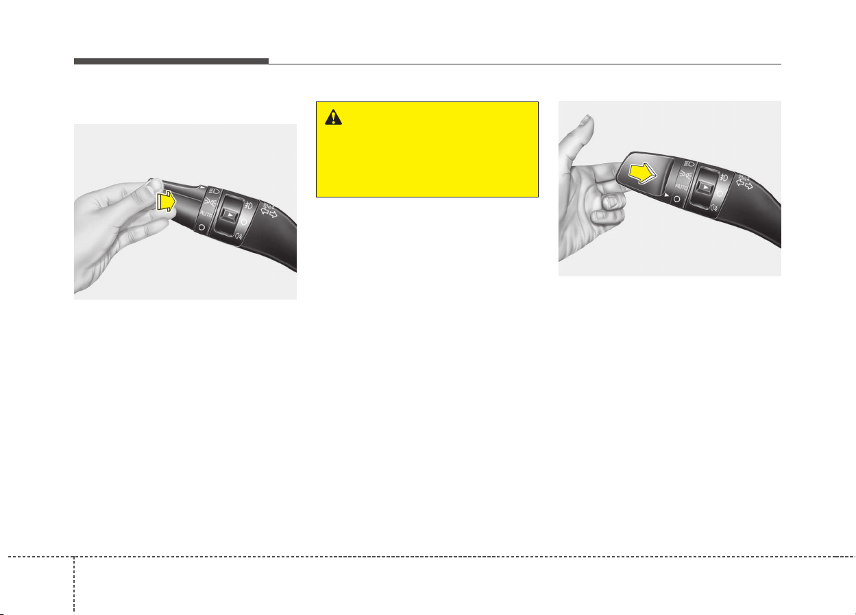
984
Features of your vehicle
High beam operation
To turn on the high beam headlamp,
push the lever away from you. The
lever will return to its original position.
The high beam indicator will light
when the headlight high beams are
switched on.
To turn off the high beam headlamp,
pull the lever to you when the high
beam is on. The lever will return to its
original position.
To prevent the battery from being
discharged, do not leave the lights
on for a prolonged time while the
engine is not running.
To flash the headlights, pull the lever
towards you. It will return to the nor-
mal (low beam) position when
released. The headlight switch does
not need to be on to use this flashing
feature.
OUM044059L
WARNING
Do not use high beam when
there are other vehicles. Using
high beam could obstruct the
other driver’s vision.
OUM044058L
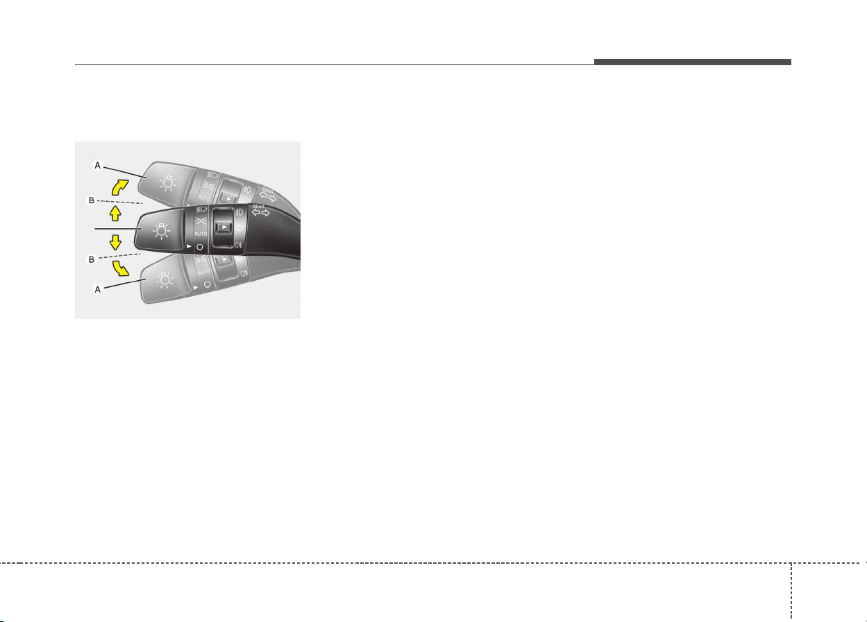
499
Features of your vehicle
Turn signals and lane change
signals
The ignition switch must be on for the
turn signals to function. To turn on
the turn signals, move the lever up or
down (A). The green arrow indicators
on the instrument panel indicate
which turn signal is operating.
They will self-cancel after a turn is
completed. If the indicator continues
to flash after a turn, manually return
the lever to the OFF position.
To signal a lane change, move the
turn signal lever slightly and hold it in
position (B). The lever will return to
the OFF position when released.
If an indicator stays on and does not
flash or if it flashes abnormally, one of
the turn signal bulbs may be burned
out and will require replacement.
One-touch lane change function
(if equipped)
To activate an one-touch lane
change function, move the turn sig-
nal lever slightly for less than 0.7
second and then release it. The lane
change signals will blink 3 times.
✽✽
NOTICE
If an indicator flash is abnormally
quick or slow, a bulb may be burned
out or have a poor electrical connec-
tion in the circuit.
OUM044060L
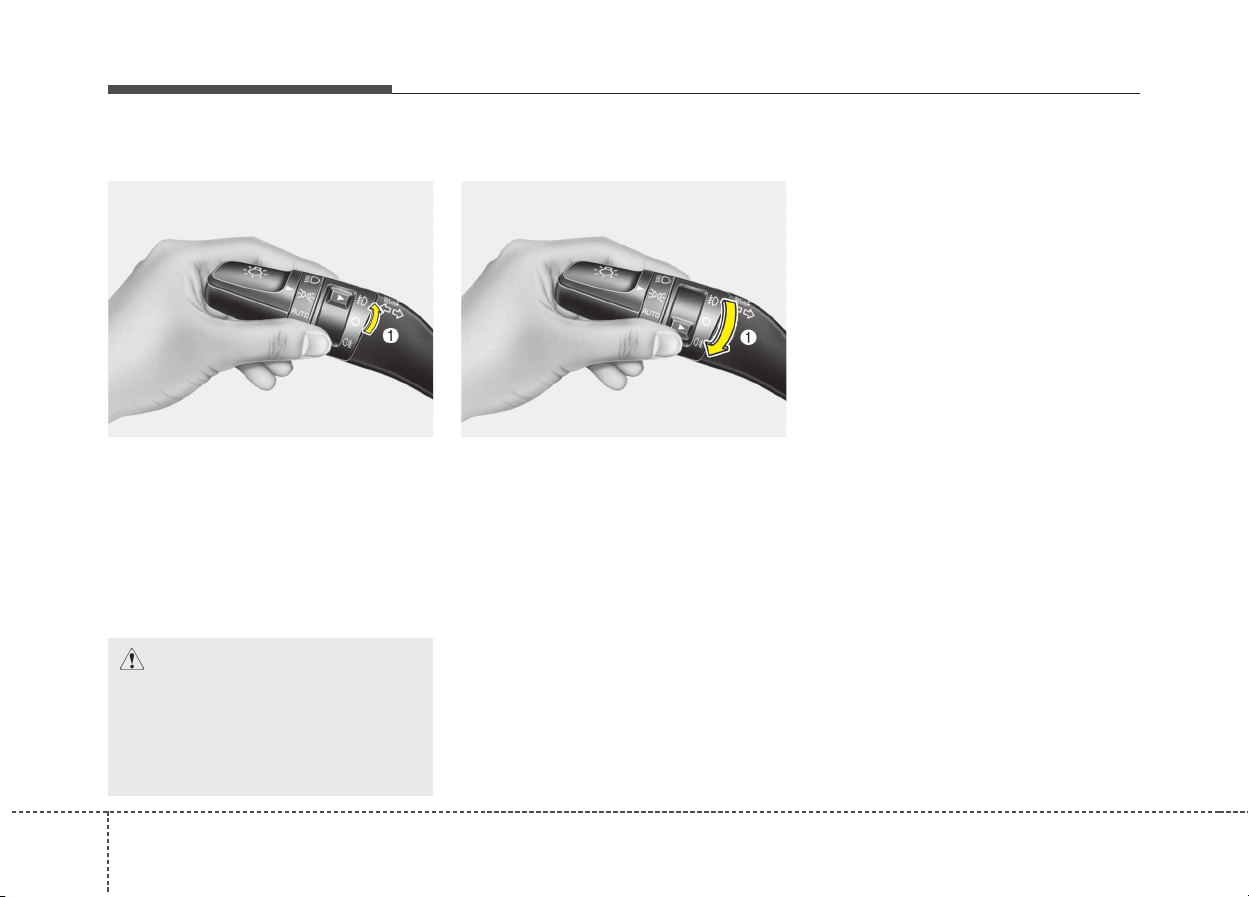
1004
Features of your vehicle
Front fog light (if equipped)
Fog lights are used to provide
improved visibility when visibility is
poor due to fog, rain or snow, etc.
The fog lights will turn on when the
fog light switch (1) is turned on after
the parklight is turned on.
To turn off the fog lights, turn the fog
light switch (1) to the OFF position.
Rear fog light (if equipped)
To turn the rear fog lights on, turn the
headlight switch to the headlight on
position and turn the rear fog light
switch (1) to the on position.
The rear fog lights turn on when the
rear fog light switch is turned on after
the front fog light switch is turned on
and the headlight switch is in the
parklight position.
To turn the rear fog lights off, turn the
rear fog light switch to the on position
again or turn the headlight switch off.
✽✽
NOTICE
To turn on the rear fog light switch,
the ignition switch must be in the
ON position.
OUM044061L
CAUTION
When in operation, the fog
lights consume large amounts
of vehicle electrical power. Only
use the fog lights when visibility
is poor.
OUM044329L
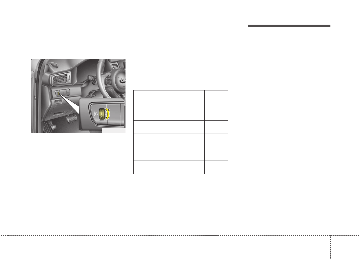
4101
Features of your vehicle
Headlight leveling device
(if equipped)
To adjust the headlight beam level
according to the number of passen-
gers and loading weight in the lug-
gage area, turn the beam leveling
switch.
The higher the number of the switch
position, the lower the headlight
beam level. Always keep the head-
light beam at the proper leveling
position, or headlights may dazzle
other road users.
Listed below are the examples of
proper switch settings. For loading
conditions other than those listed
below, adjust the switch position so
that the beam level may be the near-
est as the condition obtained accord-
ing to the list.
ODE046405
Loading condition
Switch
position
Driver only 0
Driver + Front passenger 0
Driver + Full passengers 1
Full passengers (including driver)
+ Maximum permissible loading
2
Driver + Maximum permissible
loading
3
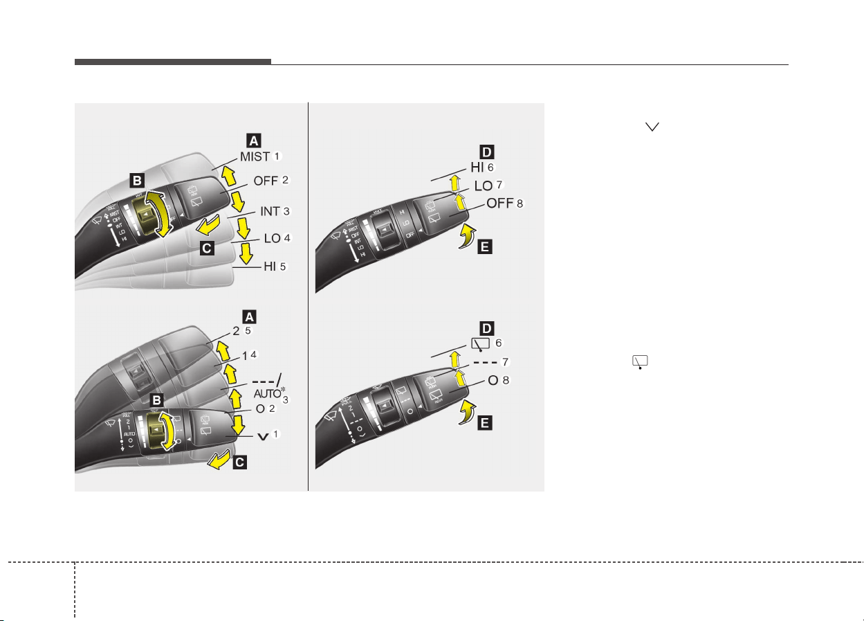
1024
Features of your vehicle
A : Wiper speed control (front)
(1) MIST/ – Single wipe
(2) OFF / O – Off
(3) INT / --- – Intermittent wipe
AUTO* – Auto control wipe
(4) LO / 1 – Low wiper speed
(5) HI / 2 – High wiper speed
B : Intermittent control wipe time
adjustment
C : Wash with brief wipes (front)*
D : Rear wiper/washer control*
(6) HI / – Continuous wipe
(7) LO / --- – Intermittent wipe*
(8) OFF / O – Off
E : Wash with brief wipes (rear)*
* if equipped
WIPERS AND WASHERS
Windshield wiper/washer Rear window wiper/washer
■ Type B
■ Type B
'
■ Type A
■ Type A
'
OQL046407/OQLE046407/OQL046464/OQL046464L
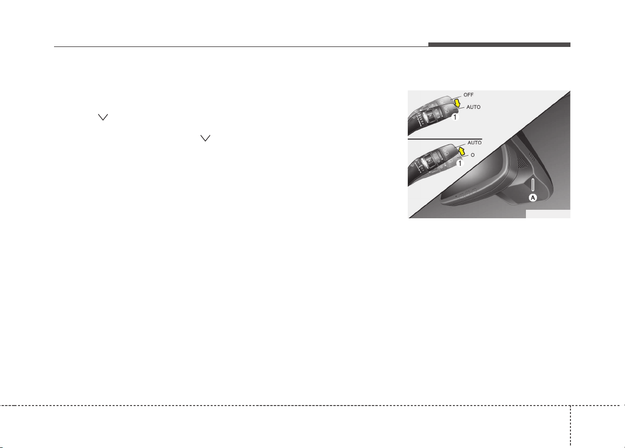
4103
Features of your vehicle
Windshield wipers
Operates as follows when the igni-
tion switch is turned ON.
(1) MIST/ : For a single wiping
cycle, move the lever
to this (MIST/ )
position and release
it. The wipers will
operate continuously
if the lever is held in
this position.
(2) OFF / O : Wiper is not in operation
(3) INT / --- : Wiper operates inter-
mittently at the same
wiping intervals. Use
this mode in light rain
or mist. To vary the
speed setting, turn the
speed control knob.
(4) LO / 1 : Normal wiper speed
(5) HI / 2 : Fast wiper speed
✽✽
NOTICE
If there is heavy accumulation of
snow or ice on the windshield,
defrost the windshield for about 10
minutes, or until the snow and/or ice
is removed before using the wind-
shield wipers to ensure proper oper-
ation. If you do not remove the snow
and/or ice before using the wiper
and washer, it may damage the
Wiper and washer system.
Auto control (if equipped)
The rain sensor (A) located on the
upper end of the windshield glass
senses the amount of rainfall and
controls the wiping cycle for the
proper interval. The more it rains, the
faster the wiper operates. When the
rain stops, the wiper stops.
OQLE045484
■ Type A
■ Type B
1044
Features of your vehicle
To vary the speed setting, turn the
speed control knob (1).
If the wiper switch is set in AUTO
mode when the ignition switch is ON,
the wiper will operate once to per-
form a self-check of the system. Set
the wiper to OFF (O) position when
the wiper is not in use.
CAUTION
• When washing the vehicle, set
the wiper switch in the OFF
(O) position to stop the auto
wiper operation.
The wiper may operate and be
damaged if the switch is set in
the AUTO mode while washing
the vehicle.
• Do not remove the sensor
cover located on the upper
end of the passenger side
windshield glass. Damage to
system parts could occur and
may not be covered by your
vehicle warranty.
• When starting the vehicle in
winter, set the wiper switch in
the OFF (O) position.
Otherwise, wipers may oper-
ate and ice may damage the
windshield wiper blades.
Always remove all snow and
ice and defrost the windshield
properly prior to operating the
windshield wipers.
(Continued)
(Continued)
• When tinting the windshield,
be careful of any fluid getting
into the sensor located in the
top center of the front wind-
shield. It may damage the
related parts.
CAUTION
When the ignition switch is ON
and the windshield wiper switch
is placed in the AUTO mode, use
caution in the following situa-
tions to avoid any injury to the
hands or other parts of the
body:
• Do not touch the upper end of
the windshield glass facing
the rain sensor.
• Do not wipe the upper end of
the windshield glass with a
damp or wet cloth.
• Do not put pressure on the
windshield glass.
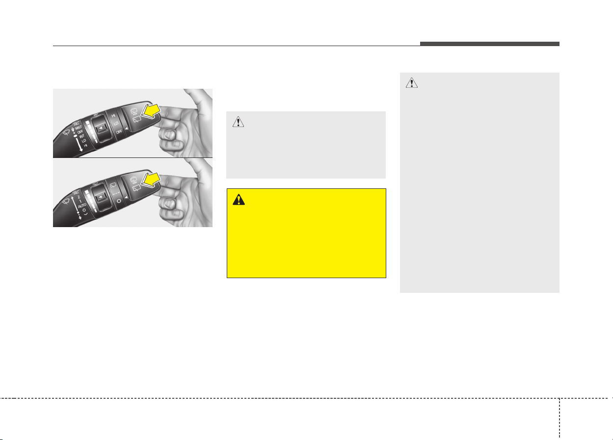
4105
Features of your vehicle
Windshield washers
In the OFF (O) position, pull the lever
gently toward you to spray washer
fluid on the windshield and to run the
wipers 1-3 cycles.
Use this function when the wind-
shield is dirty.
The spray and wiper operation will
continue until you release the lever.
If the washer does not work, check
the washer fluid level. If the fluid level
is not sufficient, you will need to add
appropriate non-abrasive windshield
washer fluid to the washer reservoir.
The reservoir filler neck is located in
the front of the engine compartment
on the passenger side.
CAUTION
• To prevent possible damage
to the wipers or windshield,
do not operate the wipers
when the windshield is dry.
• To prevent damage to the
wiper blades, do not use gaso-
line, kerosene, paint thinner,
or other solvents on or near
them.
• To prevent damage to the
wiper arms and other compo-
nents, do not attempt to move
the wipers manually.
• To prevent possible damage
to the wipers and washer sys-
tem, use anti-freezing washer
fluids in the winter season or
cold weather.
WARNING
Do not use the washer in freez-
ing temperatures without first
warming the windshield with
the defrosters; the washer solu-
tion could freeze on the wind-
shield and obscure your vision.
CAUTION
To prevent possible damage to
the washer pump, do not oper-
ate the washer when the fluid
reservoir is empty.
OQLE045409
■ Type A
■ Type B
OQL045409
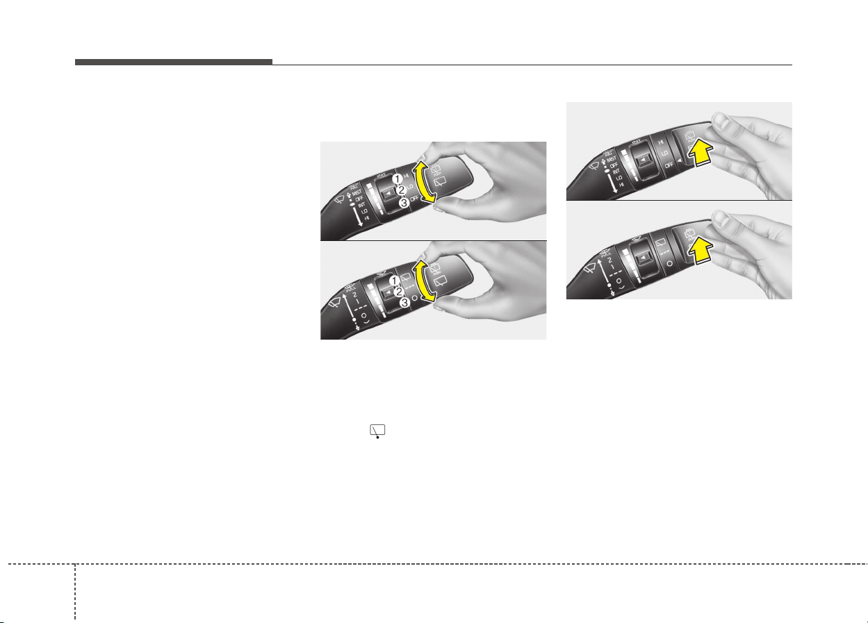
1064
Features of your vehicle
Headlight washer (if equipped)
If your vehicle is equipped with the
headlight washer it will operate at the
same time when you operate the
windshield washer. However, if this
function is operated once, the head-
light washer will not operate within
15 minutes. It will operate when the
headlight is ON and the ignition
switch or engine start/stop button is
in the ON position.
The washer fluid will be sprayed on
to the headlights.
✽✽
NOTICE
• Check the headlight washers peri-
odically to confirm that the wash-
er fluid is being sprayed properly
onto the headlight lenses.
• The headlight washer can be oper-
ated 15 minutes after being oper-
ated last time.
Rear window wiper and washer
switch
The rear window wiper and washer
switch is located at the end of the
wiper and washer switch lever. Turn
the switch to the desired position to
operate the rear wiper and washer.
(1) HI / - Normal wiper operation
(2) LO / --- - Intermittent wiper oper-
ation (if equipped)
(3) OFF / O - Wiper is not in opera-
tion
Push the lever away from you to
spray rear washer fluid and to run the
rear wipers 1~3 cycles. The spray
and wiper operation will continue
until you release the lever.
OQL045466
■ Type A
■ Type B
OQL045466L
OQL046465
■ Type A
■ Type B
OQL046465L
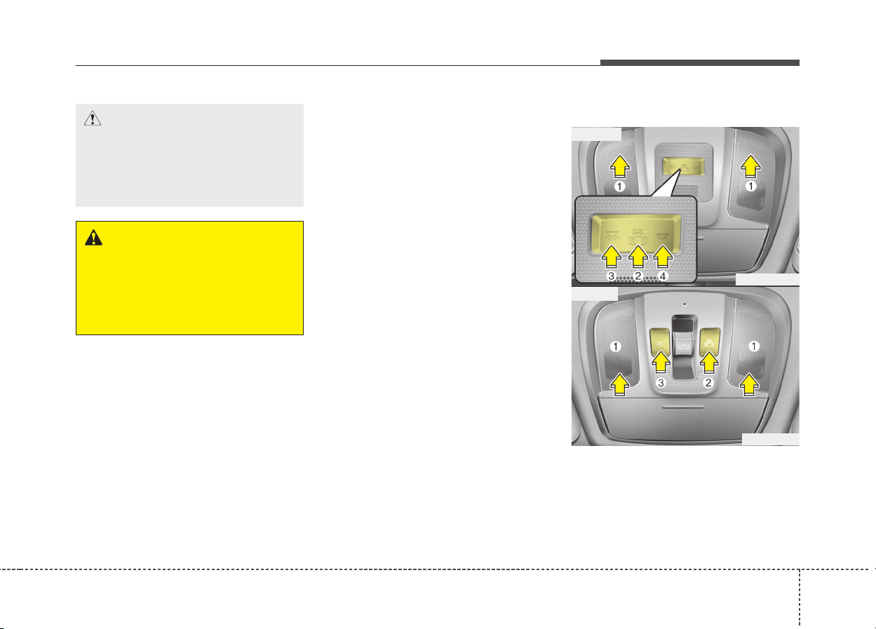
4107
Features of your vehicle
Automatic turn off function
(if equipped)
The interior lights automatically turn
off approximately 20 minutes after
the ignition switch is turned off.
If your vehicle is equipped with the
theft alarm system, the interior lights
automatically turns off approximately
3 seconds after the system is armed
stage.
Map lamp
INTERIOR LIGHT
CAUTION
Do not use the interior lights for
extended periods when the
engine is not running.
It may cause battery discharge.
WARNING
Do not use the interior lights
when driving in the dark.
Accidents could happen
because the view may be
obscured by interior lights.
ODE046409L
ODE046410
■ Type A
■ Type B
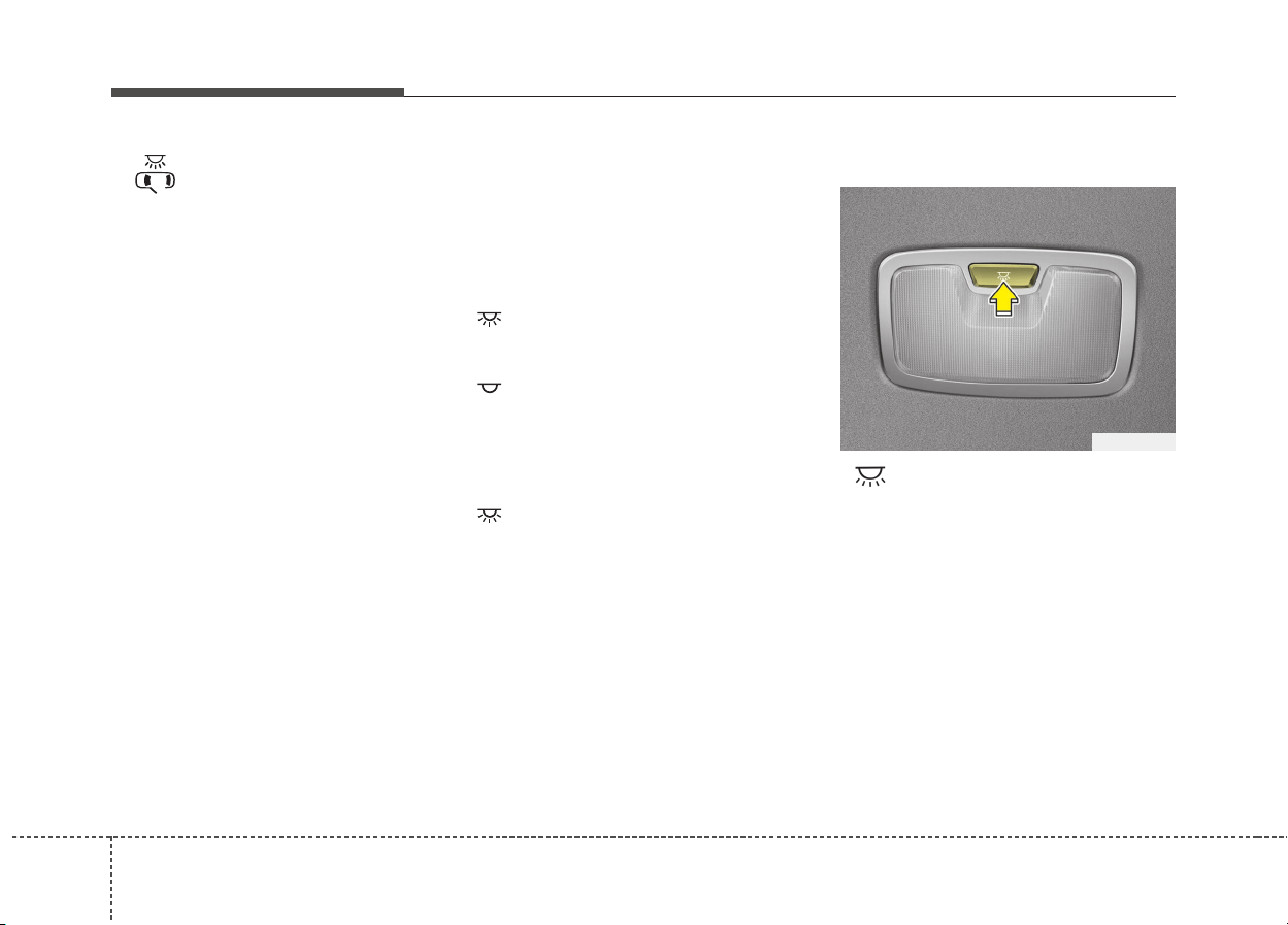
1084
Features of your vehicle
• (2) :
- The map lamp and room lamp
comes on when a door is opened.
The lamps go out after approxi-
mately 30 seconds.
- The map lamp and room lamp
comes on for approximately 30
seconds when doors are unlocked
with a transmitter or smart key as
long as the doors are not opened.
- The map lamp and room lamp will
stay on for approximately 20 min-
utes if a door is opened with the
ignition switch in the ACC or
LOCK/OFF position.
- The map lamp and room lamp will
stay on continuously if the door is
opened with the ignition switch in
the ON position.
- The map lamp and room lamp will
go out immediately if the ignition
switch is changed to the ON posi-
tion or all doors are locked.
- To turn off the DOOR mode, press
the DOOR button (2) once again
(not pressed).
✽✽
NOTICE
The DOOR mode and ROOM mode
can not be selected at a time.
Front Room Lamp:
• Type A
(3): Press this switch to turn the
front and rear room lamps
on.
(4): Press this switch to turn the
front and rear room lamps
off.
• Type B
(3): Press this switch to turn the
front and rear room lamps on
and off.
Room lamp
• : The light stays on at all
times.
ODE046411
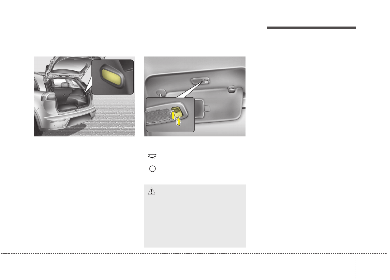
4109
Features of your vehicle
Tailgate room lamp
The tailgate room lamp comes on
when the tailgate is opened.
✽✽
NOTICE
The tailgate lamp comes on as long
as the tailgate lid is open. To prevent
unnecessary charging system drain,
close the tailgate lid securely after
using the tailgate.
Vanity mirror lamp (if equipped)
Push the switch to turn the light on or
off.
• : The lamp will turn on if this
button is pressed.
• : The lamp will turn off if this
button is pressed.
OQL045416
CAUTION - Vanity mirror
lamp
Always have the switch in the
off position when the vanity mir-
ror lamp is not in use. If the sun-
visor is closed without the lamp
off, it may discharge the battery
or damage the sunvisor.
ODE046412L
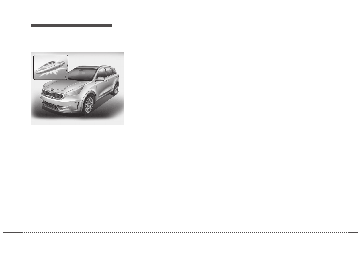
1104
Features of your vehicle
WELCOME SYSTEM (IF EQUIPPED)
Welcome light (if equipped)
When all the doors (and tailgate) are
locked and closed, the door handle
lamp will come on for about 15 sec-
onds if any of the below is per-
formed.
• With the smart key system
- When the vehicle is approached
with the smart key in possession.
Escort welcome (if equipped)
When the headlight (light switch in
the headlight or AUTO position) is on
and all doors (and tailgate) are
locked and closed, the position light
and headlight will come on for 15
seconds if any of the below is per-
formed.
• Without smart key system
- When the door unlock button is
pressed on the transmitter.
• With the smart key system
- When the door unlock button is
pressed on the smart key.
At this time, if you press the door lock
or unlock button, the position light
and headlight will turn off immediate-
ly.
Interior light
When the interior light switch is in the
DOOR position and all doors (and
tailgate) are locked and closed, the
room lamp will come on for 30 sec-
onds if any of the below is per-
formed.
• Without smart key system
- When the door unlock button is
pressed on the transmitter.
• With the smart key system
- When the door unlock button is
pressed on the smart key.
- When the button of the outside
door handle is pressed.
At this time, if you press the door lock
or unlock button, the room lamp will
turn off immediately.
ODE046413
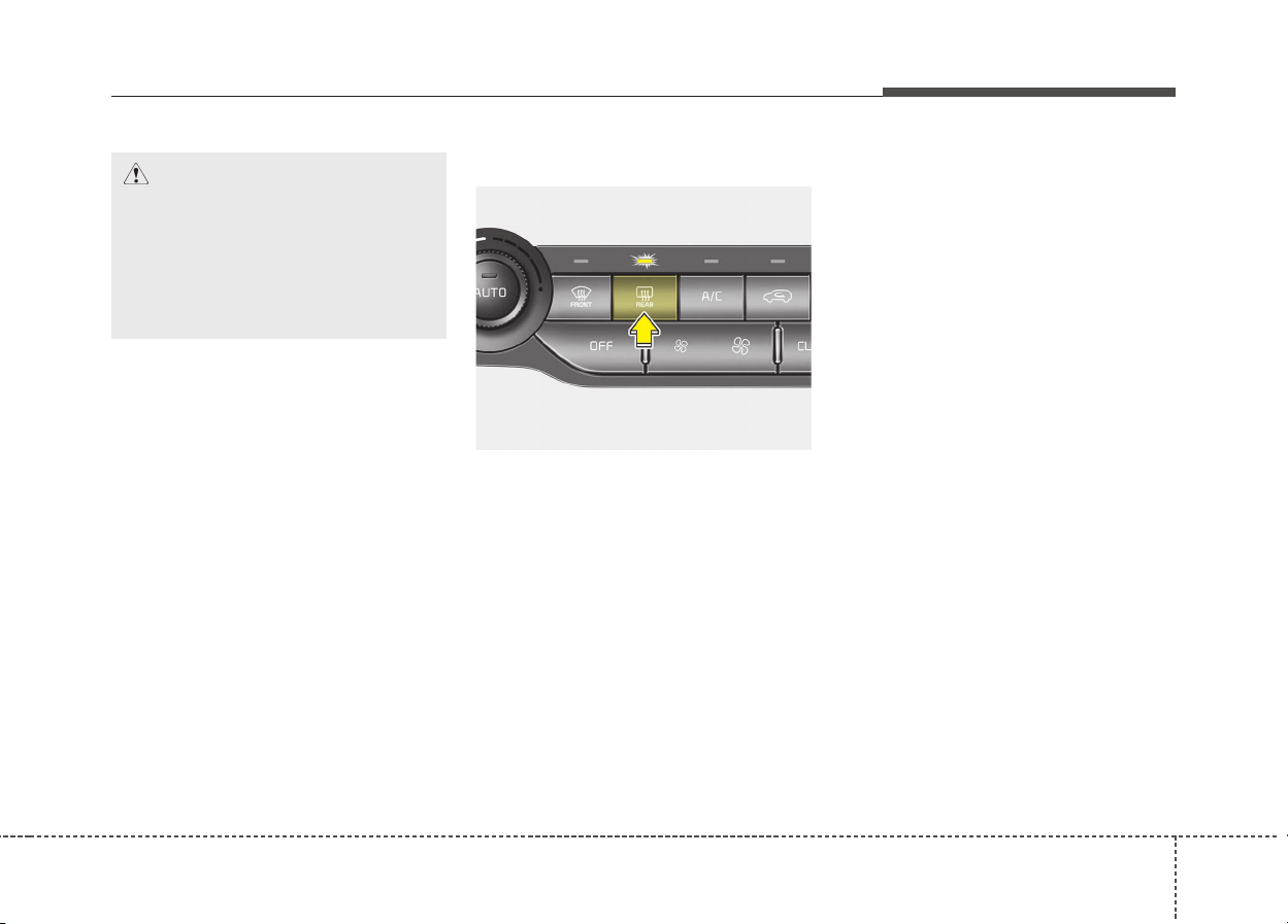
4111
Features of your vehicle
DEFROSTER
✽✽
NOTICE
If you want to defrost and defog the
front windshield, refer to
“Windshield defrosting and defog-
ging” in this section.
Rear window defroster
The defroster heats the window to
remove frost, fog and thin ice from
the rear window, while the engine is
running.
To activate the rear window
defroster, press the rear window
defroster button located in the center
facia switch panel. The indicator on
the rear window defroster button illu-
minates when the defroster is ON.
If there is heavy accumulation of
snow on the rear window, brush it off
before operating the rear defroster.
The rear window defroster automati-
cally turns off after approximately 20
minutes or when the ignition switch is
turned off. To turn off the defroster,
press the rear window defroster but-
ton again.
Outside rearview mirror defroster
(if equipped)
If your vehicle is equipped with the
outside rearview mirror defrosters,
they will operate at the same time
you turn on the rear window
defroster.
CAUTION
To prevent damage to the con-
ductors bonded to the inside
surface of the rear window,
never use sharp instruments or
window cleaners containing
abrasives to clean the window.
ODE046301

1124
Features of your vehicle
CLIMATE CONTROL SYSTEM
System operation
Ventilation
1. Set the mode to the position.
2. Set the air intake control to the
outside (fresh) air position.
3. Set the temperature control to the
desired position.
4. Set the fan speed control to the
desired speed.
Heating
1. Set the mode to the position.
2. Set the air intake control to the
outside (fresh) air position.
3. Set the temperature control to the
desired position.
4. Set the fan speed control to the
desired speed.
5. If dehumidified heating is desired,
turn the air conditioning system (if
equipped) on.
Operation Tips
• To keep dust or unpleasant fumes
from entering the vehicle through
the ventilation system, temporarily
set the air intake control to the
recirculated air position. Be sure to
return the control to the fresh air
position when the irritation has
passed to keep fresh air in the
vehicle. This will help keep the driv-
er alert and comfortable.
• Air for the heating/cooling system
is drawn in through the grilles just
ahead of the windshield. Care
should be taken that these are not
blocked by leaves, snow, ice or
other obstructions.
• To prevent interior fog on the wind-
shield, set the air intake control to
the fresh air position and fan speed
to the desired position, turn on the
air conditioning system, and adjust
the temperature control to desired
temperature.
• If the windshield fogs up, set the
mode to the position.
CAUTION
Operating the blower when the
ignition switch is in the ON posi-
tion could cause the battery to
discharge. Operate the blower
when the engine is running.
4113
Features of your vehicle
Air conditioning
Kia air conditioning systems are filled
with R-134a or R-1234yf refrigerant.
1. Start the engine. Push the air con-
ditioning button.
2. Set the mode to the position.
3. Set the air intake control to the
outside air or recirculated air posi-
tion.
4. Adjust the fan speed control and
temperature control to maintain
maximum comfort.
Your vehicle is filled with R-134a or
R-1234yf according to the regulation
in your country at the time of produc-
tion.You can find out which air condi-
tioning refrigerant is applied to your
vehicle on the label located inside of
the hood. Refer to chapter 9 for the
location of the air conditioning refrig-
erant label.
✽✽
NOTICE
• When using the air conditioning
system, monitor the temperature
gauge closely while driving up
hills or in heavy traffic when out-
side temperatures are high. Air
conditioning system operation
may cause engine overheating.
Continue to use the blower fan but
turn the air conditioning system
off if the temperature gauge indi-
cates engine overheating.
• When opening the windows in
humid weather air conditioning
may create water droplets inside
the vehicle. Since excessive water
droplets may cause damage to
electrical equipment, air condi-
tioning should only be used with
the windows closed.
CAUTION
• The refrigerant system should
only be serviced by trained
and certified technicians to
insure proper and safe opera-
tion.
• The refrigerant system should
be serviced in a well-ventilat-
ed place.
• The air conditioning evapora-
tor (cooling coil) shall never
be repaired or replaced with
one removed from a used or
salvaged vehicle and new
replacement MAC evaporators
shall be certified (and labeled)
as meeting SAE Standard
J2842.

1144
Features of your vehicle
Air conditioning system operation
tips
• If the vehicle has been parked in
direct sunlight during hot weather,
open the windows for a short time
to let the hot air inside the vehicle
escape.
• Use air conditioning to reduce
humidity and moisture inside the
vehicle on rainy or humid days.
• During air conditioning system
operation, you may occasionally
notice a slight change in engine
speed as the air conditioning com-
pressor cycles. This is a normal
system operation characteristic.
• Use the air conditioning system
every month only for a few minutes
to ensure maximum system per-
formance.
• When using the air conditioning
system, you may notice clear water
dripping (or even puddling) on the
ground under the passenger side
of the vehicle. This is a normal sys-
tem operation characteristic.
• Operating the air conditioning sys-
tem in the recirculated air position
provides maximum cooling, how-
ever, continual operation in this
mode may cause the air inside the
vehicle to become stale.
• During cooling operation, you may
occasionally notice a misty air flow
because of rapid cooling and
humid air intake. This is a normal
system operation characteristic.
Climate control air filter
The climate control air filter installed
behind the glove box filters the dust
or other pollutants that come into the
vehicle from the outside through the
heating and air conditioning system.
A : Outside air
B : Recirculated air
C : Climate control
air filter
D : Blower
E : Evaporator core
F : Heater core
OUM046438L
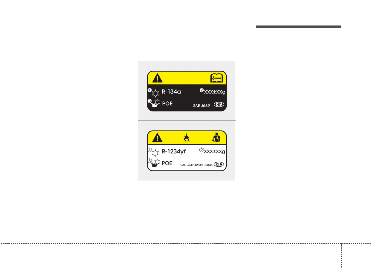
4115
Features of your vehicle
If dust or other pollutants accumulate
in the filter over a period of time, the
air flow from the air vents may
decrease, resulting in moisture accu-
mulation on the inside of the wind-
shield even when the outside (fresh)
air position is selected. If this hap-
pens, we recommend that the cli-
mate control air filter be replaced by
an authorized Kia dealer.
✽✽
NOTICE
• Replace the filter according to the
Maintenance Schedule.
If the car is being driven in severe
conditions such as dusty, rough
roads, more frequent climate con-
trol air filter inspections and
changes are required.
• When the air flow rate suddenly
decreases, we recommend that the
system be checked by an author-
ized Kia dealer.
Air Conditioning refrigerant
label
❈ The actual Air Conditioning refrig-
erant label in the vehicle may differ
from the illustration.
Each symbols and specification on
air conditioning refrigerant label
means as below ;
1. Classification of refrigerant
2. Amount of refrigerant
3. Classification of Compressor lubri-
cant
You can find out which air condition-
ing refrigerant is applied your vehicle
at the label inside of the engine
room.
Refer to chapter 9 for more detail
location of air conditioning refrigerant
label.
ODE066031L
ODE066032L
■ Example
Type B
Type A

1164
Features of your vehicle
Checking the amount of air
conditioner refrigerant and
compressor lubricant
When the amount of refrigerant is
low, the performance of the air con-
ditioning is reduced. Overfilling also
has a bad influence on the air condi-
tioning system.
Therefore, if abnormal operation is
found, we recommend that the sys-
tem be inspected by an authorized
Kia dealer.
WARNING - Vehicles
equipped with R-1234yf
Because the refriger-
ant is mildly inflam-
mable and at very
high pressure, the air
conditioning system
should only be serv-
iced by trained and
certified technicians.
It is important that the correct
type and amount of oil and
refrigerant is used.
Otherwise, it may cause dam-
age to the vehicle and personal
injury.
WARNING - Vehicles
equipped with R-134a
Because the refriger-
ant is at very high
pressure, the air con-
ditioning system
should only be serv-
iced by trained and certified
technicians. It is important that
the correct type and amount of
oil and refrigerant is used.
Otherwise, it may cause dam-
age to the vehicle and personal
injury.
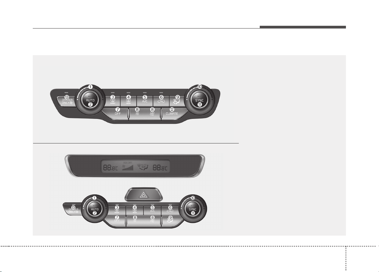
4117
Features of your vehicle
ODE046300L/ODE046320L
System Overview
1. Driver’s temperature control knob
2. AUTO (automatic control) button
3. Front windshield defroster button
4. Rear window defroster button
5. Air conditioning button
6. Air intake control button
7. OFF button
8. Fan speed control button
9. Mode selection button
10. Passenger's temperature control knob
11. SYNC temperature control selection button
12. Climate button
13. Driver only select button
■■
Type B
■■
Type A
Automatic climate control system
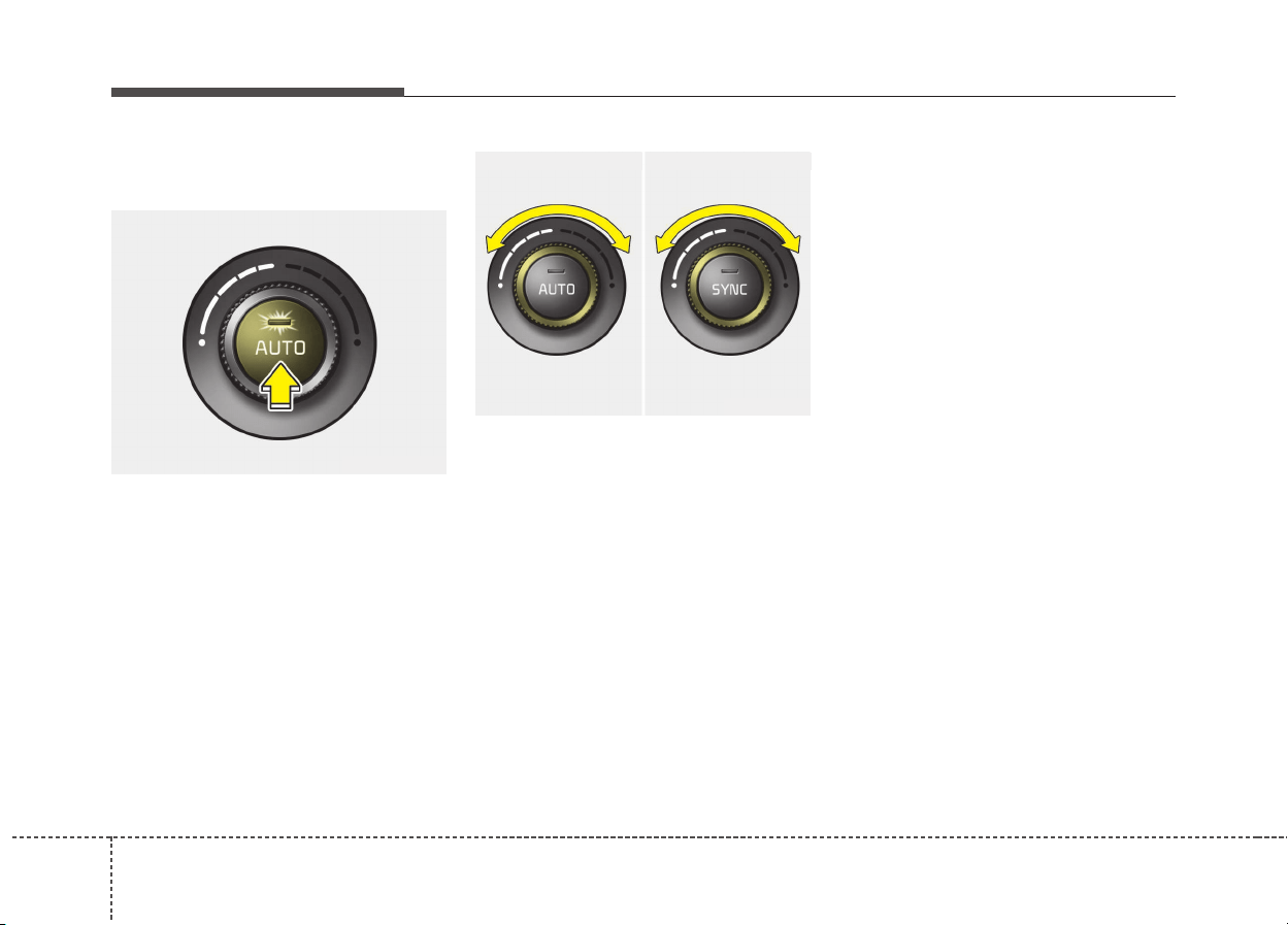
1184
Features of your vehicle
Automatic heating and air con-
ditioning
1. Press the AUTO button. The
modes, fan speeds, air intake and
air-conditioning will be controlled
automatically according to the
temperature setting.
2. Turn the temperature control knob
to the desired temperature.
✽✽
NOTICE
• To turn the automatic operation
off, select any button or switch of
the following:
- Mode selection button
- Air conditioning button
- Front windshield defroster but-
ton (Press the button one more
time to deselect the front wind-
shield defroster function. The
'AUTO' sign will illuminate on
the information display once
again.)
- Fan speed control button
The selected function will be con-
trolled manually while other func-
tions operate automatically.
• For your convenience and to
improve the effectiveness of the
climate control, use the AUTO
button and set the temperature to
22°C/71°F (23°C/73°F- Except
Europe).
ODE046302
■ Driver’s side ■ Passenger’s side
ODE046305
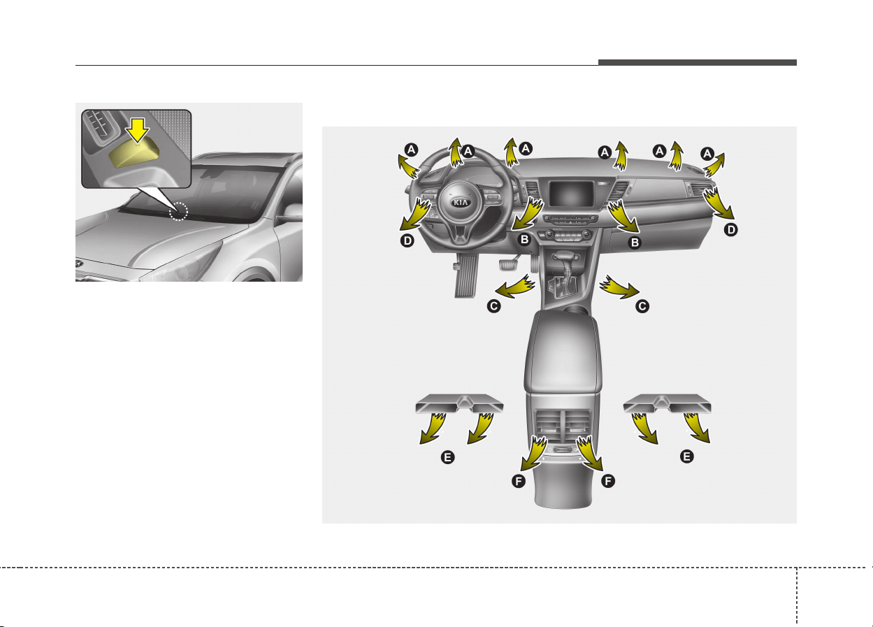
4119
Features of your vehicle
✽✽
NOTICE
Never place anything over the sen-
sor located on the instrument panel
to ensure better control of the heat-
ing and cooling system.
Mode selection
ODE046414
ODE046318
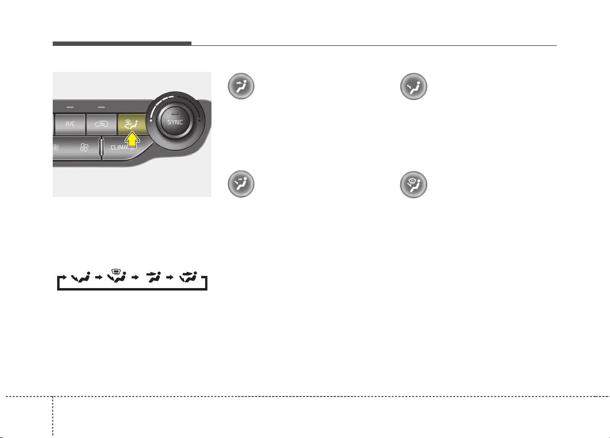
1204
Features of your vehicle
The mode selection button controls
the direction of the air flow through
the ventilation system.
The air flow outlet port is converted
as follows:
Face-Level
Air flow is directed toward the upper
body and face. Additionally, each
outlet can be controlled to direct the
air discharged from the outlet.
Bi-Level
Air flow is directed towards the face
and the floor.
Floor-Level
Most of the air flow is directed to the
floor, with a small amount of the air
being directed to the windshield and
side window defrosters.
Floor/Defrost-Level
Most of the air flow is directed to the
floor and the windshield with a small
amount directed to the side window
defrosters.
ODE046304
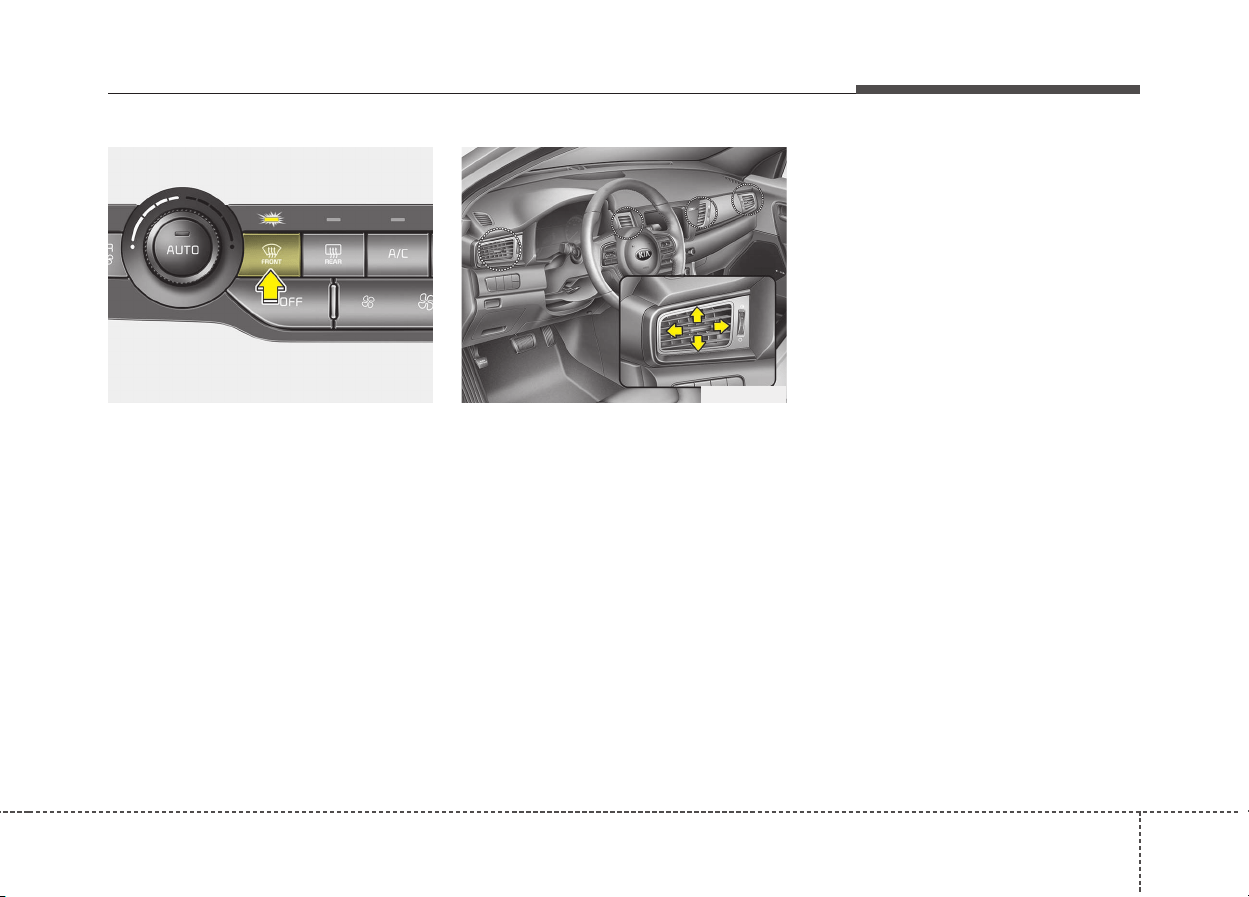
4121
Features of your vehicle
Defrost-Level
Most of the air flow is directed to the
windshield with a small amount of air
directed to the side window
defrosters.
Instrument panel vents
The outlet vents can be opened or
closed separately using the thumb-
wheel.
Also, you can adjust the direction of
air delivery from these vents using
the vent control lever as shown.
✽✽
NOTICE - 2nd row outlet
vents (E,F)
• The air flow of the 2nd row outlet
vents is controlled by the front cli-
mate control system and delivered
through the inside air duct of the
floor (E, F).
• The air flow of the 2nd row outlet
vents (E, F) may be weaker than
the instrument panel vents for the
long air duct.
ODE046319
ODE046303
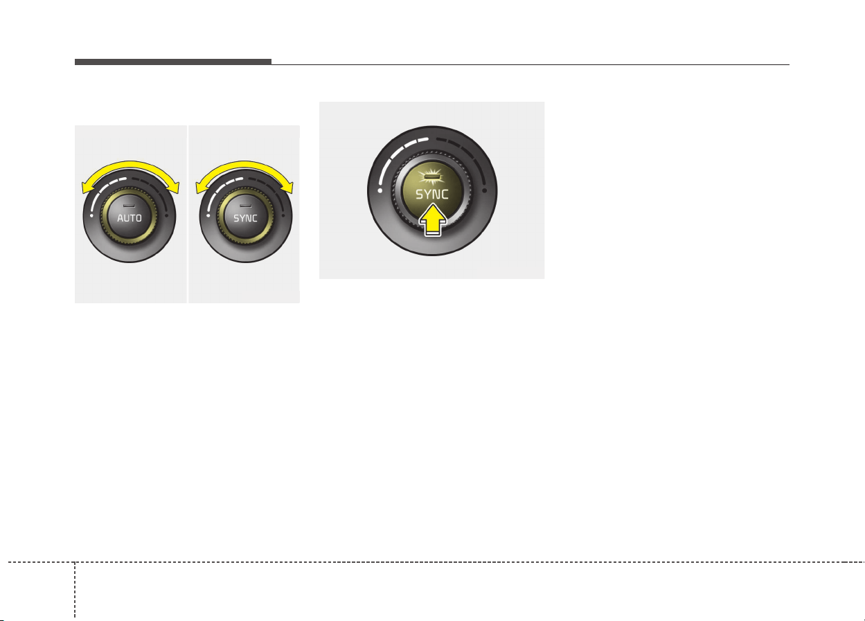
1224
Features of your vehicle
Temperature control
The temperature will increase to the
maximum by turning the knob to the
extreme right.
The temperature will decrease to the
minimum by turning the knob to the
extreme left.
When turning the knob, the tempera-
ture will increase or decrease by
0.5°C/1°F. When set to the lowest
temperature setting, the air condi-
tioning will operate continuously.
Adjusting the driver and passenger
side temperature equally
• Press the “SYNC” button to adjust
the driver and passenger side tem-
perature equally.
The passenger side temperature
will be set to the same temperature
as the driver side temperature.
• Turn the driver side temperature
control knob. The driver and pas-
senger side temperature will be
adjusted equally.
Adjusting the driver and passenger
side temperature individually
• Press the “SYNC” button again to
adjust the driver and passenger
side temperature individually. The
illumination of button turns off.
• Operate the driver side tempera-
ture control knob to adjust the driv-
er side temperature.
• Operate the passenger side tem-
perature control knob to adjust the
passenger side temperature.
Temperature conversion (°C
↔
↔
°F)
(if equipped)
You can switch the temperature
mode between Centigrade to
Fahrenheit as follows;
While pressing the OFF button,
depress the AUTO button for 3 sec-
onds or more. The display will
change from Centigrade to
Fahrenheit, or from Fahrenheit to
Centigrade.
ODE046306
■ Driver’s side ■ Passenger’s side
ODE046305
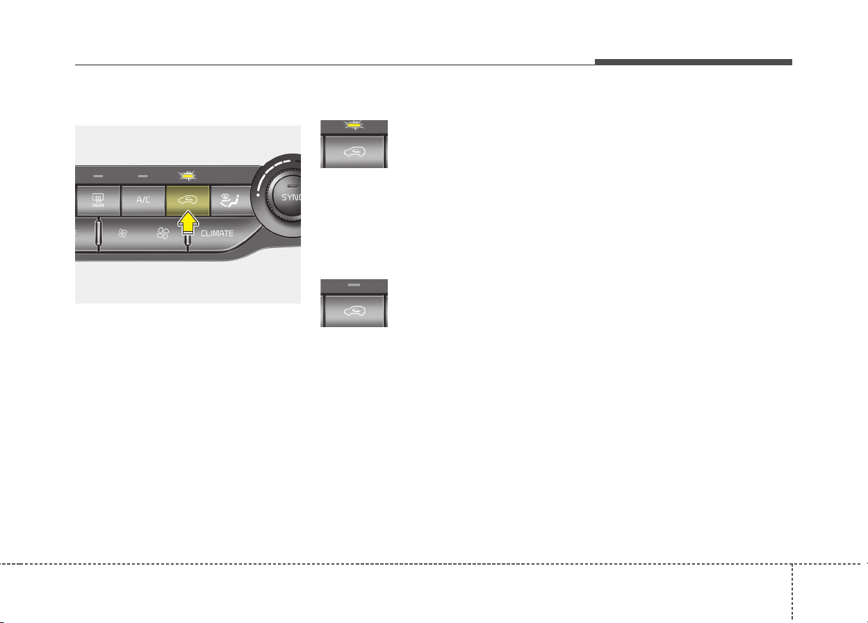
4123
Features of your vehicle
Air intake control
This is used to select the outside
(fresh) air position or recirculated air
position.
To change the air intake control posi-
tion, push the control button.
Recirculated air position
With the recirculated air
position selected, air
from the passenger
compartment will be
drawn through the heat-
ing system and heated
or cooled according to
the function selected.
Outside (fresh) air position
With the outside (fresh)
air position selected, air
enters the vehicle from
outside and is heated or
cooled according to the
function selected.
✽✽
NOTICE
Prolonged operation of the heater in
the recirculated air position (with-
out air conditioning selected) may
cause fogging of the windshield and
side windows and the air within the
passenger compartment may
become stale.
In addition, prolonged use of the air
conditioning with the recirculated
air position selected will result in
excessively dry air in the passenger
compartment.
ODE046307
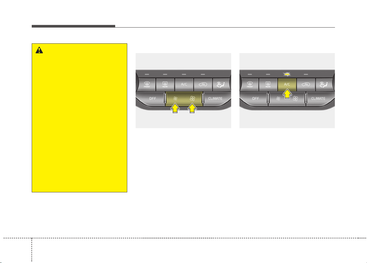
1244
Features of your vehicle
Fan speed control
The fan speed can be set to the
desired speed by pushing the fan
speed control button.
The higher the fan speed is, the
more air is delivered.
Pressing the OFF button turns off the
fan.
Air conditioning
Press the A/C button to turn the air
conditioning system on (indicator
light will illuminate).
Press the button again to turn the air
conditioning system off.
ODE046308 ODE046309
WARNING
• Continue using the climate
control system in the recircu-
lated air position may allow
humidity to increase inside
the vehicle which may fog the
glass and obscure visibility.
• Do not sleep in a vehicle with
the air conditioning or heating
system on. It may cause seri-
ous harm or death due to a
drop in the oxygen level
and/or body temperature.
• Continue using the climate
control system in the recircu-
lated air position can cause
drowsiness or sleepiness,
and loss of vehicle control.
Set the air intake control to
the outside (fresh) air position
as much as possible while
driving.
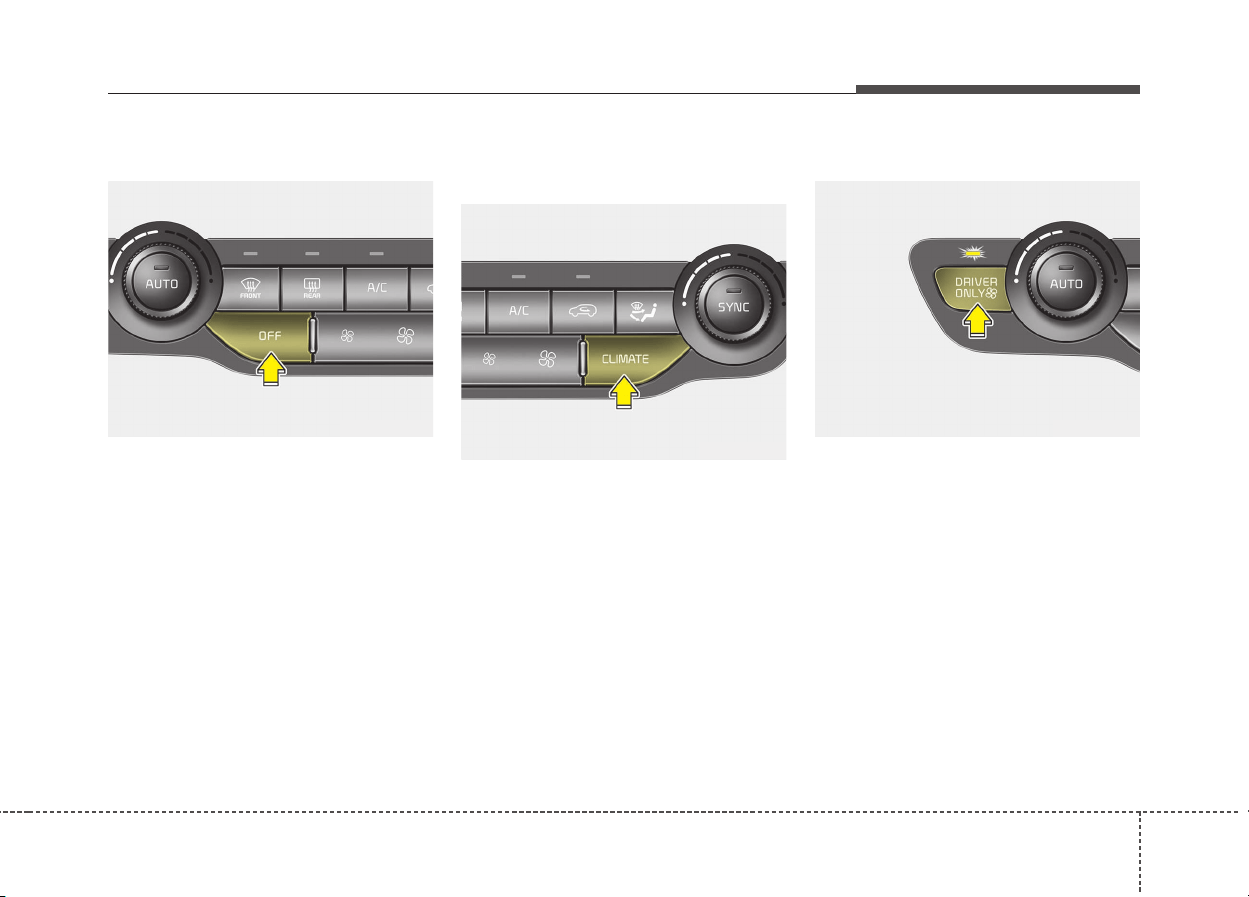
4125
Features of your vehicle
OFF mode
Press the front blower OFF button to
turn off the front air climate control
system. However, you can still oper-
ate the mode and air intake buttons
as long as the ignition switch is in the
ON position.
Climate information screen selec-
tion (if equipped)
Press the climate information screen
selection button to display climate
information on the screen.
Driver Only
If you press the DRIVER ONLY but-
ton and the indicator light illuminates,
cold air mostly blows in the direction
of the driver’s seat. However, some
of the cold air may come out of other
seats’ ducts to keep indoor air pleas-
ant.
If you use the button with no passen-
ger in the front passenger seat, ener-
gy consumption will be reduced.
ODE046311
ODE046310 ODE046312

1264
Features of your vehicle
Automatic ventilation
The system automatically selects the
outside (fresh) air position when the
climate control system operates over
a certain period of time (approxi-
mately 30 minutes) in low tempera-
ture with the recirculated air position
selected.
To cancel or reset the Automatic
Ventilation
When the air conditioning system is
on, select Face Level mode and
while pressing the A/C button, press
the recirculated air position button
five times within three seconds.
When the automatic ventilation is
canceled, the indicator blinks 3
times. When the automatic ventila-
tion is activated, the indicator blinks
6 times.
Sunroof inside air recircula-
tion
The outside (fresh) air position is
automatically selected, when the
sunroof is opened while operating
the heating/air conditioning system.
When you select the recirculated air
position, the system maintains the
recirculated air position for 3 minutes
and then automatically converts to
the outside (fresh) air position.
When the sunroof is closed, the air
intake position will return to the orig-
inal position that was selected.
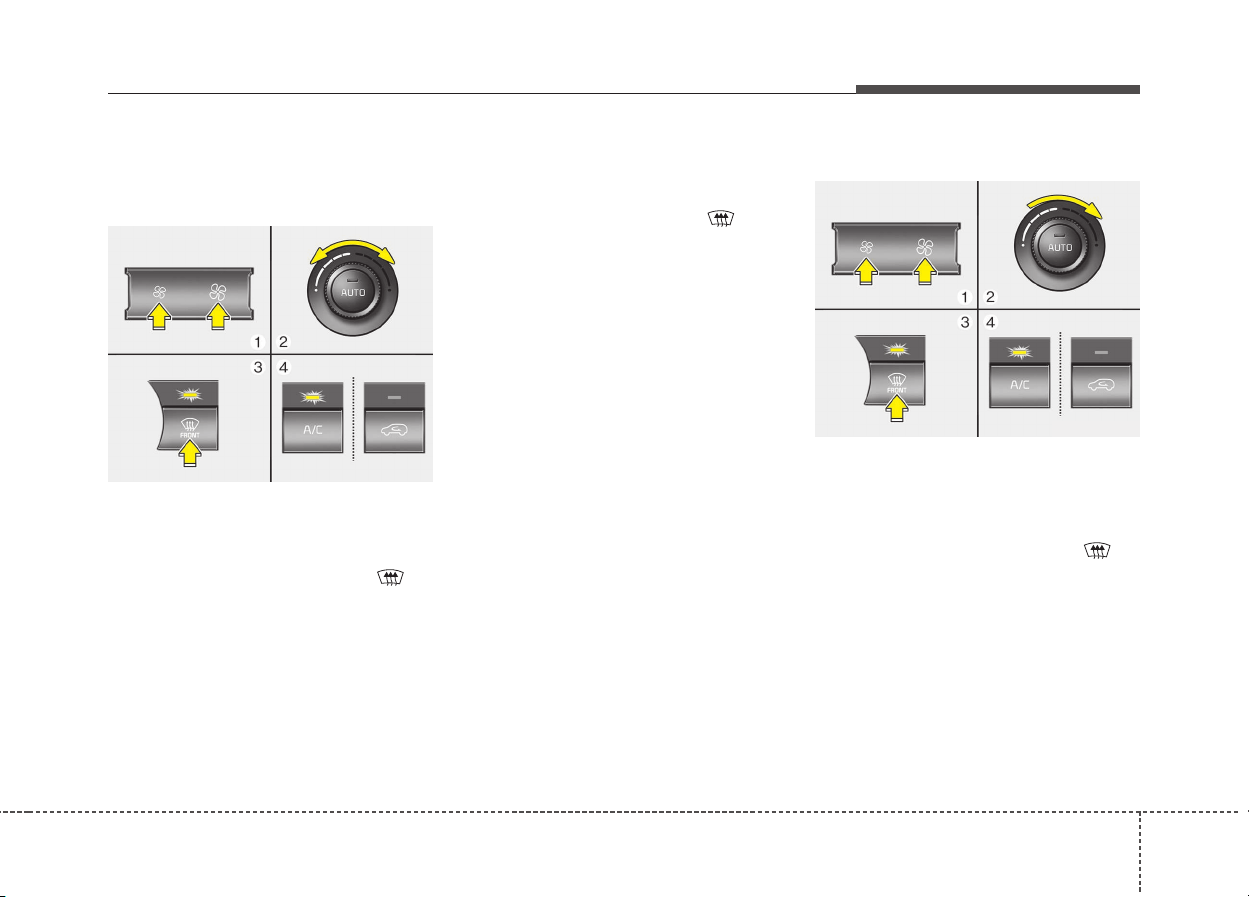
4127
Features of your vehicle
Automatic climate control
system
To defog inside windshield
1. Set the fan speed to the desired
position.
2. Select desired temperature.
3. Press the defroster button ( ).
4. The air conditioning will turn on
according to the detected ambient
temperature and outside (fresh)
air position will be selected auto-
matically.
If the air conditioning and outside
(fresh) air position are not selected
automatically, adjust the correspon-
ding button manually. If the posi-
tion is selected, lower fan speed is
adjusted to a higher fan speed.
To defrost outside windshield
1. Set the fan speed to the highest
position.
2. Set the temperature to the
extreme hot position.
3. Press the defroster button ( ).
4. The air conditioning will turn on
according to the detected ambient
temperature and outside (fresh)
air position will be selected auto-
matically.
WINDSHIELD DEFROSTING AND DEFOGGING
ODE046314
ODE046315
1284
Features of your vehicle
Operation tips
• For maximum defrosting, set the
temperature control to the extreme
right/hot position and the fan speed
control to the highest speed.
• If warm air to the floor is desired
while defrosting or defogging, set
the mode to the floor-defrost posi-
tion.
• Before driving, clear all snow and
ice from the windshield, rear win-
dow, outside rear view mirrors, and
all side windows.
• Clear all snow and ice from the
hood and air inlet in the cowl grill to
improve heater and defroster effi-
ciency and to reduce the probabili-
ty of fogging up the inside of the
windshield.
Defogging logic (if equipped)
To reduce the probability of fogging
up the inside of the windshield, the
air intake or air conditioning are con-
trolled automatically according to
certain conditions such as posi-
tion. To cancel or return the defog-
ging logic, do the following.
WARNING - Windshield
heating
Do not use the position dur-
ing cooling operation in
extremely humid weather. The
difference between the temper-
ature of the outside air and the
windshield could cause the
outer surface of the windshield
to fog up, causing loss of visi-
bility. In this case, set the mode
selection to the position
and fan speed control to the
lower speed.
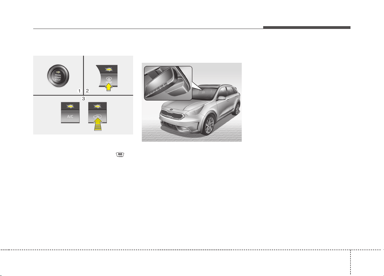
4129
Features of your vehicle
Automatic climate control system
1. Turn the ignition switch to the ON
position.
2. Press the defroster button ( ).
3. While pressing the air conditioning
button (A/C), press the air intake
control button at least 5 times with-
in 3 seconds.
The indicator on the air intake button
will blink 3 times. It indicates that the
defogging logic is canceled or
returned to the programmed status.
If the battery has been discharged or
disconnected, it resets to the defog
logic status.
Auto defogging system
(if equipped)
Auto defogging reduces the possibil-
ity of fogging up the inside of the
windshield by automatically sensing
the moisture of inside the windshield.
This indicator illuminates when the
auto defogging system senses the
moisture of inside the windshield and
operates.
If more moisture is in the vehicle,
higher steps operate as follow.
(For European region)
Step 1 : Blowing air flow toward the
windshield
Step 2 : Increasing air flow toward
the windshield
Step 3 : Operating the air condition-
ing.
Step 4 : Outside air position
(For except european region)
Step 1 : Outside air position
Step 2 : Operating the air condition-
ing
Step 3 : Blowing air flow toward the
windshield
Step 4 : Increasing air flow toward
the windshield
ODE046433
ODE046316
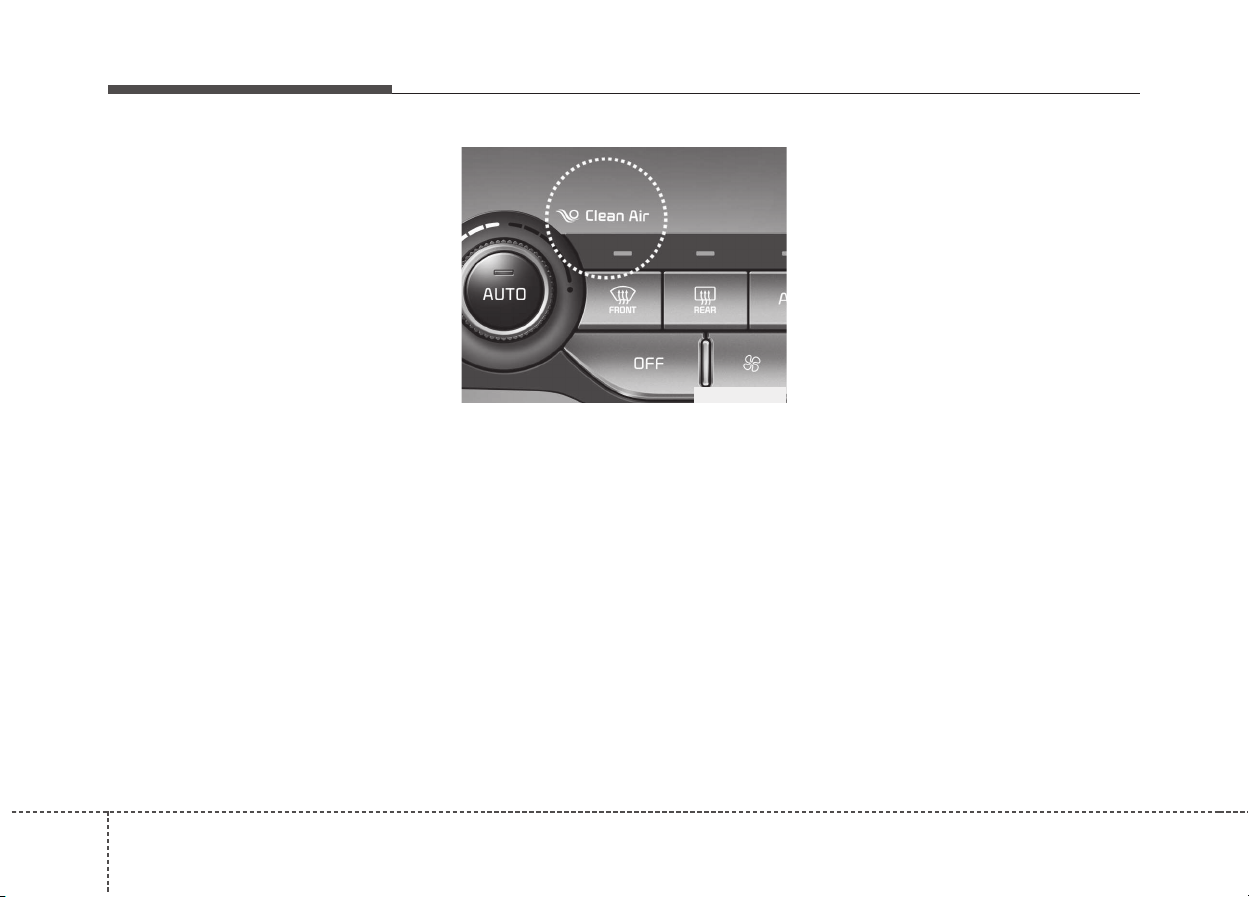
1304
Features of your vehicle
To cancel or reset the Auto Defogging
System
Press the front windshield defroster
button for 3 seconds when the igni-
tion switch is in the ON position.
When the ADS system is canceled,
Indicator on the button will blink 3
times per 0.5 sec.
When the ADS system is reset,
Indicator on the button will blink 6
times per 0.25 sec.
When the ignition switch is in the ON
position, the clean air function turns
on automatically.
Also, the clean air function turns off
automatically, when the ignition
switch turns to the OFF position.
ODE046321L
CLEAN AIR (IF EQUIPPED)
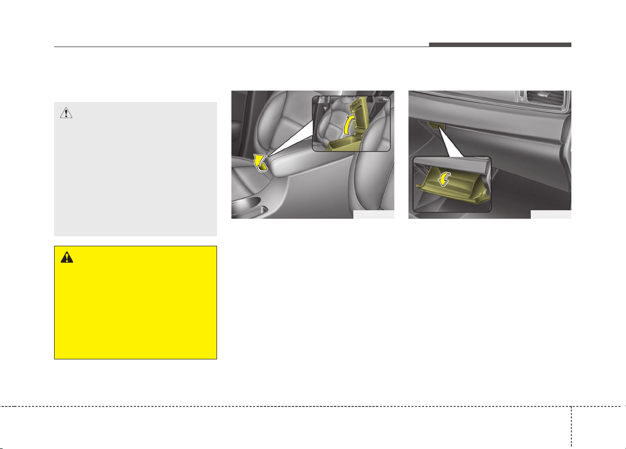
4131
Features of your vehicle
These compartments can be used to
store small items.
Center console storage
To open the center console storage,
pull up the lever.
Glove box
To open the glove box, push the lever
and the glove box will automatically
open. Close the glove box after use.
STORAGE COMPARTMENT
WARNING - Flammable
materials
Do not store cigarette lighters,
propane cylinders, or other
flammable/explosive materials
in the vehicle. These items may
catch fire and/or explode if the
vehicle is exposed to hot tem-
peratures for extended periods.
CAUTION
• To avoid possible theft, do not
leave valuables in the storage
compartment.
• Always keep the storage com-
partment covers closed while
driving. Do not attempt to
place so many items in the
storage compartment that the
storage compartment cover
cannot close securely.
ODE046416ODE046415
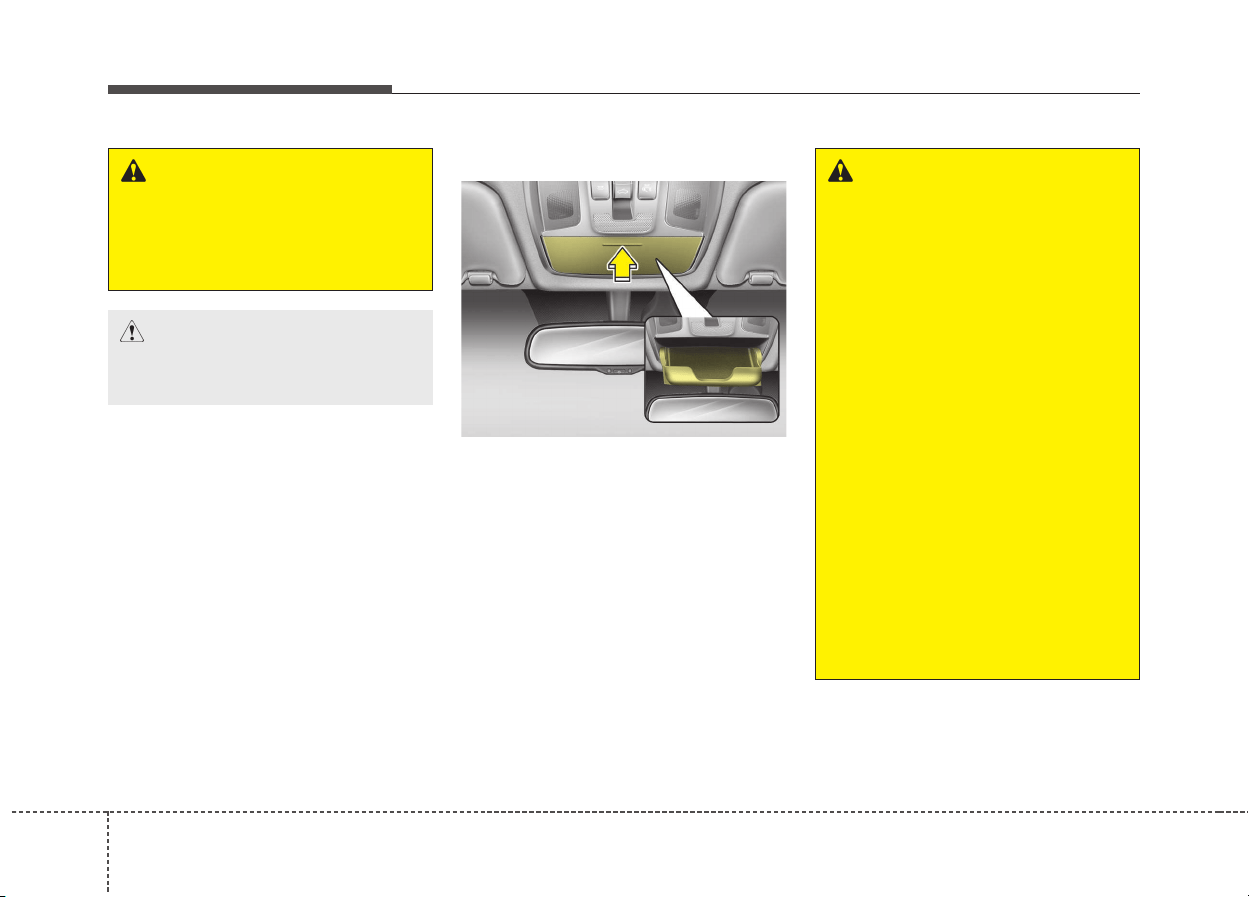
1324
Features of your vehicle
Sunglass holder
To open the sunglass holder, press
the cover and the holder will slowly
open. Place your sunglasses with the
lenses facing out. To close the sun-
glass holder, push it up.
WARNING
To reduce the risk of injury in an
accident or sudden stop, always
keep the glove box door closed
while driving.
CAUTION
Do not keep food in the glove
box for a long time.
ODE046417
WARNING
• Do not keep objects except
sunglasses inside the sun-
glass holder. Such objects
can be thrown from the holder
in the event of a sudden stop
or an accident, possibly injur-
ing the passengers in the
vehicle.
• Do not open the sunglass
holder while the vehicle is
moving. The rear view mirror
of the vehicle can be blocked
by an opened sunglass hold-
er.
• Do not put the glasses
forcibly into a sunglass holder
to prevent breakage or defor-
mation of the glasses. It may
cause personal injury if you
try to open it forcibly when the
glasses are jammed in the
holder.
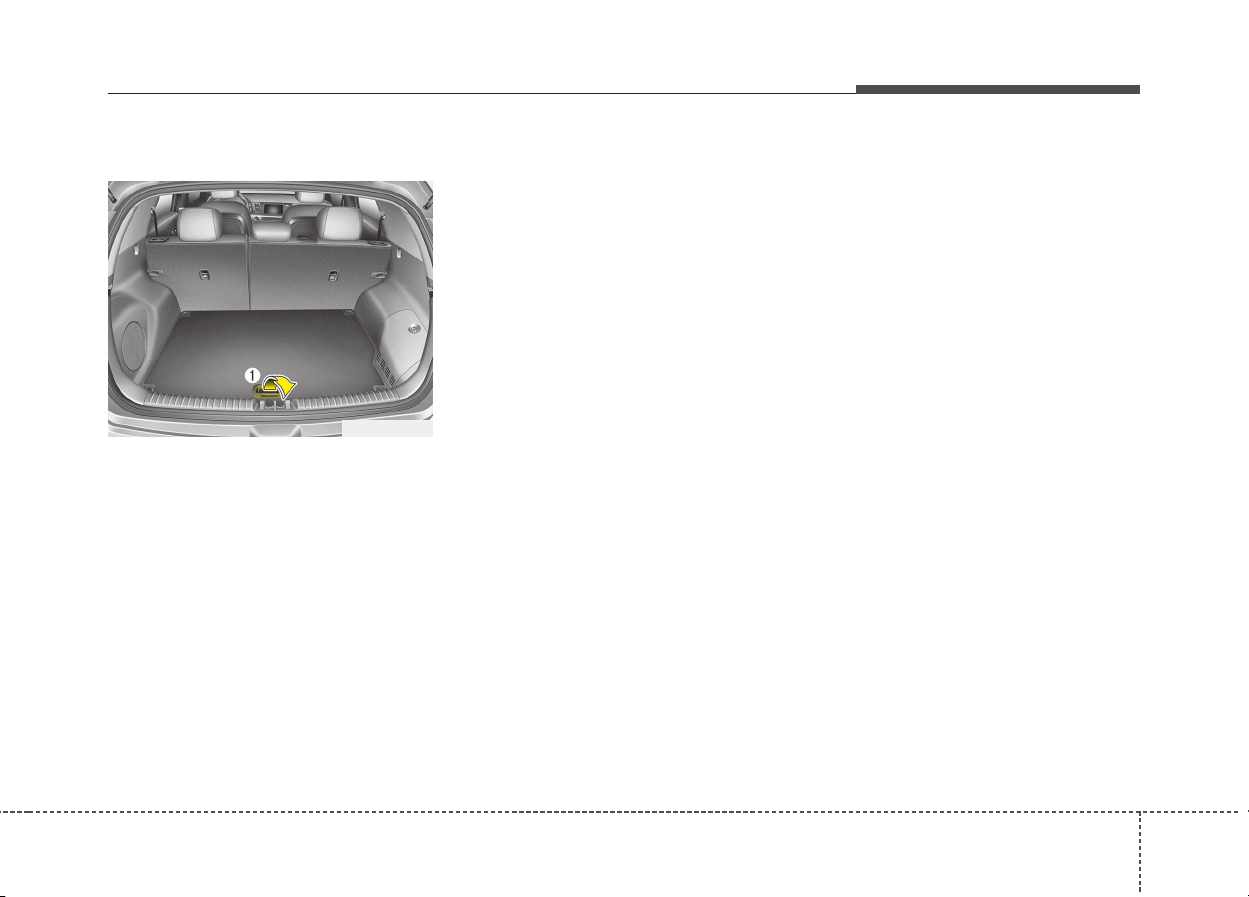
4133
Features of your vehicle
Luggage box
You can place tools, etc. in the box
for easy access.
Grasp the handle (1) on the edge of
the cover and lift it.
ODE046428L
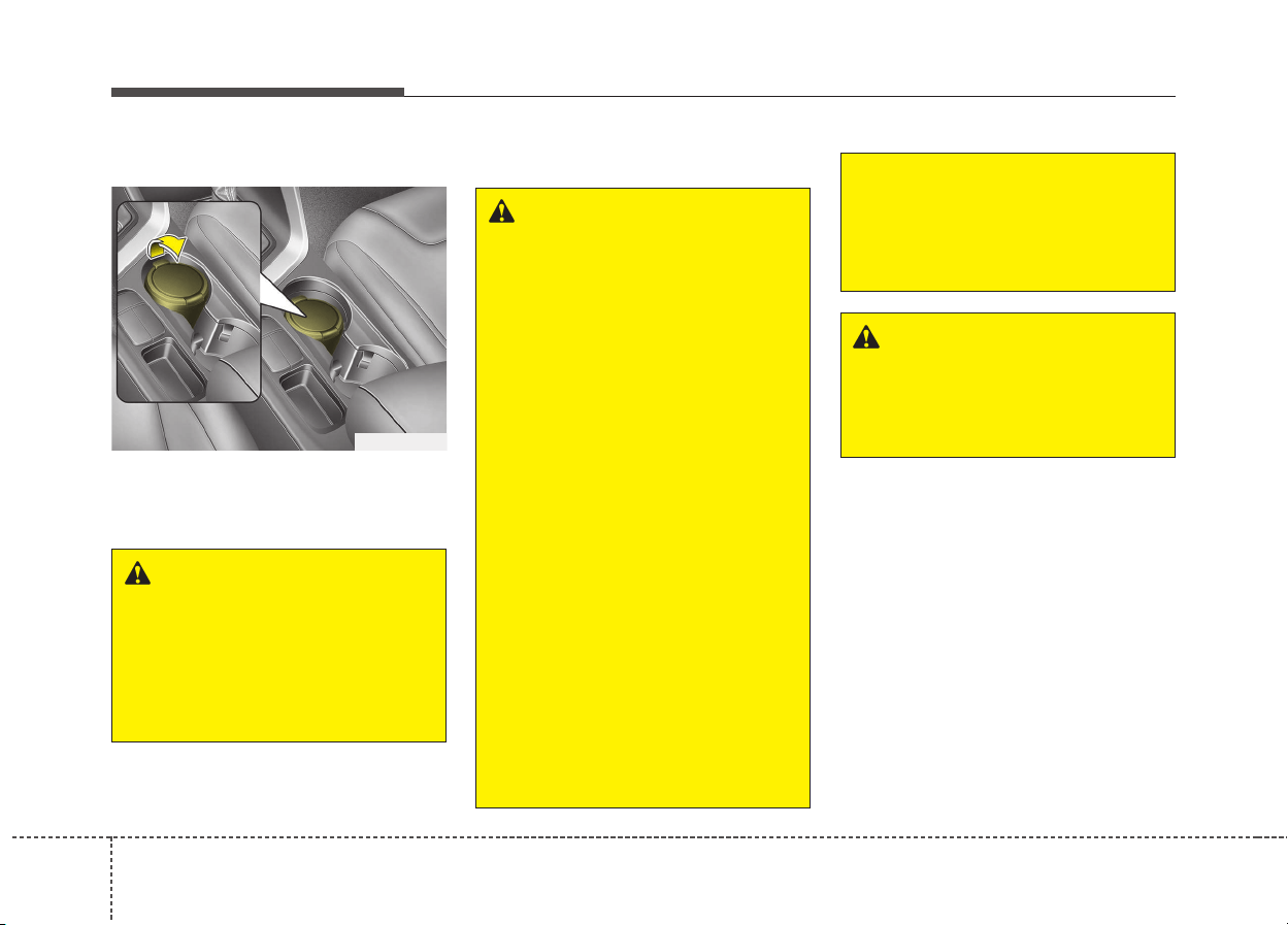
1344
Features of your vehicle
Ashtray (if equipped)
To use the ashtray, open the cover.
To clean or empty the ashtray, pull it
out.
Cup holder
INTERIOR FEATURES
ODE046451L
WARNING - Ashtray use
• Do not use the vehicle’s ash-
trays as waste receptacles.
• Putting lit cigarettes or match-
es in an ashtray with other
combustible materials may
cause a fire.
WARNING - Hot liquids
• Do not place uncovered cups
of hot liquid in the cup holder
while the vehicle is in motion.
If the hot liquid spills, you may
burn yourself. Such a burn to
the driver could lead to loss of
control of the vehicle.
• To reduce the risk of a per-
sonal injury in the event of a
sudden stop or collision, do
not place uncovered or unse-
cured bottles, glasses, cans,
etc., in the cup holder while
the vehicle is in motion.
• If uncovered cups and cans
containing any form of liquid
are put into the front/center
seat cup holders and the vehi-
cle brakes heavily, the liquid
may flow into the narrow
openings around cup holders
and console, and soak into
the vehicle's internal electri-
cal system.
(Continued)
(Continued)
To avoid subsequent system
malfunction, always firmly
cover any container holding
liquid.
WARNING
Keep cans or bottles out of
direct sun light and do not put
them in a vehicle that is heated
up. It may explode.
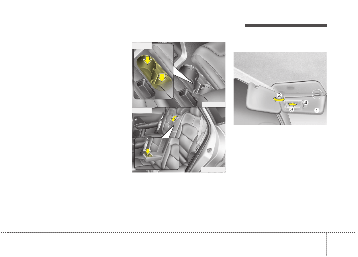
4135
Features of your vehicle
✽✽
NOTICE
• Keep your drinks sealed while
driving to prevent spilling your
drink. If liquid spills, it may get
into the vehicle's electrical/elec-
tronic system and damage electri-
cal/electronic parts.
• When cleaning spilled liquids, do
not dry the cup holder at high
temperature. This may damage
the cup holder.
Cups or small beverage cans may be
placed in the cup holders.
Sunvisor
Use the sunvisor to shield direct light
through the front or side windows.
To use the sunvisor, pull it down-
ward.
To use the sunvisor for the side win-
dow, pull it downward, unsnap it from
the bracket (1) and swing it to the
side (2).
To use the vanity mirror, pull down the
visor and slide the mirror cover (3).
The ticket holder (4) is provided for
holding a tollgate ticket. (if equipped)
ODE046418
ODE046444
■ Type A
■ Type B
ODE046420
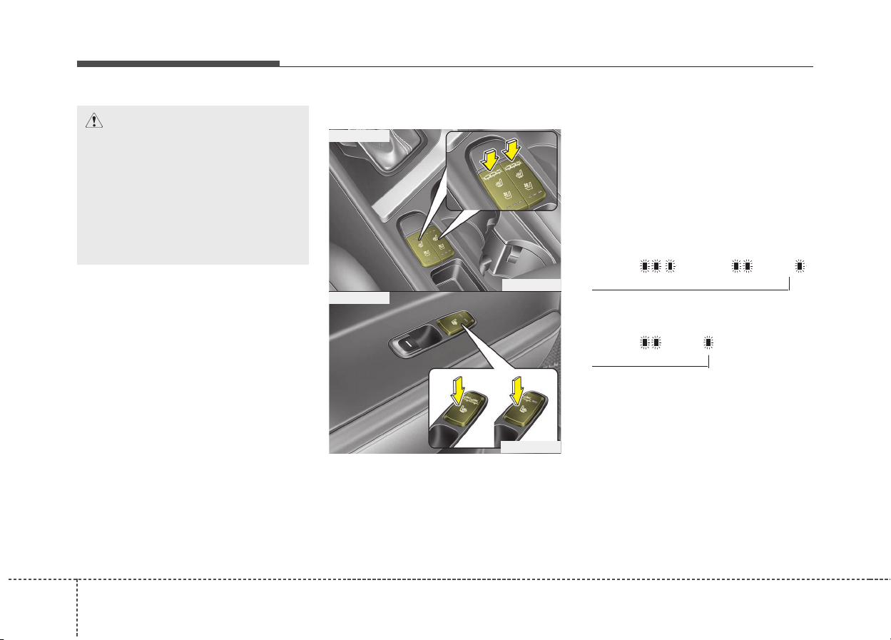
1364
Features of your vehicle
Seat warmer (if equipped)
The seat warmer is provided to warm
the front seats during cold weather.
With the ignition switch in the ON
position, push either of the switches
to warm the driver's seat or the front
passenger's seat.
During mild weather or under condi-
tions where the operation of the seat
warmer is not needed, keep the
switches in the “OFF” position.
Temperature control (Manual)
• Each time you press the switch,
the temperature setting of the seat
will change as follows :
■ Front seat
■ Rear seat
• The seat warmer defaults to the
OFF position whenever the ignition
switch is turned on.
▼
CAUTION - Vanity mirror
lamp (if equipped)
If you use the vanity mirror
lamp, turn off the lamp before
returning the sunvisor to its
original position, otherwise it
could result in battery dis-
charge and possible sunvisor
damage.
ODE046422
ODE046448
■ Front seat
■ Rear seat
OFF→HIGH( )→MIDDLE( )→LOW( )
→
OFF→HIGH( )→LOW( )
→
4137
Features of your vehicle
Temperature control(Automatic)
The seat warmer starts to automati-
cally control the seat temperature in
order to prevent low-temperature
burns after being manually turned
ON.
■ Front seat
■ Rear seat
You may manually press the button
to increase the seat temperature.
However, it soon returns to the auto-
matic mode again.
• When pressing the switch for more
than 1.5 seconds with the seat
warmer operating, the seat warmer
will turn OFF.
• The seat warmer defaults to the
OFF position whenever the Engine
Start/Stop button is in the ON posi-
tion.
✽✽
NOTICE
With the seat warmer switch in the
ON position, the heating system in
the seat turns off or on automatical-
ly depending on the seat tempera-
ture.
▼
CAUTION
• When cleaning the seats, do
not use an organic solvent
such as paint thinner, ben-
zene, alcohol and gasoline.
Doing so may damage the sur-
face of the heater or seats.
• To prevent overheating the
seat warmer, do not place any-
thing on the seats that insu-
lates against heat, such as
blankets, cushions or seat
covers while the seat warmer
is in operation.
• Do not place heavy or sharp
objects on seats equipped
with seat warmers. Damage to
the seat warming components
could occur.
• Do not change the seat cover.
It may damage the seat warmer
or airventilation system.
OFF→HIGH( )→MIDDLE( )→LOW( )
→
→
30min
60min
WARNING - Seat warmer
burns
Passengers should use extreme
caution when using seat warm-
ers due to the possibility of
excess heating or burns. The
seat warmer may cause burns
even at low temperatures, espe-
cially if used for long periods of
time. In particular, the driver
must exercise extreme care for
the following types of passen-
gers:
1. Infants, children, elderly or
handicapped persons, or
hospital outpatients
2. Persons with sensitive skin
or those that burn easily
3. Fatigued individuals
4. Intoxicated individuals
5. Individuals taking medication
that can cause drowsiness or
sleepiness (sleeping pills,
cold tablets, etc.)
OFF→HIGH( )→LOW( )
→
30min
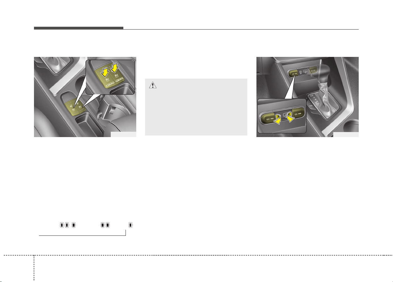
1384
Features of your vehicle
Air ventilation seat (if equipped)
The temperature setting of the seat
changes according to the switch
position.
• If you want to warm your seat
cushion, press the switch (red
color).
• If you want to ventilate your seat
cushion, press the switch (blue
color).
• Each time you press the button,
the airflow will change as follows:
• The seat warmer (with air ventila-
tion) defaults to the OFF position
whenever the ignition switch is
turned on.
Power outlet
The power outlet is designed to pro-
vide power for mobile telephones or
other devices designed to operate
with vehicle electrical systems. The
devices should draw less than 10
amps with the engine running.
ODE046423
OFF→HIGH( )→MIDDLE( )→LOW( )
→
CAUTION
When cleaning the seats, do not
use an organic solvent such as
paint thinner, benzene, alcohol
and gasoline. Doing so may
damage the surface of the
heater or seats.
ODE046421
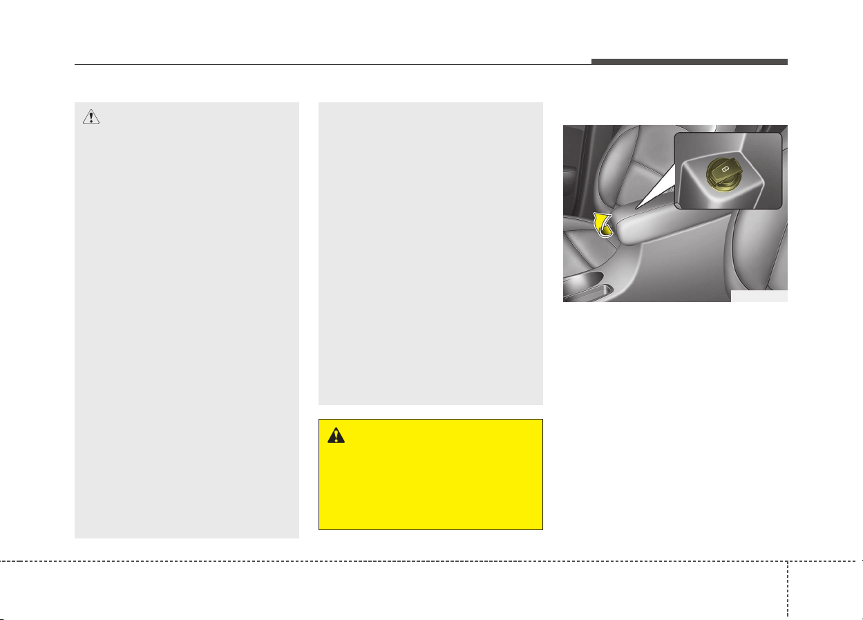
4139
Features of your vehicle
USB charger (if equipped)
The USB charger is designed to
recharge batteries of small size elec-
trical devices using a USB cable. The
electrical devices can be recharged
when the Engine Start/Stop button is
in ACC/ON/START position.
The battery charging state may be
monitored on the electrical device.
Disconnect the USB cable from the
USB port after use.
CAUTION
• Use the power outlet only
when the engine is running
and remove the accessory
plug after use. Using the
accessory plug for prolonged
periods of time with the
engine off could cause the
battery to discharge.
• Only use 12V electric acces-
sories which are less than 10A
in electric capacity.
• Adjust the air-conditioner or
heater to the lowest operating
level when using the power
outlet.
• Close the cover when not in
use.
• Some electronic devices can
cause electronic interference
when plugged into a vehicle’s
power outlet. These devices
may cause excessive audio
static and malfunctions in
other electronic systems or
devices used in your vehicle.
(Continued)
(Continued)
• Refrain from using the heater
or A/C if you need to use the
multipurpose socket. If the
heater or A/C has to be used
simultaneously, have it to the
lowest setting.
• Some add-on electrical equip-
ment will induce electromag-
netic interference. This will
lead to subsequent malfunc-
tion or hinder good reception
of the Audio/Video and electri-
cal system.
• Always make sure that electric
add-ons are fully plugged into
the multipurpose sockets.
Insecure contacts may lead to
electrical malfunctions.
WARNING
Do not put a finger or a foreign
element (pin, etc.) into a power
outlet and do not touch with a
wet hand. You may get an elec-
tric shock.
ODE046434

1404
Features of your vehicle
• Some devices are not supported
for fast charging but will be
charged with normal speed.
• Use the USB charger when the
engine is running to prevent bat-
tery discharge.
• Only devices that fits the USB port
can be used.
• The USB charger can be used only
for battery charging purposes.
• Battery chargers cannot be
charged.
AC inverter (if equipped)
The AC inverter supplies 220V/200W
electric power to operate electric
accessories or equipment.
If you wish to use the AC inverter,
open up the AC inverter cover and
connect a plug to it. The AC inverter
supplies electric power when engine
is running.
✽✽
NOTICE
• Rated voltage : AC 220V
• Maximum electric power : 200W
• In order to avoid an electrical sys-
tem failure, electric shock, etc., be
sure to read owner's manual
before use.
• Be sure to close the cover except
for when in use.
ODE046034
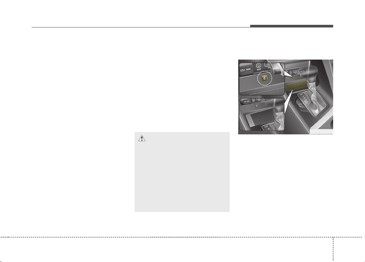
4141
Features of your vehicle
• To prevent the battery from being dis-
charged, do not use the AC inverter
while the engine is not running.
• After using an electric accessory or
equipment, pull the plug out. Leaving
the accessory or equipment plugged
in for a long time may cause battery
discharge.
• Do not use an electric accessory or
equipment the power consumption of
which is greater than 200W (220V).
• When the AC inverter input voltage is
less than 11.3V, automatically turn off
the power.
AC inverter will operate as normal
when the voltage is increased.
• When the AC inverter input voltage
is less than 10.7V, power will turn
off. The AC inverter will operate as
normal when the voltage is
increased.
• While the power consumption of
some electrical devices/appliances
may be within the AC inverter’s
electric power range, it may mal-
function in below cases.
- If the device/appliance requires
high electric power for initial start
up
- If the device/appliance processes
precise/very accurate data
- If the device/appliance requires
very stable supply of electricity
Wireless smart phone charg-
ing system (if equipped)
A wireless smart phone charging
system located in front of the center
console.
Firmly close all doors, and turn the
ignition to ACC or IGN ON. To start
wireless charging, place the smart
phone equipped with wireless charg-
ing function on the wireless charging
pad.
CAUTION - Electric acces-
sory devices
• Do not use broken electric
accessories which may dam-
age the AC inverter and elec-
trical systems of the vehicle.
• Do not use two or more elec-
tric accessories at the same
time. It may cause damage to
the electrical systems of the
vehicle.
ODE046424

1424
Features of your vehicle
For best wireless charging results,
place the smart phone on the center
of the charging pad.
The wireless charging system is
designed for one smart phone
equipped with QI per single usage
only. Please refer to the smart phone
accessory cover or the smart phone
manufacturer homepage to check
whether your smart phone supports
QI function.
Wireless smart phone charging
1. Remove any object on the smart
phone charging pad including the
smart key. If there is any foreign
object on the pad other than a
smart phone, the wireless charg-
ing function may not operate prop-
erly.
2. Place the smart phone on the cen-
ter of the wireless charging pad.
3. The indicator light will change to
orange once the wireless charging
begins. After the charging is com-
plete, the orange light will change
to green.
4. You can choose to turn the wire-
less charging function to either ON
or OFF by selecting the USM on
the instrument cluster. (Please
refer to “Instrument Cluster” for
details).
If the wireless charging does not
work, gently move your smart phone
around the pad until the charging
indicator light turns orange.
Depending on the smart phone, the
charging indicator light may not turn
green even after the charging is com-
plete.
If the wireless charging is not func-
tioning properly, the orange light will
blink and flash for ten seconds then
turn off. In such cases, remove the
smart phone from the pad and
replace it on the pad again, or double
check the charging status.
If you leave the smart phone on the
charging pad when the vehicle igni-
tion is in OFF, the vehicle will alert
you through warning messages and
sound (applicable for vehicles with
voice guidance (function) after the
‘Good bye’ function on the instru-
ment cluster ends.

4143
Features of your vehicle
CAUTION
• When the interior temperature
of the wireless charging sys-
tem rises above a set temper-
ature, the wireless charging
will cease to function. After
the interior temperature drops
below the threshold, the wire-
less charging function will
resume.
• If any metallic object such as
coins is located between the
wireless charging system and
the smart phone, the charging
may be disrupted. Also, the
metallic object may heat up.
• If there is any metallic object
between the smart phone and
the wireless charging pad,
immediately remove the smart
phone. Remove the metallic
object after it has completely
cooled down.
• The wireless charging may
not function properly when
there is a heavy accessory
cover on the smart phone.
(Continued)
(Continued)
• The wireless charging will
stop when using the wireless
smart key search function to
prevent radio wave disruption.
• The wireless charging will
stop when the smart key is
moved out of the vehicle with
the ignition in ON.
• The wireless charging will
stop when any of the doors is
opened (applicable for vehi-
cles equipped with smart
keys).
• The wireless charging will
stop when the vehicle is
turned OFF.
• The wireless charging will
stop when the smart phone is
not in complete contact with
the wireless charging pad.
• Items equipped with magnetic
components such as credit
card, telephone card, bank-
book, any transportation ticket
and such may become dam-
aged during wireless charging.
(Continued)
(Continued)
• Place the smart phone on the
center of the charge pad for
best results. The smart phone
may not charge when placed
near the rim of the charging
pad. When the smart phone
does get charged, it may heat
up excessively.
• For smart phones without
built-in wireless charging sys-
tem, an appropriate accessory
has to be equipped.
• Smart phones of some manu-
facturers may display mes-
sages on weak current. This is
due to the particular charac-
teristic of the smart phone and
does not imply a malfunction
on wireless charging function.
• The indicator light of some
manufacturers’ smart phones
may still be orange after the
smart phone is fully charged.
This is due to the particular
characteristic of the smart
phone and not a malfunction
of the wireless charging.
(Continued)

1444
Features of your vehicle
Coat hook
❈ This actual feature may differ from the illus-
tration.
A Coat hook is next to the rear grab
handle.
Floor mat anchor(s)
(if equipped)
When using a floor mat on the front
floor carpet, make sure it attaches to
the floor mat anchor(s) in your vehi-
cle. This keeps the floor mat from
sliding forward.
(Continued)
• When any smart phone with-
out a wireless charging func-
tion or a metallic object is
placed on the charging pad, a
small noise may sound. This
small sound is due to the vehi-
cle discerning compatibility of
the object placed on the
charging pad. It does not
affect your vehicle or the
smart phone in any way.
ODE046425
CAUTION
Do not hang heavy clothes, since
those may damage the hook.
WARNING
Do not hang other objects
except clothes. In an accident it
may cause vehicle damage or
personal injury.
OXM043309
■ Type A
■ Type B
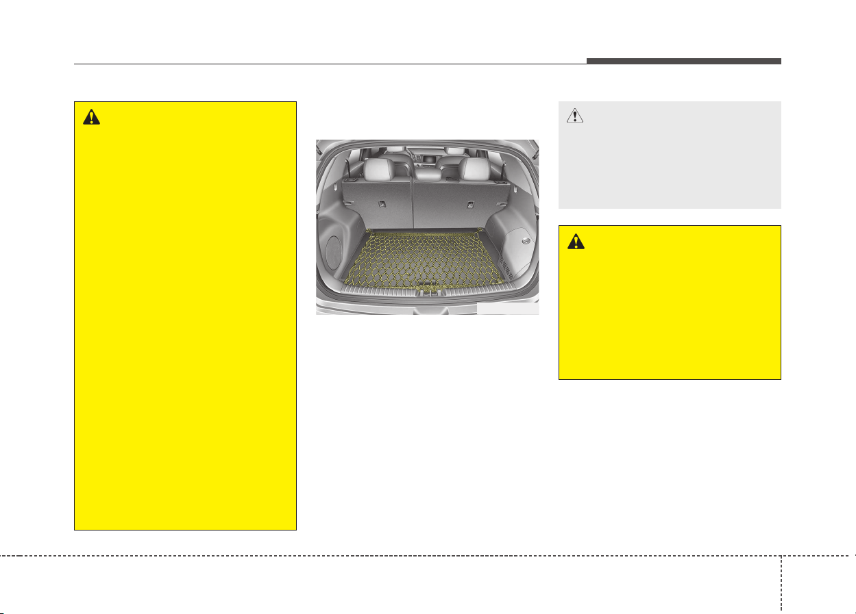
4145
Features of your vehicle
Luggage net holder
(if equipped)
To keep items from shifting in the
cargo area, you can use the holders
located in the cargo area to attach
the luggage net.
If necessary, we recommend that
you contact an authorized Kia dealer.
WARNING
The following must be observed
when installing ANY floor mat
to the vehicle.
• Ensure that the floor mats are
securely attached to the vehi-
cle's floor mat anchor(s)
before driving the vehicle.
• Do not use ANY floor mat that
cannot be firmly attached to
the vehicle's floor mat
anchors.
• Do not stack floor mats on top
of one another (e.g. all-weath-
er rubber mat on top of a car-
peted floor mat). Only a single
floor mat should be installed
in each position.
IMPORTANT - Your vehicle was
manufactured with driver's side
floor mat anchors that are
designed to securely hold the
floor mat in place. To avoid any
interference with pedal opera-
tion, Kia recommends that the
Kia floor mat designed for use
in your vehicle be installed.
CAUTION
To prevent damage to the goods
or the vehicle, care should be
taken when carrying fragile or
bulky objects in the luggage
compartment.
WARNING
To avoid eye injury, DO NOT
overstretch the luggage net.
ALWAYS keep your face and
body out of the luggage net’s
recoil path. DO NOT use the lug-
gage net when the strap has
visible signs of wear or dam-
age.
ODE046426L
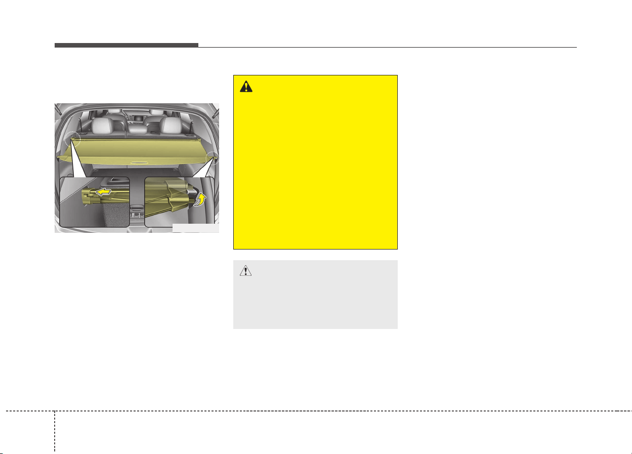
1464
Features of your vehicle
Cargo security screen
(if equipped)
Use the cargo security screen to
hide items stored in the cargo area.
To use the cargo security screen,
pull the handle backward and insert
the edges into the slots.
ODE046429L
WARNING
• Do not place objects on the
cargo security screen. Such
objects may be thrown about
inside the vehicle and possi-
bly injure vehicle occupants
during an accident or when
braking.
• Never allow anyone to ride in
the luggage compartment. It
is designed for luggage only.
• Maintain the balance of the
vehicle and locate the weight
as far forward as possible.
CAUTION
Since the cargo security screen
may be damaged or malformed,
do not put the luggage on it
when it is used.
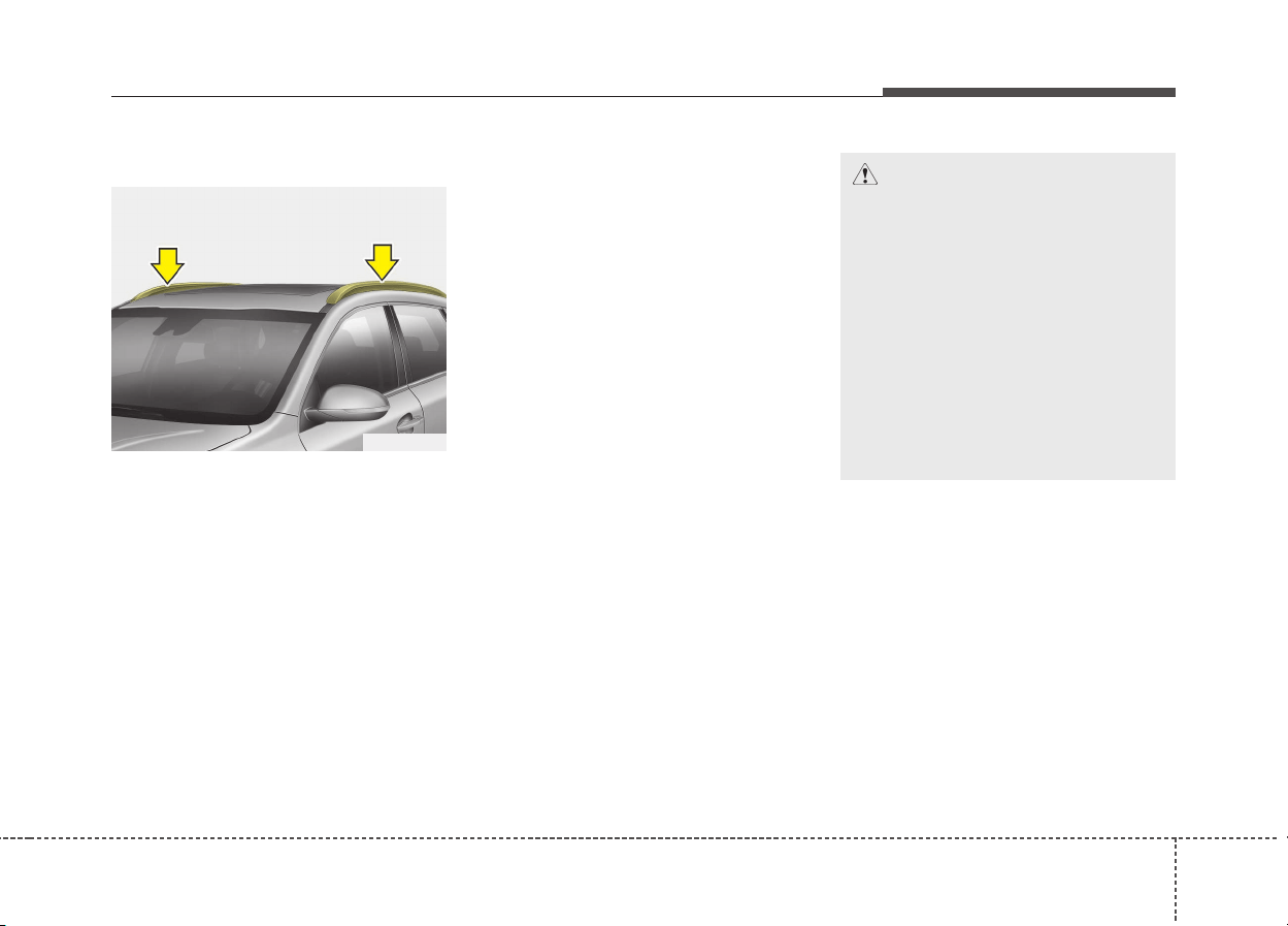
4147
Features of your vehicle
Roof rack (if equipped)
If the vehicle has a roof rack, you can
load cargo on top of your vehicle.
Crossbars and fixing components
needed to install the roof rack on
your vehicle may be obtained from
an authorized Kia dealer or other
qualified shop.
✽✽
NOTICE
• The crossbars (if equipped) should
be placed in the proper load carry-
ing positions prior to placing items
onto the roof rack.
• If the vehicle is equipped with a
sunroof, be sure not to position
cargo onto the roof rack in such a
way that it could interfere with
sunroof operation.
• When the roof rack is not being
used to carry cargo, the crossbars
may need to be repositioned if
wind noise is detected.
EXTERIOR FEATURES
CAUTION
• When carrying cargo on the
roof rack, take the necessary
precautions to make sure the
cargo does not damage the
roof of the vehicle.
• When carrying large objects
on the roof rack, make sure
they do not exceed the overall
roof length or width.
• When you are carrying cargo
on the roof rack, do not oper-
ate the sunroof (if equipped).
ODE046432
1484
Features of your vehicle
WARNING
• The following specification is
the maximum weight that can
be loaded onto the roof rack.
Distribute the load as evenly as
possible across the crossbars
(if equipped) and roof rack and
secure the load firmly.
Loading cargo or luggage in
excess of the specified weight
limit on the roof rack may
damage your vehicle.
• The vehicle center of gravity
will be higher when items are
loaded onto the roof rack.
Avoid sudden starts, braking,
sharp turns, abrupt maneu-
vers or high speeds that may
result in loss of vehicle con-
trol or rollover resulting in an
accident.
(Continued)
ROOF 100 kg (220 lbs.)
RACK EVENLY DISTRIBUTED
(Continued)
• Always drive slowly and turn
corners carefully when carry-
ing items on the roof rack.
Severe wind updrafts, caused
by passing vehicles or natural
causes, can cause sudden
upward pressure on items
loaded on the roof rack. This
is especially true when carry-
ing large, flat items such as
wood panels or mattresses.
This could cause the items to
fall off the roof rack and cause
damage to your vehicle or
others around you.
• To prevent damage or loss of
cargo while driving, check fre-
quently before or while driv-
ing to make sure the items on
the roof rack are securely fas-
tened.

Audio system
Audio system. . . . . . . . . . . . . . . . . . . . . . . . . . . . . . . 5-2
• Antenna . . . . . . . . . . . . . . . . . . . . . . . . . . . . . . . . . . . . . 5-2
• Steering wheel audio controls. . . . . . . . . . . . . . . . . . . . 5-3
• Aux, USB port . . . . . . . . . . . . . . . . . . . . . . . . . . . . . . . . 5-4
• How vehicle radio works . . . . . . . . . . . . . . . . . . . . . . . 5-4
Audio (With Touch Screen) . . . . . . . . . . . . . . . . . . . 5-8
• Feature of Your Audio. . . . . . . . . . . . . . . . . . . . . . . . . . 5-9
• Radio. . . . . . . . . . . . . . . . . . . . . . . . . . . . . . . . . . . . . . . 5-16
• Media . . . . . . . . . . . . . . . . . . . . . . . . . . . . . . . . . . . . . . 5-18
• Phone . . . . . . . . . . . . . . . . . . . . . . . . . . . . . . . . . . . . . . 5-31
• Voice Recognition . . . . . . . . . . . . . . . . . . . . . . . . . . . . 5-40
• Setup . . . . . . . . . . . . . . . . . . . . . . . . . . . . . . . . . . . . . . . 5-50
Declaration of Conformity . . . . . . . . . . . . . . . . . . 5-53
• CE for EU. . . . . . . . . . . . . . . . . . . . . . . . . . . . . . . . . . . 5-53
• NCC for Taiwan. . . . . . . . . . . . . . . . . . . . . . . . . . . . . . 5-54
• TRA for OMAN. . . . . . . . . . . . . . . . . . . . . . . . . . . . . . 5-55
5
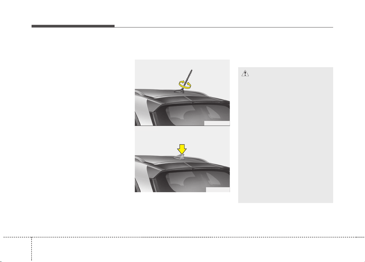
✽✽
NOTICE
If you install an after market HID
head lamp, your vehicle’s audio and
electronic device may malfunction.
❈ If your vehicle is equipped with
AVN(Audio, Video and Navigation)
system, refer to a separately sup-
plied manual for detailed informa-
tion.
Antenna
Pole type antenna
Your vehicle uses a roof antenna to
receive both AM and FM broadcast
signals. This antenna pole is remov-
able. To remove the antenna pole,
turn it counterclockwise. To install the
antenna, turn it clockwise.
Shark fin antenna (if equipped)
The shark fin antenna will receive the
transmit data.
AUDIO SYSTEM
Audio system
52
CAUTION - Pole type
antenna
• Before entering a place with a
low height clearance or a car
wash, remove the antenna
pole by rotating it counter-
clockwise. If not, the antenna
may be damaged.
• When reinstalling your anten-
na pole, it is important that it
is fully tightened and adjusted
to the upright position to
ensure proper reception. But it
could be removed when park-
ing the vehicle or when load-
ing cargo on the roof rack.
• When cargo is loaded on the
roof rack, do not place the
cargo near the antenna pole to
ensure proper reception.
ODE046453L
ODE046438
■ Type A
■ Type B
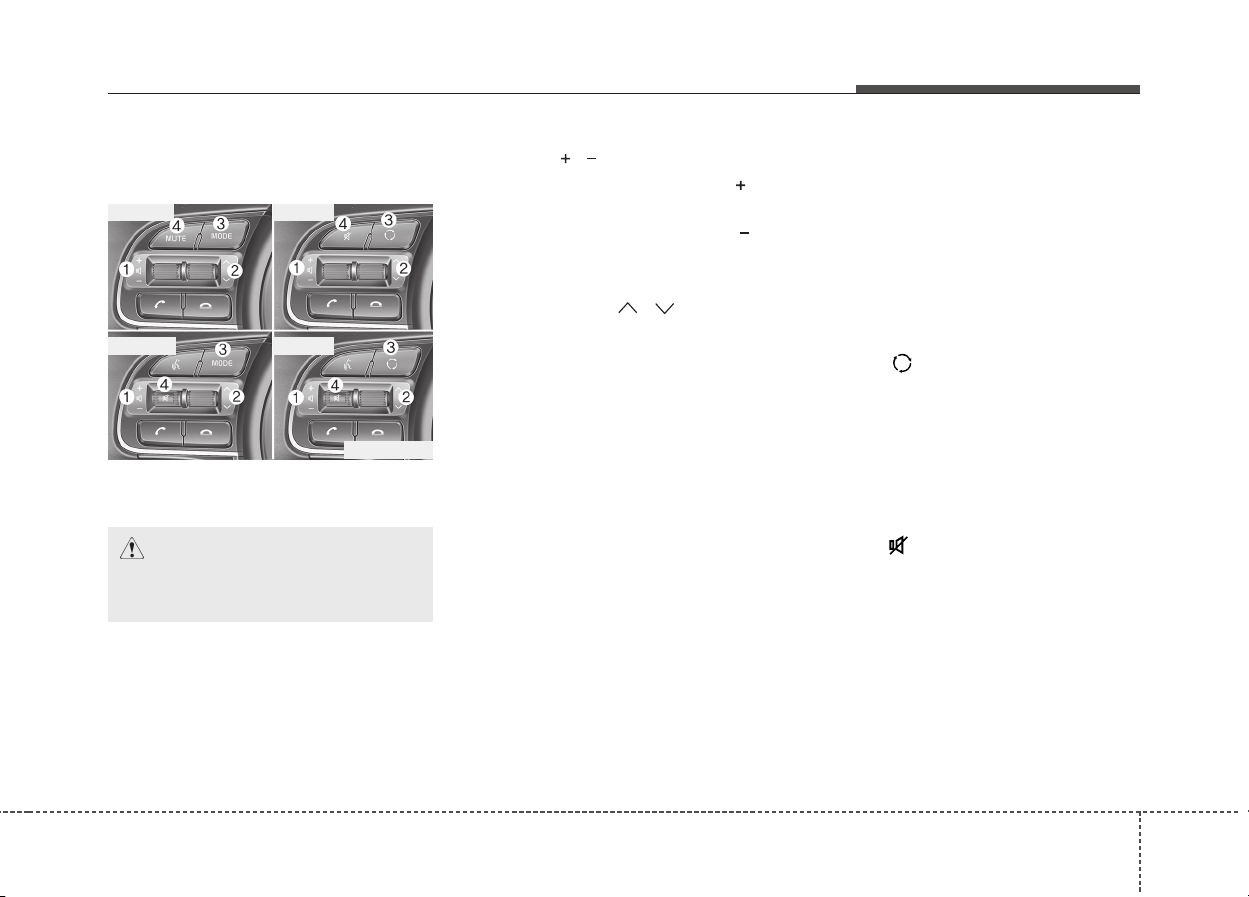
Steering wheel audio controls
(if equipped)
The steering wheel may incorporate
audio control buttons.
VOLUME ( / ) (1)
• Press the lever upward ( ) to
increase the volume.
• Press the lever downward ( ) to
decrease the volume.
SEEK/PRESET ( / ) (2)
The SEEK/PRESET lever has differ-
ent functions based on the system
mode. For the following functions the
lever should be pressed for 0.8 sec-
onds or more.
RADIO mode
It will function as the AUTO SEEK
select button.
USB/iPod
®
mode
It will function as the FF/REW button.
If the SEEK/PRESET button is
pressed for less than 0.8 seconds, it
will work as follows in each mode.
RADIO mode
It will function as the PRESET STA-
TION buttons.
USB/iPod
®
mode
It will function as TRACK UP/DOWN
button.
MODE ( ) (3)
Press the button to change audio
source.
FM ➟ AM ➟ DAB* ➟ USB ➟ iPod
®
➟
BT Audio ➟ AUX ➟ MY MUSIC
* : if equipped
MUTE ( ) (4)
• Press the button to mute the
sound.
• Press the button to turn off the
microphone during a telephone
call.
Detailed information for audio control
buttons are described in the following
pages in this section.
Audio system
3
5
CAUTION
Do not operate audio remote
control buttons simultaneously.
ODE046449L
■ Type A
■ Type B
■ Type C
■ Type D
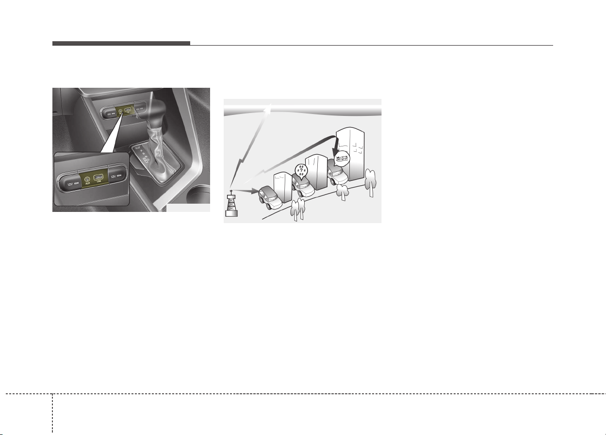
Aux, USB port
You can use the AUX port to connect
audio devices and the USB port to
plug in a USB device or iPod
®
.
✽✽
NOTICE
When using a portable audio device
connected to the power outlet, noise
may occur during playback. If this
happens, use the power source of the
portable audio device.
*
iPod
®
is a trademark of Apple Inc.
How vehicle radio works
FM reception
AM and FM radio signals are broad-
cast from transmitter towers located
around your city. They are intercept-
ed by the radio antenna on your vehi-
cle. This signal is then received by
the radio and sent to your vehicle
speakers.
When a strong radio signal has
reached your vehicle, the precise
engineering of your audio system
ensures the best possible quality
reproduction. However, in some
cases the signal coming to your vehi-
cle may not be strong and clear.
This can be due to factors, such as
the distance from the radio station,
closeness of other strong radio sta-
tions or the presence of buildings,
bridges or other large obstructions in
the area.
Audio system
54
OJF045308L
ODE046439L
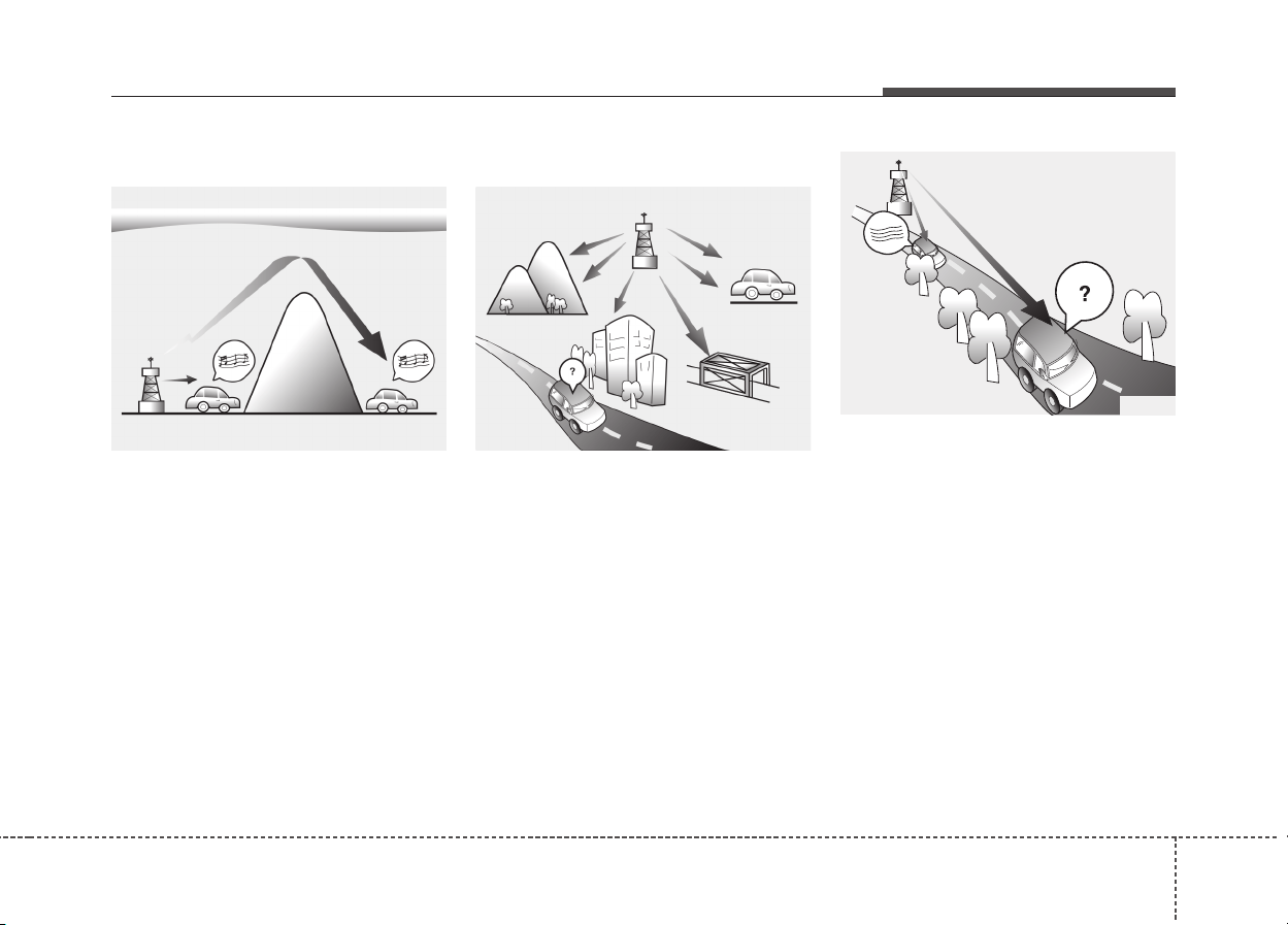
AM (MW, LW) reception
AM broadcasts can be received at
greater distances than FM broad-
casts. This is because AM radio
waves are transmitted at low fre-
quencies. These long, low frequency
radio waves can follow the curvature
of the earth rather than travelling
straight out into the atmosphere. In
addition, they curve around obstruc-
tions so that they can provide better
signal coverage.
FM radio station
FM broadcasts are transmitted at
high frequencies and do not bend to
follow the earth's surface. Because
of this, FM broadcasts generally
begin to fade at short distances from
the station. Also, FM signals are eas-
ily affected by buildings, mountains,
or other obstructions. These can
result in certain listening conditions
which might lead you to believe a
problem exists with your radio. The
following conditions are normal and
do not indicate radio trouble:
• Fading - As your vehicle moves
away from the radio station, the
signal will weaken and sound will
begin to fade. When this occurs,
we suggest that you select another
station with a stronger signal.
• Flutter/Static - Weak FM signals or
large obstructions between the
transmitter and your radio can dis-
turb the signal causing static or
fluttering noises to occur. Reducing
the treble level may lessen this
effect until the disturbance clears.
Audio system
5
5
¢¢¢
JBM004
OJF045309L OJF045310L
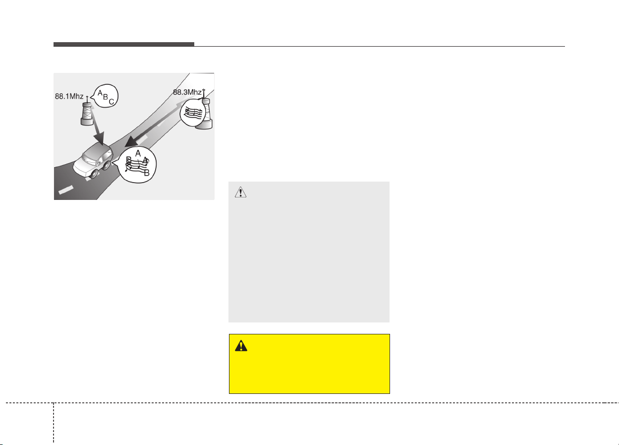
• Station Swapping - As a FM signal
weakens, another more powerful
signal near the same frequency
may begin to play. This is because
your radio is designed to lock onto
the clearest signal. If this occurs,
select another station with a
stronger signal.
• Multi-Path Cancellation - Radio
signals being received from sever-
al directions can cause distortion
or fluttering. This can be caused by
a direct and reflected signal from
the same station, or by signals
from two stations with close fre-
quencies. If this occurs, select
another station until the condition
has passed.
Using a cellular phone or a two-
way radio
When a cellular phone is used inside
the vehicle, noise may be produced
from the audio system. This does not
mean that something is wrong with the
audio equipment. In such a case, use
the cellular phone at a place as far as
possible from the audio equipment.
Audio system
56
OJF045311L
CAUTION
When using a communication
system such as a cellular phone
or a radio set inside the vehicle,
a separate external antenna
must be fitted. When a cellular
phone or a radio set is used
with an internal antenna alone,
it may interfere with the vehi-
cle's electrical system and
adversely affect safe operation
of the vehicle.
WARNING
Do not use a cellular phone
while driving. Stop at a safe
location to use a cellular phone.

iPod
®
iPod
®
is a trademark of Apple Inc.
Bluetooth
®
Wireless Technology
The Bluetooth
®
word mark and logos are registered
trademarks owned by Bluetooth
®
SIG, Inc. and any use
of such marks by Kia is under license.
Other trademarks and trade names are those of their
respective owners.
Audio system
7
5
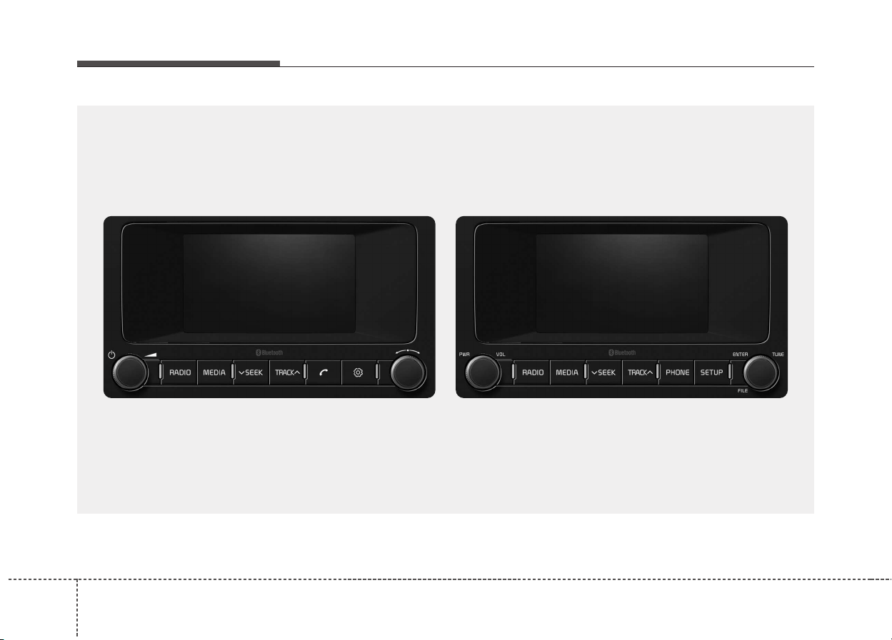
AUDIO (With Touch Screen)
G5H4G0000EE/G5H4G0001EE
■ Type 1 ■ Type 2
(With
Bluetooth
®
Wireless Technology)
Audio system
58
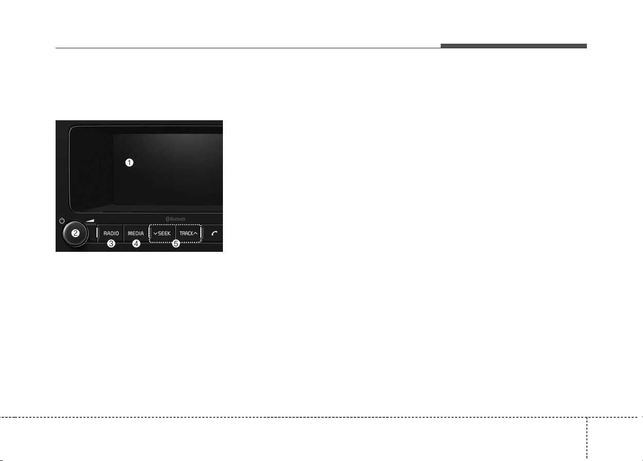
Feature of Your Audio
Head unit
❈ The actual features in the vehicle
may differ from the illustration.
(1) LCD screen
• Tap the screen to select a button.
(2) POWER/VOL knob
• Turn to adjust the volume.
• Press to turn the device on or off.
(3) RADIO
• Start FM, AM or DAB Radio*.
* if equipped
(4) MEDIA
• Select USB, iPod
®
, Bluetooth
®
Audio, AUX or My Music.
• Display the media menu when two
or more media are connected or
when the [MEDIA] button is
pressed in media mode.
(5) SEEK/TRACK
• Search for frequencies in radio
mode.
• Change the current song in media
mode.
Audio system
9
5
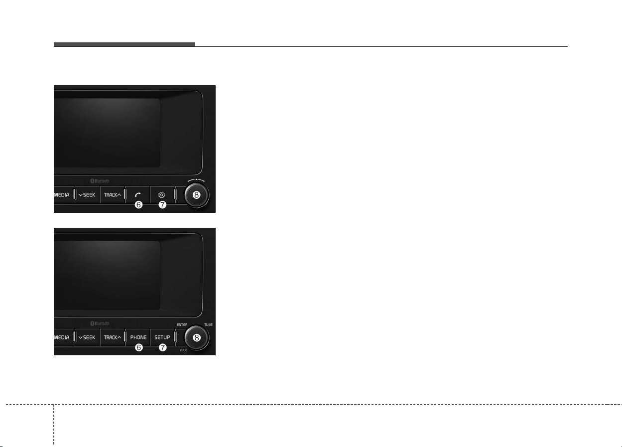
(6) PHONE
• Start Bluetooth
®
Phone mode.
(7) SETUP
• Access Display, Sound, Date/Time,
Phone, System, Screensaver
(Screen Saver) and Display Off
settings.
(8) TUNE knob
• Turn to navigate through the sta-
tions/songs list.
• Press to select an item.
■ Type 2
■ Type 1
Audio system
510
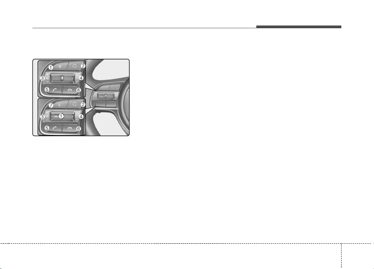
Steering wheel remote control
❈ The actual features in the vehicle
may differ from the illustration.
(1) MUTE
• Press to mute audio output.
(2) MODE
• Press the button to change the
mode in the following order: Radio
➟ Media.
(3) VOLUME
• Press to adjust the volume.
(4) UP/DOWN
• Press the button in radio mode to
search Presets.
• Press and hold the button in radio
mode to search frequencies.
• Press the button in media mode to
change the current song.
• Press and hold the button in media
mode to quick search through
songs.
(5) CALL
• Pressing the button
- If not in Bluetooth
®
Handsfree
mode or receiving a phone call
First press: Display Dial Number
screen
Second press: Automatically dis-
play the most recently Dialed
Call number
Third press: Dial the phone num-
ber entered
- Press in the Incoming Call notifi-
cation screen to accept the
phone call.
- Press in Bluetooth
®
Handsfree
mode to switch to the waiting
call.
• Pressing and holding the button
- If not in Bluetooth
®
Handsfree
mode or receiving a phone call,
the most recently Dialed Call
number is dialed.
- Press in Bluetooth
®
Handsfree
mode to transfer the call to your
cell phone.
- Press in cell phone mode to
switch to Bluetooth
®
Handsfree
mode.
Audio system
11
5

(6) END
• Press in Bluetooth
®
Handsfree
mode to end the phone call.
• Press in the incoming call screen
to reject the call.
(7) VOICE
• Pressing the button
- If voice recognition is not active:
Start voice recognition.
- During the notification message
after voice recognition is started:
The notification message is
skipped, and voice command
standby mode is activated.
- While standing by for a voice
command: Extend voice com-
mand standby time.
• Pressing and holding the button:
End voice recognition.
Audio system
512
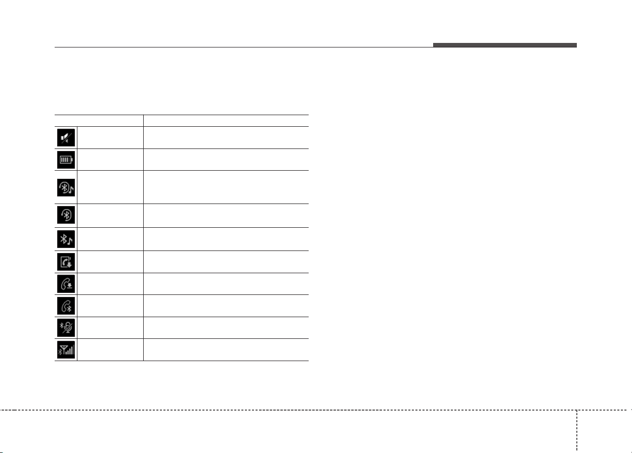
Information on status icons
Icons showing audio status are shown in the upper-right
corner of the screen.
Icon Function
Mute Mute engaged
Battery
Remaining battery life of a connected
Bluetooth
®
device
Handsfree +
Audio streaming
connection
Bluetooth
®
Handsfree call and audio stream-
ing available
Handsfree
connection
Bluetooth
®
Handsfree call available
Bluetooth
®
audio streaming
Bluetooth
®
audio streaming available
Downloading
contacts
Downloading contacts through Bluetooth
®
wire-
less communications
Downloading
call history
Downloading call history through Bluetooth
®
wireless communications
Line busy Phone call in progress
Mute mic
Mic muted during a call
(caller cannot hear your voice)
Phone signal
strength
Display the phone signal strength for a cell
phone connected by Bluetooth
®
Audio system
13
5
Audio system
514
WARNING
- Audio System Safety
Warnings
• Do not stare at the screen
while driving. Staring at the
screen for prolonged periods
of time could lead to traffic
accidents.
• Do not disassemble, assem-
ble, or modify the audio sys-
tem. Such acts could result in
accidents, fire, or electric
shock.
• Using the phone while driving
may lead to a lack of attention
of traffic conditions and
increase the likelihood of
accidents. Use the phone fea-
ture after parking the vehicle.
• Exercise caution not to spill
water or introduce foreign
objects into the device. Such
acts could lead to smoke, fire,
or product malfunction.
(Continued)
(Continued)
• Please refrain from use if the
screen is blank or no sound
can be heard as these signs
may indicate product malfunc-
tion. Continued use in such
conditions could lead to acci-
dents (fires, electric shock) or
product malfunctions.
• Do not touch the antenna dur-
ing thunder or lightening as
such acts may lead to light-
ning induced electric shock.
• Do not stop or park in park-
ing-restricted areas to operate
the product. Such acts could
lead to traffic accidents.
• Use the system with the vehi-
cle ignition turned on.
Prolonged use with the igni-
tion turned off could result in
battery discharge.
WARNING- Distracted
Driving
Driving while distracted can
result in a loss of vehicle con-
trol that may lead to an acci-
dent, severe personal injury,
and death. The driver’s primary
responsibility is in the safe and
legal operation of a vehicle, and
use of any handheld devices,
other equipment, or vehicle sys-
tems which take the driver’s
eyes, attention and focus away
from the safe operation of a
vehicle or which are not permis-
sible by law should never be
used during operation of the
vehicle.

Audio system
15
5
(Continued)
• If you want to change the posi-
tion of device installation,
please inquire with your place
of purchase or service mainte-
nance center. Technical
expertise is required to install
or disassemble the device.
• Turn on the car ignition before
using this device. Do not oper-
ate the audio system for long
periods of time with the igni-
tion turned off as such opera-
tions may lead to battery dis-
charge.
• Do not subject the device to
severe shock or impact. Direct
pressure onto the front side of
the monitor may cause damage
to the LCD or touch screen.
(Continued)
(Continued)
• When cleaning the device,
make sure to turn off the
device and use a dry and
smooth cloth. Never use
tough materials, chemical
cloths, or solvents (alcohol,
benzene, thinners, etc.) as
such materials may damage
the device panel or cause
color/quality deterioration
• Do not place beverages close
to the audio system. Spilling
beverages may lead to system
malfunction.
• In case of product malfunc-
tion, please contact your place
of purchase or After Service
center.
• Placing the audio system with-
in an electromagnetic environ-
ment may result in noise inter-
ference.
CAUTION
• Operating the device while
driving could lead to acci-
dents due to a lack of atten-
tion to external surroundings.
First park the vehicle before
operating the device.
• Adjust the volume to levels
that allow the driver to hear
sounds from outside of the
vehicle. Driving in a state
where external sounds cannot
be heard may lead to acci-
dents.
• Pay attention to the volume
setting when turning the
device on. A sudden output of
extreme volume upon turning
the device on could lead to
hearing impairment. (Adjust
the volume to a suitable levels
before turning off the device.)
(Continued)
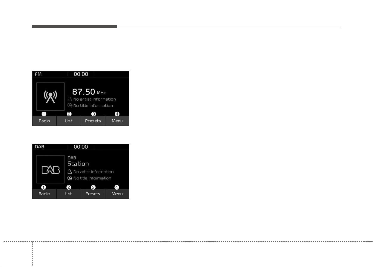
Radio
FM/AM (with RDS)
DAB (if equipped)
(1) Radio
Switch between FM, AM and DAB*.
* if equipped
(2) List
View all available stations.
(3) Presets
View all presets.
(4) Menu
Navigate to the menu screen.
Switching between FM, AM and DAB*
• Press the [RADIO] button on the
audio system to switch between
FM, AM and DAB*.
• Press the [Radio] on the screen to
switch between FM, AM and DAB*.
* if equipped
Searching channels
Press the [SEEK/TRACK] button to
search channels.
List
A list of all stations available in the
vehicle’s current location is dis-
played. Press the desired station.
Favourite stations can be saved to
[Presets] by pressing the [+].
Presets
Save up to 40 frequently used sta-
tions.
To listen to a preset, press the
desired station list.
Press and hold the desired slot from
1 through 40. This saves the current
station in the selected slot.
If the slot is empty, simply pressing
saves the station to the slot.
Menu
• Traffic Announcement (TA): Enable
or disable Traffic Announcements.
• Scan: All available stations are
played for five seconds each.
• Sound Settings: Audio sound set-
tings can be changed.
Audio system
516
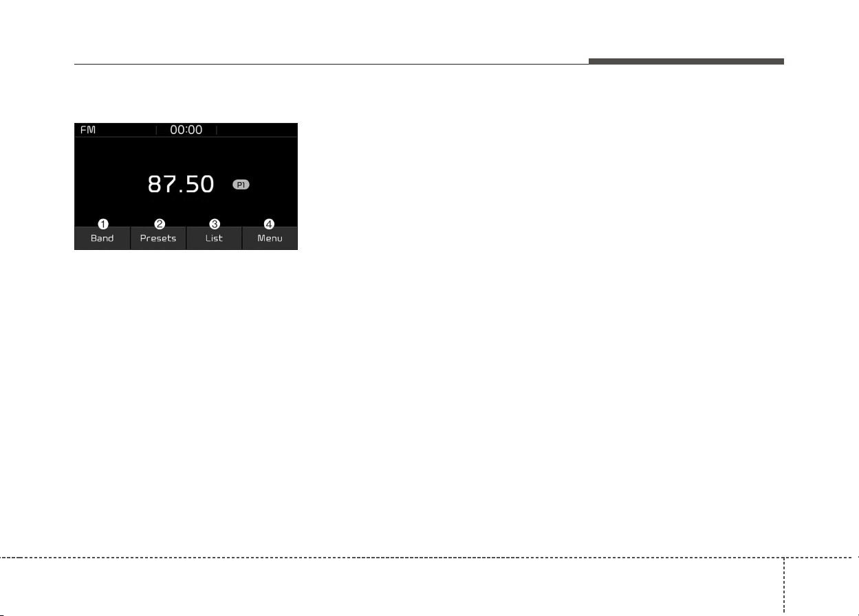
Audio system
17
5
FM/AM (without RDS)
(1) Band
Switch between FM, AM.
(2) Presets
View all presets.
(3) List
View all available stations.
(4) Menu
Navigate to the menu screen.
Switching between FM, AM
• Press the [RADIO] button on the
audio system to switch between
FM, AM.
• Press the [Radio] on the screen to
switch between FM, AM.
Searching channels
Press the [SEEK/TRACK] button to
search channels.
List
A list of all stations available in the
vehicle’s current location is dis-
played. Press the desired station.
Favourite stations can be saved to
[Presets] by pressing the [save].
Presets
Save up to 40 frequently used sta-
tions.
To listen to a preset, press the
desired station list.
Press and hold the desired slot from
1 through 40. This saves the current
station in the selected slot.
If the slot is empty, simply pressing
saves the station to the slot.
Menu
• Scan: All available stations are
played for five seconds each.
• Sound Settings: Audio sound set-
tings can be changed.

Audio system
518
Media
MP3
Supported audio formats
✽✽
NOTICE
File formats other than the formats
above may not be recognized or
playable. Information such as file-
name may not be displayed.
Range of supported compressed file
types
1. Bitrate range (Kbps)
2. Sampling frequency (Hz)
• The sound quality of MP3/WMA
compressed files may vary
depending on the bitrate. (A higher
bitrate can have better sound qual-
ity.)
• The product only recognizes files
with the MP3 or WMA extension.
Files without one of these exten-
sions are not recognized.
3. Number of recognizable folders
and files
• Folders: 2,000 for USB
• Files: 6,000 for USB
• No recognition limit for folder hier-
archies
MPEG1 MPEG2 MPEG2.5 WMA
44100 22050 11025 32000
48000 24000 12000 44100
32000 16000 8000 48000
Compressed
audio for-
mats
MPEG1 Audio Layer3
MPEG2 Audio Layer3
MPEG2.5 Audio Layer3
Windows Media Audio Ver 7.X &
8.X
BIT RATE(kbps)
MPEG1 MPEG2 MPEG2.5 WMA
Layer3
High Range
32 8 8 48
40 16 16 64
48 24 24 80
56 32 32 96
64 40 40 128
80 48 48 160
96 56 56 192
112 64 64
128 80 80
160 96 96
192 112 112
224 128 128
256 144 144
320 160 160

Audio system
19
5
4. Character display range (Unicode)
• Filenames: Up to 64 English char-
acters (64 Korean characters)
• Filenames: Up to 32 English char-
acters (32 Korean characters)
Languages supported (Unicode sup-
port)
• Korean: 2,604 characters
• English: 94 characters
• Common Chinese characters:
4,888 characters
• Special symbols: 986 characters
✽✽
NOTICE
Japanese/Simplified Chinese char-
acters are not supported.

Audio system
520
✽✽
NOTICE - Using the USB
Devices
• Starting the vehicle while a USB
device is connected can damage
the device. Please disconnect USB
devices before starting the vehicle.
• Starting the vehicle or stopping
the engine while an external USB
device is connected can result in
failure of the external USB device
to operate.
• Be cautious of static electricity
when connecting/disconnecting
external USB devices.
• An encrypted MP3 player is not
recognized when connected as an
external device.
• External USB devices may not be
recognized, depending on the state
of the external USB device.
• Only products with byte/sectors
formatted at 4 KB or lower are
recognized.
• Only USB devices in FAT12/16/32
format are recognized; NTFS and
ExFAT file systems are not recog-
nized.
• Some USB devices are not recog-
nized due to compatibility issues.
(Continued)
(Continued)
• Do not touch the USB connections.
• Connecting and disconnecting
USB devices rapidly over a short
period of time can cause equip-
ment failure.
• Abnormal sounds may be audible
when the USB device is discon-
nected.
• Turn the audio off before connect-
ing or disconnecting external USB
devices.
• Recognition may take longer
depending on the type, capacity or
file format of the external USB
device. This is not a product mal-
function.
• Use of USB devices for purposes
other than playing music files is
prohibited.
• Image display and video playback
are not supported.
• Use of USB accessories, including
charge and heat though the USB
I/F, can lead to reduced product
performance or malfunctions. Do
not use USB devices or accessories
for these purposes.
(Continued)
(Continued)
• Use of aftermarket USB hubs and
extension cables can result in the
vehicle’s audio system failing to
recognize your USB device.
Connect the USB device directly to
the multimedia port of your vehi-
cle.
• When using high-capacity USB
devices with logical drive divi-
sions, only files saved on the high-
est level logical drive can be
played.
If applications are loaded on a
USB drive, file playback may fail.
• Some MP3 players, cell phones,
digital cameras, etc. (USB devices
that are not recognized as mobile
storage) may not operate normally
when connected.
• USB charging may not be sup-
ported by some mobile devices.
• Operation is guaranteed only for
standard (Metal Cover Type) USB
Memory drives.
• Operation of HDD, CF, SD and
memory stick devices is not guar-
anteed.
(Continued)

Audio system
21
5
(Continued)
• DRM (Digital Rights Management)
files cannot be played.
• SD-type USB memory, CF-type
USB memory, and other USB
memory devices that require
adapters for connection are not
supported.
• Proper operation of USB HDDs or
USB drives with connectors that
loosen due to vehicle vibrations is
not guaranteed. (iStick, etc.)
• USB products that are
used as key chains or
cell phone accessories
may damage the USB
jack and affect proper
file playback. Please refrain from
use. Use only products with plug
connectors, as shown in the follow-
ing illustration.
• When MP3 devices or cell phones
are connected simultaneously
through AUX, BT Audio and USB
modes, a popping noise or mal-
function may occur.
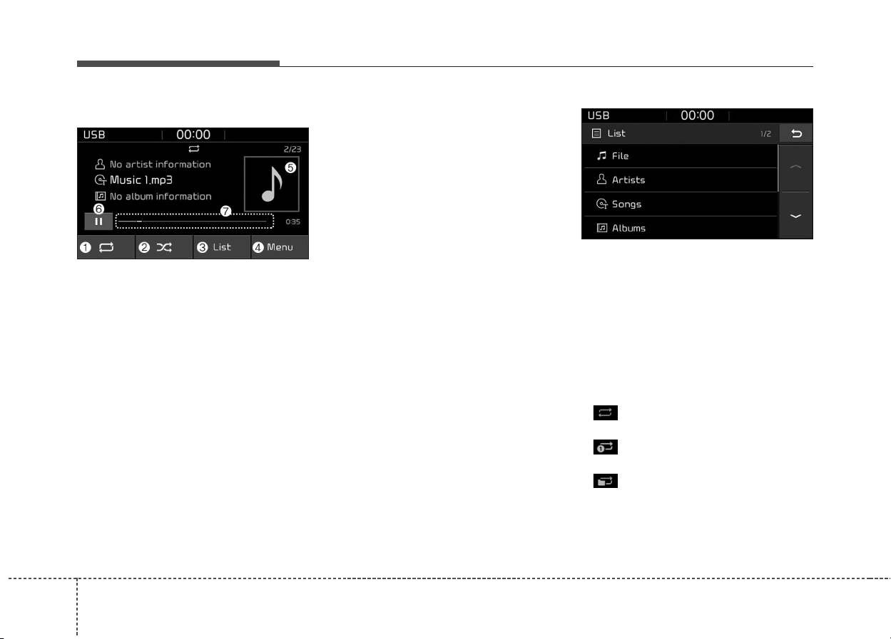
Audio system
522
USB
(1) Repeat
Enable/disable repeat.
(2) Shuffle
Enable/disable shuffle play.
(3) List
View a list of all songs.
(4) Menu
Navigate to the menu screen.
(5) Album Image
View song info.
(6) Pause
Pause or play music.
(7) Playback progress
Press to skip to the desired location.
Playback
• Press the [MEDIA] button, and
select [USB].
• Connect a USB drive to the USB
port to automatically play files on
the USB drive.
Changing songs
• Press the [SEEK/TRACK] button
to play the previous or next song.
• Press and hold the [SEEK/
TRACK] button to rewind or fast
forward the currently playing song.
• Search songs by turning TUNE
knob, and press the knob to play.
Selecting songs from a list
Press the [List] to see a list of songs
available for play.
Select and play the desired song.
Repeat play
Press the [Repeat] to enable or dis-
able ‘Repeat all’, ‘Repeat current
song’, or ‘Repeat folder’.
• Repeat all: All songs in the
playlist are repeated.
• Repeat current song: The cur-
rently playing song is repeated.
• Repeat folder: All songs in the
current folder are repeated.
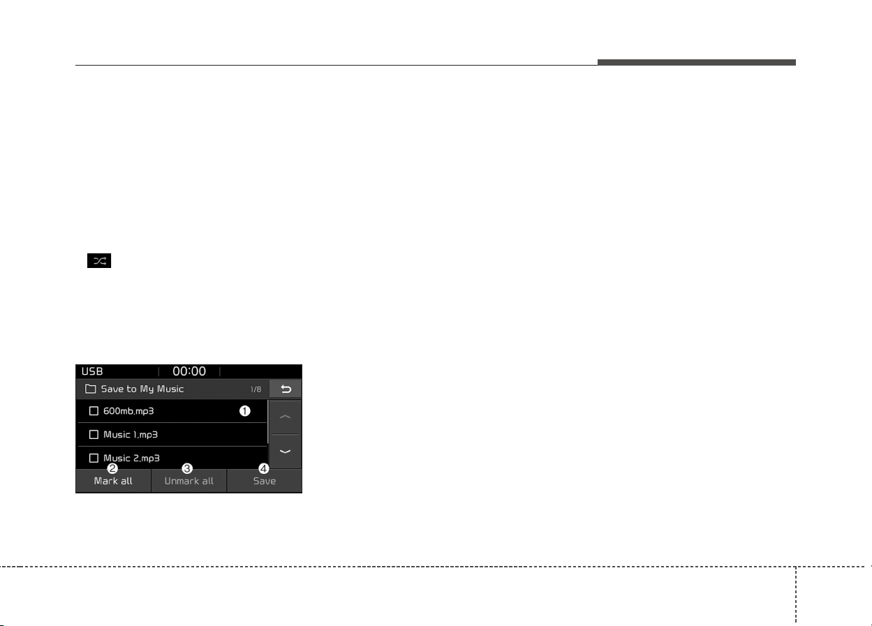
Audio system
23
5
✽✽
NOTICE
The repeat folder function is avail-
able only when songs are playing
from the [File] category under
[List].
Shuffle play
Press the [Shuffle] to enable/disable
‘Shuffle’ play.
• Shuffle: Songs are played in
random order.
Menu
Press the [Menu], and select the
desired function.
• Save to My Music: Songs on your
USB device can be saved to My
Music.
(1) File: Select a file to save
.
(2) Mark all(Mark All): Select all files.
(3) Unmark all(Unmark All): Deselect
all files.
(4) Save: Save the selected file(s).
- Select the files you want to save,
and press the [Save]. This saves
the selected files to My Music.
- Saving is canceled if voice
recognition is activated or phone
calls are received or made while
saving.
- Up to 6,000 files can be saved.
- The currently playing file on the
USB device cannot be changed
while saving.
- My Music cannot be used while
saving.
- Up to 700 MB can be saved.
• Information: Detailed information
on the currently playing song is dis-
played.
• Scan: All songs are played for 10
seconds each.
• Sound Settings: Audio sound set-
tings can be changed.

Audio system
524
✽✽
NOTICE - Using the iPod
®
Devices
• To use the audio system’s iPod
®
control function, use the dedicated
cable provided with your iPod
®
.
• Connecting the iPod
®
to the vehi-
cle during play may result in a
loud noise that lasts about one to
two seconds. Connect the iPod
®
to
the vehicle after stopping or paus-
ing play.
• Connect the iPod
®
with the vehicle
in the ACC ON state to begin
charging.
• When connecting the iPod
®
cable,
be sure to fully push the cable into
the port.
• When EQ effects are enabled
simultaneously on external
devices, such as iPod
®
s and the
audio system, the EQ effects may
overlap, causing sound quality
deterioration or distortion.
Deactivate the EQ function for all
external devices, if possible.
• Noise may occur when your iPod
®
or the AUX port is connected.
Disconnect and store separately
when not in use.
(Continued)
(Continued)
• There may be noise if the audio
system is used with an iPod
®
or
AUX external device connected to
the power jack. In these cases, dis-
connect the iPod
®
or external
device from the power jack.
• Play may be interrupted, or device
malfunctions may occur depend-
ing on the characteristics of your
iPod
®
/iPhone
®
.
• Play may fail if your iPhone
®
is con-
nected through both Bluetooth
®
and
USB. In this case, select Dock con-
nector or Bluetooth
®
on your
iPhone
®
to change the sound output
settings.
• If your software version does not
support the communication proto-
col or your iPod
®
is not recognized
due to device failure, anomalies or
defects, iPod
®
mode cannot be
used.
• iPod
®
nano (5th generation)
devices may not be recognized if
the battery is low. Charge suffi-
ciently before use.
(Continued)
(Continued)
• The search and song play order in
the iPod
®
device may be different
from the search order in the audio
system.
• If the iPod
®
has failed due to an
internal defect, please reset the
iPod
®
(consult your iPod
®
manual).
• Depending on the software ver-
sion, the iPod
®
may fail to sync
with the system. If the media is
removed or disconnected before
recognition, the previous mode
may not be restored (iPad
®
cannot
be charged).
• Cables other than the 1-meter
cable provided with iPod
®
/iPhone
®
products may not be recognized.
• When other music apps are used
on your iPod
®
, the system sync
function may fail due to malfunc-
tion of the iPod
®
application.
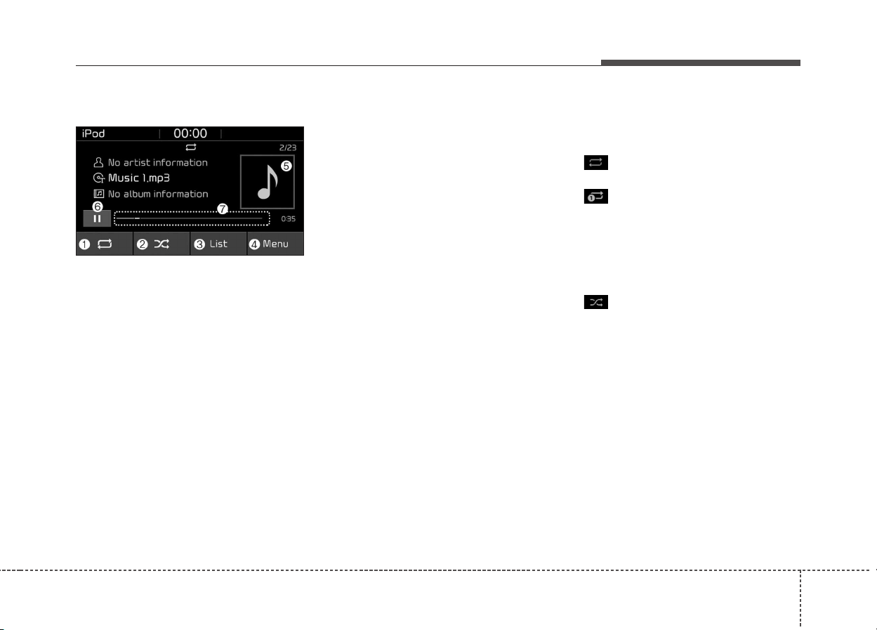
Audio system
25
5
iPod
®
(1) Repeat
Enable/disable repeat.
(2) Shuffle
Enable/disable shuffle play.
(3) List
View a list of all songs.
(4) Menu
Navigate to the menu screen.
(5) Album Image
View song info.
(6) Pause
Pause or play music.
(7) Playback progress
Press to skip to the desired location.
Playback
• Connect your iPod
®
to the audio
USB port, press the [MEDIA] but-
ton, and select [iPod
®
].
Changing songs
• Press the [SEEK/TRACK] button
to play the previous or next song.
• Press and hold the [SEEK/
TRACK] button to rewind or fast
forward the currently playing song.
• Search songs by turning the TUNE
knob, and press the knob to play.
Selecting songs from a list
Press the [List] to see a list of songs
available for play.
Select and play the desired song.
Repeat play
Press the [Repeat] to enable or dis-
able ‘Repeat current song’.
• Repeat all: Repeat all songs in
the current category.
• Repeat current song: The cur-
rently playing song is repeated.
Shuffle play
Press the [Shuffle] to enable/disable
‘Shuffle’ play.
• Shuffle: Songs are played in
random order.
Menu
Press the [Menu], and select the
desired function.
• Information: Detailed info on the
currently playing song is displayed.
• Sound Settings: Audio sound set-
tings can be changed.
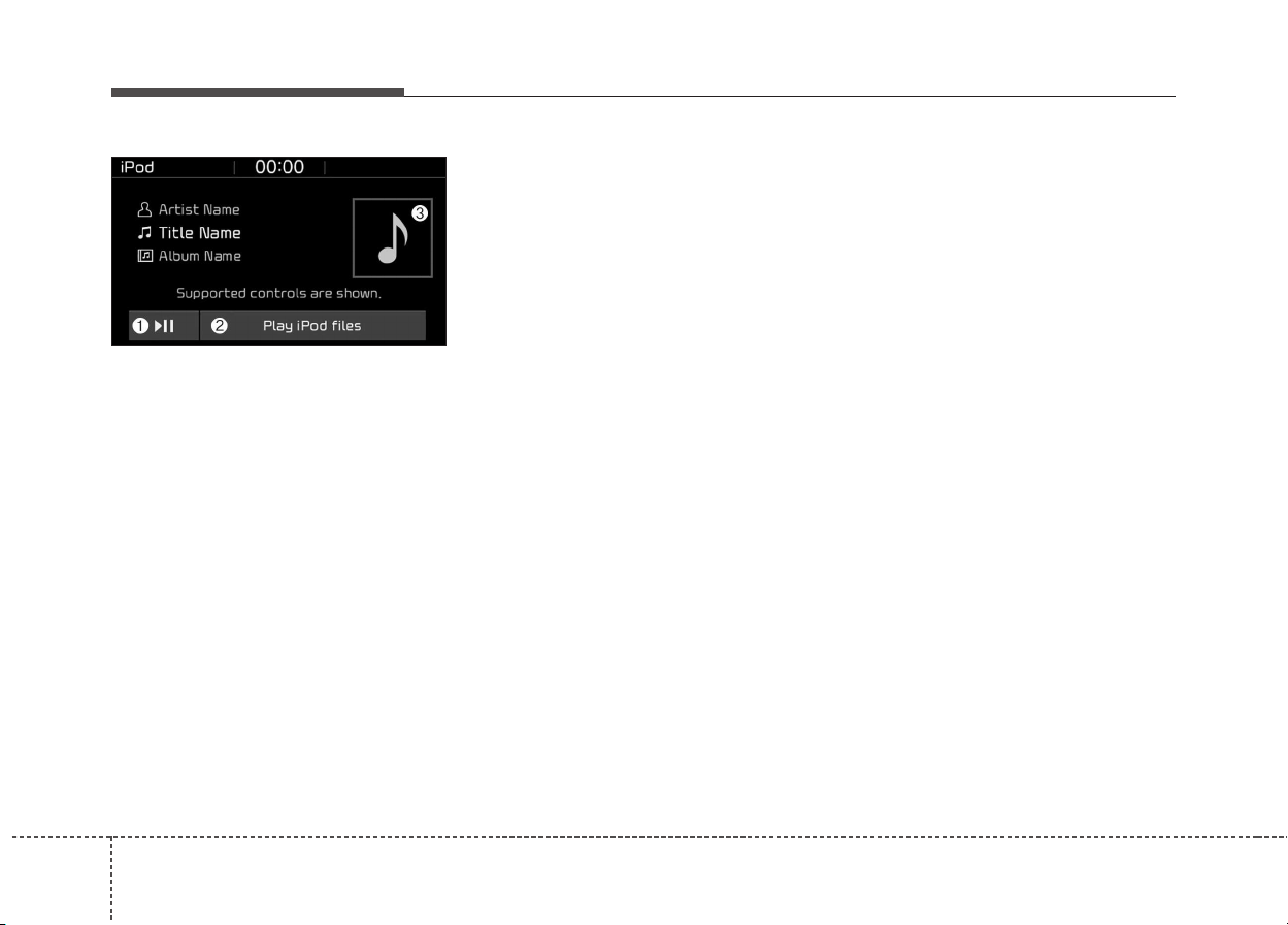
Audio system
526
When other music programs are run-
ning
When songs saved on your iPod
®
are playing through a separate music
app, the following screen is dis-
played.
(1) Play/Pause: Pause or play music.
(2) Play iPod
®
files(Play iPod
®
Files):
Play music saved on your iPod
®
.
(3) Album Image: View playback info.
✽✽
NOTICE
Operation cannot be carried out
correctly due to iPod
®
application
malfunction.
Playing iPod
®
files
• Select [Play iPod
®
files] to play
songs saved on your iPod
®
.
If there are no songs saved on your
iPod
®
, the [Play iPod
®
files(Play
iPod
®
Files)] is disabled.

Audio system
27
5
✽✽
NOTICE - Using
Bluetooth
®
(BT) Audio
• Bluetooth
®
Audio mode can only
be used if a Bluetooth
®
-enabled
phone is connected. Only devices
that support Bluetooth
®
audio can
be used.
• If the Bluetooth
®
-enabled phone is
disconnected during play, the
music stops.
• When the TRACK UP/DOWN
buttons are used during Bluetooth
®
audio streaming, a popping noise
or sound interruptions may occur,
depending on the cell phone
device.
• Depending on the cell phone
model, the audio streaming func-
tion may not be supported.
• If a phone call is made or received
when music is playing in
Bluetooth
®
Audio mode, the call
may mix with the music.
• When returning to Bluetooth
®
Audio mode after ending a call,
play might not resume automati-
cally for some cell phone models.
CAUTION
• Bluetooth
®
Wireless Technology
Handsfree is a feature that
enables drivers to practice
safe driving. Connecting the
car audio system with a
Bluetooth
®
Wireless Technology
phone allows the user to con-
veniently make calls, receive
calls, and manage the phone
book. Before using the
Bluetooth
®
Wireless Technology,
carefully read the contents of
this user’s manual.
• Excessive use or operations
while driving may lead to neg-
ligent driving practices and be
the cause of accidents.
• Do not operate the device
excessively while driving.
• Viewing the screen for pro-
longed periods of time is dan-
gerous and may lead to acci-
dents.
• When driving, view the screen
only for short periods of time.

Audio system
528
Bluetooth
®
(BT) Audio
(1) Play/Pause
Pause or play music.
(2) Menu
Navigate to the menu screen.
(3) Album Image
View song info.
✽✽
NOTICE
• Some cell phone models may not
support particular functions.
• Bluetooth
®
audio volume is synced
with cell phone media volume.
Playback
• Press the [MEDIA] button, and
select [BT Audio].
Changing songs
• Press the [SEEK/TRACK] button
to play the previous or next song.
✽✽
NOTICE
Some cell phones may not support
this function.
Menu
Press the [Menu], and select the
desired function.
• Connections: The currently con-
nected Bluetooth
®
device can be
changed.
• Information: Detailed information
on the currently playing song is dis-
played.
• Sound settings: Audio sound set-
tings can be changed.
AUX
Running AUX
• Press the [MEDIA] button, and
select [AUX].
• Connect the external device con-
nection jack to the AUX terminal to
run AUX.
(1) Sound Settings: Audio sound set-
tings can be changed.
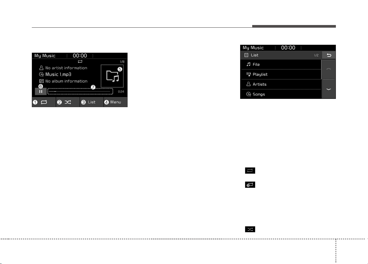
Audio system
29
5
My Music
(1) Repeat
Enable/disable repeat.
(2) Shuffle
Enable/disable shuffle play.
(3) List
View a list of all songs.
(4) Menu
Navigate to the menu screen.
(5) Album Image
View song info.
(6) Pause
Pause or play music.
(7) Playback progress
Press to skip to the desired location.
Playback
Press the [MEDIA] button, and
select [My Music].
• My Music cannot be selected if it
does not contain music.
• Check the content of your USB
drive before saving music to My
Music.
Changing songs
Press the [SEEK/TRACK] button to
play the previous or next song.
• Press and hold the [SEEK/
TRACK] button to rewind or fast
forward the currently playing song.
• Search songs by turning the TUNE
knob and press the knob to play.
Selecting songs from a list
Press the [List] to see a list of songs
available for play.
Select and play the desired song.
Repeat play
Press the [Repeat] to enable or dis-
able ‘Repeat all’ or ‘Repeat current
song’.
• Repeat all: All songs in the
playlist are repeated.
• Repeat current song: The cur-
rently playing song is repeated.
Shuffle play
Press the [Shuffle] to enable/disable
‘Shuffle’ play.
• Shuffle: Songs are played in
random order.
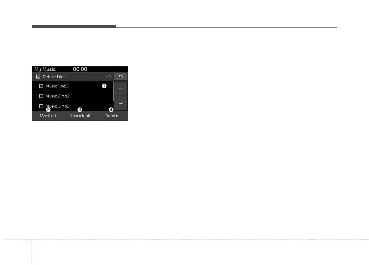
Audio system
530
Menu
Press the [Menu], and select the
desired function.
• Delete files: You can delete files
from My Music.
(1) File: Select saved file.
(2) Mark all(Mark All): Select all files.
(3) Unmark all(Unmark All): Deselect
all files.
(4) Delete: Delete the selected file(s).
- Select the file to delete, then
press the [Delete] to delete it.
- Delete is canceled if voice recog-
nition is activated or phone calls
are received or made during
delete.
• Add to playlist(Add to Playlist):
Frequently played songs can be
paired in a [Playlist].
- Songs can be played from the
[Playlist].
• Information: Detailed info on the
currently playing song is displayed.
• Sound Settings: Audio sound set-
tings can be changed.
• Scan: All songs are played for 10
seconds each.
Delete from playlist(Delete from
Playlist)
When a song in the playlist is play-
ing, press the [Menu] and select
[Delete from playlist(Delete from
Playlist)].
Select the song to delete, then press
[Delete].

Audio system
31
5
Phone
✽✽
NOTICE - Using
Bluetooth
®
(BT) Phone
• Bluetooth
®
is a near-field wireless
networking technology that uses
the 2.4 GHz frequency to connect
various devices within a certain
distance wirelessly.
• The technology is used in PCs,
peripherals, Bluetooth
®
phones,
tablet PCs, household appliances
and automobiles. Devices support-
ing Bluetooth
®
can exchange data
at high speeds without physical
cable connections.
• Bluetooth
®
Handsfree devices
enable convenient access to phone
functions through cell phones
equipped with Bluetooth
®
.
• Some Bluetooth
®
devices may not
be supported by the Bluetooth
®
Handsfree function.
(Continued)
(Continued)
• When Bluetooth
®
is connected and
calls are attempted through a con-
nected cell phone from outside the
vehicle, the call is connected
through the Bluetooth
®
Handsfree
function of the vehicle.
• Please be sure to disconnect the
Bluetooth
®
Handsfree function
through your Bluetooth
®
device or
the audio screen.
Safety precautions
• The Bluetooth
®
Handsfree function
helps drivers to drive safely. By
connecting a Bluetooth
®
-enabled
phone to the vehicle’s audio sys-
tem, phone calls can be made and
received through the audio system
and contacts can be managed.
Consult the user manual before
use.
• Excessive manipulation of controls
while driving, making it difficult to
pay attention to the road ahead,
can lead to accidents. Do not oper-
ate the device excessively while
driving.
• Looking at the screen for a pro-
longed time increases the risk of
accidents. Keep time spent looking
at the screen to a minimum.

Audio system
532
Precautions when connecting Bluetooth
®
devices
• The vehicle supports the following
Bluetooth
®
functions. Some
Bluetooth
®
devices may not sup-
port some functions.
1) Bluetooth
®
Handsfree phone
calls
2) Operations during a call
(Private, Switch, Mic Vol.(Out
Vol.) controls)
3) Download call history saved to
the Bluetooth
®
device
4) Download contacts saved to the
Bluetooth
®
device
5) Automatic contacts/call history
download when Bluetooth
®
is
connected
6) Automatic Bluetooth
®
device
connection when the vehicle is
started
7) Bluetooth
®
audio streaming
playback
• Before connecting the audio sys-
tem to your device, make sure your
device supports Bluetooth
®
.
• Even if your device supports
Bluetooth
®
, a Bluetooth
®
connec-
tion cannot be established if the
device’s Bluetooth
®
function is
switched off. Search and connect
with the Bluetooth
®
function
enabled.
• Pair or connect Bluetooth
®
devices
to the audio system with the vehi-
cle at a standstill.
• If a Bluetooth
®
connection is lost
due to abnormal conditions while a
Bluetooth
®
device is connected
(communication range exceeded,
device power OFF, communication
errors, etc.), the disconnected
Bluetooth
®
device is searched for
and automatically reconnected.
• If you want to disable the
Bluetooth
®
device auto-connect
function, turn the Bluetooth
®
func-
tion OFF on your device. Consult
the user manuals for individual
devices to see whether Bluetooth
®
is supported.
• Handsfree call quality and volume
may vary depending on the type of
Bluetooth
®
device.
• Some Bluetooth
®
devices are sub-
ject to intermittent Bluetooth
®
con-
nection failures. In this case, use
the following method.
1) Turn the Bluetooth
®
function off
on your Bluetooth
®
device ➟
Turn it on and try again.
2) Delete the paired device from
both the audio system and
Bluetooth
®
device, then pair
again.
3) Power down your Bluetooth
®
device ➟ Turn it on and try
again.
4) Completely remove the battery
from your Bluetooth
®
device;
reinsert it, reboot, and attempt
connection.
5) Restart the vehicle and reat-
tempt connection.
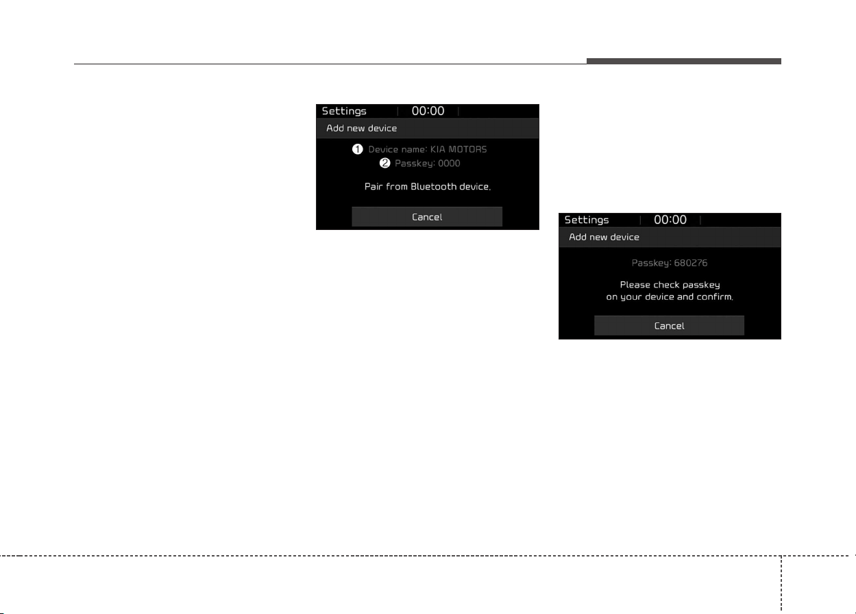
Audio system
33
5
Pairing a Bluetooth
®
device
Information on pairing Bluetooth
®
devices
• Pairing refers to the process of
pairing Bluetooth
®
cell phones or
devices with the system prior to
connection. This is a necessary
procedure for Bluetooth
®
connec-
tion and usage.
• Up to five devices can be paired.
• Pairing Bluetooth
®
device is not
allowed while vehicle is moving
Pairing the first Bluetooth
®
device
Select the [PHONE] button on the
audio system or the [CALL] button
on the steering wheel remote control
➟ Search for the vehicle from the
Bluetooth
®
device, and pair ➟ Enter
the passkey on the Bluetooth
®
device or approve passkey ➟
Bluetooth
®
pairing completed
1. When the [PHONE] button on the
audio or the [CALL] button on the
steering wheel remote control is
pressed, the following screen is dis-
played. Devices can now be paired.
(1) Device name(Vehicle name):
Searched name in Bluetooth
®
device.
(2) Passkey: Passkey for device pairing.
✽✽
NOTICE
The device name(vehicle name) in
the image above is an example.
Refer to your device for the actual
name of your device.
2. Search for available Bluetooth
®
devices in the Bluetooth
®
menu of
your Bluetooth
®
device (cell
phone, etc.).
3. Confirm that the device name
(vehicle name) in your Bluetooth
®
device matches the device name
(vehicle name) shown on the
audio screen, then select it.
4-1. For devices that require passkey
entry, a passkey entry screen is
shown on your Bluetooth
®
device.
- Enter the passkey ‘0000’, shown
on the audio screen, in your
Bluetooth
®
device.
4-2. For devices that require passkey
confirmation, the following
screen is shown on the audio
system. A 6-digit passkey input
screen is shown in the
Bluetooth
®
device.
- After confirming that the 6-digit
passkey on the audio screen and
the Bluetooth
®
device are identi-
cal, press [OK] in your Bluetooth
®
device.
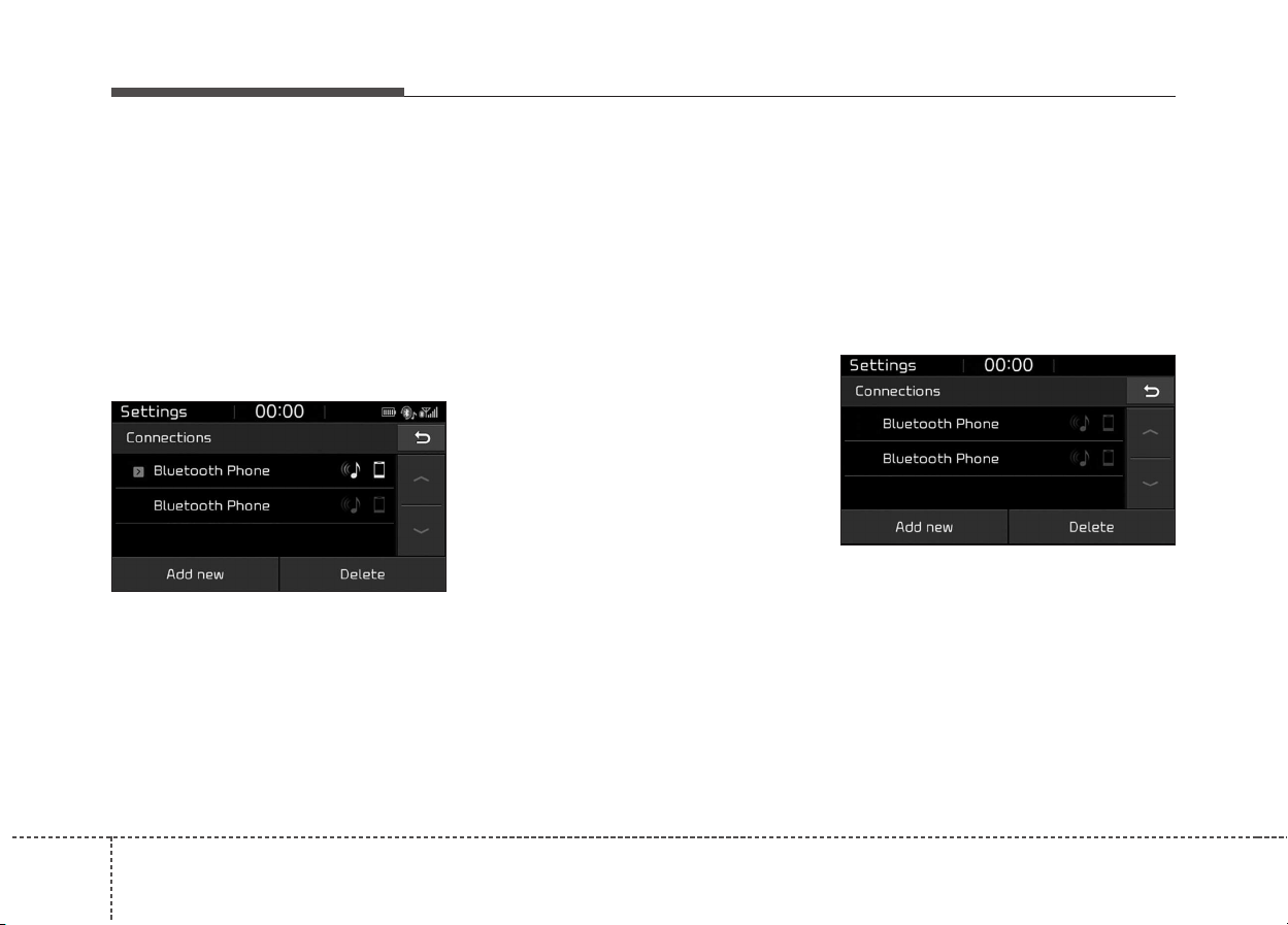
Audio system
534
✽✽
NOTICE
The 6-digit passkey in the image
above is an example. Refer to your
vehicle for the actual passkey
Pairing a second Bluetooth
®
device
Press the [SETUP] button on the
audio system ➟ Select [Phone] ➟
Select [Connections] ➟ Select [Add
new(Add New)].
- The pairing procedure from this
point is identical to [Pairing the first
Bluetooth
®
device].
✽✽
NOTICE
• Bluetooth
®
standby mode lasts for
three minutes. If a device is not
paired within three minutes, pair-
ing is canceled. Start over from the
beginning.
• For most Bluetooth
®
devices, a
connection is established automat-
ically after pairing. Some devices,
however, require separate confir-
mation when connecting after
pairing. Be sure to check your
Bluetooth
®
device after pairing to
confirm that it has connected.
Connecting Bluetooth
®
devices
If there are no connected devices
Select the [PHONE] button on the
audio system or the [CALL] button in
the steering wheel remote control ➟
List of paired Bluetooth
®
devices ➟
Select the desired Bluetooth
®
device
from the list ➟ Connect Bluetooth
®
.
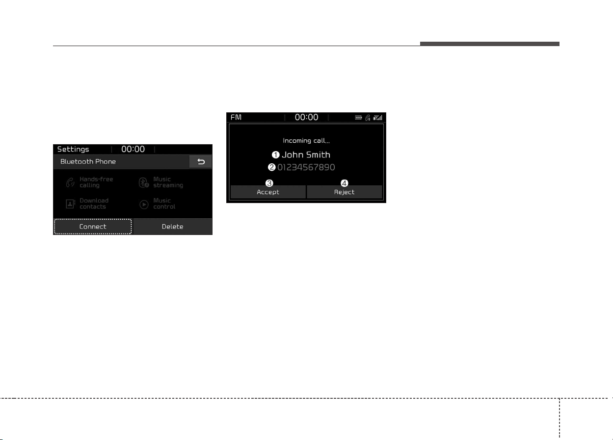
Audio system
35
5
If there are connected devices
Select the [PHONE] button on the
audio system ➟ Select [Settings] ➟
Select [Connections] ➟ Select
Bluetooth
®
device to connect ➟ Select
[Connect] ➟ Connect Bluetooth
®
.
✽✽
NOTICE
• Only one Bluetooth
®
device can be
connected at a time.
• When a Bluetooth
®
device is con-
nected, other devices cannot be
paired.
Accepting/rejecting phone calls
Receiving phone calls with
Bluetooth
®
connected.
(1) Caller name: If the caller number
is in your contacts, the correspon-
ding name is displayed.
(2) Incoming phone number: Incoming
phone number is displayed.
(3) Accept: Accept call.
(4) Reject: Reject call.
✽✽
NOTICE
• When the incoming call screen is
displayed, audio mode and the set-
tings screen cannot be shown.
Only call volume control is sup-
ported.
• Some Bluetooth
®
devices may not
support the call reject function.
• Some Bluetooth
®
devices may not
support the phone number display
function.
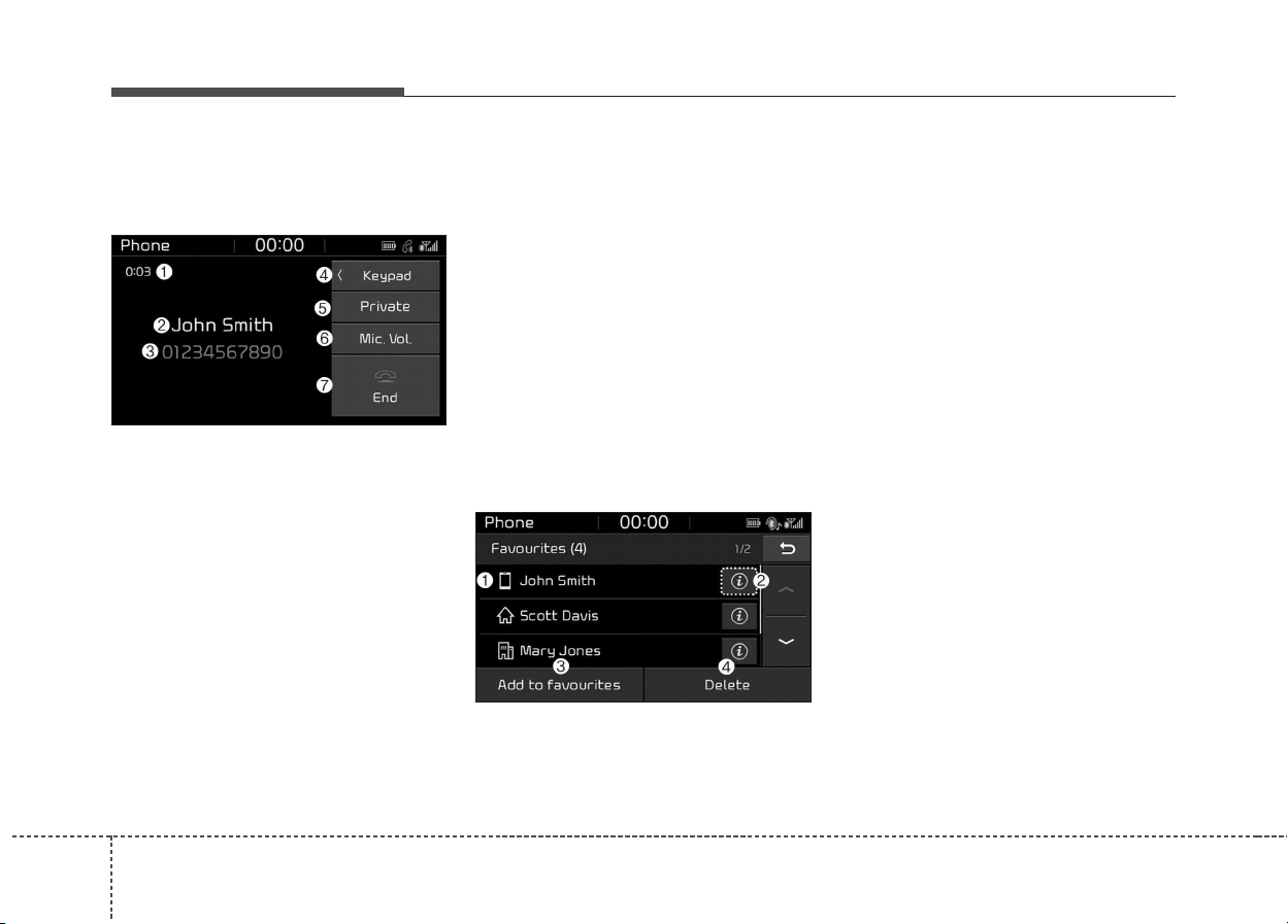
Audio system
536
Operation during calls
Incoming call with Bluetooth
®
con-
nected ➟ Select [Accept].
(1) Call duration: Call duration display.
(2) Caller name: If the caller number is
in your contacts, the corresponding
name is displayed.
(3) Incoming phone number: Incoming
phone number is displayed.
(4) Keypad: Number keypad for
Automatic Response Service input
is displayed.
(5) Private: Call is transferred to a cell
phone.
(6) Microphone Volume(Outgoing
Volume): Adjust outgoing voice
volume.
(7) End: End call.
✽✽
NOTICE
• Some Bluetooth
®
devices may not
support the Private function.
• The outgoing voice volume may
vary depending on the type of
Bluetooth
®
device. If the outgoing
voice volume is too high or low,
adjust the Microphone Volume
(Outgoing Volume).
Favourites(Favorites)
Select the [PHONE] button on the
audio system ➟ Select [Favourites
(Favorites)] ➟ Favourites(Favorites) list
displayed.
(1) Favourites(Favorites) list: A list of
paired favourites(favorites) is dis-
played.
Connect a call when selected.
(2) Detailed info: Detailed info saved
to favourites(favorites) is displayed.
(3) Add to favourites(Favorites): Add a
downloaded phone number to
favourites(favorites).
(4) Delete: Delete a saved favourites
(favorites).
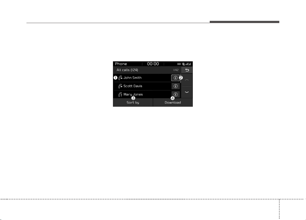
Audio system
37
5
✽✽
NOTICE
• Up to 20 favourites(favorites) can
be paired for each paired
Bluetooth
®
device.
• Favourites(Favorites) can be
accessed when the Bluetooth
®
device they were paired from is
connected.
• The audio system does not down-
load favourites(favorites) from
Bluetooth
®
devices. Favourites
(Favorites) must be newly saved
before use.
• To add to favourites(favorites),
contacts must be downloaded first.
• Saved favourites(favorites) are not
updated even if the contacts of the
connected Bluetooth
®
device are
changed. In this case, favourites
(favorites) need to be deleted and
added again.
Call history
Select the [PHONE] button on the
audio system ➟ Select [Call history]
➟ Call history is displayed.
(1) Call history: Display the down-
loaded call history list.
Connect a call when selected.
(2) Detailed info: Detailed call history
info is displayed.
(3) Sort by: Sort by all calls, dialed
calls, received calls or missed
calls.
(4) Download: Download call history
from connected Bluetooth
®
devices.
✽✽
NOTICE
• Up to 50 dialed, received and
missed calls are saved.
• When the latest call history is
received, the existing call history is
deleted.
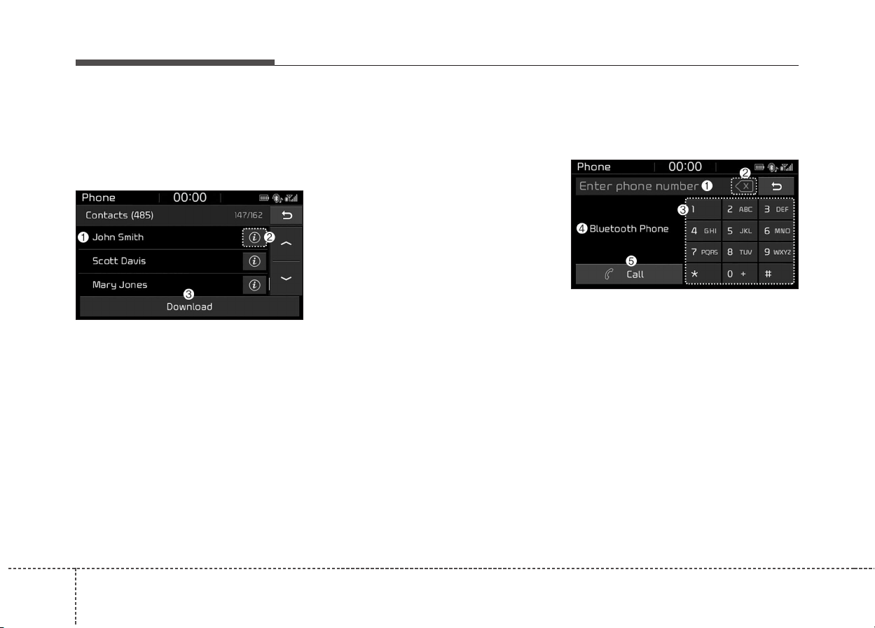
Audio system
538
Contacts
Select the [PHONE] button on the
audio system ➟ Select [Contacts] ➟
Select letter (ABC) ➟ Contacts dis-
played.
(1) Contacts: Display downloaded
contacts.
Connect a call when selected.
(2) Detailed info: Detailed contact
info is displayed.
Phone numbers can be saved in
favourites(favorites) or removed
from the detailed info screen.
(3) Download: Download contacts
from connected Bluetooth
®
devices.
✽✽
NOTICE
• Up to 2,000 contacts can be saved.
• In some cases, additional confir-
mation from your Bluetooth
®
device is necessary when down-
loading contacts. If downloading
of contacts unsuccessful, consult
your Bluetooth
®
device’s settings
or the audio screen to approve the
download.
• Contacts without phone numbers
are not displayed.
Dial
Select the [PHONE] button on the
audio ➟ Select [Dial].
(1) Phone number entry window: The
phone number entered using the
keypad is displayed.
(2) Clear
- Press to delete individual digits.
- Press and hold to delete the
entire phone number.
(3) Keypad: Enter phone number.
(4) Bluetooth
®
phone name
- The name of the connected
Bluetooth
®
device is displayed.
- Contacts matching the keypad
number/letter input are displayed.

Audio system
39
5
(5) Call
- Enter and select a phone num-
ber to call.
- Select without entering a phone
number to see the most recent
dialed call.
Settings
Select the [PHONE] button on the
audio ➟ Select [Settings].
- For phone settings, refer to Setup
page.

Audio system
540
Voice Recognition
(if epuipped)
✽✽
NOTICE - Using the Voice
Recognition
• Voice recognition is a safety tech-
nology that recognizes user voice
commands and executes multime-
dia functions during driving.
• Unfortunately, due to technical
limitations, the system is unable to
recognize all voice commands. To
address these limitations, the voice
commands that the system recog-
nizes are displayed on the screen.
Use the displayed commands.
• Because human speech varies,
voice recognition is sometimes
unable to properly recognize user
voice commands. In these cases,
repeat the voice command dis-
played on the screen, or use the
button on the screen to execute the
desired function.
Precautions to ensure smooth voice
recognition
• If the language setting is
Slovakian, Hungarian or Korean,
voice recognition is not supported.
• Voice recognition only supports
voice commands indicated on-
screen or in the user manual.
• For proper voice recognition,
speak after the beep, which
sounds after voice notification.
• Voice recognition automatically
stops in the following events.
1) Outgoing and incoming phone calls.
2) Media (USB, etc.) is connected
(voice recognition mode is main-
tained when iPod
®
s are connected).
3) Rear camera is activated (option).
4) Vehicle is started or engine is
turned off.
5) Screen transition buttons, such
as [RADIO] or [MEDIA], are
selected.
6) When a pop-up message is dis-
played on the screen due to
accidental execution of the voice
recognition function.
• The voice recognition microphone
is located above the driver’s seat.
To ensure proper voice recogni-
tion, state voice commands while
maintaining proper driving posture.
• Better voice recognition is possible
if you speak naturally and clearly,
as you would in normal conversa-
tion.
• In the following situations, outdoor
noise may prevent proper voice
recognition.
1) Wind noise from an open win-
dow or sunroof may disrupt
voice recognition.
2) Operating the climate blower at
a high level may cause wind
noise that disrupts voice recog-
nition. The recommended set-
ting is 3 or below.
3) When passing through tunnels,
vehicle echoes may disrupt
voice recognition.
4) When passing over uneven ter-
rain, vehicle noise may disrupt
voice recognition.
5) Noise from rain in heavy storms
may disrupt voice recognition.
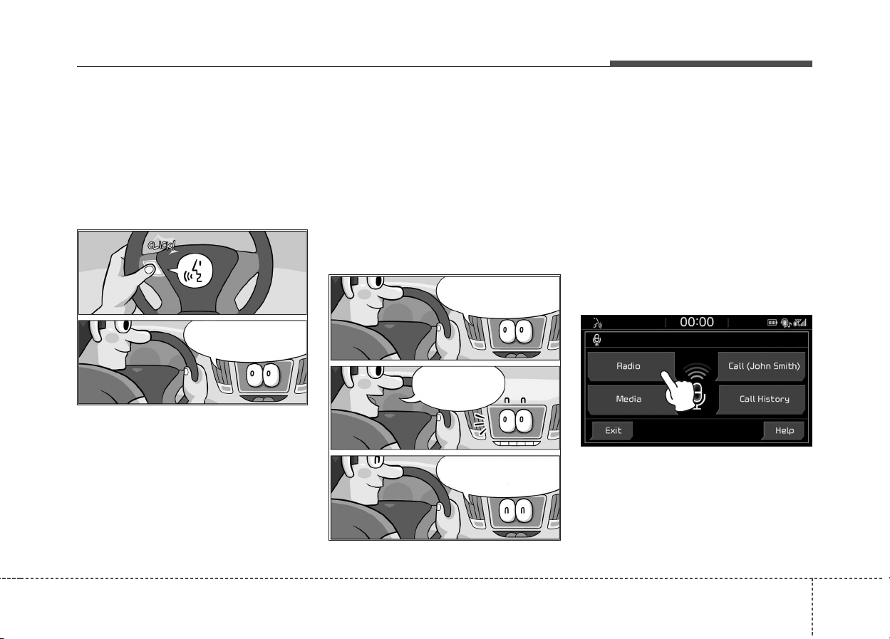
Audio system
41
5
Starting/ending voice recognition,
and settings
Starting voice recognition
Press the [VOICE] button on the
steering wheel remote control to
start voice recognition and see the
voice recognition screen.
Ending voice recognition
• In voice recognition mode, say the
command ‘Exit’ to end voice recog-
nition.
• Press the [Exit] on the bottom left
corner of the screen to end voice
recognition.
• Press and hold the [VOICE] button
on the steering wheel remote con-
trol to end voice recognition.
Quick-starting voice recognition
(manual control)
• Normally, to start voice recognition,
you must wait for the voice prompt
before saying a command. This
involves some waiting time. To run
the function immediately to select
the commands displayed on the
screen.
• This feature is useful if the voice
prompt takes too long or the sys-
tem fails to properly recognize your
voice commands.
Please say a command.
(Ding~?)
Exit
Terminating voice
recognition. (Di-Ding~?)
Please say a command.
(Ding~?)
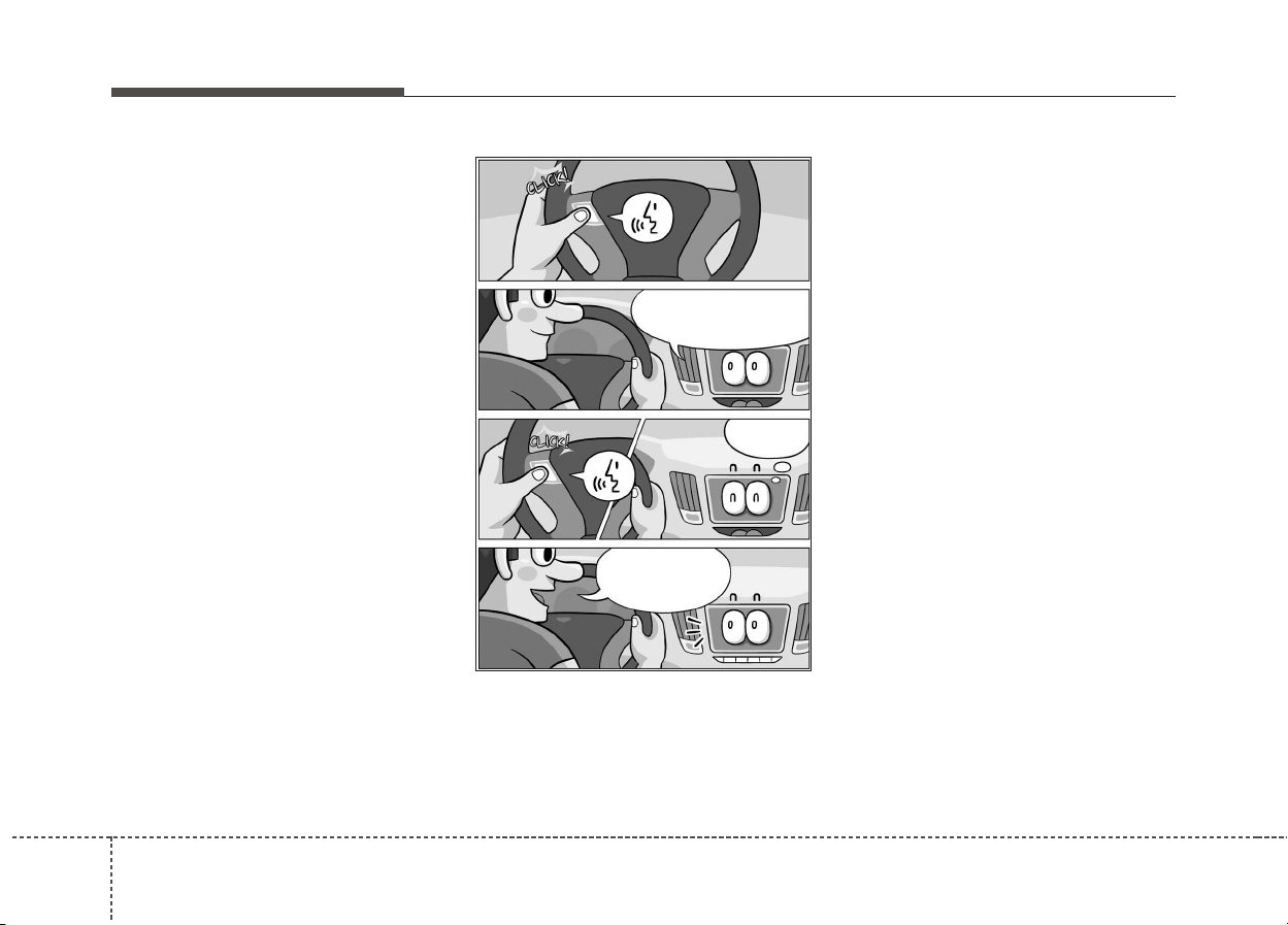
Audio system
542
Skip voice prompt
• While the voice prompt is playing,
press the [VOICE] button on the
steering wheel remote control to
skip the voice prompt and place
the system in standby for your
voice commands.
• This feature is useful if the voice
prompt takes too long or you
already know the voice command
for the desired function.
Please say a...
(Ding~?)
Call
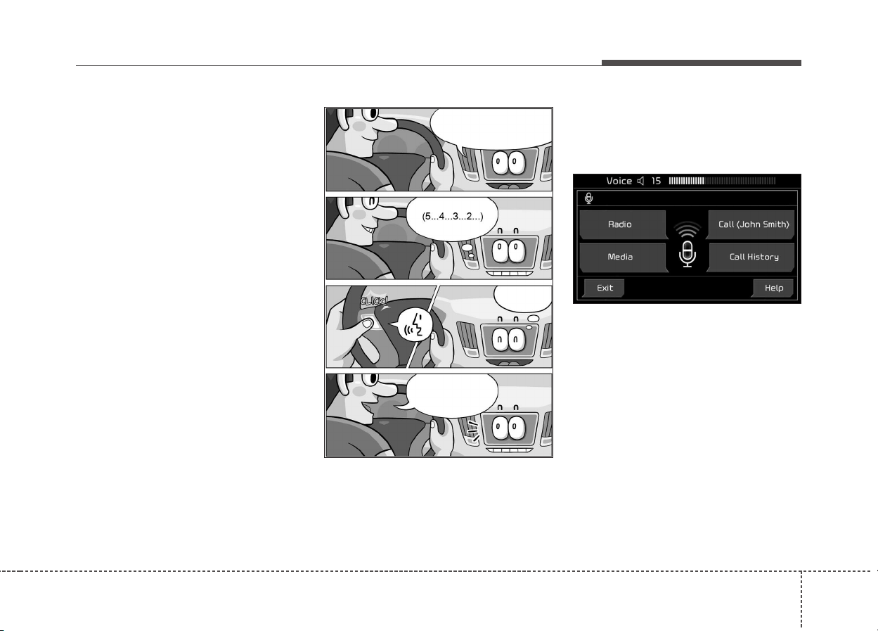
Audio system
43
5
Extending voice recognition standby
time
• After voice recognition is started
and the voice prompt and beep
sound (‘Ding~’) are played, the
system enters standby for user
voice commands for five seconds.
During this five-second standby,
press the button again to play the
beep sound (‘Ding~’), and extend
voice command standby time by
five seconds.
• If you do not say a command for
five seconds, you are prompted by
voice to repeat your command.
Adjusting voice prompt volume
• While voice recognition is running,
turn the VOL knob for the audio to
adjust voice prompt volume.
✽✽
NOTICE
The minimum voice prompt volume
is 1.
(Ding~?)
Call
Please say a command.
(Ding~?)
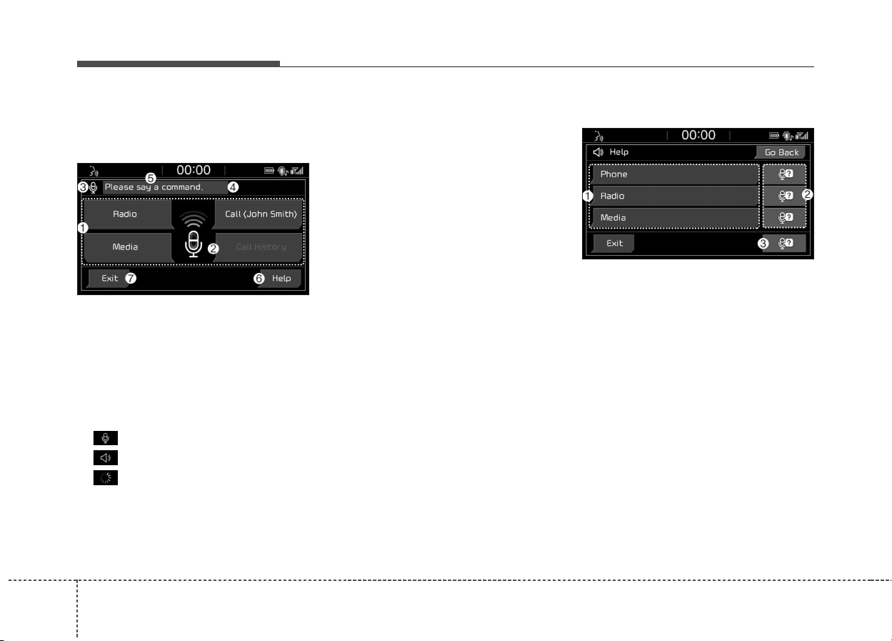
Audio system
544
Guide to the voice recognition
screen
Voice recognition start screen
(1) Four most frequently used com-
mands: The four most frequently
used commands are displayed.
(2) Commands requiring additional
settings: Commands that require
additional settings before use are
displayed.
(3) Voice status icon display.
Voice recognition standby.
Voice prompt in progress.
Processing voice command.
(4) User voice volume: User voice
volume is displayed in real time.
(5) Recognition results: Results for
voice command input are dis-
played.
(6) Help: Available voice commands
displayed in stages.
(7) Exit: End voice recognition.
Voice recognition Help screen
(1) List of voice commands
- Available voice commands are
displayed.
- Select or state each command to
bring up additional detailed com-
mands.
(2) Voice recognition instructions by
item: Voice recognition instruc-
tions are displayed by item.
(3) Voice recognition usage instruc-
tions: General instructions for use
of voice recognition are dis-
played.
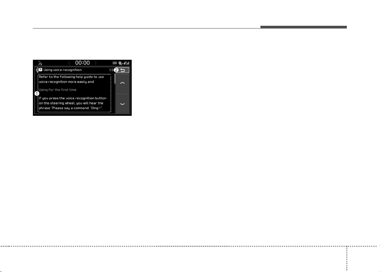
Audio system
45
5
Voice recognition usage instructions
screen
(1) Usage instructions display:
Detailed instructions on voice
instruction usage.
(2) Close: Close the voice recogni-
tion usage instructions screen
and show the previous screen.
✽✽
NOTICE
• Voice recognition is disabled in the
voice recognition usage instruc-
tions screen. Only manual controls
are supported.
• The voice recognition usage
instructions screen provides a
large amount of information. For
safety, the screen is disabled while
driving.
List of voice commands
Voice command types
• Voice commands are categorized
into ‘Global Commands’ and ‘Local
Commands.’
1) Global Commands (●): Commands
that can be used immediately after
voice recognition is started.
2) Local Commands (O): Commands
that can be used when radio,
media or Bluetooth
®
phone func-
tions are running or displayed on
the screen after voice recognition
is started.

Audio system
546
Phone commands
• Voice commands associated with phone functions can
be used after a Bluetooth
®
device has been connected.
• To use voice commands using contact names, such as
‘Call John Smith,’ download contacts beforehand.
• After contacts are downloaded over Bluetooth
®
, some
time may be required for conversion of contact info into
voice data. During this conversion, phone calls cannot
be made by saying contact names. The time required
for contact info conversion depends on the number of
entries in Contacts.
• When the ‘Call <Name>’ command is used, the name
info saved in the downloaded contacts is used. If a
friend with the name ‘John Smith’ is saved to Contacts
under the nickname ‘Buddy,’ ‘Call John Smith’ is not rec-
ognized as a valid command. Instead, ‘Call Buddy’ is
recognized.
✽✽
NOTICE
When dialing by name, if there are similar names or
multiple subentries (mobile, work, home, other), you
may be prompted to select the contact desired from a
list.
Command Features
●
Call
Downloaded contacts are shown on-screen.
Dial by stating the name of the desired contact.
●
Call history
Recent call history is shown on the screen.
State the number of the item on the screen to
dial.
●
Redial
Immediately redial the last outgoing phone
number in Call History.
Command Features
●
Call <Name>
Immediately dial the phone number under
<Name> in downloaded contacts.
E.g. Call <John Smith>
●
Call <Name> on
Mobile
Immediately dial the number saved under
‘mobile’ for <Name> in downloaded contacts.
E.g. Call <John Smith> on mobile
●
Call <Name> at
Work
Immediately dial the number saved under ‘work’
for <Name> in downloaded contacts.
E.g. Call <John Smith> at work
●
Call <Name> at
Home
Immediately dial the number saved under
‘home’ for <Name> in downloaded contacts.
E.g. Call <John Smith> at home
●
Call <Name> on
Other
Immediately dial the number saved under
‘other’ and not ‘cell, home, or work’ for <Name>
in downloaded contacts.
E.g. Call <John Smith> on other
●
Dial Number
Display a screen enabling you to say a phone
number to dial.

Audio system
47
5
Radio voice commands
(* if equipped)
Media commands
If no media type is connected or there are no files avail-
able for playback, a voice prompt to that effect is played.
• If the name of the media currently playing is stated, the
current status of operation is maintained.
E.g. Say ‘USB’ during USB playback.
• External (AUX) devices do not support play, pause,
shuffle and repeat voice commands.
Command Features
●
FM Start FM radio.
●
AM Start AM radio.
●
DAB Start DAB* radio.
●
Radio
Start the radio in FM, AM or DAB* mode,
depending on what mode was used last.
●
Traffic
Announcement On
Turn traffic announcement on.
●
Traffic
Announcement Off
Turn traffic announcement off.
O Station List Show a radio station list.
O Preset <1–40> Run the saved preset 1–40.
Command Features
●
USB
• Play music files on the currently connected
USB drive.
• Play iPod
®
music instead of USB if an iPod
®
is
connected.
●
My Music
Play My Music files saved internally on the sys-
tem.
●
iPod
®
• Play music files on the currently connected
iPod
®
.
• Play USB drive music instead of iPod
®
if a
USB drive is connected.
• Operate in the same manner when an
iPhone
®
is connected.
●
Bluetooth
®
Audio
Play music files on the currently connected
Bluetooth
®
device.
●
AUX
Play music on the currently connected external
device.
●
Media Play the last played music media.

Audio system
548
USB, iPod
®
, My Music commands Bluetooth
®
Audio commands
✽✽
NOTICE
Some Bluetooth
®
devices may not support the
play/pause features.
Command Features
O Play
• Resume playback of a paused file.
• If playback is in progress, current status is
maintained.
O Pause
• Pause the currently playing file.
• If already paused, current status is maintained.
Command Features
O Play
• Resume playback of a paused file.
• If playback is in progress, current status is
maintained.
O Pause
• Pause the currently playing file.
• If already paused, current status is maintained.
O Shuffle
• Play all files in random order.
• If already in Shuffle Play mode, current status
is maintained.
O Shuffle Off
• If currently in Shuffle Play mode, it is canceled
and tracks are played in order.
• If Shuffle Play mode has already been dis-
abled, current status is maintained.
O Repeat
• Repeat playback of the current file.
• If already in repeat playback mode, current
status is maintained.
O Repeat Off
• If in repeat playback mode, repeat is canceled.
• If repeat playback mode has already been dis-
abled, current status is maintained.

Audio system
49
5
Miscellaneous commands
Command Features
●
Help
Show the voice recognition Help screen, view
and execute available commands.
O Line 1-3
• As with the Call History list, if a particular
name cannot be selected, its index number in
the list can be used instead.
• ‘First,’ ‘Second’ and other ordinal numbers are
recognized.
O Yes/No
Used to answer questions asked by the system
during voice recognition.
O Previous/Next
If more than four search results are returned,
these voice commands can be used to navigate
to the previous or next page.
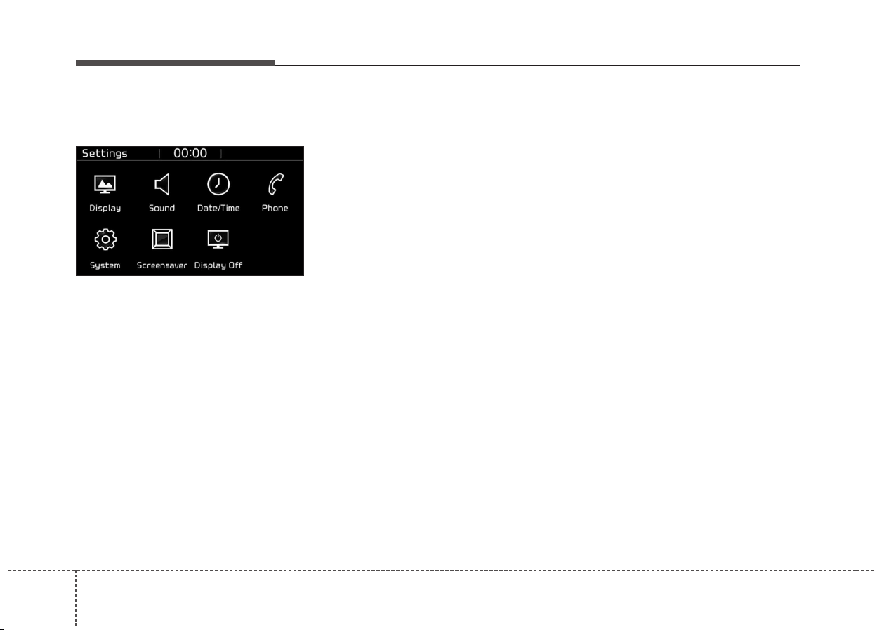
Audio system
550
Setup
Access Display, Sound, Date/Time,
Phone, System, Screensaver
(Screen Saver) and Display Off set-
tings.
Select the [SETUP] button on the
audio system.
Display
Select the [SETUP] button on the
audio system ➟ Select [Display].
• Dimming mode(Dimming Mode):
Audio screen brightness can be
adjusted to the time of day.
• Brightness(Illumination): The bright-
ness of the audio screen can be
changed.
Sound
Select the [SETUP] button on the
audio system ➟ Select [Sound].
• Position: Sound balance and pan-
ning can be adjusted.
• Equaliser(Tone): Sound tone color
can be adjusted.
• Speed dependent volume con-
trol(Speed Dependent Volume):
Automatically adjust volume based
on vehicle speed.
• Beep: Select whether to play a
beep sound when the screen is
touched.
Date/Time
Select the [SETUP] button on the
audio system ➟ Select [Date/Time].
• Set time: Set the time displayed on
the audio screen.
• Time format(Time Format): Choose
between 12-hour and 24-hour time
formats.
• Set date(Set Date): Set the date
displayed on the audio screen.

Audio system
51
5
Phone
Select the [SETUP] button on the
audio system ➟ Select [Phone].
• Connections: Control pairing, dele-
tion, connection and disconnection
of Bluetooth
®
devices.
• Auto connection priority(Auto
Connection Priority): Set the con-
nection priority of Bluetooth
®
devices when the vehicle is start-
ed.
• Update contacts(Download Contacts):
Contacts can be downloaded from
connected Bluetooth
®
devices.
• Bluetooth
®
voice guidance(Bluetooth
®
Voice Prompts): Play or mute voice
prompts for Bluetooth
®
device pair-
ing, connection and errors.
✽✽
NOTICE
• When paired devices are deleted,
the call history and contacts of the
device saved to the audio system
are deleted.
• For Bluetooth
®
connections with
low connection priority, some time
may be required for the connec-
tion to be established.
• Contacts can be downloaded only
from the currently connected
Bluetooth
®
device.
• If no Bluetooth
®
device is connect-
ed, the Download Contacts button
is disabled.
• If the language setting is English,
Bluetooth
®
voice prompts are not
supported.
• If the language setting is
Slovakian, Hungarian or Korean,
Bluetooth
®
voice guidance is not
supported.
System
Select the [SETUP] button on the
audio system ➟ Select [System].
• Memory information (Memory
Information): View My Music mem-
ory usage.
• Voice recognition guidance(Voice
Recognition Guidance): Adjust the
length of the voice recognition
prompt.
• Language: Change the user lan-
guage.
• Default: Reset the audio system.
✽✽
NOTICE
The system resets to the default val-
ues, and all saved data and settings
are lost.

Audio system
552
Screensaver(Screen Saver)
Set the information displayed when
the audio system is switched off or
the screen is turned off.
Select the [SETUP] button on the
audio system ➟ Select [Screensaver
(Screen Saver)].
• Analogue(Analog): An analog clock
is displayed.
• Digital: A digital clock is displayed.
• None: No information is displayed.
Display Off
To prevent glare, the screen can be
turned off with the audio system in
operation.
Select the [SETUP] button on the
audio system ➟ Select [Display Off].
✽✽
NOTICE
Use ‘Screensaver(Screen Saver)’ to
set the information to be displayed
when the screen is turned off.
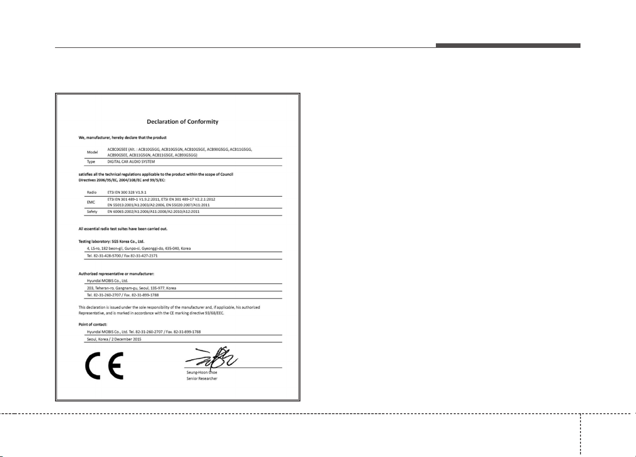
Audio system
53
5
Declaration of Conformity
CE for EU
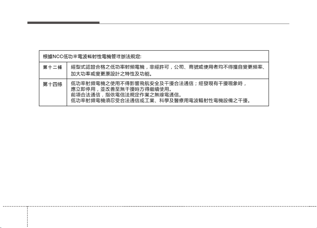
Audio system
554
NCC for Taiwan
Audio system
55
5
TRA for OMAN

Driving your vehicle
Before driving . . . . . . . . . . . . . . . . . . . . . . . . . . . . . . 6-4
• Before entering vehicle . . . . . . . . . . . . . . . . . . . . . . . . . 6-4
• Necessary inspections . . . . . . . . . . . . . . . . . . . . . . . . . 6-4
• Before starting . . . . . . . . . . . . . . . . . . . . . . . . . . . . . . . 6-4
Key positions. . . . . . . . . . . . . . . . . . . . . . . . . . . . . . . 6-6
• Illuminated ignition switch. . . . . . . . . . . . . . . . . . . . . . 6-6
• Ignition switch position. . . . . . . . . . . . . . . . . . . . . . . . . 6-6
• Starting the hybrid system . . . . . . . . . . . . . . . . . . . . . . 6-8
Engine start/stop button . . . . . . . . . . . . . . . . . . . . . 6-9
• Illuminated engine start/stop button. . . . . . . . . . . . . . 6-9
• Engine start/stop button position. . . . . . . . . . . . . . . . . 6-9
• Starting the hybrid system . . . . . . . . . . . . . . . . . . . . . 6-12
Dual Clutch Transmission (DCT) . . . . . . . . . . . . . 6-15
• Dual clutch transmission operation . . . . . . . . . . . . . 6-15
• Good driving practices . . . . . . . . . . . . . . . . . . . . . . . . 6-22
Brake system. . . . . . . . . . . . . . . . . . . . . . . . . . . . . . 6-24
• Power brakes . . . . . . . . . . . . . . . . . . . . . . . . . . . . . . . 6-24
• Foot parking brake . . . . . . . . . . . . . . . . . . . . . . . . . . . 6-25
• Anti-lock brake system (ABS) . . . . . . . . . . . . . . . . . . 6-27
• Electronic stability control (ESC) . . . . . . . . . . . . . . . 6-30
• Vehicle stability management (VSM) . . . . . . . . . . . . 6-34
• Hill-start assist control (HAC) . . . . . . . . . . . . . . . . . . 6-35
• Emergency Stop Signal (ESS) . . . . . . . . . . . . . . . . . . 6-36
• Good braking practices. . . . . . . . . . . . . . . . . . . . . . . . 6-36
Assist emergency braking (AEB) . . . . . . . . . . . . . 6-38
• System setting and activation. . . . . . . . . . . . . . . . . . . 6-38
• AEB warning message and system control. . . . . . . . 6-40
• Brake operation. . . . . . . . . . . . . . . . . . . . . . . . . . . . . . 6-42
• Sensor to detect the distance from the
vehicle in front (front radar) . . . . . . . . . . . . . . . . . . 6-42
• System malfunction. . . . . . . . . . . . . . . . . . . . . . . . . . . 6-43
• Limitation of the system . . . . . . . . . . . . . . . . . . . . . . . 6-45
• Recognizing pedestrians . . . . . . . . . . . . . . . . . . . . . . . 6-48
Cruise Control system . . . . . . . . . . . . . . . . . . . . . . 6-49
• Cruise control switch . . . . . . . . . . . . . . . . . . . . . . . . . 6-50
• To set cruise control speed: . . . . . . . . . . . . . . . . . . . . 6-50
• To increase cruise control set speed: . . . . . . . . . . . . . 6-51
• To decrease the cruising speed: . . . . . . . . . . . . . . . . . 6-51
• To temporarily accelerate with the cruise control on:. . 6-52
• To cancel cruise control, do one of the following: . . 6-52
• To resume cruising speed at more than
approximately 30 km/h (20 mph). . . . . . . . . . . . . . . 6-53
• To turn cruise control off, do one of the following: . . 6-53
Smart cruise control system . . . . . . . . . . . . . . . . . 6-54
• Speed setting . . . . . . . . . . . . . . . . . . . . . . . . . . . . . . . . 6-55
• Vehicle to vehicle distance setting . . . . . . . . . . . . . . . 6-60
• To adjust the sensitivity of smart cruise control . . . 6-63
• To convert to cruise control mode: . . . . . . . . . . . . . . 6-64
• Limitations of the system . . . . . . . . . . . . . . . . . . . . . . 6-64
6

Speed limit control system. . . . . . . . . . . . . . . . . . . 6-70
• To set speed limit :. . . . . . . . . . . . . . . . . . . . . . . . . . . . 6-70
• To turn off the speed limit control, do one of the
following: . . . . . . . . . . . . . . . . . . . . . . . . . . . . . . . . . . 6-72
Lane Keeping Assist System (LKAS) . . . . . . . . . . 6-73
• LKAS operation . . . . . . . . . . . . . . . . . . . . . . . . . . . . . 6-74
• LKAS malfunction . . . . . . . . . . . . . . . . . . . . . . . . . . . 6-79
• LKAS function change . . . . . . . . . . . . . . . . . . . . . . . . 6-80
Blind spot detection system . . . . . . . . . . . . . . . . . . 6-81
• Blind spot detection / Lane change assist . . . . . . . . . 6-82
• Rear cross traffic alert . . . . . . . . . . . . . . . . . . . . . . . . 6-84
• Driver's Attention . . . . . . . . . . . . . . . . . . . . . . . . . . . . 6-87
Economical operation . . . . . . . . . . . . . . . . . . . . . . 6-88
Special driving conditions . . . . . . . . . . . . . . . . . . . 6-90
• Hazardous driving conditions . . . . . . . . . . . . . . . . . 6-90
• Reducing the risk of a rollover . . . . . . . . . . . . . . . . . 6-90
• Rocking the vehicle . . . . . . . . . . . . . . . . . . . . . . . . . . 6-91
• Smooth cornering . . . . . . . . . . . . . . . . . . . . . . . . . . . . 6-92
• Driving at night . . . . . . . . . . . . . . . . . . . . . . . . . . . . . 6-93
• Driving in the rain . . . . . . . . . . . . . . . . . . . . . . . . . . . 6-93
• Driving in flooded areas . . . . . . . . . . . . . . . . . . . . . . 6-93
• Driving off-road. . . . . . . . . . . . . . . . . . . . . . . . . . . . . . 6-93
• Highway driving . . . . . . . . . . . . . . . . . . . . . . . . . . . . . 6-94
Winter driving . . . . . . . . . . . . . . . . . . . . . . . . . . . . 6-95
• Snowy or Icy conditions . . . . . . . . . . . . . . . . . . . . . . . 6-95
• Use high quality ethylene glycol coolant . . . . . . . . . . 6-97
• Check battery and cables . . . . . . . . . . . . . . . . . . . . . . 6-97
• Change to "winter weight" oil if necessary . . . . . . . 6-97
• Check spark plugs and ignition system. . . . . . . . . . . 6-97
• To keep locks from freezing . . . . . . . . . . . . . . . . . . . . 6-98
• Use approved window washer anti-freeze in system . . 6-98
• Don't let your parking brake freeze . . . . . . . . . . . . . 6-98
• Don't let ice and snow accumulate underneath . . . . 6-98
• Carry emergency equipment . . . . . . . . . . . . . . . . . . . 6-98
Vehicle weight . . . . . . . . . . . . . . . . . . . . . . . . . . . . . 6-99
• Base curb weight . . . . . . . . . . . . . . . . . . . . . . . . . . . . 6-99
• Vehicle curb weight . . . . . . . . . . . . . . . . . . . . . . . . . . . 6-99
• Cargo weight . . . . . . . . . . . . . . . . . . . . . . . . . . . . . . . . 6-99
• GAW (Gross axle weight) . . . . . . . . . . . . . . . . . . . . . . 6-99
• GAWR (Gross axle weight rating). . . . . . . . . . . . . . . 6-99
• GVW (Gross vehicle weight) . . . . . . . . . . . . . . . . . . . 6-99
• GVWR (Gross vehicle weight rating) . . . . . . . . . . . . 6-99
• Overloading . . . . . . . . . . . . . . . . . . . . . . . . . . . . . . . . . 6-99
6

63
Driving your vehicle
WARNING - ENGINE EXHAUST CAN BE DANGEROUS!
Engine exhaust fumes can be extremely dangerous. If, at any time, you smell exhaust fumes inside the vehicle,
open the windows immediately.
• Do not inhale exhaust fumes.
Exhaust fumes contain carbon monoxide, a colorless, odorless gas that can cause unconsciousness and death
by asphyxiation.
• Be sure the exhaust system does not leak.
The exhaust system should be checked whenever the vehicle is raised to change the oil or for any other purpose.
If you hear a change in the sound of the exhaust or if you drive over something that strikes the underneath side
of the vehicle, we recommend that the system be checked by an authorized Kia dealer.
• Do not run the engine in an enclosed area.
Letting the engine idle in your garage, even with the garage door open, is a hazardous practice. Never run the
engine in your garage any longer than it takes to start the engine and back the vehicle out.
• Avoid idling the engine for prolonged periods with people inside the vehicle.
If it is necessary to idle the engine for a prolonged period with people inside the vehicle, be sure to do so only in
an open area with the air intake set at "Fresh" and fan operating at one of the higher speeds so fresh air is drawn
into the interior.
If you must drive with the tailgate open because you are carrying objects that make this necessary:
1. Close all windows.
2. Open side vents.
3. Set the air intake control at "Fresh", the air flow control at "Floor" or "Face" and the fan at one of the higher
speeds.
To assure proper operation of the ventilation system, be sure the ventilation air intakes located just in front of the
windshield are kept clear of snow, ice, leaves or other obstructions.
Driving your vehicle
46
Before entering vehicle
• Be sure that all windows, outside
mirror(s), and outside lights are
clean.
• Check the condition of the tires.
• Check under the vehicle for any
sign of leaks.
• Be sure there are no obstacles
behind you if you intend to back up.
Necessary inspections
Fluid levels, such as engine oil,
engine coolant, brake fluid, and
washer fluid should be checked on a
regular basis, with the exact interval
depending on the fluid. Further
details are provided in chapter 8,
“Maintenance”.
Before starting
• Close and lock all doors.
• Position the seat so that all con-
trols are easily reached.
• Adjust the inside and outside
rearview mirrors.
• Be sure that all lights work.
• Check all gauges.
• Check the operation of warning
lights when the ignition switch is
turned to the ON position.
• Release the parking brake and
make sure the brake warning light
goes out.
For safe operation, be sure you are
familiar with your vehicle and its
equipment.
BEFORE DRIVING
WARNING
Driving while distracted can
result in a loss of vehicle con-
trol, that may lead to an accident,
severe personal injury, and
death. The driver’s primary
responsibility is in the safe and
legal operation of a vehicle, and
use of any handheld devices,
other equipment, or vehicle sys-
tems which take the driver’s
eyes, attention and focus away
from the safe operation of a vehi-
cle or which are not permissible
by law should never be used
during operation of the vehicle.
65
Driving your vehicle
WARNING - Driving under
the influence of alcohol or
drugs
Drinking and driving is danger-
ous. Drunk driving is the num-
ber one contributor to the high-
way death toll each year. Even a
small amount of alcohol will
affect your reflexes, percep-
tions and judgement. Driving
while under the influence of
drugs is as dangerous or more
dangerous than driving drunk.
You are much more likely to
have a serious accident if you
drink or take drugs and drive.
If you are drinking or taking
drugs, don’t drive. Do not ride
with a driver who has been drink-
ing or taking drugs. Choose a
designated driver or call a cab.
WARNING
• When you intend to park or
stop the vehicle with the
engine on, be careful not to
depress the accelerator pedal
for a long period of time. It may
overheat the engine or exhaust
system and cause fire.
• When you make a sudden
stop or turn the steering
wheel rapidly, loose objects
may drop on the floor and it
could interfere with the opera-
tion of the foot pedals, possi-
bly causing an accident. Keep
all things in the vehicle safely
stored.
• If you do not focus on driving,
it may cause an accident. Be
careful when operating what
may disturb driving such as
audio or heater. It is the
responsibility of the driver to
always drive safely.
WARNING
All passengers must be proper-
ly belted whenever the vehicle
is moving. Refer to “Seat belts”
in chapter 3 for more informa-
tion on their proper use.
WARNING
Always check the surrounding
areas near your vehicle for peo-
ple, especially children, before
putting a vehicle into “D (Drive)”
or “R (Reverse)”.
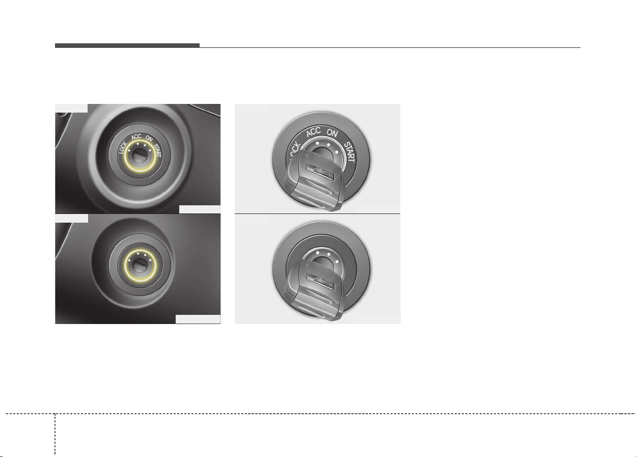
Driving your vehicle
66
Illuminated ignition switch
(If equipped)
Whenever a front door is opened, the
ignition switch will be illuminated for
your convenience, provided the igni-
tion switch is not in the ON position.
The light will go off immediately
when the ignition switch is turned on
or go off after about 30 seconds
when the door is closed.
Ignition switch position
LOCK
The steering wheel locks to protect
against theft. The ignition key can be
removed only in the LOCK position.
ACC (Accessory)
The steering wheel is unlocked and
electrical accessories are operative.
✽✽
NOTICE
If difficulty is experienced turning
the ignition switch to the ACC posi-
tion, turn the key while turning the
steering wheel right and left to
release the tension.
KEY POSITIONS
OQL055065
OQLE055065
■ Type A
■ Type B
OQL055066
OQLE055066
■ Type A
■ Type B
67
Driving your vehicle
ON
The warning lights can be checked
before the engine is started. This is
the normal running position after the
engine is started.
Do not leave the ignition switch ON if
the engine is not running to prevent
battery discharge.
START
Turn the ignition key to the START
position to start the engine. The
engine will crank until you release
the key; then it returns to the ON
position. The brake warning lamp
can be checked in this position.
WARNING - Ignition key
• Never turn the ignition switch
to LOCK or ACC while the vehi-
cle is moving. This would result
in loss of directional control
and braking function, which
could cause an accident.
• The anti-theft steering column
lock (if equipped) is not a sub-
stitute for the parking brake.
Before leaving the driver’s seat,
always make sure the shift
lever is engaged in P (Park) for
the dual clutch transaxle, set
the parking brake fully and shut
the engine off. Unexpected and
sudden vehicle movement may
occur if these precautions are
not taken.
(Continued)
(Continued)
• Never reach for the ignition
switch, or any other controls
through the steering wheel
while the vehicle is in motion.
The presence of your hand or
arm in this area could cause a
loss of vehicle control, an
accident and serious bodily
injury or death.
• Do not place any movable
objects around the driver’s
seat as they may move while
driving, interfere with the driv-
er and lead to an accident.
Driving your vehicle
86
Starting the hybrid system
✽✽
NOTICE
The hybrid system will start by turn-
ing the ignition switch to START.
1. Make sure the parking brake is
applied.
2. Make sure the shift lever is in P
(Park).
3. Depress the brake pedal.
4. Turn the ignition switch to START.
If the hybrid system starts, the
" " indicator will come on.
✽✽
NOTICE
• Do not wait for the engine to warm
up while the vehicle remains sta-
tionary.
Start driving at moderate engine
speeds. (Steep accelerating and
decelerating should be avoided.)
• Always start the vehicle with your
foot on the brake pedal. Do not
depress the accelerator while
starting the vehicle. Do not race
the engine while warming it up.
• If ambient temperature is low, the
" " indicator may remain illu-
minated longer than the normal
amount of time.
✽
✽
NOTICE
To prevent damage to the vehicle:
• If the " " indicator turns off
while you are in motion, do not
attempt to move the shift lever to
the P (Park) position.
If traffic and road conditions per-
mit, you may put the shift lever in
the N (Neutral) position while the
vehicle is still moving and turn the
ignition switch to START. In an
attempt to restart the hybrid sys-
tem.
• Do not push or tow your vehicle to
start the hybrid system.
WARNING
• Always wear appropriate
shoes when operating your
vehicle. Unsuitable shoes,
such as high heels, ski boots,
sandals, flip-flops, etc., may
interfere with your ability to
use the brake and accelerator
pedals.
• Do not start the vehicle with
the accelerator pedal
depressed.
The vehicle can move and
lead to an accident.

69
Driving your vehicle
Illuminated engine start/stop
button
Whenever the front door is opened,
the engine start/stop button will illu-
minate for your convenience. The
light will go off after about 30 sec-
onds when the door is closed. It will
also go off immediately when the
engine start/stop button is ON posi-
tion.
Engine start/stop button posi-
tion
OFF
To turn off the engine (START/RUN
position) or vehicle power (ON posi-
tion), press the engine start/stop but-
ton with the shift lever in the P (Park)
position. When you press the engine
start/stop button without the shift lever
in the P (Park) position, the engine
start/stop button will not change to the
OFF position but to the ACC position.
Vehicles equipped with anti-theft
steering column lock
The steering wheel locks when the
engine start/stop button is in the OFF
position to protect you against theft.
It locks when the door is opened.
If the steering wheel is not locked
properly when you open the driver's
door, the warning chime will sound.
Try locking the steering wheel again.
If the problem is not solved, we rec-
ommend that the system be checked
by an authorized Kia dealer.
In addition, if the engine start/stop
button is in the OFF position after the
driver's door is opened, the steering
wheel will not lock and the warning
chime will sound. In such a situation,
close the door. Then the steering
wheel will lock and the warning
chime will stop.
ENGINE START/STOP BUTTON
ODE056004
Not illuminated
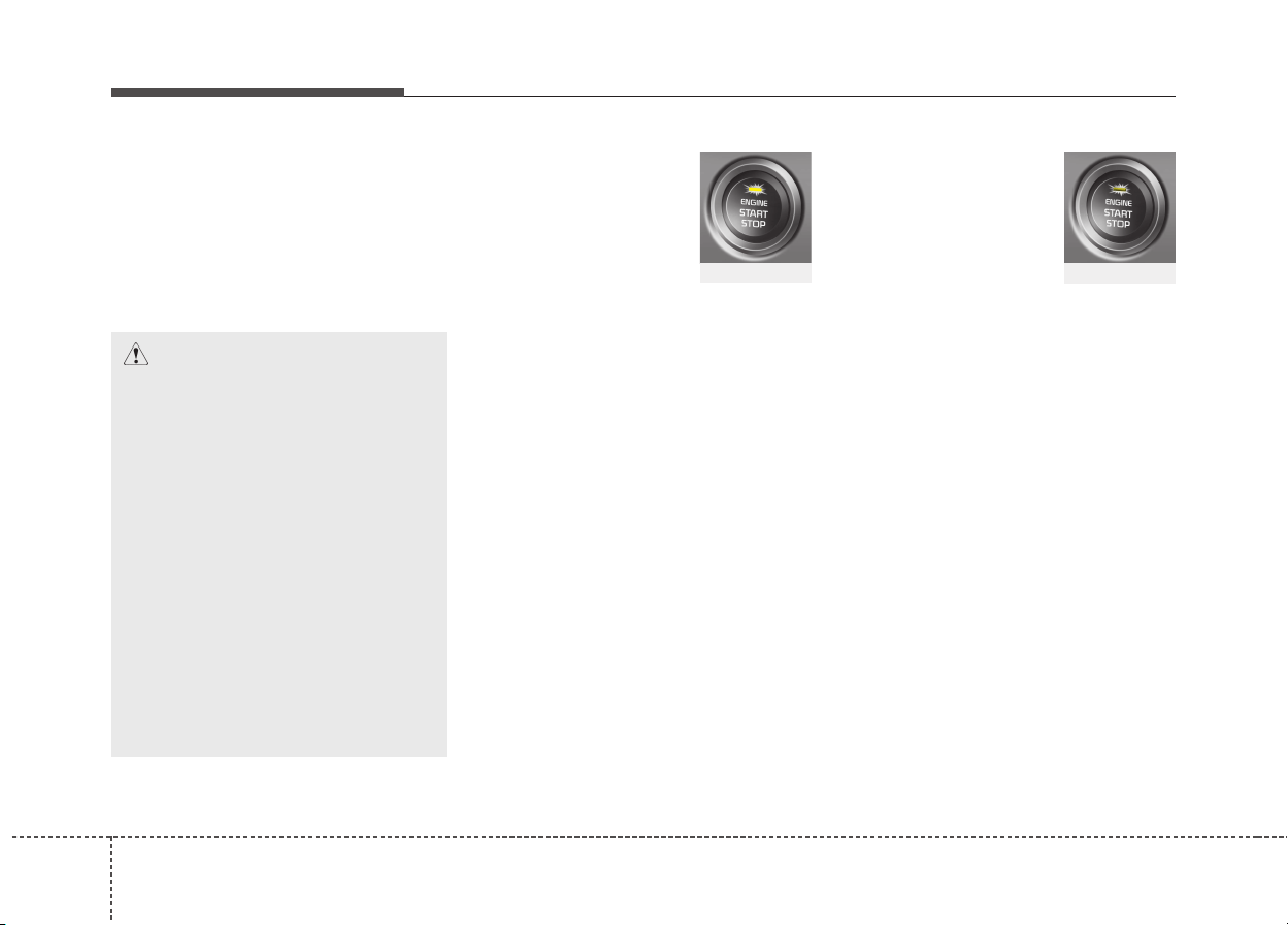
Driving your vehicle
106
✽✽
NOTICE
If the steering wheel doesn't unlock
properly, the engine start/stop but-
ton will not work. Press the engine
start/stop button while turning the
steering wheel right and left to
release the tension.
ACC (Accessory)
Press the engine start/stop button
while it is in the OFF position without
depressing the brake pedal.
The steering wheel unlocks (if
equipped with anti-theft steering col-
umn lock) and electrical accessories
are operational.
If the engine start/stop button is in the
ACC position for more than 1 hour,
the button is turned off automatically
to prevent battery discharge.
ON
Press the engine start/stop button
while it is in the ACC position without
depressing the brake pedal.
The warning lights can be checked
before the engine is started. Do not
leave the engine start/stop button in
the ON position for a long time. The
battery may discharge, because the
engine is not running.
CAUTION
You are able to turn off the
engine (START/RUN) or vehicle
power (ON), only when the vehi-
cle is not in motion. In an emer-
gency situation while the vehi-
cle is in motion, you are able to
turn the engine off and to the
ACC position by pressing the
engine start/stop button for
more than 2 seconds or 3 times
successively within 3 seconds.
If the vehicle is still moving, you
can restart the engine without
depressing the brake pedal by
pressing the engine start/stop
button with the shift lever in the
N (Neutral) position.
Amber
Redish orange
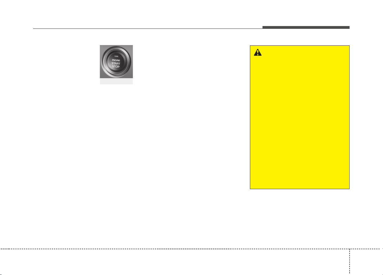
611
Driving your vehicle
START/RUN
To start the engine, depress the
brake pedal and press the engine
start/stop button with the shift lever in
the P (Park) or the N (Neutral) posi-
tion. For your safety, start the engine
with the shift lever in the P (Park)
position.
✽✽
NOTICE
If you press the engine start/stop
button without depressing the brake
pedal for dual clutch transaxle vehi-
cles, the engine will not start and the
engine start/stop button changes as
follow:
OFF
➔
➔
ACC
➔➔
ON
➔➔
OFF or ACC
✽
✽
NOTICE
If you leave the engine start/stop
button in the ACC or ON position
for a long time, the battery will dis-
charge.
WARNING
• Never press the engine
start/stop button while the
vehicle is in motion.This would
result in loss of directional
control and braking function,
which could cause an accident.
• The anti-theft steering column
lock (if equipped) is not a sub-
stitute for the parking brake.
Before leaving the driver's
seat, always make sure the
shift lever is engaged in P
(Park), set the parking brake
fully and shut the engine off.
Unexpected and sudden vehi-
cle movement may occur if
these precautions are not
taken.
(Continued)
Not illuminated
Driving your vehicle
126
Starting the hybrid system
✽✽
NOTICE
• The hybrid system will start by
pressing the Engine Start/Stop
button, only when the smart key is
in the vehicle.
• Even when the smart key is in the
vehicle, and when it is far away
from the driver, the hybrid system
may not start.
• When the Engine Start/Stop but-
ton is in the ACC or ON position,
any door is open, the system
checks for the smart key. When
the smart key is not in the vehicle,
the " " indicator will blink and
the warning "Key not in vehicle"
will come on. When all doors are
closed, the chime will also sound
for about 5 seconds. Keep the
smart key in the vehicle when in
the ACC position or if the hybrid
system is ON.
WARNING
• Always wear appropriate
shoes when operating your
vehicle. Unsuitable shoes,
such as high heels, ski boots,
sandals, flip-flops, etc., may
interfere with your ability to
use the brake and accelerator
pedals.
• Do not start the vehicle with
the accelerator pedal
depressed.
The vehicle can move and
lead to an accident.
(Continued)
• Never reach for the engine
start/ stop button or any other
controls through the steering
wheel while the vehicle is in
motion. The presence of your
hand or arm in the area could
cause loss of vehicle control,
an accident and serious bodi-
ly injury or death.
• Do not place any movable
objects around the driver's
seat as they may move while
driving, interfere with the driv-
er and lead to an accident.
613
Driving your vehicle
1. Always carry the smart key with
you.
2. Make sure the parking brake is
applied.
3. Make sure the shift lever is in P
(Park).
4. Depress the brake pedal.
5. Press the Engine Start/Stop but-
ton. If the hybrid system starts, the
" " indicator will come on.
✽✽
NOTICE
• Do not wait for the engine to warm
up while the vehicle remains sta-
tionary.
Start driving at moderate engine
speeds. (Steep accelerating and
decelerating should be avoided.)
• Always start the vehicle with your
foot on the brake pedal. Do not
depress the accelerator while
starting the vehicle. Do not race
the engine while warming it up.
• If ambient temperature is low, the
" " indicator may remain illu-
minated longer than the normal
amount of time.
✽
✽
NOTICE
To prevent damage to the vehicle:
• If the " " indicator turns off
while you are in motion, do not
attempt to move the shift lever to
the P (Park) position.
If traffic and road conditions per-
mit, you may put the shift lever in
the N (Neutral) position while the
vehicle is still moving and press
the Engine Start/Stop button in an
attempt to restart the hybrid sys-
tem.
• Do not push or tow your vehicle to
start the hybrid system.
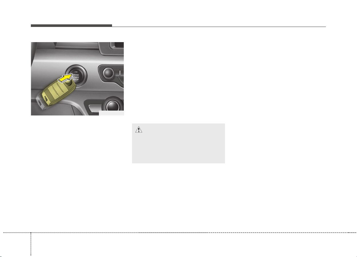
Driving your vehicle
146
✽✽
NOTICE
• If the battery is weak or the smart
key does not work correctly, you
can start the engine by pressing
the engine start/stop button with
the smart key.
The side with the lock button
should be contacted directly.
When you press the engine
start/stop button directly with the
smart key, the smart key should
contact the button at a right angle.
(Continued)
(Continued)
• When the stop lamp fuse is blown,
you cannot start the engine nor-
mally.
Replace the fuse with a new one. If
it is not possible, you can start the
engine by pressing the engine
start/stop button for 10 seconds
while it is in the ACC position. The
engine can start without depress-
ing the brake pedal. But for your
safety always depress the brake
pedal before starting the engine.
CAUTION
Do not press the engine
start/stop button for more than
10 seconds except when the
stop lamp fuse is blown.
ODE056008
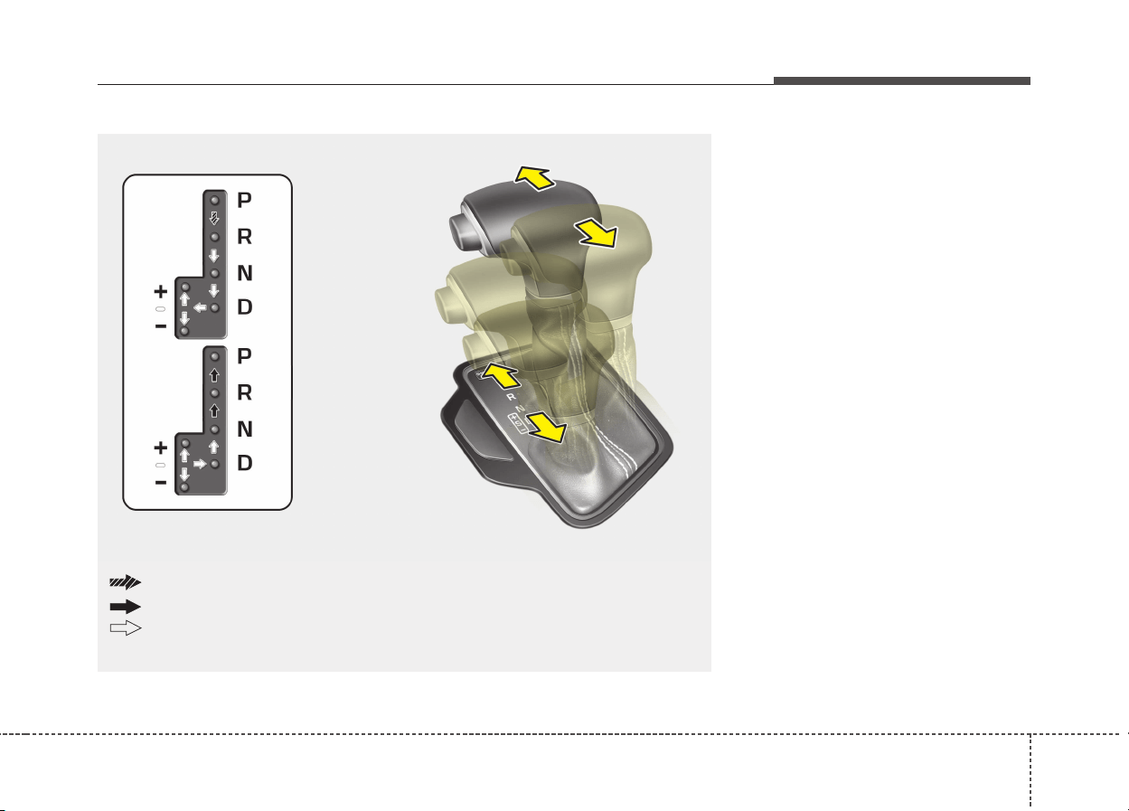
615
Driving your vehicle
Dual clutch transmission oper-
ation
The dual clutch transmission has six
forward speeds and one reverse
speed.
The individual speeds are selected
automatically in the D (Drive) posi-
tion.
DUAL CLUTCH TRANSMISSION (DCT)
ODE056010
The shift lever can be shifted freely.
Press the lock release button when shifting.
Depress the brake pedal and the lock release button when shifting.

Driving your vehicle
166
• The Dual Clutch Transmission
gives the driving feel of a manual
transmission, yet provides the
ease of a fully automatic transmis-
sion. Unlike a traditional automatic
transmission, the gear shifting can
be felt (and heard) on the dual
clutch transmission
- Think of it as an automatically
shifting manual transmission.
- Shift into Drive range and get fully
automatic shifting, similar to a con-
ventional automatic transmission.
• Dual clutch transmission adopts
dry-type dual clutch, which is dif-
ferent from torque converter of
automatic transmission, and
shows better acceleration perform-
ance during driving. But, initial
launch might be little bit slower
than Automatic Transmission.
• The dry-type clutch transfers torque
and provides a direct driving feeling
which may feel different from a con-
ventional automatic transmission
with a torque converter.This may be
more noticeable when starting from
a stop or low vehicle speed.
• When rapidly accelerating at low
vehicle speed, engine could rev at
high rpm depending on vehicle
drive condition.
• For smooth launch uphill, press
down the accelerator pedal
smoothly depending on the current
conditions.
• If you release your foot from the
accelerator pedal at low vehicle
speed, you may feel strong engine
brake, which is similar to manual
transmission.
• When driving downhill, you may
use Sports Mode to downshift to a
lower gear in order to control your
speed without using the brake
pedal excessively.
• When you turn the engine on and
off, you may hear clicking sounds
as the system goes through a self
test. This is a normal sound for the
Dual Clutch Transmission.
WARNING
To reduce the risk of serious
injury or death:
• ALWAYS check the surround-
ing areas near your vehicle for
people, especially children,
before shifting a vehicle into
D (Drive) or R (Reverse).
• Before leaving the driver’s
seat, always make sure the
shift lever is in the P (Park)
position, then set the parking
brake, and place the ignition
switch in the LOCK/OFF posi-
tion. Unexpected and sudden
vehicle movement can occur
if these precautions are not
followed.
• Do not use engine braking
(shifting from a high gear to
lower gear) rapidly on slip-
pery roads. The vehicle may
slip causing an accident.

617
Driving your vehicle
CAUTION
• To hold the vehicle on a hill
use the foot brake or the park-
ing brake. If the vehicle is held
by applying the accelerator
pedal on a hill the clutch and
transmission will be overheat-
ed resulting in damage.
At this time, a warning mes-
sage (“Steep grade! Press
brake pedal”) will appear on
the LCD display and you may
feel a vibration.
• If the clutch becomes overheat-
ed by excessive use of the
clutch to hold on a hill, you may
notice a shudder feeling and a
blinking display on the instru-
ment cluster. When this occurs,
the clutch is disabled until the
clutch cools to normal temper-
atures. If this occurs, pull over
to a safe location, shift into P
(Park) and apply the foot brake
for a certain time on the LCD
warning until it disappears.
(Continued)
(Continued)
• If the LCD warning is active,
the foot brake must be applied.
• Ignoring the warnings can lead
to damage to the transmission.
• If the display continues to
blink, for your safety, we rec-
ommend that you contact an
authorized Kia dealer.
• Under certain conditions such
as repeated launch on steep
grades, the clutch in the trans-
mission could overheat.
When the clutch is overheat-
ed, the safe protection mode
engages. If the safe protection
mode engages, the gear posi-
tion indicator on the cluster
blinks with a chime sound.
(Continued)
(Continued)
At this time, a warning mes-
sage (“Transmission temp. is
high! Stop safely”, “Trans
Cooling. Remain parked for 00
min.”, “Trans Cooled. Resume
driving”) will appear on the
LCD display and driving may
not be smooth.
If you ignore this warning, the
driving condition may become
worse.To return the normal driv-
ing condition, stop the vehicle
and apply the foot brake for a
few minutes before driving off.
• Gear shifts may be more
noticeable than a convention-
al automatic transmission.
This is a normal characteristic
of this type of dual clutch
transmission.
(Continued)
Driving your vehicle
186
The indicator in the instrument clus-
ter displays the shift lever position
when the ignition switch is in the ON
position.
P (Park)
Always come to a complete stop
before shifting into P (Park).
To shift from P (Park), you must
depress firmly on the brake pedal
and make sure your foot is off the
accelerator pedal.
The shift lever must be in P (Park)
before turning the engine off.
(Continued)
• The overheated Dual clutch
transmission may change the
gear shifting characteristics,
and illuminate the warning
message on the LCD display
under the conditions that oper-
ation of the kickdown mecha-
nism is repetitively used.
• Do not use the kickdown
mechanism to return to the
normal driving condition. Also,
temporarily stop the vehicle at
a safe location, when the warn-
ing message illuminates on
the LCD display.
• During the first 1,500 km
(1,000 miles), you may feel
that the vehicle may not be
smooth when accelerating at
low speed. During this break-
in period, the shift quality and
performance of your new vehi-
cle is continuously optimized.
(Continued)
(Continued)
• Always come to a complete
stop before shifting into D
(Drive) or R (Reverse).
• Do not put the shift lever in N
(Neutral) while driving.
WARNING
• Shifting into P (Park) while the
vehicle is in motion may
cause you to lose control of
the vehicle.
• After the vehicle has stopped,
always make sure the shift
lever is in P (Park), apply the
parking brake, and turn the
engine off.
• Do not use the P (Park) position
in place of the parking brake.
619
Driving your vehicle
R (Reverse)
Use this position to drive the vehicle
backward.
N (Neutral)
The wheels and transmission are not
engaged.
Use N (Neutral) if you need to restart
a stalled engine, or if it is necessary
to stop with the engine ON. Shift into
P (Park) if you need to leave your
vehicle for any reason.
Always depress the brake pedal
when you are shifting from N
(Neutral) to another gear.
D (Drive)
This is the normal driving position.
The transmission will automatically
shift through a six-gear sequence,
providing the best fuel economy and
power.
For extra power when passing anoth-
er vehicle or driving uphill depress
the accelerator pedal further until
you feel the transmission downshift
to a lower gear.
WARNING
Do not shift into gear unless
your foot is firmly on the brake
pedal. Shifting into gear when
the engine is running at high
speed can cause the vehicle to
move very rapidly. You could
lose control of the vehicle and
hit people or objects.
WARNING
Do not drive with the shift lever
in N (Neutral).
The engine brake will not work
and lead to an accident.
CAUTION
Always come to a complete stop
before shifting into or out of R
(Reverse); you may damage the
transmission if you shift into R
(Reverse) while the vehicle is in
motion.
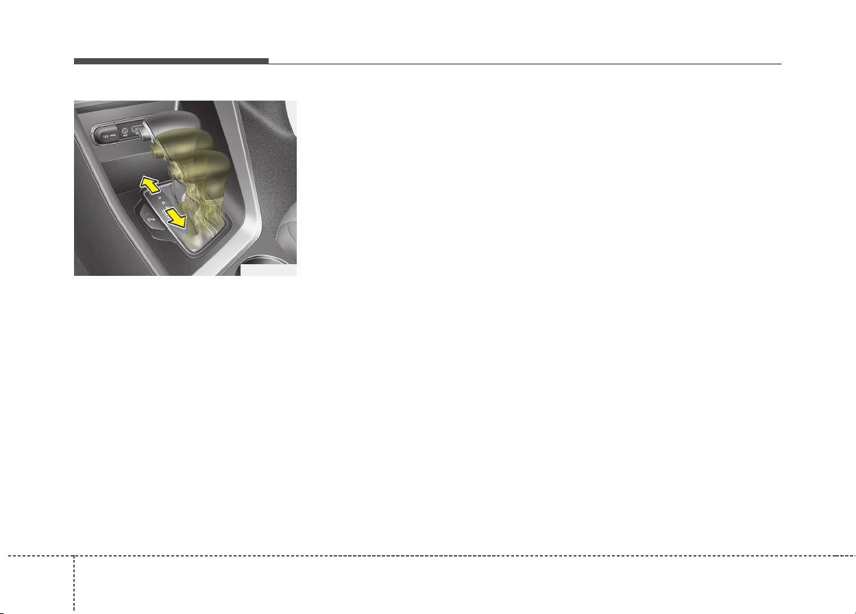
Driving your vehicle
206
Manual mode
Whether the vehicle is stationary or
in motion, manual mode is selected
by pushing the shift lever from the D
(Drive) position into the manual gate.
To return to D (Drive) range opera-
tion, push the shift lever back into the
main gate.
In manual mode, moving the shift lever
backwards and forwards will allow you
to select the desired range of gears for
the current driving conditions.
+ (Up) : Push the lever forward once
to shift up one gear.
- (Down) : Pull the lever backwards
once to shift down one gear.
✽✽
NOTICE
• Only the six forward gears can be
selected. To reverse or park the
vehicle, move the shift lever to the
R (Reverse) or P (Park) position as
required.
• Downshifts are made automatical-
ly when the vehicle slows down.
When the vehicle stops, 1st gear is
automatically selected.
• When the engine rpm approaches
the red zone the transmission will
upshift automatically.
• If the driver presses the lever to +
(Up) or - (Down) position, the trans-
mission may not make the request-
ed gear change if the next gear is
outside of the allowable rpm range.
SPORT Mode / ECO Mode
When you drive after changing the
gear shift lever to manual mode, the
vehicle will automatically shift to
SPORT mode. When you drive the
vehicle after putting the gear shift
lever to ‘D’, the vehicle will automati-
cally shift to ECO mode. Each auto-
matic change in shift will be dis-
played on the instrument cluster.
• ECO mode
This driving mode increases fuel effi-
ciency. The actual fuel mileage will
depend on your driving habits and
road conditions.
• SPORT mode
This driving mode provides sporty
driving experience. Be aware that fuel
efficiency may decrease in this mode.
ODE056012
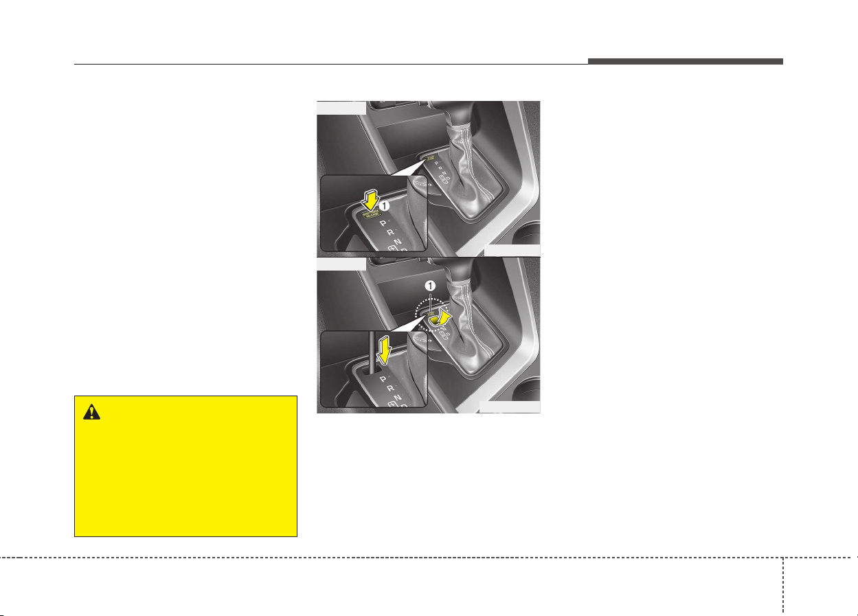
621
Driving your vehicle
Shift lock system
For your safety, the Dual clutch trans-
mission has a shift lock system which
prevents shifting the transaxle from P
(Park) into R (Reverse) unless the
brake pedal is depressed.
To shift the transaxle from P (Park)
into R (Reverse):
1. Depress and hold the brake pedal.
2. Start the engine or turn the ignition
switch to the ON position.
3. Move the shift lever.
If the brake pedal is repeatedly
depressed and released with the shift
lever in the P (Park) position, a chat-
tering noise & vibration near the shift
lever may be heard. This is a normal
condition.
Shift-lock override
If the shift lever cannot be moved
from the P (Park) position into R
(Reverse) position with the brake
pedal depressed, continue depress-
ing the brake, then do the following:
1. Place the ignition switch in the
LOCK/OFF position.
2. Apply the parking brake.
3. Carefully remove the cap (1) cov-
ering the shift-lock release access
hole.
4. Insert a tool (e.g. flathead screw-
driver) into the access hole and
press down on the tool.
5. Move the shift lever.
6. Remove the tool from the shiftlock
override access hole then install
the cap.
7. We recommend that the system
be inspected by an authorized Kia
dealer.
WARNING
Always fully depress the brake
pedal before and while shifting
out of the P (Park) position into
another position to avoid inad-
vertent motion of the vehicle
which could injure persons in
or around the car.
ODE056013
■ Type A
■ Type B
ODE056013L

Driving your vehicle
226
Ignition key interlock system
(if equipped)
The ignition key cannot be removed
unless the shift lever is in the P
(Park) position.
Good driving practices
• Never move the shift lever from P
(Park) or N (Neutral) to any other
position with the accelerator pedal
depressed.
• Never move the shift lever into P
(Park) when the vehicle is in motion.
• Be sure the car is completely
stopped before you attempt to shift
into R (Reverse) or D (Drive).
• Never take the car out of gear and
coast down a hill. This may be
extremely hazardous. Always leave
the car in gear when moving.
• Do not "ride" the brakes. This can
cause them to overheat and mal-
function. Instead, when you are
driving down a long hill, slow down
and shift to a lower gear. When you
do this, engine braking will help
slow the car.
• Slow down before shifting to a
lower gear. Otherwise, the lower
gear may not be engaged.
• Always use the parking brake. Do
not depend on placing the
transaxle in P (Park) to keep the
car from moving.
• Exercise extreme caution when
driving on a slippery surface. Be
especially careful when braking,
accelerating or shifting gears. On a
slippery surface, an abrupt change
in vehicle speed can cause the
drive wheels to lose traction and
the vehicle to go out of control.
• Optimum vehicle performance and
economy is obtained by smoothly
depressing and releasing the
accelerator pedal.
623
Driving your vehicle
WARNING
• Always buckle-up! In a colli-
sion, an unbelted occupant is
significantly more likely to be
seriously injured or killed than
a properly belted occupant.
• Avoid high speeds when cor-
nering or turning.
• Do not make quick steering
wheel movements, such as
sharp lane changes or fast,
sharp turns.
• The risk of rollover is greatly
increased if you lose control
of your vehicle at highway
speeds.
• Loss of control often occurs if
two or more wheels drop off the
roadway and the driver over-
steers to reenter the roadway.
• In the event your vehicle
leaves the roadway, do not
steer sharply. Instead, slow
down before pulling back into
the travel lanes.
• Never exceed posted speed
limits.
WARNING
If your vehicle becomes stuck in
snow, mud, sand, etc., then you
may attempt to rock the vehicle
free by moving it forward and
backward. Do not attempt this
procedure if people or objects
are anywhere near the vehicle.
During the rocking operation the
vehicle may suddenly move for-
ward of backward as it becomes
unstuck, causing injury or dam-
age to nearby people or objects.
Driving your vehicle
246
Power brakes
Your vehicle's brake system is power-
assisted by the electric hydraulic
pump.
In the event the brakes lose power
because of a brake control system
malfunction, unstable power supply or
some other reason, you can still stop
your vehicle by applying greater force
to the brake pedal than you normally
would. The stopping distance, howev-
er will be longer. Please have the sys-
tem checked as soon as possible.
If the brake pedal does not return to
its normal position when released,
there may be a malfunction in the
brake system. We recommend that
you contact an authorized Kia dealer.
✽✽
NOTICE
• Do not depress the brake pedal con-
tinuously without the " " indica-
tor ON. The battery may be dis-
charged.
• Some noise and vibration may
occur during braking. This is nor-
mal.
• In below cases, some electric
brake pump noise and motor
vibration may occur temporarily.
This is normal operation.
- When the pedal is pushed down
very quickly
- When the pedal is pushed down
multiple times in short intervals
- When the ABS function is acti-
vated during braking
BRAKE SYSTEM
(Continued)
• When descending a long or
steep hill, shift to a lower gear
and avoid continuous applica-
tion of the brakes. Continuous
brake application will cause
the brakes to overheat and
could result in a temporary
loss of braking performance.
• Wet brakes may impair the
vehicle’s ability to safely slow
down; the vehicle may also
pull to one side when the
brakes are applied. Applying
the brakes lightly will indicate
whether they have been
affected in this way.
Always test your brakes in
this fashion after driving
through deep water. To dry the
brakes, apply them lightly
while maintaining a safe for-
ward speed until brake per-
formance returns to normal.
(Continued)
(Continued)
• Always, confirm the position
of the brake and accelerator
pedal before driving. If you
don’t check the position of the
accelerator and brake pedal
before driving, you may
depress the accelerator
instead of the brake pedal. It
may cause a serious accident.
WARNING - Brakes
• Do not drive with your foot
resting on the brake pedal.
This will create abnormal high
brake temperatures, excessive
brake lining and pad wear, and
increased stopping distances.
(Continued)
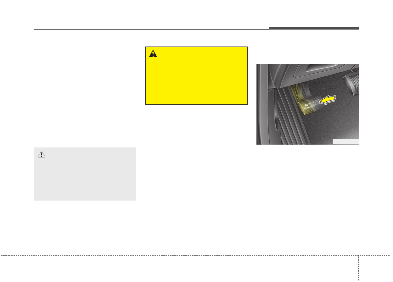
625
Driving your vehicle
Disc brakes wear indicator
When your brake pads are worn and
new pads are required, you will hear
a high-pitched warning sound from
your front brakes or rear brakes (if
equipped). You may hear this sound
come and go or it may occur when-
ever you depress the brake pedal.
Please remember that some driving
conditions or climates may cause a
brake squeal when you first apply (or
lightly apply) the brakes. This is nor-
mal and does not indicate a problem
with your brakes.
Foot parking brake
Applying the parking brake
To engage the parking brake, first
apply the foot brake and then
depress the parking brake pedal
down as far as possible.
CAUTION
• To avoid costly brake repairs,
do not continue to drive with
worn brake pads.
• Always replace the front or
rear brake pads as pairs.
WARNING - Brake wear
This brake wear warning sound
means your vehicle needs serv-
ice. If you ignore this audible
warning, you will eventually lose
braking performance, which
could lead to a serious accident.
ODE056015
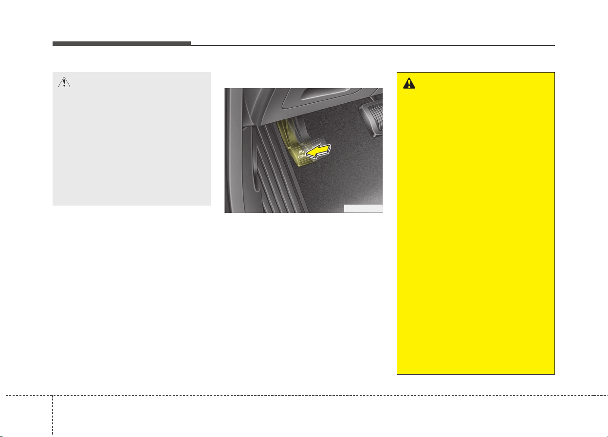
Driving your vehicle
266
Releasing the parking brake
To release the parking brake,
depress the parking brake pedal a
second time while applying the foot
brake. The pedal will automatically
extend to the fully released position.
ODE056014
CAUTION
• Driving with the parking brake
applied will cause excessive
brake pad (or lining) and
brake rotor wear.
• Do not operate the parking
brake while the vehicle is
moving except in an emer-
gency situation. It could dam-
age the vehicle system and
make endanger driving safety.
WARNING
• Whenever leaving the vehicle
or parking, always come to a
complete stop and continue to
depress the brake pedal. Move
the shift lever into the P (Park)
position, then apply the park-
ing brake, and place the
Engine Start/Stop button in
the OFF position.
Vehicles with the parking
brake not fully engaged are at
risk for moving inadvertently
and causing injury to yourself
or others.
• Never allow anyone who is
unfamiliar with the vehicle to
touch the parking brake. If the
parking brake is released
unintentionally, serious injury
may occur.
• All vehicles should always
have the parking brake fully
engaged when parking to
avoid inadvertent movement
of the vehicle which can injure
occupants or pedestrians.
627
Driving your vehicle
Check the brake warning light by
pressing engine start/stop button
switch ON (do not start the engine).
This light will be illuminated when the
parking brake is applied with the
engine start/stop button switch in the
START or ON position.
Before driving, be sure the parking
brake is fully released and the brake
warning light is off.
If the brake warning light remains on
after the parking brake is released
while the engine is running, there may
be a malfunction in the brake system.
Immediate attention is necessary.
If at all possible, cease driving the
vehicle immediately. If that is not pos-
sible, use extreme caution while
operating the vehicle and only contin-
ue to drive the vehicle until you can
reach a safe location or repair shop.
Anti-lock brake system (ABS)
WK-23_TF
WARNING
ABS (or ESC) will not prevent
accidents due to improper or
dangerous driving maneuvers.
Even though vehicle control is
improved during emergency
braking, always maintain a safe
distance between you and
objects ahead. Vehicle speeds
should always be reduced dur-
ing extreme road conditions.
The braking distance for vehicle
equipped with an anti-lock brak-
ing system (or Electronic
Stability Control) may be longer
than for those without it in the
following road conditions.
During these conditions the
vehicle should be driven at
reduced speeds:
• Rough, gravel or snow-cov-
ered roads.
• With tire chains installed.
(Continued)

Driving your vehicle
286
The ABS continuously senses the
speed of the wheels. If the wheels
are going to lock, the ABS system
repeatedly modulates the hydraulic
brake pressure to the wheels.
When you apply your brakes under
conditions which may lock the wheels,
you may hear a “tik-tik’’ sound from the
brakes, or feel a corresponding sensa-
tion in the brake pedal. This is normal
and it means your ABS is active.
In order to obtain the maximum ben-
efit from your ABS in an emergency
situation, do not attempt to modulate
your brake pressure and do not try to
pump your brakes. Press your brake
pedal as hard as possible or as hard
as the situation warrants and allow
the ABS to control the force being
delivered to the brakes.
✽✽
NOTICE
A click sound may be heard in the
engine compartment when the vehi-
cle begins to move after the engine is
started. These conditions are normal
and indicate that the anti-lock brake
system is functioning properly.
• Even with the anti-lock brake sys-
tem, your vehicle still requires suf-
ficient stopping distance. Always
maintain a safe distance from the
vehicle in front of you.
• Always slow down when cornering.
The anti-lock brake system cannot
prevent accidents resulting from
excessive speeds.
• On loose or uneven road surfaces,
operation of the anti-lock brake
system may result in a longer stop-
ping distance than for vehicles
equipped with a conventional
brake system.
(Continued)
• On roads where the road sur-
face is pitted or has different
surface height.
The safety features of an ABS
(or ESC) equipped vehicle
should not be tested by high
speed driving or cornering. This
could endanger the safety of
yourself or others.
629
Driving your vehicle
✽✽
NOTICE
When you jump start your vehicle
because of a drained battery, the
engine may not run as smoothly and
the ABS warning light may turn on at
the same time. This happens because
of the low battery voltage. It does not
mean your ABS is malfunctioning.
• Do not pump your brakes!
• Have the battery recharged before
driving the vehicle.
CAUTION
• If the ABS warning light is on
and stays on, you may have a
problem with the ABS. In this
case, however, your regular
brakes will work normally.
(Continued)
W-78
CAUTION
• When you drive on a road hav-
ing poor traction, such as an
icy road, and operate your
brakes continuously, the ABS
will be active continuously
and the ABS warning light
may illuminate. Pull your vehi-
cle over to a safe place and
stop the engine.
(Continued)
(Continued)
• Restart the engine. If the ABS
warning light is off, then your
ABS system is normal.
Otherwise, you may have a
problem with the ABS. We rec-
ommend that you contact an
authorized Kia dealer.
(Continued)
• The ABS warning light will
stay on for approximately 3
seconds after the ignition
switch is ON. During that time,
the ABS will go through self-
diagnosis and the light will go
off if everything is normal. If
the light stays on, you may
have a problem with your ABS.
We recommend that you con-
tact an authorized Kia dealer.

Driving your vehicle
306
Electronic stability control
(ESC) (if equipped)
The Electronic Stability Control
(ESC) system is designed to stabi-
lize the vehicle during cornering
maneuvers. ESC checks where you
are steering and where the vehicle is
actually going. ESC applies the
brakes at individual wheels and inter-
venes with engine management sys-
tem to stabilize the vehicle.
The Electronic stability control (ESC)
system is an electronic system
designed to help the driver maintain
vehicle control under adverse condi-
tions. It is not a substitute for safe
driving practices. Factors including
speed, road conditions and driver
steering input can all affect whether
ESC will be effective in preventing a
loss of control. It is still your respon-
sibility to drive and corner at reason-
able speeds and to leave a sufficient
margin of safety.
When you apply your brakes under
conditions which may lock the
wheels, you may hear a “tik-tik’’
sound from the brakes, or feel a cor-
responding sensation in the brake
pedal. This is normal and it means
your ESC is active.
✽✽
NOTICE
A click sound may be heard in the
engine compartment when the vehi-
cle begins to move after the engine is
started. These conditions are normal
and indicate that the Electronic sta-
bility control (ESC) System is func-
tioning properly.
ODE056016
WARNING
Never drive too fast for the road
conditions or too quickly when
cornering. Electronic stability
control (ESC) will not prevent
accidents. Excessive speed in
turns, abrupt maneuvers and
hydroplaning on wet surfaces
can still result in serious acci-
dents. Only a safe and attentive
driver can prevent accidents by
avoiding maneuvers that cause
the vehicle to lose traction.
Even with ESC installed, always
follow all the normal precautions
for driving - including driving at
safe speeds for the conditions.
631
Driving your vehicle
ESC operation
ESC ON condition
• When the ignition is turned
ON, ESC and ESC OFF
indicator lights illuminate for
approximately 3 seconds,
then ESC is turned on.
• Press the ESC OFF but-
ton for at least half a sec-
ond after turning the igni-
tion ON to turn ESC off.
(ESC OFF indicator will
illuminate). To turn the
ESC on, press the ESC
OFF button (ESC OFF
indicator light will go off).
• When starting the engine,
you may hear a slight tick-
ing sound. This is the ESC
performing an automatic
system self-check and
does not indicate a prob-
lem.
When operating
When the ESC is in opera-
tion, ESC indicator light
blinks.
• When the Electronic
Stability Control is operat-
ing properly, you can feel a
slight pulsation in the vehi-
cle. This is only the effect
of brake control and indi-
cates nothing unusual.
• When moving out of the
mud or slippery road, the
engine rpm (revolution per
minute) may not increase
even if you press the
accelerator pedal deeply.
This is to maintain the sta-
bility and traction of the
vehicle and does not indi-
cate a problem.
ESC operation off
ESC OFF state
This car has 2 kinds of ESC
off states.
If the engine stops when
ESC is off, ESC remains off.
Upon restarting the engine,
the ESC will automatically
turn on again.
-
Driving your vehicle
326
“Traction Control disabled”
• ESC off state 1
To cancel ESC operation, press the
ESC OFF button (ESC OFF ) short-
ly (ESC OFF indicator light (ESC OFF
) illuminates) and an above LCD
message will come up. At this state,
the engine control function does not
operate. It means the traction control
function does not operate. Brake con-
trol function only operates.
“Traction & Stability Control disabled”
• ESC off state 2
To cancel ESC operation, press the
ESC OFF button (ESC OFF ) for
more than 3 seconds. ESC OFF indi-
cator light (ESC OFF ) illuminates
and an above LCD message will
come up and ESC OFF warning
chime will sound. At this state, the
engine control function and brake
control function do not operate. It
means the car stability control func-
tion does not operate any more.
Indicator light
When ignition switch is turned to ON,
the indicator light illuminates, then
goes off if the ESC system is operat-
ing normally.
The ESC indicator light blinks when-
ever ESC is operating or illuminates
when ESC fails to operate.
ESC OFF indicator light comes on
when the ESC is turned off with the
button.
■ ESC indicator light
■ ESC OFF indicator light
633
Driving your vehicle
ESC OFF usage
When driving
• ESC should be turned on for daily
driving whenever possible.
• To turn ESC off while driving, press
the ESC OFF button while driving
on a flat road surface.
✽✽
NOTICE
• When operating the vehicle on a
dynamometer, ensure that the ESC
is turned off by pressing the ESC
OFF button for more than 3 sec-
onds (ESC OFF light illuminated).
If the ESC is left on, it may prevent
the vehicle speed from increasing,
and result in false diagnosis.
• Turning the ESC off does not
affect ABS or brake system opera-
tion.
WARNING
Never press the ESC OFF but-
ton while ESC is operating (ESC
indicator light blinks).
If ESC is turned off while ESC is
operating, the vehicle may slip
out of control.
CAUTION
Driving with varying tire or wheel
sizes may cause the ESC system
to malfunction. When replacing
tires, make sure they are the
same size as your original tires.
WARNING
The Electronic Stability Control
system is only a driving aid; use
precautions for safe driving by
slowing down on curved,
snowy, or icy roads. Drive slow-
ly and don’t attempt to acceler-
ate whenever the ESC indicator
light is blinking, or when the
road surface is slippery.

Driving your vehicle
346
Vehicle stability management
(VSM) (if equipped)
This system provides further
enhancements to vehicle stability
and steering responses when a vehi-
cle is driving on a slippery road or a
vehicle detected changes in coeffi-
cient of friction between right wheels
and left wheels when braking.
VSM operation
When the VSM is operating:
• ESC (Electronic Stability Control)
( ) light will blink.
• The steering wheel may be con-
trolled.
When the vehicle stability manage-
ment is operating properly, you can
feel a slight pulsation in the vehicle.
This is only the effect of brake control
and indicates nothing unusual.
The VSM does not operate when:
• Driving on bank road such as gra-
dient or incline
• Driving rearward
• ESC OFF indicator light ( )
remains on the instrument cluster
• EPS (Electronic Power Steering)
indicator light remains on the
instrument cluster
VSM operation off
If you press the ESC OFF button to
turn off the ESC, the VSM will also
cancel and the ESC OFF indicator
light ( ) illuminates.
To turn on the VSM, press the button
again. The ESC OFF indicator light
goes out.
Malfunction indicator
The VSM can be deactivated even if
you don’t cancel the VSM operation
by pressing the ESC OFF button. It
indicates that a malfunction has
been detected somewhere in the
EPS (Electronic Power Steering)
system or VSM system. If the ESC
indicator light ( ) or EPS warning
light remains on, we recommend that
the system be checked by an author-
ized Kia dealer.
✽✽
NOTICE
• The VSM is designed to function
above approximately 22 km/h
(13 mph) on curves.
• The VSM is designed to function
above approximately 10 km/h
(6 mph) when a vehicle is braking
on a split-mu road. The split-mu
road is made of surfaces which
have different friction forces.
635
Driving your vehicle
Hill-start assist control (HAC)
(if equipped)
A vehicle has the tendency to slip
back on a steep hill when it starts to
go after stopping. The Hill-start
Assist Control (HAC) prevents the
vehicle from slipping back by operat-
ing the brakes automatically for
about 1~2 seconds. The brakes are
released when the accelerator pedal
is depressed or after about 1~2 sec-
onds.
✽✽
NOTICE
• The HAC does not operate when
the transaxle shift lever is in the P
(Park) or N (Neutral) position.
• The HAC activates even though
the ESC is off but it does not acti-
vate when the ESC has malfunc-
tioned.
WARNING
• The Vehicle Stability
Management system is not a
substitute for safe driving
practices but a supplemen-
tary function only. It is the
responsibility of the driver to
always check the speed and
the distance to the vehicle
ahead. Always hold the steer-
ing wheel firmly while driving.
• Your vehicle is designed to
activate according to the dri-
ver’s intention, even with the
VSM installed. Always follow
all the normal precautions for
driving at safe speeds for the
conditions – including driving
in inclement weather and on a
slippery road.
• Driving with varying tire or
wheel sizes may cause the
VSM system to malfunction.
When replacing tires, make
sure they are the same size as
your original tires.
WARNING
The HAC is activated only for
about 1~2 seconds, so when the
vehicle is starting off always
depress the accelerator pedal.
Driving your vehicle
366
Emergency Stop Signal (ESS)
(if equipped)
The Emergency Stop Signal system
alerts the driver behind by blinking
the stop light when the vehicle is
braked rapidly and severely.
The system is activated when:
• The vehicle suddenly stops (vehi-
cle speed is over 55km/h and the
vehicle deceleration at greater
than 7 m/s
2
)
• The ABS is activating
When the vehicle speed is under 40
km/h and the ABS deactivates or the
sudden stop situation is over, the
stop light blinking will stop. Instead,
the hazard warning flasher will turn
on automatically.
The hazard warning flasher will turn
off when vehicle speed is over
10km/h after the vehicle has
stopped. Also, it will turn off when the
vehicle is driven at low speed for
some time. You can turn it off manu-
ally by pushing the hazard warning
flasher switch.
Good braking practices
WARNING
• Whenever you leave or park
your vehicle, always set the
parking brake as far as possi-
ble and fully engage the vehi-
cle's transaxle into the P (Park)
position. If the parking brake is
not fully engaged, the vehicle
may move inadvertently and
injure yourself and others.
• All vehicles should always
have the parking brake fully
engaged when parking to
avoid inadvertent movement
of the vehicle which can injure
occupants or pedestrians.
CAUTION
The Emergency Stop Signal
(ESS) system will not work if the
hazard warning flasher is
already on.

637
Driving your vehicle
• Check to be sure the parking brake
is not engaged and that the park-
ing brake indicator light is out
before driving away.
• Driving through water may get the
brakes wet. They can also get wet
when the vehicle is washed. Wet
brakes can be dangerous! Your
vehicle will not stop as quickly if the
brakes are wet. Wet brakes may
cause the vehicle to pull to one side.
To dry the brakes, apply the brakes
lightly until the braking action
returns to normal, taking care to
keep the vehicle under control at
all times. If the braking action does
not return to normal, stop as soon
as it is safe to do so and we rec-
ommend that you call an author-
ized Kia dealer.
• Do not coast down hills with the
vehicle out of gear. This is extreme-
ly hazardous. Keep the vehicle in
gear at all times, use the brakes to
slow down, then shift to a lower
gear so that engine braking will
help you maintain a safe speed.
• Do not "ride" the brake pedal.
Resting your foot on the brake
pedal while driving can be danger-
ous because it can result in the
brakes overheating and losing their
effectiveness. It also increases the
wear of the brake components.
• If a tire goes flat while you are driv-
ing, apply the brakes gently and
keep the vehicle pointed straight
ahead while you slow down. When
you are moving slowly enough for it
to be safe to do so, pull off the road
and stop in a safe place.
• If your vehicle is equipped with an
Dual clutch transmission, do not let
your vehicle creep forward. To
avoid creeping forward, keep your
foot firmly on the brake pedal when
the vehicle is stopped.
• Be cautious when parking on a hill.
Firmly engage the parking brake
and place the shift lever in P (dual
clutch transmission). If your vehicle
is facing downhill, turn the front
wheels into the curb to help keep
the vehicle from rolling.
If your vehicle is facing uphill, turn
the front wheels away from the
curb to help keep the vehicle from
rolling. If there is no curb or if it is
required by other conditions to
keep the vehicle from rolling, block
the wheels.
• Under some conditions your park-
ing brake can freeze in the engaged
position. This is most likely to hap-
pen when there is an accumulation
of snow or ice around or near the
rear brakes or if the brakes are wet.
If there is a risk that the parking
brake may freeze, apply it only tem-
porarily while you put the shift lever
in P (Dual clutch transmission) and
block the rear wheels so the vehicle
cannot roll. Then release the park-
ing brake.
• Do not hold the vehicle on the
upgrade with the accelerator
pedal. This can cause the transaxle
to overheat. Always use the brake
pedal or parking brake.
Driving your vehicle
386
The AEB system is to reduce or to
avoid accident risk. It recognizes the
distance from the vehicle ahead or
the pedestrian through the sensors
(i.e. radar and camera), and, if nec-
essary, warns the driver of accident
risk with the warning message or the
warning alarms.
System setting and activation
System setting
The driver can activate the AEB by
placing the ignition switch to the ON
position and by selecting 'User
Settings', 'Driving Assist', and 'Assist
Emergency Braking'. The AEB deac-
tivates, when the driver cancels the
system setting.
ASSIST EMERGENCY BRAKING (AEB) (IF EQUIPPED)
WARNING
Take the following precautions
when using the Assist
Emergency Braking (AEB):
• This system is only a supple-
mental system and it is not
intended to, nor does it replace
the need for extreme care and
attention of the driver. The
sensing range and objects
detectable by the sensors are
limited. Pay attention to the
road conditions at all times.
• NEVER drive too fast in accor-
dance with the road condi-
tions or while cornering.
• Always drive cautiously to
prevent unexpected and sud-
den situations from occur-
ring. AEB does not stop the
vehicle completely and does
not avoid collisions.

639
Driving your vehicle
The warning light illumi-
nates on the LCD dis-
play, when you cancel
the AEB system. The
driver can monitor the AEB ON/OFF
status on the LCD display. When the
warning light remains ON with the
AEB activated, we recommend you
to have the system checked by an
authorized Kia dealer.
The driver can select the initial warn-
ing activation time in the User
Settings in the instrument cluster
LCD display. The options for the ini-
tial Forward Collision Warning
include the following:
• EARLY - When this condition is
selected, the initial
Forward Collision Warning
is activated earlier than
normal. This setting maxi-
mizes the amount of dis-
tance between the vehicle
or pedestrian ahead before
the initial warning occurs.
• NORMAL - When this condition is
selected, the initial
Forward Collision
Warning is activated nor-
mally. This setting allows
for a nominal amount of
distance between the
vehicle or pedestrian
ahead before the initial
warning occurs.
• LATE - When this condition is
selected, the initial Forward
Collision Warning is activat-
ed later than normal. This
setting reduces the amount
of distance between the
vehicle or pedestrian ahead
before the initial warning
occurs.
Driving your vehicle
406
Prerequisite for activation
The AEB gets ready to be activated,
when the AEB is selected on the
LCD display, and when the following
prerequisites are satisfied.
- The ESC is activated.
- The driving speed is over 10km/h.
(However, AEB is activated within
certain driving speed.)
- When recognizing the vehicle or
the pedestrian in front. (However,
AEB does not activate according to
conditions in front and vehicle sys-
tems, but it notices only certain
warnings.)
AEB warning message and
system control
The AEB produces warning mes-
sages and warning alarms in accor-
dance with the collision risk levels of
followings like vehicle’s sudden brak-
ing in front or lack of vehicle to vehicle
distance or collision to pedestrians.
Also, it controls the brakes in accor-
dance with the collision risk levels.
WARNING
• The AEB automatically acti-
vates upon placing the igni-
tion switch to the ON position.
The driver can deactivate the
AEB by canceling the system
setting on the LCD display.
• The AEB automatically deacti-
vates upon canceling the
ESC. When the ESC is can-
celed, the AEB cannot be acti-
vated on the LCD display.
• Set or cancel AEB with con-
trolling switches on steering
wheel after stopping the vehi-
cle in the safe place for your
safety.
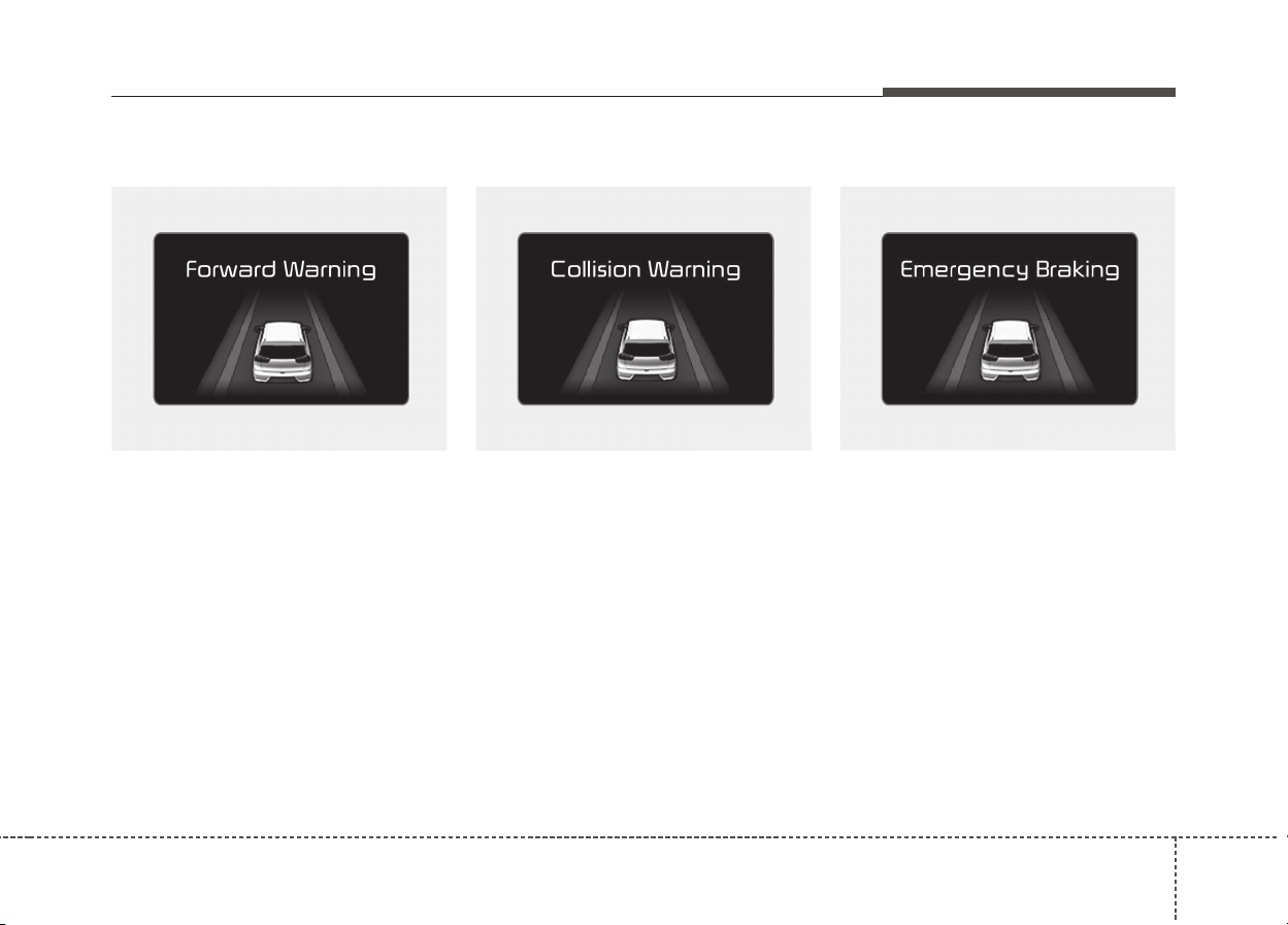
641
Driving your vehicle
Forward Warning (1st warning)
The warning message appears on
the LCD display with the warning
alarms.
Collision Warning (2nd warning)
• The warning message appears on
the LCD display with the warning
alarms.
• The AEB controls the brakes within
certain limit to release shock from
the collision.
Emergency braking (3
rd
warning)
• The warning message appears on
the LCD display with the warning
alarms.
• The AEB controls the brakes with-
in certain limit to release shock
from the collision.
The AEB controls the maximum
brakes just before the collision.
ODE056075L ODE056076L ODE056077L
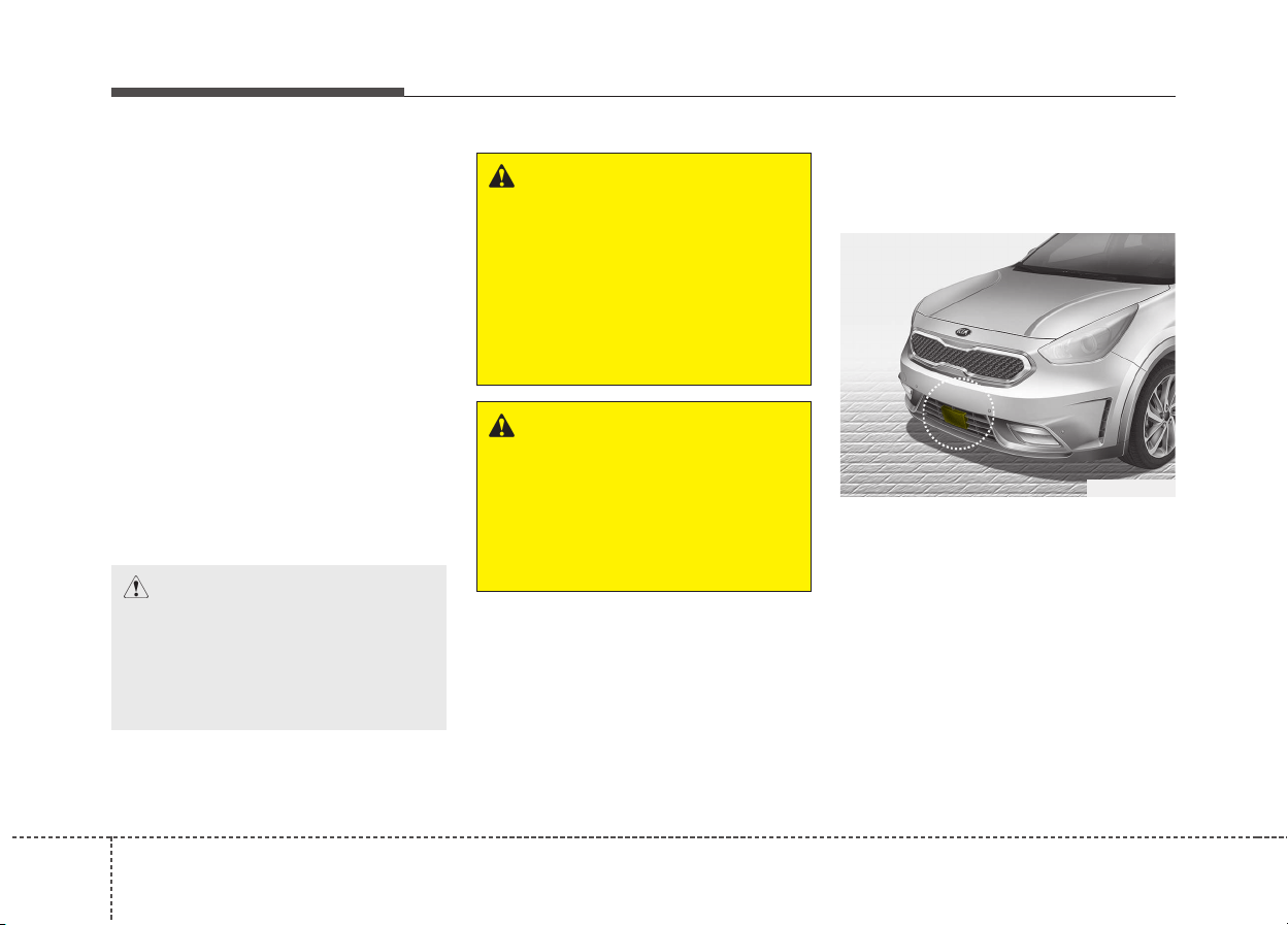
Driving your vehicle
426
Brake operation
• In an urgent situation, the braking
system enters into the ready status
for prompt reaction against the dri-
ver’s depressing the brake pedal.
• The AEB provides additional brak-
ing power for optimum braking per-
formance, when the driver
depresses the brake pedal.
• The braking control is automatical-
ly deactivated, when the driver
sharply depresses the brake pedal,
or when the driver abruptly oper-
ates the steering wheel.
• The braking control is automatical-
ly canceled, when risk factors dis-
appear.
Sensor to detect the distance
from the vehicle in front
(front radar)
The sensor is to maintain a certain
distance from the vehicle in front.
However, the smudged sensor lens
with foreign substances, such as
snow and rain, adversely affects the
sensing performance. It may even
temporarily cancel the AEB. Always
keep the sensor lens clean.
WARNING
The AEB cannot avoid all colli-
sions. The AEB might not com-
pletely stop the vehicle before
collision, due to ambient,
weather and road conditions.
The driver has the responsibili-
ty to drive safely and control the
vehicle.
WARNING
The AEB operates in accordance
with the risk levels, such as the
distance from the vehicle/pass-
er-by in front, the speed of the
vehicle/passer-by in front, and
the driver's vehicle operation.
CAUTION
The driver should always pay
great caution to vehicle opera-
tion, even though there is no
warning message or warning
alarm.
ODE056017
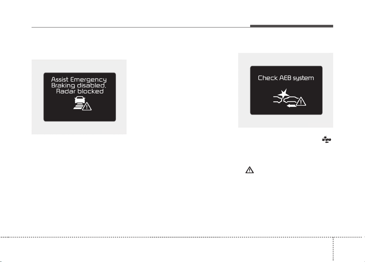
643
Driving your vehicle
Warning message and warning
light
When the sensor cover or the sensor
lens is smudged with the foreign sub-
stances, such as snow or rain, the
AEB operation may temporarily stop.
In this case, the warning message
appears to warn the driver.
This is not a malfunction with the
AEB. To operate the AEB again,
remove the foreign substances.
If the AEB system cannot detect any
external object after engine ignition,
(when the vehicle is located in open,
empty surroundings) the AEB sys-
tem may not operate properly.
✽✽
NOTICE
• Do not install any accessories,
such as license plate molding or
sticker, on the sensor area. Nor
arbitrarily replace the bumper.
Those may adversely affect the
sensing performance.
• Always keep the sensor/bumper
area clean.
• Use only soft clothes to wash the
vehicle. Also, do not spray highly-
pressurized water on the sensor
installed on the bumper.
• Be careful not to apply unneces-
sary force on the frontal sensor
area. When the sensor moves out
of the correct position due to
external force, the system may not
normally operate even without the
warning light or message. In this
case, we recommend you to have
the vehicle inspected by an
authorized Kia dealer.
• Use only the genuine Kia sensor
cover. Do not arbitrarily apply
paint on the sensor cover.
System malfunction
• When the AEB is not working prop-
erly, the AEB warning light ( )
will illuminate and the warning
message will appear for a few sec-
onds. After the message disap-
pears, the master warning light
( ) will illuminate. In this case,
we recommend you to have the
vehicle inspected by an authorized
Kia dealer.
• The AEB warning message may
appear along with the illumination
of the ESC warning light.
ODE056078L
ODE056079L

Driving your vehicle
446
WARNING
• The AEB is only a supplemen-
tal system for the driver’s con-
venience. The driver should
hold the responsibility to con-
trol the vehicle operation. Do
not solely depend on the AEB
system. Rather, maintain a safe
braking distance, and, if neces-
sary, depress the brake pedal
to lower the driving speed.
• The AEB may unnecessarily
produce the warning message
and the warning alarms. Also,
due to the sensing limitation,
the AEB may not produce the
warning message and the
warning alarm at all.
• When there is a malfunction
with the AEB, the braking con-
trol does not operate upon
detecting a collision risk even
with other braking systems
normally operating.
(Continued)
(Continued)
• The AEB operates only for the
vehicle / pedestrian in front,
while driving forward. It does
not operate for any animals or
vehicles in the opposite direc-
tion.
• The AEB does not recognize
the vehicle, which horizontally
drives across the crossroad,
or the vehicle, which is parked
in the horizontal direction.
• If the vehicle in front stops
suddenly, you may have less
control of the brake system.
Therefore, always keep safe
distance between your vehicle
and the vehicle in front of you.
• The AEB system may activate
during braking and the vehicle
may stop suddenly. And the
load in the vehicle may endan-
ger passengers. Therefore,
always be mindful of the load
volume in the vehicle.
(Continued)
(Continued)
• The AEB system may not acti-
vate if the driver applies the
brake pedal to avoid risk of
collision.

645
Driving your vehicle
Limitation of the system
The AEB is an assistant system for a
driver in a certain risky driving condi-
tion and it does not take every
responsibility for all risks from driving
condition.
The AEB monitors the driving situa-
tions through the radar and the cam-
era sensor. Thus, for a situation out
of the sensing range, the AEB may
not normally operate. The driver
should pay great caution in the fol-
lowing situations. The AEB operation
may be limited.
Recognizing vehicles
- The radar or the camera is con-
taminated with foreign substances.
- It heavily rains or snows.
- There is interruption by electric
waves.
- There is severe irregular reflection
from the radar.
- The vehicle in front has a narrow
body. (i.e. motor cycle and bicycle)
- The driver’s view is unclear due to
the backlight, the reflected light, or
darkness.
- The camera cannot contain the full
image of the vehicle in front.
- The vehicle in front is a special
vehicle, such as a heavily-loaded
truck or a trailer. The vehicle in
front does not turn ON the rear
lights, does not have rear lights,
has asymmetric rear lights, or has
rear lights out of angle.
- When the vehicle is on unpaved or
uneven rough surfaces, or roads
with sudden gradient changes.
- When the vehicle is moving under
ground level or inside a building.
- The outside brightness is greatly
changed, such as entering/exiting
the tunnel.
- The vehicle driving is unstable.
- The radar/camera sensor recogni-
tion is limited.
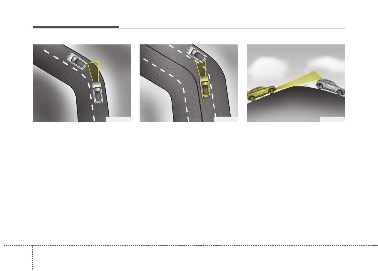
Driving your vehicle
466
- Driving on a curve
The AEB performance decreases
while driving on a curve. The AEB
may not recognize the vehicle in front
even in the same lane. It may unnec-
essarily produce the warning mes-
sage and the warning alarm, or it
may not produce the warning mes-
sage and the warning alarm at all.
While driving on a curve, pay great
caution, and, if necessary, depress
the brake pedal.
While driving on a curve, the AEB
may recognize the vehicle in front in
the next lane. Pay great caution, and,
if necessary, depress the brake pedal.
Or, depress the accelerator pedal to
maintain the driving speed. Always,
take a look around the vehicle for
your safety.
- Driving on a slope
The AEB performance decreases
while driving upward or downward on
a slope, not recognizing the vehicle
in front in the same lane. It may
unnecessarily produce the warning
message and the warning alarm, or it
may not produce the warning mes-
sage and the warning alarm at all.
When the AEB suddenly recognizes
the vehicle in front while passing
over a slope, you may experience
sharp deceleration.
Always keep your eyes forward while
driving upward or downward on a
slope, and, if necessary, depress the
brake pedal.
OQL055053 OQL055054 ODE056060
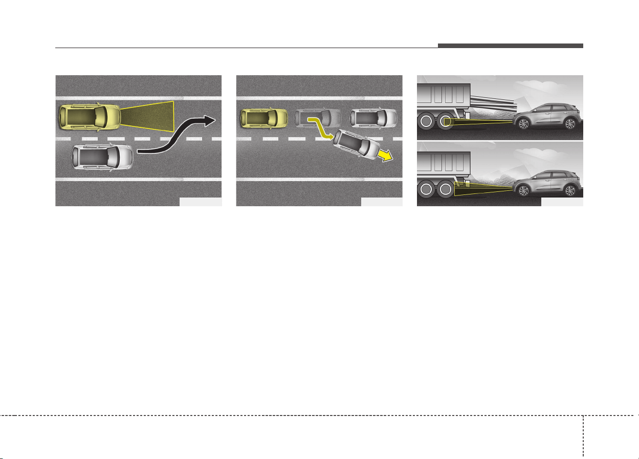
647
Driving your vehicle
- Changing lanes
Even though the vehicle in the next
lane enters into your lane, it may not
be recognized by the AEB, until it
enters the AEB sensing range.
Especially when the vehicle in the
next lane abruptly enters into your
lane, it is more likely not be recog-
nized. Always pay great attention.
When the stopped vehicle in front
gets out of the lane, it may not be
recognized by your AEB. Always pay
great attention.
- Recognizing the vehicle
When the vehicle in front has heavy
loading extended rearward, or when
the vehicle in front has higher ground
clearance, it may induce a haz-
ardous situation.
OQL055057 ODE056061OQL055056
Driving your vehicle
486
Recognizing pedestrians
- The pedestrian is not fully captured
by the camera sensor, or the
pedestrian does not walk in the
upright position.
- The pedestrian moves very fast.
- The pedestrian abruptly appears in
front.
- The pedestrian wears clothes in
the color similar to the background.
- The outside is too bright or too
dark.
- The vehicle drives at night or in the
darkness.
- There is an item similar to a per-
son’s body structure.
- The pedestrian is small.
- The pedestrian has impaired
mobility.
- It is difficult to distinguish the
pedestrian from the surroundings.
- The sensor recognition is limited.
- There is a group of pedestrians.
✽✽
NOTICE
The system may temporarily cancel
due to the strong electric waves.
WARNING
• Cancel the AEB in the User
Settings on the LCD display,
before towing another vehicle.
While towing, the brake appli-
cation may adversely affect
your vehicle safety.
• Pay great caution to the vehi-
cle in front, when it has heavy
loading extended rearward, or
when it has higher ground
clearance.
• The sensor only detects
pedestrian, not carts, bicy-
cles, motorcycles, luggage
bags, or strollers.
• The AEB does not operate in a
certain situation. Thus, never
test-operate the AEB against
a person or an object. It may
cause a severe injury or even
death.
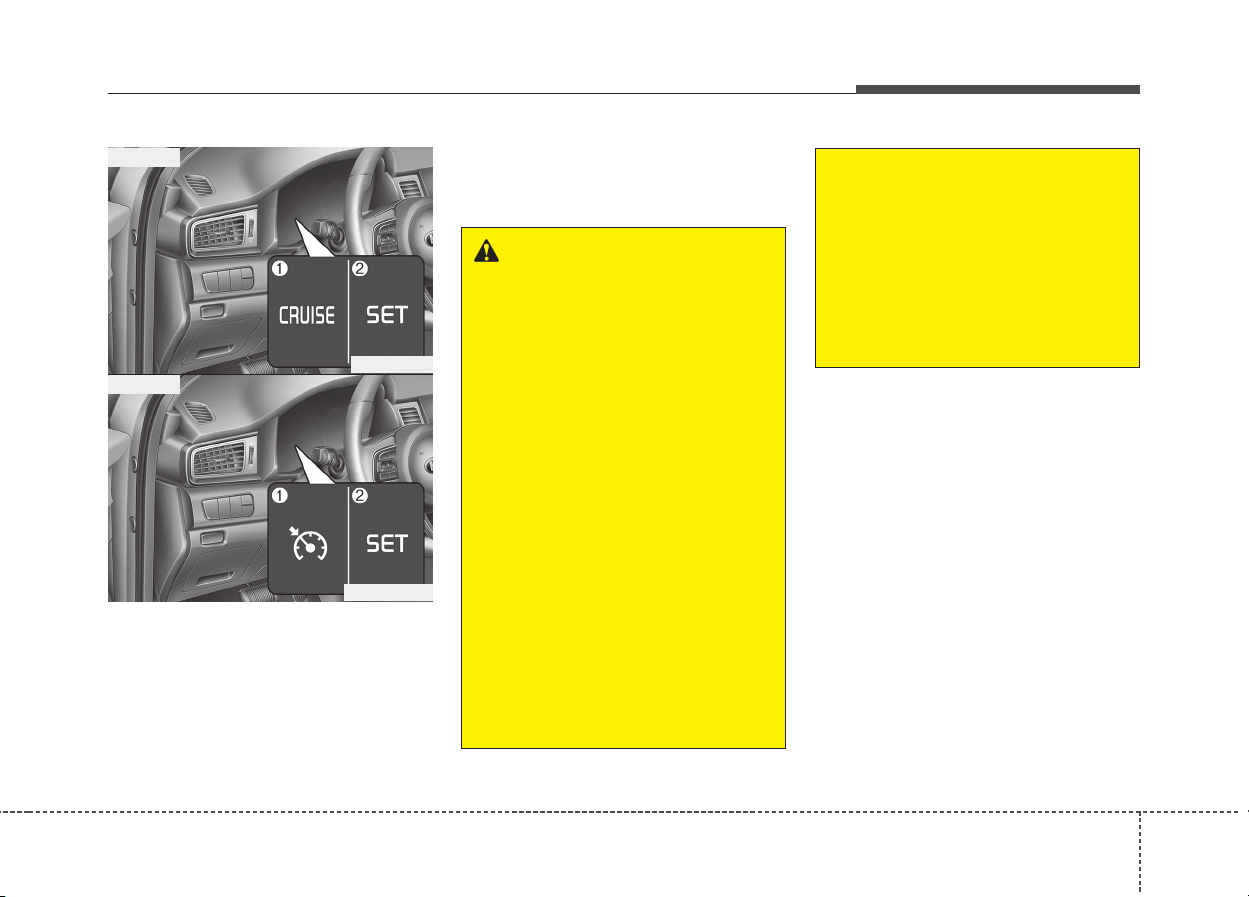
649
Driving your vehicle
1. Cruise indicator
2. Cruise set indicator
The cruise control system allows you
to program the vehicle to maintain a
constant speed without pressing the
accelerator pedal.
This system is designed to function
above approximately 30 km/h (20
mph).
CRUISE CONTROL SYSTEM (IF EQUIPPED)
WARNING
• If the cruise control is left on,
(cruise indicator light is illu-
minated), the cruise control
can be switched on acciden-
tally. Keep the cruise control
system off when the cruise
control is not in use, to avoid
inadvertently setting a speed.
• Use the cruise control system
only when traveling on open
highways in good weather.
• Do not use the cruise control
when it may not be safe to
keep the vehicle at a constant
speed, for instance, driving in
heavy or varying traffic, or on
slippery (rainy, icy or snow-
covered) or winding roads or
over 6% up-hill or down-hill
roads.
(Continued)
(Continued)
• Pay particular attention to the
driving conditions whenever
using the cruise control sys-
tem.
• Be careful when driving
downhill using the cruise con-
trol system, which may
increase the vehicle speed.
ODE056018
■ Type A
■ Type B
ODE056018L
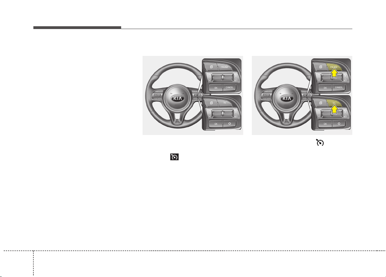
Driving your vehicle
506
✽✽
NOTICE
• During normal cruise control oper-
ation, when the SET switch is acti-
vated or reactivated after applying
the brakes, the cruise control will
energize after approximately 3 sec-
onds. This delay is normal.
• To activate cruise control, depress
the brake pedal at least once after
turning the ignition switch to the ON
position or starting the engine. This
is to check if the brake switch which
is important part to cancel cruise
control is in normal condition.
Cruise control switch
CANCEL/O : Cancels cruise control
operation.
CRUISE / : Turns cruise control
system on or off.
RES+ : Resumes or increases cruise
control speed.
SET- : Sets or decreases cruise con-
trol speed.
To set cruise control speed:
1. Press the CRUISE / button on
the steering wheel, to turn the sys-
tem on. The cruise indicator light
will illuminate.
2. Accelerate to the desired speed,
which must be more than approxi-
mately 30 km/h (20 mph).
ODE046452L ODE056035L
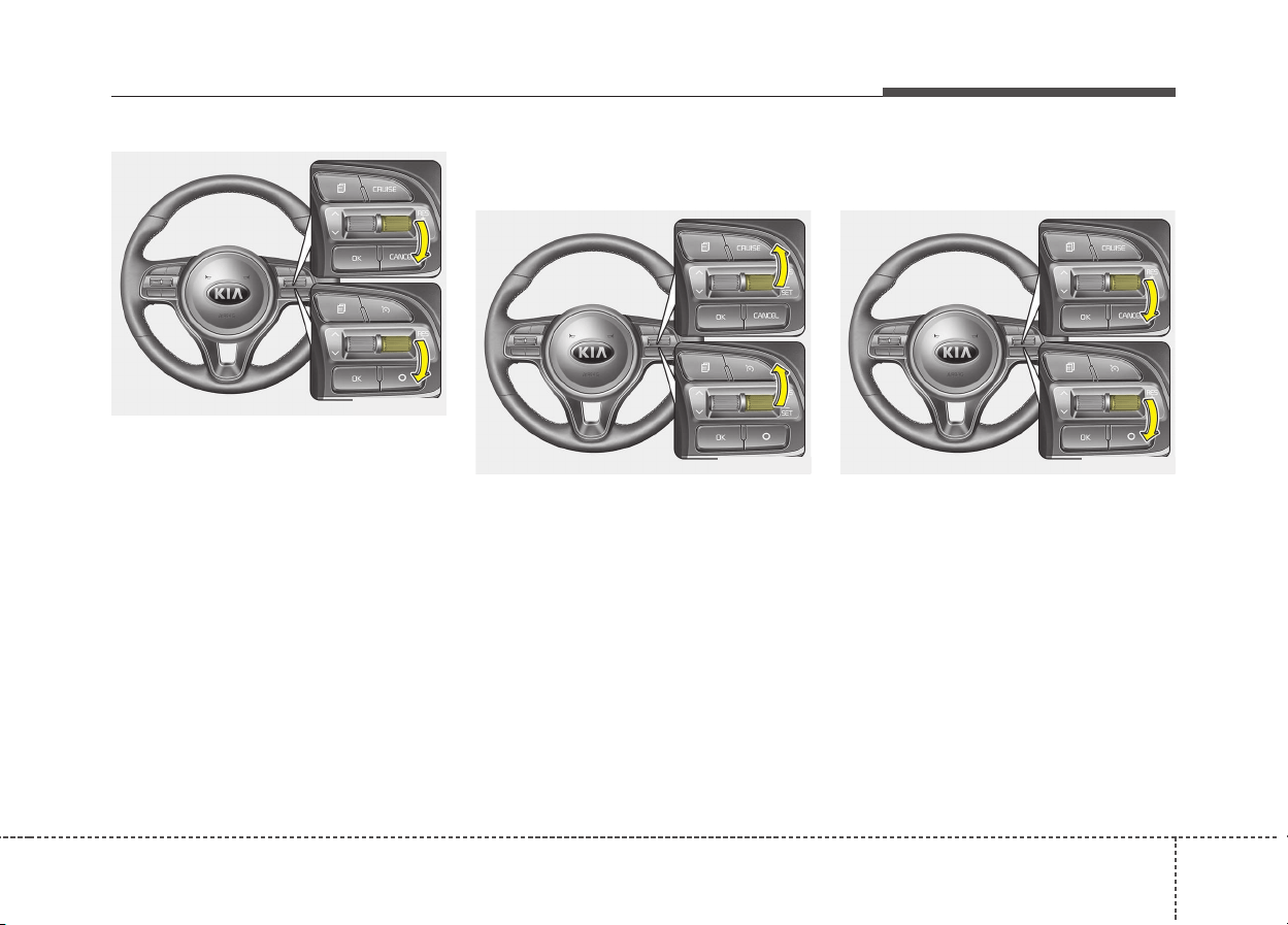
651
Driving your vehicle
3. Move the lever down (to SET-),
and release it at the desired
speed. The cruise set indicator
light will illuminate. Release the
accelerator pedal at the same
time. The desired speed will auto-
matically be maintained.
On a steep grade, the vehicle may
slow down or speed up slightly while
going downhill.
To increase cruise control set
speed:
Follow either of these procedures:
• Move the lever up (to RES+) and
hold it. Your vehicle will accelerate.
Release the lever at the speed you
want.
• Move the lever up (to RES+) and
release it immediately. The cruising
speed will increase by 2 km/h (1
mph) each time you move the lever
up (to RES+) in this manner.
To decrease the cruising
speed:
Follow either of these procedures:
• Move the lever down (to SET-) and
hold it. Your vehicle will gradually
slow down. Release the lever at the
speed you want to maintain.
• Move the lever down (to SET-) and
release it immediately. The cruising
speed will decrease by 2 km/h (1
mph) each time you move the lever
down (to SET-) in this manner.
ODE056036L
ODE056037L ODE056036L
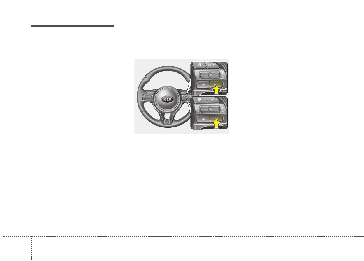
Driving your vehicle
526
To temporarily accelerate with
the cruise control on:
If you want to speed up temporarily
when the cruise control is on,
depress the accelerator pedal.
Increased speed will not interfere
with cruise control operation or
change the set speed.
To return to the set speed, take your
foot off the accelerator pedal.
To cancel cruise control, do
one of the following:
• Depress the brake pedal.
• Shift into N (Neutral) if equipped
with an Dual clutch transmission.
• Press the CANCEL/O button locat-
ed on the steering wheel.
• Decrease the vehicle speed lower
than the memory speed by approx-
imately 20 km/h (12 mph).
• Decrease the vehicle speed to less
than approximately 25 km/h (15 mph).
Each of these actions will cancel
cruise control operation (the
cruise
set
indicator light will go off), but it
will not turn the system off. If you
wish to resume cruise control opera-
tion, move up the lever (to RES+)
located on your steering wheel. You
will return to your previously preset
speed.
ODE056038L
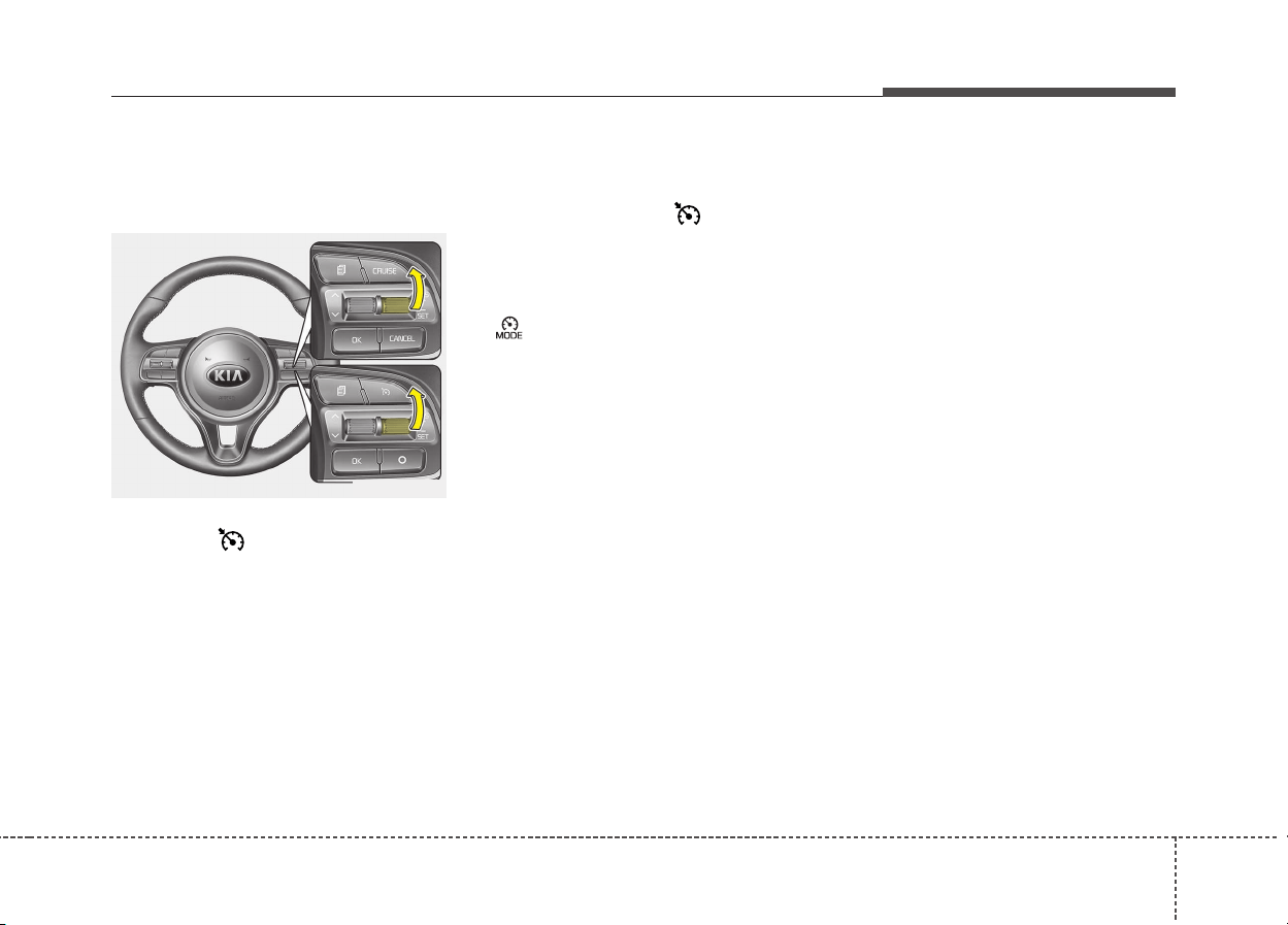
653
Driving your vehicle
To resume cruising speed at
more than approximately 30
km/h (20 mph).
If any method other than the
CRUISE / button was used to
cancel cruising speed and the sys-
tem is still activated, the most recent
set speed will automatically resume
when the RES+ switch is pushed.
It will not resume, however, if the
vehicle speed has dropped below
approximately 30 km/h (20 mph).
To turn cruise control off, do
one of the following:
• Press the CRUISE/ button (the
cruise indicator light will be turn
off).
• If your vehicle equipped the speed
limit system, press the CRUISE/
button twice. (The cruise indi-
cator light will be turn off.)
• Turn the ignition off.
Both of these actions cancel cruise
control operation. If you want to
resume cruise control operation,
repeat the steps provided in “To set
cruise control speed” on the previous
page.
ODE056037L
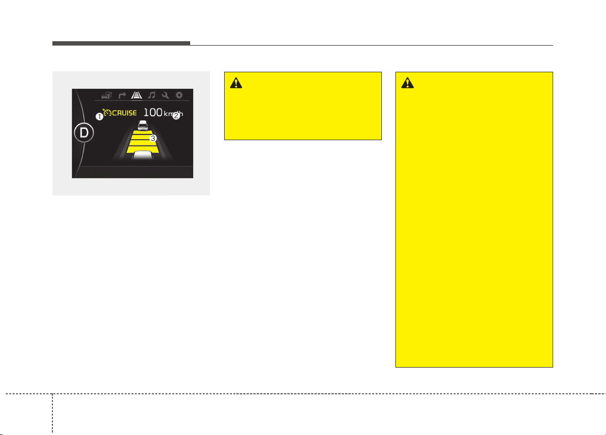
Driving your vehicle
546
SMART CRUISE CONTROL SYSTEM (IF EQUIPPED)
➀ Cruise indicator
➁ Set speed
➂ Vehicle-to-vehicle distance
The smart cruise control system
allows you to program the vehicle to
maintain constant speed and dis-
tance detecting the vehicle ahead
without depressing the accelerator or
brake pedal.
✽✽
NOTICE
To activate smart cruise control,
depress the brake pedal at least once
after turning the engine start/stop
button switch to the ON position or
starting the engine. This is to check
if the brake switch which is impor-
tant part to cancel smart cruise con-
trol is in normal condition.
WARNING
For your safety, please read the
owner's manual before using
the smart cruise control sys-
tem.
ODE056095L
WARNING
• If the smart cruise control is
left on, (cruise indicator in the
instrument cluster illuminat-
ed) the smart cruise control
can be activated unintention-
ally. Keep the smart cruise
control system off (cruise
indicator turn off) when the
smart cruise control is not
used.
• Use the smart cruise control
system only when traveling
on open highways in good
weather.
• Do not use the smart cruise
control when it may not be
safe to keep the car at a con-
stant speed. For instance.
- Highway interchange and
tollgate
- Road surrounded by abnor-
mally multiple steel con-
structions (subway con-
struction, steel tunnel, etc)
(Continued)

655
Driving your vehicle
Speed setting
To set cruise control speed:
1. Press the CRUISE button, to turn
the system on. The CRUISE indi-
cator in the instrument cluster will
illuminate.
2. Accelerate to the desired speed.
The smart cruise control speed
can be set as follows:
• 30 km/h (20mph) ~ 180 km/h
(110 mph): when there is no
vehicle in front
• 10 km/h (6.2mph) ~ 180 km/h
(110 mph): when there is a vehi-
cle in front
(Continued)
- Parking lot
- Lanes beside guard rail on a
road
- Slippery road with rain, ice,
or snow covered
- Abrupt curved road
- Steep hills
- Windy roads
- Off roads
- Rods under construction
- Rumble strip
- The sensing ability decreas-
es if the level of front and
rear vehicle is changed from
the factory.
• Pay particular attention to the
driving conditions whenever
using the smart cruise control
system.
(Continued)
(Continued)
• The smart cruise control sys-
tem is not a substitute for safe
driving. It is the responsibility
of the driver to always check
the speed and distance of the
vehicle ahead.
• Be careful when driving
downhill using the SCC.
ODE056039L

Driving your vehicle
566
3. Move the lever down (to SET-),
and release it at the desired
speed. The set speed and vehicle
to vehicle distance on the LCD
screen will illuminate.
4. Release the accelerator pedal.
The desired speed will automati-
cally be maintained.
If there is a vehicle in front of you, the
speed may decrease to maintain the
distance to the vehicle ahead.
On a steep grade, the vehicle may
slow down or speed up slightly while
going uphill or downhill.
To increase cruise control set
speed:
Follow either of these procedures:
• Move the lever up (to RES+), and
hold it. Your vehicle set speed will
increase by 10 km/h (5 mph).
Release the lever at the speed you
want.
• Move the lever up (to RES+), and
release it immediately. The cruising
speed will increase by 1.0 km/h
(1.0 mph) each time you move the
lever up (to RES+) in this manner.
• You can set the speed to 180 km/h
(110 mph).
To decrease the crusie control
set speed:
Follow either of these procedures:
• Move the lever down (to SET-), and
hold it. Your vehicle set speed will
decrease by 10 km/h (5 mph).
Release the lever at the speed you
want.
• Move the lever down (to SET-), and
release it immediately. The cruising
speed will decrease by 1.0 km/h
(1.0 mph) each time you move the
lever down (to SET-) in this manner.
• You can set the speed to 30 km/h
(20 mph).
ODE056040L
ODE056041L ODE056040L
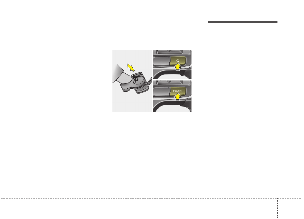
657
Driving your vehicle
To temporarily accelerate with the
cruise control on:
If you want to speed up temporarily
when the cruise control is on,
depress the accelerator pedal.
Increased speed will not interfere
with cruise control operation or
change the set speed.
To return to the set speed, take your
foot off the accelerator.
If you move the lever down (to SET-)
at increased speed, the cruising
speed will be set again.
✽✽
NOTICE
Be careful when accelerating tem-
porarily, because the speed is not con-
trolled automatically at this time even
if there is a vehicle in front of you.
smart cruise control will be tem-
porarily canceled when:
Cancelled manually
The smart cruise control is temporar-
ily canceled when the brake pedal is
depressed or the CANCEL button is
pressed. The speed and vehicle to
vehicle distance indicator on the
cluster is disappeared and the
CRUISE indicator is illuminated con-
tinuously.
Cancelled automatically
• The driver's door is opened.
• The shift lever is shifted to N
(Neutral), R (Reverse) or P (Paking).
• The EPB (electronic parking brake)
is applied.
• The vehicle speed is over 190
km/h (120 mph)
• The ESC, ABS or TCS is operating.
• The ESC is turned off.
• The sensor or the cover is dirty or
blocked with foreign matter.
• The accelerator pedal is continu-
ously depressed for long time.
• The engine speed is in dangerous
range.
ODE056026L
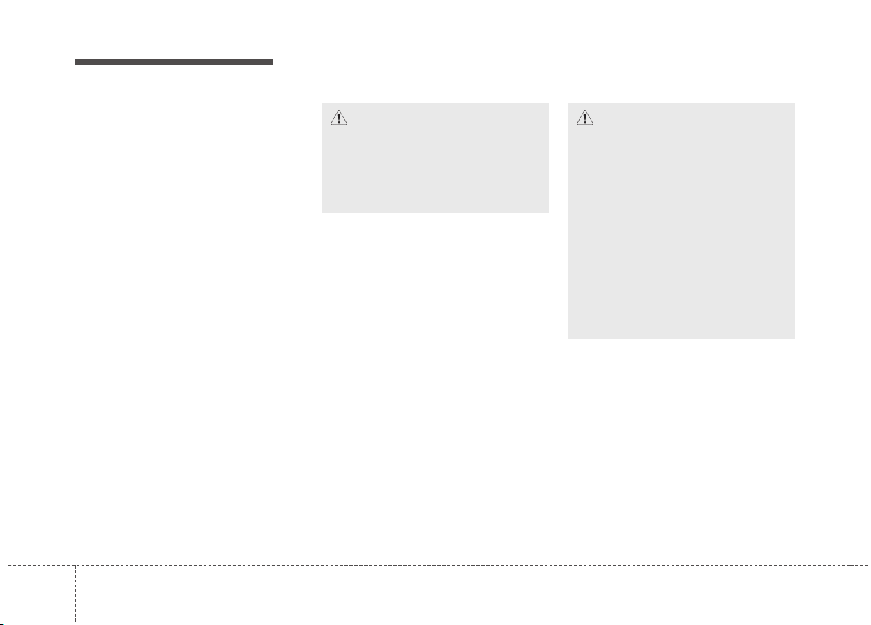
Driving your vehicle
586
• The SCC system has malfunctioned.
Each of these actions will cancel the
smart cruise control operation. (the
set speed and vehicle to vehicle dis-
tance on the LCD display will go off.)
In a condition the smart cruise con-
trol is cancelled automatically, the
smart cruise control will not resume
even though the RES+ or SET-
lever is moved.
• When activating the AEB (Assist
Emergency Braking)
• When the parking brake is locked
• Speed of the vehicle has been
decreased to less than 10km/h
• Engine has some problems
CAUTION
If the smart cruise control is
cancelled by other than the rea-
sons mentioned, we recom-
mend have the system checked
by an authorized Kia dealer.
CAUTION
If the system is automatically
cancelled, the warning chime will
sound and a message (“Smart
Cruise Control canceled”) will
appear for a few seconds.
You must adjust the vehicle
speed by depressing the accel-
erator or brake pedal according
to the road condition ahead and
driving condition.
Always check the road condi-
tions. Do not rely on the warning
chime.
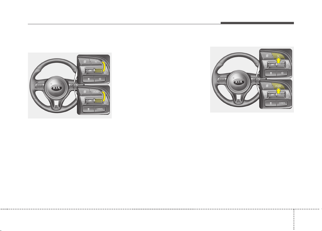
659
Driving your vehicle
To resume cruise control set
speed:
If any method other than the
CRUISE button was used to cancel
cruising speed and the system is still
activated, the cruising speed will
automatically resume when you
move the lever up (to RES+).
If you move the lever up (to RES+),
the speed will resume to the recently
set speed. When the speed of the
vehicle is greater than or equal to 10
km/h but less than 30 km/h, the smart
cruise control system will be reset
only when there is a vehicle in front.
✽✽
NOTICE
To reduce the risk of an accident,
always check the road conditions
when reactivating the smart cruise
control using the RES+ lever to
ensure the road conditions permit
safe use of the cruise control.
To turn cruise control off:
Press the CRUISE button. (the
CRUISE indicator in the instrument
cluster will go off).
ODE056041L
ODE056039L
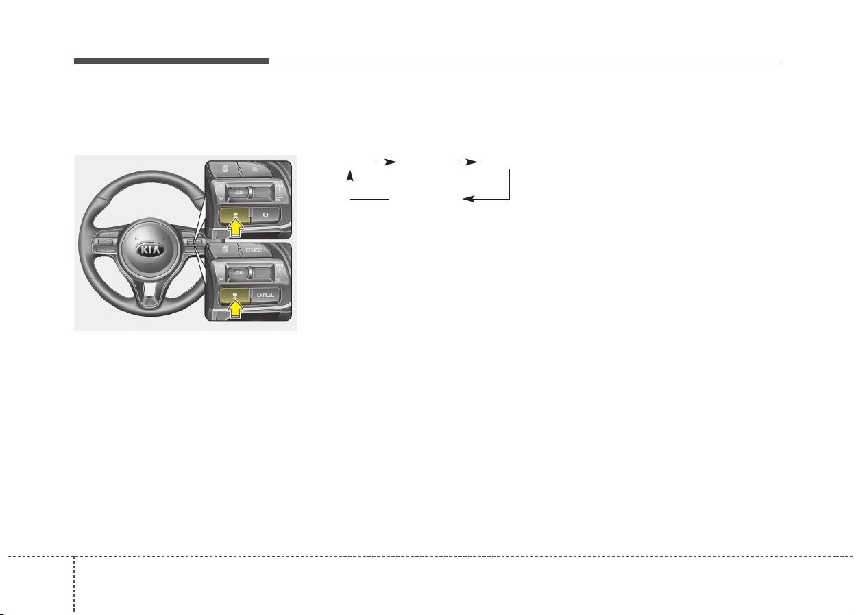
Driving your vehicle
606
Vehicle to vehicle distance
setting
To set vehicle to vehicle distance:
This function allows you to program
the vehicle to maintain relative dis-
tance to the vehicle ahead without
depressing the accelerator pedal or
brake pedal.
The vehicle to vehicle distance will
automatically activate when the
smart cruise control system is on.
Select the appropriate distance
according to road conditions and
vehicle speed.
Each time the button is pressed, the
vehicle to vehicle distance changes
as follows:
For example, if you drive at 90 km/h
(56 mph), the distance maintain as
follows;
Distance 4 - approximately 52.5 m
Distance 3 - approximately 40 m
Distance 2 - approximately 32.5 m
Distance 1 - approximately 25 m
✽✽
NOTICE
The level of distance between vehi-
cles will be set to the level designat-
ed by the driver. (Last mode save
feature)
✽
✽
NOTICE
The 'Distance 4' is always set when
the system is used for the first time
after starting the engine.
The smart cruise control system
remember the last vehicle to vehicle
distance which the driver used in the
vehicle with AEB.
ODE056042L
Distance 4 Distance 3 Distance 2
Distance 1
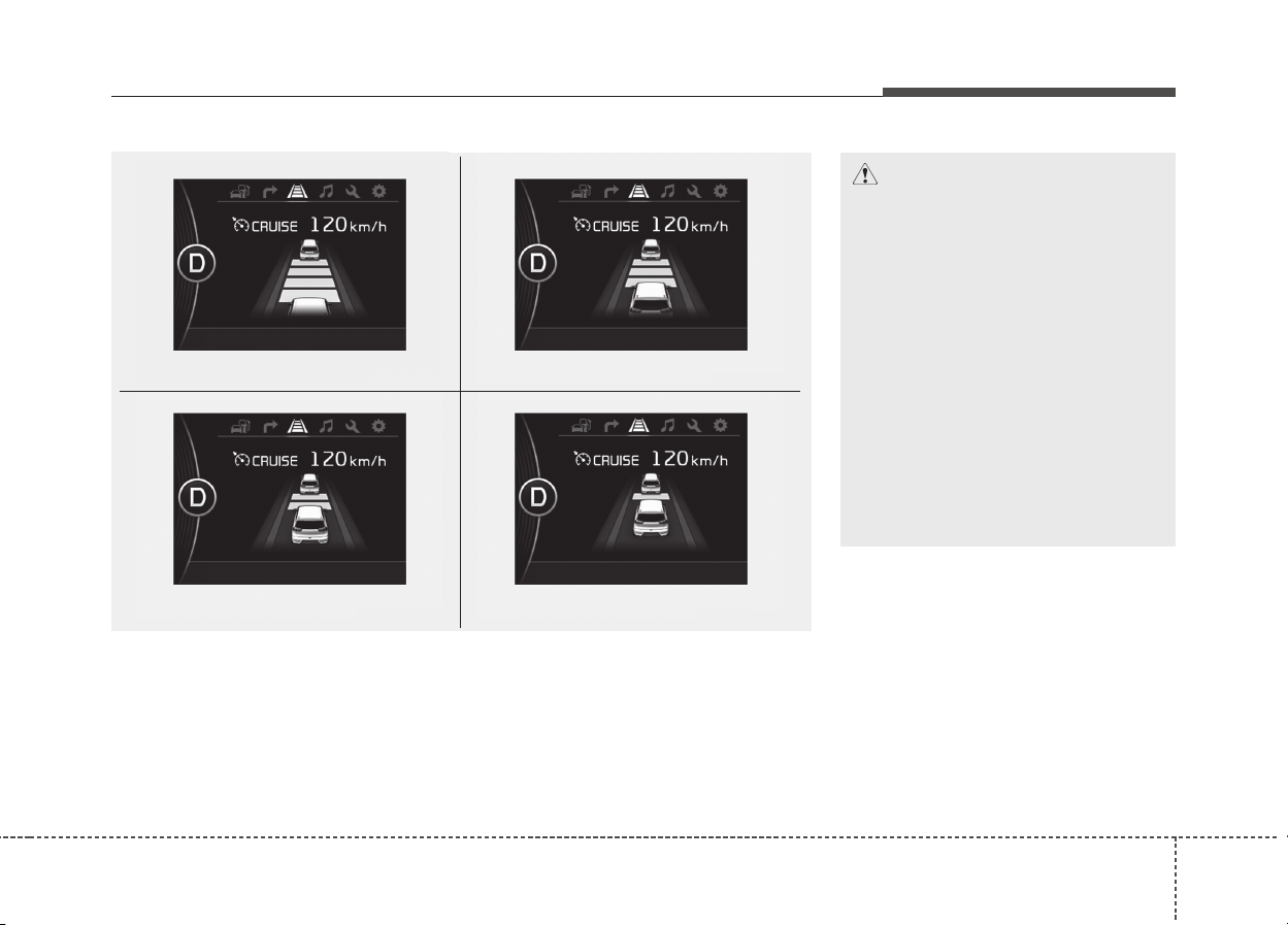
661
Driving your vehicle
CAUTION
• The warning chime sounds
and LCD display blinks if it is
hard to maintain the selected
distance to the vehicle ahead.
• If the warning chime sounds,
actively adjust the vehicle
speed by depressing the
brake pedal according to the
road condition ahead and
driving condition.
• Even if the warning chime is
not activated, always pay
attention to the driving condi-
tions to prevent dangerous
situations from occurring.
ODE056082
ODE056081
ODE056083
Distance 2 Distance 1
Distance 3
Distance 4
ODE056080
• The vehicle will maintain the set speed, when the lane ahead is clear.
• The vehicle will slow down or speed up to maintain the selected distance,
when there is a vehicle ahead of you in the lane. (A vehicle will appear in
front of your vehicle in the LCD display only when there is an actual vehi-
cle in front of you)
• If the vehicle ahead speeds up, your vehicle will travel at a steady cruising
speed after accelerating to the selected speed.
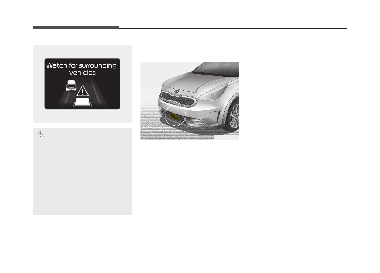
Driving your vehicle
626
Radar to detect distance to the
vehicle ahead
The sensor detects the distance to
the vehicle ahead.
If the sensor is covered with dirt or
other foreign matter, the vehicle to
vehicle distance control may not
operate correctly.
Always keep the area in front of the
sensor clean.
Radar check message
If the radar or cover is dirty or
obscured with foreign matter such as
snow, this message (“Smart Cruise
Control disabled temporarily”) will
appear and it will disappear after for
a while. In this case, the system may
not function temporarily, but it does
not indicate a malfunction of the
smart cruise control System. Clean
the radar or cover by using a soft
cloth and it will operate normally.
If the radar front is polluted after the
engine has been turned on, or the
radar cannot detect any external
object (when the vehicle is located in
open, empty surroundings), the
smart cruise control system may not
operate properly.
ODE056084L
CAUTION
If the vehicle ahead (vehicle
speed: less than 30km/h) disap-
pears to the next lane, the warn-
ing chime will sound and a mes-
sage will appear. Adjust your
vehicle speed for vehicles or
objects that can suddenly
appear in front of you by
depressing the brake pedal
according to the road condition
ahead and driving condition.
ODE056017

663
Driving your vehicle
SCC (smart cruise control) mal-
function message
The message (“Check Smart Cruise
Control System”) will appear when
the vehicle to vehicle distance control
system is not functioning normally.
We recommend have the system
checked by an authorized Kia dealer.
To adjust the sensitivity of
smart cruise control
The sensitivity of vehicle speed when
following the front vehicle to maintain
the set distance can be adjusted. Go
to the User Settings Mode and select
the Driving Assist and select SCC
(smart cruise control) and select the
Response. You may select one of the
three stages you prefer.
• Slow:
Vehicle speed following the front
vehicle to maintain the set distance
is slower than normal speed.
• Normal:
Vehicle speed following the front
vehicle to maintain the set distance
is normal
• Fast:
Vehicle speed following the front
vehicle to maintain the set distance
is faster than normal speed.
CAUTION
• Do not install accessories
around the sensor and do not
replace the bumper by your-
self. It may interfere with the
sensor performance.
• Always keep the sensor and
bumper clean.
• To prevent sensor cover dam-
age from occurring, wash the
car with a soft cloth.
• Do not damage the sensor or
sensor area by a strong
impact. If the sensor moves
slightly off position, the smart
cruise control system will not
operate correctly without any
warning or indicator from the
cluster.
If this occurs, we recommend
that the system be checked by
an authorized Kia dealer.
• Use only a genuine Kia sensor
cover for your vehicle. Do not
paint anything on the sensor
cover.
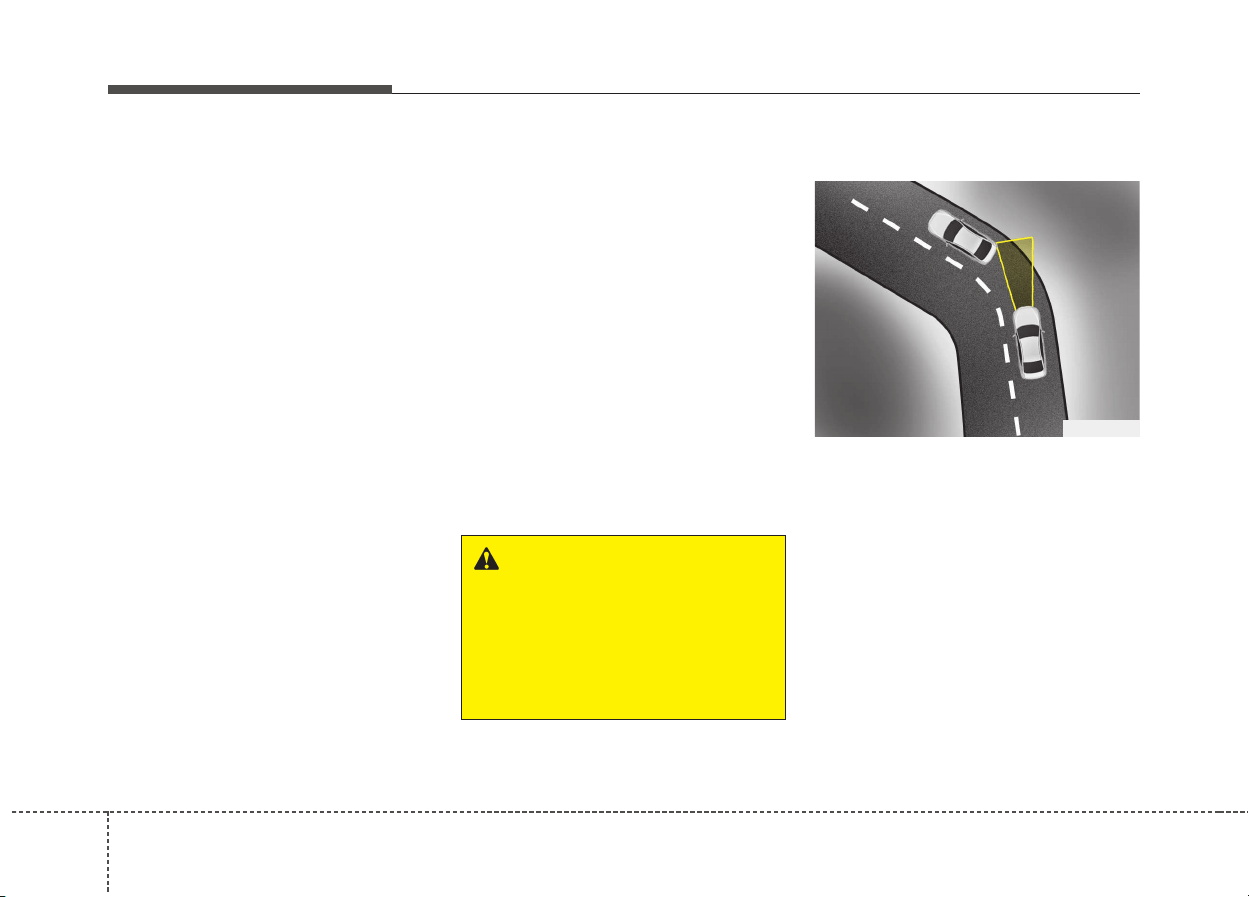
Driving your vehicle
646
✽✽
NOTICE
The last selected mode is remained
in the system
To convert to cruise control
mode:
“Smart Cruise Control or Cruise
Control”
The driver may choose to only use
the cruise control mode (speed con-
trol function) by doing as follows:
1. Turn the smart cruise control sys-
tem on (the cruise indicator light
will be on but the system will not
be activated).
2. Push the distance to distance
switch for more than 2 seconds.
3. Choose between "smart cruise
control (SCC) mode" and "Cruise
control (CC) mode".
Limitations of the system
The smart cruise control system may
have limits to its ability to detect dis-
tance to the vehicle ahead due to
road and traffic conditions.
WARNING
When using the cruise control
mode, you must manually
access the distance to other
vehicles as the system will not
automatically brake to slow
down for other vehicles.
OJF055025
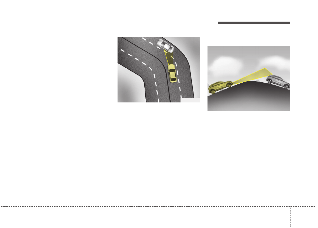
665
Driving your vehicle
On curves
• On curves, the smart cruise control
system may not detect a moving
vehicle in your lane, and then your
vehicle could accelerate to the set
speed. Also, the vehicle speed will
rapidly down when the vehicle
ahead is recognized suddenly.
• Select the appropriate set speed
on curves and adjust your vehicle
speed by depressing the accelera-
tor or brake pedal according to the
road condition ahead and driving
condition.
• Your vehicle speed can be reduced
due to a vehicle in the adjacent
lane. Adjust your vehicle speed by
depressing the brake pedal
according to the road condition
ahead and driving condition. Apply
the accelerator pedal and select
the appropriate set speed. Check
to be sure that the road conditions
permit safe operation of the smart
cruise control.
On inclines
• During uphill or downhill driving,
the smart cruise control system
may not detect a moving vehicle in
your lane, and cause your vehicle
to accelerate to the set speed.
Also, the vehicle speed will rapidly
down when the vehicle ahead is
recognized suddenly.
• Select the appropriate set speed
on inclines and adjust your vehicle
speed by depressing the accelera-
tor or brake pedal according to the
road condition ahead and driving
condition.
OJF055026
ODE056060
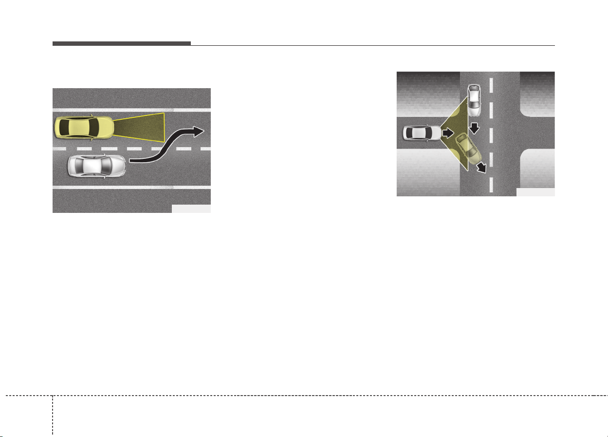
Driving your vehicle
666
Lane changing
• A vehicle which moves into your
lane from an adjacent lane cannot
be recognized by the sensor until it
is in the sensor's detection range.
• The sensor may not detect imme-
diately when a vehicle cuts in sud-
denly. Always pay attention to the
traffic, road and driving conditions.
• If a vehicle which moves into your
lane is slower than your vehicle,
your speed may decrease to main-
tain the distance to the vehicle
ahead.
• If a vehicle which moves into your
lane is faster than your vehicle,
your vehicle will accelerate to the
selected speed.
• Your vehicle may accelerate when
a vehicle ahead of you disappears.
• When you are warned that the
vehicle ahead of you is not detect-
ed, drive with caution.
OJF055049
OJF055028
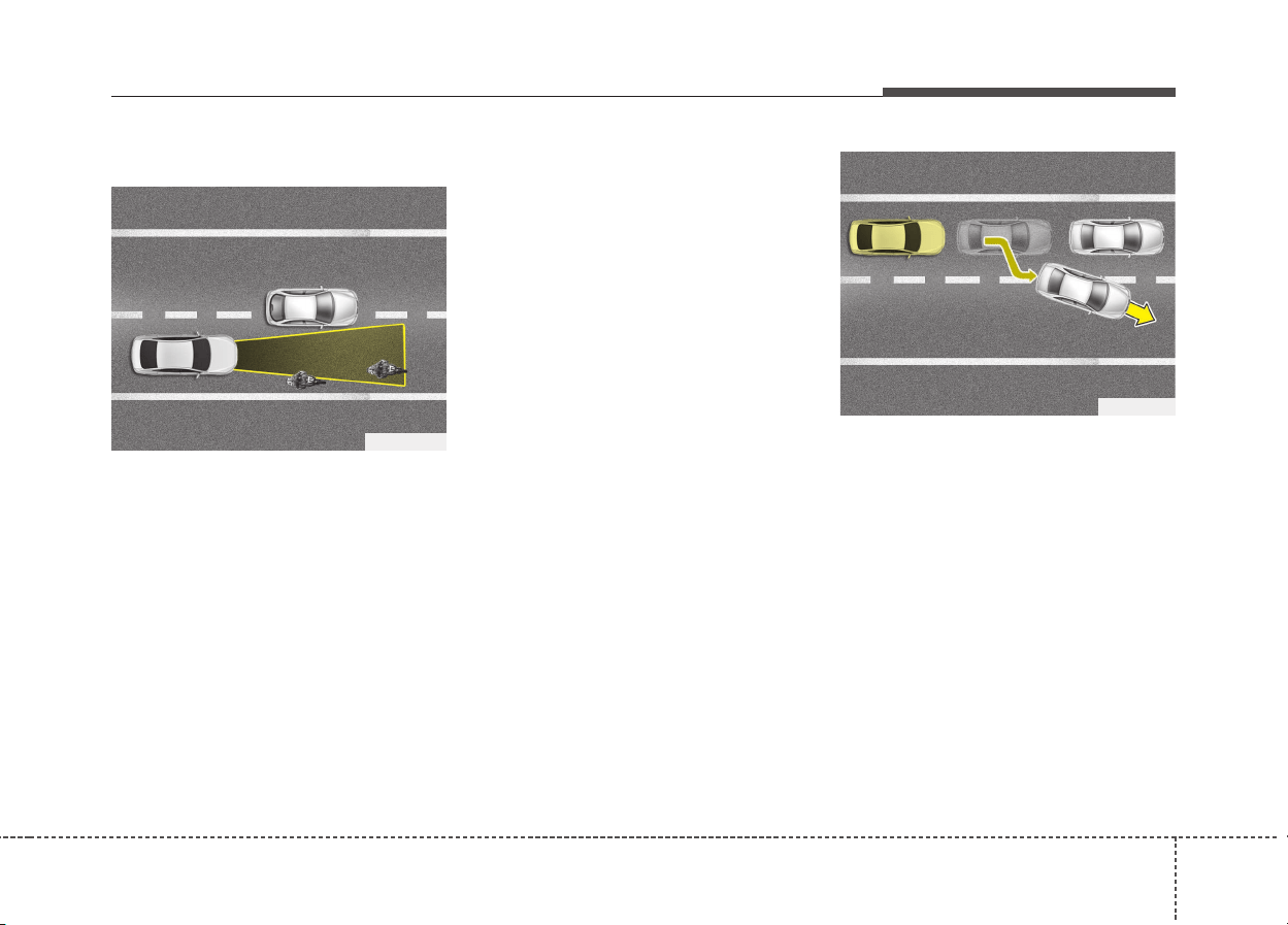
667
Driving your vehicle
Vehicle recognition
Some vehicles ahead in your lane
cannot be recognized by the sensor
as follows:
- Narrow vehicles such as motorcy-
cles or bicycles
- Vehicles offset to one side
- Slow-moving vehicles or sudden-
decelerating vehicles
- Stopped vehicles
- Vehicles with small rear profile such
as trailers with no loads
A vehicle ahead cannot be recog-
nized correctly by the sensor if any of
following occurs:
- When the vehicle is pointing
upwards due to overloading in the
trunk
- While making turns by steering
- When driving to one side of the lane
- When driving on narrow lanes or on
curves
Adjust your vehicle speed by
depressing the brake pedal accord-
ing to the road condition ahead and
driving condition.
• If the vehicle right in front moves to
another direction, the SCC system
may not sense stopped vehicle in
front and may crash. Always main-
tain safe distance.
OJF055048
OJF055029
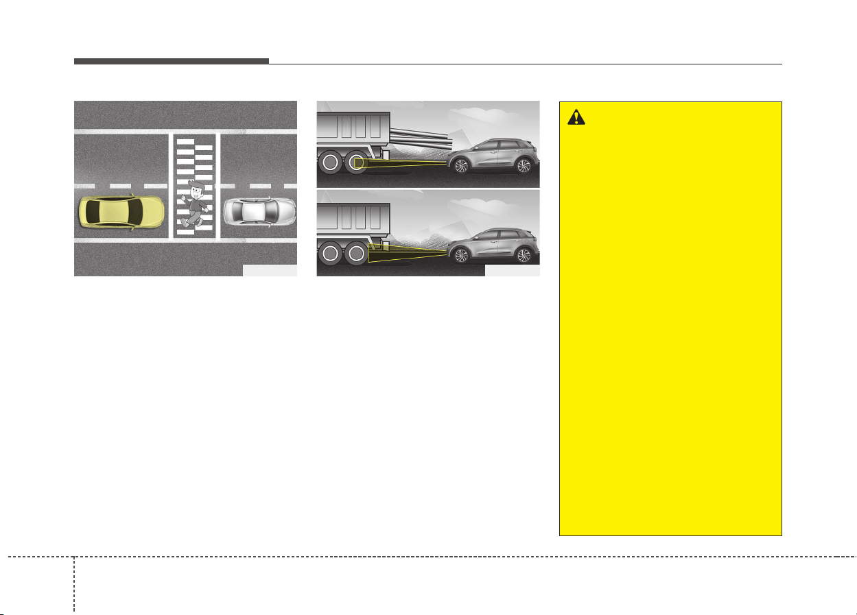
Driving your vehicle
686
• Always look out for pedestrians
when your vehicle is maintaining a
distance with the vehicle ahead.
• Always be cautious for vehicles
with higher height or vehicles car-
rying loads that sticks out to the
back of the vehicle.
OJF055050 ODE056061
WARNING
• The smart cruise control sys-
tem cannot guarantee the
stop for every emergency sit-
uation.
If an emergency stop is nec-
essary, you must apply the
brakes.
• Keep a safe distance accord-
ing to road conditions and
vehicle speed. If the vehicle to
vehicle distance is too close
during a high-speed driving, a
serious collision may result.
• The smart cruise control sys-
tem cannot recognize a
stopped vehicle, pedestrians or
an oncoming vehicle. Always
look ahead cautiously to pre-
vent unexpected and sudden
situations from occurring.
• SCC system may have diffi-
culty in maintaining the cor-
rect distance or speed, if the
vehicle is driving on a steep
incline or towing a trailer.
(Continued)
669
Driving your vehicle
(Continued)
• When other vehicles are
changing lanes in front of you
frequently, the smart cruise
control system may not oper-
ate appropriately. Always look
ahead cautiously to prevent
unexpected and sudden situa-
tions from occurring.
• The smart cruise control sys-
tem is not a substitute for safe
driving practices but a con-
venience function only. It is
the responsibility of the driver
to always check the speed
and the distance to the vehi-
cle ahead.
• Always be aware of the select-
ed speed and vehicle to vehi-
cle distance.
• Always maintain sufficient
braking distance and deceler-
ate your vehicle by applying
the brakes if necessary.
(Continued)
CAUTION
The smart cruise control system
may not operate temporarily
due to electrical interference.
(Continued)
• As the smart cruise control
system may not recognize
complex driving situations,
always pay attention to driv-
ing conditions and control
your vehicle speed.
• For safe operation, carefully
read and follow the instruc-
tions in this manual before use.
• After an engine start, please
stop for several seconds. If
system initialization is not
completed, the SCC does not
normally operate.
• After an engine start, if any
objects are not detected or the
sensor cover is obscured with
foreign substances, there is a
possibility that the SCC sys-
tem may not work.
• Below conditions are not
allowed: over baggage load-
ing in a trunk, suspension
remodeling, tire replacement
with unauthorized tires or
tires with different worn-out
and pressure levels.
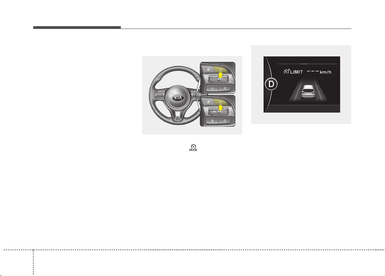
Driving your vehicle
706
You can set the speed limit when you
do not want to drive over a specific
speed.
If you drive over the preset speed
limit, the warning system operates
(set speed limit will blink and chime
will sound) until the vehicle speed
returns within the speed limit.
✽✽
NOTICE
While speed limit control is in oper-
ation, the cruise control system can-
not be activated.
To set speed limit :
1. Press the CRUISE & SPEED
LIMIT MODE ( ) button twice on
the steering wheel, to turn the sys-
tem on.
The speed limit indicator light will illu-
minate.
SPEED LIMIT CONTROL SYSTEM (IF EQUIPPED)
ODE056043L
OQLE055137
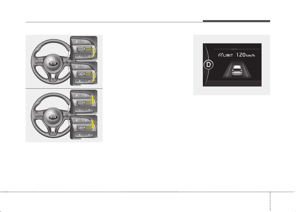
671
Driving your vehicle
2. Move the lever down (to SET-).
3. Move the lever up (to RES+) or
down (to SET-), and release it at
the desired speed. Move the lever
up (to RES+) or down (to SET-)
and hold it. The speed will increase
or decrease by 5 km/h (3 mph).
Move the lever up (to RES+) or
down (SET-) and release it imme-
diately. The speed will increase or
decrease by 1 km/h.
The set speed limit will display on
the instrument cluster.
The set speed limit will be displayed.
To drive over the preset speed limit
you must depress hard on the accel-
erator pedal (more than approxi-
mately 80%) until the kick down
mechanism works with a clicking
noise. Then the set speed limit will
blink and chime will sound until you
return the vehicle speed within the
speed limit.
ODE056044L
ODE056045L
OQLE045113
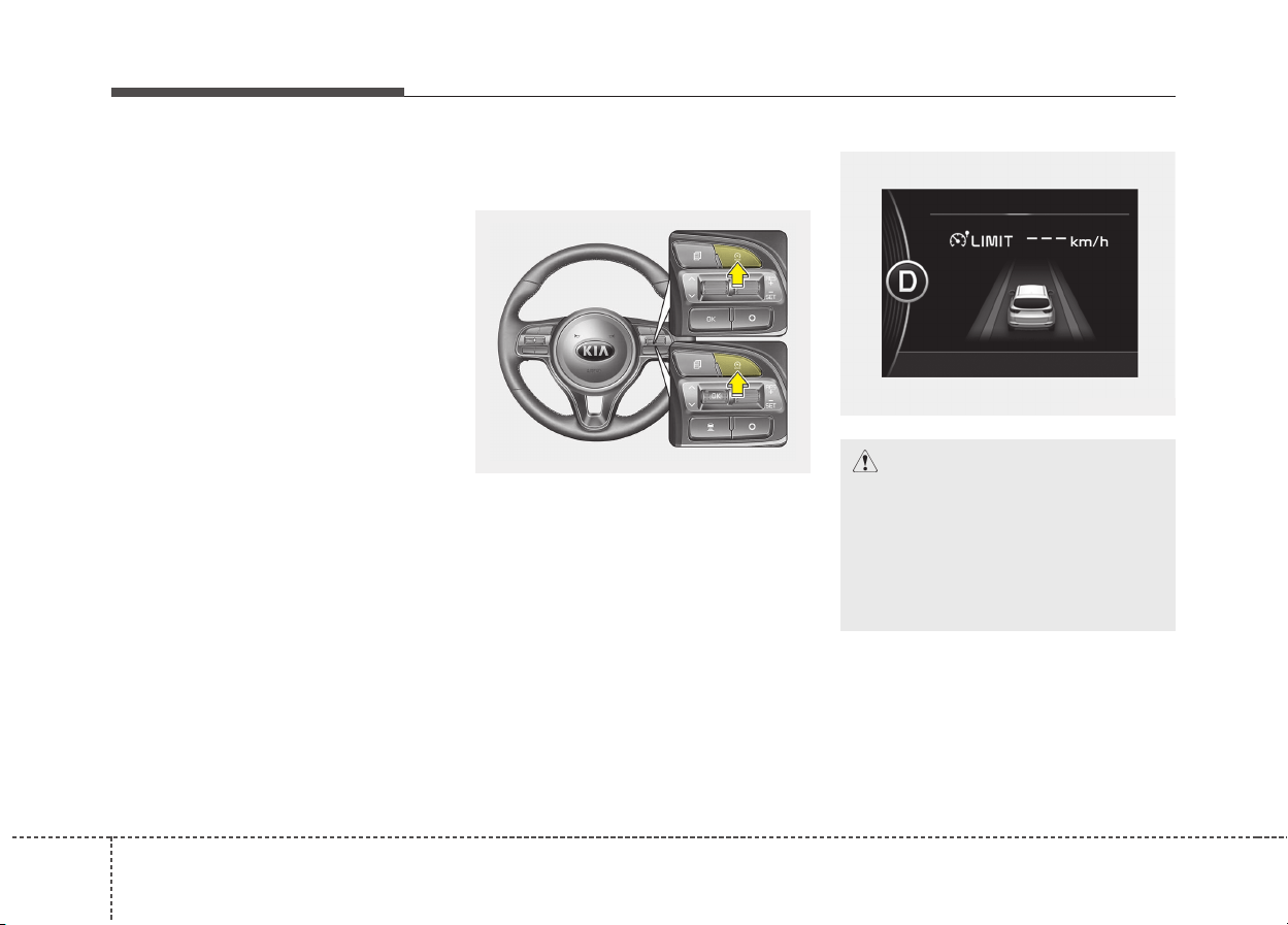
Driving your vehicle
726
✽✽
NOTICE
• Depressing the accelerator pedal
less than approximately 50%, the
vehicle will not speed over the pre-
set speed limit but maintain the
vehicle speed within the speed
limit.
• A clicking noise heard from the
kick down mechanism by depress-
ing the accelerator pedal fully is a
normal condition.
To turn off the speed limit con-
trol, do one of the following:
• Press the CRUISE & SPEED LIMIT
MODE switch.
• Turn the ignition off.
If you press the cancel O switch
once, the set speed limit will cancel,
but it will not turn the system off. If
you wish to reset the speed limit,
move the lever up (to RES+) or down
(to SET-) to the desired speed.
ODE056043L
CAUTION
The “---” indicator will blink if
there is a problem with speed
limit control system.
If this occurs, we recommend
that the system be checked by
an authorized Kia dealer.
OQLE055137

673
Driving your vehicle
The Lane Keeping Assist System
detects lane markers on the road,
and assists the driver’s steering to
help keep the vehicle between lanes.
When the system detects the vehicle
straying from its lane, it alerts the
driver with a visual and audible warn-
ing, while applying a slight counter-
steering torque, trying to prevent the
vehicle from moving out of its lane.
LANE KEEPING ASSIST SYSTEM (LKAS) (IF EQUIPPED)
ODE056029
ODE056047L
WARNING
• The steering wheel is not con-
tinuously controlled so if the
vehicle speed is very fast
when leaving a lane the vehi-
cle may not be controlled by
the system.
• It is the responsibility of the
driver to drive safely.
• Do not steer the steering
wheel suddenly when the
steering wheel is being assist-
ed by the system.
(Continued)
(Continued)
• LKAS prevents the driver
from moving out of the lane
unintentionally by assisting
the driver's steering. However,
the driver should not solely
rely on the system but always
pay attention on the steering
wheel to stay in the lane.
• Always check the road condi-
tion and surroundings and be
cautious when the system
cancels, does not operate or
malfunctions.
• Do not place any accessories,
stickers or tint the windshield
near the rearview mirror.
• The system detects lane
markers and controls the
steering wheel by a camera,
therefore, if the lane markers
are hard to detect, the system
may not work properly.
Please refer to "Driver's
Attention".
(Continued)
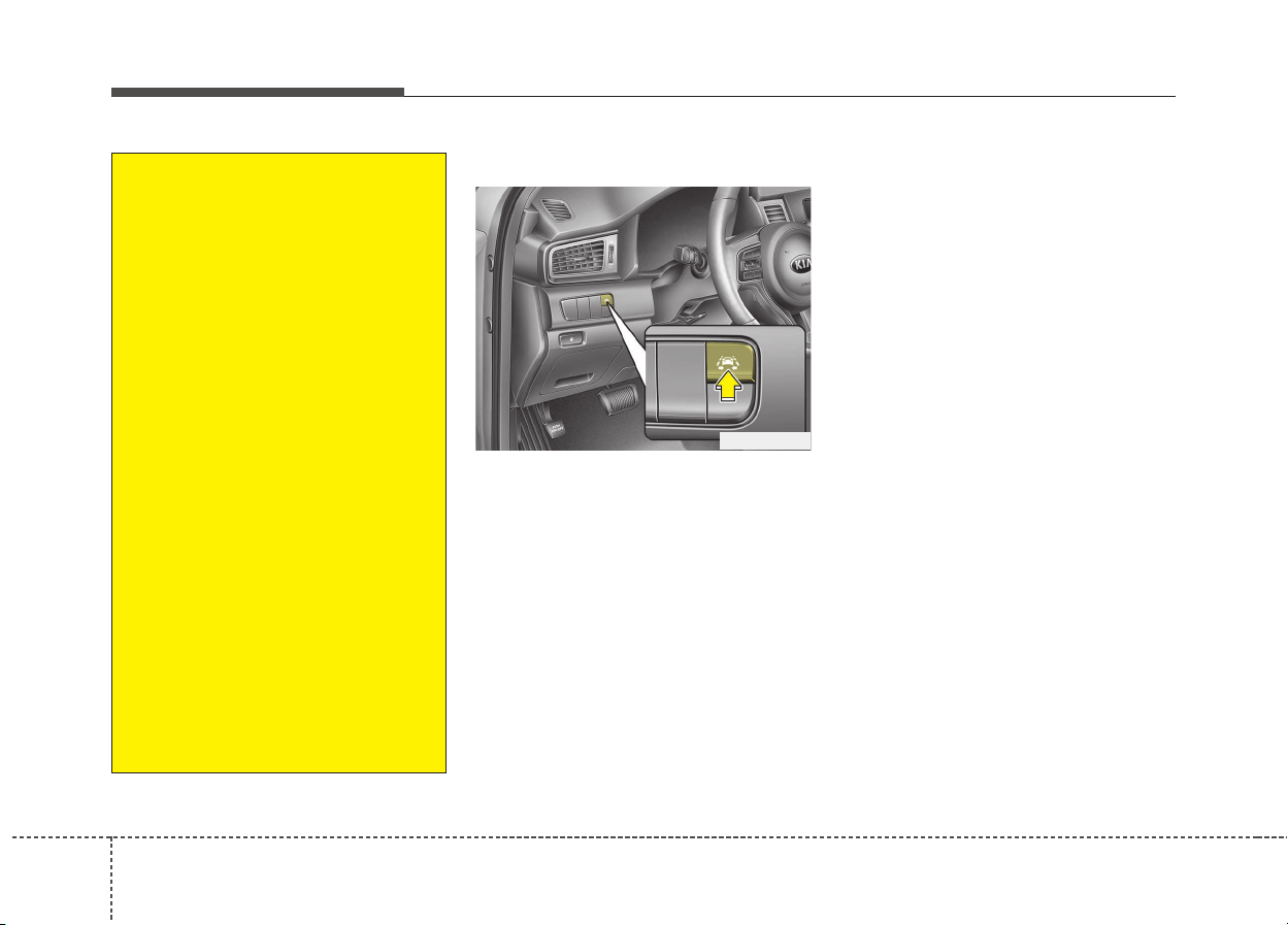
Driving your vehicle
746
LKAS operation
• To turn on the LKAS, push the but-
ton with the ignition switch in the
ON position.
• The LKAS indicator (green) will illu-
minate.
• To turn off the system, press the
button again. The indicator turns off.
• LKAS indicator
- green : LKAS
- white : LDWS
- yellow : FAIL
ODE056046L
(Continued)
• Do not remove any LKAS
parts or apply impact.
• Do not place objects on the
dashboard that reflects light
such as mirrors, white paper,
etc. The system may malfunc-
tion if the sunlight is reflected.
• Loud audio sounds may inter-
fere with the passenger from
hearing warning chimes.
• Always have your hands on
the steering wheel while the
LKAS system is activated. If
you continue to drive with
your hands off the steering
wheel after the "Hand on"
warning, the system will turn
off automatically.
• If you drive very fast, the vehi-
cle may stray out of the lane.
Always be cautious when
using the system.
• When you tow the trailer,
make sure that you turn off
LKAS function.
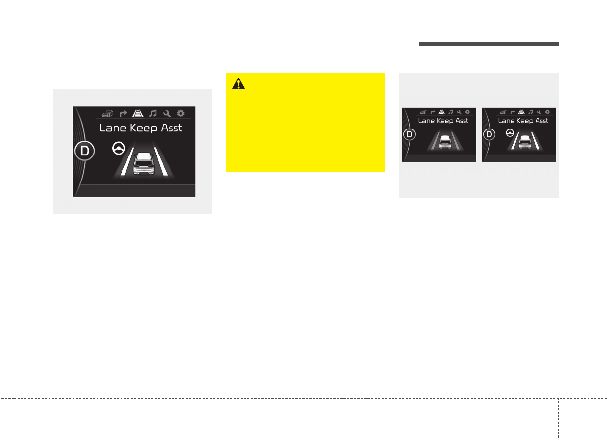
675
Driving your vehicle
LKAS activation
• The LKAS screen will appear on
the LCD display if the system is
activated.
• When both lanes are detected and
all the conditions to activate the
LKAS are satisfied, the steering
wheel will be controlled (green
steering wheel indicator will illumi-
nate).
• If the system detects a lane, the
color changes from gray to white.
• If the system detects the left lane,
the left lane color will change from
gray to white.
• If the system detects the right lane,
the right lane color will change
from gray to white.
• Both lanes must be detected for
the system to fully activate.
• If only one of the lane is detected,
the system will warn (warning beep
and blinking yellow lane) the driver
when the driver crosses the detect-
ed lane.
ODE056098L
WARNING
The Lane Keeping Assist
System is a system to prevent
the driver from leaving the lane.
However, the driver should not
solely rely on the system but
always check the road condi-
tions when driving.
ODE056070L/ODE056098L
■ Lane undetected
■ Lane detected
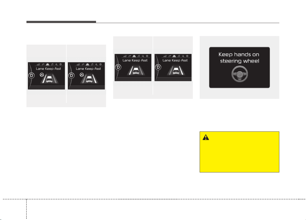
Driving your vehicle
766
Warning
• If you cross a lane, the lane you
cross will blink (yellow) and symbol
will blink green on LCD with an
audible warning during max 3 sec-
onds.
• If the steering wheel appears, the
system will control the vehicle’s
steering to prevent the vehicle from
crossing the lane.
• If all the conditions to activate
LKAS are not satisfied, the system
will convert to LDWS and warn the
driver only when the driver crosses
the lane markers.
• If the driver takes one’s hands off
the steering wheel while the LKAS
is activated, the system will warn
the driver after several seconds
with a visual and audible warning.
ODE056099L
WARNING
The warning message may
appear late according to road
conditions. Therefore, always
have your hands on the steering
wheel while driving.
ODE056096L/ODE056097L
■ Left lane
■ Right lane
ODE056071L/ODE056073L
■ Left lane
■ Right lane

677
Driving your vehicle
If the driver still does not have one’s
hand on the steering wheel after sev-
eral seconds, LKAS does not acti-
vate.
While LKAS deactivation, if the driv-
er have one’s hand on the steering
wheel, LKAS activate again.
✽✽
NOTICE
• Even though the steering is assist-
ed by the system, the driver may
control the steering.
• The steering wheel may feel heav-
ier when the steering wheel is
assisted by the system than when it
is not.
The system will be cancelled when:
• Vehicle speed is below 55km/h
(34.2mph) and over 180 Km (111.8
mph).
• Only one lane is detected.
• Always turn on the turn signal to
change lanes. If you change lanes
without the turn signal on, the
steering wheel might be controlled.
• The hazard warning light is on.
• The width of the lane is below 2.6 m
and over 4.5 m.
• ESC(Electronic Stability Control)
and VSM(Vehicle stability manage-
ment) are activated.
• When the system is on or after
changing a lane, drive in the mid-
dle of the lane. If not, the system
will not provide the steering assist
function.
• The steering will not be assisted
when you drive fast on a sharp
curve.
• The steering will not be assisted
when you change lanes fast.
• The steering will not be assisted
when you brake suddenly.
WARNING
• The driver is responsible for
accurate steering.
• Turn off the system and drive
the vehicle personally in
below situations.
- In bad weather
- In bad road condition
- When the steering wheel
needs to be controlled by the
driver frequently.

Driving your vehicle
786
DRIVER'S ATTENTION
The driver must be cautious in the
below situations for the system may
not assist the driver and may not
work properly.
• The lane is not visible due to snow,
rain, stain, a puddle or many other
things.
• The brightness of the outside
changes suddenly such as passing
through a tunnel.
• Not turning on the headlight or
the light is weak even at night or in
a tunnel.
• Difficult to distinguish the color of
the lane marker from the road.
• Driving on a steep grade or a curve.
• Light reflects from the water on the
road such as sunlight, streetlight or
the light of oncoming vehicles.
• The lens or windshield is stained
with foreign matter.
• The sensor cannot detect the lane
because of fog, heavy rain or
heavy snow.
• The surrounding of the inside rear
view mirror temperature is high
due to direct light.
(Continued)
(Continued)
• The lane is very wide or narrow.
• The lane marker is damaged or
indistinct.
• The shadow is on the lane marker
by a median strip.
• There is a mark similar to a lane
marker.
• There is a boundary structure.
• The distance from vehicle ahead is
very short or the vehicle ahead
drives hiding the lane marker.
• The vehicle shakes heavily.
• The lane number increases or
decreases or the lane marker are
crossing complicatedly.
• Placing something on the dash-
board.
• Driving with the sun in front of
you.
• Driving in areas under construction.
• The lane marker is more than two.
• The lane marker in a tunnel is hard
to distinguish due to dust or grease.
• The lane marker is hard to distin-
guish after raining at night.
• The lane marker is hard to distin-
guish due to dust.
(Continued)
(Continued)
• EPS (Electronic Power Steering) is
not operational.
• Some objects are attached in steer-
ing wheel.
• The windshield is fogged by
humid air in the vehicle.
• The distance from the vehicle
ahead is very short or the vehicle
ahead drives covering the lane line.
• The lane line is merged or divided.
• Driving through a toll plaza or toll
gate.
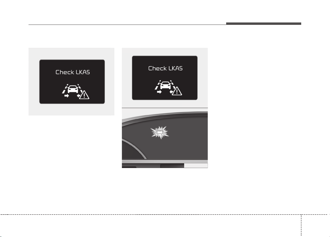
679
Driving your vehicle
LKAS malfunction
• If there is a problem with the sys-
tem a message will appear. If the
problem continues the LKAS fail
indicator will illuminate.
LKAS fail indicator
The LKAS fail indicator (yellow) will
illuminate with an audible warning if
the LKAS is not working properly. We
recommend that you contact an
authorized Kia dealer.
When there is a problem with the sys-
tem do one of the following:
• Turn the system on after turning
the engine off and on again.
• Check if the ignition switch is in the
ON position.
• Check if the system is affected by
the weather. (ex: fog, heavy rain,
etc.)
• Check if there is foreign matter on
the camera lens
If the problem is not solved, we rec-
ommend that the system be checked
by an authorized Kia dealer.
ODE056100L
ODE056100L
■ Type A
■ Type B
ODE056048L

Driving your vehicle
806
LKAS function change
The driver can change LKAS to Lane
Departure Warning System (LDWS)
or change the LKAS mode between
Standard LKA and Active LKA from
the User Settings Mode on the LCD
display. The driver can choose them
by placing the ignition switch to the
ON position and by selecting ‘User
Settings’, ‘Driving Assist’, and ‘Lane
Keeping Assist System’.
The system is automatically set to
Standard LKA.
Lane Departure Warning system
(LDWS)
• The system can be converted to
LKA to LDW at the User setting
mode.
• Refer to User setting in section 4.
• LDWS alerts the driver with a visu-
al and audible warning when the
system detects the vehicle straying
from its lane.
• If the LDWS is operating the indi-
cator yellow/white will illuminate.
• The steering wheel will not be con-
trolled.
Standard LKA
• LKAS only starts intervention when
the vehicle is predicted to cross the
line.
• It's useful to a driver who dislikes
frequent intervention by LKAS
• LDW is generated when the vehi-
cle is about to cross the line.
Active LKA
• LKAS operates for a vehicle to
keep the region of lane center
more efficiently.
• The steering assistance is activat-
ed more frequently and earlier than
standard LKA.
• LDW is generated when the vehi-
cle is about to cross the line.
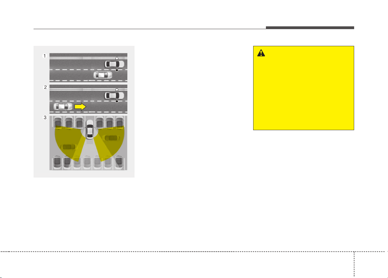
681
Driving your vehicle
The Blind spot detection system
uses a radar sensor to alert the driv-
er while driving.
It senses the rear side territory of the
vehicle and provides information to
the driver.
➀ Blind spot detection
Warning range is dependent on your
vehicle speed. However, if the speed
of your vehicle is faster by 10km/h or
more than other nearby vehicles, the
warning is not operated.
➁ Lane change assist
When vehicles are approaching to
your vehicle at high speed, the warn-
ing is operated.
➂ Rear cross traffic alert
When your vehicle moves backward,
the sensor detects approaching vehi-
cles to the left or right side direction
and warning is operated.
BLIND SPOT DETECTION SYSTEM (IF EQUIPPED)
ODE056063L
WARNING
• Always check the road condi-
tion while driving for unex-
pected situations even though
the Blind spot detection sys-
tem is operating.
• Blind spot detection system is
a system made for conven-
ience. Do not solely rely on
the system but always pay
attention to drive safely.
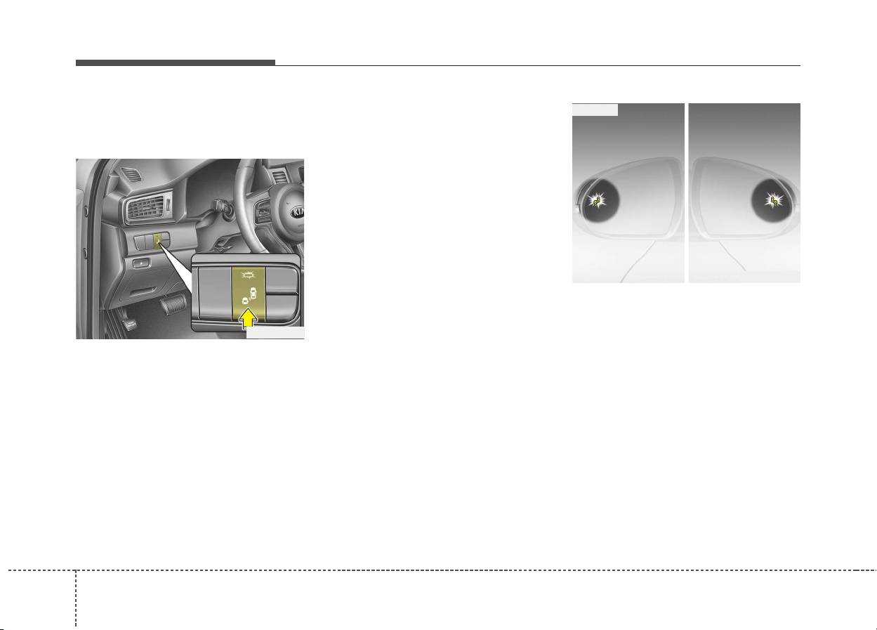
Driving your vehicle
826
Blind spot detection /
Lane change assist
Operating conditions
The indicator on the switch will illumi-
nate when the Blind spot detection
system switch is pressed with the
ignition switch ON. If the vehicle
speed exceeds 30 km/h (18.6 mph),
the system will activate.
If you press the switch again, the
switch indicator and system will be
turned off.
If the ignition switch is turned OFF
and ON the system returns to the
previous state.
When the system is not used turn the
system off by pressing the switch.
When the system is turned on the
warning light will illuminate for 3 sec-
onds on the outside rearview mirror.
Warning type
The system will activate when:
1.The system is on
2.Vehicle speed is above 30 km/h
(18.6 mph)
3.Other vehicles are detected in the
rear side
If a vehicle is detected within the
boundary of the system, a warning
light will illuminate on the outside
rearview mirror.
If the detected vehicle is not in detec-
tion range, the warning will be turned
off.
ODE056031
ODE056033
1st stage
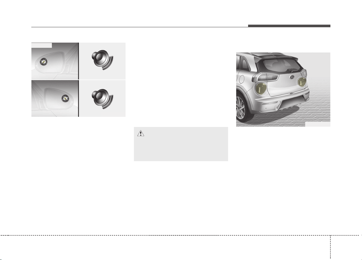
683
Driving your vehicle
The second stage alarm will activate
when:
1. The first stage alert is on
2. The turn signal is on to change a
lane
When the second stage alert is acti-
vated, a warning light will be blinking
on the outside rearview mirror and
an alarm will sound.
If you move the turn signal switch to
origin position, the second stage
alert will be deactivated.
- The second stage alarm can be
deactivated.
• To activate the alarm:
Go to the User Settings Mode →
Sound and select Blind Spot
Detection Sound on the LCD dis-
play.
• To deactivate the alarm:
Go to the User Settings Mode →
Sound and deselect Blind Spot
Detection Sound on the LCD dis-
play.
Detecting sensor
The sensors are located inside the
rear bumper.
Always keep the rear bumper clean
for the system to work properly.
ODE056034
2nd stage
CAUTION
The alarm function helps alert
the driver. Deactivate this func-
tion only when it is necessary
ODE056032
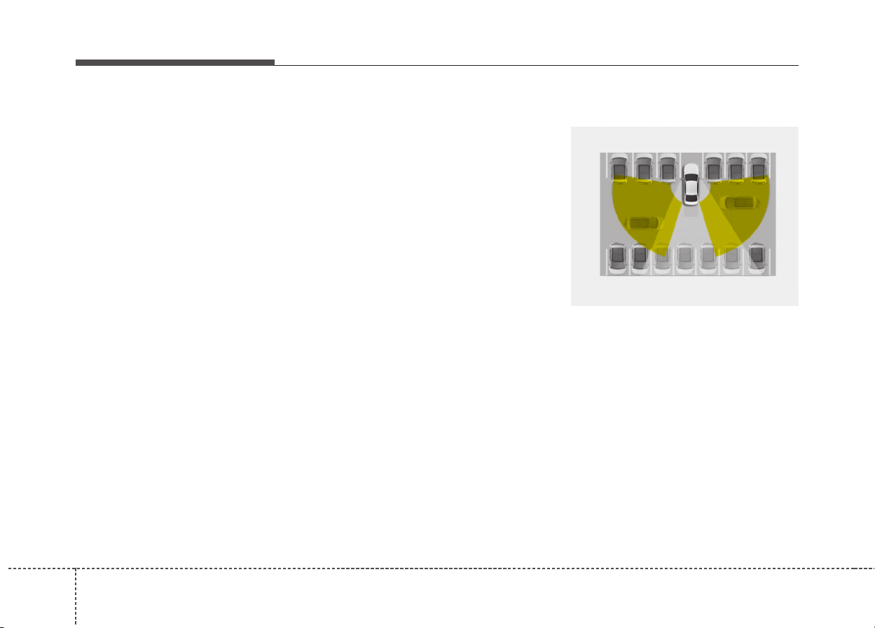
Driving your vehicle
846
Warning message
The message (“Blind Spot Detection
disabled temporarily”) will appear to
notify the driver if there are foreign
substances on the rear bumper or it
is hot near the rear bumper. The light
on the switch and the system will be
turned off automatically.
Remove the foreign substance on
the rear bumper.
After the foreign substance is
removed, if you drive for approxi-
mately 10 minutes, the system will
work normally.
If the system does not work normally
even though the foreign substance is
removed, take your vehicle to an
authorized Kia dealer and have the
system checked.
It is possible to get the message with
no foreign substance on the rear
bumper, for example, when driving in
sparse rural or open area, such as
desert, where there is insufficient
data for operation.
This message may also activate dur-
ing heavy rain or due to road spray.
In this case, the vehicle does not
need service.
If the system does not work properly,
a warning message (“Check BSD
System”) will appear and the light
on the switch will turn off. The system
will turn off automatically.
We recommend you to have the sys-
tem checked by an authorized Kia
dealer.
Rear cross traffic alert
When your vehicle moves backwards
from a parking position, the sensor
detects approaching vehicles to the
left or right side direction and gives
information to the driver.
ODE056064
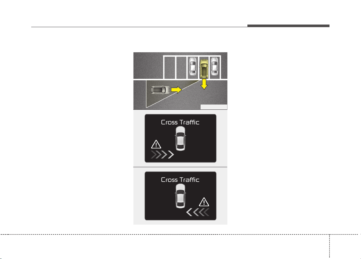
685
Driving your vehicle
Operating conditions
• Go to the User Settings Mode →
Driving Assist → Rear Collision
Warning and select "Rear Cross
Traffic Alert" on the LCD display.
The system will turn on and stand
by to be activated.
• Select Rear cross traffic alert
again, to turn the system off.
• If the vehicle is turned off and on
again, the Rear cross traffic alert
system will return to the state right
before the vehicle was turned off.
Turn the Rear cross traffic alert
system off when not in use.
• The system is operated when the
vehicle speed is below 10km/h with
the shift lever in R (Reverse).
• The Rear cross traffic alert detec-
tion range is 0.5m~20m based on
side direction. If an approaching
vehicle speed is 4 km/h~36 km/h in
detection range, The warning is on.
However, the system sensing
range is different based on condi-
tions. Always pay attention to sur-
rounding.
Warning type
• If an approaching vehicle detected
by sensors, the warning is chime
and the warning light will blink on
the outside rearview mirror.
• If the detected vehicle is out of
detection range, moving away in
the opposite direction or moving
slow, the warning is cancelled.
• The system may not be operating
properly due to other factors or cir-
cumstances, so always pay atten-
tion to your surrounding.
❈ If the bumper on either side is
blocked by a barrier or vehicles,
the system sensing ability may be
deteriorated.
ODE056091L
OQLE055130
ODE056092L
Driving your vehicle
866
Non-operating condition
Outside rearview mirror may not
alert the driver when:
- The outside rearview mirror housing
is damaged or covered with debris.
- The window is covered with debris.
- The windows are severely tinted.
WARNING
• The warning light on the out-
side rearview mirror will illu-
minate whenever a vehicle is
detected at the rear side by
the system.
To avoid accidents, do not
focus only on the warning
light and neglect to see the
surrounding of the vehicle.
• Drive safely even though the
vehicle is equipped with a
Blind spot detection system.
Do not solely rely on the sys-
tem but check for yourself
before changing lanes.
The system may not alert the
driver in some conditions so
always check the surround-
ings while driving.
CAUTION
• The system may not work prop-
erly if the bumper has been
replaced or if a repair work has
been done near the sensor.
• The detection area differs
according to the roads width.
If the road is narrow the sys-
tem may detect other vehicles
in the second next lane.
• On the contrary, if the road is
very wide the system may not
detect other vehicles in the
next lane.
• The system might be turned
off due to strong electromag-
netic waves.

687
Driving your vehicle
Driver's Attention
The driver must be cautious in the
below situations, because the sys-
tem may not detect other vehicles
or objects in certain circumstances.
- The vehicle drives on a curved
road or through a tollgate.
- The sensor is polluted with rain,
snow, mud, etc.
- The rear bumper, in which the
sensor is located, is covered or
blocked with a foreign matter
such as a sticker, a bumper
guard, a bicycle stand, etc.
- The rear bumper is damaged, or
the sensor is out of the original
default position.
- The vehicle height gets lower or
higher due to heavy loading in a
tailgate, abnormal tire pressure,
etc.
- The vehicle drives in a bad
weather such as heavy rain or
snow.
(Continued)
(Continued)
- There is a fixed object near the
vehicle, such as a guardrail.
- A big vehicle is near such as a
bus or truck.
- A motorcycle or bicycle is near.
- A flat trailer is near.
- If the vehicle has started at the
same time as the vehicle next to
you and has accelerated.
- When the other vehicle passes
at a very fast speed.
- While changing lanes.
- While going down or up a steep
road where the height of the lane
is different.
- When the other vehicle
approaches very close.
- When a trailer or carrier is
installed.
(Continued)
(Continued)
- When the sensors are blocked
by other vehicles, walls or park-
ing-lot pillars.
- When the detected vehicle also
moves back, as your vehicle
drives back.
- If there are small things like
shopping cart and baby carriage.
- If there is low height vehicle like
sport vehicle.
- When other vehicles are close to
your vehicle.
- When the vehicle in the next
lane moves two lanes away from
you OR when the vehicle two
lanes away moves to the next
lane from you.
- When driving narrow roads
aside trees or bushes.

Driving your vehicle
886
Your vehicle's fuel economy depends
mainly on your style of driving, where
you drive and when you drive.
Each of these factors affects how
many kilometers (miles) you can get
from a liter (gallon) of fuel. To operate
your vehicle as economically as pos-
sible, use the following driving sug-
gestions to help save money in both
fuel and repairs:
• Drive smoothly. Accelerate at a
moderate rate. Do not make "jack-
rabbit" starts or full-throttle shifts
and maintain a steady cruising
speed. Do not race between stop-
lights. Try to adjust your speed to
the traffic so you do not have to
change speeds unnecessarily.
Avoid heavy traffic whenever pos-
sible. Always maintain a safe dis-
tance from other vehicles so you
can avoid unnecessary braking.
This also reduces brake wear.
• Drive at a moderate speed. The
faster you drive, the more fuel your
vehicle uses. Driving at a moderate
speed, especially on the highway,
is one of the most effective ways to
reduce fuel consumption.
• Do not "ride" the brake or clutch
pedal. This can increase fuel con-
sumption and also increase wear
on these components. In addition,
driving with your foot resting on the
brake pedal may cause the brakes
to overheat, which reduces their
effectiveness and may lead to
more serious consequences.
• Take care of your tires. Keep them
inflated to the recommended pres-
sure. Incorrect inflation, either too
much or too little, results in unnec-
essary tire wear. Check the tire
pressures at least once a month.
• Be sure that the wheels are
aligned correctly. Improper align-
ment can result from hitting curbs
or driving too fast over irregular
surfaces. Poor alignment causes
faster tire wear and may also result
in other problems as well as
greater fuel consumption.
• Keep your vehicle in good condi-
tion. For better fuel economy and
reduced maintenance costs, main-
tain your vehicle in accordance
with the maintenance schedule in
section 8. If you drive your vehicle
in severe conditions, more frequent
maintenance is required (see sec-
tion 8 for details).
• Keep your vehicle clean. For maxi-
mum service, your vehicle should
be kept clean and free of corrosive
materials. It is especially important
that mud, dirt, ice, etc. not be
allowed to accumulate on the
underside of the vehicle. This extra
weight can result in increased fuel
consumption and also contribute to
corrosion.
• Travel lightly. Do not carry unnec-
essary weight in your vehicle.
Weight reduces fuel economy.
• Do not let the engine idle longer
than necessary. If you are waiting
(and not in traffic), turn off your
engine and restart only when
you're ready to go.
ECONOMICAL OPERATION
689
Driving your vehicle
• Remember, your vehicle does not
require extended warm-up. After
the engine has started, allow the
engine to run for 10 to 20 seconds
prior to placing the vehicle in gear.
In very cold weather, however, give
your engine a slightly longer warm-
up period.
• Do not "lug" or "over-rev" the
engine. Lugging is driving too
slowly in too high a gear resulting
engine bucking. If this happens,
shift to a lower gear. Over-revving
is racing the engine beyond its safe
limit. This can be avoided by shift-
ing at the recommended speeds.
• Use your air conditioning sparingly.
The air conditioning system is
operated by engine power so your
fuel economy is reduced when you
use it.
• Open windows at high speeds can
reduce fuel economy.
• Fuel economy is less in crosswinds
and headwinds. To help offset
some of this loss, slow down when
driving in these conditions.
Keeping a vehicle in good operating
condition is important both for econ-
omy and safety. Therefore, we rec-
ommend that the system be serviced
by an authorized Kia dealer.
WARNING - Engine off
during motion
Never turn the engine off to
coast down hills or anytime the
vehicle is in motion. The power
steering and power brakes will
not function properly without
the engine running. Instead,
keep the engine on and down-
shift to an appropriate gear for
engine braking effect. In addi-
tion, turning off the ignition
while driving could engage the
steering wheel lock (if
equipped) resulting in loss of
vehicle steering which could
cause serious injury or death.
Driving your vehicle
906
SPECIAL DRIVING CONDITIONS
Hazardous driving conditions
When hazardous driving conditions
are encountered such as water,
snow, ice, mud, sand, or similar haz-
ards, follow these suggestions:
• Drive cautiously and allow extra
distance for braking.
• Avoid sudden braking or steering.
• When braking with non-ABS
brakes pump the brake pedal with
a light up-and-down motion until
the vehicle is stopped.
• If stalled in snow, mud, or sand, use
second gear. Accelerate slowly to
avoid spinning the drive wheels.
• Use sand, rock salt, tire chains, or
other non-slip material under the
drive wheels to provide traction
when stalled in ice, snow, or mud.
Reducing the risk of a rollover
This multi-purpose passenger vehi-
cle is defined as a Sports Utility
Vehicle (SUV).
SUV’s have higher ground clearance
and a narrower track to make them
capable of performing in a wide vari-
ety of road applications. Specific
design characteristics give them a
higher center of gravity than ordinary
vehicles. An advantage of the higher
ground clearance is a better view of
the road, which allows you to antici-
pate problems. They are not
designed for cornering at the same
speeds as conventional passenger
vehicles. Due to this risk, driver and
passengers are strongly recom-
mended to buckle their seat belts. In
a rollover crash, an unbelted person
is more likely to die than a person
wearing a seat belt. There are steps
that a driver can make to reduce the
risk of a rollover. If at all possible,
avoid sharp turns or abrupt maneu-
vers, do not load your roof rack with
heavy cargo, and never modify your
vehicle in any way.
WARNING - Downshifting
Downshifting with an dual
clutch transaxle, while driving
on slippery surfaces can cause
an accident.The sudden change
in tire speed could cause the
tires to skid. Be careful when
downshifting on slippery sur-
faces.
WARNING - ABS
Do not pump the brake pedal on
a vehicle equipped with ABS.
691
Driving your vehicle
Rocking the vehicle
If it is necessary to rock the vehicle to
free it from snow, sand, or mud, first
turn the steering wheel right and left
to clear the area around your front
wheels. Then, shift back and forth
between R (Reverse) and any for-
ward gear in vehicles equipped with
an Dual clutch transmission. Do not
race the engine, and spin the wheels
as little as possible. If you are still
stuck after a few tries, have the vehi-
cle pulled out by a tow vehicle to
avoid engine overheating and possi-
ble damage to the transaxle.
CAUTION
Prolonged rocking may cause
engine over-heating, transaxle
damage or failure, and tire dam-
age.
WARNING
Your vehicle is equipped with
tires designed to provide safe
ride and handling capability. Do
not use a size and type of tire
and wheel that is different from
the one that is originally
installed on your vehicle. It can
affect the safety and perform-
ance of your vehicle, which
could lead to steering failure or
rollover and serious injury.
When replacing the tires, be
sure to equip all four tires with
the tire and wheel of the same
size, type, tread, brand and
load-carrying capacity. If you
nevertheless decide to equip
your vehicle with any tire/wheel
combination not recommended
by Kia for off road driving, you
should not use these tires for
highway driving.
WARNING - Rollover
As with other Sports Utility
Vehicle (SUV), failure to operate
this vehicle correctly may result
in loss of control, an accident or
vehicle rollover.
• Utility vehicles have a signifi-
cantly higher rollover rate
than other types of vehicles.
• Specific design characteris-
tics (higher ground clearance,
narrower track, etc.) give this
vehicle a higher center of
gravity than ordinary vehicles.
• A SUV is not designed for cor-
nering at the same speeds as
conventional vehicles.
• Avoid sharp turns or abrupt
maneuvers.
• In a rollover crash, an unbelt-
ed person is significantly
more likely to die than a per-
son wearing a seat belt. Make
sure everyone in the vehicle is
properly buckled up.
Driving your vehicle
926
✽✽
NOTICE
The ESC system should be turned
OFF prior to rocking the vehicle.
Smooth cornering
Avoid braking or gear changing in
corners, especially when roads are
wet. Ideally, corners should always
be taken under gentle acceleration. If
you follow these suggestions, tire
wear will be held to a minimum.
WARNING - Spinning
tires
Do not spin the wheels, espe-
cially at speeds more than 56
km/h (35 mph). Spinning the
wheels at high speeds when the
vehicle is stationary could
cause a tire to overheat which
could result in tire damage that
may injure bystanders.
WARNING
If your vehicle becomes stuck in
snow, mud, sand, etc., then you
may attempt to rock the vehicle
free by moving it forward and
backward. Do not attempt this
procedure if people or objects
are anywhere near the vehicle.
During the rocking operation
the vehicle may suddenly move
forward or backward as it
becomes unstuck, causing
injury or damage to nearby peo-
ple or objects.

693
Driving your vehicle
Driving at night
Because night driving presents more
hazards than driving in the daylight,
here are some important tips to
remember:
• Slow down and keep more dis-
tance between you and other vehi-
cles, as it may be more difficult to
see at night, especially in areas
where there may not be any street
lights.
• Adjust your mirrors to reduce the
glare from other driver's head-
lights.
• Keep your headlights clean and
properly aimed on vehicles not
equipped with the automatic head-
light aiming feature. Dirty or
improperly aimed headlights will
make it much more difficult to see
at night.
• Avoid staring directly at the head-
lights of oncoming vehicles. You
could be temporarily blinded, and it
will take several seconds for your
eyes to readjust to the darkness.
Driving in the rain
Rain and wet roads can make driving
dangerous, especially if you’re not
prepared for the slick pavement.
Here are a few things to consider
when driving in the rain:
• A heavy rainfall will make it harder
to see and will increase the dis-
tance needed to stop your vehicle,
so slow down.
• Keep your windshield wiping
equipment in good shape. Replace
your windshield wiper blades when
they show signs of streaking or
missing areas on the windshield.
• If your tires are not in good condi-
tion, making a quick stop on wet
pavement can cause a skid and
possibly lead to an accident. Be
sure your tires are in good shape.
• Turn on your headlights to make it
easier for others to see you.
• Driving too fast through large pud-
dles can affect your brakes. If you
must go through puddles, try to
drive through them slowly.
• If you believe you may have gotten
your brakes wet, apply them lightly
while driving until normal braking
operation returns.
Driving in flooded areas
Avoid driving through flooded areas
unless you are sure the water is no
higher than the bottom of the wheel
hub. Drive through any water slowly.
Allow adequate stopping distance
because brake performance may be
affected.
After driving through water, dry the
brakes by gently applying them sev-
eral times while the vehicle is moving
slowly.
Driving off-road
Drive carefully off-road because your
vehicle may be damaged by rocks of
roots of trees. Become familiar with
the off-road conditions where you
are going to drive before you begin
driving.
Driving your vehicle
946
Highway driving
Tires
Adjust the tire inflation pressures to
specification. Low tire inflation pres-
sures will result in overheating and
possible failure of the tires.
Avoid using worn or damaged tires
which may result in reduced traction
or tire failure.
✽✽
NOTICE
Never exceed the maximum tire
inflation pressure shown on the
tires.
Fuel, engine coolant and engine
oil
High speed travel consumes more
fuel than urban motoring. Do not for-
get to check both engine coolant and
engine oil.
Drive belt
A loose or damaged drive belt may
result in overheating of the engine.
WARNING
• Underinflated or overinflated
tires can cause poor handling,
loss of vehicle control, and
sudden tire failure leading to
accidents, injuries, and even
death. Always check the tires
for proper inflation before
driving. For proper tire pres-
sures, refer to section 9,
“Tires and wheels”.
• Driving on tires with no or
insufficient tread is danger-
ous. Worn-out tires can result
in loss of vehicle control, col-
lisions, injury, and even death.
Worn-out tires should be
replaced as soon as possible
and should never be used for
driving. Always check the tire
tread before driving your vehi-
cle. For further information
and tread limits, refer to sec-
tion 8, “Tires and wheels”.
695
Driving your vehicle
WINTER DRIVING
Severe weather conditions in the
winter result in greater wear and
other problems. To minimize the
problems of winter driving, you
should follow these suggestions:
❈ Snow tires and tire chains for the
national language (Icelandic,
Bulgarian) see the Appendix to
chapter 10.
Snowy or Icy conditions
To drive your vehicle in deep snow, it
may be necessary to use snow tires
or to install tire chains on your tires.
If snow tires are needed, it is neces-
sary to select tires equivalent in size
and type of the original equipment
tires. Failure to do so may adversely
affect the safety and handling of your
vehicle. Furthermore, speeding,
rapid acceleration, sudden brake
applications, and sharp turns are
potentially very hazardous practices.
During deceleration, use engine
braking to the fullest extent. Sudden
brake applications on snowy or icy
roads may cause skids to occur. You
need to keep sufficient distance
between the vehicle in operation in
front and your vehicle. Also, apply
the brake gently. It should be noted
that installing tire chains on the tire
will provide a greater driving force,
but will not prevent side skids.
✽✽
NOTICE
Tire chains are not legal in all coun-
tries. Check the country laws before
fitting tire chains.
Snow tires
If you mount snow tires on your vehi-
cle, make sure they are radial tires of
the same size and load range as the
original tires. Mount snow tires on all
four wheels to balance your vehicle’s
handling in all weather conditions.
Keep in mind that the traction provid-
ed by snow tires on dry roads may
not be as high as your vehicle's orig-
inal equipment tires.You should drive
cautiously even when the roads are
clear. Check with the tire dealer for
maximum speed recommendations.
Do not install studded tires without
first checking local, state and munic-
ipal regulations for possible restric-
tions against their use.
WARNING - Snow tire size
Snow tires should be equivalent
in size and type to the vehicle's
standard tires. Otherwise, the
safety and handling of your vehi-
cle may be adversely affected.
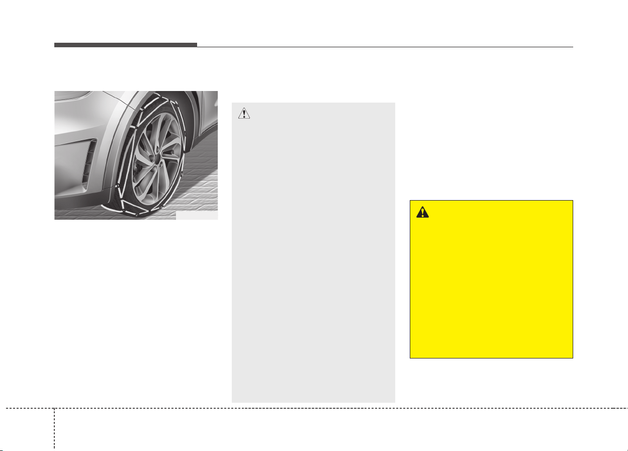
Driving your vehicle
966
Tire chains
Since the sidewalls of radial tires are
thinner, they can be damaged by
mounting some types of snow chains
on them. Therefore, the use of snow
tires is recommended instead of
snow chains. Do not mount tire
chains on vehicles equipped with
aluminum wheels; snow chains may
cause damage to the wheels. If snow
chains must be used, use wire-type
chains with a thickness of less than
12mm (0.47in). Damage to your vehi-
cle caused by improper snow chain
use is not covered by your vehicle
manufacturers warranty.
When using tire chains, install tire
chains only on the front tires.
Chain installation
When installing chains, follow the
manufacturer's instructions and
mount them as tightly as you can.
Drive slowly with chains installed. If
you hear the chains contacting the
body or chassis, stop and tighten
them. If they still make contact, slow
down until it stops. Remove the
chains as soon as you begin driving
on cleared roads.
ODE056062
CAUTION
• Make sure the snow chains are
the correct size and type for
your tires. Incorrect snow
chains can cause damage to
the vehicle body and suspen-
sion and may not be covered
by your vehicle manufacturer
warranty. Also, the snow chain
connecting hooks may be dam-
aged from contacting vehicle
components causing the snow
chains to come loose from the
tire. Make sure the snow chains
are SAE class "S" certified.
• Always check chain installa-
tion for proper mounting after
driving approximately 0.5 to 1
km (0.3 to 0.6 miles) to ensure
safe mounting. Retighten or
remount the chains if they are
loose.
• If your vehicle has 18 inch
tires, do not use tire chains.
They can damage your vehicle
(wheel, suspension and body).
WARNING - Mounting
chains
When mounting snow chains,
park the vehicle on level ground
away from traffic. Turn on the
vehicle Hazard Warning flashers
and place a triangular emer-
gency warning device behind
the vehicle if available. Always
place the vehicle in P (Park),
apply the parking brake and
turn off the engine before
installing snow chains.
697
Driving your vehicle
Use high quality ethylene gly-
col coolant
Your vehicle is delivered with high
quality ethylene glycol coolant in the
cooling system. It is the only type of
coolant that should be used because
it helps prevent corrosion in the cool-
ing system, lubricates the water
pump and prevents freezing. Be sure
to replace or replenish your coolant
in accordance with the maintenance
schedule in section 8. Before winter,
have your coolant tested to assure
that its freezing point is sufficient for
the temperatures anticipated during
the winter.
Check battery and cables
Winter puts additional burdens on
the battery system. Visually inspect
the battery and cables as described
in section 8. We recommend that the
level of charge in your battery be
checked by an authorized Kia dealer.
Change to "winter weight" oil
if necessary
In some climates it is recommended
that a lower viscosity "winter weight"
oil be used during cold weather. See
section 9 for recommendations. If
you aren't sure what weight oil you
should use, we recommend that you
consult an authorized Kia dealer.
Check spark plugs and ignition
system
Inspect your spark plugs as
described in section 8 and replace
them if necessary. Also check all
ignition wiring and components to be
sure they are not cracked, worn or
damaged in any way.
CAUTION
• Chains that are the wrong size
or improperly installed can
damage your vehicle's brake
lines, suspension, body and
wheels.
• Stop driving and retighten the
chains any time you hear them
hitting the vehicle.
WARNING - Tire chains
• The use of chains may
adversely affect vehicle han-
dling.
• Do not exceed 30 km/h (20
mph) or the chain manufactur-
er’s recommended speed
limit, whichever is lower.
• Drive carefully and avoid
bumps, holes, sharp turns, and
other road hazards, which may
cause the vehicle to bounce.
• Avoid sharp turns or locked-
wheel braking.

Driving your vehicle
986
To keep locks from freezing
To keep the locks from freezing,
squirt an approved de-icer fluid or
glycerine into the key opening. If a
lock is covered with ice, squirt it with
an approved de-icing fluid to remove
the ice. If the lock is frozen internally,
you may be able to thaw it out by
using a heated key. Handle the heat-
ed key with care to avoid injury.
Use approved window washer
anti-freeze in system
To keep the water in the window
washer system from freezing, add an
approved window washer anti-freeze
solution in accordance with instruc-
tions on the container. Window wash-
er anti-freeze is available from an
authorized Kia dealer and most auto
parts outlets. Do not use engine
coolant or other types of anti-freeze
as these may damage the paint finish.
Don't let your parking brake
freeze
Under some conditions your parking
brake can freeze in the engaged
position. This is most likely to hap-
pen when there is an accumulation
of snow or ice around or near the
rear brakes or if the brakes are wet.
If there is a risk the parking brake
may freeze, apply it only temporarily
while you put the shift lever in P
(Dual clutch transmission) and block
the rear wheels so the vehicle cannot
roll. Then release the parking brake.
Don't let ice and snow accu-
mulate underneath
Under some conditions, snow and
ice can build up under the fenders
and interfere with the steering. When
driving in severe winter conditions
where this may happen, you should
periodically check underneath the
vehicle to be sure the movement of
the front wheels and the steering
components is not obstructed.
Carry emergency equipment
Depending on the severity of the
weather, you should carry appropri-
ate emergency equipment. Some of
the items you may want to carry
include tire chains, tow straps or
chains, flashlight, emergency flares,
sand, shovel, jumper cables, window
scraper, gloves, ground cloth, cover-
alls, blanket, etc.
699
Driving your vehicle
VEHICLE WEIGHT
This section will guide you in the
proper loading of your vehicle and/or
trailer, to keep your loaded vehicle
weight within its design rating capa-
bility, with or without a trailer. Properly
loading your vehicle will provide max-
imum return of the vehicle design
performance. Before loading your
vehicle, familiarize yourself with the
following terms for determining your
vehicle's weight ratings, with or with-
out a trailer, from the vehicle's speci-
fications and the certification label:
Base curb weight
This is the weight of the vehicle
including a full tank of fuel and all
standard equipment. It does not
include passengers, cargo, or option-
al equipment.
Vehicle curb weight
This is the weight of your new vehicle
when you picked it up from your deal-
er plus any aftermarket equipment.
Cargo weight
This figure includes all weight added
to the Base Curb Weight, including
cargo and optional equipment.
GAW (Gross axle weight)
This is the total weight placed on
each axle (front and rear) - including
vehicle curb weight and all payload.
GAWR
(Gross axle weight rating)
This is the maximum allowable
weight that can be carried by a single
axle (front or rear). These numbers
are shown on the certification label.
The total load on each axle must
never exceed its GAWR.
GVW (Gross vehicle weight)
This is the Base Curb Weight plus
actual Cargo Weight plus passengers.
GVWR
(Gross vehicle weight rating)
This is the maximum allowable
weight of the fully loaded vehicle
(including all options, equipment,
passengers and cargo). The GVWR
is shown on the certification label.
Overloading
WARNING - Vehicle
weight
The gross axle weight rating
(GAWR) and the gross vehicle
weight rating (GVWR) for your
vehicle are on the certification
label attached to the driver's (or
front passenger’s) door.
Exceeding these ratings can
cause an accident or vehicle
damage. You can calculate the
weight of your load by weighing
the items (and people) before
putting them in the vehicle. Be
careful not to overload your
vehicle.

What to do in an emergency
Road warning . . . . . . . . . . . . . . . . . . . . . . . . . . . . . . 7-2
• Hazard warning flasher . . . . . . . . . . . . . . . . . . . . . . . . 7-2
In case of an emergency while driving. . . . . . . . . . 7-3
• If the engine stalls at a crossroad or crossing. . . . . . . 7-3
• If you have a flat tire while driving . . . . . . . . . . . . . . . 7-3
• If engine stalls while driving . . . . . . . . . . . . . . . . . . . . 7-3
If the engine will not start . . . . . . . . . . . . . . . . . . . . 7-4
• If engine doesn't turn over or turns over slowly . . . . 7-4
• If engine turns over normally but does not start . . . . 7-4
Emergency starting . . . . . . . . . . . . . . . . . . . . . . . . . 7-5
• Jump starting . . . . . . . . . . . . . . . . . . . . . . . . . . . . . . . . 7-5
• Push-starting . . . . . . . . . . . . . . . . . . . . . . . . . . . . . . . . 7-7
If the engine overheats. . . . . . . . . . . . . . . . . . . . . . . 7-8
Tire Pressure Monitoring System (TPMS) . . . . . . 7-9
• Check tire pressure . . . . . . . . . . . . . . . . . . . . . . . . . . . . 7-9
• Low tire pressure telltale . . . . . . . . . . . . . . . . . . . . . . 7-11
• TPMS (Tire Pressure Monitoring System)
malfunction indicator . . . . . . . . . . . . . . . . . . . . . . . . 7-12
• Changing a tire with TPMS . . . . . . . . . . . . . . . . . . . . 7-13
If you have a flat tire (with spare tire). . . . . . . . . 7-16
• Jack and tools . . . . . . . . . . . . . . . . . . . . . . . . . . . . . . . 7-16
• Removing and storing the spare tire . . . . . . . . . . . . 7-17
• Changing tires . . . . . . . . . . . . . . . . . . . . . . . . . . . . . . . 7-18
• Jack label . . . . . . . . . . . . . . . . . . . . . . . . . . . . . . . . . . . 7-25
• EC Declaration of Conformity for Jack . . . . . . . . . 7-26
If you have a flat tire (with tire mobility kit) . . . 7-27
• Introduction . . . . . . . . . . . . . . . . . . . . . . . . . . . . . . . . . 7-28
• Components of the Tire Mobility Kit (TMK). . . . . . 7-29
• Using the TMK . . . . . . . . . . . . . . . . . . . . . . . . . . . . . . 7-31
• Distributing the sealant. . . . . . . . . . . . . . . . . . . . . . . . 7-33
• Checking the tire inflation pressure . . . . . . . . . . . . . 7-34
• Notes on the safe use of the Tire Mobility Kit . . . . . 7-34
• Technical Data (16 inch tire) . . . . . . . . . . . . . . . . . . . 7-35
• Technical Data (18 inch tire) . . . . . . . . . . . . . . . . . . . 7-35
Towing . . . . . . . . . . . . . . . . . . . . . . . . . . . . . . . . . . . 7-36
• Towing service . . . . . . . . . . . . . . . . . . . . . . . . . . . . . . . 7-36
• Removable towing hook . . . . . . . . . . . . . . . . . . . . . . . 7-37
• Emergency towing. . . . . . . . . . . . . . . . . . . . . . . . . . . . 7-38
Emergency Commodity . . . . . . . . . . . . . . . . . . . . . 7-41
• Fire extinguisher . . . . . . . . . . . . . . . . . . . . . . . . . . . . . 7-41
• First aid kit . . . . . . . . . . . . . . . . . . . . . . . . . . . . . . . . . 7-41
• Triangle reflector . . . . . . . . . . . . . . . . . . . . . . . . . . . . 7-41
• Tire pressure gauge . . . . . . . . . . . . . . . . . . . . . . . . . . . 7-41
7
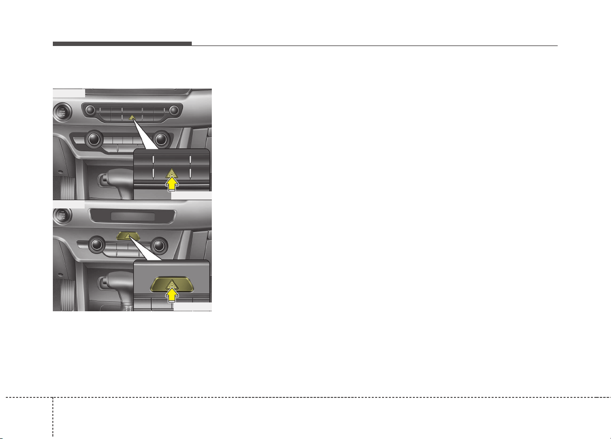
What to do in an emergency
27
ROAD WARNING
Hazard warning flasher
The hazard warning flasher serves
as a warning to other drivers to exer-
cise extreme caution when
approaching, overtaking, or passing
your vehicle.
It should be used whenever emer-
gency repairs are being made or
when the vehicle is stopped near the
edge of a roadway.
Depress the flasher switch with the
ignition switch in any position. The
flasher switch is located in the center
console switch panel. All turn signal
lights will flash simultaneously.
• The hazard warning flasher oper-
ates whether your vehicle is run-
ning or not.
• The turn signals do not work when
the hazard flasher is on.
• Care must be taken when using
the hazard warning flasher while
the vehicle is being towed.
ODE066001
ODE066024
■ Type A
■ Type B

73
What to do in an emergency
If the engine stalls at a cross-
road or crossing
• If the engine stalls at a crossroad
or crossing, set the shift lever in the
N (Neutral) position and then push
the vehicle to a safe place.
If you have a flat tire while
driving
If a tire goes flat while you are driving:
1. Take your foot off the accelerator
pedal and let the vehicle slow
down while driving straight ahead.
Do not apply the brakes immedi-
ately or attempt to pull off the road
as this may cause a loss of control.
When the vehicle has slowed down
to such a speed that it is safe to do
so, brake carefully and pull off the
road. Drive off the road as far as
possible and park on a firm level
ground. If you are on a divided
highway, do not park in the median
area between the two traffic lanes.
2. When the vehicle is stopped, turn
on your emergency hazard flash-
ers, set the parking brake and put
the transaxle in P (dual clutch
transmission).
3. Have all passengers get out of the
vehicle. Be sure they all get out on
the side of the vehicle that is away
from traffic.
4. When changing a flat tire, follow
the instruction provided later in
this section.
If engine stalls while driving
1. Reduce your speed gradually,
keeping a straight line. Move cau-
tiously off the road to a safe place.
2. Turn on your emergency flashers.
3. Try to start the engine again. If
your vehicle does not start, we
recommend that you consult an
authorized Kia dealer.
IN CASE OF AN EMERGENCY WHILE DRIVING
What to do in an emergency
47
IF THE ENGINE WILL NOT START
If engine doesn't turn over or
turns over slowly
1. If your vehicle has an dual clutch
transmission, be sure the shift
lever is in N (Neutral) or P (Park)
and the emergency brake is set.
2. Check the battery connections to
be sure they are clean and tight.
3. Turn on the interior light. If the light
dims or goes out when you oper-
ate the starter, the battery is dis-
charged.
4. Check the starter connections to
be sure they are securely tight-
ened.
5. Do not push or pull the vehicle to
start it. See instructions for "Jump
starting".
If engine turns over normally
but does not start
1. Check the fuel level.
2. With the ignition switch in the
LOCK position, check all connec-
tors at the ignition coils and spark
plugs. Reconnect any that may be
disconnected or loose.
3. Check the fuel line in the engine
compartment.
4. If the engine still does not start, we
recommend that you call an
authorized Kia dealer.
WARNING
If the engine will not start, do
not push or pull the vehicle to
start it. This could result in a
collision or cause other dam-
age. In addition, push or pull
starting may cause the catalytic
converter to be overloaded and
create a fire hazard.
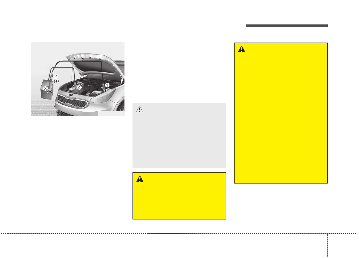
75
What to do in an emergency
EMERGENCY STARTING
Connect cables in numerical order
and disconnect in reverse order.
Jump starting
Jump starting can be dangerous if
done incorrectly. Therefore, to avoid
harm to yourself or damage to your
vehicle or battery, follow the jump
starting procedures. If in doubt, we
strongly recommend that you have a
competent technician or towing serv-
ice jump start your vehicle.
CAUTION
Use only a 12-volt jumper sys-
tem. You can damage a 12-volt
starting motor, ignition system,
and other electrical parts
beyond repair by use of a 24-
volt power supply (either two
12-volt batteries in series or a
24-volt motor generator set).
WARNING - Battery
• Keep all flames or sparks
away from the battery. The
battery produces hydrogen
gas which may explode if
exposed to flame or sparks.
If these instructions are not
followed exactly, serious per-
sonal injury and damage to
the vehicle may occur! If you
are not sure how to follow this
procedure, seek qualified
assistance. Automobile bat-
teries contain sulfuric acid.
This is poisonous and highly
corrosive. When jump start-
ing, wear protective glasses
and be careful not to get acid
on yourself, your clothing or
on the vehicle.
(Continued)
WARNING - Battery
Never attempt to check the elec-
trolyte level of the battery as
this may cause the battery to
rupture or explode causing seri-
ous injury.
ODE066002
What to do in an emergency
67
Jump starting procedure
1.Make sure the booster battery is
12-volt and that its negative termi-
nal is grounded.
2.If the booster battery is in another
vehicle, do not allow the vehicles
come in contact.
3.Turn off all unnecessary electrical
loads.
4.Connect the jumper cables in the
exact sequence shown in the illus-
tration. First connect one end of a
jumper cable to the positive termi-
nal of the fuse box (1), then con-
nect the other end to the positive
terminal on the booster battery (2).
Proceed to connect one end of the
other jumper cable to the negative
terminal of the booster battery (3),
then the other end to a solid, sta-
tionary, metallic point (for example,
the engine lifting bracket) away
from the fuse box (4). Do not con-
nect it to or near any part that
moves when the engine is cranked.
Do not allow the jumper cables to
contact anything except the correct
battery terminals or the correct
ground. Do not lean over the bat-
tery when making connections.
CAUTION - Battery cables
Do not connect the jumper
cable from the negative terminal
of the booster battery to the
negative terminal of the dis-
charged battery. This can cause
the discharged battery to over-
heat and crack, releasing bat-
tery acid.
(Continued)
• Do not attempt to jump start
the vehicle if the discharged
battery is frozen or if the elec-
trolyte level is low; the battery
may rupture or explode.
• Do not allow the (+) and (-)
jumper cables to touch. It may
cause sparks.
• The battery may rupture or
explode when you jump start
with a low or frozen battery.
77
What to do in an emergency
5.Start the engine of the vehicle with
the booster battery and let it run at
2,000 rpm, then start the engine of
the vehicle with the discharged
battery.
If the cause of your battery discharg-
ing is not apparent, we recommend
that the system be checked by an
authorized Kia dealer.
Push-starting
Vehicles equipped with dual clutch
transmission cannot be push-started.
Follow the directions in this section
for jump-starting.
WARNING
Never tow a vehicle to start it
because the sudden surge for-
ward when the engine starts
could cause a collision with the
tow vehicle.
What to do in an emergency
87
IF THE ENGINE OVERHEATS
If your temperature gauge indicates
overheating, you will experience a
loss of power, or hear loud pinging or
knocking, the engine is probably too
hot. If this happens, you should:
1.Pull off the road and stop as soon
as it is safe to do so.
2.Place the shift lever in P (dual
clutch transmission) and set the
parking brake. If the air condition-
ing is on, turn it off.
3.If engine coolant is running out
under the vehicle or steam is com-
ing out from the hood, stop the
engine. Do not open the hood until
the coolant has stopped running
or the steaming has stopped. If
there is no visible loss of engine
coolant and no steam, leave the
engine running and check to be
sure the engine cooling fan is oper-
ating. If the fan is not running, turn
the engine off.
4.Check to see if the water pump
drive belt is missing. If it is not miss-
ing, check to see that it is tight.
If the drive belt seems to be satis-
factory, check for coolant leaking
from the radiator, hoses or under
the vehicle. (If the air conditioning
had been in use, it is normal for
cold water to be draining from it
when you stop).
5.If the water pump drive belt is bro-
ken or engine coolant is leaking
out, stop the engine immediately
and we recommend that you call
an authorized Kia dealer.
6.If you cannot find the cause of the
overheating, wait until the engine
temperature has returned to nor-
mal. Then, if coolant has been lost,
carefully add coolant to the reser-
voir to bring the fluid level in the
reservoir up to the halfway mark.
7.Proceed with caution, keeping
alert for further signs of overheat-
ing. If overheating happens again,
we recommend that you call an
authorized Kia dealer.
CAUTION
• Serious loss of coolant indi-
cates there is a leak in the
cooling system and we recom-
mend that the system be
checked by an authorized Kia
dealer.
• When the engine overheats
from low engine coolant, sud-
denly adding engine coolant
may cause cracks in the
engine. To prevent damage,
add engine coolant slowly in
small quantities.
WARNING
While the engine is running,
keep hair, hands and clothing
away from moving parts such
as the fan and drive belts to pre-
vent injury.
WARNING
Do not remove the radiator cap
when the engine is hot. This can
allow coolant to blow out of the
opening and cause serious
burns.
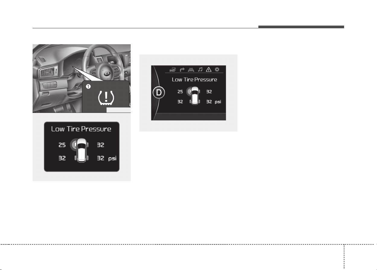
79
What to do in an emergency
TIRE PRESSURE MONITORING SYSTEM (TPMS) (IF EQUIPPED)
(1) Low tire pressure telltale /
TPMS malfunction indicator
(2) Low tire pressure position telltale
(Shown on the LCD display)
Check tire pressure
• You can check the tire pressure in
the information mode on the clus-
ter.
- Refer to “User settings mode” in
chapter 4.
• Tire pressure is displayed 1~2 min-
utes later after driving.
• If tire pressure is not displayed
when the vehicle is stopped, “Drive
to display” message displays. After
driving, check the tire pressure.
• You can change the tire pressure
unit in the user settings mode on
the cluster.
- psi, kpa, bar (Refer to “User set-
tings mode” in chapter 4).
OQLE065036
ODE066003
OQLE065035

What to do in an emergency
107
Each tire, including the spare (if pro-
vided), should be checked monthly
when cold and inflated to the inflation
pressure recommended by the vehi-
cle manufacturer on the vehicle plac-
ard or tire inflation pressure label.
(If your vehicle has tires of a different
size than the size indicated on the
vehicle placard or tire inflation pres-
sure label, you should determine the
proper tire inflation pressure for
those tires.)
As an added safety feature, your vehi-
cle has been equipped with a tire pres-
sure monitoring system (TPMS) that
illuminates a low tire pressure telltale
when one or more of your tires is sig-
nificantly under-inflated. Accordingly,
when the low tire pressure telltale illu-
minates, you should stop and check
your tires as soon as possible, and
inflate them to the proper pressure.
Driving on a significantly under-inflat-
ed tire causes the tire to overheat and
can lead to tire failure. Under-inflation
also reduces fuel efficiency and tire
tread life, and may affect the vehicle’s
handling and stopping ability.
Please note that the TPMS is not a
substitute for proper tire maintenance,
and it is the driver’s responsibility to
maintain correct tire pressure, even if
under-inflation has not reached the
level to trigger illumination of the
TPMS low tire pressure telltale.
Your vehicle has also been equipped
with a TPMS malfunction indicator to
indicate when the system is not oper-
ating properly. The TPMS malfunction
indicator is combined with the low tire
pressure telltale. When the system
detects a malfunction, the telltale will
flash for approximately 1 minute and
then remain continuously illuminated.
This sequence will continue upon
subsequent vehicle start-ups as long
as the malfunction exists. When the
TPMS malfunction indicator remains
illuminated after blinking for approxi-
mately 1 minute, the system may not
be able to detect or signal low tire
pressure as intended.
TPMS malfunctions may occur for a
variety of reasons, including the
installation of replacement or alter-
nate tires or wheels on the vehicle
that prevent the TPMS from function-
ing properly. Always check the TPMS
malfunction telltale after replacing
one or more tires or wheels on your
vehicle to ensure that the replace-
ment or alternate tires and wheels
allow the TPMS to continue to func-
tion properly.
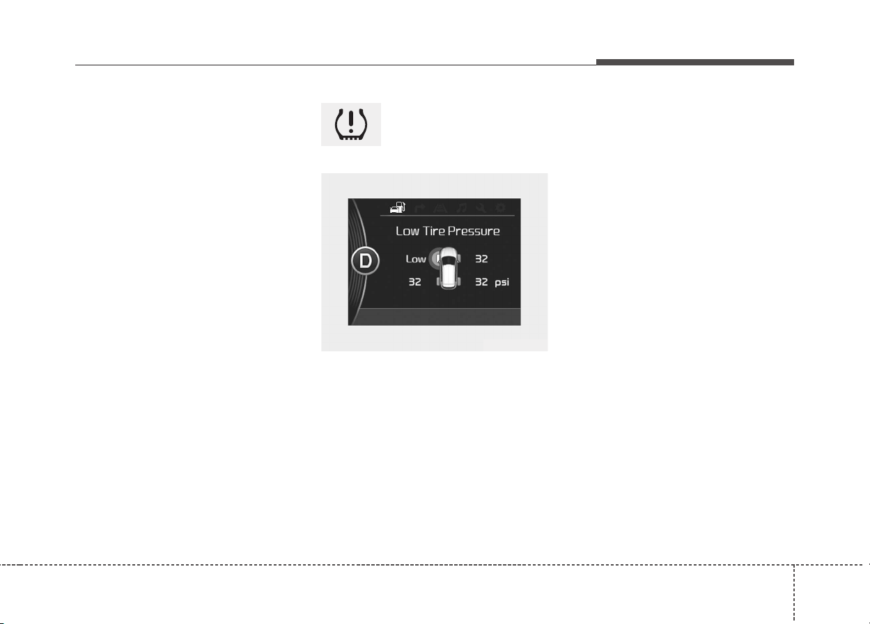
711
What to do in an emergency
✽✽
NOTICE
If any of the below happens, we rec-
ommend that the system be checked
by an authorized Kia dealer.
1.The low tire pressure telltale/
TPMS malfunction indicator do
not illuminate for 3 seconds when
the ignition switch is turned to the
ON position or engine is running.
2.The TPMS malfunction indicator
remains illuminated after blinking
for approximately 1 minute.
3.The Low tire pressure position
telltale remains illuminated.
Low tire pressure
telltale
When the tire pressure monitoring
system warning indicators are illumi-
nated and warning massage dis-
played on the cluster LCD display,
one or more of your tires is signifi-
cantly under-inflated. The low tire
pressure position telltale light will
indicate which tire is significantly
under-inflated by illuminating the cor-
responding position light.
If either telltale illuminates, immedi-
ately reduce your speed, avoid hard
cornering and anticipate increased
stopping distances. You should stop
and check your tires as soon as pos-
sible. Inflate the tires to the proper
pressure as indicated on the vehi-
cle’s placard or tire inflation pressure
label located on the driver’s side cen-
ter pillar outer panel. If you cannot
reach a service station or if the tire
cannot hold the newly added air,
replace the low pressure tire with a
spare tire.
If you drive the vehicle for about 10
minutes at speeds above 25 km/h
after replaceing the low pressure tire
with the spare tire, one of the follow-
ing will happen:
• The TPMS malfunction indicator
may blink for approximately 1
minute and then remain continu-
ously illuminated because the
TPMS sensor is not mounted on
the spare wheel. (changed tire
equipped with a sensor not in the
vehicle)
OQLE065037
What to do in an emergency
127
• The TPMS malfunction indicator
will remain continuously illuminated
while driving because the TPMS
sensor is not mounted on the spare
wheel. (changed tire equipped with
a sensor in the vehicle)
TPMS (Tire Pressure
Monitoring System)
malfunction indicator
The TPMS malfunction indicator will
illuminate after it blinks for approxi-
mately one minute when there is a
problem with the Tire Pressure
Monitoring System.
We recommend that the system be
checked by an authorized Kia dealer
to determine the cause of the prob-
lem.
✽✽
NOTICE
If there is a malfunction with the
TPMS, the low tire pressure position
telltale will not be displayed even
though the vehicle has an under-
inflated tire.
WARNING - Low pressure
damage
Significantly low tire pressure
makes the vehicle unstable and
can contribute to loss of vehicle
control and increased braking
distances.
Continued driving on low pres-
sure tires can cause the tires to
overheat and fail.
CAUTION
In winter or cold weather, the
low tire pressure telltale may
illuminate if the tire pressure
was adjusted to the recom-
mended tire inflation pressure
in warm weather. It does not
mean your TPMS is malfunction-
ing because the decreased tem-
perature leads to a lowering of
tire pressure.
When you drive your vehicle from
a warm area to a cold area or
from a cold area to a warm area,
or the outside temperature is
higher or lower, you should
check the tire inflation pressure
and adjust the tires to the recom-
mended tire inflation pressure.
713
What to do in an emergency
Changing a tire with TPMS
If you have a flat tire, the low Tire
Pressure and Position telltales will
come on. We recommend that the
system be checked by an authorized
Kia dealer.
Each wheel is equipped with a tire
pressure sensor mounted inside the
tire behind the valve stem. You must
use TPMS specific wheels. It is rec-
ommended that you have your tires
serviced by an authorized Kia dealer.
CAUTION
• The TPMS malfunction indica-
tor may blink for approximate-
ly 1 minute and then remain
continuously illuminated if the
vehicle is moving around elec-
tric power supply cables or
radios transmitter such as at
police stations, government
and public offices, broadcast-
ing stations, military installa-
tions, airports, or transmitting
towers, etc. This can interfere
with normal operation of the
Tire Pressure Monitoring
System (TPMS).
(Continued)
(Continued)
• The TPMS malfunction indica-
tor may blink for approximate-
ly 1 minute and then remain
continuously illuminated if
snow chains are used or some
separate electronic devices
such as notebook computer,
mobile charger, remote starter
or navigation etc., are used in
the vehicle.
This can interfere with normal
operation of the Tire Pressure
Monitoring System (TPMS).
CAUTION
We recommend that you use the
sealant approved by Kia.
The sealant on the tire pressure
sensor and wheel shall be elem-
inated when you replace the tire
with a new one.
What to do in an emergency
147
If you drive the vehicle for about 10
minutes at speeds above 25 km/h
after replaceing the low pressure tire
with the spare tire, one of the follow-
ing will happen:
• The TPMS malfunction indicator
may blink for approximately 1
minute and then remain continuous-
ly illuminated because the TPMS
sensor is not mounted on the spare
wheel. (changed tire equipped with
a sensor not in the vehicle)
• The TPMS malfunction indicator
will remain continuously illuminated
while driving because the TPMS
sensor is not mounted on the spare
wheel. (changed tire equipped with
a sensor in the vehicle)
You may not be able identify a low
tire by simply looking at it. Always
use a good quality tire pressure
gauge to measure the tire's inflation
pressure. Please note that a tire that
is hot (from being driven) will have a
higher pressure measurement than a
tire that is cold (from sitting station-
ary for at least 3 hours and driven
less than 1.6 km (1 mile) during that
3 hour period).
Allow the tire to cool before measur-
ing the inflation pressure. Always be
sure the tire is cold before inflating to
the recommended pressure.
A cold tire means the vehicle has
been sitting for 3 hours and driven for
less than 1.6 km (1 mile) in that 3
hour period.
WARNING - TPMS
• The TPMS cannot alert you to
severe and sudden tire dam-
age caused by external fac-
tors such as nails or road
debris.
• If you feel any vehicle instabil-
ity, immediately take your foot
off the accelerator, apply the
brakes gradually and with
light force, and slowly move to
a safe position off the road.
CAUTION
We recommend that you use the
sealant approved by Kia if your
vehicle is equipped with a Tire
Pressure Monitoring System.
The liquid sealant can damage
the tire pressure sensors.
715
What to do in an emergency
WARNING - Protecting
TPMS
Tampering with, modifying, or
disabling the Tire Pressure
Monitoring System (TPMS)
components may interfere with
the system's ability to warn the
driver of low tire pressure con-
ditions and/or TPMS malfunc-
tions. Tampering with, modify-
ing, or disabling the Tire
Pressure Monitoring System
(TPMS) components may void
the warranty for that portion of
the vehicle.
WARNING - For EUROPE
• Do not modify the vehicle, it
may interfere with the TPMS
function.
• The wheels on the market do
not have a TPMS sensor.
For your safety, we recom-
mend that you use parts for
replacement from an author-
ized Kia dealer.
• If you use the wheels on the
market, use a TPMS sensor
approved by a Kia dealer.
If your vehicle is not equipped
with a TPMS sensor or TPMS
does not work properly, you
may fail the periodic vehicle
inspection conducted in your
country.
(Continued)
(Continued)
❈
❈
All vehicles sold in the
EUROPE market during
below period must be
equipped with TPMS.
- New model vehicle :
Nov. 1, 2012 ~
- Current model vehicle :
Nov. 1, 2014~ (Based on
vehicle registrations)
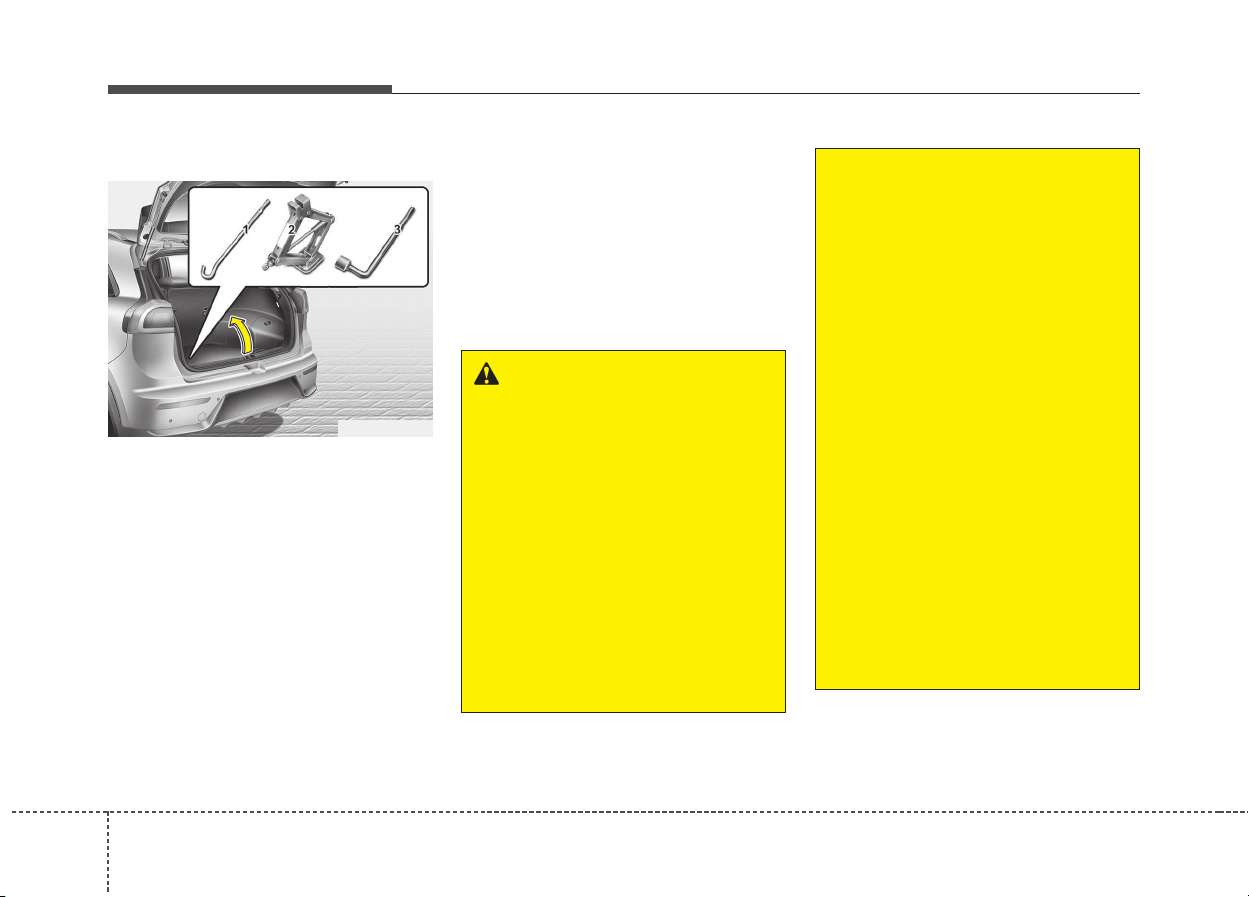
What to do in an emergency
167
IF YOU HAVE A FLAT TIRE (WITH SPARE TIRE, IF EQUIPPED)
Jack and tools
The jack, jack handle, wheel lug nut
wrench are stored in the luggage
compartment.
Pull up the luggage box cover to
reach this equipment.
(1) Jack handle
(2) Jack
(3) Wheel lug nut wrench
Jacking instructions
The jack is provided for emergency
tire changing only.
To prevent the jack from “rattling”
while the vehicle is in motion, store it
properly.
Follow jacking instructions to reduce
the possibility of personal injury.
ODE066004L
WARNING - Changing
tires
• Never attempt vehicle repairs
in the traffic lanes of a public
road or highway.
• Always move the vehicle com-
pletely off the road and onto
the shoulder before trying to
change a tire. The jack should
be used on firm level ground.
If you cannot find a firm level
place off the road, call a tow-
ing service company for
assistance.
(Continued)
(Continued)
• Be sure to use the correct
front and rear jacking posi-
tions on the vehicle; never
use the bumpers or any other
part of the vehicle for jacking
support.
• The vehicle can roll off the
jack causing serious injury or
death.
• Do not get under a vehicle
that is supported by a jack.
• Do not start or run the engine
while the vehicle is on the
jack.
• Do not allow anyone remain in
the vehicle while it is on the
jack.
• Make sure any children pres-
ent are in a secure place away
from the road and from the
vehicle to be raised with the
jack.
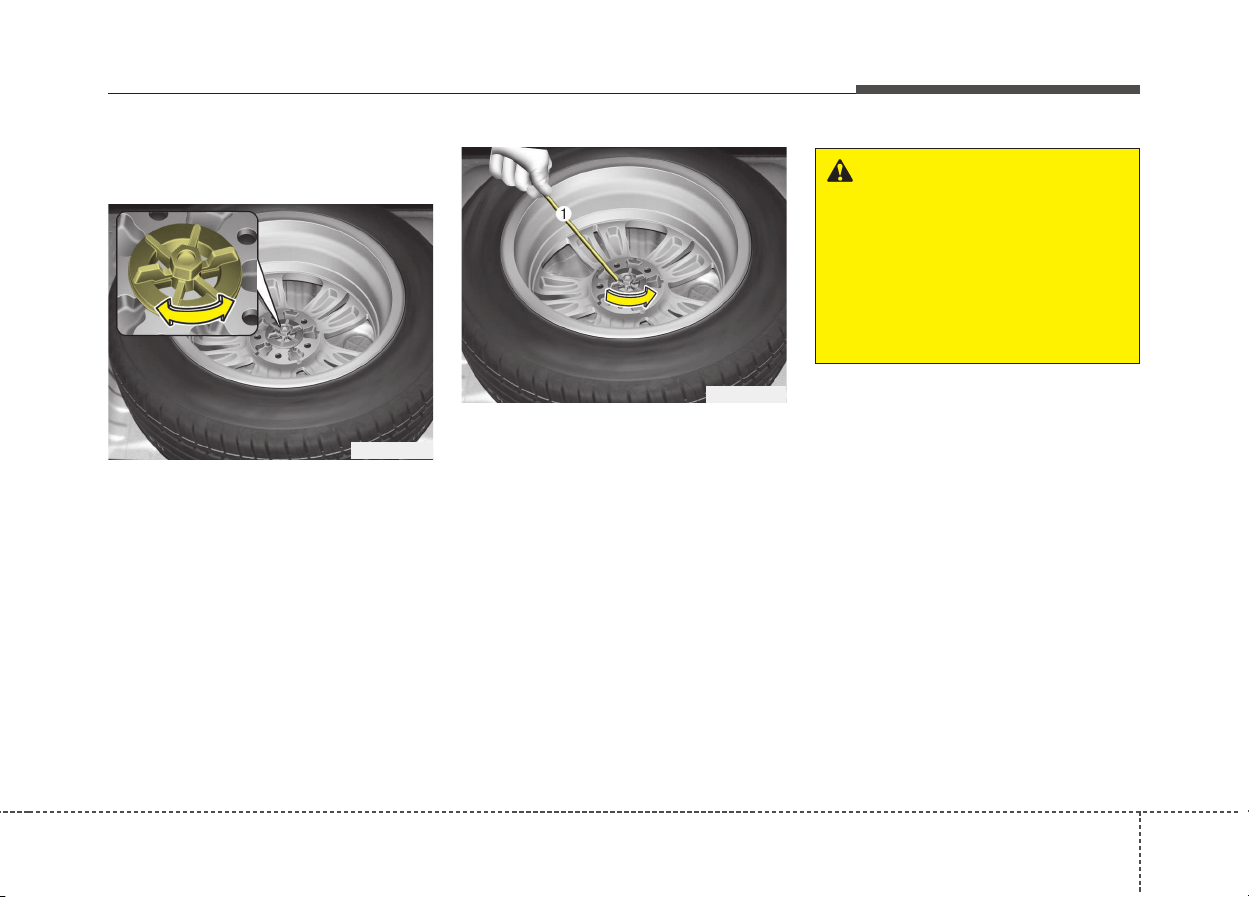
717
What to do in an emergency
Removing and storing the
spare tire
Turn the tire hold-down wing bolt
counterclockwise.
Store the tire in the reverse order of
removal.
To prevent the spare tire and tools
from “rattling” while the vehicle is in
motion, store them properly.
If it is hard to loosen the tire hold-
down wing bolt by hand, you can
loosen it easily using the jack handle.
1. Put the jack handle (1) inside of
the tire hold-down wing bolt.
2. Turn the tire hold-down wing bolt
counterclockwise with the jack
handle.
OQL065031
OQL065032
WARNING
Ensure the spare tire retainer is
properly aligned with the center
of the spare tire to prevent the
spare tire from “rattling”.
Otherwise, it may cause the
spare tire to fall off the carrier
and lead to an accident.
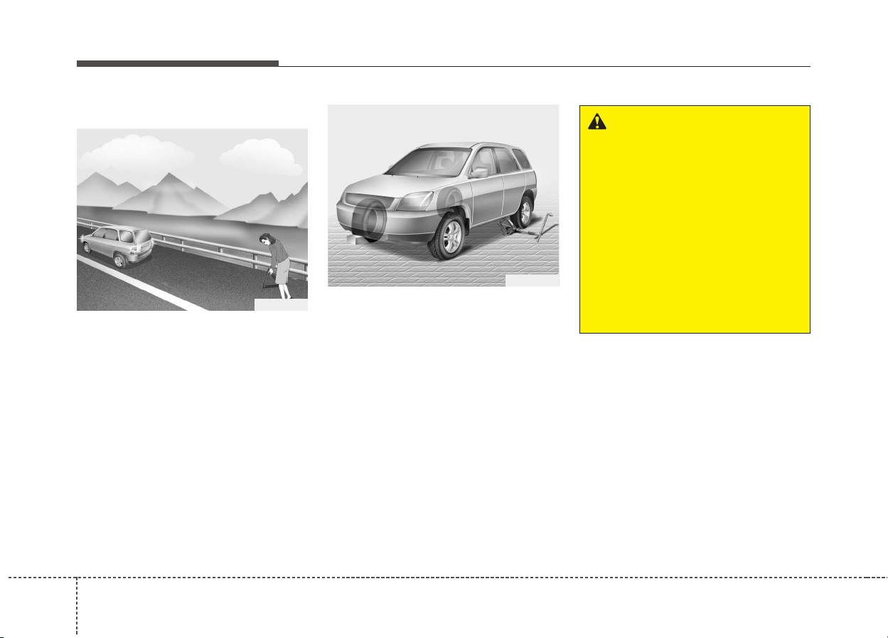
What to do in an emergency
187
Changing tires
1. Park on a level surface and apply
the parking brake firmly.
2. Shift the shift lever into P (Park)
with dual clutch transmission.
3. Activate the hazard warning flasher.
4. Remove the wheel lug nut wrench,
jack, jack handle, and spare tire
from the vehicle.
5. Block both the front and rear of
wheel that is diagonally opposite
the jack position.
1VQA4022
1VQA4023
WARNING - Changing a
tire
• To prevent vehicle movement
while changing a tire, always
set the parking brake fully,
and always block the wheel
diagonally opposite the wheel
being changed.
• We recommend that the
wheels of the vehicle be
chocked, and that no person
remain in a vehicle that is
being jacked.
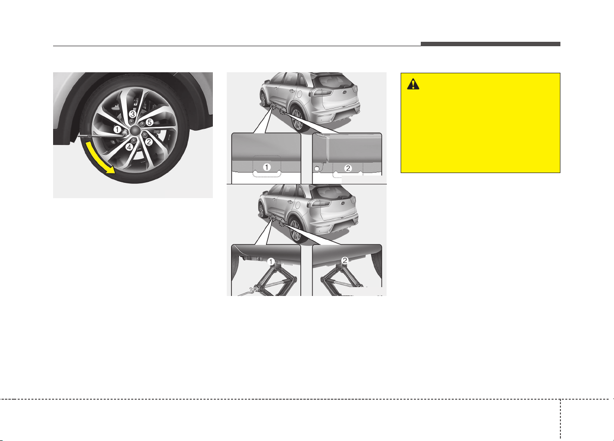
719
What to do in an emergency
6. Loosen the wheel lug nuts coun-
terclockwise one turn each, but do
not remove any nut until the tire
has been raised off the ground.
7.Place the jack at the front(1) or
rear(2) jacking position closest to
the tire you are changing. Place the
jack at the designated locations
under the frame. The jacking posi-
tions are plates welded to the
frame with two tabs and a raised
dot to index with the jack.
ODE066025L
WARNING - Jack
location
To reduce the possibility of
injury, be sure to use only the
jack provided with the vehicle
and in the correct jack position;
never use any other part of the
vehicle for jack support.
ODE066026L
ODE066027L
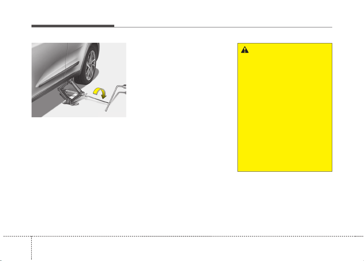
What to do in an emergency
207
8.Insert the jack handle into the jack
and turn it clockwise, raising the
vehicle until the tire just clears the
ground. This measurement is
approximately 30 mm (1.2 in).
Before removing the wheel lug
nuts, make sure the vehicle is sta-
ble and that there is no chance for
movement or slippage.
9.Loosen the wheel nuts and remove
them with your fingers. Slide the
wheel off the studs and lay it flat so
it cannot roll away. To put the wheel
on the hub, pick up the spare tire,
line up the holes with the studs and
slide the wheel onto them.
If this is difficult, tip the wheel
slightly and get the top hole in the
wheel lined up with the top stud.
Then jiggle the wheel back and
forth until the wheel can be slid
over the other studs.
ODE066028L
WARNING
Wheels may have sharp edges.
Handle them carefully to avoid
possible severe injury. Before
putting the wheel into place, be
sure that there is nothing on the
hub or wheel (such as mud, tar,
gravel, etc.) that interferes with
the wheel from fitting solidly
against the hub.
If there is, remove it. If there is
not good contact on the mount-
ing surface between the wheel
and hub, the wheel nuts could
come loose and cause the loss
of a wheel. Loss of a wheel may
result in loss of control of the
vehicle. This may cause serious
injury or death.
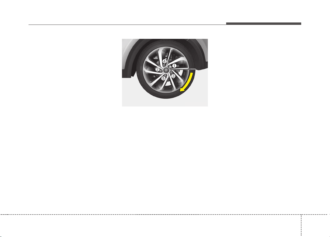
721
What to do in an emergency
10. To reinstall the wheel, hold it on
the studs, put the wheel nuts on
the studs and tighten them finger
tight. Jiggle the tire to be sure it is
completely seated, then tighten
the nuts as much as possible
with your fingers again.
11. Lower the vehicle to the ground
by turning the wheel nut wrench
counterclockwise.
Then position the wrench as shown
in the drawing and tighten the wheel
nuts. Be sure the socket is seated
completely over the nut. Do not stand
on the wrench handle or use an
extension pipe over the wrench han-
dle. Go around the wheel tightening
every other nut until they are all tight.
Then double-check each nut for
tightness. After changing wheels, we
recommend that the system be
checked by an authorized Kia dealer.
Wheel nut tightening torque:
Steel wheel & aluminum alloy wheel:
11~13kgf·m (79~94lbf·ft)
If you have a tire gauge, remove the
valve cap and check the air pressure.
If the pressure is lower than recom-
mended, drive slowly to the nearest
service station and inflate to the cor-
rect pressure. If it is too high, adjust it
until it is correct. Always reinstall the
valve cap after checking or adjusting
tire pressure. If the cap is not
replaced, air may leak from the tire. If
you lose a valve cap, buy another and
install it as soon as possible.
After you have changed wheels,
always secure the flat tire in its place
and return the jack and tools to their
proper storage locations.
ODE066029L
What to do in an emergency
227
To prevent the jack, jack handle,
wheel lug nut wrench and spare tire
from rattling while the vehicle is in
motion, store them properly.
Important - use of compact spare
tire (if equipped)
Your vehicle is equipped with a com-
pact spare tire. This compact spare
tire takes up less space than a regu-
lar-size tire. This tire is smaller than a
conventional tire and is designed for
temporary use only.
CAUTION
Your vehicle has metric threads
on the wheel studs and nuts.
Make certain during wheel
removal that the same nuts that
were removed are reinstalled -
or, if replaced, that nuts with
metric threads and the same
chamfer configuration are used.
Installation of a non-metric
thread nut on a metric stud or
vice-versa will not secure the
wheel to the hub properly and
will damage the stud so that it
must be replaced.
Note that most lug nuts do not
have metric threads. Be sure to
use extreme care in checking
for thread style before installing
aftermarket lug nuts or wheels.
If in doubt, consult an author-
ized Kia dealer.
CAUTION
• You should drive carefully
when the compact spare is in
use. The compact spare
should be replaced by the
proper conventional tire and
rim at the first opportunity.
• The operation of this vehicle
is not recommended with
more than one compact spare
tire in use at the same time.
WARNING - Wheel studs
If the studs are damaged, they
may lose their ability to retain
the wheel. This could lead to the
loss of the wheel and a collision
resulting in serious injuries.
WARNING - Inadequate
spare tire pressure
Check the inflation pressures
as soon as possible after
installing the spare tire. Adjust
it to the specified pressure, if
necessary. Refer to “Tires and
wheels” in chapter 9.
723
What to do in an emergency
The compact spare should be inflat-
ed to 420 kPa (60 psi).
✽✽
NOTICE
Check the inflation pressure after
installing the spare tire. Adjust it to
the specified pressure, as necessary.
When using a compact spare tire,
observe the following precautions:
• Under no circumstances should you
exceed 80 km/h (50 mph); a higher
speed could damage the tire.
• Ensure that you drive slowly
enough to avoid all hazards. Any
road hazard, such as a pothole or
debris, could seriously damage the
compact spare.
• Any continuous road use of this tire
could result in tire failure, loss of
vehicle control, and possible per-
sonal injury.
• Do not exceed the vehicle’s maxi-
mum load rating or the load-carry-
ing capacity shown on the sidewall
of the compact spare tire.
• Avoid driving over obstacles. The
compact spare tire diameter is
smaller than the diameter of a con-
ventional tire and reduces the
ground clearance approximately
2.5 cm (1 inch), which could result
in damage to the vehicle.
• Do not take the vehicle through an
automatic car wash while the com-
pact spare tire is installed.
• Do not use tire chains on the tem-
porary compact tire. Because of
the smaller size, a tire chain will not
fit properly. This could damage the
vehicle and result in loss of the
chain.
• Temporary compact tire should not
be installed on the front axle if the
vehicle must be driven in snow or
on ice.
WARNING
The compact spare tire is for
emergency use only. Do not
operate your vehicle on this
compact spare at the speed
over 80 km/h (50 mph).The orig-
inal tire should be repaired or
replaced as soon as possible to
avoid failure of the spare possi-
bly leading to personal injury or
death.

What to do in an emergency
247
• Do not use the temporary compact
tire on any other vehicle because
this tire has been designed espe-
cially for your vehicle.
• The temporary compact tire tread
life is shorter than a regular tire.
Inspect your temporary compact
tire regularly and replace worn
compact spare tires with the same
size and design, mounted on the
same wheel.
• The temporary compact tire should
not be used on any other wheels,
nor should standard tires, snow
tires, wheel covers or trim rings be
used with the temporary compact
spare wheel. If such use is
attempted, damage to these items
or other car components may
occur.
• Do not use more than one tempo-
rary compact tire at a time.
• Do not tow a trailer while the tem-
porary compact tire is installed.
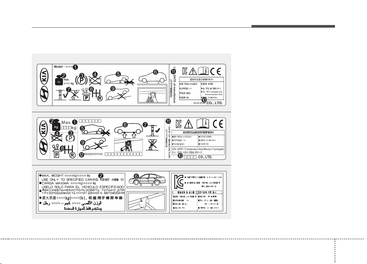
725
What to do in an emergency
Jack label
1. Model Name
2. Maximum allowable load
3. When using the jack, set your
parking brake.
4. When using the jack, stop the
engine.
5. Do not get under a vehicle that is
supported by a jack.
6. The designated locations under
the frame
7. When supporting the vehicle, the
base plate of jack must be vertical
under the lifting point.
8. Move the shift lever to the P posi-
tion on vehicles with dual clutch
transmission
9. The jack should be used on firm
level ground.
10. Jack manufacturer
11. Production date
12. Representative company and
address
OHYK064001
OHYK064005
OHYK064002
• Type A
■ Example
• Type B
• Type C
❈ The actual Jack label in the vehicle may differ from the illustration.
For more detailed specifications, refer to the label attached to the jack.
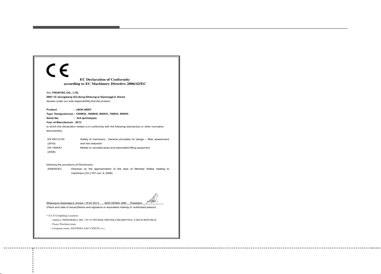
What to do in an emergency
267
EC Declaration of Conformity for Jack
OUM074110L
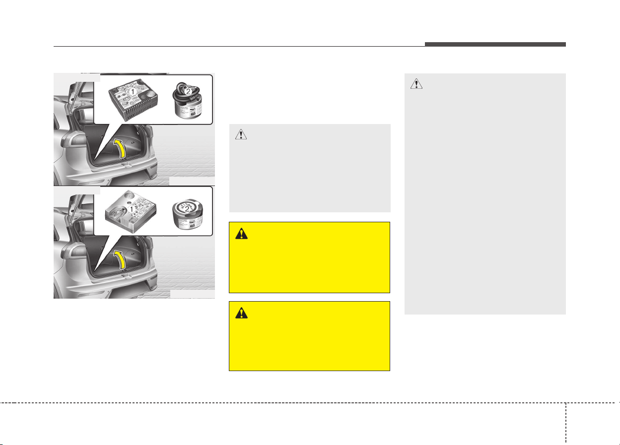
727
What to do in an emergency
IF YOU HAVE A FLAT TIRE (WITH TIRE MOBILITY KIT, IF EQUIPPED)
Please read the instructions before
using the Tire Mobility Kit.
(1) Compressor
(2) Sealant bottle
The Tire Mobility Kit is a temporary
fix to the tire and we recommend that
the tire inspected by an authorized
Kia dealer as soon as possible.
CAUTION - One sealant
for one tire
When two or more tires are flat,
do not use the tire mobility kit
because the supported one
sealant of Tire Mobility Kit is
only used for one flat tire.
CAUTION
- When replacing or repairing
the tire after using tire sealant,
make certain to remove the
sealant attached to the inner
part of the tire, including the
tire air pressure detection sen-
sor and wheel. If the sealant is
not removed, noise and vibra-
tion may occur, and the tire air
pressure detection sensor
may be damaged.
- We recommend use original
Kia manufactured sealant.
Using aftermarket sealant may
damage the tire air pressure
detection sensor.
- If the TPMS warning light illu-
minates after using the TMK,
we recommend that you con-
tact an authorized Kia dealer.
WARNING - Tire wall
Do not use the Tire Mobility Kit
to repair punctures in the tire
walls. This can result in an acci-
dent due to tire failure.
WARNING - Temporary fix
Have your tire repaired as soon
as possible.The tire may lose air
pressure at any time after inflat-
ing with the Tire Mobility Kit.
ODE066030L
ODE066020L
■ 18 inch tire
■ 16 inch tire
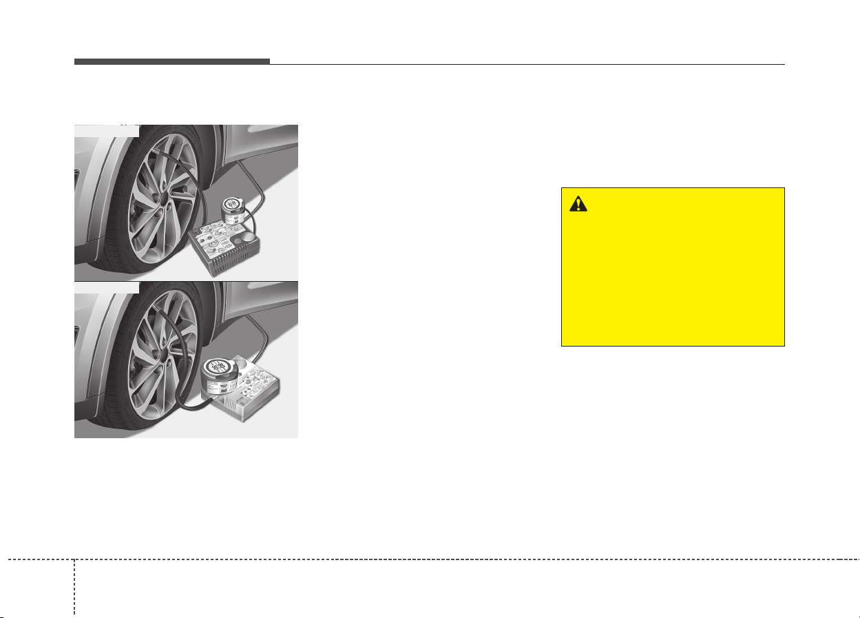
What to do in an emergency
287
Introduction
With the Tire Mobility Kit (TMK) you
stay mobile even after experiencing a
tire puncture.
The system of compressor and seal-
ing compound effectively and com-
fortably seals most punctures in a
passenger car tire caused by nails or
similar objects and reinflates the tire.
After you ensured that the tire is
properly sealed you can drive cau-
tiously on the tire (up to 200 km (120
miles)) at a max. speed of 80 km/h
(50 mph) in order to reach a vehicle or
tire dealer to have the tire replaced.
It is possible that some tires, espe-
cially with larger punctures or dam-
age to the sidewall, cannot be sealed
completely.
Air pressure loss in the tire may
adversely affect tire performance.
For this reason, you should avoid
abrupt steering or other driving
maneuvers, especially if the vehicle is
heavily loaded or if a trailer is in use.
The TMK is not designed or intended
as a permanent tire repair method
and is to be used for one tire only.
This instruction shows you step by
step how to temporarily seal the
puncture simply and reliably.
Read the section "Notes on the safe
use of the TMK".
WARNING
Do not use the TMK if a tire is
severely damaged by driving
run flat or with insufficient air
pressure.
Only punctured areas located
within the tread region of the
tire can be sealed using the
TMK.
ODE066005
ODE066021
■ 18 inch tire
■ 16 inch tire
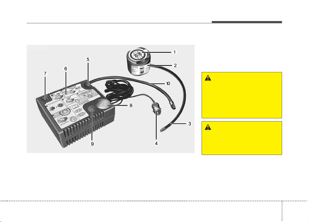
729
What to do in an emergency
1. Speed restriction label
2. Sealant bottle and label with
speed restriction
3. Filling hose from sealant bottle to
wheel
4. Connectors and cable for the bat-
tery direct connection
5. Holder for the sealant bottle
6. Compressor
7. On/off switch
8. Pressure gauge for displaying the
tire inflation pressure
9. Button for reducing tire inflation
Pressure
10. Hose to connect compressor and
sealant bottle or compressor and
wheel
Connectors, cable and connection
hose are stored in the compressor
housing.
Strictly follow the specified
sequence, otherwise the sealant
may escape under high pressure.
Components of the Tire Mobility Kit (TMK)
OQLE065038
WARNING - Expired
sealant
Do not use the tire sealant after
the sealant has expired (i.e.
pasted the expiration date on
the sealant container). This can
increase the risk of tire failure.
WARNING - Sealant
• Keep out of reach of children.
• Avoid contact with eyes.
• Do not swallow.
■ 18 inch tire

What to do in an emergency
307
1. Speed restriction label
2. Sealant bottle and label with
speed restriction
3. Filling hose from sealant bottle to
wheel
4. Connectors and cable for the
power outlet direct connection
5. Holder for the sealant bottle
6. Compressor
7. On/off switch
8. Pressure gauge for displaying the
tire inflation pressure
9. Button for reducing tire inflation
pressure
Connectors, cable and connection
hose are stored in the compressor
housing.
WARNING
Before using the TireMobilityKit,
follow the instructions on the
sealant bottle.
Remove the label with the
speed restriction from the
sealant bottle and apply it to the
steering wheel.
Please note the expiry date on
the sealant bottle.
ODE066039L
■ 16 inch tire
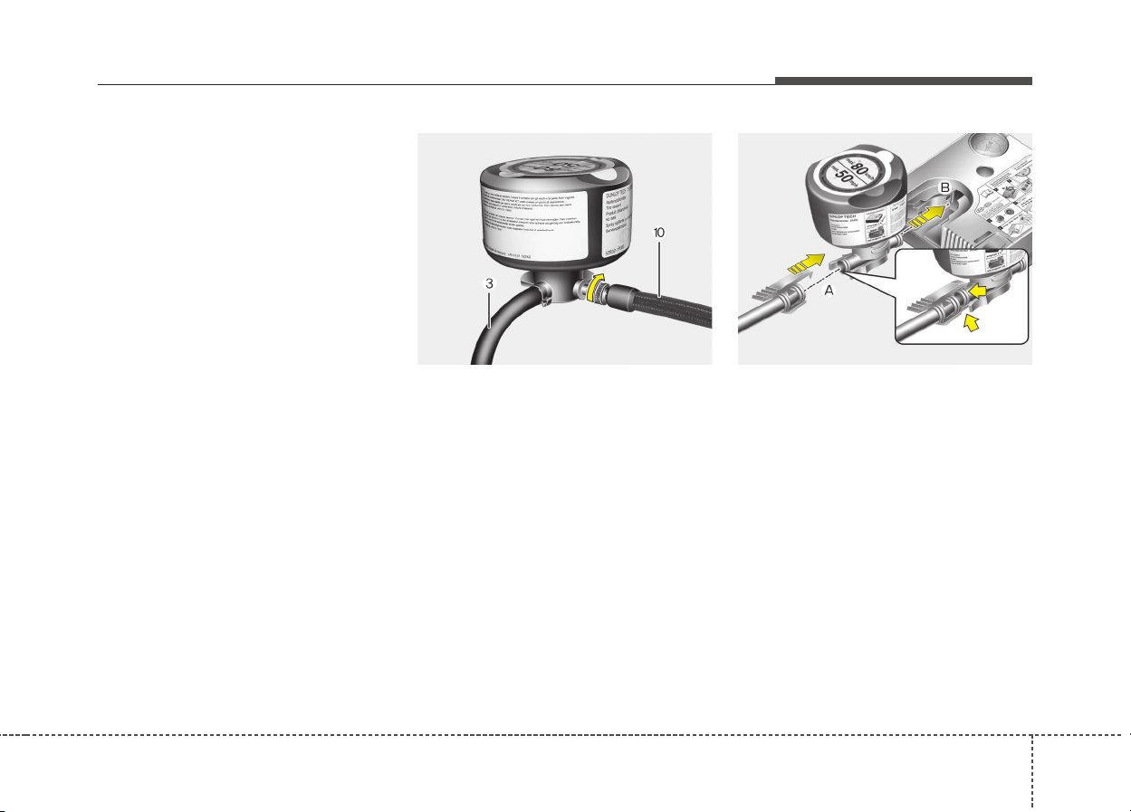
731
What to do in an emergency
Using the TMK
1. Detach the speed restriction label
(1) from the sealant bottle (2), and
place it in a highly visible place
inside the vehicle such as on the
steering wheel to remind the driv-
er not to drive too fast.
2. Screw connection hose (10) onto
the connector of the sealant bottle.
(18 inch tire only)
2. Connect the filling hose (3) onto
the connector of the sealant bottle
(A). (16 inch tire only)
3. Ensure that button (9) on the com-
pressor is not pressed.
OJFH065044
■ 18 inch tire
OYN064021
■ 16 inch tire
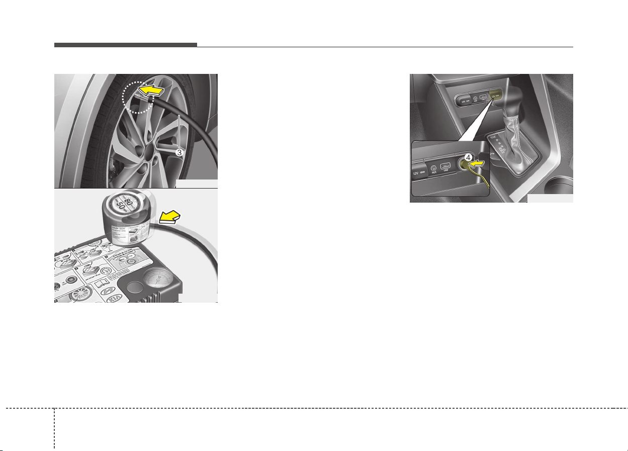
What to do in an emergency
327
4.Unscrew the valve cap from the
valve of the flat tire and screw fill-
ing hose (3) of the sealant bottle
onto the valve.
5.Insert the sealant bottle into the
housing (5) of the compressor so
that the bottle is upright.
6.Ensure that the compressor is
switched off, position 0.
7. Connect between compressor and
the vehicle power outlet using the
cable and connectors.
8.With the engine start/stop button
position on or ignition switch posi-
tion on, switch on the compressor
and let it run for approximately 5~7
minutes to fill the sealant up to
proper pressure. (refer to the Tire
and Wheels, chapter 9). The infla-
tion pressure of the tire after filling
is unimportant and will be
checked/corrected later.
Be careful not to overinflate the tire
and stay away from the tire when
filling it.
ODE066007
OJF065024
■ 18 inch tire
ODE066008L
733
What to do in an emergency
When the tire and wheel are dam-
aged, do not use Tire Mobility Kit for
your safety.
9.Switch off the compressor.
10. Detach the hoses from the
sealant bottle connector and
from the tire valve.
Return the TMK to its storage loca-
tion in the vehicle.
Distributing the sealant
11. Immediately drive approximately
7~10km (4~6miles or, about
10min) to evenly distribute the
sealant in the tire.
Checking the tire inflation
pressure
1. After driving approximately 7~10
km (4~6 miles or about 10 min-
utes), stop at a suitable location.
2. • Connect connection hose (10) of
the compressor directly to the
tire valve. (18 inch tire only)
• Connect the filling hose (3) of the
compressor (clip mounted side)
directly and then connect the fill-
ing hose (3) (opposite side) to the
tire valve. (16 inch tire only)
3. Connect between compressor and
the vehicle power outlet using the
cable and connectors.
CAUTION - Tire pressure
Do not attempt to drive your
vehicle if the tire pressure is
below 250 kPa (36 psi/2.5 bar).
This could result in an accident
due to sudden tire failure.
WARNING - Carbon
monoxide
Carbon monoxide poisoning
and suffocation is possible if
the engine is left running in a
poorly ventilated or unventilat-
ed location (such as inside a
building).
CAUTION
Do not exceed a speed of 60
km/h (35 mph). If possible, do
not fall below a speed of 20
km/h (12 mph).
While driving, if you experience
any unusual vibration, ride dis-
turbance or noise, reduce your
speed and drive with caution
until you can safely pull off of
the side of the road. Call for
road side service or towing.
When you use the Tire Mobility
Kit, the tire pressure sensors
and wheel may be stained by
sealant. Therefore, remove the
tire pressure sensors and wheel
stained by sealant and we rec-
ommend that inspect at an
authorized Kia dealer.
What to do in an emergency
347
4. Adjust the tire inflation pressure to
250 kPa (36 psi/2.5 bar). With the
ignition switched on, proceed as
follows.
- To increase the inflation pres-
sure: Switch on the compressor,
position I. To check the current
inflation pressure setting, briefly
switch off the compressor.
- To reduce the inflation pres-
sure: Press the button (9) on the
compressor.
Notes on the safe use of the
Tire Mobility Kit
• Park your car at the side of the
road so that you can work with the
TMK away from moving traffic.
Place your warning triangle in a
prominent place to make passing
vehicles aware of your location.
• To be sure your vehicle will not
move, even when you're on fairly
level ground, always set your park-
ing brake.
• Only use the TMK for sealing/infla-
tion passenger car tires. Do not
use on motorcycles, bicycles or
any other type of tires.
• Do not remove any foreign objects-
such as nails or screws -that have
penetrated the tire.
• Before using the TMK, read the
precautionary advice printed on
the sealant bottle!
WARNING
Do not let the compressor run
for more than 10 minutes, other-
wise the device will overheat
and may be damaged.
CAUTION
If the inflation pressure is not
maintained, drive the vehicle a
second time, refer to
Distributing the sealant. Then
repeat steps 1 to 4.
Use of the TMK may be ineffec-
tual for tire damage larger than
approximately 4 mm (0.16 in).
We recommend that you contact
an authorized Kia dealer if the
tire cannot be made roadworthy
with the Tire Mobility Kit.
WARNING
The tire inflation pressure must
be at least 250 kPa (36 psi/2.5
bar). If it is not, do not continue
driving. Call for road side serv-
ice or towing.

735
What to do in an emergency
• Provided the car is outdoors, leave
the engine running. Otherwise
operating the compressor may
eventually drain the car battery.
• Never leave the TMK unattended
while it is being used.
• Do not leave the compressor run-
ning for more than 10 min. at a time
or it may overheat.
• Do not use the TMK if the ambient
temperature is below -30°C (-
22°F).
• When the tire and wheel are dam-
aged, do not use Tire Mobility Kit
for your safety.
Technical Data (16 inch tire)
System voltage: DC 12 V
Working voltage: DC 10 - 15 V
Amperage rating: max. 10A ± 1A
(at DC 12V operation)
Suitable for use at temperatures:
-30 ~ +70°C (-22 ~ +158°F)
Max. working pressure:
6 bar (87 psi)
Size
Compressor: 161 X 150 X 55.8 mm
(6.3 X 5.9 X 2.2 in.)
Sealant bottle: 81 x 85 ø mm
(3.2 x 3.3 ø in.)
Compressor weight:
735 g ± 25 g (1.62 lbs ± 0.06 lbs)
Sealant volume:
200 ml (12.2 cu. in.)
Technical Data (18 inch tire)
System voltage: DC 12 V
Working voltage: DC 10 - 15 V
Amperage rating: MAX. 15A ± 1A (at
DC 12V operation)
Suitable for use at temperatures:
-30 ~ +70°C (-22 ~ +158°F)
Max. working pressure:
6 bar (87 psi)
Size
Compressor: 168 x 150 x 68 mm
(6.6 x 5.9 x 2.7 in.)
Sealant bottle: 104 x 85 ø mm
(4.1 x 3.3 ø in.)
Compressor weight:
1050g ± 30g (2.31 lbs ± 0.07 lbs)
Sealant volume:
300 mL (18.3 cu. in)
❈ Sealant and spare parts can be
obtained and replaced at an
authorized vehicle or tire dealer.
Empty sealant bottles may be dis-
posed of at home. Liquid residue
from the sealant should be dis-
posed of by your vehicle or tire
dealer or in accordance with local
waste disposal regulations.
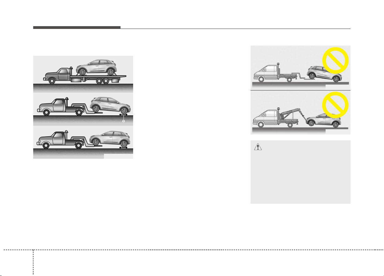
What to do in an emergency
367
TOWING
Towing service
If emergency towing is necessary,
we recommend having it done by an
authorized Kia dealer or a commer-
cial tow-truck service. Proper lifting
and towing procedures are neces-
sary to prevent damage to the vehi-
cle. The use of wheel dollies (1) or
flatbed is recommended.
On FWD vehicles, it is acceptable to
tow the vehicle with the rear wheels
on the ground (without dollies) and
the front wheels off the ground.
If any of the loaded wheels or sus-
pension components are damaged
or the vehicle is being towed with the
front wheels on the ground, use a
towing dolly under the front wheels.
When being towed by a commercial
tow truck and wheel dollies are not
used, the front of the vehicle should
always be lifted, not the rear.
ODE066010L
ODE066012
ODE066011
CAUTION
• Do not tow the vehicle back-
wards with the front wheels on
the ground as this may cause
damage to the vehicle.
• Do not tow with sling-type
equipment. Use wheel lift or
flatbed equipment.
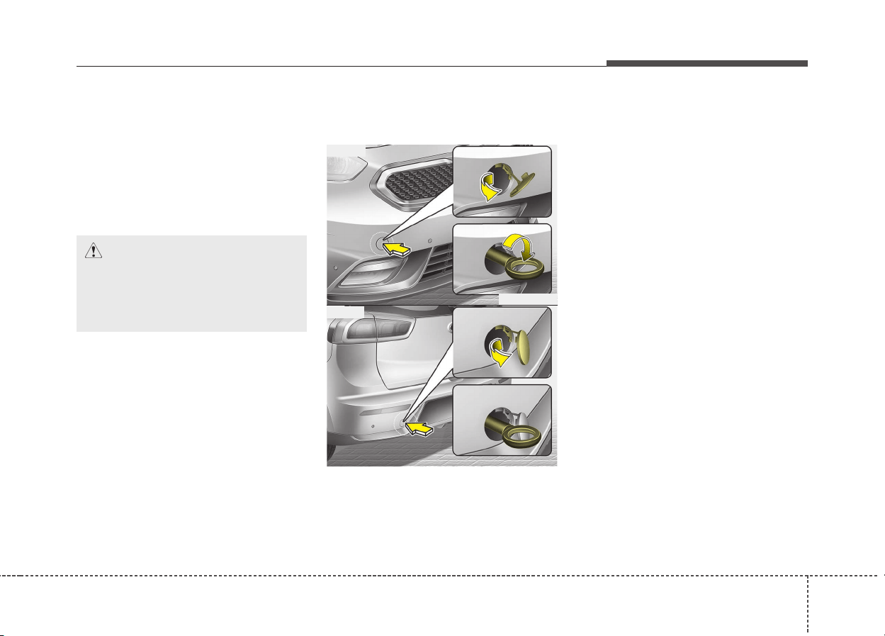
737
What to do in an emergency
When towing your vehicle in an
emergency without wheel dollies :
1. Set the ignition switch in the ACC
position.
2. Place the transaxle shift lever in N
(Neutral).
3. Release the parking brake.
Removable towing hook
(if equipped)
1. Open the tailgate, and remove the
towing hook from the tool case.
2. Remove the hole cover pressing
the upper (front) / lower (rear) part
of the cover on the bumper.
3. Install the towing hook by turning it
clockwise into the hole until it is
fully secured.
4. Remove the towing hook and
install the cover after use.
CAUTION
Failure to place the transaxle
shift lever in N (Neutral) may
cause internal damage to the
transaxle.
ODE066014
ODE066015
■ Front
■ Rear
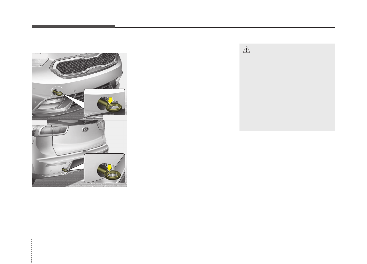
What to do in an emergency
387
Emergency towing
If towing is necessary, we recom-
mend you to have it done by an
authorized Kia dealer or a com-
mercial tow truck service.
If towing service is not available in an
emergency, your vehicle may be
temporarily towed using a cable or
chain secured to the emergency tow-
ing hook under the front (or rear) of
the vehicle. Use extreme caution
when towing the vehicle. A driver
must be in the vehicle to steer it and
operate the brakes.
Towing in this manner may be done
only on hard-surfaced roads for a
short distance and at low speed.
Also, the wheels, axles, power train,
steering and brakes must all be in
good condition.
• Do not use the tow hooks to pull a
vehicle out of mud, sand or other
conditions from which the vehicle
cannot be driven out under its own
power.
• Avoid towing a vehicle heavier than
the vehicle doing the towing.
• The drivers of both vehicles should
communicate with each other fre-
quently.
• Before emergency towing, check if
the hook is not broken or dam-
aged.
• Fasten the towing cable or chain
securely to the hook.
• Do not jerk the hook. Apply it
steadily and with even force.
• To avoid damaging the hook, do
not pull from the side or at a verti-
cal angle. Always pull straight
ahead.
CAUTION
• Attach a towing strap to the
tow hook.
• Using a portion of the vehicle
other than the tow hooks for
towing may damage the body
of your vehicle.
• Use only a cable or chain
specifically intended for use
in towing vehicles. Securely
fasten the cable or chain to
the towing hook provided.
ODE066016
ODE066017
■ Front
■ Rear
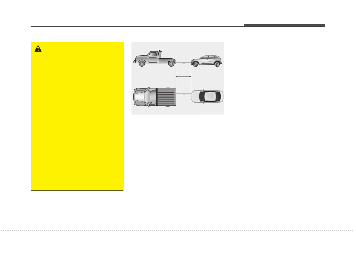
739
What to do in an emergency
• Use a towing strap less than 5 m
(16 feet) long. Attach a white or red
cloth (about 30 cm (12 inches)
wide) in the middle of the strap for
easy visibility.
• Drive carefully so that the towing
strap is not loosened during tow-
ing.
Emergency towing precautions
• Turn the ignition switch to ACC so
the steering wheel isn’t locked.
• Place the transaxle shift lever in N
(Neutral).
• Release the parking bake.
• Press the brake pedal with more
force than normal since you will
have reduced brake performance.
• More steering effort will be
required because the power steer-
ing system will be disabled.
• If you are driving down a long hill,
the brakes may overheat and brake
performance will be reduced. Stop
often and let the brakes cool off.
WARNING
Use extreme caution when tow-
ing the vehicle.
• Avoid sudden starts or erratic
driving maneuvers which
would place excessive stress
on the emergency towing hook
and towing cable or chain. The
hook and towing cable or
chain may break and cause
serious injury or damage.
• If the disabled vehicle is
unable to be moved, do not
forcibly continue the towing.
We recommend that you con-
tact an authorized Kia dealer
or a commercial tow truck
service for assistance.
• Tow the vehicle as straight
ahead as possible.
• Keep away from the vehicle
during towing.
ODE066018

What to do in an emergency
407
CAUTION - Dual clutch
transmission
• If the car is being towed with all
four wheels on the ground, it
can be towed only from the
front. Be sure that the transaxle
is in neutral. Be sure the steer-
ing is unlocked by placing the
ignition switch in the ACC posi-
tion. A driver must be in the
towed vehicle to operate the
steering and brakes.
• To avoid serious damage to the
dual clutch transmission, limit
the vehicle speed to 15 km/h
(10 mph) and drive less than
1.5 km (1 mile) when towing.
• Before towing, check the dual
clutch transmission for fluid
leaks under your vehicle. If the
dual clutch transmission fluid
is leaking, flatbed equipment
or a towing dolly must be used.

741
What to do in an emergency
EMERGENCY COMMODITY (IF EQUIPPED)
There are some emergency com-
modities in the vehicle to help you
respond to the emergency situation.
Fire extinguisher
If there is small fire and you know
how to use the fire extinguisher, take
the following steps carefully.
1.Pull the pin at the top of the extin-
guisher that keeps the handle from
being accidentally pressed.
2.Aim the nozzle toward the base of
the fire.
3.Stand approximately 2.5 m (8 ft)
away from the fire and squeeze the
handle to discharge the extinguish-
er. If you release the handle, the
discharge will stop.
4.Sweep the nozzle back and forth at
the base of the fire. After the fire
appears to be out, watch it careful-
ly since it may re-ignite.
First aid kit
There are some items such as scis-
sors, bandage and adhesive tape
and etc. in the kit to give first aid to
an injured person.
Triangle reflector
Place the triangle reflector on the
road to warn oncoming vehicles dur-
ing emergencies, such as when the
vehicle is parked by the roadside due
to any problems.
Tire pressure gauge
(If equipped)
Tires normally lose some air in day-
to-day use, and you may have to add
a few pounds of air periodically and it
is not usually a sign of a leaking tire,
but of normal wear. Always check tire
pressure when the tires are cold
because tire pressure increases with
temperature.
To check the tire pressure, take the
following steps;
1.Unscrew the inflation valve cap
that is located on the rim of the tire.
2.Press and hold the gauge against
the tire valve. Some air will escape
as you begin and more will escape
if you don't press the gauge in firm-
ly.
3.A firm non-leaking push will acti-
vate the gauge.
4.Read the tire pressure on the
gauge to know whether the tire
pressure is low or high.
5.Adjust the tire pressures to the
specified pressure. Refer to “Tires
and wheels” in section 9.
6.Reinstall the inflation valve cap.

Maintenance
Engine compartment . . . . . . . . . . . . . . . . . . . . . . . . 8-4
Maintenance services . . . . . . . . . . . . . . . . . . . . . . . . 8-5
• Owner’s responsibility . . . . . . . . . . . . . . . . . . . . . . . . . 8-5
• Owner maintenance precautions . . . . . . . . . . . . . . . . . 8-5
Owner maintenance . . . . . . . . . . . . . . . . . . . . . . . . . 8-7
• Owner maintenance schedule . . . . . . . . . . . . . . . . . . . 8-7
Scheduled maintenance service . . . . . . . . . . . . . . . 8-9
• Scheduled maintenanceservice precaution . . . . . . . . . 8-9
Explanation of scheduled maintenance items . . . 8-23
• Engine oil and filter. . . . . . . . . . . . . . . . . . . . . . . . . . . 8-23
• HSG (Hybrid starter & generator) belt . . . . . . . . . . 8-23
• Fuel filter (for gasoline) . . . . . . . . . . . . . . . . . . . . . . . 8-23
• Fuel lines, fuel hoses and connections . . . . . . . . . . . . 8-23
• Vapor hose (for gasoline engine) and fuel filler cap. 8-23
• Vacuum crankcase ventilation hoses . . . . . . . . . . . . . 8-24
• Air cleaner filter . . . . . . . . . . . . . . . . . . . . . . . . . . . . . 8-24
• Spark plugs . . . . . . . . . . . . . . . . . . . . . . . . . . . . . . . . . 8-24
• Cooling system. . . . . . . . . . . . . . . . . . . . . . . . . . . . . . . 8-24
• Coolant (Engine / Inverter) . . . . . . . . . . . . . . . . . . . . 8-24
• Dual clutch transmission fluid . . . . . . . . . . . . . . . . . . 8-24
• Brake hoses and lines . . . . . . . . . . . . . . . . . . . . . . . . . 8-25
• Brake fluid . . . . . . . . . . . . . . . . . . . . . . . . . . . . . . . . . . 8-25
• Parking brake . . . . . . . . . . . . . . . . . . . . . . . . . . . . . . . 8-25
• Brake discs, pads, calipers and rotors. . . . . . . . . . . . 8-25
• Suspension mounting bolts . . . . . . . . . . . . . . . . . . . . . 8-25
• Steering gear box, linkage &
boots/lower arm ball joint . . . . . . . . . . . . . . . . . . . . 8-25
• Drive shafts and boots. . . . . . . . . . . . . . . . . . . . . . . . . 8-25
• Air conditioning refrigerant. . . . . . . . . . . . . . . . . . . . 8-25
Engine oil. . . . . . . . . . . . . . . . . . . . . . . . . . . . . . . . . 8-26
• Checking the engine oil level . . . . . . . . . . . . . . . . . . . 8-26
• Changing the engine oil and filter . . . . . . . . . . . . . . . 8-27
Engine Coolant . . . . . . . . . . . . . . . . . . . . . . . . . . . . 8-28
• Checking the coolant level . . . . . . . . . . . . . . . . . . . . . 8-28
• Engine coolant . . . . . . . . . . . . . . . . . . . . . . . . . . . . . . 8-29
• Inverter coolant . . . . . . . . . . . . . . . . . . . . . . . . . . . . . 8-30
• Recommended coolant . . . . . . . . . . . . . . . . . . . . . . . . 8-30
• Changing the coolant . . . . . . . . . . . . . . . . . . . . . . . . . 8-32
Brake fluid . . . . . . . . . . . . . . . . . . . . . . . . . . . . . . . 8-33
• Checking the brake fluid level . . . . . . . . . . . . . . . . . . 8-33
Engine clutch actuator fluid . . . . . . . . . . . . . . . . . 8-34
• Checking the engine clutch actuator fluid level . . . . 8-34
Washer fluid . . . . . . . . . . . . . . . . . . . . . . . . . . . . . . 8-36
• Checking the washer fluid level . . . . . . . . . . . . . . . . . 8-36
Parking brake. . . . . . . . . . . . . . . . . . . . . . . . . . . . . 8-37
• Checking the parking brake. . . . . . . . . . . . . . . . . . . . 8-37
Air cleaner. . . . . . . . . . . . . . . . . . . . . . . . . . . . . . . . 8-38
• Filter replacement . . . . . . . . . . . . . . . . . . . . . . . . . . . 8-38
8

Climate control air filter . . . . . . . . . . . . . . . . . . . . 8-40
• Filter inspection . . . . . . . . . . . . . . . . . . . . . . . . . . . . . . 8-40
Wiper blades . . . . . . . . . . . . . . . . . . . . . . . . . . . . . . 8-42
• Blade inspection. . . . . . . . . . . . . . . . . . . . . . . . . . . . . . 8-42
• Blade replacement . . . . . . . . . . . . . . . . . . . . . . . . . . . 8-42
Battery . . . . . . . . . . . . . . . . . . . . . . . . . . . . . . . . . . . 8-46
• For best battery service . . . . . . . . . . . . . . . . . . . . . . . 8-46
• Battery capacity label . . . . . . . . . . . . . . . . . . . . . . . . 8-48
• Battery recharging . . . . . . . . . . . . . . . . . . . . . . . . . . . 8-48
• Reset items . . . . . . . . . . . . . . . . . . . . . . . . . . . . . . . . . . 8-49
Tires and wheels . . . . . . . . . . . . . . . . . . . . . . . . . . . 8-50
• Tire care . . . . . . . . . . . . . . . . . . . . . . . . . . . . . . . . . . . 8-50
• Recommended cold tire inflation pressures . . . . . . . 8-50
• Checking tire inflation pressure. . . . . . . . . . . . . . . . . 8-51
• Tire rotation . . . . . . . . . . . . . . . . . . . . . . . . . . . . . . . . 8-52
• Wheel alignment and tire balance . . . . . . . . . . . . . . 8-53
• Tire replacement . . . . . . . . . . . . . . . . . . . . . . . . . . . . . 8-54
• Wheel replacement . . . . . . . . . . . . . . . . . . . . . . . . . . . 8-55
• Tire traction . . . . . . . . . . . . . . . . . . . . . . . . . . . . . . . . . 8-56
• Tire maintenance . . . . . . . . . . . . . . . . . . . . . . . . . . . . 8-56
• Tire sidewall labeling . . . . . . . . . . . . . . . . . . . . . . . . . 8-56
• Low aspect ratio tire . . . . . . . . . . . . . . . . . . . . . . . . . . 8-60
Fuses . . . . . . . . . . . . . . . . . . . . . . . . . . . . . . . . . . . . 8-62
• Inner panel fuse replacement. . . . . . . . . . . . . . . . . . . 8-63
• Engine compartment fuse replacement. . . . . . . . . . . 8-65
• Fuse/relay panel description . . . . . . . . . . . . . . . . . . . 8-67
Light bulbs . . . . . . . . . . . . . . . . . . . . . . . . . . . . . . . 8-81
• Bulb replacement precaution . . . . . . . . . . . . . . . . . . 8-81
• Light bulb position (Front). . . . . . . . . . . . . . . . . . . . . 8-83
• Light bulb position (Rear) . . . . . . . . . . . . . . . . . . . . . 8-83
• Light bulb position (Side). . . . . . . . . . . . . . . . . . . . . . 8-84
• Headlamp (HID type) bulb replacement . . . . . . . . . 8-84
• Headlamp (High/Low beam) bulb replacement. . . . 8-85
• Front turn signal lamp bulb replacement . . . . . . . . 8-86
• Fog lamp/DRL bulb replacement . . . . . . . . . . . . . . . 8-87
• Stop and tail lamp bulb replacement . . . . . . . . . . . . 8-87
• Tail lamp (inside) bulb replacement . . . . . . . . . . . . . 8-88
• Stop and tail lamp (LED type) bulb replacement . . 8-89
• Back-up lamp bulb replacement . . . . . . . . . . . . . . . . 8-90
• High mounted stop lamp bulb replacement . . . . . . . 8-90
• License plate lamp bulb replacement . . . . . . . . . . . . 8-90
• Side repeater lamp (LED type) bulb replacement . . 8-91
• Map lamp bulb replacement . . . . . . . . . . . . . . . . . . . 8-91
• Vanity mirror lamp bulb replacement . . . . . . . . . . . 8-92
• Room lamp bulb replacement . . . . . . . . . . . . . . . . . . 8-92
• Tailgate room lamp bulb replacement . . . . . . . . . . . 8-93
• Headlamp and front fog lamp aiming (for Europe) . . 8-94
8

Appearance care. . . . . . . . . . . . . . . . . . . . . . . . . . 8-100
• Exterior care . . . . . . . . . . . . . . . . . . . . . . . . . . . . . . . 8-100
• Interior care . . . . . . . . . . . . . . . . . . . . . . . . . . . . . . . . 8-106
Emission control system . . . . . . . . . . . . . . . . . . . 8-107
• 1. Crankcase emission control system . . . . . . . . . . 8-107
• 2. Evaporative emission control system . . . . . . . . . 8-107
• 3. Exhaust emission control system . . . . . . . . . . . . 8-108
8
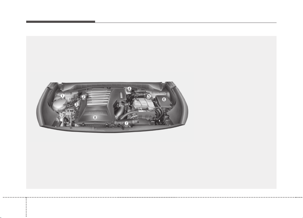
48
Maintenance
ENGINE COMPARTMENT
ODE076001
■■
Gasoline Engine (Kappa 1.6 GDI)
❈ The actual engine room in the vehicle may differ from the illustration.
1. Engine coolant reservoir
2. Engine oil filler cap
3. Engine oil dipstick
4. Brake fluid reservoir
5. Inverter coolant reservoir
6. Fuse box
7. Engine clutch actuator reservoir tank
8. Air cleaner
9. Windshield washer fluid reservoir

85
Maintenance
MAINTENANCE SERVICES
You should exercise the utmost care
to prevent damage to your vehicle
and injury to yourself whenever per-
forming any maintenance or inspec-
tion procedures.
Inadequate, incomplete or insuffi-
cient servicing may result in opera-
tional problems with your vehicle that
could lead to vehicle damage, an
accident, or personal injury.
Owner’s responsibility
✽✽
NOTICE
Maintenance Service and Record
Retention are the owner's responsi-
bility.
We recommend in general that you
have your vehicle serviced by an
authorized Kia dealer.
You should retain documents that
show proper maintenance has been
performed on your vehicle in accor-
dance with the scheduled mainte-
nance service charts shown on the
following pages.
You need this information to estab-
lish your compliance with the servic-
ing and maintenance requirements
of your vehicle warranties.
Detailed warranty information is pro-
vided in your Warranty &
Maintenance book.
Repairs and adjustments required as
a result of improper maintenance or
a lack of required maintenance are
not covered when your vehicle is
covered by warranty.
Owner maintenance precautions
Improper or incomplete service may
result in problems. This section gives
instructions only for the maintenance
items that are easy to perform.
✽✽
NOTICE
Improper owner maintenance dur-
ing the warranty period may affect
warranty coverage. For details, read
the separate Warranty &
Maintenance book provided with the
vehicle. If you're unsure about any
servicing or maintenance procedure,
we recommend that the system be
seviced by an authorized Kia dealer.
68
Maintenance
WARNING
- Maintenance work
• Performing maintenance work
on a vehicle can be dangerous.
You can be seriously injured
while performing some mainte-
nance procedures. If you lack
sufficient knowledge and expe-
rience or the proper tools and
equipment to do the work, we
recommend that the system be
servied by an authorized Kia
dealer.
• Working under the hood with
the engine running is danger-
ous. It becomes even more
dangerous when you wear jew-
elry or loose clothing. These
can become entangled in mov-
ing parts and result in injury.
Therefore, if you must run the
engine while working under the
hood, make certain that you
remove all jewelry (especially
rings, bracelets, watches, and
necklaces) and all neckties,
scarves, and similar loose
clothing before getting near the
engine or cooling fans.
CAUTION
• Do not put heavy objects or
apply excessive force on top of
the engine cover or fuel related
parts.
• When you inspect the fuel
system (fuel lines and fuel
injection devices), we recom-
mend that you contact an
authorized kia dealer.
• Do not drive long time with the
engine cover removed.
• When checking the engine
room, do not go near fire.
Fuel, washer fluid, etc. are
flammable oils that may cause
fire.
• Before touching the battery,
ignition cables and electrical
wiring, you should disconnect
the battery "-" terminal. You
may get an electric shock
from the electric current.
(Continued)
(Continued)
• When you remove the interior
trim cover with a flat bed (-)
driver, be careful not to dam-
age the cover.
• Be careful when you replace
and clean bulbs to avoid
burns or electrical shock.
87
Maintenance
OWNER MAINTENANCE
The following lists are vehicle checks
and inspections that should be per-
formed at the frequencies indicated
to help ensure safe, dependable
operation of your vehicle.
Any adverse conditions should be
brought to the attention of your deal-
er as soon as possible.
These Owner Maintenance Checks
are generally not covered by war-
ranties and you may be charged for
labor, parts and lubricants used.
Owner maintenance schedule
When you stop for fuel:
• Check the engine oil level.
• Check the coolant level in the
coolant reservoir.
• Check the windshield washer fluid
level.
• Look for low or under-inflated tires.
While operating your vehicle:
• Note any changes in the sound of
the exhaust or any smell of
exhaust fumes in the vehicle.
• Check for vibrations in the steering
wheel. Notice any increased steer-
ing effort or looseness in the steer-
ing wheel, or change in its straight-
ahead position.
• Notice if your vehicle constantly turns
slightly or “pulls” to one side when
traveling on smooth, level road.
• When driving, listen and check for
unusual sounds, pulling to one
side, increased brake pedal travel
or “hard-to-push” brake pedal.
• If any slipping or changes in the
operation of your transaxle occurs,
check the transaxle fluid level.
• Check the dual clutch transmission
P (Park) function.
• Check the parking brake.
• Check for fluid leaks under your
vehicle (water dripping from the air
conditioning system during or after
use is normal).
WARNING
Be careful when checking your
engine coolant level when the
engine is hot. Scalding hot
coolant and steam may blow
out under pressure. This could
cause burns or other serious
injury.

88
Maintenance
At least monthly:
• Check the coolant level in the
engine coolant reservoir.
• Check the operation of all exterior
lights, including the stoplights, turn
signals and hazard warning flash-
ers.
• Check the inflation pressures of all
tires including the spare.
At least twice a year
(i.e., every Spring and Fall):
• Check the radiator, heater and air
conditioning hoses for leaks or
damage.
• Check the windshield washer
spray and wiper operation. Clean
the wiper blades with clean cloth
dampened with washer fluid.
• Check the headlight alignment.
• Check the muffler, exhaust pipes,
shields and clamps.
• Check the lap/shoulder belts for
wear and function.
• Check for worn tires and loose
wheel lug nuts.
At least once a year:
• Clean the body and door drain
holes.
• Lubricate the door hinges and
checks, and hood hinges.
• Lubricate the door and hood locks
and latches.
• Lubricate the door rubber weather-
strips.
• Check the air conditioning system.
• Inspect and lubricate the automat-
ic transaxle linkage and controls.
• Clean the battery and terminals.
• Check the brake fluid level.

89
Maintenance
SCHEDULED MAINTENANCE SERVICE
Scheduled maintenance service precaution
Follow the Normal Maintenance Schedule if the vehicle is usually operated where none of the following conditions
apply. If any of the following conditions apply, follow the Maintenance Under Severe Usage Conditions.
• Repeated driving short distance of less than 8 km (5 miles) in normal temperature or less than 16 km(10 miles) in
freezing temperature
• Extensive engine idling or low speed driving for long distances
• Driving on rough, dusty, muddy, unpaved, graveled or salt-spread roads
• Driving in areas using salt or other corrosive materials or in very cold weather
• Driving in heavy dust condition
• Driving in heavy traffic area
• Driving on uphill, downhill, or mountain road repeatedly
• Towing a trailer or using a camper, or roof rack
• Driving as a patrol car, taxi, other commercial use of vehicle towing
• Driving over 170 km/h (106 mile/h)
• Frequently driving in stop-and-go condition
If your vehicle is operated under the above conditions, you should inspect, replace or refill more frequently than the
following Normal Maintenance Schedule. After the periods or distance shown in the chart, continue to follow the pre-
scribed maintenance intervals.

108
Maintenance
Normal Maintenance Schedule - For Gasoline Engine [For Europe (Except Russia)]
The following maintenance services must be performed to ensure good emission control and performance. Keep receipts for all
vehicle emission services to protect your warranty.Where both mileage and time are shown, the frequency of service is determined
by whichever occurs first.
NO.
ITEM
REMARK
*1 Coolant (Engine / Inverter)
When adding coolant, use only deionized water or soft water for your vehicle and never mix
hard water in the coolant filled at the factory. An improper coolant mixture can result in seri-
ous malfunction or engine damage.
*2 Engine oil and engine oil filter Check the engine oil level and leak every 500 km (350 miles) or before starting a long trip.
*3 Fuel additives (Gasoline)
Kia recommends that you use unleaded gasoline which has an octane rating of RON
(Research Octane Number) 95 / AKI (Anti Knock Index) 91 or higher (for Europe) or Octane
Rating of RON (Research Octane Number) 91 / AKI (Anti-Knock Index) 87 or higher (except
Europe).
For customers who do not use good quality gasolines including fuel additives regularly,
and have problems starting or the engine does not run smoothly, one bottle of additives
added to the fuel tank at every 15,000 km (10,000 miles) (for Europe, Australia and New
Zealand)/ 10,000 km (6,500 miles) (except Europe, Australia and New Zealand).
Additives are available from your authorized Kia dealer along with information on how to
use them. Do not mix other additives.

811
Maintenance
NO.
ITEM
REMARK
*4
HSG (Hybrid Starter &
Generator) belt
Inspect HSG belt for evidence of cuts, crocks, excessive wear or oil saturation and replace
if necessary. If drive belt noise occurred, readjust drive belt tension before replace.
*5 Spark plug
For your convenience, it can be replaced prior to it's interval when you do maintenance of
other items.
*6
Dual clutch transmission
(DCT) fluid
Dual clutch transmission (DCT) fluid should be changed anytime it has been submerged
in water.
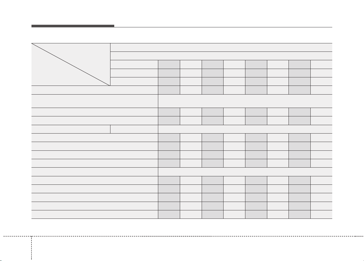
128
Maintenance
MAINTENANCE
INTERVALS
MAINTENANCE
ITEM
Normal Maintenance Schedule - For Gasoline Engine [For Europe (Except Russia)]
Number of months or driving distance, whichever comes first
Months 12 24 36 48 60 72 84 96
Miles×1,000 10 20 30 40 50 60 70 80
Km×1,000 15 30 45 60 75 90 105 120
Engine oil and engine oil filter *
2
R R R R R R R R
Coolant (Engine / Inverter) *
1
At first, Replace 210,000 km (140,000 miles) or 120 months
after that, Replace every 30,000 km (20,000 miles) or 24 months
HSG (Hybrid Starter & Generator) belt *
4
I I I I I I I I
Vacuum hoses and crankcase ventilation hoses I I I I I I I I
Spark plugs *
5
Kappa 1.6 GDI Replace every 150,000 km (100,000 miles) or 120 months
Dual clutch transmission (DCT) fluid *
6
I I
Engine clutch actuator fluid I R I R I R I R
Engine clutch actuator hose and line I I I I I I I I
Drive shaft and boots I I I I
Fuel additives *
3
Add every 15,000 km (10,000 miles) or 12 months
Fuel lines, hoses and connections I I
Fuel tank air filter I I
Vapor hose and fuel filler cap I I
Air cleaner filter I I R I I R I I
Air cleaner rubber packing I I I I I I I I
I : Inspect and if necessary, adjust, correct, clean or replace. R : Replace or change.

813
Maintenance
I : Inspect and if necessary, adjust, correct, clean or replace. R : Replace or change.
MAINTENANCE
INTERVALS
MAINTENANCE
ITEM
Normal Maintenance Schedule - For Gasoline Engine [For Europe (Except Russia)]
Number of months or driving distance, whichever comes first
Months 12 24 36 48 60 72 84 96
Miles×1,000 10 20 30 40 50 60 70 80
Km×1,000 15 30 45 60 75 90 105 120
Exhaust system I I I I
Cooling system
At first, Inspect 60,000 km (40,000 miles) or 48months
after that, Inspect every 30,000 km (20,000 miles) or 24 months
Air conditioner compressor/refrigerant (if equipped) I I I I I I I I
Climate control air filter R R R R
Brake lines, hoses and connections I I I I I I I I
Brake fluid I R I R I R I R
Parking brake I I I I
Steering gear rack, linkage and boots I I I I I I I I
Tire (pressure & tread wear) I I I I I I I I
Suspension ball joints I I I I I I I I
Battery condition I I I I I I I I
Brake discs and pads I I I I I I I I

148
Maintenance
Maintenance Under Severe Usage Conditions - For Gasoline Engine [For Europe (Except Russia)]
MAINTENANCE ITEM
MAINTENANCE
OPERATION
MAINTENANCE INTERVALS
DRIVING
CONDITION
Engine oil and engine oil filter R Every 7,500 km (5,000 miles) or 6 months
A, B, C, D, E, F,
G, H, I, J, K, L
HSG (Hybrid Starter & Generator) belt
R Every 45,000 km (30,000 miles) or 24 months C, D, E, L
I Every 7,500 km (5,000 miles) or 6 months C, D, E, L
Air cleaner filter R
Replace more frequently
depending on the condition
C, E
Spark plugs R
Replace more frequently
depending on the condition
B, H, I, L
Dual clutch transmission (DCT) fluid R Every 120,000 km (80,000 miles)
C, D, E, F, G,
H, I, K
Steering gear rack, linkage and boots I
Inspect more frequently
depending on the condition
C, D, E, F, G
Suspension ball joints I
Inspect more frequently
depending on the condition
C, D, E, F, G
Brake discs and pads, calipers and
rotors
I
Inspect more frequently
depending on the condition
C, D, E, G, H

815
Maintenance
SEVERE DRIVING CONDITIONS
A : Repeatedly driving short distance of less than 8 km
(5miles) in normal temperature or less than 16 km (10
miles) in freezing temperature.
B : Extensive engine idling or low speed driving for long distances.
C : Driving on rough, dusty, muddy, unpaved, graveled or salt-
spread roads.
D : Driving in areas using salt or other corrosive materials or in
very cold weather
E : Driving in heavy dust condition
F : Driving in heavy traffic area
G : Driving on uphill, downhill, or mountain roads.
H : Towing a trailer or using a camper on roof rack.
I : Driving for patrol car, taxi, commercial car or vehicle towing.
J : Driving in very cold weather.
K : Driving over 170 km/h (106 mile/h).
L : Frequently driving in stop-and-go conditions.
Maintenance operation
I : Inspect and if necessary, adjust, correct, clean or replace.
R : Replace or change.
MAINTENANCE ITEM
MAINTENANCE
OPERATION
MAINTENANCE INTERVALS
DRIVING
CONDITION
Parking brake I
Inspect more frequently
depending on the condition
C, D, G, H
Drive shaft and boots I
Inspect more frequently
depending on the condition
C, D, E, F, G,
H, I, K
Climate control air filter R
Replace more frequently
depending on the condition
C, E, G

168
Maintenance
Normal Maintenance Schedule - For Gasoline Engine [Except Europe (Including Russia)]
The following maintenance services must be performed to ensure good emission control and performance. Keep receipts for all
vehicle emission services to protect your warranty.Where both mileage and time are shown, the frequency of service is determined
by whichever occurs first.
NO.
ITEM
REMARK
*1 Coolant (Engine / Inverter)
When adding coolant, use only deionized water or soft water for your vehicle and never mix
hard water in the coolant filled at the factory. An improper coolant mixture can result in seri-
ous malfunction or engine damage.
*2 Engine oil and engine oil filter Check the engine oil level and leak every 500 km (350 miles) or before starting a long trip.
*3 Fuel additives (Gasoline)
Kia recommends that you use unleaded gasoline which has an octane rating of RON
(Research Octane Number) 95 / AKI (Anti Knock Index) 91 or higher (for Europe) or Octane
Rating of RON (Research Octane Number) 91 / AKI (Anti-Knock Index) 87 or higher (except
Europe).
For customers who do not use good quality gasolines including fuel additives regularly,
and have problems starting or the engine does not run smoothly, one bottle of additives
added to the fuel tank at every 15,000 km (10,000 miles) (for Europe, Australia and New
Zealand)/ 10,000 km (6,500 miles) (except Europe, Australia and New Zealand).
Additives are available from your authorized Kia dealer along with information on how to
use them. Do not mix other additives.

817
Maintenance
NO.
ITEM
REMARK
*4
HSG (Hybrid Starter &
Generator) belt
Inspect HSG belt for evidence of cuts, crocks, excessive wear or oil saturation and replace
if necessary. If drive belt noise occurred, readjust drive belt tension before replace.
*5 Spark plug
For your convenience, it can be replaced prior to it's interval when you do maintenance of
other items.
*6
Dual clutch transmission
(DCT) fluid
Dual clutch transmission (DCT) fluid should be changed anytime it has been submerged
in water.

188
Maintenance
MAINTENANCE
INTERVALS
MAINTENANCE
ITEM
Normal Maintenance Schedule - For Gasoline Engine [Except Europe (Including Russia)]
Number of months or driving distance, whichever comes first
Months 12 24 36 48 60 72 84 96
Miles×1,000 10 20 30 40 50 60 70 80
Km×1,000 15 30 45 60 75 90 105 120
Engine oil and engine oil
filter *
2
For Middle East,India,
Central & South America
Replace every 10,000 km (6,500 miles) or 12 months
Except Middle East,India,
Central & South America
R R R R R R R R
Coolant (Engine / Inverter) *
1
At first, Replace 210,000 km (140,000 miles) or 120 months
after that, Replace every 30,000 km (20,000 miles) or 24 months
HSG (Hybrid Starter & Generator) belt *
4
Except Middle East, Brazil : Inspect every 15,000 km (10,000 miles) or
12 months, and replace every 105,000km (70,000 miles) or 48 months
For Middle East : Inspect every 10,000 km (6,500 miles) or 12 months,
and replace every 50,000km (30,000 miles) or 24 months
Vacuum hoses and crankcase ventilation hoses I I I I I I I I
Spark plugs *
5
Kappa 1.6 GDI Replace every 150,000 km (100,000 miles) or 120 months
Dual clutch transmission (DCT) fluid *
6
I I
Engine clutch actuator fluid Replace every 40,000 km (26,000 miles) or 24 months
Engine clutch actuator hose and line I I I I I I I I
Drive shaft and boots I I I I I I I I
I : Inspect and if necessary, adjust, correct, clean or replace. R : Replace or change.

819
Maintenance
MAINTENANCE
INTERVALS
MAINTENANCE
ITEM
Normal Maintenance Schedule - For Gasoline Engine [Except Europe (Including Russia)]
Number of months or driving distance, whichever comes first
Months 12 24 36 48 60 72 84 96
Miles×1,000 10 20 30 40 50 60 70 80
Km×1,000 15 30 45 60 75 90 105 120
Fuel additives (Gasoline) *
3
Add every 10,000 km (6,500 miles) or 6 months
Fuel filter For China, Brazil I R I R
Fuel lines, hoses and connections I I
Fuel tank air filter I R I R
Vapor hose and fuel filler cap I I
Air cleaner filter
Except China, India, Middle East I I R I I R I I
For China, India, Middle East R R R R R R R R
Exhaust system I I I I
Cooling system
At first, Inspect 60,000 km (40,000 miles) or 48months
after that, Inspect every 30,000 km (20,000 miles) or 24 months
Air conditioner compressor/refrigerant (if equipped) I I I I I I I I
Climate control air filter R R R R R R R R
Air cleaner rubber packing I I I I I I I I
I : Inspect and if necessary, adjust, correct, clean or replace. R : Replace or change.

208
Maintenance
MAINTENANCE
INTERVALS
MAINTENANCE
ITEM
Normal Maintenance Schedule - For Gasoline Engine [Except Europe (Including Russia)]
Number of months or driving distance, whichever comes first
Months 12 24 36 48 60 72 84 96
Miles×1,000 10 20 30 40 50 60 70 80
Km×1,000 15 30 45 60 75 90 105 120
Brake lines, hoses and connections I I I I I I I I
Brake fluid I R I R I R I R
Parking brake I I I I
Steering gear rack, linkage and boots I I I I I I I I
Tire (pressure & tread wear) I I I I I I I I
Suspension ball joints I I I I I I I I
Battery condition I I I I I I I I
Brake discs and pads I I I I I I I I
I : Inspect and if necessary, adjust, correct, clean or replace. R : Replace or change.

821
Maintenance
Maintenance Under Severe Usage Conditions
- For Gasoline Engine [Except Europe (Including Russia)]
MAINTENANCE ITEM
MAINTENANCE
OPERATION
MAINTENANCE INTERVALS
DRIVING
CONDITION
Engine oil and
engine oil filter
For Middle East,India,
Central&South America
R Every 5,000 km (3,000 miles) or 6 months
A, B, C, D, E, F,
G, H, I, J, K, L
Except Middle East,India,
Central&South America
R Every 7,500 km (5,000 miles) or 6 months
A, B, C, D, E, F,
G, H, I, J, K, L
HSG (Hybrid
Starter &
Generator) belt
For Middle East
R
Every 30,000 km (20,000 miles) or 12
months
C, D, E, L
I Every 5,000 km (3,000 miles) or 6 months C, D, E, L
Except Middle East,
Brazil
R
Every 45,000 km (30,000 miles) or 24
months
C, D, E, L
I Every 7,500 km (5,000 miles) or 6 months C, D, E, L
Air cleaner filter R
Replace more frequently
depending on the condition
C, E
Spark plugs R
Replace more frequently
depending on the condition
B, H, I, L
Dual clutch transmission (DCT) fluid R Every 120,000 km (80,000 miles)
C, D, E, F,
G, H, I, K
Steering gear rack, linkage and boots I
Inspect more frequently
depending on the condition
C, D, E, F, G

228
Maintenance
MAINTENANCE ITEM
MAINTENANCE
OPERATION
MAINTENANCE INTERVALS
DRIVING
CONDITION
Suspension ball joints I Inspect more frequently depending on the condition C, D, E, F, G
Brake discs and pads, calipers and
rotors
I Inspect more frequently depending on the condition C, D, E, G, H
Parking brake I Inspect more frequently depending on the condition C, D, G, H
Drive shaft and boots I Inspect more frequently depending on the condition
C, D, E, F,
G, H, I, K
Climate control air filter R Replace more frequently depending on the condition C, E, G
SEVERE DRIVING CONDITIONS
A : Repeatedly driving short distance of less than 8 km
(5miles) in normal temperature or less than 16 km (10
miles) in freezing temperature.
B : Extensive engine idling or low speed driving for long distances.
C : Driving on rough, dusty, muddy, unpaved, graveled or salt-
spread roads.
D : Driving in areas using salt or other corrosive materials or in
very cold weather
E : Driving in heavy dust condition
F : Driving in heavy traffic area
G : Driving on uphill, downhill, or mountain roads.
H : Towing a trailer or using a camper on roof rack.
I : Driving for patrol car, taxi, commercial car or vehicle towing.
J : Driving in very cold weather.
K : Driving over 170 km/h (106 mile/h).
L : Frequently driving in stop-and-go conditions.
Maintenance operation
I : Inspect and if necessary, adjust, correct, clean or replace.
R : Replace or change.

823
Maintenance
EXPLANATION OF SCHEDULED MAINTENANCE ITEMS
Engine oil and filter
The engine oil and filter should be
changed at the intervals specified in
the maintenance schedule. If the
vehicle is being driven in severe con-
ditions, more frequent oil and filter
changes are required.
HSG (Hybrid starter & genera-
tor) belt
The HSG belt should be changed at
the intervals specified in the mainte-
nance schedule.
Fuel filter (for gasoline)
Kia gasoline vehicle is equipped a
lifetime fuel filter that integrated with
the fuel tank. Regular maintenance
or replacement is not needed but
depends on fuel quality. If there are
some important safety matters like
fuel flow restriction, surging, loss of
power, hard starting problem etc, fuel
filter inspection or replace is needed.
We recommend that the fuel filter be
Inspected or replaced by an author-
ized Kia dealer.
Fuel lines, fuel hoses and con-
nections
Check the fuel lines, fuel hoses and
connections for leakage and dam-
age. We recommend that the fuel
lines, fuel hoses and connections be
replaced by an authorized Kia dealer.
Vapor hose (for gasoline
engine) and fuel filler cap
The vapor hose and fuel filler cap
should be inspected at those inter-
vals specified in the maintenance
schedule. Make sure that a new
vapor hose or fuel filler cap is cor-
rectly replaced.
248
Maintenance
Vacuum crankcase ventilation
hoses (if equipped)
Inspect the surface of hoses for evi-
dence of heat and/or mechanical
damage. Hard and brittle rubber,
cracking, tears, cuts, abrasions, and
excessive swelling indicate deterio-
ration. Particular attention should be
paid to examine those hose surfaces
nearest to high heat sources, such
as the exhaust manifold.
Inspect the hose routing to assure
that the hoses do not come in con-
tact with any heat source, sharp
edges or moving component which
might cause heat damage or
mechanical wear. Inspect all hose
connections, such as clamps and
couplings, to make sure they are
secure, and that no leaks are pres-
ent. Hoses should be replaced
immediately if there is any evidence
of deterioration or damage.
Air cleaner filter
We recommend that the air cleaner
filter be replaced by an authorized
Kia dealer.
Spark plugs
Make sure to install new spark plugs
of the correct heat range.
Cooling system
Check the cooling system compo-
nents, such as the radiator, coolant
reservoir, hoses and connections for
leakage and damage. Replace any
damaged parts.
Coolant (Engine / Inverter)
The coolant should be changed at
the intervals specified in the mainte-
nance schedule.
Dual clutch transmission fluid
Inspect the dual clutch transmission
fluid according to the maintenance
schedule.
WARNING
Do not disconnect and inspect
spark plugs when the engine is
hot. You may burn yourself.

825
Maintenance
Brake hoses and lines
Visually check for proper installation,
chafing, cracks, deterioration and
any leakage. Replace any deteriorat-
ed or damaged parts immediately.
Brake fluid
Check the brake fluid level in the
brake fluid reservoir. The level should
be between “MIN” and “MAX” marks
on the side of the reservoir. Use only
hydraulic brake fluid conforming to
DOT 3 or DOT 4 specification.
Parking brake
Inspect the parking brake system
including the parking brake lever (or
pedal) and cables.
Brake discs, pads, calipers
and rotors
Check the pads for excessive wear,
discs for run out and wear, and
calipers for fluid leakage.
For more information on checking
the pads or lining wear limit, we rec-
ommend to refer to the Kia web site.
(https://www
.kia-hotline.com)
Suspension mounting bolts
Check the suspension connections
for looseness or damage. Retighten
to the specified torque.
Steering gear box, linkage &
boots/lower arm ball joint
With the vehicle stopped and engine
off, check for excessive free-play in
the steering wheel.
Check the linkage for bends or dam-
age. Check the dust boots and ball
joints for deterioration, cracks, or dam-
age. Replace any damaged parts.
Drive shafts and boots
Check the drive shafts, boots and
clamps for cracks, deterioration, or
damage. Replace any damaged parts
and, if necessary, repack the grease.
Air conditioning refrigerant
Check the air conditioning lines and
connections for leakage and damage.
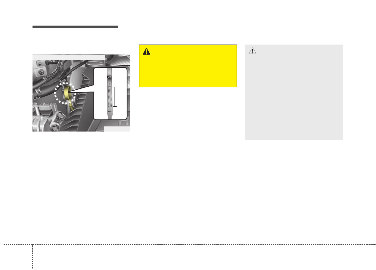
268
Maintenance
ENGINE OIL
Checking the engine oil level
1. Be sure the vehicle is on level
ground.
2. Start the engine and allow it to
reach normal operating tempera-
ture.
3. Turn the engine off and wait for a
few minutes (about 5 minutes) for
the oil to return to the oil pan.
4. Pull the dipstick out, wipe it clean,
and re-insert it fully.
5. Pull the dipstick out again and
check the level. The level should
be between F (Full) and L (Low).
WARNING - Radiator hose
Be very careful not to touch the
radiator hose when checking or
adding the engine oil as it may
be hot enough to burn you.
ODE076002
■ Gasoline Engine (Kappa 1.6L-GDI)
CAUTION
• Do not overfill the engine oil. It
may damage the engine.
• Do not spill engine oil, when
adding or changing engine oil.
If you drop the engine oil on
the engine room, wipe it off
immediately.
• When you wipe the oil level
gauge, you should wipe it with
a clean cloth. When mixed
with debris, it can cause
engine damage.
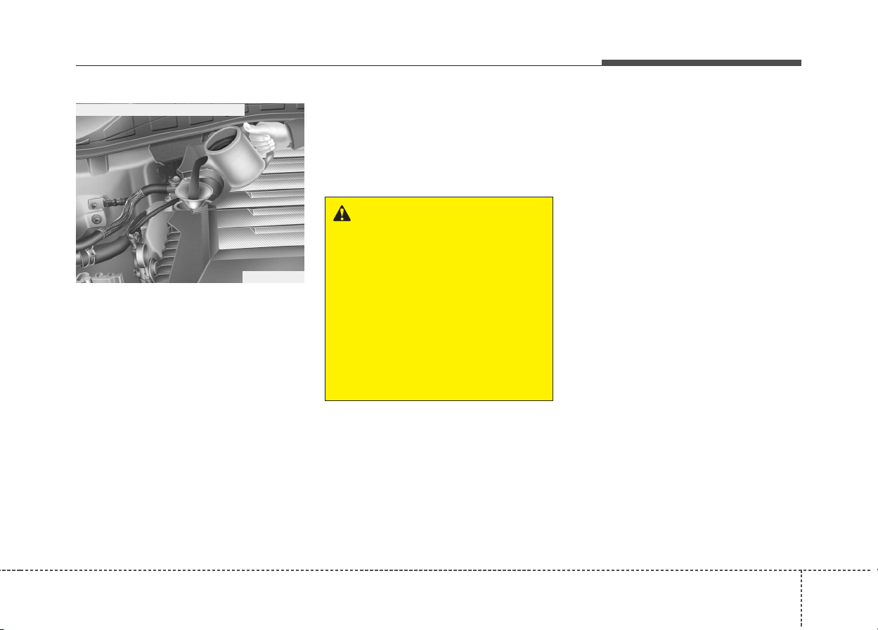
827
Maintenance
If it is near or at L (Low), add enough
oil to bring the level to F (Full). Do
not overfill.
Use a funnel to help prevent oil
from being spilled on engine com-
ponents.
Use only the specified engine oil.
(Refer to “Recommended lubricants
and capacities” in chapter 9.)
Changing the engine oil and
filter
We recommend that the engine oil
and filter be replaced by an author-
ized Kia dealer.
ODE076003
■ Gasoline Engine (Kappa 1.6L-GDI)
WARNING
Used engine oil may cause skin
irritation or cancer if left in con-
tact with the skin for prolonged
periods of time. Used engine oil
contains chemicals that have
caused cancer in laboratory
animals. Always protect your
skin by washing your hands
thoroughly with soap and warm
water as soon as possible after
handling used oil.
288
Maintenance
ENGINE COOLANT
The high-pressure cooling system
has a reservoir filled with year round
antifreeze coolant. The reservoir is
filled at the factory.
Check the antifreeze protection and
coolant level at least once a year, at
the beginning of the winter season,
and before traveling to a colder cli-
mate.
Checking the coolant level
WARNING
Removing radiator
cap
• Never attempt to remove the
radiator cap while the engine
is operating or hot. Doing so
might lead to cooling system
and engine damage. Also, hot
coolant or steam could cause
serious personal injury.
• Turn the engine off and wait
until it cools down. Use
extreme care when removing
the radiator cap. Wrap a thick
towel around it, and turn it
counterclockwise slowly to
the first stop. Step back while
the pressure is released from
the cooling system.
(Continued)
(Continued)
When you are sure all the
pressure has been released,
press down on the cap, using
a thick towel, and continue
turning counterclockwise to
remove it.
• Even if the engine is not oper-
ating, do not remove the radi-
ator cap or the drain plug
while the engine and radiator
are hot. Hot coolant and
steam may still blow out
under pressure, causing seri-
ous injury.
CAUTION
• When the engine overheats
from low engine coolant, sud-
denly adding engine coolant
may cause cracks in the
engine. To prevent damage,
add engine coolant slowly in
small quantities.
• Do not drive with no engine
coolant. It may cause water
pump failure and engine
seizure, etc.
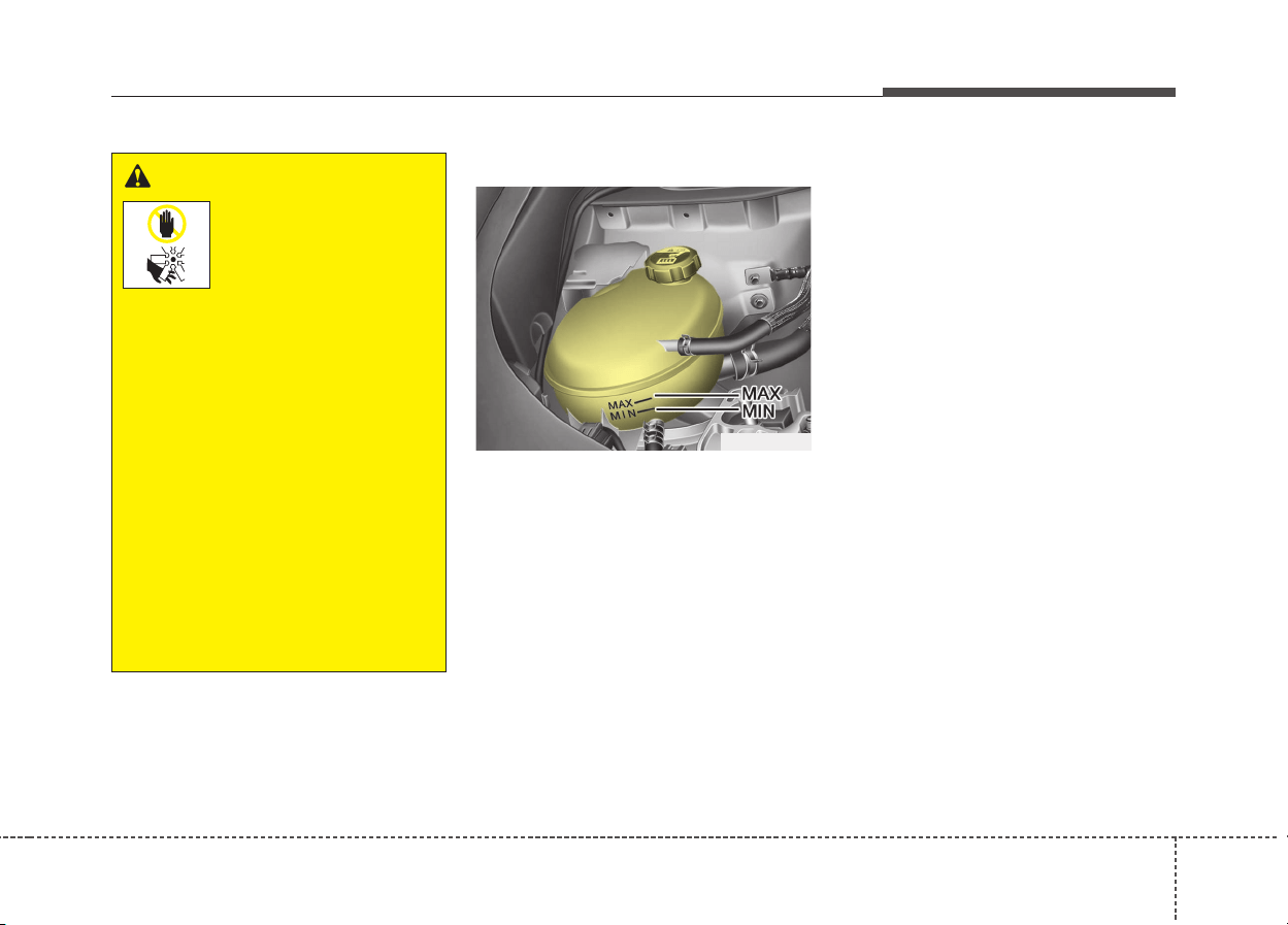
829
Maintenance
Engine coolant
Check the condition and connections
of all cooling system hoses and
heater hoses. Replace any swollen
or deteriorated hoses.
The coolant level should be filled
between F (Full) and L (Low) marks
on the side of the coolant reservoir
when the engine is cool.
If the coolant level is low, add enough
specified coolant to provide protec-
tion against freezing and corrosion.
Bring the level to F (Full), but do not
overfill. If frequent additions are
required, we recommend that the
system be inspected by an author-
ized Kia dealer.
WARNING
The electric motor
(cooling fan) is con-
trolled by engine
coolant temperature,
refrigerant pressure
and vehicle speed. It may some-
times operate even when the
engine is not running. Use
extreme caution when working
near the blades of the cooling
fan so that you are not injured
by a rotating fan blades. As the
engine coolant temperature
decreases, the electric motor
will automatically shut off. This
is a normal condition.
If your vehicle is equipped with
GDI, the electric motor (cooling
fan) may operate until you dis-
connect the negative battery
cable.
ODE076005
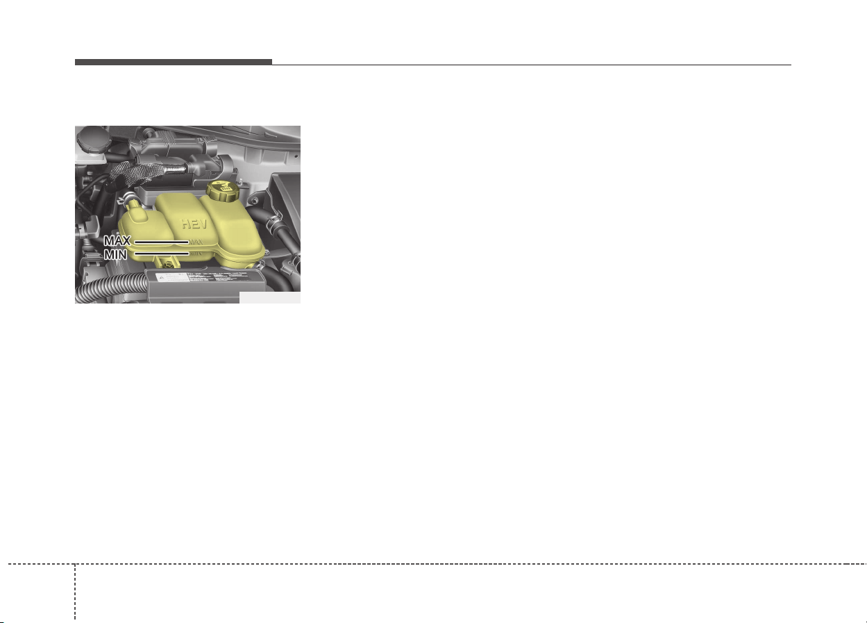
308
Maintenance
Inverter coolant
Check the condition and connections
of all cooling system hoses and
heater hoses. Replace any swollen
or deteriorated hoses.
The coolant level should be filled
between MAX and MIN marks on the
side of the coolant reservoir when
the engine is cool.
If the coolant level is low, add enough
specified coolant to provide protec-
tion against freezing and corrosion.
Bring the level to MAX, but do not
overfill. If frequent additions are
required, we recommend that the
system be inspected by an author-
ized Kia dealer.
Recommended coolant
• When adding coolant, use only
deionized water or soft water for
your vehicle and never mix hard
water in the coolant filled at the fac-
tory. An improper coolant mixture
can result in serious malfunction or
engine damage.
• The engine in your vehicle has alu-
minum engine parts and must be
protected by an ethylene-glycol
with phosphate based coolant to
prevent corrosion and freezing.
• DO NOT USE alcohol or methanol
coolant or mix them with the spec-
ified coolant.
• Do not use a solution that contains
more than 60% antifreeze or less
than 35% antifreeze, which would
reduce the effectiveness of the
solution.
ODE076053
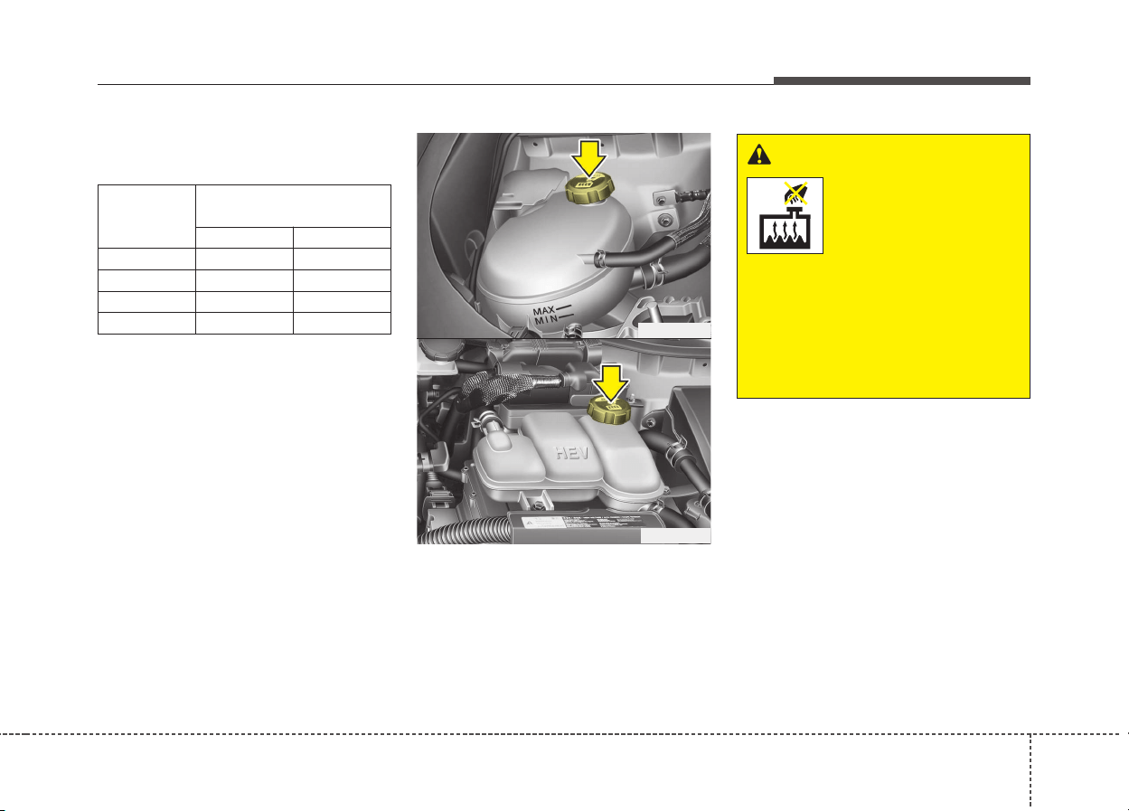
831
Maintenance
For mixture percentage, refer to the
following table.
ODE076006
ODE076004
WARNING
Radiator cap
Do not remove the radiator cap
when the engine and radiator
are hot. Scalding hot coolant
and steam may blow out under
pressure causing serious
injury.
Ambient
Temperature
Mixture Percentage
(volume)
Antifreeze Water
-15°C (5°F) 35 65
-25°C (-13°F) 40 60
-35°C (-31°F) 50 50
-45°C (-49°F) 60 40
328
Maintenance
Changing the coolant
We recommend that the coolant be
replaced by an authorized Kia dealer.
CAUTION
Put a thick cloth around the
radiator cap before refilling the
coolant in order to prevent the
coolant from overflowing into
engine parts such as the alter-
nator.
WARNING - Coolant
• Do not use radiator coolant or
antifreeze in the washer fluid
reservoir.
• Radiator coolant can severely
obscure visibility when
sprayed on the windshield
and may cause loss of vehicle
control or damage the paint
and body trim.
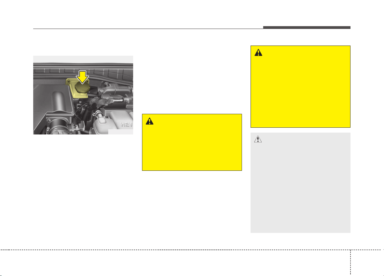
833
Maintenance
BRAKE FLUID
Checking the brake fluid level
Check the fluid level in the reservoir
periodically. The fluid level should be
between MAX and MIN marks on the
side of the reservoir.
Before removing the reservoir cap
and adding brake fluid, clean the
area around the reservoir cap thor-
oughly to prevent brake fluid contam-
ination.
If the level is low, add fluid to the
MAX level. The level will fall with
accumulated mileage. This is a nor-
mal condition associated with the
wear of the brake linings.
If the fluid level is excessively low, we
recommend that the system be
checked by an authorized Kia dealer.
Use only the specified brake fluid.
(Refer to “Recommended lubricants
or capacities” in chapter 9.)
Never mix different types of fluid.
WARNING - Brake fluid
When changing and adding
brake fluid, handle it carefully.
Do not let it come in contact
with your eyes. If brake fluid
should come in contact with
your eyes, immediately flush
them with a large quantity of
fresh tap water. Have your eyes
examined by a doctor as soon
as possible.
WARNING
- Loss of brake fluid
In the event the brake system
requires frequent additions of
fluid, we recommend that the
system be inspected by an
authorized Kia dealer.
ODE076008
CAUTION
Do not allow brake fluid to con-
tact the vehicle's body paint, as
paint damage will result. Brake
fluid, which has been exposed
to open air for an extended time
should never be used as its
quality cannot be guaranteed. It
should be properly disposed.
Don't put in the wrong kind of
fluid. A few drops of mineral-
based oil, such as engine oil, in
your brake system can damage
brake system parts.
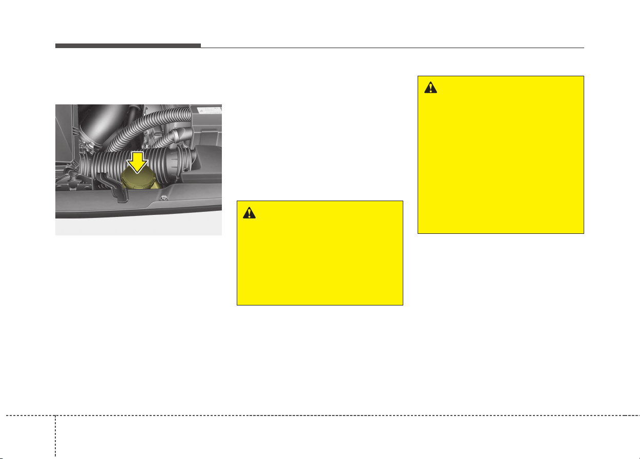
348
Maintenance
ENGINE CLUTCH ACTUATOR FLUID
Checking the engine clutch
actuator fluid level
In normal driving conditions, the
actuator fluid level does not go down
rapidly. However, oil consumption
rate may rise as vehicle mileage
increases, and leakage in actuator
related parts may result in increased
consumption of the engine clutch
actuator oil. Regularly check and
make sure the engine clutch actuator
oil fluid level is between [MIN] and
[MAX] marks.
If the oil level is below [MIN] mark,
we recommend that your vehicle be
checked by an authorized Kia dealer.
If the fluid level is excessively low, we
recommend that the system be
checked by an authorized Kia dealer.
Use only the specified engine clutch
actuator fluid.
(Refer to “Recommended lubricants
or capacities” in chapter 9.)
Never mix different types of fluid.
WARNING - Engine clutch
actuator fluid
When changing and adding
engine clutch actuator fluid,
handle it carefully. Do not let it
come in contact with your eyes.
If engine clutch actuator fluid
should come in contact with
your eyes, immediately flush
them with a large quantity of
fresh tap water. Have your eyes
examined by a doctor as soon
as possible.
WARNING
- Loss of engine clutch
actuator fluid
In the event the engine clutch
actuator requires frequent addi-
tions of fluid, we recommend
that the system be inspected by
an authorized Kia dealer.
ODE076057

835
Maintenance
CAUTION
Do not allow engine clutch actu-
ator fluid to contact the vehi-
cle's body paint, as paint dam-
age will result. The engine
clutch actuator fluid, which has
been exposed to open air for an
extended time should never be
used as its quality cannot be
guaranteed. It should be proper-
ly disposed. Don't put in the
wrong kind of fluid. A few drops
of mineral-based oil, such as
engine oil, in your engine clutch
actuator system can damage
engine clutch actuator system
parts.
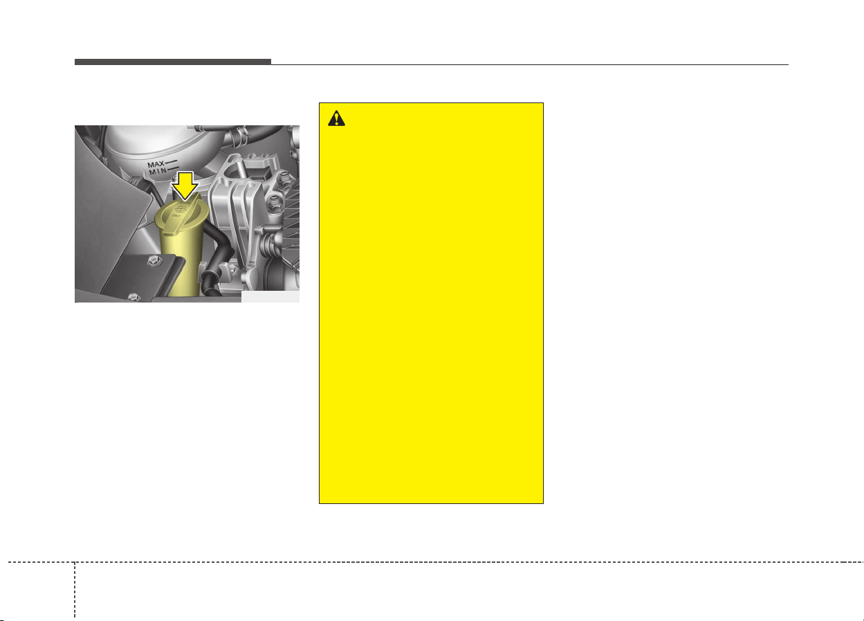
368
Maintenance
WASHER FLUID
Checking the washer fluid level
The reservoir is translucent so that
you can check the level with a quick
visual inspection.
Check the fluid level in the washer
fluid reservoir and add fluid if neces-
sary. Plain water may be used if
washer fluid is not available.
However, use washer solvent with
antifreeze characteristics in cold cli-
mates to prevent freezing.
WARNING - Coolant
• Do not use radiator coolant or
antifreeze in the washer fluid
reservoir.
• Radiator coolant can severely
obscure visibility when
sprayed on the windshield
and may cause loss of vehicle
control or damage to paint
and body trim.
• Windshield Washer fluid
agents contain some amounts
of alcohol and can be flamma-
ble under certain circum-
stances. Do not allow sparks
or flame to contact the washer
fluid or the washer fluid reser-
voir. Damage to the vehicle or
occupants could occur.
• Windshield washer fluid is
poisonous to humans and ani-
mals. Do not drink and avoid
contacting windshield washer
fluid. Serious injury or death
could occur.
ODE076009
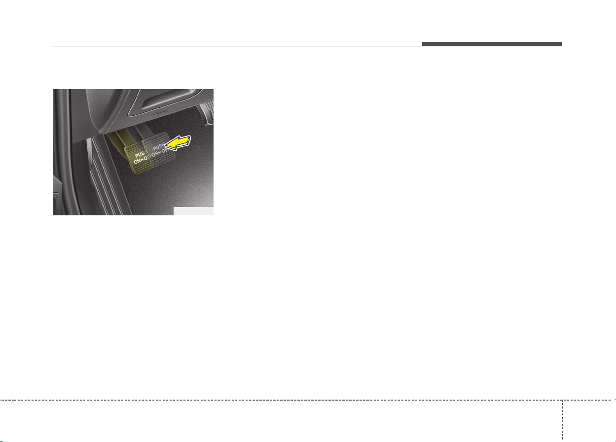
837
Maintenance
PARKING BRAKE
Checking the parking brake
Check whether the stroke is within
specification when the parking brake
pedal is depressed with 20 kg (44
lbs, 196 N) of force. Also, the parking
brake alone should securely hold the
vehicle on a fairly steep grade. If the
stroke is more or less than specified,
we recommend that the system be
serviced by an authorized Kia dealer.
Stroke : 4~5 notch
OJF055017
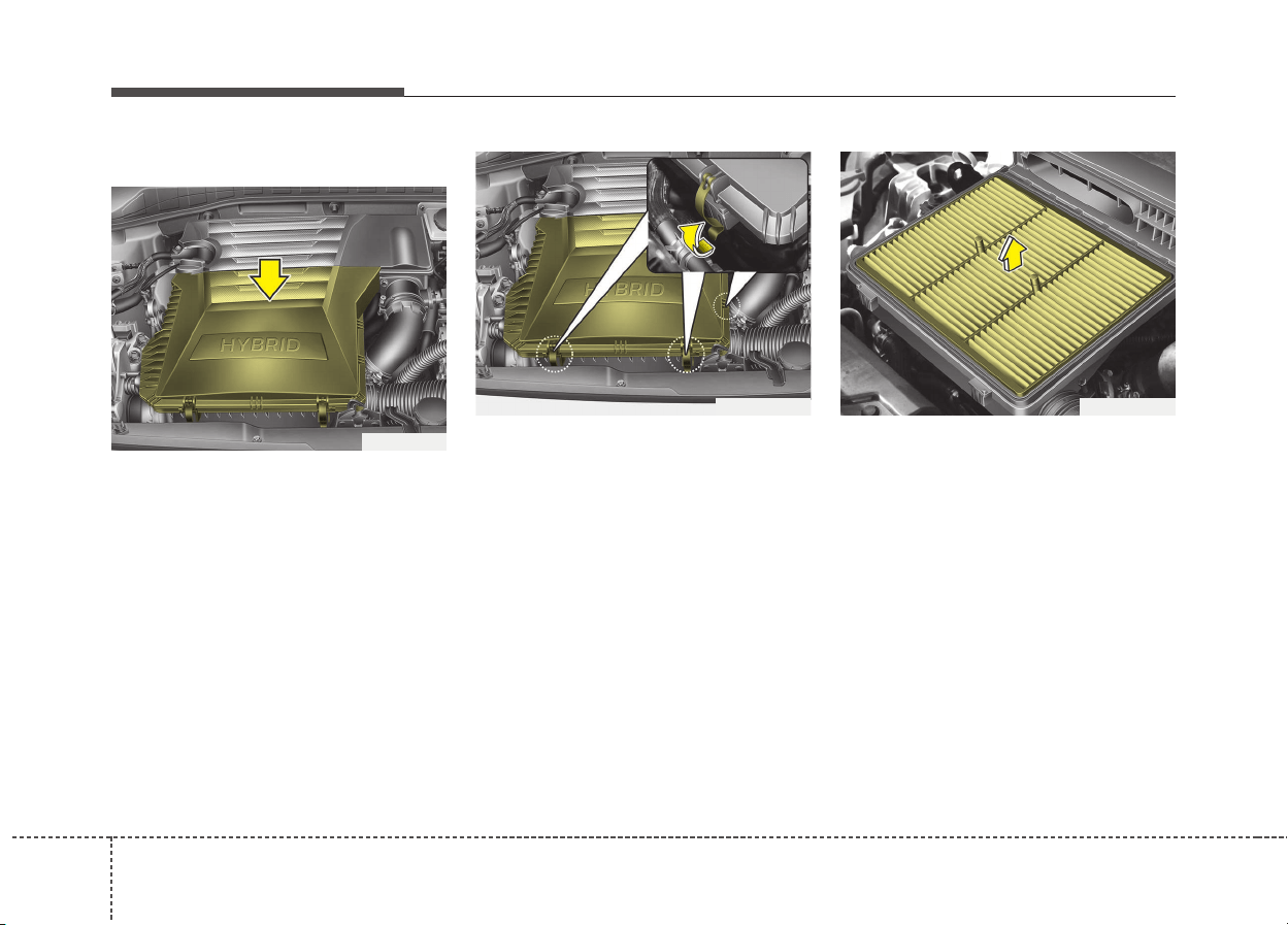
388
Maintenance
AIR CLEANER
Filter replacement
It must be replaced when necessary,
and should not be washed.
You can clean the filter when inspect-
ing the air cleaner element.
Clean the filter by using compressed
air.
1. Loosen the air cleaner cover
attaching clips and open the cover.
2. Wipe the inside of the air cleaner.
3. Replace the air cleaner filter.
4. Lock the cover with the cover
attaching clips.
ODE076011
ODE076012L ODE076013

839
Maintenance
Replace the filter according to the
Maintenance Schedule.
If the vehicle is operated in extreme-
ly dusty or sandy areas, replace the
element more often than the usual
recommended intervals. (Refer to
“Maintenance under severe usage
conditions” in this chapter.)
CAUTION
• Do not drive with the air clean-
er removed; this will result in
excessive engine wear.
• When removing the air cleaner
filter, be careful that dust or
dirt does not enter the air
intake, or damage may result.
• We recommend that you use
parts for replacement from an
authorized Kia dealer.

408
Maintenance
CLIMATE CONTROL AIR FILTER
Filter inspection
The climate control air filter should
be replaced according to the mainte-
nance schedule. If the vehicle is
operated in severely air-polluted
cities or on dusty rough roads for a
long period, it should be inspected
more frequently and replaced earlier.
When you replace the climate control
air filter, replace it performing the fol-
lowing procedure, and be careful to
avoid damaging other components.
1. Open the glove box and remove
the stoppers on both sides.
2. With the glove box open, pull the
support strap (1).
ODE076014ODE076015
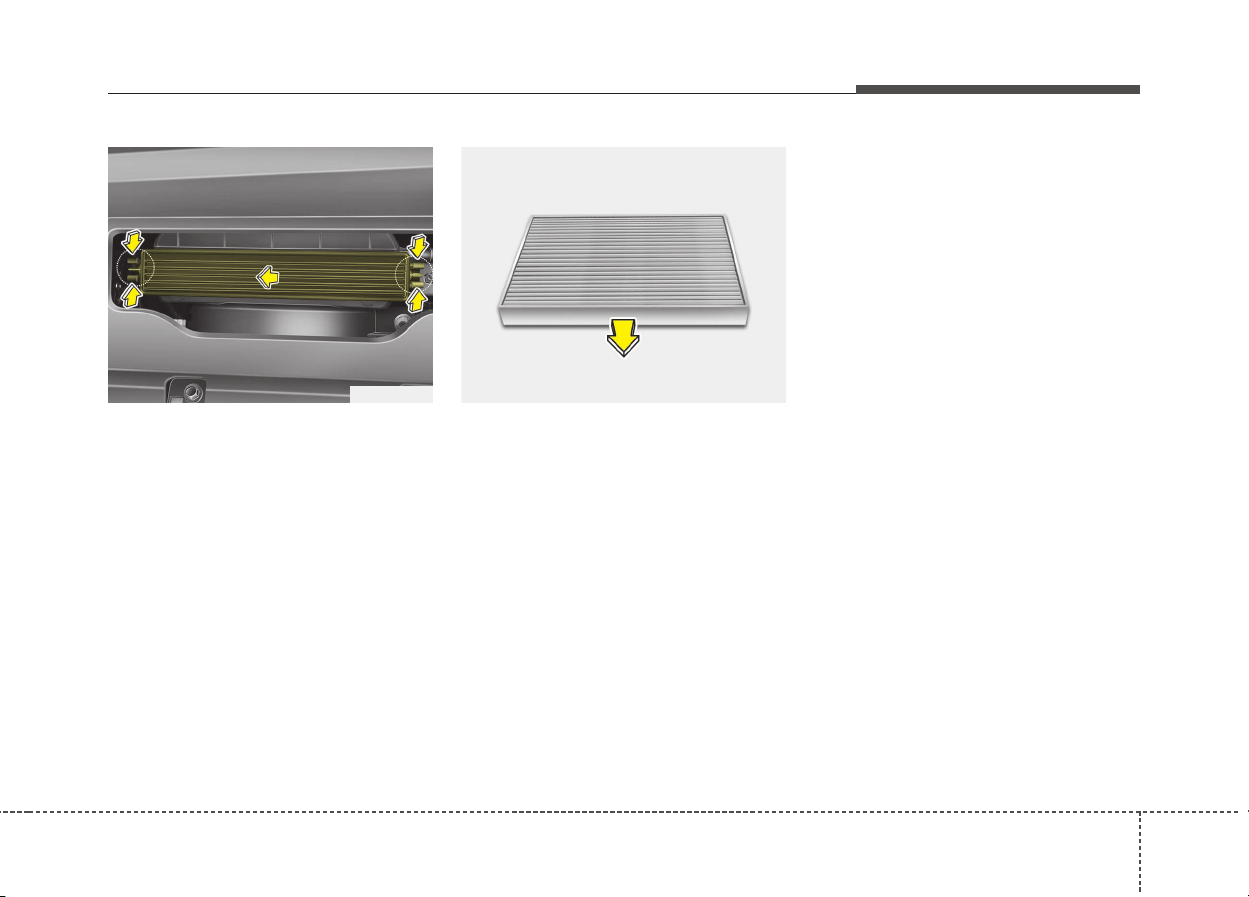
841
Maintenance
3. Remove the climate control air fil-
ter cover while pressing the lock
on the both sides of the cover.
4. Replace the climate control air fil-
ter.
5. Reassemble in the reverse order
of disassembly.
✽✽
NOTICE
When replacing the climate control
air filter install it properly.
Otherwise, the system may produce
noise and the effectiveness of the fil-
ter may be reduced.
ODE076054 OQL075021
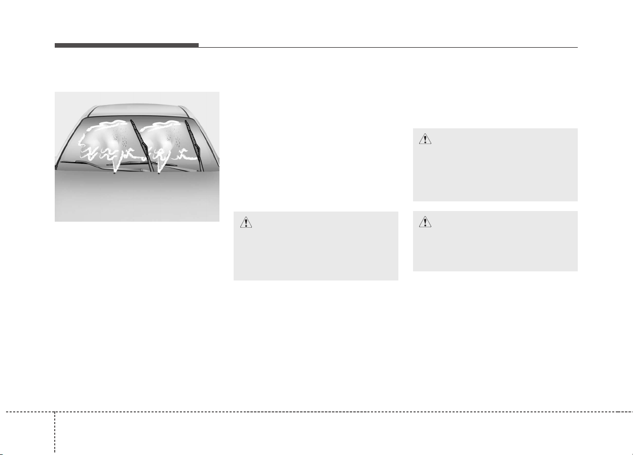
428
Maintenance
WIPER BLADES
Blade inspection
✽✽
NOTICE
Commercial hot waxes applied by
automatic car washes have been
known to make the windshield diffi-
cult to clean.
Contamination of either the wind-
shield or the wiper blades with for-
eign matter can reduce the effective-
ness of the windshield wipers.
Common sources of contamination
are insects, tree sap, and hot wax
treatments used by some commer-
cial car washes. If the blades are not
wiping properly, clean both the win-
dow and the blades with a good
cleaner or mild detergent, and rinse
thoroughly with clean water.
Blade replacement
When the wipers no longer clean
adequately, the blades may be worn
or cracked, and require replacement.
CAUTION
To prevent damage to the wiper
blades, do not use gasoline,
kerosene, paint thinner, or other
solvents on or near them.
CAUTION
To prevent damage to the wiper
arms or other components, do
not attempt to move the wipers
manually.
CAUTION
The use of a non-specified
wiper blade could result in
wiper malfunction and failure.
1JBA5122
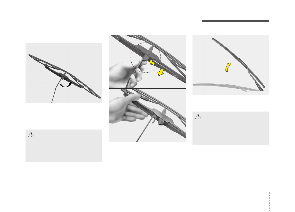
843
Maintenance
Front windshield wiper blade
Type A
1. Raise the wiper arm and turn the
wiper blade assembly to expose
the plastic locking clip.
2. Compress the clip and slide the
blade assembly downward.
3. Lift it off the arm.
4. Install the blade assembly in the
reverse order of removal.
Type B
1. Raise the wiper arm.
1LDA5023
CAUTION
Do not allow the wiper arm to
fall against the windshield,
since it may chip or crack the
windshield.
1JBA7037
1JBA7038
OHM078059
CAUTION
Do not allow the wiper arm to
fall against the windshield,
since it may chip or crack the
windshield.
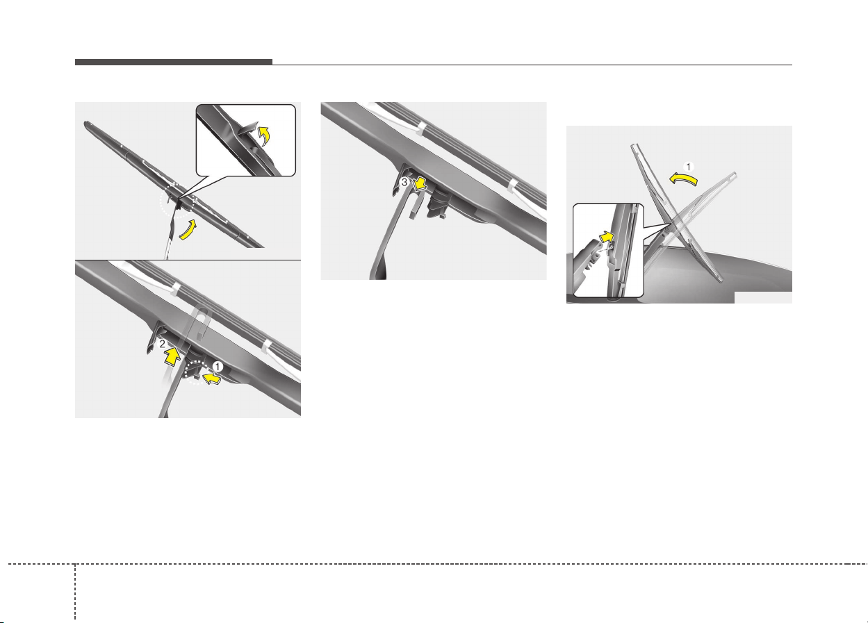
448
Maintenance
2. Turn the wiper blade clip. Then lift
up the blade clip.
3. Push the clip (1) and push up the
wiper arm (2).
4. Push down the wiper arm (3) and
install the new blade assembly in
the reverse order of removal.
5. Return the wiper arm on the wind-
shield.
Rear window wiper blade
1. Raise the wiper arm and pull out
the wiper blade assembly.
OHM078062
OSBL071002
OSBL071001
OSBL071003
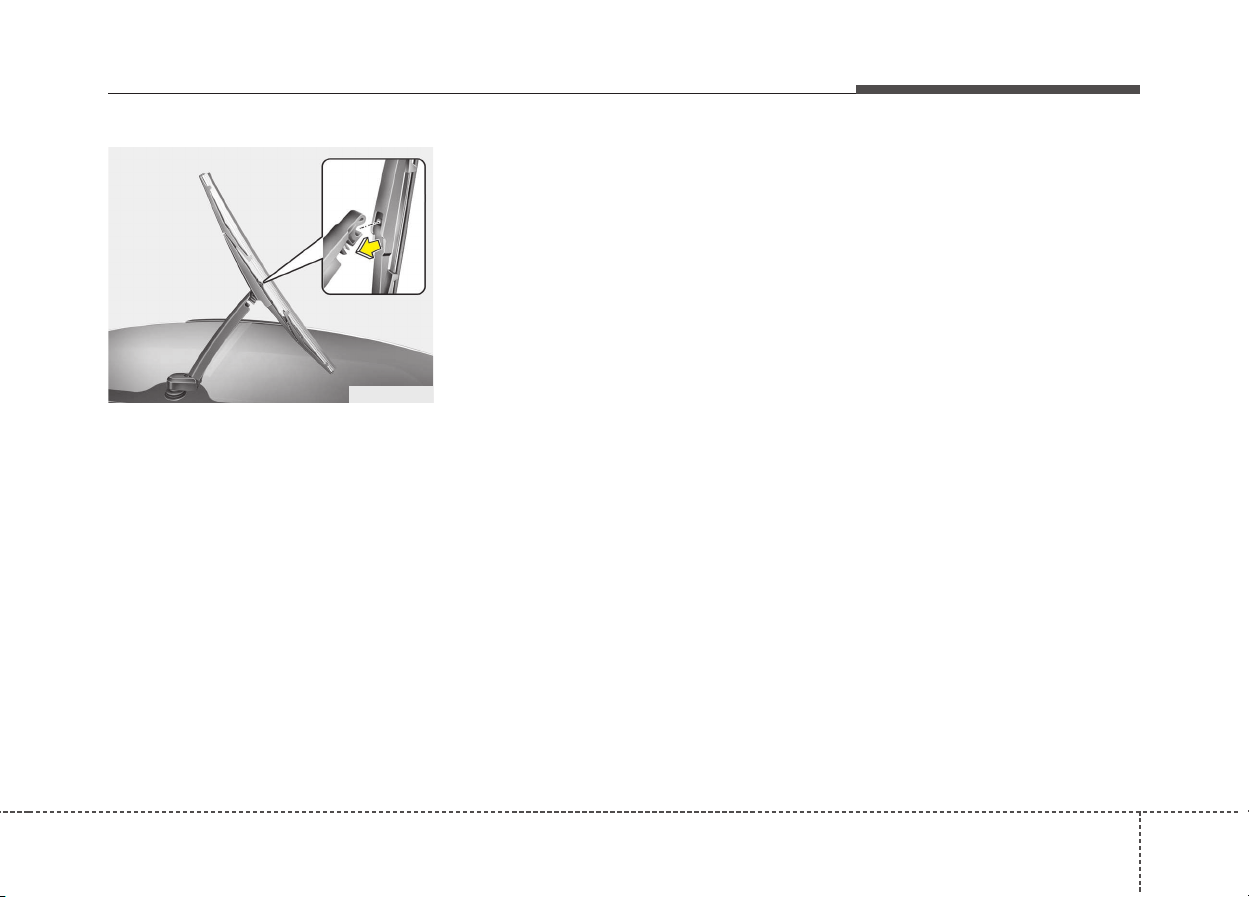
845
Maintenance
2. Install the new blade assembly by
inserting the center part into the
slot in the wiper arm until it clicks
into place.
3. Make sure the blade assembly is
installed firmly by trying to pull it
slightly.
To prevent damage to the wiper arms
or other components, we recommend
that the wiper blade be replaced by
an authorized Kia dealer.
OHM078063
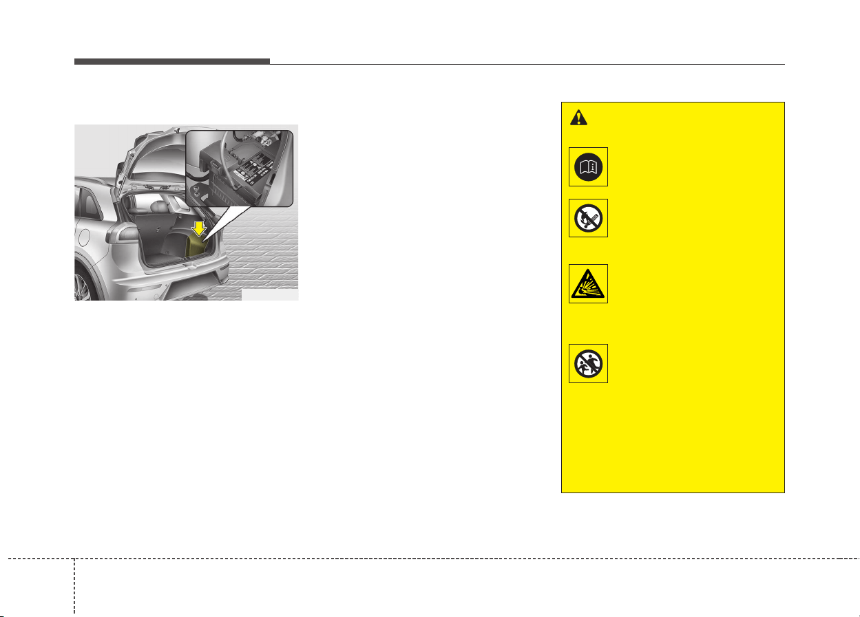
468
Maintenance
BATTERY
For best battery service
• Keep the battery securely mounted.
• Keep the battery top clean and dry.
• Keep the terminals and connec-
tions clean, tight, and coated with
petroleum jelly or terminal grease.
• Rinse any spilled electrolyte from
the battery immediately with a
solution of water and baking soda.
• If the vehicle is not going to be
used for an extended time, discon-
nect the battery cables.
✽✽
NOTICE
Basically equipped battery is main-
tenance free type. If your vehicle is
equipped with the battery marked
with LOWER and UPPER on the
side, you can check the electrolyte
level. The electrolyte level should be
between LOWER and UPPER. If
the electrolyte level is low, it needs to
add distilled (demineralized) water
(Never add sulfuric acid or other
electrolyte). When refill, be careful
not to splash the battery and adja-
cent components. And do not over-
fill the battery cells. It can cause cor-
rosion on other parts. After then
ensure that tighten the cell caps. We
recommend that you contact an
authorized Kia dealer.
ODE076016
WARNING - Battery
dangers
Always read the follow-
ing instructions carefully
when handling a battery.
Keep lighted cigarettes
and all other flames or
sparks away from the
battery.
Hydrogen, a highly com-
bustible gas, is always
present in battery cells
and may explode if ignit-
ed.
Keep batteries out of the
reach of children
because batteries con-
tain highly corrosive
SULFURIC ACID. Do not
allow battery acid to
contact your skin, eyes,
clothing or paint finish.
(Continued)
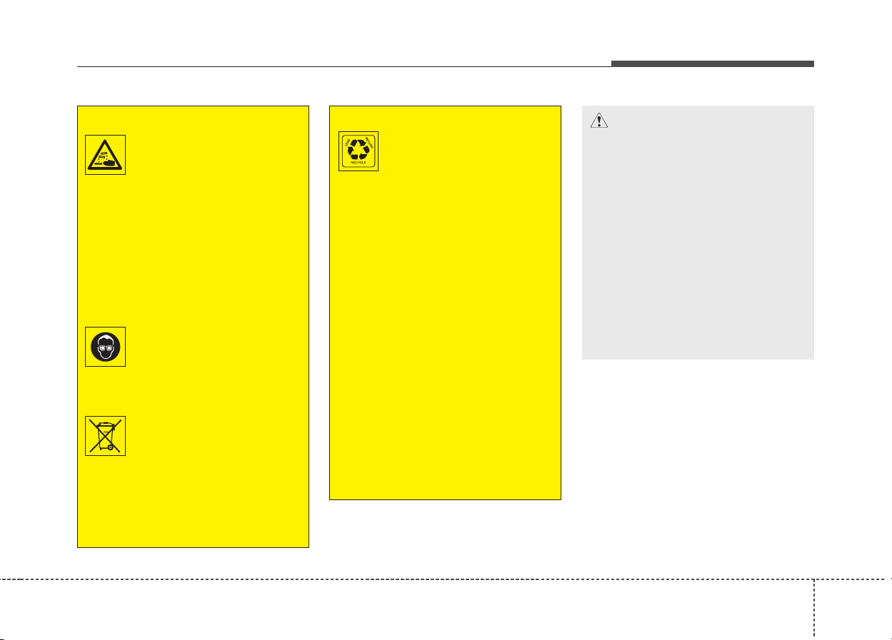
847
Maintenance
(Continued)
The battery contains
lead. Do not dispose of it
after use. We recommend
that you contact an
authorized Kia dealer.
• When lifting a plastic-cased
battery, excessive pressure
on the case may cause battery
acid to leak, resulting in per-
sonal injury. Lift with a battery
carrier or with your hands on
opposite corners.
• Never attempt to recharge the
battery when the battery
cables are connected.
• The electrical ignition system
works with high voltage.
Never touch these compo-
nents with the engine running
or the ignition switched on.
Failure to follow the above
warnings can result in serious
bodily injury or death.
CAUTION
• When you don’t use the vehi-
cle for a long time in the low
temperature area, separate
the battery and keep it
indoors.
• Always charge the battery
fully to prevent battery case
damage in low temperature
area.
• If you connect unauthorized
electronic devices to the bat-
tery, the battery may be dis-
charged. Never use unautho-
rized devices.
(Continued)
If any electrolyte gets
into your eyes, flush your
eyes with clean water for
at least 15 minutes and
get immediate medical
attention.
If electrolyte gets on your
skin, thoroughly wash
the contacted area. If you
feel pain or burning sen-
sation, get medical atten-
tion immediately.
Wear eye protection when
charging or working near
a battery. Always provide
ventilation when working
in an enclosed space.
An inappropriately dis-
posed battery can be
harmful to the environ-
ment and human health.
Dispose the battery
according to your local
law(s) or regulation.
(Continued)
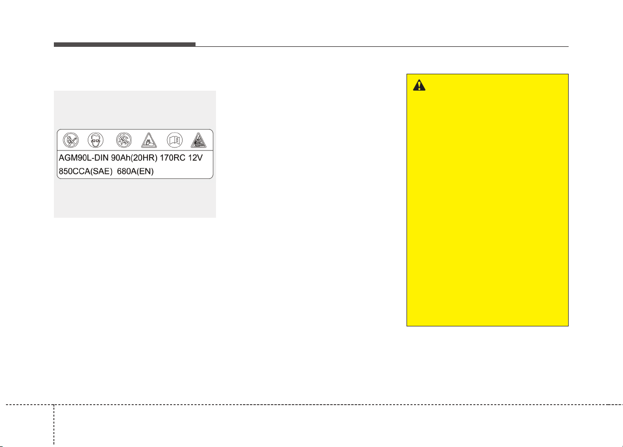
488
Maintenance
Battery capacity label
❈ The actual battery label in the vehicle may
differ from the illustration.
1. AGM90L-DIN : The Kia model
name of battery
2. 90Ah(20HR) : The nominal capaci-
ty (in Ampere hours)
3. 170RC : The nominal reserve
capacity (in min.)
4. 12V : The nominal voltage
5. 850CCA (SAE) : The cold-test cur-
rent in amperes
by SAE
6. 680A : The cold-test current in
amperes by EN
Battery recharging
Your vehicle has a maintenance-free,
calcium-based battery.
• If the battery becomes discharged
in a short time (because, for exam-
ple, the headlights or interior lights
were left on while the vehicle was
not in use), recharge it by slow
charging (trickle) for 10 hours.
• If the battery gradually discharges
because of high electric load while
the vehicle is being used, recharge
it at 20-30A for two hours.
OUM074113L
■ Example
WARNING - Recharging
battery
When recharging the battery,
observe the following precau-
tions:
• The battery must be removed
from the vehicle and placed in
an area with good ventilation.
• Do not allow cigarettes, sparks,
or flame near the battery.
• Watch the battery during
charging, and stop or reduce
the charging rate if the battery
cells begin gassing (boiling)
violently or if the temperature
of the electrolyte of any cell
exceeds 49°C (120°F).
• Wear eye protection when
checking the battery during
charging.
(Continued)
849
Maintenance
Reset items
Items should be reset after the bat-
tery has been discharged or the bat-
tery has been disconnected.
• Auto up/down window
• Sunroof
• Trip computer
• Climate control system
• Driver position Memory System
• Audio
(Continued)
• Disconnect the battery charg-
er in the following order.
1. Turn off the battery charger
main switch.
2. Unhook the negative clamp
from the negative battery ter-
minal.
3. Unhook the positive clamp
from the positive battery ter-
minal.
WARNING
• Before performing mainte-
nance or recharging the bat-
tery, turn off all accessories
and stop the engine.
• The negative battery cable
must be removed first and
installed last when the battery
is disconnected.
• Operation related to the bat-
tery is recommended to an
authorized Kia dealer.
CAUTION
• Keep the battery away from
water or any liquid.
• For your safety, we recom-
mend that you use parts for
replacement from an author-
ized Kia dealer.
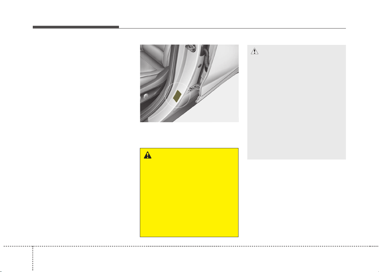
508
Maintenance
TIRES AND WHEELS
Tire care
For proper maintenance, safety, and
maximum fuel economy, you must
always maintain recommended tire
inflation pressures and stay within
the load limits and weight distribution
recommended for your vehicle.
Recommended cold tire infla-
tion pressures
All tire pressures (including the
spare) should be checked when the
tires are cold. “Cold Tires” means the
vehicle has not been driven for at
least three hours or driven less than
1.6 km (one mile).
Recommended pressures must be
maintained for the best ride, top vehi-
cle handling, and minimum tire wear.
For recommended inflation pressure,
refer to “Tire and wheels” in chapter 9.
All specifications (sizes and pres-
sures) can be found on a label
attached to the vehicle.
WARNING - Tire under-
inflation
Severe underinflation (70 kPa
(10 psi) or more) can lead to
severe heat build-up, causing
blowouts, tread separation and
other tire failures that can result
in the loss of vehicle control
leading to severe injury or
death. This risk is much higher
on hot days and when driving
for long periods at high speeds.
CAUTION
• Underinflation also results in
excessive wear, poor handling
and reduced fuel economy.
Wheel deformation also is
possible. Keep your tire pres-
sures at the proper levels. If a
tire frequently needs refilling,
we recommend that the sys-
tem be checked by an author-
ized Kia dealer.
• Overinflation produces a
harsh ride, excessive wear at
the center of the tire tread, and
a greater possibility of dam-
age from road hazards.
ODE086006L
851
Maintenance
Checking tire inflation pressure
Check your tires once a month or
more.
Also, check the tire pressure of the
spare tire.
How to check
Use a good quality gauge to check
tire pressure. You can not tell if your
tires are properly inflated simply by
looking at them. Radial tires may
look properly inflated even when
they're underinflated.
Check the tire's inflation pressure
when the tires are cold. - "Cold"
means your vehicle has been sitting
for at least three hours or driven no
more than 1.6 km (1 mile).
WARNING - Tire Inflation
Overinflation or underinflation
can reduce tire life, adversely
affect vehicle handling, and
lead to sudden tire failure. This
could result in loss of vehicle
control and potential injury.
CAUTION - Tire pressure
Always observe the following:
• Check tire pressure when the
tires are cold. (After vehicle
has been parked for at least
three hours or hasn't been
driven more than 1.6 km (one
mile) since startup.)
• Check the pressure of your
spare tire each time you check
the pressure of other tires.
• Never overload your vehicle.
Be careful not to overload a
vehicle luggage rack if your
vehicle is equipped with one.
• Worn, old tires can cause acci-
dents. If your tread is badly
worn, or if your tires have
been damaged, replace them.
CAUTION
• Warm tires normally exceed
recommended cold tire pres-
sures by 28 to 41 kPa (4 to 6
psi). Do not release air from
warm tires to adjust the pres-
sure or the tires will be under-
inflated.
• Be sure to reinstall the tire
inflation valve caps. Without
the valve cap, dirt or moisture
could get into the valve core
and cause air leakage. If a
valve cap is missing, install a
new one as soon as possible.
528
Maintenance
Remove the valve cap from the tire
valve stem. Press the tire gauge firm-
ly onto the valve to get a pressure
measurement. If the cold tire inflation
pressure matches the recommended
pressure on the tire and loading
information label, no further adjust-
ment is necessary. If the pressure is
low, add air until you reach the rec-
ommended amount.
If you overfill the tire, release air by
pushing on the metal stem in the cen-
ter of the tire valve. Recheck the tire
pressure with the tire gauge. Be sure
to put the valve caps back on the
valve stems. They help prevent leaks
by keeping out dirt and moisture.
Tire rotation
To equalize tread wear, it is recom-
mended that the tires be rotated
every 12,000 km (7,500 miles) or
sooner if irregular wear develops.
During rotation, check the tires for
correct balance.
When rotating tires, check for uneven
wear and damage. Abnormal wear is
usually caused by incorrect tire pres-
sure, improper wheel alignment, out-
of-balance wheels, severe braking or
severe cornering. Look for bumps or
bulges in the tread or side of tire.
Replace the tire if you find either of
these conditions. Replace the tire if
fabric or cord is visible. After rotation,
be sure to bring the front and rear tire
pressures to specification and check
lug nut tightness.
Refer to “Tire and wheels” in chapter 9.
WARNING
• Inspect your tires frequently
for proper inflation as well as
wear and damage. Always use
a tire pressure gauge.
• Tires with too much or too little
pressure wear unevenly caus-
ing poor handling, loss of vehi-
cle control, and sudden tire
failure leading to accidents,
injuries, and even death. The
recommended cold tire pres-
sure for your vehicle can be
found in this manual and on
the tire label located on the dri-
ver's side center pillar.
• Worn tires can cause acci-
dents. Replace tires that are
worn, show uneven wear, or
are damaged.
• Remember to check the pres-
sure of your spare tire. Kia
recommends that you check
the spare every time you
check the pressure of the
other tires on your vehicle.
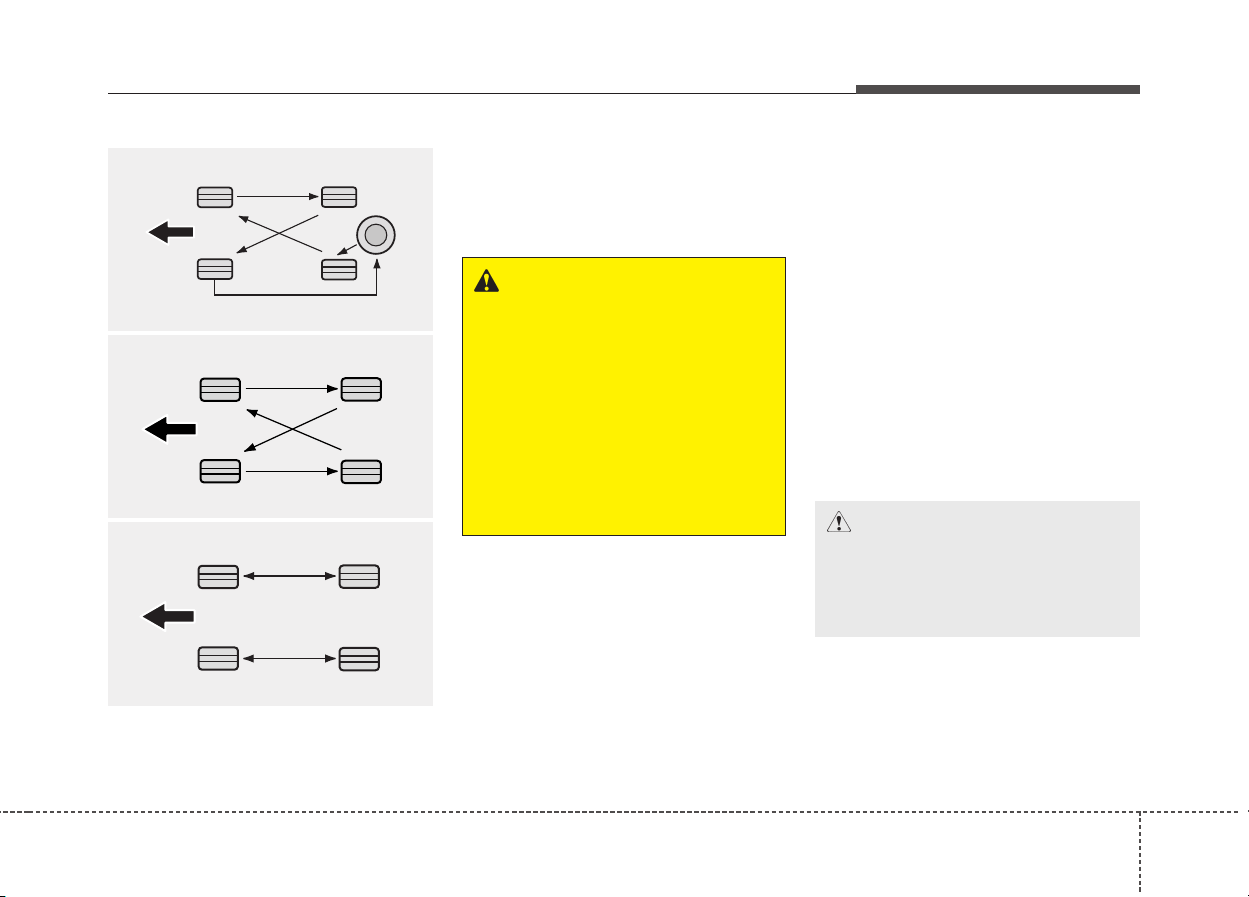
853
Maintenance
Disc brake pads should be inspected
for wear whenever tires are rotated.
✽✽
NOTICE
Rotate radial tires that have an asym-
metric tread pattern only from front
to rear and not from right to left.
Wheel alignment and tire
balance
The wheels on your vehicle were
aligned and balanced carefully at the
factory to give you the longest tire life
and best overall performance.
In most cases, you will not need to
have your wheels aligned again.
However, if you notice unusual tire
wear or your vehicle pulling one way
or the other, the alignment may need
to be reset.
If you notice your vehicle vibrating
when driving on a smooth road, your
wheels may need to be rebalanced.
WARNING
• Do not use the compact spare
tire (if equipped) for tire rota-
tion.
• Do not mix bias ply and radial
ply tires under any circum-
stances. This may cause
unusual handling characteris-
tics that could result in death,
severe injury, or property
damage.
CAUTION
Improper wheel weights can
damage your vehicle's alu-
minum wheels. Use only
approved wheel weights.
S2BLA790A
CBGQ0706
With a full-size spare tire
(Only the vehicle without TPMS system)
Directional tires (if equipped)
Without a spare tire
CBGQ0707A
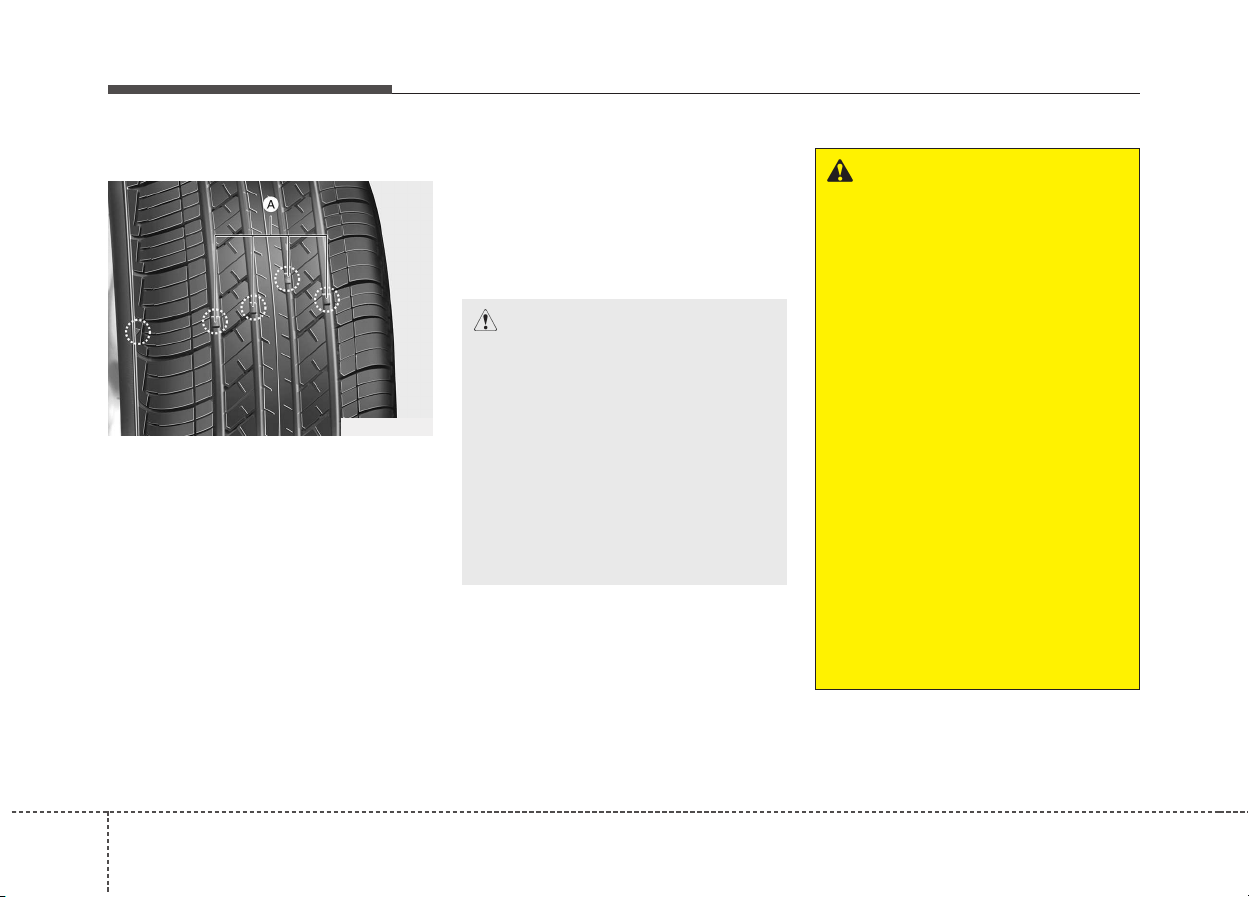
548
Maintenance
Tire replacement
If the tire is worn evenly, a tread wear
Indicator (A) will appear as a solid
band across the tread. This shows
there is less than 1.6 mm (1/16 in.) of
tread left on the tire. Replace the tire
when this happens.
Do not wait for the band to appear
across the entire tread before replac-
ing the tire.
✽✽
NOTICE
We recommend that when replacing
tires, use the same originally sup-
plied with the vehicles.
If not, that affects driving perform-
ance.
OUM076204L
CAUTION
When replacing the tires, recheck
and tighten the wheel nuts after
driving about 50km (31miles) and
recheck after driving about
1,000km (620miles). If the steer-
ing wheel shakes or the vehicle
vibrates while driving, the tire is
out of balance. Align the tire bal-
ance. If the problem is not
solved, we recommend that you
contact an authorized kia dealer.
WARNING - Replacing
tires
To reduce the chance of serious
or fatal injuries from an acci-
dent caused by tire failure or
loss of vehicle control:
• Replace tires that are worn,
show uneven wear, or are
damaged. Worn tires can
cause loss of braking effec-
tiveness, steering control, and
traction.
• Do not drive your vehicle with
too little or too much pressure
in your tires. This can lead to
uneven wear and tire failure.
• When replacing tires, never
mix radial and bias-ply tires
on the same car. You must
replace all tires (including the
spare) if moving from radial to
bias-ply tires.
(Continued)
855
Maintenance
Compact spare tire replacement
(if equipped)
A compact spare tire has a shorter
tread life than a regular size tire.
Replace it when you can see the
tread wear indicator bars on the tire.
The replacement compact spare tire
should be the same size and design
tire as the one provided with your
new vehicle and should be mounted
on the same compact spare tire
wheel. The compact spare tire is not
designed to be mounted on a regular
size wheel, and the compact spare
tire wheel is not designed for mount-
ing a regular size tire.
Wheel replacement
When replacing the metal wheels for
any reason, make sure the new
wheels are equivalent to the original
factory units in diameter, rim width
and offset.
(Continued)
• Using tires and wheels other
than the recommended sizes
could cause unusual handling
characteristics and poor vehi-
cle control, resulting in a seri-
ous accident.
• Wheels that do not meet Kia’s
specifications may fit poorly
and result in damage to the
vehicle or unusual handling
and poor vehicle control.
• The ABS works by comparing
the speed of the wheels. The
tire size affects wheel speed.
When replacing tires, all 4
tires must use the same size
originally supplied with the
vehicle. Using tires of a differ-
ent size can cause the ABS
(Anti-lock Brake System) and
ESC (Electronic Stability
Control) to work irregularly.
WARNING
A wheel that is not the correct
size may adversely affect wheel
and bearing life, braking and
stopping abilities, handling
characteristics, ground clear-
ance, body-to-tire clearance,
snow chain clearance,
speedometer and odometer cal-
ibration, headlight aim and
bumper height.
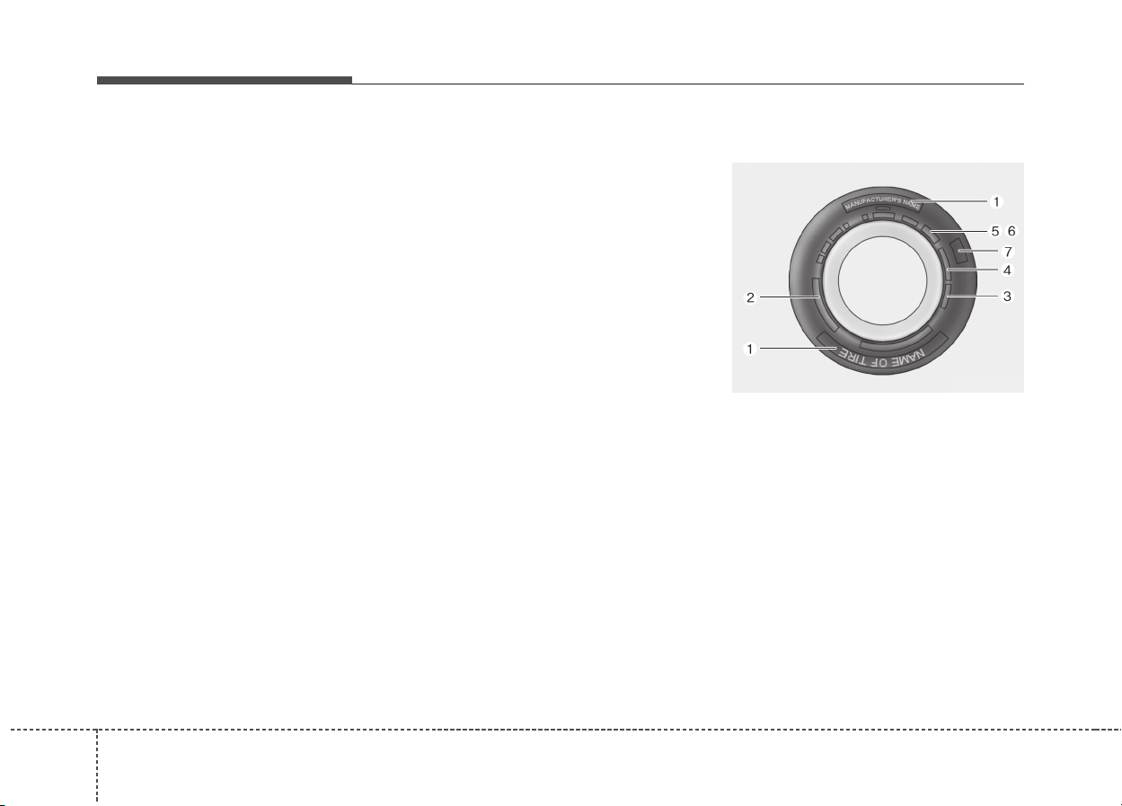
568
Maintenance
Tire traction
Tire traction can be reduced if you
drive on worn tires, tires that are
improperly inflated or on slippery
road surfaces. Tires should be
replaced when tread wear indicators
appear. Slow down whenever there
is rain, snow or ice on the road to
reduce the possibility of losing con-
trol of the vehicle.
Tire maintenance
In addition to proper inflation, correct
wheel alignment helps to decrease
tire wear. If you find a tire is worn
unevenly, have your dealer check the
wheel alignment.
When you have new tires installed,
make sure they are balanced. This
will increase vehicle ride comfort and
tire life. Additionally, a tire should
always be rebalanced if it is removed
from the wheel.
Tire sidewall labeling
This information identifies and
describes the fundamental charac-
teristics of the tire and also provides
the tire identification number (TIN)
for safety standard certification. The
TIN can be used to identify the tire in
case of a recall.
OJF085008L

857
Maintenance
1. Manufacturer or brand name
Manufacturer or Brand name is
shown.
2. Tire size designation
A tire’s sidewall is marked with a tire
size designation. You will need this
information when selecting replace-
ment tires for your vehicle. The fol-
lowing explains what the letters and
numbers in the tire size designation
mean.
Example tire size designation:
(These numbers are provided as an
example only; your tire size designa-
tor could vary depending on your
vehicle.)
P235/55R19 108T
P - Applicable vehicle type (tires
marked with the prefix “P’’ are
intended for use on passenger
vehicles or light trucks; however,
not all tires have this marking).
235 - Tire width in millimeters.
55 - Aspect ratio. The tire’s section
height as a percentage of its
width.
R - Tire construction code (Radial).
19 - Rim diameter in inches.
108 - Load Index, a numerical code
associated with the maximum
load the tire can carry.
T - Speed Rating Symbol. See the
speed rating chart in this section
for additional information.
Wheel size designation
Wheels are also marked with impor-
tant information that you need if you
ever have to replace one. The follow-
ing explains what the letters and
numbers in the wheel size designa-
tion mean.
Example wheel size designation:
7.5JX19
7.5 - Rim width in inches.
J - Rim contour designation.
19 - Rim diameter in inches.
588
Maintenance
Tire speed ratings
The chart below lists many of the dif-
ferent speed ratings currently being
used for passenger car tires. The
speed rating is part of the tire size
designation on the sidewall of the
tire. This symbol corresponds to that
tire's designed maximum safe oper-
ating speed.
3. Checking tire life
(TIN : Tire Identification Number)
Any tires that are over 6 years old,
based on the manufacturing date,
(including the spare tire) should be
replaced by new ones. You can find
the manufacturing date on the tire
sidewall (possibly on the inside of the
wheel), displaying the DOT Code.
The DOT Code is a series of num-
bers on a tire consisting of numbers
and English letters. The manufactur-
ing date is designated by the last four
digits (characters) of the DOT code.
DOT : XXXX XXXX OOOO
The front part of the DOT means a
plant code number, tire size and
tread pattern and the last four num-
bers indicate week and year manu-
factured.
For example:
DOT XXXX XXXX 1616 represents
that the tire was produced in the 16th
week of 2016.
WARNING - Tire age
Tires degrade over time, even
when they are not being used.
Regardless of the remaining
tread, we recommend that tires
be replaced after approximately
six (6) years of normal service.
Heat caused by hot climates or
frequent high loading condi-
tions can accelerate the aging
process. Failure to follow this
warning can result in sudden
tire failure, which could lead to
a loss of control and an acci-
dent involving serious injury or
death.
Speed
Rating
Symbol
Maximum Speed
S 180 km/h (112 mph)
T 190 km/h (118 mph)
H 210 km/h (130 mph)
V 240 km/h (149 mph)
W 270 km/h (168 mph)
Y 300 km/h (186 mph)

859
Maintenance
4. Tire ply composition and
material
The number of layers or plies of rub-
ber-coated fabric in the tire. Tire
manufacturers also must indicate the
materials in the tire, which include
steel, nylon, polyester, and others.
The letter "R" means radial ply con-
struction; the letter "D" means diago-
nal or bias ply construction; and the
letter "B" means belted-bias ply con-
struction.
5. Maximum permissible inflation
pressure
This number is the greatest amount
of air pressure that should be put in
the tire. Do not exceed the maximum
permissible inflation pressure. Refer
to the Tire and Loading Information
label for recommended inflation
pressure.
6. Maximum load rating
This number indicates the maximum
load in kilograms and pounds that can
be carried by the tire. When replacing
the tires on the vehicle, always use a
tire that has the same load rating as
the factory installed tire.
7. Uniform tire quality grading
Quality grades can be found where
applicable on the tire sidewall
between tread shoulder and maxi-
mum section width.
For example:
TREADWEAR 200
TRACTION AA
TEMPERATURE A
Tread wear
The tread wear grade is a compara-
tive rating based on the wear rate of
the tire when tested under controlled
conditions on a specified govern-
ment test course. For example, a tire
graded 150 would wear one-and-a-
half times (1½) as well on the gov-
ernment course as a tire graded 100.
The relative performance of tires
depends upon the actual conditions
of their use, however, and may
depart significantly from the norm
due to variations in driving habits,
service practices and differences in
road characteristics and climate.
These grades are molded on the
side-walls of passenger vehicle tires.
The tires available as standard or
optional equipment on your vehicle
may vary with respect to grade.
608
Maintenance
Traction - AA, A, B & C
The traction grades, from highest to
lowest, are AA, A, B and C. Those
grades represent the tire’s ability to
stop on wet pavement as measured
under controlled conditions on speci-
fied government test surfaces of
asphalt and concrete. A tire marked C
may have poor traction performance.
Temperature -A, B & C
The temperature grades are A (the
highest), B, and C, representing the
tire’s resistance to the generation of
heat and its ability to dissipate heat
when tested under controlled condi-
tions on a specified indoor laboratory
test wheel.
Sustained high temperature can
cause the material of the tire to
degenerate and reduce tire life, and
excessive temperature can lead to
sudden tire failure. Grades B and A
represent higher levels of perform-
ance on the laboratory test wheel
than the minimum required by law.
Low aspect ratio tire
(if equipped)
Low aspect ratio tires, whose aspect
ratio is lower than 50, are provided
for sporty looks.
Because the low aspect ratio tires
are optimized for handling and brak-
ing, it may be more uncomfortable to
ride in and there is more noise com-
pare with normal tires.
WARNING - Tire
temperature
The temperature grade for this
tire is established for a tire that
is properly inflated and not
overloaded. Excessive speed,
underinflation, or excessive
loading, either separately or in
combination, can cause heat
build-up and possible sudden
tire failure. This can cause loss
of vehicle control and serious
injury or death.
WARNING
The traction grade assigned to
this tire is based on straight-
ahead braking traction tests,
and does not include accelera-
tion, cornering, hydroplaning,
or peak traction characteristics.
861
Maintenance
CAUTION
Because the sidewall of the low
aspect ratio tire is shorter than
the normal, the wheel and tire of
the low aspect ratio tire is easi-
er to be damaged. So, follow the
instructions below.
- When driving on a rough road
or off road, drive cautiously
because tires and wheels may
be damaged. And after driv-
ing, inspect tires and wheels.
- When passing over a pothole,
speed bump, manhole, or curb
stone, drive slowly so that the
tires and wheels are not dam-
aged.
- If the tire is impacted, we rec-
ommend that you inspect the
tire condition or contact an
authorized Kia dealer.
- To prevent damage to the tire,
inspect the tire condition and
pressure every 3,000km.
CAUTION
• It is not easy to recognize the
tire damage with your own
eyes. But if there is the slight-
est hint of tire damage, even
though you cannot see the tire
damage with your own eyes,
have the tire checked or
replaced because the tire
damage may cause air leak-
age from the tire.
• If the tire is damaged by driv-
ing on a rough road, off road,
pothole, manhole, or curb
stone, it will not be covered by
the warranty.
• You can find out the tire infor-
mation on the tire sidewall.
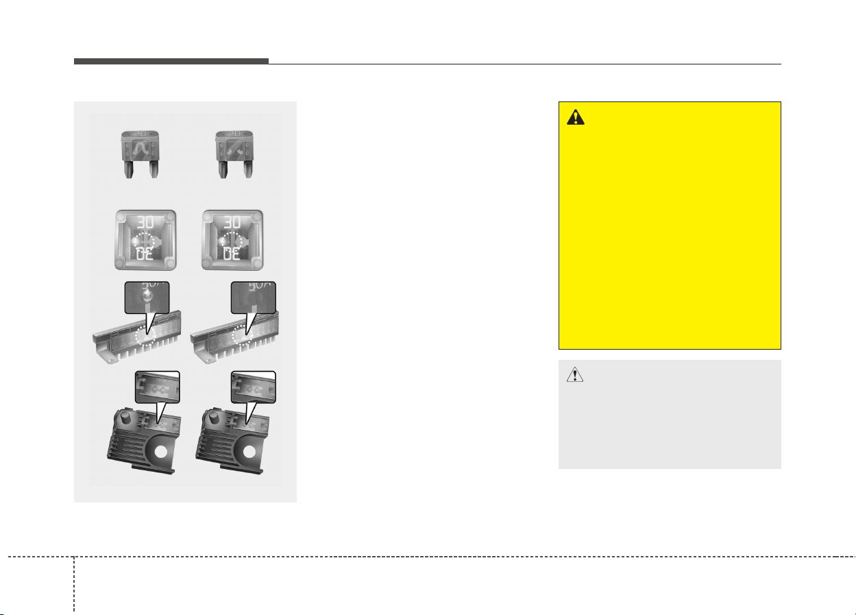
628
Maintenance
FUSES
❈ Left side : Normal
Right side : Blown
A vehicle’s electrical system is pro-
tected from electrical overload dam-
age by fuses.
This vehicle has 2 (or 3) fuse panels,
one located in the driver’s side panel
bolster, the others in the engine com-
partment near the battery.
If any of your vehicle’s lights, acces-
sories, or controls do not work, check
the appropriate circuit fuse. If a fuse
has blown, the element inside the
fuse will melt.
If the electrical system does not
work, first check the driver’s side
fuse panel.
Before replacing a blown fuse, dis-
connect the negative battery cable.
Always replace a blown fuse with
one of the same rating.
If the replacement fuse blows, this indi-
cates an electrical problem. Avoid
using the system involved and immedi-
ately consult an authorized Kia dealer.
Three kinds of fuses are used: blade
type for lower amperage rating, car-
tridge type, and multi fuse for higher
amperage ratings.
✽✽
NOTICE
The actual fuse/relay panel label
may differ from equipped items.
WARNING - Fuse
replacement
• Never replace a fuse with any-
thing but another fuse of the
same rating.
• A higher capacity fuse could
cause damage and possibly a
fire.
• Never install a wire or aluminum
foil instead of the proper fuse
even as a temporary repair. It
may cause extensive wiring
damage and a possible fire.
• Do not arbitrarily modify or add-
on electric wiring of the vehicle.
CAUTION
Do not use a screwdriver or any
other metal object to remove
fuses because it may cause a
short circuit and damage the
system.
OJF075021
■ Blade type
■ Cartridge type
■ Multi fuse
■ BFT

863
Maintenance
Inner panel fuse replacement
1. Turn the ignition switch and all
other switches off.
2. Open the fuse panel cover.
If the switch is located in the “OFF”,
caution will be displayed in the cluster.
ODE076017
CAUTION
• When replacing a blown fuse
or relay with a new one, make
sure the new fuse or relay fits
tightly into the clips. The
incomplete fastening fuse or
relay may cause the vehicle
wiring and electric systems
damage and a possible fire.
• Do not remove fuses, relays
and terminals fastened with
bolts or nuts.The fuses, relays
and terminals may be fas-
tened incompletely, and it may
cause a possible fire. If fuses,
relays and terminals fastened
with bolts or nuts are blown,
we recommend that you con-
sult an authorized Kia dealer.
• Do not input any other objects
except fuses or relays into
fuse/relay terminals such as a
driver or wiring. It may cause
contact failure and system
malfunction.
(Continued)
(Continued)
• Do not plug in screwdrivers or
aftermarket wiring into the ter-
minal originally designed for
fuse and relays only. The elec-
trical system and wiring of the
vehicle interior may be dam-
aged or burned due to contact
failure.
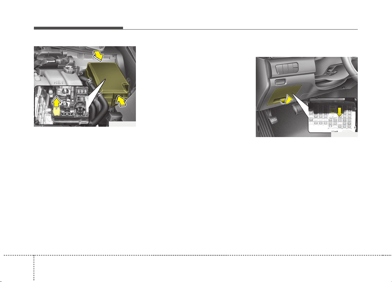
648
Maintenance
3. Pull the suspected fuse straight
out. Use the removal tool provided
in the main fuse box in the engine
compartment.
4. Check the removed fuse; replace it
if it is blown.
Spare fuses are provided in the
instrument panel fuse panel (or in
the engine compartment fuse panel).
5. Push in a new fuse of the same
rating, and make sure it fits tightly
in the clips.
If it fits loosely, we recommend that
you consult an authorized Kia dealer.
If you do not have a spare, use a
fuse of the same rating from a circuit
you may not need for operating the
vehicle, such as the cigarette lighter
fuse.
If the headlights or taillights, stop-
lights, courtesy lamp, day time run-
ning lights (D.R.L) do not work and
the fuses are OK, check the fuse
panel in the engine compartment. If a
fuse is blown, it must be replaced.
Fuse switch
Always, put the fuse switch at the ON
position.
If you move the switch to the OFF
position, some items such as audio
and digital clock must be reset and
transmitter (or smart key) may not
work properly.
If the fuse switch is in OFF, a warning
sign will illuminate on the dashboard.
ODE076020
ODE076018
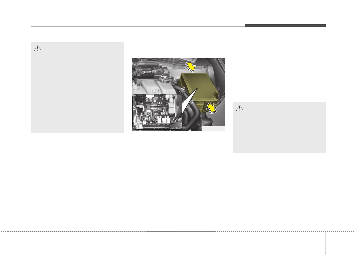
865
Maintenance
Engine compartment fuse
replacement
1. Turn the ignition switch and all
other switches off.
2. Remove the fuse panel cover by
pressing the tab and pulling the
cover up. When the blade type
fuse is disconnected, remove it by
using the clip designed for chang-
ing fuses located in the engine
room fuse box. Upon removal,
securely insert reserve fuse of
equal quantity.
3. Check the removed fuse; replace it
if it is blown. To remove or insert
the fuse, use the fuse puller in the
engine compartment fuse panel.
4. Push in a new fuse of the same
rating, and make sure it fits tightly
in the clips. If it fits loosely, we rec-
ommend that you consult an
authorized Kia dealer.
CAUTION
• Put all switches in ON when
driving.
• If the vehicle remains idle for
over 1 month, put all switches
in OFF to prevent the batteries
from being discharged.
• Excluding long-term parking
for over 1 month, the contact
points of switches may wear
out upon extensive use.
Please refrain from excessive
use of switches.
CAUTION
After checking the fuse panel in
the engine compartment, secure-
ly install the fuse panel. If not,
cover through the audible click-
ing sound. Electrical failures may
occur from water contact.
ODE076021
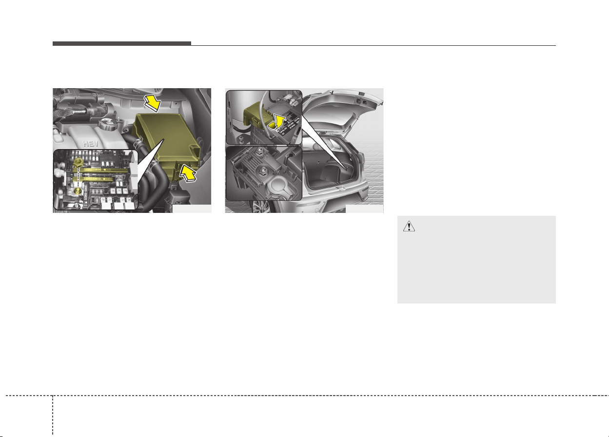
668
Maintenance
Multi fuse
If the multi fuse is blown, it must be
removed as follows:
1. Disconnect the negative battery
cable.
2. Remove the nuts shown in the pic-
ture above.
3. Replace the fuse with a new one
of the same rating.
4. Reinstall in the reverse order of
removal.
✽✽
NOTICE
If the multi fuse is blown, we recom-
mend that you consult an authorized
Kia dealer.
Main fuse
If the main fuse is blown, it must be
removed as follows:
1. Turn off the engine.
2. Disconnect the negative battery
cable.
3. Remove the nuts shown in the pic-
ture above.
4. Replace the fuse with a new one
of the same rating.
5. Reinstall in the reverse order of
removal
✽✽
NOTICE
The electronic system may not func-
tion correctly even when the engine
room and internal fuse box's individ-
ual fuses are not disconnected. In
such case the cause of the problem
may be disconnection of the main fuse
(BFT type), which is located inside
the positive battery terminal (+) cap.
Since the main fuse is designed more
intricately than other parts, please
visit the nearest Kia dealer and serv-
ice center.
ODE076022
CAUTION
Visually inspect the battery cap
for secure closing. If the battery
cap is not securely latched, the
electrical system may be dam-
aged to due influx of moisture
into the system.
ODE076023
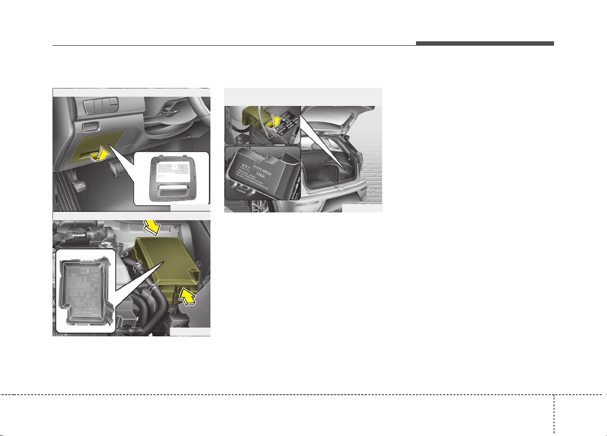
867
Maintenance
Fuse/relay panel description
Inside the fuse/relay panel covers,
you can find the fuse/relay label
describing fuse/relay name and
capacity.
✽✽
NOTICE
Not all fuse panel descriptions in
this manual may be applicable to
your vehicle. It is accurate at the
time of printing. When you inspect
the fuse panel in your vehicle, refer
to the fuse panel label.
ODE076024
■ Driver’s side fuse panel
ODE076027
■ Engine compartment fuse panel
ODE076028
■ Engine compartment fuse panel
(Battery terminal cover)
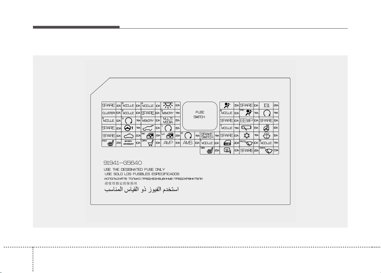
688
Maintenance
Driver’s side fuse panel
ODE076025L

869
Maintenance
Fuse Name Symbol Fuse rating Circuit Protected
MODULE 5
MODULE
5
10A
Crash Pad Switch, Electro Chromic Mirror, Audio / Video &Navigation Head Unit, Audio,
Shift Lever Indicator, VESS Unit, Air Conditioner Control Module, Head Lamp Leveling
Device Actuator LH/RH, Driver IMS Module, Front Seat Warmer Control Module, Rear Seat
Warmer Control Module, Auto Head Lamp Leveling Device Module
MODULE 4
MODULE
4
10A
Lane Departure Warning Control Module, Crash Pad Switch, AEB Module, Blind Spot
Detection Radar Left Handle side/Right Handle side
INTERIOR
LAMP
10A
Luggage Lamp, Ignition Key ILL. & Door Warning Switch, Front Vanity Lamp LH/RH, Room
Lamp, Overhead Console Lamp
A/BAG 15A SRS (Supplemental Restraint System) Control Module
IG 1
IG1
25A Printed Circuit Board Block (Fuse - F35, F36, F37, F38)
CLUSTER
CLUSTER
10A Instrument Cluster
MODULE 3
MODULE
3
10A
BCM (Body Control Module), Dual clutch transmission Shift Lever, Driver/Passenger Door
Module, Stop Lamp Switch, Instrument Cluster, MDPS (Motor Driven Power Steering) Unit
MEMORY 2
MEMORY
2
7.5A Active Air Flap Unit
MODULE 8
MODULE
8
10A
Electric Water Pump (Engine), Active Air Flap Unit, VPD Sensor,
E/R Junction Block (RLY. 4), BMS Control Module
A/BAG IND
IND
7.5A Air Conditioner Control Module, Instrument Cluster
START 7.5A
[Without Smart Key & Without Immobilizer] Burglaralarm Relay
[With Smart Key / With Immobilizer] Inhibitor Switch
Instrument panel (Driver’s side fuse panel)

708
Maintenance
Fuse Name Symbol Fuse rating Circuit Protected
MODULE 2
MODULE
2
10A
Engine Room Junction Block (Relay. 14), Wireless Charger, BCM (Body Control Module),
AMP (Amplifier), Smart Key Control Module, USB Charger, Audio, Audio / Video &
Navigation Head Unit, Driver Power Outside Mirror
PDM 3
3
7.5A
[Without Smart Key] Immobilizer Module
[With Smart Key] Smart Key Control Module
MEMORY 1
MEMORY
1
10A
Instrument Cluster, Wireless Charger, Air Conditioner Control Module, Auto Light & Photo Sensor,
Rain Sensor, BCM (Body Control Module), ICM Relay Box (Outside Mirror Folding/Unfolding
Relay), Driver Integrated memory system Module, Driver/Passenger Door Module
MULTI MEDIA
MULTI
MEDIA
15A Audio, Audio / Video & Navigation Head Unit
EEWP
EEWP
10A Electric Water Pump (HEV)
MDPS
1
7.5A MDPS (Motor Driven Power Steering) Unit
TAIL GATE 10A Tail Gate Relay, ICM Relay Box (Fuel Lid Relay), Fuel Filler Switch
PDM 1
1
15A Smart Key Control Module
MODULE 7
MODULE
7
7.5A
AC Inverter (220V), AC Inverter Module, Rear Seat Warmer Control Module, Front Seat
Warmer Control Module/ Front Air Ventilation Seat Control Module
WIPER (REAR) 15A Engine Room Junction Block (Relay.5)
HEATED
STEERING
15A BCM (Body Control Module)
SUNROOF 20A Sunroof Motor

871
Maintenance
Fuse Name Symbol Fuse rating Circuit Protected
P/WINDOW RH
RH
25A Power Window Right Handle side Relay, Driver/Passenger Safety Power Window Module
P/WINDOW LH
LH
25A Power Window Left Handle side Relay, Driver/Passenger Safety Power Window Module
PDM 2
2
7.5A
[Without Smart Key] Immobilizer Module
[With Smart Key] Smart Key Control Module, Start/Stop Button Switch
BRAKE SWITCH
BRAKE
SWITCH
7.5A Stop Lamp Switch
A/CON 7.5A
Air Conditioner Control Module, Ionizer, Engine Room Junction Block (Relay.1/2/12),
Electronic Air Conditioner Compressor
WASHER 15A Multifunction Switch
S/HEATER (FRT)
FRT
25A Front Seat Warmer Control Module, Front Air Ventilation Seat Control Module
BATTERY
MANAGEMENT
BATTERY
MANAGEMENT
10A BMS Control Module
P/SEAT (DRV)
DRV
30A
[Without Integrated memory system] Driver Seat Manual Switch
[With Integrated memory system] Driver Seat Manual Switch, Driver Integrated memory
system Module
AMP
AMP
30A AMP (Amplifier)
AMS
AMS
10A Battery Sensor
MODULE 1
MODULE
1
10A
Data Link Connector, Hazard Switch/Key Interlock, AEB Module, Driver Door Module,
Passenger Door Module, Driver Smart Key Outside Handle, Passenger Smart Key Outside
Handle
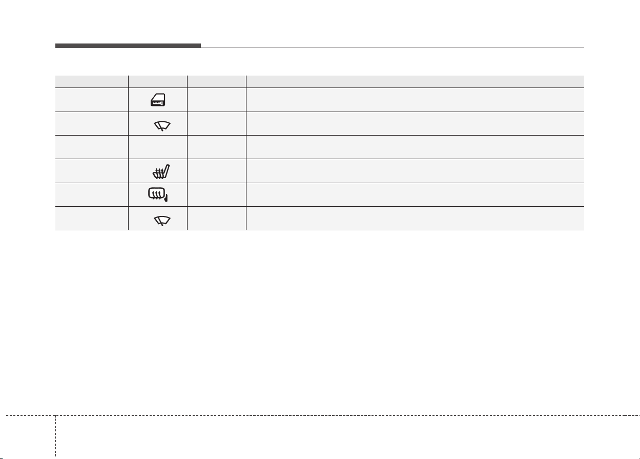
728
Maintenance
Fuse Name Symbol Fuse rating Circuit Protected
DOOR LOCK 20A Door Lock/Unlock Relay, ICM Relay Box (Dead Lock Relay)
WIPER2 (FRT)
FRT2
10A BCM (Body Control Module), ECM (Engine Control Module)
MODULE 6
MODULE
6
7.5A BCM (Body Control Module), Smart Key Control Module
S/HEATER
(REAR)
RR
25A Rear Seat Warmer Control Module
HEATED
MIRROR
10A Air Conditioner Control Module, Driver/Passenger Power Outside Mirror
WIPER1 (FRT)
FRT1
30A Wiper Motor, Printed Circuit Board Block (Front Wiper (Low) Relay
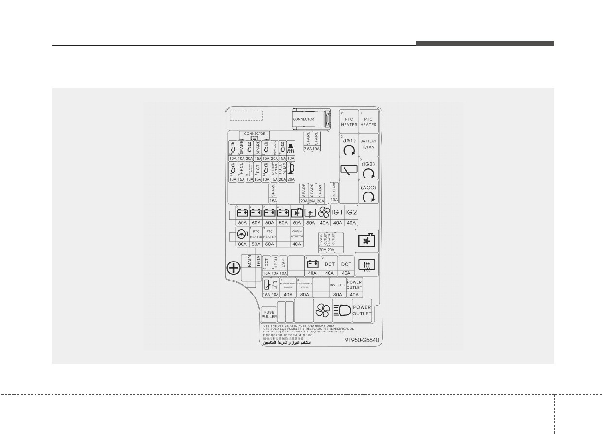
873
Maintenance
Engine compartment fuse panel
ODE076026L

748
Maintenance
Engine compartment fuse panel (Battery terminal cover)
OJFH075171
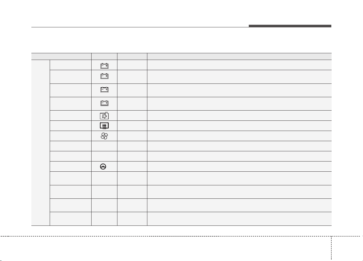
875
Maintenance
Engine room compartment fuse panel
Fuse Name Symbol Fuse rating Circuit Protected
MULTI
FUSE
B+ 5
5
60A Printed Circuit Board Block (Fuse - F40, F41, F42, F49, F50, Engine Control Relay)
B+ 2
2
60A
Integrated Gateway Power control Module (Fuse - F47, ARISU(4CH), IPS(2CH),
IPS(2CH))
B+ 3
3
60A
Integrated Gateway Power control Module (ARISU(4CH), IPS(2CH), IPS(2CH),
IPS(2CH))
B+ 4
4
50A
Integrated Gateway Power control Module (Fuse - F24, F30, F31, F32, F38, F39, F40,
F41, F42)
COOLING FAN 60A Relay.9
REAR HEATED 40A Relay.10
BLOWER 40A Relay.12
IG 1
IG1
40A Ignition Switch/ Engine Room Junction Block (Relay.3/8)
IG 2
IG2
40A Ignition Switch/ Engine Room Junction Block (Relay.6)
MDPS
1
80A MDPS (Motor Driven Power Steering) Unit
PTC
HEATER 1
PTC
HEATER
1
50A Relay
PTC
HEATER 2
PTC
HEATER
2
50A Relay
CLUTCH
ACTUATOR
CLUTCH
ACTUATOR
40A Clutch Actuator (HEV)
MAIN
MAIN
150A Fuse - F26, F27, F28, F29, F31, F32, Low Voltage DC-DC Converter

768
Maintenance
Fuse Name Symbol Fuse rating Circuit Protected
FUSE
POWER
OUTLET 3
POWER
OUTLET
3
20A Power Outlet #2
POWER
OUTLET 2
POWER
OUTLET
2
20A Power Outlet #1
DCT 3
DCT
3
15A TCM (Transmission Control Module)
HPCU 1
HPCU
1
10A HPCU
EWP
EWP
10A Electric Water Pump (Engine)
B+ 1
1
40A
Integrated Gateway Power control Module (Fuse - F25, F33, F34, F43, F44, Leak Current
Autocut Device)
DCT 2
DCT
2
40A TCM (Transmission Control Module)
DCT 1
DCT
1
40A TCM (Transmission Control Module)
REAR WIPER 15A Relay.5
HEAD LAMP
HI
10A Relay.13
AHB 1
ACTIVE HYDRAULIC
BOOSTER
1
40A Integrated Brake Actuation Unit, Multipurpose Check Connector
AHB 2
ACTIVE HYDRAULIC
BOOSTER
2
30A Integrated Brake Actuation Unit

877
Maintenance
Fuse Name Symbol Fuse rating Circuit Protected
FUSE
INVERTER
INVERTER
30A AC Inverter Module
POWER
OUTLET1
POWER
OUTLET
1
40A Relay.14
B/UP LAMP
B/UP LAMP
10A Audio, Electro Chromic Mirror, Back-Up Lamp Left Handle side/Right Handle side
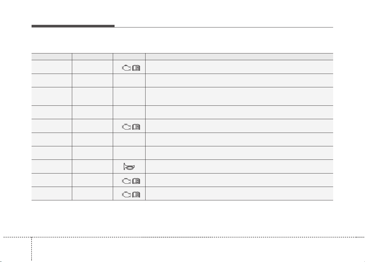
788
Maintenance
Fuse rating Fuse Name Symbol Circuit Protected
10A ECU 3
E3
ECU
15A HPCU 2
HPCU
2
HPCU, Clutch Actuator (HEV)
10A
ACTIVE
HYDRAULIC
BOOTER 3
ACTIVE
HYDRAULIC
BOOTER
Integrated Brake Actuation Unit, Multipurpose Check Connector
15A DCT 4
DCT
4
Dual clutch transmission Shift Lever, TCM (Transmission Control Module), Inhibitor
Switch
10A SENSOR 3
S3
Fuel Pump Relay, Oil Control Valve #1/#2 (Intake/Exhaust), Camshaft Position Sensor
#1/#2 (Intake/Exhaust)
15A BATTERY C/FAN
BATTERY
C/FAN
Engine Room Junction Block (Relay.4)
20A FUEL PUMP
FUEL
PUMP
Fuel Pump Relay
20A HORN Horn Relay
10A SENSOR 2
S2
Purge Control Solenoid Valve, Engine Room Junction Block (RLY.9), Mass Air Flow
Sensor
20A ECU 1
E1
ECU
Circuit (PCB Block)
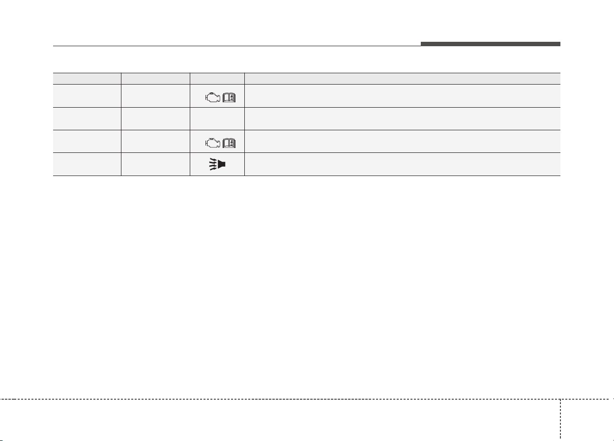
879
Maintenance
Fuse rating Fuse Name Symbol Circuit Protected
15A SENSOR 1
S1
Oxygen Sensor (UP/DOWN)
20A IGN COIL
IGN
COIL
Ignition Coil #1~#4
15A ECU 2
E2
ECM (Engine Control Module)
10A B/ALARM HORN Burglar Alarm Horn Relay
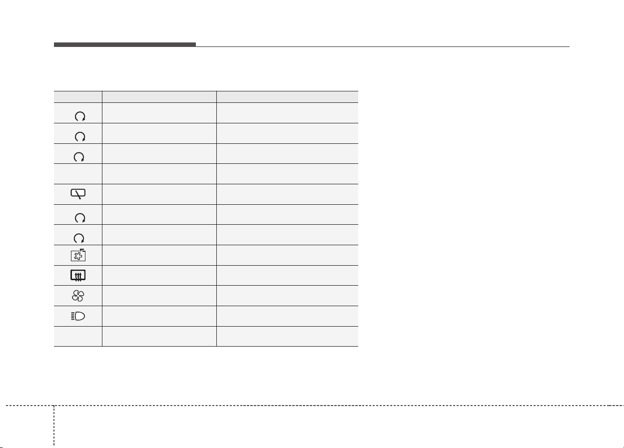
808
Maintenance
Symbol Relay Name Type
2
(IG1)
PTC Heater #2 Relay MINI
3
(IG2)
PTC Heater #1 Relay MICRO
1
(ACC)
Button Start #2 (IG1) Relay MICRO
BATTERY
C/FAN
Battery C/FAN Relay MICRO
Rear Wiper Relay MICRO
3
(IG2)
Button Start #3 (IG2) Relay MICRO
1
(ACC)
Button Start #1 (ACC) Relay MICRO
Cooling Fan Relay MICRO
Rear Defogger Relay MICRO
Blower Relay MICRO
HEAD LAMP HI Relay MICRO
POWER
OUTLET
Power Outlet Relay MICRO
Relay
881
Maintenance
LIGHT BULBS
Bulb replacement precaution
Please prepare bulbs with appropriate
standards in case of emergencies.
Refer to “Bulb Wattage” in chapter 9.
When changing bulbs and sorts, first
turn off the engine at a safe place,
firmly apply the side brake and take
out the battery's negative (-) terminal.
Use only the bulbs of the specified
wattage.
WARNING - Working on
the lights
Prior to working on the light,
firmly apply the parking brake,
ensure that the ignition switch
is turned to the LOCK position
and turn off the lights to avoid
sudden movement of the vehi-
cle and burning your fingers or
receiving an electric shock.
WARNING
Be sure to replace the burned-
out bulb with one of the same
wattage rating. Otherwise, it
may cause extensive wiring
damage and possible fire.
CAUTION
If you don’t have necessary
tools, the correct bulbs and the
expertise, consult an authorized
Kia dealer. In many cases, it is
difficult to replace vehicle light
bulbs because other parts of the
vehicle must be removed before
you can get to the bulb. This is
especially true if you have to
remove the headlight assembly
to get to the bulb(s). Removing/
installing the headlight assem-
bly can result in damage to the
vehicle.
CAUTION
• If unauthentic parts or sub-
standard lights are used when
changing lights, it may lead to
fuse disconnection and mal-
function, and other wiring
damages.
• Do not install extra lamps or
LED to the vehicle. If supple-
mentary lights are installed, it
may lead to lamp malfunction
and flickering of the lights. In
addition, the fuse box and
other writing may be damaged.

828
Maintenance
• Lamp part malfunction due to
net-work failure
The headlamp, taillight, and fog light
may lit up when the head lamp switch
is turned ON, and not light up when
the taillight or for light switch is turned
ON. This may be cause by network
failure or vehicle electrical control
system malfunction. If there is a prob-
lem, we recommend the system be
serviced by an authorized Kia dealer.
• Lamp part malfunction due to elec-
trical control system stabilization
A normally functioning lamp may
flicker momentarily. This momentary
occurrence is due to stabilization
unction of the vehicle's electrical on
control system. If the lamp soon
returns to normal, the vehicle does
not require service.
However, if the lamp goes out after
he momentary flickering, or the flick-
ering continues, we recommend the
system be serviced by an authorized
Kia dealer.
✽✽
NOTICE
• If the light bulb or lamp connector
is removed from an operating lamp
activated by electricity, the fuse
box’s electronic device may scan it
as a malfunction. Therefore, a lamp
malfunction history may be record-
ed in Diagnostic Trouble Code
(DTC) in the fuse box.
• It is normal for an operating lamp
may blink temporarily. Since this
occurrence is due stabilization
function of the vehicle’s electronic
control device, if the lamp lights up
normally after temporary blinking,
there is no problem in the vehicle.
However, if the lamp continues to
blink several times or turn off com-
pletely, there may be an error in the
vehicle’s electronic control device.
So we recommend that you have
the vehicle checked by an author-
ized Kia dealer immediately.
✽
✽
NOTICE
We recommend that the headlight
aiming be adjusted after an accident
or after the headlight assembly is rein-
stalled at an authorized Kia dealer.
✽
✽
NOTICE
After driving in heavy rain or wash-
ing, headlamp and taillamp lenses
could appear frosty. This condition is
caused by the temperature differ-
ence between the lamp inside and
outside. This is similar to the con-
densation on your windows inside
your vehicle during the rain and
doesn’t indicate a problem with your
vehicle. If the water leaks into the
lamp bulb circuitry, have the vehicle
checked by an authorized Kia dealer.
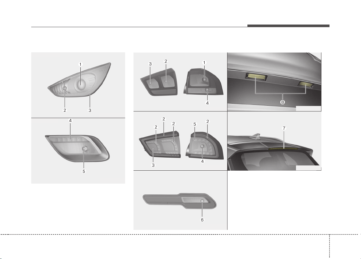
883
Maintenance
Light bulb position (Front)
(1) Headlamp (Low/High)
(2) Front turn signal lamp
(3) Position lamp
(4) Day time running lamp
(5) Front fog lamp
Light bulb position (Rear)
ODE076029
ODE076030
■ Head lamp
■ Fog lamp
■ Rear combination lamp
- Type B
■ Rear combination lamp
- Type A
ODE076032L
■ Back up lamp
ODE076033L
■ High mounted stop lamp
■ License plate lamp
ODE076056L
ODE076055L
ODE076031L
(1) Stop/tail lamp(Bulb type)
(2) Tail lamp(Bulb type)
(3) Rear fog lamp(LED type)
(4) Rear turn signal lamp
(5) Stop/tail lamp(LED type)
(6) Back up lamp
(7) High mounted stop lamp
(8) License plate lamp
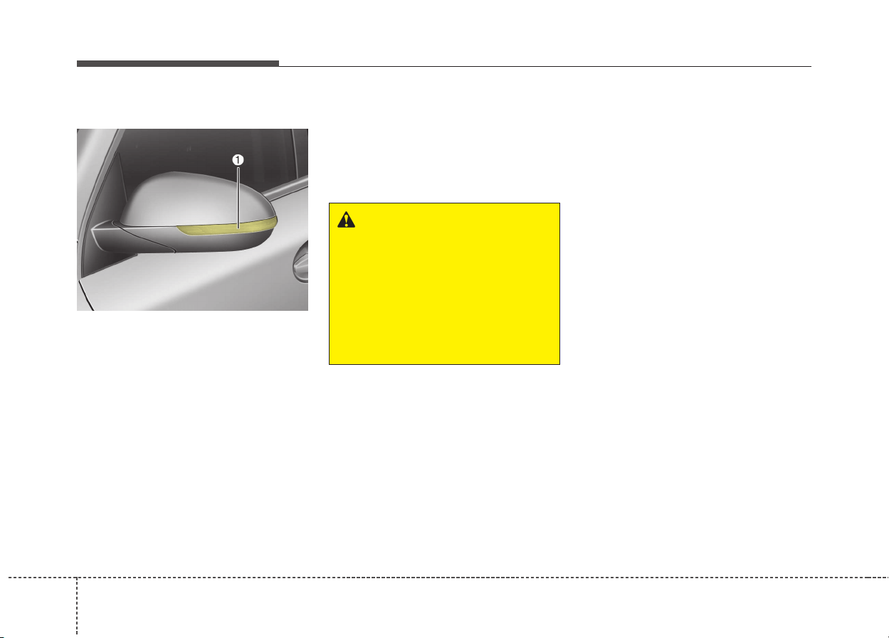
848
Maintenance
Light bulb position (Side)
(1) Side repeater lamp (LED type)
Headlamp (HID type) bulb
replacement
If the light bulb does not operate, we
recommend that you checked an
authorized Kia dealer.
✽✽
NOTICE
HID lamps have superior perform-
ance vs. halogen bulbs. HID lamps
are estimated by the manufacturer to
last twice as long or longer than halo-
gen bulbs depending on their fre-
quency of use. They will probably
require replacement at some point in
the life of the vehicle. Cycling the
headlamps on and off more than typ-
ical use will shorten HID lamps life.
HID lamps do not fail in the same
manner as halogen incandescent
lamps. If a headlamp goes out after a
period of operation but will immedi-
ately relight when the headlamp
switch is cycled it is likely the HID
lamp needs to be replaced. HID
lamping components are more com-
plex than conventional halogen bulbs
thus have higher replacement cost.
ODE076034
WARNING
- HID Headlamp (if equipped)
Do not attempt to replace or
inspect the HID headlamp
(XENON bulb) due to electric
shock danger. If the light bulb
does not operate, we recom-
mend that you checked an
authorized Kia dealer.
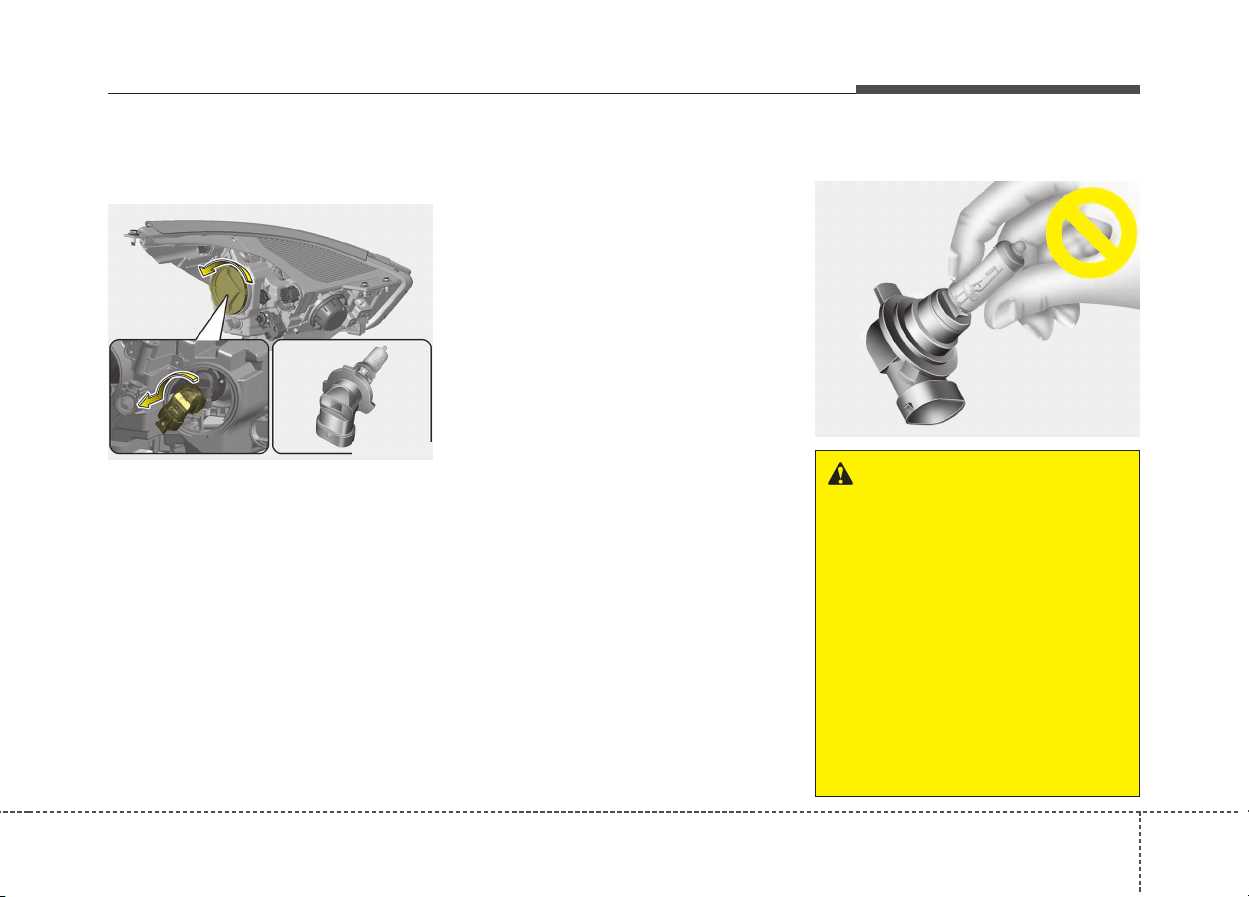
885
Maintenance
Headlamp (High/Low beam)
bulb replacement
1. Open the hood.
2. Remove the headlamp bulb cover
by turning it counterclockwise.
3. Disconnect the headlamp bulb
socket-connector.
4. Remove the bulb-socket from the
headlamp assembly by turning the
bulb-socket counterclockwise until
the tabs on the bulb-socket align
with the slots on the headlamp
assembly.
5. Install a new bulb-socket assem-
bly in the headlamp assembly by
aligning the tabs on the bulb-sock-
et with the slots in the headlamp
assembly. Push the bulb-socket
into the headlamp assembly and
turn the bulb-socket clockwise.
6. Install the headlamp bulb cover by
turning it clockwise.
Headlamp bulb
ODE076035
OQL075058
WARNING - Halogen
bulbs
• Halogen bulbs contain pres-
surized gas that will produce
flying pieces of glass if broken.
• Always handle them carefully,
and avoid scratches and abra-
sions. If the bulbs are lit, avoid
contact with liquids. Never
touch the glass with bare
hands. Residual oil may cause
the bulb to overheat and burst
when lit.
(Continued)
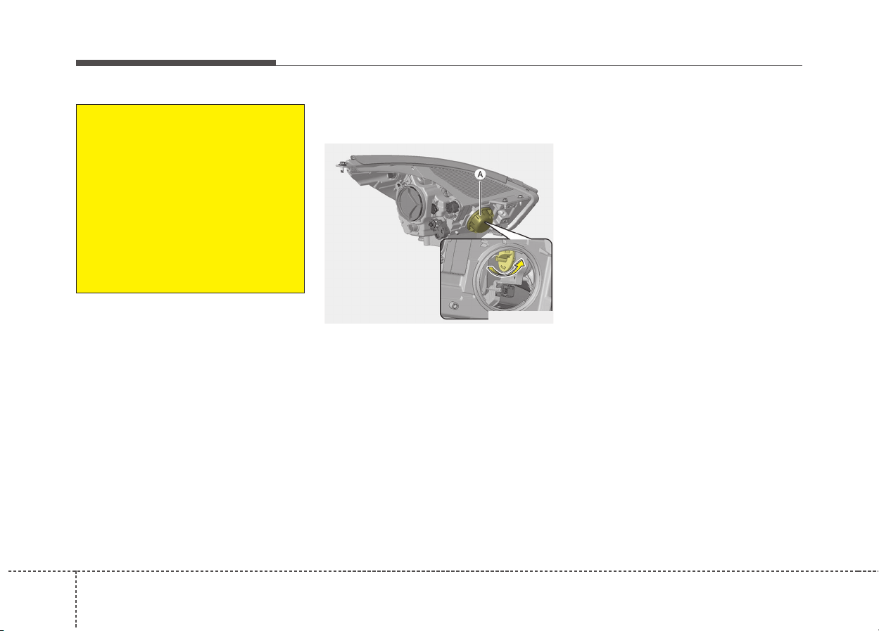
868
Maintenance
Front turn signal lamp bulb
replacement
1. Open the hood.
2. Remove the dust cover (A) from
the headlamp assembly then bulb-
socket by turning the counter-
clockwise until the tabs on the
bulb-socket align with the slots on
the headlamp assembly.
3. Remove the bulb from the bulb-
socket by pressing it in and rotat-
ing it counterclockwise until the
tabs on the bulb align with the
slots in the bulb-socket. Pull the
bulb out of the bulb-socket
4. Insert a new bulb by inserting it
into the bulb-socket and rotating it
until it locks into place.
5. Install the socket in the headlamp
assembly by aligning the tabs on
the bulb-socket with the slots in
the assembly. Push the bulb-sock-
et into the headlamp assembly
and turn the socket clockwise.
(Continued)
A bulb should be operated
only when installed in a head-
light.
• If a bulb becomes damaged or
cracked, replace it immediate-
ly and carefully dispose of it.
• Wear eye protection when
changing a bulb. Allow the
bulb to cool down before han-
dling it.
ODE076058L
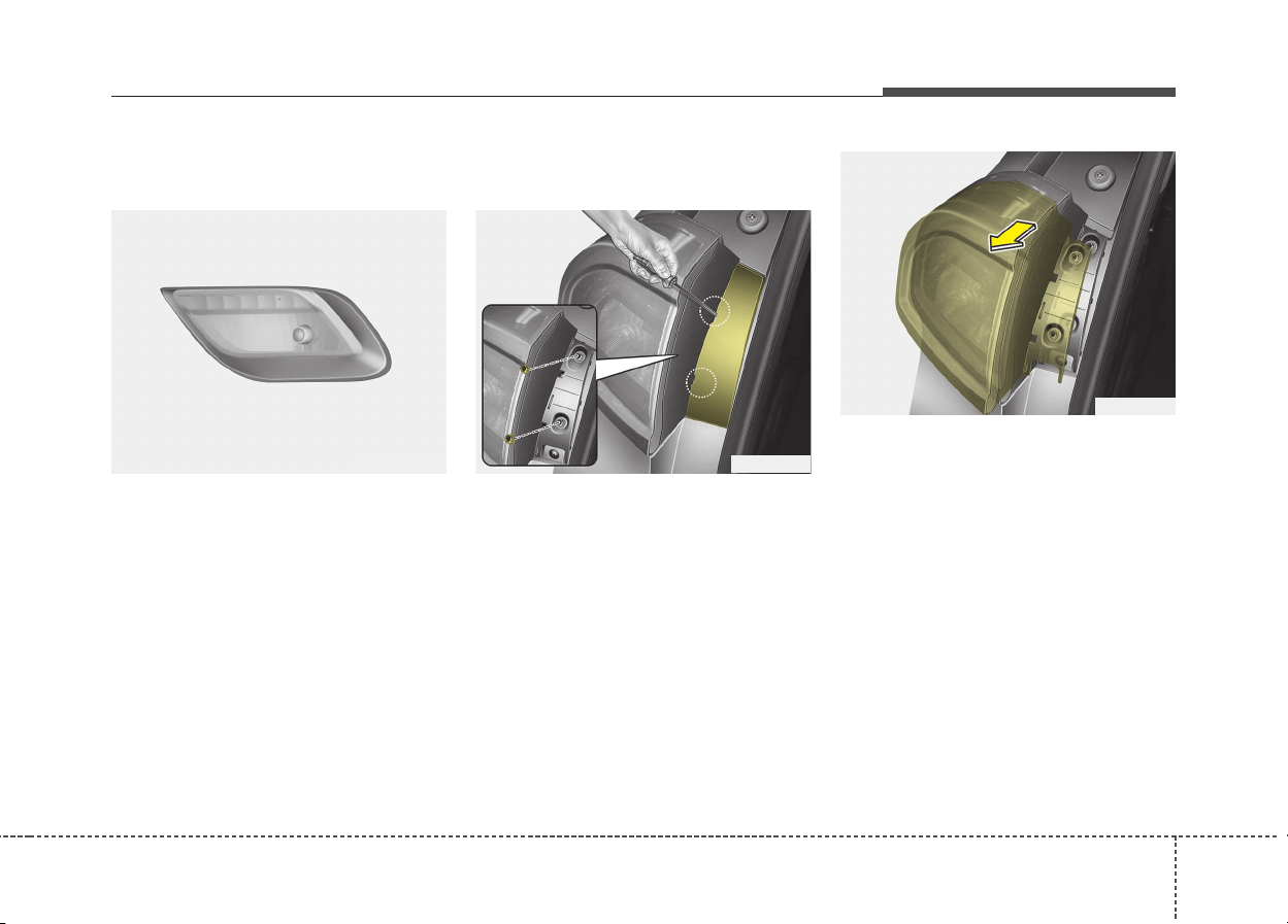
887
Maintenance
Fog lamp/DRL bulb replace-
ment
If the front fog lamp (Bulb) and DRL
bulb(LED) does not operate, we rec-
ommend that you checked an
authorized Kia dealer.
Stop and tail lamp bulb
replacement
1. Open the tailgate.
2. Open the service cover.
3. Loosen the light assembly retain-
ing screws with a cross-tip screw-
driver.
4. Remove the rear combination
lamp assembly from the body of
the vehicle.
5. Disconnect the rear combination
lamp connector.
ODE076036 ODE076037
ODE076038
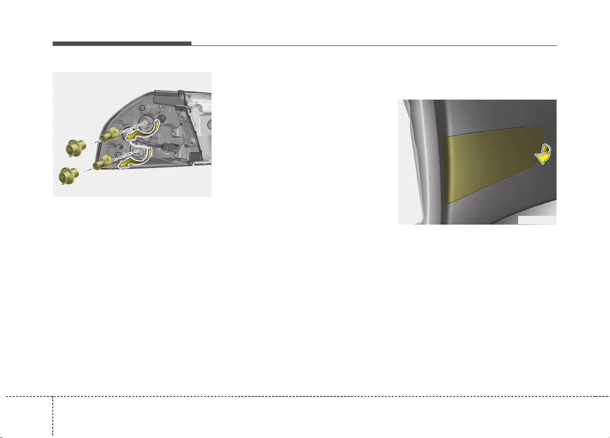
888
Maintenance
6. Remove the socket from the
assembly by turning the socket
counterclockwise until the tabs on
the socket align with the slots on
the assembly.
7. Remove the bulb from the socket by
pressing it in and rotating it counter-
clockwise until the tabs on the bulb
align with the slots in the socket.
Pull the bulb out of the socket.
8. Insert a new bulb by inserting it
into the socket and rotating it until
it locks into place.
9. Install the socket in the assembly
by aligning the tabs on the socket
with the slots in the assembly.
Push the socket into the assembly
and turn the socket clockwise.
10. Install the rear combination lamp
assembly to the body of the vehi-
cle.
11. Install the service cover.
Tail lamp (inside) bulb replace-
ment
1. Open the tailgate.
2. Remove the service cover.
ODE076039
ODE076040
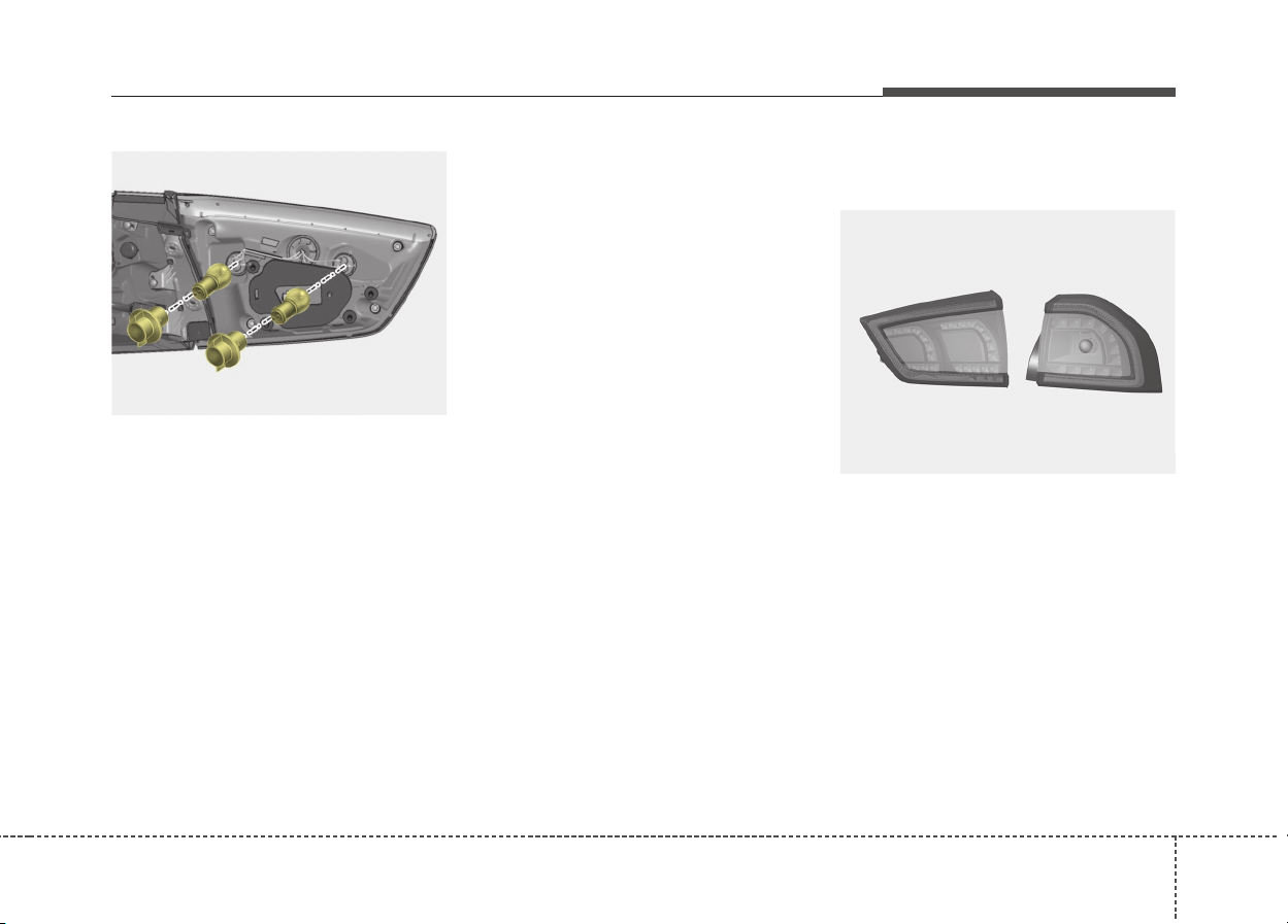
889
Maintenance
3. Remove the socket from the
assembly by turning the socket
counterclockwise until the tabs on
the socket align with the slots on
the assembly.
4. Remove the bulb from the socket
by pressing it in and rotating it
counter-clockwise until the tabs on
the bulb align with the slots in the
socket. Pull the bulb out of the
socket.
5. Insert a new bulb by inserting it
into the socket and rotating it until
it locks into place.
6. Install the socket in the assembly
by aligning the tabs on the socket
with the slots in the assembly.
Push the socket into the assembly
and turn the socket clockwise.
7. Install the service cover by putting
it into the service hole.
Stop and tail lamp (LED type)
bulb replacement
If the stop and tail lamp (LED) does
not operate, we recommend that you
checked an authorized Kia dealer.
ODE076041
ODE076042
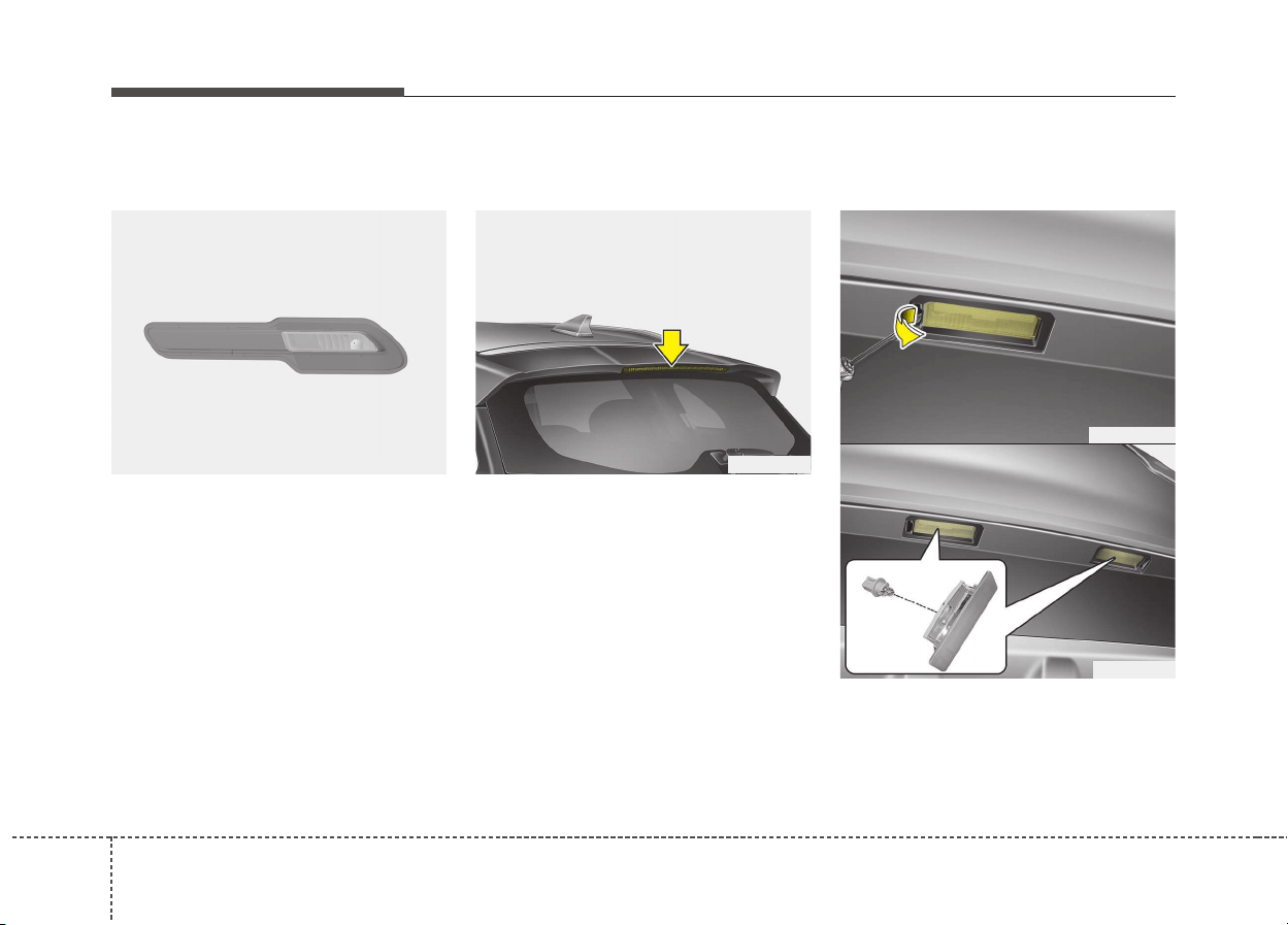
908
Maintenance
Back-up lamp bulb replace-
ment
If the Back-up lamp does not oper-
ate, we recommend that you
checked an authorized Kia dealer.
High mounted stop lamp bulb
replacement
If the high mounted stop lamp (LED)
does not operate, we recommend
that you checked an authorized Kia
dealer.
License plate lamp bulb
replacement
1. Using a flat-blade screwdriver,
gently pry the lens cover from
lamp housing.
ODE076043 ODE076044
ODE076045
ODE076046
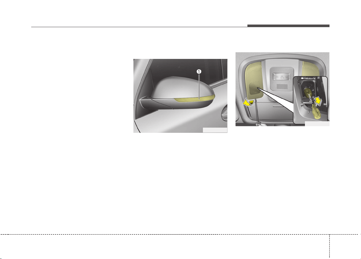
891
Maintenance
2. Remove the socket from the
assembly by turning the socket
counterclockwise until the tabs on
the socket align with the slots on
the assembly.
3. Remove the bulb from bulb-socket
by pulling it out.
4. Insert a new bulb by inserting it
into the bulb-socket.
5. Install the socket in the assembly
by aligning the tabs on the socket
with the slots in the assembly.
Push the socket into the assembly
and turn the socket clockwise.
6. Align the lens cover tabs with the
lamp housing notches and snap
the lens into place.
Side repeater lamp (LED type)
bulb replacement
If the side repeater lamp (LED type)
does not operate, we recommend
that you checked an authorized Kia
dealer.
Map lamp bulb replacement
If the map lamp (bulb and LED type)
does not operate, we recommend
that you checked an authorized Kia
dealer.
ODE076034
ODE076047

928
Maintenance
Vanity mirror lamp bulb
replacement
1. Using a flat-blade screwdriver,
gently pry the lamp assembly from
interior.
2. Remove the bulb by pulling it
straight out.
3. Install a new bulb in the socket.
4. Install the lamp assembly to interior.
Room lamp bulb replacement
ODE076048
WARNING
Prior to working on the Interior
lamps, ensure that the “OFF”
button is depressed to avoid
burning your fingers or receiv-
ing an electric shock.
CAUTION
Be careful not to dirty or dam-
age the lens, lens tab, and plas-
tic housings.
WARNING
Prior to working on the Interior
lamps, ensure that the “OFF”
button is depressed to avoid
burning your fingers or receiv-
ing an electric shock.
ODE076049
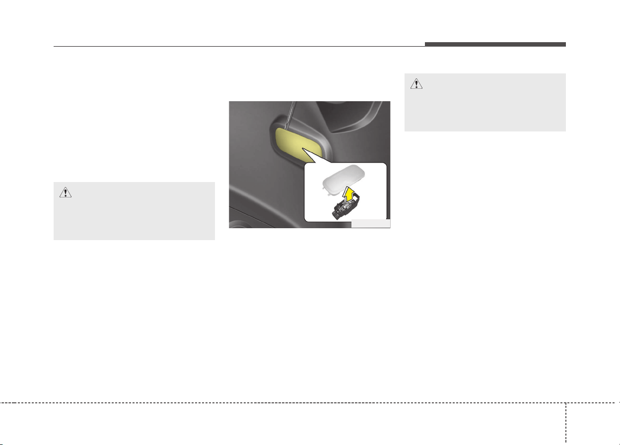
893
Maintenance
1. Using a flat-blade screwdriver,
gently pry the lens cover from
lamp housing.
2. Remove the bulb by pulling it
straight out.
3. Install a new bulb in the socket.
4. Align the lens cover tabs with the
lamp housing notches and snap
the lens into place.
Tailgate room lamp bulb
replacement
1. Using a flat-blade screwdriver,
gently pry the lens cover from
lamp housing.
2. Remove the bulb by pulling it
straight out.
3. Install a new bulb in the socket.
4. Align the lens cover tabs with the
lamp housing notches and snap
the lens into place.
✽✽
NOTICE
If the LED lamp does not operate,
we recommend that you checked on
authorized Kia dealer.
CAUTION
Be careful not to dirty or dam-
age the lens, lens tab, and plas-
tic housings.
ODE076050
CAUTION
Be careful not to dirty or dam-
age the lens, lens tab, and plas-
tic housings.
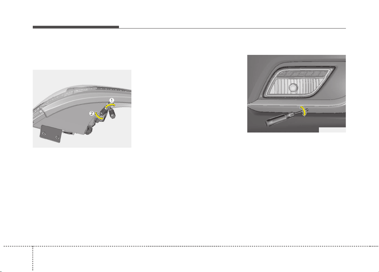
948
Maintenance
Headlamp and front fog lamp
aiming (for Europe)
Headlamp aiming
1. Inflate the tires to the specified
pressure and remove any loads
from the vehicle except the driver,
spare tire, and tools.
2. The vehicle should be placed on a
flat floor.
3. Draw vertical lines (Vertical lines
passing through respective head
lamp centers) and a horizontal line
(Horizontal line passing through
center of head lamps) on the
screen.
4. With the head lamp and battery in
normal condition, aim the head
lamps so the brightest portion falls
on the horizontal and vertical
lines.
5. To aim the low and high beams left
or right, turn the driver (1) clock-
wise or counterclockwise. To aim
the low and high beams up or
down, turn the driver (2) clockwise
or counterclockwise.
Front fog lamp aiming
The front fog lamp can be aimed as
the same manner of the head lamps
aiming.
With the front fog lamps and battery
normal condition, aim the front fog
lamps.
To aim the front fog lamp up or down,
turn the driver clockwise or counter-
clockwise.
ODE076059L
ODE076060L
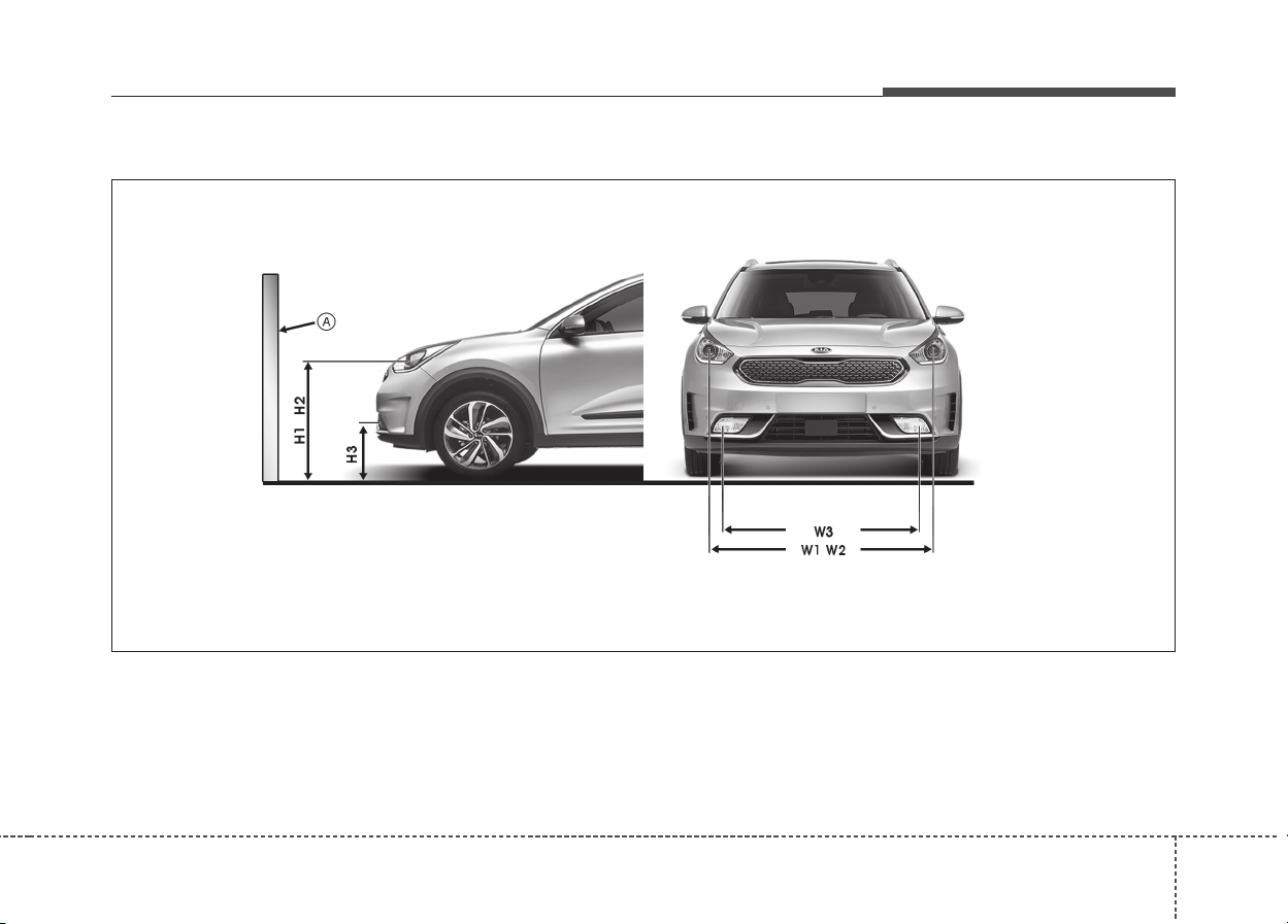
895
Maintenance
Aiming point
ODE076064L
* A : Screen

968
Maintenance
Vehicle condition
Head lamp
Ground Height Distance between lamps
Low beam High beam Low beam
High beam
H1 H2 W1
W2
Without driver 820 (32.2) 820 (32.2) 1,404 (55.3)
1,404 (55.3)
With driver 815 (32.1) 815 (32.1) 1,404 (55.3)
1,404 (55.3)
Vehicle condition
Front Fog lamp (Bulb type)
Ground Height
Distance
between lamps
H3 W3
Without driver 350 (13.8) 1,148 (45.2)
With driver 345 (13.6) 1,148 (45.2)
Unit: mm (in)
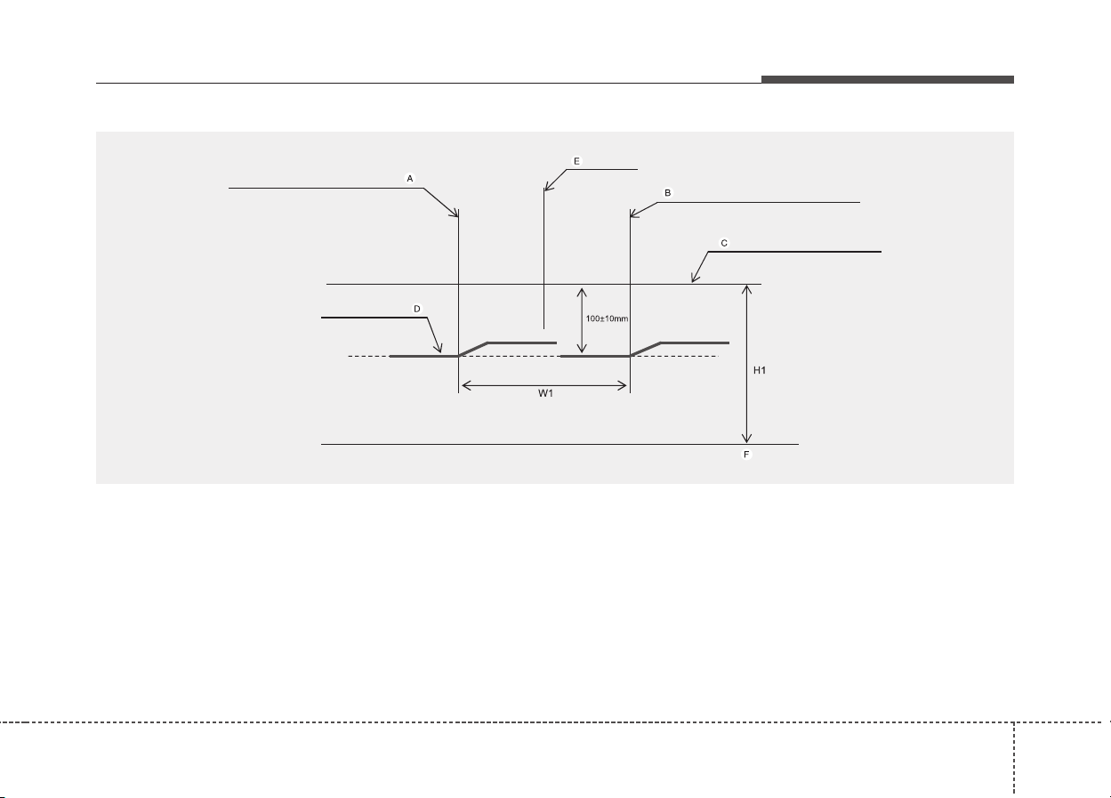
897
Maintenance
Head lamp low beam (LHD)
1. Turn the low beam on without driver aboard.
2. The cut-off line should be projected in the cut-off line shown in the picture.
3. When aiming the low beam, vertical aiming should be adjusted after adjusting the horizontal aiming.
4. If head lamp leveling device is equipped, adjust the head lamp leveling device switch with 0 positions.
A : Vertical line of the left head lamp (low) bulb center
B : Vertical line of the right head lamp (low) bulb center
C : Horizontal line of head lamp (low) bulb center
D : Cut – Off line
E : Car Axis
F : Ground
ODE076061L
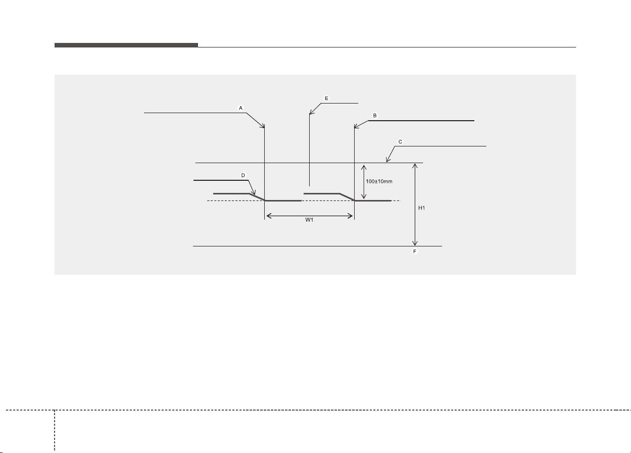
988
Maintenance
Head lamp low beam (RHD)
1. Turn the low beam on without driver aboard.
2. The cut-off line should be projected in the cut-off line shown in the picture.
3. When aiming the low beam, vertical aiming should be adjusted after adjusting the horizontal aiming.
4. If head lamp leveling device is equipped, adjust the head lamp leveling device switch with 0 positions.
A : Vertical line of the left head lamp (low) bulb center
B : Vertical line of the right head lamp (low) bulb center
C : Horizontal line of head lamp (low) bulb center
D : Cut – Off line
E : Car Axis
F : Ground
ODE076062L
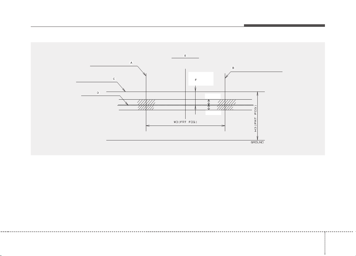
899
Maintenance
+10
-10
ΞΞ
ODE076063L
Front fog light
1. Turn the front fog lamp on without the driver aboard.
2. The cut-off line should be projected in the allowable range (shaded region).
A : Vertical line of the left fog lamp bulb center
B : Vertical line of the right fog lamp bulb center
C : Horizontal line of fog lamp (low) bulb center
D : Cut – Off line
E : Car Axis
F : Upper limit
G : Ground
1008
Maintenance
APPEARANCE CARE
Exterior care
Exterior general caution
It is very important to follow the label
directions when using any chemical
cleaner or polish. Read all warning
and caution statements that appear
on the label.
Finish maintenance
Washing
To help protect your vehicle’s finish
from rust and deterioration, wash it
thoroughly and frequently at least
once a month with lukewarm or cold
water.
If you use your vehicle for off-road
driving, you should wash it after each
off-road trip. Pay special attention to
the removal of any accumulation of
salt, dirt, mud, and other foreign mate-
rials. Make sure the drain holes in the
lower edges of the doors and rocker
panels are kept clear and clean.
Insects, tar, tree sap, bird droppings,
industrial pollution and similar
deposits can damage your vehicle’s
finish if not removed immediately.
Even prompt washing with plain water
may not completely remove all these
deposits. A mild soap, safe for use on
painted surfaces, may be used.
After washing, rinse the vehicle thor-
oughly with lukewarm or cold water.
Do not allow soap to dry on the finish.
WARNING - Wet brakes
After washing the vehicle, test
the brakes while driving slowly
to see if they have been affected
by water. If braking performance
is impaired, dry the brakes by
applying them lightly while main-
taining a slow forward speed.
CAUTION
• Do not use strong soap, chem-
ical detergents or hot water,
and do not wash the vehicle in
direct sunlight or when the
body of the vehicle is warm.
• Be careful when washing the
side windows of your vehicle.
Especially, with high-pressure
water, water may leak through
the windows and wet the inte-
rior.
• To prevent damage to the
plastic parts and lamps, do
not clean with chemical sol-
vents or strong detergents.
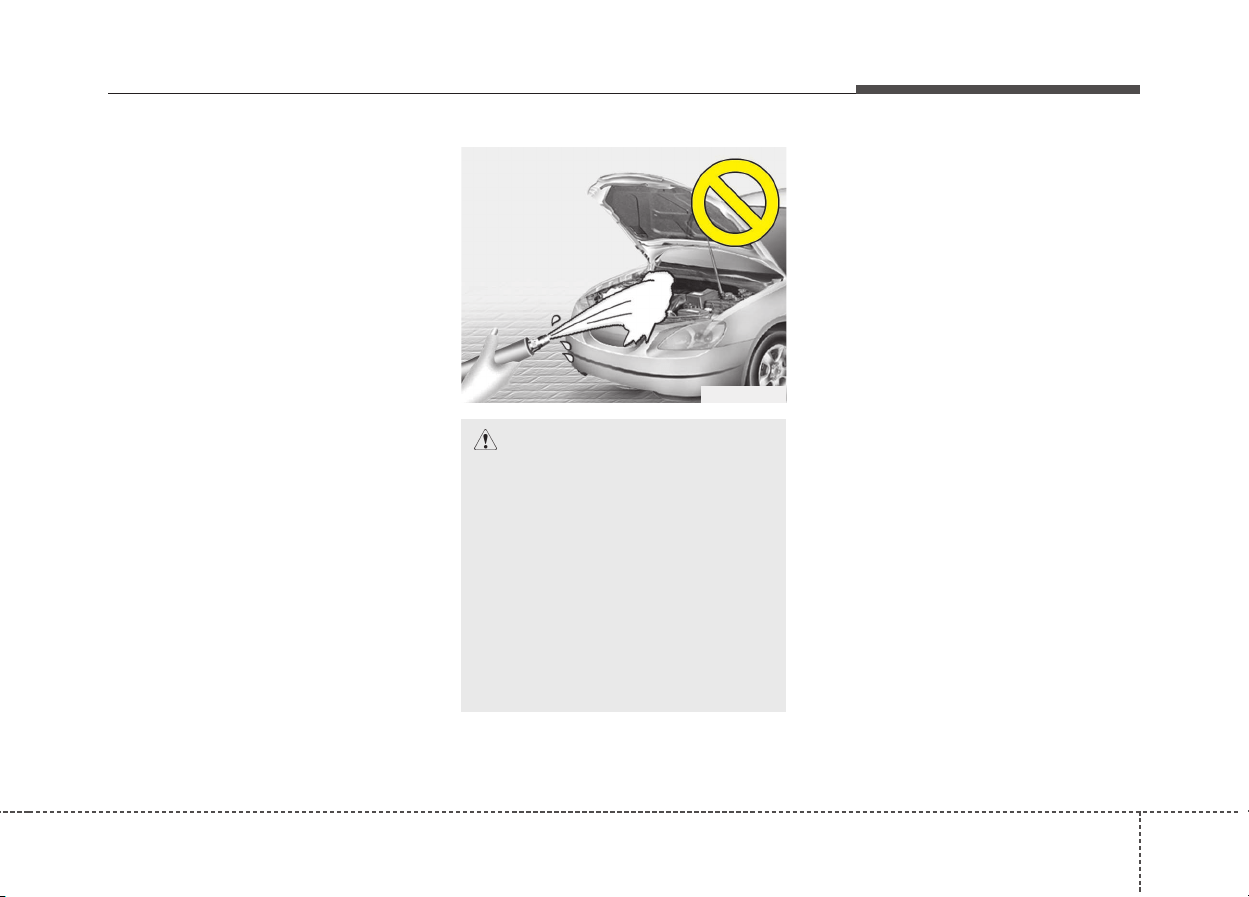
8101
Maintenance
High-pressure washing
• When using high-pressure wash-
ers, make sure to maintain suffi-
cient distance from the vehicle.
Insufficient clearance or excessive
pressure can lead to component
damage or water penetration.
• Do not spray the camera, sensors
or its surrounding area directly with
a high pressure washer. Shock
applied from high pressure water
may cause the device to not oper-
ate normally.
• Do not bring the nozzle tip close to
boots (rubber or plastic covers) or
connectors as they may be dam-
aged if they come into contact with
high pressure water.
Waxing
Wax the vehicle when water will no
longer bead on the paint.
Always wash and dry the vehicle
before waxing. Use a good quality
liquid or paste wax, and follow the
manufacturer’s instructions. Wax all
metal trim to protect it and to main-
tain its luster.
Removing oil, tar, and similar materi-
als with a spot remover will usually
strip the wax from the finish. Be sure to
re-wax these areas even if the rest of
the vehicle does not yet need waxing.
Do not apply wax on embossed
unpainted unit, as it may tarnish the
unit.
CAUTION
• Water washing in the engine
compartment including high
pressure water washing may
cause the failure of electrical
circuits located in the engine
compartment.
• Never allow water or other liq-
uids to come in contact with
electrical/electronic compo-
nents inside the vehicle as
this may damage them.
OJB037800

1028
Maintenance
Finish damage repair
Deep scratches or stone chips in the
painted surface must be repaired
promptly. Exposed metal will quickly
rust and may develop into a major
repair expense.
✽✽
NOTICE
If your vehicle is damaged and
requires any metal repair or
replacement, be sure the body shop
applies anti-corrosion materials to
the parts repaired or replaced.
Bright-metal maintenance
• To remove road tar and insects,
use a tar remover, not a scraper or
other sharp object.
• To protect the surfaces of bright-
metal parts from corrosion, apply a
coating of wax or chrome preser-
vative and rub to a high luster.
• During winter weather or in coastal
areas, cover the bright metal parts
with a heavier coating of wax or
preservative. If necessary, coat the
parts with non-corrosive petroleum
jelly or other protective compound.
CAUTION
• Wiping dust or dirt off the
body with a dry cloth will
scratch the finish.
• Do not use steel wool, abra-
sive cleaners, acid detergents
or strong detergents contain-
ing high alkaline or caustic
agents on chrome-plated or
anodized aluminum parts.
This may result in damage to
the protective coating and
cause discoloration or paint
deterioration.
8103
Maintenance
Underbody maintenance
Corrosive materials used for ice and
snow removal and dust control may
collect on the underbody. If these
materials are not removed, acceler-
ated rusting can occur on underbody
parts such as the fuel lines, frame,
floor pan and exhaust system, even
though they have been treated with
rust protection.
Thoroughly flush the vehicle under-
body and wheel openings with luke-
warm or cold water once a month,
after off-road driving and at the end
of each winter. Pay special attention
to these areas because it is difficult
to see all the mud and dirt. It will do
more harm than good to wet down
the road grime without removing it.
The lower edges of the doors, rocker
panels, and frame members have
drain holes that should not clog with
dirt; trapped water in these areas can
cause rusting.
Aluminum wheel maintenance
The aluminum wheels are coated
with a clear protective finish.
• Do not use any abrasive cleaner,
polishing compound, solvent, or
wire brushes on aluminum wheels.
They may scratch or damage the
finish.
• Clean the wheel when it has cooled.
• Use only a mild soap or neutral
detergent, and rinse thoroughly
with water. Also, be sure to clean
the wheels after driving on salted
roads.This helps prevent corrosion.
• Avoid washing the wheels with
high-speed car wash brushes.
• Do not use any alkaline or acid
detergent. It may damage and cor-
rode the aluminum wheels coated
with a clear protective finish.
WARNING
After washing the vehicle, test
the brakes while driving slowly
to see if they have been affected
by water. If braking performance
is impaired, dry the brakes by
applying them lightly while
maintaining a slow forward
speed.

1048
Maintenance
Corrosion protection
Protecting your vehicle from corrosion
By using the most advanced design
and construction practices to combat
corrosion, we produce vehicles of the
highest quality. However, this is only
part of the job. To achieve the long-
term corrosion resistance your vehi-
cle can deliver, the owner's coopera-
tion and assistance is also required.
Common causes of corrosion
The most common causes of corro-
sion on your vehicle are:
• Road salt, dirt and moisture that is
allowed to accumulate underneath
the vehicle.
• Removal of paint or protective
coatings by stones, gravel, abra-
sion or minor scrapes and dents
which leave unprotected metal
exposed to corrosion.
High-corrosion areas
If you live in an area where your vehi-
cle is regularly exposed to corrosive
materials, corrosion protection is par-
ticularly important. Some of the com-
mon causes of accelerated corrosion
are road salts, dust control chemicals,
ocean air and industrial pollution.
Moisture breeds corrosion
Moisture creates the conditions in
which corrosion is most likely to
occur. For example, corrosion is
accelerated by high humidity, partic-
ularly when temperatures are just
above freezing. In such conditions,
the corrosive material is kept in con-
tact with the vehicle’s surface by
moisture that evaporate slowly.
Mud is particularly corrosive
because it dries slowly and holds
moisture in contact with the vehicle.
Although the mud appears to be dry,
it can still retain moisture and pro-
mote corrosion.
High temperatures can also acceler-
ate corrosion of parts that are not
properly ventilated so the moisture
can be dispersed.
For all these reasons, it is particular-
ly important to keep your vehicle
clean and free of mud or accumula-
tions of other materials. This applies
not only to the visible surfaces but
particularly to the underside of the
vehicle.
To help prevent corrosion
You can help prevent corrosion from
getting started by observing the fol-
lowing:

8105
Maintenance
Keep your vehicle clean
The best way to prevent corrosion is
to keep your vehicle clean and free
of corrosive materials. Attention to
the underside of the vehicle is partic-
ularly important.
• If you live in a high-corrosion area
— where road salts are used, near
the ocean, areas with industrial pol-
lution, acid rain, etc.—, you should
take extra care to prevent corrosion.
In winter, hose off the underside of
your vehicle at least once a month
and be sure to clean the underside
thoroughly when winter is over.
• When cleaning underneath the
vehicle, give particular attention to
the components under the fenders
and other areas that are hidden
from view. Do a thorough job; just
dampening the accumulated mud
rather than washing it away will
accelerate corrosion rather than
prevent it. Water under high pres-
sure and steam are particularly
effective in removing accumulated
mud and corrosive materials.
• When cleaning lower door panels,
rocker panels and frame members,
be sure that drain holes are kept
open so that moisture can escape
and not be trapped inside to accel-
erate corrosion.
Keep your garage dry
Don't park your vehicle in a damp,
poorly ventilated garage. This cre-
ates a favorable environment for cor-
rosion. This is particularly true if you
wash your vehicle in the garage or
drive it into the garage when it is still
wet or covered with snow, ice or
mud. Even a heated garage can con-
tribute to corrosion unless it is well
ventilated so moisture is dispersed.
Keep paint and trim in good con-
dition
Scratches or chips in the finish
should be covered with "touch-up"
paint as soon as possible to reduce
the possibility of corrosion. If bare
metal is showing through, the atten-
tion of a qualified body and paint
shop is recommended.
Bird droppings : Bird droppings are
highly corrosive and may damage
painted surfaces in just a few hours.
Always remove bird droppings as
soon as possible.
Don't neglect the interior
Moisture can collect under the floor
mats and carpeting and cause corro-
sion. Check under the mats periodi-
cally to be sure the carpeting is dry.
Use particular care if you carry fertil-
izers, cleaning materials or chemi-
cals in the vehicle.
These should be carried only in prop-
er containers and any spills or leaks
should be cleaned up, flushed with
clean water and thoroughly dried.
1068
Maintenance
Interior care
Interior general precautions
Prevent chemicals such as perfume,
cosmetic oil, sun cream, hand clean-
er, and air freshener from contacting
the interior parts because they may
cause damage or discoloration. If
they do contact the interior parts,
wipe them off immediately. If neces-
sary, use a vinyle cleaner, see
instructions for correct usage.
Cleaning the upholstery and inte-
rior trim
Vinyl
Remove dust and loose dirt from
vinyl with a whisk broom or vacuum
cleaner. Clean vinyl surfaces with a
vinyl cleaner.
Fabric
Remove dust and loose dirt from fab-
ric with a whisk broom or vacuum
cleaner. Clean with a mild soap solu-
tion recommended for upholstery or
carpets. Remove fresh spots imme-
diately with a fabric spot cleaner. If
fresh spots do not receive immediate
attention, the fabric can be stained
and its color can be affected. Also, its
fire-resistant properties can be
reduced if the material is not proper-
ly maintained.
Cleaning the lap/shoulder belt
webbing
Clean the belt webbing with any mild
soap solution recommended for
cleaning upholstery or carpet. Follow
the instructions provided with the
soap. Do not bleach or re-dye the
webbing because this may weaken it.
Cleaning the interior window glass
If the interior glass surfaces of the
vehicle become fogged (that is, cov-
ered with an oily, greasy or waxy
film), they should be cleaned with a
glass cleaner. Follow the directions
on the glass cleaner container.
CAUTION
Using anything but recommend-
ed cleaners and procedures may
affect the fabric’s appearance
and fire-resistant properties.
CAUTION
Do not scrape or scratch the
inside of the rear window. This
may result in damage of the rear
window defroster grid.
CAUTION
Never allow water or other liq-
uids to come in contact with
electrical/electronic compo-
nents inside the vehicle as this
may damage them.
CAUTION
When cleaning leather products
(steering wheel, seats etc.), use
neutral detergents or low alco-
hol content solutions. If you use
high alcohol content solutions
or acid/alkaline detergents, the
color of the leather may fade or
the surface may get stripped off.

8107
Maintenance
EMISSION CONTROL SYSTEM (IF EQUIPPED)
The emission control system of your
vehicle is covered by a written limited
warranty. Please see the warranty
information contained in the
Warranty & Maintenance book in your
vehicle.
Your vehicle is equipped with an
emission control system to meet all
applicable emission regulations.
There are three emission control
systems, as follows.
(1) Crankcase emission control
system
(2) Evaporative emission control
system
(3) Exhaust emission control system
In order to assure the proper function
of the emission control systems, it is
recommended that you have your
vehicle inspected and maintained by
an authorized Kia dealer in accor-
dance with the maintenance sched-
ule in this manual.
Caution for the Inspection and
Maintenance Test (With Electronic
Stability Control (ESC) system)
• To prevent the vehicle from mis-
firing during dynamometer test-
ing, turn the Electronic Stability
Control (ESC) system off by
pressing the ESC switch.
• After dynamometer testing is
completed, turn the ESC system
back on by pressing the ESC
switch again.
1. Crankcase emission control
system
The positive crankcase ventilation
system is employed to prevent air
pollution caused by blow-by gases
being emitted from the crankcase.
This system supplies fresh filtered air
to the crankcase through the air
intake hose. Inside the crankcase,
the fresh air mixes with blow-by
gases, which then pass through the
PCV valve into the induction system.
2. Evaporative emission con-
trol system
The Evaporative Emission Control
System is designed to prevent fuel
vapors from escaping into the atmos-
phere.
1088
Maintenance
Canister
Fuel vapors generated inside the fuel
tank are absorbed and stored in the
onboard canister. When the engine is
running, the fuel vapors absorbed in
the canister are drawn into the surge
tank through the purge control sole-
noid valve.
Purge Control Solenoid Valve
(PCSV)
The purge control solenoid valve is
controlled by the Engine Control
Module (ECM); when the engine
coolant temperature is low during
idling, the PCSV closes so that evap-
orated fuel is not taken into the
engine. After the engine warms up
during ordinary driving, the PCSV
opens to introduce evaporated fuel to
the engine.
3. Exhaust emission control
system
The Exhaust Emission Control
System is a highly effective system
which controls exhaust emissions
while maintaining good vehicle per-
formance.
Vehicle modifications
This vehicle should not be modified.
Modification of your vehicle could
affect its performance, safety or
durability and may even violate gov-
ernmental safety and emissions reg-
ulations.
In addition, damage or performance
problems resulting from any modifi-
cation may not be covered under
warranty.
• If you use unauthorized electronic
devices, it may cause the vehicle to
operate abnormally, wire damage,
battery discharge and fire. For your
safety, do not use unauthorized
electronic devices.
Engine exhaust gas precautions
(carbon monoxide)
• Carbon monoxide can be present
with other exhaust fumes.
Therefore, if you smell exhaust
fumes of any kind inside your vehi-
cle, have it inspected and repaired
immediately. If you ever suspect
exhaust fumes are coming into
your vehicle, drive it only with all
the windows fully open. Have your
vehicle checked and repaired
immediately.
WARNING - Exhaust
Engine exhaust gases contain
carbon monoxide (CO). Though
colorless and odorless, it is
dangerous and could be lethal if
inhaled. Follow the instructions
on this page to avoid CO poi-
soning.

8109
Maintenance
• Do not operate the engine in con-
fined or closed areas (such as
garages) any more than what is
necessary to move the vehicle in or
out of the area.
• When the vehicle is stopped in an
open area for more than a short
time with the engine running,
adjust the ventilation system (as
needed) to draw outside air into the
vehicle.
• Never sit in a parked or stopped
vehicle for any extended time with
the engine running.
• When the engine stalls or fails to
start, excessive attempts to restart
the engine may cause damage to
the emission control system.
Operating precautions for catalyt-
ic converters (if equipped)
Your vehicle is equipped with a cat-
alytic converter emission control
device.
Therefore, the following precautions
must be observed:
• Make sure to refuel your vehicle
according to the "Fuel require-
ments" suggested in chapter 1.
• Do not operate the vehicle when
there are signs of engine malfunc-
tion, such as misfire or a noticeable
loss of performance.
• Do not misuse or abuse the
engine. Examples of misuse are
coasting with the ignition off and
descending steep grades in gear
with the ignition off.
• Do not operate the engine at high
idle speed for extended periods (5
minutes or more).
• Do not modify or tamper with any
part of the engine or emission con-
trol system. All inspections and
adjustments must be made by an
authorized Kia dealer.
• Avoid driving with an extremely low
fuel level. Running out of fuel could
cause the engine to misfire, dam-
aging the catalytic converter.
WARNING - Fire
• A hot exhaust system can
ignite flammable items under
your vehicle. Do not park the
vehicle over or near flamma-
ble objects, such as grass,
vegetation, paper, leaves, etc.
• The exhaust system and cat-
alytic system are very hot
while the engine is running or
immediately after the engine
is turned off. Keep away from
the exhaust system and cat-
alytic, you may get burned.
Also, do not remove the heat
sink around the exhaust sys-
tem, do not seal the bottom of
the vehicle or do not coat the
vehicle for corrosion control.
It may present a fire risk under
certain conditions.

Failure to observe these precautions
could result in damage to the catalyt-
ic converter and to your vehicle.
Additionally, such actions could void
your warranties.
Maintenance
8110

Specifications & Consumer information
Dimensions . . . . . . . . . . . . . . . . . . . . . . . . . . . . . . . . 9-2
Engine . . . . . . . . . . . . . . . . . . . . . . . . . . . . . . . . . . . . 9-2
Gross vehicle weight . . . . . . . . . . . . . . . . . . . . . . . . 9-3
Luggage volume . . . . . . . . . . . . . . . . . . . . . . . . . . . . 9-3
Air conditioning system . . . . . . . . . . . . . . . . . . . . . . 9-3
Bulb wattage . . . . . . . . . . . . . . . . . . . . . . . . . . . . . . . 9-4
Tires and wheels (For europe) . . . . . . . . . . . . . . . . 9-5
Tires and wheels (Except europe). . . . . . . . . . . . . . 9-6
Recommended lubricants and capacities. . . . . . . . 9-7
• Recommended SAE viscosity number. . . . . . . . . . . . . 9-8
Vehicle identification number (VIN) . . . . . . . . . . . 9-9
Vehicle certification label. . . . . . . . . . . . . . . . . . . . . 9-9
Tire specification and pressure label . . . . . . . . . . 9-10
Engine number . . . . . . . . . . . . . . . . . . . . . . . . . . . . 9-10
Air conditioner compressor label . . . . . . . . . . . . . 9-10
Refrigerant label. . . . . . . . . . . . . . . . . . . . . . . . . . . 9-11
Declaration of conformity . . . . . . . . . . . . . . . . . . . 9-11
9

Specifications & Consumer information
29
DIMENSIONS
Item Size (mm)
Overall length 4,355
Overall width 1,805
Overall height
Without Roof rack 1,535
With Roof rack 1,545
Tread
Front
205/60R16 1,565
225/45R18 1,555
Rear
205/60R16 1,579
225/45R18 1,569
Wheelbase 2,700
ENGINE
Item
Gasoline
1.6 GDI
Displacement
[cc]
1,580
Bore x Stroke
[mm]
72
Firing order
1-3-4-2
No. of cylinders
4 In-line, DOHC
93
Specifications & Consumer information
GROSS VEHICLE WEIGHT
Item
Gasoline
1.6
DCT
GVW
(lbs)
1,930 kg
(4,255)
LUGGAGE VOLUME
Min : Behind rear seat to upper edge of the seat back.
Max : Behind front seat to roof.
Item Volume
VDA
MIN. 427 liter
MAX. 1,425 liter
AIR CONDITIONING SYSTEM
We recommend that you contact an authorized Kia dealer for more details.
Item Weight of volume Classification
Refrigerant
550 ± 10g R-1234yf
550 ± 10g R-134a
Compressor lubricant 130 ± 10g POE

Specifications & Consumer information
49
BULB WATTAGE
* If equipped
Light Bulb Wattage (W) Bulb type
Front
Headlamps (Low/High) 60 HB3 HL+
Headlamps (Low/High) - HID type* 25 D8S
Front turn signal lamps 21 PY21W
Front position lamps LED type LED LED
Daytime running light
Bulb type 21 P21 L/L
LED type * LED LED
Front fog lamps Bulb type 35 H8LL
Side Repeater lamps
Bulb type 5 W5W
LED type * LED LED
Rear
Rear Stop/Tail lamps (outside)
Bulb type
21/5 P21/5W
Rear tail lamps (Inside) 5 W5W
Rear fog lamps (Inside) LED type * LED LED
Rear Stop/Tail lamps (outside)
LED type
LED LED
Rear tail lamps (Inside) LED LED
Rear turn signal lamps 21 P21W
Back-up lamps 16 W16W
High mounted stop lamp LED LED
License plate lamps 5 W5W
Interior
Map lamps 10 WEDGE
Room lamps 10 FESTOON
Vanity mirror lamps 5 FESTOON
Tailgate lamp 10 FESTOON
95
Specifications & Consumer information
TIRES AND WHEELS (FOR EUROPE)
*
1
: Load Index
*
2
: Speed Symbol
CAUTION
When replacing tires, use the same size originally supplied with the vehicle.
Using tires of a different size can damage the related parts or make it work irregularly.
Item Tire size Wheel size
Load
Capacity
Speed
capacity
Inflation pressure [bar(psi, kPa)]
Wheel lug
nut torque
[Kgf·m
(lbf·ft, N·m)]
Normal load Maximum load
LI *
1
Kg SS *
2
Km/h Front Rear Front Rear
Full size tire
205/60 R16 6.5J X 16 92 630 H 210 2.5 (36, 250) 2.5 (36, 250)
11~13
(79~94,
107~127)
225/45 ZR18 7.5J X 18 91 615 W 270 2.5 (36, 250) 2.5 (36, 250)
Compact
Spare tire
T125/80 D16 4T X 16 97 730 M 130 4.2 (60, 420) 4.2 (60, 420)
✽✽
NOTICE
• We recommend that when replacing tires, use the same originally supplied with the vehicles.
If not, that affects driving performance.
• When driving in high altitude grades, it is natural for the atmospheric pressure to decrease.
Therefore, please check the tire pressure and add more air when necessary.
Additionally required tire air pressure per km above sea level: 1.5psi/km
Specifications & Consumer information
69
TIRES AND WHEELS (EXCEPT EUROPE)
*
1
: Load Index
*
2
: Speed Symbol
CAUTION
When replacing tires, use the same size originally supplied with the vehicle.
Using tires of a different size can damage the related parts or make it work irregularly.
Item Tire size Wheel size
Load
Capacity
Speed
capacity
Inflation pressure [bar(psi, kPa)]
Wheel lug
nut torque
[Kgf·m
(lbf·ft, N·m)]
Normal load Maximum load
LI *
1
Kg SS *
2
Km/h Front Rear Front Rear
Full size tire
205/60 R16 6.5J X 16 92 630 H 210 2.5 (36, 250) 2.5 (36, 250)
11~13
(79~94,
107~127)
225/45 R18 7.5J X 18 91 615 V 240 2.5 (36, 250) 2.5 (36, 250)
Compact
Spare tire
T125/80 D16 4T X 16 97 730 M 130 4.2 (60, 420) 4.2 (60, 420)
✽✽
NOTICE
• We recommend that when replacing tires, use the same originally supplied with the vehicles.
If not, that affects driving performance.
• When driving in high altitude grades, it is natural for the atmospheric pressure to decrease.
Therefore, please check the tire pressure and add more air when necessary.
Additionally required tire air pressure per km above sea level: 1.5psi/km

97
Specifications & Consumer information
RECOMMENDED LUBRICANTS AND CAPACITIES
Lubricant Volume Classification
Engine oil *
1
*
2
(drain and refill)
Recommends
3.8 liter (4.01 US qt.) ACEA A5 or above / 5W30*
3
Dual Clutch Transaxle Fluid
1.6 ~ 1.7 liter
(1.69 ~ 1.79 US qt.)
SAE 70W, API GL-4
(Recommended HK SYN DCTF 70W (SK),
SPIRAX S6 GHME 70W DCTF (H.K.SHELL),
GS DCTF HD 70W (GS CALTEX))
Coolant 5.98 liter (6.31 US qt.)
Mixture of antifreeze and water
(Ethylene glycol base coolant for aluminum radiator)
Inverter coolant 2.43 liter (2.56 US qt.)
Mixture of antifreeze and water
(Ethylene glycol base coolant for aluminum radiator)
Brake fluid
402.6 ± 24.4 cc
(0.425 ± 0.025 US qt.)
DOT 3 or DOT 4
Engine clutch actuator fluid
100 ± 20 cc
(0.105 ± 0.021 US qt.)
DOT 3 or DOT 4
Fuel 45 liter (47.5 US qt.) Refer to Fuel requirements in chapter 1.
*
1
: Refer to the recommended SAE viscosity numbers on the next page.
*
2
: Engine oils labeled Energy Conserving Oil are now available. Along with other additional benefits, they contribute to fuel economy by reducing
the amount of fuel necessary to overcome engine friction. Often, these improvements are difficult to measure in everyday driving, but in a year’s
time, they can offer significant cost and energy savings.
*
3
: For better fuel economy, it is recommended to use the engine oil of a viscosity grade SAE 5W-30 (API SL / ILSAC GF-3 / ACEA A3). However,
if the engine oil is not available in your country, select the proper engine oil using the engine oil viscosity chart.
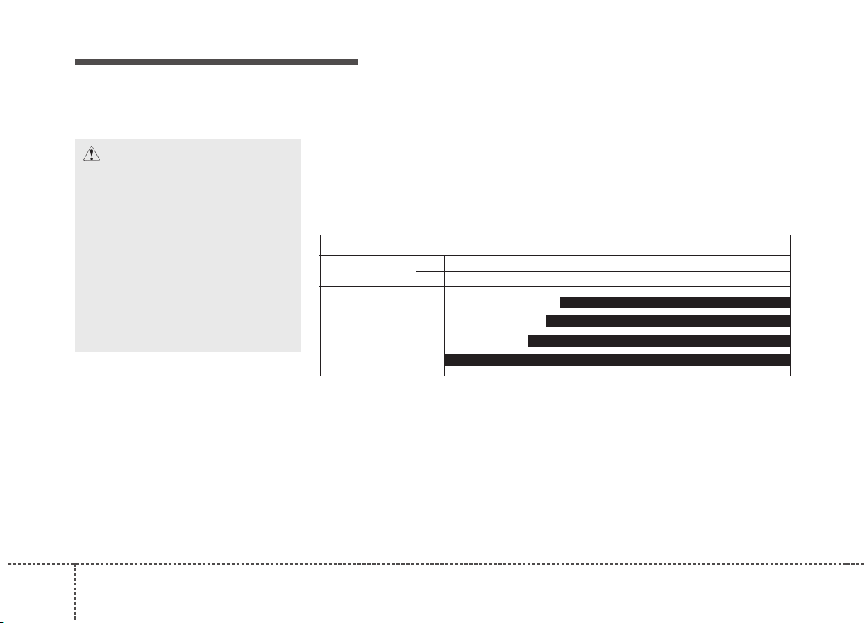
Specifications & Consumer information
89
Recommended SAE viscosity
number
CAUTION
Always be sure to clean the area
around any filler plug, drain
plug, or dipstick before check-
ing or draining any lubricant.
This is especially important in
dusty or sandy areas and when
the vehicle is used on unpaved
roads. Cleaning the plug and
dipstick areas will prevent dirt
and grit from entering the
engine and other mechanisms
that could be damaged.
Engine oil viscosity (thickness) has an effect on fuel economy and cold
weather operating (engine start and engine oil flowability). Lower viscosity
engine oils can provide better fuel economy and cold weather performance,
however, higher viscosity engine oils are required for satisfactory lubrication
in hot weather. Using oils of any viscosity other than those recommended
could result in engine damage. When choosing an oil, consider the range of
temperature your vehicle will be operated in before the next oil change.
Proceed to select the recommended oil viscosity from the chart.
Temperature Range for SAE Viscosity Numbers
Temperature
°C
(°F)
-30 -20 -10 0 10 20 30 40 50
-10 0 20 40 60 80 100 120
ACEA A5 or above /
5W-30
20W-50
10W-30
15W-40
0/5W-30, 5W-40
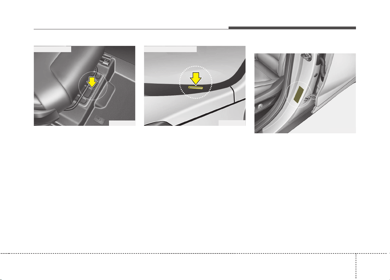
99
Specifications & Consumer information
VEHICLE IDENTIFICATION NUMBER (VIN)
The vehicle identification number
(VIN) is the number used in register-
ing your vehicle and in all legal mat-
ters pertaining to its ownership, etc.
The number is punched on the floor
under the passenger seat. To check
the number, open the cover.
The VIN is also on a plate attached
to the top of the dashboard. The
number on the plate can easily be
seen through the windshield from
outside.
The vehicle certification label
attached on the driver’s (or front pas-
senger’s) side center pillar gives the
vehicle identification number (VIN).
ODE086001
■ Frame number
VEHICLE CERTIFICATION
LABEL
ODE086002
OQLE085005
■ VIN label (if equipped)
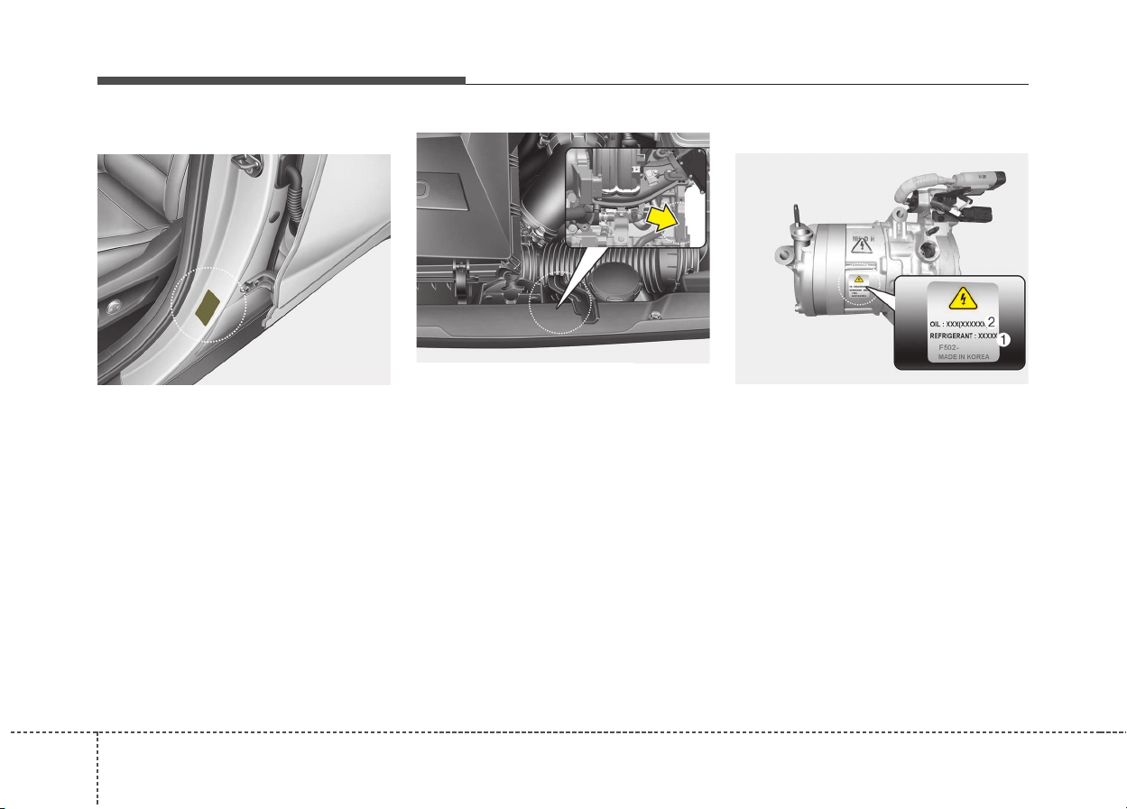
Specifications & Consumer information
109
The tires supplied on your new vehi-
cle are chosen to provide the best
performance for normal driving.
The tire label located on the driver's
side center pillar gives the tire pres-
sures recommended for your vehicle.
The engine number is stamped on the
engine block as shown in the drawing.
A compressor label informs you the
type of compressor your vehicle is
equipped with such as model, suppli-
er part number, production number,
refrigerant (1) and refrigerant oil (2).
TIRE SPECIFICATION AND
PRESSURE LABEL
ENGINE NUMBER
ODE086006L
ODE086003
AIR CONDITIONER
COMPRESSOR LABEL
ODE086005L
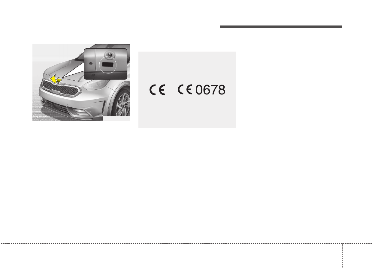
911
Specifications & Consumer information
The refrigerant label is located on
the underside of the hood.
The radio frequency components of
the vehicle comply with requirements
and other relevant provisions of
Directive 1995/5/EC.
Further information including the
manufacturer's declaration of con-
formity is available on Kia web site
as follows;
http://www.kia-hotline.com
REFRIGERANT LABEL
ODE086004L
DECLARATION OF
CONFORMITY
CE0678
■ Example

Appendix
Шофиране през зимата (Bulgarian version) . . . 10-2
Vetrarakstur (Icelandic version). . . . . . . . . . . . . . 10-6
10

Appendix
210
Тежките зимни атмосферни
условия могат да предизвикат по-
голямо износване и други
проблеми. За да сведете до
минимум проблемите, свързани с
шофирането през зимата,
следвайте препоръките по-долу:
Сняг или поледица
За да карате своето превозно
средство при дълбока снежна
покривка може да се наложи да
използвате зимни гуми или да
поставите вериги върху тях. Ако са
необ ходими зимни гуми, трябва
да изберете гуми със същия
размер и вид като тези на
оригиналните гуми.
В противен случай това може да
се отрази неблагоприятно на
безопасността и експлоатацията
на Вашия автомобил. Освен това
карането с висока скорост,
бързото ускорение, внезапното
натискане на спирачки и резките
завои крият сериозни опасности.
При забавяне на скоростта,
използвайте доколкото е
възможно спирачките на дви
гателя. Внезапното натискане на
спирачки на заснежена или
заледена настилка може да
предизвика занасяне. Трябва да
под държате достатъчна
дистанция между автомобила,
който се движи пред Вас, и Вашия
автомобил.
Освен това натискайте спирачката
леко. Следва да се отбележи че
инсталирането на веригите върху
гума та ще позволи прилагането
на по-голяма движеща сила, но
няма да предотврати занасянето
встрани.
✽✽
БЕЛЕЖКА
Веригите за гуми не са позволени
във всички държави. Проверете
норма тивната уредба в своята
страна преди да поставите вериги
за гуми.
ШОФИРАНЕ ПРЕЗ ЗИМАТА (BULGARIAN VERSION)
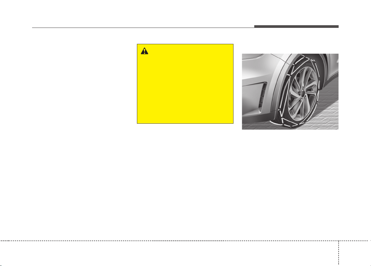
10 3
Appendix
Г уми за сняг
Ако поставите гуми за сняг на своя
авто- мобил се уверете, че това са
радиалнигуми със същия размер и
товарен индекс като тези на
оригиналните гуми. Поставете
гуми за сняг на всичките четири
колела, за да балансирате
експлоатацията на своя
автомобил във всякакви атмос-
ферни условия. Имайте предвид,
че тягата на гумите за сняг върху
суха настилка не може да бъде
толкова голяма колкото тази на
оригиналните гуми. Следва да
карате внимателно, дори когато
пътищата са почистени.
Консултирайте се с доставчика на
гуми за максималната
препоръчителна скорост.
Не монтирайте гуми с шипове,
преди да сте проверили
местните, национални и
общински разпоредби за
възможни огра- ничения в
тяхната употреба.
Вериги за гуми
Тъй като страниците на
радиалните гуми са по-тънки, те
могат да се повредят, ако върху
тях се монтират някои видове
вери- ги за сняг. Ето защо се
препоръчва изпол- зването на
гуми за сняг, а не на вериги за сняг.
Не поставяйте вериги върху
автомо- били, чиито колела са с
алуминиеви джан- ти; веригите за
сняг могат да повредят колелата.
Ако трябва да се използват вериги
за сняг, използвайте телени вериги
с дебелина от поне 12 мм.
ODE056062
ПРЕДУПРЕЖДЕНИЕ
- Размер на гумите за сняг
Г умите за сняг следва да са
равностойни по размер и тип
на тези на стандартните гуми
на автомобила. В противен
случай това може да се отрази
неблагоприятно на
безопасността и
експлоатацията на Вашия
автомобил.

Appendix
410
Повредата на Вашия автомобил
вследствие на непра- вилната
употреба на вериги за сняг не е в
обхвата на гаранцията на
производителя на Вашия
автомобил.
Вериги за гуми трябва да се
инсталират само на предните
гуми.
ВНИМАНИЕ
• Уверете се, че размерът и
видът на веригите са
правилните за Вашите
гуми. Неправилните вериги
за сняг могат да повредят
каросерията и окачването
на автомобила и този тип
повреда може да не е в
обхвата на
производствената гаранция
за Вашия автомобил. Също
така куките за свързване на
веригите за сняг могат да
се повредят от
намиращите се в контакт с
тях автомобилни части,
като това може да доведе до
разхлабването им. Уверете
се, че веригите за сняг са от
клас S според
класификацията на
Дружеството на
автомобилните инженери
(SAE).
(продолжение)
(продолжение)
• Винаги проверявайте дали
вериги- те са били
поставени правилно след
като изминете около 0,5 до
1 км, за да се уверите в
безопасното им
поставяне. Затегнете
веригите или ги
поставете отново, ако са
се разхлабили.
• Ако автомобилът ви е с 18
инчови гуми, не
използвайте вериги за
сняг. Те могат да повредят
вашия автомобил (колело,
окачване и тялото).
10 5
Appendix
Монтиране на вериги
Когато инсталирате веригите,
следвайте инструкциите на
производителя и ги затег- нете
максимално. Карайте бавно с
инста- лирани вериги. Ако чуете,
че веригите са навлезли в контакт
с каросерията или шасито, спрете
и ги затегнете. Ако те все още са в
контакт, намалете скоростта до
преустановяване на контакта.
Свалете веригите веднага, щом
започнете да кара- те по
почистените пътища.
ПРЕДУПРЕЖДЕНИЕ
- Поставяне на вериги
Когато поставите вериги за сняг
, пар- кирайте автомобила на
равно място далеч от пътното
движение. Включете
аварийните светлини и
поставете светлоотразителния
три- ъгълник зад автомобила,
ако разпо- лагате с такъв.
Винаги паркирайте автомобила
в паркинг, дръпнете ръч-ната
спирачка и изключете двигате-
ля преди да поставите веригите
за сняг.
ПРЕДУПРЕЖДЕНИЕ
- Вериги за гуми
• Използването на вериги
може да се отрази
неблагоприятно на работата
на Вашия автомобил.
• Не надвишавайте пределната
ско- рост, препоръчана от
производителя, или
скоростта от 30 км/ч, което е
по- ниско.
• Карайте внимателно и
избягвайте неравности,
дупки, резки завои и други
опасности на пътя, които
могат да накарат
автомобила да подскача.
• Избягвайте резките завои или
изпол- зването на спирачки,
ако колелата са блокирани.
ВНИМАНИЕ
• Веригите с грешен размер
или тези, които са
неправилно инсталирани,
могат да повредят
спирачните накладки,
окачването, каросерията и
колелата.
• Спрете и затегнете
веригите повтор- но
винаги, щом ги чуете да
удрят автомобила.

Appendix
610
Akstur í þungri færð og vetrarveðri
leiðir til aukins slits á ökutækinu og
skapar ýmis vandamál. Hægt er að
draga úr erfiðleikum sem fylgja
vetrarakstri ef farið er að þessum
ráðleggingum:
Akstur í snjó eða hálku
Við akstur í djúpum snjó kann að vera
nauðsynlegt að nota vetrarhjólbarða
eða setja keðjur á hjólbarðana.
Reynist nauðsynlegt að nota
vetrarhjólbarða þarf að velja hjólbarða
af sömu stærð og gerð og venjulegu
hjólbarðarnir. Sé það ekki gert getur
það dregið úr öryggi og skert
aksturseiginleika ökutækisins.
Hraðakstur, skyndileg hröðun,
nauðhemlun og krappar beygjur geta
enn fremur falið í sér mikla hættu.
Þegar dregið er úr hraða er ráðlegt
að beita vélarhemlun sem kostur er.
Við nauðhemlun á snævi þöktum
eða hálum vegum getur ökutækið
hæglega runnið til. Nauðsynlegt er
að halda hæfilegri fjarlægð á milli
þíns ökutækis og ökutækisins fyrir
framan. Alltaf ætti að beita hemlinum
mjúklega. Hafa ber í huga að ef
keðjur eru settar á hjólbarða fæst
aukinn drifkraftur en það hindrar þó
ekki að ökutækið renni til hliðanna.
✽✽
ATHUGIÐ
Notkun snjókeðja er ólögleg í
sumum ríkjum. Kynnið ykkur
gildandi landslög áður en keðjur eru
settar upp.
VETRARAKSTUR (ICELANDIC VERSION)
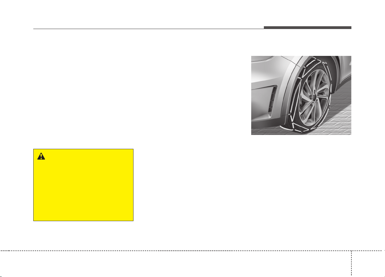
10 7
Appendix
Vetrarhjólbarðar
Ef vetrarhjólbarðar eru settir á
ökutækið þarf að gæta þess að nota
þverofna hjól- barða af sömu stærð og
ásþunga og upprunalegu
hjólbarðarnir. Setjið vetrarhjólbarða á
öll fjögur hjólin til að tryggja örugga
stýringu ökutækisins við öll
veðurskilyrði. Hafið í huga að á auðum
vegi kunna vetrarhjólbarðar að hafa
minna grip en hjólbarðarnir sem fylgdu
ökutækinu. Því þarf að aka af gætni,
jafnvel á auðum vegum. Ráðfærið
ykkur við söluaðila hjólbarðanna um
ráðlagðan hámarkshraða.
Áður en negldir hjólbarðar eru settir
upp er rétt að kynna sér reglugerðir
um notkun slíkra hjólbarða í
viðkomandi landi, fylki eða
sveitarfélagi.
Keðjur á hjólbarða
Hliðar þverofinna hjólbarða eru
þynnri en á öðrum hjólbörðum og
sumar gerðir snjókeðja geta því
valdið skemmdum á þeim. Því er
ráðlegt að nota vetrarhjólbarða
fremur en keðjur, ef þess er kostur.
Setjið aldrei keðjur á hjólbarða
ökutækja sem búin eru álfelgum þar
sem keðjurnar geta valdið
skemmdum á felgunum. Ef
óhjákvæmilegt reynist að nota keðjur
skal nota vírkeðjur sem eru innan við
12 mm á þykkt.
VIÐVÖRUN
- stærðir vetrarhjólbarða
Vetrarhjólbarðar ættu að vera af
sömu stærð og gerð og
hjólbarðarnir sem fylgdu
ökutækinu.
Misræmi á því getur dregið úr
öryggi og skert aksturseiginleika
ökutækisins.
ODE056062
Appendix
810
Ábyrgðartrygging söluaðila
ökutækisins tekur ekki til skemmda
sem orsakast af rangri notkun
snjókeðja. Snjókeðjur skal aðeins
setja á framhjólbarðana.
Uppsetning á keðjum
Þegar keðjur eru settar á skal fylgja
leiðbeiningum framleiðanda og herða
keðjurnar eins mikið og unnt er.
Þegar keðjur hafa verið settar á skal
aka hægt. Ef hljóð heyrist sem bendir
til að keðjurnar séu í snertingu við
yfirbyggingu eða undirvagn er rétt að
nema staðar og herða keðjurnar. Ef
snerting virðist enn eiga sér stað skal
hægja aksturinn þar til hljóðið þagnar.
Takið keðjurnar niður um leið og
komið er á rudda og snjólausa vegi.
VARÚÐ
• Gætið þess að snjókeðjurnar
séu af þeirri stærð og gerð sem
hæfir hjólbörðunum. Notkun
snjókeðja af rangri gerð getur
valdið skemmdum á
yfirbyggingu og fjöðrun
ökutækisins og kann að falla
utan ábyrgðartryggingar
söluaðila ökutækisins. Þá geta
festikrókar keðjanna skemmst
vegan núnings við íhluti
ökutækisins og snjókeðjurnar
losnað af hjólbarðanum. Gætið
þess að snjókeðjurnar séu með
SAE-vottun í S-flokki.
• Eftir um það bil 0,5-1 km
akstur skal ævinlega skoða
keðjurnar aftur til að tryggja að
þær hafi verið settar upp á
réttan og öruggan hátt. Herðið
keðjurnar eða setjið þær aftur
á ef þær hafa losnað.
• Ef hjólbarðar ökutækisins eru
18 tommur skal ekki nota
snjókeðjur. Þær geta valdið
skemmdum á ökutækinu
(hjólum, fjöðrun og
yfirbyggingu).
VIÐVÖRUN
- Uppsetning á keðjum
Þegar snjókeðjur eru settar upp
skal leggja ökutækinu á sléttum
fleti fjarri umferð. Kveikið á
viðvörunarljósum ökutækisins
og setjið þríhyrningslaga
viðvörunarskilti upp fyrir aftan
ökutækið, ef það er tiltækt. Hafið
ökutækið ævinlega í stöðuhemli
og drepið á vélinni áður en
snjókeðjur eru settar upp.
10 9
Appendix
VIÐVÖRUN - Keðjur á
hjólbarða
• Notkun keðja getur skert
aksturs- eiginleika ökutækisins.
• Akið ekki hraðar en 30
km/klst. eða samkvæmt
ráðlögðum hámarkshraða
framleiðanda keðjanna, hvort
sem reynist lægra.
• Akið gætilega og sneiðið hjá
þústum, holum, kröppum
beygjum og öðrum hættum á
veginum, sem gætu valdið
hristingi ökutækisins.
• Forðist krappar beygjur eða
læsta hemlun.
VARÚÐ
• Séu snjókeðjur af rangri stærð
eða rangt upp settar geta þær
valdið skemmdum á hemlalögn,
fjöðrun, yfirbyggingu og hjólum
ökutækisins.
• Hvenær sem hljóð bendir til
þess að keðjurnar sláist við
ökutækið skal stöðva akstur
og herða keðjurnar.

Index
I
I

Index
2
I
AC inverter ..................................................................4-140
Air bag warning label ....................................................3-70
Air bag warning light ....................................................3-51
Air bags..........................................................................3-47
Air bag warning label ................................................3-70
Air bag warning light..................................................3-51
Curtain air bag ............................................................3-63
Driver's and passenger's front air bag ........................3-56
Inflation conditions ....................................................3-66
Non-inflation conditions ............................................3-67
Operation ....................................................................3-48
Side air bag ................................................................3-62
SRS Care ....................................................................3-68
SRS components and functions ..................................3-53
Air cleaner ....................................................................8-38
Filter replacement ......................................................8-38
Air conditioner compressor label ..................................9-10
Air conditioning system lubricants..................................9-3
Air ventilation seat ......................................................4-138
Anti-lock brake system (ABS) ......................................6-27
Appearance care ..........................................................8-100
Exterior care..............................................................8-100
Interior care ..............................................................8-106
Armed stage ..................................................................4-12
Assist Emergency Braking (AEB) ................................6-38
AEB warning message and system control ................6-40
Brake operation ..........................................................6-42
Limitation of the system ............................................6-45
Recognizing pedestrians ............................................6-48
Sensor to detect the distance from the vehicle in front
(front radar) ..............................................................6-42
System malfunction ....................................................6-43
System setting and activation ....................................6-38
AUDIO (With Touch Screen) ........................................5-8
Feature of Your Audio ..................................................5-9
Media Mode................................................................5-18
Phone Mode ................................................................5-31
Radio Mode ................................................................5-16
Setup Mode ................................................................5-50
Voice Recognition Mode ............................................5-40
Audio system ..................................................................5-2
Antenna ........................................................................5-2
Aux, USB port ..............................................................5-4
How vehicle audio works ............................................5-4
Steering wheel audio controls ......................................5-3
Auto defogging system................................................4-129
Auto light ......................................................................4-97
Back-up lamp bulb replacement....................................8-90
Battery............................................................................8-46
Battery capacity label..................................................8-48
Battery recharging ......................................................8-48
A
B

I
3
Index
For best battery service ..............................................8-46
Reset items..................................................................8-49
Battery replacement ......................................................4-10
Battery saver function....................................................4-95
Before driving ..................................................................6-4
Blind Spot Detection System(BSD) ..............................6-81
BSD (Blind Spot Detection) /
LCA (Lane Change Assist) ......................................6-82
RCTA (Rear cross traffic alert ....................................6-84
Bonnet see the hood ......................................................4-26
Brake system..................................................................6-24
Anti-lock brake system (ABS)....................................6-27
Electronic stability control (ESC) ..............................6-30
Emergency Stop Signal (ESS) ....................................6-36
Hill-start assist control (HAC)....................................6-35
Parking brake ............................................................6-25
Power brakes ..............................................................6-24
Vehicle stability management (VSM) ........................6-34
Brakes fluid....................................................................8-33
Checking the brake fluid level....................................8-33
Bulb replacement ..........................................................8-81
Bulb replacement precaution ........................................8-81
Bulb wattage ....................................................................9-4
Button start/stop, see engine start/stop button ................6-9
Camera (Rear view) ......................................................4-94
Capacities (Lubricants)....................................................9-7
Care
Care of seat belts ........................................................3-32
Exterior care..............................................................8-100
Interior care ..............................................................8-106
SRS Care ....................................................................3-68
Tire care ......................................................................8-50
Care of seat belts ..........................................................3-32
Center console storage ................................................4-131
Central door lock switch................................................4-16
Chains - Tire ..................................................................6-96
Checking tire inflation pressure ....................................8-51
Child restraint system ....................................................3-33
Installing a Child Restraint System (CRS) ................3-36
ISOFIX anchorage and top-tether anchorage
(ISOFIX anchorage system) for children ................3-37
Selecting a Child Restraint System (CRS) ................3-34
Child-protector rear door lock ......................................4-18
Clean air ......................................................................4-130
Climate control air filter ................................................8-40
Filter inspection ..........................................................8-40
Climate control system
Automatic climate control system ............................4-117
Automatic heating and air conditioning ..................4-118
Coasting guide ..............................................................4-64
Coat hook ....................................................................4-144
Combined instrument, see instrument cluster ..............4-44
Coolant ..........................................................................8-28
C

Index
4
I
Cooling fluid, see engine coolant ..................................8-28
Crankcase emission control system ............................8-107
Cruise control system ....................................................6-49
Cruise control switch ..................................................6-50
To cancel cruise control ..............................................6-52
To decrease the cruising speed ..................................6-51
To increase cruise control set speed ..........................6-51
To resume cruising speed at more than
approximately 30 km/h ............................................6-53
To set cruise control speed..........................................6-50
To temporarily accelerate with the
cruise control on ........................................................6-52
To turn cruise control off ............................................6-53
Cup holder ..................................................................4-134
Curtain air bag ..............................................................3-63
Dashboard illumination,
see instrument panel illumination ..............................4-45
Dashboard, see instrument cluster ................................4-44
Day/night rearview mirror ............................................4-39
Declaration of Conformity (chapter 5)..........................5-53
CE for EU ..................................................................5-53
NCC for Taiwan ..........................................................5-54
TRA for OMAN ........................................................5-55
Declaration of conformity (chapter 9) ..........................9-11
Defogging (Windshield) ..............................................4-127
Defroster (Rear window) ............................................4-111
Defrosting (Windshield) ..............................................4-127
Dimensions ......................................................................9-2
Disarmed stage ..............................................................4-14
Display illumination,
see instrument panel illumination ..............................4-45
Displays, see instrument cluster ....................................4-44
Distance to empty ..........................................................4-49
Door lock/unlock features ............................................4-17
Door locks......................................................................4-15
Central door lock switch ............................................4-16
Child-protector rear door lock ....................................4-18
Door lock/unlock features ..........................................4-17
From inside the vehicle ..............................................4-15
From outside the vehicle ............................................4-15
Drinks holders, see cup holders ..................................4-134
Driver position memory system ....................................3-12
Driver's and passenger's front air bag............................3-56
Driving at night..............................................................6-93
Driving in flooded areas ................................................6-93
Driving in the rain..........................................................6-93
Driving off-road ............................................................6-93
Dual clutch transmission ..............................................6-15
Manual mode ..............................................................6-20
Shift-lock override ......................................................6-21
Dual clutch transmission shift indicator........................4-50
Dual clutch transmission shift indicator in
sports mode..................................................................4-51
D

I
5
Index
Economical operation ....................................................6-88
Electrochromic mirror (ECM) ......................................4-39
Electronic power steering ..............................................4-36
Electronic stability control (ESC) ................................6-30
Emergency starting ..........................................................7-5
Jump starting ................................................................7-5
Emergency Stop Signal (ESS) ......................................6-36
Emergency tailgate safety release..................................4-20
Emergency while driving ................................................7-3
Emission control system..............................................8-107
Crankcase emission control system ..........................8-107
Evaporative emission control System ......................8-107
Exhaust emission control system..............................8-108
Energy flow....................................................................4-56
Engine ..............................................................................9-2
Engine clutch actuator fluid ..........................................8-34
Checking the engine clutch actuator fluid level ........8-34
Engine compartment........................................................2-6
Engine compartment........................................................8-4
Engine coolant ..............................................................8-28
Changing the coolant ..................................................8-32
Checking the coolant level..........................................8-28
Engine coolant ............................................................8-29
Inverter coolant ..........................................................8-30
Engine number ..............................................................9-10
Engine oil ......................................................................8-26
Changing the engine oil and filter ..............................8-27
Checking the engine oil level ....................................8-26
Engine overheats..............................................................7-8
Engine start/stop button ..................................................6-9
Engine start/stop button position ..................................6-9
Illuminated engine start/stop button ............................6-9
Starting the hybrid system ..........................................6-12
Engine start/stop button illumination ..............................6-9
Engine start/stop button position ....................................6-9
Engine will not start ........................................................7-4
Evaporative emission control System..........................8-107
Exhaust emission control system ................................8-108
Explanation of scheduled maintenance items ..............8-23
Air cleaner filter..........................................................8-24
Air conditioning refrigerant ......................................8-25
Brake discs, pads, calipers and rotors ........................8-25
Brake fluid ..................................................................8-25
Brake hoses and lines..................................................8-25
Coolant (Engine / Inverter) ........................................8-24
Cooling system ..........................................................8-24
Drive shafts and boots ................................................8-25
Dual clutch transmission fluid ....................................8-24
Engine oil and filter ....................................................8-23
Fuel filter (for gasoline)..............................................8-23
Fuel lines, fuel hoses and connections ......................8-23
HSG (Hybrid starter & generator) belt ......................8-23
Parking brake ............................................................8-25
Spark plugs (for gasoline engine) ..............................8-24
E

Index
6
I
Steering gear box,
linkage & boots/lower arm ball joint........................8-25
Suspension mounting bolts ........................................8-25
Vacuum crankcase ventilation hoses ..........................8-24
Vapor hose (for gasoline engine) and
fuel filler cap ............................................................8-23
Exterior care ................................................................8-100
Exterior features ..........................................................4-147
Exterior features
Roof rack ..................................................................4-147
Exterior overview (Front) ................................................2-2
Exterior overview (Rear) ................................................2-3
Flat tire ..........................................................................7-16
Changing tires ............................................................7-18
Jack and tools..............................................................7-16
Removing the spare tire ..............................................7-17
Storing the spare tire ..................................................7-17
Floor mat anchor(s) ....................................................4-144
Fluid
Brake fluid ..................................................................8-33
Engine clutch actuator fluid........................................8-34
Washer fluid ................................................................8-36
Fog lamp/DRL bulb replacement ..................................8-87
Fog light (front) ..........................................................4-100
Fog light (rear) ............................................................4-100
Folding the outside rearview mirror ..............................4-42
Folding the rear seat ......................................................3-13
Front seat adjustment (manual) ......................................3-6
Front seat adjustment (power) ........................................3-7
Front seat belt warning ..................................................3-20
Front turn signal lamp bulb replacement ......................8-86
Fuel filler lid ..................................................................4-28
Fuel Gauge ....................................................................4-48
Fuel requirements ............................................................1-3
Fuses ..............................................................................8-62
Engine compartment fuse replacement ......................8-65
Fuse/relay panel description ......................................8-67
Inner panel fuse replacement ....................................8-63
Gauges ..........................................................................4-46
Distance to empty ......................................................4-49
Fuel Gauge..................................................................4-48
Hybrid Battery SOC (State of Charge) Gauge ..........4-47
Hybrid System Gauge ................................................4-47
Odometer ....................................................................4-50
Outside Temperature Gauge ......................................4-50
Speedometer................................................................4-46
Glove box ....................................................................4-131
Gross vehicle weight........................................................9-3
F
G

I
7
Index
Hazard warning flasher....................................................7-2
Hazardous driving conditions ........................................6-90
Headlamp (HID type) bulb replacement ......................8-84
Headlamp (High/Low beam) bulb replacement ............8-85
Headlamp and front fog lamp aiming (for Europe) ......8-94
Headlight (Headlamp) escort function ..........................4-95
Headlight position..........................................................4-97
Headrest (rear) ..............................................................3-16
Headrest(front) ................................................................3-8
Heated steering wheel....................................................4-37
HEV power train..............................................................1-6
High - beam operation ..................................................4-98
High mounted stop lamp bulb replacement ..................8-90
Highway driving ............................................................6-94
Hill-start assist control (HAC) ......................................6-35
Hood ..............................................................................4-26
Horn ..............................................................................4-38
How to use this manual ..................................................1-2
Hybrid Battery SOC (State of Charge) Gauge..............4-47
Hybrid System Gauge....................................................4-47
Ignition switch illumination ............................................6-6
Ignition switch position ..................................................6-6
Immobilizer system ........................................................4-5
Indicator Lights..............................................................4-80
Inflation conditions(Air bags) ......................................3-66
Inside rearview mirror ..................................................4-39
Instrument cluster ..........................................................4-44
Coasting guide ............................................................4-64
Indicator Lights ..........................................................4-80
Instrument Cluster Control ........................................4-45
LCD Modes ................................................................4-58
LCD window ..............................................................4-52
LCD window Control ................................................4-46
Service Mode ..............................................................4-59
User settings mode......................................................4-61
Warning and Indicator lights ......................................4-72
Warning lights ............................................................4-72
Instrument panel overview ..............................................2-5
Interior care..................................................................8-106
Interior features............................................................4-134
AC inverter................................................................4-140
Air ventilation seat....................................................4-138
Ashtray......................................................................4-134
Cargo security screen ..............................................4-146
Coat hook..................................................................4-144
Cup holder ................................................................4-134
Floor mat anchor(s) ..................................................4-144
Luggage net holder ..................................................4-145
Power outlet ..............................................................4-138
Seat warmer ..............................................................4-136
Sunvisor ....................................................................4-135
I
H

Index
8
I
USB charger..............................................................4-139
Wireless smart phone charging system ....................4-141
Interior lamp AUTO turn off function ........................4-107
Interior light ................................................................4-107
Interior lamp AUTO turn off function ......................4-107
Map lamp ..................................................................4-107
Room lamp................................................................4-108
Tailgate room lamp ..................................................4-109
Vanity mirror lamp....................................................4-109
Interior overview..............................................................2-4
ISO FIX system ............................................................3-37
Jack and tools ................................................................7-16
Jump starting....................................................................7-5
Key operations ................................................................4-4
Key positions ..................................................................6-6
Ignition switch position ................................................6-6
Illuminated ignition switch ..........................................6-6
Starting the hybrid system ............................................6-8
Keys ................................................................................4-4
Immobilizer system ......................................................4-5
Key operations ..............................................................4-4
Record your key number ..............................................4-4
Label
Air bag warning label ................................................3-70
Air conditioner compressor label................................9-10
Refrigerant label ........................................................9-11
Tire sidewall labeling..................................................8-56
Tire specification and pressure label ..........................9-10
Vehicle certification label ............................................9-9
Lane Keeping Assist System (LKAS) ..........................6-73
LKAS function change ..............................................6-80
LKAS malfunction......................................................6-79
LKAS operation..........................................................6-74
Lap belt ..........................................................................3-24
Lap/Shoulder belt ..........................................................3-22
LCD Modes ..................................................................4-58
LCD window..................................................................4-52
Energy flow ................................................................4-56
Over view....................................................................4-52
Trip information (Trip computer) ..............................4-52
License plate lamp bulb replacement ............................8-90
Light bulb position (Front) ............................................8-83
Light bulb position (Rear) ............................................8-83
Light bulb position (Side) ............................................8-84
Light bulbs ....................................................................8-81
Back-up lamp bulb replacement ................................8-90
Bulb replacement precaution ......................................8-81
Fog lamp/DRL bulb replacement ..............................8-87
J
L
K

I
9
Index
Front turn signal lamp bulb replacement....................8-86
Headlamp (HID type) bulb replacement ....................8-84
Headlamp (High/Low beam) bulb replacement..........8-85
Headlamp and front fog lamp aiming (for Europe)....8-94
High mounted stop lamp bulb replacement ..............8-90
License plate lamp bulb replacement ........................8-90
Light bulb position (Front) ........................................8-83
Light bulb position (Rear) ..........................................8-83
Light bulb position (Side) ..........................................8-84
Map lamp bulb replacement ......................................8-91
Room lamp bulb replacement ....................................8-92
Side repeater lamp (LED type) bulb replacement ......8-91
Stop and tail lamp (LED type) bulb replacement ......8-89
Stop and tail lamp bulb replacement ..........................8-87
Tail lamp (inside) bulb replacement ..........................8-88
Tailgate room lamp bulb replacement ........................8-93
Vanity mirror lamp bulb replacement ........................8-92
Lighting..........................................................................4-95
Auto light ....................................................................4-97
Battery saver function ................................................4-95
Front fog light ..........................................................4-100
Headlight (Headlamp) escort function........................4-95
Headlight leveling device ........................................4-101
Headlight position ......................................................4-97
High - beam operation ................................................4-98
Parking light position..................................................4-96
Rear fog light ............................................................4-100
Turn signals ................................................................4-99
Lubricants and capacities ................................................9-7
Luggage box ................................................................4-133
Luggage volume ..............................................................9-3
Maintenance
Engine compartment ....................................................8-4
Explanation of scheduled maintenance items ............8-23
Maintenance services....................................................8-5
Owner maintenance ......................................................8-7
Scheduled maintenance service ....................................8-9
Tire maintenance ........................................................8-56
Maintenance schedule....................................................8-10
Normal Maintenance Schedule
- For Gasoline Engine
[For Europe (Except Russia)] ................................8-10
Maintenance Under Severe Usage Conditions
- For Gasoline Engine
[For Europe (Except Russia)] ................................8-14
Normal Maintenance Schedule
- For Gasoline Engine
[Except Europe (Including Russia)] ......................8-16
Maintenance Under Severe Usage Conditions
- For Gasoline Engine
[Except Europe (Including Russia)] ......................8-21
Scheduled maintenanceservice precaution ..................8-9
Maintenance services ......................................................8-5
M

Index
10
I
Owner maintenance precautions ..................................8-5
Owner’s responsibility ..................................................8-5
Manual mode - Dual clutch transmission......................6-20
Map lamp ....................................................................4-107
Map lamp bulb replacement ..........................................8-91
Mirrors ..........................................................................4-39
Day/night rearview mirror ..........................................4-39
Electrochromic mirror (ECM) ..................................4-39
Folding the outside rearview mirror ..........................4-42
Inside rearview mirror ................................................4-39
Outside rearview mirror..............................................4-40
Remote control............................................................4-41
Non-inflation conditions(Air bags) ..............................3-67
Odometer ......................................................................4-50
Oil (Engine) ..................................................................8-26
Outside rearview mirror ................................................4-40
Outside Temperature......................................................4-62
Outside Temperature Gauge ..........................................4-50
Over view ......................................................................4-52
Overheats ........................................................................7-8
Owner maintenance ........................................................8-7
Owner maintenance schedule ......................................8-7
Parking assist system ....................................................4-89
Types of warning indicator and sound........................4-90
Parking brake ................................................................6-25
Parking brake ................................................................8-37
Checking the parking brake ........................................8-37
Parking light position ....................................................4-96
Power brakes..................................................................6-24
Power outlet ................................................................4-138
Power window lock button ............................................4-24
Precautions ....................................................................3-29
Pre-tensioner seat belt....................................................3-26
Rear parking assist system ............................................4-85
Type of warning sound ..............................................4-86
Rear passenger’s seat belt warning................................3-21
Rear seat
Folding the rear seat....................................................3-13
Rear view camera ..........................................................4-94
Recommended lubricants and capacities ........................9-7
Recommended SAE viscosity number ........................9-8
Record your key number ................................................4-4
Refrigerant label ............................................................9-11
Remote control (outside rear view mirror)....................4-41
Remote keyless entry
N
O
P
R

I
11
Index
Battery replacement ....................................................4-10
Remote keyless entry system operations ......................4-7
Smart key system operation ........................................4-8
Transmitter precautions ................................................4-9
Remote keyless entry system operations ........................4-7
Resetting the sunroof ....................................................4-34
Road warning ..................................................................7-2
Rocking the vehicle ......................................................6-91
Room lamp ..................................................................4-108
Room lamp bulb replacement........................................8-92
Rotation (Tire) ..............................................................8-52
Scheduled maintenance service ......................................8-9
Normal Maintenance Schedule
- For Gasoline Engine
[For Europe (Except Russia)] ................................8-10
Maintenance Under Severe Usage Conditions
- For Gasoline Engine
[For Europe (Except Russia)] ..................................8-14
Normal Maintenance Schedule
- For Gasoline Engine
[Except Europe (Including Russia)] ......................8-16
Maintenance Under Severe Usage Conditions
- For Gasoline Engine
[Except Europe (Including Russia)] ........................8-21
Scheduled maintenanceservice precaution ..................8-9
Seat belt restraint system ..............................................3-18
Seat belts........................................................................3-18
Care of seat belts ........................................................3-32
Front seat belt warning ..............................................3-20
Lap belt ......................................................................3-24
Lap/Shoulder belt........................................................3-22
Precautions..................................................................3-29
Pre-tensioner seat belt ................................................3-26
Rear passenger’s seat belt warning ............................3-21
Seat belt restraint system ............................................3-18
Seat warmer ................................................................4-136
Seatback pocket (front)..................................................3-11
Seats ................................................................................3-2
Front seat adjustment (manual) ....................................3-6
Front seat adjustment (power) ......................................3-7
Headrest (rear) ............................................................3-16
Headrest(front)..............................................................3-8
Seatback pocket (front) ..............................................3-11
Service Mode ................................................................4-59
Shift-lock override - Dual clutch transmission..............6-21
Side air bag ....................................................................3-62
Side repeater lamp (LED type) bulb replacement ........8-91
Sliding the sunroof ........................................................4-32
Smart cruise control system ..........................................6-54
Limitations of the system............................................6-64
Speed setting ..............................................................6-55
To adjust the sensitivity of Smart Cruise Control ....6-63
To convert to cruise control mode ..............................6-64
S

Index
12
I
Vehicle to vehicle distance setting..............................6-60
Smart key system operation ............................................4-8
Smooth cornering ..........................................................6-92
Snow tires ......................................................................6-94
Spare tire
Changing tires ............................................................7-18
Removing the spare tire ..............................................7-17
Storing the spare tire ..................................................7-17
Special driving conditions ............................................6-90
Driving at night ..........................................................6-93
Driving in flooded areas ............................................6-93
Driving in the rain ......................................................6-93
Driving off-road ..........................................................6-93
Hazardous driving conditions ....................................6-90
Highway driving ........................................................6-94
Reducing the risk of a rollover ..................................6-90
Rocking the vehicle ....................................................6-91
Smooth cornering........................................................6-92
Speed limit control system ............................................6-70
To set speed limit ........................................................6-70
To turn off the speed limit control..............................6-72
Speedometer ..................................................................4-46
SRS Care........................................................................3-68
SRS components and functions ....................................3-53
Starting difficulties, see engine will not start ..................7-4
Starting the engine - With a smart key ............................6-9
Starting the hybrid system - With an ignition key ..........6-8
Steering wheel ..............................................................4-36
Electronic power steering ..........................................4-36
Heated steering wheel ................................................4-37
Horn ............................................................................4-38
Tilt and telescopic steering ........................................4-37
Stop and tail lamp (LED type) bulb replacement..........8-89
Stop and tail lamp bulb replacement ............................8-87
Storage compartment ..................................................4-131
Center console storage..............................................4-131
Glove box..................................................................4-131
Sunglass holder ........................................................4-132
Sunglass holder............................................................4-132
Sunroof ........................................................................4-31
Resetting the sunroof ..................................................4-34
Sliding the sunroof......................................................4-32
Sunroof open warning ................................................4-35
Sunshade ....................................................................4-34
Tilting the sunroof ......................................................4-33
Sunroof open warning ..................................................4-35
Sunshade ........................................................................4-34
Sunvisor ......................................................................4-135
Tail lamp (inside) bulb replacement ..............................8-88
Tailgate ..........................................................................4-19
Closing the tailgate ....................................................4-20
Emergency tailgate safety release ..............................4-20
Opening the tailgate ....................................................4-19
T

I
13
Index
Tailgate room lamp ......................................................4-109
Tailgate room lamp bulb replacement ..........................8-93
Tether anchor system ....................................................3-39
Theft-alarm stage ..........................................................4-13
Theft-alarm system ........................................................4-12
Armed stage ................................................................4-12
Disarmed stage............................................................4-14
Theft-alarm stage ........................................................4-13
Tilt and telescopic steering ............................................4-37
Tilting the sunroof ........................................................4-33
Tire chains......................................................................6-96
Tire mobility kit(T.M.K)................................................7-27
Tire pressure monitoring system ....................................7-9
Tire replacement ............................................................8-54
Tire rotation ..................................................................8-52
Tire specification and pressure label ............................9-10
Tires and wheels ............................................................8-50
Checking tire inflation pressure..................................8-51
Low aspect ratio tire ..................................................8-60
Recommended cold tire inflation pressures................8-50
Tire care ......................................................................8-50
Tire maintenance ........................................................8-56
Tire replacement ........................................................8-54
Tire rotation ................................................................8-52
Tire sidewall labeling ................................................8-56
Tire traction ................................................................8-56
Wheel alignment and tire balance ..............................8-53
Wheel replacement ....................................................8-55
Tires and wheels (except europe) ....................................9-6
Tires and wheels (for europe)..........................................9-5
Towing ..........................................................................7-36
Emergency towing ......................................................7-38
Removable towing hook ............................................7-37
Transmission - Dual clutch transmission ......................6-15
Transmitter precautions ..................................................4-9
Trip information (Trip computer)..................................4-52
Turn signals....................................................................4-99
USB charger ................................................................4-139
User settings mode ........................................................4-61
Vanity mirror lamp ......................................................4-109
Vanity mirror lamp bulb replacement............................8-92
Vehicle break-in process..................................................1-6
Vehicle certification label ................................................9-9
Vehicle handling instructions ..........................................1-6
Vehicle identification number (VIN) ..............................9-9
Vehicle stability management (VSM) ..........................6-34
Vehicle weight ..............................................................6-99
U
V

Index
14
I
Warning and Indicator lights ........................................4-72
Warning lights................................................................4-72
Warning Messages ........................................................4-65
Washer fluid ..................................................................8-36
Checking the washer fluid level ................................8-36
Welcome system ..........................................................4-110
Wheel alignment and tire balance ................................8-53
Wheel replacement ........................................................8-55
Windows ........................................................................4-21
Power window lock button ........................................4-24
Windshield defrosting and defogging..........................4-127
Windshield washers ....................................................4-105
Windshield wipers ......................................................4-103
Winter driving................................................................6-95
Snow tires....................................................................6-95
Tire chains ..................................................................6-96
Wiper blades ..................................................................8-42
Blade inspection..........................................................8-42
Blade replacement ......................................................8-42
Wipers and washers ....................................................4-102
Rear window wiper and washer................................4-106
Windshield washers ................................................4-105
Windshield wipers ..................................................4-103
Wireless smart phone charging system ......................4-141
W