Loading ...
T410A,B LINE VOLTAGE ELECTRIC HEAT THERMOSTATS
69-1562—02 2
2 REMOVE OLD
THERMOSTAT
WARNING
Electric shock hazard
Begin by turning off power to the heating
circuit at the main service panel.
Remove cover of old thermostat. Cover normally
snaps off when pulled firmly from the bottom. If it
resists, check for a screw that locks the cover.
Loosen screws holding thermostat base to outlet
box and lift away.
Disconnect wires from old thermostat. As you
disconnect each wire, tape the end and label it with
the letter of the terminal designation to make
reconnection to new thermostat easier.
Check the old insulation for cracks, nicks or fraying,
and apply high quality plastic tape where necessary
for adequate insulation.
Retain the old thermostat for reference purposes
and until your new thermostat is functioning
smoothly.
3 WIRE AND MOUNT NEW
THERMOSTAT
Connect wires to the thermostat as shown in the
applicable wiring diagram.
Remove thermostat cover by grasping the top and
bottom ends with fingers, and pulling outward.
Push the wires into the outlet box, and insert the
thermostat into the box for mounting by pushing
against top and bottom of the thermostat base.
IMPORTANT
Do not press on setting knob.
Secure the thermostat to the box with the two
captive mounting screws provided.
Replace thermostat cover.
Set knob to desired room temperature.
IMPORTANT
Rough handling or strong pressure can dam-
age knob or sensing element, and change cali-
bration.
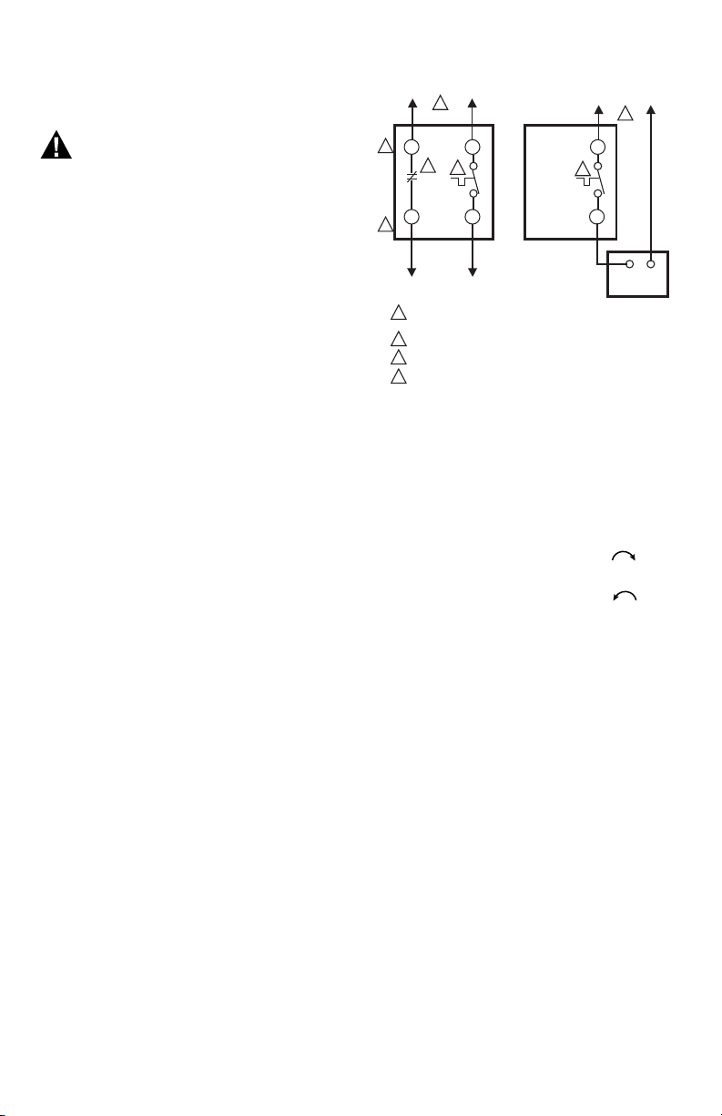
Fig. 1.
4 CHECK OUT THERMOSTAT
Turn on the power to the heating system.
Turn setting knob all the way clockwise ; listen
for clicking sound as switch makes contact. Electric
heater should begin operation.
Turn knob all the way counterclockwise ; listen
for clicking sound as switch breaks contact. Electric
heater should shut off.
5 SETTING THERMOSTAT
Begin with knob to the desired setting (typically
70°F [20°C] on the scale).
If this setting is not satisfactory after at least two
hours of operation, turn setting knob upscale to
raise the temperature, or downscale to lower the
temperature. Move knob only a degree each time.
L1
(HOT) L2
1
1
1
2
3
4
3
2
4
4
POWER SUPPLY. PROVIDE DISCONNECT MEANS AND OVERLOAD
PROTECTION AS REQUIRED.
BREAKS ON POSITIVE OFF.
EXPOSED UNUSED LEADWIRES TO BE PROPERLY INSULATED.
THERMALLY ACTIVATED—BREAKS ON TEMPERATURE
RISE. MAKES ON TEMPERATURE FALL.
L2 L1 L1
T2 T1
T1
T410AT410B
3
ELECTRIC
HEATER
CAUTION:
SPECIAL SERVICE CO/ALR SOLDERLESS CONNECTORS MUST
BE USED WHEN CONNECTING WITH ALUMINUM CONDUCTORS;
OTHERWISE, A FIRE HAZARD CAN RESULT.
TO
ELECTRIC
HEATER
M19099
Loading ...
Loading ...