Check that the mains voltage matches with the voltage on the data plate inside the cooker hood.
Check that the installation complies with standards of local gas and electricity authorities.
If the supply cord is damaged, it must be replaced by the manufacturer or its service agent or a similarly qualied person in order to avoid a hazard.
ACCESSORIES
Use 120mm round exhaust ducting for best performance.
When using flexible duct always install duct with the wire helix pulled taut to minimise pressure loss.
Try to keep exhaust duct short and straight.
Keep bends in the exhaust duct to a minimum.
Do not reduce the size or restrict exhaust duct.
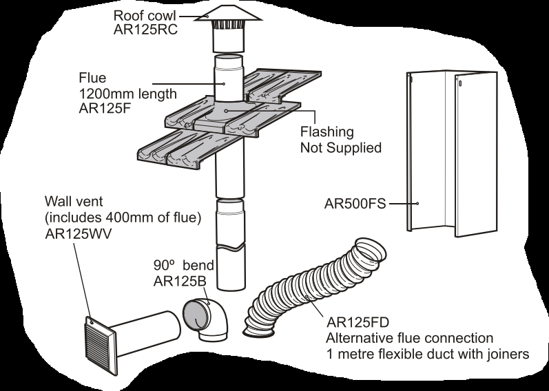
DUCTING ACCESSORIES
Part Numbers:
Description:
AR125RC
Roof Cowl
AR125B
90° Bend
AR125F
Flue 1200mm Long
AR125FD
Flexible Duct -1 Metre Long When Expanded
AR125VW
Wall Vent Kit
AR500FF
Extra Length Flue Cover 1100mm Length Brushed Stainless Steel
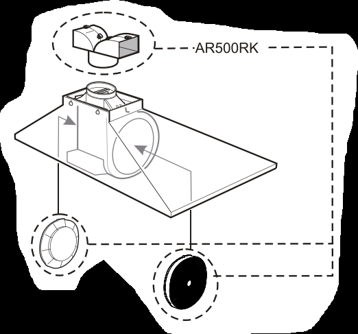
AR500RK
Recirculating Kit
AR500CF
Replacement Carbon Filters
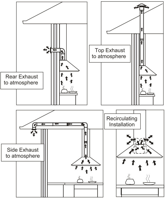
INSTALATION OPTIONS
Warning: Failure to install the screws or fixing device in accordance with these instructions may result in electrical hazards.
COMPONENTS LIST
1 body assembly with grease filters (900-3 grease filters / 600-2 grease filters)
1 telescopic flue cover set
2 cover flue mounting brackets
1 instruction book
1 plastic bag containing screws for fixing telescopic flue covers
1 plastic duct transition: oblong to round
COMPONENTS NOT INCLUDED
Fixings required to attach cover flue mounting brackets to wall
Fixings required to attach the cooker hood to wall
INSTALLING THE COOKER HOOD
Before installing the cooker hood, peel off any protective plastic covering.
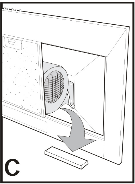
Remove polystyrene packaging from inside behind fan motor.
(Diagrams C)
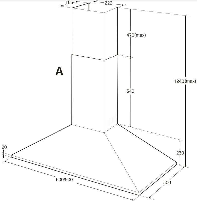
DIMENSIONS ARE IN MILLIMETRES
NOTE:
Some installations may require telescopic flue cover cut to length. Cut with tin snips or a fine-tooth hack saw blade, taking care not to distort or dent flue cover.
The maximum space between the wall and screw top is 5mm.
NOTE:
If the instructions of the hob specify a greater distance than the minimum, then that shall be the minimum height for the installation
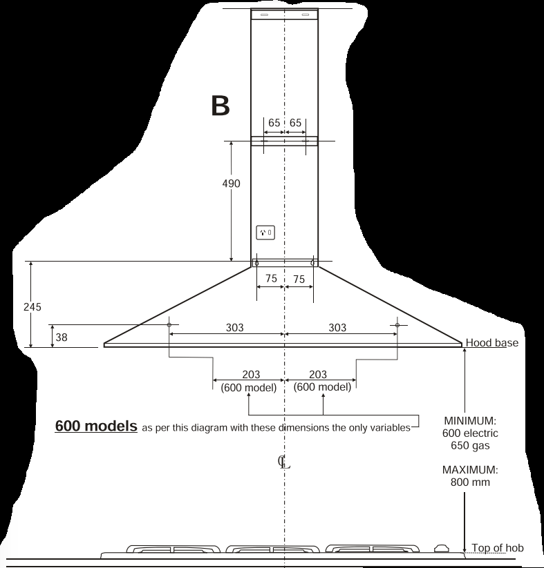
Diagram B:
Recommended working heights.
Cover flue mounting bracket locations.
*■Telescopic cover flue fixing points.
RECOMMENDED INSTALLATION SEQUENCE
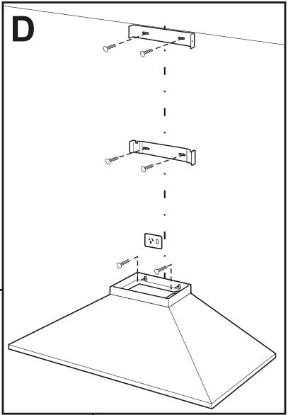
Diagram D
Install cooker hood body.
Determine working height, mark wall to suit.
Install cover flue mounting brackets.
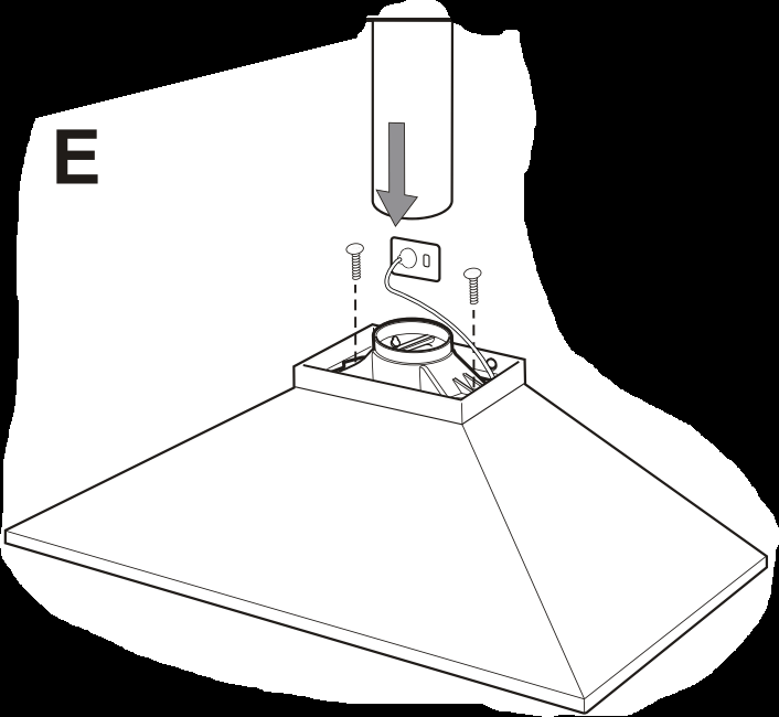
Diagram E
Fix duct transition to cooker hood body.
Install internal exhaust duct to suit installation type.
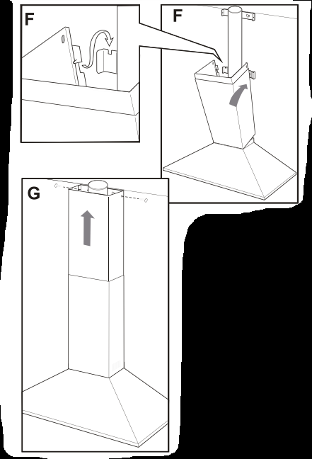
Diagram (s) F
Install bottom section of telescopic flue cover.
Diagram G
Install top section of telescopic flue cover
COOKER HOOD OPERATION
IMPORTANT:The Edison Screw lamps may have come loose during transportation. Ensure that lamps are tightened firmly into the socket before power is applied.
Best results are obtained by using a low fan speed for normal conditions and a high fan speed when odours are more concentrated. Turn the hood on a few minutes before you start cooking. It should by left on after cooking for about 15 minutes or until all odours have disappeared.
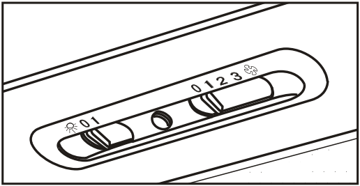
Slide switch controls:
Light switch:..............This switch is used to turn the light fitted in the hood on and off.
Extractor fan switch: ........Used to select fan speeds.
Slide position I:............Fan speed Low
Slide position 2:------------Fan speed Medium
Slide position 3:............Fan speed High
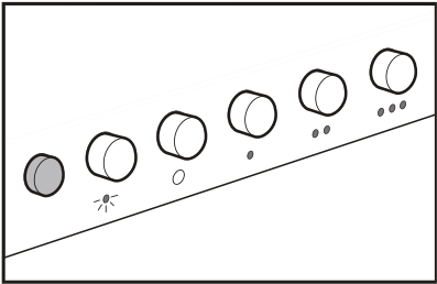
Press button switch controls
Light switch: Depress light button to turn light ON. Press light button to turn light OFF.
Extractor fan switch interlocked switching:
Select a fan speed, depress button to turn fan ON. Press button (O) to turn fan OFF.
NOTE:
This product is fitted with a safety cutout device. If the cooker hood is installed to close to the cooktop, flambe cooking, operating the cooktop without cooking utensils and blocked filters may activate the safety cutout device, if the hood stops during operation, correct the faults and allow time for the safety cutout device to reset, the cooker hood will then function correctly.
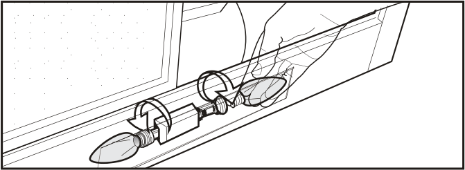
Replacing lamps:
Ensure the appliance is switched off before carrying out maintenance, to avoid any possibility of electric shock. Remove grease filter to replace lamp. Replace with 40W (maximum) E14 candle lamp.
MAINTENANCE
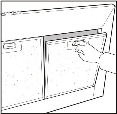
Clean grease filters every three to four weeks maximum.
Greasy filters are a fire risk.
Remove the grease filters, soak and agitate in hot soapy water.
Rinse, drain and shake well before replacing filters.
Do not use oven cleaners or other caustic materials.
CLEANING
Wipe the cooker hood body and ue with a sponge or soft cloth soaked in warm soapy water. Do not use oven cleaners or other abrasive materials.
Q: My range hood fan does not work but the light is on .what fan motor faulty or just fan switch? Welcomed feedback? Likely cost to replace also Reply
Q: My range hood fan does not work but the light is on .what fan motor faulty or just fan switch? Welcomed feedback?
Likely cost to replace also Reply
Q: Hi,
My rangehood fan doesn’t work anymore. All 3 speed settings don’t work but the light still does.
Does this mean the motor needs replacing ? Or could it be something else. Happy for some feedback on what possibilities it could be. Reply