W E B E D I T I O N
O W N E R ' S M A N U A L


DEAR VOLVO OWNER
THANK YOU FOR CHOOSING VOLVO
We hope you will enjoy many years of driving
pleasure in your Volvo. The car has been
designed for the safety and comfort of you and
your passengers. Volvo is one of the safest cars in
the world. Your Volvo has also been designed to
satisfy all current safety and environmental
requirements.
In order to increase your enjoyment of the car, we
recommend that you familiarise yourself with the
equipment, instructions and maintenance infor-
mation contained in this owner's manual.

Table of contents
2
* Option/accessory, for more information, see Introduction.
01
01 Introduction
Reading the owner's manual.................... 15
Recording data......................................... 17
Accessories and extra equipment............ 18
Change of ownership for cars with Volvo
On Call*..................................................... 18
Information on the Internet....................... 19
Volvo Cars' environmental philosophy..... 20
The owner's manual and the environ-
ment.......................................................... 22
Laminated glass........................................ 22
02
02 Safety
General information on seatbelts.............. 24
Seatbelt - putting on................................. 25
Seat belt - loosening................................. 26
Seatbelt - pregnancy................................ 26
Seatbelt reminder...................................... 27
Seatbelt tensioner..................................... 27
Safety - warning symbol........................... 28
Airbag system........................................... 29
Airbags on driver's side............................ 30
Passenger airbag...................................... 30
Passenger airbag - activating/deactivat-
ing*............................................................ 31
Side airbag (SIPS)..................................... 33
Side airbag (SIPS) - child seat/booster
cushion..................................................... 34
Inflatable Curtain (IC)................................ 34
General information on WHIPS (whiplash
protection)................................................. 35
WHIPS - child seats.................................. 36
WHIPS - seating position.......................... 36
When the systems deploy......................... 37
General information on safety mode......... 38
Safety mode - attempting to start the
car............................................................. 39
Safety mode - moving the car.................. 40
02
Pedestrian airbag*..................................... 40
Pedestrian airbag - moving the car........... 41
Pedestrian airbag - folding up.................. 42
General information on child safety.......... 42
Child seats................................................ 44
Child seats - location................................ 48
Child seat - ISOFIX................................... 48
ISOFIX - size classes................................ 49
ISOFIX - types of child seat...................... 50
Child seats - upper mounting points........ 52
Table of contents
* Option/accessory, for more information, see Introduction.
3
03
03 Instruments and controls
Instruments and controls, left-hand drive
car - overview........................................... 54
Instruments and controls, right-hand
drive car - overview................................... 57
Combined instrument panel...................... 60
Analogue combined instrument panel -
overview.................................................... 60
Digital combined instrument panel -
overview.................................................... 61
Eco guide & Power guide*........................ 64
Combined instrument panel - meaning of
indicator symbols...................................... 65
Combined instrument cluster - meaning
of warning symbols................................... 66
Outside temperature gauge...................... 68
Trip meter.................................................. 68
Clock......................................................... 69
Volvo Sensus............................................ 70
Key positions............................................ 71
Key positions - functions at different lev-
els.............................................................. 71
Seats, front................................................ 73
Seats, front - electrically operated............ 74
Key memory in remote control key........... 75
Seats, rear................................................. 76
03
Steering wheel.......................................... 77
Light switches........................................... 78
Position/parking lamps............................. 80
Daytime running lights.............................. 81
Tunnel detection*...................................... 82
Main/dipped beam.................................... 82
Active high beam*..................................... 83
Active Xenon headlamps*......................... 84
Rear fog lamp........................................... 85
Brake lights............................................... 86
Hazard warning flashers........................... 86
Direction indicators................................... 87
Interior lighting.......................................... 87
Home safe light duration........................... 89
Approach light duration............................ 89
Headlamps - adjusting headlamp pat-
tern............................................................ 90
Wipers and washing.................................. 93
Power windows......................................... 95
Door mirrors.............................................. 97
Windows and rearview and door mirrors
- heating.................................................... 98
Rearview mirror - interior.......................... 99
Glass roof*.............................................. 100
03
Compass................................................. 100
Menu navigation - combined instrument
panel....................................................... 101
Menu overview - analogue combined
instrument panel..................................... 102
Menu overview - digital combined instru-
ment panel.............................................. 102
Messages................................................ 103
Messages - handling............................... 104
MY CAR.................................................. 104
MY CAR - operation................................ 104
MY CAR - search paths.......................... 105
MY CAR - menu options......................... 106
MY CAR - Car settings........................... 108
MY CAR - driving support system.......... 109
MY CAR - System options...................... 111
MY CAR - Voice settings........................ 112
MY CAR - Climate settings..................... 113
MY CAR Information............................... 114
Trip computer......................................... 114
Trip computer - analogue combined
instrument panel..................................... 115
Trip computer - digital combined instru-
ment panel.............................................. 119
Trip computer - functions....................... 123

Table of contents
4
* Option/accessory, for more information, see Introduction.
03
Trip computer - trip statistics*................ 124
04
04 Climate control
General information on climate control... 126
Actual temperature................................. 126
Sensors - climate control........................ 127
Air cleaning............................................. 127
Air cleaning - passenger compartment fil-
ter............................................................ 127
Air cleaning - Clean Zone Interior Pack-
age (CZIP)*.............................................. 128
Air cleaning - IAQS*................................ 128
Air cleaning - material............................. 129
Menu settings - climate control.............. 129
Air distribution in the passenger com-
partment.................................................. 129
Electronic climate control - ECC*........... 131
Electronic temperature control - ETC..... 132
Heated front seats*................................. 133
Heated rear seat*.................................... 133
Fan.......................................................... 134
Auto-regulation....................................... 134
Temperature control in the passenger
compartment.......................................... 135
Air conditioning....................................... 135
Demisting and defrosting the wind-
screen..................................................... 136
Air distribution - recirculation.................. 137
04
Air distribution - table............................. 138
Engine block heater and passenger com-
partment heater*..................................... 140
Engine block heater and passenger com-
partment heater* - direct start/immediate
stop......................................................... 141
Engine block heater and passenger com-
partment heater* - timer.......................... 141
Engine block heater and passenger com-
partment heater* - messages................. 142
Additional heater*.................................... 143
Fuel-driven additional heater*................. 143
Electric additional heater*....................... 144
Table of contents
* Option/accessory, for more information, see Introduction.
5
05
05 Loading and storage
Storage spaces....................................... 146
Storage compartment driver’s side........ 148
Jacket holder.......................................... 148
Tunnel console........................................ 148
Tunnel console - armrest........................ 149
Tunnel console - cigarette lighter and
ashtray*................................................... 149
Glovebox................................................. 149
Glovebox - cooling.................................. 150
Inlay mats*.............................................. 150
Vanity mirror............................................ 150
Tunnel console - 12 V-sockets............... 151
Loading................................................... 152
Loading - long load................................. 153
Roof load................................................. 153
Load retaining eyelets............................. 153
Loading - bag holder ............................. 154
Loading - folding bag holder*................. 154
12 V socket - cargo area......................... 155
Cargo net................................................ 155
Hat shelf.................................................. 157
06
06 Locks and alarm
Remote control key with key blade......... 159
Remote control key/PCC - losing .......... 159
Remote control key/PCC - key memory* 160
Indication locking/unlocking - adjusting. 160
Lock indicator......................................... 161
Remote control key/PCC - Electronic
immobiliser.............................................. 161
Remote-controlled immobiliser with
tracking system....................................... 162
Remote control key - function................ 162
Remote control key - range.................... 163
PCC* - unique functions......................... 164
PCC* - range........................................... 165
Detachable key blade............................. 165
Detachable key blade - detaching/
attaching................................................. 166
Detachable key blade - unlocking doors 166
Remote control key/PCC - replacing the
battery..................................................... 167
Keyless*.................................................. 168
Keyless* - remote control key range....... 169
Keyless* - Secure handling of the remote
control key.............................................. 169
Keyless* - interference to remote control
key function............................................. 170
06
Keyless* - locking................................... 170
Keyless* - unlocking............................... 171
Keyless* - unlocking with the key blade 171
Keyless* - key memory........................... 172
Keyless* - lock settings........................... 172
Keyless* - antenna location.................... 173
Locking/unlocking - from the outside .... 173
Manual locking of the door..................... 174
Locking/unlocking - from the inside....... 175
Total airing function................................ 176
Locking/unlocking - glovebox................. 176
Locking/unlocking - tailgate.................... 176
Locking/unlocking - fuel filler flap........... 178
Deadlocks*.............................................. 178
Child safety locks - manual activation.... 179
Child safety locks - electrical activation* 180
Alarm....................................................... 181
Alarm indicator........................................ 182
Alarm - automatic re-arming................... 182
Alarm - automatic arming....................... 182
Alarm - remote control key not working. 183
Alarm signals........................................... 183
Reduced alarm level............................... 183

Table of contents
6
* Option/accessory, for more information, see Introduction.
07
07 Driver support
Stability and traction control system
(DSTC)..................................................... 185
Stability and traction control system
(DSTC) - operation.................................. 186
Stability and traction control system
(DSTC) - symbols and messages........... 187
Road Sign Information (RSI)................... 188
Road sign information (RSI)* - operation 188
Road sign information (RSI)* - limitations 190
Speed limiter*.......................................... 191
Speed limiter* - getting started............... 191
Speed limiter* - changing speed............. 192
Speed limiter - temporary deactivation
and standby mode*................................. 193
Speed limiter* - alarm for speed excee-
ded.......................................................... 194
Speed limiter* - deactivation................... 194
Cruise control*........................................ 194
Cruise control* - managing speed.......... 195
Cruise control* temporary deactivation
and standby mode.................................. 197
Cruise control* - resume set speed........ 198
Cruise control* - deactivate.................... 199
Adaptive cruise control (ACC)*............... 199
Adaptive cruise control* - function......... 200
07
Adaptive cruise control* - overview........ 202
Adaptive cruise control* - managing
speed...................................................... 203
Adaptive cruise control* - set time inter-
val............................................................ 204
Adaptive cruise control* - temporary
deactivation, and standby mode............ 204
Adaptive cruise control* - overtaking
another vehicle........................................ 205
Adaptive cruise control* - deactivate...... 206
Adaptive Cruise Control* - Queue Assist 206
Adaptive cruise control* - switch cruise
control functionality................................ 208
Radar sensor........................................... 209
Radar sensor - limitations....................... 209
Adaptive cruise control* - fault tracing
and action............................................... 211
Adaptive cruise control* - symbols and
messages................................................ 212
Distance Warning*.................................. 214
Distance Alert* - limitations..................... 215
Distance Alert* - symbols and messages 216
City Safety™........................................... 217
City Safety™ - function........................... 217
City Safety™ - operation........................ 218
07
City Safety™ - limitations....................... 219
City Safety™ - laser sensor.................... 220
City Safety™ - symbols and messages.. 222
Collision warning system*....................... 223
Collision warning system* - function...... 224
Collision warning system* - cyclist detec-
tion.......................................................... 225
Collision warning system* - detection of
pedestrians............................................. 227
Collision warning system* - operation.... 228
Collision warning system* - general limi-
tations..................................................... 229
Collision warning system* - camera sen-
sor limitations.......................................... 231
Collision warning system* - symbols and
message.................................................. 233
Driver Alert System*................................ 235
Driver Alert Control (DAC)*...................... 235
Driver Alert Control (DAC)* - operation... 236
Driver Alert Control (DAC)* - symbols and
messages................................................ 237
Lane Keeping Aid*.................................. 239
Lane keeping assistant - function........... 239
Lane keeping assistant - operation......... 241
Lane keeping assistant - limitations....... 241

Table of contents
* Option/accessory, for more information, see Introduction.
7
07
Lane keeping assistant - symbols and
messages................................................ 243
Park assist syst*...................................... 245
Park assist syst* - function..................... 245
Park assist syst* - backward.................. 247
Park assist syst* - forward...................... 247
Park assist syst* - fault indication........... 248
Park assist syst* - cleaning the sensors. 248
Park assist camera.................................. 249
Park assist camera - settings................. 252
Park assist camera - limitations.............. 252
Park Assist Pilot (PAP)*........................... 253
Park Assist Pilot (PAP)* - function.......... 253
Park Assist Pilot (PAP)* - operation........ 254
Park Assist Pilot (PAP)* - limitations....... 256
Active Park Assist (PAP)* - symbols and
messages................................................ 257
BLIS (Blind Spot Information System).... 257
BLIS - operation...................................... 258
CTA (Cross Traffic Alert)*........................ 260
BLIS and CTA - symbols and messages 262
Speed related power steering................. 262
08
08 Starting and driving
Alcolock*................................................. 264
Alcolock* - functions and operation........ 264
Alcolock* - storage.................................. 265
Alcolock* - before starting the engine.... 265
Alcolock* - to bear in mind..................... 266
Alcolock* - symbols and messages........ 268
Starting the engine.................................. 268
Switching off the engine......................... 270
Steering lock........................................... 270
Jump starting.......................................... 270
Gearboxes............................................... 271
Manual gearbox...................................... 272
Gear shift indicator*................................ 272
Automatic gearbox - Geartronic*............ 273
Automatic gearbox - Powershift*............ 276
Gear selector inhibitor............................. 278
Hill start assist (HSA)*............................. 279
Start/Stop*.............................................. 279
Start/Stop* - function and operation....... 280
Start/Stop* - the engine does not stop... 281
Start/Stop* - the engine auto-starts........ 282
Start/Stop* - the engine does not auto-
start......................................................... 283
08
Start/Stop* - involuntary engine stop-
page manual gearbox............................. 284
Start/Stop* - settings.............................. 284
Start/Stop* - symbols and messages..... 286
All Wheel Drive (AWD)*............................ 288
Hill Descent Control (HDC)..................... 288
Foot brake............................................... 289
Foot brake - anti-lock braking system.... 291
Foot brake - emergency brake lights and
automatic hazard warning flashers......... 291
Foot brake - emergency brake assis-
tance....................................................... 291
Parking brake.......................................... 292
Driving in water....................................... 293
Overheating............................................. 293
Driving with open tailgate....................... 294
Overload - starter battery........................ 294
Before a long journey.............................. 295
Winter driving.......................................... 295
Fuel filler flap - Opening/closing............. 296
Fuel filler flap - manual opening.............. 296
Filling up with fuel................................... 296
Fuel - handling........................................ 297
Fuel - petrol............................................. 298

Table of contents
8
* Option/accessory, for more information, see Introduction.
08
Fuel - diesel............................................. 298
Filling with fuel - with a fuel can.............. 299
Diesel particle filter (DPF)........................ 299
Economical driving.................................. 300
Driving with a trailer................................ 301
Driving with a trailer - manual gearbox... 302
Driving with a trailer - automatic gearbox 302
Towing bracket....................................... 303
Detachable towbar - storage.................. 303
Detachable towbar - specifications........ 304
Detachable towbar - attachment/
removal................................................... 304
Trailer Stability Assist - TSA.................... 307
Towing.................................................... 308
Towing eye.............................................. 309
Recovery................................................. 310
09
09 Wheels and tyres
Tyres - direction of rotation.................... 312
Tyres - maintenance............................... 312
Tyres - tread wear indicators.................. 314
Wheel bolts............................................. 314
Jack........................................................ 315
Winter tyres............................................. 315
Wheel and wheel rim dimensions........... 316
Tyres - dimensions.................................. 316
Tyres - load index................................... 316
Tyres - speed ratings.............................. 317
Spare wheel*........................................... 317
Changing wheels - taking out the spare
wheel*..................................................... 318
Changing wheels - removing wheels...... 319
Changing wheels - fitting the spare
wheel*..................................................... 320
Tyres - air pressure................................. 322
Warning triangle...................................... 323
First aid kit*............................................. 324
Emergency puncture repair*................... 324
Emergency puncture repair kit* - loca-
tion.......................................................... 325
Emergency puncture repair kit* - over-
view......................................................... 326
Emergency puncture repair* - operation. 326
09
Emergency puncture repair* - recheck-
ing........................................................... 328
Inflating tyres with the emergency punc-
ture repair kit*.......................................... 329
Emergency puncture repair* - stowing
components............................................ 330
Emergency puncture repair kit* - sealant 330

Table of contents
9
10
10 Maintenance and service
Volvo service programme....................... 332
Raising the car........................................ 333
Bonnet - opening and closing................. 335
Engine compartment - overview............. 335
Engine compartment - checking............. 336
Engine oil - general................................. 336
Engine oil - checking and filling.............. 337
Coolant - level......................................... 340
Brake and clutch fluid - level.................. 341
Climate control system - fault tracing and
repair....................................................... 341
Lamp replacement.................................. 342
Lamp replacement - location of front
lamps...................................................... 343
Lamp replacement - headlamps............. 343
Lamp replacement - cover for main/
dipped beam bulbs................................. 344
Lamp replacement - dipped beam......... 344
Lamp replacement - main beam............. 344
Lamp replacement - extra main beam.... 345
Lamp replacement - direction indicators
front......................................................... 345
Lamp replacement - position/parking
lamps front.............................................. 345
10
Lamp replacement - daytime running
lights....................................................... 346
Lamp replacement - location of rear
lamps...................................................... 346
Lamp replacement - direction indicators
rear, brake lights and reversing lamp..... 346
Lamp replacement - rear fog lamp......... 347
Lamp replacement - vanity mirror light-
ing........................................................... 348
Lamps - specifications ........................... 348
Wiper blades........................................... 349
Washer fluid - filling................................ 351
Starter battery......................................... 351
Battery - symbols.................................... 352
Starter battery - replacement.................. 353
Battery - Start/Stop................................. 353
Fuses - general....................................... 355
Fuses - in engine compartment.............. 356
Fuses - under glovebox.......................... 359
Fuses - under right front seat................. 362
Car washing............................................ 364
Polishing and waxing.............................. 365
Water and dirt-repellent coating............. 366
Rustproofing........................................... 366
Cleaning the interior................................ 367
10
Paint damage.......................................... 368

Table of contents
10
* Option/accessory, for more information, see Introduction.
11
11 Audio and media
Audio and media..................................... 371
Audio and media - overview................... 372
Audio and media - operating the system 372
Audio and media - menu navigation....... 374
Favourites............................................... 376
Audio and media - audio settings........... 376
Audio and media - general audio set-
tings........................................................ 377
Audio and media - advanced audio set-
tings........................................................ 377
Setting the equaliser............................... 378
Setting the audio profile.......................... 378
Setting the audio volume and automatic
volume control........................................ 378
Radio....................................................... 379
Radio tuning............................................ 379
Automatic radio tuning............................ 380
Radio station list..................................... 380
Manual radio tuning................................ 381
Radio stations as presets....................... 381
RDS functions......................................... 382
Alarms in the event of accidents and dis-
asters...................................................... 383
Traffic information (TP)............................ 383
Enhanced Other Networks (EON)........... 384
11
News broadcasts.................................... 384
Radio programme types (PTY)................ 384
Searching radio programme types (PTY) 385
Show radio programme types (PTY)....... 385
Volume control for interrupting radio pro-
gramme types (PTY)............................... 386
Radio text................................................ 386
Automatic radio frequency update (AF).. 386
Regional radio programmes (REG)......... 387
Scan radio frequencies........................... 387
Resetting RDS functions......................... 387
Digital radio* (DAB)................................. 388
Storing channel groups (Ensemble learn) 388
Navigation in channel group list (Ensem-
ble).......................................................... 389
DAB to DAB link...................................... 389
Digital radio* (DAB) - frequencies........... 389
Digital radio* (DAB) - subchannel............ 390
Digital radio* (DAB) - resetting................ 390
Media player........................................... 390
CD/DVD*................................................. 391
Fast forward/reverse............................... 391
Random selection of disc track or audio
file........................................................... 392
11
Playback and navigation of DVD video
discs........................................................ 392
Camera angle for playback of DVD video
discs........................................................ 393
DivX
®
Video On Demand........................ 393
Picture settings....................................... 394
Media player - compatible file formats... 394
External audio source via AUX/USB*
input........................................................ 395
Connecting an external audio source via
AUX/USB* input...................................... 396
Playback and navigation of external
audio source........................................... 396
Setting the audio volume for external
audio source........................................... 398
Media Bluetooth
®
* ................................. 398
Connecting and disconnecting a
Bluetooth
®
* device.................................. 399
Registering a Bluetooth
®
* device............ 400
Automatic connection of Bluetooth
®
*
device...................................................... 401
Changing to another Bluetooth
®
* device 402
Disconnecting the Bluetooth
®
* device.... 402
Removing a Bluetooth
®
* device.............. 403
Bluetooth
®
handsfree phone................... 403

Table of contents
* Option/accessory, for more information, see Introduction.
11
11
Bluetooth
®
* handsfree phone - overview 404
Making and receiving calls...................... 404
Bluetooth
®
handsfree phone - audio set-
tings........................................................ 405
Bluetooth
®
version information............... 406
Phone book............................................. 406
Phone book - quick search for contacts 407
Phone book - character table keypad in
centre console........................................ 408
Phone book - searching for contacts..... 409
Phone book - new contact..................... 410
Phone book - speed dial numbers.......... 411
Phone book - receiving a vCard............. 412
Phone book - memory status................. 412
Phone book - clearing............................. 412
Voice recognition* control of a mobile
phone...................................................... 413
Language options for voice recognition*
control of a mobile phone....................... 414
Help functions for voice recognition*
control of a mobile phone....................... 415
Voice recognition* control of a mobile
phone - user setting and voice volume... 416
Voice recognition* control of a mobile
phone - voice commands....................... 416
11
Voice recognition* control of a mobile
phone - quick commands....................... 417
Voice guidance* control of a mobile
phone - dialling a number....................... 417
Voice recognition* control of a mobile
phone - dialling from the call register..... 418
Voice recognition* control of a mobile
phone - dialling a contact....................... 418
Voice recognition* control of a mobile
phone - calling the voice mailbox........... 418
Save as favourite.................................... 419
Playback and navigation of CD/DVD*
disc......................................................... 419
Playback and navigation of burned discs
with audio/video files.............................. 420
Scan disc track or audio file................... 421
TV*........................................................... 421
Searching TV* channels/Preset list......... 423
TV* - channel management..................... 423
Information about the current TV* pro-
gramme................................................... 424
Teletext*.................................................. 424
Reception of TV* channel is lost............. 425
Remote control*...................................... 425
Remote control* - functions.................... 426
Remote control* - battery replacement.. 427
11
Audio and media - menu overview......... 428
Menu overview - AM............................... 428
Menu overview - FM............................... 429
Menu overview - Digital radio (DAB)*...... 429
Main overview - CD/DVD Data............... 430
Menu overview - CD Audio..................... 431
Menu overview - DVD Video................... 431
Menu overview - iPod............................. 432
Menu overview - USB............................. 433
Menu overview - Media Bluetooth.......... 433
Menu overview - AUX............................. 434
Menu overview - Bluetooth handsfree.... 434
Menu overview - TV................................ 435

Table of contents
12
12
12 Specifications
Type designations................................... 438
Dimensions............................................. 440
Weights................................................... 441
Towing capacity and towball load.......... 442
Engine specifications.............................. 445
Engine oil - adverse driving conditions... 446
Engine oil - grade and volume................ 447
Coolant - grade and volume................... 449
Transmission fluid - grade and volume... 450
Brake fluid - grade and volume............... 451
Washer fluid - quality and volume.......... 451
Fuel tank - volume.................................. 452
Air conditioning, fluid - volume and
grade....................................................... 453
Fuel consumption and CO2 emissions... 454
Tyres - approved tyre pressures............. 457
Electrical system..................................... 458
Starter battery - specification................. 459
Type approval - remote control key sys-
tem.......................................................... 460
Type approval - radar system................. 460
Type approval - Bluetooth
®
.................... 462
Licenses.................................................. 470
Symbols in the display............................ 472
13
13 Alphabetical Index
Alphabetical Index.................................. 476

Table of contents
13

INTRODUCTION
01 Introduction
01
}}
* Option/accessory, for more information, see Introduction.
15
Reading the owner's manual
A good way of getting to know your new car
is to read the owner's manual, ideally before
your first journey. This will give you the oppor-
tunity to familiarise yourself with new func-
tions, to see how best to handle the car in dif-
ferent situations, and to make the best use of
all the car's features. Please pay attention to
the safety instructions contained in the man-
ual.
The specifications, design features and illus-
trations in this owner's manual are not bind-
ing. We reserve the right to make modifica-
tions without prior notice.
©
Volvo Car Corporation
Options/accessories
All types of option/accessory are marked with
an asterisk*.
In addition to standard equipment, the
owner's manual also describes options (fac-
tory fitted equipment) and certain accessories
(retrofitted extra equipment).
The equipment described in the owner's
manual is not available in all cars - they have
different equipment depending on adapta-
tions for the needs of different markets and
national or local laws and regulations.
In the event of uncertainty over what is stand-
ard or an option/accessory, contact a Volvo
dealer.
Special texts
WARNING
Warning texts appear if there is a risk of
injury.
IMPORTANT
"Important" texts appear if there is a risk of
damage.
NOTE
NOTE texts give advice or tips that facili-
tate the use of features and functions for
example.
Footnote
There is footnote information in the owner's
manual that is located at the bottom of the
page. This information is an addition to the
text that it refers to via a number. If the foot-
note refers to text in a table then letters are
used instead of numbers for referral.
Message texts
Text messages can be shown in the com-
bined instrument panel and the screen. These
text messages are highlighted in the owner's
manual by means of the text being slightly
larger and printed in grey. Examples of this
are in menu texts and message texts in the
screen (e.g.
Audio settings).
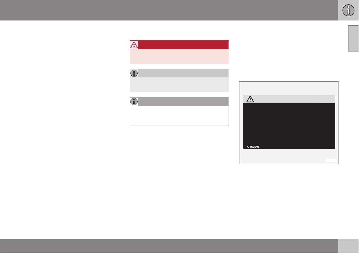
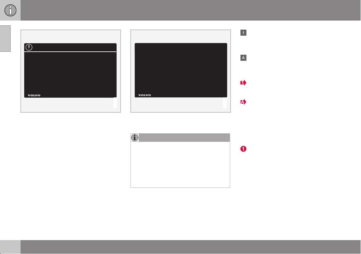
Decals
The car contains different types of decal
which are designed to convey important
information in a simple and clear manner. The
decals in the car have the following descend-
ing degree of importance for the warning/
information.
Warning for personal injury
G031590
Black ISO symbols on yellow warning field,
white text/image on black message field.
Used to indicate the presence of danger
which, if the warning is ignored, may result in
serious personal injury or fatality.
Risk of property damage
||
01 Introduction
01
16
G031592
White ISO symbols and white text/image on
black or blue warning field and message field.
Used to indicate the presence of danger
which, if the warning is ignored, may result in
damage to property.
Information
G031593
White ISO symbols and white text/image on
black message field.
NOTE
It is not intended that the decals illustrated
in the owner's manual should be exact
replicas of those in the car. They are
included to show their approximate
appearance and location in the car. The
information that applies to your particular
car is available on the respective decals
for your car.
Procedure lists
Procedures where action must be taken in a
certain sequence are numbered in the
owner's manual.
When there is a series of illustrations for
step-by-step instructions each step is
numbered in the same way as the corres-
ponding illustration.
There are numbered lists with letters
adjacent to the series of illustrations
where the order of the instructions is not
significant.
Arrows appear numbered and unnum-
bered and are used to illustrate a move-
ment.
Arrows with letters are used to clarify a
movement when the reciprocal order is of
no relevance.
If there is no series of illustrations for step-by-
step instructions then the different steps are
numbered with normal numbers.
Position lists
Red circles containing a number are used
in overview images where different com-
ponents are pointed out. The number
recurs in the position list featured in con-
nection with the illustration that describes
the item.
Bulleted lists
A bulleted list is used when there is a list of
points in the owner's manual.
Example:
•
Coolant
•
Engine oil

01 Introduction
01
17
Images
The manual's images are sometimes sche-
matic and may deviate from the car's appear-
ance depending on equipment level and mar-
ket.
Related information
Related information refers to other sections
containing related information.
To be continued
}} This symbol is located furthest down to
the right when a section continues on the fol-
lowing page.
Related information
•
The owner's manual and the environment
(p. 22)
•
Information on the Internet (p. 19)
Recording data
Certain information about the vehicle's opera-
tion and functionality, and any incidents, are
recorded in the car.
Your vehicle contains a number of computers
whose function is to continuously check and
monitor the vehicle's operation and function-
ality. Some of the computers can record
information during normal driving if they
detect an error. In addition, information is
recorded in the event of a collision or inci-
dent. Parts of the recorded information are
required so that technicians can diagnose
and rectify faults in the vehicle during servic-
ing and maintenance and so that Volvo can
fulfil legal requirements and other regulations.
In addition to this, the information is used for
research purposes by Volvo in order to con-
tinually develop quality and safety, as the
information can contribute to a better under-
standing of the factors that cause accidents
and injuries. The information includes details
of the status and functionality of various sys-
tems and modules in the vehicle with regard
to engine, throttle, steering and brake sys-
tems, amongst other things. This information
may include details regarding the way the
driver drives the vehicle, such as vehicle
speed, brake and accelerator pedal use,
steering wheel movement and whether or not
the driver and passengers have used their
seatbelts. For the reasons given this informa-
tion may be stored in the vehicle's computers
for a certain length of time, but also as a
result of a collision or incident. This informa-
tion may be stored by Volvo as long as it can
help to further develop and further enhance
safety and quality and as long as there are
legal requirements and other regulations that
Volvo needs to consider.
Volvo will not contribute to the above-descri-
bed information being disclosed to third par-
ties without the vehicle owner's consent.
However, due to national legislation and reg-
ulations Volvo may be required to disclose
such information to authorities such as police
authorities, or others who may assert a legal
right to have access to it.
To be able to read and interpret the informa-
tion recorded by the computers in the vehicle
requires special technical equipment that
Volvo, and workshops that have entered into
agreements with Volvo, have access to. Volvo
is responsible that the information, which is
transferred to Volvo during servicing and
maintenance, is stored and handled in a
secure manner and that the handling com-
plies with applicable legal requirements. For
further information - contact a Volvo dealer.
01 Introduction
01
18
* Option/accessory, for more information, see Introduction.
Accessories and extra equipment
The incorrect connection and installation of
accessories and extra equipment can nega-
tively affect the car's electronic system.
Certain accessories only function when asso-
ciated software is installed in the car's com-
puter system. Volvo therefore recommends
that you always contact an authorised Volvo
workshop before installing accessories or
extra equipment which are connected to or
affect the electrical system.
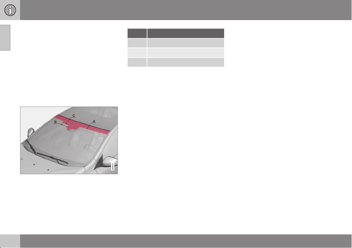
Heat-reflecting windscreen*
Areas where IR film is not applied.
Dimensions
A 65 mm
B 150 mm
C 125 mm
The windscreen is equipped with a heat-
reflecting film (IR) that reduces the solar heat
radiation into the passenger compartment.
The positioning of electronic equipment, such
as a transponder, behind a glass surface with
heat-reflecting film may affect its function and
performance.
For the optimal function of electronic equip-
ment, it should be positioned on the part of
the windscreen with no heat-reflecting film
(see the highlighted area in the above illustra-
tion).
Change of ownership for cars with
Volvo On Call*
If the car is equipped with Volvo On Call
(VOC) it is important to change the owner of
the service.
VOC is a supplemental service that consists
of safety, security and comfort services. In
the event of change of ownership it is impor-
tant to change the owner of the service.
Closing the VOC service
Contact a Volvo dealer in the event of change
of ownership in order to close the VOC serv-
ice.
Starting the VOC service
It is very important that the VOC service
changes owner so that the previous owner's
ability to use services in the car is stopped.
Contact a Volvo dealer in the event of a
change of ownership.
Related information
•
Information on the Internet (p. 19)

01 Introduction
01
19
Information on the Internet
At www.volvocars.com there is further infor-
mation concerning your car.
With a personal Volvo ID it is possible to log in
to My Volvo web which is a personal web
page for you and your car.
A QR code reader is required to read the QR
code, which is available as a supplemental
program for several mobile phones. The QR
code reader can be downloaded from e.g.
App Store, Windows Phone or Google Play.
QR code
01 Introduction
01
20
Volvo Cars' environmental philosophy
Your Volvo complies with strict international
environmental standards and is also manufac-
tured in one of the cleanest and most
resource-efficient plants in the world.
G000000
Environmental care is one of Volvo Car Cor-
poration's core values which influence all
operations. We also believe that our custom-
ers share our consideration for the environ-
ment.
Your Volvo complies with strict international
environmental standards and is also manu-
factured in one of the cleanest and most
resource-efficient plants in the world. Volvo
Car Corporation has global ISO certification,
which includes the environmental standard
ISO 14001 covering all factories and several
of our other units. We also set requirements
for our partners so that they work systemati-
cally with environmental issues.
Fuel consumption
Volvo cars have competitive fuel consump-
tion in each of their respective classes. Lower
fuel consumption generally results in lower
emission of the greenhouse gas, carbon diox-
ide.
It is possible for the driver to influence fuel
consumption. For more information read
under the heading, Reducing environmental
impact.
Efficient emission control
Your Volvo is manufactured following the
concept "Clean inside and out" – a concept
that encompasses a clean interior environ-
ment as well as highly efficient emission con-
trol. In many cases the exhaust emissions are
well below the applicable standards.
Clean air in the passenger
compartment
A passenger compartment filter prevents dust
and pollen from entering the passenger com-
partment via the air intake.

01 Introduction
01
* Option/accessory, for more information, see Introduction.
21
A sophisticated air quality system, IAQS*
(Interior Air Quality System) ensures that the
incoming air is cleaner than the air in the traf-
fic outside.
The system consists of an electronic sensor
and a carbon filter. The incoming air is moni-
tored continuously and if there is an increase
in the level of certain unhealthy gases such as
carbon monoxide then the air intake is
closed. Such a situation may arise in heavy
traffic, queues and tunnels for example.
The entry of nitrous oxides, ground-level
ozone and hydrocarbons is prevented by the
carbon filter.
Interior
The interior of a Volvo is designed to be plea-
sant and comfortable, even for people with
contact allergies and for asthma sufferers.
Extreme attention has been given to choosing
environmentally-compatible materials.
Volvo workshops and the environment
Regular maintenance creates the conditions
for a long service life and low fuel consump-
tion for your car. In this way you contribute to
a cleaner environment. When Volvo's work-
shops are entrusted with the service and
maintenance of your car it becomes part of
our system. Volvo makes clear demands
regarding the way in which our workshops
are designed in order to prevent spills and
discharges into the environment. Our work-
shop staff have the knowledge and the tools
required to guarantee good environmental
care.
Reducing environmental impact
You can easily help reduce environmental
impact - here are a few tips:
•
Avoid letting the engine idle - switch off
the engine when stationary for longer
periods. Pay attention to local regula-
tions.
•
Drive economically - think ahead.
•
Perform service and maintenance in
accordance with the owner's manual's
instructions - follow the intervals recom-
mended in the Service and Warranty
Booklet.
•
If the car is equipped with an engine
block heater*, use it before starting from
cold - it improves starting capacity and
reduces wear in cold weather and the
engine reaches normal operating tem-
perature more quickly, which lowers con-
sumption and reduces emissions.
•
High speed increases consumption con-
siderably due to increased wind resis-
tance - a doubling of speed increases
wind resistance 4 times.
•
Always dispose of environmentally hazar-
dous waste, such as batteries and oils, in
an environmentally safe manner. Consult
a workshop in the event of uncertainty
about how this type of waste should be
discarded - an authorised Volvo work-
shop is recommended.
Following this advice can save money, the
planet's resources are saved, and the car's
durability is extended. For more information
and further advice, see Economical driving (p.
300) and Fuel consumption and CO2 emis-
sions (p. 454).
Recycling
As a part of Volvo's environmental work, it is
important that the car is recycled in an envi-
ronmentally sound manner. Almost all of the
car can be recycled. The last owner of the car
is therefore requested to contact a dealer for
referral to a certified/approved recycling
facility.
Related information
•
The owner's manual and the environment
(p. 22)
01 Introduction
01
22
* Option/accessory, for more information, see Introduction.
The owner's manual and the
environment
The paper pulp in a printed owner's manual
comes from FSC
®
certified forests or other
controlled sources.
The Forest Stewardship Council
®
symbol
shows that the paper pulp in a printed
owner's manual comes from FSC
®
certified
forests or other controlled sources.
Related information
•
Volvo Cars' environmental philosophy (p.
20)
Laminated glass
Laminated glass
The glass is reinforced which pro-
vides better protection against
break-ins and improved sound insu-
lation in the passenger compart-
ment. The windscreen and other windows*
have laminated glass.
SAFETY
02 Safety
02
24
General information on seatbelts
Heavy braking can have serious consequen-
ces if the seatbelts are not used. Ensure that
all passengers are using their seatbelts during
the journey.
It is important that the seatbelt lies against
the body so it can provide maximum protec-
tion. Do not lean the backrest too far back.
The seatbelt is designed to protect in a nor-
mal seating position.
Unbelted occupants will be reminded to fas-
ten their (p. 25) seatbelt by means of an
audio and visual reminder (p. 27).
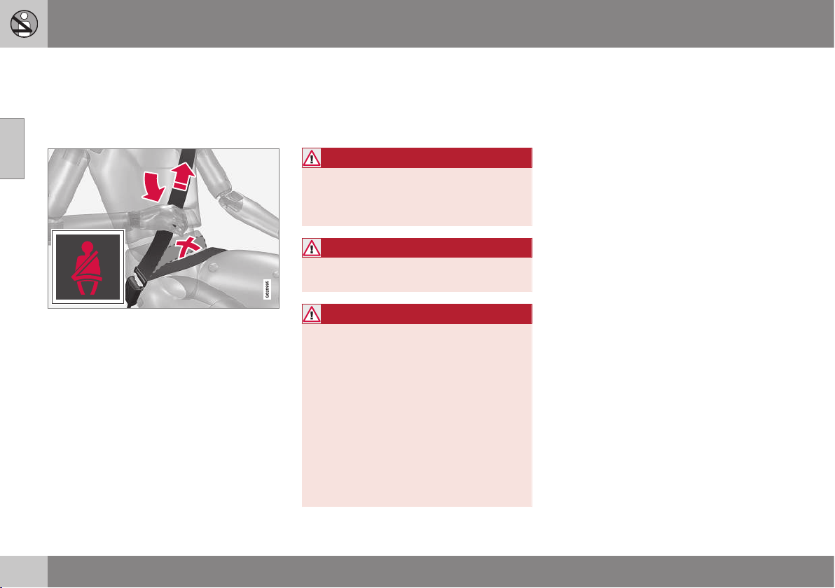
Remember
•
Do not use clips or anything else that can
prevent the seatbelt from fitting properly.
•
The seatbelt must not be twisted or
caught on anything.
•
The hip strap must be positioned low
down (not over the abdomen).
•
Tension the hip strap over the lap by pull-
ing the diagonal shoulder belt up towards
the shoulder.
WARNING
The seatbelts and airbags interact. If a
seatbelt is not used or is used incorrectly,
this may diminish the protection provided
by the airbag in the event of a collision.
WARNING
Each seatbelt is designed for only one per-
son.
WARNING
Never modify or repair the seatbelts your-
self. Volvo recommends that you contact
an authorised Volvo workshop.
If the seatbelt has been subjected to a
major load, such as in conjunction with a
collision, the entire seatbelt must be
replaced. Some of the seatbelt's protective
properties may have been lost even if the
seatbelt does not appear damaged. The
seatbelt must also be replaced if it shows
signs of wear or damage. The new seatbelt
must be type-approved and designed for
installation at the same location as the
replaced seatbelt.
Related information
•
Seatbelt - pregnancy (p. 26)
•
Seat belt - loosening (p. 26)
•
Seatbelt tensioner (p. 27)
02 Safety
02
25
Seatbelt - putting on
Put on the seatbelt (p. 24) before driving
starts.
Pull the belt out slowly and secure it by
pressing its locking tab into the seatbelt
buckle. A loud "click" indicates that the belt
has locked.
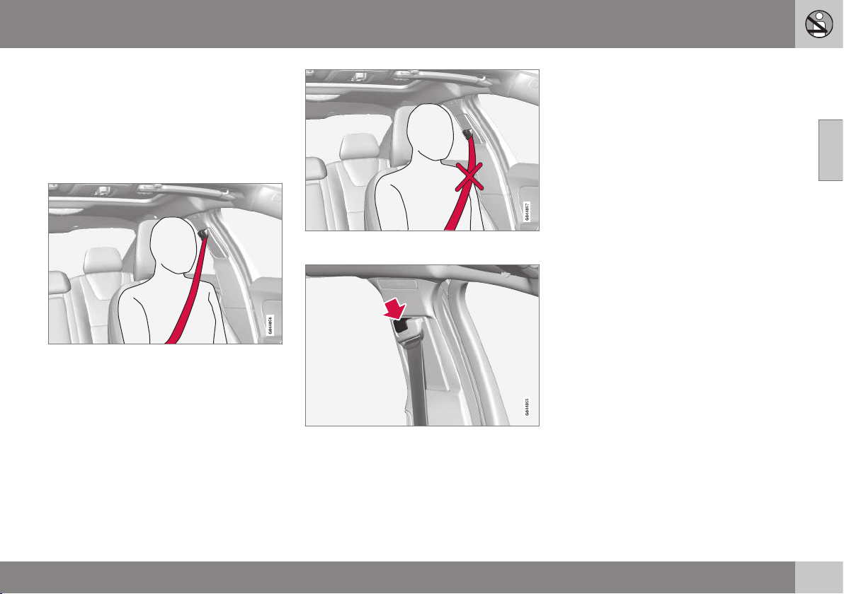
Correctly fitted seatbelt.
Incorrectly fitted seatbelt. The belt must rest on
the shoulder.
Seatbelt height adjustment. Press the button and
move the belt vertically. Position the belt as high
as possible without it chafing against your throat.
The locking tab at the centre rear seat only
fits into the intended seatbelt buckle.
Remember
The seatbelt locks and cannot be withdrawn:
•
if it is pulled out too quickly
•
during braking and acceleration
•
if the car leans heavily.
Related information
•
Seatbelt - pregnancy (p. 26)
•
Seat belt - loosening (p. 26)
•
Seatbelt tensioner (p. 27)
•
Seatbelt reminder (p. 27)
02 Safety
02
26
Seat belt - loosening
Loosen the seatbelt (p. 24) when the car is
stationary.
Press the red button on the seatbelt buckle
and then let the belt retract. If the seatbelt
does not retract fully, feed it in by hand so
that it does not hang loose.
Related information
•
Seatbelt - putting on (p. 25)
•
Seatbelt reminder (p. 27)
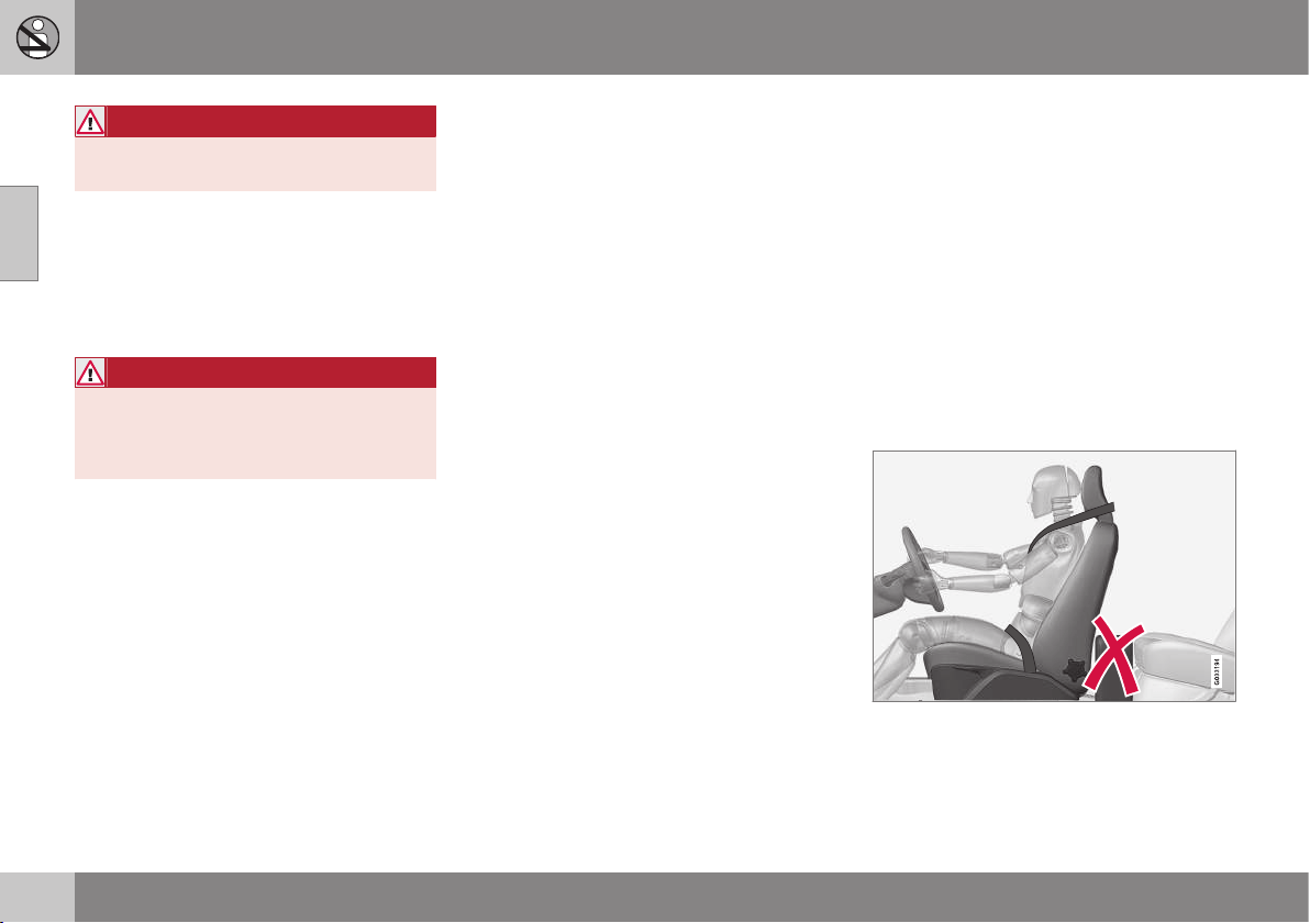
Seatbelt - pregnancy
Seatbelt (p. 24) must always be worn during
pregnancy. But it is crucial that it be worn in
the correct way.
G020998
The diagonal section should wrap over the
shoulder then be routed between the breasts
and to the side of the abdomen.
The lap section should lay flat over the thighs
and as low as possible under the abdomen. –
It must never be allowed to ride upward.
Remove the slack from the seatbelt and
ensure that it fits as close to the body as pos-
sible. In addition, check that there are no
twists in the seatbelt.
As the pregnancy progresses, pregnant dri-
vers must adjust the seat (p. 73) and steer-
ing wheel (p. 77) such that they can easily
maintain control of the vehicle as they drive
(which means that they must be able to easily
operate the foot pedals and steering wheel).
The aim should be to position the seat with as
large a distance as possible between abdo-
men and steering wheel.
Related information
•
Seatbelt - putting on (p. 25)
•
Seat belt - loosening (p. 26)
02 Safety
02
27
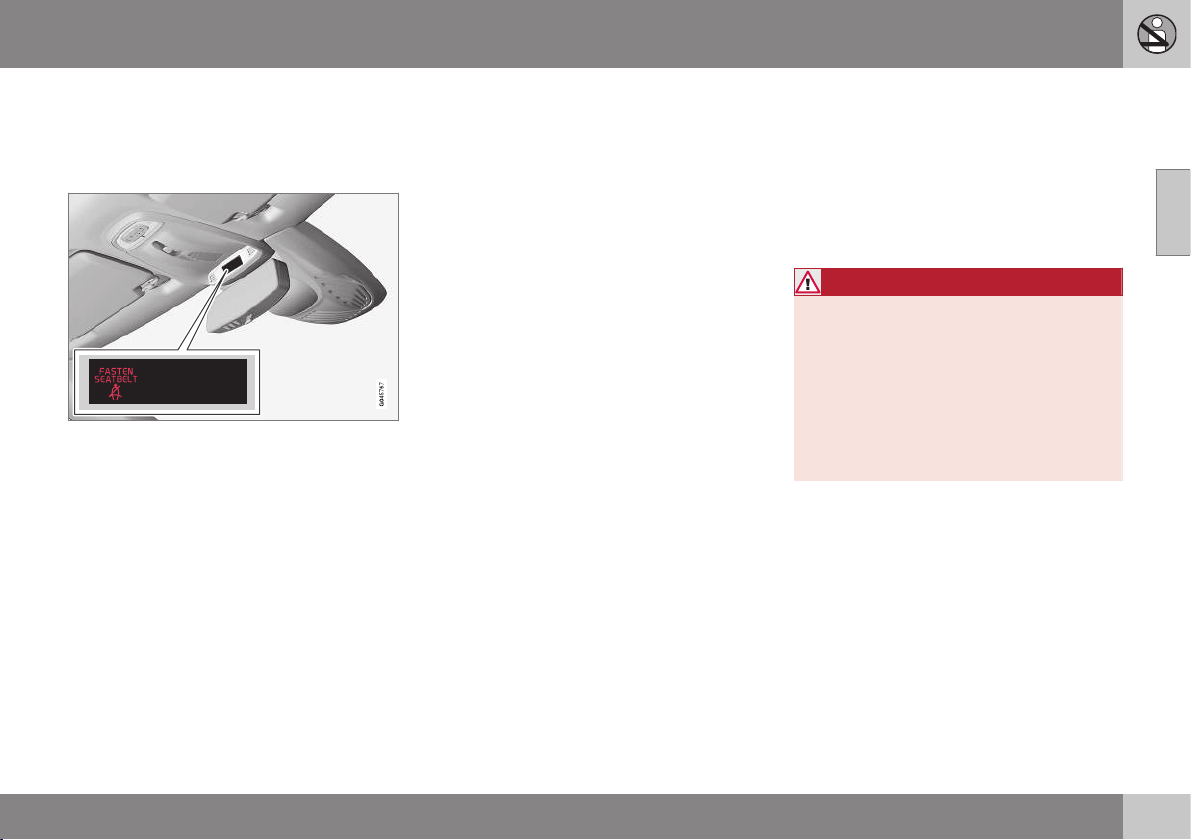
Seatbelt reminder
Unbelted occupants will be reminded to fas-
ten (p. 25) their seatbelt by means of an audio
and visual reminder.
The audio reminder is speed dependent, and
in some cases time dependent. The visual
reminder is located in the roof console and in
the combined instrument panel (p. 60).
Child seats are not covered by the seatbelt
reminder system.
Rear seat
The seatbelt reminder in the rear seat has two
subfunctions:
•
Provides information on which seatbelts
(p. 24) are being used in the rear seat. A
message appears in the combined instru-
ment panel when the seatbelts are in use,
or if one of the rear doors has been
opened. The message is acknowledged
automatically after approximately
30 seconds driving or after pressing the
indicator stalk (p. 101) OK button. If any-
one is unbelted then the message can
only be acknowledged manually by
pressing the indicator stalk OK button.
•
Provides a warning if one of the rear seat-
belts is unfastened during travel. This
warning takes the form of a message in
the combined instrument panel along with
the audio/visual signal. The warning stops
when the seatbelt is re-fastened, or it can
also be acknowledged manually by
pressing the OK button.
The combined instrument panel's information
display shows which seatbelts are in use.
This information is always available.
Seatbelt tensioner
Seatbelts (p. 24) on the driver's side, the pas-
senger side and at the outer rear seats are fit-
ted with seatbelt tensioners. A mechanism in
the seatbelt tensioner tightens the seatbelt in
the event of a sufficiently violent collision. The
seatbelt then provides more effective restraint
for the occupants.
WARNING
Never insert the tongue of the passenger's
seatbelt into the buckle on the driver's
side. Always insert the tongue of the seat-
belt into the buckle on the correct side. Do
not make any damages on seatbelts nor
insert any foreign objects into a buckle.
The seatbelts and buckles would then
possibly not function as intended in the
event of a collision. There is a risk of
serous injury.
Related information
•
General information on seatbelts (p. 24)
02 Safety
02
28
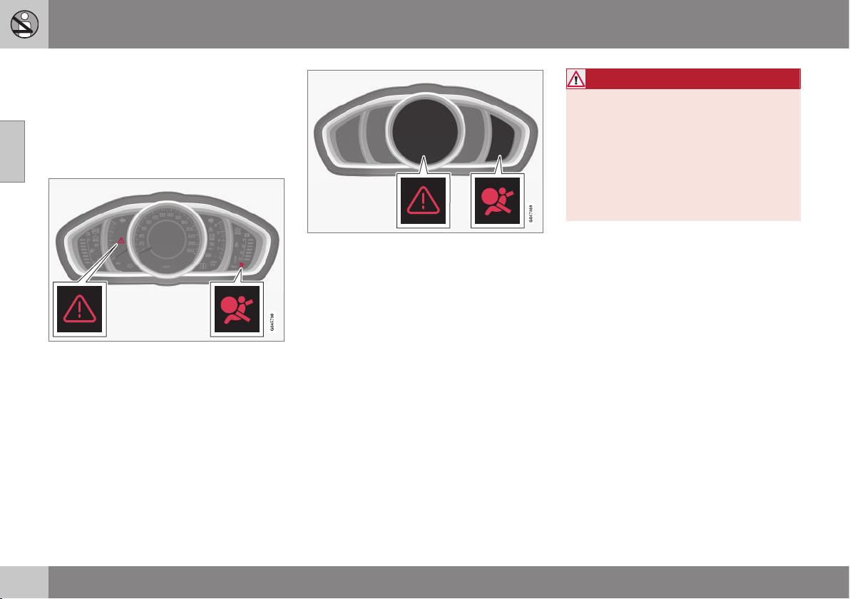
Safety - warning symbol
The warning symbol is shown if a fault is
detected during fault tracing or if a system
has been activated. Where required, the
warning symbol is shown together with a
message in the combined instrument panel
(p. 60) information display.
Warning triangle and warning symbol for the air-
bag system (p. 29) in the analogue combined
instrument panel.
Warning triangle and warning symbol for the air-
bag system in the digital combined instrument
panel.
The warning symbol in the combined instru-
ment panel is switched on with the remote
control key in key position II (p. 71), fault
tracing is performed each time the ignition is
switched on. The symbol clears after
approx. 6 seconds provided the airbag sys-
tem is fault-free.
The warning symbol is shown if a fault is
detected during fault tracing or if a system
has been activated. Where required, the
warning symbol is shown together with a
message in the display. If the warning symbol
malfunctions, the warning triangle illuminates
and
SRS airbag Service required or SRS
airbag Service urgent appears in the dis-
play. Volvo recommends that you contact an
authorised Volvo workshop immediately.
WARNING
If the warning symbol for the airbag sys-
tem remains illuminated or illuminates
while driving, it means that the airbag sys-
tem does not have full functionality. The
symbol indicates a fault in the airbag sys-
tem, the belt tensioner system, SIPS, the
IC system or some other fault in the sys-
tem. Volvo recommends that you contact
an authorised Volvo workshop immedi-
ately.
Related information
•
General information on safety mode (p.
38)
02 Safety
02
29
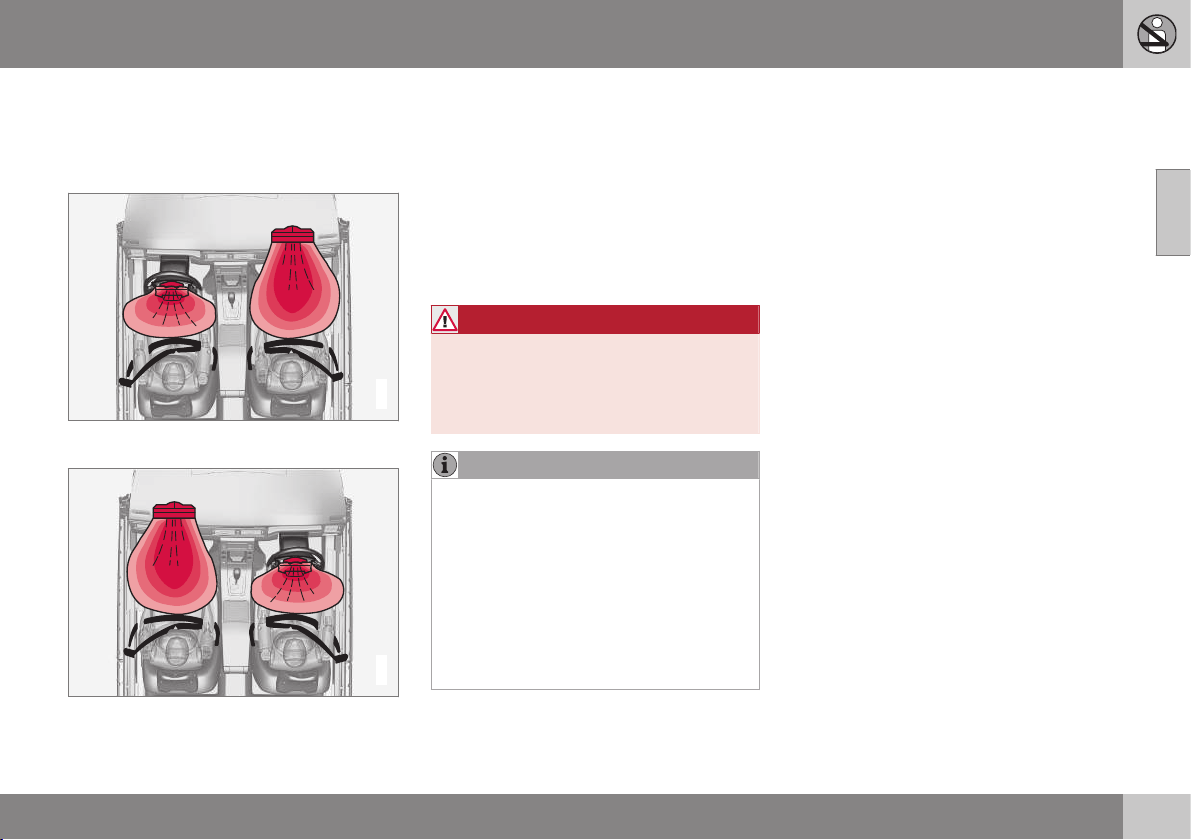
Airbag system
In the event of a frontal collision the airbag
system helps to protect the head, face and
chest of the driver and passenger.
G018665
Airbag system viewed from above, left-hand-
drive car.
G018666
Airbag system viewed from above, right-hand-
drive car.
The system consists of airbags and sensors.
A sufficiently violent collision trips the sensors
and the airbag(s) are inflated and become
hot. The airbag cushions the initial collision
impact for the occupant. The airbag deflates
when compressed by the collision. When this
occurs, smoke escapes into the car. This is
completely normal. The entire process,
including inflation and deflation of the airbag,
occurs within tenths of a second.
WARNING
Volvo recommends that you contact an
authorised Volvo workshop for repair.
Defective work in the airbag system could
cause malfunction and result in serious
personal injury.
NOTE
The detectors react differently depending
on the nature of the collision and whether
or not the seatbelt is fastened. Applies to
all seatbelt positions apart from centre
seat rear.
It is therefore possible that only one (or
none) of the airbags may inflate in a colli-
sion. The detectors sense the force of the
collision on the vehicle and the action is
adapted accordingly so that one or more
airbags are deployed.
Related information
•
Airbags on driver's side (p. 30)
•
Passenger airbag (p. 30)
•
Safety - warning symbol (p. 28)

02 Safety
02
30
Airbags on driver's side
To supplement the protection afforded by the
seatbelt (p. 24) on the driver side, the car is
equipped with two airbags (p. 29).
One of the airbags is folded up into the centre
of the steering wheel. The steering wheel is
marked AIRBAG.
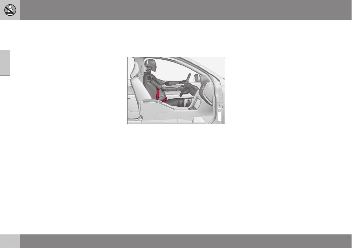
Knee airbag on the driver's side in a left-hand-
drive car.
The second airbag (at knee level) is fitted in
the lower part of the instrument panel on the
driver's side; this panel is labelled AIRBAG.
WARNING
The seatbelts and airbags interact. If the
belt is not used or is used incorrectly, this
may diminish the protection provided by
the airbags in the event of a collision.
Related information
•
Passenger airbag (p. 30)
Passenger airbag
To supplement the protection afforded by the
seatbelt (p. 24) on the passenger side, the car
is equipped with an airbag (p. 29).
The airbag is folded up into a compartment
above the glovebox. Its cover panel is
marked AIRBAG.
Location of the front passenger airbag in a left-
hand drive car.
02 Safety
02
* Option/accessory, for more information, see Introduction.
31
Location of the front passenger airbag in a right-
hand drive car.
WARNING
The seatbelts and airbags interact. If the
belt is not used or is used incorrectly, this
may diminish the protection provided by
the airbag in the event of a collision.
To minimise the risk of injury if the airbag
deploys, passengers must sit as upright as
possible with their feet on the floor and
backs against the backrest. Seatbelts
must be secured.
WARNING
Do not put objects in front of or above the
dashboard where the passenger airbag is
located.
WARNING
Never place a child in a child seat or on a
booster cushion in the front seat if the air-
bag is activated.
Never allow anybody to stand or sit in front
of the front passenger seat.
No one shorter than 140 cm should ever
sit in the front passenger seat if the airbag
is activated.
Failure to follow the advice given above
can endanger life.
Switch - PACOS*
The front passenger airbag can be deacti-
vated (p. 31) if the car is equipped with a
switch, PACOS (Passenger Airbag Cut Off
Switch).
WARNING
If the car is equipped with a front passen-
ger airbag, but does not have a PACOS
switch (Passenger Airbag Cut Off Switch),
then the airbag will always be activated.
Related information
•
Airbags on driver's side (p. 30)
•
Child seats (p. 44)
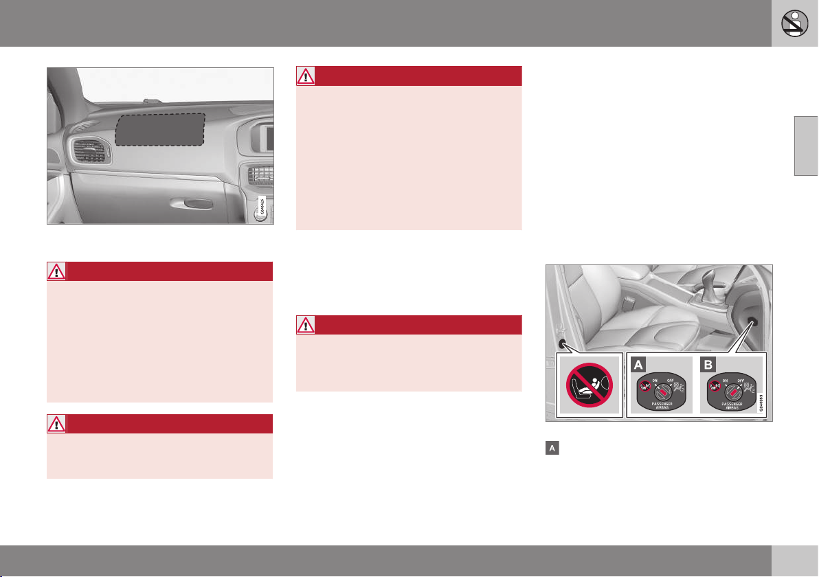
Passenger airbag - activating/
deactivating*
Front passenger airbag (p. 30) can be deacti-
vated if the car is equipped with a switch,
PACOS (Passenger Airbag Cut Off Switch).
Switch - PACOS
The switch for the passenger airbag (PACOS)
is located on the passenger end of the instru-
ment panel and is accessible when the pas-
senger door is open.
Check that the switch is in the required posi-
tion. The remote control key's key blade (p.
166) should be used to change position.
Position of airbag label plus switch.
The airbag is activated. With the switch in
this position, persons taller than 140 cm
can sit in the front passenger seat, but
||
02 Safety
02
32
never children in a child seat or on a
booster cushion.
The airbag is deactivated. With the switch
in this position, children in a child seat or
on a booster cushion can sit in the front
passenger seat, but never persons taller
than 140 cm.
WARNING
Activated airbag (passenger seat):
Never place a child in a child seat or on a
booster cushion on the front passenger
seat when the airbag is activated. This
applies to everyone shorter than 140 cm.
Deactivated airbag (passenger seat):
No one taller than 140 cm should ever sit
in the front passenger seat when the air-
bag is deactivated.
Failure to follow the advice given above
can endanger life.
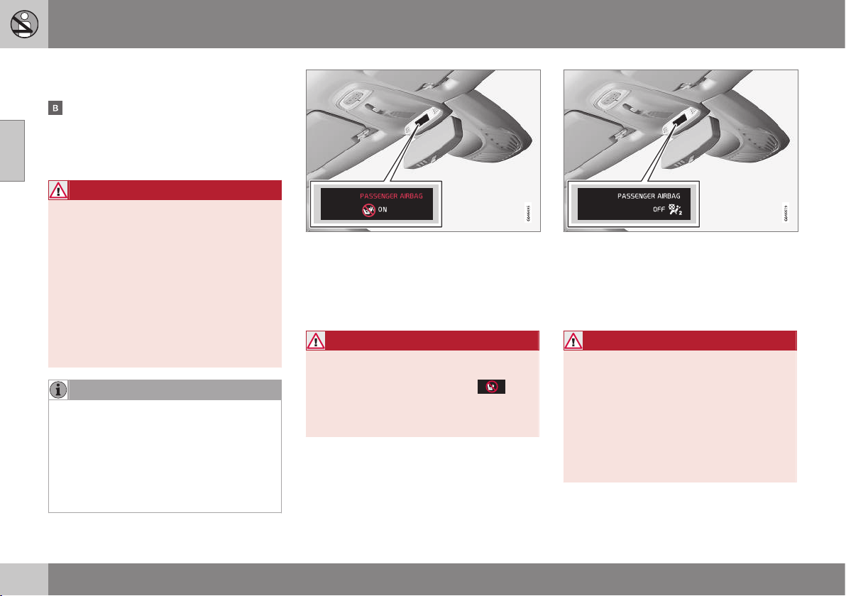
NOTE
When the remote control key is in key
position II (p. 71) the warning symbol (p.
28) for the airbag is shown in the com-
bined instrument panel for
approx. 6 seconds.
Following which, the indicator in the roof
console is illuminated showing the correct
status for the front passenger seat airbag.
Indicator showing that the passenger airbag is
activated.
A text message and a warning symbol in the
roof console indicate that the airbag for the
front passenger seat is activated (see preced-
ing illustration).
WARNING
Never place a child in a child seat or on a
booster cushion in the front seat if the air-
bag is activated and the symbol
in
the roof console is illuminated. Failure to
follow this advice could endanger the life
of the child.
Indicator showing that the passenger airbag is
deactivated.
A text message and a symbol in the roof con-
sole indicate that the airbag for the front pas-
senger seat is deactivated (see preceding
illustration).
WARNING
Do not allow anyone to sit in the front pas-
senger seat if the message in the roof con-
sole indicates that the airbag is deacti-
vated, and if the warning symbol (p. 28) for
the airbag system is also displayed on the
combined instrument panel. This indicates
that there has been a severe malfunction.
Visit a workshop as soon as possible.
Volvo recommends that you contact an
authorised Volvo workshop.
02 Safety
02
33
WARNING
Failure to follow the advice given above
can endanger the lives of passengers in
the car.
Related information
•
Child seats (p. 44)
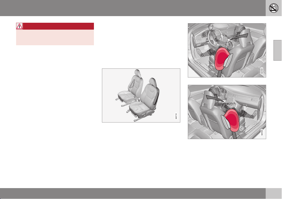
Side airbag (SIPS)
In a side impact collision a large proportion of
the collision force is transferred by the SIPS
(Side Impact Protection System) to beams,
pillars, the floor, the roof and other structural
parts of the body. The side airbags at the driv-
er's and front passenger seats protect the
chest area and the hip and are an important
part of the SIPS.
The SIPS bag system consists of two main
components, side airbag and sensors. The
side airbags are located in the front seat
backrests.
A sufficiently violent collision trips the sensors
and the side airbags are inflated. The airbag
inflates between the occupant and the door
panel and thereby cushions the initial impact.
The airbag deflates when compressed by the
collision. The side airbag is normally only
deployed on the side of the collision.
Driver's seat, left-hand drive.
Front passenger seat, left-hand drive.
||
02 Safety
02
34
WARNING
•
Volvo recommends that repairs are
only carried out by an authorised Volvo
workshop. Defective work in the SIPS-
bag system could cause malfunction
and result in serious personal injury.
•
Do not put objects in the area between
the outside of the seat and the door
panel, since this area is required by
the side airbag.
•
Volvo recommends the use only of car
seat covers approved by Volvo. Other
seat covers may impede the operation
of the side airbags.
•
Side airbags are a supplement the
seatbelts. Always use a seatbelt.
Related information
•
Airbags on driver's side (p. 30)
•
Passenger airbag (p. 30)
•
Side airbag (SIPS) - child seat/booster
cushion (p. 34)
•
Inflatable Curtain (IC) (p. 34)
Side airbag (SIPS) - child seat/booster
cushion
The protection provided by the car to children
seated in a child seat or on a booster cushion
is not diminished by the side airbag (p. 33).
Child seat/booster cushion (p. 44) can be
placed on the front passenger seat provided
that the car does not have an activated airbag
(p. 31) on the front passenger side.
Related information
•
Passenger airbag (p. 30)
•
General information on child safety (p.
42)
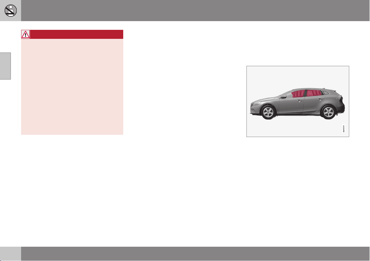
Inflatable Curtain (IC)
The inflatable curtain helps to prevent the
driver and passengers from striking their
heads on the inside of the car during a colli-
sion.
The inflatable curtain IC (Inflatable Curtain) is
a part of the SIPS system (p. 33). It is fitted in
the headlining along both sides of the roof
and protects the car's occupants sitting in the
outer seats. A sufficiently violent collision
trips the sensors and the inflatable curtain is
inflated.
02 Safety
02
35
WARNING
Never hang or attach heavy items onto the
handles in the roof. The hook is only
designed for light clothing (not for solid
objects such as umbrellas for example).
Do not screw or install anything onto the
car's headlining, door pillars or side pan-
els. This could compromise the intended
protection. Volvo recommends that you
only ever use Volvo genuine parts that are
approved for placement in these areas.
WARNING
Do not load the car higher than 50 mm
under the top edge of the windows in the
doors. Otherwise, the intended protection
of the inflatable curtain, which is con-
cealed in the headlining, may be compro-
mised.
WARNING
The inflatable curtain is a supplement to
the seatbelts.
Always use a seatbelt.
Related information
•
General information on seatbelts (p. 24)
•
Airbag system (p. 29)
•
Side airbag (SIPS) (p. 33)
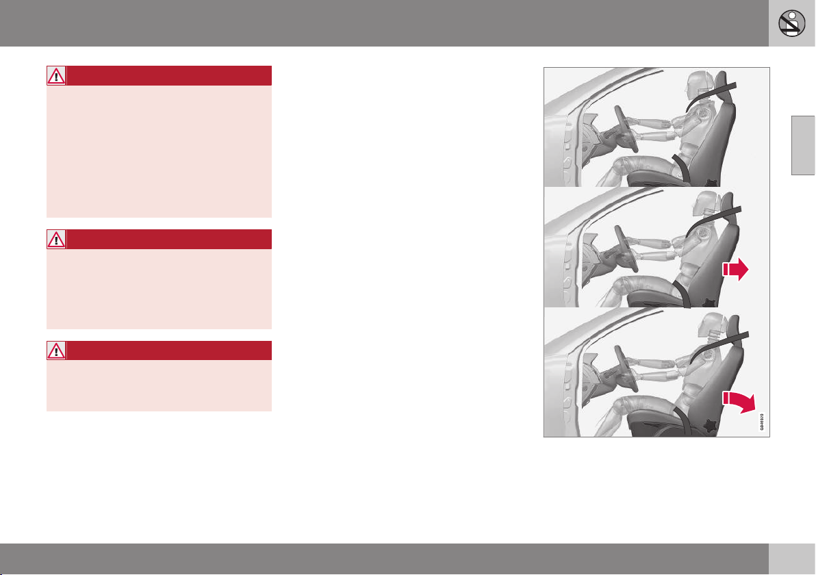
General information on WHIPS
(whiplash protection)
WHIPS (Whiplash Protection System) is a pro-
tection against whiplash injuries. The system
consists of energy absorbing backrests and
specially designed head restraints in the front
seats.
The WHIPS system is actuated by a rear-end
collision, where the angle and speed of the
collision, and the nature of the colliding vehi-
cle all have an influence.
||
02 Safety
02
36
WARNING
The WHIPS system is a supplement to the
seatbelts. Always use a seatbelt.
Properties of the seat
When the WHIPS system is deployed, the
front seat backrests are lowered backward to
alter the seating position of the driver and
front seat passenger. This reduces the risk of
whiplash injury.
WARNING
Never modify or repair the seat or WHIPS
system yourself. Volvo recommends that
you contact an authorised Volvo work-
shop.
Related information
•
WHIPS - child seats (p. 36)
•
WHIPS - seating position (p. 36)
•
General information on seatbelts (p. 24)
WHIPS - child seats
The protection provided by the car to children
seated in a child seat or on a booster cushion
is not diminished by the WHIPS system (p.
35).
Child seat/booster cushion (p. 44) can be
placed on the front passenger seat provided
that the car does not have an activated airbag
(p. 31) on the front passenger side.
Related information
•
General information on child safety (p.
42)
WHIPS - seating position
In order to obtain optimum protection from
the WHIPS system (p. 35) the driver and pas-
senger must have the correct seating position
and make sure that the system's function is
not obstructed.
Seating position
Set the correct seating position in the front
seat (p. 73) before driving starts.
Driver and front seat passenger should sit in
the centre of the seat with as little space as
possible between the head and the head
restraint.
Function
Do not leave any objects on the floor behind the
driver's seat/passenger seat that may prevent the
WHIPS system from functioning.
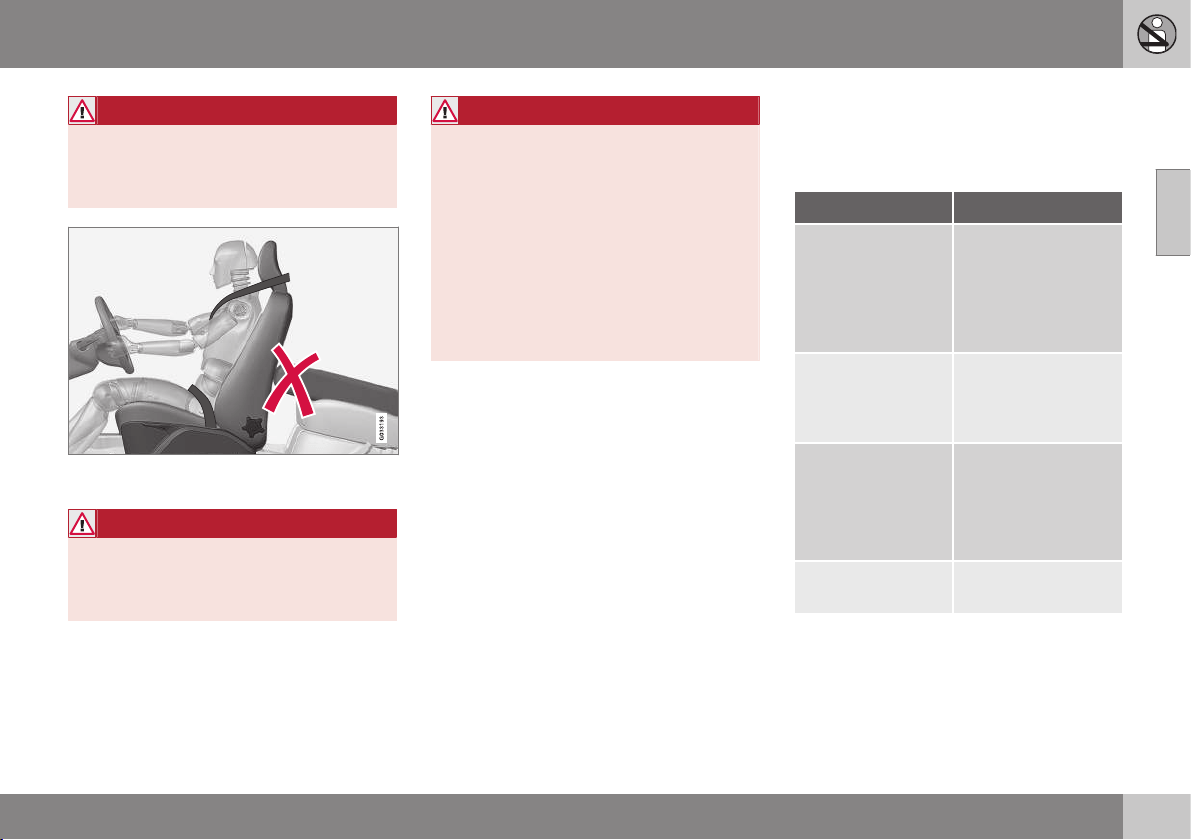
02 Safety
02
37
WARNING
Do not squeeze rigid objects between the
rear seat cushion and the front seat back-
rest. Make sure you do not to obstruct the
function of the WHIPS system.
Do not place objects on the rear seat that may
prevent the WHIPS system from functioning.
WARNING
If a rear seat backrest is folded down, the
corresponding front seat must be moved
forward so that it does not touch the
folded backrest.
WARNING
If a seat has been subjected to extreme
forces, such as due to a rear-end collision,
the WHIPS system must be checked.
Volvo recommends that it is checked by
an authorised Volvo workshop.
Part of the WHIPS system's protective
capacity may have been lost even if the
seats appear to be undamaged.
Volvo recommends that you contact an
authorised Volvo workshop to have the
system checked even after a minor rear-
end collision.
When the systems deploy
In the event of a collision Volvo's different
personal safety systems work together in
order to minimise injury.
System Triggered
Seatbelt ten-
sioner (p. 27) front
seat
In the event of a
frontal collision,
and/or side-impact
collision, and/or
rear-end collision
and/or overturning
Seatbelt ten-
sioner (p. 27) rear
seat
A
In a frontal collision
and/or side-impact
accident and/or
overturning
Airbags
(Steering wheel,
knee (p. 30), pas-
senger airbag (p.
30))
In a frontal collision
B
Side airbags
(SIPS) (p. 33)
In a side-impact
accident
B
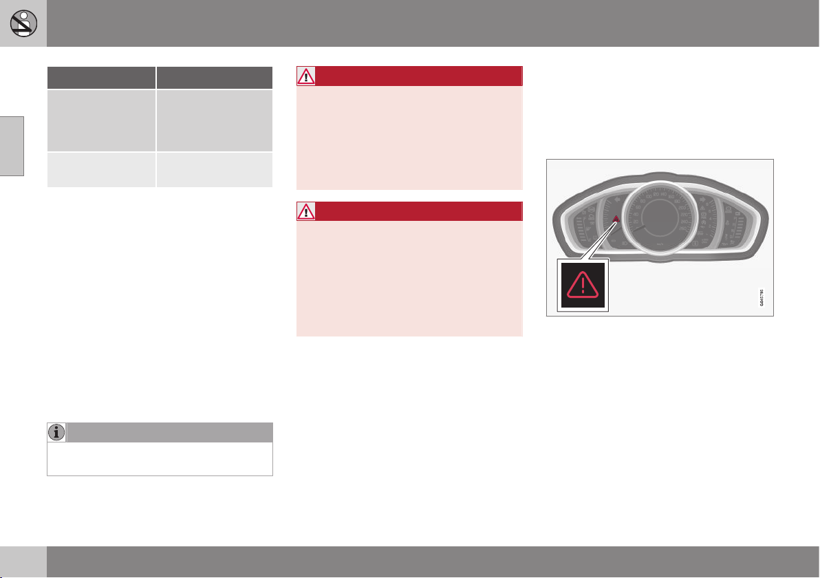
02 Safety
02
38
System Triggered
Inflatable Curtain
IC (p. 34)
In the event of a side
impact and/or over-
turning and/or some
frontal collisions
B
Whiplash protec-
tion WHIPS (p. 35)
In a rear-end colli-
sion
A
There is no seatbelt tensioner at the centre rear seat.
B
The bodywork of the car could be greatly deformed in a
collision without airbag deployment. A number of factors
such as the rigidity and weight of the object hit, the speed
of the car, the angle of the collision etc. affects how the
different safety systems of the car are activated.
If the airbags (p. 29) have deployed, the fol-
lowing is recommended:
•
Recovering the car. Volvo recommends
that you have it conveyed to an author-
ised Volvo workshop. Do not drive with
deployed airbags.
•
Volvo recommends that you engage an
authorised Volvo workshop to handle the
replacement of components in the car's
safety systems.
•
Always contact a doctor.
NOTE
The airbags and belt tensioner system are
deployed only once during a collision.
WARNING
The airbag system's control module is
located in the centre console. If the centre
console is drenched with water or other
liquid, disconnect the battery cables. Do
not attempt to start the car since the air-
bags may deploy. Recovering the car.
Volvo recommends that you have it con-
veyed to an authorised Volvo workshop.
WARNING
Never drive with deployed airbags. They
can make steering difficult. Other safety
systems may also be damaged. The
smoke and dust created when the airbags
are deployed can cause skin and eye irrita-
tion/injury after intensive exposure. In case
of irritation, wash with cold water. The
rapid deployment sequence and airbag
fabric may cause friction and skin burns.
General information on safety mode
Safety mode is a protective state that is
enforced when the collision may have dam-
aged any of the car's vital functions, such as
the fuel lines, sensors for one of the safety
systems, or the brake system.
Warning triangle in the analogue combined
instrument panel.
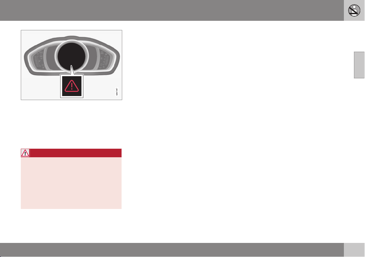
02 Safety
02
39
Warning triangle in the digital combined instru-
ment panel.
If the car is involved in a collision, the text
Safety mode See manual may appear in the
combined instrument panel (p. 60) informa-
tion display. This means that the car has
reduced functionality.
WARNING
Never attempt to repair your car or reset
the electronics yourself if the car has been
in safety mode. This could result in per-
sonal injury or the car not functioning as
normal. Volvo recommends that you
engage an authorised Volvo workshop to
check and restore the car to normal status
after
Safety mode See manual has been
displayed.
Related information
•
Safety mode - attempting to start the car
(p. 39)
•
Safety mode - moving the car (p. 40)
Safety mode - attempting to start the
car
If the car is set in safety mode (p. 38) then an
attempt to start the car can be made if every-
thing seems normal and the absence of fuel
leakage has been checked.
First, check that no fuel is leaking from the
car. There must be no smell of fuel either.
If everything seems normal and you have
checked for indications of fuel leakage, you
may attempt to start the car.
Remove the remote control key and open the
driver's door. If a message is now shown to
the effect that the ignition is on, press the
start button. Then close the door and reinsert
the remote control key. The car's electronics
will now try to reset themselves to normal
mode. Then try to start the car.
If the message
Safety mode See manual is
still shown on the display, then the car must
not be driven or towed, but a vehicle recovery
service (p. 310) used instead. Even if the car
appears to be driveable, hidden damage may
make the car impossible to control once mov-
ing.
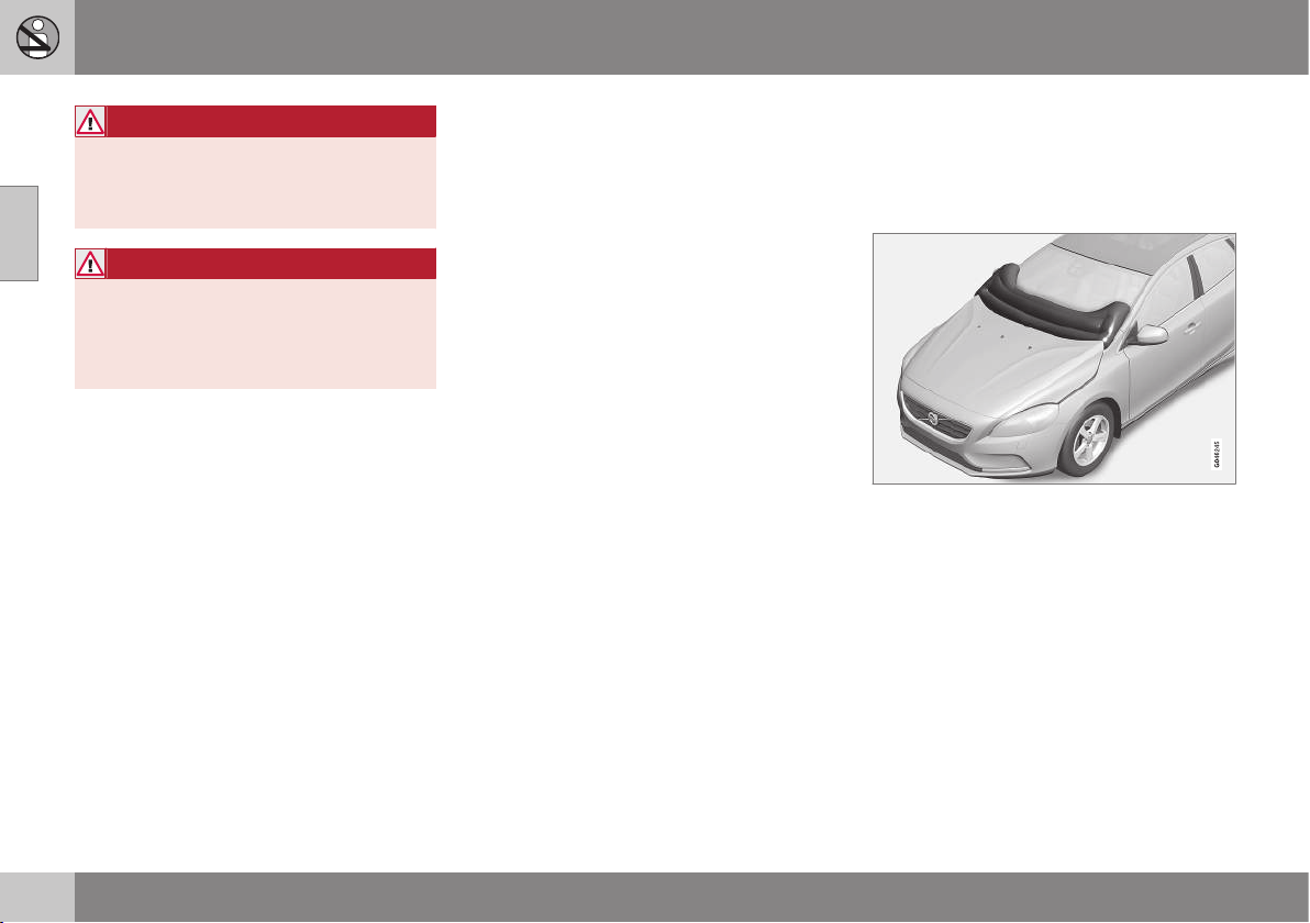
||
02 Safety
02
40
* Option/accessory, for more information, see Introduction.
WARNING
Never, under any circumstances, attempt
to restart the car if it smells of fuel when
the
Safety mode See manual message
is displayed. Leave the car at once.
WARNING
If the car is in safety mode it must not be
towed. It must be transported from its
location. Volvo recommends that it is
transported to an authorised Volvo work-
shop.
Related information
•
Safety mode - moving the car (p. 40)
Safety mode - moving the car
If Normal mode is shown after Safety mode
See manual has been reset after attempting
to start the car (p. 39) , the car can be moved
carefully out of a dangerous position.
Do not move the car further than necessary.
Related information
•
General information on safety mode (p.
38)
Pedestrian airbag*
In certain frontal collisions, the pedestrian air-
bag (Pedestrian Airbag) contributes to miti-
gating the collision of the pedestrian with the
car.
The pedestrian airbag (Pedestrian Airbag) is
fitted under the bonnet near the windscreen.
In the event of certain frontal collisions with a
pedestrian, the sensors in the front bumper
react and the airbag inflates if required based
on the force of the impact. The sensors are
active at a speed of approx. 20-50 km/h and
an ambient temperature between
-20 and +70°C.
The sensors are designed to detect a collision
with an object that has similar properties to
those of the human leg.
02 Safety
02
* Option/accessory, for more information, see Introduction.
41
NOTE
There may be objects in the traffic environ-
ment that prompt a signal to the sensors
that is similar to a collision with a pedes-
trian. It is possible that the system will be
activated in the event of a collision with
such an object.
If the airbag is activated (Pedestrian Airbag)
•
the rear part of the bonnet is raised and
locked in this position
•
the hazard warning flashers are activated
•
the brake system is prepared for the
upcoming emergency braking.
WARNING
Do not fit any accessories or change any-
thing in the front if the car is equipped with
airbag (Pedestrian Airbag). Incorrect inter-
vention at the front may cause incorrect
function in the system and lead to serious
injury and damage to the car.
Volvo recommends that genuine wiper
arms are used and that you only use genu-
ine parts for them.
WARNING
Volvo recommends contacting an author-
ised Volvo workshop in the event of dam-
age to the bumper in order to ensure that
the system is intact.
Related information
•
Pedestrian airbag - moving the car (p.
41)
•
Pedestrian airbag - folding up (p. 42)
Pedestrian airbag - moving the car
The car may be moved if it has not been set in
safety mode (p. 38).
If any of the other airbags in the passenger
compartment were activated then the car
remains in safety mode.
If only the pedestrian airbag (p. 40)
Pedestrian Airbag has been activated:
1. Move the car to a safe location as close
as possible.
2. Fold up the airbag in accordance with the
instructions (p. 42).
3. Seek the nearest workshop.
WARNING
Volvo recommends that, after activation of
the airbag, you contact an authorised
Volvo workshop as soon as possible.
Related information
•
Pedestrian airbag* (p. 40)
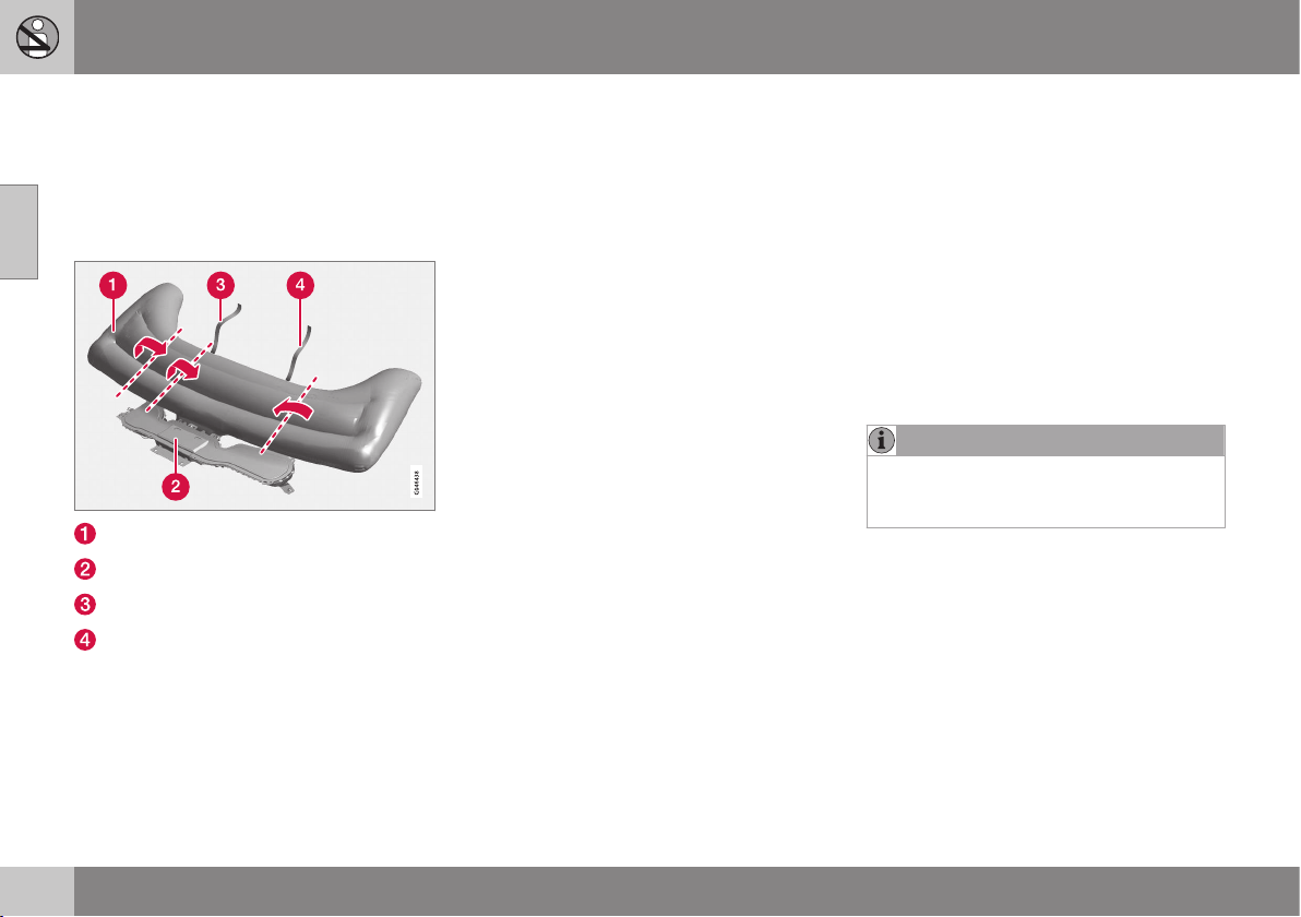
02 Safety
02
42
Pedestrian airbag - folding up
The car may be moved if it has not been set in
safety mode (p. 38).
The pedestrian airbag (p. 40) (Pedestrain
Airbag) must be folded up before the car is
moved.
Airbag (Pedestrian Airbag)
Airbag housing
Velcro strap, passenger side
Velcro strap, driver's side
The airbag may feel warm and give off
smoke. This is normal. Fold the airbag as fol-
lows:
1. Find the Velcro strap on the
driver's side (4).
2. Gather the airbag fabric along its length
on the driver's side. Then fold the gath-
ered fabric towards the centre. Wind the
Velcro strap (double sided) around as
much fabric as possible and fasten it.
3. Press the rolled up portion of the airbag
into the airbag housing (2).
4. Repeat steps 1-3 for the passenger side.
It may be necessary to fold the gathered
fabric twice on this side in order to wind
the Velcro strap around it.
5. The airbag housing cover will be open
slightly. This is completely normal.
Related information
•
Pedestrian airbag - moving the car (p. 41)
General information on child safety
Children of all ages and sizes must always sit
correctly secured in the car. Never allow a
child to sit on the knee of a passenger.
Volvo recommends that children travel in
rear-facing child seats until as late an age as
possible, at least until 3-4 years of age, and
then front-facing booster cushions/child seats
until up to 10 years of age.
The position of a child in the car and the
choice of equipment are dictated by the
child's weight and size; see Child seats (p.
44).
NOTE
Regulations regarding the placement of
children in cars vary from country to coun-
try. Check what does apply.
Volvo has child safety equipment (child seats,
booster cushions & attachment devices)
which is designed for your particular car.
Using Volvo's child safety equipment pro-
vides you with optimum conditions for your
child to travel safely in the car. Furthermore,
the child safety equipment fits and is easy to
use.

02 Safety
02
43
NOTE
In the event of questions when fitting child
safety products, contact the manufacturer
for clearer instructions.
Child safety locks
The controls for operating the rear door
power windows and the rear door opening
handles can be blocked (p. 179) from open-
ing from the inside.
Related information
•
Child seats (p. 44)
•
Child seats - location (p. 48)
•
Child seat - ISOFIX (p. 48)
•
Child seats - upper mounting points (p.
52)
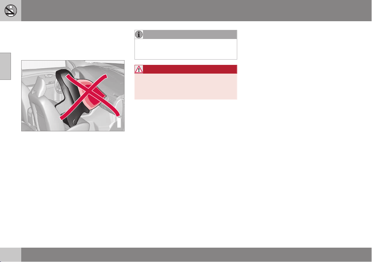
02 Safety
02
44
Child seats
Children should sit comfortably and safely.
Make sure that the child seat is being used
correctly.
G020739
Child seats and airbags are not compatible.
NOTE
When using child safety products it is
important to read the installation instruc-
tions included.
WARNING
Do not secure the straps of the child seat
to the seat's horizontal adjustment bar,
springs or the rails and beams under the
seat. Sharp edges may damage the straps.
Look in the installation instructions for the
child seat for the correct fitting.

02 Safety
02
}}
45
Recommended child seats
1
Weight Front seat (with deactivated airbag) Outer rear seat Centre rear
seat
Group 0
max 10 kg
Group 0+
max 13 kg
Volvo infant seat (Volvo Infant Seat) - rear-facing child
seat, secured with the ISOFIX fixture system.
Type approval: E1 04301146
(L)
Group 0
max 10 kg
Group 0+
max 13 kg
Volvo infant seat (Volvo Infant Seat) - rear-facing
child seat, secured with the car's seatbelt.
Type approval: E1 04301146
(U)
Volvo infant seat (Volvo Infant Seat) - rear-facing child
seat, secured with the car's seatbelt.
Type approval: E1 04301146
(U)
Volvo infant
seat (Volvo
Infant Seat) -
rear-facing child
seat, secured
with the car's
seatbelt.
Type approval:
E1 04301146
(U)
Group 0
max 10 kg
Group 0+
max 13 kg
Child seats which are universally approved.
A
(U)
Child seats which are universally approved.
(U)
1
With regard to other child seats your car should be included in the manufacturer's enclosed list of vehicles or be universally approved in accordance with the ECE R44 legal requirement.

||
02 Safety
02
46
Weight Front seat (with deactivated airbag) Outer rear seat Centre rear
seat
Group 1
9-18 kg
Volvo rear-facing/turnable child seat (Volvo
Convertible Child Seat) - rear-facing child seat,
secured with the car's seatbelt and straps.
Type approval: E5 04192
(L)
Volvo rear-facing/turnable child seat (Volvo Convertible
Child Seat) - rear-facing child seat, secured with the car's
seatbelt and straps.
Type approval: E5 04192
(L)
Group 1
9-18 kg
Child seats which are universally approved.
A
(U)
Child seats which are universally approved.
(U)
Group 2
15-25 kg
Volvo rear-facing/turnable child seat (Volvo
Convertible Child Seat) - rear-facing child seat,
secured with the car's seatbelt and straps.
Type approval: E5 04192
(L)
Volvo rear-facing/turnable child seat (Volvo Convertible
Child Seat) - rear-facing child seat, secured with the car's
seatbelt and straps.
Type approval: E5 04192
(L)
Group 2
15-25 kg
Volvo rear-facing/turnable child seat (Volvo
Convertible Child Seat) - front-facing child seat,
secured with the car's seatbelt.
Type approval: E5 04191
(U)
Volvo rear-facing/turnable child seat (Volvo Convertible
Child Seat) - front-facing child seat, secured with the
car's seatbelt.
Type approval: E5 04191
(U)
Group 2/3
15-36 kg
Volvo booster seat with backrest (Volvo Booster
Seat with backrest).
Type approval: E1 04301169
(UF)
Volvo booster seat with backrest (Volvo Booster Seat
with backrest).
Type approval: E1 04301169
(UF)

02 Safety
02
47
Weight Front seat (with deactivated airbag) Outer rear seat Centre rear
seat
Group 2/3
15-36 kg
Booster cushion with and without backrest (Booster
Cushion with and without backrest).
Type approval: E5 04216
(UF)
Booster cushion with and without backrest (Booster
Cushion with and without backrest).
Type approval: E5 04216
(UF)
L: Suitable for specific child seats. These child seats may be intended for use in a special car model, limited or semi-universal categories.
U: Suitable for universally approved child seats in this weight class.
UF: Suitable for front-facing universally approved child seats in this weight class.
B: Built-in child seats approved for this weight class.
A
Only for rear-facing child seat. Set the seat's backrest in upright position.
Related information
•
Child seats - location (p. 48)
•
Child seats - upper mounting points (p.
52)
•
Child seat - ISOFIX (p. 48)
•
General information on child safety (p. 42)
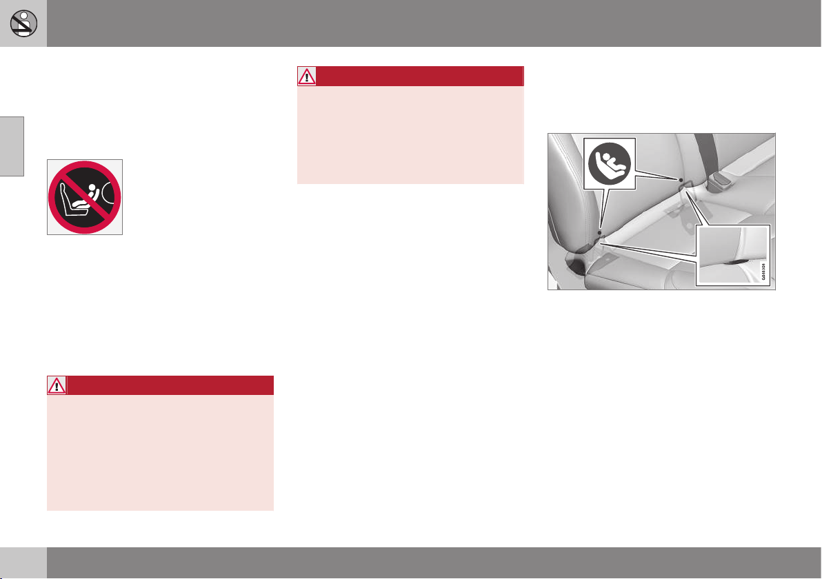
02 Safety
02
48
Child seats - location
Always fit child seats/booster cushions (p. 44)
in the rear seat if the passenger airbag is acti-
vated (p. 31). If a child is sitting on the front
passenger seat then he/she could suffer seri-
ous injury if the airbag deploys.
The label for the airbag is visible when the pas-
senger door is opened, see the illustration (p.
31).
You may place:
•
a child seat/booster cushion on the front
passenger seat provided there is no acti-
vated airbag on the front passenger side.
•
one or more child seats/booster cushions
in the rear seat.
WARNING
Never place a child in a child seat or on a
booster cushion in the front seat if the air-
bag (SRS) is activated.
No one shorter than 140 cm should ever
sit in the front passenger seat if the airbag
(SRS) is activated.
Failure to follow the advice given above
can endanger life.
WARNING
Booster cushions/child seats with steel
braces or some other design that could
rest on the seatbelt buckle's opening but-
ton must not be used, as they could cause
the seatbelt buckle to open accidentally.
Do not allow the upper section of the child
seat to rest against the windscreen.
Related information
•
General information on child safety (p. 42)
•
Child seats - upper mounting points (p.
52)
•
Child seat - ISOFIX (p. 48)
Child seat - ISOFIX
ISOFIX is a fixture system for car child seats
(p. 44) that is based on an international stand-
ard.
Mounting points for the ISOFIX fixture system
are located at the lower section of the rear
seat backrest, in the outer seats.
The location of the mounting points is indi-
cated by symbols in the backrest upholstery
(see preceding illustration).
Always follow the manufacturer's installation
instructions when connecting a child seat to
the ISOFIX mounting points.
Related information
•
ISOFIX - size classes (p. 49)
•
ISOFIX - types of child seat (p. 50)
•
General information on child safety (p. 42)
•
Child seats (p. 44)
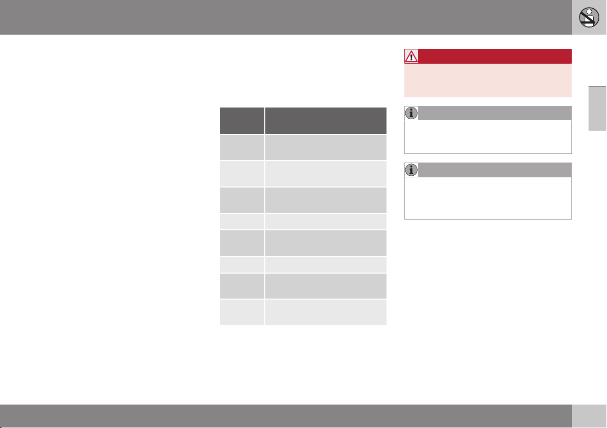
02 Safety
02
49
•
Child seats - location (p. 48)
•
Child seats - upper mounting points (p.
52)
ISOFIX - size classes
There is a size classification for child seats
using the ISOFIX (p. 48) fixture system in
order to assist users in choosing the correct
type of child seat (p. 50).
Size
class
Description
A Full size, front-facing child
seat
B Reduced size (alt. 1), front-
facing child seat
B1 Reduced size (alt.2), front-fac-
ing child seat
C Full size, rear-facing child seat
D Reduced size, rear-facing
child seat
E Rear-facing infant seat
F Transverse infant seat, left-
hand
G Transverse infant seat, right-
hand
WARNING
Never place the child in the passenger
seat if the car is fitted with an activated air-
bag.
NOTE
If an ISOFIX child seat has no size classifi-
cation, the car model must be included on
the vehicle list for the child seat.
NOTE
Volvo recommends that you contact an
authorised Volvo dealer for recommenda-
tions about which ISOFIX child seats Volvo
recommends.
Related information
•
ISOFIX - types of child seat (p. 50)
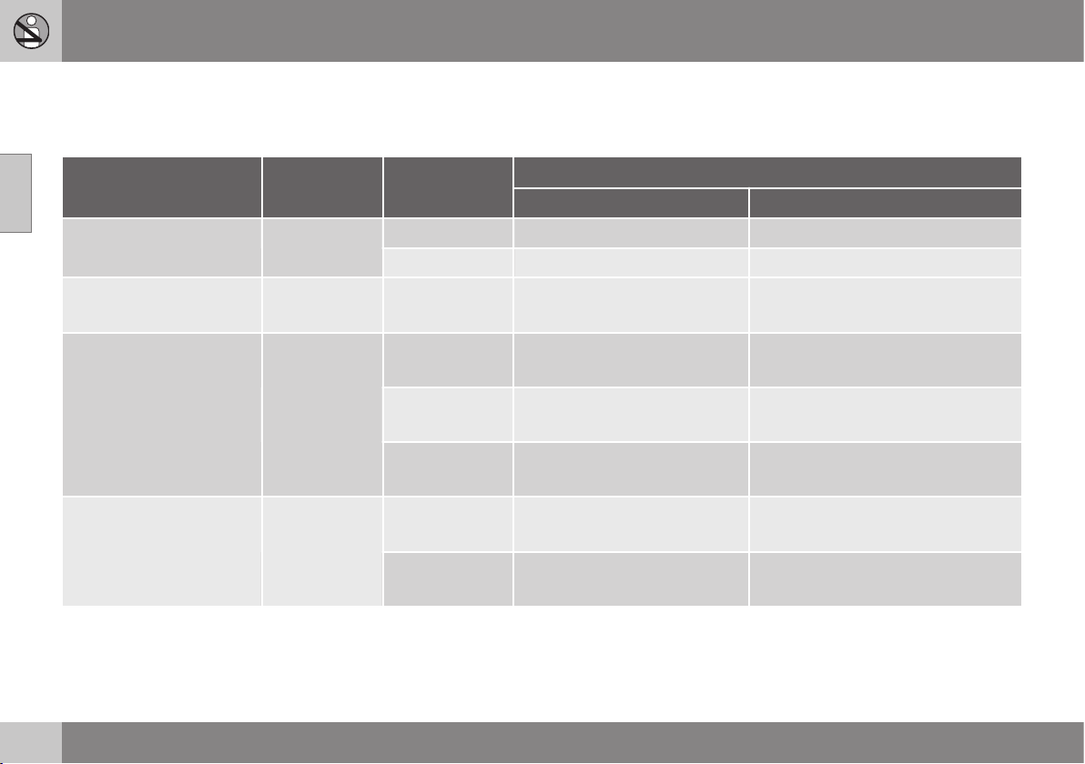
02 Safety
02
50
ISOFIX - types of child seat
Child seats are in different sizes – cars are in
different sizes. This means that not all child
seats are suitable for all seats in all car mod-
els.
Type of child seat Weight Size class
Passenger seats for ISOFIX
A
installation of child seats
Front seat Outer rear seat
Infant seat transverse max 10 kg F X X
G X X
Infant seat, rear-facing max 10 kg E X OK
(IL)
Infant seat, rear-facing max 13 kg E X OK
(IL)
D X OK
(IL)
C X OK
(IL)
Child seat, rear-facing 9-18 kg D X OK
(IL)
C X OK
(IL)

02 Safety
02
51
Type of child seat Weight Size class
Passenger seats for ISOFIX
A
installation of child seats
Front seat Outer rear seat
Front-facing child seat 9-18 kg B X
OK
B
(IUF)
B1 X
OK
B
(IUF)
A X
OK
B
(IUF)
X: The ISOFIX position is not suitable for ISOFIX child seats in this weight class and/or size class.
IL: Suitable for specific ISOFIX child seats. These child seats may be intended for use in a special car model, limited or semi-universal catego-
ries.
IUF: Suitable for front-facing ISOFIX child seats that are universally approved in this weight class.
A
ISOFIX is a fixture system for car child seats that is based on an international standard.
B
Volvo recommends rear-facing child seats for this group.
Make sure you select the right size class (p.
49) of child seat with ISOFIX fixture system.
Related information
•
Child seat - ISOFIX (p. 48)
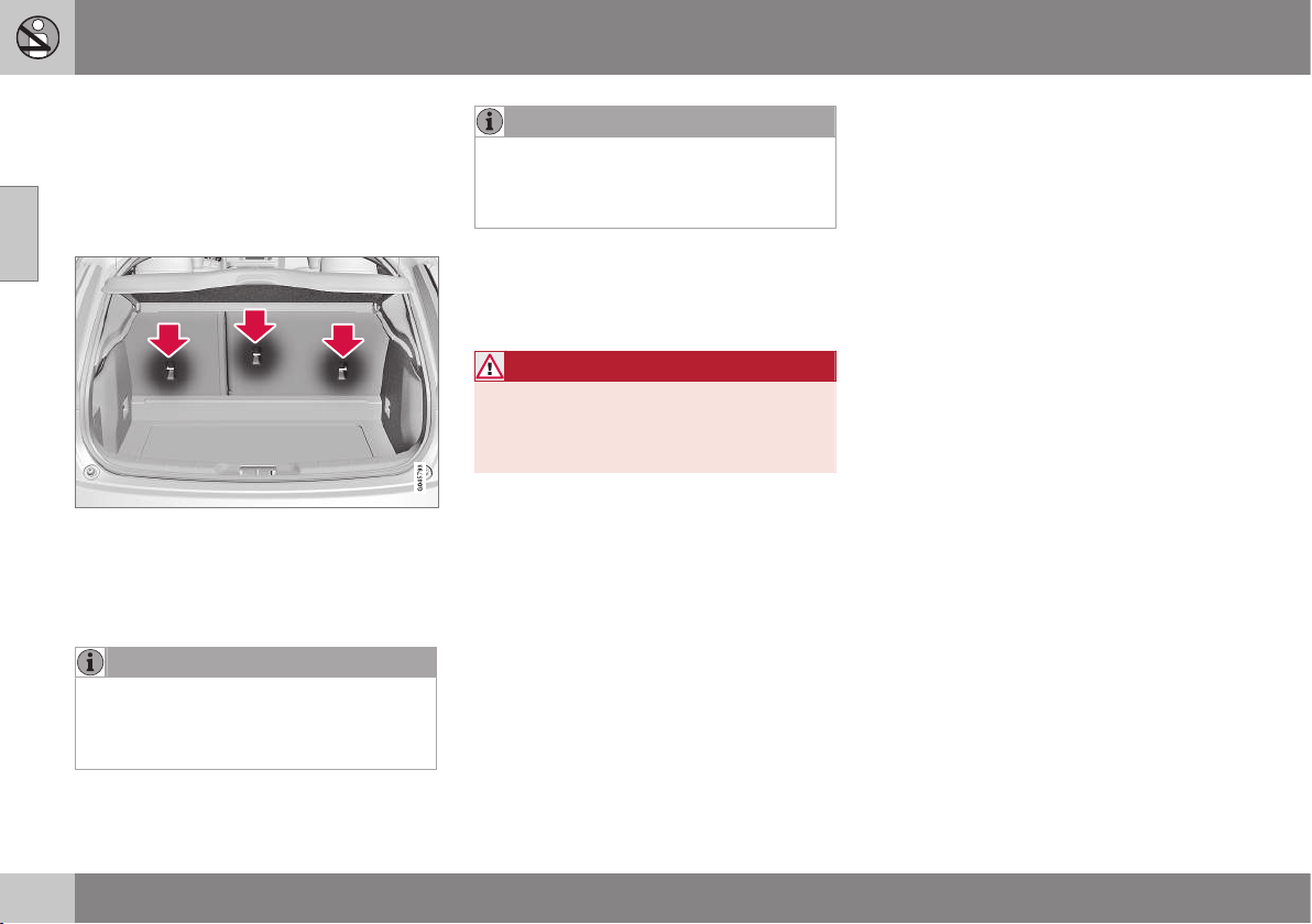
02 Safety
02
52
Child seats - upper mounting points
The car is equipped with upper mounting
points for certain front-facing child seats (p.
44). These mounting points are located on the
rear of the seat.
Upper mounting points
The upper mounting points are primarily
intended for use with front-facing child seats.
Volvo recommends that small children should
sit in rear-facing child seats to as late an age
as possible.
NOTE
Fold the head restraints in order to facili-
tate fitting this type of child seat in cars
with folding head restraints on the outer
seats.
NOTE
In cars with a cargo cover over the lug-
gage compartment, this must be removed
before child seats can be attached to the
securing points.
For detailed information on how the child seat
should be tensioned in the upper mounting
points, see the seat manufacturer's instruc-
tions.
WARNING
The child seat's straps must always be
drawn through the hole in the head
restraint leg before they are tensioned at
the attachment point.
Related information
•
General information on child safety (p. 42)
•
Child seats - location (p. 48)
•
Child seat - ISOFIX (p. 48)
INSTRUMENTS AND CONTROLS

03 Instruments and controls
03
54
Instruments and controls, left-hand
drive car - overview
The overview shows where the car's displays
and controls are located.
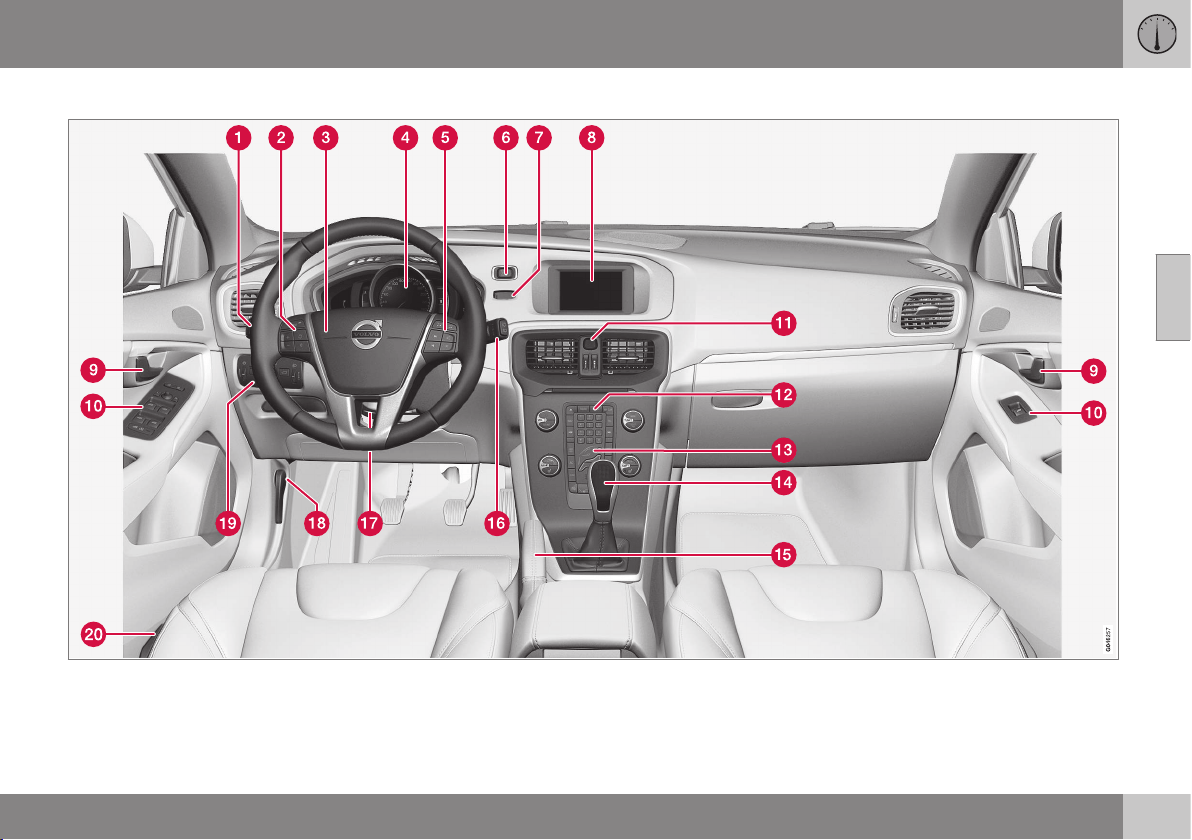
03 Instruments and controls
03
}}
55
Overview, left-hand drive cars
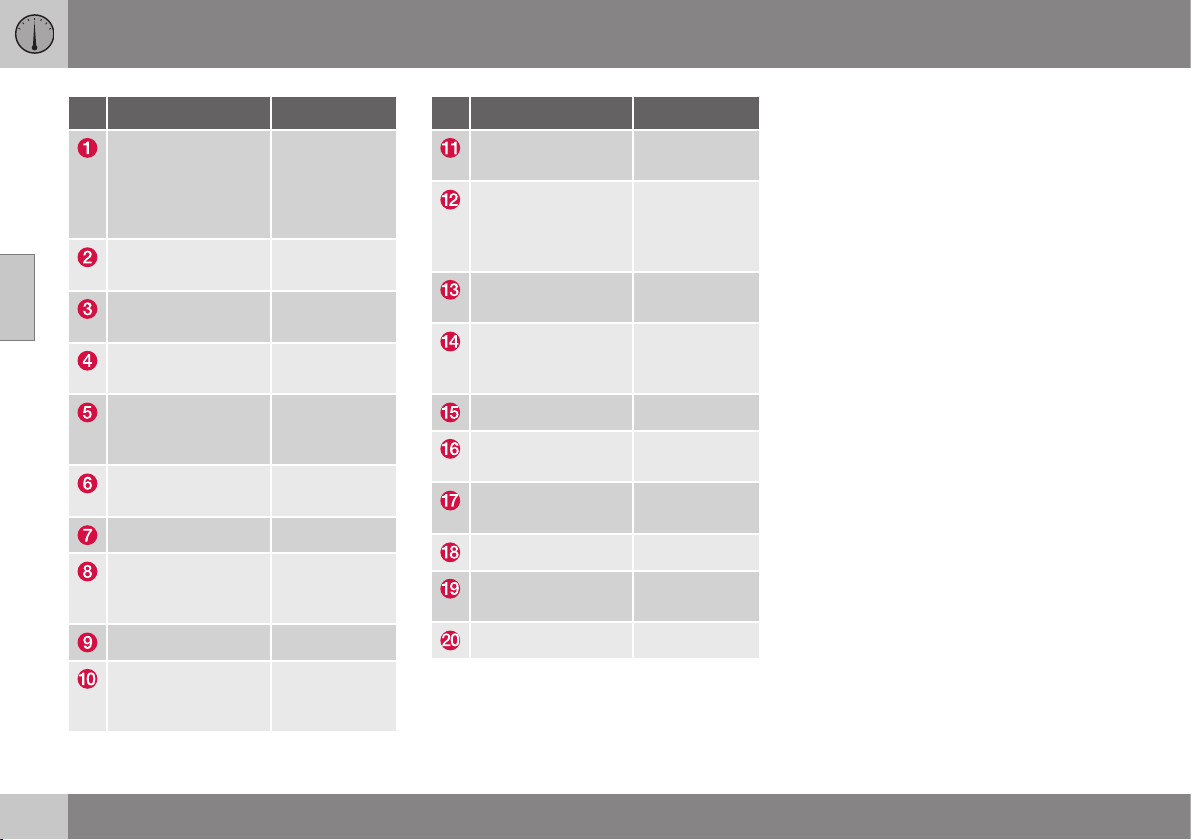
||
03 Instruments and controls
03
56
* Option/accessory, for more information, see Introduction.
Function See
Menus and mes-
sages, direction
indicators, main/
dipped beam, trip
computer
(p. 101), (p.
104), (p. 87),
(p. 82) and
(p. 123).
Cruise control (p. 194) and
(p. 199).
Horn, airbags (p. 77) and
(p. 29).
Combined instru-
ment panel
(p. 60).
Menu navigation,
audio control,
phone control*
(p. 106), (p.
372), (p. 374)
and (p. 404).
START/STOP
ENGINE button
(p. 268).
Ignition switch (p. 71).
Screen for infotain-
ment and display of
menus
(p. 106), (p.
371), (p. 372)
and (p. 372).
Door handle –
Control panel (p. 175), (p.
180), (p. 95)
and (p. 97).
Function See
Hazard warning
flashers
(p. 86).
Control panel for
infotainment system
and menu naviga-
tion
(p. 106), (p.
372) and (p.
374).
Control panel for
climate control
(p. 131) or (p.
132).
Gear selector (p. 272), (p.
273) or (p.
276).
Parking brake (p. 292).
Wipers and wash-
ing
(p. 93).
Steering wheel
adjustment
(p. 77).
Bonnet opener (p. 335).
Light switch,
opener for tailgate
(p. 78) and
(p. 176).
Seat adjustment* (p. 74).
Related information
•
Outside temperature gauge (p. 68)
•
Trip meter (p. 68)
•
Clock (p. 69)

03 Instruments and controls
03
}}
57
Instruments and controls, right-hand
drive car - overview
The overview shows where the car's displays
and controls are located.
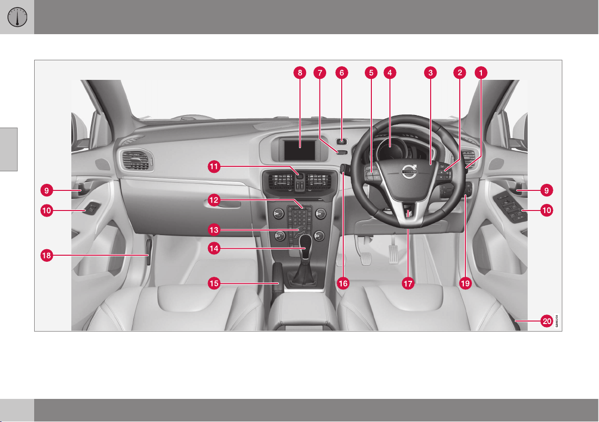
||
03 Instruments and controls
03
58
Overview, right-hand drive cars
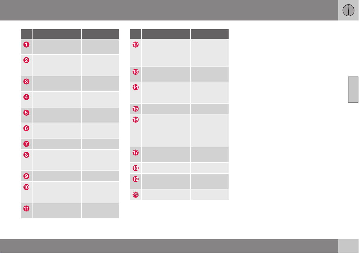
03 Instruments and controls
03
* Option/accessory, for more information, see Introduction.
59
Function See
Wipers and wash-
ing
(p. 93).
Menu navigation,
audio control,
phone control*
(p. 106), (p.
372), (p. 374)
and (p. 404).
Horn, airbags (p. 77) and
(p. 29).
Combined instru-
ment panel
(p. 60).
Cruise control (p. 194) and
(p. 199).
START/STOP
ENGINE button
(p. 268).
Ignition switch (p. 71).
Screen for infotain-
ment and display of
menus
(p. 106), (p.
371), (p. 372)
and (p. 372).
Door handle –
Control panel (p. 175), (p.
180), (p. 95)
and (p. 97).
Hazard warning
flashers
(p. 86).
Function See
Control panel for
infotainment system
and menu naviga-
tion
(p. 106), (p.
372) and (p.
374).
Control panel for
climate control
(p. 131) or (p.
132).
Gear selector (p. 272), (p.
273) or (p.
276).
Parking brake (p. 292).
Menus and mes-
sages, direction
indicators, main/
dipped beam, trip
computer
(p. 101), (p.
104), (p. 87),
(p. 82) and
(p. 123).
Steering wheel
adjustment
(p. 77).
Bonnet opener (p. 335).
Light switch,
opener for tailgate
(p. 78) and
(p. 176).
Seat adjustment* (p. 74).
Related information
•
Outside temperature gauge (p. 68)
•
Trip meter (p. 68)
•
Clock (p. 69)
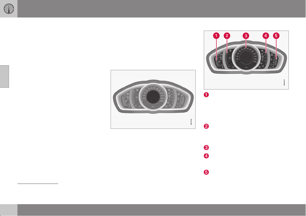
03 Instruments and controls
03
60
* Option/accessory, for more information, see Introduction.
Combined instrument panel
The combined instrument panel's information
display shows information on some of the
car's functions, e.g. cruise control and trip
computer, as well as messages.
•
Digital combined instrument panel - over-
view (p. 61)
•
Analogue combined instrument panel -
overview (p. 60)
•
Combined instrument panel - meaning of
indicator symbols (p. 65)
•
Combined instrument cluster - meaning
of warning symbols (p. 66)
Analogue combined instrument panel
- overview
The combined instrument panel's information
display shows information on some of the
car's functions, e.g. cruise control and trip
computer, as well as messages. The informa-
tion is shown with symbols and text.
Information display
Information display, analogue instrument panel.
There are further descriptions under the func-
tions that use the display.
Gauges and indicators
Fuel gauge. When the indicator lowers to
only one white marking
1
, the yellow indi-
cator symbol for low level in the fuel tank
is illuminated. See also Trip computer -
functions (p. 123) and Filling up with fuel
(p. 296).
Eco meter The meter provides an indica-
tion of how economically the car is being
driven. The higher the reading on the
scale, the more economical it is.
Speedometer
Tachometer. The meter indicates engine
speed in thousands of revolutions per
minute (rpm).
Gearchange indicator
2
/ Gear position
indicator
3
. See also Gear shift indicator*
1
When the display's message Distance to empty fuel tank: starts to show
----, the marking becomes red.
2
Manual gearbox
3
Automatic gearbox
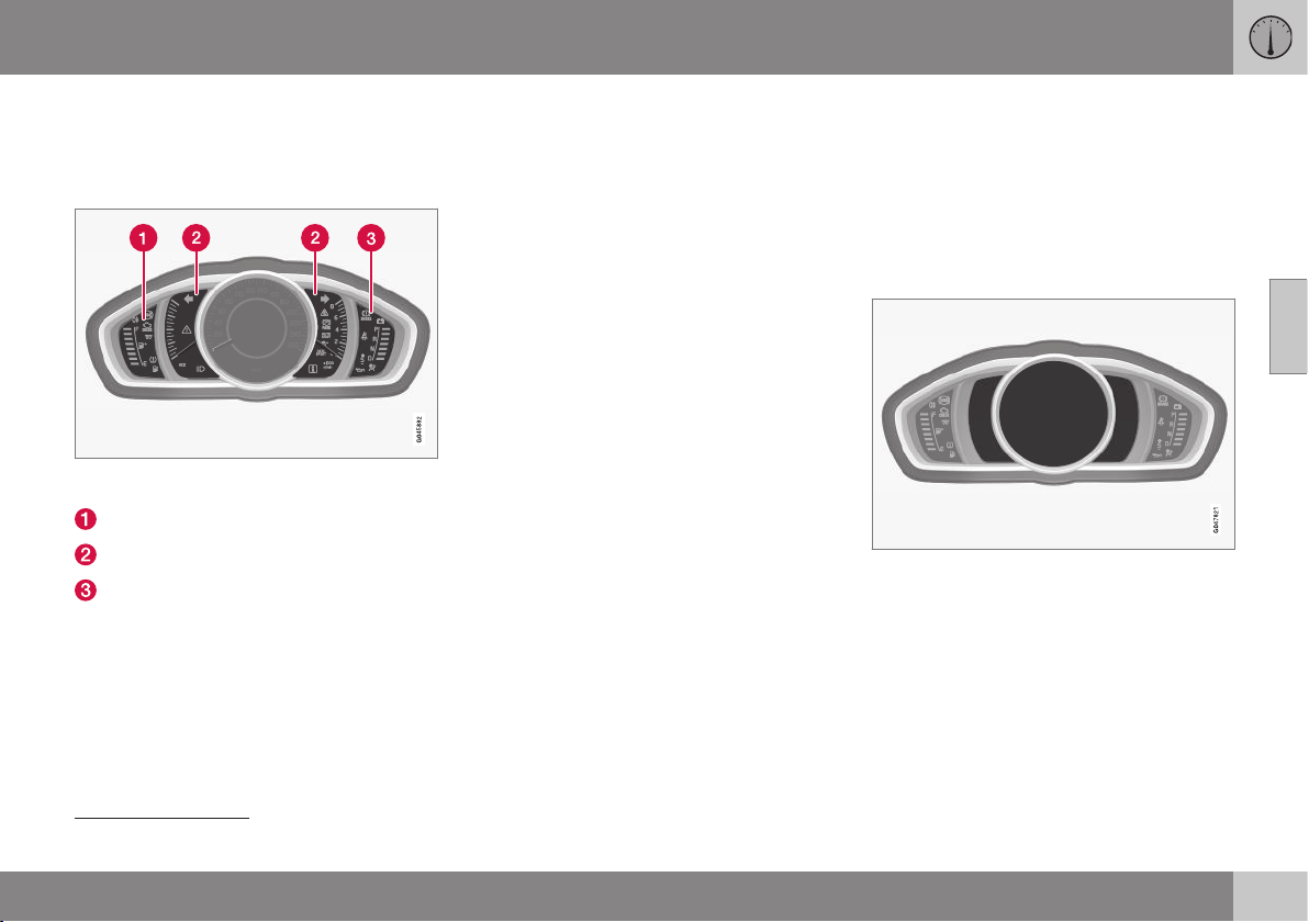
03 Instruments and controls
03
* Option/accessory, for more information, see Introduction.
61
(p. 272), Automatic gearbox - Geartronic*
(p. 273) or Automatic gearbox -
Powershift* (p. 276).
Indicator and warning symbols
Indicator and warning symbols, analogue instru-
ment panel.
Indicator symbols
Indicator and warning symbols
warning symbols
4
Functionality check
All indicator and warning symbols, apart from
symbols in the centre of the information dis-
play, illuminate in key position II or when the
engine is started. When the engine has
started, all the symbols should go out except
the parking brake symbol, which only goes
out when the brake is disengaged.
If the engine does not start or if the function-
ality check is carried out in key position II
then all symbols go out within a few seconds
except the symbol for faults in the car's emis-
sions system and the symbol for low oil pres-
sure.
Related information
•
Combined instrument panel (p. 60)
•
Combined instrument panel - meaning of
indicator symbols (p. 65)
•
Combined instrument cluster - meaning
of warning symbols (p. 66)
•
Digital combined instrument panel - over-
view (p. 61)
Digital combined instrument panel -
overview
The combined instrument panel's information
display shows information on some of the
car's functions, e.g. cruise control and trip
computer, as well as messages. The informa-
tion is shown with symbols and text.
Information display
Information display, digital instrument panel*.
There are further descriptions under the func-
tions that use the display.
Gauges and indicators
Various themes can be selected for the digital
combined instrument panel Possible themes
are "Elegance", "Eco" and "Performance".
The setting for the theme can be stored in the
remote control key's memory when locking
the car; see pages Remote control key with
4
For certain engine variants, the symbol for low oil pressure is not used. Warnings are made via display text; see Engine oil - checking and filling (p. 337).
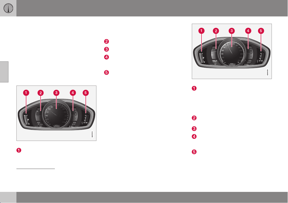
||
03 Instruments and controls
03
62
* Option/accessory, for more information, see Introduction.
key blade (p. 159) and MY CAR - Car set-
tings (p. 108).
A theme can only be selected when the
engine is running.
To select the theme, press the left-hand stalk
switch's OK button and select the
Themes
menu option by turning the thumbwheel on
the lever. Press the OK button. Turn the
thumbwheel to select the theme and confirm
the selection by pressing the OK button. For
more information on menu navigation, see
MY CAR - menu options (p. 106).
Gauges and indicators, theme "Elegance".
Fuel gauge. When the indicator lowers to
only one white marking
5
, the yellow indi-
cator symbol for low level in the fuel tank
is illuminated. See also Trip computer -
functions (p. 123) and Filling up with fuel
(p. 296).
Temperature gauge for engine coolant
Speedometer
Tachometer. The meter indicates engine
speed in thousands of revolutions per
minute (rpm).
Gearchange indicator
6
/ Gear position
indicator
7
. See also Gear shift indicator*
(p. 272), Automatic gearbox - Geartronic*
(p. 273) or Automatic gearbox -
Powershift* (p. 276).
Gauges and indicators, theme "Eco".
Fuel gauge. When the indicator lowers to
only one white marking
8
, the yellow indi-
cator symbol for low level in the fuel tank
is illuminated. See also Trip computer -
functions (p. 123) and Filling up with fuel
(p. 296).
Eco guide. See also Eco guide & Power
guide* (p. 64).
Speedometer
Tachometer. The meter indicates engine
speed in thousands of revolutions per
minute (rpm).
Gearchange indicator
6
/ Gear position
indicator
7
. See also Gear shift indicator*
(p. 272), Automatic gearbox - Geartronic*
5
When the display's message Distance to empty fuel tank: starts to show
----, the marking becomes red.
6
Manual gearbox
7
Automatic gearbox
8
When the display's message Distance to empty fuel tank: starts to show
----, the marking becomes red.
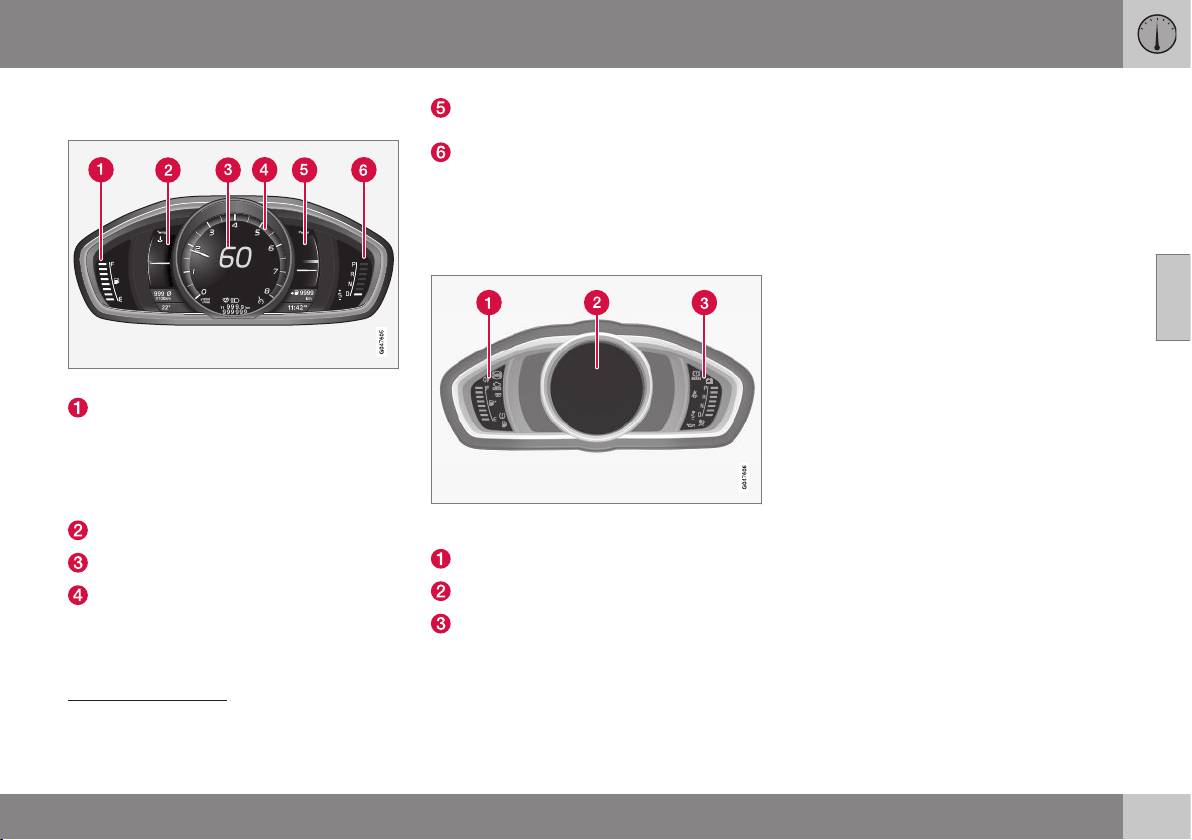
03 Instruments and controls
03
* Option/accessory, for more information, see Introduction.
63
(p. 273) or Automatic gearbox -
Powershift* (p. 276).
Gauges and indicators, theme "Performance".
Fuel gauge. When the indicator lowers to
only one white marking
9
, the yellow indi-
cator symbol for low level in the fuel tank
is illuminated. See also Trip computer -
functions (p. 123) and Filling up with fuel
(p. 296).
Temperature gauge for engine coolant
Speedometer
Tachometer. The meter indicates engine
speed in thousands of revolutions per
minute (rpm).
Power guide. See also Eco guide &
Power guide* (p. 64).
Gearchange indicator
6
/ Gear position
indicator
7
. See also Gear shift indicator*
(p. 272), Automatic gearbox - Geartronic*
(p. 273) or Automatic gearbox -
Powershift* (p. 276).
Indicator and warning symbols
Indicator and warning symbols, digital instrument
panel.
Indicator symbols
Indicator and warning symbols
warning symbols
10
Functionality check
All indicator and warning symbols, apart from
symbols in the centre of the information dis-
play, illuminate in key position II or when the
engine is started. When the engine has
started, all the symbols should go out except
the parking brake symbol, which only goes
out when the brake is disengaged.
If the engine does not start or if the function-
ality check is carried out in key position II
then all symbols go out within a few seconds
except the symbol for faults in the car's emis-
sions system and the symbol for low oil pres-
sure.
Related information
•
Combined instrument panel (p. 60)
•
Combined instrument panel - meaning of
indicator symbols (p. 65)
•
Combined instrument cluster - meaning
of warning symbols (p. 66)
•
Analogue combined instrument panel -
overview (p. 60)
9
When the display's message Distance to empty fuel tank: starts to show
----, the marking becomes red.
6
Manual gearbox
7
Automatic gearbox
10
For certain engine variants, the symbol for low oil pressure is not used. Warnings are made via display text; see Engine oil - checking and filling (p. 337).
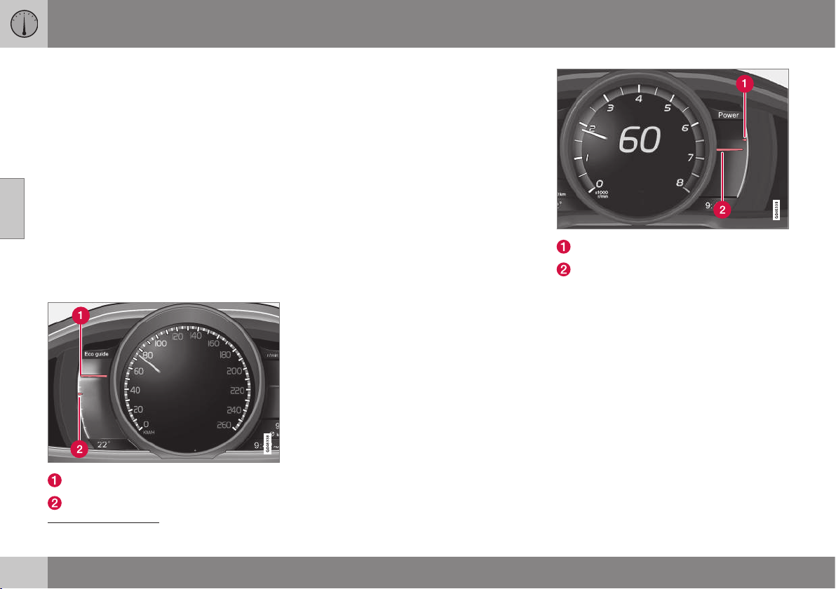
03 Instruments and controls
03
64
* Option/accessory, for more information, see Introduction.
Eco guide & Power guide*
Eco guide and Power guide are two com-
bined instrument panel (p. 60) instruments
which help the driver to drive the car with
optimum driving economy.
The car also stores statistics of journeys
made, which can be viewed in the form of a
block diagram; see Trip computer - trip statis-
tics* (p. 124).
Eco guide
This instrument provides an indication of how
economically the car is being driven.
To view this function, select the theme "Eco";
see Digital combined instrument panel - over-
view (p. 61).
Instantaneous value
Average value
Instantaneous value
The instantaneous value is displayed here -
the higher the result on the scale, the better.
The instantaneous value is calculated on the
basis of speed, engine speed, engine power
utilised plus use of the foot brake.
Optimum speed (50-80 km/h) and low revs
are encouraged. The pointers fall under
acceleration and braking.
Very low instantaneous values illuminate the
red zone on the meter (with a short delay),
which means poor driving economy and
hence should be avoided.
Average value
The average value slowly follows the instanta-
neous value and describes how the car has
been driven of late. The higher the pointers
on the scale, the better the economy ach-
ieved by the driver.
Power guide
This instrument shows the relationship
between how much power (Power) is being
taken from the engine and how much power
is available.
To view this function, select the theme
"Performance"; see Digital combined instru-
ment panel - overview (p. 61).
Available engine power
Engine power utilised
Available engine power
The smaller, upper pointer shows the availa-
ble engine power
11
. The higher the result on
the scale, the more power is available in the
current gear.
Engine power utilised
The larger, lower pointer shows the engine
power utilised
11
. The higher the result on the
scale, the more power is being taken from the
engine.
A large gap between the two pointers indi-
cates a large power reserve.
11
Power is dependent on engine speed.

03 Instruments and controls
03
}}
* Option/accessory, for more information, see Introduction.
65
Combined instrument panel -
meaning of indicator symbols
The indicator symbols alert the driver that a
function is activated, that the system is oper-
ating, or that an error or failure has occurred.
Indicator symbols
Symbol Specification
ABL fault
Emissions system
ABS fault
Rear fog lamp on
Stability system
Stability system, sport mode
Engine preheater (diesel)
Low level in fuel tank
Information, read display text
Main beam On
Left-hand direction indicator
Symbol Specification
Right-hand direction indicator
Start/Stop, the engine auto-
stopped; see Start/Stop* -
function and operation (p. 280)
ABL fault
The symbol illuminates if a fault has arisen in
the ABL function (Active Bending Lights).
Emissions system
If the symbol illuminates after the engine has
been started then it may be due to a fault in
the car's emissions system. Drive to a work-
shop for checking. Volvo recommends that
you seek assistance from an authorised Volvo
workshop.
ABS fault
If this symbol illuminates then the system is
not working. The car's regular brake system
continues to work, but without the ABS func-
tion.
1. Stop the car in a safe place and turn off
the engine.
2. Restart the engine.
3. If the symbol remains illuminated, drive to
a workshop to have the ABS system
checked. Volvo recommends that you
seek assistance from an authorised Volvo
workshop.
Rear fog lamp on
This symbol illuminates when the rear fog
lamp is switched on.
Stability system
A flashing symbol indicates that the stability
system is operating. If the symbol illuminates
with constant glow then there is a fault in the
system.
Stability system, sport mode
Sport mode allows for a more active driving
experience. The system then detects whether
the accelerator pedal, steering wheel move-
ments and cornering are more active than in
normal driving and then allows controlled
skidding of the rear section up to a certain
level before it intervenes and stabilises the
car.
Engine preheater (diesel)
This symbol illuminates during engine pre-
heating. Preheating mostly takes place due to
low temperature.
Low level in fuel tank
When the symbol illuminates the level in the
fuel tank is low, refuel as soon as possible.
Information, read display text
When one of the car's systems does not
behave as intended, this information symbol
illuminates and a text appears on the informa-
tion display. The message text is cleared with
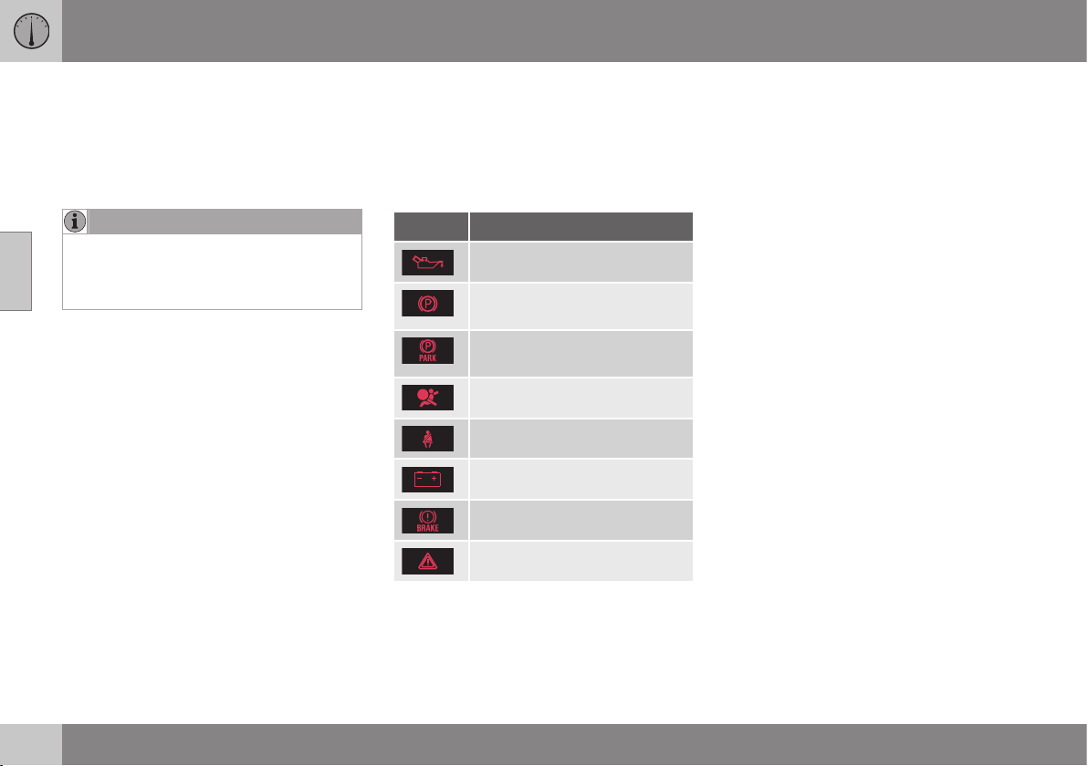
||
03 Instruments and controls
03
66
the OK button, see Menu navigation - com-
bined instrument panel (p. 101), or it disap-
pears automatically after a time (time
depending on which function is indicated).
The information symbol can also illuminate in
conjunction with other symbols.
NOTE
When a service message is shown, the
symbol and message are cleared using the
OK button, or disappear automatically
after a time.
Main beam On
The symbol illuminates when main beam is on
and with main beam flash.
Left/right-hand direction indicators
Both direction indicator symbols flash when
the hazard warning flashers are used.
Start/Stop
The symbol shines when the engine is auto-
stopped.
Related information
•
Combined instrument panel (p. 60)
•
Combined instrument cluster - meaning
of warning symbols (p. 66)
•
Analogue combined instrument panel -
overview (p. 60)
•
Digital combined instrument panel - over-
view (p. 61)
Combined instrument cluster -
meaning of warning symbols
The warning symbols alert the driver that an
important function is activated, or that a seri-
ous error or a serious failure has occurred.
Warning symbols
Symbol Specification
Low oil pressure
A
Parking brake applied, digital
instrument
Parking brake applied, ana-
logue instrument
Airbags – SRS
Seatbelt reminder
Alternator not charging
Fault in brake system
Warning
A
For certain engine variants, the symbol for low oil pressure
is not used. Warnings are made via display text; see
Engine oil - checking and filling (p. 337).
Low oil pressure
If this symbol illuminates during driving then
the engine's oil pressure is too low. Stop the
engine immediately and check the engine oil
level, top up if necessary. If the symbol illumi-
nates and the oil level is normal, contact a
workshop. Volvo recommends that you seek
assistance from an authorised Volvo work-
shop.
Parking brake applied
This symbol illuminates with a constant glow
when the parking brake is applied. The sym-
bol is illuminated during application. For more
information, see Parking brake (p. 292).
Airbags – SRS
If this symbol remains illuminated or illumi-
nates while driving, it means a fault has been
detected in the seatbelt buckle, SRS, SIPS, or
IC systems. Drive immediately to a workshop
to have the system checked. Volvo recom-
mends that you seek assistance from an
authorised Volvo workshop.
Seatbelt reminder
This symbol flashes if someone in a front seat
has not put on their seatbelt or if someone in
a rear seat has taken off their seatbelt.
Alternator not charging
This symbol illuminates during driving if a
fault has occurred in the electrical system.
Visit a workshop. Volvo recommends that you
seek assistance from an authorised Volvo
workshop.
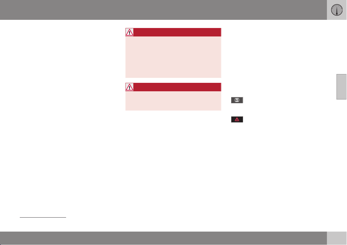
03 Instruments and controls
03
}}
* Option/accessory, for more information, see Introduction.
67
Fault in brake system
If this symbol illuminates, the brake fluid level
may be too low. Stop the car in a safe place
and check the level in the brake fluid reser-
voir; see Brake and clutch fluid - level (p.
341).
If the brake and ABS symbols illuminate at
the same time, there may be a fault in the
brake force distribution system.
1. Stop the car in a safe place and turn off
the engine.
2. Restart the engine.
•
If both symbols extinguish, continue
driving.
•
If the symbols remain illuminated,
check the level in the brake fluid reser-
voir; see Brake and clutch fluid - level
(p. 341). If the level in the brake fluid
reservoir is normal but the symbols are
still illuminated, the car can be driven,
with great care, to a workshop to have
the brake system checked. Volvo rec-
ommends that you seek assistance
from an authorised Volvo workshop.
WARNING
If the brake fluid is below the MIN level in
the brake fluid reservoir, do not drive fur-
ther before topping up the brake fluid.
The loss of brake fluid must be investiga-
ted by a workshop. Volvo recommends
that you contact an authorised Volvo
workshop.
WARNING
If the BRAKE and ABS symbols are lit at
the same time, there is a risk that the rear
end will skid during heavy braking.
Warning
The red warning symbol illuminates when a
fault has been indicated which could affect
the safety and/or driveability of the car. An
explanatory text is shown on the information
display at the same time. The symbol remains
visible until the fault has been rectified but the
text message can be cleared with the OK
button; see Menu navigation - combined
instrument panel (p. 101). The warning sym-
bol can also illuminate in conjunction with
other symbols.
Action:
1. Stop in a safe place. Do not drive the car
further.
2. Read the information on the information
display. Implement the action in accord-
ance with the message in the display.
Clear the message using the OK button.
Reminder – doors not closed
If one of the doors is not closed properly then
the information or warning symbol illuminates
together with an explanatory image in the
information display. Stop the car in a safe
place as soon as possible and close the door
that is open.
If the car is driven at a speed lower
than approx. 7 km/h then the informa-
tion symbol illuminates.
If the car is driven at a speed higher
than approx. 7 km/h then the warning
symbol illuminates.
If the bonnet
12
is not closed properly then the
warning symbol illuminates together with an
explanatory image in the information display.
Stop the car in a safe place as soon as possi-
ble and close the bonnet.
If the tailgate is not closed properly then the
information symbol illuminates together with
an explanatory image in the information dis-
play. Stop the car in a safe place as soon as
possible and close the tailgate.
12
Only cars with alarm*.
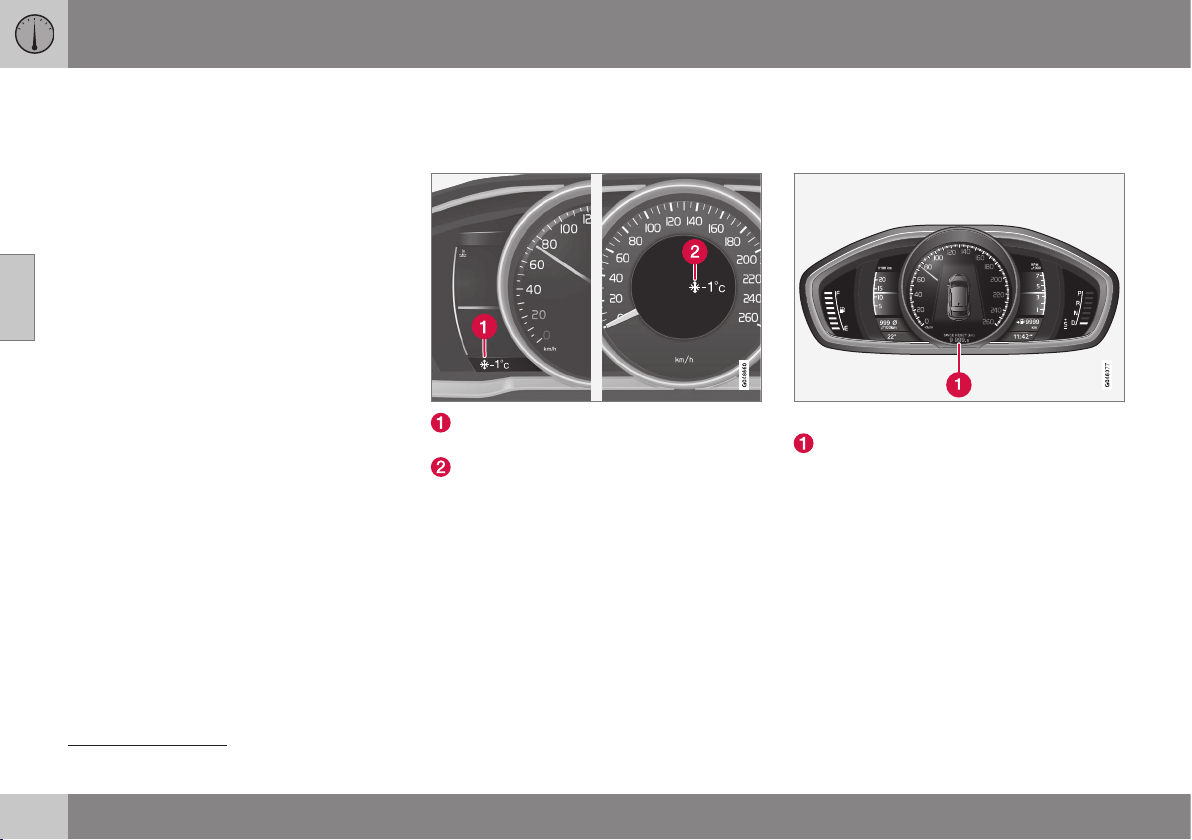
||
03 Instruments and controls
03
68
Related information
•
Combined instrument panel (p. 60)
•
Combined instrument panel - meaning of
indicator symbols (p. 65)
•
Analogue combined instrument panel -
overview (p. 60)
•
Digital combined instrument panel - over-
view (p. 61)
Outside temperature gauge
The display for the outside temperature gauge
appears in the combined instrument panel.
Display for outside temperature gauge,
digital instrument panel
Display for outside temperature gauge,
analogue instrument panel
When the temperature lies between +2 °C to
-5 °C a snowflake symbol illuminates in the
display. This warns of icy roads. If the car has
been stationary then the gauge may show a
reading that is too high.
Related information
•
Combined instrument panel (p. 60)
Trip meter
The trip meter display appears in the com-
bined instrument panel.
Trip meter, digital instrument.
Display for trip meter
13
The two trip meters
T1 and T2 are used for
measuring short distances. The distance is
shown in the display.
Turn the left stalk switch thumbwheel to show
the required meter.
A long press (until the change occurs) on the
left-hand stalk switch's RESET button resets
the trip meter shown. For more information,
see Trip computer - functions (p. 123).
Related information
•
Combined instrument panel (p. 60)
13
Display appearance may differ depending on instrument variant.
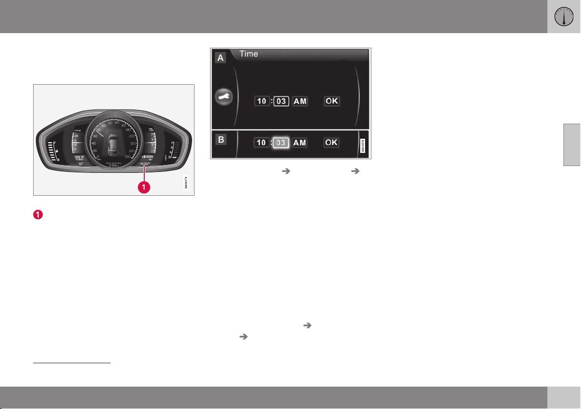
03 Instruments and controls
03
69
Clock
The clock display appears in the combined
instrument panel.
Clock, digital instrument panel.
Display for showing the time
14
Set the clock
The clock can be adjusted in the menu group
MY CAR; for more information see MY CAR -
menu options (p. 106).
1.
Locate
Settings System options
Time.
2. The cursor is located in the first box for
Hour: Press OK/MENU - the box is acti-
vated.
3. Turn TUNE to set the correct hour and
press OK/MENU - the box is deactivated.
4. Turn TUNE to select the box for Minute
(A) and press OK/MENU - the box is acti-
vated (B).
5. Turn TUNE to set the correct minute and
press OK/MENU - the box is deactivated.
6.
Turn TUNE to select the box for
OK and
press OK/MENU - the setting is com-
plete.
The menu option
Settings System
options Time format selects the 24h or
12h system (AM/PM).
Related information
•
Combined instrument panel (p. 60)
14
The time is shown in the middle of the instrument panel when an analogue instrument panel is fitted.
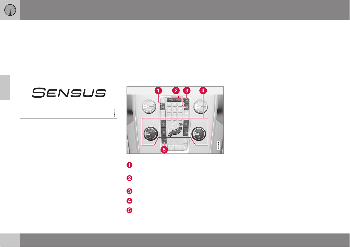
03 Instruments and controls
03
70
* Option/accessory, for more information, see Introduction.
Volvo Sensus
Volvo Sensus is the car's operating system,
the heart of your personal Volvo experience. It
is Sensus that provides information, entertain-
ment and functions to simplify your owner-
ship.
Volvo Sensus combines and presents many
functions in several of the car's systems on
the display screen. With Volvo Sensus the car
can be personalised by means of an intuitive
user interface. Settings can be made in Car
settings, Audio and media, Climate control,
etc.
With the centre console buttons and controls
or the steering wheel's right-hand keypad*
functions can be activated or deactivated and
many different settings can be made.
With a press on MY CAR all settings related
to the driving and control of the car are pre-
sented, such as City Safety, Locks and alarm,
setting the clock, etc.
With a press on the respective function:
RADIO, MEDIA, TEL*, NAV* and CAM* other
sources, systems and functions can be acti-
vated, e.g. AM, FM1, CD, DVD*, TV*, Blue-
tooth*, navigation* and park assist camera*.
For more information on all functions/
systems, see the respective section in the
owner's manual.
Overview
Centre console control panel.
Navigation* - NAV, see separate supple-
ment.
Audio and media (p. 371) (RADIO,
MEDIA, TEL*).
Car settings (p. 108) - MY CAR.
Climate control system (p. 126).
Park assist camera (p. 249) - CAM*.
Related information
•
Licenses (p. 470)
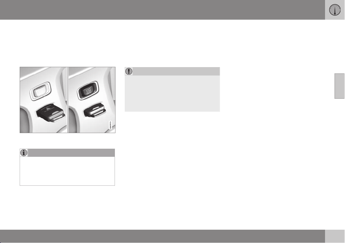
03 Instruments and controls
03
* Option/accessory, for more information, see Introduction.
71
Key positions
The remote control key can be used to set the
vehicle's electrical system in different modes/
levels so that different functions are available;
see Key positions - functions at different lev-
els (p. 71).
Ignition switch with remote control key extrac-
ted/inserted.
NOTE
For cars with the Keyless* function the key
does not need to be inserted into the igni-
tion switch but can be stored in e.g. a
pocket. For more information on Keyless
functions, see Keyless* (p. 168).
Insert the key
1. Hold the end of the remote control key
with the detachable key blade and insert
the key in the ignition switch.
2. Then press the key in the lock up to its
end position.
IMPORTANT
Foreign objects in the ignition switch can
impair the function or destroy the lock.
Do not press in the remote control key
incorrectly turned - Hold the end with the
detachable key blade; see Detachable key
blade - detaching/attaching (p. 166).
Withdraw the key
Push the remote control key, allow it to eject,
then pull it out from the ignition switch.
Key positions - functions at different
levels
In order to enable the use of a limited number
of functions with the engine switched off, the
car's electrical system can be set in 3 differ-
ent levels (key positions) - 0, I and II - with the
remote control key. Throughout this owner's
manual these levels are described using the
denomination "key positions".
The following table shows the functions avail-
able in each key position/level.
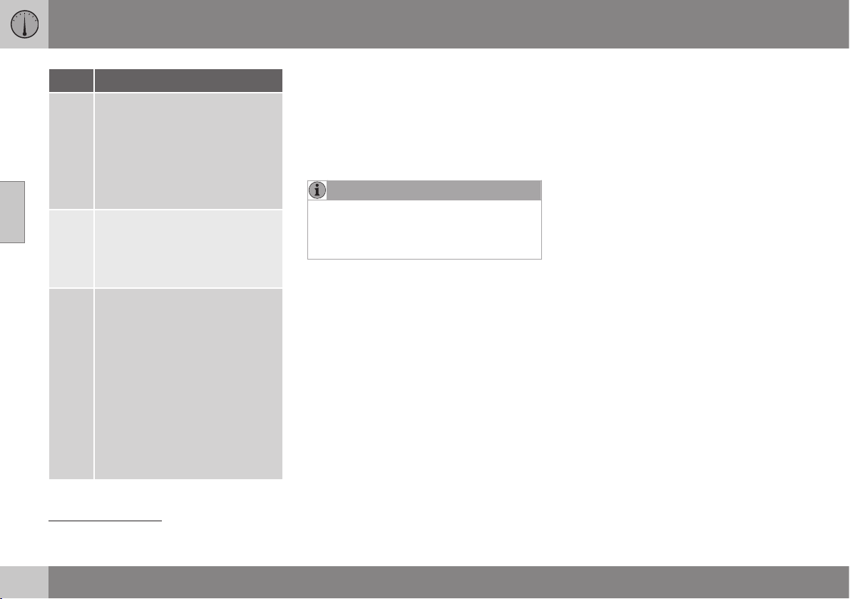
||
03 Instruments and controls
03
72
* Option/accessory, for more information, see Introduction.
Level Functions
0
Odometer, clock and temperature
gauge are illuminated.
Electrically operated seats can be
adjusted.
The audio system can be used for
a limited time, see Audio and
media (p. 371).
I
Sun visor for glass roof, power
windows, 12 V socket in the pas-
senger compartment, RTI, phone,
ventilation fan and windscreen
wipers can be used.
II
The headlamps come on.
Warning/indicator lamps illumi-
nate for 5 seconds.
Several other systems are acti-
vated. However, heating in seat
cushions and the rear window can
only be activated after the engine
has been started.
This key position consumes a
lot of current from the starter
battery and should therefore be
avoided!
Choosing key position/level
•
Key position 0 - Unlock the car - This
means that the car's electrical system is
at level 0.
•
Key position I - With the remote control
key fully inserted into the ignition switch
15
- Briefly press START/STOP ENGINE.
NOTE
To reach level I or II without starting the
engine - do not depress the brake/clutch
pedal when these key positions are due to
be selected.
•
Key position II - With the remote control
key fully inserted into the ignition switch
15
- Give a long
16
press on START/STOP
ENGINE.
•
Back to key position 0 - To return to key
position 0 from position II and I - Briefly
press on START/STOP ENGINE.
Audio system
For information on the audio system's func-
tions with remote control key removed, see
Audio and media (p. 371).
Starting and stopping the engine
For information about starting/switching off
the engine, see Starting the engine (p. 268).
Towing
For important information about the remote
control key during towing, see Towing (p.
308).
Related information
•
Key positions (p. 71)
15
Not necessary for cars with the Keyless* function.
16
Approx. 2 seconds.
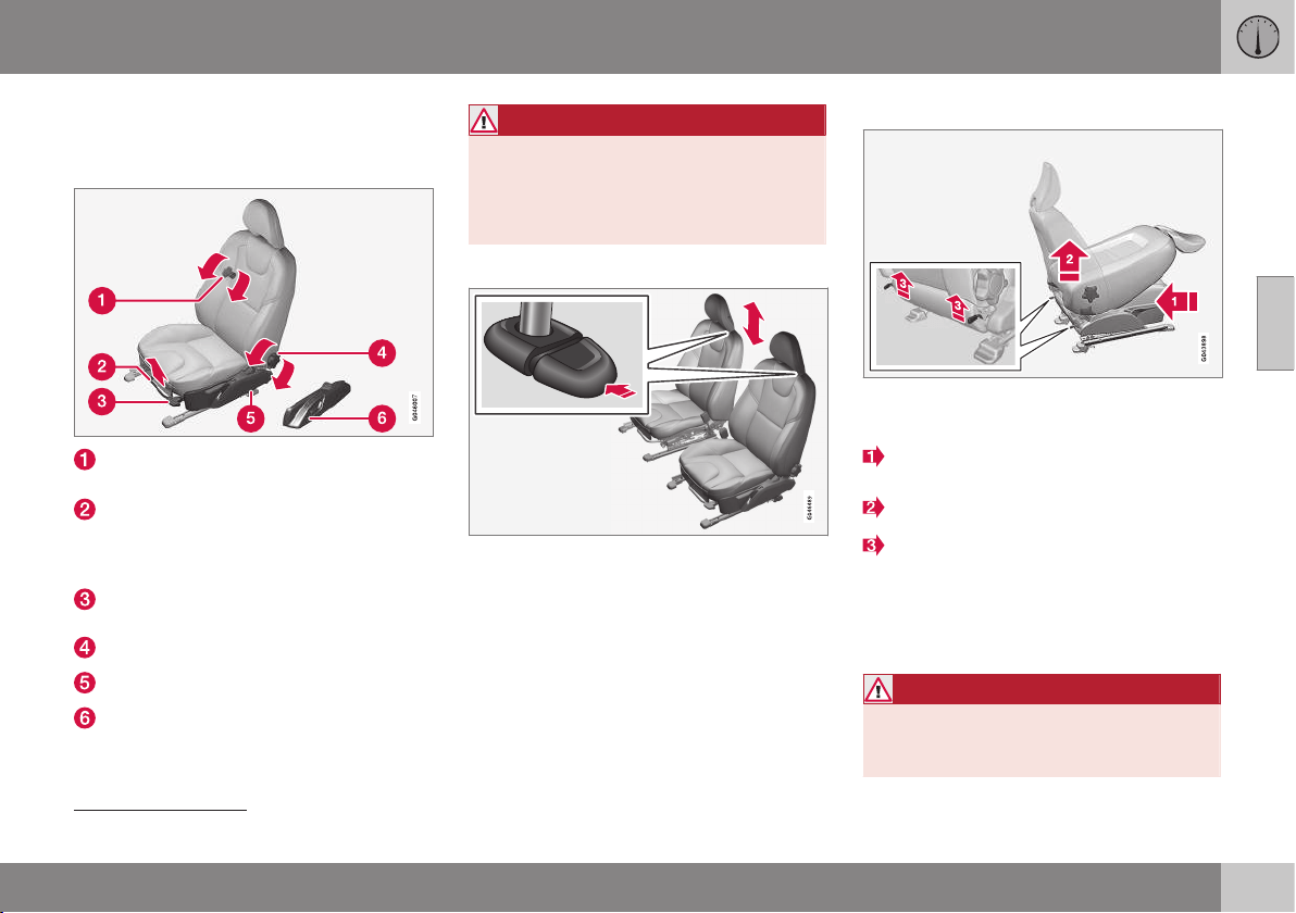
03 Instruments and controls
03
}}
* Option/accessory, for more information, see Introduction.
73
Seats, front
The car's front seats have different setting
options for optimum seating comfort.
To adjust lumbar support*, turn the
wheel
17
.
Forward/backward: lift the handle to
adjust the distance to the steering wheel
and pedals. Check that the seat is locked
after changing position.
To raise/lower the front edge of seat
cushion*, pump up/down.
Adjust backrest rake, turn the wheel.
Raise/lower the seat*, pump up/down.
Control panel for power seat*.
WARNING
Adjust the position of the driver's seat
before setting off, never while driving.
Make sure that the seat is in locked posi-
tion in order to avoid personal injury in the
event of sudden braking or an accident.
Adjusting front seat head restraints
The height of the front seat head restraints can
be adjusted.
Adjust the head restraint based on the per-
son's height so that the whole of the back of
the head is covered if possible.
To adjust the height, the button (see illustra-
tion) must be pressed while the restraint is
moved up or down.
The head restraint can be adjusted in three
different positions.
Lowering the front seat backrest*
The passenger seat backrest can be folded
forward to make room for long loads.
Move the seat as far back/down as possi-
ble.
Adjust the backrest to an upright position.
Lift the catches on the rear of the back-
rest and fold it forward.
4. Push the seat forward so that the head
restraint "locks" in under the glovebox.
Raising takes place in reverse order.
WARNING
Do not use the space behind the front
seat, or the rear seat's centre seat, when
the front seat backrest is lowered.
17
Also applies to power seat.
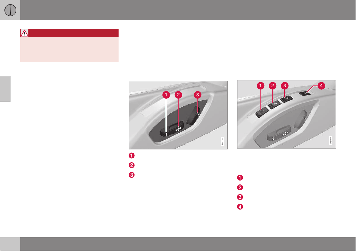
||
03 Instruments and controls
03
74
* Option/accessory, for more information, see Introduction.
WARNING
Grasp the backrest and make sure that it
is properly locked after being folded up in
order to avoid personal injury in the event
of sudden braking or an accident.
Related information
•
Seats, front - electrically operated (p.
74)
•
Seats, rear (p. 76)
Seats, front - electrically operated
The car's front seats have different setting
options for optimum seating comfort. The
power seat can be moved forward/backward
and up/down. The front edge of the seat
cushion can be raised/lowered. The backrest
angle can be changed.
Electrically operated seat*
Front edge of seat cushion up/down
Seat forward/backward and up/down
Backrest rake
The power front seats have overload protec-
tion which is tripped if a seat is blocked by an
object. If this happens, go to key position I or
0 and wait a short time before adjusting the
seat again.
Only one movement (forward/back/up/down)
can be made at a time.
Preparations
The seats can be adjusted for a certain time
after unlocking the door with the remote con-
trol key without the key in the ignition switch.
Seat adjustment is normally made in key
position I and can always be made when the
engine is running.
Seat with memory function*
The memory function stores settings for the
seat and the door mirrors.
Store setting
Memory button
Memory button
Memory button
Button for storing settings
1. Adjust the seat and the door mirrors.
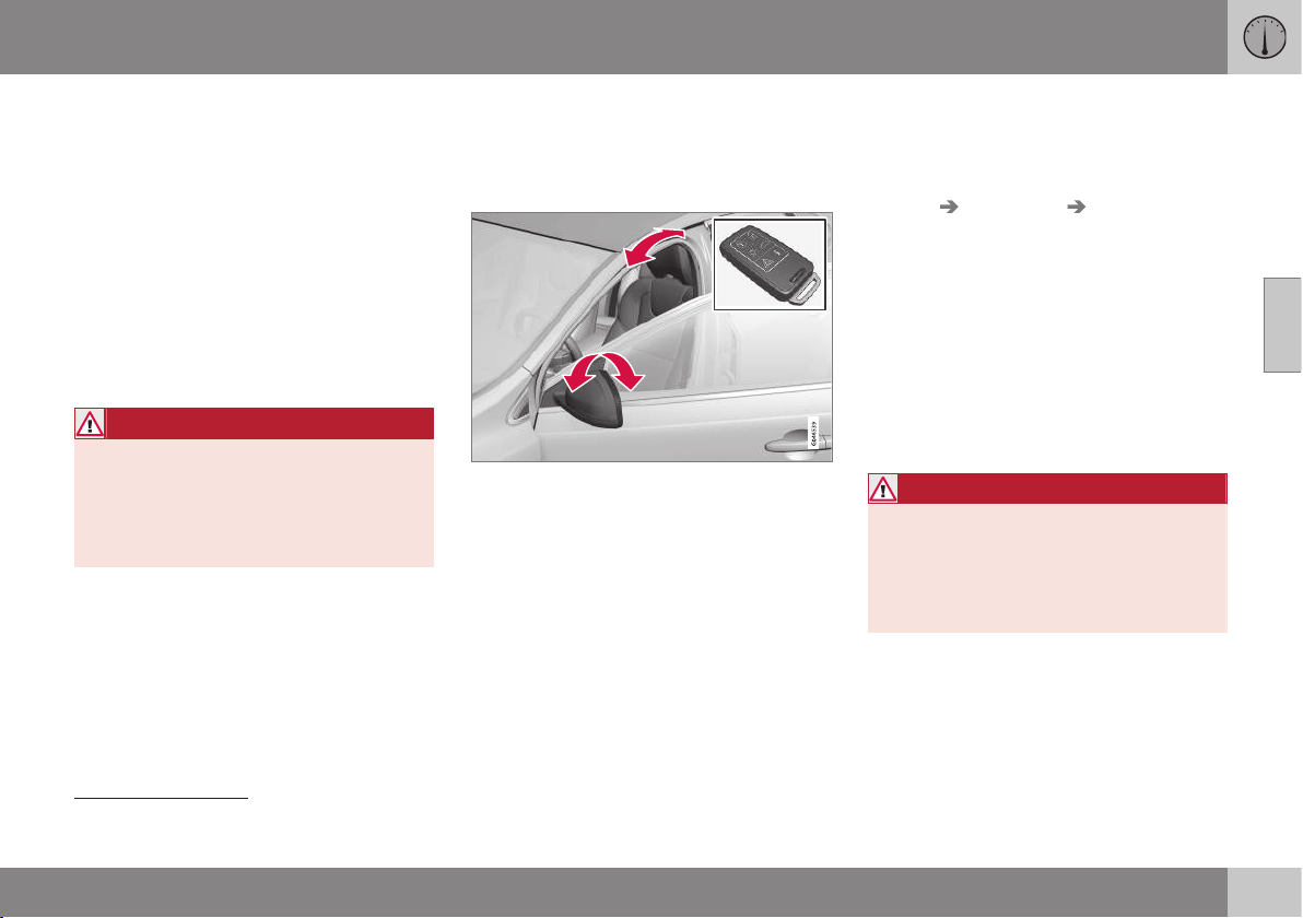
03 Instruments and controls
03
* Option/accessory, for more information, see Introduction.
75
2. Hold the button depressed to store set-
tings while depressing one of the memory
buttons.
Using a stored setting
Hold one of the memory buttons depressed
until the seat and the door mirrors stop. If you
release the button then the movement of the
seat will stop.
Emergency stop
If the seat accidentally begins to move, press
one of the setting buttons for the seat or
memory buttons in order to stop the seat.
WARNING
Risk of crushing! Make sure that children
do not play with the controls. Check that
there are no objects in front of, behind or
under the seat during adjustment. Ensure
that none of the rear seat passengers is in
danger of becoming trapped.
Heated seats
For heated seats, see Heated front seats* (p.
133) and Heated rear seat* (p. 133).
Related information
•
Seats, front (p. 73)
•
Seats, rear (p. 76)
Key memory in remote control key
All remote control keys can be used by differ-
ent drivers to store the settings for the driver's
seat and door mirrors
18
.
Proceed as follows in order to store the set-
tings and use the key memory*:
•
Adjust the seat as you want it.
•
Lock the car by pressing the lock button
on the remote control key that you nor-
mally use. This stores the positions of the
seat and door mirrors in the remote con-
trol key's memory
19
.
•
Unlock the car (by pressing the unlock
button on the same remote control key)
and open the driver's door. The driver's
seat and door mirrors will automatically
adopt the positions that are stored in the
remote control key's memory (if the seat
has been moved since you locked the
car).
The key memory can be activated/deacti-
vated in the menu system MY CAR under
Settings Car settings Car key
memory
. For a description of the menu sys-
tem, see MY CAR - menu options (p. 106).
Emergency stop
If the seat accidentally begins to move, press
one of the setting buttons for the seat or
memory buttons in order to stop the seat.
Restarting to reach the seat position stored in
the key memory is performed by pressing the
unlock button on the remote control key. The
driver's door must then be open.
WARNING
Risk of crushing! Make sure that children
do not play with the controls. Check that
there are no objects in front of, behind or
under the seat during adjustment. Ensure
that none of the rear seat passengers is in
danger of becoming trapped.
Related information
•
Remote control key - function (p. 162)
18
Only if the car is equipped with power seat with memory and retractable power door mirrors.
19
This setting does not affect settings that have been stored in the power seat's memory function.
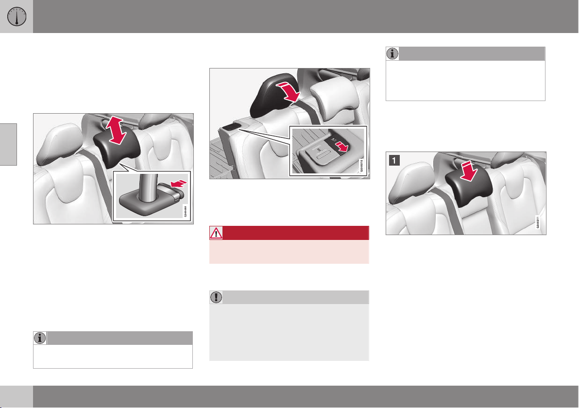
03 Instruments and controls
03
76
Seats, rear
The rear seat backrest and the outer seat
head restraints can be folded. The centre seat
head restraint can be adjusted to suit the
height of the passenger.
Head restraint, centre seat, rear
Adjust the head restraint according to pas-
senger height so that the whole of the back of
the head is covered if possible. Slide it up as
required.
To lower the head restraint again, the button
(see illustration) must be pressed while the
restraint is carefully moved down.
The head restraint can be adjusted in five dif-
ferent positions.
NOTE
Do not sit in the centre seat with the head
restraint in fully lowered position.
Manual lowering of the outer head
restraints, rear seat
Pull the locking handle closest to the head
restraint to fold the head restraint forward.
The head restraint is moved back manually.
WARNING
The head restraint must be in locked posi-
tion after being folded up.
Lowering the rear seat backrest
IMPORTANT
When the backrest is to be folded, the rear
seat cup holder must not be open and
there must be no objects in the rear seat.
Nor may the seat belts be connected. Oth-
erwise there is a risk of damage to the rear
seat upholstery.
NOTE
The front seats may need to be pushed
forwards, and/or the backrests adjusted
upwards, in order that the rear backrests
can be folded forward fully.
•
Both sections can be folded separately.
•
If the entire backrest is to be folded then
the different sections should be folded
separately.
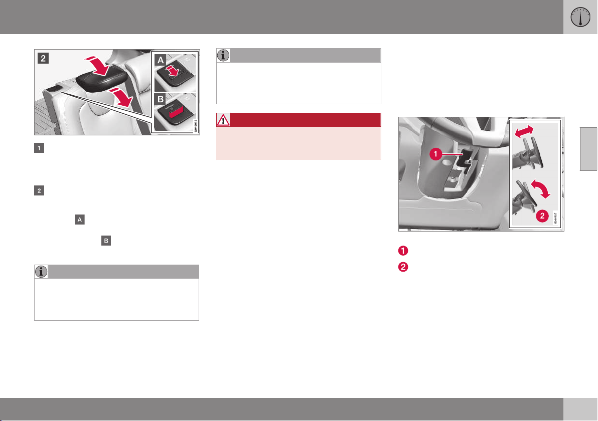
03 Instruments and controls
03
77
If the right-hand section is being lowered
- release and adjust head restraint for the
centre seat, see the earlier section "Head
restraint, centre seat, rear".
The outer head restraints are lowered
automatically when the backrests are
lowered. Pull up the backrest's locking
handle
while folding the backrest for-
ward at the same time. A red indicator on
the lock catch
shows that the back-
rest is no longer locked in place.
NOTE
When the backrests have been lowered
the head restraints must be moved for-
ward slightly so as not to make contact
with the seat cushion.
Raising takes place in reverse order.
NOTE
When the backrest has been raised, the
red indicator should no longer be showing.
If it is still showing then the backrest is not
locked in place.
WARNING
Check that the backrests and head
restraints in the rear seat are locked prop-
erly after being folded up.
Related information
•
Seats, front (p. 73)
•
Seats, front - electrically operated (p. 74)
Steering wheel
The steering wheel can be adjusted in differ-
ent positions and has controls for horn and
cruise control, as well as menu, audio and
phone control.
Adjusting
Adjusting the steering wheel.
Lever - releasing the steering wheel
Possible steering wheel positions
The steering wheel can be adjusted for both
height and depth:
1. Push the lever forwards to release the
steering wheel.
2. Adjust the steering wheel to the position
that suits you.
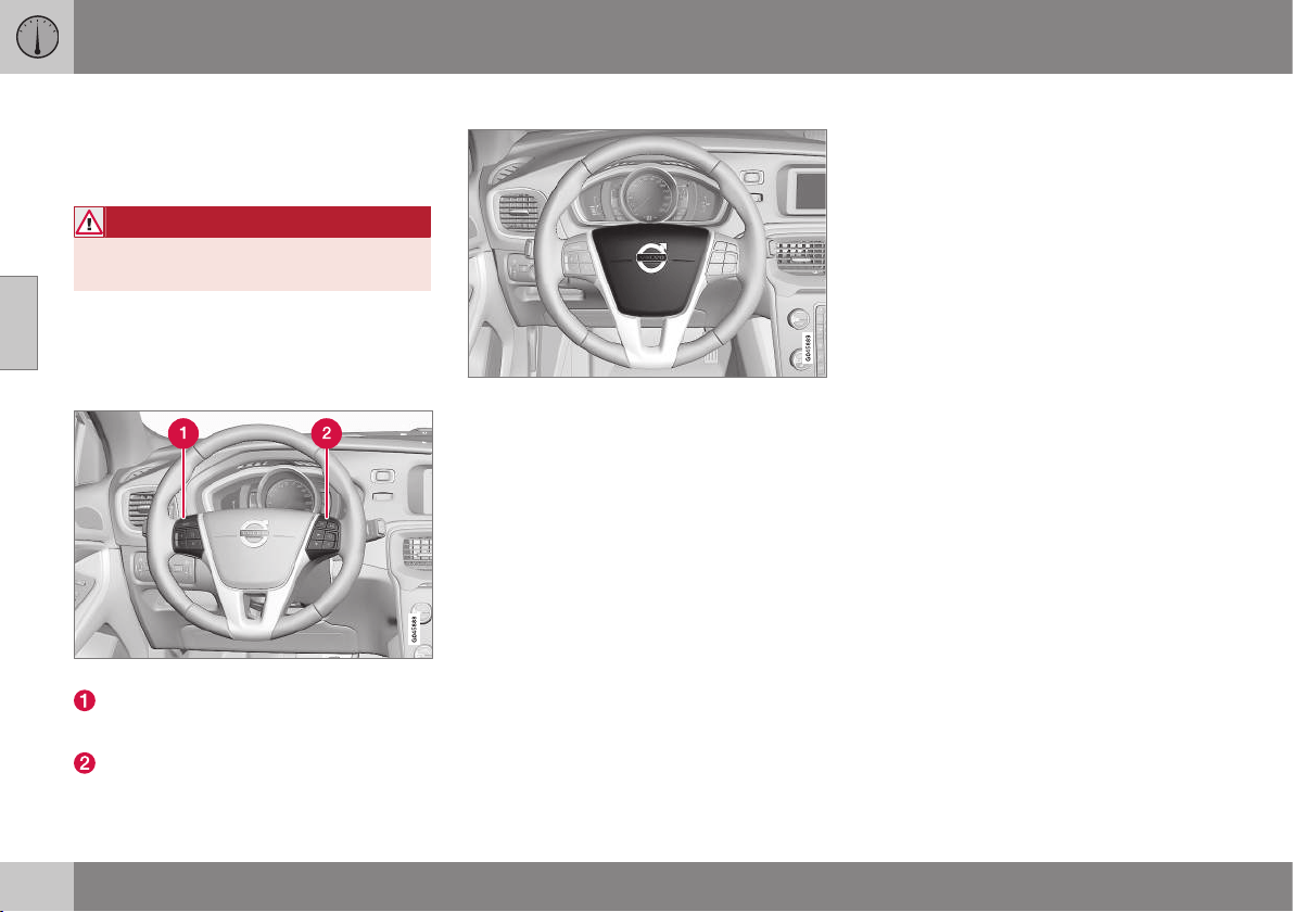
||
03 Instruments and controls
03
78
* Option/accessory, for more information, see Introduction.
3. Pull the lever back to fix the steering
wheel in place. If the lever is stiff, press
the steering wheel lightly at the same time
as you push the lever back.
WARNING
Adjust the steering wheel and fix it before
driving away.
With speed related power steering* the level
of steering force can be adjusted, see Speed
related power steering (p. 262).
Keypads*
Keypads in the steering wheel.
Cruise control* (p. 194)
Adaptive cruise control (ACC)* (p. 199)
Audio and media - operating the system
(p. 372)
Bluetooth
®
* handsfree phone - overview (p. 404)
Horn
Horn.
Press the centre of the steering wheel to sig-
nal.
Light switches
The headlamp control activates and adjusts
the external lighting. It is also used to adjust
display and instrument lighting and mood
lighting.
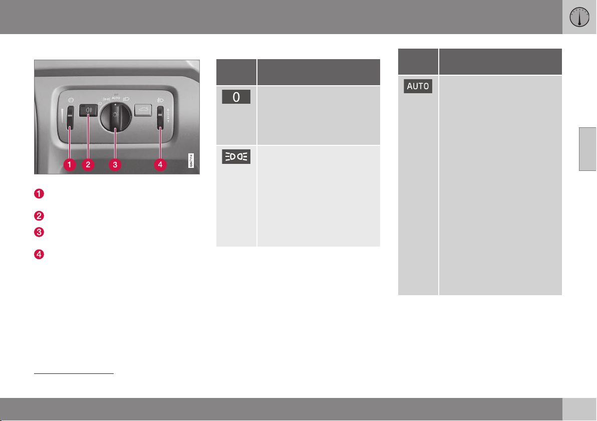
03 Instruments and controls
03
}}
* Option/accessory, for more information, see Introduction.
79
Overview, light switches
Overview, light switches.
Thumbwheel for adjusting display and
instrument lighting and ambient lighting*
Button for rear fog lamp
Knob for daytime running lights and park-
ing lamps
Thumbwheel
20
for headlamp levelling
Knob positions
Posi-
tion
Specification
Daytime running lights
A
when
the car's electrical system is in
key position II or the engine is
running.
Main beam flash can be used.
Daytime running lights and
position/parking lamps/side
marker lamps when the car's
electrical system is in key posi-
tion II or the engine is running.
Automatic switching to posi-
tion/parking lamps/side marker
lamps when the car is parked.
Main beam flash can be used.
Posi-
tion
Specification
Daytime running lights and
position/parking lamps/side
marker lamps during the day
when the car's electrical sys-
tem is in key position II or the
engine is running.
Automatic switching to dipped
beam and position/parking
lamps/side marker lamps in
poor light conditions or when
the windscreen wipers or rear
fog lamps are activated.
The tunnel detection (p. 82)*
function is activated.
The active high beam (p. 83)*
function can be used.
Main beam can be activated
when dipped beam is switched
on.
Main beam flash can be used.
20
Not available for cars equipped with active Xenon headlamps*.
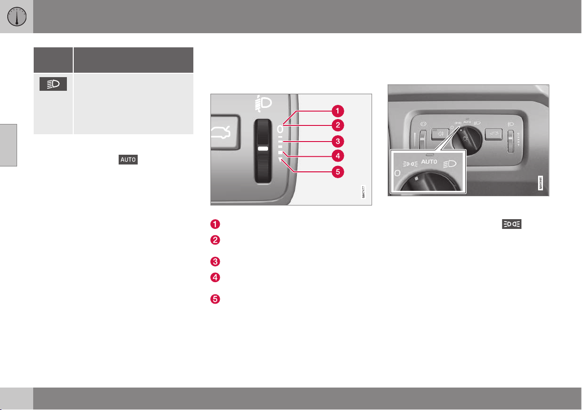
||
03 Instruments and controls
03
80
* Option/accessory, for more information, see Introduction.
Posi-
tion
Specification
Dipped beam and position/
parking lamps/side marker
lamps.
Main beam can be activated.
Main beam flash can be used.
A
Fitted in or under the front bumper.
Volvo recommends that
mode is used
when the car is being driven, as long as traffic
situations or weather conditions are unfavour-
able for the active high beam function*.
Instrument lighting
Different display and instrument lighting is
switched on depending on key position; see
Key positions - functions at different levels (p.
71).
The display lighting is automatically subdued
in darkness - the sensitivity is set with the
thumbwheel.
The intensity of the instrument lighting is
adjusted with the thumbwheel.
Headlamp levelling
The load in the car changes the vertical align-
ment of the headlamp beam, which could
dazzle oncoming motorists. Avoid this by
adjusting the height of the beam. Lower the
beam if the car is heavily laden.
1. Leave the engine running, or have the
car's electrical system in key position I.
2. Roll the thumbwheel up/down to raise/
lower beam alignment.
Thumbwheel positions for different load cases.
Only driver
Driver and passenger in the front passen-
ger seat
Occupants in all seats
Occupants in all seats and maximum load
in the cargo area
Driver and maximum load in the cargo
area
Cars with active Xenon headlamps* have
automatic headlamp levelling and are there-
fore not equipped with the thumbwheel.
Position/parking lamps
Position/parking lamps are switched on with
the headlamp control knob.
Knob for headlamp control in the position for
position/parking lamps.
Turn the knob to the position for
(num-
ber plate lighting is switched on at the same
time).
If the car's electrical system is in key position
II or the engine is running then the daytime
running lights also switch on.
When it is dark outside and the tailgate is
opened the rear position/parking lamps illumi-
nate to alert traffic behind. This takes place
irrespective of what position the knob is in or
what key position the car's electrical system
is in.
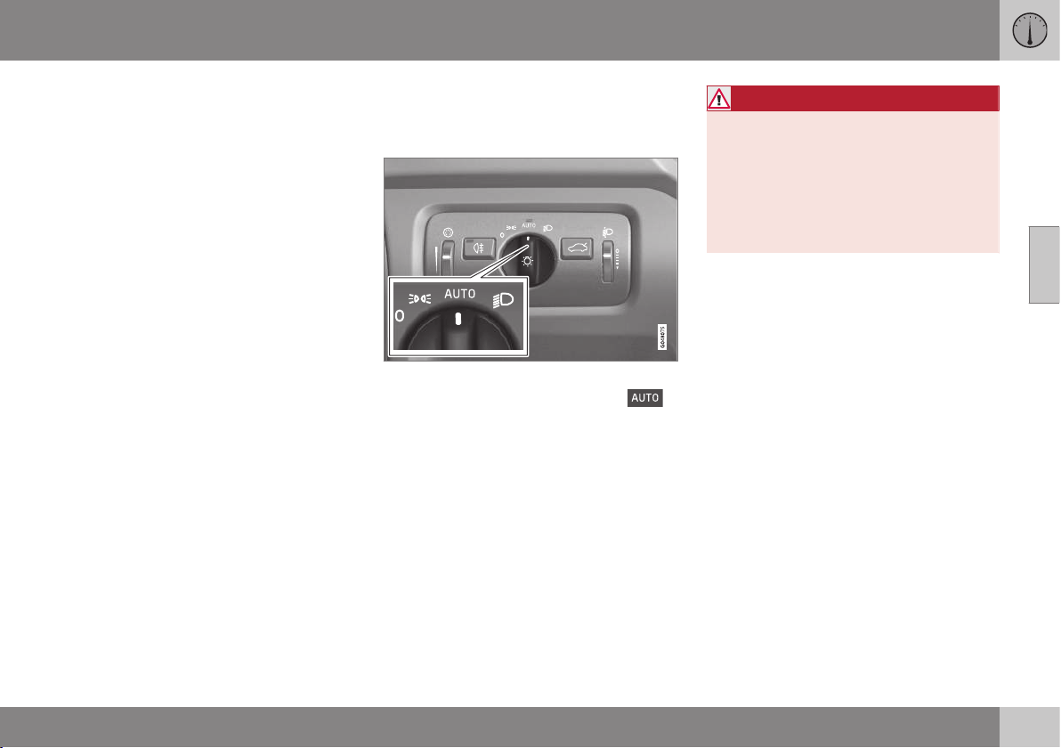
03 Instruments and controls
03
81
Related information
•
Light switches (p. 78)
•
Lamp replacement - location of front
lamps (p. 343)
Daytime running lights
Daytime running lights during the day.
DRL
Knob for headlamp control in AUTO position.
With the knob for headlamp control in
position the daytime running lights (Daytime
Running Lights - DRL) are activated automati-
cally when the car is driven during daytime. A
light sensor on the top of the instrument
panel changes from daytime running lights to
dipped beam at twilight or when daylight
becomes too weak. Changing to dipped
beam also takes place if the windscreen wip-
ers or rear fog lamps are activated.
WARNING
This system help to save energy - it cannot
determine in all situations when daylight is
too weak or sufficiently strong, e.g. in mist
and rain.
The driver is always responsible for ensur-
ing that the car is driven with its lights in a
correct state and in accordance with appli-
cable traffic regulations.
Related information
•
Lamp replacement - location of front
lamps (p. 343)
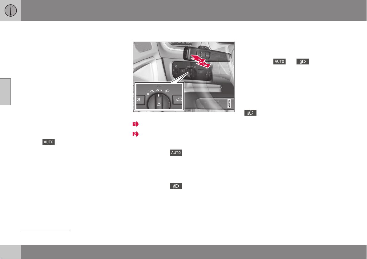
03 Instruments and controls
03
82
* Option/accessory, for more information, see Introduction.
Tunnel detection*
Tunnel detection changes the lighting from
daytime running lights to dipped beam when
the car is driven into a tunnel. Approx. 20 sec-
onds after the car has left the tunnel, the light-
ing returns to daytime running lights.
The tunnel detection function is available in
cars with rain sensor*. The sensor detects the
entrance to a tunnel and resets the lighting
from daytime running lights to dipped beam.
Approx. 20 seconds after the car has left the
tunnel, the lighting returns to daytime running
lights. If the car is driven into another tunnel
within this time period then dipped beam is
kept switched on. This prevents frequent
changes to the car lighting.
Note that the headlamp control's knob must
remain in
position for tunnel detection
to work.
Related information
•
Main/dipped beam (p. 82)
•
Light switches (p. 78)
Main/dipped beam
Stalk switch and knob for headlamp control.
Position for main beam flash
Position for main beam
Dipped beam
With the knob in position, dipped beam
is activated automatically at dusk or when
daylight becomes too weak. Dipped beam is
also activated automatically if the windscreen
wipers or rear foglights are activated.
With the knob in
position, dipped beam
is always switched on when the engine is run-
ning or when key position II is active.
Main beam flash
Move the stalk switch gently towards the
steering wheel to the position for main beam
flash. Main beam comes on until the stalk
switch is released.
Main beam
Main beam can be activated when the knob
is in position
21
or
. Activate/deac-
tivate main beam by moving the stalk switch
towards the steering wheel to the end posi-
tion and then releasing. Alternatively, the
main beam can be deactivated by a light
press of the stalk switch toward the steering
wheel.
When main beam has been activated the
symbol illuminates in the combined
instrument panel.
Related information
•
Active Xenon headlamps* (p. 84)
•
Active high beam* (p. 83)
•
Lamp replacement - location of front
lamps (p. 343)
•
Light switches (p. 78)
•
Headlamps - adjusting headlamp pattern
(p. 90)
•
Tunnel detection* (p. 82)
21
When dipped beam is activated.
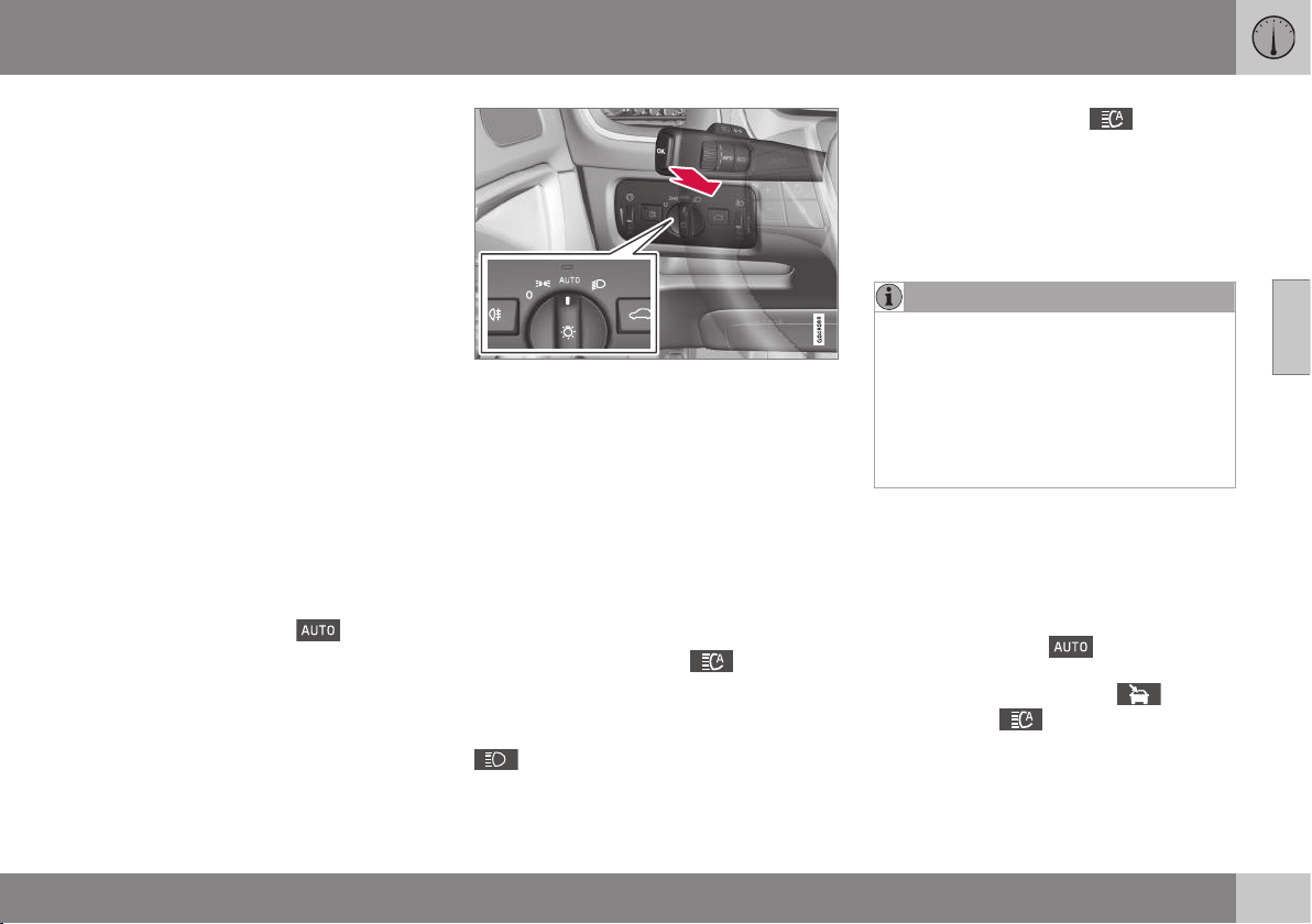
03 Instruments and controls
03
}}
* Option/accessory, for more information, see Introduction.
83
Active high beam*
The Active High Beam function detects the
headlamp beams of oncoming traffic or the
rear lights of vehicles in front, and switches
the lighting from main beam to dipped beam.
The lighting returns to main beam when the
incoming light has stopped.
Active high beam - AHB
Active high beam (Active High Beam - AHB) is
a function which uses a camera sensor at the
top edge of the windscreen to detect the
headlamp beams of oncoming traffic or the
rear lights of vehicles in front, and then
switches from main beam to dipped beam.
The function can also take streetlights into
account.
The lighting returns to main beam about a
second after the camera sensor no longer
detects the headlamp beams from oncoming
traffic or the rear lights from vehicles in front.
Activating/deactivating
AHB can be activated when the headlamp
control's knob is in position
(provided
that the function has not been deactivated in
the menu system MY CAR, see MY CAR -
menu options (p. 106)).
Stalk switch and knob for headlamp control in
AUTO position.
The function can start while driving in the
dark when the car's speed is 20 km/h or
higher.
Activate/deactivate AHB by moving the left-
hand stalk switch towards the steering wheel
to the end position and then releasing. Deac-
tivation when main beam is on means that the
lights are reset directly to dipped beam.
Car with analogue combined instrument
panel
When AHB is activated the
symbol illu-
minates in the instrument's information dis-
play.
When main beam has been switched on the
symbol also illuminates in the com-
bined instrument panel.
Car with digital combined instrument panel
When AHB is activated the
symbol
turns white in the instrument's information
display.
When main beam is activated, the symbol
shines blue.
Manual operation
NOTE
Keep the windscreen surface in front of the
camera sensor free from ice, snow, mist
and dirt.
Do not stick or attach anything to the
windscreen in front of the camera sensor
as this may reduce effectiveness or cause
one or more of the systems dependent on
the camera to stop working.
If the message Active main beam
Temporary unavailable Switch manually is
shown in the combined instrument panel's
information display then you have to switch
manually between main and dipped beam.
However, the knob for headlamp control can
still remain in position
. The same
applies if the message
Windscreen sensors
blocked See manual
and the symbol
are shown. The
symbol goes out when
these messages are shown.
AHB may be temporarily unavailable e.g. in
situations with dense fog or heavy rain. When
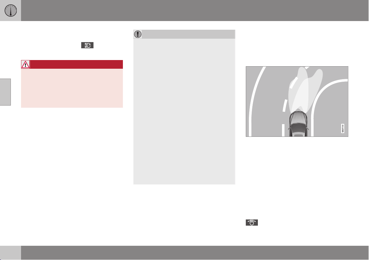
||
03 Instruments and controls
03
84
* Option/accessory, for more information, see Introduction.
AHB becomes available again, or the wind-
screen sensors are no longer blocked, the
message goes out and the
symbol illu-
minates.
WARNING
AHB is an aid for using the optimum beam
pattern when conditions are favourable.
The driver always bears responsibility for
manually switching between main and
dipped beam when traffic situations or
weather conditions so require.
IMPORTANT
Examples of when manual switching
between main and dipped beam may be
required:
•
In heavy rain or dense fog
•
In freezing rain
•
In snow flurries or slush
•
In moonlight
•
When driving in poorly lit built-up
areas
•
When the traffic ahead has weak light-
ing
•
If there are pedestrians on or beside
the road
•
If there are highly reflective objects
such as signs in the vicinity of the road
•
When the lighting from oncoming traf-
fic is obscured by e.g. a crash barrier
•
When there is traffic on connecting
roads
•
On the brow of a hill or in a hollow
•
In sharp bends.
For more information on the limitations of the
camera sensor, see Collision warning system*
- camera sensor limitations (p. 231).
Related information
•
Main/dipped beam (p. 82)
•
Light switches (p. 78)
Active Xenon headlamps*
Active Xenon headlamps are designed to pro-
vide maximum illumination in bends and junc-
tions and so provide increased safety.
Active Xenon headlamps ABL
Headlamp pattern with function deactivated (left)
and activated (right) respectively.
If the car is equipped with active Xenon head-
lamps (Active Bending Lights – ABL) then the
light from the headlamps follows the steering
wheel movement in order to provide maxi-
mum lighting in bends and junctions and so
provide increased safety.
The function is activated automatically when
the car is started (provided that it has not
been deactivated in the menu system
MY CAR, see MY CAR - menu options (p.
106)). In the event of a fault in the function the
symbol illuminates in the combined
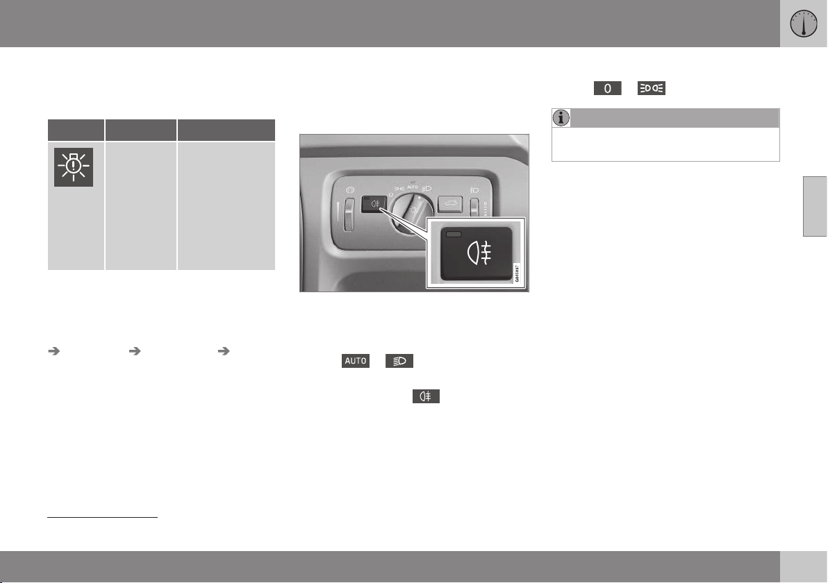
03 Instruments and controls
03
* Option/accessory, for more information, see Introduction.
85
instrument panel at the same time as the
information display shows an explanatory text
and a further illuminated symbol.
Symbol Display Specification
Headlamp
system
malfunc-
tion Serv-
ice
required
The system is
disengaged. Visit
a workshop if
the message
remains. Volvo
recommends
that you contact
an authorised
Volvo workshop.
The function is only active in twilight or dark-
ness and only when the car is moving.
The function
22
can be deactivated/ activated
in the menu system MY CAR under
Settings
Car settings Light settings Active
Bending Lights
. For a description of the
menu system, see MY CAR - menu options
(p. 106).
Related information
•
Main/dipped beam (p. 82)
•
Active high beam* (p. 83)
•
Light switches (p. 78)
•
Headlamps - adjusting headlamp pattern
(p. 90)
Rear fog lamp
When visibility is reduced by fog the rear fog
lamp can be used so that other road users
shall notice vehicles in front at an early stage.
Button for rear fog lamp.
The rear fog lamp can only be switched on
when key position II is active or the engine is
running and the headlamp control's knob is in
position
or .
Press the button for On/Off. The rear fog
lamp indicator symbol in the combined
instrument panel and the lamp in the button
illuminate when the rear fog lamp is switched
on.
The rear fog lamp is switched off automati-
cally when the engine is switched off or when
the headlamp control's knob is turned to
position
or .
NOTE
Regulations on the use of rear fog lamps
vary from country to country.
Related information
•
Light switches (p. 78)
•
Lamp replacement - location of rear
lamps (p. 346)
22
Activated on delivery from the factory.
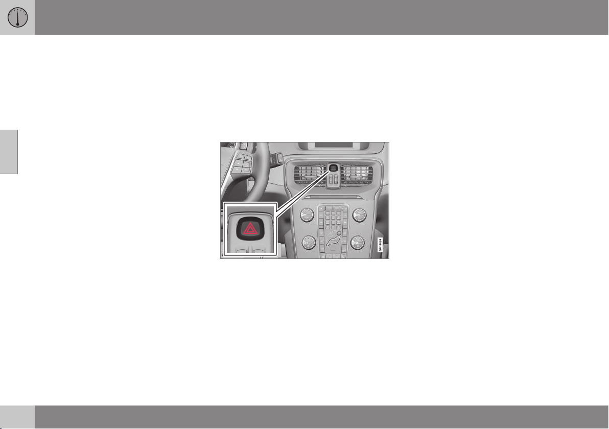
03 Instruments and controls
03
86
Brake lights
The brake light automatically comes on during
braking.
The brake light is switched on when the brake
pedal is depressed. In addition, it is switched
on when one of driving support systems
Adaptive cruise control (p. 199), City Safety
(p. 217) or Collision warning system (p. 223)
brakes the car.
For information on emergency brake lights
and automatic hazard warning flashers, see
Foot brake - emergency brake lights and
automatic hazard warning flashers (p. 291).
Related information
•
Lamp replacement - location of rear
lamps (p. 346)
Hazard warning flashers
The hazard warning flashers warn other road
users by means of all of the car's direction
indicator lamps flashing simultaneously when
this function is activated.
When the hazard warning flashers are acti-
vated, both direction indicator symbols flash
in the combined instrument panel.
Button for hazard warning flashers.
Press the button to activate the hazard warn-
ing flashers. Both direction indicator symbols
in the combined instrument panel flash when
the hazard warning flashers are used.
The hazard warning flashers are activated
automatically when the car has been braked
so suddenly that the emergency brake lights
have been activated at a speed below
10 km/h. The hazard warning flashers remain
on when the car has stopped and are deacti-
vated automatically when the car is driven off
again or the button is depressed. For more
information on emergency brake lights and
automatic hazard warning flashers, see Foot
brake - emergency brake lights and auto-
matic hazard warning flashers (p. 291).
Related information
•
Direction indicators (p. 87)
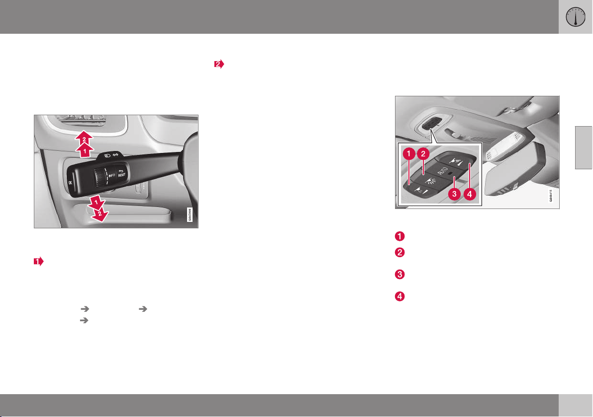
03 Instruments and controls
03
* Option/accessory, for more information, see Introduction.
87
Direction indicators
The car's direction indicators are operated
with the left-hand stalk switch. The direction
indicator lamps flash three times or continu-
ously, depending on how far up or down the
stalk switch is moved.
Direction indicators.
Short flash sequence
Move the stalk switch up or down to the
first position and release. The direction
indicator lamps flash three times. The
function can be activated/deactivated in
the menu system MY CAR under
Settings Car settings Light
settings
Triple
indicator
. For a description of the menu
system, see MY
CAR - menu options (p. 106).
Continuous flash sequence
Move the stalk switch up or down to the
outer position.
The stalk switch remains in its position and is
moved back manually, or automatically by the
steering wheel movement.
Direction indicator symbols
For direction indicator symbols, see Com-
bined instrument panel - meaning of indicator
symbols (p. 65).
Related information
•
Hazard warning flashers (p. 86)
•
Lamp replacement - location of rear
lamps (p. 346)
•
Lamp replacement - location of front
lamps (p. 343)
Interior lighting
The passenger compartment lighting is acti-
vated/deactivated with the buttons in the con-
trols above the front seats and the rear seat.
Controls in roof console for the front reading
lamps and passenger compartment lighting.
Reading lamp, left-hand side
Passenger compartment lighting (floor
lamps* and ceiling lamps) - On/Off
Auto function for passenger compartment
lighting
Reading lamp, right-hand side
All lighting in the passenger compartment can
be switched on and off manually within
30 minutes from when:
•
the engine has been switched off and the
car's electrical system is in key position 0
•
the car has been unlocked but the engine
has not been started.
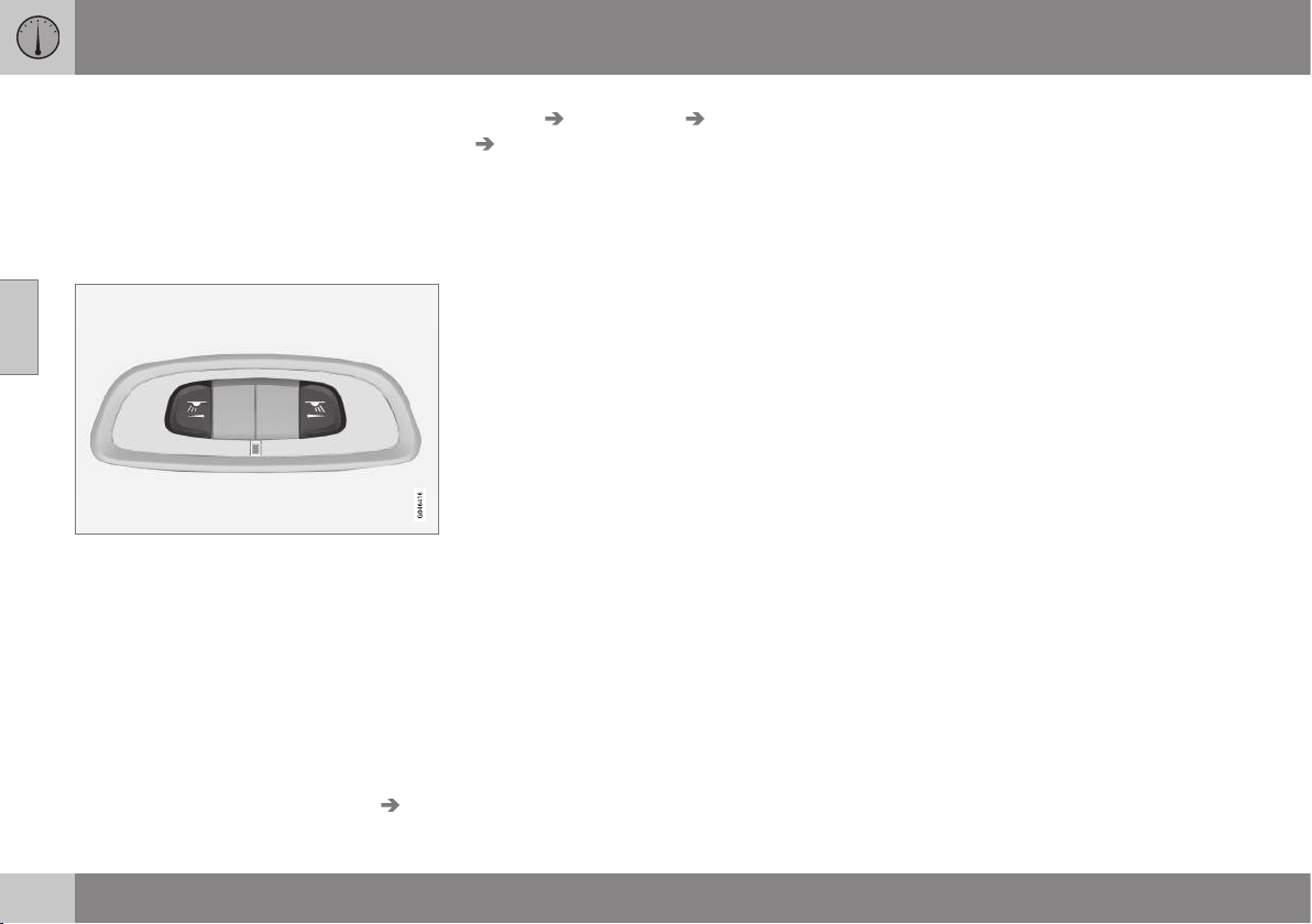
||
03 Instruments and controls
03
88
* Option/accessory, for more information, see Introduction.
Front reading lamps*
The reading lamps are switched on or off by
briefly pressing the relevant button in the roof
console.
Brightness is adjusted by holding the button
pressed in.
Rear reading lamps*
Rear reading lamps.
The lamps are switched on or off by briefly
pressing the relevant button.
Brightness is adjusted by holding the button
pressed in.
Floor lighting as ambient light*
To make the interior brighter while driving the
floor lighting can be activated at dimmed
level.
Floor lamp intensity can be changed in the
MY CAR menu system under
Settings Car
settings
Light settings Interior light
Floor lights. Select from Off, Low and
High. For more information on the menu sys-
tem, see MY CAR - menu options (p. 106).
Lighting in the front door storage
compartments*
Lighting in the front door storage compart-
ments comes on when the engine starts.
Glovebox lighting
Glovebox lighting is switched on and off
respectively when the lid is opened or closed.
Vanity mirror lighting
The lighting for the vanity mirror (p. 150) is
switched on and off respectively when the
cover is opened or closed.
To replace the lamp, see Lamp replacement -
vanity mirror lighting (p. 348).
Lighting in the cargo area
The lighting in the cargo area is switched on
and off respectively when the tailgate is
opened or closed.
Auto function for passenger
compartment lighting
The auto function is activated when the lamp
in the AUTO button is lit.
The passenger compartment lighting is then
switched on and off as indicated below.
The passenger compartment lighting is
switched on and remains on for 30 seconds
if:
•
the car is unlocked with the remote con-
trol key or key blade, see Remote control
key - function (p. 162) or Detachable key
blade - unlocking doors (p. 166)
•
the engine has been switched off and the
car's electrical system is in key position
0.
Passenger compartment lighting is switched
off when:
•
the engine is started
•
the car is locked.
The passenger compartment lighting is
switched on and off respectively when a side
door is opened or closed.
It remains switched on for two minutes if one
of the doors is open.
If any lighting is switched on manually and
the car is locked then it will be switched off
automatically after two minutes.
Mood lights*
When the normal passenger compartment
lighting is switched off and the engine is run-
ning, an LED illuminates in the front and rear
roof console respectively in order to provide a
low light and enhance the ambience while
driving. The light also makes it easier to see
objects in the storage compartments, etc.,

03 Instruments and controls
03
89
when it is dark outside. Light intensity can be
changed in the MY CAR menu system under
Settings Car settings Light settings
Interior light Ambient light. Select
from
Off, Low and High. This lighting extin-
guishes when the engine is switched off.
The colour of the light can be also set in the
MY CAR menu system under
Settings Car
settings
Light settings Interior light
Ambient light colours. If you select
Temperature, the colour shifts between
warm white and cold white depending on the
temperature in the car or you can choose
between different colour themes. The availa-
ble colour themes are Frosty White,
Toscana White, Ember Gold, Red Sunset,
Rainforest, Glacier Blue and Violet Purple.
For more information on the menu system,
see MY CAR - menu options (p. 106).
Home safe light duration
Home safe lighting consists of dipped beam,
parking lamps, lamps in the door mirrors,
number plate lighting, interior roof lighting
and floor lighting.
Some of the exterior lighting can be kept
switched on to work as home safe lighting
after the car has been locked.
1. Remove the remote control key from the
ignition switch.
2. Move the left-hand stalk switch toward
the steering wheel to the end position and
release it. The function can be activated
in the same way as with main beam flash;
see Main/dipped beam (p. 82).
3. Get out of the car and lock the door.
When the function is activated, dipped beam,
parking lamps, door mirror lamps, number
plate lighting, interior roof lighting and floor
lighting are switched on.
The length of time for which the home safe
lighting should be kept on can be set in the
menu system MY CAR under
Settings Car
settings
Light settings Home safe
light duration
. For a description of the menu
system, see MY CAR - menu options (p.
106).
Related information
•
Approach light duration (p. 89)
Approach light duration
Approach lighting consists of parking lamps,
lamps in the door mirrors, number plate light-
ing, interior roof lighting and floor lighting.
Approach lighting is switched on with the
remote control key, see Remote control key -
function (p. 162), and is used to switch on
the car's lighting at a distance.
When the function is activated with the
remote control, the parking lamps, door mir-
ror lamps, number plate lighting, interior roof
lighting and floor lighting are switched on.
The length of time for which the approach
lighting should be kept on can be set in the
menu system MY CAR under
Settings Car
settings
Light settings Approach light
duration
. For a description of the menu sys-
tem, see MY CAR - menu options (p. 106).
Related information
•
Home safe light duration (p. 89)
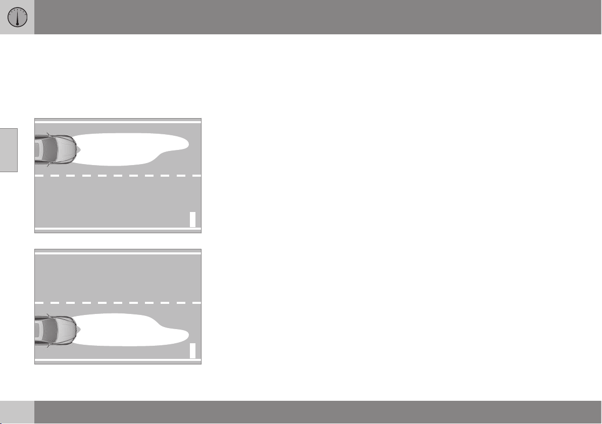
03 Instruments and controls
03
90
* Option/accessory, for more information, see Introduction.
Headlamps - adjusting headlamp
pattern
The headlamp pattern must be adjusted to
avoid dazzling oncoming motorists and can
be set for right or left-hand traffic.
Adjusting headlamp pattern
G021151
Headlamp pattern, left-hand traffic.
G021152
Headlamp pattern, right-hand traffic.
Active Xenon headlamps*
The light pattern does not need to be
adjusted. The headlamp pattern is designed
in such a way that oncoming traffic is not
dazzled.
Halogen headlamps
The headlamp pattern for halogen headlamps
is readjusted by masking the headlamp lens.
The headlamp pattern may not be as good.
Masking the headlamps
1. Copy the A and B templates for left-hand
drive cars or the C and D templates for
right-hand drive cars, see the later sec-
tion "Templates for halogen headlamps":
•
A = LHD Right (left-hand drive, right
lens)
•
B = LHD Left (left-hand drive, left lens)
•
C = RHD Right (right-hand drive, right
lens)
•
D = RHD Left (right-hand drive, left
lens)
2. Transfer the template to a self-adhesive
waterproof material and cut it out.
3. Start from the design lines on the head-
lamp lenses; see the lines in the following
figure. Position the self-adhesive tem-
plates at the design lines with the help of
the illustration.
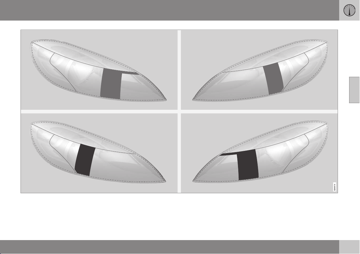
03 Instruments and controls
03
}}
91
Upper row: left-hand drive cars, templates A and B. Lower row: right-hand drive cars, templates C and D.
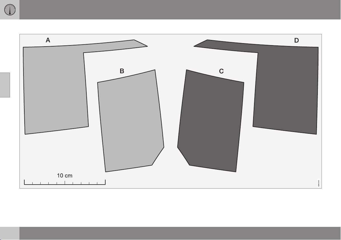
||
03 Instruments and controls
03
92
Templates for halogen headlamps
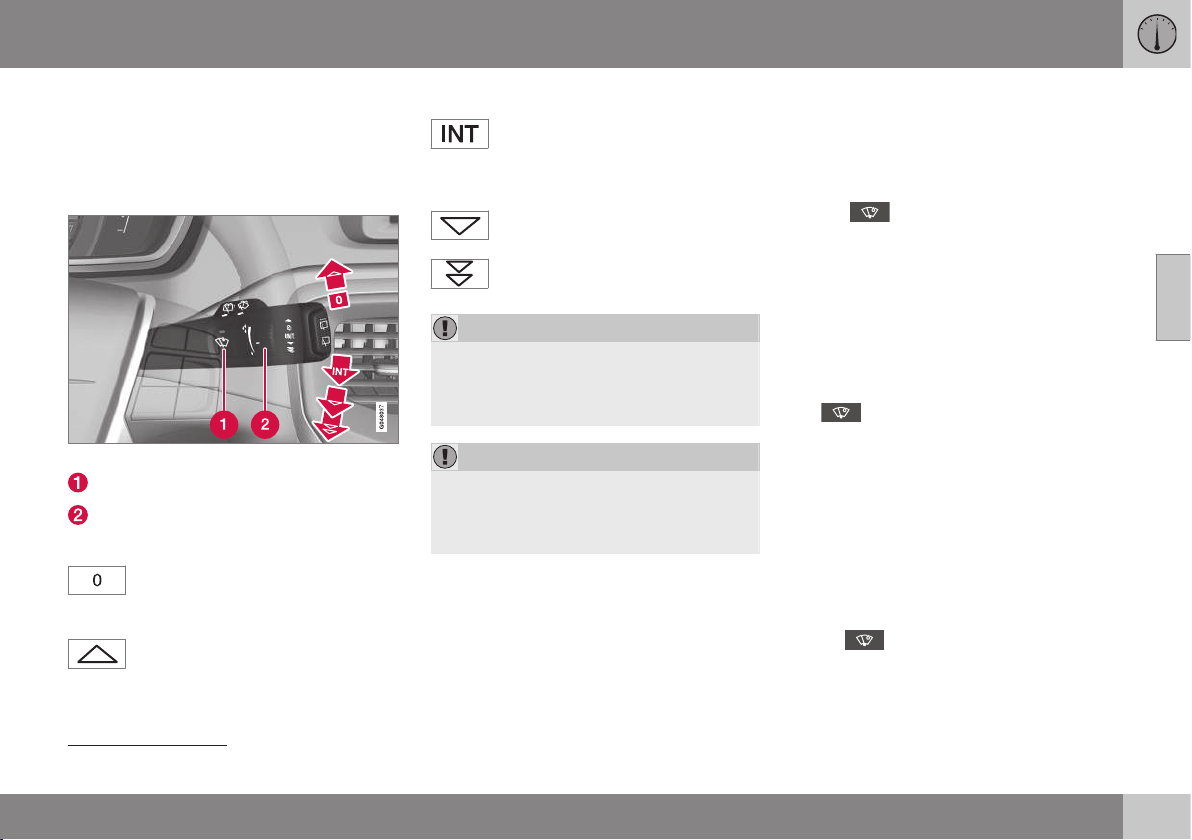
03 Instruments and controls
03
}}
* Option/accessory, for more information, see Introduction.
93
Wipers and washing
Wipers and washers clean the windscreen
and rear window. The headlamps are cleaned
with high-pressure washing.
Windscreen wipers
23
Windscreen wipers and windscreen washers.
Rain sensor, on/off
Thumbwheel sensitivity/frequency
Windscreen wipers off
Move the stalk switch to position 0
to switch off the windscreen wipers.
Single sweep
Raise the stalk switch and release to
make one sweep.
Intermittent wiping
Set the number of sweeps per time
unit with the thumbwheel when
intermittent wiping is selected.
Continuous wiping
The wipers sweep at normal speed.
The wipers sweep at high speed.
IMPORTANT
Before activating the wipers during winter
ensure that the wiper blades are not frozen
in, and that any snow or ice on the wind-
screen is scraped away.
IMPORTANT
Use plenty of washer fluid when the wipers
are cleaning the windscreen. The wind-
screen must be wet when the windscreen
wipers are operating.
Service position wiper blade
For cleaning the windscreen/wiper blades
and replacement of wiper blades, see Wiper
blades (p. 349) and Car washing (p. 364).
Rain sensor*
The rain sensor automatically starts the wind-
screen wipers based on how much water it
detects on the windscreen. The sensitivity of
the rain sensor can be adjusted using the
thumbwheel.
When the rain sensor is activated a lamp in
the button illuminates and the rain sensor
symbol
is shown in the combined
instrument panel.
Activating and setting the sensitivity
When activating the rain sensor, the car must
be running or the remote control key in posi-
tion I or II while the windscreen wiper stalk
switch must be in position 0 or in the position
for a single sweep.
Activate the rain sensor by pressing the but-
ton
. The windscreen wipers make one
sweep.
Press the stalk switch up for the wipers to
make an extra sweep.
Turn the thumbwheel upward for higher sen-
sitivity and downward for lower sensitivity.
(An extra sweep is made when the thumb-
wheel is turned upward.)
Deactivate
Deactivate the rain sensor by pressing the
button
or move the stalk switch down
to another wiper program.
23
For replacing the wiper blades and service position wiper blades, see Wiper blades (p. 349). For filling washer fluid, see Washer fluid - filling (p. 351).
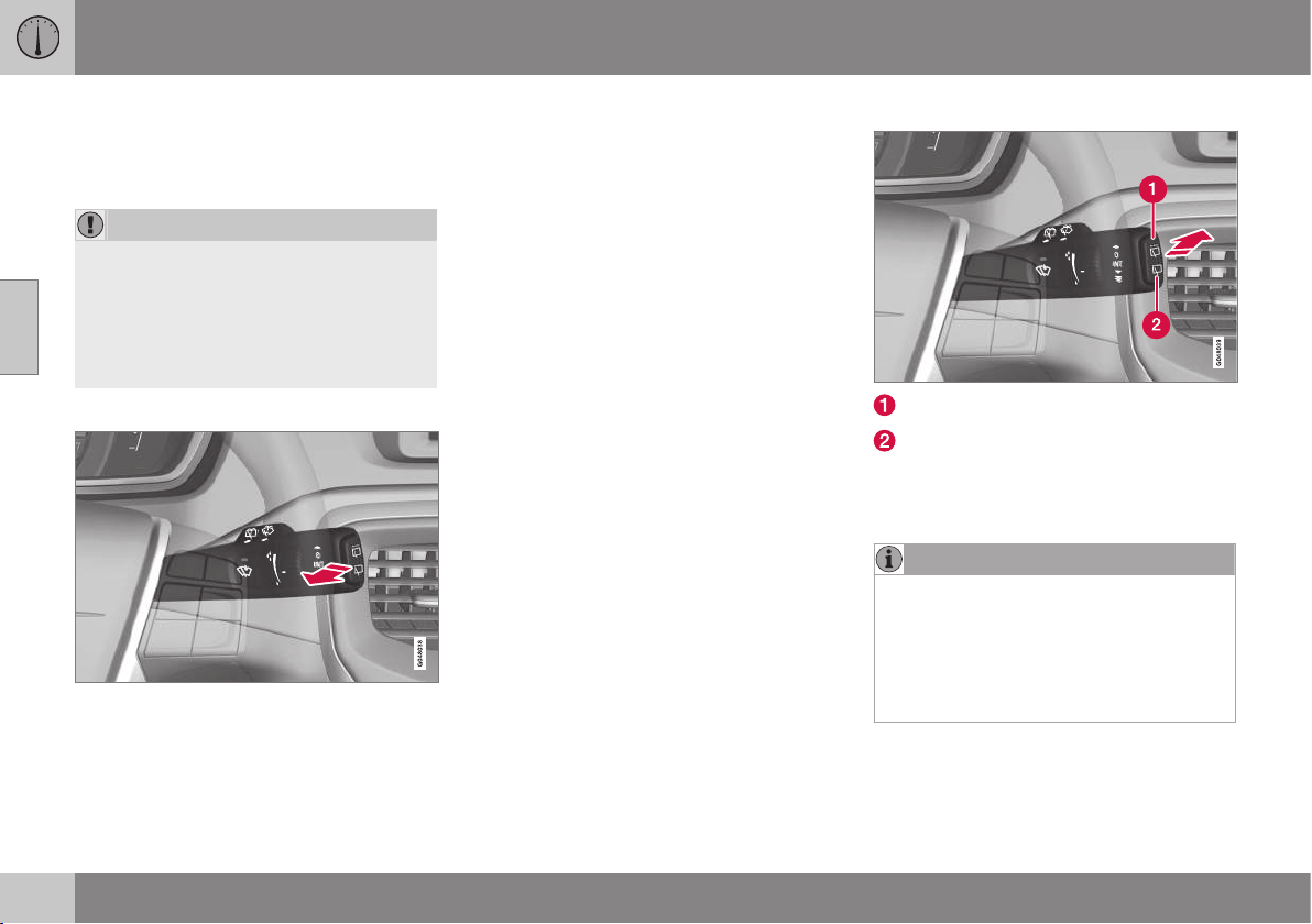
||
03 Instruments and controls
03
94
* Option/accessory, for more information, see Introduction.
The rain sensor is automatically deactivated
when the remote control key is removed from
the ignition switch or five minutes after the
engine has been switched off.
IMPORTANT
The windscreen wipers could start and be
damaged in an automatic car wash.
Switch off the rain sensor while the car is
in motion or when the remote control key
is in position I or II. The symbol in the
combined instrument panel and the light in
the button go out.
Washing the headlamps and windows
Washing function.
Washing the windscreen
Move the stalk switch toward the steering
wheel to start the windscreen and headlamp
washers.
The windscreen wipers will make several
more sweeps and the headlamps are washed
once the stalk switch has been released.
High-pressure headlamp washing*
High-pressure headlamp washing consumes
a large quantity of washer fluid. To save fluid,
the headlamps are washed automatically at
every fifth windscreen wash cycle.
Reduced washing
If only approx. 1 litre of washer fluid remains
in the reservoir and the message that you
should fill the washer fluid is shown in the
combined instrument panel, then the supply
of washer fluid to the headlamps is switched
off. This is in order to prioritise cleaning the
windscreen and the visibility through it.
Wiping and washing the rear window
Rear window wiper – intermittent wiping
Rear window wiper – continuous speed
Press the stalk switch forward (see the arrow
in the illustration above) to initiate rear win-
dow washing and wiping.
NOTE
The rear window wiper is equipped with
overheating protection which means that
the motor is switched off if it overheats.
The rear window wiper works again after a
cooling period (30 seconds or longer,
depending on the heat in the motor and
the outside temperature).
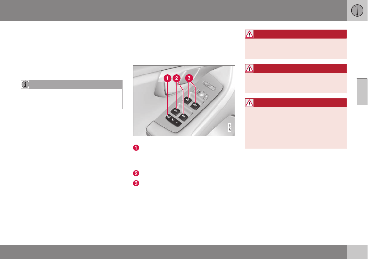
03 Instruments and controls
03
* Option/accessory, for more information, see Introduction.
95
Wiper – reversing
Engaging reverse gear while the windscreen
wipers are on initiates intermittent rear win-
dow wiping
24
. The function stops when
reverse gear is disengaged.
If the rear window wiper is already on at con-
tinuous speed, no change is made.
NOTE
On cars with rain sensors, the rear wiper is
activated during reversing if the sensor is
activated and it is raining.
Related information
•
Washer fluid - filling (p. 351)
•
Washer fluid - quality and volume (p.
451)
Power windows
All power windows can be operated using the
control panel for the driver's door - the con-
trol panels for the other doors operate their
respective power window.
Driver's door control panel.
Switch for electric child safety locks* and
disengaging rear power window buttons;
see Child safety locks - electrical activa-
tion* (p. 180).
Rear window controls
Front window controls
WARNING
Check that no rear seat passengers are
trapped when the windows are closed
from the driver's door.
WARNING
Check that children or other passengers
are not trapped if the windows are closed,
even when the remote control key is used.
WARNING
If there are children in the car - remember
to always switch off the power supply to
the power windows by selecting key posi-
tion 0 and then take the remote control key
with you when leaving the car. For infor-
mation on key positions - see Key posi-
tions - functions at different levels (p. 71).
24
This function (intermittent wiping when reversing) can be deactivated. Visit a workshop. Volvo recommends that you contact an authorised Volvo workshop.

||
03 Instruments and controls
03
96
Operating
Operating the power windows.
Operating without auto
Operating with auto
All power windows can be operated using the
control panel for the driver's door - the con-
trol panels for the other doors can only each
operate their respective power window. Only
one control panel can be operated at a time.
In order for the power windows to be used,
the key position must be at least I - see Key
positions - functions at different levels (p. 71).
The power windows can be operated for a
few minutes after the engine has been
switched off and after the remote control key
has been removed - although not after a door
has been opened.
Closing of the windows is stopped and the
window is opened if anything prevents its
movement. It is possible to override the pinch
protection when closing has been interrupted,
e.g. if there is ice forming. After two succes-
sive closing interruptions the pinch protection
will be forced and the automatic function
deactivated for a short while, now it is possi-
ble to close by continually holding the button
pulled up.
NOTE
One way to reduce the pulsating wind
noise when the rear windows are open is
to also open the front windows slightly.
Operating without auto
Move one of the controls up/down gently.
The power windows move up/down as long
as the control is held in position.
Operating with auto
Move one of the controls up/down to the end
position and release it. The window runs
automatically to its end position.
Operating with the remote control key
and central locking
To remotely operate the power windows from
the outside with the remote control key or
from inside with central locking, see Remote
control key with key blade (p. 159) and Lock-
ing/unlocking - from the inside (p. 175).
Resetting
If the battery is disconnected then the func-
tion for automatic opening must be reset so
that it can work correctly.
1. Gently raise the front section of the but-
ton to raise the window to its end position
and hold it there for one second.
2. Release the button briefly.
3. Raise the front section of the button again
for one second.
WARNING
A reset must take place for pinch protec-
tion to work.
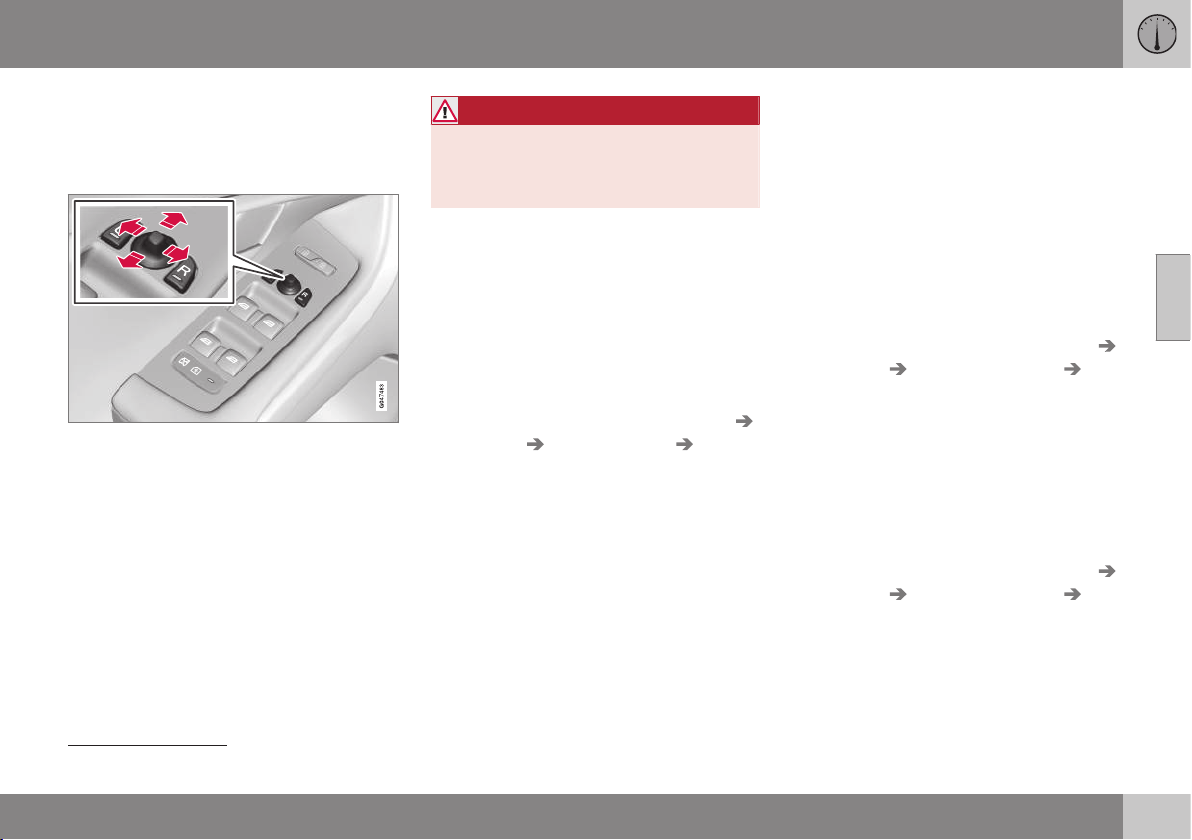
03 Instruments and controls
03
}}
97
Door mirrors
The door mirror positions are adjusted with
the joystick in the driver's door controls.
Door mirrors
Door mirror controls.
Adjusting
1. Press the L button for the left-hand door
mirror or the R button for the right-hand
door mirror. The light in the button illumi-
nates.
2. Adjust the position with the joystick in the
centre.
3. Press the L or R button again. The light
should no longer be illuminated.
WARNING
The mirror on the driver's side is the wide-
angle type to provide optimal vision.
Objects may appear further away than
they actually are.
Storing the position
25
The mirror positions are stored in the key
memory when the car has been locked with
the remote control key. When the car is
unlocked with the same remote control key
the mirrors and the driver's seat adopt the
stored positions when the driver's door is
opened.
The function can be activated/deactivated in
the menu system MY CAR under
Settings
Car settings Car key memory
Personal settings in key memory. For a
description of the menu system, see MY CAR
- menu options (p. 106).
Angling the door mirror when parking
25
The door mirror can be angled down for the
driver to view the side of the road when park-
ing for example.
– Engage reverse gear and press the L or R
button.
When reverse gear is disengaged the mirror
automatically returns to its original position
after about 10 seconds, or earlier by pressing
the button labelled L or R respectively.
Automatic angling of the door mirror
when parking
25
When reverse gear is engaged the door mirror
is automatically angled down so that the
driver can see the side of the road when
parking for example. When reverse gear is
disengaged the mirror automatically returns
to its original position after a short time.
The function can be activated/deactivated in
the menu system MY CAR under
Settings
Car settings Side mirror settings Tilt
left mirror
or Tilt right mirror. For a descrip-
tion of the menu system, see MY CAR - menu
options (p. 106).
Automatic retraction when locking
25
When the car is locked/unlocked with the
remote control key the door mirrors are auto-
matically retracted/extended.
The function can be activated/deactivated in
the menu system MY CAR under
Settings
Car settings Side mirror settings Fold
mirrors
. For a description of the menu sys-
tem, see MY CAR - menu options (p. 106).
25
Only in combination with power seat with memory; see Seats, front - electrically operated (p. 74).
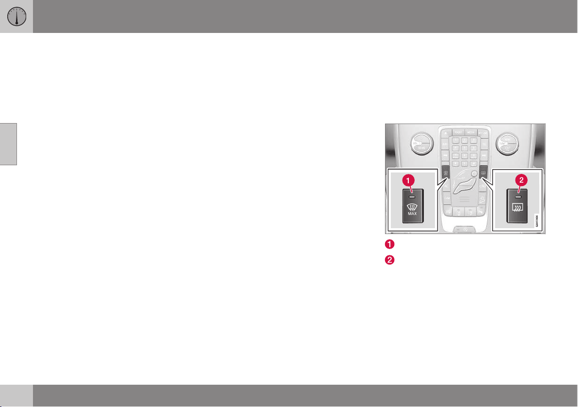
||
03 Instruments and controls
03
98
* Option/accessory, for more information, see Introduction.
Resetting to neutral
Mirrors that have been moved out of position
by an external force must be reset electrically
to the neutral position for electric retracting/
extending to work correctly:
1. Retract the mirrors with the L and R but-
tons.
2. Fold them out again with the L and R but-
tons.
3. Repeat the above procedure as neces-
sary.
The mirrors are now reset in neutral position.
Retractable power door mirrors*
The mirrors can be retracted for parking/driv-
ing in narrow spaces:
1. Depress the L and R buttons simultane-
ously (key position must be at least I).
2. Release them after
approximately 1 second. The mirrors
automatically stop in the fully retracted
position.
Fold out the mirrors by pressing down the L
and R buttons simultaneously. The mirrors
automatically stop in the fully extended posi-
tion.
Home safe and approach lighting
The lamp on the door mirrors illuminates
when approach lighting (p. 89) or home safe
lighting (p. 89) is selected.
Related information
•
Rearview mirror - interior (p. 99)
•
Windows and rearview and door mirrors -
heating (p. 98)
Windows and rearview and door
mirrors - heating
The defroster is used to quickly remove mist-
ing and ice from the windscreen, rear window
and door mirrors.
Heated windscreen*, rear window and
door mirrors
Heating, windscreen
Heating, rear window and door mirrors
The function is used to remove ice and mist-
ing from the windscreen, rear window and
door mirrors.
One press of the respective button starts the
heating. The light in the button indicates that
the function is active. Switch off the heating
as soon as the ice/misting is cleared in order
not to load the battery unnecessarily. How-
ever, the function is switched off automati-
cally after a certain time.
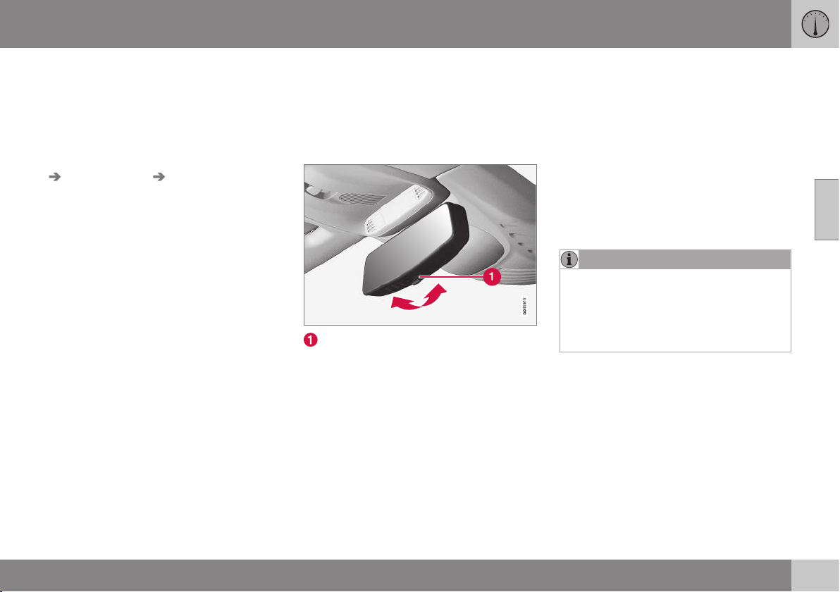
03 Instruments and controls
03
* Option/accessory, for more information, see Introduction.
99
See also Demisting and defrosting the wind-
screen (p. 136).
The door mirrors and rear window are demis-
ted/defrosted automatically if the car is
started in an outside temperature lower than
+7 °C. Automatic defrosting can be selected
in the menu system MY CAR under
Settings
Climate settings Auto start rear
defrost
. Select between On or Off. For a
description of the menu system, see MY CAR
- menu options (p. 106).
The compass (p. 100) is deactivated when
the heated windscreen is activated. When the
heated windscreen is deactivated, the com-
pass is reactivated.
Rearview mirror - interior
The interior rearview mirror can be dimmed
with a control in the mirror's lower edge.
Alternatively, the rearview mirror dims auto-
matically.
Interior rearview mirror
Control for dimming
Manual dimming
Bright light from behind could be reflected in
the rearview mirror and dazzle the driver. Use
dimming with the dimming control when
lights from behind are distracting:
1. Use dimming by moving the control in
towards the passenger compartment.
2. Return to normal position by moving the
control towards the windscreen.
Automatic dimming*
Bright light from behind is automatically
dimmed by the rearview mirror. The control
for manual dimming is not available on mir-
rors with automatic dimming.
The rearview mirror contains two sensors -
one forward facing and one rearward facing -
that work together to identify and eliminate
dazzling light. The forward facing sensor
detects ambient light, while the rearward fac-
ing sensor detects the light from vehicle
headlights behind.
NOTE
If the sensors are obscured by e.g. parking
permits, transponders, sun visors or
objects in the seats or in the cargo area in
such a way that light is prevented from
reaching the sensors, then the dimming
function of the rearview mirror is reduced.
The compass (p. 100) can only be specified
for a rearview mirror with automatic dimming.
Related information
•
Door mirrors (p. 97)
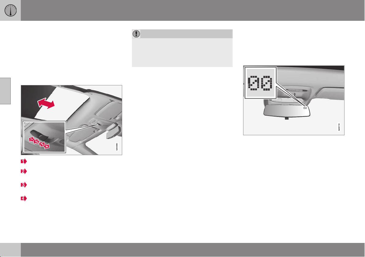
03 Instruments and controls
03
100
* Option/accessory, for more information, see Introduction.
Glass roof*
The glass roof's blind can be operated with
the control in the roof console.
The glass roof* is fixed, but the blind can be
operated in key position I or II with the con-
trol in the roof console. For information on
key positions - see Key positions - functions
at different levels (p. 71).
Automatic opening to end position
Manual opening until the button is
released
Manual closing until the button is
released
Automatic closing to end position
IMPORTANT
•
Avoid touching the blind because it
may then be damaged.
•
Only use the control in the roof con-
sole to operate the blind.
Compass
The rearview mirror contains an integrated
display that shows the compass direction in
which the front of the car is pointing.
Operation
Rearview mirror with compass.
The upper right-hand corner of the rearview
mirror has an integrated display that shows
the compass direction in which the front of
the car is pointing. Eight different directions
are shown with English abbreviations:
N
(north), NE (north east), E (east), SE (south
east), S (south), SW (south west), W (west)
and NW (north west).
The compass* is activated automatically
when the car is started or when key position
II is active, see Key positions - functions at
different levels (p. 71). To deactivate/activate
the compass - press in the button on the rear
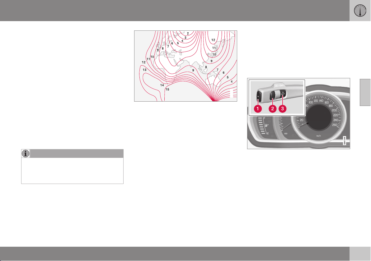
03 Instruments and controls
03
101
side of the mirror using a paper clip for exam-
ple.
The compass is deactivated when the heated
windscreen is activated. When the heated
windscreen is deactivated, the compass is
reactivated.
Calibration
The earth is divided into 15 magnetic zones.
The compass is set for the geographic area to
which the car was delivered. The compass
should be calibrated if the car is moved
across several magnetic zones. Proceed as
follows:
1. Stop the car in a large open area free
from steel structures and high-voltage
power lines.
2. Start the car.
NOTE
For the best calibration, switch off all elec-
trical equipment (climate control system,
wipers, etc.) and makes sure that all doors
are closed.
3. Hold the button on the underside of the
rearview mirror depressed
approx. 3 seconds. The number of the
current magnetic zone is shown.
G030295
Magnetic zones.
4. Press the button repeatedly until the
required magnetic zone (
1–15) is shown.
See the map of magnetic zones for the
compass.
5. Wait until the display returns to showing
the character
C, or hold the button on the
bottom of the rearview mirror depressed
for approx. 6 seconds (use e.g. a paper
clip) until the character C is shown.
6. Drive slowly in a circle at a speed of no
more than 10 km/h until a compass direc-
tion is shown in the display, indicating
that calibration is complete. Then drive a
further 2 circles to fine-tune calibration.
7. Repeat the above procedure as neces-
sary.
Menu navigation - combined
instrument panel
The menus shown on the information display
in the combined instrument panel (p. 60) are
controlled with the left-hand stalk switch.
Which menus are shown depends on the key
position (p. 71).
Information display (analogue combined instru-
ment panel) and menu navigation controls.
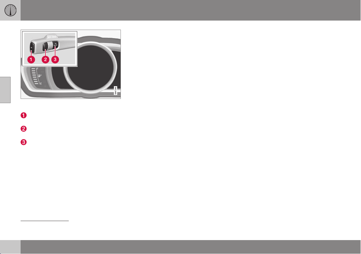
||
03 Instruments and controls
03
102
* Option/accessory, for more information, see Introduction.
Information displays (digital combined instrument
panel) and controls for menu navigation.
OK - access the menu, acknowledge
messages and confirm menu selections.
Thumbwheel – browse between menu
options.
RESET - reset data in the selected trip
computer step and go back in the menu
structure.
If there is a message (p. 103) then it must be
acknowledged with OK in order that the
menus shall be shown.
Related information
•
Messages - handling (p. 104)
•
Menu overview - analogue combined
instrument panel (p. 102)
•
Menu overview - digital combined instru-
ment panel (p. 102)
Menu overview - analogue combined
instrument panel
Which menus are shown in the combined
instrument panel's information display
depends on the key position (p. 71).
Some of the following menu options require
the function and hardware to be installed in
the car.
Digital speed
Parking heater*
Additional heater*
TC options
Service status
Oil level
26
Messages (##)
27
Related information
•
Menu navigation - combined instrument
panel (p. 101)
•
Menu overview - digital combined instru-
ment panel (p. 102)
•
Combined instrument panel (p. 60)
Menu overview - digital combined
instrument panel
Which menus are shown in the combined
instrument panel's information display
depends on the key position (p. 71).
Some of the following menu options require
the function and hardware to be installed in
the car.
Settings*
Themes
Contrast mode/Colour mode
Service status
Messages
28
Oil level
29
Parking heater*
Trip computer reset
Related information
•
Menu navigation - combined instrument
panel (p. 101)
•
Menu overview - analogue combined
instrument panel (p. 102)
•
Combined instrument panel (p. 60)
26
Certain engines.
27
The number of messages is indicated in brackets.

03 Instruments and controls
03
103
Messages
When a warning, information or indicator
symbol illuminates, a corresponding message
appears on the information display.
Message Specification
Stop safely
A
Stop and switch off the
engine. Serious risk of
damage - consult a work-
shop
B
.
Stop engine
A
Stop and switch off the
engine. Serious risk of
damage - consult a work-
shop
B
.
Service
urgent
A
Contact a workshop
B
to
check the car immedi-
ately.
Service
required
A
Contact a workshop
B
to
check the car as soon as
possible.
See manual
A
Read the owner's man-
ual.
Book time
for mainte-
nance
Time to book regular
service - contact a work-
shop
B
.
Message Specification
Time for reg-
ular mainte-
nance
Time for regular service -
contact a workshop
B
. The
timing is determined by
the number of kilometres
driven, number of months
since the last service,
engine running time and
oil grade.
Maintenance
overdue
If the service intervals are
not followed then the
warranty does not cover
any damaged parts -
contact a workshop
B
.
Transmission
Oil change
needed
Contact a workshop
B
to
check the car as soon as
possible.
Transmission
Reduced
performance
The gearbox cannot han-
dle full capacity. Drive
with care until the mes-
sage clears
C
.
If shown repeatedly -
contact a workshop
B
.
Message Specification
Transmission
hot Reduce
speed
Drive more smoothly or
stop the car in a safe
manner. Disengage the
gear and run the engine
at idling speed until the
message clears
C
.
Transmission
hot Stop
safely Wait
for cooling
Critical fault. Stop the car
immediately in a safe
manner and contact a
workshop
B
.
Temporarily
off
A
A function has been tem-
porarily switched off and
is reset automatically
while driving or after star-
ting again.
Low battery
charge
Power save
mode
The audio system is
switched off to save
energy. Charge the bat-
tery.
A
Part of message, shown together with information on
where the problem has arisen.
B
An authorised Volvo workshop is recommended.
C
For more messages concerning automatic gearbox.
Related information
•
Messages - handling (p. 104)
•
Menu navigation - combined instrument
panel (p. 101)
28
The number of messages is indicated in brackets.
29
Certain engines.
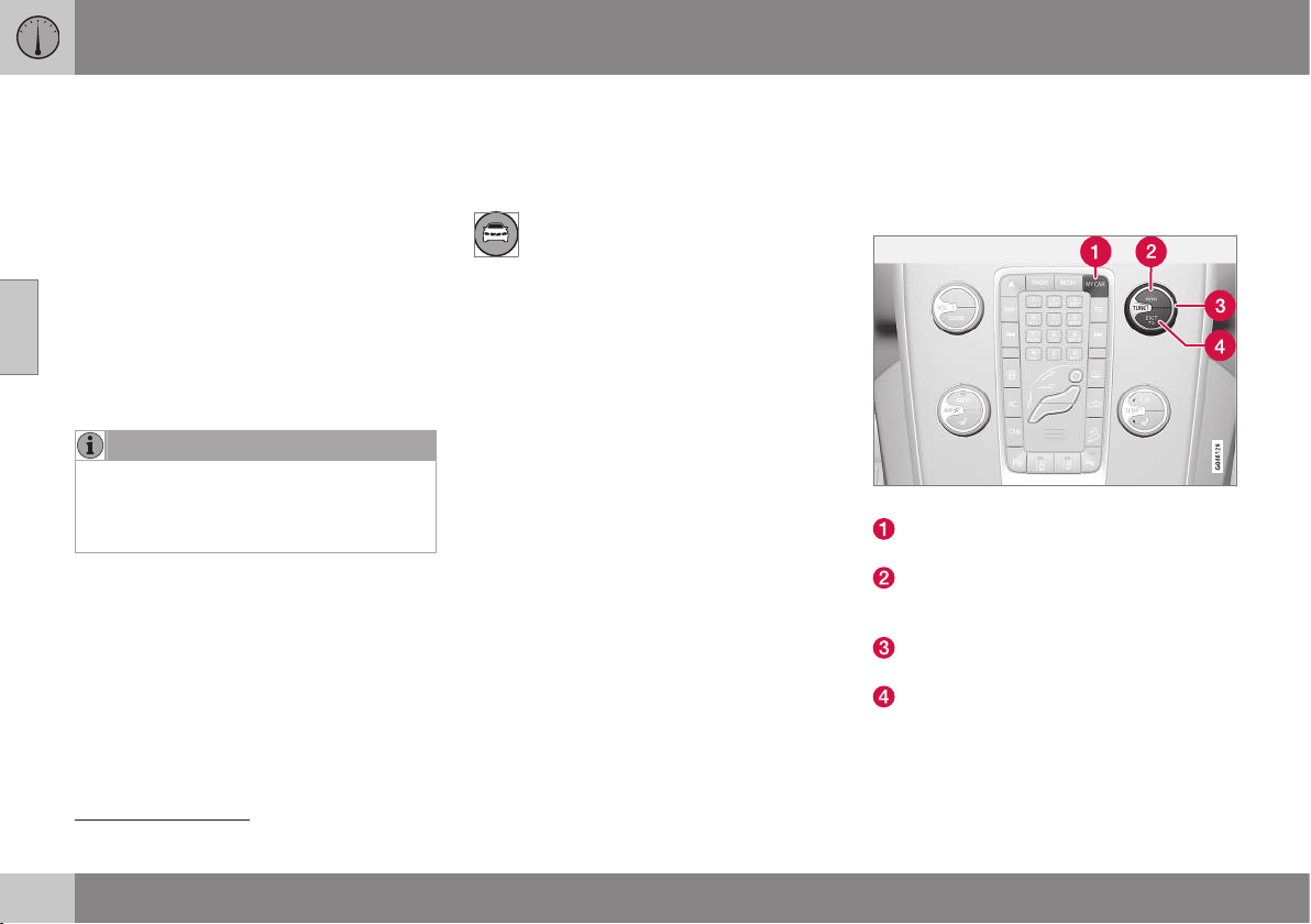
03 Instruments and controls
03
104
Messages - handling
Use the left-hand stalk switch to acknowledge
and browse among messages (p. 103) that
are shown in the information display of the
combined instrument panel.
When a warning, information or indicator
symbol illuminates, a corresponding message
is shown in the display. An error message is
stored in a memory list until the fault has
been rectified.
Press OK on the left-hand stalk switch to
acknowledge
30
a message. Scroll through
messages with the thumbwheel (p. 101).
NOTE
If a warning message appears while you
are using the trip computer, the message
must be read (press OK) before the previ-
ous activity can be resumed.
Related information
•
Menu overview - analogue combined
instrument panel (p. 102)
•
Menu overview - digital combined instru-
ment panel (p. 102)
MY CAR
MY CAR is a menu source that handles many
of the car's functions, e.g. setting the clock,
door mirrors and locks.
Many of the car's features are handled
in this menu source, e.g. setting the
clock, door mirrors and locks.
Navigation in the menus is carried out using
buttons in the centre console or with the
steering wheel's right-hand keypad.
Certain functions are standard, others are
optional - the range also varies depending on
the market.
Related information
•
MY CAR - operation (p. 104)
•
MY CAR - search paths (p. 105)
•
MY CAR - menu options (p. 106)
MY CAR - operation
MY CAR is a menu source where many of the
car's functions can be handled, e.g. setting
the clock, door mirrors and locks.
Centre console controls
Centre console controls for menu navigation.
Press MY CAR to open the menus under
MY CAR.
Press OK/MENU to select/tick in the
highlighted menu option or to store the
selected function in the memory.
Turn the TUNE knob to scroll up/down
among the menu options.
EXIT
EXIT functions
Depending on the function in which the cur-
sor is located when EXIT is pressed, and at
30
A message can also be acknowledged via the thumbwheel or RESET button.
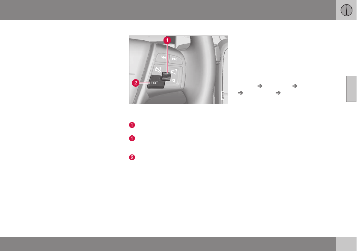
03 Instruments and controls
03
* Option/accessory, for more information, see Introduction.
105
which menu level, one of the following may
happen:
•
telephone call rejected
•
current function cancelled
•
input characters deleted
•
last selection undone
•
move up in the menu system.
Short and long press may produce varying
results.
A long press takes you to the top menu
level (p. 374) (Parent view), from which all car
functions/menu sources can be accessed.
Steering wheel keypad*
The keypad may vary depending on audio level,
see Audio and media - operating the system (p.
372).
Turn the thumbwheel to scroll up/down
among the menu options.
Press the thumbwheel to select/tick in
the highlighted menu option or to store
the selected function in the memory.
EXIT (see previous heading "EXIT func-
tions").
Related information
•
MY CAR (p. 104)
•
MY CAR - search paths (p. 105)
•
MY CAR - search paths (p. 105)
•
MY CAR - menu options (p. 106)
MY CAR - search paths
MY CAR is a menu source that handles many
of the car's functions, e.g. setting the clock,
door mirrors and locks.
The current menu level is shown at the top
right of the centre console's display screen.
The search paths to the menu system's func-
tions are given, e.g. as follows:
Settings Car settings Lock settings
Doors unlock Driver door, then all.
The following is an example of how a function
can be accessed and adjusted using the
steering wheel keypad:
1. Press the centre console button MY
CAR.
2.
Scroll to the desired menu, e.g.
Settings,
with the thumbwheel and then press the
thumbwheel - a submenu opens.
3.
Scroll to the desired menu, e.g.
Car
settings and press the thumbwheel - a
submenu opens.
4.
Scroll to
Lock settings and press the
thumbwheel - a new submenu opens.
5.
Scroll to
Doors unlock and press the
thumbwheel - a submenu of selectable
functions opens.
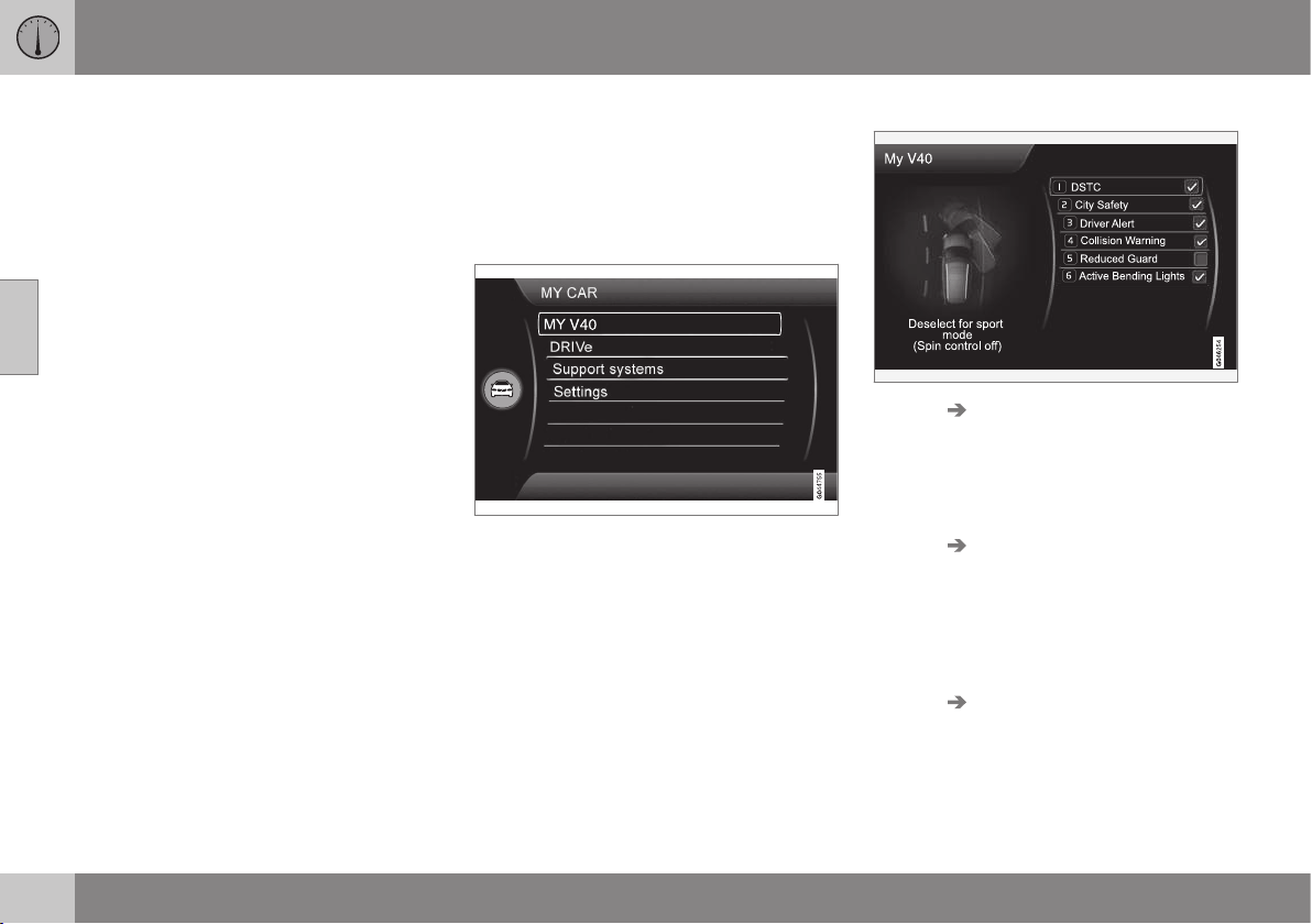
||
03 Instruments and controls
03
106
6.
Choose between the options
All doors
and Driver door, then all and press the
thumbwheel - a cross is marked in the
option's empty box.
7. Exit the programming by backing out of
the menus incrementally with short
presses on EXIT or with one long press.
The procedure is the same for the centre con-
sole controls (p. 104): OK/MENU, EXIT and
the TUNE knob.
Related information
•
MY CAR (p. 104)
•
MY CAR - operation (p. 104)
•
MY CAR - search paths (p. 105)
•
MY CAR - menu options (p. 106)
MY CAR - menu options
MY CAR is a menu source where many of the
car's functions can be handled, e.g. setting
the clock, door mirrors and locks.
The following options are available first/
uppermost in
MY CAR:
•
My V40
•
Trip statistics
•
DRIVe
•
Support systems
•
Settings
My V40
MY CAR My V40
The display screen shows a grouping of all of
the car's driving support systems - these can
be activated or deactivated here.
Trip statistics
MY CAR Trip statistics
The screen shows the history as a bar chart
with average fuel consumption and average
speed, see Trip computer - functions (p.
123).
DRIVe
MY CAR DRIVe
An introduction of Volvo's Start-Stop system
is presented here, as well as recommenda-
tions for energy-saving driving techniques.
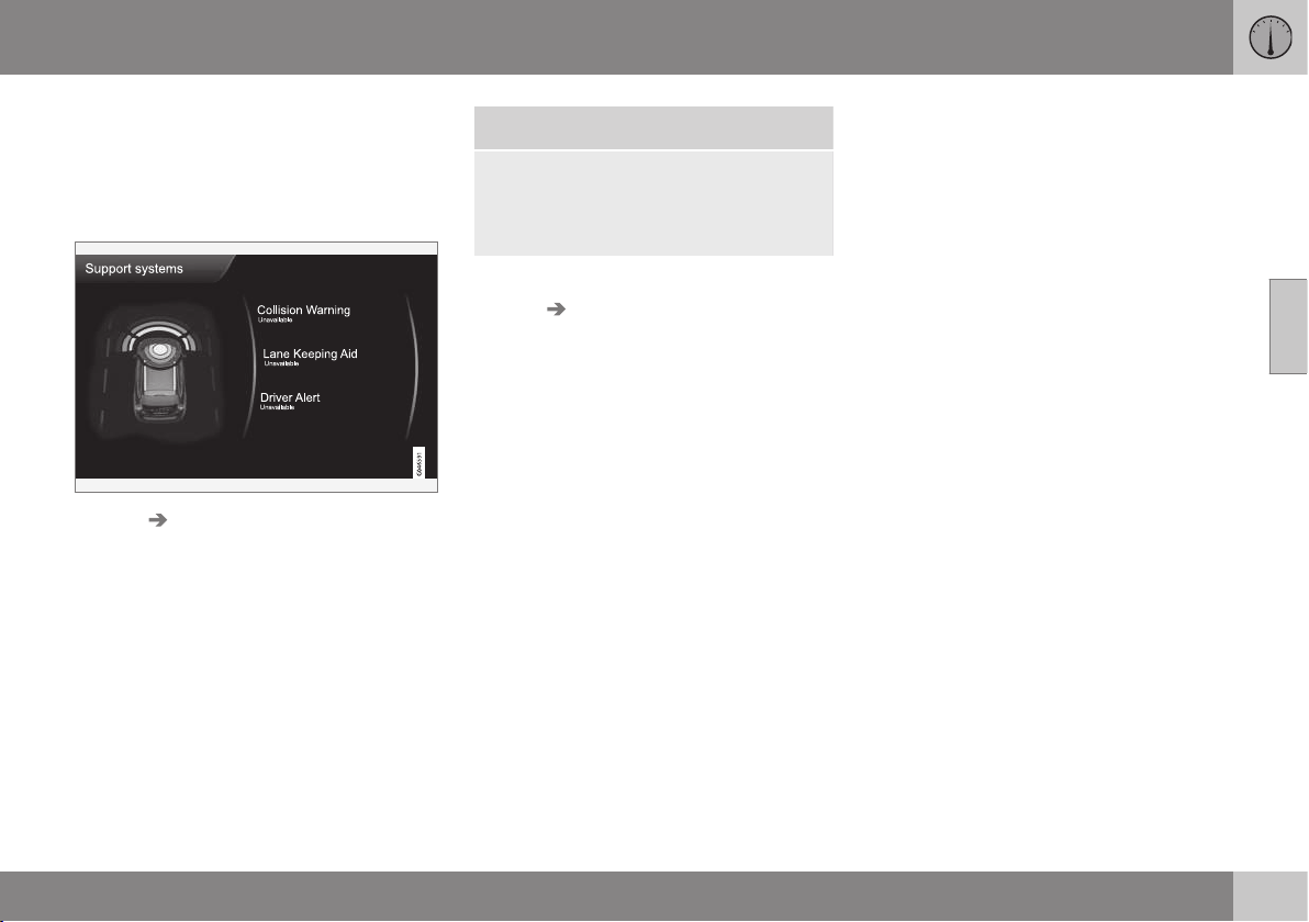
03 Instruments and controls
03
* Option/accessory, for more information, see Introduction.
107
•
Start/Stop
•
Eco driving guide
For more information - see Start/Stop* (p.
279).
Driving support systems
MY CAR Support systems
The display screen shows a summary of the
current status of the car's driving support
systems.
Settings
This is how the menus are structured:
Menu level 1
Menu level 2
Menu level 3
Menu level 4
Shown here are the 4 first menu levels under
MY CAR Settings. Some menus have fur-
ther submenus - these are then described in
detail in their respective sections.
When selecting whether a function should be
activated/
On or deactivated/Off a square is
displayed:
On: Selected square.
Off: Empty square.
•
Select
On/Off with OK - then back out of
the menu with EXIT.
Menus
•
Car settings (p. 108)
•
Driving support systems (p. 109)
•
System settings (p. 111)
•
Voice settings (p. 112)
•
Audio settings, see Audio and media -
general audio settings (p. 377)
•
Climate settings (p. 113)
•
Favourites (p. 376)
•
Volvo On Call, described in a separate
manual.
•
Information (p. 114)
Related information
•
MY CAR (p. 104)
•
MY CAR - operation (p. 104)
•
MY CAR - search paths (p. 105)
•
MY CAR - search paths (p. 105)

03 Instruments and controls
03
108
MY CAR - Car settings
Car settings menu option in the MY CAR
menu source handles many of the car's func-
tions, e.g. Car key memory and Lock settings
for doors.
Car settings See
Car key memory
On
Off
(p. 74) and
(p. 97)
Lock settings
(p. 162),
(p. 168)
and (p.
175)
Automatic door locking
On
Off
(p. 162),
(p. 168)
and (p.
175)
Doors unlock
All doors
Driver door, then all
(p. 162),
(p. 168)
and (p.
175)
Keyless entry
All doors
Any door
Doors on same side
Both front doors
(p. 162),
(p. 168)
and (p.
175)
Audible confirmation
On
Off
(p. 162),
(p. 168)
and (p.
175)
Reduced Guard
Activate once
Ask when exiting
(p. 178)
and (p.
183)
Side mirror settings
Fold mirrors
Tilt left mirror
Tilt right mirror
(p. 97)
Light settings
Interior light
Floor lights
Ambient light
Ambient light colours
(p. 87)
Door lock con-
firmation light
On
Off
(p. 160)
Unlock confirmation light
On
Off
(p. 160)
Approach light duration
Off
30 sec
60 sec
90 sec
(p. 162)
and (p. 89)
Home safe light duration
30 sec
60 sec
90 sec
(p. 89)
Triple indicator
On
Off
(p. 87)

03 Instruments and controls
03
109
Temporary LH traffic
On
Off
or
Temporary RH traffic
On
Off
(p. 90)
Active bending lights
On
Off
(p. 84)
Steering wheel force
Low
Medium
High
(p. 77)
Speed in infotain-
ment display
On
Off
(p. 119)
Reset car settings
All menus in Car settings are
given original factory settings.
Related information
•
MY CAR (p. 104)
•
MY CAR - driving support system (p.
109)
•
MY CAR - System options (p. 111)
•
MY CAR - Voice settings (p. 112)
•
Audio and media - general audio settings
(p. 377)
•
MY CAR - Climate settings (p. 113)
•
MY CAR Information (p. 114)
MY CAR - driving support system
Driving support systems menu option in the
MY CAR menu source handles functions such
as e.g. Collision warning system and Lane
keeping aid.
Driver support systems See
Collision Warning
On
Off
(p. 228)
Warning distance
Long
Normal
Short
(p. 228)
Warning sound
On
Off
(p. 228)
Lane Keeping Aid
On
Off
(p. 241)

||
03 Instruments and controls
03
110
* Option/accessory, for more information, see Introduction.
On at start-up
On
Off
(p. 241)
Increased sensitivity*
On
Off
(p. 241)
Assistance alternatives
Vibration only
Steering assist only
Full function
(p. 241)
Road Sign Information
On
Off
(p. 188)
Speed alert
On
Off
(p. 188)
DSTC
On
Off
(p. 186)
City Safety
On
Off
(p. 218)
BLIS
On
Off
(p. 258)
Cross Traffic Alert
On
Off
(p. 258)
Distance Alert
On
Off
(p. 214)
Driver Alert
On
Off
(p. 236)
Related information
•
MY CAR (p. 104)
•
MY CAR - Car settings (p. 108)
•
MY CAR - System options (p. 111)
•
MY CAR - Voice settings (p. 112)
•
Audio and media - general audio settings
(p. 377)
•
MY CAR - Climate settings (p. 113)
•
MY CAR Information (p. 114)

03 Instruments and controls
03
111
MY CAR - System options
The system settings menu option in the MY
CAR menu source handles functions such as
e.g. time and languages.
System options See
Time
The combined instrument panel's
clock is adjusted here.
(p. 69)
Time format
12 h
24 h
Screen saver
On
Off
The display screen's current con-
tent fades out after a period of
inactivity and is replaced by a
blank screen if this option is
selected.
The current screen content
returns if any of the display
screen's buttons or controls are
actuated.
Language
Selects language for menu texts.
Show help text
On
Off
Explanatory text for the display
screen's current content is
shown with this option selected.
Distance and fuel units
MPG (UK)
MPG (US)
km/l
l/100km
(p.
123)
Temperature unit
Celsius
Fahrenheit
Selects the unit for the display of
outside temperature and setting
of the climate control system.
(p.
135)
Volume levels
Voice output volume
Front park assist volume
Rear park assist volume
Phone ringing volume
(p.
416),
(p.
245)
and (p.
398)
Reset system options
All menus in System options are
given original factory settings.
Related information
•
MY CAR (p. 104)
•
MY CAR - Car settings (p. 108)
•
MY CAR - driving support system (p. 109)
•
MY CAR - System options (p. 111)
•
MY CAR - Voice settings (p. 112)
•
Audio and media - general audio settings
(p. 377)
•
MY CAR - Climate settings (p. 113)
•
MY CAR Information (p. 114)

03 Instruments and controls
03
112
* Option/accessory, for more information, see Introduction.
MY CAR - Voice settings
Voice settings menu option in the MY CAR
menu source manages functions such as
Voice tutorial and Command list for voice set-
ting.
Voice settings
Only in cars with Volvo GPS navigator RTI*
- see separate manual.
Voice tutorial
This menu option + OK provides spoken
information about how the system works.
Voice command list
Phone commands
Phone
Phone call contact
Phone dial number
Navigation commands
Navigation
Navigation repeat instruction
Navigation go to address
General commands
Help
Cancel
Voice tutorial
The menu options under
Phone com-
mands show several examples of available
voice commands - only with a Bluetooth
®
-
enabled mobile phone installed. For more
and detailed information - see Bluetooth
®
*
handsfree phone - overview (p. 404).
The menu options under
Navigation com-
mands show several examples of available
voice commands in the Navigation system.
Voice user setting
Default setting
User 1
User 2
Here there is the option to create a second
user profile - an advantage if more than
one person shall use the car/system regu-
larly.
Default setting restores factory set-
tings.
Voice training
User 1
User 2
With
Voice training the voice recognition
system is taught to recognise the driver's
voice and pronunciation. A number of
phrases are presented on the screen for
the driver to read aloud. When the system
has learnt how the driver talks, the presen-
tation of the phrases stops. Following
which e.g. User 1 can be selected in
Voice user setting in order that the sys-
tem shall listen to the right user.

03 Instruments and controls
03
113
Voice output volume
A volume control appears on the screen -
at which point, proceed as follows:
1. Adjust the volume with the thumb-
wheel.
2. Test-listen using OK.
3. Use EXIT to store the setting and the
menu is switched off.
Voice POI list
Edit list
The number of facilities is extensive and
varies depending on market. Maximum 30
favourite facilities can be stored in this list.
For more information on Facilities and
Voice recognition - see the Navigation sys-
tem's owner's manual.
Related information
•
MY CAR (p. 104)
•
MY CAR - Car settings (p. 108)
•
MY CAR - driving support system (p. 109)
•
MY CAR - System options (p. 111)
•
Audio and media - general audio settings
(p. 377)
•
MY CAR - Climate settings (p. 113)
•
MY CAR Information (p. 114)
MY CAR - Climate settings
Climate settings menu option in the MY CAR
menu source handles functions such as e.g.
fan adjustment and recirculation.
Climate settings See
Automatic blower
adjustment
Normal
High
Low
(p. 134), (p.
137), (p. 98) and
(p. 128)
Recirculation timer
On
Off
(p. 134), (p.
137), (p. 98) and
(p. 128)
Automatic rear
defroster
On
Off
(p. 134), (p.
137), (p. 98) and
(p. 128)
Interior air
quality system
On
Off
(p. 134), (p.
137), (p. 98) and
(p. 128)
Reset climate settings
All menus in
Climate
settings are given orig-
inal factory settings.
(p. 134), (p.
137), (p. 98) and
(p. 128)
Related information
•
MY CAR (p. 104)
•
MY CAR - Car settings (p. 108)
•
MY CAR - driving support system (p. 109)
•
MY CAR - System options (p. 111)
•
MY CAR - Voice settings (p. 112)
•
Audio and media - general audio settings
(p. 377)
•
MY CAR Information (p. 114)
03 Instruments and controls
03
114
* Option/accessory, for more information, see Introduction.
MY CAR Information
Information menu option in the MY CAR
menu source handles functions such as Num-
ber of keys and VIN number.
Information See
Number of keys
(p. 159)
VIN number
(p. 438)
DivX® VOD code
(p. 393)
Bluetooth software
version in car
(p. 406)
Map and software version*
Only in cars with Volvo's naviga-
tion system* - see separate sup-
plement.
Related information
•
MY CAR (p. 104)
•
MY CAR - Car settings (p. 108)
•
MY CAR - driving support system (p. 109)
•
MY CAR - System options (p. 111)
•
MY CAR - Voice settings (p. 112)
•
Audio and media - general audio settings
(p. 377)
•
MY CAR - Climate settings (p. 113)
Trip computer
The car's trip computer registers, calculates
and displays information.
General
Checking and settings can be made immedi-
ately after the combined instrument panel is
automatically illuminated in connection with
unlocking. If none of the trip computer's con-
trols are actuated within approx. 30 seconds
after the driver's door has been opened then
the instrument extinguishes, after which
either key position II (p. 71) or engine starting
is required in order to operate the trip com-
puter.
NOTE
If a warning message appears when the
trip computer is used then the message
must first be acknowledged before the trip
computer can be reactivated.
•
Acknowledge the message by briefly
pressing the indicator stalk OK button.
Group menus
The trip computer has two different group
menus:
•
Functions
•
Heading in combined instrument panel
The trip computer's functions or headings
are each listed in an infinite loop.
Related information
•
Trip computer - analogue combined
instrument panel (p. 115)
•
Trip computer - digital combined instru-
ment panel (p. 119)
•
Trip computer - functions (p. 123)
•
Trip computer - trip statistics* (p. 124)
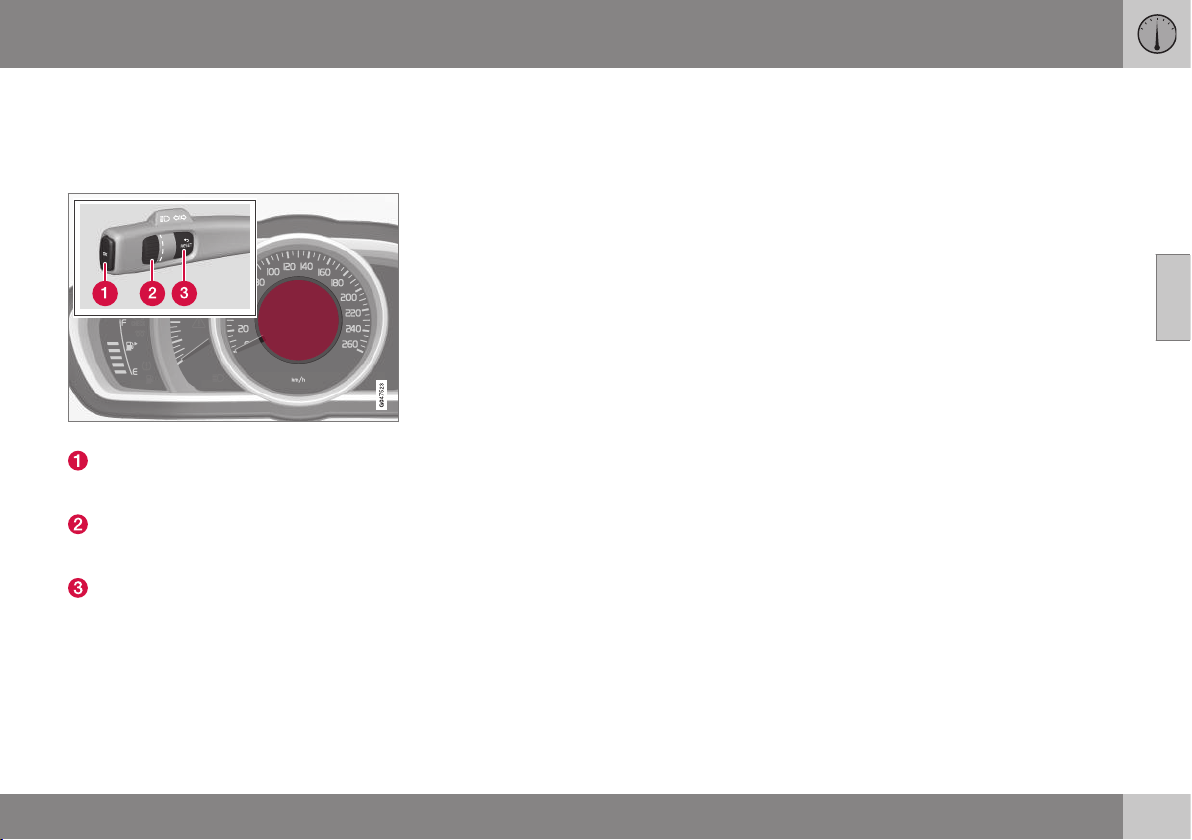
03 Instruments and controls
03
}}
115
Trip computer - analogue combined
instrument panel
The car's trip computer registers, calculates
and displays information.
Information display and controls.
OK - Opens the loop with the trip com-
puter's functions + Activates the selected
option.
Thumbwheel - Opens the loop with the
trip computer's headings + Scrolls
through the options.
RESET - Undoes, zeroes or backs out of
a function after making a selection.
Functions
Proceed as follows to open and check/adjust
functions:
1. To ensure that no control is in the middle
of a sequence - "Reset" them first with
2 presses on RESET.
2. Press OK - the loop with all functions
opens.
3. Browse through the functions with the
thumbwheel and select/confirm with OK.
4. Finish by pressing RESET twice after
completed checking/ adjustment.
The different functions of the trip computer
are listed in the following table:

||
03 Instruments and controls
03
116
* Option/accessory, for more information, see Introduction.
Functions Information
Digital speed
- km/h
mph
No display
Shows the car's speed digitally in the centre of the combined instrument panel:
•
Open with OK, select with the thumbwheel, confirm with OK and go back out with ENTER.
Parking heater*
- Direct start
- Timer 1 - leads to the menu for selecting
time.
- Timer 2 - leads to the menu for selecting
time.
For a description of programming the timer, see Engine block heater and passenger compartment
heater* - timer (p. 141).
Additional heater*
– Auto On
– Off
For more information, see Additional heater* (p. 143).
TC options
- Distance to empty tank
Fuel consumption
Average speed
- Trip meter
T1 and total dist.
- Trip meter T2 and total dist.
Here you can select/activate the options that you want to be available as selectable headings in
the trip computer. The symbols for the items already selected are WHITE with a "tick" - others are
GREY and have no "tick":
1. Open the function with OK, scroll through the symbols for the options with the thumbwheel
and highlight/stop on the desired symbol.
2. Confirm with OK - the symbol changes colour from GREY to WHITE and is marked with a
"tick".
3. Continue to select the function symbols with the thumbwheel or finish with RESET.
Service status
Shows the number of months and the distance until the next service.

03 Instruments and controls
03
}}
117
Functions Information
Oil level
A
For more information, see Engine oil - checking and filling (p. 337).
Messages (##)
For more information, see Messages (p. 103).
A
Certain engines.
Headings
One of the headings in the following table can
be selected for constant display in the com-
bined instrument panel. Proceed as follows to
determine which:
1. To ensure that no control is in the middle
of a sequence - "Reset" them first with
2 presses on RESET.
2. Turn the thumbwheel - selectable head-
ings for the trip computer are shown in a
loop.
3. Stop on desired heading.
Trip computer heading in combined instrument
panel
Information
Trip meter T1 and total dist.
•
Long press on RESET resets trip meter T1.
Trip meter T2 and total dist.
•
Long press on RESET resets trip meter T2.
Distance to empty
For more information, see Trip computer (p. 114), "Distance to empty tank".
Fuel consumption
Current consumption.
Average speed
•
Long press on RESET resets
Average speed.
No trip computer information. This option shows a blank display - it also marks the beginning/end of the loop.
The combined instrument panel's trip com-
puter can be changed to another option at
any time during the journey. Proceed as fol-
lows:
•
Turn the thumbwheel - stop on the
desired heading.
Resetting the trip computer - analogue
combined instrument panel
Trip meter and Average speed

||
03 Instruments and controls
03
118
* Option/accessory, for more information, see Introduction.
With current trip computer heading - Trip
meter T1, Trip meter T2 or Average speed -
shown in the combined instrument panel:
•
Give a long press on RESET RESET -
selected heading is zeroed.
Each heading must be zeroed individually.
Change unit
To change unit (km/miles) for distance and
speed - go to
MY CAR Settings
System options Distance and fuel units,
see Trip computer - trip statistics* (p. 124).
Related information
•
Trip computer - digital combined instru-
ment panel (p. 119)
•
Trip computer - functions (p. 123)
•
Trip computer - trip statistics* (p. 124)
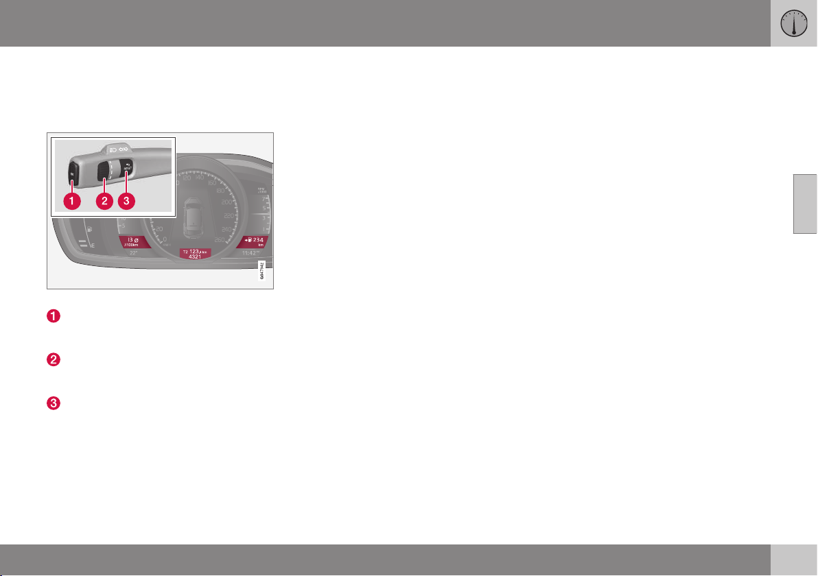
03 Instruments and controls
03
}}
119
Trip computer - digital combined
instrument panel
The car's trip computer registers, calculates
and displays information.
Information displays and controls.
OK - Opens the loop with the trip com-
puter's functions + Activates the selected
option.
Thumbwheel - Opens the loop with the
trip computer's headings + Scrolls
through the options.
RESET - Undoes, zeroes or backs out of
a function after making a selection.
Functions
Proceed as follows to open and check/adjust
functions:
1. To ensure that no control is in the middle
of a sequence - "Reset" them first with
2 presses on RESET.
2. Press OK - loop with all functions opens.
3. Browse through the functions with the
thumbwheel and select/confirm with OK.
4. Finish by pressing RESET twice after
completed checking/adjustment.
The different functions of the trip computer
are listed in the following table:

||
03 Instruments and controls
03
120
* Option/accessory, for more information, see Introduction.
Functions Information
Trip computer reset
Average
Average speed
Note that this function does not reset the two trip meters T1 and T2 - see the table under the
"Headings" section below.
Messages
For more information, see Messages (p. 103).
Themes
The appearance of the combined instrument panel is selected here, see Digital combined
instrument panel - overview (p. 61).
Settings* Select Auto On or Off.
For more information, see Additional heater* (p. 143).
Contrast mode/Colour mode
Adjusting the combined instrument panel's brightness and colour intensity.
Parking heater*
– Direct start
- Symbol Timer 1 - leads to the menu for
selecting time.
- Symbol Timer 2 - leads to the menu for
selecting time.
For a description of programming the timer, see Engine block heater and passenger compart-
ment heater* - timer (p. 141).
Service status
Shows the number of months and the distance until the next service.
Oil level
A
For more information, see Engine oil - checking and filling (p. 337).
A
Certain engines.
03 Instruments and controls
03
}}
* Option/accessory, for more information, see Introduction.
121
Headings
Three trip computer headings can be dis-
played simultaneously - one in each "win-
dow" (see figure above).
One of the heading combinations in the fol-
lowing table can be selected for constant dis-
play in the combined instrument panel. Pro-
ceed as follows to determine which:
1. To ensure that no control is in the middle
of a sequence - "Reset" them first with
2 presses on RESET.
2. Turn the thumbwheel - selectable head-
ing combinations are shown in a loop.
3. Stop on desired heading combination.
Heading combinations Information
Average Trip meter T1 + Meter reading Average speed
•
Long press on RESET resets trip meter T1.
Instantaneous Trip meter T2 + Meter reading Distance to empty
tank
•
Long press on RESET resets trip meter T2.
Instantaneous Meter reading kmh<>mph kmh<>mph - "Digital speed display", see Trip computer - functions (p.
123).
No trip computer information. This option extinguishes all three trip computer displays - it also marks
the beginning/end of the loop.
The combined instrument panel's heading
combination for the trip computer can be
changed to another option at any time during
the journey. Proceed as follows:
•
Turn the thumbwheel - stop on the
desired heading.
Resetting the trip computer - digital
combined instrument panel
Trip meter
Turn with the thumbwheel to the heading
combination containing the trip meter to be
reset:
•
Give a long press on RESET RESET -
selected trip meter is zeroed.
Average speed & Average consumption
1.
Select function
Trip computer
reset and activate with OK.
2. Select one of the following options with
the thumbwheel and activate with OK:
- l/100 km
- km/h
- Reset both
3. Finish with RESET.
Change unit
To change unit (km/miles) for distance and
speed - go to MY CAR Settings
System options Distance and fuel units,
see Trip computer - trip statistics* (p. 124).
NOTE
In addition to in the trip computer, these
units are also changed in Volvo's naviga-
tion system*.

||
03 Instruments and controls
03
122
* Option/accessory, for more information, see Introduction.
Trip meter
Turn with the thumbwheel to the heading
combination containing the trip meter to be
reset:
•
Give a long press on RESET RESET -
selected trip meter is zeroed.
Related information
•
Trip computer - analogue combined
instrument panel (p. 115)
•
Trip computer - functions (p. 123)
•
Trip computer - trip statistics* (p. 124)

03 Instruments and controls
03
* Option/accessory, for more information, see Introduction.
123
Trip computer - functions
The car's trip computer can record, calculate
and show information. It describes informa-
tion such as average consumption and aver-
age speed.
Average
Average fuel consumption is calculated from
the last resetting.
NOTE
There may be a slight error in the reading if
a fuel-driven heater* has been used.
Average speed
The average speed is calculated for the driv-
ing distance driven since the last reset to
zero.
Instantaneous.
The information for current fuel consumption
is updated continuously - approximately once
per second. When the car is driven at low
speed the consumption is shown per time
unit - at a higher speed it is shown related to
mileage.
Different units (km/miles) can be selected for
the display - see the heading "Change unit"
further down.
Range - distance to empty tank
The trip computer shows the approximate
distance that can be driven with the fuel
quantity remaining in the tank.
No guaranteed range remains when the head-
ing
Distance to empty shows "----".
•
In which case, refuel as soon as possible.
The calculation is based on the average fuel
consumption over the last 30 km and the
remaining driveable fuel quantity.
NOTE
There may be a slight error in the reading if
the driving style has been changed.
An economic driving style generally results in
a longer driving distance. For more informa-
tion on how fuel consumption can be influ-
enced, see Volvo Cars' environmental philos-
ophy (p. 20).
Digital speed display
31
The speed is shown in the opposite unit
(kmh/mph) of the main instrument panel. If it
is calibrated in mph then the trip computer
shows the corresponding speed in km/h and
vice versa.
Change unit
To change unit (metric/imperial) for distance
and speed - go to
MY CAR Settings
System options Distance and fuel units,
see MY CAR - System options (p. 111).
NOTE
In addition to in the trip computer, these
units are also changed in Volvo's naviga-
tion system*.
Related information
•
Trip computer - analogue combined
instrument panel (p. 115)
•
Trip computer - digital combined instru-
ment panel (p. 119)
•
Trip computer - trip statistics* (p. 124)
31
Only for combined instrument panel "Digital".

03 Instruments and controls
03
124
* Option/accessory, for more information, see Introduction.
Trip computer - trip statistics*
Information is stored about completed trips
containing average fuel consumption and
average speed, which can be viewed in the
centre console's screen as a bar chart.
Function
Trip statistics
32
.
Each bar symbolises 1 km or 10 km driven
distance, depending on the scale selected -
the bar at the far right shows the value for the
current kilometre or 10 km.
With the TUNE wheel, the scale of each block
can be switched between 1 km and 10 km -
the cursor at the far right shifts position
between up and down depending on the
scale selected.
Operation
A setting can be defined in the MY CAR
menu system:
MY CAR My V40 Trip statistics:
•
Start new trip - ENTER is used to delete
all previous statistics, back out of the
menu by selecting EXIT.
•
Reset for every driving cycle - highlight
the box by selecting ENTER and go back
out of the menu by selecting EXIT.
With the "
Reset for every driving cycle"
option highlighted, all statistics are deleted
automatically once driving is complete and
the car has been stationary for 4 hours. The
journey statistics start again from zero the
next time the engine is started.
If a new drive cycle begins before 4 hours
have passed, the current period has to be
deleted manually first using the "Start new
trip" option.
See also information on Eco guide (p. 64).
Related information
•
Trip computer - analogue combined
instrument panel (p. 115)
•
Trip computer - digital combined instru-
ment panel (p. 119)
•
Trip computer - functions (p. 123)
32
The figure is schematic - layout may vary depending on updated software and market.
CLIMATE CONTROL

04 Climate control
04
126
* Option/accessory, for more information, see Introduction.
General information on climate
control
The car is equipped with electronic climate
control. The climate control system cools or
heats as well as dehumidifies the air in the
passenger compartment.
There are two different climate control sys-
tems:
•
Electronic temperature control (ETC) (p.
132)
•
Electronic climate control (ECC) (p. 131)
NOTE
The air conditioning system (AC) can be
switched off, but to ensure the best possi-
ble climate comfort in the passenger com-
partment and to prevent the windows from
misting, it should always be on.
To bear in mind:
•
To ensure that the air conditioning works
optimally, the side windows must be
closed.
•
Total airing function (p. 176) opens or
closes all side windows simultaneously
and can be used for example to quickly
air the car during hot weather.
•
Remove ice and snow from the climate
control system air intake (the grille
between the bonnet and the windscreen).
•
Remove misting on the insides of the win-
dows primarily by using the defroster
function (p. 136). To reduce the risk of
misting, keep the windows clean and use
window cleaner.
•
In warm weather, condensation from the
air conditioning may drip under the car.
This is normal.
•
When the engine requires full power, e.g.
for full acceleration or driving uphill with a
trailer, the air conditioning can be tempo-
rarily switched off. There may then be a
temporary increase in temperature in the
passenger compartment.
•
With an auto-stopped engine (p. 279)
(cars with Start/Stop*), certain equipment
has its function temporarily reduced, e.g.
the climate control system's air condition-
ing and fan speed.
Related information
•
Actual temperature (p. 126)
•
Sensors - climate control (p. 127)
•
Menu settings - climate control (p. 129)
•
Air conditioning (p. 135)
•
Air distribution in the passenger compart-
ment (p. 129)
•
Air cleaning (p. 127)
•
Heated front seats* (p. 133)
•
Heated rear seat* (p. 133)
Actual temperature
The temperature you select in the passenger
compartment corresponds to the physical
experience with reference to factors such as
air speed, humidity and solar radiation etc. in
and around the car.
The system includes a sun sensor (p. 127)
which detects on which side the sun is shin-
ing into the passenger compartment. This
means
1
that the temperature can differ
between the right and left-hand air vents
despite the controls being set for the same
temperature on both sides.
Related information
•
General information on climate control (p.
126)
•
Temperature control in the passenger
compartment (p. 135)
1
Only applies to ECC.
04 Climate control
04
* Option/accessory, for more information, see Introduction.
127
Sensors - climate control
The climate control system has a number of
sensors to help control the temperature (p.
126) in the car.
•
The sun sensor is located on the top side
of the dashboard.
•
The temperature sensor for the passen-
ger compartment is located below the cli-
mate control panel.
•
The outside temperature sensor is
located in the door mirror.
NOTE
Do not cover or block the sensors with
clothing or other objects.
Related information
•
General information on climate control (p.
126)
Air cleaning
The interior in a passenger compartment is
designed to be pleasant and comfortable,
even for people with contact allergies and for
asthma sufferers.
•
Passenger compartment filter (p. 127)
•
Material in the passenger compart-
ment (p. 129)
•
Clean Zone Interior Package (CZIP) (p.
128)*
•
Interior Air Quality System (IAQS) (p.
128)*
Related information
•
General information on climate control (p.
126)
Air cleaning - passenger
compartment filter
All air entering the car's passenger compart-
ment is cleaned with a filter.
The filter must be replaced at regular inter-
vals. Follow the Volvo Service Programme for
the recommended replacement intervals. If
the car is used in a severely contaminated
environment, it may be necessary to replace
the filter more often.
NOTE
There are different types of passenger
compartment filter. Make sure that the cor-
rect filter is fitted.
Related information
•
Air cleaning (p. 127)
04 Climate control
04
128
* Option/accessory, for more information, see Introduction.
Air cleaning - Clean Zone Interior
Package (CZIP)*
CZIP comprises a series of modifications that
keep the passenger compartment even
clearer from allergy and asthma-inducing sub-
stances.
The following is included:
•
An enhanced fan function that means that
the fan starts when the car is opened with
the remote control key. The fan fills the
passenger compartment with fresh air.
The function starts when required and is
disengaged automatically after a time or
when one of the passenger compartment
doors is opened.
•
The air quality system IAQS (p. 128) is a
fully automatic system that cleans the air
in the passenger compartment from con-
taminants such as particles, hydrocar-
bons, nitrous oxides and ground-level
ozone.
NOTE
To maintain the CZIP standard in cars with
CZIP the IAQS filter should be changed
after 15 000 km or once per year depend-
ing on whichever occurs first. However, up
to 75 000 km over 5 years. In cars without
CZIP and where the customer does not
want to retain the CZIP standard, the IAQS
filter must be replaced during a regular
service.
For more information on CZIP, see the bro-
chure included with the purchase of the car.
Related information
•
General information on climate control (p.
126)
•
Air cleaning (p. 127)
Air cleaning - IAQS*
The air quality system IAQS separates gases
and particles to reduce the levels of odours
and pollution in the passenger compartment.
If the outside air is contaminated then the air
intake is closed in order to shut out hydrocar-
bons, nitrous oxides and ground-level ozone.
The air is recirculated in the passenger com-
partment.
Activate/deactivate the function in the menu
system MY CAR under
Settings Climate
settings
Interior air quality system.
NOTE
The air quality sensor must always be ena-
bled to ensure the best air in the passen-
ger compartment.
In a cold climate, automatic recirculation is
limited so as to prevent misting.
Related information
•
General information on climate control (p.
126)
•
Air cleaning (p. 127)
•
Air cleaning - Clean Zone Interior Pack-
age (CZIP)* (p. 128)
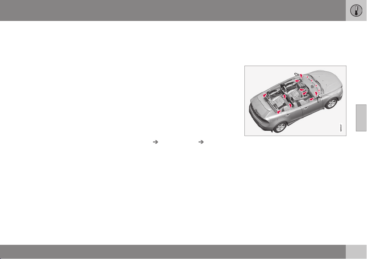
04 Climate control
04
* Option/accessory, for more information, see Introduction.
129
Air cleaning - material
Tested materials have been developed in
order to minimise the quantity of dust in the
passenger compartment and to contribute to
making the passenger compartment easier to
keep clean.
The carpets in both the passenger compart-
ment and the cargo area are removable and
easy to remove and clean. Use cleaning
agents and car care products recommended
by Volvo to clean the interior (p. 367).
Related information
•
Air cleaning (p. 127)
Menu settings - climate control
It is possible to activate/deactivate or change
the default settings for four of the climate
control system's functions via the centre con-
sole.
•
Fan level during automatic climate control
(p. 134)*.
•
Recirculation timer (p. 137).
•
Automatic start of rear window defroster
(p. 98).
•
Interior air quality system (p. 128)*.
More information is available in the descrip-
tion of the menu system (p. 104).
The climate control system's functions can be
reset to the default settings via the menu sys-
tem in MY CAR and this is carried out under:
Settings Climate settings Reset
climate settings
.
Related information
•
General information on climate control (p.
126)
Air distribution in the passenger
compartment
The incoming air is divided between a number
of different vents in the passenger compart-
ment.
Air distribution is fully automatic in AUTO
mode*.
If necessary it can be controlled manually;
see the air distribution table (p. 138).
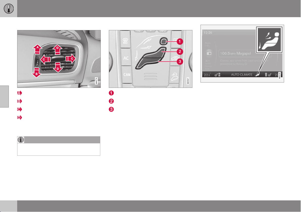
||
04 Climate control
04
130
Air vents in the dashboard
Open
Closed
Lateral airflow
Vertical airflow
Aim the vents at the side windows to remove
misting.
NOTE
Remember that small children may be sen-
sitive to air flows and draughts.
Air distribution
Air distribution - defroster windscreen
Air distribution - air vent instrument panel
Air distribution - ventilation floor
The figure consists of three buttons. When
pressing the buttons the corresponding figure
is illuminated in the display screen (see figure
below) and an arrow in front of each part of
the figure shows the air distribution that is
selected. For more information, see the air
distribution table (p. 138).
The selected air distribution is shown in the cen-
tre console display screen.
Related information
•
General information on climate control (p.
126)
•
Auto-regulation (p. 134)
•
Air distribution - recirculation (p. 137)
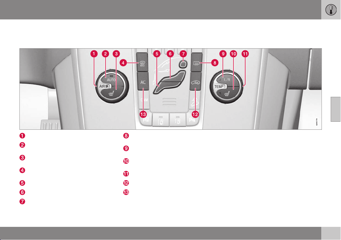
04 Climate control
04
* Option/accessory, for more information, see Introduction.
131
Electronic climate control - ECC*
ECC (Electronic Climate Control) maintains
the temperature selected in the passenger
compartment and can be set separately for
the driver's side and passenger side.
The auto function is used to automatically
control temperature, air conditioning, fan
speed, recirculation and air distribution.
Fan (p. 134)
AUTO - Automatic climate control (p.
134)
Electrically heated front seat (p. 133), left
side
Heated windscreen and max.
defroster (p. 136)*
Air distribution (p. 129) - ventilation floor
Air distribution - air vent instrument panel
Air distribution - defroster windscreen
Rear window and door mirror defrost-
ers (p. 98)
Setting, left/right-hand side for tempera-
ture control (p. 135)
Electrically heated front seat (p. 133),
right side
Temperature control (p. 135)
Recirculation (p. 137)
AC - Air conditioning on/off (p. 135)
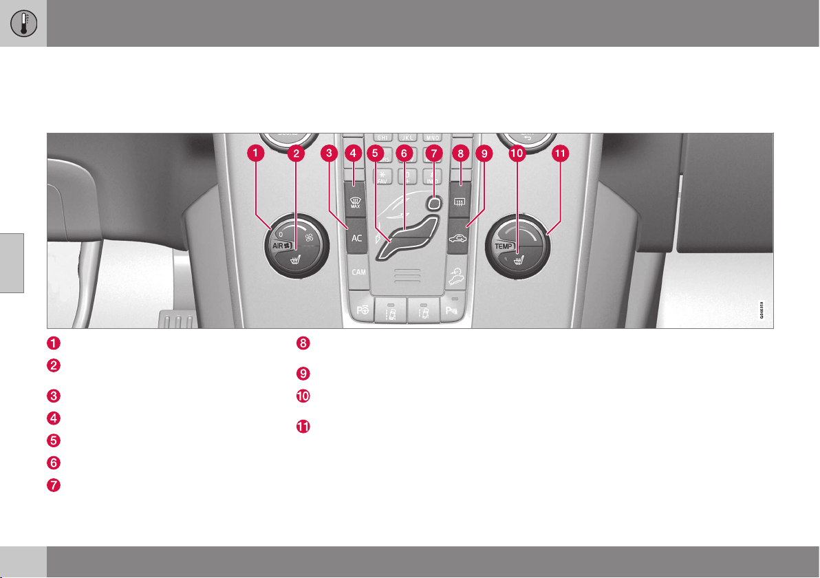
04 Climate control
04
132
* Option/accessory, for more information, see Introduction.
Electronic temperature control - ETC
The passenger compartment's climate com-
fort is controlled manually using the ETC
(Electronic Temperature Control).
Fan (p. 134)
Electrically heated front seat (p. 133), left
side
AC - Air conditioning on/off (p. 135)
Heated windscreen and max. defroster*
Air distribution (p. 129) - ventilation floor
Air distribution - air vent instrument panel
Air distribution - defroster windscreen
Rear window and door mirror defrost-
ers (p. 98)
Recirculation (p. 137)
Electrically heated front seat (p. 133),
right side
Temperature control (p. 135)

04 Climate control
04
* Option/accessory, for more information, see Introduction.
133
Heated front seats*
The front seat heating has three positions for
increasing the comfort for driver and passen-
ger when it is cold.
Current heat level is shown in the centre console
display screen.
Press the button repeatedly in order to acti-
vate the function:
•
Highest heat level - three orange fields
illuminate in the centre console's screen
(see figure above).
•
Lower heat level - two orange fields illu-
minate in the screen.
•
Lowest heat level - one orange field illu-
minates in the screen.
•
Switch off the heat - no field illuminates.
WARNING
Heated seats must not be used by people
who find it difficult to perceive an increase
in temperature due to a lack of sensation
or who otherwise have problems operating
the controls for the heated seats. Other-
wise they may suffer burn injuries.
Related information
•
General information on climate control (p.
126)
•
Heated rear seat* (p. 133)
Heated rear seat*
The heating for the rear seat's outer positions
has three positions for increasing the comfort
for passengers when it is cold.
Current heat level is shown in the pushbutton's
lamps:
Press the button repeatedly in order to acti-
vate the function:
•
Highest heat level - three lamps illumi-
nate.
•
Lower heat level - two lamps illuminate.
•
Lowest heat level - one lamp illuminates.
•
Switch off the heat - no lamp illuminates.
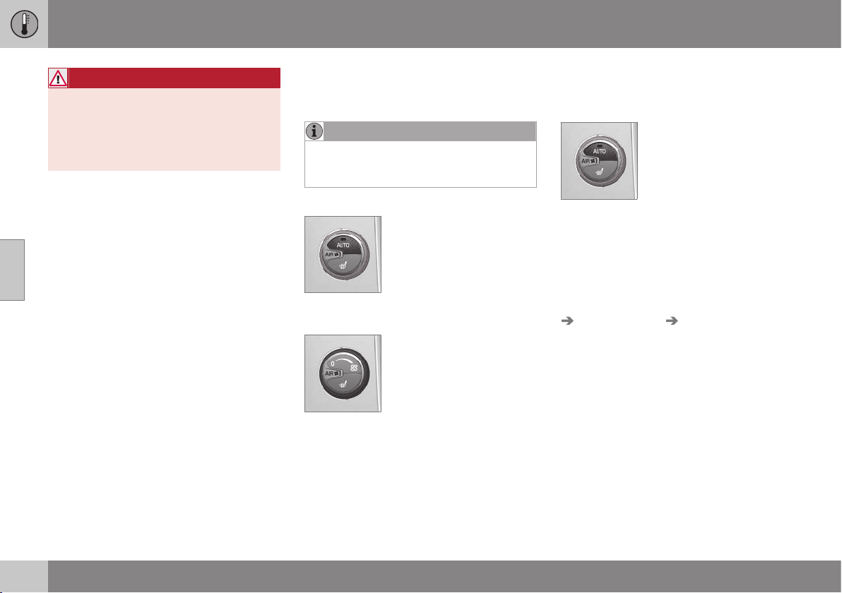
||
04 Climate control
04
134
* Option/accessory, for more information, see Introduction.
WARNING
Heated seats must not be used by people
who find it difficult to perceive an increase
in temperature due to a lack of sensation
or who otherwise have problems operating
the controls for the heated seats. Other-
wise they may suffer burn injuries.
Related information
•
General information on climate control (p.
126)
•
Heated front seats* (p. 133)
Fan
The fan should always be activated in order to
avoid misting on the windows.
NOTE
If the fan is fully switched off then the air
conditioning is not engaged - which can
cause a risk of misting on the windows.
ECC*
Turn the knob to increase or
decrease fan speed, AUTO
is disengaged. If AUTO is
selected, then the fan speed
is regulated automatically (p.
134) - the fan speed previ-
ously set is disengaged.
ETC
Turn the knob to increase or
decrease fan speed.
Related information
•
General information on climate control (p.
126)
•
Electronic climate control - ECC* (p. 131)
•
Electronic temperature control - ETC (p.
132)
Auto-regulation
Auto-regulation is only possible in electronic
climate control (ECC) (p. 131).
The auto function automati-
cally regulates temperature
(p. 135), air conditioning (p.
135), fan speed (p. 134),
recirculation (p. 137) and air
distribution (p. 129).
If you select one or more manual functions,
the other functions continue to be controlled
automatically. All manual settings are disen-
gaged when AUTO is pressed. The display
screen shows
AUTO CLIMATE.
Fan speed in automatic mode can be set in
the menu system MY CAR under:
Settings
Climate settings Automatic blower
adjustment
. Choose between Low, Normal
or High:
•
Low - Automatic fan control. Low airflow
is prioritised.
•
Normal - Automatic fan control.
•
High - Automatic fan control. A more
intense airflow is prioritised.
More information is available in the descrip-
tion of the menu system (p. 104).
Related information
•
General information on climate control (p.
126)
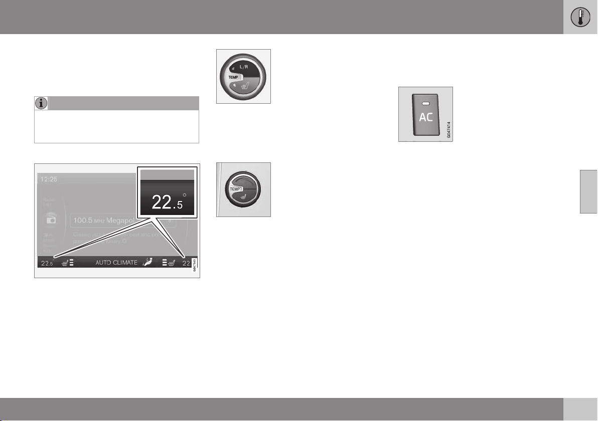
04 Climate control
04
* Option/accessory, for more information, see Introduction.
135
Temperature control in the passenger
compartment
When the car is started, the most recent tem-
perature setting is resumed.
NOTE
Heating or cooling cannot be hastened by
selecting a higher or lower temperature
than the actual desired temperature.
ECC*
Current temperature for each side is shown in
the centre console's display screen.
The temperatures on the
driver and passenger sides
can be set independently.
Repeatedly press L/R in the
button to select the setting
for left, right or both sides.
Set the temperature using
the knob - the selected temperature for either
side is displayed in the centre console dis-
play.
ETC
The temperature in the pas-
senger compartment can be
adjusted with the knob.
Related information
•
General information on climate control (p.
126)
•
Actual temperature (p. 126)
•
Electronic temperature control - ETC (p.
132)
•
Electronic climate control - ECC* (p. 131)
Air conditioning
The air conditioning cools and dehumidifies
incoming air as required.
When the lamp in the AC
button illuminates, the air
conditioning is controlled by
the system's automatic func-
tion.
When the lamp in the AC
button is switched off the air conditioning is
disconnected. Other functions are still con-
trolled automatically. When the max.
defroster function (p. 136) is activated, the air
conditioning is switched on automatically so
that the air is dehumidified at the maximum
setting.
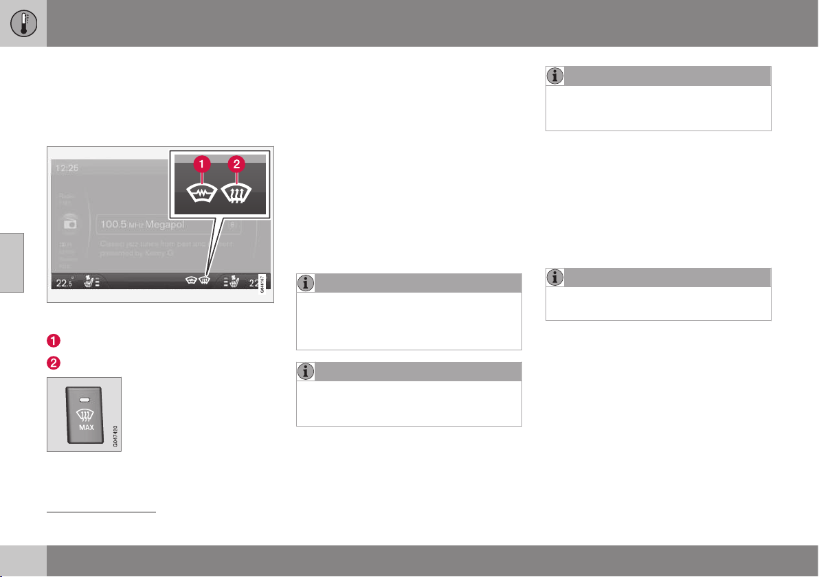
04 Climate control
04
136
* Option/accessory, for more information, see Introduction.
Demisting and defrosting the
windscreen
Heated windscreen* and max. defroster are
used to quickly remove misting and ice from
the windscreen and side windows.
The selected setting is shown in the centre con-
sole display screen.
Electric heating*
Max. defroster
The light in the defroster but-
ton illuminates when the
function is active.
Press the button repeatedly
in order to activate the func-
tion.
For cars without heated windscreens:
•
Air flows to the windows - symbol (2) illu-
minates in the screen.
•
Switch off the function - no symbol illumi-
nates.
For cars with heated windscreens:
•
Start the heating for the windscreen
2
-
symbol (1) illuminates in the screen.
•
Start the heating for the windscreen
2
and
air flow to the windows - symbols (1) and
(2) illuminate in the screen.
•
Switch off the function - no symbol illumi-
nates.
NOTE
Heated windscreen and IR window (p. 18)
may have an impact on the performance of
transponders and other communication
equipment.
NOTE
A triangular area at the end of each side of
the windscreen is not electrically heated,
where de-icing may take longer.
NOTE
Electrically heated windscreen is not avail-
able when the engine is auto-stopped (p.
279).
The following also takes place when the func-
tion is active in order to provide maximum
dehumidification in the passenger compart-
ment:
•
the air conditioning is automatically
engaged
•
recirculation and the air quality system
are automatically disengaged.
NOTE
The noise level increases as the fan is
operating at max.
When the defroster is switched off the climate
control returns to the previous settings.
Related information
•
General information on climate control (p.
126)
2
The compass goes off when the heated windscreen is active.
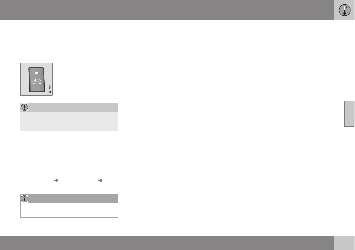
04 Climate control
04
137
Air distribution - recirculation
Select recirculation to shut out bad air,
exhaust gases etc. from the passenger com-
partment, i.e. no outside air is taken into the
car when this function is activated.
When recirculation is
engaged the orange lamp in
the button illuminates.
IMPORTANT
If the air in the car recirculates for too long,
there is a risk of misting on the insides of
the windows.
Timer
With the timer function activated the system
will exit manually activated recirculation mode
according to a time that depends on the out-
side temperature. This reduces the risk of ice,
misting and bad air. Activate/deactivate the
function in the menu system (p. 104) MY CAR
under
Settings Climate settings
Recirculation timer.
NOTE
When max. defroster is selected, recircula-
tion is always deactivated.
Related information
•
General information on climate control (p.
126)
•
Air distribution in the passenger compart-
ment (p. 129)
•
Air distribution - table (p. 138)
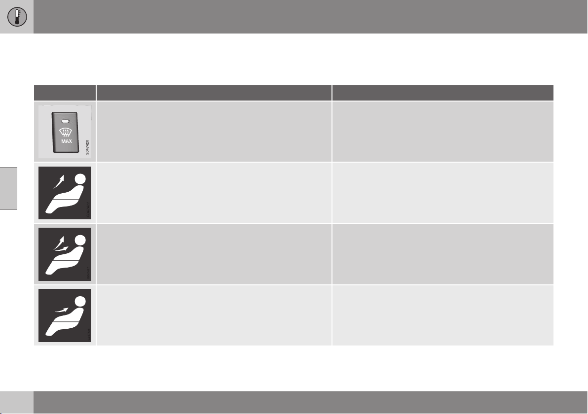
04 Climate control
04
138
Air distribution - table
Three buttons are used to select the distribu-
tion (p. 129) of the air.
Air distribution Use
A large amount of hot air flows to the windows. to remove ice and misting quickly.
Air to windscreen, via defroster vent, and side windows. Some
air flows from the air vents.
to prevent misting and icing in a cold and humid climate,
(not at too low fan speed to enable this).
Airflow to windows and from dashboard air vents. to ensure good comfort in warm, dry weather.
Airflow to the head and chest from the dashboard air vents. to ensure efficient cooling in warm weather.
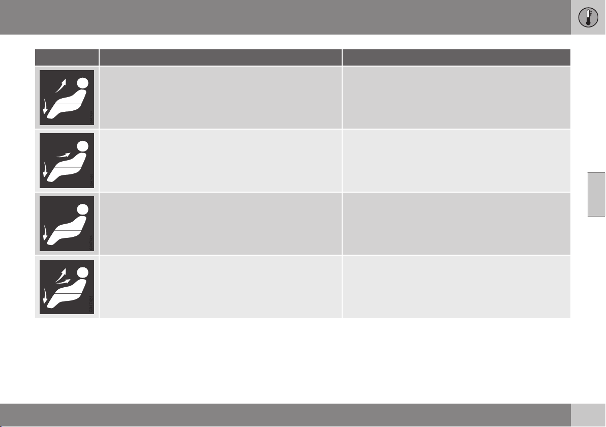
04 Climate control
04
139
Air distribution Use
Air to the floor and windows. Some air flows from the dash-
board air vents.
to ensure comfortable conditions and good demisting in
cold or humid weather.
Air to floor and from dashboard air vents. in sunny weather with cool outside temperatures.
Air to floor. Some air flows to the dashboard air vents and win-
dows.
to direct heat or cold to the floor.
Airflow to windows, from dashboard air vents and to the floor. to provide cooler air along the floor or warmer air higher up
in cold weather or hot, dry weather.
Related information
•
General information on climate control (p.
126)
•
Air distribution - recirculation (p. 137)
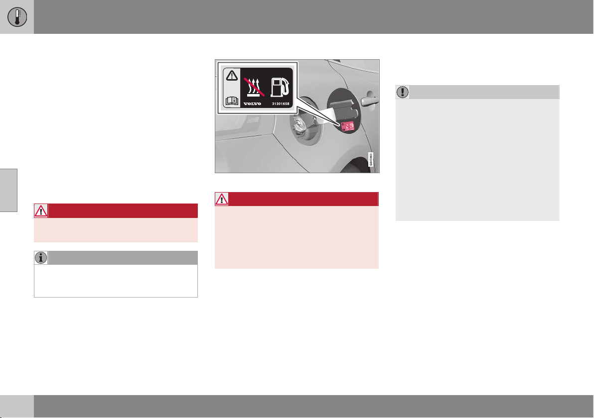
04 Climate control
04
140
* Option/accessory, for more information, see Introduction.
Engine block heater and passenger
compartment heater*
Preconditioning prepares the car's heater,
engine and passenger compartment before
departure so that both wear and energy
needs during the journey are reduced. Warm-
ing up your car will also extend the driving
distance.
The heater can be started directly (p. 141) or
with a timer (p. 141).
The heater cannot start if the outside tem-
perature exceeds 15 °C. At –5 °C or lower the
maximum running time of the heater is 50
minutes.
WARNING
Do not use the fuel-driven heater indoors.
Exhaust gases are secreted.
NOTE
When the fuel-driven auxiliary heater is
active there may be smoke from under-
neath the car, which is perfectly normal.
Refuelling
Warning label on fuel filler flap.
WARNING
Fuel which spills out could be ignited.
Switch off the fuel-driven auxiliary heater
before starting to refuel.
Check in the combined instrument panel
that the heater is switched off. The heat
symbol is shown when it is operating.
Parking on a hill
If the car is parked on a steep hill, the front of
the car should point downhill to ensure that
there is a supply of fuel to the fuel-driven
heater.
Battery and fuel
If the battery has insufficient charge or the
fuel level is too low, the heater will be
switched off automatically and a message
appears in the display. Acknowledge the
message by pressing the indicator stalk (p.
101) OK button once.
IMPORTANT
Repeated use of the heater in combination
with short driving distances may cause low
charge level in the starter battery, this can
lead to the heater stopping or never star-
ting. In the worst case, engine starting will
not be possible.
The car should be driven for the same time
as the heater is used to ensure that the
starter battery is recharged adequately to
replace the energy consumed by the
heater when it is used on a regular basis.
The heater is used for a maximum of 50
minutes each time.
Related information
•
Engine block heater and passenger com-
partment heater* - messages (p. 142)
•
Additional heater* (p. 143)
04 Climate control
04
* Option/accessory, for more information, see Introduction.
141
Engine block heater and passenger
compartment heater* - direct start/
immediate stop
Upon direct start of the engine block and pas-
senger compartment heater (p. 140), it will run
for 50 minutes.
Heating of the passenger compartment will
begin as soon as the engine coolant has
reached the correct temperature.
NOTE
The car can be started and driven while
the heater is running.
1. Press OK to access the menu.
2.
Scroll with the thumbwheel to
Parking
heater and select with OK.
3.
Scroll forward in the next menu to
Direct
start/Stop in order to activate/deactivate
the heater and select with OK.
4. Exit the menu with RESET.
Related information
•
Engine block heater and passenger com-
partment heater* - timer (p. 141)
•
Engine block heater and passenger com-
partment heater* - messages (p. 142)
Engine block heater and passenger
compartment heater* - timer
The timer of the engine block and passenger
compartment heater (p. 140) is connected to
the car's clock.
Two different times can be selected using the
timer. Here, time refers to the time when the
car is heated and ready. The car's electronic
system calculates when heating should be
started based on the outside temperature.
NOTE
All timer programming will be cleared if the
car's clock is reset.
Adjusting
1. Press OK to access the menu.
2. Scroll with the thumbwheel (p. 101) to
Parking heater and select with OK.
3. Select one of the two timers using the
thumbwheel and confirm with OK.
4. Briefly press OK to move to the lit hours
setting.
5. Select the required hour using the thumb-
wheel.
6. Briefly press OK to move to the lit
minutes setting.
7. Select the required minute using the
thumbwheel.
8.
Press OK
3
to confirm the setting.
9. Go back in the menu structure using
RESET.
10. Select the other time (continue from step
2) or exit the menu with RESET.
Starting
1. Press OK to access the menu.
2.
Scroll with the thumbwheel to
Parking
heater and select with OK.
3. Select one of the two timers using the
thumbwheel and activate with OK.
4. Exit the menu with RESET.
Switching off
A timer-started heater can be switched off
manually before the set time has elapsed.
Proceed as follows:
1. Press OK to access the menu.
2.
Scroll with the thumbwheel to
Parking
heater and select with OK.
> If a timer is set but not activated, a
clock icon is shown next to the set
time.
3. Select one of the two timers using the
thumbwheel and confirm with OK.
3
Press OK again to activate the timer.
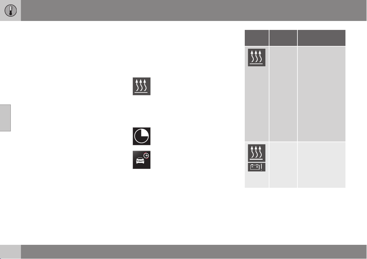
||
04 Climate control
04
142
* Option/accessory, for more information, see Introduction.
4. Deactivate the timer as follows:
•
long press on OK or
•
short press on OK to continue in the
menu. Then select to stop the timer
and confirm with OK.
5. Exit the menu with RESET.
A timer-started heater can be switched off
directly (p. 141).
Related information
•
Engine block heater and passenger com-
partment heater* - messages (p. 142)
Engine block heater and passenger
compartment heater* - messages
Symbols and messages regarding the engine
block and passenger compartment heater (p.
140) differ depending on whether the com-
bined instrument panel is analogue (p. 60) or
digital (p. 61).
When the heater has been activated
the heat symbol illuminates in the
information display.
When one of the timers is activated the sym-
bol for activated timer illuminates in the infor-
mation display at the same time as the set
time is shown next to the symbol.
Symbol for activated timer in ana-
logue combined instrument panel.
Symbol for activated timer in digital
combined instrument panel.
The table shows symbols and display texts
that appear.
Sym-
bol
Display Specification
The heater is
switched on and
running.
The heater's timer
is activated after
the remote control
key has been
removed from the
ignition switch and
leaving the car -
the engine and
passenger com-
partment are
heated at the set
time.
Fuel
operated
heater
stopped
Battery
saving
mode
The heater has
been stopped by
the car's electron-
ics in order to
facilitate starting
the engine.
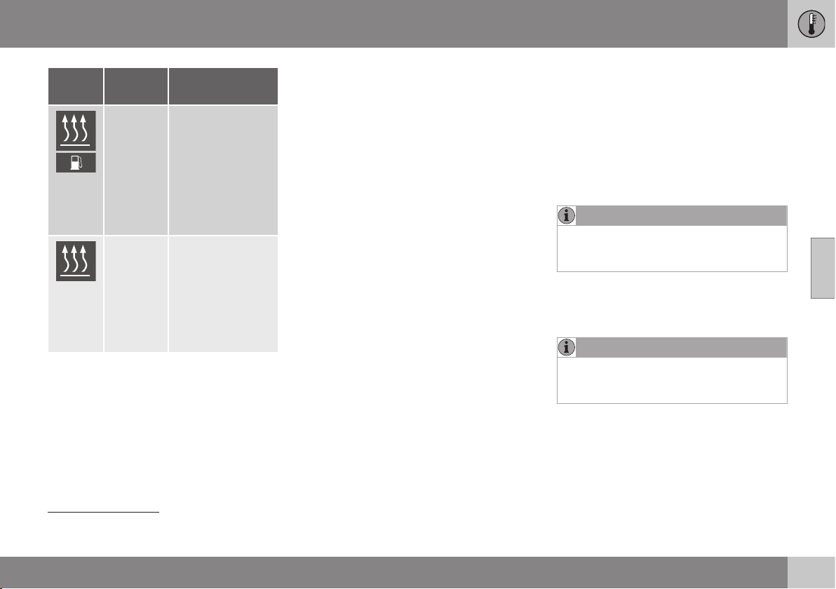
04 Climate control
04
* Option/accessory, for more information, see Introduction.
143
Sym-
bol
Display Specification
Fuel
operated
heater
stopped
Low fuel
level
Setting the heater
is not possible due
to fuel level being
too low - this is in
order to facilitate
starting the engine
as well as
approx. 50 km
driving.
Fuel
operated
heater
Service
required
Heater not work-
ing. Contact a
workshop for
repair. Volvo rec-
ommends that you
contact an author-
ised Volvo work-
shop.
A display text clears automatically after a time
or after one press on the indicator stalk (p.
101) OK button.
Related information
•
Engine block heater and passenger com-
partment heater* - direct start/immediate
stop (p. 141)
•
Engine block heater and passenger com-
partment heater* - timer (p. 141)
Additional heater*
For cars with diesel engines sold in cold cli-
mate zones
4
an additional heater may be
required to obtain the correct operating tem-
perature in the engine and to obtain sufficient
heating in the passenger compartment.
In such instances, the car is equipped with
either
•
electric additional heater (p. 144) or
•
fuel-driven additional heater (p. 143)
5
.
Related information
•
Engine block heater and passenger com-
partment heater* (p. 140)
Fuel-driven additional heater*
The car is equipped with either an electric (p.
144) or a fuel-driven additional heater (p. 143).
The heater starts automatically when extra
heat is required when the engine is running.
The heater is switched off automatically when
the correct temperature is reached or when
the engine is switched off.
NOTE
When the auxiliary heater is active there
may be smoke from underneath the car,
which is perfectly normal.
Auto mode or shutdown
The additional heater's automatic start
sequence can be switched off if required.
NOTE
Volvo recommends that the fuel-driven
additional heater should be switched off
for short distances.
1. Before starting the engine: Select key
position I (p. 71).
2. Press OK to access the menu.
4
An authorised Volvo dealer has information regarding the geographical areas concerned.
5
For cars equipped with parking heater (p. 140).

||
04 Climate control
04
144
* Option/accessory, for more information, see Introduction.
3.
Scroll with the thumbwheel to
Additional
heater
6
or
Settings
7
and select with OK.
4.
Select one of the options
ON or OFF
using the thumbwheel and confirm with
OK.
5. Exit the menu with RESET.
NOTE
The menu options are only visible in key
position I - any adjustments must therefore
be made before starting the engine.
Related information
•
Engine block heater and passenger com-
partment heater* (p. 140)
Electric additional heater*
The car is equipped with either a fuel-driven
(p. 143) or an electric additional heater (p.
143).
The heater cannot be controlled manually but
is instead activated automatically after the
engine has been started in outside tempera-
tures below 9 °C and is switched off after the
set passenger compartment temperature has
been reached.
Related information
•
Engine block heater and passenger com-
partment heater* (p. 140)
6
Analogue combined instrument panel.
7
Digital combined instrument panel.
LOADING AND STORAGE
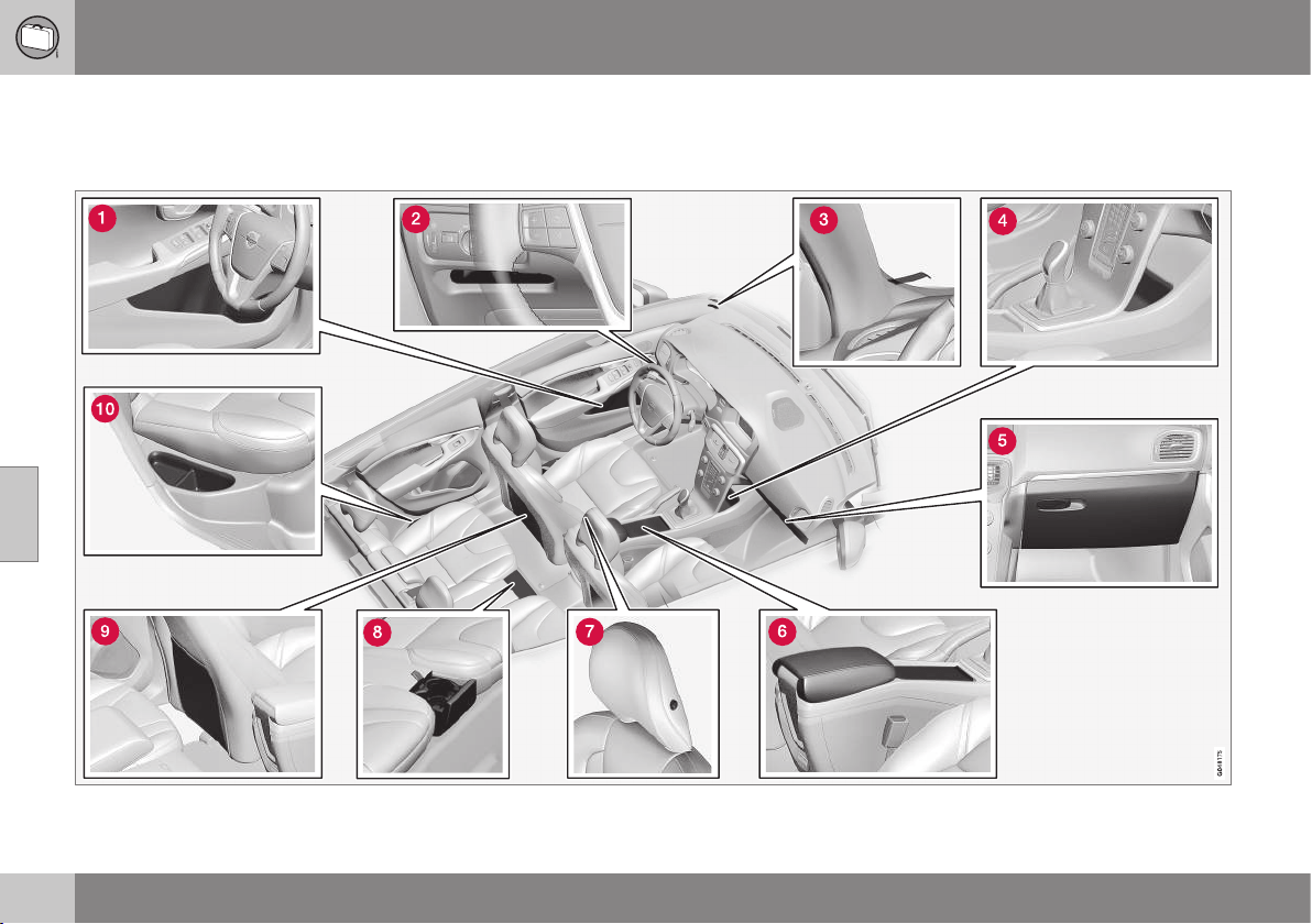
05 Loading and storage
05
146
Storage spaces
Overview of storage spaces in the passenger
compartment.

05 Loading and storage
05
* Option/accessory, for more information, see Introduction.
147
Storage compartment
1
in door panel
Storage compartment, driver’s side (p.
148)
Ticket clip
Storage compartment
Glovebox (p. 149)
Storage compartment, cup holder (p.
148)
Jacket holder (p. 148)
Cup holder* in rear seat
Storage pocket
2
Storage compartment, rear seat
WARNING
Keep loose objects such as mobile
phones, cameras, remote controls for
accessories, etc. in the glove compartment
or other compartments. Otherwise they
may injure people in the car in the event of
sudden braking or a collision.
1
With ice scraper holder on the driver’s side.
2
Not applicable to textile upholstery.
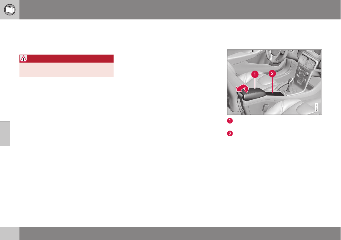
05 Loading and storage
05
148
* Option/accessory, for more information, see Introduction.
Storage compartment driver’s side
This storage compartment (p. 146) is located
on the driver's side, to the left under the light-
ing panel.
WARNING
Do not keep any sharp objects in the com-
partment, or objects which protrude.
Jacket holder
The coat hanger is located on the left-hand
side of the passenger seat's head restraint.
The jacket holder is only designed for light
clothing.
Related information
•
Storage spaces (p. 146)
Tunnel console
The tunnel console is located between the
front seats.
Storage compartment (e.g. for CDs) and
USB*/AUX input under the armrest.
Includes cup holder for driver and pas-
senger. (If ashtray and cigarette lighter (p.
149) are specified, then there is a ciga-
rette lighter in the 12 V socket (p. 151) for
the front seat and a detachable ashtray in
the cup holder.)
Related information
•
Storage spaces (p. 146)
•
Tunnel console - armrest (p. 149)

05 Loading and storage
05
* Option/accessory, for more information, see Introduction.
149
Tunnel console - armrest
The tunnel console is located between the
front seats.
When closed, the tunnel console's armrest
can be adjusted* longitudinally.
Related information
•
Tunnel console - 12 V-sockets (p. 151)
•
Tunnel console - cigarette lighter and
ashtray* (p. 149)
Tunnel console - cigarette lighter and
ashtray*
A detachable ashtray is fitted in the cup
holder under the armrest. The cigarette lighter
is fitted in the 12 V socket (p. 151) for the
front seat.
The ashtray in the tunnel console (p. 148) is
detached by lifting the tray straight up.
Activate the lighter by pushing in the button.
The button pops out when the lighter is hot.
Pull out the lighter and light a cigarette on the
heated coils.
Related information
•
Storage spaces (p. 146)
Glovebox
The glovebox is located on the passenger
side.
The owner's manual and maps can be kept in
here for example. There are also holders for
pens on the inside of the lid. The glovebox
can be locked (p. 176)* using the key blade
(p. 166).
Related information
•
Storage spaces (p. 146)
•
Glovebox - cooling (p. 150)
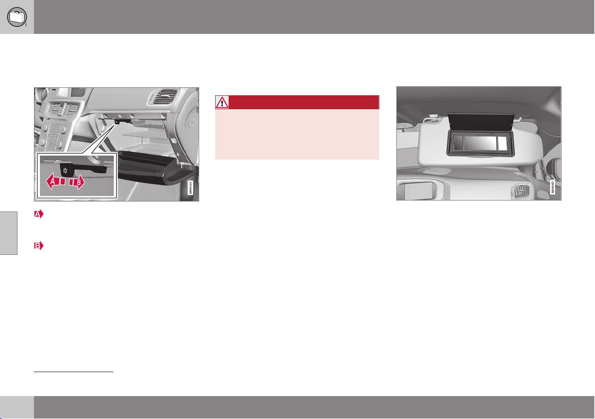
05 Loading and storage
05
150
* Option/accessory, for more information, see Introduction.
Glovebox - cooling
The glovebox (p. 149) can also be used as a
cooled area
3
.
Start cooling by moving the control in
towards the passenger compartment to
the end position.
Switch off the cooling by moving the con-
trol forwards to the end position.
Cooling is active when the climate control
system is active (i.e. when the key is in key
position (p. 71) II) or the engine is running.
Inlay mats*
Inlay mats collect e.g. rubbish and slush.
Volvo supplies specially manufactured inlay
mats.
WARNING
Before setting off check that the inlaid mat
in the driver area is firmly affixed and
secured in the pins in order to avoid get-
ting caught adjacent to and under the ped-
als.
Related information
•
Cleaning the interior (p. 367)
Vanity mirror
The vanity mirror is located on the rear of the
sun visor.
Vanity mirror with lighting.
The light illuminates automatically when the
cover is lifted.
Related information
•
Lamp replacement - vanity mirror lighting
(p. 348)
3
Applicable only to cars with ECC.

05 Loading and storage
05
* Option/accessory, for more information, see Introduction.
151
Tunnel console - 12 V-sockets
The electrical sockets (12 V) are located in the
tunnel console's storage compartment and
beside the cup holder
4
.
12 V socket in tunnel console, front seat.
The electrical sockets can be used for various
accessories designed for 12 V, e.g. display
screens, music players and mobile phones.
For the sockets to supply current, the remote
control key must be in at least key position I
(p. 71).
WARNING
Always leave the plug in the socket when
the socket is not in use.
NOTE
Optional equipment and accessories - e.g.
display screens, music players and mobile
phones - which are connected to one of
the passenger compartment's 12V electri-
cal sockets could be activated by the cli-
mate control system, even when the
remote control key has been removed or
when the car is locked, for example, when
the engine block and passenger compart-
ment heater* is activated at a preset time.
For this reason remove the plugs from the
electrical sockets for optional equipment
or accessories when not in use because
the battery could be drained in the event of
such an occurrence!
IMPORTANT
Max. power takeoff is 10 A (120 W) in
either socket.
NOTE
The compressor for emergency puncture
repair (p. 324) has been tested and
approved by Volvo. For information on the
use of Volvo's recommended temporary
emergency puncture repair (TMK).
Related information
•
Tunnel console - cigarette lighter and
ashtray* (p. 149)
•
12 V socket - cargo area (p. 155)
4
If ashtray and cigarette lighter are specified then there is no cup holder and adjacent 12 V socket.
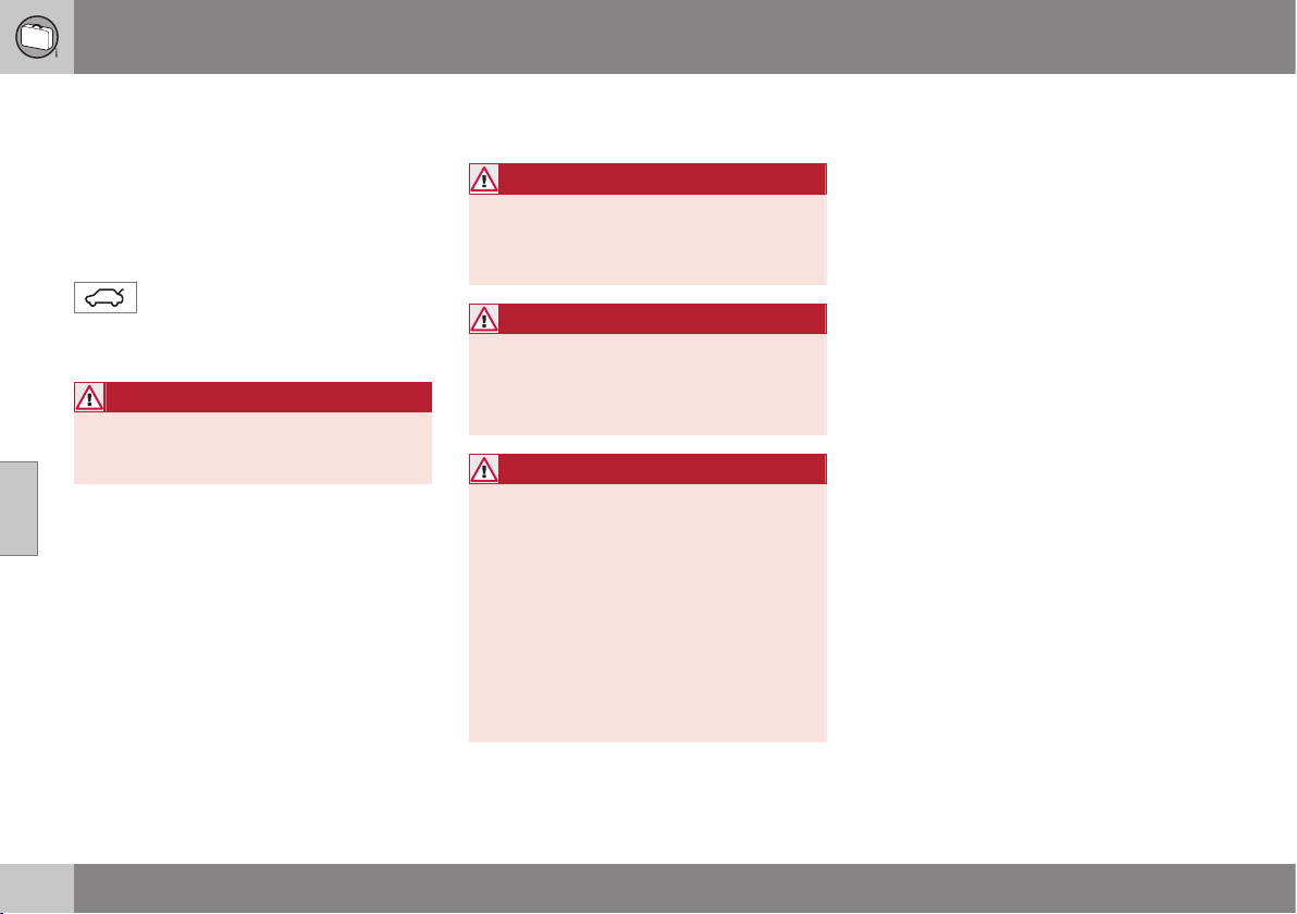
05 Loading and storage
05
152
Loading
Payload depends on the car's kerb weight.
Payload depends on the car's kerb weight.
The total of the weight of the passengers and
all accessories reduces the car's payload by
a corresponding weight. For more detailed
information on weights, see Weights (p. 441).
The tailgate is opened via a button
on the lighting panel or the remote
control key, see Locking/unlocking -
tailgate (p. 176).
WARNING
The car’s driving properties change
depending on the weight and positioning
of the load.
To bear in mind when loading
•
Position the load firmly against the rear
seat's backrest.
Note that objects must not prevent the func-
tion of the WHIPS system for the front seats if
any of the rear seat's backrests is folded
down, see WHIPS - seating position (p. 36).
•
Centre the load.
•
Heavy objects should be placed as low
as possible. Avoid placing heavy loads on
lowered backrests.
•
Cover sharp edges with something soft to
avoid damaging the upholstery.
•
Secure all loads to the load retaining eye-
lets with straps or web lashings.
WARNING
A loose object weighing 20 kg can, in a
frontal collision at a speed of 50 km/h,
carry the impact of an item weighing
1000 kg.
WARNING
The protection provided by the inflatable
curtain in the headlining may be compro-
mised or eliminated by high loads.
•
Never load cargo above the backrest.
WARNING
Always secure the load. Always secure the
load. During heavy braking the load may
otherwise shift, causing personal injury to
the car's occupants.
Cover sharp edges and sharp corners with
something soft.
Switch off the engine and apply the park-
ing brake when loading/unloading long
items. Otherwise you may accidentally
knock the gear lever or gear selector with
the load into a drive position - and the car
could then move off.
Related information
•
Load retaining eyelets (p. 153)
•
Cargo net (p. 155)
•
Loading - long load (p. 153)
•
Roof load (p. 153)

05 Loading and storage
05
153
Loading - long load
To simplify loading in the cargo area, the rear
seat backrest can be folded down. The pas-
senger seat backrest can also be folded for an
extra long load.
Folding the passenger seat
See (p. 73).
Lowering the rear seat backrest
See (p. 76).
Related information
•
Loading (p. 152)
Roof load
The load carriers recommended for roof loads
are the ones developed by Volvo. This is in
order to avoid damage to the car and in order
to achieve the maximum possible safety dur-
ing a journey.
Carefully follow the installation instructions
supplied with the carriers.
•
Load carriers must always be mounted
on the aluminium rail.
•
Check periodically that the load carriers
and load are properly secured. Lash the
load securely with retaining straps.
•
Distribute the load evenly over the load
carriers. Put the heaviest objects at the
bottom.
•
The size of the area exposed to the wind,
and therefore fuel consumption, increase
with the size of the load.
•
Drive gently. Avoid quick acceleration,
heavy braking and hard cornering.
WARNING
The car's centre of gravity and driving cha-
racteristics are altered by roof loads. For
information about the maximum permitted
load on the roof, including load carriers
and any space box, see Weights (p. 441).
Related information
•
Loading (p. 152)
Load retaining eyelets
The load retaining eyelets are used to fasten
straps in order to anchor items in the cargo
area.
WARNING
Hard, sharp and/or heavy objects which
protrude may cause injury under violent
braking.
Always secure large and heavy objects
with a seatbelt or cargo retaining straps.
Related information
•
Loading (p. 152)
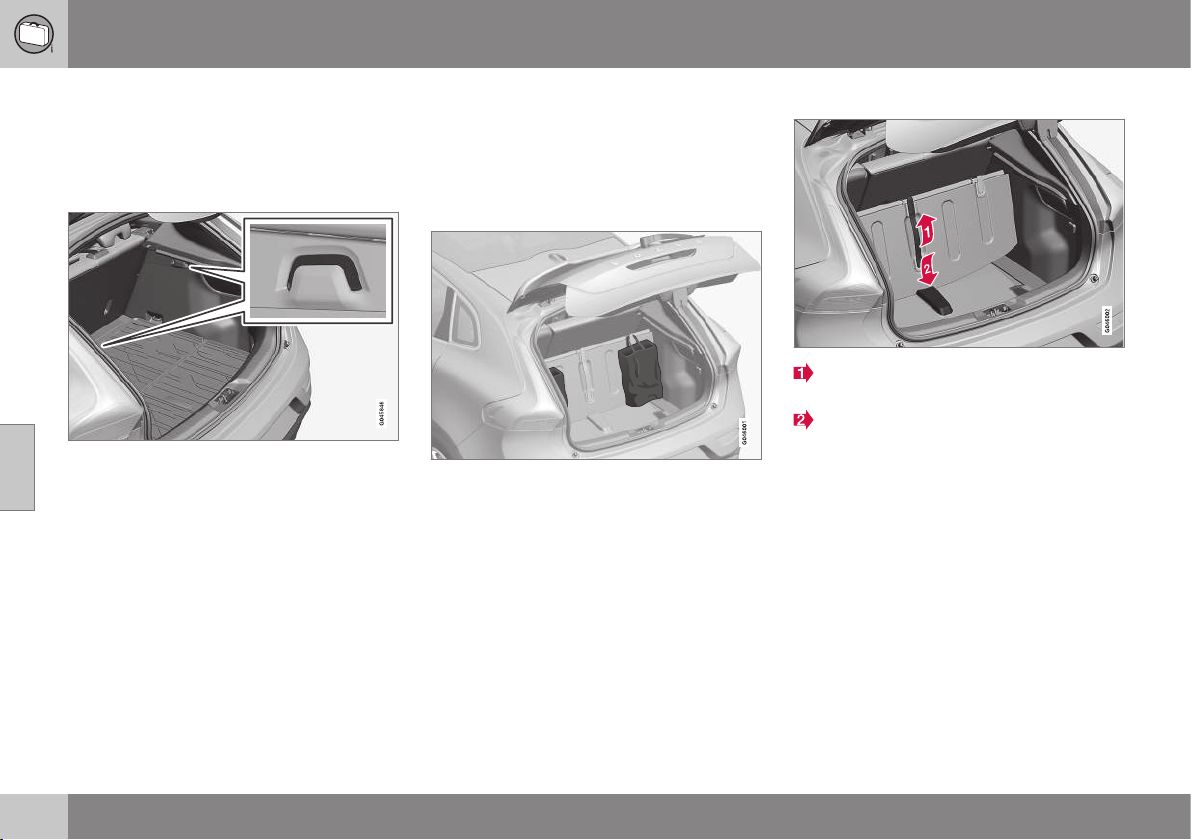
05 Loading and storage
05
154
* Option/accessory, for more information, see Introduction.
Loading - bag holder
The bag holders keep carrier bags in place
and prevent them from overturning and
spreading their contents around the cargo
area. The holder has a capacity of max. 3 kg.
Bag holder
Related information
•
Loading (p. 152)
•
Loading - folding bag holder* (p. 154)
Loading - folding bag holder*
A folding bag holder in the floor keeps bags in
place and prevents them from overturning
and spreading their contents in the cargo
area, and can be opened up in three posi-
tions.
Folding bag holder
It can be set to two adjustment positions and
one service position, as it is known, where it
is fully unfolded. There are also two floor
combination variants, one with adjustment
positions in a tub under the floor and one with
adjustment positions in plastic rails. The rais-
ing below shows the adjustment position in a
tub under the floor.
The load on the central holder is max. 3 kg
and max. 10 kg on the outer holder.
Raising
Lift the handle* on the upper floor and
fold up the floor.
Move the floor forwards to an appropriate
position and place it in the adjustment
groove.
3. In service position, the floor is moved all
the way forwards towards the rear seat
back and placed in the plastic support in
the centre.
Related information
•
Loading (p. 152)
•
Loading - bag holder (p. 154)
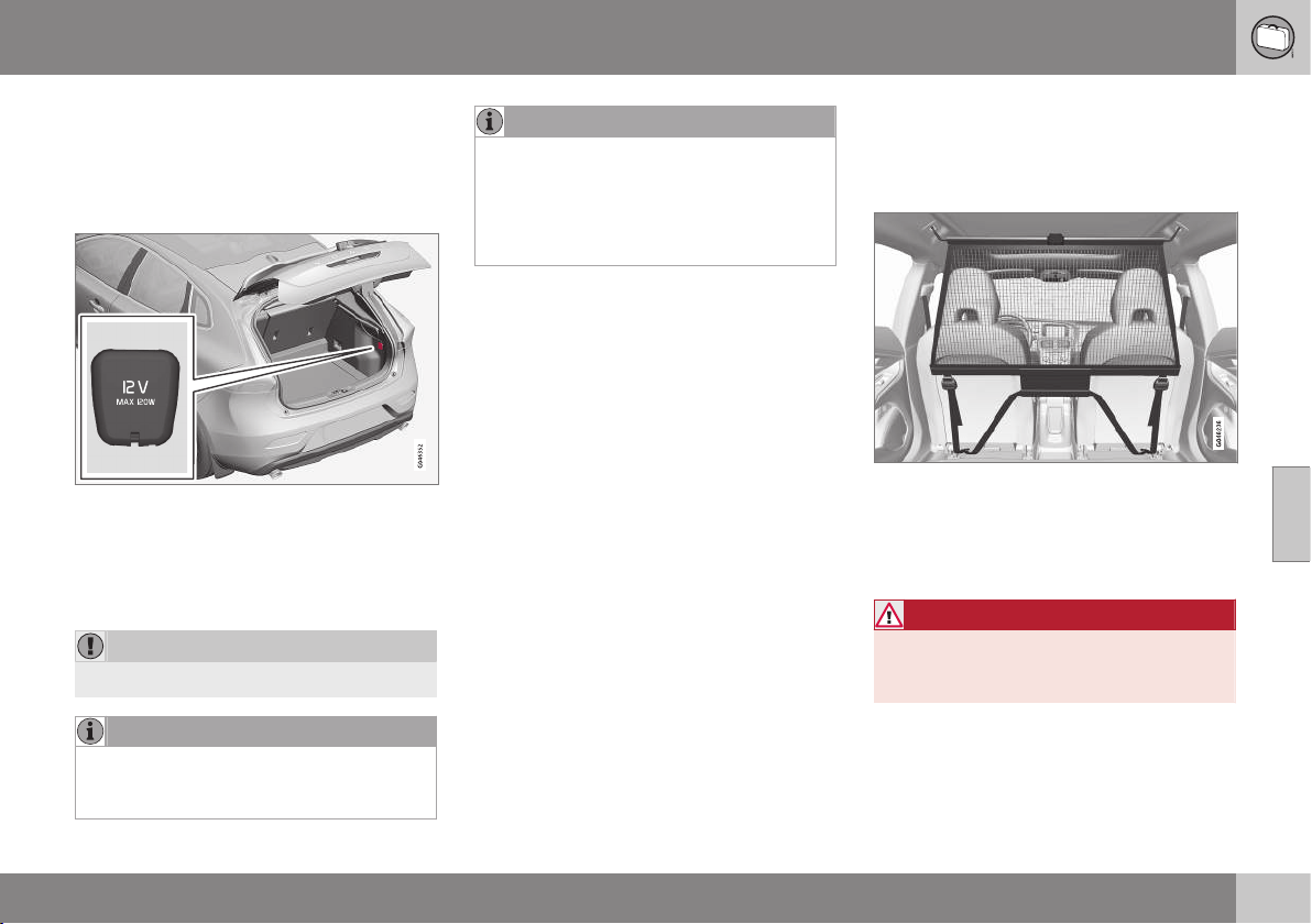
05 Loading and storage
05
* Option/accessory, for more information, see Introduction.
155
12 V socket - cargo area
The electrical socket can be used for various
accessories designed for 12 Volts, e.g. dis-
play screens, music players and mobile
phones.
Lower the cover to access the electrical
socket.
•
The socket also provides voltage when
the remote control key is not in the igni-
tion switch.
IMPORTANT
Max. socket current is 10 A (120 W).
NOTE
Remember that using the electrical socket
with the engine switched off involves the
risk of discharging the car's battery.
NOTE
The compressor for temporary emergency
puncture repair has been tested and
approved by Volvo. For information on the
use of Volvo's recommended temporary
emergency puncture repair (TMK), see
Emergency puncture repair* (p. 324).
Related information
•
Tunnel console - 12 V-sockets (p. 151)
Cargo net
A cargo net prevents cargo from being
thrown forward in the passenger compart-
ment in the event of heavy braking.
The cargo net is fitted into four mounting points.
For safety reasons, the cargo net must
always be correctly fastened and secured.
The mesh is made of a strong nylon fabric
and secured behind the front seat backrests.
WARNING
Loads in the luggage compartment must
be anchored well, and also have a cor-
rectly fitted safety net.
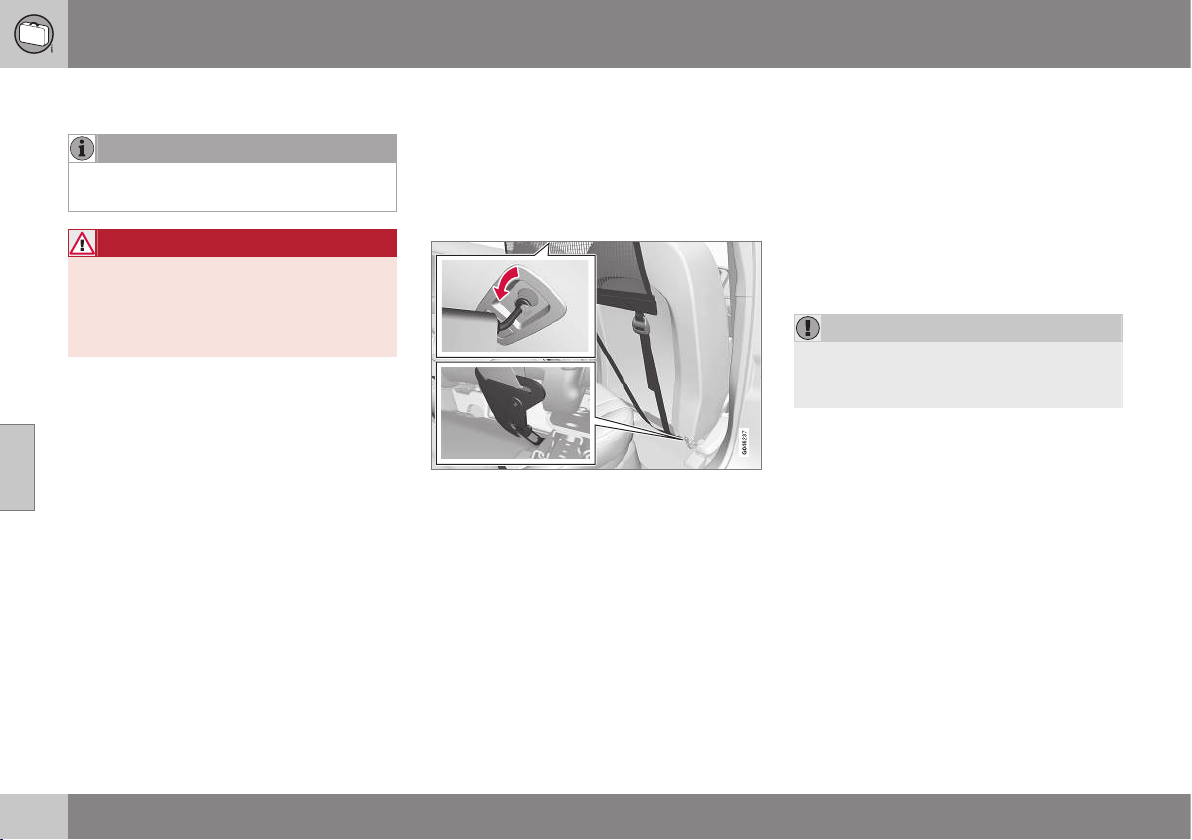
||
05 Loading and storage
05
156
Attaching
NOTE
The easiest way to fit the safety net is via
one of the rear doors.
WARNING
It is necessary to ensure that the upper
securing points of the safety net are fitted
correctly and that the puller-straps are
secured properly. Damaged nets must not
be used.
1. Unfold the cargo net and make sure that
the split upper rod is locked in the
extended position.
2. Hook one end of the rod into the roof
mounting with the anchoring strap locks
turned towards you.
3. Hook the other end of the rod into the
roof mounting on the opposite side - the
telescopic spring-loaded retaining hooks
facilitate alignment. Take care to press
forward the rod's retaining hooks for each
respective roof mounting's front end posi-
tion.
4. Hook the cargo net's anchoring straps
into the eyes on the rear of the seat slide
rails - it is easier if the backrests are
straightened and the seats are moved
forward slightly.
Pay attention to make sure that you do
not press the seat/backrest hard against
the net when the seat/backrest is moved
back again - only adjust until the seat/
backrest makes contact with the net.
IMPORTANT
If a seat/backrest is pushed backwards
hard into the safety net then the net and/or
its roof mounts may be damaged.
5. Tension the cargo net with the anchoring
straps.
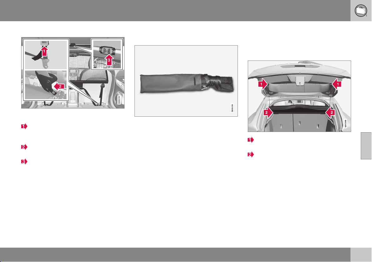
05 Loading and storage
05
157
Removal and storage
The cargo net can be easily removed and folded
up.
Release the tension in the net by pressing
in the button on the anchoring strap's
lock and feeding out part of the strap.
Press in the catch and detach both of the
anchoring strap's hooks.
Unhook the rod from its roof mounting by
pulling back on the rod in the roof mount-
ings' rear end position. Press the rod in
any direction so that the hook engages in
the rod, which at the same time releases
the hook on the other side.
Finally, remove the remaining roof mount-
ing hook from the roof mounting.
4. Break the rod in the centre, fold it
together and roll up the net.
Insert the net in the storage bag.
The folded cargo net is stored in its bag in the
cargo area.
Related information
•
Loading (p. 152)
•
Load retaining eyelets (p. 153)
Hat shelf
The hat shelf can be removed to provide
additional cargo space.
Hat shelf removal
Undo the hat shelf lifting eyes on both
sides.
Unhook the front edge of the hat shelf
and remove it.
Related information
•
Loading (p. 152)
•
Loading - long load (p. 153)
LOCKS AND ALARM
06 Locks and alarm
06
159
Remote control key with key blade
The remote control key is used to start the car
and for locking and unlocking. It contains a
detachable key blade (p. 165) made of metal.
The visible section is available in two versions
so that it is possible to distinguish between
the remote control keys.
The car is supplied with two remote control
keys - standard or withkeyless function (p.
168). They are used to start/switch off the
engine and for locking/unlocking.
Additional remote control keys can be
ordered - up to six can be programmed and
used for the same car.
Variants
There are four remote control key variants:
•
Remote control key, standard
1
•
Remote control key with Keyless start
1
•
Remote control key with Keyless drive
1
•
PCC with Keyless drive
2
PCC plus remote control key with keyless
function has extended functionality compared
to the standard remote control key.
WARNING
If there are children in the car:
Remember to switch off the supply to the
power windows by removing the remote
control key if the driver leaves the car.
Related information
•
Remote control key - function (p. 162)
Remote control key/PCC - losing
If you lose a remote control key (p. 159) then
a new one can be ordered at a workshop - an
authorised Volvo workshop is recommended.
The remaining remote control keys must be
taken to the Volvo workshop. The code of the
missing remote control key must be erased
from the system as a theft prevention meas-
ure. The current number of keys registered to
the car can be checked in MY CAR (p. 104)
under
Information Number of keys.
Related information
•
Remote control key - function (p. 162)
•
Remote control key - range (p. 163)
1
5-button key
2
6-button key
06 Locks and alarm
06
160
* Option/accessory, for more information, see Introduction.
Remote control key/PCC - key
memory*
The key memory in the remote control
key/PCC (p. 159) means that certain settings
in the car can be individually adapted for dif-
ferent people.
The key memory function is available in com-
bination with power seat and power rearview
and door mirrors. Settings for door mirrors,
driver's seat and steering force can be saved
in the key memory.
Key memory - door mirrors, driver’s
seat and steering force
The settings are automatically connected to
each respective remote control key, see Key
memory in remote control key (p. 75) and
Speed related power steering (p. 262).
When locking the car with the remote key, the
combined instrument panel theme setting can
be saved to the key, see Digital combined
instrument panel - overview (p. 61) and MY
CAR - Car settings (p. 108).
The function can be activated/deactivated in
the menu system MY CAR under
Settings
Car settings Car key memory.
For a description of the menu system, see
MY CAR (p. 104).
For remote control keys with Keyless func-
tion, see Keyless* (p. 168).
Indication locking/unlocking -
adjusting
When the car is locked or unlocked using the
remote control key (p. 159) the direction indi-
cators confirm that locking/unlocking was
correctly performed.
•
Locking - one flash and the door mirrors
are folded
3
in.
•
Unlocking - two flashes and the door mir-
rors are folded
3
out.
NOTE
Be aware of the risk of locking the remote
control key in the car.
When locking, indication is given only if all
locks have been locked and all doors are
closed. Indication is given when the last door
has been closed.
Selecting the function
Different options for indicating locking/
unlocking with light can be set in the car's
menu system, see MY CAR (p. 104).
Search in the menu system MY CAR for
Settings Car settings Light settings
and select Door lock confirmation light
and/or Unlock confirmation light.
Related information
•
Keyless* (p. 168)
•
Lock indicator (p. 161)
•
Alarm indicator (p. 182)
3
Only for cars with retractable power door mirrors.
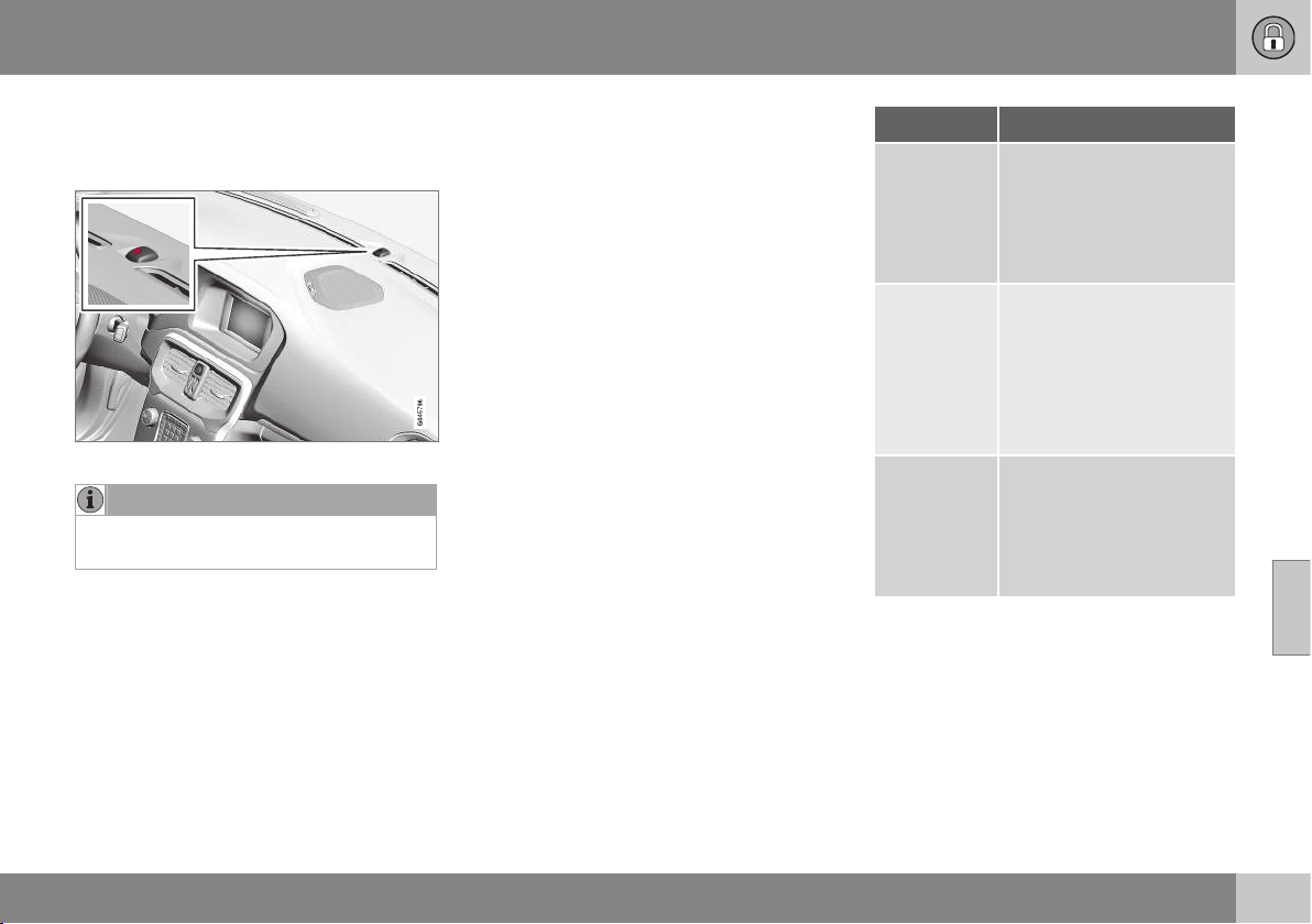
06 Locks and alarm
06
* Option/accessory, for more information, see Introduction.
161
Lock indicator
A flashing LED by the windscreen verifies that
the car is locked.
Same LED as alarm indicator (p. 182).
NOTE
Cars that are not equipped with alarm also
have this indicator.
Related information
•
Indication locking/unlocking - adjusting
(p. 160)
Remote control key/PCC - Electronic
immobiliser
The electronic immobiliser is a theft protec-
tion system that prevents the vehicle from
being started (p. 268) by an unauthorised
person.
Each remote control key/PCC (p. 159) has a
unique code. The car can only be started with
the correct remote control key with the cor-
rect code.
The following error messages in the com-
bined instrument panel's information display
are related to the electronic immobiliser:
Message Specification
Insert car
key
Error when reading the
remote control key during
starting - Remove the key
from the ignition switch,
press it in again and make
a new start attempt.
Car key not
found
(Applicable
only to cars
with
Keyless.)
Error reading the remote
control key during starting
- Try to start again.
If the error persists: Insert
the remote control key into
the ignition switch and try
to start again.
Immobiliser
Try to start
again
Error in immobiliser system
during starting. If the error
persists: Contact a work-
shop - an authorised Volvo
workshop is recom-
mended.
Related information
•
Remote-controlled immobiliser with
tracking system (p. 162)
•
Keyless* (p. 168)
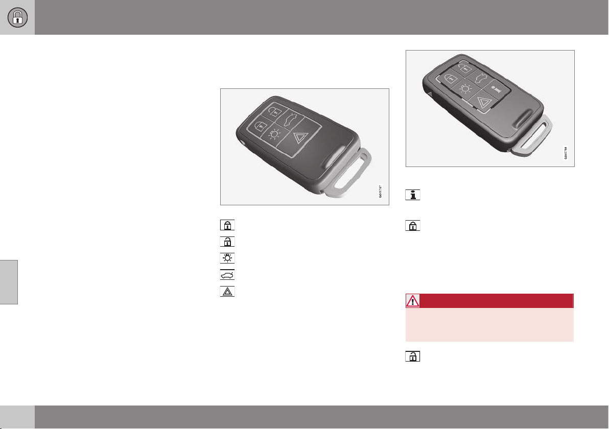
06 Locks and alarm
06
162
* Option/accessory, for more information, see Introduction.
Remote-controlled immobiliser with
tracking system
Remote-controlled immobiliser with tracking
system makes it possible to track and locate
the car, and to remotely activate the immobi-
liser to switch off the engine.
Contact your nearest Volvo dealer for more
information and assistance with activating the
system.
Related information
•
Remote control key with key blade (p.
159)
•
Remote control key/PCC - Electronic
immobiliser (p. 161)
Remote control key - function
The remote control key has functions such as
locking and unlocking the doors.
5-button remote control key
Locking
Unlocking
Approach light duration
Tailgate
Panic function
Remote control key with PCC* - Personal Car
Communicator.
Information
Function buttons
Locking – Locks the doors and tailgate
while the alarm is activated, see Locking/
unlocking - from the outside (p. 173).
A long press also closes all windows simulta-
neously (see also Total airing function (p.
176)).
WARNING
If windows are closed using the remote
control key, check that nobody's hands
are trapped.
Unlocking (p. 173) - Unlocks the doors
and tailgate while the alarm is deactivated.
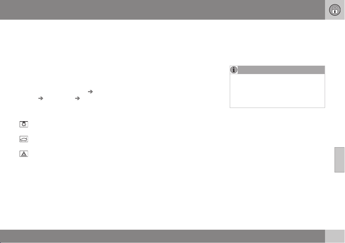
06 Locks and alarm
06
* Option/accessory, for more information, see Introduction.
163
A long press also opens all windows simulta-
neously (see also Total airing function (p.
176)).
The function can be changed from unlocking
all doors simultaneously, to unlocking the
driver's door only with one press of the but-
ton and, after a further press of the button -
within 10 seconds - unlocking the remaining
doors.
The function can be changed in the menu
system MY CAR under
Settings Car
settings
Lock settings Doors unlock
with both the alternatives All doors and
Driver door, then all. For a description of
the menu system, see MY CAR (p. 104).
Approach light duration (p. 89) - Used
to switch on the car's lighting at a distance.
Tailgate (p. 176) - Unlocks and disarms
the alarm for the tailgate only.
Panic function – Used to attract atten-
tion in an emergency.
Press and hold the button for at least 3 sec-
onds or press it twice within 3 seconds to
activate the direction indicators and the horn.
The function can be turned off with the same
button once it has been active for at least
5 seconds. Otherwise the function switches
off automatically after approx. 3 minutes.
Related information
•
Remote control key with key blade (p.
159)
•
PCC* - unique functions (p. 164)
Remote control key - range
Remote control key (p. 159) functions have a
range of about 20 m from the car.
If the car does not verify a button being
pressed - move closer and try again.
NOTE
The remote control key functions may be
disrupted by surrounding radio waves,
buildings, topographical conditions, etc.
The car can always be locked/unlocked
with the key blade, see Detachable key
blade - unlocking doors (p. 166).
Related information
•
Remote control key - function (p. 162)
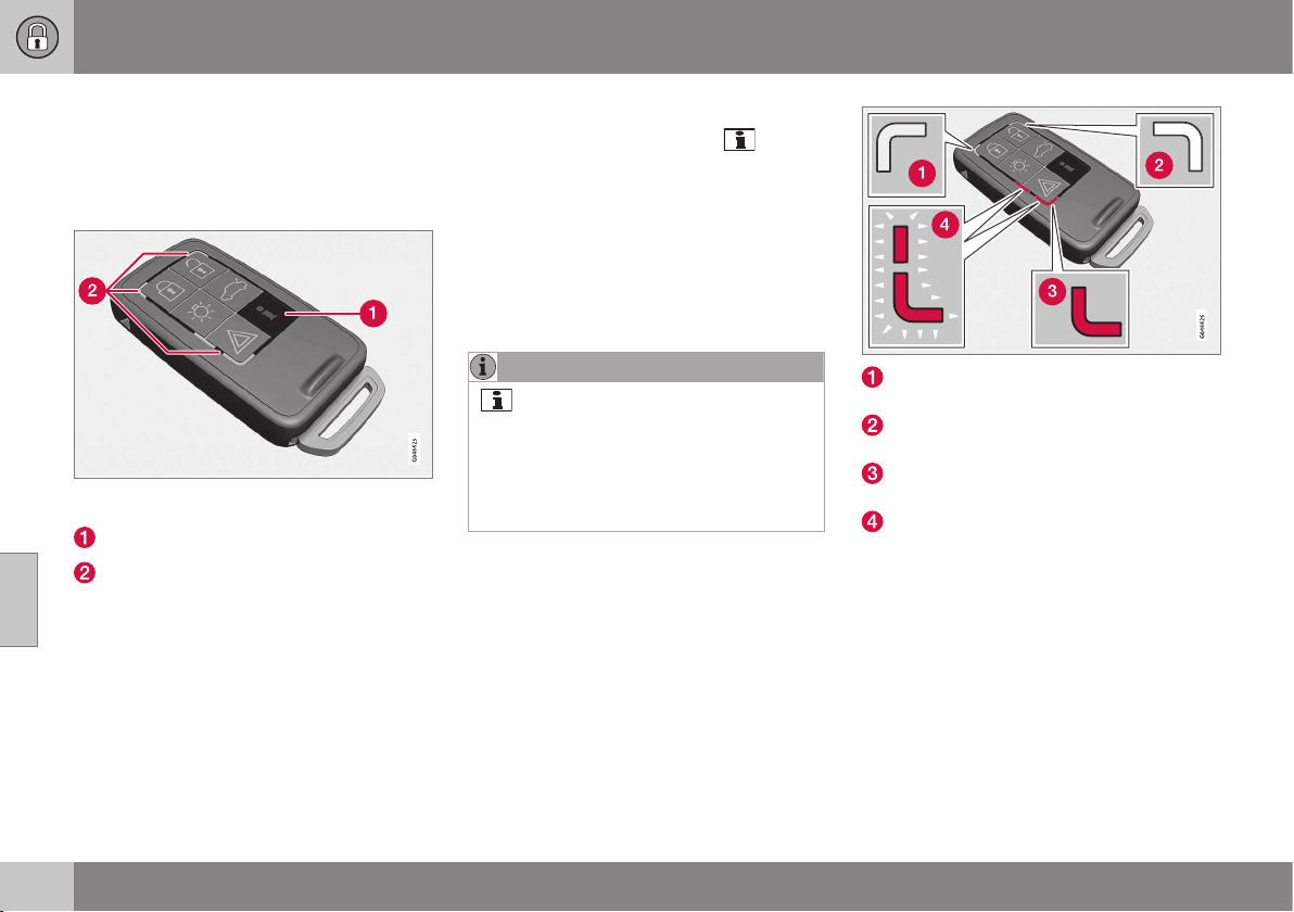
06 Locks and alarm
06
164
* Option/accessory, for more information, see Introduction.
PCC* - unique functions
Remote control key with PCC has extended
functionality compared with remote control
key without PCC (p. 159) in the form of an
information button and indicator lamps.
Remote control key with PCC* - Personal Car
Communicator.
Information button
Indicator lamps
Using the information button enables access
to certain information from the car via the
indicator lamps.
Using the information button
–
Press the information button .
> All indicator lamps flash for approxi-
mately 7 seconds and the light travels
around on the PCC. This indicates that
information from the car has been
read.
If any of the other buttons are pressed
during this time then the reading is
interrupted.
NOTE
If none of the indicator lamps illumi-
nates with repeated use of the information
button and in different locations (as well as
after 7 seconds and after the light has
travelled around on the PCC), contact a
workshop - an authorised Volvo workshop
is recommended.
Indicator lamps display information in accord-
ance with the following illustration:
Green continuous light – the car is
locked.
Yellow continuous light – the car is
unlocked.
Red continuous light – the alarm has
been triggered since the car was locked.
Red light flashing alternately in both indi-
cator lamps – The alarm was triggered
less than 5 minutes ago.
Related information
•
PCC* - range (p. 165)

06 Locks and alarm
06
* Option/accessory, for more information, see Introduction.
165
PCC* - range
The PCC's range for unlocking and tailgate is
approx. 20 m from the car - for other func-
tions up to approx. 100 m. If the car does not
verify a button being pressed - move closer
and try again.
NOTE
The information button function may be
disrupted by surrounding radio waves,
buildings, topographical conditions, etc.
Out of PCC range
If the PCC is too far away from the car for the
information to be read then the status the car
was last left in is shown, without the light
travelling around on the PCC.
If several PCCs are used for the car then it is
only the PCC last used for locking/unlocking
that shows correct status.
NOTE
If none of the indicator lamps illumi-
nates with repeated use of the information
button and in different locations (as well as
after 7 seconds and after the light has
travelled around on the PCC), contact a
workshop - an authorised Volvo workshop
is recommended.
Related information
•
Keyless* - remote control key range (p.
169)
•
Remote control key - range (p. 163)
Detachable key blade
A remote control key (p. 159) contains a
detachable key blade of metal with which
some functions can be activated and some
operations carried out.
The key blade's unique code is provided by
authorised Volvo workshops, which are rec-
ommended when ordering new key blades.
Key blade functions
Using the remote control key's detachable
key blade:
•
the left-hand front door can be opened
manually (p. 166) if central locking can-
not be activated with the remote control
key.
•
the rear doors' mechanical child safety
locks can be activated (p. 179)/deacti-
vated.
•
the right-hand front door and the rear
doors can be locked manually (p. 174),
e.g. in the event of power failure.
•
the glovebox lock* can be opened, see
Locking/unlocking - glovebox (p. 176).
•
the airbag for front passenger seat
(PACOS*) can be activated/deactivated
(p. 31).
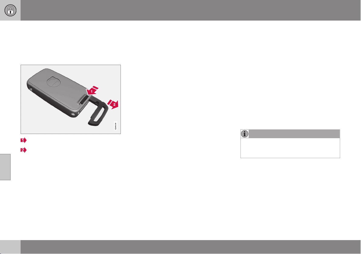
06 Locks and alarm
06
166
* Option/accessory, for more information, see Introduction.
Detachable key blade - detaching/
attaching
Detaching/attaching the detachable key blade
(p. 165) is carried out as follows:
Removing the key blade
Slide the spring-loaded catch to the side.
At the same time pull the key blade
straight out backwards.
Attaching the key blade
Carefully refit the key blade into its location in
the remote control key (p. 159).
1. Hold the remote control key with the slot
pointed up and lower the key blade into
its slot.
2. Lightly press the key blade. You should
hear a "click" when the key blade is
locked in.
Related information
•
Detachable key blade - unlocking doors
(p. 166)
•
Child safety locks - manual activation (p.
179)
•
Passenger airbag - activating/deactivat-
ing* (p. 31)
Detachable key blade - unlocking
doors
The detachable key blade (p. 165) can be
used if the central locking cannot be activated
using the remote control key (p. 159) - e.g. if
the remote control key's battery is discharged
- see Remote control key/PCC - replacing the
battery (p. 167).
The left-hand front door can be opened as
follows:
1. Unlock the left-hand front door with the
key blade in the door handle's lock cylin-
der. For illustration and more information,
see Keyless* - unlocking with the key
blade (p. 171).
NOTE
When the door has been unlocked using
the key blade and is opened, the alarm is
triggered.
2. Deactivate the alarm (p. 181) by inserting
the remote control key in the ignition
switch.
For cars with the Keyless system, see
Keyless* - unlocking with the key blade (p.
171).
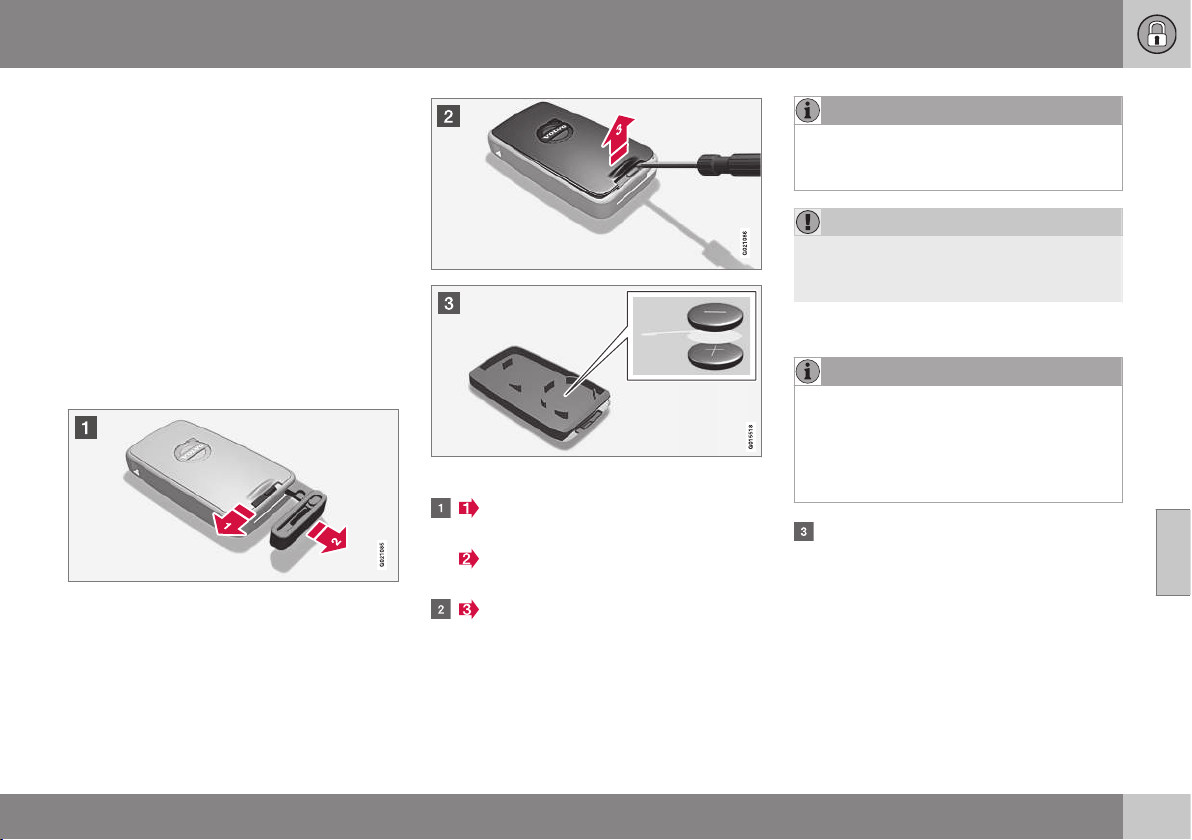
06 Locks and alarm
06
}}
167
Remote control key/PCC - replacing
the battery
The batteries for the remote control key/PCC
can be replaced.
The batteries for the remote control key/PCC
should be replaced if:
•
the information symbol is illuminated and
the combined instrument panel shows
Low battery in remote control. Please
change batteries.
and/or
•
the locks repeatedly do not react to sig-
nals from the remote control key within
20 metres from the car.
Opening
Slide the spring-loaded catch to the
side.
At the same time pull the key blade
straight out backwards.
Insert a 3 mm slot screwdriver in the
hole behind the spring-loaded catch and
gently prize the remote control key up.
NOTE
Turn the remote control key over with the
buttons facing up, this is to avoid the bat-
teries falling out when it is opened.
IMPORTANT
Avoid touching new batteries and their
contact surfaces with your fingers as this
may impair their function.
Battery replacement
NOTE
Volvo recommends that the batteries to be
used in the remote control key/PCC fulfil
UN Manual of Test and Criteria, Part III,
sub-section 38.3. Batteries fitted in the
factory or replaced by an authorised Volvo
workshop fulfil the above criteria.
Closely study how the battery/batteries
are secured on the inside of the cover,
with regard to their (+) and (–) sides.
Remote control key with 1 battery
1. Carefully prize out the battery.
2. Install a new one with the (+) side down.
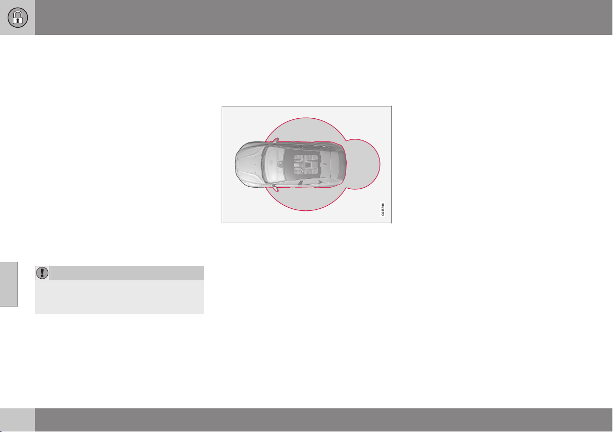
||
06 Locks and alarm
06
168
* Option/accessory, for more information, see Introduction.
Remote control key and PCC* with 2
batteries
1. Carefully prize out the batteries.
2. First install one new one with the (+) side
up.
3. Position the white plastic tab in between
and finally install a second new battery
with the (+) side down.
Battery type
Use batteries with designation CR2430, 3 V.
Assembly
1. Press the remote control key together.
2. Hold the remote control key with the slot
pointed up and lower the key blade into
its slot.
3. Lightly press the key blade. You should
hear a "click" when the key blade is
locked in.
IMPORTANT
Make sure that exhausted batteries are
disposed of in a manner which is kind to
the environment.
Related information
•
Remote control key with key blade (p.
159)
•
Remote control key - function (p. 162)
Keyless*
Keyless lock and ignition system is available in
two function levels, Keyless drive and Keyless
start.
For cars with Keyless start function the car
can be started (p. 268) without the remote
control key in the ignition switch.
For cars with Keyless drive function, the car
can be locked and unlocked (p. 171) without
pressing a button on the remote control key,
and also be started without the key being
inserted in the ignition lock. The system
makes it easier and more convenient to open
the car, e.g. when your hands are full.
Both of the car's remote control keys have
Keyless function. It is possible to order more
remote control keys, see Remote control key
with key blade (p. 159).
The car's electrical system can be set to
three different levels - key position (p. 71) 0, I
and II - with the remote control key.
Related information
•
Keyless* - Secure handling of the remote
control key (p. 169)
•
Keyless* - interference to remote control
key function (p. 170)
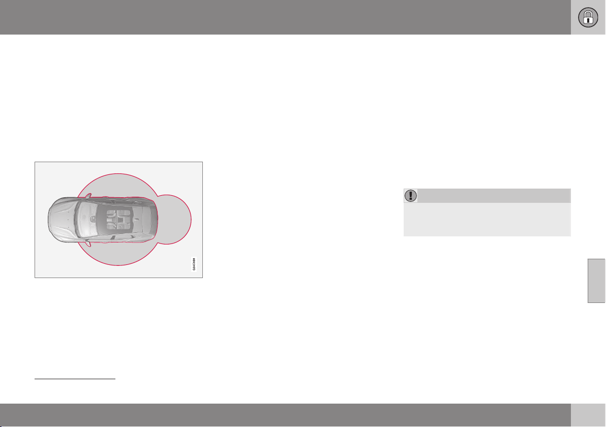
06 Locks and alarm
06
* Option/accessory, for more information, see Introduction.
169
Keyless* - remote control key range
5
In order to open a door or the tailgate without
pressing a button on the remote control key, a
remote control key must be approx. 1.5 m
from the car door handle or tailgate.
The person who wishes to lock or unlock a
door must have the remote control key with
him or her. It is not possible to lock or unlock
a door if the remote control key is on the
opposite side of the car.
The red rings in the above figure indicate the
range covered by the system's antennas.
If all remote control keys are removed from
the car when the engine is running or key
position (p. 71) I or II is active and a door has
been opened and then closed, the informa-
tion display in the combined instrument panel
shows a warning message while sounding an
audible reminder at the same time.
When the remote control key has been
returned to the car, the warning message
goes off and the audible reminder ceases
once either/or:
•
a door has been opened and closed
•
the remote control key has been inserted
in the ignition lock
•
The OK button on the direction indicator
stalk.
Related information
•
Keyless* (p. 168)
•
Keyless* - antenna location (p. 173)
Keyless* - Secure handling of the
remote control key
It is important to handle all remote control
keys with great care.
If a remote control key with keyless function
is left in the car, it is deactivated temporarily
when the car is locked. This prevents unau-
thorised entry.
However, if someone breaks into the car and
finds the remote control key, it is reactivated.
It is therefore important to handle all remote
control keys with great care.
IMPORTANT
When the door has been unlocked using
the key blade and is opened, the alarm is
triggered.
Related information
•
Keyless* (p. 168)
5
Does not apply to cars with keyless start
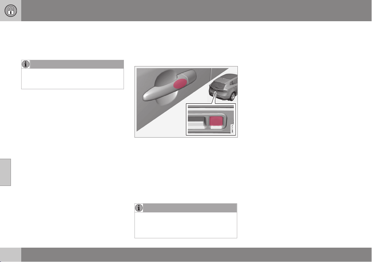
06 Locks and alarm
06
170
* Option/accessory, for more information, see Introduction.
Keyless* - interference to remote
control key function
Electromagnetic fields and screening can
interfere with the Keyless function.
NOTE
Do not place/store the remote control key
with keyless function near a mobile phone
or metal object - no closer than 10-15 cm.
If interference is experienced nonetheless,
use the remote control key (p. 159) and the
key blade like a traditional remote control key.
Related information
•
Keyless* (p. 168)
Keyless* - locking
Cars with the Keyless-drive system have a
touch-sensitive area on the outer handle of
the doors and a rubberised button next to the
tailgate's rubberised pressure plate.
Lock the doors and the tailgate by grasping
one of the door handles or pressing the
smaller of the tailgate's two rubberised but-
tons - the lock indicator (p. 161) in the wind-
screen confirms that locking has been com-
pleted by starting to flash.
All doors and the tailgate must be closed
before the car can be locked - otherwise the
car is not locked.
NOTE
In cars with automatic gearbox selectors,
the gear selector must be set to the P
position; otherwise the car can be neither
locked nor alarmed.
Related information
•
Keyless* (p. 168)
•
Alarm indicator (p. 182)
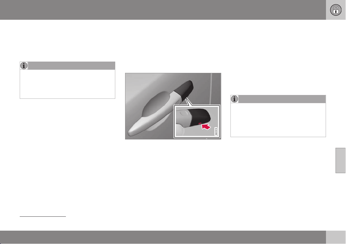
06 Locks and alarm
06
* Option/accessory, for more information, see Introduction.
171
Keyless* - unlocking
6
Unlocking with Keyless-drive takes place
when a hand grasps a door handle or the tail-
gate's rubberised pressure plate is actuated -
open the door or tailgate as normal.
NOTE
The door handles normally register a hand
that takes hold of the handle, but with
thick gloves on or after a very quick hand
movement a second attempt may be
required, or with the glove taken off.
Related information
•
Keyless* (p. 168)
•
Keyless* - locking (p. 170)
Keyless* - unlocking with the key
blade
If central locking cannot be activated with the
remote control key, e.g. if the batteries are
discharged, then the left-hand front door can
be opened using the remote control key's
detachable key blade (p. 166).
Hole for key blade - to loosen the cover.
To access the lock cylinder, the door handle's
plastic cover must be removed - this is also
done with the key blade:
1. Press the key blade approx. 1 cm straight
up into the hole on the underside of the
door handle/cover - do not prize.
> The plastic cover loosens automati-
cally by means of the torque when the
blade is pushed straight up and into
the opening.
2. Then insert the key blade in the lock cyl-
inder and unlock the door.
3. Refit the plastic cover after unlocking.
NOTE
When the left-hand front door is unlocked
using the key blade and is opened, this
triggers the alarm (p. 181). It is switched
off by inserting the remote control key in
the ignition switch, see Alarm - remote
control key not working (p. 183).
Related information
•
Keyless* (p. 168)
6
Does not apply to remote control key with keyless start.

06 Locks and alarm
06
172
* Option/accessory, for more information, see Introduction.
Keyless* - key memory
The key memory
7
in the remote control
key/PCC means that certain settings in the
car can be individually adapted for different
persons.
The key memory function is available in com-
bination with power seat* and power rearview
and door mirrors. Settings for door mirrors,
driver's seat and steering force can be saved
in the key memory.
Memory function in remote control key
with Keyless function
If several people each with a remote control
key (p. 159) approach the car, then the set-
tings for seat and mirrors are implemented for
the person who opens the driver's door.
After the driver's door has been opened by
person A with remote control key A but
person B with remote control key B shall
drive, the settings can be changed as follows:
•
Standing by the driver's door, or sitting
behind the steering wheel person B
presses their remote control key's unlock
button, see Remote control key - function
(p. 162).
•
Select one of three possible memories for
adjusting the power seat (p. 74) with seat
button 1 - 3.
•
Adjust seat and mirrors (p. 97) manually.
•
Adjust steering force in the menu system
MY CAR (p. 108).
Related information
•
Keyless* (p. 168)
Keyless* - lock settings
Lock settings for the Keyless-drive function
can be adapted in the MY CAR menu system
Lock settings for the Keyless-drive function
can be adapted by indicating in the menu
system for MY CAR which doors are to be
unlocked, under
Car settings Lock
settings
Keyless entry - there select
between
All doors unlock, Any door, Doors
on same side and Both front doors.
For a description of the menu system, see
MY CAR (p. 104).
Related information
•
Keyless* (p. 168)
7
Only in combination with power driver's seat and power mirrors.
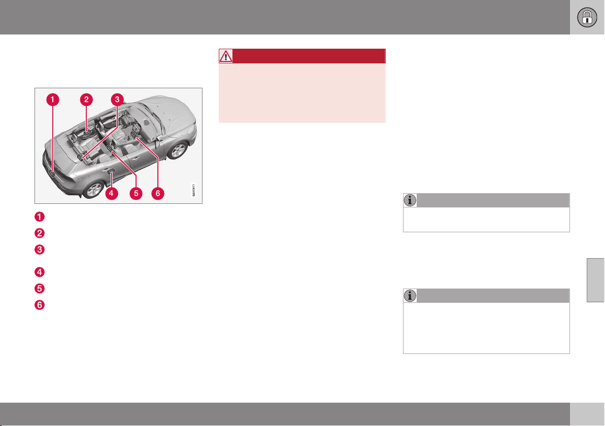
06 Locks and alarm
06
* Option/accessory, for more information, see Introduction.
173
Keyless* - antenna location
The Keyless system has a number of inte-
grated antennae located around the car.
Rear bumper, centre
Door handle, left rear
Cargo area, central and furthest in under
the floor
Door handle, right rear
Centre console, under the rear section
Centre console, under the front section.
WARNING
People who have had a pacemaker opera-
tion should not come closer than 22 cm to
the Keyless system's antennas with their
pacemaker. This is to prevent interference
between the pacemaker and the Keyless
system.
Related information
•
Keyless* (p. 168)
Locking/unlocking - from the outside
Locking/unlocking from the outside is carried
out using the remote control key (p. 162). The
remote control key can lock/unlock all doors,
the tailgate and the fuel filler flap. Different
sequences for unlocking can be selected.
In order that the lock sequence can be acti-
vated, the driver's door must be closed - if
any of the other doors or the tailgate is open,
then it/they is/are locked and the alarm is
activated only when it/they are closed. With
the Keyless* system all the doors and tailgate
must be closed.
NOTE
Be aware of the risk of locking the remote
control key in the car.
If it is not possible to lock/unlock with the
remote control key, the battery may be dis-
charged - lock or unlock the left-hand front
door with the detachable key blade (p. 166).
NOTE
Remember that the alarm is triggered
when the door is opened after being
unlocked with the key blade - the alarm is
switched off when the remote control key
is inserted into the ignition switch.
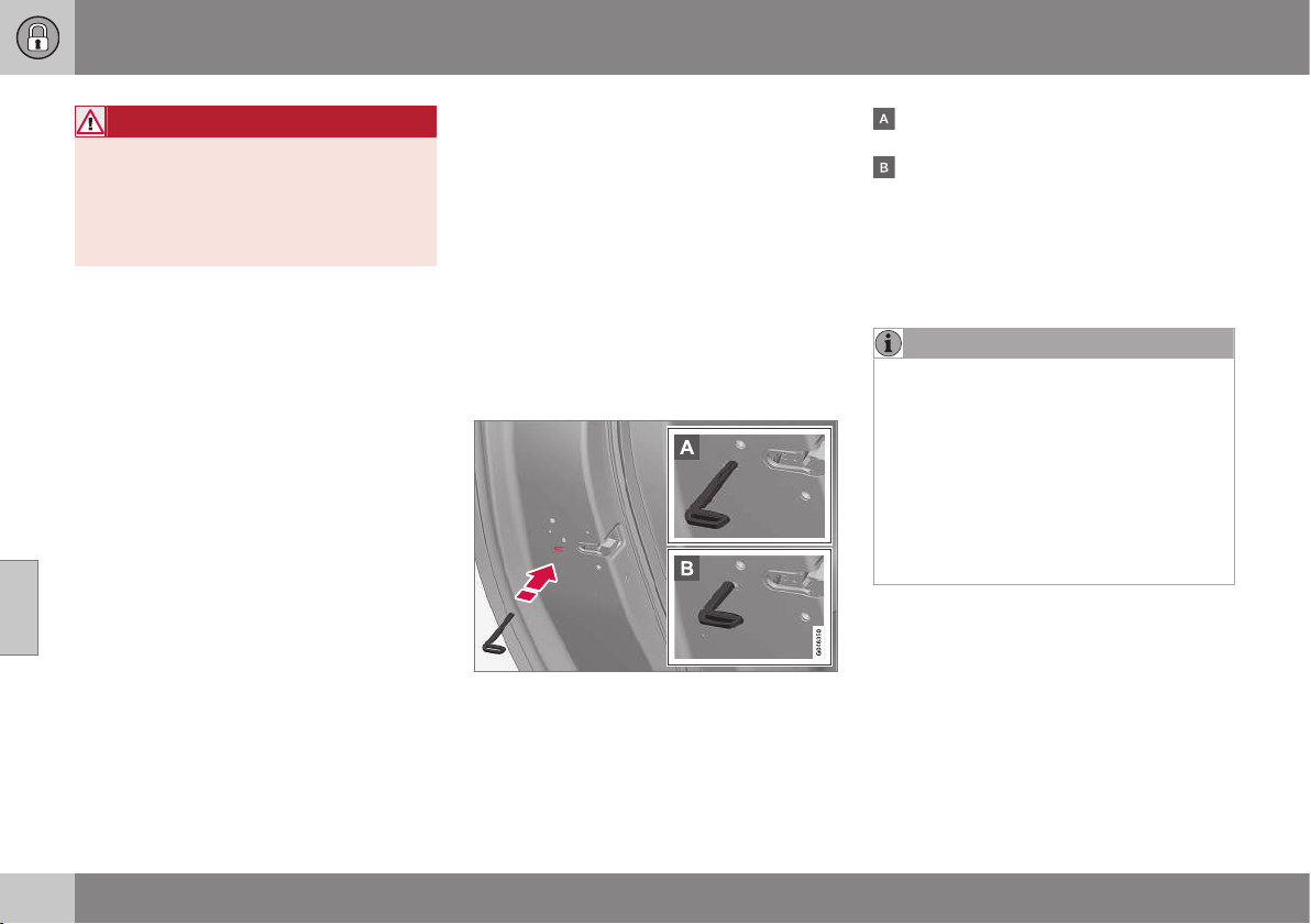
||
06 Locks and alarm
06
174
* Option/accessory, for more information, see Introduction.
WARNING
Be aware of the risk of being locked in the
car when it is locked from the outside
using the remote control key - it is then not
possible to open any of the doors from the
inside with the door controls. For more
information, see Deadlocks* (p. 178).
Automatic relocking
If none of the doors or the tailgate is opened
within 2 minutes of unlocking, all are locked
again automatically. This function reduces the
risk that the car is left unlocked unintention-
ally. (For cars with alarm, see Alarm (p. 181).)
Related information
•
Locking/unlocking - from the inside (p.
175)
•
Remote control key - function (p. 162)
Manual locking of the door
In certain situations the car must be lockable
manually, e.g. in the event of power failure.
The left-hand front door can be locked with
its lock cylinder and the remote control key's
detachable key blade (p. 171).
Other doors have no lock cylinders and
instead have a lock switch on the end of each
door which must be depressed using the key
blade - they are then mechanically locked/
blocked to prevent them being opened from
outside. The doors can still be opened from
the inside.
Manual locking of the door. Not to be mixed up
with child safety locks (p. 179).
– Remove the detachable key blade (p.
166) from the remote control key. Insert
the key blade in the hole for lock reset
and press the key in until the key bot-
toms, approx. 12 mm.
The door can be opened from both the
outside and the inside.
The door is blocked against opening from
the outside. To return to position A, the
inner door handle must be opened.
The doors can also be unlocked with the
unlock button on the remote control key (p.
159) or with the central locking button on the
driver's door.
NOTE
•
A door's lock reset only locks that par-
ticular door - not all doors simultane-
ously.
•
A manually locked rear door with acti-
vated manual child safety locks (p.
179) cannot be opened from either the
outside or the inside. A rear door that
is locked in this way can only be
unlocked with the remote control key
or central locking button.
Related information
•
Remote control key/PCC - replacing the
battery (p. 167)

06 Locks and alarm
06
* Option/accessory, for more information, see Introduction.
175
Locking/unlocking - from the inside
Locking/unlocking can be performed using
the driver's door button for central locking. All
doors and tailgate (p. 176) can be locked or
unlocked simultaneously.
Central locking
•
Press one side
of the button to lock -
the other side
to unlock.
Lamp in lock button
When the lamp in the central locking button
for the driver's door is illuminated it means
that all doors are locked.
With central locking button only in the driver's
door, other doors have no button:
•
Illuminated lamp means that all doors are
locked.
With central locking button on both front
doors and electric lock button in each rear
door:
•
Illuminated lamp means that only that
particular door is locked. When all but-
tons are illuminated all doors are locked.
Unlocking
A door can be unlocked from the inside in
two different ways:
•
Press the central locking button
.
A long press also opens all the side windows*
simultaneously (see also Total airing function
(p. 176)).
•
Pull the door handle and open the door -
the door is unlocked and opened in one
operation.
Locking
•
Both front doors must be closed for the
central locking to be activated. Press the
central locking button
- all doors are
locked. If any of the rear doors is open, it
will lock when it is closed.
A long press also closes all the side windows
simultaneously (see also Total airing function
(p. 176)).
Automatic locking
The doors and tailgate are locked automati-
cally when the car starts to move.
The function can be activated/deactivated in
the menu system MY CAR under
Settings
Car settings Lock settings Automatic
door locking
. For a description of the menu
system, see MY CAR (p. 104).
Related information
•
Locking/unlocking - from the outside (p.
173)
•
Alarm (p. 181)
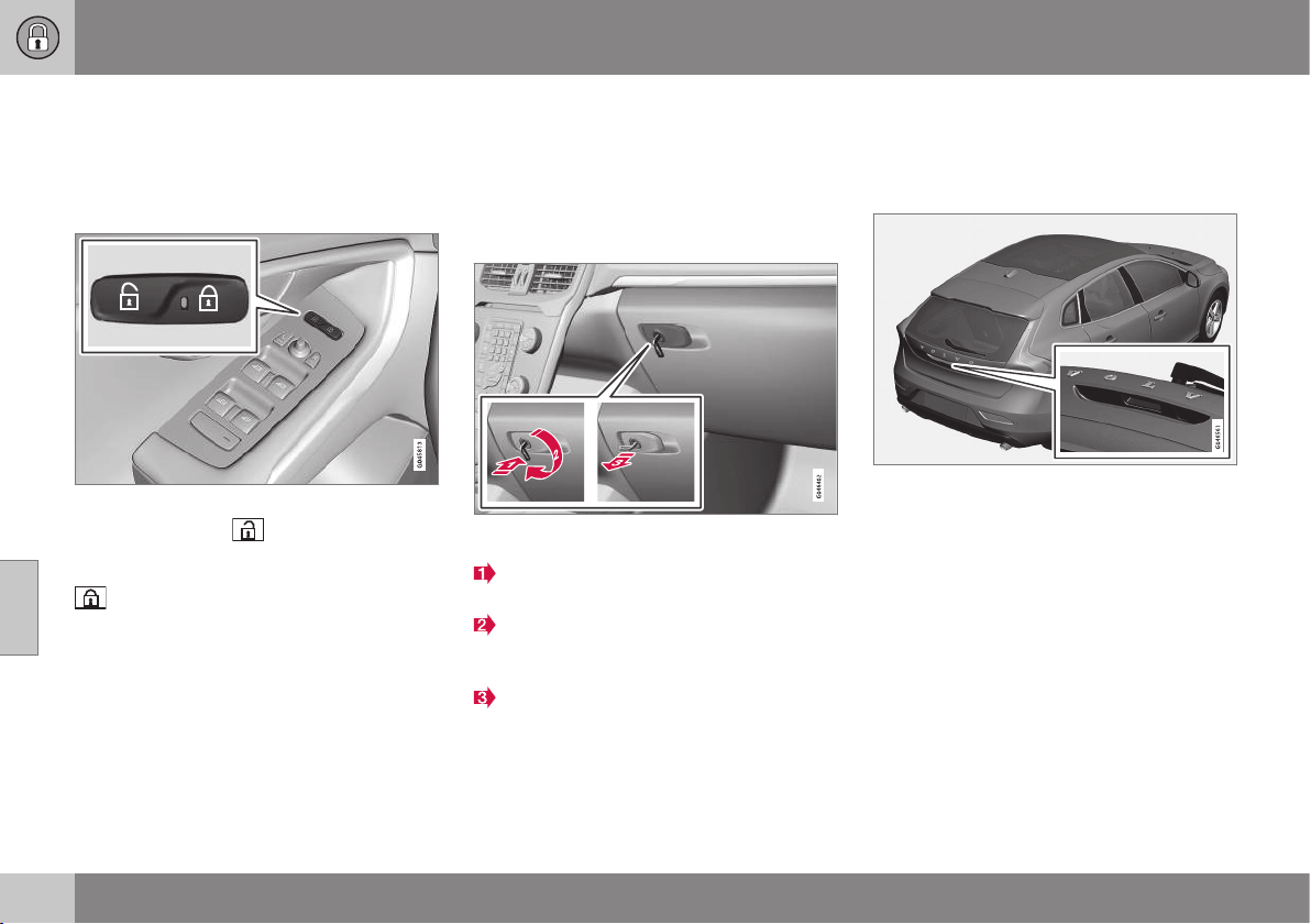
06 Locks and alarm
06
176
Total airing function
The total airing function opens or closes all
side windows simultaneously and can be
used for example to quickly air the car during
hot weather.
Central locking button
A long press on the
symbol in the central
locking button opens all side windows simul-
taneously. The same procedure on the
button closes all side windows simulta-
neously.
Related information
•
Locking/unlocking - from the inside (p.
175)
•
Power windows (p. 95)
Locking/unlocking - glovebox
The glovebox (p. 149) can only be locked/
unlocked using the detachable key blade from
the remote control key (p. 159).
For information on the key blade, see Detach-
able key blade - detaching/attaching (p. 166).
Locking the glovebox:
Insert the key blade in the glovebox lock
cylinder.
Turn the key blade 90 degrees clockwise.
The keyhole is horizontal in the locked
position.
Pull out the key blade.
•
Unlock by carrying this out in reverse
order.
Related information
•
Remote control key - function (p. 162)
Locking/unlocking - tailgate
The tailgate can be opened, locked and
unlocked in a number of different ways.
Manual opening
Rubber plate with electrical contact.
The tailgate is held closed by an electrical
lock. To open:
1. Push down gently on the wider of the two
rubberised pressure plates under the
outer handle - the lock is released.
2. Lift the outside handle in order to fully
open the tailgate.
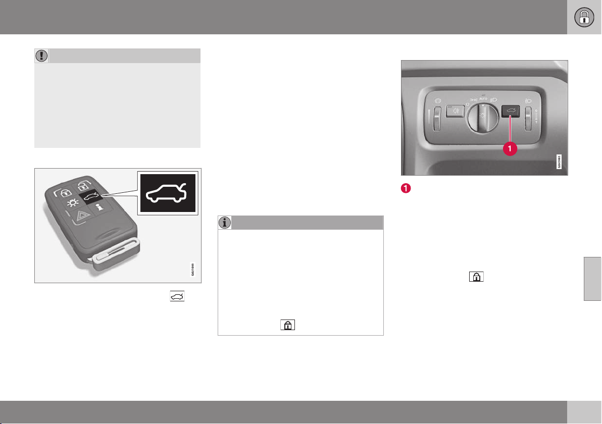
06 Locks and alarm
06
* Option/accessory, for more information, see Introduction.
177
IMPORTANT
•
Minimal force is required to release the
rear hatch lock - just gently press the
rubberised panel.
•
Do not place the lift force on the rub-
ber panel when opening the rear hatch
- lift the handle. Using too much force
may damage the electrical contacts on
the rubber panel.
Unlocking with the remote control key
Using the remote control key (p. 159)
button the alarm for the tailgate can be dis-
armed* and the tailgate unlocked on its own.
The lock indicator (p. 161) on the instrument
panel stops flashing in order to show that not
all of the car is locked and the alarm's* level
and movement sensors and the sensors for
opening the tailgate are disconnected.
The doors remain locked and armed.
The tailgate can be opened in two different
ways using the remote control key:
One press - The boot lid is unlocked, but
remains closed - press lightly on the rubber-
ised pressure plate under the outer handle
and lift the boot lid. If the tailgate is not
opened within 2 minutes then it is relocked
and the alarm is re-armed.
Two presses - The boot lid is unlocked and
the lock is disengaged at which the boot lid
opens about a centimetre - lift the outer han-
dle to open. Rain, cold, frost or snow could
however prevent the tailgate from disengag-
ing from the lock.
NOTE
•
When the boot lid/tailgate is unlocked
with 2 presses or from the car interior,
automatic relocking does not take
place because the boot lid/tailgate is
open - it must be closed manually.
•
After the boot lid/tailgate has been
closed it is unlocked and the alarm is
not armed - relock it and re-arm the
alarm with the remote control key's
lock button
.
Opening the car from inside
Unlocking, tailgate
To open the tailgate:
– Press the lighting panel button (1).
> The lock releases and the tailgate
opens by a few centimetres.
Locking with the remote control key
– Press the remote control key (p. 162) but-
ton for locking
.
> The lock indicator on the instrument
panel starts flashing, which means that
the car is locked and the alarm* has
been activated.
Related information
•
Locking/unlocking - from the inside (p.
175)
•
Locking/unlocking - from the outside (p.
173)
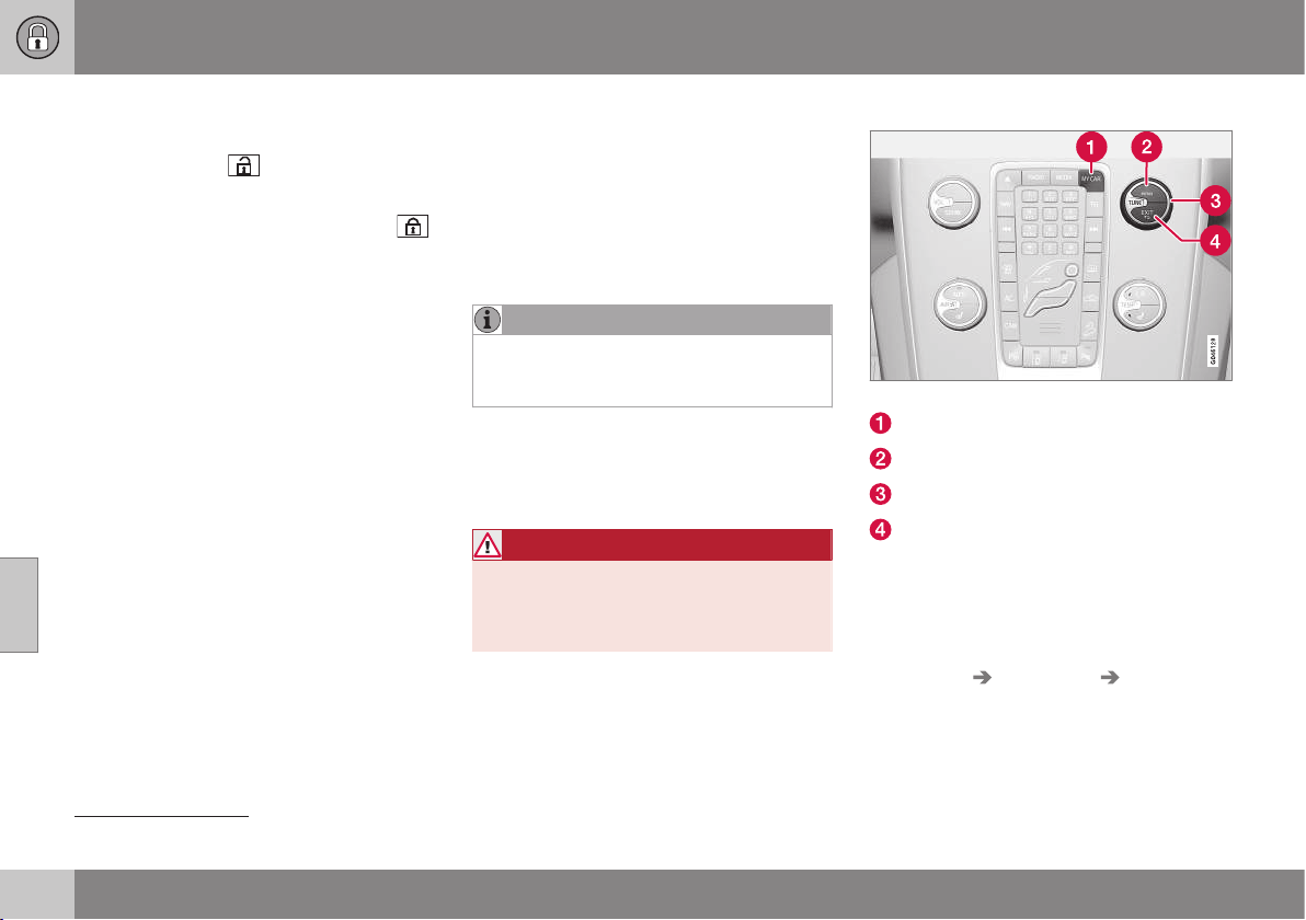
06 Locks and alarm
06
178
* Option/accessory, for more information, see Introduction.
Locking/unlocking - fuel filler flap
The fuel filler flap is unlocked with the remote
control key (p. 159)
button.
The fuel filler flap remains unlocked until the
car is locked with the remote control key
button. If the car is locked during travel or
with the interior buttons, the fuel filler flap will
remain unlocked.
The fuel filler flap locking logic also follows
the locking or unlocking of the keyless-drive
and the central locking system.
Related information
•
Fuel filler flap - Opening/closing (p. 296)
•
Fuel filler flap - manual opening (p. 296)
Deadlocks*
Deadlocks
8
means that all door handles are
mechanically disengaged, which prevents
doors being opened from the inside.
The deadlocks are activated with the remote
control key (p. 159) and are set after an
approximately 10 second delay after the
doors have been locked.
NOTE
If a door is opened within the delay time
then the sequence is interrupted and the
alarm is deactivated.
The car can only be unlocked from a dead-
lock state with the remote control key. The
front left door can also be unlocked with the
detachable key blade (p. 165).
WARNING
Do not allow anyone to remain in the car
without first deactivating the deadlocks in
order to avoid the risk of anyone being
locked in.
Temporary deactivation
Active menu options are indicated with a cross.
MY CAR
OK MENU
TUNE knob control
EXIT
If someone is going to stay in the car but the
doors must be locked from the outside, then
the deadlocks function can be temporarily
switched off. This is carried out as follows:
1. Access the menu system MY CAR under
Settings Car settings Reduced
Guard
(for a detailed description of the
menu system, see MY CAR (p. 104)).
8
Only in combination with alarm.
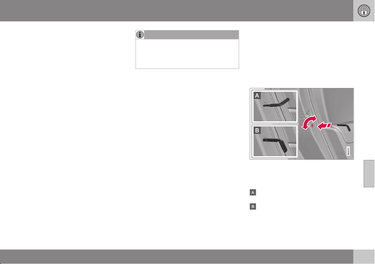
06 Locks and alarm
06
* Option/accessory, for more information, see Introduction.
179
2.
Select
Activate once.
> The combined instrument panel shows
the message
Locks and alarm
Reduced guard and the deadlocks
function is switched off when the car is
locked.
or
–
Select Ask when exiting.
> Each time the engine is switched off
the centre console's screen shows the
message
Activate Reduced Guard
until engine has started again? fol-
lowed by the alternatives Confirm
with OK and Cancel with EXIT.
If the deadlocks function shall be switched
off
– Press OK/MENU and lock the car. (Note
that the alarm's movement and tilt detec-
tors* are switched off at the same time.)
> The next time the engine is started, the
system is reset to zero and the com-
bined instrument panel shows the
message
Locks and alarm Full
guard at which the deadlocks function
and the alarm's movement and tilt
detectors are re-engaged.
If the locking system shall not be changed
– Press EXIT and lock the car.
NOTE
•
Remember that the alarm is activated
when the car is locked.
•
If any of the doors are opened from
the inside then the alarm is triggered.
Related information
•
Keyless* - unlocking with the key blade
(p. 171)
Child safety locks - manual activation
The child safety locks prevent children from
being able to open a rear door from the
inside.
The child safety locks are located on the trail-
ing edge of the rear doors and are only acces-
sible when the doors are open.
Activate/deactivate child safety locks
Manual child safety locks. Not to be mixed up
with manual door lock (p. 174).
– Use the remote control key's detachable
key blade (p. 166) to turn the knob.
The door is blocked against opening from
the inside.
The door can be opened from both the
outside and the inside.
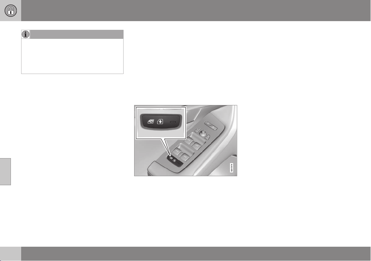
||
06 Locks and alarm
06
180
* Option/accessory, for more information, see Introduction.
NOTE
•
A door's knob control only blocks that
particular door - not both rear doors
simultaneously.
•
Cars with an electric child safety lock
do not have a manual child lock.
Related information
•
Child safety locks - electrical activation*
(p. 180)
•
Locking/unlocking - from the inside (p.
175)
Child safety locks - electrical
activation*
The child safety locks prevent children from
being able to open a rear door from the
inside.
Activation
The electrical child safety locks can be acti-
vated/deactivated in all key positions (p. 71)
higher than 0. Activation/deactivation can be
performed up to 2 minutes after switching off
the engine, provided that no door is opened.
Control panel driver's door.
1. Start the engine or choose a key position
higher than 0.
2. Press the button in the driver's door con-
trol panel.
> The information display shows the
message
Rear child lock activated
and the button's lamp illuminates - the
locks are active.
When the electric child safety lock is active
then the rear:
•
windows can only be opened with the
driver's door control panel
•
doors cannot be opened from inside.
The current setting is stored when the engine
is switched off - if the child safety locks are
activated at engine shutdown, the function
will remain activated the next time the engine
is started.
Related information
•
Child safety locks - manual activation (p.
179)
•
Locking/unlocking - from the inside (p.
175)

06 Locks and alarm
06
* Option/accessory, for more information, see Introduction.
181
Alarm
The alarm is a device that warns in the event
of e.g. a break-in in the car.
Activated alarm is triggered if:
•
a door, the bonnet or the tailgate is
opened
•
a movement is detected in the passenger
compartment (if fitted with a movement
detector*)
•
the car is raised or towed away (if fitted
with a tilt detector*)
•
the battery's cable is disconnected
•
the siren is disconnected.
If there is a fault in the alarm system then the
information display in the combined instru-
ment panel shows a message. In which case,
contact a workshop - an authorised Volvo
workshop is recommended.
NOTE
The movement sensors trigger an alarm in
the event of movement in the passenger
compartment - air currents are also regis-
tered. For this reason the alarm is trig-
gered if the car is left with a window open
or if the passenger compartment heater is
used.
To avoid this: Close the window when
leaving the car. If the car's integrated pas-
senger compartment heater (or a portable
electric heater) shall be used - direct the
airflow from the air vents so that they are
not pointing upwards in the passenger
compartment. Alternatively, reduced alarm
level can be used, Reduced alarm level (p.
183).
NOTE
Do not attempt to repair or alter compo-
nents in the alarm system yourself. Any
such attempts may affect the terms of the
insurance.
Arming the alarm
– Press the remote control key lock button.
Deactivate the alarm
– Press the remote control key unlock but-
ton.
Deactivating a triggered alarm
– Press the remote control key unlock but-
ton or insert the remote control key in the
ignition switch.
Related information
•
Alarm - automatic re-arming (p. 182)
•
Alarm - remote control key not working
(p. 183)

06 Locks and alarm
06
182
Alarm indicator
The alarm indicator shows alarm system (p.
181) status.
Same LED as lock indicator (p. 161).
A red LED on the instrument panel indicates
the alarm system's status:
•
LED not lit – Alarm not armed
•
The LED flashes once every other second
– Alarm is armed
•
The LED flashes rapidly after disarming
the alarm (and until the remote control
key is inserted in the ignition switch and
key position I is selected) – Alarm has
been triggered.
Alarm - automatic re-arming
Automatic re-arming of the alarm (p. 181) pre-
vents the car being left with the alarm dis-
armed unintentionally.
If the car is unlocked with the remote control
key (p. 159)(and the alarm is disarmed) but
none of the doors or the tailgate is opened
within 2 minutes, then the alarm is automati-
cally re-armed. The car is relocked at the
same time.
Related information
•
Alarm - automatic arming (p. 182)
Alarm - automatic arming
In certain countries the alarm (p. 181) is acti-
vated after a certain delay if the driver's door
was opened and closed but the car was not
re-locked.
Related information
•
Alarm signals (p. 183)
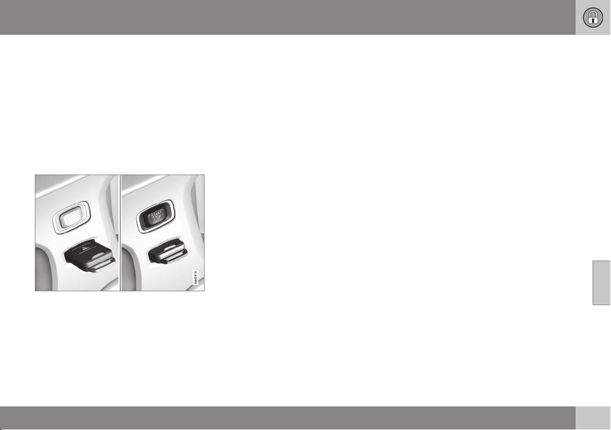
06 Locks and alarm
06
* Option/accessory, for more information, see Introduction.
183
Alarm - remote control key not
working
If the alarm (p. 181) cannot be deactivated
with the remote control key, e.g. if the key's
battery (p. 167) is discharged - the car can be
unlocked, disarmed and the engine started as
follows:
1. Open the left-hand front door with the
detachable key blade (p. 171).
> The alarm is triggered, the direction
indicators flash and the siren sounds.
2. Insert the remote control key in the igni-
tion switch.
> The alarm is deactivated.
Alarm signals
When the alarm (p. 181) is triggered a siren
sounds and all direction indicators flash.
•
A siren sounds for 30 seconds or until the
alarm is switched off. The siren has its
own battery and works independently of
the car battery.
•
The direction indicators flash for 5
minutes or until the alarm is switched off.
Reduced alarm level
Reduced guard means that the movement
and tilt detectors can be temporarily deacti-
vated.
To avoid accidental triggering of the alarm -
e.g. if a dog is left in a locked car or during
transport on a car train or car ferry - tempo-
rarily deactivate the movement and tilt detec-
tors.
The procedure is the same as with the tem-
porary disengaging of deadlocks, see Dead-
locks* (p. 178).
Related information
•
Alarm (p. 181)
•
Alarm indicator (p. 182)
DRIVER SUPPORT
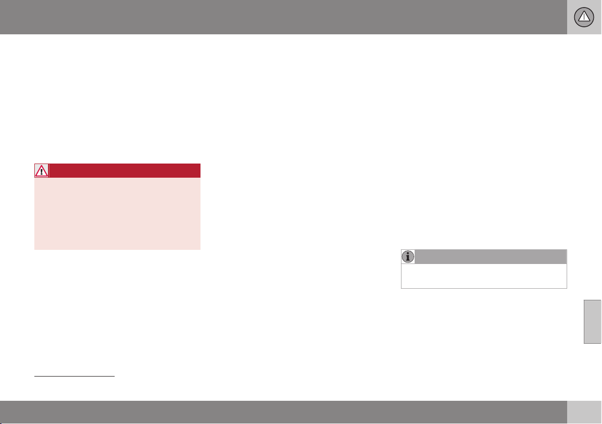
07 Driver support
07
* Option/accessory, for more information, see Introduction.
185
Stability and traction control system
(DSTC)
The stability and traction control system,
DSTC (Dynamic Stability & Traction Control),
helps the driver to avoid skidding and
improves the car's traction.
The activation of the system during braking
may be noticed as a throbbing sound. The
car may accelerate slower than expected
when the accelerator pedal is depressed.
WARNING
The stability and traction control system is
a supplementary function - it cannot han-
dle all situations in all road conditions.
The driver always bears responsibility for
ensuring that the vehicle is driven safely
and that applicable road traffic rules and
regulations are followed.
The system consists of the following func-
tions:
•
Active Yaw Control
•
Spin Control
•
Traction control system
•
Engine drag control - EDC
•
Corner Traction Control - CTC
•
Driver Steering Recommendation – DSR
•
Trailer Stability Assist* - TSA
Active Yaw Control
The function checks the driving and brake
force of the wheels individually in order to
stabilise the car.
Spin Control
The function reduces engine power if the
drive wheels slip against the underlying sur-
face in order to maintain stability and traction.
Traction control system
The function is active at low speed and trans-
fers power from the driving wheel that is spin-
ning to the one that is not.
Engine drag control - EDC
EDC (Engine Drag Control) prevents involun-
tary wheel locking, e.g. after shifting down or
engine braking when driving in low gears on
slippery road surfaces.
Involuntary wheel locking while driving can,
amongst other things, impair the driver's abil-
ity to steer the car.
Corner Traction Control - CTC
CTC compensates for understeer and allows
higher than normal acceleration in a bend
without wheelspin on the inner wheel, e.g. on
an arcing motorway entrance road to quickly
reach the prevailing traffic speed.
Driver Steering Recommendation – DSR
DSR (Driver Steering Recommendation) helps
the driver steer the car in the right direction
when there is reduced traction or when the
ABS system engages.
The primary role of the DSR function is to
help the driver steer in the right direction
when the car is skidding.
DSR engages by applying slight torque to the
steering wheel in the direction in which the
car should be steered to maintain/achieve
maximum possible traction and stabilise the
car.
Trailer Stability Assist* - TSA
1
Trailer stability assist (p. 307) function is to
stabilise the car and trailer combination if it
begins to snake. For more information, see
Driving with a trailer (p. 301).
NOTE
The function is deactivated if the driver
selects Sport mode.
Related information
•
Stability and traction control system
(DSTC) - operation (p. 186)
•
Stability and traction control system
(DSTC) - symbols and messages (p. 187)
1
Trailer Stability Assist

07 Driver support
07
186
Stability and traction control system
(DSTC) - operation
The stability and traction control system,
DSTC (Dynamic Stability & Traction Control),
helps the driver to avoid skidding and
improves the car's traction.
Selection of level - Sport mode
The stability and traction control system
(DSTC) is always activated - it cannot be
switched off.
However, the driver can select the Sport
mode, which allows for a more active driving
experience. In Sport mode the system
detects whether the accelerator pedal, steer-
ing wheel movements and cornering are more
active than in normal driving and then allows
controlled skidding with the rear section up to
a certain level before it intervenes and stabil-
ises the car.
If the driver stops a controlled skid by releas-
ing the accelerator pedal then the DSTC sys-
tem intervenes and stabilises the car.
With Sport mode, maximum traction is
obtained if the car has become stuck, or
when driving on a loose surface - e.g. sand or
deep snow.
Proceed as follows to select Sport mode:
1. Press the centre console's MY CAR but-
ton and in the display screen's menu sys-
tem find
My V40 DSTC.
2. Uncheck the box and back out of the
menu system with EXIT.
> The system then allows a more sporty
driving style.
The Sport mode is active until the driver
deselects it or until the engine is switched off
- after the engine is started the next time the
DSTC system is back in its normal mode
again.
Related information
•
Stability and traction control system
(DSTC) (p. 185)
•
Stability and traction control system
(DSTC) - symbols and messages (p. 187)
•
MY CAR (p. 104)
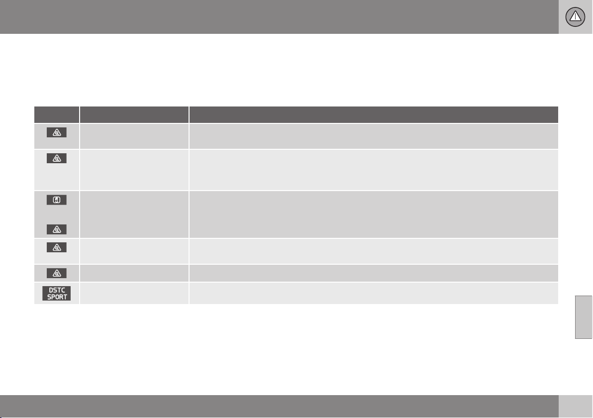
07 Driver support
07
187
Stability and traction control system
(DSTC) - symbols and messages
The stability and traction control system,
DSTC (Dynamic Stability & Traction Control),
helps the driver to avoid skidding and
improves the car's traction.
Table
Symbol
A
Message Specification
DSTC Temporarily OFF
DSTC system temporarily reduced due to excessive brake disc temperature. - The function is reacti-
vated automatically when the brakes have cooled.
DSTC Service required
DSTC system disengaged.
•
Stop the car in a safe place, switch off the engine and start it again.
•
Visit a workshop if the message remains - an authorised Volvo workshop is recommended.
and
"Message"
There is a message in the combined instrument panel - read it!
Constant glow for
2 seconds.
System check when the engine is started.
Flashing light. DSTC system is being activated.
Sport mode is activated.
A
The symbols are schematic.
Related information
•
Stability and traction control system
(DSTC) (p. 185)
•
Stability and traction control system
(DSTC) - operation (p. 186)

07 Driver support
07
188
* Option/accessory, for more information, see Introduction.
Road Sign Information (RSI)
The road sign information function (RSI –
Road Sign Information) helps the driver to
remember which road signs the car has
passed.
Examples of readable speed related
2
signs.
The road sign information function gives
information on current speed, that a motor-
way or road is starting/ending and when
overtaking is prohibited. If both a sign for
motorway/road for motorised traffic and a
sign showing the maximum permitted speed
are passed, RSI decides to show the sign
symbol for maximum permitted speed.
WARNING
RSI does not work in all situations but is
designed merely as a supplementary aid.
The driver always bears ultimate responsi-
bility for ensuring that the vehicle is driven
safely and that applicable road traffic rules
and regulations are followed.
Related information
•
Road sign information (RSI)* - operation
(p. 188)
•
Road sign information (RSI)* - limitations
(p. 190)
Road sign information (RSI)* -
operation
The road sign information function (RSI –
Road Sign Information) helps the driver to
remember which road signs the car has
passed. How the function is operated is
described below.
Recorded speed information
3
.
When RSI has recorded a road sign with an
imposed speed, the combined instrument
panel displays the sign as a symbol.
Together with the symbol for
the current speed limit, a
sign showing that overtaking
is prohibited may also be
displayed where appropriate.
2
Road signs shown in the combined instrument panel are market-dependent - the illustrations only show a few examples.
3
Road signs shown in the combined instrument panel are market-dependent - the illustrations only show a few examples.
07 Driver support
07
}}
189
End of restriction or motorway
A corresponding road sign is shown in the
combined instrument panel for
approx. 10 seconds in situations where RSI detects a sign that involves the end of a speed limit - or other speed-related information, e.g. end of a motorway
.
Examples of such signs are:
End of all restrictions.
End of motorway.
Following which, the sign information is hid-
den until the next speed-related sign is
detected.
Additional signs
Examples of additional signs
3
.
Sometimes different speed limits are signpos-
ted for the same road - an additional sign
then indicates the circumstances under which
the different speeds apply. The road section
may be particularly susceptible to accidents
in rain and/or fog, for example.
An additional sign relating to rain is displayed
only if the windscreen wipers are in use.
The speed applicable on an
exit is indicated in certain
markets by means of an
additional sign containing an
arrow.
Speed signs linked to this
type of additional sign are displayed only if
the driver is using the direction indicator.
Some speeds are applicable
only after e.g. a specific dis-
tance or at a certain time of
day. The driver's attention is
drawn to the situation by
means of a symbol for an
additional sign under the
symbol showing speed.
Display of additional information
A symbol for additional sign
in the form of an empty
frame under the combined
instrument panel's speed
symbol means that the RSI
has detected an additional
sign with supplementary
information for the current speed limit.
Setting in MY CAR
There are options for RSI in the MY CAR
menu system; see MY CAR - driving support
system (p. 109).
3
Road signs shown in the combined instrument panel are market-dependent - the illustrations only show a few examples.
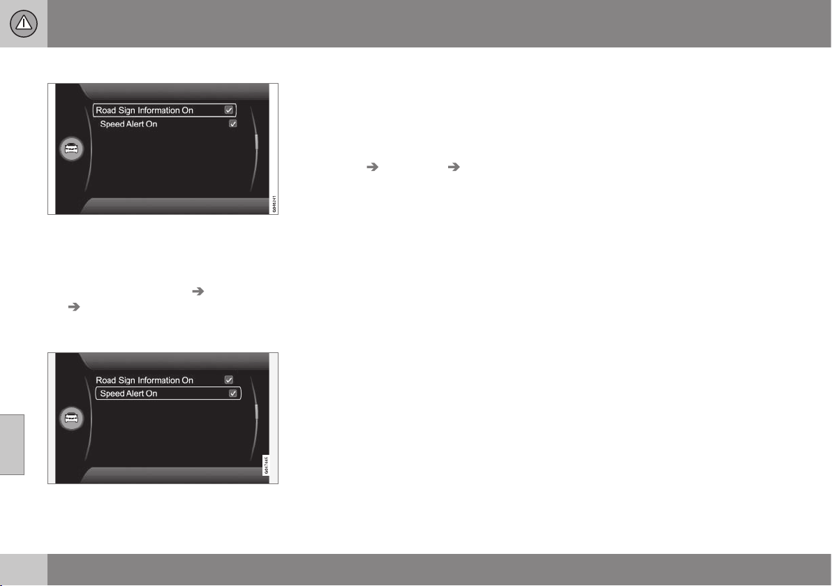
||
07 Driver support
07
190
* Option/accessory, for more information, see Introduction.
Road sign information On/Off
The combined instrument panel's speed sym-
bol display can be disabled. To deactivate the
RSI function:
•
Uncheck the option
Road Sign
Information
at Settings Car settings
Road Sign Information and go back
out by pressing EXIT.
Speed warning
The driver can opt to receive a warning when
the applicable speed limit is exceeded by
5 km/h or more. This warning is given by the
symbol showing the applicable maximum
speed temporarily flashing when this speed is
exceeded.
To activate speed warning:
•
Check the option
Speed alert at
Settings Car settings Speed alert
and go back out by pressing EXIT.
Related information
•
Road Sign Information (RSI) (p. 188)
•
Road sign information (RSI)* - limitations
(p. 190)
•
MY CAR (p. 104)
Road sign information (RSI)* -
limitations
The road sign information function (RSI –
Road Sign Information) helps the driver to
remember which road signs the car has
passed. The function has the following limita-
tions.
The RSI function's camera sensor has limita-
tions just like the human eye. Find out more
about this in the section on the camera sen-
sor limitations (p. 231).
Signs which indirectly provide information on
a prevailing speed limit, e.g. name signs for
towns/districts, are not recorded by the RSI
function.
Here are some other examples of what can
disrupt the function:
•
Faded signs
•
Signs positioned on bends
•
Rotated or damaged signs
•
Concealed or poorly positioned signs
•
Signs completely or partly covered with
frost, snow and/or dirt.
Related information
•
Road Sign Information (RSI) (p. 188)
•
Road sign information (RSI)* - operation
(p. 188)
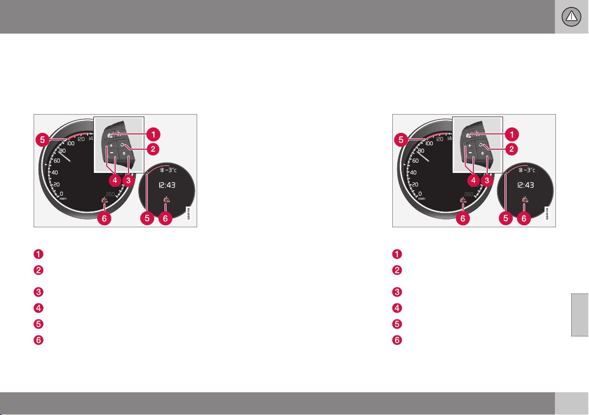
07 Driver support
07
* Option/accessory, for more information, see Introduction.
191
Speed limiter*
A (Speed Limiter) can be regarded as a
reverse cruise control - the driver regulates
the speed using the accelerator pedal but is
prevented from accidentally exceeding a pre-
selected/set speed by the speed limiter.
Steering wheel keypad and combined instrument
panel Digital and Analogue.
Speed limiter - On/Off.
Standby mode ceases and the stored
speed is resumed.
Standby mode
Activate and adjust the max. speed.
Selected speed
Speed limiter active
Related information
•
Speed limiter* - getting started (p. 191)
•
Speed limiter - temporary deactivation
and standby mode* (p. 193)
•
Speed limiter* - alarm for speed excee-
ded (p. 194)
•
Speed limiter* - deactivation (p. 194)
Speed limiter* - getting started
A (Speed Limiter) can be regarded as a
reverse cruise control - the driver regulates
the speed using the accelerator pedal but is
prevented from accidentally exceeding a pre-
selected/set speed by the speed limiter.
Steering wheel keypad and combined instrument
panel Digital and Analogue.
Speed limiter - On/Off.
Standby mode ceases and the stored
speed is resumed.
Standby mode
Activate and adjust the max. speed.
Selected speed
Speed limiter active
||
07 Driver support
07
192
* Option/accessory, for more information, see Introduction.
Switch on and activate
When the speed limiter is active, its
symbol (6) is shown in combination with a
mark (5) by the set maximum speed in the
combined instrument panel.
Selection and storage of the highest possible
speed in the memory can be made both dur-
ing a journey and while stationary.
While driving
1.
Press the steering wheel button
to
switch on the speed limiter.
> The symbol (6) for speed limiter illumi-
nates in the combined instrument
panel.
2. When the car is moving at the desired
highest possible speed: Press one of the
steering wheel buttons
or until the
combined instrument panel shows a
mark (5) next to the desired maximum
speed.
> The speed limiter is then active and the
selected max. speed is stored in the
memory.
When stationary
1.
Press the steering wheel button
to
switch on the speed limiter.
2.
Scroll with the
button until the com-
bined instrument panel shows a mark (5)
by the desired maximum speed.
> The speed limiter is then active and the
selected max. speed is stored in the
memory.
Related information
•
Speed limiter* (p. 191)
Speed limiter* - changing speed
A (Speed Limiter) can be regarded as a
reverse cruise control - the driver regulates
the speed using the accelerator pedal but is
prevented from accidentally exceeding a pre-
selected/set speed by the speed limiter.
To change the stored speed:
•
Adjust with short presses on
or in
the steering wheel keypad - every press
gives +/- 5 km/h. The last presses made
are stored in the memory.
To adjust +/- 1 km/h:
•
Hold down the button and release it when
the combined instrument panel shows a
mark next to the desired maximum
speed.
Related information
•
Speed limiter* (p. 191)
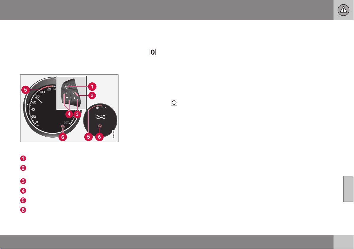
07 Driver support
07
* Option/accessory, for more information, see Introduction.
193
Speed limiter - temporary
deactivation and standby mode*
A (Speed Limiter) can be regarded as a
reverse cruise control - the driver regulates
the speed using the accelerator pedal but is
prevented from accidentally exceeding a pre-
selected/set speed by the speed limiter.
Steering wheel keypad and instrument panel Dig-
ital and Analogue.
Speed limiter - On/Off.
Standby mode ceases and the stored
speed is resumed.
Standby mode
Activate and adjust the max. speed.
Selected speed
Speed limiter active
Temporary deactivation - standby mode
To temporarily deactivate the speed limiter
and set it in standby mode:
–
Press .
> The combined instrument panel's
mark (5) changes colour from GREEN
to WHITE (Digital) or from WHITE to
GREY (Analogue) and the driver can
temporarily exceed the set maximum
speed.
The speed limiter is reactivated with
one press on
. The mark (5) then
changes colour from WHITE to GREEN
(Digital) or GREY to WHITE (Analogue)
and the car's maximum speed is lim-
ited again.
Temporary deactivation with the
accelerator pedal
The speed limiter can also be set in standby
mode with the accelerator pedal, e.g. for rap-
idly accelerating the car out of a situation:
– Depress the accelerator pedal fully.
> The combined instrument panel shows
the stored maximum speed with a col-
oured mark (5) and the driver can tem-
porarily exceed the set maximum
speed – the mark (5) changes colour
from GREEN to WHITE (Digital) or
WHITE to GREY (Analogue) during that
time.
The speed limiter is automatically reac-
tivated after the accelerator pedal is
released and the car's speed is slowed
down to below the selected/stored
maximum speed - the mark (5)
changes colour from WHITE to GREEN
(Digital) or GREY to WHITE (Analogue)
and the car's maximum speed is again
limited.
Related information
•
Speed limiter* (p. 191)
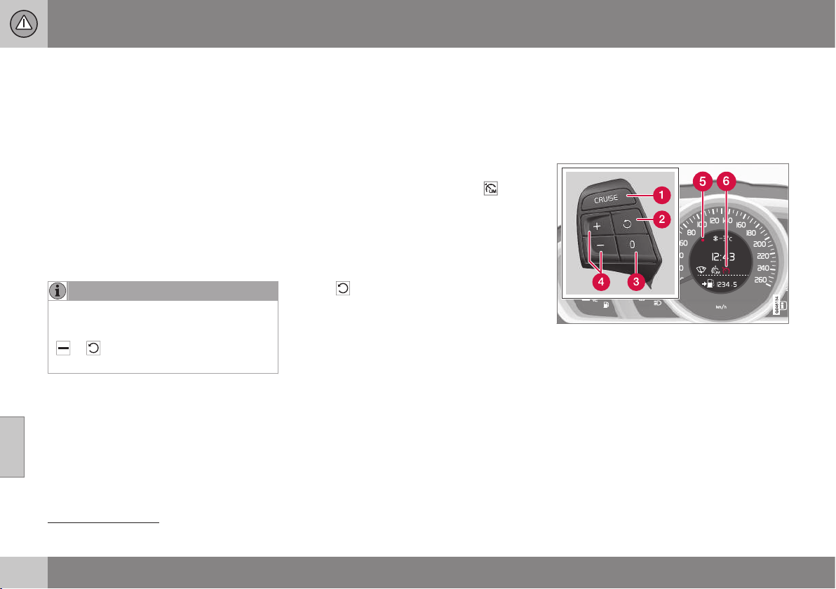
07 Driver support
07
194
* Option/accessory, for more information, see Introduction.
Speed limiter* - alarm for speed
exceeded
A (Speed Limiter) can be regarded as a
reverse cruise control - the driver regulates
the speed using the accelerator pedal but is
prevented from accidentally exceeding a
pre-selected/set speed by the speed limiter.
On steep roads the speed limiter's engine
braking effect may be inadequate and the
selected maximum speed is exceeded. The
driver is alerted about this with an acoustic
signal. The signal is active until the driver has
slowed to below the selected maximum
speed.
NOTE
The alarm is only activated after 5 seconds
if the speed has been exceeded by at least
3 km/h provided that none of the buttons
or has been depressed during the
last half minute.
Related information
•
Speed limiter* (p. 191)
Speed limiter* - deactivation
A (Speed Limiter) can be regarded as a
reverse cruise control - the driver regulates
the speed using the accelerator pedal but is
prevented from accidentally exceeding a pre-
selected/set speed by the speed limiter.
To deactivate the speed limiter:
–
Press the steering wheel button .
> The combined instrument panel's (p.
191) symbol for the speed limiter and
the mark for the set speed are extin-
guished. The selected and stored
speed are thus deleted from the mem-
ory and cannot be resumed with the
button.
The driver can then use the accelerator
pedal to choose a speed without limi-
tation.
Related information
•
Speed limiter* (p. 191)
Cruise control*
The cruise control (CC – Cruise Control) helps
the driver maintain an even speed, resulting in
more relaxing driving on motorways and long,
straight roads with regular traffic flows.
Overview
The steering wheel buttons and combined instru-
ment panel in cars without speed limiter
4
.
4
A Volvo dealer has updated information about what applies in each respective market.
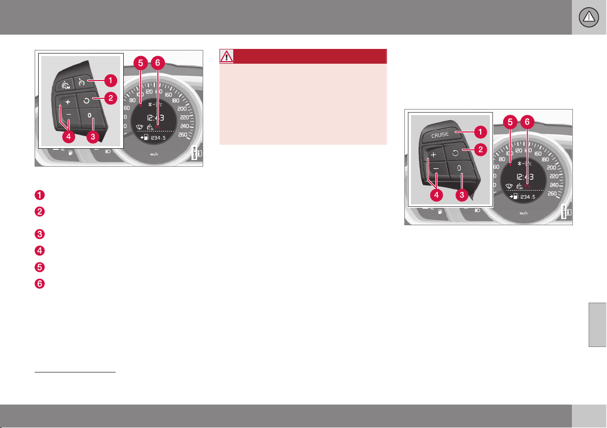
07 Driver support
07
* Option/accessory, for more information, see Introduction.
195
The steering wheel buttons and combined instru-
ment panel in cars with speed limiter
4
.
Cruise control - On/Off.
Standby mode ceases and the stored
speed is resumed.
Standby mode
Activate and adjust the speed.
Selected speed (GREY = Standby mode).
Cruise control active - WHITE symbol
(GREY = Standby mode).
WARNING
The driver must always be observant with
regard to the traffic conditions and inter-
vene when the cruise control is not main-
taining a suitable speed and/or suitable
distance.
The driver always bears ultimate responsi-
bility for ensuring that the vehicle is driven
safely.
Related information
•
Cruise control* - managing speed (p.
195)
•
Cruise control* temporary deactivation
and standby mode (p. 197)
•
Cruise control* - resume set speed (p.
198)
•
Cruise control* - deactivate (p. 199)
Cruise control* - managing speed
The cruise control (CC – Cruise Control) helps
the driver to maintain an even speed. It is
possible to activate, set or change the speed.
Activating and setting the speed
The steering wheel buttons and display in cars
without speed limiter
5
.
4
A Volvo dealer has updated information about what applies in each respective market.
5
A Volvo dealer has updated information about what applies in each respective market.
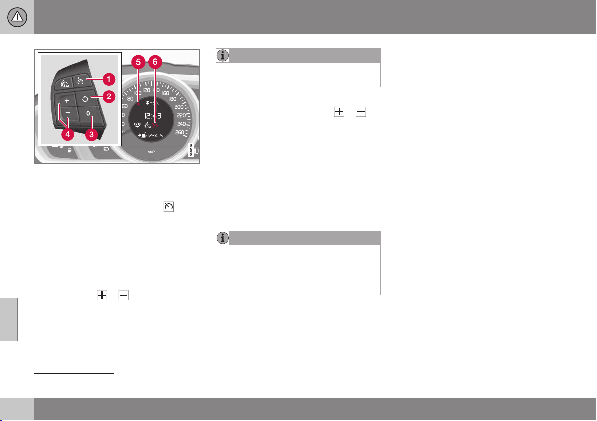
||
07 Driver support
07
196
* Option/accessory, for more information, see Introduction.
The steering wheel buttons and display in cars
with speed limiter
5
.
To enable cruise control:
•
Press the steering wheel button
> The cruise control symbol (6) in the com-
bined instrument panel for cruise control
active changes from GREY to WHITE and
shows that the cruise control is in
standby mode.
To activate cruise control:
•
At the required speed - press the steering
wheel button
or .
> The current speed is stored in the mem-
ory and the combined instrument panel's
marking (5) illuminates at the selected
speed.
NOTE
Cruise Control cannot be enabled at
speeds below 30 km/h.
Changing the speed
•
Adjust with short presses on
or -
every press gives +/- 5 km/h. The last
presses made are stored in the memory.
To adjust +/- 1 km/h:
•
Hold down the button and release it at
the required speed.
A temporary increase in speed with the accel-
erator pedal, e.g. during overtaking, does not
affect the cruise control setting - the car
returns to the set speed when the accelerator
pedal is released.
NOTE
If any of the Cruise Control buttons are
held depressed for several minutes then it
is blocked and deactivated. To be able to
reactivate Cruise Control, the car must be
stopped and the engine restarted.
Related information
•
Cruise control* (p. 194)
•
Cruise control* temporary deactivation
and standby mode (p. 197)
•
Cruise control* - resume set speed (p.
198)
•
Cruise control* - deactivate (p. 199)
5
A Volvo dealer has updated information about what applies in each respective market.
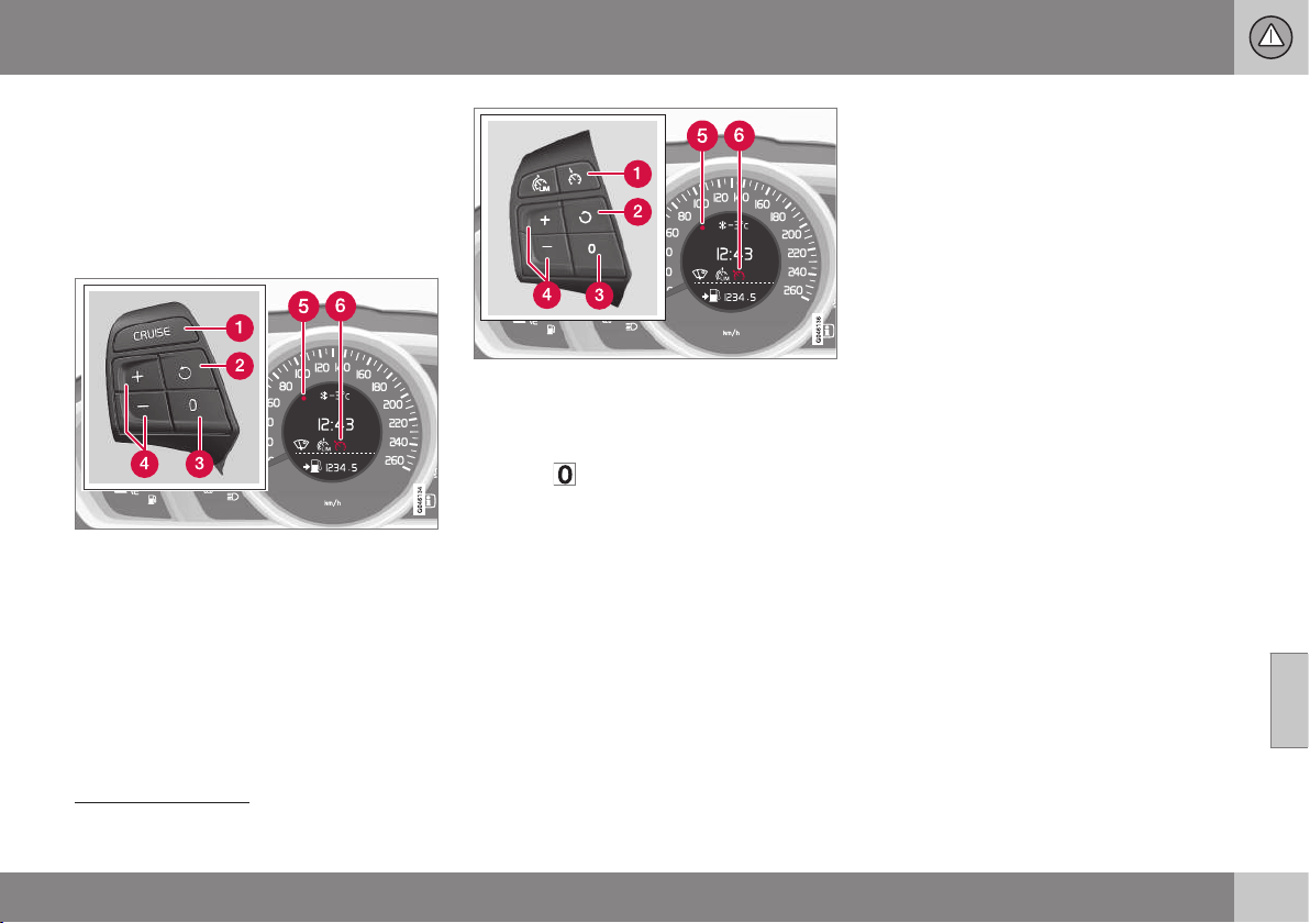
07 Driver support
07
* Option/accessory, for more information, see Introduction.
197
Cruise control* temporary
deactivation and standby mode
The cruise control (CC – Cruise Control) helps
the driver to maintain an even speed. The
function can be temporarily deactivated and
set in standby mode.
Temporary deactivation - standby mode
The steering wheel buttons and display in cars
without speed limiter
6
.
The steering wheel buttons and display in cars
with speed limiter
6
.
To temporarily disengage cruise control and
set it in standby mode:
•
Press
.
> The combined instrument panel's
marking (5) and symbol (6) change colour
from WHITE to GREY.
Automatic standby mode
Cruise control is temporarily disengaged and
set in standby mode if:
•
wheels lose traction
•
the foot brake is used
•
speed falls below approx. 30 km/h
•
the clutch pedal is depressed for longer
than 1 minute
7
•
the gear selector/lever is moved to neu-
tral position N (automatic gearbox)
•
the driver maintains a speed higher than
the set speed for longer than 1 minute.
The driver must then regulate the speed.
Related information
•
Cruise control* (p. 194)
•
Cruise control* - managing speed (p. 195)
•
Cruise control* - resume set speed (p.
198)
•
Cruise control* - deactivate (p. 199)
6
A Volvo dealer has updated information about what applies in each respective market.
7
Disengaging and selecting a higher or lower gear does not involve standby mode.
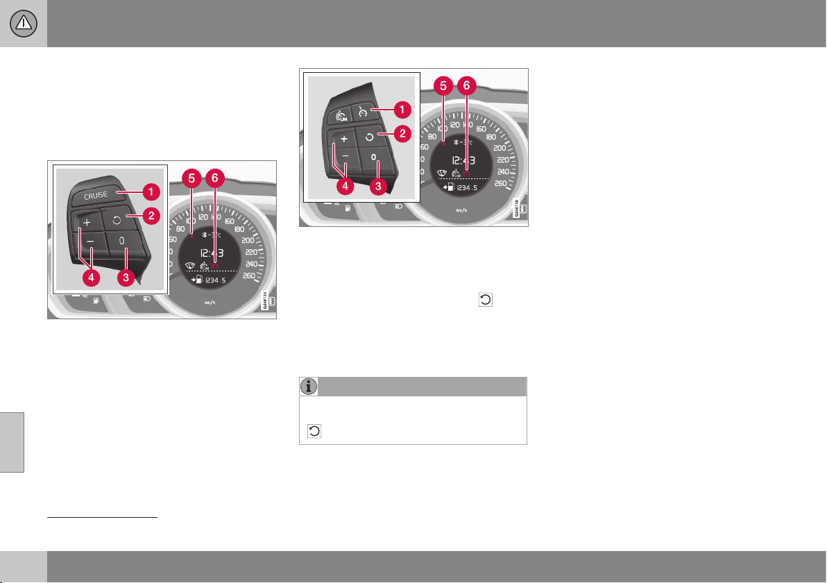
07 Driver support
07
198
* Option/accessory, for more information, see Introduction.
Cruise control* - resume set speed
The cruise control (p. 194) (CC – Cruise
Control) helps the driver to maintain an even
speed. After temporary deactivation and
standby mode (p. 197) it is possible to resume
the set speed.
The steering wheel buttons and display in cars
without speed limiter
8
.
The steering wheel buttons and display in cars
with speed limiter
8
.
To reactivate the cruise control from standby
mode:
•
Press the steering wheel button
.
> The combined instrument panel's
marking (5) and symbol (6) change colour
from GREY to WHITE and the speed is
then set to the last speed stored.
NOTE
A marked speed increase may occur once
the speed has been resumed by selecting
.
Related information
•
Cruise control* - managing speed (p. 195)
•
Cruise control* temporary deactivation
and standby mode (p. 197)
•
Cruise control* - deactivate (p. 199)
8
A Volvo dealer has updated information about what applies in each respective market.

07 Driver support
07
* Option/accessory, for more information, see Introduction.
199
Cruise control* - deactivate
The cruise control (CC – Cruise Control) helps
the driver to maintain an even speed. How it
is deactivated is described here.
The steering wheel buttons and display in cars
without speed limiter
9
.
The steering wheel buttons and display in cars
with speed limiter
9
.
The cruise control is deactivated with a steer-
ing wheel button (1) or by switching off the
engine - the set speed is deleted from the
memory and cannot be resumed with the
button.
Related information
•
Cruise control* (p. 194)
•
Cruise control* - managing speed (p. 195)
•
Cruise control* temporary deactivation
and standby mode (p. 197)
•
Cruise control* - resume set speed (p.
198)
Adaptive cruise control (ACC)*
The adaptive cruise control (ACC – Adaptive
Cruise Control) helps the driver maintain a
safe distance from the vehicle ahead.
The adaptive cruise control provides a more
relaxing driving experience on long journeys
on motorways and long straight main roads in
smooth traffic flows.
The driver sets the desired speed (p. 203)
and time interval to the car in front. When the
radar detector detects a slower vehicle in
front of the car, the speed is automatically
adapted to that. When the road is clear again
the car returns to the selected speed.
If the adaptive cruise control is switched off
or set to standby mode and the car comes
too close to a vehicle in front, then the driver
is warned instead by a Distance Alert (p. 214)
about the short distance.
9
A Volvo dealer has updated information about what applies in each respective market.
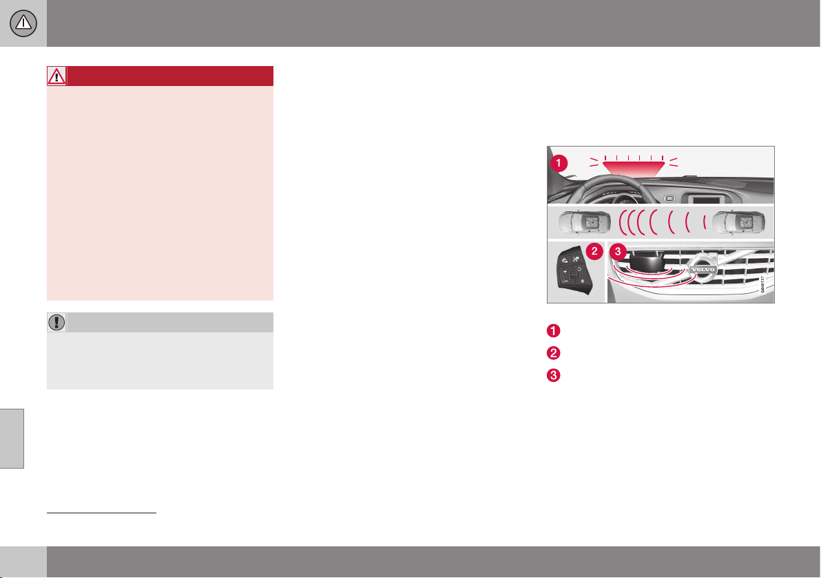
||
07 Driver support
07
200
* Option/accessory, for more information, see Introduction.
WARNING
The driver must always be observant with
regard to the traffic conditions and inter-
vene when the adaptive cruise control is
not maintaining a suitable speed or suita-
ble distance.
The adaptive cruise control cannot handle
all traffic, weather and road conditions.
Read all the sections about the adaptive
cruise control in the owner's manual in
order to learn about its limitations, of
which the driver should be aware before it
is used.
The driver always bears responsibility for
maintaining the correct distance and
speed, even when the adaptive cruise con-
trol is being used.
IMPORTANT
Maintenance of adaptive cruise control
components must only be performed at a
workshop - an authorised Volvo workshop
is recommended.
Automatic gearbox
Cars with automatic gearbox have enhanced
functionality with the adaptive cruise control's
Queue Assist (p. 206).
Related information
•
Adaptive cruise control* - overview (p.
202)
•
Adaptive cruise control* - function (p.
200)
•
Adaptive cruise control* - set time interval
(p. 204)
•
Adaptive cruise control* - temporary
deactivation, and standby mode (p. 204)
•
Adaptive cruise control* - deactivate (p.
206)
•
Adaptive cruise control* - overtaking
another vehicle (p. 205)
•
Adaptive cruise control* - switch cruise
control functionality (p. 208)
•
Adaptive cruise control* - fault tracing
and action (p. 211)
•
Adaptive cruise control* - symbols and
messages (p. 212)
Adaptive cruise control* - function
The adaptive cruise control (p. 199) (ACC –
Adaptive Cruise Control) helps the driver
maintain a safe distance from the vehicle
ahead.
Function overview
10
.
Warning lamp - braking by driver required
Steering wheel (p. 77) keypad
Radar sensor (p. 209)
Adaptive cruise control consists of a cruise
control system and a coordinated spacing
system.
10
NOTE: The illustration is schematic - details may differ depending on car model.
07 Driver support
07
* Option/accessory, for more information, see Introduction.
201
WARNING
Adaptive cruise control is not a collision
avoidance system. The driver must inter-
vene if the system does not detect a vehi-
cle in front.
The adaptive cruise control does not brake
for humans or animals, and not for small
vehicles such as bicycles and motorcy-
cles. Nor for oncoming, slow or stationary
vehicles and objects.
Do not use the adaptive cruise control, for
example, in city traffic, in dense traffic, at
junctions, on slippery surfaces, with a lot
of water or slush on the road, in heavy
rain/snow, in poor visibility, on winding
roads or on slip roads.
The distance to the vehicle ahead is mainly
measured by a radar sensor. Cruise control
regulates the speed with acceleration and
braking. It is normal for the brakes to emit a
low sound when they are being used by the
adaptive cruise control.
WARNING
The brake pedal moves when Cruise Con-
trol brakes. Do not rest your foot beneath
the brake pedal as it may become trapped.
The adaptive cruise control aims to follow the
vehicle ahead in the same lane according to
what the driver set for time interval (p. 204). If
the radar sensor cannot see any vehicle in
front then the car will instead maintain the
cruise control's set speed. This also happens
if the speed of the vehicle in front exceeds
the cruise control's set speed.
The adaptive cruise control aims to control
the speed in a smooth way. In situations that
demand sudden braking the driver must
brake himself/herself. This applies with large
differences in speed, or if the vehicle in front
brakes heavily. Due to limitations in the radar
sensor (p. 209) braking may come unexpect-
edly or not at all.
The adaptive cruise control can be activated
to follow another vehicle at speeds from
30 km/h
11
up to 200 km/h. If the speed falls
below 30 km/h or if the engine speed
becomes too low, the cruise control is set in
standby mode at which automatic braking
ceases - the driver must then take over him-
self/herself to maintain a safe distance to the
vehicle ahead.
Warning lamp - braking by driver
required
Adaptive cruise control has a braking
capacity that is equivalent to more than 40%
of the car's braking capacity.
If the car needs to be braked more heavily
than cruise control capacity and the driver
does not brake, then cruise control uses the
warning lamp and warning sound from the
collision warning system (p. 223) in order to
alert the driver that immediate intervention is
required.
NOTE
The warning lamp may be difficult to see in
strong sunlight or when wearing sun-
glasses.
WARNING
Cruise Control warns only of vehicles
which the radar sensor has detected.
Hence the warning may not be given, or it
may be given with a certain delay. Do not
wait for a warning without braking when so
required.
Steep roads and/or heavy load
Bear in mind that the adaptive cruise control
is primarily intended for use when driving on
level road surfaces. It may have difficulty in
keeping the correct distance from the vehicle
ahead when driving on steep downhill slopes,
with a heavy load or with a trailer - in which
case, be extra attentive and ready to slow
down.
Related information
•
Adaptive cruise control (ACC)* (p. 199)
11
Queue Assist (p. 206) (in cars with automatic gearbox) can operate in the range of 0-200 km/h.
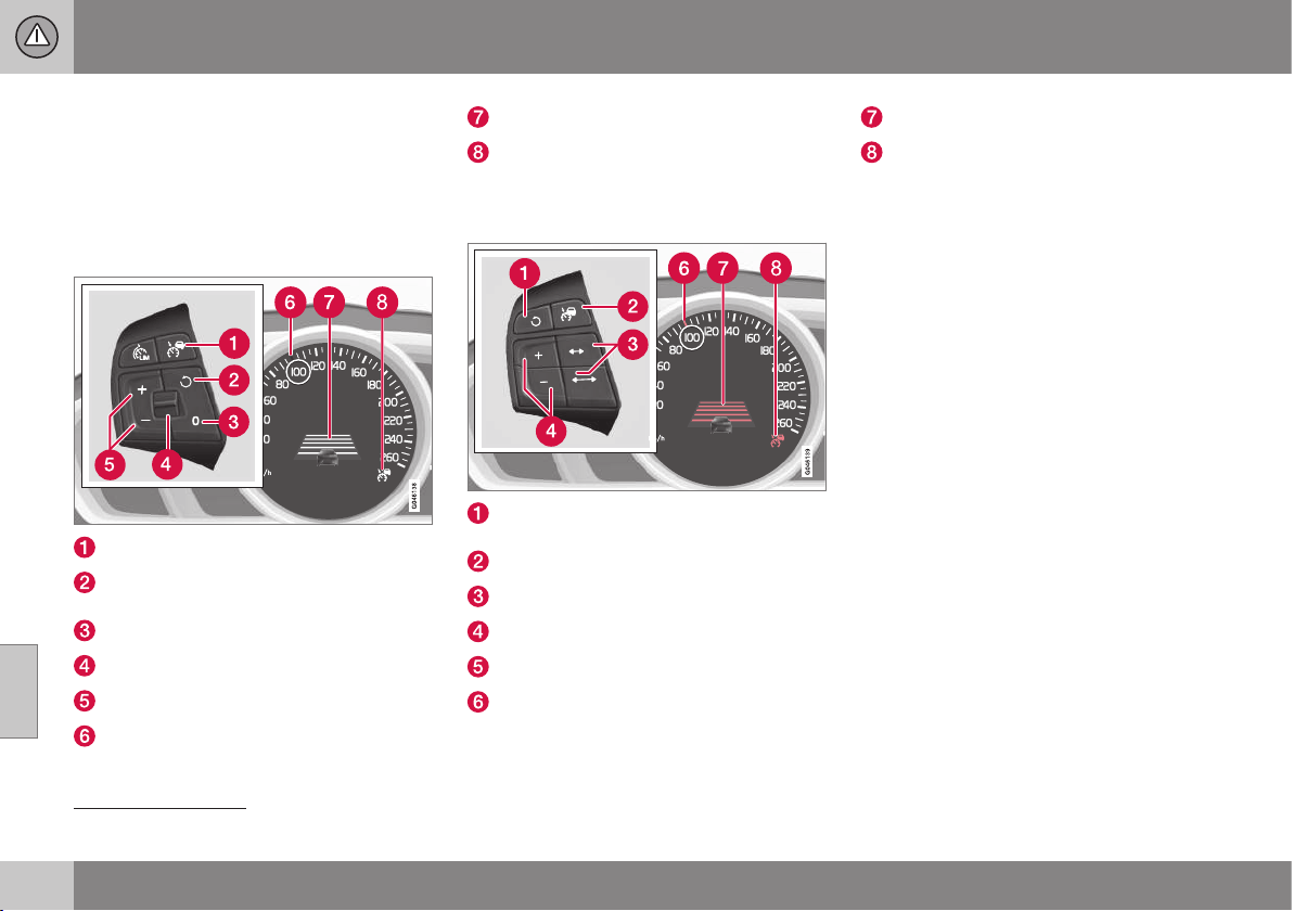
07 Driver support
07
202
* Option/accessory, for more information, see Introduction.
Adaptive cruise control* - overview
Operation of the adaptive cruise control (p.
199) and steering wheel keypad varies
depending on whether or not the car is equip-
ped with speed limiter (p. 191)
12
.
Adaptive cruise control with Speed
limiter
Cruise control - On/Off.
Standby mode ceases and the stored
speed is resumed.
Standby mode
Time interval - Increase/decrease.
Activate and adjust the speed.
Green marking at stored speed (WHITE =
standby mode).
Time distance
ACC is active at the GREEN symbol
(WHITE = standby mode).
Adaptive cruise control without Speed
limiter
Standby mode ceases and the stored
speed is resumed.
Cruise control - On/Off or Standby mode.
Time interval - Increase/decrease.
Activate and adjust the speed.
(Not used)
Green marking at stored speed (WHITE =
standby mode).
Time distance
ACC is active at the GREEN symbol
(WHITE = standby mode).
Related information
•
Adaptive cruise control* - managing
speed (p. 203)
•
Adaptive cruise control* - set time interval
(p. 204)
•
Adaptive cruise control* - temporary
deactivation, and standby mode (p. 204)
12
A Volvo dealer has updated information about what applies in each respective market.
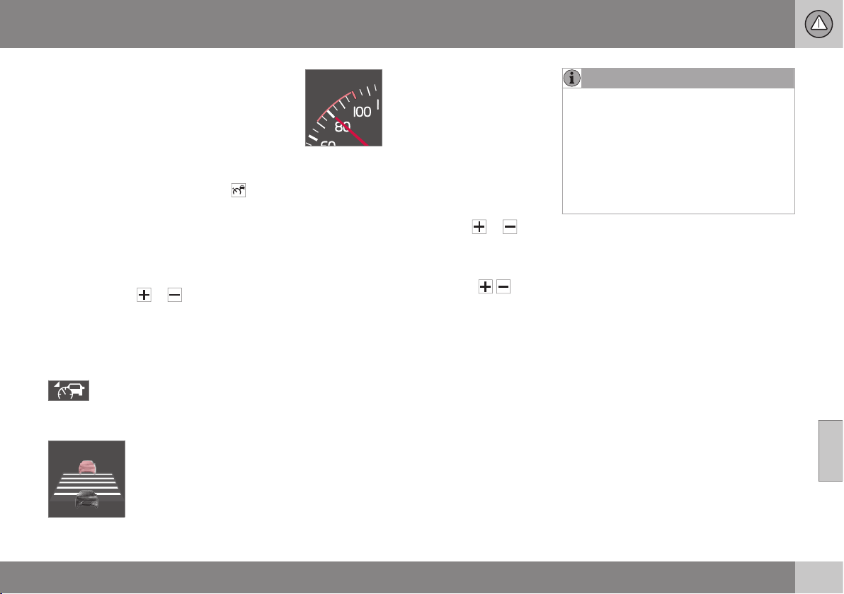
07 Driver support
07
* Option/accessory, for more information, see Introduction.
203
Adaptive cruise control* - managing
speed
The adaptive cruise control (p. 199) (ACC –
Adaptive Cruise Control) helps the driver
maintain a safe distance from the vehicle
ahead.
To enable cruise control:
•
Press the steering wheel button
- a
similar WHITE symbol is illuminated in the
combined instrument panel (p. 212)
which shows that the cruise control is in
standby mode (p. 204).
To activate cruise control:
•
At the required speed - press the steering
wheel button
or .
> The current speed is stored in the mem-
ory, the combined instrument panel
shows a "magnifying glass" around the
selected speed for a second or so and its
marking changes from WHITE to GREEN.
When this symbol changes colour
from WHITE to GREEN, the cruise
control is active and the car main-
tains the stored speed.
Only when the symbol shows
an image of another vehicle
is the distance to the vehicle
in front controlled by the
cruise control.
At the same time a speed
range is marked:
• the higher speed with
GREEN marking is the pre-
programmed speed
• the lower speed is the
speed of the car in front.
Changing the speed
To change the stored speed:
•
Adjust with short presses on
or -
every press gives +/- 5 km/h. The last
presses made are stored in the memory.
If speed is increased using the accelera-
tor pedal prior to pressing the
/ but-
ton, then it is the car's current speed
when the button is pressed that is stored
in the cruise control.
To adjust +/- 1 km/h:
•
Hold down the button and release it at
the required speed.
NOTE
If any of the Cruise Control buttons are
held depressed for several minutes then it
is blocked and deactivated. To be able to
reactivate Cruise Control, the car must be
stopped and the engine restarted.
In certain situations, cruise control cannot
be activated. In this case, the combined
instrument panel (p. 212) shows
Cruise
control Unavailable.
Related information
•
Adaptive cruise control (ACC)* (p. 199)
•
Adaptive cruise control* - overview (p.
202)
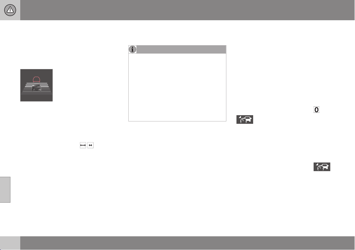
07 Driver support
07
204
* Option/accessory, for more information, see Introduction.
Adaptive cruise control* - set time
interval
The adaptive cruise control (p. 199) (ACC –
Adaptive Cruise Control) helps the driver
maintain a safe distance from the vehicle
ahead.
Different time intervals to the
vehicle in front can be
selected and shown in the
combined instrument panel
as 1-5 horizontal lines - the
more lines the longer the
time interval. One line corre-
sponds to approximately 1 second to the
vehicle in front, 5 lines
approximately 3 seconds.
To set/change the time distance:
•
Turn the steering wheel button set's
thumbwheel (or use the
/ buttons for
cars without Speed limiters).
At low speed, when the distances are short,
the adaptive cruise control increases the time
interval slightly.
The adaptive cruise control allows the time
interval to vary noticeably in certain situations
in order to allow the car to follow the vehicle
in front smoothly and comfortably.
Note that a short time interval only allows the
driver a short time to react and take action if
any unforeseen traffic problem should arise.
The same symbol is also shown when Dis-
tance Alert (p. 214) is activated.
NOTE
Only use the time intervals permitted by
local traffic regulations.
If Cruise Control does not appear to react
when activated, this may be because the
time distance to the car in front is prevent-
ing an increase in speed.
The higher the speed the longer the calcu-
lated distance in metres for a given time
interval.
Read more about how you manage the
speed (p. 203).
Related information
•
Adaptive cruise control (ACC)* (p. 199)
Adaptive cruise control* - temporary
deactivation, and standby mode
The adaptive cruise control (p. 199) (ACC –
Adaptive Cruise Control) helps the driver to
maintain an even speed and a safe distance
from the vehicle ahead. The cruise control
can be temporarily deactivated and set in
standby mode.
Temporary deactivation - standby mode
with Speed limiter
To temporarily disengage adaptive cruise
control and set it in standby mode:
•
Press the steering wheel button
This symbol and stored speed mark-
ing then changes colour from
GREEN to WHITE.
Temporary deactivation - standby mode
without Speed limiter
To temporarily disengage cruise control and
set it in standby mode:
•
Press the steering wheel button
Standby mode due to driver intervention
The adaptive cruise control is temporarily dis-
engaged and set automatically in standby
mode if:

07 Driver support
07
* Option/accessory, for more information, see Introduction.
205
•
the foot brake is used
•
the clutch pedal is depressed for longer
than 1 minute
13
•
the gear selector/lever is moved to neu-
tral position N (automatic gearbox)
•
the driver maintains a speed higher than
the set speed for longer than 1 minute.
The driver must then regulate the speed.
A temporary increase in speed with the accel-
erator pedal, e.g. during overtaking, does not
affect the cruise control setting - the car
returns to the last stored speed when the
accelerator pedal is released.
For more information, see the sections Man-
aging speed (p. 203) and Overtaking another
vehicle (p. 205).
Automatic standby mode
The adaptive cruise control is dependent on
other systems, e.g. Stability and traction con-
trol system (DSTC) (p. 185). If any of these
systems stop working then cruise control is
automatically deactivated.
In the event of automatic deactivation a signal
will sound and the message
Cruise control
Cancelled is shown in the combined instru-
ment panel. The driver must then intervene
and adapt the speed and distance to the
vehicle ahead.
An automatic deactivation can be due to:
•
the driver opens the door
•
the driver takes off his seatbelt
•
engine speed is too low/high
•
speed has fallen below 30 km/h
14
•
wheels lose traction
•
brake temperature is high
•
the radar sensor is covered e.g. by wet
snow or heavy rain (radar waves blocked).
For more information on symbols, messages
and their meaning, see section Symbols and
messages in the display (p. 212).
Resume set speed
Adaptive cruise control in standby mode is
reactivated with one press on the steering
wheel button
- the speed is then set to the
last stored speed.
NOTE
A marked speed increase may occur once
the speed has been resumed by selecting
.
Related information
•
Adaptive cruise control (ACC)* (p. 199)
•
Adaptive cruise control* - fault tracing
and action (p. 211)
Adaptive cruise control* - overtaking
another vehicle
The adaptive cruise control (p. 199) (ACC –
Adaptive Cruise Control) helps the driver
maintain a safe distance from the vehicle
ahead and it can also assist during overtaking.
Read more about the different time intervals
(p. 204) to the vehicle in front.
When the car is following another vehicle and
the driver indicates an impending overtaking
manoeuvre with the direction indicator
15
, the
adaptive cruise control helps to briefly accel-
erate the car towards the vehicle in front.
This function is active at speeds
above 70 km/h.
Read more about how you manage the speed
(p. 203).
WARNING
Be aware that this function can be acti-
vated in more situations other than during
overtaking, e.g. when a direction indicator
is used to indicate a change of lane or exit
to another road - the car will then acceler-
ate briefly.
Related information
•
Adaptive cruise control (ACC)* (p. 199)
13
Disengaging and selecting a higher or lower gear does not involve standby mode.
14
Does not apply to a car with Queue Assistant - it can go all the way down to 0 km/h.
15
On left flash only in left-hand-drive car, or right flash in right-hand-drive car.
07 Driver support
07
206
* Option/accessory, for more information, see Introduction.
Adaptive cruise control* - deactivate
The adaptive cruise control (p. 199) (ACC –
Adaptive Cruise Control) helps the driver
maintain a safe distance from the vehicle
ahead.
Keypad with Speed limiter
The adaptive cruise control is disengaged
with a short press of the steering wheel but-
ton
. The set speed is cleared and cannot
be resumed with the
button.
Keypad without Speed limiter
A short press on the steering wheel button
sets the adaptive cruise control in standby
mode. With a further short press the cruise
control is deactivated. The set speed is
cleared and cannot be resumed with the
button.
Related information
•
Adaptive cruise control (ACC)* (p. 199)
Adaptive Cruise Control* - Queue
Assist
The adaptive cruise control (p. 199) (ACC –
Adaptive Cruise Control) helps the driver
maintain a safe distance from the vehicle
ahead. Queue Assist also provides the adap-
tive cruise control with enhanced functionality
at speeds lower than 30 km/h.
In cars with automatic gearbox the adaptive
cruise control is supplemented with the
Queue Assist function (also referred to as
"Queue Assist").
Queue Assistant has the following functions:
•
Extended speed range - also at lower
than 30 km/h and at stationary
•
Change of target
•
Automatic braking ceases when station-
ary
Note that the lowest programmable speed for
the adaptive cruise control is 30 km/h - even
though the cruise control is capable of follow-
ing another vehicle down to a standstill, a
lower speed cannot be selected.
Learn more about how you manage the
speed (p. 199) and different time intervals to
the vehicle in front (p. 204).
Extended speed range
NOTE
In order to activate the cruise control the
driver's door must be closed and the driver
must be wearing the seatbelt.
With an automatic gearbox, the adaptive
cruise control can follow another vehicle
within the range 0-200 km/h.
NOTE
Activation of the cruise control below
30 km/h requires a vehicle in front within a
reasonable distance.
For shorter stops in connection with inching
in slow traffic or at traffic lights driving is
automatically resumed if the stops do not
exceed approx. 3 seconds - if it takes longer
before the car in front starts moving again
then the cruise control is set in standby mode
(p. 204) with automatic braking. The driver
must then reactivate it in one of the following
ways:
•
Press the steering wheel button
.
or
•
Depress the accelerator pedal.
> The cruise control will then resume fol-
lowing the vehicle in front.
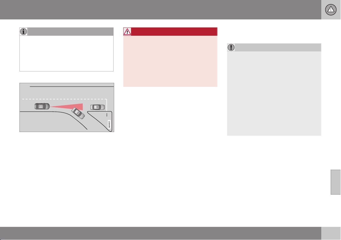
07 Driver support
07
}}
207
NOTE
Queue Assist can keep the car stationary
for a maximum of 4 minutes - then the
brakes release.
See more information under the header
below, "Cessation of automatic braking
when stationary".
Change of target
If the target vehicle in front suddenly turns then
there may be stationary traffic in front.
When the adaptive cruise control is following
another vehicle at speeds lower than
30 km/h and changes target from a moving to
a stationary vehicle, the cruise control will
slow down for the stationary vehicle.
WARNING
When the adaptive cruise control is follow-
ing a vehicle ahead at speeds in excess of
30 km/h and the target is changed from a
vehicle ahead to a stationary vehicle, the
cruise control will ignore the stationary
vehicle and instead select the stored
speed.
•
The driver must intervene him/herself
and brake.
Automatic standby mode with change
of target
The adaptive cruise control is disengaged
and set in standby mode:
•
when the speed is below 5 km/h and
cruise control is not sure whether the tar-
get object is a stationary vehicle or some
other object, e.g. a speed bump.
•
when the speed is below 5 km/h and the
vehicle in front turns off so the cruise
control no longer has a vehicle to follow.
Termination of automatic braking at a
standstill
In the following situations, Queue Assist
stops automatic braking at a standstill:
•
the driver opens the door
•
the driver takes off his seatbelt.
This means that the brakes are released and
the car will start to roll - the driver must there-
fore intervene and brake the car himself in
order to maintain its position.
IMPORTANT
Queue Assist can keep the car stationary
for a maximum of 4 minutes - then the
brakes release.
The driver's attention is drawn to this over
several stages, with increasing intensity:
1. Acoustic alarm (pinging) and text mes-
sage.
2. A warning lamp in the windscreen also
starts to flash.
3. "Stabbing" braking occurs.
For more information on symbols, mes-
sages and their meaning, see the section
Symbols and messages in the display (p.
212).
Queue Assist releases the foot brake and is
set to standby mode in these situations as
well:
•
the driver puts his/her foot on the brake
pedal
•
the gear selector is moved to P, N or R
position
•
the driver sets the cruise control in
standby mode
•
the parking brake is applied.
||
07 Driver support
07
208
* Option/accessory, for more information, see Introduction.
Related information
•
Adaptive cruise control (ACC)* (p. 199)
•
Adaptive cruise control* - switch cruise
control functionality (p. 208)
Adaptive cruise control* - switch
cruise control functionality
The adaptive cruise control (p. 199) (ACC –
Adaptive Cruise Control) helps the driver
maintain a safe distance from the vehicle
ahead.
Switch from Adaptive cruise control to
Cruise control
A button press can be used to deactivate the
adaptive element (spacing system) in the
adaptive cruise control (p. 199), with the car
then only following the set speed.
•
Hold down the steering wheel button
- the combined instrument panel's sym-
bol changes from
to .
> By these means the cruise control is acti-
vated.
WARNING
The car no longer brakes automatically
after switching from ACC to CC - it merely
follows the set speed.
Switch back from Cruise control to
Adaptive cruise control
Switch off cruise control with 1-2 presses on
. The next time the system is switched on
it is the Adaptive cruise control that is acti-
vated.
Related information
•
Adaptive cruise control (ACC)* (p. 199)
•
Adaptive cruise control* - temporary
deactivation, and standby mode (p. 204)
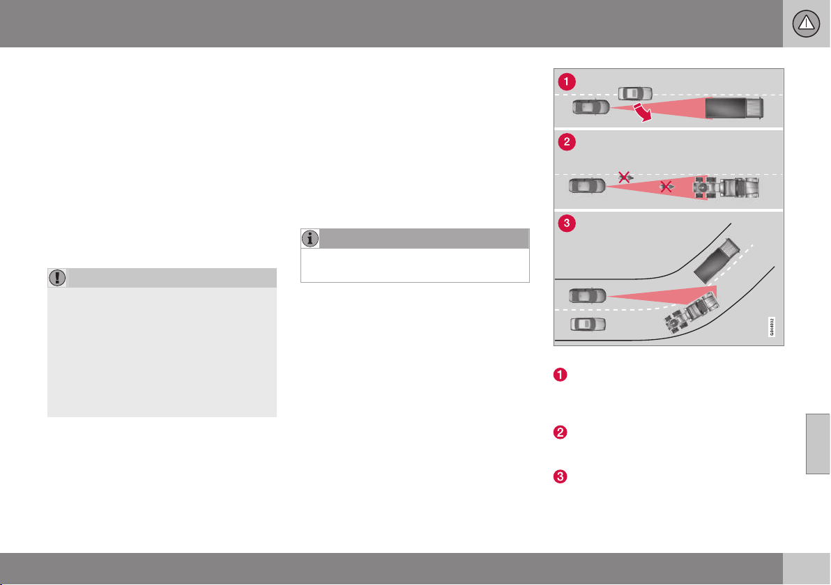
07 Driver support
07
* Option/accessory, for more information, see Introduction.
209
Radar sensor
The function of the radar sensor is to detect
cars or larger vehicles in the same direction,
in the same lane.
The radar sensor is used by the following
functions:
•
Adaptive cruise control*
•
Collision Warning with Auto Brake and
Pedestrian Detection*
•
Distance Warning*
Modification of the radar sensor could result
in it being illegal to use.
IMPORTANT
In the event of visible damage to the car's
grille, or if you suspect that the radar sen-
sor may be damaged:
•
Contact a workshop - an authorised
Volvo workshop is recommended.
The function may completely or partially
disappear - or malfunction - if the grille,
the radar sensor or its bracket is damaged
or has loosened.
Related information
•
Radar sensor - limitations (p. 209)
•
Adaptive cruise control (ACC)* (p. 199)
•
Collision warning system* (p. 223)
•
Distance Warning* (p. 214)
Radar sensor - limitations
The radar sensor (p. 209) has certain limita-
tions, due to its limited field of vision,
amongst other things.
The capacity of the radar sensor to detect
vehicles in front is reduced significantly:
•
if the radar sensor becomes blocked and
cannot detect other vehicles e.g. in heavy
rain or slush, or if other objects have col-
lected in front of the radar sensor.
NOTE
Keep the surface in front of the radar sen-
sor clean.
•
if the speed of vehicles in front is signifi-
cantly different from your own speed.
Field of vision
The radar sensor has a limited field of vision.
In some situations another vehicle is not
detected, or the detection is made later than
expected.
ACC field of vision.
Sometimes the radar sensor is late at
detecting vehicles at close distances, e.g.
a vehicle that drives in between the car
and vehicles in front.
Small vehicles, such as motorcycles, or
vehicles not driving in the centre of the
lane can remain undetected.
In bends the radar sensor may detect the
wrong vehicle or lose a detected vehicle
from view.

||
07 Driver support
07
210
* Option/accessory, for more information, see Introduction.
WARNING
The driver must always be observant with
regard to the traffic conditions and inter-
vene when the adaptive cruise control is
not maintaining a suitable speed or suita-
ble distance.
The adaptive cruise control cannot handle
all traffic, weather and road conditions.
Read all the sections about the adaptive
cruise control in the owner's manual in
order to learn about its limitations, of
which the driver should be aware before it
is used.
The driver always bears responsibility for
maintaining the correct distance and
speed, even when the adaptive cruise con-
trol is being used.
WARNING
Accessories or other objects such as auxil-
iary lamps must not be fitted in front of the
grille.
WARNING
Adaptive cruise control is not a collision
avoidance system. The driver must inter-
vene if the system does not detect a vehi-
cle in front.
The adaptive cruise control does not brake
for humans or animals, and not for small
vehicles such as bicycles and motorcy-
cles. Nor for oncoming, slow or stationary
vehicles and objects.
Do not use the adaptive cruise control, for
example, in city traffic, in dense traffic, at
junctions, on slippery surfaces, with a lot
of water or slush on the road, in heavy
rain/snow, in poor visibility, on winding
roads or on slip roads.
Related information
•
Adaptive cruise control (ACC)* (p. 199)
•
Collision warning system* (p. 223)
•
Distance Warning* (p. 214)

07 Driver support
07
* Option/accessory, for more information, see Introduction.
211
Adaptive cruise control* - fault tracing
and action
The adaptive cruise control (p. 199) (ACC –
Adaptive Cruise Control) helps the driver
maintain a safe distance from the vehicle
ahead.
If the combined instrument panel shows the
message
Radar blocked See manual this
means that the radar signals from the radar
sensor (p. 209) are blocked and that vehicles
in front of the car cannot be detected.
In turn this means that - apart from Adaptive
Cruise Control - Distance Warning (p. 214)
and Collision Warning (p. 223) with
Auto Brake are not operating either.
The following table presents examples of
possible causes for a message being shown
along with the appropriate action:
Cause Action
The radar surface in the grille is dirty or covered with ice or snow. Clean the radar surface in the grille from dirt, ice and snow.
Heavy rain or snow blocking the radar signals. No action. Sometimes the radar does not work during heavy rain or snowfall.
Water or snow from the road surface swirls up and blocks the
radar signals.
No action. Sometimes the radar does not work on a very wet or snowy road
surface.
The radar surface has been cleaned but the message remains. Wait. It could take several minutes for the radar to sense that it is no longer
blocked.
Related information
•
Adaptive cruise control (ACC)* (p. 199)
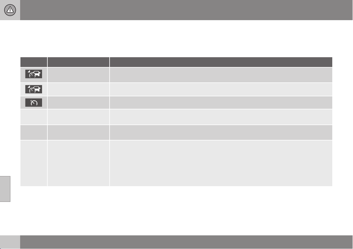
07 Driver support
07
212
* Option/accessory, for more information, see Introduction.
Adaptive cruise control* - symbols
and messages
The adaptive cruise control (p. 199) (ACC –
Adaptive Cruise Control) helps the driver
maintain a safe distance from the vehicle
ahead.
Symbol
A
Message Specification
The symbol is WHITE Adaptive cruise control is set to Adaptive cruise control* - temporary deactivation, and standby mode
(p. 204).
The symbol is GREEN The car maintains the stored speed.
Standard cruise control is selected manually.
DSTC Normal to enable
Cruise
The adaptive cruise control cannot be activated until DSTC has been set to Normal mode - Stability
and traction control system (DSTC) (p. 185).
Cruise control Cancel-
led
The adaptive cruise control has been deactivated - the driver has to regulate the speed himself.
Cruise control Unavaila-
ble
The adaptive cruise control cannot be activated.
This could be due to:
•
brake temperature is high
•
the radar sensor is blocked by e.g. wet snow or rain.
For more information about fault tracing, see the section Adaptive cruise control* - fault tracing and
action (p. 211)

07 Driver support
07
* Option/accessory, for more information, see Introduction.
213
Symbol
A
Message Specification
Radar blocked See
manual
The adaptive cruise control is temporarily disengaged.
•
The radar sensor is blocked and cannot detect other vehicles. For example, in the event of heavy
rain or if slush has collected in front of the radar sensor.
The driver can then choose to switch to normal cruise control Cruise control* (p. 194) (CC) - a text
message provides information on appropriate alternatives.
Read more about radar sensor limitations (p. 209).
Cruise control Service
required
The adaptive cruise control is disengaged.
•
Contact a workshop - an authorised Volvo workshop is recommended.
Press Brake To hold +
acoustic alarm + warning
light in windscreen + "pull-
ing" brakes
(Only with Queue Assis-
tant)
The car is at a standstill and the adaptive cruise control will release the foot brake, which is why the
car may start rolling soon.
•
The driver must brake himself/herself. The message remains and the alarm sounds until the driver
depresses the brake pedal or uses the accelerator pedal.
Below 30 km/h Only fol-
lowing
(Only with Queue Assis-
tant)
Shown with attempts to activate the adaptive cruise control at speeds below 30 km/h without a vehi-
cle in front within the activation distance (approx. 30 metres).
A
The symbols are schematic.
Related information
•
Adaptive cruise control (ACC)* (p. 199)
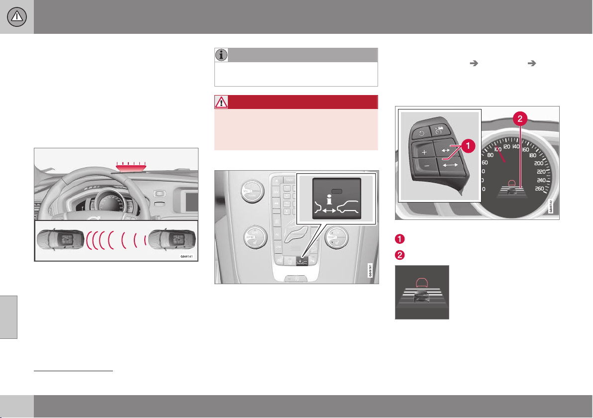
07 Driver support
07
214
* Option/accessory, for more information, see Introduction.
Distance Warning*
Distance Warning (Distance Alert) is a function
that informs the driver about the time interval
to vehicles in front.
Distance Warning is active at speeds above
30 km/h and only reacts to vehicles driving in
front of the car, in the same direction. No dis-
tance information is provided for oncoming,
slow or stationary vehicles.
Orange-coloured warning lamp
16
.
An orange-coloured warning lamp in the
windscreen illuminates with a constant glow if
the distance to the vehicle in front is shorter
than the set time interval.
NOTE
Distance warning is deactivated during the
time the adaptive cruise control is active.
WARNING
Distance warning only reacts if the dis-
tance to the vehicle ahead is shorter than
the preset value - the speed of the driver's
vehicle is not affected.
Operation
Press the button in the centre console to
switch the function on or off. The function is
switched on if one lamp is illuminated in the
button.
Some combinations of the selected equip-
ment leave no vacant space for a button in
the centre console - in which case the func-
tion is handled by the car's menu system MY
CAR under
Settings Car settings
Distance Alert. For a description of the menu
system, see MY CAR (p. 104).
Set time interval
Controls and symbol for time interval.
Time interval - Increase/decrease.
Time interval - On.
Different time intervals to the
vehicle in front can be
selected and shown in the
combined instrument panel
as 1-5 horizontal lines - the
more lines the longer the
time interval. One line corre-
sponds to approximately 1 second to the
vehicle in front, 5 lines
approximately 3 seconds.
16
NOTE: The illustration is schematic - details may vary depending on car model.

07 Driver support
07
* Option/accessory, for more information, see Introduction.
215
The same symbol is also shown when adap-
tive cruise control (p. 199) is activated.
NOTE
The higher the speed the longer the calcu-
lated distance in metres for a given time
interval.
The set time interval is also used by the
function adaptive cruise control (p. 200).
Only use the time intervals permitted by
local traffic regulations.
Related information
•
Distance Alert* - limitations (p. 215)
•
Distance Alert* - symbols and messages
(p. 216)
Distance Alert* - limitations
Distance Warning (Distance Alert) is a function
that informs the driver about the distance to
vehicles in front. The function, which uses the
same radar sensor as the adaptive cruise con-
trol (p. 199) and collision warning with auto
brake (p. 223), has some limitations.
NOTE
Strong sunlight, reflections or strong varia-
tions in light intensity, as well as wearing
sunglasses, could mean that the warning
light in the windscreen cannot be seen.
Poor weather or winding roads could
affect the radar sensor's capacity to detect
vehicles in front.
The size of other vehicles could also affect
detection capacity, e.g. motorcycles. This
could mean that the warning lamp illumi-
nates at a shorter distance than the setting
or that the warning is temporarily absent.
Extremely high speeds can also cause the
lamp to illuminate at a shorter distance
than that set due to limitations in sensor
range.
For further information on radar sensor limita-
tions, see Radar sensor - limitations (p. 209)
and Collision warning system* - operation (p.
228).
Related information
•
Distance Warning* (p. 214)
•
Distance Alert* - symbols and messages
(p. 216)
07 Driver support
07
216
* Option/accessory, for more information, see Introduction.
Distance Alert* - symbols and
messages
Distance Warning (p. 214) (Distance Alert) is a
function that informs the driver about the time
interval to vehicles in front. The function has
certain symbols and messages that can be
displayed in the combined instrument panel if
the function is reduced due to its limitations
(p. 215).
Symbol
A
Message Specification
Radar blocked See
manual
Distance Warning temporarily disengaged.
Radar sensor (p. 209) is blocked and cannot detect other vehicles. For example, in the event of heavy
rain or if slush has collected in front of the radar sensor.
For information, see Radar sensor - limitations (p. 209).
Collision warn.
Service required
Distance Warning and Collision Warning with Auto Brake (p. 229) fully or partially disengaged.
Visit a workshop if the message remains - an authorised Volvo workshop is recommended.
A
The symbols are schematic.
07 Driver support
07
* Option/accessory, for more information, see Introduction.
217
City Safety™
City Safety™ is a function for helping the
driver to avoid a collision when driving in
queues, amongst other things, when changes
in the traffic ahead, combined with a lapse in
attention, could lead to an incident.
The City Safety™ function is active at speeds
under 50 km/h and it helps the driver by auto-
matically braking the car in the event of immi-
nent risk of collision with vehicles in front,
should the driver not react in time by braking
and/or steering away.
City Safety™ is activated in situations where
the driver should have started braking earlier,
which is why it cannot help the driver in every
situation.
City Safety™ is designed to be activated as
late as possible in order to avoid unnecessary
intervention.
City Safety™ must not be used as an excuse
for the driver to change his/her driving style. If
the driver solely relies on City Safety™ to do
the braking, there might be a risk of a colli-
sion sooner or later.
The driver or passengers normally only notice
City Safety™ if a situation arises where the
car is extremely close to being in a collision.
If the car is also equipped with Collision
Warning with Auto Brake (p. 223)* these two
systems complement each other.
IMPORTANT
Maintenance and replacement of City
Safety™ components must only be per-
formed by a workshop - an authorised
Volvo workshop is recommended.
WARNING
City Safety™ does not engage in all driv-
ing situations or traffic, weather or road
conditions.
City Safety™ does not react to vehicles
driving in a different direction from the car,
to small vehicles and motorcycles or to
people and animals.
City Safety™ can prevent collision at a
speed difference of less than 15 km/h - at
a higher speed difference, it is only possi-
ble to reduce collision speed. In order to
obtain full brake function, the driver must
depress the brake pedal.
Never wait for City Safety™ to engage.
The driver always bears responsibility for
maintaining the proper distance and
speed.
Related information
•
City Safety™ - limitations (p. 219)
•
City Safety™ - function (p. 217)
•
City Safety™ - operation (p. 218)
•
City Safety™ - laser sensor (p. 220)
•
City Safety™ - symbols and messages (p.
222)
City Safety™ - function
City Safety™ detects the traffic in front of the
car with a laser sensor (p. 220) fitted in the
top edge of the windscreen. If there is an
imminent risk of collision, City Safety™ will
automatically brake the car, which may be
experienced as sudden braking.
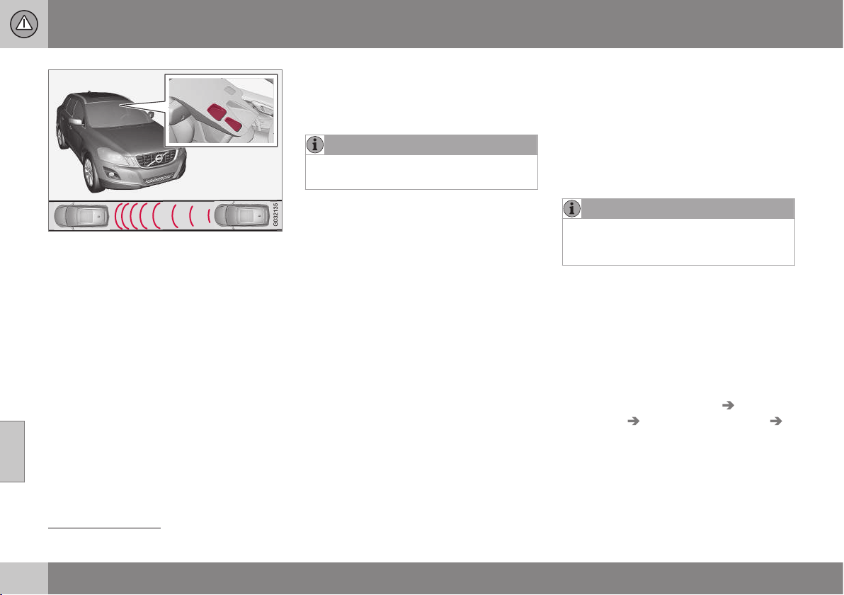
||
07 Driver support
07
218
Laser sensor transmitter and receiver window
17
.
If the speed difference is 4-15 km/h in relation
to the vehicle in front then City Safety™ can
completely prevent a collision.
City Safety™ activates a short, sharp braking
and stops the car in normal circumstances,
just behind the vehicle in front. For most dri-
vers this is well outside normal driving style
and may be experienced as being uncomfort-
able.
If the difference in speed between the vehi-
cles is greater than 15 km/h then City
Safety™ may not prevent the collision on its
own. To obtain full brake force, the driver
must depress the brake pedal. This could
then make it possible to prevent a collision,
even at speed differences above 15 km/h.
When the function is activated and brakes,
the combined instrument panel shows a mes-
sage (p. 222) to the effect that the function
is/has been active.
NOTE
When City Safety™ brakes, the brake
lights come on.
Related information
•
City Safety™ (p. 217)
•
City Safety™ - operation (p. 218)
•
City Safety™ - limitations (p. 219)
City Safety™ - operation
City Safety™ is a function for helping the
driver to avoid a collision when driving in
queues, amongst other things, when changes
in the traffic ahead, combined with a lapse in
attention, could lead to an incident.
On and Off
NOTE
The City Safety™ function is always
switched on after the engine has been
started via key position I and II (p. 71).
In certain situations, it may advisable to disa-
ble City Safety™, e.g. where leafy branches
could sweep over the bonnet and/or wind-
screen.
After starting the engine City Safety™ can be
deactivated as follows:
•
Using MY CAR on the centre console
display screen with its menu system,
search and locate
Settings Car
settings
Driver support systems
City Safety. Select the Off option. See
MY CAR (p. 104) for more information.
17
NOTE: The illustration is schematic - details may vary depending on car model.
07 Driver support
07
219
However, the function (p. 217) will be
enabled the next time the engine is
started, regardless of whether the system
was enabled or disabled when the engine
was switched off.
WARNING
The laser sensor (p. 220) emits laser light
even when City Safety™ is disabled man-
ually.
To enable City Safety™ again:
•
Follow the same procedure as for disa-
bling, but select the
On option.
Related information
•
City Safety™ (p. 217)
•
City Safety™ - limitations (p. 219)
•
City Safety™ - symbols and messages (p.
222)
City Safety™ - limitations
The sensor in City Safety™ is designed to
detect cars and other large vehicles in front of
the car irrespective of whether it is day or
night. However, the function has a number of
limitations.
The sensor has poorer functionality - or none
at all - in e.g. heavy snowfall or rain, dense
fog, dust storms or white-out situations. Mist-
ing, dirt, ice or snow on the windscreen may
also disrupt the function.
Low-hanging objects, e.g. a flag/pennant for
projecting load, or accessories such as auxili-
ary lamps and bull bars that are higher than
the bonnet limit the function.
The laser light from the sensor in City
Safety™ measures how the light is reflected.
The sensor cannot detect objects with low
reflection capacity. The rear sections of the
vehicle generally reflect the light sufficiently
thanks to the number plate and rear light
reflectors.
On slippery road surfaces the braking dis-
tance is extended, which may reduce the
capacity of City Safety™ to avoid a collision.
In such situations the ABS and DSTC sys-
tems will provide best possible braking force
with maintained stability.
When your own car is reversing, City Safety™
is temporarily deactivated.
City Safety™ is not activated at low speeds -
under 4 km/h, which is why the system does
not intervene in situations where a vehicle in
front is being approached very slowly, e.g.
when parking.
Driver commands are always prioritised,
which is why City Safety™ does not intervene
in situations where the driver is steering or
accelerating in a clear manner, even if a colli-
sion is unavoidable.
When City Safety™ has prevented a collision
with a stationary object the car remains sta-
tionary for a maximum of 1.5 seconds. If the
car is braked for a vehicle in front that is mov-
ing, then speed is reduced to the same speed
as that maintained by the vehicle in front.
On a car with manual gearbox the engine
stops when City Safety™ has stopped the
car, unless the driver manages to depress the
clutch pedal beforehand.
NOTE
•
Keep the windscreen surface in front
of the laser sensor (p. 220) free from
ice, snow and dirt. For an illustration of
sensor location, see City Safety™ -
function (p. 217).
•
Do not affix or mount anything on the
windscreen in front of the laser sensor
•
Remove ice and snow from the bonnet
- snow and ice must not exceed a
height of 5 cm.
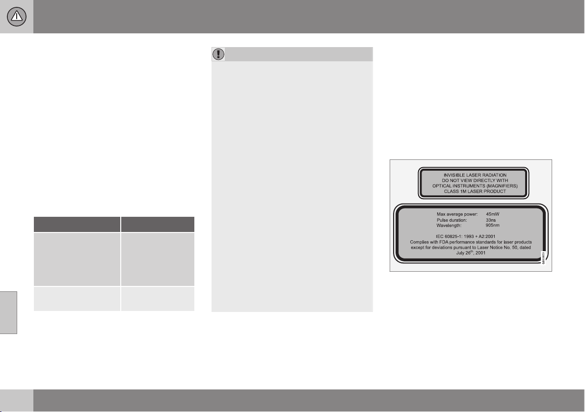
||
07 Driver support
07
220
Fault tracing and action
If the message (p. 222) Windscreen
sensors blocked See manual is shown in
the combined instrument panel it indicates
that the laser sensor is blocked and cannot
detect vehicles in front of the car. This means
that City Safety™ is not operational.
The
Windscreen sensors blocked See
manual message is not shown for all situa-
tions in which the laser sensor is blocked.
The driver must therefore be diligent about
keeping the windscreen and area in front of
the laser sensor clean.
The following table presents possible causes
for the message being shown, along with
suggestions for appropriate action.
Cause Action
The windscreen sur-
face in front of the
laser sensor is dirty or
covered with ice or
snow.
Clean the wind-
screen surface in
front of the sensor
from dirt, ice and
snow.
The laser sensor field
of vision is blocked.
Remove the
blocking object.
IMPORTANT
If there are cracks, scratches or stone
chips in the windscreen in front of either of
the laser sensor's "windows" and they
cover a surface of approx. 0.5 x 3.0 mm
(or larger), then a workshop must be con-
tacted for replacement of the windscreen -
an authorised Volvo workshop is recom-
mended. For an illustration of sensor loca-
tion, see City Safety™ - function (p. 217).
Failure to take action may result in
reduced performance for City Safety™.
To avoid the risk of failed, deficient or
reduced operation for City Safety™, the
following also applies:
•
Volvo recommends that you do not
repair cracks, scratches or stone chips
in the area in front of the laser sensor -
instead, the whole windscreen should
be replaced.
•
Before replacing a windscreen, con-
tact an authorised Volvo workshop to
verify that the correct windscreen is
ordered and fitted.
•
The same type or Volvo-approved
windscreen wipers must be fitted dur-
ing replacement.
Related information
•
City Safety™ (p. 217)
•
City Safety™ - function (p. 217)
•
City Safety™ - operation (p. 218)
City Safety™ - laser sensor
The City Safety™ function includes a sensor
which transmits laser light. Contact a qualified
workshop in the event of a fault or if the laser
sensor needs servicing - an authorised Volvo
workshop is recommended. It is absolutely
essential to follow the prescribed instructions
when handling the laser sensor.
The following two labels relate to the laser
sensor:
The upper label in the figure describes the
laser beam's classification:
•
Laser radiation - Do not look into the
laser beam with optical instruments -
Class 1M laser product.
The lower label in the figure describes the
laser beam's physical data:
•
IEC 60825-1:1993 + A2:2001. Complies
with FDA (U.S. Food Administration)

07 Driver support
07
221
standards for laser product design with
the exception of deviations in accordance
with "Laser Notice No. 50" from
26 July 2001.
Radiation data for the laser sensor
The following table specifies the laser sen-
sor's physical data.
Maximum pulse energy 2.64 µJ
Maximum average output 45 mW
Pulse duration 33 ns
Divergence (horizontal x verti-
cal)
28° × 12°
WARNING
If any of these instructions are not followed
then there is a risk of eye injury!
•
Never look into the laser sensor (which
emits spreading invisible laser radia-
tion) at a distance of 100 mm or closer
with magnifying optics such as a mag-
nifying glass, microscope, lens or simi-
lar optical instruments.
•
Testing, repair, removal, adjustment
and/or replacement of the laser sen-
sor's spare parts must only be carried
out by a qualified workshop - we rec-
ommend an authorised Volvo work-
shop.
•
To avoid exposure to harmful radia-
tion, do not carry out any readjust-
ments or maintenance other than
those specified here.
•
The repairer must follow specially
drawn up workshop information for the
laser sensor.
•
Do not remove the laser sensor (this
includes removing the lenses). A
removed laser sensor fulfils laser
class 3B as per standard IEC 60825-1.
Laser class 3B is not eye-safe and
therefore entails a risk of injury.
•
The laser sensor's connector must be
unplugged before removal from the
windscreen.
•
The laser sensor must be fitted onto
the windscreen before the sensor's
connector is plugged in.
•
The laser sensor transmits a laser light
when the remote control key is in key
position II (p. 71) even if the engine is
switched off.
Related information
•
City Safety™ (p. 217)

07 Driver support
07
222
City Safety™ - symbols and
messages
In conjunction with automatic braking by the
City Safety (p. 217)™ system, one or more
symbols (p. 222) may illuminate in the com-
bined instrument panel and a text message
may be shown. A text message can be
acknowledged by briefly pressing the OK but-
ton on the direction indicator stalk.
Symbol
A
Message Meaning/Action
Auto braking by City Safety
City Safety™ is braking or has automatically braked.
Windscreen sensors blocked
See manual
The laser sensor is temporarily non-operational because something is blocking it.
•
Remove the object blocking the sensor and/or clean the windscreen in front of the sensor.
Read about the laser sensor's limitations.
City Safety Service required
City Safety™ is not operational.
•
Visit a workshop if the message remains - an authorised Volvo workshop is recommended.
A
The symbols are schematic.
Related information
•
City Safety™ (p. 217)
•
City Safety™ - function (p. 217)
07 Driver support
07
* Option/accessory, for more information, see Introduction.
223
Collision warning system*
"Collision Warning with Auto Brake and
Cyclist and Pedestrian Detection" is an aid to
assist the driver when there is a risk of collid-
ing with a pedestrian, bicycle or vehicle in
front that are stationary or moving in the same
direction.
Collision Warning with Auto Brake & Pedes-
trian Detection is activated in situations where
the driver should have started braking earlier,
which is why it cannot help the driver in every
situation.
Collision Warning with Auto Brake & Pedes-
trian Detection is designed to be activated as
late as possible in order to avoid unnecessary
intervention.
Collision Warning with Auto Brake & Pedes-
trian Detection may prevent a collision or
reduce the collision speed.
Collision Warning with Auto Brake & Pedes-
trian Detection must not be used as an
excuse for the driver to change his/her driving
style. If the driver solely relies on Collision
Warning with Auto Brake to do the braking,
there might be a risk of a collision sooner or
later.
Two system levels
The Collision Warning with Auto Brake &
Pedestrian Detection function is available in
two variants, depending on how the car is
equipped:
Level 1
The driver is merely warned
18
of occurring
obstacles by means of visual and acoustic
signals - no automatic braking intervenes, the
driver must himself brake.
Level 2
The driver is warned of occurring obstacles
by means of visual and acoustic signals - the
car is braked automatically if the driver him-
self does not act within a reasonable time.
IMPORTANT
Maintenance of components included in
Collision Warning with Auto Brake &
Pedestrian Detection must only be carried
out in a workshop - an authorised Volvo
workshop is recommended.
Related information
•
Collision warning system* - function (p.
224)
•
Collision warning system* - detection of
pedestrians (p. 227)
•
Collision warning system* - cyclist detec-
tion (p. 225)
•
Collision warning system* - operation (p.
228)
•
Collision warning system* - general limita-
tions (p. 229)
•
Collision warning system* - camera sen-
sor limitations (p. 231)
•
Collision warning system* - symbols and
message (p. 233)
18
No warning for cyclists with "Level 1".
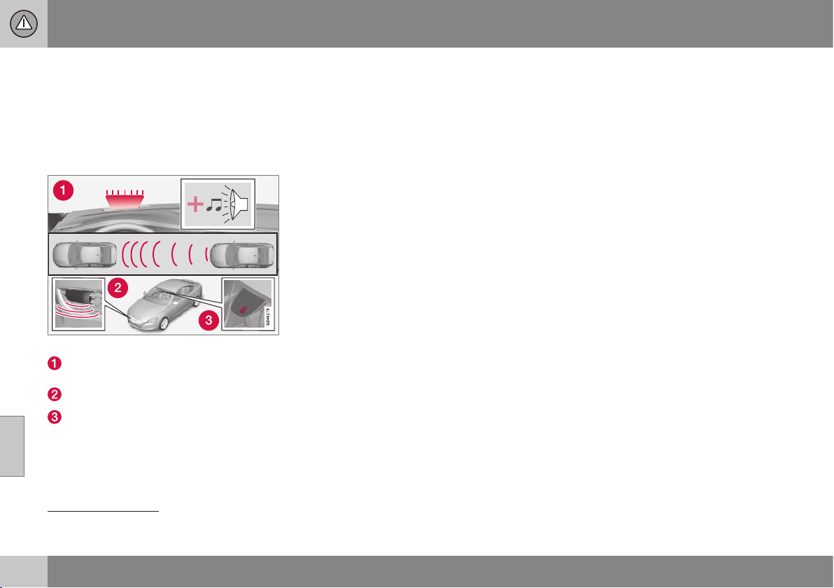
07 Driver support
07
224
* Option/accessory, for more information, see Introduction.
Collision warning system* - function
"Collision Warning with Auto Brake and
Cyclist and Pedestrian Detection" is an aid to
assist the driver when there is a risk of collid-
ing with a pedestrian, bicycle or vehicle in
front that are stationary or moving in the same
direction.
Function overview
19
.
Audio-visual warning signal in the event
of a collision risk.
Radar sensor
20
Camera sensor
Collision Warning with Auto Brake executes
three steps in the following order:
1.
Collision warning
2.
Brake support
20
3.
Auto Brake
20
The collision warning system and City
Safety™ (p. 217) complement each other.
1 - Collision warning
The driver is first warned of a potentially
imminent collision.
The collision warning system detects pedes-
trians, stationary vehicles as well as vehicles
driving in the same direction in front of the
car.
If there is a risk of collision with a pedestrian
or a vehicle then the driver's attention is
attracted with a flashing red warning signal
and an acoustic signal.
2 - Brake support
If the risk of collision has increased further
after the collision warning then the brake sup-
port is activated.
This means that the brake system is prepared
for rapid braking by applying the brakes
lightly, which may feel like a slight jolt.
If the brake pedal is depressed sufficiently
quickly then full brake function is imple-
mented.
Brake support also reinforces the driver's
braking if the system considers that the brak-
ing is not sufficient to avoid a collision.
3 - Auto Brake
The automatic brake function is activated
last.
If in this situation the driver has not yet
started to take evasive action and the risk of
collision is imminent then the automatic brak-
ing function is deployed - this takes place
irrespective of whether or not the driver
brakes. Braking then takes place with full
brake force in order to reduce collision speed,
or with limited brake force if it is sufficient to
avoid a collision. For cyclists, the warning and
full brake intervention may come very late or
simultaneously.
19
NOTE: The illustration is schematic - details may vary depending on car model.
20
With system Level 2 only.
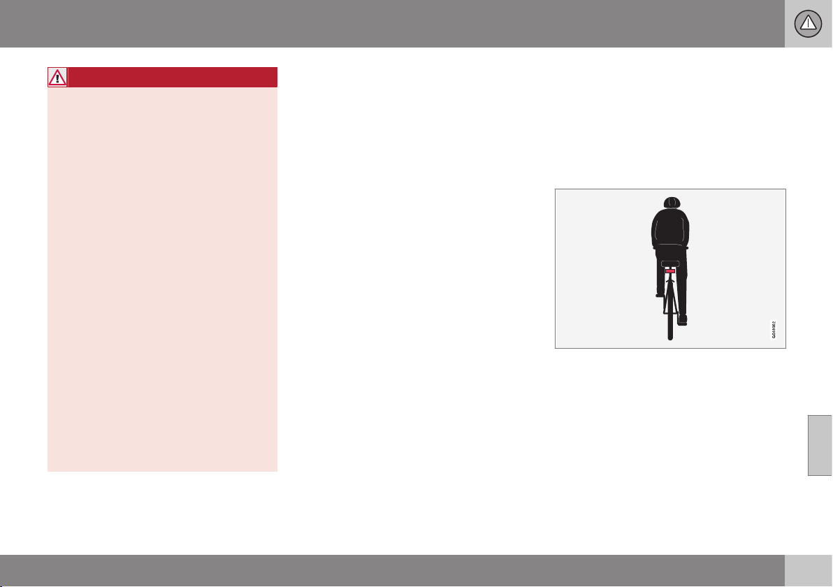
07 Driver support
07
* Option/accessory, for more information, see Introduction.
225
WARNING
The collision warning system does not
engage in all driving situations or traffic,
weather or road conditions. The collision
warning system does not react to vehicles
or cyclists driving in another direction to
the car or to animals.
Warning only activated in the event of a
high risk for collision. This section "Func-
tion" and the section "Limitations" inform
about limitations that the driver must be
aware of before using the Collision Warn-
ing system with Auto Brake.
Warnings and brake interventions for
pedestrians and cyclists are deactivated at
a vehicle speed exceeding 80 km/h.
Warnings and brake interventions for
pedestrians and cyclists do not work in
darkness and tunnels - not even when
streetlights are lit.
The auto-brake function can prevent a col-
lision or reduce collision speed. To ensure
full brake performance, the driver should
always depress the brake pedal - even
when the car auto-brakes.
Never wait for a collision warning. The
driver is always responsible that the cor-
rect distance and speed are maintained -
even when the collision warning system
with auto-brake is used.
Related information
•
Collision warning system* (p. 223)
•
Collision warning system* - detection of
pedestrians (p. 227)
•
Collision warning system* - cyclist detec-
tion (p. 225)
•
Collision warning system* - operation (p.
228)
•
Collision warning system* - general limita-
tions (p. 229)
•
Collision warning system* - camera sen-
sor limitations (p. 231)
•
Collision warning system* - symbols and
message (p. 233)
Collision warning system* - cyclist
detection
"Collision Warning with Auto Brake and
Cyclist and Pedestrian Detection" is an aid to
assist the driver when there is a risk of collid-
ing with a pedestrian, bicycle or vehicle in
front that are stationary or moving in the same
direction.
Optimum examples of what the system interprets
as a cyclist - with clear body and bicycle con-
tours, directly from behind and in the car's cen-
tre line.
Optimal performance of the system requires
that the system function that detects a cyclist
receives as unambiguous information as pos-
sible about the body and bicycle contours -
this implies the opportunity to identify the
bicycle, head, arms, shoulders, legs, upper
and lower body combined with a normal
human pattern of movement.
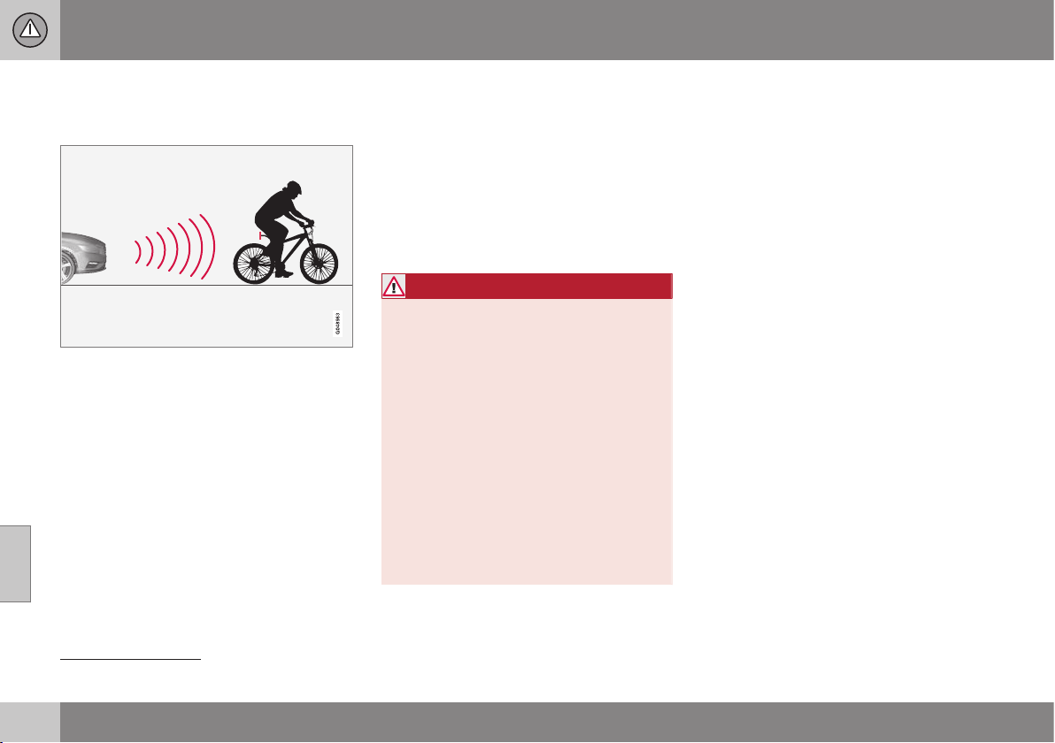
||
07 Driver support
07
226
* Option/accessory, for more information, see Introduction.
If large parts of the cyclist's body or bicycle
are not visible to the function's camera then
the system cannot detect a cyclist.
The function can only "see" cyclists from behind,
who are travelling in the same direction.
•
For the function to be able to detect a
cyclist, he/she must be an adult and rid-
ing a "senior bicycle".
•
The bicycle must be equipped with a
highly visible and approved
21
rearward-
facing red reflector, fitted at least 70 cm
above the roadway.
•
The function can only detect cyclists
directly from behind and who are travel-
ling in the same direction - not at an
angle from behind, not from the side.
•
Cyclists travelling on the left or right-hand
edge of the car's imagined/extended side
lines may be detected late or not at all.
•
The function's capacity to detect cyclists
at dusk and dawn is limited - just like the
human eye.
•
The function's capacity to detect cyclists
is deactivated when driving in darkness
and tunnels - even when streetlights are
lit.
•
For optimum bicycle detection, the City
Safety™ function must be activated, see
City Safety™ (p. 217).
WARNING
Collision Warning with Auto Brake &
Cyclist Detection is a means of assistance.
The function cannot detect:
•
all cyclists in all situations and does
not see partially obscured cyclists, for
example.
•
cyclists in clothing that obscures the
contours of the body or who are
approaching from the side.
•
bicycles that have no rearward-facing
red reflector.
•
bicycles loaded with large objects.
The driver is always responsible that the
vehicle is driven properly and with a safety
distance adapted to the speed.
Related information
•
Collision warning system* (p. 223)
•
Collision warning system* - function (p.
224)
•
Collision warning system* - detection of
pedestrians (p. 227)
•
Collision warning system* - general limita-
tions (p. 229)
•
Collision warning system* - operation (p.
228)
•
Collision warning system* - camera sen-
sor limitations (p. 231)
•
Collision warning system* - symbols and
message (p. 233)
21
The reflector must fulfil the recommendations and conditions of the traffic authority in the market in question.
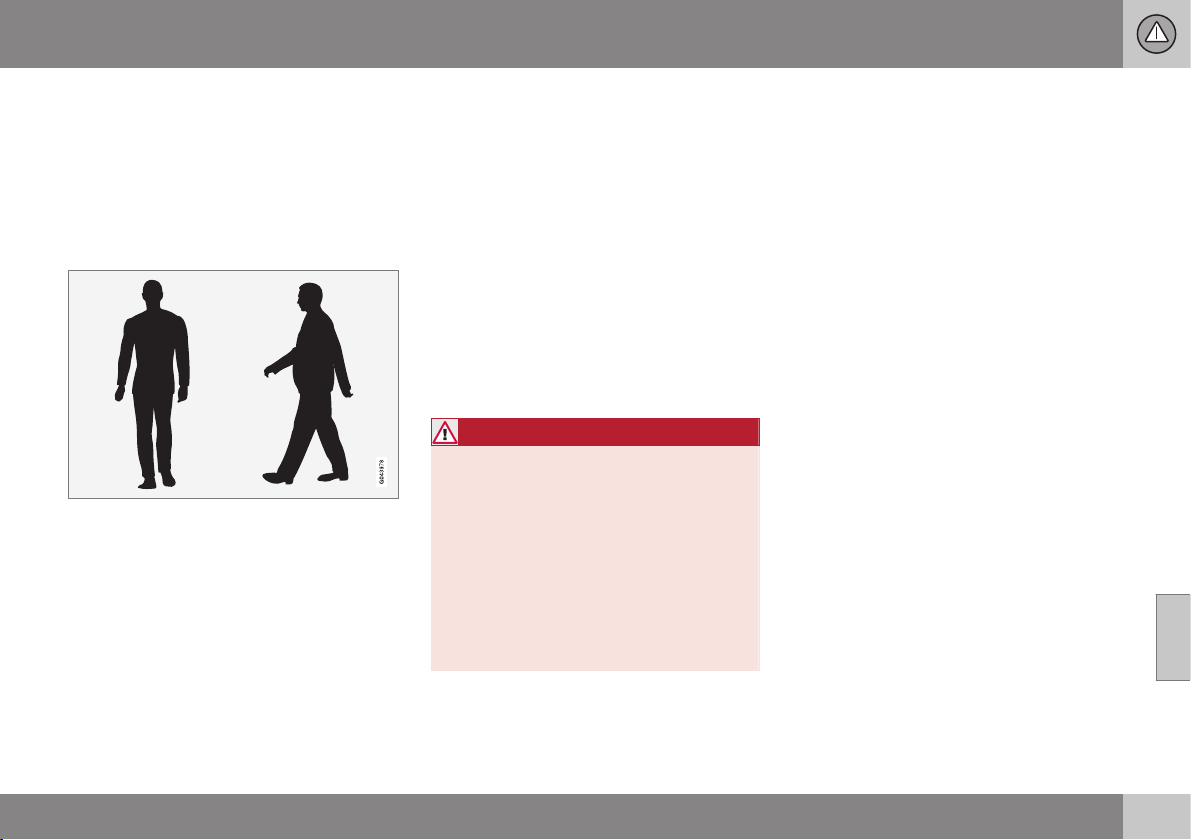
07 Driver support
07
* Option/accessory, for more information, see Introduction.
227
Collision warning system* - detection
of pedestrians
"Collision Warning with Auto Brake and
Cyclist and Pedestrian Detection" is an aid to
assist the driver when there is a risk of collid-
ing with a pedestrian, bicycle or vehicle in
front that are stationary or moving in the same
direction.
Optimal examples of what the system regards as
pedestrians with clear body contours.
Optimal performance of the system requires
that the system function that detects pedes-
trians receives as unambiguous information
as possible about the contours of the body -
this implies the opportunity to identify the
head, arms, shoulders, legs, upper and lower
body combined with a normal human pattern
of movement.
If large parts of the body are not visible to the
camera then the system cannot detect a
pedestrian.
•
In order for a pedestrian to be detected
he/she must appear full-length and have
a height of at least 80 cm.
•
The system cannot detect a pedestrian
carrying larger items.
•
The camera sensor's ability to see pedes-
trians at dusk and dawn is limited - just
like the human eye.
•
The camera sensor's capacity to detect
pedestrians is deactivated when driving in
darkness and tunnels - even when street-
lights are lit.
WARNING
Collision Warning with Auto Brake &
Pedestrian Detection is an assistance tool.
This function cannot detect all pedestrians
in all situations and it cannot see e.g. parti-
ally obscured pedestrians, people in cloth-
ing that hides the contours of the body or
pedestrians shorter than 80 cm.
•
The driver is always responsible that
the vehicle is driven properly and with
a safety distance adapted to the
speed.
Related information
•
Collision warning system* (p. 223)
•
Collision warning system* - function (p.
224)
•
Collision warning system* - operation (p.
228)
•
Collision warning system* - cyclist detec-
tion (p. 225)
•
Collision warning system* - general limita-
tions (p. 229)
•
Collision warning system* - camera sen-
sor limitations (p. 231)
•
Collision warning system* - symbols and
message (p. 233)

07 Driver support
07
228
* Option/accessory, for more information, see Introduction.
Collision warning system* - operation
"Collision Warning with Auto Brake and
Cyclist and Pedestrian Detection" is an aid to
assist the driver when there is a risk of collid-
ing with a pedestrian, bicycle or vehicle in
front that are stationary or moving in the same
direction.
Settings for the collision warning system are
made from MY CAR via the centre console's
screen and menu system.
Warning signals On and Off
It is possible to select whether the collision
warning system's acoustic and visual warning
signals should be switched on or off.
When starting the engine, the setting that was
selected when the engine was switched off is
obtained automatically.
NOTE
The Brake Support and Auto Brake func-
tions are always activated - they cannot be
deactivated.
Light and acoustic signals
To deactivate the light and acoustic signals:
•
Locate
Settings Car settings
Driver support systems Collision
Warning
- there select to uncheck the
box.
The warning lamp, see Collision warning sys-
tem - function (p. 224), is tested every time
the engine is started by briefly illuminating the
warning lamp's separate points of light if the
collision warning system's light and acoustic
warnings are activated.
Audible signal
The warning sound can be activated/deacti-
vated separately:
•
Select
On or Off in the menu system
under
Settings Car settings Driver
support systems
Collision Warning
Warning sound.
Set warning distance
The warning distance regulates the distance
at which the visual and acoustic warnings are
deployed.
•
Select
Long, Normal or Short in the
menu system MY CAR under
Settings
Car settings Driver support
systems
Collision Warning
Warning distance
The warning distance determines the sys-
tem's sensitivity. Warning distance
Long pro-
vides an earlier warning. First test with Long
and if this setting produces too many warn-
ings, which could be perceived as irritating in
certain situations, then change to warning
distance
Normal.
Only use warning distance
Short in excep-
tional cases, e.g. for dynamic driving.
NOTE
When the adaptive cruise control is in use
the warning lamp and warning sound will
be used by the cruise control even if the
collision warning system is switched off.
The collision warning system warns the
driver in the event of a risk of a collision,
but the function cannot shorten driver
reaction time.
In order for the collision warning system to
be effective, always drive with Distance
Alert (p. 214) set at time interval 4–5.
NOTE
Even if the warning distance has been set
to
Long warnings could be perceived as
being late in certain situations, e.g. when
there are large differences in speed or if
vehicles in front brake heavily.
WARNING
No automatic system can guarantee
100 % correct function in all situations.
Therefore, never test Collision Warning
with Auto Brake by driving at people or
vehicles - this may cause severe damage
and injury and risk lives.
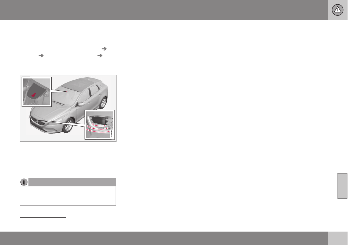
07 Driver support
07
* Option/accessory, for more information, see Introduction.
229
Checking settings
The settings required can be controlled on
the centre console's screen. Search with the
menu system MY CAR under
Settings Car
settings
Driver support systems
Collision Warning, MY CAR (p. 104).
Maintenance
Camera and radar sensor
22
.
For the sensors to work correctly, they must
be kept clear of dirt, ice and snow, and be
cleaned regularly with water and car sham-
poo.
NOTE
Dirt, ice and snow covering the sensors
will reduce their function and may prevent
measurement.
Related information
•
Collision warning system* (p. 223)
•
Collision warning system* - function (p.
224)
•
Collision warning system* - detection of
pedestrians (p. 227)
•
Collision warning system* - cyclist detec-
tion (p. 225)
•
Collision warning system* - general limita-
tions (p. 229)
•
Collision warning system* - camera sen-
sor limitations (p. 231)
•
Collision warning system* - symbols and
message (p. 233)
Collision warning system* - general
limitations
"Collision Warning with Auto Brake and
Cyclist and Pedestrian Detection" is an aid to
assist the driver when there is a risk of collid-
ing with a pedestrian, bicycle or vehicle in
front that are stationary or moving in the same
direction.
The function has certain limitations - for
example, it is not active until approx. 4 km/h..
The collision warning system's visual warning
signal may be difficult to notice in the event of
strong sunlight, reflections, when sunglasses
are being worn or if the driver is not looking
straight ahead. The warning sound should
therefore always be activated.
On slippery road surfaces the braking dis-
tance is extended, which may reduce the
capacity to avoid a collision. In such situa-
tions the ABS and DSTC (p. 185) systems will
provide best possible braking force with
maintained stability.
22
NOTE: The illustration is schematic - details may vary depending on car model.
||
07 Driver support
07
230
* Option/accessory, for more information, see Introduction.
NOTE
The visual warning signal can be temporar-
ily disengaged in the event of high passen-
ger compartment temperature caused by
strong sunlight for example. If this occurs
then the warning sound is activated even if
it is deactivated in the menu system.
•
Warnings may not appear if the dis-
tance to the vehicle in front is small or
if steering wheel and pedal move-
ments are large, e.g. a very active driv-
ing style.
WARNING
Warnings and brake interventions could be
implemented late or not at all if the traffic
situation or external influences mean that
the radar or camera sensor cannot detect
a pedestrian, a vehicle or a cyclist in front
correctly.
The sensor system has a limited range for
pedestrians and cyclists
23
- the system
can provide effective warnings and brake
interventions for them at vehicle speeds up
to 50 km/h. For stationary or slow-moving
vehicles, warnings and brake interventions
are effective at vehicle speeds up to
70 km/h.
Warnings for stationary or slow-moving
vehicles could be disengaged due to dark-
ness or poor visibility.
Warnings and brake interventions for
pedestrians and cyclists are deactivated at
vehicle speeds exceeding 80 km/h.
The collision warning system uses the same
radar sensors as the adaptive cruise control
(p. 199).
If warnings are perceived as being too fre-
quent or disturbing then the warning distance
can be reduced. This then leads to the sys-
tem providing a warning at a later stage,
which reduces the total number of warnings;
see Collision warning system - operation (p.
228).
Collision Warning with Auto Brake is tempo-
rarily deactivated with reverse gear engaged.
Collision Warning with Auto Brake is not acti-
vated at low speeds - under 4 km/h, which is
why the system does not intervene in situa-
tions where the car is approaching a vehicle
in front very slowly, e.g. when parking.
In situations where the driver demonstrates
active, aware driving behaviour, a collision
warning may be postponed slightly in order to
keep unnecessary warnings to a minimum.
When Auto Brake has prevented a collision
with a stationary object the car remains sta-
tionary for a maximum of 1.5 seconds. If the
car is braked for a vehicle in front that is mov-
ing, then speed is reduced to the same speed
as that maintained by the vehicle in front.
On a car with manual gearbox the engine
stops when Auto Brake has stopped the car,
unless the driver manages to depress the
clutch pedal beforehand.
Related information
•
Collision warning system* (p. 223)
•
Collision warning system* - function (p.
224)
•
Collision warning system* - detection of
pedestrians (p. 227)
•
Collision warning system* - cyclist detec-
tion (p. 225)
23
For cyclists, the warning and full brake intervention may come very late or simultaneously.
07 Driver support
07
* Option/accessory, for more information, see Introduction.
231
•
Collision warning system* - operation (p.
228)
•
Collision warning system* - camera sen-
sor limitations (p. 231)
•
Collision warning system* - symbols and
message (p. 233)
Collision warning system* - camera
sensor limitations
"Collision Warning with Auto Brake and
Cyclist and Pedestrian Detection" is an aid to
assist the driver when there is a risk of collid-
ing with a pedestrian, bicycle or vehicle in
front that are stationary or moving in the same
direction.
The function uses the car's camera sensor,
which has certain limitations.
The car’s camera sensor is also used - as
well as by Collision Warning with Auto Brake
- by the functions:
•
Active high beam (p. 83)
•
Road sign information (p. 188)
•
Driver Alert Control - DAC (p. 235)
•
Lane Keeping Aid (p. 239).
NOTE
Keep the windscreen surface in front of the
camera sensor free from ice, snow, mist
and dirt.
Do not stick or attach anything to the
windscreen in front of the camera sensor
as this may reduce effectiveness or cause
one or more of the systems dependent on
the camera to stop working.
The camera sensors have limitations similar
to the human eye, i.e. they "see" worse in
darkness, heavy snowfall or rain and in thick
fog for example. Under such conditions the
functions of camera-dependent systems
could be significantly reduced or temporarily
disengaged.
Strong oncoming light, reflections in the car-
riageway, snow or ice on the road surface,
dirty road surfaces or unclear lane markings
could also significantly reduce camera sensor
function when it is used to scan the carriage-
way and detect pedestrians and other vehi-
cles.
The field of vision of the camera sensor is lim-
ited, which is why pedestrians, cyclists and
vehicles cannot be detected in some situa-
tions, or they are detected later than anticipa-
ted.
During very high temperatures the camera is
temporarily switched off for
approx. 15 minutes after the engine is started
in order to protect camera functionality.
Fault tracing and action
If the display shows the message
Windscreen Sensors blocked then this
means that the camera sensor is blocked and
cannot detect pedestrians, cyclists, vehicles
or road markings in front of the car.
At the same time, this means that - besides
Collision Warning with Auto Brake - the Auto-
matic main/dipped beam dimming, Road Sign
Information, Driver Alert Control and Lane

||
07 Driver support
07
232
* Option/accessory, for more information, see Introduction.
Keeping Aid functions will not have full func-
tionality either.
The following table presents possible causes
for a message being shown along with the
appropriate action.
Cause Action
The windscreen
surface in front of
the camera is dirty
or covered with ice
or snow.
Clean the wind-
screen surface in
front of the camera
from dirt, ice and
snow.
Thick fog, heavy
rain or snow means
that the camera
does not work suffi-
ciently well.
No action. At times
the camera does
not work during
heavy rain or snow-
fall.
Cause Action
The windscreen
surface in front of
the camera has
been cleaned but
the message
remains.
Wait. It may take
several minutes for
the camera to
measure the visibil-
ity.
Dirt has appeared
between the inside
of the windscreen
and the camera.
Visit a workshop to
have the wind-
screen inside the
camera cover
cleaned - an author-
ised Volvo work-
shop is recom-
mended.
Related information
•
Collision warning system* (p. 223)
•
Collision warning system* - function (p.
224)
•
Collision warning system* - detection of
pedestrians (p. 227)
•
Collision warning system* - cyclist detec-
tion (p. 225)
•
Collision warning system* - operation (p.
228)
•
Collision warning system* - general limita-
tions (p. 229)
•
Collision warning system* - symbols and
message (p. 233)
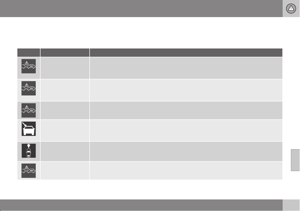
07 Driver support
07
}}
* Option/accessory, for more information, see Introduction.
233
Collision warning system* - symbols
and message
"Collision Warning with Auto Brake and
Cyclist and Pedestrian Detection" is an aid to
assist the driver when there is a risk of collid-
ing with a pedestrian, bicycle or vehicle in
front that are stationary or moving in the same
direction.
Symbol
A
Message Specification
Collis'n warning OFF
Collision warning system switched off.
Shown when the engine is started.
The message clears after about 5 seconds or after one press of the OK button.
Collision warn.
Unavailable
The collision warning system cannot be activated.
Shown when the driver attempts to activate the function.
The message clears after about 5 seconds or after one press of the OK button.
Auto braking was acti-
vated
Auto Brake has been active.
The message clears after one press of the OK button.
Windscreen sensors
blocked See manual
Camera sensor is temporarily disengaged.
Shown in the event of snow, ice or dirt on the windscreen for example.
•
Clean the windscreen surface in front of the camera sensor.
Radar blocked See
manual
Collision Warning with Auto Brake is temporarily disengaged.
Radar sensor is blocked and cannot detect other vehicles. For example, in the event of heavy rain or if
slush has collected in front of the radar sensor.
Collision warn. Serv-
ice required
Collision Warning with Auto Brake is fully or partially disengaged.
•
Visit a workshop if the message remains - an authorised Volvo workshop is recommended.
A
Symbols are schematic - may vary by market and car model.

||
07 Driver support
07
234
* Option/accessory, for more information, see Introduction.
Related information
•
Collision warning system* (p. 223)
•
Collision warning system* - function (p.
224)
•
Collision warning system* - detection of
pedestrians (p. 227)
•
Collision warning system* - cyclist detec-
tion (p. 225)
•
Collision warning system* - operation (p.
228)
•
Collision warning system* - general limita-
tions (p. 229)
•
Collision warning system* - camera sen-
sor limitations (p. 231)
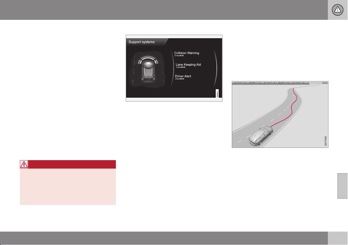
07 Driver support
07
* Option/accessory, for more information, see Introduction.
235
Driver Alert System*
The Driver Alert System is intended to assist
drivers whose driving ability is deteriorating or
who are inadvertently leaving the lane they are
driving on.
The Driver Alert System consists of different
functions which can either be switched on at
the same time or individually:
•
Driver Alert Control (DAC)* - operation (p.
236).
•
Lane keeping assistant - operation (p.
241).
A switched-on function is set in standby
mode and is not activated automatically until
speed exceeds 65 km/h.
The function is deactivated again when speed
decreases to below 60 km/h.
The functions use a camera which is depend-
ent on the lane having side markings painted
on each side.
WARNING
Driver Alert System does not work in all
situations but is designed merely as a sup-
plementary aid.
The driver always bears ultimate responsi-
bility for ensuring that the vehicle is driven
safely.
Driver aid status
The current status for all driver aids can be
checked in MY CAR (p. 106).
Related information
•
Driver Alert Control (DAC)* (p. 235)
•
Driver Alert Control (DAC)* - symbols and
messages (p. 237)
•
Driver Alert Control (DAC)* - operation (p.
236)
Driver Alert Control (DAC)*
DAC is intended to attract the driver's atten-
tion when he/she starts to drive less consis-
tently, e.g. if he/she becomes distracted or
starts to fall asleep.
The objective for DAC is to detect slowly
deteriorating driving ability and it is primarily
intended for major roads.
A camera detects the side markings painted
on the carriageway and compares the section
of the road with the driver's steering wheel
movements. The driver is alerted if the vehicle
does not follow the carriageway evenly.
In some cases driving ability is not affected
despite driver fatigue. In which case there
may not be any warning issued for the driver.
For this reason it is always important to stop
and take a break in the event of any signs of

||
07 Driver support
07
236
* Option/accessory, for more information, see Introduction.
driver fatigue, irrespective of whether or not
DAC issues a warning.
NOTE
The function must not be used to extend a
period of driving. Always plan breaks at
regular intervals, and make sure you are
well rested.
Limitation
In some cases the system may issue a warn-
ing despite driving ability not deteriorating, for
example:
•
in strong side winds
•
on rutted road surfaces.
DAC is not intended for city traffic.
NOTE
The camera sensor has certain limitations,
see Collision warning system* - camera
sensor limitations (p. 231).
Related information
•
Driver Alert System* (p. 235)
•
Driver Alert Control (DAC)* - operation (p.
236)
•
Driver Alert Control (DAC)* - symbols and
messages (p. 237)
•
Lane Keeping Aid* (p. 239)
Driver Alert Control (DAC)* - operation
Settings for Driver Alert Control - DAC (p.
235) are made from the centre console screen
and its menu system (p. 104).
To set Driver Alert in standby mode:
•
In MY CAR, search for
Car settings
Driver support systems Driver Alert
and check the box - No check in the box
means: Standby function disengaged.
Driver Alert is activated when speed exceeds
65 km/h and remains active as long as the
speed is over 60 km/h.
If the vehicle is being driven errati-
cally, the driver is notified by an
acoustic signal plus the text mes-
sage (p. 237)
Driver Alert Time for
a break - the linked symbol is illuminated in
the combined instrument panel at the same
time. The warning is repeated after a time if
driving ability does not improve.
The warning symbol can go off:
•
Press the left stalk switch OK button.
WARNING
An alarm should be taken very seriously,
as a sleepy driver is often not aware of
his/her own condition.
In the event of an alarm or a feeling of
tiredness; stop the car in a safe manner as
soon as possible and rest.
Studies have shown that it is equally as
dangerous to drive while tired as it is under
the influence of alcohol.
Related information
•
Driver Alert System* (p. 235)
•
Driver Alert Control (DAC)* (p. 235)
•
Lane Keeping Aid* (p. 239)
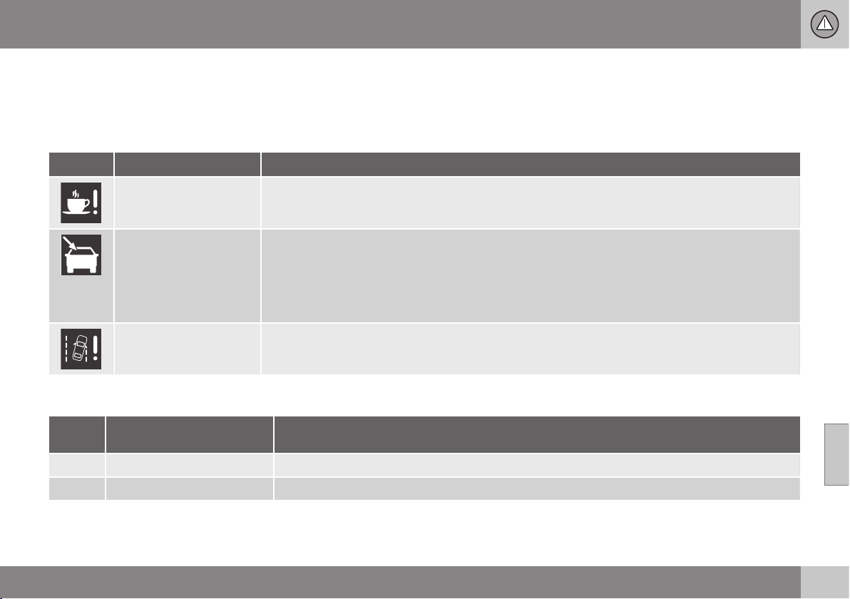
07 Driver support
07
}}
* Option/accessory, for more information, see Introduction.
237
Driver Alert Control (DAC)* - symbols
and messages
Driver Alert Control - DAC (p. 235) can show
symbols and text messages in the combined
instrument panel or in the centre console's
screen in different situations.
Combined instrument panel
Symbol
A
Message Specification
Driver Alert Time for a
break
The vehicle has been driven inconsistently - the driver is alerted by an acoustic warning signal + text.
Windscreen sensors
blocked See manual
The camera sensor is temporarily disengaged.
Shown in the event of snow, ice or dirt on the windscreen for example.
•
Clean the windscreen surface in front of the camera sensor.
Read about the limitations of the camera sensor, see Collision warning system* - camera sensor limita-
tions (p. 231).
Driver Alert system
Service required
The system is disengaged.
•
Visit a workshop if the message remains - an authorised Volvo workshop is recommended.
A
The symbols are schematic.
Display
Sym-
bol
Message Specification
Driver Alert OFF
The function is disengaged.
Driver Alert Available
The function is activated.

||
07 Driver support
07
238
* Option/accessory, for more information, see Introduction.
Sym-
bol
Message Specification
Driver Alert Standby <65
km/h
The function is set in standby mode due to speed being lower than 65 km/h.
Driver Alert Unavailable
The carriageway does not have clear side markings or the camera sensor is temporarily disengaged.
Read about the limitations of the camera sensor, see Collision warning system* - camera sensor lim-
itations (p. 231).
Related information
•
Driver Alert System* (p. 235)
•
Driver Alert Control (DAC)* - operation (p.
236)
•
Lane Keeping Aid* (p. 239)
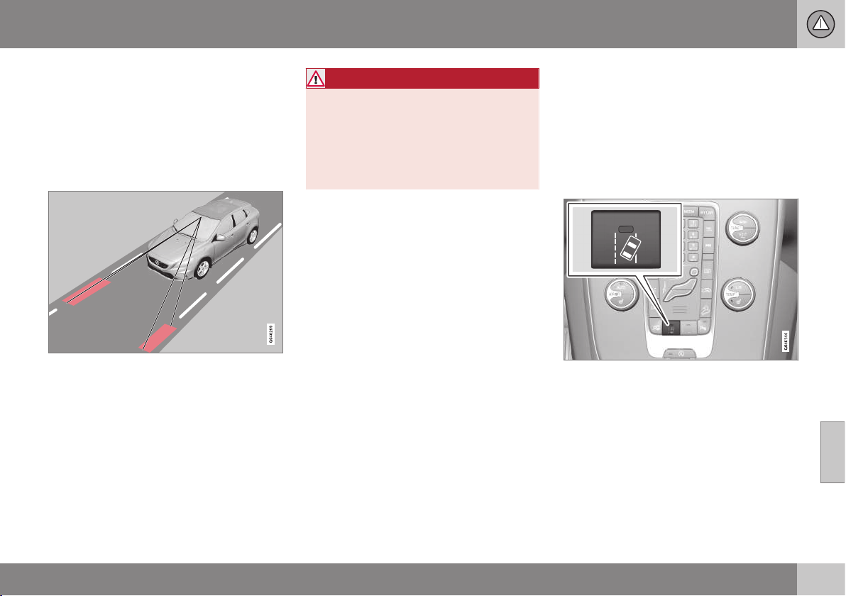
07 Driver support
07
* Option/accessory, for more information, see Introduction.
239
Lane Keeping Aid*
The lane keeping assistant is one of the func-
tions in the Driver Alert System - sometimes
also referred to as LKA (Lane Keeping Aid).
The lane keeping assistant is intended for use
on motorways and similar major roads to
reduce the risk of the vehicle accidentally
leaving its own lane in certain situations.
A camera reads the painted side lines of the
road/lane. If the car is about to cross a side
line, the Lane Keeping Aid actively steers the
car back into the lane with slight steering tor-
que in the steering wheel.
If the car reaches or passes a side line, the
Lane Keeping Aid warns the driver with puls-
ing vibrations in the steering wheel.
WARNING
LKA is merely a driver's aid and does not
engage in all driving situations or traffic,
weather or road conditions.
The driver always bears ultimate responsi-
bility for ensuring that the vehicle is driven
safely and that applicable laws and road
traffic regulations are followed.
Related information
•
Driver Alert System* (p. 235)
•
Lane keeping assistant - limitations (p.
241)
•
Lane keeping assistant - function (p. 239)
•
Lane keeping assistant - operation (p.
241)
•
Lane keeping assistant - symbols and
messages (p. 243)
Lane keeping assistant - function
Off & On
The Lane Keeping Aid is active within the
speed interval 65-200 km/h on roads with
clearly visible side lines. The function is tem-
porarily deactivated on narrow roads with
less than 2.6 metres between the lane side
lines.
Press the button in the centre console to acti-
vate or deactivate the function. The function
is switched on if one lamp is illuminated in the
button.
Some combinations of the selected equip-
ment leave no vacant space for an On/Off
button in the centre console - in which case
the function is handled instead by the car's
menu system MY CAR. Here, proceed as fol-
lows:
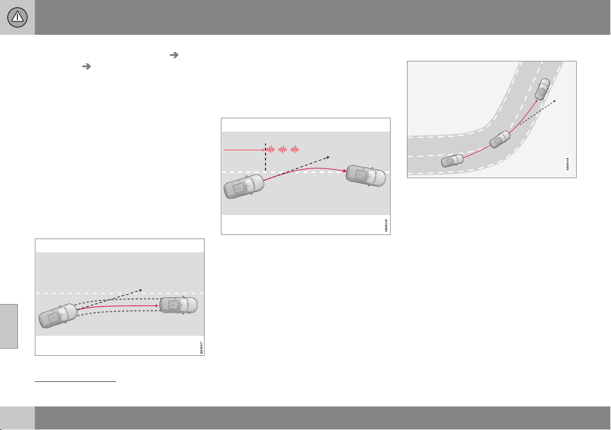
||
07 Driver support
07
240
* Option/accessory, for more information, see Introduction.
•
Select
On or Off under Settings Car
settings
Lane Keeping Aid.
For a description of the menu system, see
MY CAR - menu options (p. 106).
In addition, the following selections can be
made in MY CAR:
•
Warning with vibration in the steering
wheel:
Vibration only - On or Off.
•
Active steering:
Steering assist only -
On or Off.
•
Both Warning with vibration in the steer-
ing wheel and Active steering:
Full
function - On or Off.
Active steering
The Lane Keeping Aid strives to keep the car
within the side lines for the lane.
LKA intervenes and steers away.
If the vehicle approaches the left or right side
line of the lane and the direction indicator is
not activated, the car is steered back into the
lane.
Warning with vibration in the steering
wheel
LKA steers and warns with pulsing steering
wheel vibrations
24
.
If the vehicle passes a side line, the Lane
Keeping Aid warns the driver with pulsing
vibrations in the steering wheel. This occurs
regardless of whether the car is actively
steered back by applying a slight steering tor-
que.
Dynamic cornering
LKA does not engage in sharp inside curves.
In certain cases, the Lane Keeping Aid allows
the car to cross side lines without engaging
active steering or warning with pulsing vibra-
tions in the steering wheel. Using an adjacent
lane for dynamic cornering when there is a
clear line of vision is an example of one such
case.
Related information
•
Lane Keeping Aid* (p. 239)
•
Lane keeping assistant - limitations (p.
241)
•
Lane keeping assistant - operation (p.
241)
•
Lane keeping assistant - symbols and
messages (p. 243)
24
The figure shows 3 pulsing vibrations when the side line is passed.
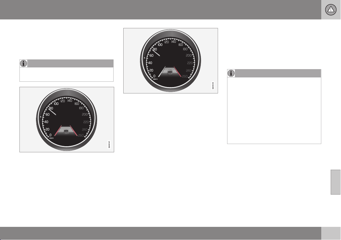
07 Driver support
07
* Option/accessory, for more information, see Introduction.
241
Lane keeping assistant - operation
The lane keeping assistant is supplemented
with self-explanatory graphics in different sit-
uations. Here are some examples:
NOTE
LKA is temporarily deactivated for as long
as the direction indicator is switched on.
LKA "sees" and follows the side lines (marked in
red in the figure).
If the Lane Keeping Aid is active and
detects/"sees" the side lines, the LKA symbol
indicates this with WHITE lines.
•
GREY side line – the Lane Keeping Aid
does not see a line on that side of the car.
LKA intervenes on the right-hand side (marked in
red in the figure).
The Lane Keeping Aid intervenes and steers
away from the side line - this is indicated
with:
•
RED line for the side in question.
Related information
•
Lane Keeping Aid* (p. 239)
•
Driver Alert System* (p. 235)
•
Lane keeping assistant - limitations (p.
241)
•
Lane keeping assistant - function (p. 239)
•
Lane keeping assistant - symbols and
messages (p. 243)
Lane keeping assistant - limitations
•
The Lane Keeping Aid camera sensor is
restricted in a similar way to the human
eye. For more information, see Collision
warning system* - camera sensor limita-
tions (p. 231) and (p. 229).
NOTE
In certain demanding situations LKA may
find it difficult to assist the driver correctly
- in which case it is recommended that
LKA is switched off.
Examples of such a situation could be:
•
roadworks
•
winter road conditions
•
poor road surface
•
very sporty driving style
•
poor weather with reduced visibility.
Hands on the steering wheel
In order for Lane Keeping Aid to operate, the
driver must have his/her hands on the steer-
ing wheel. LKA continual monitors this. If
hands are not detected on the steering wheel,
a text message encouraging the driver to
actively steer the car is shown.
If the driver does not follow the request to
begin steering, the Lane Keeping Aid goes
into standby mode and will remain in this
mode until the driver begins to steer the car
again.

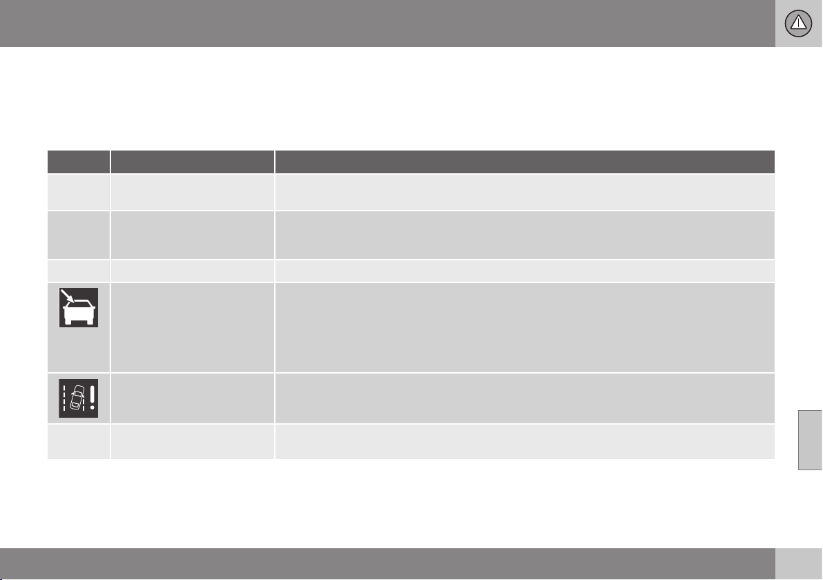
07 Driver support
07
}}
* Option/accessory, for more information, see Introduction.
243
Lane keeping assistant - symbols and
messages
In situations where there is no LKA function
or it is interrupted, a symbol may be shown in
the combined instrument panel in combina-
tion with an explanatory message - follow the
recommendation given if appropriate.
Message examples:
Symbol
A
Message Specification
Lane Keeping Aid Unavaila-
ble at this speed
The Lane Keeping Aid is set to standby mode because the speed is lower than 65 km/h.
Lane Keeping Aid Unavaila-
ble for current markings
The lane does not have clear side lines or the camera sensor is temporarily disengaged. Read
about the limitations of the camera sensor, see Collision warning system* - camera sensor limita-
tions (p. 231) and (p. 229).
Lane Keeping Aid Available
The function scans the lane's side lines.
Windscreen sensors
blocked See manual
The camera sensor is temporarily disengaged.
Shown in the event of snow, ice or dirt on the windscreen for example.
•
Clean the windscreen surface in front of the camera sensor.
Read about the limitations of the camera sensor, see Collision warning system* - camera sensor
limitations (p. 231) and (p. 229).
Lane Keeping Aid Service
required
The system is disengaged.
•
Visit a workshop if the message remains - an authorised Volvo workshop is recommended.
Lane Keeping Aid Interrup-
ted
LKA has been set to standby mode. The lines of the LKA symbol indicate when the function is
active again.
A
The table's symbols are schematic. The symbols shown in the combined instrument panel may have a slightly different appearance.

07 Driver support
07
* Option/accessory, for more information, see Introduction.
245
Park assist syst*
Parking assistance is used as an aid to park-
ing. An acoustic signal as well as symbols on
the centre console's display screen indicate
the distance to the detected obstacle.
Parking assistance sound level can be
adjusted during the ongoing acoustic signal
using the centre console's VOL knob or in the
car's menu system MY CAR, see MY CAR (p.
104).
Parking assistance is available in two vari-
ants:
•
Rear only
•
Both front and rear.
NOTE
When a towbar is configured with the car's
electrical system, the protrusion of the
towbar is included when the function
measures the parking space.
WARNING
•
Parking assistance does not relinquish
the driver's own responsibility during
parking.
•
The sensors have blind spots where
obstacles cannot be detected.
•
Be aware of e.g. people and animals
near the car.
Related information
•
Park assist syst* - cleaning the sensors
(p. 248)
•
Park assist syst* - function (p. 245)
•
Park assist syst* - forward (p. 247)
•
Park assist syst* - fault indication (p. 248)
•
Park assist syst* - backward (p. 247)
•
Park assist camera (p. 249)
•
Park Assist Pilot (PAP)* (p. 253)
Park assist syst* - function
The parking assistance system is automati-
cally activated when the engine is started -
the switch's On/Off lamp is illuminated. If
parking assistance is switched off with the
button, the lamp goes out.
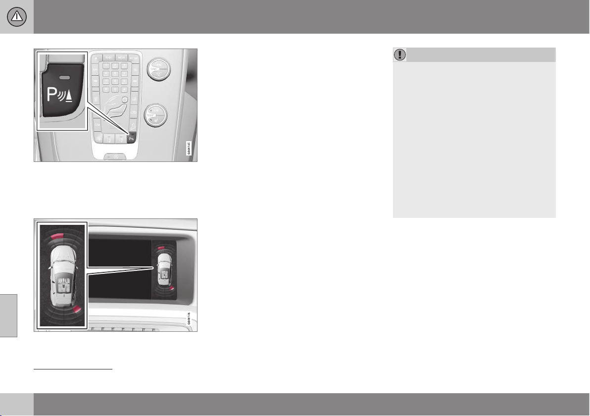
||
07 Driver support
07
246
* Option/accessory, for more information, see Introduction.
On/Off for the sensors for parking assistance and
CTA
25
.
The centre console's display screen shows
an overview of the relationship between the
car and detected obstacle.
Display screen view - showing an obstacle left
front and right rear.
Marked sectors show which of the four sen-
sor(s) detected an obstacle. The closer to the
car symbol a selected sector box is, the
shorter the distance between the car and a
detected obstacle.
The frequency of the signal increases the
shorter the distance to an obstacle, in front of
or behind the car. Other sound from the audio
system is muted automatically.
When the distance is within 30 cm the tone is
constant and the active sensor's field nearest
the car is filled in. If the detected obstacle is
within the distance for the constant tone both
behind and in front of the car, then the tone
sounds alternately from the loudspeakers.
IMPORTANT
Objects e.g. chains, thin glossy poles or
low barriers may be in the "signal shadow"
and are then temporarily not detected by
the sensors - the pulsating tone may then
unexpectedly stop instead of changing
over to the expected constant tone.
The sensors cannot detect high objects,
such as projecting loading docks.
•
In such situations, pay extra attention
and manoeuvre/reposition the car par-
ticularly slowly or stop the current
parking manoeuvre - there may be a
high risk of damage to vehicles or
other objects since the sensors are
temporarily unable to function opti-
mally.
Related information
•
Park assist syst* (p. 245)
•
Park assist syst* - cleaning the sensors
(p. 248)
•
Park assist syst* - forward (p. 247)
•
Park assist syst* - fault indication (p. 248)
•
Park assist syst* - backward (p. 247)
•
Park assist camera (p. 249)
•
Park Assist Pilot (PAP)* (p. 253)
25
Side warning, CTA (Cross Traffic Alert) (p. 260)
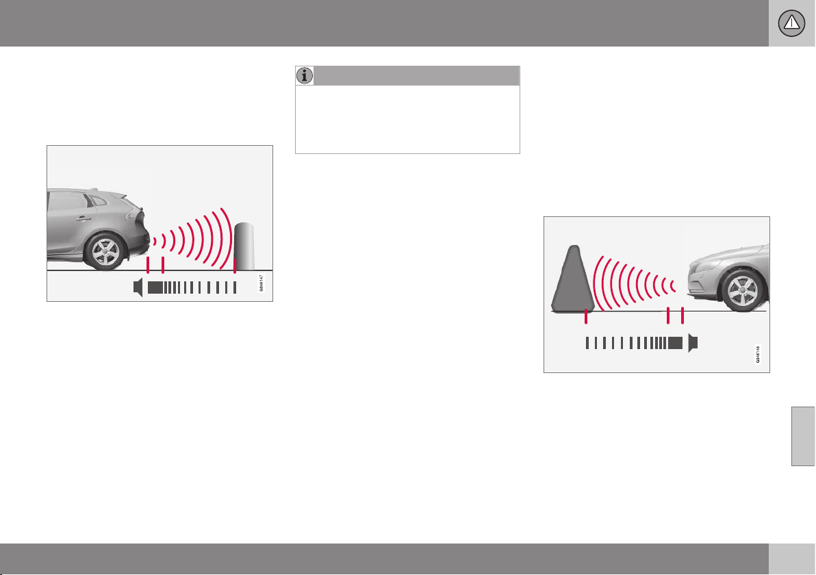
07 Driver support
07
* Option/accessory, for more information, see Introduction.
247
Park assist syst* - backward
Parking assistance is used as an aid to park-
ing. An acoustic signal as well as symbols on
the centre console's display screen indicate
the distance to the detected obstacle.
The distance covered to the rear of the car is
about 1.5 metres. The acoustic signal for
obstacles behind comes from one of the rear
loudspeakers.
Rear parking assistance is activated when
reverse gear is engaged.
When reversing with e.g. a trailer on the tow-
bar, rear parking assistance is switched off
automatically - otherwise the sensors would
react to the trailer.
NOTE
When reversing with e.g. a trailer or bike
carrier on the towbar - without Volvo genu-
ine trailer wiring - parking assistance may
need to be switched off manually in order
that the sensors do not react to them.
Related information
•
Park assist syst* (p. 245)
•
Park assist syst* - cleaning the sensors
(p. 248)
•
Park assist syst* - function (p. 245)
•
Park assist syst* - forward (p. 247)
•
Park assist syst* - fault indication (p. 248)
•
Park assist camera (p. 249)
•
Park Assist Pilot (PAP)* (p. 253)
Park assist syst* - forward
Parking assistance is used as an aid to park-
ing. An acoustic signal as well as symbols on
the centre console's display screen indicate
the distance to the detected obstacle.
The parking assistance system is automati-
cally activated when the engine is started -
the switch's On/Off lamp is illuminated. If
parking assistance is switched off with the
button, the lamp goes out.
The distance covered in front of the car is
about 0.8 metres. The acoustic signal for
obstacles in front comes from one of the front
loudspeakers.
Front park assist is active up to
approx. 10 km/h. The lamp in the button is
illuminated in order to indicate that the sys-
tem is activated. When the speed is below
10 km/h the system is reactivated.
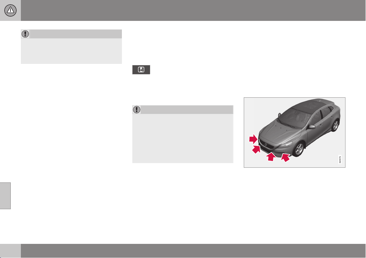
||
07 Driver support
07
248
* Option/accessory, for more information, see Introduction.
IMPORTANT
When auxiliary lamps are fitted: Remember
that these must not obscure the sensors -
the auxiliary lamps may then be perceived
as an obstacle.
Related information
•
Park assist syst* (p. 245)
•
Park assist syst* - cleaning the sensors
(p. 248)
•
Park assist syst* - function (p. 245)
•
Park assist syst* - fault indication (p. 248)
•
Park assist syst* - backward (p. 247)
•
Park assist camera (p. 249)
•
Park Assist Pilot (PAP)* (p. 253)
Park assist syst* - fault indication
Parking assistance is used as an aid to park-
ing. An acoustic signal as well as symbols on
the centre console's display screen indicate
the distance to the detected obstacle.
If the combined instrument panel's
information symbol illuminates with
a constant glow and the text mes-
sage
Park assist syst Service required is
shown, then parking assistance is disen-
gaged.
IMPORTANT
Under some circumstances, the parking
sensors can give false warning signals due
to external sound sources which emit the
same ultrasound frequencies as those with
which the system works.
Examples of such sources include horns,
wet tyres on asphalt, pneumatic brakes
and exhaust noises from motorcycles etc.
Related information
•
Park assist syst* (p. 245)
•
Park assist syst* - cleaning the sensors
(p. 248)
•
Park assist syst* - function (p. 245)
•
Park assist syst* - forward (p. 247)
•
Park assist syst* - backward (p. 247)
•
Park assist camera (p. 249)
•
Park Assist Pilot (PAP)* (p. 253)
Park assist syst* - cleaning the
sensors
Parking assistance is used as an aid to park-
ing. An acoustic signal as well as symbols on
the centre console's display screen indicate
the distance to the detected obstacle.
The sensors for parking assistance must be
cleaned regularly to ensure that they work
properly. Clean them with water and car
shampoo.
Sensor location, front.
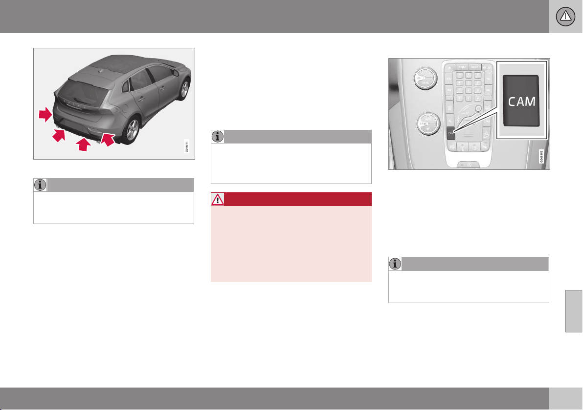
07 Driver support
07
* Option/accessory, for more information, see Introduction.
249
Sensor location, rear.
NOTE
Dirt, ice and snow covering the sensors
will reduce their function and may prevent
measurement.
Related information
•
Park assist syst* (p. 245)
•
Park assist syst* - function (p. 245)
•
Park assist syst* - forward (p. 247)
•
Park assist syst* - fault indication (p. 248)
•
Park assist syst* - backward (p. 247)
•
Park assist camera (p. 249)
•
Park Assist Pilot (PAP)* (p. 253)
Park assist camera
The parking camera is an assist system and is
activated when reverse gear is engaged (can
be changed in the settings menu, see MY
CAR - menu options (p. 106)).
The camera image is shown on the centre
console's screen.
NOTE
When a towbar is configured with the car's
electrical system, the protrusion of the
towbar is included when the function
measures the parking space.
WARNING
•
The parking camera is an aid and can
never replace the responsibilities of
the driver when reversing.
•
The camera has blind spots where
obstacles cannot be detected.
•
Be aware of people and animals near
the car.
Function and operation
CAM button location.
The camera shows what is behind the car
and if something appears from the sides.
The camera shows a wide area behind the
car and part of the bumper and any towbar.
Objects on the screen may appear to tilt
slightly - this is normal.
NOTE
Objects on the display screen may be
closer to the car than they appear to be on
the screen.
If another view is active the parking camera
system takes over automatically and the
camera image is displayed on the screen.
When reverse gear is engaged two unbroken
lines are shown graphically which illustrate

||
07 Driver support
07
250
* Option/accessory, for more information, see Introduction.
where the car's rear wheels will roll with the
current steering wheel angle, this facilitates
tight parking, reversing into tight spaces and
for hitching a trailer. The car’s approximate
external dimensions are illustrated by means
of two dashed lines. These help lines can be
switched off in the settings menu.
If the car is also equipped with parking assis-
tance sensors* then their information is dis-
played graphically as coloured fields in order
to illustrate the distance to detected obsta-
cles, see Park assist syst* - function (p. 245).
The camera is active approx. 5 seconds after
reverse gear has been disengaged or until the
car's speed exceeds 10 km/h forward or
35 km/h backward.
Camera location next to the opening handle.
Light conditions
The camera image is adjusted automatically
according to prevailing light conditions.
Because of this, the image may vary slightly
in brightness and quality. Poor light condi-
tions can result in a slightly reduced image
quality.
NOTE
Keep the camera lens clear of dirt, snow
and ice to ensure optimum function. This
is particularly important in poor light.
Park assist lines
Examples of how the park assist lines can be dis-
played for the driver.
The lines on the screen are projected as if
they were at ground level behind the car and
are directly related to steering wheel move-
ment, which shows the driver the path the car
will take when it turns.
NOTE
•
When reversing with a trailer which is
not connected electrically to the car,
the lines on the display show the route
the car will take - not the trailer.
•
The screen shows no lines when a
trailer is connected electrically to the
car's electrical system.
•
The parking camera is deactivated
automatically when towing a trailer if a
Volvo genuine trailer cable is used.
IMPORTANT
Remember that the display only shows the
area behind the car - so pay attention to
the sides and front of the car when turning
the steering while reversing.
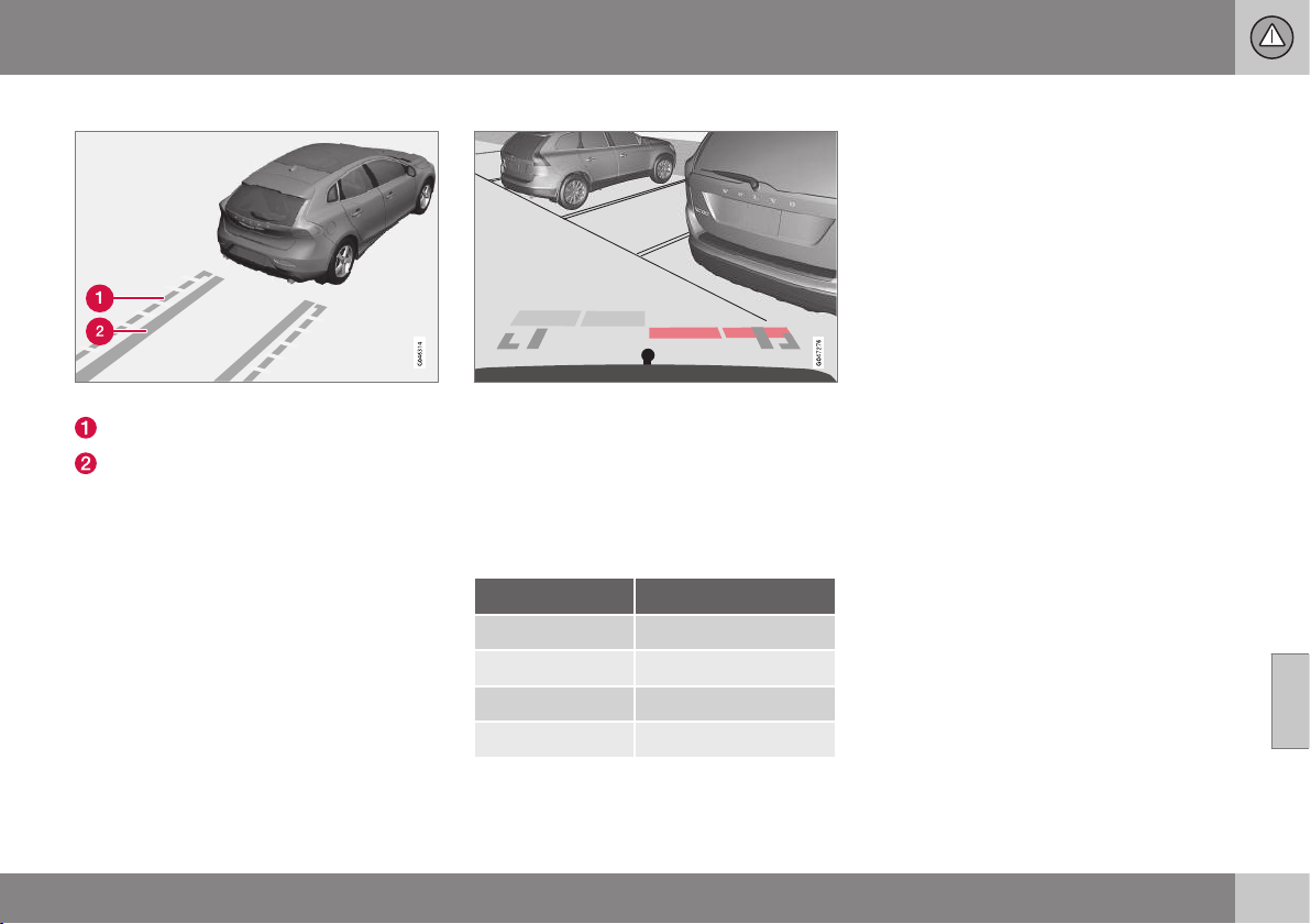
07 Driver support
07
* Option/accessory, for more information, see Introduction.
251
Boundary lines
Different lines in the system.
Boundary line, free reversing zone
"Wheel tracks"
The dashed line (1) frames in a zone up to
about 1.5 m back from the bumper. It is also
the limit of the car's most protruding parts,
such as door mirrors and corners - also dur-
ing turning.
The wide "wheel tracks" (2) between the side
lines indicate where the wheels will roll and
can extend about 3.2 m back from the
bumper if no obstacle is in the way.
Cars with reversing sensors*
Coloured areas (x 4 - one per sensor) show dis-
tance.
If the car is also equipped with parking assis-
tance sensors (see Park assist syst* - function
(p. 245)) the distance indication will be more
precise and the coloured areas show which
of the 4 sensors is/are registering an obsta-
cle.
Colour / paint Distance (metres)
Light yellow 0,7–1,5
Yellow 0,5–0,7
Orange 0,3–0,5
Red 0–0,3
Related information
•
Park assist camera - settings (p. 252)
•
Park assist camera - limitations (p. 252)
•
Park assist syst* (p. 245)
•
Park Assist Pilot (PAP)* (p. 253)
07 Driver support
07
252
* Option/accessory, for more information, see Introduction.
Park assist camera - settings
The parking camera is an assist system and is
activated when reverse gear is engaged.
Press OK/MENU when a camera view is
shown. Make the settings as desired.
Miscellaneous
•
The default setting is that the camera is
activated when reverse gear is engaged.
•
One press on CAM activates the camera
even if reverse gear is not engaged.
•
Change between normal and zoomed
image by turning TUNE or by pressing
CAM.
Towbar
The camera can be used to advantage when
hitching a trailer. A help line for the towbar's
intended "course" towards the trailer can be
shown in the display - just as for the "wheel
tracks".
•
The towbar can be zoomed in for preci-
sion manoeuvring with one press on
CAM. Pressing again gives normal view.
The towbar's park assist line is activated in
the menu system MY CAR where a selection
can be made between displaying the "wheel
tracks" or towbar course - both options can-
not be displayed simultaneously.
Related information
•
Park assist camera (p. 249)
•
Park assist camera - limitations (p. 252)
•
Park assist syst* (p. 245)
•
Park Assist Pilot (PAP)* (p. 253)
•
MY CAR (p. 104)
Park assist camera - limitations
The parking camera is an assist system and is
activated when reverse gear is engaged.
NOTE
Bicycle racks or other accessories moun-
ted on the back of the car may obscure
the line of sight of the camera.
To bear in mind
Pay attention to the possibility that, even if it
only looks like a relatively small part of the
image is obscured, it could be a relatively
large sector that is hidden from view. Obsta-
cles could thereby go undetected until they
are very close to the car.
•
Keep the camera lens free from dirt, ice
and snow.
•
Clean the camera lens regularly with luke-
warm water and car shampoo - take care
not to scratch the lens.
Related information
•
Park assist camera (p. 249)
•
Park assist camera - settings (p. 252)
•
Park assist syst* (p. 245)
•
Park Assist Pilot (PAP)* (p. 253)
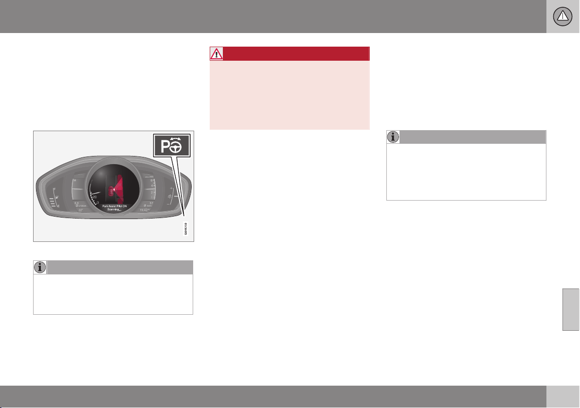
07 Driver support
07
* Option/accessory, for more information, see Introduction.
253
Park Assist Pilot (PAP)*
The Park Assist Pilot (PAP – Park Assist Pilot)
helps the driver to park by first checking
whether a space is sufficiently large and then
turning the steering wheel and steering the
car into the space. The combined instrument
panel uses symbols, graphics and text when
elements are to be executed.
The On/Off button is on the centre console.
NOTE
When a towbar is configured with the car's
electrical system, the protrusion of the
towbar is included when the function
measures the parking space.
WARNING
PAP does not work in all situations but is
designed merely as a supplementary aid.
The driver always has the final responsibil-
ity for driving the vehicle in a safe manner
and for paying attention to the surround-
ings and other road users approaching or
passing during parking.
Related information
•
Park Assist Pilot (PAP)* - limitations (p.
256)
•
Park Assist Pilot (PAP)* - function (p.
253)
•
Park Assist Pilot (PAP)* - operation (p.
254)
•
Active Park Assist (PAP)* - symbols and
messages (p. 257)
•
Park assist camera (p. 249)
Park Assist Pilot (PAP)* - function
The Park Assist Pilot (PAP – Park Assist Pilot)
helps the driver to park by first checking
whether a space is sufficiently large and then
turning the steering wheel and steering the
car into the space. The combined instrument
panel uses symbols, graphics and text when
elements are to be executed.
NOTE
The PAP function measures the space and
turns the steering wheel - the driver's task
is to follow the combined instrument pan-
el's instructions and select the gear
(reverse/forward), control the speed, brake
and stop.
PAP can be activated if the following criteria
are met once the engine has been started:
•
The functions DSTC or ABS must not
intervene during an ongoing PAP function
- these can be activated due to e.g. steep
and slippery surfaces, see the sections
on Foot brake (p. 289) and Stability and
traction control system (p. 185) for more
information.
•
Trailers must not be connected to the car.
•
The speed must be below 50 km/h.

||
07 Driver support
07
254
* Option/accessory, for more information, see Introduction.
Principle for PAP.
The PAP function parks the car using the fol-
lowing steps:
1. The function searches for a parking space
and measures it (A & B (p. 254)). During
measurement, speed must not
exceed 30 km/h.
2. The car is steered into the space while
reversing (C & D (p. 255)).
3. The car is straightened up in the space by
driving back and forth (E & F (p. 255)).
Related information
•
Park Assist Pilot (PAP)* (p. 253)
•
Park assist camera (p. 249)
Park Assist Pilot (PAP)* - operation
The Park Assist Pilot (PAP – Park Assist Pilot)
helps the driver to park by first checking
whether a space is sufficiently large and then
turning the steering wheel and steering the
car into the space.
The driver is instructed about how PAP works
by means of simple, clear instructions in the
combined instrument panel - using both
graphics and text graphics and text message
(p. 257).
NOTE
Remember that certain steering wheel
positions may obstruct the combined
instrument panel's instructions when you
turn it during the parking manoeuvre.
1 - Searching and checking
measurements
The PAP function searches for a parking
space and checks whether it is big enough.
Proceed as follows:
1. Activate PAP by pressing
this button and do not drive
faster than 30 km/h.
2. Keep an eye on the combined instrument
panel and be prepared to stop the car
when the graphics and text message so
request.
3. Stop the car when the graphics and text
so request.
NOTE
PAP searches the area for a parking
space, displays instructions and guides
the car in on its passenger side. But if
required the car can also be parked on the
driver's side of the street:
•
Activate the direction indicator for the
driver's side - the car is then parked
on that side of the street instead.
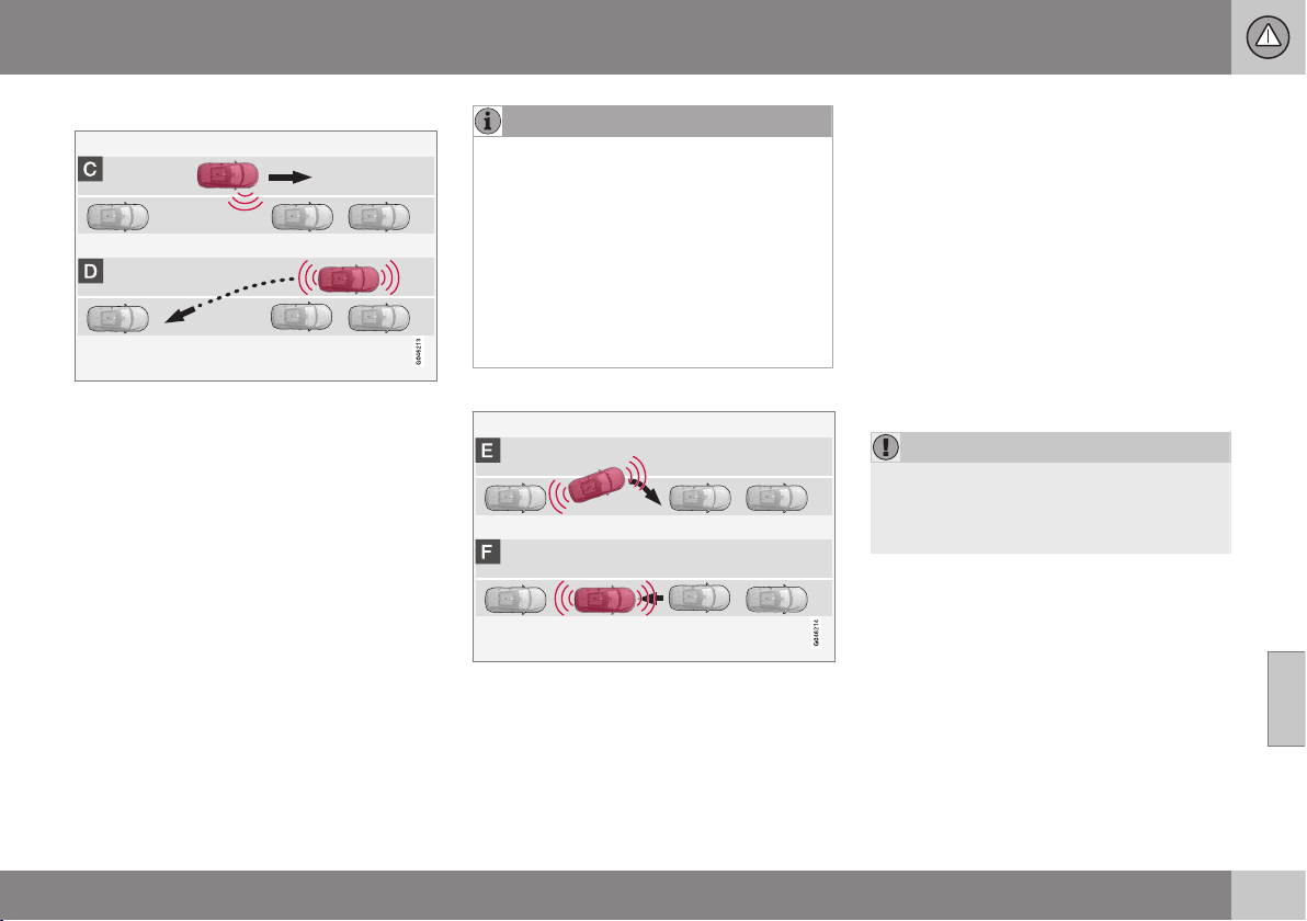
07 Driver support
07
* Option/accessory, for more information, see Introduction.
255
2 - Reversing in
During the Reversing step, PAP will steer the
car into the parking space. Proceed as fol-
lows:
1. Check that the area behind the car is
clear, then engage reverse gear.
2. Reverse slowly and carefully without
touching the steering wheel - and no
faster than approx. 7 km/h.
3. Keep an eye on the combined instrument
panel and be prepared to stop the car
when the graphics and text message so
request.
NOTE
•
Keep your hands away from the steer-
ing wheel when the PAP function is
activated.
•
Make sure that the steering wheel is
not hindered in any way and can rotate
freely.
•
To achieve optimum results - wait until
the steering wheel is fully turned
before starting to drive backward/
forward.
3 - Straightening up
When the car has reversed into the parking
space, it must be straightened up and stop-
ped.
1. Engage first gear or D position, wait until
the steering wheel has been turned, then
drive slowly forwards.
2. Stop the car when the graphics and text
message so request.
3. Engage reverse gear and drive back-
wards slowly until the graphics and text
message tell you to stop.
The function is disengaged automatically
when parking is complete, and the graphics
and text message show that parking is com-
plete. It may be necessary for the driver to
correct the positioning. Only the driver can
determine whether the car is properly parked.
IMPORTANT
The warning distance is shorter when the
sensors are used by Active Park Assist
compared with when Park Assist uses the
sensors.
Related information
•
Park Assist Pilot (PAP)* (p. 253)
•
Park assist camera (p. 249)
07 Driver support
07
256
* Option/accessory, for more information, see Introduction.
Park Assist Pilot (PAP)* - limitations
The Park Assist Pilot (PAP – Park Assist Pilot)
helps the driver to park by first checking
whether a space is sufficiently large and then
turning the steering wheel and steering the
car into the space. The combined instrument
panel uses symbols, graphics and text when
elements are to be executed.
The PAP sequence is stopped:
•
if the car is driven too quickly - above
7 km/h
•
if the driver touches the steering wheel
•
if the ABS or DSTC function is enabled -
e.g. if a wheel loses grip on a slippery
road surface.
A text message indicates where the PAP
sequence was stopped.
NOTE
Dirt, ice and snow covering the sensors
will reduce their function and may prevent
measurement.
IMPORTANT
Under certain circumstances, PAP is
unable to find parking spaces - one reason
for this may be the fact that there is inter-
ference with the sensors from external
sound sources which emit the same ultra-
sound frequencies as those with which the
system works.
Examples of such sources include horns,
wet tyres on asphalt, pneumatic brakes
and exhaust noises from motorcycles etc.
To bear in mind
The driver should bear in mind that the Park
Assist Pilot is an aid – not an infallible, fully-
automatic function. The driver must therefore
be prepared to intervene. There are also
details to bear in mind while parking, e.g.:
•
PAP starts out from the current location
of the parked vehicles - if they are inap-
propriately parked then the car's tyres
and wheel rims may be damaged against
kerbs.
•
PAP is designed for parking on straight
streets, not sharp curves or bends. For
this reason, make sure the car is parallel
to the parking space when PAP measures
the space.
•
It is not always possible to find parking
spaces on narrow streets since there is
not enough space for manoeuvring. In
such parking situations, it helps the sys-
tem to drive as close to the side of the
road as possible where you intend to
park.
•
Bear in mind that the front of the car may
swing out towards oncoming traffic while
being parked.
•
Objects situated higher than the detection
areas of the sensors are not included
when calculations are made for the park-
ing manoeuvre. This may cause PAP to
swing into the parking space too early,
and hence such parking pockets should
be avoided.
•
The driver is responsible for determining
whether the space selected by PAP is
suitable for parking.
•
Use approved tyres
26
with the correct tyre
pressure - this affects the ability of PAP
to park the car.
•
Heavy rain or snow may cause the sys-
tem to measure the parking space incor-
rectly.
•
Do not use PAP if snow chains or a spare
wheel are fitted.
•
Do not use PAP if loaded objects are pro-
truding from the car.
26
"Approved tyres" refers to tyres of the same type and make as those fitted new on delivery from the factory.
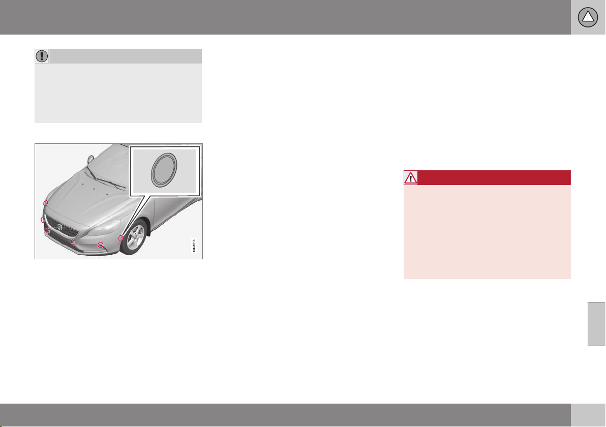
07 Driver support
07
* Option/accessory, for more information, see Introduction.
257
IMPORTANT
The PAP system's parameters may need
to be updated when changing to another
approved wheel rim size involving changed
tyre circumference. Consult a workshop -
an authorised Volvo workshop is recom-
mended.
Maintenance
The PAP sensors are located in the bumpers - 6
front and 4 rear.
For the PAP function to work correctly, its
sensors must be cleaned (p. 248) regularly
with water and car shampoo - these are the
same sensors as are used by parking assis-
tance (p. 245).
Related information
•
Park Assist Pilot (PAP)* (p. 253)
•
Park assist camera (p. 249)
Active Park Assist (PAP)* - symbols
and messages
The Park Assist Pilot (PAP – Park Assist Pilot)
helps the driver to park by first checking
whether a space is sufficiently large and then
turning the steering wheel and steering the
car into the space. The combined instrument
panel uses symbols, graphics and text when
elements are to be executed.
The combined instrument panel can show dif-
ferent combinations of symbols and text with
varying content - sometimes with a self-
explanatory piece of advice on appropriate
action.
If a message says that the Park Assist Pilot is
disengaged, contact with an authorised Volvo
workshop is recommended.
Related information
•
Park Assist Pilot (PAP)* (p. 253)
BLIS (Blind Spot Information System)
BLIS (Blind Spot Information System) is a
function designed for providing support for
the driver when driving in dense traffic on
roads with several lanes in the same direction.
BLIS is a driver's aid intended to provide a
warning about:
•
vehicles in the car's blind spot
•
quickly approaching vehicles in the left
and right lanes closest to the car.
WARNING
BLIS is a supplementary aid and does not
work in all situations.
BLIS is no substitute for a safe driving
style and the use of rearview and door mir-
rors.
BLIS can never replace the driver's
responsibility and attention - it is always
the driver's responsibility to change lanes
in a safe manner.
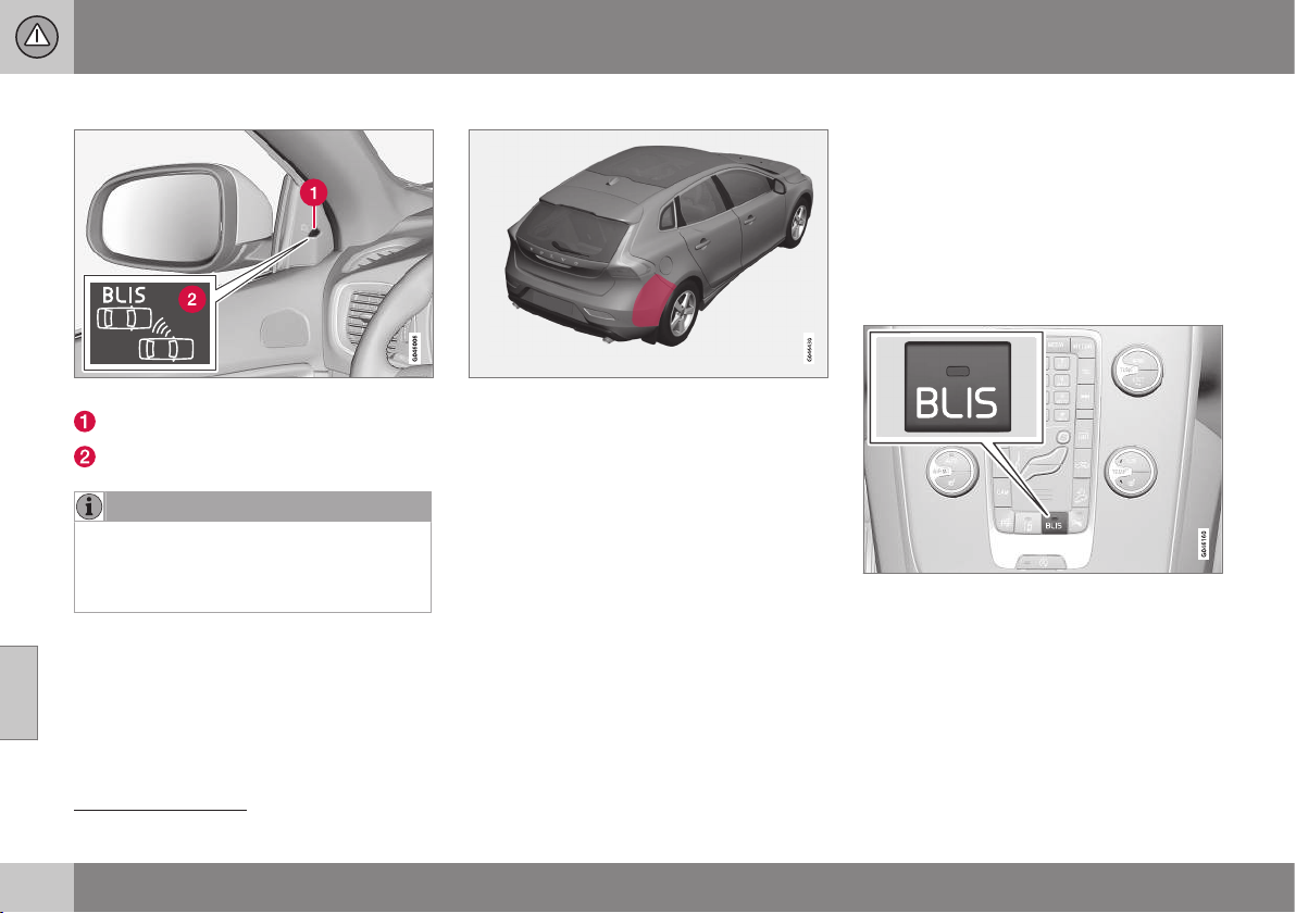
||
07 Driver support
07
258
* Option/accessory, for more information, see Introduction.
Overview
Position of the BLIS lamp
27
.
Indicator lamp
BLIS symbol
NOTE
The lamp illuminates on the side of the car
where the system has detected the vehi-
cle. If the car is overtaken on both sides at
the same time then both lamps illuminate.
Maintenance
Sensor location.
The sensors for the BLIS functions are
located inside the rear wing/bumper on each
side of the car.
•
To ensure optimal functionality, the areas
in front of the sensors must be kept
clean.
Related information
•
BLIS - operation (p. 258)
•
CTA (Cross Traffic Alert)* (p. 260)
BLIS - operation
BLIS (Blind Spot Information System) is a
function designed for providing support for
the driver when driving in dense traffic on
roads with several lanes in the same direction.
Activate/deactivate BLIS
BLIS is activated when the engine is started.
This is confirmed by the indicator lamps in
the door panels flashing once.
Button for activating/deactivating.
The BLIS function can be deactivated/acti-
vated by pressing the BLIS button on the
centre console.
Some combinations of the selected equip-
ment leave no vacant space for a button in
the centre console - in which case the func-
27
NOTE: The illustration is schematic - details may vary depending on car model.
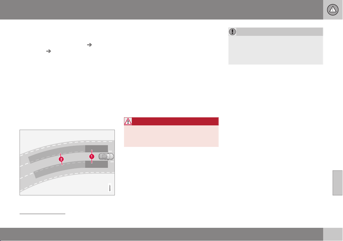
07 Driver support
07
259
tion is handled by the car's menu system MY
CAR
28
:
•
Select On or Off at
Settings Car
settings
BLIS.
When BLIS is deactivated/activated the lamp
in the button goes out/illuminates and the
combined instrument panel confirms the
change with a text message. The door panel
indicator lamps flash once upon activation.
To extinguish the message:
•
Press the left stalk switch OK button.
or
•
Wait approx. 5 seconds – the message
extinguishes.
When BLIS operates
Principle for BLIS: 1. Zone in blind spot. 2. Zone
for quickly approaching vehicle.
The BLIS function is active at speeds above
approx. 10 km/h.
The system is designed to react when:
•
the vehicle is overtaken by other vehicles
•
another vehicle is quickly approaching
the vehicle.
When BLIS detects a vehicle in zone 1 or a
quickly approaching vehicle in zone 2, the
door panel BLIS lamp illuminates with a con-
stant glow. If the driver activates the direction
indicator on the same side as the warning in
this situation then the BLIS lamp will change
from a constant glow to flashing with a more
intense light.
WARNING
BLIS does not work in sharp bends.
BLIS does not work when the car is being
reversed.
Limitations
•
Dirt, ice and snow covering sensors can
reduce functionality and make it impossi-
ble to provide warnings. BLIS cannot
detect hazards if it is covered.
•
Do not affix any objects, tape or labels in
the area of the sensors.
•
BLIS is deactivated when a trailer is con-
nected to the car's electrical system.
IMPORTANT
Repair of the BLIS and CTA functions'
components or repainting the bumpers
must only be performed by a workshop -
an authorised Volvo workshop is recom-
mended.
Related information
•
BLIS (Blind Spot Information System) (p.
257)
•
BLIS and CTA - symbols and messages
(p. 262)
28
For information about the menu system - My car - menu option (p. 106).
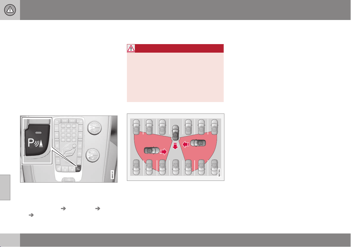
07 Driver support
07
260
* Option/accessory, for more information, see Introduction.
CTA (Cross Traffic Alert)*
CTA (Cross Traffic Alert) is a driver aid
intended to warn about crossing traffic when
the car is reversing. CTA is a supplement to
BLIS (p. 257).
Activate/deactivate CTA
CTA is activated when the engine is started.
This is confirmed by the indicator lamps in
the door panels flashing once.
In cars equipped with parking assistance (p.
245), the CTA function can be deactivated/
activated with the parking assistance On/Off
button.
On/Off for parking assistance and CTA sensors.
CTA itself can be deactivated in the MY CAR
menu system as follows:
•
Go to
Settings Car settings BLIS
Cross Traffic Alert and deselect. The
CTA function is then deactivated. BLIS
remains activated.
WARNING
CTA is a supplementary aid and does not
work in all situations.
CTA is no substitute for a safe driving style
and the use of rearview and door mirrors.
CTA can never replace the driver's respon-
sibility and attention - it is always the driv-
er's responsibility to reverse in a safe man-
ner.
When CTA operates
Principle for CTA.
CTA supplements the BLIS function by being
able to see crossing traffic from the side dur-
ing reversing, such as when reversing out of a
parking space.
CTA is primarily designed to detect vehicles.
In favourable conditions, it may also be able
to detect smaller objects, such as cyclists
and pedestrians.
CTA is only active during reversing and is
activated automatically when reverse is
selected at the gearbox.
•
If CTA detects something approaching
from the side, an acoustic warning signal
sounds. The signal comes from either the
left or the right speaker depending on
which direction the approaching object is
coming from.
•
CTA also warns by illuminating the BLIS
lamps.
•
An additional warning is provided in the
form of an illuminated icon in the display
screen's PAS graphics (p. 245).
Limitations
CTA does not perform optimally in all situa-
tions, but has a certain limitation - for exam-
ple, the CTA sensors cannot "see" through
other parked vehicles or obstructing objects.
Here are some examples of when CTA's "field
of vision" may be limited from the beginning
and approaching vehicles cannot therefore be
detected until they are very close:

07 Driver support
07
261
The car is parked deep inside a parking slot.
Blind CTA sector.
Sector where CTA can detect/"see".
In an angled parking slot CTA can be completely
"blind" on one side.
However, when the driver is slowly reversing
the car, the angle is changed in relation to the
vehicle/object that is blocking, at which the
blind sector rapidly decreases.
Examples of further limitations:
•
Dirt, ice and snow covering sensors can
reduce functionality and make it impossi-
ble to provide warnings. CTA cannot
detect hazards if it is covered.
•
Do not affix any objects, tape or labels in
the area of the sensors.
•
CTA is deactivated when a trailer is con-
nected to the car’s electrical system.
IMPORTANT
Repair of the BLIS and CTA functions'
components or repainting the bumpers
must only be performed by a workshop -
an authorised Volvo workshop is recom-
mended.
Maintenance
Sensor location.
The sensors for the CTA functions are located
inside the rear wing/bumper on each side of
the car.
•
To ensure optimal functionality, the areas
in front of the sensors must be kept
clean.
Related information
•
BLIS (Blind Spot Information System) (p.
257)
•
BLIS and CTA - symbols and messages
(p. 262)

07 Driver support
07
262
* Option/accessory, for more information, see Introduction.
BLIS and CTA - symbols and
messages
In situations where the BLIS (p. 257) and CTA
(p. 260) functions fail or are interrupted, the
combined instrument panel may show a sym-
bol, supplemented by an explanatory mes-
sage - follow any recommendation given.
Message examples:
Message Specification
CTA OFF
CTA has been deactivated
manually. BLIS is active.
BLIS and
CTA OFF
Trailer
attached
BLIS and CTA are tempo-
rarily disabled because a
trailer is connected to the
car’s electrical system.
BLIS and
CTA Serv-
ice required
BLIS and CTA are not
working.
•
Visit a workshop if the
message remains - an
authorised Volvo work-
shop is recommended.
A text message can be acknowledged by
briefly pressing the OK button on the direc-
tion indicator stalk.
Related information
•
BLIS (Blind Spot Information System) (p.
257)
•
CTA (Cross Traffic Alert)* (p. 260)
Speed related power steering
Speed related power steering causes the
steering wheel force to increase with the
speed of the car in order to give the driver
enhanced sensitivity.
The steering is firmer and more immediate on
motorways. Steering is light and requires no
extra effort when parking and at low speed.
The driver can choose between three differ-
ent levels of steering force for road respon-
siveness or steering sensitivity. Go to the
menu system MY CAR and locate
Settings
Car settings Steering wheel force and
select
Low, Medium or High.
This menu is not accessible when the car is
moving.
Related information
•
MY CAR (p. 104)
STARTING AND DRIVING
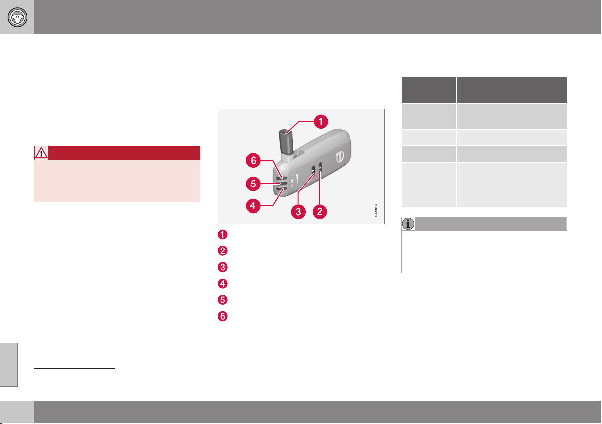
08 Starting and driving
08
264
* Option/accessory, for more information, see Introduction.
Alcolock*
The function of the Alcolock
1
is to prevent the
car from being driven by individuals under the
influence of alcohol. Before the engine can be
started the driver must take a breath test that
verifies that he/she is not under the influence
of alcohol. Alcolock calibration takes place in
accordance with each market's limit value in
force for driving legally.
WARNING
The Alcolock is an aid and does not
exempt the driver from responsibility. It is
always the responsibility of the driver to be
sober and to drive the car safely.
Related information
•
Alcolock* - functions and operation (p.
264)
•
Alcolock* - to bear in mind (p. 266)
•
Alcolock* - storage (p. 265)
•
Alcolock* - before starting the engine (p.
265)
•
Alcolock* - symbols and messages (p.
268)
Alcolock* - functions and operation
The function of the Alcolock
2
is to prevent the
car from being driven by individuals under the
influence of alcohol.
Functions
Nozzle for breath test.
Switch.
Transmission button.
Lamp for battery status.
Lamp for result of breath test.
Lamp indicates ready for breath test.
Operation
Battery
Alcolock indicator lamp (4) shows battery sta-
tus:
Indicator
lamp (4)
Battery status
Green flash-
ing
Charging in progress
Green Fully charged
Yellow Semi-charged
Red Discharged - fit the charger
in the holder or connect the
power supply cable from
the glovebox.
NOTE
Store the Alcolock in its holder. This will
keep the built-in battery fully charged and
the Alcolock is activated automatically
when the car is opened.
Related information
•
Alcolock* (p. 264)
1
Also called Alcoguard.
2
Also called Alcoguard.
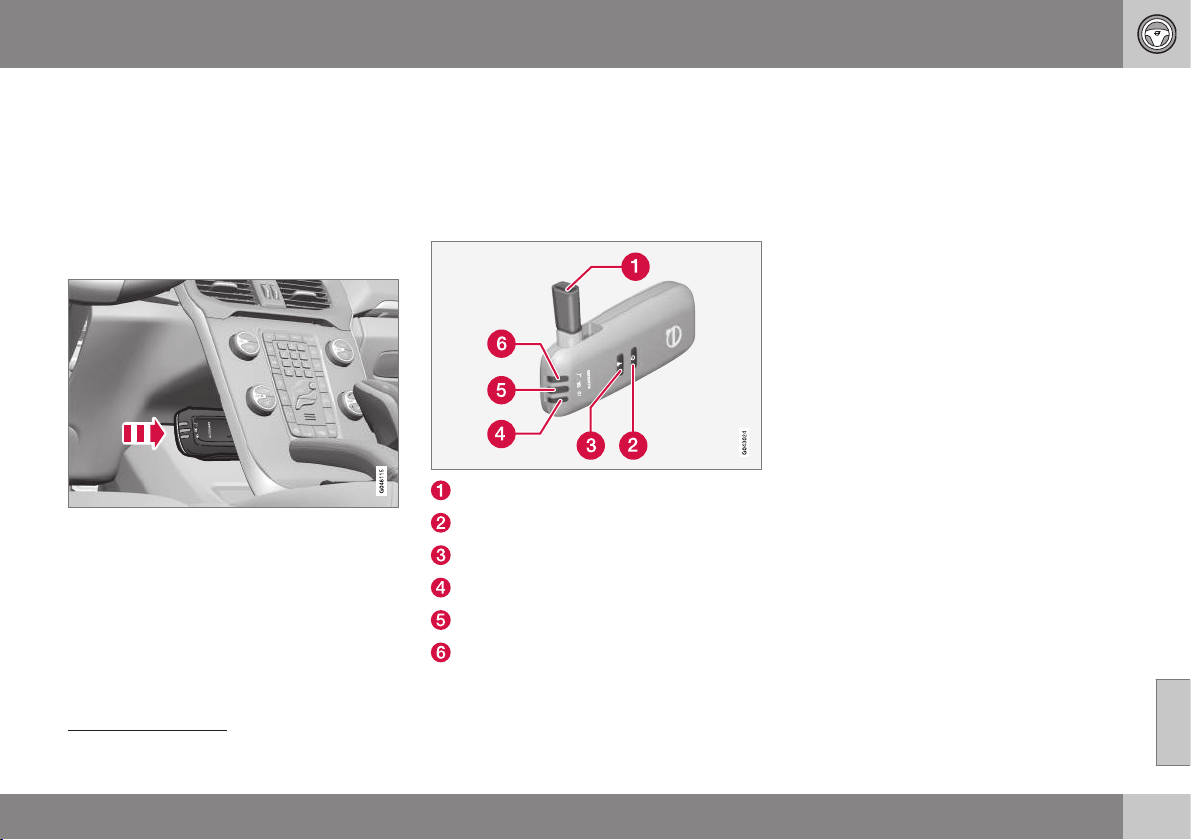
08 Starting and driving
08
* Option/accessory, for more information, see Introduction.
265
Alcolock* - storage
The function of the Alcolock
3
is to prevent the
car from being driven by individuals under the
influence of alcohol.
Store the Alcolock in its holder. Release the
handheld unit by depressing it slightly in its
holder and releasing it - it then springs out
and can be removed from the holder.
Handheld unit storage and charging station.
•
Replace the handheld unit in the holder
by pushing it in until it engages.
•
Store the handheld unit in the holder -
this provides it with the best protection
and keeps its batteries fully charged.
Related information
•
Alcolock* (p. 264)
Alcolock* - before starting the engine
The function of the Alcolock
4
is to prevent the
car from being driven by individuals under the
influence of alcohol.
The Alcolock is activated automatically and is
then ready for use when the car is opened.
Nozzle for breath test.
Switch.
Transmission button.
Lamp for battery status.
Lamp for result of breath test.
Lamp indicates ready for breath test.
1. When the indicator lamp (6) is green the
Alcolock is ready for use.
2. Withdraw the Alcolock from its holder. If
the Alcolock is outside the car when it is
unlocked then it must first be activated
with the switch (2).
3. Fold up the nozzle (1), take a deep breath
and blow with an even pressure until a
"click" is heard after approx. 5 seconds.
The result will be one of the alternatives in
the following table Result after breath
test.
4. If no message is shown then the trans-
mission to the car may have failed - in
which case, press the button (3) to trans-
mit the result to the car manually.
5. Fold down the nozzle and refit the Alco-
lock in its holder.
6. Start the engine following an approved
breath test within 5 minutes - otherwise it
must be repeated.
3
Also called Alcoguard.
4
Also called Alcoguard.
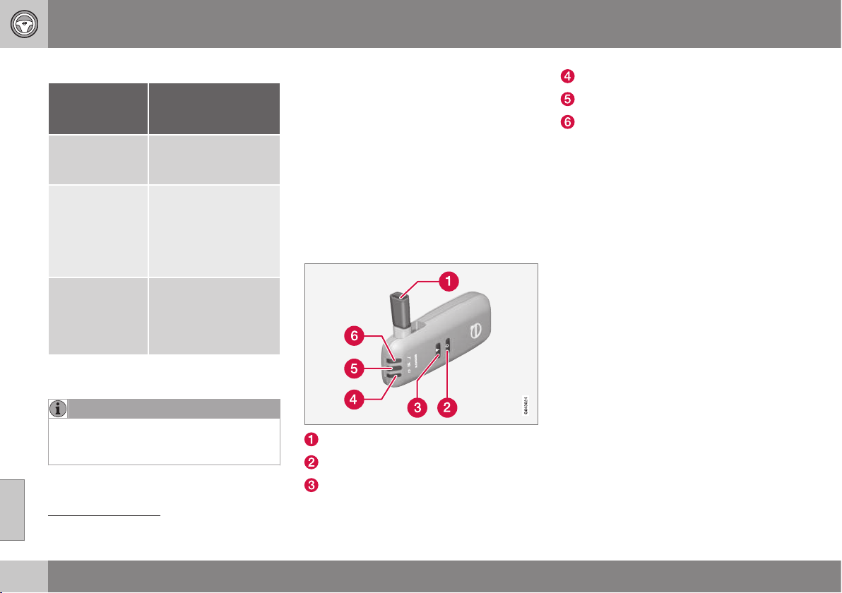
||
08 Starting and driving
08
266
* Option/accessory, for more information, see Introduction.
Result after breath test
Indicator
lamp (5) +
Display text
Specification
Green lamp +
Alcoguard
Approved test
Start the engine - no
alcohol content meas-
ured.
Yellow lamp +
Alcoguard
Approved test
Engine starting possi-
ble - measured alcohol
content is above
0.1 promille but below
the limit value in
force
A
.
Red lamp + Dis-
approved test
Wait 1 minute
Engine starting not
possible - measured
alcohol content is
above the limit value in
force
A
.
A
Limit values vary from country to country. Find out what
applies in your country. See also Alcolock* - to bear in
mind (p. 266)
NOTE
After a completed period of driving, the
engine can be restarted within 30 minutes
without a new breath test.
Related information
•
Alcolock* (p. 264)
Alcolock* - to bear in mind
The function of the Alcolock
5
is to prevent the
car from being driven by individuals under the
influence of alcohol.
In order to obtain correct function and as
accurate a measurement result as possible:
•
Avoid eating or drinking
approx. 5 minutes before the breath test.
•
Avoid excess windscreen washing - the
alcohol in the washer fluid may result in
an incorrect measurement result.
Change of driver
Nozzle for breath test.
Switch.
Transmission button.
Lamp for battery status.
Lamp for result of breath test.
Lamp indicates ready for breath test.
In order to ensure that a new breath test is
carried out in the event of a change of driver -
depress the switch (2) and the send button (3)
simultaneously for approx. 3 seconds. At
which point the car returns to start inhibition
mode and a new approved breath test is
required before starting the engine.
Calibration and service
The Alcolock must be checked and calibrated
at a workshop
6
every 12 months.
30 days before recalibration is necessary the
combined instrument panel shows the mes-
sage
Alcoguard Calibr. required. If calibra-
tion is not carried out within these 30 days
then normal engine starting will be blocked -
only starting with the Bypass function will
then be possible, see the following heading
"Emergency situation".
The message can be cleared by pressing the
send button (3) once. Otherwise it goes out
on its own after approx. 2 minutes but then
reappears each time the engine is started -
only recalibration at a workshop
6
can clear
the message permanently.
5
Also called Alcoguard.
6
An authorised Volvo workshop is recommended.

08 Starting and driving
08
* Option/accessory, for more information, see Introduction.
267
Cold or hot weather
The colder the weather the longer it takes
before the Alcolock is ready for use:
Temperature (ºC) Maximum heat-
ing time (sec-
onds)
+10 to +85 10
-5 to +10 60
-40 to -5 180
At temperatures below -20 ºC or above
+60 ºC the Alcolock requires additional power
supply. The combined instrument panel
shows
Alcoguard insert power cable. In
which case, connect the power supply cable
from the glovebox and wait until indicator
lamp (6) is green.
In extremely cold weather the heating time
can be reduced by taking the Alcolock
indoors.
Emergency situation
In the event of an emergency situation or the
Alcolock is out of order, it is possible to
bypass the Alcolock in order to drive the car.
NOTE
All activation with bypass is logged and
saved in a memory; see Recording data (p.
17).
After the Bypass function has been activated
the combined instrument panel shows
Alcoguard Bypass enabled the whole time
while driving and can only be reset by a work-
shop
6
.
The Bypass function can be tested without
the error message being logged - in which
case, carry out all the steps without starting
the car. The error message is cleared when
the car is locked.
When the Alcolock is installed, either the
Bypass or Emergency function is selected as
the bypassing option. This setting can be
changed afterwards at a workshop
6
.
Activating the Bypass function
•
Depress and hold the left-hand stalk
switch OK button and the button for haz-
ard warning flashers simultaneously for
approx. 5 seconds - the combined instru-
ment panel first shows
Bypass activated
Wait 1 minute
and then Alcoguard
Bypass enabled - after which the engine
can be started.
This function can be activated several times.
The error message shown during driving can
only be cleared at a workshop
6
.
Activating the Emergency function
•
Depress and hold the left-hand stalk
switch OK button and the button for haz-
ard warning flashers simultaneously for
approx. 5 seconds - the combined instru-
ment panel shows
Alcoguard Bypass
enabled and the engine can be started.
This function can be used once, after which a
reset must be made at a workshop
6
.
Related information
•
Alcolock* (p. 264)
6
An authorised Volvo workshop is recommended.
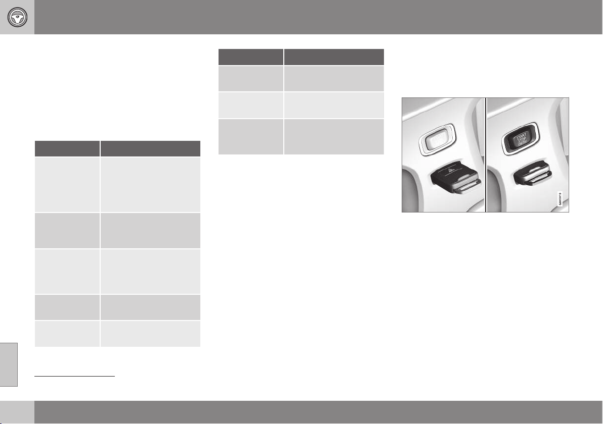
08 Starting and driving
08
268
* Option/accessory, for more information, see Introduction.
Alcolock* - symbols and messages
The function of the Alcolock
7
is to prevent the
car from being driven by individuals under the
influence of alcohol.
In addition to the previously described mes-
sages related to how the alcolock works
before starting the engine (p. 265) the follow-
ing can also be displayed:
Display text Meaning/Action
Alcoguard
Restart possi-
ble
The engine has been
switched off for less than
30 minutes - engine star-
ting possible without
new test.
Alcoguard
Service
required
Contact a workshop
A
.
Alcoguard No
signal
Transmission failed -
send manually with but-
ton (3) or take a new
breath test.
Alcoguard
Invalid test
Test failed - take a new
breath test.
Alcoguard
Blow longer
Blowing too short - blow
for longer.
Display text Meaning/Action
Alcoguard
Blow softer
Blowing too hard - blow
more gently.
Alcoguard
Blow harder
Blowing too weak - blow
harder.
Alcoguard
wait Preheat-
ing
Heating not finished -
wait for text
Alcoguard
Blow 5 seconds.
A
An authorised Volvo workshop is recommended.
Related information
•
Alcolock* (p. 264)
Starting the engine
The engine is started and switched off using
the remote control key and the START/STOP
ENGINE button.
Ignition switch with remote control key extrac-
ted/inserted. and START/STOP ENGINE button.
7
Also called Alcoguard.
08 Starting and driving
08
* Option/accessory, for more information, see Introduction.
269
IMPORTANT
Do not press in the remote control key
incorrectly turned - Hold the end with the
detachable key blade; see Detachable key
blade - detaching/attaching (p. 166)
1. Insert the remote control key in the igni-
tion switch and press it in to its end posi-
tion. Note that if the car is equipped with
Alcolock* then a breath test must first be
approved before the engine can be
started. For more information on the
Alcolock, see Alcolock* (p. 264).
2.
Hold the clutch pedal fully depressed
8
.
(For cars with automatic gearbox -
Depress the brake pedal.)
3. Press the START/STOP ENGINE button
and then release it.
The starter motor works until the engine is
started or until its overheating protection trig-
gers.
IMPORTANT
If the engine fails to start after 3 attempts -
wait for 3 minutes before making a further
attempt. Starting capacity increases if the
battery is allowed to recover.
WARNING
Always remove the remote control key
from the ignition switch when leaving the
car, and make sure that the key position is
0 - in particular if there are children in the
car. For information on how this works,
see Key positions (p. 71).
NOTE
The idling speed can be noticeably higher
than normal for certain engine types during
cold starting. This is done in order that the
emissions system can reach normal oper-
ating temperature as quickly as possible,
which minimises exhaust emissions and
protects the environment.
Keyless drive*
Follow steps 2–3 for keyless(p. 168) starting
of petrol and diesel engines.
NOTE
A prerequisite for the engine to start is that
one of the car's remote control keys with
the Keyless drive function is in the passen-
ger compartment or cargo area.
WARNING
Never remove the remote control key from
the car while driving or during towing.
Related information
•
Key positions (p. 71)
8
If the car is moving then it is enough to press the START/STOP ENGINE button to start the car.
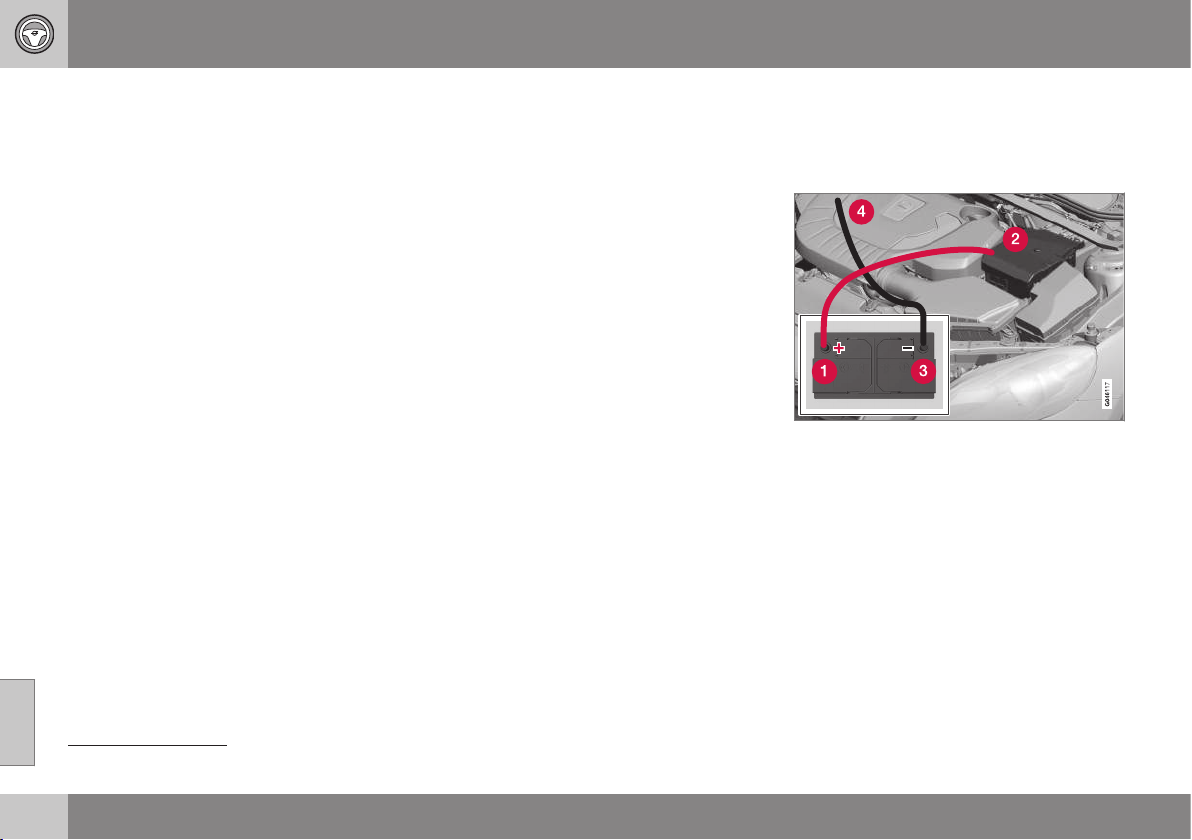
08 Starting and driving
08
270
Switching off the engine
The engine is switched off using the START/
STOP ENGINE button.
To switch off the engine:
•
Press the START/STOP ENGINE button
- the engine stops.
•
If the car has an automatic gearbox and
the gear selector is not in a position P or
if the car is moving - Press twice or hold
the START/STOP ENGINE button
depressed until the engine stops.
Related information
•
Key positions (p. 71)
Steering lock
The steering lock makes steering difficult if
the car is e.g. taken unlawfully.
Function
•
The steering lock locks when the driver's
door is opened after the engine has been
switched off.
•
The steering lock unlocks when the
remote control key is in the ignition
switch
9
and the START/STOP ENGINE
button is depressed.
A mechanical noise can be perceived when
the steering lock unlocks or locks.
Related information
•
Starting the engine (p. 268)
•
Key positions (p. 71)
•
Steering wheel (p. 77)
Jump starting
If the starter battery (p. 351) is discharged
then the car can be started with current from
another battery.
When jump starting the car, the following
steps are recommended to avoid short cir-
cuits or other damage:
1. Insert the remote control key in key posi-
tion (p. 71) 0.
2. Check that the donor battery has a volt-
age of 12 V.
3. If the donor battery is installed in another
car - switch off the donor car's engine
and make sure that the two cars do not
touch each other.
9
Cars with Keyless drive must have a remote control key inside the passenger compartment.
08 Starting and driving
08
271
4. Connect one of the red jump lead's
clamps to the donor battery's positive
terminal (1).
IMPORTANT
Connect the start cable carefully to avoid
short circuits with other components in the
engine compartment.
5. Open the clips on the front cover of the
battery in your car and remove the cover.
6. Connect the red jump lead's other clamp
onto the car's positive terminal (2).
7. Connect one of the black jump lead's
clamps to the donor battery's negative
terminal (3).
8. Connect the other clamp to a grounding
point, e.g. right-hand engine mounting at
the top, the outer screw head (4).
9. Check that the jump lead clamps are
affixed securely so that there are no
sparks during the starting procedure.
10. Start the engine of the "donor car" and
allow it to run a few minutes at a speed
slightly higher than idle
approx. 1500 rpm.
11. Start the engine in the car with the dis-
charged battery.
IMPORTANT
Do not use the connections when attempt-
ing to start, as there is a risk of sparking.
12. Remove the jump leads in reverse order -
first the black and then the red.
> Make sure that none of the black jump
lead's clamps comes into contact with
the battery's positive terminal or the
clamp connected to the red jump lead!
WARNING
•
The battery can generate oxyhydrogen
gas, which is highly explosive. A spark
can be formed if a jump lead is con-
nected incorrectly, and this can be
enough for the battery to explode.
•
The battery contains sulphuric acid,
which can cause serious burns.
•
If sulphuric acid comes into contact
with eyes, skin or clothing, flush with
large quantities of water. If acid
splashes into the eyes - seek medical
attention immediately.
Related information
•
Starting the engine (p. 268)
Gearboxes
There are two main types of gearbox - Manual
and Automatic.
•
Manual gearbox (p. 272)
•
Automatic gearbox - Geartronic (p. 273)
and Powershift (p. 276)
IMPORTANT
To prevent damage to any drive system
components, the working temperature of
the gearbox is checked. If there is a risk of
overheating, a warning symbol in the com-
bined instrument panel lights up and a text
message is shown. Follow the recommen-
dation given in the text message.
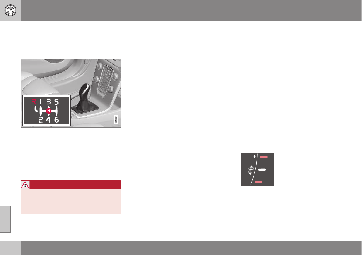
08 Starting and driving
08
272
* Option/accessory, for more information, see Introduction.
Manual gearbox
The function of the gearbox is to change the
gear ratio depending on speed and power
requirements.
Gearing pattern.
Look at the actual gearshift pattern imprinted
on the gear lever.
•
Depress the clutch pedal fully during
each gear change.
•
Take your foot off the clutch pedal
between gear changes.
WARNING
Always apply the parking brake when
parking on a slope - leaving the car in gear
is not sufficient to hold the car in all situa-
tions.
Reverse gear inhibitor
The reverse gear inhibitor hinders the possi-
bility of mistakenly attempting to engage
reverse gear during normal forward travel.
•
Follow the gearing pattern printed on the
gear lever and start from neutral position,
N then depress the gear lever before
moving it to R position.
•
Engage reverse gear only when the car is
stationary.
Related information
•
Gearboxes (p. 271)
•
Transmission fluid - grade and volume (p.
450)
Gear shift indicator*
The gear shift indicator notifies the driver
when it is appropriate to engage the next
higher or lower gear in order to obtain the
lowest possible fuel consumption.
An essential detail in connection with environ-
mental driving is to drive in the right gear and
to change gear in plenty of time.
An indicator is available as an aid on certain
variants - GSI (Gear Shift Indicator) - which
notifies the driver when it is appropriate to
engage the next higher or lower gear in order
to obtain the lowest possible fuel consump-
tion. However, taking into consideration cha-
racteristics such as performance and vibra-
tion-free running, it may be advantageous to
change gear at a higher engine speed. The
framed number indicates the current gear.
Manual gearbox
Gear shift indicator for man-
ual gearbox. Only one
marker is illuminated at a
time - it is illuminated in the
centre only during normal
driving.
When gearing up/down as recommended, the
upper one is illuminated at +" or the lower at
"-", marked red in the illustration.

08 Starting and driving
08
* Option/accessory, for more information, see Introduction.
273
Automatic gearbox
Combined instrument panel "Digital" with gear
shift indicator.
With "Analogue" combined
instrument panel, the gear
positions and indicator
arrows are displayed in its
centre.
Related information
•
Manual gearbox (p. 272)
Automatic gearbox - Geartronic*
An automatic gearbox with Geartronic differs
from an Automatic gearbox - Powershift (p.
276), in that it has a hydraulic torque con-
verter that transfers power from engine to
gearbox. It has two different gear modes -
Automatic and Manual.
D: Automatic gear positions. +/–: Manual gear
positions. S: Sport mode*.
10
The combined instrument panel shows the
position of the gear selector using the follow-
ing indications:
P, R, N, D, S*, 1, 2, 3 etc.
Gear positions
Automatic gear positions are
indicated on the right of the
combined instrument panel.
(Only one marker is illumi-
nated at a time - the one
showing the current gear
selector position.)
Symbol "S" for Sport mode is ORANGE when
the mode is active.
P – Parking position
Select P when starting the engine or when
the car is parked.
•
In order to be able to move the gear
selector from P-position, the brake pedal
must first be depressed firmly.
The gearbox is mechanically blocked when
the P position is engaged. Apply the parking
brake as well, as a precaution - , see Parking
brake (p. 292).
NOTE
The gear selector must be in P position to
allow the car to be locked and alarmed.
IMPORTANT
The car must be stationary when posi-
tion P is selected.
10
The gear lever's gearshift pattern varies depending on engine option.
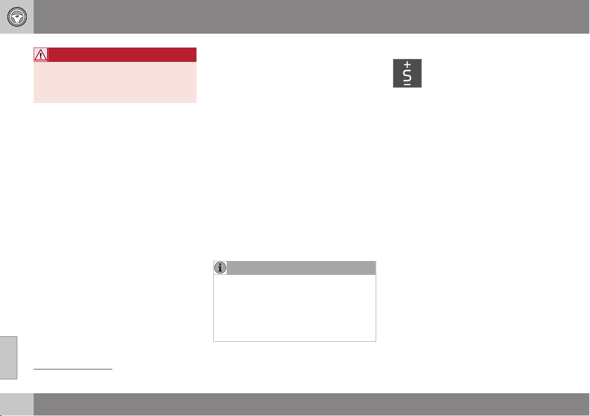
||
08 Starting and driving
08
274
* Option/accessory, for more information, see Introduction.
WARNING
Always apply the parking brake when
parking on a slope - the automatic trans-
mission in P is not sufficient to hold the car
in all situations.
R – Reverse
The car must be stationary when position R is
selected.
N – Neutral
No gear is engaged and the engine can be
started. Apply the parking brake if the car is
stationary with the gear selector in position N.
D – Drive
D is the normal driving position. Shifting up
and down takes place automatically based on
the level of acceleration and speed. The car
must be stationary when the gear selector is
moved to position D from position R.
Geartronic – Manual gear positions (+/-)
The driver can also change gear manually
using the Geartronic automatic gearbox. The
car engine-brakes when the accelerator pedal
is released.
The manual gear position is reached by mov-
ing the lever to the side from position D to the
end position at "+/-". The combined instru-
ment panel's symbol "+/-" changes colour
from WHITE to ORANGE and the digits
1, 2, 3
etc. are displayed in a box which corre-
sponds to the gear that has just been
selected.
•
Move the lever forwards towards + (plus)
to change up a gear and release the
lever, which returns to its neutral position
between "+" and "–".
or
•
Pull the lever back towards "–" (minus) to
change down a gear and release it.
The manual gearshift mode "+/-" can be
selected at any time while driving.
Geartronic automatically shifts down if the
driver allows the speed to decrease lower
than a level suitable for the selected gear, in
order to avoid jerking and stalling.
To return to automatic driving mode:
•
Move the lever to the side to the end
position at D.
NOTE
f the gearbox has a Sport programme then
the gearbox will only become manual after
the lever has been moved forwards or
backwards in its "+/-" position. The com-
bined instrument panel then shifts the indi-
cation from
S to show which of the gears
1, 2, 3 etc. is engaged.
Geartronic - Sport mode (S)
The Sport programme provides
sportier characteristics and allows
higher engine speed for the gears.
At the same time it responds more
quickly to acceleration. During active driving,
the use of a lower gear is prioritised, leading
to a delayed upshift.
To activate Sport mode:
•
Move the gear selector to the side from D
position to the end position at "+S–" - the
combined instrument panel changes indi-
cation from
D to S.
Sport mode can be selected at any time while
driving.
Geartronic - Winter mode
It can be easier to pull away on slippery roads
if 3rd gear is engaged manually.
1. Depress the brake pedal and move the
gear selector from D position to the end
position at "+/–" - the combined instru-
ment panel shifts the indication from
D to
the figure
1
11
.
2. Scroll up to gear 3 by pushing the lever
forward towards "+" (plus) twice - the
combined instrument panel shifts the
indication from
1 to 3.
3. Release the brake and accelerate care-
fully.
11
If the car has Sport mode* then "S" is shown first.

08 Starting and driving
08
* Option/accessory, for more information, see Introduction.
275
The gearbox "winter mode" means that the
car moves off with a lower engine speed and
reduced engine power on the drive wheels.
Kick-down
When the accelerator pedal is pressed all the
way to the floor (beyond the position normally
regarded as full acceleration) a lower gear is
immediately engaged. This is known as kick-
down.
If the accelerator is released from the kick-
down position, the gearbox automatically
changes up.
Kick-down is used when maximum accelera-
tion is needed, such as for overtaking.
Safety function
To prevent overrevving the engine, the gear-
box control program has a protective down-
shift inhibitor which prevents the kick-down
function.
Geartronic does not permit downshifting/
kick-down which would result in an engine
speed high enough to damage the engine.
Nothing happens if the driver still tries to shift
down in this way at high engine speed – the
original gear remains engaged.
When kick-down is activated the car can
change one or more gears at a time depend-
ing on engine speed. The car changes up
when the engine reaches its maximum speed
in order to prevent damage to the engine.
Related information
•
Automatic gearbox - Powershift* (p. 276)
•
Transmission fluid - grade and volume (p.
450)
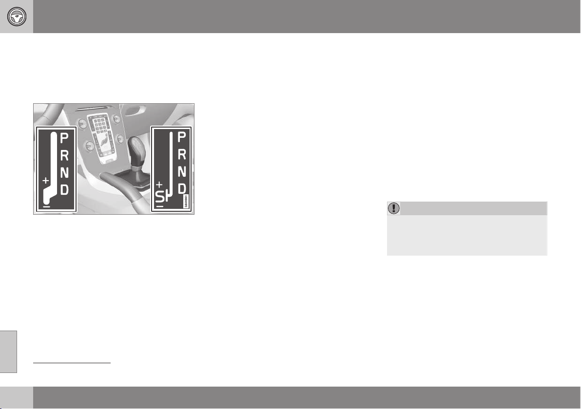
08 Starting and driving
08
276
* Option/accessory, for more information, see Introduction.
Automatic gearbox - Powershift*
An automatic gearbox with Powershift differs
from an automatic gearbox with Geartronic (p.
273), in that it has double mechanical clutch
discs.
D: Automatic gear positions. +/–: Manual gear
positions. S: Sport mode*.
12
The Powershift automatic gearbox transmits
the motive force from the engine to the drive
wheels with double mechanical clutch discs,
as opposed to Geartronic which instead uses
a conventional hydraulic torque converter.
Powershift transmission operates in the same
way and has similar controls and functions as
the Geartronic automatic transmission. One
exception is Geartronic's Winter mode, see
Automatic gearbox - Geartronic* (p. 273).
Powershift enables driving away on a slippery
road surface if 2nd gear is engaged manually
instead of 3rd gear (Geartronic).
Powershift or Geartronic
The model with Powershift transmission
should not be towed as it is dependent on the
engine running in order to receive sufficient
lubrication. If towing still has to take place,
the route must be as short as possible and
then with very low speed.
In the event of uncertainty as to whether or
not the car is equipped with Powershift trans-
mission, this can be verified by checking the
designation on the gearbox label under the
bonnet - see Type designations (p. 438). The
designation ”MPS6” means that it is
Powershift transmission - otherwise it is
Geartronic automatic transmission.
To bear in mind
The transmission's double clutch has over-
load protection that is activated if it becomes
too hot, e.g. if the car is held stationary with
the accelerator pedal on an uphill gradient for
a long time.
Overheated transmission causes the car to
shake and vibrate, and the warning symbol
illuminates and the combined instrument
panel shows a message. The transmission
can also overheat during slow driving in
queues (10 km/h or slower) on an uphill gradi-
ent, or with a trailer hitched. The transmission
cools down when the car is stationary, with
foot brake depressed and the engine running
at idling speed.
Overheating during slow driving in queues
can be avoided by driving in stages:
•
Stop the car and wait with your foot on
the brake pedal until there is a moderate
distance to the traffic ahead, drive for-
ward a short distance, and then wait
another moment with your foot on the
brake pedal.
IMPORTANT
Use the foot brake to hold the car station-
ary on an uphill gradient - do not hold the
car with the accelerator pedal. The gear-
box could then overheat.
For important information regarding
Powershift transmission, see Towing (p. 308).
Text message and action
In some situations the combined instrument
panel may show a text message at the same
time as a symbol is illuminated.
12
The gear lever's gearshift pattern varies depending on engine option.
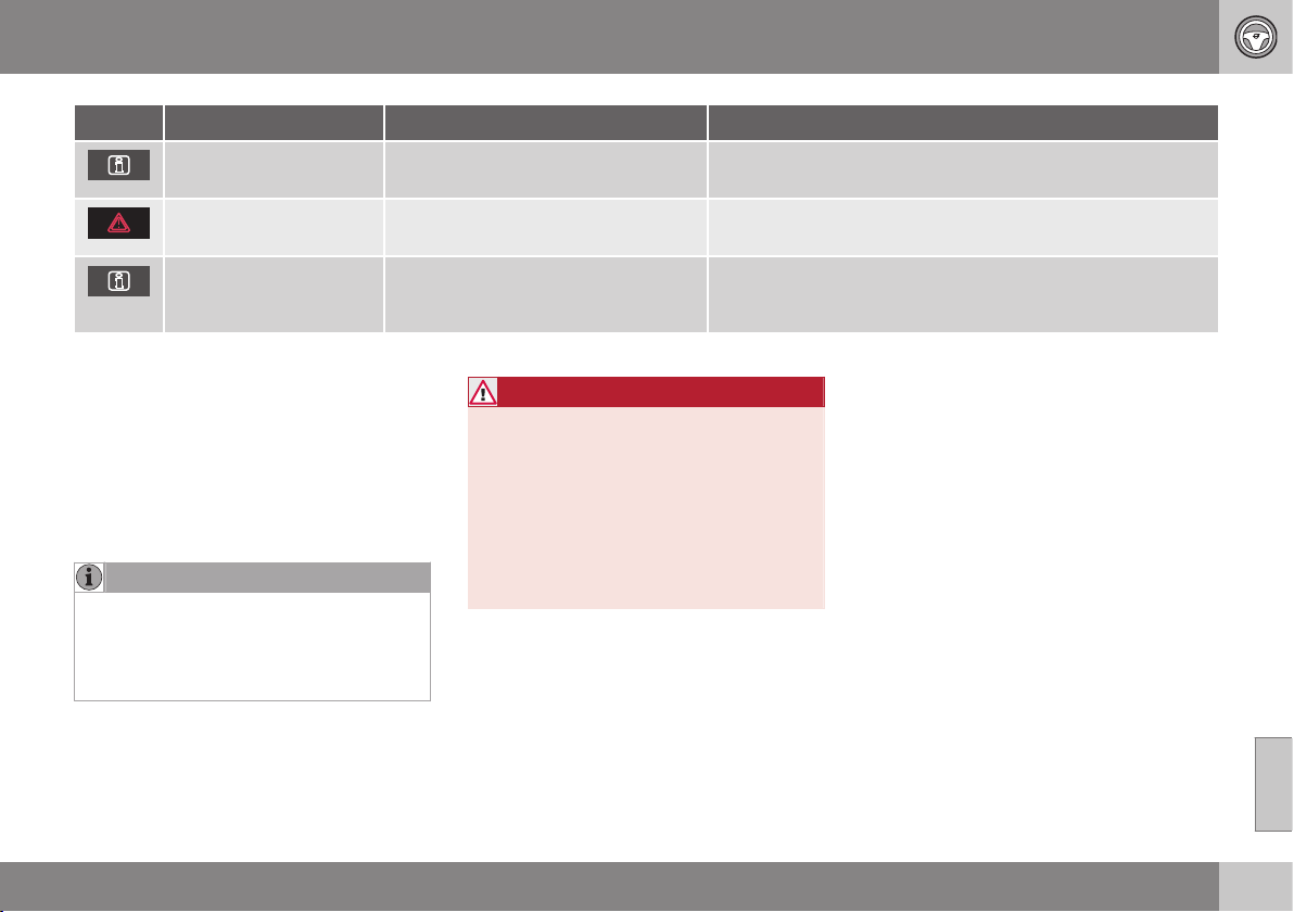
08 Starting and driving
08
* Option/accessory, for more information, see Introduction.
277
Symbol Message Driving characteristics Action
Transm. overheat
brake to hold
Difficulty in maintaining even speed at
constant engine speed.
Transmission overheated. Keep the car stationary using the
foot brake.
A
Transm. overheat park
safely
Significant pulling in the car's traction. Transmission overheated. Park the car immediately in a safe
manner.
A
Transm. cooling let
engine run
No drive due to overheated gearbox. Transmission overheated. For fastest cooling: Run the engine
at idling speed with the gear lever in the N or P position until
the message clears.
A
For fastest cooling: run the engine at idling speed with the gear lever in the N or P position, until the message clears.
The table shows three steps with an
increased degree of seriousness should the
transmission become too hot. In parallel with
the text message, the driver is also advised
that the car's electronics are temporarily
changing the driving characteristics. Follow
the instructions in the text message where
appropriate.
NOTE
The examples in the table are no indication
of the car being defective, but show that a
safety function has been activated with a
view to preventing damage to any of the
car's components.
WARNING
If a warning symbol combined with the text
Transm. overheat park safely is ignored
then the heat in the gearbox may become
so high that the power transmission
between engine and gearbox is temporar-
ily halted in order to prevent the clutch
from malfunctioning - the car then loses
drive and is stationary until gearbox tem-
perature has cooled to an acceptable
level.
For more possible text messages with their
respective proposals for solutions concerning
automatic gearbox, see Messages (p. 103).
A text message extinguishes automatically
after the action has been carried out or after
one press on the indicator stalk OK button.
Related information
•
Automatic gearbox - Geartronic* (p. 273)
•
Transmission fluid - grade and volume (p.
450)

08 Starting and driving
08
278
* Option/accessory, for more information, see Introduction.
Gear selector inhibitor
There are two different types of gear selector
inhibitor - mechanical and automatic.
Mechanical gear selector inhibitor
G021351
The gear selector can be moved forward and
back freely between N and D. Other positions
are locked with a latch that is released with
the inhibitor button on the gear selector.
With the inhibitor button depressed the lever
can be moved forwards or backwards
between P, R, N and D.
Automatic gear selector inhibitor
The automatic gearbox has special safety
systems:
Parking position (P)
Stationary car with engine running:
•
Keep your foot on the brake pedal when
moving the gear selector to another posi-
tion.
Electric gear inhibitor – Shiftlock
Parking position (P)
To be able to move the gear selector from P
to other gear positions, the brake pedal must
be depressed and the remote control key
must be in position II.
Shiftlock – Neutral (N)
If the gear selector is in the N position and
the car has been stationary for at least 3 sec-
onds (irrespective of whether the engine is
running) then the gear selector is locked.
To be able to move the gear selector from N
to another gear position the brake pedal must
be depressed and the remote control key
must be in key position II (p. 71).
Deactivate automatic gear selector
inhibitor
If the car cannot be driven, e.g. due to a flat
battery, the gear selector must be moved
from the P position so that the car can be
moved.
Lift out the contoured insert in the com-
partment behind the centre console and
locate a spring-loaded button in the bot-
tom of the compartment.
Press and hold the button.
Move the gear selector from the P posi-
tion and release the button.
4. Refit the storage compartment insert.
Related information
•
Automatic gearbox - Geartronic* (p. 273)
•
Automatic gearbox - Powershift* (p. 276)
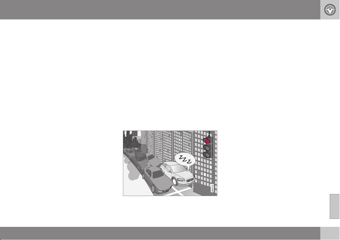
08 Starting and driving
08
* Option/accessory, for more information, see Introduction.
279
Hill start assist (HSA)*
The foot brake can be released before setting
off or reversing uphill - the HSA (Hill Start
Assist) function means that the car does not
roll backwards.
The function means that the pedal pressure in
the brake system remains for several seconds
while the driver's foot is moved from brake
pedal to accelerator pedal.
The temporary braking effect releases after
several seconds or when the driver acceler-
ates.
Related information
•
Starting the engine (p. 268)
Start/Stop*
Some engine and gearbox combinations
come fitted with a Start and Stop function
which engages in the event of e.g. stationary
traffic or waiting at traffic lights - the engine is
then switched off temporarily and restarts
automatically when the journey is due to con-
tinue.
Environmental care is one of Volvo Car Cor-
poration's core values and it influences all of
our operations. This target orientation has
resulted in several separate energy-saving
functions of which Start/Stop is one, all with
the collective task of reducing fuel consump-
tion, which in turn helps to reduce exhaust
emissions.
General information about Start/Stop
The engine is switched off - it becomes quieter
and cleaner...
The Start/Stop function gives the driver the
opportunity for a more active environmentally
conscious way of driving the car by means of
being able to allow the engine to stop auto-
matically, whenever appropriate.
Manual or Automatic
Note that there are differences in the
Start/Stop function depending on whether the
gearbox is manual or automatic.
Related information
•
Start/Stop* - function and operation (p.
280)
•
Starting the engine (p. 268)
•
Start/Stop* - settings (p. 284)
•
Start/Stop* - the engine does not auto-
start (p. 283)
•
Start/Stop* - the engine auto-starts (p.
282)
•
Start/Stop* - the engine does not stop (p.
281)
•
Start/Stop* - involuntary engine stoppage
manual gearbox (p. 284)
•
Start/Stop* - symbols and messages (p.
286)
•
Battery - Start/Stop (p. 353)

08 Starting and driving
08
280
* Option/accessory, for more information, see Introduction.
Start/Stop* - function and operation
Some engine and gearbox combinations are
equipped with a Start and Stop function
which engages in the event of e.g. stationary
traffic or waiting at traffic lights. The
Start/Stop function is activated automatically
when the engine is started with the key.
Start/StopThe function is
activated automatically when
the engine is started with the
key. The driver is made
aware of the function by the
function's On/Off button
symbol lighting up in the
combined instrument panel
and the On/Off button lamp
illuminating.
All of the car's normal systems such as light-
ing, radio, etc. work as normal even with an
engine that has stopped automatically,
except that some equipment may have the
function temporarily reduced, e.g. the climate
control system's fan speed or extremely high
volume on the audio system.
Auto-stopping the engine
The following is required for the engine to
auto-stop:
Conditions M/A
A
Declutch, set the gear lever in neu-
tral position and release the clutch
pedal - the engine stops automati-
cally.
M
Stop the car with the foot brake
and then keep your foot on the
pedal - the engine stops automati-
cally.
A
A
M = Manual gearbox, A = Automatic gearbox.
In some cases the engine stops automatically
before the car is completely stationary.
The combined instrument panel's
symbols for the Start/Stop function
illuminate as verification and
reminder that the engine has stop-
ped automatically.
Auto-starting the engine
Conditions M/
A
A
With the gear lever in neutral posi-
tion:
1. Depress the clutch pedal or
press the accelerator pedal -
the engine starts.
2. Engage a suitable gear and
drive.
M
The following option is also availa-
ble on a downhill gradient:
Release the foot brake and let the
car move off - the engine starts
automatically when the speed
exceeds normal walking pace.
M
Release the foot pressure on the
foot brake - the engine starts auto-
matically and the journey can con-
tinue.
A
A
M = Manual gearbox, A = Automatic gearbox.
Deactivating the Start/Stop function
In certain situations, it may
advisable to temporarily
switch off the automatic
Start/Stop function - this is
carried out with a push of
this button.
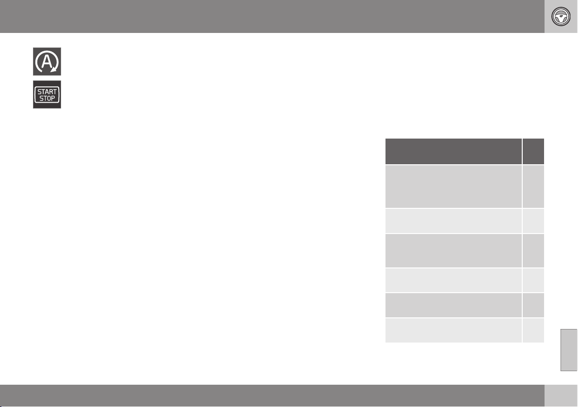
08 Starting and driving
08
* Option/accessory, for more information, see Introduction.
281
Disengaged function is indicated by
the combined instrument panel's
Start/Stop symbols and the button's
lamp extinguishing.
The Start/Stop function is disengaged until it
is reactivated with the button or until the next
time the engine is started with the key.
Start assistance HSA
The foot brake can also be released on an
uphill slope to auto-start the engine - the HSA
(p. 279) (Hill Start Assist) function prevents
the car from rolling backwards.
HSA means that the pressure in the brake
system remains temporarily available while
the driver moves his/her foot from the brake
pedal to the accelerator pedal for driving off
with the engine auto-stopped. The temporary
braking effect releases after a couple of sec-
onds or when the driver accelerates.
Related information
•
Start/Stop* (p. 279)
•
Starting the engine (p. 268)
•
Start/Stop* - settings (p. 284)
•
Start/Stop* - the engine does not auto-
start (p. 283)
•
Start/Stop* - the engine auto-starts (p.
282)
•
Start/Stop* - the engine does not stop (p.
281)
•
Start/Stop* - involuntary engine stoppage
manual gearbox (p. 284)
•
Start/Stop* - symbols and messages (p.
286)
•
Battery - Start/Stop (p. 353)
Start/Stop* - the engine does not stop
Some engine and gearbox combinations are
equipped with a Start and Stop function
which engages in the event of e.g. stationary
traffic or waiting at traffic lights. Although the
Start/Stop function is activated, the engine
does not always stop automatically.
The engine does not auto-stop if:
Conditions M/
A
A
the car has not achieved
approx. 5 km/h (= fast walking pace)
first after a key start or the last auto-
stop.
M
+ A
the driver has opened the seatbelt's
buckle.
M
+ A
the capacity of the starter battery is
below the minimum permissible
level.
M
+ A
the engine does not have normal
operating temperature.
M
+ A
outside temperature is below freez-
ing point or above approx. 30 °C.
M
+ A
the windscreen's electric heating is
activated.
M
+ A

||
08 Starting and driving
08
282
* Option/accessory, for more information, see Introduction.
Conditions M/
A
A
the environment in the passenger
compartment differs from the preset
values
B
- indicated by the ventilation
fan running at a high speed.
M
+ A
the car is reversed. M
+ A
the starter battery's temperature is
below freezing point or too high.
M
+ A
the driver makes greater steering
wheel movements.
M
+ A
the exhaust system's particulate fil-
ter is full - the temporarily disen-
gaged Start/Stop function is reacti-
vated once an automatic cleaning
cycle has been performed (see Die-
sel particle filter (p. 299)).
M
+ A
the road is very steep. M
+ A
a trailer is connected electrically to
the car’s electrical system.
M
+ A
the atmospheric air pressure is less
than equivalent to
1500-2400 metres above sea level -
the current air pressure varies with
the prevailing weather conditions.
M
+ A
Conditions M/
A
A
adaptive cruise control Queue Assist
is activated.
A
the driver’s door has been opened
with the gear selector in D position.
A
the gear selector is moved out of the
D position to S position
C
or "+/-".
A
A
M = Manual gearbox, A = Automatic gearbox.
B
Car with ECC.
C
Sport mode.
Related information
•
Start/Stop* (p. 279)
•
Start/Stop* - function and operation (p.
280)
•
Starting the engine (p. 268)
•
Start/Stop* - settings (p. 284)
•
Start/Stop* - the engine does not auto-
start (p. 283)
•
Start/Stop* - the engine auto-starts (p.
282)
•
Start/Stop* - involuntary engine stoppage
manual gearbox (p. 284)
•
Start/Stop* - symbols and messages (p.
286)
•
Battery - Start/Stop (p. 353)
Start/Stop* - the engine auto-starts
Some engine and gearbox combinations are
equipped with a Start and Stop function
which engages in the event of e.g. stationary
traffic or waiting at traffic lights. An auto-stop-
ped engine may restart in certain cases with-
out the driver having decided that the journey
should continue.
In the following cases the engine also starts
automatically if the driver has not depressed
the clutch pedal (manual gearbox) or takes
his/her foot off the brake pedal (automatic
gearbox):
Conditions
M/A
A
Misting forms on the windows. M + A
The environment in the passenger
compartment deviates from the
preset values
B
.
M + A
The outside temperature falls
below freezing point or exceeds
approx. 30 °C.
M + A
There is a temporarily high current
take-off or starter battery capacity
drops below the lowest permissi-
ble level.
M + A
Repeated pumping of the brake
pedal.
M + A
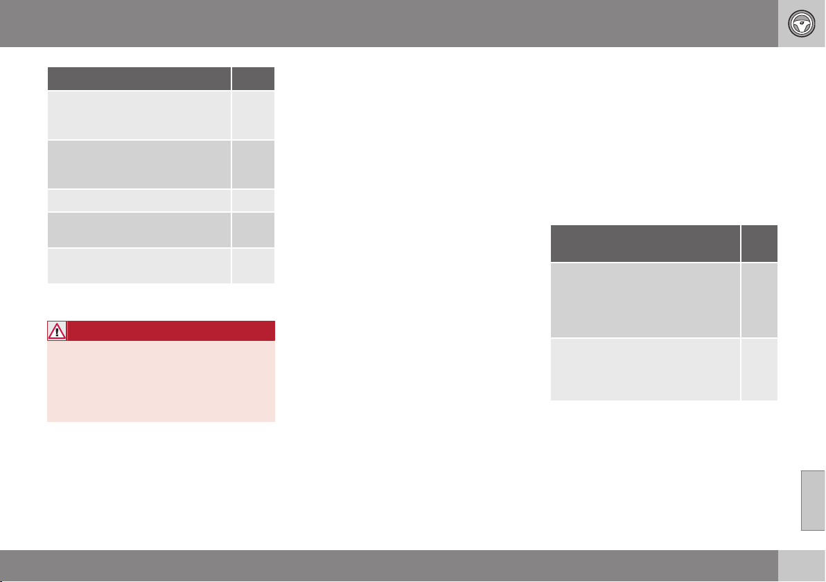
08 Starting and driving
08
* Option/accessory, for more information, see Introduction.
283
Conditions
M/A
A
The car starts to roll - faster than
the equivalent normal walking
pace.
M
The driver's seatbelt buckle is
opened with the gear selector in D
or N position.
A
Steering wheel movements. A
The gear selector is moved from
the D position to "+/-" or R.
A
The driver’s door is opened with
the gear selector in D position.
A
A
M = Manual gearbox, A = Automatic gearbox.
B
Car with ECC.
WARNING
Do not open the bonnet when the engine
has stopped automatically - the engine
may suddenly start automatically. First
switch off the engine as normal using the
START/STOP ENGINE button before
opening the bonnet.
Related information
•
Start/Stop* - function and operation (p.
280)
•
Starting the engine (p. 268)
•
Start/Stop* - settings (p. 284)
•
Start/Stop* - the engine does not auto-
start (p. 283)
•
Start/Stop* - the engine does not stop (p.
281)
•
Start/Stop* - involuntary engine stoppage
manual gearbox (p. 284)
•
Start/Stop* - symbols and messages (p.
286)
•
Battery - Start/Stop (p. 353)
•
Start/Stop* (p. 279)
Start/Stop* - the engine does not
auto-start
Some engine and gearbox combinations are
equipped with a Start and Stop function
which engages in the event of e.g. stationary
traffic or waiting at traffic lights. The engine
does not always auto-start after having auto-
stopped.
In the following cases the engine does not
auto-start after having auto-stopped:
Conditions M/
A
A
A gear is engaged without
declutching - a display text
prompts the driver to set the gear
lever in neutral position in order to
enable automatic starting.
M
The driver is unrestrained, the gear
selector is in P position and the
driver’s door is open - a normal
engine start must take place.
A
A
M = Manual gearbox, A = Automatic gearbox.
Related information
•
Start/Stop* (p. 279)
•
Start/Stop* - function and operation (p.
280)
•
Starting the engine (p. 268)
•
Start/Stop* - settings (p. 284)
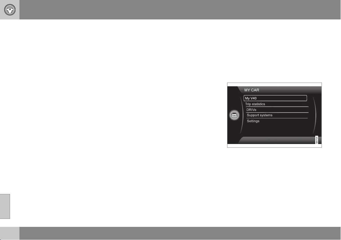
08 Starting and driving
08
284
* Option/accessory, for more information, see Introduction.
•
Start/Stop* - the engine auto-starts (p.
282)
•
Start/Stop* - the engine does not stop (p.
281)
•
Start/Stop* - involuntary engine stoppage
manual gearbox (p. 284)
•
Start/Stop* - symbols and messages (p.
286)
•
Battery - Start/Stop (p. 353)
Start/Stop* - involuntary engine
stoppage manual gearbox
Some engine and gearbox combinations are
equipped with a Start and Stop function
which engages in the event of e.g. stationary
traffic or waiting at traffic lights. In the event
that a start-up fails and the engine stops, pro-
ceed in accordance with the below:
1. Depress the clutch pedal again - the
engine starts automatically.
2. In certain cases the gear lever must be
set in neutral position. The combined
instrument panel then shows the text
Put
gear in neutral.
Related information
•
Start/Stop* (p. 279)
•
Start/Stop* - function and operation (p.
280)
•
Starting the engine (p. 268)
•
Start/Stop* - settings (p. 284)
•
Start/Stop* - the engine does not auto-
start (p. 283)
•
Start/Stop* - the engine auto-starts (p.
282)
•
Start/Stop* - the engine does not stop (p.
281)
•
Start/Stop* - symbols and messages (p.
286)
•
Battery - Start/Stop (p. 353)
Start/Stop* - settings
Some engine and gearbox combinations are
equipped with a Start and Stop function
which engages in the event of e.g. stationary
traffic or waiting at traffic lights. The car's MY
CAR (p. 104) menu system contains an intro-
duction of Volvo's Start-Stop system, as well
as recommendations for energy-saving driv-
ing techniques.
Related information
•
Start/Stop* (p. 279)
•
Start/Stop* - function and operation (p.
280)
•
Starting the engine (p. 268)
•
Start/Stop* - the engine does not auto-
start (p. 283)
•
Start/Stop* - the engine auto-starts (p.
282)


08 Starting and driving
08
286
* Option/accessory, for more information, see Introduction.
Start/Stop* - symbols and messages
The Start/Stop function can show text mes-
sages on the information display.
Text message
In combination with this indicator
lamp the Start/Stop function may
display text messages in the com-
bined instrument panel for certain situations.
For some of them there is a recommended
action that should be performed. The follow-
ing table shows some examples.
Symbol Message Info/Action
M/A
A
Engine in Auto Start
Illuminates for a few seconds after Start/Stop has been activated. M + A
Eco DRIVe OFF
Illuminates for a few seconds after Start/Stop has been switched off. M + A
Auto Start/Stop Service
required
Start/Stop is not operational. Contact a workshop - an authorised Volvo workshop is rec-
ommended.
M + A
Engine management system
An automatic function check is carried out. M + A
Autostart Engine running +
acoustic signal
Activated if the driver's door is opened with auto-stopped engine. M + A
Engine in Auto Start
The engine is ready to start automatically - waiting for the brake or clutch pedal to be
depressed.
M
Press Start button
The engine will not start automatically - start the engine as normal with the START/STOP
ENGINE button.
M
Depress clutch pedal to
start
The engine is ready to auto-start - waiting for the clutch pedal to be depressed. M
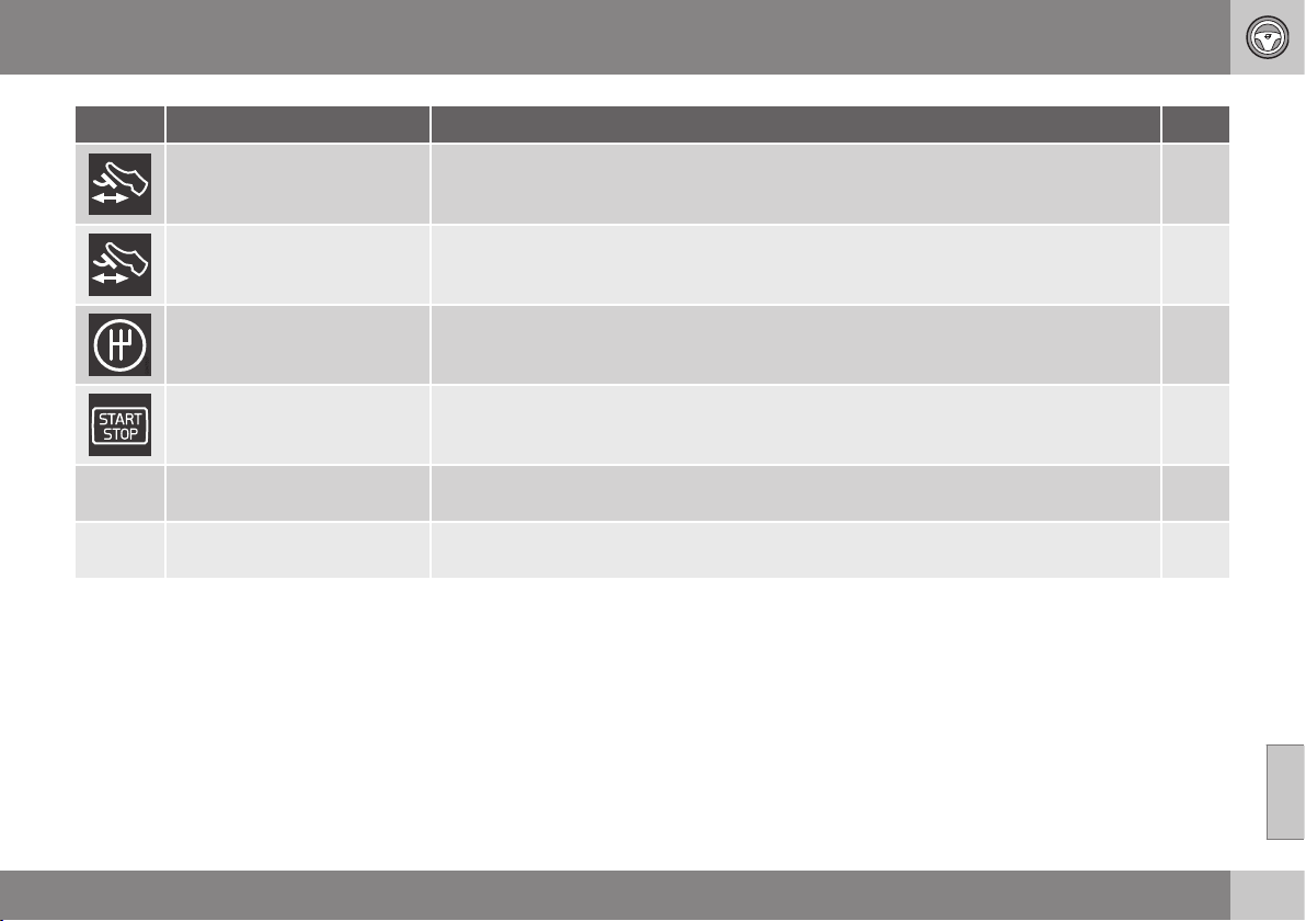
08 Starting and driving
08
* Option/accessory, for more information, see Introduction.
287
Symbol Message Info/Action
M/A
A
Depress brake pedal to start
The engine is ready to auto-start - waiting for the brake pedal to be depressed. M
Press brake and clutch to
start
The engine is ready to auto-start - waiting for the brake or clutch pedal to be depressed. M
Put gear in neutral to start
Gear is engaged without declutching - disengage and set the gear lever in neutral position. M
Engine in Auto Start
The engine is ready to start automatically - waiting for the brake pedal to be released. A
Select P or N to start
Start/Stop has been deactivated - move the gear selector to N or P position and start the
engine as normal with the START/STOP ENGINE button.
A
Press Start button
The engine will not start automatically - start the engine as normal with the START/STOP
ENGINE button and the gear selector in P or N.
A
A
M = Manual gearbox, A = Automatic gearbox.
If a message does not go out following com-
pletion of the action then a workshop should
be contacted - an authorised Volvo workshop
is recommended.
Related information
•
Start/Stop* (p. 279)
•
Start/Stop* - function and operation (p.
280)
•
Starting the engine (p. 268)
•
Start/Stop* - settings (p. 284)
•
Start/Stop* - the engine does not auto-
start (p. 283)
•
Start/Stop* - the engine auto-starts (p.
282)
•
Start/Stop* - the engine does not stop (p.
281)
•
Start/Stop* - involuntary engine stoppage
manual gearbox (p. 284)
•
Battery - Start/Stop (p. 353)
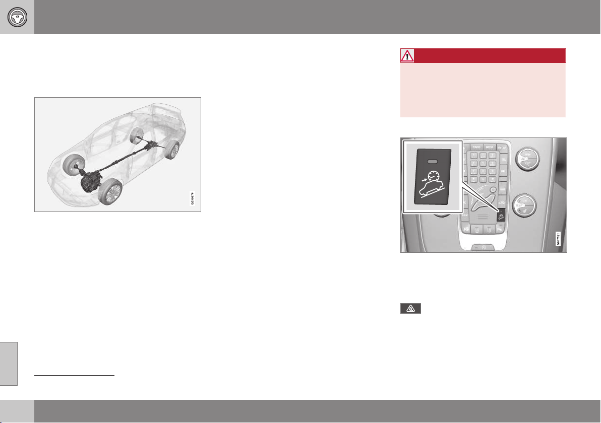
08 Starting and driving
08
288
* Option/accessory, for more information, see Introduction.
All Wheel Drive (AWD)*
All Wheel Drive (AWD – All Wheel Drive)
means that the car is driven by all four wheels.
All-wheel drive is always engaged.
AWD principle
13
.
The power is automatically distributed
between the front and rear wheels. An elec-
tronically controlled clutch system distributes
the power to the wheels that have the best
grip on the current road surface. This pro-
vides the best traction and prevents wheel
spin. Under normal driving conditions, the
majority of power is transmitted to the front
wheels.
All-wheel drive improves driving safety in rain,
snow and icy conditions.
Hill Descent Control (HDC)
HDC can be compared to an automatic
engine brake. When you release the accelera-
tor on downhill gradients the car is normally
braked by means of the engine striving for low
engine idling speeds, so-called engine brak-
ing. But the steeper the road and the more
load there is in the car, the faster the car rolls
despite engine braking. In order to then
reduce speed the driver has to assist using
the footbrake.
General
The function makes it possible to increase/
reduce speed on steep downhill gradients,
with a foot only on the accelerator pedal,
without using the footbrake. The sensitivity of
the accelerator pedal decreases and
becomes more precise by means of the full
actuation of the pedal being restricted to
adjusting engine speed within a limited range.
The brake system brakes itself and provides
the car with a low and even speed, so allow-
ing the driver to fully focus on steering.
HDC is particularly helpful on steep gradients
with an uneven road surface and slippery
sections. E.g. when launching a boat on a
trailer from a ramp.
WARNING
HDC does not work in all situations but is
designed merely as a supplementary aid.
The driver always bears ultimate responsi-
bility for ensuring that the vehicle is driven
safely.
Function
HDC is engaged or disengaged using a
switch on the centre console. An indicator
lamp in the button illuminates when the func-
tion is switched on.
When HDC is working normally the
combined instrument panel's symbol
illuminates combined with the text message
Hill descent control ON.
13
The figure is schematic - details may vary depending on market and model.
08 Starting and driving
08
* Option/accessory, for more information, see Introduction.
289
The function only operates in first gear posi-
tion and in reverse gear. For an automatic
gearbox, gear position 1 must be selected,
which is shown with the figure
1 in the com-
bined instrument panel; see Automatic gear-
box - Geartronic* (p. 273).
NOTE
HDC cannot be activated on an automatic
gearbox in position D.
Operation
HDC allows the car to roll at a maximum of
10 km/h forwards with engine braking and
7 km/h backwards. However, any speed
within the gear's speed register can be
selected using the accelerator pedal. When
the accelerator pedal is released, the car is
braked quickly to 10 or 7 km/h respectively,
irrespective of the hill's gradient and without
the need for the footbrake.
The brake lights come on automatically when
the function is operating. The driver can brake
or stop the car at any time by using the foot-
brake.
HDC is deactivated:
•
with the on/off button on the centre con-
sole
•
if a gear higher than 1 is selected on a
manual gearbox
•
if a gear higher than 1 is selected on an
automatic gearbox, or if the gear selector
is moved to position D.
The function can be disengaged at any time.
If it takes place on a steep downhill gradient
then the braking effect will not release
directly, but slowly instead.
NOTE
With HDC activated you may experience a
delay between acceleration pedal activa-
tion and engine response.
Foot brake
The foot brake is used to reduce the car's
speed while driving.
The car is equipped with two brake circuits. If
one brake circuit is damaged then this will
mean that the brakes engage at a deeper
level and harder pressure on the pedal is nee-
ded to produce the normal braking effect.
The driver's brake pedal pressure is assisted
by a brake servo.
WARNING
The brake servo only works when the
engine is running.
If the brake is used when the engine is
switched off then the pedal will feel stiff and
more force must be used to brake the car.
In very hilly terrain or when driving with a
heavy load the brakes can be relieved by
using engine braking. Engine braking is most
efficiently used if the same gear is used
downhill as up.
For more general information on heavy loads
on the car, see Engine oil - adverse driving
conditions (p. 446).
Cleaning the brake discs
Coatings of dirt and water on the brake discs
may result in delayed brake function. This
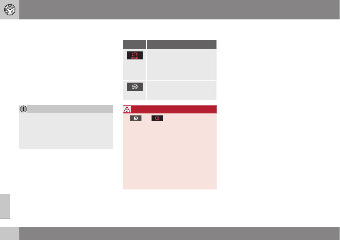
||
08 Starting and driving
08
290
delay is minimised by cleaning the brake lin-
ings.
Manual cleaning is advisable with wet road
surfaces, prior to long-stay parking and after
the car has been washed. Carry this out by
braking gently during a short period while en
route.
Maintenance
To keep the car as safe and reliable as possi-
ble, follow the Volvo service intervals as
specified in the Service and Warranty Book-
let.
IMPORTANT
The wear on the brake system's compo-
nents must be checked regularly.
Contact a workshop for information about
the procedure or engage a workshop to
carry out the inspection - an authorised
Volvo workshop is recommended.
Symbols in the combined instrument
panel
Symbol Specification
Constant glow – Check the
brake fluid level. If the level is
low, fill with brake fluid and
check for the cause of the
brake fluid loss.
Constant glow for 2 seconds
when the engine is started -
automatic function check.
WARNING
If and illuminate at the same
time, there may be a fault in the brake sys-
tem.
If the level in the brake fluid reservoir is
normal at this stage, drive carefully to the
nearest workshop and have the brake sys-
tem checked - an authorised Volvo work-
shop is recommended.
If the brake fluid is below the MIN level in
the brake fluid reservoir, do not drive fur-
ther before topping up the brake fluid.
The reason for the loss of brake fluid must
be investigated.
Related information
•
Parking brake (p. 292)
•
Foot brake - emergency brake lights and
automatic hazard warning flashers (p.
291)
•
Foot brake - emergency brake assistance
(p. 291)
•
Foot brake - anti-lock braking system (p.
291)
08 Starting and driving
08
291
Foot brake - anti-lock braking system
The anti-lock braking system, ABS (Anti-lock
Braking System), prevents the wheels from
locking up during braking.
The function allows steering ability to be
maintained, and it is easier to swerve to avoid
a hazard for example. Vibration may be felt in
the brake pedal when this is engaged and this
is normal.
A short test of the ABS system is made auto-
matically after the engine has been started
when the driver releases the brake pedal. A
further automatic test of the ABS system may
be made when the car reaches 10 km/h. The
test may be experienced as pulses in the
brake pedal.
Related information
•
Foot brake (p. 289)
•
Parking brake (p. 292)
•
Foot brake - emergency brake lights and
automatic hazard warning flashers (p.
291)
•
Foot brake - emergency brake assistance
(p. 291)
Foot brake - emergency brake lights
and automatic hazard warning
flashers
Emergency brake lights are activated to alert
vehicles behind about sudden braking. The
function means that the brake light flashes
instead of - as in normal braking - shining with
a constant glow.
Emergency brake lights are activated at
speeds above 50 km/h if the ABS system is
working and/or in the event of sudden brak-
ing. After the car's speed has been slowed
below 10 km/h the brake light returns from
flashing to the normal constant glow - while
at the same time the Hazard warning flashers
are activated, and they flash until the driver
accelerates the car to at least 20 km/h or they
are deactivated with their button.
Related information
•
Foot brake (p. 289)
•
Parking brake (p. 292)
•
Foot brake - emergency brake assistance
(p. 291)
•
Foot brake - anti-lock braking system (p.
291)
Foot brake - emergency brake
assistance
Emergency brake assistance EBA (Emergency
Brake Assist) helps to increase the braking
force and so reduce the braking distance.
EBA detects the driver's braking style and
increases the braking force when necessary.
The brake force can be reinforced up to the
level when the ABS system is engaged. The
EBA function is interrupted when the pressure
on the brake pedal is reduced.
NOTE
When EBA is activated the brake pedal
lowers slightly more than usual, depress
(hold) the brake pedal as long as neces-
sary. If the brake pedal is released then all
braking ceases.
Related information
•
Foot brake (p. 289)
•
Parking brake (p. 292)
•
Foot brake - emergency brake lights and
automatic hazard warning flashers (p.
291)
•
Foot brake - anti-lock braking system (p.
291)
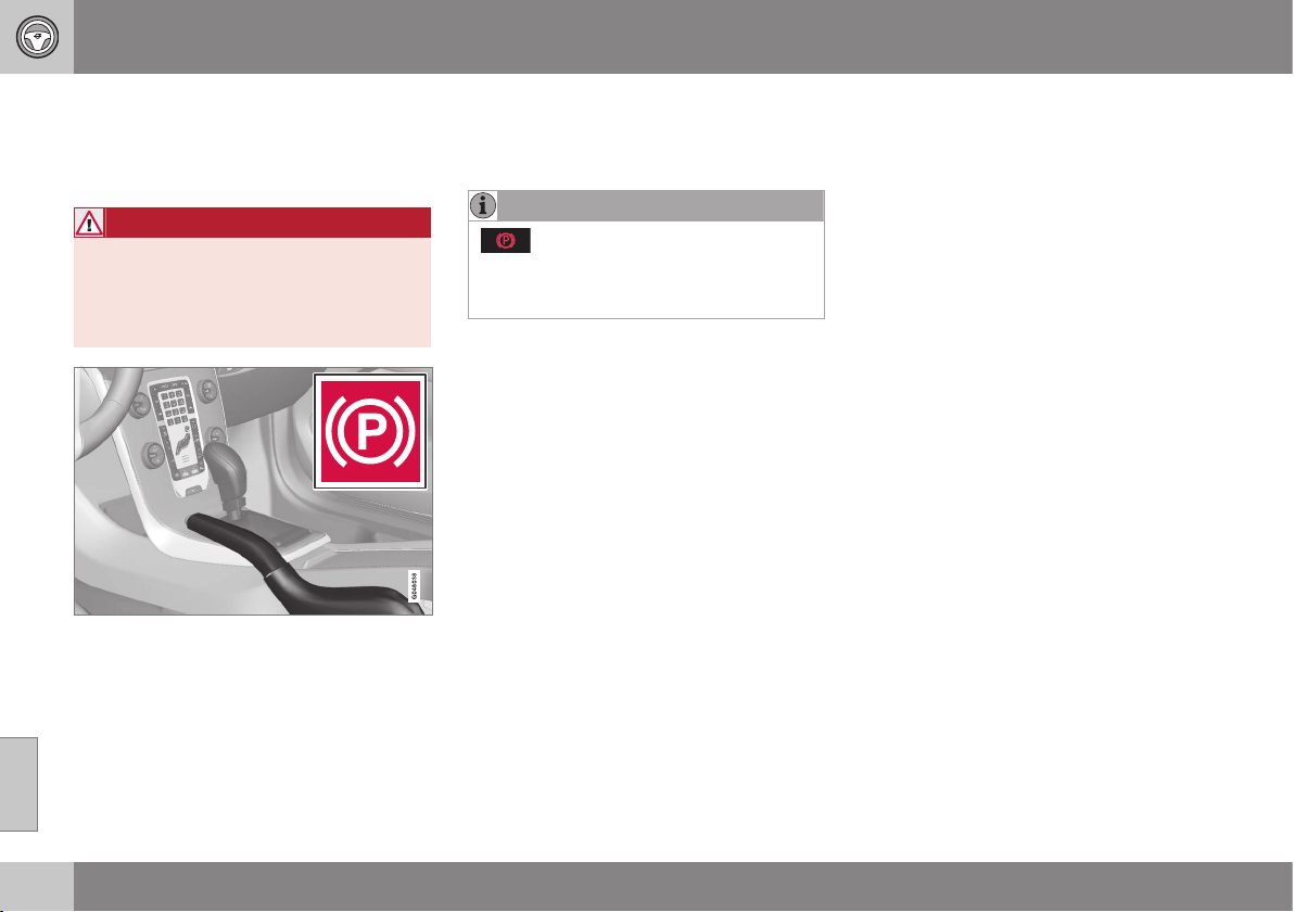
08 Starting and driving
08
292
Parking brake
The parking brake holds the car stationary,
when the driver's seat is empty, by mechani-
cally locking/blocking two wheels.
WARNING
Always apply the parking brake when
parking on a slope - leaving the car in
gear, or in P if it has automatic transmis-
sion, is not sufficient to hold the car in all
situations.
Combined instrument panel warning symbol.
Applying the parking brake
1. Press the foot brake pedal down firmly.
2. Pull the lever firmly.
> The combined instrument panel warn-
ing symbol comes on.
NOTE
- The combined instrument panel's
warning symbol illuminates regardless of
whether the parking brake is applied
slightly or fully.
3. Release the foot brake pedal and make
sure that the car is at a standstill position.
4. If the vehicle moves then the parking
brake lever must be applied at least a lit-
tle more firmly.
•
When parking the vehicle, always engage
1st gear (for manual gearbox) or put the
gear selector in position P (for automatic
gearbox).
Parking on a hill
If the car is parked facing uphill:
•
Turn the wheels away from the kerb.
If the car is parked facing downhill:
•
Turn the wheels towards the kerb.
Disengaging the parking brake
1. Press the foot brake pedal down firmly.
2. Pull the lever up slightly, press the button,
release the lever and release the button.
> The combined instrument panel warn-
ing symbol goes off.
If the driver forgets to release the parking
brake – in addition to the illuminated warning
lamp – a pinging sound combined with a
message in the combined instrument panel
alerts the driver of this when the car's speed
exceeds 10 km/h.
Related information
•
Foot brake (p. 289)

08 Starting and driving
08
293
Driving in water
Fording means that the car is driven through a
water-covered roadway. Fording must be car-
ried out with great caution.
The car can be driven through water at a
maximum depth of 30 cm at a maximum
speed of 10 km/h. Extra caution should be
exercised when passing through flowing
water.
During driving in water, maintain a low speed
and do not stop the car. When the water has
been passed, depress the brake pedal lightly
and check that full brake function is achieved.
Water and mud for example can make the
brake linings wet resulting in delayed brake
function.
•
Clean the electric contacts of the electric
engine block heater and trailer coupling
after driving in water and mud.
•
Do not let the car stand with water over
the sills for any long period of time - this
could cause electrical malfunctions.
IMPORTANT
Engine damage can occur if water enters
the air filter.
In depths greater than 30 cm, water could
enter the transmission. This reduces the
lubricating ability of the oils and shortens
the service life of these systems.
In the event of the engine stalling in water,
do not try restart - tow the car from the
water to a workshop - an authorised Volvo
workshop is recommended. Risk of engine
breakdown.
Related information
•
Recovery (p. 310)
•
Towing (p. 308)
Overheating
Under special conditions, for example hard
driving in hilly terrain and hot climate, there is
a risk that the engine and drive system may
overheat - in particular with a heavy load.
For information about overheating when driv-
ing with a trailer, see Driving with a trailer (p.
301).
•
Remove any auxiliary lamps from in front
of the grille when driving in hot climates.
•
If the temperature in the engine's cooling
system is too high then a warning symbol
is illuminated and a text message
High
engine temp Stop safely is shown in the
combined instrument panel's information
display - stop the car in a safe way and
allow the engine to run at idling speed for
several minutes in order to cool down.
•
If the text message
High engine temp
Stop engine or Coolant level low, Stop
engine is shown then the engine must be
switched off after stopping the car.
•
In the event of overheating in the gearbox
a built-in protection function is activated,
which is indicated in the combined instru-
ment panel with a warning symbol and
the text message
Transmission hot
Reduce speed or Transmission hot
Stop safely - follow the recommendation
given and lower the speed and stop the
car in a safe way and allow the engine to
run at idling speed for a few minutes in
order to allow the gearbox to cool down.
||
08 Starting and driving
08
294
•
If the car overheats, the air conditioning
may be switched off temporarily.
•
Do not turn the engine off immediately
you stop after a hard drive.
NOTE
It is normal for the engine's cooling fan to
operate for a time after the engine has
been switched off.
Related information
•
Driving with a trailer - manual gearbox (p.
302)
•
Driving with a trailer - automatic gearbox
(p. 302)
Driving with open tailgate
When driving with the tailgate open, toxic
exhaust fumes can be sucked into the car
through the cargo area.
WARNING
Do not drive with an open tailgate! Toxic
exhaust fumes could be drawn into the car
through the cargo area.
Related information
•
Loading (p. 152)
Overload - starter battery
The electrical functions in the car load the
starter battery to varying degrees. Avoid using
the key position II when the engine is
switched off. Instead use the I mode - which
uses less power, see Key positions - functions
at different levels (p. 71).
Also, be aware of different accessories that
load the electrical system. Do not use func-
tions which use a lot of power when the
engine is switched off. Examples of such
functions are:
•
ventilation fan
•
headlamps
•
windscreen wiper
•
audio system (high volume).
If the battery voltage is low the information
display shows the text
Low battery Power
save mode. The energy-saving function then
shuts down certain functions or reduces cer-
tain functions such as the ventilation fan
and/or audio system.
– In which case, charge the starter battery
by starting the engine and then running it
for at least 15 minutes - battery charging
is more effective during driving than run-
ning the engine at idling speed while sta-
tionary.
Related information
•
Starter battery (p. 351)
08 Starting and driving
08
* Option/accessory, for more information, see Introduction.
295
Before a long journey
Before a long journey, it makes good sense to
go through the following points:
•
Check that the engine is working normally
and that fuel consumption (p. 454) is nor-
mal.
•
Make sure that there are no leaks (fuel, oil
or other fluid).
•
Check all bulbs and tyre tread depths.
•
Carrying a warning triangle (p. 323) is a
legal requirement in certain countries.
Related information
•
Engine oil - checking and filling (p. 337)
•
Spare wheel* (p. 317)
•
Lamp replacement (p. 342)
Winter driving
For winter driving it is important to perform
certain checks in order to ensure that the car
can be driven safely.
To bear in mind:
Check the following in particular before the
cold season:
•
The engine coolant (p. 449) must contain
at least 50% glycol. This mixture protects
the engine against frost erosion down to
approximately –35 °C. To achieve opti-
mum antifreeze protection, different types
of glycol must not be mixed.
•
The fuel tank must be kept filled to pre-
vent condensation.
•
Engine oil viscosity is important. Oils with
lower viscosity (thinner oils) facilitate star-
ting in cold weather and also reduce fuel
consumption while the engine is cold. For
more information on suitable oils, see
Engine oil - adverse driving conditions (p.
446).
IMPORTANT
Low viscosity oil must not be used for hard
driving or in hot weather.
•
The condition of the battery and charge
level must be inspected. Cold weather
places great demands on the battery and
its capacity is reduced by the cold.
•
Use washer fluid (p. 351) to avoid ice
forming in the washer fluid reservoir.
To achieve optimum roadholding Volvo rec-
ommends using winter tyres on all wheels if
there is a risk of snow or ice.
NOTE
The use of winter tyres is a legal require-
ment in certain countries. Studded tyres
are not permitted in all countries.
Slippery driving conditions
Practise driving on slippery surfaces under
controlled conditions to learn how the car
reacts.
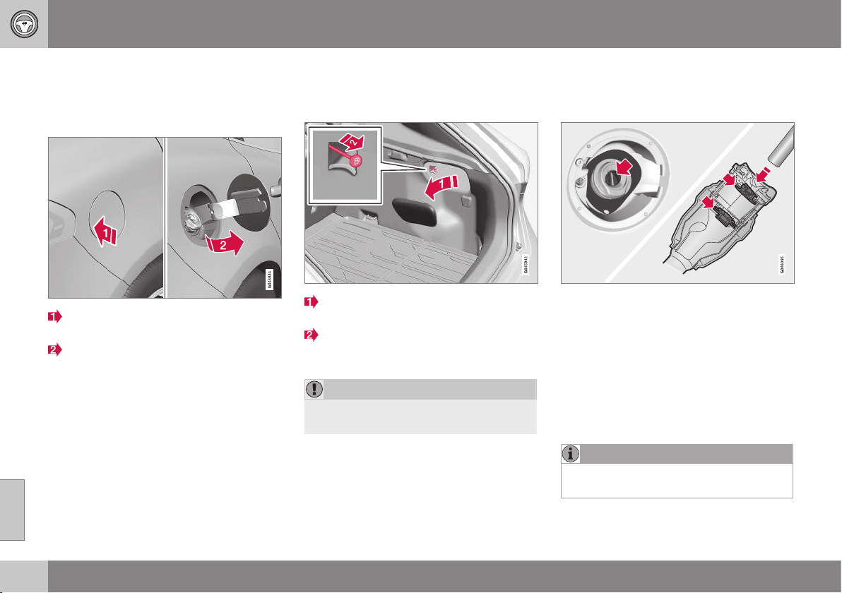
08 Starting and driving
08
296
Fuel filler flap - Opening/closing
The fuel filler flap can be opened/closed as
follows:
Opening/closing the fuel filler flap
Open the fuel filler flap by slightly press-
ing in the rear part of the hatch.
Take out the flap.
Close the flap after fuelling.
For a description of locking and unlocking the
fuel filler flap, see Locking/unlocking - fuel
filler flap (p. 178). The fuel filler flap's lock
logic also follows Keyless drive and the lock-
ing and unlocking of the central locking.
Related information
•
Filling up with fuel (p. 296)
Fuel filler flap - manual opening
The fuel filler flap can be opened manually
when it cannot be opened from outside.
Open/remove the side hatch in the cargo
area (same side as fuel filler flap).
Carefully pull the line back in a straight
line. The flap can now be opened from
outside.
IMPORTANT
Pull the wire gently - minimal force is
required to disengage the hatch lock.
Related information
•
Locking/unlocking - fuel filler flap (p. 178)
•
Filling up with fuel (p. 296)
Filling up with fuel
The fuel tank is fitted with a coverless fuel
filler system. Filling is carried out as follows:
•
Open the fuel filler flap (p. 296). See also
Fuel filler flap - manual opening (p. 296).
•
Insert the pump nozzle in the fuel filler
opening. Take care to insert the nozzle
properly into the filler pipe. The filler pipe
consists of two opening covers. The noz-
zle must be pushed past both covers
before refuelling is started.
•
Do not overfill the tank but fill until the
pump nozzle cuts out.
NOTE
Excess fuel in the tank can overflow in hot
weather.
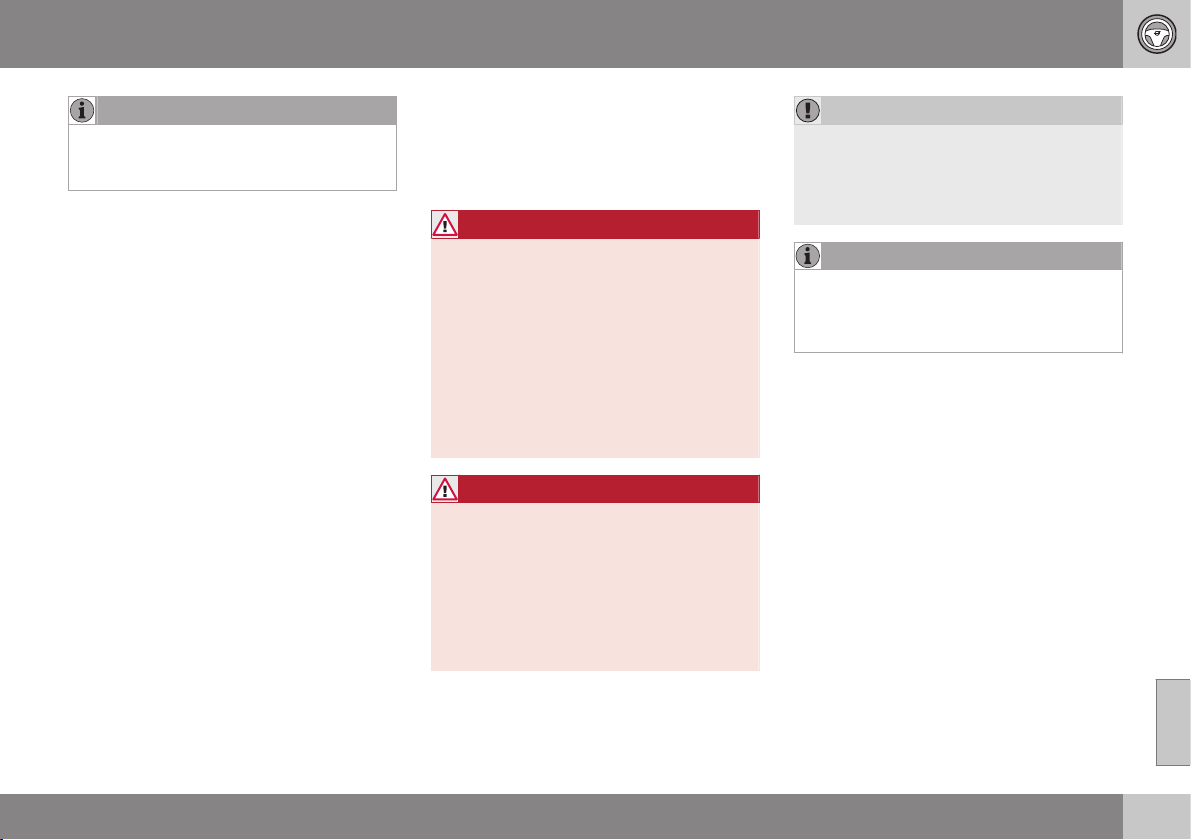
08 Starting and driving
08
297
NOTE
Avoid spilling by waiting approximately
5-8 seconds before carefully removing the
nozzle once refuelling is complete.
Related information
•
Filling with fuel - with a fuel can (p. 299)
Fuel - handling
Fuel of a lower quality than that recom-
mended by Volvo must not be used as engine
power and fuel consumption is negatively
affected.
WARNING
Always avoid inhaling fuel vapour and fuel
splashing in the eyes.
In the event of fuel in the eyes, remove any
contact lenses and rinse the eyes in plenty
of water for at least 15 minutes and seek
medical attention.
Never swallow fuel. Fuels such as petrol
and diesel are highly toxic and could
cause permanent injury or be fatal if swal-
lowed. Seek medical attention immediately
if fuel has been swallowed.
WARNING
Fuel which spills onto the ground can be
ignited.
Switch off the fuel-driven heater before
starting to refuel.
Never carry an activated mobile phone
when refuelling. The ring signal could
cause spark build-up and ignite petrol
fumes, leading to fire and injury.
IMPORTANT
Mixtures of various fuel types or use of
fuels which are not recommended will
invalidate Volvo's guarantees and any sup-
plementary service agreements; this is
applicable to all engines.
NOTE
Extreme weather conditions, driving with a
trailer or driving at high altitudes in combi-
nation with fuel grade are factors that
could affect the car's performance.
Related information
•
Economical driving (p. 300)
•
Economical driving (p. 300)

08 Starting and driving
08
298
Fuel - petrol
Petrol is used as fuel.
Petrol must fulfil the EN 228 standard. Most
engines can be run with octane ratings of 95
and 98 RON. Only in exceptional cases
should 91 RON be used.
•
95 RON can be used for normal driving.
•
98 RON is recommended for optimum
performance and minimum fuel consump-
tion.
When driving in temperatures above +38 °C,
fuel with the highest possible octane rating is
recommended for optimum performance and
fuel economy.
IMPORTANT
•
Use only unleaded petrol to avoid
damaging the catalytic converter.
•
Do not use any additives which have
not been recommended by Volvo.
Related information
•
Economical driving (p. 300)
•
Fuel - handling (p. 297)
•
Filling up with fuel (p. 296)
Fuel - diesel
Diesel is used as fuel.
Only use diesel fuel from well-known produc-
ers. Never use diesel of dubious quality. Die-
sel should fulfil the EN 590 or JIS K2204
standards. Diesel engines are sensitive to
contaminants in the fuel, such as excessively
high volumes of sulphur particles for exam-
ple.
At low temperatures (-6 °C to -40 °C), a par-
affin precipitate may form in the diesel fuel,
which may lead to ignition problems. Special
diesel fuel designed for low temperatures
around freezing point is available from the
major oil companies. This fuel is less viscous
at low temperatures and reduces the risk of
paraffin precipitate.
The risk of condensation in the fuel tank is
reduced if the tank is kept well filled. When
refuelling, check that the area around the fuel
filler pipe is clean. Avoid spilling fuel onto the
paintwork. Wash off any spillage with deter-
gent and water.
IMPORTANT
Only ever use fuel that fulfils the European
diesel standard.
The sulphur content must be a maximum
of 50 ppm.
IMPORTANT
Diesel type fuels that must not be used:
•
Special additives
•
Marine diesel fuel
•
Heating oil
•
FAME
14
(Fatty Acid Methyl Ester) and
vegetable oil.
These fuels do not fulfil the requirements in
accordance with Volvo recommendations
and generate increased wear and engine
damage that is not covered by the Volvo
warranty.
Empty tank
The design of the fuel system in a diesel
engine means that if the vehicle runs out of
fuel, the tank may need to be vented in the
workshop in order to restart the engine after
fuelling.
Once the engine has stopped due to fuel
starvation, the fuel system needs a few
moments to carry out a check. Do this before
starting the engine, once the fuel tank has
been filled with diesel:
1. Insert the remote control key in the igni-
tion switch and push it in to the end posi-
tion, see Key positions (p. 71).
2. Press the START button without
depressing the brake and/or clutch pedal.
14
Diesel fuel may contain a certain amount of FAME, but further amounts must not be added.

08 Starting and driving
08
299
3. Wait approx. 1 minute.
4. To start the engine: Depress the brake
and/or clutch pedal and then press the
START button again.
NOTE
Before filling with fuel in the event of fuel
shortage:
•
Stop the car on as flat/level ground as
possible - if the car is tilting there is a
risk of air pockets in the fuel supply.
Draining condensation from the fuel
filter
The fuel filter separates condensation from
the fuel. Condensation can disrupt engine
operation.
The fuel filter must be drained at the intervals
specified in the Service and Warranty Booklet
or if you suspect that the car has been filled
with contaminated fuel, see Volvo service
programme (p. 332).
IMPORTANT
Certain special additives remove the water
separation in the fuel filter.
Related information
•
Diesel particle filter (DPF) (p. 299)
•
Fuel - handling (p. 297)
•
Economical driving (p. 300)
Filling with fuel - with a fuel can
When filling with fuel (p. 296) from a fuel can,
use the funnel located under the floor hatch in
the cargo area.
Take care to insert the funnel properly into
the filler pipe. The filler pipe consists of two
opening covers. The funnel must be pushed
past both covers before filling is started.
Related information
•
Locking/unlocking - fuel filler flap (p. 178)
•
Fuel filler flap - manual opening (p. 296)
Diesel particle filter (DPF)
Diesel cars are equipped with a particle filter,
which results in more efficient emission con-
trol.
The particles in the exhaust gases are collec-
ted in the filter during normal driving. So-
called "regeneration" is started in order to
burn away the particles and empty the filter.
This requires the engine to have reached nor-
mal operating temperature.
Filter regeneration takes place automatically
and normally takes 10-20 minutes. It may
take a little longer at a low average speed.
Fuel consumption may increase slightly dur-
ing regeneration.
Regeneration in cold weather
If the car is frequently driven short distances
in cold weather then the engine does not
reach normal operating temperature. This
means that regeneration of the diesel particle
filter does not take place and the filter is not
emptied.
When the filter has become approximately
80% full of particles, a yellow warning triangle
is shown in the combined instrument panel,
and the message
Soot filter full See manual
is shown in the information display.
Start regeneration of the filter by driving the
car until the engine reaches normal operating
temperature, preferably on a main road or
||
08 Starting and driving
08
300
* Option/accessory, for more information, see Introduction.
motorway. The car should then be driven for
approximately 20 minutes more.
NOTE
The following may arise during regenera-
tion:
•
a smaller reduction of engine power
may be noticed temporarily
•
fuel consumption may increase tem-
porarily
•
a smell of burning may arise.
When regeneration is complete the warning
text is cleared automatically.
Use the parking heater* in cold weather so
that the engine reaches normal operating
temperature more quickly.
IMPORTANT
If the filter is completely filled with parti-
cles, it may be difficult to start the engine
and the filter is non-functional. Then there
is a risk that the filter will need to be
replaced.
Related information
•
Fuel - diesel (p. 298)
•
Economical driving (p. 300)
Economical driving
Driving economically means driving smoothly
while thinking ahead and adjusting your driv-
ing style and speed to the prevailing condi-
tions.
•
Avoid driving with open windows.
•
Do not use winter tyres when the winter
season is over.
•
Avoid sudden unnecessary acceleration
and heavy braking.
•
Drive with the correct air pressure in the
tyres and check it regularly - select ECO
tyre pressure for best results, see Tyres -
approved tyre pressures (p. 457).
•
Drive in the highest gear possible, adap-
ted to the current traffic situation and
road - lower engine speeds result in lower
fuel consumption. Use the gear shift indi-
cator (p. 272)
15
.
•
Remove unnecessary items from the car -
the greater the load the higher the fuel
consumption.
•
Use engine braking to slow down, when it
can take place without risk to other road
users.
•
Choice of tyres can affect fuel consump-
tion - seek advice on suitable tyres from a
dealer.
•
A roof load and ski box increase air resis-
tance, leading to higher fuel consumption
- remove the load carriers when not in
use.
•
Do not run the engine to operating tem-
perature at idling speed, but rather drive
with a light load as soon as possible - a
cold engine consumes more fuel than a
warm one.
•
High speed results in increased fuel con-
sumption - the wind resistance increases
with speed.
For more information, see Volvo Cars' envi-
ronmental philosophy (p. 20) and Fuel con-
sumption and CO2 emissions (p. 454).
WARNING
Never switch off the engine while moving,
such as downhill, this deactivates impor-
tant systems such as the power steering
and brake servo.
15
Manual gearbox
08 Starting and driving
08
* Option/accessory, for more information, see Introduction.
301
Driving with a trailer
When driving with a trailer there are a number
of important points to think about regarding
e.g. the towing bracket, the trailer and how
the load is positioned in the trailer.
Payload depends on the car's kerb weight.
The total of the weight of the passengers and
all accessories, e.g. towbar, reduces the car's
payload by corresponding weights (p. 441).
If the towing bracket is mounted by Volvo,
then the car is delivered with the necessary
equipment for driving with a trailer.
•
The car's towing bracket must be of an
approved type.
•
If the towbar is retrofitted, check with
your Volvo dealer that the car is fully
equipped for driving with a trailer.
•
Distribute the load on the trailer so that
the weight on the towing bracket com-
plies with the specified maximum towball
load.
•
Increase the tyre pressure to the recom-
mended air pressure (p. 322) for a full
load.
•
The engine is loaded more heavily than
usual when driving with a trailer.
•
Do not tow a heavy trailer when the car is
brand new. Wait until it has been driven
at least 1000 km.
•
The brakes are loaded much more than
usual on long and steep downhill slopes.
Downshift to a lower gear and adjust your
speed.
•
For safety reasons, the maximum permit-
ted speed for the car when coupled with
a trailer should not be exceeded. Follow
the regulations in force for the permitted
speeds and weights.
•
Maintain a low speed when driving with a
trailer up long, steep ascents.
•
Avoid driving with a trailer on inclines of
more than 12 %.
Trailer cable
An adapter is required if the car's towing
bracket has a 13 pin connector and the trailer
has a 7 pin connector. Use an adapter cable
approved by Volvo. Make sure the cable does
not drag on the ground.
Direction indicators and brake lights on
the trailer
If any of the trailer's lamps for direction indi-
cators are broken, the symbol for direction
indicators in the combined instrument panel
flashes faster than normal and the information
display shows the text
Bulb fail - Ind. signal
trailer.
If any of the trailer's lamps for the brake light
are broken then the
Bulb fail - Stop lamp
trailer text is shown.
Level control*
The rear shock absorbers maintain a constant
height irrespective of the car's load (up to the
maximum permissible weight). When the car
is stationary the rear of the car lowers slightly,
which is normal.
Trailer weights
For information on Volvo's permitted trailer
weights, see Towing capacity and towball
load (p. 442).
NOTE
The stated maximum permitted trailer
weights are those permitted by Volvo. The
maximum permitted speed for a car with a
trailer attached is 100 km/h. National vehi-
cle regulations may further restrict the
trailer weight and speed. Towbars can be
certified for higher towing weights than the
car can actually tow.
WARNING
Follow the stated recommendations for
trailer weights. Otherwise, the car and
trailer may be difficult to control in the
event of sudden movement and braking.
Related information
•
Towing bracket (p. 303)
•
Lamp replacement (p. 342)
08 Starting and driving
08
302
* Option/accessory, for more information, see Introduction.
Driving with a trailer - manual gearbox
When driving with a trailer (p. 301) in hilly ter-
rain in a hot climate there may be a risk of
overheating.
•
Do not run the engine at higher revolu-
tions than 4500 rpm (diesel engines:
3500 rpm) - otherwise the oil temperature
may become too high.
Diesel engine 5-cyl
•
In the event of a risk of overheating the
optimal speed for the engine is
2300-3000 rpm for optimal circulation of
the coolant.
Related information
•
Manual gearbox (p. 272)
Driving with a trailer - automatic
gearbox
When driving with a trailer in hilly terrain in a
hot climate there may be a risk of overheating.
•
An automatic gearbox selects the opti-
mum gear related to load and engine
speed.
•
In the event of overheating, a warning
symbol is illuminated in the combined
instrument panel and a text message is
shown in the information display - follow
the recommendation given.
Steep inclines
•
Do not lock the automatic transmission in
a higher gear than the engine "can cope
with" - it is not always a good idea to
drive at a high gear with low engine revo-
lutions.
IMPORTANT
See also the specific information on slow
driving with a trailer for cars with automatic
gearbox - Powershift (p. 276).
Parking on a hill
1. Depress the foot brake.
2. Activate the parking brake.
3. Move the gear selector to position P.
4. Release the foot brake.
•
Move the gear selector to park position P
when parking an automatic car with a
hitched trailer. Always use the parking
brake.
•
Block the wheels with chocks when park-
ing a car with hitched trailer on a hill.
Starting on a hill
1. Depress the foot brake.
2. Move the gear selector to driving posi-
tion D.
3. Release the parking brake.
4. Release the foot brake and start driving
off.
Related information
•
Automatic gearbox - Geartronic* (p. 273)
•
Automatic gearbox - Powershift* (p. 276)
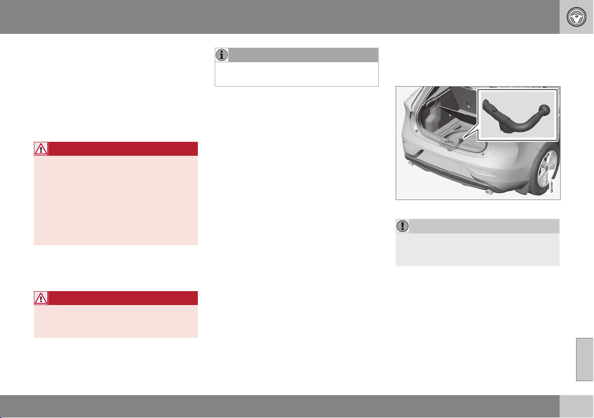
08 Starting and driving
08
303
Towing bracket
A towing bracket means that it is possible to
e.g. tow a trailer behind the car.
If the car is equipped with a detachable tow-
bar, the installation instructions for the loose
section must be followed carefully, see
Detachable towbar - attachment/removal (p.
304).
WARNING
If the car is fitted with a Volvo detachable
towbar:
•
Follow the installation instructions
carefully.
•
The detachable section must be
locked with the key before setting off.
•
Check that the indicator window
shows green.
Important checks
•
The towbar's towball must be cleaned
and greased regularly.
WARNING
The moving parts of the detachable towbar
must not be lubricated/oiled. This may
reduce safety.
NOTE
When a hitch with a vibration damper is
used, the towball must not be lubricated.
Related information
•
Driving with a trailer (p. 301)
•
Detachable towbar - specifications (p.
304)
•
Detachable towbar - storage (p. 303)
Detachable towbar - storage
Store the detachable towbar in the cargo
area.
The storage location for the removable towbar.
IMPORTANT
Always remove the detachable towbar
after use and store it in the designated
location in the car.
Related information
•
Detachable towbar - specifications (p.
304)
•
Detachable towbar - attachment/removal
(p. 304)
•
Driving with a trailer (p. 301)
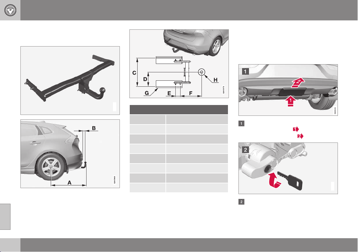
08 Starting and driving
08
304
Detachable towbar - specifications
Specifications for detachable towbar.
G021485
Dimensions, mounting points (mm)
A 887
B 73
C 881
D 441
E 109
F 306
G Side member
H Ball centre
Related information
•
Detachable towbar - attachment/removal
(p. 304)
•
Detachable towbar - storage (p. 303)
•
Driving with a trailer (p. 301)
Detachable towbar - attachment/
removal
The attachment/removal of the detachable
towbar is performed in the following way:
Attaching
Remove the protective cover by first
pressing in the catch
and then pulling
the cover straight back
.
G021487
Ensure that the mechanism is in the
unlocked position by turning the key
clockwise.
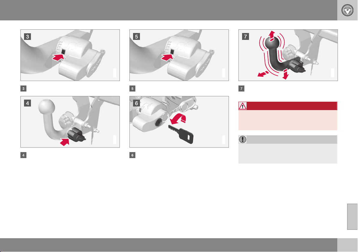
08 Starting and driving
08
}}
305
G021488
The indicator window must show red.
G021489
Insert the towball section until you hear a
click.
G021490
The indicator window must show green.
G000000
Turn the key anticlockwise to locked
position. Remove the key from the lock.
G021494
Check that the towball section is secure
by pulling it up, down and back.
WARNING
If the towball is not fitted correctly then it
must be detached and reattached in
accordance with the previous instructions.
IMPORTANT
Only grease in the ball for the towball
hitch, the remainder of the towbar must be
clean and dry.
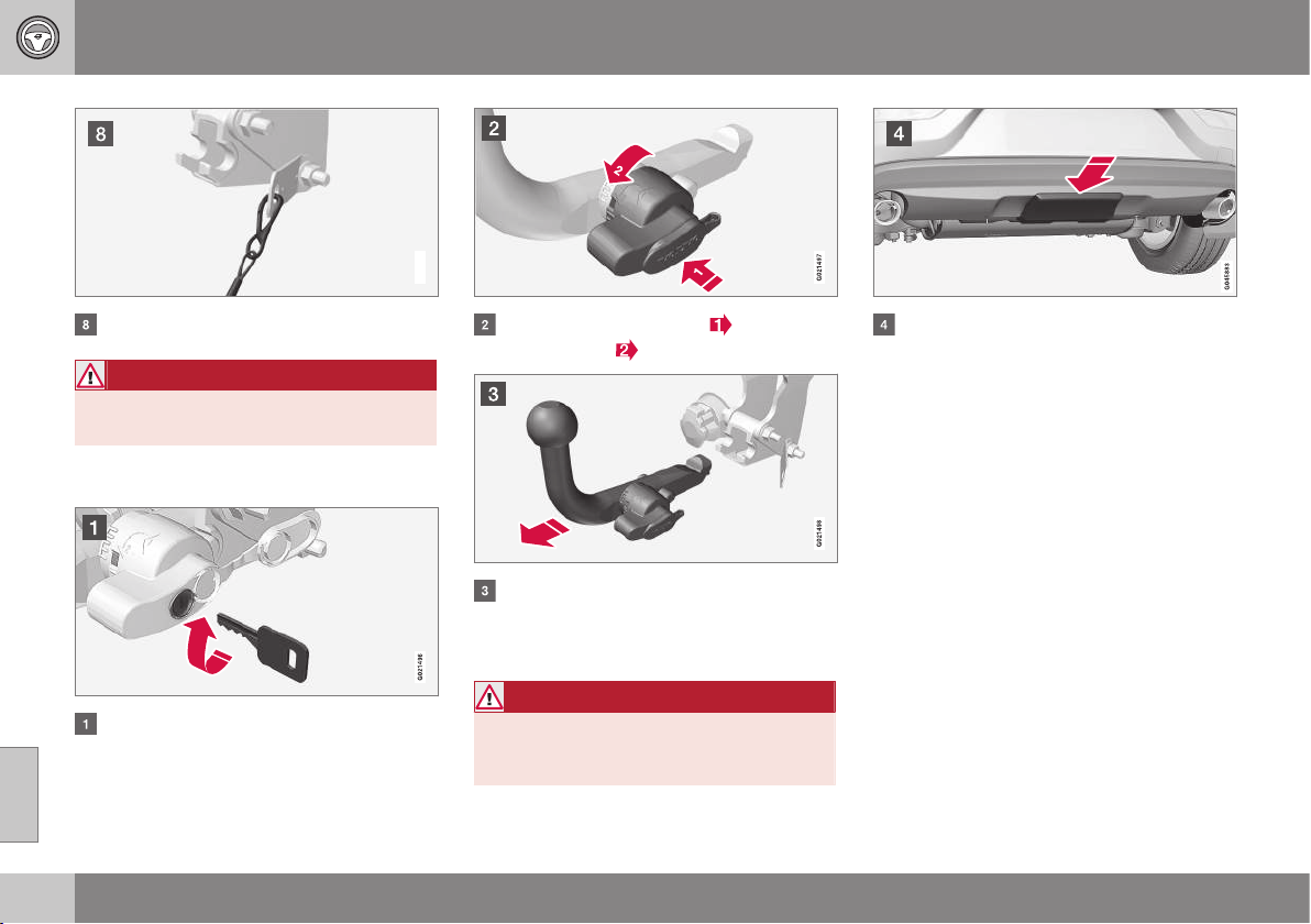
||
08 Starting and driving
08
306
G021495
Safety cable.
WARNING
Take care to secure the trailer's safety
cable in the intended bracket.
Removal of detachable towbar
Insert the key and turn it clockwise to the
unlocked position.
Push in the locking wheel and turn it
anticlockwise
until you hear a click.
Turn the locking wheel down fully, until it
comes to a stop. Hold it in this position
while pulling the towball rearward and
upward.
WARNING
Secure the detachable towbar safely if it is
stored in the car, see Detachable towbar -
storage (p. 303).
Push the protective cover until it snaps
tight.
Related information
•
Detachable towbar - storage (p. 303)
•
Detachable towbar - specifications (p.
304)
•
Driving with a trailer (p. 301)
08 Starting and driving
08
307
Trailer Stability Assist - TSA
The trailer stability assist TSA (Trailer Stability
Assist) function is to stabilise the car and
trailer combination if it begins to snake.
The TSA function is part of the DSTC system
(Dynamic Stability and Traction Control), see
Stability and traction control system (DSTC)
(p. 185).
Function
The snaking phenomenon can occur with any
car/trailer combination. Snaking normally
occurs at high speeds. But, there is a risk of it
occurring at lower speeds (70-90 km/h) if the
trailer is overloaded or the load is improperly
distributed, e.g. too far back.
In order for snaking to occur, there must be a
triggering factor, e.g.:
•
Car with trailer subjected to a sudden and
powerful side wind.
•
Car with trailer drives on an uneven road
surface or in a pothole.
•
Sweeping steering wheel movements.
Operation
If snaking has started, it could be difficult or
even impossible to suppress. This makes the
car/trailer combination difficult to control and
there is a risk that you could, for example,
end up in the wrong lane or leave the car-
riageway.
TSA system continually monitors car move-
ments, particularly lateral movements. If
snaking is detected, the front wheels are indi-
vidually braked. This serves to stabilise the
car/trailer combination. This is often enough
to help the driver regain control of the car.
If snaking is not eliminated the first time the
TSA system comes into action, the car/trailer
combination is braked with all wheels and
engine power is reduced. Once snaking has
been gradually suppressed and the car/trailer
combination is once again stable, the TSA
system stops regulating and the driver once
again has full control of the car.
Miscellaneous
The TSA system can engage within the speed
interval 65-160 km/h.
NOTE
TSA function is switched off if the driver
selects
Sport mode, see Stability and
traction control system (DSTC) (p. 185).
TSA may fail to engage if the driver uses
severe steering wheel movements to try to
rectify the snaking because in such a situa-
tion the TSA system cannot determine
whether it is the trailer or the driver that is
causing the snaking.
The DSTC symbol in the combined
instrument panel flashes when the
TSA system is working.
Related information
•
Stability and traction control system
(DSTC) - symbols and messages (p. 187)
•
Stability and traction control system
(DSTC) - operation (p. 186)
08 Starting and driving
08
308
Towing
During towing, one vehicle is towed by
another vehicle using a tow rope.
Find out the statutory maximum speed limit
for towing before towing begins.
1. Unlock the steering lock (p. 270) by
inserting the remote control key in the
ignition switch and giving a long press on
the START/STOP ENGINE button - key
position (p. 71) II is activated.
2. The remote control key must remain in
the ignition switch while the car is being
towed.
3. Keep the towline taut when the towing
vehicle reduces speed by holding your
foot gently pressed on the brake pedal -
thereby avoiding unnecessary jerking.
4. Be prepared to brake to stop.
WARNING
•
Check that the steering lock is
unlocked before towing.
•
The remote control key must be in key
position II - in position I all airbags are
deactivated.
•
Never remove the remote control key
from the ignition switch when the car
is being towed.
WARNING
The brake servo and power steering do not
work when the engine is switched off - the
brake pedal needs to be depressed
about 5 times more heavily and the steer-
ing is considerably heavier than normal.
Manual gearbox
Prior to towing:
– Move gear lever into neutral and release
the parking brake.
Automatic gearbox Geartronic
IMPORTANT
Note that the car must always be towed
with the wheels rolling forward.
•
Do not tow cars with automatic trans-
mission at speeds higher than 80 km/h
or for distances in excess of 80 km.
Follow the speeds that are permitted
in accordance with local traffic regula-
tions.
Prior to towing:
– Move the gear selector to position N and
release the parking brake.
Automatic gearbox Powershift
The model with Powershift transmission
should not be towed as it is dependent on the
engine running in order to receive sufficient
lubrication. If towing still has to take place,
the route must be as short as possible and
then with very low speed.
In the event of uncertainty as to whether or
not the car is equipped with Powershift trans-
mission, this can be verified by checking the
type designation (p. 438) on the transmis-
sion's label under the bonnet. The designa-
tion ”MPS6” means that it is Powershift –
transmission otherwise it is Geartronic auto-
matic transmission.
IMPORTANT
Avoid towing.
•
However, the car can be towed for a
short distance at low speed to move it
from a dangerous position - not further
than 10 km and not faster than
10 km/h. Note that the car must
always be towed with the wheels roll-
ing forward.
•
In the event of moving a longer dis-
tance than 10 km, the car must be
transported with the drive wheels
raised from the road - professional
recovery is recommended.
Prior to towing:
– Move the gear selector to position N and
release the parking brake.
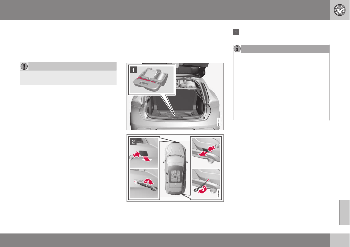
08 Starting and driving
08
309
Jump starting
Do not tow the car to bump start the engine.
Use a donor battery if the battery is dis-
charged and the engine does not start, see
Jump starting (p. 270).
IMPORTANT
The catalytic converter may be damaged
during attempts to tow-start the engine.
Related information
•
Towing eye (p. 309)
Towing eye
The towing eye is screwed into a threaded
socket behind a cover on the right-hand side
of the bumper, front or rear.
Attaching the towing eye
Take out the towing eye that is located
under the floor hatch in the cargo area.
NOTE
To access the towing eye/wheel wrench in
the foam block:
•
Version 1: Lift the emergency puncture
repair kit compressor unit (point 5) to
access the wheel wrench. Lift out the
bottle of sealant (point 6) to access the
towing eye.
•
Version 2: Lift the emergency puncture
repair kit compressor unit (point 5) to
access the towing eye. The wheel
wrench is located underneath the jack.
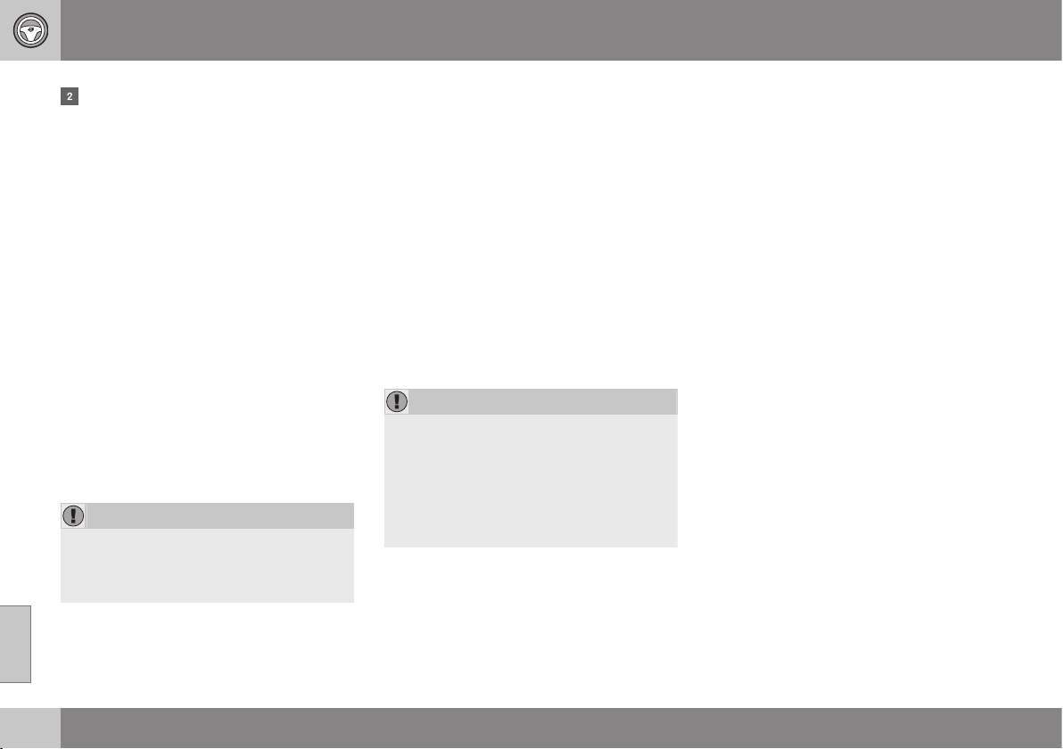
||
08 Starting and driving
08
310
The cover for the towing eye's attach-
ment point is available in two variants
which must be opened in the following
way:
•
Open the rear bumper's recess using a
coin or similar inserted in the recess,
carefully turning it outwards. Then turn
out the cover completely and remove
it.
•
The front bumper's recess has a mark-
ing along one side or in a corner: Press
the marking with a finger and fold out
the opposite side/corner at the same
time - the cover turns around its axis
and can then be removed.
Screw the towing eye right in up to its
flange. Turn in the towing eye firmly e.g.
using the wheel wrench.
The towing eye is unscrewed after use.
Place the towing eye back in its position.
Finish by refitting the cover onto the
bumper.
IMPORTANT
The towing eye is only designed for towing
on roads - not for pulling the car unstuck
or out of a ditch. Call a recovery service for
recovery assistance.
Related information
•
Towing (p. 308)
•
Recovery (p. 310)
Recovery
Recovery means that the vehicle is transpor-
ted away by means of another vehicle.
Call a recovery service for recovery assis-
tance.
The towing eye may be used to pull the car
up onto a recovery vehicle with a flatbed plat-
form. The car's position and ground clear-
ance determine whether it is possible. If the
slope of the recovery vehicle's ramp is too
steep, or if the ground clearance under the
car is inadequate, then the car may be dam-
aged if you try to pull it up using the towing
eye. Raise the car using the recovery vehi-
cle's lifting device if necessary.
IMPORTANT
Note that the car must always be transpor-
ted with the wheels rolling forward.
•
An all-wheel drive car (AWD) with
raised front suspension must not be
towed at speeds above 70 km/h. It
should not be towed further than
50 km.
Related information
•
Towing (p. 308)
WHEELS AND TYRES
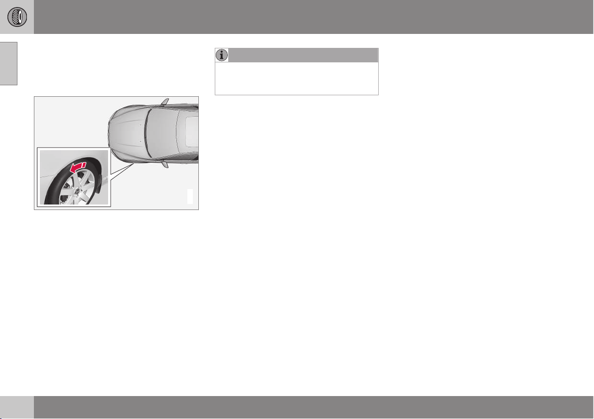
09 Wheels and tyres
09
312
Tyres - direction of rotation
Tyres with a tread pattern which are designed
to only turn in one direction have the direction
of rotation marked with an arrow.
G021778
The arrow shows the tyre's direction of rotation.
The tyre must always rotate in the same
direction throughout its lifespan. Tyres should
only be switched between front and rear
positions, never between left and right-hand
sides, or vice versa. If the tyres are fitted
incorrectly, the car's braking characteristics
and capacity to force rain and slush out of the
way are adversely affected. Tyres with the
greatest tread depth should always be fitted
to the rear of the car (to decrease the risk of
skidding).
NOTE
Make sure that both pairs of wheels have
the same type and dimension, and also the
same make.
Follow the recommended tyre pressure (p.
322) specified in the tyre pressure table.
Related information
•
Tyres - dimensions (p. 316)
•
Tyres - speed ratings (p. 317)
•
Tyres - maintenance (p. 312)
•
Tyres - tread wear indicators (p. 314)
Tyres - maintenance
Amongst other things, the function of the
tyres is to provide grip on the road surface,
dampen vibration and protect the wheel from
wear.
Driving characteristics
Tyres greatly affect the car's driving characte-
ristics. The type of tyre, dimensions, tyre
pressure and speed rating are important for
how the car performs.
Tyre age
All tyres older than 6 years old should be
checked by an expert even if they seem
undamaged. Tyres age and decompose, even
if they are hardly ever or never used. The
function can therefore be affected. This
applies to all tyres that are stored for future
use. Examples of external signs which indi-
cate that the tyre is unsuitable for use are
cracks or discoloration.
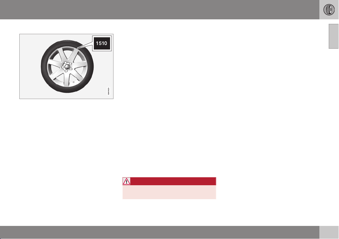
09 Wheels and tyres
09
313
New tyres
Tyres are perishable. After a few years they
begin to harden at the same time as the fric-
tion capacity/characteristics gradually deteri-
orate. For this reason, aim to get as fresh
tyres as possible when you replace them.
This is especially important with regard to
winter tyres. The last four digits in the
sequence mean the week and year of manu-
facture. This is the tyre's DOT marking
(Department of Transportation), and this is
stated with four digits, for example 1510. The
tyre in the figure was manufactured in week
15 of 2010.
Summer and winter tyres
When summer and winter wheels are
changed the wheels should be marked with
which side of the car they were mounted on,
for example L for left and R for right.
Wear and maintenance
Correct tyre pressure (p. 322) results in more
even wear. Driving style, tyre pressure, cli-
mate and road condition affect how quickly
your tyres age and wear. To avoid differences
in tread depth and to prevent wear patterns
(p. 314) arising, the front and rear wheels can
be switched with each other. A suitable dis-
tance for the first change is approx. 5000 km
and then at 10000 km intervals. Volvo recom-
mends that you contact an authorised Volvo
workshop for checking if you are uncertain
about tread depth. If significant differences in
wear (>1 mm difference in tread depth)
between tyres have already occurred, the
least worn tyres must always be placed on
the rear. Understeer is normally easier to cor-
rect than oversteer, and leads to the car con-
tinuing forwards in a straight line rather than
having the rear end skidding to one side,
resulting in possible complete loss of control
over the car. This is why it is important for the
rear wheels never to lose grip before the front
wheels.
Wheels must be stored lying down or hanging
up - never standing up.
WARNING
A damaged tyre may lead to loss of control
over the car.
Related information
•
Tyres - dimensions (p. 316)
•
Tyres - speed ratings (p. 317)
•
Tyres - direction of rotation (p. 312)
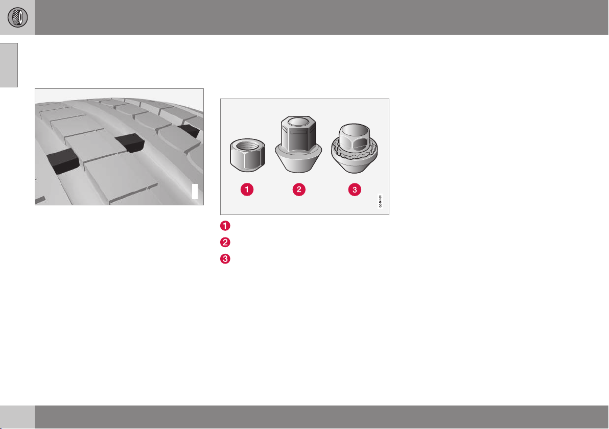
09 Wheels and tyres
09
314
* Option/accessory, for more information, see Introduction.
Tyres - tread wear indicators
A tread wear indicator shows the status of the
tyre's tread.
G021829
Tread wear indicators.
Tread wear indicators are narrow treadless
bands across the width of the tread. On the
side of the tyre are the letters TWI (Tread
Wear Indicator). When the tyre's tread depth
is down to 1.6 mm, the tread depth will be
level in height with the tread wear indicators.
Change to new tyres as soon as possible.
Remember that tyres with little tread depth
provide very poor grip in rain and snow.
Related information
•
Tyres - speed ratings (p. 317)
•
Tyres - air pressure (p. 322)
•
Tyres - direction of rotation (p. 312)
Wheel bolts
Wheel bolts are used to fasten the wheels at
the hubs and are available in different ver-
sions.
Low wheel bolt
High wheel bolt
Locking wheel bolts
Tightening torque
•
Type 1 wheel bolt (steel rim): 110 Nm
•
Type 2 wheel bolt (aluminium rim): 130
Nm
•
Type 3 Lockable wheel bolt (steel/
aluminium rim): 110 Nm
Only use rims that are tested and approved
by Volvo and which are Volvo genuine acces-
sories. Check the torque with a torque
wrench.
Locking wheel bolts*
Locking wheel bolts can be used on both alu-
minium and steel rims. Under the cargo area
floor there is space for the sleeve for the lock-
able wheel bolts.
Related information
•
Wheel and wheel rim dimensions (p. 316)
09 Wheels and tyres
09
* Option/accessory, for more information, see Introduction.
315
Jack
A jack is used to raise the car, e.g. when
changing the tyres.
The original jack should only be used for
changing to the spare wheel. The jack's
thread must always be well greased.
Related information
•
Warning triangle (p. 323)
•
Emergency puncture repair* (p. 324)
Winter tyres
Winter tyres are tyres that are adapted for
winter road conditions.
Winter tyres
Volvo recommends winter tyres with particu-
lar dimensions. Tyre dimensions are depend-
ent on engine variant. When driving on winter
tyres, the correct type of tyres must be fitted
to all four wheels.
NOTE
Volvo recommends that you consult a
Volvo dealer about which wheel rim and
tyre types are most suitable.
Studded tyres
Studded winter tyres should be run in gently
for 500-1000 km so the studs settle properly
into the tyres. This gives the tyre, and espe-
cially the studs, a longer service life.
NOTE
The legal provisions for the use of studded
tyres vary from country to country.
Tread depth
Road conditions with ice, slush and low tem-
peratures place considerably higher demands
on tyres than summer conditions. Volvo
therefore recommends not to drive on winter
tyres that have a tread depth of less
than4 mm.
Using snow chains
Snow chains may only be used on the front
wheels (also applies to all-wheel drive cars).
Never drive faster than 50 km/h with snow
chains. Avoid driving on bare ground as this
wears out both the snow chains and tyres.
WARNING
Use Volvo genuine snow chains or equiva-
lent chains designed for the car model,
and tyre and rim dimensions. In the event
of uncertainty Volvo recommends that you
consult an authorised Volvo workshop.
The wrong snow chains may cause serious
damage to your car and lead to an acci-
dent.
Related information
•
Changing wheels - removing wheels (p.
319)

09 Wheels and tyres
09
316
Wheel and wheel rim dimensions
Wheel and rim dimensions are designated in
accordance with the examples in the table
below.
Wheels (rims) have a designation of dimen-
sions, for example: 7Jx16x50.
7 Rim width in inches
J Rim flange profile
16 Rim diameter in inches
50 Off-set in mm (distance from wheel
centre to wheel contact surface
against the hub)
Related information
•
Wheel bolts (p. 314)
Tyres - dimensions
The car's wheels, tyres and rims have a cer-
tain dimension, see the examples in the table
below.
The dimensions are stated on all car tyres.
Example of designation:215/55R16 97W.
205 Tyre width (mm)
50 Ratio between tyre wall height and
tyre width (%)
R Radial ply
17 Rim diameter in inches (")
93 Codes for the maximum permitted
tyre load, load index (p. 316) (LI)
W Speed rating for maximum permitted
speed, speed rating (p. 317) (SS). (In
this case 270 km/h).
Related information
•
Tyres - air pressure (p. 322)
•
Tyres - direction of rotation (p. 312)
•
Tyres - tread wear indicators (p. 314)
Tyres - load index
Load index indicates a tyre's ability to carry a
certain load.
Each tyre has a certain capacity to carry a
load, a load index (LI). The car's weight deter-
mines the load capacity required of the tyres.
Related information
•
Tyres - dimensions (p. 316)
•
Tyres - speed ratings (p. 317)
•
Tyres - air pressure (p. 322)
•
Tyres - tread wear indicators (p. 314)
09 Wheels and tyres
09
* Option/accessory, for more information, see Introduction.
317
Tyres - speed ratings
Each tyre can withstand a certain maximum
speed and therefore belongs to a particular
speed rating (SS - Speed Symbol).
Tyre speed class must at least correspond
with the car's top speed. Minimum speed rat-
ing is indicated in the speed rating table
below. The only exception to these conditions
is winter tyres (p. 315) (both those with metal
studs and those without), where a lower
speed rating may be used. If such a tyre is
chosen, the car must not be driven faster
than the speed rating of the tyre (for example,
class Q can be driven at a maximum of
160 km/h). Traffic regulations determine how
fast a car can be driven, not the speed rating
of the tyres.
NOTE
The maximum permitted speed is speci-
fied in the table.
Q 160 km/h (used only on winter tyres)
T 190 km/h
H 210 km/h
V 240 km/h
W 270 km/h
Y 300 km/h
WARNING
The car must be fitted with tyres which
have the same or a higher load index (p.
316) (LI) and speed rating (SS) than speci-
fied. If a tyre with too low a load index or
speed rating is used, it may overheat.
Related information
•
Tyres - dimensions (p. 316)
•
Tyres - air pressure (p. 322)
•
Tyres - direction of rotation (p. 312)
Spare wheel*
A spare wheel (Temporary spare) is used to
temporarily replace a punctured normal
wheel.
A spare wheel is only intended for use tempo-
rarily and must be replaced by an normal
wheel as soon as possible. The car's handling
may be altered by the use of a spare wheel.
The spare wheel is smaller than the normal
wheel. The car's ground clearance is affected
accordingly. Pay attention to high kerbs and
do not machine wash the car. If the spare
wheel is fitted on the front axle, you cannot
use snow chains at the same time. On all-
wheel drive cars the drive on the rear axle can
be disconnected. The spare wheel must not
be repaired. The correct tyre pressure for the
spare wheel is stated in the tyre pressure
table, Tyres - air pressure (p. 322).
IMPORTANT
•
Never drive faster than 80 km/h with a
spare wheel on the car.
•
The car must never be driven fitted
with more than one "Temporary
Spare" wheel.
Related information
•
Changing wheels - removing wheels (p.
319)
•
Changing wheels - fitting the spare
wheel* (p. 320)
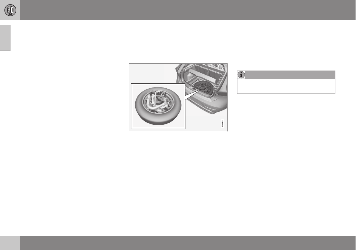
09 Wheels and tyres
09
318
* Option/accessory, for more information, see Introduction.
•
Changing wheels - taking out the spare
wheel* (p. 318)
•
Jack (p. 315)
•
Warning triangle (p. 323)
•
Wheel bolts (p. 314)
Changing wheels - taking out the
spare wheel*
The spare wheel* plus jack* and wheel
wrench* are stored under the floor in the
cargo area.
1. Lift the rear edge of the luggage compart-
ment floor (or on models with a jointed
luggage compartment floor, take hold of
the luggage compartment floor handle, lift
and move the rear part of the floor for-
wards).
2. Lift out the storage compartment* (only
models with a jointed cargo area floor).
3. Lift out the lower floor (models with a join-
ted luggage compartment floor only).
4. Undo the attaching screw and lift out the
foam block containing the jack and tools.
5. Take hold of the far end of the spare
wheel, then lift. Push the spare wheel for-
wards slightly and lift it out of the storage
compartment.
6. Remove the wheel wrench, the jack and
the towing eye from the foam block.
NOTE
The jack must be lifted out in order to
access the towing eye.
Related information
•
Changing wheels - removing wheels (p.
319)
•
Changing wheels - fitting the spare
wheel* (p. 320)
•
Jack (p. 315)
•
Spare wheel* (p. 317)
•
Warning triangle (p. 323)
•
Wheel bolts (p. 314)
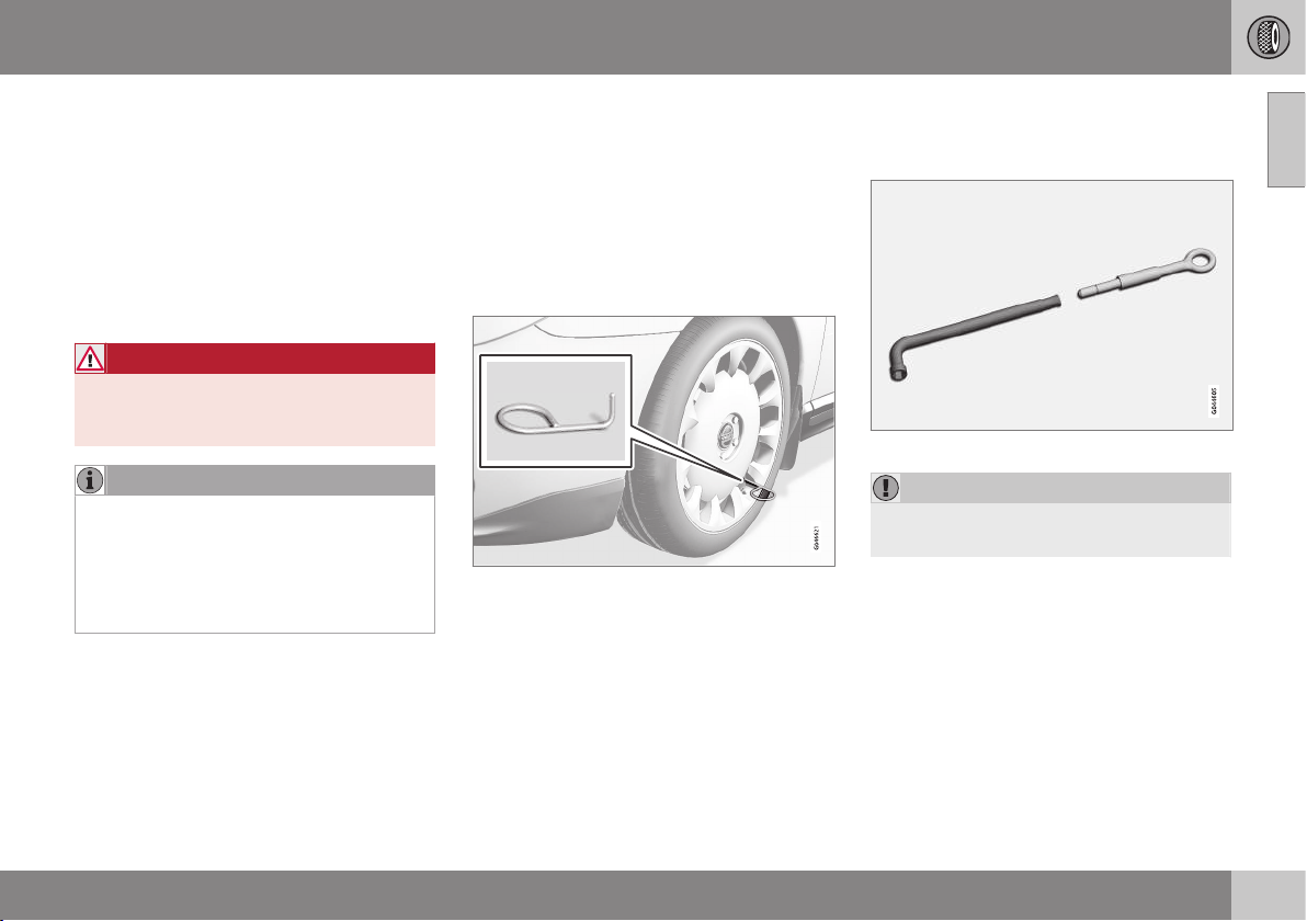
09 Wheels and tyres
09
}}
* Option/accessory, for more information, see Introduction.
319
Changing wheels - removing wheels
The car's wheels can be changed for e.g. win-
ter wheels/winter tyres.
Set up the warning triangle if a wheel must be
replaced at a busy location. The car and jack*
must be on a firm horizontal surface.
1. Apply the parking brake and engage
reverse gear, or position P if the car has
an automatic gearbox.
WARNING
Check that the jack is not damaged, that
the threads are thoroughly lubricated and
that it is free from dirt.
NOTE
Volvo recommends only using the jack*
that belongs to the car model in question,
which is indicated on the jack's label.
The decal also indicates the jack's maxi-
mum lift capacity at a specified lifting
height.
2. Take out the wheel to be fitted (summer
tyre, winter tyre or spare wheel) as well as
the tools. If it is a spare wheel being fitted
then there is a package in its location
containing gloves and a plastic bag for
the punctured wheel.
3. Place chocks in front of and behind the
wheels which will remain on the ground.
Use heavy wooden blocks or large stones
for example.
4. Cars with steel rims have removable
wheel covers. Use the removal tool to
hook in and pull off any full-wheel wheel
covers. Alternatively, the wheel covers
can be pulled away by hand.
5. Screw together the towing eye with the
wheel wrench* until the stop position as
shown in the following illustration.
The wheel wrench and towing eye.
IMPORTANT
The towing eye must be screwed into all
threads in the wheel bolt wrench.
6. Loosen the wheel bolts ½-1 turn anti-
clockwise with the wheel wrench.
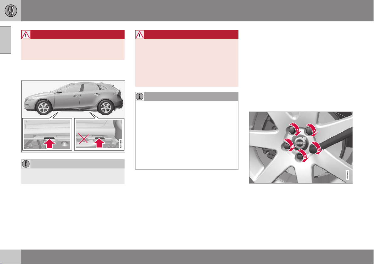
||
09 Wheels and tyres
09
320
* Option/accessory, for more information, see Introduction.
WARNING
Never position anything between the
ground and the jack, nor between the jack
and the car's jacking point.
7. There are two jacking points on each side
of the car.
IMPORTANT
The ground under the jack must be firm,
smooth and level.
8. Wind up the jack so that the flange in the
bodywork ends up in the notch in the
head of the jack.
9. Lift the car so that the wheel is free.
Remove the wheel bolts and lift off the
wheel.
WARNING
Never crawl under the car when it is raised
on the jack.
Passengers must leave the car when it is
raised on the jack.
Park the car such that passengers have
the car, or ideally a crash barrier, between
themselves and the roadway.
NOTE
The car's regular jack is designed only for
use occasionally and for a short time, such
as when changing a wheel with a punc-
tured tyre, switching between summer
tyres and winter tyres, etc. Only the jack
belonging to the specific model is to be
used to jack up the car. If the car is to be
jacked up more often, or for a longer time
than is required just to change a wheel,
use of a garage jack is recommended. In
this instance, follow the instructions for
use that come with the equipment.
Related information
•
Changing wheels - fitting the spare
wheel* (p. 320)
•
Changing wheels - taking out the spare
wheel* (p. 318)
•
Jack (p. 315)
•
Spare wheel* (p. 317)
•
Warning triangle (p. 323)
•
Wheel bolts (p. 314)
Changing wheels - fitting the spare
wheel*
It is important that the procedure for fitting
the spare wheel is carried out correctly.
Fitting
1. Clean the contact surfaces between
wheel and hub.
2. Put on the wheel. Tighten the wheel bolts
thoroughly.
3. Lower the car so that the wheels cannot
rotate.
4. Tighten the wheel bolts crosswise. It is
important that the wheel bolts are tight-
ened with the correct tightening torque.
Check the torque with a torque wrench.

09 Wheels and tyres
09
}}
* Option/accessory, for more information, see Introduction.
321
5.
Refit any full wheel covers.
NOTE
The wheel cover outlet for the valve must
be positioned over the valve on the wheel
rim during fitting.
Putting back the jack* and tools
The tools and jack must be returned to their
correct places in the foam block after use.
1. Unscrew the towing eye from the wheel
bolt wrench.
2. Put back any tools that have been used in
the relevant compartments in the foam
block in the following order:
•
towing eye/funnel/torx wrench/socket
for locking wheel bolts/tool for wheel
covers
•
jack (must be cranked to the correct
height so that it fits into the foam
block's compartment, the handle
above the foot and down in the groove
in the foam block)
•
socket wrench (above the jack).
3. If the spare wheel has been used, then
the punctured wheel can be placed in the
plastic bag contained in the package with
the gloves. Place the foam block back in
the storage compartment and tighten the
mounting screw to the floor of the storage
compartment.
If the spare wheel has not been used,
place the foam block in the spare wheel
and place the spare wheel back in the
storage compartment. Tighten the attach-
ing screw to the floor of the storage com-
partment.
4. Return the detachable towbar.
NOTE
•
After a tyre has been inflated, always
refit the dust cap in order to avoid
damage to the valve from gravel, dirt,
etc.
•
Only use plastic dust caps. Metal dust
caps can rust and become difficult to
unscrew.
IMPORTANT
The tools and jack* must be stored in the
intended location in the car's cargo area
when not in use.
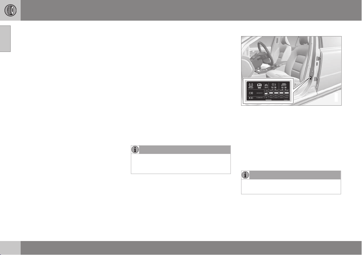
||
09 Wheels and tyres
09
322
* Option/accessory, for more information, see Introduction.
Related information
•
Changing wheels - taking out the spare
wheel* (p. 318)
•
Changing wheels - removing wheels (p.
319)
•
Jack (p. 315)
•
Spare wheel* (p. 317)
•
Warning triangle (p. 323)
•
Wheel bolts (p. 314)
Tyres - air pressure
Tyres can have different air pressures which
are measured in bar.
Check the air pressure in the tyres
The air pressure (p. 457) for the tyres must
be checked every month. Check air pressure
with cold tyres. "Cold tyres" means the tyres
are the same temperature as the ambient
temperature. After several few kilometres of
driving, the tyres warm up and the pressure
increases. Inadequate tyre pressure increases
fuel consumption, shortens tyre lifespan and
impairs the car's roadholding. Driving on
tyres with tyre pressure that is too low could
result in the tyres overheating and being
damaged. Tyre pressure affects travelling
comfort, road noise and steering characteris-
tics.
NOTE
Tyre pressure decreases over time, this is
a natural phenomenon. Tyre pressure also
varies depending on ambient temperature.
Tyre pressure label
G021830
The tyre pressure label on the driver's side
door pillar (between front and rear door)
shows which pressures the tyres should have
at different loads and speed conditions. This
is also specified in the tyre pressure table.
•
Tyre pressures for the car's recom-
mended tyre dimension (p. 316)
•
ECO pressure results in improved fuel
economy (p. 300)
NOTE
Temperature differences change the
tyre pressure.
Fuel economy, ECO pressure
In order to obtain optimum fuel economy at
speeds below 160 km/h an ECO pressure is
recommended (applies to both full and light
load - see the tyre pressure table (p. 457)).

09 Wheels and tyres
09
* Option/accessory, for more information, see Introduction.
323
Related information
•
Tyres - speed ratings (p. 317)
•
Tyres - direction of rotation (p. 312)
•
Tyres - maintenance (p. 312)
•
Tyres - tread wear indicators (p. 314)
Warning triangle
The warning triangle is used to warn other
road users of a stationary vehicle.
Storage and folding up
Lift the floor hatch (or push the rear part
of the luggage compartment floor for-
wards in models with a jointed floor and
then lift the lower floor) and remove the
warning triangle.
Take the warning triangle from the case,
fold out and assemble the two loose
sides.
Fold out the warning triangle's support
legs.
Follow the regulations for the use of a warn-
ing triangle. Position the warning triangle in a
suitable place with regard to traffic.
Ensure the warning triangle and its case are
properly secured in the cargo area after use.
Related information
•
Spare wheel* (p. 317)
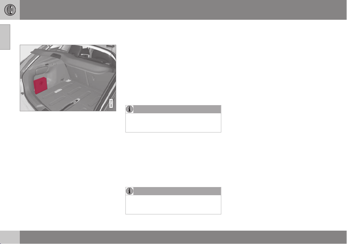
09 Wheels and tyres
09
324
* Option/accessory, for more information, see Introduction.
First aid kit*
The first aid box contains first aid equipment.
A case containing first aid equipment is
located on the left-hand side of the cargo
area.
Emergency puncture repair*
Emergency puncture repair, the emergency
puncture repair kit* (TMK - Temporary Mobi-
lity Kit), is used to seal a puncture and check
and adjust the air pressure.
The emergency puncture repair kit consists of
a compressor and a bottle of sealant. The
sealing works as a temporary repair. The
sealing fluid bottle must be replaced before
its expiration date and after use. The sealing
fluid effectively seals tyres punctured in the
tread.
NOTE
The emergency puncture repair kit is only
intended for sealing tyres with a puncture
in the tread.
The emergency puncture repair kit has limited
capacity to seal tyres which have punctures
in the wall. Do not seal tyres with the emer-
gency puncture repair kit if they have larger
slits, cracks or similar damage. Connect the
compressor to one of the car's 12 V sockets.
Choose the socket that is nearest to the
punctured tyre.
NOTE
The compressor for temporary emergency
puncture repair has been tested and
approved by Volvo.
Related information
•
Emergency puncture repair* - operation
(p. 326)
•
Emergency puncture repair* - rechecking
(p. 328)
•
Emergency puncture repair kit* - overview
(p. 326)
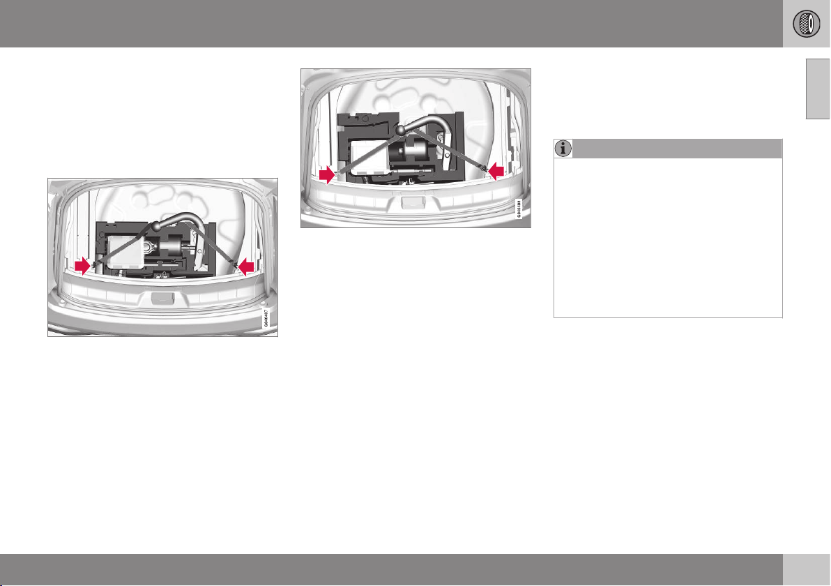
09 Wheels and tyres
09
* Option/accessory, for more information, see Introduction.
325
Emergency puncture repair kit* -
location
Emergency puncture repair kit (TMK - Tempo-
rary Mobility Kit) is used to seal a puncture
and check and adjust the air pressure.
Location of the emergency puncture
repair kit
Version 1.
Version 2.
Set up the warning triangle if a tyre is being
sealed in a trafficked location. The warning
triangle and emergency puncture repair kit
are located under the floor in the cargo area.
1. Lift the rear edge of the luggage compart-
ment floor (or on models with a jointed
luggage compartment floor, take hold of
the luggage compartment floor handle, lift
and move the rear part of the floor for-
wards).
2. Lift out the storage compartment
(optional extra) - models with a jointed
luggage compartment floor only.
3. Lift out the lower floor (models with a join-
ted luggage compartment floor only).
4. Unhook the elastic part of the belt over
the TMK compressor unit on the left side.
5. Lift the TMK compressor unit straight up.
6. To access the bottle of sealant, it must be
pushed to the left until it can be lifted out
of the foam block.
NOTE
To access the towing eye/wheel wrench in
the foam block:
•
Version 1: Lift the emergency punc-
ture repair kit compressor unit (point 5)
to access the wheel wrench. Lift out
the bottle of sealant (point 6) to access
the towing eye.
•
Version 2: Lift the emergency punc-
ture repair kit compressor unit (point 5)
to access the towing eye. The wheel
wrench is located underneath the jack.
After use, hook the belt back onto the left
side.
Version 1: The belt must be pulled behind the
foam block (not above).
Version 2: The belt must be in the fork on the
rear part of the foam block.
Related information
•
Emergency puncture repair kit* - overview
(p. 326)
•
Emergency puncture repair kit* - sealant
(p. 330)
•
Emergency puncture repair* (p. 324)
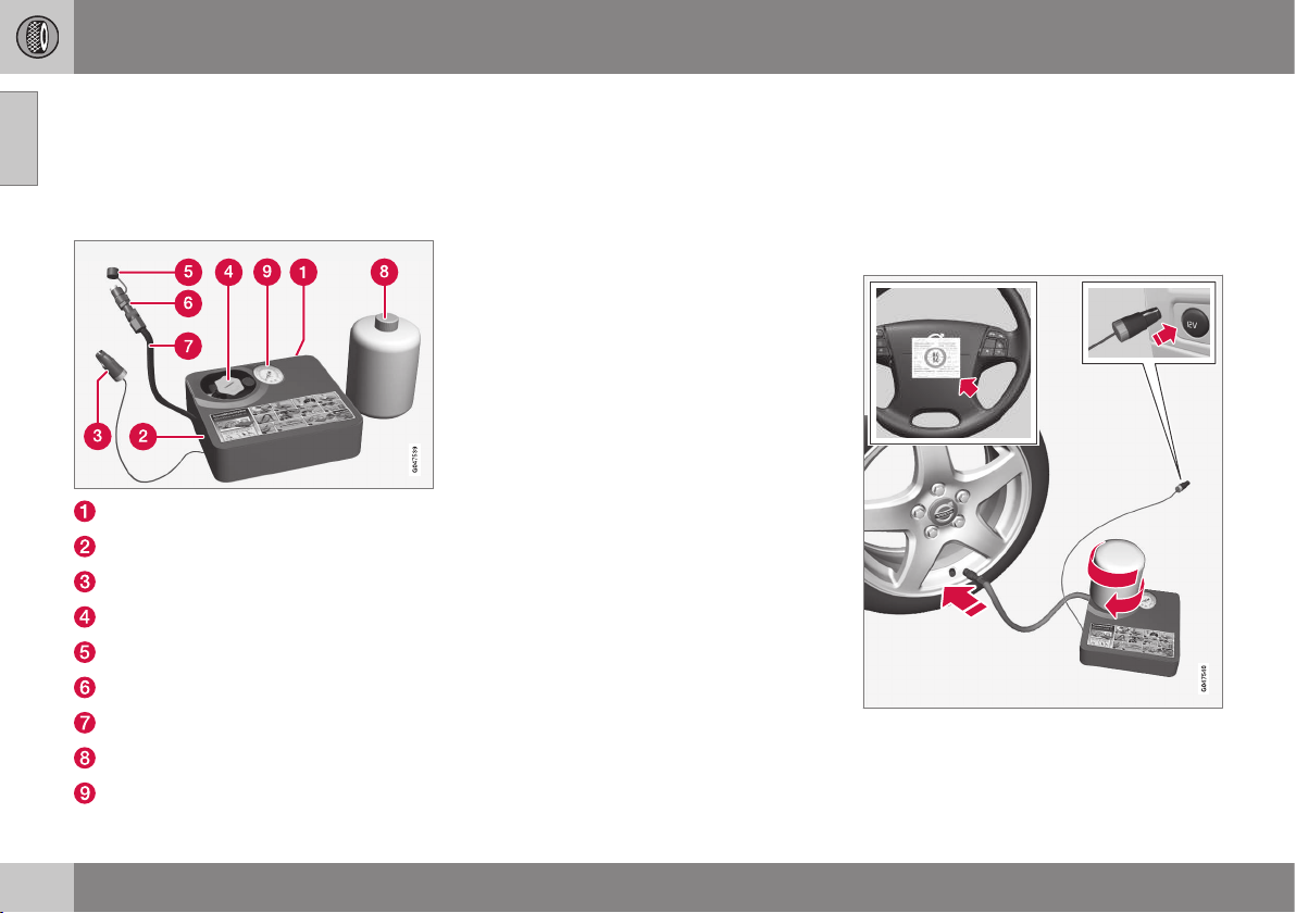
09 Wheels and tyres
09
326
* Option/accessory, for more information, see Introduction.
Emergency puncture repair kit* -
overview
Emergency puncture repair kit (TMK - Tempo-
rary Mobility Kit) is used to seal a puncture
and check and adjust the air pressure.
Label, maximum permitted speed
Switch
Cable
Bottle holder (orange cap)
Protective cap
Pressure reducing valve
Air hose
Bottle holder with sealant
Pressure gauge
Related information
•
Emergency puncture repair kit* - location
(p. 325)
•
Emergency puncture repair kit* - sealant
(p. 330)
•
Emergency puncture repair* (p. 324)
•
Emergency puncture repair* - stowing
components (p. 330)
Emergency puncture repair* -
operation
Emergency puncture repair, the emergency
puncture repair kit* (TMK - Temporary Mobi-
lity Kit), is used to seal a puncture and check
and adjust the air pressure.
Emergency puncture repair
For information on the function of the parts, see
Emergency puncture repair kit.
09 Wheels and tyres
09
}}
327
1. Detach the label for maximum permitted
speed (which is fitted on one side of the
compressor) and affix it to the steering
wheel.
WARNING
You should not drive faster than 80 km/h
after the emergency tyre repair kit has
been used. Volvo recommends that you
visit an authorised Volvo workshop for
inspection of the sealed tyre (maximum
driving distance is 200 km). The staff there
can determine whether or not the tyre can
be repaired or if it needs to be replaced.
WARNING
The sealing fluid can irritate the skin. In the
case of contact with skin, wash away the
fluid with soap and water.
2. Check that the switch is in position 0 and
locate the cable and the air hose.
NOTE
Do not break the bottle's seal before use.
The seal is broken automatically when the
bottle is screwed in.
3. Unscrew the orange cap and unscrew the
bottle's stopper.
4. Screw the bottle into its holder.
WARNING
Do not unscrew the bottle, it is equipped
with a reverse catch to prevent leakage.
5. Unscrew the wheel's dust cap and screw
in the air hose valve connection to the
bottom of the thread on the tyre's air
valve.
6. Plug the cable into the 12 V socket and
start the car.
WARNING
Do not leave children in the car without
supervision when the engine is running.
7. Flick the switch to position I.
WARNING
Never stand next to the tyre when the
compressor is running. If cracks or
unevenness arise then the compressor
must be switched off immediately. The
journey should not be continued. Contact-
ing an authorised tyre centre is recom-
mended.
NOTE
When the compressor starts, the pressure
can increase up to 6 bar but the pressure
drops after approximately 30 seconds.
8. Inflate the tyre for 7 minutes.
IMPORTANT
Risk of overheating. The compressor must
not run for more than 10 minutes.
||
09 Wheels and tyres
09
328
* Option/accessory, for more information, see Introduction.
9. Switch off the compressor to check the
pressure on the pressure gauge. Mini-
mum pressure is 1.8 bar and maximum
3.5 bar. (Release air with the pressure
reducing valve if the tyre pressure is too
high.)
WARNING
If the pressure is below 1.8 bar then the
hole in the tyre is too big. The journey
should not be continued. Contacting an
authorised tyre centre is recommended.
10. Switch off the compressor and unplug the
cable from the 12 V socket.
11. Detach the hose from the tyre valve and
fit the valve cap.
12. As soon as possible, drive approximately
3 km at a maximum speed of 80 km/h so
that the sealing fluid can seal the tyre.
Related information
•
Emergency puncture repair* (p. 324)
•
Emergency puncture repair* - rechecking
(p. 328)
•
Emergency puncture repair kit* - overview
(p. 326)
•
Emergency puncture repair* - stowing
components (p. 330)
Emergency puncture repair* -
rechecking
Emergency puncture repair (p. 324), in which
the emergency puncture repair kit (p. 326)*
(TMK - Temporary Mobility Kit), is used to seal
a puncture and check and adjust the air pres-
sure.
Check tyre pressure
1. Connect the tyre sealing equipment
again.
2. Read the tyre pressure on the pressure
gauge.
•
If it is below 1.3 bar then the tyre is
insufficiently sealed. The journey
should not be continued. Contact a
tyre centre.
•
If the tyre pressure is higher than 1.3
bar, the tyre must be inflated to the
pressure specified in accordance with
the tyre pressure table (p. 457) (1 bar
= 100 kPa). Release air using the pres-
sure reducing valve if the tyre pressure
is too high.
WARNING
Do not unscrew the bottle, it is equipped
with a reverse catch to prevent leakage.
3. Make sure the compressor is switched
off. Detach the air hose and cable. Refit
the dust cap.
4. Fold the hose into the box and leave the
bottle where it is. Place TMK in the cargo
area.
NOTE
•
After a tyre has been inflated, always
refit the dust cap in order to avoid
damage to the valve from gravel, dirt,
etc.
•
Only use plastic dust caps. Metal dust
caps can rust and become difficult to
unscrew.
NOTE
The sealing fluid bottle and the hose must
be replaced after use. Volvo recommends
that this replacement is performed by an
authorised Volvo workshop.
WARNING
Check the tyre pressure regularly.
09 Wheels and tyres
09
* Option/accessory, for more information, see Introduction.
329
Volvo recommends that you drive to the near-
est authorised Volvo workshop for the
replacement/repair of the damaged tyre.
Advise the workshop that the tyre contains
sealing fluid.
WARNING
You should not drive faster than 80 km/h
after the emergency tyre repair kit has
been used. Volvo recommends that you
visit an authorised Volvo workshop for
inspection of the sealed tyre (maximum
driving distance is 200 km). The staff there
can determine whether or not the tyre can
be repaired or if it needs to be replaced.
Related information
•
Emergency puncture repair* - operation
(p. 326)
•
Emergency puncture repair* - stowing
components (p. 330)
Inflating tyres with the emergency
puncture repair kit*
The car's original tyres can be inflated using
the compressor in the emergency puncture
repair kit.
1. The compressor must be switched off.
Make sure that the switch is in position 0
and locate the cable and air hose.
2. Unscrew the wheel's dust cap and screw
in the air hose valve connection to the
bottom of the thread on the tyre's air
valve.
WARNING
Inhaling car exhaust fumes could result in
danger to life. Never leave the engine run-
ning in sealed areas or areas that lack suf-
ficient ventilation.
WARNING
Do not leave children in the car without
supervision when the engine is running.
3. Connect the cable to one of the car's
12 V sockets and start the car.
4. Start the compressor by flicking the
switch to position I.
IMPORTANT
Risk of overheating. The compressor must
not run for more than 10 minutes.
5. Inflate the tyre to the pressure specified in
accordance with the tyre pressure table.
(Release air using the pressure reducing
valve if the tyre pressure is too high.)
6. Switch off the compressor. Detach the air
hose and cable.
7. Refit the dust cap.
Related information
•
Emergency puncture repair* (p. 324)
•
Emergency puncture repair kit* - overview
(p. 326)
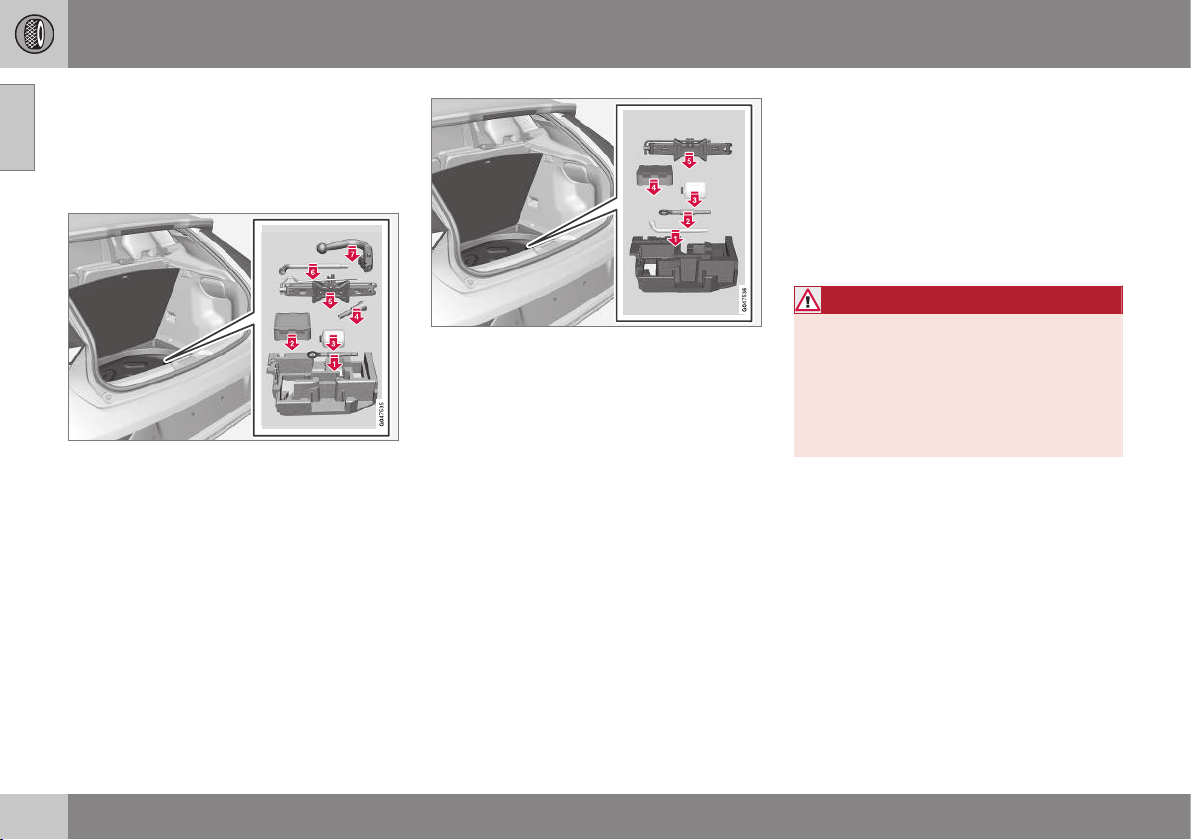
09 Wheels and tyres
09
330
* Option/accessory, for more information, see Introduction.
Emergency puncture repair* - stowing
components
After using the puncture repair kit, the com-
ponents returned to their correct places in the
foam block.
Version 1.
The components are fitted in the foam block
in the following order:
1. Towing eye/socket wrench
2. Bottle (pressed in from the side)
3. TMK kit
4. Funnel
5. Jack
6. Torx wrench
7. Towbar
Version 2.
The components are fitted in the foam block
in the following order:
1. Socket wrench
2. Towing eye
3. Bottle
4. TMK kit
5. Jack
Related information
•
Emergency puncture repair* (p. 324)
•
Emergency puncture repair* - operation
(p. 326)
•
Emergency puncture repair* - rechecking
(p. 328)
•
Emergency puncture repair kit* - overview
(p. 326)
Emergency puncture repair kit* -
sealant
The container (bottle) with the emergency
puncture repair kit (p. 326) contains sealant
and it can be replaced.
Replace the bottle when the expiration date
has passed. Treat the old bottle as environ-
mentally hazardous waste.
WARNING
The bottle contains 1.2-Ethanol and natu-
ral rubber-latex.
Harmful if ingested. Could result in allergic
reaction in the event of skin contact.
Avoid contact with the skin and eyes.
Store out of the reach of children.
Related information
•
Emergency puncture repair* (p. 324)
•
Emergency puncture repair kit* - location
(p. 325)
MAINTENANCE AND SERVICE

10 Maintenance and service
10
332
Volvo service programme
To keep the car as safe and reliable as possi-
ble, follow the Volvo service programme as
specified in the Service and Warranty Booklet.
Volvo recommends engaging an authorised
Volvo workshop to perform the service and
maintenance work. Volvo workshops have the
personnel, special tools and service literature
to guarantee the highest quality of service.
IMPORTANT
For the Volvo warranty to apply, check and
follow the instructions in the Service and
Warranty Booklet.
Related information
•
Climate control system - fault tracing and
repair (p. 341)

10 Maintenance and service
10
}}
333
Raising the car
When raising the car it is important that the
jack or lifting arms are fitted in the intended
points on the car's underbody.
NOTE
Volvo recommends only using the jack that
belongs to the car model in question. If a
jack is selected other than the one recom-
mended by Volvo, follow the instructions
supplied with the equipment.
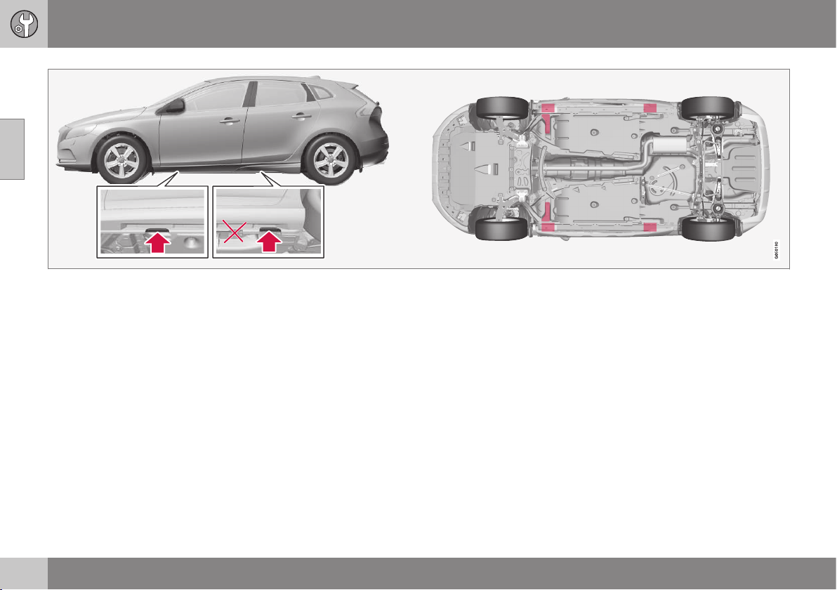
||
10 Maintenance and service
10
334
Jacking points (arrows) for the jack that belongs to the car and lifting points (marked in red).
If the car is raised with a front workshop jack
then it must be positioned under one of the
two lifting points furthest in under the car. If
the car is raised with a rear workshop jack
then it must be positioned under one of the
lifting points. Ensure that the workshop jack
is positioned so that the car cannot slide off
the jack. Always use axle stands or similar.
If the car is raised with a two-pillar workshop
lift then the front and rear lifting arms can be
positioned under the outer lifting points (jack-
ing points). Alternatively, the inner lifting
points can be used at the front.
Related information
•
Changing wheels - removing wheels (p.
319)

10 Maintenance and service
10
335
Bonnet - opening and closing
The bonnet can be opened when the handle
in the passenger compartment has been
turned clockwise and the lock by the grille has
been moved to the left.
The handle for bonnet opening is always on the
left-hand side.
Turn the handle about 20-25 degrees
clockwise. You will hear when the catch
releases.
Move the catch to the left and open the
bonnet. (The catch hook is located
between the headlamp and grille, see
illustration.)
WARNING
Check that the bonnet locks properly when
closed.
Related information
•
Engine compartment - checking (p. 336)
•
Engine compartment - overview (p. 335)
Engine compartment - overview
The overview shows normal checking points.
The appearance of the engine compartment may
differ depending on engine variant.
Coolant expansion tank
Filling washer fluid
Radiator
Engine oil dipstick
1
Filling engine oil
Reservoir for brake and clutch fluid
(located on the driver's side)
Starter battery
Relay and fuse box
Air filter
1
Engines with electronic oil level sensor do not have a dipstick (5-cyl. diesel).
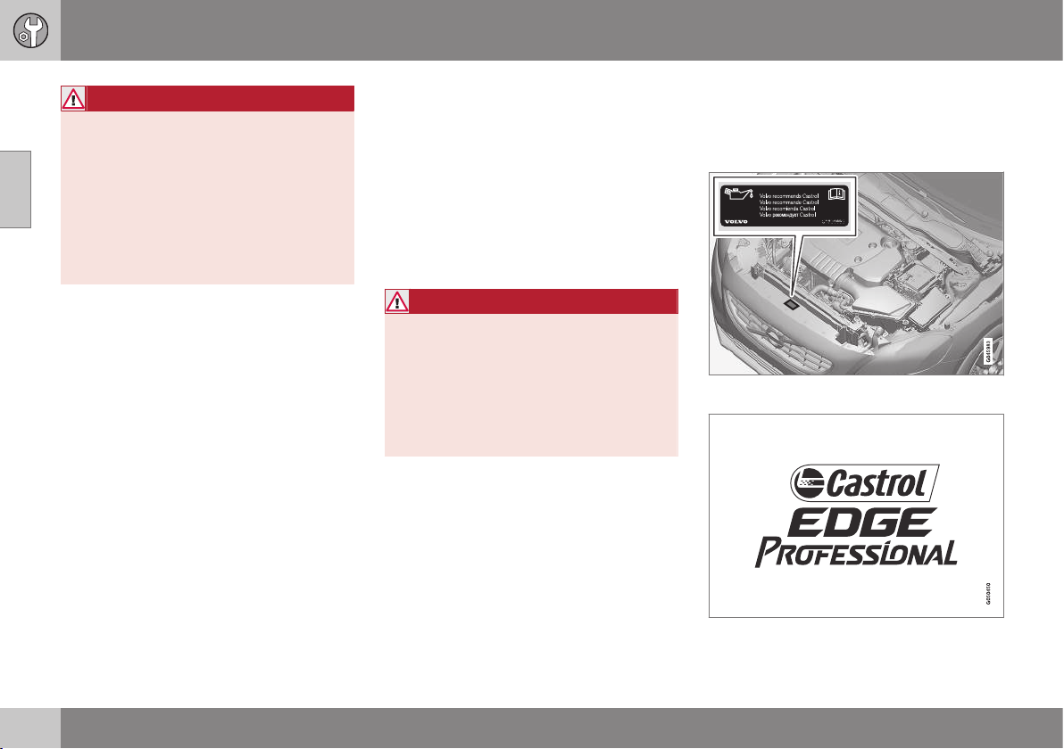
||
10 Maintenance and service
10
336
WARNING
The ignition system has very high voltage
and output. The voltage in the ignition sys-
tem is highly dangerous. The car's electri-
cal system must always be in key position
0 when work is being performed in the
engine compartment; see Key positions -
functions at different levels (p. 71).
Do not touch the spark plugs or ignition
coil when the car's electrical system is in
key position II or when the engine is hot.
Related information
•
Bonnet - opening and closing (p. 335)
•
Engine compartment - checking (p. 336)
Engine compartment - checking
Some oils and fluids should be checked at
regular intervals.
Regular checking
Check the following oils and fluids at regular
intervals, e.g. when refuelling:
•
Coolant
•
Engine oil
•
Washer fluid
WARNING
Remember that the radiator fan (located at
the front of the engine compartment,
behind the radiator) may start automati-
cally some after the engine has been
switched off.
Always have the engine cleaned by a
workshop. There is a risk of fire if the
engine is hot.
Related information
•
Bonnet - opening and closing (p. 335)
•
Engine compartment - overview (p. 335)
•
Coolant - level (p. 340)
•
Engine oil - checking and filling (p. 337)
•
Washer fluid - filling (p. 351)
Engine oil - general
An approved engine oil must be used in order
that the recommended service intervals can
be applied.
Volvo recommends:

10 Maintenance and service
10
337
When driving under adverse conditions, see
Engine oil - adverse driving conditions (p.
446).
IMPORTANT
In order to fulfil the requirements for the
engine's service intervals all engines are
filled with a specially adapted synthetic
engine oil at the factory. The choice of oil
has been made very carefully with regard
to service life, starting characteristics, fuel
consumption and environmental impact.
An approved engine oil must be used in
order that the recommended service inter-
vals can be applied. Only use a prescribed
grade of oil for both filling and oil change,
otherwise you will risk affecting service life,
starting characteristics, fuel consumption
and environmental impact.
Volvo Car Corporation disclaims all war-
ranty liability if engine oil of the prescribed
grade and viscosity is not used.
Volvo recommends that oil changes are
carried out at an authorised Volvo work-
shop.
Volvo uses different systems for warning of
low/high oil level or low/high oil pressure.
Certain engine variants have an oil pressure
sensor, and then the combined instrument
panel's warning symbol for low oil pressure is
used. Other variants have an oil level sensor,
when the driver is informed via the instru-
ment's warning symbol and display
texts. Certain variants have both systems.
Contact a Volvo dealer for more information.
Change the engine oil and oil filter in accord-
ance with the intervals specified in the Serv-
ice and Warranty Booklet.
Using oil of a higher than specified grade is
permitted. If the car is driven in adverse con-
ditions, Volvo recommends using an oil of a
higher grade; see Engine oil - adverse driving
conditions (p. 446).
For filling capacities, see Engine oil - grade
and volume (p. 447).
Related information
•
Engine oil - checking and filling (p. 337)
Engine oil - checking and filling
Depending on engine variant the oil level is
checked with the dipstick or the electronic oil
level sensor.
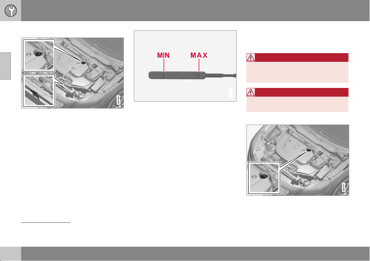
||
10 Maintenance and service
10
338
Engine with oil dipstick
2
Dipstick and filler pipe.
Checking the oil level in a new car is espe-
cially important before the first scheduled oil
change.
Volvo recommends checking the oil level
every 2 500 km. The most accurate measure-
ments are made on a cold engine before star-
ting. The measurement will be inaccurate if
taken immediately after the engine is
switched off. The dipstick will indicate that
the level is too low because the oil has not
had time to flow down into the oil sump.
G021737
The oil level must be between the MIN and MAX
marks.
Measurement and filling if required
1. Ensure that the car is level. After switch-
ing off the engine it is important to wait
5 minutes to allow the oil time to run back
to the sump.
2. Pull up and wipe the dipstick.
3. Re-insert the dipstick.
4. Pull it out and check the level.
5. If the level is close to MIN then 0.5 litres
should be added. If the level is signifi-
cantly below, then an additional amount
is required.
6. If required, check the level again, do it
after driving a short distance. Then repeat
steps 1-4.
WARNING
Never fill above the MAX mark. The level
should never be above MAX or below MIN
as this could lead to engine damage.
WARNING
Do not spill oil onto the hot exhaust mani-
fold due to the risk of fire.
Engine with electronic oil level sensor
3
Filler pipe
4
.
2
Only applies to petrol and 4-cyl. diesel.
3
Only applies to 5-cyl. diesel.
4
Engines with electronic oil level sensor do not have a dipstick (5-cyl. diesel).
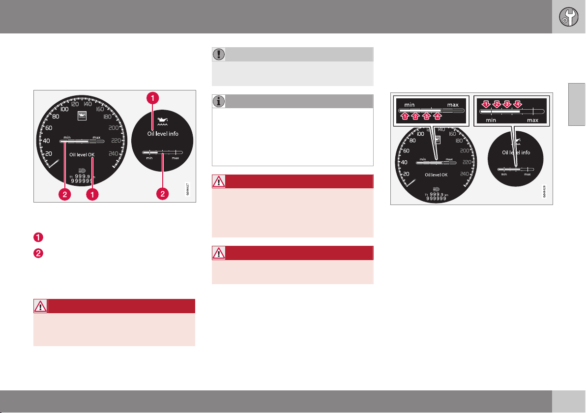
10 Maintenance and service
10
339
You do not need to take action with respect
to the engine oil level before a message is
shown in the combined instrument panel's
information display, see following figure.
Message and graph in the display. The left-hand
display shows the digital combined instrument
panel and the right-hand the analogue.
Message
Engine oil level
On certain cars, the oil level can be checked
using the electronic oil level gauge with the
thumbwheel when the engine is switched off.
WARNING
If the message Oil service required is
shown, visit a workshop. The oil level may
be too high.
IMPORTANT
In the event of the message Oil level low
Refill 0.5 litre, only fill with 0.5 litres.
NOTE
The oil level is only detected by the system
during driving. The system cannot directly
detect changes when the oil is filled or
drained. The car must be driven
about 30 km before the oil level display is
correct.
WARNING
Do not fill more oil if filling level (3) or (4)
appears as shown in the illustration below.
The level must never be above MAX or
below MIN, as this could lead to engine
damage.
WARNING
Do not spill oil onto the hot exhaust mani-
fold due to the risk of fire.
Measuring the oil level
If the oil level needs to be checked then it
should be carried out in accordance with the
sequence below.
1. Activate key position II; see Key positions
- functions at different levels (p. 71).
2. Rotate the thumbwheel on the left-hand
stalk switch to position
Oil level.
> You will then see information displayed
about the engine oil level.
The figures 1-4 represent filling level. Do not fill
more oil if filling level (3) or (4) is shown. The rec-
ommended filling level is 4. Message and graph
in the display. The left-hand display shows the
digital combined instrument panel and the right-
hand the analogue.
Related information
•
Engine oil - general (p. 336)
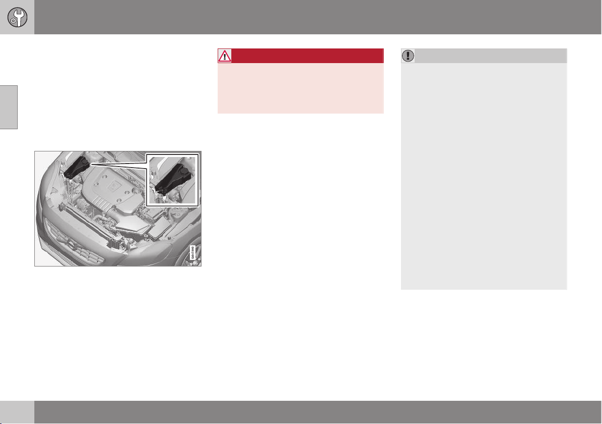
10 Maintenance and service
10
340
Coolant - level
The coolant cools the internal combustion
engine to the correct operating temperature.
The heat that is transferred from the engine to
the coolant can be used to heat the passen-
ger compartment.
The coolant level must lie between the MIN
and MAX marks on the expansion tank.
Checking the level and topping up
When topping up the coolant, follow the
instructions on the packaging. It is important
that the mixture of coolant concentrate and
water is correct for the prevailing weather
conditions. Never top up with water only. The
risk of freezing increases with both too little
and too much coolant concentrate.
WARNING
Coolant can be very hot. If the coolant
requires topping up when the engine is at
operating temperature, unscrew the
expansion tank cap slowly to gently
release the overpressure.
For capacities and for standards regarding
water quality; see Coolant - grade and vol-
ume (p. 449).
Check the coolant regularly
The level must lie between the MIN and MAX
marks on the expansion tank. If the system is
not filled sufficiently, high temperatures could
occur, causing a risk of damage to the
engine.
IMPORTANT
•
A high content of chlorine, chlorides
and other salts may cause corrosion in
the cooling system.
•
Always use coolant with anti-corrosion
agent as recommended by Volvo.
•
Ensure that the coolant mixture is 50%
water and 50% coolant.
•
Mix the coolant with approved quality
tap water. In the event of any doubt
about water quality, used ready-mixed
coolant in accordance with Volvo rec-
ommendations.
•
When changing coolant/replacing
cooling system components, flush the
cooling system clean with approved
quality tap water or flush with ready-
mixed coolant.
•
The engine must only be run with a
well-filled cooling system. Otherwise,
temperatures that are too high may
occur resulting in the risk of damage
(cracks) in the cylinder head.
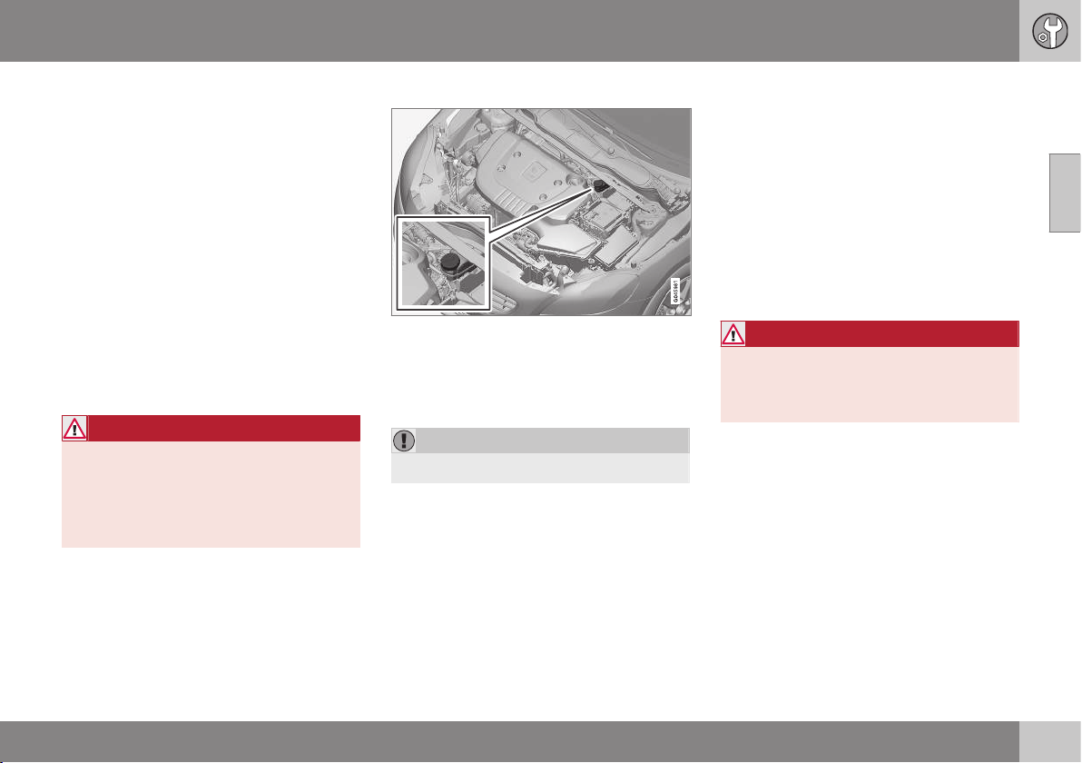
10 Maintenance and service
10
341
Brake and clutch fluid - level
Brake and clutch fluid level should be
between the reservoir MIN and MAX marks.
Checking the level
Brake and clutch fluid have a common reser-
voir. The level must be between the MIN and
MAX marks that are visible inside the reser-
voir. Check the level regularly.
Change the brake fluid every other year or at
every other regular service.
For capacities and recommended brake fluid
grade, see Brake fluid - grade and volume (p.
451). The fluid should be changed annually on
cars driven in conditions requiring hard, fre-
quent braking, such as driving in mountains
or tropical climates with high humidity.
WARNING
If the brake fluid is below the MIN level in
the brake fluid reservoir, do not drive fur-
ther before topping up the brake fluid.
Volvo recommends that the reason for the
loss of brake fluid is investigated by an
authorised Volvo workshop.
Filling
The fluid reservoir is located on the driver's side.
Unscrew the reservoir cap and fill the fluid.
The level must be between the MIN and MAX
marks, which are located on the inside of the
reservoir.
IMPORTANT
Do not forget to refit the cap.
Climate control system - fault tracing
and repair
The air conditioning system must only be
serviced and repaired by an authorised work-
shop.
Troubleshooting and repair
The air conditioning system contains fluores-
cent tracing agents. Use ultraviolet light when
looking for leaks.
Volvo recommends that you contact an
authorised Volvo workshop.
WARNING
The air conditioning system contains pres-
surised refrigerant R134a. This system
must only be serviced and repaired by an
authorised workshop.
Related information
•
Volvo service programme (p. 332)
10 Maintenance and service
10
342
Lamp replacement
Lamp replacement can be carried out for
bulbs. When replacing LED and Xenon lamps,
please refer to a workshop.
The bulbs are specified (p. 348). The follow-
ing list contains locations of bulbs and other
light sources that are specialised, such as
LED
5
lamps, or are unsuitable for changing
for some other reason, except at a workshop:
•
Active Xenon headlamps - ABL (Xenon
lamps)
•
Position/parking lamps front
6
•
Daytime running lights
6
•
Side direction indicators, door mirrors
6
•
Approach lighting, door mirrors
•
Interior and cargo area lighting
•
Glovebox lighting
•
Position/parking lamps rear
•
Side marker lamps, rear
•
Brake light above the rear windscreen
•
Number plate lighting.
WARNING
On cars with Xenon headlamps, the
replacement of Xenon lamps must be car-
ried out at a workshop - an authorised
Volvo workshop is recommended. Working
with Xenon lamps demands extreme cau-
tion because the headlamp is equipped
with a high voltage unit.
WARNING
The car’s electrical system must be in key
position 0 when replacing bulbs; see Key
positions - functions at different levels (p.
71).
IMPORTANT
Never touch the glass part of the bulbs
with your fingers. Grease from your fingers
is vaporised by the heat, coating the
reflector and then causing damage.
NOTE
If an error message remains after the bro-
ken bulb has been replaced then we rec-
ommend that you visit an authorised Volvo
workshop.
NOTE
Outside lighting such as headlamps, fog
lamps and rear lamps may temporarily
have condensation on the inside of the
lens. This is normal, all exterior lighting is
designed to withstand this. Condensation
is normally vented out of the lamp housing
when the lamp has been switched on for a
time.
Related information
•
Lamps - specifications (p. 348)
•
Lamp replacement - location of front
lamps (p. 343)
•
Lamp replacement - location of rear
lamps (p. 346)
•
Lamp replacement - vanity mirror lighting
(p. 348)
5
LED (Light Emitting Diode)
6
Certain variants
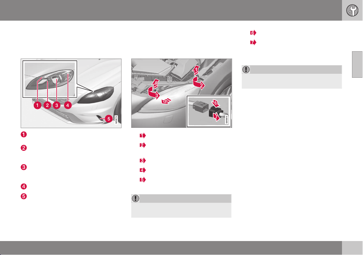
10 Maintenance and service
10
* Option/accessory, for more information, see Introduction.
343
Lamp replacement - location of front
lamps
The overview shows the location of the lamps
at the front.
Position/parking lamps (p. 345) (LED in
Xenon headlamps)
Main beam in Xenon headlamps (p.
344) / Extra main beam in Xenon head-
lamps (p. 345)
Dipped beam in halogen headlamps (p.
344) / Xenon lamps in Xenon headlamps
(p. 342)
Indicator (p. 345)
Daytime running lights (p. 346) (LED* or
bulb depending on variant)
Related information
•
Lamp replacement (p. 342)
•
Lamps - specifications (p. 348)
Lamp replacement - headlamps
All of the headlamp bulbs are replaced via the
engine compartment. First loosen and remove
the whole headlamp.
1.
Lift out the bonnet stop.
2.
Loosen the screw with a Torx tool,
size T30.
3.
Turn the locking pin anticlockwise.
Pull out the locking pin.
4.
Release the headlamp by alternately
tilting and pulling it out.
IMPORTANT
Take care when lifting out the headlamp so
as not to damage any parts.
5.
Press down the catch.
Unplug the connector.
Place the headlamp on a soft surface so
as not to scratch the lens.
IMPORTANT
Do not pull the electrical cable, only the
connector.
6. Replace the relevant bulb as instructed.
The headlamp must be fitted and the contact
fitted correctly before switching on the lights
or switching key position.
Related information
•
Lamp replacement (p. 342)
•
Lamp replacement - location of front
lamps (p. 343)
•
Lamp replacement - cover for main/
dipped beam bulbs (p. 344)
•
Lamps - specifications (p. 348)
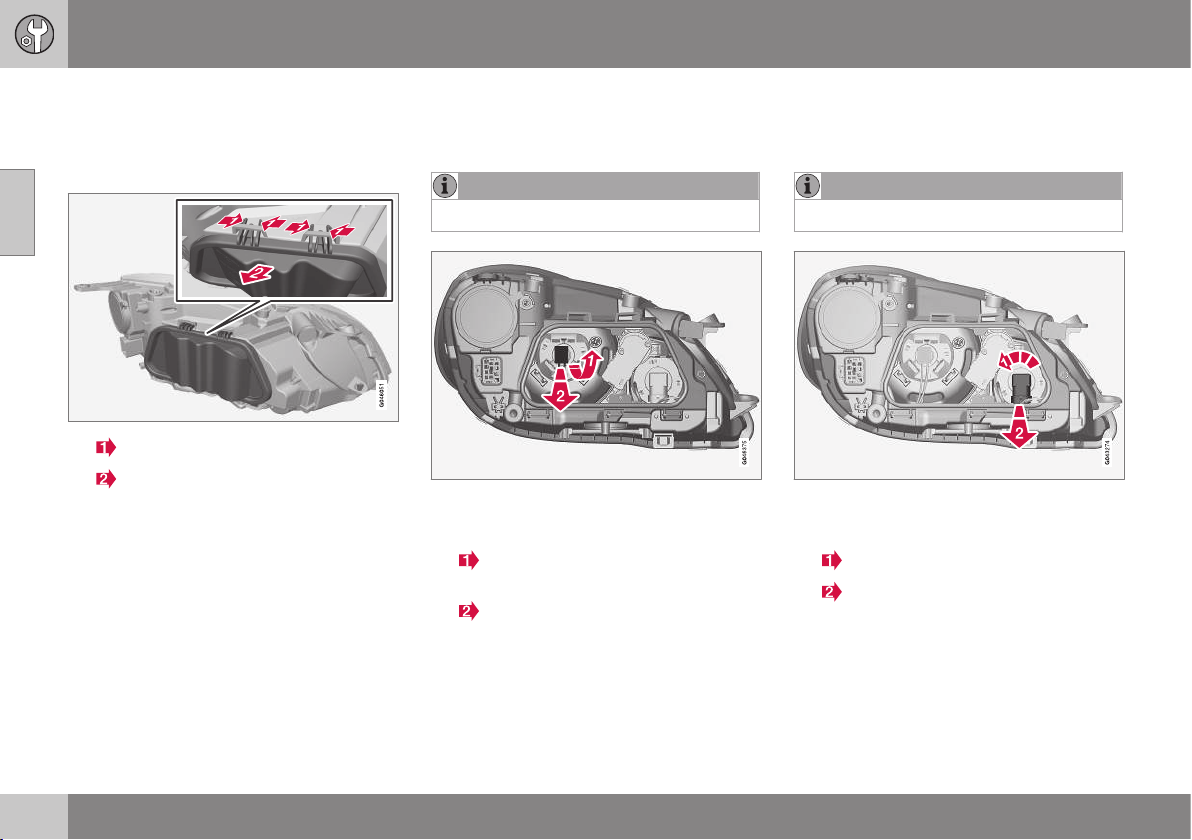
10 Maintenance and service
10
344
Lamp replacement - cover for main/
dipped beam bulbs
Main/dipped beam bulbs are accessed by
releasing the headlamp's larger cover.
1.
Press the hooks together.
Angle out the cover.
2. Replace the relevant bulb as instructed.
Related information
•
Lamp replacement - headlamps (p. 343)
•
Lamp replacement - dipped beam (p.
344)
•
Lamp replacement - main beam (p. 344)
•
Lamp replacement - extra main beam (p.
345)
Lamp replacement - dipped beam
The dipped beam bulb is fitted inside the
headlamp's larger cover.
NOTE
Applies to cars with halogen headlamps.
1. Detach the headlamp (p. 343).
2. Undo the cover (p. 344).
3.
Press the bulb holder upwards until it
releases.
Pull out the bulb holder.
4. Replace the bulb and put back the parts
in reverse order.
Related information
•
Lamps - specifications (p. 348)
Lamp replacement - main beam
The main beam bulb is fitted inside the head-
lamp's larger cover.
NOTE
Applies to cars with halogen headlamps.
1. Detach the headlamp (p. 343).
2. Undo the cover (p. 344).
3.
Turn the bulb holder anticlockwise.
Pull out the bulb holder.
4. Replace the bulb and put back the parts
in reverse order.
Related information
•
Lamps - specifications (p. 348)
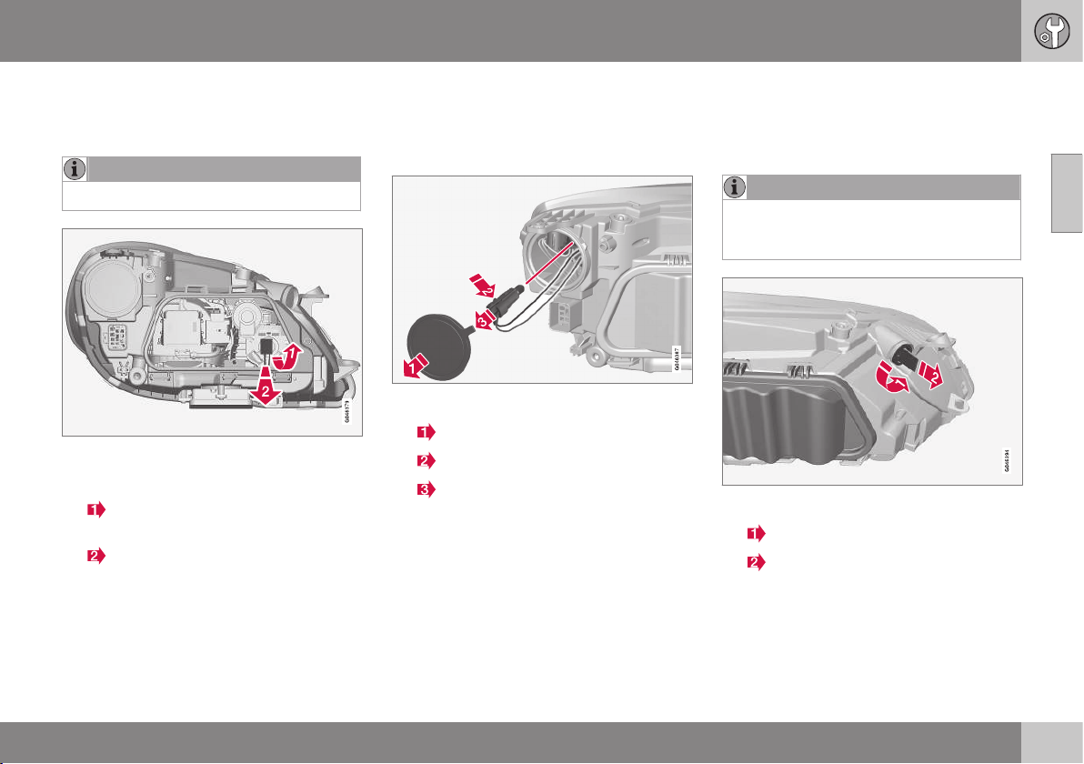
10 Maintenance and service
10
* Option/accessory, for more information, see Introduction.
345
Lamp replacement - extra main beam
The extra main beam bulb is fitted inside the
headlamp's larger cover.
NOTE
Applies to cars with Xenon headlamps*.
1. Detach the headlamp (p. 343).
2. Undo the cover (p. 344).
3.
Press the bulb holder upwards until it
detaches.
Pull out the bulb holder.
4. Replace the bulb and put back the parts
in reverse order.
Related information
•
Lamps - specifications (p. 348)
Lamp replacement - direction
indicators front
The direction indicator lamp is fitted inside
the headlamp's smaller cover.
1. Detach the headlamp (p. 343).
2.
Undo the cover.
3.
Push in the catch.
Pull out the bulb holder.
4. Replace the bulb and put back the parts
in reverse order.
Related information
•
Lamps - specifications (p. 348)
Lamp replacement - position/parking
lamps front
The position/parking lamp bulb holder is
located on the side of the headlamp.
NOTE
Not applicable to cars with Xenon head-
lamps* as these are equipped with LED
lamps.
1. Detach the headlamp (p. 343).
2.
Turn the bulb holder anticlockwise.
Pull out the bulb holder.
3. Replace the bulb and put back the parts
in reverse order.
Related information
•
Lamps - specifications (p. 348)
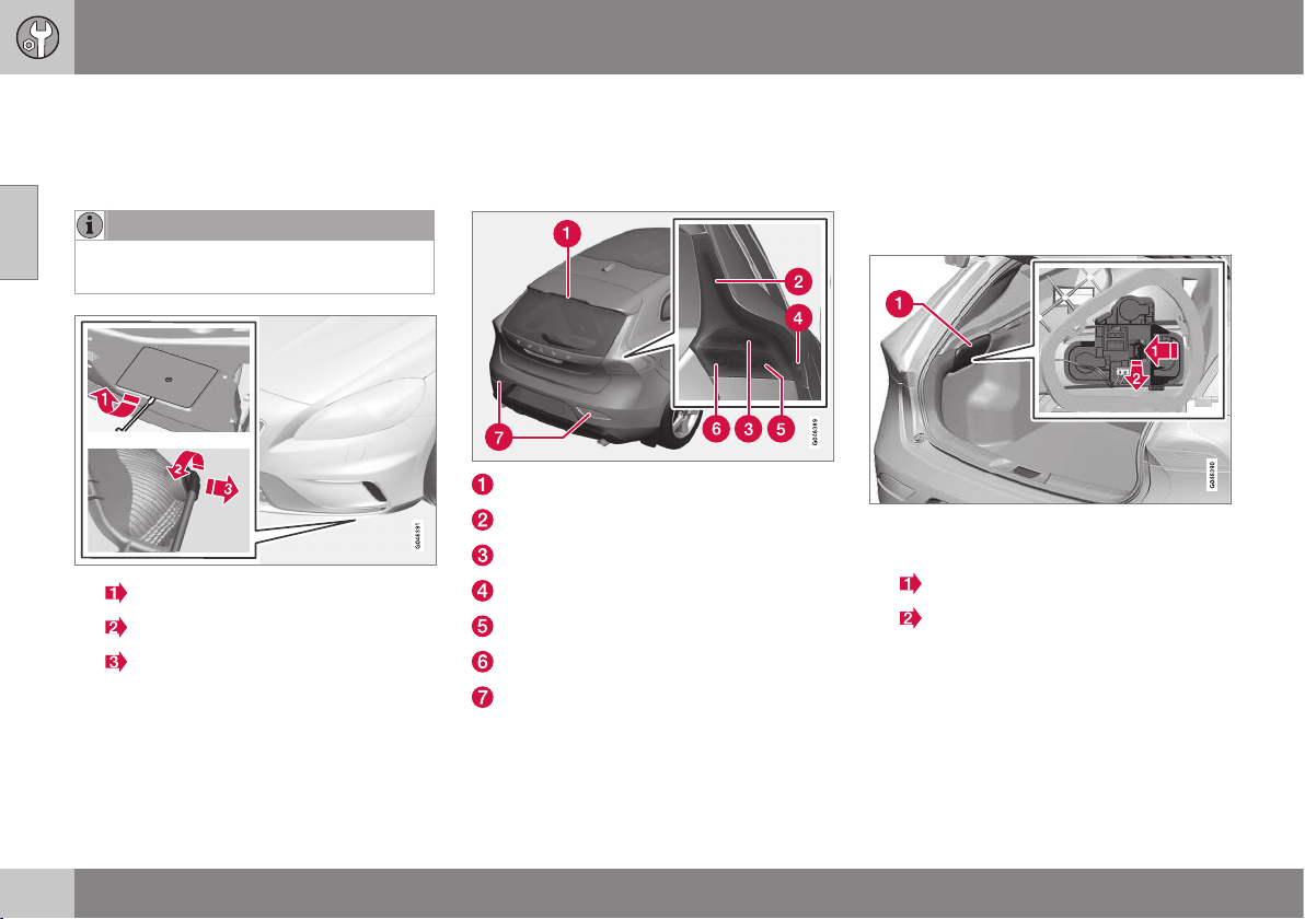
10 Maintenance and service
10
346
Lamp replacement - daytime running
lights
The daytime running light bulb is fitted inside
the bumper's cover.
NOTE
Only applies to daytime running lights with
bulbs.
1.
Undo the cover.
2.
Turn the bulb holder anticlockwise.
Pull out the bulb holder.
3. Replace the bulb and put back the parts
in reverse order.
Related information
•
Lamps - specifications (p. 348)
Lamp replacement - location of rear
lamps
The overview shows the location of the lamps
at the rear.
Brake light (LED)
Position/parking lights (LED)
Brake lights (p. 346)
Side marker lamps (LED)
Indicator (p. 346)
Reversing lamp (p. 346)
Fog lamps (p. 347)
Related information
•
Lamp replacement (p. 342)
•
Lamps - specifications (p. 348)
Lamp replacement - direction
indicators rear, brake lights and
reversing lamp
Direction indicators rear, brake lights and
reversing lamp are replaced from inside the
cargo area.
1. Remove the hatch in the upholstery (1) on
the same side as the defective bulb.
2.
Press the catch sideways.
Pull out the bulb holder.
3. Remove the blown bulb by pressing it in
and turning anticlockwise.
4. Replace the bulb and put back the parts
in reverse order.
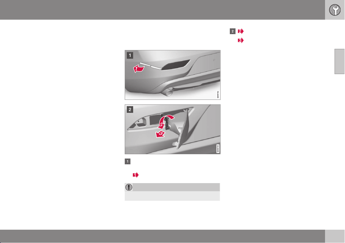
10 Maintenance and service
10
347
Related information
•
Lamp replacement - location of rear
lamps (p. 346)
•
Lamps - specifications (p. 348)
Lamp replacement - rear fog lamp
The fog lamp bulb is fitted in the bumper's
bulb holder.
Insert (approx.20 mm) a blunt, knife-like
object, e.g. a table knife, at the triangle.
Carefully prise until the lug releases.
IMPORTANT
Take care not to damage any parts.
Turn the bulb holder anticlockwise.
Pull out the bulb holder.
3. Replace the bulb and put back the parts
in reverse order.
Related information
•
Lamps - specifications (p. 348)
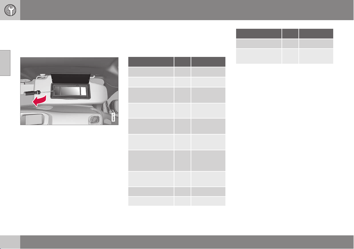
10 Maintenance and service
10
348
Lamp replacement - vanity mirror
lighting
The vanity mirror's lamps are fitted inside the
lamp lenses.
1. Insert a screwdriver under the lamp lens
and gently prize up the lug on the edge.
2. Carefully detach and lift aside the lamp
lens.
3. Using needle-nose pliers, pull the bulb
straight out to the side. Do not squeeze
too hard with the pliers. Otherwise, the
bulb glass could break.
4. Replace the bulb and put back the parts
in reverse order.
Related information
•
Lamps - specifications (p. 348)
Lamps - specifications
The specifications apply to bulbs. When
replacing LED and Xenon lamps, please refer
to a workshop.
Lighting
[W]
A
Type
Dipped beam
B
55 H7 LL
Main beam
B
65 H9
Additional main
beam
C
55 H7 LL
Front direction
indicators
21 HY21W
Position/parking
lamps front
B
5 W5W LL
Daytime running
lights
D
19 PW19W
Side direction indi-
cators, door mir-
rors
D
5 WY5W LL
Direction indica-
tors, rear
21 PY21W LL
Brake lights 21 P21W LL
Reversing lamp 21 P21W LL
Lighting
[W]
A
Type
Rear fog lamp 21 H21W LL
Vanity mirror light-
ing
1,2 T5 Socket
W2x4.6d
A
Watt
B
Cars with halogen headlamps
C
Cars with Xenon headlamps
D
Certain variants
Related information
•
Lamp replacement (p. 342)
•
Lamp replacement - location of front
lamps (p. 343)
•
Lamp replacement - location of rear
lamps (p. 346)
•
Lamp replacement - vanity mirror lighting
(p. 348)
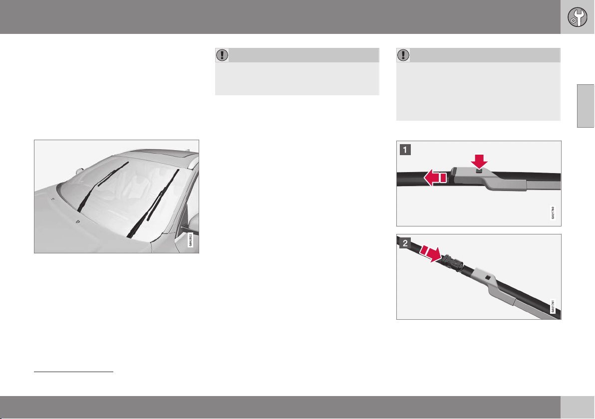
10 Maintenance and service
10
}}
349
Wiper blades
The wiper blades sweep water away from the
windscreen and rear window. Together with
the washer fluid they clean the windows and
ensure visibility for driving.
The windscreen wiper blades must be in serv-
ice position when they are to be replaced.
Service position
Wiper blades in service position.
In order to make replacement possible, to
clean or lift the wiper blades (for scraping off
ice from the windscreen, for example), they
must be in service position.
IMPORTANT
Before placing the wiper blades in the
service position, make sure that they are
not frozen down.
1. Place the remote control key in the igni-
tion lock
7
and briefly press the START/
STOP ENGINE button to set the car's
electrical system to key position I. For
detailed information on key positions, see
Key positions - functions at different lev-
els (p. 71).
2. Briefly press the START/STOP ENGINE
button again to set the car’s electrical
system in key position 0.
3. Within 3 seconds, move the right stalk
switch up and hold it in position for
approx. 1 second.
> The wipers then move to standing
straight up.
The wipers return to their starting position
when you briefly press the START/STOP
ENGINE button to set the car’s electrical sys-
tem to key position I (or when the car is
started).
IMPORTANT
If the wiper arms in the service position
have been folded up from the windscreen,
they must be folded back down onto the
windscreen before the wipers are allowed
to return to their starting position. This is to
avoid scraping the paint on the bonnet.
Replacing the wiper blades
7
Not necessary in cars with Keyless function.
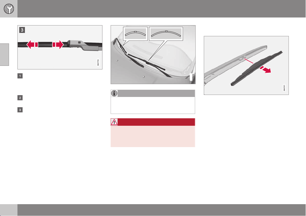
||
10 Maintenance and service
10
350
Fold up the wiper arm when it is in serv-
ice position. Press the button located on
the wiper blade mounting and pull
straight out parallel with the wiper arm.
Slide in the new wiper blade until a "click"
is heard.
Check that the blade is firmly installed.
4. Fold the wiper arm back towards the
windscreen.
The wipers return from service position to
their starting position when you briefly press
the START/STOP ENGINE button to set the
car’s electrical system to key position I (or
when the car is started).
G021763
NOTE
The wiper blades are different lengths. The
blade on the driver's side is longer than on
the passenger side.
WARNING
If the car is equipped with airbag
Pedestrian Airbag then Volvo recommends
that genuine wiper arms are used and that
you only use genuine parts for them.
Replacing the wiper blades, rear
window
1. Fold out the wiper arm.
2. Grip the inner section of the blade (by the
arrow).
3. Turn anticlockwise to use the blade's end
position against the wiper arm as a lever
to detach the blade more easily.
4. Press the new wiper blade into position.
Check that it is firmly installed.
5. Lower the wiper arm.
Cleaning
For cleaning wiper blades and windscreen,
see Car washing (p. 364).
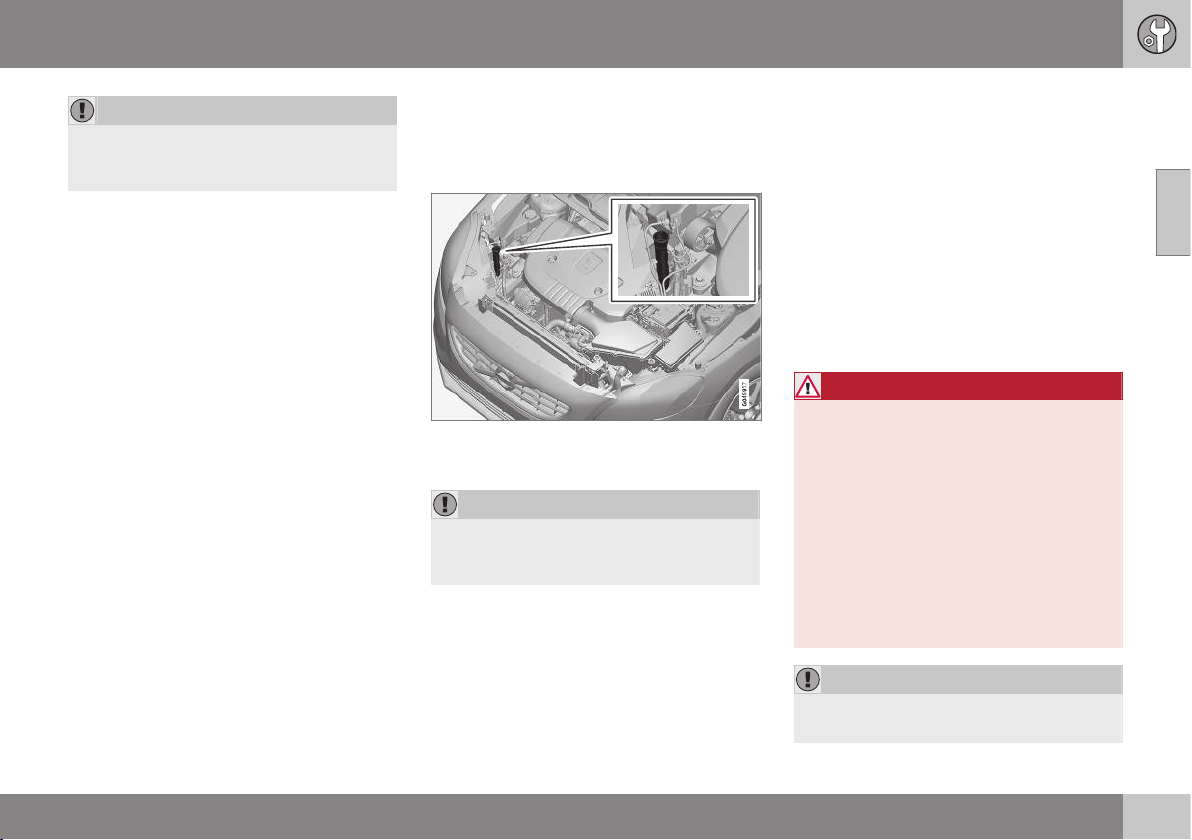
10 Maintenance and service
10
351
IMPORTANT
Check the blades regularly. Neglected
maintenance shortens the service life of
the wiper blades.
Related information
•
Washer fluid - filling (p. 351)
Washer fluid - filling
Washer fluid is used for cleaning the head-
lamps and windows. Washer fluid with anti-
freeze must be used during winter.
The windscreen and headlamp washers share
a common reservoir.
IMPORTANT
Use washer fluid with antifreeze during the
winter to avoid freezing in the pump, reser-
voir and hoses.
For capacities, see Washer fluid - quality and
volume (p. 451).
Related information
•
Wiper blades (p. 349)
Starter battery
The service life and function of the battery is
influenced by factors such as the number of
starts, discharging, driving style, driving con-
ditions, climatic conditions etc.
The starter battery is a traditional 12 V bat-
tery.
•
Never disconnect the battery when the
engine is running.
•
Check that the cables to the battery are
correctly connected and properly tight-
ened.
WARNING
•
The battery can generate oxyhydrogen
gas, which is highly explosive. A spark
can be formed if a jump lead is con-
nected incorrectly, and this can be
enough for the battery to explode.
•
The battery contains sulphuric acid,
which can cause serious burns.
•
If sulphuric acid comes into contact
with eyes, skin or clothing, flush with
large quantities of water. If acid
splashes into the eyes - seek medical
attention immediately.
IMPORTANT
Only a traditional battery charger should
ever be used when charging the battery.
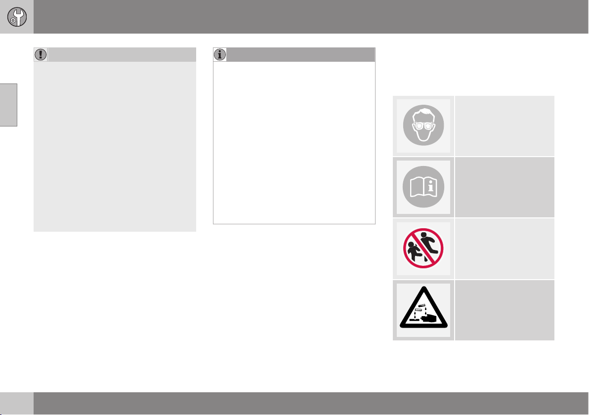
||
10 Maintenance and service
10
352
IMPORTANT
If the following instruction is not observed
then the energy saving function for info-
tainment system may be temporarily dis-
engaged, and/or the message in the com-
bined instrument panel's information dis-
play about the starter battery's state of
charge may be temporarily inapplicable,
following the connection of an external
battery or battery charger:
•
The negative battery terminal on the
car's starter battery must never be
used for connecting an external bat-
tery or battery charger - only the car
chassis may be used as the ground-
ing point.
See Jump starting (p. 270) for a descrip-
tion of how the cable clamps must be
attached.
NOTE
The life of the battery is shortened if it
becomes discharged repeatedly.
The life of the battery is affected by several
factors, including driving conditions and
climate. Battery starting capacity decrea-
ses gradually with time and therefore
needs to be recharged if the car is not
used for a longer time or when it is only
driven short distances. Extreme cold fur-
ther limits starting capacity.
To maintain the battery in good condition,
at least 15 minutes of driving/week is rec-
ommended or that the battery is con-
nected to a battery charger with automatic
trickle charging.
A battery that is kept fully charged has a
maximum service life.
Related information
•
Battery - symbols (p. 352)
•
Starter battery - replacement (p. 353)
•
Battery - Start/Stop (p. 353)
Battery - symbols
There are information and warning symbols
on the battery.
Symbols on the battery
Use protective goggles.
Further information is
available in the owner's
manual.
Store the battery out of
the reach of children.
The battery contains cor-
rosive acid.
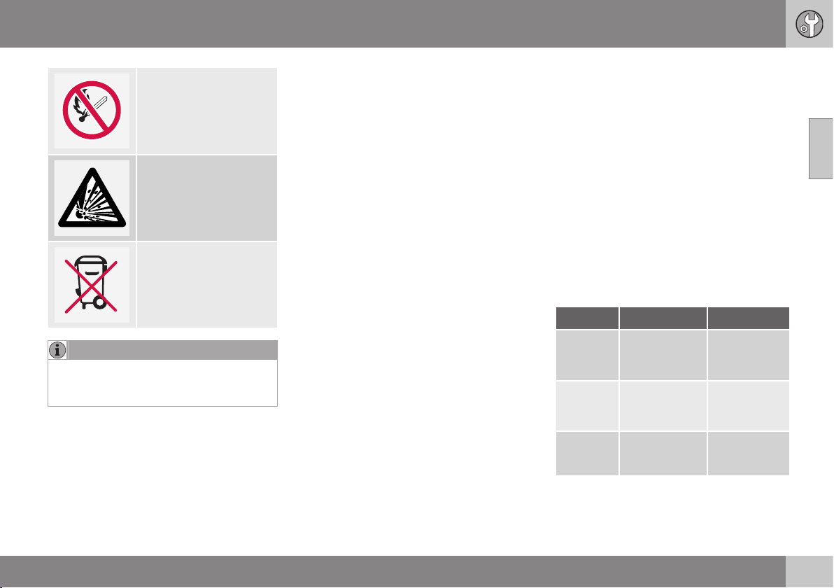
10 Maintenance and service
10
* Option/accessory, for more information, see Introduction.
353
Avoid sparks and naked
flames.
Risk of explosion.
Must be taken for recy-
cling.
NOTE
An expended battery must be recycled in
an environmentally safe manner as it con-
tains lead.
Related information
•
Starter battery (p. 351)
•
Battery - Start/Stop (p. 353)
Starter battery - replacement
The starter battery should be replaced by an
authorised workshop.
The starter battery is a traditional 12 V bat-
tery.
Volvo recommends that you allow an author-
ised workshop to replace the batteries - an
authorised Volvo workshop is recommended.
For more information on the car's starter bat-
tery, see Jump starting (p. 270).
Battery - Start/Stop
Cars with Start/Stop function, in addition to
the starter battery, are equipped with a sup-
port battery.
Start/Stop
Cars with the Start/Stop function are equip-
ped with two 12 V batteries - one extra pow-
erful starter battery and one support battery
that helps during the Start/Stop function's
starting sequence.
For more information on the Start/Stop func-
tion, see Start/Stop* (p. 279).
For more information on the car's starter bat-
tery, see Jump starting (p. 270) and Starter
battery - specification (p. 459).
Battery Start Support
Cold start
capacity
A
,
CCA (A)
Starter battery
- specification
(p. 459)
120
C
180
D
Size
B
,
L×W×H
(mm)
278×175×190
C
315×175×190
D
150×90×106
C
150×90×130
D
Capacity
(Ah)
70
C
80
D
8
C
10
D
A
According to EN standard.
B
Largest possible size.
C
Manual gearbox.
D
Automatic gearbox.
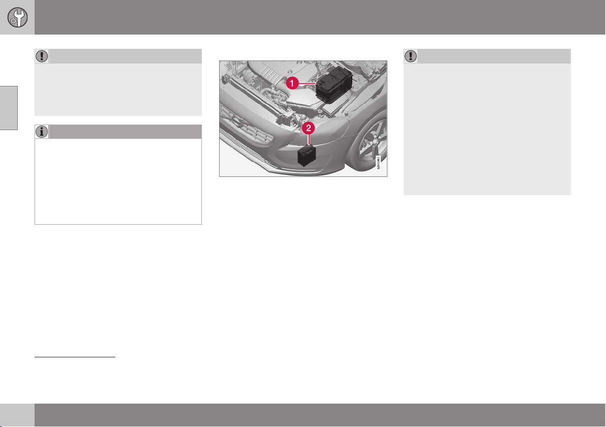
||
10 Maintenance and service
10
354
IMPORTANT
When replacing the starter battery in a car
with the Start/Stop function, batteries of
the correct type must be installed, EFB
8
for manual gearbox and AGM
9
for auto-
matic gearbox.
NOTE
•
The higher the current take-off in the
car (extra cooling/heating, etc.) the
more the batteries must be charged =
increased fuel consumption.
•
When the capacity of the battery has
fallen below the lowest permissible
level then the Start/Stop function is
disengaged.
Temporarily reduced Start/Stop function due
to high current take-off means:
•
The engine starts automatically
10
without
the driver depressing the clutch pedal
(manual gearbox).
•
The engine starts automatically without
the driver lifting his/her foot off the foot
brake pedal (automatic gearbox).
Location of the batteries
(1) Starter battery
11
(2) Support battery
The support battery normally requires no
more service than the normal starter battery.
A workshop should be contacted in the event
of questions or problems - an authorised
Volvo workshop is recommended.
IMPORTANT
If the following instruction is not observed
then the Start/Stop function may tempo-
rarily cease to work after the connection of
an external battery or battery charger:
•
The negative battery terminal on the
car's starter battery must never be
used for connecting an external bat-
tery or battery charger - only the car
chassis may be used as the ground-
ing point.
See Jump starting (p. 270) for a descrip-
tion of how the cable clamps must be
attached.
8
Enhanced Flooded Battery
9
Absorbed Glass Mat
10
Automatic starting can only take place if the gear lever is in neutral position.
11
See Starter battery (p. 351) for a detailed description of the starter battery.
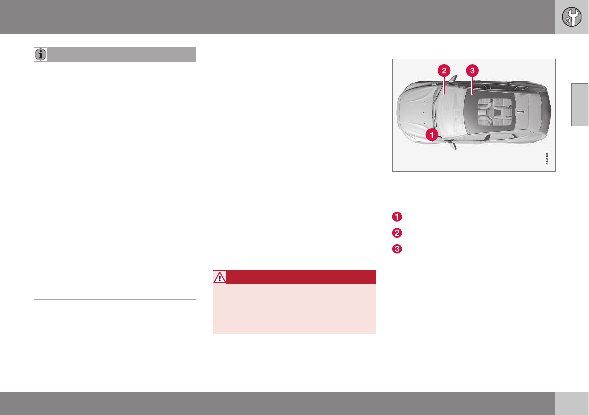
10 Maintenance and service
10
355
NOTE
If the battery has become so discharged
that everything is "black" and in principle
the car does not have all the normal elec-
trical functions and the engine is subse-
quently started using an external battery or
battery charger, then the Start/Stop func-
tion will be activated. It will then be possi-
ble for the engine to be auto-stopped but
in the event of an auto-stop the Start/Stop
function may fail to auto-start the engine
due to inadequate capacity in the battery.
The battery must first be charged in order
to ensure a successful auto-start after an
auto-stop. At an outside temperature of
+15 °C the battery needs to be charged for
at least 1 hour. At a lower outside tem-
perature a charging time of 3-4 hours is
recommended. The recommendation is
that the battery is charged using an exter-
nal battery charger.
If this is not possible then the recommen-
dation is to temporarily deactivate the
Start/Stop function until the battery has
been adequately recharged.
For more information on charging the
starter battery, see Starter battery (p. 351).
Related information
•
Battery - symbols (p. 352)
Fuses - general
All electrical functions and components are
protected by a number of fuses in order to
protect the car's electrical system from dam-
age by short circuiting or overloading.
If an electrical component or function does
not work, it may be because the component's
fuse was temporarily overloaded and failed. If
the same fuse fails repeatedly then there is a
fault in the circuit. Volvo recommends that
you visit an authorised Volvo workshop for
checking.
Changing
1. Look in the fuse diagram to locate the
fuse.
2. Pull out the fuse and check from the side
to see whether the curved wire has
blown.
3. If this is the case, replace it with a new
fuse of the same colour and amperage.
WARNING
Never use a foreign object or a fuse with
an amperage higher than that specified
when replacing a fuse. This could cause
significant damage to the electrical system
and possibly lead to fire.
Location, fuse boxes
Fuse box locations in a left-hand drive car. In
a right-hand drive car the fuse box under the
glovebox changes sides.
Engine compartment
Under the glovebox
Below right front seat
Related information
•
Fuses - in engine compartment (p. 356)
•
Fuses - under glovebox (p. 359)
•
Fuses - under right front seat (p. 362)
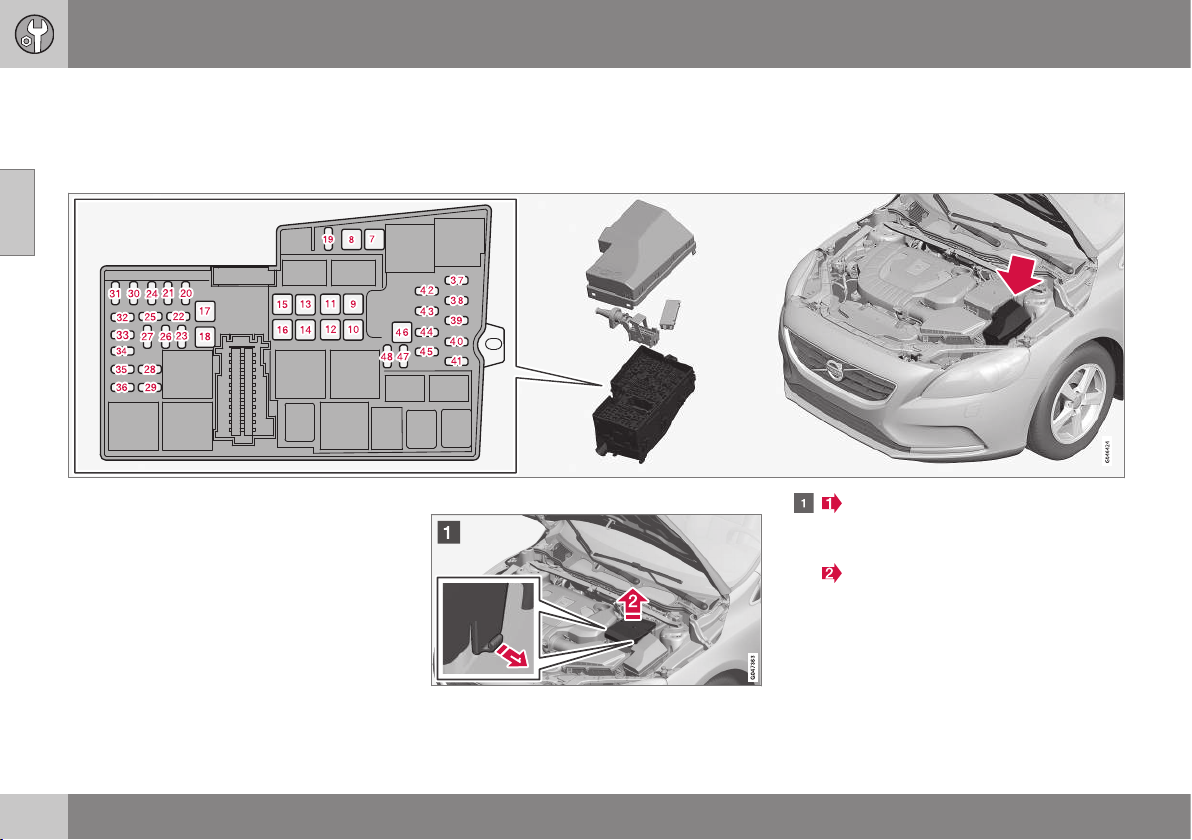
10 Maintenance and service
10
356
Fuses - in engine compartment
Fuses in the engine compartment protect
engine and brake functions, amongst other
things.
On the inside of the cover there are tweezers
that facilitate the procedure for the removal
and fitting of fuses.
The fuse box also provides space for several
spare fuses.
Replacing fuses
The fuses can be accessed following the
removal of the cover fitted on the starter bat-
tery and the cover for the electrical distribu-
tion unit.
Removing the covers
Fold out the locking catches that are
fitted on the sides of the cover on the
starter battery.
Lift the cover straight up.
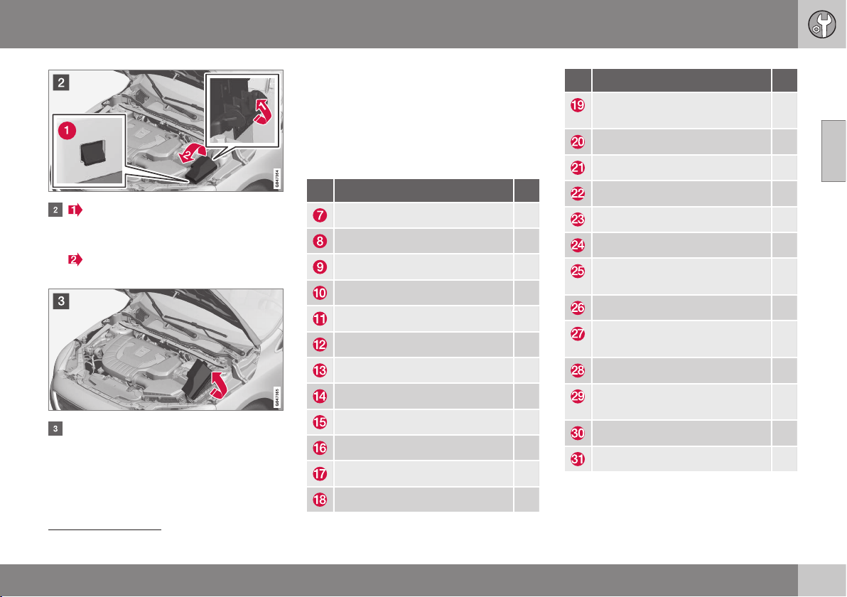
10 Maintenance and service
10
}}
* Option/accessory, for more information, see Introduction.
357
Fold out the locking catch that is fitted
on the side of the electrical distribution
unit.
Rotate the cover upward until the lock
lugs (1) are released.
Fold the cover toward the engine to
access the fuses.
Refitting the covers
Reinstall the parts in reverse order.
Positions
The label on the inside of the cover shows the
positions of the fuses.
•
Fuses 7-18 are of "JCASE" type and
should be replaced by a workshop
12
.
•
Fuses 19-45 and 47-48 are of "Mini Fuse"
type.
Function A
ABS pump 40
ABS valves 30
Headlamp washers* 20
Ventilation fan 40
– –
Primary fuse for fuses 32-36 30
– –
Electric windscreen, right side* 40
– –
Electric windscreen, left side* 40
Parking heater* 20
Windscreen wipers 20
Function A
Central electronic module, refer-
ence voltage, support battery
5
Horn 15
Brake lights 5
– –
Light switches 5
Internal relay coils 5
12 V socket, tunnel console
front
15
Transmission control module 15
Solenoid clutch A/C (petrol,
4-cyl. diesel)
15
12 V socket, tunnel console rear 15
Climate sensor*; air intake throt-
tle motors
10
Engine control module (5-cyl.) 5
Power seat, right* 20
12
An authorised Volvo workshop is recommended.
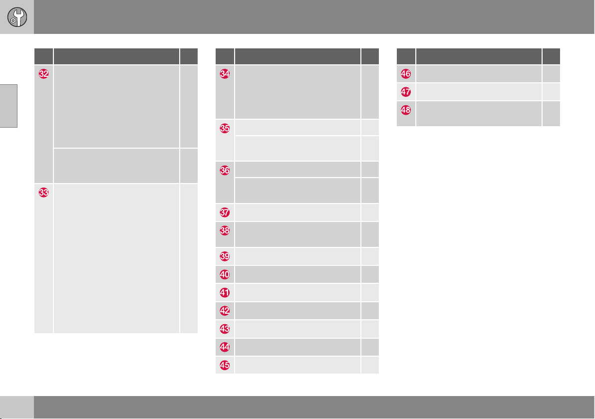
||
10 Maintenance and service
10
358
* Option/accessory, for more information, see Introduction.
Function A
Relay coil in cooling fan relay
(4-cyl., 5-cyl. diesel); Lambda-
sonds (4-cyl. petrol); Mass air
flow meter (diesel), Bypass
valve, EGR cooling (diesel); Reg-
ulator valve, fuel flow (5-cyl. die-
sel); Regulator valve, fuel pres-
sure (5-cyl. diesel)
10
Relay coil in cooling fan relay
(5-cyl. petrol); Lambda-sonds
(5-cyl. petrol)
20
Oil pump, automatic gearbox
(5-cyl.); Mass air flow sensor
(petrol); EVAP valve (4-cyl. pet-
rol); Valves (5-cyl. petrol); Sole-
noids (5-cyl. petrol); Crankcase
ventilation heater (5-cyl. petrol);
Control motor, turbo (4-cyl. die-
sel); Regulator valve, fuel flow
(4-cyl. diesel); Control module,
radiator roller cover (4-cyl. die-
sel); Solenoid, piston cooling (5-
cyl. diesel); Turbo control valve
(5-cyl. diesel); Oil level sensor
(5-cyl. diesel); Solenoid clutch
A/C (5-cyl.)
10
Function A
Valves (4-cyl. petrol); Solenoids
(4-cyl. petrol); Injectors (5-cyl.
petrol); Lambda-sond (5-cyl.
diesel); Crankcase ventilation
heater (5-cyl. diesel)
10
Ignition coils (petrol) 10
Diesel filter heater; Glow plug
control module (5-cyl. diesel)
15
Engine control module (4-cyl.) 10
Engine control module (5-cyl.);
Throttle unit (5-cyl. petrol)
15
ABS 5
Engine control module; Trans-
mission control module; Airbags
10
Light height control* 10
Electric control servo 5
Central electronic module 15
– –
– –
Collision warning 5
Accelerator pedal sensor 5
Function A
Charging point, support battery –
– –
Coolant pump (when no parking
heater is available)
10
Related information
•
Fuses - under glovebox (p. 359)
•
Fuses - under right front seat (p. 362)
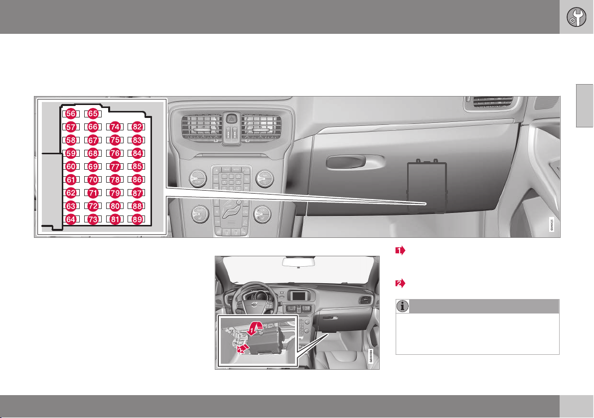
10 Maintenance and service
10
}}
359
Fuses - under glovebox
Fuses under the glovebox protect the airbag
and passenger compartment lighting func-
tions, amongst other things.
On the inside of the cover for the fuse box in
the engine compartment there are tweezers
that facilitate the procedure for the removal
and fitting of fuses.
The fuse box in the engine compartment
also provides space for several spare fuses.
Replacing fuses
The fuses can be accessed when a protective
cover has been removed from the fuse box.
Cover removal
Take hold of the recess and pull until the
locking lugs in the lower edge of the
cover are released from the fuse box.
Remove the cover.
NOTE
A relatively large amount of tensile force is
required to release the locking lugs at the
top edge of the cover from the electrical
distribution unit.
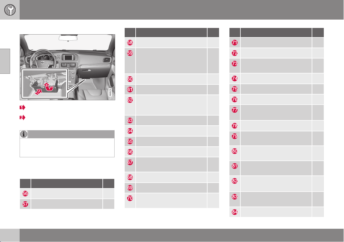
||
10 Maintenance and service
10
360
* Option/accessory, for more information, see Introduction.
Cover refitting
Guide in the lower lugs.
Turn the cover upwards until the upper
lugs engage.
NOTE
Make sure that the upper locking lugs are
seated properly in the grooves of the elec-
trical distribution unit.
Positions
The fuses are of "Mini Fuse" type.
Function A
Fuel pump 20
– –
Function A
Rear window wiper 15
Interior lighting, Roof console
for front reading lamps and
passenger compartment light-
ing
5
Interior lighting; Power seats* 10
Blind, glass roof* 10
Rain sensor*; Dimming, interior
rearview mirror*; Moisture sen-
sor*
5
Collision warning* 5
– –
Unlocking, tailgate
A
10
– –
Reserve position 3, constant
voltage
5
Steering lock 15
Combined instrument panel 5
Central locking system, fuel
filler flap
B
10
Function A
Climate panel 10
Steering wheel module 7,5
Siren*; Data link connector
OBDII
5
Main beam 15
– –
Reversing lamp 10
Windscreen wipers
C
; Rear
windscreen wiper
C
20
Immobiliser 5
Reserve position 1, constant
voltage
15
Reserve position 2, constant
voltage
20
Movement sensor alarm*;
Remote receiver
5
Windscreen wipers
D
; Rear
windscreen wiper
D
20
Central locking system, fuel
filler flap
E
10
Unlocking, tailgate
F
10

10 Maintenance and service
10
* Option/accessory, for more information, see Introduction.
361
Function A
Electric additional heater*; But-
ton seat heating rear*
7,5
Airbags; Pedestrian airbag 10
Reserve position 4, constant
voltage
7,5
– –
– –
A
See also fuse 84.
B
See also fuse 83.
C
See also fuse 82.
D
See also fuse 77.
E
See also fuse 70.
F
See also fuse 65.
Related information
•
Fuses - in engine compartment (p. 356)
•
Fuses - under right front seat (p. 362)
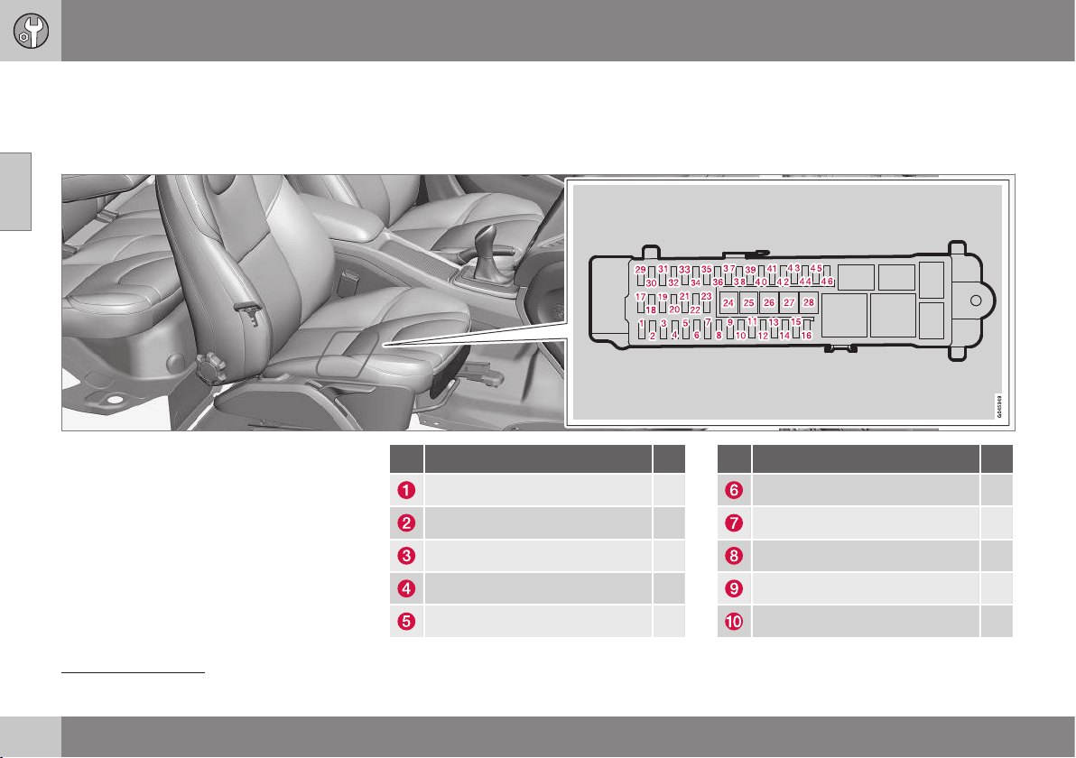
10 Maintenance and service
10
362
* Option/accessory, for more information, see Introduction.
Fuses - under right front seat
Fuses under the right-hand front seat protect
infotainment and trailer functions, amongst
other things.
On the inside of the cover for the fuse box in
the engine compartment there are tweezers
that facilitate the procedure for the removal
and fitting of fuses.
The fuse box in the engine compartment
also provides space for several spare fuses.
Positions
•
Fuses 24-28 are of "JCASE" type and
should be replaced by a workshop
13
.
•
Fuses 1-23 and 29-46 are of "Mini Fuse"
type.
Function A
– –
Keyless* 10
Door handle (Keyless*) 5
Control panel, left front door 25
Control panel, right front door 25
Function A
Control panel, left rear door 25
Control panel, right rear door 25
– –
Power seat left* 20
– –
13
An authorised Volvo workshop is recommended.
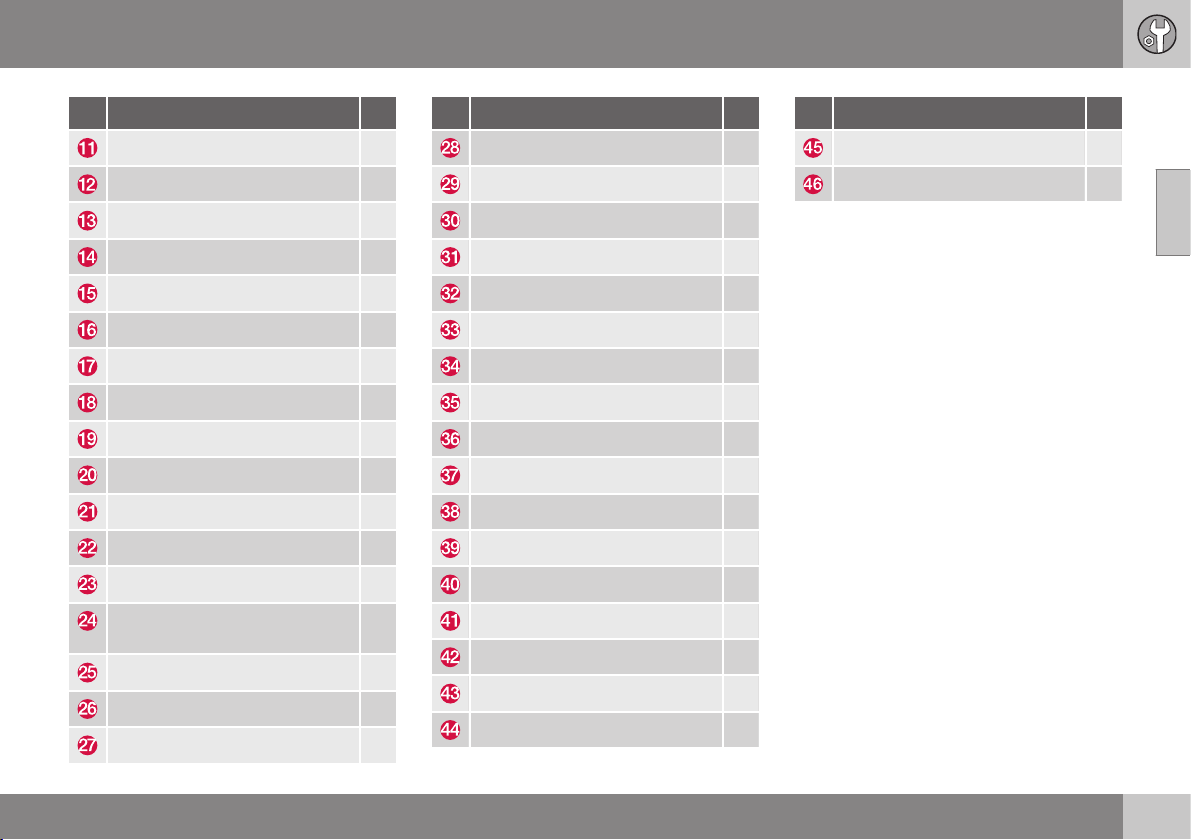
10 Maintenance and service
10
* Option/accessory, for more information, see Introduction.
363
Function A
Internal relay coil 5
Audio control unit (amplifier)* 5
– –
Telematics*; Bluetooth* 5
Audio; Infotainment control unit 15
Digital radio*; TV* 10
12 V socket, cargo area 15
– –
– –
– –
– –
– –
Trailer socket 2* 20
Primary fuse for fuses 12-16:
Infotainment
40
– –
Trailer socket 1* 40
Rear window defroster 30
Function A
– –
BLIS* 5
Parking assistance* 5
Parking camera* 5
– –
– –
Seat heating (driver's side) 15
Seat heating (passenger side) 15
– –
– –
– –
Seat heating, rear right* 15
Seat heating, rear left* 15
AWD control module* 15
– –
– –
– –
Function A
– –
– –
Related information
•
Fuses - in engine compartment (p. 356)
•
Fuses - under glovebox (p. 359)
10 Maintenance and service
10
364
Car washing
The car should be washed as soon as it
becomes dirty. Wash the car in a car wash
with oil separator. Use car shampoo.
Washing by hand
•
Remove bird droppings from the paint-
work as soon as possible. Bird droppings
contain chemicals that affect and discol-
our paintwork very quickly. An authorised
Volvo workshop is recommended for the
removal of any discoloration.
•
Hose down the underbody.
•
Rinse the entire car until the dissolved dirt
has been removed so as to reduce the
risk of scratches from washing. Do not
spray directly onto the locks.
•
If necessary, use cold degreasing agent
on very dirty surfaces. Note that in this
case, the surfaces must not be hot from
the sun!
•
Wash using a sponge, car shampoo and
plenty of lukewarm water.
•
Clean the wiper blades with a lukewarm
soap solution or car shampoo.
•
Dry the car using a clean, soft chamois or
a water scraper. If you avoid allowing
drops of water to dry in strong sunlight,
you reduce the risk of water drying stains
which may need to be polished out.
WARNING
Always have the engine cleaned by a
workshop. There is a risk of fire if the
engine is hot.
IMPORTANT
Dirty headlamps have impaired functional-
ity. Clean them regularly, when refuelling
for example.
Do not use any corrosive cleaning agents
but use water and a non-scratching
sponge instead.
NOTE
Outside lighting such as headlamps, fog
lamps and rear lamps may temporarily
have condensation on the inside of the
lens. This is normal, all exterior lighting is
designed to withstand this. Condensation
is normally vented out of the lamp housing
when the lamp has been switched on for a
time.
Wiper blades
Asphalt, dust and salt residue on wiper
blades, as well as insects, ice etc. on the
windscreen, impair the service life of wiper
blades.
For cleaning:
– Set the wiper blades to the service posi-
tion; see Wiper blades (p. 349).
NOTE
Wash the wiper blades and windscreen
regularly with lukewarm soap solution or
car shampoo.
Do not use any strong solvents.
Automatic car washes
An automatic car wash is a simple and quick
way of washing the car, but it cannot reach
everywhere. Handwashing the car is recom-
mended for achieving optimum results.
NOTE
The car must only be washed by hand
over the first few months. This is because
the paint is more delicate when it is new.
High-pressure washing
When using high-pressure washing, use
sweeping movements and make sure that the
nozzle does not come closer than 30 cm to
the surface of the car (the distance applies to
all exterior parts). Do not spray directly onto
the locks.
10 Maintenance and service
10
365
Testing the brakes
WARNING
Always test the brakes after washing the
car, including the parking brake, to ensure
that moisture and corrosion do not attack
the brake linings and reduce braking per-
formance.
Lightly depress the brake pedal now and then
when driving long distances in rain or slush.
The heat from the friction causes the brake
linings to warm up and dry. Do the same
thing after starting in very damp or cold
weather.
Exterior plastic, rubber and trim
components
A special cleaning agent available from Volvo
dealers is recommended for the cleaning and
care of coloured plastic parts, rubber and trim
components, such as glossy trim mouldings.
When using such a cleaning agent the
instructions must be followed carefully.
IMPORTANT
Avoid waxing and polishing on plastic and
rubber.
When using degreasant on plastic and
rubber, only rub with light pressure if it is
necessary. Use a soft washing sponge.
Polishing glossy trim mouldings could
wear away or damage the glossy surface
layer.
Polishing agent that contains abrasive
must not be used.
Rims
Only use rim cleaning agent recommended
by Volvo.
Strong rim cleaning agents can damage the
surface and cause stains on chrome-plated
aluminium rims.
Related information
•
Polishing and waxing (p. 365)
•
Cleaning the interior (p. 367)
•
Water and dirt-repellent coating (p. 366)
Polishing and waxing
Polish and wax the car if the paintwork is dull
or to give the paintwork extra protection.
The car does not need to be polished until it
is at least one year old. However, the car can
be waxed during this time. Do not polish or
wax the car in direct sunlight.
Wash and dry the car thoroughly before you
begin polishing or waxing. Clean off asphalt
and tar stains using tar remover or white spi-
rit. More stubborn stains can be removed
using fine rubbing paste designed for car
paintwork.
Polish first with a polish and then wax with
liquid or solid wax. Follow the instructions on
the packaging carefully. Many preparations
contain both polish and wax.
IMPORTANT
Avoid waxing and polishing on plastic and
rubber.
When using degreasant on plastic and
rubber, only rub with light pressure if it is
necessary. Use a soft washing sponge.
Polishing glossy trim mouldings could
wear away or damage the glossy surface
layer.
Polishing agent that contains abrasive
must not be used.
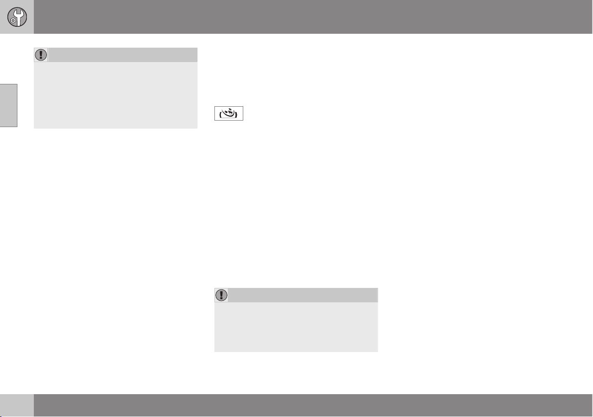
||
10 Maintenance and service
10
366
* Option/accessory, for more information, see Introduction.
IMPORTANT
Only paint treatment recommended by
Volvo should be used. Other treatment
such as preserving, sealing, protection,
lustre sealing or similar could damage the
paintwork. Paintwork damage caused by
such treatments is not covered by Volvo
warranty.
Related information
•
Car washing (p. 364)
Water and dirt-repellent coating
The windows are treated with a surface coa-
ting that improves visibility in difficult weather
conditions.
Water and dirt-repellent coating*
There is natural wear of the water-
repellent coating.
Maintenance:
•
Never use products such as car wax,
degreaser or similar on glass surfaces as
this could ruin their water-repellent prop-
erties.
•
Take care when cleaning so as not to
damage the glass surface.
•
To avoid damaging glass surfaces when
removing ice – only use plastic ice scra-
pers.
•
Treatment with a special finishing agent
available from Volvo dealers is recom-
mended in order to maintain the water-
repellent properties. This should be used
first after three years and then each year.
IMPORTANT
Do not use a metal ice scraper to remove
ice from the windows. Use the heating to
remove ice from the door mirrors; see Win-
dows and rearview and door mirrors -
heating (p. 98).
Related information
•
Car washing (p. 364)
Rustproofing
The car received a thorough and complete
rustproofing at the factory. Parts of the body
are made of galvanised sheet metal. The
underbody is protected by a wear-resistant
anti-corrosion compound. A thin, penetrating
rustproofing fluid was sprayed into the
exposed members, cavities, closed sections
and side doors.
Inspection and maintenance
Dirt and road salt can lead to corrosion so it
is important to keep the car clean. The car's
rustproofing needs to be checked regularly
and touched-up if necessary in order for it to
be maintained.
Under normal conditions the rustproofing
does not require treatment for approximately
12 years. After this period, it should be trea-
ted at three-year intervals. Volvo recom-
mends that you engage an authorised Volvo
workshop for assistance if the car needs fur-
ther treatment.
Related information
•
Paint damage (p. 368)
10 Maintenance and service
10
}}
367
Cleaning the interior
Only use cleaning agents and car care prod-
ucts recommended by Volvo. Clean regularly
and follow the instructions included with the
car care product.
Vacuuming is important prior to using clean-
ing agents.
Carpets and cargo area
Remove inlaid carpets for separate cleaning
of the floor carpet and the inlaid carpets. Use
a vacuum cleaner to remove dust and dirt.
Each inlay mat is secured with pins.
– Take hold of the inlay mat at each pin and
lift the mat straight up.
Fit the inlay mat in place by pressing it in
at each pin.
WARNING
Before setting off check that the inlaid mat
in the driver area is firmly affixed and
secured in the pins in order to avoid get-
ting caught adjacent to and under the ped-
als.
A special textile cleaner is recommended for
stains on the floor mat after vacuuming. Floor
mats should be cleaned with agents recom-
mended by your Volvo dealer!
Stains on fabric upholstery and roof
upholstery
A special fabric cleaning agent, available from
authorised Volvo dealers, is recommended to
avoid impairing the fire retardant qualities of
the upholstery.
IMPORTANT
Sharp objects and Velcro may damage the
fabric upholstery.
IMPORTANT
•
Certain items of coloured clothing (for
example, jeans and suede garments)
may stain the upholstery.
•
Never use strong solvents. Such prod-
ucts may damage fabric, vinyl and
leather upholstery.
Stains on leather upholstery
Volvo's leather upholstery is treated to pre-
serve its original appearance.
Leather upholstery ages and acquires a beau-
tiful patina over time. The leather is refined
and processed so that it retains its natural
characteristics. It is given a protective coa-
ting, but regular cleaning is required in order
to maintain both characteristics and appear-
ance. Volvo offers a comprehensive product
for the cleaning and treatment of leather
upholstery which, when used in accordance
with the instructions, preserves the leather's
protective coating. After a period of use the
natural appearance of the leather will never-
theless emerge, depending more or less on
the surface texture of the leather. This is a
natural maturing of the leather and shows
that it is a natural product.
To achieve best results Volvo recommends
cleaning and the application of protective
cream once to four times per year (or more if
necessary). The Volvo Leather Care kit is
available from your Volvo dealer.
IMPORTANT
•
Certain items of coloured clothing (for
example, jeans and suede garments)
may stain the upholstery.
•
Never use strong solvents. Such prod-
ucts may damage fabric, vinyl and
leather upholstery.
Washing instructions for leather
upholstery
1. Pour the leather cleaner on the damp-
ened sponge and squeeze out a strong
foam.
2. Work the dirt away with gentle circular
movements.
3. Dab accurately with the sponge on the
stains. Allow the sponge to absorb the
stain. Do not rub.

||
10 Maintenance and service
10
368
4. Wipe off with soft paper or a cloth and
allow the leather to dry completely.
Protective treatment of leather
upholstery
1. Pour a small amount of the protective
cream on the felted cloth and massage in
a thin layer of cream with gentle circular
movements on the leather.
2. Allow the leather to dry for 20 minutes
before use.
The leather has now been given improved
protection against stains and improved UV
protection.
Washing instructions for the leather
steering wheel
•
Remove dirt and dust with a soft pre-
moistened sponge and neutral soap.
•
Leather needs to breathe. Never cover
the leather steering wheel with protective
plastic.
•
Use natural oils. Volvo's leather care
agents are recommended for best results.
If the steering wheel has stains:
Group 1 (ink, wine, coffee, milk, sweat and
blood)
– Use a soft cloth or sponge. Mix a 5%
ammonia solution. (For blood stains, use
a solution of 2 dl water and 25g salt.)
Group 2 (fats, oils, sauces and chocolate)
1. Same procedure as for group 1.
2. Polish with an absorbent paper or cloth.
Group 3 (dry dirt, dust)
1. Use a soft brush to remove the dirt.
2. Same procedure as for group 1.
Stains on interior plastic parts, metal
parts and wood parts
A fibrillated fibre or microfibre cloth, lightly
moistened with water, available from Volvo
dealers, is recommended for cleaning interior
parts and surfaces.
Do not scrape or rub stains. Never use strong
stain removers. A special cleaning agent
available from Volvo dealers can be used for
more difficult cleaning.
Seatbelts
Use water and a synthetic detergent. A spe-
cial textile cleaning agent is available from
your Volvo dealer. Make sure the seatbelt is
dry before allowing it to retract.
Related information
•
Car washing (p. 364)
Paint damage
Paint is an important part of the car's rust-
proofing and should therefore be checked
regularly. The most common types of paint-
work damage are stone chips, scratches, and
marks on the edges of wings, doors and
bumpers.
Touching up minor paintwork damage
To avoid the onset of rust, damaged paint-
work should be rectified immediately.
Materials
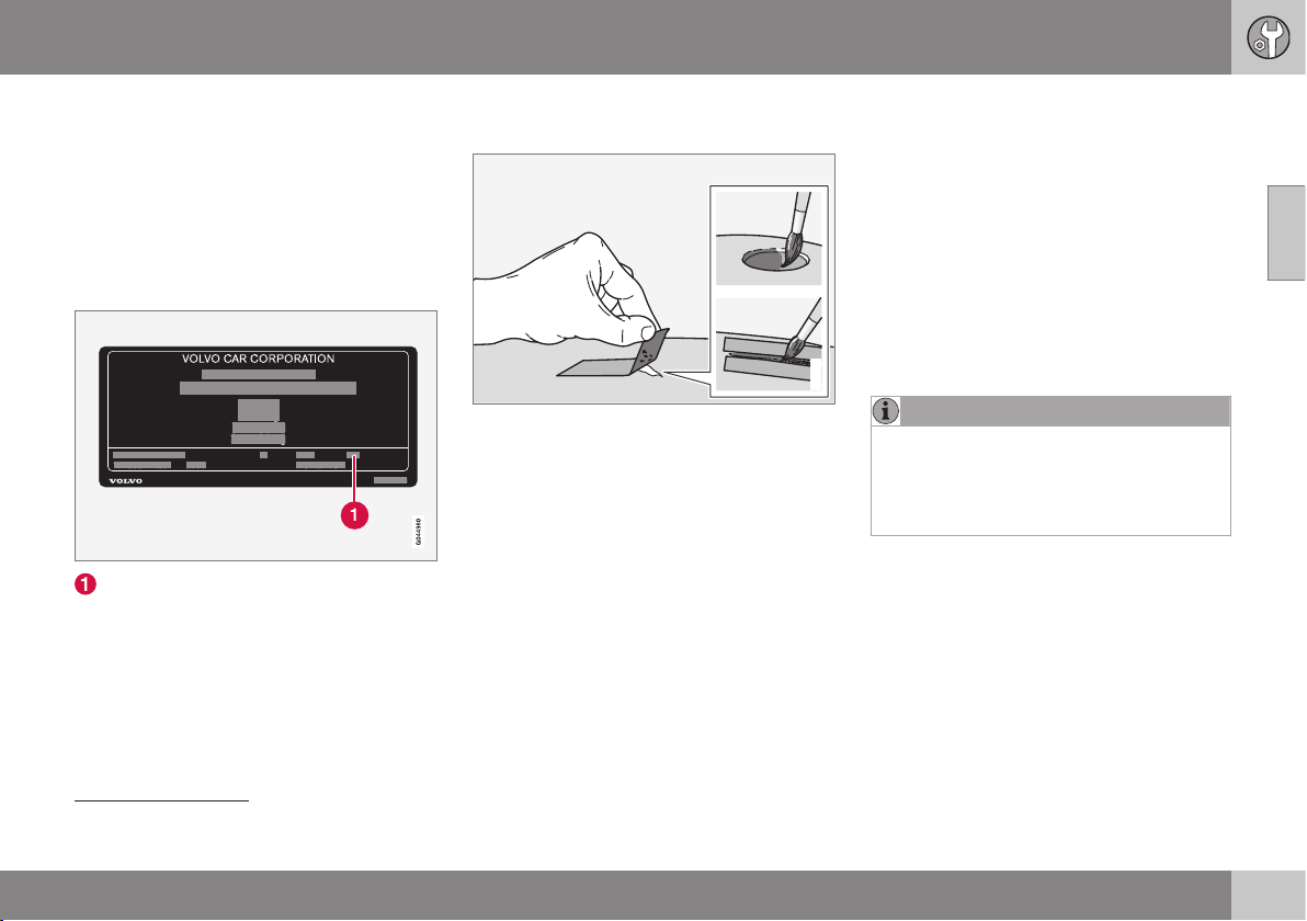
10 Maintenance and service
10
369
•
primer
14
- a special adhesive primer in a
spray can is available for e.g. plastic-
coated bumpers
•
basecoat and clearcoat - available in
spray cans or as touch-up pens/sticks
15
•
masking tape
•
fine sand paper
14
.
Colour code
Code for the car's colour
It is important that the correct colour is used.
For product label location, see Type designa-
tions (p. 438).
Repair minor paintwork damage such
as stone chips and scratches
G021832
Before work is begun, the car must be clean
and dry and at a temperature above 15 °C.
1. Apply a piece of masking tape over the
damaged surface. Then remove the tape
to remove any loose paint.
If the damage is down to the metal, use
of a primer is appropriate. In the event of
damage to a plastic surface, an adhesive
primer should be used to give better
results - spray into the lid of the spray
can and brush on thinly.
2. Before painting, gentle polishing using a
very fine polishing agent may be carried
out locally if required (e.g. if there are any
uneven edges). The surface is cleaned
thoroughly and left to dry.
3. Stir the primer well and apply using a fine
brush, a matchstick or similar. Finish off
with a basecoat and clearcoat once the
primer has dried.
4. For scratches, proceed as above, but
mask around the damaged area to pro-
tect the undamaged paintwork.
NOTE
If the stone chip has not penetrated down
to the meal and an undamaged layer of
paint remains in place, fill in with basecoat
and clearcoat as soon as the surface has
been cleaned.
Related information
•
Rustproofing (p. 366)
14
If required.
15
Follow the instructions that are included with the package for the touch-up pen/stick.
AUDIO AND MEDIA
11 Audio and media
11
* Option/accessory, for more information, see Introduction.
371
Audio and media
The audio and media system consists of radio
(p. 379), media player (p. 390), TV (p. 421)*
as well as the option to communicate with
mobile phone (p. 403) *. Information is pre-
sented on a 5 or 7-inch* screen in the upper
section of the centre console. Functions can
be controlled via buttons in the steering
wheel, in the centre console below the screen
or via a remote control (p. 425) *.
If the audio and media system is active when
the engine is switched off then it is automati-
cally activated the next time the key is
inserted into key position I (p. 71) or higher,
and it continues with the same source (e.g.
radio) as before the engine was switched off
(the driver's door must be closed on cars with
Keyless systems*).
The audio and media system can be used for
15 minutes at a time without the remote con-
trol key being in the ignition switch by press-
ing the On/Off button.
When the car is being started the audio and
media system is switched off temporarily and
continues when the engine has started.
NOTE
Remove the remote control key from the
ignition switch if the audio and media sys-
tem is being used when the engine is
switched off. This is to avoid discharging
the battery unnecessarily.
Dolby Digital, Dolby Pro Logic
1
Made under license from Dolby Laboratories.
Dolby Digital, Dolby Pro Logic and the dou-
ble-D symbol are trademarks of Dolby
Laboratories.
Audyssey MultEQ
1
The Audyssey MultEQ system has been used
in the development and tuning of the sound
to ensure a world-class sound experience.
Related information
•
Audio and media - overview (p. 372)
•
Audio and media - operating the system
(p. 372)
•
Audio and media - menu navigation (p.
374)
•
Audio and media - menu overview (p.
428)
•
Audio and media - audio settings (p. 376)
•
Picture settings (p. 394)
•
Favourites (p. 376)
1
Only applies to Premium Sound Multimedia.
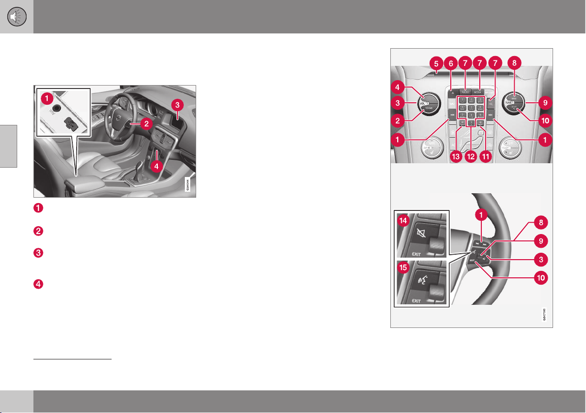
11 Audio and media
11
372
* Option/accessory, for more information, see Introduction.
Audio and media - overview
Overview of the audio and media system's
associated parts.
AUX
2
and USB
3
inputs for external audio
sources (e.g. iPod
®
)
Steering wheel keypad (with*/without
thumbwheel).
display screen. The display screen is
available in two sizes: 5 and 7-inch. The
manual shows a 7-inch display screen.
Control panel in centre console
Related information
•
Audio and media (p. 371)
•
Audio and media - operating the system
(p. 372)
Audio and media - operating the
system
The audio and media system is controlled
from the centre console and partly from the
steering wheel buttons. The information is
presented on the screen in the upper section
of the centre console.
2
Applicable to Performance only
3
Not applicable to Performance

11 Audio and media
11
* Option/accessory, for more information, see Introduction.
373
Scroll/fast forward/search - A short
press scrolls among tracks, preset radio sta-
tions
4
or chapters
5
. A long press fast for-
wards through disc tracks or searches for the
next available radio station.
SOUND - press for access to audio set-
tings (bass, treble, etc.). For more informa-
tion, see general audio settings (p. 377).
VOL - raise or lower volume.
ON/OFF/MUTE - short press starts
the system and long press (until the screen is
off) switches off. Note that the whole of the
Sensus system (including navigation * and
phone functions*) starts/switches off at the
same time. Briefly press to mute the sound
(MUTE) or restore the sound if it had been
switched off.
Disc insert and eject slot.
Disc eject.
Main sources - press to select the main
source (e.g. RADIO, MEDIA). Last active
source is shown (e.g.
FM1). A new source
view is selected if the main source button is
pressed while in RADIO or MEDIA. If you are
in TEL* or NAV* and press the main source
button then a shortcut menu is shown with
commonly used menu options.
OK/MENU - press the thumbwheel in the
steering wheel or the button in the centre
console to accept a menu selection. If OK/
MENU is pressed while in the normal view, a
menu for the selected source opens (e.g.
RADIO or MEDIA). Arrow to the right of the
screen is shown when there are underlying
menus.
TUNE - turn the thumbwheel in the steer-
ing wheel or the knob in the centre console to
scroll among tracks/folders, radio and TV*
stations, phone contacts* or to navigate
among choices on the display screen.
EXIT - short press leads upwards in the
menu system, interrupts current function,
interrupts/rejects phone calls or erases
entered characters. Long press leads to nor-
mal view, or if you are in normal view to the
highest menu level (main source view), from
where you can reach the same main source
buttons located in the centre console (7).
INFO - If more information than can be
shown on the screen is available, press the
INFO button to see the remaining informa-
tion.
Preset buttons, input of numbers and let-
ters.
FAV – shortcut to a favourite setting. The
button can be programmed for a commonly
used function in AM, FM, etc. For more infor-
mation, see favourites (p. 376)).
MUTE
6
- press to switch off the radio/
media audio or restore the audio if it has been
switched off.
Voice recognition
7
- press to activate
voice recognition (for mobile phone and navi-
gation system connected via Bluetooth
®
*).
Related information
•
Audio and media - menu navigation (p.
374)
•
Audio and media (p. 371)
4
Does not apply to DAB.
5
Only applies to DVD discs.
6
Cars without navigation.
7
Cars with navigation*.
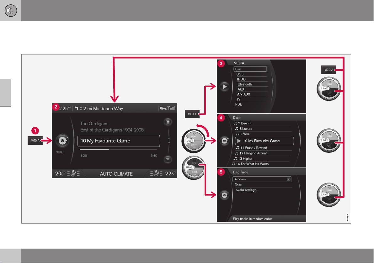
11 Audio and media
11
374
Audio and media - menu navigation
The audio and media system is controlled
from the centre console and partly from the
steering wheel buttons. The information is
presented on the screen in the upper section
of the centre console.
The example shows navigation to different functions when a disc is played back. (1) Main source button, (2) Normal view, (3) Shortcut/source menu, (4) Quick
menu, (5) Source menu
11 Audio and media
11
375
Select main source by pressing a main
source button (1) (RADIO, MEDIA, TEL). To
navigate through the source menus, use the
controls TUNE, OK/MENU, EXIT or the main
source button (1).
To view available functions, see Audio and
media - menu overview (p. 428).
NOTE
If the car is equipped with a steering wheel
keypad with a thumbwheel*, these can be
used instead of the controls in the centre
console (TUNE, OK/MENU, EXIT), Audio
and media - operating the system (p. 372).
Menus and views in the display screen
The appearance depends on the source,
equipment in the car, settings, etc.
Main source button - press to switch the
main source or to show the Shortcut/Source
menu in the active source.
Normal view - normal mode for the
source.
Shortcut/Source menu - shows com-
monly used menu options in the main
sources, e.g. TEL and MEDIA (accessed by
pressing the active source's main source but-
ton (1)).
Quick menu - fast mode when TUNE is
turned, e.g. for changing disc tracks, radio
station, etc.
Source menu - for menu navigation
(accessed by pressing OK/MENU).
Related information
•
Audio and media - operating the system
(p. 372)
•
Audio and media - menu overview (p.
428)
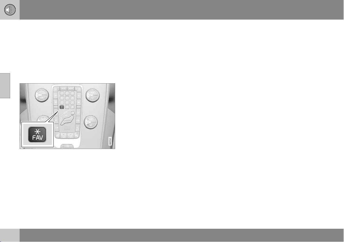
11 Audio and media
11
376
* Option/accessory, for more information, see Introduction.
Favourites
Save frequently used functions as favourites.
Possible functions that can be saved are
within radio, media, reversing camera and
menu source MY CAR where many of the
car's functions are handled, e.g. setting the
clock, door mirrors and locks. The function is
then accessed easily by pressing the FAV
button.
The FAV button can be used to store func-
tions that are used frequently so that the
function can be started simply by pressing
FAV. You can select a favourite (e.g.
Equalizer) for each function as follows:
In RADIO mode:
•
AM
•
FM1/FM2
•
DAB1*/DAB2*
In MEDIA mode:
•
DISC
•
USB*
•
iPod*
•
Bluetooth*
•
AUX
•
TV*
It is also possible to select and store a
favourite for MY CAR, CAM* and NAV*.
Favourites can also be selected and stored
under MY CAR. For more information on the
menu system, see MY CAR (p. 104).
Related information
•
Save as favourite (p. 419)
Audio and media - audio settings
The audio system is pre-calibrated for optimal
sound reproduction, but can be adapted to
your needs.
Setting for optimal sound reproduction
The audio system is pre-calibrated for opti-
mum sound reproduction by means of digital
signal processing.
This calibration takes into account loud-
speakers, amplifiers, passenger compartment
acoustics, listener position etc. for each com-
bination of car model and audio system.
There is a also a dynamic calibration that
takes into account the position of the volume
control, radio reception and vehicle speed.
The controls explained in these operating
instructions, e.g.
Bass, Treble and
Equalizer, are only intended for the user to
be able to adapt the sound reproduction
according to personal taste.
Related information
•
Audio and media - general audio settings
(p. 377)
•
Audio and media - advanced audio set-
tings (p. 377)
•
Setting the audio profile (p. 378)
11 Audio and media
11
* Option/accessory, for more information, see Introduction.
377
Audio and media - general audio
settings
General audio settings for the audio and
media system.
Press SOUND to access the audio settings
menu (
Bass, Treble, etc.). Scroll forward with
SOUND or OK/MENU to your selection (e.g.
Treble).
Adjust the setting by turning TUNE and save
the setting with OK/MENU.
Continue pressing SOUND or OK/MENU to
access other options:
•
Surround
8
- Can be set to the On/Off
position. When On is selected, the sys-
tem selects the setting for optimal sound
reproduction. Normally DPLII and
then appear in the display screen. If the
recording is made with Dolby Digital tech-
nology then playback will take place with
this setting,
then appears in the
display screen. When Off is selected, 3-
channel stereo is available.
•
Bass - Bass level.
•
Treble - Treble level.
•
Fader – Balance between the front and
rear speakers.
•
Balance – Balance between the left and
right-hand speakers.
•
Subwoofer*
8
- Bass speaker level.
•
DPL II centre level3 channel centre
level
8
- Volume for centre speaker.
•
DPL II surround level
8, 9
– Level for sur-
round.
Related information
•
Audio and media - menu navigation (p.
374)
•
Audio and media - audio settings (p. 376)
•
Audio and media - advanced audio set-
tings (p. 377)
Audio and media - advanced audio
settings
Adapt the audio settings for radio and media
according to your wishes.
The following functions can be adapted:
•
Setting the equaliser (p. 378)
•
Setting the audio profile (p. 378)
•
Setting the audio volume and automatic
volume control (p. 378)
•
Setting the audio volume for external
audio source (p. 398)
Related information
•
Audio and media - audio settings (p. 376)
•
Audio and media - general audio settings
(p. 377)
8
Only Premium Sound Multimedia.
9
Only when Surround is activated.

11 Audio and media
11
378
Setting the equaliser
Set the equaliser
10
and adjust the volume
separately for different radio frequencies or
TV.
1.
Press OK/MENU to access
Audio
settings and select Equalizer.
2. Select wavelength by turning TUNE and
confirm with OK/MENU.
3. Adjust the audio settings by turning
TUNE and confirm with OK/MENU. Con-
tinue in the same way with other wave-
lengths you want to change.
4. When you have finished with audio set-
tings, press EXIT to confirm and return to
normal view.
Related information
•
Audio and media - advanced audio set-
tings (p. 377)
•
Audio and media - menu navigation (p.
374)
Setting the audio profile
Set the audio profile and optimise your audio
experience in accordance with your needs.
The sound experience can be optimised for
the driver's seat, both front seats or the rear
seat. If there are passengers in both the front
and rear seats then the option recommended
is; both front seats. The options can be
selected under
Audio settings Sound
stage
.
Related information
•
Audio and media - audio settings (p. 376)
•
Audio and media - menu navigation (p.
374)
Setting the audio volume and
automatic volume control
Set the audio compensation for excessive
noise in the passenger compartment.
The audio system compensates for disrupting
noises in the passenger compartment by
increasing the volume in relation to the speed
of the car. The compensation level can be set
to low, medium, high or off. Select the level
under
Audio settings Volume
compensation
.
Related information
•
Audio and media - advanced audio set-
tings (p. 377)
•
Audio and media - menu navigation (p.
374)
10
Not applicable to Performance
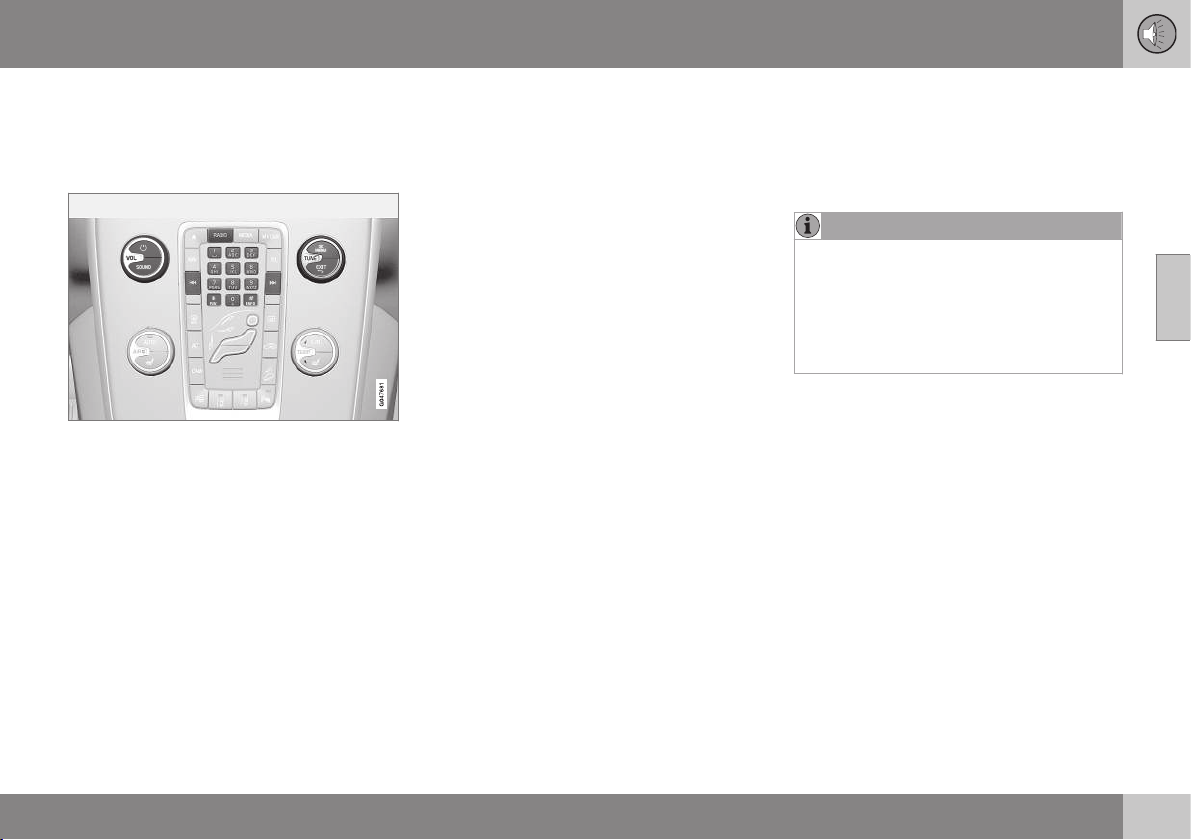
11 Audio and media
11
* Option/accessory, for more information, see Introduction.
379
Radio
It is possible to listen to the AM and FM radio
frequencies and, also in certain cases, digital
radio (DAB) (p. 388)*.
Controls for radio functions.
For operating the radio, see Operating the
system (p. 372) and Menu navigation (p. 374).
AM/FM radio
•
Radio tuning (p. 379)
•
Radio stations as presets (p. 381)
•
Scan radio frequencies (p. 387)
•
RDS functions (p. 382)
•
Radio programme types (PTY) (p. 384)
•
Radio text (p. 386)
Digital radio* (DAB)
•
Digital radio* (DAB) (p. 388)
•
Storing channel groups (Ensemble learn)
(p. 388)
•
Navigation in channel group list (Ensem-
ble) (p. 389)
•
Radio stations as presets (p. 381)
•
Scan radio frequencies (p. 387)
•
Radio programme types (PTY) (p. 384)
•
Radio text (p. 386)
•
DAB to DAB link (p. 389)
•
Digital radio* (DAB) - frequencies (p. 389)
•
Digital radio* (DAB) - subchannel (p. 390)
•
Digital radio* (DAB) - resetting (p. 390)
Related information
•
Audio and media - operating the system
(p. 372)
•
Audio and media - menu navigation (p.
374)
•
Audio and media - menu overview (p.
428)
Radio tuning
The radio automatically compiles a radio sta-
tion list
11
of the strongest FM stations whose
signals it is currently receiving. It is possible to
activate automatic or manual radio tuning.
NOTE
The reception is dependent both on how
good the signal strength and signal quality
are. The transmission may be disturbed by
various factors such as tall buildings or the
transmitter being far away. Coverage level
can also vary depending on where in the
country you are located.
Related information
•
Automatic radio tuning (p. 380)
•
Manual radio tuning (p. 381)
•
Radio station list (p. 380)
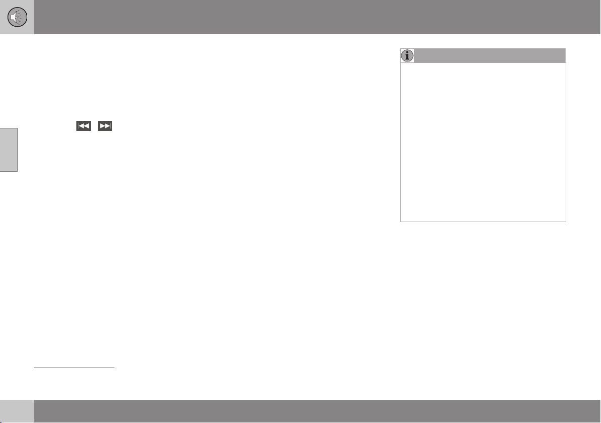
11 Audio and media
11
380
* Option/accessory, for more information, see Introduction.
Automatic radio tuning
Searches for the next/previous available sta-
tion.
1. Press RADIO, turn TUNE until the
desired wavelength (
AM, FM1 etc.) is
shown, press OK/MENU.
2.
Hold in
/ in the centre console
(or in the steering wheel keypad*). The
radio searches for the next/previous avail-
able station.
Related information
•
Radio tuning (p. 379)
Radio station list
The radio automatically compiles a radio sta-
tion list
12
of the strongest FM stations whose
signals it is currently receiving. This enables
you to find a station when you drive into an
area where you do not know the radio sta-
tions and their frequencies.
To go to the list and select a station:
1.
Select the desired wavelength (
FM1 or
FM2).
2. Turn TUNE one step in either direction.
This displays the list of all stations in the
area. The currently tuned station is indi-
cated with enlarged text in the list.
3. Turn TUNE again in either direction to
select a station from the list.
4. Confirm your choice by pressing OK/
MENU.
NOTE
•
The list only shows the frequencies of
stations that are currently being
received, not a complete list of all
radio frequencies on the selected
wavelength.
•
If the signal from the currently received
station is weak, this may prevent the
radio from updating the station list. If
this occurs, press the INFO button
(while the station list is shown in the
display screen) in order to change to
manual tuning and set a frequency. If
the station list is no longer shown, turn
TUNE one step in either direction to
show the list again, and press INFO to
switch.
The list disappears from the display screen
after a few seconds.
If the station list is no longer shown, turn
TUNE one step in either direction and press
the INFO button in the centre console to
change to manual tuning (or to return from
manual tuning to the function for "Station
list").
Related information
•
Radio tuning (p. 379)
11
Does not apply to Performance.
12
Does not apply to Performance.
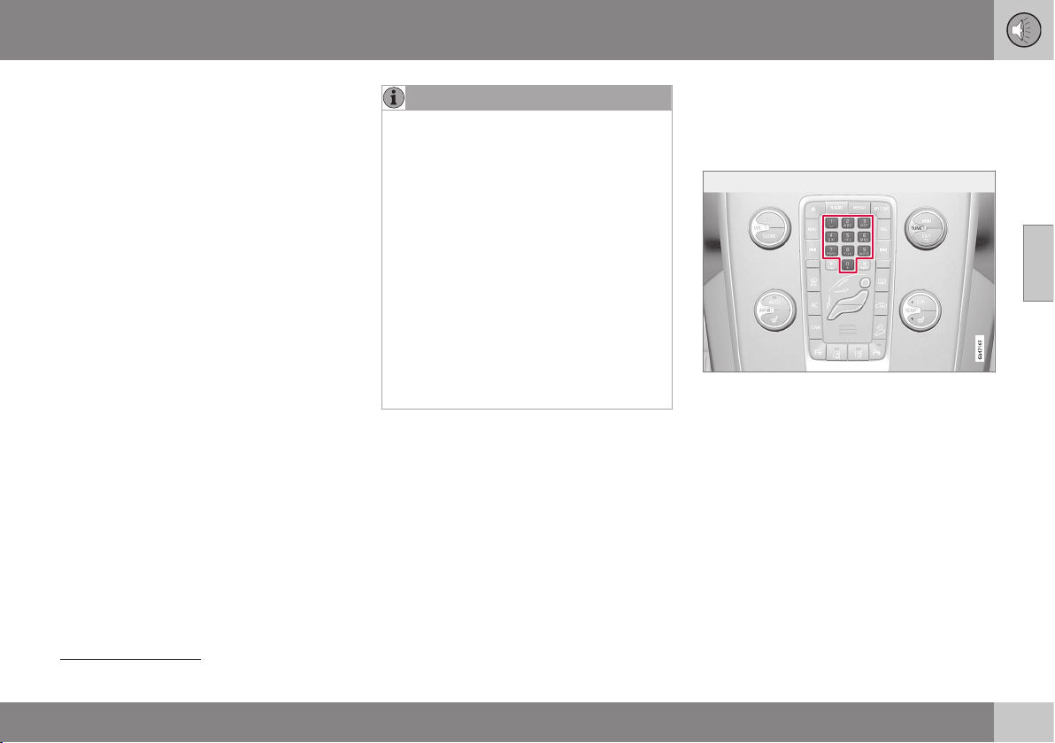
11 Audio and media
11
381
Manual radio tuning
The radio automatically compiles a radio sta-
tion list
13
, but it is possible to perform radio
tuning manually.
The preset from the factory is that the radio
shows the station list of the strongest stations
in the area when you turn TUNE (see the sec-
tion Radio station list (p. 380)). When the
radio station list is shown, press the INFO
button in the centre console to change to
manual tuning. This allows you to select a fre-
quency from the list of all available radio fre-
quencies in the selected wavelength. In other
words, if turn TUNE one step in a manual
search the frequency is changed from e.g.
93.3 to 93.4 MHz, etc.
To manually select a station:
1. Press the RADIO button, turn TUNE until
the required frequency band (
AM, FM1
etc.) is displayed, press OK/MENU.
2. Turn TUNE to select a frequency.
NOTE
The preset from the factory is that the
radio automatically searches for the sta-
tions in the area where you are driving (see
section "Radio station list").
But if you have changed over to manual
tuning (by pressing the INFO button in the
centre console when the station list was
shown), then the radio remains set in the
function for manual tuning the next time
you switch on the radio. To change back
to the function for "Radio station list", turn
TUNE one step (to show the complete list
of stations) and press the button INFO.
Note that if you press INFO when the sta-
tion list is not shown then INFO is acti-
vated. For more information on this func-
tion, see Audio and media - operating the
system (p. 372).
Related information
•
Radio tuning (p. 379)
Radio stations as presets
Frequently used radio stations are optimally
saved as presets in order to facilitate simple
activation.
Preset buttons.
AM/FM radio
10 presets can be stored per wavelength
(
AM, FM1 etc.).
The stored presets are selected using the
preset buttons.
1. Tune into a station, see Radio tuning (p.
379).
13
Does not apply to Performance.
||
11 Audio and media
11
382
2. Hold in one of the preset buttons for a
few seconds, the sound disappears dur-
ing this time and returns when the station
is stored. The preset button can now be
used.
A list of pre-selected channels can be shown
in the display screen
14
. The function is acti-
vated/deactivated in FM/AM mode under
FM
menu
Show presets or AM menu
Show presets.
Digital radio (DAB)
10 station presets can be stored per wave-
length. DAB has 2 memories for presets:
DAB1 and DAB2. Storage of presets is per-
formed by means of a long press on the
desired preset button, for more information
see AM/FM radio above. The stored presets
are selected using the preset buttons.
A preset contains one channel but no sub-
channels. If a subchannel is being played and
a preset is saved then only the main channel
is registered. This is because subchannels
are temporary. At the next attempt to retrieve
the preset, the channel which contained the
subchannel will be played. The preset is not
dependent on the channel list.
A list of pre-selected channels can be shown
in the display screen
14
. The function is acti-
vated/deactivated in DAB mode under
DAB
menu
Show presets.
NOTE
The audio system's DAB system does not
support all functions in the DAB standard.
Related information
•
Radio tuning (p. 379)
•
Audio and media - menu navigation (p.
374)
RDS functions
With RDS the radio can automatically change
to the strongest transmitter. RDS provides the
facility to receive e.g. traffic information (TP)
and to search for certain programme types
(PTY).
RDS (Radio Data System) links FM transmit-
ters into a network. An FM transmitter in such
a network sends information that gives an
RDS radio the following functions:
•
Automatically switches to a stronger
transmitter if reception in the area is poor.
•
Searches for programme type, such as
traffic information or news.
•
Receives text information on current radio
programme.
NOTE
Some radio stations do not use RDS or
only selected parts of its functionality.
If a required programme type is located the
radio can switch stations interrupting the
audio source currently in use. For example, if
the CD player is in use, it is paused. The
interrupting transmission is played back at a
preset volume, see Volume control for inter-
rupting radio programme types (PTY) (p.
386). The radio returns to the previous audio
14
Only applies to High Performance Multimedia and Premium Sound Multimedia.

11 Audio and media
11
383
source and volume when the set programme
type is no longer broadcast.
The programme functions alarm (
ALARM!),
traffic information (TP), news (NEWS), and
programme types (PTY) interrupt one another
in order of priority, where alarm has the high-
est priority and programme types has the
lowest. For additional settings of program-
ming interruptions (EON Distant and EON
Local), see Enhanced Other Networks (EON)
(p. 384). Press EXIT to return to the interrup-
ted audio source, press the OK/MENU to
clear the message.
Related information
•
Alarms in the event of accidents and dis-
asters (p. 383)
•
Traffic information (TP) (p. 383)
•
Enhanced Other Networks (EON) (p. 384)
•
Traffic information (TP) (p. 383)
•
News broadcasts (p. 384)
•
Radio programme types (PTY) (p. 384)
•
Radio text (p. 386)
•
Automatic radio frequency update (AF) (p.
386)
•
Regional radio programmes (REG) (p.
387)
•
Resetting RDS functions (p. 387)
Alarms in the event of accidents and
disasters
This function is used to warn of serious acci-
dents and catastrophes. The message
ALARM! appears on the display screen when
an alarm message is transmitted.
The alarm cannot be temporarily interrupted
or deactivated.
Related information
•
RDS functions (p. 382)
Traffic information (TP)
This function allows traffic information that is
broadcast within a set radio station's RDS
network to break through.
The symbol
TP shows that the function is
activated. If the preset station can send traffic
information then this is shown by TP glowing
brightly in the display screen, otherwise TP
will be grey.
– Activate/deactivate in FM mode under
FM menu TP.
TP from selected station/all stations
The radio can only interrupt for traffic infor-
mation from the selected station or all sta-
tions within the RDS network.
–
Go in FM mode to FM menu
Advanced settings Set TP favourite
to change.
Related information
•
RDS functions (p. 382)
11 Audio and media
11
384
Enhanced Other Networks (EON)
EON is useful in urban areas with many
regional radio stations. It allows the distance
between the car and the radio station trans-
mitter to determine when programme func-
tions should interrupt the current audio
source.
– Activate/deactivate in FM mode by
selecting one of the options under FM
menu
Advanced settings EON:
•
Local – interrupts only if the radio station
transmitter is close.
•
Distant
15
– interrupts if the station trans-
mitter is far away, even if there is a lot of
static.
Related information
•
RDS functions (p. 382)
News broadcasts
This function allows news broadcasts within a
set radio station's RDS network to break
through.
The symbol
NEWS shows that the function is
active.
– Activate/deactivate in FM mode under
FM menu News settings News.
News from selected station/all stations
The radio can only interrupt for news from the
selected station or all stations in the RDS net-
work.
–
Go in FM mode to FM menu News
settings
Set news favourite to
change.
Related information
•
RDS functions (p. 382)
Radio programme types (PTY)
The PTY function can be used to select one
or more radio programme types, such as Pop
Music and Serious Classical Music. After
selecting a programme type, navigation only
takes place within the channels that are
broadcasting that type.
PTY can be selected for FM and DAB radio.
The PTY symbol is shown in the display
screen when the function is active. This func-
tion allows programme types broadcast
within a set station's RDS network to break
through.
PTY for FM radio
1. Activate in FM mode by first selecting the
programme types under
FM menu
Advanced settings PTY settings
Select PTY.
2. Then the PTY function must be activated
under
FM menu Advanced settings
PTY settings Receive traffic
bulletins from other networks
.
Deactivation of the PTY function is performed
in FM mode under
FM menu Advanced
settings
PTY settings Receive traffic
bulletins from other networks
. Selected
programme types (PTY) are not reset.
15
Factory settings.
11 Audio and media
11
385
Resetting and removing PTY are performed
under
FM menu Advanced settings
PTY settings Select PTY Clear all.
PTY for DAB radio
Programme type is selected in DAB mode
under
DAB menu PTY filtering. Exit this
mode as follows:
– Press EXIT.
> An indicator is shown in the display
screen when PTY is activated.
In some cases DAB radio will exit PTY mode,
see DAB to DAB link (p. 389).
Related information
•
Searching radio programme types (PTY)
(p. 385)
•
Show radio programme types (PTY) (p.
385)
•
Volume control for interrupting radio pro-
gramme types (PTY) (p. 386)
•
RDS functions (p. 382)
Searching radio programme types
(PTY)
This function searches the whole frequency
band for the selected radio programme type.
1. In FM mode select one or more PTY
under
FM menu Advanced settings
PTY settings Select PTY.
2.
Go to FM menu Advanced settings
PTY settings Seek PTY.
To finish searching, press EXIT.
– To continue searching for another broad-
cast of the selected programme types,
press on
or .
Related information
•
Radio programme types (PTY) (p. 384)
•
Show radio programme types (PTY) (p.
385)
•
RDS functions (p. 382)
Show radio programme types (PTY)
Some radio stations broadcast information
about programme type and programme cate-
gory. The current station's radio programme
type, e.g. Pop Music and Serious Classical
Music, can be shown in the display screen.
PTY can be selected for FM and DAB radio.
Show radio programme type for FM
radio
– Activate/deactivate in FM mode under
FM menu Advanced settings PTY
settings
Show PTY text.
Show radio programme type for DAB
radio
Activate/deactivate in DAB mode under DAB
menu
Advanced settings Show PTY
text
.
Related information
•
Radio programme types (PTY) (p. 384)
•
Searching radio programme types (PTY)
(p. 385)
•
RDS functions (p. 382)

11 Audio and media
11
386
Volume control for interrupting radio
programme types (PTY)
The interrupting programme types, e.g.
NEWS or TP, are heard at the volume
selected for each respective programme
type. If the volume level is adjusted during the
programme interruption, the new level is
saved until the next programme interruption.
Related information
•
Radio programme types (PTY) (p. 384)
Radio text
Certain RDS stations transmit information on
programme content, artists etc. This informa-
tion is shown in the display screen
16
. Radio
text can be shown for FM and DAB radio.
Radio text for FM radio
– Activate/deactivate in FM mode under
FM menu Show radio text.
Radio text for DAB radio
Activate/deactivate in DAB mode under DAB
menu
Show radio text.
NOTE
Only one of the functions "Show radio
text" and "Show presets" can be acti-
vated at a time. If one of them is activated
when the other is already activated, then
the previously activated function is deacti-
vated automatically. Both functions can be
deactivated.
Related information
•
RDS functions (p. 382)
•
Radio stations as presets (p. 381)
Automatic radio frequency update
(AF)
The function selects the strongest transmitter
for the set radio station.
In order to find a strong transmitter the func-
tion may, in exceptional cases, need to
search the entire FM wavelength.
– Activate/deactivate in FM mode under
FM menu Advanced settings
Alternative frequency.
Related information
•
RDS functions (p. 382)
16
Only cars with 7-inch screen
11 Audio and media
11
* Option/accessory, for more information, see Introduction.
387
Regional radio programmes (REG)
This function causes the radio to continue
with a regional radio transmitter even if its sig-
nal strength is low.
The symbol
REG shows that the function is
active.
– Activate/deactivate in FM mode under
FM menu Advanced settings REG.
Related information
•
RDS functions (p. 382)
Scan radio frequencies
The function automatically searches for avail-
able radio channels and takes into account
any programme type filtering (PTY).
When a station is found, it is played for
approx. 10 seconds before scanning is
resumed. When a station is playing back it is
saved as a preset in the usual way, see Radio
stations as presets (p. 381).
– To start scanning go in FM/AM/DAB*
mode to
FM menu Scan, AM menu
Scan or DAB menu Scan.
NOTE
Scanning stops if a station is saved.
Scanning can also be selected in DAB-PTY
mode. In which case only channels of the
pre-selected programme type are played.
Related information
•
Radio programme types (PTY) (p. 384)
•
Radio stations as presets (p. 381)
Resetting RDS functions
All radio settings can be reset to the original
factory settings.
– The reset is carried out in FM mode under
FM menu Advanced settings
Reset all FM settings.
Related information
•
RDS functions (p. 382)

11 Audio and media
11
388
* Option/accessory, for more information, see Introduction.
Digital radio* (DAB)
DAB (Digital Audio Broadcasting) is a digital
broadcasting system for radio. The car sup-
ports DAB, DAB+ and DMB.
NOTE
Coverage for DAB is not available in all
locations. If there is no coverage then the
message
No reception is shown in the
display screen.
Service and Ensemble
•
Service - Channel, radio channel (only
audio services are supported by the sys-
tem).
•
Ensemble - A collection of radio chan-
nels on the same frequency.
Related information
•
Storing channel groups (Ensemble learn)
(p. 388)
•
Navigation in channel group list (Ensem-
ble) (p. 389)
•
Radio (p. 379)
•
Radio stations as presets (p. 381)
•
Scan radio frequencies (p. 387)
•
Radio programme types (PTY) (p. 384)
•
Radio text (p. 386)
•
DAB to DAB link (p. 389)
•
Digital radio* (DAB) - frequencies (p. 389)
•
Digital radio* (DAB) - subchannel (p. 390)
•
Digital radio* (DAB) - resetting (p. 390)
Storing channel groups (Ensemble
learn)
Storage of channel groups (Ensemble learn)
for digital radio (DAB).
When the vehicle is moved to a new broad-
casting area, programming of existing chan-
nel groups in the area may be necessary.
Programming of channel groups creates an
updated list of all available channel groups.
The list is not updated automatically.
Programming is carried out in the menu sys-
tem in DAB mode under
DAB menu
Ensemble learn. Programming can also take
place as follows:
1. Turn TUNE one step in either direction.
>
Ensemble learn is shown in the list of
available channel groups.
2. Press OK/MENU.
> New programming is started.
Programming can be cancelled with EXIT.
Related information
•
Digital radio* (DAB) (p. 388)
•
Navigation in channel group list (Ensem-
ble) (p. 389)

11 Audio and media
11
* Option/accessory, for more information, see Introduction.
389
Navigation in channel group list
(Ensemble)
Navigation in the channel group list (Ensem-
ble) for digital radio (DAB).
To navigate in and access the channel group
list turn TUNE. The name of the Ensemble is
shown in the upper part of the display screen.
When switching to the new Ensemble the
name changes to the new one.
•
Service - Shows channels irrespective of
the channel group to which they are allo-
cated. The list can also be filtered using
the selection of programme type (
PTY
filtering), see Radio programme types
(PTY) (p. 384).
Related information
•
Storing channel groups (Ensemble learn)
(p. 388)
•
Digital radio* (DAB) (p. 388)
•
Radio programme types (PTY) (p. 384)
DAB to DAB link
DAB to DAB linking means that the DAB radio
can go from one channel with poor or no
reception to the same channel in another
channel group with better reception.
There may be a certain delay when changing
channel group. There may be a period of
silence between the current channel no
longer being available to the new channel
becoming available.
The function can be activated/deactivated in
DAB mode under
DAB menu Advanced
settings
DAB linking.
Related information
•
Digital radio* (DAB) (p. 388)
Digital radio* (DAB) - frequencies
DAB can be transmitted on two wave-
lengths
17
.
•
Band III - covers most areas.
•
LBand - available only in a few areas.
By selecting for example
Band III on its own,
channel programming takes place more
quickly than if both Band III and LBand have
been selected. It is not certain that all channel
groups will be found. Wavelength selection
does not affect the stored memories.
Wavelengths can be deactivated/activated in
DAB mode under
DAB menu Advanced
settings
DAB band.
Related information
•
Digital radio* (DAB) (p. 388)
17
Not all areas/countries use both wavelengths.
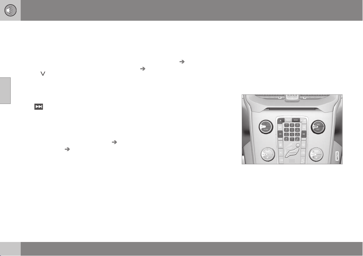
11 Audio and media
11
390
* Option/accessory, for more information, see Introduction.
Digital radio* (DAB) - subchannel
Secondary components are usually named
subchannels. These are temporary and can
contain e.g. translations of the main pro-
gramme into other languages.
If one or more subchannels are broadcast
then the
symbol is shown to the left of the
channel name in the display screen. A sub-
channel is indicated by the
- symbol appear-
ing to the left of the channel name in the dis-
play screen.
Press
to access the subchannels.
Subchannels can only be accessed on the
selected main channel and not on any other
channel without selecting it.
Display of subchannels can be deactivated/
activated in DAB mode under DAB menu
Advanced settings Sub channels
Related information
•
Digital radio* (DAB) (p. 388)
Digital radio* (DAB) - resetting
All DAB settings can be reset to the original
factory settings.
– The reset is carried out in DAB mode
under
DAB menu Advanced settings
Reset all DAB settings.
Related information
•
Digital radio* (DAB) (p. 388)
Media player
The media player can playback audio and
video from CD/DVD* (p. 391) discs and exter-
nally connected audio sources via AUX/USB*
(p. 395) input, or wirelessly stream (p. 398)
audio files from external devices using
Bluetooth
®
. Certain media players can show
TV (p. 421)* and have the option to communi-
cate with a mobile phone (p. 403)* via
Bluetooth
®
.
Controls for the media player.
For operating the media player, see Audio
and media - operating the system (p. 372)
and Audio and media - menu navigation (p.
374).
Related information
•
Audio and media (p. 371)
•
Voice recognition* control of a mobile
phone (p. 413)

11 Audio and media
11
* Option/accessory, for more information, see Introduction.
391
•
Remote control* (p. 425)
•
Media player - compatible file formats (p.
394)
CD/DVD*
The media player can playback pre-recorded
and burned CD/DVD
18
discs.
The media player supports and can play the
following main types of discs and files:
•
Pre-recorded CD discs (CD Audio).
•
Burned CD discs with audio and/or video
files
18
.
•
Pre-recorded DVD video discs
18
.
•
Burned DVD discs
18
with audio and/or
video files.
For more information about the supported
formats, see Media player - compatible file
formats (p. 394).
Related information
•
Audio and media - operating the system
(p. 372)
•
Playback and navigation of CD/DVD* disc
(p. 419)
•
Playback and navigation of DVD video
discs (p. 392)
Fast forward/reverse
It is possible to fast forward/rewind audio and
video files.
19
Hold the button for
/ depressed in
order to fast forward/rewind audio or video
files forward/backward.
Audio files are fast forwarded/rewound at one
speed, while video files can be fast forwar-
ded/rewound at several speeds. Repeatedly
press the buttons
/ to increase the
fast forward/rewind speed for video files.
Release the button to return to viewing at
normal speed.
Related information
•
Audio and media - operating the system
(p. 372)
•
Playback and navigation of CD/DVD* disc
(p. 419)
•
Playback and navigation of external audio
source (p. 396)
18
Only applies to High Performance Multimedia and Premium Sound Multimedia.
19
Only applies to CD/DVD* discs, USB and iPod
®
.
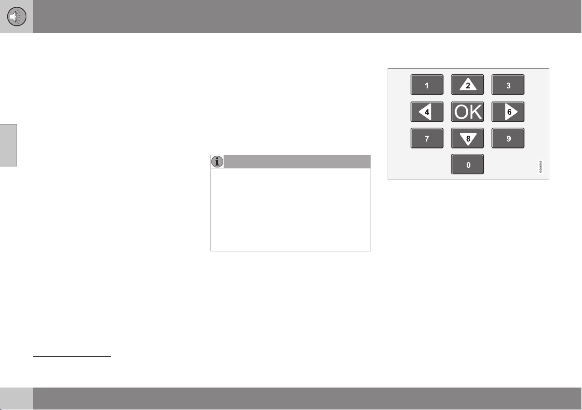
11 Audio and media
11
392
* Option/accessory, for more information, see Introduction.
Random selection of disc track or
audio file
This function plays the tracks/audio files in
random order
20
.
To listen to the tracks/audio files in random
order for the selected source:
1. Press OK/MENU
2.
Turn TUNE to
Random
3. Press OK/MENU to activate/deactivate
the function.
Related information
•
Audio and media - operating the system
(p. 372)
•
Playback and navigation of CD/DVD* disc
(p. 419)
•
Playback and navigation of external audio
source (p. 396)
•
Media Bluetooth
®
* (p. 398)
Playback and navigation of DVD video
discs
When playing back a DVD video disc
21
a disc
menu may appear on the display screen. The
disc menu gives access to additional func-
tions and settings, such as selecting subtitles,
language and scene selection.
For basic playback and navigation, see Oper-
ating the system, page (p. 372). See below for
a more detailed description.
NOTE
A video film is only shown when the car is
stationary. When the car is moving at a
speed of over about 8 km/h no picture is
shown and
No visual media available
while driving appears on the display
screen, although the audio is heard during
this time. The picture is shown again as
soon as the car's speed falls below about
6 km/h.
Navigation in the DVD video disc's
menu
Navigation in the DVD video disc's menu is
performed using the number keys in the cen-
tre console as illustrated above.
Changing chapter or title
Turn TUNE to access the list of chapters and
navigate through them (if the film is being
played back then it is paused). Press OK/
MENU to select the chapter, this also leads
back to the original position (if the film was
being played back then it is restarted). Press
EXIT to access the title list.
Titles are selected in the title list by turning
TUNE and the selection is confirmed with
OK/MENU, this also leads back to the chap-
ter list. Press OK/MENU to activate the
20
Does not apply to DVD video discs. For externally connected audio sources via the AUX/USB input this only applies to USB and iPod
®
. Not supported by all mobile phones.
21
Only applies to High Performance Multimedia and Premium Sound Multimedia.

11 Audio and media
11
* Option/accessory, for more information, see Introduction.
393
selection and return to the start position. Use
EXIT to cancel the selection and this leads
back to the original position (without any
selection being made).
The chapter can also be changed by pressing
on
/ on the centre console or the
steering wheel keypad*.
Related information
•
Audio and media - operating the system
(p. 372)
•
Playback and navigation of CD/DVD* disc
(p. 419)
•
Camera angle for playback of DVD video
discs (p. 393)
•
Playback and navigation of burned discs
with audio/video files (p. 420)
•
Fast forward/reverse (p. 391)
•
Scan disc track or audio file (p. 421)
•
Random selection of disc track or audio
file (p. 392)
•
Media player - compatible file formats (p.
394)
Camera angle for playback of DVD
video discs
If the DVD video disc supports it, the function
can be used to choose from which camera
position a particular scene should be
shown
22
.
Go in disc mode to
Disc menu Advanced
settings
Angle.
Related information
•
Audio and media - operating the system
(p. 372)
•
Playback and navigation of DVD video
discs (p. 392)
DivX
®
Video On Demand
The media player can be registered in order to
play DivX VOD
23
type files from burned discs
or USB.
The code for registration can be found in the
menu system MY CAR
Settings
Information DivX® VOD code. For gen-
eral information on menus, see under
MY CAR, see MY CAR - operation (p. 104).
For more information visit www.divx.com/
vod.
Related information
•
Audio and media - operating the system
(p. 372)
•
Playback and navigation of DVD video
discs (p. 392)
•
Playback and navigation of burned discs
with audio/video files (p. 420)
•
Playback and navigation of external audio
source (p. 396)
22
Applies to High Performance Multimedia and Premium Sound Multimedia.
23
Applies to High Performance Multimedia and Premium Sound Multimedia.
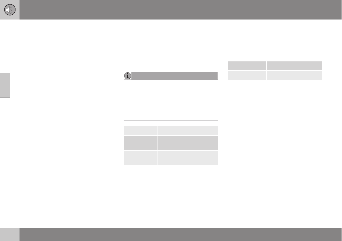
11 Audio and media
11
394
* Option/accessory, for more information, see Introduction.
Picture settings
You can adjust the display settings (when the
car is stationary) for brightness and contrast
24
.
1.
Press OK/MENU and select
Image
settings, confirm with OK/MENU.
2. Turn TUNE to the adjustment option and
confirm with OK/MENU.
3. Adjust the setting by turning TUNE and
confirm with OK/MENU.
To return to the settings list, press the OK/
MENU or EXIT.
The picture settings can be reset to factory
settings with the
Reset option.
Related information
•
Audio and media - operating the system
(p. 372)
•
Audio and media (p. 371)
Media player - compatible file formats
The media player can play back a variety of
file types and is compatible with the formats
in the following tables.
Compatible file formats for CD/DVD*
discs
NOTE
Dual format, double-sided discs (DVD
Plus, CD-DVD format) are thicker than reg-
ular CD discs and therefore playback can-
not be guaranteed and malfunction may
arise.
If a CD contains a mixture of MP3 and
CDDA tracks, all MP3s will be ignored.
Audio format
A
CD audio, mp3, wma
Audio format
B
CD audio, mp3, wma, aac,
m4a
Video format
C
CD video, DVD video,
divx, avi, asf
A
Applies to Performance.
B
Does not apply to Performance.
C
Only applies to High Performance Multimedia and Pre-
mium Sound Multimedia.
Compatible file formats via USB
connection
Audio and video files in the following table are
supported by the system for playback via the
USB connection.
Audio format mp3, wma, aac, m4a
Video format
A
divx, avi, asf
A
Only applies to High Performance Multimedia and Pre-
mium Sound Multimedia.
Related information
•
Playback and navigation of CD/DVD* disc
(p. 419)
•
Playback and navigation of DVD video
discs (p. 392)
•
Playback and navigation of burned discs
with audio/video files (p. 420)
•
Playback and navigation of external audio
source (p. 396)
24
Applies to High Performance Multimedia and Premium Sound Multimedia.
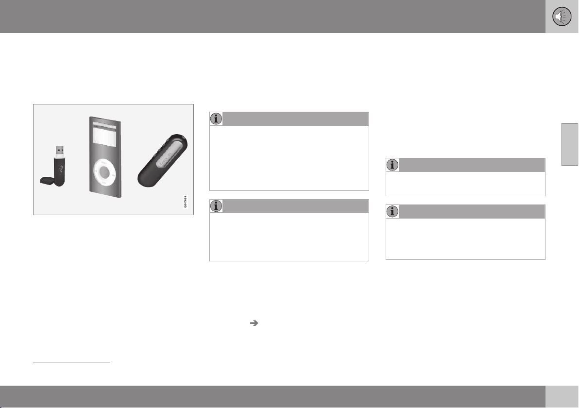
11 Audio and media
11
* Option/accessory, for more information, see Introduction.
395
External audio source via AUX/USB*
input
An external audio source, e.g. an iPod
®
or
MP3 player, can be connected to the audio
system.
An audio source connected to the USB input
can be operated
25
using the car's audio con-
trols. A device connected via the AUX input
cannot be controlled via the car.
There is a recess in the right-hand rear edge
of the tunnel console where cables can be
routed so that the hatch can be closed with-
out cables being pinched.
An iPod
®
or MP3 player with rechargeable
batteries is recharged (when the ignition is on
or the engine is running) if the device is plug-
ged into the USB connection.
USB memory
To facilitate the use of a USB memory stick,
only store music files on it. It takes a lot
longer for the system to load storage media
that contains anything other than compatible
music files.
NOTE
The system supports mobile media com-
pliant with USB 2.0 and the FAT32 file sys-
tem and can handle 1000 folders with a
maximum of 254 subfolders/files in every
folder. The top level, which can handle up
to 1000 subfolders/files, is an exception to
this.
NOTE
When using a longer model USB memory
stick the use of a USB adapter cable is
recommended. This is to avoid mechanical
wear to the USB input and the connected
USB memory stick.
USB hub
It is possible to connect a USB hub to the
USB connection and thereby connect multi-
ple USB devices simultaneously. Selection of
USB device is made in
USB mode under
USB menu Select USB device.
MP3 player
Many MP3 players have their own file sys-
tems that are not supported by the audio sys-
tem. For use in the system, an MP3 player
must be set in
USB Removable device/
Mass Storage Device mode.
iPod
®
An iPod
®
is charged and supplied with power
by the USB connection* via the player's con-
nection cable.
NOTE
The system only supports the playback of
audio files from iPod
®
.
NOTE
When an iPod
®
is used as audio source,
the car's infotainment system has a menu
structure that is similar to the iPod
®
play-
er's own menu structure.
Related information
•
Audio and media - operating the system
(p. 372)
•
Connecting an external audio source via
AUX/USB* input (p. 396)
•
Playback and navigation of external audio
source (p. 396)
25
Only applies to the media source connected via the USB connection.
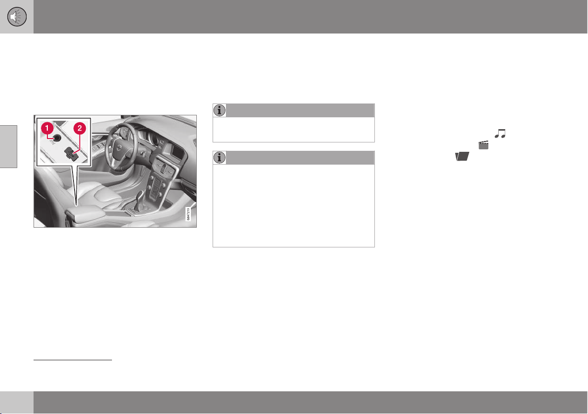
11 Audio and media
11
396
* Option/accessory, for more information, see Introduction.
Connecting an external audio source
via AUX/USB* input
An external audio source, e.g. an iPod
®
or
MP3 player, can be connected to the audio
system via any of the connections in the cen-
tre console.
Connection points for external audio sources.
To connect the audio source:
1. Press MEDIA, turn TUNE to the required
sound source
USB, iPod or AUX, press
OK/MENU.
>
If USB is selected then
Connect USB
is shown in the display screen.
2. Connect your audio source to one of the
connections in the centre console's stor-
age compartment (see previous illustra-
tion).
The text Reading USB is shown in the dis-
play screen when the system is loading the
storage media's file structure. Depending on
the file structure and number of files there
may be some delay before loading is finished.
NOTE
The system supports most iPod
®
models
produced in 2005 or later.
NOTE
To prevent damage to the USB connec-
tion, this is shut off if the USB connection
is short-circuited or if a connected USB
unit is taking too much power (this may
happen if the unit connected does not
meet the USB standard). The USB con-
nection is reactivated automatically the
next time the ignition is turned on, unless
the fault persists.
Related information
•
External audio source via AUX/USB* input
(p. 395)
•
Playback and navigation of external audio
source (p. 396)
Playback and navigation of external
audio source
Playback and navigation of external audio
source
26
For basic playback and navigation, see Audio
and media - operating the system (p. 372).
See below for a more detailed description.
Audio files have the symbol
, video
files
27
have the symbol
and folders
have the symbol
.
When playback of a file is complete the play-
back of the other files (of the same type) in
26
Only applies to USB and iPod
®
.
27
Applies to High Performance Multimedia and Premium Sound Multimedia.

11 Audio and media
11
* Option/accessory, for more information, see Introduction.
397
that particular folder continues. Change
28
of
folder takes place automatically when all the
files in the current folder have been played
back. The system automatically detects and
changes setting when a device containing
only audio files or only video files is con-
nected to the USB port and then it plays back
these files. However, the system does not
change setting if a device containing a mix-
ture of audio and video files is connected to
the USB port, but instead the player contin-
ues to play back the previous file type.
Search function
26
The keypad on the control panel in the centre
console can be used to find a filename in the
current folder.
The search function is accessed either by
turning TUNE (to access the folder structure)
or by pressing one of the letter keys. As a let-
ter or character in a search string is entered
you get closer to your search target.
Start playback of a file by pressing OK/
MENU.
Repeat folder
29
This function makes it possible to play files in
a folder over and over again. When the last
file has been played out, playback of the first
file starts again.
1. Press OK/MENU
2.
Turn TUNE to
Repeat folder
3. Press OK/MENU to activate/deactivate
the function.
Pause
When the volume is reduced entirely or MUTE
is pressed, the media player is paused. When
the volume is increased or MUTE is pressed
again, the media player starts. It is also possi-
ble to pause via the menu system
30
, press
OK/MENU, select
Play/Pause.
Related information
•
Audio and media - operating the system
(p. 372)
•
Connecting an external audio source via
AUX/USB* input (p. 396)
•
External audio source via AUX/USB* input
(p. 395)
•
Fast forward/reverse (p. 391)
•
Scan disc track or audio file (p. 421)
•
Random selection of disc track or audio
file (p. 392)
•
Media player - compatible file formats (p.
394)
•
DivX
®
Video On Demand (p. 393)
28
If Repeat folder is activated then this does not take place.
26
Only applies to USB and iPod
®
.
29
Only applies to USB.
30
Does not apply to iPod
®
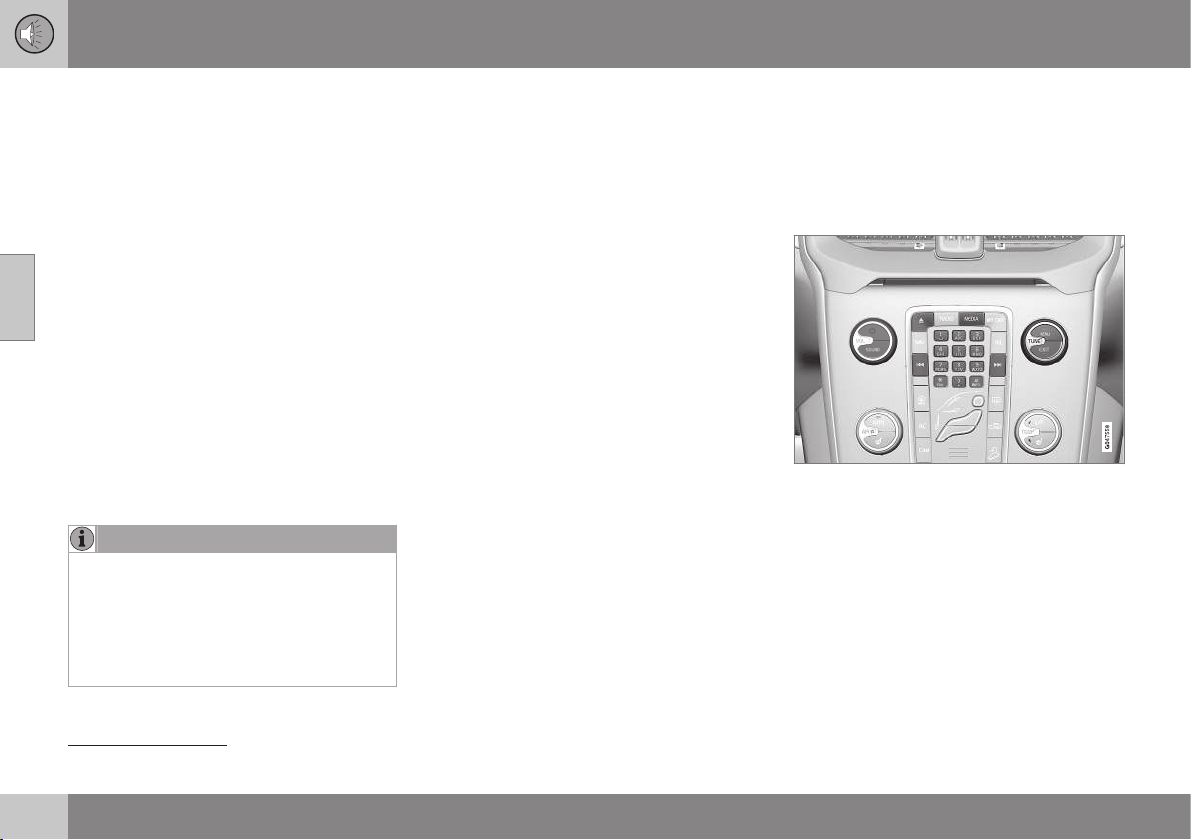
11 Audio and media
11
398
* Option/accessory, for more information, see Introduction.
Setting the audio volume for external
audio source
Set the volume for external audio player. If the
volume is too high or too low then the quality
of the sound may deteriorate.
If an external audio source (e.g. an MP3
player or iPod
®
) is connected to the AUX
input then the audio source that is connected
can have a different volume than the audio
system's internal volume (e.g. radio). Correct
this by adjusting the volume of the input:
1. Press the MEDIA button and turn TUNE
to
AUX and wait a few seconds or press
OK/MENU.
2. Press OK/MENU and then turn TUNE to
AUX input volume. Confirm with OK/
MENU.
3. Turn TUNE to adjust the volume for the
AUX input.
NOTE
If the external audio source's volume is too
high or too low, the quality of the sound
may deteriorate. The audio quality may
also be impaired if the player is charged
while the infotainment system is in AUX
mode. In which case, avoid charging the
player via the 12 V socket.
Related information
•
Audio and media - advanced audio set-
tings (p. 377)
•
Audio and media - menu navigation (p.
374)
Media Bluetooth
®
*
The car's media player (p. 390) is equipped
with Bluetooth
®
31
and can wirelessly play
streaming audio files from external devices
with Bluetooth
®
, such as mobile phones and
PDAs.
Media Bluetooth
®
functions, controls overview.
The device must first be registered and con-
nected to the car (p. 400).
Navigation and control of the audio can be
carried out via the centre console buttons or
via the steering wheel keypad*. In some
external devices it is also possible to change
tracks from the device.
To play back the audio the car's media player
must first be set in
Bluetooth mode.
31
Applies to High Performance, High Performance Multimedia and Premium Sound Multimedia.

11 Audio and media
11
* Option/accessory, for more information, see Introduction.
399
When a mobile phone is connected to the
car, it is also possible to remotely control a
selection of the mobile phone's functions, see
Bluetooth
®
handsfree phone (p. 403). Switch
between the main sources TEL and MEDIA
to operate each one's functions.
NOTE
The Bluetooth
®
media player must support
the Audio/Video Remote Control Profile
(AVRCP) and Advanced Audio Distribution
Profile (A2DP). The player should use
AVRCP version 1.3, A2DP 1.2. Otherwise
some functions may not work.
Not all mobile phones and external media
players available in the market are fully
compatible with the Bluetooth
®
function in
the car's media player. Volvo recommends
that you contact an authorised Volvo
dealer or visit www.volvocars.com for
information on compatible phones and
external media players.
NOTE
The car's media player can only play the
audio files via the Bluetooth
®
function.
Related information
•
Audio and media - operating the system
(p. 372)
•
Connecting and disconnecting a
Bluetooth
®
* device (p. 399)
•
Scan disc track or audio file (p. 421)
•
Random selection of disc track or audio
file (p. 392)
Connecting and disconnecting a
Bluetooth
®
* device
The car is equipped with Bluetooth
®
32
and
can wirelessly communicate with other
Bluetooth
®
devices after registration and con-
nection (p. 400).
A maximum of ten Bluetooth
®
devices can be
registered. Registration is performed once
per device. After registration the device no
longer needs to be activated as visible/
searchable.
When the Bluetooth
®
function is active and
the last device connected is in range it is con-
nected automatically to the car. When the car
searches for the last device connected its
name is shown in the display screen. To con-
nect to another device, press EXIT and select
change device (p. 402).
When the Bluetooth
®
device is out of range of
the car it is automatically disconnected. It is
also possible to manually disconnect (p. 402)
a device. If you want to deregister a
Bluetooth
®
device from the car, select
Removing a Bluetooth
®
* device (p. 403). The
car will then not locate the device automati-
cally.
It is possible to have two Bluetooth
®
devices
connected simultaneously. One phone and
one media device, which it is possible to
switch between (p. 402). It is also possible to
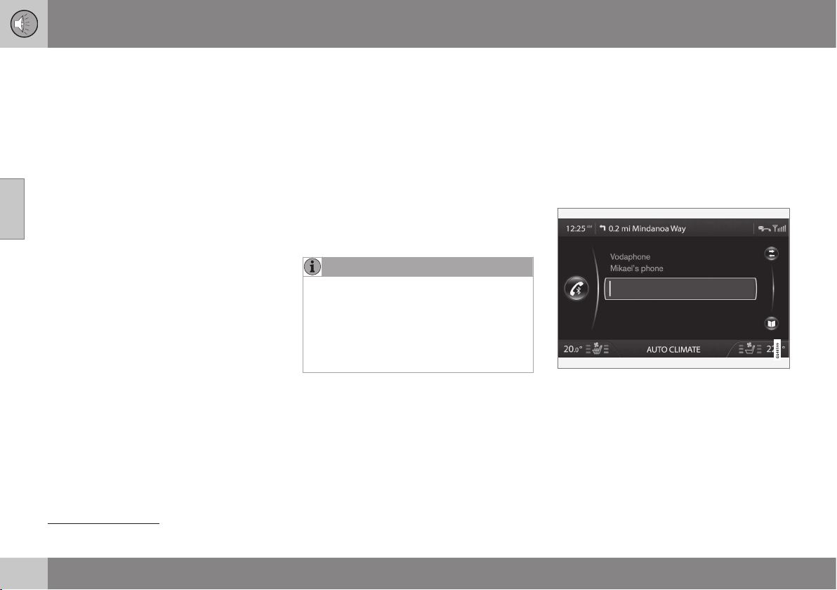
||
11 Audio and media
11
400
* Option/accessory, for more information, see Introduction.
call with the phone and simultaneously
stream audio files.
Related information
•
Audio and media - operating the system
(p. 372)
•
Media Bluetooth
®
* (p. 398)
•
Bluetooth
®
handsfree phone (p. 403)
Registering a Bluetooth
®
* device
It is possible to have two Bluetooth
®
devices
connected simultaneously. One phone and
one media device, which it is possible to
switch between. It is also possible to call with
the phone and simultaneously stream audio
files.
A maximum of ten Bluetooth
®
devices can be
registered. Registration is performed once
per device. After registration the device no
longer needs to be activated as visible/
searchable.
NOTE
If the phone's operating system is updated
then it is possible that the registration of
the phone is interrupted. In which case,
disconnect the phone, see Removing a
Bluetooth
®
* device (p. 403) and then
reconnect it, see Registering a Bluetooth
®
*
device (p. 400).
Connecting an external device takes place in
different ways depending on whether or not
the device has been connected previously.
The connection options below presume that
this is the first time the device is being con-
nected (registered) and that no other device is
connected. The connection options show the
connection of a phone. Connecting a media
device (p. 398) is performed in the same way
although it starts from the main source
MEDIA.
There are two possible ways of connecting
devices, either search for the external device
from the car, or search for the car from the
external device. If one option does not work
then try with the other.
If you are not already in the normal view for
the phone, press TEL in the centre console.
Example of normal view for phone.
Alternative 1 - search for the external
device via the car's menu system
1. Make the external device searchable/visi-
ble via Bluetooth
®
, see the external devi-
ce's manual or www.volvocars.com.
32
Applies to High Performance, High Performance Multimedia and Premium Sound Multimedia.

11 Audio and media
11
* Option/accessory, for more information, see Introduction.
401
2. Press OK/MENU and follow the instruc-
tions on the display screen.
> The external device is now connected
to the car and can be controlled from
the car.
If connection failed, press EXIT twice and
connect the device as described under Alter-
native 2.
Alternative 2 - Search for the car with
the Bluetooth
®
function of the external
device.
1. Make the car searchable/visible via
Bluetooth
®
. Turn TUNE to
Phone
settings
, confirm with OK/MENU, select
Discoverable and confirm with OK/
MENU.
2.
Select
My Volvo Car on the screen of the
external device and follow the instruc-
tions.
3. Enter a PIN code in the external device
and then select to connect.
4. Press OK/MENU and enter the same PIN
code via the car keypad in the centre
console.
Once the external device is connected, its
Bluetooth
®
name appears on the car's display
screen and the unit can be controlled from
the car.
Related information
•
Audio and media - operating the system
(p. 372)
•
Connecting and disconnecting a
Bluetooth
®
* device (p. 399)
Automatic connection of Bluetooth
®
*
device
When a Bluetooth
®
device is registered (p.
400) in the car the last external device con-
nected is connected automatically when it is
within range.
When the Bluetooth
®
function is active and
the last device connected is in range it is con-
nected automatically. When the car searches
for the last device connected its name is
shown in the display screen. If the last con-
nected device is not available then the sys-
tem will try to connect an earlier device.
To connect to another device, press EXIT,
select to connect a new device (p. 400) or
change to another already registered device
(p. 402).
Related information
•
Audio and media - operating the system
(p. 372)
•
Connecting and disconnecting a
Bluetooth
®
* device (p. 399)

11 Audio and media
11
402
* Option/accessory, for more information, see Introduction.
Changing to another Bluetooth
®
*
device
It is possible to change from a connected
device to another one if there are several
devices in the car. The device must first have
been registered (p. 402)) to the car.
Changing media device
1. Check that the external device is search-
able/visible via Bluetooth
®
, see the man-
ual for the external device.
2.
Press MEDIA, select
Bluetooth and then
Change device.
> The car searches for previously con-
nected devices. The external devices
detected are specified with their
respective Bluetooth
®
name in the dis-
play screen.
3. Select the device to be connected.
> Connection of the external device
takes place.
Changing phone
1. Check that the external device is search-
able/visible via Bluetooth
®
, see the man-
ual for the external device.
2.
Press TEL and then select
Change
phone.
> The car searches for previously con-
nected devices. The external devices
detected are specified with their
respective Bluetooth
®
name in the dis-
play screen.
3. Select the device to be connected.
> Connection of the external device
takes place.
Related information
•
Audio and media - operating the system
(p. 372)
•
Connecting and disconnecting a
Bluetooth
®
* device (p. 399)
Disconnecting the Bluetooth
®
* device
When the Bluetooth
®
device is out of range of
the car it is automatically disconnected. It is
also possible to disconnect a phone manually.
When the mobile phone has been discon-
nected an ongoing call can be continued by
using the mobile phone's built-in microphone
and speaker.
The handsfree function is deactivated when
the engine is switched off and the door is
opened
33
.
If you want to deregister a Bluetooth
®
device
from the car, select Remove Bluetooth®
device (p. 403). The car will then not locate
the device automatically.
Manual disconnection of phone
The phone can be manually disconnected in
phone mode under
Phone menu
Disconnect phone.
NOTE
Even when your mobile phone has been
manually disconnected, some mobile
phones may automatically couple up to
the last handsfree unit connected, e.g.
when a new call begins.
33
Only Keyless Drive.
11 Audio and media
11
* Option/accessory, for more information, see Introduction.
403
Related information
•
Audio and media - operating the system
(p. 372)
•
Connecting and disconnecting a
Bluetooth
®
* device (p. 399)
•
Media Bluetooth
®
* (p. 398)
•
Bluetooth
®
handsfree phone (p. 403)
Removing a Bluetooth
®
* device
If you do not want a Bluetooth
®
* device regis-
tered to the car any longer then it is possible
to remove (deregister) it from the car. The car
will then not locate the device automatically.
Removing a media device
Press MEDIA, select Bluetooth Remove
Bluetooth device
.
Removing a phone
Press TEL, select Phone menu Remove
Bluetooth device
.
Related information
•
Audio and media - operating the system
(p. 372)
•
Connecting and disconnecting a
Bluetooth
®
* device (p. 399)
•
Media Bluetooth
®
* (p. 398)
•
Bluetooth
®
handsfree phone (p. 403)
Bluetooth
®
handsfree phone
A mobile phone equipped with Bluetooth
®
can be connected wirelessly to the car
34
.
The device must first be registered and con-
nected to the car (p. 400).
The audio and media system works as
handsfree, with the option to remote control a
selection of the mobile phone's functions via
the centre console buttons or via the steering
wheel keypad*. The mobile phone can be
operated by its own keys irrespective of
whether or not it is connected.
When another Bluetooth
®
device is con-
nected to the car, it is also possible to use
the media device, see Media Bluetooth
®
* (p.
398). Switch between the main sources TEL
and MEDIA to operate each one's functions.
NOTE
Only a selection of mobile phones are fully
compatible with the handsfree function.
Volvo recommends that you seek assis-
tance from an authorised Volvo dealer for
information on compatible phones.
Activate
A short press on TEL activates/searches last
connected phone. If a phone is already con-
nected, and TEL is pressed, a shortcut menu
is shown with commonly used menu options
34
Applies to High Performance, High Performance Multimedia and Premium Sound Multimedia.
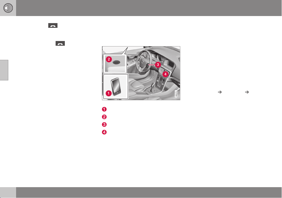
||
11 Audio and media
11
404
* Option/accessory, for more information, see Introduction.
for the phone. The symbol indicates
that a phone is connected.
To call
1.
Make sure that the
symbol appears
at the top of the display screen and that
the handsfree function is in phone mode.
2. Dial either the desired number or the
speed dial number (p. 411). Or in normal
view turn TUNE to the right to access the
phone book, and to the left for the call
register for all calls. For information on
the phone book, see Phone book (p.
406).
3. Press OK/MENU.
The call is interrupted with EXIT.
Related information
•
Audio and media - operating the system
(p. 372)
•
Bluetooth
®
* handsfree phone - overview
(p. 404)
•
Connecting and disconnecting a
Bluetooth
®
* device (p. 399)
•
Making and receiving calls (p. 404)
•
Bluetooth
®
handsfree phone - audio set-
tings (p. 405)
•
Bluetooth
®
version information (p. 406)
Bluetooth
®
* handsfree phone -
overview
System overview for Bluetooth
®
* handsfree
phone.
System overview
Mobile phone
Microphone
Steering wheel keypad
Control panel in centre console
Related information
•
Audio and media - operating the system
(p. 372)
•
Bluetooth
®
handsfree phone (p. 403)
•
Connecting and disconnecting a
Bluetooth
®
* device (p. 399)
Making and receiving calls
Making and receiving calls and functions for
making and receiving calls.
Incoming call
– Press OK/MENU to answer the call, even
if the audio system is in e.g.
RADIO or
MEDIA mode.
Refuse or end with EXIT.
Automatic answer
The automatic answer function means that
calls are accepted automatically.
– Activate/deactivate in phone mode under
Phone menu Call options Auto
answer
.
In call menu
Press OK/MENU during an ongoing call to
access the following functions:
•
Mute - audio system microphone is
muted.
•
Mobile phone - the call is transferred
from handsfree to the mobile phone. For
some mobile phones the connection is
interrupted. This is normal. The handsfree
function asks if you want to reconnect.
•
Dial number - option to call a third party
using the number keys (current call set in
standby).
11 Audio and media
11
* Option/accessory, for more information, see Introduction.
405
Call lists
The call lists are copied to the handsfree
function at each new connection and are then
updated during the connection. In normal
view, turn to the left with TUNE to see the call
register for
All calls .
In phone mode it is possible to see all the call
lists under
Phone menu All calls:
•
All calls
•
Missed calls
•
Answered calls
•
Dialled calls
•
Call duration
NOTE
Certain mobile phones show a list of the
last dialled numbers in reverse order.
Voice mailbox
In normal view a speed dial number for the
voice mailbox can be programmed in and
then accessed later via a long press on 1.
Voice mailbox number is changed in phone
mode under
Phone menu Call options
Voicemail number Change number. If
there is no number stored then this menu can
be reached with one long press on 1.
Related information
•
Audio and media - operating the system
(p. 372)
•
Voice recognition* control of a mobile
phone - dialling a contact (p. 418)
•
Voice recognition* control of a mobile
phone - dialling from the call register (p.
418)
•
Voice recognition* control of a mobile
phone - calling the voice mailbox (p. 418)
•
Bluetooth
®
handsfree phone (p. 403)
•
Bluetooth
®
handsfree phone - audio set-
tings (p. 405)
•
Phone book (p. 406)
Bluetooth
®
handsfree phone - audio
settings
It is possible to adjust the call volume, audio
system volume and ring signal volume, and
change the ring tone.
Phone call volume
The phone call volume can only be changed
during a call. Use the steering wheel keypad*
or turn the VOL control.
Audio system volume
Providing there is no ongoing call taking
place, the audio system volume is controlled
as usual by turning VOL.
If an audio source is active during an incom-
ing call then it can be muted automatically.
Activate/deactivate in phone mode under
Phone menu Phone settings Sounds
and volume
Mute radio/media.
Ring volume
In phone mode go to Phone menu Phone
settings
Sounds and volume Ring
volume
and adjust by turning VOL. Press
OK/MENU to hear the audio volume. Press
EXIT to save.
Ring signals
The handsfree function has integrated ring
signals that can be selected in phone mode
under
Phone menu Phone settings
||
11 Audio and media
11
406
* Option/accessory, for more information, see Introduction.
Sounds and volume Ring signals Ring
signal 1
etc.
NOTE
For some mobile phones, the ringtone on
the phone connected will not be switched
off when one of the inbuilt signals for the
handsfree system is used.
In order to select the connected phone's ring
signal
35
, go in phone mode to
Phone menu
Phone settings Sounds and volume
Ring signals Mobile phone ring
signal
.
Related information
•
Audio and media - operating the system
(p. 372)
•
Bluetooth
®
handsfree phone (p. 403)
Bluetooth
®
version information
Show the car's current Bluetooth
®
version.
The car's current Bluetooth
®
version can be
seen in Bluetooth mode under
Bluetooth
menu
Bluetooth software version in car.
Related information
•
Audio and media - operating the system
(p. 372)
•
Bluetooth
®
handsfree phone (p. 403)
•
Media Bluetooth
®
* (p. 398)
Phone book
There are two phone books. These are
merged into one in the car and are displayed
as a single phone book in the car.
•
The car downloads the mobile phone's
phone book and only displays this phone
book when the mobile phone from which
this phone book was downloaded is con-
nected.
•
The car also has a built-in phone book.
This contains all the contacts stored in
the car irrespective of which phone was
connected when saving them. These con-
tacts are visible for all users, regardless of
the mobile phone that is connected to the
car. If a contact is saved in the car then
the symbol
is shown in front of the
contact in the phone book.
NOTE
Changes made from the car to a record in
the mobile phone's telephone book will
result in a new record in the car's tele-
phone book, i.e. changes will not be saved
to the phone. From the car, this will now
look like you have double records, with dif-
ferent icons. Note also that when a short-
cut number is saved or a change to a con-
tact is made, this will result in a new
record in the car's phone book.
35
Not supported by all mobile phones.

11 Audio and media
11
407
All use of the phone book requires that the
symbol appears at the top of the dis-
play screen and that the handsfree function is
in phone mode.
The audio and media system stores a copy of
each registered mobile phone's phone book.
The phone book can be copied automatically
to the audio and media system during each
connection.
– Activate/deactivate the function in phone
mode under
Phone menu Phone
settings
Download phone book.
If the phone book contains a ringing caller's
contact information then this is shown in the
display screen.
Related information
•
Audio and media - operating the system
(p. 372)
•
Bluetooth
®
handsfree phone (p. 403)
•
Phone book - quick search for contacts
(p. 407)
•
Phone book - character table keypad in
centre console (p. 408)
•
Phone book - searching for contacts (p.
409)
•
Phone book - new contact (p. 410)
•
Phone book - speed dial numbers (p.
411)
•
Phone book - receiving a vCard (p. 412)
•
Phone book - memory status (p. 412)
•
Phone book - clearing (p. 412)
Phone book - quick search for
contacts
In normal view turn TUNE to the right to show
a list of contacts.
Turn TUNE to select and press OK/MENU to
call.
Under the name of the contact is the phone
number that is selected by default. If the sym-
bol > appears to the right of the contact then
there are several phone numbers stored for
the contact. Press OK/MENU to show the
numbers. Change and dial a number other
than that selected by default by turning
TUNE. Press OK/MENU to dial.
Search the list of contacts via the centre con-
sole's keypad, enter the start of the contact's
name, see Character table keypad in centre
console (p. 408) for the function of the but-
tons.
The list of contacts can also be accessed
from normal view by pressing and holding the
button on the centre console's keypad with
the letter that the contact searched for starts
with. For example, a long press on the button
for 6 gives instant access to that part of the
list where the contacts with the letter
M are
located.
Related information
•
Audio and media - operating the system
(p. 372)
•
Bluetooth
®
handsfree phone (p. 403)
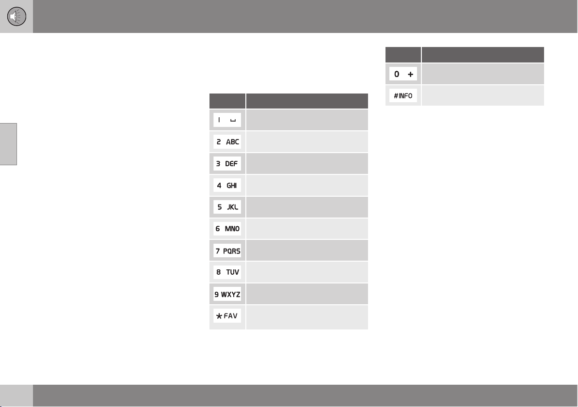
11 Audio and media
11
408
•
Phone book (p. 406)
•
Phone book - character table keypad in
centre console (p. 408)
•
Phone book - searching for contacts (p.
409)
•
Phone book - new contact (p. 410)
•
Phone book - speed dial numbers (p.
411)
•
Phone book - receiving a vCard (p. 412)
•
Phone book - memory status (p. 412)
•
Phone book - clearing (p. 412)
Phone book - character table keypad
in centre console
Character table of possible characters for use
in the phone book.
Key Function
Space . , - ? @ : ; / ( ) 1
A B C Å Ä Æ À Ç 2
D E F È Δ 3
G H I Ì 4
J K L 5
M N O Κ Ø Ñ Ò 6
P Q R S Τ 7
T U V Ü Ù 8
W X Y Z 9
Shift between upper and lower
case letter.
Key Function
+ 0 p w
# *
Related information
•
Audio and media - operating the system
(p. 372)
•
Bluetooth
®
handsfree phone (p. 403)
•
Phone book - quick search for contacts
(p. 407)
•
Phone book (p. 406)
•
Phone book - searching for contacts (p.
409)
•
Phone book - new contact (p. 410)
•
Phone book - speed dial numbers (p.
411)
•
Phone book - receiving a vCard (p. 412)
•
Phone book - memory status (p. 412)
•
Phone book - clearing (p. 412)
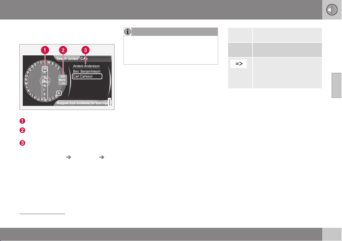
11 Audio and media
11
}}
409
Phone book - searching for contacts
Searching for contacts in the phone book.
Search contacts using the text wheel.
Character list
Changing the input mode (see table
below)
Phone book
To search for or edit a contact, go in phone
mode to
Phone menu Phone book
Search.
NOTE
There is no text wheel for High Perform-
ance, so TUNE cannot be used there to
input characters: only the digit and letter
buttons on the control panel in the centre
console can be used for this.
1.
Turn
36
TUNE to the desired letter, press
OK/MENU to confirm. The number and
letter buttons on the control panel in the
centre console can also be used.
2. Continue with the next letter and so on.
The result of the search is shown in the
phone book (3).
3. To change the input mode to numbers or
special characters, or to go to the phone
book, turn TUNE to one of the options
(see explanation in the table below) in the
list for changing the input mode (2), press
OK/MENU.
123/ABC
Change between letters and
numbers with OK/MENU.
More
Change to special characters
with OK/MENU.
Leads to the phone book (3).
Turn TUNE to select a contact,
press OK/MENU to see the
saved numbers and other
information.
A short press on EXIT deletes an input char-
acter. A long press on EXIT will clear all
entered characters.
By pressing a number key in the centre con-
sole when the text wheel is shown (see illus-
tration above), a new character list (1)
appears in the display screen. Continue
repeatedly pressing the number key to the
desired letter and then release. Continue with
the next letter and so on. When a button is
depressed the entry is confirmed when
another button is depressed.
To enter a number, hold in the corresponding
number key.
Related information
•
Audio and media - operating the system
(p. 372)
•
Bluetooth
®
handsfree phone (p. 403)
36
Only applies to High Performance Multimedia and Premium Sound Multimedia.
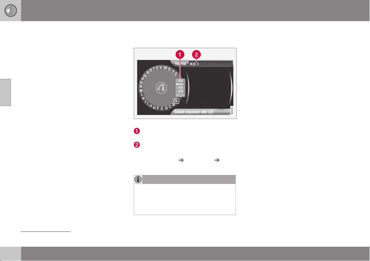
11 Audio and media
11
410
•
Phone book (p. 406)
•
Phone book - character table keypad in
centre console (p. 408)
•
Phone book - quick search for contacts
(p. 407)
•
Phone book - new contact (p. 410)
•
Phone book - speed dial numbers (p.
411)
•
Phone book - receiving a vCard (p. 412)
•
Phone book - memory status (p. 412)
•
Phone book - clearing (p. 412)
Phone book - new contact
Create new contact in the phone book.
Entering letters for New contact.
Changing the input mode (see table
below)
Input field
New contacts can be added in phone mode
under
Phone menu Phone book New
contact
.
NOTE
There is no text wheel for High Perform-
ance, so TUNE cannot be used there to
input characters: only the digit and letter
buttons on the control panel in the centre
console can be used for this.
1.
When the
Name row is selected, press
OK/MENU to reach the input mode (illus-
tration above).
2.
Turn
37
TUNE to the desired letter, press
OK/MENU to confirm. The number and
letter buttons on the control panel in the
centre console can also be used.
3. Continue with the next letter and so on.
The name entered is shown in the input
field (2) in the display screen.
4. To change the input mode to numbers,
special characters, change between
uppercase/lowercase letters, etc., turn
TUNE to one of the options (see explana-
tion in the table below) in the list (1) and
then press OK/MENU.
When the name has been fully entered, select
OK in the list on the display screen (1) and
press OK/MENU. Now continue with the tele-
phone number in the same way as above.
When the telephone number has been
entered, press OK/MENU and select a tele-
phone number type (
Mobile phone, Home,
Work or General). Press OK/MENU to con-
firm.
When all details have been filled in, select
Save contact in the menu to save the con-
tact.
37
Only applies to High Performance Multimedia and Premium Sound Multimedia.
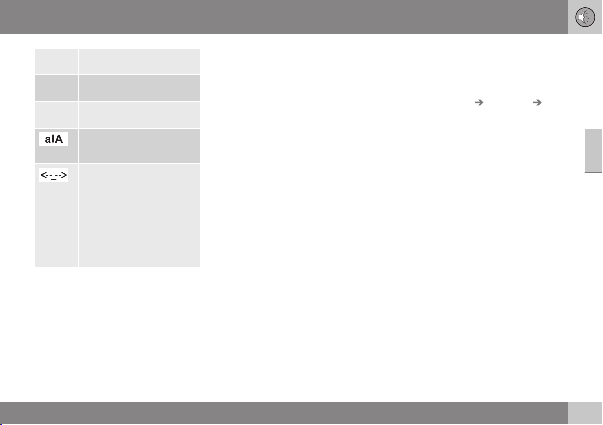
11 Audio and media
11
411
123/ABC
Change between letters and
numbers with OK/MENU.
More
Change to special characters
with OK/MENU.
OK Save and go back to Add
contact with OK/MENU.
Change between uppercase
and lowercase letters with OK/
MENU.
Press OK/MENU, the cursor
moves to the input field (2) at
the top of the display screen.
The cursor can now be moved,
with TUNE, to the appropriate
place to e.g. insert new letters
or delete with EXIT. To be able
to insert new letters first go
back to the input mode, by
pressing OK/MENU.
Related information
•
Audio and media - operating the system
(p. 372)
•
Bluetooth
®
handsfree phone (p. 403)
•
Phone book (p. 406)
•
Phone book - quick search for contacts
(p. 407)
•
Phone book - character table keypad in
centre console (p. 408)
•
Phone book - searching for contacts (p.
409)
•
Phone book - speed dial numbers (p.
411)
•
Phone book - receiving a vCard (p. 412)
•
Phone book - memory status (p. 412)
•
Phone book - clearing (p. 412)
Phone book - speed dial numbers
Store as speed dial number in order to easily
dial a number or a contact.
Use phone mode to add speed dial numbers
under
Phone menu Phone book
Speed dial.
Dialling with speed dial numbers can be per-
formed in phone mode using the number
keys on the keypad in the centre console, by
pressing a number key and then pressing
OK/MENU. If there is no contact stored on
the speed dial number then an option is
shown to save a contact to the selected
speed dial number.
Related information
•
Audio and media - operating the system
(p. 372)
•
Bluetooth
®
handsfree phone (p. 403)
•
Phone book (p. 406)
•
Phone book - quick search for contacts
(p. 407)
•
Phone book - character table keypad in
centre console (p. 408)
•
Phone book - searching for contacts (p.
409)
•
Phone book - new contact (p. 410)
•
Phone book - receiving a vCard (p. 412)
•
Phone book - memory status (p. 412)
•
Phone book - clearing (p. 412)
11 Audio and media
11
412
Phone book - receiving a vCard
Receiving electronic business cards (vCard) to
the car's phone book.
It is possible to receive a vCard to the car's
phone book from other mobile phones (other
than the one currently connected to the car).
In order to allow this the car is set to visible
mode for Bluetooth
®
. The function is acti-
vated in phone mode under Phone menu
Phone book Receive vCard.
Related information
•
Audio and media - operating the system
(p. 372)
•
Bluetooth
®
handsfree phone (p. 403)
•
Phone book (p. 406)
•
Phone book - quick search for contacts
(p. 407)
•
Phone book - character table keypad in
centre console (p. 408)
•
Phone book - searching for contacts (p.
409)
•
Phone book - new contact (p. 410)
•
Phone book - speed dial numbers (p.
411)
•
Phone book - memory status (p. 412)
•
Phone book - clearing (p. 412)
Phone book - memory status
See phone book memory status.
Memory status of the car's phone book and
the connected mobile phone's phone book
can be seen in phone mode under
Phone
menu
Phone book Memory status.
Related information
•
Audio and media - operating the system
(p. 372)
•
Bluetooth
®
handsfree phone (p. 403)
•
Phone book (p. 406)
•
Phone book - quick search for contacts
(p. 407)
•
Phone book - character table keypad in
centre console (p. 408)
•
Phone book - searching for contacts (p.
409)
•
Phone book - new contact (p. 410)
•
Phone book - speed dial numbers (p.
411)
•
Phone book - receiving a vCard (p. 412)
•
Phone book - clearing (p. 412)
Phone book - clearing
Clear the car's built-in phone book (p. 406).
The car's phone book can be deleted, this is
carried out in phone mode under
Phone
menu
Phone book Clear phone book.
NOTE
Deleting the car's telephone book only
deletes contacts in the car's telephone
book. Contacts in the mobile phone's
phone book are not deleted.
Related information
•
Audio and media - operating the system
(p. 372)
•
Bluetooth
®
handsfree phone (p. 403)
•
Phone book (p. 406)
•
Phone book - quick search for contacts
(p. 407)
•
Phone book - character table keypad in
centre console (p. 408)
•
Phone book - searching for contacts (p.
409)
•
Phone book - new contact (p. 410)
•
Phone book - speed dial numbers (p.
411)
•
Phone book - receiving a vCard (p. 412)
•
Phone book - memory status (p. 412)
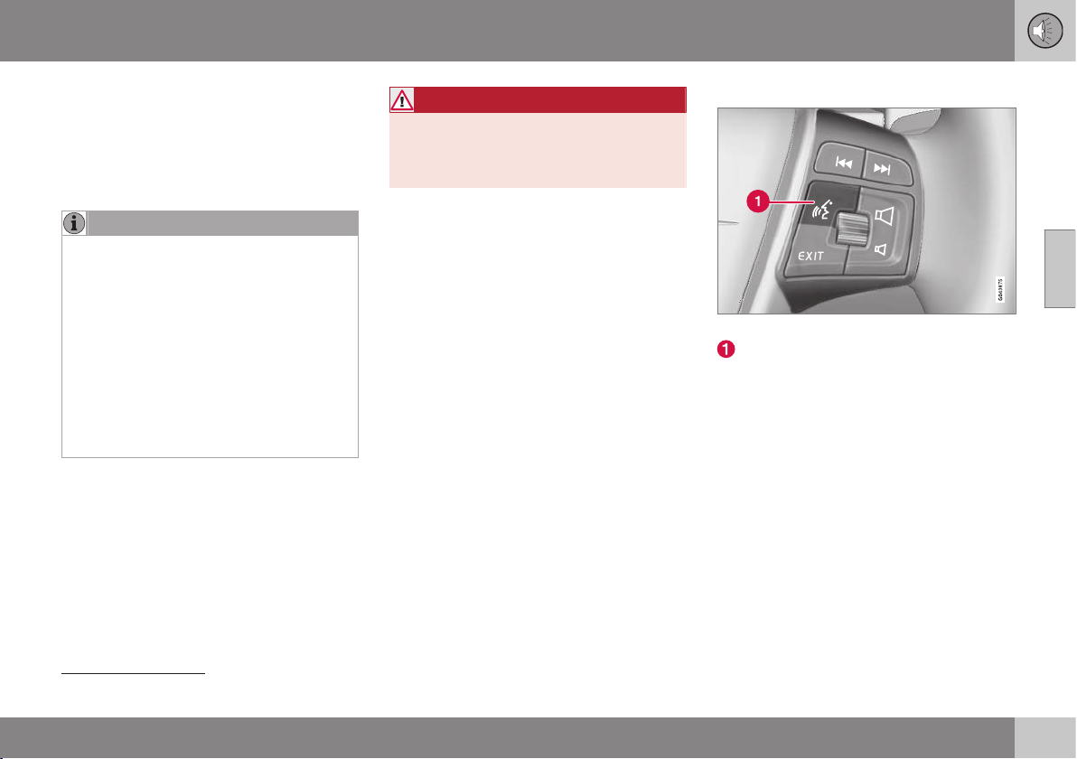
11 Audio and media
11
}}
* Option/accessory, for more information, see Introduction.
413
Voice recognition* control of a mobile
phone
Voice recognition
38
allows the driver to voice-
activate certain functions in a Bluetooth
®
-con-
nected mobile phone or in Volvo's navigation
system.
NOTE
•
The information in this section
describes the use of voice commands
to control a mobile phone connected
using Bluetooth
®
. For detailed infor-
mation on using a Bluetooth
®
-con-
nected mobile phone, see Bluetooth
®
handsfree phone (p. 403).
•
The Volvo navigation system has a
separate supplement which contains
more information on voice recognition
and voice commands to control the
system.
Voice commands offer convenience and help
the driver to avoid being distracted, and
instead concentrate on driving and focus
attention on the road and traffic conditions.
WARNING
The driver always holds overall responsibil-
ity for driving the vehicle in a safe manner
and complying with all applicable rules of
the road.
The voice recognition system allows the
driver to voice-activate certain functions of a
Bluetooth
®
-connected mobile phone and in
Volvo's navigation system, while the driver
can keep his/her hands on the wheel at the
same time. The input data are in dialogue
form with spoken commands from the user
and verbal replies from the system. The voice
recognition system uses the same micro-
phone as the Bluetooth
®
handsfree system
(see Bluetooth
®
* handsfree phone - overview
(p. 404)) and the voice recognition system's
replies come via the car's speakers.
Getting started with voice recognition
Steering wheel keypad.
Button for voice recognition
Before voice commands to a mobile phone
can be used the mobile phone must be
paired and connected via Bluetooth
®
hands-
free. If a telephone command is given and no
mobile phone is paired, then the system will
provide information about this. For informa-
tion on pairing and connecting a mobile
phone, see Registering a Bluetooth
®
* device
(p. 400).
•
Press the button for voice recognition (1)
in order to activate the system and initiate
a dialogue with voice commands. The
system will then display commonly used
commands in the display screen in the
centre console.
38
Only applies to vehicles equipped with Volvo's navigation system.
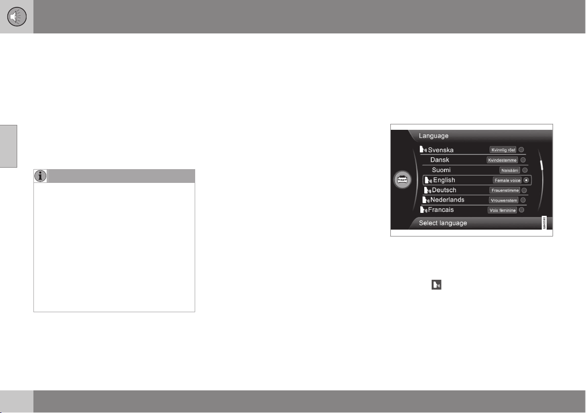
||
11 Audio and media
11
414
* Option/accessory, for more information, see Introduction.
Keep the following things in mind when you
use the voice recognition system:
•
For a command - speak after the tone,
with normal voice at normal speed.
•
Do not speak while the system is replying
(the system cannot understand com-
mands during this time).
•
The car's doors and windows must be
closed.
•
Avoid background noise in the passenger
compartment.
NOTE
If the driver is unsure of which command
to use, he (she) can say "Help" - the sys-
tem then responds with a few different
commands which can be used in the cur-
rent situation.
Voice commands can be disabled by:
•
saying "Cancel"
•
not speaking
•
a long press on the steering wheel but-
ton for Voice recognition
•
Press EXIT or another main source
button (e.g. MEDIA).
Related information
•
Audio and media - operating the system
(p. 372)
•
Bluetooth
®
* handsfree phone - overview
(p. 404)
•
Connecting and disconnecting a
Bluetooth
®
* device (p. 399)
•
Language options for voice recognition*
control of a mobile phone (p. 414)
•
Help functions for voice recognition* con-
trol of a mobile phone (p. 415)
•
Voice recognition* control of a mobile
phone - user setting and voice volume (p.
416)
•
Voice recognition* control of a mobile
phone - voice commands (p. 416)
Language options for voice
recognition* control of a mobile
phone
Possible language options for voice recogni-
tion* control of a mobile phone are selected in
the menu system for MY CAR, see MY CAR -
Voice settings (p. 112).
Language list.
Voice recognition is not possible for all lan-
guages. Languages available for voice recog-
nition are marked with an icon in the lan-
guage list -
. Changing the language is per-
formed in the menu system MY CAR, see MY
CAR (p. 104).
11 Audio and media
11
* Option/accessory, for more information, see Introduction.
415
Related information
•
Audio and media - operating the system
(p. 372)
•
Voice recognition* control of a mobile
phone (p. 413)
•
MY CAR - Voice settings (p. 112)
Help functions for voice recognition*
control of a mobile phone
Help functions are available to help you
become familiar with the system and the
facility to teach the voice recognition system
your voice and your accent.
•
Instructions: A function that helps you
become familiar with the system and the
procedure for giving commands.
•
Voice training: A function that enables
the voice recognition system to learn to
know your voice and your accent. The
function provides an opportunity to voice
train two user profiles.
The help functions can be accessed by
pressing the MY CAR button on the control
panel in the centre console and then turning
TUNE to the desired menu option.
Instructions
The instructions can be started in two ways:
NOTE
This instruction and voice training can only
be started when the car is parked.
•
Press the button for voice recognition (p.
372) and say "Voice tutorial".
•
Activate the instructions in the menu sys-
tem MY CAR under
Settings Voice
settings Voice tutorial. For a descrip-
tion of the menu system, see MY CAR (p.
104).
The instructions are divided into 3 lessons,
which take around 5 minutes in total to com-
plete. The system starts with the first lesson.
To skip a lesson and go to the next one,
press the button for voice recognition and say
"Next". Go back to the previous lesson by
saying "Previous".
Exit the instructions by means of a long press
on the button for voice recognition.
Voice training
The system displays up to fifteen phrases for
you to say. Voice training can be started in
the menu system MY CAR under
Settings
Voice settings Voice training. Select
between
User 1 or User 2. For a description
of the menu system, see MY CAR (p. 104).
After voice training has been completed,
remember to set your user profile under
Voice user setting.
Related information
•
Audio and media - operating the system
(p. 372)
•
Voice recognition* control of a mobile
phone (p. 413)

11 Audio and media
11
416
* Option/accessory, for more information, see Introduction.
Voice recognition* control of a mobile
phone - user setting and voice volume
User profile and voice volume can be set in
the MY CAR menu system.
•
User setting - Two user profiles can be
set, the function is activated in the menu
system MY CAR under
Settings Voice
settings
Voice user setting. Select
between
User 1 or User 2. For a descrip-
tion of the menu system, see MY CAR (p.
104).
•
Voice output volume - Can be changed
in the menu system MY CAR under
Settings Voice settings Voice
output volume
. For a description of the
menu system, see MY CAR (p. 104).
Related information
•
Audio and media - operating the system
(p. 372)
•
Voice recognition* control of a mobile
phone (p. 413)
Voice recognition* control of a mobile
phone - voice commands
It is possible to use voice recognition to con-
trol the mobile phone with predefined voice
commands.
The driver initiates a dialogue with voice com-
mands by pressing the button for voice rec-
ognition (p. 413).
Once a dialogue has been started, commonly
used commands will be shown in the display
screen. Greyed-out text or text within brack-
ets is not included in the spoken command.
When the driver becomes accustomed to the
system, he/she can speed up the command
dialogue and skip the prompts from the sys-
tem, by briefly pressing the button for voice
recognition.
Commands can be given in several
ways
The command "Phone call contact" can be
pronounced as e.g.:
•
"Phone > Call contact" - Say "Phone",
wait for the system's reply, and then con-
tinue by saying "Call contact."
or
•
"Phone call contact" - Say the whole
command in one sequence.
Related information
•
Audio and media - operating the system
(p. 372)
•
Voice recognition* control of a mobile
phone (p. 413)
•
Voice recognition* control of a mobile
phone - quick commands (p. 417)
•
Voice guidance* control of a mobile
phone - dialling a number (p. 417)
•
Voice recognition* control of a mobile
phone - dialling from the call register (p.
418)
•
Voice recognition* control of a mobile
phone - dialling a contact (p. 418)
•
Voice recognition* control of a mobile
phone - calling the voice mailbox (p. 418)

11 Audio and media
11
* Option/accessory, for more information, see Introduction.
417
Voice recognition* control of a mobile
phone - quick commands
Voice recognition* control of a mobile phone
can be performed with a number of prede-
fined quick commands.
Quick commands for the phone can be found
in the menu system MY CAR under
Settings
Voice settings Voice command list
Phone commands and General
commands. For a description of the menu
system, see MY CAR (p. 104).
Related information
•
Audio and media - operating the system
(p. 372)
•
Voice recognition* control of a mobile
phone - voice commands (p. 416)
Voice guidance* control of a mobile
phone - dialling a number
How to describe a number to control a mobile
phone using voice recognition.
The system understands the numbers 0 (zero)
to 9 (nine). These numbers can be pro-
nounced individually, in groups of several
numbers at a time, or the whole number all at
once. Numbers greater than 9 (nine) cannot
be handled by the system, e.g. 10 (ten) or 11
(eleven) are not possible.
The following is an example of a dialogue
with voice commands. The system's reply will
vary depending on the situation.
The user starts the dialogue by saying:
Phone > call number
or
Phone call number
System reply
Number?
User action
Start saying the numbers (as individual units,
i.e. six-eight-seven, etc.) in the phone num-
ber. If you say several numbers and pause,
the system will repeat them, and then say
"Continue".
Continue to say the numbers. When finished,
finish the command by saying "Call".
•
You can also change the number by say-
ing the commands "Correct" (which dele-
tes the last spoken group of numbers) or
"Delete" (which deletes the whole spoken
phone number).
Related information
•
Audio and media - operating the system
(p. 372)
•
Voice recognition* control of a mobile
phone - voice commands (p. 416)

11 Audio and media
11
418
* Option/accessory, for more information, see Introduction.
Voice recognition* control of a mobile
phone - dialling from the call register
Use voice recognition with the mobile phone
to dial from the call register.
The following dialogue allows you to make a
phone call from one of your mobile phone's
call registers.
The user starts the dialogue by saying:
Phone > call from the call register
or
Phone call from the call register
Continue by responding to the system's
prompts.
Related information
•
Audio and media - operating the system
(p. 372)
•
Voice recognition* control of a mobile
phone - voice commands (p. 416)
Voice recognition* control of a mobile
phone - dialling a contact
Use voice recognition with the mobile phone
to dial a contact.
The following dialogue allows you to call your
pre-defined contacts in the mobile phone.
The user starts the dialogue by saying:
Phone > call contact
or
Phone call contact
Continue by responding to the system's
prompts.
Consider the following when you call a con-
tact:
•
If there are several contacts with similar
names, they will be presented in the
screen in the numbered rows and the
system prompts you to select a row num-
ber.
•
If there are more rows in the list than can
be displayed simultaneously, saying
"Down" allows you to scroll down in the
list (and saying "Up" allows you to scroll
up in the list).
Related information
•
Audio and media - operating the system
(p. 372)
•
Voice recognition* control of a mobile
phone - voice commands (p. 416)
Voice recognition* control of a mobile
phone - calling the voice mailbox
Use voice recognition with a mobile phone to
call the voice mailbox.
The following dialogue allows you to call your
voice mailbox to check if you have received
any messages. The phone number for your
voice mailbox must be registered in the
Bluetooth
®
function, see Making and receiv-
ing calls (p. 404).
The user starts the dialogue by saying:
Phone > call voice mailbox
or
Phone call voice mailbox
Continue by responding to the system's
prompts.
Related information
•
Audio and media - operating the system
(p. 372)
•
Voice recognition* control of a mobile
phone - voice commands (p. 416)
11 Audio and media
11
* Option/accessory, for more information, see Introduction.
419
Save as favourite
Save frequently used functions as favourites.
The function can then be started easily by
pressing the FAVbutton.
To save a function as a favourite:
1. Select a main source (e.g. RADIO,
MEDIA).
2.
Select a wavelength or source (
AM, Disc,
etc.).
3. Press and hold the FAV button until the
"favourites menu" is shown.
4. Turn TUNE to select an option from the
list and press OK/MENU to save.
> When the main source (e.g. RADIO,
MEDIA) is active the stored function is
available via a short press on FAV.
Related information
•
Favourites (p. 376)
Playback and navigation of CD/DVD*
disc
For basic playback and navigation, see Audio
and media - operating the system (p. 372).
See below for a more detailed description.
Starting playback of a disc
Press the MEDIA button, turn TUNE until
Disc is displayed, press OK/MENU. If there
is a disc in the media player then the disc
starts playing back automatically, otherwise
Insert disc is shown in the display screen.
Then insert a disc, with text side up. The disc
starts to play back automatically.
If a disc with audio/video files is inserted into
the player then the disc's folder structure
needs to be loaded. Depending on the quality
of the disc and the quantity of information
there may be a certain delay before playback
starts.
Disc eject
Press the eject button (p. 372) to eject the
disc.
A disc remains in the ejected position for
about 12 seconds, after which it is inserted
back into the player for safety reasons.
Pause in playback (pause)
When the volume is reduced entirely or MUTE
is pressed, the media player is paused. When
the volume is increased or MUTE is pressed
again, the media player starts. It is also possi-
ble to pause via the menu system
39
, press
OK/MENU, select
Play/Pause.
NOTE
A video film is only shown when the car is
stationary. When the car is moving at a
speed of over about 8 km/h no picture is
shown and
No visual media available
while driving appears on the display
screen, although the audio is heard during
this time. The picture is shown again as
soon as the car's speed falls below about
6 km/h.
NOTE
Some audio files that are copy-protected
by record companies or privately copied
audio files cannot be loaded by the player.
Related information
•
Audio and media - operating the system
(p. 372)
•
Playback and navigation of burned discs
with audio/video files (p. 420)
•
Playback and navigation of DVD video
discs (p. 392)
•
Fast forward/reverse (p. 391)
•
Scan disc track or audio file (p. 421)
39
Does not apply to CD Audio
11 Audio and media
11
420
* Option/accessory, for more information, see Introduction.
•
Random selection of disc track or audio
file (p. 392)
•
Media player - compatible file formats (p.
394)
Playback and navigation of burned
discs with audio/video files
Playback and navigation of burned discs with
audio/video files
40
.
NOTE
A video film is only shown when the car is
stationary. When the car is moving at a
speed of over about 8 km/h no picture is
shown and
No visual media available
while driving appears on the display
screen, although the audio is heard during
this time. The picture is shown again as
soon as the car's speed falls below about
6 km/h.
NOTE
Some audio files that are copy-protected
by record companies or privately copied
audio files cannot be loaded by the player.
Audio files have the symbol , video
files
40
have the symbol
and folders
have the symbol
.
When playback of a file is complete the play-
back of the other files (of the same type) in
that particular folder continues. Change
41
of
folder takes place automatically when all the
files in the current folder have been played
back. The system automatically detects and
changes setting when a disc containing only
audio files or only video files is loaded into
the media player and then plays back these
files. However, the system does not change
setting if a disc containing a mixture of audio
and video files is loaded into the media
player, but instead the player continues to
play back the previous file type.
Repeat folder
This function makes it possible to play files in
a folder over and over again. When the last
file has been played out, playback of the first
file starts again.
1. Press OK/MENU
2.
Turn TUNE to
Repeat folder
3. Press OK/MENU to activate/deactivate
the function.
Related information
•
Audio and media - operating the system
(p. 372)
•
Playback and navigation of CD/DVD* disc
(p. 419)
•
Playback and navigation of DVD video
discs (p. 392)
•
Fast forward/reverse (p. 391)
•
Scan disc track or audio file (p. 421)
•
Random selection of disc track or audio
file (p. 392)
40
Only applies to High Performance Multimedia and Premium Sound Multimedia.
41
If Repeat folder is activated then this does not take place.
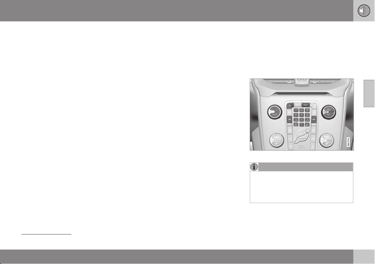
11 Audio and media
11
* Option/accessory, for more information, see Introduction.
421
•
Media player - compatible file formats (p.
394)
•
DivX
®
Video On Demand (p. 393)
Scan disc track or audio file
This function play backs the first ten seconds
of each disc track/audio file
42
.
To scan selected source:
1. Press OK/MENU
2.
Turn TUNE to
Scan
> The first 10 seconds of each disc track
or audio file are played.
3. Cancel the scan with EXIT, the disc track
or audio file being played back will con-
tinue playing.
Related information
•
Audio and media - operating the system
(p. 372)
•
Playback and navigation of CD/DVD* disc
(p. 419)
•
Playback and navigation of external audio
source (p. 396)
•
Media Bluetooth
®
* (p. 398)
TV*
The TV picture is only shown when the car is
stationary. When the car is moving at a speed
over approx. 6 km/h the picture disappears,
although the audio is heard during this time.
The picture reappears when the car has stop-
ped.
TV functions, control overview.
NOTE
This system only supports TV broadcasts
in the countries that broadcast in MPEG-2
or MPEG-4 format and follow the DVB-T
standard. The system does not support
analogue broadcasts.
42
Does not apply to DVD video discs. For externally connected audio sources via the AUX/USB input this only applies to USB and iPod
®
. Not supported by all mobile phones.

||
11 Audio and media
11
422
* Option/accessory, for more information, see Introduction.
NOTE
The TV picture is only shown when the car
is stationary. When the car is moving at a
speed over about 6 km/h the picture dis-
appears,
No visual media available
while driving appears on the display
screen, although the audio is heard during
this time. The picture reappears when the
car has stopped.
NOTE
The reception is dependent both on how
good the signal strength and signal quality
are. The transmission may be disturbed by
various factors such as tall buildings or the
TV transmitter being far away. Coverage
level can also vary depending on where in
the country you are located.
IMPORTANT
A TV licence is required for this product in
some countries.
Watch TV
–
Press MEDIA, turn TUNE until TV is
shown in the display, press OK/MENU.
> A search starts and after a short while
the most recently used channel is
shown.
Changing channel
It is possible to change channel as follows:
•
Turn TUNE, a list of all available channels
in the area is shown. If any of these chan-
nels is already saved as a preset then its
preset number is shown to the right of the
channel name. Continue turning TUNE to
reach the desired channel and press OK/
MENU.
•
By pressing the preset buttons (0-9).
•
Via a short press on the
/ but-
tons the next available channel in the area
is shown.
NOTE
If the car has been moved within the coun-
try, for example, from one city to another,
it is not certain that the presets are availa-
ble at the new location as the frequency
range may have changed. Then do another
search and save a new preset list; see
Save available TV channels as presets (p.
423).
NOTE
If no reception is available on the preset
buttons, it may be because the car is at a
location other than where the scan of TV
channels was run, for example, if the car
was driven from Germany to France. A
new selection of country and a new search
may then need to be carried out.
Related information
•
Audio and media - operating the system
(p. 372)
•
Searching TV* channels/Preset list (p.
423)
•
TV* - channel management (p. 423)
•
Information about the current TV* pro-
gramme (p. 424)
•
Teletext* (p. 424)
•
Picture settings (p. 394)
•
Reception of TV* channel is lost. (p. 425)

11 Audio and media
11
* Option/accessory, for more information, see Introduction.
423
Searching TV* channels/Preset list
After a search of TV channels the available
channels are saved in a preset list.
1. Press TV mode on OK/MENU.
2.
Turn TUNE to
TV menu and press OK/
MENU.
3.
Turn TUNE to Select country and press
OK/MENU.
> If one or more countries have previ-
ously been selected then they are
shown in a list.
4.
Turn TUNE to either
Other countries or
one of the previously selected countries.
Press OK/MENU.
> A list of all available countries is
shown.
5. Turn TUNE to the desired country (e.g.
Sweden) and press OK/MENU.
> An automatic scan for available TV
channels starts, this scan takes a little
while. During this time the figure for
each channel found and added as a
preset is shown. When the scan is
complete a message is shown and the
picture is shown. A preset list (max. 30
presets) has now been created and is
available. To change channel, see TV*
(p. 421).
The scan and preset storage can be cancel-
led with EXIT.
Related information
•
Audio and media - operating the system
(p. 372)
•
TV* (p. 421)
•
TV* - channel management (p. 423)
TV* - channel management
The preset list can be edited. You can change
the order of the channels that are shown in
the preset list. A TV channel can have more
than one place in the preset list. The TV chan-
nel positions can also vary in the preset list.
To change the order in the preset list, go in
TV mode to
TV menu Reorganise
presets
.
1. Turn TUNE to the channel you want to
move in the list and confirm with OK/
MENU.
> The selected channel is highlighted.
2. Turn TUNE to the new location in the list
and confirm with OK/MENU.
> The channels change places with each
other.
After the preset channels (max. 30) come all
the other channels available in the area. It is
possible to move a channel up to a place in
the preset list.
Save the available TV channels as
presets
If the car has been moved within the country,
for example, from one city to another, it is not
certain that the presets are available at the
new location as the frequency range may
have changed. In which case, carry out
another scan and save a new preset list.
1. Press TV mode on OK/MENU.

||
11 Audio and media
11
424
* Option/accessory, for more information, see Introduction.
2.
Turn TUNE to
TV menu and press OK/
MENU.
3.
Turn TUNE to
Autostore and press OK/
MENU.
> An automatic scan for available TV
channels starts, this scan takes a little
while. During this time the figure for
each channel found and added as a
preset is shown. When the scan is
complete a message is shown and the
picture is shown. A preset list (max. 30
presets) has now been created and is
available. To change channel, see TV*
(p. 421).
Scanning the TV channels
This function automatically scans through the
frequency range for all channels available in
the area where you are. When a channel is
found, it is shown for approx. 10 seconds
before scanning is resumed. Scanning is
stopped with EXIT, then the channel that you
just watched continues to be shown. Scan-
ning does not affect the preset list.
Activate scanning in TV mode under
TV
menu
Scan.
Related information
•
Audio and media - operating the system
(p. 372)
•
TV* (p. 421)
•
Searching TV* channels/Preset list (p.
423)
Information about the current TV*
programme
Press the INFO button (p. 372) in order to dis-
play information about the current pro-
gramme, the next programme and its start
time.
If the INFO button is pressed once more then
additional information on the current pro-
gramme can sometimes be displayed, such
as start and end times and a brief description
of the current programme.
To return to the TV picture, wait several sec-
onds or press EXIT.
Related information
•
Audio and media - operating the system
(p. 372)
•
TV* (p. 421)
Teletext*
It is possible to look at Teletext.
Proceed as follows:
1.
Press the
button on the remote
control.
2. Enter the page number (3 digits) with the
number keys (0-9) to select page.
> The page is shown automatically.
Enter new page number, or press the remote
control buttons
/ to go to the next
page.
Return to TV screen with EXIT or by pressing
the
button on the remote control.
It is also possible to control the teletext with
the coloured buttons on the remote control.
Related information
•
Audio and media - operating the system
(p. 372)
•
TV* (p. 421)
•
Remote control* (p. 425)
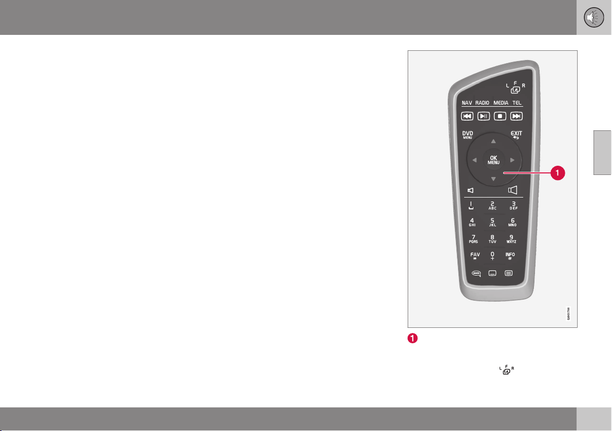
11 Audio and media
11
* Option/accessory, for more information, see Introduction.
425
Reception of TV* channel is lost.
If the reception for the TV channel that is
being shown disappears then the picture will
freeze. When the reception returns the display
starts again.
If the reception for the TV channel that is
being shown disappears then the picture will
freeze. Shortly after this a message appears
informing that the reception has been lost for
the current TV channel, and a new search for
the channel continues. When the reception
returns the display of the TV channel starts
immediately. It is possible to change channel
at any time when the message is shown.
If the message
Reception lost, searching is
shown then this is because the system has
detected that there is no reception for all TV
channels. One possible reason may be that a
border has been crossed and that the system
is set to the wrong country. In which case,
change to the right country in accordance
with Searching TV* channels/Preset list (p. (p.
423)).
Related information
•
Audio and media - operating the system
(p. 372)
•
TV* (p. 421)
Remote control*
The remote control can be used for all func-
tions in the audio and media system. The
remote control's buttons have similar func-
tions as the buttons on the centre console or
the steering wheel keypad.
Corresponds to TUNE in the centre con-
sole.
When using the remote control, first press the
remote control's button
to position F.
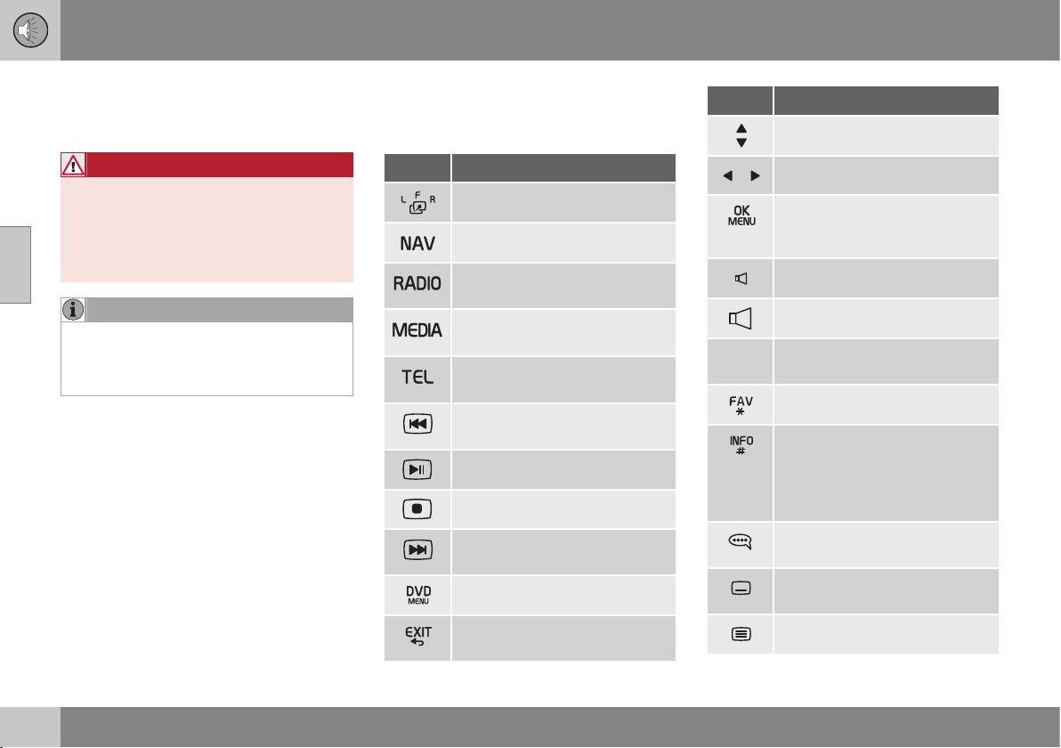
||
11 Audio and media
11
426
* Option/accessory, for more information, see Introduction.
Then aim the remote control at the IR
receiver, which is located to the right of the
INFO button (p. 372) in the centre console.
WARNING
Keep loose objects such as mobile
phones, cameras, remote controls for
accessories, etc. in the glove compartment
or other compartments. Otherwise they
may injure people in the car in the event of
sudden braking or a collision.
NOTE
Do not expose the remote control to direct
sunlight (e.g. on the instrument panel) -
otherwise problems may arise with the
batteries.
Related information
•
Audio and media - operating the system
(p. 372)
•
Remote control* - functions (p. 426)
•
Remote control* - battery replacement (p.
427)
Remote control* - functions
Possible functions to be controlled using the
remote control*.
Key Function
F = Front display screen
Change to navigation*
Change to radio source (AM,
FM1 etc.)
Change to media source (Disc,
TV* etc.)
Change to Bluetooth
®
hands-
free*
Scroll/fast rewind, change track/
song.
Play/pause
Stop
Scroll/fast forward, change
track/song
Menu
To previous, cancels function,
deletes input characters
Key Function
Navigate up/down
Navigate right/left
Confirm selection or go to the
menu system for the selected
source
Volume, decrease
Volume, increase
0-9 Preset channels, number and
letter input
Shortcuts for favourite setting
Information about the current
programme, song, etc. Also
used when there is more infor-
mation available than can be
shown in the display screen
Selection of language for sound-
track
Subtitles, selection of language
for text
Teletext*, On/Off
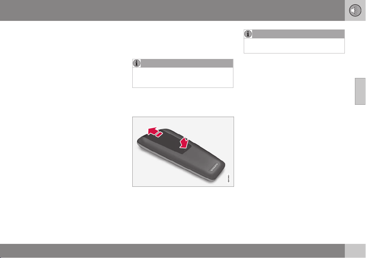
11 Audio and media
11
* Option/accessory, for more information, see Introduction.
427
Related information
•
Audio and media - operating the system
(p. 372)
•
Remote control* (p. 425)
Remote control* - battery
replacement
How to replace the batteries in the remote
control for the audio and media system
NOTE
Battery life is normally 1-4 years and
depends on how much the remote control
is used.
The remote control is powered by four batter-
ies of the AA/LR6 type.
Take along extra batteries for a long journey.
1. Push down the catch on the battery cover
and slide the battery cover in the direc-
tion of the infrared lens.
2. Remove the used batteries, turn the new
batteries in accordance with the symbols
in the battery compartment and fit them.
3. Refit the cover.
NOTE
Be sure to dispose of the exhausted bat-
teries in an environmentally safe manner.
Related information
•
Remote control* (p. 425)

11 Audio and media
11
428
* Option/accessory, for more information, see Introduction.
Audio and media - menu overview
Overview of possible options and settings in
the audio and media system.
RADIO
•
Menu overview - AM (p. 428)
•
Menu overview - FM (p. 429)
•
Menu overview - Digital radio (DAB)* (p.
429)
MEDIA
•
Menu overview - CD Audio (p. 431)
•
Main overview - CD/DVD Data (p. 430)
•
Menu overview - DVD Video (p. 431)
•
Menu overview - iPod (p. 432)
•
Menu overview - USB (p. 433)
•
Menu overview - Media Bluetooth (p.
433)
•
Menu overview - AUX (p. 434)
•
Menu overview - TV (p. 435)
TEL
•
Menu overview - Bluetooth handsfree (p.
434)
Related information
•
Audio and media - operating the system
(p. 372)
•
Audio and media - menu navigation (p.
374)
Menu overview - AM
Overview of possible options and settings for
AM radio.
Main menu AM See page
Show presets
See footnote
A
(p. 381)
Scan
(p. 387)
Audio settings
See footnote
B
(p. 377)
Sound stage
See footnote
C
(p. 378)
Equalizer
See footnote
D
(p. 378)
Volume compensation
(p. 378)
Reset all
audio settings
(p. 377)
A
Only applies to High Performance Multimedia and Pre-
mium Sound Multimedia.
B
The menu options for audio settings are the same for all
audio sources.
C
Only applies to Premium Sound Multimedia.
D
Does not apply to Performance.
Related information
•
Audio and media - menu overview (p.
428)
•
Audio and media - menu navigation (p.
374)

11 Audio and media
11
* Option/accessory, for more information, see Introduction.
429
Menu overview - FM
Overview of possible options and settings for
FM radio.
Main menu FM1/FM2 See page
TP
(p. 383)
Show radio text
(p. 386)
Show presets
See footnote
A
(p. 381)
Scan
(p. 387)
News settings
(p. 384)
Advanced settings
REG
(p. 387)
Alternative frequency
(p. 386)
EON
(p. 384)
Set TP favourite
(p. 383)
PTY settings
(p. 384)
Reset all FM settings
(p. 387)
Audio settings
(p. 377)
Sound stage
See footnote
B
(p. 378)
Equalizer
See footnote
C
(p. 378)
Volume compensation
(p. 378)
Reset all
audio settings
(p. 377)
A
Only applies to High Performance Multimedia and Pre-
mium Sound Multimedia.
B
Only applies to Premium Sound Multimedia.
C
Does not apply to Performance.
Related information
•
Audio and media - menu overview (p.
428)
•
Audio and media - menu navigation (p.
374)
Menu overview - Digital radio (DAB)*
Overview of possible options and settings for
DAB radio*.
Main menu DAB1*/DAB2*
See page
Ensemble learn
(p. 388)
PTY filtering
(p. 384)
Turn off PTY filtering
(p. 384)
Show radio text
(p. 385)
Show presets
See footnote
A
(p. 381)
Scan
(p. 387)
Advanced settings
DAB linking
(p. 389)
DAB band
(p. 389)
Sub channels
(p. 390)
Show PTY text
(p. 384)

||
11 Audio and media
11
430
Reset all DAB settings
(p. 390)
Audio settings
(p. 377)
Sound stage
See footnote
B
(p. 378)
Equalizer
See footnote
C
(p. 378)
Volume compensation
(p. 378)
Reset all
audio settings
(p. 377)
A
Only applies to High Performance Multimedia and Pre-
mium Sound Multimedia.
B
Only applies to Premium Sound Multimedia.
C
Does not apply to Performance.
Related information
•
Audio and media - menu overview (p.
428)
•
Audio and media - menu navigation (p.
374)
Main overview - CD/DVD Data
Overview of possible options and settings for
CD/DVD
43
Data.
Main menu CD/DVD
A
Data
(
Disc menu)
See page
Play
Pause
(p. 419)
Stop
(p. 419)
Random
(p. 392)
Repeat folder
(p. 420)
Change subtitles
(p. 419)
Change audio track
(p. 419)
Scan
(p. 421)
Audio settings
(p. 377)
Sound stage
See footnote
B
(p. 378)
Equalizer
See footnote
C
(p. 378)
Volume compensation
(p. 378)
Reset all
audio settings
(p. 377)
A
Only applies to High Performance Multimedia and Pre-
mium Sound Multimedia.
B
Only applies to Premium Sound Multimedia.
C
Does not apply to Performance.
Related information
•
Audio and media - menu overview (p.
428)
•
Audio and media - menu navigation (p.
374)
43
Only applies to High Performance Multimedia and Premium Sound Multimedia.

11 Audio and media
11
* Option/accessory, for more information, see Introduction.
431
Menu overview - CD Audio
Overview of possible options and settings for
CD Audio.
Main menu CD Audio (Disc
menu)
See page
Random
(p. 392)
Scan
(p. 421)
Audio settings
(p. 377)
Sound stage
See footnote
A
(p. 378)
Equalizer
See footnote
B
(p. 378)
Volume compensation
(p. 378)
Reset all
audio settings
(p. 377)
A
Only applies to Premium Sound Multimedia.
B
Does not apply to Performance.
Related information
•
Audio and media - menu overview (p.
428)
•
Audio and media - menu navigation (p.
374)
Menu overview - DVD Video
Overview of possible options and settings for
DVD
44
Video.
Main menu DVD
A
Video
(
Disc menu)
See page
DVD disc menu
(p. 392)
Play/Pause/Continue
(p. 392)
Stop
(p. 392)
Subtitles
(p. 392)
Audio tracks
(p. 392)
Advanced settings
Angle
(p. 393)
DivX® VOD code
(p. 393)
Audio settings
(p. 377)
Sound stage
(p. 378)
Equalizer
(p. 378)
Volume compensation
(p. 378)
Reset all
audio settings
(p. 377)
A
Only applies to High Performance Multimedia and Pre-
mium Sound Multimedia.
Pop-up menu
A
*video and TV*
Press OK/MENU when a video
file is being played back or TV*
is being shown in order to
access the pop-up menu.
See
page
Image settings
(p. 394)
Source menu
See footnote
B
(p. 374)
DVD disc menu
See footnote
C
(p. 392)
DVD disc TOP menu
C
(p. 392)
A
Only applies when playing back videos or displaying TV.
B
What is shown in the pop-up menu for the source menu
depends on what is being played back or displayed, it can
be e.g. CD/DVD data menu or USB menu.
C
Only applies to DVD video discs.

||
11 Audio and media
11
432
Related information
•
Audio and media - menu overview (p.
428)
•
Audio and media - menu navigation (p.
374)
Menu overview - iPod
Overview of possible options and settings for
iPod
®45
.
Main menu iPod
A
See page
Random
(p. 392)
Scan
(p. 421)
Audio settings
(p. 377)
Sound stage
See footnote
B
(p. 378)
Equalizer
See footnote
C
(p. 378)
Volume compensation
(p. 378)
Reset all
audio settings
(p. 377)
A
Does not apply to Performance.
B
Only applies to Premium Sound Multimedia.
C
Does not apply to Performance.
Related information
•
Audio and media - menu overview (p.
428)
•
Audio and media - menu navigation (p.
374)
44
Only applies to High Performance Multimedia and Premium Sound Multimedia.
45
Does not apply to Performance.

11 Audio and media
11
433
Menu overview - USB
Overview of possible options and settings for
USB
46
.
Main menu USB
A
See page
Play
Pause
(p. 396)
Stop
(p. 396)
Random
(p. 392)
Repeat folder
(p. 396)
Select USB device
(p. 395)
Change subtitles
(p. 396)
Change audio track
(p. 396)
Scan
(p. 421)
Audio settings
(p. 377)
Sound stage
See footnote
B
(p. 378)
Equalizer
See footnote
C
(p. 378)
Volume compensation
(p. 378)
Reset all
audio settings
(p. 377)
A
Does not apply to Performance.
B
Only applies to Premium Sound Multimedia.
C
Does not apply to Performance.
Related information
•
Audio and media - menu overview (p.
428)
•
Audio and media - menu navigation (p.
374)
Menu overview - Media Bluetooth
Overview of possible options and settings for
Media Bluetooth
®47
.
Main menu Media Blue-
tooth
A
See page
Random
(p. 392)
Change device
(p. 402)
Remove Bluetooth device
(p. 403)
Scan
(p. 421)
Bluetooth software
version in car
(p. 406)
Audio settings
(p. 377)
Sound stage
See footnote
B
(p. 378)
Equalizer
See footnote
C
(p. 378)
46
Does not apply to Performance.
47
Does not apply to Performance.

||
11 Audio and media
11
434
Volume compensation
(p. 378)
Reset all
audio settings
(p. 377)
A
Does not apply to Performance.
B
Only applies to Premium Sound Multimedia.
C
Does not apply to Performance.
Related information
•
Audio and media - menu overview (p.
428)
•
Audio and media - menu navigation (p.
374)
Menu overview - AUX
Overview of possible options and settings for
AUX.
Main menu AUX See page
AUX input volume
(p. 398)
Audio settings
(p. 377)
Sound stage
See footnote
A
(p. 378)
Equalizer
See footnote
B
(p. 378)
Volume compensation
(p. 378)
Reset all
audio settings
(p. 377)
A
Only applies to Premium Sound Multimedia.
B
Does not apply to Performance.
Related information
•
Audio and media - menu overview (p.
428)
•
Audio and media - menu navigation (p.
374)
Menu overview - Bluetooth handsfree
Overview of possible options and settings for
Bluetooth
®
handsfree
48
.
Main menu Bluetooth
®
handsfree
A
(
Phone menu)
See page
All calls
(p. 404)
All calls
(p. 404)
Missed calls
(p. 404)
Answered calls
(p. 404)
Dialled calls
(p. 404)
Call duration
(p. 404)
Phone book
(p. 406)
Search
(p. 409)
New contact
(p. 410)
Speed dials
(p. 411)
48
Does not apply to Performance.

11 Audio and media
11
* Option/accessory, for more information, see Introduction.
435
Receive vCard
(p. 412)
Memory status
(p. 412)
Clear phone book
(p. 412)
Change phone
(p. 402)
Remove Bluetooth device
(p. 403)
Phone settings
Discoverable
(p. 400)
Sounds and volume
(p. 405)
Download phone book
(p. 406)
Bluetooth software
version in car
(p. 406)
Call options
Auto answer
(p. 404)
Voicemail number
(p. 404)
Disconnect phone
(p. 402)
A
Does not apply to Performance.
Related information
•
Audio and media - menu overview (p.
428)
•
Audio and media - menu navigation (p.
374)
Menu overview - TV
Overview of possible options and settings for
TV*.
Main menu TV*
See page
Select country
(p. 423)
Reorganise presets
(p. 423)
Autostore
(p. 423)
Scan
(p. 423)
Audio settings
(p. 377)
Sound stage
See footnote
A
(p. 378)
Equalizer
See footnote
B
(p. 378)
Volume compensation
(p. 378)
Reset all
audio settings
(p. 377)
A
Only applies to Premium Sound Multimedia.
B
Does not apply to Performance.

||
11 Audio and media
11
436
* Option/accessory, for more information, see Introduction.
Pop-up menu
A
*video and TV*
Press OK/MENU when a video
file is being played back or TV*
is being shown in order to
access the pop-up menu.
See
page
Image settings
(p. 394)
Source menu
See footnote
B
(p. 374)
DVD disc menu
See footnote
C
(p. 392)
DVD disc TOP menu
C
(p. 392)
A
Only applies when playing back videos or displaying TV.
B
What is shown in the pop-up menu for the source menu
depends on what is being played back or displayed, it can
be e.g. CD/DVD data menu or USB menu.
C
Only applies to DVD video discs.
Related information
•
Audio and media - menu overview (p.
428)
•
Audio and media - menu navigation (p.
374)
SPECIFICATIONS
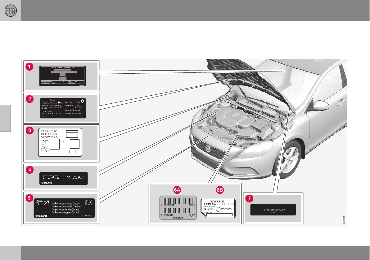
12 Specifications
12
438
Type designations
Type designation, vehicle identification num-
ber, etc., i.e. information unique to the car,
can be read on a label in the car.
Label location
12 Specifications
12
439
Knowing the car's type designation, vehicle
identification and engine numbers can facili-
tate all contact with an authorised Volvo
dealer regarding the car and when ordering
spare parts and accessories.
Type designation, vehicle identification
number, maximum permissible weights,
codes for colour and upholstery and type
approval number. The label is visible
when the right rear door is opened.
Label for A/C system.
Label for parking heater.
Engine code and engine serial number.
Label for engine oil.
Gearbox type designation and serial num-
ber.
Manual gearbox
Automatic gearbox
Car's identification number. (VIN Vehicle
Identification Number)
Further information on the car is presented in
the registration document.
NOTE
It is not intended that the decals illustrated
in the owner's manual should be exact
replicas of those in the car. They are
included to show their approximate
appearance and location in the car. The
information that applies to your particular
car is available on the respective decals
for your car.
Related information
•
Weights (p. 441)
•
Engine specifications (p. 445)
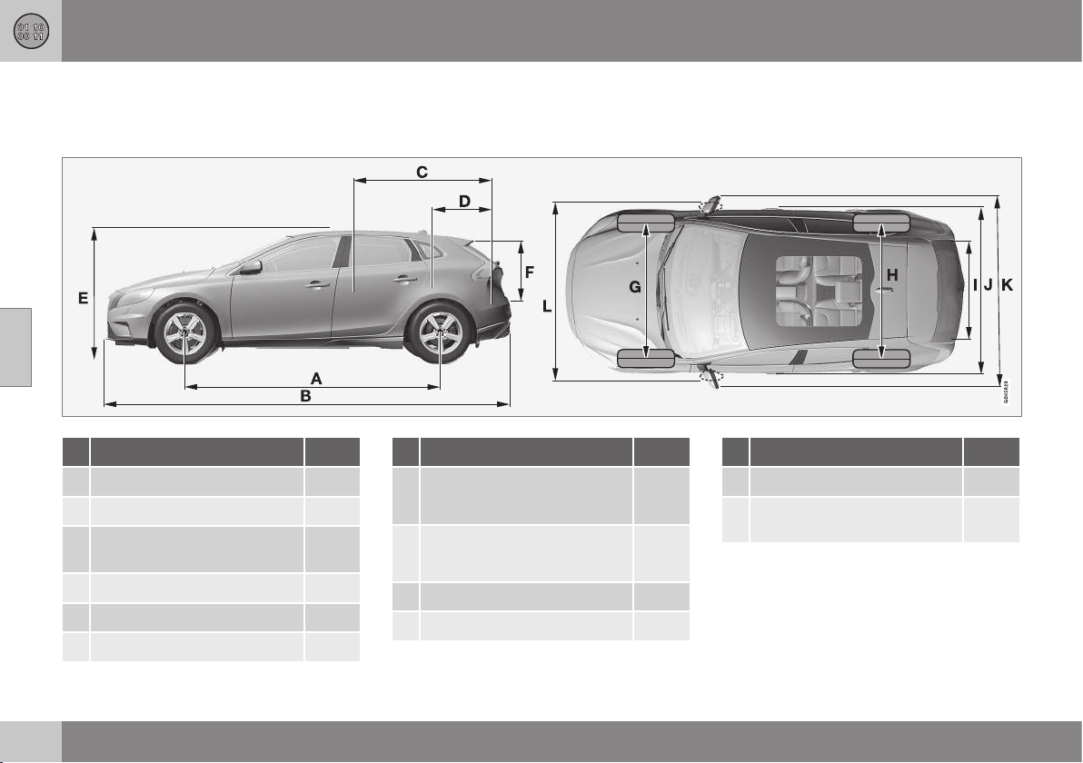
12 Specifications
12
440
Dimensions
Measurement of car length, height, etc. can
be read in the table.
Dimensions mm
A Wheelbase 2646
B Length 4370
C Load length, floor, folded rear
seat 1508
D Load length, floor 684
E Height 1458
F Load height 532
Dimensions mm
G Front track
1552
A
1547
B
H Rear track
1540
A
1535
B
I Load width, floor 960
J Width 1802
Dimensions mm
K Width including door mirrors 2041
L Width including folded-in
door mirrors 1857
A
Offset 50 mm.
B
Offset 52.5 mm.

12 Specifications
12
441
Weights
Max. gross vehicle weight, etc. can be read
on a label in the car.
Kerb weight includes the driver, the fuel tank
90% full and all fluids.
The weight of passengers and accessories,
and towball load (p. 442) (when a trailer is
hitched) influence the load capacity and are
not included in the kerb weight.
Permitted max. load = Gross vehicle weight -
Kerb weight.
NOTE
The documented kerb weight applies to
cars in the standard version - i.e. a car
without extra equipment or accessories.
This means that for every accessory added
the loading capacity of the car is reduced
correspondingly by the weight of the
accessory.
Examples of accessories that reduce load-
ing capacity are the Kinetic/Momentum/
Summum equipment levels, as well as
other accessories such as Towbar, Load
carrier, Space box, Audio system, Auxiliary
lamps, GPS, Fuel-driven heater, Safety
grille, Carpets, Luggage cover, Power
seats, etc.
Weighing the car is a certain way of ascer-
taining the kerb weight of your own partic-
ular car.
WARNING
The car's driving characteristics change
depending on how heavily it is loaded and
how the load is distributed.
For information on label location, see Type des-
ignations (p. 438).
Max. gross vehicle weight
Max. train weight (car+trailer)
Max. front axle load
Max. rear axle load
Equipment level
Max. load: See registration document.
Max. roof load: 75 kg.
Related information
•
Towing capacity and towball load (p.
442)
12 Specifications
12
442
Towing capacity and towball load
Towing capacity and towball load for driving
with a trailer can be read in the tables.
Max. weight braked trailer
Engine
Engine code
A
Gearbox Max. weight braked trailer (kg) Max. towball load (kg)
T4 B4164T Manual, B6 1300 75
T4 B4164T Automatic, MPS6 1500 75
T4 B5204T8 Automatic, TF-80SD 1500 75
T4 AWD B5204T8 Automatic, TF-80SD 1500 75
T5 B5204T9 Automatic, TF-80SD 1500 75
T5 AWD B5204T9 Automatic, TF-80SD 1500 75
T5 B5254T12 Automatic, TF-80SD 1500 75
T5 AWD B5254T12 Automatic, TF-80SD 1500 75
T5 B5254T14 Automatic, TF-80SD 1500 75
T5 AWD B5254T14 Automatic, TF-80SD 1500 75
D2 D4162T Manual, B6 1300 75
D2 D4162T Automatic, MPS6 1300 75
D3 D5204T6 Manual, M66 1500 75
D3 D5204T6 Automatic, TF-80SD 1500 75
D4 D5204T4 Manual, M66 1500 75
D4 D5204T4 Automatic, TF-80SD 1500 75
A
Engine code, component and serial number can be read on the engine; see Type designations (p. 438).

12 Specifications
12
}}
443
Max. weight unbraked trailer
Engine
Engine code
A
Gearbox Max. weight unbraked trailer (kg) Max. towball load (kg)
T4 B4164T Manual, B6 650 50
T4 B4164T Automatic, MPS6 700 50
T4 B5204T8 Automatic, TF-80SD 700 50
T4 AWD B5204T8 Automatic, TF-80SD 750 50
T5 B5204T9 Automatic, TF-80SD 700 50
T5 AWD B5204T9 Automatic, TF-80SD 750 50
T5 B5254T12 Automatic, TF-80SD 700 50
T5 AWD B5254T12 Automatic, TF-80SD 750 50
T5 B5254T14 Automatic, TF-80SD 700 50
T5 AWD B5254T14 Automatic, TF-80SD 750 50
D2 D4162T Manual, B6 650 50
D2 D4162T Automatic, MPS6 700 50
D3 D5204T6 Manual, M66 700 50
D3 D5204T6 Automatic, TF-80SD 750 50
D4 D5204T4 Manual, M66 700 50
D4 D5204T4 Automatic, TF-80SD 750 50
A
Engine code, component and serial number can be read on the engine; see Type designations (p. 438).


12 Specifications
12
445
Engine specifications
Engine specifications (output etc.) for each
respective engine alternative can be read in
the table.
NOTE
Not all engines are available in all markets.
Engine Engine
code
A
Output
(kW/rpm)
Output
(hp/rpm)
Torque (Nm/
rpm)
No. of
cylinders
Bore
(mm)
Stroke
(mm)
Swept
volume
(litres)
Com-
pression
ratio
T4 B4164T 132/5700 180/5700 240/1600–5000 4 79 81,4 1,596 10,0:1
T4 B5204T8 132/5000 180/5000 300/2700–4000 5 81,0 77 1,984 10.5:1
T5 B5204T9 157/6000 213/6000 300/2700–5000 5 81,0 77 1,984 10.5:1
T5 B5254T12 187/5400 254/5400 360/1800–4200 5 83 92,3 2,497 9.5:1
T5 B5254T14 183/5400 249/5400 360/1800–4200 5 83 92,3 2,497 9.5:1
D2 D4162T 84/3600 115/3600 270/1750-2500 4 75 88,3 1,560 16,0:1
D3 D5204T6 110/3500 150/3500 350/1500-2750 5 81,0 77 1,984 16,5:1
D4 D5204T4 130/3500 177/3500 400/1750-2750 5 81,0 77 1,984 16,5:1
A
Engine code, component and serial number can be read on the engine; see Type designations (p. 438).
Related information
•
Coolant - grade and volume (p. 449)
•
Engine oil - grade and volume (p. 447)

12 Specifications
12
446
Engine oil - adverse driving conditions
Adverse driving conditions can lead to abnor-
mally high oil temperature or oil consumption.
Below are some examples of adverse driving
conditions.
Check the oil level (p. 337), more frequently
for long journeys:
•
towing a caravan or trailer
•
in mountainous regions
•
at high speeds
•
in temperatures colder than -30 °C or
hotter than +40 °C
The above also apply to shorter driving dis-
tances at low temperatures.
Choose a fully synthetic engine oil for adverse
driving conditions. It provides extra protection
for the engine.
Volvo recommends:
IMPORTANT
In order to fulfil the requirements for the
engine's service intervals all engines are
filled with a specially adapted synthetic
engine oil at the factory. The choice of oil
has been made very carefully with regard
to service life, starting characteristics, fuel
consumption and environmental impact.
An approved engine oil must be used in
order that the recommended service inter-
vals can be applied. Only use a prescribed
grade of oil for both filling and oil change,
otherwise you will risk affecting service life,
starting characteristics, fuel consumption
and environmental impact.
Volvo Car Corporation disclaims all war-
ranty liability if engine oil of the prescribed
grade and viscosity is not used.
Volvo recommends that oil changes are
carried out at an authorised Volvo work-
shop.
Related information
•
Engine oil - grade and volume (p. 447)
•
Engine oil - general (p. 336)
12 Specifications
12
}}
447
Engine oil - grade and volume
Recommended engine oil grade and volume
for each respective engine alternative can be
read in the table.
Volvo recommends:
Engine
Engine code
A
Oil grade Volume, incl. oil filter
(litres)
T4 B4164T
Certified and factory-filled oil: Oil grade WSS-M2C925-A
options for service:
Oil grade: ACEA A5/B5
Viscosity: SAE 5W–30
approx. 4.1
D2 D4162T
Oil grade: ACEA A5/B5
Viscosity: SAE 5W–30
When driving under adverse conditions, use ACEA A5/B5 SAE 0W-30.
approx. 3.8
D3 D5204T6
Oil grade: ACEA A5/B5
Viscosity: SAE 0W–30
approx. 5.9
D4 D5204T4 approx. 5.9

||
12 Specifications
12
448
Engine
Engine code
A
Oil grade Volume, incl. oil filter
(litres)
T4 B5204T8
Oil grade: ACEA A5/B5
Viscosity: SAE 0W–30
approx 5.5
T5 B5204T9 approx 5.5
T5 B5254T12 approx 5.5
T5 B5254T14 approx 5.5
A
Engine code, component and serial number can be read on the engine; see Type designations (p. 438).
Related information
•
Engine oil - adverse driving conditions (p.
446)
•
Engine oil - checking and filling (p. 337)

12 Specifications
12
449
Coolant - grade and volume
Approved coolant volume for each respective
engine alternative can be read in the table.
Prescribed grade: Coolant recommended by
Volvo mixed with 50% water
1
, see the pack-
aging.
Engine
A
Volume
(litres)
T4 B4164T 7,0
D2 D4162T 10,0
D3 D5204T6
8,0
D4 D5204T4
T4 B5204T8
8,0
T5 B5204T9
T5 B5254T12
T5 B5254T14
A
Engine code, component and serial number can be read
on the engine; see Type designations (p. 438).
Related information
•
Coolant - level (p. 340)
1
Water quality must fulfil the standard STD 1285.1.
12 Specifications
12
450
Transmission fluid - grade and volume
The prescribed transmission fluid and volume
for each respective gearbox alternative can be
read in the table.
Manual gearbox
Manual gearbox Volume (litres) Prescribed transmission fluid
B6 1,6
BOT 350M3
M66 1,9
Automatic gearbox
Automatic gearbox Volume (litres) Prescribed transmission fluid
TF-80SD 7,0 AW1
MPS6 7.3 BOT 341
NOTE
Under normal driving conditions, the gear-
box oil does not need to be changed dur-
ing its service life. However, it may be nec-
essary under adverse driving conditions.
Related information
•
Engine oil - adverse driving conditions (p.
446)
•
Type designations (p. 438)

12 Specifications
12
451
Brake fluid - grade and volume
The medium in a hydraulic brake system is
called brake fluid, and it is used to transfer
force from e.g. a brake pedal via a master
brake cylinder to one or more slave cylinders,
which in turn act on a mechanical brake.
Prescribed grade: DOT 4
Volume: 0.6 litres
Related information
•
Brake and clutch fluid - level (p. 341)
Washer fluid - quality and volume
Washer fluid is used, together with wind-
screen and rear window wipers (p. 93) to keep
the car's windows and headlamps clean and
ensure visibility when driving.
Prescribed grade: Washer fluid recom-
mended by Volvo - with frost protection dur-
ing cold weather and below freezing point.
Volume:
•
Cars with headlamp washing: 5.5 litres.
•
Cars without headlamp washing: 3.2
litres.
Related information
•
Washer fluid - filling (p. 351)
•
Wiper blades (p. 349)

12 Specifications
12
452
Fuel tank - volume
Fuel tank volume for each respective engine
alternative can be read in the table.
Engine Volume (litres) Prescribed grade
4-cylinder petrol
5-cylinder petrol (FWD)
approx 62 Petrol: Fuel - petrol (p. 298)
5-cylinder petrol (AWD) approx. 57
4-cylinder diesel approx 52 Diesel: Fuel - diesel (p. 298)
5-cylinder diesel approx 60
Related information
•
Filling up with fuel (p. 296)
•
Engine specifications (p. 445)
12 Specifications
12
453
Air conditioning, fluid - volume and
grade
The prescribed grade and volume of fluids in
the air conditioning system can be read in the
table.
Fluid Volume (litres) Prescribed grade
Compressor oil 0,11 PAG oil
Coolant 0,65 kg R134a
WARNING
The air conditioning system contains pres-
surised refrigerant R134a. This system
must only be serviced and repaired by an
authorised workshop.
Related information
•
Climate control system - fault tracing and
repair (p. 341)
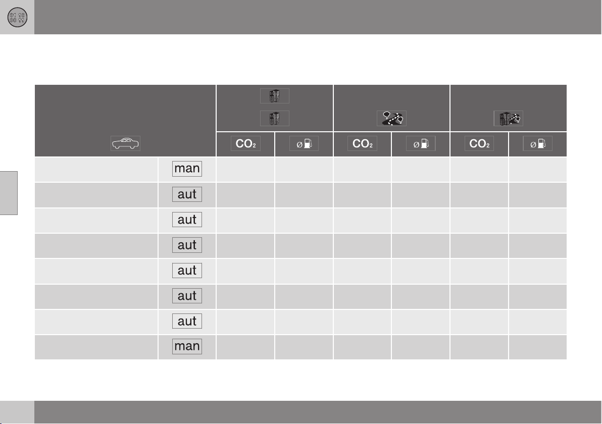
12 Specifications
12
454
Fuel consumption and CO2 emissions
Fuel consumption in a vehicle is measured in
litres per 100 km and CO2 emissions in grams
per km.
T4 (B4164T) 164 7,0 109 4,7 129 5,5
T4 (B4164T) 184 7.9 120 5.1 143 6.1
T4 AWD (B5204T8) 259 11.1 146 6.3 187 8,0
T5 (B5204T9) 243 10,4 135 5.8 174 7,5
T5 AWD (B5204T9) 259 11.1 146 6.3 187 8,0
T5 (B5254T12) 259 11.1 138 5.9 182 7.8
T5 AWD (B5254T12) 270 11,6 150 6.4 194 8.3
D2 (D4162T) 110 4,2 93 3,5 99 3,8
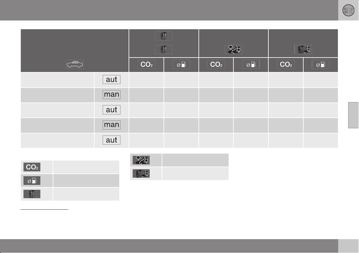
12 Specifications
12
}}
455
D2 (D4162T) 118 4,5 103 3.9 108 4.1
D3 (D5204T6) 140 5,3 103 3.9 117 4,4
D3 (D5204T6) 178 6,8 114 4,3 137 5,2
D4 (D5204T4) 140 5,3 103 3.9 117 4,4
D4 (D5204T4) 178 6,8 114 4,3 137 5,2
Explanation
gram/km
litre/100 km
Urban driving
Extra-urban driving
Combined driving
Fuel consumption and emission values in the
table above are based on specific EU cycles
2
,
that apply to cars with kerb weight in the
basic version and without extra equipment.
The car's weight may increase depending on
equipment. This, as well as how heavily the
car is loaded, increases fuel consumption and
carbon dioxide emissions. See information
about Weights (p. 441).
2
Official fuel consumption figures are based on two standardised driving cycles in a laboratory environment ("EU driving cycles") all in accordance with EU Regulation no 692/2008 and 715/2007
(Euro 5 / Euro 6) and UN ECE Regulation no 101. The regulations cover the driving cycles for city driving and driving on main roads. - City driving - the measurement starts with cold starting the
engine. The driving is simulated. - Driving on main roads - the car is accelerated and braked at speeds between 0-120 km/h. The driving is simulated. - Cars with manual transmission are started
in 2nd gear. The value for combined driving, which is reported in the table, is a combination of city driving and driving on main roads, in accordance with legal requirements. CO
2
emissions - the
exhaust gases are collected in order to calculate the carbon dioxide emissions during the two driving cycles. These are then analysed and give the value for CO
2
emissions.
||
12 Specifications
12
456
There are several reasons for increased fuel
consumption compared with the table's val-
ues. Examples of this are:
•
The driver's driving style.
•
If the customer has specified wheels
larger than those fitted as standard on the
model's basic version, then resistance
increases.
•
High speed results in increased wind
resistance.
•
Fuel quality, road and traffic conditions,
weather and the condition of the car.
Even a combination of the above-mentioned
examples can result in significantly improved
consumption. For further information, please
refer to the regulations referred to
2
.
Large deviations in fuel consumption may
arise in a comparison with the EU driving
cycles
2
which are used in the certification of
the car and on which the consumption figures
in the table are based.
Consumption is higher and power output
lower for fuel with an octane rating of
91 RON.
NOTE
Extreme weather conditions, driving with a
trailer or driving at high altitudes in combi-
nation with fuel grade are factors that
could affect the car's performance.
Related information
•
Economical driving (p. 300)
•
Fuel - petrol (p. 298)
•
Fuel - diesel (p. 298)
2
Official fuel consumption figures are based on two standardised driving cycles in a laboratory environment ("EU driving cycles") all in accordance with EU Regulation no 692/2008 and 715/2007
(Euro 5 / Euro 6) and UN ECE Regulation no 101. The regulations cover the driving cycles for city driving and driving on main roads. - City driving - the measurement starts with cold starting the
engine. The driving is simulated. - Driving on main roads - the car is accelerated and braked at speeds between 0-120 km/h. The driving is simulated. - Cars with manual transmission are started
in 2nd gear. The value for combined driving, which is reported in the table, is a combination of city driving and driving on main roads, in accordance with legal requirements. CO
2
emissions - the
exhaust gases are collected in order to calculate the carbon dioxide emissions during the two driving cycles. These are then analysed and give the value for CO
2
emissions.
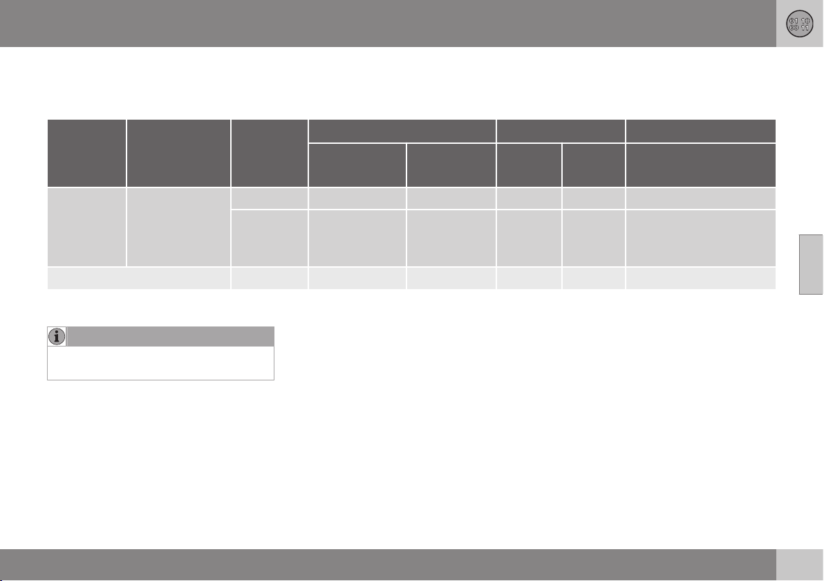
12 Specifications
12
457
Tyres - approved tyre pressures
Approved tyre pressures for each respective
engine alternative can be read in the table.
Engine Tyre size Speed
(km/h)
Load, 1 - 3 persons Max. load
ECO pressure
A
Front
(kPa)
B
Rear
(kPa)
Front
(kPa)
Rear
(kPa)
Front/rear
(kPa)
All
205/60 R16
225/50 R17
225/45 R18
225/40 R19
0 - 160 240 230 260 260 260
160 + 260 240 280 280 –
Temporary Spare Tyre max. 80 420 420 420 420 –
A
Economical driving.
B
In certain countries there is the "bar" unit beside the SI unit "Pascal": 1 bar = 100 kPa.
NOTE
All engines, tyres or combinations of these
are not always available in all markets.
Related information
•
Tyres - dimensions (p. 316)
•
Tyres - air pressure (p. 322)
•
Type designations (p. 438)

12 Specifications
12
458
Electrical system
The electrical system is single-pole and uses
the chassis and engine casing as a conductor.
The car has a voltage-regulated AC alterna-
tor.
The size, type and performance of the starter
battery depend on the car's equipment and
function.
IMPORTANT
If the battery is replaced, take care to
replace it with a battery with the same cold
starting capacity, reserve capacity and
type as the original battery (see the label
on the battery).
Related information
•
Starter battery - specification (p. 459)
•
Starter battery - replacement (p. 353)
•
Starter battery (p. 351)
12 Specifications
12
459
Starter battery - specification
The starter battery is used to drive the starter
motor and other electrical equipment in the
car.
Engine Voltage (V) Cold start capacity,
CCA - Cold Cranking Amperes (A)
Reserve capacity
(minutes)
Petrol 12 520–800 100–160
Diesel 12 700–800 135–160
Petrol/Diesel, manual gearbox with Start/Stop function 12
720
A
130
Petrol/Diesel, automatic gearbox with Start/Stop function 12
800
B
140
A
Battery type EFB (Enhanced Flooded Battery) must be used in cars with manual gearbox and the Start/Stop function.
B
Battery type AGM (Absorbed Glass Mat) must be used in cars with automatic gearbox and the Start/Stop function.
IMPORTANT
If the battery is replaced, take care to
replace it with a battery with the same cold
starting capacity, reserve capacity and
type as the original battery (see the label
on the battery).
NOTE
•
The battery's container size should be
consistent with the original battery's
dimensions.
•
The battery's height is different
depending on size.
Related information
•
Starter battery - replacement (p. 353)
•
Starter battery (p. 351)
•
Battery - Start/Stop (p. 353)
12 Specifications
12
460
Type approval - remote control key
system
Type approval for the remote control key sys-
tem can be read in the table.
Lock system, standard
Country/Area
EU, China
Keyless lock system (Keyless drive)
Country/Area
EU
Korea
Country/Area
China
Hong Kong
Related information
•
Remote control key with key blade (p.
159)
Type approval - radar system
Type approval for the radar system can be
read in the table.
12 Specifications
12
461
Coun-
try/
Area
Singa-
pore
IDA: Infocomm Development
Authority of Singapore.
Brazil
Europe
Delphi Electronics &
Safety hereby declares that
L2C0038TR and L2C0049TR
are in compliance with the
essential requirements and
other relevant provisions of
Directive 1999/5/EC. This dec-
laration of conformity may, if
necessary, be consulted with
Delphi Electronics & Safety /
One Corporate Center /
Kokomo, Indiana 46904-9005
USA.
Related information
•
Radar sensor (p. 209)

12 Specifications
12
462
Type approval - Bluetooth
®
Type approval for Bluetooth
®
can be read in
the table.
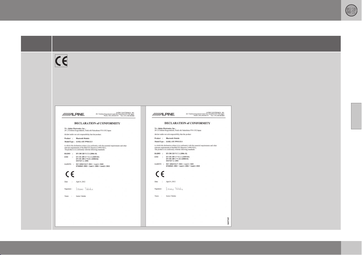
12 Specifications
12
}}
463
Declaration of Conformity (Declaration of Conformity)
Country/
Area
Countries
in the EU:
Exporting country: Japan
Manufacturer: Alpine Electronics Inc.
Type of equipment: Bluetooth
®
device
For further information visit http://ec.europa.eu/enterprise/rtte/faq.htm #informing

||
12 Specifications
12
464
Country/
Area
Czech
Republic:
Alpine Electronics, Inc. tímto prohlašuje, že tento Bluetooth
®
Module je ve shodě se základními požadavky a dalšími příslušnými
ustanoveními směrnice 1999/5/ES.
Denmark:
Undertegnede Alpine Electronics, Inc. erklærer herved, at følgende udstyr Bluetooth
®
Module overholder de væsentlige krav og
øvrige relevante krav i direktiv 1999/5/EF.
Germany:
Hiermit erklärt Alpine Electronics, Inc., dass sich das Gerät Bluetooth
®
Module in Übereinstimmung mit den grundlegenden
Anforderungen und den übrigen einschlägigen Bestimmungen der Richtlinie 1999/5/EG befindet.
Estonia:
Käesolevaga kinnitab Alpine Electronics, Inc. seadme Bluetooth
®
Module vastavust direktiivi 1999/5/EÜ põhinõuetele ja
nimetatud direktiivist tulenevatele teistele asjakohastele sätetele.
UK
Hereby, Alpine Electronics, Inc., declares that this Bluetooth
®
Module is in compliance with the essential requirements and other
relevant provisions of Directive 1999/5/EC.
Spain:
Por medio de la presente Alpine Electronics, Inc. declara que el Bluetooth
®
Module cumple con los requisitos esenciales y
cualesquiera otras disposiciones aplicables o exigibles de la Directiva 1999/5/CE.
Greece:
ΜΕ ΗΝ ΠΑΡΟΣΑ Alpine Electronics, Inc. ΗΛΩΝΕ Ο Bluetooth
®
Module ΣΜΜΟΡΦΩΝΕΑ ΠΡΟΣ Σ ΟΣΩΕΣ
ΑΠΑΗΣΕΣ Α Σ ΛΟΠΕΣ ΣΧΕΕΣ ΑΑΞΕΣ ΗΣ ΟΗΑΣ 1999/5/Ε.
France:
Par la présente Alpine Electronics, Inc. déclare que l'appareil Bluetooth
®
Module est conforme aux exigences essentielles et aux
autres dispositions pertinentes de la directive 1999/5/CE.
Italy:
Con la presente Alpine Electronics, Inc. dichiara che questo Bluetooth
®
Module è conforme ai requisiti essenziali ed alle altre
disposizioni pertinenti stabilite dalla direttiva 1999/5/CE.
Latvia:
Ar šo Alpine Electronics, Inc. deklarē, ka Bluetooth
®
Module atbilst Direktīvas 1999/5/EK būtiskajām prasībām un citiem ar to
saistītajiem noteikumiem.
Lithuania:
Šiuo Alpine Electronics, Inc. deklaruoja, kad šis Bluetooth
®
Module atitinka esminius reikalavimus ir kitas 1999/5/EB Direktyvos
nuostatas.

12 Specifications
12
}}
465
Country/
Area
Nether-
lands:
Hierbij verklaart Alpine Electronics, Inc. dat het toestel Bluetooth
®
Module in overeenstemming is met de essentiële eisen en de
andere relevante bepalingen van richtlijn 1999/5/EG.
Malta:
Hawnhekk, Alpine Electronics, Inc., jiddikjara li dan Bluetooth
®
Module jikkonforma mal-ħtiġijiet essenzjali u ma provvedimenti
oħrajn relevanti li hemm fid-Dirrettiva 1999/5/EC.
Hungary:
Alulírott, Alpine Electronics, Inc. nyilatkozom, hogy a Bluetooth
®
Module megfelel a vonatkozó alapvetõ követelményeknek és az
1999/5/EC irányelv egyéb elõírásainak.
Poland:
Niniejszym Alpine Electronics, Inc. oświadcza, że Bluetooth
®
Module jest zgodny z zasadniczymi wymogami oraz pozostałymi
stosownymi postanowieniami Dyrektywy 1999/5/EC.
Portugal:
Alpine Electronics, Inc. declara que este Bluetooth
®
Module está conforme com os requisitos essenciais e outras disposições da
Directiva 1999/5/CE.
Slovenia:
Alpine Electronics, Inc. izjavlja, da je ta Bluetooth
®
Module v skladu z bistvenimi zahtevami in ostalimi relevantnimi določili direk-
tive 1999/5/ES.
Slovakia:
Alpine Electronics, Inc. týmto vyhlasuje, že Bluetooth
®
Module spĺňa základné požiadavky a všetky príslušné ustanovenia Smer-
nice 1999/5/ES.
Finland:
Alpine Electronics, Inc. vakuuttaa täten että Bluetooth
®
Module tyyppinen laite on direktiivin 1999/5/EY oleellisten vaatimusten ja
sitä koskevien direktiivin muiden ehtojen mukainen.
Sweden:
Härmed intygar Alpine Electronics, Inc. att denna Bluetooth
®
Module står I överensstämmelse med de väsentliga egenskapskrav
och övriga relevanta bestämmelser som framgår av direktiv 1999/5/EG.
Iceland:
Alpine Electronics, Inc. hereby certifies that this Bluetooth
®
Module conforms to the essential characteristic requirements and
other relevant regulations of directive 1999/5/EC.
Norway:
Alpine Electronics, Inc. erklærer herved at utstyret Bluetooth
®
Module er i samsvar med de grunnleggende krav og øvrige
relevante krav i direktiv 1999/5/EF.

||
12 Specifications
12
466
Country/
Area
China:
第十三条进口和生产厂商在其产品的说明书或使用手册中,应刊印下述有关内容
1. 标明附件中所规定的技术指标和使用范围,说明所有控制调整及开关等使用方法
■ 使用频率2.4 - 2.4835 GHz
■ 等效全向辐射率(EIRP)天线增益 10dBi 时≤100 mW 或≤20 dBm①
■ 最大率谱密度天线增益 10dBi 时≤20 dBm / MHz(EIRP) ①
■ 载频容限20 ppm
■ 杂散发射(辐射)率(对应载波±2.5 倍信道带宽以外)
•
≤-36 dBm / 100 kHz (30 - 1000 MHz)
•
≤-33 dBm / 100 kHz (2.4 - 2.4835 GHz)
•
≤-40 dBm / 1 MHz (3.4 - 3.53 GHz)
•
≤-40 dBm / 1 MHz (5.725 - 5.85 GHz)
•
≤-30 dBm / 1 MHz (其它 1 - 12.75 GHz)
2. 不得擅自更改发射频率大发射率(包括额外装射频率放大器),不得擅自外接天线或改用其它发射天线
3. 使用时不得对各种合法的无线电通信业产生有害干扰一旦发现有干扰现象时,应立即停止使用,并采措施消除干扰后方可
继续使用
4. 使用微率无线电设备,必须忍各种无线电业的干扰或工业科学及医疗应用设备的辐射干扰
5. 不得在飞机和机场附近使用
12 Specifications
12
}}
467
Country/
Area
Taiwan:
低効率電波輻射性電機管理辧法第十条
第十二條
經型式認證合格之低功率射頻電機,非經許可,公司商號或使用者均不得擅自 變更頻率加大功率或變更原設計之特性及功能
第十四條
低功率射頻電機之使用不得影響飛航安全及干擾合法通信;經發現有干擾現象時, 應立即停用,並改善至無干擾時方得繼續使用
前項合法通信,指依電信法規定 作業之無線電通信低功率射頻電機須忍受合法通信或工業科學及醫療用電波 輻射性電機設備之
干擾

||
12 Specifications
12
468
Country/
Area
South
Korea:
제품 정보
Volvo Car Korea
신청자 코드: KCC-CMM-N25-IAM21L3, KCC-CMM-N25-IAM21L2 and KCC-CMM-N25-IAM21L1
제품 명: Bluetooth Audio Navigation Radio
모델 명: IAM2.1
산 날짜: March/2010
Alpine Electronics, Inc
Made in Japan
고객 정보
Volvo Car Korea
볼보자동차코리아
서울시 용산구 한남 2 동 726-173 볼보빌딩 4 층
볼보자동차 고객센터 1588-1777
http://www.volvocars.com/kr
사용자 주의사항
※당해 무선설비는 전파혼신 가능성이 있으므로 인명안전과 관련된 서비스는 할 수 없습니다
12 Specifications
12
* Option/accessory, for more information, see Introduction.
469
Country/
Area
The United
Arab Emi-
rates:
South
Africa:
Jamaica: Approved for use in Jamaica SMA EI: IAM2.1
Thailand: This telecommunication equipment conforms to NTC technical requirement.
Oman
Related information
•
Bluetooth
®
handsfree phone (p. 403)
•
Media Bluetooth
®
* (p. 398)

12 Specifications
12
470
Licenses
Sensus software
This software uses parts of sources from
clib2 and Prex Embedded Real-time OS -
Source (Copyright (c) 1982, 1986, 1991,
1993, 1994), and Quercus Robusta (Copyright
(c) 1990, 1993), The Regents of the University
of California. All or some portions are derived
from material licensed to the University of
California by American Telephone and
Telegraph Co. or Unix System Laboratories,
Inc. and are reproduced herein with the
permission of UNIX System Laboratories, Inc.
Redistribution and use in source and binary
forms, with or without modification, are
permitted provided that the following
conditions are met: Redistributions of source
code must retain the above copyright notice,
this list of conditions and the following
disclaimer. Redistributions in binary form
must reproduce the above copyright notice,
this list of conditions and the following
disclaimer in the documentation and/or other
materials provided with the distribution.
Neither the name of the <ORGANIZATION>
nor the names of its contributors may be
used to endorse or promote products derived
from this software without specific prior
written permission. THIS SOFTWARE IS
PROVIDED BY THE COPYRIGHT HOLDERS
AND CONTRIBUTORS "AS IS" AND ANY
EXPRESS OR IMPLIED WARRANTIES,
INCLUDING, BUT NOT LIMITED TO, THE
IMPLIED WARRANTIES OF
MERCHANTABILITY AND FITNESS FOR A
PARTICULAR PURPOSE ARE DISCLAIMED.
IN NO EVENT SHALL THE COPYRIGHT
OWNER OR CONTRIBUTORS BE LIABLE
FOR ANY DIRECT, INDIRECT, INCIDENTAL,
SPECIAL, EXEMPLARY, OR
CONSEQUENTIAL DAMAGES (INCLUDING,
BUT NOT LIMITED TO, PROCUREMENT OF
SUBSTITUTE GOODS OR SERVICES; LOSS
OF USE, DATA, OR PROFITS; OR BUSINESS
INTERRUPTION) HOWEVER CAUSED AND
ON ANY THEORY OF LIABILITY, WHETHER
IN CONTRACT, STRICT LIABILITY, OR TORT
(INCLUDING NEGLIGENCE OR OTHERWISE)
ARISING IN ANY WAY OUT OF THE USE OF
THIS SOFTWARE, EVEN IF ADVISED OF THE
POSSIBILITY OF SUCH DAMAGE.
This software is based in part on the work of
the Independent JPEG Group.
This software uses parts of sources from
"libtess". The Original Code is: OpenGL
Sample Implementation, Version 1.2.1,
released January 26, 2000, developed by
Silicon Graphics, Inc. The Original Code is
Copyright (c) 1991-2000 Silicon Graphics,
Inc. Copyright in any portions created by third
parties is as indicated elsewhere herein. All
Rights Reserved. Copyright (C) [1991-2000]
Silicon Graphics, Inc. All Rights Reserved.
Permission is hereby granted, free of charge,
to any person obtaining a copy of this
software and associated documentation files
(the "Software"), to deal in the Software
without restriction, including without limitation
the rights to use, copy, modify, merge,
publish, distribute, sublicense, and/or sell
copies of the Software, and to permit persons
to whom the Software is furnished to do so,
subject to the following conditions: The
above copyright notice including the dates of
first publication and either this permission
notice or a reference to http://oss.sgi.com/
projects/FreeB/ shall be included in all copies
or substantial portions of the Software. THE
SOFTWARE IS PROVIDED "AS IS",
WITHOUT WARRANTY OF ANY KIND,
EXPRESS OR IMPLIED, INCLUDING BUT
NOT LIMITED TO THE WARRANTIES OF
MERCHANTABILITY, FITNESS FOR A
PARTICULAR PURPOSE AND
NONINFRINGEMENT. IN NO EVENT SHALL
SILICON GRAPHICS, INC. BE LIABLE FOR
ANY CLAIM, DAMAGES OR OTHER
LIABILITY, WHETHER IN AN ACTION OF
CONTRACT, TORT OR OTHERWISE,
ARISING FROM, OUT OF OR IN
CONNECTION WITH THE SOFTWARE OR
THE USE OR OTHER DEALINGS IN THE
SOFTWARE. Except as contained in this
notice, the name of Silicon Graphics, Inc.
shall not be used in advertising or otherwise
to promote the sale, use or other dealings in
this Software without prior written
authorization from Silicon Graphics, Inc.
12 Specifications
12
}}
471
This software is based in parts on the work of
the FreeType Team.
This software uses parts of SSLeay Library:
Copyright (C) 1995-1998 Eric Young
([email protected]). All rights reserved
Combined Instrument Panel Software
Open Source Software Notice
This product uses certain free / open source
and other software originating from third
parties, that is subject to the GNU General
Public License version 2 and 3 (GPLv2/
GPLv3), GNU Lesser General Public License
version 3 (LGPLv3), The FreeType Project
License (“FreeType License”) and other
different and/or additional copyright licenses,
disclaimers and notices. The links how to
access the exact terms of GPLv2, GPLv3,
LGPLv3, and the other open source software
licenses, disclaimers, acknowledgements and
notices are provided to you below. Please
refer to the exact terms of the relevant
License, regarding your rights under said
licenses. Volvo Car Corporation (VCC) offers
to provide the source code of said free/open
source software to you for a charge covering
the cost of performing such distribution, such
as the cost of media, shipping and handling,
upon written request. Please contact your
nearest Volvo Dealer.
This offer is valid for a period of at least three
(3) years from the date of the distribution of
this product by VCC / or for as long as VCC
offers spare parts or customer support.
Portions of this product uses software
copyrighted © v2.4.3/2010 The
FreeTypeProject (www.freetype.org). All rights
reserved.
This product includes software under
following licenses:
GPL v2 : http://www.gnu.org/licenses/old-
licenses/gpl-2.0.html
•
Linux kernel (merge between MontaVista
2.6.31 kernel and kernel from
L2.6.31_MX51_ER_1007 BSP)
•
uBoot (based on v2009.08)
•
busybox (based on version 1.13.2.)
GCC runtime library exception: http://
www.gnu.org/licenses/gcc-exception.html
•
libgcc_s.so.1
LGPL v3: http://www.gnu.org/licenses/
lgpl.html
•
Libc.so.6, libpthread.so.0, Librt.so.1
The FreeType Project License: http://
www.freetype.org/FTL.TXT
•
libfreetype.so.6 (version 2.4.3)
Linux software
This product contains software licensed
under GNU General Public License (GPL) or
GNU Lesser General Public License (LGPL),
etc.
You have the right of acquisition,
modification, and distribution of the source
code of the GPL/LGPL software.
You may download Source Code from the
following website at no charge: http://
www.embedded-carmultimedia.jp/linux/oss/
download/TVM_8351_013
The website provides the Source Code "As
Is" and without warranty of any kind.
By downloading Source Code, you expressly
assume all risk and liability associated with
downloading and using the Source Code and
complying with the user agreements that
accompany each Source Code.
Please note that we cannot respond to any
inquiries regarding the source code.
DivX
®
DivX Certified
®
to play DivX
®
video. DivX
®
,
DivX Certified
®
and associated logos are
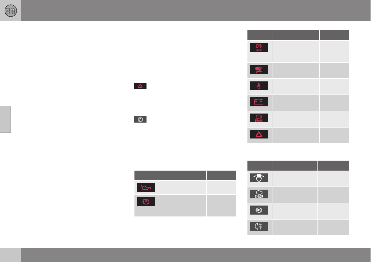
||
12 Specifications
12
472
* Option/accessory, for more information, see Introduction.
registered trademarks of DivX, Inc. and are
used under license. ABOUT DIVX VIDEO:
DivX
®
is a digital video format created by
DivX, Inc. This is an official DivX Certified
device that plays DivX video. Visit
www.divx.com for more information and
software tools to convert your files into DivX
video.
ABOUT DIVX VIDEO-ON-DEMAND: This DivX
Certified
®
device must be registered in order
to play DivX Video-on-Demand (VOD)
content. To generate the registration code,
locate the DivX VOD section in the device
setup menu. Go to http://vod.divx.com with
this code to complete the registration
process and learn more about DivX VOD.
Covered by one or more of the following U.S.
Patents: 7,295,673; 7,460,668; 7,515,710;
7,519,274.
Related information
•
Volvo Sensus (p. 70)
Symbols in the display
There are a variety of different symbols in the
display in the car. The symbols are divided
into warning, indicator and information sym-
bols. Shown below are the most common
symbols with their meanings and a reference
to where in the manual further information can
be found.
- Red warning symbol, illuminates when
a fault has been indicated which could affect
the safety and/or driveability of the car. An
explanatory text is shown in the combined
instrument panel at the same time.
- Information symbol, illuminates in
combination with text in the combined instru-
ment panel, when a deviation in any of the
car's systems has occurred. The yellow sym-
bol information can also illuminate in combi-
nation with other symbols.
Warning symbols in the combined
instrument panel
Symbol Specification See
Low oil pressure (p. 66)
Parking brake
applied, digital
instrument
(p. 66), (p.
292)
Symbol Specification See
Parking brake
applied, analogue
instrument
(p. 66)
Airbags – SRS (p. 28), (p.
66)
Seatbelt reminder (p. 24), (p.
66)
Alternator not
charging
(p. 66)
Fault in brake sys-
tem
(p. 66), (p.
289)
Warning, safety
mode
(p. 28), (p.
38), (p. 66)
Control symbols in the combined
instrument panel
Symbol Specification See
ABL fault* (p. 65), (p.
84)
Emissions sys-
tem
(p. 65)
ABS fault (p. 65), (p.
289)
Rear fog lamp on (p. 65), (p.
85)
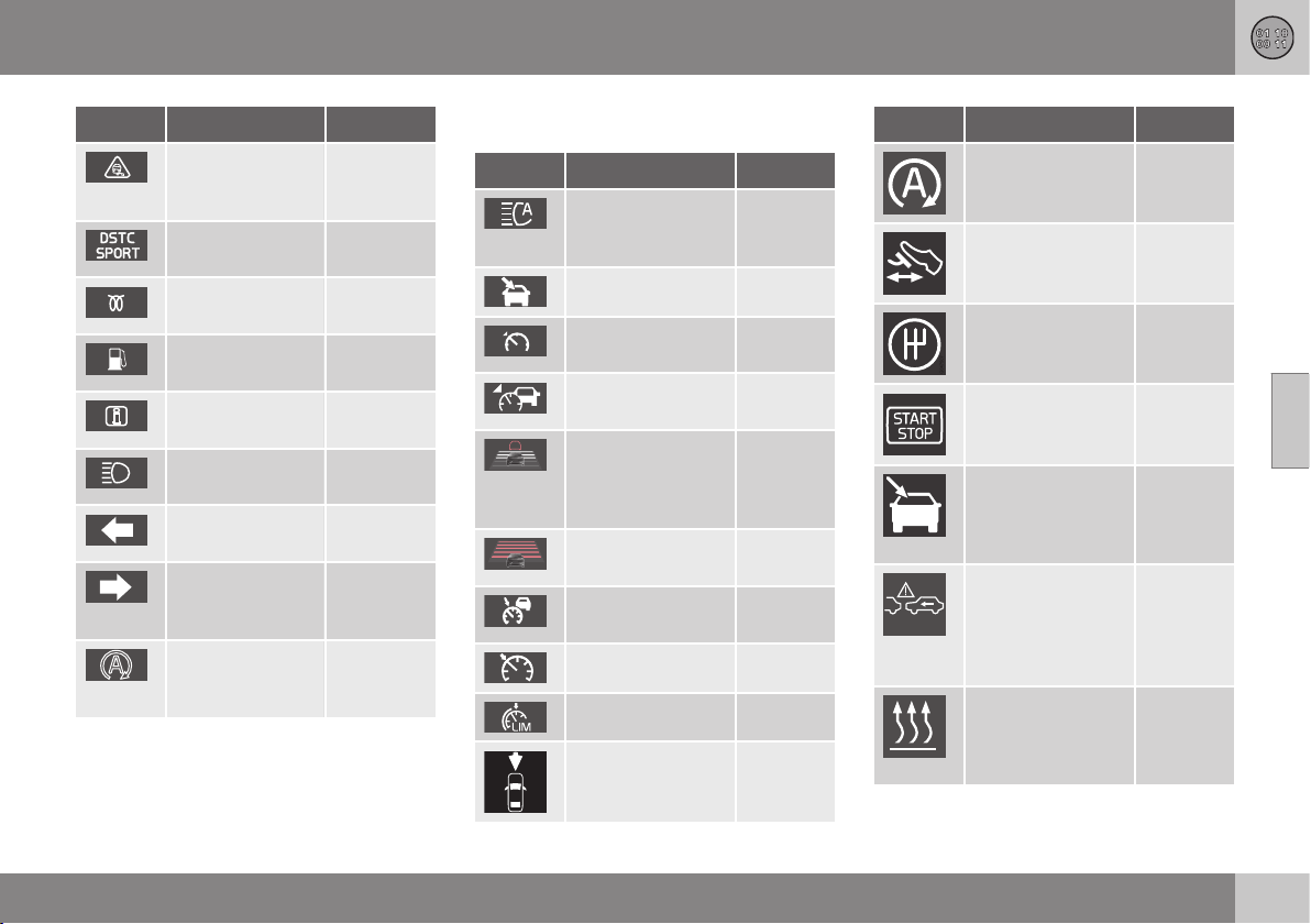
12 Specifications
12
}}
* Option/accessory, for more information, see Introduction.
473
Symbol Specification See
Stability system,
DSTC, Trailer
stability assist*
(p. 65), (p.
187), (p.
307)
Stability system,
sport mode
(p. 65), (p.
187)
Engine preheater
(diesel)
(p. 65)
Low level in fuel
tank
(p. 65), (p.
142)
Information, read
display text
(p. 65)
Main beam On (p. 65), (p.
82)
Left-hand direc-
tion indicators
(p. 65)
Right-hand
direction indica-
tors
(p. 65)
Start/Stop*,
engine auto-
stopped
(p. 65), (p.
280)
Information symbols in the combined
instrument panel
Symbol Specification See
Main beam with
auto dimming -
AHB*
(p. 83)
Camera sensor* (p. 83)
Adaptive cruise
control*
(p. 212)
Adaptive cruise
control*
(p. 203),
(p. 212)
Adaptive cruise
control*, Distance
Warning* (Distance
Alert)
(p. 212),
(p. 214)
Adaptive cruise
control*
(p. 202)
Adaptive cruise
control*
(p. 203)
Cruise control* (p. 194)
Speed limiter (p. 191)
Radar sensor* (p. 212),
(p. 216),
(p. 233)
Symbol Specification See
Start/Stop* (p. 286)
Start/Stop* (p. 286)
Start/Stop* (p. 286)
Start/Stop* (p. 286)
Camera sensor*,
Laser sensor*
(p. 222),
(p. 233),
(p. 237),
(p. 243)
Distance warning*
(Distance Alert),
City Safety
TM
, Col-
lision warning sys-
tem*, Auto-brake*
(p. 216),
(p. 222),
(p. 233)
Engine block
heater and pas-
senger compart-
ment heater*
(p. 142)
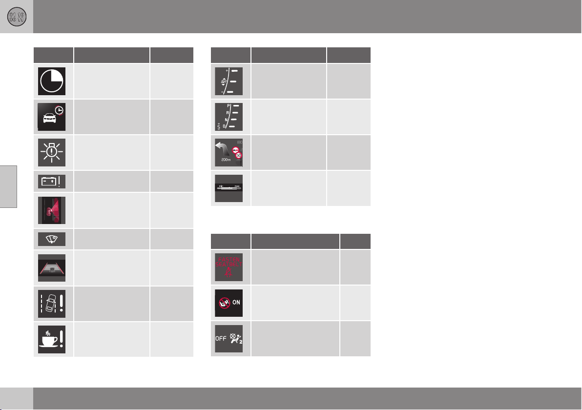
||
12 Specifications
12
474
* Option/accessory, for more information, see Introduction.
Symbol Specification See
Activated timer* (p. 142)
Activated timer* (p. 142)
ABL system* (p. 84)
Low battery (p. 142)
Park Assist Pilot -
PAP*
(p. 253)
Rain sensor* (p. 93)
Lane Keeping Aid* (p. 241)
Driver Alert Sys-
tem*, Lane Keep-
ing Aid*
(p. 237),
(p. 243)
Driver Alert Sys-
tem*, Time for a
break
(p. 236),
(p. 237)
Symbol Specification See
Gear indicator,
manual gearbox
(p. 272)
Automatic gear
positions
(p. 273)
Registered speed
information*
(p. 188)
Measuring the oil
level
(p. 337)
Information symbols in the roof console
display
Symbol Specification See
Seatbelt reminder (p. 27)
Airbag, passenger
seat, activated
(p. 31)
Airbag, passenger
seat, deactivated
(p. 31)
Related information
•
Combined instrument panel - meaning of
indicator symbols (p. 65)
•
Combined instrument cluster - meaning
of warning symbols (p. 66)
•
Messages - handling (p. 104)

12 Specifications
12
475

13 Alphabetical Index
13
476
A
ACC – Adaptive cruise control................. 199
Active Bending Lights (ABL)...................... 84
Active high beam....................................... 83
Active Park Assist.................................... 253
function............................................... 253
Limitations.......................................... 256
operation............................................. 254
Symbols and messages..................... 257
Active Xenon headlamps........................... 84
Active Yaw Control.................................. 185
Adapting driving characteristics.............. 262
Adaptive Cruise Control........................... 199
change cruise control functionality..... 208
deactivate........................................... 206
fault tracing......................................... 211
function............................................... 200
managing speed................................. 203
overtaking........................................... 205
overview.............................................. 202
radar sensor........................................ 209
setting the time interval...................... 204
standby mode..................................... 204
temporary deactivation....................... 204
Additional heater
electric........................................ 143, 144
fuel-driven........................................... 143
Adjusting the steering wheel...................... 77
Airbag
activating/deactivating, PACOS........... 31
driver's side.................................... 30, 37
passenger side......................... 30, 31, 37
AIRBAG ..................................................... 30
Airbag system............................................ 29
warning symbol.................................... 28
Air cleaning
material............................................... 129
passenger compartment.... 127, 128, 129
Air conditioning........................................ 135
Air conditioning, fluid
volume and grade............................... 453
Air conditioning system
repair................................................... 341
Air distribution.......................................... 129
Recirculation....................................... 137
table.................................................... 138
Air quality system IAQS........................... 128
Alarm........................................ 181, 182, 183
alarm indicator.................................... 182
alarm signals....................................... 183
automatic activation........................... 182
automatic re-arming........................... 182
checking the alarm............................. 164
reduced alarm level............................ 183
remote control key not working.......... 183
Alarm for accidents and disasters........... 383
Alcolock................................................... 264
Allergy and asthma inducing substances. 128
All Wheel Drive, (AWD)............................. 288
All Wheel Drive (AWD).............................. 288
Approach lighting.............................. 89, 162
Audio
settings............................................... 376
surround..................................... 371, 377
Audio and media
introduction......................................... 371
manage the system............................ 372
menu overview.................................... 428
menus................................................. 374
overview.............................................. 372
Audio profile............................................. 378
audio system
functions............................................. 376
overview.............................................. 372
Audio system........................................... 371
Audio volume........................................... 372
external audio source......................... 398
phone.................................................. 405
phone/media player............................ 405
ring signal, phone............................... 405
speed/noise compensation................ 378
Automatic car washes............................. 364

13 Alphabetical Index
13
477
Automatic gearbox.......................... 273, 276
manual gear positions (Geartronic)..... 274
towing and recovery........................... 308
trailer................................................... 302
Automatic relocking................................. 174
AUX input......................................... 372, 395
AWD, All Wheel Drive............................... 288
B
Backrest..................................................... 73
front seat, lowering............................... 73
Backrest rear seat, lowering...................... 76
Bag holder .............................................. 154
folding................................................. 154
Battery..................................... 294, 351, 459
jump starting....................................... 270
maintenance....................................... 351
overload.............................................. 294
remote control.................................... 427
remote control key/PCC..................... 167
specification....................................... 459
symbols on the battery....................... 352
warning symbols................................. 352
BLIS................................................. 257, 258
Bluetooth
®
handsfree............................................ 403
media.................................................. 398
microphone off................................... 404
streaming audio.................................. 398
transfer call to mobile......................... 404
Bonnet, opening...................................... 335
Brake and clutch fluid.............................. 341
Brake fluid
grade and volume............................... 451
Brake light.................................................. 86
Brakes.............................................. 289, 291
Anti-lock braking system, ABS........... 291
brake light............................................. 86
brake system.............................. 289, 291
Emergency Brake Assistance, EBA ... 291
emergency brake lights........................ 86
filling brake fluid.................................. 341
handbrake........................................... 292
symbols in the combined instrument
panel................................................... 290
Bulbs, see Lighting.................................. 343
C
Calls
incoming............................................. 403
operation............................................. 403
Camera sensor................................ 219, 231
Car care................................................... 364
Car care, leather upholstery.................... 367
Cargo area
cargo net............................................. 155
lighting.................................................. 88
loading................................................ 152
mounting points.................................. 153
parcel shelf......................................... 157
Car upholstery......................................... 367
Car washing............................................. 364
Catalytic converter
Recovery............................................. 309
CD............................................................ 391
Changing wheels..................................... 318
Checking the engine oil level................... 336
Children
child safety locks.................................. 42
child seat and airbag............................ 48
child seats and side airbags................. 34
location in car....................................... 48
safety.............................................. 34, 42

13 Alphabetical Index
13
478
Child safety locks............................ 179, 180
Child seats................................................. 42
ISOFIX fixture system for child seats... 48
recommended...................................... 44
size classes for child seats with ISO-
FIX fixture system................................. 49
types..................................................... 50
upper mounting points for child seats.. 52
City Safety™............................................ 217
Cleaning
automatic car wash............................ 364
car washing........................................ 364
rims..................................................... 365
seatbelts............................................. 368
upholstery........................................... 367
Clean Zone Interior Package (CZIP)........ 128
Climate control
actual temperature............................. 126
auto-regulation................................... 134
general................................................ 126
personal preferences.......................... 129
sensors............................................... 127
temperature control............................ 135
Clock, adjustment...................................... 69
CO
2
emissions......................................... 454
Collision..................................................... 38
Collision warning............................. 223, 224
Collision warning system
function............................................... 224
general limitations............................... 229
operation............................................. 228
Pedestrian detection........................... 227
Radar sensor.............................. 209, 217
Collision Warning System with Auto
Brake....................................................... 223
Colour code, paint................................... 369
Combined instrument panel................ 60, 61
Compass................................................. 100
calibration........................................... 101
Condensation in headlamps.................... 364
Controls
centre console.................................... 372
Controls, lights........................................... 78
Control symbols................................... 61, 63
Coolant
volume and grade............................... 449
Coolant, checking and filling................... 340
Cooling system........................................ 293
overheating......................................... 293
Corner Traction Control........................... 185
Crash, see Collision................................... 38
Cruise control.......................................... 194
deactivate........................................... 199
managing speed................................. 195
resume set speed............................... 198
temporary deactivation....................... 197
CTA.......................................................... 260
Cyclist detection...................................... 225
CZIP (Clear Zone Interior Package)......... 128
D
DAB Radio....................................... 379, 388
Daytime running lights............................... 81
Deadlock.................................................. 178
deactivation........................................ 178
temporary deactivation....................... 178
Defroster.................................................. 136
Detachable towbar
storage................................................ 303
Diesel....................................................... 298
run out of fuel..................................... 298
Diesel particle filter.................................. 299
Digital radio (DAB).................................... 388
Dimensions.............................................. 440
Dipstick, electronic.................................. 338
Direction indicator..................................... 87
Direction indicators.................................... 87
direction of rotation................................. 312

13 Alphabetical Index
13
479
Disengaging the gear selector inhibitor... 278
Display lighting.......................................... 80
Distance Warning.................................... 214
Limitations.......................................... 215
Symbols and messages..................... 216
Door mirrors............................................... 97
Driver Alert Control.................................. 235
operation............................................. 236
Driver Alert System.................................. 235
Driving...................................................... 295
cooling system.................................... 293
with a tailer......................................... 301
with the tailgate open......................... 294
Driving in water........................................ 293
Driving with a trailer
towball load........................................ 442
towing capacity.................................. 442
DVD.......................................................... 391
E
ECC, electronic climate control............... 131
EcoGuide................................................... 64
Ecolabelling, FSC, owner's manual........... 22
Economical driving.................................. 300
ECO pressure.................................. 322, 457
Electrical socket...................................... 151
cargo area........................................... 155
Electrical system...................................... 458
Electronic climate control - ECC............. 131
Electronic temperature control - ETC...... 132
Emergency equipment
first aid kit........................................... 324
warning triangle.................................. 323
Emergency puncture repair............. 324, 325
action.................................................. 326
inflating the tyres................................ 329
rechecking.......................................... 328
stowing components.......................... 330
Emergency puncture repair kit
location............................................... 325
overview.............................................. 326
sealing fluid......................................... 330
Emissions of carbon dioxide................... 454
Engine
deactivate........................................... 270
overheating......................................... 301
start..................................................... 268
Start/Stop........................................... 279
Engine and passenger compartment heater
direct start/immediate stop................ 141
messages........................................... 142
timer.................................................... 141
Engine block heater................................. 140
Engine braking, automatic....................... 288
Engine compartment
coolant................................................ 340
oil........................................................ 336
overview.............................................. 335
Engine drag control................................. 185
Engine oil......................................... 336, 446
adverse driving conditions.................. 446
filter..................................................... 336
grade and volume............................... 447
Engine specifications............................... 445
Equalizer.................................................. 378
Error messages
Adaptive Cruise Control..................... 212
Driver Alert Control............................. 237
LKA..................................................... 243
see Messages and symbols............... 212
Error messages in BLIS........................... 262
ETC, electronic temperature control........ 132
External dimensions................................ 440
F
Fan
ECC.................................................... 134
ETC..................................................... 134
Fault tracing for the camera sensor......... 220

13 Alphabetical Index
13
480
First aid.................................................... 324
First aid kit............................................... 324
Fluids, capacities..... 449, 450, 451, 452, 453
Fluids and oils.................. 449, 450, 451, 453
Fog lamp
rear........................................................ 85
Foot brake....................................... 289, 291
Front seat
head restraint........................................ 73
FSC, ecolabelling....................................... 22
Fuel.................................................. 297, 298
fuel consumption................................ 454
fuel economy...................................... 322
fuel filter.............................................. 299
Fuel-driven heater
direct start/immediate stop................ 141
timer.................................................... 141
Fuelling............................................ 178, 299
filling................................................... 296
filling with reserve fuel can................. 299
fuel filler flap....................................... 296
fuel filler flap, locking.......................... 178
fuel filler flap, manual opening............ 296
Fuel tank
volume................................................ 452
Fuse box.................................................. 355
Fuses....................................................... 355
changing............................................. 355
engine compartment.......................... 356
General............................................... 355
under front right seat.......................... 362
under glovebox................................... 359
G
Gearbox........................................... 271, 272
automatic.................................... 273, 276
manual................................................ 272
Gear selector inhibitor............................. 278
Gear selector inhibitor, mechanical disen-
gagement................................................. 278
Gear shift indicator.................................. 272
Geartronic................................................ 274
Glass
laminated/reinforced............................. 22
Glass roof, roller blind.............................. 100
Glovebox................................................. 149
cooling................................................ 150
locking................................................ 176
Gross vehicle weight............................... 441
GSI - Gear selector assistance................ 272
H
Handbrake............................................... 292
Hazard warning flashers............................ 86
HDC......................................................... 288
Headlamp control...................................... 78
Headlamp levelling.................................... 80
Headlamp pattern, adjusting..................... 90
Headlamp pattern adjustment................... 90
Active Bending Lights .......................... 90
Halogen headlamp............................... 90
Headlamps............................................... 343
head restraint
centre seat, rear.................................... 76
front seat............................................... 73
lowering................................................ 76
Heating
rearview and door mirrors.................... 98
rear window.......................................... 98
seats................................................... 133
Heat-reflecting windscreen........................ 18
High engine temperature......................... 301
High-pressure headlamp washing............. 94
Hill Descent Control................................. 288
Hill Start Assist........................................ 279
Home safe light duration........................... 89

13 Alphabetical Index
13
481
Horn........................................................... 78
I
IAQS - Interior Air Quality System........... 128
Image settings......................................... 394
Immobiliser.............................................. 161
Indicator symbols...................................... 65
Inflatable curtain.................................. 34, 37
Information button, PCC.......................... 164
Information display.............................. 60, 61
Infotainment system
source buttons.................................... 372
voice control....................................... 413
Infotainment system (Audio and media).. 371
Inlaid mats............................................... 150
Instrument lighting, see Lighting................ 80
Instrument overview
left-hand drive car................................ 54
right-hand drive car.............................. 57
Instruments and controls..................... 54, 57
Interior Air Quality System (IAQS)
Air cleaning......................................... 128
Interior lighting, see Lighting..................... 87
Interior rearview mirror............................... 99
automatic dimming............................... 99
Intermittent wiping..................................... 93
iPod®, connection................................... 396
J
Jack......................................................... 315
Jacket holder........................................... 148
Journey statistics..................................... 124
Jump starting........................................... 270
K
Kerb weight.............................................. 441
Key........................................... 159, 160, 172
Key blade......................................... 165, 166
Keyless drive 168, 169, 170, 171, 172,
173, 269
Keyless - locking..................................... 170
Keyless start (keyless drive) 168, 169,
170, 171, 172, 173, 269
Keyless - unlocking................................. 171
Keypad in the steering wheel............ 78, 372
Key positions............................................. 71
L
Labels...................................................... 438
Laminated glass......................................... 22
Lamps, see Lighting................................ 342
Lane keeping assistant
operation............................................. 241
Lane keeping assistant - LKA.................. 239
Laser sensor............................................ 220
Leather upholstery, washing instructions 367
Light indications, PCC............................. 164
Lighting.................................................... 342
Active Xenon headlamps...................... 84
approach lighting.......................... 89, 162
automatic lighting, passenger com-
partment............................................... 88
bulbs, specifications........................... 348
controls................................................. 87
daytime running lights.......................... 81
display lighting...................................... 80
headlamp levelling................................ 80
home safe lighting................................ 89
instrument lighting................................ 80
in the passenger compartment............. 87
main/dipped beam............................... 82
position/parking lamps......................... 80
rear fog lamp........................................ 85
tunnel detection.................................... 82

13 Alphabetical Index
13
482
Lighting, bulb replacement...................... 343
daytime running lights........................ 346
dipped beam (cars with halogen head-
lamps)................................................. 344
direction indicators, front.................... 345
main beam (cars with active xenon
headlamps)......................................... 345
main beam (cars with halogen head-
lamps)................................................. 344
position/parking lamps....................... 345
rear bulb holder: direction indicators,
brake lamps and reversing lamps...... 346
rear fog lamps..................................... 347
vanity mirror........................................ 348
LKA - Lane keeping assistant.................. 239
Loading
cargo area................................... 152, 154
General....................................... 152, 153
long load............................................. 153
mounting points.................................. 153
roof load............................................. 153
Lock
locking................................................ 173
manual locking.................................... 174
unlocking.................................... 173, 175
Lockable wheel bolts............................... 314
Lock confirmation ................................... 160
Lock indicator.......................................... 161
Locking/unlocking
inside.................................................. 175
tailgate................................................ 176
M
Main/dipped beam, see Lighting............... 82
Main beam, automatic activation.............. 83
maintenance
Rustproofing....................................... 366
Making calls............................................. 403
Manual gearbox....................................... 272
GSI - Gear selector assistance........... 272
Towing and recovery.......................... 308
trailer................................................... 302
Manual gear positions (Geartronic).......... 274
Max. roof load.......................................... 441
Media, Bluetooth
®
.................................... 398
Media player.................................... 379, 390
compatible file formats....................... 394
Memory function in seat............................ 74
Menu navigation audio and media.......... 374
Menus
Combined instrument panel............... 101
menu overview, analogue................... 102
menu overview, digital........................ 102
Messages................................................ 104
Information display............................. 103
Messages and symbols
Adaptive Cruise Control..................... 212
Collision Warning with Auto
Brake.......................................... 222, 233
Driver Alert Control............................. 237
Engine block heater and passenger
compartment heater........................... 142
LKA..................................................... 243
Messages in BLIS.................................... 262
Meters
fuel gauge....................................... 60, 61
speedometer................................... 60, 61
tachometer..................................... 60, 61
Microphone.............................................. 404
misting
attending to the windows................... 126
Misting
condensation in headlamps............... 364
Mobile phone
connect............................................... 400
handsfree............................................ 403
register phone..................................... 400
voice control....................................... 413
Mood lighting............................................. 88
MY CAR 104, 105, 106, 108, 109, 111,
112, 113, 114

13 Alphabetical Index
13
483
N
News broadcasts..................................... 384
O
Oil, see also Engine oil..................... 446, 447
Oil level low.............................................. 336
Output...................................................... 445
outside temperature gauge....................... 68
Overheating............................................. 301
Owner's manual, ecolabelling.................... 22
P
PACOS....................................................... 31
Paintwork
colour code......................................... 369
damage and touch-up........................ 368
Panel lighting............................................. 80
Panic function.......................................... 162
PAP - Active Park Assist.......................... 253
Parcel shelf.............................................. 157
Park Assist............................................... 245
backward............................................ 247
fault indicator...................................... 248
function............................................... 245
parking assistance sensors................ 248
Park assist camera.................................. 249
settings............................................... 252
Parking brake........................................... 292
Passenger compartment filter................. 127
Passenger compartment heater.............. 140
Passenger compartment lighting
automatic.............................................. 88
PCC – Personal Car Communicator
functions............................................. 162
range........................................... 165, 169
Pedestrian airbag....................................... 40
folding up.............................................. 42
moving the car...................................... 41
Pedestrian detection................................ 223
Petrol grade............................................. 298
Phone
connect............................................... 400
handsfree............................................ 403
incoming call....................................... 403
making calls........................................ 403
phone book......................................... 406
phone book, shortcut......................... 406
receiving a call.................................... 404
register phone..................................... 400
voice control....................................... 413
Pocket park assist - PAP......................... 253
Polishing.................................................. 365
Position/parking lamps.............................. 80
Power guide............................................... 64
Power seat................................................. 74
Powershift gearbox.......................... 276, 308
Power windows......................................... 95
Q
Queue Assist............................................ 206
Queue Assistant....................................... 206
R
Radar sensor........................................... 200
Limitations.......................................... 209
Radio....................................................... 379
DAB............................................ 379, 388
Radio programme types (PTY)................ 384
Rain sensor................................................ 93
RDS.......................................................... 382
Rear bulbs
location............................................... 346

13 Alphabetical Index
13
484
Rear seat
Heating............................................... 133
Rearview and door mirrors
compass............................................. 100
door...................................................... 97
electrically retractable........................... 98
heating.................................................. 98
interior................................................... 99
Rear window, defrosting............................ 98
Recommendations during driving............ 295
Recommended child seats
table...................................................... 44
Recovery.................................................. 310
Refrigerant............................................... 341
Regeneration........................................... 299
Relay/fuse box, see Fuses....................... 355
Remote control........................................ 425
battery replacement............................ 427
Remote control immobiliser..................... 162
Remote control key......................... 159, 160
battery replacement............................ 167
detachable key blade................. 165, 166
functions............................................. 162
loss..................................................... 159
range........................................... 163, 169
Remote control key system, type appro-
val............................................................ 460
Resetting, trip meter........................ 117, 121
Resetting the door mirrors......................... 98
Resetting the power windows................... 96
Retractable power door mirrors................. 98
Reverse gear inhibitor.............................. 272
Road sign information............................. 188
Limitations.......................................... 190
operation............................................. 188
Roller blind for glass roof......................... 100
Roof load, max. weight............................ 441
Rustproofing............................................ 366
S
Safety lock
children................................................. 42
Safety mode.............................................. 38
moving the car...................................... 40
start attempt......................................... 39
Sealing fluid............................................. 330
Seat, see Seats.......................................... 73
Seatbelt...................................................... 24
loosen................................................... 26
pregnancy............................................. 26
putting on............................................. 25
rear seat................................................ 27
seatbelt reminder.................................. 27
seatbelt tensioner................................. 27
Seatbelt reminder...................................... 27
Seatbelt tensioner................................ 27, 37
Seats.......................................................... 73
head restraints, rear.............................. 76
heating................................................ 133
Heating............................................... 133
lowering the front backrest................... 73
lowering the rear backrest.................... 76
power.................................................... 74
Securing loads (Loading)......................... 153
Sensus....................................................... 70
Service position....................................... 349
Service programme................................. 332
Set time interval....................................... 214
Side airbag SIPS.................................. 33, 37
Signal input, external....................... 372, 395
SIPS airbag................................................ 33
Skidding................................................... 295
slippery driving conditions....................... 295
Soot filter................................................. 299
SOOT FILTER FULL................................. 299
spare wheel..................................... 317, 318
installation........................................... 320
taking out............................................ 318

13 Alphabetical Index
13
485
Speed limiter............................................ 191
alarm for speed exceeded.................. 194
deactivation........................................ 194
getting started............................ 191, 192
temporary deactivation....................... 193
Speed ratings, tyres................................. 317
Spin control............................................. 185
Stability and traction control system 185,
187
operation............................................. 186
Stability system....................................... 185
Stains....................................................... 367
Start/Stop................................................ 279
Function and operation...................... 280
the engine does not stop.................... 281
Steering force, speed related.................. 262
Steering force level, see Steering force... 262
Steering lock............................................ 270
Steering wheel........................................... 77
keypad.......................................... 78, 372
steering wheel adjustment.................... 77
Stone chips and scratches...................... 368
Storage spaces
driver's side........................................ 148
glovebox............................................. 149
Jacket holder...................................... 148
tunnel console.................................... 148
Storage spaces in the passenger com-
partment.................................................. 146
surround.......................................... 371, 377
Switching off the engine.......................... 270
Symbols
indicator symbols..................... 61, 63, 65
warning symbols............................. 61, 63
Symbols and messages
Adaptive Cruise Control..................... 212
Collision Warning with Auto
Brake.......................................... 222, 233
Driver Alert Control............................. 237
LKA..................................................... 243
System
tripping.................................................. 37
T
Tailgate
Locking/unlocking.............................. 176
Temperature
actual temperature............................. 126
Temperature control................................ 135
Total airing function......................... 126, 176
Towbar
detachable, attachment...................... 304
detachable, removal........................... 306
Towbar, see Towing equipment.............. 303
Towbar - detachable
attachment/removal.................... 304, 306
Towing..................................................... 308
towing eye.......................................... 309
Towing bracket........................................ 303
specifications...................................... 304
Towing capacity and towball load........... 442
Towing eye.............................................. 309
Traction control........................................ 185
Traffic information (TP) ........................... 383
Trailer....................................................... 301
cable................................................... 301
driving with a trailer............................ 301
snaking............................................... 307
Trailer stability assist............................... 185
Trailer Stability Assist.............................. 307
Transmission............................................ 272
Transmission oil
volume and grade............................... 450
Transponder.............................................. 18
Tread depth............................................. 315
Tread wear indicators.............................. 314
Trip computer.................. 114, 119, 123, 124
analogue instrument panel................. 115
Trip meter.................................................. 68

13 Alphabetical Index
13
486
Trip meter, resetting........................ 117, 121
Troubleshooting
Adaptive Cruise Control..................... 211
TSA - trailer stability assist ............. 185, 307
Tunnel console........................................ 148
12 V socket......................................... 151
armrest................................................ 149
cigarette lighter and ashtray............... 149
Tunnel detection........................................ 82
TV............................................................. 421
Type approval
Bluetooth
®
.......................................... 462
radar system....................................... 460
remote control key system................. 460
Type designations................................... 438
Tyre dimension........................................ 316
Tyre load index........................................ 316
Tyre pressure label.................................. 322
Tyres
direction of rotation............................ 312
maintenance....................................... 312
pressure...................................... 322, 457
puncture repair................................... 324
specifications...................................... 457
tread depth......................................... 315
tread wear indicators.......................... 314
winter tyres......................................... 315
U
Unlocking
from the inside.................................... 175
from the outside................................. 173
Unlocking with the key blade................... 171
USB, connection...................................... 396
USB input................................................ 395
V
Vanity mirror...................................... 88, 150
Ventilation................................................ 129
Vibration damper..................................... 303
Voice control, mobile phone.................... 413
Volvo Sensus............................................. 70
W
Warning lamp
Adaptive Cruise Control..................... 200
collision warning system.................... 228
stability and traction control system.. 185
Warning lamps
Airbags – SRS....................................... 66
alternator not charging......................... 66
Fault in brake system........................... 66
Low oil pressure................................... 66
Parking brake applied........................... 66
seatbelt reminder............................ 27, 66
Warning................................................ 66
Warning sound
collision warning system.................... 228
Warning symbols........................... 61, 63, 66
Warning triangle....................................... 323
Washer fluid
volume................................................ 451
Washer fluid, filling................................... 351
Washers
rear window.......................................... 94
washer fluid, filling.............................. 351
windscreen........................................... 94
Water and dirt-repellent coating.............. 366
Water-repellent surface, cleaning............ 366
Waxing..................................................... 365
Weights
kerb weight......................................... 441
Wheel bolts.............................................. 314
lockable.............................................. 314
Wheel rim, dimensions............................ 316
Wheel rims
cleaning.............................................. 365

13 Alphabetical Index
13
487
Wheels
removal............................................... 319
snow chains........................................ 315
spare wheel........................................ 317
Wheels and tyres..................................... 317
Whiplash injury, WHIPS............................. 35
WHIPS
child seat/booster cushion................... 36
seating position.................................... 36
whiplash protection........................ 35, 37
Windows, rearview and door mirrors. 22, 366
Windscreen
heating................................................ 136
Windscreen, heating.................................. 98
Windscreen washing.................................. 94
Windscreen wiper...................................... 93
rain sensor............................................ 93
Winter driving........................................... 295
Winter tyres.............................................. 315
Wiper blades............................................ 349
changing............................................. 349
Cleaning.............................................. 350
replacing, rear window....................... 350
Service position.................................. 349
Wipers and washing.................................. 93

13 Alphabetical Index
13
488


Volvo Car Corporation 16803 (English), AT 1348, Printed in Sweden, Göteborg 2013, Copyright © 2000-2013 Volvo Car Corporation