Loading ...
Loading ...
Loading ...
12
CD-DP2400E_2.fm01/7/17
CD-DP2400E
Preparation for Use
- System connections -
System connections (continued)
!
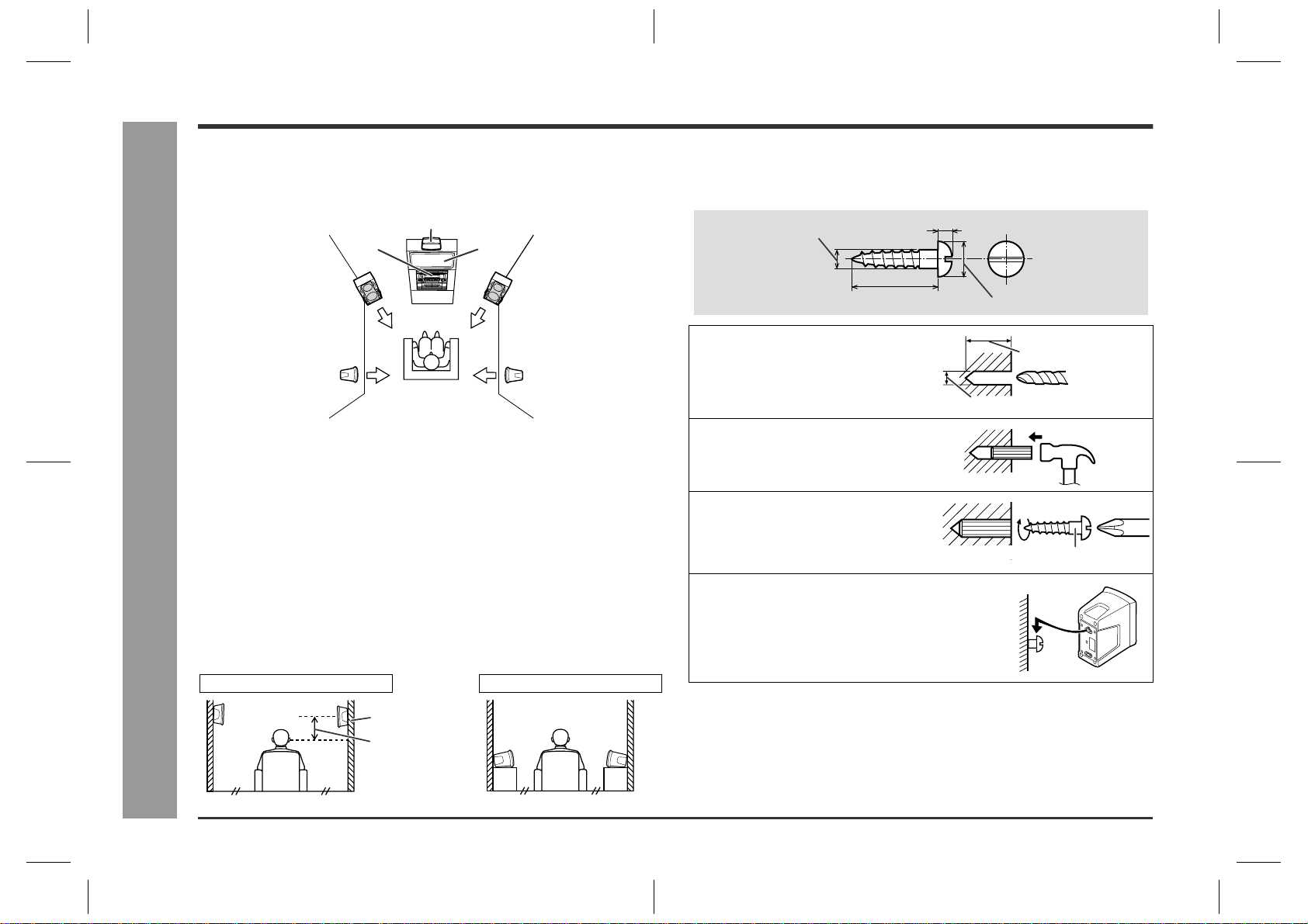
Placing the speaker system
To enjoy the surround effect, we recommend that you place each speaker as shown
below.
Installation of the surround speakers:
If possible, mount the surround speakers on the wall. Install them 60 cm - 90 cm (23"
- 35") above the height of your ears when you are seated.
!
To mount the surround speakers on the wall
The design of the surround speakers allows them to be hung on the wall. Be sure to
use the type and size of screw that is shown to the below.
!
Connecting the AC power lead
After making all connections, plug in the unit. If you plug in the unit
first, it will enter the demonstration mode.
Note:
Unplug the AC power lead from the wall socket if the unit will not be in use for a pro-
longed period of time.
Notes:
"
The front speakers and the centre speaker are magnetically shielded.
Therefore, they do not affect the display even if you use them near the TV. Howev-
er, some colour variation may occur, depending on the type of TV used.
If colour variation occurs...
Turn off the TV (from the power switch).
After 15 - 30 minutes, turn the TV on again.
If the colour variation is still present...
Move the front speakers further away from the TV.
"
If any kind of magnet or an electromagnet is placed too close to the TV and the sys-
tem, irregular colours may appear on the TV screen.
Main unit
Front speaker
(Left)
Front speaker
(Right)
Surround speaker
(Left)
Surround speaker
(Right)
TV
Centre speaker
Wall
Example: when installed on the wall Example: when installed vertically
60 - 90 cm
(23" - 35")
1
Make a hole in the wall using a
drill.
2
Drive a wall mount plug into the
hole using a hammer. Drive the
wall mount plug in until it is flush
with the wall surface.
3
Drive one screw into the wall
mount plug for each speaker.
Drive the screws, so there is about a 5
mm (3/16") space between the wall and
the head of the screw.
4
Mount the surround speaker on
the wall so that the screw head is
inserted into the slot on the sur-
round speaker.
5 mm (3/16")
3.2 mm (1/8")
Min. 22 mm (7/8")
9 mm (3/8")
32 mm (1-1/4")
8-9 mm (3/8")
Wall mounting screw
Wall surface
Wall surface
Downloaded from: http://www.usersmanualguide.com/
Loading ...
Loading ...
Loading ...