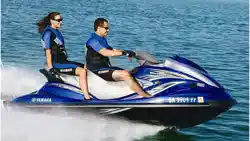
2007 WaveRunner
FX High Output
FX Cruiser High Output
OWNER’S/OPERATOR’S MANUAL
READ THIS MANUAL
CAREFULLY BEFORE OPERATION!
F1X-F8199-11
U.S.A. Edition
LIT-18626-06-87
UF1X11E0.book Page 1 Monday, August 7, 2006 3:51 PM
Important manual information
EJU30180
To the owner/operator
Thank you for choosing a Yamaha watercraft.
This owner’s/operator’s manual contains in-
formation you will need for proper operation,
maintenance, and care. A thorough under-
standing of these simple instructions will help
you to obtain maximum enjoyment from your
new Yamaha. If you have any questions
about the operation or maintenance of your
watercraft, please consult a Yamaha dealer.
Because Yamaha has a policy of continuing
product improvement, this product may not be
exactly as described in this owner’s/opera-
tor’s manual. Specifications are subject to
change without notice.
This manual should be considered a perma-
nent part of this watercraft and should remain
with it even if the watercraft is subsequently
sold.
In this manual, information of particular impor-
tance is distinguished in the following ways:
The Safety Alert Symbol means ATTEN-
TION! BECOME ALERT! YOUR SAFETY IS
INVOLVED!
WARNING
EWJ00070
Failure to follow WARNING instructions
could result in severe injury or death
to the
machine operator, passengers, a bystand-
er, or a person inspecting or repairing the
watercraft.
CAUTION:
ECJ00090
A CAUTION indicates special precautions
that must be taken to avoid damage to the
watercraft.
NOTE:
A NOTE provides key information to make
procedures easier or clearer.
EJU30220
WaveRunner FX High Output/
FX Cruiser High Output
OWNER’S/OPERATOR’S MANUAL
©2006 by Yamaha Motor Corporation,
USA
1st Edition, August 2006
All rights reserved.
Any reprinting or unauthorized use
without the written permission of
Yamaha Motor Corporation, USA
is expressly prohibited.
Printed in USA
P/N LIT-18626-06-87
UF1X11E0.book Page 1 Monday, August 7, 2006 3:51 PM

Table of contents
General and important labels........... 1
Identification numbers .................... 1
Primary Identification (PRI-ID)
number ........................................... 1
Hull Identification Number (HIN) ........ 1
Engine serial number ........................ 1
Emission control information .......... 2
Approval label of emission control
certificate ........................................ 2
Manufactured date label .................... 2
Star labels ......................................... 2
Important labels .............................. 4
Warning labels ................................... 5
Other labels ....................................... 7
Safety information.............................9
Limitations on who may operate
the watercraft .............................. 9
Cruising limitations ....................... 10
Operation requirements ............... 12
Recommended equipment ........... 14
Hazard information ....................... 15
Watercraft characteristics ............. 15
Water-skiing ................................. 17
Rules of the Road ........................ 19
To get more boating safety
information ................................ 23
Enjoy your watercraft
responsibly ................................ 24
Features and functions................... 25
Location of main components ...... 25
Operation of controls and other
functions .................................... 29
Seats ............................................... 29
Hood ................................................ 30
Fuel tank filler cap ........................... 31
Remote control transmitter .............. 31
Engine stop switch .......................... 32
Engine shut-off switch ..................... 32
Start switch ...................................... 33
Throttle lever ................................... 33
Cooling water pilot outlets ............... 33
Steering system ............................... 34
Tilt lever ........................................... 34
Shift lever ........................................ 35
Quick Shift Trim System (QSTS)
selector ........................................ 35
Handgrip .......................................... 37
Reboarding step .............................. 37
Bow eye ........................................... 37
Stern eyes ....................................... 38
Pull-up cleats (for FX Cruiser High
Output) ......................................... 38
Yamaha Engine Management
System (YEMS) ........................... 38
Yamaha Security System and
low-RPM mode ............................ 38
Multifunction information center ...... 40
Storage compartments .................... 50
Operation ......................................... 54
Fuel and oil .................................. 54
Gasoline .......................................... 54
Engine oil ......................................... 55
Filling the fuel tank .......................... 55
Pre-operation checks ................... 56
Pre-operation check list ................... 56
Pre-operation check points .............. 58
Operation ..................................... 66
Engine break-in ............................... 66
Launching the watercraft ................. 66
Starting the engine .......................... 66
Stopping the engine ........................ 68
Leaving the watercraft ..................... 68
Operating your watercraft ............ 69
Getting to know your watercraft ....... 69
Learning to operate your
watercraft ..................................... 69
Riding with passengers ................... 70
Starting the watercraft ..................... 70
Boarding and starting in deep
water ............................................ 71
Capsized watercraft ......................... 74
Turning the watercraft ..................... 75
Stopping the watercraft ................... 77
Beaching the watercraft ................... 77
UF1X11E0.book Page 1 Monday, August 7, 2006 3:51 PM

Table of contents
Docking the watercraft ..................... 77
Reverse on waterways .................... 77
Rough water operation .................... 78
Post-operation care ...................... 78
Transporting ................................. 79
Maintenance and care..................... 80
Storage ......................................... 80
Flushing the cooling system ............ 80
Lubrication ....................................... 81
Fuel system ..................................... 81
Battery ............................................. 82
Cleaning the watercraft ................... 82
Maintenance and adjustments ..... 83
Owner’s/operator’s manual and
tool kit ........................................... 83
Periodic maintenance chart ............. 85
Checking the fuel system ................ 87
Engine oil and oil filter ..................... 87
Checking the air filter element ......... 88
Checking the jet thrust nozzle
angle ............................................ 89
Checking the shift cable .................. 89
Checking and adjusting the throttle
cable ............................................ 89
Cleaning and adjusting the spark
plugs ............................................ 90
Lubrication points ............................ 91
Checking the battery ....................... 92
Fuel injection system ....................... 94
Specifications.................................. 95
Specifications ................................ 95
Trouble recovery ............................. 96
Troubleshooting ........................... 96
Troubleshooting chart ...................... 96
Emergency procedures ................ 98
Cleaning the jet intake and
impeller ........................................ 98
Jumping the battery ......................... 99
Replacing the fuses ....................... 100
Towing the watercraft .................... 101
Submerged watercraft ................... 101
Consumer information ................. 103
Limited warranty ......................... 103
YAMAHA EXTENDED SERVICE
(Y.E.S.) ................................... 105
UF1X11E0.book Page 2 Monday, August 7, 2006 3:51 PM
General and important labels
1
EJU30260
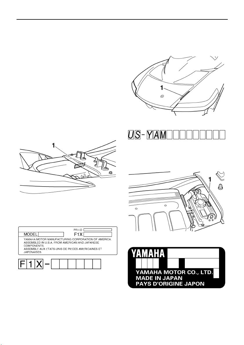
Identification numbers
Record the Primary Identification (PRI-ID)
number, Hull Identification Number (HIN), and
engine serial number in the spaces provided
for assistance when ordering spare parts from
a Yamaha dealer. Also record and keep these
ID numbers in a separate place in case your
watercraft is stolen.
EJU30281
Primary Identification (PRI-ID) number
The PRI-ID number is stamped on a plate at-
tached inside the engine compartment.
MODEL:
FX1100-F (FX High Output)
FX1100A-F (FX Cruiser High Output)
EJU30300
Hull Identification Number (HIN)
The HIN is stamped on a plate attached to the
aft deck.
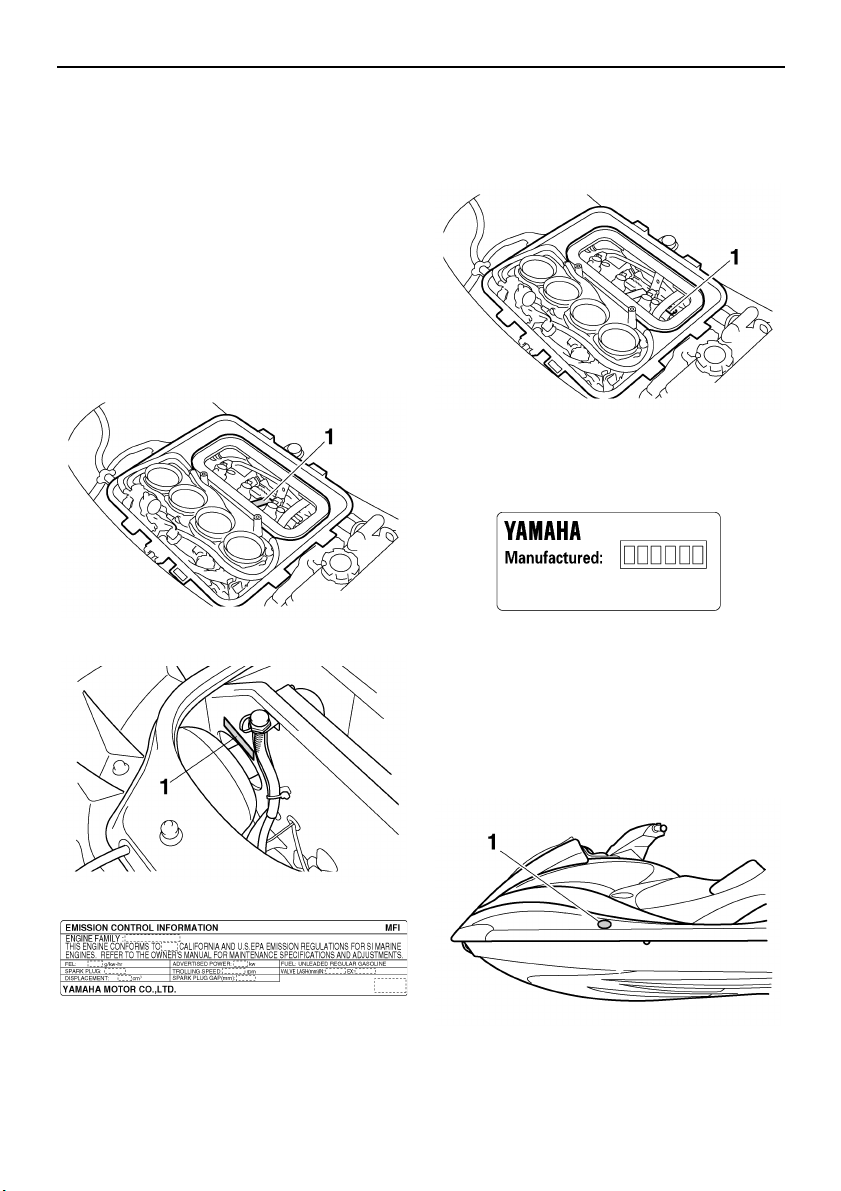
EJU30310
Engine serial number
The engine serial number is stamped on a
plate attached to the engine unit.
1 Primary Identification (PRI-ID) number loca-
tion
1 Hull Identification Number (HIN) location
1 Engine serial number location
UF1X11E0.book Page 1 Monday, August 7, 2006 3:51 PM
General and important labels
2
EJU30350
Emission control information
This engine conforms to 2007 U.S. Environ-
mental Protection Agency (EPA) and/or Cali-
fornia Air Resources Board (CARB)
regulations for marine SI engines.
This engine is certified to operate on regular
unleaded gasoline.
EJU30390
Approval label of emission control
certificate
This label is attached to the top of the cylinder
head and to the bulkhead.
EJU30430
Manufactured date label
This label is attached to the top of the cylinder
head.
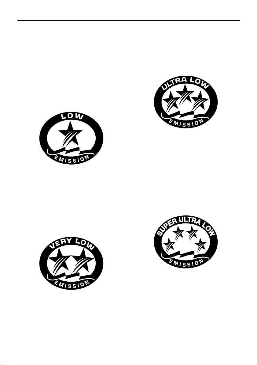
EJU30440
Star labels
This watercraft is labeled with a California Air
Resources Board (CARB) star label. See be-
low for a description of your particular label.
1 Emission control information label location
1 Emission control information label location
1 Manufactured date label location
1 Star label location
UF1X11E0.book Page 2 Monday, August 7, 2006 3:51 PM
General and important labels
3
One Star - Low Emission
The one-star label identifies engines that
meet the Air Resources Board’s Personal
Watercraft and Outboard marine engine 2001
exhaust emission standards. Engines meet-
ing these standards have 75% lower emis-
sions than conventional carbureted two-
stroke engines. These engines are equivalent
to the U.S. EPA’s 2006 standards for marine
engines.
Two Stars - Very Low Emission
The two-star label identifies engines that meet
the Air Resources Board’s Personal Water-
craft and Outboard marine engine 2004 ex-
haust emission standards. Engines meeting
these standards have 20% lower emissions
than One Star-Low Emission engines.
Three Stars - Ultra Low Emission
The three-star label identifies engines that
meet the Air Resources Board’s Personal
Watercraft and Outboard marine engine 2008
exhaust emission standards or the Sterndrive
and Inboard marine engine 2003-2008 ex-
haust emission standards. Engines meeting
these standards have 65% lower emissions
than One Star-Low Emission engines.
Four Stars - Super Ultra Low Emission
The four-star label identifies engines that
meet the Air Resources Board’s Sterndrive
and Inboard marine engine 2009 exhaust
emission standards. Personal Watercraft and
Outboard marine engines may also comply
with these standards. Engines meeting these
standards have 90% lower emissions than
One Star-Low Emission engines.
UF1X11E0.book Page 3 Monday, August 7, 2006 3:51 PM
General and important labels
4
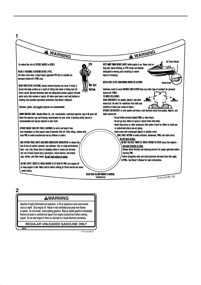
EJU30450
Important labels
UF1X11E0.book Page 4 Monday, August 7, 2006 3:51 PM
General and important labels
5
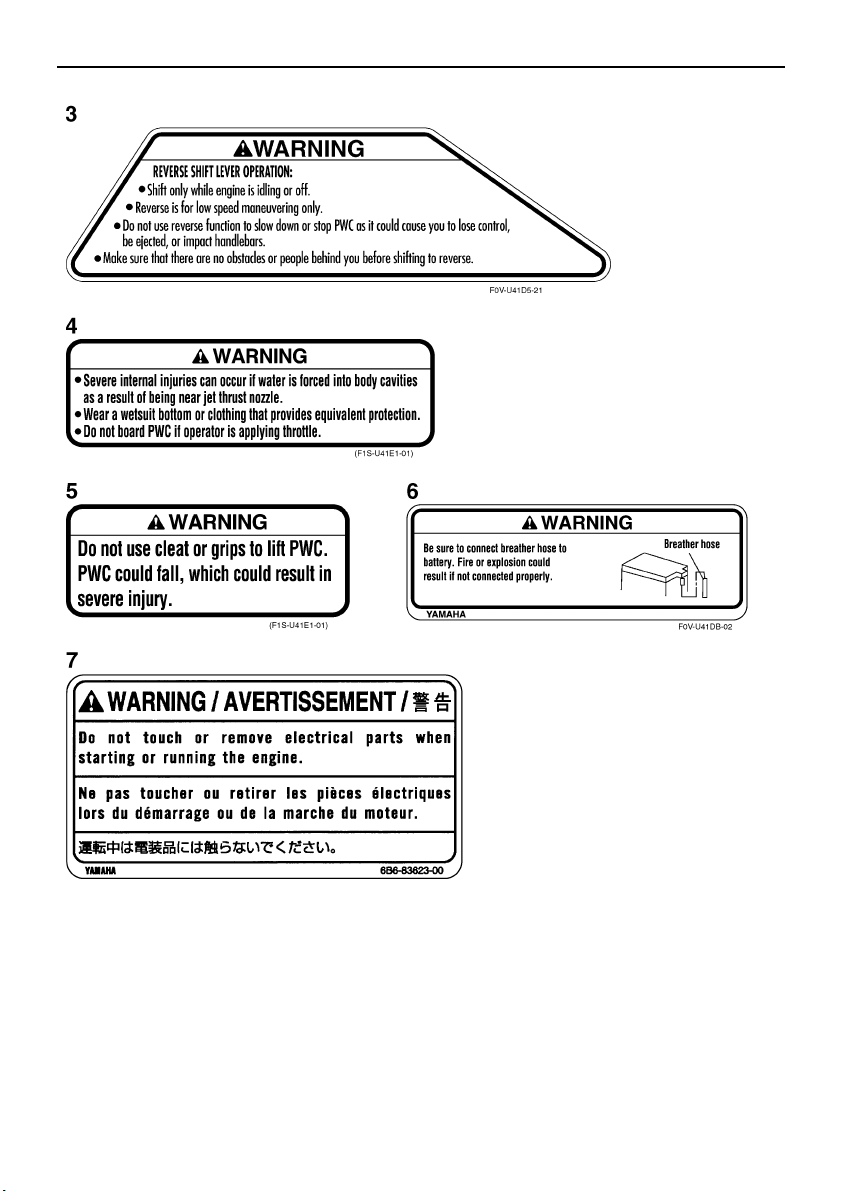
EJU35910
Warning labels
UF1X11E0.book Page 5 Monday, August 7, 2006 3:51 PM
General and important labels
6
UF1X11E0.book Page 6 Monday, August 7, 2006 3:51 PM

General and important labels
7
EJU35922
Other labels
UF1X11E0.book Page 7 Monday, August 7, 2006 3:51 PM
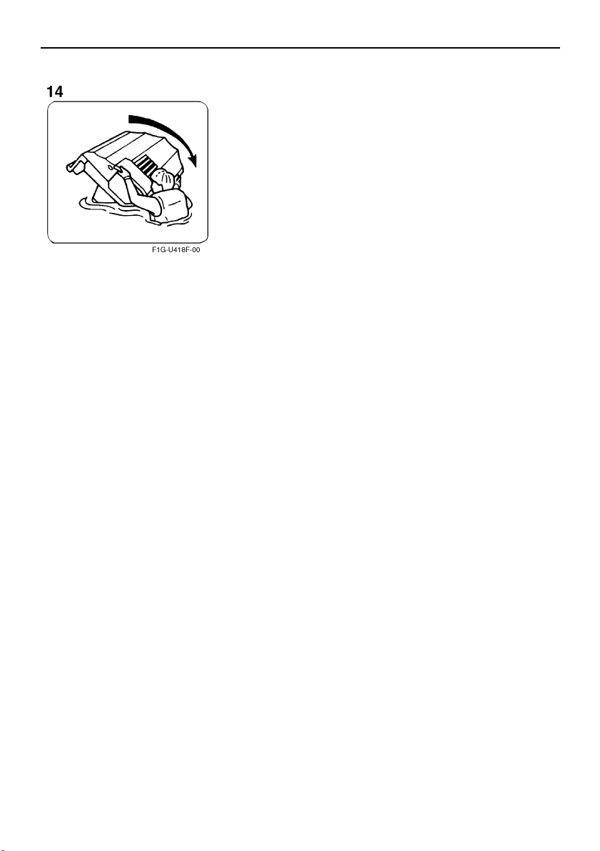
General and important labels
8
The following label indicates the correct direction to upright a capsized watercraft.
UF1X11E0.book Page 8 Monday, August 7, 2006 3:51 PM
Safety information
9
EJU30670
The safe use and operation of this water-
craft is dependent upon the use of proper
riding techniques, as well as upon the
common sense, good judgment, and ex-
pertise of the operator. Every operator
should know the following requirements
before riding the watercraft.
● Before operating the watercraft, read this
owner’s/operator’s manual, the Riding
Practice Guide, the Riding Instruction card,
and all warning and caution labels on the
watercraft. Also, watch the Basic Orienta-
tion Video provided with your watercraft.
These materials should give you an under-
standing of the watercraft and its operation.
● Never allow anyone to operate this water-
craft until they too have read this own-
er’s/operator’s manual, the Riding Practice
Guide, the Riding Instruction card, and all
warning and caution labels, and, if possible,
watched the Basic Orientation Video.
Showing them the video may help reinforce
the information contained in these materi-
als.
EJU30730
Limitations on who may
operate the watercraft
● Yamaha recommends a minimum operator
age of 16 years old.
Adults must supervise use by minors.
Know the operator age and training require-
ments for your state. A boating safety
course is recommended and may be re-
quired in your state. You can find local rules
by contacting the United States Coast
Guard (USCG), the National Association of
State Boating Law Administrators, or your
local Power Squadron.
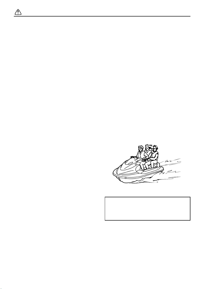
● This watercraft is designed to carry the op-
erator and up to 2 passengers. Never ex-
ceed the maximum load limit or allow more
than 3 persons (or 2 persons if a water-skier
is being pulled) to ride the watercraft at any
time.
● Do not operate the watercraft with any pas-
sengers on board until you have consider-
able practice and experience riding alone.
Operating the watercraft with passengers
requires more skill. Take the time to be-
come accustomed to the handling charac-
Maximum load:
240 kg (530 lb)
Load is the total weight of cargo, oper-
ator, and passengers.
UF1X11E0.book Page 9 Monday, August 7, 2006 3:51 PM
Safety information
10
teristics of the watercraft before trying any
difficult maneuvers.
EJU30760
Cruising limitations
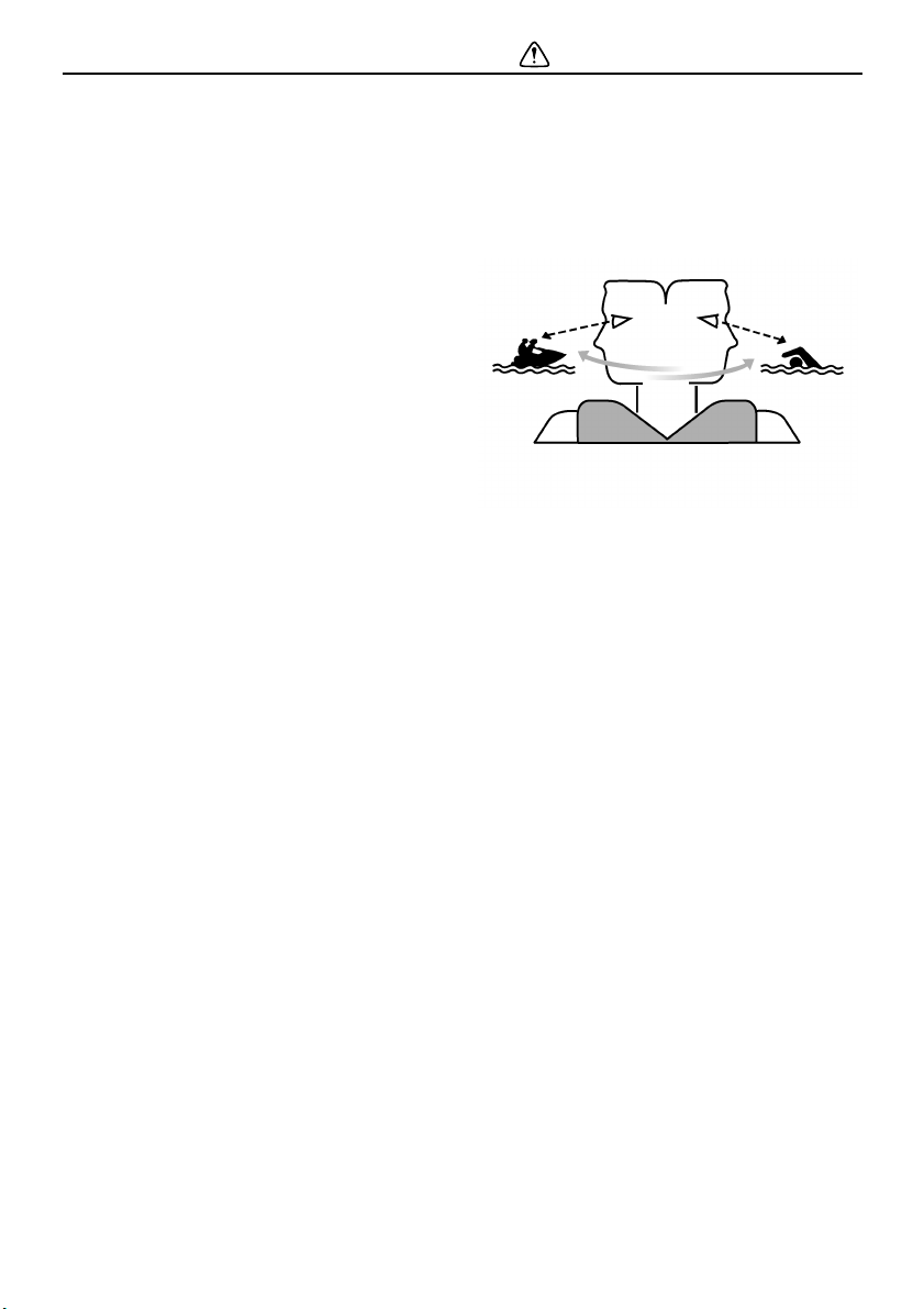
● Scan constantly for people, objects, and
other watercraft. Be alert for conditions that
limit your visibility or block your vision of
others.
● Operate defensively at safe speeds and
keep a safe distance away from people, ob-
jects, and other watercraft.
● Do not follow directly behind watercraft or
other boats.
● Do not go near others to spray or splash
them with water.
● Avoid sharp turns or other maneuvers that
make it hard for others to avoid you or un-
derstand where you are going.
● Avoid areas with submerged objects or
shallow water.
● Take early action to avoid collisions. Re-
member, watercraft and other boats do not
have brakes.
● Do not release the throttle lever when trying
to steer away from objects—you need throt-
tle to steer. Always check throttle and steer-
ing controls before starting the watercraft.
● Ride within your limits and avoid aggressive
maneuvers to reduce the risk of loss of con-
trol, ejection, and collision.
● This is a high performance boat—not a toy.
Sharp turns or jumping wakes or waves can
increase the risk of back/spinal injury (pa-
ralysis), facial injuries, and broken legs, an-
UF1X11E0.book Page 10 Monday, August 7, 2006 3:51 PM
Safety information
11
kles, and other bones. Do not jump wakes
or waves.
● Do not operate the watercraft in rough wa-
ter, bad weather, or when visibility is poor;
this may lead to an accident causing injury
or death. Be alert to the possibility of ad-
verse weather. Take note of weather fore-
casts and the prevailing weather conditions
before setting out on your watercraft.
● As with any water sport, you should not op-
erate your watercraft without someone else
nearby. If you operate further than swim-
ming distance from shore, you should be
accompanied by another boat or watercraft,
but make sure you stay a safe distance
away. It’s good, common sense!
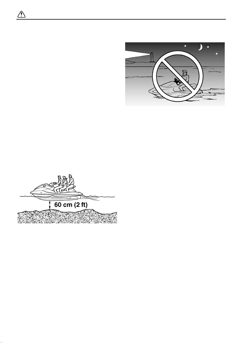
● Never operate in water that is less than 60
cm (2 ft) deep, otherwise you increase your
chance of hitting a submerged object,
which could result in injury.
● This watercraft is not equipped with lighting
required for night operation. Do not operate
the watercraft after sunset or before dawn,
otherwise you increase the risk of colliding
with another boat, which could result in se-
vere injury or death.
● Follow navigation rules, and state/provin-
cial and local laws that apply to watercraft.
UF1X11E0.book Page 11 Monday, August 7, 2006 3:51 PM
Safety information
12
EJU30811
Operation requirements
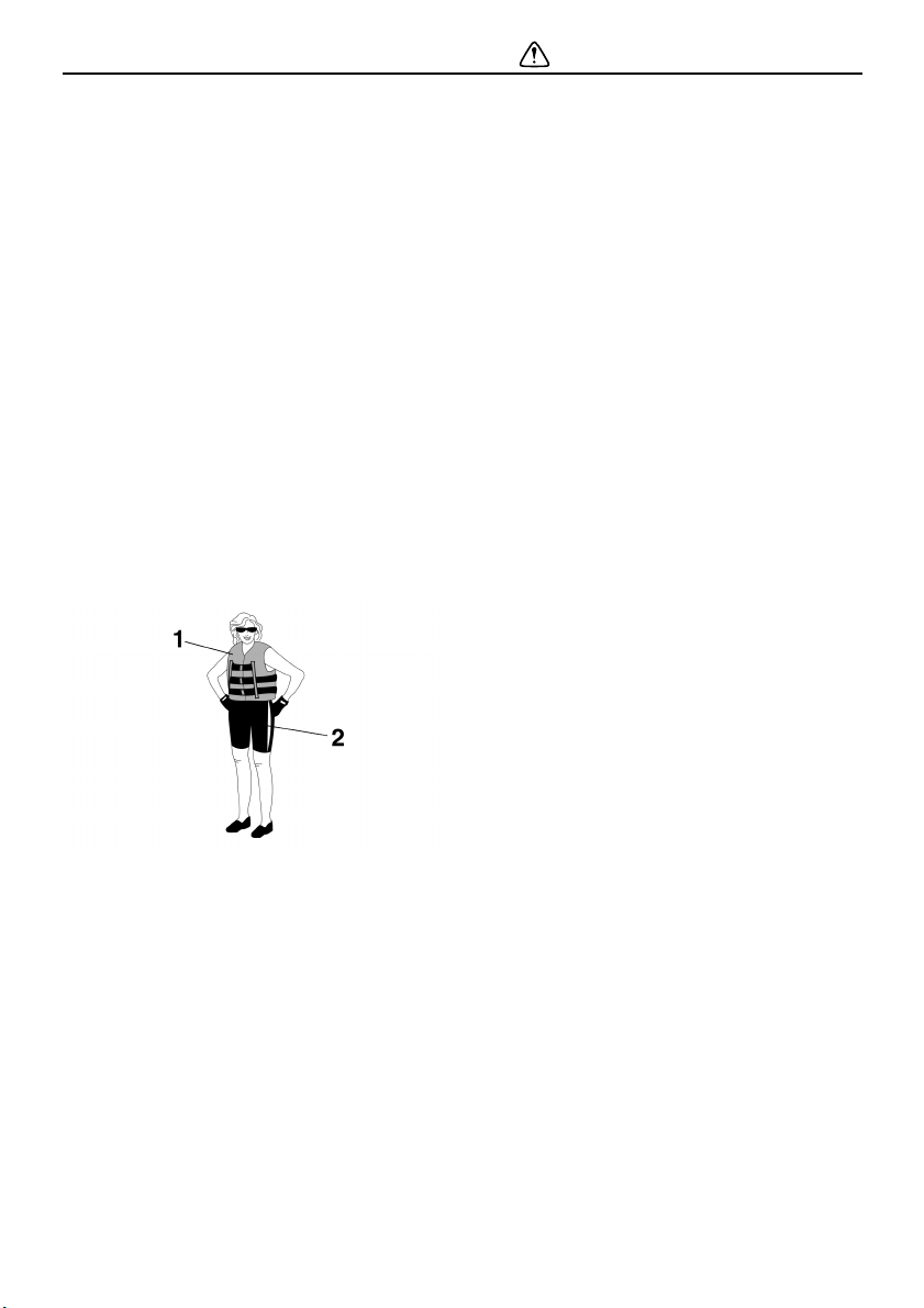
● All riders must wear a U.S. Coast Guard
(USCG) approved personal flotation device
(PFD) that is suitable for personal water-
craft use.
● Wear protective clothing. Severe internal
injuries can occur if water is forced into
body cavities as a result of falling into the
water or being near the jet thrust nozzle.
Normal swimwear does not adequately pro-
tect against forceful water entry into the rec-
tum or vagina. All riders must wear a
wetsuit bottom or clothing that provides
equivalent protection. Such clothing in-
cludes thick, tightly woven, sturdy and
snug-fitting apparel such as denim, but
does not include spandex or similar fabrics,
like those used in bicycle shorts.
● Eye protection is recommended to keep
wind, water, and glare from the sun out of
your eyes while you operate your water-
craft. Restraining straps for eyewear are
made which are designed to float should
your eyewear fall in the water.
Footwear and gloves are recommended.
● Helmets meeting Snell or DOT standards
are required for IJSBA-sanctioned races.
You must decide whether to wear a helmet
while you ride for recreation. You should
know that a helmet could help protect you in
certain kinds of accidents and that it could
injure you in others.
A helmet is designed to provide some head
protection. Although helmets cannot protect
against all foreseeable impacts, a helmet
might reduce your injuries in a collision with
a boat or other obstacle.
A helmet may have potential safety haz-
ards, as well. Falling into the water could
risk the chance of the helmet catching wa-
ter, commonly known as “bucketing”, and
the resulting strain on your neck could
cause choking, severe and permanent neck
injuries, or death. A helmet could also in-
crease the risk of an accident if it reduces
your vision or hearing, or if it distracts you or
increases your fatigue.
How should you decide if a helmet’s poten-
tial safety benefits outweigh its potential
risks for you? Consider your particular
riding conditions. Consider factors such as
your riding environment and your riding
style and ability. Also consider the likeli-
hood of traffic congestion, and the water
surface conditions.
If you decide to wear a helmet based upon
your riding circumstances, choose one
carefully. Look for a helmet designed for
personal watercraft use, if possible. Con-
sider a helmet meeting Snell or DOT stan-
dards. If you will be engaging in closed-
course competition, follow the helmet re-
quirements of the sanctioning organization.
1 USCG approved PFD
2 Wetsuit bottom
UF1X11E0.book Page 12 Monday, August 7, 2006 3:51 PM
Safety information
13
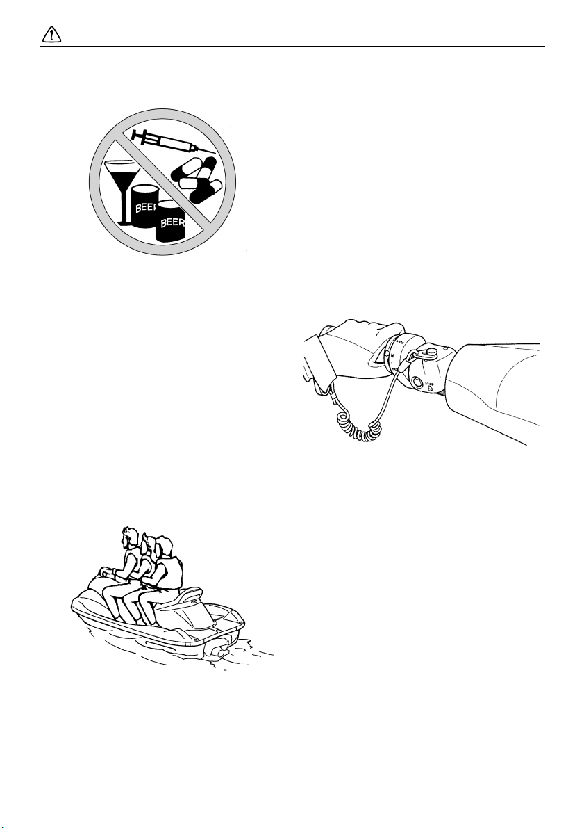
● NEVER operate the watercraft after con-
suming alcohol or taking other drugs.
● For reasons of safety and proper care of the
watercraft, always perform the pre-opera-
tion checks listed on page 56 before operat-
ing the watercraft.
● The operator and passengers should al-
ways keep their feet on the floor of the foot-
well when the watercraft is in motion. Lifting
your feet increases the chances of losing
your balance, or hitting objects outside the
watercraft with your feet. Do not give a ride
to children if their feet cannot reach the floor
of the footwell.
● The passengers should hold on firmly, ei-
ther to the person in front of them or to the
handgrip provided.
● Never allow a passenger to ride in front of
the operator.
● Always consult your doctor on whether it is
safe for you to ride this watercraft if you are
pregnant or in poor health.
● Do not attempt to modify this watercraft!
Modifications to your watercraft may reduce
safety and reliability, and render the water-
craft unsafe or illegal for use.
● Attach the engine shut-off cord to your left
wrist and keep it free from the handlebars
so that the engine stops if you, the operator,
fall off. After riding, remove the engine shut-
off cord from the watercraft to avoid acci-
dental starting or unauthorized use by chil-
dren or others.
● Scan carefully for swimmers and stay away
from swimming areas. Swimmers are hard
to see and you could accidentally hit some-
one in the water.
● Avoid being hit by another boat! You should
always take the responsibility to watch for
traffic; other boaters may not be watching
for you. If they do not see you, or if you ma-
neuver more quickly than other boaters ex-
pect, you risk a collision.
● Maintain a safe distance from other boats
and watercraft, and also watch for ski ropes
or fishing lines. Obey the “Rules of the
Road” and be sure to check behind you be-
fore making a turn. (See “Rules of the
Road” on page 19.)
UF1X11E0.book Page 13 Monday, August 7, 2006 3:51 PM
Safety information
14
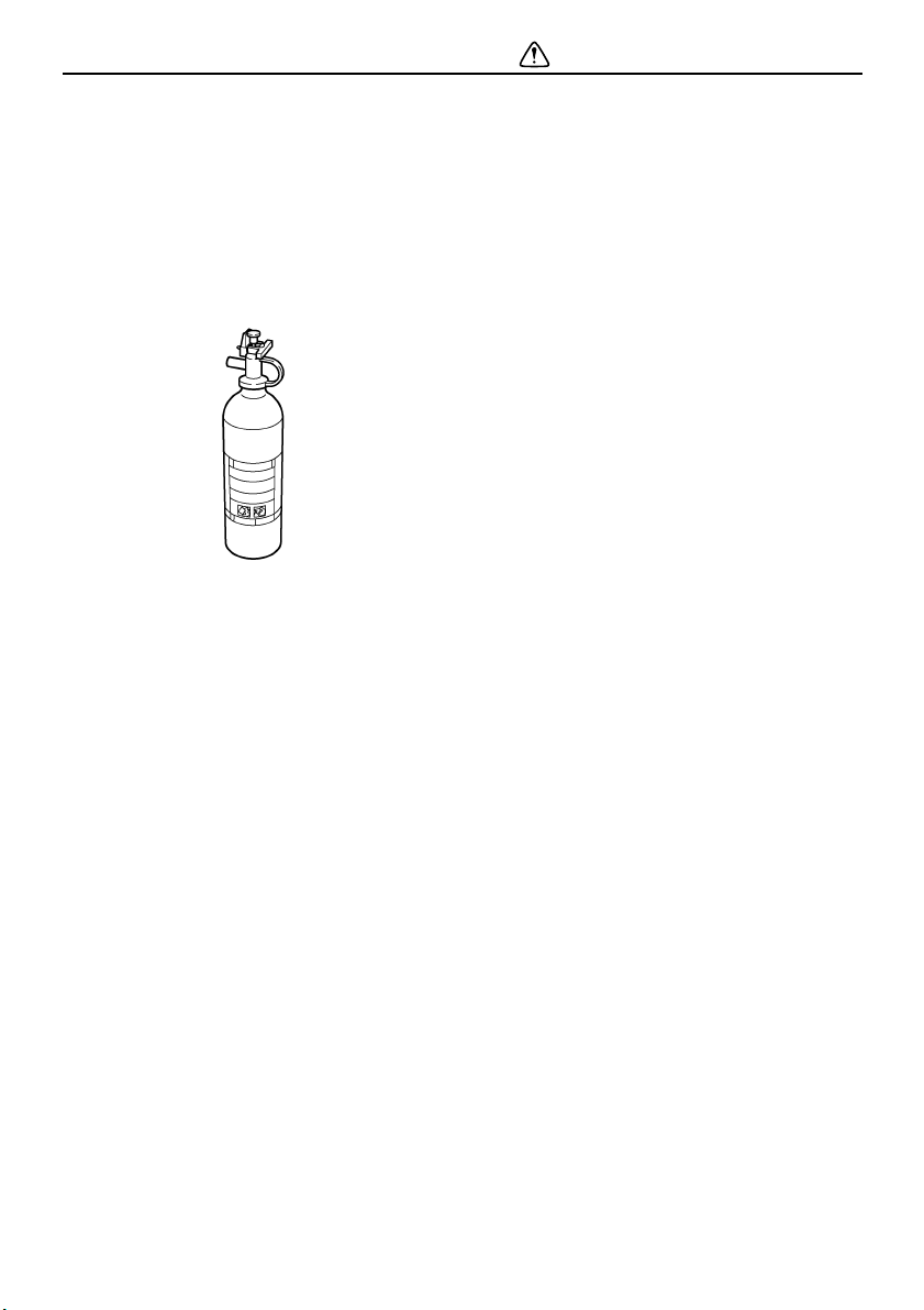
● According to the USCG, boats under 6.1 m
(20 ft) in length like your watercraft MUST
carry a fire extinguisher of a B-1 classifica-
tion, with a capacity of two pounds or more
when navigating in waters under USCG ju-
risdiction. In addition, most state and local
boating laws also require that the fire extin-
guisher be approved by the USCG.
EJU30830
Recommended equipment
The following items should be carried on
board your watercraft:
● Sound-signaling device
You should carry a whistle or other sound-
signaling device that can be used to signal
other boats. See “Rules of the Road” for
more information.
● Visual distress signals
It is recommended that a U.S. Coast Guard
approved pyrotechnic device be stored in a
waterproof container on your watercraft. A
mirror can also be used as an emergency
signal. Contact a Yamaha dealer or the
U.S. Coast Guard for more information.
● Watch
A watch is helpful so you will know how long
you have been operating the watercraft.
● Towline
A towline can be used to tow a disabled wa-
tercraft in an emergency.
UF1X11E0.book Page 14 Monday, August 7, 2006 3:51 PM

Safety information
15
EJU30870
Hazard information
● Never start the engine or let it run for any
length of time in an enclosed area. Exhaust
fumes contain carbon monoxide, a color-
less, odorless gas that may cause loss of
consciousness and death within a short
time. Always operate the watercraft in an
open area.
● Do not touch the hot oil tank, muffler, or en-
gine during or immediately after engine op-
eration; they can cause serious burns.
EJU30920
Watercraft characteristics
● Jet thrust turns the watercraft. Releasing
the throttle lever completely produces only
minimum thrust. If you are traveling at
speeds above trolling, you will have rapidly
decreasing ability to steer without throttle.
This model is equipped with the Yamaha
Engine Management System (YEMS) that
includes an off-throttle steering (OTS) sys-
tem. It will activate at planing speeds should
you attempt to steer the watercraft after re-
leasing the throttle lever. The OTS system
assists in turning by continuing to supply
some thrust while the watercraft is deceler-
ating, but you can turn more sharply if you
apply throttle while turning the handlebars.
The OTS system does not function below
planing speeds or when the engine is off.
Once the engine slows down, the watercraft
will no longer turn in response to handlebar
input until you apply throttle again or you
reach trolling speed.
Practice turning in an open area without ob-
stacles until you have a good feel for this
maneuver.
● This watercraft is water-jet propelled. The
jet pump is directly connected to the engine.
This means that jet thrust will produce some
movement whenever the engine is running.
There is no “neutral” position. You are in ei-
ther “forward” or “reverse”, depending upon
the shift lever position.
● Do not use the reverse function to slow
down or stop the watercraft as it could
cause you to lose control, be ejected, or im-
pact the handlebars.
This could increase the risk of back/spinal
injury (paralysis), facial injuries, and broken
legs, ankles, and other bones. You could
also damage the shift mechanism.
UF1X11E0.book Page 15 Monday, August 7, 2006 3:51 PM
Safety information
16
● Reverse can be used to slow down or stop
during slow-speed maneuvering, such as
when docking. Once the engine is idling,
shift into reverse and gradually increase en-
gine speed. Make sure that there are no ob-
stacles or people behind you before shifting
into reverse.
● Keep away from the intake grate while the
engine is on. Items such as long hair, loose
clothing, or PFD straps can become entan-
gled in moving parts, resulting in severe in-
jury or drowning.
● Never insert any object into the jet thrust
nozzle while the engine is running. Severe
injury or death could result from coming in
contact with the rotating parts of the jet
pump.
● Stop the engine and remove the clip from
the engine shut-off switch before removing
any debris or weeds, which may have col-
lected around the jet intake.
1 Intake grate
2 Jet thrust nozzle
1 Clip
2 Engine shut-off switch
UF1X11E0.book Page 16 Monday, August 7, 2006 3:51 PM
Safety information
17
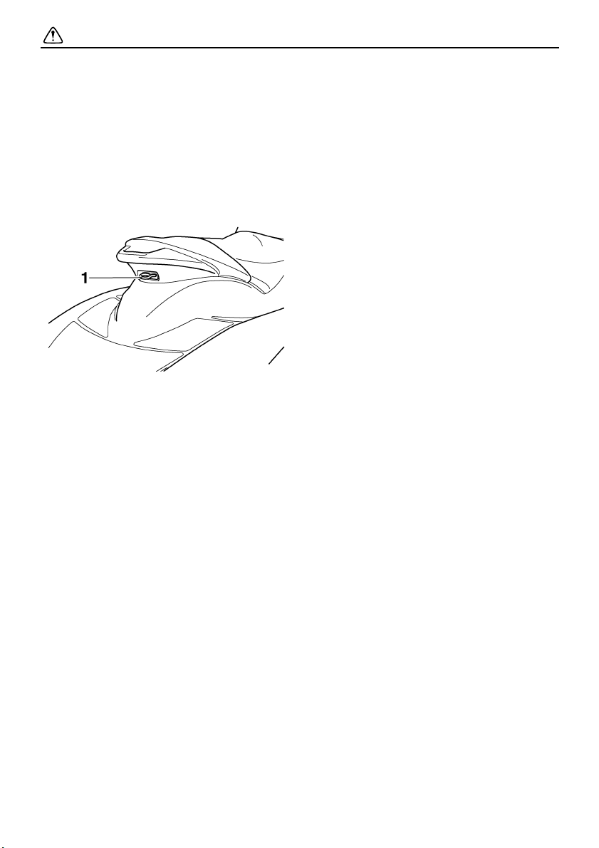
EJU30940
Water-skiing
You can use the watercraft for water-skiing if
it has the seating capacity to carry the opera-
tor, a rearward-facing spotter, and the water-
skier when he or she is not skiing.
The watercraft must also have a cleat de-
signed to pull a ski rope; do not attach the
rope to any other location.
It is the watercraft operator’s responsibility to
be alert to the safety of the water-skier and
others. Know and follow all state and local wa-
ter-skiing regulations in effect for the waters in
which you will be operating.
The operator should be comfortable carrying
passengers before attempting to pull a skier.
The following are some important consider-
ations for minimizing risks while water-skiing.
● The skier should wear an approved PFD,
preferably a brightly colored one so boat
operators can see the skier.
● The skier should wear protective clothing.
Severe internal injuries can occur if water is
forced into body cavities as a result of falling
into the water. Normal swimwear does not
adequately protect against forceful water
entry into the rectum or vagina. The skier
should wear a wetsuit bottom or clothing
that provides equivalent protection.
● A second person should be on board as a
spotter to watch the skier; in most states it
is required by law. Let the skier direct the
operator’s control of speed and direction
with hand signals.
The spotter should sit astride the rear of the
seat and hold onto the handgrip with both
feet firmly on the floor of the footwell for
proper balance while facing to the rear to
1 Cleat
UF1X11E0.book Page 17 Monday, August 7, 2006 3:51 PM

Safety information
18
watch the skier’s hand signals and condi-
tion.
FX High Output
FX Cruiser High Output
● Your control while pulling a water-skier is
affected by the skier’s ability, as well as wa-
ter and weather conditions.
● When preparing to pull a skier, operate the
watercraft at the slowest possible speed
until the watercraft is well away from the ski-
er and slack in the ski rope is taken up.
Make sure that the rope is not looped
around anything.
After checking that the skier is ready and
that there is no traffic or other obstacles, ap-
ply enough throttle to raise the skier.
● Make smooth, wide turns. The watercraft is
capable of very sharp turns, which could ex-
ceed the abilities of the skier. Keep the skier
at least 50 m (150 ft), about twice the dis-
tance of a standard ski rope, from any po-
tential hazard.
● Be alert to the hazard of the ski rope handle
snapping back at the watercraft when the
skier falls or is unable to get up on the skis.
● Towing heavy or bulky objects other than
skiers, such as another boat or watercraft,
can cause loss of steering control and cre-
ate a hazardous condition. If you must tow
another boat in an emergency situation, op-
erate slowly and cautiously.
1 Handgrip
1 Handgrip
1 Handgrip
UF1X11E0.book Page 18 Monday, August 7, 2006 3:51 PM

Safety information
19
EJU30960
Rules of the Road
Your Yamaha watercraft is legally consid-
ered a powerboat. Operation of the water-
craft must be in accordance with the rules
and regulations governing the waterway
on which it is used.
Just as there are rules that apply when you
are driving on streets and highways, there are
waterway rules that apply when you are oper-
ating your watercraft. These rules are used in-
ternationally, and are also enforced by the
United States Coast Guard and local agen-
cies. You should be aware of these rules, and
follow them whenever you encounter another
vessel on the water.
Several sets of rules prevail according to geo-
graphic location, but are all basically the same
as the International Rules of the Road. The
rules presented here in this owner’s/opera-
tor’s manual are condensed, and have been
provided for your convenience only. Consult
your local U.S. Coast Guard Auxiliary or De-
partment of Motor Vehicles for a complete set
of rules governing the waters in which you will
be operating your watercraft.
Steering and sailing rules
Whenever two vessels on the water meet one
another, one vessel has the right-of-way; it is
called the “stand-on” vessel. The vessel that
does not have the right-of-way is called the
“give-way” or “burdened” vessel. These rules
determine which vessel has the right-of-way,
and what each vessel should do.
Stand-on vessel
The vessel with the right-of-way has the duty
to continue its course and speed, except to
avoid an immediate collision. When you main-
tain your direction and speed, the other vessel
will be able to determine how best to avoid
you.
Give-way vessel
The vessel which does not have the right-of-
way has the duty to take positive and timely
action to stay out of the way of the stand-on
vessel. Normally, you should not cross in front
of the vessel with the right-of-way. You should
slow down or change directions briefly and
pass behind the other vessel. You should al-
ways move in such a way that the operator of
the other vessel can see what you are doing.
The General Prudential Rule regarding the
right-of-way is that if a collision appears un-
avoidable, neither boat has the right-of-way.
Both boats must avoid the collision.
In other words, follow the standard rules ex-
cept when a collision will occur unless both
vessels try to avoid each other. If that is the
case, both vessels become give-way vessels.
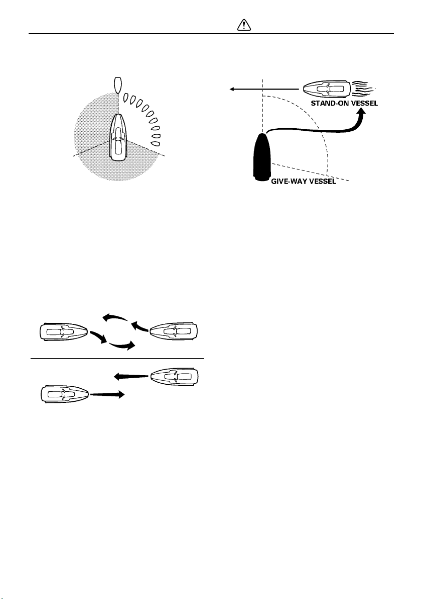
Rules when encountering vessels
There are three main situations that you may
encounter with other vessels which could lead
to a collision unless the Steering Rules are fol-
lowed:
Meeting: you are approaching another vessel
head-on
Crossing: you are traveling across another
vessel’s path
Overtaking: you are passing or being passed
by another vessel
In the following illustration, your watercraft is
in the center. You should give the right-of-way
to any vessels shown in the white area (you
are the give-way vessel). Any vessels in the
shaded area must yield to you (they are the
UF1X11E0.book Page 19 Monday, August 7, 2006 3:51 PM
Safety information
20
give-way vessels). Both you and the meeting
vessel must alter course to avoid each other.
Meeting
If you are meeting another power-driven ves-
sel head on, and are close enough to run the
risk of collision, neither of you has the right-of-
way! Both of you should alter course to avoid
an accident. You should keep the other vessel
on your port (left) side. This rule does not ap-
ply if both of you will clear one another if you
continue on your set course and speed.
Crossing
When two power-driven vessels are crossing
each other’s path close enough to run the risk
of collision, the vessel which has the other on
the starboard (right) side must keep out of the
way of the other. If the other vessel is on your
starboard (right) side, you must keep out of its
way; you are the give-way vessel. If the other
vessel is on your port (left) side, remember
that you should maintain course and direction,
provided the other vessel gives you the right-
of-way as it should.
Overtaking
If you are passing another vessel, you are the
give-way vessel. This means that the other
vessel is expected to maintain its course and
speed. You must stay out of its way until you
are clear of it. Likewise, if another vessel is
passing you, you should maintain your speed
and direction so that the other vessel can
steer itself around you.
Other special situations
There are three other rules you should be
aware of when riding your watercraft around
other vessels.
Narrow channels and bends
When navigating in narrow channels, you
should keep to the right when it is safe and
practical to do so. If the operator of a power-
driven vessel is preparing to go around a
bend that may obstruct the view of other water
vessels, the operator should sound a pro-
longed blast of four to six seconds on the
whistle. If another vessel is around the bend,
it too should sound the whistle. Even if no re-
ply is heard, however, the vessel should still
proceed around the bend with caution. If you
navigate such waters with your watercraft,
you will need to carry a portable air horn,
available from local marine supply stores.
UF1X11E0.book Page 20 Monday, August 7, 2006 3:51 PM

Safety information
21
Fishing vessel right-of-way
All vessels fishing with nets, lines, or trawls
are considered to be “fishing vessels” under
the International Rules. Vessels with trolling
lines are not considered fishing vessels. Fish-
ing vessels have the right-of-way regardless
of position. Fishing vessels cannot, however,
impede the passage of other vessels in nar-
row channels.
Sailing vessel right-of-way
Sailing vessels should normally be given the
right-of-way. The exceptions to this are:
(1) When the sailing vessel is overtaking the
power-driven vessel, the power-driven
vessel has the right-of-way.
(2) Sailing vessels should keep clear of any
fishing vessel.
(3) In a narrow channel, a sailing vessel
should not hamper the safe passage of a
power-driven vessel that can navigate
only in such a channel.
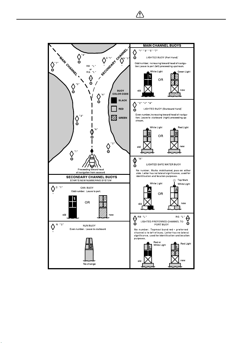
Reading buoys and other markers
The waters of the United States are marked
for safe navigation by the lateral system of
buoyage. Simply put, buoys and markers
have an arrangement of shapes, colors, num-
bers, and lights to show which side of the
buoy a boater should pass on when navigat-
ing in a particular direction. The markings on
these buoys are oriented from the perspective
of being entered from seaward (the boater is
going towards the harbor). Red buoys are
passed on your starboard (right) side when
proceeding from open water into the harbor,
and black buoys are to your port (left) side. An
easy way to remember the meaning of the
colors is the phrase “red right returning”.
When navigating out of the harbor, your posi-
tion with respect to the buoys should be re-
versed; red buoys should be to port and black
buoys to starboard.
Many bodies of water used by boaters are en-
tirely within the boundaries of a particular
state. The Uniform State Waterway Marking
System has been devised for these waters.
This system uses buoys and signs with dis-
tinctive shapes and colors to show regulatory
or advisory information. These markers are
white with black letters and orange borders.
UF1X11E0.book Page 21 Monday, August 7, 2006 3:51 PM
Safety information
22
They signify speed zones, restricted areas,
danger areas, and general information.
Remember, markings may vary by geograph-
ic location. Always consult local boating au-
thorities before riding your watercraft in
unfamiliar waters.
UF1X11E0.book Page 22 Monday, August 7, 2006 3:51 PM

Safety information
23
EJU30980
To get more boating safety
information
Be informed about boating safety. Additional
publications and information can be obtained
from many organizations, including the follow-
ing.
United States Coast Guard
Consumer Affairs Staff (G-BC)
Office of Boating, Public, and Consumer Af-
fairs
U.S. Coast Guard Headquarters
Washington, D.C. 20593-0001
Boating Safety Hotline: 1-800-368-5647
Other sources
You can find local rules by contacting the Na-
tional Association of State Boating Law Ad-
ministrators, or your local Power Squadron.
Watercraft Education and Training
The Online Boating Safety Course, available
through the watercraft section of the yamaha-
motor.com website, is a free, 50 question
learning course available to the public. Upon
successful completion of 80 percent or better,
the user can request a certificate of comple-
tion by mail or can download one immediate-
ly. The Online Boating Safety Course,
provided by the Boat/US Foundation, is ap-
proved by the National Association of State
Boating Law Administrators (NASBLA) and
recognized by the United States Coast
Guard. This course meets the education re-
quirement for those states that recognize non-
proctored, NASBLA-approved courses.
Yamaha is the watercraft industry’s leading
manufacturer to build awareness and support
for boating education. In 1997, Yamaha
launched its GET W.E.T. (Watercraft Educa-
tion and Training) initiative and has since
reached out to over one million Americans
promoting the benefits of boating education.
The Online Boating Safety Course:
http://www.boatus.com/onlinecourse/
UF1X11E0.book Page 23 Monday, August 7, 2006 3:51 PM

Safety information
24
EJU30990
Enjoy your watercraft
responsibly
You share the areas you enjoy when riding
your watercraft with others and with nature.
So your enjoyment includes a responsibility to
treat these other people, and the lands, wa-
ters, and wildlife with respect and courtesy.
Whenever and wherever you ride, think of
yourself as the guest of those around you. Re-
member, for example, that the sound of your
watercraft may be music to you, but it could be
just noise to others. And the exciting splash of
your wake can make waves others won’t en-
joy.
Avoid riding close to shoreline homes and wa-
terfowl nesting areas or other wildlife areas,
and keep a respectful distance from fisher-
men, other boats, swimmers, and populated
beaches. When travel in areas like these is
unavoidable, ride slowly and obey all laws.
Proper maintenance is necessary to ensure
that the exhaust emission and sound levels of
your watercraft will continue to be within regu-
lated limits. You have the responsibility to
make sure that the recommended mainte-
nance in this owner’s/operator’s manual is
carried out.
Remember, pollution can be harmful to the
environment. Do not refuel or add oil where a
spill could cause damage to nature. Remove
your watercraft from the water and move it
away from the shoreline before refueling. And
keep your surroundings pleasant for the peo-
ple and wildlife that share the waterways:
don’t litter!
When you ride responsibly, with respect and
courtesy for others, you help ensure that our
waterways stay open for the enjoyment of a
variety of recreational opportunities.
UF1X11E0.book Page 24 Monday, August 7, 2006 3:51 PM
Features and functions
25
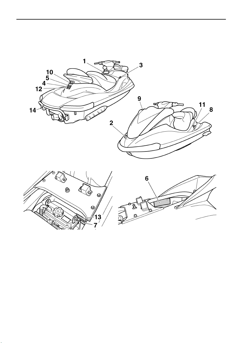
EJU31010
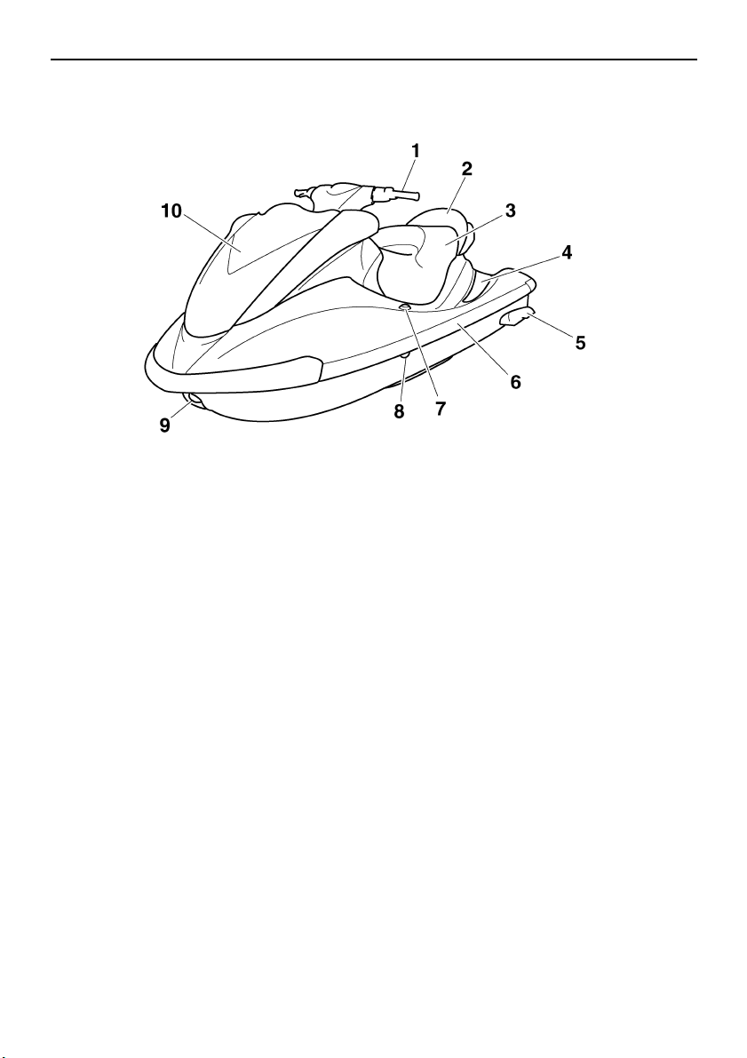
Location of main components
Front view
1 Handlebars
2 Rear seat
3 Front seat
4 Footwell
5 Sponsons
6 Gunwale
7 Pull-up cleat (for FX Cruiser High Output)
8 Cooling water pilot outlet
9 Bow eye
10 Hood
UF1X11E0.book Page 25 Monday, August 7, 2006 3:51 PM
Features and functions
26
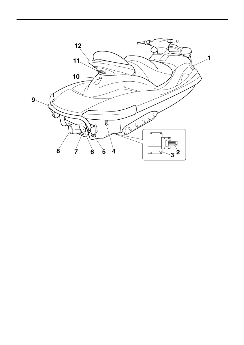
Rear view
1 Fuel tank filler cap
2 Intake grate
3 Speed sensor
4 Stern eyes
5 Stern drain plugs
6 Reverse gate
7 Ride plate
8 Jet thrust nozzle
9 Reboarding step
10 Electric bilge pilot outlet
11 Cleat
12 Handgrip
UF1X11E0.book Page 26 Monday, August 7, 2006 3:51 PM
Features and functions
27
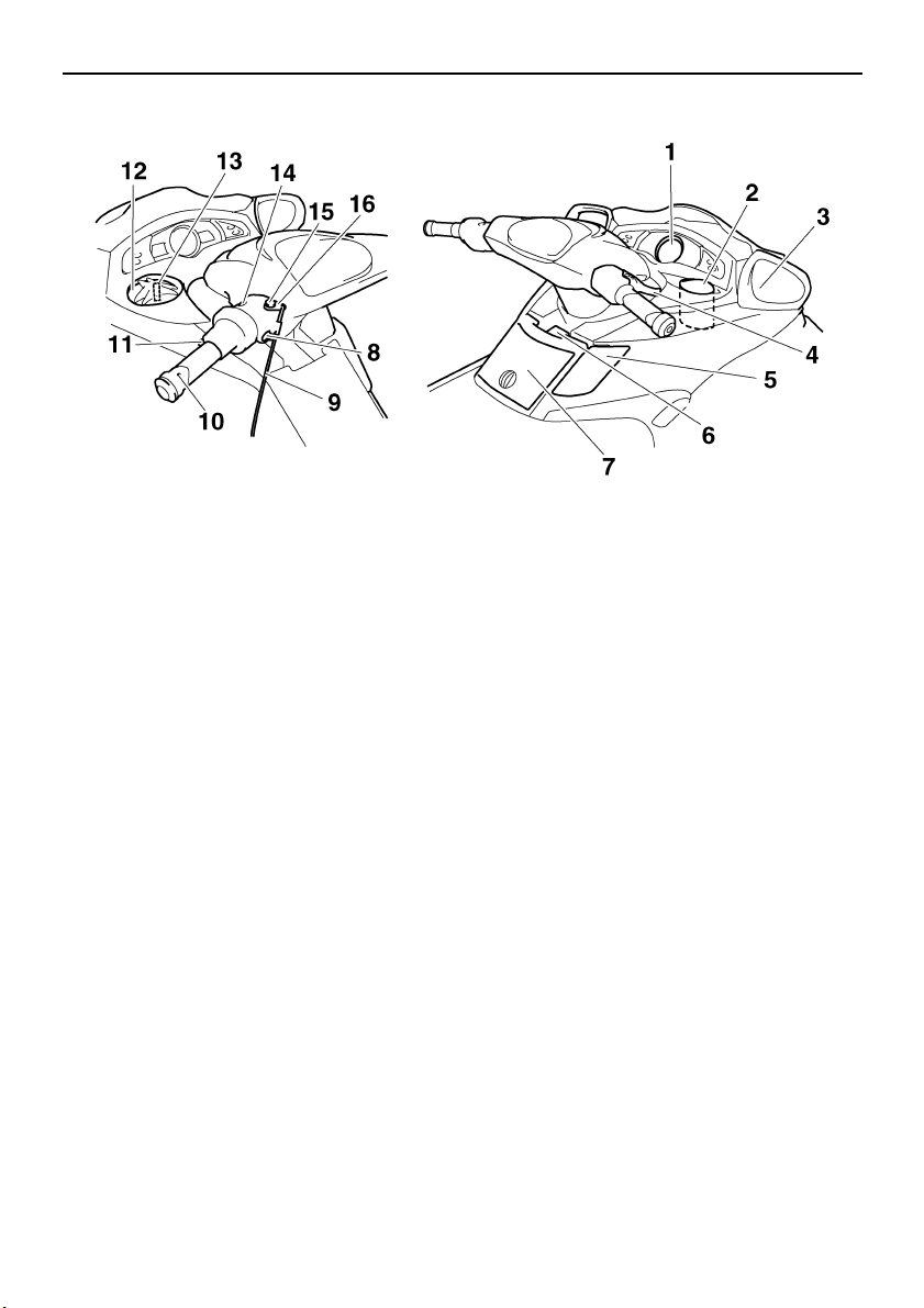
Control system
1 Multifunction information center
2 Beverage holder
3 Rearview mirrors
4 Throttle lever
5 Shift lever
6 Tilt lever
7 Glove compartment
8 Engine stop switch
9 Engine shut-off cord (lanyard)
10 Quick Shift Trim System (QSTS) selector
11 QSTS selector lock lever
12 Watertight compartment
13 Remote control transmitter
14 Start switch
15 Engine shut-off switch
16 Clip
UF1X11E0.book Page 27 Monday, August 7, 2006 3:51 PM
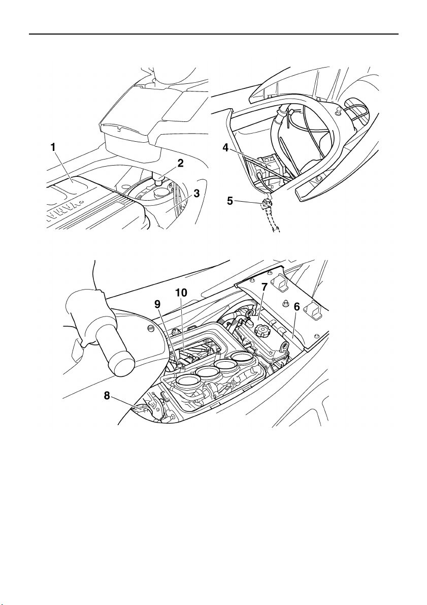
Features and functions
28
Engine compartment
1 Air filter case
2 Water separator
3 Fuel tank
4 Battery
5 Flushing hose connector
6 Electrical box
7 Oil tank
8 Muffler
9 Spark plugs/Spark plug caps/Ignition coils
10 Spark plug lead
UF1X11E0.book Page 28 Monday, August 7, 2006 3:51 PM
Features and functions
29
EJU31020
Operation of controls and other
functions
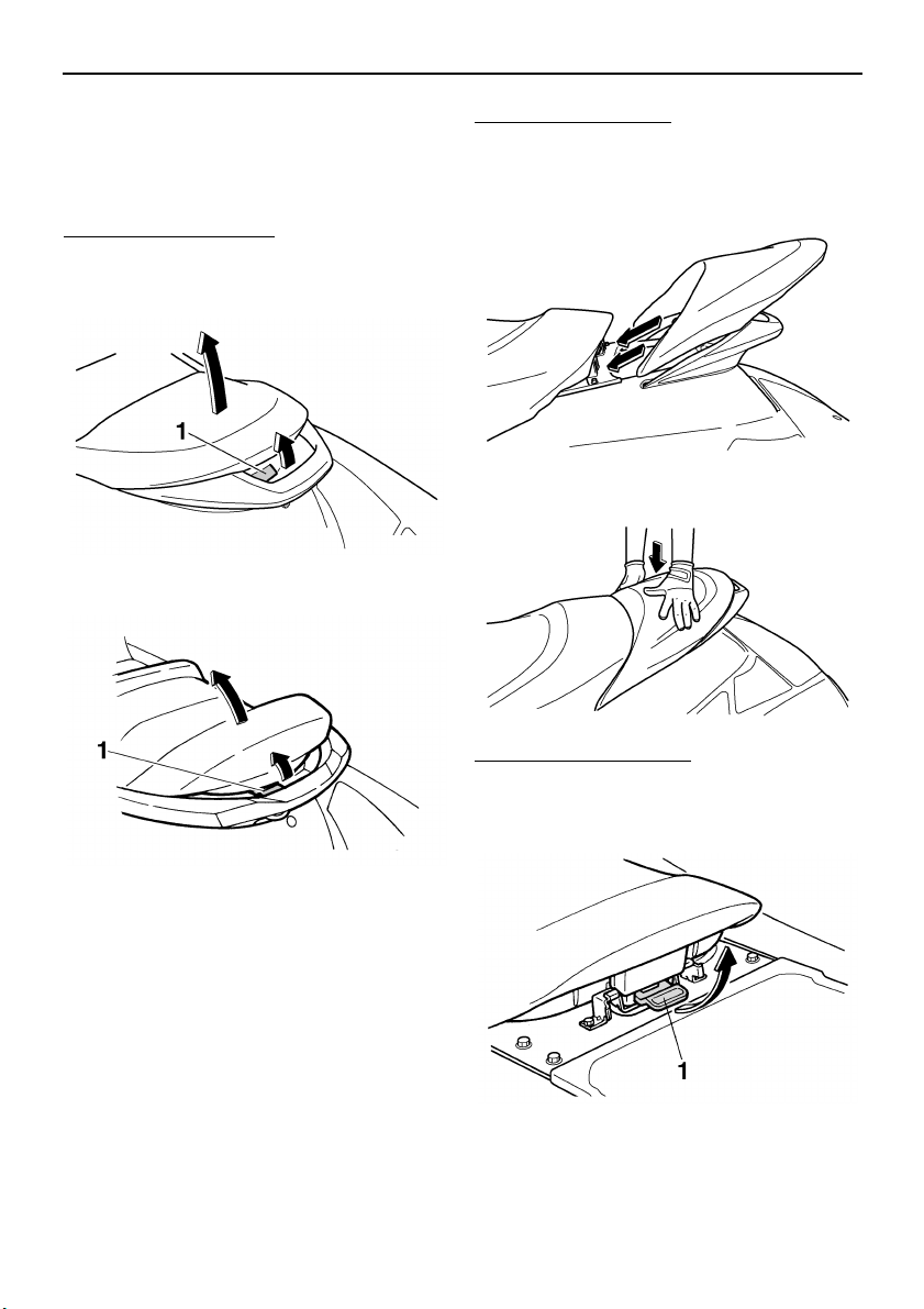
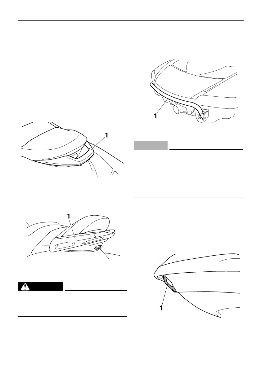
EJU31040
Seats
To remove the rear seat:
Pull the rear seat latch up, and then pull the
seat off.
FX High Output
FX Cruiser High Output
To install the rear seat:
Insert the projections on the front of the seat
into the stays on the deck, and then push the
rear of the seat down to lock it in place.
To remove the front seat:
(1) Remove the rear seat.
(2) Pull the front seat latch up, and then pull
the seat off.
1 Seat latch
1 Seat latch
1 Seat latch
UF1X11E0.book Page 29 Monday, August 7, 2006 3:51 PM
Features and functions
30
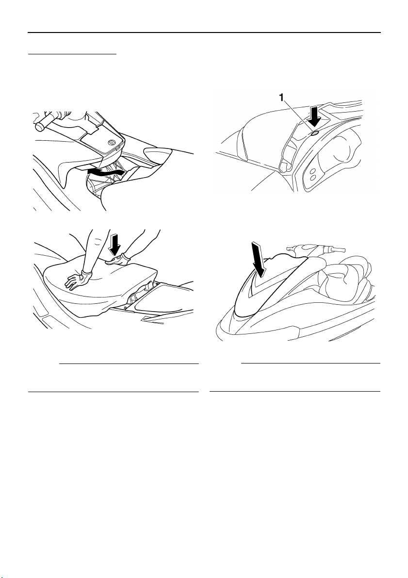
To install the front seat:
(1) Insert the projections on the front of the
seat into the stays on the deck, and then
push the rear of the seat down to lock it in
place.
(2) Install the rear seat.
NOTE:
Make sure that the seats are securely in-
stalled before operating the watercraft.
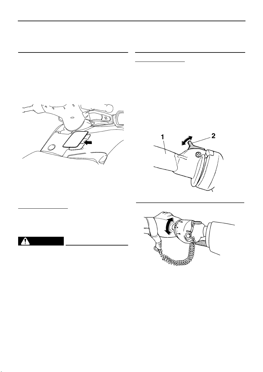
EJU31061
Hood
To open the hood, push the hood latch down,
and then lift up the hood.
To close the hood, push the hood down to
lock it in place.
NOTE:
Make sure that the hood is securely closed
before operating the watercraft.
1 Hood latch
UF1X11E0.book Page 30 Monday, August 7, 2006 3:51 PM
Features and functions
31
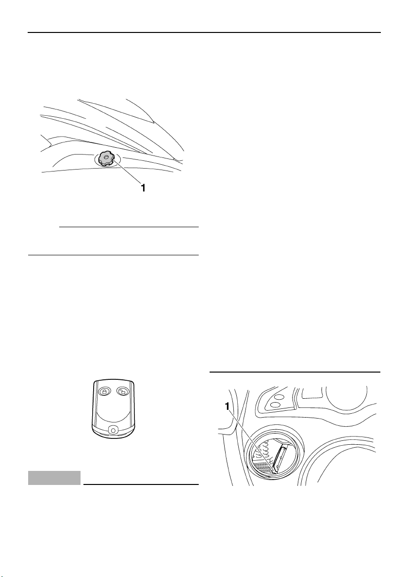
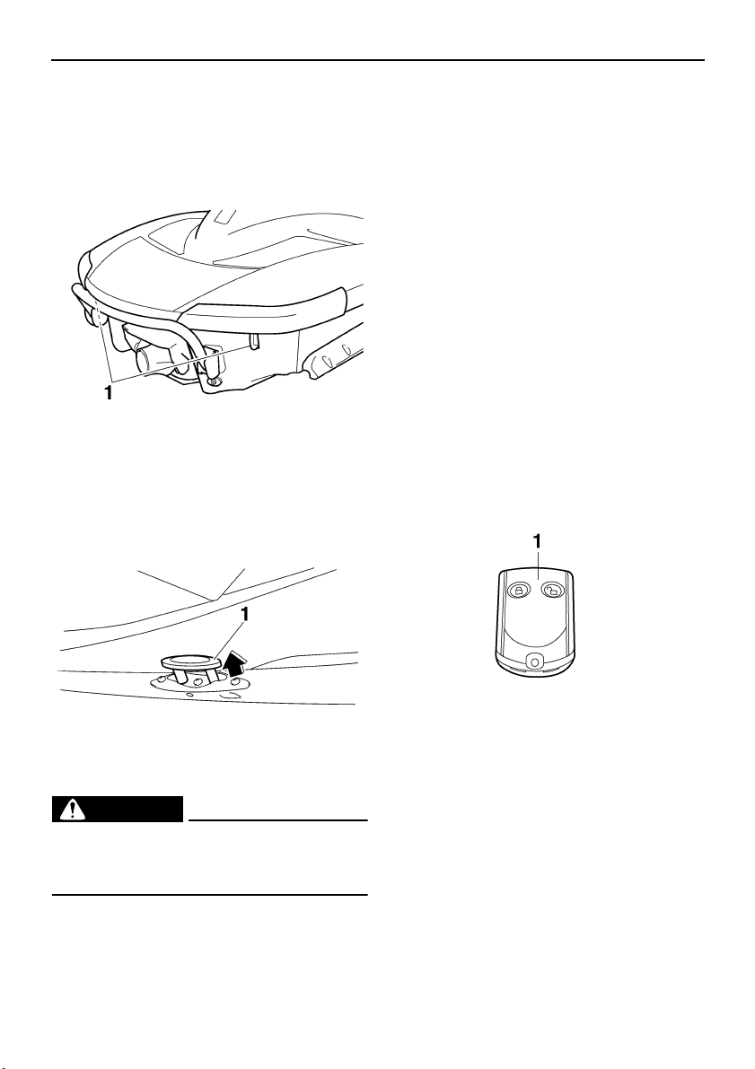
EJU31090
Fuel tank filler cap
To remove the fuel tank filler cap, turn it coun-
terclockwise.
NOTE:
Make sure that the fuel tank filler cap is se-
curely closed before operating the watercraft.
EJU34841
Remote control transmitter
The Yamaha Security System and low-RPM
mode settings are selected using the remote
control transmitter. (See “Yamaha Security
System and low-RPM mode” on page 38 for
information on using the remote control trans-
mitter.)
CAUTION:
ECJ00750
The Yamaha Security System and low-
RPM mode settings can only be selected
using the remote control transmitter. Ob-
serve the following precautions to protect
your remote control transmitter:
● Store the remote control transmitter
carefully so it will not be lost. When op-
erating the watercraft, use the transmit-
ter holder in the watertight
compartment. If you accidentally lose
your remote control transmitter, contact
a Yamaha dealer.
● While the remote control transmitter has
been designed for use in wet environ-
ments, it should not be operated under-
water or submerged for an extended
length of time. If it gets wet, dry it with a
soft, dry cloth.
● Keep the remote control transmitter
away from high temperatures and do not
place it in direct sunlight.
● Do not drop the remote control transmit-
ter, subject it to strong shocks, or place
any heavy items on it.
● Use a soft, dry cloth to clean the trans-
mitter. Do not use detergent, alcohol, or
other chemicals.
● If the remote control transmitter needs a
new battery or is not operating properly,
contact a Yamaha dealer. Do not attempt
to replace the battery yourself.
1 Fuel tank filler cap
1 Transmitter holder
UF1X11E0.book Page 31 Monday, August 7, 2006 3:51 PM
Features and functions
32
NOTE:
While the engine is running, input from the re-
mote control transmitter is not received.
This device complies with Part 15 of the FCC
Rules. Operation is subject to the following
two conditions: (1) this device may not cause
harmful interference, and (2) this device must
accept any interference received, including in-
terference that may cause undesired opera-
tion.
CAUTION:
ECJ00030
Changes or modifications not expressly
approved by the party responsible for
compliance could void the user’s authori-
ty to operate the remote control transmit-
ter.
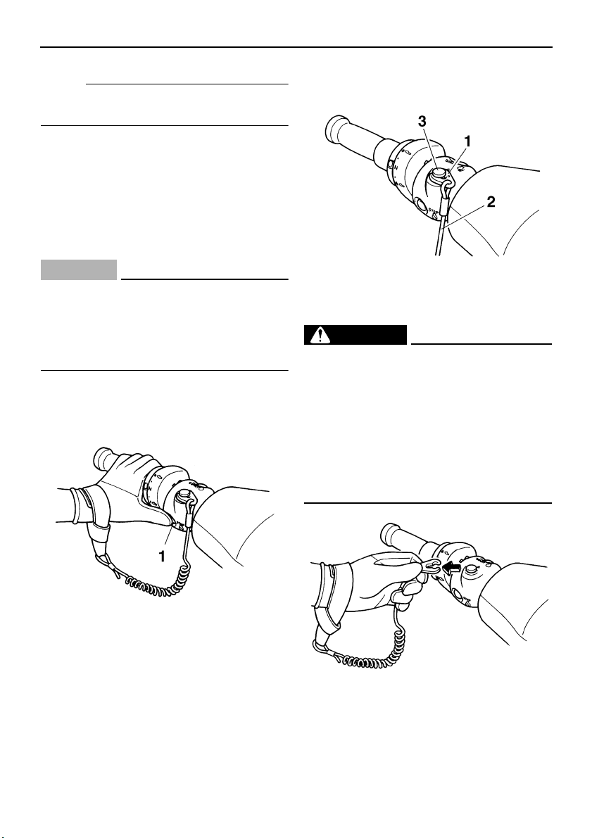
EJU31150
Engine stop switch
Push the engine stop switch (red button) to
stop the engine normally.
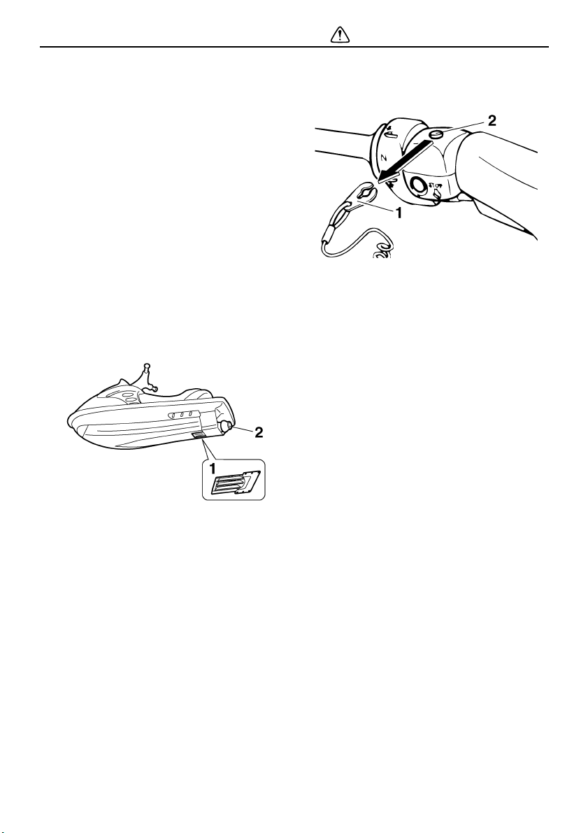
EJU31160
Engine shut-off switch
Insert the clip, on the end of the engine shut-
off cord, under the engine shut-off switch
(black button). The engine will stop automati-
cally when the clip is removed from the
switch, such as if the operator falls off the wa-
tercraft.
WARNING
EWJ00010
● Always attach the engine shut-off cord
to your left wrist and the clip to the en-
gine shut-off switch BEFORE starting
the engine.
● To prevent accidental starting of the en-
gine or unauthorized use by children or
others, always remove the clip from the
engine shut-off switch when the engine
is not running.
1 Engine stop switch
1 Clip
2 Engine shut-off cord
3 Engine shut-off switch
UF1X11E0.book Page 32 Monday, August 7, 2006 3:51 PM
Features and functions
33
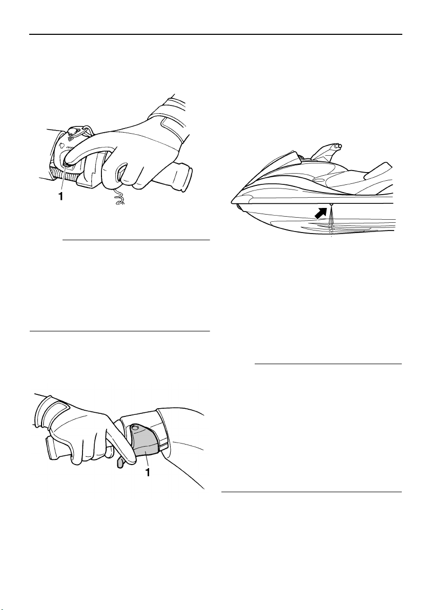
EJU31190
Start switch
Push the start switch (green button) to start
the engine.
NOTE:
The engine will not start when the lock mode
of the Yamaha Security System has been se-
lected, the clip is removed from the engine
shut-off switch, or the throttle lever is
squeezed. (See page 38 for Yamaha Security
System and low-RPM mode selection proce-
dures.)
EJU31210
Throttle lever
Squeeze the throttle lever to increase engine
speed.
Release the throttle lever to decrease engine
speed or to return it to the idle position.
EJU31240
Cooling water pilot outlets
This watercraft is equipped with cooling water
pilot outlets.
When the engine is running, cooling water is
circulated in the engine, and then it is dis-
charged from the pilot outlets.
To check for proper operation of the cooling
system, check that water is being discharged
from the port (left) pilot outlet. If water is not
being discharged from this outlet, cooling wa-
ter may not be circulating in the engine. When
this occurs, stop the engine and check for the
cause. (See pages 45 and 98 for more infor-
mation.)
NOTE:
● If the cooling water passages are dry, it will
take about 60 seconds for the water to
reach the outlet after the engine is started.
● Water discharge may not be constant at
idle, therefore, open the throttle a little to
check that water discharges properly.
● Water discharge may not be constant at the
starboard (right) pilot outlet, however, if it is
constant at the port (left) pilot outlet, the
cooling system is operating normally.
1 Start switch
1 Throttle lever
UF1X11E0.book Page 33 Monday, August 7, 2006 3:51 PM
Features and functions
34
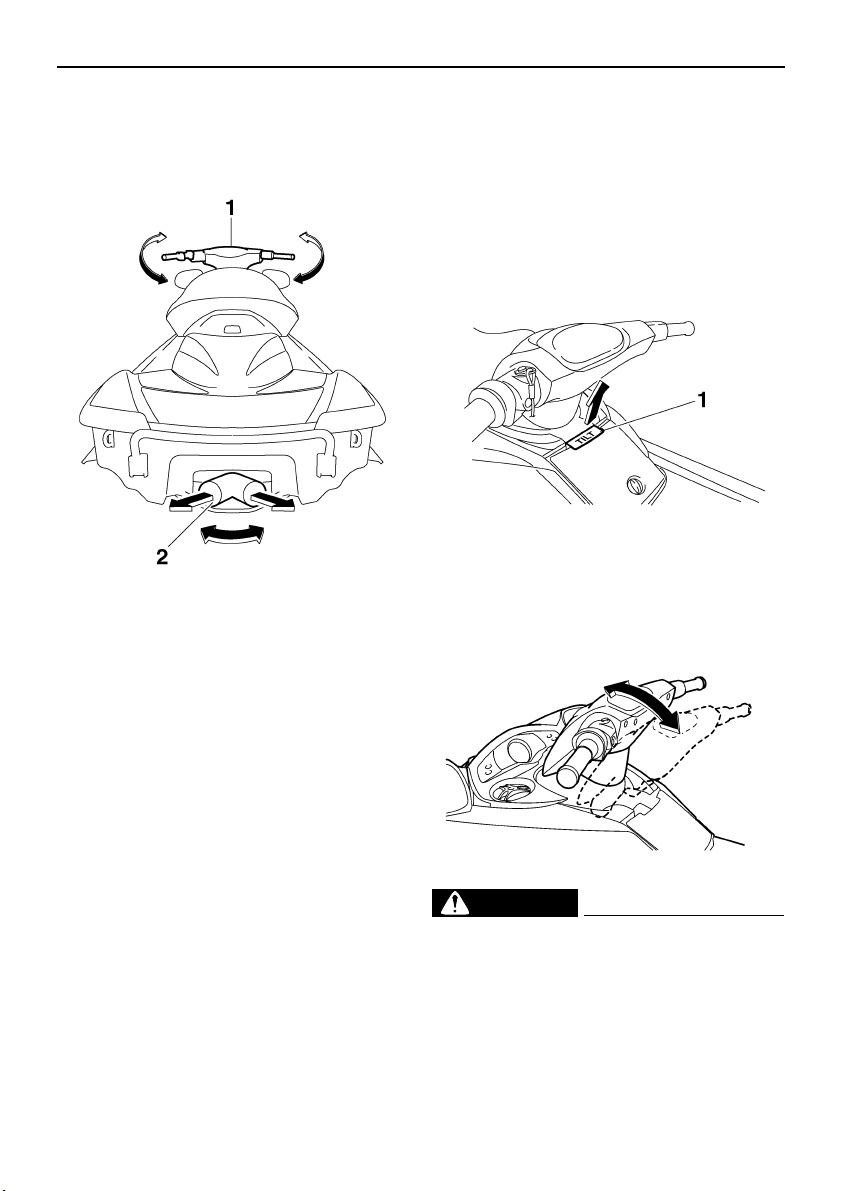
EJU31260
Steering system
Your watercraft can be steered by turning the
handlebars in the direction you wish to travel.
When the handlebars are turned, the angle of
the jet thrust nozzle is changed, and the direc-
tion of the watercraft is changed accordingly.
Since the strength of the jet thrust determines
the speed and degree of a turn, throttle must
always be applied when attempting a turn, ex-
cept at trolling speed.
This model is equipped with the Yamaha En-
gine Management System (YEMS) that in-
cludes an off-throttle steering (OTS) system.
It will activate at planing speeds should you
attempt to steer the watercraft after releasing
the throttle lever. The OTS system assists in
turning by continuing to supply some thrust
while the watercraft is decelerating, but you
can turn more sharply if you apply throttle
while turning the handlebars.
The OTS system does not function below
planing speeds or when the engine is off.
Once the engine slows down, the watercraft
will no longer turn in response to handlebar in-
put until you apply throttle again or you reach
trolling speed.
EJU31290
Tilt lever
The tilt lever is located in front of the glove
compartment and is used to adjust the tilt of
the handlebars.
To adjust the tilt, pull the tilt lever up, and then
move the handlebars up or down to the de-
sired position.
WARNING
EWJ00040
● Never touch the tilt lever during opera-
tion, otherwise the handlebars may sud-
denly change position, which may lead
to an accident.
● Make sure that the tilt lever returns to its
original position and that the handlebars
are locked in place after adjusting them,
1 Handlebar
2 Jet thrust nozzle
1 Tilt lever
UF1X11E0.book Page 34 Monday, August 7, 2006 3:51 PM
Features and functions
35
otherwise the handlebars may suddenly
change position, which may lead to an
accident.
EJU31300
Shift lever
The shift lever is located on the starboard
(right) side of the watercraft and is used to
control the reverse gate, which allows the wa-
tercraft to move in reverse or forward.
When the shift lever is in the reverse position,
the watercraft can be launched from a trailer,
or backed up out of tight spots where you can-
not turn around easily.
To shift into reverse:
(1) Release the throttle lever and let the en-
gine speed return to idle.
(2) Pull the shift lever toward you.
WARNING
EWJ00030
● Make sure that the throttle lever is com-
pletely released and that the engine is at
idle before shifting into reverse.
● Do not use the reverse function to slow
down or stop the watercraft as it could
cause you to lose control, be ejected, or
impact the handlebars.
● Use reverse for slow-speed maneuver-
ing only.
● Make sure that there are no obstacles or
people behind you before shifting into
reverse.
● Do not touch the reverse gate while the
shift lever is being operated, otherwise
you could be pinched.
To shift into forward:
(1) Release the throttle lever and let the en-
gine speed return to idle.
(2) Push the shift lever away from you.
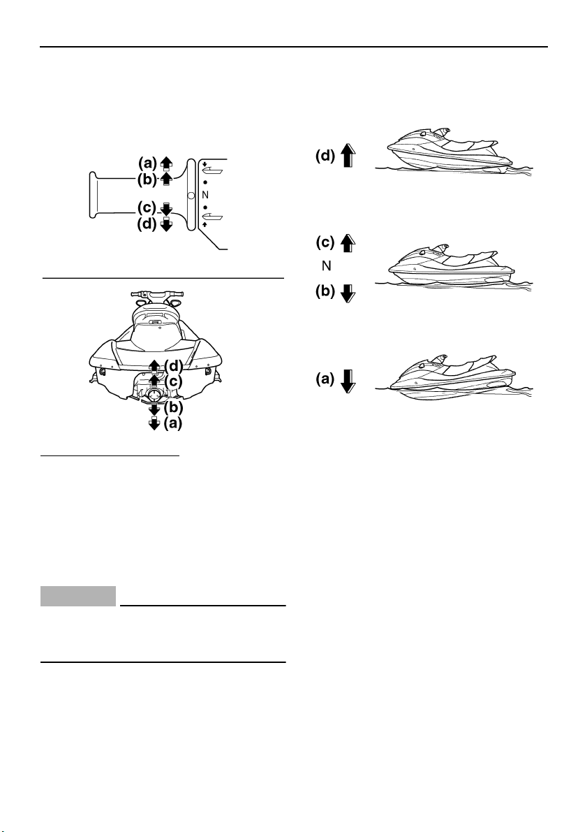
EJU31320
Quick Shift Trim System (QSTS)
selector
The QSTS selector is located at the left han-
dlebar grip and is used to adjust the trim angle
of the watercraft.
Operating the QSTS selector changes the an-
gle of the jet thrust nozzle vertically. This
changes the trim angle of the watercraft.
1 Quick Shift Trim System (QSTS) selector
2 QSTS selector lock lever
UF1X11E0.book Page 35 Monday, August 7, 2006 3:51 PM
Features and functions
36
There are 5 positions: 2 bow-down positions
(a) and (b), neutral “N”, and 2 bow-up posi-
tions (c) and (d).
To change the trim angle:
(1) Reduce engine speed to 4000 r/min or
less.
(2) Squeeze the QSTS selector lock lever,
and then turn the QSTS selector to the
desired position.
(3) Release the lock lever to lock the QSTS
selector.
CAUTION:
ECJ00010
Do not turn the QSTS selector while oper-
ating the watercraft at full throttle, other-
wise damage could occur to the QSTS.
The neutral “N” position will provide good per-
formance for most operating conditions.
To enhance particular types of performance,
select bow down or bow up.
EJU31330
Bow down
Turn the QSTS selector to (a) or (b) and the
bow will go down while the watercraft is on
plane.
Bow down puts more of the bow in the water.
This gives the watercraft more “hook”, which
enhances turning performance. This position
will also help the watercraft get up on plane
more quickly.
At higher speeds, however, the watercraft will
have a greater tendency to “bow steer” and
follow waves and wakes in the water. Fuel
economy and maximum speed are also re-
duced.
EJU31340
Bow up
Turn the QSTS selector to (c) or (d) and the
bow will go up while the watercraft is on plane.
Bow up puts less of the bow in the water.
There is less water resistance, so straight-
UF1X11E0.book Page 36 Monday, August 7, 2006 3:51 PM
Features and functions
37
ahead acceleration when on plane and top
speed are enhanced.
In some conditions, however, the watercraft
may tend to “porpoise” (hop in the water). If
the watercraft is porpoising, select neutral or
bow down.
EJU31360
Handgrip
The handgrip provides a handhold for board-
ing the watercraft and for a spotter when fac-
ing rearward.
FX High Output
FX Cruiser High Output
WARNING
EWJ00020
Do not use the handgrip to lift the water-
craft. The watercraft could fall, which
could result in severe injury.
EJU34860
Reboarding step
The reboarding step provides a handhold and
footstep for boarding the watercraft.
CAUTION:
ECJ00740
Use the reboarding step only to board the
watercraft in the water. Do not use the re-
boarding step for lifting the watercraft, as
a footstep when the watercraft is on land,
or for any other purpose. The watercraft
can be damaged.
EJU34870
Bow eye
The bow eye is located at the bow of the wa-
tercraft.
The bow eye is used to attach a rope to the
watercraft when transporting, mooring, or
towing it in an emergency.
1 Handgrip
1 Handgrip
1 Reboarding step
1 Bow eye
UF1X11E0.book Page 37 Monday, August 7, 2006 3:51 PM
Features and functions
38
EJU34880
Stern eyes
The stern eyes are located at the stern of the
watercraft.
The stern eyes are used to attach a rope to
the watercraft when transporting or mooring it.
EJU34890
Pull-up cleats (for FX Cruiser High
Output)
The pull-up cleats are used to attach a rope to
the watercraft when mooring it.
To use a pull-up cleat, pull it up.
WARNING
EWJ00820
Do not use the pull-up cleats to lift the wa-
tercraft. The watercraft could fall, which
could result in severe injury.
EJU31370
Yamaha Engine Management System
(YEMS)
This model is equipped with an integrated,
computerized management system that con-
trols and adjusts ignition timing, fuel injection,
engine diagnostics, and the off-throttle steer-
ing (OTS) system.
EJU31380
Yamaha Security System and low-
RPM mode
This watercraft is equipped with a remote con-
trol transmitter that is used to select the secu-
rity system and low-RPM mode settings.
Since the watercraft is programmed to recog-
nize the internal code from this transmitter
only, the security system setting can only be
changed with this transmitter. If you lose the
remote control transmitter or it does not oper-
ate properly, contact a Yamaha dealer.
EJU31390
Yamaha Security System
The Yamaha Security System functions to
help prevent unauthorized use or theft of the
watercraft. The engine cannot be started if the
security system is in the lock mode. The en-
gine can only be started in the unlock mode.
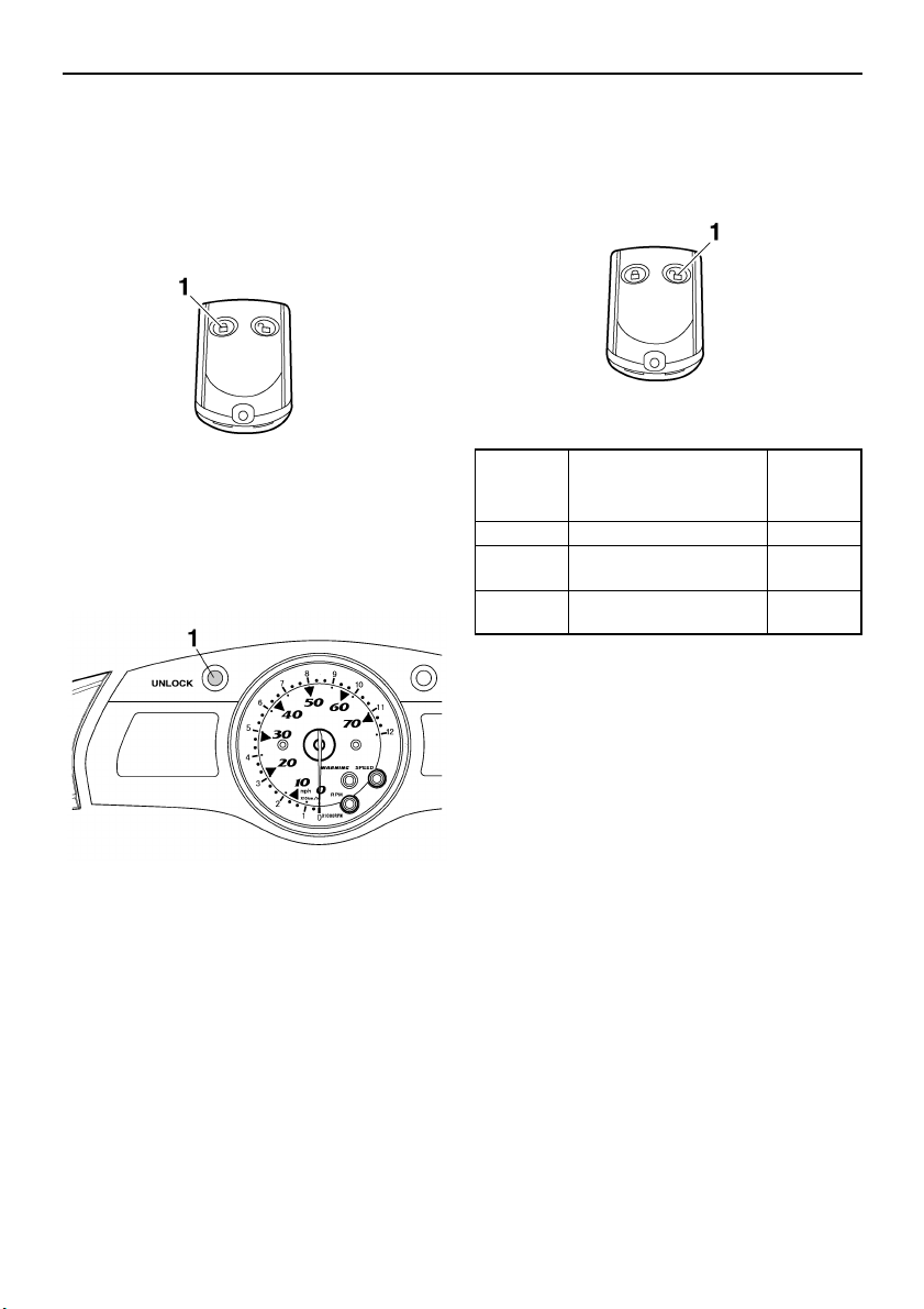
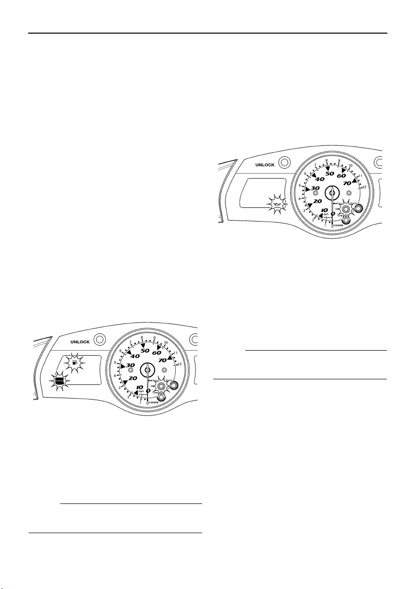
EJU31400
Yamaha Security System lock and unlock
modes
The lock and unlock modes of this system can
only be selected while the engine is stopped.
1 Stern eye
1 Pull-up cleat
1 Remote control transmitter
UF1X11E0.book Page 38 Monday, August 7, 2006 3:51 PM
Features and functions
39
When the lock button on the remote control
transmitter is pressed, the beeper sounds
once. This indicates the lock mode is selected
and the engine cannot be started.
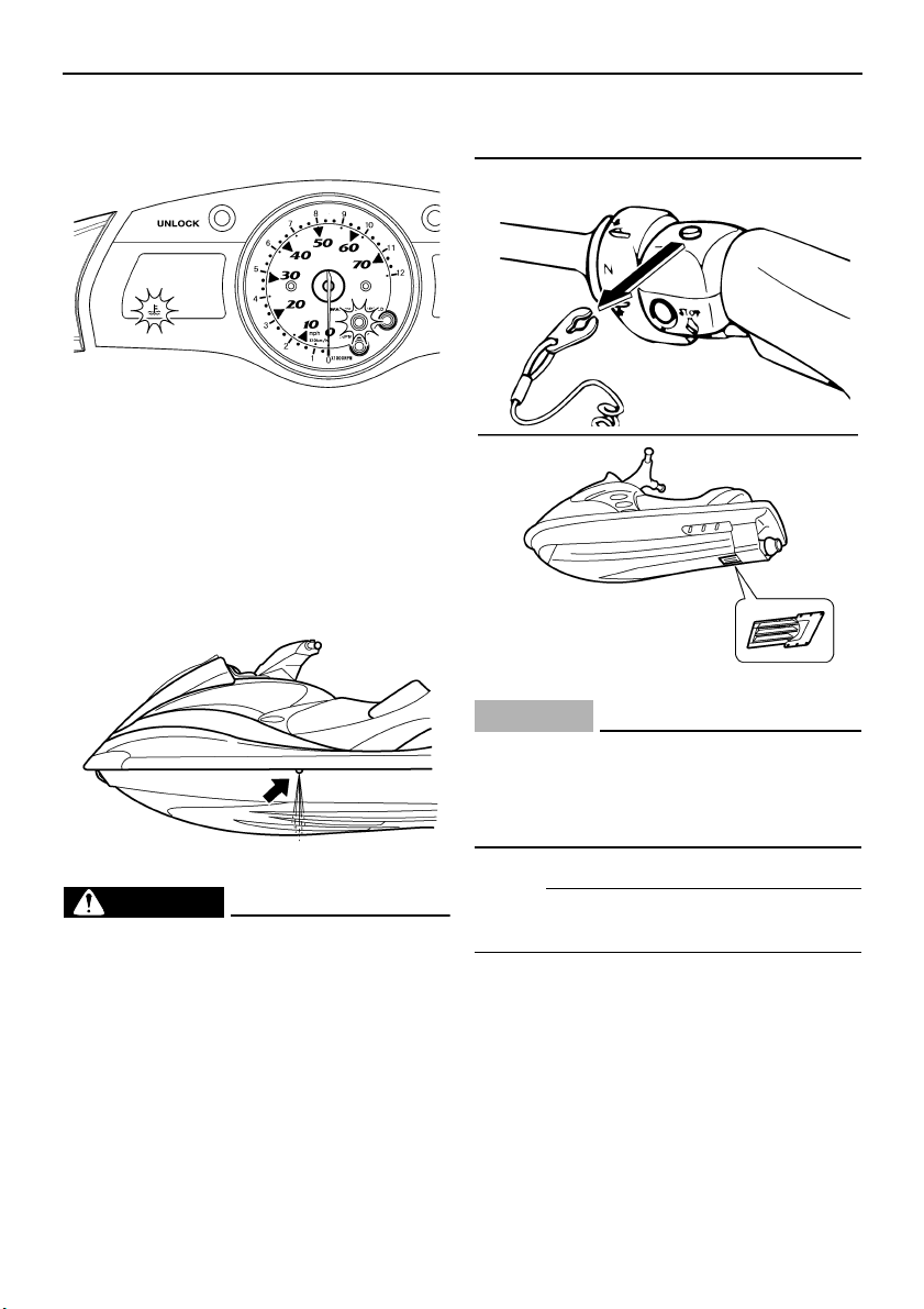
The “UNLOCK” indicator light comes on when
the security system is in the unlock mode and
goes off when the security system is in the
lock mode.
When the unlock button on the remote control
transmitter is pressed for a short time, the
beeper sounds two times for the normal mode
or three times for the low-RPM mode. The
“UNLOCK” indicator light will come on and the
engine can be started. (See the items in “Se-
lecting the normal mode/low-RPM mode” for
operation mode information.)
EJU36220
Selecting the normal mode/low-RPM
mode
The normal mode and low-RPM mode can
only be selected when the engine is stopped
in the unlock mode. Press the unlock button
on the remote control transmitter for more
than 4 seconds to switch between the normal
mode and the low-RPM mode.
Normal mode
If the beeper sounds twice, the normal mode
is activated.
The watercraft can be ridden normally.
1 Lock button
1 “UNLOCK” indicator light
1 Unlock button
Number
of beeps
Yamaha Security Sys-
tem mode
Engine
can be
started
1 beep Lock NO
2 beeps
Unlock
(normal mode)
YES
3 beeps
Unlock
(low-RPM mode)
YES
UF1X11E0.book Page 39 Monday, August 7, 2006 3:51 PM
Features and functions
40
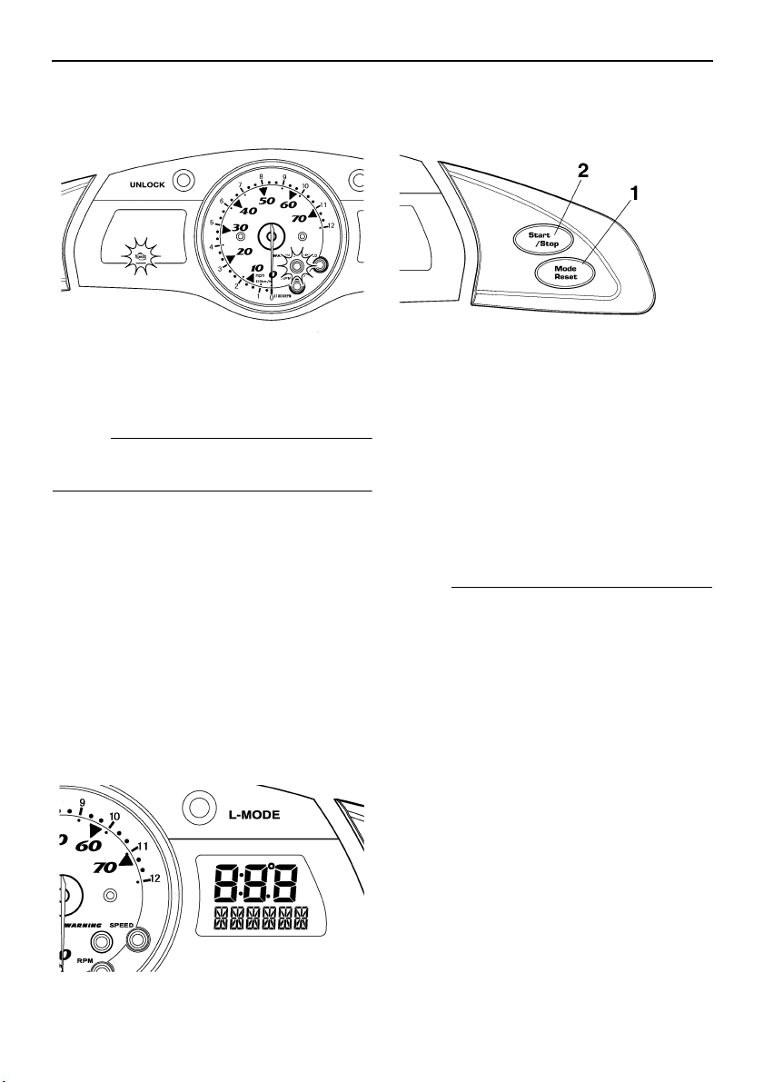
Low-RPM mode
If the beeper sounds three times, the low-
RPM mode is activated and the “L-MODE” in-
dicator light comes on.
Maximum engine speed (r/min) in the low-
RPM mode is limited to approximately 80% of
the maximum engine speed in the normal
mode.
NOTE:
● If neither the start switch nor the remote
control transmitter is operated within 25
seconds after the unlock button is pressed
to select the unlock mode, the multifunction
meter display and the “L-MODE” indicator
light will go off. If this occurs, press the lock
button on the transmitter briefly to select the
lock mode, press the unlock button briefly to
select the unlock mode, and then press the
unlock button again for more than 4 sec-
onds to select the normal mode or low-RPM
mode.
● While the engine is running, input from the
remote control transmitter is not received.
CAUTION:
ECJ00080
If the remote control transmitter does not
operate when its buttons are pressed, the
battery may be low. Have a Yamaha dealer
replace the battery.
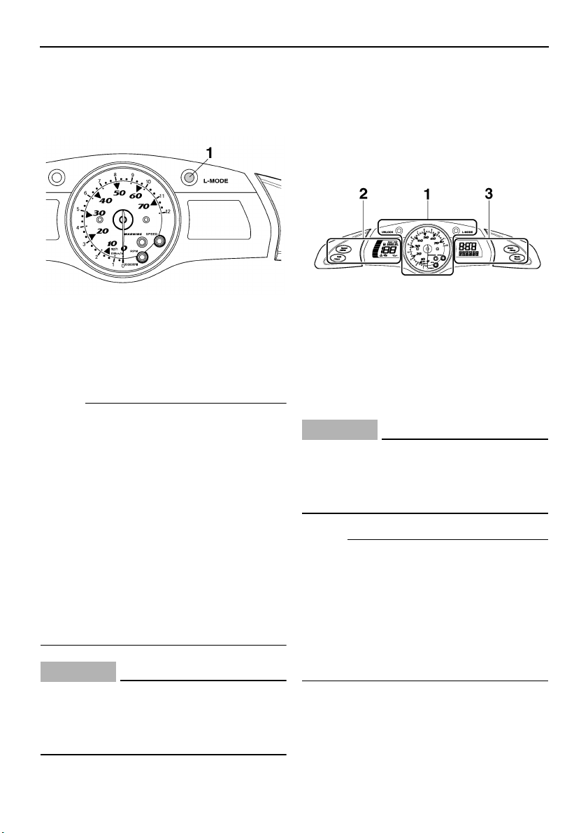
EJU34900
Multifunction information center
The multifunction information center is
equipped with the following three main com-
ponents for help and convenience in operat-
ing the watercraft.
CAUTION:
ECJ00730
Do not run the engine for more than 15
seconds when checking the operation of
the meter on land. The engine could over-
heat.
NOTE:
● When the multifunction information center
starts operating, the analog speedome-
ter/tachometer makes one sweep, all dis-
plays light up for 2 seconds, and then the
meter starts to operate normally.
● The multifunction information center will
continue to operate for 25 seconds after the
engine stops.
1 “L-MODE” indicator light
1 Analog speedometer/tachometer and indi-
cator lights
2 Left multifunction display and operation but-
tons
3 Right multifunction display and operation
buttons (for FX Cruiser High Output)
UF1X11E0.book Page 40 Monday, August 7, 2006 3:51 PM
Features and functions
41
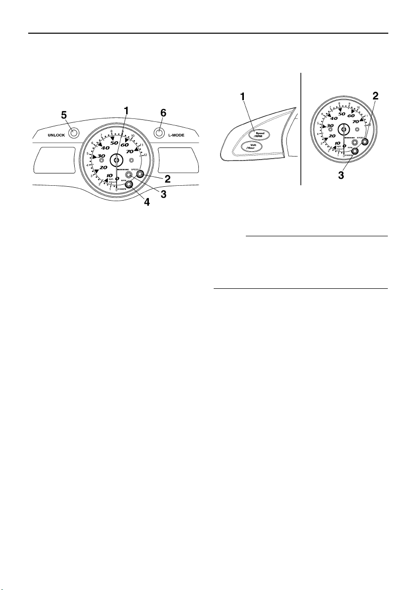
EJU34930
Analog speedometer/tachometer and indi-
cator lights
This watercraft is equipped with the following
meter and indicator lights.
EJU34940
Analog speedometer/tachometer
The analog speedometer/tachometer can be
used as a speedometer or a tachometer.
To switch between the speedometer and the
tachometer functions, push the “Speed/RPM”
button for at least 1 second when the multi-
function meter is operating.
The “SPEED” indicator light comes on when
the analog speedometer is selected. The
“RPM” indicator light comes on when the an-
alog tachometer is selected.
NOTE:
When the analog speedometer/tachometer is
switched to the speedometer function, the
“SPEED” indicator light blinks three times,
and then comes on.
Analog speedometer
The analog speedometer shows the water-
craft speed against water.
The large inner numbers on the meter show
the watercraft speed in miles per hour (mph)
and the small outer numbers show the speed
in kilometers per hour (km/h) when the speed-
ometer function is selected.
Analog tachometer
The analog tachometer shows the engine
speed (r/min).
The small outer numbers on the meter show
the engine speed when the tachometer func-
tion is selected.
1 Analog speedometer/tachometer
2 “SPEED” indicator light
3 “WARNING” indicator light
4 “RPM” indicator light
5 “UNLOCK” indicator light
6 “L-MODE” indicator light
1 “Speed/RPM” button
2 “SPEED” indicator light
3 “RPM” indicator light
UF1X11E0.book Page 41 Monday, August 7, 2006 3:51 PM

Features and functions
42
EJU34950
“SPEED” indicator light
The “SPEED” indicator light comes on when
the analog speedometer is selected.
The “SPEED” indicator light blinks three times
in the following instances:
● The analog speedometer/tachometer is
switched to the speedometer function.
● The display units of the multifunction meter
are switched to miles from kilometers.
● Miles are selected as the display units when
the multifunction meter starts operating.
EJU34960
“RPM” indicator light
The “RPM” indicator light comes on when the
analog tachometer is selected.
EJU34980
“WARNING” indicator light
The “WARNING” indicator light blinks or
comes on, together with a warning indicator,
when a malfunction has occurred.
EJU34990
“UNLOCK” indicator light
The “UNLOCK” indicator light comes on when
the unlock mode of the Yamaha Security Sys-
tem is selected. The watercraft can be ridden
normally when this light is on. (See page 38
for more information.)
1 “SPEED” indicator light
1 “RPM” indicator light
1 “WARNING” indicator light
1 “UNLOCK” indicator light
UF1X11E0.book Page 42 Monday, August 7, 2006 3:51 PM
Features and functions
43
EJU35010
“L-MODE” indicator light
The “L-MODE” indicator light comes on when
the low-RPM mode is selected. (See page 39
for more information.)
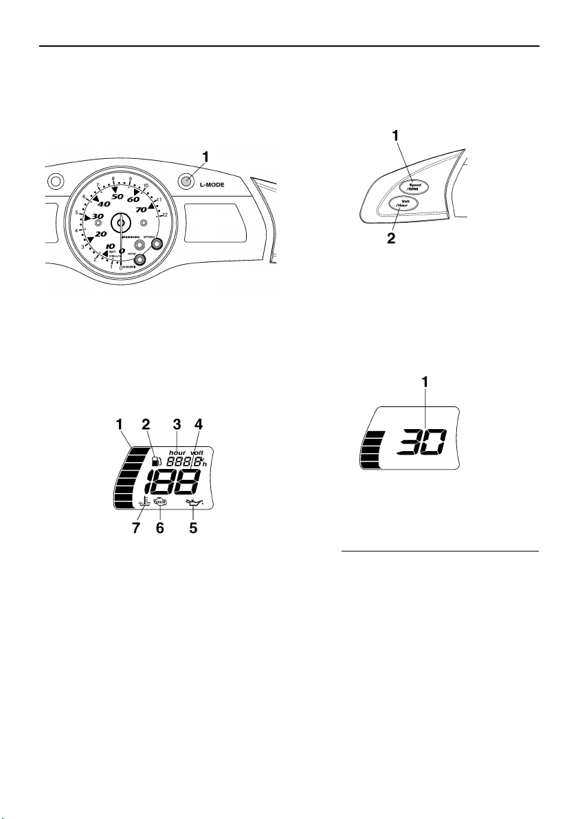
EJU35020
Left multifunction display and operation
buttons
The left multifunction display is equipped with
the following functions.
The following operation buttons are on the left
side of the multifunction meter.
EJU35041
Digital speedometer
The digital speedometer shows the watercraft
speed against water.
NOTE:
● To switch the speedometer display be-
tween kilometers and miles, push the
“Volt/Hour” button for at least 1 second,
within 10 seconds after the multifunction
meter starts operating.
● The “SPEED” indicator light blinks three
times if miles are selected as the display
units when the multifunction meter starts
1 “L-MODE” indicator light
1 Fuel level meter
2 Fuel level warning indicator
3 Hour meter/voltmeter
4 Digital speedometer
5 Oil pressure warning indicator
6 Check engine warning indicator
7 Engine overheat warning indicator
1 “Speed/RPM” button
2 “Volt/Hour” button
1 Digital speedometer
UF1X11E0.book Page 43 Monday, August 7, 2006 3:51 PM

Features and functions
44
operating, or if the display units of the meter
are switched to miles.
EJU31511
Fuel level meter
The fuel level meter is provided for convenient
fuel level checking while riding.
The fuel level meter has eight segments
which show the amount of fuel remaining in
the fuel tank.
NOTE:
The fuel level is most accurate when the wa-
tercraft is sitting level on a trailer or in the wa-
ter.
EJU35060
Hour meter/voltmeter
NOTE:
To switch the display between the hour meter
and the voltmeter, push the “Volt/Hour” button
for at least 1 second after the meter is dis-
played for more than 10 seconds.
Hour meter
The hour meter is provided to make it easy to
follow the maintenance schedule.
1 “Volt/Hour” button
1 “SPEED” indicator light
1 Fuel level meter
1 Hour meter/voltmeter
2 “Volt/Hour” button
UF1X11E0.book Page 44 Monday, August 7, 2006 3:51 PM
Features and functions
45
The meter shows the hours of engine opera-
tion that have elapsed since the watercraft
was new.
Voltmeter
The voltmeter is provided to display the volt-
age of the battery.
When the battery voltage is normal, the volt-
meter displays approximately 12 volts.
If the battery voltage is less than 8.0 volts,
“LO” is displayed on the voltmeter and if the
voltage is above 18.1 volts, “HI” is displayed
on the voltmeter. If “HI” or “LO” is displayed,
return to shore and, if necessary, have a
Yamaha dealer check the charging system
and the battery.
EJU35071
Fuel level warning indicator
If the fuel remaining in the fuel tank drops to
about 13 L (3.4 US gal, 2.9 Imp gal), the low-
est two fuel level segments, the fuel level
warning indicator, and the “WARNING” indi-
cator light begin to blink. The buzzer also
starts sounding intermittently.
If this occurs, refill the fuel tank as soon as
possible.
The warning signals will be cleared when the
engine is restarted after the fuel tank is re-
filled.
NOTE:
Press any button on the multifunction meter to
stop the buzzer.
EJU35120
Oil pressure warning indicator
If the oil pressure does not rise to specifica-
tion, the “WARNING” indicator light and the oil
pressure warning indicator begin to blink, and
the buzzer sounds intermittently. At the same
time, the engine speed is limited to help pre-
vent damage.
If this occurs, reduce the engine speed, return
to shore, and then check the engine oil level.
(See page 58 for engine oil level checking
procedures.) If the oil level is low, add enough
engine oil to raise it to the proper level. If the
oil level is sufficient, have a Yamaha dealer
check the watercraft.
NOTE:
Press any button on the multifunction meter to
stop the buzzer.
EJU35111
Engine overheat warning indicator
This model is equipped with an engine over-
heat warning system.
If the engine starts to overheat, the “WARN-
ING” indicator light and the engine overheat
warning indicator blink, and then come on.
The buzzer also begins to sound intermittent-
ly, and then it sounds continuously. After the
light and indicator start to blink and the buzzer
UF1X11E0.book Page 45 Monday, August 7, 2006 3:51 PM
Features and functions
46
sounds, the engine speed is limited to help
prevent damage.
If this occurs, immediately reduce the engine
speed, return to shore, and then check for wa-
ter discharge at the port (left) cooling water pi-
lot outlet while the engine is running. If there
is no discharge of water, shut the engine off,
and then check the intake grate and impeller
for clogging.
WARNING
EWJ00050
Before attempting to remove weeds or de-
bris from the intake grate or impeller, shut
the engine off and remove the clip from the
engine shut-off switch. Severe injury or
death could result from coming in contact
with the rotating parts of the jet pump.
CAUTION:
ECJ00040
If you cannot locate and correct the cause
of the overheating, consult a Yamaha deal-
er. Continuing to operate at higher speeds
could result in severe engine damage.
NOTE:
Press any button on the multifunction meter to
stop the buzzer.
EJU35130
Check engine warning indicator
If a sensor malfunction or a short circuit is de-
tected, the “WARNING” indicator light and the
UF1X11E0.book Page 46 Monday, August 7, 2006 3:51 PM
Features and functions
47
check engine warning indicator begin to blink,
and the buzzer sounds intermittently.
If this occurs, reduce the engine speed, return
to shore, and have a Yamaha dealer check
the engine.
NOTE:
Press any button on the multifunction meter to
stop the buzzer.
EJU35032
Right multifunction display and operation
buttons (for FX Cruiser High Output)
The right multifunction display shows the fol-
lowing information.
● Compass
● Average speed
● Tripmeter
● Trip timer
● Fuel consumption per hour
● Fuel consumption per kilometer/mile
● Water temperature
● Air temperature
The following operation buttons are on the
right side of the multifunction meter.
To switch the display mode, push the
“Mode/Reset” button for less than 1 second.
The display mode changes in the following or-
der.
Compass → Average speed → Tripmeter →
Trip timer → Fuel consumption per hour →
Fuel consumption per kilometer/mile → Water
temperature → Air temperature
NOTE:
● To switch the display units between kilome-
ters/liters/degrees Celsius and miles/gal-
lons/degrees Fahrenheit, push the
“Volt/Hour” button for at least 1 second,
within 10 seconds after the multifunction
meter starts operating.
● The “SPEED” indicator light blinks three
times if miles/gallons/degrees Fahrenheit
are selected as the display units when the
multifunction meter starts operating, or if
1 “Mode/Reset” button
2 “Start/Stop” button
UF1X11E0.book Page 47 Monday, August 7, 2006 3:51 PM

Features and functions
48
the display units of the meter are switched
to miles/gallons/degrees Fahrenheit.
Compass
This display shows the current direction of the
watercraft using the 8 major compass points.
NOTE:
The accuracy of the compass varies depend-
ing on the operating conditions. Use this func-
tion as a reference only.
Average speed
This display shows the average speed in
miles per hour “AV MPH” or kilometers per
hour “AV KMH” since it was reset.
Tripmeter
This display shows the distance traveled in
miles “MILES” or kilometers “KM” since it was
reset.
Trip timer
This display shows the hours of operation
“TRIPTM” since it was reset.
1 “Volt/Hour” button
2 “SPEED” indicator light
UF1X11E0.book Page 48 Monday, August 7, 2006 3:51 PM
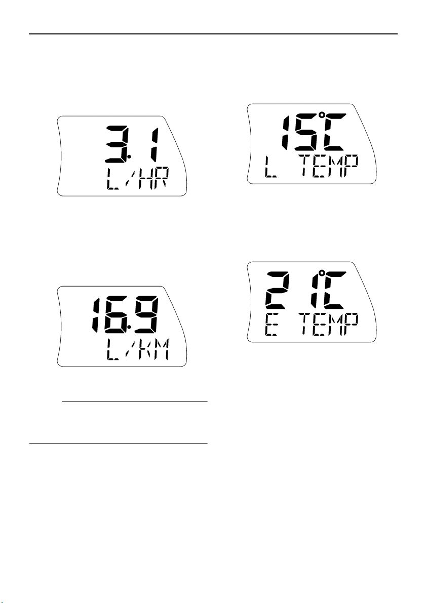
Features and functions
49
Fuel consumption per hour
This display shows the current fuel consump-
tion in gallons per hour “G/HR” or liters per
hour “L/HR”.
Fuel consumption per kilometer/mile
This display shows the current fuel consump-
tion in gallons per mile “G/MILE” or liters per
kilometer “L/KM”.
NOTE:
The actual fuel consumption varies depend-
ing on the operating conditions. Use this func-
tion as a reference only.
Water temperature
This display shows the ambient water temper-
ature “L TEMP” (lake temperature).
Air temperature
This display shows the ambient air tempera-
ture “E TEMP” (environmental temperature).
Average speed/Tripmeter/Trip timer
modes
Average speed, distance traveled, and trip
time are recorded once measurements have
started, regardless of the current display.
To start the measurements, push the
“Start/Stop” button for less than 1 second.
The beeper sounds once.
To stop the measurements, push the
“Start/Stop” button for less than 1 second.
The beeper sounds once. To restart the mea-
surements, push the “Start/Stop” button for
less than 1 second. The beeper sounds once.
To reset the displays, push the “Mode/Reset”
button for at least 2 seconds while the mea-
UF1X11E0.book Page 49 Monday, August 7, 2006 3:51 PM
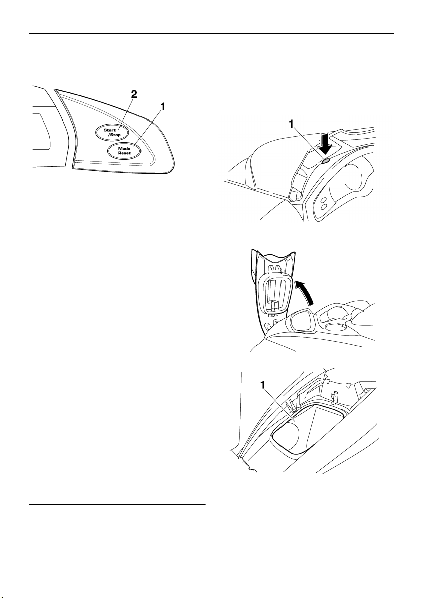
Features and functions
50
surements are stopped. The beeper sounds
twice.
NOTE:
● The displays can be reset only when the
measurements are stopped.
● The measurements are not saved if the en-
gine is stopped. The displays are reset au-
tomatically when they go off 25 seconds
after the engine stops.
EJU35141
Storage compartments
A front storage compartment, glove compart-
ment, seat storage compartment, watertight
compartment, and beverage holder are pro-
vided.
NOTE:
● Make sure that the storage compartments
are closed securely before operating the
watercraft.
● The front storage compartment, glove com-
partment, and seat storage compartment
are not designed to be watertight. If you car-
ry objects that must be kept dry, such as the
manuals, put them in a waterproof bag or
the watertight compartment.
EJU35151
Front storage compartment
The front storage compartment is located at
the bow.
To open the front storage compartment, push
the hood latch down, and then lift up the hood.
1 “Mode/Reset” button
2 “Start/Stop” button
1 Hood latch
1 Front storage compartment
UF1X11E0.book Page 50 Monday, August 7, 2006 3:51 PM
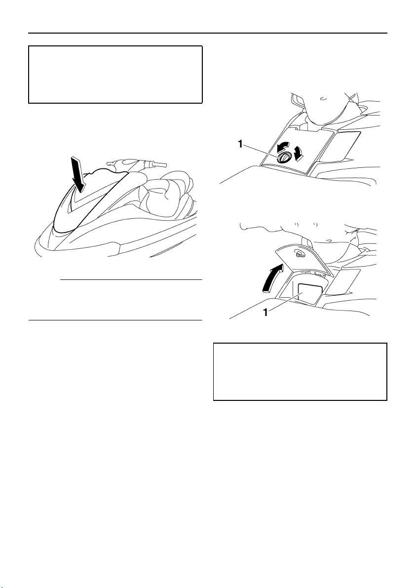
Features and functions
51
To close the front storage compartment, push
down on the rear of the hood until it latches
securely.
NOTE:
Make sure that the front storage compartment
is securely closed before operating the water-
craft.
EJU35161
Glove compartment
The glove compartment is located in front of
the seat.
To open the glove compartment, turn the
glove compartment knob, and then lift up the
lid.
To close the glove compartment, lower the lid,
and then turn the glove compartment knob to
lock the lid in place.
EJU31760
Seat storage compartment
The seat storage compartment is located un-
der the rear seat.
Front storage compartment:
Capacity:
75.0 L (19.8 US gal) (16.5 Imp.gal)
Load limit:
5.0 kg (11 lb)
1 Glove compartment knob
1 Glove compartment
Glove compartment:
Capacity:
5.5 L (1.5 US gal) (1.2 Imp.gal)
Load limit:
1.0 kg (2 lb)
UF1X11E0.book Page 51 Monday, August 7, 2006 3:51 PM
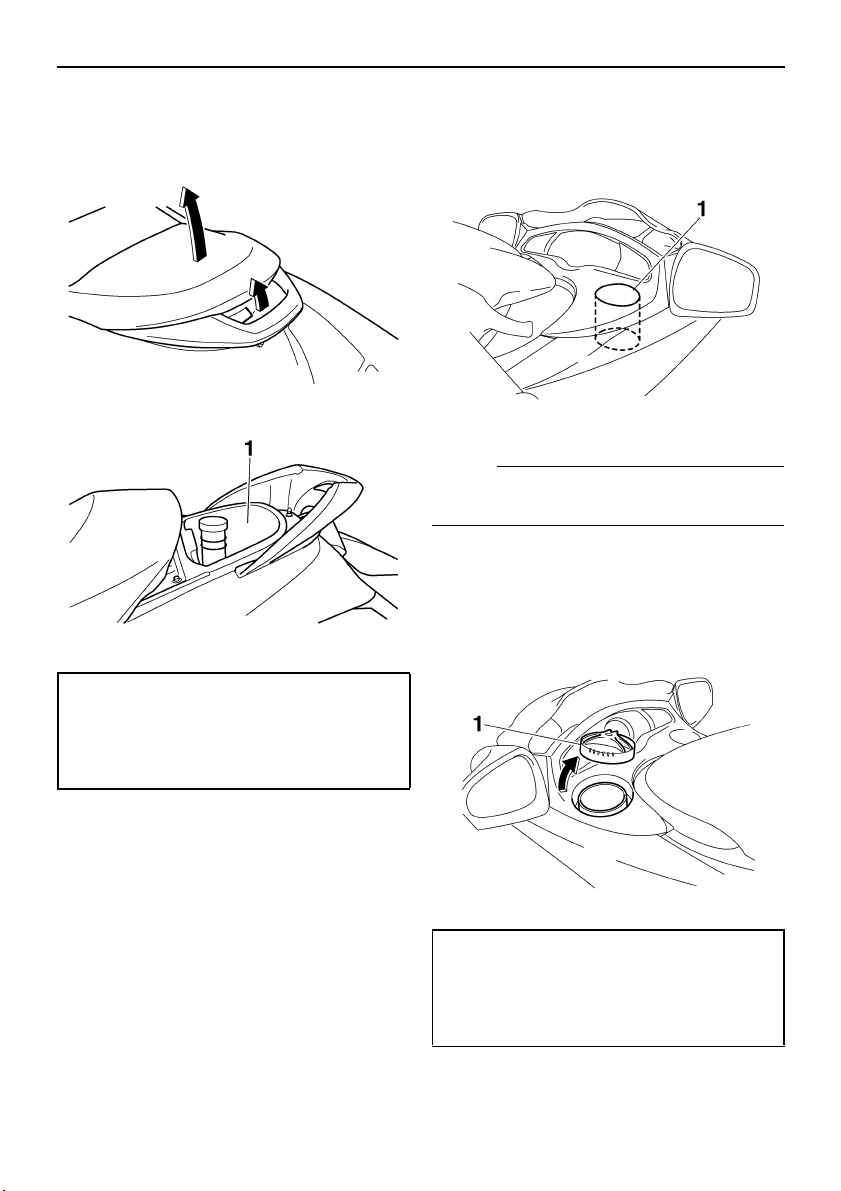
Features and functions
52
To open the seat storage compartment, re-
move the rear seat. (See page 29 for rear seat
removal and installation procedures.)
EJU35170
Beverage holder
The beverage holder is located on the star-
board (right) side of the watercraft.
NOTE:
Do not place beverages in the beverage hold-
er when operating the watercraft.
EJU35182
Watertight compartment
The watertight compartment is located on the
port (left) side of the watercraft.
To open the watertight compartment, turn the
cap counterclockwise.
1 Seat storage compartment
Seat storage compartment:
Capacity:
15.0 L (4.0 US gal) (3.3 Imp.gal)
Load limit:
9.0 kg (20 lb)
1 Beverage holder
1 Watertight compartment cap
Watertight compartment:
Capacity:
2.6 L (0.7 US gal, 0.6 Imp gal)
Load limit:
1.0 kg (2.2 lb)
UF1X11E0.book Page 52 Monday, August 7, 2006 3:51 PM

Features and functions
53
NOTE:
Make sure that the watertight compartment
cap is closed securely before operating the
watercraft.
UF1X11E0.book Page 53 Monday, August 7, 2006 3:51 PM
Operation
54
EJU31820
Fuel and oil
This watercraft is equipped with a 4-stroke en-
gine. Conventional 2-stroke engine oil cannot
be used.
The engine utilizes an electronic fuel injection
system to deliver the optimal air-fuel ratio re-
quired by the engine. By ensuring the optimal
combustion conditions, this system is able to
increase startability and improve fuel econo-
my.
EJU31841
Gasoline
WARNING
EWJ00280
GASOLINE AND ITS VAPORS ARE HIGH-
LY FLAMMABLE AND EXPLOSIVE!
● Do not smoke when refueling, and keep
away from sparks, flames, and other
sources of ignition.
● Stop the engine before refueling.
● Refuel in a well-ventilated area with the
watercraft in a horizontal position.
● Do not stand or sit on the watercraft
while refueling in case of fire.
● Take care not to spill gasoline. If gaso-
line spills, wipe it up immediately with
dry rags. Always properly dispose of
gasoline-soaked rags.
● Avoid overfilling the fuel tank. Stop fill-
ing when the fuel level reaches approxi-
mately 50 mm (2 in) from the top of the
fuel tank. Fuel expands as it warms up
and could overflow if the fuel tank has
been overfilled. If temporarily leaving
the watercraft with a full fuel tank, do not
leave it in direct sunlight. Leave it in a
well-ventilated area with the watercraft
in a horizontal position.
● Tighten the fuel tank filler cap securely
after refueling.
● If you should swallow some gasoline, in-
hale a lot of gasoline vapor, or get gaso-
line in your eyes, get immediate medical
attention.
● If any gasoline spills on your skin or
clothing, immediately wash the affected
area with soap and water and change
your clothes.
CAUTION:
ECJ00310
Use only fresh gasoline that has been
stored in clean containers.
EJU31860
Gasohol
There are two types of gasohol: gasohol con-
taining ethanol and that containing methanol.
Gasohol containing ethanol can be used if
ethanol content does not exceed 10% and the
fuel meets the minimum octane ratings.
Gasohol containing methanol is not recom-
mended by Yamaha because it can cause
fuel system damage and engine performance
problems.
Recommended gasoline:
Regular unleaded gasoline with a mini-
mum octane rating of
86 (Pump octane number) = (R +
M)/2
90 (Research octane number)
UF1X11E0.book Page 54 Monday, August 7, 2006 3:51 PM
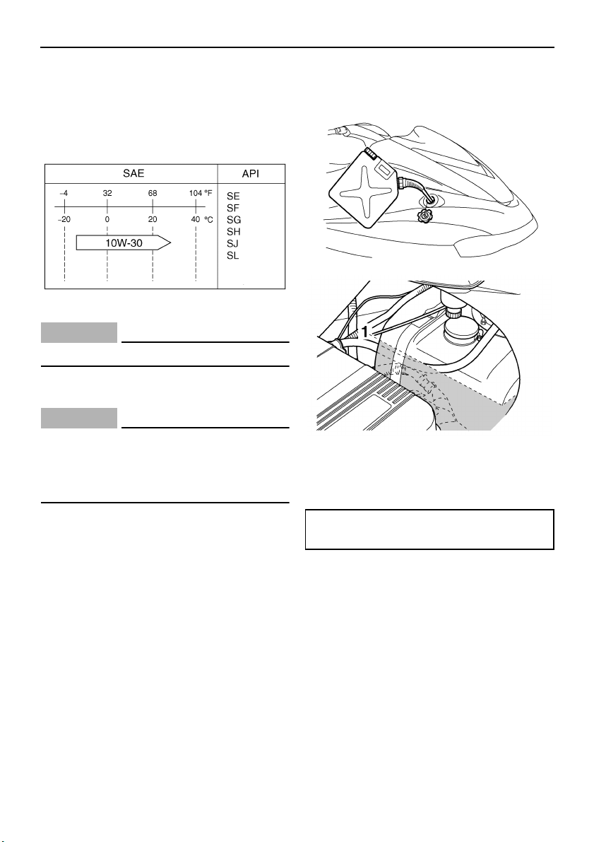
Operation
55
EJU31890
Engine oil
Use a combination of the recommended SAE
and API engine oil classifications shown in the
chart below.
CAUTION:
ECJ00280
Use only 4-stroke engine oil.
EJU31950
Filling the fuel tank
CAUTION:
ECJ00290
Be careful when refueling. Avoid getting
water and other contaminants in the fuel
tank. Contaminated fuel can cause poor
running and engine damage.
(1) Remove the seats. (See page 29 for seat
removal and installation procedures.)
(2) Remove the fuel tank filler cap, and then
slowly add fuel to the fuel tank. Stop filling
when the fuel level reaches approximate-
ly 50 mm (2 in) from the top of the fuel
tank as indicated in the illustration.
(3) Install the fuel tank filler cap and the
seats.
1 Approximately 50 mm (2 in) from top of the
fuel tank
Fuel tank capacity:
70 L (18.5 US gal) (15.4 Imp.gal)
UF1X11E0.book Page 55 Monday, August 7, 2006 3:51 PM

Operation
56
EJU31980
Pre-operation checks
EJU31990
Pre-operation check list
Before operating this watercraft, perform the checks in the following check list. See the accom-
panying text in this chapter for details on how to perform the checks.
WARNING
EWJ00410
If any item in the pre-operation check list is not working properly, have it inspected and
repaired before operating the watercraft, otherwise an accident could occur.
ITEM ROUTINE PAGE
BEFORE LAUNCH OR OPERATION
Engine compartment
Remove the seats to ventilate the engine compart-
ment. Check for fuel vapors and loose electrical con-
nections.
58
Bilge Check for water and fuel and drain if necessary. 59
Stern drain plugs Check for proper installation. 60
Throttle lever Check that the throttle lever springs back smoothly. 62
Steering system
Check for proper operation.
Check that the handlebars are locked in place.
62
Shift lever and reverse gate Check for proper operation. 62
QSTS Check for proper operation. 63
Fuel and oil
Check the fuel and oil levels and replenish if neces-
sary.
Check the hoses and tanks for leakage.
58, 58
Water separator Check for water and drain if necessary. 59
Battery Check the electrolyte level and battery condition. 60
Hood Check that the hood is securely closed. 30
Front and rear seats Check that the seats are securely installed. 29
Hull and deck
Check the hull and deck for cracks and other dam-
age.
58
Jet intake Check for debris and remove if necessary. 64
Fire extinguisher Check the condition and replace if necessary. 61
Engine shut-off cord Check the condition and replace if frayed or broken. 64
Switches
Check the start switch, engine stop switch, and en-
gine shut-off switch for proper operation.
65
AFTER LAUNCH
Cooling water pilot outlet
Check that water is discharged while the engine is
running and the watercraft is in the water.
65
Multifunction information
center
Check for warning indications and proper operation. 65
UF1X11E0.book Page 56 Monday, August 7, 2006 3:51 PM

Operation
57
NOTE:
Pre-operation checks should be made each time the watercraft is used. These checks can be
completed in a short time. It is worth the time spent to ensure safety and reliability.
UF1X11E0.book Page 57 Monday, August 7, 2006 3:51 PM
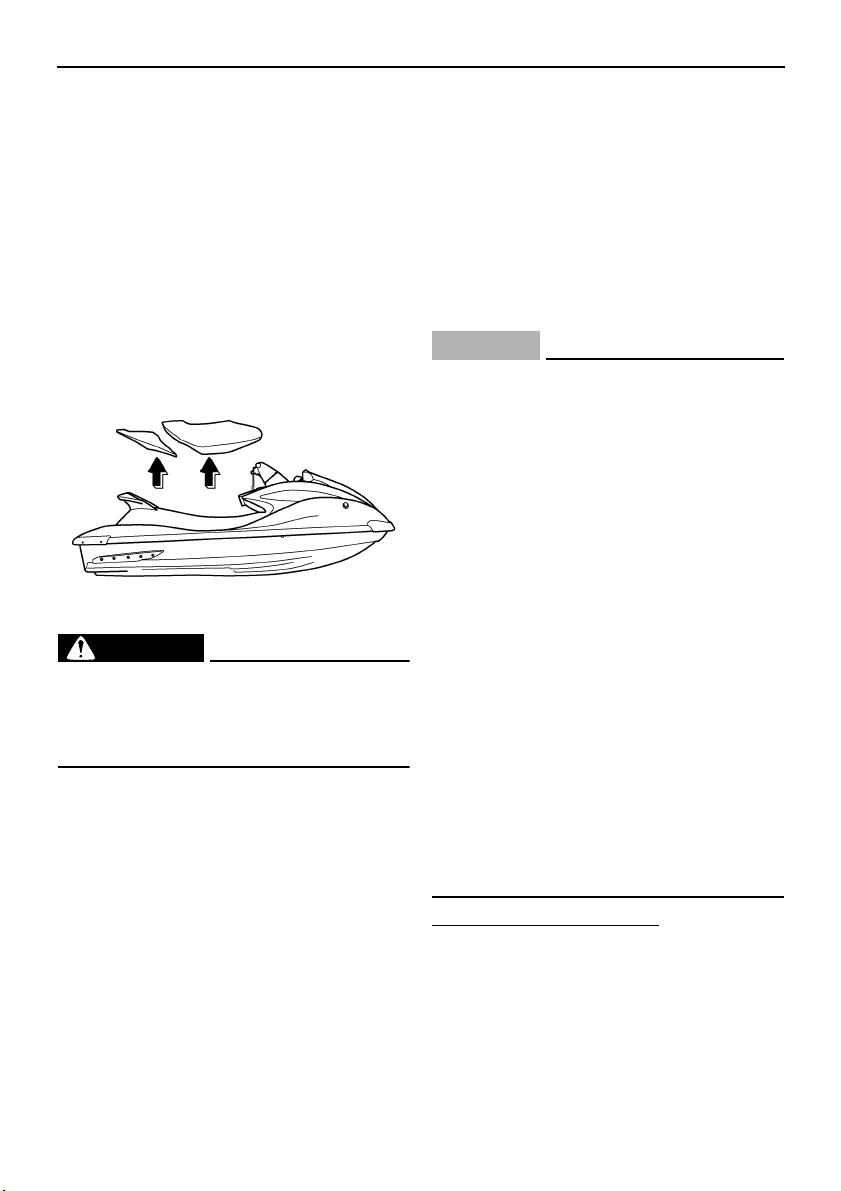
Operation
58
EJU32280
Pre-operation check points
EJU32330
Engine compartment
Ventilate the engine compartment before
each use.
To ventilate the engine compartment, remove
the seats. (See page 29 for seat removal and
installation procedures.) Leave the engine
compartment open for a few minutes to allow
any fuel vapors to escape.
While the engine compartment is open, check
for loose electrical connections.
WARNING
EWJ00460
Failure to ventilate the engine compart-
ment could result in a fire or explosion. Do
not start the engine if there is a fuel leak or
a loose electrical connection.
EJU32350
Hull and deck
Check the hull and deck for cracks and other
damage. If any damage is found, have a
Yamaha dealer repair the watercraft.
EJU32380
Fuel level
Check the fuel system for leakage, cracks,
and malfunctions before each use. (See page
87 for check points and correct procedures.)
(1) Remove the fuel tank filler cap to release
any pressure that might have built up in
the fuel tank.
(2) Remove the seats. (See page 29 for seat
removal and installation procedures.)
(3) Check the fuel level in the fuel tank and
replenish if necessary. (See page 55 for
filling procedures.)
(4) Install the fuel tank filler cap and the
seats.
EJU32411
Engine oil level
Check the engine oil level before each use.
CAUTION:
ECJ00390
● When checking the engine oil level on
water, be careful of other watercraft,
boats, swimmers, and obstacles. The
water current and wind can cause the
watercraft to move and lead to a colli-
sion.
● When checking the engine oil level on
land, supply water to the cooling water
passages. (See page 80 for procedures
on supplying water.)
● Make sure that the engine has enough
oil, but do not overfill it. If there is too lit-
tle oil, the engine can be damaged. If
there is too much oil, the air filter can be-
come saturated with oil, permanently
damaging the filter and reducing engine
performance. Follow the checking pro-
cedure carefully.
● Make sure that debris and water do not
enter the oil tank filler hole. Debris and
water in the engine oil can cause serious
engine damage.
To check the engine oil level:
(1) Place the watercraft in a horizontal posi-
tion or launch the watercraft, and then
start the engine.
(2) Run the engine at trolling speed for 6 min-
utes or more, and then stop the engine.
UF1X11E0.book Page 58 Monday, August 7, 2006 3:51 PM
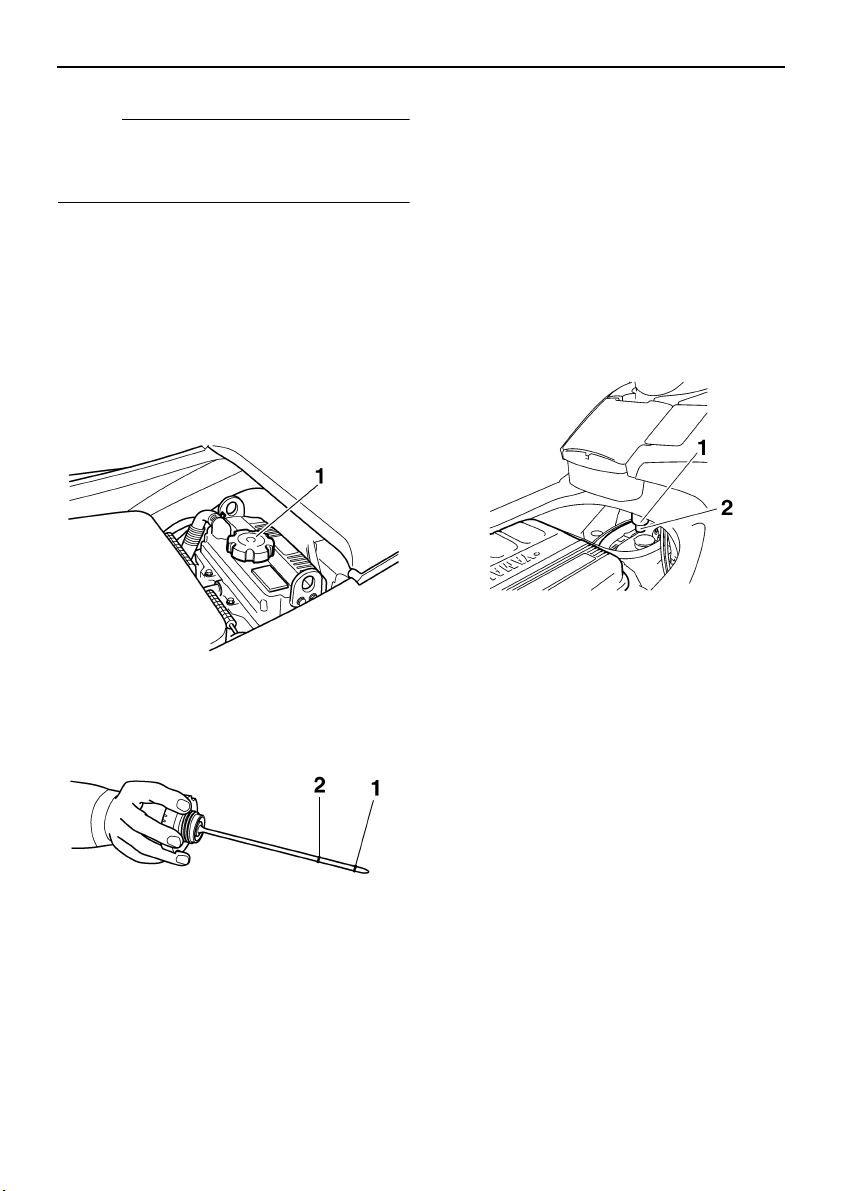
Operation
59
NOTE:
If the ambient temperature is 20 °C (68 °F) or
less, warm up the engine for an additional 5
minutes.
(3) Remove the seats. (See page 29 for seat
removal and installation procedures.)
(4) Remove the oil tank filler cap, wipe the
dipstick clean, and then screw the filler
cap into the filler hole completely. Re-
move the filler cap again and check that
the engine oil level is between the mini-
mum level mark and maximum level
mark on the dipstick.
(5) If the engine oil level is below the mini-
mum level mark, add enough oil so that
the oil level is between the minimum and
maximum level marks on the dipstick,
and then install the filler cap. If the engine
oil level is significantly above the maxi-
mum level mark, the oil tank is overfilled.
Have a Yamaha dealer remove the ex-
cessive amount of engine oil.
EJU32420
Water separator
Check the water separator for water. The wa-
ter separator retains any water that may have
entered through the fuel tank breather hose if
the watercraft was capsized. Normally, the
water separator is empty.
If water remains in the water separator, drain
it by removing the drain screw. Place a drain
pan under the water separator to catch the
draining water or use a dry cloth to soak up
any water that could spill into the watercraft. If
any water spills into the watercraft, be sure to
wipe it up with a dry cloth. Also, be sure to in-
stall the drain screw after draining the water
separator.
EJU32450
Bilge
Check the bilge for moisture and fuel residue.
This watercraft is equipped with a convention-
al jet vacuum bilge draining system and an
electric bilge draining system. The electric
bilge draining system is operated when the
engine is running. When excess water reach-
es the water inlet of the electric bilge pump,
1 Oil tank filler cap
1 Minimum level mark
2 Maximum level mark
1 Water separator
2 Drain screw
UF1X11E0.book Page 59 Monday, August 7, 2006 3:51 PM
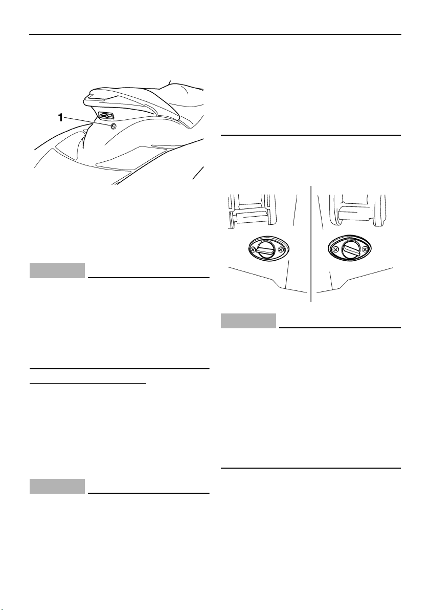
Operation
60
the water is discharged from the electric bilge
pilot outlet at the stern.
A small quantity of water will remain in the
bilge and should be drained manually. To
drain any residual water, beach the watercraft
and perform the following procedure.
CAUTION:
ECJ00350
If starting the engine after the watercraft
has capsized, do not operate the engine at
full throttle when water is being dis-
charged from the electric bilge pilot outlet
at the stern. Excessive water in the bilge
can splash into the engine, which can re-
sult in severe damage.
To drain water from the bilge:
(1) Remove the stern drain plugs.
(2) Raise the bow of the watercraft until the
water drains.
(3) After the water has drained, wipe the
bilge with dry rags to make sure that it is
thoroughly dry.
(4) Install the stern drain plugs.
CAUTION:
ECJ00360
● Before installing the stern drain plugs,
clean the drain plug threads to remove
any foreign materials, such as dirt or
sand. Otherwise, the stern drain plugs
could be damaged, allowing water to en-
ter the engine compartment.
● Make sure that the stern drain plugs are
tightened securely before launching the
watercraft. Otherwise, water may flood
the engine compartment and cause the
watercraft to submerge.
EJU32470
Stern drain plugs
Check the stern drain plugs for proper instal-
lation.
CAUTION:
ECJ00360
● Before installing the stern drain plugs,
clean the drain plug threads to remove
any foreign materials, such as dirt or
sand. Otherwise, the stern drain plugs
could be damaged, allowing water to en-
ter the engine compartment.
● Make sure that the stern drain plugs are
tightened securely before launching the
watercraft. Otherwise, water may flood
the engine compartment and cause the
watercraft to submerge.
EJU32480
Battery
Check the battery condition and the electro-
lyte level.
1 Electric bilge pilot outlet
UF1X11E0.book Page 60 Monday, August 7, 2006 3:51 PM

Operation
61
Check that the battery leads are tightened se-
curely and that there is no corrosion on the
battery terminals.
WARNING
EWJ00450
● The battery must always be fully
charged and in good condition. Loss of
battery power may leave you stranded.
Never operate the watercraft if the bat-
tery does not have sufficient power to
start the engine or if it shows any other
signs of decreased power.
● Be sure to connect the breather hose to
the battery. Fire or explosion could re-
sult if the breather hose is damaged, ob-
structed, or not connected properly.
Make sure that the battery is securely held in
place.
EJU32570
Fire extinguisher
Check that there is a full fire extinguisher on
board.
The fire extinguisher container is located in
the seat storage compartment.
To open the fire extinguisher container, turn
the cap counterclockwise.
To close the fire extinguisher container, insert
the fire extinguisher into the container, and
then install the cap and tighten it securely.
NOTE:
● To check the fire extinguisher, see the in-
structions supplied by the fire extinguisher
manufacturer. Always keep the fire extin-
guisher in the fire extinguisher container.
● Always carry a fire extinguisher on board. A
fire extinguisher is not standard equipment
with this watercraft. If you do not have one,
1 Positive (+) battery terminal: Red lead
2 Negative (–) battery terminal: Black lead
3 Breather hose
1 Fire extinguisher container
2 Fire extinguisher container cap
UF1X11E0.book Page 61 Monday, August 7, 2006 3:51 PM

Operation
62
contact a Yamaha dealer or a fire extin-
guisher dealer to obtain one meeting the
proper specifications.
EJU32590
Throttle lever
Check the throttle lever for proper operation.
Squeeze and release the throttle lever several
times to make sure that there is no hesitation
in its travel. It should be smooth over the com-
plete range and spring back to the idle posi-
tion when released.
WARNING
EWJ00490
Before starting the engine, always check
the operation of the throttle lever.
EJU32610
Steering system
Check the handlebars for looseness.
Turn the handlebars as far as possible to the
right and left to make sure that operation is
smooth and unrestricted throughout the
whole range. Also, make sure that the jet
thrust nozzle moves as the handlebars are
turned, and that there is no free play between
the handlebars and the jet thrust nozzle.
Check that the handlebars are locked in
place. (See “Tilt lever” on page 34 for more in-
formation.)
EJU32630
Shift lever and reverse gate
Check the shift lever and reverse gate for
proper operation.
Make sure that the reverse gate goes down
completely when the shift lever is pulled up.
Fire extinguisher:
Classification:
B-1
Capacity:
2 lb or more
UF1X11E0.book Page 62 Monday, August 7, 2006 3:51 PM
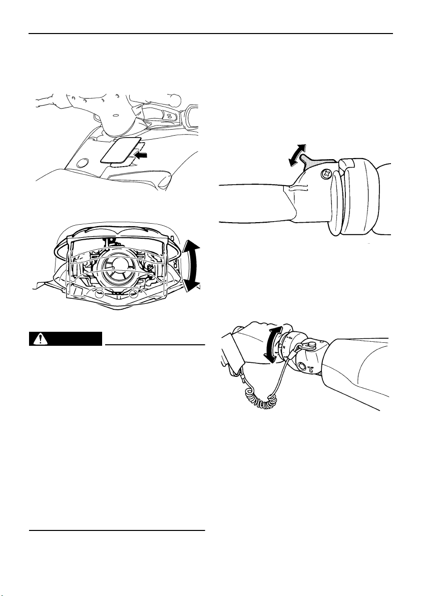
Operation
63
Also, make sure that the reverse gate goes up
completely when the shift lever is pushed
down.
WARNING
EWJ00480
● Make sure that the throttle lever is com-
pletely released and that the engine is at
idle before shifting into reverse.
● Do not use the reverse function to slow
down or stop the watercraft as it could
cause you to lose control, be ejected, or
impact the handlebars.
● Use reverse for slow-speed maneuver-
ing only.
● Make sure that there are no obstacles or
people behind you before shifting into
reverse.
● Do not touch the reverse gate while the
shift lever is being operated, otherwise
you could be pinched.
EJU32641
Quick Shift Trim System (QSTS)
Operate the QSTS selector lock lever and the
QSTS selector several times to check that
they operate properly.
(1) Squeeze the QSTS selector lock lever
and check that it returns smoothly to its
original position when released.
(2) Check that the QSTS selector turns
smoothly when the lever is squeezed and
check that the selector locks in place at
each position when the lever is released.
(3) Check that the angle of the jet thrust noz-
zle changes when the QSTS selector is
UF1X11E0.book Page 63 Monday, August 7, 2006 3:51 PM
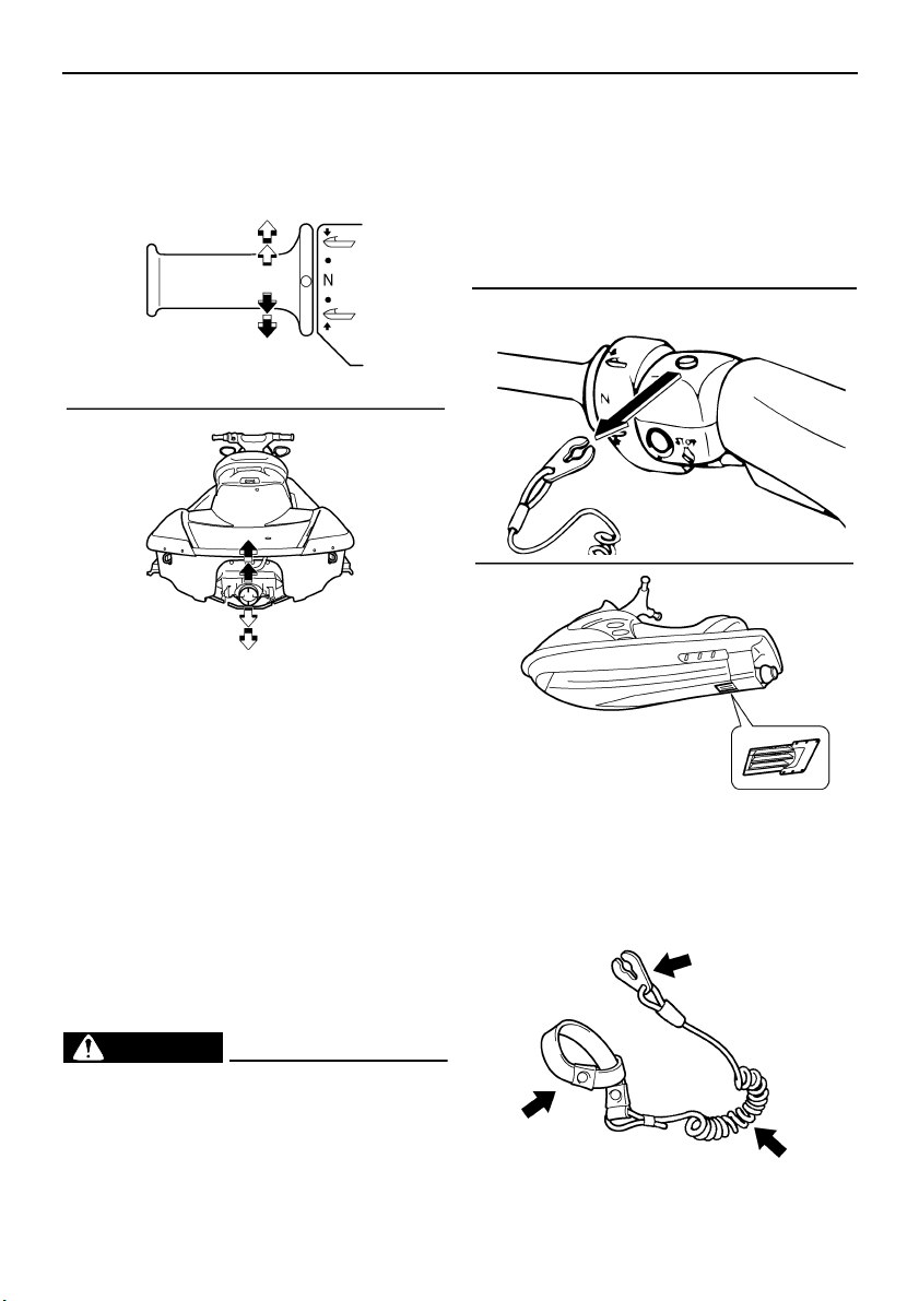
Operation
64
shifted from neutral to bow up or bow
down.
If the mechanism does not work properly,
have a Yamaha dealer service it.
EJU32650
Jet intake
Carefully check the jet intake for weeds, de-
bris, or anything else that might restrict the in-
take of water. If the jet intake is clogged,
cavitation could occur, reducing jet thrust, and
possibly damaging the jet pump.
In some cases, the engine may overheat be-
cause of lack of cooling water, and damage to
the engine could result. Cooling water is fed to
the engine by the jet pump. (See page 98 for
jet intake cleaning procedures.)
WARNING
EWJ00470
● Keep away from the intake grate while
the engine is on. Items such as long hair,
loose clothing, or PFD straps can be-
come entangled in moving parts, result-
ing in severe injury or drowning.
● Stop the engine and remove the clip
from the engine shut-off switch before
removing any debris or weeds, which
may have collected around the jet in-
take.
EJU32660
Engine shut-off cord
Check that the engine shut-off cord is not
frayed or broken. If the cord is damaged, re-
place it; never try to repair it or tie it together.
UF1X11E0.book Page 64 Monday, August 7, 2006 3:51 PM
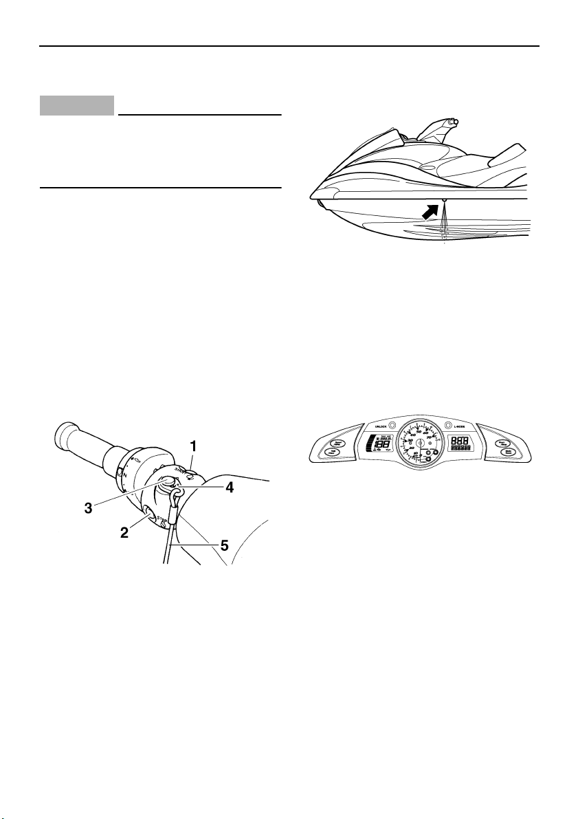
Operation
65
EJU32670
Switches
CAUTION:
ECJ00410
Do not run the engine for more than 15
seconds when checking the switches on
land without supplying water, otherwise
the engine could overheat.
Check the start switch, the engine stop
switch, and the engine shut-off switch for
proper operation.
Push the start switch to start the engine. As
soon as the engine starts running, push the
engine stop switch to verify that the engine
stops immediately. Restart the engine, and
then pull the engine shut-off cord to remove
the clip from the engine shut-off switch to ver-
ify that the engine stops immediately. (See
pages 32 to 33 for information on proper op-
eration of the start switch, the engine stop
switch, and the engine shut-off switch.)
EJU32700
Cooling water pilot outlet
Check that water comes out from the port
(left) cooling water pilot outlet while the engine
is running and the watercraft is in the water.
(See page 33 for more information.)
EJU32710
Multifunction information center
Check the multifunction information center for
proper operation. (See page 40 for informa-
tion on proper operation of the multifunction
information center.)
1 Start switch
2 Engine stop switch
3 Engine shut-off switch
4 Clip
5 Engine shut-off cord
UF1X11E0.book Page 65 Monday, August 7, 2006 3:51 PM
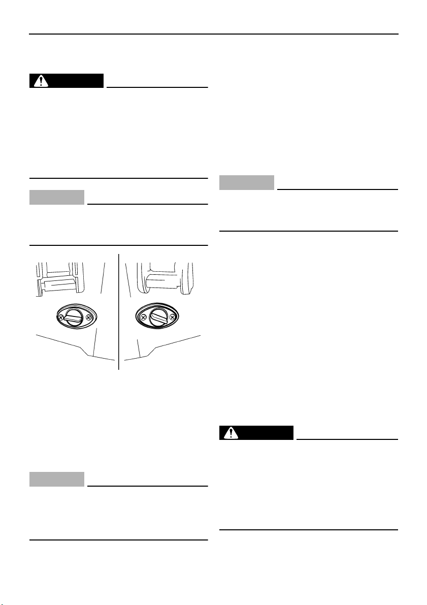
Operation
66
EJU32740
Operation
WARNING
EWJ00510
Before operating your watercraft, become
familiar with all of the controls. Consult a
Yamaha dealer about any control or func-
tion that you do not fully understand. Fail-
ure to understand how the controls work
could cause an accident or prevent you
from avoiding an accident.
CAUTION:
ECJ00460
Make sure that the stern drain plugs are
tightened securely before launching the
watercraft.
EJU36140
Engine break-in
The engine break-in period is essential to al-
low the various components of the engine to
wear and polish themselves to the correct op-
erating clearances. This ensures proper per-
formance and promotes longer component
life.
CAUTION:
ECJ00440
Be sure to check the engine oil level be-
fore operating the watercraft for the first
time. (See page 58 for engine oil checking
procedures.)
(1) Launch the watercraft and start the en-
gine. (See page 66 for engine starting
procedures.)
(2) For the first 5 minutes, run the engine at
trolling speed only. For the 30 minutes of
operation after that, keep the engine
speed below 5000 r/min. For the 1 hour of
operation after that, keep the engine
speed below 8000 r/min.
(3) Proceed with normal operation.
CAUTION:
ECJ00430
Failure to follow the engine break-in pro-
cedure could result in reduced engine life
or even severe engine damage.
EJU32800
Launching the watercraft
When launching the watercraft, make sure
that there are no obstacles behind you.
Use the remote control transmitter to select
the unlock mode. (See page 38 for Yamaha
Security System and low-RPM mode selec-
tion procedures.)
After the watercraft is in the water, start the
engine. Shift into reverse and move the water-
craft back slowly. If there are waves, some-
one should make sure that the watercraft is
not pushed into the trailer before backing
away.
EJU32850
Starting the engine
WARNING
EWJ00560
Never start the engine or let it run for any
length of time in an enclosed area. Ex-
haust fumes contain carbon monoxide, a
colorless, odorless gas that may cause
loss of consciousness and death within a
short time. Always operate the watercraft
in an open area.
UF1X11E0.book Page 66 Monday, August 7, 2006 3:51 PM
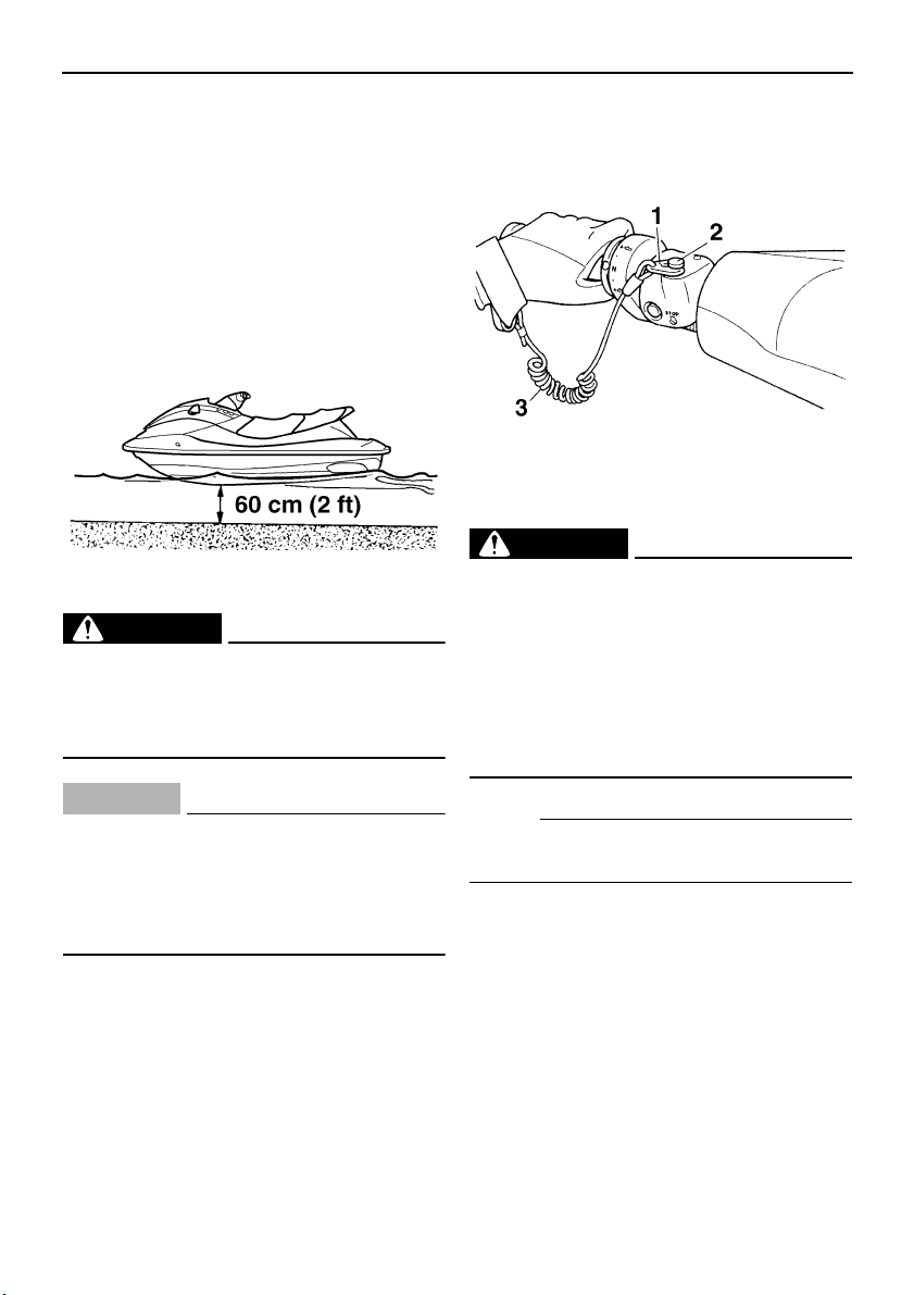
Operation
67
(1) If the lock mode of the Yamaha Security
System is selected, use the remote con-
trol transmitter to select the unlock mode.
(See page 38 for Yamaha Security Sys-
tem and low-RPM mode selection proce-
dures.)
(2) Launch the watercraft in water free from
weeds and debris and at least 60 cm (2 ft)
deep.
WARNING
EWJ00570
Never operate in water that is less than 60
cm (2 ft) deep, otherwise you increase
your chance of hitting a submerged ob-
ject, which could result in injury.
CAUTION:
ECJ00470
Never operate in water that is less than 60
cm (2 ft) deep, otherwise pebbles or sand
could be sucked into the jet intake, caus-
ing impeller damage and engine overheat-
ing.
(3) Attach the engine shut-off cord to your left
wrist, and then attach the clip to the en-
gine shut-off switch.
WARNING
EWJ00580
Check that the engine shut-off cord is not
frayed or broken, and keep it free from the
handlebars so that the engine stops if the
operator falls off. The engine shut-off cord
may not pull free if wrapped around the
handlebars when the operator falls off, al-
lowing the watercraft to continue to run
and cause an accident.
NOTE:
It is not possible to start the engine with the
clip removed from the engine shut-off switch.
1 Clip
2 Engine shut-off switch
3 Engine shut-off cord
UF1X11E0.book Page 67 Monday, August 7, 2006 3:51 PM

Operation
68
(4) Push the start switch (green button), and
then release it as soon as the engine
starts to run.
NOTE:
The engine will not start if the throttle lever is
squeezed.
CAUTION:
ECJ00480
● Never push the start switch while the en-
gine is running.
● Do not operate the start switch for more
than 5 seconds, otherwise the battery
will be discharged and the engine will
not start. Also, the starter motor could
be damaged. If the engine does not start
in 5 seconds, release the start switch,
wait 15 seconds, and then try again.
EJU32860
Stopping the engine
To stop the engine, release the throttle lever,
and then push the engine stop switch (red
button).
WARNING
EWJ00600
You need throttle to steer. Shutting the en-
gine off can cause you to hit an obstacle
you are attempting to avoid. A collision
could result in severe injury or death.
EJU32880
Leaving the watercraft
If leaving the watercraft, select the lock mode
of the Yamaha Security System and remove
the engine shut-off cord to reduce the chance
of accidental starting or unauthorized use by
children or others. (See page 38 for Yamaha
Security System and low-RPM mode selec-
tion procedures.)
UF1X11E0.book Page 68 Monday, August 7, 2006 3:51 PM
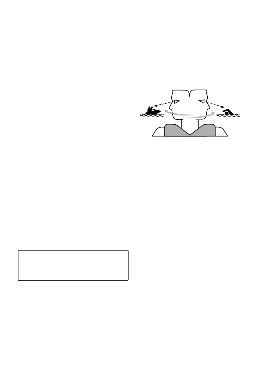
Operation
69
EJU32900
Operating your watercraft
EJU32951
Getting to know your watercraft
Operating your watercraft requires skills ac-
quired through practice over a period of time.
Take the time to learn the basic techniques
well before attempting more difficult maneu-
vers.
Operating your new watercraft can be a very
enjoyable activity, providing you with hours of
pleasure. However, it is essential to familiar-
ize yourself with the operation of the water-
craft to achieve the skill level necessary to
enjoy riding safely.
Before operating this watercraft, read this
owner’s/operator’s manual, the Riding Prac-
tice Guide, the Riding Instruction card, and all
warning and caution labels on the watercraft.
Pay particular attention to the safety informa-
tion on page 9. Also, watch the Basic Orienta-
tion Video provided with your watercraft.
These materials should give you an under-
standing of the watercraft and its operation.
Remember: This watercraft is designed to
carry the operator and up to 2 passengers.
Never exceed the maximum load limit or allow
more than 3 persons (or 2 persons if a water-
skier is being pulled) to ride the watercraft at
any time.
EJU32990
Learning to operate your watercraft
Before operating the watercraft, always per-
form the pre-operation checks listed on page
56. The short time spent checking the water-
craft will reward you with added safety and re-
liability.
Check state and local laws before operating
your watercraft.
Operate defensively at safe speeds and keep
a safe distance away from people, objects,
and other watercraft. Select a wide area to
learn in, where there is good visibility and light
boat traffic.
Use the buddy system—operate with some-
one nearby. Scan constantly for people, ob-
jects, and other watercraft. Be alert for
conditions that limit your visibility or block your
vision of others.
Attach the engine shut-off cord to your left
wrist and keep it free from the handlebars so
that the engine stops if you, the operator, fall
off.
Wear a personal flotation device (PFD). All
riders must wear a U.S. Coast Guard ap-
proved PFD that is suitable for personal wa-
tercraft use.
Wear protective clothing. Severe internal inju-
ries can occur if water is forced into body cav-
ities as a result of falling into the water or
being near the jet thrust nozzle. Normal swim-
wear does not adequately protect against
forceful water entry into the rectum and vagi-
na. All riders must wear a wetsuit bottom or
clothing that provides equivalent protection.
Such clothing includes thick, tightly woven,
sturdy and snug-fitting apparel such as den-
im, but does not include spandex or similar
Maximum load:
240 kg (530 lb)
Load is the total weight of cargo, oper-
ator, and passengers.
UF1X11E0.book Page 69 Monday, August 7, 2006 3:51 PM
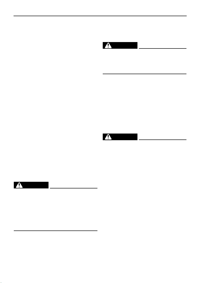
Operation
70
fabrics, like those used in bicycle shorts. A full
wetsuit can also protect against hypothermia
(subnormal body temperature) and abra-
sions.
Footwear and gloves are recommended.
Eye protection is recommended to keep wind,
water, and glare from the sun out of your eyes
while you operate your watercraft. Restraining
straps for eyewear are made which are de-
signed to float should your eyewear fall in the
water.
You should grip the handlebars firmly and
keep both feet on the floor of the footwell. Do
not attempt to ride with passengers until your
operating skills are fully developed.
EJU33050
Riding with passengers
When 2 or 3 persons (including the operator)
are on board, the watercraft handles different-
ly, and is not as easy to maneuver, so operat-
ing it requires a higher degree of skill. Before
attempting to operate the watercraft with pas-
sengers on board, the operator must practice
operating the watercraft alone enough to be
able to acquire the necessary skills.
The passengers must always wear a U.S.
Coast Guard approved PFD and a wetsuit
bottom or equivalent.
WARNING
EWJ00540
Do not apply throttle when anyone is at the
rear of the watercraft. Turn the engine off
or keep it at idle. Water and/or debris exit-
ing the jet thrust nozzle can cause severe
injury. Passengers should not attempt to
board the watercraft if the operator is ap-
plying throttle.
Do not give a ride to children whose feet can-
not reach the floor of the footwell. The pas-
sengers should hold on firmly, either to the
person in front of them or to the handgrip pro-
vided, and keep their feet on the floor of the
footwell. Never allow a passenger to ride in
front of the operator.
WARNING
EWJ00550
When passengers are on board, make
sure that they are holding on firmly and
have their feet on the floor of the footwell
before you start to accelerate.
When pulling a water-skier, the spotter should
face to the rear while holding the handgrip
with both hands. The spotter should always sit
astride the seat with both feet placed firmly on
the floor of the footwell for proper balance.
Follow state laws regarding water-skiing,
such as those for skier-down flags, rearward-
facing spotter, and other requirements.
EJU33080
Starting the watercraft
WARNING
EWJ00710
● Scan constantly for people, objects, and
other watercraft. Be alert for conditions
that limit your visibility or block your vi-
sion of others.
● Operate defensively at safe speeds and
keep a safe distance away from people,
objects, and other watercraft.
● Do not follow directly behind watercraft
or other boats. Do not go near others to
spray or splash them with water. Avoid
sharp turns or other maneuvers that
make it hard for others to avoid you or
understand where you are going. Avoid
areas with submerged objects or shal-
low water.
● Take early action to avoid collisions. Re-
member, watercraft and other boats do
not have brakes. Do not release the
throttle lever when trying to steer away
from objects—you need throttle to steer.
UF1X11E0.book Page 70 Monday, August 7, 2006 3:51 PM
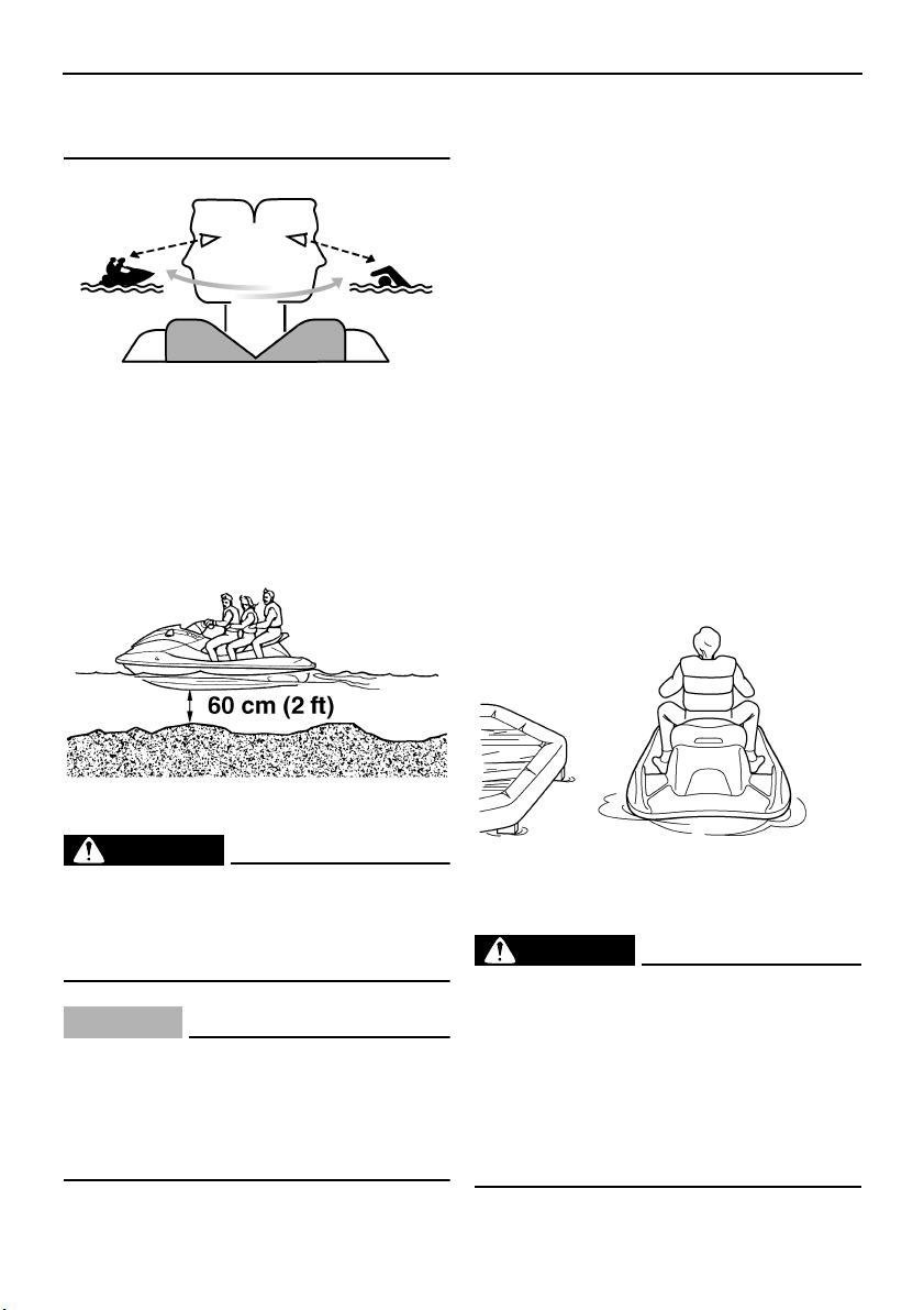
Operation
71
● Practice reboarding in shallow water be-
fore riding in deep water.
EJU33090
Boarding and starting in shallow water
(1) Launch the watercraft in water free from
weeds and debris and at least 60 cm (2 ft)
deep.
WARNING
EWJ00640
Never operate in water that is less than 60
cm (2 ft) deep, otherwise you increase
your chance of hitting a submerged ob-
ject, which could result in injury.
CAUTION:
ECJ00500
Never operate in water that is less than 60
cm (2 ft) deep, otherwise pebbles or sand
could be sucked into the jet intake, caus-
ing impeller damage and engine overheat-
ing.
(2) Board the watercraft from the side or the
rear.
(3) Attach the engine shut-off cord to your left
wrist, and then attach the clip to the en-
gine shut-off switch.
(4) Grip the handlebars with both hands,
place both feet on the floor of the footwell,
start the engine, and then look in all direc-
tions before starting off.
EJU33110
Boarding and starting from a dock
(1) Board the watercraft from the side.
(2) Attach the engine shut-off cord to your left
wrist, and then attach the clip to the en-
gine shut-off switch.
(3) Push the watercraft away from the dock,
grip the handlebars with both hands,
place both feet on the floor of the footwell,
start the engine, and then look in all direc-
tions before starting off.
EJU36080
Boarding and starting in deep water
WARNING
EWJ01110
● The operator and passengers should
practice boarding in shallow water be-
fore riding in deep water. Boarding in
deep water requires more skill.
● The fatigue and exposure that could re-
sult after unsuccessful attempts to get
back on the watercraft may increase the
risk of injuries and drowning.
UF1X11E0.book Page 71 Monday, August 7, 2006 3:51 PM
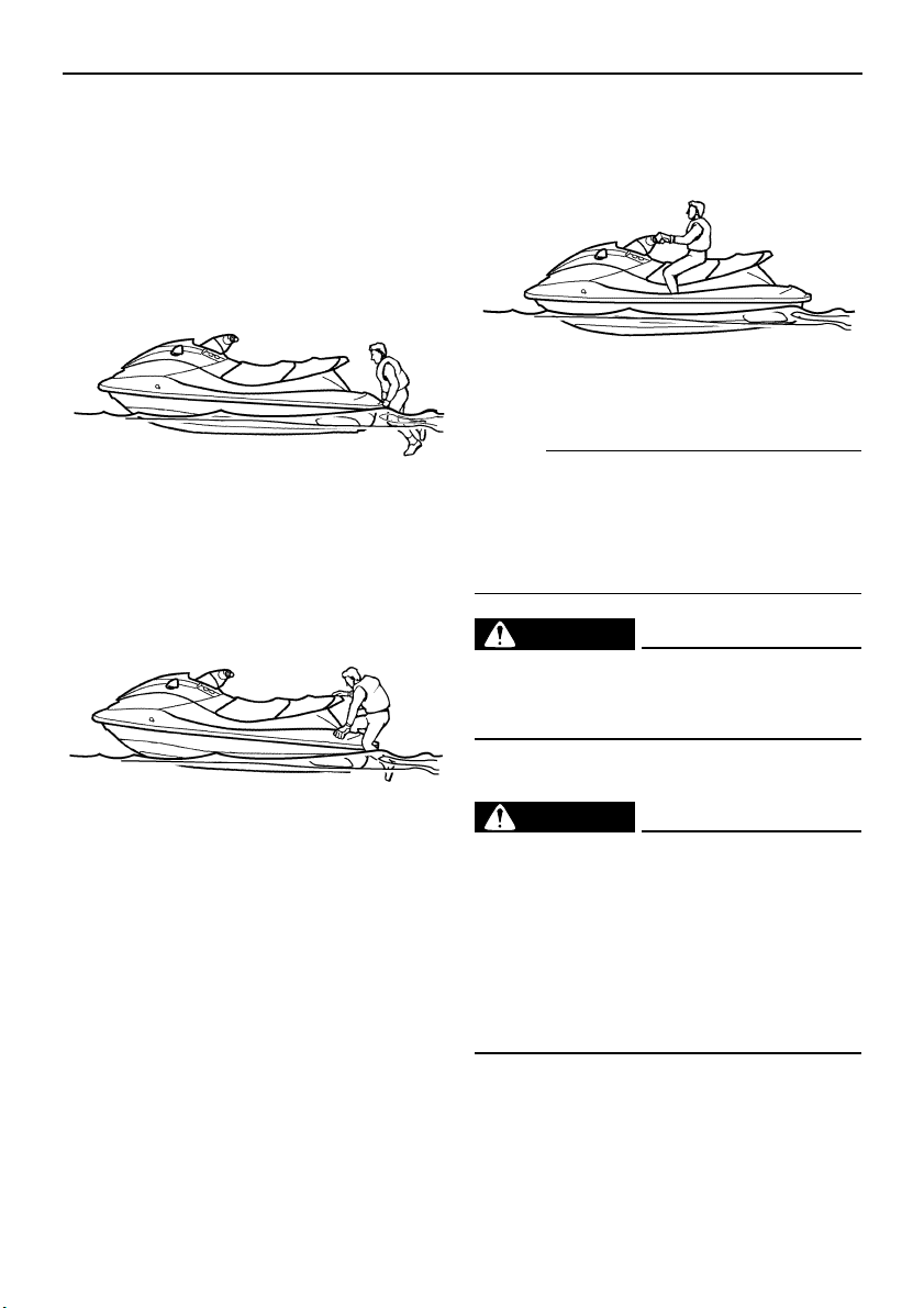
Operation
72
EJU35230
Boarding alone
(1) Swim to the rear of the watercraft and
place both hands on the boarding plat-
form, pull yourself up, and then grasp the
handgrip with one hand.
(2) Pull yourself up to a kneeling position on
the platform, and then move to the seat
and sit astride.
(3) Attach the engine shut-off cord to your left
wrist, and then attach the clip to the en-
gine shut-off switch.
(4) Grip the handlebars with both hands,
place both feet on the floor of the footwell,
start the engine, and then look in all direc-
tions before starting off.
NOTE:
If your watercraft is equipped with the re-
boarding step, you can lower the step to make
reboarding easier. The step returns automati-
cally to the up position after you have board-
ed.
WARNING
EWJ00610
Before starting off, make sure that there
are no boats, swimmers, or obstacles
around you.
EJU33161
Boarding with passengers
WARNING
EWJ00660
Severe internal injuries can occur if water
is forced into body cavities as a result of
being near the jet thrust nozzle. Do not ap-
ply throttle until the passengers are seated
with their feet on the floor of the footwell
and are securely holding on to the person
in front of them or to the handgrip provid-
ed.
UF1X11E0.book Page 72 Monday, August 7, 2006 3:51 PM
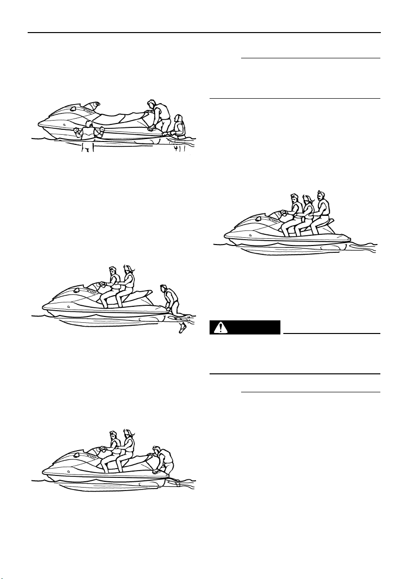
Operation
73
(1) Climb on board as noted in the previous
section, and sit astride the seat.
(2) Attach the engine shut-off cord to your left
wrist, and then attach the clip to the en-
gine shut-off switch.
(3) Have the passengers move to the rear of
the watercraft.
(4) Have a passenger board and sit astride
the seat. If a second passenger is board-
ing, have him or her follow the same pro-
cedure.
NOTE:
When a passenger is boarding, both the pas-
sengers and the operator should try to bal-
ance the watercraft.
(5) Check that the passengers have their
feet on the floor of the footwell and are
securely holding on to the person in front
of them or to the handgrip provided. Nev-
er allow a passenger to ride in front of the
operator.
(6) Start the engine, look in all directions, and
then accelerate to planing speed.
WARNING
EWJ00610
Before starting off, make sure that there
are no boats, swimmers, or obstacles
around you.
NOTE:
The heavier the total weight of the operator
and passengers, the more difficult it will be to
balance the watercraft. Do not operate the
watercraft when the total weight exceeds 240
kg (530 lb) including any cargo. If it is difficult
to balance the watercraft at a standstill, pro-
ceed as follows:
(1) While the passengers are steadying the
watercraft, pull yourself up onto the
boarding platform into a kneeling posi-
UF1X11E0.book Page 73 Monday, August 7, 2006 3:51 PM
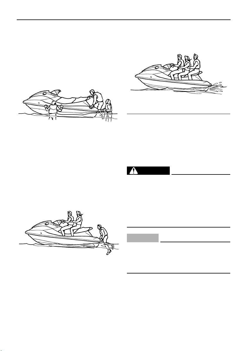
Operation
74
tion, and then move to the seat and sit
astride to balance the watercraft.
(2) Have a passenger pull him or herself up
onto the boarding platform into a kneeling
position, then move to the seat and sit
astride to balance the watercraft.
(3) Attach the engine shut-off cord to your left
wrist, and then attach the clip to the en-
gine shut-off switch.
(4) Start the engine and keep it at idle.
(5) Have the second passenger pull him or
herself up onto the boarding platform into
a kneeling position, then crawl onto the
seat as the watercraft accelerates.
(6) Gradually increase the speed to balance
the watercraft.
EJU33230
Capsized watercraft
If the watercraft capsizes, turn it over immedi-
ately.
Be sure to carefully follow the procedures be-
low to prevent injury, or damage to the water-
craft.
WARNING
EWJ00670
IMPROPER UPRIGHTING CAN CAUSE IN-
JURY:
● Be sure to shut the engine off by pulling
on the engine shut-off cord to remove
the clip from the engine shut-off switch.
● Do not put your hands in the intake
grate.
CAUTION:
ECJ00530
If the watercraft capsizes, release the
throttle lever immediately. Oil could flow
into the air filter case and the engine could
be damaged.
(1) Remove the clip from the engine shut-off
switch.
(2) Swim to the rear of the watercraft. Pull the
watercraft over with your left hand on the
UF1X11E0.book Page 74 Monday, August 7, 2006 3:51 PM
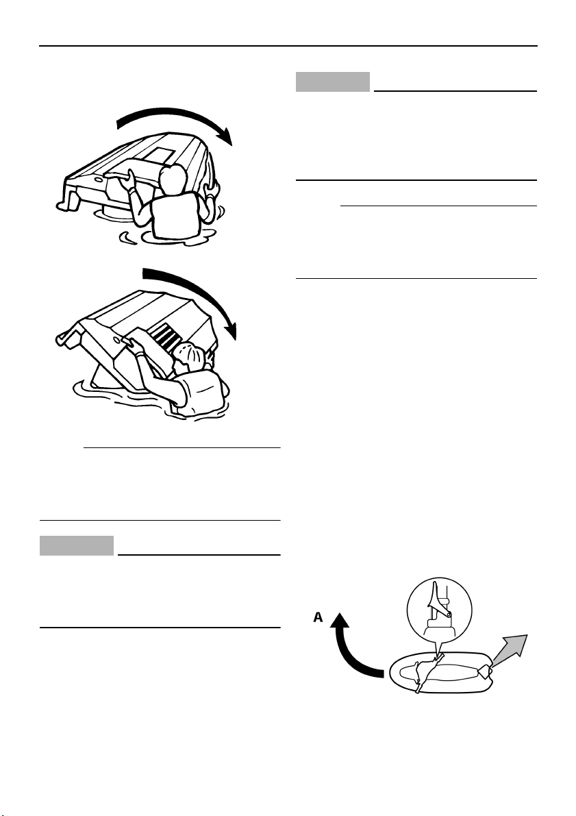
Operation
75
ride plate while pushing down on the gun-
wale with your right hand or foot.
NOTE:
If the port (left) side of the capsized watercraft
is tilting up, push down on the gunwale so that
the port (left) side is down before turning the
watercraft clockwise.
CAUTION:
ECJ00540
Do not turn the watercraft over counter-
clockwise, otherwise water can enter the
engine, which can result in severe dam-
age.
(3) Start the engine and operate the water-
craft to discharge any water remaining in
the engine compartment. (If the engine
does not start, see “Towing the water-
craft” on page 101 or “Submerged water-
craft” on page 101.)
CAUTION:
ECJ00550
Do not operate the engine at full throttle
for at least 1 minute after the engine has
been restarted. Excessive water in the
bilge can splash into the engine, which
can result in severe damage.
N
O
TE:
To efficiently discharge water from the engine
compartment, operate the watercraft as
straight as possible and above planing speed
for at least 2 minutes.
EJU33250
Turning the watercraft
Steering control depends on the combination
of handlebar position and the amount of throt-
tle.
Water sucked in through the intake grate is
pressurized by the impeller in the jet pump. As
the pressurized water is expelled from the
pump through the jet thrust nozzle, it creates
thrust to move and steer the watercraft. The
higher the engine speed, the more thrust pro-
duced.
The amount of jet thrust, in addition to the po-
sition of the handlebars, determines how
sharply you turn.
A. More throttle produces higher thrust, so
the watercraft will turn more sharply.
UF1X11E0.book Page 75 Monday, August 7, 2006 3:51 PM
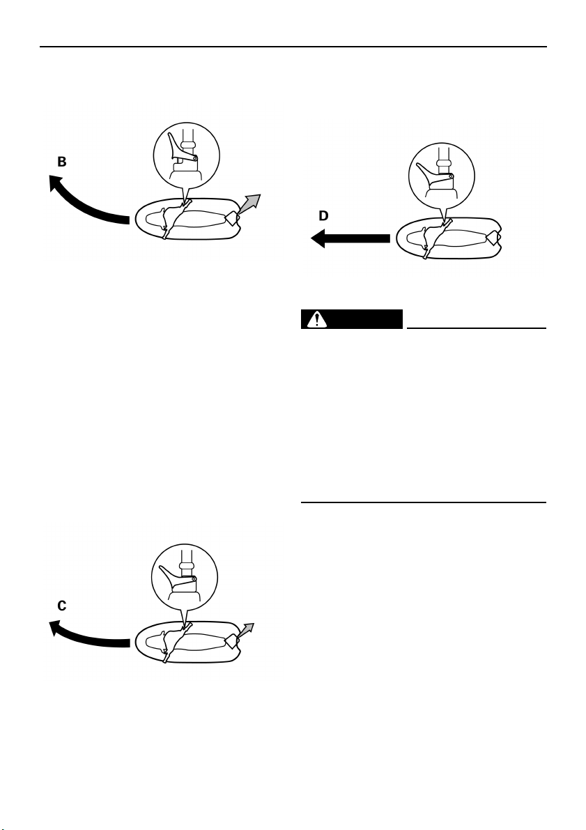
Operation
76
B. Less throttle produces lower thrust, so
the watercraft will turn more gradually.
C. Releasing the throttle lever completely
produces only minimum thrust. If you are
traveling at speeds above trolling, you will
have rapidly decreasing ability to steer
without throttle. You may still have some
turning ability immediately after releasing
the throttle lever, but once the engine
slows down, the watercraft will no longer
respond to handlebar input until you ap-
ply throttle again or you reach trolling
speed.
At trolling speed, the watercraft can be
turned gradually by handlebar position
alone using just the amount of thrust
available at idle.
D. If the engine is stopped while riding, there
is no thrust. The watercraft will go straight
even though the handlebars are turned.
You need throttle to steer.
WARNING
EWJ00770
● Do not release the throttle lever when
trying to steer away from objects—you
need throttle to steer. A collision could
result in severe injury or death.
● When operating at higher speeds, make
gradual turns or slow down before turn-
ing. Sharp high-speed turns may cause
the watercraft to slide sideways or spin,
throwing the operator and passengers
overboard, which could cause an injury.
This model is equipped with the Yamaha En-
gine Management System (YEMS) that in-
cludes an off-throttle steering (OTS) system.
It will activate at planing speeds should you
attempt to steer the watercraft after releasing
the throttle lever (see condition C above).
The OTS system assists in turning by continu-
ing to supply some thrust while the watercraft
is decelerating, but you can turn more sharply
if you apply throttle while turning the handle-
bars. The OTS system does not function be-
low planing speeds or when the engine is off.
Once the engine slows down, the watercraft
will no longer turn in response to handlebar in-
UF1X11E0.book Page 76 Monday, August 7, 2006 3:51 PM
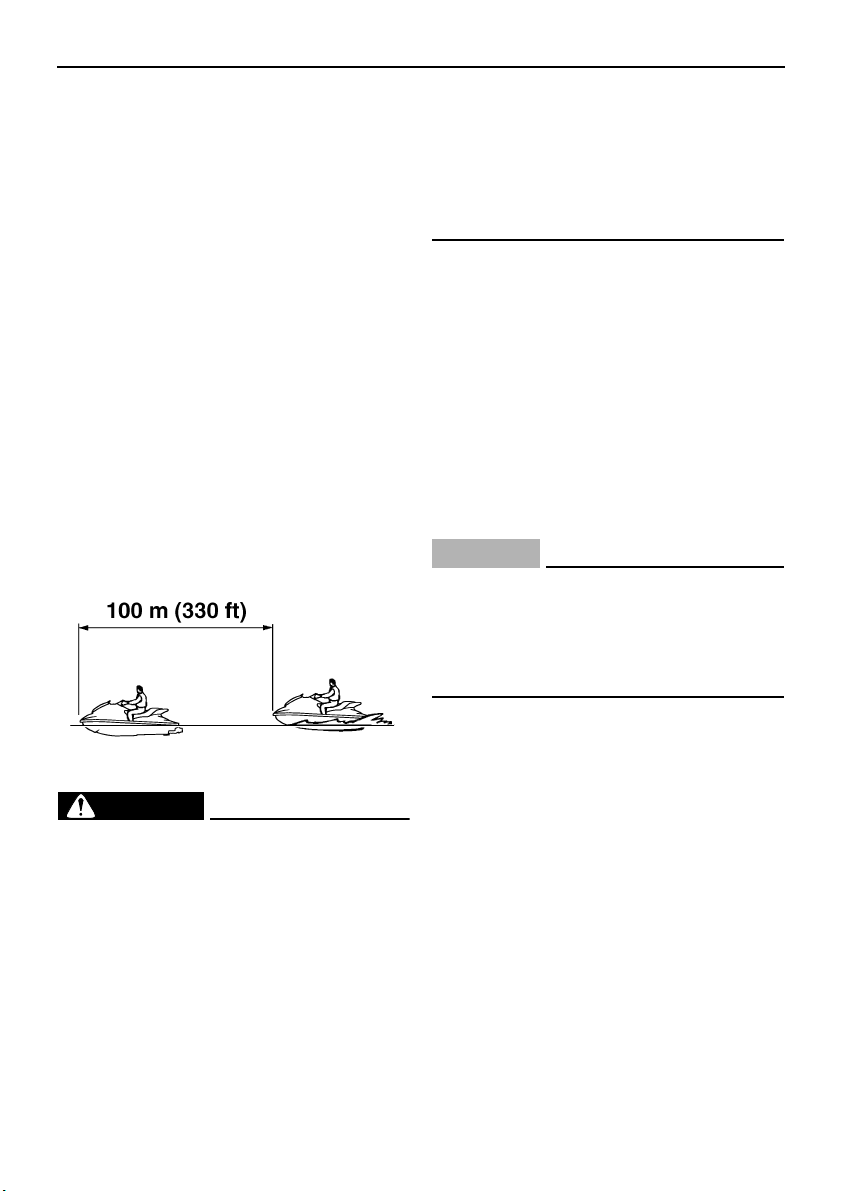
Operation
77
put until you apply throttle again or you reach
trolling speed.
EJU33290
Stopping the watercraft
The watercraft is not equipped with a sepa-
rate braking system. It is stopped by water re-
sistance when the throttle lever is released.
From full speed, the watercraft comes to a
complete stop in approximately 100 m (330 ft)
after the throttle lever is released or the en-
gine is stopped, although this distance will
vary depending on many factors, including
gross weight, water surface conditions, and
wind direction. The watercraft slows down as
soon as the throttle lever is released, but will
coast for a distance before fully stopping. If
you are not sure you can stop in time before
hitting an obstacle, apply throttle and turn in
another direction.
WARNING
EWJ00740
● Allow adequate stopping distance.
● Take early action to avoid collisions. Re-
member, watercraft and other boats do
not have brakes.
● Operate defensively at safe speeds and
keep a safe distance away from people,
objects, and other watercraft to give you
time to stop.
● Do not shut the engine off when slowing
down in case you need engine power to
steer away from a boat or other obstacle
that comes into your path.
● Do not use the reverse function to slow
down or stop the watercraft as it could
cause you to lose control, be ejected, or
impact the handlebars.
EJU35960
Beaching the watercraft
(1) Make sure that there are no boats, swim-
mers, or obstacles near the beach. Re-
lease the throttle lever about 100 m (330
ft) before you reach the intended beach-
ing area.
(2) Approach the beach slowly and stop the
engine before reaching land.
Remember, you need throttle to steer.
(3) Get off the watercraft and pull it up on the
beach.
CAUTION:
ECJ00490
Small pebbles, sand, seaweed, and other
debris can be sucked into the jet intake
and impair or damage the impeller. Always
stop the engine and get off the watercraft
before beaching it.
EJU36060
Docking the watercraft
(1) Make sure that there are no boats, swim-
mers, or obstacles near the watercraft.
Reduce speed about 100 m (330 ft) away
from the dock.
(2) Slowly approach the dock and stop the
engine just before coming alongside it.
EJU33320
Reverse on waterways
Reverse can be used for slow-speed maneu-
vering when it is necessary to back up out of
tight spots where you cannot turn around. Re-
verse can be used to slow down or stop only
during slow-speed maneuvering, such as
when docking.
UF1X11E0.book Page 77 Monday, August 7, 2006 3:51 PM
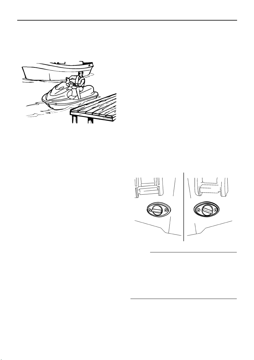
Operation
78
Once the engine is idling, shift into reverse
and gradually increase engine speed. Make
sure that there are no obstacles or people be-
hind you before shifting into reverse.
EJU33350
Rough water operation
The force of landing after jumping can cause
a strong impact on both the watercraft and the
operator and passengers. It is possible for the
operator to hit his or her chest or jaw on the
watercraft or handlebars and be injured. The
passengers could also impact the watercraft
and be injured.
Do not operate the watercraft with your chin
right above the handlebars. In addition, the
operator and passengers should keep their
feet on the floor of the footwell.
Operating in rough water or jumping waves
can also crack the watercraft hull and deck,
and damage internal parts. Avoid operating in
rough water or bad weather conditions.
EJU33390
Post-operation care
To keep your watercraft in top shape, always
take it out of the water after using it and per-
form the following procedures. Leaving the
watercraft in the water for extended periods
will accelerate the rate of normal deterioration
of the jet unit components and hull finish. Ma-
rine organisms and corrosion are some of the
conditions that can adversely affect the life of
many watercraft components.
(1) Remove the watercraft from the water.
(2) Wash down the hull, handlebars, and jet
unit with fresh water.
(3) Remove the seat and check the engine
compartment for water. To drain excess
water, remove the stern drain plugs, and
then raise the bow of the watercraft
enough to allow the water in the bilge to
drain out.
NOTE:
This watercraft is equipped with a jet vacuum
bilge draining system and an electric bilge
draining system that remove water from the
engine compartment while you are underway.
However, some residual water will remain.
(See page 59 for bilge draining procedures.)
(4) Place the watercraft in a horizontal posi-
tion.
UF1X11E0.book Page 78 Monday, August 7, 2006 3:51 PM

Operation
79
(5) Flush the cooling system to prevent it
from clogging with salt, sand, or dirt. (See
page 80 for flushing procedures.)
(6) Drain residual water from the exhaust
system by alternately squeezing and re-
leasing the throttle lever for 10 to 15 sec-
onds while the engine is running.
CAUTION:
ECJ00560
Do not run the engine for more than 15
seconds, otherwise the engine could over-
heat.
(7) If the watercraft will be stored for a week
or more, lubricate internal engine compo-
nents to help prevent corrosion. (See
page 81 for lubrication procedures.)
(8) Rinse the engine and engine compart-
ment with a small amount of water.
CAUTION:
ECJ00570
Do not use high-pressure water when rins-
ing the engine or engine compartment as
severe engine damage could result.
(9) Wipe the engine and engine compart-
ment dry with a clean cloth (repeat step 3,
if necessary).
(10) Wipe the hull, handlebars, and jet unit dry
with a clean cloth.
(11) Spray a rust inhibitor, such as Yamaha
Silicone Protectant and Lubricant, on me-
tallic parts to minimize corrosion.
(12) Allow the engine compartment to air dry
completely before installing the seat.
EJU33461
Transporting
When transporting the watercraft on a trailer,
secure the tie downs to the trailer through the
bow eye and stern eyes.
CAUTION:
ECJ00641
● Do not attach ropes or tie downs to any
part of the watercraft other than the bow
eye and stern eyes to secure the water-
craft to the trailer. Otherwise, the water-
craft may be damaged.
● Do not route ropes or tie downs over the
seat, as they may leave permanent
marks on the seat’s surface. Also, wrap
the ropes or tie downs with towels or
rags where they touch the body of the
watercraft to avoid scratches or dam-
age.
● Before putting the watercraft on the trail-
er or transporting it, be sure to put the
shift lever in the forward position, other-
wise the reverse gate may hit an obsta-
cle, which may cause damage.
UF1X11E0.book Page 79 Monday, August 7, 2006 3:51 PM
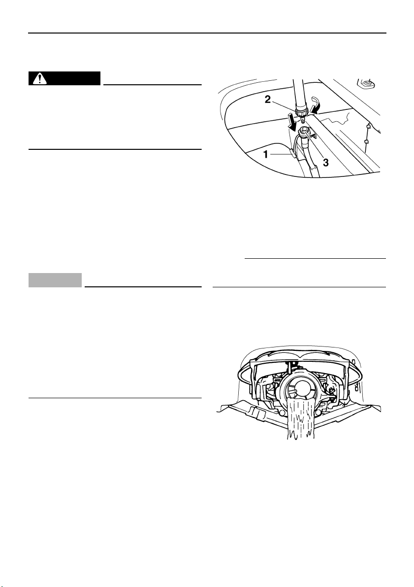
Maintenance and care
80
EJU33490
Storage
WARNING
EWJ00330
Always place the watercraft upright in a
horizontal position when storing it, other-
wise fuel could leak out into the engine or
engine compartment, which could create a
fire hazard.
Storage for long periods of time, such as win-
ter storage, requires preventive maintenance
to ensure against deterioration. It is advisable
to have the watercraft serviced by a Yamaha
dealer prior to storage. However, the following
procedures can be performed by the owner.
EJU33531
Flushing the cooling system
Flushing the cooling system is essential to
prevent it from clogging with salt, sand, or dirt.
CAUTION:
ECJ00121
● Do not supply water to the cooling water
passages when the engine is not run-
ning. The water could flow back through
the muffler into the crankcase, causing
severe engine damage.
● Do not run the engine for more than 15
seconds without supplying water or
over 4000 r/min on land, otherwise the
engine could overheat.
(1) Remove the watercraft from the water
and place it in a horizontal position.
(2) Remove the rear seat and seat storage
compartment. (See page 29 for seat re-
moval and installation procedures.)
(3) Remove the flushing hose connector
cap, and then insert the garden hose
adapter into the flushing hose connector
and turn it until it is securely connected.
(4) Connect the garden hose adapter to a
water tap using a garden hose.
NOTE:
A garden hose is not included and must be
purchased separately.
(5) Start the engine, and then immediately
turn the water supply on until water flows
out continually from the jet thrust nozzle.
(6) Run the engine at idling speed for about
3 minutes watching the engine condition.
If the engine stops while flushing, turn the
water supply off immediately and repeat
the above steps.
(7) Turn the water supply off, and then force
the remaining water out of the cooling
1 Flushing hose connector cap
2 Garden hose adapter
3 Flushing hose connector
UF1X11E0.book Page 80 Monday, August 7, 2006 3:51 PM
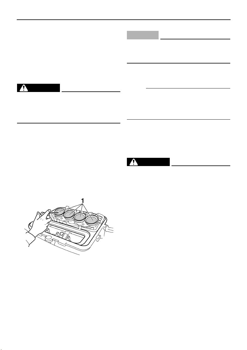
Maintenance and care
81
water passages by alternately squeezing
and releasing the throttle lever for 10 to
15 seconds.
(8) Stop the engine.
(9) Remove the garden hose adapter and in-
stall the flushing hose connector cap.
EJU33590
Lubrication
WARNING
EWJ00260
Do not spray flammable rust inhibitor
products on engine surfaces while the en-
gine is hot. The sprayed substance or pro-
pellants could catch fire.
(1) Remove the seats. (See page 29 for seat
removal and installation procedures.)
(2) Remove the air filter case cover and the
air filter element. (See page 88 for air fil-
ter case cover and air filter element re-
moval and installation procedures.)
(3) Spray a rust inhibitor such as Yamaha
Stor-Rite Engine Fogging Oil into each in-
take opening for 3 seconds.
(4) Install the air filter element in the air filter
case, and then install the air filter case
cover.
(5) Start the engine in a well-ventilated area
and let it run at idle for 15 seconds.
CAUTION:
ECJ00160
Do not run the engine for more than 15
seconds, otherwise the engine could over-
heat.
(6) Lubricate all cables such as the throttle
and steering cables.
N
O
TE:
Use a Yamaha Power Cable Luber and
Yamaha Lube-Zall to pressure-lubricate the
cables and purge out any moisture between
the inner and outer cables.
(7) Lubricate the areas of the watercraft
specified in “Lubrication points” on page
91.
EJU33660
Fuel system
WARNING
EWJ00280
GASOLINE AND ITS VAPORS ARE HIGH-
LY FLAMMABLE AND EXPLOSIVE!
● Do not smoke when refueling, and keep
away from sparks, flames, and other
sources of ignition.
● Stop the engine before refueling.
● Refuel in a well-ventilated area with the
watercraft in a horizontal position.
● Do not stand or sit on the watercraft
while refueling in case of fire.
● Take care not to spill gasoline. If gaso-
line spills, wipe it up immediately with
dry rags. Always properly dispose of
gasoline-soaked rags.
● Avoid overfilling the fuel tank. Stop fill-
ing when the fuel level reaches approxi-
mately 50 mm (2 in) from the top of the
fuel tank. Fuel expands as it warms up
and could overflow if the fuel tank has
been overfilled. If temporarily leaving
the watercraft with a full fuel tank, do not
1 Intake opening
UF1X11E0.book Page 81 Monday, August 7, 2006 3:51 PM

Maintenance and care
82
leave it in direct sunlight. Leave it in a
well-ventilated area with the watercraft
in a horizontal position.
● Tighten the fuel tank filler cap securely
after refueling.
● If you should swallow some gasoline, in-
hale a lot of gasoline vapor, or get gaso-
line in your eyes, get immediate medical
attention.
● If any gasoline spills on your skin or
clothing, immediately wash the affected
area with soap and water and change
your clothes.
Top off the fuel tank with fresh gasoline and
add one ounce of Yamaha Fuel Stabilizer and
Conditioner per each gallon of fuel.
EJU33680
Battery
If the watercraft will not be used for more than
a month, remove the battery from the water-
craft and store it in a cool, dry place.
(1) Disconnect the negative (–) battery lead
first, then the positive (+) battery lead and
breather hose, and then remove the bat-
tery from the watercraft.
(2) Clean the battery casing using fresh wa-
ter.
(3) If the battery terminals are dirty or corrod-
ed, clean them with a wire brush.
(4) Fully charge the battery.
(5) Apply Yamaha Marine Grease or
Yamaha Grease A to the battery termi-
nals, and then store the battery in a cool,
dry place.
(6) Check the battery at least once every 2
months and fully charge it if necessary.
CAUTION:
ECJ00100
Always keep the battery charged. Storing
a discharged battery can cause permanent
battery damage.
To check the condition of the battery, check
the specific gravity of the electrolyte or mea-
sure the voltage at both battery terminals.
Charge the battery if the voltage is less than
12 volts.
It is recommended to have a Yamaha dealer
check the specific gravity and charge the bat-
tery. If you maintain the battery yourself, be
sure to read and follow the instructions provid-
ed with the battery tester and charger you
use.
EJU33740
Cleaning the watercraft
Clean the watercraft before storing it for a long
period.
(1) Wash down the hull, handlebars, and jet
unit with fresh water.
(2) Rinse the engine and bilge area with
fresh water. Drain all of the water and
wipe up any remaining moisture with
clean, dry rags.
CAUTION:
ECJ00110
Do not use high-pressure water when rins-
ing the engine and bilge area as severe en-
gine damage could result.
(3) Spray the engine’s exterior with a rust in-
hibitor and lubricant such as Yamaha Sil-
icone Protectant and Lubricant.
(4) Wax the hull with a non-abrasive wax
such as Yamaha Silicone Wax.
(5) Wipe all vinyl and rubber components,
such as the seat and engine compart-
ment seals, with a vinyl protectant such
as Yamaha Protectant.
Specific gravity (for reference):
1.28 at 20 °C (68 °F)
UF1X11E0.book Page 82 Monday, August 7, 2006 3:51 PM
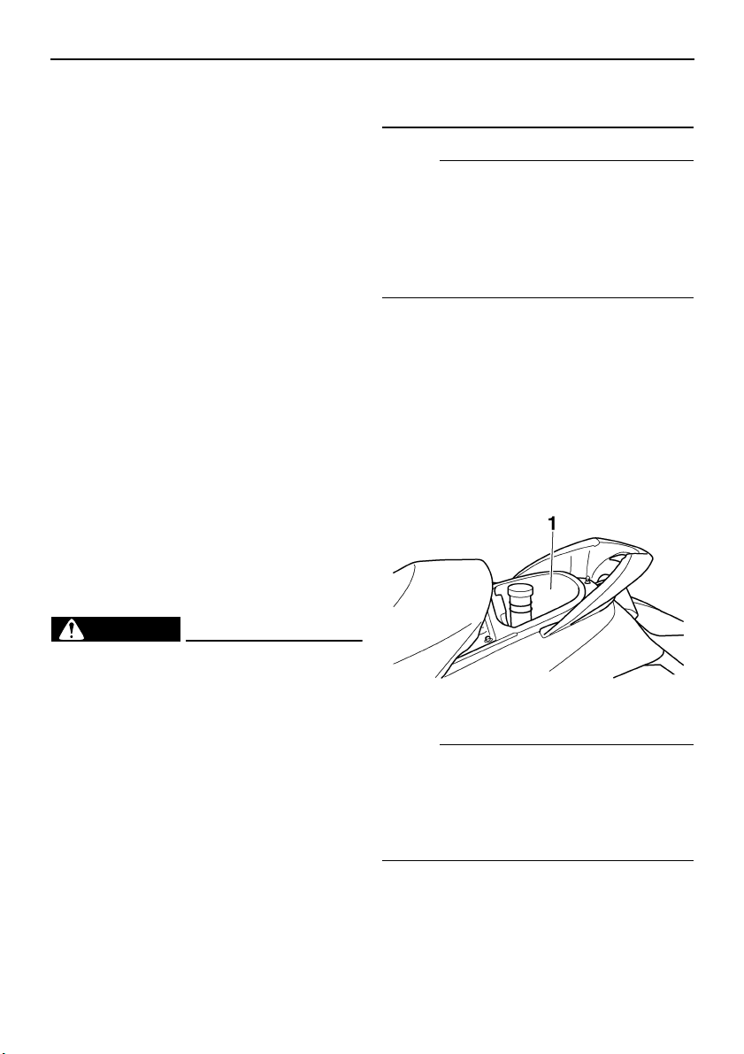
Maintenance and care
83
EJU33751
Maintenance and adjustments
Periodic inspection, adjustment, and lubrica-
tion will keep your watercraft in the safest and
most efficient condition possible. Safety is an
obligation of the watercraft owner. Proper
maintenance must be carried out to keep the
exhaust emission and sound levels within the
regulated limits. The most important points of
watercraft inspection, adjustment, and lubri-
cation are explained on the following pages.
See a Yamaha dealer for genuine Yamaha re-
placement parts and optional accessories de-
signed for your watercraft.
Remember, failures that are the result of the
installation of parts or accessories which are
not qualitatively equivalent to genuine
Yamaha parts are not covered by the limited
warranty.
Maintenance, replacement, or repair of the
emission control devices and system may
be performed by any marine SI engine re-
pair establishment or individual. Warranty
repair, however, must be performed at an
authorized Yamaha marine dealership.
WARNING
EWJ00310
● Be sure to shut the engine off when you
perform maintenance unless otherwise
specified, otherwise an accident or inju-
ry could result from unexpected opera-
tion, moving parts, or electric shock. If
the owner is not familiar with watercraft
servicing, this work should be done by a
Yamaha dealer. Improperly serviced
components could fail or stop operating
correctly, which could result in an acci-
dent.
● Modifications to this watercraft not ap-
proved by Yamaha may cause loss of
performance or excessive noise and ex-
haust emissions, or render it unsafe for
use. Consult a Yamaha dealer before at-
tempting any modifications.
NOTE:
A service manual is available for purchase
through a Yamaha dealer for owners who
have the mechanical skills, tools, and other
equipment necessary to perform mainte-
nance not covered by this owner’s/operator’s
manual.
EJU33800
Owner’s/operator’s manual and tool
kit
It is advisable to always carry the owner’s/op-
erator’s manual and tool kit with you whenev-
er you use the watercraft. For your
convenience, a storage compartment is pro-
vided on the watercraft for the manual and
tool kit.
NOTE:
To protect these materials from water dam-
age, it would be a good idea to put them in a
waterproof bag. If your owner’s/operator’s
manual is damaged, order a replacement
from a Yamaha dealer.
The service information included in this man-
ual is intended to provide you, the owner, with
the necessary information for completing your
own preventive maintenance and minor re-
1 Storage compartment
UF1X11E0.book Page 83 Monday, August 7, 2006 3:51 PM
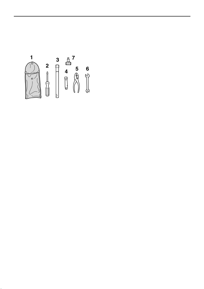
Maintenance and care
84
pairs. The tools provided in the tool kit are suf-
ficient for this purpose, except that a torque
wrench may also be necessary to tighten nuts
and bolts.
1 Tool bag
2 Screwdriver
3 16 mm box wrench
4 10/12 mm box wrench
5 Pliers
6 Open-end wrench
7 Garden hose adapter
UF1X11E0.book Page 84 Monday, August 7, 2006 3:51 PM
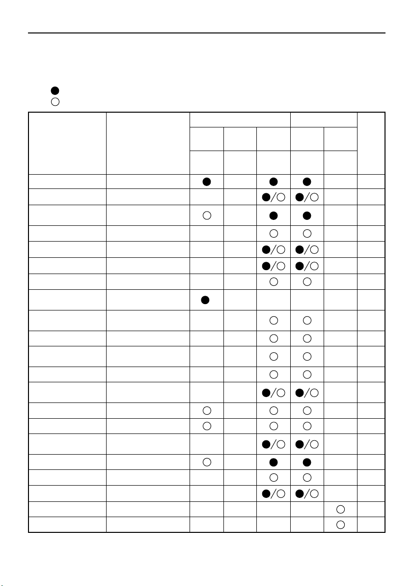
Maintenance and care
85
EJU33820
Periodic maintenance chart
The following chart gives general guidelines for periodic maintenance. However, maintenance
may need to be performed more frequently depending on your operating conditions.
This “” mark indicates maintenance that you may do yourself.
This “” mark indicates work to be done by a Yamaha dealer.
Item Operation
Initial Thereafter every
Page
10
hours
50
hours
100
hours
100
hours
200
hours
6
months
12
months
12
months
24
months
Spark plugs Check, clean, adjust 90
Lubrication points Lubricate 91
Intermediate hous-
ing
Lubricate 91
Fuel system Check 87
Fuel tank Check, clean 87
Trolling speed Check, adjust 94
Throttle shaft Check —
Cooling water pas-
sages
Flush
*
80
Water inlet strain-
er
Check, clean —
Bilge strainer Clean —
Electric bilge
pump strainer
Check, clean —
Impeller Check —
Jet thrust nozzle
angle
Check, adjust 89
Steering master Check —
QSTS mechanism Check, adjust —
Shift cable and re-
verse gate
Check, adjust 89
Throttle cable Check, adjust 89
Stern drain plugs Check, replace 60
Battery Check, charge 92
Rubber coupling Check —
Engine mount Check —
UF1X11E0.book Page 85 Monday, August 7, 2006 3:51 PM
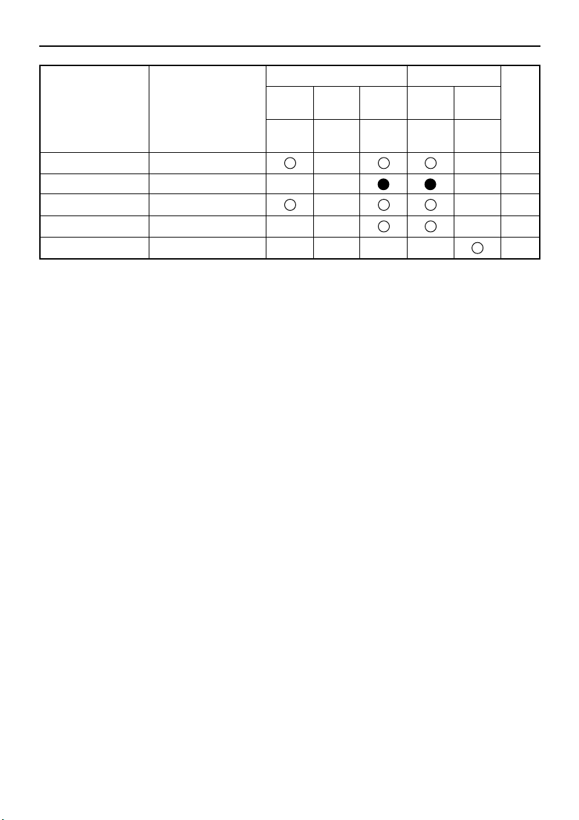
Maintenance and care
86
* This operation should be performed after every use.
Nuts and bolts Check —
Air filter element Check 88
Engine oil Replace 87
Oil filter Replace 87
Valve clearance Check, adjust —
Item Operation
Initial Thereafter every
Page
10
hours
50
hours
100
hours
100
hours
200
hours
6
months
12
months
12
months
24
months
UF1X11E0.book Page 86 Monday, August 7, 2006 3:51 PM
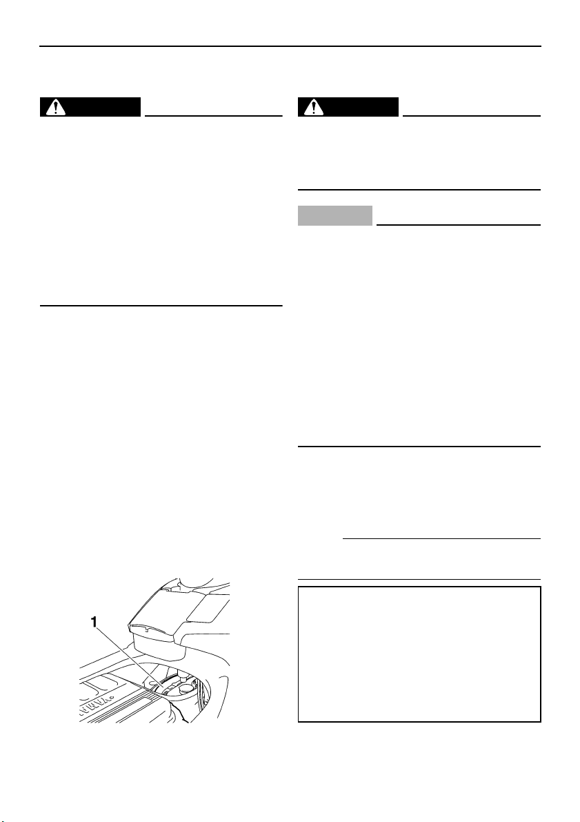
Maintenance and care
87
EJU34210
Checking the fuel system
WARNING
EWJ00380
Gasoline is highly flammable and explo-
sive. Failure to check for and repair any
fuel leakage could result in a fire or explo-
sion. A fire or explosion can cause severe
injury or death. Shut the engine off. Do not
smoke. Avoid spilling gasoline.
Fuel in the fuel lines is pressurized.
Fuel can spray out and cause injury or a
fire hazard if a fuel line is disconnected.
Do not run the engine with a fuel line dis-
connected.
Check the fuel system for leaks, cracks, and
malfunctions. If any problem is found, consult
a Yamaha dealer.
Check:
● Fuel tank filler cap and seal for damage.
● Fuel in fuel tank for water and dirt.
● Fuel tank for damage, cracks, and leakage.
● Fuel hoses and joints for damage, cracks,
and leakage.
● Air bleeding passages for leakage.
EJU34230
Fuel tank
Check the fuel tank for leakage and for water
in the tank. If water is found in the fuel system,
or if the fuel tank needs to be cleaned, have a
Yamaha dealer service the watercraft.
EJU34280
Engine oil and oil filter
WARNING
EWJ00340
Engine oil is extremely hot immediately af-
ter the engine is turned off. Coming in con-
tact with or getting any engine oil on your
clothes could result in burns.
CAUTION:
ECJ00180
● Do not run the engine with too much or
not enough oil in the oil tank. Oil could
spray out and the engine could be dam-
aged.
● Be sure to change the engine oil after
the first 10 hours of operation, and every
100 hours thereafter or at the start of a
new season, otherwise the engine will
wear quickly.
The oil filter should be replaced every
year or every 100 hours of operation.
Have a Yamaha dealer replace the oil fil-
ter if necessary.
It is recommended to have a Yamaha dealer
change the engine oil. However, if you choose
to change the oil on your own, refer to the ser-
vice manual for this watercraft.
NOTE:
Dispose of used oil according to local regula-
tions.
1 Fuel tank
Recommended engine oil:
See page 55.
Oil quantity:
With oil filter replacement:
2.3 L (2.43 US qt) (2.02 Imp.qt)
Without oil filter replacement:
2.1 L (2.22 US qt) (1.85 Imp.qt)
Total amount:
4.5 L (4.76 US qt) (3.96 Imp.qt)
UF1X11E0.book Page 87 Monday, August 7, 2006 3:51 PM
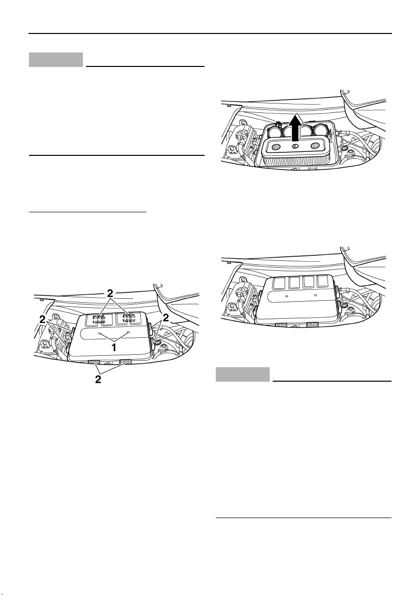
Maintenance and care
88
CAUTION:
ECJ00190
If oil is leaking or the oil pressure warning
indicator comes on when the engine is
running, immediately shut the engine off
and have a Yamaha dealer check the wa-
tercraft. Continuing to operate the engine
under such conditions could cause severe
engine damage.
EJU34300
Checking the air filter element
The air filter element should be checked every
12 months or every 100 hours of operation.
To check the air filter element:
(1) Remove the seats. (See page 29 for seat
removal and installation procedures.)
(2) Remove the air filter case cover screws,
slide the locks open, and then remove the
air filter case cover.
(3) Remove the air filter element and check it
for dirt and oil. Replace the air filter ele-
ment if there is any oil buildup, or every 2
years or every 200 hours of operation.
(4) Install the air filter element in the air filter
case, and then install the air filter case
cover.
(5) Install the seats.
CAUTION:
ECJ00200
● Make sure that the air filter element is in-
stalled in the air filter case properly.
● Do not start the engine with the air filter
element removed, otherwise the pistons
and cylinders could be damaged.
● If cleaning the air filter element, use cold
or lukewarm water and let it air dry com-
pletely. Do not use detergent or solvent
to clean the air filter element, or dry it
with hot or compressed air, otherwise it
could be damaged.
1 Air filter case cover screw
2 Lock
UF1X11E0.book Page 88 Monday, August 7, 2006 3:51 PM
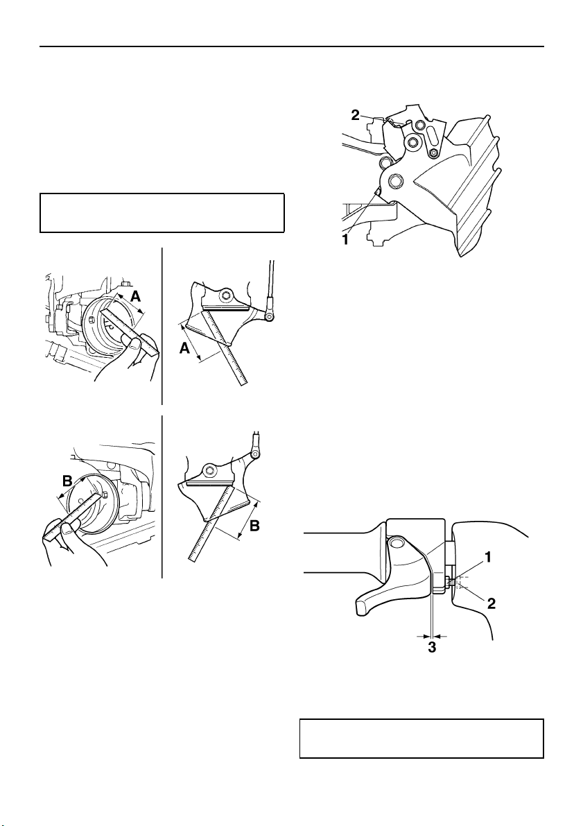
Maintenance and care
89
EJU34320
Checking the jet thrust nozzle angle
Check the handlebars and jet thrust nozzle for
smooth operation.
Turn the handlebars as far as possible to the
right and left and check that the difference of
distances A and B between the jet thrust noz-
zle and the nozzle is within specification.
If the steering is stiff or misadjusted, have a
Yamaha dealer service it.
EJU34340
Checking the shift cable
Place the shift lever in the reverse position.
Make sure that the reverse gate makes con-
tact with the stopper on the bracket, and that
the shift arm makes contact with the reverse
gate.
If the reverse gate does not reach the correct
positions, have a Yamaha dealer service it.
EJU34360
Checking and adjusting the throttle
cable
Check that the throttle cable moves back to
the set position smoothly and that the throttle
lever free play is within specification.
(1) Squeeze and release the throttle lever. If
the throttle lever does not return smooth-
ly, have a Yamaha dealer service it.
(2) Adjust the free play by loosening the lock-
nut and turning the adjuster.
Difference of A and B:
Maximum 5 mm (0.20 in)
1 Stopper
2 Shift arm
1 Locknut
2 Adjuster
3 Throttle lever free play
Throttle lever free play:
4.0–7.0 mm (0.16–0.28 in)
UF1X11E0.book Page 89 Monday, August 7, 2006 3:51 PM
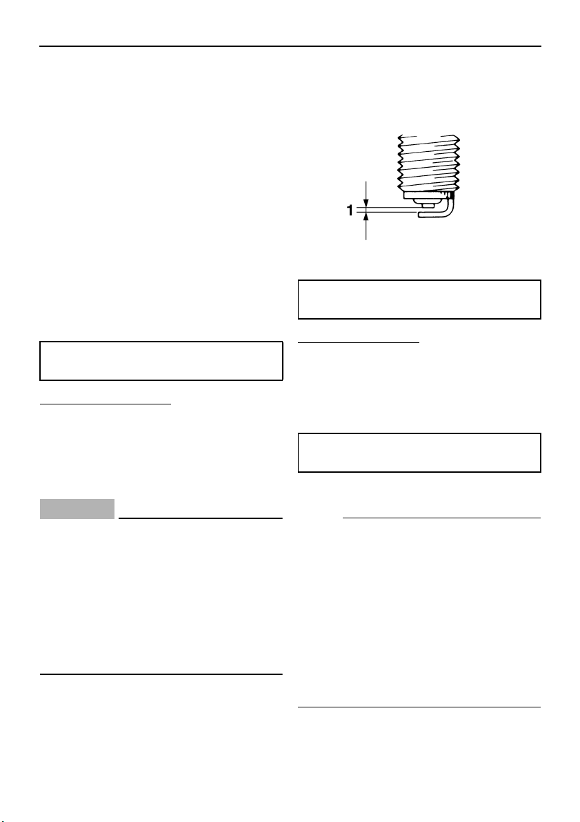
Maintenance and care
90
EJU34381
Cleaning and adjusting the spark
plugs
The spark plug is an important engine compo-
nent and is easy to inspect. The condition of
the spark plug can indicate something about
the condition of the engine. For example, if
one spark plug has a distinctly different color,
the engine could require servicing. Do not at-
tempt to diagnose any problems yourself.
Have a Yamaha dealer service the watercraft.
Remove and inspect the spark plugs periodi-
cally; heat and deposits will cause the spark
plugs to slowly break down and erode. If elec-
trode erosion becomes excessive, or if carbon
and other deposits are excessive, replace the
spark plug with the specified plug.
To remove a spark plug:
(1) Remove the air filter case cover and air
filter element. (See page 88 for air filter
element removal and installation proce-
dures.)
(2) Remove the spark plug cap.
CAUTION:
ECJ00210
Do not use any tools to remove or install
the spark plug cap, otherwise the ignition
coil coupler could be damaged. The spark
plug cap may be difficult to remove be-
cause the rubber seal on the end of the
cap fits tightly. To remove the spark plug
cap, simply twist it back and forth while
pulling it up; to install it, twist it back and
forth while pushing it down.
(3) Remove the spark plug.
Measure the spark plug gap with a wire
thickness gauge. Replace the spark plug
or adjust the gap to specification if neces-
sary.
To install a spark plug:
(1) Clean the gasket surface.
(2) Wipe any dirt from the threads of the
spark plug.
(3) Install the spark plug, and then tighten it
to the specified torque.
(4) Install the spark plug cap.
NOTE:
● Wipe off any water on the spark plug or in-
side the spark plug cap before installing the
cap. Push the spark plug cap down until it is
securely installed.
● If a torque wrench is not available when you
are installing a spark plug, a good estimate
of the correct torque is 1/4 turn to 1/2 turn
past finger tight using the spark plug
wrench included in the tool kit. Have the
spark plug adjusted to the correct torque
with a torque wrench as soon as possible.
Specified spark plug:
CR9EB
1 Spark plug gap
Spark plug gap:
0.7–0.8 mm (0.028–0.031 in)
Spark plug tightening torque:
12.5 Nm (9.2 ft-lb) (1.27 kgf-m)
UF1X11E0.book Page 90 Monday, August 7, 2006 3:51 PM
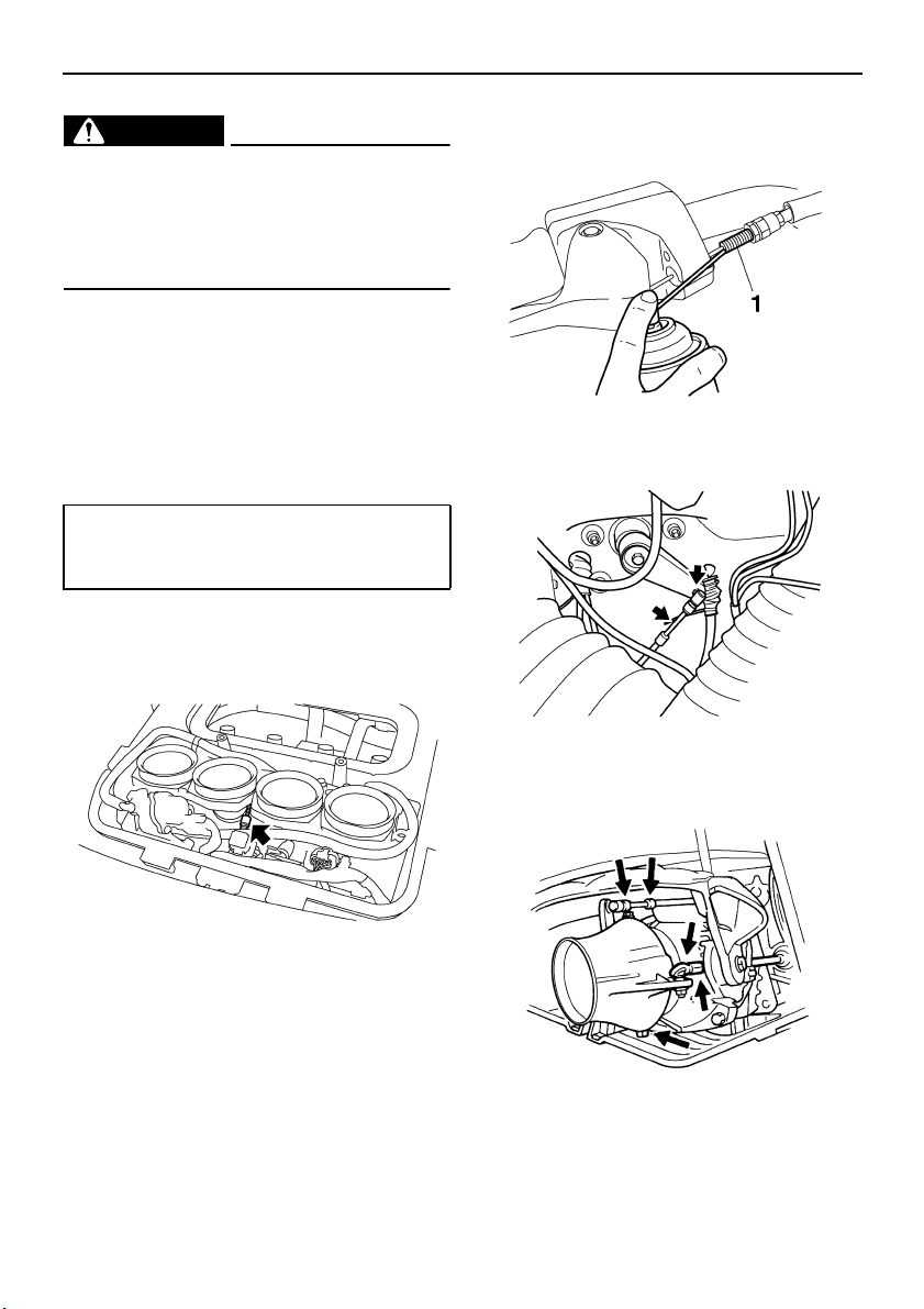
Maintenance and care
91
WARNING
EWJ00350
Be careful not to damage the insulator
when removing or installing a spark plug.
A damaged insulator could allow sparks to
escape, which could result in a fire or ex-
plosion.
(5) Install the air filter element in the air filter
case, and then install the air filter case
cover.
EJU34432
Lubrication points
To keep moving parts sliding or rotating
smoothly, coat them with water-resistant
grease.
● Throttle cable (throttle body end)
● Throttle bodies (throttle cable pulley, throt-
tle cam, and return spring)
● Throttle cable (handlebar end)
Loosen the adjuster and disconnect the
outer cable from the bracket. Spray a rust
inhibitor into the outer cable. Connect the
outer cable, and then adjust the throttle ca-
ble free play. (See page 89 for adjustment
procedures.)
● Steering cable (handlebar end)
● Steering cable (jet thrust nozzle end)
● Jet thrust nozzle pivot shaft
● QSTS cable (jet thrust nozzle end)
Recommended water-resistant grease:
Yamaha Marine Grease/Yamaha
Grease A
1 Adjuster
UF1X11E0.book Page 91 Wednesday, August 9, 2006 11:57 AM
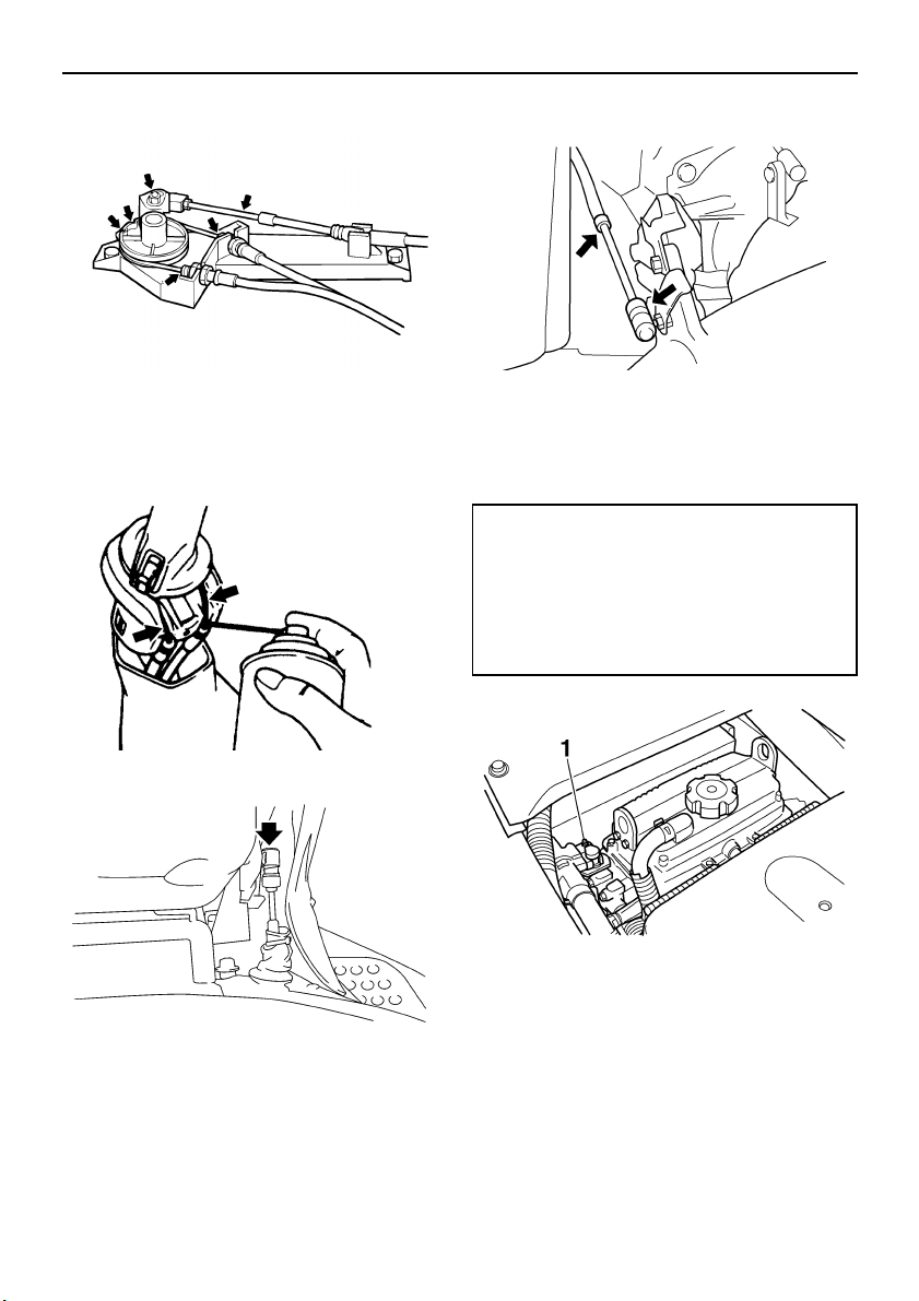
Maintenance and care
92
● QSTS cables (pulley end)
● QSTS cables (handlebar end)
Remove the QSTS cable housing. Spray a
rust inhibitor into the outer cables. Reinstall
the QSTS cable housing.
● Shift cable (shift lever end)
● Shift cable (reverse gate end)
● Intermediate housing
Fill the intermediate housing with water-re-
sistant grease through the grease nipple
using a grease gun.
EJU34450
Checking the battery
Check the level of the battery electrolyte and
make sure that the negative (–) and positive
(+) battery leads are tightened securely.
Grease quantity:
Initial 10 hours or 1 month:
33.0–35.0 cm³ (1.12–1.18 US oz)
(1.16–1.23 Imp.oz)
Every 100 hours or 12 months:
6.0–8.0 cm³ (0.20–0.27 US oz)
(0.21–0.28 Imp.oz)
1 Grease nipple
UF1X11E0.book Page 92 Monday, August 7, 2006 3:51 PM
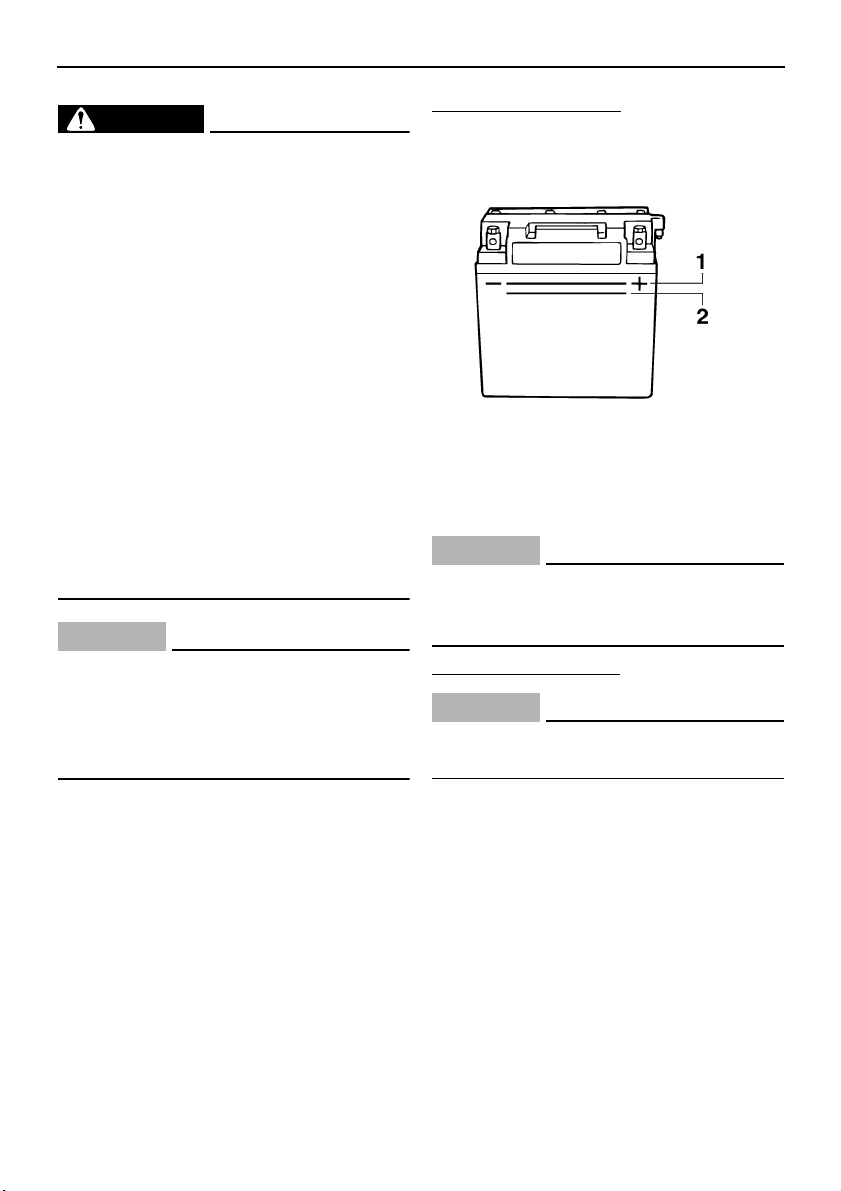
Maintenance and care
93
WARNING
EWJ00790
Battery electrolyte is poisonous and dan-
gerous, causing severe burns, etc. Elec-
trolyte contains sulfuric acid. Avoid
contact with skin, eyes, or clothing.
Antidotes
External: Flush with water.
Internal: Drink large quantities of water or
milk. Follow with milk of magnesia, beaten
egg, or vegetable oil. Call a physician im-
mediately.
Eyes: Flush with water for 15 minutes and
get prompt medical attention.
Batteries produce explosive gases. Keep
sparks, flames, cigarettes, etc., well away.
If using or charging the battery in an en-
closed space, make sure that it is well ven-
tilated. Always shield your eyes when
working near batteries.
KEEP OUT OF THE REACH OF CHILDREN.
CAUTION:
ECJ00230
● Be careful not to place the battery on its
side.
● Be sure to remove the battery from the
battery compartment when adding elec-
trolyte or charging the battery.
To replenish the battery:
(1) Make sure that the electrolyte level is be-
tween the maximum and minimum level
marks.
(2) Refill the battery with distilled water if
necessary.
CAUTION:
ECJ00240
Normal tap water contains minerals that
are harmful to a battery. Use only distilled
water for replenishing the battery.
To recharge the battery:
CAUTION:
ECJ00250
Do not attempt to charge a battery hastily.
Battery life could be shortened.
It is recommended to have a Yamaha dealer
charge the battery. If you charge the battery
yourself, carefully read the battery charger in-
structions before charging and follow the
points below.
(1) Remove all of the battery caps.
(2) If the electrolyte level is low, add distilled
water to raise it to the specified level.
(3) Set the charging rate to 1.9 ampere and
charge the battery slowly until the explo-
sive gases are discharged vigorously
from the battery cells.
1 Maximum level mark
2 Minimum level mark
UF1X11E0.book Page 93 Monday, August 7, 2006 3:51 PM
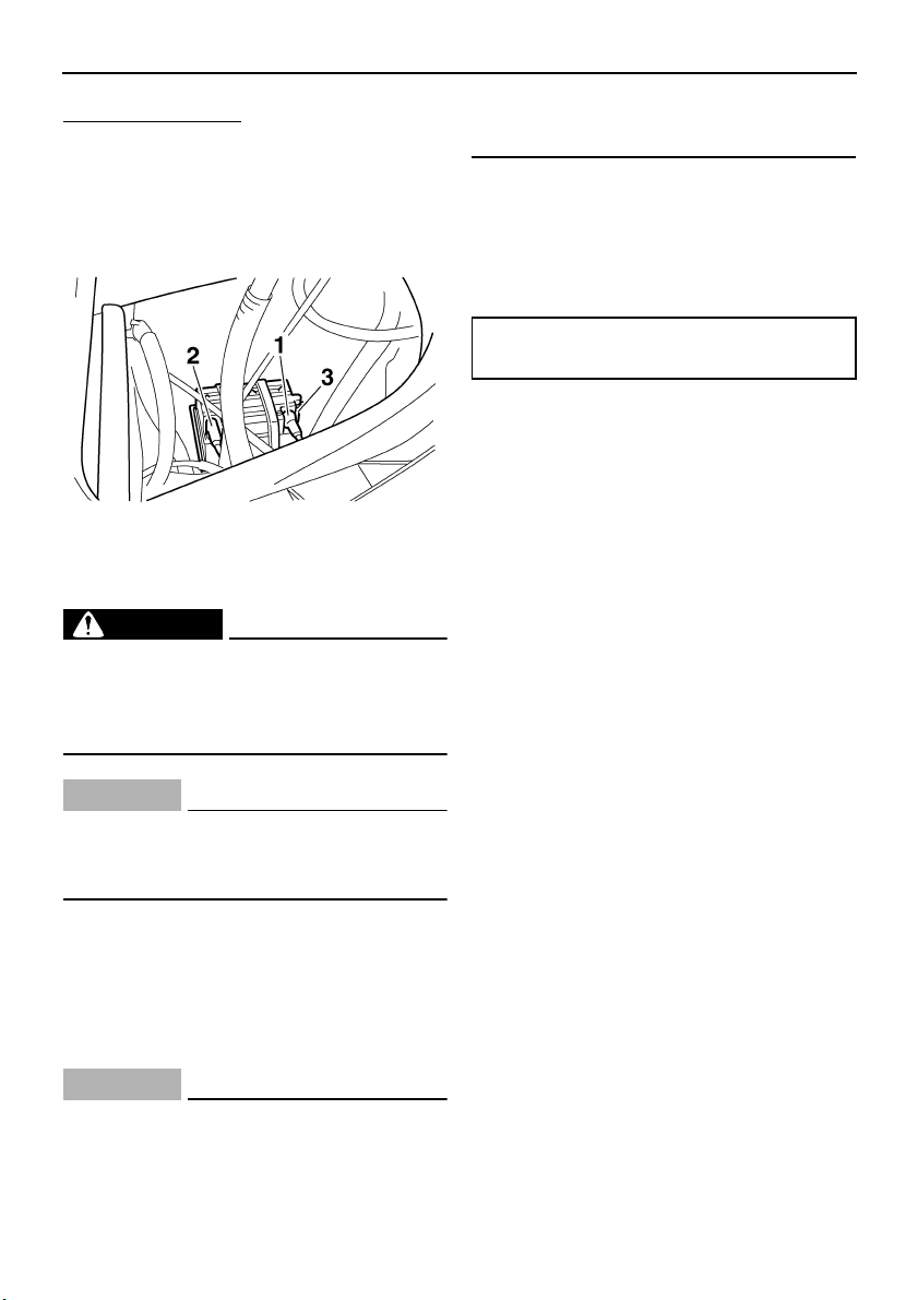
Maintenance and care
94
To install the battery:
(1) Place the battery in the battery compart-
ment and connect the battery leads to the
battery terminals.
(2) Connect the breather hose to the battery.
(3) Secure the battery in place.
WARNING
EWJ00400
Be sure to connect the breather hose to
the battery. Fire or explosion could result
if the breather hose is damaged, obstruct-
ed, or not connected properly.
CAUTION:
ECJ00260
After installation, make sure that the bat-
tery leads are properly connected to the
battery terminals.
EJU34490
Fuel injection system
The fuel injection system was set at the
Yamaha factory. If the fuel injection system
needs to be adjusted, have a Yamaha dealer
service the watercraft.
CAUTION:
ECJ00220
Do not attempt to adjust the fuel injection
system. If the settings are disturbed by
someone who does not have the neces-
sary technical knowledge, poor engine
performance and damage may result.
EJU34500
Checking the trolling speed
(1) Place the watercraft in the water.
(2) Start the engine and warm it up. Use the
tachometer in the multifunction informa-
tion center to check the trolling speed.
If the trolling speed is out of specification,
have a Yamaha dealer service the watercraft.
1 Positive (+) battery terminal: Red lead
2 Negative (–) battery terminal: Black lead
3 Breather hose
Trolling speed:
1650 ±50 r/min
UF1X11E0.book Page 94 Monday, August 7, 2006 3:51 PM

Specifications
95
EJU34542
Specifications
Watercraft capacity:
Maximum people on board:
3 person
Maximum load capacity:
240 kg (530 lb)
Dimensions:
Length:
3340 mm (131.5 in)
Width:
1230 mm (48.4 in)
Height:
FX High Output 1160 mm (45.7 in)
FX Cruiser High Output 1240 mm (48.8 in)
Dry weight:
FX High Output 375 kg (827 lb)
FX Cruiser High Output 380 kg (838 lb)
Performance:
Maximum fuel consumption:
45.0 L/h (11.9 US gal/h) (9.9 Imp.gal/h)
Cruising range at full throttle:
1.56 hour
Trolling speed:
1650 ±50 r/min
Engine:
Engine type:
Liquid cooled 4-stroke, DOHC
Number of cylinders:
4
Engine displacement:
1052 cm³
Bore & stroke:
76.0 × 58.0 mm (2.99 × 2.28 in)
Compression ratio:
11.9 : 1
Valve clearance-intake (cold):
0.11–0.20 mm (0.0043–0.0079 in)
Valve clearance-exhaust (cold):
0.25–0.34 mm (0.0098–0.0134 in)
Lubrication system:
Dry sump
Cooling system:
Water
Starting system:
Electric
Ignition system:
T.C.I.
Spark plug:
CR9EB
Spark plug gap:
0.7–0.8 mm (0.028–0.031 in)
Battery capacity:
12 V, 19.0 Ah
Charging system:
Flywheel magneto
Drive unit:
Propulsion system:
Jet pump
Jet pump type:
Axial flow, single stage
Impeller rotation:
Counterclockwise
Jet thrust nozzle angle:
24.0+24.0 °
Jet thrust nozzle trim angle:
-10, -5, 0, 5, 10 °
Fuel and oil:
Recommended fuel:
Regular unleaded gasoline
Minimum octane rating (PON):
86
Minimum octane rating (RON):
90
Recommended oil:
SAE 10W-30
Oil grade:
API SE,SF,SG,SH,SJ,SL
Fuel tank total capacity:
70 L (18.5 US gal) (15.4 Imp.gal)
Engine oil quantity with oil filter replacement:
2.3 L (2.43 US qt) (2.02 Imp.qt)
Engine oil quantity without oil filter replacement:
2.1 L (2.22 US qt) (1.85 Imp.qt)
Engine oil total quantity:
4.5 L (4.76 US qt) (3.96 Imp.qt)
UF1X11E0.book Page 95 Monday, August 7, 2006 3:51 PM

Trouble recovery
96
EJU34560
Troubleshooting
If you have any trouble with your watercraft, use this section to check for the possible cause.
If you cannot find the cause, or if the procedure for replacement or repair is not described in
this owner’s/operator’s manual, have a Yamaha dealer perform the necessary service.
EJU34601
Troubleshooting chart
TROUBLE POSSIBLE CAUSE REMEDY PAGE
Engine does not
start (Starter motor
does not turn over)
Yamaha Se-
curity System
Lock mode selected Select unlock mode
38
Engine shut-
off switch
Clip not in place Install clip
32
Fuse Burned out Replace the fuse and
check wiring
100
Battery Run down Recharge 92
Poor terminal con-
nections
Tighten as required
92
Terminal corroded Clean 82
Starter motor Faulty Have serviced by
Yamaha dealer
—
Engine does not
start (Starter motor
turns over)
Throttle lever Squeezed Release 33
Fuel Empty Refill as soon as pos-
sible
55
Stale or contaminat-
ed
Have serviced by
Yamaha dealer
87
Fuel tank Water or dirt present Have serviced by
Yamaha dealer
87
Spark plug Fouled or defective Clean or replace 90
Spark plug
cap
Not connected or
loose
Connect properly
90
Connected to wrong
cylinder
Connect properly
90
Fuel injec-
tion system
Fuel pump faulty Have serviced by
Yamaha dealer
—
UF1X11E0.book Page 96 Monday, August 7, 2006 3:51 PM

Trouble recovery
97
Engine runs irregu-
larly or stalls
Fuel Empty Refill as soon as pos-
sible
55
Stale or contaminat-
ed
Have serviced by
Yamaha dealer
87
Fuel tank Water or dirt present Have serviced by
Yamaha dealer
87
Spark plug Fouled or defective Replace 90
Incorrect heat range Replace 90
Gap incorrect Adjust 90
Spark plug
cap
Loose Connect properly 90
Cracked, torn, or
damaged
Replace
—
Electrical wir-
ing
Loose connection Tighten or connect
properly
—
Fuel injec-
tion system
Faulty or clogged in-
jectors
Have serviced by
Yamaha dealer
—
Warning light or in-
dicator blinks
Fuel level Empty Refill as soon as pos-
sible
55
Engine over-
heated
Jet intake clogged Clean
98
Check engine
warning
Faulty sensors Have serviced by
Yamaha dealer
46
Watercraft slow or
loses power
Yamaha Se-
curity System
Low-RPM mode se-
lected
Select normal mode
39
Cavitation Jet intake clogged Clean 98
Impeller damaged or
worn
Have serviced by
Yamaha dealer
98
Engine over-
heat warning
Engine speed reduc-
tion control activated
Clean jet intake and
cool engine
45
Oil pressure
warning
Engine speed reduc-
tion control activated
Add oil
45
Spark plug Fouled or defective Replace 90
Incorrect heat range Replace 90
Gap incorrect Adjust 90
Spark plug
caps
Loose Connect properly
90
Electrical wir-
ing
Loose connection Tighten or connect
properly
—
Fuel Stale or contaminat-
ed
Have serviced by
Yamaha dealer
87
Air filter Clogged Clean or replace 88
Oil buildup Replace 88
TROUBLE POSSIBLE CAUSE REMEDY PAGE
UF1X11E0.book Page 97 Monday, August 7, 2006 3:51 PM
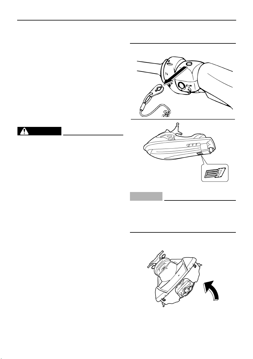
Trouble recovery
98
EJU34620
Emergency procedures
EJU34630
Cleaning the jet intake and impeller
If weeds or debris get caught in the jet intake
or impeller, cavitation can occur, causing jet
thrust to decrease even though engine speed
rises. If this condition is allowed to continue,
the engine will overheat and may seize. If
there is any sign that the jet intake or impeller
is clogged with weeds or debris, return to
shore and check the intake and impeller. Al-
ways stop the engine before beaching the wa-
tercraft.
WARNING
EWJ00780
Before attempting to remove weeds or de-
bris from the jet intake or impeller area,
shut the engine off and remove the clip
from the engine shut-off switch. Severe in-
jury or death could result from coming in
contact with the rotating parts of the jet
pump.
CAUTION:
ECJ00650
If weeds or debris get caught in the jet in-
take, do not operate the watercraft above
trolling speed until they have been re-
moved.
(1) Turn the watercraft on its side as shown.
UF1X11E0.book Page 98 Monday, August 7, 2006 3:51 PM
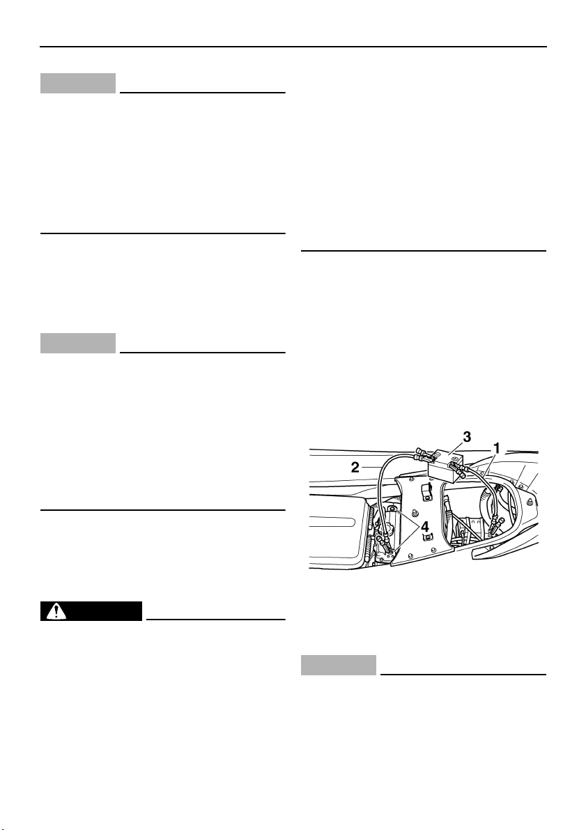
Trouble recovery
99
CAUTION:
ECJ00660
● Place a suitable clean cloth or carpeting
underneath the watercraft to protect it
from abrasions and scratches.
● Always turn the watercraft over onto its
port (left) side.
● When turning the watercraft on its side,
support the bow so that the handlebars
are not bent or damaged.
(2) Remove any weeds or debris from
around the drive shaft, impeller, jet pump
housing, and jet thrust nozzle.
If debris is difficult to remove, consult a
Yamaha dealer.
CAUTION:
ECJ00670
Always avoid operating your watercraft in
areas where weed growth is thick. If travel-
ing in weeded areas is unavoidable, oper-
ate the engine alternately at partial throttle
and full throttle. Weeds tend to accumu-
late more at a steady speed and at trolling
speed. If weeds clog the jet intake or im-
peller area and cause cavitation, follow the
cleaning procedure above.
EJU34640
Jumping the battery
If the watercraft battery has run down, the en-
gine can be started using a 12-volt booster
battery and jumper cables.
WARNING
EWJ00790
Battery electrolyte is poisonous and dan-
gerous, causing severe burns, etc. Elec-
trolyte contains sulfuric acid. Avoid
contact with skin, eyes, or clothing.
Antidotes
External: Flush with water.
Internal: Drink large quantities of water or
milk. Follow with milk of magnesia, beaten
egg, or vegetable oil. Call a physician im-
mediately.
Eyes: Flush with water for 15 minutes and
get prompt medical attention.
Batteries produce explosive gases. Keep
sparks, flames, cigarettes, etc., well away.
If using or charging the battery in an en-
closed space, make sure that it is well ven-
tilated. Always shield your eyes when
working near batteries.
KEEP OUT OF THE REACH OF CHILDREN.
EJU34660
Connecting the jumper cables
(1) Connect the positive (+) jumper cable to
the positive (+) battery terminals of both
batteries.
(2) Connect one end of the negative (–)
jumper cable to the negative (–) battery
terminal of the booster battery.
(3) Connect the other end of the negative (–)
jumper cable to an engine hanger.
CAUTION:
ECJ00680
Do not connect the end of the negative (–)
jumper cable to the negative (–) battery
terminal of the watercraft battery! Make
sure that all connections are secure and
correct before attempting to start the en-
1 Positive (+) jumper cable
2 Negative (–) jumper cable
3 Booster battery
4 Engine hanger
UF1X11E0.book Page 99 Monday, August 7, 2006 3:51 PM
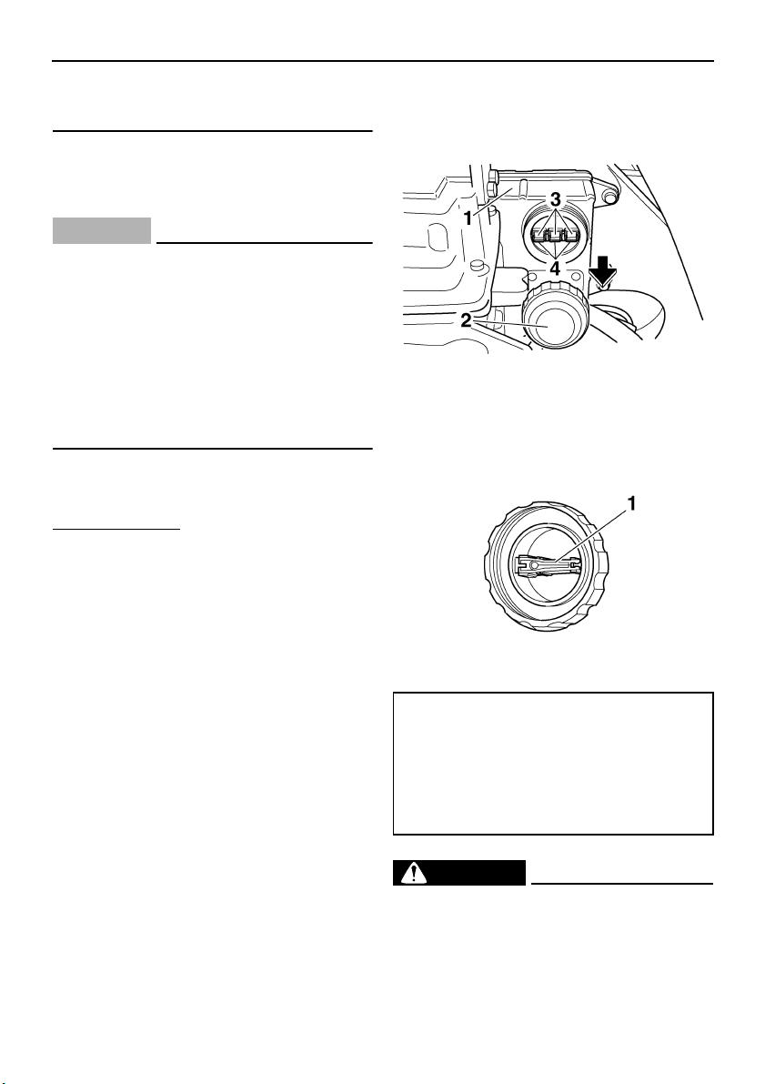
Trouble recovery
100
gine. Any wrong connection could dam-
age the electrical system.
(4) Start the engine, and then disconnect the
jumper cables by reversing the steps
above.
CAUTION:
ECJ00690
● Never push the start switch while the en-
gine is running.
● Do not operate the start switch for more
than 5 seconds, otherwise the battery
will be discharged and the engine will
not start. Also, the starter motor could
be damaged. If the engine does not start
in 5 seconds, release the start switch,
wait 15 seconds, and then try again.
EJU34680
Replacing the fuses
The fuses are located in the electrical box.
To replace a fuse:
(1) Remove the cap on the electrical box.
(2) Replace the blown fuse with the spare
fuse of the correct amperage by using the
fuse puller on the reverse side of the cap.
WARNING
EWJ00800
Do not use fuses of higher amperage than
recommended. Substitution with a fuse
that has an improper rating can cause ex-
1 Electrical box
2 Cap
3 Fuse
4 Spare fuse
1 Fuse puller
Fuse amperage:
Main fuse:
20 A
Meter fuse:
3 A
Bilge pump fuse:
3 A
UF1X11E0.book Page 100 Monday, August 7, 2006 3:51 PM
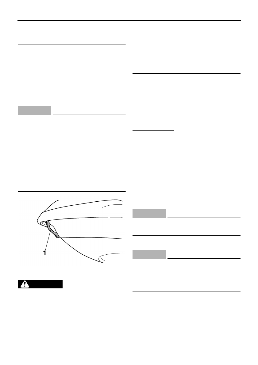
Trouble recovery
101
tensive electrical system damage and pos-
sible fire.
EJU34710
Towing the watercraft
If the watercraft becomes inoperative in the
water, it can be towed to shore.
If the watercraft must be towed in an emer-
gency using a towline, the operator should
ride the watercraft, holding onto the handle-
bars.
CAUTION:
ECJ00720
● Tow the watercraft at 5 mph (8 km/h) or
less, otherwise water could enter the en-
gine through the exhaust passages or
through the air intake and flood the en-
gine compartment if it is towed too fast.
● Tow the watercraft using the bow eye
only.
● The bow must be kept up out of the wa-
ter during towing to prevent water from
entering the engine compartment.
WARNING
EWJ00810
● The watercraft should only be towed in
an emergency.
● The towline should be long enough so
that the watercraft will not collide with
the towing boat when slowing down. A
good rule of thumb is a towline that is
three times the combined length of the
towing boat and the watercraft.
● The operator of the towing boat must
keep speed to a minimum and avoid traf-
fic or obstacles which could be a hazard
to the rider on the watercraft.
EJU35270
Submerged watercraft
If the watercraft is submerged or flooded with
water, follow the procedure below and consult
a Yamaha dealer as soon as possible. Failure
to do so could result in serious engine dam-
age!
In an emergency:
(1) Beach the watercraft and remove the
stern drain plugs to drain the water from
the engine compartment. (See page 59
for more information.) Remove the stor-
age compartment drain plugs to drain the
water from the storage compartments.
(2) Install the stern drain plugs and storage
compartment drain plugs.
(3) Disconnect the spark plug caps, and then
remove the spark plugs.
CAUTION:
ECJ00760
Do not connect the spark plugs to the
spark plug caps.
(4) Disconnect the fuel injector couplers.
CAUTION:
ECJ00770
Cover the disconnected fuel injector cou-
plers so that they do not get wet. If the cou-
plers get wet, they could corrode, which
could lead to poor connections.
(5) Crank the engine for 5 seconds at wide
open throttle. Repeat this step until all of
the water in the cylinders has been ex-
pelled.
1 Bow eye
UF1X11E0.book Page 101 Monday, August 7, 2006 3:51 PM

Trouble recovery
102
(6) Spray a rust inhibitor such as Yamaha
Stor-Rite Engine Fogging Oil into each
spark plug hole for 5 seconds.
(7) Crank the engine for 5 seconds at wide
open throttle. Repeat this step several
times.
(8) Install the spark plugs, and then connect
the spark plug caps and fuel injector cou-
plers.
CAUTION:
ECJ00780
Do not start the engine even after complet-
ing the previous steps. Any water remain-
ing in the engine could cause serious
engine damage.
(9) Have the watercraft inspected by a
Yamaha dealer as soon as possible.
CAUTION:
ECJ00790
Be sure to have a Yamaha dealer inspect
the watercraft. Otherwise, serious engine
damage could result.
UF1X11E0.book Page 102 Monday, August 7, 2006 3:51 PM

Consumer information
103
EJU34780
Limited warranty
YAMAHA MOTOR CORPORATION, U.S.A.
WATERCRAFT LIMITED WARRANTY
Yamaha Motor Corporation is proud of its heritage and reputation for producing products with high standards of quality and workman-
ship. Product excellence provides the cornerstone for our commitment to customer satisfaction. The Yamaha Watercraft Limited War-
ranty is your assurance of this commitment.
This warranty provides you with protection against the expense of repairs for your watercraft that are required as a result of defects in
materials or workmanship. When maintained and utilized in the prescribed manner, you can count on your Yamaha watercraft to pro-
vide reliable service.
This warranty provides you with specific coverage and notes your responsibilities in maintaining and operating your watercraft.
Please take the time to read and become familiar with this warranty.
PERIOD OF WARRANTY.
Any new Yamaha watercraft purchased for pleasure use from an authorized Yamaha dealer in the United
States, will be warranted against defects in material or workmanship for a period of one (1) year from date of purchase, subject to
exclusions noted herein. Any Yamaha Watercraft purchased and utilized for commercial applications will be warranted for a period of
ninety [90] days from the date of purchase, subject to exclusions noted herein. Replacement parts used in warranty repairs will be war-
ranted for the balance of the applicable warranty period.
The warranty described here applies to watercrafts purchased and registered for use in the United States only. For warranty provisions
outside the United States, contact the particular country’s local Yamaha distributor.
OBTAINING REPAIRS UNDER WARRANTY.
During the period of warranty, any authorized Yamaha dealer will, free of charge, repair
or replace, at Yamaha’s option, any parts adjudged defective by Yamaha due to faulty workmanship or material from the factory. All
parts replaced under warranty will become the property of Yamaha Motor Corporation, U.S.A.
CUSTOMER’S RESPONSIBILITY.
Under the terms of this warranty, the customer will be responsible for ensuring that the watercraft is
properly operated, maintained, and stored as specified in the applicable Owner’s/Operator’s Manual.
The owner of the watercraft shall give notice to an authorized Yamaha dealer of any and all apparent defects within ten [10] days of dis-
covery and make the watercraft available at that time for inspection and repairs at the dealer’s place of business.
GENERAL EXCLUSIONS FROM WARRANTY.
This warranty will not cover the repair of damage if the damage is a result of abuse or
neglect of the product. Examples of abuse and neglect include, but are not limited to:
1. Racing or competition use, modification of original parts abnormal strain.
2. Lack of proper maintenance and off season storage as described in the Owner’s/Operator’s Manual, installation of parts or acces-
sories that are not equivalent in design and quality to genuine Yamaha parts.
3. Use of lubricants, oils, and fuel/oil mixtures that are not suitable for watercraft motor use.
4. Damage as a result of accidents, collisions, contact with foreign materials, or submersion.
5. Growth of marine organisms on motor or hull surfaces.
6. Normal deterioration.
7. Gel coat stress cracks.
SPECIFIC PARTS EXCLUDED FROM WARRANTY.
Parts replaced due to normal wear or routine maintenance such as oil, spark plugs, fuel filters, impeller and liner, and anodes are not
covered by warranty. Charges for transporting the watercraft to and from an authorized Yamaha dealer are excluded from warranty cov-
erage.
TRANSFER OF WARRANTY.
Transfer of the warranty from the original purchaser to any subsequent purchaser is possible by having
the watercraft inspected by an authorized Yamaha dealer and requesting the dealer to submit a change of registration to Yamaha Motor
Corporation. U.S.A. within ten [10] days of the transfer.
YAMAHA MOTOR CORPORATION, U.S.A. MAKES NO OTHER WARRANTY OF ANY KIND, EXPRESSED OR IMPLIED. ALL IMPLIED WAR
-
RANTIES OF MERCHANTABILITY AND FITNESS FOR A PARTICULAR PURPOSE WHICH EXCEED THE OBLIGATIONS AND TIME LIMIT
S
STATED IN THIS WARRANTY ARE HEREBY DISCLAIMED BY YAMAHA MOTOR CORPORATION, U.S.A. AND EXCLUDED FROM THI
S
WARRANTY.
SOME STATES DO NOT ALLOW LIMITATIONS ON HOW LONG AN IMPLIED WARRANTY LASTS, SO THE ABOVE LIMITATION MAY NO
T
APPLY TO YOU. ALSO EXCLUDED FROM THIS WARRANTY ARE ANY INCIDENTAL OR CONSEQUENTIAL DAMAGES INCLUDING LOS
S
OF USE. SOME STATES DO NOT ALLOW THE EXCLUSION OR LIMITATION OF INCIDENTAL OR CONSEQUENTIAL DAMAGES, SO TH
E
ABOVE EXCLUSION MAY NOT APPLY TO YOU.
UF1X11E0.book Page 103 Monday, August 7, 2006 3:51 PM

Consumer information
104
THIS WARRANTY GIVES YOU SPECIFIC LEGAL RIGHTS, AND YOU MAY ALSO HAVE OTHER RIGHTS WHICH VARY FROM STATE T
O
STATE.
YAMAHA MOTOR CORPORATION, U.S.A.
Post Office Box 6555
Cypress, California 90630
WARRANTY QUESTIONS AND ANSWERS
Q. What costs are my responsibility during the warranty period?
A. The customer’s responsibility includes all costs of normal maintenance services, non-warranty repairs, accident and collision dam-
ages.
Q. What are some examples of “abnormal” strain, neglect, or abuse?
A. These terms are general and overlap each other in areas. Specific examples include:
Running the watercraft out of oil, operating the machine with a broken or damaged part which causes another part to fail, and so
on. If you have any specific questions on operation or maintenance, please contact your Yamaha dealer for advice.
Q. Does the warranty cover incidental costs such as transportation due to a failure?
A. No. The warranty is limited to repair of the watercraft itself.
Q. May I perform any or all of the recommended maintenance shown in the Owner’s/Operator’s Manual instead of having the dealer do
them?
A. Yes, if you are a qualified mechanic and follow the procedures specified in the Owner’s/Operator’s and Service Manual. We do rec-
ommend, however, that items requiring special or equipment be done by a Yamaha dealer.
Q. Will the warranty be void or cancelled if I do not operate or maintain my new watercraft exactly as specified in the Owner’s/Opera-
tor’s Manual?
A. No. The warranty on a new watercraft cannot be “voided” or “cancelled”.
However, if a particular failure is caused by operatio
n
or maintenance other than as shown in the Owner’s/Operator’s
Manual, that failure may not be covered under warranty.
Q. What responsibility does my dealer have under this warranty?
A. Each Yamaha dealer is expected to:
1. Completely set up each new watercraft before sale.
2. Explain the operation, maintenance, and warranty requirements to your satisfaction at the time of sale, and upon your request at
any later date. In addition, each Yamaha dealer is held responsible for his setup, service and warranty repair work.
Q. Is the warranty transferable to second owners?
A. Yes. The remainder of the existing warranty can be transferred upon request. The unit has to be inspected and re-registered by an
authorized Yamaha dealer for the policy to remain effective.
CUSTOMER SERVICE
If your watercraft requires warranty service, you must take it to any authorized Yamaha dealer within the continental United States. Be
sure to bring your warranty registration card or other valid proof of the original date of purchase. If a question or problem arises regard-
ing warranty, first contact the owner of the dealership. Since all warranty matters are handled at the dealer level, this person is in the
best position to help you. If you are still not satisfied and require additional assistance, please write:
YAMAHA MOTOR CORPORATION U.S.A.
CUSTOMER RELATIONS DEPARTMENT
P.O. Box 6555
Cypress, California 90630
CHANGE OF ADDRESS
The federal government requires each manufacturer to maintain a complete, up-to-date list of all first purchasers against the possibility
of a safety-related defect and recall. This list is complied from the purchase registrations sent to Yamaha Motor Corporation, U.S.A. by
the selling dealer at the time of your purchase.
If you should move after you have purchased your new watercraft, please advise us of your new address by sending a postcard listing
your Yamaha model name, engine number, dealer number [or dealer’s name] as it is shown on your warranty card, your name and new
mailing address.
Mail to:
YAMAHA MOTOR CORPORATION, U.S.A.
P.O. Box 6555
Cypress, California 90630
Attention: Warranty Department
This will ensure that Yamaha Motor Corporation, U.S.A. has an up-to-date registration record in accordance with federal law.
UF1X11E0.book Page 104 Monday, August 7, 2006 3:51 PM

Consumer information
105
EJU34800
YAMAHA EXTENDED SERVICE (Y.E.S.)
Keep your Yamaha protected even after your warranty expires with genuine Yamaha Extended
Service (Y.E.S.).
•
Y.E.S. is designed and administered by Yamaha Motor Corporation to provide maximum owner
satisfaction. You get uninterrupted factory-backed coverage for extra peace of mind.
•
Y.E.S. is flexible. You choose the plan that is right for you: 12 months, 24 months, 36 months, or
(on four-stroke models) 48 months beyond your warranty period.
•
Y.E.S. is designed and administered by the same Yamaha people who handle your warranty—
and it shows in the comprehensive coverage benefits. There are no mileage limitations. Cover-
age is not limited to “moving parts” or the “drive train” like many other plans. And Y.E.S. covers
manufacturing defects just like the warranty. See the sample contract at your Yamaha dealer to
see how comforting uninterrupted factory-backed protection can be.
•
You do not have to pay anything for covered repairs. There is no deductible to pay, and repairs
are not “pro-rated.” You do not have any “out-of-pocket” expenses for covered repairs.
•
In addition, Travel and Recreation Interruption Protection (TRIP) is included at no extra cost.
TRIP gives you up to $150 reimbursement per occurrence for any reasonable expenses you
incur because your Yamaha needs covered service: replacement vehicle rental, emergency
towing, phone calls, even food and lodging when you are away from home. This superb cover-
age goes into effect when you purchase Y.E.S., so it applies to any warranty repairs as well as
covered repairs during your entire Y.E.S. plan period.
•
Y.E.S. coverage is honored at any authorized Yamaha dealer nationwide.
•
Y.E.S. coverage is transferable to a new owner if you sell or trade-in. That can make your
Yamaha much more valuable!
This excellent Y.E.S. plan coverage is only available to Yamaha owners like you, and only while
your Yamaha is still within the Yamaha Limited Warranty period. So visit your authorized Yamaha
dealer to get all the facts. He can show you how easy it is to protect your investment with Yamaha
Extended Service.
We urge you to act now. You will get the excellent benefits of TRIP coverage right away, and you
will rest easy knowing you will have strong factory-backed protection even after your Yamaha
Limited Warranty expires.
A special note:
If visiting your dealer is not convenient, contact Yamaha with your Primary ID number (your Owner’s
Manual shows you where to find this number). We will be happy to help you get the Y.E.S. coverage
you need.
Yamaha Service Marketing
P.O. Box 6555
Cypress, CA 90630
1-(866)-YES-EXTD
(1-866-937-3983)
UF1X11E0.book Page 105 Monday, August 7, 2006 3:51 PM

Index
A
Air filter element, checking ....................... 88
Analog speedometer/tachometer............. 41
Analog speedometer/tachometer and
indicator lights....................................... 41
Approval label of emission control
certificate ................................................ 2
B
Battery................................................ 60, 82
Battery, checking...................................... 92
Battery, jumping ....................................... 99
Beaching the watercraft ........................... 77
Beverage holder....................................... 52
Bilge ......................................................... 59
Boarding alone......................................... 72
Boarding and starting from a dock ........... 71
Boarding and starting in deep water ........ 71
Boarding and starting in shallow water .... 71
Boarding with passengers........................ 72
Bow down................................................. 36
Bow eye ................................................... 37
Bow up ..................................................... 36
C
Capsized watercraft ................................. 74
Check engine warning indicator............... 46
Cleaning the watercraft ............................ 82
Cooling water pilot outlet.......................... 65
Cooling water pilot outlets ........................ 33
Cruising limitations................................... 10
D
Digital speedometer ................................. 43
Docking the watercraft ............................. 77
E
Emergency procedures............................ 98
Emission control information...................... 2
Engine break-in........................................ 66
Engine compartment................................ 58
Engine oil ................................................. 55
Engine oil and oil filter .............................. 87
Engine oil level......................................... 58
Engine overheat warning indicator........... 45
Engine serial number ................................. 1
Engine shut-off cord................................. 64
Engine shut-off switch.............................. 32
Engine stop switch ................................... 32
Enjoy your watercraft responsibly ............ 24
F
Filling the fuel tank ................................... 55
Fire extinguisher....................................... 61
Flushing the cooling system..................... 80
Front storage compartment...................... 50
Fuel and oil............................................... 54
Fuel injection system................................ 94
Fuel level.................................................. 58
Fuel level meter........................................ 44
Fuel level warning indicator...................... 45
Fuel system.............................................. 81
Fuel system, checking.............................. 87
Fuel tank .................................................. 87
Fuel tank filler cap .................................... 31
Fuses, replacing..................................... 100
G
Gasohol.................................................... 54
Gasoline ................................................... 54
Getting to know your watercraft ............... 69
Glove compartment.................................. 51
H
Handgrip................................................... 37
Hazard information................................... 15
Hood......................................................... 30
Hour meter/voltmeter ............................... 44
Hull and deck ........................................... 58
Hull Identification Number (HIN)................. 1
I
Identification numbers ................................ 1
Important labels.......................................... 4
J
Jet intake.................................................. 64
Jet intake and impeller, cleaning.............. 98
Jet thrust nozzle angle, checking ............. 89
Jumper cables, connecting ...................... 99
L
Labels, other .............................................. 7
Labels, warning .......................................... 5
Launching the watercraft.......................... 66
Learning to operate your watercraft ......... 69
Leaving the watercraft.............................. 68
Left multifunction display and operation
buttons .................................................. 43
UF1X11E0.book Page 1 Monday, August 7, 2006 3:51 PM

Index
Limitations on who may operate the
watercraft................................................ 9
Limited warranty..................................... 103
“L-MODE” indicator light........................... 43
Lubrication................................................ 81
Lubrication points..................................... 91
M
Main components, location of .................. 25
Maintenance and adjustments ................. 83
Manufactured date label............................. 2
Multifunction information center ......... 40, 65
O
Oil pressure warning indicator.................. 45
Operating your watercraft......................... 69
Operation ................................................. 66
Operation of controls and other
functions ............................................... 29
Operation requirements ........................... 12
Owner’s/operator’s manual and tool kit.... 83
P
Periodic maintenance chart...................... 85
Post-operation care.................................. 78
Pre-operation check list............................ 56
Pre-operation check points ...................... 58
Pre-operation checks ............................... 56
Primary Identification (PRI-ID) number ...... 1
Pull-up cleats (for FX Cruiser High
Output).................................................. 38
Q
Quick Shift Trim System (QSTS) ............. 63
Quick Shift Trim System (QSTS)
selector ................................................. 35
R
Reboarding step....................................... 37
Recommended equipment ....................... 14
Remote control transmitter....................... 31
Reverse on waterways............................. 77
Riding with passengers............................ 70
Right multifunction display and
operation buttons (for FX Cruiser
High Output) ......................................... 47
Rough water operation............................. 78
“RPM” indicator light................................. 42
Rules of the Road .................................... 19
S
Seat storage compartment....................... 51
Seats ........................................................ 29
Selecting the normal mode/low-RPM
mode..................................................... 39
Shift cable, checking ................................ 89
Shift lever ................................................. 35
Shift lever and reverse gate .....................62
Spark plugs, cleaning and adjusting ........ 90
“SPEED” indicator light ............................ 42
Star labels .................................................. 2
Start switch............................................... 33
Starting the engine ................................... 66
Starting the watercraft .............................. 70
Steering system ................................. 34, 62
Stern drain plugs ...................................... 60
Stern eyes ................................................ 38
Stopping the engine ................................. 68
Stopping the watercraft ............................ 77
Storage..................................................... 80
Storage compartments............................. 50
Submerged watercraft............................ 101
Switches................................................... 65
T
Throttle cable, checking and adjusting..... 89
Throttle lever ...................................... 33, 62
Tilt lever.................................................... 34
To get more boating safety information.... 23
Towing the watercraft............................. 101
Transporting ............................................. 79
Trolling speed, checking .......................... 94
Troubleshooting ....................................... 96
Troubleshooting chart .............................. 96
Turning the watercraft .............................. 75
U
“UNLOCK” indicator light.......................... 42
W
“WARNING” indicator light ....................... 42
Water separator ....................................... 59
Watercraft characteristics......................... 15
Water-skiing ............................................. 17
Watertight compartment........................... 52
Y
Yamaha Engine Management System
(YEMS) ................................................. 38
UF1X11E0.book Page 2 Monday, August 7, 2006 3:51 PM

Index
YAMAHA EXTENDED SERVICE
(Y.E.S.) ............................................... 105
Yamaha Security System......................... 38
Yamaha Security System and low-RPM
mode..................................................... 38
Yamaha Security System lock and
unlock modes........................................ 38
UF1X11E0.book Page 3 Monday, August 7, 2006 3:51 PM

A5-tate_Blank.fm Page 1 Friday, May 16, 2003 9:00 AM

A5-tate_Blank.fm Page 1 Friday, May 16, 2003 9:00 AM

Printed in USA
August 2006–1.7 × 1 CR
YAMAHA MOTOR CORPORATION, USA