263-349 R1213
263-349 R0515
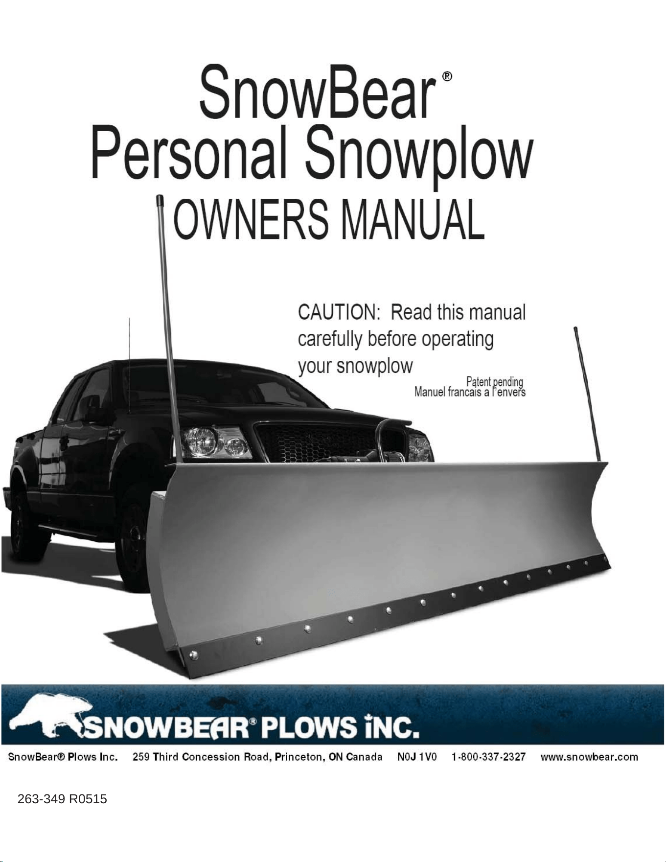
CAUTION:
Read this manual carefully
before operating your
Snowplow!
263-349 R518
Patent Pending
2
OVERVIEW
1) READ THE OWNER’S MANUAL CAREFULLY. Know your snowplow. Learn its applications and limitations.
2) KEEP AWAY FROM CHILDREN AND PETS. Be sure children and pets are kept a safe distance from the
plow operating area.
3) DO NOT ABUSE THE SNOWPLOW. Follow the guidelines set forth in this manual. Do not force the
snowplow to do a job it was not designed for.
4) MAINTAIN THE SNOWPLOW. Keep the snowplow clean and lubricated when the unit is not in use to
avoid corrosion. Cover the winch when not in use (if stored outside).
5) INSPECT THE PLOW BEFORE EACH USE. Check the alignment of all moving parts and check for any loose
bolts that may affect the operation.
6) NEVER SIT OR RIDE ON THE SNOWPLOW. Serious injury could occur.
7) ONLY USE ORIGINAL EQUIPMENT PARTS AND ACCESSORIES. Consult the owner’s manual for the
recommended accessories. The use of improper accessories may cause hazards.
* ASSEMBLY INSTRUCTIONS: PAGES 7 TO 18*
TROUBLESHOOTING - PAGE 19
CAUTION: READ BEFORE YOU PLOW
ALWAYS check that the hitch pins pass through the appropriate holes in the mounting forks. IF THE
PLOW IS INCORRECTLY ATTACHED TO THE MOUNTS, IT WILL PULL AWAY FROM THE VEHICLE AND FALL
OFF.
Not for commercial use.
Lights are recommended if plowing at night.
Do not plow at speeds above 10 mph (16 km/hr) as this may cause your engine to overheat.
Do not drive on public roadways with plow attached.
Install safety chain when transporting plow in raised position.
Avoid all obstacles - be familiar with the terrain.
For best results plow every 3 to 6 inches of snowfall.
Keep hands and feet clear of blade and winch/actuator.
Lower the blade when parked.
WARNING: Do not attempt to operate the snowplow until you have thoroughly read and completely
understood all instructions contained in this manual. Improper operation can result in personal injury or
damage to your plow and vehicle. As SnowBear
®
Plows Inc. does not assemble or install this snowplow we
cannot be held responsible for personal injury or damages that may occur with product misuse.

3
INSTALLING YOUR VEHICLE MOUNTING HARNESS
Overview:
Snowbear
®
snowplow mounts are unique because they use existing holes and attachment points on your vehicles frame. Use only
Snowbear
®
Certified mounts with your Snowbear
®
personal snowplow.
All of the mount kits have been designed using manufacturer’s frame specifications as well as actual frame measurements. However
based on our experience, we know that these measurements are not always the same and can easily vary by ¼” or more.
We have attempted to compensate for some of these inconsistencies by providing slots in our support brackets wherever possible. You
may however still need to adjust the holes in your mounting brackets, or vehicle frame. This can be easily done by using a file, a small
grinder, or drill.
Before beginning your installation check the assembly drawing inside of the box to confirm that you have the proper mount for your
vehicle. The accessory package of your vehicle (e.g. XLT, Custom, Sport, Extended Cab, SLT, etc.) does not affect the frame specifications.
Manufacturers tend to have many models, but few platforms. Our mounts are designed around these frames and platforms.
Installation:
Many customers find that the mount installation is intimidating because they are not familiar with the underside of their vehicles. In
general, a mounting harness consists of a cross member (shipped with your plow hardware) and a set of custom brackets to attach the
crossmember to the vehicle.
Begin by loosely attaching the brackets to the frame of the vehicle, then loosely attach the cross-member to the two brackets.
Be careful not to pinch any wires or hoses between the plow mount and your vehicle frame.
When the parts are all in place, push the assembly back as far as possible (as though you were the plow) and begin to tighten the
hardware.
NOTE: We supply standard grade 5 bolts and lock nuts which will appear tight as you thread them onto the
bolts, THIS IS NORMAL.
Operation:
After plowing for the first time, we recommend that you re-tighten the bolts on the mounting harness. On most vehicles the
components will “seat” into each other after the first use.
2WD vehicles and vehicles equipped with Sport package will normally have a lower ground clearance due to the tire size as well as the
suspension package. You should expect a reduction in ground clearance at the front of your vehicle, because the mounting tubes must
be exposed below the lowest part of your vehicles body. Adding an extra helper spring, or increasing the tire size will give you the extra
clearance you may need. Minimal ground clearance does not affect your ability to plow, but it does mean you must use extra caution
when plowing. Avoiding any raised or uneven areas that your plow hardware may get caught up on will ensure trouble free use.
With some applications the mounting forks on the cross-member will point slightly downward after use, this is a normal part of the
“SEATING” process and will not affect the operation of the plow. (In most cases steel shims can be used to bring the forks back up, but
you should be careful not to make them point upwards or it will be difficult to install your plow.
Your plow is designed to move freshly fallen snow. It is not suitable for smashing through piles of ice, or grading sand and gravel.
WARNING:
If you overload the mounting harness it is designed to yield or break before your plow or vehicle’s frame is severely damaged. It is
especially important to exercise caution with heavier full sized trucks to ensure that you will receive years of trouble free service from
your personal snowplow.
SnowBear
®
mounts are an essential part of the SnowBear
®
plow and are designed and manufactured to specifically fit SnowBear
®
snowplows. These mounts are not designed to fit other manufacturers' plows. Using a SnowBear
®
mount on a non-SnowBear
®
product
will void the Snowbear
®
mount warranty. Using a non-Snowbear
®
mount on SnowBear
®
snowplows will void the manufacturer warranty
for the SnowBear
®
snowplow. SnowBear
®
will not provide assistance to customers using SnowBear
®
mounts or snowplows with non-
Snowbear
®
products.
SnowBear
®
Plows Inc. cannot be held responsible, and disclaims any liability, for any personal injury or damages that may occur in
connection with such use of any unapproved products with SnowBear
®
products.

4
PLOWING INSTRUCTIONS
The Snowplow is intended for light duty, personal use only. It can be used to effectively clear snow from parking lots, lane
ways and driveways quickly and with minimal effort.
To obtain many years of trouble free service from your Snowplow, be sure to observe these basic plowing instructions.
1. Before beginning to plow check that the hitch pins are properly installed through the holes on the mounting
forks under the vehicle. To check this pull forward on the plow. If the plow moves from the vehicle when pulled
the hitch pins are not correctly installed.
2. Plow promptly after every 3-6 inches of accumulation during heavy snowfalls.
3. Plow immediately after each snowfall. The plow cannot be used to break through ice.
4. Exercise caution and be familiar with the area that you are plowing. Hidden obstacles can damage both the plow
and your vehicle.
5. Stay clear of all obstacles by at least 3 feet (walls, telephone poles, gate, etc.) as your vehicle may slip sideways on
ice causing the plow to strike the obstacle.
6. Never ram a pile of snow. Your unit is not designed to move blocks of ice and attempting to do so will void your
warranty and may cause damage to your vehicle.
7. Do not exceed 10 mph (16 km/hr).
Excessive speeds can overload the plow or cause you to lose control of your
vehicle.
8. When you encounter drifts of snow, proceed by raising the plow to remove the top layer of snow, then remove
the base on successive passes.
9. If your plow hops when plowing reduce your speed.
10. Your plow is designed to trip forward if it is overloaded or if it encounters a small obstacle buried in the snow. The
plow will automatically reset itself. If you are unsure as to why it tripped, examine the snow pile for a hidden
obstacle before proceeding with caution.
11. Always lift the plow before backing up.
12. Always lower the plow when parked.
13. Remove the plow from your vehicle after each use and do not allow ice or snow to accumulate on the
winch/actuator.
14. THE SNOWPLOW IS NOT INTENDED FOR TRANSPORTATION ON PUBLIC ROADS. To drive on the highway with a
plow attached most states and provinces require the installation of a lighting kit complete with turn signals. A
safety chain is also required, which would not allow the plow to fall off the front of the vehicle. Always consult
your local regulatory agency for their particular requirements.
Note: Driving at speeds above 10 mph (16 km/hr) with the plow attached may cause your engine to overheat.

5
PLOWING LANE WAYS
Note: To ensure easy maintenance of lane ways throughout the winter season, plow your lane ways as
widely as possible during the first snowfalls.
Technique:
Set the plow on an angle and proceed down the lane close to the edge where the snow will be piled. Be careful
to stay clear of ditches, trees, buildings and any other obstacles that may run parallel with the lane way.
At the end of the lane way, turn the vehicle around and without changing the angle of the plow, return on the
other side of the lane way to accumulate a second pile of snow. Repeat this action to push the snow pile back
further.
PLOWING PARKING AREAS
Hint: Always plow parking areas as widely and as deeply as possible during the first snowfalls.
Technique:
Generally, work from the center to one side and then from the center again to the other side.
Do this by setting the plow on an angle and proceed down the center of the parking lot until you reach the far
edge.
Lift the plow and back up to the position that you started from.
Now, plow a parallel and slightly overlapping path.
After you have plowed half the parking lot, exit the vehicle, adjust the plow to the opposite angle and starting
from the center again, work progressively in a lateral direction, towards the outer edge of the parking lot.
Note: When approaching the end of the lot, reduce your speed and stop before the blade slams the
snow pile. Your plow should not be used to stack the snow.
ASSEMBLY TOOLS REQUIRED
RATCHETING WRENCH
9/16” SOCKET
3/4” SOCKET
15/16” SOCKET
3/8” OPEN ENDED WRENCH
1-1/16” OPEN ENDED WRENCH

Item Quantity Description Part Number Item Quantity Description Part Number
1 8.00
1/2-13 X 2.00 HHCS
600-709 42A 60" BLADE - RH 297-610
2 14.00
1/2 FLAT WASHER (2 FOR CASTER KIT)
600-605 42B 72" BLADE - RH 297-579
3
31.00
1/2-13 LOCKING HEX NUT (2 FOR 60/72", 4 FOR 82/84/88")
600-027
42C 82" BLADE - RH 297-666
4 16.00
3/8-16 X 1.00 CARRIAGE BOLT, BLACK
600-605 42D 84" BLADE - RH 297-644
5 34.00
3/8-16 NYLON LOCK NUT (4 FOR 60/72")
600-605 42E 88" BLADE - RH 297-719
6 10.00
3/8-16 X 1.00 HHCS
600-605 43 1.00 LOWER A-FRAME 297-745
7 2.00
3/4-10 HEX NUT (2 FOR 82/84/88")
600-020 44 1.00 UPPER A-FRAME 297-753
8 2.00
3/4-10 LOCKING NUT (2 FOR 82/84/88")
600-020 45A
HD WINCH ARM - RH (82/84/88" BLADE)
297-740
9 2.00
1/2-13 HEX NUT (2 FOR 60/72")
600-027 45B
LD WINCH ARM - RH (60/72" BLADE)
297-778
10 4.00
3/8-16 X 1.00 HHCS (4 FOR 60/72")
600-027 46A
HD WINCH ARM - LH (82/84/88" BLADE)
297-741
11 1.00
.637 X .797OD X 1.50 SLEEVE
600-709 46B
LD WINCH ARM - LH (60/72" BLADE)
297-779
12 1.00
5/8-18 X 2.50 HHCS
600-709 47 1.00 WINCH MOUNT 297-595
13 2.00
5/8 FLAT WASHER
600-709 48 1.00 RELEASE HANDLE 297-008
14 1.00
5/8-18 LOCKING HEX NUT
600-709 49 1.00 RELEASE ROD 297-632
15 4.00
5/16-18 X 1.00 HHCS
600-709 50A 2" HOLLOW SHANK RECEIVER 324-135
16 15.00
5/16-18 NYLON LOCK NUT (8 FOR CASTER KIT)
600-709 50B 2" SOLID SHANK RECEIVER 324-138
17 5.00
1/2-13 X 1.25 HHCS
600-605 50C VEHICLE SPECIFIC CUSTOM RECEIVER 324-136
18 2.00
1/2-13 X 2.00 HHCS
600-709 51 2.00 12" SNOWPLOW SPRING 297-094
19 2.00
SNOWPLOW MARKER
297-057 52A 60" RUBBER DEFLECTOR 263-348
20 1.00
5/16-18 X 1.25 HHCS
600-709 52B 72" RUBBER DEFLECTOR 263-325
21 1.00
3/8-16 U-BOLT (WINCH STRAP)
363-064 52C 82" RUBBER DEFLECTOR 262-929
22 3.00
1/2 X 2.00 CLEVIS PIN
600-605 52D 84" RUBBER DEFLECTOR 262-932
23 5.00
1/8" HITCH PIN CLIP (2 FOR CASTER KIT)
600-601 52E 88" RUBBER DEFLECTOR 263-314
24A
1/2-13 EYE BOLT (4.5") - (60/72/82" BLADE)
262-930 53A 60" DEFLECTOR BAR (2PC) 297-615/616
24B
1/2-13 EYE BOLT (6.5") - (84" BLADE)
263-351 53B 72" DEFLECTOR BAR (2PC) 297-647/648
24C
1/2-13 EYE BOLT (9.5") - (88" BLADE)
262-931
53C 82" DEFLECTOR BAR (2PC) 297-769/770
25 1.00
1/2-13 X 3.00 HHCS (ACTUATOR KIT)
600-608 53D 84" DEFLECTOR BAR (2PC) 297-767/768
26 2.00
1/2-13 X 2.50 HHCS (ACTUATOR KIT)
600-608 53E 88" DEFLECTOR BAR (3PC) 297-713/712
27 5.00
D-CLIP (ACTUATOR KIT/2 FOR CASTER KIT/2 FOR 5XM5 KIT)
600-601 54A 60" SCRAPER BAR (2PC) 297-617/618
28 1.00
D-SHACKLE
600-709 54B 72" SCRAPER BAR (2PC) 297-649/650
29 1.00
CARABINER
600-709 54C 82" SCRAPER BAR (2PC) 297-669/770
30 8.00
5/16-18 X .75 HHCS (8 FOR CASTER KIT)
600-601 54D 84" SCRAPER BAR (2PC) 297-634-635
32 6.00
1/2-13 X 1.00 HHCS (2 FOR CASTER KIT)
600-601 54E 88" SCRAPER BAR (3PC) 297-711/714
33 2.00
1/2 X 1.25 CLEVIS PIN (2 FOR CASTER KIT)
600-601 55A LIGHT DUTY SKID SHOE KIT (60/72") 297-158
34 N/A
CHAIN LINK
263-301 55B HEAVY DUTY SKID SHOE KIT (82/84/88") 600-019
35 2.00
14" HEAVY DUTY CABLE TIES
N/A 56A BLADE STIFFENER (60/72/82/84") 297-633
36 1.00
35A BREAKER BRACKET
297-042 56B
BLADE STIFFENER (88") (2PC)
297-710
37 6.00
6" HEAVY DUTY CABLE TIES
N/A 57 2.00
LOCKING PIN (VEHICLE SPECIFC MNT ONLY)
363-016
38 1.00
5/8 X 4.00 HITCH PIN W/ CLIP
263-320 58 2.00 CASTER STAND 297-788
39 1.00
35A CIRCUIT BREAKER
263-347 59 2.00 CASTER STAND LOCKING PIN RETAINER CLIP 363-016
40 1.00
WINCH UNIT + MODULE + WIRED REMOTE
263-282 60 1.00 5XM5 CROSS MEMBER (OPTIONAL) 297-679
41A
60" BLADE - LH
297-611 61 1.00 WINCH CUP MOUNT (OPTIONAL) 324-136
41B
72" BLADE - LH
297-580 62 1.00 WIRELESS REMOTE KIT 324-144
41C
82" BLADE - LH
297-667
41D
84" BLADE - LH
297-643
41E
88" BLADE - LH
297-720
* Snowbear® Plows Inc. reserves the right to change products or part numbers without prior notification, and under no obligation to incorporate such changes into previously manufactured products
* Snowbear
MD a limité des réservations la droite de changer des produits ou des numéros de la pièce sans avis préalable, et sous aucune obligation d'incorporer de tels changements aux produits précédemment manufacturés
1.00
SNOWPLOW PARTS LIS
T
Before you begin please verify that all of the parts below have been included with your plow. Your plow is packaged in three boxes.
Avant que vous commenciez svp vérifiez que toutes les pièces ci-dessous ont été incluses avec votre charrue. Votre charrue est empaquetée dans des trois boîtes.
1.00
1 OR 2
2.00
1.00
1.00
1.00
1.00
1.00
1.00
1.00
6
!
"!
##$
"
"%
"
"&
"
'%
($
#'
$##
#
"
"%
"
"%
"
"&
!
!
"&
"
")
"
"
"%
"&
"
"
"*")
"*"&
"%
"
( $
#
+&
+
!!%
"*"
"&*"%
$
'%
!
!
"
!
!
!
!
$
7
Diamond shape
Driver Side
&
"
"%
"
"
%
($
'
$(
")
( $
#
($
"
"&
"
"
"%
"
"%
"
'%
"
"&
"
"%
"
8
%
"
"%
"
"%
!
#(
$
!
$
!
"
"
"&
"
"
"&
"
"&
"
'%
"
"
"%
($
' $(
#
#$
")
9
Install Item #11 from
the top surface.
"%
"
"%
"
$
$
$
'
'$
&'##
')!
#
%'##
'!)!#
)!
##(
$
"
10
#47
)
##
($
!
#**($
"
"
"&
$#
"&
"
"&
"
$!
#($
"
"%
"
"
"
"
"%
"
'%
""$
$
#
11

"
"
"
"
"&
"%
"
#! $
'
#
"&
"
$#
"
"&
"
"%
"&
"
"
"%
#!
# $
##
(
"%
"%
#!
$
"
11
12
HOOK SPRINGS TO REAR OF BLADE
WARNING!! -- SAFETY GLASSES REQUIRED
&
$
#
"
")
"&
"&
"
")
##
!
(#
# *
!
13
%
"&
"&&
"&
"
"&
"&
"
"&
"
"&
"&&
"&
"
'%
$ #(
$
!
#!
$
#
#
#!
)!#
!
#!*
($
,-!#
##(
$
+
+
"&
$
#&*($
14
+
#.
##
#*!&((
$
#
#
+
$
$
$
#
#
#
15
PT # 324-127
)
!
##
&($
#
!*($
+
"
"
"%
"&
&
'%
+
!
#!*(
$
!#!
$
#(
$
"&
"
"
"
"%
'%
"%
"
"
"&
"
"%
"
"&
"
"&
"
16
PRO SHOVEL & WINTERWOLF
PRO SHOVEL & WINTERWOLF
+
!
"
#
$ "$"%
!
&#
##!
!
&#!
!
!"
!
"
"
"&
"
"
"&
"
17
17
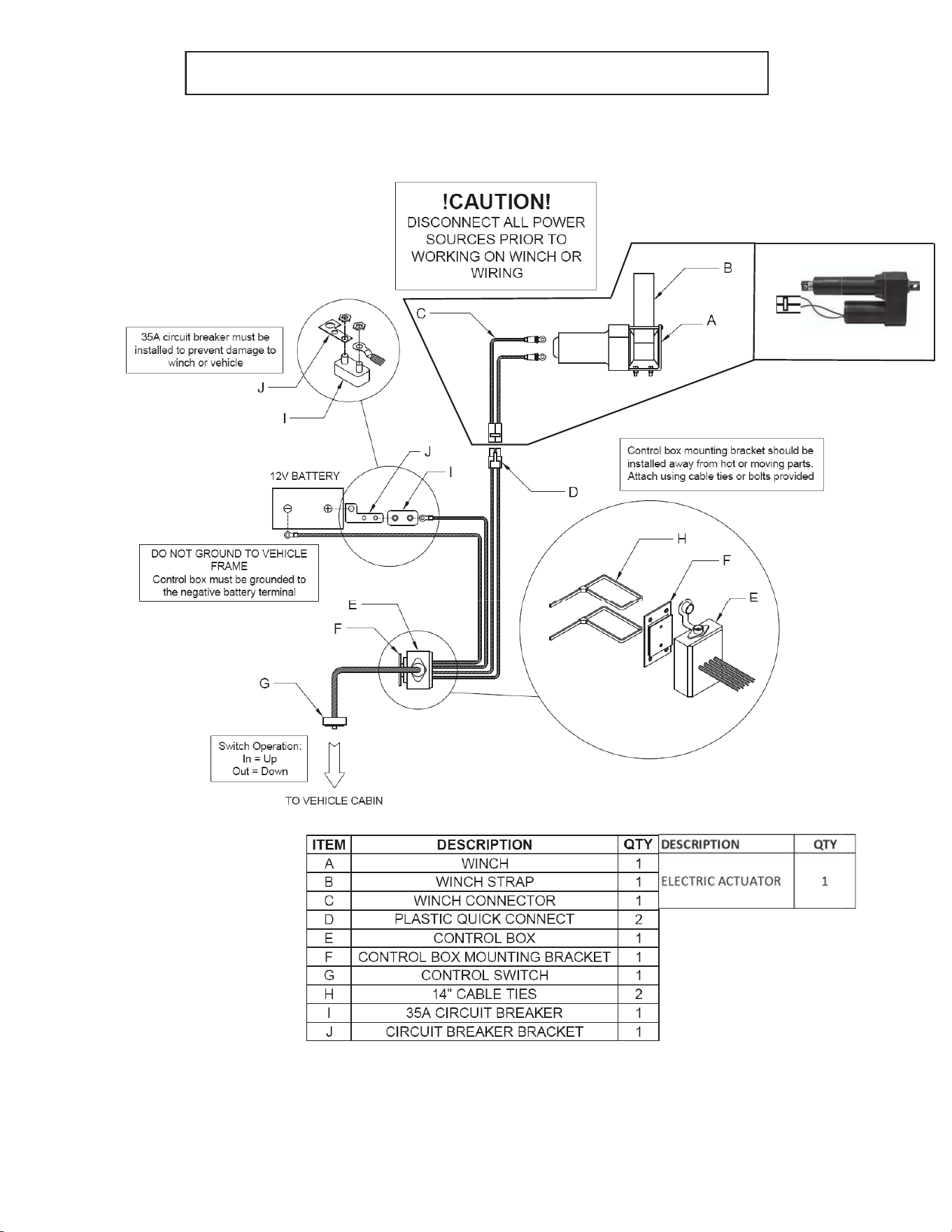
WINCH WIRING DIAGRAM
WINCH/ACTUATOR WIRING DIAGRAM
18

TROUBLESHOOTING
If you are experiencing difficulties with your plow, please consult the troubleshooting tips below. This is intended
as a guide, to assist you in resolving common technical issues and performing simple adjustments. If you require
further assistance, please contact the SnowBear
®
Customer Service department at 1.800.337.2327.
1. Plow rocks or tips from side to side.
a. Your plow is intended to rock from side to side by 8 to 10 inches. This will help to compensate for
differences in the terrain that you are plowing, and should not be reduced by adding shims or
washers.
b. If the plow is rocking excessively, check the 5/8” pivot bolt (#6) to ensure that there is no more
than ¼” of free play. The 5/8” lock nut can be tightened, if required.
c. Check the springs and eye bolts to ensure that there is adequate tension. If the springs appear
loose, tighten the lock nuts on the eye bolts to ¼” past the point of tension.
2. Winch strap is breaking.
a. The single most common cause of a broken strap is lack of free movement in the U Bolt, where
the strap attaches to the A Frame. Ensure that the lock nuts on the U Bolt are sufficiently loose,
and there is plenty of play in the U Bolt.
b. Another common cause for a broken strap is over-tightening the winch. This will also cause
deformation in the Winch Arms. Ensure your 35A breaker is installed and working properly, and
do not over-tighten the winch when raising and lowering the plow blade.
3. Winch/Actuator does not engage, or winch hesitates.
CAUTION - Disconnect power from the plow, prior to
working on the winch/actuator or wiring.
a. Ensure that the battery cable is securely grounded to the negative terminal on your battery. DO
NOT GROUND TO VEHICLE FRAME.
b. Ensure that the switch on the control box (under your hood) is in the “ON” position. Check your
contacts and connectors to ensure that they are secure and free of any dirt or corrosion.
Dielectric grease can be used to protect electrical connections against dirt and corrosion.
4. Plow operation is backwards (i.e. blade lifts when it should lower)
a. Ensure that the red wire on the 2’ winch connector is connected to the positive (top) terminal on
the winch, and the black wire is connected to the negative (bottom) terminal.
5. Wiring, control switch or control box are getting hot.
a. Circuit breaker must be installed between the red battery cable and the positive terminal on your
battery. Ensure that the breaker bracket is connected between the battery and the brass
terminal on the circuit breaker.
REMEMBER
This plow is intended for personal use ONLY. The plow is not rated for
commercial use, and it is not designed to be transported at speeds greater than 10 mph
(16 km/hr). Commercial use or travelling above the recommended speeds will void
your warranty and can cause serious damage to the plow, your vehicle, or your person.

263-349 R1213
263-349 R0515
Mise En Garde:
Lisez ce manuel attentivement avant
d'utiliser votre chasse-neige
263-349 R161
Brevet en instance
Le chasse-neige personnel
GUIDE D'UTILISATION
21
VUE D’ENSEMBLE
1) LIRE ATTENTIVEMENT LE MODE D’EMPLOI. Se familiariser avec le chasse-neige. Se familiariser avec ses
applications et ses limites.
2) GARDER À DISTANCE DES ENFANTS ET DES ANIMAUX DOMESTIQUES. S’assurer que les enfants et les animaux
domestiques se trouvent à une distance sécuritaire de la zone d’utilisation du chasse-neige.
3) ÉVITER L’USAGE ABUSIF DU CHASSE-NEIGE. Suivre les directives de ce mode d’emploi. Ne pas utiliser le chasse-
neige pour effectuer une tâche pour laquelle il n’est pas conçu.
4) ENTRETENIR LE CHASSE-NEIGE. Garder le chasse-neige propre et lubrifié lorsqu’il n’est pas utilisé afin d’éviter la
corrosion. Couvrir le treuil lorsqu’il n’est pas utilisé (si rangé à l’extérieur).
5) INSPECTER LE CHASSE-NEIGE AVANT CHAQUE UTILISATION. Vérifier l’alignement de toutes les pièces mobiles et
vérifier qu’aucun boulon desserré n’entrave le fonctionnement.
6) NE JAMAIS S’ASSEOIR OU ROULER SUR LE CHASSE-NEIGEsous risque de blessures graves.
7) UTILISER UNIQUEMENT LES PIÈCES ET LES ACCESSOIRES D’ÉQUIPEMENT D’ORIGINE. Consulter le mode d’emploi
pour connaître les accessoires recommandés. L’utilisation d’accessoires inadéquats peut être dangereux.
* INSTRUCTIONS DE MONTAGE : PAGES 25 À 36*
DÉPANNAGE - PAGE 37
ATTENTION : À LIRE AVANT DE DÉNEIGER
TOUJOURS vérifier que les goupilles d’attelages sont insérées dans les trous appropriés des fourches. SI LE
CHASSE- NEIGE N’EST PAS BIEN ATTACHÉ AUX FIXATIONS, IL SE DÉTACHERA DU VÉHICULE ET TOMBERA.
Ne convient pas à l’utilisation commerciale.
Des phares sont recommandés pour l’utilisation le soir.
Ne pas déneiger à plus de 10 mph (16 km/h) comme ceci peut faire surchauffer votre moteur.
Ne pas rouler sur des voies publiques si le chasse-neige est attaché au véhicule.
Installer chaîne de sécurité lors du transport du chasse-neige en position élevée.
entraîner l’échauffement du moteur.
Éviter tous les obstacles - se familiariser avec le terrain.
Pour obtenir des résultats optimaux, déneiger après chaque chute de neige de 3 à 6 pouces.
Garder les mains et les pieds éloignés de la lame et du treuil/déclencheur.
Abaisser la lame lorsque le véhicule est en stationnement.
AVERTISSEMENT: Ne pas tenter d’utiliser le chasse-neige sans avoir lu attentivement et compris à fond toutes les
directives contenues dans ce guide. Une utilisation incorrecte peut entraîner des blessures à la personne ou des
dommages au chasse-neige ou au véhicule. Puisque SnowBear
MD
n’assemble pas, ni installe ce chasse-neige sur le
véhicule, nous ne pouvons pas être tenu pour responsable pour toutes blessures personnelles ou dommages pouvant
résulter de l’usage inapproprié de ce produit.

22
INSTALLATION DU HARNAIS
DE FIXATION SUR LE VÉHICULE
Vue d’ensemble
Les fixations de notre chasse-neige sont uniques parce qu’elles utilisent les trous et les points d’attache existants du
chassis du véhicule.
Tous les ensembles de fixation ont été conçus selon les spécifications du châssis des fabricants ainsi que les measures
réelles des châssis. Toutefois, nous savons par expérience que ces mesures ne sont pas toujours les mêmes et
peuvent facilement varier de 1/4 po ou plus.
Nous tentons de compenser certaines de ces irregularities en intégrant des fentes aux supports lorsque cela est
possible. Il peut toutefois être nécessaire de devoir régler les trous des supports de fixation ou duchâssis du véhicule
à l’aide d’une lime, d’une petite meuleuse ou d’une perceuse.
Avant de commencer l’installation, examiner le schéma de montage inclus dans la boîte afin de s’assurer d’avoir les
fixations correctes pour le véhicule. L’ensemble d’accessoires pour votre véhicule ( par ex. XLT, Custom, Sport, Cabine
sur dimensionnée, SLT, etc.) n’influence pas le châssis du véhicule. Les fabricants ont tendance à offrir de nombreux
modèles construits sur un nombre restreint de châssis. Nos fixations sont conçues en fonction de ces châssis ou
plateaux.
Installation
De nombreux clients trouvent l’installation de la monture intimidante car ils ne sont pas familiers avec le dessous de
leur véhicule. Il peut toutefois être nécessaire de devoir régler les trous des supports de fixation ou du châssis du
véhicule. Ceci peut s’accomplir facilement avec une lime, une petite meuleuse ou une pereceuse.
En général, un harnais de fixation se compose d’une traverse (expédiée avec les ferrures du chasse-neige)et d’un jeu
de supports sur mesure servant à monter la traverse sur le véhicule.
Pour installer le support:
1. Commencer par attacher les supports au châssis du véhicule sans les serrer.
2. Attacher ensuite la traverse aux deux supports sans serrer.
3. Une fois les pièces en place, pousser l’ensemble aussi loin que possible (comme si on était lechasseneige) et
commencer à serrer les ferrures.
Remarque: Nous fournissons des boulons et des contre-écrous de catégorie 5 standard qui semblent serrés
lorsqu’on les enfile sur les boulons. Ce phénomène est normal.
Attention: * Prendre soin de ne pas coincer de fils électriques ou de tuyaux entre la fixation duchasseneige et le
chassis du véhicule.
Les supports SnowBear
MD
sont des composants essentiels du chasse-neige SnowBear
MD
. Ils sont conçus et fabriqués
spécialement pour les chasse-neiges SnowBear
MD
. Ils ne sont pas compatibles avec les chasse- neiges d'autres
fabricants. L'utilisation d'un support SnowBear
MD
sur un produit d'une autre marque aura pour effet d'annuler la
garantie du support SnowBear
MD
. L'utilisation d'un support d'une autre marque sur un chasse-neige SnowBear
MD
aura pour effet d'annuler la garantie du fabricant du chasse-neige SnowBear
MD
. SnowBear
MD
ne fournira aucune
assistance aux clients qui utilisent des supports ou des chasse-neiges SnowBear
MD
avec d'autres produits.
SnowBear
MD
ne saurait être tenue responsable et rejette toute responsabilité pour toute blessure individuelle ou
tout dommage découlant de l'utilisation de produits non approuvés pour une utilisation avec les produits
SnowBear
MD
.

23
INSTRUCTIONS DE DÉNEIGEMENT
Le chasse-neige est conçu uniquement pour une utilisation personnelle pour des travaux de déneigement légers. Il peut être
utilisé pour enlever efficacement, rapidement et avec un effort minimal, la neige des parcs de stationnement, des allées et des
entrées.
Pour profiter du service sans problème du chasse-neige pendant de nombreuses années, s’assurer d’observer les directives
dedéneigement de base ci-dessous.
1. Avant de commencer à déneiger, vérifier que les goupilles d’attelage sont bien installées dans les trous des fourches de
montage situées sous le véhicule. Pour ce faire, tirer le chasse-neige vers l’avant. Si le chasse-neige se détache du
véhicule lorsqu’il est tiré, les goupilles d’attelage ne sont pas bien installées.
2. Déneiger rapidement après chaque accumulation de neige de 3 à 6 pouces pendant des chutes de neige importantes.
3. Déneiger immédiatement après chaque chute de neige. Le chasse-neige ne peut pas être utilisé pour briser la glace.
4. Faire preuve de prudence et se familiariser avec les surfaces à déneiger. Des obstacles cachés peuvent endommager le
chasse-neige et le véhicule.
5. Rester à une distance d’au moins 3 pieds de tous les obstacles (murs, poteaux téléphoniques, barrières, etc.), carle
véhicule peut glisser de côté sur la glace et causer le chasse-neige de heurter l’obstacle.
6. Ne jamais foncer sur un banc de neige. L’unité n’est pas conçue pour déplacer des blocs de glace; de telles tentatives
annulent la garantie et risquent d’endommager le véhicule.
7. Ne pas dépasser une vitesse de 16 km/h (10 mph). Une vitesse excessive peut surcharger le chasse-neige ou entraîner la
perte de contrôle du véhicule.
8. En présence d’amoncellements de neige, élever le chasse-neige pour enlever la couche supérieure de neige, puis enlever
la couche inférieure par passages successifs.
9. Si le chasse-neige saute pendant le déneigement, ralentir.
10. Le chasse-neige est conçu pour basculer vers l’avant lorsqu’il est surchargé ou qu’il heurte un petit obstacle enterré dans
la neige. Toutefois, le chasse-neige se remet automatiquement en état de service. Si la cause du basculement n’est pas
connue, examiner l’amoncellement de neige pour voir s’il cache des obstacles avant de procéder avec prudence.
11. Toujours élever le chasse-neige avant de faire marche arrière.
12. Toujours abaisser le chasse-neige lorsque le véhicule est en stationnement.
13. Retirer le chasse-neige du véhicule après chaque utilisation et ne pas permettre l’accumulation de glace ou de neige sur le
treuil/déclencheur.
14. LE CHASSE-NEIGE N’EST PAS CONÇU POUR LA CONDUITE DU VÉHICULE SUR DES VOIES PUBLIQUES. Pour conduire un
véhicule avec un chasse-neige installé sur l’autoroute, la plupart des États et des provinces exigent l’installation d’un
ensemble de phares, y compris des clignotants. Une chaîne de sécurité est également requise afin d’empêcher le chasse-
neige de tomber du devant du véhicule. Toujours consulter l’organisme de réglementation local afin de connaître ses
exigences particulières.
Remarque: Conduire à une vitesse supérieure à 16 km/h (10 mph) lorsque le chasse-neige est fixé au véhicule peutentraîner la
surchauffe du moteur.
Utilisation
Après le premier déneigement, nous recommandons de resserrer les boulons du harnais de fixation. Sur la plupart
desvéhicules, les éléments « s’asseyent » l’un sur l’autre après la première utilisation.
Les véhicules à deux roues motrices et les véhicules munis d’un ensemble sport ont normalement une garde au sol
inférieure en raison de la dimension des pneus et de la suspension. Il faut s’attendre à une réduction de la garde au
sol à l’avant du véhicule parce que les tubes de fixation doivent être exposés sous la partie la plus basse de la
carrosserie du véhicule. L’ajout d’un ressort auxiliaire supplémentaire ou la pose de pneus de dimension supérieure
permettent d’obtenir la garde supplémentaire nécessaire. La garde au sol minimale n’affecte pas la capacité de
déneiger mais exige une prudence extrême lors du déneigement. L’évitement de toute zone en relief ou inégale dans
laquelle les ferrures du chasse-neige pourraient rester coincées assure une utilisation sans problème.

24
Pendant certaines applications, les fourches de montage de la traverse pointeront légèrement vers le bas après
l’utilisation. C’est une étsationape normale du processus « d’assise » qui n’influence en rien le fonctionnement du
chasse-neige. (Dans la plupart des cas, des cales d’acier peuvent être utilisées pour remonter les fourches, mais il faut
prendre soin de ne pas les faire pointer vers la haut sinon l’installation du chasse-neige sera difficile).
Le chasse-neige est conçu pour déplacer de la neige fraîchement tombée. Il n’est pas conçu pour enlever ou pousser
degrands amas de glace, de neige, de sable ou du gravier. Le tirage vers l’arrière n’est pas recommandé avec cette
unité.
Avertissement:
Le harnais de fixation est conçu de telle facon qu’en cas de surcharge, il cède ou se brise avant que le chasse-neige ou
le châssis du véhicule soient sérieusement endommagés. Il est particulièrement important de faire preuve de
prudence avec lesgros véhicules afin d’assurer des années de service sans problème du chasse-neige personnel.
DÉNEIGEMENT DES ALLÉES
Remarque: Pour assurer l’entretien facile des allées en hiver, déneiger les allées de façon qu’elles soient
les plus larges possible après les premières chutes de neige.
Technique:
Régler le chasse-neige en biais et descendre l’allée en plaçant le chasse-neige près du bord où la neige va être
amoncelée. Prendre soin de rester à l’écart des fossés, des arbres, des bâtiments et de tout autre obstacle parallèles
à l’allée. Au bout de l’allée, faire tourner le véhicule sans changer l’angle du chasse-neige et passer de l’autre côté de
l’allée pour empiler un autre amoncellement de neige. Répéter cette opération pour pousser l’amoncellement de
neige davantage vers l’extérieur.
DÉNEIGEMENT DES AIRES DE STATIONNEMENT
Conseil: Toujours déneiger les aires de stationnement de façon à ce qu’elles soient les plus larges et les plus
profondes possible après les premières chutes de neige.
Technique:
De manière générale, procéder du centre vers un côté et ensuite du centre vers l’autre côté. Pour ce faire, régler le
chasseneige en biais puis partir du centre du parc de stationnement et se rendre jusqu’au bout. Élever le chasse-
neige et retourner en position de départ. Faire ensuite un chemin parallèle en chevauchant légèrement le chemin
precedent. Après avoir déneigé la moitié du parc de stationnement, sortir du véhicule et régler le chaque-neige à
l’angle oppose ensuite, en commençant de nouveau à partir du centre, déneiger progressivement en direction
latérale vers l’extérieur du parc de stationnement.
Remarque: À l’approche de l’extrémité du parc, ralentir et s’arrêter avant que la lame ne heurte
l’amoncellement de neige. Le chasse-neige ne doit pas être utilisé pour tasser la neige.
LES OUTILS D'ASSEMBLÉE ONT EXIGÉ
CLÉ DE RATCHETING
9/16” DOUILLE
¾” DOUILLE
15/16” DOUILLE
3/8” CLÉ OUVERTE
1-1/16” CLÉ OUVERTE
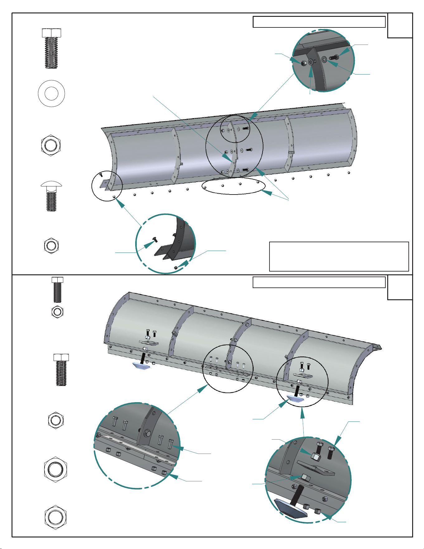
1
60, 72, 82, & 84" ENSEMBLE DES LAMES
NOTE: SI VOUS AVEZ ACHETÉ UN
POLYSCRAPER JAUNE, VOIR ÉTAPES
21&22
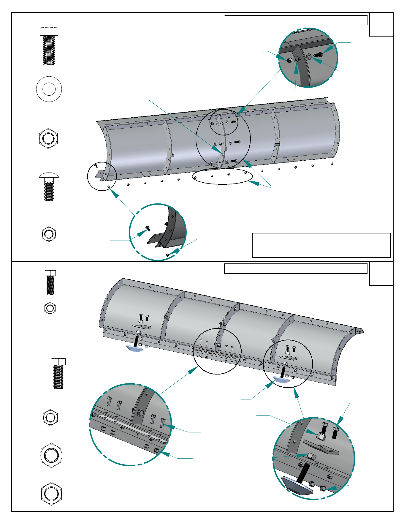
ATTACHEZ LE RACLEUR À L'AVANT DE LA
LAME À L'AIDE DES BOULONS DE TÊTE
BOMBÉE ET COLLET CARRÉ ET DES
CONTE-ÉCROUS
#17
#5
#2
#3
#4
1.25"
1"
UTILISEZ LES BOULONS ET LES CONTRE-ÉCROUS
POUR MONTER LA PLAQUE ANGLÉ ET SUPPORT.
POUSSEZ LE PATINS DE GLISSEMENT PAR
TRAVERS LA PLAQUE ANGLÉ ET SERREZ
#6
#5
#10
#5
#17
#3
60"-72"
82"-88"
#3
#8
#9
#7
1"
#4
#5
#3
#2
#17
#7/#9
#8/#3
#5
#6
#17/#10
#3/#5
CHAUSSURES
DE DÉRAPAGE
1.25"
60, 72, 82, & 84" ENSEMBLE DES LAMES
2
LAISSEZ DESSERRÉES
60"-72"
60"-72"
LAISSEZ
DESSERRÉES
#2
60"-72"
82"-88"
82"-88"
82"-88"
CHAUSSURES
DE DÉRAPAGE
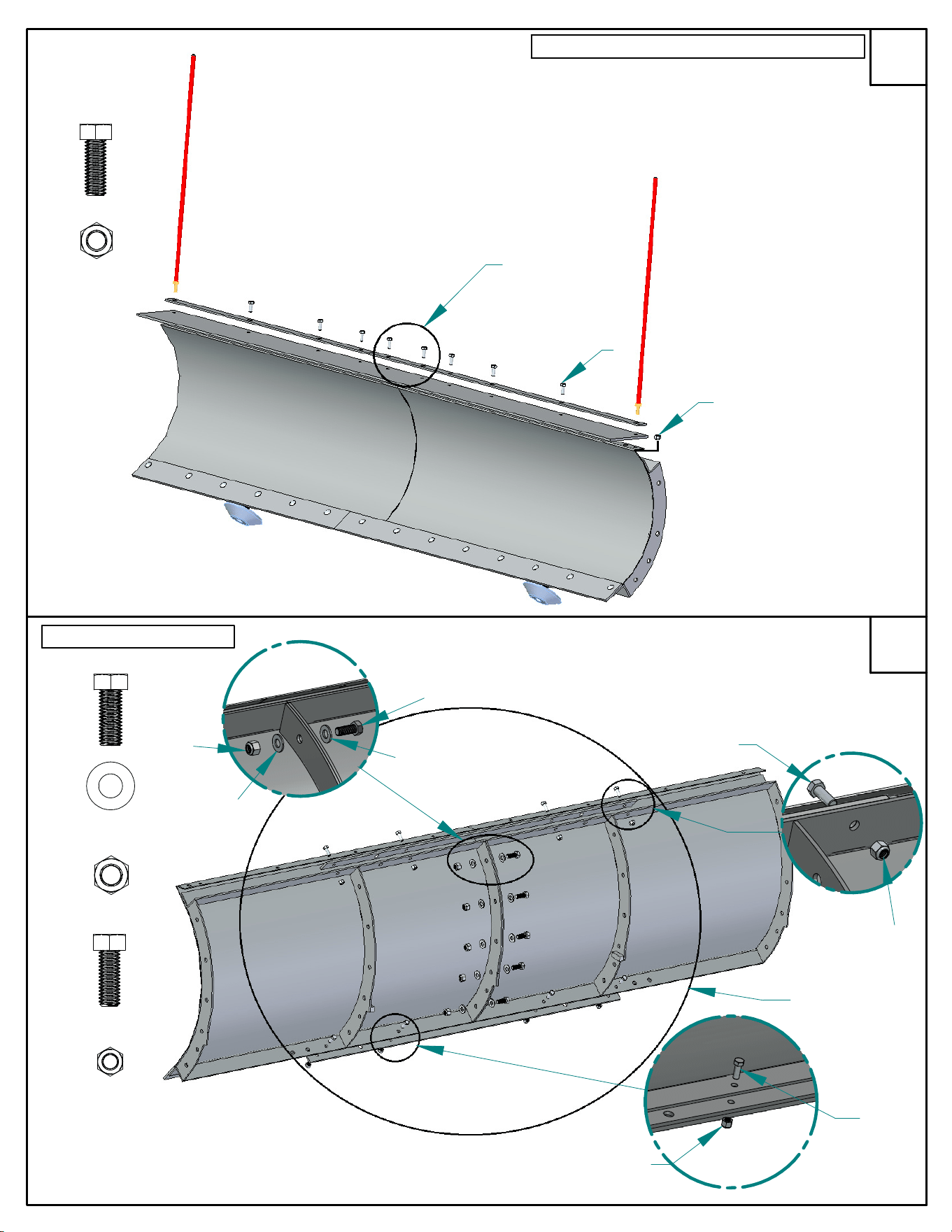
UTILISEZ LES BOULONS, LES RONDELLES, ET LES
CONTRE-ÉCROUS POUR ATTACHER LA LAME
ENSEMBLE
60", 72", ET 82" LAMES REQUIS 3 BOULONS
84" LAME REQUIS 4 BOULONS
88" LAMES - VOIR LES ÉTAPES 4-5
ASSURER DEUXIÉME TROU LE BAS DE LA
LAME EST LAISSÉE OUVERTE
25
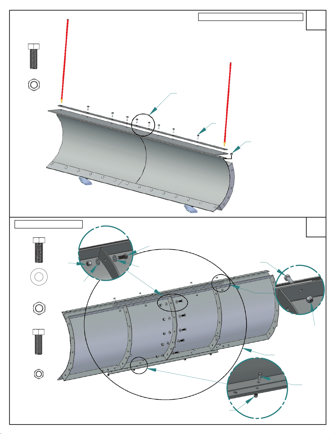
DIAMANT CÔTÉ
CONDUCTEUR
3
4
#6
#5
LAISSEZ
DESSERRÉES
#6
#
5
UTILISEZ LES BOULONS HEX ET LES ÉCROUS POUR
FIXER LE DÉFLECTEUR DE NEIGE. LES GUIDES
REMPLACENT LES BOULONS SUR LES DEUX COINS
#19
1"
UTILISEZ LES BOULONS, LES RONDELLES,
ET LES CONTRE-ÉCROUS POUR
ATTACHER LA LAME ENSEMBLE
UTILISEZ LES BOULONS ET LES
CONTRE-ÉCROUS POUR MONTER
LA SUPPORT
88" LAME ENSEMBLE
LAISSEZ
DESSERRÉES
#17
#3
#2
#6
#5
#6
#5
#17
1.25"
#2
#3
#6
#5
1"
2
#2
60, 72, 82, & 84" ENSEMBLE DES LAMES
26
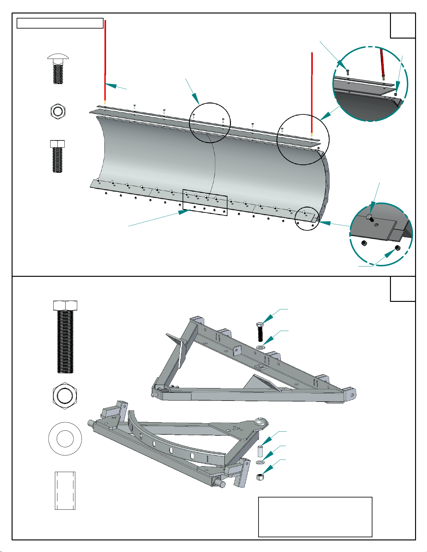
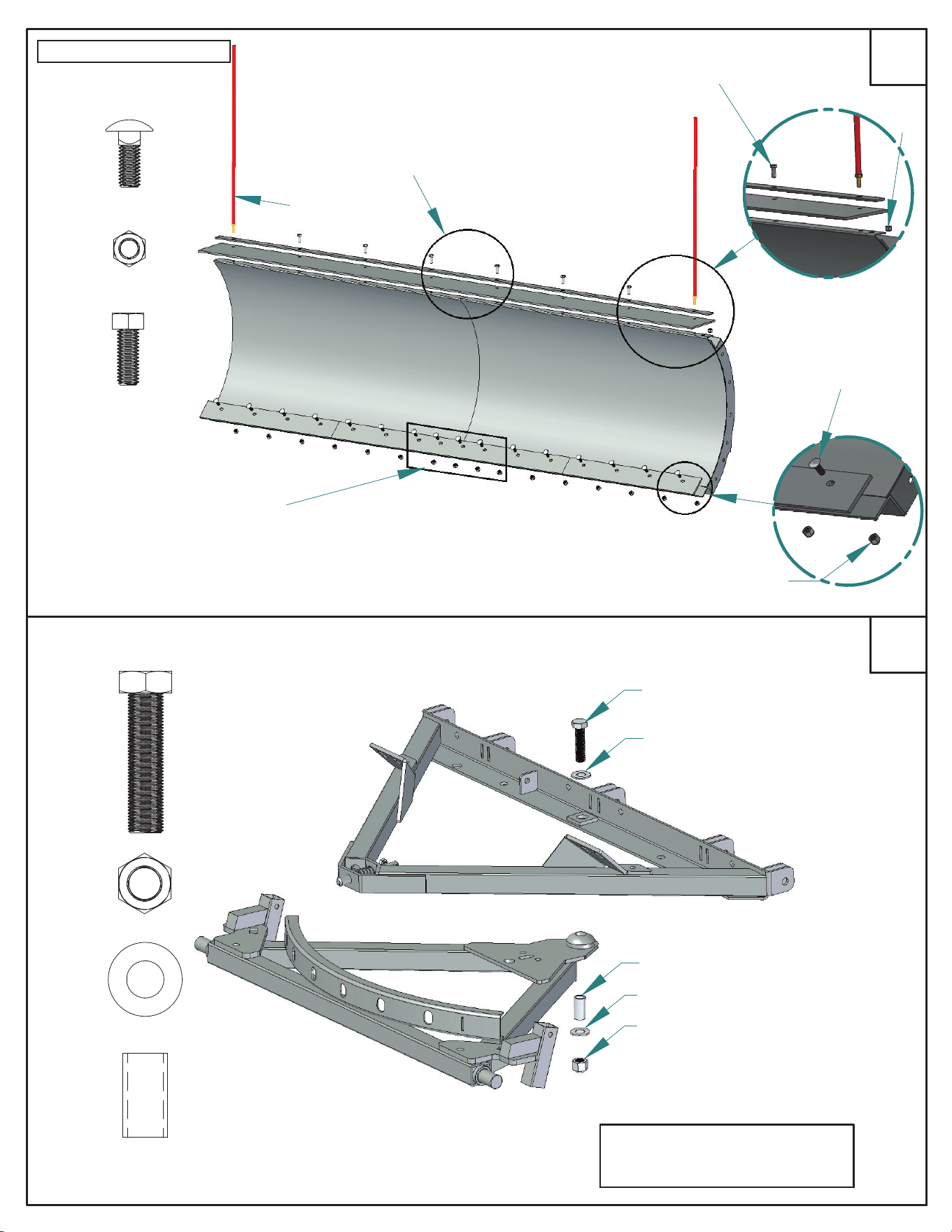
5
6
#4
#5
#6
#5
INSÉREZ LA CLAVETTE DE
DÉCLENCHEMENT DU CADRE EN «A»
SUPÉRIEUR DANS LE SUPPORT ARCHÉ
DU CADRE EN «A» INFÉRIEURE
NOTE:
ATTACHEZ LE BOULON
COMPLÈTEMENT ET DÉGAGER
2 TOURS
#12
#14
#13
#11
#12
#13
#11
#13
#14
2.5"
1"
LAISSEZ LES 4 DU
MILIEU
DESSERRÉES
#4
#6
#5
88" LAME ENSEMBLE
UTILISEZ LES BOULONS HEX ET LES ÉCROUS POUR
FIXER LE DÉFLECTEUR DE NEIGE. LES GUIDES
REMPLACENT LES BOULONS SUR LES DEUX COINS
LAISSEZ
DESSERRÉES
ATTACHEZ LE RACLEUR À L'AVANT DE LA
LAME À L'AIDE DES BOULONS DE TÊTE
BOMBÉE ET COLLET CARRÉ ET DES
CONTRE-ÉCROUS
1"
FIXEZ LA PARTIE SUPÉRIEUR ET INFÉRIEURE
DU CADRE EN
«A»
EN UTILISANT LE BOULON,
LA DOUILLE, DES RONDELLES, ET
CONTRE-ÉCROUS
#19
27
Installez l'élément #11 de la
surface supérieure.
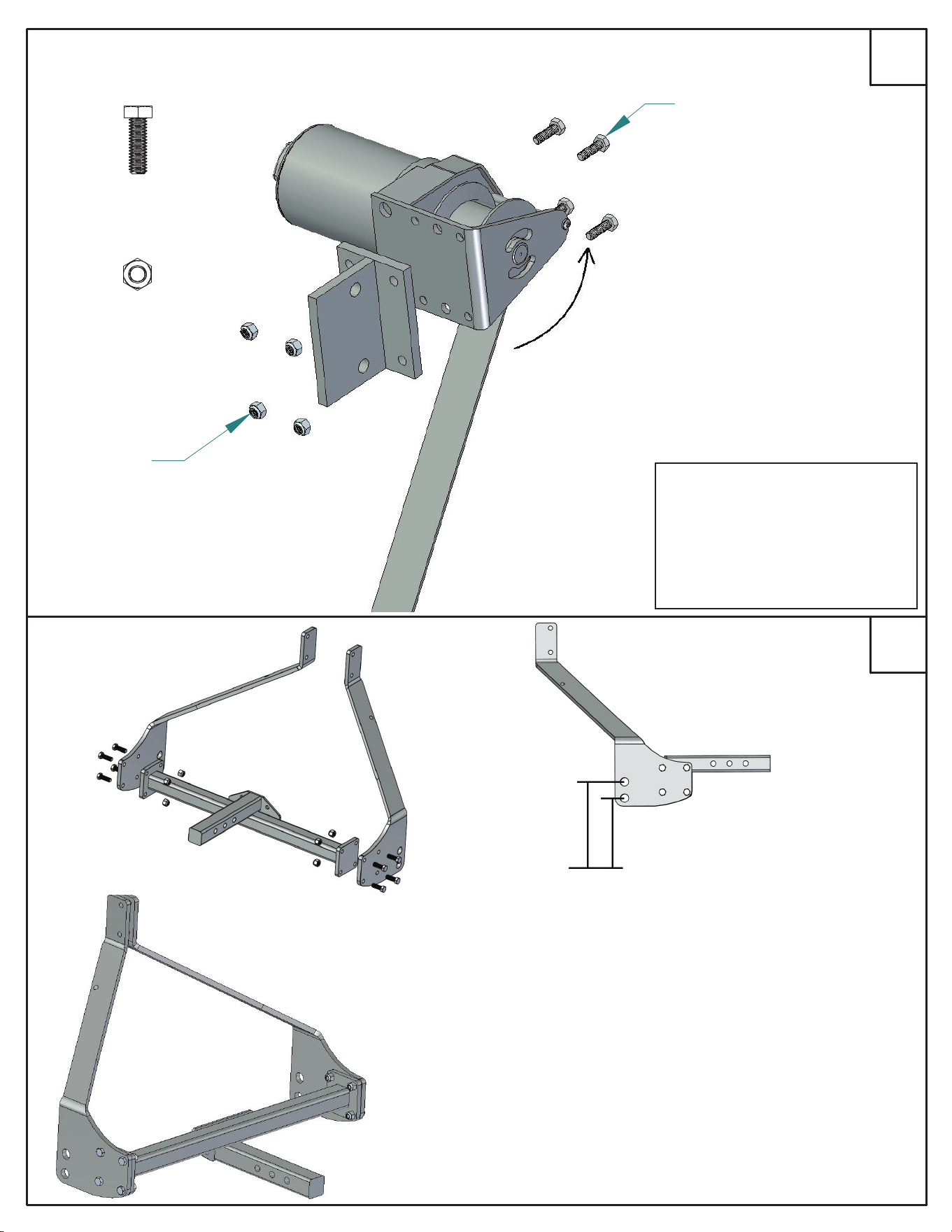
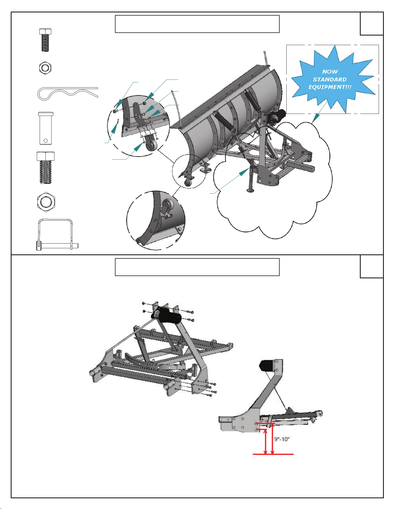
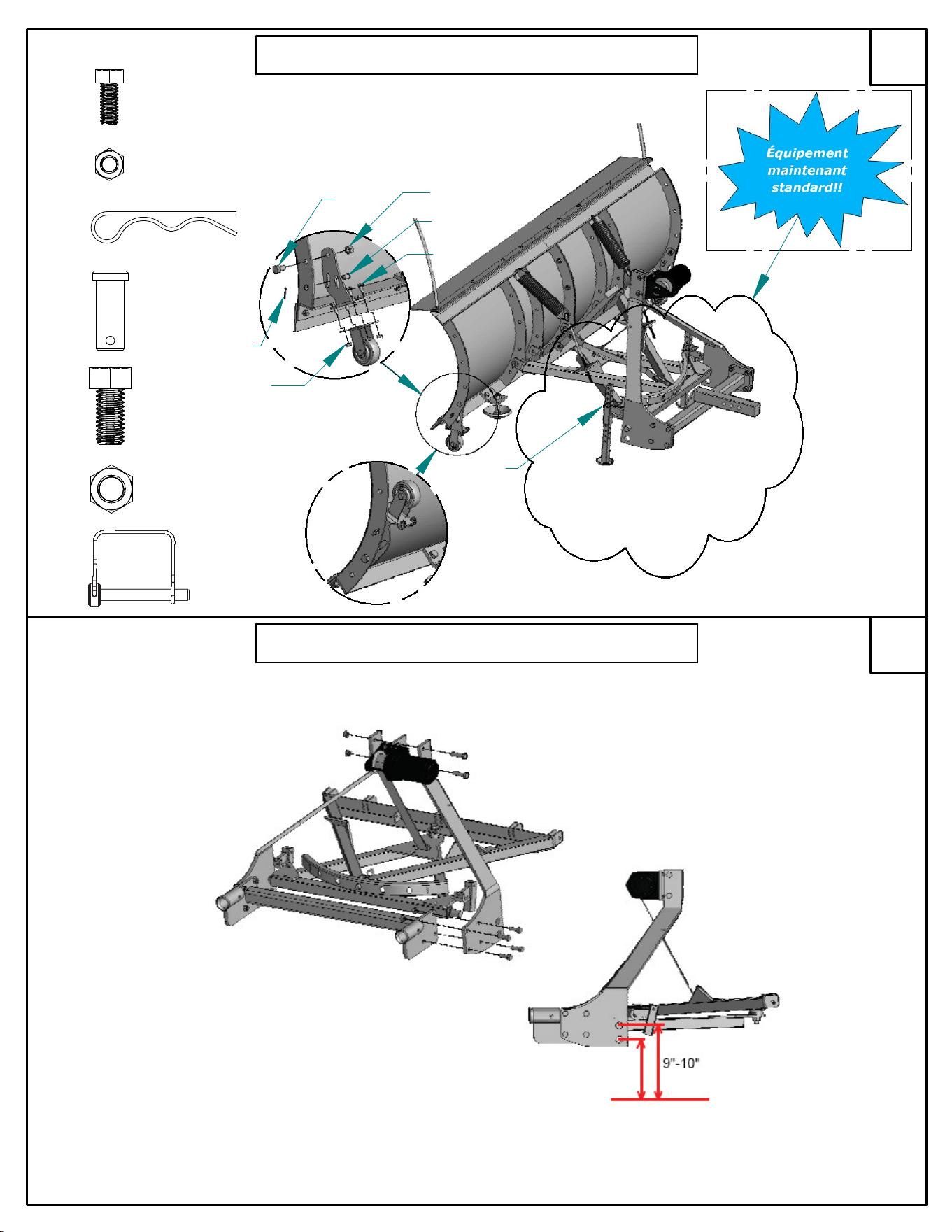
7
8
#15
#16
1"
#15
#16
TIGE VERS LE
BAS
TIGE VERS LE
HAUT
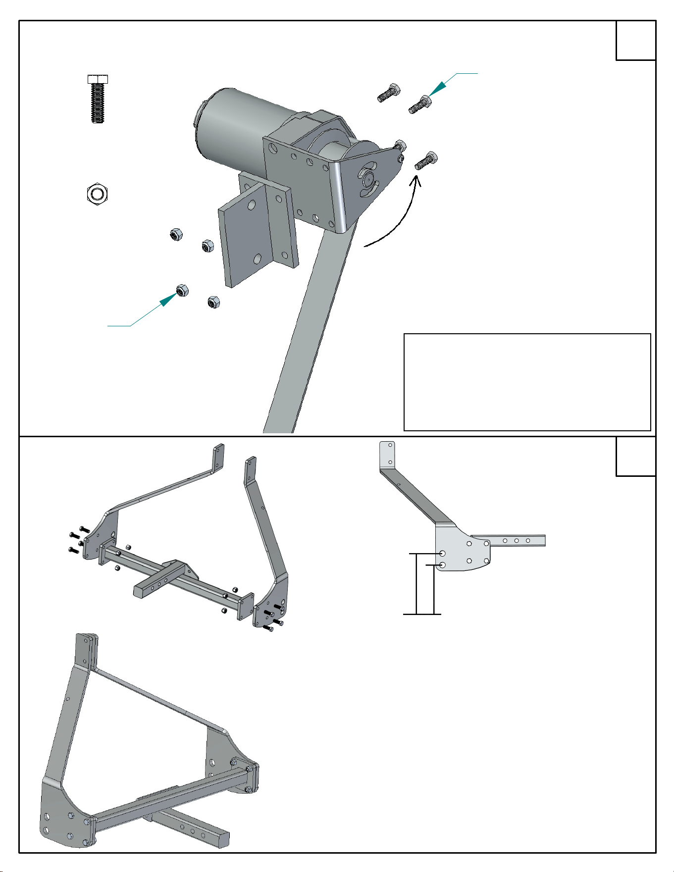
POUR DÉTERMINER LA HAUTEUR DE L'ADAPTEUR MALE:
1. FIXEZ SANS SERRER LA TRAVERSE ET BRAS DE TREUIL DANS
L'UNE DES ORIENTATIONS MONTRÉE
2. FIXER
L'ASSEMBLAGE AU RÉCEPTEUR DE CAMION
3. MESURER DU SOL AUX GRANDS TROUS DANS LES BRAS DE
TREUIL
4. SI LA DISTANCE N'EST PAS 9-10" DE CHAQUE TROU, NE
PEUT PAS ÊTRE R
É
ALIS
É
E, FIXER LA TRAVERS DANS
L'ORIENTATION OPPOSÉE
5.
FIXER AU CADRE «A» UTILLISANT CE TROU
9-10"
ENROULEZ CETTE
DIRECTION SEULEMENT
VISSER LE TREUIL AU SUPPORT DE
FIXATION À L'AIDE DES BOULONS
ET CONTRE-ÉCROUS
#26
NOTE:
SI VOUS AVEZ ACHETÉ UNE CHARRUE
ACTIONNÉE ÉLECTRIQUE DE NEIGE
RÉFÉREZ-VOUS SVP AUX ÉTAPES 19
ET 20 POUR LES DÉTAILS
D'INSTALLATION DE DÉCLENCHEUR
28
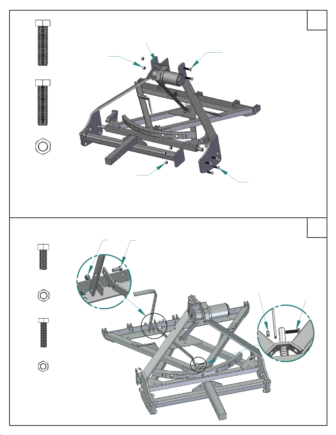
#47
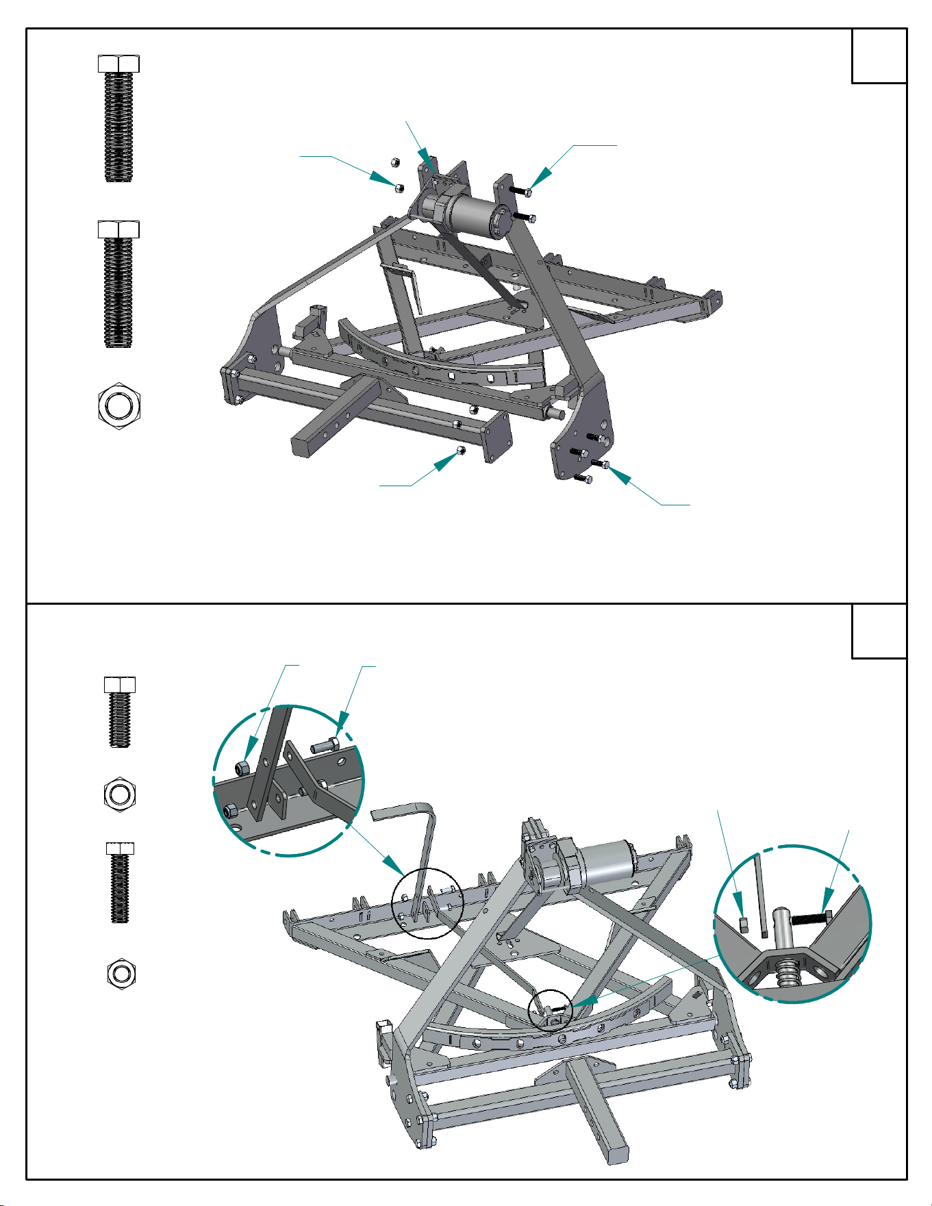
10
9
ATTACHEZ LES BRAS DE TREUIL À
LA PLAQUE DE MONTAGE EN
UTILISANT LES BOULONS 2" ET LES
CONTRE-ÉCROUS
ATTACHEZ LES BRAS DE TREUIL SUR LE
CADRE «A» INFÉRIEURE ET LA TRAVERSE
EN UTILISANT LES BOULONS 2" ET LES
CONTRE-ÉCROUS
#18
#1
#3
2"
INSTALLER LE TREUIL AVEC SUPPORT
DE TREUIL APRÈS L'INSTALLATION DU
BRAS DE TREUIL
#3
#18
#3
#1
ATTACHER LA POIGNÉE DE DÉCLENCHEMENT À LA
TIGE DE DÉGAGEMENT ET ATTACHÉ CELA AU CADRE
«A» SUPÉRIEUR À L'AIDE DES BOULONS ET
CONTRE-ÉCROUS
#6
#5
#20
#16
1"
#20
#16
#5
#6
1.25"
UTILISEZ LE BOULON #20 ET LES
CONTRE-ÉCROU POUR ATTACHER
L'AUTRE EXTRÉMITÉE DE LA TIGE DE
DÉGAGEMENT À LA CLAVETTE DE
DÉCLENCHEMENT ACTIONNÉ PAR
RESSORT SITUÉE SUR LE CADRE EN
«A» SUPÉRIEUR
2"
29
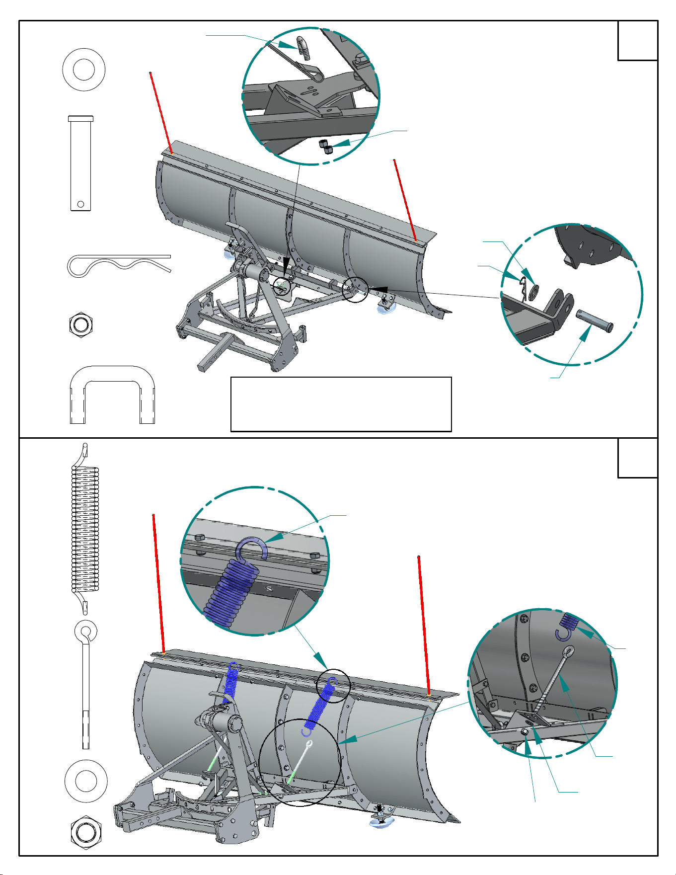
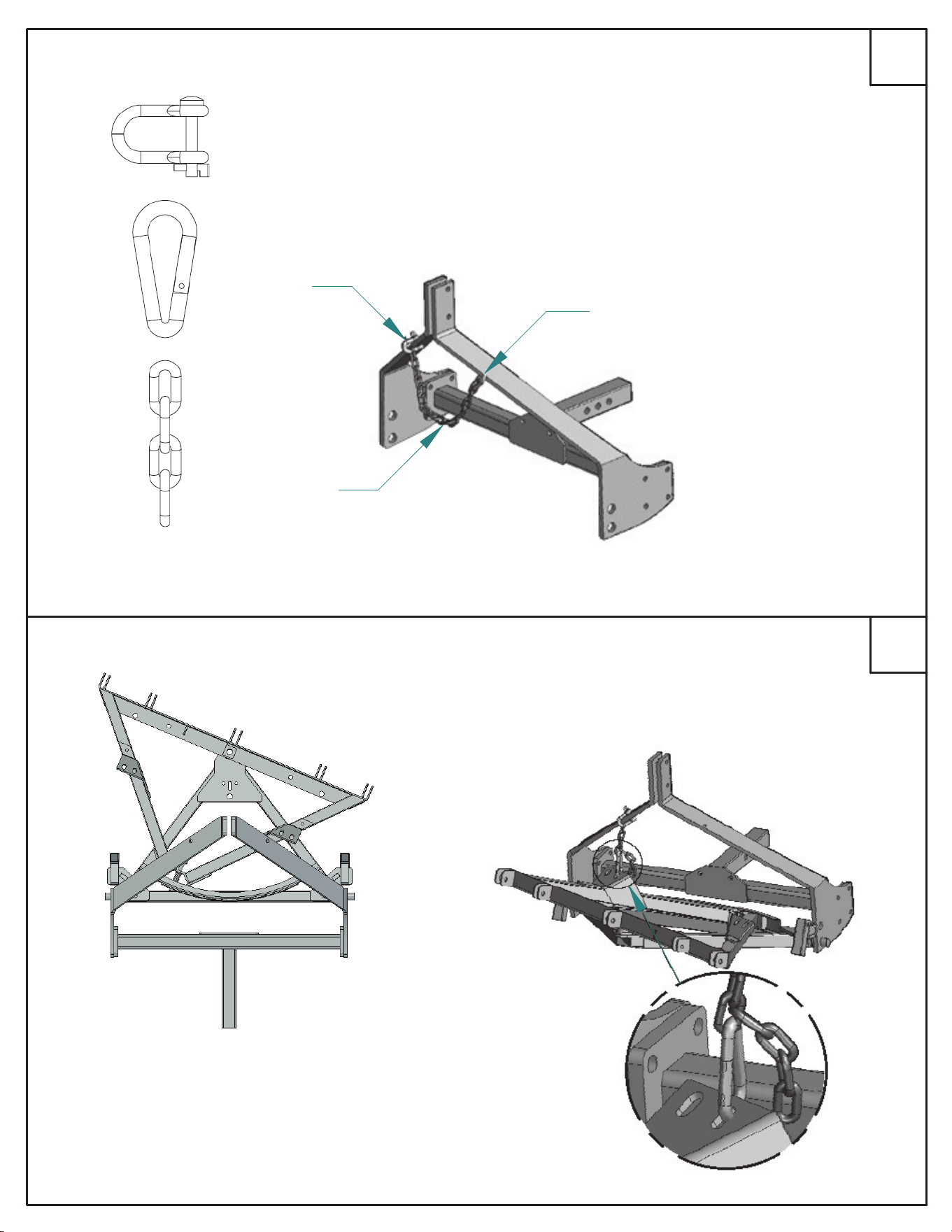
12
11
#22
#2
#22
#23
#5
#21
ATTACHEZ SANS SERRER
LA COURROIE DE TREUIL À
L'AIDE DU BOULON «U» ET
DES CONTRE-
É
CROUS
ALIGNER LE CADRE EN «A» SUPÉRIEUR SUR
LES NERVURES SITUÉES À L'ARRIÈRE DE LA
LAME. LE FIXEZ AVEC LES VIS À OEILLET, DES
RONDELLES ET DES GOUPILLES FENDUES
SERRER LES BOULONS DE LAME
UNE FOIS LES BROCHES
INSTALLÉS
NOTE:
LA COURROIE DOIT ÊTRE
ENTIÈREMENT DÉROULÉE LORS DU
MONTAGE
#21
#5
#23
#2
ACCROCHER LES RESSORTS À L'ARRIÈRE DE LA LAME
#2
#3
#24
#51
#3
#2
#24
#51
FIXEZ LES RESSORTS ÀU CADRE EN «A»
SUPÉRIEUR À L'AIDE DES BOULONS À
L'OEUIL ET DE CONTRE-ÉCROUS. SERREZ
JUSQU'À CE QUE LES RESSORTS
COMMENCERA À AUGMENTER
#51
30
Avertissement!! --lunettes de sécurité requises
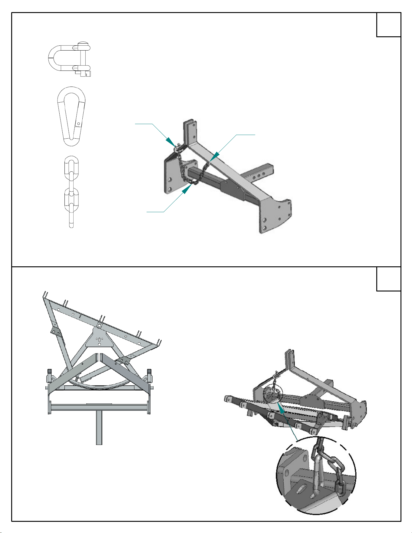
14
13
ENFILER L'EXTRÉMITÉ DE LA CHAÎNE SUR LA
MANILLE ET L'ATTACHER AU CÔTÉ DE
PASSAGER DU BRAS DE TREUIL
CONNECTER L'AUTRE EXTRÉMITÉE DE LA
CHA
Î
NE À LA PINCE MOUSQUETON ET
ATTACHER CELA AU BRAS DE TREUIL AU
CÔTÉ
DU CONDUCTEUR
#28
#29
#34
#34
#28
#29
ENGAGER LA CHA
Î
NE DE SÉCURITÉ,
UTILISER LA POIGNÉE DE DEGAGEMENT
POUR DÉPLACER LE CADRE EN «A»
SUPÉRIEUR DE LA FENTE DU
CÔTÉ DU
CONDUCTEUR
AUGMENTER LA CHARRUE
À LA
HAUTEUR MAXIMUM EN UTILISANT
LE TREUIL/ACTINNEURS
DÉBRANCHEZ LE MOUSQUETON DU BRAS DE
TREUIL ATTACHEZ
À
LA PLAQUE SUR LE CADRE
RELIEZ AU PLAT SUR A-FRAME
RACCOURCISSEZ LA
CHAÎNE AUTANT QUE
POSSIBLE ET REBRANCHEZ À
CARABINER
31
16
15
#3
#33
#30
#16
#23
#32
#27
#30
#16
#23
#33
#32
#27
.75"
1"
FIXEZ SANS SERRER LE SUPPORT DU PATIN DE GLISSEMENT
À LA CHARRUE
À
L'AIDE DU 1" BOULON ET CONTRE-ÉCROU
UTILISEZ LE VIS À OEILLET ET LA GROUPILLE FENDUE POUR
METTRE LA ROULETTE DANS LA POSITION ABAISSÉE
MONTER LE SUPPORT DE ROULETTES
À LES DEUX CÔTÉS DU CADRE «A»
FIXER LE SUPPORT AVEC LES
ATTACHES «D»
LORSQUE LES ROUES NE
SONT PAS EN COURS
D'UTILISATION, FAITES
TOURNER LES SUPPORT DE
ROULETTES VERS LE HAUT
ET LES FIXEZ AVEC LE VIS À
OEILLET ET LA GOUPILLE
FENDUE
UTILISEZ LES GROS TROUS DANS LE BRAS DE
TREUIL POUR DÉTERMINER LE TROU DE
MONTAGE
ATTACHEZ LES BRAS DE TREUIL SUR LE
CADRE EN «À» INFÉRIEUR ET LE RÉCEPTEUR
TRAVERSE EN UTILISANT 1-1/2" BOULONS ET
LES CONTRE-ÉCROUS
(FACULTATIF) - SYSTÈME FAIT SUR COMMANDE DE
SUPPORT MONTRÉ
ATTACHEZ LES BRAS DE TREUIL A
LA PLAQUE DE MONTAGE EN
UTILISANT 2" BOULONS À TÊTE
HEX ET LES ÉCROUS
#3
ATTACHEZ LA ROULETTE ÀU
SUPPORT À L'AIDE DES ÉCROUS
HEX ET DES CONTRE-ÉCROUS
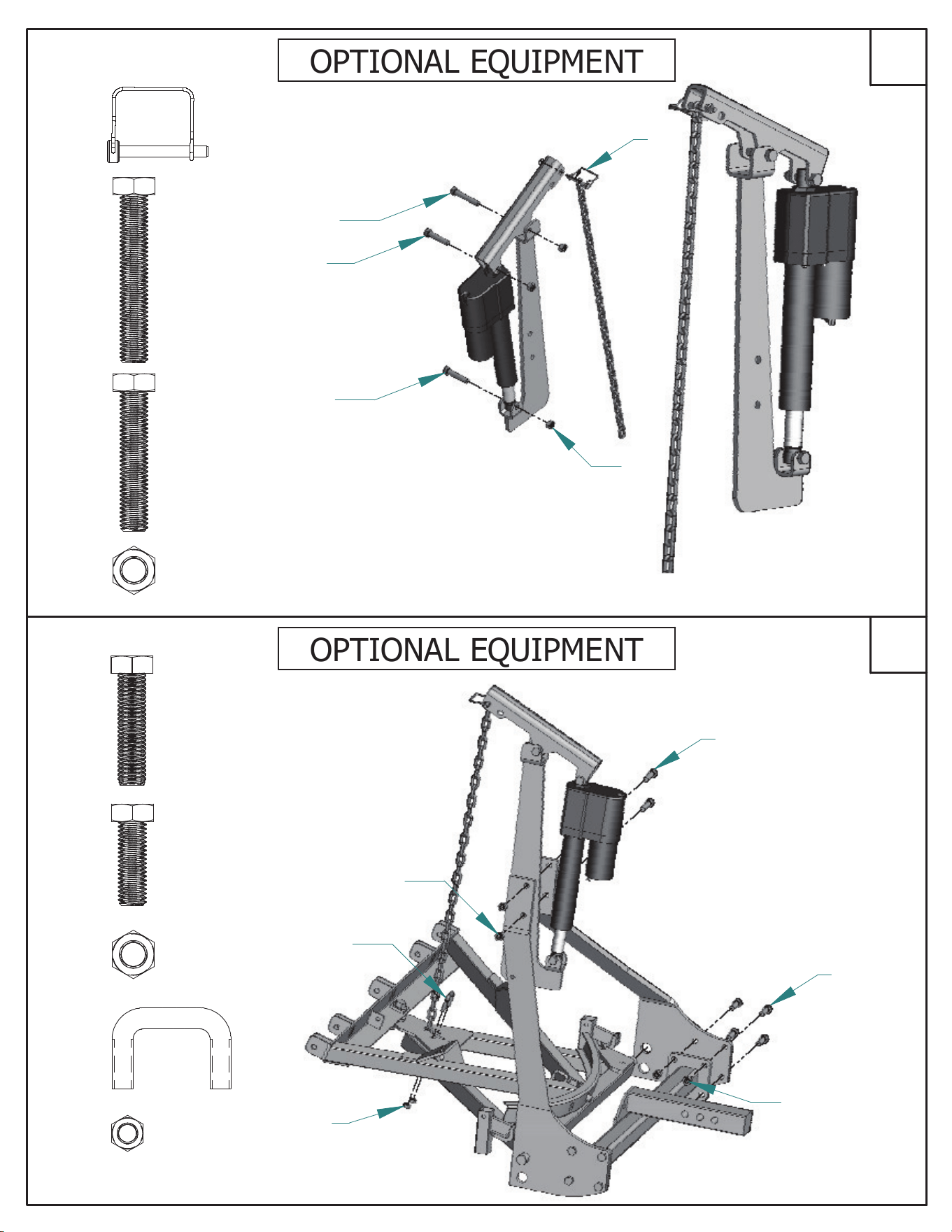
EQUIPEMENT OPTIONNEL
LE CENTRE DE LAS GOUPILLE DE MONTAGE
SUR LE CADRE EN
«A» DOIT ÊTRE À 9-10" DU
SOL
EQUIPEMENT OPTIONNEL
32
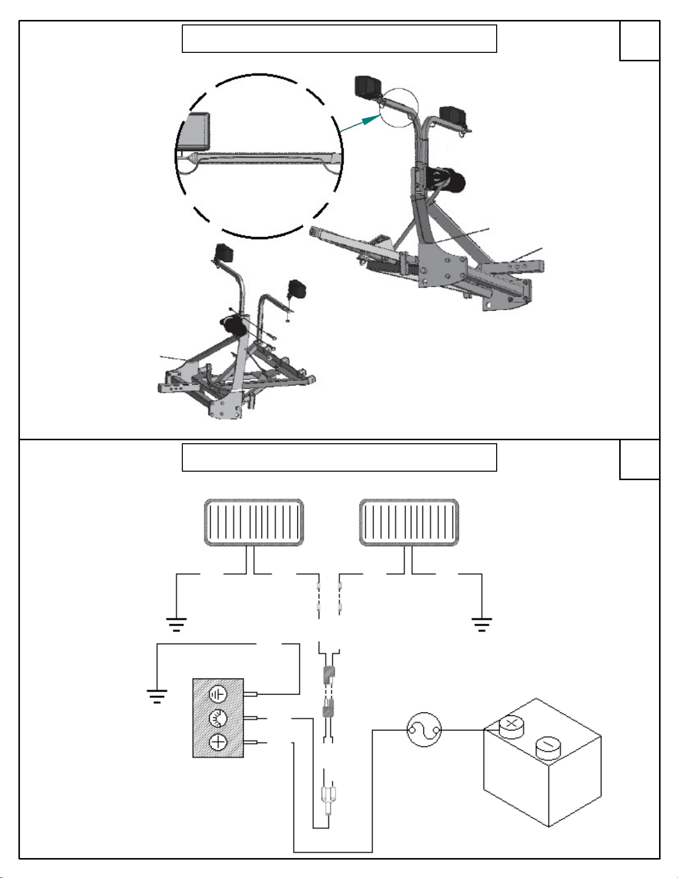
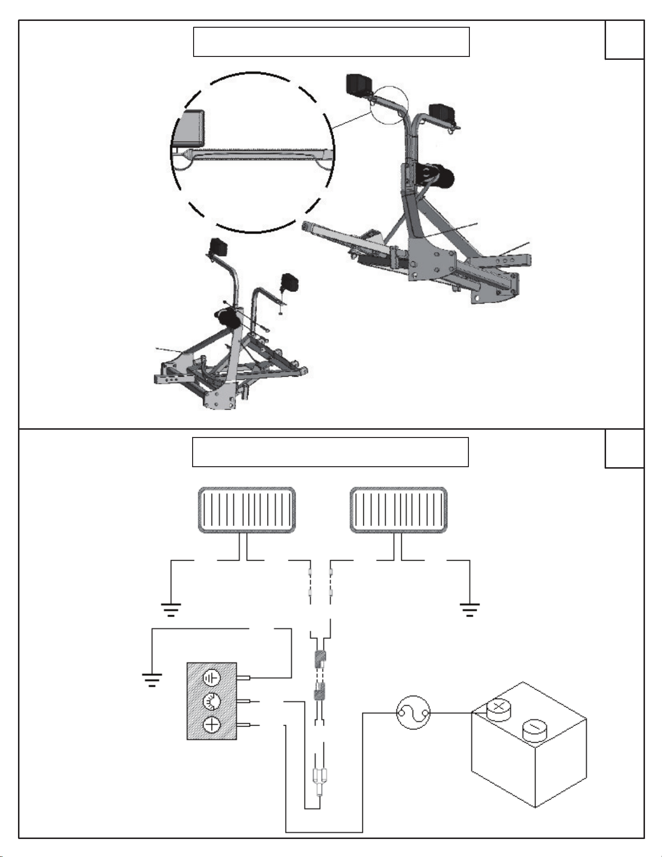
18
17
SÉCURISER LES CÂBLES DANS
LE TUBE ET BRAS TREUIL À
L'AIDE DES SERRE-C
Â
BLES
FIXEZ LES LUMIÈRES À
L'AIDE DES ÈCROUS
FOURNIS
MONTEZ LES TUBES DE SOUTIEN À
L'EXTÈRIEUR DU BRAS TREUIL À L
'
AIDE
DES
1
/
2
-13 X 4" BOULONS
À
TÊTE
HEXAGONALE ET CONTRE-ÉCROUS
PASSER LES FILS À TRAVERS
LE TUBE DE SUPPORT DE
LA LAMPS
BLANC
BLANC
PORTE-FUSIBLE
À LA TERRE
INTERRUPTEUR
BATTERIE
À LA TERRE
R
O
U
G
E
NOIR
À LA TERRE
NOIR
BLANC
BLANC
NOIR
LAMPELAMPE
R
O
U
G
E
B
R
U
N
B
R
U
N
EQUIPEMENT OPTIONNEL
EQUIPEMENT OPTIONNEL
33
PT # 324-127
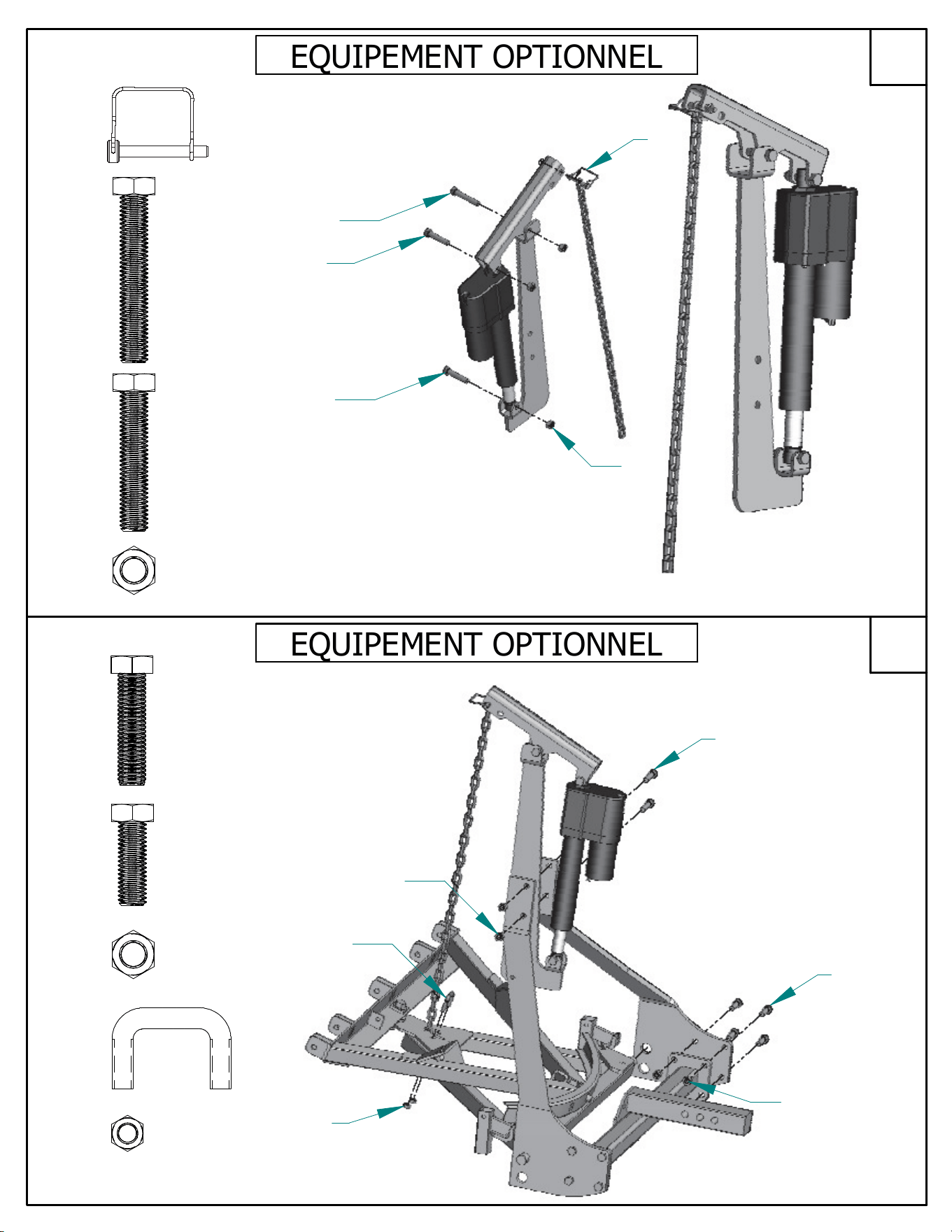
20
19
CONNECTEZ LA CHAÎNE AVEC
BOULON «D» ET LE JOINDRE À LA
LONGUE EXTRÉMITÉ DU BRAS DE
LEVAGE
UTILISEZ LE 3" BOULON ET LE
CONTRE-ÉCROU POUR FIXER LE BRAS DE
LEVAGE AU SUPPORT DE L'ACTIONNEUR
UTILIZER 2-
1
/
2
" BOULONS À TÊTE
HEXAGONALE ET
CONTRE-ÉCROU POUR
MONTER L'ACTIONNEUR
#27
#26
#25
#3
3"
2.5"
ATTACHER LES BRAS DU TREUIL AU
CADRE «A» INFÉRIEUR ET LE
RÉCEPTEUR TRAVERSE EN UTILISANT
LES BOULONS 1.5" À TÊTE
HEXAGONALE ET LES CONTRE-ÉCROUS
FIXEZ SANS SERRER LA CHAÎNE AU
CADRE EN «A» AVEC LE BOULON «U»
ET CONTRE-ÉCROUS
MONTER L'ACTIONNEUR SUR
LES BRAS DU TREUIL AVEC 2"
BOULONS À
TÊTE HEXAGONALE
ET LES
CONTRE-ÉCROU
#3
2"
#18
#1
#21
#5
1.5"
#25
#26
#26
#3
#27
#5
#21
#3
#8
#3
#1
EQUIPEMENT OPTIONNEL
EQUIPEMENT OPTIONNEL
34
PRO SHOVEL & WINTERWOLF
PRO SHOVEL & WINTERWOLF
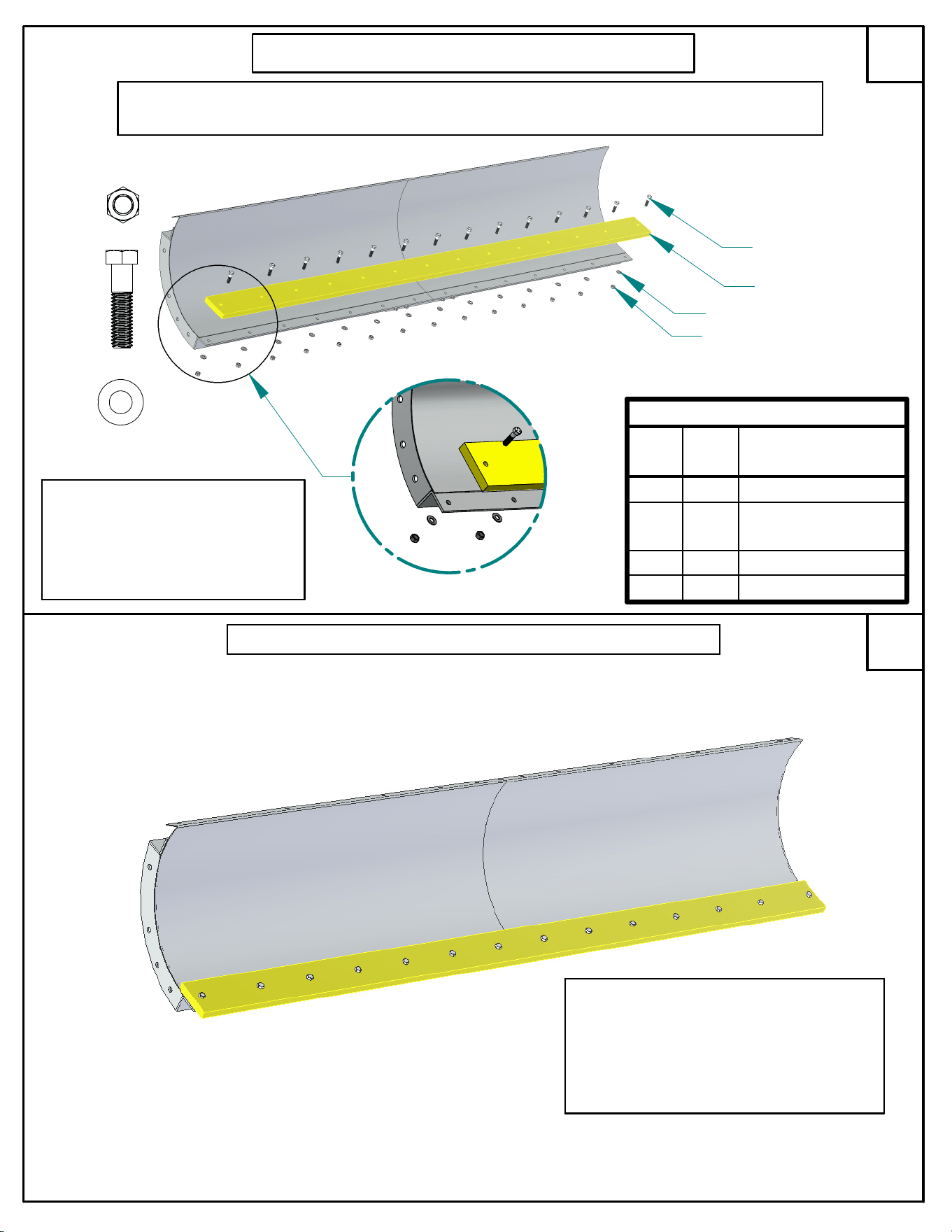
22
21
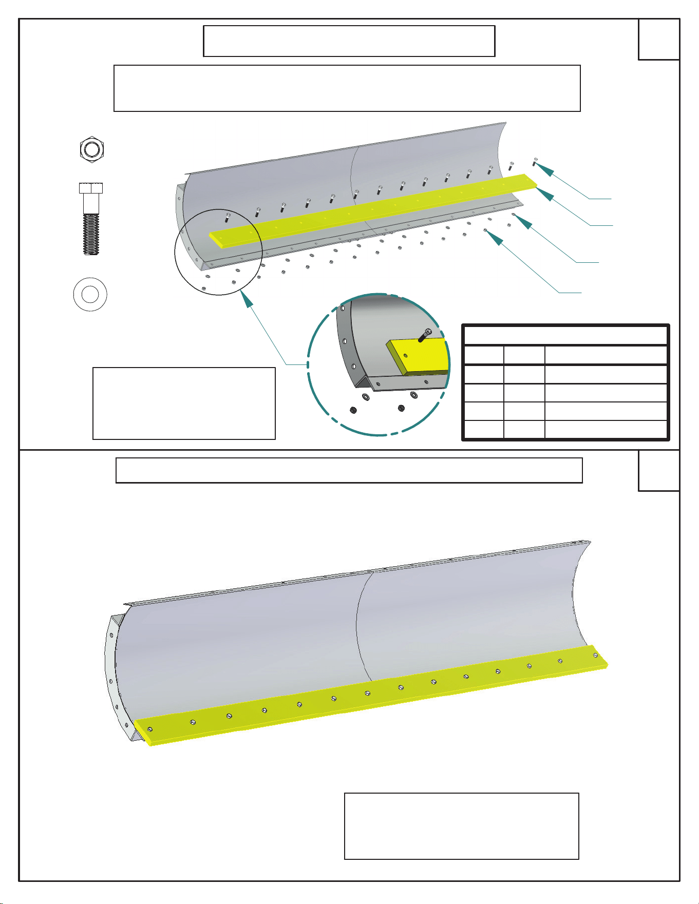
CONTENU DU SACHET DE VISSERIE 600-033
# DU
PRODUIT
QTY DESCRIPTION
1 15 ÉCROUS HEXAGONAUX 3/8-16
2 15 BOULONS HEXAGONAUX 3/8-16 X 1-1/2 ,
GR5
3 15 RONDELLE PLATE 3/8
4 1 POLYSCRAPER 82, 84, OU 88"
ATTACHER LES POLYSCRAPER
VERS L'AVANT DE LA LAME À
L'AIDE DE POLYSCRAPER
FOURNI 600-033 ET LE
SACHET DE VISSERIE
#2
#4
#3
#1
#2
#3
#1
EQUIPEMENT OPTIONNEL
INSTRUCTIONS D'INSTALLATION ACCESSOIRE POLYSCRAPER
NOTE: REMPLACER UNE PORTION DE L`ÉTAPE D'ASSEMBLÉ #1
ASSEMBLAGE COMPLET
NOTE: SI POLYSCRAPER EST
ACHETÉ COMME ACCESOIRE OU
FOURNIE AVEC VOTRE CHASSE
NEIGE, LES CHAUSSURES DE
DÉRAPAGE NE SERONT PAS
INCLUS
35
36
TREUILSCHÉMADECÂBLAGE
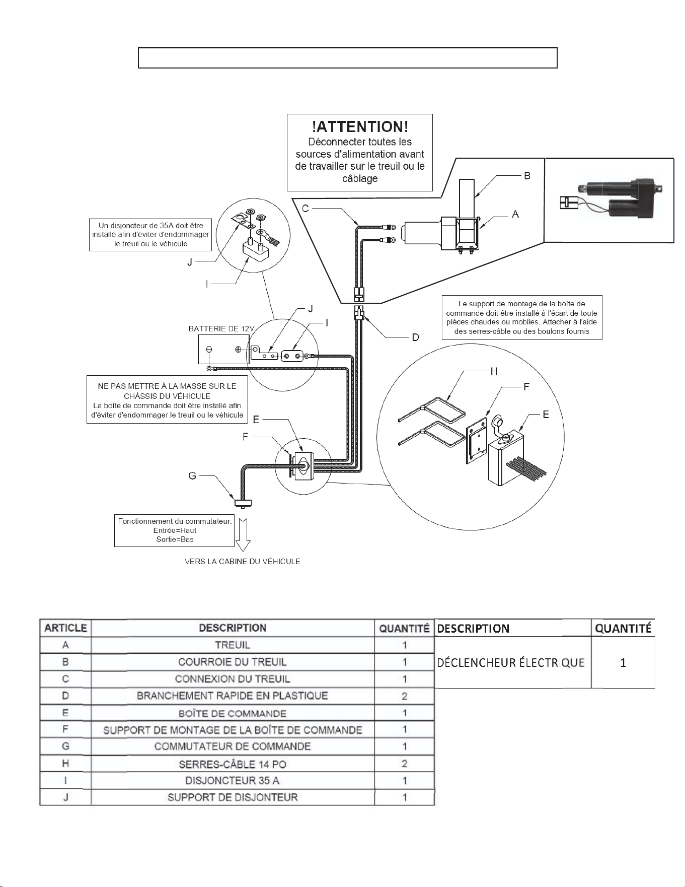
34
DIAGRAMME DE CÂBLAGE DE TREUIL ET DE DÉCLENCHEUR
36

DÉPANNAGE
Si le chasse-neige ne fonctionne pas correctement, consulter les conseils de dépannage ci-dessous. Ceux-ci sont destinés à
servir de guide pour résoudre les problèmes techniques courants et à vous permettre d’effectuer de simples réglages. Si une
assistance complémentaire est nécessaire, contacter le service d’assistance à la clientele de SnowBear
MD
au 1.800.337.2327.
1. Le chasse-neige se balance ou s’incline d’un côté vers l’autre.
a) Le chasse-neige se balance normalement de 8 à 10 pouces d’un côté vers l’autre. Ce mouvement aide à
compenser les différences de niveau du terrain à déneiger et ne doit pas être réduit par l’addition de cales ou de
rondelles.
b) Si le balancement du chasse-neige est excessif, examiner le boulon à pivot de 5/8 po (n° 6) pour s’assurer qu’il n’a
pas un jeu supérieur à 1/4 de po. Si nécessaire, le contre-écrou de 5/8 de po peut être serré.
c) Vérifier si la tension des ressorts et des boulons à oeil est adéquate. Si le ressort paraît ne pas être tendu, serrer
les contre-écrous des boulons à oeil jusqu’à 1/4 de po au-delà du point de tension.
2. La courroie du treuil se casse.
a) La raison la plus fréquente de la rupture d’une courroie est le manque de movement libre du boulon en « U », à
l’endroit où la courroie se fixe au cadre en « A ». S’assurer que les contreécrous du boulon en « U » ne sont pas
trop serrés et qu’il y a assez de jeu dans le boulon en «U ».
b) Une autre cause courante d’une courroie brisée est un serrage excessif du treuil. Ceci entraînera aussi la
déformation des bras du treuil. Veillez à ce que votre disjoncteur 35A soit bien installé, et qu’il fonctionne
correctement, et ne serrez pas trop le treuil lorsque vous élevez et abaissez la lame du chasse-neige.
3. Le treuil/déclencheur ne s’engage pas ou le treuil hésite. (broute).
ATTENTION - Débrancher l’alimentaiton du chasse-neige
avant de procéder à tout dépannage du treuil/déclencheur ou du câblage.
a) S”assurer que le câble de la batterie est mis à la masse de manière sécuritaire sur la borne négative de la batterie.
NE PAS METTRE LE CHÂSSIS DU VÉHICULE À LA MASSE.
b) S’assurer que le commutateur de la boîte de commande (sous le capot) est en position de marche « ON ».
c) Vérifier les contacts et les connecteurs pour s’assurer qu’ils sont bien raccordés et libres de toute saleté ou
corrosion. De la graisse diélectrique peut être utilisée pour protéger les connexions électriques contre la saleté et
la corrosion.
4. Le fonctionnement du chasse-neige est inversé (c’est-à-dire, la lame se soulève lorsqu’elle devrait s’abaisser)
a) S’assurer que le fil rouge de la connexion de 2 pieds du treuil est raccordé à la borne positive (haut) du treuil et le
fil noir à la borne négative (bas).
5. Le câblage, le commutateur de commande ou la boîte de commande s’échauffent.
a) Un disjoncteur doit être installé entre le câble de batterie rouge et la borne positive de celle-ci. S’assurer que le
support du disjoncteur est connecté entre la batterie et la borne de cuivre du disjoncteur.
SE SOUVENIR
Ce chasse-neige est conçu pour utilisation personnelle UNIQUEMENT. Le chasse-neige ne convient pas à des
fins commerciales et n’est pas conçu pour être transporté à des vitesses supérieures à 10 mph (16 km/h).
L’utilisation à des fins commerciales ou le déplacement à des vitesses supérieures à celles recommandées
annuleront la garantie et peuvent occasionner des dommages importants au chasse-neige, au véhicule et à la
personne.

Warranty Information -- L'information de garantie
Please see the latest version of SNOWBEAR
®
Plows Inc. warranty at:
http://www.snowbear.com/UserContent/documents/Warranty.pdf
Alternatively, please call our Customer Service Hotline at:
(800) 337-2327
Veuillez vous referrer au site Internet SNOWBEAR pour la derniere edition:
http://www.snowbear.com/UserContent/documents/Warranty.pdf
Vous pouvez aussi nous contacter directement au service à là clientele:
(800) 337-2327