Loading ...
Loading ...
Loading ...
PREPARING FOR INSTALLATION
Installation Instructions
TOOLS AND PARTS NEEDED
• Large flat-blade screwdriver
• Phillips screwdriver
• 3/8″ socket and ratchet
• Saw
• Carpenter’s square
• Pipe wrench
• Gas line shut off valve
• Pipe joint sealant for use with gas connections
that resists action of LP gas
For flexible connection where local codes permit:
• Flexible metal tubing (same 3/4″ or 1/2″ I.D. as gas
supply line)
• Flare union adapter for connection to supply line
(3/4″ NPT x 3/4″ I.D. or 1/2″ NPT x 1/2″ I.D.)
• Flare union adapter for connection to regulator
(1/2″ NPT x 3/4″ I.D. or 1/2″ I.D.)
For rigid connection:
• Pipe fittings as required
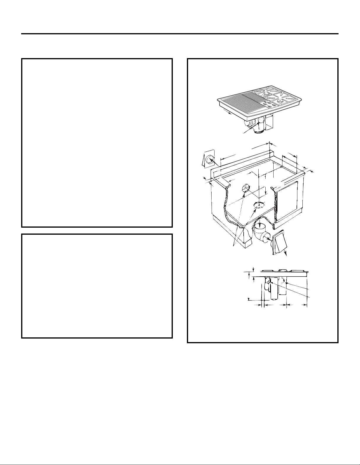
Tie down
bolt on
each end
Grease Container
Pressure Regulator
Wiring Box Cover
29″ ±
1
⁄16″
*Blower can be swiveled 90°
9″
9
1
⁄2″
1
7
⁄8″ Min.
4.76 cm
15
⁄16″
21″ ±
1
⁄16″
Minimum
Clearance
73.66 ± .16 cm
24.13 cm
2.38 cm
22.86 cm
53.5 ± .16 cm
14
3
⁄16″
36.04 cm
IMPORTANT
Motor Clearance—Provide 2″ min. (5.1 cm) cabinet
clearance to motor for cooling purpose.
NOTE: Where possible, 6″ (15.2 cm) is recommended
for motor/blower service.
Side Clearance—Grills installed near a side wall should
allow a minimum clearance of 8″ (20.3 cm).
You must allow room enough to remove and empty
grease container(s).
CAUTION: Warranty is void on equipment installed other
than as recommended by GE. Recommended wall
caps and transitions must be used for proper
operation and installation.
20
* Blower may be rotated for horizontal or vertical direction by loosening
nuts around blower inlet. Accessible inside ventilation chamber.
4
3
⁄16″ 10.64 cm
18
1
⁄2″
47 cm
Minimum
Clearance
2″
5.08 cm
Minimum
Clearance
14
1
⁄2″
36.83 cm
12
7
⁄8″
32.7 cm
Grease
Container
Appliance
Pressure
Regulator
Select appropriate duct
cutout. (See ducting
installation instructions.)
PREPARATION
Loading ...
Loading ...
Loading ...